CorelDRAW® 2019 User Guide - Corel Corporation
897
-
Upload
khangminh22 -
Category
Documents
-
view
0 -
download
0
Transcript of CorelDRAW® 2019 User Guide - Corel Corporation

Copyright © 2019 Corel Corporation. All rights reserved.
CorelDRAW® 2019 User Guide
The features documented in this User Guide are available in the full version of CorelDRAW Graphics Suite. Some features may not beavailable in your version of the product.
Product specifications, pricing, packaging, technical support and information (“specifications”) refer to the retail English version only. Thespecifications for all other versions (including other language versions) may vary.
Information is provided by Corel on an “as is” basis, without any other warranties or conditions, express or implied, including, but notlimited to, warranties of merchantable quality, satisfactory quality, merchantability or fitness for a particular purpose, or those arising by law,statute, usage of trade, course of dealing or otherwise. The entire risk as to the results of the information provided or its use is assumedby you. Corel shall have no liability to you or any other person or entity for any indirect, incidental, special, or consequential damageswhatsoever, including, but not limited to, loss of revenue or profit, lost or damaged data or other commercial or economic loss, even if Corelhas been advised of the possibility of such damages, or they are foreseeable. Corel is also not liable for any claims made by any third party.Corel's maximum aggregate liability to you shall not exceed the costs paid by you to purchase the materials. Some states/countries do notallow exclusions or limitations of liability for consequential or incidental damages, so the above limitations may not apply to you.
Corel, the Corel logo, the Corel balloon logo, Corel DESIGNER, CorelDRAW, the CorelDRAW balloon logo, Corel Font Manager, CAPTURE,CONNECT, LiveSketch, PaintShop, PaintShop Pro, Painter, PHOTO-PAINT, PowerClip, PowerTRACE, Presentations, Quattro, Quattro Pro,VideoStudio and WordPerfect are trademarks or registered trademarks of Corel Corporation and/or its subsidiaries in Canada, the U.S. and/or other countries. Other product, font and company names and logos may be trademarks or registered trademarks of their respectivecompanies.
Patents: www.corel.com/patent
2102059

Contents | 1
Contents
Get started...........................................................................................................................................................................................19
Install CorelDRAW Graphics Suite......................................................................................................................................................... 21
System requirements.......................................................................................................................................................................21
Prepare for installation................................................................................................................................................................... 22
Install CorelDRAW Graphics Suite applications................................................................................................................................22
Installation options......................................................................................................................................................................... 22
Modify and repair installations....................................................................................................................................................... 24
Uninstall CorelDRAW Graphics Suite...............................................................................................................................................24
FAQ................................................................................................................................................................................................ 25
Corel accounts and services..................................................................................................................................................................27
Authenticate CorelDRAW Graphics Suite.........................................................................................................................................27
Account settings.............................................................................................................................................................................28
Updates.......................................................................................................................................................................................... 28
Change user credentials..................................................................................................................................................................28
Corel Support Services.................................................................................................................................................................... 29
About Corel....................................................................................................................................................................................29
What’s new in CorelDRAW Graphics Suite?..........................................................................................................................................31
Individuality.................................................................................................................................................................................... 31
Creativity.........................................................................................................................................................................................32
Productivity.....................................................................................................................................................................................33
What was new in previous versions................................................................................................................................................34
Learning resources................................................................................................................................................................................35
Get help......................................................................................................................................................................................... 35
Help and tooltips............................................................................................................................................................................36
Hints...............................................................................................................................................................................................38
Welcome screen............................................................................................................................................................................. 38
Quick Start Guide........................................................................................................................................................................... 38
Video resources.............................................................................................................................................................................. 39
Developers’ website........................................................................................................................................................................ 39
Network deployment guide............................................................................................................................................................ 39

2 | CorelDRAW 2019 User Guide
Web-based resources......................................................................................................................................................................39
Start and set up................................................................................................................................................................................... 41
Start and quit CorelDRAW..............................................................................................................................................................41
Change the language..................................................................................................................................................................... 41
Startup settings.............................................................................................................................................................................. 42
CorelDRAW basics................................................................................................................................................................................ 43
Vector graphics and bitmaps..........................................................................................................................................................43
Start and open drawings................................................................................................................................................................44
Scan images................................................................................................................................................................................... 47
Work with multiple drawings......................................................................................................................................................... 48
Undo, redo, and repeat actions......................................................................................................................................................49
Zoom, pan, and scroll.................................................................................................................................................................... 50
Preview drawings............................................................................................................................................................................52
Viewing modes...............................................................................................................................................................................54
Views..............................................................................................................................................................................................55
Save drawings................................................................................................................................................................................ 56
Locked files.....................................................................................................................................................................................58
Back up and recover files............................................................................................................................................................... 58
Add and access drawing information............................................................................................................................................. 59
Close drawings............................................................................................................................................................................... 60
Explore basic tasks..........................................................................................................................................................................60
CorelDRAW.app, CorelDRAW, and Corel Cloud............................................................................................................................... 61
CorelDRAW workspace tour..................................................................................................................................................................63
CorelDRAW terms...........................................................................................................................................................................63
Application window....................................................................................................................................................................... 64
Standard toolbar............................................................................................................................................................................ 66
Toolbox...........................................................................................................................................................................................69
Property bar....................................................................................................................................................................................82
Dockers...........................................................................................................................................................................................82
Status bar.......................................................................................................................................................................................84
Choose a workspace.......................................................................................................................................................................84

Contents | 3
Creative tools and content................................................................................................................................................................... 87
Content types................................................................................................................................................................................. 87
Change content locations...............................................................................................................................................................89
Acquire applications, plug-ins, and content....................................................................................................................................89
Find images with the CONNECT Content docker............................................................................................................................ 90
Use and manage images with the CONNECT Content docker.........................................................................................................93
CONNECT Browser..........................................................................................................................................................................95
Find content with the CONNECT Browser.......................................................................................................................................97
View content in the CONNECT Browser..........................................................................................................................................99
Use content from the CONNECT Browser..................................................................................................................................... 100
Manage content with the Tray docker..........................................................................................................................................102
Sync trays with OneDrive..............................................................................................................................................................104
Touchscreen and wheel devices.......................................................................................................................................................... 107
Touch............................................................................................................................................................................................107
Wheel devices...............................................................................................................................................................................109
Using a document management system with CorelDRAW Graphics Suite........................................................................................... 115
Understanding document management systems...........................................................................................................................115
Getting started with Microsoft SharePoint....................................................................................................................................116
Checking documents in and out of a document library................................................................................................................ 117
Viewing documents and document properties..............................................................................................................................118
Lines, shapes, and outlines................................................................................................................................................................119
Lines, outlines, and brushstrokes........................................................................................................................................................ 121
Lines............................................................................................................................................................................................. 121
Calligraphic and preset lines......................................................................................................................................................... 130
LiveSketch..................................................................................................................................................................................... 132
Format lines and outlines............................................................................................................................................................. 138
Add arrowheads to lines and curves.............................................................................................................................................143
Copy, convert, remove, and replace outlines.................................................................................................................................145
Brushstrokes................................................................................................................................................................................. 148
Brushstrokes and stylus input....................................................................................................................................................... 149
Spray objects along a line............................................................................................................................................................ 151

4 | CorelDRAW 2019 User Guide
Connector and callout lines..........................................................................................................................................................153
Dimension lines............................................................................................................................................................................ 157
Pressure-sensitive pens and devices...............................................................................................................................................160
Shapes................................................................................................................................................................................................163
Rectangles and squares................................................................................................................................................................ 163
Ellipses, circles, arcs, and pie shapes............................................................................................................................................ 166
Polygons and stars........................................................................................................................................................................168
Spirals...........................................................................................................................................................................................170
Grids.............................................................................................................................................................................................170
Predefined shapes.........................................................................................................................................................................171
Use shape recognition.................................................................................................................................................................. 172
Shape objects..................................................................................................................................................................................... 175
Curve objects................................................................................................................................................................................176
Select and move nodes................................................................................................................................................................ 177
Align and distribute nodes........................................................................................................................................................... 179
Manipulate segments................................................................................................................................................................... 186
Join curves....................................................................................................................................................................................187
Copy and cut segments................................................................................................................................................................189
Add, remove, and join nodes....................................................................................................................................................... 189
Node types................................................................................................................................................................................... 191
Transform nodes...........................................................................................................................................................................192
Break the path of curve objects....................................................................................................................................................193
Mirror changes in curve objects................................................................................................................................................... 194
Skew and stretch objects..............................................................................................................................................................195
Smudge and smear objects.......................................................................................................................................................... 196
Roughen objects...........................................................................................................................................................................199
Smooth objects............................................................................................................................................................................ 201
Attract or push away nodes to shape.......................................................................................................................................... 202
Apply distortion effects.................................................................................................................................................................203
Add twirl effects...........................................................................................................................................................................205
Shape objects by using envelopes................................................................................................................................................ 206
Contents | 5
Crop and erase objects.................................................................................................................................................................214
Split objects..................................................................................................................................................................................218
Trim objects.................................................................................................................................................................................. 220
Fillet, scallop, and chamfer corners.............................................................................................................................................. 222
Weld and intersect objects........................................................................................................................................................... 225
PowerClip objects......................................................................................................................................................................... 226
Options for nodes, handles, and previews....................................................................................................................................232
Symmetrical drawing.......................................................................................................................................................................... 237
Create symmetry...........................................................................................................................................................................238
Editing symmetry..........................................................................................................................................................................240
Fuse curves in symmetry groups................................................................................................................................................... 245
Remove symmetry and break symmetry links................................................................................................................................246
Objects, symbols, and layers............................................................................................................................................................. 249
Objects............................................................................................................................................................................................... 251
Select objects................................................................................................................................................................................252
Transform objects......................................................................................................................................................................... 255
Copy, duplicate, and delete objects.............................................................................................................................................. 258
Create objects from enclosed areas.............................................................................................................................................. 261
Create a boundary around objects............................................................................................................................................... 261
Use object coordinates to draw and modify objects..................................................................................................................... 262
Copy object properties, transformations, and effects.................................................................................................................... 270
Clone objects................................................................................................................................................................................271
Position objects.............................................................................................................................................................................272
Align and distribute objects..........................................................................................................................................................274
Apply object hinting.....................................................................................................................................................................278
Snap objects.................................................................................................................................................................................278
Dynamic guides............................................................................................................................................................................ 281
Alignment guides......................................................................................................................................................................... 285
Change the order of objects.........................................................................................................................................................289
Size and scale objects...................................................................................................................................................................290
Rotate and mirror objects.............................................................................................................................................................291

6 | CorelDRAW 2019 User Guide
Modify objects with the Properties docker....................................................................................................................................293
Fit objects to a path.....................................................................................................................................................................295
Group objects...............................................................................................................................................................................299
Combine objects...........................................................................................................................................................................301
Lock objects..................................................................................................................................................................................302
Find and replace objects...............................................................................................................................................................303
Hide and show objects.................................................................................................................................................................304
Constrain objects.......................................................................................................................................................................... 305
Bar codes......................................................................................................................................................................................306
Link and embed objects..................................................................................................................................................................... 309
Insert linked or embedded objects................................................................................................................................................309
Edit linked or embedded objects.................................................................................................................................................. 310
QR codes............................................................................................................................................................................................311
Insert QR codes............................................................................................................................................................................ 311
Edit QR codes...............................................................................................................................................................................312
Validate QR codes........................................................................................................................................................................ 314
Layers................................................................................................................................................................................................. 317
Create layers................................................................................................................................................................................. 317
View layers, pages, and objects....................................................................................................................................................320
Change layer properties................................................................................................................................................................323
Find, move, and copy layers and objects...................................................................................................................................... 325
Symbols.............................................................................................................................................................................................. 327
Create, edit, and delete symbols...................................................................................................................................................327
Use symbols in drawings..............................................................................................................................................................329
Symbol collections and libraries....................................................................................................................................................331
Reference: Symbols.......................................................................................................................................................................332
Manage and track projects.................................................................................................................................................................335
Set up the project database......................................................................................................................................................... 335
Assign and copy object data........................................................................................................................................................ 336
Object data summary................................................................................................................................................................... 337
Track project time.........................................................................................................................................................................338

Contents | 7
Color, fills, and transparencies...........................................................................................................................................................345
Color.................................................................................................................................................................................................. 347
Color models................................................................................................................................................................................ 347
Color depth.................................................................................................................................................................................. 349
Choose colors............................................................................................................................................................................... 350
Document palette.........................................................................................................................................................................355
Create and edit color palettes...................................................................................................................................................... 357
Organize and show color palettes................................................................................................................................................ 360
Show or hide color palettes......................................................................................................................................................... 362
Set color palette properties.......................................................................................................................................................... 363
Fills..................................................................................................................................................................................................... 365
Uniform fills..................................................................................................................................................................................365
Fountain fills.................................................................................................................................................................................366
Vector and bitmap pattern fills.....................................................................................................................................................371
Two-color pattern fills...................................................................................................................................................................376
Texture fills................................................................................................................................................................................... 377
PostScript fills............................................................................................................................................................................... 379
Mesh fills......................................................................................................................................................................................380
Apply fills to areas........................................................................................................................................................................383
Work with fills..............................................................................................................................................................................384
Object transparency............................................................................................................................................................................387
Uniform transparency................................................................................................................................................................... 388
Fountain transparency.................................................................................................................................................................. 389
Pattern transparency..................................................................................................................................................................... 391
Texture transparency..................................................................................................................................................................... 394
Copy, freeze, and remove transparencies......................................................................................................................................395
Merge modes............................................................................................................................................................................... 396
Find, manage, and save fills and transparencies................................................................................................................................. 399
Find and view fills and transparencies.......................................................................................................................................... 399
Manage fills and transparencies................................................................................................................................................... 401
Save fills and transparencies......................................................................................................................................................... 403

8 | CorelDRAW 2019 User Guide
Color management.............................................................................................................................................................................405
About color management............................................................................................................................................................ 405
Get started with color management.............................................................................................................................................409
Install, load, and embed color profiles......................................................................................................................................... 412
Assign color profiles..................................................................................................................................................................... 413
Convert colors to other color profiles........................................................................................................................................... 414
Color-conversion settings.............................................................................................................................................................. 414
Soft proofing................................................................................................................................................................................415
Color management presets...........................................................................................................................................................418
Color management policies.......................................................................................................................................................... 419
Manage colors when opening documents....................................................................................................................................420
Manage colors when importing and pasting files.........................................................................................................................421
Manage colors for print............................................................................................................................................................... 421
Use a safe CMYK workflow.......................................................................................................................................................... 422
Manage colors for online viewing................................................................................................................................................ 422
Special effects....................................................................................................................................................................................423
Lenses.................................................................................................................................................................................................425
Apply lenses................................................................................................................................................................................. 425
Edit lenses.................................................................................................................................................................................... 427
Add 3D effects................................................................................................................................................................................... 429
Contour objects............................................................................................................................................................................ 429
Apply perspective..........................................................................................................................................................................432
Create extrusions.......................................................................................................................................................................... 435
Create bevel effects...................................................................................................................................................................... 439
Add drop shadows.......................................................................................................................................................................441
Add block shadows...................................................................................................................................................................... 443
Blend objects................................................................................................................................................................................446
Mosaics.............................................................................................................................................................................................. 453
Vector mosaics (Pointillizer effect).................................................................................................................................................453
Bitmap mosaics (PhotoCocktail effect).......................................................................................................................................... 457
Add movement and focus..................................................................................................................................................................461

Contents | 9
Impact effects...............................................................................................................................................................................461
Text.....................................................................................................................................................................................................469
Add and manipulate text................................................................................................................................................................... 471
Import and paste text...................................................................................................................................................................471
Artistic text................................................................................................................................................................................... 473
Paragraph text.............................................................................................................................................................................. 473
Add columns to text frames.........................................................................................................................................................477
Combine and link paragraph text frames......................................................................................................................................478
Align text to the baseline grid......................................................................................................................................................480
Select text.....................................................................................................................................................................................481
Find, edit, and convert text.......................................................................................................................................................... 482
Shift, rotate, mirror, and flip text..................................................................................................................................................484
Move text..................................................................................................................................................................................... 486
Wrap text..................................................................................................................................................................................... 487
Fit text to a path..........................................................................................................................................................................488
Special characters, symbols, and glyphs........................................................................................................................................490
Embed graphics............................................................................................................................................................................494
Legacy text................................................................................................................................................................................... 494
Format text.........................................................................................................................................................................................495
Choose typefaces and fonts..........................................................................................................................................................495
Format characters......................................................................................................................................................................... 498
Change text color.........................................................................................................................................................................499
Kern a range of characters........................................................................................................................................................... 501
Changing text case.......................................................................................................................................................................501
OpenType features........................................................................................................................................................................ 502
Adjust character and word spacing.............................................................................................................................................. 507
Adjust line and paragraph spacing...............................................................................................................................................508
Add bullets to text....................................................................................................................................................................... 510
Drop caps.....................................................................................................................................................................................511
Change character position and angle........................................................................................................................................... 512
Align text......................................................................................................................................................................................513

10 | CorelDRAW 2019 User Guide
Add tabs and indents...................................................................................................................................................................516
Text styles..................................................................................................................................................................................... 517
Hyphenate text............................................................................................................................................................................. 517
Formatting codes..........................................................................................................................................................................519
Nonprinting characters................................................................................................................................................................. 520
Work with text in different languages................................................................................................................................................ 523
Format Asian text......................................................................................................................................................................... 523
Line-breaking rules for Asian text................................................................................................................................................. 524
OpenType support for Asian text.................................................................................................................................................. 525
Format multilingual text............................................................................................................................................................... 525
Display text correctly in any language.......................................................................................................................................... 527
Manage fonts.....................................................................................................................................................................................529
Change the default font...............................................................................................................................................................529
Substitute fonts............................................................................................................................................................................ 530
Embed fonts.................................................................................................................................................................................531
View fonts....................................................................................................................................................................................532
Filter fonts.................................................................................................................................................................................... 533
Search for fonts............................................................................................................................................................................535
Acquire more fonts...................................................................................................................................................................... 536
Choose fonts................................................................................................................................................................................ 537
Corel Font Manager......................................................................................................................................................................539
Writing tools...................................................................................................................................................................................... 541
QuickCorrect.................................................................................................................................................................................541
Spell Check and Grammatik..........................................................................................................................................................543
Thesaurus..................................................................................................................................................................................... 545
Work with languages................................................................................................................................................................... 546
Customize the writing tools......................................................................................................................................................... 546
Checking styles............................................................................................................................................................................. 548
Word lists..................................................................................................................................................................................... 548
Check statistics............................................................................................................................................................................. 550
Reference: Writing tools............................................................................................................................................................... 551

Contents | 11
Templates and styles..........................................................................................................................................................................557
Templates........................................................................................................................................................................................... 559
Use templates...............................................................................................................................................................................559
Find templates..............................................................................................................................................................................560
Manage templates........................................................................................................................................................................562
Create templates...........................................................................................................................................................................563
Edit templates.............................................................................................................................................................................. 564
Styles and style sets............................................................................................................................................................................565
Create styles and style sets........................................................................................................................................................... 566
Apply styles and style sets............................................................................................................................................................ 568
Edit styles and style sets............................................................................................................................................................... 569
Manage default object properties.................................................................................................................................................570
Export and import style sheets..................................................................................................................................................... 571
Assign keyboard shortcuts to styles or style sets...........................................................................................................................572
Find objects that use a specific style or style set...........................................................................................................................572
Break the link between objects and styles or style sets................................................................................................................. 573
Color styles.........................................................................................................................................................................................575
Create and apply color styles........................................................................................................................................................575
Edit color styles............................................................................................................................................................................ 578
View color styles...........................................................................................................................................................................581
Export and import color styles......................................................................................................................................................583
Break the link between a color style and an object...................................................................................................................... 583
Pages and layout............................................................................................................................................................................... 585
Pages and layout tools....................................................................................................................................................................... 587
Page layout...................................................................................................................................................................................587
Page background..........................................................................................................................................................................590
Add, duplicate, rename, and delete pages................................................................................................................................... 591
Insert page numbers.................................................................................................................................................................... 593
Rulers............................................................................................................................................................................................595
Calibrate the rulers....................................................................................................................................................................... 597

12 | CorelDRAW 2019 User Guide
Document grid and pixel grid.......................................................................................................................................................597
Baseline grid.................................................................................................................................................................................599
Set up guidelines..........................................................................................................................................................................600
Modify guidelines......................................................................................................................................................................... 602
Drawing scale...............................................................................................................................................................................603
Tables................................................................................................................................................................................................. 605
Add tables....................................................................................................................................................................................605
Select, move, and navigate table components..............................................................................................................................607
Insert and delete table rows and columns....................................................................................................................................609
Resize table cells, rows, and columns...........................................................................................................................................611
Format tables and cells.................................................................................................................................................................612
Text in tables................................................................................................................................................................................ 615
Convert tables to text...................................................................................................................................................................616
Merge and split tables and cells...................................................................................................................................................617
Manipulate tables as objects........................................................................................................................................................ 618
Add images, graphics, and backgrounds to tables....................................................................................................................... 619
Import tables................................................................................................................................................................................619
Bitmaps.............................................................................................................................................................................................. 621
Work with bitmaps.............................................................................................................................................................................623
Convert vector graphics to bitmaps.............................................................................................................................................. 623
Import bitmaps.............................................................................................................................................................................625
Crop bitmaps................................................................................................................................................................................625
Bitmap dimensions and resolution................................................................................................................................................625
Straighten bitmaps....................................................................................................................................................................... 627
Correct perspective distortions......................................................................................................................................................629
Use Digimarc watermarks to identify bitmaps...............................................................................................................................630
Remove dust and scratch marks from bitmaps............................................................................................................................. 632
Change and mask colors in bitmaps.............................................................................................................................................632
Image Adjustment Lab................................................................................................................................................................. 634
Adjust color and tone.................................................................................................................................................................. 638
Tone Curve filter........................................................................................................................................................................... 644

Contents | 13
Transform color and tone............................................................................................................................................................. 647
Edit bitmaps with Corel PHOTO-PAINT......................................................................................................................................... 648
Apply special effects to bitmaps................................................................................................................................................... 648
Special effects categories....................................................................................................................................................................655
3-D............................................................................................................................................................................................... 655
Art strokes....................................................................................................................................................................................659
Blur...............................................................................................................................................................................................665
Camera......................................................................................................................................................................................... 670
Color transform............................................................................................................................................................................ 674
Contour........................................................................................................................................................................................ 676
Creative........................................................................................................................................................................................ 677
Custom.........................................................................................................................................................................................681
Distort.......................................................................................................................................................................................... 683
Noise............................................................................................................................................................................................ 688
Sharpen........................................................................................................................................................................................ 691
Texture..........................................................................................................................................................................................693
Bitmap color modes........................................................................................................................................................................... 699
Change the color mode of bitmaps..............................................................................................................................................699
Change bitmaps to black-and-white.............................................................................................................................................700
Change bitmaps to duotones....................................................................................................................................................... 701
Change bitmaps to the paletted color mode................................................................................................................................702
Trace...................................................................................................................................................................................................705
Trace bitmaps............................................................................................................................................................................... 705
PowerTRACE controls....................................................................................................................................................................708
Preview traced results................................................................................................................................................................... 709
Fine-tune traced results................................................................................................................................................................ 710
Adjust colors in traced results...................................................................................................................................................... 712
Default tracing options.................................................................................................................................................................714
Tips for tracing bitmaps............................................................................................................................................................... 715
RAW camera files............................................................................................................................................................................... 717
Use RAW camera files.................................................................................................................................................................. 717

14 | CorelDRAW 2019 User Guide
Import RAW camera files in CorelDRAW.......................................................................................................................................718
Adjust the color and tone of RAW camera files............................................................................................................................720
Sharpen RAW camera files and reduce noise................................................................................................................................723
Preview RAW camera files and obtain image information.............................................................................................................724
Printing.............................................................................................................................................................................................. 725
Print basics......................................................................................................................................................................................... 727
Print your work............................................................................................................................................................................ 727
Lay out print jobs.........................................................................................................................................................................728
Preview print................................................................................................................................................................................ 729
Print styles.................................................................................................................................................................................... 730
Fine-tune print jobs...................................................................................................................................................................... 731
Print colors accurately...................................................................................................................................................................732
Print to a PostScript printer.......................................................................................................................................................... 734
Print merge...................................................................................................................................................................................736
Preflight summaries...................................................................................................................................................................... 739
Prepare files for print service providers............................................................................................................................................... 741
Prepare for a print service provider...............................................................................................................................................741
Imposition layouts........................................................................................................................................................................ 742
Printers’ marks..............................................................................................................................................................................744
Maintain OPI links........................................................................................................................................................................ 746
Color separations..........................................................................................................................................................................747
Color trapping and overprinting................................................................................................................................................... 748
In-RIP trapping settings................................................................................................................................................................ 751
Print to film..................................................................................................................................................................................753
Prepare banners for printing.........................................................................................................................................................754
Work with a print service provider............................................................................................................................................... 756
Web graphics.....................................................................................................................................................................................757
Create objects for the web.................................................................................................................................................................759
Create pixel-perfect graphics for the web..................................................................................................................................... 759
Export bitmaps for the web......................................................................................................................................................... 760

Contents | 15
Export and upload bitmaps to WordPress.................................................................................................................................... 765
Save and apply web presets......................................................................................................................................................... 766
Export objects with transparent colors and backgrounds..............................................................................................................767
Web-compatible text.................................................................................................................................................................... 767
Rollovers....................................................................................................................................................................................... 768
Bookmarks and hyperlinks............................................................................................................................................................ 769
Add hotspots and alternate text to objects.................................................................................................................................. 771
File formats........................................................................................................................................................................................773
Import and export files.......................................................................................................................................................................775
Import files...................................................................................................................................................................................775
Export files....................................................................................................................................................................................778
Export to PDF..................................................................................................................................................................................... 781
Export to PDF............................................................................................................................................................................... 781
PDF hyperlinks, bookmarks, and thumbnails.................................................................................................................................784
Reduce PDF file size......................................................................................................................................................................784
Text and fonts in PDF files............................................................................................................................................................785
Encode PDF files........................................................................................................................................................................... 787
View options for EPS files.............................................................................................................................................................787
PDF color management options....................................................................................................................................................788
PDF security options..................................................................................................................................................................... 789
Optimize PDF files........................................................................................................................................................................ 790
PDF preflight summaries...............................................................................................................................................................791
Prepare PDF files for a print provider............................................................................................................................................792
Work with office productivity applications..........................................................................................................................................795
Import files from office productivity applications..........................................................................................................................795
Export files to office productivity applications...............................................................................................................................795
Add objects to documents........................................................................................................................................................... 795
Supported file formats........................................................................................................................................................................797
Adobe Illustrator (AI)....................................................................................................................................................................798
Adobe Type 1 Font (PFB).............................................................................................................................................................. 800
Windows Bitmap (BMP)................................................................................................................................................................801

16 | CorelDRAW 2019 User Guide
OS/2 Bitmap (BMP).......................................................................................................................................................................802
Computer Graphics Metafile (CGM)..............................................................................................................................................802
CorelDRAW (CDR).........................................................................................................................................................................803
Corel Presentation Exchange (CMX)..............................................................................................................................................803
Corel PHOTO-PAINT (CPT)............................................................................................................................................................. 804
Corel Symbol Library (CSL)............................................................................................................................................................804
Cursor Resource (CUR)..................................................................................................................................................................805
Microsoft Word (DOC, DOCX, or RTF).......................................................................................................................................... 805
Microsoft Publisher (PUB)............................................................................................................................................................. 807
Corel DESIGNER (DES, DSF, DS4, or DRW).................................................................................................................................... 807
AutoCAD Drawing Database (DWG) and AutoCAD Drawing Interchange Format (DXF).................................................................808
Encapsulated PostScript (EPS)....................................................................................................................................................... 810
PostScript (PS or PRN)...................................................................................................................................................................814
GIF................................................................................................................................................................................................815
JPEG (JPG).................................................................................................................................................................................... 815
JPEG 2000 (JP2)........................................................................................................................................................................... 816
Kodak Photo CD Image (PCD).......................................................................................................................................................817
PICT (PCT).....................................................................................................................................................................................818
PaintBrush (PCX)........................................................................................................................................................................... 819
Adobe Portable Document Format (PDF)...................................................................................................................................... 820
HPGL Plotter File (PLT).................................................................................................................................................................. 822
Portable Network Graphics (PNG)................................................................................................................................................. 823
Adobe Photoshop (PSD)............................................................................................................................................................... 824
Corel Painter (RIF)......................................................................................................................................................................... 825
Scalable Vector Graphics (SVG).....................................................................................................................................................825
Adobe Flash (SWF)....................................................................................................................................................................... 829
TARGA (TGA)................................................................................................................................................................................830
TIFF...............................................................................................................................................................................................831
TrueType Font (TTF).......................................................................................................................................................................831
Visio (VSD)....................................................................................................................................................................................832
WordPerfect Document (WPD)......................................................................................................................................................832
Contents | 17
WordPerfect Graphic (WPG)..........................................................................................................................................................832
RAW camera file formats..............................................................................................................................................................833
Wavelet Compressed Bitmap (WI).................................................................................................................................................833
Windows Metafile Format (WMF).................................................................................................................................................834
Additional file formats..................................................................................................................................................................834
Recommended formats for importing graphics.............................................................................................................................835
Recommended formats for exporting graphics............................................................................................................................. 836
General notes on importing text files........................................................................................................................................... 836
Customize and automate.................................................................................................................................................................. 839
Setting basic preferences.................................................................................................................................................................... 841
Disabling warning messages.........................................................................................................................................................841
Viewing system information......................................................................................................................................................... 841
Customize CorelDRAW........................................................................................................................................................................843
Choose options.............................................................................................................................................................................843
Save and restore defaults............................................................................................................................................................. 844
Create workspaces........................................................................................................................................................................844
Import and export workspaces..................................................................................................................................................... 845
Customize workspace appearance................................................................................................................................................ 846
Customize keyboard shortcuts...................................................................................................................................................... 848
Customize menus......................................................................................................................................................................... 849
Customize toolbars.......................................................................................................................................................................851
Customize the toolbox................................................................................................................................................................. 854
Customize the property bar..........................................................................................................................................................854
Customize the status bar..............................................................................................................................................................855
Customize filters........................................................................................................................................................................... 856
Use macros and scripts to automate tasks......................................................................................................................................... 859
Macros......................................................................................................................................................................................... 859
JavaScript scripts...........................................................................................................................................................................866
Reference........................................................................................................................................................................................... 869
CorelDRAW for Adobe Illustrator users...............................................................................................................................................871

18 | CorelDRAW 2019 User Guide
Comparing terminology................................................................................................................................................................871
Comparing tools...........................................................................................................................................................................872
Using the Adobe Illustrator workspace......................................................................................................................................... 875
Glossary.............................................................................................................................................................................................. 877

Get started | 19
Get started
Install CorelDRAW Graphics Suite.......................................................................................................................................................... 21
Corel accounts and services................................................................................................................................................................... 27
What’s new in CorelDRAW Graphics Suite?...........................................................................................................................................31
Learning resources................................................................................................................................................................................. 35
Start and set up.................................................................................................................................................................................... 41
CorelDRAW basics..................................................................................................................................................................................43
CorelDRAW workspace tour...................................................................................................................................................................63
Creative tools and content.....................................................................................................................................................................87
Touchscreen and wheel devices........................................................................................................................................................... 107
Using a document management system with CorelDRAW Graphics Suite............................................................................................ 115

20 | CorelDRAW 2019 User Guide
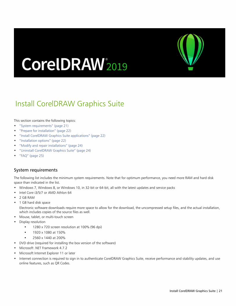
Install CorelDRAW Graphics Suite | 21
Install CorelDRAW Graphics Suite
This section contains the following topics:• “System requirements” (page 21)• “Prepare for installation” (page 22)• “Install CorelDRAW Graphics Suite applications” (page 22)• “Installation options” (page 22)• “Modify and repair installations” (page 24)• “Uninstall CorelDRAW Graphics Suite” (page 24)• “FAQ” (page 25)
System requirements
The following list includes the minimum system requirements. Note that for optimum performance, you need more RAM and hard diskspace than indicated in the list.• Windows 7, Windows 8, or Windows 10, in 32-bit or 64-bit, all with the latest updates and service packs• Intel Core i3/5/7 or AMD Athlon 64• 2 GB RAM• 1 GB hard disk space
Electronic software downloads require more space to allow for the download, the uncompressed setup files, and the actual installation,which includes copies of the source files as well.
• Mouse, tablet, or multi-touch screen• Display resolution
• 1280 x 720 screen resolution at 100% (96 dpi)
• 1920 x 1080 at 150%
• 2560 x 1440 at 200%• DVD drive (required for installing the box version of the software)• Microsoft .NET Framework 4.7.2• Microsoft Internet Explorer 11 or later
• Internet connection is required to sign in to authenticate CorelDRAW Graphics Suite, receive performance and stability updates, and useonline features, such as QR Codes.
22 | CorelDRAW 2019 User Guide
If the required version of Microsoft .NET Framework is not available on your computer, it will be installed during product installation.
Prepare for installation• Make sure that your system’s date and time are set correctly.• Make sure that your system has the latest updates installed.• Close all applications, including all virus detection programs and applications that are open in the system tray or on the Windows
taskbar. Not doing so may increase the installation time and interfere with the installation.• Log in as a user with administrative privileges.• Make sure that you have enough free disk space available on the drive where you want to install the application.• Delete the contents of the system’s TEMP folders to avoid file and memory conflicts. To navigate to the Temp folders, type %temp% in
the Search box on the Windows 7 SP1 or Windows 10 Start menu, or the Windows 8 desktop.• Make sure that your system is connected to the Internet.• Install CorelDRAW® Graphics Suite in its own directory to avoid conflicts with previous versions.
Install CorelDRAW Graphics Suite applications
The installation wizard makes it easy to install CorelDRAW Graphics Suite applications and components. You can choose a typical installationto quickly install the suite, or you can customize the installation by choosing different options.
To install CorelDRAW Graphics Suite applications
1 Close all applications, including all virus detection programs.
For smooth installation, we recommend that you restart Windows. This action will ensure that no restart is required by the latest systemupdates, and there are no memory issues.
2 Do one of the following:
• Download the product from the link provided on your order confirmation.
• Insert the DVD in the DVD drive.
3 In the installation wizard, review the End User License Agreement and the Terms of Service by clicking the corresponding links.
4 Enable the I agree to the End User License Agreement check box, and click Accept.
5 Type your name in the Full name text box.
6 Type your serial number in the Serial number text box.
The serial number is not case-sensitive, and the dashes are optional.
7 Click Next.
8 Follow the instructions for installing the software.
Installation options
You can choose between the following types of installations:• Typical installation — automatically installs the main programs and utilities of the suite to a default location in the Program Files folder.
If later you need a component that is not installed, you can modify your installation.• Custom installation — lets you choose additional features, exclude components that you don’t need, and specify where to install the
suite.
• Deployment — available only for multiseat purchases. This option lets you create a server image for installing the software to individualworkstations. For more information, see the CorelDRAW Graphics Suite 2019 Deployment Guide.

Install CorelDRAW Graphics Suite | 23
Programs
The following table lists the programs that are installed by default. To exclude a program from the installation, you must choose Custominstallation.
Program Description
CorelDRAW® 2019 An intuitive and versatile graphics application for creating high-quality vector illustrations, logo designs, and page layouts
Corel PHOTO-PAINT® 2019 A complete image-editing application that lets you retouch andenhance photos as well as create original bitmap illustrations andpaintings
CAPTURE™ 2019 An easy-to-use application for capturing images from yourcomputer screen
Corel Font Manager™ 2019 An application for finding, organizing, and managing fonts
Program features and utilities
The following table lists the program features that you can install. Not all components are available in all versions of the software.
Feature or utility Description Notes
Microsoft Visual Basic for Applications 7.1 A subset of the Microsoft Visual Basic(VB) programming environment, which issuitable for beginners.
You can use VBA to create basic macrosfor personal use, but you can also use it tocreate more advanced macro projects.
Microsoft Visual Studio Tools forApplications (VSTA)
A built-in program environment that allowsdevelopers and other programming expertsto use VSTA for creating the most advancedmacro projects
To use VSTA with CorelDRAW GraphicsSuite, you must have your own copy ofMicrosoft Visual Studio 2017 installed.
If you install Microsoft Visual Studio afterinstalling CorelDRAW Graphics Suite,you must re-install the VSTA feature bymodifying your CorelDRAW Graphics Suiteinstallation. For more information, see “Tomodify or repair a CorelDRAW GraphicsSuite installation” on page 24.
Windows Shell Extension Lets you view thumbnails of native Corelfiles such as CorelDRAW (CDR), CorelPHOTO-PAINT (CPT), pattern fill (FILL), andother native file.
If you have installed CorelDRAW GraphicsSuite or CorelDRAW Technical Suitebefore, this option does not appear in theinstallation wizard.
GPL Ghostscript Highly recommended if you import EPSand PDF files in your documents. Thisfeature lets you isolate and use individualelements of imported EPS files rather than
Included with the Typical installation

24 | CorelDRAW 2019 User Guide
Feature or utility Description Notes
only header images. It also improves theimport of PDF files generated by third-partyapplications.
Language packs Let you use the programs and Help in twoor more languages
This option is included only withmultilingual versions of the software andrequires Custom installation.
Install desktop shortcuts Adds product icons to your desktop for easyaccess
Included with the Typical installation
Copy installation files Lets you maintain and update the softwarewithout using the installation disc
Included with the Typical installation
Modify and repair installations
You can also use the installation wizard to do the following:• modify the current installation by adding or deleting components• repair the current installation by fixing errors such as missing or corrupt files as well as inaccurate shortcuts and registry entries
Repairing an installation is helpful when you encounter problems in using the application, or when you suspect that the installation iscorrupt.
Before repairing an installation, try resetting the current workspace to the default settings by holding down F8 while starting theapplication. Note that when you reset the workspace, all workspace preferences are reset.
To modify or repair a CorelDRAW Graphics Suite installation
1 Close all applications.
2 On the Windows Control Panel, click Uninstall a program.
3 Double-click the suite’s name on the Uninstall or change a program page.
4 Enable one of the following options:
• Modify — to add or delete program components and languages. Follow the instructions in the wizard that appears. To addlanguages, open the Product languages list box on page 3 of the wizard, and enable the check boxes for the languages you want toinstall.
• Repair — to fix errors in the current installation
Program features and utilities that are already installed may not appear in the wizard, or their check boxes appear disabled.
Certain features, such as Copy installation files and Install desktop shortcuts, cannot be added by modifying your installation.
Uninstall CorelDRAW Graphics Suite
You can uninstall CorelDRAW Graphics Suite from the Control Panel. If you want to uninstall the product and then reinstall it with the sameserial number on another computer, make sure to uninstall while being connected to the Internet. This will restore by one the number ofcomputers on which you can legitimately install the product.

Install CorelDRAW Graphics Suite | 25
To uninstall CorelDRAW Graphics Suite
1 On the Windows Control Panel, click Uninstall a program.
2 Double-click the suite’s name on the Uninstall or change a program page.
3 Enable the Remove option in the wizard that appears, and follow the instructions.
To completely uninstall the product by removing user files, such as presets, user-created fills, and customized files, enable the Removeuser files check box.
Any additional components and applications that you installed with the suite, such as the Corel Graphics - Windows Shell Extension,GPL Ghostscript, or Microsoft Visual Studio Tools for Applications (VSTA), must be uninstalled separately.
FAQ
If your question is not included in the list of frequently asked questions (FAQ) below, visit Corel® Support Services, and search the Corel®Knowledge Base.• “I am upgrading my version of the software. Do I need to uninstall the previous version?” (page 25)• “What is the difference between an upgrade and an update?” (page 25)• “What if I lost my serial number and need to reinstall the software?” (page 25)• “What is the difference between Typical and Custom installation? Which type of installation is suitable for me?” (page 25)• “Why do you ask me to update my operating system with the latest service packs and critical updates?” (page 25)• “How do I deploy CorelDRAW Graphics Suite to my organization’s network?” (page 26)
• “How do I change the language of the user interface and Help?” (page 26)
I am upgrading my version of the software. Do I need to uninstall the previous version?No, you don’t need to uninstall the previous version. By default, the new version is installed to a separate folder, which ensures that youcan work with both versions. Do not change the installation folder to install the upgrade and the previous version to the same folder.
What is the difference between an upgrade and an update?An upgrade lets you install the latest major version of the software. After a major version is released, updates usually follow to offerdefect fixes, and performance and stability improvements. Updates have the name of the major version with a number appended — forexample, .1. Usually, the application notifies you when a product update is available, but you can also check for updates by clicking Help Updates.
What if I lost my serial number and need to reinstall the software?
Do one of the following:
• For download versions, check the email you received from Corel when you purchased the product.
• Sign in on corel.com to access Your Account page.
• If you purchased a box, check the cover of the installation disk.
What is the difference between Typical and Custom installation? Which type of installation is suitable for me?See “Installation options” on page 22.
Why do you ask me to update my operating system with the latest service packs and critical updates?We ask you to install the latest service packs and critical updates in order to:
• protect your computer from malicious software
• resolve Windows issues and defects
• ensure smooth operation of the operating system and your Corel software
• help meet the minimum system requirements
• help speed up the installation process
• reduce the likelihood of needing to restart your operating system

26 | CorelDRAW 2019 User Guide
• ensure that system drivers are up-to-date and optimized for the suite.
How do I deploy CorelDRAW Graphics Suite to my organization’s network?If you purchased multiple licenses of CorelDRAW Graphics Suite, you have the option of deploying the applications to your organization’snetwork.
The CorelDRAW Graphics Suite 2019 Deployment Guide provides more information about network installations. To purchase a volumelicense of the software, please contact Corel® Support Services.
How do I change the language of the user interface and Help?You can change the language of the user interface and Help only if you have purchased and installed a multilingual version of the suite.For more information, see “To change the language of the user interface and Help” on page 42.
Corel accounts and services | 27
Corel accounts and services
This section contains the following topics:• “Authenticate CorelDRAW Graphics Suite” (page 27)• “Account settings” (page 28)• “Updates” (page 28)• “Change user credentials” (page 28)• “Corel Support Services” (page 29)• “About Corel” (page 29)
Authenticate CorelDRAW Graphics Suite
Authentication lets you access online features and content that are included with your software. You can authenticateCorelDRAW Graphics Suite after the suite installation, before starting an application, or while using an application.
To authenticate CorelDRAW Graphics Suite, you must sign in with your Corel.com account. This action associates your product with youraccount. If you don’t have a Corel.com account or you want to associate your product with a new account, you need to create an accountbefore signing in.
After you install and authenticate CorelDRAW Graphics Suite, the product appears in Your Account page on corel.com. If you want toassociate the product with a different account, you must change your user credentials. For more information, see “Change user credentials”on page 28.
To authenticate CorelDRAW Graphics Suite
1 Click the Sign-in button in the upper-right corner of the application window.
2 In the dialog box that appears, do one of the following:
• Sign in by entering the email address and the password associated with your Corel.com account.
• Follow the instructions to create an account, and sign in.
You can now access online features provided you have Internet connection.
28 | CorelDRAW 2019 User Guide
Account settings
You can check your account settings by accessing Your Account page from within the application. On Your Account page, you can find outmore about the products associated with your account, and you can access support and set your communication preferences.
In those rare cases when your account settings may not reflect your latest transaction, you can refresh your account from within theapplication.
To check your corel.com account
• Click Help Account Settings.
Updates
Product updates, formerly known as service packs, include performance and stability improvements that enhance your product experience.By default, you are automatically notified when product updates and news become available. You can customize the update and messagesettings. For example, you can choose how often to receive updates and offers as tray notifications: daily, weekly, monthly, or not at all.
To view information about product updates, click Help Updates.
To customize update and message settings, click Help Message Settings.
Change user credentials
As a user and owner of CorelDRAW Graphics Suite, you must know your user credentials:• your product serial number — lets you install and reinstall your product. The serial number is the unique identifier of your product
license.• the email address associated with your Corel.com account. For each Corel.com account, a unique email address and password are
required. When you authenticate your product to access online features and content, you sign in with a specific Corel.com account,associating the product with that account and its email address.
This topic describes two typical cases in which you need to change your account settings and then update your user credentials in theinstalled product to match the new account settings. Updating your user credentials ensures that you don’t need to uninstall and reinstallthe product.
You want to merge two product subscriptions that you purchased with the same Corel.com account at a different time so that thesubscriptions have the same renewal date.
In this case, each subscription is associated with a different serial number. You must first go to Your Account page, and then associate bothsubscriptions with one of the serial numbers. Second, you must edit the user credentials in the product that now has an obsolete serialnumber.
Step 1: Go to Your Account page by signing in on corel.com, and then click Merge in the Product Status area. On the Subscriptions page,select the subscriptions that you want to merge. Proceed to the Confirm selection page, and choose the serial number that you want tokeep.
Step 2: Start the version of CorelDRAW or Corel PHOTO-PAINT that now has an obsolete serial number. Click Tools Options Global. Inthe left pane of the dialog box, click User ID. Next, click Edit Credentials, and in the dialog box, type the serial number that you chose instep 1.

Corel accounts and services | 29
You have two Corel.com accounts associated with different email addresses, and you want to merge the two accounts.
First, you must call Corel Support Services to merge the accounts for you, and then you must update your email address through theproduct.
Step 1: Contact Corel Support Services with a request to merge the two accounts for you. You will be asked to provide an active emailaddress for your merged account. If you have subscriptions or Upgrade Programs in each account, they are associated with different serialnumbers so you need to choose one of the serial numbers.
Step 2: Start the version of CorelDRAW or Corel PHOTO-PAINT that is now associated with an obsolete account and email address. Click
Tools Options Global. In the left pane of the dialog box, click User ID. Click Edit Credentials, and in the dialog box that appears, typethe email address that you chose for your merged account. Type your password. If necessary, type the serial number that you chose in step 1.
Corel Support Services
Corel Support Services can provide you with prompt and accurate information about product features, specifications, pricing, availability,services, and technical support. For the most current information on support services available for your Corel product, please visitwww.corel.com/support.
About Corel
Over the years, Corel has brought a spirit of innovation to the development of a range of award-winning products that includes graphics,painting, photo, video and office software. We’ve also earned a reputation for delivering high-quality products that are easy to learn anduse, and help people achieve new levels of productivity. But more than that, we’ve built a relationship with our community of users—tens ofmillions strong—who have amazed and delighted us with everything they create using our software.
Corel’s product line includes CorelDRAW Graphics Suite, CorelDRAW Technical Suite, Corel® Painter®, Corel® PaintShop® Pro, Corel®VideoStudio®, WinDVD, Corel® WordPerfect® Office, and WinZip. For more information about Corel, please visit www.corel.com.

30 | CorelDRAW 2019 User Guide
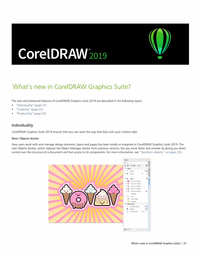
What’s new in CorelDRAW Graphics Suite? | 31
What’s new in CorelDRAW Graphics Suite?
The new and enhanced features of CorelDRAW Graphics Suite 2019 are described in the following topics:• “Individuality” (page 31)• “Creativity” (page 32)• “Productivity” (page 33)
Individuality
CorelDRAW Graphics Suite 2019 ensures that you can work the way that best suits your creative style.
New! Objects docker
How users work with and manage design elements, layers and pages has been totally re-imagined in CorelDRAW Graphics Suite 2019. Thenew Objects docker, which replaces the Object Manager docker from previous versions, lets you work faster and smarter by giving you directcontrol over the structure of a document and fast access to its components. For more information, see “Transform objects ” on page 255.

32 | CorelDRAW 2019 User Guide
Enhanced! Options workflow
The interface for setting document, application, and suite-wide preferences has been reorganized in CorelDRAW Graphics Suite 2019,making it quicker and easier to tailor your design environment to best suit the way you work.
Creativity
Be more creative with an enhanced template workflow, new non-destructive bitmap effects, and more.
Enhanced! Template workflow
A redesigned template workflow helps boost your productivity. You can download new templates, add your own library, easily migrate acollection anywhere, and modify properties — all within the suite. What’s more, there are a wide range of totally refreshed and updatedtemplates that can help anyone deliver professional results. Because they’re all easily customizable, producing a design with just the rightlook for is effortless. For more information, see “Templates ” on page 559.
New! Non-destructive bitmap effects
CorelDRAW 2019 makes it easy to apply, modify, and experiment with bitmap effects on both vectors and bitmaps, all without altering thesource image or object. The new Effects tab in the Properties docker is the hub for non-destructive editing, allowing for quick adjustmentsand unlimited experimentation. For more information, see “Apply special effects to bitmaps” on page 648.
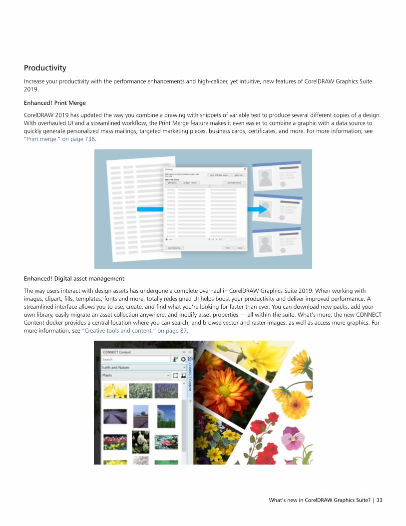
What’s new in CorelDRAW Graphics Suite? | 33
Productivity
Increase your productivity with the performance enhancements and high-caliber, yet intuitive, new features of CorelDRAW Graphics Suite2019.
Enhanced! Print Merge
CorelDRAW 2019 has updated the way you combine a drawing with snippets of variable text to produce several different copies of a design.With overhauled UI and a streamlined workflow, the Print Merge feature makes it even easier to combine a graphic with a data source toquickly generate personalized mass mailings, targeted marketing pieces, business cards, certificates, and more. For more information, see“Print merge ” on page 736.
Enhanced! Digital asset management
The way users interact with design assets has undergone a complete overhaul in CorelDRAW Graphics Suite 2019. When working withimages, clipart, fills, templates, fonts and more, totally redesigned UI helps boost your productivity and deliver improved performance. Astreamlined interface allows you to use, create, and find what you’re looking for faster than ever. You can download new packs, add yourown library, easily migrate an asset collection anywhere, and modify asset properties — all within the suite. What’s more, the new CONNECTContent docker provides a central location where you can search, and browse vector and raster images, as well as access more graphics. Formore information, see “Creative tools and content ” on page 87.

34 | CorelDRAW 2019 User Guide
Enhanced! Performance
You can work faster than ever thanks to performance enhancements.
New! Pixel-perfect workflow
CorelDRAW 2019 takes the guesswork out of creating clean, crisp images for the web with a series of new features that ensure pixel-perfectprecision. For more information, see “Create pixel-perfect graphics for the web” on page 759.
Enhanced! PDF/X support
CorelDRAW Graphics Suite 2019 offers a greater variety of ISO-compliant PDF/X export options. New support for PDF/X4 helps ensure easyoutput of files that are compatible with the widest range of devices and compliant with the latest print-industry standards.
New! Find and Replace docker
The new Find and Replace docker in CorelDRAW 2019 offers a straightforward, intuitive interface that lets you locate drawings componentsand change their attributes faster than ever. There’s a new option that lets you select an object and use its properties as the basis of asearch. You can simultaneously replace multiple object properties, such as color, fill, and outline. And finding and text replacing text isenhanced to include text in PowerClips and nested in grouped objects. For more information, see “Find and replace objects ” on page303, “To find and replace fill colors ” on page 386, “Copy, convert, remove, and replace outlines ” on page 145, and “Find, edit, andconvert text ” on page 482.
What was new in previous versions
You can easily identify what features have been improved or introduced since the last version of CorelDRAW Graphics Suite that you used.
To find out what was new in previous versions of CorelDRAW Graphics Suite
• Click Help Highlight what’s new, and click one of the following commands:
• Since version 2018— highlights menu commands and tools for features introduced or improved in this version
• Since version 2017— highlights menu commands and tools for features introduced or improved in version 2017, 2018, and 2019
• Since version X8— highlights menu commands and tools for features introduced or improved in version X8, 2017, 2018, and 2019
• No highlight — removes highlighting from menu commands and tools in the toolbox

Learning resources | 35
Learning resources
You can learn to use the product in various ways: by reading the Quick Start Guide; by accessing the Help, Hints, and tooltips, and byexploring the resources on the Corel website (www.corel.com). You can also check the Readme file (readme.html), which is installed withthe software.
This section contains the following topics:• “Get help” (page 35)• “Help and tooltips” (page 36)• “Hints” (page 38)• “Welcome screen” (page 38)• “Quick Start Guide” (page 38)• “Video resources” (page 39)• “Developers’ website” (page 39)• “Network deployment guide” (page 39)• “Web-based resources” (page 39)
Get help
Various learning resources are available. The following table can help you decide what learning resources to consult when you needassistance. You can access more information about some resources by clicking the corresponding links.
To See
Start learning the applications “Video resources ” on page 39
“Quick Start Guide ” on page 38
Learn about new and enhanced features “Video resources ” on page 39
Obtain additional information about product tools and features “Help and tooltips ” on page 36
“Web-based resources ” on page 39
“Hints ” on page 38
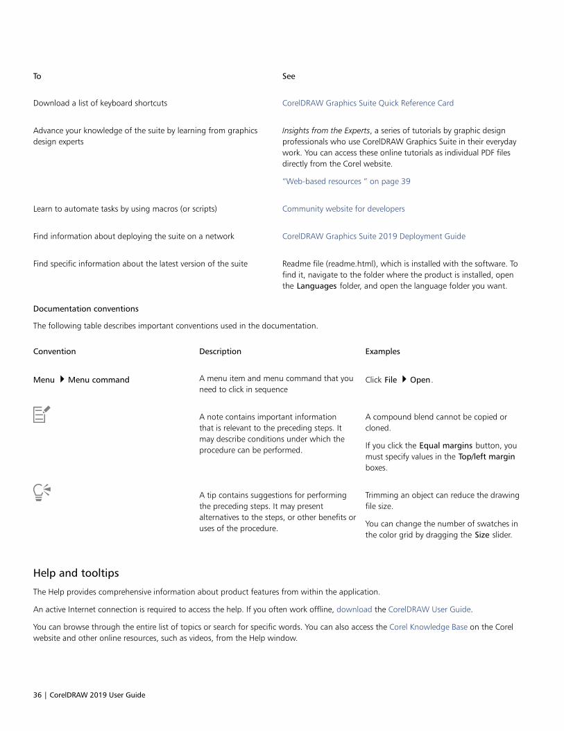
36 | CorelDRAW 2019 User Guide
To See
Download a list of keyboard shortcuts CorelDRAW Graphics Suite Quick Reference Card
Advance your knowledge of the suite by learning from graphicsdesign experts
Insights from the Experts, a series of tutorials by graphic designprofessionals who use CorelDRAW Graphics Suite in their everydaywork. You can access these online tutorials as individual PDF filesdirectly from the Corel website.
“Web-based resources ” on page 39
Learn to automate tasks by using macros (or scripts) Community website for developers
Find information about deploying the suite on a network CorelDRAW Graphics Suite 2019 Deployment Guide
Find specific information about the latest version of the suite Readme file (readme.html), which is installed with the software. Tofind it, navigate to the folder where the product is installed, openthe Languages folder, and open the language folder you want.
Documentation conventions
The following table describes important conventions used in the documentation.
Convention Description Examples
Menu Menu command A menu item and menu command that youneed to click in sequence
Click File Open.
A note contains important informationthat is relevant to the preceding steps. Itmay describe conditions under which theprocedure can be performed.
A compound blend cannot be copied orcloned.
If you click the Equal margins button, youmust specify values in the Top/left marginboxes.
A tip contains suggestions for performingthe preceding steps. It may presentalternatives to the steps, or other benefits oruses of the procedure.
Trimming an object can reduce the drawingfile size.
You can change the number of swatches inthe color grid by dragging the Size slider.
Help and tooltips
The Help provides comprehensive information about product features from within the application.
An active Internet connection is required to access the help. If you often work offline, download the CorelDRAW User Guide.
You can browse through the entire list of topics or search for specific words. You can also access the Corel Knowledge Base on the Corelwebsite and other online resources, such as videos, from the Help window.

Learning resources | 37
The Help is also available online in a print-friendly PDF format. You can access the User Guide PDF from within the application or download itfrom product.corel.com.
Tooltips provide helpful information about application controls when you position the pointer over icons, buttons, and other user interfaceelements.
To use the Help
1 Click Help Product Help.
2 Perform a task from the following table.
To Do the following
Browse through topics in the Help Click the Contents tab. To open a topic, click the topicheading in the left pane.
Search the full text of the Help for a particular word or phrase Click the Search tab, and type a word or phrase in the search box.
For example, if you are looking for information about the RGB colormode, you can type “RGB” to display a list of relevant topics. Tosearch for a phrase, type the phrase, and enclose it in quotationmarks (for example, type “dynamic guides” or “color mode”).
Choose a topic from the list that appears.
Tip: If your search results do not include any relevant topics, checkwhether you spelled the search word or phrase correctly. Notethat the English Help uses American spelling (for example, “color,”“favorite,” “center,” and “rasterize”), so searching for Britishspellings (“colour,” “favourite,” “centre,” and “rasterise”) producesno results.
Print a specific Help topic Open the page that you want to print, and click Print at the top ofthe Help window.
You can also access the Help by pressing F1.
View context-sensitive Help from within a dialog box by clicking the Help button in the dialog box.
To access the CorelDRAW 2019 User Guide
• Click Help User Guide.
An active Internet connection is required to access the User Guide. If you often work offline, download the User Guide fromproduct.corel.com.
38 | CorelDRAW 2019 User Guide
Hints
Hints provide information about tools in the toolbox from within the application. When you click a tool, a hint appears in the Hints dockeron the right side of the application window, telling you how to use the tool. If you need additional information about a tool, you can accessrelevant learning resources such as a Help topic, video, or written tutorial. You can hide the Hints at any time.
To use Hints
To Do the following
Display or hide Hints Click Help Hints.
When the Hints command is enabled, the Hints docker appearsand provides information about the active tool in the toolbox.
Display information about a tool Click the tool, or perform an action with a tool that is alreadyactive.
Get additional information about the active tool In the Learn more section, click a link to a relevant Help topic,video, or a written tutorial.
Navigate to previously viewed topics Click the Back and Forward buttons at the bottom of the Hintsdocker.
Welcome screen
The Welcome Screen appears when you start the application. With the Welcome Screen, you can quickly start or open a document, choose aworkspace that suits your needs, access online learning videos and other learning resources, and get inspired by a gallery of original artworkcreated with CorelDRAW.
To access the Welcome screen
• Click Help Welcome screen.
You can also access the Welcome screen by clicking the Welcome screen button on the tab bar.
Quick Start Guide
The Quick Start Guide, available in PDF format, can help you get started quickly with the suite by introducing you to useful tools andfeatures.
To access the Quick Start Guide
• Click Help Quick Start Guide.

Learning resources | 39
An active Internet connection is required to access the Quick Start Guide. If you often work offline, download the Quick Start Guidefrom product.corel.com.
Video resources
You can access video learning resources from the Welcome screen as well as from the Help menu.
The video tutorials show you how to complete basic tasks such as drawing, shaping, and coloring objects in CorelDRAW, or masking andcropping in Corel PHOTO-PAINT and help you get the most out of features such as symmetry, font management, fills and transparencies,alignment tools, QR codes, bitmap and vector effects, and more. Some videos don't have sound but include captions that provide usefultips and help you understand the features that are shown. Whether you are a new or long-time user, you will find useful demos and tips toboost your productivity and expand your experience.
To access a video
• Click Help Video tutorials.
Developers’ website
Whether you are automating tasks by using macros or scripts, creating custom tools, or developing commercial solutions that integratewith CorelDRAW Graphics Suite; the developer community website can help you with its wealth of useful resources: a programming guide,detailed Object Model reference documentation with code samples, and in-depth programming articles.
You can use either Microsoft Visual Basic for Applications (VBA) or Microsoft Visual Studio Tools for Applications (VSTA) to create macros andcustomized solutions for CorelDRAW and Corel PHOTO-PAINT.
Network deployment guide
The CorelDRAW Graphics Suite 2019 Deployment Guide is a step-by-step resource for deploying CorelDRAW Graphics Suite 2019 to anetwork. This guide is provided to customers who purchase a volume (“multi-seat”) license of CorelDRAW Graphics Suite 2019 for theirorganization. To purchase a volume license of the software and obtain its deployment guide, please contact Corel Support Services.
Web-based resources
The following web-based resources can help you get the most out of CorelDRAW Graphics Suite:• Corel Knowledge Base — articles written by the Corel Technical Support Services Team in response to questions by users• Community.CorelDRAW.com — an online environment to share your experience with the product, ask questions, and receive help and
suggestions from other users• Tutorials on the Corel website — in-depth tutorials in which CorelDRAW Graphics Suite experts share their knowledge and techniques
An active Internet connection is required to access web-based resources.

40 | CorelDRAW 2019 User Guide

Start and set up | 41
Start and set up
This section contains the following topics:• “Start and quit CorelDRAW” (page 41)• “Change the language” (page 41)• “Startup settings” (page 42)
Start and quit CorelDRAW
You can start CorelDRAW from the Windows taskbar and end a CorelDRAW session from the application window.
To start and quit CorelDRAW
To Do the following
Start CorelDRAW Do one of the following:
• (Windows 7 and Windows 10) From the Windows
taskbar, click Start Programs CorelDRAW Graphics
Suite 2019 CorelDRAW.
• (Windows 8) Click the CorelDRAW 2019 tile on yourdesktop.
Quit CorelDRAW Click File Exit.
Change the language
If an application has been installed in more than one language, you can change the language of the user interface and Help at any time.

42 | CorelDRAW 2019 User Guide
To change the language of the user interface and Help
1 Click Tools Options Global.
2 Click General.
3 Choose a language from the User interface language list box.
If you want to change the language of the user interface and Help when you start the application, enable the Ask me the next time theapplication starts check box.
4 Restart the application.
If there is only one language available in the User interface language list box, you must first install the additional languages that youwant. For more information, see “To modify or repair a CorelDRAW Graphics Suite installation” on page 24.
Startup settings
You can specify the startup settings for CorelDRAW, which control how the application appears when it’s opened. For example, you canstart the application with the Welcome screen open or a new blank document.
To change startup settings
1 Click Tools Options CorelDRAW.
2 Click General.
3 In the Getting started area, choose an option from the On CorelDRAW start-up list box.
If you want to hide the Create a new document dialog box when starting documents, disable the Show New Document dialog boxcheck box.

CorelDRAW basics | 43
CorelDRAW basics
CorelDRAW lets you create and edit drawings. In this section, you can find information about commonly performed tasks.
This section contains the following topics:• “Vector graphics and bitmaps” (page 43)• “Start and open drawings” (page 44)• “Scan images” (page 47)• “Work with multiple drawings” (page 48)• “Undo, redo, and repeat actions” (page 49)• “Zoom, pan, and scroll” (page 50)• “Preview drawings” (page 52)• “Viewing modes” (page 54)• “Views” (page 55)• “Save drawings” (page 56)• “Locked files” (page 58)• “Back up and recover files” (page 58)• “Add and access drawing information” (page 59)• “Close drawings” (page 60)
• “Explore basic tasks” (page 60)
• “CorelDRAW.app, CorelDRAW, and Corel Cloud” (page 61)
Vector graphics and bitmaps
The two main types of computer graphics are vector graphics and bitmaps. Vector graphics are made of lines and curves, and they aregenerated from mathematical descriptions that determine the position, length, and direction in which lines are drawn. Bitmaps, also knownas raster images, are composed of small squares called pixels; each pixel is mapped to a location in an image and has numerical color values.
Vector graphics are ideal for logos and illustrations because they are resolution-independent and can be scaled to any size, or printed anddisplayed at any resolution, without losing detail and quality. In addition, you can produce sharp and crisp outlines with vector graphics.
Bitmaps are excellent for photographs and digital paintings because they reproduce color gradations well. Bitmaps are resolution-dependent— that is, they represent a fixed number of pixels. They look good at their actual size, but they can appear jagged or lose image qualitywhen scaled, or when displayed or printed at a resolution higher than their original resolution.

44 | CorelDRAW 2019 User Guide
You can create vector graphics in CorelDRAW. You can also import bitmaps (such as JPEG and TIFF files) into CorelDRAW and add them toyour drawings. For information about working with bitmaps, see “Work with bitmaps” on page 623.
Top: A vector graphic consists of lines and fills. Bottom: A bitmap is made up of pixels.
Start and open drawings
CorelDRAW lets you start a new drawing from a blank page, a template, or an existing drawing. A blank page gives you the freedom tospecify every aspect of a drawing. A template provides you with a starting point and leaves the amount of customization up to you.
For information about starting a drawing from a template, see “To start a document from a template” on page 560. For more informationabout creating and using templates, see “Templates” on page 559.
Notes for starting new drawings
When starting a new drawing, CorelDRAW lets you specify page, document, and color management settings. You can choose from a list ofpreset settings, which are based on how you intend to use the drawing. For example, you can choose the Web option if you are creatinga drawing for the Internet, or the Default CMYK option if you are creating a document destined for commercial printing. However, if thepreset settings are not suitable for the drawing that you want to create, you can also customize the settings and save them for future use.
Notes for opening existing drawings
Basing a new drawing on an existing drawing lets you reuse objects and page settings. CorelDRAW lets you open existing drawings savedto the CorelDRAW (CDR) format as well as drawings and projects saved to various file formats such as Corel DESIGNER (DSF or DES), AdobeIllustrator (AI), Adobe Portable Document Format (PDF), Encapsulated PostScript (EPS), and Computer Graphics Metafile (CGM). However,you may not be able to open certain files, depending on their file type and contents. In such cases, you can try importing the files as objectsin an open drawing. For information about the file formats that you can import into CorelDRAW, see “Supported file formats” on page797.
If the drawing you are opening is from an earlier version of CorelDRAW and contains text in a language different from the language of youroperating system, you can choose code page settings to ensure that text is properly converted according to the Unicode Standard. Codepage settings help you correctly display text such as keywords, file names, and text entries outside the drawing window — for example, inthe Objects and Object Data Manager dockers. To display text correctly in the drawing window, you must use encoding settings. For moreinformation, see “Display text correctly in any language” on page 527.
If the drawing you are opening contains an embedded International Color Consortium (ICC) profile, the embedded color profile remains thedocument’s color profile. For more information, see “About color management” on page 405.
CorelDRAW basics | 45
You can search for drawings by different criteria, such as filename, title, subject, author, keyword, comment, text within the file, and otherproperties attached to the file. For more information about searching for files, see the Windows Help. For more information about browsingand searching for content, see “Find content with the CONNECT Browser ” on page 97.
You can also display previous versions of a drawing.
To start a drawing
1 Do one of the following:
• On the Welcome screen, click Get started New document.
• In the application window, click File New.
2 Type a filename in the Name text box.
3 From the Preset destination list box, choose an output destination for the drawing:
• CorelDRAW default — applies the CorelDRAW default settings for creating graphics that are destined for printing
• Default CMYK — applies settings for creating graphics that are destined for commercial printing
• Default RGB — applies settings for creating graphics that are destined for printing to a high-fidelity printer
• Web — applies settings for creating graphics that are destined for the Internet
• Custom — lets you customize destination settings for a document
You can also
Change the unit of measurement for the page Choose a unit of measurement from the Drawing units list box.
Change the page size Choose a page size for the drawing from the Size list box or typevalues in the Width and Height boxes.
Change the page orientation Click one of the following page orientation buttons:•Portrait•Landscape
Set the number of pages Type a value in the Number of pages box.
Set the default color mode for the document to RGB or CMYK Choose a color mode from the Primary color mode list box.
Set the resolution for effects that will likely be rasterized, such astransparency, drop shadow, and bevel effects
Choose a rendering resolution from the Rendering resolution listbox.
Choose the preview mode for the drawing Choose a preview mode from the Preview mode list box.
Choose an RGB profile for the drawing In the Color settings area, choose a default RGB profile from theRGB profile list box.
Choose a CMYK profile for the drawing Choose a default CMYK profile from the CMYK profile list box.
Choose a Grayscale profile for the drawing Choose a default Grayscale profile from the Grayscale profile listbox.

46 | CorelDRAW 2019 User Guide
You can also
Choose a default method for out-of-gamut colors to be mappedinto gamut
Choose an option from the Rendering intent list box.
When you choose a color mode from the Primary color mode list box, it becomes the default color mode for the document. Thedefault color mode affects how colors work together in effects such as blends and transparencies. It does not restrict the type ofcolors that you can apply to a drawing. For example, if you set the color mode to RGB, you can still apply colors from a CMYK colorpalette to the document.
The primary color mode also specifies the default color mode for exporting documents. For example, if you choose the RGB colormode and export a document as a JPEG, the color mode is automatically set to RGB.
The settings that are displayed in the Color settings area of the Create a new document dialog box are based on the settings thatare specified in the Default color management settings dialog box.
If you do not want to show the Create a new document dialog box and prefer to use the last used settings to create newdocuments, enable the Do not show this dialog again check box.
You can restore the Create a new document dialog box when starting drawings by clicking Tools Options CorelDRAW, clickingGeneral, and enabling the Show New Document dialog box check box.
To create a custom preset
1 In the application window, click File New.
2 In the Create a new document dialog box, choose the settings that you want to save as a preset destination.
3 Click the button next to the Preset list box, and click Save Preset.
4 In the Add preset dialog box, type a name for the new destination preset.
You can delete a destination preset by choosing the preset name from the Preset list box, clicking the button and then clicking
Delete Preset.
To open a drawing
1 Click File Open.
2 Locate the folder where the drawing is stored.
3 Click a filename.
4 Click Open.
You can also
Extract an embedded International Color Consortium (ICC) profileto the color folder in which the application is installed
Enable the Extract embedded ICC profile check box.
This option is not available for all file formats.
Maintain layers and pages when you open files Enable the Maintain layers and pages check box.

CorelDRAW basics | 47
You can also
If you disable the check box, all layers are combined in a singlelayer.
This option is not available for all file formats.
View thumbnail of a drawing Click the arrow button next to the Views button, and click Extralarge icons, Large icons, Medium icons, or Small icons.
Choose a code page Choose a code page from the Select code page list box. Thisoption is not available for all file formats.
Search for a drawing Type a word or phrase in the search box.
The search box looks for files only in the current folder andsubfolders. To search for a drawing in another location, you mustfirst navigate to the folder where the drawing is stored.
Access a previous version of a file Right-click a file, and click Restore previous versions.
You can access a previous version of a file only if System Protectionis turned on.
For detailed information about accessing previous versions of files,see the Windows Help.
You can view file information, such as version number and compression ratio. For example, a compression ratio of 80 percent meansthat the file size was reduced by 80 percent after the file was saved. You can also see in what application and language the drawingwas last saved, and you can view keywords and notes associated with a drawing.
To open a file you have recently worked on, click File Open Recent, and click the filename. To clear the list of recently opened files,click File Open Recent Clear Menu.
If you have multiple files open, you can navigate between them by clicking Window, and then clicking the name of the file that youwant to display in the drawing window.
Scan images
You can scan images in CorelDRAW by using a compatible TWAIN driver. CorelDRAW supports scanners that use Microsoft Windows ImageAcquisition (WIA), which provides a standard interface for scanning images.
If your scanner does not support WIA, but has a compatible TWAIN driver, you may be able to use this driver for scanning images inCorelDRAW. TWAIN is supported by both the 32-bit and 64-bit versions of CorelDRAW. However, note that there are few 64-bit TWAINdrivers available.
The software interfaces and options vary. For information about using the software associated with your scanner, see the manufacturer’sdocumentation.
48 | CorelDRAW 2019 User Guide
To scan images
1 Click File Acquire Image, and click one of the following commands:
• Select WIA source — for a scanner that uses a WIA driver
• Select TWAIN source — for a scanner that uses a TWAIN driver
A command appears disabled if a compatible WIA or TWAIN scanner driver is not installed.
2 Choose a scanner from the dialog box that appears.
3 Click Select.
4 Click File Acquire Image Acquire.
5 Preview the image, and select the area that you want to scan.
WIA, in combination with some scanners, supports scanning of multiple areas to separate files.
6 Click Scan.
On your scanner’s interface, this button may have a different name, such as OK or Send.
To scan additional images during the same session, click File Acquire Image Acquire.
Work with multiple drawings
Multiple drawings can be opened in a single drawing window, making it easy to handle many drawings simultaneously. You can access eachopen drawing from its tab at the top of the drawing window, and you can start new drawings.
Open drawings appear docked, but you can undock any drawing you want and drag it inside or outside the application window.
You can also arrange drawings in overlapping (cascading) windows, side by side, or stacked vertically.
To work with multiple drawings
To Do the following
Switch to another open drawing At the top of the drawing window, click the tab that has thefilename you want.
An asterisk after the filename shows that the file has unsavedchanges.
Start another drawing Click the New button to the right of the last tab in the drawingwindow.
Undock a drawing Drag the tab to a new position inside or outside the applicationwindow.
To arrange multiple drawing windows
• Click Window, and click one of the following commands:
• Cascade — arranges drawings so that they overlap and the title bars are visible
• Tile Horizontally — arranges drawings side by side
• Tile Vertically — stacks drawings vertically

CorelDRAW basics | 49
Undo, redo, and repeat actions
You can undo the actions that you perform in a drawing, starting with the most recent action. If you don’t like the result of undoing anaction, you can redo it. Reverting to the last saved version of a drawing also lets you remove one or more actions. Certain actions applied toobjects, such as stretching, filling, moving, and rotating, can be repeated to create a stronger visual effect.
Customizing the Undo settings lets you increase or decrease the number of actions that you can undo or redo.
To undo, redo, and repeat actions
To Do the following
Undo an action Click Edit Undo [Last Action].
Redo an action Click Edit Redo.
Undo or redo a series of actions Click Window Dockers History. In the History docker, click theaction that precedes all the actions that you want to undo, or clickthe last undone action that you want to redo.
Revert to the last saved version of a drawing Click File Revert.
Repeat an action Click Edit Repeat.
When you undo a series of actions in the History docker, all actions listed below the action that you click are undone.
When you redo a series of actions in the History docker, the action that you click and all preceding undone actions are redone.
You can repeat an action on another object or group of objects by selecting the object or objects and clicking Edit Repeat.
You can also undo or redo a series of actions by clicking the arrow button next to the Undo button or Redo button on the
standard toolbar and choosing an action from the list.
To specify the Undo settings
1 Click Tools Options CorelDRAW.
2 Click General in the left pane of the dialog box that appears.
3 In the Undo levels area, type a value in the Regular box to specify the number of actions that can be reversed when you use the Undocommand with vector objects.
The value that you specify is limited only by your computer’s memory resources. The higher the value you specify, the greater thedemand on memory resources.

50 | CorelDRAW 2019 User Guide
Zoom, pan, and scroll
You can change the view of a drawing by zooming in to get a closer look or by zooming out to see more of the drawing. You canexperiment with a variety of zoom options to determine the amount of detail you want.
You can also zoom in and out in preset increments by using common keyboard shortcuts, supported by web browsers and otherapplications.
Panning and scrolling are two additional ways to view specific areas of a drawing. When you work at high magnification levels or with largedrawings, you may not be able to see the whole drawing. Panning and scrolling let you move the page around in the drawing window toview previously hidden areas.
You can use the Pan tool to pan around a large image and view particular areas.
You can zoom in and out while you are panning, and you can pan while you are zooming. In this way, you can avoid having to alternatebetween the two tools.
You can also use the Quick Pan mode to switch from any active tool to the Pan tool. This feature lets you pan without having to changetools.
If you use a mouse wheel, the wheel zooms in and zooms out by default. You can also use the mouse wheel to scroll.
You can specify default zooming and panning settings.
To zoom
1 In the toolbox, click the Zoom tool .
2 On the property bar, click one of the following:
• Zoom in
• Zoom out
• Zoom to selected
• Zoom to all objects
• Zoom to page
• Zoom to page width
• Zoom to page height

CorelDRAW basics | 51
The Zoom to selected button is available only if one or more objects are selected before you click the Zoom tool.
You can also zoom in, zoom out, and zoom to all objects by using the zoom commands in the View menu.
When you are not editing text, you can also access the Zoom tool by pressing Z.
Using the Zoom tool, you can also zoom in by clicking anywhere in the drawing window or dragging to select a specific area tomagnify. To zoom out, right-click in the drawing window, or drag with the right mouse button to select a specific area.
You can also zoom in by using the Pan tool and double-clicking in the drawing window. To zoom out, right-click in the drawing
window.
To zoom using keyboard shortcuts
• Do one of the following:
• To zoom in, press Ctrl+(+).
• To zoom out, press Ctrl+(-).
You can use these keyboard shortcuts to adjust the zoom level in the document window as well as in dialog boxes and labs thatfeature preview windows such as the Print Preview dialog box, PowerTRACE, Image Adjustment Lab, and more.
To pan in the drawing window
1 In the toolbox, click the Pan tool .
2 Drag in the drawing window until the area you want to view appears.
When you are not editing text, you can also access the Pan tool by pressing the H key.
To pan in the drawing window while zoomed in on the drawing, click the Navigator button in the lower-right corner of the
drawing window.
You can quickly center the page in the drawing window by double-clicking the Pan tool in the toolbox.
Using the Navigator, you can display any part of a drawing without having to zoom out.

52 | CorelDRAW 2019 User Guide
To switch to the Quick Pan mode
1 Click any selection, drawing, or shaping tool, and start using it.
2 Hold down the middle mouse button or wheel, and drag in the drawing window.
To specify default zoom settings
1 Click Tools Options Tools.
2 In the left pane of the dialog box that appears, click Zoom/Pan.
3 To specify the action of the Zoom or Pan tool when you right-click in the drawing window, enable one of the following options:
• Zoom out — zooms out by a factor of 2
• Context menu — displays a menu of commands that let you zoom to a specific level
4 To specify how the page appears when the zoom is set to 100%, enable or disable the Zoom relative to 1:1 check box.
• When the option is enabled, a 100% zoom displays real-world dimensions.
• When the option is disabled, a 100% zoom displays the full page, regardless of real-world dimensions.
5 To specify how the page appears when you zoom in and out using the mouse wheel, enable or disable the Center mouse whenzooming with the mouse wheel check box.
• When the option is enabled, the area where the mouse pointer is located moves to the center of the screen as you zoom in and outusing the mouse wheel.
• When the option is disabled, the area where the mouse pointer is located stays in the same position as you zoom in and out using themouse wheel.
To establish default setting for the mouse wheel
1 Click Tools Options CorelDRAW.
2 In the left pane of the dialog box that appears, click Display.
3 To specify the default action of the mouse wheel, choose Zoom or Scroll from the Default action for mouse wheel list box.
To scroll by using a mouse wheel
• Do one of the following:
• To scroll vertically, press Shift while you move the wheel.
• To scroll horizontally, press Ctrl while you move the wheel.
The mouse wheel can be used for scrolling only if the Scroll option for the mouse is enabled. For more information, see “To establishdefault setting for the mouse wheel” on page 52.
Preview drawings
You can preview a drawing to see how it will look when printed or exported. When you preview a drawing, only the objects on the drawingpage and in the immediate area of the drawing window are displayed, and you can see all layers that are set to print in the Objects docker.If you want a closer look at specific objects in a drawing, you can select and preview them. When you preview selected objects, the rest ofthe drawing is hidden.
Before you preview a drawing, you can specify the preview mode. The preview mode affects the speed with which your preview appears aswell as the amount of detail displayed in the drawing window.
By default, the borders of a page are displayed in the drawing window, but you can hide them at any time. If a drawing is intended for print,you can display the area that will actually print as well as the bleed, the part of the drawing that extends beyond the page border. Bleeds are

CorelDRAW basics | 53
useful when a drawing contains a color page background or objects that are positioned on the page border. Bleeds ensure that no whitespace appears between the edges of a drawing and the edge of the paper after the printer cuts, binds, and trims the document.
To preview a drawing
• Click View Full-screen Preview.
Click anywhere on the screen, or press any key, to return to the application window.
You can press Page up and Page down to preview pages in a multipage drawing.
To preview selected objects
1 Select the objects.
2 Click View Preview Selected Only.
Click anywhere on the screen, or press any key, to return to the application window.
If Preview selected only mode is enabled and no objects are selected, Full-screen preview displays a blank screen.
To choose a full-screen preview mode
1 Click Tools Options CorelDRAW.
2 In the left pane of the dialog box that appears, click Display.
3 In the Full-screen preview area, enable one of the following options:
• Use normal view — Drawings appear without PostScript fills or high‑resolution bitmaps, and no anti-aliasing is used.
• Use enhanced view — Drawings appear with PostScript fills, and anti-aliasing is used to sharpen the display of the drawings.
To set the page display
1 Click Layout Document Options.
2 In the left pane of the dialog box that appears, click Page Size.
3 Enable or disable the following check boxes:
• Show page border — shows or hides page borders
• Show bleed area — shows or hides the area of the drawing extending beyond the page border. To change the bleed area, type avalue in the Bleed box.
When preparing a drawing for commercial printing, you may also need to set a bleed limit. For more information, see “To set a bleedlimit” on page 745.
You can also click View Page Page border, or View Page Bleed.
You can display the printable area of a drawing by clicking View Page Printable area. The printable area is usually indicated bytwo dotted lines inside or around the page, depending on the current printer settings. One outline indicates the area that can beprinted on the current printer; the other outline indicates the paper size that your printer is set to use.
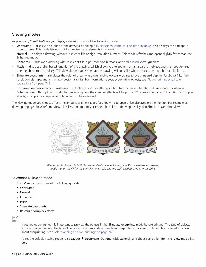
54 | CorelDRAW 2019 User Guide
Viewing modes
As you work, CorelDRAW lets you display a drawing in any of the following modes:• Wireframe — displays an outline of the drawing by hiding fills, extrusions, contours, and drop shadows; also displays the bitmaps in
monochrome. This mode lets you quickly preview basic elements in a drawing.• Normal — displays a drawing without PostScript fills or high-resolution bitmaps. This mode refreshes and opens slightly faster than the
Enhanced mode.• Enhanced — displays a drawing with PostScript fills, high-resolution bitmaps, and anti-aliased vector graphics.
• Pixels — displays a pixel-based rendition of the drawing, which allows you to zoom in on an area of an object, and then position andsize the object more precisely. This view also lets you see what the drawing will look like when it is exported to a bitmap file format.
• Simulate overprints — simulates the color of areas where overlapping objects were set to overprint and displays PostScript fills, high-resolution bitmaps, and anti-aliased vector graphics. For information about overprinting objects, see “To overprint selected colorseparations” on page 749.
• Rasterize complex effects — rasterizes the display of complex effects, such as transparencies, bevels, and drop shadows when inEnhanced view. This option is useful for previewing how the complex effects will be printed. To ensure the successful printing of complexeffects, most printers require complex effects to be rasterized.
The viewing mode you choose affects the amount of time it takes for a drawing to open or be displayed on the monitor. For example, adrawing displayed in Wireframe view takes less time to refresh or open than does a drawing displayed in Simulate Overprints view.
Wireframe viewing mode (left); Enhanced viewing mode (center), and Simulate overprints viewingmode (right). The fill for the gray diamond shape and the cup’s shadow are set to overprint.
To choose a viewing mode
• Click View, and click one of the following modes:
• Wireframe
• Normal
• Enhanced
• Pixels
• Simulate overprints
• Rasterize complex effects
If you are overprinting, it is important to preview the objects in the Simulate overprints mode before printing. The type of objectsyou are overprinting and the type of colors you are mixing determine how overprinted colors are combined. For more informationabout overprinting, see “Color trapping and overprinting” on page 748.
To set the default viewing mode, click Layout Document Options, click General, and choose an option from the View mode listbox.

CorelDRAW basics | 55
You can quickly switch between the selected viewing mode and the previous viewing mode by pressing Shift + F9.
Views
You can save a view of any part of a drawing. For example, you can save a view of an object at 230% magnification and then return to thisspecific view at any time.
If a document contains multiple pages, you can view them all at once by using the Page Sorter view. You can also display consecutive left-hand and right-hand pages on the screen at the same time (facing pages) and create objects that span two pages.
To save a view
1 Click Window Dockers Views.
2 Click the Add current view button .
You can also
Rename a view Double-click a view name, and type a new name.
Delete a saved view Click a view, and click the Delete current view button .
You can also save the current view by clicking the Zoom or Pan tool in the toolbox, clicking in the Zoom levels list box on thestandard toolbar, typing a name, and pressing Enter.
To switch to a saved view
1 Click Window Dockers Views.
2 Click a view in the Views docker.
You can also switch to a saved view by selecting it from the Zoom levels list box on the standard toolbar.
To view all pages in a multipage document
• Click View Page Sorter View.
To return to the default page view, click the Page sorter view button on the property bar.
To view facing pages
1 Click Layout Page Layout.
2 Enable the Facing pages check box.
3 Choose one of the following settings from the Start on list box:
• Left side — starts the document on a left-hand page
• Right side — starts the document on a right-hand page

56 | CorelDRAW 2019 User Guide
You cannot view facing pages if the document uses a Tent Card or Top-fold Card layout style, or if it contains multiple pageorientations. The Left side option is available only for the Full Page and Book layout styles.
When you enable the Facing pages check box, the content on the facing pages is merged on one page. The layer structure forthe merged page is based on the left-hand page. The layers from the right-hand page are inserted above the layers on the left-hand page. This rule also applies if you reorder the pages. If you disable the Facing pages check box, the layers and content areredistributed across separate pages. Objects that cross both pages are assigned to a page according to where the center of the objectis found.
It is recommended that you avoid switching back and forth between individual pages and facing pages within the same document.
Save drawings
By default, drawings are saved to the CorelDRAW file format (CDR) and are compatible with the latest version of the application. You canalso save a drawing that is compatible with an earlier version of CorelDRAW Graphics Suite and specify save options. Such options are usefulwhen the file contains new text, fill, outline, and transparency features that are not supported in earlier versions.
You can save a drawing to other vector file formats as well. If you want to use a drawing in another application, you must save it to a fileformat that is supported by that application. For information about saving files to other formats, see “Export files” on page 778.
The application makes it easy to tell if a drawing has unsaved changes by adding an asterisk after its filename.The asterisk is added indifferent locations where the filename appears such as the Windows menu, the title bar, and the document tab.
The asterisk after the filename on the document tab shows that the file LoremIpsum_1.cdrhas unsaved changes. The file LoremIpsum_2.cdr has no unsaved changes.
When saving a drawing, you can embed the used fonts to facilitate file sharing. By default, CorelDRAW embeds all used fonts, with theexception of Asian fonts and fonts that do not have embedding permissions. For more information, see “Manage fonts” on page 529.
When you save a drawing, CorelDRAW lets you add reference information so that you can easily find and organize drawings later on. Youcan attach tags (also known as properties) such as title, subject, and rating.
You can also save selected objects in a drawing. For large drawings, saving only the selected objects reduces the file size, which can decreasethe time it takes to load the drawing.
When saving a file, you can use advanced options to control how bitmaps, textures, and vector effects, such as blends and extrusions, aresaved with the drawing.
You can also save a drawing as a template, which lets you create other drawings with the same properties. For information about saving adrawing as a template, see “Templates” on page 559.
To save a drawing
1 Click File Save as.
2 Type a filename in the File name box.
3 Locate the folder where you want to save the file.
If you want to save the drawing to a vector file format other than CorelDRAW (CDR)
You can also
Save only selected objects Enable the Selected only check box.
This option is available only if there are selected objects in thedrawing.

CorelDRAW basics | 57
You can also
Embed fonts Enable the Embed fonts check box.
This check box is unavailable when you save a drawing to an earlierversion of CorelDRAW.
Add reference information Do any of the following:•Type a title and subject in the corresponding box.•Assign a rating to the file.
If you are using an expired trial version of CorelDRAW, you will not be able to save drawings.
Saving a drawing to a previous version of CorelDRAW may result in loss of certain effects that were not available in the previousversion of the application.
You can also save a drawing by clicking File Save.
You can also save a drawing by clicking the Save button on the Standard toolbar.
To use advanced options when saving
1 Click File Save as.
2 Click Advanced.
3 Enable any of the following check boxes:
• Save in Corel Presentation Exchange (CMX) format — saves a drawing as a Corel® Presentations™ Exchange (CMX) file so that youcan open and edit it in other Corel applications, such as WordPerfect
• Use bitmap compression — reduces the file size by compressing bitmap effects, such as bitmap extrusions, transparencies, and dropshadows
• Use graphic object compression — reduces the file size by compressing vector objects, such as polygons, rectangles, ellipses, andperfect shapes
Using compression increases the time required for opening and saving a drawing.
4 If a drawing contains texture fills, enable one of the following options:
• Save texture fills with the file — saves custom texture fills with the file
• Rebuild texture fills when opening the file — re-creates texture fills when you open the saved drawing
5 If a drawing contains blends and extrusions, enable one of the following options:
• Save blends and extrusions with the file — saves all blends and extrusions included in a drawing
• Rebuild blends and extrusions when opening the file — re-creates blends and extrusions when you open the saved drawing
Choosing to save textures, blends, and extrusions with the file increases the file size but lets you open and save a drawing morequickly. Conversely, choosing to rebuild textures, blends, and extrusions when a saved drawing is opened decreases the file size butincreases the time required for saving or opening a drawing.
To save a drawing that is compatible with an older version of CorelDRAW
1 Click File Save as.
2 Type a filename in the File name box.

58 | CorelDRAW 2019 User Guide
3 Locate the folder where you want to save the file.
4 Choose a version from the Version list box.
5 Click Save.
If the drawing includes new features; enable one of the following options in the Save to a previous version dialog box:
• Keep appearance — preserves the appearance of text, fills, outlines and transparencies when the file is opened in a previous versionof CorelDRAW. However, this option may limit editing.
• Keep editable — preserves the file editable. However, this option may change the appearance of text, outlines, fills, andtransparencies when the file is opened in a previous version of CorelDRAW.
You can also
Specify save settings Click Tools Options CorelDRAW. Click Save, and enable one ofthe following options:
•Keep appearance (suitable for limited edits)•Keep editable (may change appearance)
Disable the prompt that appears when saving to an earlier version Click Tools Options CorelDRAW. Click Save, and disable theAsk when saving check box.
Locked files
In a corporate environment you may open a locked file that is already being edited by another user. You can save changes that you make toa locked file in one of the following ways:• If the other user has modified the file or still has the file open, you must save the file with a new name by clicking File Save As.• If the other user has closed the file without modifying it, you can save the changes by clicking File Save.
Back up and recover files
CorelDRAW can save backup copies of drawings and prompt you to recover them in the event of a system error. The back-up feature createsa copy of the drawing when you save a drawing. This backup copy does not contain the changes that you made since you last opened thefile. The backup copy is named backup_of_filename, and by default is stored in the same folder as the original drawing. You can changethe location where backup files are created.
The auto-backup feature saves drawings that you have opened and modified. Auto-backup files are named auto_backup_of_filename.During any working session with CorelDRAW, you can set the time interval for automatically backing up files and specify whether youwant the files to be saved in your temporary folder (the default location) or in a folder of your choice. You can recover the backup filesfrom the temporary or specified folder when you restart CorelDRAW after a system error. If you choose not to recover the backup file, it isautomatically erased when you quit the application.
To specify backup and auto-backup settings
1 Click Tools Options CorelDRAW.
2 In the left pane of the dialog box that appears, click Save.
3 Perform a task from the following table.
To Do the following
Create a backup file before saving Enable the Back up original file before saving check box.

CorelDRAW basics | 59
To Do the following
Change the location where backup files are created In the Back up original file to area, enable the Choose locationoption. Click Browse, and navigate to the folder you want.
Specify auto-backup settings To set how often to back up the file automatically, enable the Backup every check box, and choose a value from the Minutes list box.
To choose the location for auto-backup files, in the Back up toarea, enable one of the following options:
•Temporary folder — lets you save auto-backup files in thetemporary folder
•Choose location — lets you specify the folder for auto-backupfiles
Disable the auto-backup feature Choose Never from the Minutes list box.
All open or modified files that are not in the CorelDRAW (CDR) file format are backed up as CorelDRAW files.
You can cancel the creation of an auto-backup file by pressing Esc while a file is being saved.
To recover a backup file
1 Restart CorelDRAW.
2 Click OK in the file recovery dialog box that appears.
The file recovery dialog box appears upon startup after a system error.
3 Save and rename the file in the specified folder.
If you click Cancel, CorelDRAW ignores the backup file and deletes it when you quit the application.
Add and access drawing information
CorelDRAW lets you add reference information, such as language, title, author, subject, keywords, rating, and other notes to a drawing.Although adding document information is optional, doing so makes it easier to organize and locate drawings later on.
The application also lets you access other important document information, such as the number of pages and layers, fonts, object and textstatistics, and the types of objects the drawing contains. You can also view color information such as the color profiles that are used todefine document colors as well as the primary color mode and rendering intent.
To add and access drawing information
1 Click File Document Properties.
2 In the Document Properties dialog box, type text in any of the following boxes:
• Language
• Title
• Subject

60 | CorelDRAW 2019 User Guide
• Author
• Copyright
• Keywords
• Notes
3 To specify a rating, choose a rating from the Rating list box.
4 Click OK.
You can modify the drawing information at any time.
Close drawings
You can close one drawing, or multiple drawings, at any time before quitting CorelDRAW.
To close drawings
To Do the following
Close one drawing Click File Close.
Close all drawings Click File Close All.
If you are unable to close a document, you may have a task, such as printing or saving, in progress or a task that has failed. Pleaserefer to the status bar to view the status of a task.
Explore basic tasks
CorelDRAW has a virtually unlimited number of tools and capabilities to help you create drawings. The following table provides you with thebasic features of CorelDRAW to help you get started.
For information about See
Drawing lines “Format lines and outlines ” on page 138
Drawing shapes “Shapes ” on page 163
Creating and manipulating objects “Transform objects ” on page 255
Adding color to objects “Fills ” on page 365

CorelDRAW basics | 61
For information about See
Adding text to a drawing “Add and manipulate text ” on page 471
Creating drawings for use on the web “Export bitmaps for the web ” on page 760
Printing drawings “Print basics ” on page 727
CorelDRAW.app, CorelDRAW, and Corel Cloud
Available exclusively to CorelDRAW Graphics Suite users, CorelDRAW.app is a web-based application for creating vector graphics. Access itfrom any device to capture your ideas into designs instantly or share your designs with customers.
CorelDRAW. app is integrated with CorelDRAW. You can save files created in CorelDRAW.app or CorelDRAW to Corel Cloud, an onlinestorage for files, and then open these files in either one of the applications. For example, you can create a design in CorelDRAW.app, save itCorel Cloud, and later edit the design in CorelDRAW, taking advantage of its wide array of editing tools. After you have finished editing, youcan save and upload the file to Corel Cloud directly from CorelDRAW. The edited file can be opened in CorelDRAW.app for annotation, notfor editing, and then saved to Corel Cloud. If you need to edit the file, you can open it in CorelDRAW from Corel Cloud.
CorelDRAW.app and CorelDRAW share some features, but they also differ. For information about saving, editing, and opening files with
CorelDRAW.app, view a tutorial from within the app by clicking Help Learning Tutorial.
Important notes!• To open files created in CorelDRAW. app in CorelDRAW and vice versa, you must save them as CorelDRAW (CDR) files.• The first time you access Corel Cloud from CorelDRAW, you will be prompted to sign in with the password associated with your Corel
account. You need to sign in only once a year.• An Internet connection is required to open files from and save files to Corel Cloud.
To access CorelDRAW.app
1 Go to https://coreldraw.app.
2 In the Sign in to Corel Cloud dialog box, type the password associated with your Corel.com account.
To open a CorelDRAW (CDR) file saved in Corel Cloud
1 In CorelDRAW, click File Open from Corel Cloud.
2 Double-click the file you want to open.
You can also open a CDR file from Corel Cloud by clicking the Open from Corel Cloud button on the standard toolbar.
To save a CorelDRAW (CDR) file to Corel Cloud
1 In CorelDRAW, click File Save to Corel Cloud.
2 Type a file name in the File name box.
You can also save a CorelDRAW file to CorelDRAW cloud by clicking the Save to Corel Cloud button on the standard toolbar.

62 | CorelDRAW 2019 User Guide

CorelDRAW workspace tour | 63
CorelDRAW workspace tour
Becoming familiar with the terminology and workspace of CorelDRAW will help you follow the concepts and procedures in the user guideand in the Help.
In this section, you’ll learn about• “CorelDRAW terms” (page 63)• “Application window” (page 64)• “Standard toolbar” (page 66)• “Toolbox” (page 69)• “Property bar” (page 82)• “Dockers” (page 82)• “Status bar” (page 84)• “Choose a workspace” (page 84)
CorelDRAW terms
Before you get started with CorelDRAW, you should be familiar with the following terms.
Term Description
Object An element in a drawing such as an image, shape, line, text, curve,symbol, or layer
Drawing The work you create in CorelDRAW; for example, custom artwork,logos, posters, and newsletters
Vector graphic An image generated from mathematical descriptions thatdetermine the position, length, and direction in which lines aredrawn
Bitmap An image composed of grids of pixels or dots
64 | CorelDRAW 2019 User Guide
Term Description
Docker A window that contains commands and settings relevant to aspecific tool or task
Flyout A group of related tools or menu items
List box A list of options that drops down when a user clicks the downarrow button
Artistic text A type of text to which you can apply special effects, such asshadows
Paragraph text A type of text to which you can apply formatting options, andwhich can be edited in large blocks
Application window
The CorelDRAW application window appears below.

CorelDRAW workspace tour | 65
Circled numbers correspond to the numbers in the following table, which describesthe main components of the application window. Artwork by Ludmila Zoldakova.
Part Description
1. Toolbox Provides tools for creating and modifying objects in the drawing
2. Document tab Lets you quickly move between open documents
3. Title bar Displays the title of the currently selected drawing
4. Menu bar Contains pull-down menu options
5. Toolbar Contains shortcuts to menu and other commands
6. Drawing window The area outside the drawing page bordered by the scroll bars andapplication controls
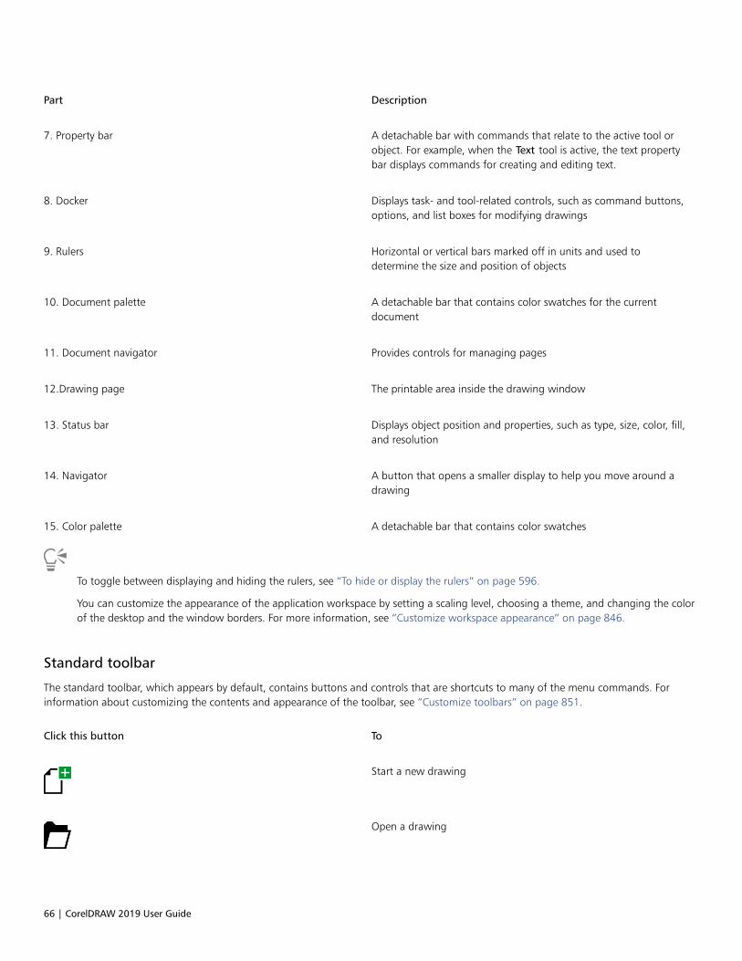
66 | CorelDRAW 2019 User Guide
Part Description
7. Property bar A detachable bar with commands that relate to the active tool orobject. For example, when the Text tool is active, the text propertybar displays commands for creating and editing text.
8. Docker Displays task- and tool-related controls, such as command buttons,options, and list boxes for modifying drawings
9. Rulers Horizontal or vertical bars marked off in units and used todetermine the size and position of objects
10. Document palette A detachable bar that contains color swatches for the currentdocument
11. Document navigator Provides controls for managing pages
12.Drawing page The printable area inside the drawing window
13. Status bar Displays object position and properties, such as type, size, color, fill,and resolution
14. Navigator A button that opens a smaller display to help you move around adrawing
15. Color palette A detachable bar that contains color swatches
To toggle between displaying and hiding the rulers, see “To hide or display the rulers” on page 596.
You can customize the appearance of the application workspace by setting a scaling level, choosing a theme, and changing the colorof the desktop and the window borders. For more information, see “Customize workspace appearance” on page 846.
Standard toolbar
The standard toolbar, which appears by default, contains buttons and controls that are shortcuts to many of the menu commands. Forinformation about customizing the contents and appearance of the toolbar, see “Customize toolbars” on page 851.
Click this button To
Start a new drawing
Open a drawing
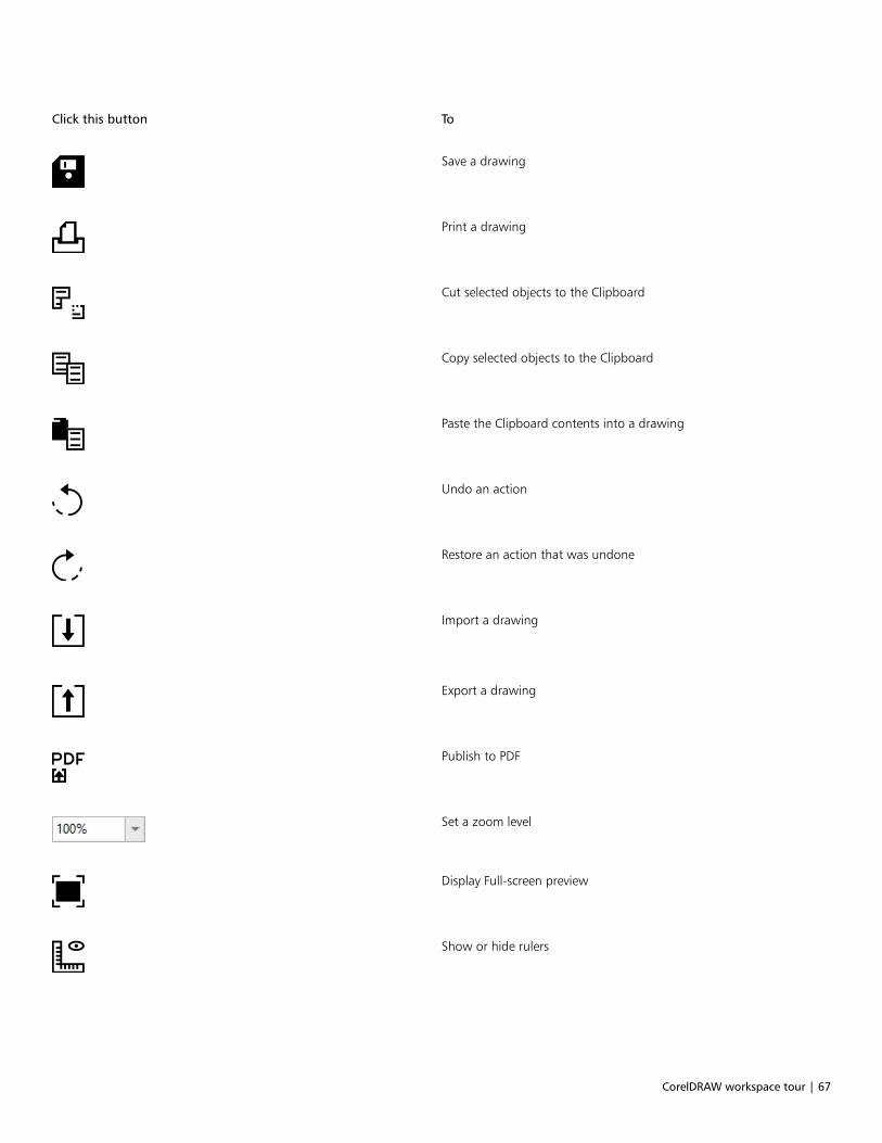
CorelDRAW workspace tour | 67
Click this button To
Save a drawing
Print a drawing
Cut selected objects to the Clipboard
Copy selected objects to the Clipboard
Paste the Clipboard contents into a drawing
Undo an action
Restore an action that was undone
Import a drawing
Export a drawing
Publish to PDF
Set a zoom level
Display Full-screen preview
Show or hide rulers

68 | CorelDRAW 2019 User Guide
Click this button To
Show or hide grid
Show or hide guidelines
Disable all snapping. Click again to restore the selected snappingoptions.
Enable or disable automatic alignment for the pixels, documentgrid, baseline grid, guidelines, objects, and page
Open the CorelDRAW Options dialog box
Start Corel applications and plug-ins, or access the Get Moredialog box to download other creative tools
More about toolbars
In addition to the standard toolbar, CorelDRAW has toolbars for specific tasks. For example, the Text toolbar contains commands relevant tousing the Text tool. If you use a toolbar frequently, you can display it in the workspace at all times.
For information about customizing the position, contents, and appearance of toolbars, see “Customize toolbars” on page 851.
The following table describes toolbars other than the standard toolbar.
Toolbar Description
Zoom Contains commands for zooming in and out of a drawing page byspecifying percentage of original view, clicking the Zoom tool, andselecting a page view
Text Contains commands for formatting and aligning text
Layout Contains commands for converting objects to PowerClip framesand text frames, displaying alignment guides as well as settingcolumns and margins
Transform Contains commands for skewing, rotating, and mirroring objects
Macros Contains commands for editing, testing, and running macros
Internet Contains commands for web-related tools for creating rollovers andpublishing to the Internet
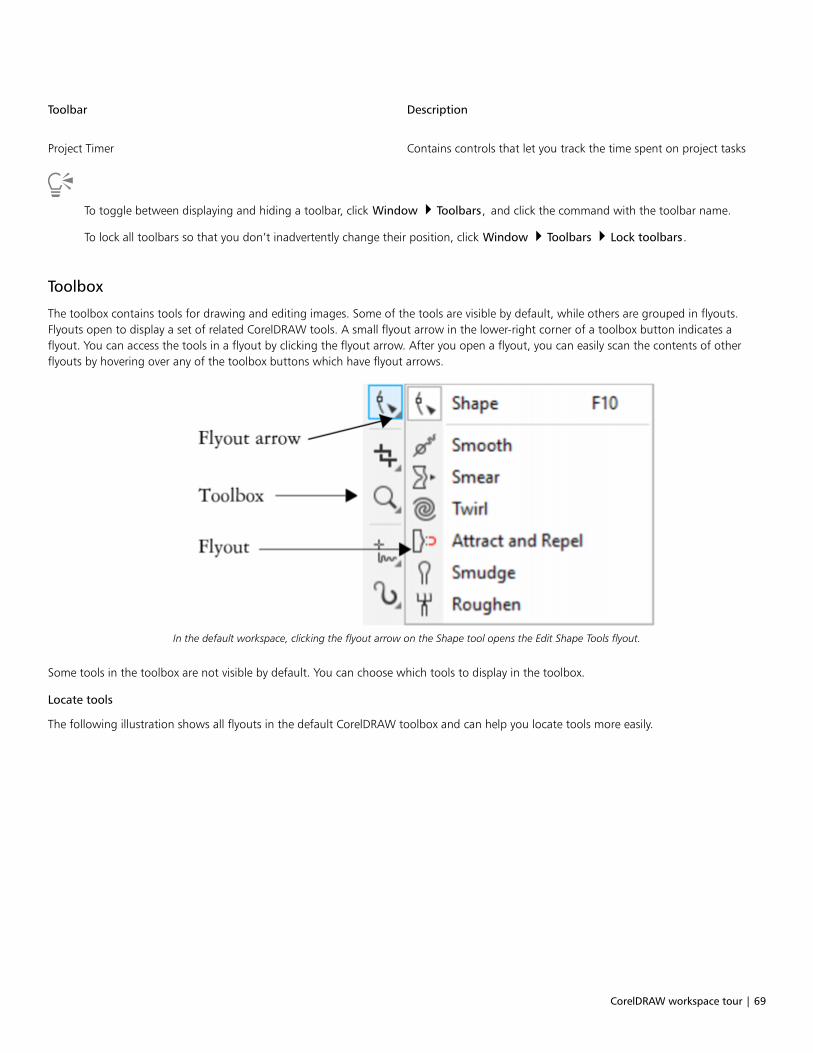
CorelDRAW workspace tour | 69
Toolbar Description
Project Timer Contains controls that let you track the time spent on project tasks
To toggle between displaying and hiding a toolbar, click Window Toolbars, and click the command with the toolbar name.
To lock all toolbars so that you don’t inadvertently change their position, click Window Toolbars Lock toolbars.
Toolbox
The toolbox contains tools for drawing and editing images. Some of the tools are visible by default, while others are grouped in flyouts.Flyouts open to display a set of related CorelDRAW tools. A small flyout arrow in the lower-right corner of a toolbox button indicates aflyout. You can access the tools in a flyout by clicking the flyout arrow. After you open a flyout, you can easily scan the contents of otherflyouts by hovering over any of the toolbox buttons which have flyout arrows.
In the default workspace, clicking the flyout arrow on the Shape tool opens the Edit Shape Tools flyout.
Some tools in the toolbox are not visible by default. You can choose which tools to display in the toolbox.
Locate tools
The following illustration shows all flyouts in the default CorelDRAW toolbox and can help you locate tools more easily.

70 | CorelDRAW 2019 User Guide
To toggle between displaying and hiding the toolbox, click Window Toolbars Toolbox.
To hide or display tools in the toolbox, click the Quick customize button , and enable or disable the corresponding check boxes.
For more information, see “Customize the toolbox” on page 854.
The following table provides descriptions of the tools in the CorelDRAW toolbox.
Pick tools
The Pick tool lets you select, size, skew, androtate objects.
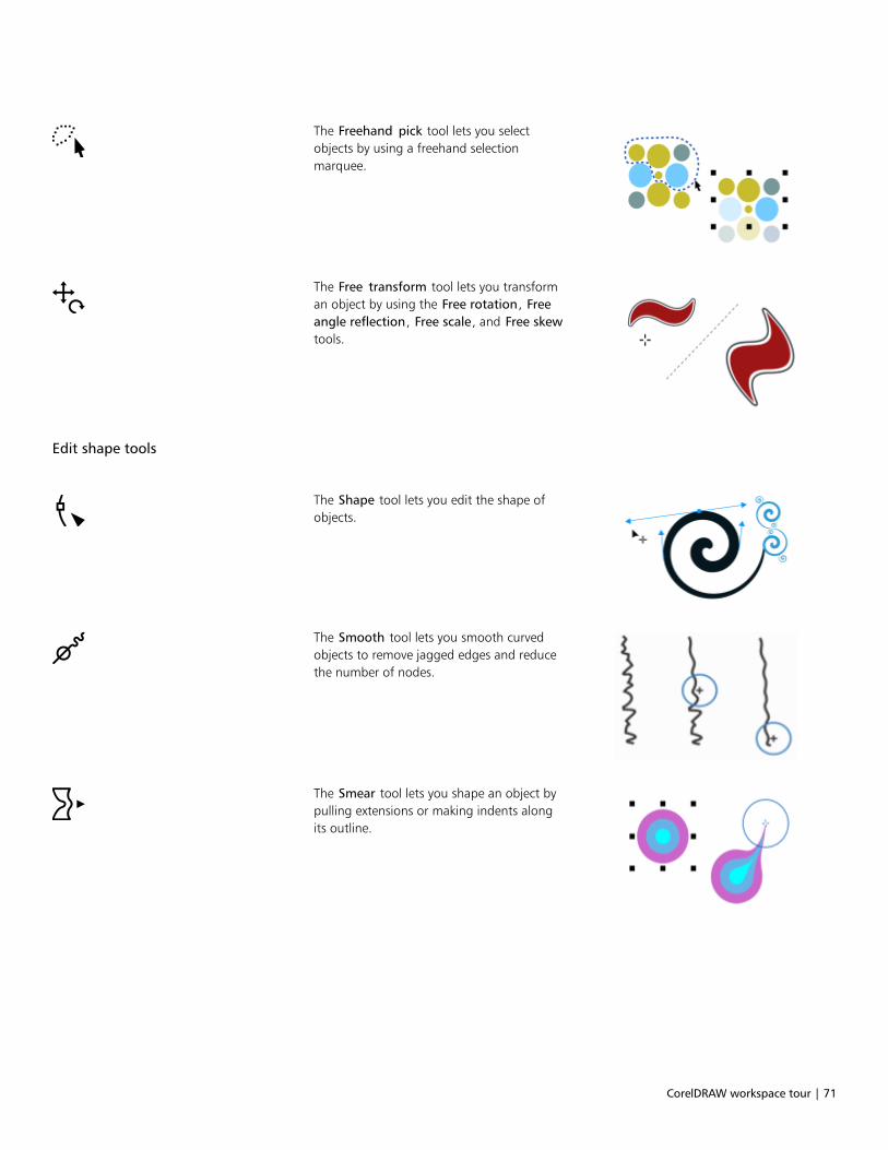
CorelDRAW workspace tour | 71
The Freehand pick tool lets you selectobjects by using a freehand selectionmarquee.
The Free transform tool lets you transforman object by using the Free rotation, Freeangle reflection, Free scale, and Free skewtools.
Edit shape tools
The Shape tool lets you edit the shape ofobjects.
The Smooth tool lets you smooth curvedobjects to remove jagged edges and reducethe number of nodes.
The Smear tool lets you shape an object bypulling extensions or making indents alongits outline.
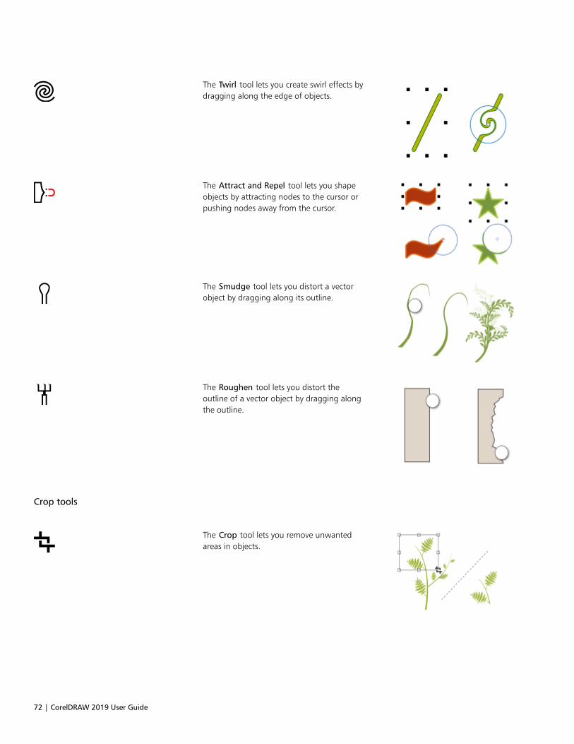
72 | CorelDRAW 2019 User Guide
The Twirl tool lets you create swirl effects bydragging along the edge of objects.
The Attract and Repel tool lets you shapeobjects by attracting nodes to the cursor orpushing nodes away from the cursor.
The Smudge tool lets you distort a vectorobject by dragging along its outline.
The Roughen tool lets you distort theoutline of a vector object by dragging alongthe outline.
Crop tools
The Crop tool lets you remove unwantedareas in objects.

CorelDRAW workspace tour | 73
The Knife tool lets you slice objects, groupsof objects, and bitmaps along any path youspecify.
The Virtual segment delete tool lets youdelete portions of objects that are betweenintersections.
The Eraser tool lets you remove areas ofyour drawing.
Zoom tools
The Zoom tool lets you change themagnification level in the drawing window.
The Pan tool lets you control which partof the drawing is visible in the drawingwindow.
Curve tools

74 | CorelDRAW 2019 User Guide
The Freehand tool lets you draw single linesegments and curves.
The 2-point line tool lets you draw astraight two-point line segment.
The Bézier tool lets you draw curves onesegment at a time.
The Pen tool lets you draw curves onesegment at a time.
The B-spline tool lets you draw curved linesby setting control points that shape thecurve without breaking it into segments.
The Polyline tool lets you draw lines andcurves in preview mode.
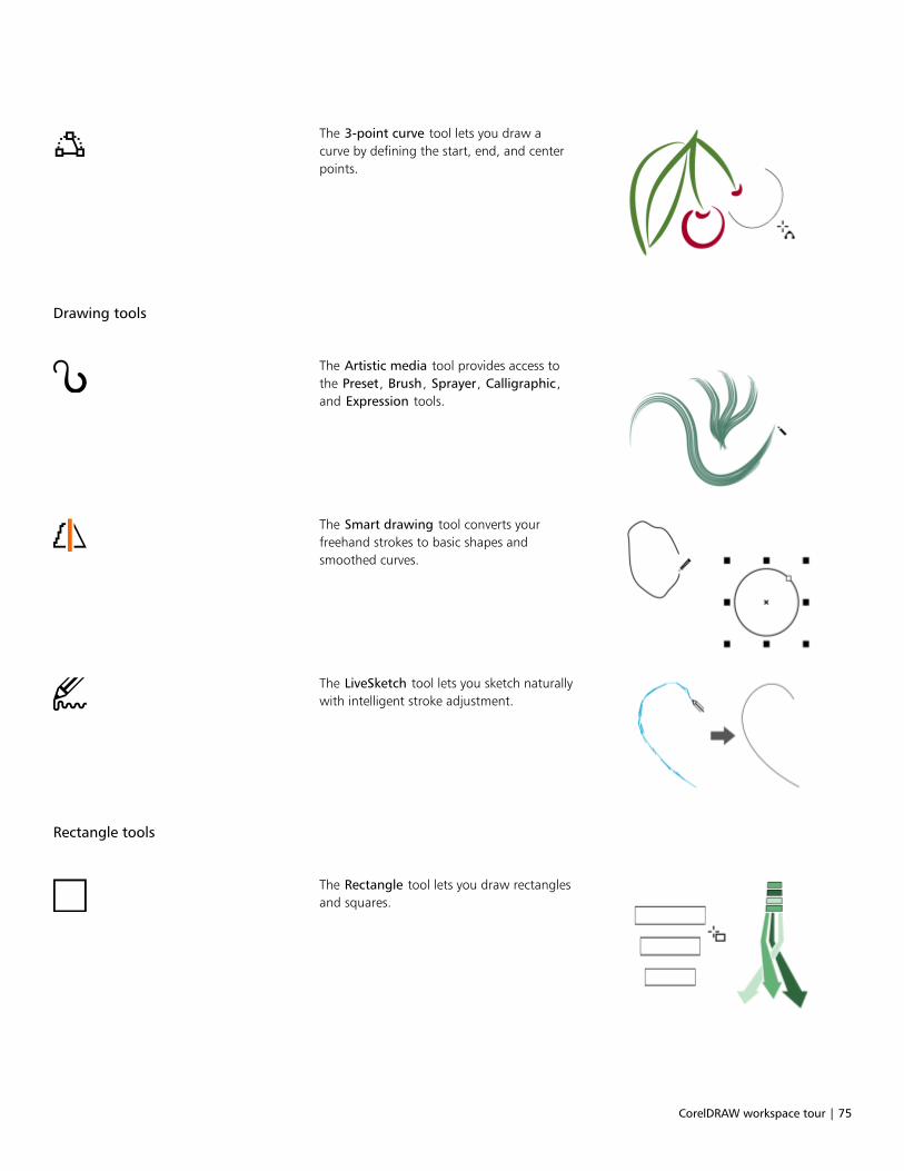
CorelDRAW workspace tour | 75
The 3-point curve tool lets you draw acurve by defining the start, end, and centerpoints.
Drawing tools
The Artistic media tool provides access tothe Preset, Brush, Sprayer, Calligraphic,and Expression tools.
The Smart drawing tool converts yourfreehand strokes to basic shapes andsmoothed curves.
The LiveSketch tool lets you sketch naturallywith intelligent stroke adjustment.
Rectangle tools
The Rectangle tool lets you draw rectanglesand squares.
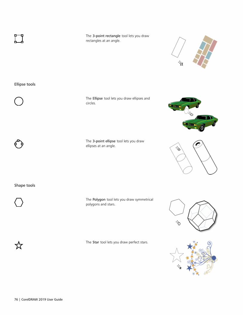
76 | CorelDRAW 2019 User Guide
The 3-point rectangle tool lets you drawrectangles at an angle.
Ellipse tools
The Ellipse tool lets you draw ellipses andcircles.
The 3-point ellipse tool lets you drawellipses at an angle.
Shape tools
The Polygon tool lets you draw symmetricalpolygons and stars.
The Star tool lets you draw perfect stars.

CorelDRAW workspace tour | 77
The Spiral tool lets you draw symmetricaland logarithmic spirals.
The Common shapes tool lets youchoose from a full set of shapes, includinghexagram, a smiley face, and a right-angletriangle.
The Impact tool lets you create graphiceffects in a style inspired by comic booksand contemporary illustrations.
The Graph paper tool lets you draw a gridof lines similar to that on graph paper.
Text tools
The Text tool lets you type words directly onthe screen as artistic or paragraph text.
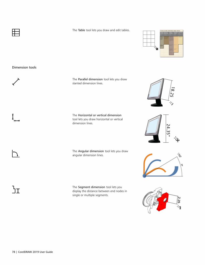
78 | CorelDRAW 2019 User Guide
The Table tool lets you draw and edit tables.
Dimension tools
The Parallel dimension tool lets you drawslanted dimension lines.
The Horizontal or vertical dimensiontool lets you draw horizontal or verticaldimension lines.
The Angular dimension tool lets you drawangular dimension lines.
The Segment dimension tool lets youdisplay the distance between end nodes insingle or multiple segments.

CorelDRAW workspace tour | 79
The 3-point callout tool lets you draw acallout with a two-segment leader line.
Connector tools
The Connector tool lets you draw straight,right-angle, and rounded right-angleconnector lines.
The Anchor editing tool lets you modifyconnector line anchor points.
Effect tools
The Drop shadow tool lets you apply adrop shadow to an object.
The Contour tool lets you apply a contourto an object.
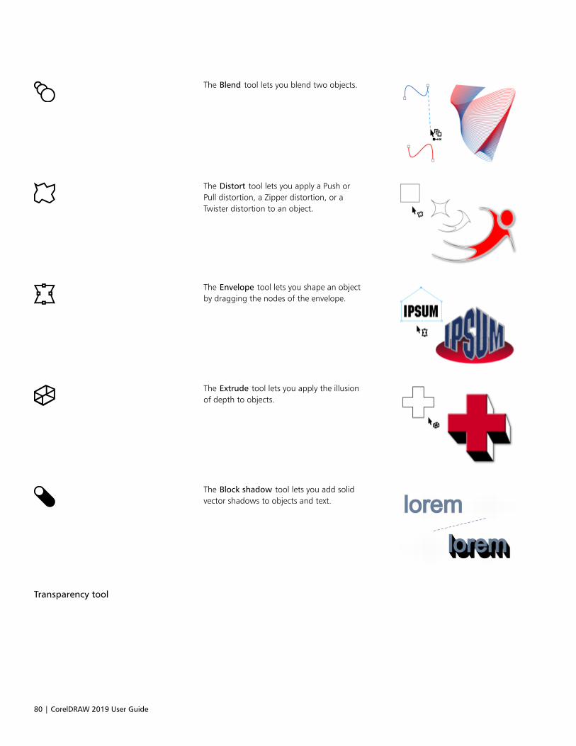
80 | CorelDRAW 2019 User Guide
The Blend tool lets you blend two objects.
The Distort tool lets you apply a Push orPull distortion, a Zipper distortion, or aTwister distortion to an object.
The Envelope tool lets you shape an objectby dragging the nodes of the envelope.
The Extrude tool lets you apply the illusionof depth to objects.
The Block shadow tool lets you add solidvector shadows to objects and text.
Transparency tool
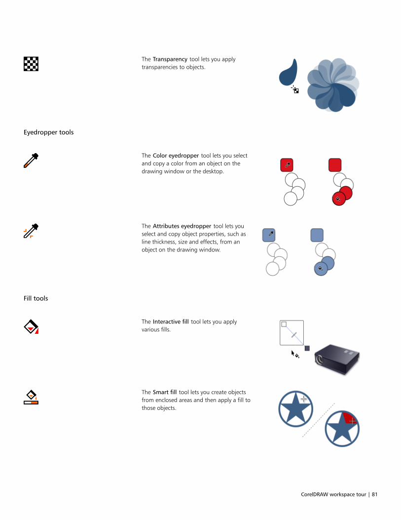
CorelDRAW workspace tour | 81
The Transparency tool lets you applytransparencies to objects.
Eyedropper tools
The Color eyedropper tool lets you selectand copy a color from an object on thedrawing window or the desktop.
The Attributes eyedropper tool lets youselect and copy object properties, such asline thickness, size and effects, from anobject on the drawing window.
Fill tools
The Interactive fill tool lets you applyvarious fills.
The Smart fill tool lets you create objectsfrom enclosed areas and then apply a fill tothose objects.
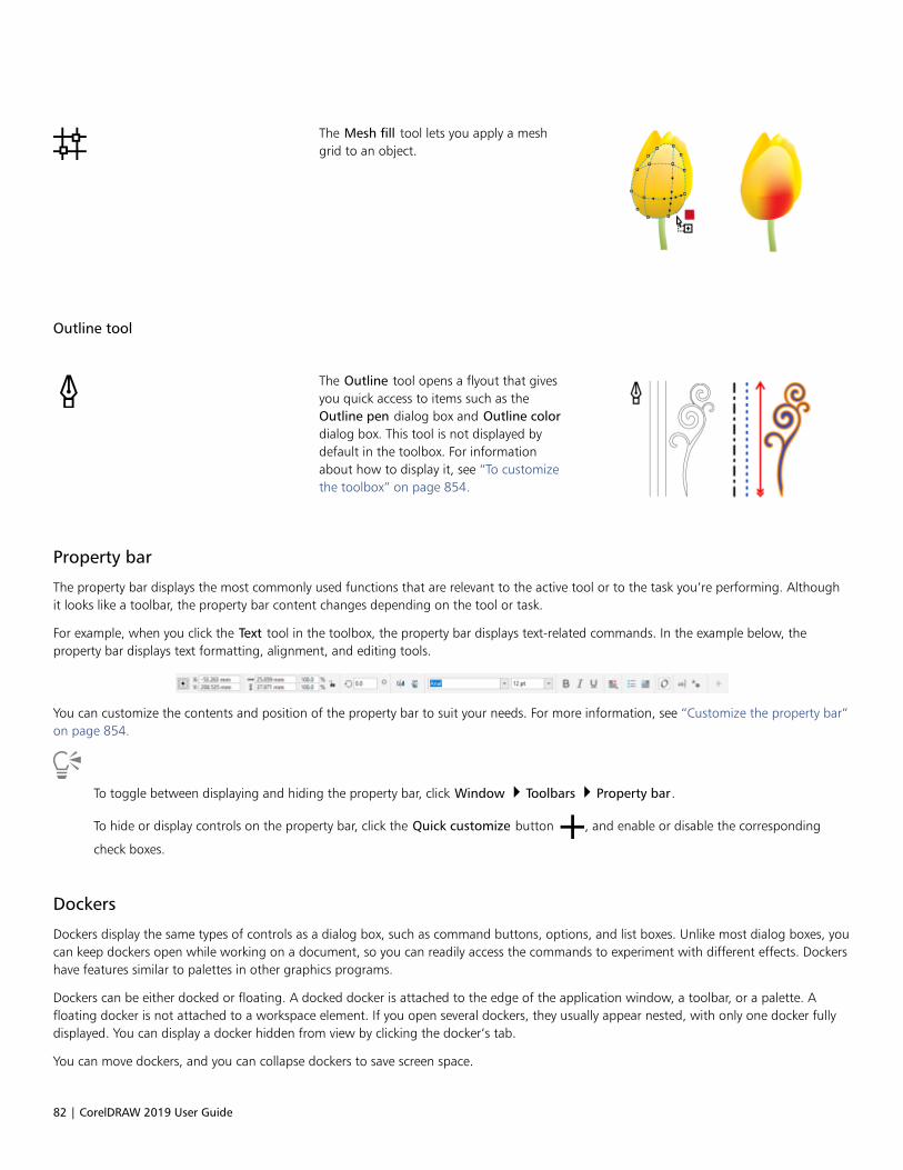
82 | CorelDRAW 2019 User Guide
The Mesh fill tool lets you apply a meshgrid to an object.
Outline tool
The Outline tool opens a flyout that givesyou quick access to items such as theOutline pen dialog box and Outline colordialog box. This tool is not displayed bydefault in the toolbox. For informationabout how to display it, see “To customizethe toolbox” on page 854.
Property bar
The property bar displays the most commonly used functions that are relevant to the active tool or to the task you’re performing. Althoughit looks like a toolbar, the property bar content changes depending on the tool or task.
For example, when you click the Text tool in the toolbox, the property bar displays text-related commands. In the example below, theproperty bar displays text formatting, alignment, and editing tools.
You can customize the contents and position of the property bar to suit your needs. For more information, see “Customize the property bar”on page 854.
To toggle between displaying and hiding the property bar, click Window Toolbars Property bar.
To hide or display controls on the property bar, click the Quick customize button , and enable or disable the corresponding
check boxes.
Dockers
Dockers display the same types of controls as a dialog box, such as command buttons, options, and list boxes. Unlike most dialog boxes, youcan keep dockers open while working on a document, so you can readily access the commands to experiment with different effects. Dockershave features similar to palettes in other graphics programs.
Dockers can be either docked or floating. A docked docker is attached to the edge of the application window, a toolbar, or a palette. Afloating docker is not attached to a workspace element. If you open several dockers, they usually appear nested, with only one docker fullydisplayed. You can display a docker hidden from view by clicking the docker’s tab.
You can move dockers, and you can collapse dockers to save screen space.

CorelDRAW workspace tour | 83
An example of a docker. When you open the Properties docker and click an object inthe drawing window, you can access various options for modifying object properties.
In this example, the Properties and the Objects dockers are docked and nested. The Transform docker is floating.
To open a docker
• Click Window Dockers, and click a docker.

84 | CorelDRAW 2019 User Guide
To open or close dockers, you can also click the Quick customize button on the right side of a docker, and enable or disable the
corresponding check boxes.
You can also close a docker by clicking the X button on its title bar. Clicking the X button on the title bar closes all nested dockers in agroup. To close only a specific docker, click the X button on the docker tab.
To move dockers
To move Do the following
A docker Drag the docker tab to a new location.
Multiple nested dockers Drag the title bar of the active docker to a new location.
To dock a floating docker
• Drag the docker’s title bar or tab to an edge of the drawing window and position the pointer along the edge. When a gray preview ofthe docker’s position appears, release the mouse button.
To collapse a docker
• Click the Collapse docker button on the docker’s title bar.
To expand a collapsed docker, click its tab.
Status bar
The status bar displays information about selected objects (such as color, fill type, outline, cursor position, and relevant commands). It alsodisplays document color information, such as the document color profile and color proofing status.
You can edit the fill and outline of selected objects by clicking the Fill and Outline icons on the status bar.
See “Customize the status bar ” on page 855 for information about customizing the contents and appearance of the status bar.
To hide the status bar
• To hide the status bar, click Window Toolbars Status Bar.
Choose a workspace
CorelDRAW includes a collection of workspaces that are designed to help you increase your productivity. A workspace is a configurationof settings that specifies how the various command bars, commands, and buttons are arranged when you open the application. You canchoose a workspace from the Welcome Screen, or you can switch to a different workspace from within the application.

CorelDRAW workspace tour | 85
The specialized workspaces in CorelDRAW are configured according to specific workflows or tasks, such as page layout work or illustrating.Their purpose is to make more accessible the tools that you use most often.
The following table describes the available workspaces.
Workspace Description
Lite This workspace makes CorelDRAW’s most commonly used toolsand features more accessible. If you are new to CorelDRAW, theLite workspace is ideal for getting started.
Default This workspace has been redesigned to provide a more intuitiveplacement of tools and controls.This workspace is ideal for userswho have experience with other vector graphics software, as wellas users who are familiar with CorelDRAW.
Help topics are based on the Default workspace.
Touch Optimized for touch-enabled devices, the Touch workspace is idealfor field work and sketching. Complete your tasks by using touch,dial, or a stylus, without needing a mouse or keyboard.
Illustration This workspace is designed to make the process of creating bookcover designs, magazine ads, storyboards, and other types ofillustrations more intuitive and efficient.
Page layout This workspace is optimized for arranging graphics and text objectsso you can create compelling layouts for business cards, brandingmaterials, product packaging, or multipage documents such asbrochures and newsletters.
Adobe Illustrator Simulates the Adobe Illustrator workspace by positioning theCorelDRAW features where you would find the equivalent featurein Adobe Illustrator. This workspace is useful if you recentlyswitched from Adobe Illustrator to CorelDRAW and you are notfamiliar with the CorelDRAW workspace.
If you have a unique workflow, you can create a custom workspace that is optimized for your specific needs. For more information, see“Create workspaces” on page 844.
To choose a workspace
• Click Window Workspace, and choose one of the available workspaces.
You can also choose a workspace from the Welcome Screen or from the Workspaces dialog box (Tools Options Workspaces).

86 | CorelDRAW 2019 User Guide

Creative tools and content | 87
Creative tools and content
You can expand your collection of creative tools by downloading free tools and content and purchasing apps, plug-ins, and content packs.You can also search and manage content, such as vector and bitmap (also known as raster) images in local or network folders and onportable devices. When you find the content that you need, you can insert it into your document or open it in its associated application.
CorelDRAW is fully integrated with the search capabilities that are offered by Windows. By default, the application searches all locations thatWindows Search is configured to index. For information about modifying indexing options in Windows Search, see the Windows Help.
This section contains the following topics:• “Content types” (page 87)• “Change content locations” (page 89)• “Acquire applications, plug-ins, and content” (page 89)• “Find images with the CONNECT Content docker” (page 90)• “Use and manage images with the CONNECT Content docker” (page 93)• “CONNECT Browser” (page 95)• “Find content with the CONNECT Browser” (page 97)• “View content in the CONNECT Browser” (page 99)• “Use content from the CONNECT Browser” (page 100)• “Manage content with the Tray docker” (page 102)• “Sync trays with OneDrive” (page 104)
Content types
Content types include images (vector and bitmap graphics), fills (fountain, bitmap patterns, and vector patterns), fonts, image lists, palettes,photo frames, and templates. For information about fills, see “Find and view fills and transparencies” on page 399. For information abouttemplates, see “Find templates” on page 560. For information about fonts, see the Corel Font Manager Help or “Acquire more fonts” onpage 536.
To find vector and bitmap graphics stored in local and network folders, and portable devices, use the CONNECT Content docker. To findimages on Flickr, sync content with OneDrive, or download all images used on a website, use the CONNECT Browser docker.
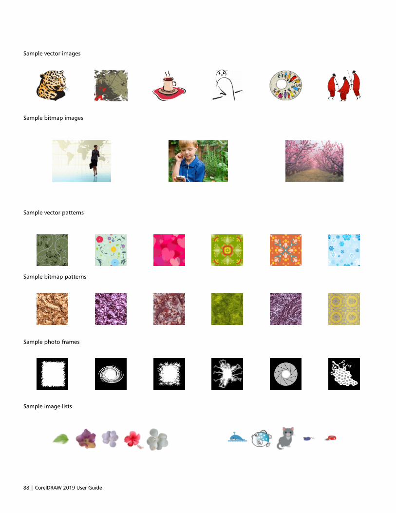
88 | CorelDRAW 2019 User Guide
Sample vector images
Sample bitmap images
Sample vector patterns
Sample bitmap patterns
Sample photo frames
Sample image lists
Creative tools and content | 89
Change content locations
Images, fills, fonts, image lists, photo frames, trays, and templates are saved to your Documents\Corel\Corel Content\[Content Type]folders. You can change the location of some or all these content files by browsing to different folders. For example, you can choose to savetemplates and fonts to a new location, but leave other content files in your Documents\Corel\Corel Content folder.
When you change a content location, you can choose to move the content files from the old location to the new location.
You can reset individual or multiple content locations to their default folders from the Global Options dialog box. Alternatively, you can resetall content locations when you reset the application to its default settings by holding down F8 during startup. With this method, all filessaved to custom locations remain in place. To restore your custom content locations, you must browse again to the respective folders.
To change a content location
1 Click Tools Options Global.
2 Click File Locations.
3 Click the location that you want to change, and click Edit.
4 In the Select Folder dialog box, navigate to the folder you want.
If you want to move the content files saved to the old location to the new folder, click Yes in the Move Content dialog box.
You can also
Reset the location of a single content type Click the content type name, and click Reset.
Reset the locations of multiple content types Holding down Ctrl, click the content types you want, and clickReset.
Acquire applications, plug-ins, and content
The Get More dialog box lets you download apps and plug-ins as well as creative tools and content such as fill packs and font packs fromwithin CorelDRAW. The selection is updated with new offerings as they become available. Some items are free whereas other items areavailable for purchase.
Both applications and plug-ins require installation.
To uninstall an application or a plug-in, go to the Control Panel of the operating system.
AfterShot 3 HDR
Corel® AfterShot™ 3 HDR lets you make easy corrections and enhancements to your RAW or JPEG photos, and apply adjustments tothousands of photos at once with batch-processing tools. Plus, you can create high dynamic range (HDR) images with the HDR module,included in AfterShot 3 HDR. Download Corel AfterShot 3 HDR for free from within CorelDRAW, and quickly learn professional-grade photoediting. To access even more powerful photo-management and photo-editing features, upgrade to the latest version of AfterShot Pro fromwithin the Get More dialog box.
Restore purchases
After you purchase creative tools, check marks appear beside their names. If you reinstall the suite or install it on another computer, you canrestore your purchases. The items that you have purchased will appear in the Get More dialog box, so that you can download them andreinstall them.
90 | CorelDRAW 2019 User Guide
To access the Get More dialog box
• Click the Launch button on the standard toolbar, and click Get More.
To download AfterShot 3 HDR
• Click the Launch button on the standard toolbar, and click AfterShot 3 HDR.
After downloading AfterShot 3 HDR, you can start it from the Launch button on the standard toolbar.
For detailed information about how to use AfterShot 3 HDR, start the application and access the Help by pressing F1.
To access an application or a plug-in
• Click the Launch button on the standard toolbar, and click the application or plug-in that you want to use.
To restore your purchases
1 Click Help Restore Purchases.
2 In the dialog box that appears, type the email address that was used to make the purchases, and click Continue.
A list of your purchases is displayed.
3 Click Close.
The list of offerings in the Get More dialog box is updated to show which items you have already purchased.
4 Download the items you want.
Find images with the CONNECT Content docker
The CONNECT Content docker (Window Dockers CONNECT Content) provides a central location where you can search and browsevector and bitmap images in local or network folders and on portable devices. After you find the image you need, you can add it to yourproject. For more information, see “Use and manage images with the CONNECT Content docker” on page 93.
To get you started, Corel provides local content that is stored in your Documents\Corel\Corel Content\Images folder. If you are looking toexpand your image collection, you can download additional image packs from within the Get More dialog box.
To access images that are saved to local folders outside your Documents\Corel\Corel Content\Images folder, you can create links, knownas aliases, to these folders. In addition, aliases can be used to access images saved to shared network locations as well as secondary storagedevices such as USB flash drives, and portable hard drives.
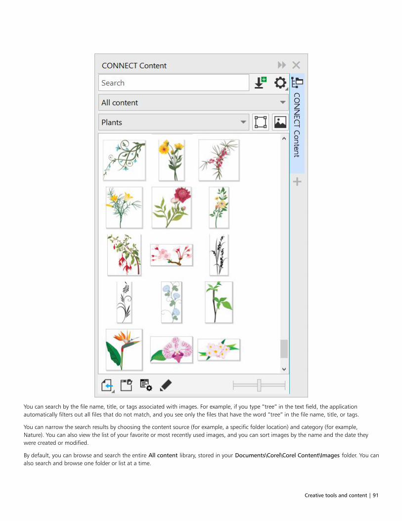
Creative tools and content | 91
You can search by the file name, title, or tags associated with images. For example, if you type “tree” in the text field, the applicationautomatically filters out all files that do not match, and you see only the files that have the word “tree” in the file name, title, or tags.
You can narrow the search results by choosing the content source (for example, a specific folder location) and category (for example,Nature). You can also view the list of your favorite or most recently used images, and you can sort images by the name and the date theywere created or modified.
By default, you can browse and search the entire All content library, stored in your Documents\Corel\Corel Content\Images folder. You canalso search and browse one folder or list at a time.

92 | CorelDRAW 2019 User Guide
After you copy a folder that contains images to your computer, it may take some time for your operating system to index the folder. To view,browse, and search content in such a folder right away, you may need to reindex the folder.
You can increase the size of thumbnails, and you can decrease thumbnail size to view more search results at a glance.
To find, filter, and sort images
1 Click Window Dockers CONNECT Content.
2 Type a word in the Search box, and press Enter.
Thumbnails that match the search term appear in the viewing pane.
To search and browse all available content, choose All content from the Choose content source list box.
You can also
Filter images From the Choose content source list box, choose an item otherthan All content. Choose a category from the Filter content listbox.
To view only clipart and vector graphics, click the Show vector
images button .
To view only photos and other bitmaps, click the Show raster
images button .
View the most recently used images From the Choose content source list box, choose Recent.
View your favorite images From the Choose content source list box, choose Favorites. Forinformation about how to mark content as favorite, see “To tag,delete, and edit the properties of images ” on page 94.
Sort images Click the Options for folder or alias button , and choose one
of the following:•Sort by name sorts templates by file name, in alphabetical order.•Sort by date created sorts images by the date they were created,
starting with the last created image.•Sort by last modified sorts images by the date they were
modified, starting with the last modified image.
Images in your Favorites list are automatically sorted by the dateyou marked them as favorites, starting with the last image addedto Favorites.
Images in your Recent list are automatically sorted by the date youused them, starting with the last used image.
Browse or search all items in your All content library From the Choose content source list box, choose All content.
Click the Options for folder or alias button , and make sure
the Browse recursively command is enabled.

Creative tools and content | 93
You can also
Reindex a folder Click the Options for folder or alias button , and click
Reindex folder.
To download and add a new image pack
1 Click Window Dockers CONNECT Content.
2 Click the Get More button.
3 In the Get More dialog box, click the image pack you want.
4 Do one of the following:
• Click Buy Now, and follow the onscreen instructions to purchase the item.
• Click Download if the item is included in your product or subscription.
To add an alias to a location that contains images
1 In the CONNECT Content docker, open the Choose content source list box, and click Add new.
2 Click Create alias.
3 Browse to the folder or location you want in the Locate content library dialog box.
4 Click Select Folder.
If you cannot see the images right away, click the Options for folder or alias button, and click Reindex folder.
To view the filename and location of an image
• Hold the pointer over a thumbnail.
To adjust the size of image thumbnails
• Move the Thumbnail size slider.
Use and manage images with the CONNECT Content docker
After you find the vector or bitmap image you need, you can place it into your project as an embedded or linked object. When inserting avector graphic, you can place it at the original position where it was created relative to the page.
You can manage the list of your local packs and aliases (links to local folders, network locations, and secondary storage devices). Forexample, you can rename the local packs or aliases, and you can remove aliases from the list. If an alias no longer works because the folderhas been moved, you can browse to the new location to restore the link.
To find the images you like with ease, you can tag them as favorites. In addition, you can view and change the properties of an image. Forexample, you can change its title, add new tags, and delete existing tags. When you no longer need an image, you can delete it.
To insert content in the active document
1 In the CONNECT Content docker, click a thumbnail.
2 Click the Import button and choose one of the following commands:
• Import and link — inserts the file as a linked object
• Import at original position — lets you place a vector graphic at the original position where it was created relative to the page. Thegraphic is placed as an embedded object.
• Import — inserts the file as an embedded object
3 Follow the onscreen instructions.
94 | CorelDRAW 2019 User Guide
You can also insert a file into an active document as an embedded object by dragging the file from the viewing pane to the activedocument.
You can also insert a file into an active document by right-clicking the file in the viewing pane and choosing an Import command.
To open and edit an image
1 In the CONNECT Content docker, click a thumbnail.
2 Click the Edit button .
The file opens in its associated application.
To update the list of folders and aliases in the CONNECT Content docker1 Click Window Dockers CONNECT Content.
2 Choose a content folder or an alias from the Choose content source list box under All content.
3 Click the Options for folder or alias button , and perform a task from the following table.
To Do the following
Rename a content pack or alias Click Rename, and in the Rename dialog box, type a name in theName box.
Browse to a folder that has been moved or renamed Click Browse, and navigate to the folder that contains the images.
Remove an alias from the list Click Remove.
Open the content pack or alias in Windows Explorer Click Open folder location.
To tag, delete, and edit the properties of images
1 Click Window Dockers CONNECT Content.
2 Perform an action from the following table.
To Do the following
Tag an image as favorite Right-click a thumbnail, and click Favorite.
Edit image properties Right-click a thumbnail, and click Properties. In the Propertiesdialog box, do any of the following:
•Choose a language from the Language list box.•Type a new name in the Title box.•Choose a category from the Category list box to categorize the
image.•To assign a custom category, choose New category from the
Category list box, and type the category name in the box.•Add or delete tags in the Tags box.
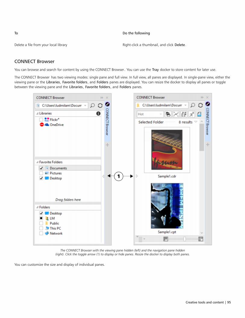
Creative tools and content | 95
To Do the following
Delete a file from your local library Right-click a thumbnail, and click Delete.
CONNECT Browser
You can browse and search for content by using the CONNECT Browser. You can use the Tray docker to store content for later use.
The CONNECT Browser has two viewing modes: single pane and full view. In full view, all panes are displayed. In single-pane view, either theviewing pane or the Libraries, Favorite folders, and Folders panes are displayed. You can resize the docker to display all panes or togglebetween the viewing pane and the Libraries, Favorite folders, and Folders panes.
The CONNECT Browser with the viewing pane hidden (left) and the navigation pane hidden(right). Click the toggle arrow (1) to display or hide panes. Resize the docker to display both panes.
You can customize the size and display of individual panes.
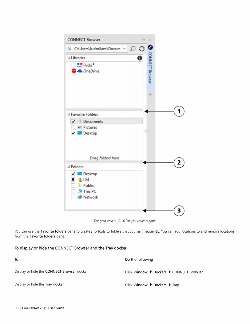
96 | CorelDRAW 2019 User Guide
The grab area (1, 2, 3) lets you resize a pane.
You can use the Favorite folders pane to create shortcuts to folders that you visit frequently. You can add locations to and remove locationsfrom the Favorite folders pane.
To display or hide the CONNECT Browser and the Tray docker
To Do the following
Display or hide the CONNECT Browser docker Click Window Dockers CONNECT Browser.
Display or hide the Tray docker Click Window Dockers Tray.

Creative tools and content | 97
To resize a pane
• Point to the pane’s grab area, and when the cursor changes to a two-directional arrow, drag the edge of the pane.
To display or hide a pane
• Click the arrow to toggle between displaying and hiding the pane.
To add a location to the Favorite Folders pane
• Drag a folder from the Libraries, Folders, or viewing pane to the Favorite folders pane.
You can also add locations to the Favorite folders pane by right-clicking a folder in the Libraries or Folders pane, and clicking Addto Favorites.
To remove a location from the Favorite Folders pane
• Right-click a location in the Favorite folders pane, and click Remove from Favorites.
Find content with the CONNECT Browser
With the CONNECT Browser, you can browse for content, or you can search for content by using keywords.
You can browse and search for content in one or multiple locations on your computer or local network. You can also browse and searchonline on Flickr ®. The images that you find online are often subject to usage restrictions and may be watermarked or low-resolution. Forinformation about using such images, see “Use content from the CONNECT Browser” on page 100.
Note that online content is unavailable in workplaces with restricted Internet access.
You can also navigate to previously viewed content.
Searching for content
You can search by the name, category (for example, clipart, photo images, or fonts), or reference information (for example, tags or notes)associated with a file. When you type a term in the Search and address box and initiate a search, all matching files are displayed asthumbnail images in the viewing pane. For example, if you type flower, the application automatically filters out all files that do not matchand displays only the files that have the word flower in the filename, category, or tags assigned to the file. You can also type phrasesand multiple words, and you can fine-tune your search by using Boolean operators such as AND, NOT, and OR. For example, you canfind content that contains both flower and sun images by typing flowers AND sun. For information about adding tags and referenceinformation, see “To add and access drawing information ” on page 59.
To increase the search speed for local content and improve results, you can adjust the Windows Search options by adding more locations tothe index.
You can also find all images on a webpage by typing the web address. For example, typing www.corel.com displays all the images thatappear on the Corel website.
Refining your search
By default, your search results include all relevant content such as vector graphics, bitmaps, and fonts. You can narrow down the searchresults by excluding content. For example, if you are searching for graphics, you can display only vector graphics or only bitmaps. If you wantto choose a font for your project, you can display only fonts.
You can widen the scope of a search, and you can cancel a search at any time.
98 | CorelDRAW 2019 User Guide
To browse and search for content
1 Click Window Dockers CONNECT Browser.
2 Click a location in one of the following panes:
• Libraries — lets you browse and search local content
• Favorite folders — lets you browse and search your favorite locations
• Folders — lets you browse the folder structure available on your computer
3 Type a word or multiple words in the Search and address box, and press Enter.
Files that match the search terms appear in the viewing pane.
If you want to search for a phrase, enclose the phrase with quotation marks.
You can also
Search for content in multiple locations Enable the check boxes for the libraries and folders that you want
to search, and click the Refresh button .
Show or hide search results for a location In the viewing pane, click the Show/Hide arrow to the right of thelocation.
Specify how many Flickr online search results to display In the Libraries pane, click the Configure content libraries button
. Click Flickr, and choose a number from the Search results list
box. This number determines the initial number of search resultsthat are displayed in the viewing pane, as well as the additionalresults that are displayed each time you click More from.
Fine-tune a search by using Boolean operators Type one of the following Boolean operators between the searchterms:
AND — lets you find content that contains all search terms in theSearch and address box. Instead of AND, you can also use the plussign (+).
NOT — lets you exclude content that contains the search term afterNOT. Instead of NOT, you can also use the minus sign (-).
OR — lets you find content that contains at least one of the searchterms
You can browse the contents of only one folder at a time.
To specify the location where you want to browse for content, type or paste a path in the Search and address box, and press Enter.The Search and address bar keeps track only of the locations that you enter manually. To delete all locations, click the drop-downarrow, and click Clear list.
If you want to browse the folder where a file is stored or access the source webpage of an image, right-click the file, and click Opensource location.

Creative tools and content | 99
To find all images on a webpage
• Type a web address (for example, www.corel.com) in the Search and address box.
To refine your search
• In the CONNECT Browser, click one of the following buttons:
• Folders — to hide or display folders in selected folders
• Vector drawing files — to hide or display vector graphics that are supported by the suite
• Bitmap files — to hide or display bitmaps that are supported by the suite
• Font files — to hide or display TrueType (TTF), OpenType (OTF), and PostScript fonts (PFB and PFM)
• Other files — to hide or display file formats that are not supported by the suite
A category is included in the search results if the button appears pressed.
View content in the CONNECT Browser
Clipart, photos, and fonts appear in the viewing pane as thumbnail images. You can select individual, multiple, or all thumbnails.
By positioning your pointer over a thumbnail, you can display a larger preview. You can also display file information such as filename, filesize, image resolution, and color mode for content that was not provided by an online content provider. You can also preview the fonts thatyou find. Thumbnail zooming makes recognizing a particular file easier and faster.
To select a thumbnail
1 Search or browse for content in the CONNECT Browser.
2 Click a thumbnail.
You can also
Select multiple thumbnails Do one of the following:•Drag around the thumbnails that you want to select.•Hold down Ctrl, and in the viewing pane click the thumbnails
that you want to select.•Click a thumbnail, and holding down Shift, click the last
thumbnail in the range that you want to select.
Select all thumbnails Press Ctrl + A.
To view file information
• Hover over a thumbnail.
To preview a font
• Double-click a font thumbnail.

100 | CorelDRAW 2019 User Guide
You can also preview a font by right-clicking a font thumbnail and clicking Open.
To adjust the size of thumbnails
• Drag the Zoom slider to the left to decrease the size of the thumbnails, or to the right to increase the size of the thumbnails.
Use content from the CONNECT Browser
If you want to view or edit a file before you incorporate it into your project, you can open it in CorelDRAW, Corel PHOTO-PAINT, or itsassociated application.
You can insert and place content in your document. Images that are obtained from Flickr may be subject to copyright and usage restrictions.Such images, also referred to as “comp images,” are often low-resolution or watermarked. To use comp images, you must first check withthe owner if you have rights to use them and purchase them if necessary. Then, you can replace the comp images in your document with thepurchased images. You can view a list of all comp images in a document.
You can install the fonts that you find, and you can install font families.
To open a file
To Do the following
Open a file by using the CONNECT Browser Click Window Dockers CONNECT Browser. Select athumbnail. Do one of the following:
•In full view, click the Open button .
•In single pane view, click the File commands button , and
click Open.
Open a file by using the Tray docker Click Window Dockers Tray. Select a thumbnail. Click the
Open button .
You can also open a file by right-clicking it and choosing the option that you want.
You can also open multiple selected files.
To insert a file into an active document
To Do the following
Insert a file into an active document by using the CONNECTBrowser
Do one of the following:•Drag a file from the viewing pane of the CONNECT Browser to
the active document to insert the file as an embedded object.•Drag a file from the viewing pane of the to the active document
to insert the file as an embedded object.•In single-pane view, select a file in the viewing pane, click the
File commands button , click Import to insert the file as an
Creative tools and content | 101
To Do the following
embedded object or Import and link to insert the file as a linkedobject, and click in your document.
•In full view, select a file in the viewing pane, click the Import
button to insert the file as an embedded object or the
Import and link button to insert the file as a linked object,
and click in your document.
Insert a file into an active document by using the Tray docker Select the file, and click one of the following buttons in the Traydocker:
•Import — lets you insert a file as an embedded object
•Import and link — lets you insert a file as a linked object
•Import at original position — lets you import and place a vectorgraphic at the original position where it was created relative tothe page
Note that the Import buttons are not available in the standaloneutility.
Insert and place a vector graphic in a document Click the Import or Import and link button and do one of thefollowing:
•Drag to place and resize the graphic.•Press Enter to center the graphic on page.•Press Spacebar to place the vector graphic at the original
position where it was created relative to the page.
For information about inserting embedded and linked objects, see “Link and embed objects ” on page 309.
You can also insert a file into an active document by dragging the file from the viewing pane or the Tray docker to the activedocument.
You can also insert a file into an active document by right-clicking the file in the viewing pane and choosing an import command.
You can also insert multiple selected files.
To check, purchase, and replace a comp image
1 In your document, right-click a comp image, and click Open Comp Source.
2 On the Flickr website, check the copyright and usage restrictions for the image, and purchase it if necessary.
3 In your document, right-click the comp image, and click Replace Comp.
4 Navigate to the purchased image, and click Import.
Transformations, such as scaling, rotating, and resizing, that were applied to the comp image are preserved in the final image.However, effects, such as envelopes, distortions, perspective, as well as bitmap effects and adjustments, are not preserved.

102 | CorelDRAW 2019 User Guide
You can also access the Open comp source and Replace comp commands by right-clicking a comp image.
To view a list of all comp images in a document
• Open a document, and do one of the following:
• Click File Print, click the Preflight ( Issues) tab, and click Some images may be subject to copyright and usage restrictions.
• Click File Document Properties.
When you export a document to the Adobe Illustrator (AI), Scalable Vector Graphics (SVG), HTML, or PDF file format, you can view alist of all comp images in the preflight summaries.
To install fonts
1 Click Window Dockers CONNECT Browser.
2 Find the font that you want to install.
3 Do one of the following:
• In the viewing pane, right-click the font thumbnail, and click Install.
A check mark appears in the lower-right corner of the font thumbnail to show that the font is installed.
• To install a font family, right-click the font thumbnail, and click Install font family.
To uninstall a font, right-click the font thumbnail, and click Uninstall.
Manage content with the Tray docker
You can organize your content by using trays or by adding content files to specific folders on your computer.
A tray is useful for gathering content from various folders. While the files are referenced in the tray, they actually remain in their originallocation. You can add and remove content from the tray. The tray is shared between CorelDRAW, and Corel PHOTO-PAINT. You can also openfiles from the tray to preview them more easily.
You can rename trays to give them meaningful names. When working with multiple trays, you can close some trays temporarily to avoidclutter. You can easily reopen a tray when you need it. In addition, you can load a tray file that is not listed among the available trays. Youcan delete a tray at any time.
To add content to a tray
1 Click Window Dockers CONNECT Browser.
2 Search or browse for content.
3 Select one or more thumbnails in the viewing pane, and drag them to the tray.
If you want to open a file from the tray, double-click its thumbnail.
You can also drag content from a folder on your computer to the tray.

Creative tools and content | 103
To add content to a folder
• Select one or more thumbnails in the viewing area, and drag them to a folder in the Favorite folders or Folders pane, or any otherfolder on your computer.
You can drag content from the tray to a folder.
To remove content from a tray
• Select one or more thumbnails in the tray, and click the Remove from tray button .
To create a tray
• Click the Add new tray button in the lower-right corner of the tray pane.
By default, trays are saved to your Documents\Corel\Corel Content\Trays folder.
You can email trays that contain only online content.
To work with trays
To Do the following
Select a tray Click the tray tab.
Rename a tray Right-click the tray tab, click Rename, and type a new name.
Open a tray Click the All trays arrow, and click a tray.
An open tray has a check mark beside its name.
Close a tray Right-click the tray tab, and click Close.
Load a tray file Click the All trays arrow, click Open tray file, and navigate to thetray file.
Delete a tray Right-click the tray tab, and click Delete.
You can also close and delete a selected tray from the All trays menu.
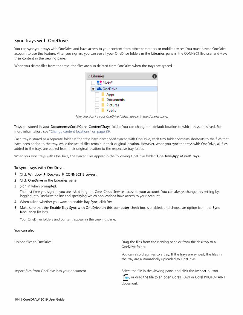
104 | CorelDRAW 2019 User Guide
Sync trays with OneDrive
You can sync your trays with OneDrive and have access to your content from other computers or mobile devices. You must have a OneDriveaccount to use this feature. After you sign in, you can see all your OneDrive folders in the Libraries pane in the CONNECT Browser and viewtheir content in the viewing pane.
When you delete files from the trays, the files are also deleted from OneDrive when the trays are synced.
After you sign in, your OneDrive folders appear in the Libraries pane.
Trays are stored in your Documents\Corel\Corel Content\Trays folder. You can change the default location to which trays are saved. Formore information, see “Change content locations” on page 89.
Each tray is stored as a separate folder. If the trays have never been synced with OneDrive, each tray folder contains shortcuts to the files thathave been added to the tray, while the actual files remain in their original location. However, when you sync the trays with OneDrive, all filesadded to the trays are copied from their original location to the respective tray folder.
When you sync trays with OneDrive, the synced files appear in the following OneDrive folder: OneDrive\Apps\Corel\Trays.
To sync trays with OneDrive
1 Click Window Dockers CONNECT Browser.
2 Click OneDrive in the Libraries pane.
3 Sign in when prompted.
The first time you sign in, you are asked to grant Corel Cloud Service access to your account. You can always change this setting bylogging into OneDrive online and specifying which applications have access to your account.
4 When asked whether you want to enable Tray Sync, click Yes.
5 Make sure that the Enable Tray Sync with OneDrive on this computer check box is enabled, and choose an option from the Syncfrequency list box.
Your OneDrive folders and content appear in the viewing pane.
You can also
Upload files to OneDrive Drag the files from the viewing pane or from the desktop to aOneDrive folder.
You can also drag files to a tray. If the trays are synced, the files inthe tray are automatically uploaded to OneDrive.
Import files from OneDrive into your document Select the file in the viewing pane, and click the Import button
, or drag the file to an open CorelDRAW or Corel PHOTO-PAINT
document.

Creative tools and content | 105
You can also
Remove files from a synced OneDrive folder Select the file in the tray, and click the Remove from tray button
.
When the tray is synced, the file is removed from the syncedlocation in OneDrive.
If you delete a file from a synced OneDrive folder, the file from thelocal tray folder is moved to the Recycle Bin when the trays aresynced.
Access OneDrive online In the viewing pane, right-click a OneDrive file or folder, andchoose Open source location from the context menu.
OneDrive opens in a browser, where you can manage yourOneDrive files and folders.
View the properties of a file in a OneDrive folder Right-click the file, and then click Properties.
View the properties of a OneDrive folder Right-click an empty space in the viewing pane, and then clickProperties.
Sign out of OneDrive In the Libraries pane, click the Configure content libraries button
, and click Sign out in the OneDrive area.
If trays are syncing and there is a conflict between two files with the same name, both files are kept, and a number is appended tothe name of the second file.
If you do not enable Tray Sync, you can still see your OneDrive folders in Corel CONNECT and upload or download files.
The tray tab icons indicate the sync status of the tray: offline , error , syncing , or synced .
You can enable and disable Tray Sync directly from the Tray docker by clicking the All trays arrow in the lower-left corner and then
clicking Synchronize with OneDrive.

106 | CorelDRAW 2019 User Guide

Touchscreen and wheel devices | 107
Touchscreen and wheel devices
This section includes the following topics:• “Touch” (page 107)• “Wheel devices” (page 109)
For information about using a pen and stylus with CorelDRAW, see “Pressure-sensitive pens and devices” on page 160.
Touch
CorelDRAW provides touch gesture support, a Touch workspace, and automatic workspace switching to help you make the most of yourtouch-enabled device.
Gestures
You can use common gestures on your touchscreen device to scroll, zoom, and pan in a document as well as access tools grouped in flyouts.The following table describes how to complete common tasks using touch gestures.
To Do the following
Scroll in a document Tap the screen with two fingers and drag in the direction you wantto scroll.
Zoom in and out Using two fingers, pinch outwards to zoom in and pinch inwardsto zoom out.
Zoom and pan simultaneously Using two fingers, pinch outwards or inwards while dragging inthe direction you want.
Choose a tool located in a flyout In the toolbox, tap a flyout button, and tap the tool you want.
Touch workspace
Optimized for touch-enabled devices, the Touch workspace is ideal for field work and sketching. It allows you to complete your tasks byusing touch, dial, and a stylus, without needing a mouse or keyboard.

108 | CorelDRAW 2019 User Guide
The Touch workspace has streamlined user interface (UI) that shows you only the tools and commands that you are most likely to use whenusing a tablet. In comparison to the other available workspaces, the Touch workspace features the following changes:• Buttons and other UI elements are bigger to be touch-friendly.• The toolbox is modified to include only tools you are likely to use often.• The toolbox lets you access Undo and Redo commands as well as Copy, Paste, and Delete.• The menu bar is no longer at the top of the main window. You can access menu commands by clicking the Menu button in the lower-
left corner of the status bar.• The status bar lets you quickly change the zoom level as well as access commonly used commands and dockers.
The Touch workspace in CorelDRAW
Switch between Touch and Desktop workspaces
Tablet mode is a Windows feature that optimizes the UI for touch-enabled devices. Usually, Tablet mode is activated when you detach atablet from its base. When a tablet is attached to its base, it is in Desktop mode. On Windows 10, CorelDRAW automatically switches to theTouch workspace when Tablet mode is enabled. When Tablet mode is disabled, the application switches to a desktop workspace. You canchoose which workspace to use in Desktop mode and which workspace to use in Tablet mode. You can also turn off automatic workspaceswitching.
In addition, you can show and hide the rulers for Desktop mode and Tablet mode independently to suit your workflow. For moreinformation, see “To show or hide the rulers for Desktop and Tablet mode” on page 597.
Similarly to other workspaces, the Touch workspace can be selected from the Window Workspace menu.
To set options for switching between Tablet mode and Desktop mode
1 Click Tools Options CorelDRAW.
2 In the left pane of the dialog box that appears, click Tablet Mode.
3 Perform a task from the following table.

Touchscreen and wheel devices | 109
To Do the following
Turn on or off automatic workspace switching when changingbetween Desktop and Tablet mode
Enable or disable the Auto-switch between Tablet and Desktopworkspaces check box.
Automatic workspace switching is not available for Windows 8 orWindows 7. To switch to the Touch workspace, you must choose it
manually (Window Workspace).
Set the workspace for Tablet mode Choose a workspace from the Tablet mode list box.
Set the workspace for Desktop mode Choose a workspace from the Desktop mode list box.
To choose the Touch workspace
• Click Window Workspace Touch Touch.
Wheel devices
With CorelDRAW Graphics Suite, you can take advantage of Microsoft Surface Dial and other wheel devices so that you can focus on yourcreative tasks. Especially useful in combination with a stylus, a wheel device helps you draw and create naturally and ergonomically. You caneasily transition between tools and tasks by using your nondominant hand while you are sketching or designing with your stylus.
Your wheel device can be used in two modes: off-screen (placed on your desk) and on-screen (placed directly on the screen).
For information about setting up your wheel device, see the manufacturer’s instructions.
Off-screen mode
When the wheel device is off the screen, its on-screen interface lets you zoom in and out as well as undo and redo actions. In addition, youcan now navigate the pages of your document, and you can change the object order by moving selected objects to the front or back ofother objects. Plus, your wheel device can help you use the LiveSketch tool more efficiently. For more information, see “Wheel devices andthe LiveSketch tool” on page 111.
The on-screen UI of surface dial when used in off-screen mode in CorelDRAW.
On-screen mode
In on-screen mode (when you place the wheel device on the screen), the on-screen UI is designed to simulate an artist’s palette, giving youquick access to tools and controls through the Tool and Property panels. To select a tool or control on the on-screen UI, you need to useyour stylus, or you can simply tap on a touch-screen enabled device.

110 | CorelDRAW 2019 User Guide
The default Tool panel lets you switch between the following tools: Pick, Eraser, Rectangle, Ellipse, Text, Pen, and Bézier. You can alsoaccess commonly used commands such as Delete, Convert to curves, and Weld.
From the Property panel, you can adjust document, tool, and object settings. For example, you can change the document dimensions andorientation as well as the unit of measurement.
The Tool panel (1) and the Property panel (2) appear when you place the wheel device in the drawing window.
The Property panel is similar to the property bar. It includes controls that are relevant to the selected tool and object. Each time you switchtools on the Tool panel, the Property panel is updated to allow you to edit tool and object properties on the fly. For example, if you havean object selected in the drawing window, you can use the Property panel to quickly adjust object width, height, and outline width; andyou can mirror and rotate the object. In addition, if you need to adjust property values, the wheel device can help you fine-tune them withprecision.

Touchscreen and wheel devices | 111
The Property panel displays controls that let you edit the selected object, a rectangle in this example.
To tailor the Tool panel to your workflow and have a non-cluttered yet complete collection of tools at your fingertips, you can remove, add,and rearrange tools.
Left: The default Tool panel. Right: A customized Tool panel. In this example, new tools (Crop,Knife, and Smart Drawing) are added; the Delete button is removed; and the tools are rearranged.
Wheel devices and the LiveSketch tool
Your wheel device can be especially helpful when you are sketching with the LiveSketch tool. In off-screen mode, you can use the wheeldevice to easily undo and redo your strokes. In on-screen mode, you can fine-tune the time it takes to adjust strokes, and set other tool andstroke properties. Plus, you won’t need to use a keyboard to reset the timer and have your strokes adjusted instantly in both modes of thewheel device.

112 | CorelDRAW 2019 User Guide
The Property panel displays controls related to the LiveSketch tool.
To use a wheel device in off-screen mode
1 Press down the wheel device to show the on-screen menu, and then release.
2 Rotate the wheel device to select one of the following commands on the on-screen menu, and click.
• Zoom — lets you zoom in and out
• Undo — lets you undo and redo actions
• LiveSketch — lets you undo and instantly adjust strokes when using the LiveSketch tool. For more information, see “To use theLiveSketch tool with a wheel device in off-screen mode” on page 114.
• Object Order — lets you move the selected object up or down in the stacking order
• Page — lets you navigate the pages of your document
3 Rotate the wheel device clockwise or counterclockwise to complete your task.
To choose tools and adjust properties using a wheel device in on-screen mode
1 Place the wheel device on the screen with your nondominant hand.
The Tool and Property panels appear beside the wheel device.
2 Perform a task from the following table by using a stylus or mouse.
To Do the following
Adjust document properties Make sure that no object is selected in the drawing window. Selectthe Pick tool on the Tool panel. On the Property panel, selecta control. To adjust values, rotate the wheel device clockwise orcounterclockwise.
Choose a tool Select a tool on the Tool panel.

Touchscreen and wheel devices | 113
To Do the following
Adjust tool and object properties Select the control you want on the Property panel. To adjustvalues, rotate the wheel device clockwise or counterclockwise.
To delete, convert or weld objects using a wheel device in on-screen mode
1 Place the wheel device on the screen.
The Tool and Property panels appear beside the wheel device.
2 Perform a task from the following table using a stylus or mouse.
To Do the following
Delete a selected object Select the Delete button on the Tool panel.
Convert selected objects to curves Select the Convert to curves button on the Tool panel.
Weld selected objects Select the Weld button on the Tool panel.
To customize the Tool panel
1 Place the wheel device on the screen.
The Tool and Property panels appear beside the wheel device.
2 Using your stylus or mouse, select Edit on the Tool panel.
The Customization panel opens.
3 Perform a task from the following table.
To Do the following
Add a tool Drag the tool from the Customization panel to the Tool panel.
Delete a tool Drag the tool out of the Tool panel.
Reposition a tool Drag the tool to a new position in the Tool panel.
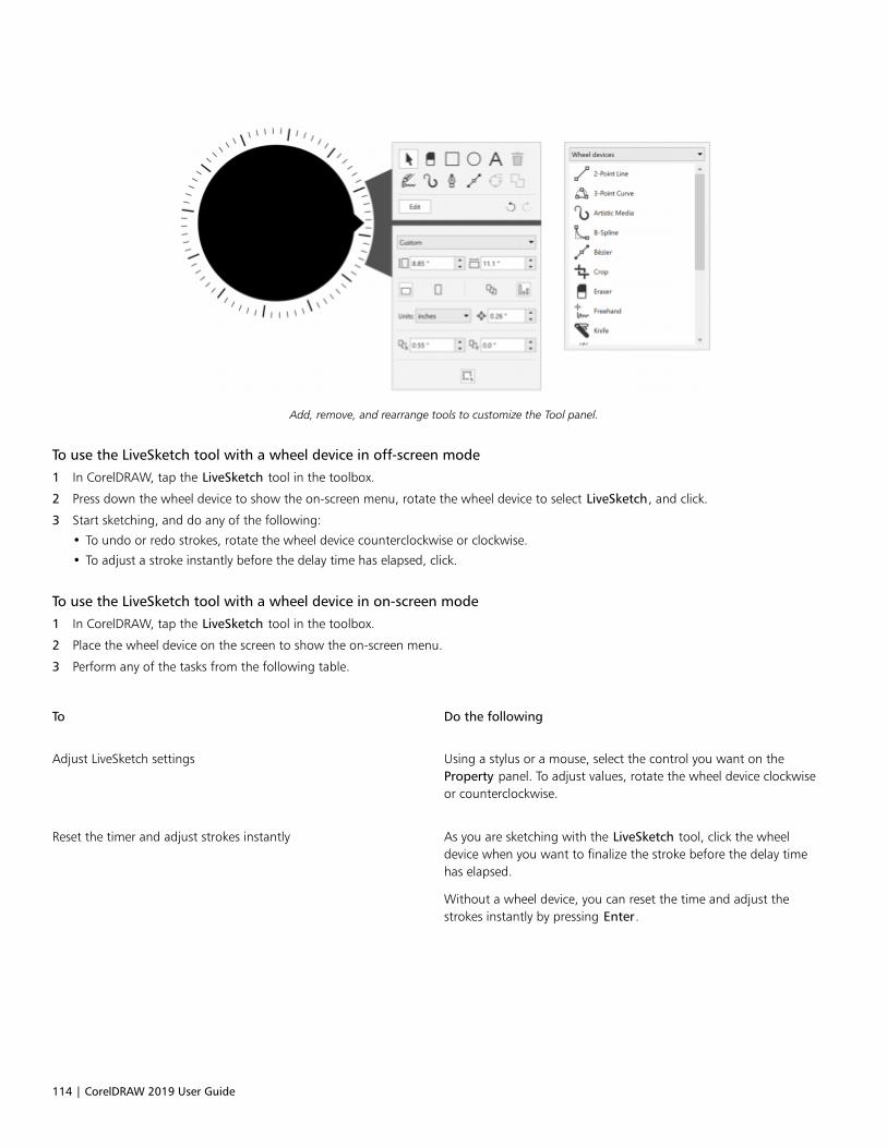
114 | CorelDRAW 2019 User Guide
Add, remove, and rearrange tools to customize the Tool panel.
To use the LiveSketch tool with a wheel device in off-screen mode
1 In CorelDRAW, tap the LiveSketch tool in the toolbox.
2 Press down the wheel device to show the on-screen menu, rotate the wheel device to select LiveSketch, and click.
3 Start sketching, and do any of the following:
• To undo or redo strokes, rotate the wheel device counterclockwise or clockwise.
• To adjust a stroke instantly before the delay time has elapsed, click.
To use the LiveSketch tool with a wheel device in on-screen mode
1 In CorelDRAW, tap the LiveSketch tool in the toolbox.
2 Place the wheel device on the screen to show the on-screen menu.
3 Perform any of the tasks from the following table.
To Do the following
Adjust LiveSketch settings Using a stylus or a mouse, select the control you want on theProperty panel. To adjust values, rotate the wheel device clockwiseor counterclockwise.
Reset the timer and adjust strokes instantly As you are sketching with the LiveSketch tool, click the wheeldevice when you want to finalize the stroke before the delay timehas elapsed.
Without a wheel device, you can reset the time and adjust thestrokes instantly by pressing Enter.
Using a document management system with CorelDRAW Graphics Suite | 115
Using a document management system with CorelDRAW Graphics Suite
CorelDRAW gives you direct access to your organization’s document management system (DMS), such as Microsoft SharePoint, to quicklyretrieve and store documents from within CorelDRAW.
The Document Management feature is available exclusively to customers with licensed CorelSure Maintenance. The DocumentManagement menu commands and toolbar are displayed in CorelDRAW only if the software has been purchased as CorelDRAWGraphics Suite Enterprise license or Subscription license, which includes CorelSure Maintenance.
In this section, you’ll find the following topics:• “Understanding document management systems” (page 115)• “Getting started with Microsoft SharePoint” (page 116)
• “Checking documents in and out of a document library” (page 117)
• “Viewing documents and document properties” (page 118)
Understanding document management systems
A document management system is a server-based computer system that lets organizations store and track their electronic documents. Inother words, a document management system is a secure central location, or virtual filing cabinet, for electronic documents. It lets you easilysearch for and retrieve electronic documents and make them available to others.
A document management system can also include tools that make it easy for a group of people to collaborate on the same documents.For example, some document management systems can track and store multiple versions of documents, so that you can track changes andretrieve previous versions.
Understanding document libraries
In some document management systems, the term “document library” is used to refer to the component that lets you access, store, andretrieve your documents. To access documents, you must know where the document library is located on the server. You can obtain thisinformation from your network administrator, who can provide you with the Web address, or URL, of the document library. The URL has thefollowing format: http://[ServerName]/[Site]/[Name].

116 | CorelDRAW 2019 User Guide
Getting started with Microsoft SharePoint
CorelDRAW gives you direct access to your organization’s Microsoft SharePoint document management system (DMS).
The Document Management feature is available only if your organization has licensed CorelSure Maintenance.
To use your organization’s DMS with CorelDRAW, you must log in to SharePoint by using your SharePoint credentials, not yourCorel.com account credentials.
Saving documents to a document library
You can share Corel DESIGNER (DES) and CorelDRAW (CDR) documents with others by saving them to your organization’s document library.After you save a document to the document library, others can view the document, or check it out, provided they have the permission to doso.
Using the working folder
By default, CorelDRAW places a folder called “Working Files” in My Documents, so the location of the default working folder is as follows:Users\<Your name>\Documents\Working Files
The file you check out is copied to the working folder, and you can modify the file in CorelDRAW from that location. When you are ready tocheck in the changes, the file is copied from the working folder back into the SharePoint document library. For information about checkingout files, see “Checking documents in and out of a document library” on page 11.
You can change the working folder, although you should never need to do so.
You must check in all checked-out files before changing the working folder. If you change the working folder while files are checkedout; you will not be able check them in from within CorelDRAW.
To save a document to a document library for the first time
1 Click File Document Management Save.
2 In the Save dialog box, type the document library URL in the Look in text box, and then press Enter. The URL must have the properformat: http://[ServerName]/[Site]/[Name].
The document library page appears.
3 Browse to the location where you want to save the file.
4 Type a name for the document in the File name box.
5 Click Save.
You can save only CorelDRAW (CDR) documents.
To save the document to a local folder, click File Save As.
To change the working folder
1 Check in all checked-out files.
2 Click Tools Options Global.
Using a document management system with CorelDRAW Graphics Suite | 117
3 In the Global Options dialog box, click File Locations.
4 Click Documents, and click the Browse button , located to the right of the file path.
5 In the Browse for Folder dialog box, navigate to the folder you want.
If you want to move the documents saved to the old location to the new folder, click Yes in the Move Content dialog box.
You can also
Reset the location of the working folder Click Documents, and click Reset.
To display the Document Management toolbar
• Click View Toolbars Document Management.
Checking documents in and out of a document library
The checkout process lets you collaborate with others on the same set of documents. It provides a method for controlling and tracking thechanges that are made to the documents. You can check out a document if it is not already checked out by someone else. By checking out adocument, you can temporarily prevent others from making changes to it.
You can make changes to a document after checking it out. When you are ready for others to view the changes that you made, you cancheck in your version of the document to the document library. After the document is checked in, your version of the document can bechecked out by someone else.
When you check out a document, a copy of the document is saved to your working folder. You can modify this copy of the document andsave the changes locally, without sharing them with others. You can also keep working on the copy of the document when you are offline.You can repeatedly close and reopen the copy without affecting the checkout status and then check in the document when you are onlineagain.
Undoing document checkouts
You can undo a checkout at any time. Undoing a checkout lets you discard all changes that you made to the document since you checked itout. If you choose to keep the document open after undoing a checkout, the working copy becomes a read-only version.
To check a document out of a document library
1 Click File Document Management Open.
The document library Web page appears.
2 Browse to the location of the file that you want to check out.
3 Click the filename.
4 Click Open.
The file appears in Corel DESIGNER as read-only.
The checkout status of the file appears on the Document Management toolbar. The file is ready to be checked out if it is described asChecked In.
5 Click the Check out document button on the Document Management toolbar (View Toolbars Document management).
When you check out a document, a copy of the document is saved to a working folder on your computer.
118 | CorelDRAW 2019 User Guide
To check a document in to a document library
1 Click the Check in document button on the Document Management toolbar.
2 In the Check in document dialog box, type a description of the changes that you made to the document in the Description of changestext box.
If you want to check in the changes but keep working on the document, enable the Keep document checked out after checking in thisversion check box.
If you copy a file to another location and make changes to the file, you will not be able to check in the changes from withinCorelDRAW. Instead, you must either check in the file directly in SharePoint or copy the file to the working folder and then check thefile in from within CorelDRAW.
The availability of major and minor versions depends on the settings of your organization’s document management system.
To undo a document checkout
• Click the Undo checkout button on the Document Management toolbar.
Undoing a checkout discards all the changes you made to the document. If you want to save a copy of the document thathas your changes to a local folder, click File Save As.
Viewing documents and document properties
You can view a document stored on SharePoint by opening it as a read-only file. In addition, you can view document information, such asthe document title, name, creation date, percentage of completion, and version description. The document properties that are displayedmay vary depending on the document library settings.
To view and edit document properties
1 Open the document by clicking File Document Management Open.
2 Click the Document properties button on the Document Management toolbar (View Toolbars Document Management).
You can modify any available editable properties in the Document Properties dialog box.

Lines, shapes, and outlines | 119
Lines, shapes, and outlines
Lines, outlines, and brushstrokes......................................................................................................................................................... 121
Shapes................................................................................................................................................................................................. 163
Shape objects...................................................................................................................................................................................... 175
Symmetrical drawing........................................................................................................................................................................... 237

120 | CorelDRAW 2019 User Guide
Lines, outlines, and brushstrokes | 121
Lines, outlines, and brushstrokes
CorelDRAW lets you add lines and brushstrokes by using a variety of techniques and tools. After you draw lines or apply brushstrokes tolines, you can format them. You can also format the outlines that surround objects.
CorelDRAW provides preset objects that you can spray along a line. You can also create flow and dimension lines in drawings.
This section contains the following topics:• “Lines” (page 121)• “Calligraphic and preset lines” (page 130)• “LiveSketch” (page 132)• “Format lines and outlines” (page 138)• “Add arrowheads to lines and curves” (page 143)• “Copy, convert, remove, and replace outlines” (page 145)• “Brushstrokes” (page 148)• “Brushstrokes and stylus input” (page 149)• “Spray objects along a line” (page 151)• “Connector and callout lines” (page 153)• “Dimension lines” (page 157)• “Pressure-sensitive pens and devices” (page 160)
You can draw lines by using shape recognition. For more information, see “Use shape recognition” on page 172.
You can also draw lines with precision by using object coordinates. For more information, see “Use object coordinates to draw and modifyobjects” on page 262.
Lines
A line is a path between two points. Lines can consist of multiple segments, and the line segments can be curved or straight. The linesegments are connected by nodes, which are depicted as small squares. CorelDRAW provides various drawing tools that let you draw curvedand straight lines, and lines containing both curved and straight segments.
Freehand and Polyline tools
The Freehand and Polyline tools let you draw freehand lines as if you were sketching on a sketchpad. If you make a mistake while
drawing freehand curves, you can erase the unwanted part immediately and continue drawing. When drawing straight lines or segments,you can constrain them to straight vertical or horizontal lines.
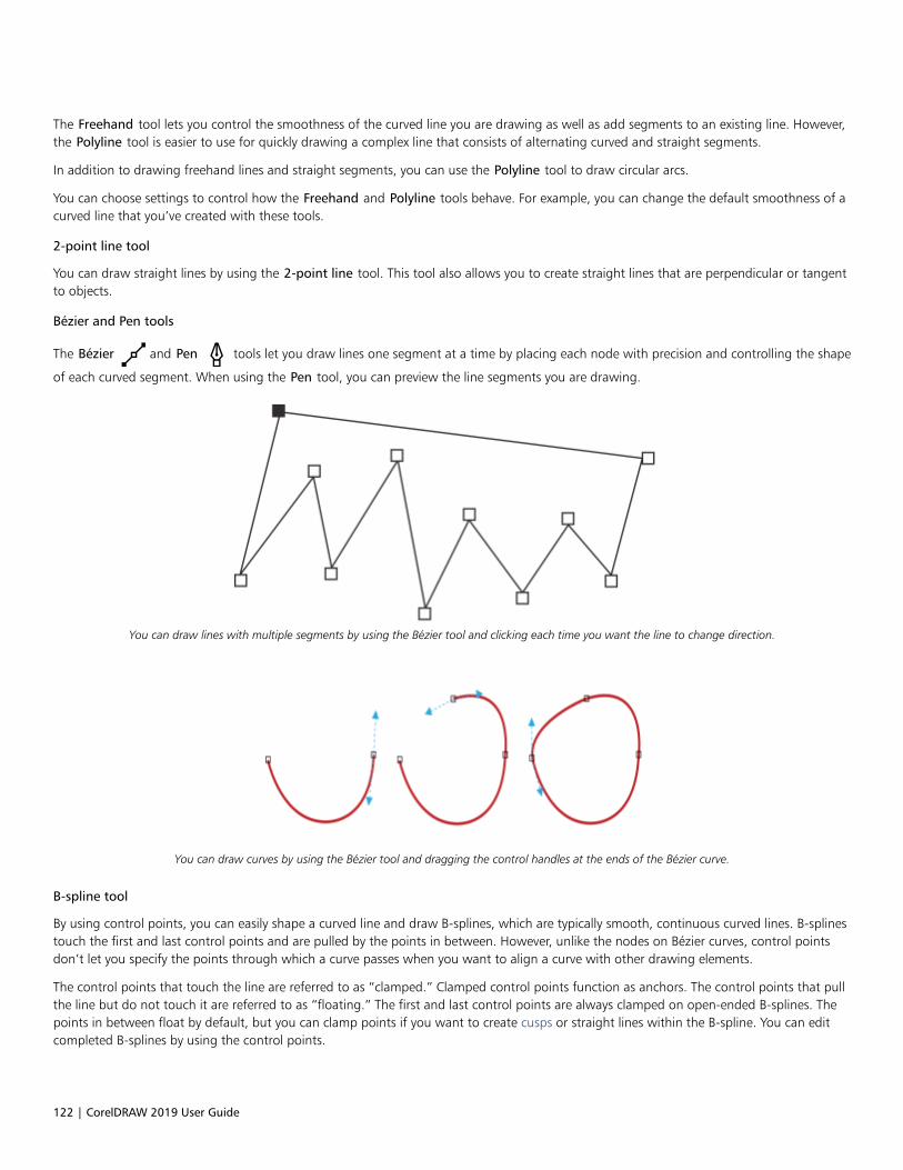
122 | CorelDRAW 2019 User Guide
The Freehand tool lets you control the smoothness of the curved line you are drawing as well as add segments to an existing line. However,the Polyline tool is easier to use for quickly drawing a complex line that consists of alternating curved and straight segments.
In addition to drawing freehand lines and straight segments, you can use the Polyline tool to draw circular arcs.
You can choose settings to control how the Freehand and Polyline tools behave. For example, you can change the default smoothness of acurved line that you’ve created with these tools.
2-point line tool
You can draw straight lines by using the 2-point line tool. This tool also allows you to create straight lines that are perpendicular or tangentto objects.
Bézier and Pen tools
The Bézier and Pen tools let you draw lines one segment at a time by placing each node with precision and controlling the shape
of each curved segment. When using the Pen tool, you can preview the line segments you are drawing.
You can draw lines with multiple segments by using the Bézier tool and clicking each time you want the line to change direction.
You can draw curves by using the Bézier tool and dragging the control handles at the ends of the Bézier curve.
B-spline tool
By using control points, you can easily shape a curved line and draw B-splines, which are typically smooth, continuous curved lines. B-splinestouch the first and last control points and are pulled by the points in between. However, unlike the nodes on Bézier curves, control pointsdon’t let you specify the points through which a curve passes when you want to align a curve with other drawing elements.
The control points that touch the line are referred to as “clamped.” Clamped control points function as anchors. The control points that pullthe line but do not touch it are referred to as “floating.” The first and last control points are always clamped on open-ended B-splines. Thepoints in between float by default, but you can clamp points if you want to create cusps or straight lines within the B-spline. You can editcompleted B-splines by using the control points.
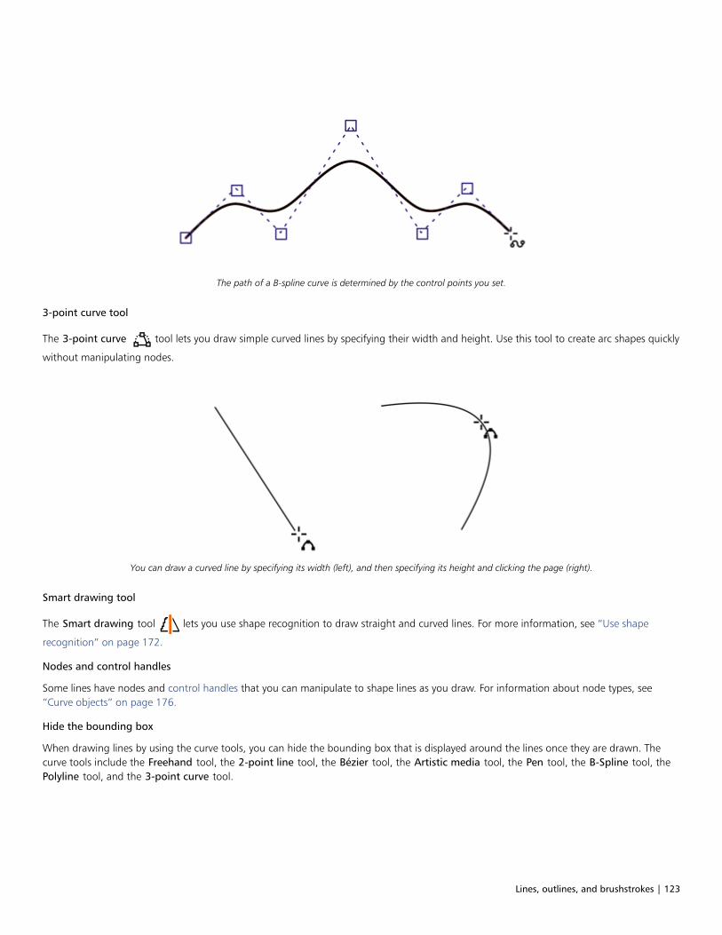
Lines, outlines, and brushstrokes | 123
The path of a B-spline curve is determined by the control points you set.
3-point curve tool
The 3-point curve tool lets you draw simple curved lines by specifying their width and height. Use this tool to create arc shapes quickly
without manipulating nodes.
You can draw a curved line by specifying its width (left), and then specifying its height and clicking the page (right).
Smart drawing tool
The Smart drawing tool lets you use shape recognition to draw straight and curved lines. For more information, see “Use shape
recognition” on page 172.
Nodes and control handles
Some lines have nodes and control handles that you can manipulate to shape lines as you draw. For information about node types, see“Curve objects” on page 176.
Hide the bounding box
When drawing lines by using the curve tools, you can hide the bounding box that is displayed around the lines once they are drawn. Thecurve tools include the Freehand tool, the 2-point line tool, the Bézier tool, the Artistic media tool, the Pen tool, the B-Spline tool, thePolyline tool, and the 3-point curve tool.

124 | CorelDRAW 2019 User Guide
You can hide the bounding box to make drawing artistic media strokes in quick succession more fluid.
To draw a line by using the Freehand tool
1 In the toolbox, click the Freehand tool .
2 Perform a task from the following table.
To Do the following
Draw a curved line Click where you want to start the curved line, and drag.
Draw a straight line Click where you want to start the line, and then click where youwant the line to end.
Control the smoothness of a curved line Type a value in the Freehand smoothing box on the property bar.Higher values produce smoother curves.
Reposition a line Hold down both the left and right mouse buttons, and drag theline to a new position.
Place a copy of a line in the drawing Hold down the right mouse button, and drag the line to a newposition. Click Copy here.
Add line segments to an existing line Click the end node of a selected line, and click where you want thenew segment to end.
Create a closed shape from two or more connected lines In a line that contains two segments, click the end node, and thenclick the start node.
You can constrain a line created with the Freehand tool to a predefined angle, called a constrain angle, by holding down Ctrl whileyou drag. This feature is useful for drawing straight vertical and horizontal lines. For information about changing the constrain angle,see “To change the constrain angle” on page 306.
You can erase a portion of a curved freehand line by holding down Shift and dragging backward over the line before releasing themouse button.

Lines, outlines, and brushstrokes | 125
To draw a line by using the Polyline tool
1 In the toolbox, click the Polyline tool .
2 Do one of the following:
• To draw a straight segment, click where you want to start the line segment, and then click where you want to end it.
• To draw a curved segment, click where you want to start the segment, and drag across the drawing page.
You can add as many segments as you want and alternate between curved and straight segments.
3 Double-click to end the line.
You can also
Reposition a line while drawing Hold down both the left and right mouse buttons, and drag theline to a new position.
Place a copy of a line in the drawing Hold the right mouse button, and drag the line to a new position.Click Copy here.
Before you create a curved segment, click the Auto-close curve button on the property bar to automatically close an open
object.
To draw an arc by using the Polyline tool
1 In the toolbox, click the Polyline tool .
2 Click in the drawing window, and then release the mouse button.
3 Hold down Alt, and move the pointer to create an arc.
4 Do one of the following:
• Click to finish the arc, and release Alt to return to freehand drawing.
• Click to finish the arc, and, without releasing Alt, move the pointer to draw another arc.
5 Double-click to end the line.
You can hold down Ctrl in conjunction with Alt to constrain the arc to 15-degree increments or another predefined angle, called aconstrain angle. For information about changing the constrain angle, see “Constrain objects” on page 305.
To draw a straight line by using the 2-point line tool
1 In the toolbox, click the 2-point line tool .
2 Point to where you want to start the line, and drag to draw the line.
As you drag, the length and angle of the segment appears in the status bar. If you’re adding to a line, the total length for all segmentsalso appears.
To draw a perpendicular line
1 In the toolbox, click the 2-point line tool .

126 | CorelDRAW 2019 User Guide
2 On the property bar, click the Perpendicular 2-point line button.
3 Click the edge of an object, and drag to where you want the line to end.
If you want to draw a line that is perpendicular to two objects, drag to the edge of the second object, and release the mouse buttonwhen the perpendicular snap point appears.
To extend the line beyond the second object, hold down Ctrl when the perpendicular snap point appears, and drag to where you wantthe line to end.
This procedure cannot be used for drawing a line that is perpendicular to the baseline of a text object.
You can also drag from an existing curve to draw a perpendicular line.
Drawing perpendicular lines
To draw a tangent line
1 In the toolbox, click the 2-point line tool .
2 On the property bar, click the Tangential 2-point line button .
3 Click the edge of a curved segment in an object, and drag to where you want the tangent line to end.
If you want to draw a line that is tangent to two objects, drag to the edge of the second object, and release the mouse button when thetangent snap point appears. When the quadrant snap point coincides with tangent snap point, the quadrant snap point appears.
To extend the line beyond the second object, hold down Ctrl when the tangent snap point appears, and drag to where you want the lineto end.
The Tangential 2-point line mode can be used for drawing the sides of the cylinder.

Lines, outlines, and brushstrokes | 127
Drawing tangent lines
To draw a line by using the Bézier tool
1 In the toolbox, click the Bézier tool .
2 Do one of the following:
• To draw a curved segment, click where you want to place the first node, and drag the control handle to where you want to place thenext node. Release the mouse button, and drag the control handle to create the curve.
• To draw a straight segment, click where you want to start the line segment, and click where you want to end it.
You can add as many segments as you want.
3 Press the Spacebar to finish the line.
You can also
Draw a curved segment followed by a straight segment Draw a curved segment, double-click the end node, and click whereyou want the straight segment to end.
Draw a straight segment followed by a curved segment Draw a straight segment. Click the endpoint of the segment, dragto where you want, and release the mouse button. Drag to draw acurve.
Change curve angle to preset increments as you draw While holding down Ctrl, drag a control handle.
To draw a line by using the Pen tool
1 In the toolbox, click the Pen tool .
2 Do one of the following:
• To draw a curved segment, click where you want to place the first node, and drag the control handle to where you want to place thenext node. Release the mouse button, and drag the control handle to create the curve you want.
• To draw a straight segment, click where you want to start the line segment, and click where you want to end it.
You can add as many segments as you want and alternate between curved and straight segments. For more information aboutalternating curved and straight segments, see “To draw a line by using the Bézier tool” on page 127.
3 Double-click to finish the line.

128 | CorelDRAW 2019 User Guide
You can also
Preview a line while drawing Enable the Preview mode button in the property bar. Click on thedrawing page, and release the mouse button. Move the mouse,and click to finish the line.
Add a node to a line Enable the Automatically add or delete nodes button on the
property bar. Point to where in the line you want to add a node,
and click when the pointer changes to the Add nodes state .
Delete a node from a line Point to a node, and click when the pointer changes to the Delete
nodes state .
To draw a B-spline
1 In the toolbox, click the B-spline tool .
2 Click where you want to start the line.
3 Click to set as many control points as you need to shape your line.
Control points float by default, but you can clamp control points to the line by pressing V while clicking.
4 Double-click to finish the line.
Pressing Esc cancels the line instead of finishing it.
You can also
Reshape the line by using control points Select the line by using the Shape tool , and reposition the
control points to reshape the line.
Float a control point Select the line by using the Shape tool , click a clamped
control point, and click the Make control point floating button
on the property bar.
Clamp a control point Select the line by using the Shape tool , click a floating control
point, and click the Make control point clamped button on
the property bar.
Add a control point Select the line by using the Shape tool , and double-click
along a control line.
Delete a control point Select the line by using the Shape tool , and double-click the
control point that you want to delete.

Lines, outlines, and brushstrokes | 129
You can also
Select multiple control points Select the line by using the Shape tool , and hold down Shift
while you click on the control points that you want to select.
If you add to a B-spline by selecting the first or last control point, the clamped control point automatically changes to a floatingcontrol point as you draw the new portion of the line.
You can also add control points while you draw a B-spline by pressing Spacebar instead of clicking.
To draw a curve by using the 3-point curve tool
1 In the toolbox, click the 3-point curve tool .
2 Click where you want to start the curve, and drag to where you want the curve to end.
3 Release the mouse button, and click where you want the center of the curve to be.
You can also
Draw a circular curve Hold down Ctrl while dragging.
Draw a symmetrical curve Hold down Shift while dragging.
To set options for the Freehand and Bézier tools
1 Click Tools Options Tools.
2 In the left pane of the dialog box that appears, click Freehand /Bézier.
3 Move the Freehand smoothing slider to set the default smoothness for curved lines.
Higher values produce smoother curves.
4 Specify a value in any of the following boxes:
• Corner threshold — to set the value at which a corner node changes from cusp to smooth
• Straight line threshold — to set the amount by which a line can deviate from a straight path and still be treated as a straight line
• Auto-join — to set how close two end nodes must be to join automatically, forming a closed curve
Double-click the Freehand or Bézier tool to display the Freehand/Bézier page in the Options dialog box.
To hide the bounding box when using curve tools
1 In the toolbox, click one of the following curve tools:
• Freehand
• 2-point line
• Bézier
• Artistic Media
• Pen

130 | CorelDRAW 2019 User Guide
• B-Spline
• Polyline
• 3-point curve
2 Click the Bounding box button on the property bar.
When you hide the bounding box while working with one curve tool, the bounding box remains hidden for all curve tools. Forexample, if you hide the bounding box when using the Freehand tool, it remains hidden when you switch to the Bézier tool.
You can also hide the bounding box by clicking Tools Options CorelDRAW, clicking Display and then enabling the Hidebounding box for curve tools check box.
Calligraphic and preset lines
CorelDRAW lets you simulate the effect of a calligraphic pen when you draw lines. Calligraphic lines vary in thickness according to thedirection of the line and the angle of the pen nib. By default, calligraphic lines appear as closed shapes drawn with a pencil. You can controlthe thickness of a calligraphic line by changing the angle of the line you draw in relation to the calligraphic angle you choose. For example,when the line you draw is perpendicular to the calligraphic angle, the line is at the maximum thickness specified by the pen width. Linesdrawn at the calligraphic angle, however, have little or no thickness.
A calligraphic pen allows you to draw lines of various thicknesses.
CorelDRAW lets you create pressure-sensitive lines which vary in thickness. For more information, see “Brushstrokes and stylus input” onpage 149.

Lines, outlines, and brushstrokes | 131
A flower drawn by using three different artistic media lines: calligraphic lines (left),pressure-sensitive lines of variable thickness (center), and flat preset lines (right).
CorelDRAW provides preset lines that let you create thick strokes in a variety of shapes. After you draw a calligraphic or preset line, you canapply a fill to it as you would to any other object. For information about applying fills, see “Fills” on page 365.
To draw a calligraphic line
1 In the toolbox, click the Artistic media tool .
2 Click the Calligraphic button on the property bar.
3 Type a value in the Calligraphic angle box on the property bar.
4 Drag until the line is the shape you want.
You can also
Set the width of the line Type a value in the Stroke width box on the property bar.
Smooth the edges of the line Type a value in the Freehand smoothing box on the property bar.
Apply transformations to line thickness when scaling Click the Scale stroke with object button on the property bar.
The width you set is the maximum line width. The angle of the line you draw in relation to the calligraphic angle determines the line’sactual width.
To draw a preset line
1 In the toolbox, click the Artistic media tool .
2 Click the Preset button on the property bar.
3 Choose a preset line from the Preset stroke list box.
4 Drag until the line is the shape you want.

132 | CorelDRAW 2019 User Guide
You can also
Set the width of the line Type a value in the Stroke width box on the property bar.
Smooth the edges of the line Type a value in the Freehand smoothing box on the property bar.
Apply transformations to line thickness when scaling Click the Scale stroke with object button on the property bar.
You can also choose preset lines from the Artistic Media docker. You can open the Artistic Media docker by clicking Effects Artistic Media.
LiveSketch
The LiveSketch tool offers the simplicity and speed of freehand sketching combined with intelligent stroke adjustment and vector drawing.As you sketch, CorelDRAW analyses the properties, temporal order, and spacial proximity of your input strokes, adjusts them, and convertsthem into Bézier curves.
Perfect for quick sketches and drawings, the LiveSketch tool speeds up your workflow and allows you to focus on the creation process.Instead of being preoccupied with nodes and handles and switching between tools, you can let your creativity flow and achieve the desiredresult quickly and effectively. There is no need to scan your sketches and trace them any more. You can sketch out your design concepts andideas using vector curves right from the get-go.
Whether you have great sketching skills or you are just learning to sketch, CorelDRAW can adjust yourstrokes and help you quickly move your ideas from imagination to reality. Artwork by Andrew Stacey.
CorelDRAW supports the most common drawing styles: discrete overlapping strokes, folded strokes (scribbling back and forth across thesurface, with lines doubling back on each other), chicken scratch (drawing short lines rapidly one after the other to build long lines and largeforms).

Lines, outlines, and brushstrokes | 133
Strokes before (top) and after (bottom) stroke adjustment: discreteoverlapping strokes (left), folded strokes (middle), chicken scratch (right)
To make the most of the LiveSketch tool, use a stylus and customize CorelDRAW to fit your sketching style.
You can specify the time it takes to activate stroke adjustment after you draw one or more strokes. For example, if you set the timer to onesecond and make a few strokes, stroke enhancement will take effect one second after you finish drawing the strokes. The timer creates atemporal window within which the discrete strokes that you make are analyzed and converted into curves. Experiment with the timer to finda setting that best matches your sketching speed and style. If you use multiple small strokes to build up a bigger line, set a short delay timeto create your curves right away and develop a sketching cadence. Alternatively, increase the delay time to 5 seconds and take advantage ofthe live preview to see your input strokes and build upon them. Setting a longer delay period also gives you more time to manipulate yourlines.
With the timer set to 0 milliseconds (left), successive strokes are converted into discretecurves. With the timer set to 1 second (right), successive strokes are joined into a single curve.
You can reset the timer and adjust the strokes before the specified time has elapsed. You can also delete strokes before they have beenadjusted.
As your composition progresses, you may want to re-draw existing lines to change their position and shape or simply to refine them.CorelDRAW lets you modify existing curves by including them into your sketch as new input strokes. You can specify the width of the

134 | CorelDRAW 2019 User Guide
editable area around previously drawn curves. When you sketch within this area, the existing curves are processed along with the other inputstrokes and are readjusted; when you sketch outside the specified distance, your input strokes are added as new objects.
An existing stroke (left); A new stroke (in blue) is created close to theexisting curve (middle); The existing stroke is extended and readjusted (right.)
When you move the pointer inside the editable area of an existingcurve, the curve is highlighted to indicate that you can modify it.
If you need to sketch very close to existing lines or draw over strokes to reinforce them, you can disable proximity-based stroke adjustmenttemporarily or permanently so that strokes are added as separate objects.
Disable proximity-based stroke grouping to keep your strokes as separate objects.
When you include an existing curve into a sketch, the resulting curve inherits the properties of the existing curve.
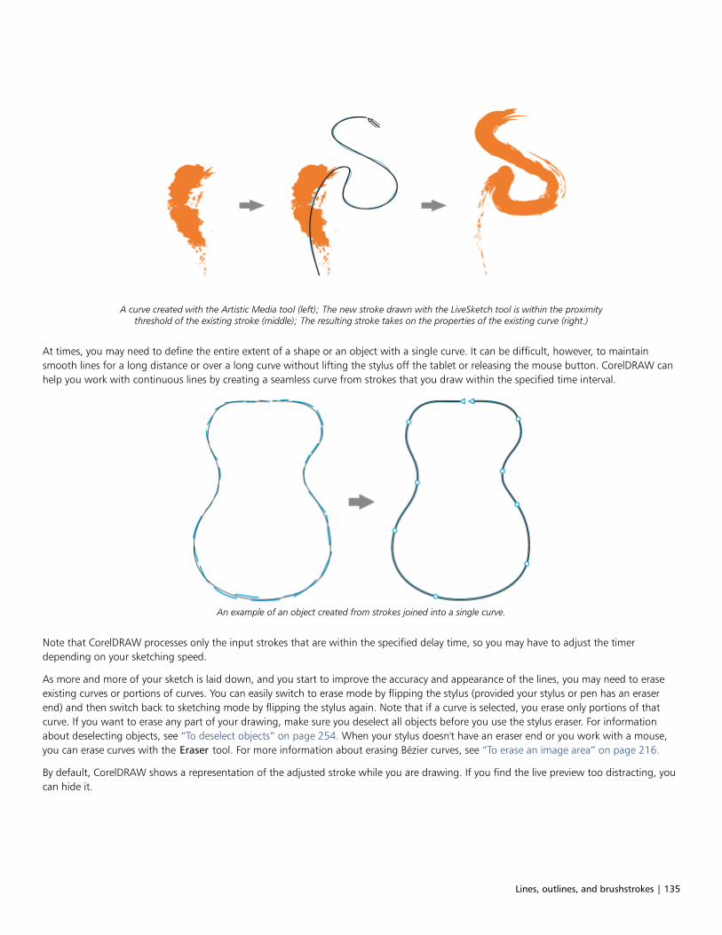
Lines, outlines, and brushstrokes | 135
A curve created with the Artistic Media tool (left); The new stroke drawn with the LiveSketch tool is within the proximitythreshold of the existing stroke (middle); The resulting stroke takes on the properties of the existing curve (right.)
At times, you may need to define the entire extent of a shape or an object with a single curve. It can be difficult, however, to maintainsmooth lines for a long distance or over a long curve without lifting the stylus off the tablet or releasing the mouse button. CorelDRAW canhelp you work with continuous lines by creating a seamless curve from strokes that you draw within the specified time interval.
An example of an object created from strokes joined into a single curve.
Note that CorelDRAW processes only the input strokes that are within the specified delay time, so you may have to adjust the timerdepending on your sketching speed.
As more and more of your sketch is laid down, and you start to improve the accuracy and appearance of the lines, you may need to eraseexisting curves or portions of curves. You can easily switch to erase mode by flipping the stylus (provided your stylus or pen has an eraserend) and then switch back to sketching mode by flipping the stylus again. Note that if a curve is selected, you erase only portions of thatcurve. If you want to erase any part of your drawing, make sure you deselect all objects before you use the stylus eraser. For informationabout deselecting objects, see “To deselect objects” on page 254. When your stylus doesn't have an eraser end or you work with a mouse,you can erase curves with the Eraser tool. For more information about erasing Bézier curves, see “To erase an image area” on page 216.
By default, CorelDRAW shows a representation of the adjusted stroke while you are drawing. If you find the live preview too distracting, youcan hide it.

136 | CorelDRAW 2019 User Guide
In preview mode, CorelDRAW displays the adjusted stroke (in black) before thedelay time has elapsed and the input strokes (in blue) have been processed.
You can control the amount of smoothing applied to curves.
To sketch with the LiveSketch tool
1 In the toolbox, click the LiveSketch tool.
2 Adjust any of the settings on the property bar.
3 Sketch in the document window.
You can also access the LiveSketch tool by pressing S on your keyboard.
To set a delay before input strokes are adjusted
• Move the Timer slider.
By default, the delay is 1000 milliseconds or 1 second. The minimum delay is 0 milliseconds; the maximum is 5 seconds.
Clicking a different tool before the specified delay time has elapsed implements stroke adjustment.
Press Enter to reset the timer and adjust the strokes before the delay time has elapsed.
Press Esc to delete an input stroke before it has been adjusted.
Setting a longer delay period gives you more time to manipulate your lines.
To readjust an existing curve
1 Click the Include curves toggle button on the property bar to enable it.

Lines, outlines, and brushstrokes | 137
2 Move the Distance from curve slider to set the distance at which existing curves are included into a sketch as new input strokes.
3 Sketch over an existing stroke to modify it.
To disable proximity-based stroke adjustment temporarily, hold down Shift and make one or more strokes.
To disable proximity-based stroke enhancement permanently, click the Include curves toggle button on the property bar.
By default, the distance threshold is 5 pixels. The minimum value is 0 pixels; the maximum is 40 pixels.
To create a single curve from strokes
1 Click the Create single curve button on the property bar to allow input strokes to be converted into one continuous line.
2 Sketch in the document window.
For best results, set a longer delay time. CorelDRAW processes only strokes that are within the specified delay time.
To erase a curve
1 Perform a task from the following table.
To Do the following
Erase an area in a drawing Deselect all objects on the drawing page.
Erase portions of a curve Select the curve.
Note: The last curve that you draw before you lift the stylus off thetablet is automatically selected by default.
2 Flip the stylus to automatically switch to erase mode, and stroke over the unwanted areas.
To erase a curve or portions of a curve when your stylus doesn't have an eraser end or when using a mouse, select the curve, click
the Eraser tool in the toolbox, and drag where you want to erase.
You can change the size and shape of the eraser nib. For information, see “To erase an image area” on page 216.
To show or hide a preview of the resulting curve
• Click the Preview mode button on the property bar.
To control curve smoothness
• Type a value in the Curve smoothing box on the property bar.
Higher values produce smoother curves.
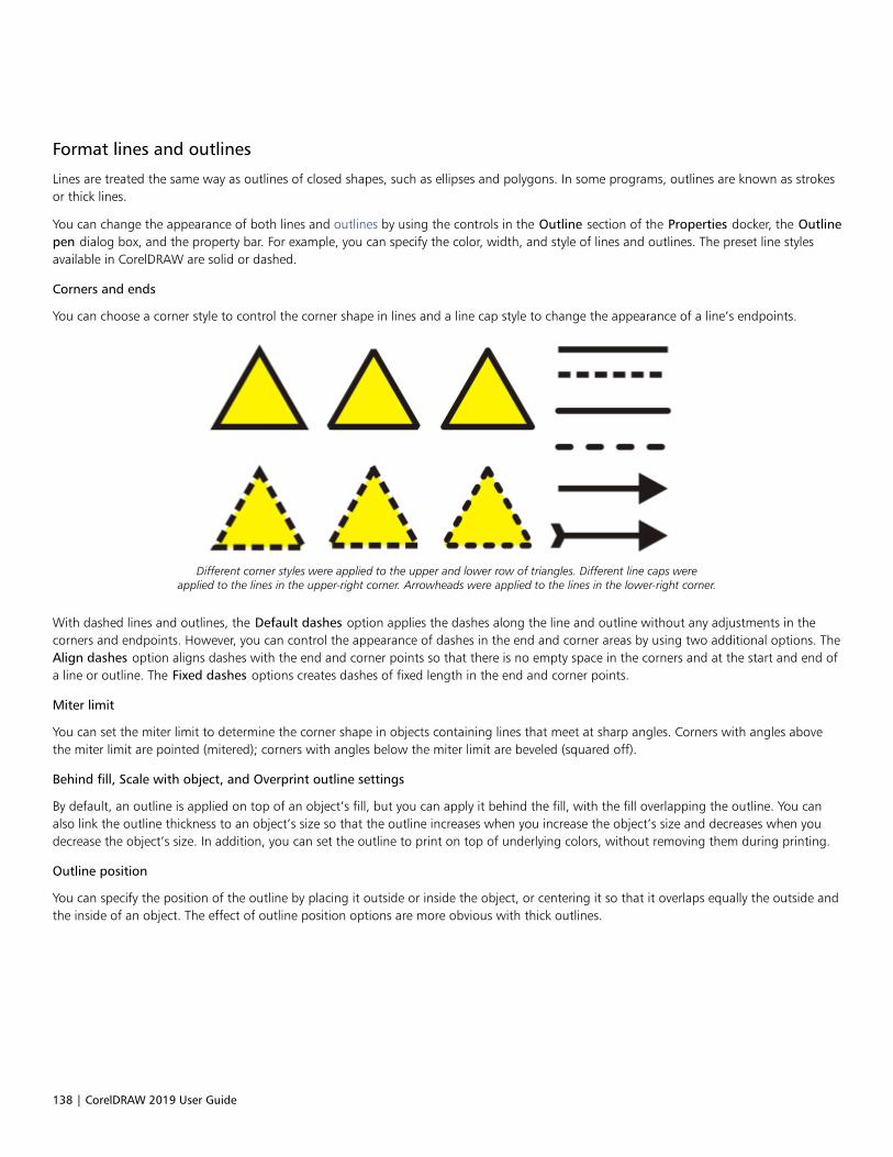
138 | CorelDRAW 2019 User Guide
Format lines and outlines
Lines are treated the same way as outlines of closed shapes, such as ellipses and polygons. In some programs, outlines are known as strokesor thick lines.
You can change the appearance of both lines and outlines by using the controls in the Outline section of the Properties docker, the Outlinepen dialog box, and the property bar. For example, you can specify the color, width, and style of lines and outlines. The preset line stylesavailable in CorelDRAW are solid or dashed.
Corners and ends
You can choose a corner style to control the corner shape in lines and a line cap style to change the appearance of a line’s endpoints.
Different corner styles were applied to the upper and lower row of triangles. Different line caps wereapplied to the lines in the upper-right corner. Arrowheads were applied to the lines in the lower-right corner.
With dashed lines and outlines, the Default dashes option applies the dashes along the line and outline without any adjustments in thecorners and endpoints. However, you can control the appearance of dashes in the end and corner areas by using two additional options. TheAlign dashes option aligns dashes with the end and corner points so that there is no empty space in the corners and at the start and end ofa line or outline. The Fixed dashes options creates dashes of fixed length in the end and corner points.
Miter limit
You can set the miter limit to determine the corner shape in objects containing lines that meet at sharp angles. Corners with angles abovethe miter limit are pointed (mitered); corners with angles below the miter limit are beveled (squared off).
Behind fill, Scale with object, and Overprint outline settings
By default, an outline is applied on top of an object’s fill, but you can apply it behind the fill, with the fill overlapping the outline. You canalso link the outline thickness to an object’s size so that the outline increases when you increase the object’s size and decreases when youdecrease the object’s size. In addition, you can set the outline to print on top of underlying colors, without removing them during printing.
Outline position
You can specify the position of the outline by placing it outside or inside the object, or centering it so that it overlaps equally the outside andthe inside of an object. The effect of outline position options are more obvious with thick outlines.

Lines, outlines, and brushstrokes | 139
You can specify the position of the outline. Outline options from left to right: Outside, Centered, Inside.
Line styles and calligraphic outlines
You can create custom line styles, and you can edit the available preset line styles.
In addition, you can create calligraphic outlines. A calligraphic outline varies in thickness, creating the effect of a hand-made drawing.
Default line and outline properties
The default line and outline properties for each new object that you draw are as follows:• black color• solid line• square corner and line cap styles• centered outline• no arrowheads applied• outline applied on top of an object’s fill• outline not linked to an object’s size.
However, you can change any of these default line and outline properties at any time.
Cuttable outlines
To create a cuttable outline for devices such as plotters, vinyl cutters and Print-Cut devices, you need to assign the appropriate predefinedcolor name (usually CutContour) that is specified by the device manufacturer.
Note that cuttable outlines do not print when identified by the RIP or Print-Cut device. If you want to make the outlines printable, you can
use the Object Shaping Boundary command. For more information, see “To create a boundary around selected objects” on page262.
To change the color of a line or an outline
1 Select a line or an object that has an outline.
2 Right-click a color on the onscreen color palette.
To specify line and outline settings
1 Select an object.
2 Click Window Dockers Properties.
3 In the Outline section, type a value in the Width box.
If the Outline section is not displayed, click Outline.
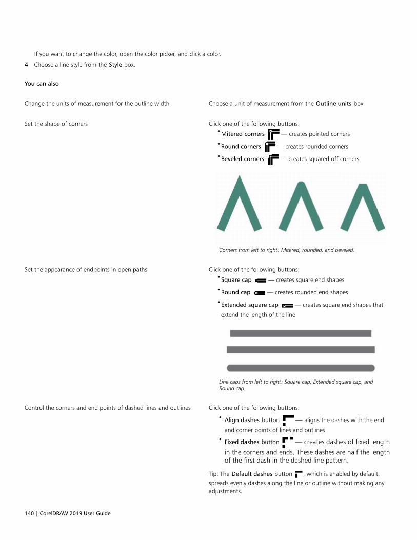
140 | CorelDRAW 2019 User Guide
If you want to change the color, open the color picker, and click a color.
4 Choose a line style from the Style box.
You can also
Change the units of measurement for the outline width Choose a unit of measurement from the Outline units box.
Set the shape of corners Click one of the following buttons:•Mitered corners — creates pointed corners
•Round corners — creates rounded corners
•Beveled corners — creates squared off corners
Corners from left to right: Mitered, rounded, and beveled.
Set the appearance of endpoints in open paths Click one of the following buttons:•Square cap — creates square end shapes
•Round cap — creates rounded end shapes
•Extended square cap — creates square end shapes that
extend the length of the line
Line caps from left to right: Square cap, Extended square cap, andRound cap.
Control the corners and end points of dashed lines and outlines Click one of the following buttons:
• Align dashes button — aligns the dashes with the end
and corner points of lines and outlines
• Fixed dashes button — creates dashes of fixed length
in the corners and ends. These dashes are half the lengthof the first dash in the dashed line pattern.
Tip: The Default dashes button , which is enabled by default,spreads evenly dashes along the line or outline without making anyadjustments.
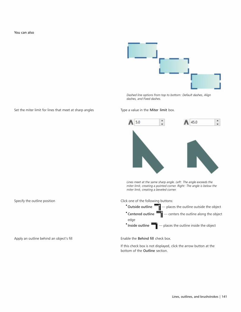
Lines, outlines, and brushstrokes | 141
You can also
Dashed line options from top to bottom: Default dashes, Aligndashes, and Fixed dashes.
Set the miter limit for lines that meet at sharp angles Type a value in the Miter limit box.
Lines meet at the same sharp angle. Left: The angle exceeds themiter limit, creating a pointed corner. Right: The angle is below themiter limit, creating a beveled corner.
Specify the outline position Click one of the following buttons:•Outside outline — places the outline outside the object
•Centered outline — centers the outline along the object
edge•Inside outline — places the outline inside the object
Apply an outline behind an object’s fill Enable the Behind fill check box.
If this check box is not displayed, click the arrow button at thebottom of the Outline section.

142 | CorelDRAW 2019 User Guide
You can also
The Behind fill check box is disabled (left) and enabled (right).
Link the outline thickness to an object’s size Enable the Scale with object check box.
If this check box is not displayed, click the arrow button at thebottom of the Outline section.
Left to right: Original object; scaled object with Scale with objectdisabled — there is no change in the outline thickness; scaled objectwith Scale with object enabled.
Set the outline to print on top of underlying colors during printing Enable the Overprint outline check box.
If this check box is not displayed, click the arrow button at thebottom of the Outline section.
You can also specify line and outline settings in the Outline pen dialog box. To access the Outline pen dialog box, double-click the
Outline icon on the status bar or press F12.
You can also change the outline width of a selected object by typing a value in the Outline width box on the property bar.
To create or edit a line style
1 Select an object.
2 In the Outline section of the Properties docker (Window Dockers Properties), perform a task from the following table.
To Do the following
Create a line style Click the Settings button , and move the slider in the Edit line
style dialog box. By clicking the boxes to the left of the slider, you
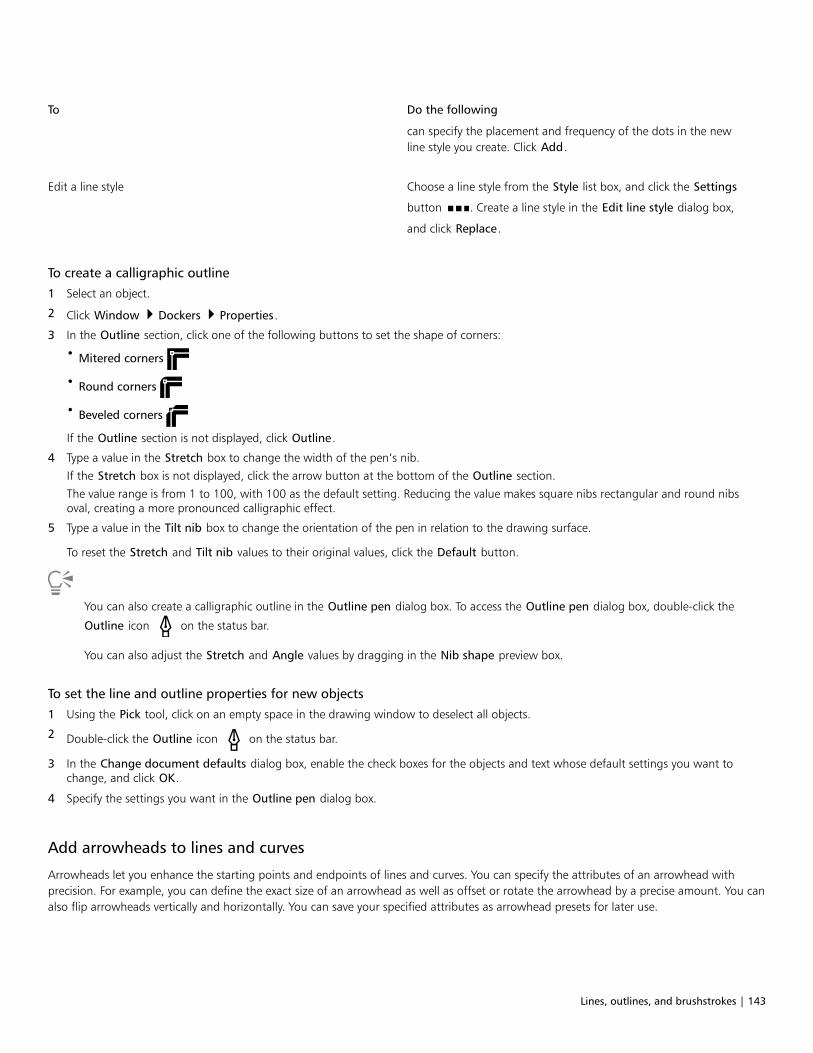
Lines, outlines, and brushstrokes | 143
To Do the following
can specify the placement and frequency of the dots in the newline style you create. Click Add.
Edit a line style Choose a line style from the Style list box, and click the Settings
button . Create a line style in the Edit line style dialog box,
and click Replace.
To create a calligraphic outline
1 Select an object.
2 Click Window Dockers Properties.
3 In the Outline section, click one of the following buttons to set the shape of corners:
• Mitered corners
• Round corners
• Beveled corners
If the Outline section is not displayed, click Outline.
4 Type a value in the Stretch box to change the width of the pen’s nib.
If the Stretch box is not displayed, click the arrow button at the bottom of the Outline section.
The value range is from 1 to 100, with 100 as the default setting. Reducing the value makes square nibs rectangular and round nibsoval, creating a more pronounced calligraphic effect.
5 Type a value in the Tilt nib box to change the orientation of the pen in relation to the drawing surface.
To reset the Stretch and Tilt nib values to their original values, click the Default button.
You can also create a calligraphic outline in the Outline pen dialog box. To access the Outline pen dialog box, double-click the
Outline icon on the status bar.
You can also adjust the Stretch and Angle values by dragging in the Nib shape preview box.
To set the line and outline properties for new objects
1 Using the Pick tool, click on an empty space in the drawing window to deselect all objects.
2 Double-click the Outline icon on the status bar.
3 In the Change document defaults dialog box, enable the check boxes for the objects and text whose default settings you want tochange, and click OK.
4 Specify the settings you want in the Outline pen dialog box.
Add arrowheads to lines and curves
Arrowheads let you enhance the starting points and endpoints of lines and curves. You can specify the attributes of an arrowhead withprecision. For example, you can define the exact size of an arrowhead as well as offset or rotate the arrowhead by a precise amount. You canalso flip arrowheads vertically and horizontally. You can save your specified attributes as arrowhead presets for later use.
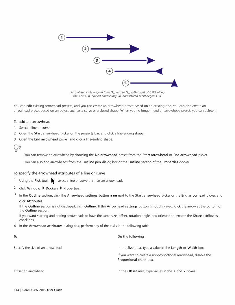
144 | CorelDRAW 2019 User Guide
Arrowhead in its original form (1), resized (2), with offset of 6 0% alongthe x-axis (3), flipped horizontally (4), and rotated at 90 degrees (5).
You can edit existing arrowhead presets, and you can create an arrowhead preset based on an existing one. You can also create anarrowhead preset based on an object such as a curve or a closed shape. When you no longer need an arrowhead preset, you can delete it.
To add an arrowhead
1 Select a line or curve.
2 Open the Start arrowhead picker on the property bar, and click a line-ending shape.
3 Open the End arrowhead picker, and click a line-ending shape.
You can remove an arrowhead by choosing the No arrowhead preset from the Start arrowhead or End arrowhead picker.
You can also add arrowheads from the Outline pen dialog box or the Outline section of the Properties docker.
To specify the arrowhead attributes of a line or curve
1 Using the Pick tool , select a line or curve that has an arrowhead.
2 Click Window Dockers Properties.
3 In the Outline section, click the Arrowhead settings button next to the Start arrowhead picker or the End arrowhead picker, and
click Attributes.
If the Outline section is not displayed, click Outline. If the Arrowhead settings button is not displayed, click the arrow at the bottom ofthe Outline section.
If you want starting and ending arrowheads to have the same size, offset, rotation angle, and orientation, enable the Share attributescheck box.
4 In the Arrowhead attributes dialog box, perform any of the tasks in the following table.
To Do the following
Specify the size of an arrowhead In the Size area, type a value in the Length or Width box.
If you want to create a nonproportional arrowhead, disable theProportional check box.
Offset an arrowhead In the Offset area, type values in the X and Y boxes.
Lines, outlines, and brushstrokes | 145
To Do the following
Mirror an arrowhead In the Mirror area, enable the Horizontally or Vertically check box.
Rotate an arrowhead Specify an angle in the Rotation box.
Save custom arrowhead attributes as an arrowhead preset Enable the Save as arrowhead preset check box.
You can access the new arrowhead preset from the Startarrowhead and End arrowhead pickers on the property bar.
You can switch arrowheads from one end of a line or curve to another by clicking the Arrowhead settings button, and clickingSwap.
You can remove an arrowhead from a line or curve by clicking the Arrowhead settings button and clicking None.
To edit an arrowhead preset
1 Using the Pick tool , select an object that has an arrowhead.
2 Click Window Dockers Properties.
3 In the Outline section, click the Arrowhead settings button next to the Start arrowhead picker or the End arrowhead picker, and clickEdit.
If the Outline section is not displayed, click Outline. If the Start arrowhead picker is not displayed, click the arrow at the bottom of theOutline section.
4 In the Arrowhead attributes dialog box, specify the attributes you want.
You can create an arrowhead preset that is based on an existing preset. Click Arrowhead settings button, and click New. Then,specify the attributes you want in the Arrowhead attributes dialog box, and type a preset name in the Save arrowhead area.
To delete an arrowhead preset, select the preset from the Start or End arrowhead picker, click the Arrowhead settings button, andclick Delete.
To create an arrowhead preset from an object
1 Select an object to use as an arrowhead.
2 Click Object Create Arrowhead.
3 In the Create arrowhead dialog box, type a value in the Length box or Width box.
If you want to create a nonproportional arrowhead, disable the Proportional check box, and type values in both the Length and Widthboxes.
Copy, convert, remove, and replace outlines
CorelDRAW lets you copy outline properties to other objects.
You can also convert an outline to an object, and you can remove an outline. Converting an outline to an object creates an unfilled closedobject with the outline’s shape. You can apply fills and special effects to the new object. You can search for objects based on their outlinewidth and color and replace those properties.
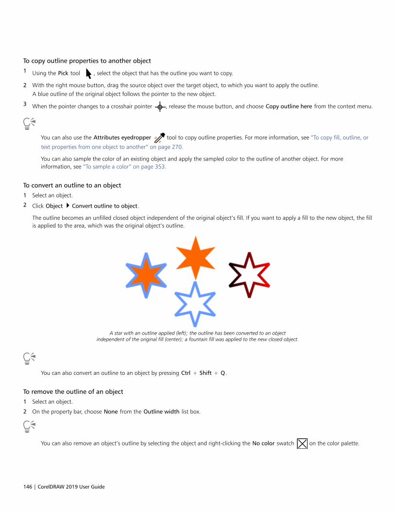
146 | CorelDRAW 2019 User Guide
To copy outline properties to another object
1 Using the Pick tool , select the object that has the outline you want to copy.
2 With the right mouse button, drag the source object over the target object, to which you want to apply the outline.
A blue outline of the original object follows the pointer to the new object.
3 When the pointer changes to a crosshair pointer , release the mouse button, and choose Copy outline here from the context menu.
You can also use the Attributes eyedropper tool to copy outline properties. For more information, see “To copy fill, outline, or
text properties from one object to another” on page 270.
You can also sample the color of an existing object and apply the sampled color to the outline of another object. For moreinformation, see “To sample a color” on page 353.
To convert an outline to an object
1 Select an object.
2 Click Object Convert outline to object.
The outline becomes an unfilled closed object independent of the original object’s fill. If you want to apply a fill to the new object, the fillis applied to the area, which was the original object’s outline.
A star with an outline applied (left); the outline has been converted to an objectindependent of the original fill (center); a fountain fill was applied to the new closed object.
You can also convert an outline to an object by pressing Ctrl + Shift + Q.
To remove the outline of an object
1 Select an object.
2 On the property bar, choose None from the Outline width list box.
You can also remove an object’s outline by selecting the object and right-clicking the No color swatch on the color palette.
Lines, outlines, and brushstrokes | 147
To find and replace outline widths
1 Click Edit Find and Replace.
2 In the Find and Replace docker, choose Replace Objects from the list box at the top of the docker.
3 Enable the Outline properties option.
4 Enable the Outline width check box in the Find area.
5 Specify the outline width to find.
6 Enable the Outline width check box in the Replace area, and specify the replacement outline width.
7 Click Find, and click any of the following:
• Find Next > or Find Previous < to scroll through objects that meet the outline-search criteria.
• Find All to select all objects that meet the outline-search criteria.
• Replace to replace the outline of the selected object.
• Replace All to replace all outlines that meet the outline-search criteria.
You can also
Find and replace outline-scaling settings Enable the Scale width with image check box in the Find area,and specify the setting to find. Then, enable the Scale width withimage check box in the Find area, and specify the replacementsetting.
Find and replace outline-overprint settings Enable the Outline overprint check box in the Find area, andspecify the setting to find. Then, enable the Outline overprintcheck box in the Find area, and specify the replacement setting.
To find and replace outline colors
1 Click Edit Find and Replace.
2 In the Find and Replace docker, choose Replace Objects from the list box at the top of the docker.
3 Enable the Color option.
4 Choose the color to find in the Find color picker.
5 Enable the Outlines option in the Replace area.
6 Choose the replacement color to find in the Replace with picker.
To include monochrome bitmaps in the search, enable the Apply to monochrome bitmaps check box.
7 Click Find, and click any of the following:
• Find Next or Find Previous to scroll through objects that meet the outline-search criteria.
• Find All to select all objects that meet the outline-search criteria.
• Replace to replace the outline color on the selected object.
• Replace All to replace the color of all outlines that meet the outline-search criteria.
You can also
Find and replace an outline’s color model Enable the Color Model or Palette option, enable the Specificcolor model option in the Find area, choose the color model tofind, and choose the replacement color model from the Replacewith list box.

148 | CorelDRAW 2019 User Guide
You can also
Find an outline’s color palette and replace it with a color model Enable the Color Model or Palette option, enable the Specificcolor palette option in the Find area, choose the color model tofind, and choose the replacement color model from the Replacewith list box.
Brushstrokes
CorelDRAW lets you apply a variety of preset brushstrokes, ranging from strokes with arrowheads to ones that are filled with rainbowpatterns. When you draw a preset brushstroke, you can specify some of its attributes. For example, you can change the width of abrushstroke and specify its smoothness.
You can also create custom brushstrokes by using an object or a group of vector objects. When you create a custom brushstroke, you cansave it as a preset.
The above image was created by using many different brushstrokes and widths.
To apply a preset brushstroke
1 In the toolbox, click the Artistic media tool .
2 Click the Brush button on the property bar.
3 Choose a brush category from the Category list box.
4 Choose a brushstroke from the Brushstroke list box.
5 Drag until the stroke is the shape you want.
You can also
Set the width of the brushstroke Type a value in the Stroke width box on the property bar.
Smooth the edges of the brushstroke Type a value in the Freehand smoothing box on the property bar.
Apply transformations to brushstroke thickness when scaling Click the Scale stroke with object button on the property bar.
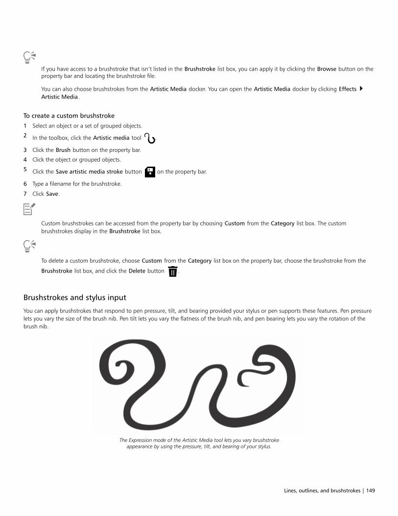
Lines, outlines, and brushstrokes | 149
If you have access to a brushstroke that isn’t listed in the Brushstroke list box, you can apply it by clicking the Browse button on theproperty bar and locating the brushstroke file.
You can also choose brushstrokes from the Artistic Media docker. You can open the Artistic Media docker by clicking Effects Artistic Media.
To create a custom brushstroke
1 Select an object or a set of grouped objects.
2 In the toolbox, click the Artistic media tool .
3 Click the Brush button on the property bar.
4 Click the object or grouped objects.
5 Click the Save artistic media stroke button on the property bar.
6 Type a filename for the brushstroke.
7 Click Save.
Custom brushstrokes can be accessed from the property bar by choosing Custom from the Category list box. The custombrushstrokes display in the Brushstroke list box.
To delete a custom brushstroke, choose Custom from the Category list box on the property bar, choose the brushstroke from the
Brushstroke list box, and click the Delete button .
Brushstrokes and stylus input
You can apply brushstrokes that respond to pen pressure, tilt, and bearing provided your stylus or pen supports these features. Pen pressurelets you vary the size of the brush nib. Pen tilt lets you vary the flatness of the brush nib, and pen bearing lets you vary the rotation of thebrush nib.
The Expression mode of the Artistic Media tool lets you vary brushstrokeappearance by using the pressure, tilt, and bearing of your stylus.

150 | CorelDRAW 2019 User Guide
You can use pen pressure, tilt, and bearing at the same time, or you can use only one or two of these features. For example, you can use penpressure to vary the size of the brush nib, but disable pen tilt so that the flatness of the brush nib does not change. You can set a fixed valuefor pen tilt to flatten the nib. Disabling pen pressure lets you set a fixed nib size. Disabling pen bearing lets you use a nib of fixed rotation.
To apply a brushstroke that responds to pen pressure, tilt, and bearing
1 In the toolbox, click the Artistic media tool .
2 Click the Expression button on the property bar.
3 Make sure the following buttons on the property bar are enabled:
• Pen pressure — lets you vary the size of the brush nib. If you are using the mouse, press the Up arrow or Down arrow to
simulate changes in pen pressure and change the width of the stroke.
• Pen tilt — lets you vary the flatness of the nib
• Pen bearing — lets you vary the rotation of the brush nib
4 Drag until the stroke is the shape you want.
You can also
Change the width of the stroke Type a value in the Stroke width box on the property bar.
Change the stroke width when scaling the object Click the Scale stroke with object button on the property bar.
The width you set represents the stroke’s maximum width. The amount of pressure you apply determines the actual size of the brushnib.
You can use pen tilt and pen bearing to vary brushstrokes only if your stylus or pen supports these features.
To use a brush nib of fixed width, flatness, or rotation
1 In the toolbox, click the Artistic media tool .
2 Click the Expression button on the property bar.
3 Perform a task from the following table.
To Do the following
Set the size of the brush nib Click the Pen pressure button on the property bar to disable
it. Type a value in the Stroke width box.
Flatten the brush nib by using a fixed value for pen tilt Click the Pen tilt button on the property bar to disable it. Type
a value in the Tilt angle box.
Use a value between 15 and 90 degrees.
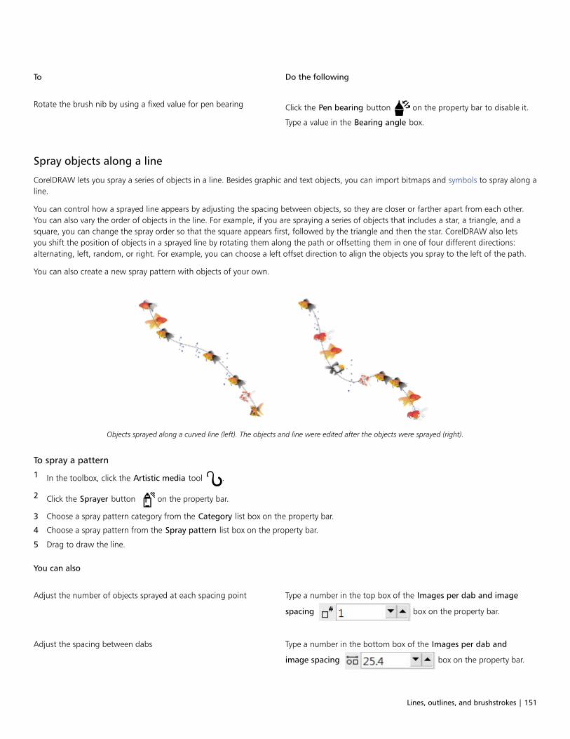
Lines, outlines, and brushstrokes | 151
To Do the following
Rotate the brush nib by using a fixed value for pen bearing Click the Pen bearing button on the property bar to disable it.
Type a value in the Bearing angle box.
Spray objects along a line
CorelDRAW lets you spray a series of objects in a line. Besides graphic and text objects, you can import bitmaps and symbols to spray along aline.
You can control how a sprayed line appears by adjusting the spacing between objects, so they are closer or farther apart from each other.You can also vary the order of objects in the line. For example, if you are spraying a series of objects that includes a star, a triangle, and asquare, you can change the spray order so that the square appears first, followed by the triangle and then the star. CorelDRAW also letsyou shift the position of objects in a sprayed line by rotating them along the path or offsetting them in one of four different directions:alternating, left, random, or right. For example, you can choose a left offset direction to align the objects you spray to the left of the path.
You can also create a new spray pattern with objects of your own.
Objects sprayed along a curved line (left). The objects and line were edited after the objects were sprayed (right).
To spray a pattern
1 In the toolbox, click the Artistic media tool .
2 Click the Sprayer button on the property bar.
3 Choose a spray pattern category from the Category list box on the property bar.
4 Choose a spray pattern from the Spray pattern list box on the property bar.
5 Drag to draw the line.
You can also
Adjust the number of objects sprayed at each spacing point Type a number in the top box of the Images per dab and image
spacing box on the property bar.
Adjust the spacing between dabs Type a number in the bottom box of the Images per dab and
image spacing box on the property bar.

152 | CorelDRAW 2019 User Guide
You can also
Set the spray order Choose a spray order from the Spray order list box on the propertybar.
Adjust the size of spray objects Type a number in the top box of the Size of sprayed objects boxon the property bar.
Increase or decrease the size of the spray objects as they progressalong the line
Type a number in the bottom box of the Size of sprayed objectsbox on the property bar.
Apply transformations to spray line thickness when scaling Click the Scale stroke with object button on the property bar.
Increasing the value for the size of spray objects along the line causes objects to become larger as they are distributed along the path.
Spray patterns that have more complex objects use more system resources. CorelDRAW requires more time to produce lines whencomplex objects are used, and these objects increase the file size. Using symbols for each group in the list can help reduce file sizeand ease the demands on your system. For more information about creating symbols, see “Symbols” on page 327.
You can also choose spray patterns from the Artistic Media docker. You can open the Artistic Media docker by clicking Effects Artistic Media.
To rotate the lines that you spray
1 Select the spray pattern that you want to adjust.
2 Click the Rotation button on the property bar.
3 Type a value between 0 and 360 in the Angle box on the property bar.
If you want each object in the spray to rotate incrementally, enable the Use Increment check box and type a value in the Increment box.
4 Enable one of the following options:
• Relative to path — rotates objects in relation to the line
• Relative to page — rotates objects in relation to the page
5 Press Enter.
To offset the lines that you spray
1 Select a spray pattern.
2 Click the Offset button on the property bar.
3 Enable the Use offset check box to offset objects from the path of the line sprayed.
If you want to adjust the offset distance, type a new value in the Offset box.
4 Choose an offset direction from the Offset direction list box.
If you want to alternate between the left and right of the line, choose Alternating.
To create a new spray pattern
1 Click Effects Artistic Media.

Lines, outlines, and brushstrokes | 153
2 Select an object, a set of grouped objects, or a symbol.
3 Click the Save button on the Artistic Media docker.
4 Enable Object sprayer.
5 Click OK.
6 Type a filename in the File name box.
7 Click Save.
Spray patterns are saved as CorelDRAW (CDR) files and can be accessed by choosing Custom from the Category list box on theArtistic media property bar, and choosing a spray pattern from the Spray pattern list box.
To delete a custom spray pattern, select the spray pattern from the Spray pattern list box on the property bar, and click the Delete
button .
Connector and callout lines
You can draw connector lines between objects. Objects stay connected by these lines even when you move one or both objects. Connectorlines, which are also known as “flow lines”, are used in technical drawings such as diagrams, flowcharts, and schematics. For informationabout drawing flowchart shapes, see “Predefined shapes” on page 171.
There are three types of connector lines that you can draw. You can draw a straight connector line. You can also draw right-angle connectorlines with a sharp corner or a rounded corner. You can edit connector lines by moving, adding, or deleting segments.
Using the controls on the property bar, you can modify the width and style of a connector line as well as apply arrowheads. For moreinformation, see “Format lines and outlines ” on page 138. You can also change the color of connector lines.
You can choose default settings for connector lines such as snapping points and distance from the objects they are connecting.
When you move objects, their connector lines remain attached.
You can draw callout lines that label and draw attention to objects.

154 | CorelDRAW 2019 User Guide
Examples of callouts
To use connector and callout lines with precision, you need to snap them to specific nodes in objects. For more information about snappingand snapping modes, see “Snap objects” on page 278.
To draw a connector line between two or more objects
1 In the toolbox, click the Connector tool button, and then on the property bar click one of the following:
• Straight-line connector tool — to create a straight connector line at any angle
• Right-angle connector tool — to create a connector line containing vertical and horizontal segments at right angles
• Rounded right-angle connector tool — to create a connector line containing vertical and horizontal elements at rounded right
angles
2 Drag from a node on one object to a node on another object.
You can also
Move a horizontal segment in an angled connector line Using the Shape tool , select a connector line, and drag the
middle node on the segment that you want to move.
Move an end point of an angled connector line Using the Shape tool , drag an end node along the edge of
the object.
Add a segment in an angled connector line Using the Shape tool , drag a corner node.
Delete a segment in an angled connector line Using the Shape tool , drag a corner node over the closest
corner node.
To change the direction of a connection line
1 In the toolbox, click the Anchor editing tool .
2 Click the anchor point from which you want to change the connector line direction.
3 On the property bar, click the Adjust anchor direction button .
4 In the Adjust anchor direction box, type one of the following values:
• 0 — directs the connector line to the right
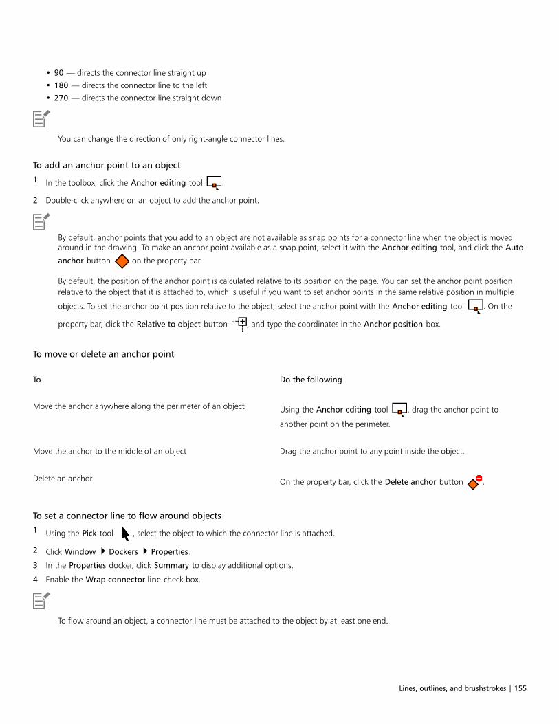
Lines, outlines, and brushstrokes | 155
• 90 — directs the connector line straight up
• 180 — directs the connector line to the left
• 270 — directs the connector line straight down
You can change the direction of only right-angle connector lines.
To add an anchor point to an object
1 In the toolbox, click the Anchor editing tool .
2 Double-click anywhere on an object to add the anchor point.
By default, anchor points that you add to an object are not available as snap points for a connector line when the object is movedaround in the drawing. To make an anchor point available as a snap point, select it with the Anchor editing tool, and click the Auto
anchor button on the property bar.
By default, the position of the anchor point is calculated relative to its position on the page. You can set the anchor point positionrelative to the object that it is attached to, which is useful if you want to set anchor points in the same relative position in multiple
objects. To set the anchor point position relative to the object, select the anchor point with the Anchor editing tool . On the
property bar, click the Relative to object button , and type the coordinates in the Anchor position box.
To move or delete an anchor point
To Do the following
Move the anchor anywhere along the perimeter of an object Using the Anchor editing tool , drag the anchor point to
another point on the perimeter.
Move the anchor to the middle of an object Drag the anchor point to any point inside the object.
Delete an anchor On the property bar, click the Delete anchor button .
To set a connector line to flow around objects
1 Using the Pick tool , select the object to which the connector line is attached.
2 Click Window Dockers Properties.
3 In the Properties docker, click Summary to display additional options.
4 Enable the Wrap connector line check box.
To flow around an object, a connector line must be attached to the object by at least one end.

156 | CorelDRAW 2019 User Guide
To add a text label to a connector line
1 In the toolbox, click the Connector tool button, and then on the property bar click one of the following:
• Straight-line connector tool
• Right-angle connector tool
• Rounded right-angle connector tool
2 Double-click the connector line.
A text cursor appears.
3 Type the text.
As you move the connector line, the text label remains attached to it.
To choose default settings for connector lines
1 Click Tools Options Tools.
2 In the left pane of the dialog box that appears, click Connector.
3 To limit snapping and attaching connector lines to only anchor points in objects, disable the Use geometric anchor points as snappingpoints check box. When this check box is enabled, you can snap and attach connector lines to edge nodes, center nodes and othergeometric points in an object.
4 To increase or decrease the distance between connector lines and objects, type a higher or lower value in the Route distance fromobject box. This setting doesn’t apply to straight connector lines.
To draw a callout
1 In the toolbox, click the 3-Point callout tool .
The 3-Point callout tool is located on the Dimension tools flyout.
2 Click where you want the first callout segment to start, and drag to where you want the first segment to end.
3 Click where you want the second segment to end.
A text cursor is displayed at the end of the callout line, indicating where to type a label for the object.
4 Type the callout text.
You can also
Change the callout shape Choose a shape from the Callout shape box on the property bar.
Change the distance between the text and the callout shape Type a value in the Gap box.
If you want to edit the callout line and callout text independently of each other, as a line and a text object, you must first separate the
callout line from the callout text by clicking Object Break callout apart.
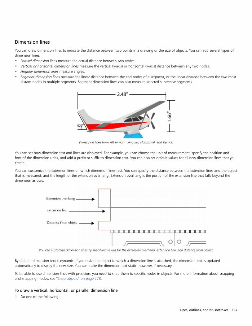
Lines, outlines, and brushstrokes | 157
Dimension lines
You can draw dimension lines to indicate the distance between two points in a drawing or the size of objects. You can add several types ofdimension lines:• Parallel dimension lines measure the actual distance between two nodes.• Vertical or horizontal dimension lines measure the vertical (y-axis) or horizontal (x-axis) distance between any two nodes.• Angular dimension lines measure angles.• Segment dimension lines measure the linear distance between the end nodes of a segment, or the linear distance between the two most
distant nodes in multiple segments. Segment dimension lines can also measure selected successive segments.
Dimension lines from left to right: Angular, Horizontal, and Vertical
You can set how dimension text and lines are displayed. For example, you can choose the unit of measurement, specify the position andfont of the dimension units, and add a prefix or suffix to dimension text. You can also set default values for all new dimension lines that youcreate.
You can customize the extension lines on which dimension lines rest. You can specify the distance between the extension lines and the objectthat is measured, and the length of the extension overhang. Extension overhang is the portion of the extension line that falls beyond thedimension arrows.
You can customize dimension lines by specifying values for the extension overhang, extension line, and distance from object.
By default, dimension text is dynamic. If you resize the object to which a dimension line is attached, the dimension text is updatedautomatically to display the new size. You can make the dimension text static, however, if necessary.
To be able to use dimension lines with precision, you need to snap them to specific nodes in objects. For more information about snappingand snapping modes, see “Snap objects” on page 278.
To draw a vertical, horizontal, or parallel dimension line
1 Do one of the following:

158 | CorelDRAW 2019 User Guide
• To draw a parallel dimension line, click the Parallel dimension tool in the toolbox.
• To draw a vertical or horizontal dimension line, click the Horizontal or vertical dimension tool .
2 Click to place the starting point, and drag to where you want to place the endpoint of the dimension line.
3 Move the pointer to position the dimension line, and click to place the dimension text.
By default, dimension text is centered on the dimension line.
To draw an angular dimension line
1 In the toolbox, click the Angular dimension tool .
2 Click where you want the two lines that measure the angle to intersect, and drag to where you want the first line to end.
3 Click where you want the second line to end.
4 Click where you want the angle label to appear.
To draw a segment dimension line
1 In the toolbox, click the Segment dimension tool .
2 Click the segment that you want to measure.
3 Move the pointer to where you want to position the dimension line, and click where you want to place the dimension text.
You can also
Measure the distance between the two most distant nodes inmultiple segments
Using the Segment dimension tool , marquee select the
segments, drag to position the dimension line, and click where youwant to place the dimension text.
Measure successive segments automatically Click the Automatic successive dimensioning button on the
property bar, and marquee select the segments that you want tomeasure. Drag to position the dimension line, and click where youwant to place the dimension text.
Segment dimension lines can be applied automatically to selected successive segments.
To set the display of dimension units
1 Select a dimension line.

Lines, outlines, and brushstrokes | 159
2 On the property bar, choose options from the following list boxes:
• Dimension style — lets you choose fractional, decimal or standard dimension units
• Dimension precision — lets you choose a level of precision for the measurements
• Dimension units — lets you choose the unit of measurement
You can also
Hide dimension units Click the Display units button .
Specify the position of dimension units Click the Text position button on the property bar, and click a
text position.
Change the point size and font of dimension units Select the dimension text by using the Pick tool . On the
property bar, choose a font style from the Font list box, and type avalue in the Font size box.
Specify a prefix or suffix for dimension text Type a prefix or suffix in the Prefix or Suffix box on the propertybar.
Hide or show a leading zero with a dimension value Click the Leading zero button on the property bar. (The
leading zero appears in dimension lines by default.)
Make dimension text static Click the Dynamic dimensioning button .
Most dimension line controls on the property bar becomeunavailable. If you change the size of the object to which thedimension line is attached, the dimension line text is not updated.
To set default properties for new dimension lines
1 Click Tools Options Tools.
2 In the left pane of the dialog box that appears, click one of the following:
• Angular Dimension - to set default properties for angular dimension lines
• Dimension - to set default properties for all other dimension lines
3 Specify the dimension style, precision, and units, prefix, and suffix.
The dimension style control is not available for angular dimension lines.
To customize extension lines
1 Select a dimension line.
2 On the property bar, click the Extension lines options button .
3 To specify the distance between the extension lines and the object, enable the Distance from object check box, and type a value in theDistance box.
4 To specify the length of the extension overhang, enable the Extension overhang check box, and type a value in the Distance box.

160 | CorelDRAW 2019 User Guide
Pressure-sensitive pens and devices
The following tools in CorelDRAW let you use the pressure of your pressure-sensitive pen, stylus, or other device: Artistic Media (Expressionmode), Eraser, Smear, Twirl, Attract and Repel, Roughen, and Smudge.
In addition, you can vary brushstrokes by using pen tilt and pen bearing with the Artistic Media (Expression mode) tool, Eraser, Roughenand Smudge tools. Note that pen tilt and pen bearing can be used only if your pen or stylus supports these features.
Pressure and pen settings
When you use a pressure-sensitive stylus or pen tablet with CorelDRAW, the amount of pressure that you apply controls the width of yourstrokes. Each person uses a different strength or pressure level in a stroke, and you can set the application to match your stroke strength byspecifying pen settings. Proper pen settings are particularly useful if you have a light touch. If a light stroke leaves no trace, adjusting pensettings can increase sensitivity for specific tools. Abrupt changes in the width your brushstrokes shows that you need to adjust your pensettings on the Pen Settings page in the Options dialog box. Pen settings can be saved as presets to use later.
You can adjust pen settings to match your stroke strength.
Tilt and bearing
Pen tilt lets you vary the flatness of the nib. If you do not want nib flatness to vary, you can disable pen tilt, and specify a fixed value for tiltangle to determine the nib flatness. Pen bearing lets you use the direction in which the stylus is tilted to vary nib rotation. You can disablepen bearing, and set a fixed value for the bearing angle to rotate the nib.
To adjust pen settings
1 Click Tools Options CorelDRAW.
2 In the left pane of the dialog box that appears, click Pen Settings.
3 Using your stylus or digital pen, apply at least three strokes, building from the lowest to the highest pressure.
To save the settings as a preset, click Save.

Lines, outlines, and brushstrokes | 161
To choose a pen tablet interface
1 Click Tools Options CorelDRAW.
2 In the left pane of the dialog box that appears, click Pen Settings.
3 Choose one of the following tablet options:
• WinTab — recommended for Wacom-compatible pen tablets or devices
• Real-Time Stylus — recommended for pen tablets or devices that use the RTS interface of Windows 7 and later versions

162 | CorelDRAW 2019 User Guide
Shapes | 163
Shapes
CorelDRAW lets you draw basic shapes, which you can modify by using special effects and reshaping tools.
In this section, you’ll learn about• “Rectangles and squares” (page 163)• “Ellipses, circles, arcs, and pie shapes” (page 166)• “Polygons and stars” (page 168)• “Spirals” (page 170)• “Grids” (page 170)• “Predefined shapes” (page 171)• “Use shape recognition” (page 172)
You can also draw shapes with precision by using object coordinates. For more information, see “Use object coordinates to draw and modifyobjects” on page 262.
Rectangles and squares
CorelDRAW lets you draw rectangles and squares. You can draw a rectangle or square by dragging diagonally with the Rectangle tool or byspecifying the width and height with the 3-point rectangle tool. The 3-point rectangle tool lets you quickly draw rectangles at an angle.
You can create a 3-point rectangle by first drawing its baseline and then drawing its height. The resulting rectangle is angled.
You can also draw a rectangle or square with rounded, scalloped or chamfered corners. You can modify each corner individually or apply thechanges to all corners. In addition, you can specify that all corners scale relative to the object. You can also specify the default corner size fordrawing rectangles and squares.
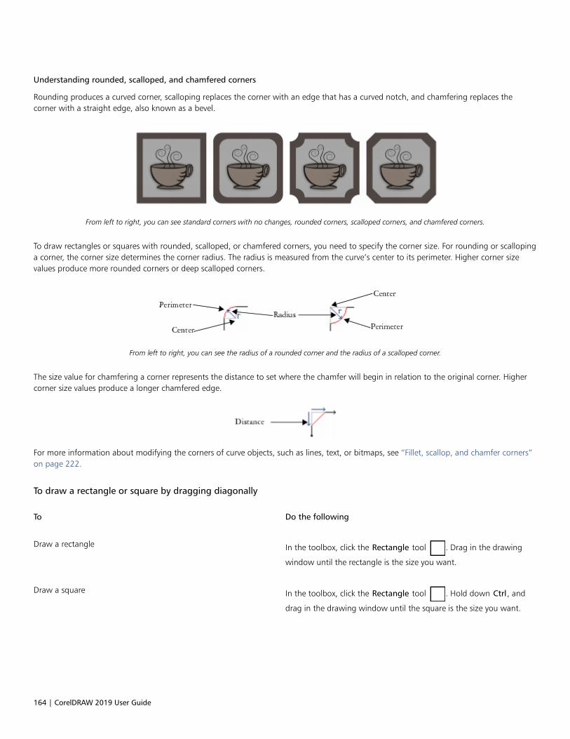
164 | CorelDRAW 2019 User Guide
Understanding rounded, scalloped, and chamfered corners
Rounding produces a curved corner, scalloping replaces the corner with an edge that has a curved notch, and chamfering replaces thecorner with a straight edge, also known as a bevel.
From left to right, you can see standard corners with no changes, rounded corners, scalloped corners, and chamfered corners.
To draw rectangles or squares with rounded, scalloped, or chamfered corners, you need to specify the corner size. For rounding or scallopinga corner, the corner size determines the corner radius. The radius is measured from the curve’s center to its perimeter. Higher corner sizevalues produce more rounded corners or deep scalloped corners.
From left to right, you can see the radius of a rounded corner and the radius of a scalloped corner.
The size value for chamfering a corner represents the distance to set where the chamfer will begin in relation to the original corner. Highercorner size values produce a longer chamfered edge.
For more information about modifying the corners of curve objects, such as lines, text, or bitmaps, see “Fillet, scallop, and chamfer corners”on page 222.
To draw a rectangle or square by dragging diagonally
To Do the following
Draw a rectangle In the toolbox, click the Rectangle tool . Drag in the drawing
window until the rectangle is the size you want.
Draw a square In the toolbox, click the Rectangle tool . Hold down Ctrl, and
drag in the drawing window until the square is the size you want.

Shapes | 165
You can draw a rectangle from its center outward by holding down Shift as you drag. You can also draw a square from its centeroutward by holding down Shift + Ctrl as you drag.
You can draw a rectangle that covers the drawing page by double-clicking the Rectangle tool.
To draw a rectangle by specifying height and width
1 In the toolbox, click the 3-point rectangle tool .
2 In the drawing window, point to where you want to start the rectangle, drag to draw the width, and release the mouse button.
3 Move the pointer to draw the height, and click.
To adjust the size of the rectangle, type values in the Object size boxes on the property bar.
To constrain the angle of the baseline to a preset increment, known as constrain angle, hold down Ctrl as you drag. For informationabout changing the constrain angle, see “To change the constrain angle” on page 306.
To draw a rectangle or square with rounded, scalloped, or chamfered corners
1 Click a rectangle or square.
2 Click one of the following buttons on the property bar:
• Round corner — produces a curved corner
• Scalloped corner — replaces a corner with an edge that has a curved notch
• Chamfered corner — replaces a corner with a flat edge
3 Type values in the Corner radius areas on the property bar.
4 Click Apply.
You can also
Apply the same changes to all corners Click the Edit corners together button on the property bar.
Disable the scaling of corners relative to the object Click the Relative corner scaling button on the property bar.
You can also modify the corners of a selected rectangle or square by clicking the Shape tool , clicking a corner option button on
the property bar, then dragging a corner node toward the shape’s center. If you prefer to modify only one corner, hold down Ctrl,then drag a corner node toward the shape’s center.
To specify the default corner shape and size for drawing rectangles and squares
1 Click Tools Options Tools.
2 In the left pane of the dialog box that appears, click Rectangle.
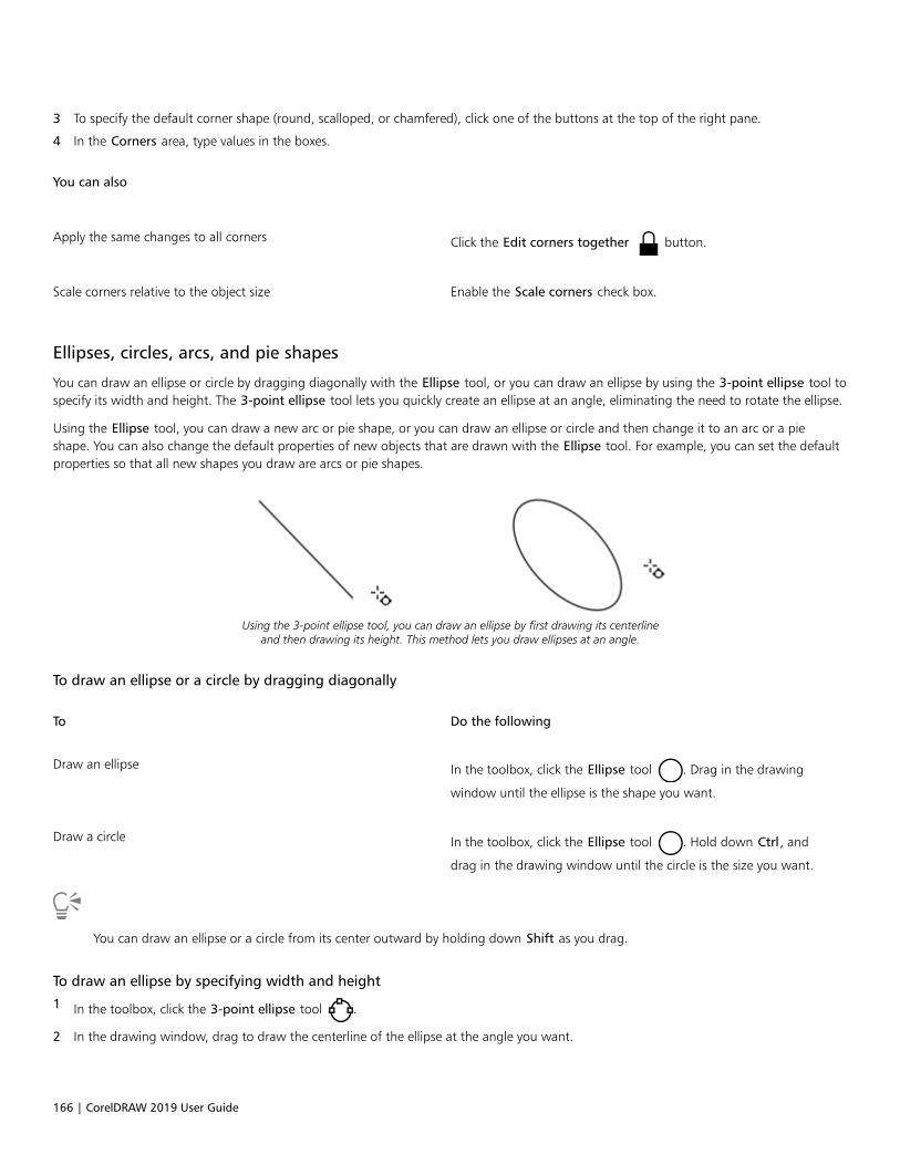
166 | CorelDRAW 2019 User Guide
3 To specify the default corner shape (round, scalloped, or chamfered), click one of the buttons at the top of the right pane.
4 In the Corners area, type values in the boxes.
You can also
Apply the same changes to all corners Click the Edit corners together button.
Scale corners relative to the object size Enable the Scale corners check box.
Ellipses, circles, arcs, and pie shapes
You can draw an ellipse or circle by dragging diagonally with the Ellipse tool, or you can draw an ellipse by using the 3-point ellipse tool tospecify its width and height. The 3-point ellipse tool lets you quickly create an ellipse at an angle, eliminating the need to rotate the ellipse.
Using the Ellipse tool, you can draw a new arc or pie shape, or you can draw an ellipse or circle and then change it to an arc or a pieshape. You can also change the default properties of new objects that are drawn with the Ellipse tool. For example, you can set the defaultproperties so that all new shapes you draw are arcs or pie shapes.
Using the 3-point ellipse tool, you can draw an ellipse by first drawing its centerlineand then drawing its height. This method lets you draw ellipses at an angle.
To draw an ellipse or a circle by dragging diagonally
To Do the following
Draw an ellipse In the toolbox, click the Ellipse tool . Drag in the drawing
window until the ellipse is the shape you want.
Draw a circle In the toolbox, click the Ellipse tool . Hold down Ctrl, and
drag in the drawing window until the circle is the size you want.
You can draw an ellipse or a circle from its center outward by holding down Shift as you drag.
To draw an ellipse by specifying width and height
1 In the toolbox, click the 3-point ellipse tool .
2 In the drawing window, drag to draw the centerline of the ellipse at the angle you want.
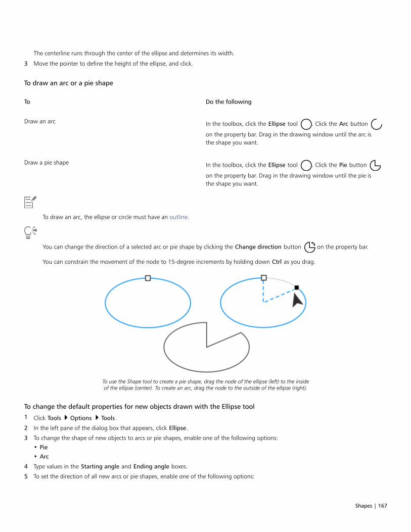
Shapes | 167
The centerline runs through the center of the ellipse and determines its width.
3 Move the pointer to define the height of the ellipse, and click.
To draw an arc or a pie shape
To Do the following
Draw an arc In the toolbox, click the Ellipse tool . Click the Arc button
on the property bar. Drag in the drawing window until the arc isthe shape you want.
Draw a pie shape In the toolbox, click the Ellipse tool . Click the Pie button
on the property bar. Drag in the drawing window until the pie isthe shape you want.
To draw an arc, the ellipse or circle must have an outline.
You can change the direction of a selected arc or pie shape by clicking the Change direction button on the property bar.
You can constrain the movement of the node to 15-degree increments by holding down Ctrl as you drag.
To use the Shape tool to create a pie shape, drag the node of the ellipse (left) to the insideof the ellipse (center). To create an arc, drag the node to the outside of the ellipse (right).
To change the default properties for new objects drawn with the Ellipse tool
1 Click Tools Options Tools.
2 In the left pane of the dialog box that appears, click Ellipse.
3 To change the shape of new objects to arcs or pie shapes, enable one of the following options:
• Pie
• Arc
4 Type values in the Starting angle and Ending angle boxes.
5 To set the direction of all new arcs or pie shapes, enable one of the following options:

168 | CorelDRAW 2019 User Guide
• Clockwise
• Counterclockwise
Polygons and stars
CorelDRAW lets you draw polygons and two types of stars: perfect and complex. Perfect stars are traditional-looking stars and can have a fillapplied to the entire star shape. Complex stars have intersecting sides and produce original results with a fill applied.
Left to right: Polygon, perfect star, and complex star, each with a fountain fill applied
You can modify polygons and stars. For example, you can change the number of sides on a polygon or the number of points on a star, andyou can sharpen the points of a star. You can also use the Shape tool to reshape polygons and complex stars, just as you would with anyother curve object. For more information about working with curve objects, see “Curve objects” on page 176. Perfect stars can also bereshaped, but with some restrictions.
To draw a polygon
• In the toolbox, click the Polygon tool , and drag in the drawing window until the polygon is the size you want.
You can draw a polygon from its center by holding down Shift as you drag.
You can draw a symmetrical polygon by holding down Ctrl as you drag.
To draw a star
To Do the following
Draw a perfect star In the toolbox, click the Star tool , and drag in the drawing
window until the star is the size you want.
Draw a complex star In the toolbox, click the Star tool . Click the Complex star tool
on the property bar, and drag in the drawing window until the
star is the size you want.

Shapes | 169
You can draw a star from its center by holding down Shift as you drag.
You can draw a symmetrical star by holding down Ctrl as you drag.
To modify a polygon
To Do the following
Change the number of sides of a polygon Select a polygon, type a value in the Points or sides box on theproperty bar, and press Enter.
Reshape a polygon into a star Select a polygon, click the Shape tool , and drag a node on
the polygon until the star is the shape you want.
Left to right: The Shape tool was used to change a polygon into a star that can be shaped as a curve object.The line segments of the star were then converted to curves and adjusted to produce the starfish shape.
To modify a star
To Do the following
Change the number of points on a star Select a star, type a value in the Points or sides box on the propertybar, and press Enter.
Sharpen a star’s points Select a star, and type a value in the Sharpness box on the propertybar.
Reshape a star Select a star, click the Shape tool , and drag a node on the
star.
When you use the Shape tool to reshape a perfect star, the node movement is constrained. Also, on perfect stars, you cannot add ordelete nodes, nor can you convert line segments to curves.

170 | CorelDRAW 2019 User Guide
Spirals
You can draw two types of spirals: symmetrical and logarithmic. Symmetrical spirals expand evenly so that the distance between eachrevolution is equal. Logarithmic spirals expand with increasingly larger distances between revolutions. You can set the rate by which alogarithmic spiral expands outward.
You can change the default settings of the Spiral tool so that all new spirals you draw have the properties you want.
A symmetrical spiral (left) and a logarithmic spiral (right)
To draw a spiral
1 In the toolbox, click the Spiral tool .
2 Type a value in the Spiral revolutions box on the property bar.
3 On the property bar, click one of the following buttons:
• Symmetrical spiral
• Logarithmic spiral
If you want to change the amount by which the spiral expands as it moves outward, move the Spiral expansion factor slider.
4 Drag diagonally in the drawing window until the spiral is the required size.
You can draw a spiral from its center outward by holding down Shift as you drag.
You can also draw a spiral with even horizontal and vertical dimensions by holding down Ctrl as you drag.
To choose default settings for the Spiral tool
1 Click Tools Options Tools.
2 In the left pane of the dialog box that appears, click Spiral.
3 Change the settings you want.
Grids
You can draw a grid and set the number of rows and columns. A grid is a grouped set of rectangles that you can break apart.
You can change the default settings of the Graph Paper tool to specify the number of rows and columns for new grids.

Shapes | 171
To draw a grid
1 In the toolbox, click the Graph paper tool .
2Type values in the top and bottom portions of the Columns and rows box on the property bar.
The value you type in the top portion specifies the number of columns; the value you type in the bottom portion specifies the number ofrows.
3 Point to where you want the grid to appear.
4 Drag diagonally to draw the grid.
If you want to draw the grid from its center point outward, hold down Shift as you drag; if you want to draw a grid with squarecells, hold down Ctrl as you drag.
To ungroup a grid
1 Select a grid by using the Pick tool .
2 Click Object Group Ungroup.
You can also break apart a grid by clicking the Ungroup button on the property bar.
To choose default settings for the Graph Paper tool
1 Click Tools Options Tools.
2 In the left pane of the dialog box that appears, click Graph Paper.
3 Type values in the Number of columns and Number of rows boxes.
Predefined shapes
Using the Perfect Shapes™ collection, you can draw predefined shapes. Certain shapes — specifically basic shapes, arrow shapes, bannershapes, and callout shapes — contain diamond-shaped handles that are called glyphs. You can drag a glyph to modify the appearance of ashape.
Using the Shape tool, you can drag a glyph to alter a shape.
You can add text to the inside or outside of the shape. For example, you might want to put a label inside a flowchart symbol or a callout.

172 | CorelDRAW 2019 User Guide
To draw a predefined shape
1 In the toolbox, click the Common Shapes tool .
2 Open the Perfect Shapes picker on the property bar, and click a shape.
3 Drag in the drawing window until the shape is the size you want.
Like other shapes, shapes that are drawn from the Perfect Shapes picker can be modified.
To modify a predefined shape
1 Select a shape that contains a glyph.
2 Drag a glyph until you achieve the shape you want.
The right-angle, heart, lightning bolt, explosion, and flowchart shapes do not contain glyphs.
To add text to a predefined shape
1 Click the Text tool .
2 Position the cursor inside the shape’s outline until it changes to a text cursor .
3 Type inside the shape, choose a font, and format the text.
Use shape recognition
You can use the Smart drawing tool to draw freehand strokes that can be recognized and converted to basic shapes. Rectangles and ellipsesare translated to native CorelDRAW objects; trapezoids and parallelograms are translated to Perfect Shapes objects; lines, triangles, squares,diamonds, circles, and arrows are translated to curve objects. If an object is not converted to a shape, it is smoothed. Objects and curvesdrawn with shape recognition are editable. You can set the level at which CorelDRAW recognizes shapes and converts them to objects. Youcan also specify the amount of smoothing applied to curves.
You can set the amount of time to elapse between making a pen stroke and the implementation of shape recognition. For example, if thetimer is set to one second and you draw a circle, shape recognition takes effect one second after you draw the circle.
You can make corrections as you draw. You can also change the thickness and line style of a shape that was drawn by using shaperecognition.
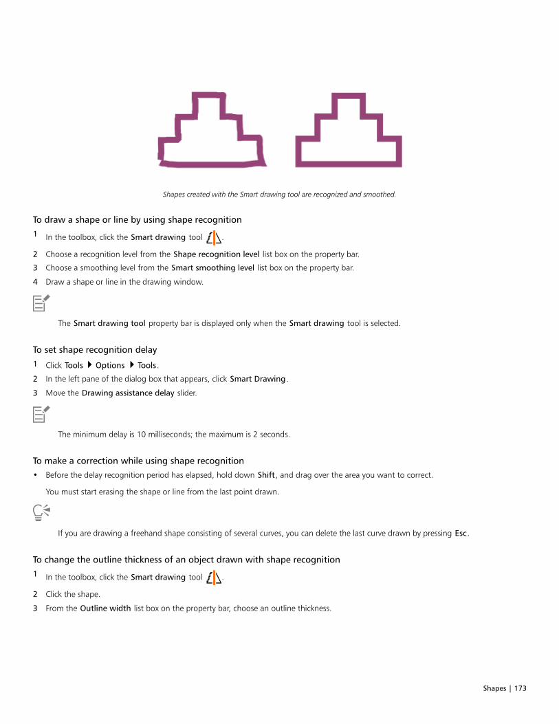
Shapes | 173
Shapes created with the Smart drawing tool are recognized and smoothed.
To draw a shape or line by using shape recognition
1 In the toolbox, click the Smart drawing tool .
2 Choose a recognition level from the Shape recognition level list box on the property bar.
3 Choose a smoothing level from the Smart smoothing level list box on the property bar.
4 Draw a shape or line in the drawing window.
The Smart drawing tool property bar is displayed only when the Smart drawing tool is selected.
To set shape recognition delay
1 Click Tools Options Tools.
2 In the left pane of the dialog box that appears, click Smart Drawing.
3 Move the Drawing assistance delay slider.
The minimum delay is 10 milliseconds; the maximum is 2 seconds.
To make a correction while using shape recognition
• Before the delay recognition period has elapsed, hold down Shift, and drag over the area you want to correct.
You must start erasing the shape or line from the last point drawn.
If you are drawing a freehand shape consisting of several curves, you can delete the last curve drawn by pressing Esc.
To change the outline thickness of an object drawn with shape recognition
1 In the toolbox, click the Smart drawing tool .
2 Click the shape.
3 From the Outline width list box on the property bar, choose an outline thickness.

174 | CorelDRAW 2019 User Guide
The Smart drawing tool property bar is displayed only when the Smart drawing tool is selected.
When you overlap lines drawn with the Smart drawing tool, the outline thickness is determined by the average.
You can change the line style of a shape drawn with shape recognition. For more information, see “To specify line and outlinesettings” on page 139.
Shape objects | 175
Shape objects
CorelDRAW lets you shape objects in various ways.
This section contains the following topics:• “Curve objects” (page 176)• “Select and move nodes” (page 177)• “Align and distribute nodes” (page 179)• “Manipulate segments” (page 186)• “Join curves” (page 187)• “Copy and cut segments” (page 189)• “Add, remove, and join nodes” (page 189)• “Node types” (page 191)• “Transform nodes” (page 192)• “Break the path of curve objects” (page 193)• “Mirror changes in curve objects” (page 194)• “Skew and stretch objects” (page 195)• “Smudge and smear objects” (page 196)• “Roughen objects” (page 199)• “Smooth objects” (page 201)• “Attract or push away nodes to shape” (page 202)• “Apply distortion effects” (page 203)• “Add twirl effects” (page 205)• “Shape objects by using envelopes” (page 206)• “Crop and erase objects” (page 214)• “Split objects” (page 218)• “Trim objects” (page 220)• “Fillet, scallop, and chamfer corners” (page 222)• “Weld and intersect objects” (page 225)• “PowerClip objects” (page 226)
• “Options for nodes, handles, and previews” (page 232)

176 | CorelDRAW 2019 User Guide
Curve objects
A curve object has nodes and control handles, which you can use to change the object’s shape. A curve object can be any shape, includinga straight or curved line. An object’s nodes are the small shapes that appear along the object’s outline. The line between two nodes is calleda segment. Segments can be curved or straight. Each node has a control handle for each curved segment connected to it. Control handleshelp you adjust the curve of a segment.
The components of a curve: control handles, segments, and nodes
Curve objects created in CorelDRAW follow a path that gives them their defining shape. A path can be open (for example, a line) or closed(for example, an ellipse) and can sometimes include subpaths. For more information about paths and subpaths, see “Break the path of curveobjects” on page 193.
Most objects that are added to a drawing are not curve objects, with the exception of spirals, freehand lines, and Bézier lines. Therefore, ifyou want to customize the shape of an object or text object, it is recommended that you convert it to a curve object.
You can view the properties of a curve object in the Properties docker.
To convert objects to curve objects
1 Select the object.
2 Click Object Convert to curves.
You can convert artistic text to curves so that you can shape individual characters.
Bitmaps cannot be converted to curve objects.
To view curve properties
1 Select the curve object.
2 Click Object Properties.
3 At the top of the Properties docker, click the Curve button .
You can also convert an object to a curve object by selecting the object and clicking the Convert to curves button on the
property bar.
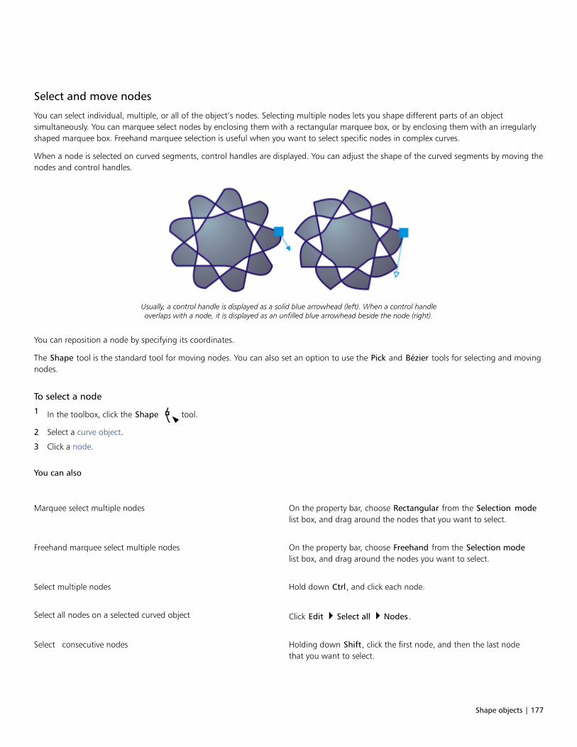
Shape objects | 177
Select and move nodes
You can select individual, multiple, or all of the object’s nodes. Selecting multiple nodes lets you shape different parts of an objectsimultaneously. You can marquee select nodes by enclosing them with a rectangular marquee box, or by enclosing them with an irregularlyshaped marquee box. Freehand marquee selection is useful when you want to select specific nodes in complex curves.
When a node is selected on curved segments, control handles are displayed. You can adjust the shape of the curved segments by moving thenodes and control handles.
Usually, a control handle is displayed as a solid blue arrowhead (left). When a control handleoverlaps with a node, it is displayed as an unfilled blue arrowhead beside the node (right).
You can reposition a node by specifying its coordinates.
The Shape tool is the standard tool for moving nodes. You can also set an option to use the Pick and Bézier tools for selecting and movingnodes.
To select a node
1 In the toolbox, click the Shape tool.
2 Select a curve object.
3 Click a node.
You can also
Marquee select multiple nodes On the property bar, choose Rectangular from the Selection modelist box, and drag around the nodes that you want to select.
Freehand marquee select multiple nodes On the property bar, choose Freehand from the Selection modelist box, and drag around the nodes you want to select.
Select multiple nodes Hold down Ctrl, and click each node.
Select all nodes on a selected curved object Click Edit Select all Nodes.
Select consecutive nodes Holding down Shift, click the first node, and then the last nodethat you want to select.
178 | CorelDRAW 2019 User Guide
You can also
To change the direction in which the nodes are selected, click whileholding down Shift.
Select the node that follows or precedes a selected node Press Tab or Shift + Tab.
Deselect a node Hold down Ctrl, and click a selected node.
Deselect multiple nodes Hold down Ctrl, and click each selected node.
Deselect all nodes Click an unused space in the drawing window.
You can also select a node by using the Pick , Freehand , Bézier , or Polyline tool. To do this, first click Tools
Options CorelDRAW. Click Nodes and Handles, and enable the Enable node tracking check box. Click a curve object, move the
pointer over a node until the tool’s shape state cursor appears, and click the node. Note that when the Enable node tracking
check box is enabled, you can no longer select and move an object by clicking and dragging any of its nodes.
To select all nodes on a selected curve, double-click the Shape tool.
To move a node
1 Select an object by using the Shape tool .
2 Drag the node until you achieve the desired shape.
You can also move a node by using the Pick , Freehand , Bézier , or Polyline tool. To do this, first click Tools
Options CorelDRAW. Click Nodes and Handles, and make sure that the Enable node tracking check box is enabled. Click a curve
object, move the pointer over a node until the tool’s shape state cursor appears, and drag the node.
To specify a node’s coordinate values
1 Click the Shape tool .
2 Select a node on a curve object.
3 Click Window Dockers Coordinates.
4 Click the Multi-point curve button .
5 Type values in the X and Y boxes to specify the exact position of the point along the x and y rulers.
6 Click one of the following:
• Create object — adds a new curve object to the drawing window
• Replace object — replaces the selected curve object with a new one

Shape objects | 179
Align and distribute nodes
CorelDRAW lets you quickly align and distribute nodes in one or more curves.
First, you need to choose a reference point. The reference point can be the bounding box of the selection, the page edge or center, theclosest grid line, or a specified point.

180 | CorelDRAW 2019 User Guide
1 2
3 4
5 6
The nodes in a curve (1) are left-aligned relative to the bounding box of all active nodes(2), the page edge (3) or center (4), the closest grid line (5), or a specified point (6).
After you set a reference point, you can choose an alignment option. You can align nodes to the left, right, top, or bottom, or along ahorizontal or vertical axis.

Shape objects | 181
1
5 6
3 4
2
The active nodes in a curve (top left) are aligned to the left (1), right (3), top (4), bottom (6),and along a vertical (2) and horizontal (5) axis relative to the bounding box of the selection.
You can align nodes from different curves.
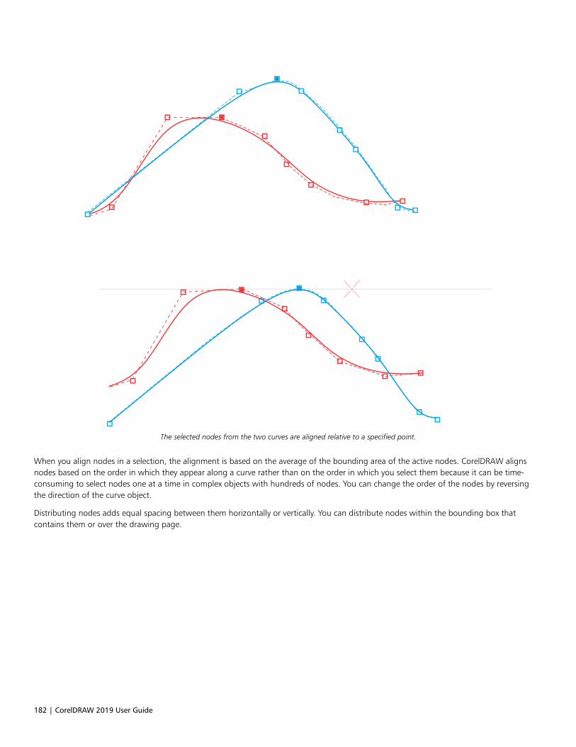
182 | CorelDRAW 2019 User Guide
The selected nodes from the two curves are aligned relative to a specified point.
When you align nodes in a selection, the alignment is based on the average of the bounding area of the active nodes. CorelDRAW alignsnodes based on the order in which they appear along a curve rather than on the order in which you select them because it can be time-consuming to select nodes one at a time in complex objects with hundreds of nodes. You can change the order of the nodes by reversingthe direction of the curve object.
Distributing nodes adds equal spacing between them horizontally or vertically. You can distribute nodes within the bounding box thatcontains them or over the drawing page.
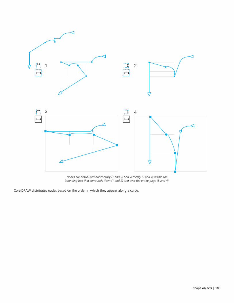
Shape objects | 183
1
3 4
2
Nodes are distributed horizontally (1 and 3) and vertically (2 and 4) within thebounding box that surrounds them (1 and 2) and over the entire page (3 and 4).
CorelDRAW distributes nodes based on the order in which they appear along a curve.
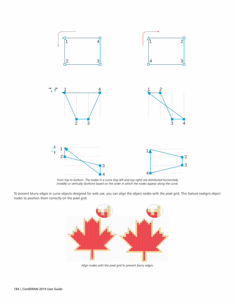
184 | CorelDRAW 2019 User Guide
1
34
21
32
4
1
1 1
3
3 3
4
2
2
2 2
3
14
4 4From top to bottom: The nodes in a curve (top left and top right) are distributed horizontally(middle) or vertically (bottom) based on the order in which the nodes appear along the curve.
To prevent blurry edges in curve objects designed for web use, you can align the object nodes with the pixel grid. This feature realigns objectnodes to position them correctly on the pixel grid.
Align nodes with the pixel grid to prevent blurry edges.
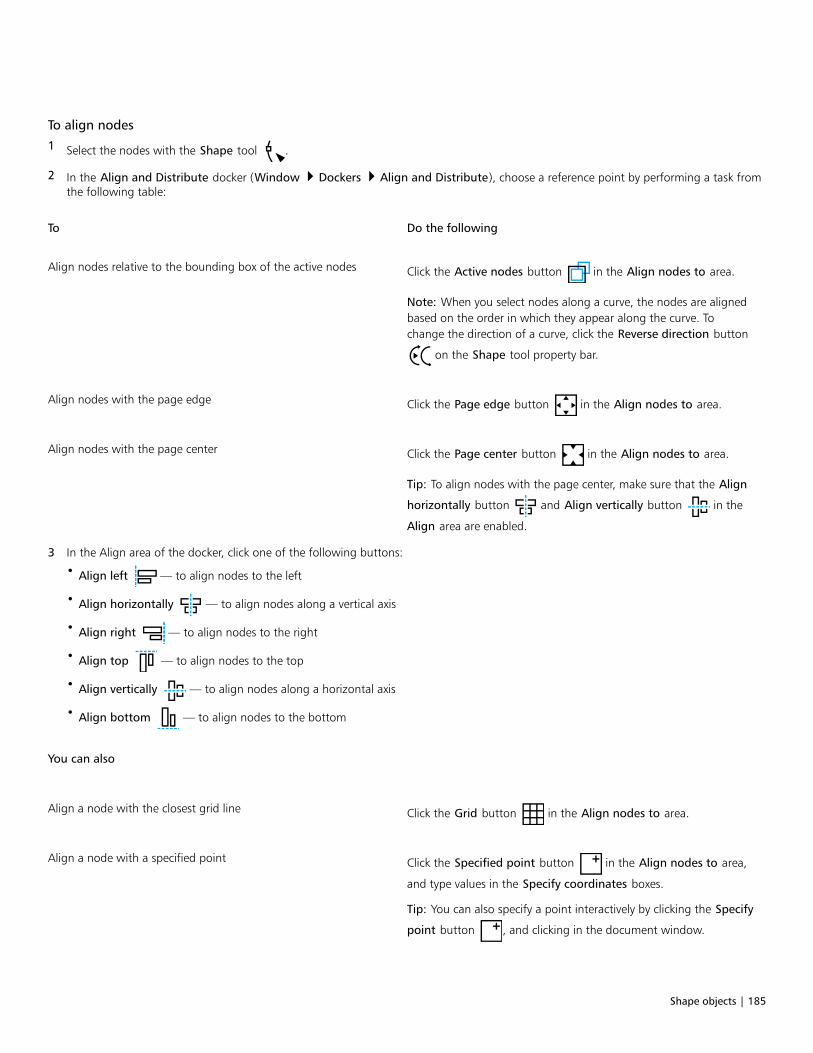
Shape objects | 185
To align nodes
1 Select the nodes with the Shape tool .
2 In the Align and Distribute docker (Window Dockers Align and Distribute), choose a reference point by performing a task fromthe following table:
To Do the following
Align nodes relative to the bounding box of the active nodes Click the Active nodes button in the Align nodes to area.
Note: When you select nodes along a curve, the nodes are alignedbased on the order in which they appear along the curve. Tochange the direction of a curve, click the Reverse direction button
on the Shape tool property bar.
Align nodes with the page edge Click the Page edge button in the Align nodes to area.
Align nodes with the page center Click the Page center button in the Align nodes to area.
Tip: To align nodes with the page center, make sure that the Align
horizontally button and Align vertically button in the
Align area are enabled.
3 In the Align area of the docker, click one of the following buttons:
• Align left — to align nodes to the left
• Align horizontally — to align nodes along a vertical axis
• Align right — to align nodes to the right
• Align top — to align nodes to the top
• Align vertically — to align nodes along a horizontal axis
• Align bottom — to align nodes to the bottom
You can also
Align a node with the closest grid line Click the Grid button in the Align nodes to area.
Align a node with a specified point Click the Specified point button in the Align nodes to area,
and type values in the Specify coordinates boxes.
Tip: You can also specify a point interactively by clicking the Specify
point button , and clicking in the document window.
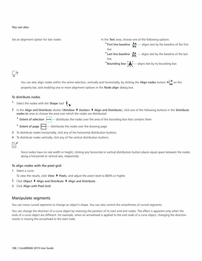
186 | CorelDRAW 2019 User Guide
You can also
Set an alignment option for text nodes In the Text area, choose one of the following options:•First line baseline — aligns text by the baseline of the first
line•Last line baseline — aligns text by the baseline of the last
line•Bounding box — aligns text by its bounding box
You can also align nodes within the active selection, vertically and horizontally, by clicking the Align nodes button on the
property bar, and enabling one or more alignment options in the Node align dialog box.
To distribute nodes
1 Select the nodes with the Shape tool .
2 In the Align and Distribute docker (Window Dockers Align and Distribute), click one of the following buttons in the Distributenodes to area to choose the area over which the nodes are distributed:
• Extent of selection — distributes the nodes over the area of the bounding box that contains them
• Extent of page — distributes the nodes over the drawing page
3 To distribute nodes horizontally, click any of the horizontal distribution buttons.
4 To distribute nodes vertically, click any of the vertical distribution buttons.
Since nodes have no real width or height, clicking any horizontal or vertical distribution button places equal space between the nodesalong a horizontal or vertical axis, respectively.
To align nodes with the pixel grid
1 Select a curve.
To view the results, click View Pixels, and adjust the zoom level to 800% or higher.
2 Click Object Align and Distribute Align and Distribute.
3 Click Align with Pixel Grid.
Manipulate segments
You can move curved segments to change an object’s shape. You can also control the smoothness of curved segments.
You can change the direction of a curve object by reversing the position of its start and end nodes. The effect is apparent only when theends of a curve object are different. For example, when an arrowhead is applied to the end node of a curve object, changing the directionresults in moving the arrowhead to the start node.

Shape objects | 187
Changing the direction of a curve
To manipulate the segments of a curve object
1 In the toolbox, click the Shape tool .
2 Click a curve object.
3 Perform a task from the following table.
To Do the following
Shape a segment by using the control handles without affectingthe placement of the node
Click a node, then drag one of the control handles.
Shape a segment by using the control handles while moving anode
Click a node. Hold down Alt, and drag one of the control handles.
You can also
Straighten a curve segment Click a curve segment, and click the Convert to line button
on the property bar.
Curve a straight segment Click a straight segment, and click the Convert to curve
button on the property bar.
Smooth a segment Click a node, and move the Curve smoothness slider on theproperty bar. To smooth all segments in a curve object, select all ofthe object’s nodes before moving the Curve smoothness slider.
Change the direction of a curve object Click a segment, and click the Reverse direction button on
the property bar.
Join curves
You can join curves and line segments to create more complex curves as well as closed objects. The shape of the connecting lines isdetermined by the mode that you choose: Extend, Chamfer, Fillet, or Bézier Curve.
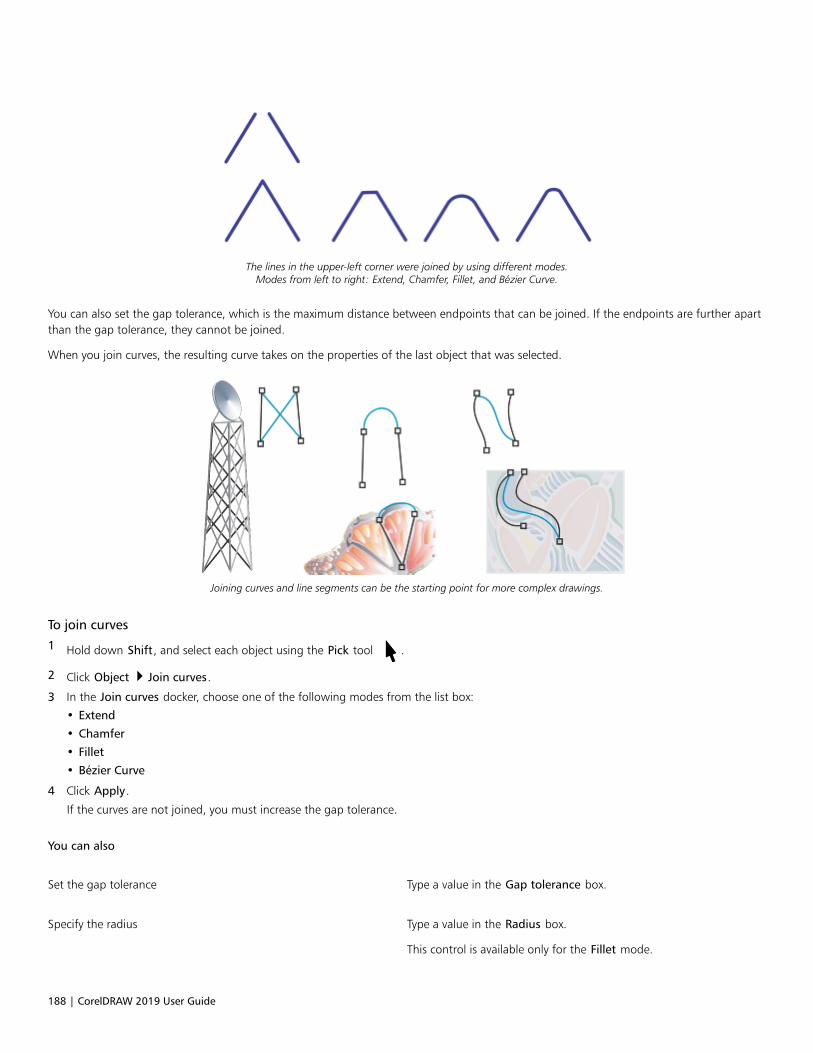
188 | CorelDRAW 2019 User Guide
The lines in the upper-left corner were joined by using different modes.Modes from left to right: Extend, Chamfer, Fillet, and Bézier Curve.
You can also set the gap tolerance, which is the maximum distance between endpoints that can be joined. If the endpoints are further apartthan the gap tolerance, they cannot be joined.
When you join curves, the resulting curve takes on the properties of the last object that was selected.
Joining curves and line segments can be the starting point for more complex drawings.
To join curves
1 Hold down Shift, and select each object using the Pick tool .
2 Click Object Join curves.
3 In the Join curves docker, choose one of the following modes from the list box:
• Extend
• Chamfer
• Fillet
• Bézier Curve
4 Click Apply.
If the curves are not joined, you must increase the gap tolerance.
You can also
Set the gap tolerance Type a value in the Gap tolerance box.
Specify the radius Type a value in the Radius box.
This control is available only for the Fillet mode.

Shape objects | 189
You cannot join interior points, only endpoints.
If endpoints to be joined do not share coordinates, the endpoints are extended to their intersection.
You can also connect the subpaths in a group of objects.
You can also select lines by marquee selecting. If the lines are marquee selected, the properties from the bottom object on a layer are
used. To see which object is the bottom one, open the Objects docker by clicking Window Dockers Objects.
Copy and cut segments
You can copy and cut curve segments, and then paste them as objects, making it easy to extract subpaths or create adjacent shapes withsimilar contours.
A curve segment was copied (left) and then pasted as an object (right).
To copy or cut a curve segment
1 Select the curve object.
2 Using the Shape tool , select the nodes on a curve segment, and then press one of the following:
• Ctrl + C to copy the curve segment
• Ctrl + X to cut the curve segment
• Ctrl + D to duplicate the curve segment at a specified offset distance
To paste the curve segment, press Ctrl + V.
Add, remove, and join nodes
When you add nodes, you increase the number of segments and, therefore, the amount of control you have over the shape of the object.You can delete selected nodes to simplify an object’s shape.
When curve objects contain many nodes, it is difficult to edit and output them to devices such as vinyl cutters, plotters, and rotary engravers.You can have the number of nodes in a curve object reduced automatically. Reducing the number of nodes removes overlapping nodes andcan smooth a curve object. This feature is especially useful for reducing the number of nodes in objects imported from other applications.

190 | CorelDRAW 2019 User Guide
Reducing the number of nodes to smooth a curve object
You can join the start and end nodes of an open path such as a line to create a closed object. This feature is useful for filling an object withcolor because you can apply fills only to the inside of closed objects. For information about applying fills, see “Fills” on page 365.
You can align the nodes of a curve object horizontally or vertically.
Aligning nodes horizontally
To add or delete a node
To Do the following
Add a node In the toolbox, click the Shape tool , select a curve object, and
double-click where you want to add a node.
Delete a node In the toolbox, click the Shape tool, select a curve object, anddouble-click a node.
To reduce the number of nodes in a curve object
1 In the toolbox, click the Shape tool .
2 Click a curve object, and do one of the following:
• To reduce the number of nodes in the entire object, click the Select all nodes button on the property bar.
• To reduce the number of nodes in a part of a curve object, marquee select the part you want to change.
3 Do one of the following:
• Click Reduce nodes on the property bar to have overlapping and redundant nodes automatically removed.
Shape objects | 191
• Move the Curve smoothness slider to control the number of nodes that are removed. Removing many nodes can reshape the curveobject.
To join the end nodes of a single subpath
1 In the toolbox, click the Shape tool .
2 Click a subpath.
3 Click the Close curve button on the property bar.
You can close multiple subpaths in an object by clicking Object Join curves and choosing settings in the Join curves docker. Formore information, see “Join curves” on page 187.
To join the nodes of multiple subpaths
1 In the toolbox, click the Shape tool .
2 Hold down Shift, and click a node from each subpath.
3 Click the Extend curve to close button on the property bar.
If you want to join nodes from separate curve objects, you must first combine them into a single curve object, and then join the endnodes of the new subpaths. For information about combining objects, see “Combine objects” on page 301.
Node types
You can change the nodes on a curve object to one of three types: cusp, smooth, and symmetrical. The control handles of each node typebehave differently.
Cusp nodes let you create sharp transitions, such as corners or sharp angles, in a curve object. You can move the control handles in a cuspnode independently of one another, changing only the line on one side of the node.
With smooth nodes, the lines passing through the node take on the shape of a curve, producing smooth transitions between line segments.The control handles of a smooth node are always directly opposite one another, but they may be at different distances from the node.
Symmetrical nodes are similar to smooth nodes. They create a smooth transition between line segments, but they also let you give lines onboth sides of a node the same curve appearance. The control handles of symmetrical nodes are directly opposite each other and at an equaldistance from the node.
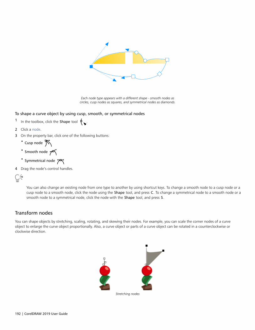
192 | CorelDRAW 2019 User Guide
Each node type appears with a different shape - smooth nodes ascircles, cusp nodes as squares, and symmetrical nodes as diamonds.
To shape a curve object by using cusp, smooth, or symmetrical nodes
1 In the toolbox, click the Shape tool .
2 Click a node.
3 On the property bar, click one of the following buttons:
• Cusp node
• Smooth node
• Symmetrical node
4 Drag the node’s control handles.
You can also change an existing node from one type to another by using shortcut keys. To change a smooth node to a cusp node or acusp node to a smooth node, click the node using the Shape tool, and press C. To change a symmetrical node to a smooth node or asmooth node to a symmetrical node, click the node with the Shape tool, and press S.
Transform nodes
You can shape objects by stretching, scaling, rotating, and skewing their nodes. For example, you can scale the corner nodes of a curveobject to enlarge the curve object proportionally. Also, a curve object or parts of a curve object can be rotated in a counterclockwise orclockwise direction.
Stretching nodes
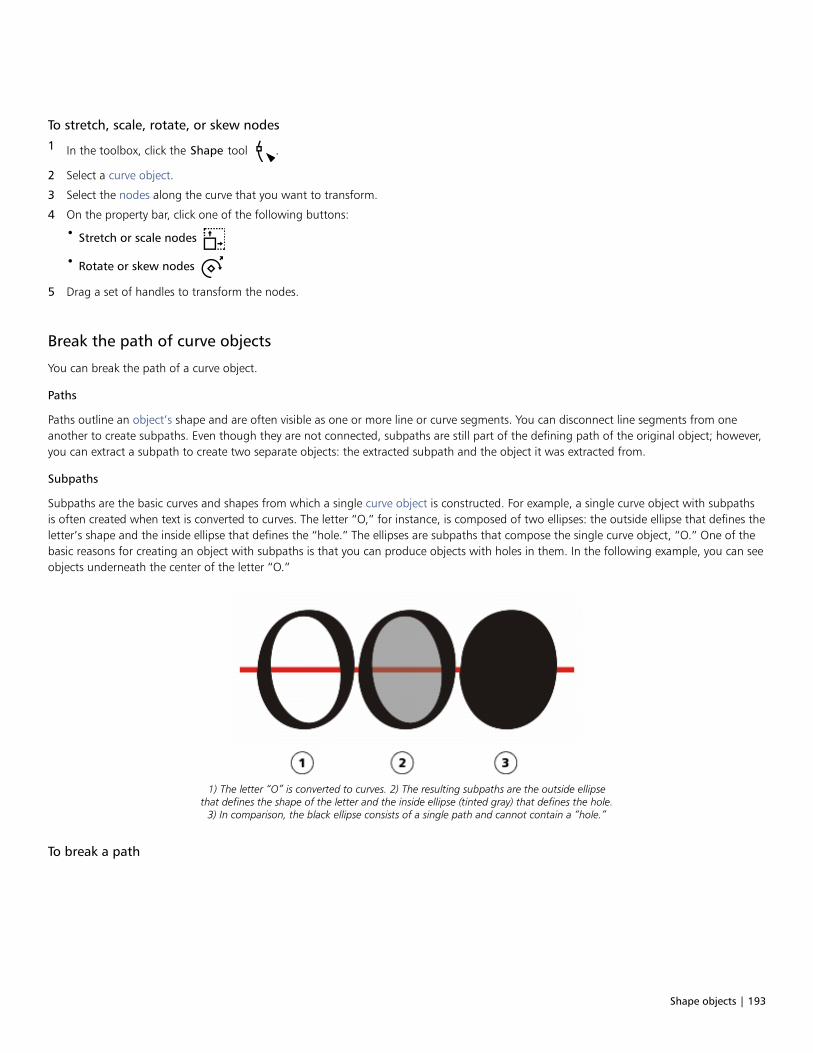
Shape objects | 193
To stretch, scale, rotate, or skew nodes
1 In the toolbox, click the Shape tool .
2 Select a curve object.
3 Select the nodes along the curve that you want to transform.
4 On the property bar, click one of the following buttons:
• Stretch or scale nodes
• Rotate or skew nodes
5 Drag a set of handles to transform the nodes.
Break the path of curve objects
You can break the path of a curve object.
Paths
Paths outline an object’s shape and are often visible as one or more line or curve segments. You can disconnect line segments from oneanother to create subpaths. Even though they are not connected, subpaths are still part of the defining path of the original object; however,you can extract a subpath to create two separate objects: the extracted subpath and the object it was extracted from.
Subpaths
Subpaths are the basic curves and shapes from which a single curve object is constructed. For example, a single curve object with subpathsis often created when text is converted to curves. The letter “O,” for instance, is composed of two ellipses: the outside ellipse that defines theletter’s shape and the inside ellipse that defines the “hole.” The ellipses are subpaths that compose the single curve object, “O.” One of thebasic reasons for creating an object with subpaths is that you can produce objects with holes in them. In the following example, you can seeobjects underneath the center of the letter “O.”
1) The letter “O” is converted to curves. 2) The resulting subpaths are the outside ellipsethat defines the shape of the letter and the inside ellipse (tinted gray) that defines the hole.
3) In comparison, the black ellipse consists of a single path and cannot contain a “hole.”
To break a path

194 | CorelDRAW 2019 User Guide
To Do the following
Break a path In the toolbox, click the Shape tool . Select a node on the
path, and click the Break curve button on the property bar.
Extract a broken path from an object In the toolbox, click the Shape tool. Right-click a path, and clickBreak apart. Select a segment, node, or group of nodes thatrepresents the portion of the path you want to extract, and click
the Extract subpath button on the property bar.
When you break a path in a curve object, the resulting subpaths remain part of the same object. When you extract a path from anobject, you create two separate objects.
Mirror changes in curve objects
When you mirror changes in curve objects by using Reflect Nodes mode, you edit nodes and have the same edits take place in reverse oncorresponding nodes. For example, you can move a node to the right, and its corresponding node moves the same distance to the left. Thisfeature is useful when you want to shape a curve object and mirror the changes across the object’s left and right side or top and bottomside.
To mirror changes, you must select two curve objects one of which was created by mirroring the other, or a symmetrical object. Forinformation about mirroring objects, see “Rotate and mirror objects” on page 291. Next, you need to choose whether to mirror changeshorizontally (along a vertical line of symmetry) or vertically (along a horizontal line of symmetry). Finally, you need to select the appropriatecorresponding nodes so that editing changes are mirrored across the selected objects.
Left: Two corresponding nodes are selected in mirrored curve objects. Right: When the bluecontrol handles are moved, the change is reflected in the corresponding control handles (in red).
To mirror changes in curve objects
1 Using the Pick tool, select mirrored curve objects or a symmetrical curve object.
2 Click the Shape tool .
3 On the property bar, click one of the following:
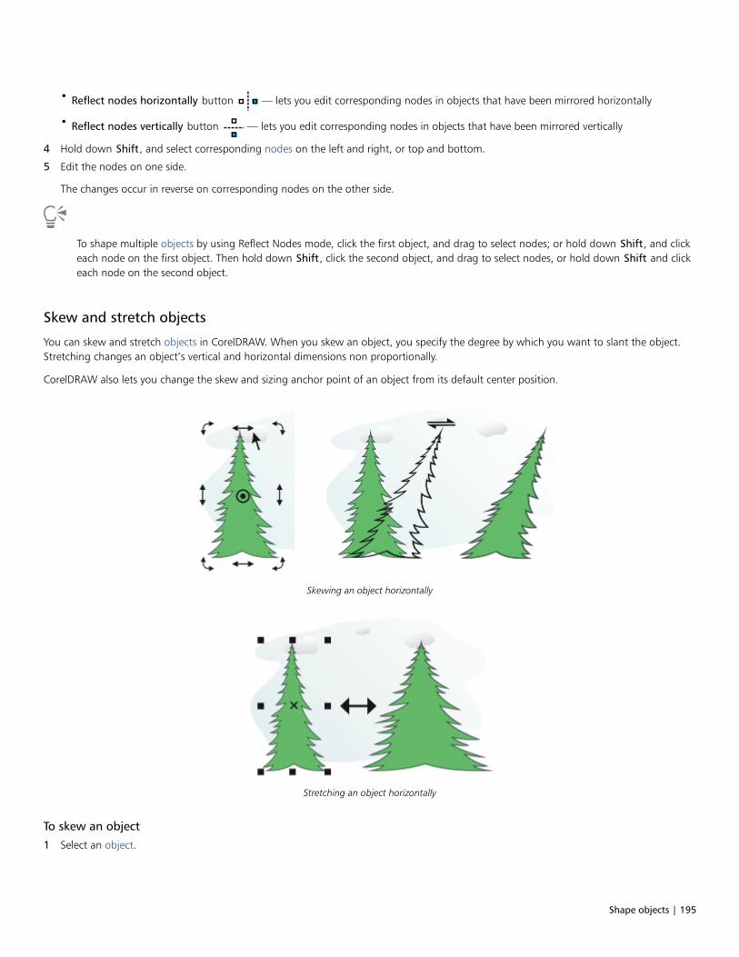
Shape objects | 195
• Reflect nodes horizontally button — lets you edit corresponding nodes in objects that have been mirrored horizontally
• Reflect nodes vertically button — lets you edit corresponding nodes in objects that have been mirrored vertically
4 Hold down Shift, and select corresponding nodes on the left and right, or top and bottom.
5 Edit the nodes on one side.
The changes occur in reverse on corresponding nodes on the other side.
To shape multiple objects by using Reflect Nodes mode, click the first object, and drag to select nodes; or hold down Shift, and clickeach node on the first object. Then hold down Shift, click the second object, and drag to select nodes, or hold down Shift and clickeach node on the second object.
Skew and stretch objects
You can skew and stretch objects in CorelDRAW. When you skew an object, you specify the degree by which you want to slant the object.Stretching changes an object’s vertical and horizontal dimensions non proportionally.
CorelDRAW also lets you change the skew and sizing anchor point of an object from its default center position.
Skewing an object horizontally
Stretching an object horizontally
To skew an object
1 Select an object.

196 | CorelDRAW 2019 User Guide
2 In the toolbox, click the Free transform tool .
3 Click the Free skew button on the property bar.
4 Type values in the Skew angle boxes on the property bar to specify the number of degrees by which you want to skew the objecthorizontally or vertically.
If you want to apply the scaling according to the object’s position rather than the x and y coordinates, click the Relative to object
button on the property bar.
You can also skew an object interactively by dragging one of its skew handles . If the skew handles are not displayed, click the
selected object again, and point to the middle handles.
You can also access skewing options from the Transform docker.
To stretch an object
1 Select an object.
2 Click Window Dockers Transform.
3 In the Transform docker, click the Size button.
4 Disable the Proportional check box.
5 Type a value in the following boxes:
• W — lets you specify the width of a selected object
• H — lets you specify the height of a selected object
6 Click Apply.
The new values that you enter to stretch an object are the basis for a new ratio of the horizontal and vertical dimensions of theobject. When you enable the Proportional check box, any resizing of the object is based on this new ratio. To revert the object toits original one-to-one proportions before transforming it again, you must enable the Proportional check box, and then retype theoriginal values.
You can change object dimensions proportionally by enabling the Proportional check box, typing a value in either the H or W box,and pressing Enter.
You can also stretch an object from its center by pressing Shift and dragging a corner selection handle.
You can also stretch an object in increments of 100% by pressing Ctrl, and dragging a corner selection handle.
Smudge and smear objects
Smudging and smearing let you shape an object by pulling extensions or making indents along its outline. With smudging, the extensionsand indents resemble streaks that vary little in width as you drag with the Smudge tool. With smearing, the extensions and indents have amore fluid shape that decreases in width as you drag with the Smear tool.
Smudge objects
When applying smudging to an object, you can control the extent and shape of the distortion whether you activate the controls for thegraphics tablet stylus or use the settings that apply to a mouse.
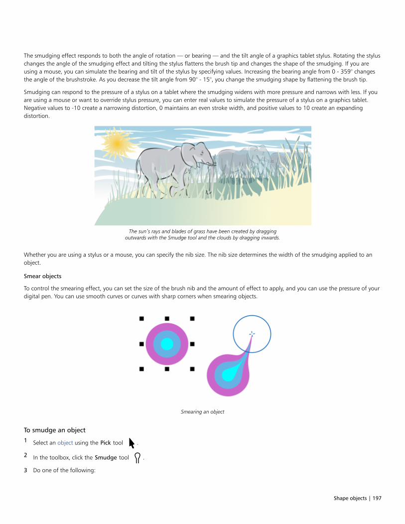
Shape objects | 197
The smudging effect responds to both the angle of rotation — or bearing — and the tilt angle of a graphics tablet stylus. Rotating the styluschanges the angle of the smudging effect and tilting the stylus flattens the brush tip and changes the shape of the smudging. If you areusing a mouse, you can simulate the bearing and tilt of the stylus by specifying values. Increasing the bearing angle from 0 - 359° changesthe angle of the brushstroke. As you decrease the tilt angle from 90° - 15°, you change the smudging shape by flattening the brush tip.
Smudging can respond to the pressure of a stylus on a tablet where the smudging widens with more pressure and narrows with less. If youare using a mouse or want to override stylus pressure, you can enter real values to simulate the pressure of a stylus on a graphics tablet.Negative values to -10 create a narrowing distortion, 0 maintains an even stroke width, and positive values to 10 create an expandingdistortion.
The sun’s rays and blades of grass have been created by draggingoutwards with the Smudge tool and the clouds by dragging inwards.
Whether you are using a stylus or a mouse, you can specify the nib size. The nib size determines the width of the smudging applied to anobject.
Smear objects
To control the smearing effect, you can set the size of the brush nib and the amount of effect to apply, and you can use the pressure of yourdigital pen. You can use smooth curves or curves with sharp corners when smearing objects.
Smearing an object
To smudge an object
1 Select an object using the Pick tool .
2 In the toolbox, click the Smudge tool .
3 Do one of the following:
198 | CorelDRAW 2019 User Guide
• To smudge the inside of an object, click outside an object, and drag inwards.
• To smudge the outside of an object, click inside an object, and drag outwards.
You can also
Change the size of the brush nib Type a value in the Nib size box on the
property bar.
Change the size of the brush nib when using the graphics stylus Click the Pen pressure button on the property bar and apply
pressure to the stylus.
Widen or narrow the smudging Type a value between -10 and 10 in the Dryout box on the
property bar.
Specify the shape of the smudging Type a value between 15 and 90 in the Pen tilt box on the propertybar.
Change the shape of the smudging when using the graphics stylus Click the Use pen tilt button on the property bar.
Specify the angle of the nib shape for smudging Type a value between 0 and 359 in the Pen bearing box on theproperty bar.
Change the angle of the nib shape for smudging when using thegraphics stylus
Click the Use pen bearing button on the property bar.
You cannot apply smudging to Internet or embedded objects, linked images, grids, masks, mesh-filled objects, or objects with blendand contour effects.
To get the minimum and maximum values for the smudging controls, right-click the control on the property bar, and click Settings.
To smear an object
1 Select an object by using the Pick tool .
2 In the toolbox, click the Smear tool .
3 Do one of the following:
• To smear the outside of an object, click outside an object, close to its edge, and drag outwards.
• To smear the inside of an object, click inside an object, close to its edge, and drag inwards.
You can also
Change the size of the brush nib Type a value in the Nib size box on the property bar.

Shape objects | 199
You can also
Set the amount of smearing Type a value in the Pressure box.
Use the pressure of a digital pen to control the amount of smearing Click the Pen pressure button on the property bar.
Use smooth curves when smearing Click the Smooth smear button .
Use curves with sharp corners when smearing Click the Pointy smear button .
The difference between a smooth smear and pointy smear is noticeable only with higher Pressure values.
Roughen objects
The roughening effect lets you apply a jagged or spiked edge to objects, including lines, curves, and text. You can control the size, angle,direction, and number of the indentations whether you activate the graphics tablet stylus or apply settings to a mouse.
The roughening effect is determined either by movements of a graphics tablet stylus, by fixed settings, or by automatically applyingperpendicular spikes to the line. Tilting the stylus toward and away from the tablet’s surface increases and decreases the size of the spikes.If you are using a mouse, you can specify the tilt angle from 0 - 90°. You can determine the direction of the spikes by changing the angleof rotation (or bearing) of the stylus as you apply the roughening effect to an object. When you are using a mouse, you can set the bearingangle from 0 - 359°. You can also increase or decrease the number of spikes that are applied as you drag.
The roughening effect also responds to the pressure of the stylus on the tablet. The more pressure you apply, the more spikes are created inthe roughened area. If you are using a mouse, you can specify values to simulate the stylus pressure.
You can also change the brush nib size.
Roughening allows you to apply jags or spikes to part of an outline or path.
To roughen an object
1 Select an object using the Pick tool .
200 | CorelDRAW 2019 User Guide
2 In the toolbox, click the Roughen tool .
3 Point to the area on the outline you want to roughen, and drag the outline to distort it.
You can also
Specify the size of the roughening spikes Type a value from 0.01 to 2.0 in the Nib size box
on the property bar.
Change the number of spikes in a roughened area Type a value between 1 and 10 in the Frequency of spikes box
on the property bar.
Change the number of spikes in a roughened area when using agraphics stylus
Click the Pen pressure button on the property bar.
Specify the height of the roughening spikes Type a value between 0 and 90 in the Pen tilt box on the propertybar.
Increase the number of roughening spikes as you drag Type a value between -10 and 10 in the Dryout box on theproperty bar.
Change the height of the roughening spikes when using a graphicsstylus
Click the Use pen tilt button on the property bar.
Specify the direction of the roughening spikes Choose Fixed direction from the Spike direction list box. Type avalue between 0 and 359 in the Bearing box on the property bar.
Change the direction of the roughening spikes when using agraphics stylus
Choose Stylus setting from the Spike direction list box on theproperty bar.
Create roughening spikes perpendicular to the path or outline Choose Auto from the Spike direction list box on the property bar.
Objects with distortions, envelopes, and perspective applied to them are converted to curve objects before the roughening effect isapplied.
To make the tilt angle and bearing angle responsive to the graphics tablet stylus, right-click the roughened object, and select acommand from the submenu.
To get the minimum and maximum values for the roughening controls, right-click the control on the property bar, and click Settings.
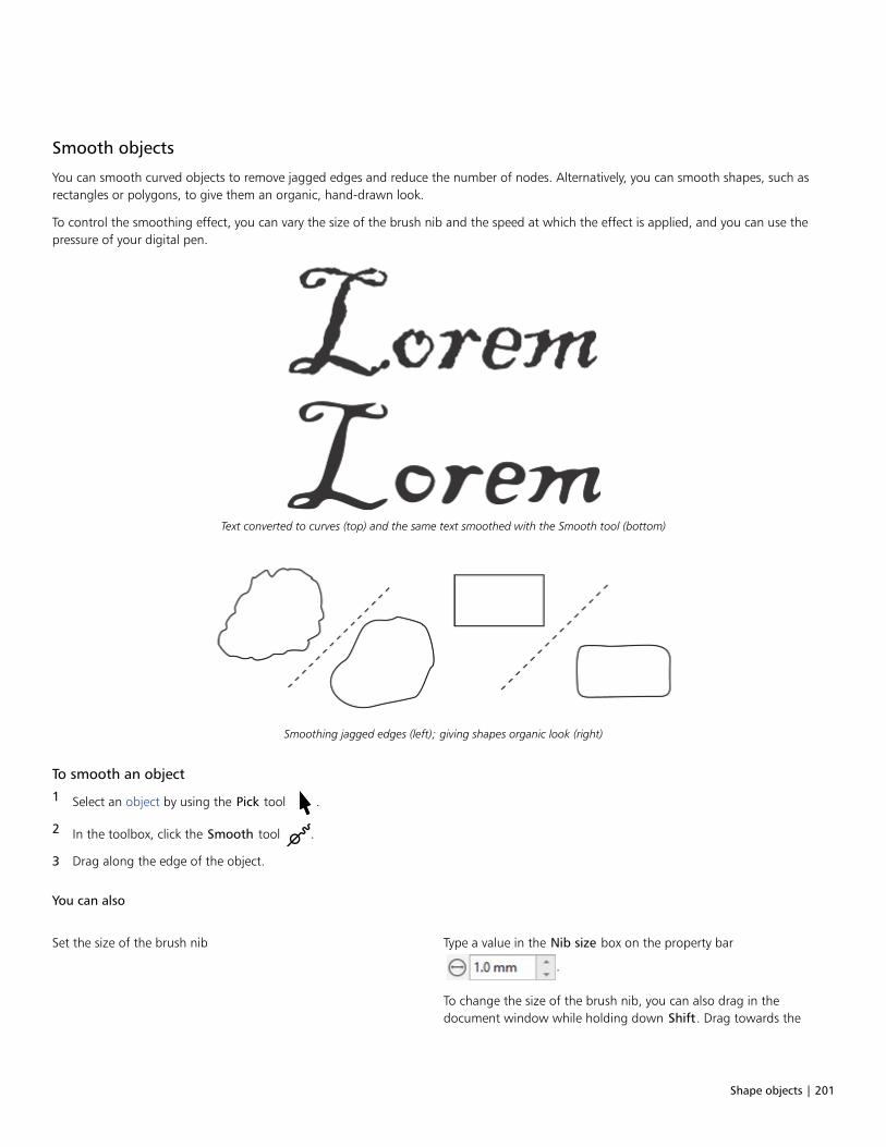
Shape objects | 201
Smooth objects
You can smooth curved objects to remove jagged edges and reduce the number of nodes. Alternatively, you can smooth shapes, such asrectangles or polygons, to give them an organic, hand-drawn look.
To control the smoothing effect, you can vary the size of the brush nib and the speed at which the effect is applied, and you can use thepressure of your digital pen.
Text converted to curves (top) and the same text smoothed with the Smooth tool (bottom)
Smoothing jagged edges (left); giving shapes organic look (right)
To smooth an object
1 Select an object by using the Pick tool .
2 In the toolbox, click the Smooth tool .
3 Drag along the edge of the object.
You can also
Set the size of the brush nib Type a value in the Nib size box on the property bar
.
To change the size of the brush nib, you can also drag in thedocument window while holding down Shift. Drag towards the
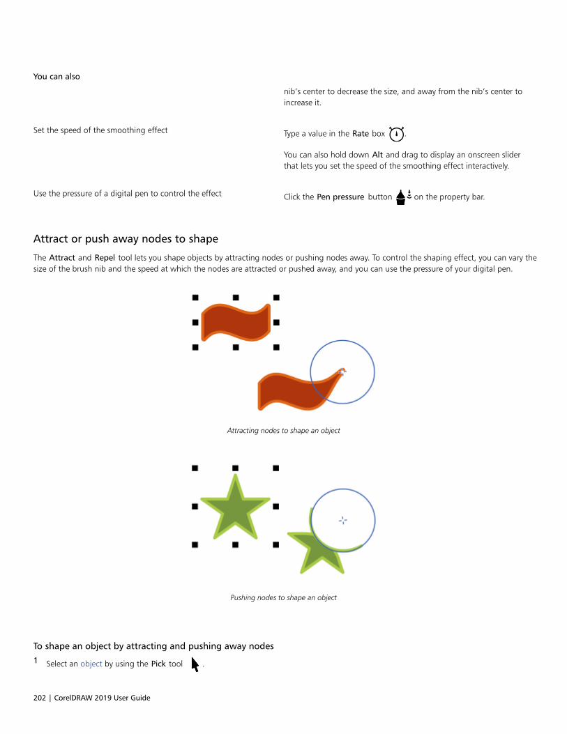
202 | CorelDRAW 2019 User Guide
You can also
nib’s center to decrease the size, and away from the nib’s center toincrease it.
Set the speed of the smoothing effect Type a value in the Rate box .
You can also hold down Alt and drag to display an onscreen sliderthat lets you set the speed of the smoothing effect interactively.
Use the pressure of a digital pen to control the effect Click the Pen pressure button on the property bar.
Attract or push away nodes to shape
The Attract and Repel tool lets you shape objects by attracting nodes or pushing nodes away. To control the shaping effect, you can vary thesize of the brush nib and the speed at which the nodes are attracted or pushed away, and you can use the pressure of your digital pen.
Attracting nodes to shape an object
Pushing nodes to shape an object
To shape an object by attracting and pushing away nodes
1 Select an object by using the Pick tool .
Shape objects | 203
2 In the toolbox, click the Attract and Repel tool .
3 Do one of the following:
• To attract nodes to the cursor, click the Attract tool on the property bar.
• To push nodes away from the cursor, click the Repel tool .
4 Click inside or outside the object, close to its edge, and hold down the mouse button to reshape the edge. For a more pronouncedeffect, drag while holding down the mouse button.
You can also
Set the size of the brush nib Type a value in the Nib size box on the property bar.
To change the size of the brush nib, you can also drag in thedocument window while holding down Shift. Drag towards thenib’s center to decrease the radius, and away from the nib’s centerto increase it.
Set the speed at which nodes are attracted or pushed away Type a value in the Rate box.
Use the pressure of a digital pen to control the effect Click the Pen pressure button on the property bar.
Apply distortion effects
You can apply three types of distortion effects to shape objects.
Distortion effect Description
Push and pull Lets you push the edges of an object in or pull the edges of anobject out
Zipper Lets you apply a saw tooth effect to the edges of the object. Youcan adjust the amplitude and frequency of the effect.
Twister Lets you rotate an object to create a swirl effect. You can choosethe direction of the swirl, as well as the degree and amount ofrotation.

204 | CorelDRAW 2019 User Guide
From left to right: Original image; Zipper and Twister distortions applied; Pull distortion applied
After you distort an object, you can change the effect by altering the center of distortion. This point is identified by a diamond-shapedhandle, around which a distortion appears. It is similar to a mathematical compass, where the pencil moves around a stationary point. Youcan place the center of distortion anywhere in the drawing window, or choose to center it in the middle of an object so that the distortion isdistributed evenly and the shape of the object changes in relation to its center.
You can create an even more dramatic effect by applying a new distortion to an already distorted object. You don’t lose the effect of theoriginal distortion if, for example, you apply a zipper distortion on top of a twister distortion. The CorelDRAW application also lets youremove and copy distortion effects.
To distort an object
1 In the toolbox, click the Distort tool .
2 On the property bar, click one of the following buttons, and specify the settings you want:
• Push and pull distortion
• Zipper distortion
• Twister distortion
3 Point to where you want to place the center of distortion, and drag until the object is the shape you want.
You can also
Change the center of distortion Drag the diamond-shaped position handle to a new location.
Adjust the number of points on a zipper distortion Move the slider on the center of the distortion handle.
Apply a preset distortion Choose a distortion preset from the Preset list box on the propertybar.
Apply more than one distortion to an object Click another distortion type on the property bar, click an object,and drag.
You can reapply the effects to distorted objects.

Shape objects | 205
You can center a distortion by clicking the Center distortion button on the property bar.
You can use the interactive vector controls to edit a distortion effect. Upper left: Zipper effect applied to circle.Upper right: Zipper effects with higher frequency (more spikes) applied. Bottom: Results of applying zipper effects.
To remove a distortion
1 Select a distorted object.
2 Click Object Clear Distortion.
Removing a distortion this way clears the most recent distortion you’ve applied.
You can also remove a distortion from a selected object by clicking Clear Distortion on the property bar.
To copy a distortion
1 Select the object to which you want to copy a distortion.
2 Click Object Copy effect Distortion from.
3 Click a distorted object.
You can also use the Eyedropper tool to copy the effect. For more information, see “To copy effects from one object to
another” on page 271.
Add twirl effects
You can add twirl effects to objects. You can set the radius, speed, and direction of the twirl effects, and you can use the pressure of yourdigital pen to change the intensity of the twirl effect.

206 | CorelDRAW 2019 User Guide
Adding a twirl effect
To add a twirl effect to an object
1 Select an object by using the Pick tool .
2 In the toolbox, click the Twirl tool .
3 Click the edge of the object, and hold down the mouse button until the twirl is the size you want.
To position and reshape the twirl, you can drag while holding down the mouse button.
You can also
Set the radius of the twirl effect Type a value in the Nib size box on the property bar.
Set the rate at which the twirl effect is applied Type a value between 1 and 100
in the Rate box on the property bar.
Set the direction of the twirl effect Click the Counterclockwise twirl button or the Clockwise
twirl button .
Use the pressure of a digital pen to control the intensity of the twirleffect
Click the Pen pressure button on the property bar.
Shape objects by using envelopes
CorelDRAW lets you shape objects, including lines, artistic text, paragraph text frames, and bitmaps by applying envelopes. Envelopes aremade of multiple nodes that you can move to shape the envelope and, as a result, change the shape of the object.

Shape objects | 207
The original bitmap (left) with an envelope (right). The envelope is applied nondestructively,so you can edit it or remove it and revert to the original image at any point.
You can apply a basic envelope that conforms to the shape of an object, or you can also apply a preset envelope.
A preset envelope has been applied to a group of bitmaps.
If none of the presets fits your needs, you can create a custom envelope and save it for future use. Envelope presets are saved as Preset(.PST) files and are stored in the \AppData\Roaming\Corel\CorelDRAW Graphics Suite 2019\Draw\Presets\Envelope folder.
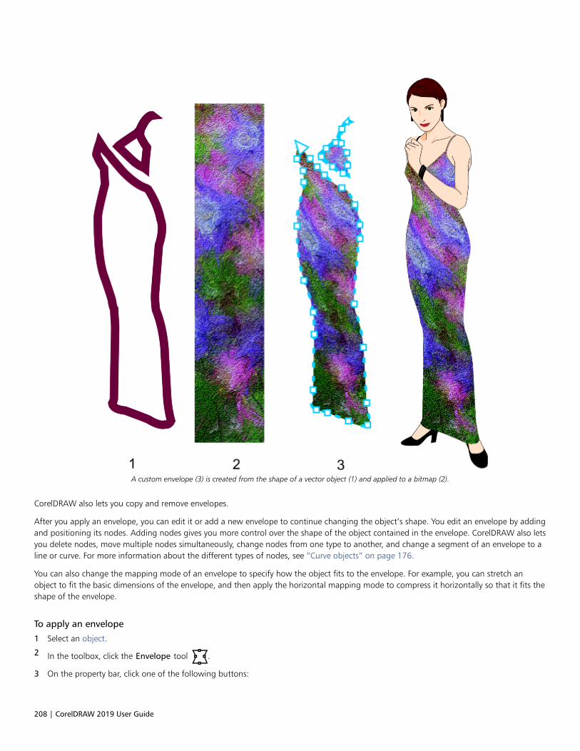
208 | CorelDRAW 2019 User Guide
A custom envelope (3) is created from the shape of a vector object (1) and applied to a bitmap (2).
CorelDRAW also lets you copy and remove envelopes.
After you apply an envelope, you can edit it or add a new envelope to continue changing the object’s shape. You edit an envelope by addingand positioning its nodes. Adding nodes gives you more control over the shape of the object contained in the envelope. CorelDRAW also letsyou delete nodes, move multiple nodes simultaneously, change nodes from one type to another, and change a segment of an envelope to aline or curve. For more information about the different types of nodes, see “Curve objects” on page 176.
You can also change the mapping mode of an envelope to specify how the object fits to the envelope. For example, you can stretch anobject to fit the basic dimensions of the envelope, and then apply the horizontal mapping mode to compress it horizontally so that it fits theshape of the envelope.
To apply an envelope
1 Select an object.
2 In the toolbox, click the Envelope tool .
3 On the property bar, click one of the following buttons:
Shape objects | 209
• Straight line mode — creates envelopes based on straight lines, adding perspective to objects
• Single-arc mode — creates envelopes with an arc shape on one side, giving objects a concave or convex appearance
• Double-arc mode — creates envelopes with an S shape on one or more sides
• Unconstrained mode — creates freeform envelopes that let you change the properties of the nodes, and add and delete the
nodes
4 Click the object.
5 Drag the nodes to shape the envelope.
If you want to reset the envelope, press Esc before releasing the mouse.
You can also
Apply a preset envelope Click the Preset list list box on the property bar, and click anenvelope shape.
Apply an envelope to an object with an envelope Click the Add new envelope button on the property bar, and
drag the nodes to change the shape of the envelope.
Remove an envelope Click Effects Clear envelope.
Applying an envelope to paragraph text allows you to modify only the shape of the text frame. To shape the text inside the frame,consider converting the frame to a curve after you finish editing and formatting the content. For information about convertingobjects to curves, see “To convert objects to curve objects” on page 176. Note that once you convert the frame to a curve, you canno longer edit the text. To shape individual characters with an envelope, use artistic text.
You cannot apply an envelope to a bitmap with an envelope.
You can also apply an envelope by using the Envelope docker (Effects Envelope).
You can prevent the straight lines of a vector object from being converted to curves by enabling the Keep lines button on the
property bar.
To create an envelope based on the shape of another object
1 Select an object to which you want to apply an envelope.
2 In the toolbox, click the Envelope tool .
3 Click the Create envelope from button on the property bar.
4 Click the object from which you want to create an envelope.
The envelope is applied to the object that you selected in step 1.
To save the envelope for future use, click the Add preset button on the property bar, type a filename in the File name list box, and
click Save.
210 | CorelDRAW 2019 User Guide
You can create an envelope only from a closed curve.
To copy an envelope
1 Select an object to which you want to apply an envelope.
2 Click Object Copy effect Envelope from.
3 Select the object from which you want to copy the envelope.
You can also copy an envelope by selecting an object, clicking the Copy envelope properties button on the property bar, andselecting an object with the envelope you want to copy.
You can also use the Attributes Eyedropper tool to copy an envelope. For more information, see “To copy effects from one
object to another” on page 271.
To edit the nodes and segments of an envelope
1 In the toolbox, click the Envelope tool .
2 Select an object with an envelope.
3 Double-click the envelope to add a node or double-click a node to delete it.
You can also
Move several envelope nodes at once Click the Unconstrained mode button on the property bar,
marquee select the nodes you want to move, and drag any node toa new position.
Marquee select multiple nodes On the property bar, choose Rectangular from the Selection modelist box, and drag around the nodes that you want to select.
Freehand marquee select multiple nodes On the property bar, choose Freehand from the Selection modelist box, and drag around the nodes you want to select.
Move two opposing nodes an equal distance in the same direction Click the Straight line mode , Single-arc mode or
Double-arc mode button on the property bar so that it
appears raised, press Ctrl, and drag a node to a new position.

Shape objects | 211
You can also
Moving corner nodes skews the envelope.
Moving middle nodes
Note: This feature applies only to some preset envelopes withsymmetrical nodes.
Move two opposing nodes an equal distance in the oppositedirection
Click the Straight line mode , Single-arc mode or
Double-arc mode button on the property bar so that it
appears raised, press Shift, and drag a node to a new position.

212 | CorelDRAW 2019 User Guide
You can also
Moving corner nodes
Moving middle nodes
Note: This feature applies only to some preset envelopes withsymmetrical nodes.
Move all opposing nodes symmetrically to or away from a centralpoint
Click the Straight line mode , Single-arc mode or
Double-arc mode button on the property bar so that it
appears raised, press Ctrl + Shift, and drag a node to a newposition.
Moving all corner nodes stretches the envelope horizontally orvertically.

Shape objects | 213
You can also
Moving all middle nodes lets you push the edges of the envelope inor pull the edges of the envelope out.
Note: This feature applies only to some preset envelopes withsymmetrical nodes.
Change an envelope node type Click the Unconstrained mode button on the property bar so
that it appears pressed, and click either the Cusp node , the
Smooth node , or the Symmetrical node button.
Change an envelope segment to a straight line or curve Click the Unconstrained mode button on the property bar so thatit appears pressed, click a line segment, and click the Convert to
line button or the Convert to curve button.
Note: Both the Convert to line and Convert to curve
buttons are disabled when you apply an envelope to a bitmap.
If you split, crop, or erase portions of an object with an envelope, you can no longer edit the envelope.
If you edit a bitmap with an envelope in Corel PHOTO-PAINT, or if you copy a bitmap with an envelope and paste it into CorelPHOTO-PAINT or into an earlier version of CorelDRAW, the envelope is no longer editable.
To change the mapping mode
1 In the toolbox, click the Envelope tool.
2 Click an object with an envelope.
3 On the property bar, choose one of the following from the Mapping mode list box:

214 | CorelDRAW 2019 User Guide
• Horizontal — stretches the object to fit the basic dimensions of the envelope and then compresses the object horizontally to fit theshape of the envelope
• Original — maps the corner handles of the object’s selection box to the envelope’s corner nodes. The other nodes are mapped linearlyalong the edge of the object’s selection box.
• Putty — maps the corner handles of the object’s selection box to the envelope corner nodes
• Vertical — stretches the object to fit the basic dimensions of the envelope and then compresses the object vertically to fit the shape ofthe envelope
4 Drag the nodes or the control handles.
The mapping mode of paragraph text frames cannot be changed after an envelope is applied.
Crop and erase objects
You can crop and erase portions of objects.
Crop
Cropping lets you quickly remove unwanted areas in objects and imported photos, eliminating the need to ungroup objects, break linkedgroups apart, or convert objects to curves. You can crop vector objects and bitmaps.
Cropping objects
When cropping objects, you define a rectangular area (cropping area) that you want to keep. Object portions outside the cropping areaare removed. You can specify the exact position and size of the cropping area, and you can rotate and resize it. You can also remove thecropping area.
You can crop only selected objects without affecting other objects in a drawing, or you can crop all objects on the drawing page. In eithercase, the affected text and shape objects are automatically converted to curves.
Erase
CorelDRAW lets you erase unwanted portions of bitmaps and vector objects. The Eraser tool works just like a pencil eraser, removing anypart of the image over which you click and drag. If you want to erase only portions of a specific object, you have to select it. When noobject is selected, the Eraser tool removes any part of the drawing over which you drag. For information about selecting objects, see “Selectobjects” on page 252. Erasing automatically closes any affected paths and converts the object to curves. If you erase connecting lines,CorelDRAW creates subpaths rather than individual objects. You cannot erase objects with contours, blends, drop shadows, block shadows,and extrusions.

Shape objects | 215
When working with a pen or stylus, you can use pressure to vary the size of the eraser nib. If your pen or stylus supports tilt and bearing,you can use these features to vary the flatness and rotation of the eraser nib. You can also set fixed values for the tilt angle and bearingangle so that the flatness and rotation of the nib remain the same.
You can use your stylus to vary the size and flatness of the eraser nib.
You can also choose default settings for the Eraser tool such as the default size of the eraser nib. Objects created as a result of erasing havetheir nodes automatically reduced; however you can choose to disable this setting.
Delete
You can also delete virtual line segments, which are portions of objects that overlap each other. For example, you can delete a loop in a linethat crosses over itself, or loops in line segments in which two or more objects overlap.
To crop an object or imported photo
1 Select the object or imported photo that you want to crop.
You can select one or more objects. If no objects on the drawing page are selected, all objects in the drawing will be cropped.
2 In the toolbox, click the Crop tool .
3 Drag to define a cropping area.
4 Double-click inside the cropping area.
You can also
Specify the exact position of the cropping area Type values in the Crop position boxes on the property bar, andpress Enter.
Specify the exact size of the cropping area Type values in the Crop size boxes on the property bar, and pressEnter.
Rotate the cropping area Type values in the Angle of rotation box.
Remove the cropping area Click Clear.
216 | CorelDRAW 2019 User Guide
Objects on locked, hidden, Grid, or Guides layers cannot be cropped. Also, you cannot crop OLE and Internet objects, rollovers, or thecontent of PowerClip objects.
During cropping, affected linked groups, such as contours, blends, and extrusions, are automatically broken apart.
You can move, rotate, and size the cropping area interactively as you would any object. To move the cropping area, drag it to a new
position. To size the cropping area, drag any of its handles. To rotate the cropping area, click inside, and drag a rotation handle .
You can remove the cropping area by pressing Esc.
To erase an image area
1 Perform a task from the following table.
To Do the following
Erase an area in a drawing Deselect all objects.
Erase portions of an object Select the object.
2 Do one of the following:
• When using a mouse, click the Eraser tool in the toolbox.
• When using a stylus, flip the stylus to automatically switch to erase mode.
3 Drag over the area that you want to erase.
You can also
Change the size of the eraser nib Type a value in the Eraser thickness box on the property bar, andpress Enter.
Change the shape of the eraser nib Click the Round nib or the Square nib button on the
property bar.
Vary the width of the eraser nib Click the Pen pressure button on the property bar to enable
it.
The maximum width of the nib is determined by the value specifiedin the Eraser thickness box.
If you are using the mouse, press the Up arrow or Down arrowto simulate changes in pen pressure and change the width of theeraser nib.
Vary the flatness of the eraser nib Click the Pen tilt button on the property bar to enable it.
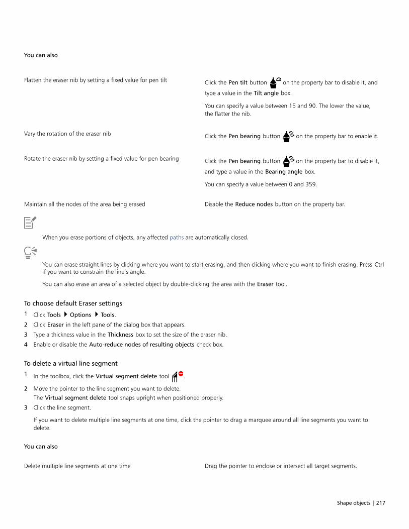
Shape objects | 217
You can also
Flatten the eraser nib by setting a fixed value for pen tilt Click the Pen tilt button on the property bar to disable it, and
type a value in the Tilt angle box.
You can specify a value between 15 and 90. The lower the value,the flatter the nib.
Vary the rotation of the eraser nib Click the Pen bearing button on the property bar to enable it.
Rotate the eraser nib by setting a fixed value for pen bearing Click the Pen bearing button on the property bar to disable it,
and type a value in the Bearing angle box.
You can specify a value between 0 and 359.
Maintain all the nodes of the area being erased Disable the Reduce nodes button on the property bar.
When you erase portions of objects, any affected paths are automatically closed.
You can erase straight lines by clicking where you want to start erasing, and then clicking where you want to finish erasing. Press Ctrlif you want to constrain the line’s angle.
You can also erase an area of a selected object by double-clicking the area with the Eraser tool.
To choose default Eraser settings
1 Click Tools Options Tools.
2 Click Eraser in the left pane of the dialog box that appears.
3 Type a thickness value in the Thickness box to set the size of the eraser nib.
4 Enable or disable the Auto-reduce nodes of resulting objects check box.
To delete a virtual line segment
1 In the toolbox, click the Virtual segment delete tool .
2 Move the pointer to the line segment you want to delete.
The Virtual segment delete tool snaps upright when positioned properly.
3 Click the line segment.
If you want to delete multiple line segments at one time, click the pointer to drag a marquee around all line segments you want todelete.
You can also
Delete multiple line segments at one time Drag the pointer to enclose or intersect all target segments.
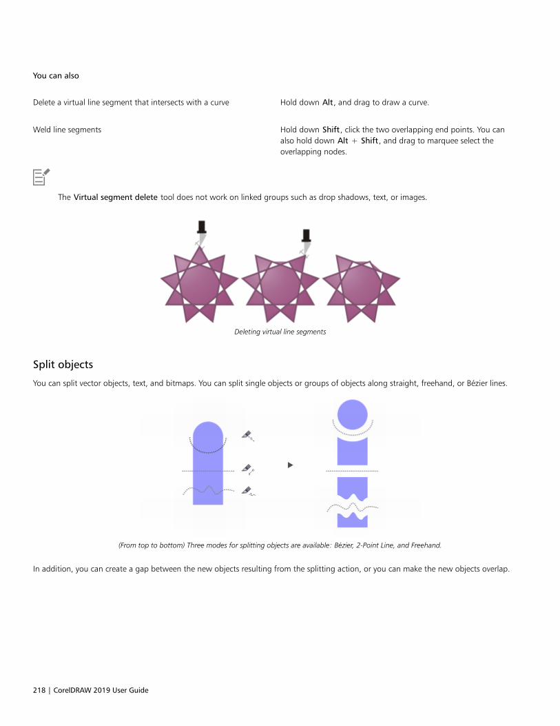
218 | CorelDRAW 2019 User Guide
You can also
Delete a virtual line segment that intersects with a curve Hold down Alt, and drag to draw a curve.
Weld line segments Hold down Shift, click the two overlapping end points. You canalso hold down Alt + Shift, and drag to marquee select theoverlapping nodes.
The Virtual segment delete tool does not work on linked groups such as drop shadows, text, or images.
Deleting virtual line segments
Split objects
You can split vector objects, text, and bitmaps. You can split single objects or groups of objects along straight, freehand, or Bézier lines.
(From top to bottom) Three modes for splitting objects are available: Bézier, 2-Point Line, and Freehand.
In addition, you can create a gap between the new objects resulting from the splitting action, or you can make the new objects overlap.
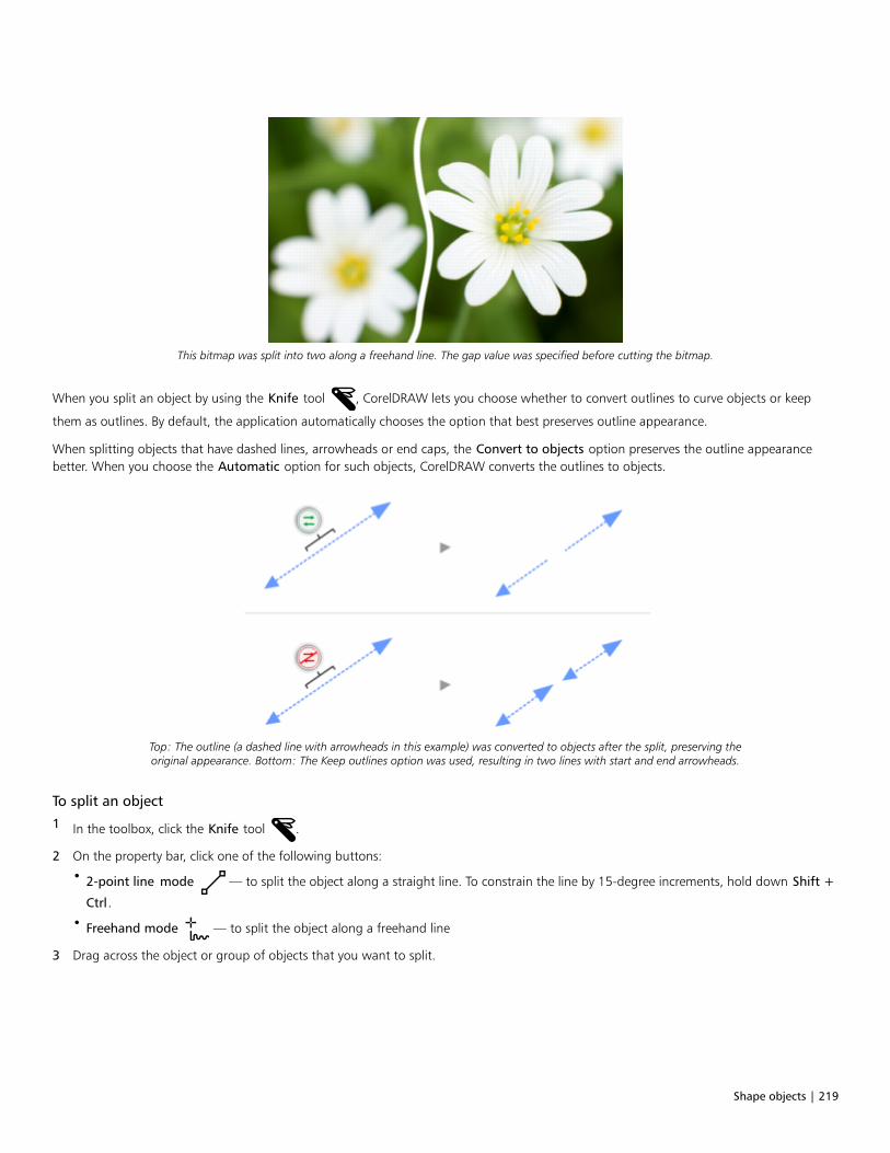
Shape objects | 219
This bitmap was split into two along a freehand line. The gap value was specified before cutting the bitmap.
When you split an object by using the Knife tool , CorelDRAW lets you choose whether to convert outlines to curve objects or keep
them as outlines. By default, the application automatically chooses the option that best preserves outline appearance.
When splitting objects that have dashed lines, arrowheads or end caps, the Convert to objects option preserves the outline appearancebetter. When you choose the Automatic option for such objects, CorelDRAW converts the outlines to objects.
Top: The outline (a dashed line with arrowheads in this example) was converted to objects after the split, preserving theoriginal appearance. Bottom: The Keep outlines option was used, resulting in two lines with start and end arrowheads.
To split an object
1 In the toolbox, click the Knife tool .
2 On the property bar, click one of the following buttons:
• 2-point line mode — to split the object along a straight line. To constrain the line by 15-degree increments, hold down Shift +
Ctrl.
• Freehand mode — to split the object along a freehand line
3 Drag across the object or group of objects that you want to split.
220 | CorelDRAW 2019 User Guide
You can also
Split an object along a Bézier line Click the Bézier mode button on the property bar. Click where
you want to start cutting an object, drag the control handle towhere you want to position the next node, and click. Continueclicking to add more straight segments to the line. To add a curvedsegment, point to where you want to place the node and drag toshape the curve. To constrain the line by 15-degree increments,hold down Shift + Ctrl.
Create a gap or an overlap between the new objects On the property bar, choose Gap or Overlap from the Cut span listbox. Type a value in the Width box.
Choose outline options On the property bar, choose an option from the Outline optionslist box.
When you split an object by using the Knife tool, the new objects become curve objects.
Trim objects
Trimming creates irregularly shaped objects by removing object areas that overlap. You can trim almost any object, including clones, objectson different layers, and single objects with intersecting lines. However, you cannot trim paragraph text, dimension lines, or masters of clones.
Before you trim objects, you must decide which object you want to trim (the target object) and which object you want to use to performthe trimming (the source object). For example, if you want to create a star-shaped cut out of a square object, the star is the source objectbecause you are using it to trim the square. The square is the target object because it’s the object you want to trim. The source object trimsthe part of the target object it overlaps.
The target object retains its fill and outline attributes. For example, if you trim a rectangle that is overlapped by a circle, the area of therectangle that was covered by the circle is removed, creating an irregular shape.
CorelDRAW lets you trim objects in different ways. You can use a front object as the source object to trim an object behind it, as well as usethe back object to trim a front object. You can also remove hidden areas of overlapping objects, so that only the visible areas remain in thedrawing. Removing the hidden areas can reduce file size when you convert vector graphics to bitmaps.
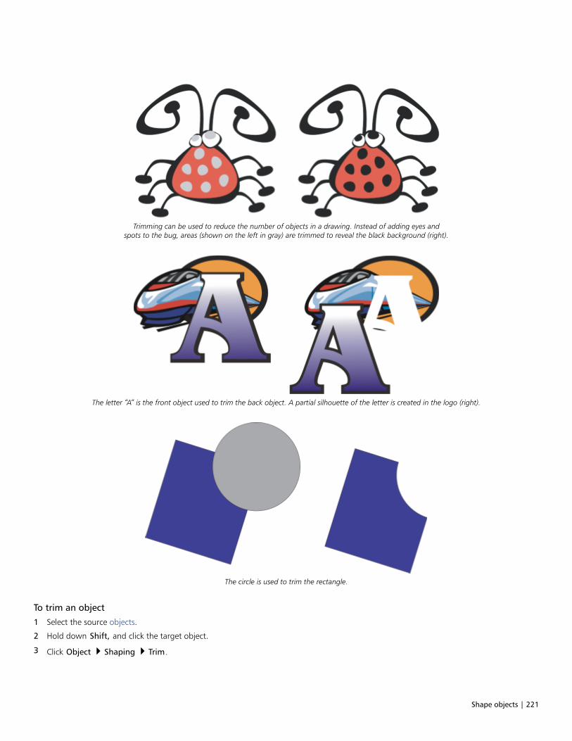
Shape objects | 221
Trimming can be used to reduce the number of objects in a drawing. Instead of adding eyes andspots to the bug, areas (shown on the left in gray) are trimmed to reveal the black background (right).
The letter “A” is the front object used to trim the back object. A partial silhouette of the letter is created in the logo (right).
The circle is used to trim the rectangle.
To trim an object
1 Select the source objects.
2 Hold down Shift, and click the target object.
3 Click Object Shaping Trim.

222 | CorelDRAW 2019 User Guide
If you marquee select the objects, CorelDRAW trims the bottom-most selected object. If you select multiple objects individually, thelast object selected is trimmed.
You can also trim objects by marquee-selecting the source and target objects and clicking the Trim button on the property bar.
To trim front or back objects
1 Marquee select the source and target objects.
2 Click Object Shaping, and click one of the following:
• Front minus back — removes the back object from the front one
• Back minus front — removes the front object from the back one
You can trim the control object of a PowerClip object so that the object inside the PowerClip object will assume the new shape of thePowerClip container. For information about PowerClip objects, see “PowerClip objects” on page 226.
Linked objects such as drop shadows, text on a path, blends, contours, and extrusions are converted to curve objects before they aretrimmed.
To trim overlapping areas in objects
1 Marquee select the objects you want to trim.
2 Click Object Shaping Simplify.
You can trim the control object of a PowerClip object, so that the object inside the PowerClip object assumes the new shape.
Linked objects, such as drop shadows, text on a path, blends, contours, and extrusions, are converted to curve objects before they aretrimmed.
Fillet, scallop, and chamfer corners
You can fillet, scallop, or chamfer the corners of any curve object, whether it originates from a shape, lines, text, or a bitmap. Filletingproduces a rounded corner, scalloping rounds and inverts the corner to create a notch, and chamfering bevels a corner so that it appearsflat. CorelDRAW also lets you preview the corners before you apply the changes to them. For information about modifying the corners ofsquares and rectangles, see “Rectangles and squares ” on page 163.
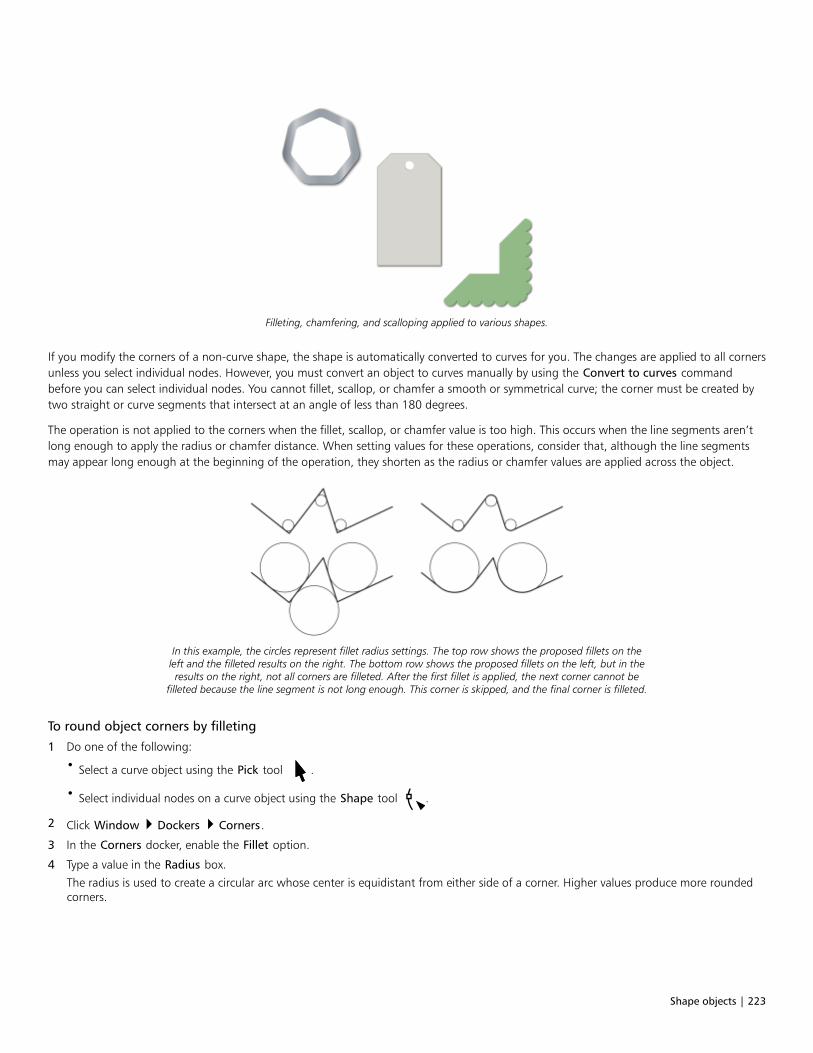
Shape objects | 223
Filleting, chamfering, and scalloping applied to various shapes.
If you modify the corners of a non-curve shape, the shape is automatically converted to curves for you. The changes are applied to all cornersunless you select individual nodes. However, you must convert an object to curves manually by using the Convert to curves commandbefore you can select individual nodes. You cannot fillet, scallop, or chamfer a smooth or symmetrical curve; the corner must be created bytwo straight or curve segments that intersect at an angle of less than 180 degrees.
The operation is not applied to the corners when the fillet, scallop, or chamfer value is too high. This occurs when the line segments aren’tlong enough to apply the radius or chamfer distance. When setting values for these operations, consider that, although the line segmentsmay appear long enough at the beginning of the operation, they shorten as the radius or chamfer values are applied across the object.
In this example, the circles represent fillet radius settings. The top row shows the proposed fillets on theleft and the filleted results on the right. The bottom row shows the proposed fillets on the left, but in theresults on the right, not all corners are filleted. After the first fillet is applied, the next corner cannot be
filleted because the line segment is not long enough. This corner is skipped, and the final corner is filleted.
To round object corners by filleting
1 Do one of the following:
• Select a curve object using the Pick tool .
• Select individual nodes on a curve object using the Shape tool .
2 Click Window Dockers Corners.
3 In the Corners docker, enable the Fillet option.
4 Type a value in the Radius box.
The radius is used to create a circular arc whose center is equidistant from either side of a corner. Higher values produce more roundedcorners.
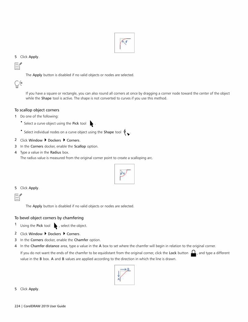
224 | CorelDRAW 2019 User Guide
5 Click Apply.
The Apply button is disabled if no valid objects or nodes are selected.
If you have a square or rectangle, you can also round all corners at once by dragging a corner node toward the center of the objectwhile the Shape tool is active. The shape is not converted to curves if you use this method.
To scallop object corners
1 Do one of the following:
• Select a curve object using the Pick tool .
• Select individual nodes on a curve object using the Shape tool .
2 Click Window Dockers Corners.
3 In the Corners docker, enable the Scallop option.
4 Type a value in the Radius box.
The radius value is measured from the original corner point to create a scalloping arc.
5 Click Apply.
The Apply button is disabled if no valid objects or nodes are selected.
To bevel object corners by chamfering
1 Using the Pick tool , select the object.
2 Click Window Dockers Corners.
3 In the Corners docker, enable the Chamfer option.
4 In the Chamfer distance area, type a value in the A box to set where the chamfer will begin in relation to the original corner.
If you do not want the ends of the chamfer to be equidistant from the original corner, click the Lock button , and type a different
value in the B box. A and B values are applied according to the direction in which the line is drawn.
5 Click Apply.
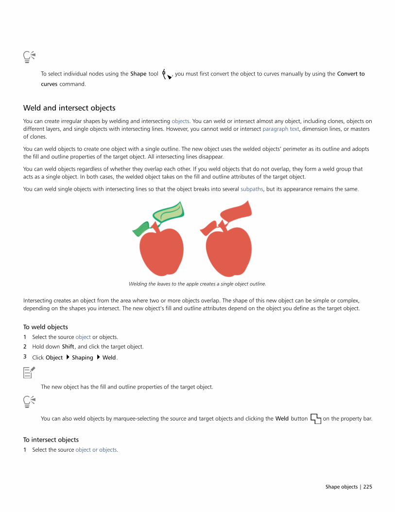
Shape objects | 225
To select individual nodes using the Shape tool , you must first convert the object to curves manually by using the Convert to
curves command.
Weld and intersect objects
You can create irregular shapes by welding and intersecting objects. You can weld or intersect almost any object, including clones, objects ondifferent layers, and single objects with intersecting lines. However, you cannot weld or intersect paragraph text, dimension lines, or mastersof clones.
You can weld objects to create one object with a single outline. The new object uses the welded objects’ perimeter as its outline and adoptsthe fill and outline properties of the target object. All intersecting lines disappear.
You can weld objects regardless of whether they overlap each other. If you weld objects that do not overlap, they form a weld group thatacts as a single object. In both cases, the welded object takes on the fill and outline attributes of the target object.
You can weld single objects with intersecting lines so that the object breaks into several subpaths, but its appearance remains the same.
Welding the leaves to the apple creates a single object outline.
Intersecting creates an object from the area where two or more objects overlap. The shape of this new object can be simple or complex,depending on the shapes you intersect. The new object’s fill and outline attributes depend on the object you define as the target object.
To weld objects
1 Select the source object or objects.
2 Hold down Shift, and click the target object.
3 Click Object Shaping Weld.
The new object has the fill and outline properties of the target object.
You can also weld objects by marquee-selecting the source and target objects and clicking the Weld button on the property bar.
To intersect objects
1 Select the source object or objects.

226 | CorelDRAW 2019 User Guide
2 Hold down Shift, and select the target object.
3 Click Object Shaping Intersect.
The new object, which is created from the overlapping parts of the source and target object, has the fill and outline properties of thetarget object.
You can also intersect objects by selecting the source and target objects and clicking the Intersect button on the property bar.
To intersect multiple objects
1 Marquee select the source object or objects.
2 Hold down Shift, and click each target object.
3 Click Object Shaping Intersect.
You can also intersect objects by marquee-selecting the source and target objects and clicking the Intersect button on the
property bar.
PowerClip objects
CorelDRAW lets you place vector objects and bitmaps, such as photos, inside other objects, or frames. A frame can be any object, forexample artistic text or a rectangle. When the object is larger than the frame, the object, called the contents, is cropped to fit the form of theframe. This creates a PowerClip object.
Objects before becoming a PowerClip object: artistic text and a bitmap
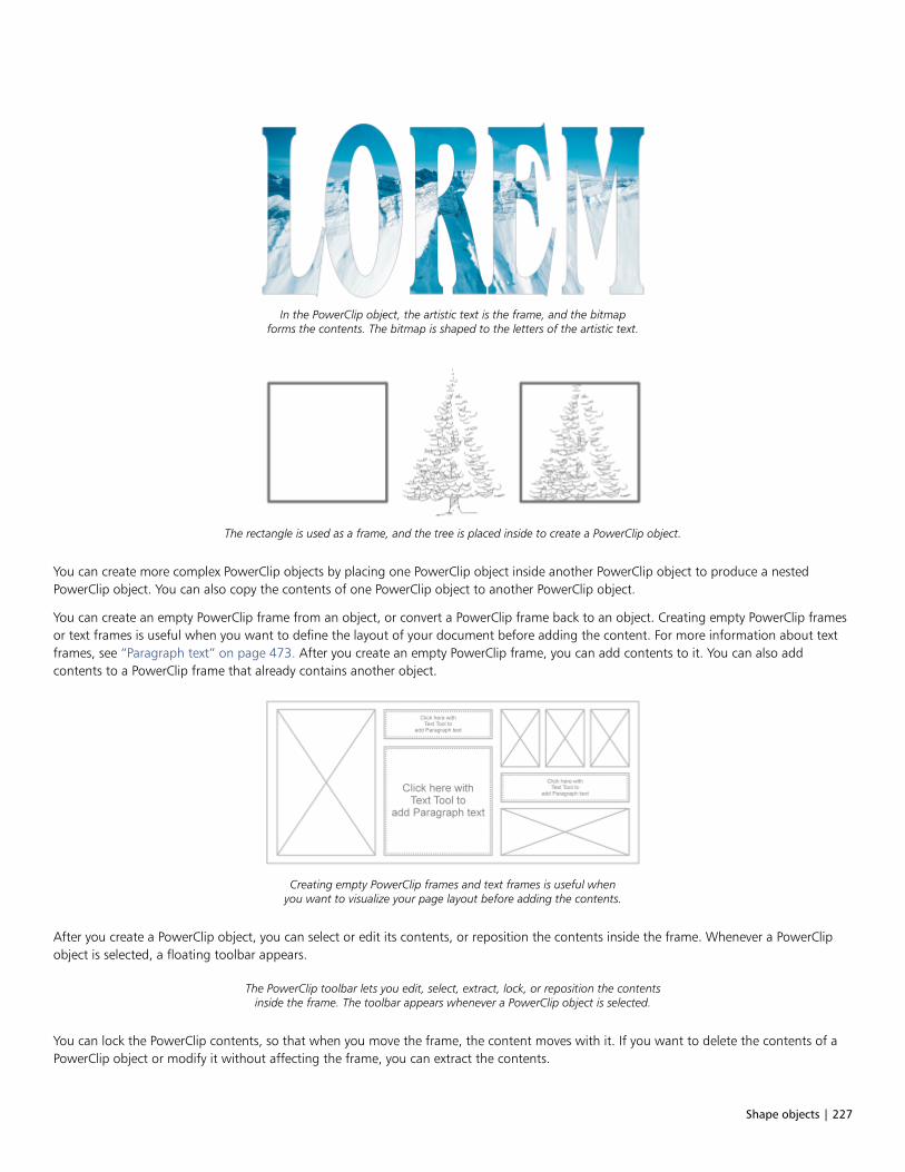
Shape objects | 227
In the PowerClip object, the artistic text is the frame, and the bitmapforms the contents. The bitmap is shaped to the letters of the artistic text.
The rectangle is used as a frame, and the tree is placed inside to create a PowerClip object.
You can create more complex PowerClip objects by placing one PowerClip object inside another PowerClip object to produce a nestedPowerClip object. You can also copy the contents of one PowerClip object to another PowerClip object.
You can create an empty PowerClip frame from an object, or convert a PowerClip frame back to an object. Creating empty PowerClip framesor text frames is useful when you want to define the layout of your document before adding the content. For more information about textframes, see “Paragraph text” on page 473. After you create an empty PowerClip frame, you can add contents to it. You can also addcontents to a PowerClip frame that already contains another object.
Creating empty PowerClip frames and text frames is useful whenyou want to visualize your page layout before adding the contents.
After you create a PowerClip object, you can select or edit its contents, or reposition the contents inside the frame. Whenever a PowerClipobject is selected, a floating toolbar appears.
The PowerClip toolbar lets you edit, select, extract, lock, or reposition the contentsinside the frame. The toolbar appears whenever a PowerClip object is selected.
You can lock the PowerClip contents, so that when you move the frame, the content moves with it. If you want to delete the contents of aPowerClip object or modify it without affecting the frame, you can extract the contents.

228 | CorelDRAW 2019 User Guide
You can set the default behavior for dragging content to PowerClip frames, centering new content, and marking empty PowerClip frames.
To create a PowerClip object
1 Select the object that you want to use as the PowerClip contents.
2 Click Object PowerClip Place inside frame.
3 Click the object that you want to use as a frame.
If you want to create a nested PowerClip object, drag the PowerClip object inside another PowerClip object, and hold down the W key asyou release the mouse button to place the object inside the frame.
You can also right-click an object or a group of objects, click PowerClip inside, and then click the object that you want to use as acontainer.
If the content is placed so that it falls outside the frame in its current position, it is automatically centered inside the frame to make it
visible. To change this setting, click Tools Options CorelDRAW, choose PowerClip in the left pane, and set the options you wantin the Auto-center new content area.
To create an empty PowerClip frame
1 Select an object that you want to use as a frame.
2 Click Object PowerClip Create empty PowerClip frame.
You can also right-click the object, choose Frame type, and click Create empty PowerClip frame.
You can also click the PowerClip frame button on the Layout toolbar. To open the Layout toolbar, click Window Toolbars Layout.
To add content to a PowerClip frame
1 Drag an object to the PowerClip frame.
When the object approaches the frame, the frame is highlighted.
2 Do one of the following:
• To add the object to an empty PowerClip frame, release the mouse button.
• To add the object to a full PowerClip frame, hold down the W key as you release the mouse button.
You can also drag content to the PowerClip frame directly from the Corel CONNECT docker.
If the content is placed so that it falls outside the frame in its current position, it is automatically centered inside the frame to make it
visible. To change this setting, click Tools Options CorelDRAW, choose PowerClip in the left pane, and set the options you wantin the Auto-center new content area.
To convert a PowerClip frame back to an object
• Right-click the PowerClip frame, choose Frame type, and click Remove Frame.
If the frame contains content, the content is deleted when the frame reverts to a regular object. To avoid losing the content, you canfirst extract it from the PowerClip object.

Shape objects | 229
You can also click the No frame button on the Layout toolbar. To open the Layout toolbar, click Window Toolbars Layout.
To select the contents of a PowerClip object
1 Select the PowerClip object.
The PowerClip toolbar appears.
2 Click the Select contents button on the PowerClip toolbar.
To position the contents inside a PowerClip frame
1 Select a PowerClip object.
2 Perform a task from the following table.
To Do the following
Center the contents inside the PowerClip frame Click Object PowerClip Center.
Fit the contents proportionally inside the PowerClip frame Click Object PowerClip Fit Proportionally.
The content is resized so that its longest dimension fits insidethe frame. The content is not distorted, and its aspect ratio ispreserved. The whole content is visible, but there may be emptyareas in the frame.
Fill the PowerClip frame proportionally Click Object PowerClip Fill Proportionally.
The content is resized so that it fills the frame without beingdistorted. The content’s aspect ratio is preserved. The frame is full,but there may be parts of the content that fall outside the frameand are not visible.
Fill the PowerClip frame by stretching the contents Click Object PowerClip Stretch to Fill.
The content is resized and distorted so that it fills the frame. Thecontent’s aspect ratio is not preserved. The frame is full, and all ofthe content is visible.
The Fit Proportionally, Fill Proportionally, and the Stretch to Fill commands modify the PowerClip contents. The content remainsmodified even if you extract it from the frame.
You can also position the contents by clicking the arrow button on the PowerClip toolbar and clicking a command.

230 | CorelDRAW 2019 User Guide
Examples of PowerClip contents positioned by using the following commands: Center contents (top left), Fit contentsproportionally (top right), Fill frame proportionally (bottom left), and Stretch contents to fill frame (bottom right).
To copy the contents of a PowerClip object
1 Select an object.
2 Click Object PowerClip Copy PowerClip From.
3 Click a PowerClip object.
To edit the contents of a PowerClip object
1 Select a PowerClip object.
2 Click Object PowerClip Edit PowerClip.
3 Edit the contents of the PowerClip object.
4 Click Object PowerClip Finish Editing PowerClip.
While you edit the contents, the frame appears in Wireframe mode and cannot be selected or edited.
You can also double-click the PowerClip object to enable it for editing, or select the PowerClip object and click the Edit button on thePowerClip toolbar. When you have finished editing the contents, click the Finish button.
To lock or unlock the contents of a PowerClip object
1 Select a PowerClip object.
2 Click Object PowerClip Lock Contents to PowerClip.
If you move the frame while the content is unlocked, the content remains stationary and is not visible until you move the frame overit.

Shape objects | 231
You can also right-click a PowerClip object and click Lock Contents to PowerClip, or you can select the PowerClip object and click theLock Contents button on the PowerClip toolbar.
To extract the contents of a PowerClip object
1 Select a PowerClip object.
2 Click Object PowerClip Extract Contents.
The contents remains in the same location, but it is separated from the frame. The PowerClip frame remains as an empty PowerClipframe.
You must extract the contents of each level in a nested PowerClip separately.
You can also select the PowerClip object and click the Extract Contents button on the PowerClip toolbar.
To set default options for PowerClip frames
1 Click Tools Options CorelDRAW.
2 In the left pane of the dialog box that appears, click PowerClip.
3 Perform a task from the following table.
To Do the following
Set the default behavior for dragging content to a PowerClip frame From the Drag content inside PowerClip list box, choosePowerClip with content or Empty PowerClip, and then chooseone of the following options:
•Ignore PowerClip frame — places the content on top of thePowerClip frame instead of inside
•Add content to PowerClip frame•Replace existing content (available only for PowerClip frames
with content)
Set the default behavior for centering new content in a PowerClipframe
In the Auto-center new content area, choose one of the followingoptions:
•When content is completely outside frame — centers contentonly if it is beyond the boundaries of the PowerClip frame andwill not be visible otherwise
•Always — always centers new content•Never— turns off auto-centering
Mark empty PowerClip frames Enable the Show lines in empty PowerClip frames check box, andchoose one of the following options:
•Always (including print and export) — displays lines inempty PowerClip frames on screen and in printed or exporteddocuments
•On screen only — displays lines in empty PowerClip frames onlyon screen
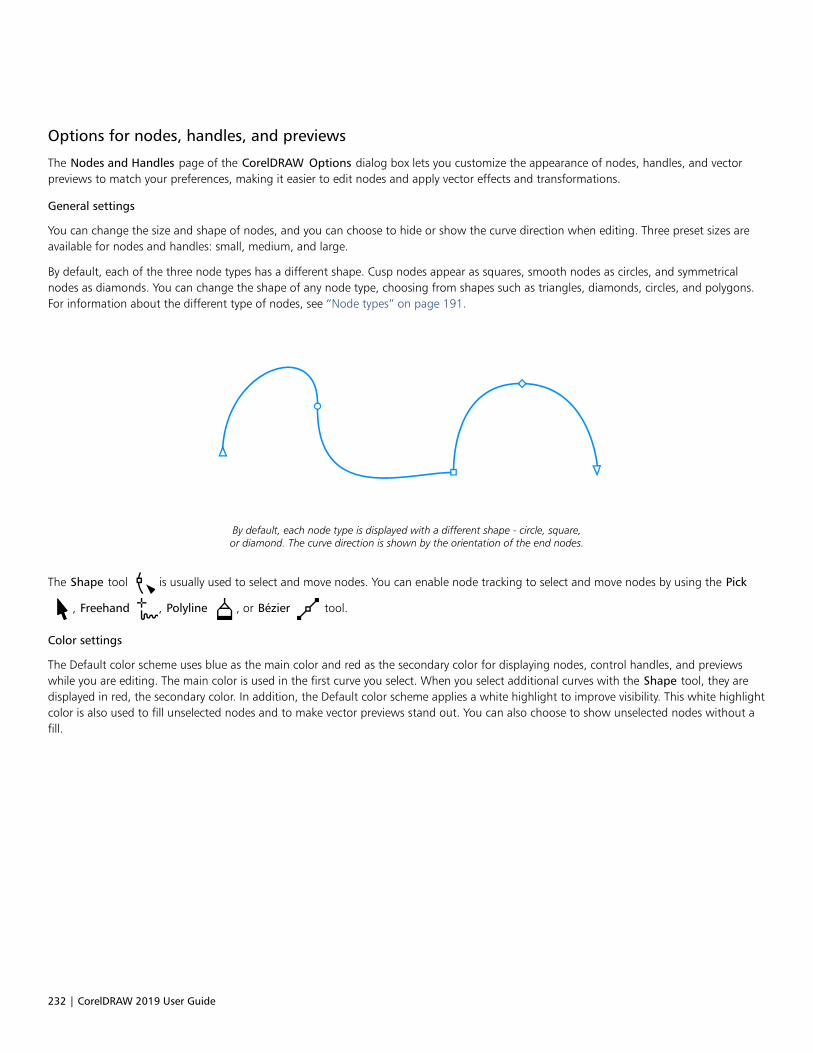
232 | CorelDRAW 2019 User Guide
Options for nodes, handles, and previews
The Nodes and Handles page of the CorelDRAW Options dialog box lets you customize the appearance of nodes, handles, and vectorpreviews to match your preferences, making it easier to edit nodes and apply vector effects and transformations.
General settings
You can change the size and shape of nodes, and you can choose to hide or show the curve direction when editing. Three preset sizes areavailable for nodes and handles: small, medium, and large.
By default, each of the three node types has a different shape. Cusp nodes appear as squares, smooth nodes as circles, and symmetricalnodes as diamonds. You can change the shape of any node type, choosing from shapes such as triangles, diamonds, circles, and polygons.For information about the different type of nodes, see “Node types” on page 191.
By default, each node type is displayed with a different shape - circle, square,or diamond. The curve direction is shown by the orientation of the end nodes.
The Shape tool is usually used to select and move nodes. You can enable node tracking to select and move nodes by using the Pick
, Freehand , Polyline , or Bézier tool.
Color settings
The Default color scheme uses blue as the main color and red as the secondary color for displaying nodes, control handles, and previewswhile you are editing. The main color is used in the first curve you select. When you select additional curves with the Shape tool, they aredisplayed in red, the secondary color. In addition, the Default color scheme applies a white highlight to improve visibility. This white highlightcolor is also used to fill unselected nodes and to make vector previews stand out. You can also choose to show unselected nodes without afill.
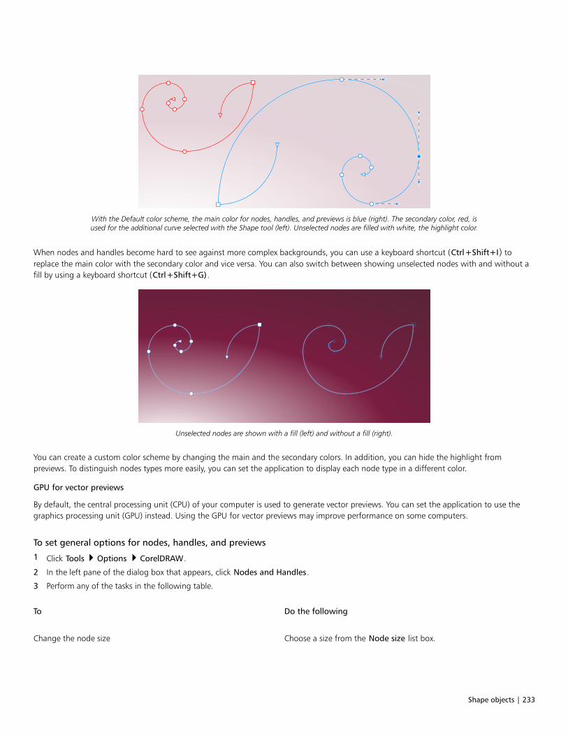
Shape objects | 233
With the Default color scheme, the main color for nodes, handles, and previews is blue (right). The secondary color, red, isused for the additional curve selected with the Shape tool (left). Unselected nodes are filled with white, the highlight color.
When nodes and handles become hard to see against more complex backgrounds, you can use a keyboard shortcut (Ctrl+Shift+I) toreplace the main color with the secondary color and vice versa. You can also switch between showing unselected nodes with and without afill by using a keyboard shortcut (Ctrl+Shift+G).
Unselected nodes are shown with a fill (left) and without a fill (right).
You can create a custom color scheme by changing the main and the secondary colors. In addition, you can hide the highlight frompreviews. To distinguish nodes types more easily, you can set the application to display each node type in a different color.
GPU for vector previews
By default, the central processing unit (CPU) of your computer is used to generate vector previews. You can set the application to use thegraphics processing unit (GPU) instead. Using the GPU for vector previews may improve performance on some computers.
To set general options for nodes, handles, and previews
1 Click Tools Options CorelDRAW.
2 In the left pane of the dialog box that appears, click Nodes and Handles.
3 Perform any of the tasks in the following table.
To Do the following
Change the node size Choose a size from the Node size list box.
234 | CorelDRAW 2019 User Guide
To Do the following
Change the shapes of nodes From the Node shape list boxes, choose a shape for each nodetype: cusp, smooth, and symmetrical.
Revert to the default node shapes Next to the Nodes shape list boxes, click Reset.
Show or hide the direction of selected curves Enable or disable the Show curve direction when editing checkbox.
Select and move nodes by using the Pick , Freehand ,
Polyline , or Bézier tool
Enable the Enable node tracking check box.
Show unselected nodes without a fill Disable the Show unselected nodes with fill check box.
To switch color settings for nodes, handles, and previews by using keyboard shortcuts
1 Select the nodes you want with the Shape tool.
2 Perform a task from the following table.
To Do the following
Replace the main color with the secondary color and vice versa Press Ctrl+Shift+I.
Switch between showing unselected nodes with a fill and without afill
Press Ctrl+Shift+G.
To choose a color scheme
1 Click Tools Options CorelDRAW.
2 In the left pane of the dialog box that appears, click Nodes and Handles.
3 In the Colors area, choose one of the following color schemes from the Color scheme list box:
• Default
• Custom
The controls below the Color scheme list box become available only after you choose Custom from the Color scheme list box.
To create a custom color scheme for nodes, handles, and previews
1 Click Tools Options CorelDRAW.
2 In the left pane of the dialog box that appears, click Nodes and Handles.
3 In the Colors area, choose Custom from the Color scheme list box.
4 Open the following color pickers, and choose a color:
• Main color — used in nodes and handles when an object is selected for editing. When you select multiple objects for editing, themain color is used for the nodes and handles of the first selected object

Shape objects | 235
• Secondary color — used in nodes and handles when additional objects are selected for editing with the Shape tool or when you areediting vector effects such as extrusions
You can also
Hide the highlight color from vector previews Disable the Show highlight check box.
Display each node type in a different color Enable the Show node types in different colors check box.
Revert to the default main and secondary colors Click Reset next to the Main color and the Secondary color picker.
The Reset button is available only for custom color schemes.
To use the GPU for vector previews
1 Click Tools Options Global.
2 In the left pane of the dialog box that appears, click General.
3 Enable the Use GPU for vector previews check box.

236 | CorelDRAW 2019 User Guide
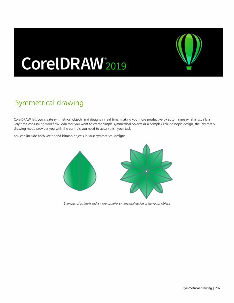
Symmetrical drawing | 237
Symmetrical drawing
CorelDRAW lets you create symmetrical objects and designs in real time, making you more productive by automating what is usually avery time-consuming workflow. Whether you want to create simple symmetrical objects or a complex kaleidoscopic design, the Symmetrydrawing mode provides you with the controls you need to accomplish your task.
You can include both vector and bitmap objects in your symmetrical designs.
Examples of a simple and a more complex symmetrical design using vector objects
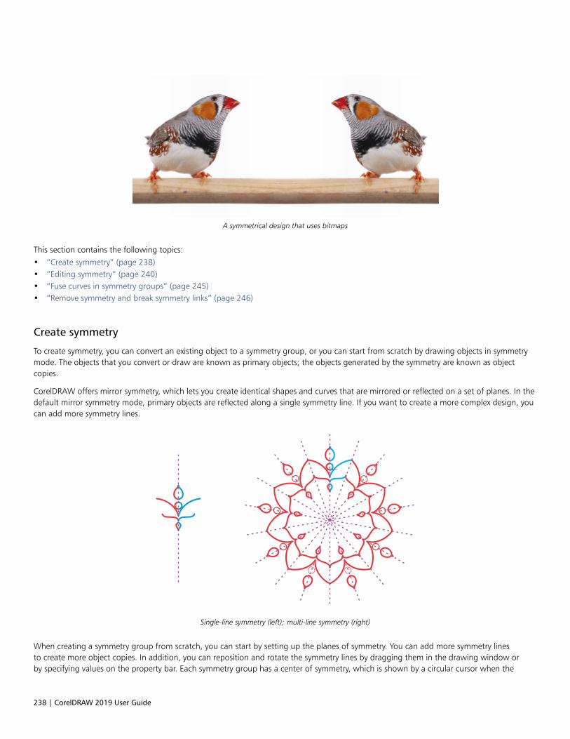
238 | CorelDRAW 2019 User Guide
A symmetrical design that uses bitmaps
This section contains the following topics:• “Create symmetry” (page 238)• “Editing symmetry” (page 240)• “Fuse curves in symmetry groups” (page 245)• “Remove symmetry and break symmetry links” (page 246)
Create symmetry
To create symmetry, you can convert an existing object to a symmetry group, or you can start from scratch by drawing objects in symmetrymode. The objects that you convert or draw are known as primary objects; the objects generated by the symmetry are known as objectcopies.
CorelDRAW offers mirror symmetry, which lets you create identical shapes and curves that are mirrored or reflected on a set of planes. In thedefault mirror symmetry mode, primary objects are reflected along a single symmetry line. If you want to create a more complex design, youcan add more symmetry lines.
Single-line symmetry (left); multi-line symmetry (right)
When creating a symmetry group from scratch, you can start by setting up the planes of symmetry. You can add more symmetry linesto create more object copies. In addition, you can reposition and rotate the symmetry lines by dragging them in the drawing window orby specifying values on the property bar. Each symmetry group has a center of symmetry, which is shown by a circular cursor when the
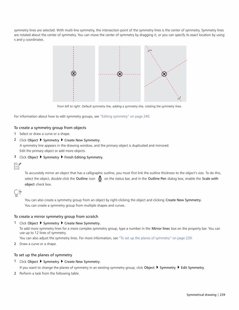
Symmetrical drawing | 239
symmetry lines are selected. With multi-line symmetry, the intersection point of the symmetry lines is the center of symmetry. Symmetry linesare rotated about the center of symmetry. You can move the center of symmetry by dragging it, or you can specify its exact location by usingx and y coordinates.
From left to right: Default symmetry line, adding a symmetry line, rotating the symmetry lines.
For information about how to edit symmetry groups, see “Editing symmetry” on page 240.
To create a symmetry group from objects
1 Select or draw a curve or a shape.
2 Click Object Symmetry Create New Symmetry.
A symmetry line appears in the drawing window, and the primary object is duplicated and mirrored.
Edit the primary object or add more objects.
3 Click Object Symmetry Finish Editing Symmetry.
To accurately mirror an object that has a calligraphic outline, you must first link the outline thickness to the object’s size. To do this,
select the object, double-click the Outline icon on the status bar, and in the Outline Pen dialog box, enable the Scale with
object check box.
You can also create a symmetry group from an object by right-clicking the object and clicking Create New Symmetry.
You can create a symmetry group from multiple shapes and curves.
To create a mirror symmetry group from scratch
1 Click Object Symmetry Create New Symmetry.
To add more symmetry lines for a more complex symmetry group, type a number in the Mirror lines box on the property bar. You canuse up to 12 lines of symmetry.
You can also adjust the symmetry lines. For more information, see “To set up the planes of symmetry” on page 239.
2 Draw a curve or a shape.
To set up the planes of symmetry
1 Click Object Symmetry Create New Symmetry.
If you want to change the planes of symmetry in an existing symmetry group, click Object Symmetry Edit Symmetry.
2 Perform a task from the following table.
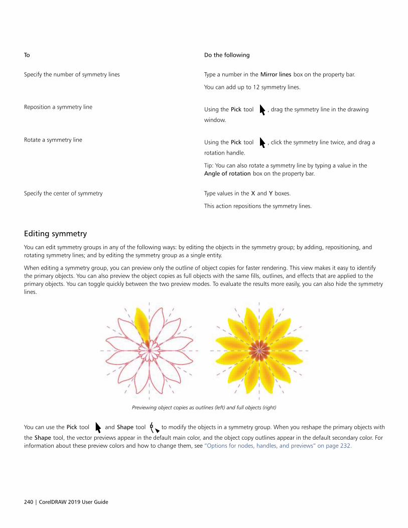
240 | CorelDRAW 2019 User Guide
To Do the following
Specify the number of symmetry lines Type a number in the Mirror lines box on the property bar.
You can add up to 12 symmetry lines.
Reposition a symmetry line Using the Pick tool , drag the symmetry line in the drawing
window.
Rotate a symmetry line Using the Pick tool , click the symmetry line twice, and drag a
rotation handle.
Tip: You can also rotate a symmetry line by typing a value in theAngle of rotation box on the property bar.
Specify the center of symmetry Type values in the X and Y boxes.
This action repositions the symmetry lines.
Editing symmetry
You can edit symmetry groups in any of the following ways: by editing the objects in the symmetry group; by adding, repositioning, androtating symmetry lines; and by editing the symmetry group as a single entity.
When editing a symmetry group, you can preview only the outline of object copies for faster rendering. This view makes it easy to identifythe primary objects. You can also preview the object copies as full objects with the same fills, outlines, and effects that are applied to theprimary objects. You can toggle quickly between the two preview modes. To evaluate the results more easily, you can also hide the symmetrylines.
Previewing object copies as outlines (left) and full objects (right)
You can use the Pick tool and Shape tool to modify the objects in a symmetry group. When you reshape the primary objects with
the Shape tool, the vector previews appear in the default main color, and the object copy outlines appear in the default secondary color. Forinformation about these preview colors and how to change them, see “Options for nodes, handles, and previews” on page 232.
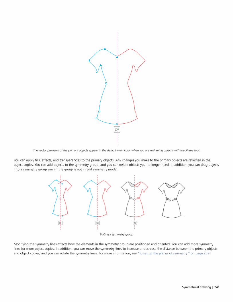
Symmetrical drawing | 241
The vector previews of the primary objects appear in the default main color when you are reshaping objects with the Shape tool.
You can apply fills, effects, and transparencies to the primary objects. Any changes you make to the primary objects are reflected in theobject copies. You can add objects to the symmetry group, and you can delete objects you no longer need. In addition, you can drag objectsinto a symmetry group even if the group is not in Edit symmetry mode.
Editing a symmetry group
Modifying the symmetry lines affects how the elements in the symmetry group are positioned and oriented. You can add more symmetrylines for more object copies. In addition, you can move the symmetry lines to increase or decrease the distance between the primary objectsand object copies; and you can rotate the symmetry lines. For more information, see “To set up the planes of symmetry ” on page 239.
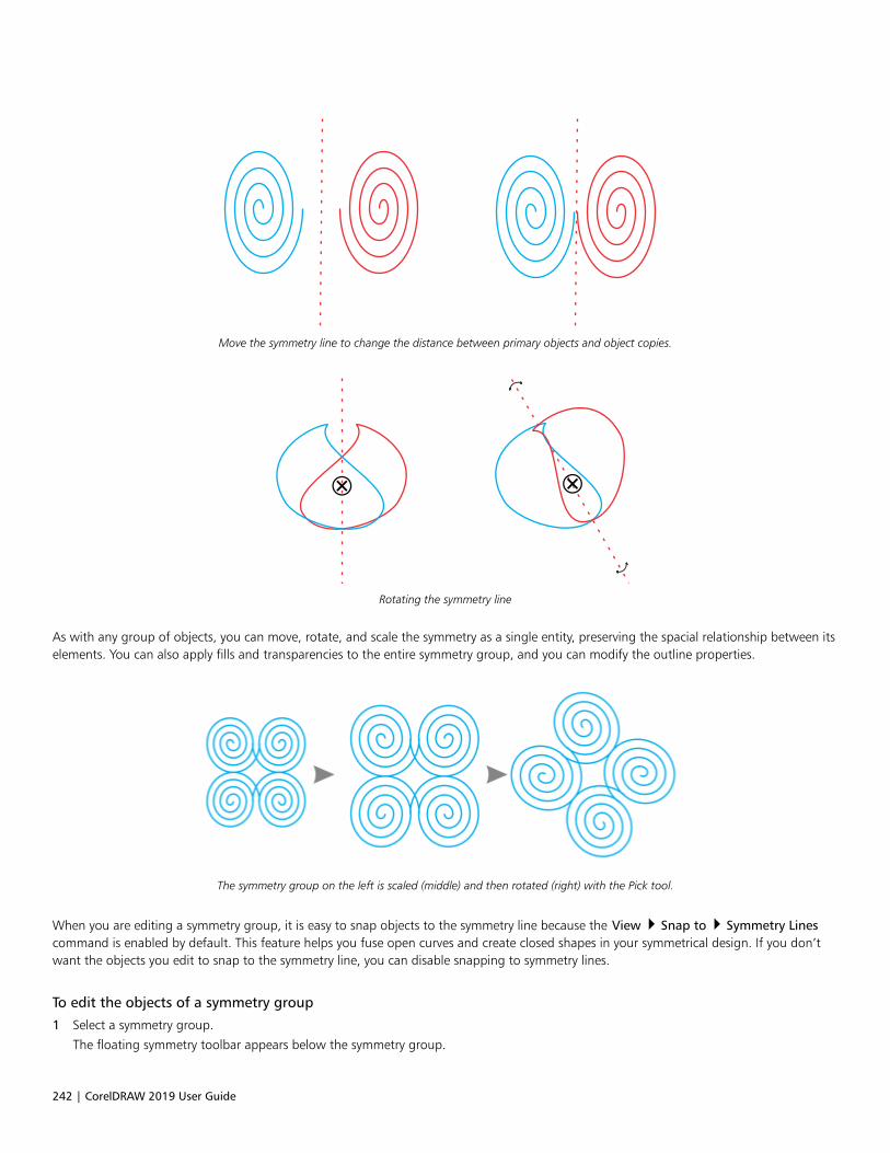
242 | CorelDRAW 2019 User Guide
Move the symmetry line to change the distance between primary objects and object copies.
Rotating the symmetry line
As with any group of objects, you can move, rotate, and scale the symmetry as a single entity, preserving the spacial relationship between itselements. You can also apply fills and transparencies to the entire symmetry group, and you can modify the outline properties.
The symmetry group on the left is scaled (middle) and then rotated (right) with the Pick tool.
When you are editing a symmetry group, it is easy to snap objects to the symmetry line because the View Snap to Symmetry Linescommand is enabled by default. This feature helps you fuse open curves and create closed shapes in your symmetrical design. If you don’twant the objects you edit to snap to the symmetry line, you can disable snapping to symmetry lines.
To edit the objects of a symmetry group
1 Select a symmetry group.
The floating symmetry toolbar appears below the symmetry group.
Symmetrical drawing | 243
2 Click Edit on the toolbar.
3 Edit the primary objects in the group by using the Shape tool and the Pick tool . You can also apply fills and transparencies,
and you can apply effects such as contours, envelopes, blends, and distortions.
4 Add and delete objects as needed.
5 Click the Finish on the toolbar.
You can also
Display object copies as outlines or full objects Click the Show full preview button on the property bar to
disable or enable it.
Show or hide symmetry lines Click the Show symmetry lines button on the property bar to
disable or enable it.
You can start editing a symmetry group by double-clicking it or by clicking Object Symmetry Edit Symmetry.
You can also enter the Edit Symmetry mode by clicking a selected symmetry group while holding down Ctrl.
You can also finish editing a symmetry group by clicking Object Symmetry Finish Editing Symmetry.
To drag an object into a symmetry group that contains objects
• Drag the object over the symmetry group, hold down W, and release the mouse button.
To drag an object into an empty symmetry group
• Drag the object over the symmetry group, and release the mouse button.
To edit a symmetry group as a single entity
1 Using the Pick tool , click the symmetry group.
2 Perform a task from the following table.
To Do the following
Move the symmetry group Drag it to a new location in the drawing window.
Scale the symmetry group Drag a corner selection handle.
Rotate the symmetry group Click the symmetry group again to display the rotation handles, anddrag a rotation handle.
Apply a fill to the symmetry group Click the Interactive fill tool , and drag across the symmetry
group. For more information about fills, see “Fills” on page 365.
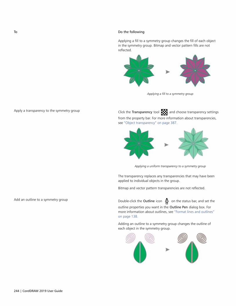
244 | CorelDRAW 2019 User Guide
To Do the following
Applying a fill to a symmetry group changes the fill of each objectin the symmetry group. Bitmap and vector pattern fills are notreflected.
Applying a fill to a symmetry group
Apply a transparency to the symmetry group Click the Transparency tool , and choose transparency settings
from the property bar. For more information about transparencies,see “Object transparency” on page 387.
Applying a uniform transparency to a symmetry group
The transparency replaces any transparencies that may have beenapplied to individual objects in the group.
Bitmap and vector pattern transparencies are not reflected.
Add an outline to a symmetry group Double-click the Outline icon on the status bar, and set the
outline properties you want in the Outline Pen dialog box. Formore information about outlines, see “Format lines and outlines”on page 138.
Adding an outline to a symmetry group changes the outline ofeach object in the symmetry group.
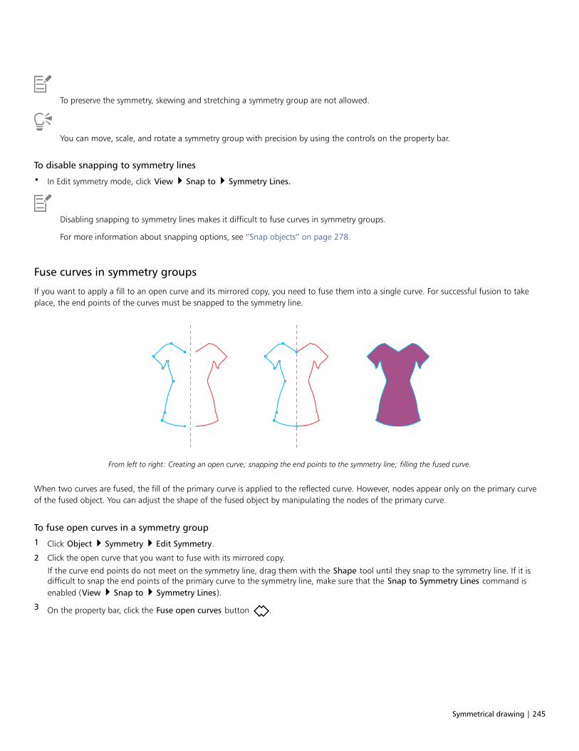
Symmetrical drawing | 245
To preserve the symmetry, skewing and stretching a symmetry group are not allowed.
You can move, scale, and rotate a symmetry group with precision by using the controls on the property bar.
To disable snapping to symmetry lines
• In Edit symmetry mode, click View Snap to Symmetry Lines.
Disabling snapping to symmetry lines makes it difficult to fuse curves in symmetry groups.
For more information about snapping options, see “Snap objects” on page 278.
Fuse curves in symmetry groups
If you want to apply a fill to an open curve and its mirrored copy, you need to fuse them into a single curve. For successful fusion to takeplace, the end points of the curves must be snapped to the symmetry line.
From left to right: Creating an open curve; snapping the end points to the symmetry line; filling the fused curve.
When two curves are fused, the fill of the primary curve is applied to the reflected curve. However, nodes appear only on the primary curveof the fused object. You can adjust the shape of the fused object by manipulating the nodes of the primary curve.
To fuse open curves in a symmetry group
1 Click Object Symmetry Edit Symmetry.
2 Click the open curve that you want to fuse with its mirrored copy.
If the curve end points do not meet on the symmetry line, drag them with the Shape tool until they snap to the symmetry line. If it isdifficult to snap the end points of the primary curve to the symmetry line, make sure that the Snap to Symmetry Lines command isenabled (View Snap to Symmetry Lines).
3 On the property bar, click the Fuse open curves button .

246 | CorelDRAW 2019 User Guide
Only the selected curve set is fused into a single object. Unselected open curves are not affected.
You can undo the fusion by clicking the Fuse open curves button on the property bar to disable it.
Remove symmetry and break symmetry links
If you want to delete all object copies from a symmetry group and keep only the primary objects, you can remove the symmetry.
Left to right: Symmetry group in Edit mode; the symmetry group innormal state; the symmetry is removed, leaving only the primary objects.
After completing a symmetry group, you may want to make some of its elements non-symmetrical. To do this, you need to break thesymmetry link of the symmetry group, turning it into a regular group of objects. You can then edit individual objects in the group.
The symmetry link is broken in the symmetry group on the left.Then, some objects are resized, and other objects are deleted (right).
To remove the symmetry from a symmetry group
1 Select a symmetry group.

Symmetrical drawing | 247
2 Click Remove on the floating toolbar that appears below or above the symmetry group.
All object copies are deleted.
You can also remove the symmetry link by clicking Object Symmetry Remove Symmetry.
You can also right-click a symmetry group, and click Remove Symmetry.
To break the symmetry link of a symmetry group
1 Select a symmetry group.
2 Click Break Link on the floating toolbar that appears below or above the symmetry group.
After the symmetry link is broken, the symmetry group becomes a regular group of objects.
You can also break the symmetry link by clicking Object Symmetry Break Symmetry Link.
You can also right-click a symmetry group, and click Break Symmetry Link.

248 | CorelDRAW 2019 User Guide
Objects, symbols, and layers | 249
Objects, symbols, and layers
Objects................................................................................................................................................................................................ 251
Link and embed objects...................................................................................................................................................................... 309
QR codes............................................................................................................................................................................................. 311
Layers...................................................................................................................................................................................................317
Symbols............................................................................................................................................................................................... 327
Manage and track projects..................................................................................................................................................................335

250 | CorelDRAW 2019 User Guide

Objects | 251
Objects
Working with objects is an essential part of creating drawings.
This section contains the following topics:• “Select objects” (page 252)• “Transform objects” (page 255)• “Copy, duplicate, and delete objects” (page 258)• “Create objects from enclosed areas” (page 261)• “Create a boundary around objects” (page 261)• “Use object coordinates to draw and modify objects” (page 262)• “Copy object properties, transformations, and effects” (page 270)• “Clone objects” (page 271)• “Position objects” (page 272)• “Align and distribute objects” (page 274)• “Apply object hinting” (page 278)• “Snap objects” (page 278)• “Dynamic guides” (page 281)• “Alignment guides” (page 285)• “Change the order of objects” (page 289)• “Size and scale objects” (page 290)• “Rotate and mirror objects” (page 291)• “Modify objects with the Properties docker” (page 293)• “Fit objects to a path” (page 295)• “Group objects” (page 299)• “Combine objects” (page 301)• “Lock objects” (page 302)• “Find and replace objects” (page 303)• “Hide and show objects” (page 304)• “Constrain objects” (page 305)• “Bar codes” (page 306)

252 | CorelDRAW 2019 User Guide
Select objects
Before you can change an object, you must select it. You can select visible objects, objects that are hidden from view by other objects, anda single object in a group or a nested group. In addition, you can select objects in the order in which they were created, select all objects atonce, and deselect objects.
A bounding box appears around a selected object, and an “X” appears at its center.
You can select a single object from a group.
You can marquee select objects by enclosing them with a selection area of rectangular or irregular shape.
Marquee selecting objects using a rectangular selection area (top) and a selection area of irregular shape (bottom)
You can create selection groups that let you select specific objects simultaneously without grouping them. Selection groups are associatedwith numbers from 0 to 9 and are saved with the document. When you press the number associated with a selection group, all objects
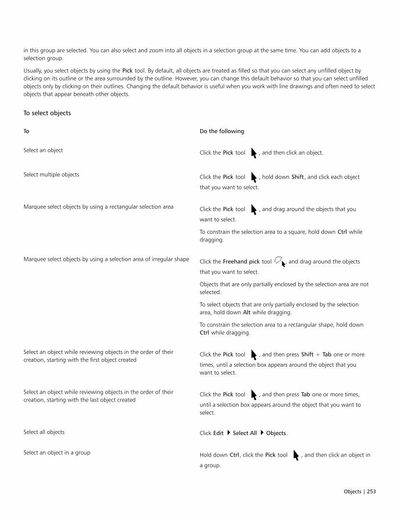
Objects | 253
in this group are selected. You can also select and zoom into all objects in a selection group at the same time. You can add objects to aselection group.
Usually, you select objects by using the Pick tool. By default, all objects are treated as filled so that you can select any unfilled object byclicking on its outline or the area surrounded by the outline. However, you can change this default behavior so that you can select unfilledobjects only by clicking on their outlines. Changing the default behavior is useful when you work with line drawings and often need to selectobjects that appear beneath other objects.
To select objects
To Do the following
Select an object Click the Pick tool , and then click an object.
Select multiple objects Click the Pick tool , hold down Shift, and click each object
that you want to select.
Marquee select objects by using a rectangular selection area Click the Pick tool , and drag around the objects that you
want to select.
To constrain the selection area to a square, hold down Ctrl whiledragging.
Marquee select objects by using a selection area of irregular shape Click the Freehand pick tool , and drag around the objects
that you want to select.
Objects that are only partially enclosed by the selection area are notselected.
To select objects that are only partially enclosed by the selectionarea, hold down Alt while dragging.
To constrain the selection area to a rectangular shape, hold downCtrl while dragging.
Select an object while reviewing objects in the order of theircreation, starting with the first object created
Click the Pick tool , and then press Shift + Tab one or more
times, until a selection box appears around the object that youwant to select.
Select an object while reviewing objects in the order of theircreation, starting with the last object created
Click the Pick tool , and then press Tab one or more times,
until a selection box appears around the object that you want toselect.
Select all objects Click Edit Select All Objects.
Select an object in a group Hold down Ctrl, click the Pick tool , and then click an object in
a group.

254 | CorelDRAW 2019 User Guide
To Do the following
Select an object in a nested group Hold down Ctrl, click the Pick tool , and then click an object
one or more times, until a selection box appears around it.
Select an object hidden from view by other objects Hold down Alt, click the Pick tool or the Freehand pick tool
, and then click the topmost object one or more times, until a
selection box appears around the hidden object.
Select multiple hidden objects Hold down Shift + Alt, click the Pick tool or the Freehand
pick tool , and then click the topmost object one or more
times, until a selection box appears around the hidden objects.
Select a hidden object in a group Hold down Ctrl + Alt, click the Pick tool , and then click the
topmost object one or more times, until a selection box appearsaround the hidden object.
The status bar displays a description of each hidden object as you select it.
To create a selection group
1 Click the Pick tool , hold down Shift, and click each object that you want to include in the selection group.
2 Press Ctrl + a number from 0 to 9.
The number you pressed is associated with the new selection group.
You can also
Select all objects in a selection group Press the number associated with the selection group.
Select and zoom in on all objects in a selection group Press twice the number associated with the selection group.
Add an object to a selection group Select the object, and press Alt + the number associated with theselection group.
To deselect objects
To Do the following
Deselect all objects Click the Pick tool , and click a blank space in the drawing
window.
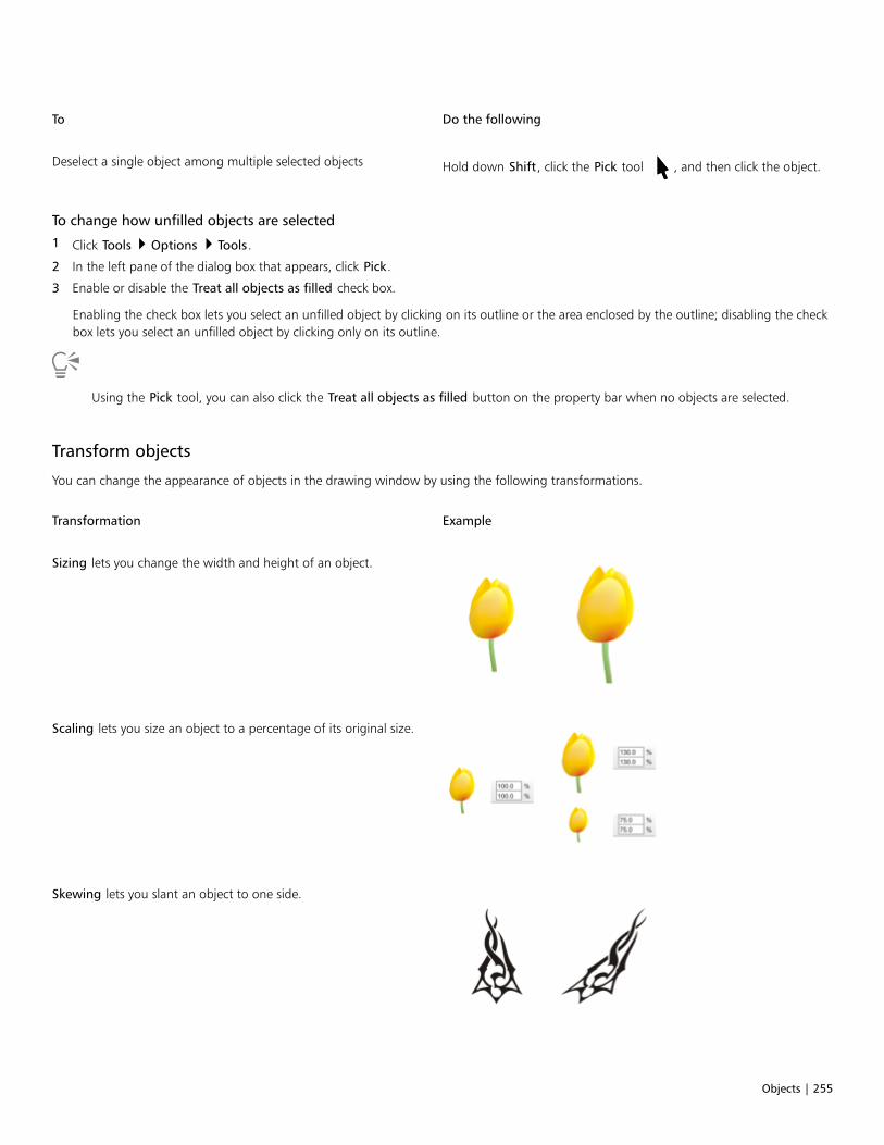
Objects | 255
To Do the following
Deselect a single object among multiple selected objects Hold down Shift, click the Pick tool , and then click the object.
To change how unfilled objects are selected
1 Click Tools Options Tools.
2 In the left pane of the dialog box that appears, click Pick.
3 Enable or disable the Treat all objects as filled check box.
Enabling the check box lets you select an unfilled object by clicking on its outline or the area enclosed by the outline; disabling the checkbox lets you select an unfilled object by clicking only on its outline.
Using the Pick tool, you can also click the Treat all objects as filled button on the property bar when no objects are selected.
Transform objects
You can change the appearance of objects in the drawing window by using the following transformations.
Transformation Example
Sizing lets you change the width and height of an object.
Scaling lets you size an object to a percentage of its original size.
Skewing lets you slant an object to one side.
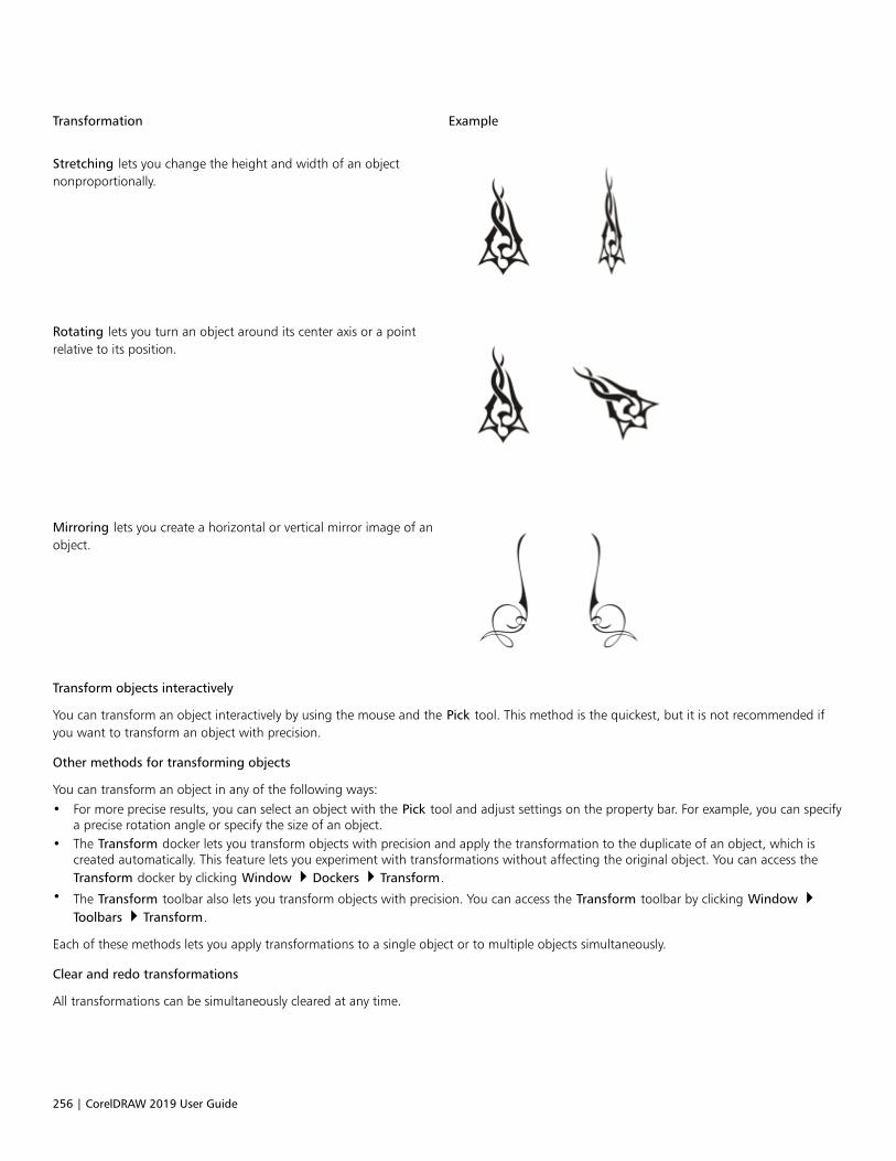
256 | CorelDRAW 2019 User Guide
Transformation Example
Stretching lets you change the height and width of an objectnonproportionally.
Rotating lets you turn an object around its center axis or a pointrelative to its position.
Mirroring lets you create a horizontal or vertical mirror image of anobject.
Transform objects interactively
You can transform an object interactively by using the mouse and the Pick tool. This method is the quickest, but it is not recommended ifyou want to transform an object with precision.
Other methods for transforming objects
You can transform an object in any of the following ways:• For more precise results, you can select an object with the Pick tool and adjust settings on the property bar. For example, you can specify
a precise rotation angle or specify the size of an object.• The Transform docker lets you transform objects with precision and apply the transformation to the duplicate of an object, which is
created automatically. This feature lets you experiment with transformations without affecting the original object. You can access theTransform docker by clicking Window Dockers Transform.
• The Transform toolbar also lets you transform objects with precision. You can access the Transform toolbar by clicking Window Toolbars Transform.
Each of these methods lets you apply transformations to a single object or to multiple objects simultaneously.
Clear and redo transformations
All transformations can be simultaneously cleared at any time.
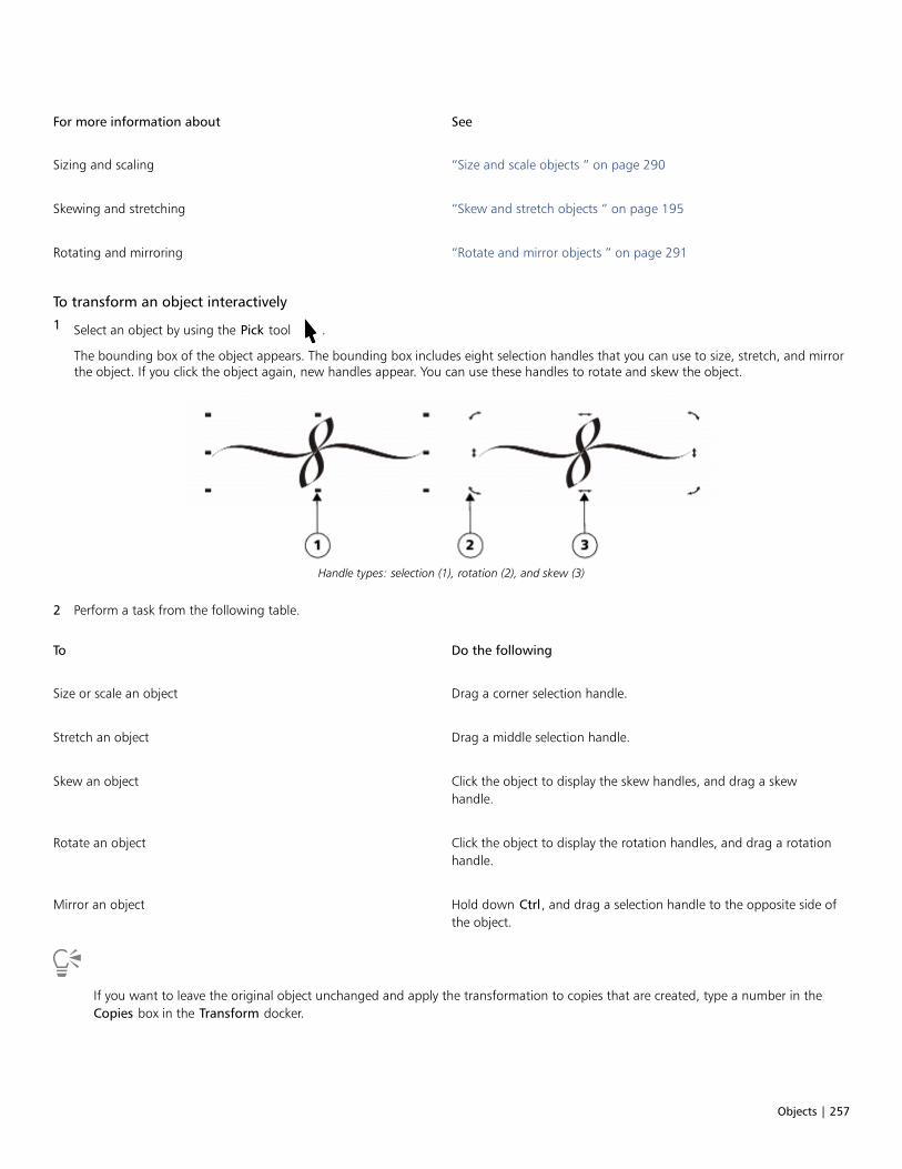
Objects | 257
For more information about See
Sizing and scaling “Size and scale objects ” on page 290
Skewing and stretching “Skew and stretch objects ” on page 195
Rotating and mirroring “Rotate and mirror objects ” on page 291
To transform an object interactively
1 Select an object by using the Pick tool .
The bounding box of the object appears. The bounding box includes eight selection handles that you can use to size, stretch, and mirrorthe object. If you click the object again, new handles appear. You can use these handles to rotate and skew the object.
Handle types: selection (1), rotation (2), and skew (3)
2 Perform a task from the following table.
To Do the following
Size or scale an object Drag a corner selection handle.
Stretch an object Drag a middle selection handle.
Skew an object Click the object to display the skew handles, and drag a skewhandle.
Rotate an object Click the object to display the rotation handles, and drag a rotationhandle.
Mirror an object Hold down Ctrl, and drag a selection handle to the opposite side ofthe object.
If you want to leave the original object unchanged and apply the transformation to copies that are created, type a number in theCopies box in the Transform docker.

258 | CorelDRAW 2019 User Guide
To clear all transformations applied to an object
1 Select an object.
2 Click Object Clear Transformations.
You can undo the Clear Transformations command by clicking Edit Undo Clear Transformations.
Copy, duplicate, and delete objects
CorelDRAW provides you with several ways to copy objects. When you no longer need an object, you can delete it.
You can cut or copy an object to place it on the Clipboard and paste it into a drawing or another application. Cutting an object places it onthe Clipboard and removes it from the drawing. Copying an object places it on the Clipboard but keeps the original in the drawing.
Duplicating an object places a copy directly in the drawing window and does not use the Clipboard. Duplicating is faster than copying andpasting. Also, when duplicating an object, you can specify the distance between the duplicate and the original object along the x and y axes.This distance is known as the offset.
You can apply a transformation, such as rotating, sizing, or skewing, to the duplicate of an object while keeping the original object intact. Ifyou decide that you want to keep the original object, you can delete the duplicate.
You can create multiple copies of objects simultaneously, while specifying their position, without using the Clipboard. For example, youcan distribute object copies horizontally, to the left or right of the original object; or you can distribute copies of objects vertically, below orabove the original object. You can specify the spacing between copies of objects, or you can specify the offset at which copies of objects arecreated in relation to each other.
You can use other methods to create copies of objects quickly, without using the Clipboard. You can use the plus sign (+) on the numerickeypad to place a copy of an object on top of the original object, or you can create copies instantly by pressing the Spacebar or right-clicking while dragging an object.
To cut or copy an object
1 Select an object.
2 Click Edit, and click one of the following:
• Cut
• Copy

Objects | 259
You can also cut or copy an object by right-clicking the object and clicking Cut or Copy.
To paste an object into a drawing
• Click Edit Paste.
You can use this procedure to paste an object from another application.
To paste an object from an unsupported file format, or to specify options for the pasted object, click Edit Paste Special. For moreinformation about pasting objects from other applications, see “Link and embed objects” on page 309.
To duplicate an object
1 Select an object.
2 Click Edit Duplicate.
Duplicating an object is useful for creating cuttable drop shadows for devices such as vinyl cutters and plotters.
You can also duplicate a selected object by pressing Ctrl + D.
To create copies of an object at a specified position
1 Select an object.
2 Click Edit Step and Repeat.
3 In the Step and Repeat docker, type a value in the Number of copies box, and click Apply.
To Do the following
Distribute copies of objects horizontally In the Vertical settings area, choose No offset from the Mode listbox. In the Horizontal settings area, choose Spacing betweenobjects from the Mode list box. To specify the spacing betweenobject copies, type a value in the Distance box. To place the objectcopies to the right or left of the original, choose Right or Left fromthe Direction list box.
Distribute copies of objects vertically In the Horizontal settings area, choose No offset from the Modelist box. In the Vertical settings area, choose Spacing betweenobjects from the Mode list box. To specify the spacing betweencopies of objects, type a value in the Distance box. To place thecopies above or below the original, choose Up or Down from theDirection list box.
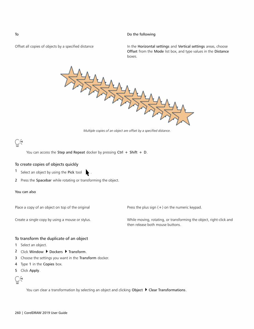
260 | CorelDRAW 2019 User Guide
To Do the following
Offset all copies of objects by a specified distance In the Horizontal settings and Vertical settings areas, chooseOffset from the Mode list box, and type values in the Distanceboxes.
Multiple copies of an object are offset by a specified distance.
You can access the Step and Repeat docker by pressing Ctrl + Shift + D.
To create copies of objects quickly
1 Select an object by using the Pick tool .
2 Press the Spacebar while rotating or transforming the object.
You can also
Place a copy of an object on top of the original Press the plus sign (+) on the numeric keypad.
Create a single copy by using a mouse or stylus. While moving, rotating, or transforming the object, right-click andthen release both mouse buttons.
To transform the duplicate of an object
1 Select an object.
2 Click Window Dockers Transform.
3 Choose the settings you want in the Transform docker.
4 Type 1 in the Copies box.
5 Click Apply.
You can clear a transformation by selecting an object and clicking Object Clear Transformations.
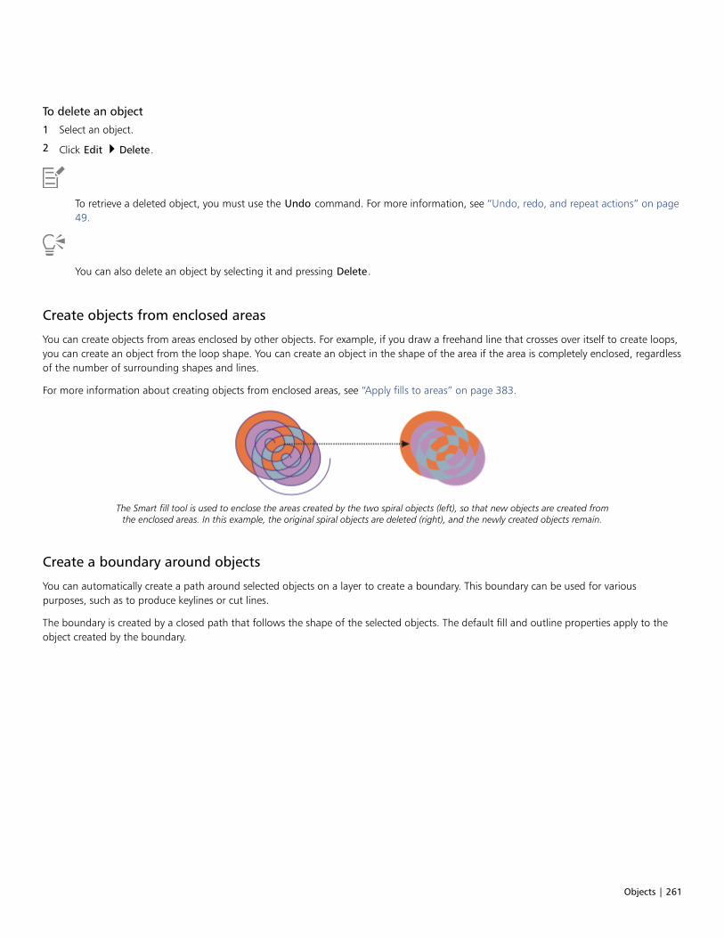
Objects | 261
To delete an object
1 Select an object.
2 Click Edit Delete.
To retrieve a deleted object, you must use the Undo command. For more information, see “Undo, redo, and repeat actions” on page49.
You can also delete an object by selecting it and pressing Delete.
Create objects from enclosed areas
You can create objects from areas enclosed by other objects. For example, if you draw a freehand line that crosses over itself to create loops,you can create an object from the loop shape. You can create an object in the shape of the area if the area is completely enclosed, regardlessof the number of surrounding shapes and lines.
For more information about creating objects from enclosed areas, see “Apply fills to areas” on page 383.
The Smart fill tool is used to enclose the areas created by the two spiral objects (left), so that new objects are created fromthe enclosed areas. In this example, the original spiral objects are deleted (right), and the newly created objects remain.
Create a boundary around objects
You can automatically create a path around selected objects on a layer to create a boundary. This boundary can be used for variouspurposes, such as to produce keylines or cut lines.
The boundary is created by a closed path that follows the shape of the selected objects. The default fill and outline properties apply to theobject created by the boundary.
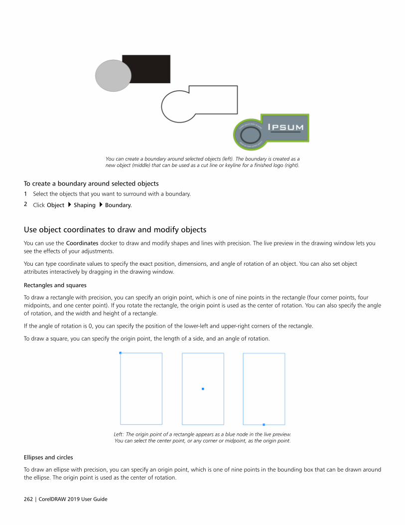
262 | CorelDRAW 2019 User Guide
You can create a boundary around selected objects (left). The boundary is created as anew object (middle) that can be used as a cut line or keyline for a finished logo (right).
To create a boundary around selected objects
1 Select the objects that you want to surround with a boundary.
2 Click Object Shaping Boundary.
Use object coordinates to draw and modify objects
You can use the Coordinates docker to draw and modify shapes and lines with precision. The live preview in the drawing window lets yousee the effects of your adjustments.
You can type coordinate values to specify the exact position, dimensions, and angle of rotation of an object. You can also set objectattributes interactively by dragging in the drawing window.
Rectangles and squares
To draw a rectangle with precision, you can specify an origin point, which is one of nine points in the rectangle (four corner points, fourmidpoints, and one center point). If you rotate the rectangle, the origin point is used as the center of rotation. You can also specify the angleof rotation, and the width and height of a rectangle.
If the angle of rotation is 0, you can specify the position of the lower-left and upper-right corners of the rectangle.
To draw a square, you can specify the origin point, the length of a side, and an angle of rotation.
Left: The origin point of a rectangle appears as a blue node in the live preview.You can select the center point, or any corner or midpoint, as the origin point.
Ellipses and circles
To draw an ellipse with precision, you can specify an origin point, which is one of nine points in the bounding box that can be drawn aroundthe ellipse. The origin point is used as the center of rotation.
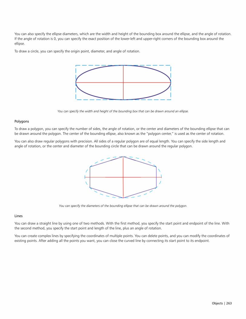
Objects | 263
You can also specify the ellipse diameters, which are the width and height of the bounding box around the ellipse, and the angle of rotation.If the angle of rotation is 0, you can specify the exact position of the lower-left and upper-right corners of the bounding box around theellipse.
To draw a circle, you can specify the origin point, diameter, and angle of rotation.
You can specify the width and height of the bounding box that can be drawn around an ellipse.
Polygons
To draw a polygon, you can specify the number of sides, the angle of rotation, or the center and diameters of the bounding ellipse that canbe drawn around the polygon. The center of the bounding ellipse, also known as the “polygon center,” is used as the center of rotation.
You can also draw regular polygons with precision. All sides of a regular polygon are of equal length. You can specify the side length andangle of rotation, or the center and diameter of the bounding circle that can be drawn around the regular polygon.
You can specify the diameters of the bounding ellipse that can be drawn around the polygon.
Lines
You can draw a straight line by using one of two methods. With the first method, you specify the start point and endpoint of the line. Withthe second method, you specify the start point and length of the line, plus an angle of rotation.
You can create complex lines by specifying the coordinates of multiple points. You can delete points, and you can modify the coordinates ofexisting points. After adding all the points you want, you can close the curved line by connecting its start point to its endpoint.

264 | CorelDRAW 2019 User Guide
Straight and multipoint lines
Stars
You can also use coordinates to draw stars and complex stars.
Modify existing objects
You can use the Coordinates docker to modify existing objects with precision. Note that when you modify an existing object, it is replacedwith a new object. As a result, the following transformations and effects applied to the original objects are lost: envelope effects, rotations,and skew effects. In addition, any changes that were previously applied to the nodes on a polygon are lost.
To draw or modify a rectangle by using object coordinates
1 Click Window Dockers Coordinates.
If you want to modify an existing rectangle, select the rectangle.
2 Click the Rectangle flyout, and choose Rectangle.
3 Make any of the following adjustments:
• To set the origin point of the rectangle, click a point in the Origin area.
• To specify the exact position of the origin point, type values in the x and y boxes.
• To specify the width and height of the rectangle, type values in the W and H boxes.
• To specify only the height or width of the rectangle and have the other dimensions automatically adjusted in proportion, enable theSet proportional check box.
• To rotate the rectangle at a specified angle, type a value in the Angle of rotation box. The origin point of the rectangle is used as thecenter of rotation.
4 Click one of the following:
• Create object — adds a new rectangle to the drawing window
• Replace object — replaces the selected rectangle with a new one
You can also
Draw a rectangle by specifying the exact position of its lower-leftand upper-right corners
In the Bounding box area, type values in the X and Y boxes underthe Lower-left corner or Upper-right corner label.
This method for drawing rectangles is available only when norotation is applied.
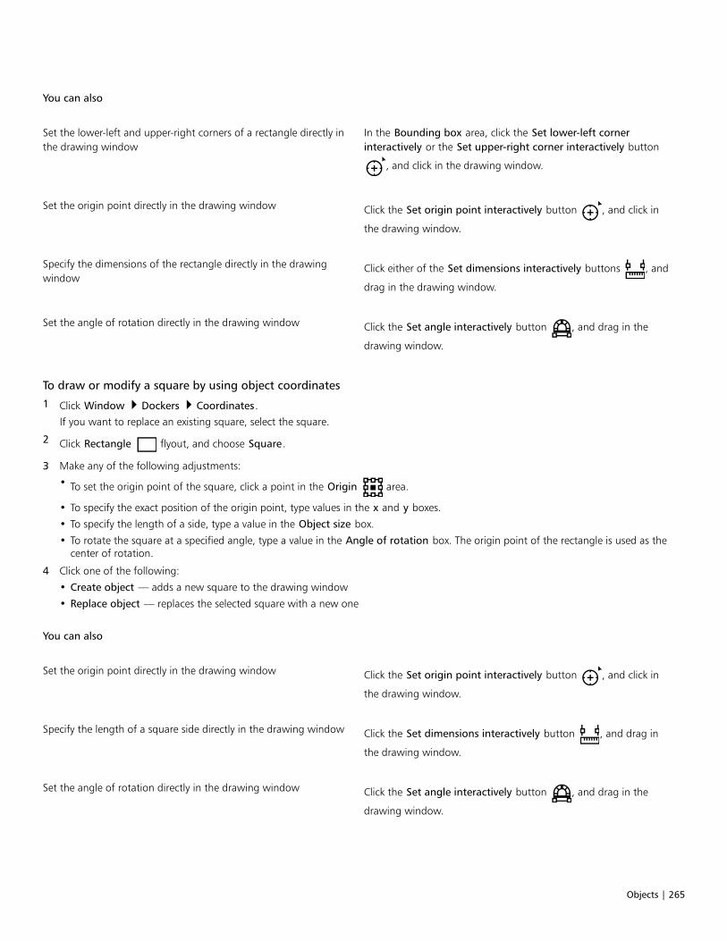
Objects | 265
You can also
Set the lower-left and upper-right corners of a rectangle directly inthe drawing window
In the Bounding box area, click the Set lower-left cornerinteractively or the Set upper-right corner interactively button
, and click in the drawing window.
Set the origin point directly in the drawing window Click the Set origin point interactively button , and click in
the drawing window.
Specify the dimensions of the rectangle directly in the drawingwindow
Click either of the Set dimensions interactively buttons , and
drag in the drawing window.
Set the angle of rotation directly in the drawing window Click the Set angle interactively button , and drag in the
drawing window.
To draw or modify a square by using object coordinates
1 Click Window Dockers Coordinates.
If you want to replace an existing square, select the square.
2 Click Rectangle flyout, and choose Square.
3 Make any of the following adjustments:
• To set the origin point of the square, click a point in the Origin area.
• To specify the exact position of the origin point, type values in the x and y boxes.
• To specify the length of a side, type a value in the Object size box.
• To rotate the square at a specified angle, type a value in the Angle of rotation box. The origin point of the rectangle is used as thecenter of rotation.
4 Click one of the following:
• Create object — adds a new square to the drawing window
• Replace object — replaces the selected square with a new one
You can also
Set the origin point directly in the drawing window Click the Set origin point interactively button , and click in
the drawing window.
Specify the length of a square side directly in the drawing window Click the Set dimensions interactively button , and drag in
the drawing window.
Set the angle of rotation directly in the drawing window Click the Set angle interactively button , and drag in the
drawing window.

266 | CorelDRAW 2019 User Guide
To draw or modify an ellipse by using object coordinates
1 Click Window Dockers Coordinates.
If you want to modify an existing ellipse, select the ellipse.
2 Click the Ellipse flyout, and choose Ellipse.
3 Make any of the following adjustments:
• To set the origin point of the ellipse, click a point in the Origin area.
• To specify the exact position of the origin point, type values in the x and y boxes.
• To specify the diameters (width and height) of the ellipse, type values in the W and H boxes.
• To specify only one of the diameters and have the other diameter automatically adjusted in proportion, enable the Set proportionalcheck box.
• To rotate the ellipse at a specified angle, type a value in the Angle of rotation box. The origin point of the ellipse is used as the centerof rotation.
4 Click one of the following:
• Create object — adds a new ellipse to the drawing window
• Replace object — replaces the selected ellipse with a new one
You can also
Draw an ellipse by specifying the lower-left and upper-right cornersof the bounding box around an ellipse
In the Bounding box area, type values in the X and Y boxes underthe Lower-left corner or Upper-right corner label.
This method for drawing ellipses is available only when no rotationis applied to the ellipse.
Set the lower-left and upper-right corners of an ellipse’s boundingbox directly in the drawing window
In the Bounding box area, click the Set lower-left corner
interactively or Set upper-right corner interactively button ,
and click in the drawing window.
Set the origin point directly in the drawing window Click the Set origin point interactively button , and click in
the drawing window.
Specify the dimensions of the ellipse directly in the drawingwindow
Click either of the Set diameter interactively buttons , and
drag in the drawing window.
Set the angle of rotation directly in the drawing window Click the Set angle interactively button , and drag in the
drawing window.
To draw or modify a circle by using object coordinates
1 Click Window Dockers Coordinates.
If you want to replace an existing circle, select the circle.
2 Click the Ellipse flyout, and choose Circle.
3 Make any of the following adjustments:

Objects | 267
• To set the origin point of the square, click a point in the Origin area.
• To specify the exact position of the origin point, type values in the x and y boxes.
• To specify the diameter of a circle, type a value in the Object size box.
• To rotate the circle at a specified angle, type a value in the Angle of rotation box. The origin point of the circle is used as the center ofrotation.
4 Click one of the following:
• Create object — adds a new circle to the drawing window
• Replace object — replaces the selected circle with a new one
You can also
Set the origin point directly in the drawing window Click the Set origin point interactively button , and click in
the drawing window.
Specify the diameter of a circle directly in the drawing window Click the Set diameter interactively button , and drag in the
drawing window.
Set the angle of rotation directly in the drawing window Click the Set angle interactively button , and drag in the
drawing window.
To draw or modify a polygon by using object coordinates
1 Click Window Dockers Coordinates.
If you want to modify an existing polygon, select the polygon.
2 Click the Polygon flyout , and choose Polygon.
3 In the Polygon area, type a value in the Points or sides box.
4 Make any of the following adjustments:
• To rotate the polygon at a specified angle, type a value in the Angle of rotation box.
• To specify the polygon center, type values in the X and Y boxes in the Bounding box area. The polygon center is the center of thebounding ellipse that can be drawn around the polygon. The polygon center is used as the center of rotation.
• To specify the diameters of the bounding ellipse around the polygon, type values in the W and H boxes in the Bounding box area.
• To specify only one diameter and have the other diameter automatically adjusted in proportion, enable the Set proportional checkbox.
5 Click one of the following:
• Create object — adds a new polygon to the drawing window
• Replace object — replaces the selected polygon with a new one
You can also
Set the angle of rotation directly in the drawing window Click the Set angle interactively button , and drag in the
drawing window.

268 | CorelDRAW 2019 User Guide
You can also
Set the polygon center directly in the drawing window Click the Set polygon center interactively button , and click in
the drawing window.
Specify the diameters of the bounding ellipse directly in thedrawing window
Click either of the Set diameter interactively buttons , and
drag in the drawing window.
To draw or modify a regular polygon by using object coordinates
1 Click Window Dockers Coordinates.
If you want to modify an existing polygon, select the polygon.
2 Click Polygon flyout, and choose Regular polygon.
3 In the Regular Polygon area, type a value in the Points or sides box.
4 Type a value in the Side length box.
5 Make any of the following adjustments:
• To rotate the polygon at a specified angle, type a value in the Angle of rotation box.
• To specify the polygon center, type values in the X and Y boxes in the Bounding box area.
• To specify the diameter of the bounding circle around the polygon, type a value in the Object size box.
6 Click one of the following:
• Create object — adds a new polygon to the drawing window
• Replace object — replaces the selected polygon with a new one
You can also
Set the side length directly in the drawing window Click the Set dimensions interactively button , and drag in
the drawing window.
Set the angle of rotation directly in the drawing window Click the Set angle interactively button , and drag in the
drawing window.
Set the polygon center directly in the drawing window Click the Set polygon center interactively button , and click in
the drawing window.
Specify the diameter of the bounding circle directly in the drawingwindow
Click the Set diameter interactively button , and drag in the
drawing window.
To draw or modify a straight line by using object coordinates
1 Click Window Dockers Coordinates.
If you want to modify an existing line, select the line.
2 Click the 2-point line button .
3 To specify the start point and endpoint along the x and y rulers, type values in the X and Y boxes in the End point and Start point areas.
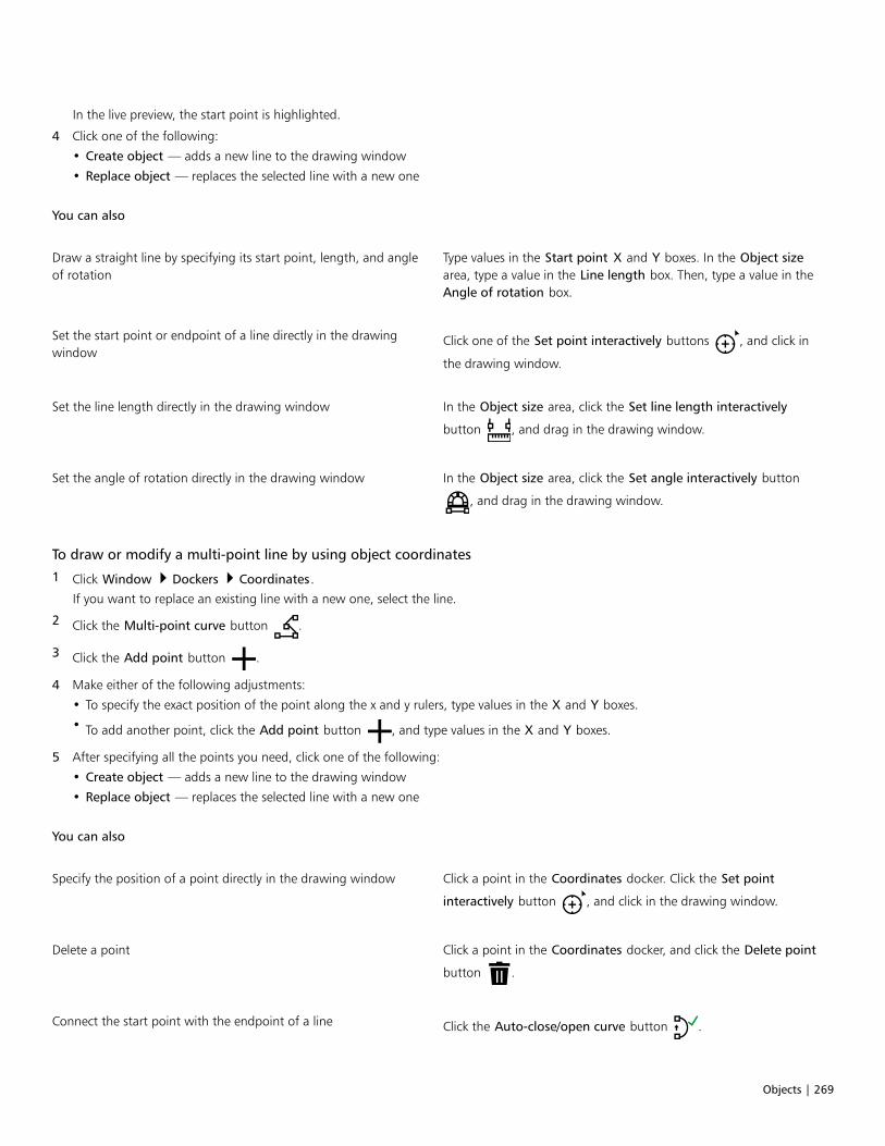
Objects | 269
In the live preview, the start point is highlighted.
4 Click one of the following:
• Create object — adds a new line to the drawing window
• Replace object — replaces the selected line with a new one
You can also
Draw a straight line by specifying its start point, length, and angleof rotation
Type values in the Start point X and Y boxes. In the Object sizearea, type a value in the Line length box. Then, type a value in theAngle of rotation box.
Set the start point or endpoint of a line directly in the drawingwindow
Click one of the Set point interactively buttons , and click in
the drawing window.
Set the line length directly in the drawing window In the Object size area, click the Set line length interactively
button , and drag in the drawing window.
Set the angle of rotation directly in the drawing window In the Object size area, click the Set angle interactively button
, and drag in the drawing window.
To draw or modify a multi-point line by using object coordinates
1 Click Window Dockers Coordinates.
If you want to replace an existing line with a new one, select the line.
2 Click the Multi-point curve button .
3 Click the Add point button .
4 Make either of the following adjustments:
• To specify the exact position of the point along the x and y rulers, type values in the X and Y boxes.
• To add another point, click the Add point button , and type values in the X and Y boxes.
5 After specifying all the points you need, click one of the following:
• Create object — adds a new line to the drawing window
• Replace object — replaces the selected line with a new one
You can also
Specify the position of a point directly in the drawing window Click a point in the Coordinates docker. Click the Set point
interactively button , and click in the drawing window.
Delete a point Click a point in the Coordinates docker, and click the Delete point
button .
Connect the start point with the endpoint of a line Click the Auto-close/open curve button .

270 | CorelDRAW 2019 User Guide
Use the following keyboard shortcuts to create a multi-point line quickly:
• To add a point, click in the Points area, and press Insert.
• To delete a selected point, press Delete.
• To activate the X or Y box of a selected point, press F2.
• To navigate through the X and Y boxes of the available points, select a box and press Tab repeatedly.
• To navigate backward through the X or Y boxes of the available points, select a box and press Shift + Tab repeatedly.
• To activate the Set point interactively button, double-click a point in the docker.
To draw or modify a star or complex star by using object coordinates
1 Click Window Dockers Coordinates.
If you want to replace an existing star with a new one, select the star.
2 Click the Star or the Complex star button.
3 Specify the settings you want.
4 Click one of the following:
• Create object — adds a new star to the drawing window
• Replace object — replaces the selected star with a new one
Copy object properties, transformations, and effects
CorelDRAW lets you copy attributes from one object to another. You can copy object properties such as outline, fill, and text properties. Youcan copy object transformations such as sizing, rotating, and positioning. You can also copy effects applied to an object.
To copy fill, outline, or text properties from one object to another
1 In the toolbox, click the Attributes Eyedropper tool .
2 Click the Properties flyout on the property bar, and enable any of the following check boxes:
• Outline
• Fill
• Text
3 Click the object whose properties you want to copy.
The Attribute Eyedropper tool automatically switches to the Apply object attributes mode.
4 Click the object to which you want to apply the copied properties.
Options that are enabled in the Transformations and Effects flyouts on the property bar are also applied when you copy properties.
You can also copy fill or outline properties, or both, by right-clicking an object with the Pick tool , dragging over another object,
releasing the mouse button, and choosing Copy fill here, Copy outline here, or Copy all properties.

Objects | 271
To copy size, position, or rotation from one object to another
1 In the toolbox, click the Attributes Eyedropper tool .
2 Click the Transformations flyout on the property bar, and enable any of the following check boxes:
• Size
• Rotation
• Position
3 Click the object whose transformations you want to copy.
The Attributes Eyedropper tool automatically switches to the Apply object attributes mode.
4 Click the object to which you want to apply the copied transformations.
Options that are enabled in the Properties and Effects flyouts on the property bar are also applied when you copy properties.
To copy effects from one object to another
1 In the toolbox, click the Attributes Eyedropper tool .
2 Click the Effects flyout on the property bar, and enable any of the following check boxes:
• Perspective
• Envelope
• Blend
• Extrude
• Contour
• Lens
• PowerClip
• Drop shadow
• Distortion
3 Click the object whose effects you want to copy.
The Attributes Eyedropper tool automatically switches to the Apply object attributes mode.
4 Click the object to which you want to apply the copied effects.
Options that are enabled in the Properties and Transformations flyouts on the property bar are also applied when you copyproperties.
Clone objects
When you clone an object, you create a copy of an object that is linked to the original. Any changes you make to the original object arereflected automatically in the clone. Changes you make to the clone are not automatically reflected in the original, however. You can removechanges made to the clone by reverting to the original.
Cloning lets you modify multiple copies of an object simultaneously by changing the master object. This type of modification is especiallyuseful if you want the clone and master objects to differ by certain properties, such as fill and outline color, but want the master object tocontrol other properties, such as shape.
If you simply want to use the same object in a drawing multiple times, consider using symbols, instead of clones, to keep the file sizemanageable. For more information about symbols, see “Symbols” on page 327.

272 | CorelDRAW 2019 User Guide
The object on the left was cloned twice. Different fill and outline propertieswere applied to the clones. The clone on the right was also reshaped.
To clone an object
1 Select an object.
2 Click Edit Clone.
You can also
Select the master object of a clone Right-click the clone, and click Select Master.
Select the clone objects of a master Right-click the master, and click Select Clones.
You can clone a master object multiple times, but you cannot clone a clone.
To revert to the master object of a clone
1 Right-click a modified clone, and click Revert to Master.
2 Enable any of the following check boxes:
• Clone Fill — restores the master fill attributes
• Clone Outline — restores the master outline attributes
• Clone Path Shape — restores the master shape attributes
• Clone Transformations — restores the master shape and size attributes
• Clone Bitmap Color Mask — restores the master color settings
Only the clone properties that are different from the master object are available in the Revert to Master dialog box.
Position objects
You can position objects by dragging them to a new location, by nudging, or by specifying their horizontal and vertical coordinates.
Nudging lets you move an object in increments by pressing the Arrow keys. The increment value is known as “nudge distance.” Micro-nudging lets you move an object by a fraction of the nudge distance. Super-nudging lets you move an object by a multiple of the nudgedistance. By default, you can nudge objects in 0.1-inch increments, but you can change this increment value to suit your needs. You can alsochange micro-nudge and super-nudge values.
To position an object, you can set horizontal and vertical coordinates that are relative to the center anchor point, or other anchor point, ofthe object.

Objects | 273
You can also move an object to another page. For more information, see “To move an object to another page” on page 592.
To move an object
1 Select an object.
2 Point to the center of the bounding box.
3 When the position cursor appears, drag the object to a new position in the drawing.
You can move an object to another page by dragging the object over a page number tab at the bottom of the document windowand then dragging the object into the document window.
To move an object while drawing
1 Start drawing a shape such as a rectangle, ellipse, or polygon.
2 Hold down the right mouse button without releasing the left mouse button, and drag the unfinished object to its new position.
3 Release the right mouse button, and continue drawing.
Moving an object while drawing
To nudge an object
To Do the following
Nudge a selected object by the nudge distance Press an Arrow key.
Nudge a selected object by a fraction of the nudge distance (micro-nudge)
Hold down Ctrl, and press an Arrow key.
Nudge a selected object by a multiple of the nudge distance (super-nudge)
Hold down Shift, and press an Arrow key.
To set nudge distances
1 Click Layout Document Options.
2 In the left pane of the dialog box, click Rulers.
3 Type a value in any of the following boxes:

274 | CorelDRAW 2019 User Guide
• Nudge
• Super nudge
• Micro nudge
You can also set the nudge distance by deselecting all objects and typing a value in the Nudge distance box on the property bar.
To save the new nudge distances to use in new drawings, click Tools Save Settings as Default.
To position an object by x and y coordinates
1 Select an object.
If you want to change the object origin, click a point on the Object Origin button on the property bar.
2 Type values in the following boxes:
• x — lets you position the object on the x-axis
• y — lets you position the object on the y-axis
The x and y values specify the exact position of the object origin.
3 Press Enter.
The object origin, also known as “anchor point” or “reference point,” can be the center of an object or any one of the object’sselection handles. The object origin remains stationary when an object is positioned by typing values in the x and y boxes on theproperty bar.
To position an object by changing the anchor point
1 Select an object.
2 Click Window Dockers Transform.
3 Click the Position button .
4 Disable the Relative position check box in the Transform docker.
5 Type values in the following boxes:
• X — lets you specify a value for the position of an object along the horizontal axis
• Y — lets you specify a value for the position of an object along the vertical axis
6 Enable the check box that corresponds to the anchor point that you want to set.
7 Click Apply.
By default, the point of origin (0,0) is at the lower-left corner of the drawing page.
When you enable the Relative position check box on the Transform docker, the position of the center anchor point is identified as0,0 in the X and Y boxes. When you specify a different position in the X and Y boxes, the values represent a change from the currentposition as measured from the center anchor point of the object.
Align and distribute objects
CorelDRAW lets you precisely align and distribute objects in a drawing. You can align objects with each other and with parts of the drawingpage, such as the center, edges, and grid. When you align objects with objects, you can line them up by their centers or by their edges.

Objects | 275
You can align multiple objects horizontally or vertically with the center of the drawing page. Single or multiple objects can also be arrangedalong the edge of the page and to the nearest point on a grid. You can also align objects with a reference point by specifying its exact x andy coordinates.
Distributing objects automatically adds spacing between them based on their width, height, and center points. You can distribute objects sothat their center points or selected edges (for example, top or right) appear at equal intervals. You can also distribute objects so that thereis equal space between them. You can distribute objects over the extent of the bounding box surrounding them or over the entire drawingpage.
Scattered objects (left) are vertically aligned and equally distributed (right).
To prevent blurry edges in objects designed for web use, you can align the objects with the pixel grid. This feature realigns the nodes oredges of the object to position them correctly on the pixel grid.
Align objects with the pixel grid to prevent blurry edges.
To align objects
1 Select the objects.
2 Click Object Align and Distribute Align and Distribute.
3 In the Align area of the docker, click one of the following buttons to use an object edge or center for aligning.
• Align left — to align the left edges of objects
• Align center horizontally — to align object centers along a vertical axis

276 | CorelDRAW 2019 User Guide
• Align right — to align the right edges of objects
• Align top — to align the top edges of objects
• Align center vertically — to align object centers along a horizontal axis
• Align bottom — to align the bottom edges of objects
To align objects from their outlines, click the Outline button .
4 In the Align objects to area, perform any of the following tasks.
To Do the following
Align an object with a specific object Click the Active objects button .
If you select the objects one at a time, the last object selected is thereference point for aligning the other objects. If you marquee selectthe objects, the object that is positioned in the upper-left corner ofthe selection is used as a reference point.
Align an object with the page edge Click the Page edge button .
Align an object with the page center Click the Page center button .
To align the center of the object with the page center, make sure
that the Align center horizontally button and Align center
vertically button in the Align area are enabled.
Align an object with the closest grid line Click the Grid button .
Align an object with a specified point Click the Specified point button , and type values in the
Specify coordinates boxes.
You can also specify a point interactively by clicking the Specifypoint button, and clicking in the document window.
Set an alignment option for text objects In the Text area, choose one of the following options:•First line baseline — aligns text by the baseline of the first
line•Last line baseline — aligns text by the baseline of the last
line•Bounding box — aligns text by its bounding box
You can also align objects with another object quickly, without using the Align and Distribute docker, by clicking Object Alignand Distribute and clicking any of the first six alignment commands. The letter next to a command name indicates the keyboard
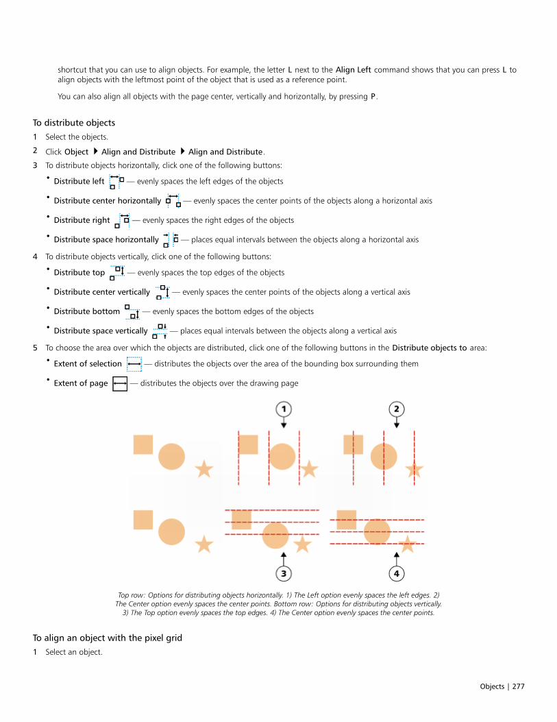
Objects | 277
shortcut that you can use to align objects. For example, the letter L next to the Align Left command shows that you can press L toalign objects with the leftmost point of the object that is used as a reference point.
You can also align all objects with the page center, vertically and horizontally, by pressing P.
To distribute objects
1 Select the objects.
2 Click Object Align and Distribute Align and Distribute.
3 To distribute objects horizontally, click one of the following buttons:
• Distribute left — evenly spaces the left edges of the objects
• Distribute center horizontally — evenly spaces the center points of the objects along a horizontal axis
• Distribute right — evenly spaces the right edges of the objects
• Distribute space horizontally — places equal intervals between the objects along a horizontal axis
4 To distribute objects vertically, click one of the following buttons:
• Distribute top — evenly spaces the top edges of the objects
• Distribute center vertically — evenly spaces the center points of the objects along a vertical axis
• Distribute bottom — evenly spaces the bottom edges of the objects
• Distribute space vertically — places equal intervals between the objects along a vertical axis
5 To choose the area over which the objects are distributed, click one of the following buttons in the Distribute objects to area:
• Extent of selection — distributes the objects over the area of the bounding box surrounding them
• Extent of page — distributes the objects over the drawing page
Top row: Options for distributing objects horizontally. 1) The Left option evenly spaces the left edges. 2)The Center option evenly spaces the center points. Bottom row: Options for distributing objects vertically.
3) The Top option evenly spaces the top edges. 4) The Center option evenly spaces the center points.
To align an object with the pixel grid
1 Select an object.
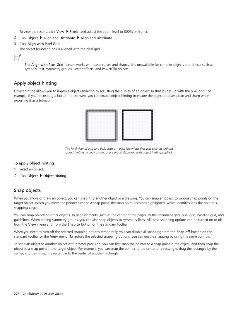
278 | CorelDRAW 2019 User Guide
To view the results, click View Pixels, and adjust the zoom level to 800% or higher.
2 Click Object Align and Distribute Align and Distribute.
3 Click Align with Pixel Grid.
The object bounding box is aligned with the pixel grid.
The Align with Pixel Grid feature works with basic curves and shapes. It is unavailable for complex objects and effects such assymbols, text, symmetry groups, vector effects, and PowerClip objects.
Apply object hinting
Object hinting allows you to improve object rendering by adjusting the display of an object so that it lines up with the pixel grid. Forexample, if you’re creating a button for the web, you can enable object hinting to ensure the object appears clean and sharp whenexporting it as a bitmap.
The Pixel view of a square (left) with a 1-pixel line width that was created withoutobject hinting. A copy of the square (right) displayed with object hinting applied.
To apply object hinting
1 Select an object.
2 Click Object Object Hinting.
Snap objects
When you move or draw an object, you can snap it to another object in a drawing. You can snap an object to various snap points on thetarget object. When you move the pointer close to a snap point, the snap point becomes highlighted, which identifies it as the pointer’ssnapping target.
You can snap objects to other objects, to page elements (such as the center of the page), to the document grid, pixel grid, baseline grid, andguidelines. When editing symmetry groups, you can also snap objects to symmetry lines. All these snapping options can be turned on or offfrom the View menu and from the Snap to button on the standard toolbar.
When you need to turn off the selected snapping options temporarily, you can disable all snapping from the Snap off button on thestandard toolbar or the View menu. To restore the selected snapping options, you can enable snapping by using the same controls.
To snap an object to another object with greater precision, you can first snap the pointer to a snap point in the object, and then snap theobject to a snap point in the target object. For example, you can snap the pointer to the center of a rectangle, drag the rectangle by thecenter, and then snap the rectangle to the center of another rectangle.

Objects | 279
The pointer was snapped to an end node of the leaf (top), and thenthe leaf was dragged to snap to the end node of the branch (bottom).
Snapping modes determine which snap points you can use in an object. The table below includes descriptions of all available snappingmodes.
Snapping mode Description Snapping mode indicator
Node Lets you snap to a node on an object
Intersection Lets you snap to a geometric intersection ofobjects
Midpoint Lets you snap to a line segment midpoint
Quadrant Lets you snap to points that are at 0°, 90°,180°, and 270° on a circle, ellipse, or arc
Tangent Lets you snap to a point on the outsideedge of an arc, circle, or ellipse where a linetouches, but does not intersect, the object
Perpendicular Lets you snap to a point on the outsideedge of a segment where a line isperpendicular to the object
Edge Lets you snap to a point that touches theedge of an object
Center Lets you snap to the center of the closestobject (arc, regular polygon, or curvecentroid)
Text baseline Lets you snap to a point on the baseline ofartistic or paragraph text

280 | CorelDRAW 2019 User Guide
You can adjust a number of snapping settings. For example, you can disable some or all snapping modes to make the application run faster.You can also set a snapping threshold, which specifies the distance from the pointer at which a snap point becomes active.
To turn snapping on or off
• Perform one or more tasks from the following table:
To Do the following
Enable snapping for all objects Click View Snap To Objects.
Enable snapping objects to page elements (edges, edge midpoints,and page center)
Click View Snap To Page.
Enable snapping objects to the pixel grid Click View Snap To Pixels.
This option is available only when pixel view is enabled. For moreinformation, see “Viewing modes” on page 54.
Enable snapping objects to the document grid Click View Snap To Document Grid.
For more information, see “Document grid and pixel grid” on page597.
Enable snapping objects to the baseline grid Click View Snap To Baseline Grid.
For more information, see “Baseline grid” on page 599.
Enable snapping objects to guidelines Click View Snap To Guidelines.
For more information, see “Set up guidelines” on page 600.
Enable snapping objects to symmetry lines Click View Snap To Symmetry Lines.
This option is available only in symmetry mode. For moreinformation, see “Editing symmetry” on page 240.
A check mark next to the snap command indicates that snapping is turned on.
You can also press Alt + Z to toggle snapping to objects on and off, or press Alt + Y to toggle snapping to the document grid onand off.
You can also turn snapping modes on or off from the Snap To button on the standard toolbar.
To disable and enable snapping
• Click View Snap Off.
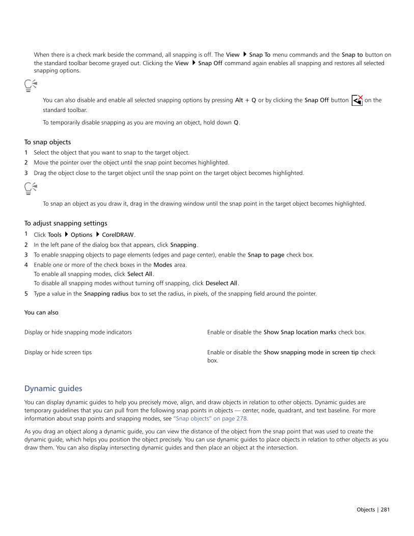
Objects | 281
When there is a check mark beside the command, all snapping is off. The View Snap To menu commands and the Snap to button onthe standard toolbar become grayed out. Clicking the View Snap Off command again enables all snapping and restores all selectedsnapping options.
You can also disable and enable all selected snapping options by pressing Alt + Q or by clicking the Snap Off button on the
standard toolbar.
To temporarily disable snapping as you are moving an object, hold down Q.
To snap objects
1 Select the object that you want to snap to the target object.
2 Move the pointer over the object until the snap point becomes highlighted.
3 Drag the object close to the target object until the snap point on the target object becomes highlighted.
To snap an object as you draw it, drag in the drawing window until the snap point in the target object becomes highlighted.
To adjust snapping settings
1 Click Tools Options CorelDRAW.
2 In the left pane of the dialog box that appears, click Snapping.
3 To enable snapping objects to page elements (edges and page center), enable the Snap to page check box.
4 Enable one or more of the check boxes in the Modes area.
To enable all snapping modes, click Select All.To disable all snapping modes without turning off snapping, click Deselect All.
5 Type a value in the Snapping radius box to set the radius, in pixels, of the snapping field around the pointer.
You can also
Display or hide snapping mode indicators Enable or disable the Show Snap location marks check box.
Display or hide screen tips Enable or disable the Show snapping mode in screen tip checkbox.
Dynamic guides
You can display dynamic guides to help you precisely move, align, and draw objects in relation to other objects. Dynamic guides aretemporary guidelines that you can pull from the following snap points in objects — center, node, quadrant, and text baseline. For moreinformation about snap points and snapping modes, see “Snap objects” on page 278.
As you drag an object along a dynamic guide, you can view the distance of the object from the snap point that was used to create thedynamic guide, which helps you position the object precisely. You can use dynamic guides to place objects in relation to other objects as youdraw them. You can also display intersecting dynamic guides and then place an object at the intersection.
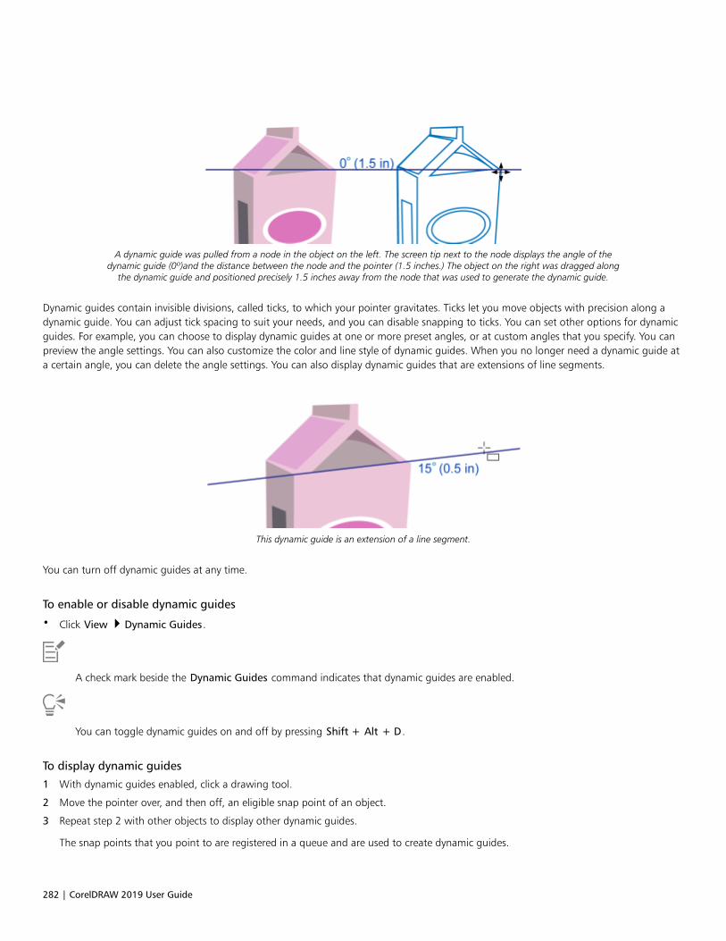
282 | CorelDRAW 2019 User Guide
A dynamic guide was pulled from a node in the object on the left. The screen tip next to the node displays the angle of thedynamic guide (0º)and the distance between the node and the pointer (1.5 inches.) The object on the right was dragged along
the dynamic guide and positioned precisely 1.5 inches away from the node that was used to generate the dynamic guide.
Dynamic guides contain invisible divisions, called ticks, to which your pointer gravitates. Ticks let you move objects with precision along adynamic guide. You can adjust tick spacing to suit your needs, and you can disable snapping to ticks. You can set other options for dynamicguides. For example, you can choose to display dynamic guides at one or more preset angles, or at custom angles that you specify. You canpreview the angle settings. You can also customize the color and line style of dynamic guides. When you no longer need a dynamic guide ata certain angle, you can delete the angle settings. You can also display dynamic guides that are extensions of line segments.
This dynamic guide is an extension of a line segment.
You can turn off dynamic guides at any time.
To enable or disable dynamic guides
• Click View Dynamic Guides.
A check mark beside the Dynamic Guides command indicates that dynamic guides are enabled.
You can toggle dynamic guides on and off by pressing Shift + Alt + D.
To display dynamic guides
1 With dynamic guides enabled, click a drawing tool.
2 Move the pointer over, and then off, an eligible snap point of an object.
3 Repeat step 2 with other objects to display other dynamic guides.
The snap points that you point to are registered in a queue and are used to create dynamic guides.

Objects | 283
The eligible snap points — the node, center, quadrant, and text baseline snap points — appear only when the correspondingsnapping modes are activated. For more information about snap points and snapping modes, see “Snap objects” on page 278.
To avoid displaying too many dynamic guides, you can clear the queue of points at any time by clicking in the drawing window orpressing Esc.
You can use the snap points you registered to display intersecting dynamic guides. To do this, display a dynamic guide, and thenmove the pointer along the dynamic guide to where an intersecting dynamic guide would appear from a registered snap point.
To place an object in relation to another object
1 With dynamic guides enabled, select an object.
If you want to move the object by a specific snap point, move the pointer over the snap point until the snap point becomes highlighted.
2 Drag the object to an eligible snap point of the target object.
3 When the snap point of the target object becomes highlighted, drag the object along the dynamic guide to position it.
The eligible snap points — the node, center, quadrant, and text baseline snap points — appear only when the correspondingsnapping modes are activated. For more information about snap points and snapping modes, see “Snap objects” on page 278.
To draw an object in relation to another object
1 With dynamic guides enabled, click a drawing tool.
2 Move the pointer over an eligible snap point of an object.
3 When the snap point becomes highlighted, move the pointer to display a dynamic guide.
4 Move the pointer along the dynamic guide to the point where you want to draw, and drag to draw an object.
The eligible snap points — the node, center, quadrant, and text baseline snap points — appear only when the correspondingsnapping modes are activated. For more information about snap points and snapping modes, see “Snap objects” on page 278.
To place an object at the intersection of dynamic guides
1 With dynamic guides enabled, select an object.
If you want to use a specific snap point to move the object, move the pointer over the snap point until the snap point becomeshighlighted.
2 Drag the object to an eligible snap point of another object, drag to display a dynamic guide, and continue to hold down the mousebutton.
3 Drag the object to another eligible snap point. When the snap point becomes highlighted, drag to display another dynamic guide wherethe two dynamic guides would intersect.
4 When the intersecting point appears, release the mouse button.
In the following example, intersecting dynamic guides are used to position an ellipse.
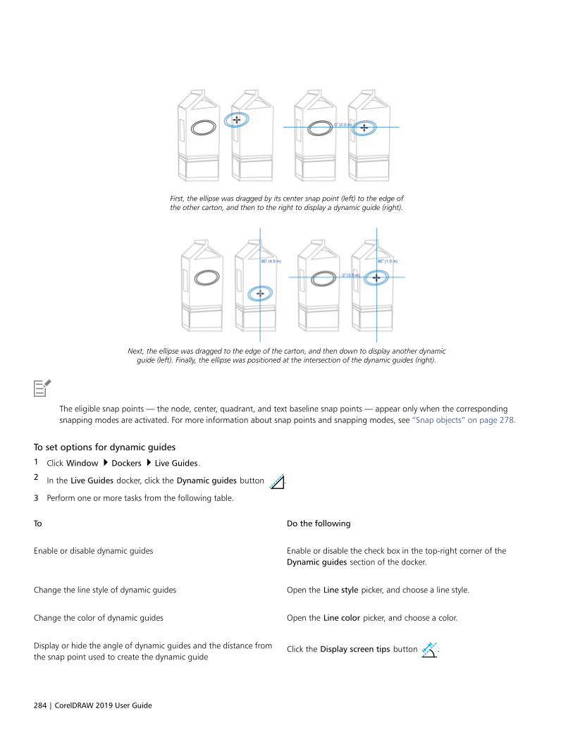
284 | CorelDRAW 2019 User Guide
First, the ellipse was dragged by its center snap point (left) to the edge ofthe other carton, and then to the right to display a dynamic guide (right).
Next, the ellipse was dragged to the edge of the carton, and then down to display another dynamicguide (left). Finally, the ellipse was positioned at the intersection of the dynamic guides (right).
The eligible snap points — the node, center, quadrant, and text baseline snap points — appear only when the correspondingsnapping modes are activated. For more information about snap points and snapping modes, see “Snap objects” on page 278.
To set options for dynamic guides
1 Click Window Dockers Live Guides.
2 In the Live Guides docker, click the Dynamic guides button .
3 Perform one or more tasks from the following table.
To Do the following
Enable or disable dynamic guides Enable or disable the check box in the top-right corner of theDynamic guides section of the docker.
Change the line style of dynamic guides Open the Line style picker, and choose a line style.
Change the color of dynamic guides Open the Line color picker, and choose a color.
Display or hide the angle of dynamic guides and the distance fromthe snap point used to create the dynamic guide
Click the Display screen tips button .
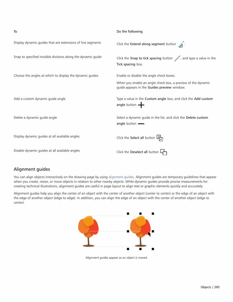
Objects | 285
To Do the following
Display dynamic guides that are extensions of line segments Click the Extend along segment button .
Snap to specified invisible divisions along the dynamic guide Click the Snap to tick spacing button , and type a value in the
Tick spacing box.
Choose the angles at which to display the dynamic guides Enable or disable the angle check boxes.
When you enable an angle check box, a preview of the dynamicguide appears in the Guides preview window.
Add a custom dynamic guide angle Type a value in the Custom angle box, and click the Add custom
angle button .
Delete a dynamic guide angle Select a dynamic guide in the list, and click the Delete custom
angle button .
Display dynamic guides at all available angles Click the Select all button .
Disable dynamic guides at all available angles Click the Deselect all button .
Alignment guides
You can align objects interactively on the drawing page by using alignment guides. Alignment guides are temporary guidelines that appearwhen you create, resize, or move objects in relation to other nearby objects. While dynamic guides provide precise measurements forcreating technical illustrations, alignment guides are useful in page layout to align text or graphic elements quickly and accurately.
Alignment guides help you align the center of an object with the center of another object (center to center) or the edge of an object withthe edge of another object (edge to edge). In addition, you can align the edge of an object with the center of another object (edge tocenter).
Alignment guides appear as an object is moved.
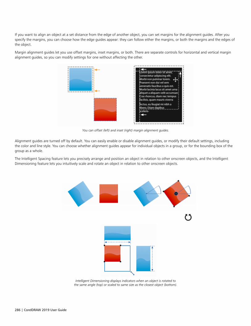
286 | CorelDRAW 2019 User Guide
If you want to align an object at a set distance from the edge of another object, you can set margins for the alignment guides. After youspecify the margins, you can choose how the edge guides appear: they can follow either the margins, or both the margins and the edges ofthe object.
Margin alignment guides let you use offset margins, inset margins, or both. There are separate controls for horizontal and vertical marginalignment guides, so you can modify settings for one without affecting the other.
You can offset (left) and inset (right) margin alignment guides.
Alignment guides are turned off by default. You can easily enable or disable alignment guides, or modify their default settings, includingthe color and line style. You can choose whether alignment guides appear for individual objects in a group, or for the bounding box of thegroup as a whole.
The Intelligent Spacing feature lets you precisely arrange and position an object in relation to other onscreen objects, and the IntelligentDimensioning feature lets you intuitively scale and rotate an object in relation to other onscreen objects.
Intelligent Dimensioning displays indicators when an object is rotated tothe same angle (top) or scaled to same size as the closest object (bottom).

Objects | 287
Intelligent Spacing displays indicators when an object is equidistant between twoother objects (left) or has the same spacing as the closest onscreen objects (right).
To enable or disable alignment guides
• Click View Alignment Guides.
A check mark beside the Alignment Guides command indicates that alignment guides are enabled.
You can also enable or disable alignment guides by clicking the Alignment guides button on the Layout toolbar. To open the Layouttoolbar, click Window Toolbars Layout.
You can also enable alignment guides by pressing Shift + Alt + A.
To modify alignment guide settings
1 Click Window Dockers Live Guides.
2 In the Live Guides docker, click the Alignment guides button .
3 Perform any of the following tasks.
To Do the following
Enable or disable alignment guides Enable or disable the check box in the top-right corner of theAlignment guides section.
Change the color of alignment guides Open the Line color picker, and choose a color.
Change the line style of alignment guides Open the Line style picker, and choose a line style.
Set guides to align the edge of an object with the edge of anotherobject
Click the Object edges button .
Set guides to align the edge of an object with the center of anotherobject
Click the Object centers button .

288 | CorelDRAW 2019 User Guide
To Do the following
Set guides to align to individual objects in a group Click the Individual objects in a group button .
Distribute objects using the same spacing as the closest onscreenobjects
Ensure that the Intelligent spacing button is enabled, and
drag the object until indicator arrows appear.
Position an object equidistantly between two other objects Ensure that the Intelligent spacing button is enabled, and drag theobject between two other objects until indicator arrows appear.
Scale objects to the same dimensions as other onscreen objects Ensure that the Intelligent dimensioning button is enabled,
and scale the object until indicator arrows appear.
Rotate objects to the same angle as other rotated onscreen objects Ensure that the Intelligent dimensioning button is enabled, androtate the object until rotation indicators appear.
You can access most alignment guide controls on the Layout toolbar by clicking the Layout toolbar button .
To add margin alignment guides
1 Click Window Dockers Live Guides.
2 In the Live Guides docker, click the Alignment guides button .
3 Perform any of the following tasks.
To Do the following
Add margin alignment guides Enable the Margins check box. If the Margins check box is not
displayed, click the arrow button located at the bottom of the
Alignment guides section.
Change the line color of margins Open the Margin line color picker, and choose a color.
Change the line style of margins Open the Margin line style picker, and choose a line style.
Set horizontal margins Type a value in the Horizontal margin box, click the Horizontalmargin button, and choose one of the following options:
•Offset horizontally — creates a margin of the specified
distance around an object•Inset horizontally — creates a margin of the specified
distance within an object•Offset and inset horizontally — creates margins of the
specified distance around and within an object
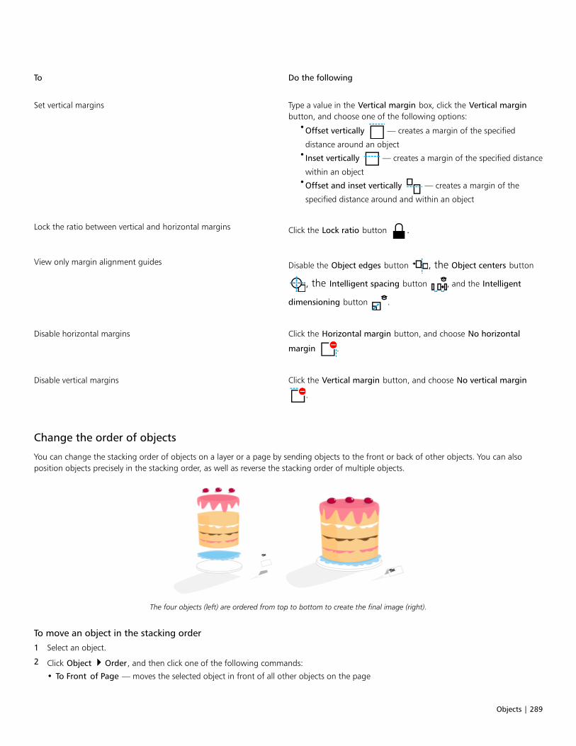
Objects | 289
To Do the following
Set vertical margins Type a value in the Vertical margin box, click the Vertical marginbutton, and choose one of the following options:
•Offset vertically — creates a margin of the specified
distance around an object•Inset vertically — creates a margin of the specified distance
within an object•Offset and inset vertically — creates a margin of the
specified distance around and within an object
Lock the ratio between vertical and horizontal margins Click the Lock ratio button .
View only margin alignment guides Disable the Object edges button , the Object centers button
, the Intelligent spacing button , and the Intelligent
dimensioning button .
Disable horizontal margins Click the Horizontal margin button, and choose No horizontal
margin .
Disable vertical margins Click the Vertical margin button, and choose No vertical margin
.
Change the order of objects
You can change the stacking order of objects on a layer or a page by sending objects to the front or back of other objects. You can alsoposition objects precisely in the stacking order, as well as reverse the stacking order of multiple objects.
The four objects (left) are ordered from top to bottom to create the final image (right).
To move an object in the stacking order
1 Select an object.
2 Click Object Order, and then click one of the following commands:
• To Front of Page — moves the selected object in front of all other objects on the page

290 | CorelDRAW 2019 User Guide
• To Back of Page — moves the selected object behind all other objects on the page
• To Front of Layer — moves the selected object in front of all other objects on the active layer
• To Back of Layer — moves the selected object behind all other objects on the active layer
• Forward One — moves the selected object forward one position. If the selected object is in front of all other objects on the activelayer, it is moved to the layer above.
• Back One — moves the selected object behind one position. If the selected object is behind all other objects on the selected layer, it ismoved to the layer below.
• In Front Of — moves the selected object in front of the object that you click in the drawing window
• Behind — moves the selected object behind the object that you click in the drawing window
An object cannot be moved to a locked (non-editable) layer; instead, it is moved to the closest editable layer. For example, when youapply the To Front of Page command, and the topmost layer is locked, the object is moved to the topmost editable layer. Any objectson the locked layer remain in front of the object.
By default, all objects on the master page appear on top of the objects on other pages. For information about reordering content onmaster page layers, see “To move a layer” on page 325.
An Order command is unavailable if the selected object is already positioned in the specified stacking order. For example, the ToFront of Page command is unavailable if the object is already in front of all the other objects on the page.
To reverse the order of multiple objects
1 Select the objects.
2 Click Object Order Reverse Order.
Size and scale objects
CorelDRAW lets you size and scale objects. In both cases, you change the dimensions of an object proportionally by preserving its aspectratio. You can change the dimensions of an object by specifying precise values or by changing the object interactively. When you scale anobject, you change its dimensions by a specified percentage.
To size an object
To Do the following
Size a selected object Drag any of the corner selection handles.
Set a precise size Type values in the Object size boxes on the property bar.
Size a selected object from its center Hold down Shift, and drag one of the corner selection handles.
Size a selected object to a multiple of its original size Hold down Ctrl, and drag one of the corner selection handles.
Stretch and size a selected object simultaneously Hold down Alt, and drag one of the corner selection handles.
Objects | 291
The anchor point of an object, also known as “object origin,” remains stationary when you resize the object by typing values in the
Object size boxes on the property bar. If you want to change the object origin, click a point on the Object Origin button on the
property bar.
You can also size an object by clicking Window Dockers Transform, clicking the Size button and then typing values in theTransform docker.
To scale an object
1 Select an object.
2 In the toolbox, click the Free Transform tool .
3 Click the Free scale button on the property bar.
If you want to change the object origin, click a point on the Object Origin button on the property bar.
4 Type a percentage by which you want to scale the object in the Scale factor boxes on the property bar.
You can also
Apply the scaling according to the object’s position rather than thex and y coordinates
Click the Relative to object button on the property bar.
Scale an object using the Transform docker Click Window Dockers Transform. Click the Scale and mirrorbutton, type values in the X and Y boxes, and click Apply.
Leave the original object unchanged and apply the transformationto a copy
Click the Apply to duplicate button on the property bar, or type a
number in the Copies box in the Transform docker.
The object origin, also known as “anchor point” or “reference point,” can be the center of an object or any one of the object’sselection handles. The object origin remains stationary when an object is scaled by typing values in the Scale factor boxes on theproperty bar.
You can also scale an object by dragging a corner selection handle.
You can also scale an object by using the Transform toolbar. To open the toolbar, click Window Toolbars Transform.
Rotate and mirror objects
CorelDRAW lets you rotate and create mirror images of objects. You can rotate an object by specifying horizontal and vertical coordinates.You can move the center of rotation to a specific ruler coordinate or to a point that is relative to the current position of the object.

292 | CorelDRAW 2019 User Guide
Rotating objects around a single point
Mirroring an object flips it from left to right or top to bottom. By default, the mirror anchor point is in the center of the object.
Mirroring an object from top to bottom
To rotate an object
1 Select an object.
2 In the toolbox, click the Free Transform tool .
3 Click the Free rotation button on the property bar.
4 Type a value in the Angle of rotation box on the property bar.
5 Press Enter.
You can also
Apply the rotation according to the object’s position rather thanthe x and y coordinates
Click the Relative to object button on the property bar.
Use rotation handles to rotate an object Using the Pick tool, click the object twice to display the rotationhandles. Drag a rotation handle clockwise or counterclockwise.
Objects | 293
You can also
Rotate an object using the Transform docker Click Window Dockers Transform. Click the Rotate button
.
You can also view and set the relative center of an object by clicking the object to display the rotation handles and dragging therelative center handle (circle with a dot in the middle) to a new position.
You can set the relative center of an object to its original position by enabling the Relative Center check box in the Transform docker.
You can also rotate an object by using the Transform toolbar. To open the toolbar, click Window Toolbars Transform.
To rotate an object around a ruler coordinate
1 Select an object.
2 Click Window Dockers Transform.
3 Click the Rotate button .
4 Disable the Relative Center check box.
5 Type a value in the Angle of Rotation box.
6 Type values in any of the following Center boxes:
• X — lets you specify the point on the horizontal ruler around which the object rotates
• Y — lets you specify the point on the vertical ruler around which the object rotates
7 Click Apply.
To mirror an object
1 Select an object.
2 Click Window Dockers Transform.
3 Click the Scale and mirror button.
4 In the Transform docker, click one of the following buttons:
• Mirror horizontally — lets you flip the object from left to right
• Mirror vertically — lets you flip the object from top to bottom
If you want to flip the object on a specific anchor point, enable the check box that corresponds to the anchor point you want to set.
5 Click Apply.
You can also mirror a selected object by holding down Ctrl and dragging a selection handle to the opposite side of the object.
You can also mirror a selected object by clicking the Mirror horizontally or the Mirror vertically button on the property bar.
Modify objects with the Properties docker
The Properties docker presents object-dependent formatting options and properties, letting you modify object settings from one location.For example, if you create a rectangle, the Properties docker automatically presents outline, fill, transparency, and corner formatting options,as well as the rectangle’s properties. If you create a text frame, the docker instantly displays character, paragraph, and frame formattingoptions, as well as the text frame’s properties.

294 | CorelDRAW 2019 User Guide
You can navigate quickly to the properties that you want to modify by using the controls at the top of the Properties docker. In addition,two view modes are available: Scroll and Tab. Scroll mode displays all relevant object properties, letting you scroll to the options you want.Tab mode displays only one group of object properties at a time, hiding the other options. For example, you can view only fill options, andthen click the Outline button to view only outline options.
In this example, the Properties docker displays the editable propertiesof a selected rectangle in Tab mode (left) and Scroll mode (right).
If objects have outline, fill, or other styles applied to them, style indicators appear beside the property in the Properties docker. You can hidethe style indicators to save space.
To use the Properties docker
1 Select an object.
If the Properties docker is not open, click Window Dockers Properties.
2 Perform any of the following tasks.

Objects | 295
To Do the following
Display the object properties that you want to modify Click the corresponding button at the top of the docker.
Switch between Scroll and Tab mode Click the Scroll/Tab mode button.
Display or hide the style indicators Click the Style indicators button.
Fit objects to a path
The Fit Objects to Path feature lets you fit any type and number of objects to a path of your choice. Smart distribution and rotation settingshelp you customize the placement of objects on the path.
You can distribute objects along a path by placing equal gaps between them and you can distribute objects by spacing evenly their referencepoints such as center of rotation or object origin. Objects can be rotated to follow the path. Moreover, you can use additional options suchas different rotation styles and spin angles to create unique effects.
Fitting objects to a path
To fit objects to a path
1 Using the Pick tool, select the objects that you want to fit to a path.
2 Holding down Shift, click the path.
If you do not select a path, the last object you selected in step 1 is used as a path.
3 Click Objects Fit Objects to Path.
4 In the Fit Objects to Path docker, choose any settings you want.
5 Click Apply.
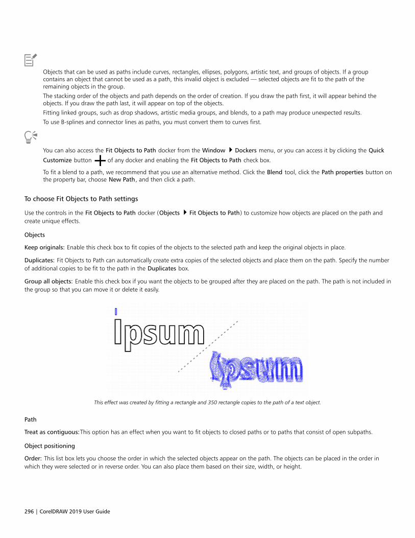
296 | CorelDRAW 2019 User Guide
Objects that can be used as paths include curves, rectangles, ellipses, polygons, artistic text, and groups of objects. If a groupcontains an object that cannot be used as a path, this invalid object is excluded — selected objects are fit to the path of theremaining objects in the group.
The stacking order of the objects and path depends on the order of creation. If you draw the path first, it will appear behind theobjects. If you draw the path last, it will appear on top of the objects.
Fitting linked groups, such as drop shadows, artistic media groups, and blends, to a path may produce unexpected results.
To use B-splines and connector lines as paths, you must convert them to curves first.
You can also access the Fit Objects to Path docker from the Window Dockers menu, or you can access it by clicking the Quick
Customize button of any docker and enabling the Fit Objects to Path check box.
To fit a blend to a path, we recommend that you use an alternative method. Click the Blend tool, click the Path properties button onthe property bar, choose New Path, and then click a path.
To choose Fit Objects to Path settings
Use the controls in the Fit Objects to Path docker (Objects Fit Objects to Path) to customize how objects are placed on the path andcreate unique effects.
Objects
Keep originals: Enable this check box to fit copies of the objects to the selected path and keep the original objects in place.
Duplicates: Fit Objects to Path can automatically create extra copies of the selected objects and place them on the path. Specify the numberof additional copies to be fit to the path in the Duplicates box.
Group all objects: Enable this check box if you want the objects to be grouped after they are placed on the path. The path is not included inthe group so that you can move it or delete it easily.
This effect was created by fitting a rectangle and 350 rectangle copies to the path of a text object.
Path
Treat as contiguous:This option has an effect when you want to fit objects to closed paths or to paths that consist of open subpaths.
Object positioning
Order: This list box lets you choose the order in which the selected objects appear on the path. The objects can be placed in the order inwhich they were selected or in reverse order. You can also place them based on their size, width, or height.

Objects | 297
Order options shown from left to right: Selection: Follow selection order, Selection: Reverse order, and Area: Small to big.
Distribution: This list box lets you choose a distribution method. You can distribute objects by inserting equal space between them (Uniformobject spacing). You can also distribute objects by spacing evenly the reference points that you select.
The Uniform object spacing method places equal gaps between the objects on the path.
Reference points: An object is anchored (fit) to the path by its reference point. The Reference list box lets you choose the center of rotationof each object or the object origin as a reference point. The object origin, also known as “anchor point”, can be the center of an object orany one of eight other points on the object’s bounding box. To change the origin point, simply click another point on the Origin control.
Object origin spacing method. The object origin point is changed to create the effect of leaves hanging from a branch.

298 | CorelDRAW 2019 User Guide
Rotation options
Ignore initial rotation: This control lets you clear all previous rotations applied to the objects before they were placed on the path.
Top: The original clipart is rotated. Middle: It is fit to a straight path, ignoringthe applied rotation. Bottom: The clipart is fit to the path, preserving its rotation.
The following controls let you enhance object rotation along the path.
Style: Choose from several rotation styles to create various rotation effects. The Uniform style lets you add the same rotation to each objectalong the path by specifying a value in the Start angle box. The Progressive style works together with the Start angle and Spin angle boxesto add a rotation that changes along the path. If you want to create a more organic rotation effect with angles of rotation varying randomly,you can choose Jitter or Progressive jitter. You can specify the range of the random rotations.
Left: With the Uniform style, the same angle of rotation is added to each object on thepath. Right: With the Progressive style, the added angle of rotation changes for each object.
Direction: By default, added rotation is applied counterclockwise. To change the direction, enable the Clockwise check box.
Start angle: Add an angle of rotation to each object.
Spin angle: This control works together with the Progressive and Progressive jitter styles. It allows you to add an angle of rotation to eachobject, ranging from 0º to the specified value. Suppose that you want to fit an object and three duplicates to a path, and you specify a spinangle of 180º. This spin angle applies an additional rotation of 0º to the first object, 60º to the second object, 120º to the third object, and180º to the last object.

Objects | 299
Progressive rotation style with a start angle of 5º and a spin angle of 180º
Revolutions: An alternative way of adding rotation to the objects on the path progressively. One revolution equals 360º.
Range: This control is available when the Jitter and Progressive jitter styles are selected. Specify a value range for random rotations used tocreate jitter. For example, with a value of 15º, the angles of rotation vary between 15º and -15º.
Examples of Jitter (top) and Progressive jitter (bottom) rotation styles with range of 30º
Group objects
When you group two or more objects, they are treated as a single unit but retain their individual attributes. Grouping lets you apply thesame formatting, properties, and other changes to all the objects within the group at the same time. In addition, grouping helps preventaccidental changes to the position of an object in relation to other objects. You can also create nested groups by grouping together existinggroups.
Individual objects retain their attributes when they are grouped.
300 | CorelDRAW 2019 User Guide
You can add objects to or remove objects from a group, and you can delete objects that are members of a group. You can also edit a singleobject in a group without ungrouping the objects. If you want to edit multiple objects in a group at the same time, you must first ungroupthe objects. If a group contains nested groups, you can ungroup all objects in the nested groups simultaneously.
To group objects
1 Select the objects.
2 Click Object Group Group.
The status bar indicates that a group of objects is selected.
You can select objects from different layers and group them; however, after objects are grouped, they reside on the same layer andare stacked on top of one another.
You can create a nested group by selecting two or more groups of objects and clicking Object Group Group.
You can also group objects by dragging an object in the Objects docker over another object. If the Objects docker is not open, clickWindow Dockers Objects.
You can also group objects by clicking the Group objects button on the property bar.
To add an object to a group
• In the Objects docker, drag the object to the group.
If the Objects docker is not open, click Window Dockers Objects.
To remove an object from a group
• In the Objects docker, drag an object outside the group.
If the Objects docker is not open, click Window Dockers Objects.
To delete an object in a group, select the object in the object list, and click Edit Delete.
To edit an object in a group
1 Click the Pick tool .
2 Hold down Ctrl, and click an object in a group to select it.
3 Edit the object.
You can also select an object in a group by clicking the object in the Objects docker. If the Objects docker is not open, click Window
Dockers Objects.
To ungroup objects
1 Select one or more groups.
2 Click Object Group, and click one of the following commands:

Objects | 301
• Ungroup — breaks a group into individual objects, or a nested group into multiple groups
• Ungroup All — breaks one or more groups into individual objects, including objects within nested groups
Choosing Ungroup All also ungroups all nested groups. To preserve nested groups, select Ungroup.
You can also ungroup objects by clicking the Ungroup button on the property bar.
You can also ungroup all nested groups within a group by clicking the Ungroup all button on the property bar.
Combine objects
Combining two or more objects creates a single object with common fill and outline attributes. You can combine rectangles, ellipses,polygons, stars, spirals, graphs, or text so that they are converted to a single curve object. If you need to modify the attributes of an objectthat has been combined from separate objects, you can break apart the combined object. You can extract a subpath from a combined objectto create two separate objects. You can also weld two or more objects to create a single object. For information about welding objects, see“Weld and intersect objects” on page 225.
The two objects (left) are combined to create a single object (right). Thenew object has the fill and outline properties of the last object selected.
To combine objects
1 Select the objects to be combined.
2 Click Object Combine.
Combined text objects become larger blocks of text.
You can also combine selected objects by clicking the Combine button on the property bar.
You can close open lines in a combined object by clicking Object Join Curves and choosing settings in the Join Curves docker.
302 | CorelDRAW 2019 User Guide
To break apart a combined object
1 Select a combined object.
2 Click Object Break Curve Apart.
If you break apart a combined object that contains artistic text, the text breaks apart into lines first, and then into words. Paragraphtext breaks into separate paragraphs.
To extract a subpath from a combined object
1 Click the Shape tool , and select a segment, node, or group of nodes on a combined object.
2 Click the Extract subpath button on the property bar.
After you extract the subpath, the fill and outline properties of the path are removed from the combined object.
Lock objects
Locking an object prevents you from accidentally moving, sizing, transforming, filling, or otherwise changing it. You can lock single, multiple,or grouped objects. To change a locked object, you need to unlock it first. You can unlock one object at a time, or all locked objects at thesame time.
To lock an object
• Select an object, and click Object Lock Lock.
You cannot lock linked objects, such as blends, contours, or text inside an object. You also cannot lock objects within groups or linkedgroups.
You can also lock an object by right-clicking it and then clicking Lock.
You can also lock an object by clicking the lock icon beside the object name in the Objects docker.
To unlock objects
1 Select a locked object or group of objects.
2 Click Object Lock, and then click one of the following:
• Unlock
• Unlock All
You can also unlock an object by right-clicking it and then clicking Unlock.
You can also unlock multiple locked objects by dragging in the second column in the Objects docker.

Objects | 303
Find and replace objects
You can find objects so that you can quickly replace or edit them.
Using search criteria that you specify, you can find and select objects in a drawing. The search criteria can include object type and its relatedproperties, fill and outline properties, vector effects applied to objects, or the name of an object or style. For example, you can search forand select all rectangles with rounded corners and without fill. You can also search for objects that contain the same properties as a selectedobject. You can change the search criteria in the middle of a search. You can also save search criteria for later use.
You can also find objects that contain the properties you specify and then replace those properties with others. For example, you can replaceall object fills of a certain color with fills of a different color. You can also replace color models and palettes, outline properties, and textattributes, such as font and font size.
You can also search for specific words and replace them with other words. For more information, see “To find and replace text” on page483.
To find and select objects
1 Click Edit Find and Replace.
2 In the Find and Replace docker, choose Find Objects from the list box at the top of the docker.
3 Enable the Properties option.
4 Click Add Query, and then in the dialog box that appears, do any of the following:
• Click the arrow beside Object Types, and enable check boxes corresponding to object types to include in the search. You can narrowthe search by specifying object properties. To include all objects in a search, enable the Object Types check box.
• Click the arrow beside Fills, and enable check boxes corresponding to fill types to include in the search. You can narrow the searchby specifying fill properties. To include fill types in a search, enable the Fills check box. For more information about fill types and theirproperties, see “Fills ” on page 365.
• Click the arrow beside Outlines, and enable check boxes corresponding to outline types to include in the search. You can narrow thesearch by specifying outline properties. To include all outline types in a search, enable the Outlines check box. For more informationabout outlines and their properties, see “Format lines and outlines ” on page 138.
• Click the arrow beside Special Effects, and enable check boxes corresponding to special effects to include in the search. You cannarrow the search by specifying special effect properties. To include all objects with a special effect in a search, enable the SpecialEffects check box. For more information about special effects and their properties, see “Add 3D effects ” on page 429.
5 Click OK.
6 In the Find and Replace docker, click any of the following:
• Find Next > or Find Previous < to scroll through objects that meet the search criteria.
• Find All to select all objects that meet the search criteria.
• Edit Query to modify the search criteria.
You can also
Search for objects by name In the Find and Replace docker, enable the Names or Stylesoption, enable the Object name check box, and type the objectname.
Search for objects by style In the Find and Replace docker, enable the Names or Stylesoption, enable the Style check box, and then either enable theName option and choose the style name or enable the Type optionand choose the style type.
304 | CorelDRAW 2019 User Guide
You can also
Save object-search criteria Click the Save button, type a name in the Save As box, locate
the folder Where you want to save the file, and then click Save.The search criteria is saved to a FIN file.
Reuse object-search criteria Click the Load button, navigate to the folder where the FIN
file is stored, and click Open.
You can also initiate an object search by pressing Ctrl + F.
To find objects with similar properties
1 Select an object.
2 Click Edit Find and Replace.
3 In the Find and Replace docker, click From Selection.
The Search options area displays all the properties of the selected object.
4 Click any of the following:
• Find Next or Find Previous to scroll through objects that meet the search criteria.
• Find All to select all objects that meet the search criteria.
• Edit Query to modify the search criteria.
To replace object properties
1 Click Edit Find and Replace.
2 In the Find and Replace docker, choose Replace Objects from the list box at the top of the docker.
3 To specify which object properties you want to replace, enable one of the following options: Color, Color model or palette, Outlineproperties, or Text properties.
4 Choose the settings you want in the Find and Replace areas.
5 Click one of the following buttons:
• Replace — to replace the properties of the selected objects
• Replace All — to modify all objects that meet the search-criteria.
For more information about how to replace fill colors, see “To find and replace fill colors” on page 386.
For more information about how to replace outline colors, see “To find and replace outline colors” on page 147.
For more information about how to replace outline widths, see “To find and replace outline widths” on page 147.
For more information about how to replace text properties, see “To find and replace text properties” on page 483.
Hide and show objects
CorelDRAW allows you to hide objects and groups of objects, helping you edit objects in complex projects and experiment with your designsmore easily.
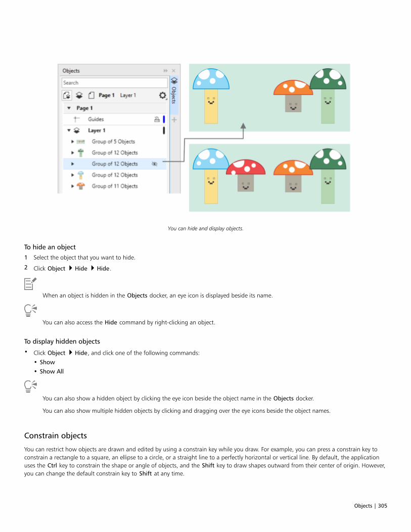
Objects | 305
You can hide and display objects.
To hide an object
1 Select the object that you want to hide.
2 Click Object Hide Hide.
When an object is hidden in the Objects docker, an eye icon is displayed beside its name.
You can also access the Hide command by right-clicking an object.
To display hidden objects
• Click Object Hide, and click one of the following commands:
• Show
• Show All
You can also show a hidden object by clicking the eye icon beside the object name in the Objects docker.
You can also show multiple hidden objects by clicking and dragging over the eye icons beside the object names.
Constrain objects
You can restrict how objects are drawn and edited by using a constrain key while you draw. For example, you can press a constrain key toconstrain a rectangle to a square, an ellipse to a circle, or a straight line to a perfectly horizontal or vertical line. By default, the applicationuses the Ctrl key to constrain the shape or angle of objects, and the Shift key to draw shapes outward from their center of origin. However,you can change the default constrain key to Shift at any time.
306 | CorelDRAW 2019 User Guide
You can use a control key to draw or rotate an object, or the nodes and control handles of an object, at a preset increment. This increment isknown as the constrain angle. By default, the constrain angle is 15 degrees, but you can change it to suit your needs.
To constrain objects while drawing or editing
To Do the following
Constrain a shape to equal width and height While holding down Ctrl, draw diagonally.
Use a preset increment (the constrain angle) to draw or rotate anobject
While holding down Ctrl, move the pointer to draw or rotate theobject.
A rectangle is constrained to a square, an ellipse to a circle, and a polygon to a shape with sides of equal length.
To change the constrain key
1 Click Tools Options Tools.
2 In the left pane of the dialog box that appears, click Pick.
3 In the Ctrl and Shift keys area, enable one of the following options:
• CorelDRAW defaults — lets you use the Ctrl key as the constrain key and the Shift key to draw shapes outward from their center oforigin
• Windows standard — lets you use the Shift key as the constrain key and the Ctrl key to apply transformations to the duplicate of anobject while leaving the original intact
To change the constrain angle
1 Click Tools Options CorelDRAW.
2 In the left pane of the dialog box that appears, click Edit.
3 Type a value in the Constrain angle box.
Bar codes
The Barcode wizard in CorelDRAW lets you add bar codes to drawings. A bar code is a group of bars, spaces, and sometimes numbers thatis designed to be scanned and read into computer memory. Bar codes are most commonly used to identify merchandise, inventory, anddocuments.
The Barcode wizard guides you through the process of inserting a bar code. If you need additional information at any step, you can consultthe Help in the Barcode wizard.
You can also insert QR codes. For more information, see “Insert QR codes” on page 311.
To insert a bar code
1 Click Object Insert Barcode.
2 Follow the instructions in the Barcode wizard.
If you need help with choosing options, click Help in the Barcode wizard.

Objects | 307
A bar code is inserted into a drawing as an object.

308 | CorelDRAW 2019 User Guide

Link and embed objects | 309
Link and embed objects
Object linking and embedding (OLE) is a method of exchanging information between applications. Using OLE, you can take selectedobjects or entire files from one application, called the source application, and place them into another application, called the destinationapplication.
You can freely move objects and files between applications as long as all the applications involved support OLE. CorelDRAW lets you createand edit OLE objects, as well as insert objects and files created in other applications.
Linking results in a larger file size but is useful when you want to use an object or file in multiple files. To change every instance of the objector the file, you only need to change the object in the source application. Linking is also useful when the destination application does notdirectly support files created in the source application. Embedding is useful when you want to include all objects in one file. Embeddedobjects are not linked to the source file, and result in a smaller file size in the destination application.
This section contains the following topics:• “Insert linked or embedded objects” (page 309)• “Edit linked or embedded objects” (page 310)
Insert linked or embedded objects
CorelDRAW lets you insert CorelDRAW files as linked or embedded objects in other applications. You can also insert a linked or embeddedobject in CorelDRAW. A linked object remains connected to its source file; whereas an embedded object is not linked to its source file but isintegrated into the active document.
To insert a linked object
1 In CorelDRAW, select an object.
Make sure that the file is saved first.
2 Click Edit Copy.
3 Click Edit Paste special in the destination application.
4 Enable the Paste link option.
To insert a linked object into the active drawing from another application, click Object Insert Object. In the Insert new objectdialog box, enable the Create from file option, browse to the file you want to insert, and enable the Link check box.
310 | CorelDRAW 2019 User Guide
To insert an embedded object
1 In the destination application, click Object Insert Object.
2 Enable the Create from file option.
3 Click the Browse button.
4 Click a filename.
You can also create an embedded object by enabling the Create new option, and choosing the application in which you want tocreate the object from the Object type list box.
You can also insert an embedded object by selecting an object in the source application, and dragging it to the window of the targetapplication.
Edit linked or embedded objects
You can edit a linked or embedded object. You can edit a linked object by editing its source file. Any changes you make to the source file areautomatically applied to the linked object. You can also modify a linked object; for example, you can update a linked object, substitute thesource file of a linked object for another, or break a link between a linked object and its source file.
To edit a linked or embedded object
1 Double-click the linked or embedded object to start the source application.
2 Edit the object in the source application.
3 Save the changes in the source application.
4 Close the source application.
5 Return to the active application window to review the edits.
In most cases, you can edit OLE objects only in the source application. If you try to change an OLE object using CorelDRAW, note thefollowing limitations. Depending on the source of the OLE object, you might not be able to rotate, skew, clone, trim, weld, intersect,use as symbols, or combine OLE objects. Also, you might not be able to apply any of the effects in the Effects menu to OLE objects,except for PowerClip objects. You can only size, move, copy OLE objects and place them into PowerClip containers.
You can also edit linked or embedded objects by starting the source application and opening the file directly.
To modify a linked object
1 Select a linked object using the Pick tool .
2 Click Object Insert Links.
3 Click one of the following buttons:
• Update now — updates the linked object to reflect changes made in the source file
• Open source — opens the object in the source application
• Change source — redirects the link to another file
• Break link — disconnects the link so that the object is embedded in the file

QR codes | 311
QR codes
A Quick Response (QR) code is a type of barcode that represents information in two dimensions. Typically, QR codes consist of dots (alsocalled “pixels”) arranged in a square pattern and displayed against a contrasting background. QR codes are known for their fast readabilityand can store information such as website addresses, phone numbers, and messages.
With the widespread use of smartphones, QR codes have become popular in consumer advertising and packaging. By scanning a QR codeon your smartphone, you can quickly access the brand’s website for more information about a product.
To insert, edit, and validate QR codes, you must sign in to your account and be connected to the Internet.
This section contains the following topics:• “Insert QR codes” (page 311)• “Edit QR codes” (page 312)• “Validate QR codes” (page 314)
Insert QR codes
CorelDRAW lets you insert QR codes with embedded information such as a web address, email address, phone number, text message, geolocation, or plain text. After you insert a QR code, you can edit and validate it. For more information, see “Edit QR codes ” on page 312and “Validate QR codes” on page 314.
An example of a QR code
To insert a QR code
1 Click Object Insert QR code.

312 | CorelDRAW 2019 User Guide
2 In the Properties docker, choose one of the following options from the QR code type list box:
• URL — lets you specify a URL for a website
• Email address — lets you specify an email address if you want to use the QR code to generate a blank email
• Phone number — lets you specify a phone number for the QR code. Depending on the QR reader that you use, scanning the code caninitiate, with your permission, dialing the phone number on smartphones.
• SMS — lets you include a Short Message Service (SMS) message by typing a phone number and message text. With your permission,the QR reader can initiate sending the SMS message to the specified phone number.
• Contact — lets you specify contact information in vCard or meCard format. From the Contact card type list box, choose vCardor meCard, and type the contact information in the appropriate boxes. With your permission, this contact information can beautomatically added to the address book on your phone.
• Calendar event — lets you schedule an event by specifying a name, location, start date/time, and end date/time for the event. Withyour permission, the event can be added to your calendar.
• Geo location — lets you show a geographic location by specifying latitude and longitude values
• Plain text — lets you include plain (unformatted) text
To insert, edit, and validate QR codes, you must sign in to your account and be connected to the Internet.
Edit QR codes
After you insert a QR code, you can use the Properties docker to customize the pixel fill, the background fill, the pixel outline, as well as thepixel shape and corner roundness. When you customize the shape of the pixels, the markers (the three larger squares in the corners, as wellas one or more smaller squares in the interior of the code pattern) remain unchanged to maintain the readability of the code. You can alsospecify the margin around the QR code or weld the pixels together.
A QR code with customized pixel shapes and added text. The markers remain unchanged.
From left to right: Custom pixel fill color, custom pixel fill and backgroundcolor, custom pixel fill and outline color as well as custom pixel outline width

QR codes | 313
From left to right: QR codes with circular, diamond, and star pixel shapes
Error correction
Visual effects, logos, or text added to a QR code can give it an artistic look but may be considered errors by scanners. You can use the errorcorrection settings to minimize the possibility of error when scanning the QR code. For example, if part of the pixel pattern is covered by agraphic or text, the error correction duplicates some of the hidden data so that this data can be recovered. Four levels of error correction areavailable.
You can move, resize, scale, and align the QR code like any other object. For more information, see “Transform objects” on page 255.
With QR codes, you can use styles to control the appearance of the fill, outline, and other properties. For more information, see “Stylesand style sets” on page 565. You can also change the default look of QR codes by modifying the default object properties. For moreinformation, see “Manage default object properties” on page 570.
To edit a QR code
1 Double-click the QR code.
2 In the Properties docker, perform any of the following tasks.
To Do the following
Apply a fill to the pixels of the QR code Choose a fill type from the Pixel fill type list box, and then choosea fill from the Pixel fill color picker.
If you want to customize the fill, click the Pixel fill settings button
next to the pixel color picker, and specify the fill settings.
Apply a fill to the background Choose a fill type from the Background fill type list box, and thenchoose a fill from the Background fill color picker.
If you want to customize the fill, click the Background fill settings
button next to the background color picker, and specify the fill
settings.
Specify the pixel outline width and color
Type a value in the Pixel outline width box, and then choose acolor from the Pixel outline color picker.
If you want to customize the outline, click the Pixel outline
settings button next to the outline color picker, and specify
the outline settings.
Specify the margin around the QR code Type a value in the Margin box.

314 | CorelDRAW 2019 User Guide
To Do the following
Choose a pixel shape Choose a shape from the Pixel shape picker.
To set the percentage of fill on the pixels, type a value in the Pixelfill factor box.
Weld pixels Click the arrow button at the bottom of the QR code section
to expand it, and enable the Weld pixels check box.
Set the corner roundness of the pixels Click the arrow button at the bottom of the QR code section
to expand it, and type a value in the Pixel roundness box.
When editing the fill, make sure that there is high contrast between the pixels and the background to avoid errors in scanning thecode.
To insert, edit, and validate QR codes, you must sign in to your account and be connected to the Internet.
To add a text or graphic object to a QR code
1 Select the text or graphic object that you want to add.
2 Move the object and place it in the QR code.
If the object is behind the QR code, change the stacking order by using the Object Order command.
To set the error correction level
1 Double-click a QR code.
2 In the Properties docker, click the arrow button at the bottom of the QR code section to expand it, and choose an option from the
Error correction level list box.
The error correction levels specify what percentage of the information used in a QR code can be restored if lost.
• Low — restores 7% of the information
• Medium — restores 15% of the information
• Quartile — restores 25% of the information
• High — restores 30% of the information
Higher correction levels duplicate a higher percentage of the information, which may limit the amount of new information a QR codecan store. This may be a problem for QR codes that are approaching, or already contain, the maximum amount of information beforehigh error correction is applied. In that case, you are prompted to reduce either the correction level or the amount of data in the QRcode.
Validate QR codes
After inserting and formatting a QR code, you can validate it to make sure that it can be read by QR code readers and scanners.

QR codes | 315
To validate a QR code
1 Double-click the QR code.
2 In the Properties docker, click Validate.
To insert, edit, and validate QR codes, you must sign in to your account and be connected to the Internet.
To validate a QR code that was not created in CorelDRAW, click Object Insert Validate Bar Code, and marquee-select the QRcode.

316 | CorelDRAW 2019 User Guide

Layers | 317
Layers
Layers help you organize and arrange objects in complex illustrations.
This section contains the following topics:• “Create layers” (page 317)• “View layers, pages, and objects” (page 320)• “Change layer properties” (page 323)• “Find, move, and copy layers and objects” (page 325)
Create layers
All CorelDRAW drawings consist of stacked objects. The vertical order of these objects — the stacking order — contributes to theappearance of the drawing. An effective way to organize these objects is by using invisible planes called layers.
Drawings can be assembled by placing objects on various levels or layers.
Layering gives you added flexibility when you organize and edit the objects in complex drawings. You can divide a drawing into multiplelayers, each containing a portion of the drawing’s contents. For example, you can use layers to organize an architectural plan for a building.You can organize the building’s various components (for example, plumbing, electrical, structural) by placing them on separate layers.
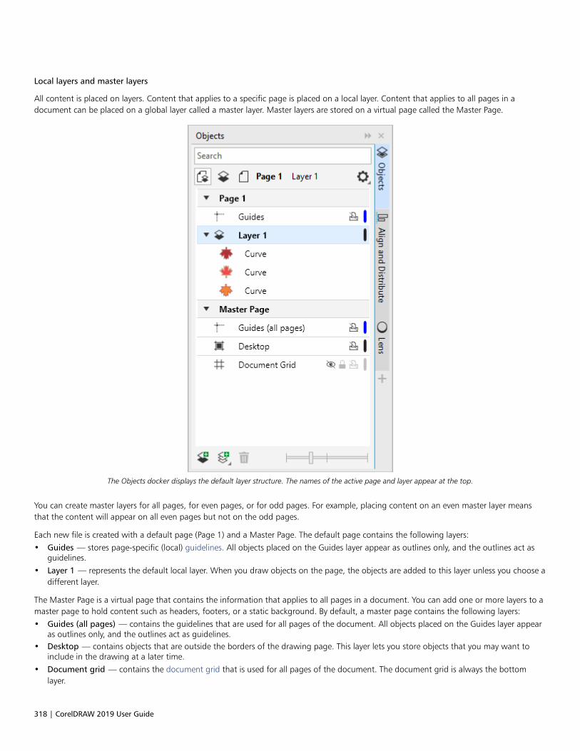
318 | CorelDRAW 2019 User Guide
Local layers and master layers
All content is placed on layers. Content that applies to a specific page is placed on a local layer. Content that applies to all pages in adocument can be placed on a global layer called a master layer. Master layers are stored on a virtual page called the Master Page.
The Objects docker displays the default layer structure. The names of the active page and layer appear at the top.
You can create master layers for all pages, for even pages, or for odd pages. For example, placing content on an even master layer meansthat the content will appear on all even pages but not on the odd pages.
Each new file is created with a default page (Page 1) and a Master Page. The default page contains the following layers:• Guides — stores page-specific (local) guidelines. All objects placed on the Guides layer appear as outlines only, and the outlines act as
guidelines.• Layer 1 — represents the default local layer. When you draw objects on the page, the objects are added to this layer unless you choose a
different layer.
The Master Page is a virtual page that contains the information that applies to all pages in a document. You can add one or more layers to amaster page to hold content such as headers, footers, or a static background. By default, a master page contains the following layers:• Guides (all pages) — contains the guidelines that are used for all pages of the document. All objects placed on the Guides layer appear
as outlines only, and the outlines act as guidelines.• Desktop — contains objects that are outside the borders of the drawing page. This layer lets you store objects that you may want to
include in the drawing at a later time.• Document grid — contains the document grid that is used for all pages of the document. The document grid is always the bottom
layer.
Layers | 319
The default layers on the master page cannot be deleted or copied.
To add content to a layer, you must make it the active layer.
You can delete selected local layers. If a document contains layers that do not contain any content, you can delete them all at once to reduceclutter.
To create a layer
1 If the Objects docker is not open, click Object Objects.
2 Click the Options button , and perform a task from the following table.
To Do the following
Create a local layer Click Layer New Layer.
Create a master layer for all pages Click Layer New Master Layer (all pages).
Create a master layer for odd pages Click Layer New Master Layer (odd pages).
This command is available only when the active page is an oddpage.
Create a master layer for even pages Click Layer New Master Layer (even pages).
This command is available only when the active page is an evenpage.
To use a layer in the drawing, you must first make the layer active by clicking the layer name in the Objects docker. When you start adrawing, the default layer (Layer 1) is the active layer.
Master layers are always added to the master page. Content added to these layers is visible on all pages of the document, all oddpages, or all even pages, depending on the type of master layer that you have chosen.
Master layers for odd and even pages cannot be created in Facing Pages view. If you have created odd and even master pages beforeswitching to Facing Pages view, the odd and even master layers will be converted to all-page master layers. For more informationabout facing pages, see “To view facing pages” on page 55.
You can also add a layer by clicking the New Layer button in the Objects docker.
You can also create new master layers by opening the flyout at the bottom of the Objects docker and clicking the respective button:
New Master Layer (all pages) , New Master Layer (odd pages) , or New Master Layer (even pages) .
You can make any layer a master layer by right-clicking the layer name, clicking Change Layer To, and choosing Master Layer (allpages), Master Layer (odd pages), or Master Layer (even pages).
To make a layer active
1 If the Objects docker is not open, click Object Objects.
2 In the Objects docker, do one of the following:

320 | CorelDRAW 2019 User Guide
• Click the layer name.
• Click an object residing on the layer you want to make active.
By default, the active layer is Layer 1.
The name of the active layer and the type of the currently selected object appear on the status bar at the bottom of the applicationwindow. The names of the active page and layer also appear at the top of the Objects docker.
If you don’t want to activate layers by selecting objects that reside on them, click the Options button , and click Select Object
to Activate Layer to disable the command.
To delete a layer
1 If the Objects docker is not open, click Object Objects.
2 Click the name of a layer.
3 Click the Delete button .
When you delete a layer, you also delete all the objects on it. To preserve an object, move it to a different layer before you delete thecurrent layer.
You can delete any unlocked layer except the following default layers: Document grid, Desktop, Guides, and Guides (all pages). Formore information about locking and unlocking layers, see “To set the editing properties of a layer” on page 324.
You can also delete a layer by right-clicking the layer name in the Objects docker and choosing Delete.
To delete all empty layers
• In the Objects docker, click the Options button , and click Layer Delete Empty Layers.
View layers, pages, and objects
The views in the Objects docker let you display the components of your document in different ways. The view you choose depends on thecomplexity of your document and the task you are performing. For example, in a long multipage document, you can choose to view onlypages so that you can navigate the document more easily and view only one page at a time. The Layers and Objects view lets you view andreorder all the layers that affect the selected page.

Layers | 321
Available views: Pages, Layers, and Objects (left); Layers and Objects (upper right); Pages (lower right)
You can expand layers, pages, and groups, including any nested groups residing on them, with a single click.
You can also switch the view of a layer from a color viewing mode such as Normal or Enhanced to Wireframe. Useful for complex projects,
this feature lets you control the viewing mode of each layer as opposed to the View Wireframe command that applies to all layers in aproject. Also, you can change the color of the wireframe lines.
The Objects docker shows thumbnail previews of objects so that you can identify them more easily. You can increase and decrease the sizeof the object thumbnails.
For information about how facing page views affect layers, see “To view facing pages” on page 55.
For information about how layers are affected when you save a file to an earlier version of CorelDRAW, see “To save a drawing” on page 56.
To display pages, layers, and objects in the Objects docker
1 If the Objects docker is not open, click Object Objects.
2 Perform a task from the following table.
To Do the following
Display pages Click the View Pages button .
322 | CorelDRAW 2019 User Guide
To Do the following
Display all layers and objects for a page Click the View Layers and Objects button . Choose a page
from the Choose Page list box.
Display all layers and objects across all pages Click the View Pages, Layers, and Objects button .
Display selected objects in the Objects docker Click the Options button , and then click Expand to Show
Selection.
Display master layers under each page in the Objects docker Click the Options button , and then click Show Master Layers
on Pages.
This feature is useful for hiding the master layer content orchanging the layer stacking order on a specific page. For moreinformation about changing layer properties, see “Change layerproperties” on page 323.
The name of the active layer and the type of the currently selected object appear on the status bar at the bottom of the applicationwindow. The names of the active page and layer also appear at the top of the Objects docker.
If you want to view a document that has facing pages, see “To view facing pages” on page 55.
To expand fully layers, pages, and groups
• In the Objects docker, Ctrl+click the arrow to the left of the layer, page, or group name.
To switch the view of a layer
• In the Objects docker, right-click a layer, and click Switch to Wireframe View or Switch to Color View.
This feature lets you control the viewing mode of each layer as opposed to the View Wireframe and other view commands thatapply to all layers in a project.
You can also point to the right of the layer name and Ctrl-click the layer color icon.
To change the color of the wireframe lines
• In the Objects docker, click the layer color bar that appears to the right of the layer name, and choose a color.
Objects on the layer are displayed with the layer color when you use Wireframe view (View Wireframe).
To change the size of object thumbnails
• Move the Resize list slider at the bottom of the Objects docker.

Layers | 323
Change layer properties
For each new layer that you create, the display, editing, and printing and exporting properties are enabled by default. You can change theseproperties at any time. You can also turn a local layer into a master layer, or a master layer into a local layer. For information about masterlayers, see “Create layers” on page 317.
The icons to the right of a layer’s name let you change the layer’s properties.
You can choose to show or hide layers in a drawing. Hiding a layer lets you identify and edit the objects on other layers. It also reduces thetime required for your drawing to refresh when you edit it.
You can set printing and exporting properties for a layer to control whether a layer is displayed in the printed or exported drawing. Notethat hidden layers are displayed in the final output if the printing and exporting properties are enabled. The Document grid layer cannot beprinted or exported.
You can allow editing of the objects on all layers or restrict editing so that you can only edit objects on the active layer. You can also lock alayer to prevent accidental changes to the objects it contains. When you lock a layer, you cannot select or edit the objects on that layer.
You can rename layers to indicate their contents, their position in the stacking order, or their relationship with other layers.
You can change the layer color so that objects on the layer are displayed with the layer color when you use Wireframe view. For example, ifyou place various components of an architectural plan (plumbing, electrical, structural) on separate layers, you can use layer color to quicklyidentify to which component the objects belong. For more information about Wireframe view, see “Viewing modes ” on page 54.

324 | CorelDRAW 2019 User Guide
To hide or show a layer
1 If the Objects docker is not open, click Object Objects.
2 Point to the layer name, and click the eye icon .
To show the layer, click the eye icon.
Objects on a hidden layer are displayed in the printed or exported drawing unless the layer’s printing and exporting properties aredisabled. For more information, see “To enable or disable printing and exporting of a layer” on page 324.
You can also show or hide a layer by right-clicking the layer in the Objects docker and then clicking Show or Hide.
To enable or disable printing and exporting of a layer
1 If the Objects docker is not open, click Object Objects.
2 Click the printer icon beside the layer name.
Disabling the printing and exporting of a layer prevents its contents from appearing in the printed or exported drawing, or in full-screen previews. For information about full-screen previews, see “Preview drawings” on page 52.
You can also enable or disable the printing and exporting of a layer by right-clicking the layer in the Objects docker and clickingEnable Print and Export or Disable Print and Export.
To set the editing properties of a layer
1 If the Objects docker is not open, click Object Objects.
2 In the Objects docker, click the name of the layer that you want to edit.
3 Perform a task from the following table.
To Do the following
Lock or unlock a layer Right-click the layer name, and click Lock. To unlock a layer, click
the lock icon beside the layer name.
Allow editing on all layers Click the Options button , and then click Edit Across Layers to
enable the command.
Allow editing on the active layer only Click the Options button , and then click Edit Across Layers to
disable the command.

Layers | 325
If you disable editing across layers, you can work only on the active layer and the Desktop layer. You cannot select or edit objects oninactive layers. For example, if you use the Pick tool to marquee-select multiple objects on the drawing page, only the objects on theactive layer are selected.
You cannot lock or unlock the Document grid layer.
You can also unlock a layer by right-clicking the layer in the Objects docker and then clicking Unlock.
To rename a layer
1 If the Objects docker is not open, click Object Objects.
2 Right-click the layer name, and click Rename.
Layer names may not be preserved when you save a CorelDRAW Graphics Suite file to a previous version.
Find, move, and copy layers and objects
When working with complex projects, you can find layers and objects quickly by using the Objects docker.
You can move or copy layers on a single page or between pages. You can also move or copy selected objects to new layers, including layerson the master page.
Moving and copying layers affects the stacking order. Moving or copying an object to a layer below its current layer causes the object tobecome the top object on its new layer. Similarly, moving or copying an object to a layer above its current layer causes the object to becomethe bottom object on its new layer.
When you add a new page, objects that reside on the desktop are kept on the layer where they were created and do not appear on the newpage. You can have such objects moved to the Desktop layer automatically so that they appear on all document pages.
To find an object or a layer
• In the Objects docker, type the name of an object or a layer in the Search box.
To move a layer
1 If the Objects docker is not open, click Object Objects.
2 In the layers list, drag a layer name to a new position.
To copy a layer
1 If the Objects docker is not open, click Object Objects.
2 In the layer list, right-click the layer that you want to copy, and click Copy.
3 Right-click the layer above which you want to place the copied layer, and click Paste.
The layer and the objects it contains are pasted above the selected layer.
To move or copy an object to another layer
1 If the Objects docker is not open, click Object Objects.

326 | CorelDRAW 2019 User Guide
2 Click an object in the Objects docker.
3 Click the Options button , and click one of the following:
• Move to Layer
• Copy to Layer
4 Click the destination layer.
When you move objects to or from a layer, the layer must be unlocked.
You can move and copy an object to another layer by dragging the object to a new layer in the Objects docker.
You can also move an object to another layer by using an Order command. For more information, see “To move an object in thestacking order” on page 289.
To move objects on the desktop to the Desktop layer when adding new pages
• In the Objects docker, click the Options button , and disable the Keep Desktop Objects on Layer command.

Symbols | 327
Symbols
CorelDRAW lets you create objects and save them as symbols. Symbols are defined once and can be referenced many times in a drawing.Each time you insert a symbol into a drawing, you create an instance of the symbol. Symbol definitions, as well as information aboutinstances, are stored in a symbol manager, which is part of the CorelDRAW (CDR) file. Using symbols for objects that appear many times in adrawing helps to reduce file size.
In this section, you’ll learn about• “Create, edit, and delete symbols” (page 327)• “Use symbols in drawings” (page 329)• “Symbol collections and libraries” (page 331)
For information about modifying symbol instances and about unsupported object types, see “Reference: Symbols” on page 332.
For information about working with special characters in text, see “Embed graphics” on page 494.
Create, edit, and delete symbols
Symbols are objects that are defined once and can be referenced many times in a drawing. You can have multiple instances of a symbol in adrawing with little impact on file size. Symbols make editing a drawing quicker and easier, as changes made to a symbol are automaticallyinherited by all instances.
Using symbols for objects that appear many times helps to reduce file size.

328 | CorelDRAW 2019 User Guide
Symbols are created from objects. When you convert an object to a symbol, the new symbol is added to the Symbols docker, and theselected object becomes an instance. You can also create a symbol from multiple objects. Most objects in CorelDRAW can be converted tosymbols, with some exceptions. For more information, see “Unsupported object types ” on page 333.
The symbols that you create in a drawing are saved with the CorelDRAW (CDR) file. In addition, you can create symbol libraries, whichcontain symbols that can be shared between drawings. For more information, see “Symbol collections and libraries ” on page 331.
You can edit a symbol; any changes you make affect all instances in the drawing. The selection handles for symbols differ from those forobjects. Selection handles for symbols are blue; selection handles for objects are black. When you insert a symbol from an external library,a copy of the symbol is added to the active drawing, but it remains linked to the source symbol. You can edit a linked symbol or you candecide to break the link to the external library and make the symbol internal. When the link is broken, the local copy of the symbol remainsin the drawing as an internal symbol, and it can be edited independently from the symbol in the external library.
You can delete a symbol. When you delete a symbol that is used in a document, all instances of the symbol are removed from the document.You can also delete all symbols that are stored in the document library but are not used in the document.
To create a symbol
1 Select an object or multiple objects.
2 Click Object Symbol Create new symbol.
3 Type a name for the symbol in the Create new symbol dialog box.
Symbols cannot span layers. If you convert objects on different layers to a symbol, the objects are combined on the topmost object’slayer. For more information about layers, see “Layers” on page 317.
Not all objects can be converted to symbols. For more information, see “Unsupported object types ” on page 333.
You can also convert an existing object or objects to a symbol by dragging the object or objects to the Symbols docker. To open the
docker, click Object Symbol Symbols.
To edit a symbol
1 In the Symbols docker, choose a symbol from the list.
To open the Symbols docker, click Object Symbol Symbols.
2 Click the Edit symbol button .
3 Modify the objects on the drawing page.
4 Click Finish in the top-left corner of the drawing window.
Changes made to a symbol are automatically made to all instances in the active drawing.
While working in symbol edit mode, you cannot add layers or save a drawing.
Symbols | 329
You can also edit a symbol by selecting an instance in the drawing window and clicking the Edit symbol button on the property
bar, or holding down Ctrl and clicking a symbol instance.
To edit a linked symbol, click File Open. Choose the drive and folder of the library that contains the symbol that you want tomodify. Click a library (.csl) filename, and click Open. The symbol appears in the Symbols docker, and it can be selected and editedlike any other symbol. You may need permission to change files on the network.
To rename a symbol, double-click the symbol’s name in the Symbols docker, and type a new name.
While editing a symbol, you can insert an instance of another symbol, which creates a nested symbol. You cannot, however, insert aninstance of the same symbol.
To make a linked symbol internal
1 Select a symbol in the drawing window.
2 Click Object Symbol Break link .
If there are other instances of the symbol in the drawing, you are given the choice to break the link to all instances. If you do, the internalsymbol will then apply to all the instances.
You can also make a linked symbol internal by right-clicking a symbol and choosing Break link.
To delete a symbol
1 In the Symbols docker, choose a symbol from the list.
2 Click the Delete symbol button .
When you delete a symbol, all instances of the symbol are removed from the drawing.
To delete unused symbols
1 In the Symbols docker, click the name of the active document.
2 Click the Options button , and choose Delete unused symbols.
Use symbols in drawings
You can insert a symbol into a drawing, which creates a symbol instance. You can modify certain properties of a symbol instance, suchas size and position, without affecting the symbol definition stored in the library. For a full list of the properties that you can modify, see“Modify symbol instances ” on page 332. You can convert a symbol instance back to an object while preserving its properties.
You can share symbols between drawings. Copying symbols to the Clipboard leaves the originals in the library. You can also copy and pasteinstances of a symbol to and from the Clipboard. Pasting a symbol instance places the symbol in the library and also places an instance ofthe symbol in the drawing. Subsequent pasting will place another instance of the symbol in the drawing without adding it to the library.If a modified symbol instance is pasted into a drawing, the new instance maintains the properties of the original instance, and the newsymbol definition in the library maintains the properties of the original symbol. Symbol instances are copied and pasted in the same wayother objects are. For more information, see “Copy, duplicate, and delete objects” on page 258.
You can also export symbols to an external library that can be shared between drawings. For more information, see “Symbol collections andlibraries” on page 331.

330 | CorelDRAW 2019 User Guide
You can also delete a symbol instance.
To insert a symbol instance
1 Open the Symbols docker by clicking Object Symbol Symbols.
If you want the symbol scaled automatically to match the current drawing scale, click the Options button , and ensure that Scale to
world units is enabled.
2 Right-click a symbol from the list, and click Insert symbol button.
For information about working with special characters in text, see “Embed graphics” on page 494.
You can also insert a symbol instance by dragging a symbol from the Symbols docker to the drawing window.
To modify a symbol instance
1 Select a symbol instance.
2 Make any changes.
Not all properties of a symbol instance can be modified. For a list of properties that can be modified, see “Modify symbol instances” onpage 332. To modify other properties, you can revert the symbol instance to an object, or modify the symbol itself.
If a symbol contains multiple objects, all objects in the symbol instance are treated as if they were a group. You cannot modifyindividual objects in a symbol instance.
When a symbol instance is selected, you can modify many object properties on the property bar.
To convert a symbol instance to an object or objects
1 Select a symbol instance.
2 Click Object Symbol Revert to objects.
The symbol remains in the Symbols docker.
You can also revert a symbol instance to an object by right-clicking the symbol instance and clicking Revert to objects.
To share symbols between drawings
To Do the following
Copy symbols to the Clipboard Open the source document. In the Symbols docker, choose thesymbol or symbols from the list, right-click, and click Copy.

Symbols | 331
To Do the following
Paste symbols from the Clipboard Open the target document. In the Symbols docker, right-click, andclick Paste.
The first pasted symbol is named “Symbol1,” and an increment number is appended to the names of subsequent copies: “Symbol2,”“Symbol3,” and so on.
To delete a symbol instance
1 Select a symbol instance.
2 Press Delete.
The symbol remains in the Symbols docker.
Symbol collections and libraries
The symbols that you create in a drawing are saved with the CorelDRAW file. If you want to use the symbols in other drawings or share themwith other users, you can save or export them to the Corel Symbol Library (CSL) format, creating a symbol library. When you save a drawingto the Corel Symbol Library (CSL) format, all symbol instances are saved with the document. When you export a library, only the symbols aresaved with the document.
The Symbols docker displays the libraries that are in the local Symbols folder. The Symbols folder is the default location for custom symbollibraries that have been exported from CorelDRAW and imported libraries that are copied locally.
The symbols that are used within the document appear under the document filename in the Symbols docker.
You can add libraries and collections (groups of library files) to your drawing. You can also delete libraries and collections.
You can add symbols to an existing library.
To create a symbol library
1 Create the symbols you want.
2 Click File Save as.
3 Choose the drive and folder where you want to store the library.
4 Choose CSL - Corel Symbol Library from the Save as type list box.
5 Type a filename in the File name box.
6 Click Save.
All symbols and symbol instances are saved with the document.
You can also click the name of the active document in the Symbols docker, click the Options button and then click Export
library. When you export a library, only the symbols are saved with the document.
To add a collection or library to a drawing
1 In the folder tree of the Symbols docker, click Local symbols or Network symbols.
332 | CorelDRAW 2019 User Guide
2 Click the Options button , and click Import Library.
3 Locate and choose a collection or library.
4 Click OK.
By default, library files are referenced from their original location. If you want to copy a library to your Symbols folder, enable theCopy libraries locally check box.
If you are adding a collection, you can enable the Recursive check box to include subfolders.
To delete a collection or library
1 In the Symbols docker, click a collection or library.
2 Press Delete.
The collection or library is removed from the folder tree in the Symbols docker, but files are not deleted.
To add a symbol to an existing library
1 In the Symbols docker, right-click a symbol, and click Copy.
2 Click File Open.
3 Choose the drive and folder where the library is stored.
4 Choose CSL - Corel Symbol Library from the Files of type list box.
5 Choose the library file where you want to add a symbol.
6 Right-click in the drawing window, and click Paste.
7 Save the library file.
Reference: Symbols
Modify symbol instances
The following object properties can be modified for symbol instances. If a symbol contains multiple objects, all objects in the symbol instanceare treated collectively as a single object, just as if they were grouped.
Property Notes
Position Can be modified on the property bar. For more information, see“Position objects” on page 272.
Size Can be modified on the property bar. For more information, see“Size and scale objects” on page 290.
Scale Percentage is relative to the symbol definition. Can be modified onthe property bar. For more information, see “Size and scale objects”on page 290.

Symbols | 333
Property Notes
Skew For more information, see “Skew and stretch objects” on page 195.
Rotation angle Can be modified on the property bar. For more information, see“Rotate and mirror objects” on page 291.
Transparency Uniform transparency only. Can be modified in the Symbol sectionof the Properties docker.
Mirror Can be modified on the property bar. For more information, see“Rotate and mirror objects” on page 291.
Wrap text Can be modified in the Summary section of the Properties docker.Can also be modified on the property bar. For more information,see “To wrap paragraph text around an object, artistic text, or a textframe” on page 487.
Order Can be modified on the property bar. For more information, see“Change the order of objects” on page 289.
Name The name of an instance is displayed in the Symbols docker. Clicktwice to change it.
Unsupported object types
Most objects in CorelDRAW can be converted to symbols, with the following exceptions.
Unsupported object type Notes
Linked or embedded objects Includes bar codes
Objects with lenses that are not frozen Lenses must be frozen.
Control objects in link groups (such as drop shadows, contours,blends, bevels, and extrusions)
All related objects in the link group must be included in the symbol.For example, if an object has a drop shadow, you cannot convertthe object without the drop shadow. Alternatively, you can breakthe group apart.
Objects with Artistic Media effects applied Spray effects must be broken apart into curve objects. Other ArtisticMedia effects must be either broken apart, or converted as alink group. Spray effects that contain transparencies cannot beconverted to symbols.
Print merge fields
334 | CorelDRAW 2019 User Guide
Unsupported object type Notes
Linked bitmaps
Placed PDF or EPS files
Locked object Object must be unlocked.
Paragraph text
Connector and dimension lines Must be broken apart or included with the linked object or objects
Guidelines
Rollovers You cannot convert a rollover to a symbol; however, you caninclude a symbol instance in a rollover state.
Objects with transparency or transparency effects applied Transparency effects must be converted to a bitmap.

Manage and track projects | 335
Manage and track projects
The Object Data Manager is an advanced feature that is particularly useful as a project management tool when you create or supervise alarge project. Using the Object Data Manager is like having a small spreadsheet program, like Quattro Pro or Microsoft Excel, within yourgraphics program. It lets you track expenses, deadlines, assignments, progress, or anything else you need to organize. You can enter manytypes of project data about individual objects or groups of objects.
Project Timer offers a quick, automated, and non-intrusive way to track the time spent on a project.
This section contains the following topics:• “Set up the project database” (page 335)• “Assign and copy object data” (page 336)• “Object data summary” (page 337)
• “Track project time” (page 338)
Set up the project database
Before you assign project data to objects in a drawing, you need to know what information you want to display. By default, CorelDRAWcreates four data fields: Name, Cost, Comments, and CDRStaticID. The first three fields can be edited or deleted as required. TheCDRStaticID field is hidden; it is used by CorelDRAW to identify objects, and it can’t be edited or deleted.
You can create and assign as many data fields as you want, as long as they use permitted format variables. For more information aboutassigning data fields, see “Assign and copy object data” on page 336.
At any time, you can change the setting, such as the name or format, of a data field. If you require custom fields, you can define theirformats using four basic field formats: General, Date/time, Linear/angular, and Numeric. Each of these formats provides a series ofcommon settings. If the preset formats in CorelDRAW don’t provide the information you want in your data summary, you can create yourown custom formats using the variables available for the format type you’re using. The field format you select is used for all objects in theactive drawing.
You can also delete any data field except Name and CDRStaticID. When you delete a field, you also delete all data entered for that field inthe active document.
To add a data field
1 Click Window Dockers Object Data Manager.
2 In the Object Data Manager docker, click the Open field editor button .

336 | CorelDRAW 2019 User Guide
3 In the Object data field editor dialog box, click Create new field.
4 To change the name of the field you created, double-click the field, type a new name, and press Enter.
5 In the Add field to area, enable one or both of the following check boxes:
• Document defaults — stores the new field in the current document
• Application defaults — stores the new field in the application
You can also use this procedure to change the settings of an existing data field.
You can also
Change the format of a data field Select the data field, and click Change in the Format area. In theFormat definition dialog box, enable the option beside the formattype that you want to use, and choose a format from the list.
Create a custom format for a data field Select the data field, and click Change in the Format area. In theFormat definition dialog box, enable the option beside the formattype that you want to create. Type the format in the Create box,and press Enter.
Delete a data field Choose the name of the data field from the list, and click DeleteField(s). To choose multiple fields, hold down Ctrl, and click thenames in the list.
Assign and copy object data
After creating all the data fields you want for a drawing, you can create a database. The Object Data Manager docker and the Object DataManager (a spreadsheet launched from the Object Data Manager docker) provide all the commands and features that you need to add andedit object information.
The Object Data Manager docker is best for entering data for single objects. It lets you add, edit, and delete object data. The Object DataManager, in contrast, is best for entering and editing data for multiple objects. It provides many of the editing features available in popularspreadsheet applications.
You can use one object’s data entries to update another object’s data entries. This function does not replace an object’s data entries; rather,it appends fields and data where appropriate.
To add or edit data for an object
1 Select the object using the Pick tool .
2 Click Window Dockers Object Data Manager.
3 Select a data field. Type text in the Value column for the field, and press Enter.
4 Repeat step 3 to add data to other fields.
You can also
Clear one field Click the Clear field button .
Manage and track projects | 337
You can also
Clear all fields Click the Clear all fields button .
To add or edit data for multiple objects
1 Select the objects using the Pick tool .
2 Click Window Dockers Object Data Manager.
3 In the Object data docker, click the Open spreadsheet button .
4 In the Data window, click a cell, and type the appropriate data. Press Enter to assign the entry to the cell, the fields, and the objects.
To copy data from one object to another
1 Using the Pick tool , select the object to which you want to copy data.
2 Click Window Dockers Object Data Manager.
3 In the Object data docker, click the Copy data from button .
4 Click the object from which you want to copy data.
Object data summary
The Object Data Manager provides the commands and functions you need to view your object data summary. It summarizes the informationyou’ve assigned to the objects in a drawing. While the Object Data Manager docker can be used to view and edit data associated with asingle object, its main purpose is to help you view and manage large amounts of data associated with multiple objects contained in variousgroups in a drawing.
You can change how object data displays:• You can display individual group subtotals for fields shared by multiple groups. Use this command when more than one group of objects
is displayed in a datasheet. This command applies only to fields with numeric formats.• To create a visible distinction between groups in a column, you can place a two-space indent before data relating to objects in groups.• You can have the Object Data Manager docker automatically total the values in the selected column. The total is displayed at the
bottom of the column.
The Object Data Manager docker gives you access to all of the application’s printing capabilities. This gives you the option to print quickly orprint using specific settings.
To view an object data summary
1 Select the object or objects using the Pick tool .
If you want to view an object data summary for the entire document, click Edit Select all Objects.
2 Click Window Dockers Object Data Manager.
3 In the Object data docker, click the Open spreadsheet button .
The object data summary is displayed in the Object Data Manager window.
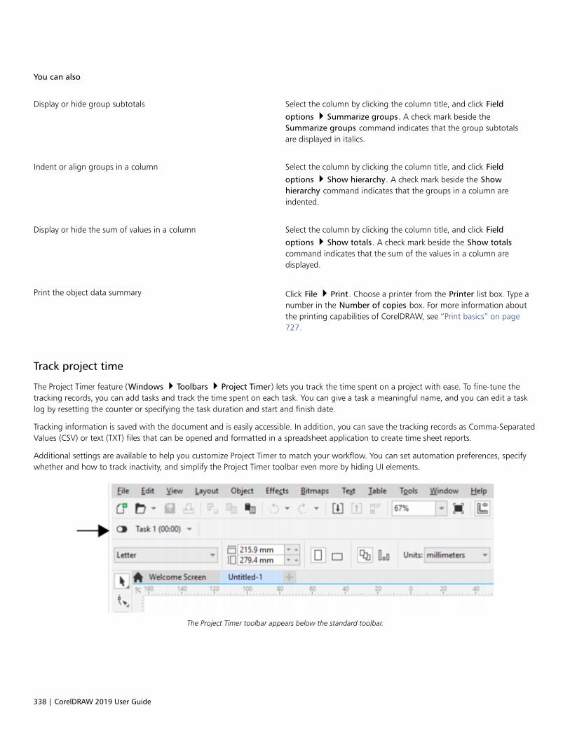
338 | CorelDRAW 2019 User Guide
You can also
Display or hide group subtotals Select the column by clicking the column title, and click Field
options Summarize groups. A check mark beside theSummarize groups command indicates that the group subtotalsare displayed in italics.
Indent or align groups in a column Select the column by clicking the column title, and click Field
options Show hierarchy. A check mark beside the Showhierarchy command indicates that the groups in a column areindented.
Display or hide the sum of values in a column Select the column by clicking the column title, and click Field
options Show totals. A check mark beside the Show totalscommand indicates that the sum of the values in a column aredisplayed.
Print the object data summary Click File Print. Choose a printer from the Printer list box. Type anumber in the Number of copies box. For more information aboutthe printing capabilities of CorelDRAW, see “Print basics” on page727.
Track project time
The Project Timer feature (Windows Toolbars Project Timer) lets you track the time spent on a project with ease. To fine-tune thetracking records, you can add tasks and track the time spent on each task. You can give a task a meaningful name, and you can edit a tasklog by resetting the counter or specifying the task duration and start and finish date.
Tracking information is saved with the document and is easily accessible. In addition, you can save the tracking records as Comma-SeparatedValues (CSV) or text (TXT) files that can be opened and formatted in a spreadsheet application to create time sheet reports.
Additional settings are available to help you customize Project Timer to match your workflow. You can set automation preferences, specifywhether and how to track inactivity, and simplify the Project Timer toolbar even more by hiding UI elements.
The Project Timer toolbar appears below the standard toolbar.
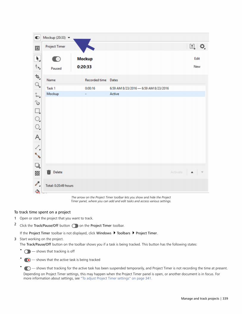
Manage and track projects | 339
The arrow on the Project Timer toolbar lets you show and hide the ProjectTimer panel, where you can add and edit tasks and access various settings.
To track time spent on a project
1 Open or start the project that you want to track.
2 Click the Track/Pause/Off button on the Project Timer toolbar.
If the Project Timer toolbar is not displayed, click Windows Toolbars Project Timer.
3 Start working on the project.
The Track/Pause/Off button on the toolbar shows you if a task is being tracked. This button has the following states:
• — shows that tracking is off
• — shows that the active task is being tracked
• — shows that tracking for the active task has been suspended temporarily, and Project Timer is not recording the time at present.
Depending on Project Timer settings, this may happen when the Project Timer panel is open, or another document is in focus. Formore information about settings, see “To adjust Project Timer settings” on page 341.

340 | CorelDRAW 2019 User Guide
To add, activate, delete, modify, or move a task
• Click the drop-down arrow on the Project Timer toolbar, and in the Project Timer panel, perform any of the tasks from the followingtable. When you are finished, click outside the Project Timer panel to hide it.
To Do the following
Add a task Click New.
Change the task that is being tracked Choose the task that you want to track from the task list, and clickActivate.
The task list shows the task as Active to indicate that this is nowthe task that you are tracking.
You can also double-click a task to activate it.
Delete a task Select the task, and click Delete.
You can also delete the selected task by pressing the Delete key.
Rename a task Click the task name twice in the task list, and type a new name.
Change the task duration Click the Recorded time field twice, and specify the amount oftime you want.
Notes: From the task list, you can modify only the duration of a taskthat is not active (not being tracked). To modify the active task, youmust use the Edit Active Task dialog box. For more information,see “To edit the active task” on page 340.
Changing the task duration does not update the start and finishtime and dates.
Change the start and finish time and dates Click twice the Dates field of the task, and specify the start andfinish time and dates you want.
Notes: From the task list, you can modify only the start and finishtime and date of a task that is not active. To modify the active task,you must use the Edit Active Task dialog box.
Changing the task start and finish time and dates does not updatethe task duration.
Move the selected task up or down the list Select a task, and click the Up or Down button.
To edit the active task
You can reset the timer for the active task. You can also change the task start or finish time and date, or you can change the task duration.
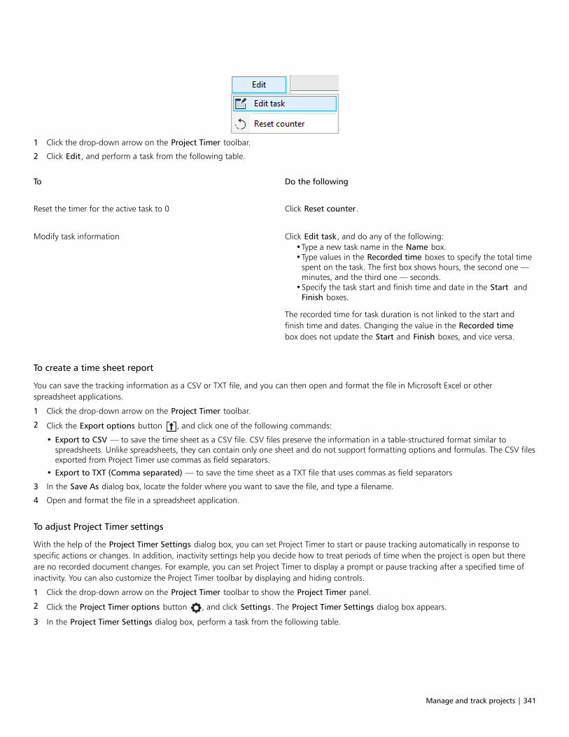
Manage and track projects | 341
1 Click the drop-down arrow on the Project Timer toolbar.
2 Click Edit, and perform a task from the following table.
To Do the following
Reset the timer for the active task to 0 Click Reset counter.
Modify task information Click Edit task, and do any of the following:•Type a new task name in the Name box.•Type values in the Recorded time boxes to specify the total time
spent on the task. The first box shows hours, the second one —minutes, and the third one — seconds.
•Specify the task start and finish time and date in the Start andFinish boxes.
The recorded time for task duration is not linked to the start andfinish time and dates. Changing the value in the Recorded timebox does not update the Start and Finish boxes, and vice versa.
To create a time sheet report
You can save the tracking information as a CSV or TXT file, and you can then open and format the file in Microsoft Excel or otherspreadsheet applications.
1 Click the drop-down arrow on the Project Timer toolbar.
2 Click the Export options button , and click one of the following commands:
• Export to CSV — to save the time sheet as a CSV file. CSV files preserve the information in a table-structured format similar tospreadsheets. Unlike spreadsheets, they can contain only one sheet and do not support formatting options and formulas. The CSV filesexported from Project Timer use commas as field separators.
• Export to TXT (Comma separated) — to save the time sheet as a TXT file that uses commas as field separators
3 In the Save As dialog box, locate the folder where you want to save the file, and type a filename.
4 Open and format the file in a spreadsheet application.
To adjust Project Timer settings
With the help of the Project Timer Settings dialog box, you can set Project Timer to start or pause tracking automatically in response tospecific actions or changes. In addition, inactivity settings help you decide how to treat periods of time when the project is open but thereare no recorded document changes. For example, you can set Project Timer to display a prompt or pause tracking after a specified time ofinactivity. You can also customize the Project Timer toolbar by displaying and hiding controls.
1 Click the drop-down arrow on the Project Timer toolbar to show the Project Timer panel.
2 Click the Project Timer options button , and click Settings. The Project Timer Settings dialog box appears.
3 In the Project Timer Settings dialog box, perform a task from the following table.
342 | CorelDRAW 2019 User Guide
To Do the following
Set Project Timer to start tracking automatically upon performing aspecific action
In the Automation area, enable any of the following check boxesbelow Start recording when:
•Document is opened•New document is created•Task is activated
Set inactivity preferences In the Inactivity detection area, choose one of the followingoptions from the On inactivity list box:
•Prompt — to display a prompt after a specified time of inactivity•Pause timer — to pause recording after the specified time of
inactivity and resume tracking when you continue working on thedocument
•Always track — to ignore inactivity and record all time as work
Specify how long after inactivity to pause the timer or display aprompt
In the Inactivity tolerance box, type a value.
Pause tracking automatically in certain circumstances Enable any of the following check boxes below Pause recordingwhen:
•CorelDRAW is minimized and out of focus•Another document is in focus•Project Timer panel is open
Recording resumes when you continue working on the document.
Customize the Project Timer toolbar Enable or disable any of the following check boxes in the Toolbarappearance area:
•Track/Pause/Off button — to show or hide the Track/Pause/Offbutton
•Task name — to show or hide the name of the task that is beingtracked
•Timer — to show or hide the timer displaying the current taskduration
To respond to the Inactivity prompt
If no changes are made to the document for some time, by default Project Timer prompts you to decide how to track this time of inactivity.The prompt is displayed as soon as the inactivity tolerance time elapses.
• In the Inactivity Detected dialog box, click one of the following buttons:
• Discard — to delete the entire period of inactivity from the tracking record
• Track as work — to record the period of inactivity as work time. This option is useful to track time spent on tasks related to the projectbut not performed in CorelDRAW. For example, you may have done research on the project or discussed it at length with a client overthe phone. Hence, you want to track this time even though you did not make any changes to the project itself.
• Custom — to log a custom amount of time. In the Custom Activity Log dialog box, specify the amount of time (in minutes) that youwant to be tracked as work. For example, you may have been away from your desk for an hour. If you worked for 20 minutes duringthat hour on project-related tasks, you can choose to log only 20 minutes. The remaining 40 minutes will be discarded.
If you want Project Timer to remember your choice and apply it all future inactivity, enable the Remember and don’t ask again checkbox before clicking a button in the dialog box. This action suppresses all inactivity prompts. To start displaying prompts again, you mustchange the inactivity preferences in the Project Timer Settings dialog box. In the Inactivity detection area, choose Prompt from the Oninactivity list box.
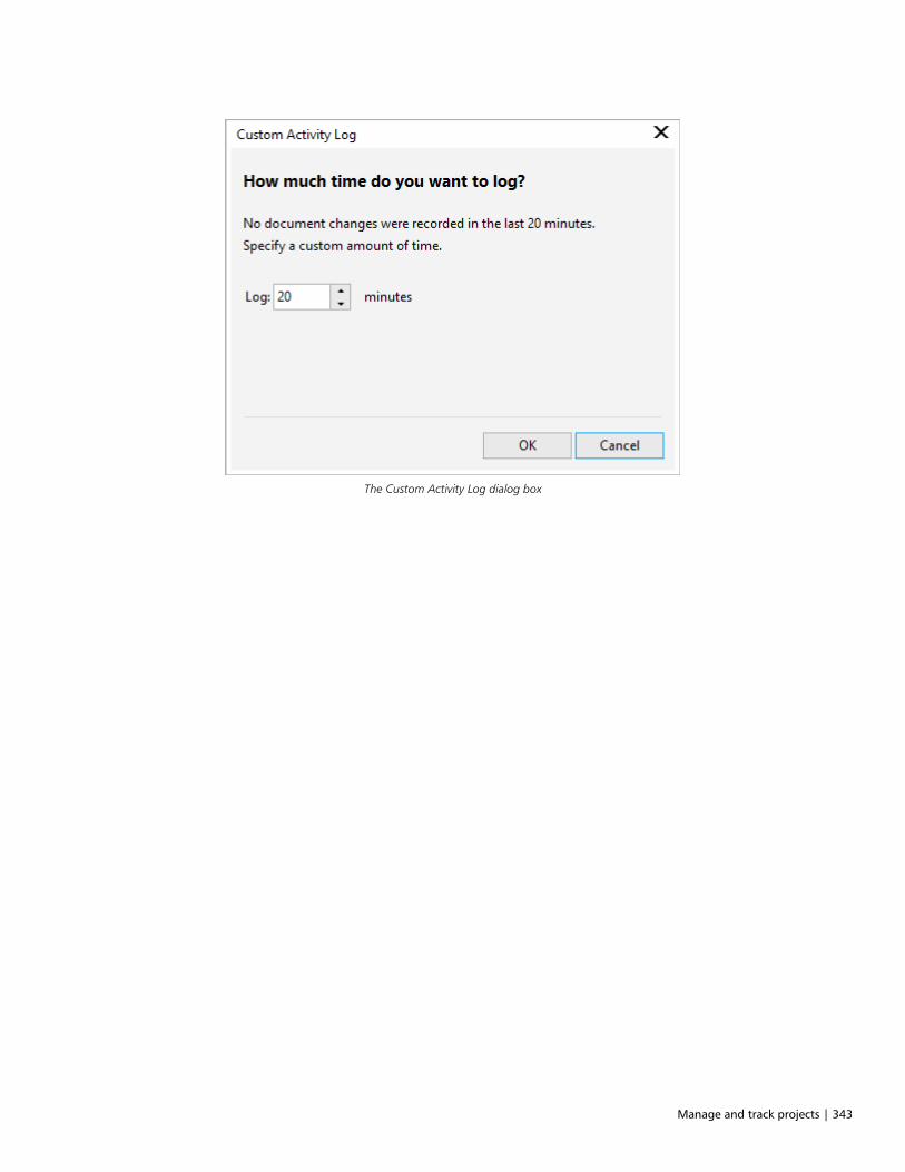
Manage and track projects | 343
The Custom Activity Log dialog box

344 | CorelDRAW 2019 User Guide

Color, fills, and transparencies | 345
Color, fills, and transparencies
Color....................................................................................................................................................................................................347
Fills...................................................................................................................................................................................................... 365
Object transparency............................................................................................................................................................................. 387
Find, manage, and save fills and transparencies.................................................................................................................................. 399
Color management.............................................................................................................................................................................. 405

346 | CorelDRAW 2019 User Guide
Color | 347
Color
CorelDRAW lets you choose and create colors by using a wide variety of industry-standard color palettes, color mixers, and color models. Youcan store frequently used colors for future use by using the Document palette, or creating and editing custom color palettes.
You can customize how a color palette appears on your screen by changing the size of swatches, the number of rows, and other properties.
You can also create color styles. For more information, see “Color styles” on page 575.
This section contains the following topics:• “Color models” (page 347)• “Color depth” (page 349)• “Choose colors” (page 350)• “Document palette” (page 355)• “Create and edit color palettes” (page 357)• “Organize and show color palettes” (page 360)• “Show or hide color palettes” (page 362)• “Set color palette properties” (page 363)
Color models
Color models provide a precise method for defining colors, each model defining colors through the use of specific color components. Thereis a range of color models to choose from when creating graphics.
CMYK color model
The CMYK color model, which is used in printing, uses the components cyan (C), magenta (M), yellow (Y), and black (K) to define color.Values for these components range from 0 to 100 and represent percentages.
In subtractive color models, such as CMYK, color (that is, ink) is added to a surface, such as white paper. The color then “subtracts”brightness from the surface. When the value of each color component (C,M,Y) is 100, the resulting color is black. When the value of eachcomponent is 0, no color is added to the surface, so the surface itself is revealed — in this case, the white paper. Black (K) is included in thecolor model for printing purposes because black ink is more neutral and darker than blending equal amounts of cyan, magenta, and yellow.Black ink produces sharper results, especially for printed text. In addition, black ink is usually less expensive than using colored ink.
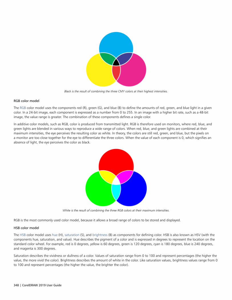
348 | CorelDRAW 2019 User Guide
Black is the result of combining the three CMY colors at their highest intensities.
RGB color model
The RGB color model uses the components red (R), green (G), and blue (B) to define the amounts of red, green, and blue light in a givencolor. In a 24-bit image, each component is expressed as a number from 0 to 255. In an image with a higher bit rate, such as a 48-bitimage, the value range is greater. The combination of these components defines a single color.
In additive color models, such as RGB, color is produced from transmitted light. RGB is therefore used on monitors, where red, blue, andgreen lights are blended in various ways to reproduce a wide range of colors. When red, blue, and green lights are combined at theirmaximum intensities, the eye perceives the resulting color as white. In theory, the colors are still red, green, and blue, but the pixels ona monitor are too close together for the eye to differentiate the three colors. When the value of each component is 0, which signifies anabsence of light, the eye perceives the color as black.
White is the result of combining the three RGB colors at their maximum intensities.
RGB is the most commonly used color model, because it allows a broad range of colors to be stored and displayed.
HSB color model
The HSB color model uses hue (H), saturation (S), and brightness (B) as components for defining color. HSB is also known as HSV (with thecomponents hue, saturation, and value). Hue describes the pigment of a color and is expressed in degrees to represent the location on thestandard color wheel. For example, red is 0 degrees, yellow is 60 degrees, green is 120 degrees, cyan is 180 degrees, blue is 240 degrees,and magenta is 300 degrees.
Saturation describes the vividness or dullness of a color. Values of saturation range from 0 to 100 and represent percentages (the higher thevalue, the more vivid the color). Brightness describes the amount of white in the color. Like saturation values, brightness values range from 0to 100 and represent percentages (the higher the value, the brighter the color).
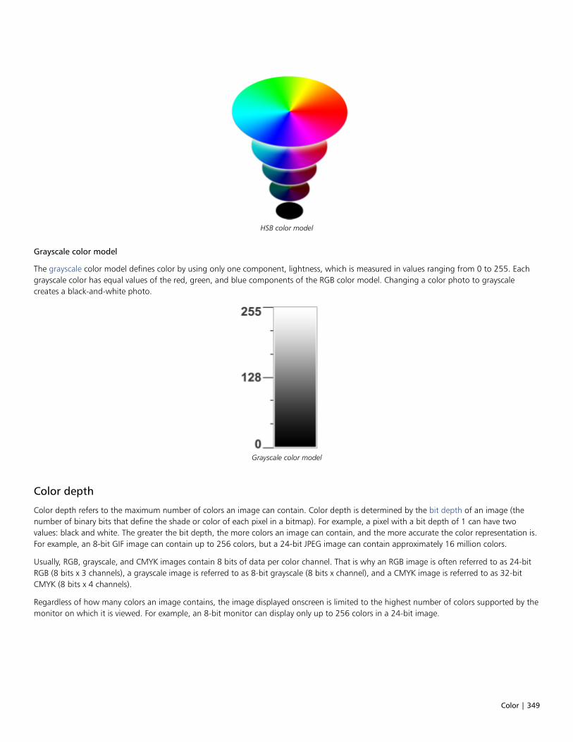
Color | 349
HSB color model
Grayscale color model
The grayscale color model defines color by using only one component, lightness, which is measured in values ranging from 0 to 255. Eachgrayscale color has equal values of the red, green, and blue components of the RGB color model. Changing a color photo to grayscalecreates a black-and-white photo.
Grayscale color model
Color depth
Color depth refers to the maximum number of colors an image can contain. Color depth is determined by the bit depth of an image (thenumber of binary bits that define the shade or color of each pixel in a bitmap). For example, a pixel with a bit depth of 1 can have twovalues: black and white. The greater the bit depth, the more colors an image can contain, and the more accurate the color representation is.For example, an 8-bit GIF image can contain up to 256 colors, but a 24-bit JPEG image can contain approximately 16 million colors.
Usually, RGB, grayscale, and CMYK images contain 8 bits of data per color channel. That is why an RGB image is often referred to as 24-bitRGB (8 bits x 3 channels), a grayscale image is referred to as 8-bit grayscale (8 bits x channel), and a CMYK image is referred to as 32-bitCMYK (8 bits x 4 channels).
Regardless of how many colors an image contains, the image displayed onscreen is limited to the highest number of colors supported by themonitor on which it is viewed. For example, an 8-bit monitor can display only up to 256 colors in a 24-bit image.

350 | CorelDRAW 2019 User Guide
Choose colors
You can choose fill and outline colors by selecting a color from the Document palette, custom color palettes, palettes from the Palettelibraries, or color viewers. When you want to use a color that already exists in an object or document, you can sample the color by using theColor eyedropper tool to achieve an exact match.
For information about applying the colors you choose, see “Uniform fills ” on page 365 and “Format lines and outlines” on page 138. Forinformation about saving colors for future use, see “Color styles” on page 575.
Default color palette
A color palette is a collection of color swatches. In some programs, color palettes are known as “swatch palettes.”
In CorelDRAW, the default color palette is based on the primary color mode of the document. For example, if the document’s primary colormodel is RGB, the default color palette is also RGB. For more information, see “Color models” on page 347. You choose the default colormodel when you create a new drawing. You can open and use additional color palettes at any time.
You can choose both fill and outline colors by using the default color palette. The selected fill and outline colors appear in the color swatcheson the status bar.
Document palette
When you create a new drawing, the application automatically generates an empty palette, called the Document palette. It helps you keeptrack of the colors that you use by storing them with your document for future use. For more information, see “Document palette” on page355.
Palette libraries and custom color palettes
The color palettes that are found in the Palette libraries cannot be edited directly. Some of them are provided by third-party manufacturers,for example PANTONE, HKS Colors, and TRUMATCH. It may be useful to have on hand a manufacturer’s swatch book, which is a collectionof color samples that shows exactly what each color looks like when printed.
The PANTONE solid coated palette is an example of a color palette from the Palette libraries.
Some palettes found in the Palette libraries — PANTONE, HKS Colors, TOYO, DIC, Focoltone, and SpectraMaster — are collections of spotcolors. If you create color separations when you print, each spot color requires a separate printing plate, which can significantly affect thecost of the printing job. If you want to use color separations but would like to avoid using spot colors, you can convert the spot colors toprocess colors when printing. For more information, see “Color separations” on page 747.

Color | 351
Custom color palettes can include colors from any color model, including palettes from the Palette libraries, such as a spot color palette. Youcan save a custom color palette for future use. For more information about working with custom color palettes, see “Create and edit colorpalettes ” on page 357 and “Organize and show color palettes” on page 360.
Sampling colors
When you want to use a color that already exists in a drawing, palette, or on your desktop, you can sample the color to achieve an exactmatch. By default, you sample a single pixel from the drawing window.
Color viewers
Color viewers provide a representation of a range of colors by using either one-dimensional or three-dimensional shapes. The default colorviewer is based on the HSB color model, but you can use this viewer to choose CMYK, CMY, or RGB colors. For information about colormodels, see “Color models” on page 347.
An example of a color viewer
Choosing web colors
You can use web colors when you design documents that will be published to the web. With CorelDRAW, you can define web colors byusing RGB hexadecimal values (for example, ‑aa003f).
To choose a color by using the default color palette
To Do the following
Choose a fill color for a selected object Click a color swatch.
Choose an outline color for a selected object Right-click a color swatch.
Choose from different shades of a color Click and hold a color swatch to display a pop-up color picker, andthen click a color.
View more colors on the default color palette Click the scroll arrows at the top and bottom of the color palette.
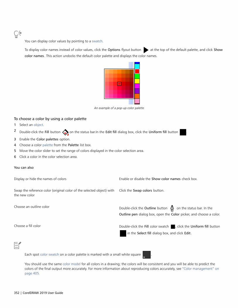
352 | CorelDRAW 2019 User Guide
You can display color values by pointing to a swatch.
To display color names instead of color values, click the Options flyout button at the top of the default palette, and click Show
color names. This action undocks the default color palette and displays the color names.
An example of a pop-up color palette
To choose a color by using a color palette
1 Select an object.
2 Double-click the Fill button on the status bar.In the Edit fill dialog box, click the Uniform fill button .
3 Enable the Color palettes option.
4 Choose a color palette from the Palette list box.
5 Move the color slider to set the range of colors displayed in the color selection area.
6 Click a color in the color selection area.
You can also
Display or hide the names of colors Enable or disable the Show color names check box.
Swap the reference color (original color of the selected object) withthe new color
Click the Swap colors button.
Choose an outline color Double-click the Outline button on the status bar. In the
Outline pen dialog box, open the Color picker, and choose a color.
Choose a fill color Double-click the Fill color swatch , click the Uniform fill button
in the Select fill dialog box, and click Edit.
Each spot color swatch on a color palette is marked with a small white square .
You should use the same color model for all colors in a drawing; the colors will be consistent and you will be able to predict thecolors of the final output more accurately. For more information about reproducing colors accurately, see “Color management” onpage 405.
Color | 353
You can also access color palettes in the Color docker by clicking the Show color palettes button, and choosing a palette from
the list box. If the Color docker is not open, click Window Dockers Color.
To choose a color by using a color viewer
1 Select an object.
2 Double-click the Fill button on the status bar.In the Edit fill dialog box, click the Uniform fill button .
3 Choose a color model from the Color model list box.
4 Choose a color viewer from the Color viewers list box.
5 Move the color slider.
6 Click a color in the color selection area.
You can also
Sample a color from the drawing or desktop Click the Eyedropper button , and click the drawing or
desktop.
Choose a fill color Double-click the Fill color swatch , click the Uniform fill button
in the Select fill dialog box, and click Edit.
Swap the reference color (original color of the selected object) withthe new color
Click the Swap colors button.
If you choose a color that is out of the printer’s gamut, CorelDRAW allows you to replace it with a similar color that is in the printer’sgamut. To replace the color, click the Bring color into gamut button, which appears to the left of the New color swatch. Forinformation about color correction, see “Color management” on page 405.
You should use the same color model for all colors in a drawing; the colors will be consistent and you will be able to predict thecolors of the final output more accurately. It is preferable to use the same color model in your drawing that you will be using for thefinal output.
You can also access color models in the Color docker by clicking the Show color viewers button and choosing a color model
from the list box. If the Color docker is not open, click Window Dockers Color.
To sample a color
1 In the toolbox, click the Color eyedropper tool .
2 On the property bar, click one of the following buttons:
• 1×1 — lets you choose the color of the pixel you click
• 2×2 — lets you choose the average color in a sample area of 2 × 2 pixels. The pixel you click is in the middle of the sample area.
354 | CorelDRAW 2019 User Guide
• 5×5 — lets you choose the average color in a sample area of 5 × 5 pixels
If you want to sample a color outside the drawing window, click Select from desktop on the property bar, and click a color on thedesktop.
3 Click the color that you want to sample.
The Color eyedropper tool automatically switches to the Apply color mode.
4 Perform a task from the following table.
To Do the following
Fill an object with a sampled color Hover over an object. When the Apply color pointer changes to asolid color swatch , click to apply the sampled color.
Fill an object’s outline color with the sampled color Hover over an object’s outline. When the Apply color pointerchanges to an outline shape , click to apply the sampled color.
Add the sampled color to the Document palette On the property bar, click the arrow next to Add to palette, andchoose Document palette.
Sample an additional color On the property bar, click the Select color button , and then
click the color that you want to sample.
You can also
Drag a sampled color from one object to another Drag the color to another object.
Apply a sampled color from the Selected color swatch on theproperty bar
Drag the sampled color from the Selected color swatch to theobject.
Apply a sampled color from the Uniform fill swatch in the lower-right corner of the drawing window
Drag a color from the Uniform fill swatch to the object.
Add the sampled color to the Document palette Drag the sampled color from the Selected color swatch or theUniform fill swatch to the Document palette.
In some cases, the sampled color may be an RGB or CMYK color that is the closest equivalent to the original color, rather than being acomplete match.
To choose a web color
1 Select an object.
2 Click Window Dockers Color.
3 In the Color docker, choose RGB from the list box.
4 Type or paste a value in the Hex value box.
Whether you use a three-digit (‑fff) or six-digit format (‑ffffff), the final value is presented in the six-digit format.
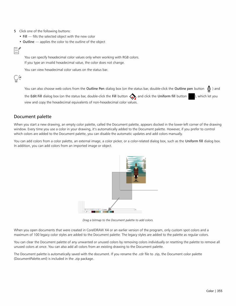
Color | 355
5 Click one of the following buttons:
• Fill — fills the selected object with the new color
• Outline — applies the color to the outline of the object
You can specify hexadecimal color values only when working with RGB colors.
If you type an invalid hexadecimal value, the color does not change.
You can view hexadecimal color values on the status bar.
You can also choose web colors from the Outline Pen dialog box (on the status bar, double-click the Outline pen button ) and
the Edit Fill dialog box (on the status bar, double-click the Fill button , and click the Uniform fill button ), which let you
view and copy the hexadecimal equivalents of non-hexadecimal color values.
Document palette
When you start a new drawing, an empty color palette, called the Document palette, appears docked in the lower-left corner of the drawingwindow. Every time you use a color in your drawing, it’s automatically added to the Document palette. However, if you prefer to controlwhich colors are added to the Document palette, you can disable the automatic updates and add colors manually.
You can add colors from a color palette, an external image, a color picker, or a color-related dialog box, such as the Uniform fill dialog box.In addition, you can add colors from an imported image or object.
Drag a bitmap to the Document palette to add colors.
When you open documents that were created in CorelDRAW X4 or an earlier version of the program, only custom spot colors and amaximum of 100 legacy color styles are added to the Document palette. The legacy styles are added to the palette as regular colors.
You can clear the Document palette of any unwanted or unused colors by removing colors individually or resetting the palette to remove allunused colors at once. You can also add all colors from an existing drawing to the Document palette.
The Document palette is automatically saved with the document. If you rename the .cdr file to .zip, the Document color palette(DocumentPalette.xml) is included in the .zip package.
356 | CorelDRAW 2019 User Guide
To disable the automatic adding of color to the Document palette
• On the Document palette, click the flyout button , and click Automatically update.
By default, the Document palette is docked above the status bar at the bottom of the application window.
You can also disable the automatic adding of color by clicking Tools Options Customization, clicking Color Palette in the leftpane of the dialog box that appears, and disabling the Automatically update the document palette check box.
To manually add colors to the Document palette
To Do the following
Add a color from another color palette Drag a color from an open color palette to the Document palette.
Add a color from a bitmap image On the Document palette, click the Eyedropper button , and
click a color in the image.
Add multiple colors from an image On the Document palette, click the Eyedropper button , hold
down Ctrl, and then click the image until you add the colors thatyou want.
Add multiple colors from an image or object by dragging Drag an image or object from the drawing window to theDocument palette.
Add colors from a selection Select an object or multiple objects. On the Document palette, click
the flyout button , and click Add from selection.
Add a color from a color-related dialog box In the dialog box, click a color swatch, click the arrow next to Addto palette, choose Document palette, and then click Add topalette.
Move a color swatch Drag a color swatch to a new position on the Document palette.
When dragging most vector objects to the palette, you add all object colors to the palette. When dragging a bitmap, you can specifythe number of colors that you want to be added to the palette. If an object includes a fountain fill, texture fill, or pattern fill, onlycolors that are defined during the fill creation are supported. Colors from PostScript fills are not supported.
By default, the Document palette is docked above the status bar at the bottom of the application window.
To add colors from an existing drawing to the Document palette
1 Open a drawing.
Color | 357
2 On the Document palette, click the flyout button , and click Add from document.
By default, the Document palette is docked above the status bar at the bottom of the application window.
If the drawing was created in a previous version of CorelDRAW and it includes custom spot colors, they appear in the Documentpalette.
If you have a document with both vector and bitmap images, and you want to add only the colors from the vector images to theDocument palette, specify 0 in the Add colors from bitmap dialog box.
To remove a color from the Document palette
1 Click a color swatch on the Document palette.
2 On the Document palette, click the flyout button , and click Delete color.
By default, the Document palette is docked above the status bar at the bottom of the application window.
You can also remove all colors that are no longer used from the Document palette by clicking the flyout button , choosing
Palette, and clicking Reset palette.
To reset the Document palette
• On the Document palette, click the flyout button , choose Palette, and click Reset palette.
By default, the Document palette is docked above the status bar at the bottom of the application window.
To hide the Document palette
• Click Window Color palettes Document palette.
Hiding the Document palette does not disable the automatic adding of color.
Create and edit color palettes
Custom color palettes are collections of colors or color styles that you save. They can include colors or color styles from any color model,including spot colors, or any color palette found in the Palette libraries. You can create a custom palette to store all colors or color styles thatyou need in a current, or future, project.
It’s easy to share color palettes with others. The custom palettes are accessible from the My palettes folder in the Palettes docker.
You can create a custom color palette by choosing individual colors or color styles, or by using the colors in a selected object or an entiredocument. You can also edit, rename, and delete custom color palettes.
Custom color palettes are saved as XML files and are stored in your Documents\Corel\Corel Content\Palettes folder.

358 | CorelDRAW 2019 User Guide
To create a custom color palette from scratch
1 Click Window Dockers Palettes.
2 Click the + at the bottom of the docker, and choose New empty color palette .
3 Type a filename in the File name box.
4 Click Save.
5 In the Palettes docker, choose the custom palette that you created.
6 Click the Options button, and choose Edit palette.
7 In the Palette editor dialog box, click Add color.
8 In the Select color dialog box, choose a color, and click OK.
You can also
Treat the color as a spot color In the Selected color area of the Palette editor dialog box, chooseSpot from the Treat as list.
Treat the color as a process color In the Selected color area of the Palette editor dialog box, chooseProcess from the Treat as list.
Rename a color In the Palette editor dialog box, click a color in the color selectionarea, and type a name in the Name box.
To add a color to a custom color palette
1 Open a custom color palette.
2 Perform a task from the following table.
To Do the following
Add a color from another color palette Drag a color from an open color palette to the custom palette.
Add a color from an image On the custom palette, click the Eyedropper button , and click
the color that you want to add.
Add multiple colors from an image On the custom palette, click the Eyedropper button , hold
down Ctrl, and click the image until you add the colors that youwant.
Add multiple colors from an image or object Drag an image or object from the drawing window to the custompalette.

Color | 359
To Do the following
Add a color from a color-related dialog box In the dialog box, click a color swatch, click the arrow next to Addto palette, choose the name of your custom palette from the list,and then click Add to palette.
Add colors from a selection Select an object or multiple objects. On the custom palette, click
the flyout button , and click Add from selection.
Move a color swatch Drag a color swatch to a new position on the palette.
When dragging most vector objects to the palette, you add all object colors to the palette. When dragging a bitmap, you can specifythe number of colors that you want to be added to the palette. If an object includes a fountain fill, texture fill, or pattern fill, onlycolors that are defined during the fill creation are supported. Colors from PostScript fills are not supported.
To create a color palette from an object
1 Select an object.
2 Click Window Color Palettes Create Palette from Selection.
3 Type a filename in the File name box.
4 Click Save.
To create a color palette from a document
1 Click Window Color Palettes Create Palette from Document.
2 Type a filename in the File name box.
3 Click Save.
To edit a custom color palette
1 Click Window Color palettes Palette editor.
2 Choose a palette from the list box.
3 Perform a task from the following table.
To Do the following
Add a color Click Add color. In the Select color dialog box, click the Modelstab, click a color in the color selection area, and click Add topalette.
Treat a color as a spot color In the Selected color area of the Palette editor dialog box, chooseSpot from the Treat as list.
Treat a color as a process color In the Selected color area of the Palette editor dialog box, chooseProcess from the Treat as list.

360 | CorelDRAW 2019 User Guide
To Do the following
Change a color In the color selection area, click a color, and click Edit color. In theSelect color dialog box, click the Models tab, and click a new colorin the color selection area.
Delete a color In the color selection area, click a color, and click Delete color.
Sort colors Click Sort colors, and choose a color sorting method.
Move a color Drag a color swatch to a new position.
Rename a color Click a color in the color selection area, and type a name in theName box.
You can delete multiple colors by holding down Shift or Ctrl clicking the colors that you want to delete, and clicking Delete color.
If you add a process color to the palette, but treat it as a spot color, the color is changed to spot and the color name is preserved.However, if you choose a spot color with a trademarked name, for example a PANTONE color, and convert it to a process color, thetrademarked name is substituted with the color components for that color.
To rename a custom color palette
1 Click Window Dockers Palettes.
2 From the My Palettes folder, click a custom palette twice.
3 Type a new name, and press Enter.
To delete a custom color palette
1 Click Window Dockers Palettes.
2 From the My Palettes folder, right-click a custom palette, and click Delete.
Organize and show color palettes
The Palettes docker lets you quickly access the available color palettes, including the Document palette and the Color Styles palette, andcreate custom color palettes. The color palettes in the Palettes docker are divided into two main folders: My palettes and Palette libraries.
You can use the My palettes folder to store all the custom color palettes that you create. You can add folders to store and organize yourcolor palettes for different projects. You can also copy a color palette or move it to a different folder. You can open and control the display ofall color palettes.
The Palette libraries folder of the Palettes docker contains collections of preset color palettes from which you can choose colors. You cannotedit any of the color palettes that are found in the Palette libraries. However, you can create a custom color palette by copying a colorpalette from the Palette libraries folder. For more information, see “Show or hide color palettes” on page 362.
Color | 361
To open the Palettes docker
• Click Window Dockers Palettes.
To display or hide a custom color palette
1 Open the Palettes docker.
2 In the My palettes folder, enable the check box beside the custom palette name.
If you want to set a custom color palette as the default palette, click the custom palette flyout button , and click Set as default.
To open a custom color palette
1 Open the Palettes docker.
2 Click the Opens a palette button .
3 Choose the drive and folder where the custom color palette is stored.
If you want to open a color palette (.cpl file) that was created in a previous version of CorelDRAW, select Legacy custom palette (*.cpl)from the Files of type list box.
4 Click the custom palette.
5 Click Open.
When you open a legacy custom palette (.cpl) file, it is automatically converted to the XML format (.xml). The XML version is stored inyour Documents\Corel\Corel Content\Palettes folder, and also appears in the My palettes folder in the Palettes docker.
If the custom color palette (.xml) was saved to the My palettes folder, you can open it by clicking Window Color palettes andchoosing the custom palette from the list.
To create a folder for storing custom color palettes
1 Open the Palettes docker.
2 Click the Create a new folder button .
3 Type a new name, and press Enter.
If you want to move a custom color palette, drag it to the new folder.
To cut or copy a custom color palette
1 Open the Palettes docker.
2 In the My palettes folder, right-click a custom palette, and click one of the following:
• Cut
• Copy
If you want to paste the custom palette to a different folder, right-click the folder, and click Paste.
To copy a palette from the Palette libraries for editing
• Open the Palettes docker, drag a palette from the Palette libraries folder to the My palettes folder.
An editable copy of the color palette appears in the My palettes folder.

362 | CorelDRAW 2019 User Guide
Show or hide color palettes
The Palette libraries contain a collection of color palettes. You can control the display of the default color palettes, such as the default RGBand default CMYK color palettes. The main Palette libraries that are included are Process color and Spot color.
The Process color library contains the default RGB, CMYK, and Grayscale color palettes. In addition, you can find preset color palettes thathave a specific theme, such as nature. The Spot color library contains color palettes that are provided by third-party manufacturers, such asHKS Colors, PANTONE, Focoltone, and TOYO. These color palettes can be very useful when you need specific company-approved colors foryour printed projects. The color palette libraries are locked, which means that you cannot edit them.
Palette libraries

Color | 363
To display a color palette in the Palette libraries
1 Open the Palettes docker.
2 In the Palette libraries folder, enable the check box beside the color palette name.
To display spot or process color palettes
1 Open the Palettes docker.
2 In the Palette libraries folder, double-click one of the following folders:
• Spot
• Process
3 Enable the check box beside the color palette name.
Set color palette properties
You can customize color palettes.
Color palettes can be either docked or floating. Docking a color palette attaches it to the edge of the application window. Undocking a colorpalette pulls it away from the edge of the application window, so it floats and can be easily moved around.
With color swatches, you can set the right mouse button either to display a context menu or to set the outline color. You can also adjust thecolor swatch border and size, and you can hide or display the No color well.
To dock or undock a color palette
To Do the following
Dock a color palette Click the top of the color palette border, and drag the color paletteto any edge of the application window until a thin black toolbaroutline appears.
Undock a color palette Click the dotted border of the color palette, and drag the colorpalette away from the edge of the application window.
Change the number of rows on a docked color palette On the palette, click the flyout button , click Rows, and choose
an option from the list.
You can also change the number of rows on a docked color palette by clicking Tools Options Customization, clicking ColorPalette in the left pane of the dialog box that appears, and typing a value in the Maximum palette rows when docked box. You canset a maximum of seven rows on a color palette.
To set the action of the right mouse button for color swatches
1 Click Tools Options Customization.
2 In the left pane of the dialog box that appears, click Color Palette.
3 Enable one of the following check boxes:

364 | CorelDRAW 2019 User Guide
• Context menu
• Set outline color
If you enable Set outline color, you can still display the context menu by right-clicking anywhere on the border of a color palette.
To customize color swatches
1 Click Tools Options Customization.
2 In the left pane of the dialog box that appears, click Color Palette.
3 Enable any of the following check boxes:
• Wide borders
• Large swatches
• Show “No Color” well
You can also display color names in the color swatches by clicking the flyout button on a color palette and clicking Show color
names.

Fills | 365
Fills
You can add colored, patterned, textured, and other fills to the inside of objects or other enclosed areas. You can customize a fill and set itas a default, so that each object you draw has the same fill.
Fill samples: Uniform, linear fountain, elliptical fountain, vector pattern, bitmap pattern, two-color, texture, and PostScript
This section contains the following topics:• “Uniform fills” (page 365)• “Fountain fills” (page 366)• “Vector and bitmap pattern fills” (page 371)• “Two-color pattern fills” (page 376)• “Texture fills” (page 377)• “PostScript fills” (page 379)• “Mesh fills” (page 380)• “Apply fills to areas” (page 383)• “Work with fills” (page 384)
Uniform fills
You can apply a uniform fill to objects. Uniform fills are solid colors you can choose or create using color models and color palettes. Forinformation about creating colors, see “Color” on page 347.
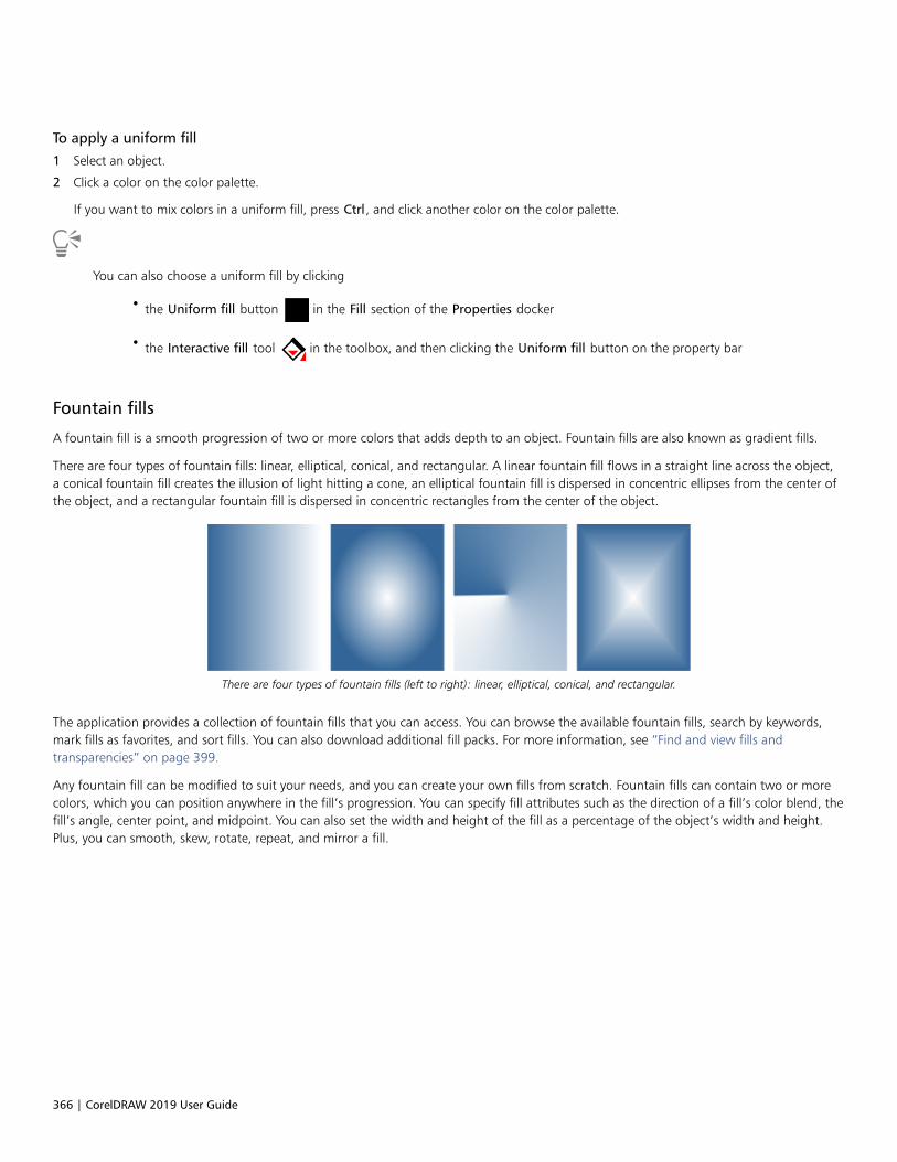
366 | CorelDRAW 2019 User Guide
To apply a uniform fill
1 Select an object.
2 Click a color on the color palette.
If you want to mix colors in a uniform fill, press Ctrl, and click another color on the color palette.
You can also choose a uniform fill by clicking
• the Uniform fill button in the Fill section of the Properties docker
• the Interactive fill tool in the toolbox, and then clicking the Uniform fill button on the property bar
Fountain fills
A fountain fill is a smooth progression of two or more colors that adds depth to an object. Fountain fills are also known as gradient fills.
There are four types of fountain fills: linear, elliptical, conical, and rectangular. A linear fountain fill flows in a straight line across the object,a conical fountain fill creates the illusion of light hitting a cone, an elliptical fountain fill is dispersed in concentric ellipses from the center ofthe object, and a rectangular fountain fill is dispersed in concentric rectangles from the center of the object.
There are four types of fountain fills (left to right): linear, elliptical, conical, and rectangular.
The application provides a collection of fountain fills that you can access. You can browse the available fountain fills, search by keywords,mark fills as favorites, and sort fills. You can also download additional fill packs. For more information, see “Find and view fills andtransparencies” on page 399.
Any fountain fill can be modified to suit your needs, and you can create your own fills from scratch. Fountain fills can contain two or morecolors, which you can position anywhere in the fill’s progression. You can specify fill attributes such as the direction of a fill’s color blend, thefill’s angle, center point, and midpoint. You can also set the width and height of the fill as a percentage of the object’s width and height.Plus, you can smooth, skew, rotate, repeat, and mirror a fill.

Fills | 367
You can edit fill properties from the Properties docker.
Left to right: An object with a linear fountain fill applied. Another color is added to the fill. The fill is resizedto 50% of the object’s width and height, and then repeated and mirrored. Last, the fill is rotated 45 degrees.
After you create a fountain fill, you can save it for future use. For more information, see “Save fills and transparencies” on page 403.

368 | CorelDRAW 2019 User Guide
You can adjust the print and display quality of the fountain fill by specifying the number of fountain steps. By default, the fountain stepssetting is locked so that the print quality of the fountain fill is determined by the value specified in the print settings and the display qualityis determined by the default value you set. However, you can unlock the fountain steps setting and specify a value that applies to both theprint and view quality of the fill. For information about setting fountain fill steps for printing, see “Fine-tune print jobs” on page 731.
To apply a fountain fill
1 Select an object.
2 Click the Interactive fill tool in the toolbox, and then click the Fountain fill button on the property bar.
3 Open the Fill picker on the property bar, and double-click a fill thumbnail.
For information about how to find fills in the Fill picker, see “To find, filter, and sort fills and transparencies” on page 400.
You can also apply a fill by clicking a fill thumbnail in the Fill picker. This action applies the fill without closing the Fill picker.
You can add a color to a fountain fill by clicking the Interactive fill tool in the toolbox, clicking the Fountain fill button on the
property bar, and dragging a color from the color palette to an object’s interactive vector handle.
To create a fountain fill
1 Select an object.
2 Click the Interactive fill tool in the toolbox, and then click the Fountain fill button on the property bar.
3 Click one of the following buttons to choose a fountain fill type:
• Linear fountain fill
• Elliptical fountain fill
• Conical fountain fill
• Rectangular fountain fill
4 Click the start node, open the Node color picker on the property bar, and choose a color.
5 Click the end node, open the Node color picker on the property bar, and choose a color.
6 Move the midpoint slider to set the midpoint between the two colors.
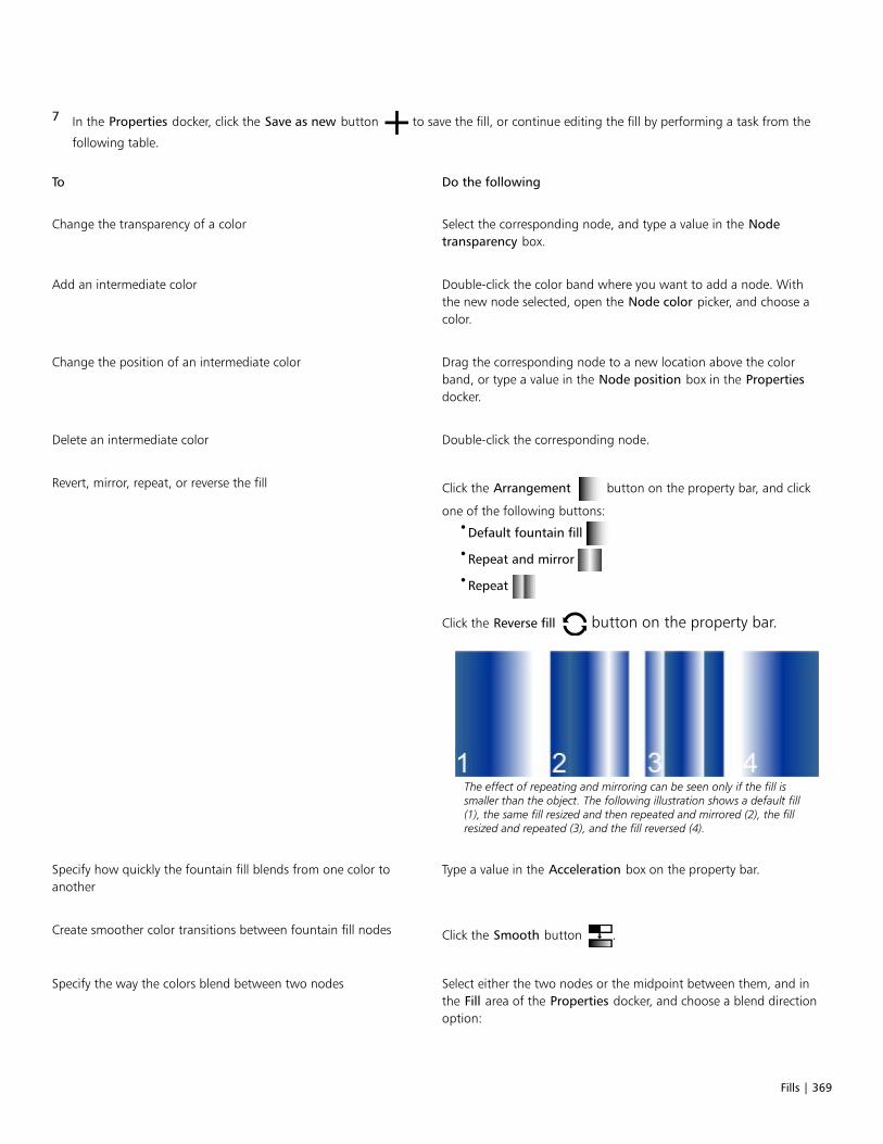
Fills | 369
7 In the Properties docker, click the Save as new button to save the fill, or continue editing the fill by performing a task from the
following table.
To Do the following
Change the transparency of a color Select the corresponding node, and type a value in the Nodetransparency box.
Add an intermediate color Double-click the color band where you want to add a node. Withthe new node selected, open the Node color picker, and choose acolor.
Change the position of an intermediate color Drag the corresponding node to a new location above the colorband, or type a value in the Node position box in the Propertiesdocker.
Delete an intermediate color Double-click the corresponding node.
Revert, mirror, repeat, or reverse the fill Click the Arrangement button on the property bar, and click
one of the following buttons:•Default fountain fill
•Repeat and mirror
•Repeat
Click the Reverse fill button on the property bar.
The effect of repeating and mirroring can be seen only if the fill issmaller than the object. The following illustration shows a default fill(1), the same fill resized and then repeated and mirrored (2), the fillresized and repeated (3), and the fill reversed (4).
Specify how quickly the fountain fill blends from one color toanother
Type a value in the Acceleration box on the property bar.
Create smoother color transitions between fountain fill nodes Click the Smooth button .
Specify the way the colors blend between two nodes Select either the two nodes or the midpoint between them, and inthe Fill area of the Properties docker, and choose a blend directionoption:
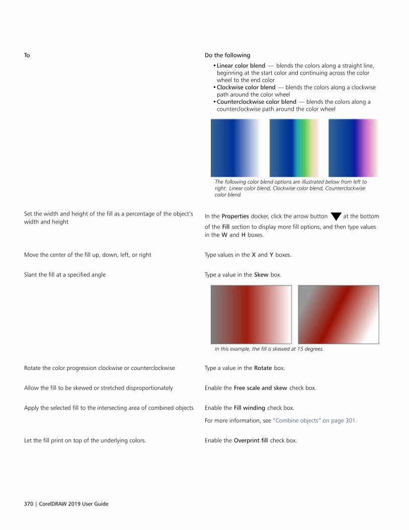
370 | CorelDRAW 2019 User Guide
To Do the following
•Linear color blend — blends the colors along a straight line,beginning at the start color and continuing across the colorwheel to the end color
•Clockwise color blend — blends the colors along a clockwisepath around the color wheel
•Counterclockwise color blend — blends the colors along acounterclockwise path around the color wheel
The following color blend options are illustrated below from left toright: Linear color blend, Clockwise color blend, Counterclockwisecolor blend.
Set the width and height of the fill as a percentage of the object’swidth and height
In the Properties docker, click the arrow button at the bottom
of the Fill section to display more fill options, and then type valuesin the W and H boxes.
Move the center of the fill up, down, left, or right Type values in the X and Y boxes.
Slant the fill at a specified angle Type a value in the Skew box.
In this example, the fill is skewed at 15 degrees.
Rotate the color progression clockwise or counterclockwise Type a value in the Rotate box.
Allow the fill to be skewed or stretched disproportionately Enable the Free scale and skew check box.
Apply the selected fill to the intersecting area of combined objects Enable the Fill winding check box.
For more information, see “Combine objects” on page 301.
Let the fill print on top of the underlying colors. Enable the Overprint fill check box.
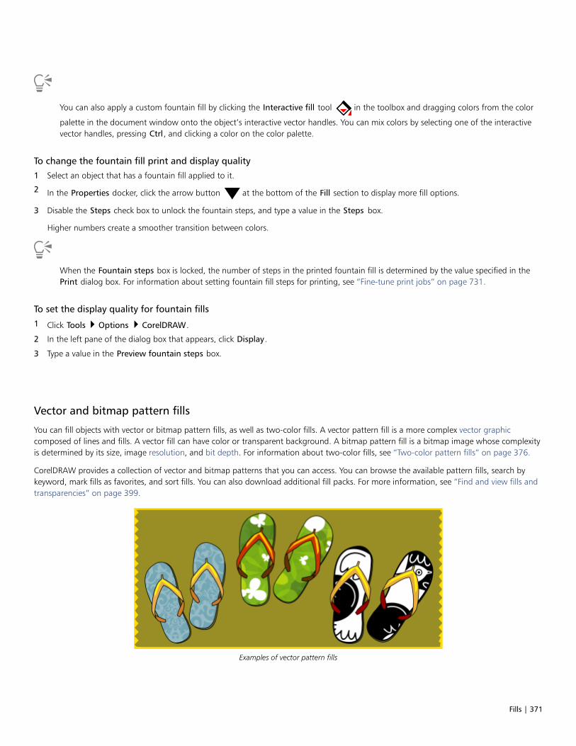
Fills | 371
You can also apply a custom fountain fill by clicking the Interactive fill tool in the toolbox and dragging colors from the color
palette in the document window onto the object’s interactive vector handles. You can mix colors by selecting one of the interactivevector handles, pressing Ctrl, and clicking a color on the color palette.
To change the fountain fill print and display quality
1 Select an object that has a fountain fill applied to it.
2 In the Properties docker, click the arrow button at the bottom of the Fill section to display more fill options.
3 Disable the Steps check box to unlock the fountain steps, and type a value in the Steps box.
Higher numbers create a smoother transition between colors.
When the Fountain steps box is locked, the number of steps in the printed fountain fill is determined by the value specified in thePrint dialog box. For information about setting fountain fill steps for printing, see “Fine-tune print jobs” on page 731.
To set the display quality for fountain fills
1 Click Tools Options CorelDRAW.
2 In the left pane of the dialog box that appears, click Display.
3 Type a value in the Preview fountain steps box.
Vector and bitmap pattern fills
You can fill objects with vector or bitmap pattern fills, as well as two-color fills. A vector pattern fill is a more complex vector graphiccomposed of lines and fills. A vector fill can have color or transparent background. A bitmap pattern fill is a bitmap image whose complexityis determined by its size, image resolution, and bit depth. For information about two-color fills, see “Two-color pattern fills” on page 376.
CorelDRAW provides a collection of vector and bitmap patterns that you can access. You can browse the available pattern fills, search bykeyword, mark fills as favorites, and sort fills. You can also download additional fill packs. For more information, see “Find and view fills andtransparencies” on page 399.
Examples of vector pattern fills

372 | CorelDRAW 2019 User Guide
Examples of bitmap pattern fills
Modifying pattern fills
You can modify pattern fills to suit your needs. For example, you can change the size of the pattern fill, or move the center of the pattern leftor right and up or down. CorelDRAW also lets you offset tiles in a fill.
From left to right: Original vector pattern fill. The center of the pattern tileis moved to the right (middle). The center of the tile is moved down (right).
You can mirror the fill so that alternating tiles are reflections of each other. If you want a pattern fill to change according to actions youperform on the filled object, you can set the fill to transform with the object. For example, if you enlarge the object, the pattern becomeslarger while the number of tiles remains the same.
The brightness and the contrast of bitmap patterns can be adjusted. You can also create a radial or linear seamless blend between thebitmap pattern tiles, and you can smooth the color transition between tiles by matching their edges. You can also adjust pattern parameterssuch as the brightness, luminance, and color contrast of the pattern.
Creating pattern fills
You can also create your own patterns. Vector and bitmap patterns are made up of smaller units called tiles. Depending on the size of theobject, the pattern fill may consist of one or more tiles. The pattern is created by repeating the tile to fill up the object. You can create a newpattern by selecting an area of the workspace to use as a tile, or by using an imported image as a tile source.
After you create a new pattern, you can save it for future use. For more information, see “Save fills and transparencies” on page 403.
To apply a vector or bitmap pattern fill
1 Select an object.
2 Click the Interactive fill tool in the toolbox, and then click one of the following buttons on the property bar:
• Vector pattern fill
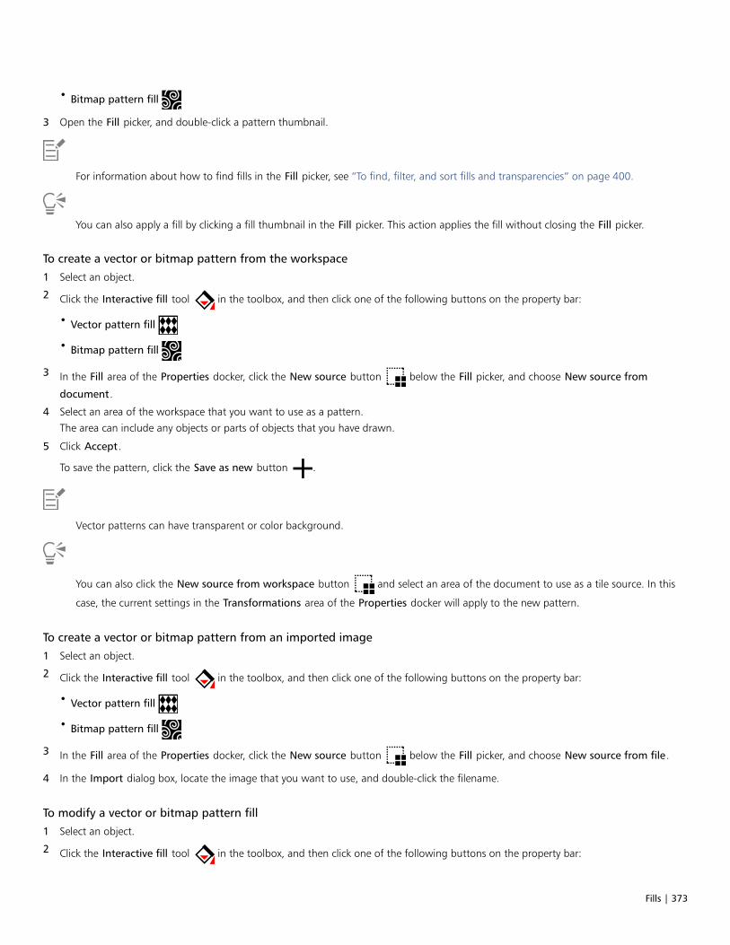
Fills | 373
• Bitmap pattern fill
3 Open the Fill picker, and double-click a pattern thumbnail.
For information about how to find fills in the Fill picker, see “To find, filter, and sort fills and transparencies” on page 400.
You can also apply a fill by clicking a fill thumbnail in the Fill picker. This action applies the fill without closing the Fill picker.
To create a vector or bitmap pattern from the workspace
1 Select an object.
2 Click the Interactive fill tool in the toolbox, and then click one of the following buttons on the property bar:
• Vector pattern fill
• Bitmap pattern fill
3 In the Fill area of the Properties docker, click the New source button below the Fill picker, and choose New source from
document.
4 Select an area of the workspace that you want to use as a pattern.
The area can include any objects or parts of objects that you have drawn.
5 Click Accept.
To save the pattern, click the Save as new button .
Vector patterns can have transparent or color background.
You can also click the New source from workspace button and select an area of the document to use as a tile source. In this
case, the current settings in the Transformations area of the Properties docker will apply to the new pattern.
To create a vector or bitmap pattern from an imported image
1 Select an object.
2 Click the Interactive fill tool in the toolbox, and then click one of the following buttons on the property bar:
• Vector pattern fill
• Bitmap pattern fill
3 In the Fill area of the Properties docker, click the New source button below the Fill picker, and choose New source from file.
4 In the Import dialog box, locate the image that you want to use, and double-click the filename.
To modify a vector or bitmap pattern fill
1 Select an object.
2 Click the Interactive fill tool in the toolbox, and then click one of the following buttons on the property bar:

374 | CorelDRAW 2019 User Guide
• Vector pattern fill
• Bitmap pattern fill
3 In the Fill area of the Properties docker, click the arrow button at the bottom to display more pattern fill options.
4 Perform a task from the following table.
To Do the following
Arrange the tiles so that alternating tiles are reflections of eachother
Click the Mirror tiles horizontally or the Mirror tiles
vertically button.
This illustration shows a pattern fill (left) that is mirrored horizontally(middle), and vertically (right).
Set the width and height of the pattern tiles Type values in the Fill width and Fill height boxes.
This illustration shows the effect of changing the size of a patterntile from bigger to smaller.
Move the center of the pattern fill up, down, left, or right Type values in the X and Y boxes.
Slant or rotate the pattern at a specified angle Type a value in the Skew box or the Rotate box.
The pattern fill in this illustration is slanted 15 degrees (middle) androtated 15 degrees (right).
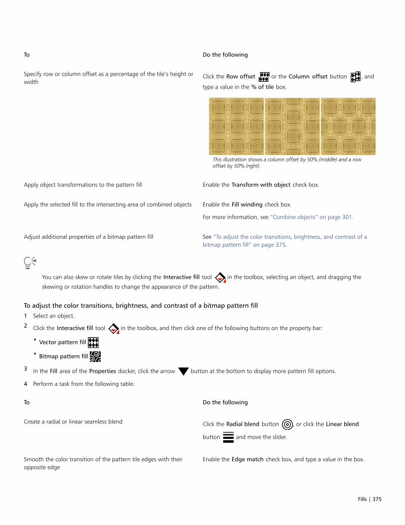
Fills | 375
To Do the following
Specify row or column offset as a percentage of the tile’s height orwidth
Click the Row offset or the Column offset button , and
type a value in the % of tile box.
This illustration shows a column offset by 50% (middle) and a rowoffset by 50% (right).
Apply object transformations to the pattern fill Enable the Transform with object check box.
Apply the selected fill to the intersecting area of combined objects Enable the Fill winding check box.
For more information, see “Combine objects” on page 301.
Adjust additional properties of a bitmap pattern fill See “To adjust the color transitions, brightness, and contrast of abitmap pattern fill” on page 375.
You can also skew or rotate tiles by clicking the Interactive fill tool in the toolbox, selecting an object, and dragging the
skewing or rotation handles to change the appearance of the pattern.
To adjust the color transitions, brightness, and contrast of a bitmap pattern fill
1 Select an object.
2 Click the Interactive fill tool in the toolbox, and then click one of the following buttons on the property bar:
• Vector pattern fill
• Bitmap pattern fill
3 In the Fill area of the Properties docker, click the arrow button at the bottom to display more pattern fill options.
4 Perform a task from the following table.
To Do the following
Create a radial or linear seamless blend Click the Radial blend button , or click the Linear blend
button and move the slider.
Smooth the color transition of the pattern tile edges with theiropposite edge
Enable the Edge match check box, and type a value in the box.

376 | CorelDRAW 2019 User Guide
To Do the following
Increase or decrease the brightness of the pattern Enable the Brightness check box, and type a value in the box.
Increase or decrease the grayscale contrast of the pattern Enable the Luminance check box, and type a value in the box.
Increase or decrease the color contrast of the pattern Enable the Color check box, and type a value in the box.
Two-color pattern fills
A two-color pattern fill is composed only of the two colors that you choose. In addition to specifying the colors, you can mirror the fill tilesvertically or horizontally, and you can set the size of the fill tiles. You can also skew and rotate the fill, and you can move its center.
Examples of two-color pattern fills
A two-color fill applied to an object (left). Next, the fill is resized (middle), and rotated (right).
You can create your own pattern fill from objects in the drawing window by using the Object Create Pattern Fill command.
To apply a two-color pattern fill
1 Select an object.
2 Click the Interactive fill tool in the toolbox, and then click the Two-color pattern fill button on the property bar.
3 Choose a fill from the First fill color or pattern picker.
4 Open the Front color picker, and click a color.
5 Open the Back color picker, and click a color.
Fills | 377
You can use the Properties docker to edit the attributes of the two-color fill by clicking the arrow button at the bottom of the Fill
section, and performing a task from the following table.
To Do the following
Arrange the tiles so that alternating tiles are reflections of eachother
Click the Mirror tiles horizontally or the Mirror tiles
vertically button.
Set the width and height of the pattern tiles Type values in the Fill width and Fill height boxes.
Move the center of the pattern fill up, down, left, or right Type values in the X and Y boxes.
Rotate the pattern at a specified angle Type a value in the Rotate box.
Slant the pattern at a specified angle Type a value in the Skew box.
Specify row or column offset as a percentage of the tile’s height orwidth
Click the Row offset or the Column offset button , and
type a value in the % of tile box.
Apply object changes to the pattern fill Enable the Transform with object check box.
Any transformations applied to the object such as resizing androtating will be applied to the fill as well.
Apply the selected fill to the intersecting area of combined objects Enable the Fill winding check box.
For more information, see “Combine objects” on page 301.
You can also mix colors in a two-color pattern fill by pressing Ctrl and clicking a color on the color palette.
You can also drag colors from the color palette to the interactive handles to change the colors of the fill. You can mix colors byholding down Ctrl while dragging a color to the interactive handles.
To create a two-color pattern fill
1 Click Object Create Pattern Fill.
2 In the Create pattern dialog box, enable the Two color option, and click OK.
3 In the drawing window, select the pattern or area that you want to use for the fill, and then double-click the selection.
4 In the dialog box that appears, choose a resolution, and then click OK.
The new two-color pattern fill can be accessed from the Fill picker.
Texture fills
A texture fill is a randomly generated fill that you can use to give your objects a natural appearance. You can use existing texture fills, suchas water, minerals, and clouds. You can change the colors of a texture fill. Texture fills can hold only RGB colors; however, other color modelsand palettes can be used as a reference to select colors. For information about color models, see “Color models” on page 347.
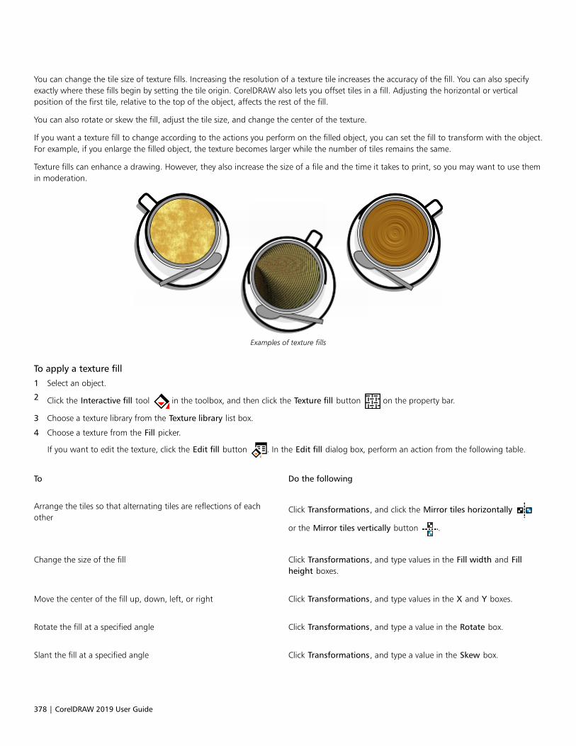
378 | CorelDRAW 2019 User Guide
You can change the tile size of texture fills. Increasing the resolution of a texture tile increases the accuracy of the fill. You can also specifyexactly where these fills begin by setting the tile origin. CorelDRAW also lets you offset tiles in a fill. Adjusting the horizontal or verticalposition of the first tile, relative to the top of the object, affects the rest of the fill.
You can also rotate or skew the fill, adjust the tile size, and change the center of the texture.
If you want a texture fill to change according to the actions you perform on the filled object, you can set the fill to transform with the object.For example, if you enlarge the filled object, the texture becomes larger while the number of tiles remains the same.
Texture fills can enhance a drawing. However, they also increase the size of a file and the time it takes to print, so you may want to use themin moderation.
Examples of texture fills
To apply a texture fill
1 Select an object.
2 Click the Interactive fill tool in the toolbox, and then click the Texture fill button on the property bar.
3 Choose a texture library from the Texture library list box.
4 Choose a texture from the Fill picker.
If you want to edit the texture, click the Edit fill button . In the Edit fill dialog box, perform an action from the following table.
To Do the following
Arrange the tiles so that alternating tiles are reflections of eachother
Click Transformations, and click the Mirror tiles horizontally
or the Mirror tiles vertically button .
Change the size of the fill Click Transformations, and type values in the Fill width and Fillheight boxes.
Move the center of the fill up, down, left, or right Click Transformations, and type values in the X and Y boxes.
Rotate the fill at a specified angle Click Transformations, and type a value in the Rotate box.
Slant the fill at a specified angle Click Transformations, and type a value in the Skew box.

Fills | 379
To Do the following
Specify a row or column offset as a percentage of the tile’s widthor height
Click Transformations, and click the Row offset or the
Column offset button . Type a value in the % of tile box.
Apply object changes to the texture fill Click Transformations, and enable the Transform with objectcheck box.
Specify the bitmap resolution of the texture fill Click Texture resolution and size, and type a value in the Bitmapresolution box.
Apply the selected fill to the intersecting area of combined objects Enable the Fill winding check box.
For more information, see “Combine objects” on page 301.
PostScript fills
You can apply PostScript texture fills to objects. A PostScript texture fill is created in the PostScript language. Some textures are very complex,and large objects that contain PostScript texture fills may take time to print or to be updated on the screen. Depending on the view modeyou are using, the letters “PS” — rather than the fill — may appear. For more information about displaying PostScript fills, see “Views” onpage 55.
When you apply a PostScript texture fill, you can change several properties, such as the size, line width, and the amount of gray that appearsin the texture’s foreground and background.
Examples of PostScript fills
To apply a PostScript fill
1 Select an object.
2 Click the Interactive fill tool in the toolbox, and then click the PostScript fill button on the property bar.
3 Choose a fill from the PostScript fill textures list box.
If you want to change the fill properties, click the Edit fill button , and specify the settings you want.
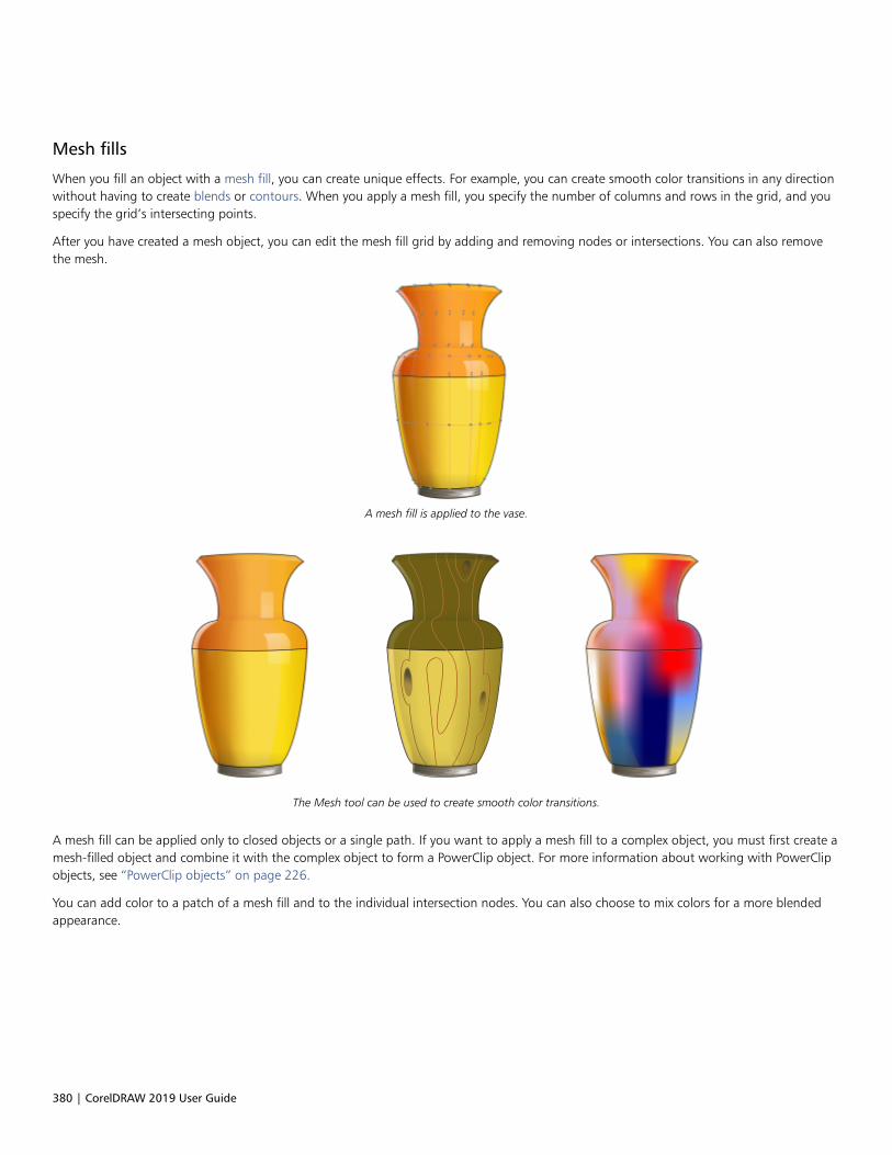
380 | CorelDRAW 2019 User Guide
Mesh fills
When you fill an object with a mesh fill, you can create unique effects. For example, you can create smooth color transitions in any directionwithout having to create blends or contours. When you apply a mesh fill, you specify the number of columns and rows in the grid, and youspecify the grid’s intersecting points.
After you have created a mesh object, you can edit the mesh fill grid by adding and removing nodes or intersections. You can also removethe mesh.
A mesh fill is applied to the vase.
The Mesh tool can be used to create smooth color transitions.
A mesh fill can be applied only to closed objects or a single path. If you want to apply a mesh fill to a complex object, you must first create amesh-filled object and combine it with the complex object to form a PowerClip object. For more information about working with PowerClipobjects, see “PowerClip objects” on page 226.
You can add color to a patch of a mesh fill and to the individual intersection nodes. You can also choose to mix colors for a more blendedappearance.

Fills | 381
Left: Adding a color to a mesh fill. Right: Moving an intersection node in a mesh fill lets you adjust the progression of colors.
In addition, you can smooth the color in a mesh fill to reduce the appearance of hard edges. You can also reveal objects underneath aselected area by applying transparency to the mesh fill.
Mesh fills were used in this artwork by Ariel Garaza Díaz, based on photography by Rikk Flohr.
You can set the default properties of all new mesh fills by specifying the number of rows and columns in the mesh grid.
To apply a mesh to an object
1 Select an object.
2 In the toolbox, click the Mesh fill tool .
3 Type the number of columns in the top portion of the Grid size box on the property bar.
4 Type the number of rows in the bottom portion of the Grid size box on the property bar, and press Enter.
5 Adjust the grid nodes on the object.

382 | CorelDRAW 2019 User Guide
You can also
Add a node or an intersection Click once within a grid, and click the Add intersection button
on the property bar.
You can also add a node or an intersection by double-clickingwithin a grid.
Remove a node or an intersection Click a node, and click the Delete nodes button on the
property bar.
Shape the mesh fill Drag a node to a new location.
Remove the mesh fill Click the Clear mesh button on the property bar.
If the mesh object contains color, adjusting the intersection nodes of the mesh affects how the colors blend together.
You can also marquee select or freehand marquee select nodes to shape an entire area of the mesh. To marquee select nodes, chooseRectangular from the Selection mode list box on the property bar, and drag around the nodes that you want to select. To freehandselect nodes, choose Freehand from the Selection mode list box, and drag around the nodes that you want to select. Holding downAlt while dragging lets you toggle between the Rectangular and Freehand selection modes.
You can add an intersection or a node by double-clicking in a space, or you can add a single line by double-clicking a line.
To fill a mesh with color
1 Select a mesh-filled object.
2 In the toolbox, click the Mesh fill tool .
3 Drag a color from the color palette to a patch in the object.
You can also
Color a node in a mesh fill Click a node, and click a color on the color palette.
You can also drag a color from the color palette to a node.
Mix a color in a mesh fill Select part of the mesh, press Ctrl, and click a color on the colorpalette.
You can also marquee select or freehand marquee select nodes to apply a color to an entire area of the mesh. To marquee selectnodes, choose Rectangular from the Selection mode list box on the property bar, and drag around the nodes that you want toselect. To freehand select nodes, choose Freehand from the Selection mode list box on the property bar, and drag around the nodesthat you want to select. Holding down Alt while dragging lets you toggle between the Rectangular and Freehand selection modes.

Fills | 383
To smooth color transitions in a mesh fill
1 Select a mesh-filled object.
2 In the toolbox, click the Mesh fill tool .
3 Make sure that the Smooth mesh color button on the property bar is enabled.
To apply transparency to a mesh fill
1 Select a mesh-filled object.
2 In the toolbox, click the Mesh fill tool .
3 Click a node to select part of the mesh.
4 On the property bar, type a value in the Transparency box slider.
Higher values increase the transparency of the selected area.
To set the default properties of mesh fills
1 Click Tools Options Tools.
2 In the left pane of the dialog that appears, click Mesh Fill.
3 Type values in the Number of columns and Number of rows boxes.
Apply fills to areas
You can apply fills to any enclosed area by using the Smart fill tool. Unlike other fill tools, which fill only objects, the Smart fill tool detectsthe edges of an area and creates a closed path so that the area can be filled. For example, if you draw a freehand line that crosses over itselfto create loops, the Smart fill tool can detect the edges of the loops and fill them.
In the example above, the original spiral object is duplicated and offset,resulting in enclosed areas that can be filled by using the Smart fill tool.
Using the Smart fill tool to fill enclosed areas
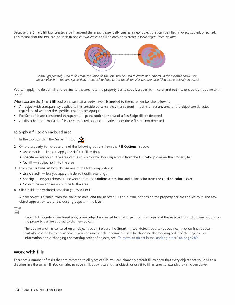
384 | CorelDRAW 2019 User Guide
Because the Smart fill tool creates a path around the area, it essentially creates a new object that can be filled, moved, copied, or edited.This means that the tool can be used in one of two ways: to fill an area or to create a new object from an area.
Although primarily used to fill areas, the Smart fill tool can also be used to create new objects. In the example above, theoriginal objects — the two spirals (left) — are deleted (right), but the fill remains because each filled area is actually an object.
You can apply the default fill and outline to the area, use the property bar to specify a specific fill color and outline, or create an outline withno fill.
When you use the Smart fill tool on areas that already have fills applied to them, remember the following:• An object with transparency applied to it is considered completely transparent — paths under any area of the object are detected,
regardless of whether the specific area appears opaque.• PostScript fills are considered transparent — paths under any area of a PostScript fill are detected.• All fills other than PostScript fills are considered opaque — paths under these fills are not detected.
To apply a fill to an enclosed area
1 In the toolbox, click the Smart fill tool .
2 On the property bar, choose one of the following options from the Fill Options list box:
• Use default — lets you apply the default fill settings
• Specify — lets you fill the area with a solid color by choosing a color from the Fill color picker on the property bar
• No fill — applies no fill to the area
3 From the Outline list box, choose one of the following options:
• Use default — lets you apply the default outline settings
• Specify — lets you choose a line width from the Outline width box and a line color from the Outline color picker
• No outline — applies no outline to the area
4 Click inside the enclosed area that you want to fill.
A new object is created from the enclosed area, and the selected fill and outline options on the property bar are applied to it. The newobject appears on top of the existing objects in the layer.
If you click outside an enclosed area, a new object is created from all objects on the page, and the selected fill and outline options onthe property bar are applied to the new object.
The outline width is centered on an object’s path. Because the Smart fill tool detects paths, not outlines, thick outlines appearpartially covered by the new object. You can uncover the original outlines by changing the stacking order of the objects. Forinformation about changing the stacking order of objects, see “To move an object in the stacking order” on page 289.
Work with fills
There are a number of tasks that are common to all types of fills. You can choose a default fill color so that every object that you add to adrawing has the same fill. You can also remove a fill, copy it to another object, or use it to fill an area surrounded by an open curve.
Fills | 385
If you want to apply the same fill to other objects or simultaneously modify the fill attributes of multiple objects in a drawing, you can savethe fill settings as a style. For more information about styles, see “Styles and style sets” on page 565. You can search for objects based ontheir fill and replace the existing fill with a new one.
To choose a default fill color
1 Click a blank area on the drawing page to deselect all objects.
2 On the status bar, double-click the Fill icon .
3 In the Edit fill dialog box, choose a fill type, choose a fill color, and click OK.
4 In the Change document defaults dialog box, enable the check boxes for the types of objects whose default fill you want to change.
You can also change the default fill color by editing the default style sets in the Object Styles docker. For more information, see“Manage default object properties” on page 570.
To remove a fill
1 Select an object.
2 Click the Interactive fill tool in the toolbox, and then click the No fill button on the property bar.
You cannot remove mesh fills by following this procedure. To remove a mesh fill from an object, select the object by using the Mesh
fill tool , and click Clear Mesh on the property bar.
To copy a fill to another object
1 Using the Pick tool , select the object from which you want to copy the fill.
2 With the right mouse button, drag the object over the destination object to which you want to apply the fill.
A blue outline of the first object follows the pointer to the destination object.
3 When the pointer changes to a crosshair pointer , release the mouse button, and choose Copy fill here from the context menu.
You can also click the Interactive fill tool , select the object to which you want to copy a fill, click the Copy fill button on the
property bar, and click the object from which you want to copy the fill.
You can also use the Attributes eyedropper tool to copy a fill. For more information, see “To copy fill, outline, or text properties
from one object to another” on page 270.
You can also sample the color of an existing object and apply the sampled color to another object as a uniform fill. For moreinformation, see “To sample a color” on page 353.
To show fills in open curves
1 Click Layout Document Options.
2 In the left pane of the dialog box that appears, click General.
3 Enable the Fill open curves check box.
386 | CorelDRAW 2019 User Guide
To find and replace fill colors
1 Click Edit Find and Replace.
2 In the Find and Replace docker, choose Replace Objects from the list box at the top of the docker.
3 Enable the Color option.
4 In the Find area, enable the Fills option.
5 Choose the color to find in the Find color picker.
6 Choose the replacement color to find in the Replace color picker.
7 Click Find, and click any of the following:
• Find Next > or Find Previous < to scroll through objects that meet the outline-search criteria.
• Find All to select all objects that meet the fill-search criteria.
• Replace to replace the fill color on the selected object.
• Replace All to replace the color of all fills that meet the fill-search criteria.
You can also
Apply the color replacement to monochrome bitmaps Enable the Apply to monochrome bitmaps check box.
Apply the color replacement to fountain fills Enable the Apply to fountain fills check box.
Apply the color replacement to 2-color fills Enable the Apply to 2-color fills check box.
Find and replace a fill’s color model Enable the Color model or palette option, enable the Specificcolor model option in the Find area, choose the color model tofind, and choose the replacement color model from the Replacewith list box.
Find a fill’s color palette and replace it with a color model Enable the Color model or palette option, enable the Specificcolor palette option in the Find area, choose the color model tofind, and choose the replacement color model from the Replacewith list box.

Object transparency | 387
Object transparency
When you apply a transparency to an object, you make the objects beneath it partially visible. You can apply transparencies by using thesame kind of fills you apply to objects; that is, uniform, fountain, hatch, texture, and pattern. For more information about these fills, see“Fills” on page 365.
Examples of different types of transparencies, including uniform, fountain, and pattern.
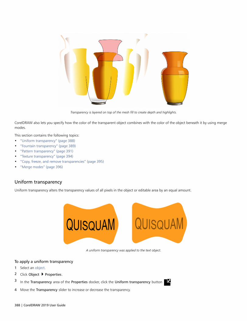
388 | CorelDRAW 2019 User Guide
Transparency is layered on top of the mesh fill to create depth and highlights.
CorelDRAW also lets you specify how the color of the transparent object combines with the color of the object beneath it by using mergemodes.
This section contains the following topics:• “Uniform transparency” (page 388)• “Fountain transparency” (page 389)• “Pattern transparency” (page 391)• “Texture transparency” (page 394)• “Copy, freeze, and remove transparencies” (page 395)• “Merge modes” (page 396)
Uniform transparency
Uniform transparency alters the transparency values of all pixels in the object or editable area by an equal amount.
A uniform transparency was applied to the text object.
To apply a uniform transparency
1 Select an object.
2 Click Object Properties.
3 In the Transparency area of the Properties docker, click the Uniform transparency button .
4 Move the Transparency slider to increase or decrease the transparency.
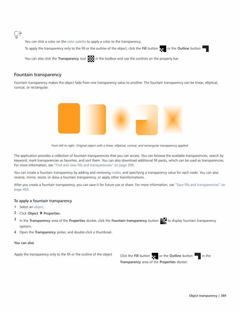
Object transparency | 389
You can click a color on the color palette to apply a color to the transparency.
To apply the transparency only to the fill or the outline of the object, click the Fill button or the Outline button .
You can also click the Transparency tool in the toolbox and use the controls on the property bar.
Fountain transparency
Fountain transparency makes the object fade from one transparency value to another. The fountain transparency can be linear, elliptical,conical, or rectangular.
From left to right: Original object with a linear, elliptical, conical, and rectangular transparency applied.
The application provides a collection of fountain transparencies that you can access. You can browse the available transparencies, search bykeyword, mark transparencies as favorites, and sort them. You can also download additional fill packs, which can be used as transparencies.For more information, see “Find and view fills and transparencies” on page 399.
You can create a fountain transparency by adding and removing nodes, and specifying a transparency value for each node. You can alsoreverse, mirror, resize, or skew a fountain transparency, or apply other transformations.
After you create a fountain transparency, you can save it for future use or share. For more information, see “Save fills and transparencies” onpage 403.
To apply a fountain transparency
1 Select an object.
2 Click Object Properties.
3 In the Transparency area of the Properties docker, click the Fountain transparency button to display fountain transparency
options.
4 Open the Transparency picker, and double-click a thumbnail.
You can also
Apply the transparency only to the fill or the outline of the object Click the Fill button or the Outline button in the
Transparency area of the Properties docker.

390 | CorelDRAW 2019 User Guide
You can also
Modify the transparency Click the Edit transparency button in the Properties docker,
and specify the settings you want.
You can also click the Transparency tool in the toolbox, and use the controls on the property bar to apply a fountain
transparency.
For information about how to find transparencies in the Transparency picker, see “To find, filter, and sort fills and transparencies” onpage 400.
To create a fountain transparency
1 Select an object.
2 Click Object Properties.
3 In the Transparency area of the Properties docker, click the Fountain transparency button to display fountain transparency
options.
4 Click one of the following buttons to choose a fountain transparency type:
• Linear fountain transparency
• Elliptical fountain transparency
• Conical fountain transparency
• Rectangular fountain transparency
5 Click the first node below the grayscale band, and type a value in the Opacity box.
6 Click the last node below the grayscale band, and type a value in the Opacity box.
7 Move the midpoint slider above the grayscale band to set the midpoint of the transparency.
To save the transparency, click the click the Save as new button in the Transparency area of the Properties docker.
You can also
Change the transparency of the midpoint Select the midpoint node, and type a value in the Opacity box.
Add an intermediate transparency Double-click the grayscale band where you want to add a node.With the new node selected, type a value in the Opacity box.
Change the position of an intermediate transparency Drag the corresponding node to a new location below thegrayscale band, or type a value in the Position box.
Delete an intermediate transparency Click the Transparency tool , and double-click the node on the
interactive vector handles that appear on the object.
Allow the transparency to be skewed or stretcheddisproportionately
Enable the Free scale and skew check box.
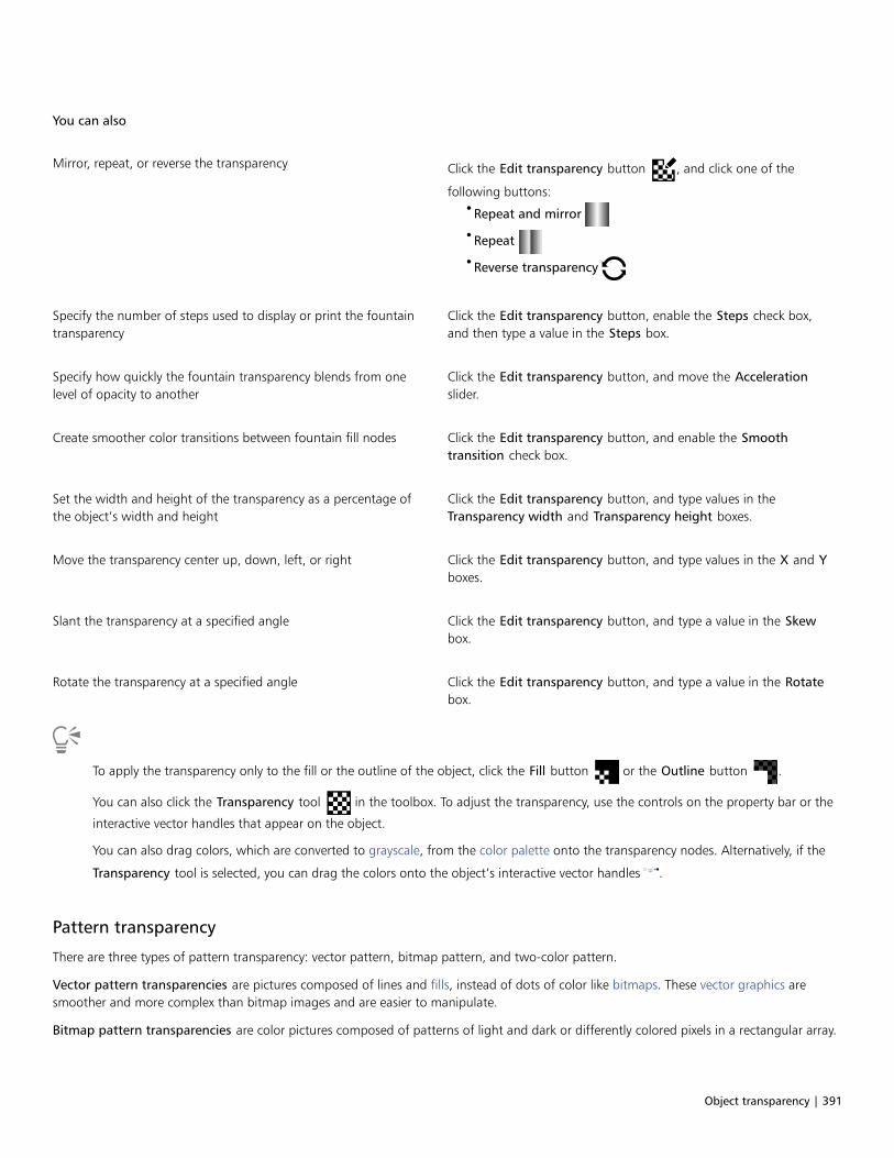
Object transparency | 391
You can also
Mirror, repeat, or reverse the transparency Click the Edit transparency button , and click one of the
following buttons:•Repeat and mirror
•Repeat
•Reverse transparency
Specify the number of steps used to display or print the fountaintransparency
Click the Edit transparency button, enable the Steps check box,and then type a value in the Steps box.
Specify how quickly the fountain transparency blends from onelevel of opacity to another
Click the Edit transparency button, and move the Accelerationslider.
Create smoother color transitions between fountain fill nodes Click the Edit transparency button, and enable the Smoothtransition check box.
Set the width and height of the transparency as a percentage ofthe object’s width and height
Click the Edit transparency button, and type values in theTransparency width and Transparency height boxes.
Move the transparency center up, down, left, or right Click the Edit transparency button, and type values in the X and Yboxes.
Slant the transparency at a specified angle Click the Edit transparency button, and type a value in the Skewbox.
Rotate the transparency at a specified angle Click the Edit transparency button, and type a value in the Rotatebox.
To apply the transparency only to the fill or the outline of the object, click the Fill button or the Outline button .
You can also click the Transparency tool in the toolbox. To adjust the transparency, use the controls on the property bar or the
interactive vector handles that appear on the object.
You can also drag colors, which are converted to grayscale, from the color palette onto the transparency nodes. Alternatively, if the
Transparency tool is selected, you can drag the colors onto the object’s interactive vector handles .
Pattern transparency
There are three types of pattern transparency: vector pattern, bitmap pattern, and two-color pattern.
Vector pattern transparencies are pictures composed of lines and fills, instead of dots of color like bitmaps. These vector graphics aresmoother and more complex than bitmap images and are easier to manipulate.
Bitmap pattern transparencies are color pictures composed of patterns of light and dark or differently colored pixels in a rectangular array.
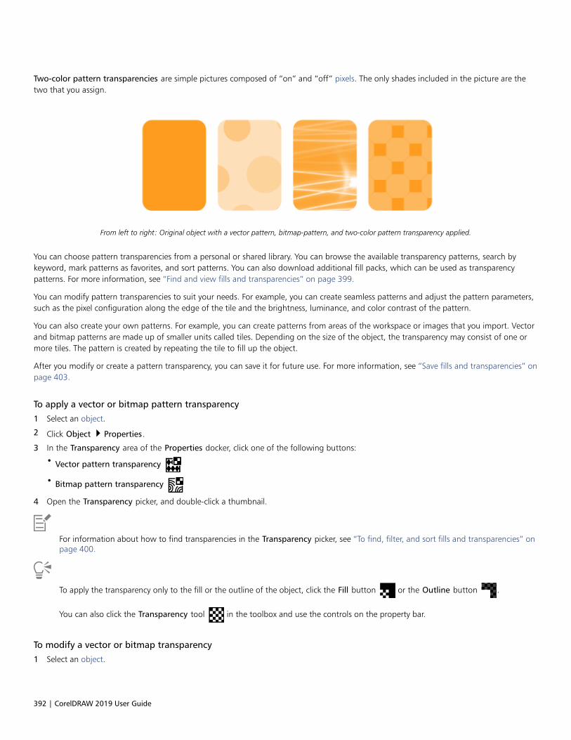
392 | CorelDRAW 2019 User Guide
Two-color pattern transparencies are simple pictures composed of “on” and “off” pixels. The only shades included in the picture are thetwo that you assign.
From left to right: Original object with a vector pattern, bitmap-pattern, and two-color pattern transparency applied.
You can choose pattern transparencies from a personal or shared library. You can browse the available transparency patterns, search bykeyword, mark patterns as favorites, and sort patterns. You can also download additional fill packs, which can be used as transparencypatterns. For more information, see “Find and view fills and transparencies” on page 399.
You can modify pattern transparencies to suit your needs. For example, you can create seamless patterns and adjust the pattern parameters,such as the pixel configuration along the edge of the tile and the brightness, luminance, and color contrast of the pattern.
You can also create your own patterns. For example, you can create patterns from areas of the workspace or images that you import. Vectorand bitmap patterns are made up of smaller units called tiles. Depending on the size of the object, the transparency may consist of one ormore tiles. The pattern is created by repeating the tile to fill up the object.
After you modify or create a pattern transparency, you can save it for future use. For more information, see “Save fills and transparencies” onpage 403.
To apply a vector or bitmap pattern transparency
1 Select an object.
2 Click Object Properties.
3 In the Transparency area of the Properties docker, click one of the following buttons:
• Vector pattern transparency
• Bitmap pattern transparency
4 Open the Transparency picker, and double-click a thumbnail.
For information about how to find transparencies in the Transparency picker, see “To find, filter, and sort fills and transparencies” onpage 400.
To apply the transparency only to the fill or the outline of the object, click the Fill button or the Outline button .
You can also click the Transparency tool in the toolbox and use the controls on the property bar.
To modify a vector or bitmap transparency
1 Select an object.

Object transparency | 393
2 Click Object Properties.
3 In the Transparency area of the Properties docker, click one of the following buttons:
• Vector pattern transparency
• Bitmap pattern transparency
4 Click the Edit transparency button .
5 Perform a task from the following table.
To Do the following
Arrange the tiles so that alternating tiles are reflections of eachother
Click the Mirror tiles horizontally or the Mirror tiles
vertically button.
Create a radial or linear seamless blend Click the Radial blend button , or click the Linear blend
button and move the slider.
This setting applies only to bitmap pattern transparency.
Smooth the color transition of the pattern tile edges with theiropposite edge
Enable the Edge match check box, and type a value in the box.
This setting applies only to bitmap pattern transparency.
Increase or decrease the brightness of the pattern Enable the Brightness check box, and type a value in the box.
This setting applies only to bitmap pattern transparency.
Increase or decrease the grayscale contrast of the pattern. Enable the Luminance check box, and type a value in the box.
This setting applies only to bitmap pattern transparency.
Increase or decrease the color contrast of the pattern Enable the Color check box, and type a value in the box.
This setting applies only to bitmap pattern transparency.
Set the width and height of the transparency as a percentage ofthe object’s width and height
Type values in the Transparency width and Transparency heightboxes.
Move the center of the transparency up, down, left, or right Type values in the X and Y boxes.
Rotate the transparency at a specified angle Type a value in the Rotate box.
Slant the transparency at a specified angle Type a value in the Skew box.
Specify row or column offset as a percentage of the tile’s height orwidth
Click the Row offset or the Column offset button , and
type a value in the % of tile box.

394 | CorelDRAW 2019 User Guide
To Do the following
Apply object changes to the transparency Enable the Transform with object check box.
To save the edited transparency, click the Save as new button .
You can also click the Transparency tool in the toolbox and use the controls on the property bar.
You can also skew or rotate tiles by clicking the Transparency tool in the toolbox, selecting an object, and dragging the skewing
or rotation handles to change the appearance of the pattern.
To apply a two-color pattern transparency
1 Select an object.
2 Click Object Properties.
3 In the Transparency area of the Properties docker, click the Two-color pattern transparency button .
4 Choose a pattern from the Transparency picker.
5 Type values in the Foreground transparency and Background transparency boxes.
To apply the transparency only to the fill or the outline of the object, click the Fill button or the Outline button .
To modify the pattern, click the Edit transparency button , and specify the settings you want.
You can also click the Transparency tool in the toolbox and use the controls on the property bar.
Texture transparency
You can use textures to create transparency effects. You can use existing textures, such as water, minerals, and clouds, or you can edit atexture to create your own texture transparency.
A texture transparency is applied to the object filled with light green.
When you edit a texture, you can modify its parameters, such as softness, density, brightness, and colors. Parameters vary for each texture.You can also apply other transformations, such as mirror, resize, or offset the texture tiles. After you have edited a texture, you can save it forfuture use.
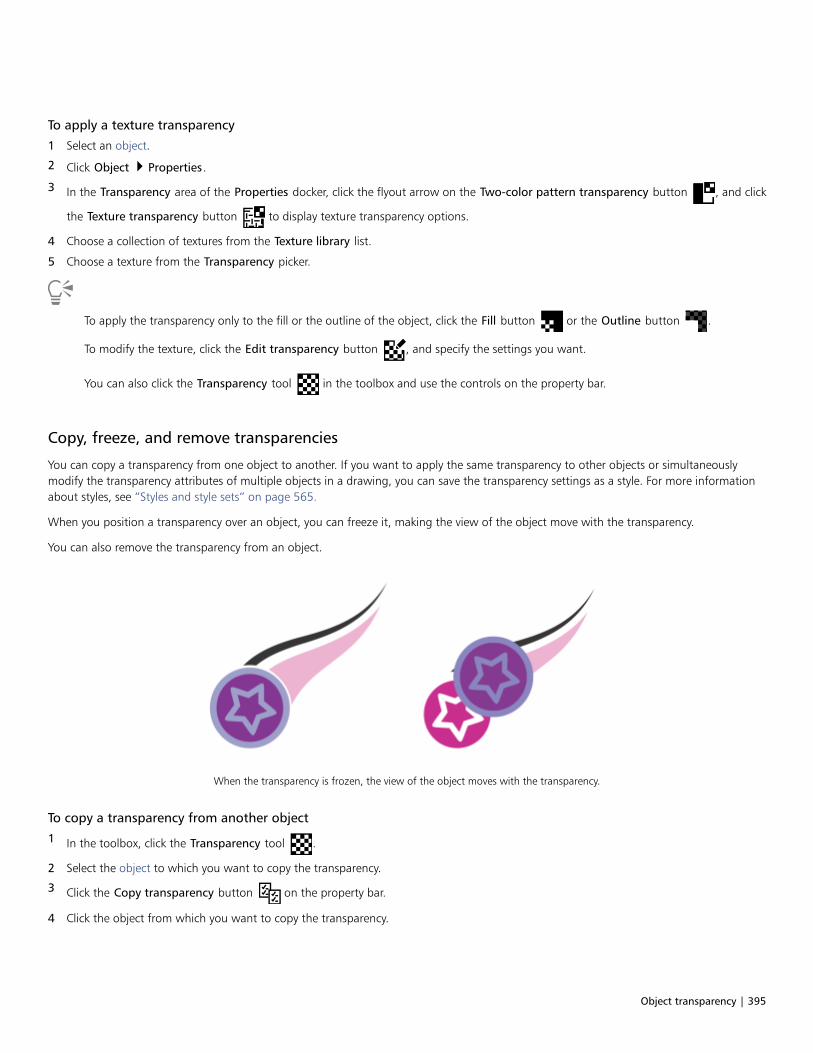
Object transparency | 395
To apply a texture transparency
1 Select an object.
2 Click Object Properties.
3 In the Transparency area of the Properties docker, click the flyout arrow on the Two-color pattern transparency button , and click
the Texture transparency button to display texture transparency options.
4 Choose a collection of textures from the Texture library list.
5 Choose a texture from the Transparency picker.
To apply the transparency only to the fill or the outline of the object, click the Fill button or the Outline button .
To modify the texture, click the Edit transparency button , and specify the settings you want.
You can also click the Transparency tool in the toolbox and use the controls on the property bar.
Copy, freeze, and remove transparencies
You can copy a transparency from one object to another. If you want to apply the same transparency to other objects or simultaneouslymodify the transparency attributes of multiple objects in a drawing, you can save the transparency settings as a style. For more informationabout styles, see “Styles and style sets” on page 565.
When you position a transparency over an object, you can freeze it, making the view of the object move with the transparency.
You can also remove the transparency from an object.
When the transparency is frozen, the view of the object moves with the transparency.
To copy a transparency from another object
1 In the toolbox, click the Transparency tool .
2 Select the object to which you want to copy the transparency.
3 Click the Copy transparency button on the property bar.
4 Click the object from which you want to copy the transparency.

396 | CorelDRAW 2019 User Guide
To freeze the contents of a transparency
1 In the toolbox, click the Transparency tool .
2 Select an object to which a transparency has been applied.
3 Click the Freeze transparency button on the property bar.
The view of the object beneath the transparency moves with it; however, the actual object remains unchanged.
To remove a transparency
1 Select an object to which a transparency has been applied.
2 In the Transparency area of the Properties docker, click the No transparency button .
Merge modes
You can apply a merge mode to a transparency to specify how the color of a transparency is combined with the color of the object behind it.The following merge modes available for transparencies can also be applied to drop shadows.
Merge mode Description
Normal Applies the transparency color on top of the base color
Add Adds the values of the transparency color and the base color
Subtract Adds the values of the transparency color and the base colortogether, and then subtracts 255
Difference Subtracts the transparency color from the base color and multipliesby 255. If the transparency color value is 0, the result will always be255.
Multiply Multiplies the base color by the transparency color, and thendivides by 255. This has a darkening effect, unless you are applyingcolor to white. Multiplying black with any color results in black.Multiplying white with any color leaves the color unchanged.
Divide Divides the base color by the transparency color, or conversely,divides the transparency color by the base color, depending onwhich color has the higher value
If lighter Replaces any base color pixels that are a darker color with thetransparency color. Base color pixels that are lighter than thetransparency color are not affected.

Object transparency | 397
Merge mode Description
If darker Replaces any base color pixels that are a lighter color with thetransparency color. Base color pixels that are darker than thetransparency color are not affected.
Texturize Converts the transparency color to grayscale, and then multipliesthe grayscale value by the base color
Color Uses the hue and saturation values of the source color and thelightness value of the base color to create a result. This mergemode is the opposite of the Lightness merge mode.
Hue Uses the hue of the transparency color, as well as the saturationand lightness of the base color. If you are adding color to agrayscale image, there will be no change because the colors aredesaturated.
Saturation Uses the lightness and hue of the base color and the saturation ofthe transparency color
Lightness Uses the hue and saturation of the base color and the lightness ofthe transparency color
Invert Uses the transparency color’s complementary color. If atransparency color value is 127, there will be no change becausethe color value falls in the center of the color wheel.
Logical AND Converts the transparency and base colors to binary values, andthen applies the Boolean algebraic formula AND to these values
Logical OR Converts the transparency and base colors to binary values, andthen applies the Boolean algebraic formula OR to these values
Logical XOR Converts the transparency and base colors to binary values, andthen applies the Boolean algebraic formula XOR to these values
Behind Applies the source color to those areas of the image that aretransparent. The effect is similar to looking through the clear, silver-free areas on a 35-mm negative.
Screen Inverts the source and base color values, multiplies them, and theninverts the result. The result color is always lighter than the basecolor.
Overlay Multiplies or screens the source color according to the value of thebase color
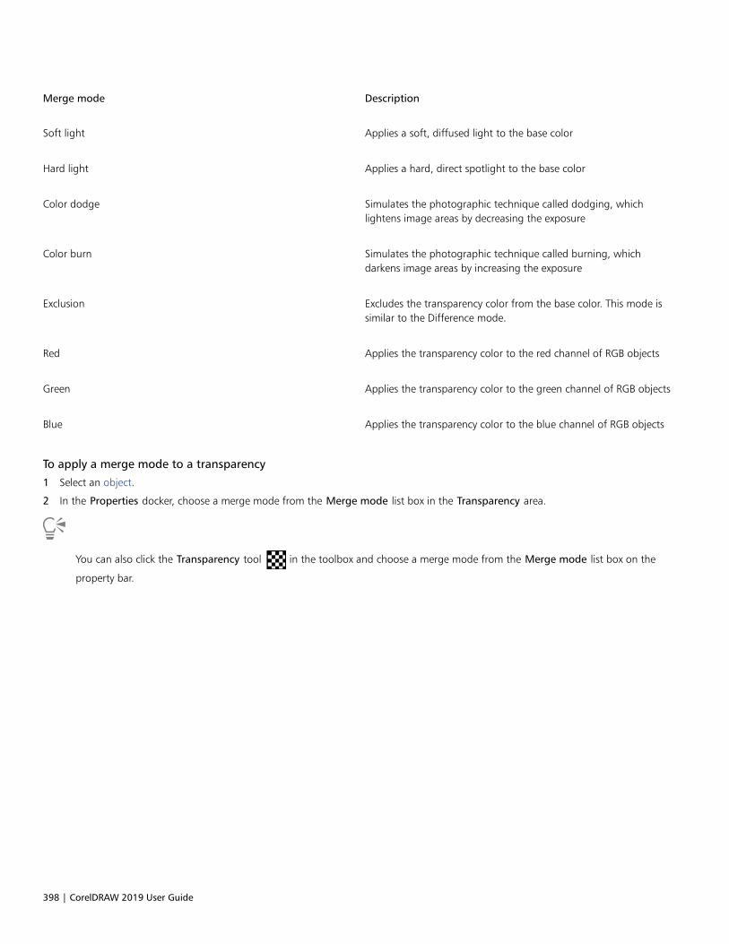
398 | CorelDRAW 2019 User Guide
Merge mode Description
Soft light Applies a soft, diffused light to the base color
Hard light Applies a hard, direct spotlight to the base color
Color dodge Simulates the photographic technique called dodging, whichlightens image areas by decreasing the exposure
Color burn Simulates the photographic technique called burning, whichdarkens image areas by increasing the exposure
Exclusion Excludes the transparency color from the base color. This mode issimilar to the Difference mode.
Red Applies the transparency color to the red channel of RGB objects
Green Applies the transparency color to the green channel of RGB objects
Blue Applies the transparency color to the blue channel of RGB objects
To apply a merge mode to a transparency
1 Select an object.
2 In the Properties docker, choose a merge mode from the Merge mode list box in the Transparency area.
You can also click the Transparency tool in the toolbox and choose a merge mode from the Merge mode list box on the
property bar.

Find, manage, and save fills and transparencies | 399
Find, manage, and save fills and transparencies
When working with vector patterns, bitmap patterns, or fountain fills and transparencies, you can access your personal local library as wellas shared and local folders to browse, search, and save fills and transparency patterns.
This section contains the following topics:
• “Find and view fills and transparencies” (page 399)
• “Manage fills and transparencies” (page 401)
• “Save fills and transparencies” (page 403)
Find and view fills and transparencies
CorelDRAW lets you use, browse, and search vector patterns, bitmap patterns, and fountain fills that are available locally on your computer,on portable media devices, and in network folders. Any of these fills can also be used as transparency patterns. For more information, see“Object transparency” on page 387.
To get you started, Corel provides local fills that are listed under All content in the Fill and Transparency pickers. These fills are stored inyour Documents\Corel\Corel Content\Fills folder. If you are looking to expand your fill collection, you can download additional fill packsfrom within the Get More dialog box.
To access fills and patterns that are saved to local folders outside your Documents\Corel\Corel Content\Fills folder, you can create links tothese folders in the Fill and Transparency pickers. Such links are known as aliases. In addition, aliases can be used to access fills saved toshared network locations as well as secondary storage devices such as USB flash drives, and portable hard drives.
You can also view the list of your favorite or most recently used fills and transparencies.
You can search and browse one pack, folder or list at a time. You can also browse and search your entire All content library by enabling theBrowse recursively option.
When you copy a folder that contains many fills to your computer, it may take some time for Windows to index the folder. To view, browse,and search fills in such a folder right away, you may need to reindex the folder.
To find fills and transparencies more easily, you can filter them based on categories such Abstract, Animals, Floral, Nature, and more. Youcan also sort local fills and transparencies by name and the date they were created or modified.
The Fill picker lets you search, browse, and manage local and shared fills.
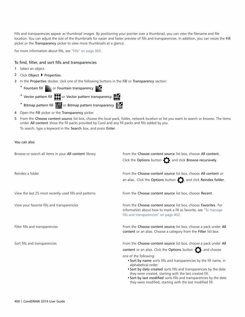
400 | CorelDRAW 2019 User Guide
Fills and transparencies appear as thumbnail images. By positioning your pointer over a thumbnail, you can view the filename and filelocation. You can adjust the size of the thumbnails for easier and faster preview of fills and transparencies. In addition, you can resize the Fillpicker or the Transparency picker to view more thumbnails at a glance.
For more information about fills, see “Fills” on page 365.
To find, filter, and sort fills and transparencies
1 Select an object.
2 Click Object Properties.
3 In the Properties docker, click one of the following buttons in the Fill or Transparency section:
• Fountain fill or Fountain transparency
• Vector pattern fill or Vector pattern transparency
• Bitmap pattern fill or Bitmap pattern transparency
4 Open the Fill picker or the Transparency picker.
5 From the Choose content source list box, choose the local pack, folder, network location or list you want to search or browse. The itemsunder All content show the fill packs provided by Corel and any fill packs and fills added by you.
To search, type a keyword in the Search box, and press Enter.
You can also
Browse or search all items in your All content library From the Choose content source list box, choose All content.
Click the Options button , and click Browse recursively.
Reindex a folder From the Choose content source list box, choose All content or
an alias. Click the Options button , and click Reindex folder.
View the last 25 most recently used fills and patterns From the Choose content source list box, choose Recent.
View your favorite fills and transparencies From the Choose content source list box, choose Favorites. Forinformation about how to mark a fill as favorite, see “To managefills and transparencies” on page 402.
Filter fills and transparencies From the Choose content source list box, choose a pack under Allcontent or an alias. Choose a category from the Filter list box.
Sort fills and transparencies From the Choose content source list box, choose a pack under All
content or an alias. Click the Options button , and choose
one of the following:•Sort by name sorts fills and transparencies by the fill name, in
alphabetical order.•Sort by date created sorts fills and transparencies by the date
they were created, starting with the last created fill.•Sort by last modified sorts fills and transparencies by the date
they were modified, starting with the last modified fill.

Find, manage, and save fills and transparencies | 401
You can also
Fills and transparencies in your Favorites list are automaticallysorted by the date you marked them as favorites, starting with thelast fill and transparency added to Favorites.
Fills and transparencies in your Recent list are automatically sortedby the date you used them, starting with the last used fill ortransparency.
This procedure applies only to vector patterns, bitmap patterns, and fountain fills and transparencies.
To download and add a new fill and transparency pack
1 Open the Fill picker or the Transparency picker in the Fill or Transparency section of the Properties docker.
2 Open the Choose content source list box, and click Add new.
3 Click Get More.
4 In the Get More dialog box, click the fill pack you want.
5 Do one of the following:
• Click Buy, and follow the onscreen instructions to purchase the item.
• Click Download if the item is included in your product or subscription.
To add an alias to a location that contains fills and transparencies
1 Open the Fill picker or the Transparency picker in the Fill or Transparency section of the Properties docker.
2 Open the Choose content source list box, and click Add new.
3 Click Create alias.
4 In the Locate fills library dialog box, browse to the folder or location you want.
5 Click Select Folder.
To view the filename and location of a fill or transparency
• In the Fill picker or the Transparency picker, point to a thumbnail.
To adjust the size of fill or transparency thumbnails
• In the Fill picker or the Transparency picker, move the Thumbnail size slider.
To resize the Fill picker or the Transparency picker
• Drag the lower-right corner of the Fill picker or the Transparency picker.
You can increase the width of the picker by dragging its right side, and you can increase the height of the picker by dragging its bottomside.
Manage fills and transparencies
The Fill and Transparency pickers let you manage the list of your local packs and aliases (links to local folders, network locations, andsecondary storage devices). For example, you can rename the local packs or aliases, and you can remove aliases from the list. If an alias nolonger works because the fill folder has been moved, you can browse to the new location to restore the link.
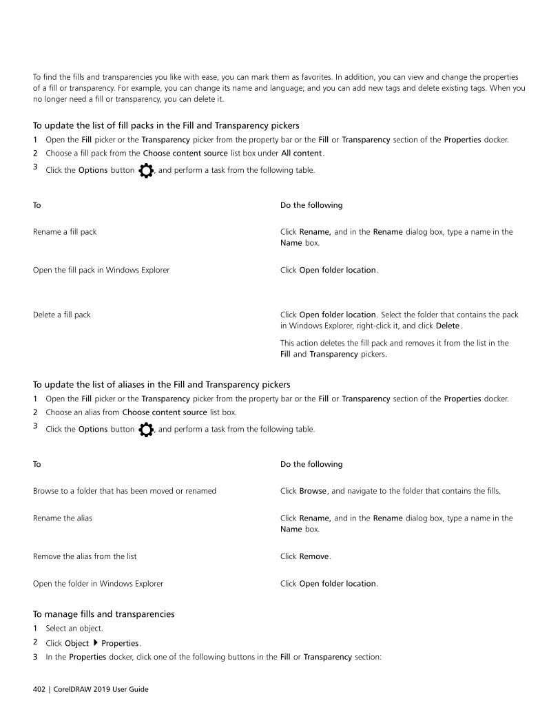
402 | CorelDRAW 2019 User Guide
To find the fills and transparencies you like with ease, you can mark them as favorites. In addition, you can view and change the propertiesof a fill or transparency. For example, you can change its name and language; and you can add new tags and delete existing tags. When youno longer need a fill or transparency, you can delete it.
To update the list of fill packs in the Fill and Transparency pickers
1 Open the Fill picker or the Transparency picker from the property bar or the Fill or Transparency section of the Properties docker.
2 Choose a fill pack from the Choose content source list box under All content.
3 Click the Options button , and perform a task from the following table.
To Do the following
Rename a fill pack Click Rename, and in the Rename dialog box, type a name in theName box.
Open the fill pack in Windows Explorer
Click Open folder location.
Delete a fill pack Click Open folder location. Select the folder that contains the packin Windows Explorer, right-click it, and click Delete.
This action deletes the fill pack and removes it from the list in theFill and Transparency pickers.
To update the list of aliases in the Fill and Transparency pickers
1 Open the Fill picker or the Transparency picker from the property bar or the Fill or Transparency section of the Properties docker.
2 Choose an alias from Choose content source list box.
3 Click the Options button , and perform a task from the following table.
To Do the following
Browse to a folder that has been moved or renamed Click Browse, and navigate to the folder that contains the fills.
Rename the alias Click Rename, and in the Rename dialog box, type a name in theName box.
Remove the alias from the list Click Remove.
Open the folder in Windows Explorer Click Open folder location.
To manage fills and transparencies
1 Select an object.
2 Click Object Properties.
3 In the Properties docker, click one of the following buttons in the Fill or Transparency section:
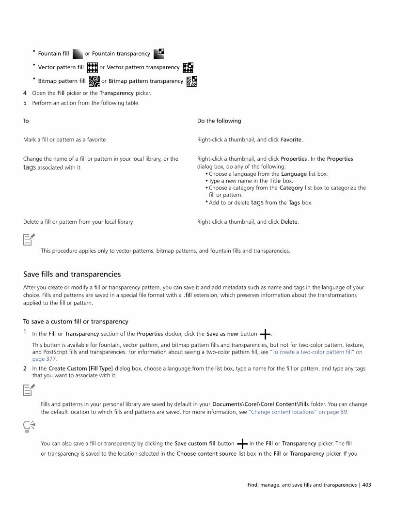
Find, manage, and save fills and transparencies | 403
• Fountain fill or Fountain transparency
• Vector pattern fill or Vector pattern transparency
• Bitmap pattern fill or Bitmap pattern transparency
4 Open the Fill picker or the Transparency picker.
5 Perform an action from the following table.
To Do the following
Mark a fill or pattern as a favorite Right-click a thumbnail, and click Favorite.
Change the name of a fill or pattern in your local library, or the
tags associated with it
Right-click a thumbnail, and click Properties. In the Propertiesdialog box, do any of the following:
•Choose a language from the Language list box.•Type a new name in the Title box.•Choose a category from the Category list box to categorize the
fill or pattern.•Add to or delete tags from the Tags box.
Delete a fill or pattern from your local library Right-click a thumbnail, and click Delete.
This procedure applies only to vector patterns, bitmap patterns, and fountain fills and transparencies.
Save fills and transparencies
After you create or modify a fill or transparency pattern, you can save it and add metadata such as name and tags in the language of yourchoice. Fills and patterns are saved in a special file format with a .fill extension, which preserves information about the transformationsapplied to the fill or pattern.
To save a custom fill or transparency
1 In the Fill or Transparency section of the Properties docker, click the Save as new button .
This button is available for fountain, vector pattern, and bitmap pattern fills and transparencies, but not for two-color pattern, texture,and PostScript fills and transparencies. For information about saving a two-color pattern fill, see “To create a two-color pattern fill” onpage 377.
2 In the Create Custom [Fill Type] dialog box, choose a language from the list box, type a name for the fill or pattern, and type any tagsthat you want to associate with it.
Fills and patterns in your personal library are saved by default in your Documents\Corel\Corel Content\Fills folder. You can changethe default location to which fills and patterns are saved. For more information, see “Change content locations” on page 89.
You can also save a fill or transparency by clicking the Save custom fill button in the Fill or Transparency picker. The fill
or transparency is saved to the location selected in the Choose content source list box in the Fill or Transparency picker. If you

404 | CorelDRAW 2019 User Guide
have selected Recent from the Choose content source list box, the fill or transparency is saved to your Documents\Corel\CorelContent\Fills folder.

Color management | 405
Color management
Color management helps ensure colors appear consistent when you work with files from various sources and output these files on differentdevices.
This section contains the following topics:• “About color management” (page 405)• “Get started with color management” (page 409)• “Install, load, and embed color profiles” (page 412)• “Assign color profiles” (page 413)• “Convert colors to other color profiles” (page 414)• “Color-conversion settings” (page 414)• “Soft proofing” (page 415)• “Color management presets” (page 418)• “Color management policies” (page 419)• “Manage colors when opening documents” (page 420)• “Manage colors when importing and pasting files” (page 421)• “Manage colors for print” (page 421)• “Use a safe CMYK workflow” (page 422)• “Manage colors for online viewing” (page 422)
About color management
This section provides answers to the following commonly asked questions about color management:• “Why don’t colors match?” (page 406)• “What is color management?” (page 406)• “Why do I need color management?” (page 406)• “How do I get started with color management?” (page 407)• “Is my monitor displaying the correct colors?” (page 407)• “Should I assign a color profile or convert colors to a color profile?” (page 407)• “What is a rendering intent?” (page 407)

406 | CorelDRAW 2019 User Guide
Why don’t colors match?
Different tools are used during the process of creating and sharing a document. For example, you may start with a file that was created inanother application or import an image that was captured by a digital camera or scanner. After completing the document, you may print itor email it to a colleague for review. Each of the tools that you use in your workflow has a different way of interpreting color. In addition,each tool has its own range of available colors, called a color space, which is a set of numbers that define how each color is represented.
Example of a document workflow
In other words, when defining and interpreting color, each tool speaks a unique language. Consider a color in the color space of your digitalcamera: a vivid blue RGB color with the values Red = 0, Green = 0, and Blue =255. This color may appear as a different color in the colorspace of your monitor. In addition, the color space of your printer may not contain a match for this color. As a result, when your documentmoves through the workflow, this vivid blue color gets lost in the translation and is not accurately reproduced. A color management systemis designed to improve the communication of color in the workflow so that the color of the output matches your intended color.
Colors are defined by their color space. 1. Lab color space. 2. sRGB color space, displayed againstthe Lab color space. 3. U.S. Web Coated (SWOP) v2 color space. 4. ProPhoto RGB color space.
What is color management?
Color management is a process that lets you predict and control color reproduction, regardless of the source or destination of thedocument. It ensures a more accurate color representation when a document is viewed, modified, shared, exported to another format, orprinted.
A color management system, also known as a color engine, uses color profiles to translate the color values from one source to another. Forexample, it translates the colors that are displayed on the monitor into the colors that a printer can reproduce. Color profiles define the colorspace of monitors, scanners, digital cameras, printers, and the applications that you use to create or edit documents.
Why do I need color management?
If your document requires accurate color representation, you may want to learn more about color management. The complexity of yourworkflow and the ultimate destination of your documents are also important considerations. If your documents are destined only for onlineviewing, color management may not be as important. However, if you plan to open documents in another application or if you are creatingdocuments for print or multiple types of output, then proper color management is essential.

Color management | 407
Color management lets you do the following:• reproduce colors consistently across your workflow, especially when opening documents that were created in other applications• reproduce colors consistently when sharing files with others• preview (or “soft-proof”) colors before they are sent to their final destination, such as a printing press, a desktop printer, or the web• reduce the need to adjust and correct documents when sending them to different destinations
A color management system does not offer identical color matching, but it greatly improves color accuracy.
How do I get started with color management?
Here are some suggestions for adding color management to your workflow:• Make sure that your monitor is displaying the correct colors. For more information, see “Is my monitor displaying the correct colors?” on
page 407.• Install color profiles for any input or output devices that you are planning to use. For more information, see “Install, load, and embed
color profiles” on page 412.• Become familiar with the color management features of CorelDRAW. The default settings for color management produce good color
results, but you can change these default settings so that they suit your specific workflow. For more information, see “Get started withcolor management” on page 409.
• Soft-proof documents to preview final results on-screen. For more information, see “Soft proofing” on page 415.• Embed color profiles when saving and exporting files. In this way, you help ensure color consistency when the files are viewed, modified,
or reproduced. For more information, see “Install, load, and embed color profiles” on page 412.
Is my monitor displaying the correct colors?
Calibrating and profiling the monitor are essential steps for ensuring color accuracy. When you calibrate a monitor, you set it to displaycolors according to an established standard of accuracy. After calibration, you can create a color profile of the monitor, which describeshow the monitor interprets colors. This custom color profile is usually installed in your operating system by the profiling software, so it canbe shared with other devices and applications. Calibration and profiling work together to achieve color accuracy: If a monitor is incorrectlycalibrated, its color profile is not useful.
Calibration and profiling are complex and usually require third-party calibration devices, such as colorimeters and specialized software.Furthermore, improper calibration may do more harm than good. You can learn more about monitor calibration and custom color profilesby researching color management techniques and products. You can also refer to the documentation that was provided with your operatingsystem or monitor.
How you perceive the color that your monitor displays is also important for managing color consistency. Your perception is influenced by theenvironment in which you are viewing the documents. Here are some ways to create a suitable viewing environment:• Ensure that your room has a consistent flow of light. For example, if the room is filled with sunlight, use a shade, or if possible, work in a
room without windows.• Set the monitor background to a neutral color, such as gray, or apply a grayscale image. Avoid using colorful wallpapers and
screensavers.• Don’t wear bright clothing that can clash with the display of colors on the monitor. For example, wearing a white shirt reflects onto the
monitor and alters your perception of color.
Should I assign a color profile or convert colors to a color profile?
When you assign a color profile, the color values, or numbers, in the document do not change. Instead, the application uses the color profileto interpret the document colors. However, when you convert colors to another color profile, the color values in the document change.
The best practice is to choose a suitable color space when you create a document and to use the same color profile throughout yourworkflow. You should avoid assigning color profiles and converting colors to other color profiles while working on a document. For moreinformation, see “Assign color profiles ” on page 413 and “Convert colors to other color profiles” on page 414.
What is a rendering intent?
A color management system can perform effective translation of document colors to multiple devices. However, when converting colorsfrom one color space to another, a color management system may be unable to match certain colors. This translation failure occursbecause some colors in the source may not fit within the range (or gamut) of the destination color space. For example, the bright red
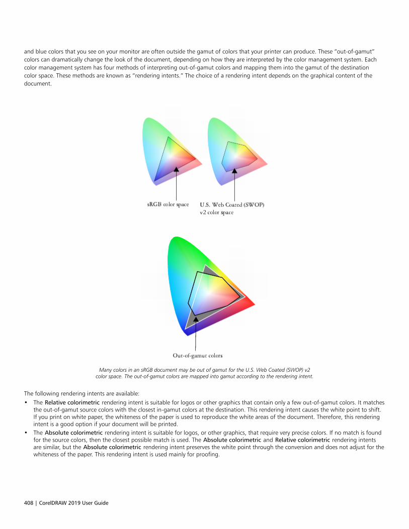
408 | CorelDRAW 2019 User Guide
and blue colors that you see on your monitor are often outside the gamut of colors that your printer can produce. These “out-of-gamut”colors can dramatically change the look of the document, depending on how they are interpreted by the color management system. Eachcolor management system has four methods of interpreting out-of-gamut colors and mapping them into the gamut of the destinationcolor space. These methods are known as “rendering intents.” The choice of a rendering intent depends on the graphical content of thedocument.
Many colors in an sRGB document may be out of gamut for the U.S. Web Coated (SWOP) v2color space. The out-of-gamut colors are mapped into gamut according to the rendering intent.
The following rendering intents are available:• The Relative colorimetric rendering intent is suitable for logos or other graphics that contain only a few out-of-gamut colors. It matches
the out-of-gamut source colors with the closest in-gamut colors at the destination. This rendering intent causes the white point to shift.If you print on white paper, the whiteness of the paper is used to reproduce the white areas of the document. Therefore, this renderingintent is a good option if your document will be printed.
• The Absolute colorimetric rendering intent is suitable for logos, or other graphics, that require very precise colors. If no match is foundfor the source colors, then the closest possible match is used. The Absolute colorimetric and Relative colorimetric rendering intentsare similar, but the Absolute colorimetric rendering intent preserves the white point through the conversion and does not adjust for thewhiteness of the paper. This rendering intent is used mainly for proofing.

Color management | 409
• The Perceptual rendering intent is suitable for photographs and bitmaps that contain many out-of-gamut colors. The overall colorappearance is preserved by changing all the colors, including the in-gamut colors, to fit within the range of colors at the destination. Thisrendering intent maintains the relationships between colors to produce the best results.
• The Saturation rendering intent produces more concentrated solid colors in business graphics, such as charts and graphs. Colors may beless accurate than those produced by other rendering intents.
The number of out-of-gamut colors (indicated by the green overlay) may influence your choice of a rendering intent.Left: The Relative colorimetric rendering intent is suitable for this photo, which contains only a few out-of-gamut colors.
Right: The Perceptual rendering intent is a good choice for this photo, which contains many out-of-gamut colors.
Get started with color management
CorelDRAW has two types of color management settings: default settings for color management and document color settings. The defaultsettings for color management control the colors of new documents and any documents that do not contain color profiles (also known as“untagged documents”). Documents that were created in earlier versions of CorelDRAW are treated as untagged. Document color settingsaffect only the colors of the active document.
Default settings for color management
The default settings for color management are essential for producing consistent colors.• Preset — If you are new to color management and create designs for a specific output, you can choose a preset to help you get started
with the right color management settings such as default color profiles and color-conversion settings. Examples are the North AmericaPrepress preset, which is suitable for projects to be printed by North American print service providers, and the Europe Web preset,which is suitable for web projects that are created in Europe. For more information about color management presets, see “Colormanagement presets” on page 418.
• Default color profiles — define the RGB, CMYK, and grayscale colors in new and untagged documents. You can change these settingsso that all new documents use the color profiles that you specify. In some applications, default color profiles are called “working spaceprofiles.”
• Primary color mode — determines the document color palette that is displayed when you open or start a document as well as thedefault color mode of a document that is exported as a bitmap. The primary color mode is set for all new and untagged documents, butyou can change this setting for the active document on the Document tab of the Color management settings dialog box. Note that theprimary color mode does not limit colors in a CorelDRAW document to a single color mode.
• Rendering intent — lets you choose a method for mapping out-of-gamut colors in new and untagged documents. If the defaultrendering intent is not suitable for the active document, you can change it on the Document tab of the Color Management settingsdialog box. For information about choosing the right rendering intent for your projects, see “What is a rendering intent?” on page407.
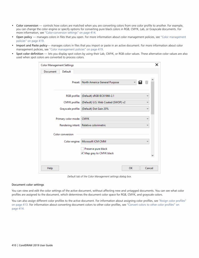
410 | CorelDRAW 2019 User Guide
• Color conversion — controls how colors are matched when you are converting colors from one color profile to another. For example,you can change the color engine or specify options for converting pure black colors in RGB, CMYK, Lab, or Grayscale documents. Formore information, see “Color-conversion settings” on page 414.
• Open policy — manages colors in files that you open. For more information about color management policies, see “Color managementpolicies” on page 419.
• Import and Paste policy— manages colors in files that you import or paste in an active document. For more information about colormanagement policies, see “Color management policies” on page 419.
• Spot color definition — lets you display spot colors by using their Lab, CMYK, or RGB color values. These alternative color values are alsoused when spot colors are converted to process colors.
Default tab of the Color Management settings dialog box.
Document color settings
You can view and edit the color settings of the active document, without affecting new and untagged documents. You can see what colorprofiles are assigned to the document, which determines the document color space for RGB, CMYK, and grayscale colors.
You can also assign different color profiles to the active document. For information about assigning color profiles, see “Assign color profiles”on page 413. For information about converting document colors to other color profiles, see “Convert colors to other color profiles” onpage 414.

Color management | 411
Document tab of the Color Management settings dialog box.
In addition, you can change the primary color mode and rendering intent for the active document.
To access default settings for color management
1 Click Tools Color Management.
2 Click the Default tab.
To change the default color profiles
1 Click Tools Color Management.
2 Click the Default tab.
3 Choose a color profile from the following list boxes:
• RGB profile — describes RGB colors in new and untagged documents
• CMYK profile — describes CMYK colors in new and untagged documents
• Grayscale profile — describes grayscale colors in new and untagged documents
You can also
Change the primary color mode Choose a color mode from the Primary color mode list box.

412 | CorelDRAW 2019 User Guide
You can also
Changing the primary color mode on the Default tab of the Colormanagement settings dialog box does not affect the activedocument.
Change the rendering intent Choose a rendering intent from the Rendering intent list box.
To access document color settings
1 Click Tools Color Management.
2 Click the Document tab.
To display the color profiles that are used in the active document on the status bar, click the flyout button on the status bar, and
choose Document Color Settings.
Install, load, and embed color profiles
To ensure color accuracy, a color management system needs ICC-compliant profiles for monitors, input devices, external monitors, outputdevices, and documents.• Monitor color profiles — define the color space that is used by your monitor to display document colors. CorelDRAW uses the primary
monitor profile that is assigned by the operating system. The monitor profile is very important for color accuracy. For more information,see “Is my monitor displaying the correct colors?” on page 407.
• Input device color profiles — used by input devices such as scanners and digital cameras. These color profiles define which colors can becaptured by specific input devices.
• Display color profiles — include monitor profiles that are not associated with your monitor in the operating system. These color profilesare especially useful for soft-proofing documents for monitors that are not connected to your computer.
• Output device color profiles — define the color space of output devices such as desktop printers and printing presses. The colormanagement system uses these profiles to map accurately document colors to the colors of the output device.
• Document color profiles — define the RGB, CMYK, and grayscale colors of a document. Documents that contain color profiles are knownas “tagged.”
Finding color profiles
Many color profiles are installed with your application or can be generated with profiling software. Manufacturers of monitors, scanners,digital cameras, and printers also provide color profiles. In addition, you can access color profiles from websites such as:• http://www.color.org/findprofile.xalter — This website of the International Color Consortium (ICC) can help you find commonly used
standard color profiles.• http://www.eci.org/doku.php?id=en:downloads — This website of the European Color Initiative (ECI) provides standard ISO profiles as
well as profiles that are specific to Europe• http://www.tftcentral.co.uk/articles/icc_profiles.htm — This website provides ICC profiles for many different types of LCD (Liquid Crystal
Display) monitors to help you display consistent colors. However, if color accuracy is essential for your workflow, you should calibrateand profile your monitor instead of relying on readily available monitor profiles. For more information, see “Is my monitor displaying thecorrect colors?” on page 407.
Installing and loading color profiles
If you don’t have the necessary color profile, you can install it, or you can load it within the application. Installing a color profile adds it tothe Color folder of the operating system; loading a color profile adds it to the Color folder of the application. CorelDRAW Graphics Suite canaccess color profiles from both Color folders.
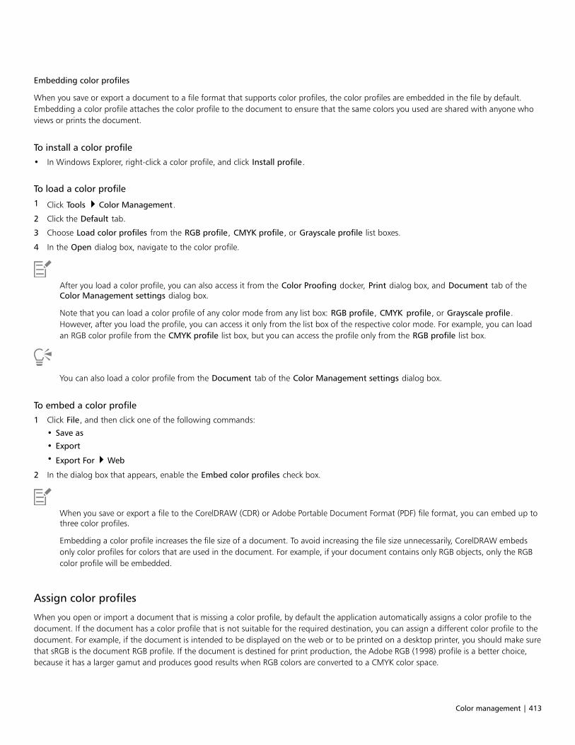
Color management | 413
Embedding color profiles
When you save or export a document to a file format that supports color profiles, the color profiles are embedded in the file by default.Embedding a color profile attaches the color profile to the document to ensure that the same colors you used are shared with anyone whoviews or prints the document.
To install a color profile
• In Windows Explorer, right-click a color profile, and click Install profile.
To load a color profile
1 Click Tools Color Management.
2 Click the Default tab.
3 Choose Load color profiles from the RGB profile, CMYK profile, or Grayscale profile list boxes.
4 In the Open dialog box, navigate to the color profile.
After you load a color profile, you can also access it from the Color Proofing docker, Print dialog box, and Document tab of theColor Management settings dialog box.
Note that you can load a color profile of any color mode from any list box: RGB profile, CMYK profile, or Grayscale profile.However, after you load the profile, you can access it only from the list box of the respective color mode. For example, you can loadan RGB color profile from the CMYK profile list box, but you can access the profile only from the RGB profile list box.
You can also load a color profile from the Document tab of the Color Management settings dialog box.
To embed a color profile
1 Click File, and then click one of the following commands:
• Save as
• Export
• Export For Web
2 In the dialog box that appears, enable the Embed color profiles check box.
When you save or export a file to the CorelDRAW (CDR) or Adobe Portable Document Format (PDF) file format, you can embed up tothree color profiles.
Embedding a color profile increases the file size of a document. To avoid increasing the file size unnecessarily, CorelDRAW embedsonly color profiles for colors that are used in the document. For example, if your document contains only RGB objects, only the RGBcolor profile will be embedded.
Assign color profiles
When you open or import a document that is missing a color profile, by default the application automatically assigns a color profile to thedocument. If the document has a color profile that is not suitable for the required destination, you can assign a different color profile to thedocument. For example, if the document is intended to be displayed on the web or to be printed on a desktop printer, you should make surethat sRGB is the document RGB profile. If the document is destined for print production, the Adobe RGB (1998) profile is a better choice,because it has a larger gamut and produces good results when RGB colors are converted to a CMYK color space.

414 | CorelDRAW 2019 User Guide
When you assign a different color profile to a document, the colors may appear different, although the color values do not change.
Left: The SWOP 2006_Coated3v2.icc color profile is assigned to the active document. Right: When the JapanColor 2002 Newspaper color profile is assigned to the document, the colors appear much less saturated.
To assign color profiles to a document
1 Click Tools Color Management.
2 Click the Document tab.
3 Enable the Assign new (preserves color appearance) option.
4 Choose color profiles from the RGB, CMYK, and Grayscale list boxes.
Convert colors to other color profiles
When you convert document colors from one color profile to another, the color values in the document are changed according to therendering intent, but the appearance of colors is preserved. The main purpose of converting colors is to match the appearance of colors inthe source color space as closely as possible to colors in the destination color space.
Because multiple color conversions deteriorate accuracy, it is recommended that you convert colors only once. Wait until the document isready and you are sure of the color profile that will be used for the final output. For example, if you designed a document in the Adobe RGB(1998) color space, and the document will be posted on the web, you can convert document colors to the sRGB color space.
You can choose the color management engine that is used for converting colors. For more information, see “Color-conversion settings” onpage 414.
To convert colors to other color profiles
1 Click Tools Color Management.
2 Click the Document tab.
3 Enable the Convert (preserve color values) option.
4 Choose a color profile from the RGB, CMYK, and Grayscale list box.
5 Choose a suitable rendering intent from the Rendering intent list box. For information about the available rendering intents, see “Whatis a rendering intent?” on page 407.
Color-conversion settings
When you choose color profiles, colors are matched between devices as closely as possible by the color management module (CMM) of theMicrosoft Image Color Management (ICM), which is the default CMM. Color management modules are also known as “color engines.”
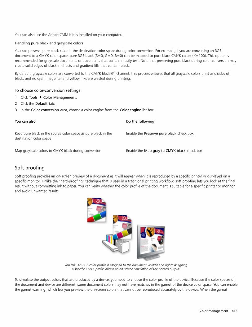
Color management | 415
You can also use the Adobe CMM if it is installed on your computer.
Handling pure black and grayscale colors
You can preserve pure black color in the destination color space during color conversion. For example, if you are converting an RGBdocument to a CMYK color space, pure RGB black (R=0, G=0, B=0) can be mapped to pure black CMYK colors (K=100). This option isrecommended for grayscale documents or documents that contain mostly text. Note that preserving pure black during color conversion maycreate solid edges of black in effects and gradient fills that contain black.
By default, grayscale colors are converted to the CMYK black (K) channel. This process ensures that all grayscale colors print as shades ofblack, and no cyan, magenta, and yellow inks are wasted during printing.
To choose color-conversion settings
1 Click Tools Color Management.
2 Click the Default tab.
3 In the Color conversion area, choose a color engine from the Color engine list box.
You can also Do the following
Keep pure black in the source color space as pure black in thedestination color space
Enable the Preserve pure black check box.
Map grayscale colors to CMYK black during conversion Enable the Map gray to CMYK black check box.
Soft proofing
Soft proofing provides an on-screen preview of a document as it will appear when it is reproduced by a specific printer or displayed on aspecific monitor. Unlike the “hard-proofing” technique that is used in a traditional printing workflow, soft proofing lets you look at the finalresult without committing ink to paper. You can verify whether the color profile of the document is suitable for a specific printer or monitorand avoid unwanted results.
Top left: An RGB color profile is assigned to the document. Middle and right: Assigninga specific CMYK profile allows an on-screen simulation of the printed output.
To simulate the output colors that are produced by a device, you need to choose the color profile of the device. Because the color spaces ofthe document and device are different, some document colors may not have matches in the gamut of the device color space. You can enablethe gamut warning, which lets you preview the on-screen colors that cannot be reproduced accurately by the device. When the gamut
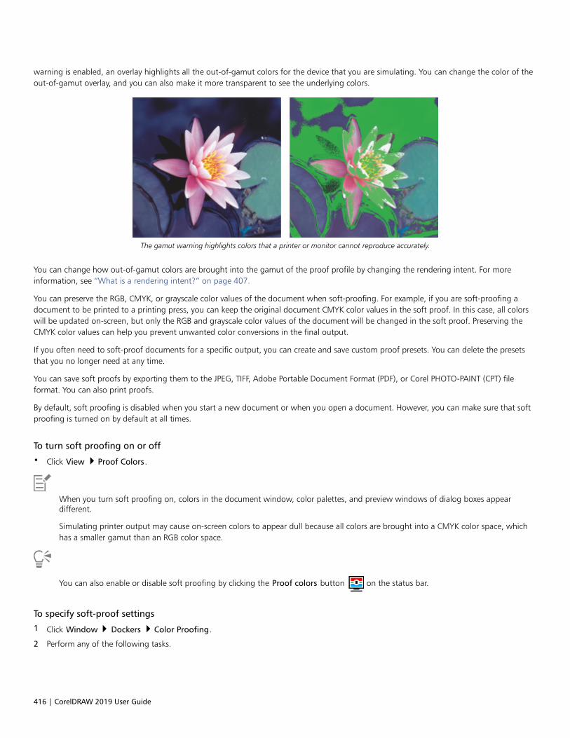
416 | CorelDRAW 2019 User Guide
warning is enabled, an overlay highlights all the out-of-gamut colors for the device that you are simulating. You can change the color of theout-of-gamut overlay, and you can also make it more transparent to see the underlying colors.
The gamut warning highlights colors that a printer or monitor cannot reproduce accurately.
You can change how out-of-gamut colors are brought into the gamut of the proof profile by changing the rendering intent. For moreinformation, see “What is a rendering intent?” on page 407.
You can preserve the RGB, CMYK, or grayscale color values of the document when soft-proofing. For example, if you are soft-proofing adocument to be printed to a printing press, you can keep the original document CMYK color values in the soft proof. In this case, all colorswill be updated on-screen, but only the RGB and grayscale color values of the document will be changed in the soft proof. Preserving theCMYK color values can help you prevent unwanted color conversions in the final output.
If you often need to soft-proof documents for a specific output, you can create and save custom proof presets. You can delete the presetsthat you no longer need at any time.
You can save soft proofs by exporting them to the JPEG, TIFF, Adobe Portable Document Format (PDF), or Corel PHOTO-PAINT (CPT) fileformat. You can also print proofs.
By default, soft proofing is disabled when you start a new document or when you open a document. However, you can make sure that softproofing is turned on by default at all times.
To turn soft proofing on or off
• Click View Proof Colors.
When you turn soft proofing on, colors in the document window, color palettes, and preview windows of dialog boxes appeardifferent.
Simulating printer output may cause on-screen colors to appear dull because all colors are brought into a CMYK color space, whichhas a smaller gamut than an RGB color space.
You can also enable or disable soft proofing by clicking the Proof colors button on the status bar.
To specify soft-proof settings
1 Click Window Dockers Color Proofing.
2 Perform any of the following tasks.
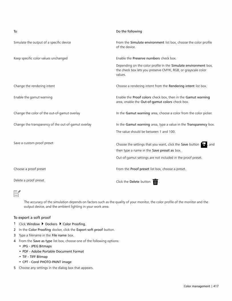
Color management | 417
To Do the following
Simulate the output of a specific device From the Simulate environment list box, choose the color profileof the device.
Keep specific color values unchanged Enable the Preserve numbers check box.
Depending on the color profile in the Simulate environment box,the check box lets you preserve CMYK, RGB, or grayscale colorvalues.
Change the rendering intent Choose a rendering intent from the Rendering intent list box.
Enable the gamut warning Enable the Proof colors check box, then in the Gamut warningarea, enable the Out-of-gamut colors check box.
Change the color of the out-of-gamut overlay In the Gamut warning area, choose a color from the color picker.
Change the transparency of the out-of-gamut overlay In the Gamut warning area, type a value in the Transparency box.
The value should be between 1 and 100.
Save a custom proof preset Choose the settings that you want, click the Save button , and
then type a name in the Save preset as box.
Out-of-gamut settings are not included in the proof preset.
Choose a proof preset From the Proof preset list box, choose a preset.
Delete a proof preset Click the Delete button .
The accuracy of the simulation depends on factors such as the quality of your monitor, the color profile of the monitor and theoutput device, and the ambient lighting in your work area.
To export a soft proof
1 Click Window Dockers Color Proofing.
2 In the Color Proofing docker, click the Export soft proof button.
3 Type a filename in the File name box.
4 From the Save as type list box, choose one of the following options:
• JPG - JPEG Bitmaps
• PDF - Adobe Portable Document Format
• TIF - TIFF Bitmap
• CPT - Corel PHOTO-PAINT image
5 Choose any settings in the dialog box that appears.
418 | CorelDRAW 2019 User Guide
To print a proof
1 Click Window Dockers Color Proofing.
2 In the Color Proofing docker, click the Print proof button.
To turn soft proofing on by default
1 Click Tools Options CorelDRAW.
2 In the list of categories, click Display.
3 Enable the Proof colors check box.
Color management presets
The application provides color management presets, which are default color settings that are applied to new and untagged documents. Youcan choose a color management preset that is suitable for the geographic region where a document is created or for the location of its finaloutput.
You can also create your own presets, which allows you to retain your selections on the Default tab of the Color management settingsdialog box and reuse them in other documents. If you no longer need a preset, you can delete it.
To choose a color management preset for new documents
1 Click Tools Color Management.
2 Click the Default tab.
3 Choose one of the following color management presets from the Preset list box:
• North America General Purpose — suitable for designs that will be used in multiple types of output in North America
• Europe General Purpose — suitable for designs that will be used in multiple types of output in Europe
• Europe Prepress — suitable for designs that will be printed by print service providers in Europe
• Europe Web — suitable for web designs that are created in Europe
• Japan General Purpose — suitable for designs that will be used in multiple types of output in Japan
• Japan Prepress — suitable for designs that will be printed by print service providers in Japan
• Japan Web — suitable for web designs that are created in Japan
• Minimal Color Management — preserves the original RGB, CMYK, and Grayscale color values when opening, importing, or pastingdocuments
• North America Prepress — suitable for designs that will be printed by print service providers in North America
• North America Web — suitable for web designs that are created in North America
• Simulate Color Management Off — produces the color-conversion results of the Color Management Off preset that is available inearlier versions of CorelDRAW
• Simulate CorelDRAW Graphics Suite X4 — displays colors as they appear in CorelDRAW Graphics Suite X4
To add a color management preset
1 Click Tools Color Management.
2 Click the Default tab.
3 Change any default color settings.
4 Click the Save button next to the Preset list box.
5 In the Save color management style dialog box, type a name in the Save style as box.
Color management | 419
To delete a color management preset
1 Click Tools Color Management.
2 Click the Default tab.
3 Choose a preset from the Preset list box.
4 Click the Delete button .
Color management policies
Color management policies determine how colors are managed in documents that you open and work with in an application. InCorelDRAW, you can set one color-management policy for opening documents and another for importing and pasting files and objects inthe active document.
The color management policy for opening files determines what RGB, CMYK, and Grayscale color profiles are used in each file you want toopen. By default, the application uses the color profiles embedded in the file. You can also choose to assign the default color profiles to thefile or convert colors in the file to the default color profiles.
By default, the color management policy for importing and pasting files converts the RGB and Grayscale colors of the files to the documentcolor profiles, and assigns the document CMYK color profile to files in the CMYK mode. You can also choose to assign the document colorprofiles to the file, or convert the colors of the active document to the color profiles that are embedded in the file.
The files that you are opening or importing may be missing color profiles, or may contain color profiles that do not match the default colorprofiles. By default, the application does not warn you about missing or mismatched color profiles but makes color management choicesthat produce good results. However, you can activate warning messages if you want to have full control over the colors in your documents.
To set a color management policy for opening documents
1 Click Tools Color Management.
2 Click the Default tab.
3 In the Open policy area, choose one of the following options from the RGB list box:
• Use embedded color profile — preserves the RGB color profile that is embedded in the file. This option is recommended, because itpreserves the original RGB color appearance and RGB color values of the document.
• Assign default color profile — uses the default RGB color profile to define document colors. RGB color values are preserved, but theappearance of RGB colors may change.
• Convert to default color profile — converts colors to the default RGB color profile. The appearance of RGB colors in documents ispreserved, but the color values may change.
4 From the CMYK list box in the Open policy area, choose an option for managing CMYK colors in documents. The options are the sameas the options that are available for RGB colors.
5 From the Grayscale list box in the Open policy area, choose an option for managing the grayscale colors in documents. The options arethe same as the options that are available for RGB colors.
To set a color management policy for importing and pasting files
1 Click Tools Color Management.
2 Click the Default tab.
3 In the Import and Paste policy area, choose one of the following options from the RGB list box:
• Convert to document color profile — converts the RGB colors of the imported or pasted file to the RGB color profile of the activedocument. This option is used when the imported file contains a color profile that does not match the color profile of the document.
• Assign document color profile — assigns the RGB color profile of the document to the imported or pasted file. The RGB color valuesof the file are preserved but the color appearance may change.

420 | CorelDRAW 2019 User Guide
• Use embedded color profile — uses the RGB color profile that is embedded in the file, preserving the RGB color values andappearance of the imported or pasted file. This option converts document colors to the color profile that is embedded in the importedor pasted file.
4 From the CMYK list box in the Import and Paste policy area, choose an option for managing CMYK colors in imported and pasted files.The options are the same as the options that are available for RGB colors.
5 From the Grayscale list box in the Import and Paste policy area, choose an option for managing the grayscale colors in imported andpasted files. The options are the same as the options that are available for RGB colors.
To activate warning messages for missing and mismatched color profiles
1 Click Tools Color Management.
2 Click the Default tab.
3 Enable any of the following check boxes in the Open policy and Import and paste policy areas:
• Warn on color profile mismatch
• Warn on missing color profile
Manage colors when opening documents
The default color management policy for opening documents preserves colors in all tagged documents that you open and assigns thedefault color profiles to untagged documents.
If a document that you open is missing a color profile or contains color profiles that do not match the default color profiles of theapplication, CorelDRAW makes color-management choices based on the color management policy. If you are comfortable with colormanagement, you can view warnings about missing and mismatched color profiles and choose different color management options. Formore information about how to activate warnings, see “To activate warning messages for missing and mismatched color profiles” on page420.
Opening documents with missing color profiles
The document you are opening may support one or multiple color modes and therefore be missing one or more color profiles. For example,a CorelDRAW (CDR) or PDF document may contain three types of objects: RGB, CMYK, and Grayscale, so up to three color profiles may bemissing from such a document.
The following options are available when you are opening a document with a missing color profile and have activated warnings for missingcolor profiles.• Assign color profile — lets you assign a color profile to the document. This option preserves color values, but may change the
appearance of colors. For example, if the RGB color profile is missing from the document, the default RGB color profile of the applicationis assigned by default. The RGB color values are preserved but the RGB colors may not appear as originally designed. You can also chooseto assign a color profile that is different from the default color profile of the application. This option is recommended only if you knowthe original color space of the document and have the associated color profile installed.
• Convert to default color profile — Used in conjunction with the Assign color profile control, this option converts colors from theassigned color profile to the default color profile. Colors will appear as they would in the assigned color space, but the color values maychange.
Opening documents with mismatched color profiles
When a document contains a color profile that does not match the default color profile, you can choose one of the following options:• Use embedded color profile — This option ensures that the color values are preserved and colors are displayed as originally intended.• Ignore embedded color profile, and use default color profile — Assigning the default color profile will preserve the color values but
may change the appearance of colors.• Convert from embedded color profile to default color profile — This option converts colors from the embedded color profile to the
default color profile. The appearance of colors will be preserved, but the color values may change. This option is recommended if youhave already set color management options suitable for your workflow. For example, you may be creating graphics for the web, and youmay have chosen sRGB as the application default color space. Enabling this option ensures that the document uses the sRGB color space,and document colors are consistent and suitable for the web.

Color management | 421
Opening documents with missing and mismatched color profiles
Documents that support multiple color modes can be missing color profiles and contain mismatched color profiles at the same time. Forexample, a document that contains RGB, Grayscale, and CMYK objects may be missing an RGB profile and may have a mismatched CMYKcolor profile. In such cases, you are presented with warning dialog boxes that include options for missing and mismatched color profiles.
Manage colors when importing and pasting files
The default color policy for importing and pasting files converts the colors of imported and pasted files to the color profile of the activedocument. If the color profile of the imported or pasted file matches the color profile of the active document, no color conversion isperformed. For more information about color management policies, see “Color management policies” on page 419.
However, you can choose to view warnings about missing and mismatched profiles and set other color management options. For moreinformation about how to view warnings, see “To activate warning messages for missing and mismatched color profiles” on page 420.
Importing and pasting files with missing color profiles
If color profiles are missing from a file, you can choose to assign specific color profiles to the file, and then convert its colors to thedocument color profiles. The color values of the file will change.
Importing and pasting files with mismatched color profiles
If a file contains color profiles that do not match the document color profile, the following options are available:• Ignore embedded color profile, and assign the document color profile — Color values are preserved, but the appearance of colors
may change.• Convert from embedded color profile to the document color profile (default option) — The color of the imported file are converted
from the embedded color space to the document color space. The appearance of colors is preserved, but the color values may change.• Convert document colors to embedded color profile — Document colors are converted to the color profile embedded in the imported
file. The appearance and color values of the imported or pasted file are preserved.
Importing and pasting files with missing and mismatched color profiles
Some files can be missing color profiles and contain mismatched color profiles at the same time. In such cases, you are presented withdialog boxes that include options for missing and mismatched color profiles.
Manage colors for print
By default, CorelDRAW does not perform color conversions when a document is sent to the printer. The printer receives the color values andinterprets the colors. However, if there is a color profile associated with the printer in the operating system, CorelDRAW detects the colorprofile and uses it to convert document colors to the color space of the printer.
If you have a PostScript printer, you can let CorelDRAW or the PostScript printer perform any necessary color conversion. When CorelDRAWmanages the color conversion, document colors are converted from the assigned color space to the color space of the PostScript printer.Note that you must disable color management in the printer driver. Otherwise, both application and printer manage colors during printing,and document colors are corrected twice, which causes unwanted color shifts.
When the PostScript printer converts document colors, the color management feature must be enabled in the printer driver. Only PostScriptprinters and RIP engines that support printer color conversions can be used in this advanced method. Although it increases the file size, thismethod has the advantage of ensuring consistent colors when you send the same print job to different print service providers.
For more information about reproducing colors for print, see “Print colors accurately” on page 732.
You can also manage colors in PDF files that you create for commercial printing. For more information, see “PDF color management options”on page 788.

422 | CorelDRAW 2019 User Guide
Use a safe CMYK workflow
Often, you may use specific CMYK color values in your projects. To ensure reliable color reproduction, you may obtain these CMYK colorvalues from a color swatch book. By preserving these CMYK color values throughout the printing process, you can help prevent unwantedcolor conversions and ensure that colors are reproduced as they appeared in the original design. A workflow that preserves the CMYK colorvalues is known as a “safe” CMYK workflow.
CorelDRAW supports a safe CMYK workflow. By default, CMYK color values are preserved in any document that you open, import, or paste.Also, CMYK color values are preserved by default when you print documents.
In some cases, you may want to bypass the safe CMYK workflow and preserve the appearance of CMYK colors when you open, import, orpaste documents. This option is useful when you want to see the original colors of a design on-screen, or view a copy that is printed to adesktop printer. To preserve the appearance of CMYK colors, you can set color management policies that convert CMYK colors in documentsthat you open, import, or paste. In addition, when printing to a PostScript printer, you can convert CMYK colors to the printer color profileby disabling the Preserve CMYK numbers check box on the Color page of the Print dialog box.
Manage colors for online viewing
Managing colors for online viewing can be even more complex than managing colors for print. Documents and images on the web aredisplayed on a great variety of monitors, which are often uncalibrated. In addition, most web browsers do not support color managementand ignore the color profiles that are embedded in files.
When you design documents for exclusive web use, it is recommended that you use the sRGB color profile as your document RGB colorprofile and choose RGB colors. If a document contains a different color profile, you should convert document colors to sRGB before savingthe document for use on the web.
When you create a PDF file for online viewing, you can embed color profiles in the file to reproduce colors consistently in Adobe Reader andAdobe Acrobat. For more information, see “To specify color management options for exporting PDF files” on page 788.
When you start a new document that is destined for online viewing, you can choose a preset that can help you achieve good color results.For more information, see “To start a drawing” on page 45. In addition, CorelDRAW offers color management presets for web documents.For information about how to choose a color management preset, see “To choose a color management preset for new documents” on page418.

Special effects | 423
Special effects
Lenses..................................................................................................................................................................................................425
Add 3D effects.................................................................................................................................................................................... 429
Mosaics................................................................................................................................................................................................453
Add movement and focus................................................................................................................................................................... 461

424 | CorelDRAW 2019 User Guide

Lenses | 425
Lenses
Lenses contain creative effects that let you change the appearance of an object without actually changing the object.
This section contains the following topics:• “Apply lenses” (page 425)• “Edit lenses” (page 427)
Apply lenses
Lenses change how the object area beneath the lens appears, not the actual properties and attributes of the objects. You can apply lensesto any vector object, such as a rectangle, ellipse, closed path, or polygon. You can also change the appearance of artistic text and bitmaps.When you apply a lens over a vector object, the lens itself becomes a vector image. Likewise, if the lens is placed over a bitmap, the lens alsobecomes a bitmap.
After you apply a lens, you can copy it and use it with another object.
The lens types applied to the original (far left): (left to right) Heat map, Magnify, and Custom color map
The following are the types of lenses that you can apply to objects.

426 | CorelDRAW 2019 User Guide
Lens Description
Brighten Lets you brighten and darken object areas and set the rate of thebrightness and darkness
Color add Lets you simulate an additive light model. The colors of the objectsbeneath the lens are added to the color of the lens as if you weremixing colors of light. You can choose the color and the amount ofcolor you want to add.
Color limit Lets you view an object area with only black and the lens colorshowing through. For example, if you place a green color limit lensover a bitmap, all colors except green and black are filtered out inthe lens area.
Custom color map Lets you change all the colors of the object area beneath the lensto a color ranging between two colors you specify. You can choosethe range’s start and end colors and the progression between thetwo colors. The progression can follow a direct, forward, or reverseroute through the color spectrum.
Fish eye Lets you distort, magnify, or shrink the objects beneath the lens,according to the percentage value you specify
Heat map Lets you create the effect of an infrared image by mimicking theheat levels of colors in object areas beneath the lens
Invert Lets you change the colors beneath the lens to theircomplementary CMYK colors. Complementary colors are colors thatare opposite each other on the color wheel.
Magnify Lets you magnify an area on an object by an amount that youspecify. The magnify lens overrides the original object’s fill, makingthe object look transparent.
Tinted grayscale Lets you change the colors of object areas beneath the lens totheir grayscale equivalents. Tinted grayscale lenses are particularlyeffective for creating sepia-tone effects.
Transparency Lets you make an object look like a piece of tinted film or coloredglass
Wireframe Lets you display the object area beneath the lens with the outline orfill color of your choice. For example, if you set red for the outlineand blue for the fill, all areas beneath the lens appear to have redoutlines and blue fills.

Lenses | 427
To apply a lens
1 Select an object.
2 Click Effects Lens.
3 Choose a lens type from the list box in the Lens docker.
4 Specify the settings you want.
You cannot apply the lens effect directly to linked groups such as contoured objects, beveled objects, extruded objects, drop
shadows, paragraph text, or objects created with the Artistic media tool .
To copy a lens
1 Select the object to which you want to copy the lens.
2 Click Effects Copy effect Lens from.
3 Click the object from which you want to copy the lens.
Edit lenses
You can edit a lens to change how it affects the area beneath it. For example, you can change the viewpoint of a lens, indicated by an X inthe drawing window, to display any part of a drawing. The viewpoint represents the center point of what is being viewed through the lens.You can position the lens anywhere in the drawing window, but it always shows the area around its viewpoint marker. For example, you canuse the viewpoint marker on the Magnify lens to enlarge part of a map.
You can also display a lens only where it overlaps other objects or the background. As a result, the lens effect is not seen where the lenscovers blank space (white space) in the drawing window.
Freezing the current view of a lens lets you move the lens without changing what’s displayed through it. In addition, changes you make tothe areas beneath the lens have no effect on the view.
To edit a lens
1 Select an object.
2 Click Effects Lens.
3 Enable the Viewpoint check box in the Lens docker.
If you want to display a lens only where it covers other objects, enable the Remove face check box.
4 Drag the viewpoint marker in the drawing window to a new location.
5 Click End.
If you want to freeze the current view of a lens, enable the Frozen check box.
The Remove face check box is not available for the Fish Eye and Magnify lenses.

428 | CorelDRAW 2019 User Guide

Add 3D effects | 429
Add 3D effects
You can create the illusion of three-dimensional (3D) depth in objects by adding contour, perspective, extrusion, bevel, or drop shadoweffects.
This section contains the following topics:• “Contour objects” (page 429)• “Apply perspective” (page 432)• “Create extrusions” (page 435)• “Create bevel effects” (page 439)• “Add drop shadows” (page 441)• “Add block shadows” (page 443)• “Blend objects” (page 446)
Contour objects
You can contour an object to create a series of concentric lines that progress to the inside or outside of the object. CorelDRAW also lets youset the number and distance of the contour lines.
In addition to creating interesting 3D effects, you can use contours to create cuttable outlines for output to devices such as plotters,engraving machines, and vinyl cutters.
After contouring an object, you can copy or clone its contour settings to another object. You can also change the colors of the fill betweenthe contour lines and the contour outlines themselves. You can set a color progression in the contour effect, where one color blends intoanother. The color progression can follow a straight, clockwise, or counterclockwise path through the color range of your choice.
You can also choose how contour corners appear. For example, you can use pointed or rounded corners, or you can bevel (square off) sharpcontour corners.
You can separate an object from its contour lines.
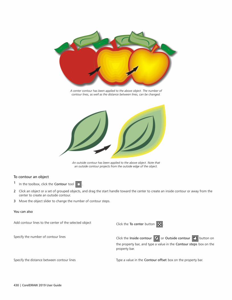
430 | CorelDRAW 2019 User Guide
A center contour has been applied to the above object. The number ofcontour lines, as well as the distance between lines, can be changed.
An outside contour has been applied to the above object. Note thatan outside contour projects from the outside edge of the object.
To contour an object
1 In the toolbox, click the Contour tool .
2 Click an object or a set of grouped objects, and drag the start handle toward the center to create an inside contour or away from thecenter to create an outside contour.
3 Move the object slider to change the number of contour steps.
You can also
Add contour lines to the center of the selected object Click the To center button .
Specify the number of contour lines Click the Inside contour or Outside contour button on
the property bar, and type a value in the Contour steps box on theproperty bar.
Specify the distance between contour lines Type a value in the Contour offset box on the property bar.

Add 3D effects | 431
You can also
Accelerate contour line progression Click the Object and color acceleration button on the
property bar, and move the Object slider.
Choose the shape of contour corners Click the Contour corners button on the property bar, and
choose one of the following commands:•Mitered corners (for pointed contour corners)
•Round corners
•Bevel corners
You can create contours by clicking Effects Contour and specifying the settings you want in the Contour docker.
To copy or clone a contour
1 Select the object to which you want to apply the contour effect.
2 Click Object, and click one of the following:
• Copy Effect Contour From
• Clone Effect Contour From
3 Click the object whose contour effect you want to copy or clone.
You can also use the Attributes eyedropper tool to copy a contour. For more information, see “To copy effects from one object
to another” on page 271.
To set the fill color for a contour object
1 In the toolbox, click the Contour tool .
2 Select a contour object.
3 Open the Fill color picker on the property bar, and click a color.
If you cannot apply the fill color, make sure that the Fill color option is enabled on the status bar.
If the original object has a fountain fill, a second color picker appears.
You can accelerate the fill color progression by clicking the Object and color acceleration button on the property bar and
moving a slider.
You can change the contour center’s color by dragging a color from the color palette to the end fill handle.
To specify an outline color for the contour object
1 In the toolbox, click the Contour tool .
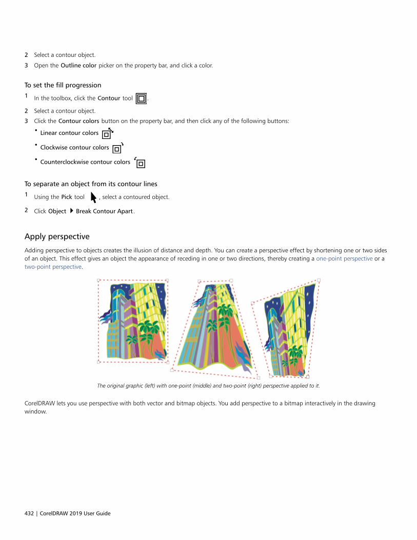
432 | CorelDRAW 2019 User Guide
2 Select a contour object.
3 Open the Outline color picker on the property bar, and click a color.
To set the fill progression
1 In the toolbox, click the Contour tool .
2 Select a contour object.
3 Click the Contour colors button on the property bar, and then click any of the following buttons:
• Linear contour colors
• Clockwise contour colors
• Counterclockwise contour colors
To separate an object from its contour lines
1 Using the Pick tool , select a contoured object.
2 Click Object Break Contour Apart.
Apply perspective
Adding perspective to objects creates the illusion of distance and depth. You can create a perspective effect by shortening one or two sidesof an object. This effect gives an object the appearance of receding in one or two directions, thereby creating a one-point perspective or atwo-point perspective.
The original graphic (left) with one-point (middle) and two-point (right) perspective applied to it.
CorelDRAW lets you use perspective with both vector and bitmap objects. You add perspective to a bitmap interactively in the drawingwindow.
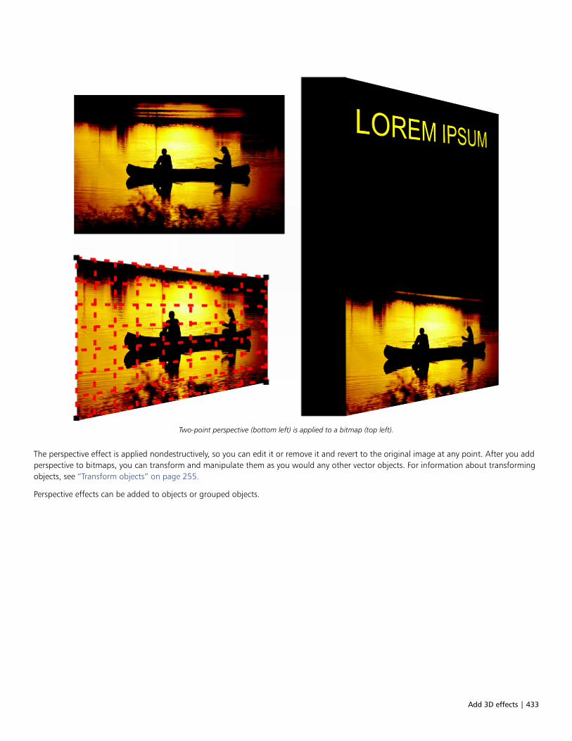
Add 3D effects | 433
Two-point perspective (bottom left) is applied to a bitmap (top left).
The perspective effect is applied nondestructively, so you can edit it or remove it and revert to the original image at any point. After you addperspective to bitmaps, you can transform and manipulate them as you would any other vector objects. For information about transformingobjects, see “Transform objects” on page 255.
Perspective effects can be added to objects or grouped objects.
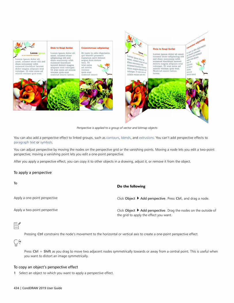
434 | CorelDRAW 2019 User Guide
Perspective is applied to a group of vector and bitmap objects
You can also add a perspective effect to linked groups, such as contours, blends, and extrusions. You can’t add perspective effects toparagraph text or symbols.
You can adjust perspective by moving the nodes on the perspective grid or the vanishing points. Moving a node lets you edit a two-pointperspective; moving a vanishing point lets you edit a one-point perspective.
After you apply a perspective effect, you can copy it to other objects in a drawing, adjust it, or remove it from the object.
To apply a perspective
ToDo the following
Apply a one-point perspective Click Object Add perspective. Press Ctrl, and drag a node.
Apply a two-point perspective Click Object Add perspective. Drag the nodes on the outside ofthe grid to apply the effect you want.
Pressing Ctrl constrains the node’s movement to the horizontal or vertical axis to create a one-point perspective effect.
Press Ctrl + Shift as you drag to move two adjacent nodes symmetrically towards or away from a central point. This is useful whenyou want to distort an image symmetrically.
To copy an object’s perspective effect
1 Select an object to which you want to apply a perspective effect.
Add 3D effects | 435
2 Click Object Copy Effect Perspective From.
3 Select an object whose perspective effect you want to copy.
You can also use the Attributes eyedropper tool to copy a perspective effect. For more information, see “To copy effects from
one object to another” on page 271.
To adjust the perspective
1 In the toolbox, click the Shape tool
2 Select an object that has a perspective effect.
3 Drag a node to a new position.
Pressing Ctrl constrains a node’s movement to the horizontal or vertical axis to create a one-point perspective effect.
Splitting, cropping, or erasing portions of an object with perspective flattens the perspective effect, so you can no longer edit it.
You can also adjust one-point perspective by dragging a vanishing point.
Press Ctrl + Shift as you drag to move adjacent nodes closer together or further apart along a horizontal or vertical axis. This is usefulwhen you want to achieve a symmetrical perspective effect.
To remove a perspective effect from an object
1 Select an object that has a perspective effect.
2 Click Object Clear Perspective.
Create extrusions
You can make objects appear three-dimensional by creating extrusions. You can create extrusions by projecting points from an object andjoining them to create an illusion of three dimensions. CorelDRAW also lets you apply a vector extrusion to an object in a group.
After you create an extrusion, you can copy or clone its attributes to a selected object. Cloning and copying transfer the extrusion attributesof an extruded object to another. However, the cloned extrusion settings cannot be edited independently from the master.
You can change an extruded form by rotating it and rounding its corners.
CorelDRAW also lets you remove a vector extrusion.
Bevels
Another way in which you can give an object a three-dimensional appearance is by applying a beveled edge to an extrusion. A bevel createsthe illusion that an object’s extruded edges are cut on an angle. You can specify the angle and depth values of the bevel to control theeffect.
You can create a bevel effect without extruding an object. For more information, see “Create bevel effects” on page 439.
Extruded fills
You can apply fills to an entire extrusion or only to the extruded surfaces. You can cover each surface individually with the fill, or you candrape the fill so that it blankets the entire object with no breaks to the pattern or texture.

436 | CorelDRAW 2019 User Guide
Left to right: a simple shape, the shape with an extruded fill of solidcolor, the shape with an extruded gradient fill and a rotation applied.
Lighting
You can enhance extrusions by applying light sources. You can add up to three light sources to project toward the extruded object withvarying intensity. When you no longer need light sources, you can remove them.
Vanishing points
You can create a vector extrusion in which the lines of the extrusion converge at a vanishing point. The vanishing point of a vector extrusioncan be copied to another object so that both objects appear to recede toward the same point.
You can also give extrusions different vanishing points.
Extrusions with different vanishing points
To create an extrusion
1 Select an object using the Pick tool .
2 In the toolbox, click the Extrude tool .
3 Choose a preset from the Presets list box on the property bar.
4 Choose an extrusion type from the Extrusion type list box on the property bar.
You can edit the extrusion by using the Extrude docker (Effects Extrude).

Add 3D effects | 437
To copy or clone an extrusion
1 Select the object you want to extrude.
2 Click Object and click one of the following:
• Copy Effect Extrude From
• Clone Effect Extrude From
3 Click an object whose extrusion properties you want to copy.
You can also use the Attributes eyedropper tool to copy an extrusion. For more information, see “To copy effects from one
object to another” on page 271.
To change the form of a vector extrusion
To Do the following
Rotate an extrusion Select an extruded object. Click the Extrude rotation button
on the property bar. Drag the extrusion in the direction you want.
Change the direction of an extrusion Using the Extrude tool , click an extrusion. Click the vanishing
point, and drag in the direction you want.
Change the depth of an extrusion Using the Extrude tool , click an extrusion. Drag the slider
between the interactive vector handles.
Round the corners of an extruded rectangle or square In the toolbox, click the Shape tool . Drag a corner node along
the outline of the rectangle or square.
To remove a vector extrusion
1 Select an extruded object.
2 Click Effects Clear Extrusion.
You can also remove a vector extrusion by clicking Clear Extrusion on the property bar.
To apply a fill to an extrusion
1 Select an extruded object with the Extrude tool .
2 Click the Extrusion color button on the property bar.
3 Click one of the following buttons:
• Use object fill — applies the object’s fill to the extrusion
438 | CorelDRAW 2019 User Guide
• Use solid color — applies a solid color to the extrusion
• Use color shading — applies a gradient fill to the extrusion
You can apply an unbroken pattern or texture fill to an object by enabling the Drape fills check box before you click the Use objectfill button.
To apply beveled edges to an extrusion
1 In the toolbox, click the Extrude tool .
2 Select an extruded object.
3 Click the Extrusion bevels button on the property bar.
4 Enable the Use bevel check box.
5 Type a value in the Bevel depth box.
6 Type a value in the Bevel angle box.
You can also set the bevel depth and angle by using the Bevel interactive display box below the Use bevel check box.
You can show only the bevel and hide the extrusion by enabling the Show bevel only check box.
To add light to an extrusion
1 Select an extruded object.
2 Click the Extrusion lighting button on the property bar.
3 Enable any of the three numbered check boxes.
The lights appear as numbered circles in the preview window.
4 Drag the numbered circles in the Light intensity preview window to position the lights.
You can also
Adjust the intensity of a light source Move the Intensity slider next to the numbered check box.
Remove a light source Disable a numbered check box.
To change the vanishing point of an extrusion
To Do the following
Lock a vanishing point Double-click an extruded object. Choose VP locked to object or VPlocked to page from the Vanishing point properties list box onthe property bar.
Copy a vanishing point Double-click an extruded object whose vanishing point you wantto change. From the Vanishing point properties list box on the
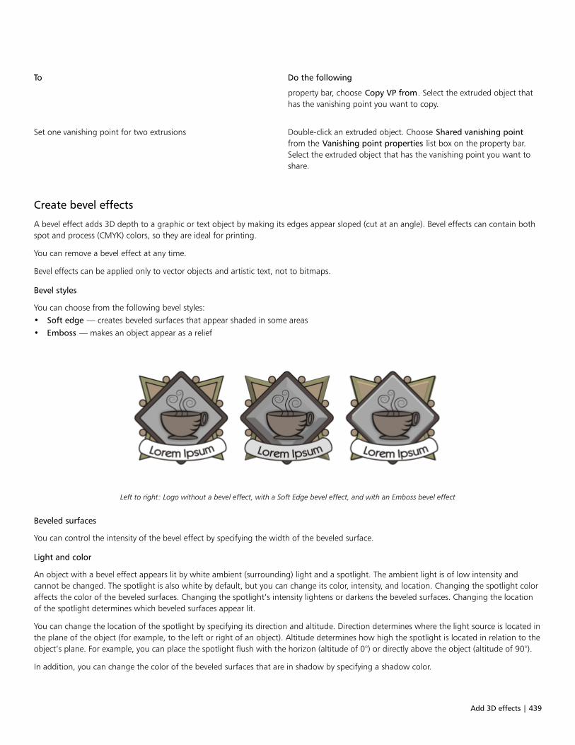
Add 3D effects | 439
To Do the following
property bar, choose Copy VP from. Select the extruded object thathas the vanishing point you want to copy.
Set one vanishing point for two extrusions Double-click an extruded object. Choose Shared vanishing pointfrom the Vanishing point properties list box on the property bar.Select the extruded object that has the vanishing point you want toshare.
Create bevel effects
A bevel effect adds 3D depth to a graphic or text object by making its edges appear sloped (cut at an angle). Bevel effects can contain bothspot and process (CMYK) colors, so they are ideal for printing.
You can remove a bevel effect at any time.
Bevel effects can be applied only to vector objects and artistic text, not to bitmaps.
Bevel styles
You can choose from the following bevel styles:• Soft edge — creates beveled surfaces that appear shaded in some areas• Emboss — makes an object appear as a relief
Left to right: Logo without a bevel effect, with a Soft Edge bevel effect, and with an Emboss bevel effect
Beveled surfaces
You can control the intensity of the bevel effect by specifying the width of the beveled surface.
Light and color
An object with a bevel effect appears lit by white ambient (surrounding) light and a spotlight. The ambient light is of low intensity andcannot be changed. The spotlight is also white by default, but you can change its color, intensity, and location. Changing the spotlight coloraffects the color of the beveled surfaces. Changing the spotlight’s intensity lightens or darkens the beveled surfaces. Changing the locationof the spotlight determines which beveled surfaces appear lit.
You can change the location of the spotlight by specifying its direction and altitude. Direction determines where the light source is located inthe plane of the object (for example, to the left or right of an object). Altitude determines how high the spotlight is located in relation to theobject’s plane. For example, you can place the spotlight flush with the horizon (altitude of 0°) or directly above the object (altitude of 90°).
In addition, you can change the color of the beveled surfaces that are in shadow by specifying a shadow color.
440 | CorelDRAW 2019 User Guide
To create a Soft Edge bevel effect
1 Select an object that is closed and has a fill applied to it.
2 Click Effects Bevel.
3 In the Bevel docker, enable the Soft edge option.
4 Enable one of the following Bevel offset options:
• To center — lets you create beveled surfaces that meet in the middle of the object
• Distance — lets you specify the width of the beveled surfaces. Type a value in the Distance box.
5 Click Apply.
You can also
Change the color of beveled surfaces in shadow Choose a color from the Shadow color picker.
Beveled surfaces change to a shade of the specified shadow color.
Choose a spotlight color Choose a color from the Light color picker.
Change the intensity of the spotlight Move the Intensity slider.
Specify the position of the spotlight Move either of the following sliders:•Direction•Altitude
Direction values range from 0° to 360°; altitude values range from0° to 90°.
Bevel effects can be applied only to artistic text. You can convert paragraph text to artistic text by selecting the text using the Pick tooland then clicking Text Convert to artistic text.
The lowest altitude value (0°) places the spotlight on the plane of the object; the highest altitude value (90°) places the spotlightdirectly above the object.
The effect of the shadow color is most apparent when the spotlight is located close to the object’s plane (low altitude value).
Using a given altitude value, you can change the spotlight’s location by changing the direction value. For example, at an altitude of45°, the following direction values change the spotlight location as noted:
• 45° places the spotlight on the upper right.
• 135° places the spotlight on the upper left.
• 225° places the spotlight on the lower left.
• 315° places the spotlight on the lower right.
To create an Emboss effect
1 Select an object that is closed and has a fill applied to it.
2 Click Effects Bevel.
3 In the Bevel docker, enable the Emboss option.
4 In the Distance box, type a low value.
5 To change the intensity of the spotlight, move the Intensity slider.

Add 3D effects | 441
6 To specify the direction of the spotlight, move the Direction slider.
7 Click Apply.
If you want to create a more pronounced bevel effect, type a higher value in the Distance box, and reapply the effect.
You can also
Choose a shadow color Choose a color from the Shadow color picker.
Choose a spotlight color Choose a color from the Light color picker.
The Emboss bevel effect is achieved by creating two duplicates of the object. The duplicates are offset in opposite directions: onetoward the light source and the other away from the light source. The color of the duplicate placed toward the spotlight is a blend ofthe spotlight and object colors and depends on the light intensity. The color of the duplicate placed away from the spotlight is a 50percent blend of the shadow and object colors.
The Altitude slider is disabled for the Emboss bevel style.
To remove a bevel effect
1 Select an object with a bevel effect applied.
2 Click Object Clear Effect.
Add drop shadows
Drop shadows simulate light falling on an object from one of five particular perspectives: flat, right, left, bottom, and top. You can add dropshadows to most objects or groups of objects, including artistic text, paragraph text, and bitmaps. You can also use extrusions to createshadows.
Drop shadows and extrusions created in CorelDRAW are ideal for printed outputs, but are not appropriate for output to devices such as vinylcutters and plotters. Cuttable shadows are needed for such projects. To add a cuttable shadow to an object, you must use a block shadow.For more information about block shadows, see “Add block shadows” on page 443. You can also create a cuttable shadow by duplicatingthe object, filling the duplicate with a dark color, and then placing it behind the original object.
When you add a drop shadow, you can change its perspective, and you can adjust attributes such as color, opacity, fade level, angle, andfeathering.
A drop shadow applied to an object

442 | CorelDRAW 2019 User Guide
The feathered effect softens the edges of a drop shadow.
Drop shadows look more realistic when they use Gaussian Blur feathering, which is the default option. You can change the feathering ofdrop shadows from the Feathering direction button on the property bar.
After you create a drop shadow, you can copy it or clone it to a selected object. When you copy a drop shadow, the original and copy haveno connection and can be edited independently. With cloning, the master object’s drop shadow attributes are automatically applied to itsclone.
By separating a drop shadow from its object, you gain more control over the drop shadow itself. For example, you can edit the drop shadowas you would edit a transparency. For information about editing a transparency, see “Object transparency” on page 387.
As with transparencies, you can apply a merge mode to a drop shadow to control how the color of the drop shadow blends with the colorof the object underneath. For more information about merge modes, see “Merge modes” on page 396.
You can remove a drop shadow.
To add a drop shadow
1 In the toolbox, click the Drop shadow tool .
2 Click an object.
3 Drag from the center or side of the object until the drop shadow is the size you want.
4 Specify any attributes on the property bar.
Drop shadows cannot be added to linked groups, such as blended objects, contoured objects, beveled objects, extruded objects,
objects created with the Artistic media tool , or other drop shadows.
To add a cuttable shadow
1 Select an object.
2 Click Edit Duplicate.
3 Click a dark color on the onscreen color palette.
4 Click Object Order Behind, and click the original to position the duplicate behind it.
5 Adjust the position of the duplicate.

Add 3D effects | 443
You can also create a cuttable shadow by using the Block Shadow tool . For more information, see “To add a block shadow” on
page 444.
To copy or clone a drop shadow
1 Select the object to which you want to copy or clone a drop shadow.
2 Click Object and click one of the following:
• Copy Effect Drop Shadow From
• Clone Effect Drop Shadow From
3 Click the drop shadow of an object.
You can also use the Attributes eyedropper tool to copy a drop shadow. For more information, see “To copy effects from one
object to another” on page 271.
To separate a drop shadow from an object
1 Select an object’s drop shadow.
2 Click Object Break Drop Shadow Apart.
3 Drag the shadow.
To apply a merge mode to a drop shadow
1 In the toolbox, click the Drop shadow tool .
2 Select an object with a drop shadow, and choose a merge mode from the Merge mode list box on the property bar.
The default merge mode Multiply produces natural-looking drop shadows.
To remove a drop shadow
1 Select an object’s drop shadow.
2 Click Effects Clear Drop Shadow.
You can also remove a drop shadow from an object by clicking Clear Drop Shadow on the property bar.
Add block shadows
The Block Shadow tool in CorelDRAW lets you add solid shadows to objects and text. Unlike drop shadows and extrusions, block shadowsconsist of simple lines, which makes them ideal for screen printing and sign making.

444 | CorelDRAW 2019 User Guide
Text with a block shadow
The Block Shadow tool is located on the Interactive tool flyout.
You can adjust the depth and direction of a block shadow, and you can change its color. A block shadow may contain holes, but you canremove them to create a solid curve object.
By default, a block shadow is generated from the object outline. You can also choose to ignore the outline and start the block shadow fromthe object edge. The effect of this option is more obvious when an object has a thick outline. In addition, you can expand a block shadowthat is generated from the object outline.
Top: Original text. In the bottom row, different block shadows are added to the text. Lower-left: The block shadow extendsfrom the object outline. Middle: The block shadow ignores the outline. Lower-right: The block shadow is expanded.
If you are planning to print or export your document, you can specify block shadow settings to suit your needs. For example, you can set ablock shadow to overprint, that is to print on top of underlying objects. Also, overlapping areas between the object and its block shadowcan be removed when the document is exported or printed.
You can remove block shadows from objects at any time.
To add a block shadow
1 In the toolbox, click the Block Shadow tool .
2 Click the object, and drag in the direction you want until the block shadow is the size you want.
To edit a block shadow
1 Using the Block Shadow tool , click the object.
2 Perform any of the tasks from the following table.

Add 3D effects | 445
To Do the following
Adjust the depth of a block shadow Type a value in the Depth box.
Tip: You can also adjust the depth by dragging the vector handle inthe drawing window.
Adjusting the depth of a block shadow
Set the direction of a block shadow Type a value in the Direction box.
This value specifies the angle of the block shadow in relation to theobject.
Tip: You can also change the direction of a block shadow bydragging the handle in the drawing window.
Change the color of a block shadow Choose a color from the Block shadow color picker on theproperty bar.
Tip: You can also change the color by dragging a color from thecolor palette to the vector handle in the drawing window.
Remove the holes from a block shadow Click the Remove holes button on the property bar to enable
it.
Top: A block shadow with holes. Bottom: The same block shadowwith the holes removed.
Expand a block shadows that is generated from the outline On the property bar, click the Generate from object outline
button to enable it. Type a value in the Expand block
shadow box on the property bar.
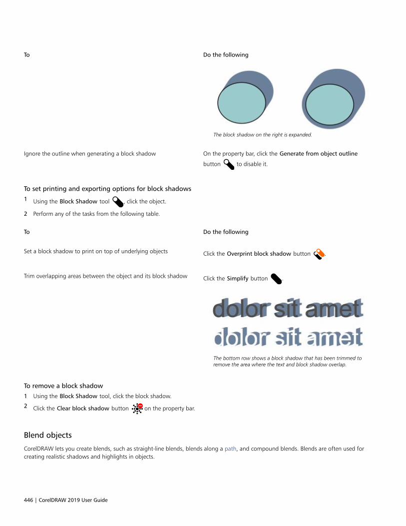
446 | CorelDRAW 2019 User Guide
To Do the following
The block shadow on the right is expanded.
Ignore the outline when generating a block shadow On the property bar, click the Generate from object outline
button to disable it.
To set printing and exporting options for block shadows
1 Using the Block Shadow tool , click the object.
2 Perform any of the tasks from the following table.
To Do the following
Set a block shadow to print on top of underlying objects Click the Overprint block shadow button .
Trim overlapping areas between the object and its block shadow Click the Simplify button .
The bottom row shows a block shadow that has been trimmed toremove the area where the text and block shadow overlap.
To remove a block shadow
1 Using the Block Shadow tool, click the block shadow.
2 Click the Clear block shadow button on the property bar.
Blend objects
CorelDRAW lets you create blends, such as straight-line blends, blends along a path, and compound blends. Blends are often used forcreating realistic shadows and highlights in objects.
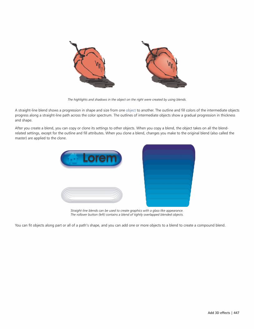
Add 3D effects | 447
The highlights and shadows in the object on the right were created by using blends.
A straight-line blend shows a progression in shape and size from one object to another. The outline and fill colors of the intermediate objectsprogress along a straight-line path across the color spectrum. The outlines of intermediate objects show a gradual progression in thicknessand shape.
After you create a blend, you can copy or clone its settings to other objects. When you copy a blend, the object takes on all the blend-related settings, except for the outline and fill attributes. When you clone a blend, changes you make to the original blend (also called themaster) are applied to the clone.
Straight-line blends can be used to create graphics with a glass-like appearance.The rollover button (left) contains a blend of tightly overlapped blended objects.
You can fit objects along part or all of a path’s shape, and you can add one or more objects to a blend to create a compound blend.
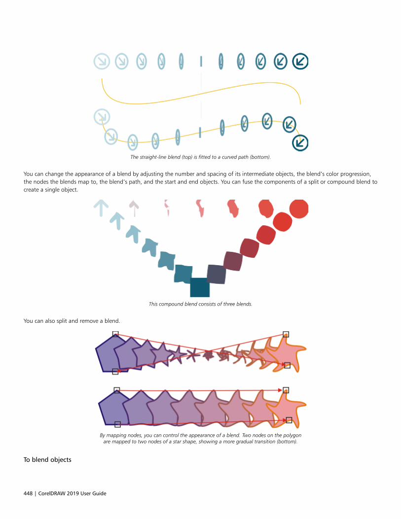
448 | CorelDRAW 2019 User Guide
The straight-line blend (top) is fitted to a curved path (bottom).
You can change the appearance of a blend by adjusting the number and spacing of its intermediate objects, the blend’s color progression,the nodes the blends map to, the blend’s path, and the start and end objects. You can fuse the components of a split or compound blend tocreate a single object.
This compound blend consists of three blends.
You can also split and remove a blend.
By mapping nodes, you can control the appearance of a blend. Two nodes on the polygonare mapped to two nodes of a star shape, showing a more gradual transition (bottom).
To blend objects

Add 3D effects | 449
To Do the following
Blend along a straight line In the toolbox, click the Blend tool . Select the first object, and
drag over the second object.
Blend an object along a freehand path In the toolbox, click the Blend tool. Select the first object. Holddown Alt, and drag to draw a line to the second object.
Fit a blend to a path In the toolbox, click the Blend tool . Click the Path properties
button on the property bar. Click New path. Using the curved
arrow, click the path to which you want to fit the blend.
Stretch the blend over an entire path Select a blend that is already fitted on a path. Click the More blend
options button on the property bar, and click Blend along
full path.
Create a compound blend Using the Blend tool, drag from an object to the start or end objectof another blend.
You can also blend objects by using the Blend docker (Effects Blend).
To copy or clone a blend
1 Select the two objects that you want to blend.
2 Click Object, and click one of the following:
• Copy Effect Blend from
• Clone Effect Blend from
3 Select the blend whose attributes you want to copy or clone.
You can’t copy or clone a compound blend.
You can also use the Attributes eyedropper tool to copy a blend. For more information, see “To copy effects from one object to
another” on page 271.
To set the number of intermediate objects in a blend
1 Select a blend.
2 Type a value in the Blend objects box on the property bar.
3 Press Enter.

450 | CorelDRAW 2019 User Guide
You can set object and color acceleration rates by clicking the Object and color acceleration button on the property bar and
moving the corresponding slider.
To set the distance between objects in a blend that is fit to a path
1 Select a blend that is fit to a path.
2 Click the Blend spacing button on the property bar.
3 Type a value in the Blend objects box on the property bar.
4 Press Enter.
If you have used the Blend along full path command, the Blend spacing button is unavailable.
You can set object and color acceleration rates by clicking the Object and color acceleration button on the property bar and
moving the corresponding slider.
To set the color progression in a blend
1 Select a blend.
2 On the property bar, click one of the following:
• Direct blend
• Clockwise blend
• Counterclockwise blend
You can’t create color progressions by using blended objects filled with bitmaps, texture, pattern, or PostScript fills.
You can set how fast the object’s colors transform from the first to the last object by clicking the Object and color acceleration
button on the property bar and moving the corresponding sliders.
To map the nodes of a blend
1 Select a blend.
2 Click the More blend options button on the property bar, and click Map nodes.
3 Click a node on the start object and on the end object.
To work with the start or end objects in a blend
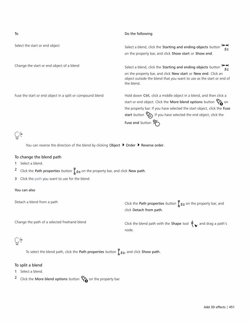
Add 3D effects | 451
To Do the following
Select the start or end object Select a blend, click the Starting and ending objects button
on the property bar, and click Show start or Show end.
Change the start or end object of a blend Select a blend, click the Starting and ending objects button
on the property bar, and click New start or New end. Click anobject outside the blend that you want to use as the start or end ofthe blend.
Fuse the start or end object in a split or compound blend Hold down Ctrl, click a middle object in a blend, and then click a
start or end object. Click the More blend options button on
the property bar. If you have selected the start object, click the Fuse
start button . If you have selected the end object, click the
Fuse end button .
You can reverse the direction of the blend by clicking Object Order Reverse order.
To change the blend path
1 Select a blend.
2 Click the Path properties button on the property bar, and click New path.
3 Click the path you want to use for the blend.
You can also
Detach a blend from a path Click the Path properties button on the property bar, and
click Detach from path.
Change the path of a selected freehand blend Click the blend path with the Shape tool , and drag a path’s
node.
To select the blend path, click the Path properties button , and click Show path.
To split a blend
1 Select a blend.
2 Click the More blend options button on the property bar.

452 | CorelDRAW 2019 User Guide
3 Click the Split button .
4 Click the intermediate object at the point at where you want to split the blend.
You can’t split a blend at the intermediate object that is immediately adjacent to the start or end object.
To remove a blend
1 Select a blend.
2 Click Effects Clear blend.
You can also remove a selected blend by clicking Clear Blend on the property bar.
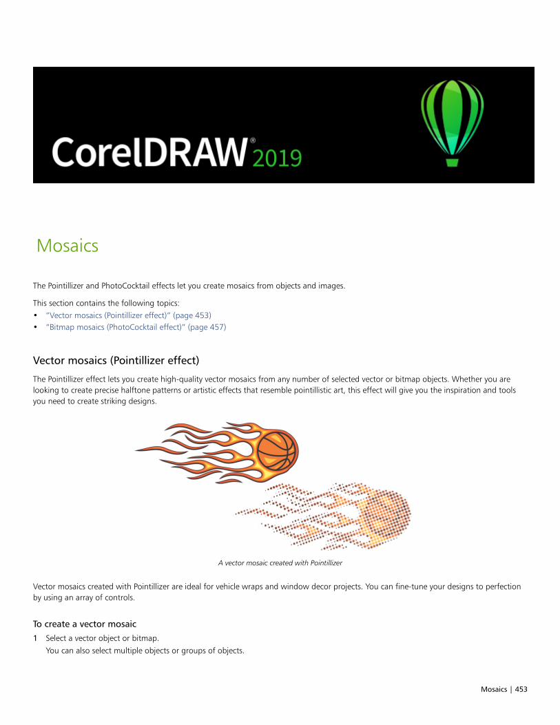
Mosaics | 453
Mosaics
The Pointillizer and PhotoCocktail effects let you create mosaics from objects and images.
This section contains the following topics:• “Vector mosaics (Pointillizer effect)” (page 453)• “Bitmap mosaics (PhotoCocktail effect)” (page 457)
Vector mosaics (Pointillizer effect)
The Pointillizer effect lets you create high-quality vector mosaics from any number of selected vector or bitmap objects. Whether you arelooking to create precise halftone patterns or artistic effects that resemble pointillistic art, this effect will give you the inspiration and toolsyou need to create striking designs.
A vector mosaic created with Pointillizer
Vector mosaics created with Pointillizer are ideal for vehicle wraps and window decor projects. You can fine-tune your designs to perfectionby using an array of controls.
To create a vector mosaic
1 Select a vector object or bitmap.
You can also select multiple objects or groups of objects.
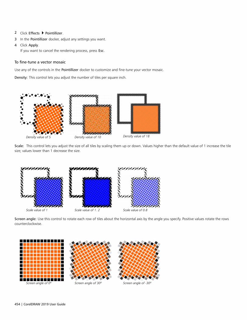
454 | CorelDRAW 2019 User Guide
2 Click Effects Pointillizer.
3 In the Pointillizer docker, adjust any settings you want.
4 Click Apply.
If you want to cancel the rendering process, press Esc.
To fine-tune a vector mosaic
Use any of the controls in the Pointillizer docker to customize and fine-tune your vector mosaic.
Density: This control lets you adjust the number of tiles per square inch.
Density value of 5 Density value of 10 Density value of 18
Scale: This control lets you adjust the size of all tiles by scaling them up or down. Values higher than the default value of 1 increase the tilesize; values lower than 1 decrease the size.
Scale value of 1 Scale value of 1. 2 Scale value of 0.8
Screen angle: Use this control to rotate each row of tiles about the horizontal axis by the angle you specify. Positive values rotate the rowscounterclockwise.
Screen angle of 0º Screen angle of 30º Screen angle of -30º
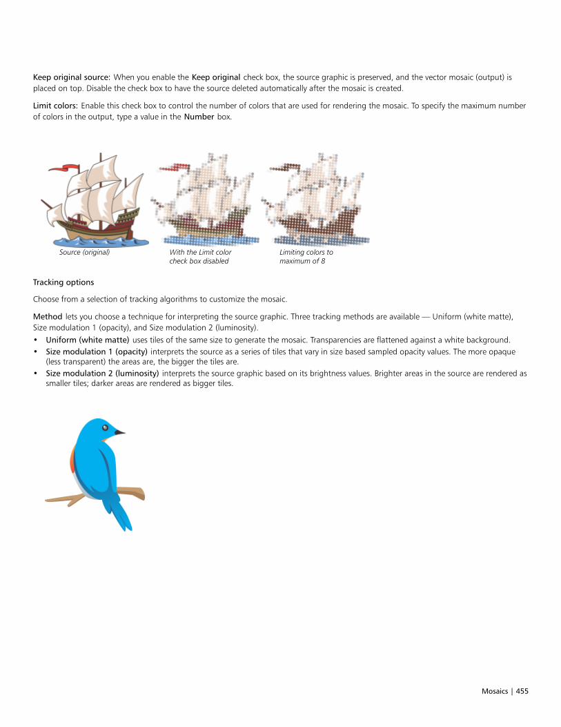
Mosaics | 455
Keep original source: When you enable the Keep original check box, the source graphic is preserved, and the vector mosaic (output) isplaced on top. Disable the check box to have the source deleted automatically after the mosaic is created.
Limit colors: Enable this check box to control the number of colors that are used for rendering the mosaic. To specify the maximum numberof colors in the output, type a value in the Number box.
Source (original) With the Limit colorcheck box disabled
Limiting colors tomaximum of 8
Tracking options
Choose from a selection of tracking algorithms to customize the mosaic.
Method lets you choose a technique for interpreting the source graphic. Three tracking methods are available — Uniform (white matte),Size modulation 1 (opacity), and Size modulation 2 (luminosity).• Uniform (white matte) uses tiles of the same size to generate the mosaic. Transparencies are flattened against a white background.• Size modulation 1 (opacity) interprets the source as a series of tiles that vary in size based sampled opacity values. The more opaque
(less transparent) the areas are, the bigger the tiles are.• Size modulation 2 (luminosity) interprets the source graphic based on its brightness values. Brighter areas in the source are rendered as
smaller tiles; darker areas are rendered as bigger tiles.
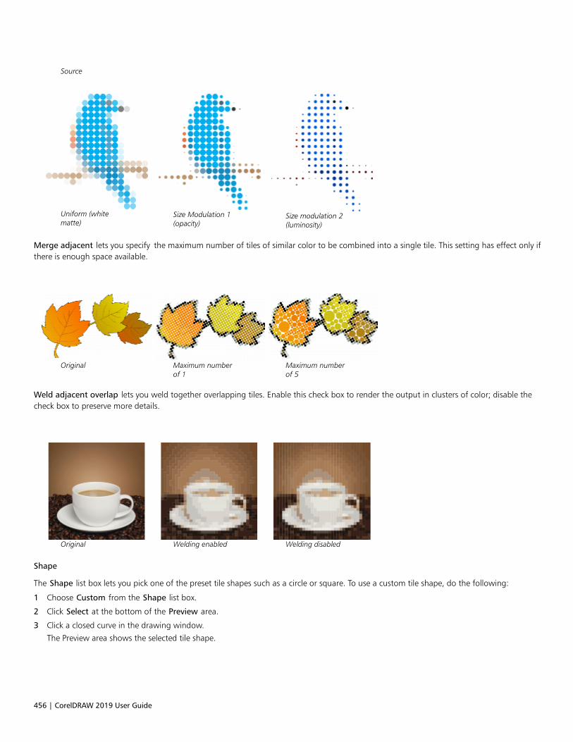
456 | CorelDRAW 2019 User Guide
Source
Uniform (whitematte)
Size Modulation 1(opacity)
Size modulation 2(luminosity)
Merge adjacent lets you specify the maximum number of tiles of similar color to be combined into a single tile. This setting has effect only ifthere is enough space available.
Original Maximum numberof 1
Maximum numberof 5
Weld adjacent overlap lets you weld together overlapping tiles. Enable this check box to render the output in clusters of color; disable thecheck box to preserve more details.
Original Welding enabled Welding disabled
Shape
The Shape list box lets you pick one of the preset tile shapes such as a circle or square. To use a custom tile shape, do the following:
1 Choose Custom from the Shape list box.
2 Click Select at the bottom of the Preview area.
3 Click a closed curve in the drawing window.
The Preview area shows the selected tile shape.
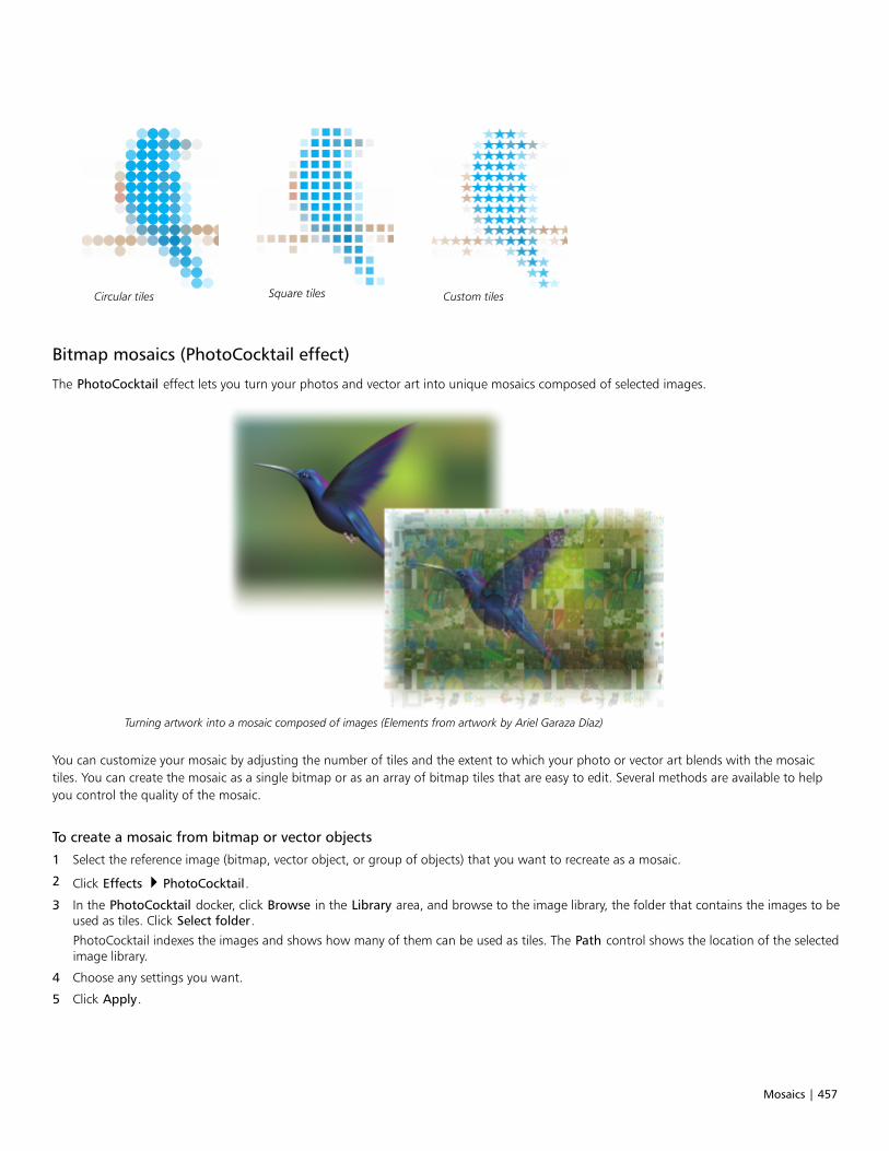
Mosaics | 457
Circular tiles Square tiles Custom tiles
Bitmap mosaics (PhotoCocktail effect)
The PhotoCocktail effect lets you turn your photos and vector art into unique mosaics composed of selected images.
Turning artwork into a mosaic composed of images (Elements from artwork by Ariel Garaza Díaz)
You can customize your mosaic by adjusting the number of tiles and the extent to which your photo or vector art blends with the mosaictiles. You can create the mosaic as a single bitmap or as an array of bitmap tiles that are easy to edit. Several methods are available to helpyou control the quality of the mosaic.
To create a mosaic from bitmap or vector objects
1 Select the reference image (bitmap, vector object, or group of objects) that you want to recreate as a mosaic.
2 Click Effects PhotoCocktail.
3 In the PhotoCocktail docker, click Browse in the Library area, and browse to the image library, the folder that contains the images to beused as tiles. Click Select folder.
PhotoCocktail indexes the images and shows how many of them can be used as tiles. The Path control shows the location of the selectedimage library.
4 Choose any settings you want.
5 Click Apply.
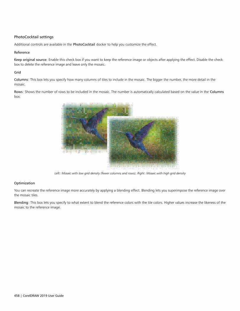
458 | CorelDRAW 2019 User Guide
PhotoCocktail settings
Additional controls are available in the PhotoCocktail docker to help you customize the effect.
Reference
Keep original source: Enable this check box if you want to keep the reference image or objects after applying the effect. Disable the checkbox to delete the reference image and leave only the mosaic.
Grid
Columns: This box lets you specify how many columns of tiles to include in the mosaic. The bigger the number, the more detail in themosaic.
Rows: Shows the number of rows to be included in the mosaic. The number is automatically calculated based on the value in the Columnsbox.
Left: Mosaic with low grid density (fewer columns and rows); Right: Mosaic with high grid density
Optimization
You can recreate the reference image more accurately by applying a blending effect. Blending lets you superimpose the reference image overthe mosaic tiles.
Blending: This box lets you specify to what extent to blend the reference colors with the tile colors. Higher values increase the likeness of themosaic to the reference image.
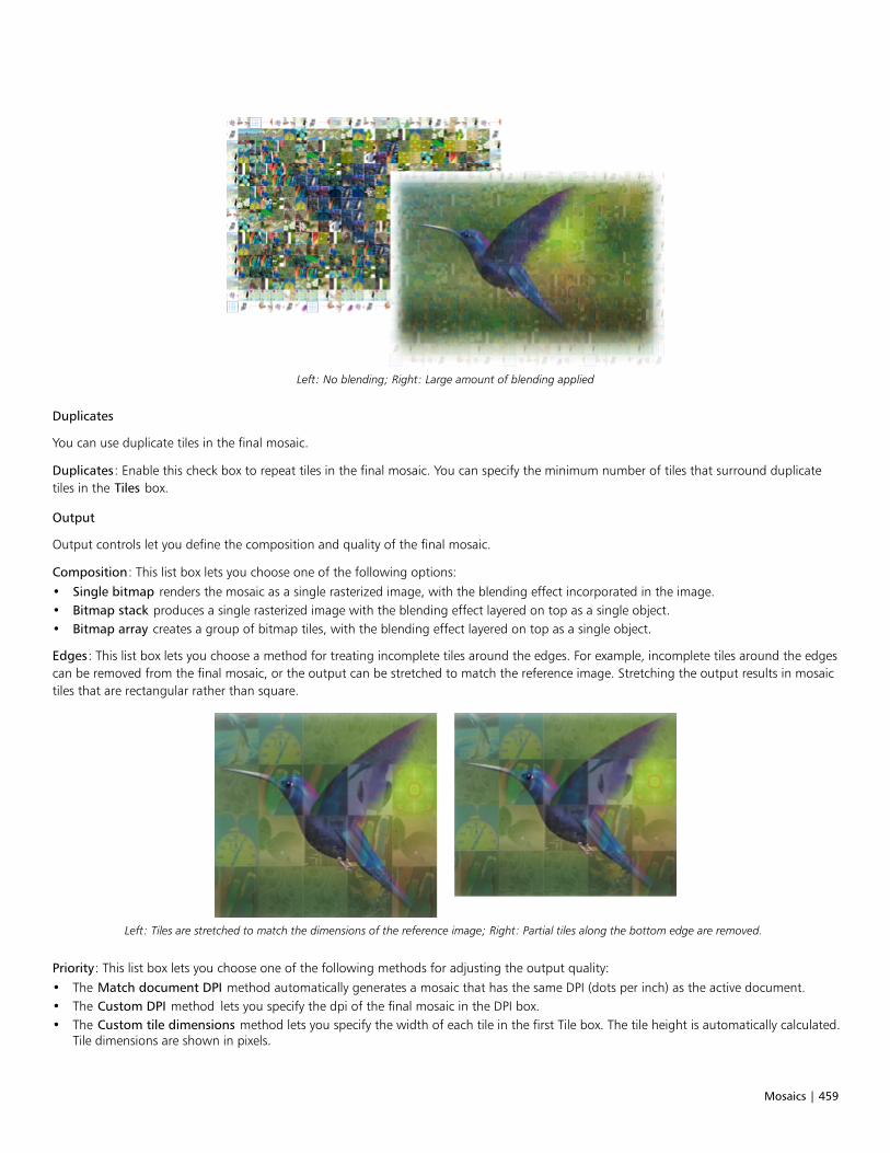
Mosaics | 459
Left: No blending; Right: Large amount of blending applied
Duplicates
You can use duplicate tiles in the final mosaic.
Duplicates: Enable this check box to repeat tiles in the final mosaic. You can specify the minimum number of tiles that surround duplicatetiles in the Tiles box.
Output
Output controls let you define the composition and quality of the final mosaic.
Composition: This list box lets you choose one of the following options:• Single bitmap renders the mosaic as a single rasterized image, with the blending effect incorporated in the image.• Bitmap stack produces a single rasterized image with the blending effect layered on top as a single object.• Bitmap array creates a group of bitmap tiles, with the blending effect layered on top as a single object.
Edges: This list box lets you choose a method for treating incomplete tiles around the edges. For example, incomplete tiles around the edgescan be removed from the final mosaic, or the output can be stretched to match the reference image. Stretching the output results in mosaictiles that are rectangular rather than square.
Left: Tiles are stretched to match the dimensions of the reference image; Right: Partial tiles along the bottom edge are removed.
Priority: This list box lets you choose one of the following methods for adjusting the output quality:• The Match document DPI method automatically generates a mosaic that has the same DPI (dots per inch) as the active document.• The Custom DPI method lets you specify the dpi of the final mosaic in the DPI box.• The Custom tile dimensions method lets you specify the width of each tile in the first Tile box. The tile height is automatically calculated.
Tile dimensions are shown in pixels.

460 | CorelDRAW 2019 User Guide
• The Custom output dimensions method lets you specify the width of the final mosaic in the first Artwork box. The height isautomatically calculated. The maximum dimensions of a mosaic are 15,000 x 15,000 pixels.
The mosaic DPI is influenced by the grid density and the dimensions of the mosaic.
The tile size is a good indicator of output quality. The higher the tile size, the better the quality. Dividing the mosaic size in pixels by the griddensity gives you the tile size in pixels.
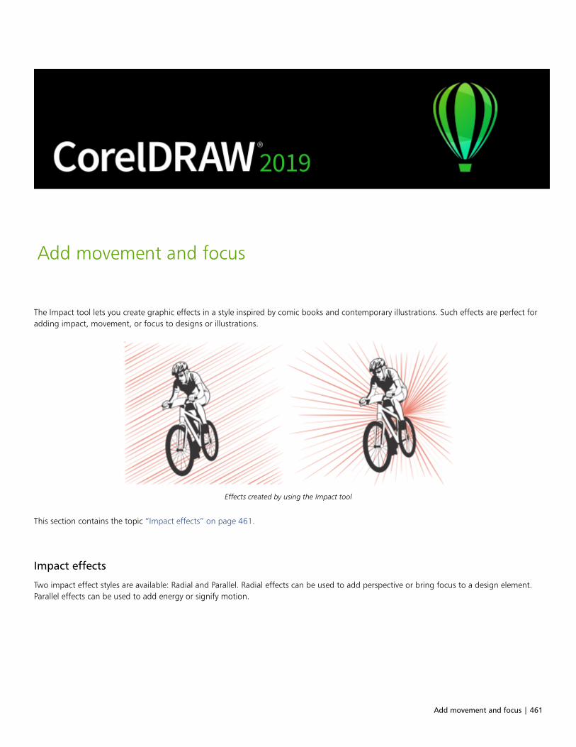
Add movement and focus | 461
Add movement and focus
The Impact tool lets you create graphic effects in a style inspired by comic books and contemporary illustrations. Such effects are perfect foradding impact, movement, or focus to designs or illustrations.
Effects created by using the Impact tool
This section contains the topic “Impact effects” on page 461.
Impact effects
Two impact effect styles are available: Radial and Parallel. Radial effects can be used to add perspective or bring focus to a design element.Parallel effects can be used to add energy or signify motion.
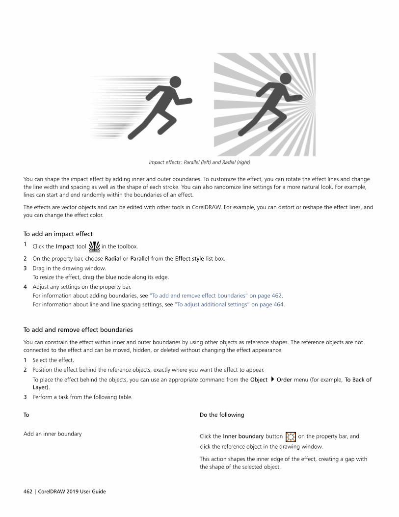
462 | CorelDRAW 2019 User Guide
Impact effects: Parallel (left) and Radial (right)
You can shape the impact effect by adding inner and outer boundaries. To customize the effect, you can rotate the effect lines and changethe line width and spacing as well as the shape of each stroke. You can also randomize line settings for a more natural look. For example,lines can start and end randomly within the boundaries of an effect.
The effects are vector objects and can be edited with other tools in CorelDRAW. For example, you can distort or reshape the effect lines, andyou can change the effect color.
To add an impact effect
1 Click the Impact tool in the toolbox.
2 On the property bar, choose Radial or Parallel from the Effect style list box.
3 Drag in the drawing window.
To resize the effect, drag the blue node along its edge.
4 Adjust any settings on the property bar.
For information about adding boundaries, see “To add and remove effect boundaries” on page 462.
For information about line and line spacing settings, see “To adjust additional settings” on page 464.
To add and remove effect boundaries
You can constrain the effect within inner and outer boundaries by using other objects as reference shapes. The reference objects are notconnected to the effect and can be moved, hidden, or deleted without changing the effect appearance.
1 Select the effect.
2 Position the effect behind the reference objects, exactly where you want the effect to appear.
To place the effect behind the objects, you can use an appropriate command from the Object Order menu (for example, To Back ofLayer).
3 Perform a task from the following table.
To Do the following
Add an inner boundary Click the Inner boundary button on the property bar, and
click the reference object in the drawing window.
This action shapes the inner edge of the effect, creating a gap withthe shape of the selected object.
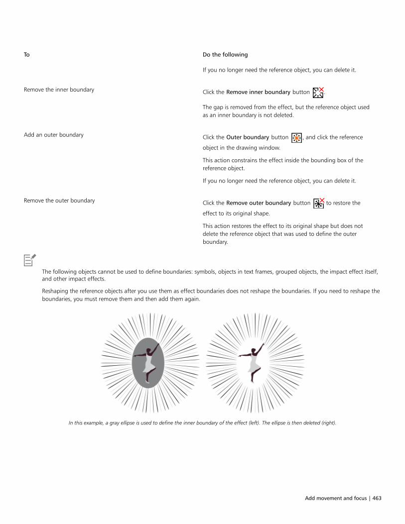
Add movement and focus | 463
To Do the following
If you no longer need the reference object, you can delete it.
Remove the inner boundary Click the Remove inner boundary button .
The gap is removed from the effect, but the reference object usedas an inner boundary is not deleted.
Add an outer boundary Click the Outer boundary button , and click the reference
object in the drawing window.
This action constrains the effect inside the bounding box of thereference object.
If you no longer need the reference object, you can delete it.
Remove the outer boundary Click the Remove outer boundary button to restore the
effect to its original shape.
This action restores the effect to its original shape but does notdelete the reference object that was used to define the outerboundary.
The following objects cannot be used to define boundaries: symbols, objects in text frames, grouped objects, the impact effect itself,and other impact effects.
Reshaping the reference objects after you use them as effect boundaries does not reshape the boundaries. If you need to reshape theboundaries, you must remove them and then add them again.
In this example, a gray ellipse is used to define the inner boundary of the effect (left). The ellipse is then deleted (right).
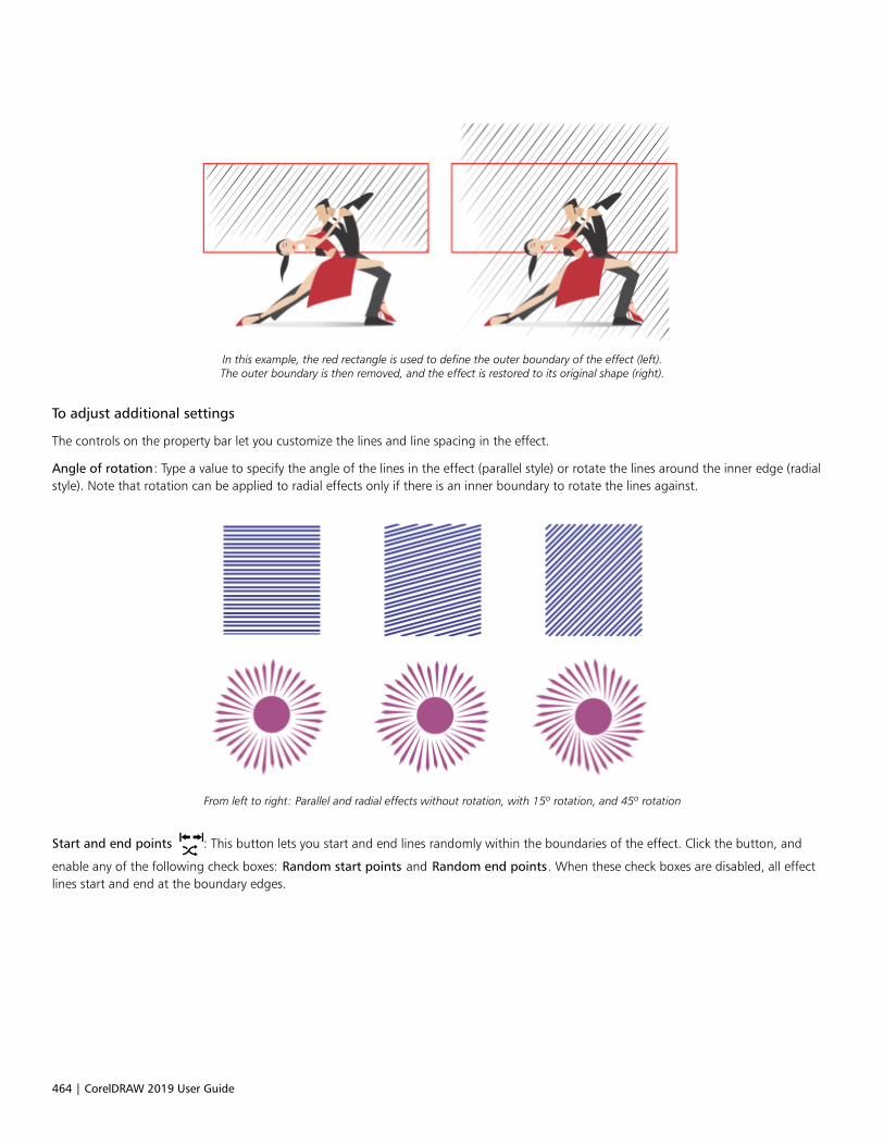
464 | CorelDRAW 2019 User Guide
In this example, the red rectangle is used to define the outer boundary of the effect (left).The outer boundary is then removed, and the effect is restored to its original shape (right).
To adjust additional settings
The controls on the property bar let you customize the lines and line spacing in the effect.
Angle of rotation: Type a value to specify the angle of the lines in the effect (parallel style) or rotate the lines around the inner edge (radialstyle). Note that rotation can be applied to radial effects only if there is an inner boundary to rotate the lines against.
From left to right: Parallel and radial effects without rotation, with 15º rotation, and 45º rotation
Start and end points : This button lets you start and end lines randomly within the boundaries of the effect. Click the button, and
enable any of the following check boxes: Random start points and Random end points. When these check boxes are disabled, all effectlines start and end at the boundary edges.

Add movement and focus | 465
From left to right: Before and after randomizing the start and end points of an effect
Line width: Type values in the Min and the Max box to set the minimum and maximum width for the lines in the effect. The minimum valuecannot exceed the maximum value.
Width steps: Set the number of steps between the minimum and maximum width. When the value is 0, there are only two types of lines inthe effect: of maximum width and of minimum width. Higher numbers add lines of increasing width between the thinnest and the thickestlines. For example, a value of 2 adds two lines between each line of minimum and maximum width.
Left: Width step value of 0. Right: Width step value of 2. Two linesare added between the thickest and the thinnest lines in the effect.
Randomize width order: Click this button to randomize the order of lines in the effect. Lines will no longer appear in a repeating patternfrom thinnest to thickest.
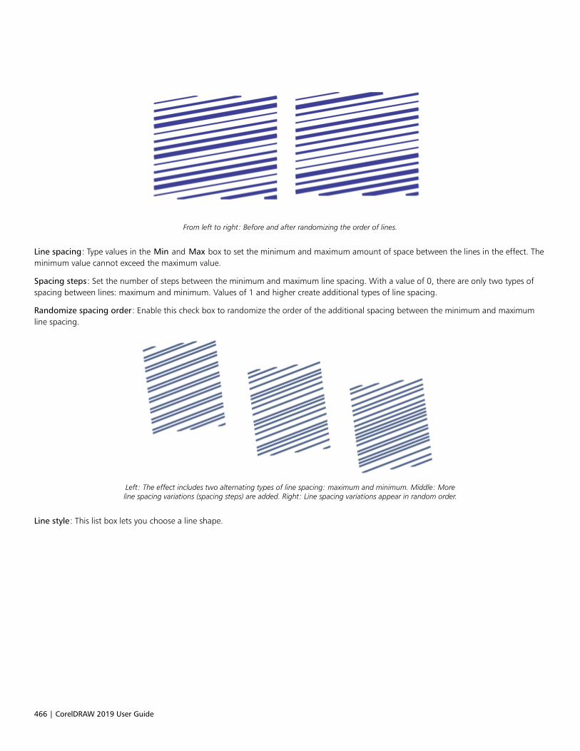
466 | CorelDRAW 2019 User Guide
From left to right: Before and after randomizing the order of lines.
Line spacing: Type values in the Min and Max box to set the minimum and maximum amount of space between the lines in the effect. Theminimum value cannot exceed the maximum value.
Spacing steps: Set the number of steps between the minimum and maximum line spacing. With a value of 0, there are only two types ofspacing between lines: maximum and minimum. Values of 1 and higher create additional types of line spacing.
Randomize spacing order: Enable this check box to randomize the order of the additional spacing between the minimum and maximumline spacing.
Left: The effect includes two alternating types of line spacing: maximum and minimum. Middle: Moreline spacing variations (spacing steps) are added. Right: Line spacing variations appear in random order.
Line style: This list box lets you choose a line shape.
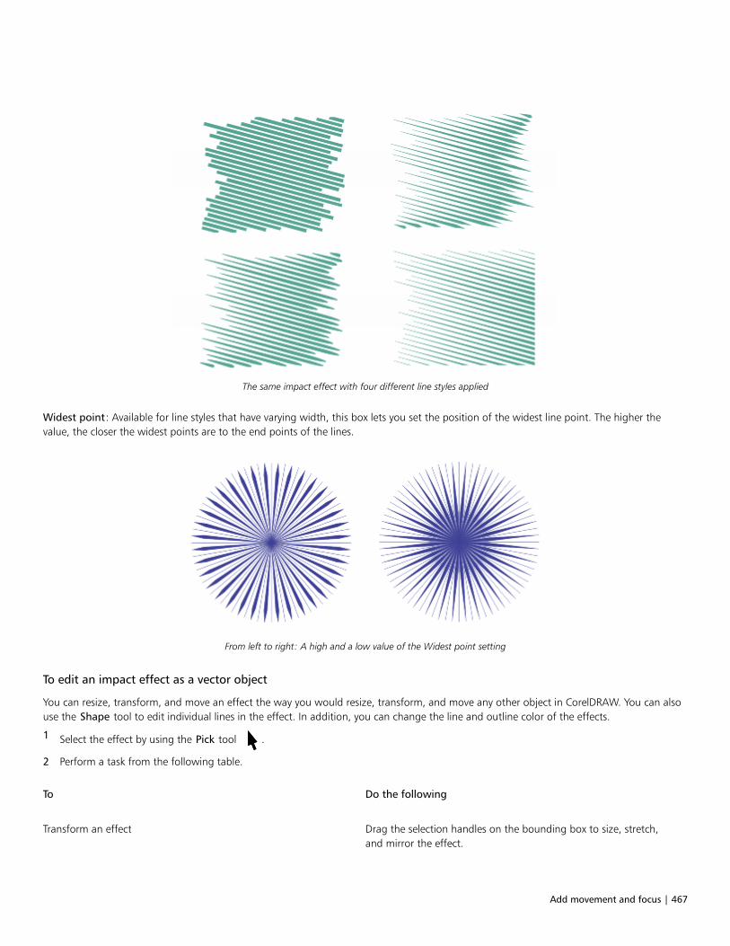
Add movement and focus | 467
The same impact effect with four different line styles applied
Widest point: Available for line styles that have varying width, this box lets you set the position of the widest line point. The higher thevalue, the closer the widest points are to the end points of the lines.
From left to right: A high and a low value of the Widest point setting
To edit an impact effect as a vector object
You can resize, transform, and move an effect the way you would resize, transform, and move any other object in CorelDRAW. You can alsouse the Shape tool to edit individual lines in the effect. In addition, you can change the line and outline color of the effects.
1 Select the effect by using the Pick tool .
2 Perform a task from the following table.
To Do the following
Transform an effect Drag the selection handles on the bounding box to size, stretch,and mirror the effect.

468 | CorelDRAW 2019 User Guide
To Do the following
Click the effect again to display a new set of handles, and drag ahandle to rotate or skew the effect.
Edit lines by using the Shape tool Click Object Break Impact Shape Apart. Next, ungroup the
lines by pressing Object Group Ungroup. Click the Shape tool
, and edit the lines by adding, removing, and manipulating
nodes.
Change the effect color To change the line color, click a color on the onscreen color palette.To add an outline color to the effect lines, right-click a color on theonscreen color palette.
Each time you adjust a setting on the property bar of the Impact tool, the effect is redrawn, and some of the changes you made withthe vector-editing tools may be lost. That is why we recommend that you make additional changes only after you finish adjusting thesettings of the impact effect.

Text | 469
Text
Add and manipulate text.....................................................................................................................................................................471
Format text..........................................................................................................................................................................................495
Work with text in different languages................................................................................................................................................. 523
Manage fonts...................................................................................................................................................................................... 529
Writing tools........................................................................................................................................................................................541

470 | CorelDRAW 2019 User Guide

Add and manipulate text | 471
Add and manipulate text
CorelDRAW provides multiple ways to add and manipulate text (also known as ‘type’). You can create two types of text objects: artistic textand paragraph text. Artistic text is useful for adding a single word or a short line of text. Paragraph text is suitable for creating text-intensivedocuments, such as newsletters or brochures.
You can change the position and appearance of text. For example, you can fit text to a path, wrap text around objects, or rotate text. Youcan also format the appearance of characters and paragraphs. For more information, see “Format text” on page 495.
This section contains the following topics:• “Import and paste text” (page 471)• “Artistic text” (page 473)• “Paragraph text” (page 473)• “Add columns to text frames” (page 477)• “Combine and link paragraph text frames” (page 478)• “Align text to the baseline grid” (page 480)• “Select text” (page 481)• “Find, edit, and convert text” (page 482)• “Shift, rotate, mirror, and flip text” (page 484)• “Move text” (page 486)• “Wrap text” (page 487)• “Fit text to a path” (page 488)• “Special characters, symbols, and glyphs” (page 490)• “Embed graphics” (page 494)• “Legacy text” (page 494)
Import and paste text
You can import text in a new or existing document. This allows you to author text in a word processor and then add it to a CorelDRAWdocument. CorelDRAW supports the following text file formats:• ANSI Text (TXT)• Microsoft Word Document (DOC) files• Microsoft Word Open XML Document (DOCX) files• WordPerfect file (WPD)• Rich Text Format (RTF) files

472 | CorelDRAW 2019 User Guide
When importing or pasting text, you can choose to keep or discard fonts and formatting. Maintaining fonts ensures that imported or pastedtext retains its original font. Maintaining formatting preserves information such as bullets and columns. If you choose to discard fontsand formatting, the properties of the selected text are applied to the imported or pasted text. If no text is selected, the default font andformatting properties are applied to the imported or pasted text. For more information about importing files, see “Import files” on page775. For more information about pasting, see “To paste an object into a drawing” on page 259.
The text import cursor lets you place text on the drawing page.
You can import text in a selected text frame, or, if you did not select a text frame, the imported text is automatically inserted in a new textframe in the document window. By default, the size of text frames remains static, regardless of how much text you add to them. Any textthat does not fit the frame is hidden and the frame appears red until you enlarge it or link it to another text frame. You can adjust the textsize so that the text fits perfectly in the frame. For more information, see “Combine and link paragraph text frames” on page 478.
To import text in a document
1 Using the Text tool , position the cursor in the text frame where you want to import the text.
If you do not have a text frame in the document, skip step 1 and proceed to step 2.
2 Click File Import.
3 Choose the drive and folder where the file is stored.
4 Click the filename.
5 Click Import.
6 In the Importing/Pasting Text dialog box, choose one of the following options:
• Maintain Fonts and Formatting
• Maintain Formatting Only
• Discard Fonts and FormattingIf you want to apply CMYK black to the imported black text, enable the Force CMYK Black check box. This check box is available whenyou choose an option that maintains text formatting.
7 Do one of the following:
• Position the import cursor in the drawing page, and click.
• Click and drag on the drawing page to define the size of the text frame.
• Press the Spacebar to place the imported text in the default location.
For more information about importing a specific file format, see “Supported file formats” on page 797.
To paste text in a document
1 Copy or cut text.
2 Click Edit Paste.
3 In the Importing/Pasting Text dialog box, choose one of the following options:
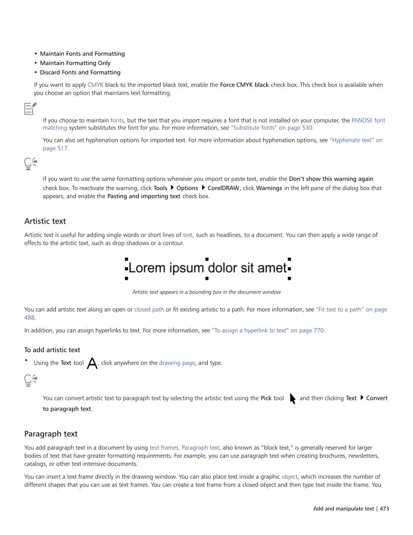
Add and manipulate text | 473
• Maintain Fonts and Formatting
• Maintain Formatting Only
• Discard Fonts and Formatting
If you want to apply CMYK black to the imported black text, enable the Force CMYK black check box. This check box is available whenyou choose an option that maintains text formatting.
If you choose to maintain fonts, but the text that you import requires a font that is not installed on your computer, the PANOSE fontmatching system substitutes the font for you. For more information, see “Substitute fonts” on page 530.
You can also set hyphenation options for imported text. For more information about hyphenation options, see “Hyphenate text” onpage 517.
If you want to use the same formatting options whenever you import or paste text, enable the Don’t show this warning again
check box. To reactivate the warning, click Tools Options CorelDRAW, click Warnings in the left pane of the dialog box thatappears, and enable the Pasting and importing text check box.
Artistic text
Artistic text is useful for adding single words or short lines of text, such as headlines, to a document. You can then apply a wide range ofeffects to the artistic text, such as drop shadows or a contour.
Artistic text appears in a bounding box in the document window
You can add artistic text along an open or closed path or fit existing artistic to a path. For more information, see “Fit text to a path” on page488.
In addition, you can assign hyperlinks to text. For more information, see “To assign a hyperlink to text” on page 770.
To add artistic text
• Using the Text tool , click anywhere on the drawing page, and type.
You can convert artistic text to paragraph text by selecting the artistic text using the Pick tool and then clicking Text Convert
to paragraph text.
Paragraph text
You add paragraph text in a document by using text frames. Paragraph text, also known as “block text,” is generally reserved for largerbodies of text that have greater formatting requirements. For example, you can use paragraph text when creating brochures, newsletters,catalogs, or other text-intensive documents.
You can insert a text frame directly in the drawing window. You can also place text inside a graphic object, which increases the number ofdifferent shapes that you can use as text frames. You can create a text frame from a closed object and then type text inside the frame. You

474 | CorelDRAW 2019 User Guide
can separate the frame from the object at any time, so that you can modify them independently. You can convert a text frame back to anobject.
If you want to see the layout of your document before you add the final content, you can fill the text frames with temporary placeholdertext. You can also use custom placeholder text.
Paragraph text placed inside an object. You can make the object invisible by removing its outline.
By default, text frames have a fixed size, regardless of how much text you add to them. You can increase or decrease the frame size, so thatthe text fits in the frame. If you add more text than a frame allows, the text continues past the lower-right border of the text frame, butremains hidden. The color of the frame turns red to alert you that there's additional text. You can fix the overflow manually by increasingthe frame size, adjusting the text size, adjusting the column width, or linking the frame to another text frame. For more information, see“Combine and link paragraph text frames” on page 478.
The text frame turns red to indicate that there is additional text.
You can also choose to automatically adjust the point size of text so that it fits neatly inside a frame. If the text overflows, CorelDRAWautomatically decreases the point size; if you have little text, the application expands it to fill the frame.
The point size of the text in the frame (left) was automatically adjusted so that it fits neatly inside the frame (right).

Add and manipulate text | 475
You can also change the formatting of selected paragraph text frames and any frames to which they are linked. For information, see “Tospecify formatting preferences for text frames” on page 480. You can also align text inside a text frame by using the baseline grid. Formore information, see “Align text to the baseline grid” on page 480.
In addition, you can assign hyperlinks to paragraph text. For more information, see “To assign a hyperlink to text” on page 770. You canalso change the text orientation for Asian text. For more information, see “To choose a text orientation for Asian text” on page 523.
To add paragraph text
1 Click the Text tool .
2 Drag in the drawing window to size the paragraph text frame.
3 Type in the text frame.
You can also
Set text frame column width to adjust automatically to fit the text Click Window Dockers Properties. In the Properties docker,
click the Frame button to display the frame-related options.
In the Frame area, click the Columns button . In the Column
settings dialog box, enable the Automatically adjust frame widthoption.
Apply a background color to a text frame Open the Background color picker, and click a color.
A red text frame indicates text overflow. You can fix the overflow manually by increasing the frame size, adjusting the text size, orlinking the frame to another text frame. For more information, see “Combine and link paragraph text frames” on page 478. You
can also fix the overflow automatically by clicking Text Paragraph Text Frame Fit Text to Frame.
You can use the Pick tool to adjust the size of a paragraph text frame. Click the text frame, and drag any selection handle.
To create a frame from an object
1 Do one of the following:
• Using the Pick tool , click the object in which you want to insert a text frame.
• Using a drawing tool, draw a closed shape.
2 Select the object, and click Text Paragraph Text Frame Create Empty Text Frame.
You can also
Create a text frame from an object by using the Text tool Click the Text tool . Move the pointer over the outline of the
object, and click the object when the pointer changes to an Insert
in object pointer . Type inside the text frame.
476 | CorelDRAW 2019 User Guide
You can also
Create a text frame from an object from the context menu Right-click the object, and click Frame type Create Empty TextFrame.
Create a text frame from an object by using the Layout toolbar Click Window Toolbars Layout. Using the Pick tool , click
the object in which you want to insert a text frame. Click the Textframe button.
To convert a text frame back to an object
• Right-click the text frame, choose Frame type, and click Remove Frame.
If the frame contains content, the content is deleted when the frame reverts to a regular object.
You can also click the No frame button on the Layout toolbar. To open the Layout toolbar, click Window Toolbars Layout.
To separate a text frame from an object
1 Click the Pick tool .
2 Select the object that includes the text frame.
3 Click Object Break Paragraph Text inside a Path Apart.
The text frame and the object can now be moved or edited separately.
When you separate a text frame from some objects, such as ellipses or stars, the text does not retain the shape of the object.Alternatively, the text is contained in a standard rectangular text frame.
To insert placeholder text
1 Select an empty text frame.
2 Click Text Paragraph Text Frame Insert Placeholder Text.
You can customize the placeholder text by creating text in a word processor or text application and saving the document asplaceholder.rtf. You then need to store the file in the following Users folder: Documents\Corel\Corel Content. The next time that youlaunch the application, the customized placeholder text is inserted in the text frame. However, if you save the file using an incorrectfile name or in the wrong folder, the default Lorem ipsum placeholder text is inserted in the text frame.

Add and manipulate text | 477
You can insert placeholder text in multiple frames by clicking Pick tool , selecting the text frames while holding down Shift, and
then clicking Text Paragraph Text Frame Insert Placeholder Text.
You can also select the empty text frame, right-click, and choose Insert placeholder text.
When you insert placeholder text in the first frame in linked frames, the placeholder text fills all frames.
You can undo inserting placeholder text by clicking Edit Undo insert placeholder text.
To adjust text to fill the text frame
1 Select a text frame.
2 Click Text Paragraph Text Frame Fit Text to Frame.
If you choose to fit text to a frame that is linked to other frames, the application adjusts the size of text in all linked text frames. Formore information about linking text frames, see “Combine and link paragraph text frames” on page 478.
Add columns to text frames
You can lay out text in columns. Columns are useful for designing text-intensive projects, such as newsletters, magazines, and newspapers.You can create columns of equal or varying widths and gutters. You can also apply right-to-left text flow to the columns for bidirectional(bidi) text, such as Arabic and Hebrew (Note that this option is available only for certain languages).
The text in the frame (left) was laid out in two columns (right).
To add columns to a text frame
1 Select a paragraph text frame.
2 Click Window Dockers Properties.
3 In the Properties docker, click the Frame button to display the frame-related options.
4 Type a value in the Number of columns box.
To resize text frame columns
1 Click the Text tool and select a text frame with columns.
2 Perform a task from the following table.

478 | CorelDRAW 2019 User Guide
To Do the following
Manually adjust column and gutter width Click the Text tool . Drag a column side selection handle.
Set a specific column and gutter width In the Properties docker, click the Frame button to display the
frame-related options. Click the Columns button , and type
values in the Width or Gutter boxes.
Automatically create columns of equal width In the Properties docker, click the Frame button to display the
frame-related options. Click the Columns button , and enable
the Equal column width check box.
To change the flow of bidirectional text in columns
1 Select a paragraph text frame.
2 Click Window Dockers Properties.
3 In the Properties docker, click the Frame button to display the frame-related options.
4 Click the Columns button .
5 In the Column Settings dialog box, enable the Right-to-left columns check box.
The Right-to-left columns option is available only for bidirectional languages, such as Hebrew and Arabic. The proper keyboard mustalso be installed.
Combine and link paragraph text frames
You can combine text frames. You can also break text frames apart into subcomponents — columns, paragraphs, bullets, lines, words, andcharacters. Every time you break apart a text frame, the subcomponents are placed into separate text frames.
Linking text frames directs the overflow text of one text frame to another. If you resize a linked frame, or change the size of the text, theamount of text in the next frame is automatically adjusted. You can link text frames before or after you type text.
You cannot link artistic text. However, you can link a paragraph frame to an open or closed object. When you link a frame to an open object,such as a line, the text flows along the path of the line. Linking a text frame to a closed object, such as a rectangle, inserts a text frame anddirects the flow of text inside the object. If text exceeds the open or closed path, you can link the text to another frame or object. You canalso link to existing frames and objects across pages or create a linked frame in the same location on another page.
After linking text frames, you can redirect the flow from one object or text frame to another. When you select the text frame or object, ablue arrow indicates the direction of the text flow. You can hide or display these arrows.
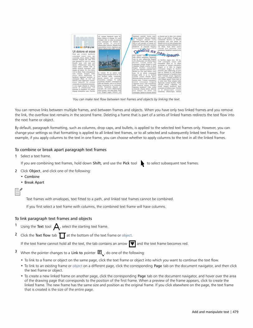
Add and manipulate text | 479
You can make text flow between text frames and objects by linking the text.
You can remove links between multiple frames, and between frames and objects. When you have only two linked frames and you removethe link, the overflow text remains in the second frame. Deleting a frame that is part of a series of linked frames redirects the text flow intothe next frame or object.
By default, paragraph formatting, such as columns, drop caps, and bullets, is applied to the selected text frames only. However, you canchange your settings so that formatting is applied to all linked text frames, or to all selected and subsequently linked text frames. Forexample, if you apply columns to the text in one frame, you can choose whether to apply columns to the text in all the linked frames.
To combine or break apart paragraph text frames
1 Select a text frame.
If you are combining text frames, hold down Shift, and use the Pick tool to select subsequent text frames.
2 Click Object, and click one of the following:
• Combine
• Break Apart
Text frames with envelopes, text fitted to a path, and linked text frames cannot be combined.
If you first select a text frame with columns, the combined text frame will have columns.
To link paragraph text frames and objects
1 Using the Text tool , select the starting text frame.
2 Click the Text flow tab at the bottom of the text frame or object.
If the text frame cannot hold all the text, the tab contains an arrow and the text frame becomes red.
3 When the pointer changes to a Link to pointer , do one of the following:
• To link to a frame or object on the same page, click the text frame or object into which you want to continue the text flow.
• To link to an existing frame or object on a different page, click the corresponding Page tab on the document navigator, and then clickthe text frame or object.
• To create a new linked frame on another page, click the corresponding Page tab on the document navigator, and hover over the areaof the drawing page that corresponds to the position of the first frame. When a preview of the frame appears, click to create thelinked frame. The new frame has the same size and position as the original frame. If you click elsewhere on the page, the text framethat is created is the size of the entire page.

480 | CorelDRAW 2019 User Guide
If a text frame is linked, the Text flow tab changes , and a blue arrow indicates the direction of text flow. If the linked text is on
another page, the page number and a dashed blue line are displayed. To hide or display these indicators, see “To specify formattingpreferences for text frames” on page 480.
To link text frames successfully, you have to make sure that the automatic sizing of frames is disabled. For more information, see “Toadd paragraph text” on page 475.
To redirect text flow to a different text frame or object
1 Using the Pick tool , click the Text flow tab at the bottom of the frame or object that contains the text flow that you want to
modify.
2 Select the new frame or object into which you want the text flow to continue.
To remove links between text frames or objects
1 Using the Pick tool, select the linked frames or objects.
2 Click Text Paragraph Text Frame Unlink.
You can disconnect linked frames on different pages only if they are on facing pages.
You can also remove links by clicking a text frame, and then clicking Object Break text apart.
To specify formatting preferences for text frames
1 Click Tools Options CorelDRAW.
2 In the left pane of the dialog box that appears, click Text, and click Paragraph Text.
If you want to hide or display the text flow indicators, disable or enable the Show linking of text frames check box.
3 In the When editing, apply paragraph frames formatting to area, enable one of the following options:
• All linked frames — applies paragraph formatting to selected text frames and all text frames that are linked to them
• Selected frames only — applies paragraph formatting to the selected text frames only
• Selected and subsequent frames — applies paragraph formatting to selected text frames and any text frames that are later linked tothem.
You can also
Display and hide text frames Enable the Show text frames check box.
Enable automatic expanding and shrinking of frames to fit text Enable the Expand and shrink paragraph text frames to fit textcheck box.
Align text to the baseline grid
You can align text within a frame or in different frames by using the baseline grid. This is useful, for example, when you want to align two ormore text frames that contain different fonts, font sizes, and spacing.
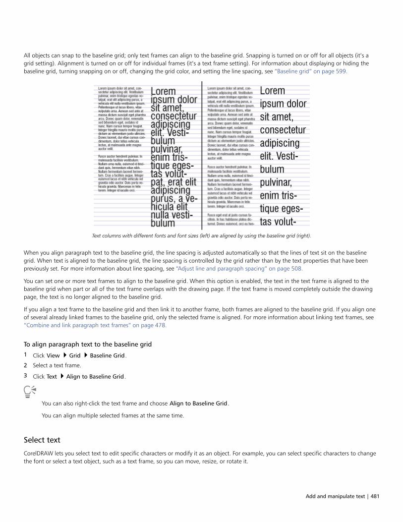
Add and manipulate text | 481
All objects can snap to the baseline grid; only text frames can align to the baseline grid. Snapping is turned on or off for all objects (it’s agrid setting). Alignment is turned on or off for individual frames (it’s a text frame setting). For information about displaying or hiding thebaseline grid, turning snapping on or off, changing the grid color, and setting the line spacing, see “Baseline grid” on page 599.
Text columns with different fonts and font sizes (left) are aligned by using the baseline grid (right).
When you align paragraph text to the baseline grid, the line spacing is adjusted automatically so that the lines of text sit on the baselinegrid. When text is aligned to the baseline grid, the line spacing is controlled by the grid rather than by the text properties that have beenpreviously set. For more information about line spacing, see “Adjust line and paragraph spacing” on page 508.
You can set one or more text frames to align to the baseline grid. When this option is enabled, the text in the text frame is aligned to thebaseline grid when part or all of the text frame overlaps with the drawing page. If the text frame is moved completely outside the drawingpage, the text is no longer aligned to the baseline grid.
If you align a text frame to the baseline grid and then link it to another frame, both frames are aligned to the baseline grid. If you align oneof several already linked frames to the baseline grid, only the selected frame is aligned. For more information about linking text frames, see“Combine and link paragraph text frames” on page 478.
To align paragraph text to the baseline grid
1 Click View Grid Baseline Grid.
2 Select a text frame.
3 Click Text Align to Baseline Grid.
You can also right-click the text frame and choose Align to Baseline Grid.
You can align multiple selected frames at the same time.
Select text
CorelDRAW lets you select text to edit specific characters or modify it as an object. For example, you can select specific characters to changethe font or select a text object, such as a text frame, so you can move, resize, or rotate it.

482 | CorelDRAW 2019 User Guide
To select a text object
To Do the following
Select artistic text Using the Pick tool , click the artistic text.
Select a text frame Using the Pick tool , click the text frame.
You can use the Pick tool to select multiple text objects. Hold down Shift, and click each text object.
To select text for editing
To Do the following
Select specific characters of artistic or paragraph text for editing Using the Text tool , drag across the text.
Select a text frame for editing Using the Text tool , click the text frame.
Find, edit, and convert text
You can find text in a document and replace it automatically. You can also find and replace the properties of text objects. You can findspecial characters, such as an em dash or optional hyphen. You can edit text directly in the drawing window or in a dialog box.
Additional formatting options are available for paragraph text. To apply these formatting options to artistic text, you first need to convert theartistic text to paragraph text. Likewise, you can apply special effects to paragraph text by converting the text to artistic text. Converting textmay result in the loss of any formatting.
You can also convert both paragraph and artistic text to curves. By transforming characters into lines or curve objects, you can add, delete,or move the nodes of individual characters to alter their shape. For more information, see “Curve objects” on page 176.
When you convert text to curves, the appearance of the text is preserved, including font, style, character position and rotation, spacing, andany other text settings and effects. Any linked text objects are also converted to curves. If you convert paragraph text in a fixed-sized textframe to curves, any text that overflows the text frame is deleted. For information about fitting text to a text frame, see “Format text” onpage 495.
To find text
1 Click Edit Find and Replace.
2 In the Find and Replace docker, choose Find and Replace Text from the list box at the top of the docker.
3 Type the text that you want to find in the Find box.
If you want to find the exact case of the text that you specified, enable the Match case check box.
If you want to find whole words only, enable the Find whole words only check box.
4 Click Find Next.

Add and manipulate text | 483
You can also find special characters by clicking the right arrowhead next to the Find box, choosing a special character, and clickingFind Next.
To find and replace text
1 Click Edit Find and Replace.
2 In the Find and Replace docker, choose Find and Replace Text from the list box at the top of the docker.
3 Enable the Replace option.
4 Type the text that you want to find in the Find box.
If you want to find the exact case of the text that you specified, enable the Match case check box.
If you want to find only whole words, enable the Find whole words only check box.
5 Type the replacement text in the Replace box.
6 Click one of the following buttons:
• Find Next > to scroll through occurrences of the text that is specified in the Find box
• Replace — replaces the selected occurrence of the text that is specified in the Find box. If no occurrence is selected, Replace finds thenext occurrence.
• Replace All — replaces every occurrence of the text that is specified in the Find box
To find and replace text properties
1 Click Edit Find and Replace.
2 In the Find and Replace docker, choose Replace Objects from the list box at the top of the docker.
3 Enable the Text properties option.
4 In the Find area, do any of following:
• Enable the Font check box and choose the font to find.
• Enable the Weight check box, and choose the text weight to find.
• Enable the Size check box, and choose the text size to find.
5 In the Replace area, do any of following:
• Enable the Font check box and choose a replacement font.
• Enable the Weight check box, and choose a replacement text weight.
• Enable the Size check box, and choose a replacement text size.
6 Click Find, and click any of the following:
• Find Next or Find Previous to scroll through text objects that meet the search criteria.
• Find All to select all text objects that meet the search criteria.
• Replace to replace the properties of the selected text object.
• Replace All to replace the color of all text objects that meet the search criteria.
To edit text
1 Click the Text tool .
2 Perform a task from the following table.
To Do the following
Edit artistic text Click in the artistic text.

484 | CorelDRAW 2019 User Guide
To Do the following
Edit paragraph text Click in the text frame.
Text that has been converted to curves cannot be edited.
You can also edit text by clicking Text Edit Text, and making changes to the text in the Edit Text dialog box.
To convert text
To Do the following
Convert paragraph text to artistic text Using the Pick tool , select the text, and click Text Convert
to Artistic Text.
Convert artistic text to paragraph text Using the Pick tool , select the text, and click Text Convert
to Paragraph Text.
Convert artistic or paragraph text to curves Using the Pick tool , select the text, and click Object
Convert to Curves.
Paragraph text cannot be converted to artistic text when it’s in a linked frame, has text overflow, or has special effects applied to it.
You can also convert text to curves by clicking the Pick tool , right-clicking the text, and clicking Convert to Curves.
Shift, rotate, mirror, and flip text
You can shift the characters of artistic and paragraph text vertically or horizontally or rotate them to create interesting effects.You canstraighten characters into their original position, and you can return vertically shifted characters to the baseline. You can also mirror or flipartistic and paragraph text characters.
If you want to adjust the position of an entire text object that is fitted to a path, such as a circle or a freehand line, see “To adjust theposition of text that is fitted to a path” on page 489.
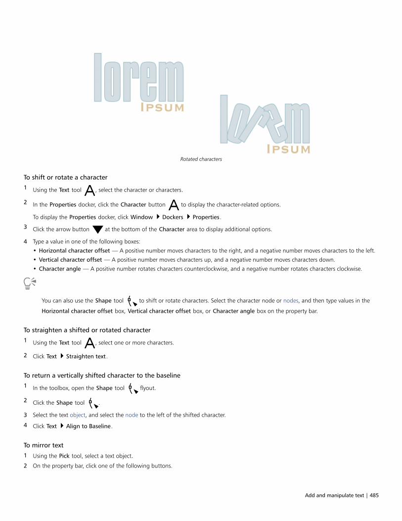
Add and manipulate text | 485
Rotated characters
To shift or rotate a character
1 Using the Text tool , select the character or characters.
2 In the Properties docker, click the Character button to display the character-related options.
To display the Properties docker, click Window Dockers Properties.
3 Click the arrow button at the bottom of the Character area to display additional options.
4 Type a value in one of the following boxes:
• Horizontal character offset — A positive number moves characters to the right, and a negative number moves characters to the left.
• Vertical character offset — A positive number moves characters up, and a negative number moves characters down.
• Character angle — A positive number rotates characters counterclockwise, and a negative number rotates characters clockwise.
You can also use the Shape tool to shift or rotate characters. Select the character node or nodes, and then type values in the
Horizontal character offset box, Vertical character offset box, or Character angle box on the property bar.
To straighten a shifted or rotated character
1 Using the Text tool , select one or more characters.
2 Click Text Straighten text.
To return a vertically shifted character to the baseline
1 In the toolbox, open the Shape tool flyout.
2 Click the Shape tool .
3 Select the text object, and select the node to the left of the shifted character.
4 Click Text Align to Baseline.
To mirror text
1 Using the Pick tool, select a text object.
2 On the property bar, click one of the following buttons.

486 | CorelDRAW 2019 User Guide
• Mirror horizontally — flips the text characters from left to right
• Mirror vertically — flips the text characters from top to bottom
You can also mirror text by holding down Ctrl and dragging a selection handle to the opposite side of the object.
You can also mirror text fitted to a path. For more information, see “To mirror text that is fitted to a path” on page 490.
Left to right: Text in original form, mirrored vertically, and mirrored horizontally
To flip text by dragging diagonally
1 Using the Text tool , select the artistic text or the paragraph text frame.
2 Drag a middle selection handle across the text and past the corner handle on the opposite side.
Move text
CorelDRAW offers different methods for moving text. If you select text as an object, such as a block of artistic text or a text frame, you canmove it to a new position, as you would any other object.
You can also move a selection of paragraph text between text frames or move artistic text between artistic text objects. Conversely, you canmove paragraph text to an artistic text object, or artistic text to a paragraph text frame.
To move a text object
1 Click the Pick tool .
2 Drag the text object to a new position in the drawing window.
To move a text selection
1 Click the Text tool .
2 Select the text that you want to move.
3 Perform a task from the following table.
To Do the following
Move text within the same text object Drag the text to a new position within the text object. The textcursor appears to indicate the insertion point.
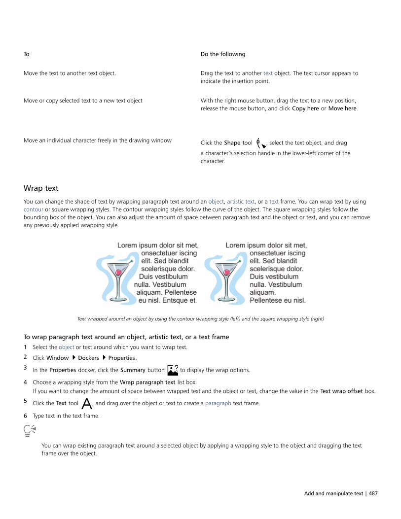
Add and manipulate text | 487
To Do the following
Move the text to another text object. Drag the text to another text object. The text cursor appears toindicate the insertion point.
Move or copy selected text to a new text object
With the right mouse button, drag the text to a new position,release the mouse button, and click Copy here or Move here.
Move an individual character freely in the drawing window Click the Shape tool , select the text object, and drag
a character’s selection handle in the lower-left corner of thecharacter.
Wrap text
You can change the shape of text by wrapping paragraph text around an object, artistic text, or a text frame. You can wrap text by usingcontour or square wrapping styles. The contour wrapping styles follow the curve of the object. The square wrapping styles follow thebounding box of the object. You can also adjust the amount of space between paragraph text and the object or text, and you can removeany previously applied wrapping style.
Text wrapped around an object by using the contour wrapping style (left) and the square wrapping style (right)
To wrap paragraph text around an object, artistic text, or a text frame
1 Select the object or text around which you want to wrap text.
2 Click Window Dockers Properties.
3 In the Properties docker, click the Summary button to display the wrap options.
4 Choose a wrapping style from the Wrap paragraph text list box.
If you want to change the amount of space between wrapped text and the object or text, change the value in the Text wrap offset box.
5 Click the Text tool , and drag over the object or text to create a paragraph text frame.
6 Type text in the text frame.
You can wrap existing paragraph text around a selected object by applying a wrapping style to the object and dragging the textframe over the object.
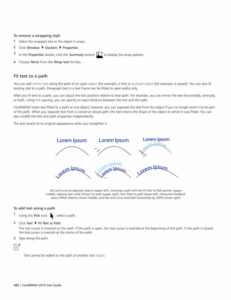
488 | CorelDRAW 2019 User Guide
To remove a wrapping style
1 Select the wrapped text or the object it wraps.
2 Click Window Dockers Properties.
3 In the Properties docker, click the Summary button to display the wrap options.
4 Choose None from the Wrap text list box.
Fit text to a path
You can add artistic text along the path of an open object (for example, a line) or a closed object (for example, a square). You can also fitexisting text to a path. Paragraph text in a text frame can be fitted to open paths only.
After you fit text to a path, you can adjust the text position relative to that path. For example, you can mirror the text horizontally, vertically,or both. Using tick spacing, you can specify an exact distance between the text and the path.
CorelDRAW treats text fitted to a path as one object; however, you can separate the text from the object if you no longer want it to be partof the path. When you separate text from a curved or closed path, the text retains the shape of the object to which it was fitted. You canalso modify the text and path properties independently.
The text reverts to its original appearance when you straighten it.
Text and curve as separate objects (upper left), choosing a path with the Fit Text to Path pointer (uppermiddle), aligning text while fitting it to path (upper right), text fitted to path (lower left), interactive feedback
about offset distance (lower middle), and text and curve stretched horizontally by 200% (lower right)
To add text along a path
1 Using the Pick tool , select a path.
2 Click Text Fit Text to Path.
The text cursor is inserted on the path. If the path is open, the text cursor is inserted at the beginning of the path. If the path is closed,the text cursor is inserted at the center of the path.
3 Type along the path.
Text cannot be added to the path of another text object.
Add and manipulate text | 489
You can also fit text to a path by clicking the Text tool and pointing to a path. When the pointer changes to the Fit Text to Path
pointer , click where you want the text to begin, and type.
To fit text to a path
1 Using the Pick tool , select a text object.
2 Click Text Fit Text to Path.
The pointer changes to the Fit Text to Path pointer . By moving the pointer over the path, you can preview where the text will be
fitted.
3 Click a path.
If the text is fitted to a closed path, the text is centered along the path. If the text is fitted to an open path, the text flows from the pointof insertion.
Artistic text can be fitted to open or closed paths. Paragraph text can be fitted to open paths only.
Text cannot be fitted to the path of another text object.
To adjust the position of text that is fitted to a path
1 Using the Pick tool , select the text that is fitted to a path.
2 Choose a setting from any of the following list boxes on the property bar:
• Text orientation — specifies how the text bends to follow the path
• Distance from path — distance between the text and the path
• Offset — horizontal position of the text along the path
You can also
Use tick spacing to increase the distance between the path and thetext in specified increments
Select the text. On the property bar, click Tick snapping, enable theTick snapping on option, and type a value in the Tick spacing box.
When you move the text from the path, it moves in the incrementyou specified in the Tick spacing box. When you move the text, thedistance from the path is displayed below the original text.
Change the horizontal position of fitted text Using the Shape tool , select the text, and drag the character
nodes that you want to reposition.
Move fitted text along or off the path Using the Pick tool , drag the red glyph that appears next to
the text.
When you drag the glyph along the path, a preview of the textis displayed. When you drag the glyph off the path, the distancebetween the text preview and the path is displayed.
490 | CorelDRAW 2019 User Guide
To mirror text that is fitted to a path
1 Using the Pick tool , click the text that is fitted to a path.
2 On the property bar, click one of the following buttons:
• Mirror text horizontally — flips the text characters from left to right
• Mirror text vertically — flips the text characters upside down
You can apply a 180-degree rotation to text that is fitted to a path by clicking both the Mirror text horizontally and the Mirror textvertically buttons.
You can also mirror artistic text and paragraph text frames. For more information, see “To mirror text” on page 485.
To separate text from a path
1 Using the Pick tool , select the path and the fitted text.
2 Click Object Break Text Apart.
To straighten text
1 Using the Pick tool , select the path and the fitted text.
2 Click Object Break Text Apart.
3 Using the Pick tool, select the text.
4 Click Text Straighten Text.
Special characters, symbols, and glyphs
Using the Glyphs docker, you can find and insert special characters, symbols, and glyphs (variations of individual characters or charactercombinations) of OpenType fonts.
Filtering
All characters, symbols, and glyphs included in a font are displayed by default, but you can filter character subsets to display only thecharacters you want. For example, you can display only currency symbols or numbers, or you can display only Cyrillic characters and symbols.
Characters included in a font are organized in the following categories:• Common — includes arrows, currency, mathematical symbols, numbers, punctuation marks, and separators as well as CJK symbols and
punctuation marks (used in Asian scripts)• Scripts — includes the scripts that the selected font supports, such as Latin, Greek, Cyrillic, Hiragana and Katakana, Han, Arabic, or
Hebrew scripts• OpenType — includes the OpenType features provided by the selected font such as standard ligatures, discretionary ligatures, fraction,
alternate annotation forms, and more. For more information about OpenType features, see “OpenType features” on page 502.
OpenType fonts
The Glyphs docker is ideal for viewing and applying the OpenType features provided by OpenType fonts. The default view shows a list ofcharacters in which the glyphs for individual characters appear grouped. Alternatively, you can display a longer list that shows availableglyphs at a glance.
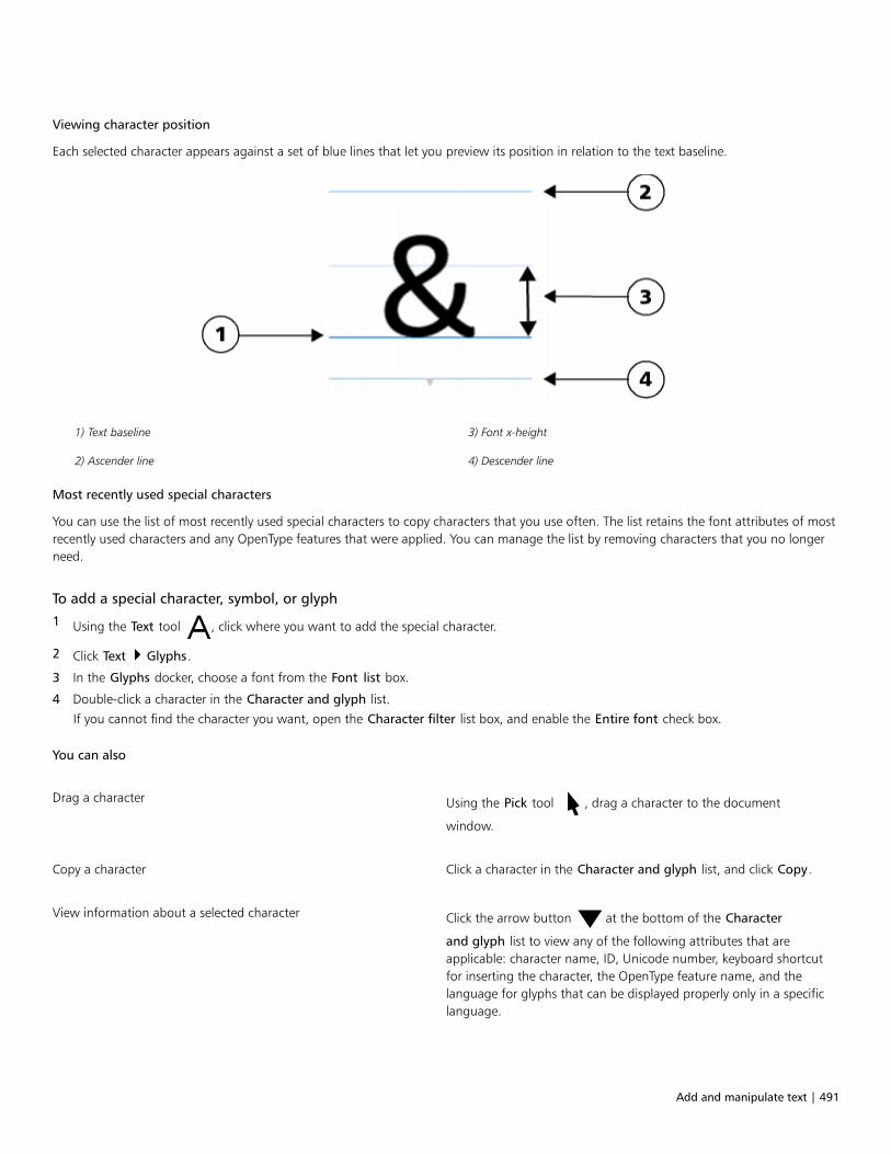
Add and manipulate text | 491
Viewing character position
Each selected character appears against a set of blue lines that let you preview its position in relation to the text baseline.
1) Text baseline 3) Font x-height
2) Ascender line 4) Descender line
Most recently used special characters
You can use the list of most recently used special characters to copy characters that you use often. The list retains the font attributes of mostrecently used characters and any OpenType features that were applied. You can manage the list by removing characters that you no longerneed.
To add a special character, symbol, or glyph
1 Using the Text tool , click where you want to add the special character.
2 Click Text Glyphs.
3 In the Glyphs docker, choose a font from the Font list box.
4 Double-click a character in the Character and glyph list.
If you cannot find the character you want, open the Character filter list box, and enable the Entire font check box.
You can also
Drag a character Using the Pick tool , drag a character to the document
window.
Copy a character Click a character in the Character and glyph list, and click Copy.
View information about a selected character Click the arrow button at the bottom of the Character
and glyph list to view any of the following attributes that areapplicable: character name, ID, Unicode number, keyboard shortcutfor inserting the character, the OpenType feature name, and thelanguage for glyphs that can be displayed properly only in a specificlanguage.

492 | CorelDRAW 2019 User Guide
You can also
Zoom in and out Move the Zoom slider.
To zoom in and out in preset increments, click the zoom buttons tothe right and left of the Zoom slider.
Navigate to a special character by using an Alt code Click in the Character and glyph list, hold down Alt, and type theAlt code for the character you want.
Navigate to a character Press the corresponding key on the keyboard.
To filter special characters, symbols, and glyphs
1 Click Text Glyphs.
2 In the Glyphs docker, choose a font from the Font list box.
3 Open the Character filter list box, and enable the check boxes for the character subsets that you want to display.
4 Click Close.
To view glyphs of OpenType features
1 Click Text Glyphs.
2 In the Glyphs docker, choose an OpenType font from the Font list box.
3 Open the Character filter list box, and in the OpenType area, enable any of the check boxes for the available OpenType features.
4 Do one of the following:
• To display a list that includes grouped glyphs, make sure that the Show all glyphs button does not appear pressed. To view all
glyphs in a group, click a character, and then click the OpenType feature indicator. Click a glyph to display it in the Character andglyph list.
• To display a list that includes all available glyphs, click the Show all glyphs button .
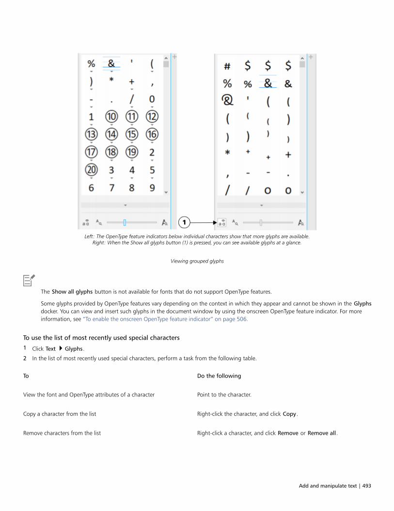
Add and manipulate text | 493
Left: The OpenType feature indicators below individual characters show that more glyphs are available.Right: When the Show all glyphs button (1) is pressed, you can see available glyphs at a glance.
Viewing grouped glyphs
The Show all glyphs button is not available for fonts that do not support OpenType features.
Some glyphs provided by OpenType features vary depending on the context in which they appear and cannot be shown in the Glyphsdocker. You can view and insert such glyphs in the document window by using the onscreen OpenType feature indicator. For moreinformation, see “To enable the onscreen OpenType feature indicator” on page 506.
To use the list of most recently used special characters
1 Click Text Glyphs.
2 In the list of most recently used special characters, perform a task from the following table.
To Do the following
View the font and OpenType attributes of a character Point to the character.
Copy a character from the list Right-click the character, and click Copy.
Remove characters from the list Right-click a character, and click Remove or Remove all.
494 | CorelDRAW 2019 User Guide
Embed graphics
You can embed a graphic object or bitmap in text. The graphic object or bitmap is treated as a text character. As a result, you can applyformatting options according to the type of text in which you embed the graphic object. You can also remove an embedded object fromtext, after which the object returns to its original state.
To embed a graphic object in text
1 Select a graphic object.
2 Click Edit, and click one of the following:
• Cut
• Copy
3 Using the Text tool , click where you want to embed the graphic object.
4 Click Edit Paste.
To remove an embedded object from text
1 Using the Text tool , select an embedded object.
2 Click Edit Cut.
3 Click the Pick tool , and click outside the text object.
4 Click Edit Paste.
Legacy text
If a document contains text and was created in a previous version of CorelDRAW, such as CorelDRAW X5, you must update the legacytext before you can use new text features such as OpenType options and aligning text with the baseline grid. For more information, see“OpenType features ” on page 502 and “Align text to the baseline grid” on page 480.
To update legacy text
1 Open the document with legacy text.
An Update toolbar appears at the top of the drawing window.
2 Click Update.
To undo the update, click Undo on the Update toolbar. However, once you make changes to the updated text, this option is no longeravailable.
When legacy text is updated, its flow and layout may change.
You can also update legacy text by clicking the Update button in the Character area of the Properties docker.
Format text | 495
Format text
CorelDRAW offers many tools and controls for formatting individual characters, entire paragraphs, and text in frames.
This section contains the following topics:• “Choose typefaces and fonts” (page 495)• “Format characters” (page 498)• “Change text color” (page 499)• “Kern a range of characters” (page 501)• “Changing text case” (page 501)• “OpenType features” (page 502)• “Adjust character and word spacing” (page 507)• “Adjust line and paragraph spacing” (page 508)• “Add bullets to text” (page 510)• “Drop caps” (page 511)• “Change character position and angle” (page 512)• “Align text” (page 513)• “Add tabs and indents” (page 516)• “Text styles” (page 517)• “Hyphenate text” (page 517)• “Formatting codes” (page 519)• “Nonprinting characters” (page 520)
Choose typefaces and fonts
Text is an important element in the design and layout of documents. In CorelDRAW, you can choose the typeface that is best suited to yourproject. You can specify the font size and style. In addition, you can use an OpenType font to achieve a unique and distinctive style. For moreinformation, see “OpenType features” on page 502. The default unit of measure for text is points; however, you can change the unit ofmeasure for the active drawing and all subsequent drawings. For information about previewing fonts, see “View fonts” on page 532.
Fonts vs. typefaces
“Font” and “typeface” are two typography terms that are often used interchangeably, but they do not have the same meaning. A font is acollection of characters that includes letters, numbers, and symbols of one variation of a typeface, such as bold or italic. A typeface, whichis also known as a font family, is made up of several fonts that share similar design characteristics. In other words, a font is the mechanism

496 | CorelDRAW 2019 User Guide
that allows you to render the characters onscreen or in print, whereas the typeface, which embodies the style and visual distinctiveness ofthe characters, refers to the design and style of the type.
The following table lists a few examples of typefaces and fonts.
Typeface (Font family) Font
Helvetica Helvetica Bold-Italic
Times New Roman Normal
Verdana Verdana Bold-Italic
Choosing a typeface
Typefaces come in different shapes and sizes and have unique characteristics and expressive qualities. Choosing the right typeface is animportant design consideration because it can set the tone of the project. Moreover, it can help, or hinder, effective communication. Forexample, if you design a poster with a typeface that is difficult to read, or sets the wrong tone, your message may not effectively reach yourintended audience.
The typeface applied to the word “Menu” on the left is more suitablefor an upscale restaurant menu than the typeface on the right.
Here are a few basic tips for choosing the right typeface:• Choose a typeface that best suits the tone of your design.• Choose a typeface that is appropriate for the final output of your design (e.g. web or print).• Use less typefaces in your document. The general rule is not to exceed three or four typefaces in a document.• Make sure the typeface characters are easy to read and recognize.• Choose a typeface that is appropriate for the age of your target audience.• Make sure the typeface of headings stands out and looks good when displayed at larger sizes.• Make sure the typeface of body text enhances readability.• Choose a typeface that supports multiple languages if you’re working on multilingual documents.
To change the font
1 Using the Text tool , select a character or a block of text.
If the Properties docker is not open, click Window Dockers Properties.
2 In the Properties docker, click the Character button to display the character-related options.
3 In the Character area of the Properties docker, perform one or more tasks from the following table.
To Do the following
Choose a typeface Choose a typeface from the Font list box.

Format text | 497
To Do the following
For information about finding fonts more easily, see “Filter fonts ”on page 533 and “Search for fonts” on page 535.
Set font size Type a value in the Font size box.
Change the font style Choose a style from the Font style list box.
You can also change the font and font size from the property bar.
You can also change the font style of selected text by clicking the Bold button , Italic button , or Underline button on
the property bar.
To resize text
1 Using the Text tool , select a character or a block of text.
2 On the property bar, choose a size from the Font size list box.
You can also
Resize artistic text using the Pick tool Click the Pick tool , and drag one of the corner handles.
Resize paragraph text using the Pick tool Click the Pick tool , press Alt, and then drag one of the corner
handles.
Increase the size of text Press Num Lock to activate the number pad on your keyboard, and
use the Text tool to select the text. Then, hold down Ctrl, and
press 8 on the number pad.
Decrease the size of text Using the Text tool , select the text. Then, hold down Ctrl, and
press 2 on the number pad.
Set an increment for resizing text Click Tools Options CorelDRAW. In the left pane of the dialogbox that appears, click Text, and type a value in the Keyboard textincrement box on the Display page.
Change the default unit of measure Click Tools Options CorelDRAW. In the left pane of the dialogbox that appears, click Text, and choose a unit from the Defaulttext units list box on the Display page.
You can also resize the text from the Character area of the Properties docker, by choosing a size from the Font size list box.

498 | CorelDRAW 2019 User Guide
Format characters
You can change the position and appearance of characters by displaying them as subscript or superscript, which is useful in drawings withscientific notations. If you select an OpenType font that supports subscript and superscript, you can apply the OpenType feature. However,if you select a font, including an OpenType font, that does not support subscript and superscript, you can apply a synthesized version of thecharacter, which CorelDRAW produces by altering the characteristics of the default font character. For more information, see “OpenTypefeatures” on page 502.
Artistic text with superscript (1) and subscript (2) applied
You can also add underlines, strikethrough lines, and overlines to selected characters.
Artist text with underline (1), strikethrough (2), and overline (3) applied to the text using both single and double line styles.
If you want to reuse the formatting of selected text, you can use styles or copy the text attributes and apply them to another text selection.For more information, see “Styles and style sets ” on page 565 and “Copy object properties, transformations, and effects” on page 270.
To insert superscript or subscript text
1 Using the Text tool , select a character or a block of text.
If the Properties docker is not open, click Window Dockers Properties.
2 In the Properties docker, click the Character button to display the character-related options.
3 In the Character area of the Properties docker, click the Position button, and choose one of the following options.
• None — turns off all the features in the list
• Superscript (auto) — applies the OpenType feature if the font supports it, or applies a synthesized version if the font does not supportsuperscript
• Subscript (auto) — applies the OpenType feature if the font supports it, or applies a synthesized version if the font does not supportsubscript

Format text | 499
• Superscript (synthesized) — applies a synthesized version of the superscript feature, which looks the same as in previous versions ofCorelDRAW
• Subscript (synthesized) — applies a synthesized version of the subscript feature, which looks the same as in previous versions ofCorelDRAW
Some OpenType fonts may appear to support features that are unsupported. For example, Superscript and Subscript optionsmay appear available, but are not. If you apply one of these OpenType fonts, CorelDRAW cannot provide a synthesized version ofSuperscript and Subscript.
To underline, overline, or strikethrough text
1 Using the Text tool , select a character or a block of text.
If the Properties docker is not open, click Window Dockers Properties.
2 In the Properties docker, click the Character button to display the character-related options.
3 In the Character area of the Properties docker, click the arrow button located at the bottom of Character area to display the
additional character options.
4 Perform one or more tasks from the following table.
To Do the following
Underline text Click the Underline button and choose a style from the list
box.
Apply a line through the selected text Choose a style from the Character strikethrough list box.
Apply a line above the selected text. Choose a style from the Character overline list box.
Change text color
You can quickly change both the fill and outline color of text. You can change the fill, outline, and background color of text. You can changethe color of individual characters, a block of text, or all characters in a text object.
Left to right: Background color is applied to artistic text, paragraph text, and selected characters

500 | CorelDRAW 2019 User Guide
To quickly change the color of a text object
1 Using the Pick tool , click a text object to select it.
2 Perform a task from the following table.
To Do the following
To fill characters in a text object with one color Click any color swatch on the default color palette or drag a colorswatch to the text object.
To apply an outline color to all characters in a text object Right-click any color swatch on the default color palette or drag acolor swatch to the edge of a character in the text object.
To change the color of a text selection
1 Using the Text tool , select a character or a block of text.
If the Properties docker is not open, click Window Dockers Properties.
2 In the Properties docker, click the Character button to display the character-related options.
3 In the Character area of the Properties docker, perform one or more tasks from the following table.
To Do the following
Choose a fill In the text color area, choose a fill type from the Fill type list box,open the Fill picker, and then click a color or a fill.
Modify fill settings In the text color area, click the Fill settings button , and
modify the settings in the dialog box.
Choose a background fill In the text background color area, choose a fill type from theBackground fill type list box, open the Fill picker, and then click acolor or a fill.
Modify background fill settings In the text background color area, click the Fill settings button, andmodify the settings in the dialog box.
Choose an outline width In the text outline color area, click the Outline width button, andchoose an option from the list.
Choose an outline color In the text outline color area, click the Outline color picker, and
click a color.
Modify line outline settings In the text outline color area, click the Outline settings button
, and modify the settings in the Outline pen dialog box.
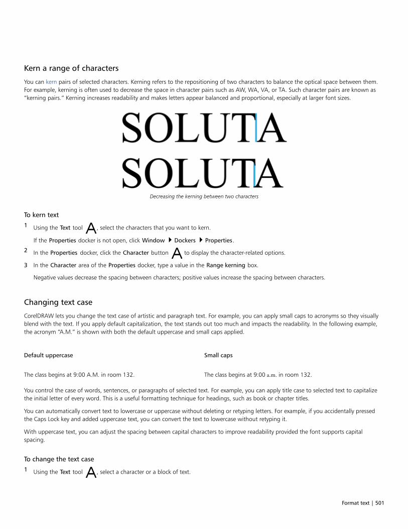
Format text | 501
Kern a range of characters
You can kern pairs of selected characters. Kerning refers to the repositioning of two characters to balance the optical space between them.For example, kerning is often used to decrease the space in character pairs such as AW, WA, VA, or TA. Such character pairs are known as“kerning pairs.” Kerning increases readability and makes letters appear balanced and proportional, especially at larger font sizes.
Decreasing the kerning between two characters
To kern text
1 Using the Text tool , select the characters that you want to kern.
If the Properties docker is not open, click Window Dockers Properties.
2 In the Properties docker, click the Character button to display the character-related options.
3 In the Character area of the Properties docker, type a value in the Range kerning box.
Negative values decrease the spacing between characters; positive values increase the spacing between characters.
Changing text case
CorelDRAW lets you change the text case of artistic and paragraph text. For example, you can apply small caps to acronyms so they visuallyblend with the text. If you apply default capitalization, the text stands out too much and impacts the readability. In the following example,the acronym “A.M.” is shown with both the default uppercase and small caps applied.
Default uppercase Small caps
The class begins at 9:00 A.M. in room 132. The class begins at 9:00 a.m. in room 132.
You control the case of words, sentences, or paragraphs of selected text. For example, you can apply title case to selected text to capitalizethe initial letter of every word. This is a useful formatting technique for headings, such as book or chapter titles.
You can automatically convert text to lowercase or uppercase without deleting or retyping letters. For example, if you accidentally pressedthe Caps Lock key and added uppercase text, you can convert the text to lowercase without retyping it.
With uppercase text, you can adjust the spacing between capital characters to improve readability provided the font supports capitalspacing.
To change the text case
1 Using the Text tool , select a character or a block of text.
502 | CorelDRAW 2019 User Guide
If the Properties docker is not open, click Window Dockers Properties.
2 In the Properties docker, click the Character button to display the character-related options.
3 In the Character area of the Properties docker, click the Caps button, and click one of the following options:
• None — turns off all of the features in the list
• All Caps — substitutes lowercase characters with upper case equivalents
• Titling Caps — applies the OpenType version of the feature if the font supports it
• Small Caps (auto) — applies the OpenType version of the feature if the font supports it
• All Small Caps — substitutes characters with a scaled-down version of the upper case characters
• Small Caps from Caps — applies the OpenType version of the feature if the font supports it
• Small Caps (synthesized) — applies a synthesized version of Small caps, which appears the same as in previous versions ofCorelDRAW
If the font supports capital spacing, you can click the Capital spacing button to increase the spacing between capital characters
and improve readability.
If you choose a non-OpenType font that supports Caps styles, CorelDRAW provides a synthesized version of the Small caps and Allsmall caps styles.
Some OpenType fonts may appear to support features that are unsupported.
You can also change text case by selecting a character or a block of text, clicking Text Change Case, and enabling an option in theChange Case dialog box.
OpenType features
CorelDRAW supports OpenType fonts so you can take advantage of their advanced typographic features. OpenType features allow you tochoose an alternate appearance for an individual character (also referred to as a glyph) or a sequence of characters. For example, you canchoose alternate glyphs for numbers, fractions, or ligature sets.
You can access OpenType commands and options in the Character area of the Properties docker. You can also let CorelDRAW prompt youwhich OpenType features you can apply by enabling the Interactive OpenType option. When you select text, an indicator arrow appearsbelow the text if an OpenType feature is available. You can click the indicator to access a list of the most popular OpenType features that areavailable for the selected text.

Format text | 503
Clicking the Interactive OpenType indicator arrow (1) expands a list of themost popular OpenType features that are available for the selected text.
The OpenType font specification was created jointly by Adobe and Microsoft. Based on Unicode, OpenType fonts extend the capabilities ofolder font technologies. The most notable advantages of OpenType are:• cross-platform support (Windows and Mac OS)• extended character sets that offer better language support and advanced typographic features• coexistence with Type 1 (PostScript) and TrueType fonts• support for a larger glyph limit (64k)
OpenType features
The following table describes the OpenType features that you can apply in CorelDRAW provided that the feature is included in the font.
In addition, CorelDRAW also provides synthesized versions of some Caps and Position OpenType features. For example, if a font does notsupport a feature, such as Small Caps, CorelDRAW produces its own version of the glyph by scaling the font.
OpenType feature Description Example
Caps Changes the case of text, which is useful forinserting titles and acronyms
Small caps
Position Displays characters as superscript orsubscript, which is useful for insertingfootnotes or mathematical symbols. If youselect an OpenType font that does notsupport subscript and superscript, or a non-OpenType font, you can apply a synthesizedglyph.
Superscript
Number styles Includes features for controlling theappearance of numbers
See examples below
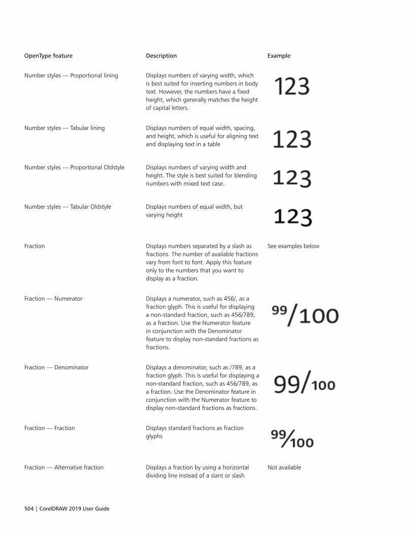
504 | CorelDRAW 2019 User Guide
OpenType feature Description Example
Number styles — Proportional lining Displays numbers of varying width, whichis best suited for inserting numbers in bodytext. However, the numbers have a fixedheight, which generally matches the heightof capital letters.
Number styles — Tabular lining Displays numbers of equal width, spacing,and height, which is useful for aligning textand displaying text in a table
Number styles — Proportional Oldstyle Displays numbers of varying width andheight. The style is best suited for blendingnumbers with mixed text case.
Number styles — Tabular Oldstyle Displays numbers of equal width, butvarying height
Fraction Displays numbers separated by a slash asfractions. The number of available fractionsvary from font to font. Apply this featureonly to the numbers that you want todisplay as a fraction.
See examples below
Fraction — Numerator Displays a numerator, such as 456/, as afraction glyph. This is useful for displayinga non-standard fraction, such as 456/789,as a fraction. Use the Numerator featurein conjunction with the Denominatorfeature to display non-standard fractions asfractions.
Fraction — Denominator Displays a denominator, such as /789, as afraction glyph. This is useful for displaying anon-standard fraction, such as 456/789, asa fraction. Use the Denominator feature inconjunction with the Numerator feature todisplay non-standard fractions as fractions.
Fraction — Fraction Displays standard fractions as fractionglyphs
Fraction — Alternative fraction Displays a fraction by using a horizontaldividing line instead of a slant or slash
Not available
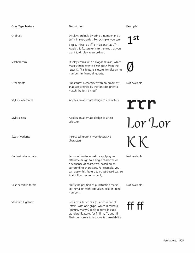
Format text | 505
OpenType feature Description Example
Ordinals Displays ordinals by using a number and asuffix in superscript. For example, you can
display “first” as 1st or “second” as 2nd.Apply this feature only to the text that youwant to display as an ordinal.
Slashed zero Displays zeros with a diagonal slash, whichmakes them easy to distinguish from theletter O. This feature is useful for displayingnumbers in financial reports.
Ornaments Substitutes a character with an ornamentthat was created by the font designer tomatch the font’s motif
Not available
Stylistic alternates Applies an alternate design to characters
Stylistic sets Applies an alternate design to a textselection
Swash Variants Inserts calligraphic-type decorativecharacters
Contextual alternates Lets you fine-tune text by applying analternate design to a single character, ora sequence of characters, based on itssurrounding characters. For example, youcan apply this feature to script-based text sothat it flows more naturally.
Not available
Case-sensitive forms Shifts the position of punctuation marksso they align with capitalized text or liningnumbers
Not available
Standard Ligatures Replaces a letter pair (or a sequence ofletters) with one glyph, which is called aligature. Many OpenType fonts includestandard ligatures for fi, fl, ff, ffi, and ffl.Their purpose is to improve text readability.
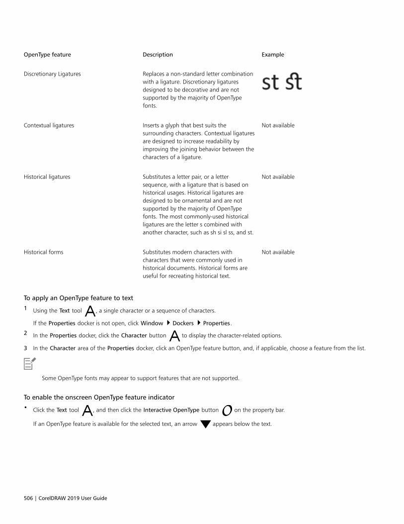
506 | CorelDRAW 2019 User Guide
OpenType feature Description Example
Discretionary Ligatures Replaces a non-standard letter combinationwith a ligature. Discretionary ligaturesdesigned to be decorative and are notsupported by the majority of OpenTypefonts.
Contextual ligatures Inserts a glyph that best suits thesurrounding characters. Contextual ligaturesare designed to increase readability byimproving the joining behavior between thecharacters of a ligature.
Not available
Historical ligatures Substitutes a letter pair, or a lettersequence, with a ligature that is based onhistorical usages. Historical ligatures aredesigned to be ornamental and are notsupported by the majority of OpenTypefonts. The most commonly-used historicalligatures are the letter s combined withanother character, such as sh si sl ss, and st.
Not available
Historical forms Substitutes modern characters withcharacters that were commonly used inhistorical documents. Historical forms areuseful for recreating historical text.
Not available
To apply an OpenType feature to text
1 Using the Text tool , a single character or a sequence of characters.
If the Properties docker is not open, click Window Dockers Properties.
2 In the Properties docker, click the Character button to display the character-related options.
3 In the Character area of the Properties docker, click an OpenType feature button, and, if applicable, choose a feature from the list.
Some OpenType fonts may appear to support features that are not supported.
To enable the onscreen OpenType feature indicator
• Click the Text tool , and then click the Interactive OpenType button on the property bar.
If an OpenType feature is available for the selected text, an arrow appears below the text.

Format text | 507
You can also
View a list of the most popular OpenType features onscreen Click the down arrow below the text in the document
window.
Apply an OpenType feature to a text selection In the OpenType feature list, click a feature.
Adjust character and word spacing
You can improve text readability by adjusting the character and word spacing. When letters or words are too close together, or too far apart,they become difficult to read. CorelDRAW offers you different tools for controlling text spacing.
Character spacing
You can change the spacing between characters (also known as “letter spacing”) in a block of text. For example, fully justifying a block oftext may insert too much space between characters, which creates a visual imbalance. To improve readability, you can decrease the characterspacing.
Increased character spacing (left) makes it difficult to read the text. Decreased character spacing (right) improves readability.
If you want to change the spacing between several characters, you need to adjust the kerning. For more information, see “Kern a range ofcharacters” on page 501.
Word spacing
You can also adjust the spacing between words.
Decreased word spacing makes it difficult to discern the individual words in aparagraph (left). Increased word spacing (right) makes easier to read the paragraph.
To adjust character spacing
1 Do one of the following:
508 | CorelDRAW 2019 User Guide
• Using the Text tool , position the cursor in a block of text.
• Using the Pick tool , click an artistic text object or a text frame.
If the Properties docker is not open, click Window Dockers Properties.
2 In the Properties docker, click the Paragraph button to display the paragraph-related options.
3 In the Paragraph area of the Properties docker, type a value in the Character spacing box.
Values for adjusting spacing represent a percentage of the space character. The Character values range from -100 to 2000 percent.All other values range from 0 to 2000 percent.
You can also change the character spacing proportionally by clicking the Shape tool , selecting the text object, and dragging the
Interactive horizontal spacing arrow in the lower-right corner of the text object.
You can increase the character spacing in uppercase text by using capital spacing. For more information, see “To change the textcase” on page 501.
To adjust word spacing
1 Do one of the following:
• Using the Text tool , position the cursor in a block of text.
• Using the Pick tool , click an artistic text object or a text frame.
If the Properties docker is not open, click Window Dockers Properties.
2 In the Properties docker, click the Paragraph button to display the paragraph-related options.
3 In the Paragraph area of the Properties docker, type a value in the Word spacing box.
You can also change the word spacing proportionally by clicking the Shape tool , holding down Shift, selecting the text object,
and dragging the Interactive horizontal spacing arrow in the lower-right corner of the text object.
Adjust line and paragraph spacing
You can change the spacing between lines of text, which is also known as “leading” or “interline spacing.”
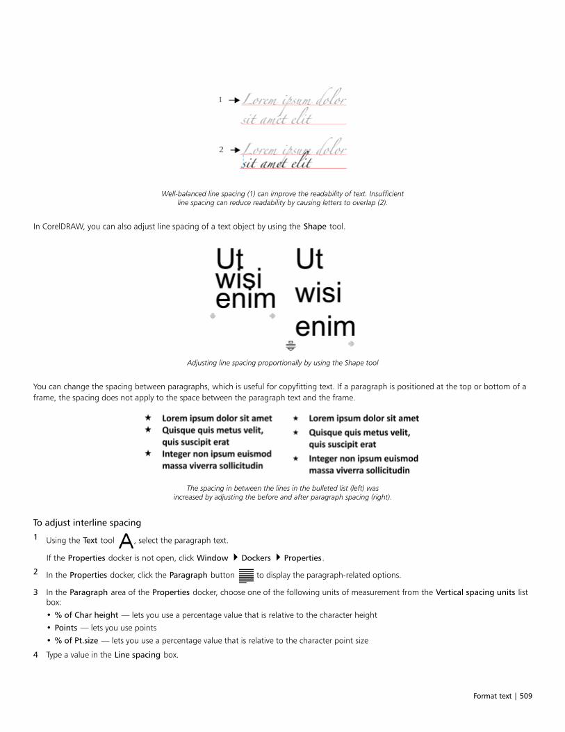
Format text | 509
Well-balanced line spacing (1) can improve the readability of text. Insufficientline spacing can reduce readability by causing letters to overlap (2).
In CorelDRAW, you can also adjust line spacing of a text object by using the Shape tool.
Adjusting line spacing proportionally by using the Shape tool
You can change the spacing between paragraphs, which is useful for copyfitting text. If a paragraph is positioned at the top or bottom of aframe, the spacing does not apply to the space between the paragraph text and the frame.
The spacing in between the lines in the bulleted list (left) wasincreased by adjusting the before and after paragraph spacing (right).
To adjust interline spacing
1 Using the Text tool , select the paragraph text.
If the Properties docker is not open, click Window Dockers Properties.
2 In the Properties docker, click the Paragraph button to display the paragraph-related options.
3 In the Paragraph area of the Properties docker, choose one of the following units of measurement from the Vertical spacing units listbox:
• % of Char height — lets you use a percentage value that is relative to the character height
• Points — lets you use points
• % of Pt.size — lets you use a percentage value that is relative to the character point size
4 Type a value in the Line spacing box.
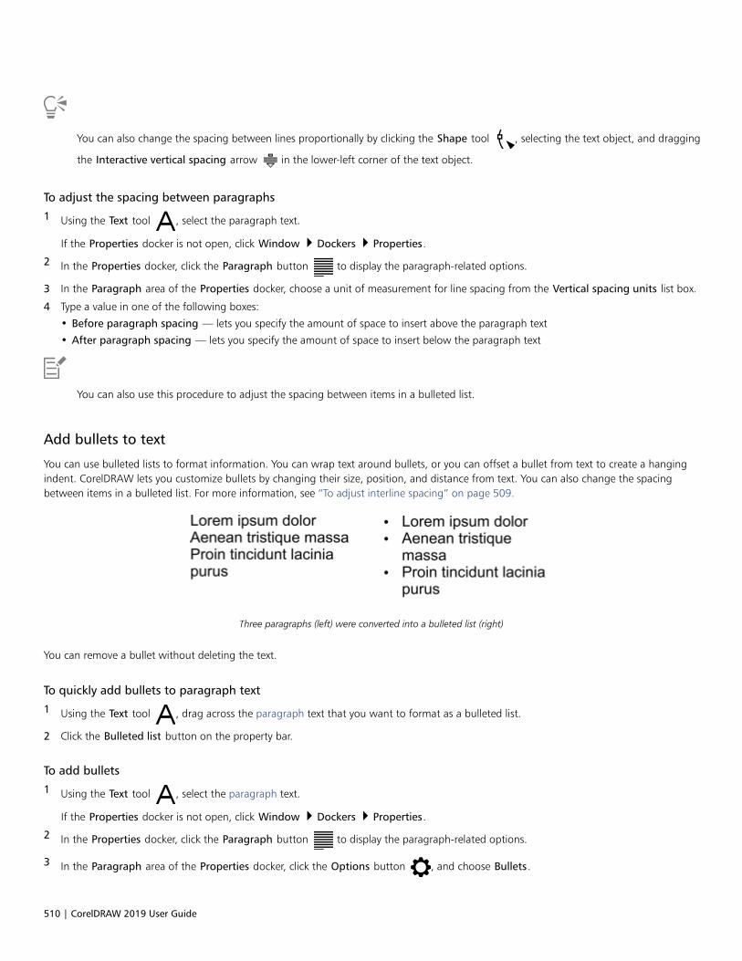
510 | CorelDRAW 2019 User Guide
You can also change the spacing between lines proportionally by clicking the Shape tool , selecting the text object, and dragging
the Interactive vertical spacing arrow in the lower-left corner of the text object.
To adjust the spacing between paragraphs
1 Using the Text tool , select the paragraph text.
If the Properties docker is not open, click Window Dockers Properties.
2 In the Properties docker, click the Paragraph button to display the paragraph-related options.
3 In the Paragraph area of the Properties docker, choose a unit of measurement for line spacing from the Vertical spacing units list box.
4 Type a value in one of the following boxes:
• Before paragraph spacing — lets you specify the amount of space to insert above the paragraph text
• After paragraph spacing — lets you specify the amount of space to insert below the paragraph text
You can also use this procedure to adjust the spacing between items in a bulleted list.
Add bullets to text
You can use bulleted lists to format information. You can wrap text around bullets, or you can offset a bullet from text to create a hangingindent. CorelDRAW lets you customize bullets by changing their size, position, and distance from text. You can also change the spacingbetween items in a bulleted list. For more information, see “To adjust interline spacing” on page 509.
Three paragraphs (left) were converted into a bulleted list (right)
You can remove a bullet without deleting the text.
To quickly add bullets to paragraph text
1 Using the Text tool , drag across the paragraph text that you want to format as a bulleted list.
2 Click the Bulleted list button on the property bar.
To add bullets
1 Using the Text tool , select the paragraph text.
If the Properties docker is not open, click Window Dockers Properties.
2 In the Properties docker, click the Paragraph button to display the paragraph-related options.
3 In the Paragraph area of the Properties docker, click the Options button , and choose Bullets.
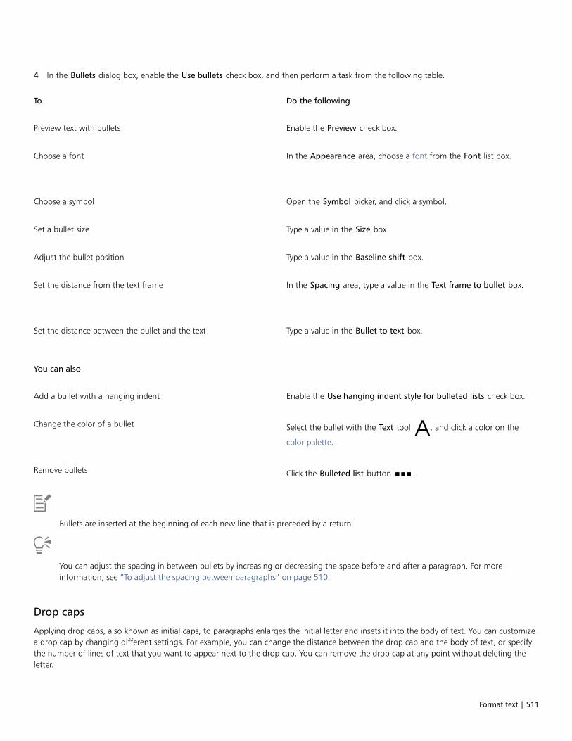
Format text | 511
4 In the Bullets dialog box, enable the Use bullets check box, and then perform a task from the following table.
To Do the following
Preview text with bullets Enable the Preview check box.
Choose a font In the Appearance area, choose a font from the Font list box.
Choose a symbol Open the Symbol picker, and click a symbol.
Set a bullet size Type a value in the Size box.
Adjust the bullet position Type a value in the Baseline shift box.
Set the distance from the text frame In the Spacing area, type a value in the Text frame to bullet box.
Set the distance between the bullet and the text Type a value in the Bullet to text box.
You can also
Add a bullet with a hanging indent Enable the Use hanging indent style for bulleted lists check box.
Change the color of a bullet Select the bullet with the Text tool , and click a color on the
color palette.
Remove bullets Click the Bulleted list button .
Bullets are inserted at the beginning of each new line that is preceded by a return.
You can adjust the spacing in between bullets by increasing or decreasing the space before and after a paragraph. For moreinformation, see “To adjust the spacing between paragraphs” on page 510.
Drop caps
Applying drop caps, also known as initial caps, to paragraphs enlarges the initial letter and insets it into the body of text. You can customizea drop cap by changing different settings. For example, you can change the distance between the drop cap and the body of text, or specifythe number of lines of text that you want to appear next to the drop cap. You can remove the drop cap at any point without deleting theletter.

512 | CorelDRAW 2019 User Guide
You can add a drop cap (left) or a hanging indent drop cap (right).
You can preview a drop cap before you add it to a drawing. The changes you make are temporarily applied to the text in the drawingwindow, so you can see how the drop cap will look when you add it.
To add a drop cap
1 Using the Text tool , select the paragraph text.
If the Properties docker is not open, click Window Dockers Properties.
2 In the Properties docker, click the Paragraph button to display the paragraph-related options.
3 In the Paragraph area of the Properties docker, click the Options button , and choose Drop Cap.
4 In the Drop Cap dialog box, enable the Use drop cap check box, and then perform a task from the following table.
To Do
Specify the number of lines next to a drop cap In the Appearance area, type a value in the Number of linesdropped box.
Set the distance between the drop cap and the body of text In the Appearance area, type a value in the Space after drop capbox.
This sets the space to the right of the drop cap.
Preview a drop cap Enable the Preview check box.
Offset the drop cap from the body of text Enable the Use hanging indent style for drop cap check box.
Remove drop caps Click the Drop cap button .
Change character position and angle
You can modify the appearance of text by shifting the characters vertically or horizontally, which changes the position of the selectedcharacters relative to the surrounding characters.
You can also rotate characters by specifying an angle of rotation.

Format text | 513
Examples of rotating text
To shift a character
1 Using the Text tool , select a character or a block of text.
If the Properties docker is not open, click Window Dockers Properties.
2 In the Properties docker, click the Character button to display the character-related options.
3 In the Character area of the Properties docker, click the arrow button located at the bottom of Character area to display additional
options.
4 Perform one or more tasks from the following table.
To Do the following
Shift characters horizontally Type a value in the Horizontal character offset box.
Shift characters vertically Type a value in the Vertical character offset box.
To rotate a character
1 Using the Text tool , select a character or a block of text.
If the Properties docker is not open, click Window Dockers Properties.
2 In the Properties docker, click the Character button to display the character-related options.
3 In the Character area of the Properties docker, click the arrow button located at the bottom of Character area to display additional
options.
4 Type a value in the Character angle box.
Align text
CorelDRAW lets you align text in various ways. You can align paragraph text horizontally and vertically in relation to its text frame. You canalign paragraph text with the baseline grid. For more information, see “Align text to the baseline grid” on page 480. You can also align textto a selected object.
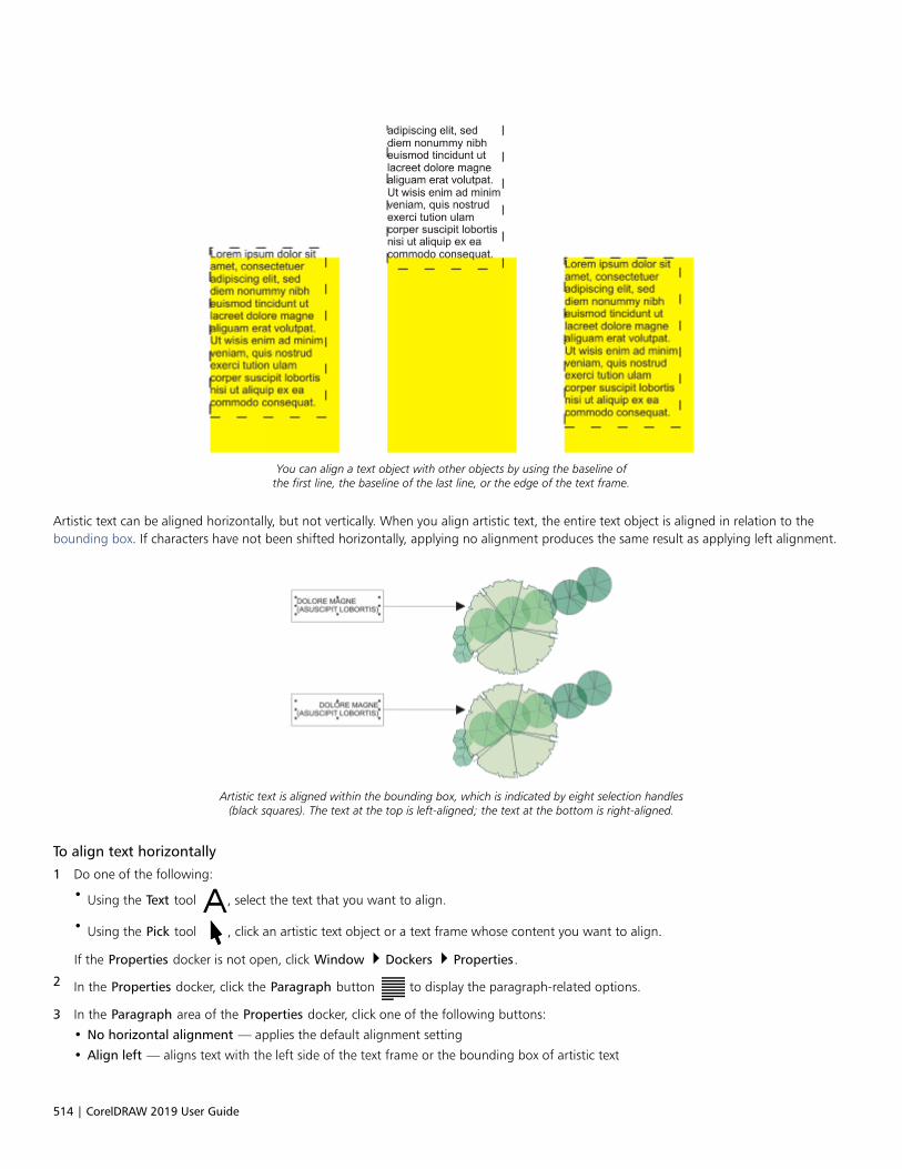
514 | CorelDRAW 2019 User Guide
You can align a text object with other objects by using the baseline ofthe first line, the baseline of the last line, or the edge of the text frame.
Artistic text can be aligned horizontally, but not vertically. When you align artistic text, the entire text object is aligned in relation to thebounding box. If characters have not been shifted horizontally, applying no alignment produces the same result as applying left alignment.
Artistic text is aligned within the bounding box, which is indicated by eight selection handles(black squares). The text at the top is left-aligned; the text at the bottom is right-aligned.
To align text horizontally
1 Do one of the following:
• Using the Text tool , select the text that you want to align.
• Using the Pick tool , click an artistic text object or a text frame whose content you want to align.
If the Properties docker is not open, click Window Dockers Properties.
2 In the Properties docker, click the Paragraph button to display the paragraph-related options.
3 In the Paragraph area of the Properties docker, click one of the following buttons:
• No horizontal alignment — applies the default alignment setting
• Align left — aligns text with the left side of the text frame or the bounding box of artistic text

Format text | 515
• Center — centers text within the text frame
• Align right — aligns text with the right side of the text frame and the bounding box of artistic text
• Full justify — aligns text, with the exception of the last line, with the left and right sides of the text frame
• Force justify — aligns text, including the last line, with the left and right sides of the text frame
You can also align text horizontally by clicking the Horizontal alignment button on the property bar and choosing an alignment stylefrom the list box. The property bar displays an icon that corresponds to the current alignment style.
You can align multiple paragraphs in a text frame by selecting them with the Text tool and choosing an alignment style.
To align paragraph text vertically
1 Using the Pick tool , click a text frame.
If the Properties docker is not open, click Window Dockers Properties.
2 In the Properties docker, click the Frame button to display the frame-related options.
3 In the Frame area of the Properties docker, choose an alignment option from the Vertical alignment list box.
To align text with an object
1 Using the Pick tool , hold down Shift, click the text object, and then click the object.
2 Click Object Align and Distribute Align and Distribute.
3 In the Text area, click one of the following buttons:
• First line baseline — uses the baseline of the first line of text to align the objects
• Last line baseline — uses the baseline of the last line of text to align the objects
• Bounding box — aligns text with its bounding box
4 In the Align objects to area, click the Active objects button .
5 In the Align area, click one of the following buttons to use an object edge or center for aligning.
• Align left — to align the left edges of objects
• Align center horizontally — to align object centers along a vertical axis
• Align right — to align the right edges of objects
• Align top — to align the top edges of objects
• Align center vertically — to align object centers along a horizontal axis
• Align bottom — to align the bottom edges of objects
To align objects from their outlines, click the Outline button .

516 | CorelDRAW 2019 User Guide
If you select the text objects one at a time, the last object selected is the reference point for aligning the other objects. If you marqueeselect the objects before you align them, the object that is positioned in the upper-left corner of the selection is used.
Add tabs and indents
You can modify existing tab stops by changing their alignment. You can also add trailing leader characters, so that dots, or other characters,automatically precede the tab stops. In addition, you can add new tab stops and remove existing tab stops.
Indenting changes the space between a text frame and the text that it contains. You can add and remove indents without deleting orretyping text. You can indent an entire paragraph, the first line of a paragraph, or all lines of a paragraph except the first line (a hangingindent). You can also indent from the right side of the text frame.
To modify a tab stop
1 Click Window Docker Properties.
2 In the Properties docker, click the Paragraph button to display the paragraph-related options.
3 In the Paragraph area of the Properties docker, click the arrow button located at the bottom of Paragraph area to display
additional options.
4 Click the Tab settings button.
5 Perform a task from the following table.
To Do the following
Change the alignment of tab stops Click the cell in the Alignment column, and choose an alignmentoption from the list box.
Set tab stops with trailing leader characters Click the cell in the Leaders column, and choose On from the listbox.
Delete a tab stop Click the cell, and click Remove.
Change the default leader character Click Leader Options, open the Character picker, and click acharacter.
Change the default leader spacing Click Leader Options, and type a value in the Spacing box.
You can also add, move, or delete tab stops on the horizontal ruler at the top of the drawing window. Click to add a tab stop, drag atab marker to move it, and drag a tab marker off the ruler to delete it. For information about rulers, see “Rulers” on page 595.
To add a tab stop
1 Using the Text tool , select the paragraph text.
2 Click Window Dockers Properties.

Format text | 517
3 In the Properties docker, click the Paragraph button to display the paragraph-related options.
4 In the Paragraph area of the Properties docker, click the arrow button located at the bottom of Paragraph area to display
additional options.
5 Click the Tab settings button .
6 Click Add.
7 Click the new cell in the Tabs column, and type a value.
To indent paragraph text
1 Using the Text tool , select the paragraph text.
2 Click Window Dockers Properties.
3 In the Properties docker, click the Paragraph button to display the paragraph-related options.
4 In the Paragraph area of the Properties docker, type values in the following boxes:
• First line indent — indents the first line of text relative to the left side of the frame
• Left line indent — creates a hanging indent relative to the left side of the text frame; all lines, except the first line, are indented
• Right line indent — indents the text relative to the right side of the frame
You can remove indents by typing 0 in the First line indent, Left line indent, and Right line indent boxes.
You can indent an entire paragraph by typing the same value in both the First line indent and the Left line indent boxes.
Text styles
CorelDRAW provides advanced style capabilities that allow you to format document text with speed, ease, and consistency. A style isa collection of formatting attributes defining object properties, such as artistic and paragraph text properties. For example, to define acharacter style, you can specify font type, font style and size, text color and background color, character position, caps, and more. You cancreate styles and style sets for text. You can also change the default text style, so that the same properties are applied to all new artistic orparagraph text. For example, you can change the font type and size, or change the text to bold or italic. For more information, see “Stylesand style sets” on page 565.
Hyphenate text
Hyphenation can be used to break a word if the entire word does not fit at the end of a line. You can hyphenate automatically by usinga preset hyphenation definition in combination with your own hyphenation settings. You can set the minimum number of charactersbefore and after a hyphen. You can also specify the number of characters in the “hot zone,” which is the area at the end of a line wherehyphenation can occur.
You can insert an optional hyphen in a word to produce a specific word break at the end of a line. You can also create custom definitionsthat specify the location of optional hyphens in specific words whenever you type, paste, or import the words in the application.
To hyphenate paragraph text automatically
1 Using the Text tool , select the text frame or paragraph text.
If the Properties docker is not open, click Window Dockers Properties.
2 In the Properties docker, click the Paragraph button to display the paragraph-related options.
518 | CorelDRAW 2019 User Guide
3 In the Paragraph area of the Properties docker, click the Options button , and choose Hyphenation settings.
4 In the Hyphenation dialog box, enable the Automatically hyphenate paragraph text check box.
Hyphenation can be used for any languages that have corresponding writing tools installed with the application. For moreinformation about language modules, see “Work with languages” on page 546.
If you do not see any hyphenated words in the paragraph after applying hyphenation, you may need to modify the hyphenationsettings.
To modify the hyphenation settings
1 Using the Text tool , select the text frame or paragraph text.
If the Properties docker is not open, click Window Dockers Properties.
2 In the Properties docker, click the Paragraph button to display the paragraph-related options.
3 In the Paragraph area of the Properties docker, click the Options button , and choose Hyphenation settings.
4 In the Hyphenation dialog box, perform one or more tasks from the following table.
To Do the following
Hyphenate capitalized words Enable the Break capitalized words check box.
Hyphenate words that contain all uppercase letters Enable the Break words using ALL CAPS check box.
Set a minimum word length for automatic hyphenation In the Hyphenation criteria area, type a value in the Minimumword length box.
This value represents the minimum number of characters thathyphenated words must contain.
Set the minimum number of characters to precede a hyphen In the Hyphenation criteria area, type a value in the Minimumcharacters before box.
Set the minimum number of characters to follow a hyphen In the Hyphenation criteria area, type a value in the Minimumcharacters after box.
Set the “hot zone” In the Hyphenation criteria area, type a value in the Distancefrom right margin box. This value represents the number ofcharacters in the hot zone. A word that does not fit within thiszone is hyphenated or moved to the next line.

Format text | 519
To insert an optional hyphen
1 Using the Text tool , click in a word where you want to place an optional hyphen.
2 Click Text Insert Formatting code Optional Hyphen.
You can insert an optional hyphen by pressing Ctrl + -.
To create a custom definition for optional hyphenation
1 Click Text Insert Formatting Code Custom Optional Hyphens.
2 In the Word box, type the word for which you want to create the hyphenation definition.
When you type in the Word box, the same text is entered in the Hyphenated word box.
3 In the Hyphenated Word box, click where you want the optional hyphen inserted, and press the Hyphen key (-).
4 Click Add Definition.
You can also
Create a custom hyphen definition for a specific language keyboard Enable the Show all languages check box, and choose a languageoption from the Language list box.
Automatically insert custom optional hyphens when typing Enable the When typing check box.
Automatically insert custom optional hyphens when typing,pasting, or importing text
Enable the When pasting and importing text check box.
Delete a custom optional hyphen definition Click Remove Definition.
The custom hyphenation definition is defined only for the language specified in the Language list box. You can choose anotherlanguage without affecting your keyboard.
You can create a custom optional hyphen definition by selecting a word in the document. The word appears in the Word box ofthe Custom optional hyphens dialog box. After you insert the optional hyphen in the Hyphenated word box, you can apply it byclicking Apply to Selection.
You can find and replace optional hyphens. For more information, see “To find text ” on page 482 and “To find and replace text” onpage 483.
Formatting codes
You can insert formatting codes, such as em dashes and nonbreaking spaces. In some programs, formatting codes are also known as“symbols.” The following table lists the available formatting codes and their corresponding keyboard shortcuts.
520 | CorelDRAW 2019 User Guide
Formatting code Keyboard shortcut
Em space Ctrl + Shift + M
En space Ctrl + Shift + N
1/4 em space Ctrl + Alt + Space
Nonbreaking space Ctrl + Shift + Space
Tab Tab
Column break or text-frame break Ctrl + Enter
Em dash Alt + _
En dash Alt + -
Nonbreaking hyphen Ctrl + Shift + -
Optional hyphen Ctrl + -
All shortcut keys for formatting codes are customizable. For information about customizing these shortcut keys, see the Text commandscategory in “To assign a keyboard shortcut to a command” on page 848.
You can find and replace formatting codes. For more information, see “To find text ” on page 482 and “To find and replace text” on page483.
To insert a formatting code
1 Using the Text tool , click to place the cursor where you want to insert a character or space.
2 Click Text Insert Formatting Code, and choose a formatting code from the menu.
The Insert Formatting Code menu is unavailable when the Text tool is not active.
You can insert a character not listed in the Insert Formatting Code menu by clicking Text Glyphs and clicking the character in theGlyphs docker.
Nonprinting characters
You can display nonprinting characters, such as spaces, tabs, and formatting codes. For example, when you display nonprinting characters,a space appears as a tiny black dot, a nonbreaking space appears as a circle, and an em space appears as a line. When enabled, nonprintingcharacters are displayed only when you add or edit text.

Format text | 521
To display nonprinting characters
• Click Text Show Non-Printing Characters.

522 | CorelDRAW 2019 User Guide

Work with text in different languages | 523
Work with text in different languages
In CorelDRAW, you can work with text in different languages. For example, if you are running CorelDRAW on an Asian operating system, orif you have Asian language support installed on another operating system, you can take advantage of the Asian text formatting capabilitiesavailable with CorelDRAW.
This section contains the following topics:• “Format Asian text” (page 523)• “Line-breaking rules for Asian text” (page 524)• “OpenType support for Asian text” (page 525)• “Format multilingual text” (page 525)• “Display text correctly in any language” (page 527)
Format Asian text
Asian character input is supported in CorelDRAW only when using an appropriate operating system or when language support is installed ona non-Asian operating system. You can choose a default font and text orientation (either horizontal or vertical) when typing text. When youtype artistic or paragraph text, the program uses a default artistic or paragraph text style.
To choose a default font for Asian text
1 Click the Text tool .
2 Press Esc to ensure that no objects are selected.
3 Choose an input method from the Input Method Editor (IME) on the Windows status bar.
If the Windows Language bar is displayed, you can choose an input method from the Language bar.
4 Choose a font from the Font list box on the property bar.
5 Choose a font style from the Font style list box.
To choose a text orientation for Asian text
1 Using the Pick tool , select the frame that contains the text whose orientation you want to change.
2 Click Window Dockers Properties.
3 In the Properties docker, click the Frame button to display the frame-related controls.
524 | CorelDRAW 2019 User Guide
4 Choose one of the following orientation options from the Text orientation list box:
• Horizontal
• Vertical
The default orientation for Asian text is horizontal.
When you change the text orientation from horizontal to vertical, underlines become left lines and overlines become right lines.
The text orientation setting applies to the entire text object. You cannot have text with different orientations in one text object.
If you have Asian text support installed with your operating system, you can also change text orientation by clicking the Vertical text
orientation or Horizontal text orientation buttons on the property bar when the Text tool is active.
Line-breaking rules for Asian text
CorelDRAW includes line-breaking rules for use with Asian text when you have an Asian operating system. For most Asian languages, aline of text can break between any two characters, with a few exceptions. Some characters cannot appear at the beginning of a line. Thesecharacters are referred to as “leading characters.” Other characters — referred to as “following characters” — cannot appear at the end of aline. The line breaks either after the following character or before the character that precedes the following character. Still others — referredto as “overflow characters” — are not wrapped but are, instead, allowed to extend beyond the right or bottom margin.
To enforce one or more of the line-breaking rules, you can enable any of the rules. To customize the rules, you can add or remove characters.You can also reset the rules to the default.
To disable or enable line-breaking rules
1 Click Text Line-Breaking Rules.
2 In the Asian line-breaking rules dialog box, enable any of the following check boxes:
• Leading characters — ensures that a line does not break before any of the characters in the list
• Following characters — ensures that a line does not break after any of the characters in the list
• Overflow characters — ensures that the characters in the list are allowed to extend beyond the margin of the line
You must have Asian text support installed on your operating system to view the Line-Breaking Rules menu item.
To add or remove characters to a line-breaking rule
1 Click Text Line-Breaking Rules.
2 Type or remove the characters in the appropriate box.
You must have Asian text support installed on your operating system to view the Line-Breaking Rules menu item.
To reset a line-breaking rule to the default
1 Click Text Line-Breaking Rules.
2 Click the Reset button beside a rule.

Work with text in different languages | 525
You must have Asian text support installed on your operating system to view the Line-Breaking Rules menu item.
OpenType support for Asian text
You can apply advanced OpenType typography features to Asian text. OpenType features can be accessed from the Character area in the
Text docker (Text Text). The following table lists the OpenType features that you can use with Asian text provided the features are includedin the font.
OpenType feature Description
Asian widths Changes the width by spacing or replacing the glyphs
The Centered CJK punctuation feature centers punctuation markshorizontally and vertically.
Asian forms Replaces the selected characters with a different glyph form. Formscannot be combined.
Asian vertical metrics The Alternate vertical metrics feature centers shorter charactersvertically relative to full-height characters. This feature also appliesto full-width Latin glyphs.
The Alternate vertical half metrics feature centers charactersvertically relative to half-height characters.
Horizontal Kana alternates Substitutes the standard kana glyph with a horizontal kana glyph
Vertical Kana alternates Substitutes the standard kana glyph with a vertical kana glyph
Vertical alternates and rotation Substitutes characters with forms suitable for vertical text, oftenrotating them at 90 degrees
Alternate annotation forms Applies an annotation form to the selected characters. ThisOpenType feature applies to both Latin and Asian text.
Format multilingual text
CorelDRAW includes controls that let you format text in different languages. You can limit any font, style, and size changes to only Latin,Asian, or Middle Eastern text by choosing the script type. For example, if you want to change the font size of Japanese text in a documentthat includes both English and Japanese text, you can choose the Asian script type, and then change the font size. This applies the newfont size only to the Japanese text, the English text font size is unaffected. You can also enable right-to-left text flow when working withbidirectional languages, such as Middle Eastern languages. In addition, you can mix Latin text with Asian or Middle Eastern in one textobject and set the spacing between the two words.

526 | CorelDRAW 2019 User Guide
To limit font property changes to multilingual text
1 Using the Text tool , select the text.
If the Properties docker is not open, click Window Dockers Properties.
2 In the Properties docker, click the Character button to display the character-related options.
3 In the Character area of the Properties docker, choose one of the following language options from the Script list box:
• All scripts
• Latin
• Asian
• Middle Eastern
4 Change any font properties.
The Script list box is available only when using an Asian or Middle Eastern operating system or when language support is installed onthe operating system.
To set right-to-left text flow in text
1 Do one of this following:
• Using the Text tool , position the cursor in a block of text.
• Using the Pick tool , click an artistic text object or a text frame.
If the Properties docker is not open, click Window Dockers Properties.
2 In the Properties docker, click the Paragraph button to display the paragraph-related options.
3 In the Paragraph area of the Properties docker, choose an option from the Text direction list box.
The Text direction option is available, and visible, only when you use a Middle Eastern operating system or when language support isinstalled on a non-Middle Eastern operating system.
You can also change the direction of text flow in columns. For more information, see “To change the flow of bidirectional text incolumns” on page 478.
To specify spacing between Latin and Asian words
1 Using the Text tool , select the paragraph that combines both the Latin and Asian text.
2 In the Properties docker, click the Paragraph button to display the paragraph-related properties.
3 In the Paragraph area of the Properties docker, type values in the Language spacing box.
The language spacing value is based on the percentage of a standard space. For example, two spaces are represented by typing avalue of 200.

Work with text in different languages | 527
Display text correctly in any language
In CorelDRAW, all text that is added to a document is encoded using the Unicode character set. When you open or import a drawing thatcontains text, CorelDRAW converts the encoding system that was used in the file to Unicode. For example, if you import an older documentthat includes 8-bit ANSI text that uses a specific code page (e.g. (949 ANSI/OEM - Korean), CorelDRAW converts code page 949 to Unicode.If the code page is not specified when you open a document, CorelDRAW uses a default code page to convert the text. Therefore, this maycause some text to display incorrectly in CorelDRAW. However, you can display the text correctly by selecting it and converting it back toUnicode by using the appropriate code page.
Encoding settings do not affect the display of text outside the drawing window, such as keywords, filenames, and text entries in the Objectsdocker and Object Data Manager docker. For these types of text, you must use code page settings in the Open or Import dialog boxes toset the proper characters. For information about using code page settings, see “Start and open drawings” on page 44.
To display text correctly in any language
1 Using the Text tool , select the text object that is displaying incorrectly.
2 Click Text Encode.
3 In the Text encoding dialog box, choose the Other encoding option.
4 From the Other encoding list, choose an encoding setting that makes the text readable.
The preview window displays the text with the selected encoding setting.
Changing the encoding allows you to use Unicode fonts, even if your original text was using non-Unicode fonts.

528 | CorelDRAW 2019 User Guide
Manage fonts | 529
Manage fonts
CorelDRAW allows you to manage and preview fonts.
This section contains the following topics:• “Change the default font” (page 529)• “Substitute fonts” (page 530)• “Embed fonts” (page 531)• “View fonts” (page 532)• “Filter fonts” (page 533)• “Search for fonts” (page 535)• “Acquire more fonts” (page 536)• “Choose fonts” (page 537)• “Corel Font Manager” (page 539)
Change the default font
You can change the default font that is used for artistic, callout, dimension, and paragraph text.
To change the default font
1 Click the Text tool and without clicking anywhere in the document window, choose a font from the Font list box on the property bar.
2 In the Change Document Defaults dialog box, enable any of the following check boxes to change the default font for thecorresponding text types:
• Artistic text
• Callout
• Dimension
• Paragraph textThis step changes the default font for the active document. If you want to change the default font for all new documents that youcreate, click Tools Save Settings as Default.

530 | CorelDRAW 2019 User Guide
You can also change the default font from the Object Styles docker. For more information, see “To edit default object properties” onpage 570.
Substitute fonts
You can use PANOSE font matching to access a list of fonts that can be used as substitutes for fonts used in a document but not found onyour computer.
You can set options for font matching. You can use font matching in text only or in both text and text styles. You can also turn off fontmatching. When you use font matching, you can accept the default substitute font, or you can choose another font to substitute for themissing font. You can apply the substitution temporarily or permanently.
You can build a list of exceptions to font substitutions. Exceptions override the font substitutions recommended by the PANOSE font-matching feature. A list of exceptions can be useful when you share drawings and documents across platforms, because sometimes thesame font is spelled differently on each platform.
To set options for font matching
1 Click Tools Options CorelDRAW.
2 In the left pane of the dialog box that appears, click Text.
3 Click Fonts.
4 Click PANOSE font matching.
5 In the PANOSE font matching preferences dialog box, enable one of the following options:
• Text — lets you choose font substitutions for text in the document and applies default font substitutions for text styles
• Text and styles — lets you choose font substitutions for text in the document and for text styles
• Never show — applies default font substitutions for text in the document and for text styles
To use PANOSE font matching
1 Open or import a document.
If the document contains missing fonts, the Substitute missing fonts dialog box opens. The name of the missing font appears in theMissing font list, and the recommended substitute appears in the Substituted font list.
2 Enable the Use the PANOSE suggested match option.
3 Enable one of the following options:
• Temporary — replaces the missing font with the substitution in the current session of the document
• Permanent — permanently replaces the missing font with the substitution. When you save and reopen the file, the new font is used.
To substitute a missing font
1 Open or import a document.
If the document contains missing fonts, the Font matching results dialog box opens.
2 Enable the Substitute font with option.
3 Enable one of the following options:
• Show fonts in the same code page as missing font — displays only missing fonts that support the code page of the activedocument
• Show all fonts — displays all missing fonts
4 Choose a missing font from the Missing font list.
5 Choose a font from the Substitute font with list box.
6 Enable one of the following options:

Manage fonts | 531
• Temporary — replaces the missing font with the substitution in the current session of the document
• Permanent — permanently makes the font substitution in the document. When you save and reopen the file, the new font is used.
You can save font substitutions by enabling the Save this exception for future font matching check box.
You can substitute a font for more than one missing font by holding down Shift and selecting the fonts in the Missing font list in theFont substitution for missing fonts dialog box.
To build a list of exceptions to font substitutions
1 Click Tools Options CorelDRAW.
2 In the left pane of the dialog box that appears, click Text.
3 Click Fonts.
4 Click PANOSE font matching.
5 In the PANOSE font matching preferences dialog box, click Exceptions.
6 In the PANOSE font matching exceptions dialog box, type the name of the missing font in the Missing font box.
7 Choose a font that is installed on your computer from the Substituted font list box.
Embed fonts
Font embedding can help you share drawings so that others can view, print, and even edit them without having to install or substitute fonts.By default, CorelDRAW embeds the fonts that are used in a drawing when the file is saved, but you can choose to disable font embeddingfor that particular drawing. For more information, see “To save a drawing” on page 56. You can change the default option for embeddingfonts in drawings.
Note that CorelDRAW respects the embedding permissions of each font. Some fonts allow embedding for print and preview purposes, butnot for text editing; other fonts may not allow embedding. The following font embedding permissions are respected by CorelDRAW:• Editable — allows fonts to be embedded in electronic documents and used by the recipients of the documents to edit the text.• Installable — similar to Editable. In addition, this permission allows fonts to be permanently installed on a recipient’s computer and
used to create new documents.• No Embedding — does not allow fonts to be embedded in electronic documents• Preview and Print — allows fonts to be embedded in an electronic document strictly for previewing and printing purposes. Such fonts
cannot be installed and used to edit the document on other computers.
If a drawing contains fonts that cannot be embedded, a warning is displayed. You can disable this warning.
You can import files that contain embedded fonts. If an embedded font does not allow editing, a visual indicator appears next to thefont name in the Objects docker. When you try to edit text that uses this font, you are prompted to choose a font substitution. For moreinformation, see “Substitute fonts” on page 530.
To change the default option for embedding fonts
1 Click Tools Options CorelDRAW.
2 In the left pane of the dialog box that appears, click Save.
3 Enable or disable the Embed fonts when saving files check box.
To enable or disable the warning for fonts that cannot be embedded
1 Click Tools Options CorelDRAW.
2 In the left pane of the dialog box that appears, click Warnings.
3 In the Show warnings when box, enable or disable the Fonts cannot be embedded check box.
532 | CorelDRAW 2019 User Guide
The warning lists a maximum of 7 fonts that cannot be embedded. If a document contains more than 7 fonts that cannot beembedded, an ellipsis is displayed at the bottom of the list.
View fonts
You can customize the font list, from within the Font list box, to make it easier to find fonts. For example, you can change the size of thefont names displayed in the Font list box. You can display fonts grouped by family or as a flat list. If you have non-Latin fonts installed, youcan show their names in Latin or in their native language. In addition, you can show recently used fonts at the top of the font list, or hidethem, and you can specify the number of recently used fonts to display.
By default, font names use the corresponding fonts, but you can display all font names by using the same font.
CorelDRAW lets you preview fonts in the Preview area at the bottom of the Font list box or in the drawing window. You can also preview afont in all available styles, such as bold and italic.
You can resize the Font list area by adjusting its height and width or by hiding the preview area.
To customize the font list
1 Click the Text tool in the toolbox, and open the Font list box on the property bar.
2 To change the size of the font names, move the Resize slider.
3 Click the Font Options button , and perform a task from the following table.
To Do the following
Display the font list grouped by family or as a flat list Click Group by family to enable or disable the command.
Show the names of non-Latin fonts in Latin or in the nativelanguage
Click Show Latin names to enable or disable the command.
This option is useful when you work with Cyrillic, Arabic, and Asianfonts.
Display font names by using the same font Click Use font to display the font name to disable the command.
Display or hide recently used fonts Click Show recently used fonts to enable or disable the command.
Specify the number of recently used fonts to display Click Font List Options, and on the Fonts page of the dialog boxthat appears, type a value in the Number of most recently usedfonts displayed box.
The maximum number of recently used fonts that you can display is20.
To preview a font
1 Click the Text tool in the toolbox.
If you want to preview a font in the drawing window, select the text you want.
Manage fonts | 533
2 On the property bar, click the Font list box.
The font name appears in the given font.
To preview the selected text with a specific font applied, point to the font name in the Font list box.
The names of symbol fonts are displayed in the default user interface font, with examples of the symbol font appearing to the rightof the symbol font name and in the Preview area.
If a font has other styles, such as bold or italic, you can preview them by pointing to the flyout arrow next to the font name.
To resize the Font list area
1 Click the Text tool in the toolbox, and open the Font list box on the property bar.
2 Do any of the following:
• To hide the preview area, click the Hide preview button .
• To adjust the width of the Font list area, point to the vertical grab area (right edge) and drag when the double-sided arrow appears.
• To adjust the height, point to the horizontal grab area (below the Resize slider), and drag when the double-sided arrow appears.
Filter fonts
Filtering helps you view only the fonts that meet specific requirements. For example, you can display only the fonts used in the document oronly symbol fonts. You can filter fonts based on the font technology, weight, width, style, supported language(s), OpenType features, andmore; and you can apply one or more filters at the same time.
The following table lists available font filter categories and filters.
Font filter category Description
My Collections Lets you display only fonts downloaded from the Content Exchange
Document Fonts Lets you display only the fonts used in the document
Font Status Lets you filter fonts based on their status such as Installed, Notinstalled, and Protected System Fonts.
Embedding Rights Lets you filter fonts based on embedding permissions such aswhether fonts can be embedded, installed, and previewed.Available filers include: Editable, Installable, No Embedding, andPreview and Print. For information about embedding permissions,see “Embed fonts” on page 531.
If fonts with a specific permission are not available, thecorresponding filter is not displayed. For example, if all your fontscan be embedded in a document, the No Embedding filter is notdisplayed.
534 | CorelDRAW 2019 User Guide
Font filter category Description
Font Technology Lets you filter fonts based on the font technology such as OpenType- TrueType, OpenType - PostScript, TrueType, and Type1
If a font technology is not available on your computer, it does notappear in the list of filters.
Weight Lets you display fonts based on their weight such as Light, Normal,or Bold
Width Lets you display fonts based on their width such as Condensed,Normal, and Expanded
Style Lets you display fonts based on their style such as Decorative,Display, Monospaced, Sans Serif, Script, Serif, and Symbol
Character Range Lets you filter fonts based on their language or script. Filters inthis group include Arabic, Chinese Simplified, Chinese Traditional,Cyrillic, Devanagari, Greek, Hebrew, Japanese, Korean, Latin, andTurkish
OpenType Lets you display fonts that have specific OpenType features such asCapital Spacing, Case-Sensitive forms, and more
To filter fonts
1 Click the Text tool in the toolbox.
2 Open the Font list box on the property bar, and click the Show filters button .
3 Enable any of the filter check boxes.
You can also
Clear all filters Click Clear filters.
Close the filter list Click the Hide filters button .

Manage fonts | 535
You can filter only fonts that are installed on your computer.
You can also filter fonts from the Font list box in the Properties docker, Text docker, Font Sampler docker, and Glyphs docker.
Search for fonts
Corel Font Service is a utility that checks what fonts are installed on your computer and generates a font database with keywords. Thesekeywords include font names, font technology, and other metadata included in the fonts, and can be used to search for local fonts fromwithin the Font list box.
When you start typing a font name or another keyword, a relevant list of fonts is displayed. This list is automatically updated as you type.To refine your search, you can type two or more keywords. For example, to find all available Arial fonts that have bold weight, you can typeArial bold in the Font list box.
To search for fonts by using keywords
1 Click the Text tool in the toolbox.
2 Open the Font list box on the property bar, and type a keyword such as a font name or font technology.
3 To refine your search, press the space bar after typing the first keyword, and type another keyword.
The following table lists the search keywords that you can use organized by categories.
Category Keywords
Document Fonts Document Fonts
Font Technology OpenType - TrueType, OpenType - PostScript, TrueType, Type1
Weight Thin, Extra Light, Light, Regular, Medium, Semi Bold, Bold, ExtraBold, Black
Width Ultra Condensed, Extra Condensed, Condensed, Semi Condensed,Normal, Semi Expanded, Expanded, Extra Expanded, UltraExpanded
Style Decorative, Display, Monospaced, Sans Serif, Script, Serif, Symbol
Character Range Arabic, Armenian, Chinese Simplified, Chinese Traditional, Coptic,Cyrillic, Devanagari, Dhivehi, Georgian, Greek, Gujarati, Hebrew,Hiragana, Japanese, Kannada, Katakana, Korean, Latin, Russian,Syria, Tamil, Telugu, Thai, Turkish, Vietnamese

536 | CorelDRAW 2019 User Guide
Category Keywords
Manufacturer Ale/Paul, Bitstream, Cultivated/Mind, DynaComware, Font Fabric,Fontlab, Fontographer, ITC, Linotype, Mark Simonson, Monotype,Typodermic, RW++
Embedding rights Editable, Installable, No Embedding, Preview& Print, Restricted
OpenType All Small Capitals, Alternate Annotation Forms, AlternateHalf Widths, Alternate Vertical Half Metrics, Alternate VerticalMetrics, Alternative Fractions, Capital Spacing, Case SensitiveForms Centered CJK Punctuation, Character Variants ContextualAlternates, Contextual Ligatures, Denominators DiscretionaryLigatures, Expert Forms, Fractions, Half Widths, Historical Forms,Historical Ligatures, Hojo Kanji Forms, Horizontal Kana Alternates,JIS2004 Forms, JIS78 Forms, JIS83 Forms, JIS90 Forms, Kerning,Lining Figures, Localized Forms, NLC Kanji, Numerators, Ordinals,Ornaments, Proportional Kana, Proportional Lining, ProportionalOldstyle, Proportional Widths, Quarter Widths, Scientific Inferiors,Simplified Forms, Slashed ZeroSmall Capitals, Small Capitals fromCapitals, Standard Ligatures, Stylistic Alternates, Stylistic Sets,Subscript, Superscript, Swash Variants, Tabular, Tabular Oldstyle,Third Widths, Titling, Traditional Forms, Traditional Name Forms,Vertical Alternates and Rotation
Acquire more fonts
You can download additional fonts from within the Font list box in CorelDRAW and Corel Font Manager. These fonts are usually groupedin font packs. Some font packs are free whereas others are available for purchase. You can access information about the font packs and thefonts they include as well as view font samples.
You can change the default location to which fonts are saved. For more information, see “Change content locations” on page 89.
To acquire a font pack
1 Click the Text tool in the toolbox.
2 Open the Font list box on the property bar.
3 Click the Get More button .
4 In the Get More dialog box, click a font pack.
5 Do one of the following:
• Click Buy, and follow the onscreen instructions to purchase the font pack.
• Click Download if the font pack is free.
The downloaded font pack can be accessed from the Font list box. It also appears in the Filters list under My Collections.

Manage fonts | 537
Choose fonts
Font Sampler lets you view the same sample text in different fonts and sizes to help you choose fonts for your project.
You can preview preset text samples, or you can type or paste text. In addition, you can view samples as single lines of text or multiline text,and you can view a text sample as single lines of text in increasing font sizes.
When a text sample uses an OpenType font, you can view available OpenType features and apply them to the text sample.
Views from left to right: Single line, Multiline, and Waterfall
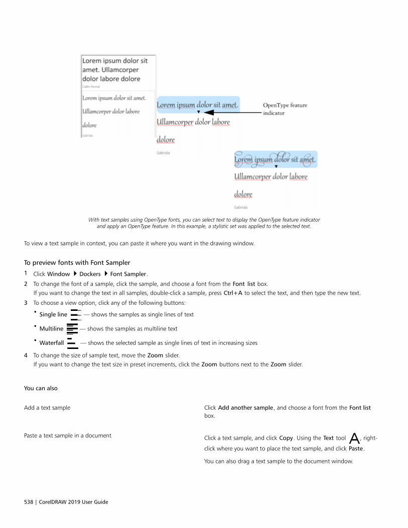
538 | CorelDRAW 2019 User Guide
With text samples using OpenType fonts, you can select text to display the OpenType feature indicatorand apply an OpenType feature. In this example, a stylistic set was applied to the selected text.
To view a text sample in context, you can paste it where you want in the drawing window.
To preview fonts with Font Sampler
1 Click Window Dockers Font Sampler.
2 To change the font of a sample, click the sample, and choose a font from the Font list box.
If you want to change the text in all samples, double-click a sample, press Ctrl+A to select the text, and then type the new text.
3 To choose a view option, click any of the following buttons:
• Single line — shows the samples as single lines of text
• Multiline — shows the samples as multiline text
• Waterfall — shows the selected sample as single lines of text in increasing sizes
4 To change the size of sample text, move the Zoom slider.
If you want to change the text size in preset increments, click the Zoom buttons next to the Zoom slider.
You can also
Add a text sample Click Add another sample, and choose a font from the Font listbox.
Paste a text sample in a document Click a text sample, and click Copy. Using the Text tool , right-
click where you want to place the text sample, and click Paste.
You can also drag a text sample to the document window.

Manage fonts | 539
You can also
Delete a text sample Click a text sample, and click the Close button in the upper-rightcorner of the sample.
Paste text in a text sample Click a text sample, and then press Ctrl+V.
Change the order of text samples Drag a text sample to a new position in the list.
Corel Font Manager
Corel Font Manager is a standalone font management application included with CorelDRAW Graphics Suite. Corel Font Manager lets youeasily handle, organize, and explore your typeface and font collections by giving you tools to control every aspect of your typographyworkflow. You can find and preview local fonts, install and uninstall fonts, and delete fonts that you no longer need. For more information,see the Help in Corel Font Manager.
To start Corel Font Manager
• Click the Application launcher button on the standard toolbar, and then click Corel Font Manager.
To access the Corel Font Manager Help
• In Corel Font Manager, click the Help button on the title bar.

540 | CorelDRAW 2019 User Guide

Writing tools | 541
Writing tools
You can use writing tools to correct errors in spelling and grammar, correct mistakes automatically, and refine your writing style.
This section contains the following topics:• “QuickCorrect” (page 541)• “Spell Check and Grammatik” (page 543)• “Thesaurus” (page 545)• “Work with languages” (page 546)• “Customize the writing tools” (page 546)• “Checking styles” (page 548)• “Word lists” (page 548)• “Check statistics” (page 550)
For more information about using the writing tools, see “Reference: Writing tools” on page 551.
QuickCorrect
QuickCorrect™ automatically corrects misspelled words and capitalization errors. You can customize QuickCorrect by specifying which typesof errors you want to correct automatically.
In CorelDRAW, the quotation marks that are applied to text vary according to the language that you have selected. You can furthercustomize the quotation marks for different languages by using QuickCorrect. For example, you can change the style of double, single, andstraight quotation marks for a language.
Adding words to QuickCorrect lets you replace words and abbreviations that you often mistype. The next time you type the misspelledword, QuickCorrect corrects the word automatically. You can use this feature to create shortcuts to frequently used words and phrases. Forexample, you can store the phrase “for your information” under the abbreviation “FYI” so that each time you type “FYI” followed by a space,it is replaced with the phrase.
You can have QuickCorrect add corrections made with the spelling checker to its word list so that the next time you misspell the word thesame way, it is automatically corrected.
You can also undo a QuickCorrect correction.
To customize QuickCorrect
1 Click Text Writing tools QuickCorrect.

542 | CorelDRAW 2019 User Guide
2 Enable any of the following check boxes:
• Capitalize first letter of sentences
• Correct two initial, consecutive capitals
• Capitalize names of days
• Automatically create hyperlinks when typing web addresses
The Correct two initial, consecutive capitals option doesn’t make a change when a capital letter is followed by a space or period, orif a word contains other capital letters.
Instead of enabling the Capitalize first letter of sentences check box, you can change the text case to sentence case. For moreinformation, see “To change the text case” on page 501.
To customize quotation marks for different languages
1 Click Text Writing tools QuickCorrect.
2 Choose a language from the Language list box.
3 Perform a task from the following table.
To Do the following
Change straight quotation marks to typographic (“curly”) quotationmarks
Enable the Change straight quotes to typographic quotes checkbox.
Insert straight quotation marks when the quotation mark follows anumber
Enable the Use straight quotation marks after numbers checkbox.
Change the appearance of single quotation marks Choose a quotation mark style from the Open and Close list boxeslocated below Single quotes, or type a character in each of theboxes.
Change the appearance of double quotation marks Choose a quotation mark style from the Open and Close list boxeslocated below Double quotes, or type a character in each of theboxes.
Straight quotation marks are sometimes used to represent feet ( ' ) and inches ( " ).
To add words to QuickCorrect
1 Click Text Writing tools QuickCorrect.
2 In the Replacement text area, enable the Replace text while typing check box.
3 In the Replace box, type the text to be replaced.
4 Type the replacement text in the With box.
5 Click Add.

Writing tools | 543
You can use this feature to create shortcuts to frequently used words and phrases. Type the abbreviation in the Replace box, and theword or phrase in the With box.
To add spelling corrections to QuickCorrect
1 Click Text Writing Tools Settings.
2 Enable the Add corrections to QuickCorrect check box.
To undo a QuickCorrect correction
• Click Edit Undo QuickCorrect.
Spell Check and Grammatik
By using the spelling checker and Grammatik, you can check the spelling and grammar in an entire drawing, part of a drawing, or onlyselected text. You can also check the spelling or grammar of dates, time, currency symbols, text or look up a word in a different language.
You can manually edit text and then resume checking the drawing.
The spelling checker and Grammatik replace words or phrases in two ways: you can choose a word, or define an automatic replacement fora word. Defining automatic replacement words is useful for words that are regularly misspelled. Automatic replacement words are stored ina user word-list file. For more information about user word-list files, see “Word lists” on page 548.
You can skip a writing error once but flag subsequent occurrences of the problem, or you can skip the error throughout the entireproofreading session.
To check the spelling or grammar in an entire drawing
1 Click Text Writing tools, and click one of the following:
• Spell check
• Grammatik
2 Choose Document from the Check list box.
To check the spelling or grammar in a different language, click Options Language, and select a language.
By default, the Auto start command is enabled for the spelling checker and Grammatik. If you disable the Auto start command
(Options Auto start), you must click the Start button in the Writing tools dialog box to check a drawing.
To check the spelling or grammar in part of a drawing
1 Click the Text tool and click in a text frame.
2 Click Text Writing tools, and click one of the following:
• Spell check
• Grammatik
3 From the Check list box, choose one of the following:
• Paragraph
• Selected text
• Sentence
• Word
To check the spelling or grammar in a different language, click Options Language, and select a language.

544 | CorelDRAW 2019 User Guide
By default, the Auto start command is enabled for the spelling checker and Grammatik. If you disable the Auto start command(Options Auto start), you must click the Start button in the Writing tools dialog box to check a drawing.
The options available in the Check list box vary according to the type of drawing that you are checking.
To check the spelling or grammar of selected text
1 Select the text you want to check.
2 Click Text Writing tools, and click one of the following:
• Spell check
• Grammatik
To check the spelling or grammar in a different language, click Options Language, and select a language.
By default, the Auto start command is enabled for the spelling checker and Grammatik. If you disable the Auto start command
(Options Auto start), you must click the Start button in the Writing tools dialog box to check a drawing.
To edit text manually
1 Click Text Writing tools, and click one of the following:
• Spell check
• Grammatik
2 When the spelling or grammar checker stops on a word or phrase, click in the Replace with box, and edit the text.
To replace a word or phrase
1 Click Text Writing tools, and click one of the following:
• Spell check
• Grammatik
2 When the spelling or grammar checker stops, choose a word or phrase from the Replacements list.
3 Click Replace.
If the spelling checker does not offer replacement words, you can edit text manually in the Replace with box.
To define automatic text replacements
1 Click Text Writing tools, and click one of the following:
• Spell check
• Grammatik
2 When the spelling or grammar checker stops on a word, click Auto replace.
To skip a spelling or grammar error
1 Click Text Writing tools, and click one of the following:
• Spell check
• Grammatik
2 When the spelling or grammar checker stops, click one of the following:
• Skip once — to skip an error once
• Skip all — to skip all occurrences of an error

Writing tools | 545
You can also skip all occurrences of a word for all proofreading sessions by adding it to a user word list. For more information aboutuser word-list files, see “Word lists” on page 548.
Thesaurus
You can use the thesaurus to refine your writing style. The thesaurus lets you look up options such as synonyms, antonyms, and relatedwords.
You can replace a word by using the thesaurus. When you look up a word, the thesaurus provides a short definition and a list of the lookupoptions selected. The thesaurus does not specify word forms for verbs that appear the same in both the present and past tense and wordsused as multiple parts of speech words used as multiple parts of speech. The thesaurus lets you choose the correct word form to insert orreplace in a document. The thesaurus also maintains a history list of the words that you have looked up. Each time you start the thesaurus, itbegins a new history list.
You can also insert words with the thesaurus.
Disclaimer: The expanded thesaurus file and the dictionary contain words that may be offensive to some people. These words are includedin the file to enable relational searches. It is not our intention to offend nor to promote the use of these terms.
To replace a word
1 Select a word.
2 Click Text Writing tools Thesaurus.
3 In the list of lookup options, double-click a definition to access the list of its synonyms, antonyms, and related words.
4 Click a word, and click Replace.
You can also
Look up words suggested by the thesaurus Double-click a word.
The definitions of the word appear in the bottom pane.
Look up any word Type a word in the list box at the top of the Thesaurus page andpress Enter.
Look up recently checked words Choose a word from the list box at the top of the Thesaurus page.
In some instances, you are prompted to select the correct form of the word that you want to insert. This prompt appears when theword that you want to replace is spelled the same in both the present and past tenses (for example, “read”), or when the word canbe used as more than one part of speech (for example, “wonder,” which can be used as either a noun or a verb).
Click the up and down arrows to scroll up and down through the word lists.
To insert a word
1 In the drawing, click where you want to insert the word.
546 | CorelDRAW 2019 User Guide
2 Click Text Writing tools Thesaurus.
3 Type a word in the box at the top of the Thesaurus page and press Enter.
4 Choose a word from the list box.
5 Click Insert.
In some instances, you are prompted to select the correct form of the word that you want to insert. This prompt appears when theword that you want to replace is spelled the same in both the present and past tenses (for example, “read”), or when the word canbe used as more than one part of speech (for example, “wonder,” which can be used as either a noun or a verb).
Work with languages
A drawing can contain text that alternates between different languages. For example, if English is the default language of your computer’soperating system, and you also have a French language module installed, you can use the writing tools to check the spelling or grammarof both French and English text. When you run the spelling checker, Grammatik, or the thesaurus, CorelDRAW checks words, phrases, andsentences according to their assigned language. This prevents foreign words from being marked as misspellings. You can use the writingtools the same way you would if the text were all in one language. You can check the spelling or grammar of dates, time, currency symbols,text or look up a word in a different language.
If multiple language modules are available, you can choose from the list and set a default Writing Tools language.
You can check for the formatting conventions of another language. For example, the spelling checker can format all dates in a drawingaccording to French conventions (such as “12 avril 2005”).
Many of the languages support hyphenation. Hyphenation lets you reduce the raggedness of text along the right margin by dividing a wordthat falls at the end of a line, instead of forcing the entire word to the next line.
You can also specify which quotation marks to use for different languages. For more information, see “To customize quotation marks fordifferent languages” on page 542.
To assign a language to text
1 Select the text.
2 Click Text Writing tools Language.
3 In the Text language dialog box, choose a language from the list.
You can assign a language to selected words, sentences, or paragraphs.
To use the writing tools for the language you select in the Text language dialog box, the module for that language must be installed.
You can check which language has been assigned to text by selecting the text and viewing the three-letter language code thatappears in the status bar.
Customize the writing tools
You can customize how the spelling is checked in a drawing. For example, you can choose how the spelling checker starts and whether itsearches for misspelled words, irregular capitalization, duplicate words, or words with numbers.
You can customize how Grammatik checks grammar in a drawing. For example, you can customize Grammatik to start automatically, toprompt you before it automatically replaces words, and to show spelling suggestions for misspelled words.

Writing tools | 547
You can customize the thesaurus to look up words or close automatically. The thesaurus can also be customized to suggest spellingsuggestions for misspelled words and to display different types of word lists, such as synonyms, antonyms, and related words.
To set spelling checker options
1 Click Text Writing tools Spell check.
2 Click Options, and then click one of the following:
• Auto start
• Beep on misspelled
• Recheck all text
• Check words with numbers
• Check duplicate words
• Check irregular capitalization
• Prompt before auto replacement
• Show phonetic suggestions
The options you click are applied the next time you open the spelling checker.
To set Grammatik options
1 Click Text Writing tools Grammatik.
2 Click Options, and click one of the following:
• Auto start
• Prompt before auto replacement
• Suggest spelling replacements
The options you click are applied the next time you open Grammatik.
To set thesaurus options
1 Click Text Writing tools Thesaurus.
2 Click Options, and click one of the following:
• Auto look up
• Auto close
• Spelling assist
• Synonym
• Antonym
• Related words
• Is a type of
• Has types
• Is a part of
• Has parts
• Example
The options you click are applied the next time you open the thesaurus.

548 | CorelDRAW 2019 User Guide
Checking styles
A checking style consists of preset writing style rules. Using a checking style lets you check a drawing that has a specific type of writing. Forexample, you can choose an advertising checking style to check advertising copy or marketing materials.
To select a checking style
1 Click Text Writing tools Grammatik.
2 Click Options Checking styles, and choose one of the following:
• Spelling plus
• Quick check
• Very strict
• Formal memo or letter
• Informal memo or letter
• Technical or scientific
• Documentation or speech
• Student composition
• Advertising
• Fiction
• Grammar As-You-Go
A checking style remains in effect until you choose another one.
Word lists
A word list is a list of words or phrases scanned when you proof text by using the writing tools. Writing tools scan two types of wordlists: user word lists and main word lists. Each language comes with a default user word list. You can customize user word lists by adding,deleting, or replacing words. Main word lists are lists of specialized words used by the spelling checker for a particular language, field orcompany.
You can add a user word list to help proof a text. You can have up to 10 user word lists active simultaneously. For example, if you want thespelling checker to scan both the US English and the Canadian English user word lists, add both lists. If you work in the medical profession,you can select a third-party medical word list that runs with the writing tools. Each language supported by the spelling checker has a defaultmain word list. The active user word lists are scanned first; if the word or phrase is not found there, the active main word lists are scanned.You can also remove word lists.
You can add a word to a user word list so that the word is not flagged as an error. You can also add replacement words to a user word list,which lets you choose a replacement when the spelling checker or Grammatik stops on a word.
You can edit or delete words in a user word list at any time.
To add a user word list
1 Click Text Writing tools, and click one of the following:
• Spell check
• Grammatik
2 Click Options User word lists.
3 Click Add list.

Writing tools | 549
4 In the Add user word list dialog box, choose a user word list.
5 Click Open.
The filename extension for a user word list is .uwl.
When you check a drawing, the user word lists are scanned in the order of their appearance in the User word lists dialog box.
To remove a user word list
1 Click Text Writing tools Spell check.
2 Click Options User word lists.
3 Choose a user word list.
4 Click Remove list.
You cannot remove the default language word list.
To add a word to a user word list
1 Click Text Writing tools, and click one of the following:
• Spell check
• Grammatik
2 Click Options User word lists.
3 In the User word lists dialog box, choose a user word list.
4 Type a word in the Word/phrase box.
If you want to add a replacement word, type it in the Replace with box.
5 Click Add entry.
6 Click Close.
In the spelling checker, replacement words appear in the Replacements box.
Click Add from the Spell checker or Grammatik pages to add a word to the current user word list.
You can also add short phrases to a user word list.
To edit a word or phrase in a user word list
1 Click Text Writing tools, and click one of the following:
• Spell check
• Grammatik
2 Click Options User word lists.
3 Choose the user word list that contains the word or phrase you want to edit.
4 Choose the word or phrase you want to edit.
5 Edit the word or phrase in the Replace with box.
6 Click Replace entry.

550 | CorelDRAW 2019 User Guide
If the word list you want to edit does not appear in the User word lists dialog box, click Add list to open the list.
To delete a word or phrase from a user word list
1 Click Text Writing tools, and click one of the following:
• Spell check
• Grammatik
2 Click Options User word lists.
3 Choose the word list you want to edit.
4 Choose the word or phrase you want to delete.
5 Click Delete entry.
To choose, add, or remove a main word list
1 Click Text Writing tools, and click Spell check.
2 Click Options Main word lists.
3 Perform a task from the following table.
To Do the following
Choose a main word list Enable the check box that corresponds to the main word list thatyou want to use.
Add a main word list Click Add list. In the Main word list editor dialog box, choose amain word list. Click Open.
Remove a main word list Choose a main word list. Click Remove list.
Check statistics
You can check text statistics to count text elements, including the number of lines, words, characters, and the names of the fonts and stylesused. You can display statistics either for selected text objects or for the entire drawing. If no text is selected, all text elements in the drawing,including tab and space characters, are counted.
To count text elements
1 Do one of the following:
• To count text elements for an entire drawing, click a blank space in the drawing window.
• To count text elements for selected text, select a block of text.
2 Click Text Text statistics.
You can also
Display information about the styles used Enable the Show style statistics check box.

Writing tools | 551
Reference: Writing tools
Grammatik uses the following notations to identify parts of speech or parts of a sentence.
Notation in Grammatik Grammatical term Explanation
3v third-person present verb The following sentences use the third-person present-tense verb form:
“He waits.”
“She brushes her hair.”
“Does it sing?”
<> punctuation Punctuation clarifies the meaning of aphrase or statement. Examples:
•period (.)•comma (,)•question mark (?)
abrv abbreviation An abbreviation is a shortened version of aword. For example, “etc.” is an abbreviationof “etcetera.”
adj adjective An adjective modifies a noun. Example: a“good” book.
adv adverb An adverb modifies a verb or an adjective.Examples:
•go “quickly”•a “very” good book
aux auxiliary verb An auxiliary verb is a form of “be,” “have,”or “do.” Examples:
•“is” coming•“had” not run•“did” he say
bv base verb A base verb is the form of a verb that comesafter “to” in an infinitive, or after a modal(such as “would”).
c/s comparative/superlative The comparative and superlative forms ofadjectives or adverbs indicate a degree ofcomparison. Examples:
•happier•slowest
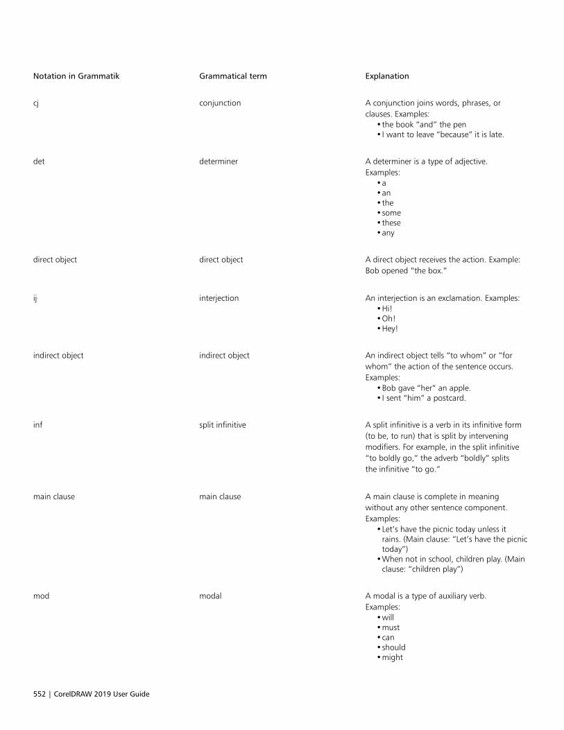
552 | CorelDRAW 2019 User Guide
Notation in Grammatik Grammatical term Explanation
cj conjunction A conjunction joins words, phrases, orclauses. Examples:
•the book “and” the pen•I want to leave “because” it is late.
det determiner A determiner is a type of adjective.Examples:
•a•an•the•some•these•any
direct object direct object A direct object receives the action. Example:Bob opened “the box.”
ij interjection An interjection is an exclamation. Examples:•Hi!•Oh!•Hey!
indirect object indirect object An indirect object tells “to whom” or “forwhom” the action of the sentence occurs.Examples:
•Bob gave “her” an apple.•I sent “him” a postcard.
inf split infinitive A split infinitive is a verb in its infinitive form(to be, to run) that is split by interveningmodifiers. For example, in the split infinitive“to boldly go,” the adverb “boldly” splitsthe infinitive “to go.”
main clause main clause A main clause is complete in meaningwithout any other sentence component.Examples:
•Let’s have the picnic today unless itrains. (Main clause: “Let’s have the picnictoday”)
•When not in school, children play. (Mainclause: “children play”)
mod modal A modal is a type of auxiliary verb.Examples:
•will•must•can•should•might

Writing tools | 553
Notation in Grammatik Grammatical term Explanation
num number A number expresses a quantity. Examples:•“three” boys•“497” days•“62” percent
phrasal phrasal preposition A phrasal preposition is a preposition thatbelongs to, but is separated from, a verbphrase. Example: put the book “down.”
pn plural noun A plural noun is the plural form of a noun.Examples:
•books•children
poss possessive noun A possessive noun shows ownership. Itis used as an adjective to modify anothernoun. Examples:
•“dog’s” leg•“students’” cars•“Joe’s” son
ppt past participle A past participle is a past-tense verb form.Example: The note was “written” in ink.
prep phr prepositional phrase A prepositional phrase consists of apreposition and its object, plus anymodifiers. Prepositional phrases function asadjectives, adverbs, or nouns. Example: Wecame back “for the second show.”
pres-p present participle A present participle is a verb form that canfunction as part of a verb phrase or as anadjective. It is usually created by adding“ing” to the base verb. Examples:
•He is “writing” a book.•She is “going” to bed.•The lawyers presented “closing”
arguments.
prn pronoun A pronoun takes the place of a noun.Examples:
•I•me•you•mine•yourself•these•who•which
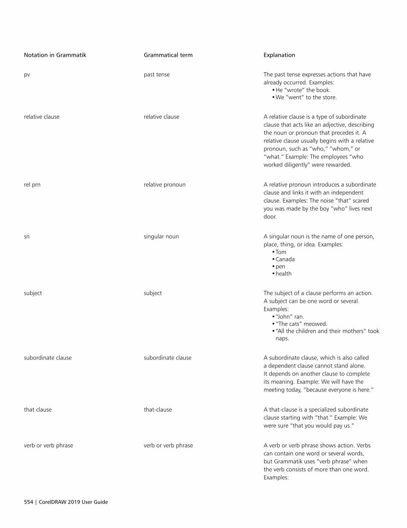
554 | CorelDRAW 2019 User Guide
Notation in Grammatik Grammatical term Explanation
pv past tense The past tense expresses actions that havealready occurred. Examples:
•He “wrote” the book.•We “went” to the store.
relative clause relative clause A relative clause is a type of subordinateclause that acts like an adjective, describingthe noun or pronoun that precedes it. Arelative clause usually begins with a relativepronoun, such as “who,” “whom,” or“what.” Example: The employees “whoworked diligently” were rewarded.
rel prn relative pronoun A relative pronoun introduces a subordinateclause and links it with an independentclause. Examples: The noise “that” scaredyou was made by the boy “who” lives nextdoor.
sn singular noun A singular noun is the name of one person,place, thing, or idea. Examples:
•Tom•Canada•pen•health
subject subject The subject of a clause performs an action.A subject can be one word or several.Examples:
•“John” ran.•“The cats” meowed.•“All the children and their mothers” took
naps.
subordinate clause subordinate clause A subordinate clause, which is also calleda dependent clause cannot stand alone.It depends on another clause to completeits meaning. Example: We will have themeeting today, “because everyone is here.”
that clause that-clause A that-clause is a specialized subordinateclause starting with “that.” Example: Wewere sure “that you would pay us.”
verb or verb phrase verb or verb phrase A verb or verb phrase shows action. Verbscan contain one word or several words,but Grammatik uses “verb phrase” whenthe verb consists of more than one word.Examples:

Writing tools | 555
Notation in Grammatik Grammatical term Explanation
•John “ran.”•He “has gone.
wh-clause wh-clause A wh-clause is a specialized subordinateclause starting with “when,” “how,” “why,”or “where.” A wh-clause can serve as anoun, an adverb, or an adjective. Examples:
•We knew “where she would go.”•I will tell you “when I go.”

556 | CorelDRAW 2019 User Guide

Templates and styles | 557
Templates and styles
Templates.............................................................................................................................................................................................559
Styles and style sets.............................................................................................................................................................................565
Color styles.......................................................................................................................................................................................... 575

558 | CorelDRAW 2019 User Guide
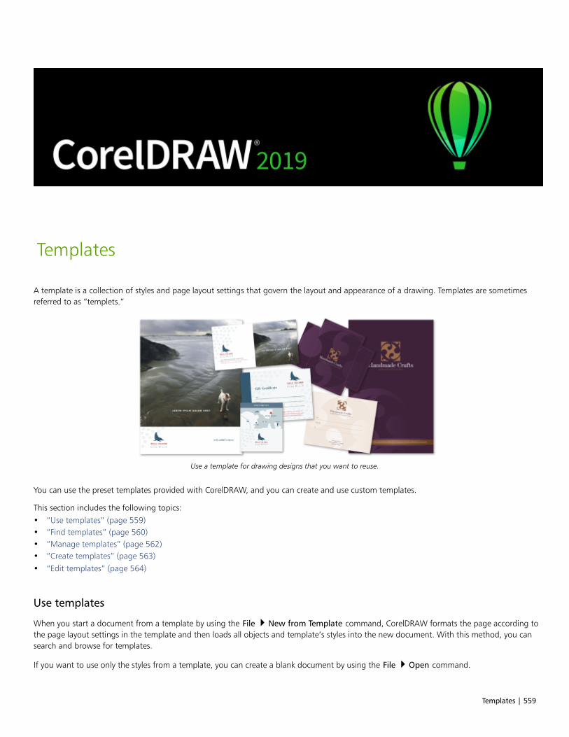
Templates | 559
Templates
A template is a collection of styles and page layout settings that govern the layout and appearance of a drawing. Templates are sometimesreferred to as “templets.”
Use a template for drawing designs that you want to reuse.
You can use the preset templates provided with CorelDRAW, and you can create and use custom templates.
This section includes the following topics:• “Use templates” (page 559)• “Find templates” (page 560)• “Manage templates” (page 562)• “Create templates” (page 563)• “Edit templates” (page 564)
Use templates
When you start a document from a template by using the File New from Template command, CorelDRAW formats the page according tothe page layout settings in the template and then loads all objects and template’s styles into the new document. With this method, you cansearch and browse for templates.
If you want to use only the styles from a template, you can create a blank document by using the File Open command.
560 | CorelDRAW 2019 User Guide
You can also import styles from a template into a document at any time.
To start a document from a template
1 Click File New from Template.
2 Search or browse for templates.
3 Choose a template by clicking its thumbnail.
4 Click Open.
For information about searching for templates, see “To find, filter, and sort templates” on page 561.
You can also start a document from a template by clicking File Open, locating the template, double-clicking it, and enabling theNew from template option in the Open dialog box. If you want to use only the template’s styles, disable the With contents checkbox.
To import styles from a template into a document
1 Click Window Dockers Object Styles.
2 In the Object Styles docker, open the Import, export, or save defaults flyout, and then click the Import style sheet button .
3 Locate the folder where the template is stored.
4 Click the template that contains the styles that you want to load.
5 Click Import.
Only the template styles are imported. Page layout settings and objects saved with the template are ignored. The attributes of existingobjects are maintained.
Find templates
CorelDRAW provides an easy way of finding templates.
You can search by the file name, title, or keywords associated with a template. For example, if you type “certificate” in the text field, theapplication automatically filters out all files that do not match, and you see only the files that have the word “certificate” in the file name orkeywords. You can cancel a search at any time.
You can narrow the search results by using the template source (for example, only templates created by you) and category (for example,Brochures, Flyers, or Letterheads & Letters). You can also view the list of your favorite or most recently used templates, and you can sorttemplates by the name and the date they were created or modified.
You can search and browse one pack, folder or list at a time. You can also browse and search your entire All templates library (the templatesincluded with CorelDRAW and provided by third-party designers, as well as templates that you have created).
Add templates
To get you started, Corel provides local templates that are listed under All templates in the New from Template dialog box. These templatesare stored in your Documents\Corel\Corel Content\Templates folder. If you are looking to expand your template collection, you candownload additional template packs from within the Get More dialog box.
To access templates that are saved to local folders outside your Documents\Corel\Corel Content\Templates folder, you can create links tothese folders. Such links are known as aliases. In addition, aliases can be used to access templates saved to shared network locations as wellas secondary storage devices such as USB flash drives, and portable hard drives.
Templates | 561
When you copy a folder that contains many templates to your computer, it may take some time for your operating system to index thefolder. To view, browse, and search templates in such a folder right away, you may need to reindex the folder.
View template and template information
You can increase the size of thumbnails to recognize a particular template easier and faster, and you can decrease thumbnail size to viewmore search results at a glance.When you select a template in the viewing area, additional information is displayed about the template’scategory, style, pagination, and fold options.
To find, filter, and sort templates
1 Click File New from Template.
2 From the Choose content source list box, choose All templates to search or browse the templates provided by Corel and any templatesadded by you.
3 Type a word in the Search box, and press Enter.
Templates that match the search term appear in the left pane.
You can also
Filter templates From the Choose content source list box, choose an item otherthan All templates. Choose a category from the Filter content listbox.
View the most recently used templates From the Choose content source list box, choose Recent.
View your favorite templates From the Choose content source list box, choose Favorites. Forinformation about how to mark a template as favorite, see “To tag,rename, and delete templates ” on page 563.
Sort templates Click the Options button , and choose one of the following:
•Sort by name sorts templates by template name, in alphabeticalorder.
•Sort by date created sorts templates by the date they werecreated, starting with the last created template.
•Sort by last modified sorts templates by the date they weremodified, starting with the last modified template.
Templates in your Favorites list are automatically sorted by thedate you marked them as favorites, starting with the last templateadded to Favorites.
Templates in your Recent list are automatically sorted by the dateyou used them, starting with the last used template.
Browse or search all items in your All templates library From the Choose content source list box, choose All templates.
Click the Options button , and click Browse recursively.
Reindex a folder Click the Options button , and click Reindex folder.
562 | CorelDRAW 2019 User Guide
When you choose My templates as the content source, you can browse all templates located in the root of your Documents\Corel\Corel Content\Templates folder.
If the CorelDRAW shell integration components are not installed (that is, if you have disabled the Windows Shell Extension optionunder Utilities in the Setup wizard during a custom installation), you can search for templates only by filename, not by name orkeywords.
To download and add a new template pack
1 Click File New from Template.
2 Click the Get More button.
3 In the Get More dialog box, click the template pack you want.
4 Do one of the following:
• Click Buy Now, and follow the onscreen instructions to purchase the item.
• Click Download if the item is included in your product or subscription.
To add an alias to a location that contains templates
1 In the New from Template dialog box, open the Choose content source list box, and click Add new.
2 Click Create alias.
3 In the Locate template library dialog box, browse to the folder or location you want.
4 Click Select Folder.
To view templates and template information
1 In the New from Template dialog box, search for templates.
2 Perform one or more tasks from the following table.
To Do the following
Increase or decrease the size of thumbnails Move the Thumbnail size slider.
View template details Click a thumbnail in the left pane. The template details aredisplayed in the right pane.
To hide the right pane where template details are displayed, disablethe Show template details check box.
Manage templates
You can manage the list of your local template packs and aliases (links to local folders, network locations, and secondary storage devices).For example, you can rename the local packs or aliases, and you can remove aliases from the list. If an alias no longer works because thetemplate folder has been moved, you can browse to the new location to restore the link.
To find the templates you like with ease, you can mark them as favorites. In addition, you can view and change the properties of a template.For example, you can change its title and language; and you can add new tags and delete existing tags. You can change the templatecategory, or you can assign a custom category to a template. When you no longer need a template, you can delete it.

Templates | 563
To update the list of template packs and aliases in the New from Template dialog box
1 Click File New from Template.
2 Choose a template pack or an alias from the Choose content source list box under All templates.
3 Click the Options button , and perform a task from the following table.
To Do the following
Rename a template pack or alias Click Rename, and in the Rename dialog box, type a name in theName box.
Browse to a folder that has been moved or renamed Click Browse, and navigate to the folder that contains thetemplates.
Remove the alias from the list Click Remove.
Open the template pack or alias in Windows Explorer Click Open folder location.
To tag, rename, and delete templates
1 Click File New from Template.
2 Perform an action from the following table.
To Do the following
Tag a template as favorite Right-click a thumbnail, and click Favorite.
Change the name of a template in your local library, or the tagsassociated with it
Right-click a thumbnail, and click Properties. In the Propertiesdialog box, do any of the following:
•Choose a language from the Language list box.•Type a new name in the Title box.•Add or delete tags in the Tags box.•Choose a category from the Category list box to categorize the
template.•To assign a custom category, choose New category from the
Category list box, and type the category name in the box.
Delete a template from your local library Right-click a thumbnail, and click Delete.
Create templates
If the preset templates do not meet your needs, you can create your own templates, based on documents that you often use. For example, ifyou regularly put together a newsletter, you can save the page layout settings and styles to a template.
When you save a template, CorelDRAW allows you to add reference information, such as pagination, folds, and category. Although addingtemplate information is optional, doing so makes it easier to organize and locate templates later on.

564 | CorelDRAW 2019 User Guide
You can change the default location to which templates are saved. For more information, see “Change content locations” on page 89.
To create a template
1 Click File Save as Template.
2 Type a name in the File name list box.
3 Locate the folder where you want to save the template.
4 Click Save.
5 In the Template properties dialog box, specify the options you want:
• Title — Assign a name to your template. This name will appear with the thumbnail in the Templates pane.
• Tags — Type keywords that you want to associate with the template. You can use these words to search for the template in the Newfrom Template dialog box.
• Sided — Choose a pagination option.
• Folds — Choose a fold from the list.
• Category — Choose a category to assign to the template. To assign a custom category, choose New category from the Category listbox, and type the category name in the box.
If you click Cancel, you close the Template properties dialog box without saving the template.
If you don’t want to add reference information, click Save without specifying any of the options.
Edit templates
You can edit a template by making changes to the styles, page layout settings, or objects. For example, if you like a template but want tomake it more versatile, you can add styles that you’ve created or that you’ve taken from another template. For information about editingstyles, see “Edit styles and style sets” on page 569. For information about setting page layout options, see “Page layout” on page 587.
To edit a template
1 Click File Open.
2 Locate the folder where the template is stored.
3 Double-click a template filename.
4 In the Open dialog box, enable the Open for Editing option.
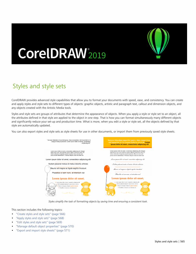
Styles and style sets | 565
Styles and style sets
CorelDRAW provides advanced style capabilities that allow you to format your documents with speed, ease, and consistency. You can createand apply styles and style sets to different types of objects: graphic objects, artistic and paragraph text, callout and dimension objects, andany objects created with the Artistic Media tools.
Styles and style sets are groups of attributes that determine the appearance of objects. When you apply a style or style set to an object, allthe attributes defined in that style are applied to the object in one step. That is how you can format simultaneously many different objectsand significantly reduce your set-up and production time. What is more, when you edit a style or style set, all the objects defined by thatstyle are automatically updated.
You can also export styles and style sets as style sheets for use in other documents, or import them from previously saved style sheets.
Styles simplify the task of formatting objects by saving time and ensuring a consistent look.
This section includes the following topics:• “Create styles and style sets” (page 566)• “Apply styles and style sets” (page 568)• “Edit styles and style sets” (page 569)• “Manage default object properties” (page 570)• “Export and import style sheets” (page 571)
566 | CorelDRAW 2019 User Guide
• “Assign keyboard shortcuts to styles or style sets” (page 572)• “Find objects that use a specific style or style set” (page 572)• “Break the link between objects and styles or style sets” (page 573)
Create styles and style sets
A style is a group of formatting attributes that defines an object property, such as outline or fill. For example, to define an outline style, youcan specify attributes such as outline width, color, and type of line. To define a character style, you can specify the font type, font style andsize, text color and background color, character position, caps, and more. CorelDRAW lets you create and apply outline, fill, paragraph,character, and text frame styles.
CorelDRAW lets you group styles into style sets. A style set is a collection of styles that helps you define the appearance of an object. Forexample, you can create a style set containing a fill style and an outline style that you can apply to graphic objects such as rectangles,ellipses, and curves.
There are two options for creating styles. You can create a style or style set based on the formatting of an object that you like, or you cancreate a style or style set from scratch by setting the object attributes in the Object Styles docker.
In CorelDRAW, styles can contain other styles. A style that contains another style is called a parent; a style that is contained within anotherstyle is called a child. Properties are automatically inherited from the parent; however, you can override inherited properties for a child andset its own specific properties. When you modify the parent style, the child style is updated automatically. If you set child-specific attributes,the attributes are no longer related to the parent, so if you modify the parent, the child-specific attributes will not be modified. The parent-child relationship applies to style sets as well.
You can use child and parent styles in documents where you want objects to share some, but not all, attributes, and you need to makeglobal changes on a regular basis. For example, if you are working on a long document and you want to have headings and subheadingswith similar formatting, you can create a parent character style for the headings and a child character style for the subheadings. The parentand the child styles can share the same color and font type but differ in size. If you choose a different color or font type for the parent, boththe headings and the subheadings will be updated automatically. The subheadings, however, will still appear smaller than the headings.
To create a style from an object
1 Using the Pick tool , right-click an object.
2 Choose Object Styles, choose New Style From, and point to a style type.
A preview shows you what object attributes will be included in the new style.
3 Click a style type.
4 In the New Style From dialog box, type a name in the New Style Name box.
If the Object Styles docker is not open, enable the Open Object Styles docker check box in the New Style From dialog box.
You can also create a style from an object by right-clicking the Styles folder in the Object Styles docker, choosing New fromSelected, and then choosing a style type.
To create a style set from an object
1 Using the Pick tool , right-click an object.
2 Choose Object Styles, and point to New Style Set From.
Styles and style sets | 567
A preview shows you what object attributes will be included in the new style set.
3 Click New Style Set From.
4 In the New Style Set From dialog box, type a name in the New Style Set Name box.
If the Object Styles docker is not open, enable the Open Object Styles docker check box in the New Style Set From dialog box.
You can also create a style set from an object by dragging the object to the Style Sets folder in the Object Styles docker. If you dragthe object over an existing style set in the Style Sets folder, the attributes of the object replace the attributes of the style set, and allobjects to which the style set has been applied are automatically updated.
To define a style
1 Click Window Dockers Object Styles.
2 In the Object Styles docker, click the New style button , and choose a style type.
The style appears in the Styles folder with a name assigned by the application, for example “Fill 1.”
3 Specify the style attributes that you want.
You can also
Rename a style Right-click a style, click Rename, type a new name, and pressEnter.
Delete a style Do one of the following:•Select a style in the Styles folder, and click the Delete style
button .
•Right-click a style, and click Delete.
Duplicate a style Right-click a style, and click Duplicate.
Create a child style Do one of the following:•Select a style in the Styles folder, and click the New Child Style
button .
•Right-click a style, and click New Child Style.
To define a style set
1 Click Window Dockers Object Styles.
2 In the Object Styles docker, click the New style set button to create an empty style set to which you can add styles.
The style set appears in the Style Sets folder with a name assigned by the application, for example “Style Set 1.”
3 Do one of the following:
• Click the Add or remove style button next to the style set, and select the style types that you want to add to the style set. Then,
set the properties of each style.
• From the Styles folder, drag existing styles to the new style set.
568 | CorelDRAW 2019 User Guide
You can also
Rename a style set Right-click a style set in the Style Sets folder, click Rename, type anew name, and press Enter.
Delete a style set Do one of the following:•Select a style set in the Style Sets folder, and click the Delete
style set button .
•Right-click a style set, and click Delete.
Duplicate a style set Right-click a style set, and click Duplicate.
Create a child style set Do one of the following:•Select a style set in the Style Sets folder, and click the New Child
Style Set button .
•Right-click a style set, and click New Child Style Set.
Apply styles and style sets
When you apply a style or a style set to an object, the object takes on only the attributes that are defined by the style or style set. Forexample, if you apply an outline style, the object outline changes while its other attributes stay the same.
You can apply styles and styles sets by using the Object Styles docker and the Properties docker.
In the Properties docker, attributes which are defined by a style appear with a source indicator that is green and has a vertical line in themiddle . (The source indicator is the little square next to the attribute name.) If there is no style applied, the source indicator appears blank
. If there is an override of the applied style, the source indicator color is orange with a horizontal line in the middle .
To apply a style or style set to an object
1 Using the Pick tool , select an object.
2 Click Window Dockers Object Styles.
3 In the Object Styles docker, select a style or style set, and click Apply to Selected.
To see a preview of the style or style set before applying it, point to it in the Object Styles docker.
You can also apply a style by clicking a source indicator next to an object property (outline, fill, character, paragraph, or frame) in theProperties docker and choosing a style from the list of styles.
You can also apply a style or style set to a selected object by using any of the following methods:
• In the Object Styles docker, double-click a style or style set.
• Right-click the object, choose Styles, choose Apply Style, and then choose a style or style set from the list.
• In the Object Styles docker, right-click a style or style set, and choose Apply Style or Apply Style Set.
• In the Object Styles docker, select a style or style set, and drag it to the object.

Styles and style sets | 569
Edit styles and style sets
You can edit a style or style set either by changing its attributes in the Object Styles docker, or by changing the attributes of an object linkedto the style or style set, and then applying these changes to the style or style set.
You can also edit a style or style set by copying attributes from an object to the style or style set.
You can override style attributes. When you override an attribute, it is no longer related to the style definition, and changes to the style donot affect the object until you remove the override.
To edit a style
1 Click Window Dockers Object Styles.
2 In the Object Styles docker, open the Styles folder, and select a style.
3 In the style properties area of the Object Styles docker, modify the attributes you want.
To edit a style set
1 Click Window Dockers Object Styles.
2 In the Object Styles docker, open the Style Sets folder, and select a style set.
3 Click the Add or remove style button next to the style set, and click the style type that you want to add or remove from the style
set.
Check marks appear next to the style types that are included in the style set.
In the style properties area of the Object Styles docker, you can edit the styles that are included in the style set.
To edit a style or style set by editing an object
1 Using the Pick tool , select an object that has a style or style set applied to it.
2 Click Object Properties.
3 In the Properties docker, edit the object properties.
4 In the document window, right-click the object, choose Object Styles from the context menu, and choose Apply to Style.
The new attributes of the object replace the attributes of the styles or style sets associated with this object.
To edit a style or style set by copying properties from an object
1 Click Window Dockers Object Styles.
2 Drag an object from the document window over a style or style set name in the Object Styles docker.
You can also copy the properties of an object to a style or style set by right-clicking the style or style set in the Object Styles docker,choosing Copy Properties From, and then clicking an object in the document window.
To override a style attribute
1 Using the Pick tool , select an object that has a style applied to it.
2 Click Object Properties.
570 | CorelDRAW 2019 User Guide
3 In the Properties docker, edit an object attribute defined by a style.
The source indicator next to the attribute changes from green with a vertical line to orange with a horizontal line , showing that theobject attribute is no longer defined by the style.
To remove a style override, do one of the following:
• Click the orange source indicator , and choose Revert.
• In the document window, right-click the object by using the Pick tool , choose Object Styles from the context menu,
and choose Revert to Style.
Manage default object properties
The default object properties in CorelDRAW control the appearance of text and graphic objects in the active document. For example, whenyou install CorelDRAW for the first time, the default properties for graphic objects determine that each new graphic object has a blackoutline and no fill.
You can modify the default properties of the following types of objects: artistic media, artistic text, callout, dimension, graphic, andparagraph text. When you modify the defaults, CorelDRAW automatically saves these changes to the current document. If you want to usethe custom settings in subsequent documents that you create, you can set them as the new document defaults.
You can specify which object styles, style sets, color styles, or default object properties in the active drawing are set as the new documentdefaults.
To edit default object properties
1 Click Window Dockers Object Styles.
2 In the Object Styles docker, open the Default Object Properties folder, and choose one of the following object types:
• Artistic Media
• Artistic Text
• Callout
• Dimension
• Graphic
• Paragraph Text
• QR Code
3 Modify the attributes you want.
Any changes you make are applied to all new objects in the active document and are automatically saved with the document.
You can also
Undo changes by reverting selected default properties to the newdocument defaults
Do one of the following:•Click the Revert to new document default button next to
the object type.•Right-click the object type, and choose Revert to new document
default.
Undo changes to the default object properties for all object typesby reverting to the new document defaults
Do one of the following:

Styles and style sets | 571
You can also
•Click the Revert all to new document default button next
to the Default Object Properties folder.•Right-click the Default Object Properties folder, and click Revert
all to new document default.
Set selected object properties as the default settings for newdocuments
Do one of the following:•Click the Set as new document default button next to the
object type.•Right-click the object type, and click Set as new document
default.
You can also edit the default object properties by deselecting all objects in the document window, clicking a color or a color style on apalette, or choosing a control that lets you change fill, outline, or text properties, and then enabling the respective check boxes in theChange document defaults dialog box.
You can also edit the default object properties while editing any object in the document window. Right-click the Default ObjectProperties folder in the Object Styles docker, and choose Update Default Properties When Editing Objects. Any change you maketo an object becomes the default setting for new objects.
To set the current style settings as the new document defaults
1 Click Window Dockers Object Styles.
2 In the Object Styles docker, click the Import, export, or save defaults button , and click Set as New Document Defaults.
3 Enable the check boxes for the settings that you’d like to save as the default settings for new documents.
You can also save settings as the default settings for new documents by using the Options dialog box. For more information, see“Save and restore defaults” on page 844.
Export and import style sheets
You can make styles and style sets available for use in other documents by exporting them to a CorelDRAW style sheet (.cdss) file. A stylesheet contains all the object styles, style sets, color styles, and default object properties in the active document. You can also use styles andstyle sets from other documents by importing the style sheet to which they were saved.
To export a style sheet
1 Click Window Dockers Object Styles.
2 In the Object Styles docker, click the Import, export, or save defaults button , and click Export Style Sheet.
3 In the Export Style Sheet dialog box, choose the folder where you want to save the style sheet.
4 Type a file name in the File name box.
5 Click Export.
6 Enable the check boxes for the settings you’d like to export from the document.

572 | CorelDRAW 2019 User Guide
To import a style sheet
1 Click Window Dockers Object Styles.
2 In the Object Styles docker, click the Import, export, or save defaults button , and click Import Style Sheet.
3 In the Import Style Sheet dialog box, choose the folder where the style sheet is stored.
4 Select the file name, and click Import.
5 Enable the check boxes for the settings you’d like to import into the document.
You can also import styles and style sets from an existing CorelDRAW file by selecting the file in the Import Style Sheet dialog boxand clicking Import.
Assign keyboard shortcuts to styles or style sets
You can assign a keyboard shortcut to a style or style set. When you press the keyboard shortcut, CorelDRAW applies the style or style set tothe selected object. A keyboard shortcut can use up to four different keystrokes.
If a keyboard shortcut is already assigned to another command, you can override the existing setting.
For more information about working with keyboard shortcuts, see “Customize keyboard shortcuts” on page 848.
To assign a keyboard shortcut to a style or style set
1 Click Window Dockers Object Styles.
2 In the Object Styles docker, right-click a style or style set, and click Assign Keyboard Shortcut.
The Options dialog box opens with the Shortcut keys tab of the Commands page displayed and Apply styles in the top list boxselected.
3 Select the style or style set to which you want to assign a shortcut.
If you have already assigned a keyboard shortcut to the selected style, the shortcut is displayed in the Current shortcut keys box.
4 Click in the New shortcut key box, and press a key combination.
If the key combination is already assigned to another command, that command is listed in the Currently assigned to box.
5 Click Assign.
If the same keyboard shortcut is already assigned to another command, the second assignment overwrites the first. By enabling theNavigate to conflict on assign check box, you can automatically navigate to the command whose shortcut you reassigned andassign a new shortcut.
Find objects that use a specific style or style set
CorelDRAW allows you to find objects with a specific style or style set in the active drawing. For example, you can find all text objects thatuse a specific heading style.
To find objects that use a specific style or style set
1 Click Window Dockers Object Styles.
2 In the Object Styles docker, open the styles or styles sets folder that contains a specific style or style set.
3 Right-click the style or style set, and choose Select Objects Using Style.

Styles and style sets | 573
Break the link between objects and styles or style sets
You can break the link between an object and the style or style set applied to it. When you break the link, the object retains its currentappearance. Subsequent changes to the style or style set will not affect the object attributes.
To break the link between an object and a style or style set
• In the document window, right-click an object by using the Pick tool , choose Object Styles from the context menu, and click Break
Link to Style.
If the Break Link to Style command is not available, there are no styles or style sets applied to this object.
You can also break the link between an object and a style by clicking the source indicator next to the styled property (outline, fill,paragraph, character, or frame) in the Properties docker and choosing Not Styled.

574 | CorelDRAW 2019 User Guide
Color styles | 575
Color styles
A color style is a color you save and apply to objects in a document. Any time you update a color style, you also update all objects using thatcolor style. Color styles allow you to apply custom colors with ease and consistency.
This section contains the following topics:• “Create and apply color styles” (page 575)• “Edit color styles” (page 578)• “View color styles” (page 581)• “Export and import color styles” (page 583)• “Break the link between a color style and an object” (page 583)
Create and apply color styles
You can create color styles from the colors of an existing object or from scratch. When you create a color style, the new color style is saved tothe active document and to the Color styles palette.
After you create a color style, you can apply it to objects in the document. CorelDRAW lets you access available color styles through variouscontrols: the Color Styles docker, the Object Styles docker, the Properties docker, the Color styles palette, and the Document palette. (Acolor style is automatically added to the Document palette when you apply it to an object.)
Color styles can be combined into groups called harmonies. A harmony allows you to link color styles into hue-based relationships andmodify them together as a set. By editing color styles in a harmony, you can quickly create a variety of alternate color schemes by shifting thecolors together, or you can alter the color composition of your artwork in one step.
CorelDRAW allows you to create a special type of color harmony called a gradient. A gradient consists of a master color style and a numberof shades of that color style. For most of the available color models and palettes, the derivative color styles share the same hue as the mastercolor style but have different saturation and brightness levels. With the PANTONE MATCHING SYSTEM and Custom spot color palettes, themaster color style and the derivative color styles are linked to one another but have different tint levels.
You can create a harmony from the colors of an existing object or from scratch.
CorelDRAW also lets you select all color styles that are not used in the document or merge unwanted color styles into others. It also lets youconvert color styles to different color modes or to spot colors to prepare your document for production printing.
To create a color style or harmony from a selected object
1 Select an object by using the Pick tool .
576 | CorelDRAW 2019 User Guide
2 Click Window Dockers Color Styles.
3 In the Color Styles docker, click the New color style button , and choose New from selected.
4 In the Create color styles dialog box, enable one of the following options in the Create color styles from area:
• Object fill — creates a color style from the color of the object fill
• Object outline — creates a color style from the color of the object outline
• Both fill and outline — creates color styles from the object fill and outline colors
5 To group the new color styles based on hues of similar saturation and value, enable the Group color styles into harmonies check box,and specify the number of harmonies in the box.
To convert the color styles to a different color mode, enable the Convert all color styles to check box, and choose a color mode fromthe list box.
You can also create color styles or color harmonies from a selected object by using any of the following methods:
• Drag the selected object to the top part of the gray area in the Color Styles docker to create independent color styles, ordrag the selected object to the bottom part of the gray area to create color styles grouped into harmonies. Then, specify thesettings you want in the Create color styles dialog box.
• Right-click the object in the document window, and choose Color styles New from Selected. Then, specify the settingsyou want in the Create color styles dialog box.
To create a color style
1 Click Window Dockers Color Styles.
2 Drag a swatch from any open palette to the top part of the gray area in the Color Styles docker.
You can also create a color style by clicking the New color style button , choosing New color style, and choosing a color in the
Color editor. The Color editor provides a variety of options to choose the right color: Eyedropper tool, color viewers, sliders, andpalettes. For more information about choosing colors, see “Color” on page 347.
If you want to create color styles from all the colors in your document, do one of the following:
• In the Color Styles docker, click the New color style button , and choose New from document.
• In the document window, right-click an object using the Pick tool , and choose Color styles New from document.
To create a color harmony
1 Click Window Dockers Color Styles.
2 In the Color Styles docker, click the New color harmony button , and choose New color harmony.
A folder icon for the color harmony appears in the bottom part of the gray area.
3 Drag any color swatches or color style swatches to the harmony folder.
Color styles | 577
You can also duplicate a harmony by selecting its folder in the Color Styles docker, clicking the New color harmony button ,
and choosing Duplicate harmony.
You can resize the Color harmonies area so that you can view available color harmonies without scrolling by pointing to the grabarea, and when the cursor changes to a two-directional arrow, dragging the edge of the pane.
To create a gradient
1 Click Window Dockers Color Styles.
2 In the Color Styles docker, select a color style as the master color for the gradient.
3 Click the New color harmony button , and choose New gradient.
4 In the New gradient dialog box, specify the number of shades in the Number of colors box.
5 Adjust the Shade similarity slider.
Move the slider to the left to create very different shades; move the slider to the right to create very similar shades.
6 Enable one of the following options:
• Lighter shades — creates shades that are lighter than the master color
• Darker shades — creates shades that are darker than the master color
• Both — creates an equal number of light and dark shades
To apply a color style
1 Click Window Dockers Color Styles.
2 Select an object by using the Pick tool .
3 In the Color Styles docker, do one of the following:
• Double-click a color style to apply a fill.
• Right-click a color style to apply an outline.
You can also
Delete a color style Select the color style, and click the Delete button .
Merge selected color styles with the last selected color style Click the Merge button .
Swap color styles Select two color styles in the Color Styles docker, and click the
Swap color styles button . The fill color style becomes the
object outline, and the outline color style becomes the object fill.
Select all color styles which are not used in the document Click the Select unused button .
You can also apply a color style to a selected object by using any of the following methods:

578 | CorelDRAW 2019 User Guide
• On the Color styles palette or the Document palette, click a color style to apply a fill or right-click a color style to apply an
outline. To open the Color styles palette, click Window Color palettes Color styles palette.
• Drag a color style from a palette or the Color Styles docker to the object.
• In the Outline or Fill section of the Properties docker, click the source indicator next to the color picker, and choose fromthe list of previously created color styles.
• You can also use the Object Styles docker to apply a color style, if the object style that is assigned to an object contains acolor attribute, such as a fill or outline. In the style properties area of the Object Styles docker, click the source indicatornext to a color picker, and choose from the list of previously saved color styles.
Edit color styles
You can edit an individual color style or a color style in a harmony.
When you edit a harmony, you can edit color styles simultaneously by preserving the relationship between them, or you can modifyindividual color styles within the harmony.
When you change the hue of the master color style in a gradient, all its derivative shades are updated based on the new hue and the originalsaturation and brightness value.
Harmony rules
You can apply a rule to a color harmony to shift all colors according to predetermined logic and create various color schemes (combinations).The selected color in the color harmony is considered to be the base color and is used as reference to position the remaining colors on thecolor wheel.
You can also use a harmony rule to create a color harmony from scratch. The resulting color harmony contains five colors that are createdrandomly based on the chosen rule, and its base color is the selected color in the harmony swatch list.
The following harmony rules are available.
• Analogous — includes colors that are next to each other on the color wheel, creating clear and smooth color schemes
• Analogous - Accented — similar to the Analogous rule, but includes a complementary (contrasting) color in addition to the adjacentcolors
• Complementary (also known as “contrast”) — balances the base color with the opposite color on the color wheel. Warm and coldcolors are created for vibrant and energetic color schemes.
• Monochromatic — includes variations of a single color, creating soothing color schemes
• Tetrad — based on a pair of colors and their complements on the color wheel. This rule usually creates bold color harmonies andrequires careful planning when used.
• Triad — balances the base color with colors that are situated close to the opposite end of the color wheel, forming a triangle. Thisharmony rule usually creates color schemes of soft contrast.
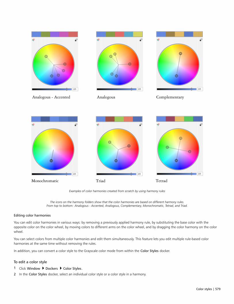
Color styles | 579
Examples of color harmonies created from scratch by using harmony rules
The icons on the harmony folders show that the color harmonies are based on different harmony rules.From top to bottom: Analogous - Accented, Analogous, Complementary, Monochromatic, Tetrad, and Triad.
Editing color harmonies
You can edit color harmonies in various ways: by removing a previously applied harmony rule, by substituting the base color with theopposite color on the color wheel, by moving colors to different arms on the color wheel, and by dragging the color harmony on the colorwheel.
You can select colors from multiple color harmonies and edit them simultaneously. This feature lets you edit multiple rule-based colorharmonies at the same time without removing the rules.
In addition, you can convert a color style to the Grayscale color mode from within the Color Styles docker.
To edit a color style
1 Click Window Dockers Color Styles.
2 In the Color Styles docker, select an individual color style or a color style in a harmony.
580 | CorelDRAW 2019 User Guide
3 In the Color editor or Harmony editor, edit the color style by using any of the available controls: Eyedropper tool, color viewers, sliders,and palettes.
For more information about choosing colors, see “Color” on page 347.
You can also
Rename a color style Select the color style in the Color Styles docker, and type a newname in the name box at the top of the docker.
Convert a color style to a different color mode Click the Convert button , and choose a color mode from the
flyout.
Convert a color style to a spot color Click the Convert button , and choose Convert to Spot.
To edit a color harmony
1 Click Window Dockers Color Styles.
2 In the Color Styles docker, click a harmony folder.
3 Do any of the following:
• In the Harmony editor, click a selector ring and drag to edit the color styles in the harmony. To constrain the movement of the selectorring, hold down Ctrl while dragging the selector ring to preserve the original saturation, or hold down Shift to preserve the originalhue.
• In the Color editor, choose a color by using any of the available controls: Eyedropper tool, color viewers, sliders, and palettes. Formore information about choosing colors, see “Color” on page 347.
4 In the Harmony editor, move the Brightness slider to change the tint of the color.
If you want to specify the exact tint, type a value in the Brightness box.
To edit an individual color style in the harmony, select the style by clicking its swatch in the harmony folder, or by clicking itsrespective selector ring or swatch in the Harmony editor.
You can resize the Color harmonies area so that you can view available color harmonies without scrolling by pointing to the grabarea, and when the cursor changes to a two-directional arrow, dragging the edge of the pane.
You can reorder color harmonies by dragging a color swatch.
To apply a rule to a color harmony
1 Click Window Dockers Color Styles.
2 In the Color Styles docker, click a harmony folder.
3 Choose a rule from the Harmony rule list box.
You can also
Create a rule-based color harmony from scratch Make sure that no color styles are selected, and choose a rule fromthe Harmony rule list box.

Color styles | 581
You can also
Distribute colors evenly when changing a harmony rule Make sure the Distribute colors button is enabled, and
choose a harmony rule from the Harmony rule list box.
Colors will be distributed evenly along the arms on the color wheel,which can result in radical color changes.
When the Distribute colors button is disabled, color relationshipsin the color harmony are maintained.
You can choose Custom from the Harmony rule list box to remove a previously applied rule or start a new harmony folder.
To edit a color harmony
1 Click Window Dockers Color styles.
2 In the Color Styles docker, click a color style in a color harmony.
3 In the Harmony editor, perform any of the following tasks.
To Do the following
Remove a rule from a color harmony Click the Remove harmony rule button .
Change to the opposite color on the color wheel Click the Switch to opposite color button .
Move a color to another arm Holding down Alt, drag a selector ring to another arm.
This feature is available for color harmonies that are based on theComplementary, Tetrad, or Triad harmony rule as well as customcolor harmonies.
Edit multiple color harmonies simultaneously Click the color styles you want while holding down Ctrl, and drag aselector ring in the Harmony editor.
Convert a color style to the Grayscale color mode Click the Convert button , and click Convert to grayscale.
You can also convert a color style or a color harmony to the Grayscale color mode in the Create Color Styles docker when you arecreating a color style or a color harmony from a selected object. For information about how to access the Create Color Styles docker,see “To create a color style or harmony from a selected object” on page 575.
View color styles
Several view options are available in the Color Styles docker to help your work with color styles more easily.

582 | CorelDRAW 2019 User Guide
Page Sorter view displays thumbnails of all pages in a document. When you edit a color style in Page Sorter view, you can see how all objectsthat use the color style are changed. You can change the size of the page thumbnails to suit your needs.
Hint view shows what objects are associated with color styles. When you point to a color style in the Color Styles docker, an indicator marksthe object that uses the color style in the document window.
Hint view helps you identify objects that use specific color styles.
In addition, you can show larger color swatches, and you can view empty arms in color harmonies in the Harmony editor.
Two of the arms in this color harmony, based on the Tetrad harmony rule,do not contain any colors, but are displayed to help with editing tasks.
To enable Page Sorter view
1 Click Window Dockers Color Styles.
2 In the Color Styles docker, click the View options button , and click Page sorter view.
3 To change the size of the page thumbnails, click one of the following buttons on the property bar:
• Small thumbnails
Color styles | 583
• Medium thumbnails
• Large thumbnails
To return to the default page view, click the Page sorter view button on the property bar.
To use Hint view
1 Click Window Dockers Color Styles.
2 In the Color Styles docker, click the View options button , and click Hint view.
3 Point to a color style that was applied to an object.
A small indicator appears in the center of the object that uses the color style.
To show larger color swatches
1 Click Window Dockers Color Styles.
2 In the Color Styles docker, click the View options button , and click Use large swatches.
To show empty arms in a color harmony
1 Click Window Dockers Color Styles.
2 In the Color Styles docker, click the View options button , and click Show empty arms.
Export and import color styles
You can reuse color styles by adding them to custom palettes, saving them as the new document defaults, or exporting them to a stylesheet. You can also import color styles from other documents. For more information, see “Create and edit color palettes ” on page 357,“Manage default object properties ” on page 570, and “Export and import style sheets ” on page 571.
Break the link between a color style and an object
When you break the link between a color style and an object, the object no longer derives its color properties from the color style; you canupdate the color style without modifying the object.
To break the link between a color style and an object
• Right-click an object by using the Pick tool , and choose Color styles Break link to color styles.
You can also break the link to a color style in the Properties docker. Click the source indicator next to the color picker in the Outlineor Fill sections of the Properties docker, and choose Break link to color style.

584 | CorelDRAW 2019 User Guide

Pages and layout | 585
Pages and layout
Pages and layout tools........................................................................................................................................................................ 587
Tables...................................................................................................................................................................................................605

586 | CorelDRAW 2019 User Guide
Pages and layout tools | 587
Pages and layout tools
CorelDRAW lets you specify the size, orientation, unit of scale, and background of the drawing page. You can customize and display pagegrids and guidelines to help you organize objects and place them exactly where you want. For example, if you are designing a newsletter,you can set the dimensions of the pages and create guidelines for positioning columns and heading text. When you are laying out anadvertisement, you can align graphics and text along guidelines and arrange graphic elements within a grid. Rulers can help you positiongrids, guidelines, and objects along a scale that uses units of your choice. Also, you can add and delete pages.
Page layout settings and tools are fully customizable and can be used as defaults for other drawings.
This section contains the following topics:
• “Page layout” (page 587)
• “Page background” (page 590)
• “Add, duplicate, rename, and delete pages” (page 591)
• “Insert page numbers” (page 593)
• “Rulers” (page 595)
• “Calibrate the rulers” (page 597)
• “Document grid and pixel grid” (page 597)
• “Baseline grid” (page 599)
• “Set up guidelines” (page 600)• “Modify guidelines” (page 602)• “Drawing scale” (page 603)
Page layout
You can begin working on a drawing by specifying settings for the size, orientation, and layout style of the page. The options you choosewhen specifying the page layout can be used as a default for all new drawings you create. You can also adjust the page size and orientationsettings to match the standard paper settings for printing.
Page size
There are two options for specifying a page size: choosing a preset page size and creating your own. You can choose from many preset pagesizes, ranging from legal-size paper and envelopes to posters and web pages. If a preset page size does not meet your needs, you can createa custom page size by specifying a drawing’s dimensions.
You can save custom page sizes as presets for later use, and you can delete any custom preset page sizes that you no longer need.

588 | CorelDRAW 2019 User Guide
Page orientation
The orientation of the page can be landscape or portrait. In landscape orientation, the drawing’s width is greater than its height, and inportrait orientation, the drawing’s height is greater than its width. Any pages you add to a drawing have the current orientation; however,you can change the orientation of individual pages at any time.
Layout styles
When you use the default layout style (Full Page), each page in a document is considered a single page and prints on one sheet. You canchoose layout styles for multipage publications, such as booklets and brochures. The multipage layout styles — Book, Booklet, Tent Card,Side-fold Card, Top-fold Card, and Tri-fold Brochure — split the page size into two or more equal parts. Each part is considered a separatepage. The advantage of working with separate parts is that you can edit each page in upright orientation, and in sequential order in thedrawing window, regardless of the layout required to print your document. When you are ready to print, the application automaticallyarranges the pages in the order required for printing and binding.
Label styles
You can choose from more than 800 preset label formats from different label manufacturers. You can preview the dimensions of labels andsee how they fit on a printed page. If CorelDRAW does not provide a label style that meets your requirements, you can modify an existingstyle or create and save your own original style.
To set the page size and orientation
1 Click Layout Page Size.
2 Enable the Page size option.
3 Perform a task from the following table.
To Do the following
Choose a preset page size Choose a page size from the Size list box.
Match the page size and orientation to the printer settings Click the Get page size from printer button.
Specify a custom page size Type values in the Width and Height boxes.
Set the page orientation Click the Landscape or the Portrait button.
Set the page size and orientation for an individual page in amultipage document
Make sure that the page you want to change is displayed in thedrawing window, choose a page size and orientation, and enablethe Apply size to current page only check box.
Display the page border Enable the Show page border check box.
Add a frame around the page Click Add page frame.
Choose a rendering resolution for the document Choose a resolution from the Rendering resolution list box.
Set a bleed limit Enable the Show bleed area check box, and type a value in theBleed box.
Pages and layout tools | 589
You can also specify the page size and orientation by clicking View Page Sorter View and adjusting the controls on the propertybar.
You can also open the Options dialog box with the Page size page displayed by double-clicking the shadow of the drawing page.
You can change the page orientation by clicking Layout Switch Page Orientation.
To add or delete custom preset page sizes
1 Click Layout Page Size.
2 Perform a task from the following table.
To Do the following
Add a custom preset page size Specify a custom page size in the Width and Height boxes, click
the Save button , and type a name for the custom page in the
Save custom page type as box.
The custom preset page size appears in the Size list box.
Delete a preset page size Choose a page size from the Size list box, and click the Delete
button .
With the Pick tool active and no objects selected, you can also add or delete custom preset page sizes by clicking Edit this list at thebottom of the Page size list box on the property bar.
To choose a layout style
1 Click Layout Page Layout.
2 Choose a layout style from the Layout list box.
Each layout style is accompanied by a short description and illustration.
To use a label style
1 Click Layout Page Size.
2 Enable the Label presets option.
3 Double click a manufacturer name from the list, and then choose a label style.
If you want to customize the label style, click Customize, and adjust the label size, margins, gutters, and the number of labels appearingon each sheet.
If you want to save the custom label style you created, click the Add button . In the Save Settings dialog box, type a name for the
new label style in the Save as box.
You cannot use label styles if a drawing contains multiple pages.
590 | CorelDRAW 2019 User Guide
For best results, choose Letter paper size and Portrait orientation before applying a label style.
To save the current page layout as the default
1 Click Layout Document Options.
2 Click Save as Default.
3 Enable the Page size and Layout check boxes.
Page background
You can choose the color and type of background for a drawing. For example, you can use a solid color if you want a uniform background.If you want a more intricate or dynamic background, you can use a bitmap. Some examples of bitmaps include textured designs,photographs, and clipart.
When you choose a bitmap as the background, it is embedded in the drawing by default. This option is recommended. However, you canalso link the bitmap to the drawing so that if you later edit the source image, the change is automatically reflected in the drawing. If yousend a drawing with a linked image to someone else, you must also send the linked image.
You can make a background bitmap printable and exportable, or you can save computer resources by exporting and printing a drawingwithout the background bitmap.
If you no longer need a background, you can remove it.
To use a solid color as the background
1 Click Layout Page Background.
2 Enable the Solid option.
3 Open the color picker, and click a color.
When you export files to a bitmap format, the background color is used for anti-aliasing edges. If the bitmaps are of irregular shapeand will be placed against a background different from white, it is recommended that you select a matching page background color.For example, if you are planning to place the exported bitmap against a blue background, you may want to choose a similar bluecolor for the page background.
To use a bitmap as the background
1 Click Layout Page Background.
2 Enable the Bitmap option.
3 Click Browse.
4 Locate the folder in which the file is stored.
5 Double-click the filename.
6 Enable one of the following options:
• Linked — links the bitmap to the drawing so that changes made to the source file are reflected in the bitmap background
• Embedded — embeds the bitmap in the drawing so that changes made to the source file are not reflected in the bitmap background
If you want the background to be printed and exported with the drawing, enable the Print and export background check box.
7 Enable one of the following options:
• Default size — lets you use the bitmap’s current size
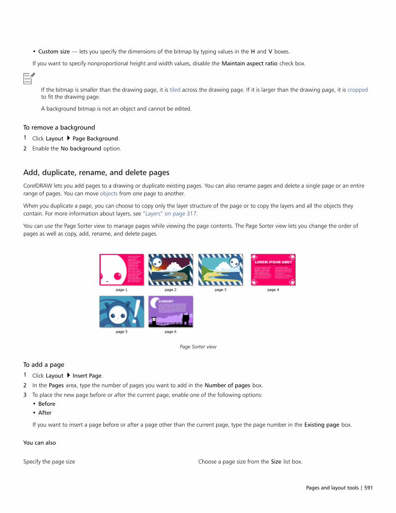
Pages and layout tools | 591
• Custom size — lets you specify the dimensions of the bitmap by typing values in the H and V boxes.
If you want to specify nonproportional height and width values, disable the Maintain aspect ratio check box.
If the bitmap is smaller than the drawing page, it is tiled across the drawing page. If it is larger than the drawing page, it is croppedto fit the drawing page.
A background bitmap is not an object and cannot be edited.
To remove a background
1 Click Layout Page Background.
2 Enable the No background option.
Add, duplicate, rename, and delete pages
CorelDRAW lets you add pages to a drawing or duplicate existing pages. You can also rename pages and delete a single page or an entirerange of pages. You can move objects from one page to another.
When you duplicate a page, you can choose to copy only the layer structure of the page or to copy the layers and all the objects theycontain. For more information about layers, see “Layers” on page 317.
You can use the Page Sorter view to manage pages while viewing the page contents. The Page Sorter view lets you change the order ofpages as well as copy, add, rename, and delete pages.
Page Sorter view
To add a page
1 Click Layout Insert Page.
2 In the Pages area, type the number of pages you want to add in the Number of pages box.
3 To place the new page before or after the current page, enable one of the following options:
• Before
• After
If you want to insert a page before or after a page other than the current page, type the page number in the Existing page box.
You can also
Specify the page size Choose a page size from the Size list box.
592 | CorelDRAW 2019 User Guide
You can also
Specify a custom page size Type values in the Width and Height boxes.
Set the page orientation Click the Landscape or the Portrait button.
You can also insert a page before or after the current page by clicking one of the Add page buttons in the document navigator.
You can also add a page by right-clicking a page tab in the document navigator and clicking Insert page after or Insert page before.
To duplicate a page
1 Click Layout Duplicate Page.
2 In the Insert new page area of the Duplicate page dialog box, choose one of the following options:
• Before selected page
• After selected page
3 At the bottom of the dialog box, choose one of the following options:
• Copy layer(s) only — lets you duplicate the layer structure without copying the contents of the layers
• Copy layer(s) and their contents — lets you duplicate the layers and all their contents
You can also duplicate a page by right-clicking a page name in the Objects docker and choosing Duplicate page.
To rename a page
1 Click Layout Rename Page.
2 Type the name of the page in the Page name box.
You can also rename a page in the Objects docker by clicking the page name twice and typing a new name. To access the Objects
docker, click Object Objects.
To delete a page
1 Click Layout Delete Page.
2 In the Delete page dialog box, type the number of the page that you want to delete.
You can delete a range of pages by enabling the Through to page check box and typing the number of the last page to delete in theThrough to page box.
To change the order of pages
• Drag the page tabs in the document navigator.
To move an object to another page
1 Drag the object over the appropriate page tab in the document navigator.

Pages and layout tools | 593
The destination page appears in the drawing window.
2 Without releasing the mouse button, drag to position the object on the page.
You can also move an object to another page by dragging the object name in the Objects docker over a layer name on thedestination page.
To manage pages while viewing their contents
1 Click View Page Sorter View.
2 Perform a task from the following table.
To Do the following
Change the order of pages Drag a page to a new location.
Copy a page With the right mouse button, drag the page to a new location,release the mouse button, and click Copy here.
Add a page Right-click a page, and click Insert page before or Insert pageafter.
Rename a page Click the page name below a selected page, and type a new name.
Delete a page Right-click a page, and click Delete page.
Change the size of the page thumbnails Click one of the following buttons on the property bar:•Small thumbnails
•Medium thumbnails
•Large thumbnails
Return to normal view Double-click a page.
You can also copy a page by right-clicking the page and choosing Duplicate page. For more information about duplicating pages,see “To duplicate a page” on page 592.
Insert page numbers
You can insert page numbers on the current page, all pages, all odd pages, or all even pages. When you insert page numbers on multiplepages, a new master layer is automatically created, and the page number is placed on it. The master layer can be an all-page master layer, anodd-page master layer, or an even-page master layer. For more information about master layers, see “Create layers” on page 317.
Page numbers are automatically updated when you add or delete pages in your document.
594 | CorelDRAW 2019 User Guide
You can also insert a page number inside existing artistic or paragraph text. If the text is located on a local layer, the page number is insertedon the current page only. If the text is located on a master layer, the page number becomes part of the master layer and appears on all pageswhere the master layer is visible. For more information about artistic and paragraph text, see “Add and manipulate text” on page 471.
If the page numbers are on a master layer, you can hide the page number on a specific page.
You can change the default page number settings before or after you insert page numbers in your document. For example, you can startthe page count at a specific number other than 1. This is particularly useful if you want to create multiple CorelDRAW files that will be puttogether as one publication.
You can also specify whether to start page numbering on the first page or on another page. For example, if you choose to start pagenumbering on page 3, page 3 displays the number 1. If you insert a new page between 1 and 2, it becomes the new page 2, whereas theold page 2 becomes page 3 — the page where the first page number is displayed.
You can also choose from a variety of commonly used page number styles.
When you save to CorelDRAW X5 or earlier version, page numbers are preserved as editable artistic text. However, if you add or delete apage, the page count will not be updated.
Manipulating page numbers as objects
Page numbers are artistic text objects (unless you insert them in paragraph text) that can be modified and manipulated like any other artistictext object. For example, you can resize, scale, or rotate a page number, change its color, or apply effects such as texture fill or a dropshadow.
When the page number is on a master layer, applying transformations to it affects all page numbers.
The following table lists various ways to manipulate page numbers as objects.
You can For more information see
Resize and scale a page number “Transform objects ” on page 255
Rotate a page number “Transform objects ” on page 255
Mirror a page number “Transform objects ” on page 255
Change the color of a page number “Choose colors ” on page 350
Apply texture to a page number “Texture fills ” on page 377
Apply a drop shadow to a page number “Add drop shadows ” on page 441
To insert a page number
• Click Layout Insert Page Number, and choose one of the following options:
• On active layer — lets you insert a page number on the layer that is currently selected in the Objects docker. If the active layer is amaster layer, page numbers are inserted on all pages of the document where the master layer is visible. If the active layer is a locallayer, the page number is inserted on the current page only.
• On all pages — lets you insert page numbers on all pages. The page number is inserted on a new all-page master layer.
• On all odd pages — lets you insert page numbers on all odd pages. The page number is inserted on a new odd-page master layer.
• On all even pages — lets you insert page numbers on all even pages. The page number is inserted on a new even-page master layer.
By default, the page number is centered at the bottom of the page.
Pages and layout tools | 595
In the Objects docker, the page number appears as an artistic text object with the name “Page Number.”
You can insert page numbers on odd pages only if the current page is an odd page, and you can insert page numbers on even pagesonly if the current page is an even page.
You can move the page number anywhere on the page by selecting it with the Pick tool and dragging it to a new location. If youmove a page number outside the drawing page, the page number turns into the generic number sign (‑). If you then place it onanother page, it displays the correct number of the page.
You can also insert a page number inside an existing text object. Using the Text tool, type artistic or paragraph text. With the cursor
inside the text object, click Layout Insert page number On active layer. The page number is added as part of the existing text,and it will not appear as a separate object in the Objects docker.
To hide the page number on a single page
1 Select the page in the Objects docker.
If the Objects docker is not open, click Object Objects.
2 In Pages, Layers, and Objects view, select the page.
3 Click the Options button , and click Show Master Layers on Pages.
4 Under the selected page, point to the master layer that has the page numbering, and click the Show or hide icon .
The application hides the page number of the current page, but the page is still included in the page count. All other pages continue todisplay their page numbers.
To modify page number settings
1 Click Layout Page Number Settings.
2 In the Page number settings dialog box, choose any of the following options.
• Start at number — lets you start the page count at a specific number
• Start on page — lets you specify the page on which to start page numbering
• Style — lets you choose from commonly used page number styles
Rulers
You can display rulers in the drawing window to help you draw, size, and align objects precisely. You can hide the rulers or move them toanother position in the drawing window. You can also customize the ruler settings to suit your needs. For example, you can set the rulerorigin, choose a unit of measure, and specify how many marks or ticks appear within each full unit mark.
You can show and hide rulers for Desktop mode and Tablet mode independently to suit your workflow. By default, rulers are displayed inDesktop mode and hidden when you switch to Tablet mode.
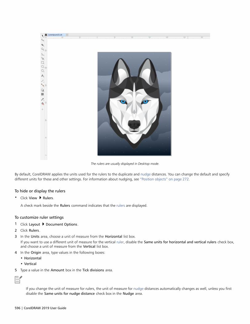
596 | CorelDRAW 2019 User Guide
The rulers are usually displayed in Desktop mode.
By default, CorelDRAW applies the units used for the rulers to the duplicate and nudge distances. You can change the default and specifydifferent units for these and other settings. For information about nudging, see “Position objects” on page 272.
To hide or display the rulers
• Click View Rulers.
A check mark beside the Rulers command indicates that the rulers are displayed.
To customize ruler settings
1 Click Layout Document Options.
2 Click Rulers.
3 In the Units area, choose a unit of measure from the Horizontal list box.
If you want to use a different unit of measure for the vertical ruler, disable the Same units for horizontal and vertical rulers check box,and choose a unit of measure from the Vertical list box.
4 In the Origin area, type values in the following boxes:
• Horizontal
• Vertical
5 Type a value in the Amount box in the Tick divisions area.
If you change the unit of measure for rulers, the unit of measure for nudge distances automatically changes as well, unless you firstdisable the Same units for nudge distance check box in the Nudge area.
Pages and layout tools | 597
You can access ruler settings directly by double-clicking a ruler.
You can specify nudge settings by typing values in the Nudge, Super nudge, and Micro nudge boxes in the Nudge area.
To show or hide the rulers for Desktop and Tablet mode
1 Click Layout Document Options.
2 Click Rulers.
3 On the Rulers page, enable or disable the following check boxes:
• Show rulers in Desktop mode
• Show rulers in Tablet mode
Calibrate the rulers
You can have one inch on your screen equal one inch of “real” distance. This lets you work with real-world distances as opposed to relativedistances that depend on screen resolution. This tool is particularly useful when you work with signs or draw in 1:1 zoom mode.
Before you can perform this procedure, you must have a clear plastic ruler for comparing real-world and on-screen distances. This rulershould use the same unit of measure that you set for the CorelDRAW rulers. For information about ruler settings, see “Rulers” on page595.
To calibrate the rulers to real-world distance
1 Click Tools Options Tools.
2 Click Zoom/Pan.
3 Click Calibrate rulers.
4 Place a clear plastic ruler under the on-screen horizontal ruler.
5 Click the up or down arrows on the Horizontal box to match one unit of measure on the on-screen ruler with one unit of measure onthe actual ruler.
6 Place the ruler beside the on-screen vertical ruler.
7 Click the up or down arrows on the Vertical box to match one unit of measure on the on-screen ruler with one unit of measure on theactual ruler.
Document grid and pixel grid
The document grid is a series of non-printing intersecting lines that you can display in the drawing window. You can use the document gridto precisely align and position objects.
You can customize the look of the document grid by changing the grid display and grid spacing. The grid display lets you view thedocument grid as lines or as dots. The spacing lets you set the distance between the grid lines. The spacing options are based on the unit ofmeasure for the ruler. For example, if the ruler unit of measure is set to inches, the spacing options are based on inches.
If the ruler unit of measure is set to pixels, or if you enabled the Pixels view, you can specify the color and opacity of the pixel grid. The pixelgrid is a series of intersecting lines that show you individual pixels in a document. For more information about the Pixels view, see “Viewingmodes” on page 54. By default, the lower-left corner of the document page is aligned with pixel grid to help you create pixel-perfect objectsfor the web.
You can also have objects snap to the document grid or the pixel grid, so that when you move the objects, they align with the grid lines.

598 | CorelDRAW 2019 User Guide
The checkered effect in this graphic was created by using the document grid.
To display or hide the document grid
• Click View Grid Document Grid.
A check mark beside the Document Grid command indicates that the document grid is displayed.
To set the document grid display and spacing
1 Click Layout Document Options.
2 In the left pane of the dialog box that appears, click Grid.
3 Enable the Show grid as check box, and enable one of the following options:
• Lines
• Dots
4 In the Document grid area, type a value in the Horizontal box.
If you want to change the grid spacing intervals or the number of lines displayed per unit of measure, choose an option from the listbox. The options are based on the unit of measure used for the ruler.
5 Type a value in the Vertical box.
The unit of measure used for grid spacing is the same as that used for rulers. For information about ruler settings, see “To customizeruler settings” on page 596.
To change the settings of the pixel grid
1 Click Layout Document Options.
2 Click Grid.
3 In the Pixel grid area, open the Color picker, and click a color.
4 Move the Opacity slider to the right to increase the opacity of the grid.
You can also
Enable or disable object snapping to pixels Enable or disable the Snap to pixel check box.
Show or hide the pixel grid (when zoomed in at 800% or higher) Enable or disable the Show grid at 800% or higher zoom checkbox.

Pages and layout tools | 599
You can also
To see the effect, switch to pixel view (View Pixels) and zoom to800% or higher.
Align page center with the pixel grid (useful when saving files toearlier versions of CorelDRAW)
Disable the Align page with pixel grid check box.
The Align page with pixel grid setting aligns the lower-left cornerof the page with the pixel grid to help you create pixel-perfectdesigns on export. Disable this check box only when you plan tosave the file to an earlier version of CorelDRAW.
To set objects to snap to the document grid
1 Click View Snap To Document Grid.
2 Move the objects with the Pick tool .
To set objects to snap to the pixel grid
1 Click View Snap To Pixels.
2 Move the objects with the Pick tool .
This option is available only when pixel view is enabled. For more information, see “Viewing modes” on page 54.
Baseline grid
The guides of the baseline grid run across the drawing page and follow the pattern of a ruled notebook. You can display or hide the baselinegrid, turn snapping on or off, change the grid color, and set the line spacing. By default, the line spacing is 14 pt. All objects can snap to thebaseline grid; only text frames can align to baseline grid. For more information, see “Align text to the baseline grid” on page 480.
To display or hide the baseline grid
• Click View Grid Baseline Grid.
A check mark beside the Baseline grid command indicates that the baseline grid is displayed.
To set baseline grid spacing and color
1 Click Layout Document Options.
2 In the left pane of the dialog box that appears, click Grid.
3 Perform a task from the following table.
To Do the following
Set spacing In the Baseline grid area, type a value in the Spacing box.
Set distance from top Type a value in the Start from top box.
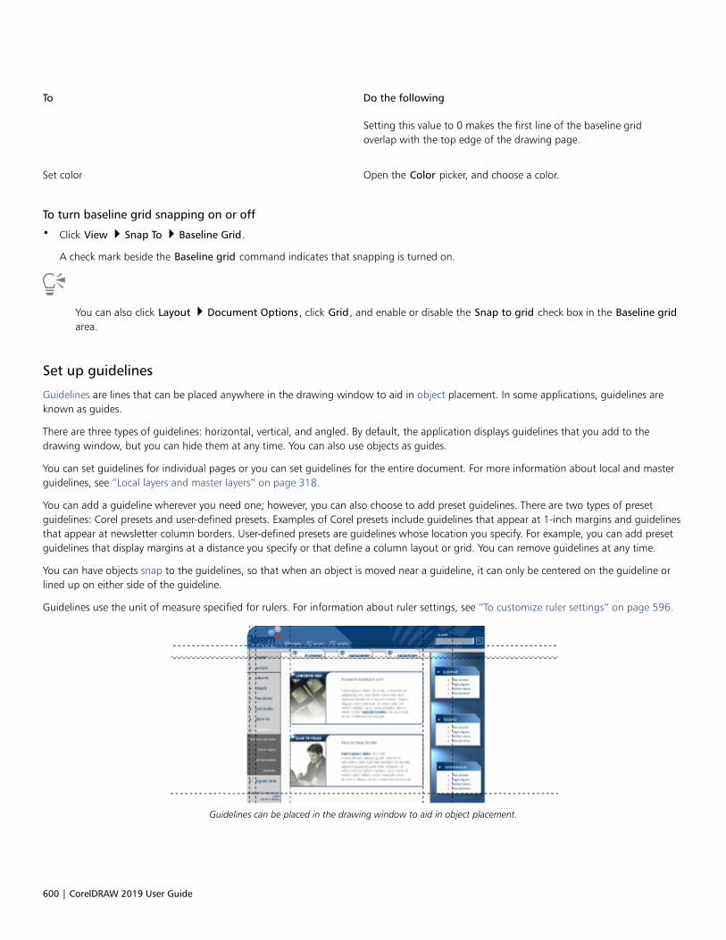
600 | CorelDRAW 2019 User Guide
To Do the following
Setting this value to 0 makes the first line of the baseline gridoverlap with the top edge of the drawing page.
Set color Open the Color picker, and choose a color.
To turn baseline grid snapping on or off
• Click View Snap To Baseline Grid.
A check mark beside the Baseline grid command indicates that snapping is turned on.
You can also click Layout Document Options, click Grid, and enable or disable the Snap to grid check box in the Baseline gridarea.
Set up guidelines
Guidelines are lines that can be placed anywhere in the drawing window to aid in object placement. In some applications, guidelines areknown as guides.
There are three types of guidelines: horizontal, vertical, and angled. By default, the application displays guidelines that you add to thedrawing window, but you can hide them at any time. You can also use objects as guides.
You can set guidelines for individual pages or you can set guidelines for the entire document. For more information about local and masterguidelines, see “Local layers and master layers” on page 318.
You can add a guideline wherever you need one; however, you can also choose to add preset guidelines. There are two types of presetguidelines: Corel presets and user-defined presets. Examples of Corel presets include guidelines that appear at 1-inch margins and guidelinesthat appear at newsletter column borders. User-defined presets are guidelines whose location you specify. For example, you can add presetguidelines that display margins at a distance you specify or that define a column layout or grid. You can remove guidelines at any time.
You can have objects snap to the guidelines, so that when an object is moved near a guideline, it can only be centered on the guideline orlined up on either side of the guideline.
Guidelines use the unit of measure specified for rulers. For information about ruler settings, see “To customize ruler settings” on page 596.
Guidelines can be placed in the drawing window to aid in object placement.
Pages and layout tools | 601
To display or hide the guidelines• Click View Guidelines.
A check mark beside the Guidelines command indicates that the guidelines are displayed.
You can also display or hide the guidelines by clicking Window Dockers Guidelines and clicking the Show or hide guidelines
button .
You can also access additional guideline options by clicking Layout Document Options, and then clicking Guidelines in the leftpane of the dialog box that appears.
To add a horizontal or vertical guideline
1 Click Window Dockers Guidelines.
2 Choose one of the following options from the Guideline type list box:
• Horizontal
• Vertical
3 Specify the location of the guideline in the x or y box.
4 Click Add.
You can also add a guideline by dragging from the horizontal or vertical ruler to the drawing window.
To add an angled guideline
1 Click Window Dockers Guidelines.
2 Choose Angled from the Guideline type list box.
3 Specify the location of the guideline in the x and y boxes.
4 Type a value in Angle of rotation box.
5 Click Add.
You can also add an angled guideline by dragging from the horizontal or vertical ruler in the drawing window, and typing a value inthe Angle of rotation box on the property bar.
To use an object as a guide
1 In the Objects docker, click the Guides layer on the page you want.
If the Objects docker is not open, click Object Objects.
2 Draw and position the object you want to use as a guide.
To set guidelines for the entire document
1 In the Objects docker, click Guides (all pages) on the Master page.
If the Objects docker is not open, click Object Objects.
2 In the drawing window, add the guidelines you want.
602 | CorelDRAW 2019 User Guide
The guidelines that you set on the Guides (all pages) layer of the Master page appear on all pages of the document. Theseguidelines appear in addition to any guidelines that you set for individual pages.
To add preset guidelines
1 Click Layout Document Options.
2 In the left pane of the dialog box that appears, click Guidelines.
3 Click Presets.
4 Choose one of the following options from the Preset type list box:
• Corel presets
• User-defined presets
5 Specify guideline settings by enabling the corresponding check boxes.
If you enable the User-defined presets option, specify values in the Margins, Columns, or Grid area.
To remove a guideline
1 Click Window Dockers Guidelines.
2 Choose a guideline from the list.
You can choose multiple guidelines by holding down Ctrl as you click.
3 Click the Delete button .
You can also remove individual guidelines by dragging them off the document window, or clicking a guideline with the Pick tool andpressing Delete.
To delete a preset guideline, click Layout Document Options. In the left pane of the dialog box that appears, click Guidelines, andthen click Presets. Disable the check box beside the preset guideline that you want to delete.
To have objects snap to the guidelines
1 Click View Snap To Guidelines.
2 Drag the object to the guideline.
To snap the center of an object to a guideline, select the object, and drag it by its center over the guideline until the center snaps to theguideline.
You can also set objects and editable areas to snap to a guideline by clicking Window Dockers Guidelines and clicking the Snap
to guidelines button .
Modify guidelines
After you add a guideline, you can select it, move it, rotate it, or lock it in place. You can also change the line style and color of guidelines.
To select a guideline
Pages and layout tools | 603
To Do the following
Select a single guideline Click the guideline with the Pick tool .
Select all guidelines on a page Click Edit Select all Guidelines. The local guidelines andmaster guidelines are selected.
To move or rotate a guideline
1 Click Window Dockers Guidelines.
2 Select the guideline.
3 Perform any of the following tasks.
To Do the following
Move a guideline Specify the new location of the guideline in the x and y boxes, andclick Modify.
You can also drag a guideline to a new position in the drawingwindow.
Rotate a guideline Choose Angled from the Guideline type list box, type a value inthe Angle of rotation box, and click Modify.
You can also use the Pick tool to click the guideline twice and
then rotate the guideline when skewing handles appear.
To lock or unlock a guideline
• Right-click the guideline, and click Lock or Unlock.
You can also click Window Dockers Guidelines and click the Lock guideline button .
To set the line style and color of a guideline
1 Click Window Dockers Guidelines.
2 Open the Guideline color picker, and choose a guideline color.
3 Open the Guideline style picker, and choose a line style.
Drawing scale
You can choose a preset or custom drawing scale so that distances in a drawing are proportionate to real-world distances. For example, youcan specify that 1 inch in the drawing corresponds to 1 meter in the physical world. A preset drawing scale lets you set a typical scale, suchas 1:2 or 1:10. A custom drawing scale lets you set any distance on the page to correspond to a real-world distance. For example, you canset a more precise scale that includes decimal numbers, such as 4.5 to 10.6.

604 | CorelDRAW 2019 User Guide
Drawing scales are particularly useful if you are creating a technical or architectural drawing with dimension lines. For information aboutdimension lines, see “Connector and callout lines” on page 153.
To choose a preset drawing scale
1 Click Layout Document Options.
2 In the left pane of the dialog box that appears, click Rulers.
3 Click Edit scale.
4 Choose a drawing scale from the Typical scales list box.
To create a custom drawing scale
1 Click Layout Document Options.
2 In the left pane of the dialog box that appears, click Rulers.
3 Click Edit scale.
4 Choose Custom from the Typical scales list box.
5 Specify the settings you want.
The Edit scale button does not appear if the ruler’s unit of measure is pixels.
If the drawing scale is set to anything other than 1:1, the units on the vertical ruler are the same as the units on the horizontal ruler.

Tables | 605
Tables
A table provides a structured layout that lets you present text or images within a drawing. You can draw a table, or you can create a tablefrom paragraph text. You can easily change the look of a table by modifying the table properties and formatting. In addition, because tablesare objects, you can manipulate them in various ways. You can also import existing tables from a text file or a spreadsheet.
This section contains the following topics:• “Add tables” (page 605)• “Select, move, and navigate table components” (page 607)• “Insert and delete table rows and columns” (page 609)• “Resize table cells, rows, and columns” (page 611)• “Format tables and cells” (page 612)• “Text in tables” (page 615)• “Convert tables to text” (page 616)• “Merge and split tables and cells” (page 617)• “Manipulate tables as objects” (page 618)• “Add images, graphics, and backgrounds to tables” (page 619)• “Import tables” (page 619)
Add tables
With CorelDRAW, you can add a table to a drawing to create a structured layout for text and images. You can draw a table, or you cancreate a table from existing text.
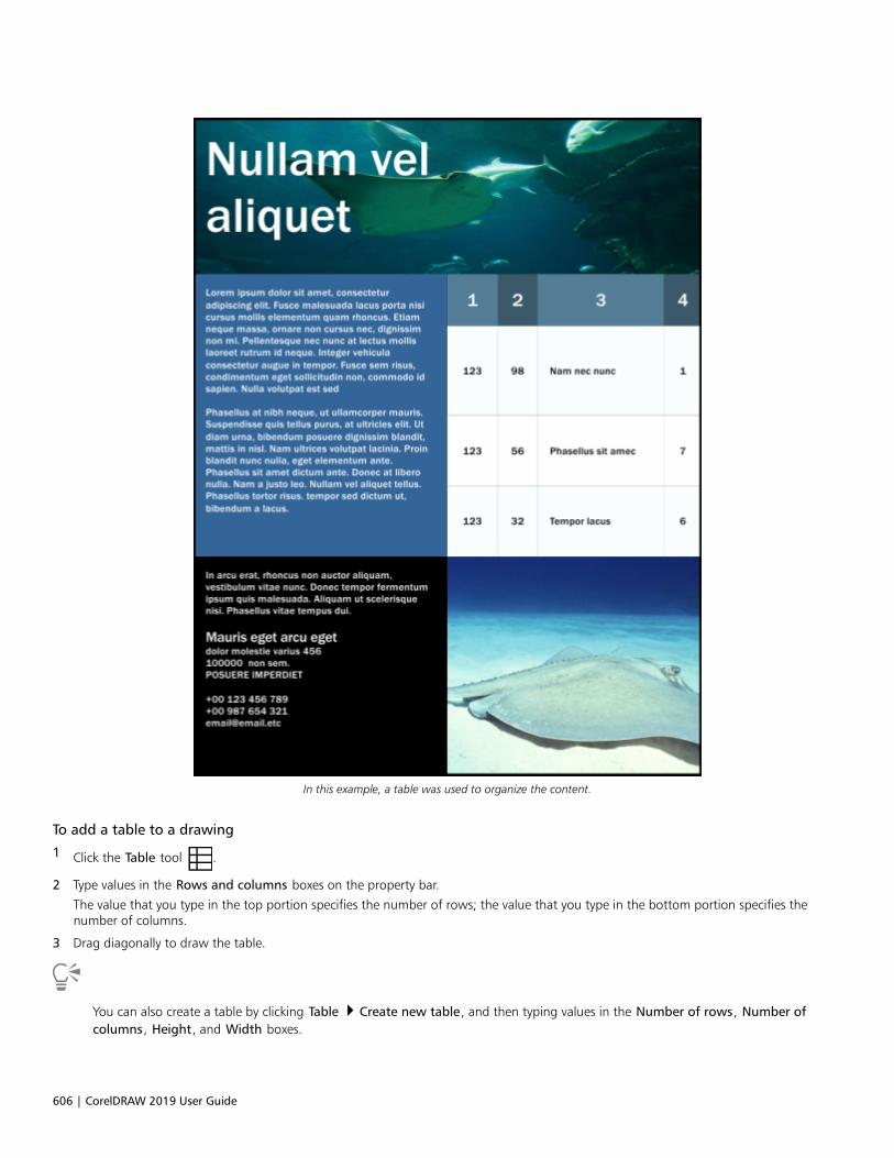
606 | CorelDRAW 2019 User Guide
In this example, a table was used to organize the content.
To add a table to a drawing
1 Click the Table tool .
2 Type values in the Rows and columns boxes on the property bar.
The value that you type in the top portion specifies the number of rows; the value that you type in the bottom portion specifies thenumber of columns.
3 Drag diagonally to draw the table.
You can also create a table by clicking Table Create new table, and then typing values in the Number of rows, Number ofcolumns, Height, and Width boxes.

Tables | 607
To create a table from text
1 Click the Pick tool .
2 Select the text that you want to convert to a table.
3 Click Table Convert text to table.
4 In the Create columns based on the following separator area, choose one of the following options:
• Commas — creates a column where a comma appears and a row where a paragraph marker appears
• Tabs — creates a column where a tab appears and a row where a paragraph marker appears
• Paragraphs — creates a column where a paragraph marker appears
• User defined — creates a column where a specified marker appears and a row where a paragraph marker appears
If you enable the User defined option, you must type a character in the User defined box.
If you do not type a character in the User defined box, only one column is created, and each paragraph of text creates a table row.
You can also convert a table to text. For more information, see “To convert a table to text” on page 616.
Select, move, and navigate table components
You must select a table, table rows, table columns, or table cells before you insert rows or columns, change the table border properties, adda background fill color, or edit other table properties. You can move selected rows and columns to a new location in a table. You can alsocopy or cut a row or column from one table and paste it in another table. In addition, you can move from one table cell to another whenediting the table cell text, and you can set the direction in which the Tab key lets you move around a table.
To select a table, row, or column
1 Click the Table tool , and then click a table.
2 Perform one of the following tasks.
To Do the following
Select a table Click Table Select Table.
Select a row Click in a row, and click Table Select Row.
Select a column Click in a column, and click Table Select Column.
Select all table contents Position the Table tool pointer over the upper-left corner of the
table until a diagonal arrow appears , and click.
Use a keyboard shortcut to select a table With the Table tool pointer inserted in an empty cell, press Ctrl + A+ A.

608 | CorelDRAW 2019 User Guide
To Do the following
Select a row interactively Position the Table tool pointer over the table border to the left ofthe row that you want to select. When a horizontal arrow appears
, click the border to select the row.
Select a column interactively Position the Table tool pointer over the top border of the column
that you want to select. When a vertical arrow appears , click
the border to select the column.
To select table cells
To Do the following
Select a table cell Click the Table tool , click a table, and click a cell. Then, click
Table Select Cell.
Select adjacent table cells Using the Table tool, click inside the first cell that you want toselect, and drag over the adjacent cells that you want to select.
Select nonadjacent table cells Using the Table tool, click a table. Then, hold down Ctrl, and clickeach table cell that you want to select.
You can also select a cell by inserting the Table tool pointer in an empty cell and pressing Ctrl + A.
You can also use the Shape tool to select a single cell by clicking it, or to select adjacent cells by dragging over them.
To move a table row or column
1 Select the row or column that you want to move.
2 Drag the row or column to another location in the table.
To move a table row to another table
1 Select the table row that you want to move.
2 Click Edit Cut.
3 Select a row in the other table.
4 Click Edit Paste.
5 Choose one of the following options:
• Replace selected row
• Insert above selected row
• Insert below selected row

Tables | 609
To move a table column to another table
1 Select the table column that you want to move.
2 Click Edit Cut.
3 Select a column in the other table.
4 Click Edit Paste.
5 Choose one of the following options:
• Replace selected column
• Insert left of the selected column
• Insert right of the selected column
To move to the next table cell
• With the Table tool inserted in a cell, press Tab.
If you are pressing Tab in a table for the first time, you must choose a tab order option from the Tab order list box.
You can use the Tab key to move to the next cell only if the Move to the next cell option is enabled in the Tab key options dialogbox.
To change the navigational direction of the Tab key
1 Click Tools Options Tools.
2 In left pane of the dialog box that appears, click Table.
3 Enable the Move to the next cell option.
4 From the Tab order list box, choose one of the following options:
• Left to right, top to bottom
• Right to left, top to bottom
You can program the Tab key to insert a tab character in the table text by enabling the Insert a tab character in the current celloption.
Insert and delete table rows and columns
You can insert and delete the rows and columns in a table.
To insert a table row
1 Select a row in the table.
2 Perform a task from the following table.
To Do the following
Insert a row above the selected row Click Table Insert Row above.
Insert a row below the selected row Click Table Insert Row below.
610 | CorelDRAW 2019 User Guide
To Do the following
Insert multiple rows above the selected row Click Table Insert Insert rows, type a value in the Number ofrows box, and enable the Above the selection option.
Insert multiple rows below the selected row Click Table Insert Insert rows, type a value in the Number ofrows box, and enable the Below the selection option.
When you use either the Row above command or the Row below command from the Table Insert menu, the number of rowsthat are inserted depends on how many rows you have selected. For example, if you have selected two rows, then two rows areinserted in the table.
To insert a table column
1 Select a column.
2 Perform a task from the following table.
To Do the following
Insert a column to the left of the selected column Click Table Insert Column left.
Insert a column to the right of the selected column Click Table Insert Column right.
Insert multiple columns to the left of the selected column Click Table Insert Insert columns, type a value in the Numberof columns box, and enable the Left of the selection option.
Insert multiple columns to the right of the selected column Click Table Insert Insert columns, type a value in the Numberof columns box, and enable the Right of the selection option.
When you use the Column left command or the Column right command from the Table Insert menu, the number of columnsthat are inserted depends on how many columns you have selected. For example, if you have selected two columns, then twocolumns are inserted in the table.
To delete a row or column from a table
1 Select the row or column that you want to delete.
2 Perform a task from the following table.
To Do the following
Delete a row Click Table Delete Row.
Delete a column Click Table Delete Column.
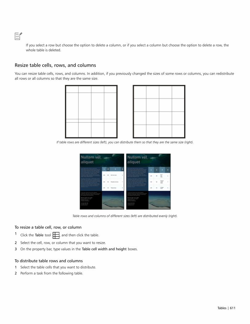
Tables | 611
If you select a row but choose the option to delete a column, or if you select a column but choose the option to delete a row, thewhole table is deleted.
Resize table cells, rows, and columns
You can resize table cells, rows, and columns. In addition, if you previously changed the sizes of some rows or columns, you can redistributeall rows or all columns so that they are the same size.
If table rows are different sizes (left), you can distribute them so that they are the same size (right).
Table rows and columns of different sizes (left) are distributed evenly (right).
To resize a table cell, row, or column
1 Click the Table tool , and then click the table.
2 Select the cell, row, or column that you want to resize.
3 On the property bar, type values in the Table cell width and height boxes.
To distribute table rows and columns
1 Select the table cells that you want to distribute.
2 Perform a task from the following table.

612 | CorelDRAW 2019 User Guide
To Do the following
Make the height of all selected rows the same Click Table Distribute Rows evenly.
Make the width of all selected columns the same Click Table Distribute Columns evenly.
Format tables and cells
You can change the look of a table by modifying both table and cell borders. For example, you can change the table border width or color.
You can modify both table and table cell borders.
Thin table and cell borders (left) are made thicker (right).
In addition, you can change the table cell margins and cell border spacing. The cell margins let you increase the space between the cellborders and the text in the cell. By default, table cell borders overlap to form a grid. However, you can increase the cell border spacing tomove the borders away from each other. As a result, the cells do not form a grid, but appear as individual boxes (also known as “separatedborders”).
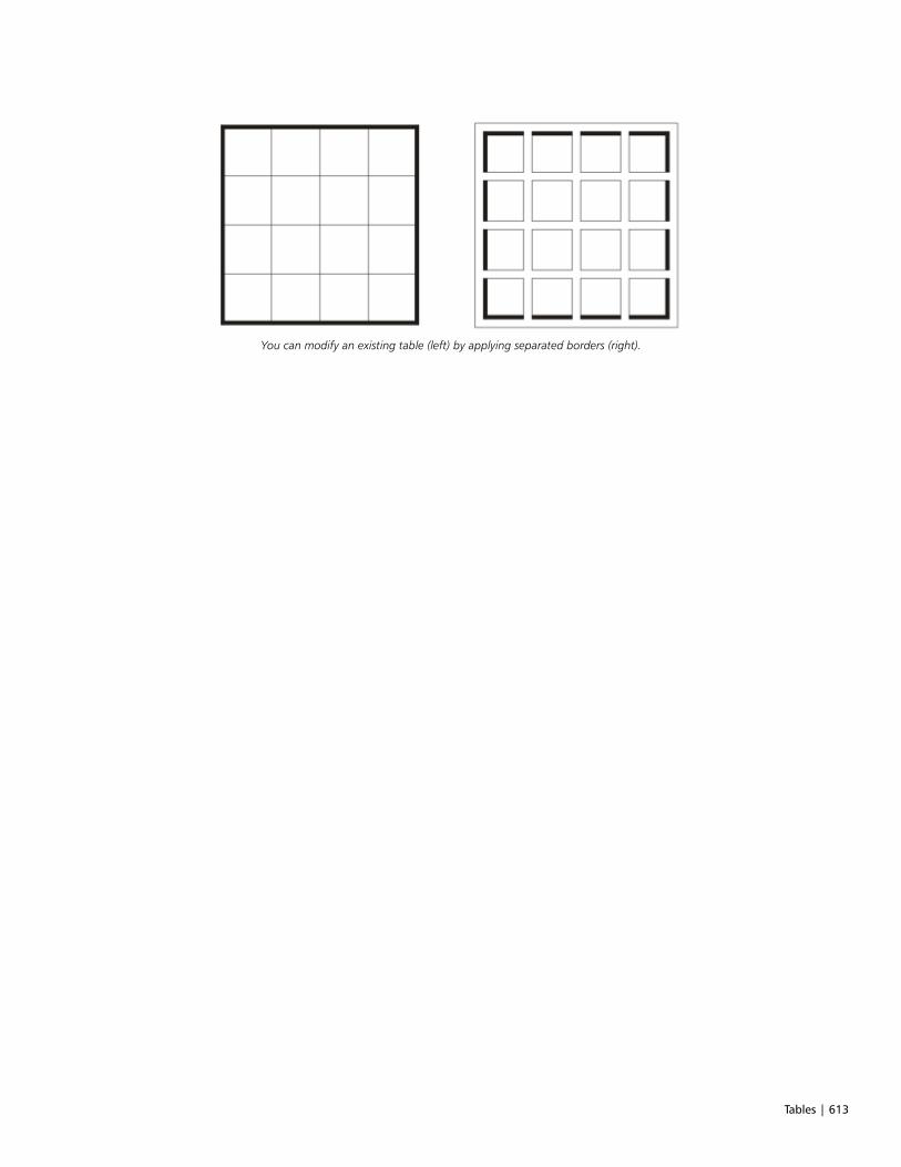
Tables | 613
You can modify an existing table (left) by applying separated borders (right).

614 | CorelDRAW 2019 User Guide
Separated borders applied to a table.
To modify table borders and cell borders
1 Select the table or table area that you want to modify.
A table area can include a cell, a group of cells, rows, columns, or the entire table.
2 Click the Border selection button on the property bar, and choose the borders that you want to modify.
3 Perform a task from the following table.
To Do the following
Modify the border thickness Choose a border width from the Outline width list box on theproperty bar.

Tables | 615
To Do the following
Modify the border color Click the Outline color picker on the property bar, and then click acolor on the color palette.
Modify the border line style and outline width In the Outline area of the Properties docker, choose a line stylefrom the Line style picker, and type a value in the Outline widthbox.
If the Properties docker is not open, click Window Dockers Properties.
To modify cell margins in tables
1 Click the Table tool , and then click the table.
2 Select the cells that you want to modify.
3 Click Margins on the property bar.
4 Type a value in the Top margin box.
By default, the value in the top margin box is applied to all margins, so that equal margins are created.
If you want to apply different values for the margins, click the Lock margins button to unlock the margin boxes, and type values in theTop margin, Bottom margin, Left margin, and Right margin boxes.
5 Press Enter.
To modify cell border spacing in tables
1 Click the Table tool , and then click the table.
2 Click Options on the property bar.
3 Enable the Separated cell borders check box.
4 Type a value in the Horizontal cell spacing box.
By default, the vertical cell spacing is equal to the horizontal cell spacing.
If you do not want equal cell spacing, click the Lock cell spacing button to unlock the Vertical cell spacing box, and then type values inboth the Horizontal cell spacing and Vertical cell spacing boxes.
5 Press Enter.
Text in tables
You can easily add text to table cells, and you can modify this text as you would any other paragraph text. For example, you can changethe font, add bullets, or add indents to table text. You can change the text properties of a single table cell, or of multiple table cellssimultaneously. In addition, you can add tab stops to table cells so that text is shifted away from the cell margins.
When you type text in a new table, you can choose to automatically adjust the size of table cells.
To type text in a table cell
1 Click the Table tool .
2 Click a cell.
3 Type text in the cell.

616 | CorelDRAW 2019 User Guide
You can select text in a cell by pressing Ctrl + A.
To change the properties of text in table cells
1 Using the Table tool , click a table.
2 Hold down Ctrl, and click the table cells that contain text to be formatted.
3 Click Text Text, and specify the settings you want in the Text docker.
For more information about formatting text, see “Format text” on page 495.
To change the text properties for an entire row, column, or table simultaneously, you must first select the table component or table.For more information, see “To select a table, row, or column” on page 607.
To insert a tab stop in a table cell
• With the Table tool pointer inserted in a cell, click Text Insert formatting code Tab.
Another way to insert a tab stop is by pressing the Tab key. To use this method, you must set the Tab key to insert tab stops. Forinformation about changing the Tab key options, see “To change the navigational direction of the Tab key” on page 609.
To automatically resize table cells when you type
1 Click the Pick tool , and then click the table.
2 Click Options on the property bar, and enable the Automatically resize cells while typing check box.
This option can be applied to new tables that do not yet have text or other content.
If a table already contains text, only cells to which new text is added will be resized.
Convert tables to text
If you no longer want table text to appear in a table, you can convert the table text to paragraph text. For more information aboutconverting text to a table, see “To create a table from text” on page 607.
To convert a table to text
1 Click the Table tool , and then click the table.
2 Click Table Convert table to text.
3 In the Separate cell text with area, choose one of the following options:
• Commas — replaces each column with a comma and replaces each row with a paragraph marker
• Tabs — replaces each column with a tab and replaces each row with a paragraph marker
• Paragraphs — replaces each column with a paragraph marker
• User defined — replaces each column with a specified character and replaces each row with a paragraph marker
If you enable the User defined option, you must type a character in the User defined box.
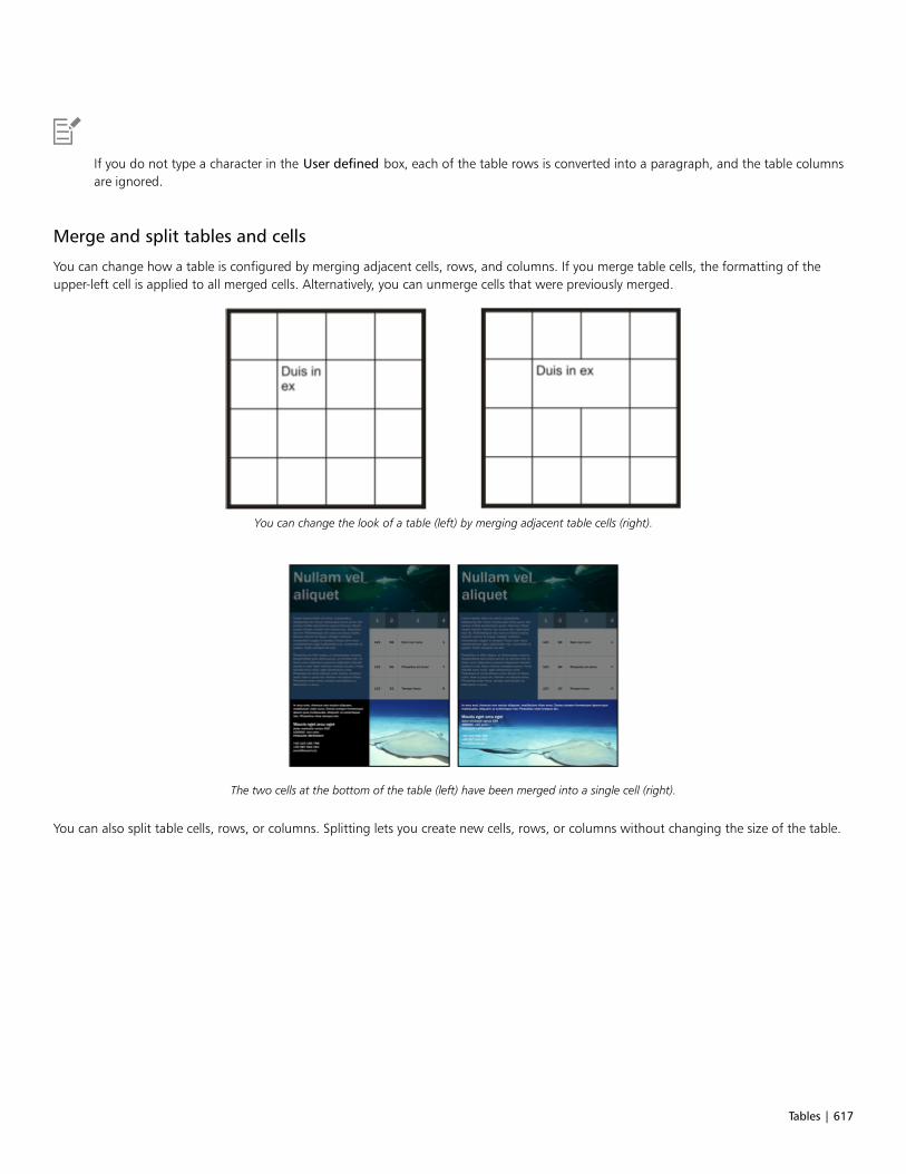
Tables | 617
If you do not type a character in the User defined box, each of the table rows is converted into a paragraph, and the table columnsare ignored.
Merge and split tables and cells
You can change how a table is configured by merging adjacent cells, rows, and columns. If you merge table cells, the formatting of theupper-left cell is applied to all merged cells. Alternatively, you can unmerge cells that were previously merged.
You can change the look of a table (left) by merging adjacent table cells (right).
The two cells at the bottom of the table (left) have been merged into a single cell (right).
You can also split table cells, rows, or columns. Splitting lets you create new cells, rows, or columns without changing the size of the table.
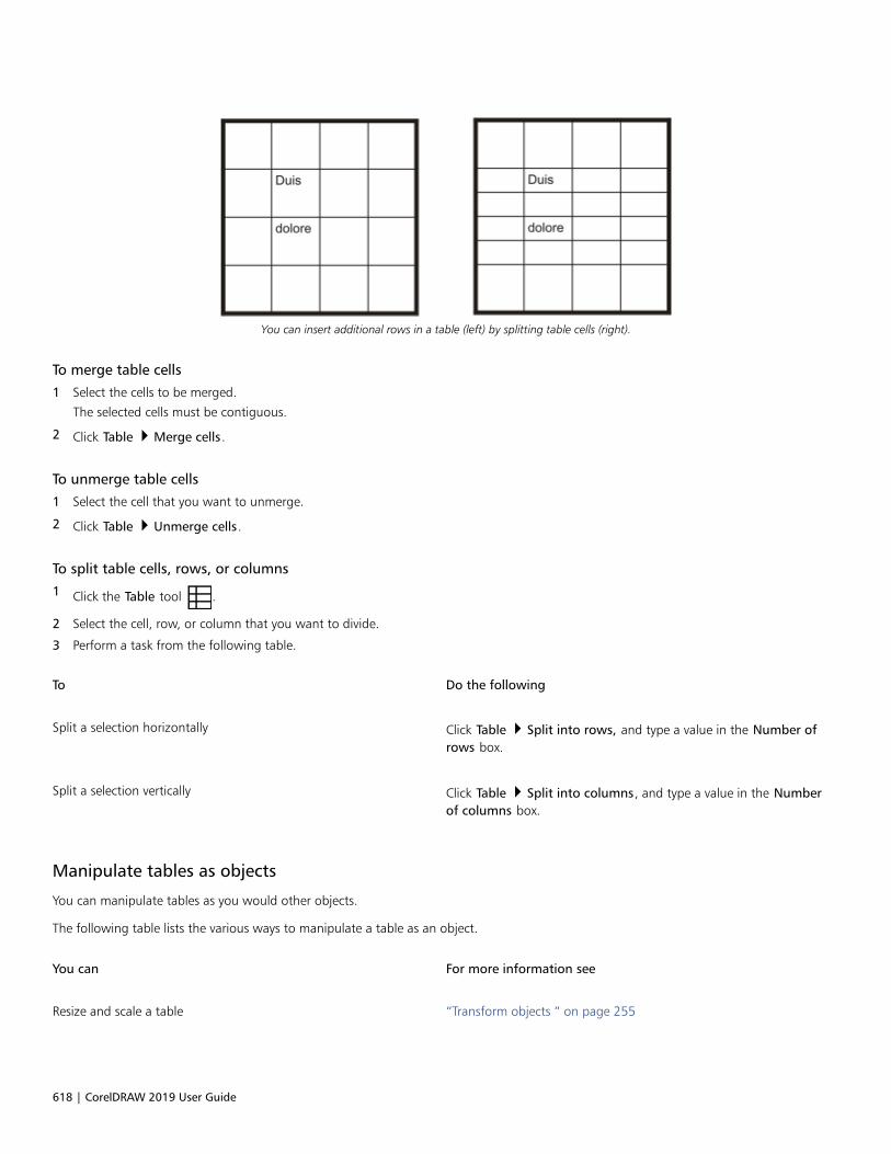
618 | CorelDRAW 2019 User Guide
You can insert additional rows in a table (left) by splitting table cells (right).
To merge table cells
1 Select the cells to be merged.
The selected cells must be contiguous.
2 Click Table Merge cells.
To unmerge table cells
1 Select the cell that you want to unmerge.
2 Click Table Unmerge cells.
To split table cells, rows, or columns
1 Click the Table tool .
2 Select the cell, row, or column that you want to divide.
3 Perform a task from the following table.
To Do the following
Split a selection horizontally Click Table Split into rows, and type a value in the Number ofrows box.
Split a selection vertically Click Table Split into columns, and type a value in the Numberof columns box.
Manipulate tables as objects
You can manipulate tables as you would other objects.
The following table lists the various ways to manipulate a table as an object.
You can For more information see
Resize and scale a table “Transform objects ” on page 255

Tables | 619
You can For more information see
Rotate a table “Transform objects ” on page 255
Mirror a table “Transform objects ” on page 255
Lock a table “Lock objects ” on page 302
Convert a table to a bitmap “Convert vector graphics to bitmaps ” on page 623
Break a table apart “To convert objects to curve objects ” on page 176
Add images, graphics, and backgrounds to tables
If you want to arrange bitmap images or vector graphics in a structured layout, you can add them to tables. You can also change the look ofa table by adding a background color.
To insert an image or a graphic in a table cell
1 Copy an image or a graphic.
2 Click the Table tool, and select the cell where you want to insert the image or graphic.
3 Click Edit Paste.
You can also insert a graphic or an image by holding down the right mouse button over the image, dragging the image to a cell,releasing the right mouse button, and then clicking Place inside cell.
To add a background color to a table
1 Click the Table tool , and then click the table.
2 Click the Background color picker, and then click a color on the color palette.
You can also modify the background color of specific cells, rows, or columns by selecting the cells, clicking the Background colorpicker on the property bar, and then clicking a color on the color palette.
Import tables
With CorelDRAW, you can create tables by importing content from Quattro Pro® (.qpw) and Microsoft Excel (.xls) spreadsheets. You can alsoimport tables created in a word-processing application, such as WordPerfect or Microsoft Word.
To import a table from Quattro Pro or Excel
1 Click File Import.
2 Choose the drive and folder where the spreadsheet is stored.
3 Click the file to select it.

620 | CorelDRAW 2019 User Guide
4 Click Import.
The Import/Paste dialog box appears.
5 From the Import tables as list box, choose Tables.
6 Choose one of the following options:
• Maintain fonts and formatting — imports all fonts and formatting that are applied to the text
• Maintain formatting only — imports all formatting that is applied to the text
• Discard fonts and formatting — ignores all fonts and formatting that are applied to the text
To import a table from a word-processing document
1 Click File Import.
2 Choose the drive and folder where the text file is stored.
3 Click the file.
4 Click Import.
5 From the Import tables as list box, choose Tables.
6 Choose one of the following options:
• Maintain fonts and formatting — imports all fonts and formatting that are applied to the text
• Maintain formatting only — imports all formatting that is applied to the text
• Discard fonts and formatting — ignores all fonts and formatting that are applied to the text

Bitmaps | 621
Bitmaps
Work with bitmaps..............................................................................................................................................................................623
Special effects categories..................................................................................................................................................................... 655
Bitmap color modes............................................................................................................................................................................ 699
Trace.................................................................................................................................................................................................... 705
RAW camera files................................................................................................................................................................................ 717

622 | CorelDRAW 2019 User Guide

Work with bitmaps | 623
Work with bitmaps
You can convert a vector graphic to a bitmap. You can also import and crop bitmaps.
You can add perspective, shape bitmaps with envelopes, apply color masks, watermarks, and special effects, and change the color and toneof the images. For information about applying perspective to bitmaps, see “Apply perspective” on page 432. For information about shapingbitmaps with envelopes, see “Shape objects by using envelopes” on page 206.
This section contains the following topics:• “Convert vector graphics to bitmaps” (page 623)• “Import bitmaps” (page 625)• “Crop bitmaps” (page 625)• “Bitmap dimensions and resolution” (page 625)• “Straighten bitmaps” (page 627)• “Correct perspective distortions” (page 629)• “Use Digimarc watermarks to identify bitmaps” (page 630)• “Remove dust and scratch marks from bitmaps” (page 632)• “Change and mask colors in bitmaps” (page 632)• “Image Adjustment Lab” (page 634)• “Adjust color and tone” (page 638)• “Tone Curve filter” (page 644)• “Transform color and tone” (page 647)
• “Edit bitmaps with Corel PHOTO-PAINT” (page 648)
• “Apply special effects to bitmaps” (page 648)
Convert vector graphics to bitmaps
Converting a vector graphic or object to a bitmap lets you apply special effects to the object with CorelDRAW. The process of converting avector graphic to a bitmap is also known as “rasterizing.”
When you convert the vector graphic, you can select the color mode of the bitmap. A color mode determines the number and kind of colorsthat make up the bitmap, so the file size is also affected. For more information about color modes, see “Change the color mode of bitmaps”on page 699.
You can also specify settings for such controls as dithering, anti-aliasing, overprinting black, and background transparency.

624 | CorelDRAW 2019 User Guide
When you export a file to a bitmap file format, such as TIFF, JPEG, CPT, or PSD, the same bitmap conversion options are available. For moreinformation about exporting, see “Export files” on page 778.
To convert a vector graphic to a bitmap
1 Select an object.
2 Click Bitmaps Convert to bitmap.
3 Choose a resolution from the Resolution list box.
4 Choose a color mode from the Color mode list box.
5 Enable any of the following check boxes:
• Dithered — simulates a greater number of colors than those available. This option is available for images that use 256 or fewer colors.
• Always overprint black — overprints black when black is the top color. Enabling this option prevents gaps from appearing betweenblack objects and underlying objects when you print bitmaps.
• Anti-aliasing — smooths the edges of the bitmap
• Transparent background — makes the background of the bitmap transparent
You can change the black threshold for the Always overprint black option. For information about setting the black threshold, see“To set the overprint black threshold” on page 750.
If you export a vector file to a bitmap format, such as GIF, you are prompted to set the bitmap conversion options described in theprocedure above before you export the file.
Making the background of a bitmap transparent lets you see images or a background otherwise obscured by the bitmap background.
To convert a vector graphic to a bitmap when exporting
1 Click File Export.
2 Choose the folder where you want to save the file.
3 Choose a bitmap file format from the Save as type list box, and type a filename in the File name list box.
4 Set the options you want, and click Export.
5 In the Convert to bitmap dialog box, type values in one of the following pairs of boxes:
• Width and Height — let you specify the image dimensions
• Width % and Height % — let you resize the image to a percentage of its original size
6 To specify the resolution, type a value in the Resolution box.
7 Choose a color mode from the Color mode list box.
8 Enable any of the following check boxes:
• Dithered — simulates a greater number of colors than those available. This option is available for images that use 256 or fewer colors.
• Always overprint black — overprints black when black is the top color. Enabling this option when you print bitmaps prevents gapsfrom appearing between black objects and underlying objects.
9 Enable any of the following:
• Anti-aliasing — smooths the edges of the bitmap
• Maintain layers — preserves layers
• Transparent background — makes the background of the bitmap transparent

Work with bitmaps | 625
You can change the black threshold for the Always overprint black option. For information about setting the black threshold, see“To set the overprint black threshold” on page 750.
Not all options in the Convert to bitmap dialog box are available for all bitmap file formats.
Making the background of a bitmap transparent lets you see images or a background otherwise obscured by the bitmap background.
Import bitmaps
You can import a bitmap into a drawing either directly or by linking it to an external file. When you link to an external file, edits to theoriginal file are automatically updated in the imported file. After you import a bitmap, the status bar provides information about its colormode, size, and resolution. For more information about importing bitmaps, see “Import files” on page 775. For more information aboutmanaging externally linked bitmaps, see “Bookmarks and hyperlinks” on page 769.
You can also resample or crop a bitmap while importing. For more information, see “To resample a bitmap while importing ” on page 777and “To crop a bitmap while importing” on page 778.
Crop bitmaps
Cropping removes unwanted areas of a bitmap. To crop a bitmap into a rectangular shape, you can use the Crop tool. For moreinformation, see “To crop an object or imported photo” on page 215. To crop a bitmap into an irregular shape, you can use the Shape tooland the Crop bitmap command.
To crop a bitmap
1 In the toolbox, click the Shape tool .
2 Select a bitmap.
3 Drag the corner nodes to reshape the bitmap.
If you want to add a node, double-click the node boundary (dotted line) by using the Shape tool where you want the node to appear.
4 Click Bitmaps Crop bitmap.
You cannot crop a bitmap comprised of more than one object.
You can also quickly crop a bitmap into a rectangular shape by using the Crop tool . For information about the Crop tool, see
“To crop an object or imported photo” on page 215.
You can also crop a selected bitmap after you drag the corner nodes by clicking the Pick tool , then clicking the Crop bitmap
button on the property bar.
Bitmap dimensions and resolution
After you add a bitmap to a drawing, you can change its dimensions and resolution.
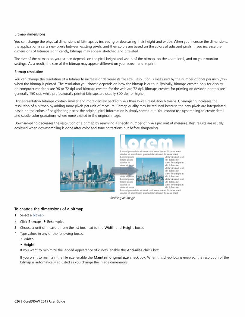
626 | CorelDRAW 2019 User Guide
Bitmap dimensions
You can change the physical dimensions of bitmaps by increasing or decreasing their height and width. When you increase the dimensions,the application inserts new pixels between existing pixels, and their colors are based on the colors of adjacent pixels. If you increase thedimensions of bitmaps significantly, bitmaps may appear stretched and pixelated.
The size of the bitmap on your screen depends on the pixel height and width of the bitmap, on the zoom level, and on your monitorsettings. As a result, the size of the bitmap may appear different on your screen and in print.
Bitmap resolution
You can change the resolution of a bitmap to increase or decrease its file size. Resolution is measured by the number of dots per inch (dpi)when the bitmap is printed. The resolution you choose depends on how the bitmap is output. Typically, bitmaps created only for displayon computer monitors are 96 or 72 dpi and bitmaps created for the web are 72 dpi. Bitmaps created for printing on desktop printers aregenerally 150 dpi, while professionally printed bitmaps are usually 300 dpi, or higher.
Higher-resolution bitmaps contain smaller and more densely packed pixels than lower- resolution bitmaps. Upsampling increases theresolution of a bitmap by adding more pixels per unit of measure. Bitmap quality may be reduced because the new pixels are interpolatedbased on the colors of neighboring pixels; the original pixel information is simply spread out. You cannot use upsampling to create detailand subtle color gradations where none existed in the original image.
Downsampling decreases the resolution of a bitmap by removing a specific number of pixels per unit of measure. Best results are usuallyachieved when downsampling is done after color and tone corrections but before sharpening.
Resizing an image
To change the dimensions of a bitmap
1 Select a bitmap.
2 Click Bitmaps Resample.
3 Choose a unit of measure from the list box next to the Width and Height boxes.
4 Type values in any of the following boxes:
• Width
• HeightIf you want to minimize the jagged appearance of curves, enable the Anti-alias check box.
If you want to maintain the file size, enable the Maintain original size check box. When this check box is enabled, the resolution of thebitmap is automatically adjusted as you change the image dimensions.
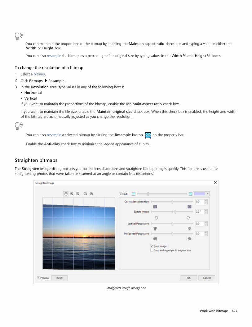
Work with bitmaps | 627
You can maintain the proportions of the bitmap by enabling the Maintain aspect ratio check box and typing a value in either theWidth or Height box.
You can also resample the bitmap as a percentage of its original size by typing values in the Width % and Height % boxes.
To change the resolution of a bitmap
1 Select a bitmap.
2 Click Bitmaps Resample.
3 In the Resolution area, type values in any of the following boxes:
• Horizontal
• VerticalIf you want to maintain the proportions of the bitmap, enable the Maintain aspect ratio check box.
If you want to maintain the file size, enable the Maintain original size check box. When this check box is enabled, the height and widthof the bitmap are automatically adjusted as you change the resolution.
You can also resample a selected bitmap by clicking the Resample button on the property bar.
Enable the Anti-alias check box to minimize the jagged appearance of curves.
Straighten bitmaps
The Straighten image dialog box lets you correct lens distortions and straighten bitmap images quickly. This feature is useful forstraightening photos that were taken or scanned at an angle or contain lens distortions.
Straighten image dialog box

628 | CorelDRAW 2019 User Guide
Correct camera lens distortions
With photos that contain camera lens distortions, it is recommended that you start with correcting the lens distortion. You can correct twotypes of lens distortions, which make straight lines in photos appear curved: barrel and pincushion. Barrel distortions make photos appearpushed out at the center. Pincushion distortions make photos appear pushed in at the center.
Rotate and preview
The Straighten image dialog box lets you rotate an image by moving a slider, typing a rotation angle, or using the arrow keys. You canspecify a custom rotation angle from -15 to 15 degrees.
You can use the preview window to dynamically preview the adjustments that you are making. If you want to change the orientation of theimage before straightening it, you can start by rotating the image 90 degrees clockwise and 90 degrees counterclockwise.
A grid is displayed in the preview window to help you straighten the image. You can make more precise adjustments by controlling the cellsize of the grid. To heighten the contrast of the grid against the colors of the image, you can change the grid’s color. You can also hide thegrid if you want to preview the final result without the gridlines. In addition, you can zoom in and out, and pan the image in the previewwindow to evaluate the results.
Crop
By default, the straightened image is cropped to the cropping area that is displayed in the preview window. The final image has the sameaspect ratio as the original image, but it has smaller dimensions. However, you can preserve the original width and height of the image bycropping and resampling the image.
You can also produce an image at an angle by disabling cropping and then using the Crop tool to crop the image in the drawing window.
To straighten an image
1 Select an image.
2 Click Bitmaps Straighten image.
If the image has a lens distortion, move the Correct lens distortion slider to the left to correct a barrel distortion or to the right tocorrect a pincushion distortion.
3 Move the Rotate image slider, or type a value between 15 and -15 in the Rotate image box.
4 If necessary, move the Grid slider to adjust the size of the grid cells.
5 To crop and straighten the image, enable the Crop image check box.
The image is cropped to preserve the aspect ratio of the original image, which means that the final image is smaller than the originalimage.
If you want to preserve the width and height of the original image, enable the Crop and resample to original size check box. The finalimage is resampled.
You can also
Change the grid color Choose a color from the Grid color picker.
Align an image area with a gridline Using the Pan tool , drag the image until the area is aligned
with the gridline.
You can use the Pan tool only after you zoom in on the image.

Work with bitmaps | 629
You can also
Rotate the image 90 degrees in either direction Click the Rotate counterclockwise button or the Rotate
clockwise button .
Hide or display the grid Disable or enable the Grid check box.
Adjust the rotation angle by 0.1-degree increments Click in the Rotate image box, and press the Up arrow or Downarrow key.
Reset the image to its original orientation Click Reset.
Zoom in or out Using the Zoom in or Zoom out tool, click in the
preview window.
Fit an image in the preview window Click the Zoom to fit button.
Display an image at its actual size Click the 100% button.
Correct perspective distortions
You can correct perspective distortions in photos that have straight lines and flat surfaces such as architectural photos and photos ofbuildings.
Perspective distortions usually occur when you take pictures of tall or wide objects, and the camera sensor is at an angle to the objects. As aresult, the photographed objects may appear to be leaning or to be at an angle. Adjusting the vertical perspective helps straighten leaningobjects; adjusting the horizontal perspective helps with angled objects. Often, you may need to adjust both the vertical and horizontalperspectives for best results.
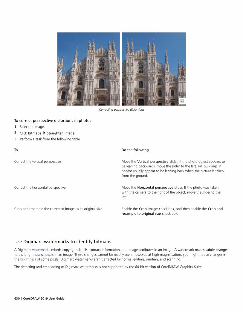
630 | CorelDRAW 2019 User Guide
Correcting perspective distortions
To correct perspective distortions in photos
1 Select an image.
2 Click Bitmaps Straighten image.
3 Perform a task from the following table.
To Do the following
Correct the vertical perspective Move the Vertical perspective slider. If the photo object appears tobe leaning backwards, move the slider to the left. Tall buildings inphotos usually appear to be leaning back when the picture is takenfrom the ground.
Correct the horizontal perspective Move the Horizontal perspective slider. If the photo was takenwith the camera to the right of the object, move the slider to theleft.
Crop and resample the corrected image to its original size Enable the Crop image check box, and then enable the Crop andresample to original size check box.
Use Digimarc watermarks to identify bitmaps
A Digimarc watermark embeds copyright details, contact information, and image attributes in an image. A watermark makes subtle changesto the brightness of pixels in an image. These changes cannot be readily seen; however, at high magnification, you might notice changes inthe brightness of some pixels. Digimarc watermarks aren’t affected by normal editing, printing, and scanning.
The detecting and embedding of Digimarc watermarks is not supported by the 64-bit version of CorelDRAW Graphics Suite.

Work with bitmaps | 631
Detecting watermarks
When you open an image in CorelDRAW, you can check for a watermark. If a watermark is present, a copyright symbol appears on the titlebar. You can find information about the watermarked image by reading the embedded message and by linking to the contact profile in theDigimarc database.
Embedding watermarks
In CorelDRAW, you can also embed Digimarc watermarks in images. First, you must obtain a unique Creator ID by subscribing to Digimarc’sonline service. The Creator ID includes contact details, such as name, phone number, address, email, and web addresses.
Once you have a Creator ID, you can embed a watermark in an image. You can specify the copyright year, image attributes, and thedurability of a watermark. You can also specify the target output method for an image, such as print or the web.
Digimarc watermarks do not prevent unauthorized image use or copyright infringement. But the watermarks do communicate copyrightclaims. They also provide contact information for those who want to use or license an image.
For more information about Digimarc, see www.digimarc.com.
To detect a watermark
1 Click Bitmaps Plug-ins Digimarc Read watermark.
2 Click Web lookup to view the webpage with contact details, or call the Digimarc fax-back service at the listed fax number.
This feature is not supported by the 64-bit version of CorelDRAW Graphics Suite.
To get a Creator ID
1 Click Bitmaps Plug-ins Digimarc Embed watermark.
2 Click Personalize.
3 In the Personalize Creator ID dialog box, click Register, and follow the instructions on the Digimarc website.
4 In the Personalize Creator ID dialog box, type your Creator ID in the Creator ID box.
To embed a watermark
1 Click Bitmaps Plug-ins Digimarc Embed watermark.
2 In the Copyright year(s) box, type a year or years.
3 In the Image attributes area, enable the check boxes for the applicable attributes.
4 Choose an option from the Target output list box.
5 Type a value in the Watermark durability box.
Higher values increase the persistence of the watermark under common image modifications such as dithering, cropping, compression,and scaling.
If you want to confirm the information available to viewers when they detect the watermark, enable the Verify check box.
This feature is not supported by the 64-bit version of CorelDRAW Graphics Suite.
In the Copyright year(s) box, you cannot type a year before 1922 or after the current year. Separate the years with commas.
In the Target output box, the Monitor and Web controls require a setting of less than 200 per inch (dpi), and the Printer controlrequires a setting of 300 dpi or higher.

632 | CorelDRAW 2019 User Guide
Combine all objects with the background before adding a watermark. For more information about combining objects with thebackground, see “Combine objects” on page 301.
Remove dust and scratch marks from bitmaps
You can quickly improve the appearance of a bitmap by removing dust and scratch marks. The dust and scratch filter works by eliminatingthe contrast between pixels that exceed the contrast threshold you set. You can set a radius to determine how many pixels are affected bythe changes. The settings you choose depend on the size of the blemish and the area surrounding it. For example, to remove a white scratchthat is 1 or 2 pixels wide on a dark background, you can set a radius of 2 or 3 pixels and set the contrast threshold higher than you wouldfor a similar scratch on a light background.
To remove dust and scratch marks from a bitmap
1 Click Effects Correction Dust and scratch.
2 Move the following sliders:
• Radius — sets the range of pixels used to produce the effect. To retain image detail, choose a setting as low as possible.
• Threshold — sets the amount of noise reduction. To retain image detail, choose a setting as high as possible.
Change and mask colors in bitmaps
CorelDRAW lets you change colors in monochrome images, apply PostScript halftone screens to optimize color and black-and-white bitmapsfor printing, hide and show colors, and mask colors. Monochrome bitmaps have two colors: black and white. You can replace the black andwhite pixels with any color on a color palette.
If you plan to print to a PostScript printer, you can optimize color or black-and-white printing by applying a halftone screen to an image.Halftone screens break down an image into small dots or lines for clearer printing, continuous tones, and special effects. However, you cansee the effect of the screen on the bitmap only after you print it on a PostScript printer. For information about making changes to halftonescreens, see “To customize a halftone screen” on page 748.
You can hide and display selected colors by masking them. Hiding colors in a bitmap lets objects or backgrounds show through the image.Hiding a color can also alter the apparent shape of a bitmap. For example, if a bitmap shows a person on a black background, you canhide the background so that the bitmap appears to take on the shape of the person rather than a rectangular shape. Also, hiding colors inbitmaps can increase the speed at which objects are rendered on the screen. You can also display certain colors in a bitmap to change theappearance of the image or to see where a particular color has been applied. You can mask as many as 10 colors in a bitmap.
Color masking also lets you change selected colors without altering the other colors in an image. You can also save a bitmap color mask to afile and open the file for future use.
To color a monochrome bitmap
1 Select a bitmap by using the Pick tool .
2 Right-click a color on the color palette to change the color of the foreground (black) pixels.
3 Click a color on the color palette to change the color of the background (white) pixels.
To apply a screen to a bitmap
1 Select a bitmap by using the Pick tool .
2 In the toolbox, click the Interactive fill tool .
Work with bitmaps | 633
3 On the property bar, click the Uniform fill button , and then click the Edit fill button .
4 In the Edit fill dialog box, enable the Color palettes option.
5 Choose a spot color palette from the Palette list box.
6 Click PostScript options.
7 In the PostScript options dialog box, choose an option (other than Default) from the Type list to set the dot shape or line type.
8 Type a value in the Frequency box to set the number of dots or lines that appear in each inch of the screen.
9 Type a value in the Angle box to set the angle of the dots or lines that appear on the screen.
To hide or display a color in a bitmap
1 Select the bitmap by using the Pick tool .
2 Click Bitmaps Bitmap Mask.
3 In the Bitmap Mask docker, click the Color selector button , and click a color in the bitmap.
4 Enable the check box next to the channel that you want to hide or display.
5 Move the Tolerance slider to set the color tolerance for the color.
6 Enable one of the following options:
• Hide selected
• Show selected
7 Click Apply.
Higher tolerance levels target a broader range of colors around the color you select. For example, if you select baby blue and increasethe tolerance, CorelDRAW hides or displays such colors as pastel blue or electric blue.
To open a bitmap color mask
1 Click Bitmaps Bitmap Mask.
2 Click the Open mask button .
3 Choose the folder where the color mask file is stored.
4 Double-click the file.
Files containing bitmap color mask have the filename extension .ini.
To change a masked color
1 Click Bitmaps Bitmap Mask.
2 Choose a color from the list of masked colors.
3 Click the Edit color button .
4 Use the controls in the Select color dialog box to edit the color.
You can also change a masked color by clicking the Color selector button , selecting another color from the bitmap, and clicking
Apply.

634 | CorelDRAW 2019 User Guide
Image Adjustment Lab
The Image Adjustment Lab lets you correct the color and tone of most photos quickly and easily.
1. Rotation tools 5. Select white point 9. Sliders
2. Pan tool 6. Select black point 10. Histogram
3. Zoom tools 7. Undo, Redo, and Reset
4. Preview Modes 8. Snapshots
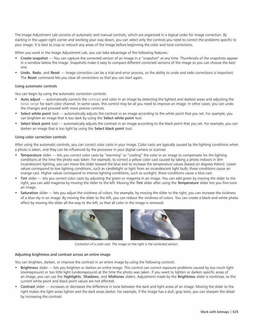
Work with bitmaps | 635
The Image Adjustment Lab consists of automatic and manual controls, which are organized in a logical order for image correction. Bystarting in the upper-right corner and working your way down, you can select only the controls you need to correct the problems specific toyour image. It is best to crop or retouch any areas of the image before beginning the color and tone corrections.
When you work in the Image Adjustment Lab, you can take advantage of the following features:• Create snapshot — You can capture the corrected version of an image in a “snapshot” at any time. Thumbnails of the snapshots appear
in a window below the image. Snapshots make it easy to compare different corrected versions of the image so you can choose the bestone.
• Undo, Redo, and Reset — Image correction can be a trial-and-error process, so the ability to undo and redo corrections is important.The Reset command lets you clear all corrections so that you can start again.
Using automatic controls
You can begin by using the automatic correction controls:• Auto adjust — automatically corrects the contrast and color in an image by detecting the lightest and darkest areas and adjusting the
tonal range for each color channel. In some cases, this control may be all you need to improve an image. In other cases, you can undothe changes and proceed with more precise controls.
• Select white point tool — automatically adjusts the contrast in an image according to the white point that you set. For example, youcan brighten an image that is too dark by using the Select white point tool.
• Select black point tool — automatically adjusts the contrast in an image according to the black point that you set. For example, you candarken an image that is too light by using the Select black point tool.
Using color correction controls
After using the automatic controls, you can correct color casts in your image. Color casts are typically caused by the lighting conditions whena photo is taken, and they can be influenced by the processor in your digital camera or scanner.• Temperature slider — lets you correct color casts by “warming” or “cooling” the color in an image to compensate for the lighting
conditions at the time the photo was taken. For example, to correct a yellow color cast caused by taking a photo indoors in dimincandescent lighting, you can move the slider toward the blue end to increase the temperature values (based on degrees Kelvin). Lowervalues correspond to low lighting conditions, such as candlelight or light from an incandescent light bulb; these conditions cause anorange cast. Higher values correspond to intense lighting conditions, such as sunlight; these conditions cause a blue cast.
• Tint slider — lets you correct color casts by adjusting the green or magenta in an image. You can add green by moving the slider to theright; you can add magenta by moving the slider to the left. Moving the Tint slider after using the Temperature slider lets you fine-tunean image.
• Saturation slider — lets you adjust the vividness of colors. For example, by moving the slider to the right, you can increase the vividnessof a blue sky in an image. By moving the slider to the left, you can reduce the vividness of colors. You can create a black-and-white photoeffect by moving the slider all the way to the left, so that all color in the image is removed.
Correction of a color cast. The image on the right is the corrected version.
Adjusting brightness and contrast across an entire image
You can brighten, darken, or improve the contrast in an entire image by using the following controls:• Brightness slider — lets you brighten or darken an entire image. This control can correct exposure problems caused by too much light
(overexposure) or too little light (underexposure) at the time the photo was taken. If you want to lighten or darken specific areas ofan image, you can use the Highlights, Shadows, and Midtones sliders. Adjustment made by the Brightness slider is nonlinear, so thecurrent white point and black point values are not affected.
• Contrast slider — increases or decreases the difference in tone between the dark and light areas of an image. Moving the slider to theright makes the light areas lighter and the dark areas darker. For example, if the image has a dull, gray tone, you can sharpen the detailby increasing the contrast.

636 | CorelDRAW 2019 User Guide
Adjusting the brightness and contrast of an image can reveal more image detail.
Adjusting highlights, shadows, and midtones
You can brighten or darken specific areas of an image. In many cases, the position or strength of the lighting at the time a photo is takencauses some areas to appear too dark and other areas to appear too light.• Highlights slider — lets you adjust brightness in the lightest areas of an image. For example, if you take a photo with a flash, and the
flash washes out the foreground subjects, you can move the Highlights slider to the left to darken the washed-out areas of the image.You can use the Highlights slider in conjunction with the Shadows and Midtones sliders to balance the lighting.
• Shadows slider — lets you adjust the brightness in the darkest areas of an image. For example, a bright light behind a photo subject(backlighting) at the time a photo is taken can cause the subject to appear in shadow. You can correct the photo by moving the Shadowslider to the right to lighten the dark areas and reveal more detail. You can use the Shadows slider in conjunction with the Highlightsand Midtones sliders to balance the lighting.
• Midtones slider — lets you adjust the brightness of the midrange tones in an image. After adjusting the highlights and shadows, youcan use the Midtones slider to fine-tune the image.
The Highlights and Shadows sliders can lighten or darken specific areas of an image.
Using the histogram
The histogram lets you view the tonal range of an image to evaluate and adjust the color and tone. For example, a histogram can help youdetect hidden detail in a photo that is too dark because of underexposure (a photo taken with insufficient light).
The histogram plots the brightness values of the pixels in an image on a scale of 0 (dark) to 255 (light). The left part of the histogramrepresents the shadows, the middle part represents the midtones, and the right part represents the highlights. The height of the spikesindicates how many pixels are at each brightness level. For example, a higher number of pixels on the left side of the histogram indicates thepresence of image detail in the dark areas of the image.
The photo on the left is underexposed. Right: The histogram indicatesa large amount of image detail in the dark areas of the photo.
Viewing images in the Image Adjustment Lab
The tools in the Image Adjustment Lab let you view images in various ways, so that you can evaluate the color and tone adjustments youmake. For example, you can rotate images, pan to a new area, zoom in or out, and choose how to display the corrected image in thepreview window.

Work with bitmaps | 637
Using other adjustment filters
Although the Image Adjustment Lab lets you correct the color and tone of most images, a specialized adjustment filter is sometimesrequired. Using the powerful adjustment filters in the application, you can make precise adjustments to images. For example, you can adjustimages by using a tone curve. For more information about adjustment filters, see “Adjust color and tone” on page 638.
To correct color and tone in the Image Adjustment Lab
1 Click Effects Adjust Image Adjustment Lab.
2 Click Auto adjust.
Auto adjust automatically adjusts color and contrast by setting the white point and black point for an image.
If you want to control the white point and black point setting more precisely, click the Select white point tool , and click the
lightest area of your image. Then click the Select black point tool , and click the darkest area of your image.
3 Perform one or more tasks from the following table.
To Do the following
Correct color in the image Adjust the Temperature slider to warm or cool the colors, and thenfine-tune the color correction by adjusting the Tint slider.
Make colors more vivid or less vivid Move the Saturation slider to the right to increase the amountof color in the image; move the slider to the left to decrease theamount of color in the image.
Brighten or darken an image Move the Brightness slider to the right to lighten the image; movethe slider to the left to darken the image.
Improve image sharpness by adjusting tone Move the Contrast slider to the right to make the light areas lighterand the dark areas darker.
Brighten or darken specific areas Move the Highlights slider to brighten or darken the lightest areasof the image. Then, move the Shadows slider to lighten or darkenthe darkest areas of the image. Finally, move the Midtones slider tofine-tune the midrange tones in the image.
The Image Adjustment Lab is not available for CMYK images. For CMYK images, you can access the Auto adjust filter and otheradjustment filters from the Effects menu.
You can capture the current version of your image by clicking the Create snapshot button. Thumbnails of the snapshots appear ina window below your image. Each snapshot is numbered sequentially and can be deleted by clicking the Close button in the upper-right corner of the snapshot title bar.
You can undo or redo the last correction you made by clicking the Undo button or the Redo button . To undo all
corrections, click the Reset to original button.

638 | CorelDRAW 2019 User Guide
To view images in the Image Adjustment Lab
1 Click Effects Adjust Image Adjustment Lab.
2 Perform a task from the following table.
To Do the following
Rotate the image Click the Rotate left button or the Rotate right button .
Pan to another area of an image Using the Pan tool , drag the image until the area you want to
see is visible.
Zoom in and out Using the Zoom in tool or the Zoom out tool , click in
the preview window.
Fit an image in the preview window Click the Zoom to fit button.
Display an image at its actual size Click the 100% button.
View the corrected image in a single preview window Click the Full preview button .
View the corrected image in one window and the original image inanother window
Click the Before and after full preview button .
View the image in one window with a divider between the originaland corrected versions
Click the Before and after split preview button . Move your
pointer over the dashed divider line, and drag to move the dividerto another area of the image.
Adjust color and tone
CorelDRAW lets you adjust the color and tone of bitmaps. For example, you can replace colors and adjust the brightness, lightness, andintensity of colors.
By adjusting tone and color, you can restore detail lost in shadows or highlights, remove color casts, correct underexposure or overexposure,and generally improve the quality of the bitmaps. You can also correct color and tone quickly by using the Image Adjustment Lab. For moreinformation, see “Image Adjustment Lab” on page 634.
You can adjust the color and tone of bitmaps automatically by using the Auto Adjust command or by using the following filters.
Effect Description
Brightness/contrast/intensity Lets you adjust the brightness of all colors and the differencebetween light and dark areas

Work with bitmaps | 639
Effect Description
Channel mixer Lets you mix color channels to balance the colors of a bitmap. Forexample, if a bitmap has too much red, you can adjust the redchannel in an RGB bitmap to improve image quality.
Color balance Lets you add cyan or red, magenta or green, and yellow or blue toselected tones in a bitmap. For example, if you want to tone downthe blue color in a photo, you can shift the color values from blueto yellow.
Contrast enhancement Lets you adjust the tone, color, and contrast of a bitmap whilepreserving shadow and highlight detail. An interactive histogramlets you shift or compress brightness values to printable limits.The histogram can also be adjusted by sampling values from thebitmap.
Desaturate Lets you reduce the saturation of each color in a bitmap to zero,remove the hue component, and convert each color to its grayscaleequivalent. This creates a grayscale black-and-white photo effectwithout changing the color model.
Gamma Gamma is a method of tonal correction that takes the humaneye's perception of neighboring pixels into account. For example, ifyou were to place a 10 percent gray circle on a black backgroundand an identical gray circle on a white background, the circlesurrounded by black appears lighter to the human eye than thecircle surrounded by white even though the brightness valuesare identical. The Gamma effect lets you pick up detail in a lowcontrast image without significantly affecting the shadows orhighlights. It affects the values in the image but it is curve-based sothat the changes are weighted toward the midtones.
Hue/saturation/lightness Lets you adjust the color channels in a bitmap and change theposition of colors in the spectrum. This effect allows you to changecolors and their richness, as well as the percentage of white in animage. Hue represents the dominant color (red, green, blue, yellow,and so on), saturation is the amount or richness of this color, andlightness represents the overall percentage of white in an image.
Local equalization Lets you enhance contrast near edges to reveal detail in bothlight and dark regions. This process can produce artificial contrastvariations in the center of relatively uniform regions. You cancorrect this by expanding the region so that it is larger than anyuniform area in the image. You can set the height and width of theregion around the pixels to accentuate contrast. To maintain equal
proportions, enable the Lock button .
640 | CorelDRAW 2019 User Guide
Effect Description
Replace colors Lets you replace one bitmap color with another color. A color maskis created to define the color to be replaced. Depending on therange you set, you can replace one color or shift an entire bitmapfrom one color range to another. You can set the hue, saturation,and lightness for the new color.
Sample/Target balance Lets you adjust color values in a bitmap with sample colors takenfrom the image. You can choose sample colors from the dark,midtone, and light ranges of an image and apply target colorsto each of the sample colors. For example, you can increase thecontrast in a bitmap by choosing the darkest and lightest tones ina bitmap and mapping them to black and white respectively. Afteryou choose sample colors from the dark, midtone, and light rangesof the image and assign a target color to each sample color, thepixels with the same color as the sample colors adjust to display thecorresponding target color.
Selective color Lets you change color by changing the percentage of spectrumCMYK process colors from the red, yellow, green, cyan, blue, andmagenta color spectrum in a bitmap. This filter also lets you addprocess color to the grayscale tonal component of an image.Selective color modifications increase and decrease the percentageof cyan, magenta, yellow, and black pixels that make up eachprimary color in the color spectrum. For example, decreasing thepercentage of magenta in the reds spectrum results in a color shifttoward yellow. Conversely, increasing the percentage of magentain the reds spectrum causes a color shift toward magenta and anoverall increase in red. The extent of color modification depends onthe adjustment percentage method you choose.
Tone curve Lets you perform color corrections precisely, by controllingindividual pixel values. By changing pixel brightness values, youcan make changes to shadows, midtones, and highlights. For moreinformation, see “Tone Curve filter” on page 644.
To adjust color and tone automatically
1 Select a bitmap.
2 Click Effects Adjust Auto adjust.
To adjust the brightness, contrast, and intensity
1 Select a bitmap.
2 Click Effects Adjust Brightness/contrast/intensity (or press Ctrl + B).
3 Move the Brightness, Contrast, or Intensity sliders to adjust the brightness, contrast, or intensity, respectively.
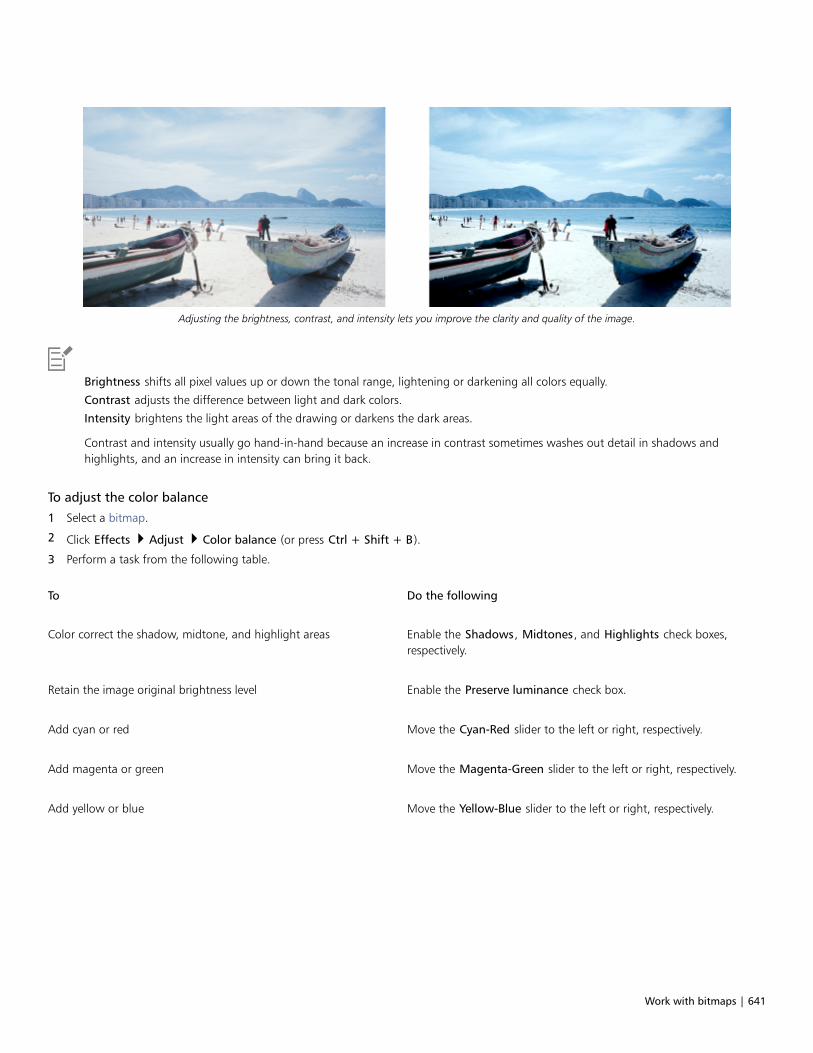
Work with bitmaps | 641
Adjusting the brightness, contrast, and intensity lets you improve the clarity and quality of the image.
Brightness shifts all pixel values up or down the tonal range, lightening or darkening all colors equally.
Contrast adjusts the difference between light and dark colors.
Intensity brightens the light areas of the drawing or darkens the dark areas.
Contrast and intensity usually go hand-in-hand because an increase in contrast sometimes washes out detail in shadows andhighlights, and an increase in intensity can bring it back.
To adjust the color balance
1 Select a bitmap.
2 Click Effects Adjust Color balance (or press Ctrl + Shift + B).
3 Perform a task from the following table.
To Do the following
Color correct the shadow, midtone, and highlight areas Enable the Shadows, Midtones, and Highlights check boxes,respectively.
Retain the image original brightness level Enable the Preserve luminance check box.
Add cyan or red Move the Cyan-Red slider to the left or right, respectively.
Add magenta or green Move the Magenta-Green slider to the left or right, respectively.
Add yellow or blue Move the Yellow-Blue slider to the left or right, respectively.
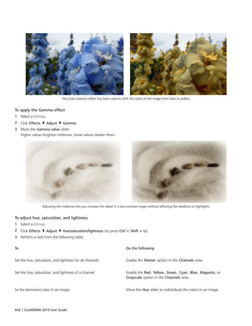
642 | CorelDRAW 2019 User Guide
The Color balance effect has been used to shift the colors in the image from blue to yellow.
To apply the Gamma effect
1 Select a bitmap.
2 Click Effects Adjust Gamma.
3 Move the Gamma value slider.
Higher values brighten midtones; lower values darken them.
Adjusting the midtones lets you increase the detail in a low-contrast image without affecting the shadows or highlights.
To adjust hue, saturation, and lightness
1 Select a bitmap.
2 Click Effects Adjust Hue/saturation/lightness (or press Ctrl + Shift + U).
3 Perform a task from the following table.
To Do the following
Set the hue, saturation, and lightness for all channels Enable the Master option in the Channels area.
Set the hue, saturation, and lightness of a channel Enable the Red, Yellow, Green, Cyan, Blue, Magenta, orGrayscale option in the Channels area.
Se the dominant color in an image Move the Hue slider to redistribute the colors in an image.

Work with bitmaps | 643
To Do the following
Set the strength of colors Move the Saturation slider. A setting of -100 results in a grayscaleimage. A setting of 100 produces vibrant, unnatural colors.
Se the amount of white (positive values) or black (negativevalues)
Move the Lightness slider.
The Before and After color ribbons help you compare the original colors and the new colors.
Use the Hue/saturation/lightness effect to change the colors in an image.
To replace colors
1 Select a bitmap.
2 Click Effects Adjust Replace colors.
3 Click the Old color picker and choose the color that you want to replace.
You can pick color from the bitmap by clicking the Eyedropper tool , and clicking the image.
4 Click the New color picker, and choose a replacement color.
You can also
Set the hue, saturation, and lightness level of the new color Move the Hue, Saturation, and Lightness sliders, respectively.
Ignore grayscale pixels when replacing colors Enable the Ignore grayscale check box.
Disabling the Ignore grayscale check box replaces gray pixels basedon saturation and lightness values alone.
Set the range of affected colors Move the Range slider.
A range of 1 affects only a single color; a range of 100 shifts mostof the colors in the direction of the new color.
Replace all colors that fall within the range of the new color Enable the Single destination check box.

644 | CorelDRAW 2019 User Guide
The Replace colors effect has been applied to replace all instances of the color red with purple.
To apply the Sample/target balance effect
1 Select a bitmap.
2 Click Effects Adjust Sample/target balance.
3 Choose a color channel from the Channel list box.
The color channels that appear in the Channel list box depend on the color mode of the bitmap. There is one composite channel andone channel for each color component. If you want to adjust all color channels, even when viewing only one channel, enable the Alwaysadjust all channels check box.
4 Click the Low-point , Mid-point , and High-point Eyedropper tool, and click in the image to choose a dark area, midtone
area, and light area, respectively.
5 Double-click the target color for the shadows, midtones, or highlights, and choose a new color.
The shadows, midtones, and highlights in the image have been adjusted by mapping a sample color in the bitmap to a target color.
Enable the Clip automatically check box to set the range of the histogram display and ensure that all spikes fit on the chart. Whenthe Clip automatically check box is disabled, use the Clipping box to set the percentage of brightness values that are ignored whenidentifying the light and dark colors in the histogram.
Tone Curve filter
The Tone curve filter lets you perform color and tonal corrections by adjusting either individual color channels or the composite channel (allchannels combined).

Work with bitmaps | 645
Original image (left); the image with adjusted tonal range (right)
Individual pixel values are plotted along a tone curve that appears in a graph and represents the balance between shadows (bottom ofgraph), midtones (middle of graph), and highlights (top of graph).
The tone curve shows the balance between the shadows, midtones, and highlights of an image. The original(x) and adjusted (y) pixel values are displayed side by side when you drag the tone curve. This example shows
a small adjustment to the tonal range, in which pixel values of 152 are replaced with pixel values of 141.
The x-axis of the graph represents the tonal values of the original image; the y-axis of the graph represents the adjusted tonal values. Movingthe curve up and to the left lightens the image and increases the color in any channel; moving the curve down and to the right darkens theimage or decreases the color of a given channel. If you have an image with a blue cast, for example, you can decrease the blue in the imageby selecting the Blue channel from the Active channel list box and moving the curve down and to the right.
You can adjust the color and tone of an image by dragging the tone curve interactively in the preview window, adding one or more nodes tothe tone curve, selecting areas in the image window, or applying a preset. You can adjust multiple points along a curve, so you can lightenthe shadows and darken the highlights.
You can also save tone curve settings as presets to use with other images. Response curve files are saved with the extension .CRV.
To apply the Tone curve effect
1 Select a bitmap.
2 Click Effects Adjust Tone curve.

646 | CorelDRAW 2019 User Guide
3 Choose a color channel from the Channel list box.
4 Choose a curve style from the Style list box.
• Curve — smooths the distribution of the values
• Straight — retains straight line segments between nodes
• Freehand — lets you draw a freehand curve
• Gamma — lets you weigh corrections toward the midtones
5 Click and drag the curve in the preview window to adjust the bitmap interactively.
You can also
View the tone curves for all channels at once Enable the Display all channels check box.
Adjust specific areas in an image Click the Eyedropper tool, and click in the image. The pixels thatyou select appear as nodes on the tone curve.
Add a node to the tone curve Click where you want to add a node along tone curve.
Smooth a freehand curve Click the Smooth button.
Click and hold the Smooth button down to continuously smooththe tonal curve.
Reset the tone curve for a selected channel Click Reset Active Channel.
Reset the tone curve for all channels Click Reset.
Equalize the tonal range of an image Click Auto Balance Tone.
To specify the outlying pixels (clipped pixels) at each end of thetonal range, click the Settings button and specify the Black limit toand White limit to values in the Auto-adjust range dialog box.
Apply a preset Click the Open button to the right of the Presets box and
choose the folder where the presets are stored.
Save tone curve settings as a preset Click the Save button to the right of the Presets box and
locate the folder where you want to save the preset.
To flip the axis of the grid, click the Invert button .
To change the resolution of the grid, press Alt and click in the preview window.
To invert the selected tonal curve, click the Horizontal Flip or Vertical Flip buttons .

Work with bitmaps | 647
The histogram lets you view the adjusted tonal range and evaluate the results. For more information about histograms, see “Usingthe histogram” on page 636.
Transform color and tone
You can transform the color and tone of an image to produce a special effect. For example, you can create an image that looks like aphotographic negative or flatten the appearance of an image. To transform the color and tone of images, you can use the following effects:• Deinterlace — lets you remove lines from scanned or interlaced images• Invert colors — lets you reverse the colors of an image. Inverting an image creates the appearance of a photographic negative.
The Invert effect makes a negative of an image by converting all color values to their opposites: black becomes white, blue becomes yellow, and so on.
• Posterize — lets you reduce the number of tonal values in an image. Posterize removes gradations and creates larger areas of flat color.
The Posterize effect converts color ranges in an image to solid blocks of color.
To transform color and tone
1 Select a bitmap.
2 Click Effects Transform, and click any of the following:
• Deinterlace — to remove lines from scanned or interlaced images. Even lines removes even lines. Odd lines removes odd lines.Duplication fills the gaps between the horizontal lines by duplicating the colors of the adjacent pixels. Interpolation fills the spaceswith colors created by averaging the surrounding pixels.

648 | CorelDRAW 2019 User Guide
• Invert Colors — to invert the color values in an image
• Posterize — to reduce the number of tonal values in an image. Move the Level slider to set the level at which posterization begins. Alevel of 2 results in drastic posterization; a level of 32 has no effect on most images.
Edit bitmaps with Corel PHOTO-PAINT
You can access Corel PHOTO-PAINT, a complete image-editing application, from within CorelDRAW. When you finish editing a bitmap, youcan quickly resume your work with CorelDRAW.
To send a bitmap to Corel PHOTO-PAINT, you can click the Edit bitmap button on the property bar, or you can use the Edit bitmapcommand from the Bitmaps menu. You can also enable an option that lets you access Corel PHOTO-PAINT by double-clicking a bitmap.
You can copy selected objects from Corel PHOTO-PAINT and then paste them into your drawing. The selected objects are pasted as a groupof bitmaps.
For more information about editing images with Corel PHOTO-PAINT, click Help Product Help from the Corel PHOTO-PAINT menu bar.
To edit a bitmap with Corel PHOTO-PAINT
1 Using the Pick tool , select the bitmap that you want to edit.
2 On the property bar, click the Edit bitmap button to start Corel PHOTO-PAINT.
The selected bitmap is displayed in the image window of Corel PHOTO-PAINT.
3 Edit the bitmap.
4 On the standard toolbar, click Finish editing to quit Corel PHOTO-PAINT.
The edited bitmap appears on the drawing page of CorelDRAW.
You can also use this procedure to edit groups of bitmaps. Corel PHOTO-PAINT opens the group of bitmaps as separate objects. Ifthe bitmaps in the group have different color modes, you are prompted to change the color mode of all bitmaps in the group to thecolor mode of the bottom-most bitmap.
You can also open Corel PHOTO-PAINT by clicking Bitmaps Edit bitmaps.
To access Corel PHOTO-PAINT by double-clicking a bitmap
1 Click Tools Options CorelDRAW.
2 Click Edit.
3 On the Edit page, enable the Double-click to edit bitmaps in PHOTO-PAINT check box.
Enabling this check box lets you access Corel PHOTO-PAINT by double-clicking the bitmap in CorelDRAW.
Apply special effects to bitmaps
You can apply a wide range of special effects to bitmaps, such as three-dimensional (3D) and artistic effects. Special effects are appliednondestructively, so you can add, edit, remove, show or hide, and revert to the original image at any point.

Work with bitmaps | 649
Left to right: Add noise effect, Zoom blur effect, Solarize color transform effect, Edge detect contour effect, Sharpen effect
Left to right: Original image, Emboss effect, Cubist artistic effect, Mosaic creative effect, Distort pixelate effect
The special effects are organized into the following categories.
Special effect category Description
3D Effects Lets you create the illusion of depth. Effects include “3-D rotate” on page 655, “Bevel effect (Corel PHOTO-PAINT) ” on page656, “Cylinder ” on page 656, “Emboss ” on page 657,“Glass (Corel PHOTO-PAINT) ” on page 657, “Page curl ” on page657, “Pinch/punch ” on page 658, “Sphere ” on page 658,“The Boss (Corel PHOTO-PAINT) ” on page 659, and “Zig zag(Corel PHOTO-PAINT) ” on page 659.
Art Strokes Lets you apply hand-painted techniques. Effects include “Charcoal” on page 659, “Conte crayon ” on page 660, “Crayon ” onpage 660, “Cubist ” on page 661, “Dabble (Corel PHOTO-PAINT) ” on page 661, “Impressionist ” on page 661, “Paletteknife ” on page 662, “Pastels ” on page 662, “Pen and ink ”on page 663, “Pointillist ” on page 663, “Scraperboard ” onpage 663, “Sketch pad ” on page 664, “Watercolor ” on page664, “Water marker ” on page 665, and “Wave paper ” onpage 665.

650 | CorelDRAW 2019 User Guide
Special effect category Description
Blur Lets you blur an image to simulate movement, speckling, orgradual change. Effects include “Tune blur (Corel PHOTO-PAINT) ”on page 666, “Directional smooth ” on page 666, “Gaussianblur ” on page 666, “Jaggy despeckle ” on page 667, “Lowpass ” on page 667, “Motion blur ” on page 668, “Radial blur” on page 668, “Bokeh blur (Corel PHOTO-PAINT) ” on page668, “Smooth ” on page 669, “Soften ” on page 669, and“Zoom ” on page 670.
Camera Lets you simulate effects produced by various camera lenses. Effectsinclude “Colorize ” on page 670, “Diffuse ” on page 671,“Lens flare (Corel PHOTO-PAINT) ” on page 671, “Lighting effects(Corel PHOTO-PAINT) ” on page 672, “Photo filter ” on page672, “Sepia toning ” on page 672, “Spot filter (Corel PHOTO-PAINT) ” on page 673, and “Time machine ” on page 673,which lets you walk your image back through history to recreatesome popular photographic styles from the past.
Color Transform Lets you create photographic illusions by using color reductionand replacements. Effects include “Bit planes ” on page 674,“Halftone ” on page 674, “Psychedelic ” on page 675, and“Solarize ” on page 675.
Contour Lets you highlight and enhance the edges of an image. Effectsinclude “Edge detect ” on page 676, “Find edges ” on page676, and “Trace contour ” on page 676.
Creative Lets you apply various textures and shapes to an image. Effectsinclude “Crystalize ” on page 677, “Fabric ” on page 677,“Frame ” on page 678, “Glass block ” on page 678, “Mosaic” on page 679, “Scatter ” on page 679, “Smoked glass ” onpage 680, “Stained glass ” on page 680, “Vignette ” on page680, and “Vortex ” on page 681.
Custom Lets you apply a wide range of effects to your image. For example,you can add texture and patterns to an image (Bump-map effect).Effects include “Band pass (Corel PHOTO-PAINT) ” on page 681,“Bump map ” on page 682, and “User defined (Corel PHOTO-PAINT) ” on page 682.
Distort Lets you distort image surfaces. Effects include “Blocks ” on page683, “Displace ” on page 683,“Mesh warp ” on page 684“Offset ” on page 684, “Pixelate ” on page 685, “Ripple ” onpage 685, “Shear (Corel PHOTO-PAINT) ” on page 686, “Swirl” on page 686, “Tile ” on page 686, “Wet paint ” on page687, “Whirlpool ” on page 687, and “Wind ” on page 688.

Work with bitmaps | 651
Special effect category Description
Noise Lets you modify the graininess of an image. Effects include “Tunenoise (Corel PHOTO-PAINT) ” on page 690, “Add noise ” onpage 688, “3-D stereo noise (Corel PHOTO-PAINT) ” on page689, “Maximum ” on page 689, “Median ” on page 689,“Minimum ” on page 690, “Remove Moire ” on page 691,and“Remove Noise ” on page 691.
Sharpen Lets you add a sharpening effect to focus and enhance edges.Effects include “Adaptive unsharp ” on page 691, “Directionalsharpen ” on page 692, “High pass ” on page 692, “Sharpen ”on page 693, and “Unsharp mask ” on page 693.
Texture Lets you add texture to an image by simulating a variety ofsurfaces, such as cobblestone, elephant skin, plastic, and reliefsculpture. Effects include “Brick wall (Corel PHOTO-PAINT) ” onpage 694, “Bubbles (Corel PHOTO-PAINT) ” on page 694,“Canvas (Corel PHOTO-PAINT) ” on page 694, “Cobblestone ” onpage 695, “Elephant skin ” on page 695, “Etching ” on page696, “Plastic ” on page 696, “Plaster wall (Corel PHOTO-PAINT)” on page 696, “Relief sculpture ” on page 697, “Screen door(Corel PHOTO-PAINT) ” on page 697, “Stone ” on page 698,and “Underpainting (Corel PHOTO-PAINT) ” on page 698.
Plug-ins Lets you use a third-party filter to apply effects to bitmaps inCorelDRAW. An installed plug-in appears at the bottom of theBitmaps menu.
To browse the special effects that are available in the application, see “Special effects categories” on page 655.
When you apply an effect to a bitmap, CorelDRAW automatically adds a border around the bitmap so that the effect covers the entireimage. Disabling the automatic inflate option cuts off the effect at the edges of the image. For example, if you apply the Gaussian Blur effectto a rectangle, the corners are cut off.
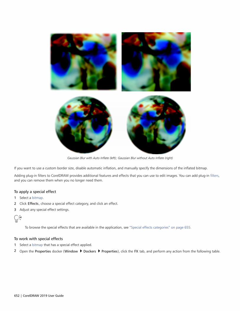
652 | CorelDRAW 2019 User Guide
Gaussian Blur with Auto Inflate (left); Gaussian Blur without Auto Inflate (right)
If you want to use a custom border size, disable automatic inflation, and manually specify the dimensions of the inflated bitmap.
Adding plug-in filters to CorelDRAW provides additional features and effects that you can use to edit images. You can add plug-in filters,and you can remove them when you no longer need them.
To apply a special effect
1 Select a bitmap.
2 Click Effects, choose a special effect category, and click an effect.
3 Adjust any special effect settings.
To browse the special effects that are available in the application, see “Special effects categories” on page 655.
To work with special effects
1 Select a bitmap that has a special effect applied.
2 Open the Properties docker (Window Dockers Properties), click the FX tab, and perform any action from the following table.

Work with bitmaps | 653
To Do the following...
Show or hide the effect Click the Show/Hide icon for the effect you want to show or
hide.
Apply additional effects Click the Add effect button and choose an effect from the
menu.
Edit an applied effect Select an effect and click the Edit icon .
Change the order of applied effects Click an effect and drag it to a new position in the list.
Delete an effect Select an effect and click the Delete button .
To inflate a bitmap manually
1 Select a bitmap.
2 Click Bitmaps Inflate bitmap Manually inflate bitmap.
3 In the Width and Height areas, do one of the following:
• In the Inflate to boxes, type the number of pixels that should make up the dimensions of the inflated bitmap.
• In the Inflate by boxes, type the percentages by which to inflate the original bitmap.
To inflate the bitmap proportionally, enable the Maintain aspect ratio check box.
To automatically inflate the bitmap to cover the entire image, click Bitmaps Inflate bitmap Auto inflate bitmap.
To choose default bitmap inflation settings
1 Click Layout Document Options.
2 Click General.
3 Enable or disable the Auto inflate bitmaps for effects check box.
To add a plug-in filter
1 Click Tools Options CorelDRAW.
2 Click Plug-ins.
3 Click Add.
4 Choose a folder containing a plug-in.
5 Restart the application.
The plug-in appears in the Bitmaps Plug-ins menu.
To remove a plug-in filter, click a plug-in folder from the Plug-in folders list, and click Remove.

654 | CorelDRAW 2019 User Guide

Special effects categories | 655
Special effects categories
In this chapter, you will find descriptions of the special effects that are available in the application as well as sample images that illustrateeach effect. The special effects are organized into the following categories:• “3-D” (page 655)• “Art strokes” (page 659)• “Blur” (page 665)• “Camera” (page 670)• “Color transform” (page 674)• “Contour” (page 676)• “Creative” (page 677)• “Custom” (page 681)• “Distort” (page 683)• “Noise” (page 688)• “Sharpen” (page 691)• “Texture” (page 693)
For information about applying special effects, see “Apply special effects to bitmaps” on page 648.
3-D
You can apply three-dimensional special effects to an image to create the illusion of depth.
To apply the effects that are labeled with ‘Corel PHOTO-PAINT’, you need to edit the bitmap in Corel PHOTO-PAINT. To send a bitmapto Corel PHOTO-PAINT, you can click the Edit bitmap button on the property bar, or you can use the Edit bitmap command fromthe Bitmaps menu. You can also enable an option that lets you access Corel PHOTO-PAINT by double-clicking a bitmap. For moreinformation, see “Edit bitmaps with Corel PHOTO-PAINT” on page 648.
3-D rotate
The 3-D rotate effect (Effects 3D Effects 3D Rotate) lets you rotate an image by adjusting an interactive, three-dimensional model.Click and drag the interactive, three-dimensional model in the 3D Rotate dialog box to rotate and position the image. Hold down Ctrl and
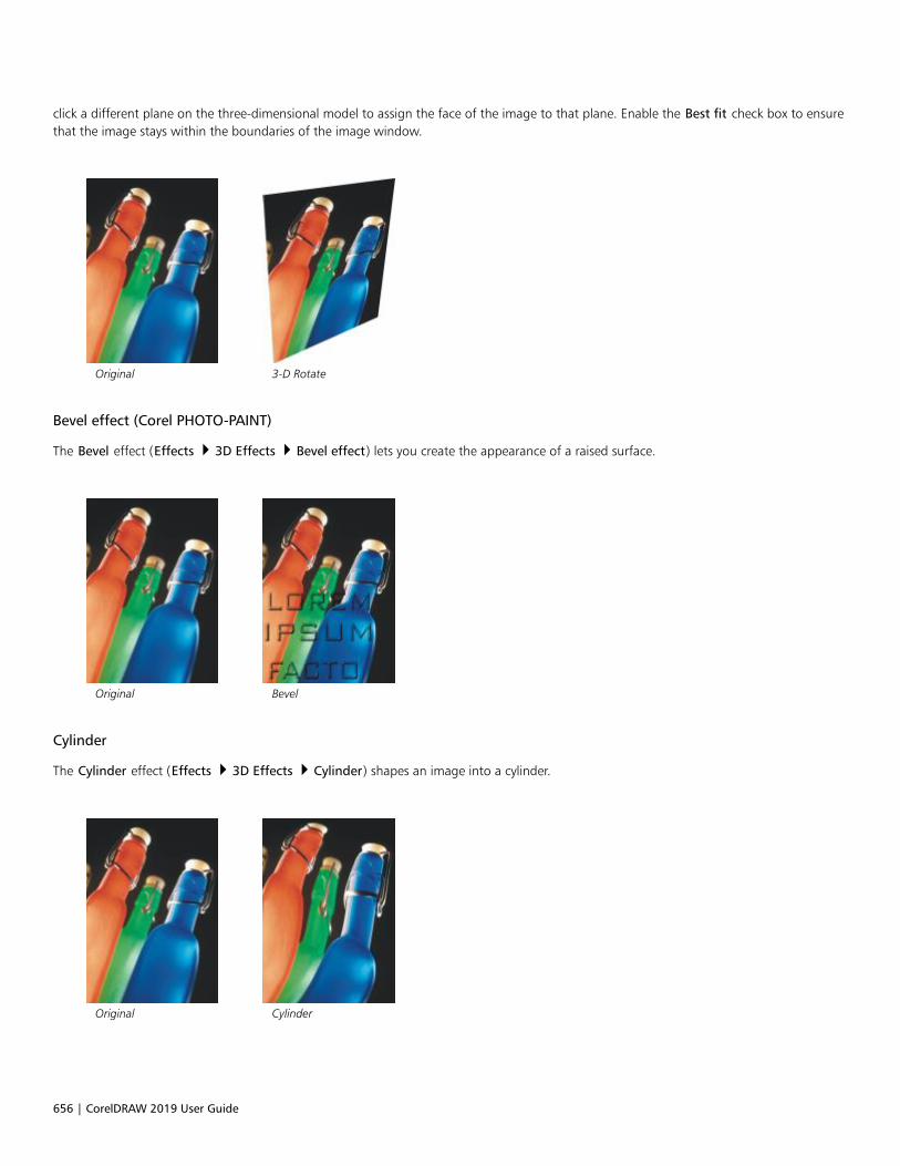
656 | CorelDRAW 2019 User Guide
click a different plane on the three-dimensional model to assign the face of the image to that plane. Enable the Best fit check box to ensurethat the image stays within the boundaries of the image window.
Original 3-D Rotate
Bevel effect (Corel PHOTO-PAINT)
The Bevel effect (Effects 3D Effects Bevel effect) lets you create the appearance of a raised surface.
Original Bevel
Cylinder
The Cylinder effect (Effects 3D Effects Cylinder) shapes an image into a cylinder.
Original Cylinder

Special effects categories | 657
Emboss
The Emboss effect (Effects 3D Effects Emboss) transforms an image into a relief, with details appearing as ridges and crevices on aflat surface. You can choose the embossing color or depth, as well as the direction of the light source. The effect works best on imageswith medium to high contrast. Depth sets the depth of the ridges and indentations in the relief. Level sets the intensity of the effect. TheDirection dial lets you specify the direction of the light source. Original color embosses the image using its original colors. Gray embossesthe image in gray with moderate, embossed highlights. Black embosses the image in black with high-contrast, embossed highlights. Otherembosses the image using a color that you choose from the Other color picker.
Original Emboss
Glass (Corel PHOTO-PAINT)
The Glass effect (Effects 3D Effects Glass) places a three-dimensional, glass-like surface over an editable area. You can specify the widthof the bevel, the area that is slanted to produce the three-dimensional look, the sharpness of the bevel's edges, and the angle at which thelight is bent at the edges. You can also specify the brightness, direction, and angle of the light that strikes the bevel. The Glass effect lets youapply preset styles and create custom preset styles.
Original Glass
Page curl
The Page curl effect (Effects 3D Effects Page curl) makes one of the corners of an image roll in on itself. You can specify a corner andset the curl orientation, transparency, and size. You can also choose a color for the curl and the background that is exposed where the imagecurls away from the paper. Click a thumbnail to specify the position of the page curl. Choose a vertical or horizontal direction for the pagecurl. The Opaque option creates a curl using a solid color, the Transparent option displays the underlying image through the curl. The Curlcolor picker lets you choose the curl color. The Background color picker let you choose a color for the background that is exposed where theimage curls away from the paper. The Width% and Height% sliders let you set the curl size.

658 | CorelDRAW 2019 User Guide
Original Page curl
Pinch/punch
The Pinch/punch effect (Effects 3D Effects Pinch/punch) warps an image by pinching it toward you or punching it away from you. Youcan position the effect by setting a center point.
Original Pinch/Punch
Sphere
The Sphere effect (Effects 3D Effects Sphere) wraps an image around the inside or outside of a sphere. You can set a center pointaround which an image wraps, and you can control the wrapping. Positive values expand the central pixels toward the edges of an imageresulting in a convex shape. Negative values compress pixels toward the center of an image resulting in a concave shape.
Original Sphere

Special effects categories | 659
The Boss (Corel PHOTO-PAINT)
The Boss effect (Effects 3D Effects The Boss) raises the area of the image that falls along the edges of a mask. You can specify thewidth, height, and smoothness of the raised edge, as well as the brightness, sharpness, direction, and angle of the light sources. The Bosseffect lets you apply preset styles and create custom preset styles.
Original The Boss
Zig zag (Corel PHOTO-PAINT)
The Zig zag effect (Effects 3D Effects Zig zag) creates waves of straight lines and angles that twist an image outward from anadjustable center point. You can choose the type of waves and specify their number and strength.
Original Zig Zag
Art strokes
The art strokes special effects give images a hand-painted look. You can use these effects to make images look like pastel drawings, spongepaintings, and watercolors, or to create textured backgrounds.
Charcoal
The Charcoal effect (Effects Art strokes Charcoal) makes an image look like a black-and-white charcoal drawing.

660 | CorelDRAW 2019 User Guide
Original Charcoal
Conte crayon
The Conte crayon effect (Effects Art strokes Conte crayon) simulates textures produced with a conté crayon. You can select multiplecrayon colors and set the crayon pressure and the granularity of the texture.
Original Conte crayon
Crayon
The Crayon effect (Effects Art strokes Crayon) makes an image look like a wax crayon drawing. You can specify the crayon pressureand create dark outlines around elements in the image.
Original Crayon

Special effects categories | 661
Cubist
The Cubist effect (Effects Art strokes Cubist) groups similarly colored pixels into squares to produce an image that resembles a cubistpainting. You can specify the square size, the amount of light, and the paper color.
Original Cubist
Dabble (Corel PHOTO-PAINT)
The Dabble effect (Effects Art strokes Dabble) makes image pixels look like dabs of paint. You can choose from a variety ofbrushstrokes and specify the brushstroke size.
To apply the Dabble effect, you need to edit the bitmap in Corel PHOTO-PAINT. To send a bitmap to Corel PHOTO-PAINT, you can clickthe Edit bitmap button on the property bar, or you can use the Edit bitmap command from the Bitmaps menu. You can also enablean option that lets you access Corel PHOTO-PAINT by double-clicking a bitmap. For more information, see “Edit bitmaps with CorelPHOTO-PAINT” on page 648.
Original Dabble
Impressionist
The Impressionist effect (Effects Art strokes Impressionist) makes an image look like an impressionist painting. You can customize thedabs of color or the brushstrokes and specify the amount of light in the image.
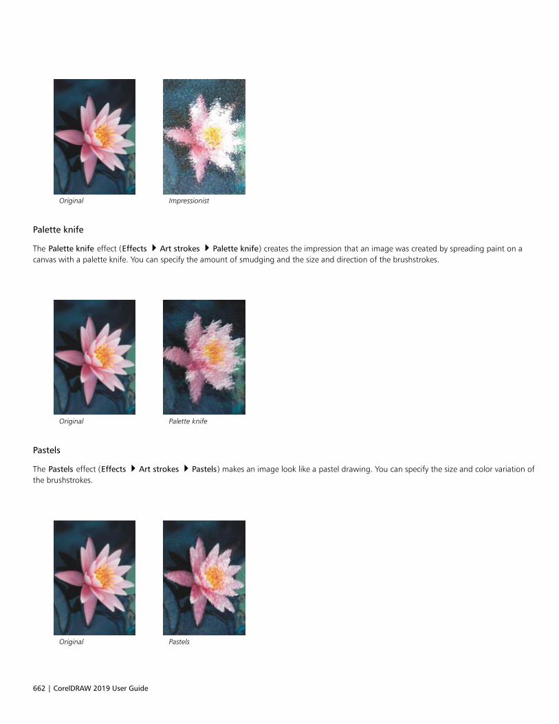
662 | CorelDRAW 2019 User Guide
Original Impressionist
Palette knife
The Palette knife effect (Effects Art strokes Palette knife) creates the impression that an image was created by spreading paint on acanvas with a palette knife. You can specify the amount of smudging and the size and direction of the brushstrokes.
Original Palette knife
Pastels
The Pastels effect (Effects Art strokes Pastels) makes an image look like a pastel drawing. You can specify the size and color variation ofthe brushstrokes.
Original Pastels
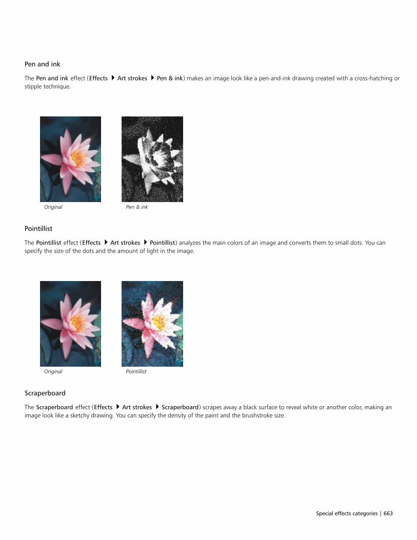
Special effects categories | 663
Pen and ink
The Pen and ink effect (Effects Art strokes Pen & ink) makes an image look like a pen-and-ink drawing created with a cross-hatching orstipple technique.
Original Pen & ink
Pointillist
The Pointillist effect (Effects Art strokes Pointillist) analyzes the main colors of an image and converts them to small dots. You canspecify the size of the dots and the amount of light in the image.
Original Pointillist
Scraperboard
The Scraperboard effect (Effects Art strokes Scraperboard) scrapes away a black surface to reveal white or another color, making animage look like a sketchy drawing. You can specify the density of the paint and the brushstroke size.
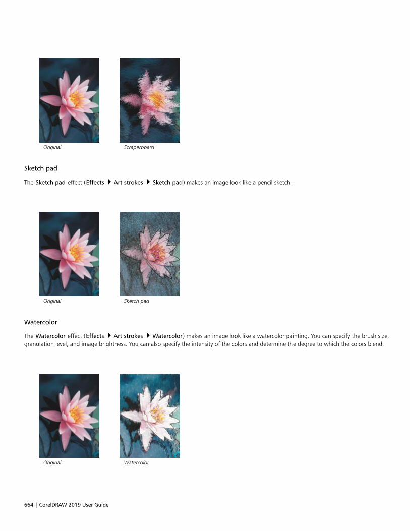
664 | CorelDRAW 2019 User Guide
Original Scraperboard
Sketch pad
The Sketch pad effect (Effects Art strokes Sketch pad) makes an image look like a pencil sketch.
Original Sketch pad
Watercolor
The Watercolor effect (Effects Art strokes Watercolor) makes an image look like a watercolor painting. You can specify the brush size,granulation level, and image brightness. You can also specify the intensity of the colors and determine the degree to which the colors blend.
Original Watercolor
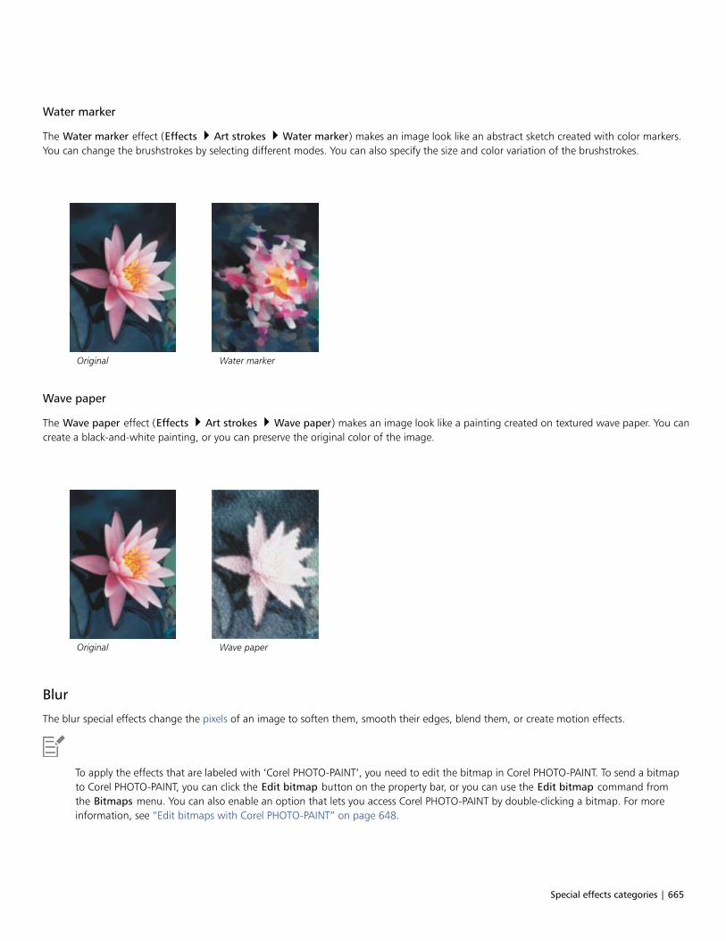
Special effects categories | 665
Water marker
The Water marker effect (Effects Art strokes Water marker) makes an image look like an abstract sketch created with color markers.You can change the brushstrokes by selecting different modes. You can also specify the size and color variation of the brushstrokes.
Original Water marker
Wave paper
The Wave paper effect (Effects Art strokes Wave paper) makes an image look like a painting created on textured wave paper. You cancreate a black-and-white painting, or you can preserve the original color of the image.
Original Wave paper
Blur
The blur special effects change the pixels of an image to soften them, smooth their edges, blend them, or create motion effects.
To apply the effects that are labeled with ‘Corel PHOTO-PAINT’, you need to edit the bitmap in Corel PHOTO-PAINT. To send a bitmapto Corel PHOTO-PAINT, you can click the Edit bitmap button on the property bar, or you can use the Edit bitmap command fromthe Bitmaps menu. You can also enable an option that lets you access Corel PHOTO-PAINT by double-clicking a bitmap. For moreinformation, see “Edit bitmaps with Corel PHOTO-PAINT” on page 648.

666 | CorelDRAW 2019 User Guide
Tune blur (Corel PHOTO-PAINT)
The Tune blur effect (Effects Blur Tune blur) lets you apply any of four blurring effects, which are represented by thumbnails, to animage. You can adjust the blur effect and preview the image with softer or sharper focus while you are editing it. The Tune blur filter letsyou improve image quality or create exciting visual effects.
Original Tune blur
Directional smooth
The Directional smooth effect (Effects Blur Directional smooth) smooths the regions of gradual change in an image while preservingedge detail and texture. You can use this filter to subtly blur the edges and surfaces of images without distorting the focus.
Original Directional smooth
Gaussian blur
The Gaussian blur (Effects Blur Gaussian blur) effect produces a hazy effect, blurring the focus of an image according to Gaussiandistribution, which spreads the pixel information outward using bell-shaped curves. The effect can improve the quality of bitmaps with sharpedges. Move the Radius slider to adjust the intensity of the effect. The Gaussian Blur effect supports all color modes except Paletted andBlack-and-White.

Special effects categories | 667
Original Gaussian blur
Jaggy despeckle
The Jaggy despeckle effect (Effects Blur Jaggy despeckle) scatters colors in an image, creating a soft, blurred effect with minimaldistortion. It is most effective for removing the jagged edges that can appear in line art or high-contrast images. The Jaggy despeckle effectis also a preset lens type.
Original Jaggy despeckle
Low pass
The Low pass effect (Effects Blur Low pass) removes sharp edges and detail from an image, leaving smooth gradients and low-frequency areas. The higher the settings you specify, the more image detail is erased.
Original Low pass

668 | CorelDRAW 2019 User Guide
Motion blur
The Motion blur effect (Effects Blur Motion blur) creates the illusion of movement in an image. You can specify the direction ofmovement.
Original Motion blur
Radial blur
The Radial blur effect (Effects Blur Radial blur) creates a blurring effect in an image that spins around or radiates outward from acenter point that you specify.
Original Radial blur
Bokeh blur (Corel PHOTO-PAINT)
The Bokeh blur effect (Effects Blur Bokeh blur) lets you control the amount of blur applied to the outside of an editable area andadjust the transition between the area in focus and the blurred area. For more information, see the Corel PHOTO-PAINT Help.
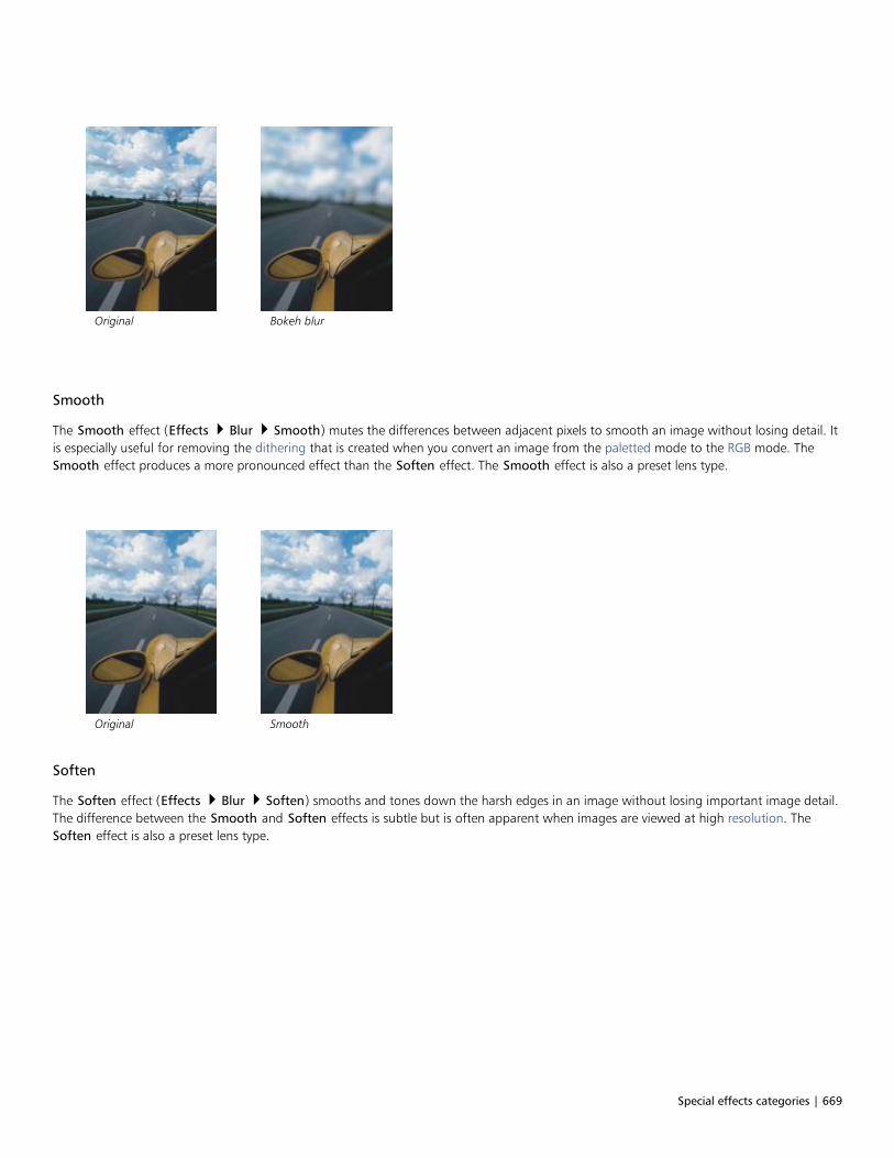
Special effects categories | 669
Original Bokeh blur
Smooth
The Smooth effect (Effects Blur Smooth) mutes the differences between adjacent pixels to smooth an image without losing detail. Itis especially useful for removing the dithering that is created when you convert an image from the paletted mode to the RGB mode. TheSmooth effect produces a more pronounced effect than the Soften effect. The Smooth effect is also a preset lens type.
Original Smooth
Soften
The Soften effect (Effects Blur Soften) smooths and tones down the harsh edges in an image without losing important image detail.The difference between the Smooth and Soften effects is subtle but is often apparent when images are viewed at high resolution. TheSoften effect is also a preset lens type.
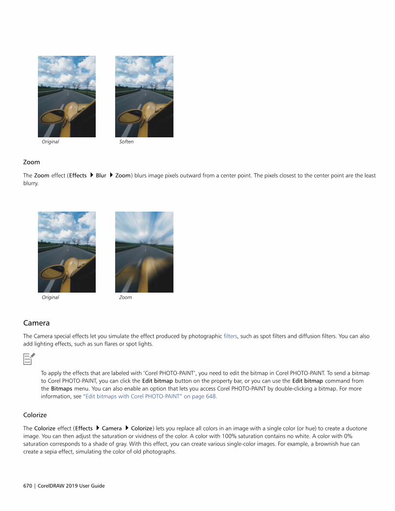
670 | CorelDRAW 2019 User Guide
Original Soften
Zoom
The Zoom effect (Effects Blur Zoom) blurs image pixels outward from a center point. The pixels closest to the center point are the leastblurry.
Original Zoom
Camera
The Camera special effects let you simulate the effect produced by photographic filters, such as spot filters and diffusion filters. You can alsoadd lighting effects, such as sun flares or spot lights.
To apply the effects that are labeled with ‘Corel PHOTO-PAINT’, you need to edit the bitmap in Corel PHOTO-PAINT. To send a bitmapto Corel PHOTO-PAINT, you can click the Edit bitmap button on the property bar, or you can use the Edit bitmap command fromthe Bitmaps menu. You can also enable an option that lets you access Corel PHOTO-PAINT by double-clicking a bitmap. For moreinformation, see “Edit bitmaps with Corel PHOTO-PAINT” on page 648.
Colorize
The Colorize effect (Effects Camera Colorize) lets you replace all colors in an image with a single color (or hue) to create a duotoneimage. You can then adjust the saturation or vividness of the color. A color with 100% saturation contains no white. A color with 0%saturation corresponds to a shade of gray. With this effect, you can create various single-color images. For example, a brownish hue cancreate a sepia effect, simulating the color of old photographs.

Special effects categories | 671
Original Colorize
Diffuse
The Diffuse effect (Effects Camera Diffuse) softens images by distributing image pixels to fill in blank spaces and remove noise. Theresult simulates the soft focus of a photographer's diffusion filter. You can make this effect smooth or blurry.
Original Diffuse
Lens flare (Corel PHOTO-PAINT)
The Lens flare (Effects Camera Lens flare) effect produces rings of light on an RGB image, simulating the flare that appears on aphotograph when the camera is aimed towards a direct, bright light. For more information, see the Corel PHOTO-PAINT help.
Original Lens flare

672 | CorelDRAW 2019 User Guide
Lighting effects (Corel PHOTO-PAINT)
The Lighting effects (Effects Camera Lighting effects) let you add light sources to an RGB or grayscale image to create the illusionof spotlights, floodlights, or sunlight. You can also apply a texture to create embossed reliefs. You can use a preset light or texture style, orcustomize a preset style and save it in the preset list. For more information, see the Corel PHOTO-PAINT help.
Original Lighting effects
Photo filter
The Photo filter effect (Effects Camera Photo filter) lets you simulate the effect of placing a colored filter in front of a camera lens. Youcan choose the color of the filter and then adjust the color density and luminosity.
Original Photo filter
Sepia toning
The Sepia toning effect (Effects Camera Sepia toning) simulates the look created when you take a photo with sepia film. Sepia-tonedimages are similar to black-and-white photos (also known as grayscale photos), except the tones are brown instead of gray.
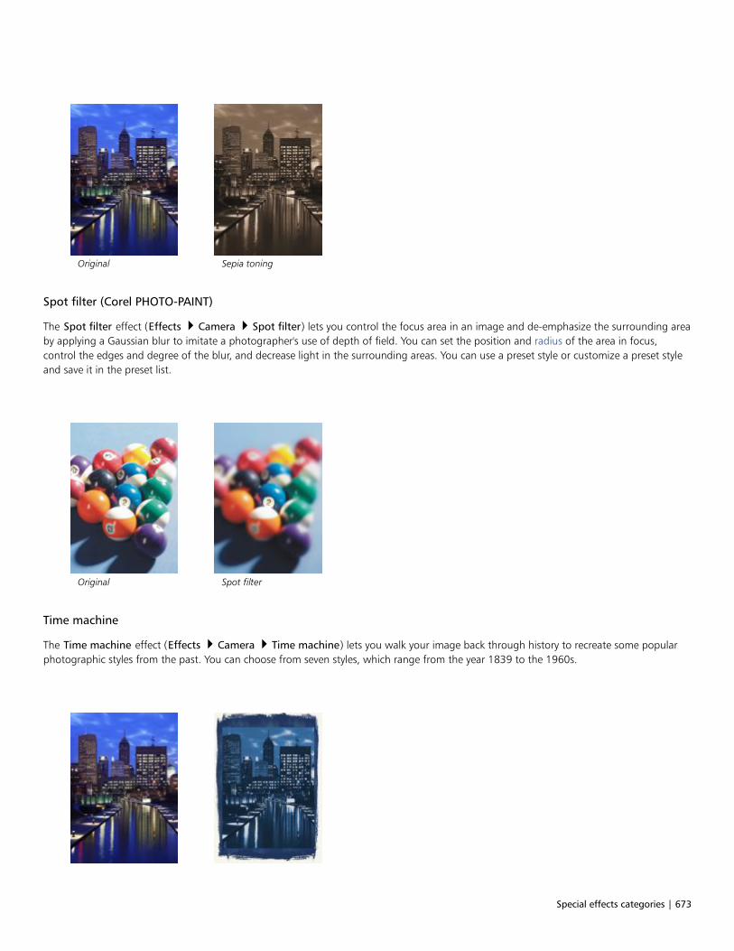
Special effects categories | 673
Original Sepia toning
Spot filter (Corel PHOTO-PAINT)
The Spot filter effect (Effects Camera Spot filter) lets you control the focus area in an image and de-emphasize the surrounding areaby applying a Gaussian blur to imitate a photographer's use of depth of field. You can set the position and radius of the area in focus,control the edges and degree of the blur, and decrease light in the surrounding areas. You can use a preset style or customize a preset styleand save it in the preset list.
Original Spot filter
Time machine
The Time machine effect (Effects Camera Time machine) lets you walk your image back through history to recreate some popularphotographic styles from the past. You can choose from seven styles, which range from the year 1839 to the 1960s.
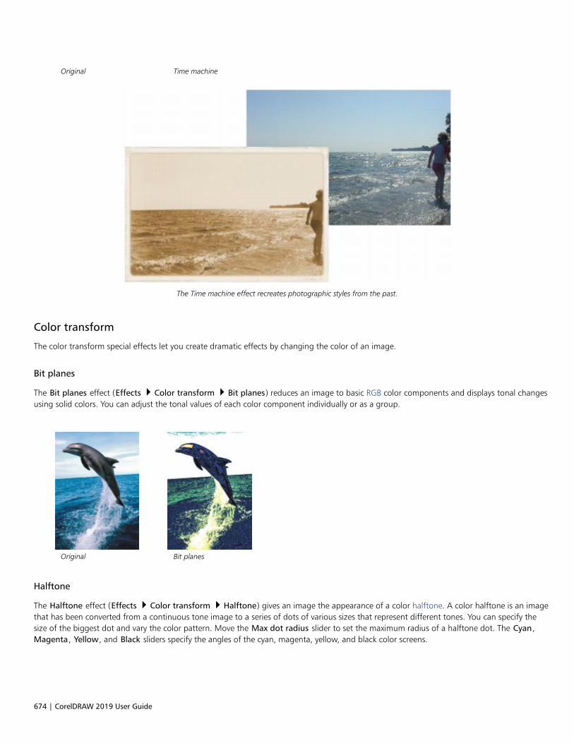
674 | CorelDRAW 2019 User Guide
Original Time machine
The Time machine effect recreates photographic styles from the past.
Color transform
The color transform special effects let you create dramatic effects by changing the color of an image.
Bit planes
The Bit planes effect (Effects Color transform Bit planes) reduces an image to basic RGB color components and displays tonal changesusing solid colors. You can adjust the tonal values of each color component individually or as a group.
Original Bit planes
Halftone
The Halftone effect (Effects Color transform Halftone) gives an image the appearance of a color halftone. A color halftone is an imagethat has been converted from a continuous tone image to a series of dots of various sizes that represent different tones. You can specify thesize of the biggest dot and vary the color pattern. Move the Max dot radius slider to set the maximum radius of a halftone dot. The Cyan,Magenta, Yellow, and Black sliders specify the angles of the cyan, magenta, yellow, and black color screens.

Special effects categories | 675
Original Halftone
Psychedelic
The Psychedelic effect (Effects Color transform Psychedelic) changes the colors in an image to bright, electric colors, such as orange,hot pink, cyan, and lime green. The Psychedelic effect is also a preset lens type.
Original Psychedelic
Solarize
The Solarize effect (Effects Color transform Solarize) transforms colors in an image by reversing image tones. The Solarize effect is alsoa preset lens type.
Original Solarize
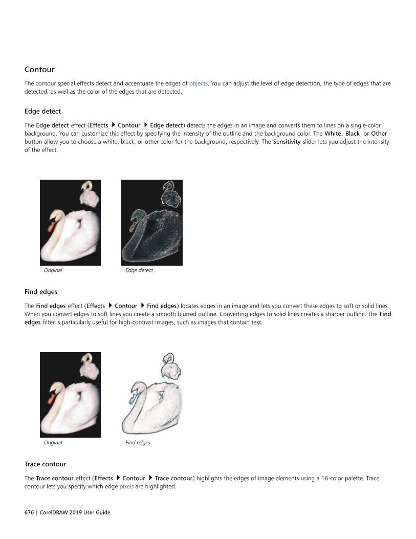
676 | CorelDRAW 2019 User Guide
Contour
The contour special effects detect and accentuate the edges of objects. You can adjust the level of edge detection, the type of edges that aredetected, as well as the color of the edges that are detected.
Edge detect
The Edge detect effect (Effects Contour Edge detect) detects the edges in an image and converts them to lines on a single-colorbackground. You can customize this effect by specifying the intensity of the outline and the background color. The White, Black, or Otherbutton allow you to choose a white, black, or other color for the background, respectively. The Sensitivity slider lets you adjust the intensityof the effect.
Original Edge detect
Find edges
The Find edges effect (Effects Contour Find edges) locates edges in an image and lets you convert these edges to soft or solid lines.When you convert edges to soft lines you create a smooth blurred outline. Converting edges to solid lines creates a sharper outline. The Findedges filter is particularly useful for high-contrast images, such as images that contain text.
Original Find edges
Trace contour
The Trace contour effect (Effects Contour Trace contour) highlights the edges of image elements using a 16-color palette. Tracecontour lets you specify which edge pixels are highlighted.
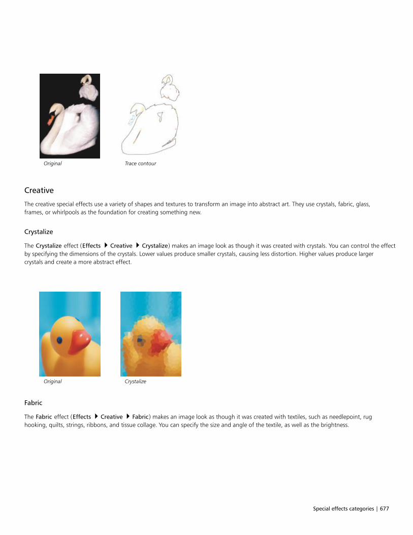
Special effects categories | 677
Original Trace contour
Creative
The creative special effects use a variety of shapes and textures to transform an image into abstract art. They use crystals, fabric, glass,frames, or whirlpools as the foundation for creating something new.
Crystalize
The Crystalize effect (Effects Creative Crystalize) makes an image look as though it was created with crystals. You can control the effectby specifying the dimensions of the crystals. Lower values produce smaller crystals, causing less distortion. Higher values produce largercrystals and create a more abstract effect.
Original Crystalize
Fabric
The Fabric effect (Effects Creative Fabric) makes an image look as though it was created with textiles, such as needlepoint, rughooking, quilts, strings, ribbons, and tissue collage. You can specify the size and angle of the textile, as well as the brightness.

678 | CorelDRAW 2019 User Guide
Original Fabric
Frame
The Frame effect (Effects Creative Frame) lets you frame an image with a preset or custom frame. You can change the color, opacity,orientation, and alignment of a frame, and you can save customized settings as preset styles. You can also update, load, and delete presetframe settings. To customize a frame, click the Modify tab. Opacity sets the opacity of the frame. Blur/Feather blurs or feathers the edge ofthe frame with the contents. Horizontal and Vertical set the horizontal and vertical frame size. The Rotate dial lets you specify the degreeto which you want to rotate a frame. Flip horizontal and Flip vertical mirror the frame horizontally and vertically, respectively. Align letsyou choose a center point for the frame from the bitmap. Re-center centers the frame on the bitmap. The Save preset button lets you savecustomized frame settings as a preset.
Original Frame
Glass block
The Glass block effect (Effects Creative Glass block) makes an image look as though it is being viewed through thick glass blocks. Youcan control the effect by specifying the dimensions of the glass blocks.

Special effects categories | 679
Original Glass block
Mosaic
The Mosaic effect (Effects Creative Mosaic) breaks an image into unequal elliptical pieces to form the appearance of a mosaic. You canspecify the size of the pieces and the background color. You can also frame the mosaic.
Original Mosaic
Scatter
The Scatter effect (Effects Creative Scatter) distorts an image by scattering pixels. You can specify the direction of the scattering. TheScatter effect is also a preset lens type.
Original Scatter

680 | CorelDRAW 2019 User Guide
Smoked glass
The Smoked glass effect (Effects Creative Smoked glass) applies a transparent colored tint to images. You can specify the color of thesmoked glass, the opacity of the tint, and the amount of blurring.
Original Smoked glass
Stained glass
The Stained glass effect (Effects Creative Stained glass) transforms images into stained-glass artwork. You can adjust the size of theglass pieces and create solder between them.
Original Stained glass
Vignette
The Vignette effect (Effects Creative Vignette) lets you add an elliptical, circular, rectangular, or square frame around an image. Youcan specify the color and fade rate of the effect. Move the Fade slider to set the transition between the frame and the bitmap. The offset isthe distance from the center of the image to the inner border of the frame. The higher the offset (that is, the higher the distance from thecenter of the image), the thinner the frame.

Special effects categories | 681
Original Vignette
Vortex
The Vortex effect (Effects Creative Vortex) produces a swirl around a center point that you specify in an image. You can specify thedirection of the swirl's inner and outer pixels.
Original Vortex
Custom
The custom special effects offer you a wide range of effects to transform an image. You can create an artistic media painting, overlay animage with a customized image, or use a variety of blur, sharpen, and edge detect effects.
Band pass (Corel PHOTO-PAINT)
The Band pass effect (Effects Custom Band pass) adjusts the sharp and smooth areas on images. Sharp areas are areas where abruptchanges take place (for example, colors, edges, noise). Smooth areas are areas where gradual changes take place.

682 | CorelDRAW 2019 User Guide
Original (left), Band pass effect (right)
Bump map
The Bump map (Effects Custom Bump-map) effect adds texture and patterns to an image by embedding its surface with a relief basedon the pixel values of a bump map image. The pixel values of the bump map image represent surface elevation. You can use a preset bumpmap or load a custom bump map image. You can specify the surface and lighting properties of the effect.
Original (left), Bump-map effect (right)
User defined (Corel PHOTO-PAINT)
These User defined effects (Effects Custom User defined) let you create blur, sharpen, or edge detect special effects by defining a newcolor value for each pixel based on the color values of adjacent pixels. You define the value of the selected pixel numerically, by typing valuesin a grid. The central box in the grid represents the selected pixel, and the boxes around it represent the adjacent pixels. The number youtype in the central box of the grid is multiplied by the original color value of the selected pixel. The resulting number (the new color value ofthe selected pixel) can be further modified by choosing how much it is influenced by the values of the adjacent pixels, which can be addedto or subtracted from the value of the selected pixel. For example, if you type 0 in all the boxes surrounding the central pixel, the pixel’s valueis not influenced by the adjacent pixels, but only by the number you type in the central box. All numbers you type in the grid are multipliedby the corresponding pixel values and added together to create a new value for the pixel. The new pixel value is then divided by a divisorvalue you choose. If the divisor is the same as the number you type in the central box, then they will cancel each other out, and the newpixel value will depend only on the values of the adjacent pixels. The result of all numerical operations in the grid represents the final colorvalue (1 to 255) of the pixel.
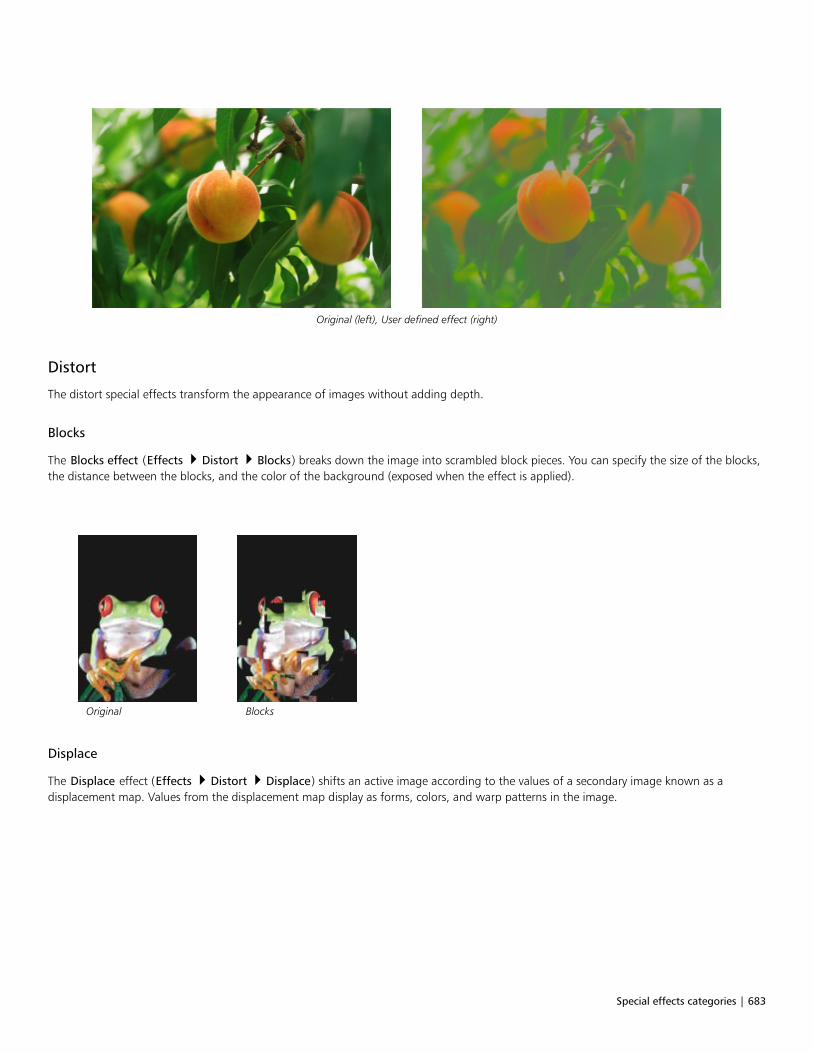
Special effects categories | 683
Original (left), User defined effect (right)
Distort
The distort special effects transform the appearance of images without adding depth.
Blocks
The Blocks effect (Effects Distort Blocks) breaks down the image into scrambled block pieces. You can specify the size of the blocks,the distance between the blocks, and the color of the background (exposed when the effect is applied).
Original Blocks
Displace
The Displace effect (Effects Distort Displace) shifts an active image according to the values of a secondary image known as adisplacement map. Values from the displacement map display as forms, colors, and warp patterns in the image.
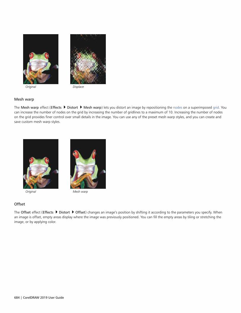
684 | CorelDRAW 2019 User Guide
Original Displace
Mesh warp
The Mesh warp effect (Effects Distort Mesh warp) lets you distort an image by repositioning the nodes on a superimposed grid. Youcan increase the number of nodes on the grid by increasing the number of gridlines to a maximum of 10. Increasing the number of nodeson the grid provides finer control over small details in the image. You can use any of the preset mesh warp styles, and you can create andsave custom mesh warp styles.
Original Mesh warp
Offset
The Offset effect (Effects Distort Offset) changes an image’s position by shifting it according to the parameters you specify. Whenan image is offset, empty areas display where the image was previously positioned. You can fill the empty areas by tiling or stretching theimage, or by applying color.

Special effects categories | 685
Original Offset
Pixelate
The Pixelate effect (Effects Distort Pixelate) breaks an image into square, rectangular, or circular cells. The Pixelate effect is also a presetlens type.
Original Pixelate
Ripple
The Ripple effect (Effects Distort Ripple) distorts an image with one or more waves. You can specify the strength of the primary waveto set the warping of the image or add an additional perpendicular wave to increase the distortion.
Original Ripple
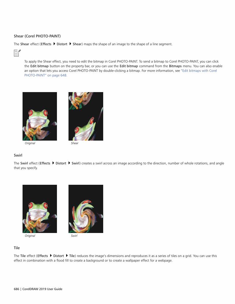
686 | CorelDRAW 2019 User Guide
Shear (Corel PHOTO-PAINT)
The Shear effect (Effects Distort Shear) maps the shape of an image to the shape of a line segment.
To apply the Shear effect, you need to edit the bitmap in Corel PHOTO-PAINT. To send a bitmap to Corel PHOTO-PAINT, you can clickthe Edit bitmap button on the property bar, or you can use the Edit bitmap command from the Bitmaps menu. You can also enablean option that lets you access Corel PHOTO-PAINT by double-clicking a bitmap. For more information, see “Edit bitmaps with CorelPHOTO-PAINT” on page 648.
Original Shear
Swirl
The Swirl effect (Effects Distort Swirl) creates a swirl across an image according to the direction, number of whole rotations, and anglethat you specify.
Original Swirl
Tile
The Tile effect (Effects Distort Tile) reduces the image’s dimensions and reproduces it as a series of tiles on a grid. You can use thiseffect in combination with a flood fill to create a background or to create a wallpaper effect for a webpage.

Special effects categories | 687
Original Tile
Wet paint
The Wet paint effect (Effects Distort Wet paint) creates the illusion of wet paint on images. You can specify the size of the drips andthe range of colors that are affected in the image.
Original Wet Paint
Whirlpool
The Whirlpool effect (Effects Distort Whirlpool) applies a fluid, swirling pattern across an image. You can use a preset whirlpoolstyle, or you can create a custom style by setting the smear length, spacing, twist, and streak detail of the effect. You can also save customwhirlpool styles.
Original Whirlpool

688 | CorelDRAW 2019 User Guide
Wind
The Wind effect (Effects Distort Wind) blurs an image in a specific direction, creating the effect of wind blowing across the image. Youcan specify the strength and direction of the blur, as well as the transparency of the effect.
Original Wind
Noise
In bitmap editing, noise is defined as the random pixels that display across an image, which resemble static on television screens. The noisespecial effects let you create, control, or eliminate noise.
To apply the effects that are labeled with ‘Corel PHOTO-PAINT’, you need to edit the bitmap in Corel PHOTO-PAINT. To send a bitmapto Corel PHOTO-PAINT, you can click the Edit bitmap button on the property bar, or you can use the Edit bitmap command fromthe Bitmaps menu. You can also enable an option that lets you access Corel PHOTO-PAINT by double-clicking a bitmap. For moreinformation, see “Edit bitmaps with Corel PHOTO-PAINT” on page 648.
Add noise
The Add noise effect (Effects Noise Add noise) creates a granular effect that adds texture to a flat or overly blended image. You canspecify the type and amount of noise that is added to the image.
Original Add noise
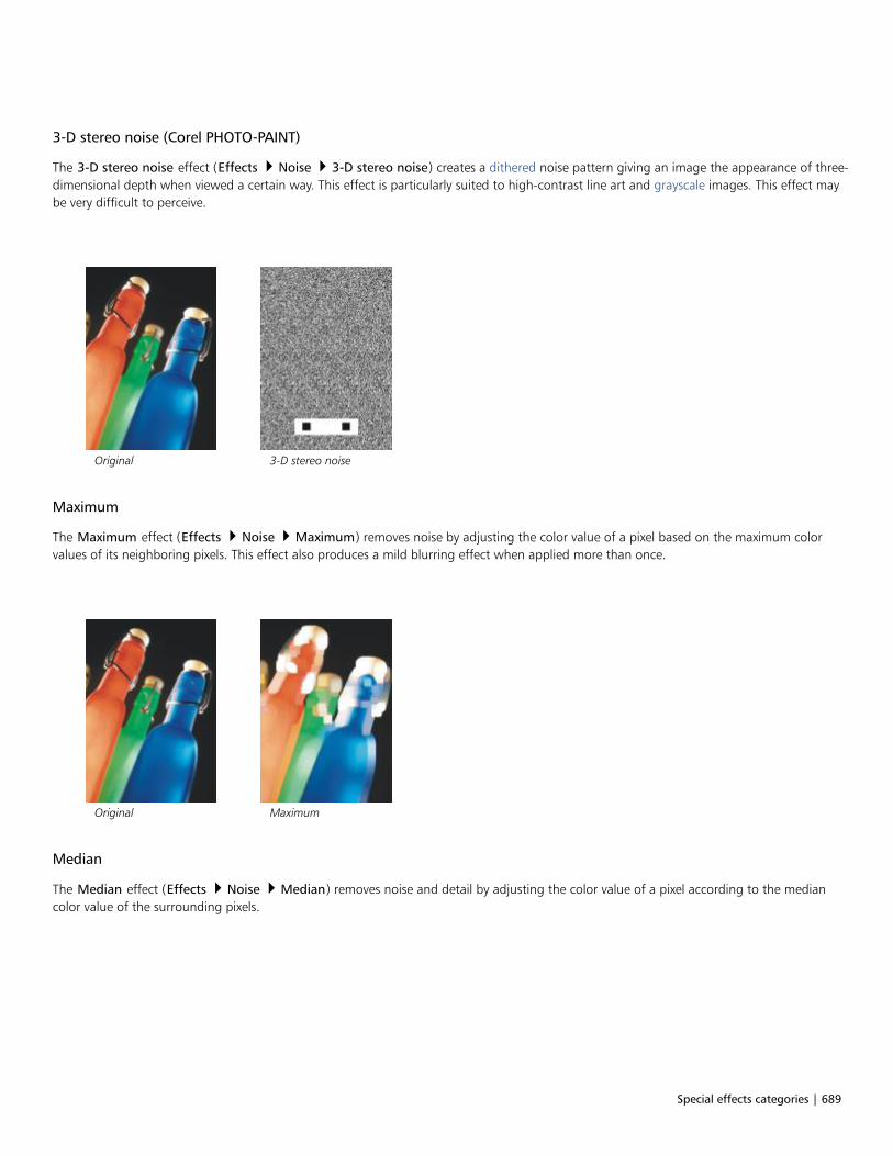
Special effects categories | 689
3-D stereo noise (Corel PHOTO-PAINT)
The 3-D stereo noise effect (Effects Noise 3-D stereo noise) creates a dithered noise pattern giving an image the appearance of three-dimensional depth when viewed a certain way. This effect is particularly suited to high-contrast line art and grayscale images. This effect maybe very difficult to perceive.
Original 3-D stereo noise
Maximum
The Maximum effect (Effects Noise Maximum) removes noise by adjusting the color value of a pixel based on the maximum colorvalues of its neighboring pixels. This effect also produces a mild blurring effect when applied more than once.
Original Maximum
Median
The Median effect (Effects Noise Median) removes noise and detail by adjusting the color value of a pixel according to the mediancolor value of the surrounding pixels.

690 | CorelDRAW 2019 User Guide
Original Median
Minimum
This effect (Effects Noise Minimum) removes noise by adjusting the color value of a pixel, based on the minimum color values of itsneighboring pixels.
Original Minimum
Tune noise (Corel PHOTO-PAINT)
The Tune noise effect (Effects Noise Tune noise) lets you apply any of nine noise effects. Each effect is represented by a thumbnailwhich lets you preview the image as you apply an effect.
Original Tune noise

Special effects categories | 691
Remove Noise
The Remove Noise effect (Effects Noise Remove Noise) lets you remove noise from scanned images. Noise is the speckled effectproduced by scanning or video-capturing.
Original Remove noise
Remove Moire
The Remove Moire effect (Effects Noise Remove Moire) lets you remove moiré from images. Moiré is the wave pattern produced whenhalftone screens of two different frequencies are superimposed on the same image.
Original Remove moire
Sharpen
You can sharpen images to increase contrast, enhance image edges, or reduce shading. Sharpening is usually done after adjusting the colorand tone of an image and after resampling or resizing. For more information about sharpening images, see the Corel PHOTO-PAINT help.
Adaptive unsharp
The Adaptive unsharp effect (Effects Sharpen Adaptive unsharp) lets you accentuate edge detail by analyzing the values ofneighboring pixels. This filter preserves most image detail, but its effect is most apparent in high-resolution images.

692 | CorelDRAW 2019 User Guide
Original Adaptive unsharp
Directional sharpen
The Directional sharpen effect (Effects Sharpen Directional sharpen) lets you enhance the edges of an image without creating agrainy effect.
Original Directional sharpen
High pass
The High pass effect (Effects Sharpen High pass) lets you remove image detail and shading to give an image a glowing quality byemphasizing its highlights and luminous areas. However, it can also affect the color and tone of the image.
Original High pass
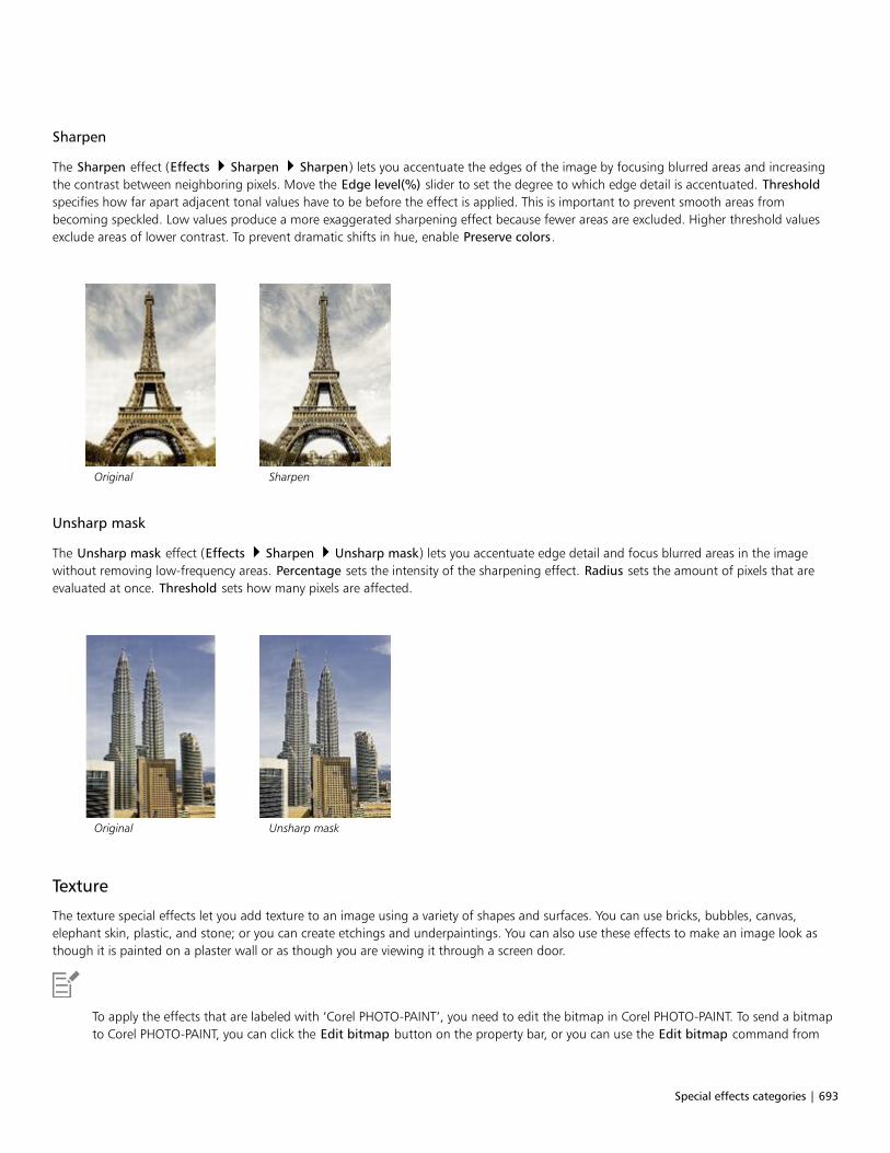
Special effects categories | 693
Sharpen
The Sharpen effect (Effects Sharpen Sharpen) lets you accentuate the edges of the image by focusing blurred areas and increasingthe contrast between neighboring pixels. Move the Edge level(%) slider to set the degree to which edge detail is accentuated. Thresholdspecifies how far apart adjacent tonal values have to be before the effect is applied. This is important to prevent smooth areas frombecoming speckled. Low values produce a more exaggerated sharpening effect because fewer areas are excluded. Higher threshold valuesexclude areas of lower contrast. To prevent dramatic shifts in hue, enable Preserve colors.
Original Sharpen
Unsharp mask
The Unsharp mask effect (Effects Sharpen Unsharp mask) lets you accentuate edge detail and focus blurred areas in the imagewithout removing low-frequency areas. Percentage sets the intensity of the sharpening effect. Radius sets the amount of pixels that areevaluated at once. Threshold sets how many pixels are affected.
Original Unsharp mask
Texture
The texture special effects let you add texture to an image using a variety of shapes and surfaces. You can use bricks, bubbles, canvas,elephant skin, plastic, and stone; or you can create etchings and underpaintings. You can also use these effects to make an image look asthough it is painted on a plaster wall or as though you are viewing it through a screen door.
To apply the effects that are labeled with ‘Corel PHOTO-PAINT’, you need to edit the bitmap in Corel PHOTO-PAINT. To send a bitmapto Corel PHOTO-PAINT, you can click the Edit bitmap button on the property bar, or you can use the Edit bitmap command from

694 | CorelDRAW 2019 User Guide
the Bitmaps menu. You can also enable an option that lets you access Corel PHOTO-PAINT by double-clicking a bitmap. For moreinformation, see “Edit bitmaps with Corel PHOTO-PAINT” on page 648.
Brick wall (Corel PHOTO-PAINT)
The Brick wall effect (Effects Texture Brick wall) groups pixels into a series of interlocking cells to make an image look like a painting ona brick wall. You can specify the brick size and the density of the brick pattern.
Original Brick wall
Bubbles (Corel PHOTO-PAINT)
The Bubbles effect (Effects Texture Bubbles) creates a bubbling foam on an image. You can specify the size of the bubbles and theamount of the image that is covered.
Original Bubbles
Canvas (Corel PHOTO-PAINT)
The Canvas effect (Effects Texture Canvas) applies a textured surface to an image by letting you use another image as a canvas. Youcan choose a preset canvas map, or you can load any image as a canvas map. For best results, choose images that have high to mediumcontrast.

Special effects categories | 695
Original Canvas
Cobblestone
The Cobblestone effect (Effects Texture Cobblestone) makes an image look as though it was created with cobblestones. You canspecify the size, spacing, and granularity of the cobblestones.
Original Cobblestone
Elephant skin
The Elephant skin effect (Effects Texture Elephant skin) gives an image a wrinkled look by creating an overlay of wavy lines. You canspecify the age of the elephant skin (up to 100 years) as well as the skin color.
Original Elephant skin
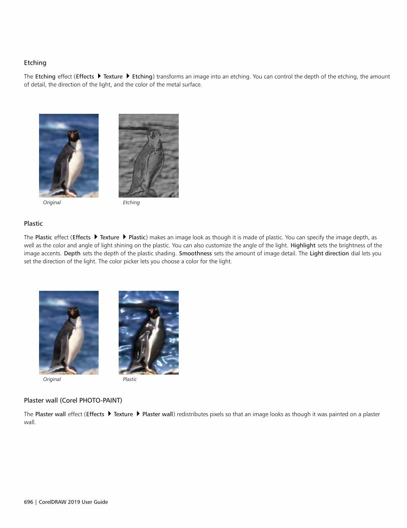
696 | CorelDRAW 2019 User Guide
Etching
The Etching effect (Effects Texture Etching) transforms an image into an etching. You can control the depth of the etching, the amountof detail, the direction of the light, and the color of the metal surface.
Original Etching
Plastic
The Plastic effect (Effects Texture Plastic) makes an image look as though it is made of plastic. You can specify the image depth, aswell as the color and angle of light shining on the plastic. You can also customize the angle of the light. Highlight sets the brightness of theimage accents. Depth sets the depth of the plastic shading. Smoothness sets the amount of image detail. The Light direction dial lets youset the direction of the light. The color picker lets you choose a color for the light.
Original Plastic
Plaster wall (Corel PHOTO-PAINT)
The Plaster wall effect (Effects Texture Plaster wall) redistributes pixels so that an image looks as though it was painted on a plasterwall.
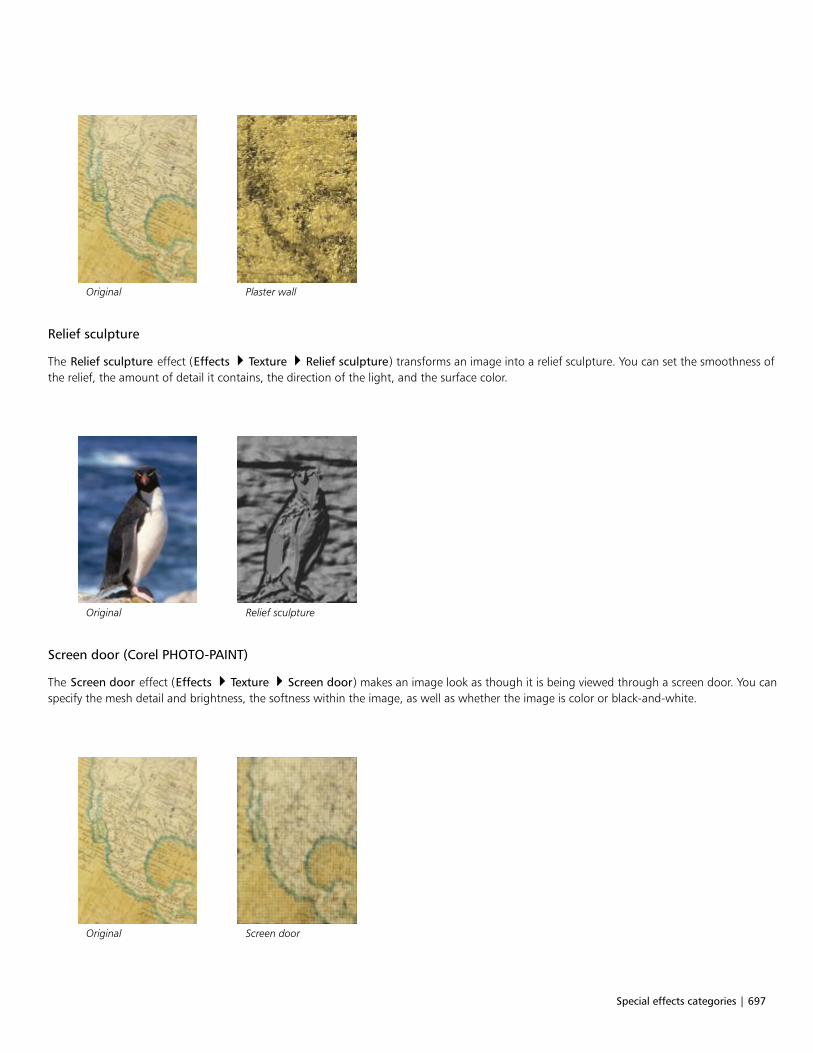
Special effects categories | 697
Original Plaster wall
Relief sculpture
The Relief sculpture effect (Effects Texture Relief sculpture) transforms an image into a relief sculpture. You can set the smoothness ofthe relief, the amount of detail it contains, the direction of the light, and the surface color.
Original Relief sculpture
Screen door (Corel PHOTO-PAINT)
The Screen door effect (Effects Texture Screen door) makes an image look as though it is being viewed through a screen door. You canspecify the mesh detail and brightness, the softness within the image, as well as whether the image is color or black-and-white.
Original Screen door

698 | CorelDRAW 2019 User Guide
Stone
The Stone effect (Effects Texture Stone) gives an image a stone texture. You can specify the amount of detail, the density of thepattern, and the angle of the light hitting an image. You can apply a preset stone style or create and save a custom stone style as a preset.
Original Stone
Underpainting (Corel PHOTO-PAINT)
The Underpainting effect (Effects Texture Underpainting) makes an image look like a painting created on a canvas that is subsequentlycovered with layers of paint. You can specify the degree to which the original image is painted over and adjust the brightness of the image.
Original Underpainting

Bitmap color modes | 699
Bitmap color modes
Changing an image to another color mode, such as RGB, CMYK, or Grayscale, changes a bitmap’s color structure.
This section contains the following topics:• “Change the color mode of bitmaps” (page 699)• “Change bitmaps to black-and-white” (page 700)• “Change bitmaps to duotones” (page 701)• “Change bitmaps to the paletted color mode” (page 702)
Change the color mode of bitmaps
The colors of the images that you work with in CorelDRAW are based on color modes. Color modes define the color characteristics of imagesand are described by their component colors. The CMYK color mode is composed of cyan, magenta, yellow, and black values; the RGB colormode is composed of red, green, and blue values.
Although you may not be able to see the difference between an image in the CMYK color mode and an image in the RGB color mode onscreen, the images are quite different. For the same image dimensions, an RGB image has a smaller file size than a CMYK image, and theRGB color space, or gamut, can display more colors. Therefore, images intended for the web or desktop printers, which require accuratecolor fidelity, are generally in RGB mode. Where accurate print reproduction is needed, such as on a commercial printing press, images aregenerally created in CMYK mode. Paletted color images attempt to preserve color fidelity while reducing the file size, making them ideal foron-screen uses.
Each time you convert an image, you may lose color information. For this reason, you should save an edited image before you change it to adifferent color mode. For more information about color modes, see “Color models” on page 347.
CorelDRAW supports the following color modes:• Black and White (1-bit)• Duotone (8-bit)• Grayscale (8-bit)• Paletted (8-bit)• RGB Color (24-bit)• Lab Color (24-bit)• CMYK Color (32-bit)
700 | CorelDRAW 2019 User Guide
To change the color mode of a bitmap
1 Click a bitmap.
2 Click Bitmaps Mode, and click a color mode.
The current mode of the selected bitmap is not available in the menu.
Change bitmaps to black-and-white
You can change any image to a black-and-white image. In addition to conversion settings such as threshold, screen type, and intensity, thereare seven conversion options that affect how the converted images will look.
Conversion
Line art Produces a high-contrast, black-and-white image. Colors witha grayscale value lower than the threshold value that you setchange to black, while colors with a grayscale value higher than thethreshold value change to white.
Ordered Organizes the gray levels into repeating geometric patterns of blackand white pixels. Solid colors are emphasized and image edges arehard. This option is best suited for uniform colors.
Halftone Creates different shades of gray by varying the pattern of black andwhite pixels in an image. You can choose the screen type, angle forthe halftone, lines per unit, and the unit of measure.
Cardinality-Distribution Creates a textured look by applying a calculation and distributingthe result to the screen.
Jarvis Applies the Jarvis algorithm to the screen. This form of errordiffusion is suitable for photographic images.
Stucki Applies the Stucki algorithm to the screen. This form of errordiffusion is suitable for photographic images.
Floyd-Steinberg Applies the Floyd-Steinberg algorithm to the screen. This form oferror diffusion is suitable for photographic images.
To change a bitmap to a black-and-white image
1 Click a bitmap.
2 Click Bitmaps Mode Black-and-white (1-bit).
3 Choose an option from the Conversion method list box.
4 Move the Intensity slider.

Bitmap color modes | 701
The Intensity slider is not available for the Halftone conversion option.
Change bitmaps to duotones
To convert an image to a duotone, you change a bitmap to the grayscale color mode and enhance it using one to four additional colors,giving the image greater tonal depth.
The following four variations of the color mode correspond to the number of additional inks:• Monotone — a grayscale image colored with a single tone• Duotone — a grayscale image colored with two tones. In most cases, one is black and the other is colored.• Tritone — a grayscale image colored with three tones. In most cases, one is black and the other two are colored.• Quadtone — a grayscale image colored with four tones. In most cases, one is black and the other three are colored.
The four color mode variations. From left to right: the original image, monotone, duotone, tritone, and quadtone.
Adjusting tone curves
When you change an image to a duotone, a tone curve grid that represents the dynamic tone curves that are used throughout theconversion is displayed. The horizontal plane (x-axis) displays the 256 possible shades of gray in a grayscale image (0 is black; 255 is white).The vertical plane (y-axis) indicates the intensity of a color (from 0 to 100 percent) that is applied to the corresponding grayscale values. Forexample, a grayscale pixel with a color value of 25 is printed with a 25-percent tint of the color. By adjusting the tone curves, you can controlthe color and intensity of the tone that is added to an image.
Saving and loading inks
You can save an adjusted duotone tone curve and ink settings and then load them for use with other bitmaps.
Specifying how overprint colors display
When you change an image to a duotone, you can specify the colors to overprint when you print an image. Overprint colors are used topreserve color integrity when inks overlap. When you display the image, each color is applied on the screen in sequence, creating a layeredeffect.
You can view all instances in which the colors you choose for the duotone conversion overlap. Associated with each instance is the color thatis produced by the overlap. You can also choose new overprint colors to see how they overlap.
Duotones hold their color ink information when you save to Encapsulated PostScript (EPS), Portable Document Format (PDF) and CorelDRAW(CDR) file formats. Other file formats don’t support duotone images.
702 | CorelDRAW 2019 User Guide
To change an image to a duotone
1 Click a bitmap.
2 Click Bitmaps Mode Duotone (8-bit).
3 Click the Curves tab.
4 Choose a duotone type from the Type list box.
5 Click an ink color in the Type window, and click Edit.
6 In the Select color dialog box, choose a color, and click OK.
If you want to adjust the color’s tone curve, click the ink tone curve on the grid to add a node, and drag the node to adjust thepercentage of color at that point on the curve.
7 Repeat steps 5 and 6 for each ink color you want to use.
You can also
Display all the ink tone curves on the grid. Enable the Show all check box.
Save the ink settings Click Save. Choose the disk and folder where you want to save thefile, and type a filename in the File name box.
Specify how overprint colors display Click the Overprint tab, and enable the Use overprint check box.Double-click the color you want to edit, and choose a new color.
You can load preset ink colors by clicking Load, locating the file in which the ink settings are stored, and double-clicking the filename.
Change bitmaps to the paletted color mode
The paletted color mode, also called indexed color mode, is sometimes used for images on the web. When you convert an image to thepaletted color mode, a fixed color value is assigned to each pixel. These values are stored in a compact color table, or palette, containing upto 256 colors. As a result, the paletted color mode image contains less data than a 24-bit color mode image, and it has a smaller file size.Conversion to paletted color mode works best on images that have a limited range of colors.
Choosing, editing, and saving a color palette
When you change an image to the paletted color mode, you can use a predefined palette, or you can customize a color palette by replacingindividual colors.
Saving conversion settings
After you choose a color palette and set the dithering and range sensitivity for changing an image to the paletted color mode, you can savethe settings as a conversion preset that you can use with other images. You can add as many conversion presets as you want.
The color palette you use is called the processed color palette. It can be saved for use with other images.
For more information about the predefined color palettes available for the paletted color mode, see “Palette types” on page 703. For moreinformation about creating and opening custom color palettes, see “Create and edit color palettes” on page 357.
Bitmap color modes | 703
Dithering
Changing images to the paletted color mode lets you use dithering to enhance color information. Dithering places pixels with specific colorsor values relative to other pixels of a specific color. The relationship of one colored pixel to another creates the appearance of additionalcolors that do not exist in the color palette.
You can use two types of dithering: ordered dithering and error diffusion. Ordered dithering approximates color blends using fixed dotpatterns; as a result, solid colors are emphasized and edges appear harder. Error diffusion scatters pixels irregularly, making edges and colorssofter. Jarvis, Stucki, and Floyd-Steinberg are conversion options that provide error diffusion.
The Ordered dithering option applies more quickly than the error diffusion options (Jarvis, Stucki, and Floyd-Steinberg) but is less accurate.
Specifying a range-sensitivity color
You can change an image to the paletted color mode and specify a focus color and a range sensitivity for the focus color, so that the focuscolor and colors that fall within the range settings are included in the processed color palette. You can also specify how much emphasis toplace on the range sensitivity. Because the palette has a maximum of 256 colors, emphasizing a focus color reduces the number of colorsthat fall outside the range sensitivity.
Palette types
The table below outlines available palette types.
Palette type Description
Uniform Colors Provides a range of 256 colors with equal parts of red, green, andblue
Standard VGA Provides the Standard VGA 16-color palette
Adaptive Provides colors original to the image and preserves the individualcolors (the entire color spectrum) in the image
Optimized Creates a color palette based on the highest percentage of colorsin the image. You can also specify a range-sensitivity color forthe color palette. This is the most common color palette forphotographic images.
Grayscale Provides 256 shades of gray, ranging from black to white
System Provides the predefined palette of colors used by the operatingsystem
Custom Lets you add colors to create a customized color palette
To change an image to the paletted color mode
1 Click a bitmap.
2 Click Bitmaps Mode Paletted (8-bit).
3 Click the Options tab.
4 Choose a color palette type from the Palette list box.

704 | CorelDRAW 2019 User Guide
5 Choose an option from the Dithering list box.
6 Move the Dither intensity slider.
If you want to save the conversion settings as a preset, click the Add preset button, and type a name in the Save preset box.
You can achieve better color fidelity by choosing the palette you want to use when you change an image to a paletted bitmap orwhen you export a GIF or PNG. For example, the standard color palette provides more colors than necessary for an image with alimited range of colors, but you can choose an optimized palette to ensure that color representation is accurate.
You can choose a custom color palette by clicking Open, locating the color palette file you want, and double-clicking the filename.
You can load preset conversion settings by choosing a preset from the Preset list box.
To create a custom processed color palette
1 Click a bitmap.
2 Click Bitmaps Mode Paletted (8-bit).
3 Click the Processed palette tab.
4 Click a color, and click the Edit button.
5 In the Color table, specify the color you want, and click Edit color.
6 Edit the color, and click OK.
7 Click the Save palette as button to save the new palette.
8 Choose the folder where you want to store the color palette.
9 Type a name in the File name box, and click Save.
To change a bitmap by setting range sensitivity
1 Click a bitmap.
2 Click Bitmaps Mode Paletted (8-bit).
3 Click the Options tab.
4 Choose Optimized from the Palette list box.
5 Enable the Color range sensitivity to check box.
6 Click the Eyedropper tool , and click a color in the image.
7 Click the Range sensitivity tab.
8 Move the range sensitivity sliders.
If you want to preview the color palette, click the Processed palette tab.

Trace | 705
Trace
CorelDRAW lets you trace bitmaps to convert them to fully editable and scalable vector graphics. You can trace artwork, photos, scannedsketches, or logos and then easily integrate them into your designs.
For information about the difference between vector graphics and bitmaps, see “Vector graphics and bitmaps” on page 43.
This section contains the following topics:• “Trace bitmaps” (page 705)• “PowerTRACE controls” (page 708)• “Preview traced results” (page 709)• “Fine-tune traced results” (page 710)• “Adjust colors in traced results” (page 712)• “Default tracing options” (page 714)• “Tips for tracing bitmaps” (page 715)
Trace bitmaps
You can trace a bitmap in one step by using the Quick Trace command. Alternatively, you can choose a suitable tracing method and presetstyle and then use the PowerTRACE® controls to preview and adjust the traced results. CorelDRAW offers two methods for tracing bitmaps:Centerline Trace and Outline Trace.
Choosing a tracing method
The Centerline Trace method uses unfilled closed and open curves (strokes) and is suitable for tracing technical illustrations, maps, linedrawings, and signatures. This method is also referred to as “stroke tracing.”
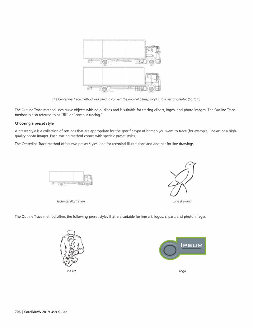
706 | CorelDRAW 2019 User Guide
The Centerline Trace method was used to convert the original bitmap (top) into a vector graphic (bottom).
The Outline Trace method uses curve objects with no outlines and is suitable for tracing clipart, logos, and photo images. The Outline Tracemethod is also referred to as “fill” or “contour tracing.”
Choosing a preset style
A preset style is a collection of settings that are appropriate for the specific type of bitmap you want to trace (for example, line art or a high-quality photo image). Each tracing method comes with specific preset styles.
The Centerline Trace method offers two preset styles: one for technical illustrations and another for line drawings.
Technical illustration Line drawing
The Outline Trace method offers the following preset styles that are suitable for line art, logos, clipart, and photo images.
Line art Logo

Trace | 707
Detailed logo Clipart
Low-quality image High-quality image
Adjusting traced results
You can adjust the traced results by using the controls in the PowerTRACE dialog box. For more information, see “Fine-tune traced results ”on page 710 and “Adjust colors in traced results” on page 712.
To trace a bitmap by using Quick Trace
1 Select a bitmap.
2 Click Bitmaps Quick Trace.
You can also trace a bitmap in one step by clicking the Trace Bitmap button on the property bar and clicking Quick Trace.
You can change the settings that are used by Quick Trace. For more information, see “Default tracing options” on page 714.
To trace a bitmap by using the Centerline Trace method
1 Select a bitmap.
2 Click Bitmaps Centerline Trace, and click one of the following:
• Technical Illustration — to trace black-and-white illustrations with thin, faint lines
• Line Drawing — to trace black-and-white sketches with thick, prominent lines
If necessary, adjust the traced results by using the controls in the PowerTRACE dialog box.
You can also access PowerTRACE from the Trace Bitmap button on the property bar.
To trace a bitmap by using the Outline Trace method
1 Select a bitmap.
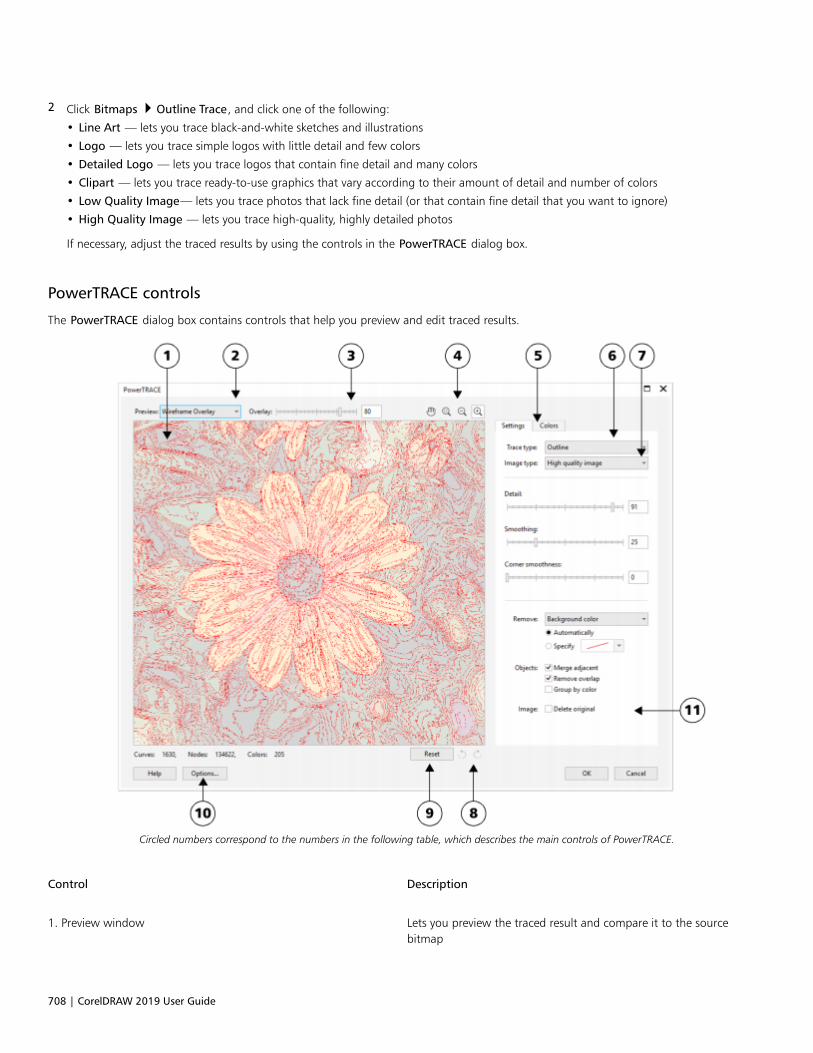
708 | CorelDRAW 2019 User Guide
2 Click Bitmaps Outline Trace, and click one of the following:
• Line Art — lets you trace black-and-white sketches and illustrations
• Logo — lets you trace simple logos with little detail and few colors
• Detailed Logo — lets you trace logos that contain fine detail and many colors
• Clipart — lets you trace ready-to-use graphics that vary according to their amount of detail and number of colors
• Low Quality Image— lets you trace photos that lack fine detail (or that contain fine detail that you want to ignore)
• High Quality Image — lets you trace high-quality, highly detailed photos
If necessary, adjust the traced results by using the controls in the PowerTRACE dialog box.
PowerTRACE controls
The PowerTRACE dialog box contains controls that help you preview and edit traced results.
Circled numbers correspond to the numbers in the following table, which describes the main controls of PowerTRACE.
Control Description
1. Preview window Lets you preview the traced result and compare it to the sourcebitmap

Trace | 709
Control Description
2. Preview list box Lets you choose one of the following previewing options:•Before and after — lets you display both the source bitmap and
the traced result•Large preview — lets you preview a traced result in a single-pane
preview window•Wireframe overlay — lets you display a wireframe (outline) view
of the traced result on top of the source bitmap
3. Overlay slider Controls visibility of the source bitmap below the wireframe whenthe Wireframe overlay option is selected
4. Zooming and panning tools Let you zoom in and out of an image displayed in the previewwindow, pan an image displayed at a zoom level higher than100%, and fit an image to the preview window.
5. Colors page Contains controls for modifying the colors of the traced results.For more information, see “Adjust colors in traced results” on page712.
6. Trace type list box Lets you change the tracing method
7. Image type list box Lets you choose a suitable preset style for the image to be traced.The available preset styles change, depending on the tracingmethod you choose.
8. Undo and Redo buttons Let you undo and redo the last action you performed
9. Reset button Lets you restore the first settings used to trace the source bitmap
10. Options button Lets you access the PowerTRACE options page in the Optionsdialog box to set default tracing options. For more information, see“Default tracing options” on page 714.
11. Settings page Contains controls for adjusting the traced results. The Traced resultdetails area on the Settings page lets you view the number ofobjects, nodes, and colors in the traced result while you are makingadjustments.
For more information about adjusting traced results, see “Fine-tunetraced results” on page 710.
Preview traced results
By default, PowerTRACE displays both the source bitmap and the traced result. You can also preview a traced result in a single-pane previewwindow, or you can display a wireframe (outline) view of the traced graphic on top of the source bitmap.
You can zoom in and out to get a better view of the graphic, and you can pan to view areas that fall outside the preview window.

710 | CorelDRAW 2019 User Guide
To preview traced results
• In PowerTRACE, choose one of the following options from the Preview list box:
• Before and after — displays both the source bitmap and the traced result
• Large preview — displays a preview of the traced result in PowerTRACE
• Wireframe overlay — displays a wireframe (outline) preview of the traced result on top of the original bitmap. To control the visibilityof the original bitmap underneath the wireframe, move the Overlay slider.
You can also
Zoom in or out Click the Zoom in or Zoom out tool, and click in the
preview window.
Fit an image in the preview window Click the Zoom to fit tool.
Pan a graphic Click the Pan tool , and drag the graphic.
Fine-tune traced results
PowerTRACE lets you perform the following adjustments to fine-tune your trace results.
Adjusting detail and smoothing
You can adjust the amount of detail in the traced result and smooth curved lines. When you adjust detail, you change the number of objectsin the traced result. If you used the Outline Trace method to trace the bitmap, adjusting the traced result also changes the number of colors.Smoothing changes the number of nodes in the traced result. You can also control the appearance of corners in the traced result by settingthe threshold for corner smoothness.
Outline tracing with a low detail value (left); outline tracing with a high detail value (right)
Completing a trace
By default, the source bitmap is preserved after being traced, and objects in the traced result are automatically grouped. You can have thesource bitmap automatically deleted after the trace is complete.
Trace | 711
Removing and preserving the background
You can choose to remove or preserve the background in the traced result. With the Outline Trace method, you can also specify thebackground color to be removed. If the background color around the edges is removed but some background color still shows throughsome areas of the image, you can remove the background from the entire image.
Setting other Outline Trace options
By default, object areas that are hidden from view by overlapping objects are removed from the traced result. You can choose to keep theunderlying object areas. This feature is useful for traced results that will be output to vinyl cutters and screen printers.
To reduce the number of objects in the traced result, you can combine adjacent objects of the same color. You can also group objects of thesame color so that you can manipulate them more easily in CorelDRAW.
Undoing and redoing actions
You can adjust the settings in PowerTRACE and retrace a bitmap as many times as necessary until you are satisfied with the result. If youmake a mistake, you can undo or redo an action, or you can revert to the first traced result.
To fine-tune traced results
1 Select a bitmap.
2 Do one of the following:
• Click Bitmaps Centerline Trace, and click a command.
• Click Bitmaps Outline Trace, and click a command.
3 Move any of the following sliders:
• Detail — lets you control the amount of original detail that is preserved in the traced result. Higher values maintain more detail andresult in a greater number of objects and colors; lower values discard some detail and result in fewer objects.
• Smoothing — lets you smooth curved lines and control the number of nodes in the traced result. Higher values result in fewer nodesand produce curves that do not closely follow the lines in the source bitmap. Lower values result in more nodes and produce moreaccurate trace results.
• Corner smoothness — This slider works in conjunction with the Smoothing slider and lets you control the appearance of corners.Lower values maintain the appearance of corners; higher values smooth corners.
You can also
Change the tracing method Choose a method from the Trace type list box.
Change the preset style Choose a preset style from the Image type list box.
Keep the source bitmap after a trace Disable the Delete original check box.
Discard or preserve the background in the traced result Enable or disable the Remove background check box.
Specify the background color you want to remove (Outline Trace) Enable the Specify option, open the color picker, click the
Eyedropper tool , and click a color in the preview window.
To specify an additional background color to remove, hold downShift, and click a color in the preview window.
The last specified color is displayed next to the Eyedropper tool.
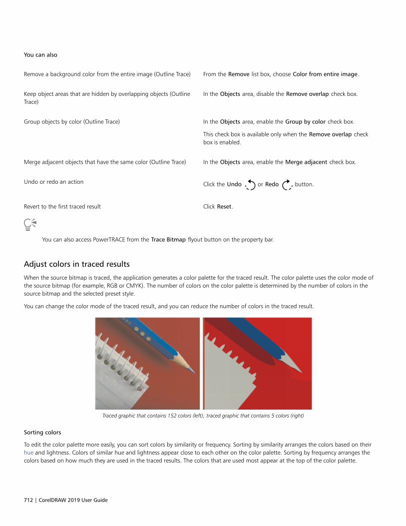
712 | CorelDRAW 2019 User Guide
You can also
Remove a background color from the entire image (Outline Trace) From the Remove list box, choose Color from entire image.
Keep object areas that are hidden by overlapping objects (OutlineTrace)
In the Objects area, disable the Remove overlap check box.
Group objects by color (Outline Trace) In the Objects area, enable the Group by color check box.
This check box is available only when the Remove overlap checkbox is enabled.
Merge adjacent objects that have the same color (Outline Trace) In the Objects area, enable the Merge adjacent check box.
Undo or redo an action Click the Undo or Redo button.
Revert to the first traced result Click Reset.
You can also access PowerTRACE from the Trace Bitmap flyout button on the property bar.
Adjust colors in traced results
When the source bitmap is traced, the application generates a color palette for the traced result. The color palette uses the color mode ofthe source bitmap (for example, RGB or CMYK). The number of colors on the color palette is determined by the number of colors in thesource bitmap and the selected preset style.
You can change the color mode of the traced result, and you can reduce the number of colors in the traced result.
Traced graphic that contains 152 colors (left); traced graphic that contains 5 colors (right)
Sorting colors
To edit the color palette more easily, you can sort colors by similarity or frequency. Sorting by similarity arranges the colors based on theirhue and lightness. Colors of similar hue and lightness appear close to each other on the color palette. Sorting by frequency arranges thecolors based on how much they are used in the traced results. The colors that are used most appear at the top of the color palette.
Trace | 713
Selecting colors
You can select a color by clicking it on the color palette of the traced result or by clicking the color in the preview window. You can alsoselect multiple colors.
Editing, merging, and deleting colors
When editing a color, you can choose a color from a color model that is different from that of other colors on the palette. For example, ifyou are editing a color in an RGB traced result, you can change the color to a spot color, creating a mixed color palette. This feature is usefulwhen you are preparing the traced result for commercial printing.
With the Outline Trace method, you can also merge and delete colors.
By default, when two or more colors are merged, their color values are averaged to produce a new color. The merged colors are replacedby the new color. However, you can change the default setting to replace the colors to be merged with the first color that you selected. Forinformation on how to change the default setting, see “Default tracing options” on page 714.
When you delete a color from the color palette, the deleted color is replaced by the next color on the color palette.
Using and creating color palettes
If you want the traced result to contain only colors from a specific color palette, you can open that color palette in PowerTRACE. The colorsof the traced result are replaced by their closest match on the color palette.
After you edit the color palette of the traced graphic, you can save it to create a custom color palette for later use.
To adjust the colors of a traced result
1 Select a bitmap.
2 Do one of the following:
• Click Bitmaps Centerline Trace, and click a command.
• Click Bitmaps Outline Trace, and click a command.
3 Click the Colors tab, and perform any of the following tasks.
To Do the following
Change the color mode Choose a color mode from the Color Mode list box.
Reduce the number of colors in a traced result (Outline Trace) Type a value in the Number of colors box, and click outside thebox.
Select a color Do one of the following:•Click a color on the color palette. The selected color swatch
button appears pressed.•Click the Eyedropper tool , and click a color in the preview
window. A marquee appears around the selected color. To selectan additional color, hold down Shift, and click a color in thepreview window. To deselect a color, hold down Ctrl, and click acolor.
Select a range of adjacent colors Hold down Shift, and click the first and last color swatch in therange you are selecting on the color palette.

714 | CorelDRAW 2019 User Guide
To Do the following
Select multiple nonadjacent colors Hold down Ctrl, and click the nonadjacent color swatches on thecolor palette.
Edit a color Select the color you want to edit, click Edit, and modify settings inthe Select color dialog box.
Merge colors (Outline Trace) Select the colors that you want to merge, and click Merge.
If you want to specify how to merge the colors, click Options toaccess the Options dialog box, and enable an option in the Mergecolors area.
Delete a color from a traced result (Outline Trace) Select a color, and click the Delete color button .
The deleted color is replaced by the next color on the color palette.
Use a custom color palette Click the Open color palette button , find the folder where
the palette is stored, and click a filename.
Each color of the traced graphic is mapped to a similar color on thecustom palette.
Create a custom color palette from the edited color palette of atraced result
Click the Save color palette button . In the Save palette as
dialog box, type a name in the File name box.
The number of colors cannot be reduced, and colors cannot be merged, when you use the Centerline Trace method.
To increase the number of colors in a traced result, you need to change the preset style or increase the amount of detail. Forinformation about how to change the preset style and the amount of detail, see “To fine-tune traced results” on page 711.
Default tracing options
You can enable any of the following tracing options.• Quick Trace method — You can change the default Quick Trace settings to any preset style, or to the most recently used settings.• Performance — This option determines how source bitmaps between 1 and 5 megapixels in size are handled, and how the quality of
the traced results is affected. The performance of PowerTRACE depends on the size and color depth of the source bitmaps as well as onthe available system memory. High-quality traced results require high-quality source bitmaps, which are often quite large. The larger thesource bitmap, the more resources are required. Bitmaps that are too large need to be downsampled before tracing, which may decreasethe image quality. To trace large bitmaps without sacrificing quality, you can set PowerTRACE to trace images as large as 5 megapixels(provided RAM is sufficient). To achieve maximum performance, you can set PowerTRACE to prompt you to downsample bitmaps largerthat 1 megapixel.
• Merge colors — You can choose whether to merge colors in a traced result by averaging their values or by replacing the colors to bemerged with the first color you select.

Trace | 715
To set default tracing options
1 Click Tools Options CorelDRAW.
2 Click PowerTRACE.
3 Perform any of the following tasks.
To Do the following
Choose a Quick Trace method From the Quick Trace method list box, choose a preset style or themost recently used settings.
Determine performance level and quality of a traced result Move the Optimize for slider to the left to increase performance,or to the right to increase the quality of the traced results. Thelowest value prompts you to downsample all bitmaps that exceed1 megapixel. The highest value prompts you to downsample allbitmaps that exceed 5 megapixels.
Choose how to merge colors in a traced result In the Merge colors area, enable an option. The Average colorsoption replaces the colors to be merged with a color of theiraverage value. The Replace with first selected color optionreplaces the colors to be merged with the first selected color.
You can also access the PowerTRACE page by clicking Options in PowerTRACE.
Tips for tracing bitmaps
The following tips can help you achieve high-quality trace results.• Use high-quality source bitmaps. If dithering or JPEG compression was used in the source bitmap, the bitmap may contain additional
noise. For best traced results, remove the noise before tracing the bitmap.• For best results when you use the Centerline Trace method, convert the bitmap to the black-and-white color mode before tracing. Note
that in this case you cannot adjust detail.• When tracing technical illustrations and sketches with faint lines, you can improve the results by applying the Find edges special effect to
the source bitmap. To do this, click Bitmaps Contour Find edges.• For outline tracing, reduce the color depth of the bitmap by changing the color mode, and then adjust the color and contrast.• You can adjust the traced results at any time, including during a trace, by changing the PowerTRACE settings.• To trace a specific area in a bitmap, use the Shape tool to define the area before clicking Bitmaps Trace bitmap.
• If important detail has been removed from the traced results, you can disable the Remove background check box on the Settings pageof PowerTRACE. You can also try enabling the Specify color option on the Settings page and sampling the color you want to specify as abackground color.
• If background color is removed around the edges but remains within image areas, from the Remove list box choose Color from entireimage.
• If too many colors or details are lost, move the Detail slider on the Settings page.• To preserve detail in bitmaps that have fine details, thin lines, and no anti-aliasing applied, choose Line art from the Image type list box
on the Settings page.

716 | CorelDRAW 2019 User Guide

RAW camera files | 717
RAW camera files
You can import and process RAW camera files in CorelDRAW.
This section contains the following topics:• “Use RAW camera files” (page 717)• “Import RAW camera files in CorelDRAW” (page 718)• “Adjust the color and tone of RAW camera files” (page 720)• “Sharpen RAW camera files and reduce noise” (page 723)• “Preview RAW camera files and obtain image information” (page 724)
You can also download AfterShot 3 HDR to edit and process RAW camera files. For more information, see “AfterShot 3 HDR” on page 89.
Use RAW camera files
RAW camera files contain picture data that is captured by the image censor of a digital camera. These files are called RAW because, unlikeJPEG and TIFF files, they contain minimal in-camera processing and need to be edited and prepared for printing in an image-editingapplication.
With RAW camera files, you can control the processing of image data, rather than having the camera make automatic color adjustments andconversions. You can adjust the white balance, tonal range, contrast, color saturation, and sharpness of a RAW image without any loss ofimage quality. In addition, you can reprocess RAW images at any time to achieve the results you want. In this sense, RAW camera files canbe compared to an exposed but undeveloped film.
To take advantage of RAW camera files, you need to set your camera to save files to its own RAW file format. CorelDRAW lets you importRAW camera files from supported camera models. Supported camera models include:• Canon EOS-1D X, Canon EOS 650D, Canon 5D Mark III, Canon G1-X, Canon ID-X, Canon EOS 6D, Canon A3300, Canon EOS C500,
Canon EOS SX50• Casio EX-ZR100• Fuji X-Pro1, Fuji X-S1, Fuji XS50, Fuji X20, Fuji X100S, Fuji SL1000, Fuji X-E1, and Fuji XF1• Olympus XZ-10• Pentax K-5 II (s)• Samsung EX2F, Samsung NX300, Samsung NX1000, Samsung NX20• Sigma SD1, Sigma SD15, Sigma DP cameras• Sony RX100
In addition, the Adobe’s lossy Digital Negative (DNG) file format and the Imacon Flexframe 3f format are now supported.

718 | CorelDRAW 2019 User Guide
For more information about supported cameras, visit the Corel Knowledge Base.
Import RAW camera files in CorelDRAW
When you open single or multiple RAW camera files in CorelDRAW, they are first displayed in the Camera RAW Lab. You can use the controlsin the Camera RAW Lab to adjust the color and tone of the RAW camera images. If you are satisfied with the adjustments of a file, you canapply the same adjustments to the remaining files.
After processing RAW camera files, you can edit them further by using the tools and effects available in CorelDRAW. Then, you can save theRAW camera files as TIFF or JPEG files, or you can save them to any other file format supported by CorelDRAW.
Note that RAW camera files cannot be saved to a RAW camera file format in CorelDRAW. Any changes made to the RAW camera files in theCamera RAW Lab are lost unless you save the files to a supported file format.
Processing RAW camera files
The Camera RAW Lab includes controls that are organized in a logical order for color correction and other adjustments of RAW cameraimages. It is recommended that you start from the top of the Color page and work your way down. Once you finish correcting the color andtone of your image, you can sharpen it and remove noise by using the controls on the Detail page. For information about the settings onthe Color page, see “Adjust the color and tone of RAW camera files” on page 720. For information about the settings on the Detail page,see “Sharpen RAW camera files and reduce noise” on page 723.

RAW camera files | 719
Camera RAW Lab: circled numbers correspond to the numbers in thefollowing table, which describes the main components of the lab.
Component Description
1. Rotation tools Let you rotate the image 90 degrees clockwise andcounterclockwise
2. Zooming and panning tools Let you zoom in and out of an image displayed in the previewwindow, pan an image displayed at a zoom level higher than100%, and fit an image to the preview window
720 | CorelDRAW 2019 User Guide
Component Description
3. Preview modes and Preview window Let you preview the adjustments made to a RAW camera image ina single or split window. To compare the original and the adjustedimage, you can display them side by side.
4. Color page Contains controls that let you adjust the color and tone of RAWcamera images to remove color casts and reveal hidden detail
5. Detail page Contains controls that let you remove noise from RAW cameraimages
6. Properties page Contains controls that let you view information about a RAWcamera image, such as size, color mode, and camera settings
7. Undo and Redo buttons Let you undo and redo the last action you performed
8. Reset button Lets you clear all corrections so that you can start with the originalRAW camera image
9. Create snapshot Lets you capture the corrected version of an image in a “snapshot”at any time. Thumbnails of the snapshots appear in a windowbelow the image.
10. Histogram Lets you preview the tonal range of the image.
To import a RAW camera file
1 Click File Import.
2 Select the RAW camera file or files that you want to import, and click Import.
3 In the Camera RAW Lab, adjust the color and tone of the RAW camera image. If necessary, you can also sharpen the image and reducethe amount of noise.
If you selected multiple RAW camera files and want to apply the same adjustments to all of them, enable the Apply to all remainingfiles check box.
You can rotate the image by clicking the Rotate left button or Rotate right button .
Adjust the color and tone of RAW camera files
You can adjust the color and tone of an image by using the following settings.
Color depth
Color depth refers to the number of colors an image can contain. One of the advantages of using RAW camera files is that they can containmore colors than photos saved as JPEG or TIFF files. This greater number of colors makes it easier to reproduce colors accurately, reveal detailin shadows, and adjust brightness levels.

RAW camera files | 721
The Camera RAW Lab lets you process the RAW camera files as 48-bit or 24-bit images. 48-bit images offer more accurate colorrepresentation and prevent loss of image quality during retouching. Note that some of the special effects available in CorelDRAW cannot beapplied to 48-bit images.
White balance
White balance is the process of removing unnatural color casts from images so that image colors appear as they do in real life. Whitebalance takes into consideration the lighting conditions in which a photo was taken and sets the color balance to produce realistic imagecolors.
By default, when a RAW camera file is brought into CorelDRAW, it reflects the camera setting for white balance. This setting appears as thepreset As shot in the White balance list box. If you are not satisfied with this setting, you can have the white balance adjusted automaticallyby choosing the preset Auto. You can also apply any of the following presets: Daylight, Cloudy, Shade, Tungsten, Fluorescent, or Flash.These presets let you simulate different lighting conditions.
RAW camera image with incorrect white balance (left); the same image with adjusted white balance (right)
In addition, you can use the Eyedropper tool to automatically adjust the contrast in an image according to the white or gray point that yousample in the preview window.
If the White balance options do not produce the results you want, you can use the following controls to remove color casts:• Temperature slider — lets you correct color casts by adjusting the color temperature of an image to compensate for the lighting
conditions at the time the photo was taken. For example, to correct a yellow color cast caused by taking a photo indoors in dimincandescent lighting, you can move the slider to the left. Conversely, to correct a blue color cast caused by intense lighting conditions,you can move the slider to the right.
• Tint slider — lets you correct color casts by adjusting the green or magenta in an image. You can add green by moving the slider to theright; you can add magenta by moving the slider to the left. Moving the Tint slider after using the Temperature slider lets you fine-tunean image.
Tonal adjustments
You can use the following controls to adjust the tone of RAW camera files.• Saturation slider — lets you adjust the vividness of colors. For example, by moving the slider to the right, you can increase the vividness
of a blue sky in an image. By moving the slider to the left, you can reduce the vividness of colors.• Exposure slider — lets you compensate for the lighting conditions at the time the photo was taken. Exposure is the amount of light
allowed to fall on the image sensor of a digital camera. High exposure values result in areas that are completely white (no detail); lowvalues result in increased shadows. Exposure values (EV) range from -3.0 to + 3.0.
• Brightness slider — lets you brighten or darken an entire image. If you want to darken only the darkest areas of an image, you must usethe Shadow slider.
• Shadow slider — lets you adjust the brightness in the darkest areas of an image without affecting the lighter areas. For example, abright light behind a photo subject (backlighting) at the time a photo is taken can cause the subject to appear in shadow. You cancorrect the photo by moving the Shadow slider to the right to lighten dark areas and reveal more detail.

722 | CorelDRAW 2019 User Guide
Using the histogram
While you are making adjustments, you can view the tonal range of the image on the histogram to check for any clipping of shadow orhighlight areas. Clipping is the shifting of image pixels to white (highlight clipping) or black (shadow clipping). Clipped highlight areasappear completely white and contain no detail; clipped shadow areas appear completely black and contain no detail.
The button on the left side of the histogram displays a warning if the image contains shadow clipping. The button on the right side of thehistogram displays a warning if the image contains highlight clipping. You can also choose to apply shading to the clipped areas in thepreview window.
To adjust the color and tone of a RAW camera file
1 Click File Import.
2 Select the RAW camera file or files that you want to import, and click Import.
3 To remove a color cast, select the Auto option from the White balance list box.
If you are not satisfied with the results, you can set the white point more precisely by using the Eyedropper tool to sample a white
or gray color in your image.
4 Perform one or more tasks from the following table.
To Do the following
Simulate different lighting conditions Select an option from the White balance list box.
Correct color in the image Adjust the Temperature slider, and then fine-tune the colorcorrection by adjusting the Tint slider.
Make colors more vivid or less vivid Move the Saturation slider to the right to increase the amount ofcolor in the image or to the left to decrease the amount of color inthe image.
Adjust exposure Move the Exposure slider to the left to compensate for high-exposure camera settings or to the right to compensate for low-exposure camera settings.
Brighten or darken an image Move the Brightness slider to the right to lighten the image or tothe left to darken the image.
Adjust the brightness in the darker areas of an image withoutchanging the lighter areas
Move the Shadow slider.
Show clipped shadow areas Click the button to the left of the histogram.
Show clipped highlight areas Click the button to the right of the histogram.

RAW camera files | 723
You can capture the current version of your image by clicking Create snapshot. Thumbnails of the snapshots appear in a windowbelow your image. Each snapshot is numbered sequentially and can be deleted by clicking the close button in the upper right cornerof the snapshot title bar.
To change a color or tone setting one increment at a time, you can click in the box to the right of a slider, and press the Up or Downarrow keys.
You can undo or redo the last correction you made by clicking Undo or Redo. To undo all corrections, click Reset to original.
Sharpen RAW camera files and reduce noise
You can sharpen RAW camera files to enhance image edges.
RAW camera files may contain luminous (grayscale) and color (chroma) noise that is especially obvious in the darker areas of an image.Luminous noise appears as a “white snow” effect; color noise appears as random pixels of different colors scattered against image areas.You can reduce noise in RAW camera files to improve image quality.
Before (left) and after (right) the amount of noise is reduced in a RAW camera image
To sharpen a RAW camera file
1 Click File Import.
2 Select the RAW camera file or files that you want to import, and click Import.
3 In the Camera RAW Lab, click the Detail tab.
4 Move the Sharpness slider to enhance the edges in an image.
To reduce noise in a RAW camera file
1 In the Camera RAW Lab, click the Detail tab.
2 Move any of the following sliders to the right:
• Luminance noise — to reduce the amount of luminance noise
• Color noise — to reduce the amount of color noise. Note that higher settings may decrease the color accuracy of an image.
Adjusting both the Luminance noise and Color noise settings produces better results.

724 | CorelDRAW 2019 User Guide
Preview RAW camera files and obtain image information
By previewing RAW camera files in various ways, you can evaluate the color and tone adjustments you make. For example, you can rotateimages, pan to a new area, zoom in or out, and choose how to display the processed image in the preview window.
You can obtain information about the color mode, size, and resolution of a RAW camera file. In addition, you can obtain information aboutthe camera and camera settings used when the photo was taken.
To preview a RAW camera file
1 Click File Import.
2 Select the RAW camera file or files that you want to import, and click Import.
3 In the Camera RAW Lab, perform a task from the following table.
To Do the following
Pan to another area of an image Using the Pan tool , drag the image until the area that you
want to see is visible.
Zoom in and out Using the Zoom in tool or Zoom out tool , click in the
preview window.
You can also zoom in and out by dragging the Zoom slider.
Fit an image in the preview window Click the Zoom to fit button.
Display an image at its actual size Click the 100% button.
View the corrected image in a single preview window Click the Full preview button .
View the corrected image in one window and the original image inanother window
Click the Before and after full preview button .
View the image in one window with a divider between the originaland corrected versions
Click the Before and after split preview button . Move your
pointer over the dashed divider line, and drag to move the dividerto another area of the image.
To obtain information about a RAW camera file
• In the Camera RAW Lab, click the Properties tab, and view any of the properties that are available for the selected RAW camera file,such as color space, camera manufacturer and model, focal length, exposure time, and ISO speed ratings.

Printing | 725
Printing
Print basics.......................................................................................................................................................................................... 727
Prepare files for print service providers................................................................................................................................................ 741

726 | CorelDRAW 2019 User Guide
Print basics | 727
Print basics
CorelDRAW provides extensive options for printing your work.
This section includes the following topics:
• “Print your work” (page 727)
• “Lay out print jobs” (page 728)
• “Preview print” (page 729)
• “Print styles” (page 730)
• “Fine-tune print jobs” (page 731)
• “Print colors accurately” (page 732)
• “Print to a PostScript printer” (page 734)• “Print merge” (page 736)• “Preflight summaries” (page 739)
Print your work
Using CorelDRAW, you can print one or more copies of the same drawing. You can also specify the page type and the page range that youwant to print.
Before printing a drawing, you can specify printer properties, including paper size and device options. For example, you can specify printerfeatures such as duplexing stapling.
To set printer properties
1 Click File Print.
2 Click the General tab.
3 In the Destination area, choose a printer from the Printer list box.
4 Click the Printer preferences button .
5 Set any properties in the dialog box.
To print your work
1 Click File Print.

728 | CorelDRAW 2019 User Guide
2 Click the General tab.
3 In the Destination area, choose a printer from the Printer list box.
4 In the Destination area, choose a page size and orientation option from the Orientation list box.
5 In the Copies area, type a value in the Number of copies box.
If you want the copies collated, enable the Collate check box.
6 In the Print range area, enable one of the following options:
• Current document — prints the active drawing
• Current page — prints the active page
• Pages — prints the pages that you specify
• Documents — prints the documents that you specify
• Selection — prints the objects that you have selected
If you enable the Pages option, you can choose to print a range of pages, only even pages, only odd pages, or both even and odd pages.
You can also
Automatically match the printer orientation to the documentorientation
In the Destination area, choose Match orientation from theOrientation list box.
Apply the printer’s default page size In the Destination area, choose Use printer default from theOrientation list box.
You must select objects before printing a selection.
Certain printers support the automatic matching of page size and orientation. To enable this option, you need to modify the driver
compatibility settings for the printer by clicking Tools Options Global and clicking Printing. Next, click Driver compatibility, andenable the Print to fit the paper size check box. In the Print dialog box, you can then choose Match orientation and size from theOrientation list box.
Lay out print jobs
You can lay out a print job by specifying the size, position, and scale. Tiling a print job prints portions of each page on separate sheets ofpaper that you can assemble into one sheet. You would, for example, tile a print job that is larger than your printer paper.
To specify the size and position of a print job
1 Click File Print.
2 Click the Layout tab.
3 In the Image position and size area, enable one of the following options:
• As in document — maintains the image size as it is in the document
• Fit to page — sizes and positions the print job to fit to a printed page
• Reposition artwork to — lets you reposition the print job by choosing a position from the list box
Print basics | 729
Enabling the Reposition artwork to option lets you specify size, position, and scale in the corresponding boxes.
You can also choose an imposition layout, such as 2 x 2 (4-up) or 2 x 3 (6-up), from the Imposition layout list box. For moreinformation, see “Imposition layouts” on page 742.
To tile a print job
1 Click File Print.
2 Click the Layout tab.
3 Enable the Tiled pages check box.
4 Type values in the following boxes:
• Tile overlap — lets you specify the amount by which to overlap tiles
• % of page width — lets you specify the percentage of the page width the tiles will occupy
You can include tiling alignment marks by enabling the Include tiling marks check box.
Preview print
You can preview your work to show how the position and size of the print job will appear on paper. For a detailed view, you can zoom in onan area. You can view how the individual color separations will appear when printed.
Before printing your work, you can view a summary of issues for a print job to find potential printing problems. For example, you can checkthe current print job for print errors, possible print problems, and suggestions for resolving issues.
To preview a print job
• Click File Print Preview.
To close the print preview, click File Close print preview.
You can quickly preview a print job in the Print dialog box by clicking File Print and clicking the Mini preview button .
To magnify the preview page
1 Click File Print Preview.
2 Click the Zoom tool in the toolbox and marquee selecting an area.
To preview color separations
1 Click File Print Preview.
2 On the property bar, click the Enable color separations button .
730 | CorelDRAW 2019 User Guide
You can preview the composite by clicking View Preview separations Composite.
You can view individual color separations by clicking the tabs at the bottom of the application window.
To view a summary of issues for a print job
1 Click File Print.
2 Click the Preflight tab.
If there are no print job issues, the tab name displays as No issues. If there are issues, the tab name displays the number of issues thatwere found.
If you want to exclude certain issues from the preflight check, click the Settings button , double-click Printing, and disable any checkboxes that correspond to issues you want overlooked.
You can save settings by clicking the Add preflight settings button and typing a name in the Save preflight style as box.
Print styles
A print style is a set of saved printing options. Each print style is a separate file. This lets you move a print style from one computer toanother, back up a print style, and keep document-specific styles in the same directory as the document file.
You can select an existing print style, create a new print style, or edit a print style and save the changes. You can also delete print styles.
To choose a print style
1 Click File Print.
2 Click the General tab.
3 Choose one of the following from the Print style list box:
• CorelDRAW defaults
• Browse
To create a print style
1 Click File Print.
2 Click the General tab.
3 Set any printing options.
4 Click Save as.
5 Choose the folder where you want to save the print style.
6 Type a name for the style in the File name box.
You can also save a print style by clicking File Print preview, and clicking the Save print style as button.
To edit a print style
1 Click File Print Preview.
Print basics | 731
2 Choose a print style from the Print style list box.
3 Modify any of the printing options.
4 Click Save as.
5 Choose the folder where the print style is stored.
6 Click the filename.
7 Click Save.
You should save the modified settings as a print style or apply the changes before canceling; otherwise, you’ll lose all the modifiedsettings.
To delete a print style
1 Click File Print Preview.
2 Select a print style.
3 Click the Delete print style button .
Fine-tune print jobs
You can fine-tune print jobs to ensure print quality. Because problems sometimes occur when you are printing text to a non-PostScriptprinting device (GDI printer), you can decrease printing time by specifying driver compatibility for non-PostScript printing devices. For moreinformation, see “Print colors accurately” on page 732.
If a printing device has difficulty processing large bitmaps, you can divide a bitmap into smaller, more manageable chunks by setting anoutput threshold. If any lines appear when the printing device prints the chunks, you can set an overlap value to produce a seamless image.
On occasion, you may experience difficulties with printing complex files. To print complex files, you may need to spend a considerableamount of time fixing and correcting the files. Another option is to convert a page to a bitmap, also known as rasterizing, which can allowyou to print complex files more easily.
To reduce file size, you can downsample bitmaps. Because bitmaps are made up of pixels, when you downsample a bitmap, the number ofpixels per line decreases, which decreases the file size.
To specify driver compatibility settings
1 Click Tools Options Global.
2 Click Printing, and then click Driver compatibility.
3 Choose a non-PostScript printing device from the Printer list box.
4 Enable any of the check boxes that correspond to the settings that you want to specify.
To choose a threshold and chunk overlap
1 Click Tools Options Global.
2 Click Printing.
3 In the Special settings area, choose values from the following list boxes:
• Bitmap output threshold (K)
• Bitmap chunk overlap
732 | CorelDRAW 2019 User Guide
To print as a bitmap
1 Click File Print.
2 On the General tab, enable the Print as bitmap check box, and type a number in the dpi box to set the resolution.
To downsample bitmaps
1 Click File Print.
2 Click the Prepress tab.
3 In the Bitmap downsampling area, enable any of the following check boxes and type a value in the corresponding box:
• Color and grayscale
• Monochrome
Downsampling bitmaps affects them only when their resolution is higher than the resolution specified in the Bitmap downsamplingarea.
Print colors accurately
CorelDRAW allows you to manage colors when printing to ensure accurate color reproduction. You can print the document with thedocument colors settings applied or you can choose alternate color settings only for printing. You can also print a document using the colorproofing settings that you previously specified in the Color Proofing docker.
In addition, you can choose a rendering intent to effectively interpret the out-of-gamut colors when printing. The rendering intent that youchoose depends on the graphic content of the document.
For more information about color management, see “Manage colors for print” on page 421.
Notes for GDI printers
GDI printers support only two color spaces: RGB and Grayscale. If your document contains colors from multiple color spaces, for exampleRGB, CMYK, and spot colors, you must convert all the colors to RGB or Grayscale before printing.
You can determine if a printer is a GDI printer by clicking File Print and choosing a printer from the Printer list box. If thePostScript tab does not appear at the top of the dialog box, the selected printer is a GDI printer.
The following table describes different ways of managing color when printing to a GDI printer.
How to In the Print dialog box
Print the document and preserve the RGB or Grayscale colors Click the Color tab, and choose the appropriate color mode fromthe Output colors list box.
Print the document with original colors Click the Color tab, and choose the document color profile fromthe Document profile area of the Color profile list box.
Print the document and convert the document colors to the printercolors
Choose the printer color profile from the Color profile list box.
Print basics | 733
Notes for PostScript printers
Most PostScript printers support the use of multiple color spaces in a document. For example, a document can contain colors from multiplecolors spaces, such as RGB, CMYK, and Grayscale.
The following table describes different ways of managing color when printing to a PostScript printer.
How to In the Print dialog box
Print the document with the original colors Click the Color tab, and choose Native from the Output colors listbox.
Print a document that contains multiple color modes using onecolor mode
Click the Color tab, and choose a color mode from the Outputcolors list box.
If the printer supports only one color mode, you can control thecolor conversion within CorelDRAW.
Print a document that contains only one color mode Click the Color tab, and choose the color profile from the Outputcolor as list box and from the Color profile list box.
To specify color settings for printing
1 Click File Print.
2 Click the Color tab.
3 Enable the Document color option.
If you selected a PostScript printer, you can choose one of the following options from the Color conversions list box:
• CorelDRAW — lets the application perform the color conversion
• (selected printer) — lets the selected printer perform the color conversion (This option is only available for PostScript printers.)
4 Choose a color model from the Output colors list box.
This allows you to merge all document colors into a specific color model when printing.
You can also
Convert spot colors to process colors Enable the Convert spot colors to check box.
If you selected Native from the Output colors list box, you need toselect a color mode from the list box.
Choose a color profile for correcting colors when printing to aspecific printer
Choose a color profile from the Color profiles list box.
This option is available only for certain color models.
Retain the color values associated with the selected color model Enable the Preserve (color model) numbers check box.
To print using color proofing settings
1 Click File Print.
2 Click the Color tab.
3 Enable the Color proof option to apply the color settings that are defined in the Color Proofing docker.
734 | CorelDRAW 2019 User Guide
If you want to correct the proof colors, you can choose a color profile from the Color profile list box.
4 Click Print.
To specify a rendering intent for printing
1 Click File Print.
2 Click the Color tab.
3 From the Rendering intent list box, choose one of the following options:
• Relative colorimetric — for producing proofs on printers, without preserving the white point
• Absolute colorimetric — for preserving the white point and proofing
• Perceptual — for a variety of images, especially bitmaps and photographs
• Saturation — for vector graphics and for preserving highly saturated colors (lines, text, and solid-colored objects, such as charts)
Print to a PostScript printer
PostScript is a page-description language that sends printing instructions to a PostScript device. All the elements in a print job (forexample, curves and text) are represented by lines of PostScript code that the printing device uses to produce the document. For improvedcompatibility, you can choose a device-independent PostScript option. You can also select a PostScript Printer Description (PPD) file. APostScript Printer Description file describes the capabilities and features of your PostScript printer and is available from your printer’smanufacturer.
You can automatically increase the fountain steps in a fountain fill to decrease banding. Increasing the number of steps used to renderfountain fills produces smoother shading when printing. To ensure that your print jobs print properly, you can also reduce curve complexityby increasing flatness. Curve flatness determines how smooth a curve appears when printed.
A print job that contains too many fonts may not print properly, and a print job that contains too many spot colors increases file size. Youcan set the PostScript options to warn you when a print job contains more than a set number of fonts or spot colors.
By default, the printing device driver downloads Type 1 fonts to the printing device. You can disable the Download Type 1 Fonts option sothat fonts are printed as graphics (either curves or bitmaps). This may be useful when the file contains many fonts that would take a longtime to download or would fail to download because of their file size. Bitmap versions of TrueType fonts look better in small print and printfaster than regular fonts. You can choose the maximum number of bitmap fonts that a print job can contain.
To select a PostScript Printer Description (PPD) file
1 Click File Print.
2 Click the General tab.
3 In the Destination area, choose a PostScript printer from the Printer list box.
4 Enable the Use PPD check box.
5 Choose the folder where the file is stored.
6 Double-click the filename.
To print to a PostScript device
1 Click File Print.
2 Click the General tab.
3 In the Destination area, choose a PostScript printer from the Printer list box.
4 Click the PostScript tab.
5 From the list box in the Compatibility area, choose the PostScript level that corresponds to the printer.
If you want to compress bitmaps when printing, choose an option from the Compression type list box in the Bitmaps area. If youchoose JPEG compression, you can move the JPEG quality slider to adjust the compression.

Print basics | 735
Bitmap compression settings can be saved in PostScript Interpreted (PS or PRN) files when you print to a file using a PostScript driver.For information about printing to a file, see “To print to a file” on page 741.
To test fountain fills for banding
1 Click File Print.
2 Click the Preflight tab.
If there are no print job issues, the tab name displays as No issues. If there are issues, the tab name displays the number of issues thatwere found.
3 Click Settings.
4 Double-click Printing.
5 Enable the Banded fountain fills check box.
If you want to optimize fountain fills to reduce complexity, enable the Optimize fountain fills check box on the PostScript tab.
Testing fountain fills for banding applies only to linear fountain fills.
To automatically increase fountain steps
1 Click File Print.
2 Click the PostScript tab.
3 Enable the Auto increase fountain steps check box.
To reduce curve complexity
1 Click File Print.
2 Click the PostScript tab.
3 Enable the Auto increase flatness check box.
Reducing curve complexity can help alleviate printing problems caused by curves that have too many nodes on each curve, but itresults in increased printing time.
To set color separations and font warning options
1 Click Tools Options Global.
2 In the left pane of the dialog box that appears, click Printing.
3 Click the Print Style tab.
4 From the Spot color separations warning list box, choose one of the following options:
• If any spot colors are used
• If more than 1 spot color used
• If more than 2 spot colors used
• If more than 3 spot colors used
5 From the Many fonts (Preflight) list box, choose a number.
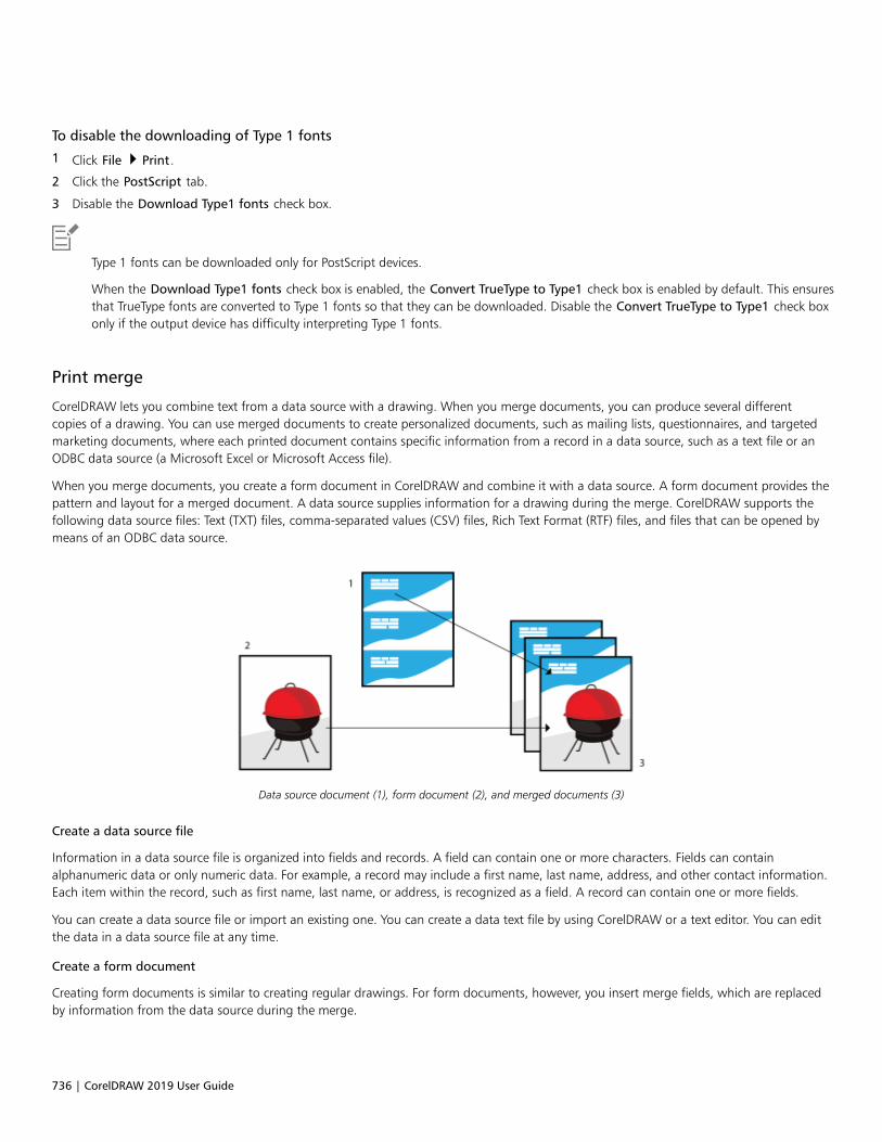
736 | CorelDRAW 2019 User Guide
To disable the downloading of Type 1 fonts
1 Click File Print.
2 Click the PostScript tab.
3 Disable the Download Type1 fonts check box.
Type 1 fonts can be downloaded only for PostScript devices.
When the Download Type1 fonts check box is enabled, the Convert TrueType to Type1 check box is enabled by default. This ensuresthat TrueType fonts are converted to Type 1 fonts so that they can be downloaded. Disable the Convert TrueType to Type1 check boxonly if the output device has difficulty interpreting Type 1 fonts.
Print merge
CorelDRAW lets you combine text from a data source with a drawing. When you merge documents, you can produce several differentcopies of a drawing. You can use merged documents to create personalized documents, such as mailing lists, questionnaires, and targetedmarketing documents, where each printed document contains specific information from a record in a data source, such as a text file or anODBC data source (a Microsoft Excel or Microsoft Access file).
When you merge documents, you create a form document in CorelDRAW and combine it with a data source. A form document provides thepattern and layout for a merged document. A data source supplies information for a drawing during the merge. CorelDRAW supports thefollowing data source files: Text (TXT) files, comma-separated values (CSV) files, Rich Text Format (RTF) files, and files that can be opened bymeans of an ODBC data source.
Data source document (1), form document (2), and merged documents (3)
Create a data source file
Information in a data source file is organized into fields and records. A field can contain one or more characters. Fields can containalphanumeric data or only numeric data. For example, a record may include a first name, last name, address, and other contact information.Each item within the record, such as first name, last name, or address, is recognized as a field. A record can contain one or more fields.
You can create a data source file or import an existing one. You can create a data text file by using CorelDRAW or a text editor. You can editthe data in a data source file at any time.
Create a form document
Creating form documents is similar to creating regular drawings. For form documents, however, you insert merge fields, which are replacedby information from the data source during the merge.

Print basics | 737
Associate a form document with a data source file
When you use CorelDRAW to create a data file, or when you import an existing data file into CorelDRAW, the data file is associated with theform document. The association is always stored with the document and cannot be changed.
Perform a merge
CorelDRAW provides different output options for merge documents. You can print a merge document or save it to a new document. Whenyou print a merge document, the form document is merged with the data source file during printing. When you save the merged documentto a new file, the application merges the form document with the data from the data source file in a new CorelDRAW file. You can use thisfile to preview your final output and make minor adjustments before printing. For major changes, such as the addition or repositioning ofmerge fields or the addition of new records, you must work in the form document.
To create a data source file by using CorelDRAW
1 Click File Print Merge Create/load Print Merge.
2 In the Print Merge dialog box, click Add Column.
3 In the Add Column dialog box, type a column name in the Name box, and then do any of the following:
• To create a text field, enable the Text option, type a field name, and then click Add,
• To create a numeric field, enable the Numeric option, type a field name, and then click Add. In the Numeric fields options area,you can apply formatting to the data in a numeric field by choosing a format from the Format list box, and automatically incrementthe value in a numeric field by enabling the Continually increment value check box and specifying starting and ending values in thecorresponding boxes.
Repeat this step for each field in the merge.
4 Click the Add a record button , and type data in the fields corresponding to that record.
Repeat this step for each record in the merge.
5 Click Save Data Source.
6 In the Save As dialog box, type a filename, choose the drive and folder where you want to save the file, choose a file format, and clickSave.
You can also
Edit a field column In the Print merge dialog box, click Configure Columns, select acolumn from the Select column list box, and click Edit Column.
Delete a field column Click Configure Columns, select a column from the Select columnlist box, and click Delete Column.
Delete a record Click a record, and click the Delete a record button .
View records Click one of the following:•View All Records — lets you display all records in a source data
file•View Single Record — lets you display the selected record
Browse records Click any of the following buttons:•First record
•Next record

738 | CorelDRAW 2019 User Guide
You can also
•Previous record
•Last record
Go to a specific record Type the record number in the Go to Record box, and click Go toRecord.
Different numeric formats are available in CorelDRAW. For example, the X.0 format represents the value 1 as 1.0; the 00X formatrepresents the value 1 as 001.
To create a data source by using a text editor
1 Open a text editor, and create a new file.
2 On the first line, type the number of merge fields that you want to insert in the drawing. For example:3
3 On the second line, type the names of the merge fields by separating them with a backslash. Each merge field must begin and end witha backslash. For example:\Name\\Date\\Instructor\
4 On the next lines, type the data that you want to appear in the merged document. Each line constitutes a record. For example:\Pixie Parsons\\6 September 2020\\Mr. Randy Harris\\Shirley Wilkinson\\13 January 2020\\Ms. Corinne Pitts\
5 Save the file as an ANSI text file (.txt extension) or as an RTF file.
Backslashes function as markers to indicate the beginning and end of merge fields; therefore, you cannot use them as data in fields.
Data in fields must end with a character. Blank spaces or lines before backslashes prevent the merge from being completedsuccessfully.
To import a data source file
1 Click File Print Merge Create/load Print Merge.
2 In the Print Merge dialog box, click the Import File.
3 In the Open dialog box, navigate to the folder where the data file is stored.
4 Choose a file.
5 Click Open.
To import an ODBC data source file
1 Click File Print Merge Create/load Print Merge.
2 In the Print Merge dialog box, click Open ODBC Data Source.
3 In the Select Data Source dialog box, do one of the following:
• Click the File Data Source tab, and select the file data source that describes the drive that you wish to connect to. You can use any filedata source that refers to an ODBC driver that is installed on your machine.
• Click the Machine Data Source tab, under Data Source Name, select a data source type, and click OK.
4 Choose the database that you want to import, and click OK.

Print basics | 739
To create a form document
1 Open a drawing in which you want to insert merge fields.
2 Click File Print Merge Create/load Print Merge.
3 In the Print Merge dialog box, select or create a data source file.
4 Click Finish.
5 In the Print Merge panel, choose a field name from the Fields, and click Insert Selected Field.
CorelDRAW places the merge field in the center of the current view. If you want to reposition the merge field, drag it to a new locationon the drawing page.
6 Repeat step 5 to insert additional fields.
If you want to edit the form document later, click File Print Merge Edit Print Merge.
To perform a merge and print the document
1 Click File Print Merge Perform Print Merge.
2 Specify any printer settings.
3 Click Print.
If you want to print all records and pages, enable the Current document option.
To perform a merge and save the document to a new file
• Click File Print Merge Merge to New Document.
Preflight summaries
Preflight checks the status of your file before you decide to output it and provides a summary of issues and potential problems, andsuggestions for resolving them. You can specify which issues Preflight checks for. You can also save Preflight settings. For more informationabout specific Preflight settings, see any of the following:• To check for issues related to printing a file, see “To view a summary of issues for a print job” on page 730.• To check for issues related to publishing a PDF file, see “To view the preflight summary for a PDF file” on page 791.• To check for issues related to exporting to Adobe Illustrator (AI), see “To view the preflight summary for an AI file” on page 799.• To check for issues related to exporting a SWF file, see “To view the issues summary for an Adobe Flash file” on page 829.• To check for issues related to exporting an SVG file, see “Scalable Vector Graphics (SVG)” on page 825.

740 | CorelDRAW 2019 User Guide
Prepare files for print service providers | 741
Prepare files for print service providers
With CorelDRAW, you can prepare a print job for sending to a print service provider.
This section contains the following topics:• “Prepare for a print service provider” (page 741)• “Imposition layouts” (page 742)• “Printers’ marks” (page 744)• “Maintain OPI links” (page 746)• “Color separations” (page 747)• “Color trapping and overprinting” (page 748)• “In-RIP trapping settings” (page 751)• “Print to film” (page 753)• “Prepare banners for printing” (page 754)• “Work with a print service provider” (page 756)
Prepare for a print service provider
You can print a drawing to a file, which lets the print service provider send the file directly to an output device. If you are unsure aboutwhich settings to choose, consult the print service provider.
For more information about commercial printing, see “Work with a print service provider” on page 756.
To print to a file
1 Click File Print.
2 Click the General tab.
3 In the Destination area, enable the Print to file check box, and choose one of the following from the list box:
• Single file — prints all pages in a document to a single file
• Pages to separate files — prints each page to a separate file
• Plates to separate files — prints each plate to a separate file
4 Click Print.
5 Choose one of the following from the Save as type list box:
• Print file — saves the file as a PRN file
742 | CorelDRAW 2019 User Guide
• PostScript file — saves the file as a PS file
6 Choose the folder where you want to save the file.
7 Type a filename in the File name box.
8 Click Save.
If you prefer not to prepare PostScript files, print service providers equipped with the application in which you created your work cantake the original files (for example, CorelDRAW files) and apply the required prepress settings.
Imposition layouts
Working with imposition layouts lets you print more than one page of a document on each sheet of paper. You can choose a presetimposition layout to create documents such as magazines and books to print on a commercial printing press; produce documents thatinvolve cutting or folding, such as mailing labels, business cards, pamphlets, or greeting cards; or print multiple thumbnails of a documenton one page. You can also edit a preset imposition layout to create your own layout.
You can select a binding method by choosing from three preset binding methods, or you can customize a binding method. When youchoose a preset binding method, all but the first signature are automatically arranged.
You can arrange pages on a signature manually or automatically. When you arrange the pages automatically, you can choose the angle ofthe image. If you have more than one page across or down, you can specify the size of gutters between pages; for example, you can choosethe automatic gutter spacing option, which sizes gutters so that the document’s pages fill the entire available space in the layout.
When printing on a desktop printer, you can adjust the margins to accommodate the non-printable area of a page. If the margin is smallerthan the non-printable area, the edges of some pages or some printers’ marks may be clipped by your printer.
To choose a preset imposition layout
1 Click File Print.
2 Click the Layout tab.
3 Choose an imposition layout from the Imposition layout list box.
The layout you choose does not affect the original document, only the way it is printed.
To edit an imposition layout
1 Click File Print.
2 Click the Layout tab.
3 Choose an imposition layout from the Imposition layout list box.
4 Click Edit.
5 Edit any imposition layout settings.
6 Click File Save imposition layout.
7 Type a name for the imposition layout in the Save as box.
When editing an imposition layout, you should save it with a new name; otherwise the settings for a preset imposition layout will beoverwritten.

Prepare files for print service providers | 743
To select a binding method
1 Click File Print Preview.
2 Click the Imposition layout tool .
3 Choose Edit basic settings from the What to edit list box on the property bar.
4 Type values in the Pages across/down boxes.
If you want the page to be double-sided, click the Single/double sided button .
5 Choose one of the following binding methods from the Binding mode list box:
• Perfect binding — cuts apart individual pages and glues them at the spine
• Saddle stitch — folds pages and inserts them into one another
• Collate and cut — collates and stacks all signatures together
• Custom binding — lets you arrange the pages that are printed in each signature
If you choose either Saddle stitch or Custom binding, type a value in the corresponding box.
When you click the Single/double sided button for double-sided printing, and you are printing on a non-duplex printing device,a wizard automatically provides instructions on how to insert the paper into the printer, so that you can print on both sides of thepage.
To arrange pages
1 Click File Print Preview.
2 Click the Imposition layout tool .
3 Choose Edit page placements from the What to edit list box on the property bar.
4 Click one of the following buttons:
• Intelligent auto-ordering — automatically arranges the pages on a signature
• Sequential auto-ordering — arranges the pages from left to right and top to bottom
• Cloned auto-ordering — places the working page in each frame of the printable page
If you want to arrange the page numbering manually, click on the page and specify the page number in the Page sequence numberbox.
5 Choose an angle from the Page rotation list box.
To edit gutters
1 Click File Print Preview.
2 Click the Imposition layout tool .
3 Choose Edit Gutters & Finishing from the What to edit list box on the property bar.
4 Click one of the following buttons:
• Auto gutter spacing — sizes gutters so that the document’s pages fill the entire available space in the layout
• Equal gutters — lets you set equal horizontal and vertical gutters
5 Click one of the following buttons:

744 | CorelDRAW 2019 User Guide
• Cut location — places cut marks between pages
• Fold location — places fold marks between pages
If you click the Equal gutters button, you must specify a value in the Gutter Size box.
You can edit the gutters only if you’ve selected an imposition layout with two or more pages across and down.
To adjust margins
1 Click File Print Preview.
2 Click the Imposition layout tool .
3 Choose Edit margins from the What to edit list box on the property bar.
4 Click one of the following buttons:
• Auto margins — sets the margins automatically
• Equal margins — lets you make the right margin equal to the left one, and the bottom margin equal to the top one
If you click the Equal margins button, you must specify values in the Top/left margin boxes.
When preparing a job for a commercial press, the print service provider may request minimum margin sizes, such as for pagegrippers and printers’ marks.
Printers’ marks
Printing printers’ marks lets you display information on a page about how a document should be printed. You can specify the position of theprinters’ marks on the page.
The available printers’ marks are as follows:• Crop/fold marks — represent the size of the paper and print at the corners of the page. You can print crop/fold marks to use as guides
to trim the paper. If you print multiple pages per sheet (for example, two rows by two columns), you can choose to print the crop/foldmarks on the outside edge of the page so that all crop/fold marks are removed after the cropping process, or you can choose to addcrop marks around each row and column. Crop/fold marks ensure that marks appear on each plate of a separated CMYK file.
• Bleed limit — determines how far an image can extend beyond the crop marks. When you use a bleed to extend the print job to theedge of the page, you must set a bleed limit. A bleed requires that the paper you are printing on is larger than the size of paper youultimately want, and the print job must extend beyond the edge of the final paper size.
• Registration marks — are required to line up film for proofing or printing plates on a color press. They print on each sheet of a colorseparation.
• Color calibration bars — are color scales that print on each sheet of a color separation and ensure accurate color reproduction. To seecalibration bars, make sure that the page size of the print job is larger than the page size of the work you are printing.
• Densitometer scales — is a series of gray boxes ranging from light to dark. These boxes are required to test the density of halftoneimages. You can position the densitometer scale anywhere on the page. You can also customize the levels of gray that appear in each ofthe seven squares on the densitometer scale.
• Page numbers — helps you collate pages of an image that do not include any page numbers or do not contain page numbers thatcorrespond to the actual number of pages
• File information — prints file information, such as, the color profile; halftone settings; name, date, and time the image was created;plate number; and job name
To print crop and fold marks
1 Click File Print.

Prepare files for print service providers | 745
2 Click the Prepress tab.
3 In the Finishing marks area, enable the Crop/fold marks check box.
If you want to print all crop/fold marks, disable the Exterior only check box.
To print crop and fold marks, ensure that the paper on which you print is 0.5 inches larger on all sides than the page size of theimage that you are printing.
To set crop and fold marks, see “To edit gutters” on page 743.
To print composite crop and fold marks
1 Click Tools Options Global.
2 Click Printing.
3 Click the Print Style tab.
4 From the Composite crop marks (PS) list box, choose Output on all plates.
To set a bleed limit
1 Click File Print.
2 Click the Layout tab.
3 Enable the Bleed limit check box.
4 Type a value in the Bleed limit box.
Usually, a bleed limit of 0.125 to 0.25 inches is sufficient. Any object extending beyond that uses memory needlessly and may causeproblems when you print multiple pages with bleeds on a single sheet of paper.
To print registration marks
1 Click File Print.
2 Click the Prepress tab.
3 In the Registration marks area, enable the Print registration marks check box.
4 Choose a registration mark style from the Style picker.
To print registration marks, ensure that the paper on which you print is 0.5 inches larger on all sides than the page size of the imagethat you are printing.
To print color calibration bars and densitometer scales
1 Click File Print.
2 Click the Prepress tab.
3 In the Calibration bars area, enable any of the following check boxes:
• Color calibration bar

746 | CorelDRAW 2019 User Guide
• Densitometer scales
If you want to customize the levels of gray in one of the densitometer scale squares, choose a number from the Densities list (lowervalues represent lighter squares), and type a new density for that square.
To print page numbers
1 Click File Print.
2 Click the Prepress tab.
3 In the File information area, enable the Print page numbers check box.
If you want to position the page number inside the page, enable the Position within page check box.
To print file information
1 Click File Print.
2 Click the Prepress tab.
3 In the File information area, enable the Print file information check box.
4 Type a job name in the Print file information box.
If you want to position the file information inside the page, enable the Position within page check box.
To position printers’ marks
1 Click File Print Preview.
2 Click the Marks placement tool .
3 Click the Auto-position marks rectangle button on the property bar.
4 Type values in the Marks alignment rectangle boxes.
You can also change the position of printers’ marks by clicking a printers’ mark icon in the print preview window and dragging thebounding box.
If you want to affix printers’ marks to the object’s bounding box instead of to the page bounding box, click File Print, click thePrepress tab, and enable the Marks to objects check box.
Maintain OPI links
Open Prepress Interface (OPI) lets you use low-resolution images as placeholders for the high-resolution images that appear in yourfinal work. When a print service provider receives your file, the OPI server substitutes the high-resolution images for the low-resolutionplaceholders.
To maintain OPI links
1 Click File Print.
2 Click the PostScript tab.
The PostScript tab only appears for non-GDI printers. For more information, see “Notes for GDI printers” on page 732.
3 Enable the Maintain OPI links check box.

Prepare files for print service providers | 747
The Maintain OPI links option is available for PostScript devices only.
You can reduce your work time by using OPI and print management server solutions, such as Creo Color Central. Low-resolutionsamples are automatically created from the high-resolution originals and are placed in CorelDRAW. These files contain their own OPIcomments, which the Creo Color Central server recognizes when it receives the job and then substitutes the high-resolution version ofthe file for the low-resolution version.
Low-resolution images must be flagged as OPI images (this must be done using third-party software) before you can import theminto a document.
Color separations
When you send color work to a print service provider or printing shop, either you or the print service provider must create color separations.Color separations are necessary because a typical printing press applies only one color of ink at a time to a sheet of paper. You can specifythe color separations to print, including the order in which they print.
Printing presses produce color using either process color or spot color, or both. You can convert the spot colors to process colors at printingtime. For more information on spot and process colors, see “Choose colors” on page 350.
When setting halftone screens to print color separations, we recommend that you use the default settings; otherwise, screens can beimproperly set and result in undesirable moiré patterns and poor color reproduction. However, if you are using an imagesetter, the screentechnology should be set to match the type of imagesetter the print service provider uses. Before customizing a halftone screen, consult theprint service provider to determine the correct setting.
If you have overprinted areas, you can choose how you want those areas to print. For more information about overprinting, see “Colortrapping and overprinting” on page 748.
To print color separations
1 Click File Print.
2 Click the Color tab.
3 Enable the Separations option.
If you want to print specific color separations, click the Separations tab, and enable the corresponding check box in the list of colorseparations.
You can change the order in which color separations print, by clicking Advanced in the Options area. In the separations list at thebottom of the dialog box, click in the Order column next to the color separation that you want to change. Chose a new order valuefrom the list box.
If you want to print separations using a color profile that is different from the document color profile, you can click the Color tab andchoose a color profile from the Color profile list box.
To convert spot colors to process colors
1 Click File Print.
2 Click the Color tab.
3 Enable the Separations option.
4 Enable the Convert spot colors to check box.

748 | CorelDRAW 2019 User Guide
Changing the spot colors to process colors does not affect the original CorelDRAW file; it affects the way colors are sent to theprinter.
To customize a halftone screen
1 Click File Print.
2 Click the Color tab.
3 Enable the Separations option.
4 Click the Separations tab.
5 In the Options area, click Advanced.
6 Change any of the following settings:
• Screening technology
• Resolution
• Basic screen
• Halftone type
You can set the screen frequency, screen angle, and overprint options for spot colors as well as process colors. For example, if youhave a fountain fill made up of two spot colors, you can set one to print at 45 degrees and the other at 90 degrees.
Color trapping and overprinting
When colors are trapped, they are intentionally overlapped so that misalignments of print separations are not noticeable. In manualtrapping, one color must overprint the other. Overprinting is achieved by printing one color over another. Overprint trapping works bestwhen the top color is much darker than the underlying color; otherwise, an undesirable third color may result (for example, cyan over yellowresults in a green object). In some cases, you might actually want to create a third color; for example, you can overprint two spot colors tocreate a third color.
How overprinted colors mix depends on the type of colors and ink you are mixing and the types of objects you are overprinting. For example,an object that uses a CMYK color overprints differently from an object that uses a spot color. Bitmaps also overprint differently from vectorobjects. You can preview a simulation of how overprinted colors will mix by enabling the Enhanced viewing mode and the Simulateoverprints viewing mode. For more information about choosing a viewing mode, see “Viewing modes” on page 54. Some variationbetween the preview and the printed version may occur, depending on the printer you use.
When you are ready to print, you can choose to preserve overprint settings if you want to trap objects in a document, or if you want to mixthe overlapping colors for effect. You can also choose to knock out the overprinted areas so that only the top color is visible. If you want toprint a proof version of the file, you can simulate overprints. Simulating overprints rasterizes the file, and it prints using process colors only.
You can set a group of objects to overprint. You can allow text to overprint overlying objects. You can also overprint bitmaps; or each vectorobject’s fill, or outline, or both. In addition, you can overprint specific color separations and specify in which order they will print, as well aswhether you want to overprint graphics, or text, or both.
The two methods for automatic color trapping include always overprinting black and auto-spreading. Overprinting black creates a color trapby causing any object that contains 95% black or more to overprint any underlying objects. This option is useful for artwork containing a lotof black text, but it should be used with caution on artwork with a high graphics content. You can adjust the threshold, if the print serviceprovider recommends a black threshold value other than 95%.
Auto-spreading creates color trapping by assigning an outline to an object that is the same color as the object’s fill and having it overprintunderlying objects. Auto-spreading is created for all objects in the file that meet three conditions: they do not already have an outline, arefilled with a uniform fill, and have not already been designated to overprint.

Prepare files for print service providers | 749
For advanced trapping options, see “In-RIP trapping settings” on page 751.
To preserve or ignore overprints when printing
1 Click File Print.
2 Click the Color tab.
3 Choose one of the following options:
• Composite
• Separations
4 Click one of the following tabs:
• Separations
• Composite
5 From the Document overprints list box, choose one of the following options:
• Ignore — does not overprint areas; color on top prints and underlying colors are knocked out
• Preserve — preserves overprinted areas
To print a simulated overprint
1 Click File Print.
2 Click the Color tab.
3 Enable the Composite option.
4 Click the Composite tab.
5 From the Document overprints list box, choose Simulate.
The Simulate option rasterizes the file; the file is printed with process colors.
To overprint selected objects
1 Select an object.
2 Click Object, and choose any of the following:
• Overprint outline
• Overprint fill
• Overprint bitmap
You can also set an object to overprint by right-clicking the object and choosing an overprint option from the context menu.
To print text over underlying objects
1 Using the Text tool , select the text.
2 In the Character area of the Properties docker, click the arrow button located at the bottom of Paragraph area to display
additional options.
3 Enable the Overprint fill check box.
To overprint selected color separations
1 Click File Print.
2 Click the Color tab.
3 Enable the Separations option.

750 | CorelDRAW 2019 User Guide
4 Click the Separations tab.
5 In the Options area, click Advanced.
6 Choose a color separation from the Screening technology list box.
7 In the Overprint column, click one or both of the following icons:
• Overprint graphics
• Overprint text
The icons appear darker when the separation is set to overprint.
You can change the order in which color separations print by selecting a color separation and choosing an order from the Order listbox.
To trap by always overprinting black
1 Click File Print.
2 Click the Color tab.
3 Choose one of the following options:
• Composite
• Separations
4 Click one of the following tabs:
• Separations
• Composite
5 In the Options area, enable the Always overprint black check box.
To set the overprint black threshold
1 Click Tools Options Global.
2 Click the Print Style tab.
3 Choose a number from the Overprint black threshold (PS) list box.
The number you choose represents the percentage of black above which black objects overprint.
To trap by auto-spreading
1 Click File Print.
2 Click the Color tab.
3 Choose one of the following options:
• Composite
• Separations
4 Click one of the following tabs:
• Separations
• Composite
5 Choose one of the following options from Automatic trapping list box:
• Auto-spreading option, and type a value in the Maximum box.

Prepare files for print service providers | 751
• Fixed width option, and type a value in the Width box.
6 Type a value in the Text above box.
The value that you type in the Text above box represents the minimum size to which auto-spreading is applied. If you set this valuetoo low, small text may be rendered illegible when auto-spreading is applied.
The amount of spread assigned to an object depends on the maximum trap value specified in the Maximum box and the object’scolor. The lighter the color, the greater the percentage of the maximum trap value. The darker the color, the smaller the percentage ofthe maximum trap value.
In-RIP trapping settings
In-RIP trapping allows you to specify advanced trapping settings. Before selecting In-RIP trapping, ensure that your PostScript 3 printersupports In-RIP trapping options.
You can select a trap width — the amount that one color spreads into another. You can also specify image trap placement, whichdetermines where the trap occurs. You can, for example, specify whether the trap is a choke or a spread, depending upon the neutraldensities of adjacent colors. Neutral density indicates the lightness or darkness of a color and helps determine how adjacent colors spreadinto one another.
You can specify a threshold at which a trap is created by specifying a step trap limit. If trap colors are of similar neutral densities, the trapplacement adjusts accordingly. The step trap limit specifies a threshold at which a trap adjusts.
Before trapping, you can set the inks; for example, you can set an ink to opaque, as in the case of a metallic ink, so that nothing showsthrough it. To reduce the visibility of a trap, you can decrease the amount of ink color in a trap. This is especially helpful in the case of pastelcolors, contrasting colors, and colors with similar neutral densities.
To select a trap width
1 Click File Print.
2 Click the Color tab.
3 Enable the Composite option.
4 Click the PostScript tab.
The PostScript tab only appears for non-GDI printers. For more information, see “Notes for GDI printers” on page 732.
5 Choose PostScript 3 from the Compatibility list box.
6 Click the Composite tab.
7 Enable the PostScript level 3 In-RIP trapping check box.
8 Click Settings.
9 Type a value in the Trap width box.
If you are trapping to black, type a value in the Black trap width box.
To select In-RIP trapping options, you must have selected PostScript 3 from the Compatibility list box under the PostScript tab of thePrint dialog box.
To specify image trap placement
1 Click File Print.
2 Click the Color tab.
3 Enable the Composite option.

752 | CorelDRAW 2019 User Guide
4 Click the PostScript tab.
The PostScript tab only appears for non-GDI printers. For more information, see “Notes for GDI printers” on page 732.
5 Choose PostScript 3 from the Compatibility list box.
6 Click the Composite tab.
7 Enable the PostScript Level 3 In-RIP trapping check box.
8 Click Settings.
9 From the Image trap placement list box, choose one of the following placements:
• Neutral density — used to determine the lighter object and thus the direction and placement of the trap
• Choke — used to trap a dark foreground object to a light background image
• Spread — used to trap a light foreground object to a dark background image
• Centerline — used when adjacent images and objects have similar neutral densities or when image density changes along an object’sedge
If you want to trap an object to an image, enable the Trap objects to images check box.
To specify a threshold
1 Click File Print.
2 Click the Color tab.
3 Enable the Composite option.
4 Click the PostScript tab.
The PostScript tab only appears for non-GDI printers. For more information, see “Notes for GDI printers” on page 732.
5 Choose PostScript 3 from the Compatibility list box.
6 Click the Composite tab.
7 Enable the PostScript 3 In-RIP trapping check box.
8 Click the Settings button.
9 Type a value in one or more of the following boxes:
• Step limit — specifies a threshold between color variations. The lower the threshold value, the more likely it is that a trap will becreated.
• Black limit — specifies the threshold at which process black is considered pure black
• Black density limit — specifies a neutral density value for the black ink
• Sliding trap limit — specifies the difference between the neutral densities of adjacent colors at which a trap adjusts (slides) from thedarker side of a color edge toward the centerline. The lower the sliding trap limit, the more gradual the transition.
To choose In-RIP trapping options, you must have selected PostScript 3 from the Compatibility list box under the PostScript tab inthe Print dialog box.
To set inks for trapping
1 Click File Print.
2 Click the Color tab.
3 Enable the Composite option.
4 Click the PostScript tab.
The PostScript tab only appears for non-GDI printers. For more information, see “Notes for GDI printers” on page 732.
5 Choose PostScript 3 from the Compatibility list box.
6 Click the Composite tab.
7 Enable the PostScript Level 3 In-RIP trapping check box.

Prepare files for print service providers | 753
8 Click the Settings button.
9 In the Type column, select one of the following for each color separation:
• Transparent — the selected ink doesn’t get trapped, but anything beneath it does
• Neutral density — the neutral density of the selected ink determines how it is treated
• Opaque — the selected ink is treated as opaque
• Opaque ignore — the selected ink doesn’t get trapped nor does anything beneath it
To choose In-RIP trapping options, you must have selected PostScript 3 from the Compatibility list box under the PostScript tab inthe Print dialog box.
To select a trap color reduction
1 Click File Print.
2 Click the Color tab.
3 Enable the Composite option.
4 Click the PostScript tab.
The PostScript tab only appears for non-GDI printers. For more information, see “Notes for GDI printers” on page 732.
5 Choose PostScript 3 from the Compatibility list box.
6 Click the Composite tab.
7 Enable the PostScript 3 In-RIP trapping check box.
8 Click the Settings button.
9 Type a value in the Trap color reduction box.
A reduction value of 100% indicates no reduction, while a lower value reduces the neutral density.
Print to film
You can set up a print job to produce negative images. An imagesetter produces images on film that may need to be produced as negativesdepending on which printing device you are using. Consult your print service provider to determine whether you can produce images onfilm.
You can specify to print with the emulsion down. Printing with the emulsion down produces a backward image on desktop printers.
To print a negative
1 Click File Print.
2 Click the Prepress tab.
3 In the Paper/film settings area, enable the Invert check box.
Do not choose negative film if you are printing to a desktop printer.
To specify film with the emulsion down
1 Click File Print.

754 | CorelDRAW 2019 User Guide
2 Click the Prepress tab.
3 In the Paper/film settings area, enable the Mirror check box.
Prepare banners for printing
You can add borders and grommet markers to prepare banners for printing. Grommets are rings or edge strips inserted into holes throughthin material such as textile fabric or composite of carbon fiber. Strings or ropes can be inserted through the grommets to stretch a bannerproperly.
You can create a banner from the active page or from selected objects on the page.
Borders can be used in two ways. You can add a border to a design that has important graphic or text elements around the edges to preventcutoffs in the final banner. Alternatively, you can add a border that can be folded before placing the grommets to make the banner edgessturdier.
CorelDRAW lets you add borders that have the page background color or a solid color of your choice. You can also stretch or mirror thedocument edges to add a border. You can specify the border size, which is the height of the area added to the top and bottom of thedocument and the width of the area placed to the right and left of the document.
You can specify the size and number of the grommet markers, and you can place them within the boundaries of the original page or inthe border areas. In addition, you can specify the margin — the distance from the grommet edge to the page edge. Grommet markers canbe placed in the corners or along the top, bottom, left and right edges of the design. With this placement method, you can specify thenumber of grommet markers to be added vertically and horizontally. You can also add grommet markers by specifying the approximatespace between them.
CorelDRAW saves your changes to a new document, which can be sent for printing, leaving the original document unchanged.
The Border and Grommet dialog box. Artwork by Janice Aydelette.
To prepare a banner design for printing
1 Click Tools Border and Grommet.
2 Perform a task from the following table.

Prepare files for print service providers | 755
To Do the following
Add a border In the Border area, enable the Add border check box.
Add borders and grommet markers to a document based on theactive page
In the Source area, enable the Page option.
Add borders and grommet markers to a document that includesonly the selected object
In the Source area, enable the Selection option.
This option is unavailable if there are no selected objects on thepage.
Choose a border type In the Border area, choose an option from the Type list box:•Page — uses the page background color•Color — lets you select a solid color•Stretch — stretches the document edges to create a border•Mirror — mirrors the document edges to create a border
Set the border size In the Border area, type a value in the Size box.
Add grommets Enable the Add grommets check box.
If you want CorelDRAW to take into account the border area whenplacing grommet markers, enable the Use border area checkbox. Disabling this option places grommet markers within theboundaries of the original page.
Set the grommet size In the Grommet area, type a value in the Size box.
Set the distance from the grommet markers’ edge to the closestpage edge
In the Grommet area, type a value in the Margin box.
Specify the number and placement of grommet markers In the Placement and Distribution area, enable the Number ofgrommets option, and type values in the Vertical and Horizontalboxes.
Click any of the following buttons:•Corners — places the grommet markers in the page corners•Top — places the grommet markers along the top of the page•Bottom — places the grommet markers along the bottom of the
page•Left — places the grommet markers along the left edge of the
page•Right — places the grommet markers along the right edge of the
page
Add grommet markers by specifying the space between them In the Placement and Distribution area, enable the Spacingoption, and type values in the Vertical and Horizontal boxes.

756 | CorelDRAW 2019 User Guide
Work with a print service provider
When you send a file to a print service provider, the provider takes your file and converts it directly to film or to plates.
When you prepare a print job for printing, you can send camera-ready paper output or the work on disk. If you send the work on disk, theprint service provider needs either a PostScript file or a native file from the application that you use. If you are creating a file to send to animagesetter or a plate-setter, speak with the print service provider about the best file format and printing device settings to use. Alwaysprovide a final printout of the work to the print service provider, even if it is only a black-and-white representation. This helps the printservice provider to identify and assess any potential problems.
Before printing a drawing, you must choose and properly configure the appropriate printing device driver. Consult the printing devicemanufacturer instructions, or the print service provider or printing shop that you use to print the work, to find out the best way to set up theprinting device driver.

Web graphics | 757
Web graphics
Create objects for the web..................................................................................................................................................................759

758 | CorelDRAW 2019 User Guide
Create objects for the web | 759
Create objects for the web
CorelDRAW lets you export objects and projects to bitmaps that are optimized for viewing in a web browser. If you have WordPressaccounts, you can export objects and projects to bitmaps and seamlessly upload these bitmaps to your WordPress media libraries. You canalso make paragraph text web-compatible.
You can also create interactive rollovers from CorelDRAW objects. In addition, you can add hyperlinks and bookmarks to a drawing.
After creating the web-compatible object in CorelDRAW, you can add the object to a design using a web-authoring tool.
This section contains the following topics:• “Create pixel-perfect graphics for the web” (page 759)• “Export bitmaps for the web” (page 760)• “Export and upload bitmaps to WordPress” (page 765)• “Save and apply web presets” (page 766)• “Export objects with transparent colors and backgrounds” (page 767)• “Web-compatible text” (page 767)• “Rollovers” (page 768)• “Bookmarks and hyperlinks” (page 769)• “Add hotspots and alternate text to objects” (page 771)
Create pixel-perfect graphics for the web
The following tips can help you create pixel-perfect graphics for the web:• Choose pixels as the unit of measurement of your document.• Check the dimensions of objects in pixels in the Object size box on the property bar. Adjust the object size to whole numbers before
exporting the document. If you plan to scale an object, use even numbers to ensure proper object scaling.• Use Pixels view (View Pixels) at a zoom of 800% or higher to view and evaluate the results.• In new documents, the pixel grid is aligned with the lower-left corner of the document page to help you create pixel-perfect designs on
export, without blurry edges and with predictable pixel dimensions. Keep the Align page with pixel grid setting enabled for best results.If you’re working with legacy files, the page is automatically aligned to the center to keep the default alignment in previous versions ofCorelDRAW. For more information, see “To change the settings of the pixel grid” on page 598.
• Make sure snapping to pixel is enabled so that objects you move or draw automatically snap to either the center or edge of the pixelgrid (depending on the objects outline properties). For information about how to enable or disable snapping to pixel, see “To change thesettings of the pixel grid” on page 598.
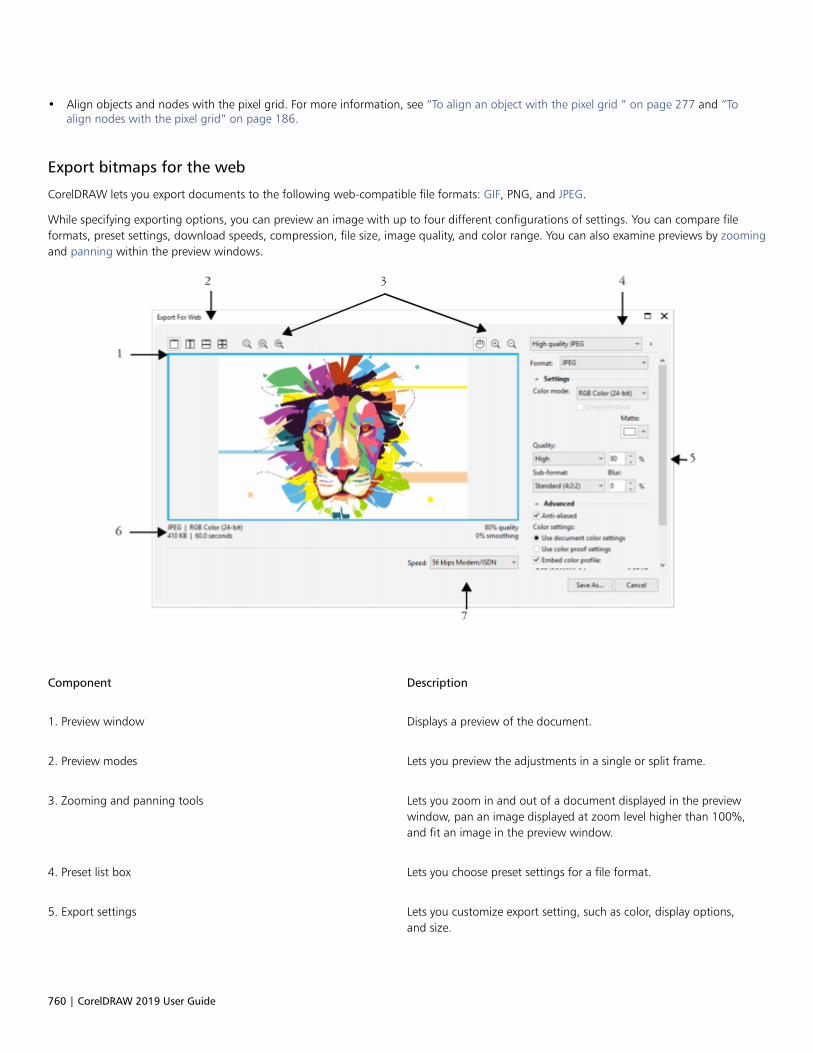
760 | CorelDRAW 2019 User Guide
• Align objects and nodes with the pixel grid. For more information, see “To align an object with the pixel grid ” on page 277 and “Toalign nodes with the pixel grid” on page 186.
Export bitmaps for the web
CorelDRAW lets you export documents to the following web-compatible file formats: GIF, PNG, and JPEG.
While specifying exporting options, you can preview an image with up to four different configurations of settings. You can compare fileformats, preset settings, download speeds, compression, file size, image quality, and color range. You can also examine previews by zoomingand panning within the preview windows.
Component Description
1. Preview window Displays a preview of the document.
2. Preview modes Lets you preview the adjustments in a single or split frame.
3. Zooming and panning tools Lets you zoom in and out of a document displayed in the previewwindow, pan an image displayed at zoom level higher than 100%,and fit an image in the preview window.
4. Preset list box Lets you choose preset settings for a file format.
5. Export settings Lets you customize export setting, such as color, display options,and size.

Create objects for the web | 761
Component Description
6. Format information Lets you view file-format information, which is available for eachpreview frame.
7. Speed list box Lets you choose an Internet speed for saving the file.
You can export web-compatible files using preset settings. This allows you to optimize the file, without the need to modify individualsettings. You can also customize the settings to produce a specific result. For example, you can adjust its color, display quality, and file size.
Choosing a web-compatible file format
This table is a quick reference for choosing a web-compatible file format.
File format Ideal for
GIF Line drawings, text, images with few colors, or images with sharpedges, such as scanned black-and-white images or logos.
GIF offers several advanced graphic options, including transparentbackgrounds, interlaced images, and animation. It also lets youcreate custom palettes for the image.
PNG Various image types, including photos and line drawings.
The PNG file format (unlike the GIF and JPEG formats) supports thealpha channel. This allows you to save transparent images withsuperior results.
JPEG Photos and scanned images.
JPEG files use file compression to store an approximation of animage, which results in some loss of image data, but does notcompromise the quality of most photographs. You can choose theimage quality when you save an image — the higher the imagequality, the larger the file size.
Exporting palette-based documents
Palette-based documents, such as paletted GIF and 8-bit PNG, allow individual pixels to retain their exact color value. This lets you controlthe display of colors in the file when exporting. Palette-based documents also allow you to introduce transparency to a file by choosinga color in the image and making it transparent. For information, see “Export objects with transparent colors and backgrounds” on page767.
To adjust the object-export preview
1 Click File Export For Web.
2 Perform one or more tasks from the following table.
To Do the following
View the bitmap in a single preview frame Click the Full preview button .
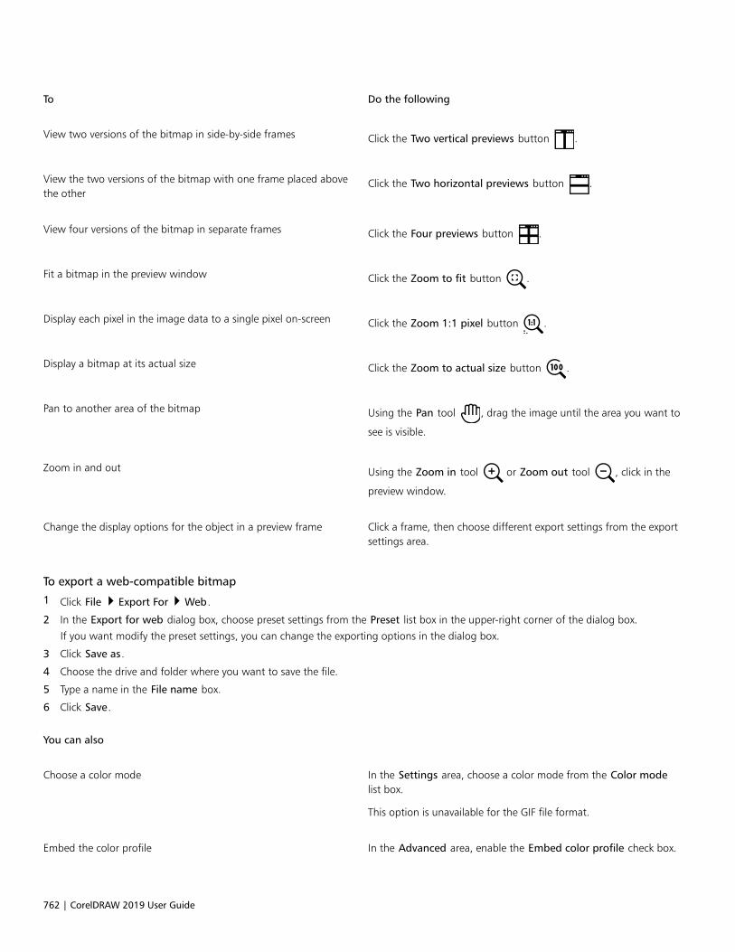
762 | CorelDRAW 2019 User Guide
To Do the following
View two versions of the bitmap in side-by-side frames Click the Two vertical previews button .
View the two versions of the bitmap with one frame placed abovethe other
Click the Two horizontal previews button .
View four versions of the bitmap in separate frames Click the Four previews button .
Fit a bitmap in the preview window Click the Zoom to fit button .
Display each pixel in the image data to a single pixel on-screen Click the Zoom 1:1 pixel button .
Display a bitmap at its actual size Click the Zoom to actual size button .
Pan to another area of the bitmap Using the Pan tool , drag the image until the area you want to
see is visible.
Zoom in and out Using the Zoom in tool or Zoom out tool , click in the
preview window.
Change the display options for the object in a preview frame Click a frame, then choose different export settings from the exportsettings area.
To export a web-compatible bitmap
1 Click File Export For Web.
2 In the Export for web dialog box, choose preset settings from the Preset list box in the upper-right corner of the dialog box.
If you want modify the preset settings, you can change the exporting options in the dialog box.
3 Click Save as.
4 Choose the drive and folder where you want to save the file.
5 Type a name in the File name box.
6 Click Save.
You can also
Choose a color mode In the Settings area, choose a color mode from the Color modelist box.
This option is unavailable for the GIF file format.
Embed the color profile In the Advanced area, enable the Embed color profile check box.

Create objects for the web | 763
You can choose an Internet connection speed from the Speed list box at the bottom of the dialog box.
You can also export to a web-compatible format by clicking File Export, and choosing a file format from the Save as type list box.
To resize an object when exporting a web-compatible bitmap
• In the Transformation area of the Export for web dialog box, perform one or more tasks from the following table.
To Do the following
Choose a unit of measurement for the bitmap Choose a unit of measurement from the Units list box.
Specify the bitmap dimensions Type values in the Width and Height boxes.
Resize the bitmap to a percentage of its original size Type values in the Width % and Height % boxes.
Avoid distortion by maintaining the width-to-height ratio of thebitmap
Enable the Maintain aspect ratio check box.
Specify the bitmap resolution Type a value in the Resolution box.
Maintain the size of the file on your hard disk when you change theresolution of the bitmap
Enable the Maintain size check box.
To customize options for exporting a JPEG bitmap
1 In the Export for web dialog box, choose JPEG from the Format list box.
2 Perform one or more tasks from the following table.
To Do the following
Control document quality In the Settings area, choose a quality option from the Quality listbox, or type a percentage value.
Choose an encoding setting In the Settings area, choose an option from the Sub-format listbox.
Blur the transition between adjacent pixels of different colors In the Settings area, type a value in the Blur box.
Load the JPEG file gradually in certain web browsers to display onlyportions of the image before it finishes loading
In the Advanced area, enable the Progressive check box.
Use the optimal encoding method to produce the smallest JPEG filesize
In the Advanced area, enable the Optimize check box.
764 | CorelDRAW 2019 User Guide
You can also
Apply the document-color settings In the Advanced area, enable the Use document color settingsoption.
Apply the color-proof settings to the document In the Advanced area, enable the Use color proof settings option.
Enable the overprinting of black when exporting to CMYK In the Settings area, enable the Overprint black check box.
Apply a matte color to the object’s background to help blend theedges of anti-aliased objects
In the Settings area, open the Matte color picker, and click a color.
To specify display-quality options for exporting web-compatible bitmaps
• In the Export for web dialog box, perform one or more tasks from the following table.
To Do the following
Apply a matte color to the object’s background to help blend theedges of anti-aliased objects
In the Settings area, open the Matte color picker, and click a color.
Smooth the edges of the object In the Advanced area, enable the Anti-aliased check box.
Load the file gradually in certain web browsers to display onlyportions of the image before it finishes loading
In the Advanced area, enable the Interlaced check box.
This option is unavailable for the JPEG file format.
To specify color settings for exporting palette-based web-compatible bitmap
• In the Export for web dialog box, perform one or more tasks from the following table.
To Do the following
Choose a color mode In the Settings area, choose a color mode from the Color modelist box.
This option is unavailable for the GIF file format.
Choose a color palette In the Settings area, choose a palette from the Color palette listbox.
This option is only available for the GIF or Paletted 8-bit PNG fileformats.
Specify a dithering setting and amount In the Settings area, choose a dithering option from the Ditheringlist box, and type a value in the box.
This option is only available for the GIF or Paletted 8-bit PNG fileformats.

Create objects for the web | 765
To Do the following
Embed the color profile In the Advanced area, enable the Embed color profile check box.
You can also
Load a color palette In the Settings area, click the arrow next to Color palette list box,and click Load palette.
This option is only available for the GIF or Paletted 8-bit PNG fileformats.
Sample a color and add it to a color palette In the Settings area, click the Eyedropper, and then click in thedrawing window to choose a color. Click the Add the sampled
color to palette button .
This option is only available for the GIF or Paletted 8-bit PNG fileformats.
Add or modify colors Double-click a color swatch on the color palette.
This option is only available for the GIF or Paletted 8-bit PNG fileformats.
Choose the number of colors that you want to display In the Settings area, choose a value from the Number of colors listbox.
This option is only available for the GIF or Paletted 8-bit PNG fileformats.
Delete a color from the color palette In the Settings area, click a color on the color palette, and thenclick the Delete the selected color button.
This option is only available for the GIF or Paletted 8-bit PNG fileformats.
You can also add transparency to a palette-based document by choosing a color in the image and making it transparent. Forinformation, see “Export objects with transparent colors and backgrounds” on page 767.
Export and upload bitmaps to WordPress
With CorelDRAW, you can export your projects to bitmap images suitable for WordPress and then upload them to your WordPress accountwithout leaving the application.
You can export your entire project or only selected objects to a JPEG, GIF, or PNG file. After choosing the file format and options you want,you can upload the image to your WordPress account. If you have multiple WordPress sites, you can choose to which site to upload thebitmap. The exported bitmap is added to the media library of the selected site.

766 | CorelDRAW 2019 User Guide
When you upload bitmaps to WordPress for the first time, you must authenticate your WordPress account and log in. If you have more thanone WordPress account, you can switch accounts at any time.
To export and upload a bitmap to WordPress
1 Select the objects that you want to export, or deselect all objects to export the entire project.
2 Click File Export For WordPress.
3 In the Export for WordPress dialog box, choose the file format you want from the Format list box, and adjust any export settings youwant.
The Export for WordPress dialog box lets you access the same export options that are available in the Export for Web dialog box. Fordetailed information about export options, see “Export bitmaps for the web” on page 760.
4 Click Upload.
5 In the Upload to WordPress dialog box, perform one or more tasks from the following table.
To Do the following
Authenticate your WordPress account and log in Click Authenticate your WordPress account.
Choose a WordPress site Choose a site from the Site box.
Upload the bitmap Click Upload.
Log in to another WordPress account Click Log out or switch accounts.
The exported bitmap is saved to a temporary file, which is deleted after you upload the image to WordPress.
Save and apply web presets
Web presets allow you to save custom settings for exporting web-compatible file formats.
To save a preset for exporting web-compatible images
1 In the Export for web dialog box, choose a file format from the Format list box.
2 Choose the settings that you want to store as a preset.
3 Click the arrow next to the Preset list box, and click Save preset.
4 Type the name of the preset in the File name box.
5 Click Save.
You can delete a saved preset by choosing a preset from the Preset list box, clicking the arrow next to the Preset list box, and clickingDelete preset.
To apply a preset for exporting web-compatible images
1 In the Export for web dialog box, click the arrow next to the Preset list box, and click Load preset.

Create objects for the web | 767
2 Click the name of the file.
3 Click Open.
Export objects with transparent colors and backgrounds
CorelDRAW lets you export palette-based bitmaps, such as paletted GIF or 8-bit PNG, with transparent colors and backgrounds. Thesebitmaps can contain objects, such as buttons and logos, which are commonly used on webpages with colored or patterned backgrounds.
If you place an object with an opaque background onto a webpage, the object background color appears as a rectangle on the page. Bymaking an object background transparent, the object background blends in with the page. Transparent object backgrounds also let youchange the color or pattern of a webpage background without having to change the backgrounds of the objects to match.
You can create a GIF with a transparent background to use on a webpage.
To save a bitmap with a transparent background
1 In the Export for web dialog box, choose a paletted file format, such as GIF or Paletted 8-bit PNG, from the Format list box.
2 Perform one or more tasks from the following table.
To Do the following
Make the background of the object transparent In the Settings area, enable the Transparency check box.
Make a selected color transparent Click the Eyedropper on the toolbar, and then click the image tochoose a color. In the Settings area, click the Make the selected
color transparent button .
Apply a matte color to the object’s background to help blend theedges of anti-aliased objects
In the Settings area, open the Matte color picker, and click a color.
For best results, choose None from the Dithering list box in the Settings area.
Web-compatible text
When you convert paragraph text to web-compatible text, you can edit the text of the published document in an HTML editor. The defaultweb font style is used automatically unless you override it with another font. If you choose to override it, the default font is used whenvisitors to your website don’t have the same font installed on their computers. The bold, italic, and underline text styles are also available.You can apply uniform fills, but not outlines, to web-compatible text.
To make text web-compatible
• Using the Pick tool , select the paragraph text frame. Click Text Make text Web-compatible.

768 | CorelDRAW 2019 User Guide
Ensure that the web-compatible text does not intersect or overlap other objects or extend beyond the boundaries of the drawingpage; otherwise the text will be converted to a bitmap, and it will lose its Internet properties.
Artistic text cannot be converted to web-compatible text and is always treated as a bitmap. However, you can convert it to paragraphtext and then make it web compatible. For information on converting text, see “Find, edit, and convert text” on page 482.
Rollovers
Rollovers are interactive objects that change in appearance when you click or point to them. You can create rollovers using objects.
To create a rollover, you add the following rollover states:• Normal — the default state of a button when no mouse activity is associated with the button• Over — the state of a button when the pointer passes over it• Down — the state of a clicked button
You can apply different object properties to each of the rollover states. You can also preview the rollover states.
Rollovers showing Normal (left), Over (center), and Down (right) states
To add a rollover object to a web design, you must save the rollover to a the Macromedia Flash (SWF) format. For more information aboutcreating and editing objects such as rollovers, see “Transform objects” on page 255.
To create a rollover object
1 Select an object.
2 Click Object Rollover Create Rollover.
To modify an object’s rollover state
1 Click the rollover object to select it.
2 Click Window Dockers Links.
3 In the Links and Rollovers docker, choose a state from the Active rollover state list box:
• Normal
• Over
• Down
4 Modify the object properties, such as the color.
5 Click the Finish editing rollover button .
Create objects for the web | 769
You can also
Delete a rollover state On the Internet toolbar, click the Delete rollover state button
.
Duplicate a rollover state On the Internet toolbar, click the Duplicate rollover state button
.
Undo a rollover On the Internet toolbar, click the Extract rollover objects button
.
Specify what frame appears when the rollover is clicked On the Internet toolbar, chose a target frame from the Target listbox.
You cannot close a drawing in which you are editing a rollover. You must finish editing first.
To preview a rollover
1 Click Object Rollover Rollover Live Preview.
2 In the drawing window, point to the rollover to view the Over state, and click the rollover to view the Down state.
To view rollover properties
1 Click Window Dockers Objects.
2 Click the page and layer where the rollover resides.
3 Click the rollover name, and expand the Normal, Over, and Down states.
You can preview a rollover object’s states in the drawing page by clicking Object Rollover Rollover Live Preview.
Bookmarks and hyperlinks
CorelDRAW lets you add bookmarks and hyperlinks to your document. You can apply these to objects, including text objects, rollovers, andbitmaps. For information, see “PDF hyperlinks, bookmarks, and thumbnails” on page 784.
Bookmarks
To create an internal link within a file, you can assign a bookmark to text or to an object. You can then assign a link to an object so that,when it’s clicked, it opens the bookmark.
Hyperlinks
You can also assign a hyperlink to an object. You can link to a web address, FTP server, email address, bookmark, or file. When the object isclicked, it opens to the assigned location in a appropriate application. After you create hyperlinks, you can display and verify them. You canalso delete links and bookmarks. When working with text, you can assign a hyperlink to both artistic and paragraph text.

770 | CorelDRAW 2019 User Guide
To assign a bookmark
1 Click Window Dockers Sources.
2 In the workspace, click the object that you want to bookmark.
3 Click the New bookmark button .
4 Type the name of the bookmark in the name box.
To assign a hyperlink to an object
1 Click Window Dockers Sources.
2 In the workspace, click the object to which you want to apply a hyperlink.
3 Click the New link button .
4 From the Link type list box, choose one of the following link types:
Link types
http:// or https:// Type a web address, or URL, for a webpage that opens when youclick the link.
ftp:// Type a web address, or URL, to the FTP server that opens when youclick the link.
mailto: Type an email address.
file:// Click the browse button and navigate to the file that you want toopen when you click the link.
bookmark Choose a previously created bookmark from the list.
You can also assign a bookmark from the Properties docker by clicking Window Dockers Properties to open the docker, andthen clicking the Internet button.
To assign a hyperlink to text
1 Click Window Dockers Sources.
2 Using the Text tool , select the text characters to which you want to assign a hyperlink.
3 Click the New link button .
4 From the Link type list box, choose one of the following link types:
Link types
http:// or https:// Type a web address, or URL, for a webpage that opens when youclick the link.
Create objects for the web | 771
Link types
ftp:// Type a web address, or URL, to the FTP server that opens when youclick the link.
mailto: Type an email address.
file:// Click the browse button and navigate to the file that you want toopen when you click the link.
bookmark Choose a previously created bookmark from the list.
You can also assign a hyperlink from the Internet toolbar by clicking Window Toolbars Internet to display the toolbar.
To verify a link
1 Click Window Dockers Sources.
2 Choose the link that you want to open.
3 Click the Open link button .
To delete a bookmark or link
1 Click Window Dockers Sources.
2 Choose the link or bookmark that you want to delete.
3 Click the Delete button .
Add hotspots and alternate text to objects
You can also set a hotspot that follows the outline of the object, or fills the object’s bounding box. CorelDRAW applies a crosshatch patternto an object containing a link. You can change the color of the crosshatch pattern as well as its background fill. In addition, you can addalternate text to objects for text-only browsers or screen readers.
To set a hotspot
1 Click Window Dockers Links.
2 In the workspace, click the object to which you want to add a hotspot.
3 In the Links and Rollovers docker, choose Link from the Behavior list box, and type a web address in the URL box.
4 In the Define hotspot using area, click one of the following buttons:
• Shape — defines the hotspot using the object’s shape
• Bounds — defines the hotspot using the object’s bounding box
5 Open the Background color picker , and click a color.
6 Open the Cross-hatch color picker , and click a color.

772 | CorelDRAW 2019 User Guide
If you choose a hyperlinked object first and then change the crosshatch and background hotspot colors, the change applies to theselected object only.
To add alternate text to an object
1 Click Window Dockers Links.
2 In the workspace, click the linked object to which you want to add alternate text.
3 In the Links docker, type the alternate text in the Alt comments text box.

File formats | 773
File formats
Import and export files........................................................................................................................................................................775
Export to PDF...................................................................................................................................................................................... 781
Work with office productivity applications...........................................................................................................................................795
Supported file formats.........................................................................................................................................................................797

774 | CorelDRAW 2019 User Guide

Import and export files | 775
Import and export files
Your application provides filters that convert files from one format to another when you import or export files.
This section contains the following topics:• “Import files” (page 775)• “Export files” (page 778)
Import files
You can import files created in other applications. For example, you can import an Adobe Portable Document Format (PDF), JPEG, or AdobeIllustrator (AI) file. You can import a file and place it in the active application window as an object. You can also resize and center a fileas you import it. The imported file becomes part of the active file. You can also import a bitmap as an externally linked image. When youimport a linked bitmap, edits to the original (external) file are automatically updated in the imported file.
While importing a bitmap, you can resample it to reduce the file size, or crop it to eliminate unused areas of the image. You can also crop abitmap to select only the exact area and size of the image that you want to import.
When you import a file from an earlier version of CorelDRAW that contains text in a language different from the language of your operatingsystem, you can use code page settings to ensure that object names, keywords, and notes saved with the file are displayed correctly.
To import a file into an active drawing
1 Click File Import.
2 Choose the folder where the file is stored.
If necessary, you can search for a file by using the search box. You can search for such things as file name, title, subject, author, keyword,comment, bitmap name, object name, and so on.
3 Choose a file format from the list box next to the File name box.
If you don’t know the file’s format, choose All file formats.
4 Click the file name.
If the file contains text in a language different from that of your operating system, choose the corresponding option from the Selectcode page list box to ensure that object names, keywords, and notes are correctly displayed.
These options are not available for all file formats.
5 Click Import, and do one of the following:
• Click the drawing page to maintain the dimensions of the file and position its top-left corner where you click.

776 | CorelDRAW 2019 User Guide
• Drag on the drawing page to resize the file. The import cursor displays the dimensions of the resized file as you drag on the drawingpage.
• Press Enter to center the file on the drawing page.
• Press the Spacebar to place the file in the same position as it was in the original file (CDR and AI files only).
Active snapping options are applied to the imported file.
You can also
Link to a bitmap externally instead of embedding it Click the arrow on the Import button, and then click Import asexternally linked image check box.
If you want to display a list of the linked images, click Window Dockers Sources.
Link to a high-resolution file for Open Prepress Interface (OPI)output
Click the arrow on the Import button, and then click Import ashigh-resolution file for output using OPI check box.
This procedure inserts a low-resolution version of a TIFF or Scitex®Continuous Tone (CT) file into a document. The low-resolutionversion is linked to the high-resolution image, which resides on anOpen Prepress Interface (OPI) server.
Merge layers in an imported bitmap Enable the Combine multi-layer bitmap check box.
Save the embedded International Color Consortium (ICC) profile Enable the Extract embedded ICC profile check box to save theICC profile to the color folder where the application is installed.
This option is not available for all file formats.
Check for watermark or copyright information Enable the Check for watermark check box.
This option is not available for all file formats.
Use the default settings for the filter instead of opening the dialogbox
Enable the Do not show filter dialog check box.
This option is not available for all file formats.
Preserve layers and pages in an imported file Enable the Maintain layers and pages check box. If you disablethe check box, all layers are combined into a single layer.
This option is not available for all file formats.
Select the pages to import when importing multi-page TIFFdocuments
In the Import TIFF dialog box, enable an option in the Select thepage(s) to import area.
This option is available only for the TIFF file format.
Open only part of an image In the Load partial file dialog box, type the range of frames toopen in the Load frames box.

Import and export files | 777
Not all importing options are available for all file formats.
You can import multiple files. Hold down Shift and click to select consecutive files in a list. Hold down Ctrl and click to select non-consecutive files.
To import a bitmap as an externally linked image
1 Click Window Dockers Sources.
2 In the Sources docker, click the New linked image button.
3 Browse to the drive and folder where the image is stored.
4 Click Import.
5 Click in the workspace to place the image.
You can also
Update a linked image Click the Update linked image button.
Break the link to an externally linked image Click the Break link button.
To resample a bitmap while importing
1 Click File Import.
2 Choose the folder where the image is stored.
If necessary, you can search for an image by using the search box. You can search for such things as file name, title, subject, author,keyword, comment, bitmap name, object name, and so on.
3 Choose a file format from the list box beside the File name box.
If you don’t know the file’s format, choose All file formats.
4 Click the file name.
5 Click the arrow next to the Import button, and then click Resample and load.
6 In the Resample image dialog box, type values in any of the following boxes:
• Width — specifies the width of the graphic in a chosen unit of measure or as a percentage of its original width
• Height — specifies the height of the graphic in a chosen unit of measure or as a percentage of its original height
7 In the Resolution area, type values in the following boxes:
• Horizontal — lets you specify the horizontal resolution of the graphic in pixels or dots per inch (dpi)
• Vertical — lets you specify the vertical resolution of the graphic in pixels or dots per inch (dpi)
8 Click the drawing page.
You can also
Maintain the width-to-height ratio of the image Enable the Maintain aspect ratio check box.
Change the unit of measure Choose a unit type from the Units list box.

778 | CorelDRAW 2019 User Guide
You can also
Maintain equal horizontal and vertical resolution valuesautomatically
Enable the Identical values check box.
If a dialog box for the import format opens, specify the options you want. For detailed information about file formats, see“Supported file formats” on page 797.
Not all importing options are available for all file formats.
To crop a bitmap while importing
1 Click File Import.
2 Choose the folder where the image is stored.
If necessary, you can search for an image by using the search box. You can search for such things as file name, title, subject, author,keyword, comment, bitmap name, object name, and so on.
3 Choose a file format from the list box beside the File name box.
If you don’t know the file’s format, choose All file formats.
4 Click the file name.
5 Click the arrow next to the Import button, and click Crop and load.
6 In the Crop image dialog box, type values in any of the following boxes:
• Top — specifies the area to remove from the top of the graphic
• Left — specifies the area to remove from the left edge of the graphic
• Width — specifies the width of the graphic that you want to keep
• Height — specifies the height of the graphic that you want to keep
7 Click the drawing page.
You can also resize a graphic by dragging the selection handles in the preview window.
You can change the unit of measure by choosing a unit type from the Units list box in the Crop image dialog box.
Export files
You can use the File Export command to export files to a variety of bitmap and vector file formats that can be used in other applications.For example, you can export a file to the Adobe Illustrator (AI) or JPG format. You can also export a file so that it is optimized for use with asuite of office productivity applications, such as Microsoft Office or Corel WordPerfect Office.
When you are exporting a file, the original file is left open in the drawing window in its existing format.
You can use the File Save as command to save files to various vector formats. After you save a file to a different format, the saved file isdisplayed immediately in the drawing window. It is recommended that you first save the file as a CorelDRAW (CDR) file because some fileformats do not support all of the features found in a CorelDRAW file.
To export a file
1 Click File Export.
2 Choose the folder where you want to save the file.
3 Choose a file format from the Save as type list box.

Import and export files | 779
4 Type a file name in the File name list box.
5 Enable any of the following check boxes:
• Export this page only — exports only the current page in a multipage file
• Selected only — saves only the objects selected in the active drawing
• Do not show filter dialog — suppresses dialog boxes that offer more advanced exporting options
These options are not available for all file formats.
6 Click Export.
If a dialog box for the export format opens, specify the options you want. For detailed information about file formats, see “Supported fileformats” on page 797.
You can also
Compress a file on export Choose a compression type from the Compression type list box.
Specify information about a file Type any comments you want in the Notes box.
Not all of the options or compression types in the Export dialog box are available for all file formats.
Objects on a hidden layer are displayed in the exported file unless the printing and exporting function for the hidden layer is disabled.
For information about the options available when you export to a bitmap file format, see “To convert a vector graphic to a bitmapwhen exporting” on page 624.
If you are using an expired trial version, you will not be able to export files.
You can specify which layers will appear in the exported file. For more information, see “To enable or disable printing and exportingof a layer” on page 324.
To export a file to Microsoft Office or WordPerfect Office
1 Click File Export For Office.
2 From the top list box, choose the office productivity suite to which the file will be exported:
• Microsoft Office — lets you set options to meet the output requirements of Microsoft Office applications
• WordPerfect Office — optimizes the image for Corel WordPerfect Office by converting it to a WordPerfect Graphics file (WPG)
3 If you chose Microsoft Office, choose the option that best suits how you intend to use the file from the middle list box:
• Compatibility — lets you save the drawing as a Portable Network Graphic (PNG) bitmap. This preserves the appearance of thedrawing when you import it into an office application.
• Editing — lets you save the drawing in the Extended Metafile Format (EMF). This retains most of the editable elements in vectordrawings.
4 If you chose Microsoft Office and Compatibility, choose an optimization option from the Optimized for list box:
• Presentation — lets you optimize the file for outputs such as slide shows or online documents (96 dpi)
• Desktop printing — lets you maintain good image quality for desktop printing (150 dpi)
• Commercial printing — lets you optimize the file for high-quality printing (300 dpi)
An estimated file size appears in the lower-left corner of the dialog box.
5 Click OK.
6 Locate the folder in which you want to save the file.
780 | CorelDRAW 2019 User Guide
7 Type a file name in the File name list box.
8 Click Save.
You can also
Zoom in and out in the preview window Using the Zoom in or Zoom out tool, click in the
preview window.
Pan to view another area of the drawing Using the Pan tool , drag in the preview window until the area
that you want to see becomes visible.
The optimization options are available only if you choose the Microsoft Office and Compatibility options.
Layers in a drawing are flattened when exported to Microsoft Office or Corel WordPerfect Office.
To save a file to a different format
1 Click File Save As.
2 Choose the folder where you want to save the file.
3 Choose a file format from the Save as type list box.
4 Type a file name in the File name list box.
5 Enable any of the following check boxes:
• Selected only — saves only the objects selected in the active drawing
• Save with embedded VBA project — lets you save, with the file, macros you have created in the VBA editor
These options are not available for all file formats.
6 Click Save.
You can also
Specify information about a file Type any comments you want in the Add comments box.
Add keywords Type any keywords you want in the Add a tag box.

Export to PDF | 781
Export to PDF
PDF is a file format designed to preserve fonts, images, graphics, and formatting of an original application file.
This section contains the following topics:• “Export to PDF” (page 781)• “PDF hyperlinks, bookmarks, and thumbnails” (page 784)• “Reduce PDF file size” (page 784)• “Text and fonts in PDF files” (page 785)• “Encode PDF files” (page 787)• “View options for EPS files” (page 787)• “PDF color management options” (page 788)• “PDF security options” (page 789)• “Optimize PDF files” (page 790)• “PDF preflight summaries” (page 791)• “Prepare PDF files for a print provider” (page 792)
Export to PDF
You can export a document as a PDF file. A PDF file can be viewed, shared, and printed on any platform provided that users have AdobeAcrobat, Adobe Reader, or a PDF-compatible reader installed on their computers. A PDF file can also be uploaded to an intranet or the web.You can also export an individual selection or an entire document to a PDF file.
When you export a document as a PDF file, you can choose from several PDF presets, which apply specific settings. For example, with theWeb preset, the resolution of the images in the PDF file is optimized for the web.
You can also create a new PDF preset or edit any existing preset. PDF file security settings are not saved with a PDF preset. For informationabout PDF file security options, see “PDF security options” on page 789.
If you have used symbols in a document, they will be supported in the PDF file. For more information on symbols, see “Symbols” on page327.
To export a document as a PDF file
1 Click File Publish to PDF.
You can also save a PDF file by clicking the Publish to PDF button on the Standard toolbar.
782 | CorelDRAW 2019 User Guide
2 Locate the folder in which you want to save the file.
3 Type a filename in the File name box.
4 Choose one of the following options from the PDF preset list box:
• Archiving (CMYK) — creates a PDF/A-1b file, which is suitable for archiving purposes. In comparison to traditional PDF files, PDF/A-1bfiles are better suited for long-term preservation of documents because they are more self-contained and more device-independent.PDF/A-1b files include embedded fonts, device-independent color, and their own description as XMP metadata. This PDF style preservesany spot or Lab colors included in the original document, but it converts all other colors, such as grayscale or RGB, to the CMYK colormode. In addition, this style embeds a color profile to specify how CMYK colors should be interpreted on the rendering device.
• Archiving (RGB) — similarly to the previous style, creates a PDF/A-1b file, preserving any spot and Lab colors. All other colors areconverted to the RGB color mode.
• Current proof settings — applies the proofing color profile to the PDF
• Document distribution — creates a PDF file that can be printed on a laser or desktop printer and is suitable for general documentdelivery. This style enables JPEG bitmap image compression and can include bookmarks and hyperlinks.
• Editing — creates a high-quality PDF file intended to be sent to a printer or digital copier. This style enables LZW compression, embedsfonts, and includes hyperlinks, bookmarks, and thumbnails. It displays the PDF file with all the fonts, with all of the images at fullresolution, and with hyperlinks, so that you can edit the file at a later date.
• PDF/X-1a — enables ZIP bitmap image compression, converts all objects to the destination CMYK color space
• PDF/X-3 — This style is a superset of PDF/X-1a. It allows both CMYK and non-CMYK data (such as Lab or Grayscale) in the PDF file.
• Prepress — enables ZIP bitmap image compression, embeds fonts, and preserves spot color options best designed for high-endquality printing. Before preparing a PDF file for printing, it’s always best to consult your print provider to find out which settings arerecommended.
• Web — creates a PDF file intended for online viewing, such as a PDF file to be distributed by email or published on the web. This styleenables JPEG bitmap image compression, compresses text, and includes hyperlinks.
5 Click Settings.
The PDF settings dialog box appears.
6 In the Export range area, enable one of the following options:
• Current document — exports the current document
• Documents — exports the documents that you specify
• Selection — exports the objects that you have selected
• Current page — exports the active page
• Pages — exports the pages that you specify
7 In the Page size area, choose one of the following options:
• Defined by document — applies the page size that is defined in the document
• Defined by selected objects — allows the page size to be determined by the size of the objects on the page
8 Click OK.
9 Click Save.
If you want to create a PDF file for archiving purposes that conforms to the PDF/A-1b standards, embedding must be allowed forall the fonts in your document. To check for fonts that cannot be embedded, view the preflight summary of the PDF file. For moreinformation about viewing summaries, see “To view the preflight summary for a PDF file” on page 791. You can substitute anyfonts that cannot be embedded, or you can convert all text to curves by enabling the Export all text as curves check box on theObjects page of the Publish to PDF settings dialog box.
If the document contains a 3D model, click Settings in the Publish to PDF dialog box, and choose Acrobat 8.0 or higher from theCompatibility list box to ensure that the 3D model is interactive in PDF readers.
To check if a font can be embedded, you can view licensing information and embedding restrictions by using a free tool, such as theFont properties extension tool available on the Microsoft website.

Export to PDF | 783
To export multiple documents as a single PDF file
1 Click File Publish to PDF.
2 Locate the folder in which you want to save the file.
3 Type a filename in the File name box.
4 Click Settings.
The PDF settings dialog box appears.
5 On the General tab, enable the Documents option from the Export range area.
6 Enable the check box for each document you want to save.
7 Click OK.
8 Click Save.
To create a PDF preset
1 Click File Publish to PDF.
2 Locate the folder in which you want to save the file.
3 Type a filename in the File name box.
4 Click Settings.
5 In the PDF settings dialog box, specify any settings.
6 Click the General tab.
7 Click the Add PDF preset button next to the PDF preset list box.
8 Type a name for the style in the Save PDF preset as list box.
9 Click OK.
10 Click Save.
If you want to delete a PDF style, select the style and click the Delete PDF Preset button next to the PDF preset list box.
To edit a PDF preset
1 Click File Publish to PDF.
2 Locate the folder in which you want to save the file.
3 Type a filename in the File name box.
4 Click Settings.
5 In the PDF settings dialog box, specify any settings.
6 Click the General tab.
7 Click the Add PDF preset button next to the PDF preset list box.
8 Choose the style you want to edit from the Save PDF preset as list box.
9 Click OK.
10 Click Save.
If you save changes you make to preset settings, the original settings will be overwritten. To avoid this, save any changes to presetsettings with a new name.

784 | CorelDRAW 2019 User Guide
PDF hyperlinks, bookmarks, and thumbnails
You can include hyperlinks, bookmarks, and thumbnails in a PDF file. Hyperlinks are useful for adding jumps to webpages or to InternetURLs. Bookmarks allow you to link to specific areas in a PDF file. You can specify whether bookmarks or thumbnails are displayed when thePDF file is first opened in Adobe Acrobat or Acrobat Reader.
For information about assigning hyperlinks and bookmarks, see “Bookmarks and hyperlinks” on page 769.
To include hyperlinks, bookmarks, and thumbnails in a PDF file
1 Click File Publish to PDF.
2 Locate the folder in which you want to save the file.
3 Type a filename in the File name box.
4 Click Settings.
The PDF settings dialog box appears.
5 Click the Document tab.
6 In the Bookmarks area, enable any of the following check boxes:
• Include hyperlinks
• Generate bookmarks
• Generate thumbnailsIf you want to display bookmarks or thumbnails on startup, enable the Bookmarks or Thumbnails button in the On start area.
7 Click OK.
8 Click Save.
Reduce PDF file size
You can compress bitmap images, text, and line art to reduce the size of a PDF file. Options for bitmap image compression include JPEG,LZW, and ZIP. Bitmap images that use JPEG compression have a quality scale ranging from 2 (high quality, less compression) to 255 (lowerquality, more compression). The higher the image quality, the larger the file size.
You can also reduce the size of a PDF file by downsampling color, grayscale, or monochrome bitmap images.
To set the bitmap compression in a PDF file
1 Click File Publish to PDF.
2 Locate the folder in which you want to save the file.
3 Type a filename in the File name box.
4 Click Settings.
The PDF settings dialog box appears.
5 Click the Objects tab.
6 Choose one of the following from the Compression type list box:
• None
• LZW
• JPEG
• ZIP
• JP2
7 Click OK.
8 Click Save.

Export to PDF | 785
The JP2 (JPEG 2000) option is available only for Adobe Acrobat 6.0, Adobe Acrobat 8.0, and Adobe Acrobat 9.0
If you choose JPEG compression, you can specify the compression quality by moving the JPEG quality slider.
To compress text and line art in a PDF file
1 Click File Publish to PDF.
2 Locate the folder in which you want to save the file.
3 Type a filename in the File name box.
4 Click Settings.
The PDF settings dialog box appears.
5 Click the Objects tab.
6 Enable the Compress text and line art check box.
7 Click OK.
8 Click Save.
To downsample bitmap images in a PDF file
1 Click File Publish to PDF.
2 Locate the folder in which you want to save the file.
3 Type a filename in the File name box.
4 Click Settings.
The PDF settings dialog box appears.
5 Click the Objects tab.
6 Enable any of the following check boxes, and type a value in the corresponding box:
• Color
• Grayscale
• Monochrome
7 Click OK.
8 Click Save.
Downsampling color, grayscale, or monochrome bitmap images is effective only when the resolution of the bitmap image is higherthan the resolution specified in the Downsampling area.
Text and fonts in PDF files
You can determine how the text in your PDF file outputs by setting text and font options.
You can embed fonts in a PDF file. Embedding increases the file size but makes a PDF file more portable, since the fonts do not have toreside on other systems. When you embed base 14 fonts, the fonts are added to your PDF file, thus eliminating font variances on differentsystems. The base 14 fonts are resident on all PostScript devices.
You can also convert TrueType fonts to Type 1 fonts, which can increase file size if there are many fonts in a file. When you convert fonts, youcan reduce file size by subsetting fonts if you use only a smaller number of characters (for example, English characters A to E). You can also

786 | CorelDRAW 2019 User Guide
include a percentage of fonts used. For example, you can create a subset that contains 50 percent of the fonts. If the number of charactersused in the document exceeds 50 percent, the whole set of characters is embedded. If the number of characters used in the document is lessthan 50 percent, only the characters used are embedded.
You can also eliminate font variances on different computers by exporting text as curves. For example, if you are using unusual textcharacters, you can export the text as curves. Exporting text as curves increases the complexity of the file and can increase file size. Forgeneral document publication, embed fonts in a document rather than convert text to curves.
To embed fonts in a PDF file
1 Click File Publish to PDF.
2 Locate the folder in which you want to save the file.
3 Type a filename in the File name box.
4 Click Settings.
The PDF settings dialog box appears.
5 Click the Objects tab.
6 Enable the Embed fonts in document check box.
If you want to install the basic fonts to your PDF file, enable the Embed base 14 fonts check box.
7 Click OK.
8 Click Save.
Enabling the Embed base 14 fonts check box increases file size, and, therefore, it is not recommended for publishing to the web.
To convert TrueType fonts to Type 1 fonts
1 Click File Publish to PDF.
2 Locate the folder in which you want to save the file.
3 Type a filename in the File name box.
4 Click Settings.
The PDF settings dialog box appears.
5 Click the Objects tab.
6 Enable the Convert TrueType to Type 1 check box.
If you want to reduce file size, you can create a subset of fonts by enabling the Subset fonts check box and typing a percentage of fontsused in the % box.
7 Click OK.
8 Click Save.
If you create a subset of fonts, some characters from the font may not be present in the file when editing the PDF file in AdobeAcrobat.
To export text as curves
1 Click File Publish to PDF.
2 Locate the folder in which you want to save the file.
3 Type a filename in the File name box.
4 Click Settings.
The PDF settings dialog box appears.

Export to PDF | 787
5 Click the Objects tab.
6 Enable the Export all text as curves check box.
7 Click OK.
8 Click Save.
Encode PDF files
ASCII and binary are encoding formats for documents. When you publish a file to PDF, you can choose to export ASCII or binary files. TheASCII format creates files that are fully portable to all platforms. The binary format creates smaller files, but they are less portable, becausesome platforms cannot handle the file format.
To specify an encoding format for a PDF file
1 Click File Publish to PDF.
2 Locate the folder in which you want to save the file.
3 Type a filename in the File name box.
4 Click Settings.
The PDF settings dialog box appears.
5 Click the Document tab.
6 Enable one of the following options:
• ASCII 85
• Binary
7 Click OK.
8 Click Save.
View options for EPS files
EPS files are PostScript files that are embedded in a document. You can choose how encapsulated PostScript (EPS) files are viewed in aPDF document. The PostScript option includes high-resolution images in the PDF document but does not let you view them in AdobeAcrobat. The Preview option includes high-resolution images in the PDF file and displays their low-resolution bitmap representation inAdobe Acrobat.
To choose a viewing option for EPS files
1 Click File Publish to PDF.
2 Locate the folder in which you want to save the file.
3 Type a filename in the File name box.
4 Click Settings.
The PDF settings dialog box appears.
5 Click the Objects tab.
6 Choose one of the following from the EPS files list box:
• PostScript — includes high-resolution images in the PDF document but does not let you view them
• Preview — includes high-resolution images in the PDF file and displays their low-resolution bitmap representation
7 Click OK.
8 Click Save.
788 | CorelDRAW 2019 User Guide
PDF color management options
You can specify color management options for exporting files to PDF. You can choose a color profile or leave the objects in their original colorspace. You can also embed the color profile with the PDF.
If you have spot colors in your file, you can either preserve the spot colors or convert them to process colors so that the file produces fourplates for CMYK output.
If you want to export to PDF for the purpose of soft-proofing the document, you can apply the document’s color proofing settings. Inaddition, you can choose additional soft-proofing options, such as preserving document overprints and overprinting black.
To specify color management options for exporting PDF files
1 Click File Publish to PDF.
2 Locate the folder in which you want to save the file.
3 Type a filename in the File name box.
4 Click Settings.
The PDF settings dialog box appears.
5 Click the Color tab.
6 Enable the Use document color settings option.
7 Choose a color profile option from the Output color list box:
• RGB
• CMYK
• Grayscale
• Native
8 Click OK.
9 Click Save.
You can also
Apply proofing color profile to the PDF Enable the Use color proof settings option.
Convert all spot colors applied in the document to the chosen colorprofile
Enable the Convert spot colors to check box.
Embed the color profile in the PDF Enable the Embed color profile check box.
Simulate how overprints appear, which is useful for soft-proofingthe document
In the Other color controls area, enable the Preserve documentoverprints check box.
Enable the overprinting of black In the Other color controls area, enable the Always overprintblack check box.

Export to PDF | 789
If you choose the Native option from the Output color list box, a maximum of three color spaces are displayed, or embedded, in thePDF file.
PDF security options
You can set security options to protect PDF files that you create. Security options let you control whether, and to what extent, a PDF file canbe accessed, edited, and reproduced when viewed in Adobe Reader.
The level of security that is available is also determined by which version of Adobe Reader you use to create the PDF file. The encryption levelsprovided by Adobe Reader have increased over time. For example, if you save to Adobe Reader version 6, or lower, it has standard encoding,version 8 has 128-bit encoding, and version 9 has 256-bit encoding. For more information about choosing a version, see “Optimize PDFfiles” on page 790.
The security options are controlled by two passwords: the Permission password and the Open password.
The Permission password is the master password that lets you control whether a file can be printed, edited, or copied. For example, as theowner of the file, you can protect the integrity of the file’s content by choosing permission settings that prevent editing.
You can also set an Open password that lets you control who can access the file. For example, if your file contains sensitive information,and you want to limit the users who can view it, you can set an Open password. It is not recommended that you set an Open passwordwithout setting a Permission password, because users would then have unrestricted access to the PDF file — including the ability to set anew password.
The security options are applied when you save the PDF file. These settings can be viewed when a PDF file is opened in Adobe Acrobat.
To open and edit a secured PDF file, you must enter the Permissions password (or the Open password if no Permission password is set). Forinformation about opening and importing PDF files, see “Adobe Portable Document Format (PDF)” on page 820.
To set PDF file permissions
1 Click File Publish to PDF.
2 Locate the folder in which you want to save the file.
3 Type a filename in the File name box.
4 Click Settings.
The PDF settings dialog box appears.
5 Click the Security tab.
6 Enable the Permission password check box.
7 Type a password in the Password box.
8 Retype the password in the Confirm password box.
9 In the Printing permissions box, choose one of the following options:
• None — lets users view the PDF on-screen but prevents them from printing the PDF file
• Low resolution — lets users print a low resolution version of the PDF file. This option is available for PDF files compatible with AdobeAcrobat 5 or higher.
• High resolution — lets users print a high resolution version of the PDF file
10 In the Editing permissions box, choose one of the following options:
• None — prevents users from editing the PDF file
• Insert, delete, and rotate pages — lets users insert, delete, and rotate pages when editing the PDF file. This option is available forPDF files compatible with Adobe Acrobat 5 or higher.
• Any except extracting pages — lets users edit the PDF file but prevents them from removing pages from the file
If you want to allow copying of content from the PDF file to other documents, enable the Enable copying of content check box.
790 | CorelDRAW 2019 User Guide
11 Click OK.
12 Click Save.
The Permission password is the master password for the document. It can be used by the file owner to set permissions, or to openthe file if an Open password is set.
Some PDF compatibility options, such as PDF/X-3 and PDF/A-1b, do not let you set PDF file permissions. If you choose such acompatibility option, all controls on the Security page appear disabled. To change the compatibility, see “To select a compatibilityoption” on page 790.
To set a user password for a PDF file
1 Click File Publish to PDF.
2 Locate the folder in which you want to save the file.
3 Type a filename in the File name box.
4 Click Settings.
The PDF settings dialog box appears.
5 Click the Security tab.
6 Enable the Open password check box.
7 Type a password in the Password box.
8 Retype the password in the Confirm password box.
9 Click OK.
10 Click Save.
If you set an Open password, it is recommended that you also set a Permission password.
Optimize PDF files
You can optimize PDF files for different versions of Adobe Acrobat or Acrobat Reader by choosing a compatibility option that matches thetype of viewer used by the recipients of the PDF file. In CorelDRAW, you can select one of the following compatibility options: Acrobat 4.0,Acrobat 5.0, Acrobat 6.0, Acrobat 8.0, Acrobat 9.0, PDF/X-1a, PDF/X-3, or PDF/A-1b.The available controls differ, depending on whichcompatibility option you choose. If you are publishing a PDF file for a wide distribution, it is better to choose an earlier compatibility optionsuch as Acrobat 8.0 or 9.0 to ensure that the file can be viewed in earlier versions of Acrobat. However, if security is a concern, you maywant to choose a later version because the encryption levels are higher. For more information, see “PDF security options” on page 789.
You can optimize the viewing of a PDF document on the web to speed up the loading time of the PDF.
If you added complex fills to the document, you can choose to convert them to bitmaps, which is also known as rasterizing. This mayincrease the PDF file size, but it will ensure that the complex fills display correctly.
To select a compatibility option
1 Click File Publish to PDF.
2 Locate the folder in which you want to save the file.
3 Type a filename in the File name box.
4 Click Settings.
The PDF settings dialog box appears.
Export to PDF | 791
5 Click the General tab.
6 From the Compatibility list box, choose a compatibility option.
To preserve layers and layer properties in the published PDF file, you must choose the Acrobat 6.0, Acrobat 8.0, or Acrobat 9.0option. Note that master layers will not be preserved.
To preserve transparencies in the published PDF file, you must choose the Acrobat 5.0, Acrobat 6.0, Acrobat 8.0, or Acrobat 9.0option.
To optimize a PDF file for viewing on the web
1 Click File Publish to PDF.
2 Locate the folder in which you want to save the file.
3 Type a filename in the File name box.
4 Click Settings.
The PDF settings dialog box appears.
5 Click the Document tab.
6 Enable the Optimize for web check box.
To convert complex fills to bitmaps
1 Click File Publish to PDF.
2 Locate the folder in which you want to save the file.
3 Type a filename in the File name box.
4 Click Settings.
The PDF settings dialog box appears.
5 Click the Objects tab.
6 Enable the Render complex fills as bitmaps check box.
PDF preflight summaries
Before saving a document as a PDF file, you can preflight your document to find potential problems. Preflighting checks and displays asummary of errors, possible problems, and suggestions for resolving issues. By default, many PDF issues are checked during a preflight, butyou can disable the issues that you do not want to check.
To view the preflight summary for a PDF file
1 Click File Publish to PDF.
2 Locate the folder in which you want to save the file.
3 Type a filename in the File name box.
4 Click Settings.
The PDF settings dialog box appears.
5 Click the Preflight tab.
If there are no print job issues, the tab name displays as No issues. If there are issues, the tab name displays the number of issues thatwere found.
You can limit the issues to check during the preflight by clicking the Preflight tab, clicking the Settings button , and, in the Preflightsettings dialog box, disabling the check boxes next to the items that you want the preflight to overlook.

792 | CorelDRAW 2019 User Guide
You can save settings by clicking the Add preflight settings button and typing a name in the Save preflight style as box.
Prepare PDF files for a print provider
Open Prepress Interface (OPI) lets you use low-resolution images as placeholders for the high-resolution images that appear in your finalwork. When a print provider receives your file, the OPI server substitutes the low-resolution images with the high-resolution images.
Printers’ marks provide information to the print provider about how the work should be printed. You can specify which printers’ marks toinclude on the page. The available printers’ marks are as follows:• Crop marks — represent the size of the paper and appear at the corners of the page. You can add crop marks to use as guides in
trimming the paper. If your output has multiple pages per sheet (for example, two rows by two columns), you can add the crop markson the outside edge of the page so that all crop marks are removed after the cropping process, or you can choose to add crop marksaround each row and column. A bleed determines how far an image can extend beyond the crop marks. A bleed requires that the paperyou are printing on is larger than the size of paper you ultimately want, and the image area must extend beyond the edge of the finalpaper size.
• Registration marks — are required to line up the film, analog proofs, or print plates on a color press. Registration marks print on eachsheet of a color separation.
• Densitometer scale — is a series of gray boxes ranging from light to dark. These boxes are required to test the density of halftoneimages. You can position the densitometer scale anywhere on the page. You can also customize the levels of gray that appear in each ofthe seven squares on the densitometer scale.
• File information — can be printed, including the color profile; name, date, and time the image was created; and page number.
To maintain OPI links in a PDF file
1 Click File Publish to PDF.
2 Locate the folder in which you want to save the file.
3 Type a filename in the File name box.
4 Click Settings.
The PDF settings dialog box appears.
5 Click the Prepress tab.
6 Enable the Maintain OPI links check box.
Don’t use OPI links if you are not sure whether your PDF file is destined for an OPI server.
To include printers’ marks in a PDF file
1 Click File Publish to PDF.
2 Locate the folder in which you want to save the file.
3 Type a filename in the File name box.
4 Click Settings.
The PDF settings dialog box appears.
5 Click the Prepress tab.
6 Enable any of the following check boxes:
• Crop marks
• File information

Export to PDF | 793
• Registration marks
• Densitometer scales
If you want to include a bleed, enable the Bleed limit check box, and type a bleed amount in the corresponding box.
Usually, a bleed amount of 0.125 to 0.25 inch is sufficient. Any object extending beyond this amount uses space needlessly and maycause problems when you print multiple pages with bleeds on a single sheet of paper.

794 | CorelDRAW 2019 User Guide

Work with office productivity applications | 795
Work with office productivity applications
CorelDRAW is highly compatible with office productivity applications such as Microsoft Word and WordPerfect Office. You can import andexport files between applications, and you can copy or insert objects from CorelDRAW into office productivity documents.
This section contains the following topics:• “Import files from office productivity applications” (page 795)• “Export files to office productivity applications” (page 795)• “Add objects to documents” (page 795)
Import files from office productivity applications
CorelDRAW lets you import files created in other applications. For example, you can import a file from a Microsoft Office or WordPerfectOffice application. For more information about importing files, see “WordPerfect Document (WPD) ” on page 832 and “Microsoft Word(DOC, DOCX, and RTF) technical notes” on page 806.
Export files to office productivity applications
You can export a file so that it is optimized for use with office productivity applications such as Microsoft Word or WordPerfect. For moreinformation about exporting files from CorelDRAW, see “To export a file to Microsoft Office or WordPerfect Office” on page 779.
Add objects to documents
CorelDRAW lets you copy an object and paste it into a drawing. You can also copy an object and place it into a document created in anoffice productivity application such as Microsoft Word or WordPerfect. For more information about copying objects, see “Copy, duplicate,and delete objects” on page 258.You can insert an object into a CorelDRAW document, or into an office productivity document, such as aMicrosoft Word or WordPerfect document. For more information about inserting objects into CorelDRAW, see “Creative tools and content”on page 87. For information about inserting objects into office productivity documents, see “Insert linked or embedded objects ” on page309, or see the office productivity application’s Help.

796 | CorelDRAW 2019 User Guide

Supported file formats | 797
Supported file formats
A file format defines how an application stores information in a file. If you want to use a file created in a different application than the oneyou are currently using, you must import that file. Conversely, if you create a file in one application and want to use it in another application,you must export the file to a different file format.
When you name a file, an application automatically appends a filename extension, usually three characters in length (for example, .cdr,.bmp, .tif, and .eps). This filename extension helps you and the computer differentiate between files of different formats.
The following list includes all file formats used in this application. Note that not all file format filters are installed by default. If you cannotexport or import a file from the list, you need to update your installation of CorelDRAW Graphics Suite. For more information, see “Modifyand repair installations” on page 24.• “Adobe Illustrator (AI)” (page 798)• “Adobe Type 1 Font (PFB)” (page 800)• “Windows Bitmap (BMP)” (page 801)• “OS/2 Bitmap (BMP)” (page 802)• “Computer Graphics Metafile (CGM)” (page 802)• “CorelDRAW (CDR)” (page 803)• “Corel Presentation Exchange (CMX)” (page 803)• “Corel PHOTO-PAINT (CPT)” (page 804)• “Corel Symbol Library (CSL)” (page 804)• “Cursor Resource (CUR)” (page 805)• “Microsoft Word (DOC, DOCX, or RTF)” (page 805)• “Microsoft Publisher (PUB)” (page 807)• “Corel DESIGNER (DES, DSF, DS4, or DRW)” (page 807)• “AutoCAD Drawing Database (DWG) and AutoCAD Drawing Interchange Format (DXF)” (page 808)• “Encapsulated PostScript (EPS)” (page 810)• “PostScript (PS or PRN)” (page 814)• “GIF” (page 815)• “JPEG (JPG)” (page 815)• “JPEG 2000 (JP2)” (page 816)• “Kodak Photo CD Image (PCD)” (page 817)• “PICT (PCT)” (page 818)• “PaintBrush (PCX)” (page 819)• “Adobe Portable Document Format (PDF)” (page 820)• “HPGL Plotter File (PLT)” (page 822)

798 | CorelDRAW 2019 User Guide
• “Portable Network Graphics (PNG)” (page 823)• “Adobe Photoshop (PSD)” (page 824)• “Corel Painter (RIF)” (page 825)• “Scalable Vector Graphics (SVG)” (page 825)• “Adobe Flash (SWF)” (page 829)• “TARGA (TGA)” (page 830)• “TIFF” (page 831)• “TrueType Font (TTF)” (page 831)• “Visio (VSD)” (page 832)• “WordPerfect Document (WPD)” (page 832)• “WordPerfect Graphic (WPG)” (page 832)• “RAW camera file formats” (page 833)• “Wavelet Compressed Bitmap (WI)” (page 833)• “Windows Metafile Format (WMF)” (page 834)• “Additional file formats” (page 834)• “Recommended formats for importing graphics” (page 835)• “Recommended formats for exporting graphics” (page 836)
• “General notes on importing text files” (page 836)
Adobe Illustrator (AI)
The Adobe Illustrator (AI) file format was developed by Adobe Systems, Incorporated for the Macintosh and Windows platforms. It isprimarily vector-based, although later versions support bitmap information.
You can import AI files for use in CorelDRAW or export CorelDRAW files to the AI file format. Before exporting a document as an AI file,you can preflight your document to find potential problems. Preflighting checks and displays a summary of errors, possible problems, andsuggestions for resolving issues. By default, many AI issues are checked during a preflight, but you can disable the issues that you do notwant to check.
To import an Adobe Illustrator file
1 Click File Import.
2 Locate the folder in which the file is stored.
3 Click the filename.
4 Click Import.
5 Click in the drawing page where you want to import the file.
To export an Adobe Illustrator file
1 Click File Export.
2 Locate the folder in which you want to save the file.
3 Choose AI - Adobe Illustrator from the Save as type list box.
4 Type a filename in the File name list box.
5 Click Export.
6 From the Compatibility list box, choose an Adobe Illustrator file format.
7 In the Export range area, enable one of the following options:
• Current document — exports the active drawing
• Current page — exports the active page
• Selection — exports the objects that you have selected
• Pages — exports the pages that you specify (This option is only available for CS 4 and later versions.)
Supported file formats | 799
8 In the Export text as area, enable one of the following options:
• Curves — lets you export text as curves
• Text — lets you export text as editable characters
You can also
Convert transparent areas to bitmaps In the Transparency area, enable the Preserve appearance andconvert transparent areas to bitmaps option.
(This option is only available for version 8 and lower.)
Discard transparent areas and preserve curves and text In the Transparency area, enable the Preserve curves and text byremoving transparent effects option.
(This option is only available for version 8 and lower.)
Convert an outline to an object to create an unfilled closed objectwith the outline’s shape
In the Options area, enable the Convert outlines to objects checkbox.
Convert complex outlines to curves In the Options area, enable the Simulate complex filled curvescheck box.
Convert spot colors to process colors In the Options area, enable the Convert spot colors to CMYKcheck box.
Embed the color profile In the Options area, enable the Embed color profiles check box.
Generate a preview of the document in the Adobe Illustrator Fileopen dialog box
In the Options area, enable the Include preview images checkbox.
If you enable the Simulate complex filled curves check box, an object that is composed of complex curves, such as a text object thatwas converted to curves, may be broken into several objects on export to help minimize the complexity of the object.
If you disable the Include placed images check box and export the file, the exporting process generates one Adobe Illustrator file anda series of EPS files. The EPS files contain individual objects and images which are linked to the AI file. Always store the EPS files withthe AI file to preserve the link to the AI file.
To view the preflight summary for an AI file
1 Click File Export.
2 Locate the folder in which you want to save the file.
3 Choose AI - Adobe Illustrator from the Save as type list box.
4 Type a filename in the File name list box.
5 Click Export.
6 In the Adobe Illustrator Export dialog box, click the second tab.
You can limit the issues to check during the preflight by clicking the Settings button , double-clicking AI Export, and disabling thecheck boxes next to the items that you want the preflight to overlook.

800 | CorelDRAW 2019 User Guide
You can save settings by clicking the Add preflight settings button and typing a name in the Save preflight style as box.
Adobe Illustrator (AI) technical notes
Importing an AI file• You can import AI file formats up to and including Adobe Illustrator CS6.• For files saved in Adobe Illustrator CS or higher with PDF-compatibility, text can be imported as text or curves.• Objects with gradient fills that were created in CS5 may not appear correctly when imported.• Corel programs cannot import AI files containing bitmaps linked as EPS files.• Adobe Illustrator graphics are imported into the program as a group of objects. Click Object Group Ungroup to manipulate objects
in the imported graphic. If you open an AI file instead of importing it, you do not need to ungroup objects.• Flash movies embedded in AI files are not imported.• For AI CS4, CS5, and CS6 files, each Artboard is imported as an individual CorelDRAW page. In multi-page documents, objects that are
placed off a page are placed on the first page of the CorelDRAW document.• Objects filled by using Global Colors (color schemes) appear correctly in CorelDRAW, but the Global Colors are not maintained as color
styles.• Symbols, objects with patterns, and objects that have 3d extrude or bevel applied are converted as curves.• Objects that have the Feather or Transparency effect applied are converted using the applicable lens effect in CorelDRAW.• Objects that have the texture, drop shadow, blur, or brushstroke effect applied are converted as bitmap objects in CorelDRAW.
Exporting an AI file• During export conversion, objects can become complex, making it difficult to edit them in other drawing programs or in CorelDRAW if
you reimport them. To avoid this problem, save the file to the CorelDRAW (CDR) format before exporting it, and use CorelDRAW for allediting.
• If you create a file that will be printed in other programs, such as Adobe PageMaker, export it using the Encapsulated PostScript (EPS)filter, not the Adobe Illustrator (AI) filter. The Encapsulated PostScript filter supports more drawing effects than the Adobe Illustrator filterdoes and yields better results overall.
• Most linear and radial fountain fills are preserved. Conical and square fountain fills are exported as a series of filled bands, an effectsimilar to that achieved by blending. You can set the number of bands by clicking Tools Options CorelDRAW. Click Display, andtype a number in the Preview fountain steps box. The maximum number of bands supported is 256.
• You can export text as text when you are exporting AI files from versions CS and later.• When exporting multi-page CorelDRAW files to CS4 or later version, individual pages are exported as Artboards. The Arrange by row
format is used for the layout of the Artboards.• When exporting multi-page CorelDRAW files to CS4 or later version, objects that are placed off of the page are removed.• Some OpenType features are not supported by Adobe Illustrator.
Adobe Type 1 Font (PFB)
The Adobe Type I Font (PFB) is a file format that stores Adobe Type 1 fonts. Most Type 1 fonts are single master fonts that permit only styleediting; for example, Roman, italic, bold. A single master Type 1 font contains two files: a Printer Font Metrics (PFM) file and a Printer FontBinary (PFB) file.
Some Type 1 fonts are also available in multiple master format. You can customize design elements of multiple master fonts such as weight,width, style, and optical size. A multiple master base font is the multiple master font itself, from which you create variations called multiplemaster instances. A multiple master base font is composed of a PFM file, a PFB file, and a Multiple Master Metrics (MMM) file. A multiplemaster instance is composed of a PFM file and a PostScript Printer Stub (PSS) file.
Adobe Type 1 Fonts technical notes• Adobe Type 1 fonts exported from CorelDRAW are unhinted.

Supported file formats | 801
• Each exported character constitutes a single object. Before you export multiple objects, you must combine them by clicking Object Combine. You cannot export multiple objects or grouped objects.
• For best results, avoid intersecting lines. Any object in your character should lie completely inside or outside of others, as shown in thefollowing example.
Left to right: three objects correctly combined; five objects correctly combined; five objects incorrectly combined
• Fill and outline attributes applied to objects are not exported.• Adobe Type 1 fonts you create are compatible with Adobe Type Manager version 2.0, but not with earlier versions.
Windows Bitmap (BMP)
The Windows bitmap (BMP) file format was developed as a standard for representing graphic images as bitmaps on the Windows operatingsystem.
To import a bitmap file
1 Click File Import.
2 Locate the folder in which the file is stored.
3 Choose BMP - Windows bitmap (*.bmp; *.dib; *.rle) from the list box next to the File name box.
4 Click the filename.
5 Click Import.
6 Click the drawing page.
To export a bitmap file
1 Click File Export.
2 Locate the folder in which you want to save the file.
3 Choose BMP - Windows bitmap from the Save as type list box.
4 Type a filename in the File name list box.
5 Click Export.
6 In the Convert to bitmap dialog box, adjust the width, height, resolution, color mode, or any of the other settings.
Windows Bitmap (BMP) technical notes
Importing a BMP file• You can import Windows Bitmap files conforming to the Windows and OS/2 BMP specifications.

802 | CorelDRAW 2019 User Guide
• Windows Bitmap files may be black-and-white, 16 colors, grayscale, paletted, or RGB color (24-bit), and print accordingly, depending onyour printer.
• Run-length encoding (RLE) compression may be used on all bitmaps, except RGB color (24-bit), and black-and-white bitmaps.• The resolution ranges from 72 to 300 dpi, or higher if you choose custom settings.• The maximum image size is 64,535 × 64,535 pixels.
Exporting a BMP file• Because raster images such as bitmaps are mapped pixel by pixel to the page, the resolution does not increase. Instead, your bitmap
appears jagged, with an apparent loss of resolution.
OS/2 Bitmap (BMP)
This type of bitmap file is designed for the OS/2 operating system. The OS/2 Bitmap file format supports a maximum image size of 64,535 ×64,535 pixels. OS/2 uses Run-length encoding (RLE) compression.
OS/2 Bitmap (BMP) technical notes• Corel programs support Standard Version 1.3 and Enhanced Version 2.0, or later versions of the OS/2 Bitmap file format.• Corel programs support the following color depths when importing and exporting BMP files: 1-bit black and white, 256 shade (8-bit)
grayscale, 16-color (4-bit) and 256-color (8-bit) paletted, and 24-bit RGB.
Computer Graphics Metafile (CGM)
Computer Graphics Metafile (CGM) is an open, platform-independent metafile format used for storing and exchanging two-dimensionalgraphics. It supports RGB color. CGM files can contain both vector graphics and bitmaps, but they usually contain one graphic type or theother — rarely both.
CorelDRAW imports CGM Version 1, 3, and 4 files and exports version 1, 3, and WebCGM 1.0 profile files.
WebCGM is a binary file format that supports hyperlinks, document navigation, picture structuring and layers, as well as searching onWebCGM picture contents. It also supports Unicode and web fonts. The WebCGM profile is used widely in web electronic documents.
To import a CGM file
1 Click File Import.
2 Locate the folder in which the file is stored.
3 Choose CGM - Computer Graphics Metafile (*.cgm) from the list box next to the File name box.
4 Click the filename.
5 Click Import.
To export a CGM file
1 Click File Export.
2 Locate the folder in which you want to save the file.
3 Choose CGM - Computer Graphics Metafile from the Save as type list box.
4 Type a filename in the File name list box.
5 Click Export.
6 In the CGM export dialog box, choose a version from the Version list box.

Supported file formats | 803
Computer Graphics Metafile (CGM) technical notes
Importing a CGM file• CorelDRAW can import CGM Version 1, 3 and 4 files.• The CGM filter accepts only markers supported by the CGM file format standard. Private-use markers are ignored.• Text is editable, provided the file is exported from the source program with the correct text options specified. The typeface you see may
not correspond to the one used in the source program; however, you can easily correct the typeface in the Corel program.• If the CGM file contains a font that is not on your computer, the PANOSE font-matching dialog box lets you replace the font with an
available one.
Exporting a CGM file• CorelDRAW can export version 1 and 3 CGM as well as WebCGM 1.0 files.• CGM files can be saved in text or binary format provided the selected profile supports text encoding. Text-encoded files can be opened in
an ASCII text editor.• PostScript textures are converted to curves.
CorelDRAW (CDR)
CorelDRAW (CDR) files are primarily vector graphic drawings. Vectors define a picture as a list of graphic primitives (rectangles, lines, text,arcs, and ellipses). Vectors are mapped point by point to the page, so if you reduce or increase the size of a vector graphic, the originalimage will not be distorted.
Vector graphics are created and edited in graphics design applications, such as CorelDRAW, but you can also edit vector graphics in image-editing applications such as Corel PHOTO-PAINT. You can use vector images of various formats in desktop publishing programs.
To import a CorelDRAW file
1 Click File Import.
2 Locate the folder in which the file is stored.
3 Choose CDR - CorelDRAW (*.cdr) from the list box next to the File name box.
4 Click the filename.
5 Click Import.
6 Click the drawing page.
CorelDRAW (CDR) technical notes• Imported files appear as a group of objects. Click Object Group Ungroup to manipulate individual objects in the imported graphic.
Corel Presentation Exchange (CMX)
Corel Presentation Exchange (CMX) is a metafile format that supports bitmap and vector information and the full range of PANTONE, RGB,and CMYK colors. Files saved in CMX format can be opened and edited in other Corel applications.
To import a Corel Presentation Exchange file
1 Click File Import.
2 Locate the folder in which the file is stored.
3 Choose one of the following from the list box next to the File name box:
• CMX - Corel Presentation Exchange — for files created in Corel Presentations X6 or later
• CMX - Corel Presentation Exchange legacy — for files created in Corel Presentations X5 or earlier

804 | CorelDRAW 2019 User Guide
4 Click the filename.
5 Click Import.
6 Click the drawing page.
To export a Corel Presentation Exchange file
1 Click File Export.
2 Locate the folder in which you want to save the file.
3 Choose one of the following from the Save as type list box:
• CMX - Corel Presentation Exchange — for versions 16.0 or later
• CMX - Corel Presentation Exchange legacy — for versions 15.0 or earlier
4 Type a filename in the File name list box.
5 Click Export.
Corel Presentation Exchange (CMX) technical notes• The following versions are supported: 5, 6, 7, 8, 9, 10, 11, 12, X3, X4, X5, and X6.
Corel PHOTO-PAINT (CPT)
Files saved to the Corel PHOTO-PAINT (CPT) file format are bitmaps that represent shapes as pixels arranged to form an image. When yousave a graphic to the Corel PHOTO-PAINT format, masks, floating objects, and lenses are saved with the image. CorelDRAW can import andexport files in Corel PHOTO-PAINT format, including files that contain color and grayscale information.
To export a Corel PHOTO-PAINT file
1 Click File Export.
2 Locate the folder in which you want to save the file.
3 Choose CPT - Corel PHOTO-PAINT image from the Save as type list box.
4 Type a filename in the File name list box.
5 Click Export.
6 In the Convert to bitmap dialog box, adjust the width, height, resolution, color mode, or any of the other settings.
You can export CorelDRAW layers as objects in the CPT file format.
You can export to an image with transparent background.
Corel PHOTO-PAINT (CPT) technical notes• This filter is available in CorelDRAW, Corel PHOTO-PAINT, and Corel DESIGNER.• Corel PHOTO-PAINT files may be black-and-white, grayscale, paletted, CMYK color (32-bit), RGB color (24-bit), or Lab.
Corel Symbol Library (CSL)
Corel Symbol Library (CSL) files store symbols that can be used in other files.
Corel Symbol Library (CSL) files can be stored locally or on a network, allowing easy deployment and management of symbol collections.
For more information, see “Symbol collections and libraries” on page 331.

Supported file formats | 805
Cursor Resource (CUR)
The Windows 3.x/NT Cursor Resource (.cur files) file format is used to create cursors for Windows 3.1, Windows NT, and Windows 95interfaces. It supports cursor graphic elements that are used in Windows pointers. You can select a color for Transparent and Inverse masks.
The Windows 3.x/NT Cursor Resource file format supports a maximum image size of 32 × 32 pixels.
Cursor Resource (CUR) technical notes• Corel programs support the following color depths when importing .cur files: 1-bit black-and-white, 16-color (4-bit) paletted, and 256-
color (8-bit) paletted.
Microsoft Word (DOC, DOCX, or RTF)
You can import the following Microsoft Word files:• Microsoft Word Document (DOC) files from versions 97, 2000, 2002, and 2003. In addition, files saved as DOC from MS Word 2007 and
2010.• Microsoft Word Open XML Document (DOCX) files. This file format is based on Open XML and uses ZIP compression. It was introduced
with Microsoft Word 2007.• Rich Text Format (RTF) files. Rich Text Format (RTF) is a text format that stores plain text and text formatting, such as bold. When you
import an RTF file to CorelDRAW, the text and any embedded Windows Metafile Format (WMF) graphics are transferred. However,graphic elements are not transferred in an RTF file exported from Corel DESIGNER.
Because Microsoft Word is a proprietary file format, it’s sometimes difficult to precisely import all aspects of a Microsoft Word file inCorelDRAW. To successfully import text with fewer inconsistencies, it is recommended that you install the Microsoft Office CompatibilityPack. If the Microsoft Office Compatibility Pack was not previously installed on your computer, you will be prompted to install it when youattempt to import text.
To import a Microsoft Word file
1 Click File Import.
2 Choose DOC, DOCX - MS Word or RTF - Rich Text Format from the All file formats list box.
3 Choose the drive and folder where the file is stored.
4 Click the filename.
5 Click Import.
If the Microsoft Office Compatibility Pack was not previously installed on your computer, the Install compatibility pack dialog boxappears. The installation of the Microsoft Office Compatibility Pack is highly recommended. To proceed with the installation, click OK andfollow the instructions in the installation wizard.
6 In the Importing/Pasting text dialog box, you can choose to maintain or discard text formatting. You can also choose to import tables astables or text.
7 Position the import cursor in the drawing window, and click.
Any embedded Windows Metafile Format (WMF) or Enhanced Metafile Format (EMF) graphics are preserved in the imported file. Ifthe file contains other graphic elements, these are lost during conversion and do not appear in CorelDRAW.

806 | CorelDRAW 2019 User Guide
You can place your imported text by dragging a marquee to define a paragraph text box, or by pressing the Spacebar to place theimported text in the default location.
If you import text and choose not to install the Microsoft Office Compatibility Pack, the Install compatibility pack dialog box willreappear the next time you import text, unless you enable the Do not ask me this question again check box. You can reactivate the
Install compatibility pack dialog box by clicking Tools Options CorelDRAW, clicking Warnings, and enabling the InstallingCompatibility Pack for DOC and DOCX check box from the Show warnings when list box.
To export a Microsoft Word file
1 Open a drawing that contains a text object.
2 Click File Export.
3 Choose DOC - MS Word for Windows 6/7 or RTF - Rich Text Format from the Save as type list box.
4 Type a filename in the File name list box.
5 Click Export.
The filename extension for the format you choose is appended to the filename automatically.
Only text in drawings can be exported to the Microsoft Word file formats. Other graphical elements, such as lines, curves, andrectangles, are lost during conversion and do not display in the file. To export graphics, use a graphic format such as WMF.
Microsoft Word (DOC, DOCX, and RTF) technical notes
Importing a DOC, DOCX, and RTF file• To successfully import text with fewer inconsistencies, it is recommended that you install the Microsoft Office Compatibility Pack. If the
Microsoft Office Compatibility Pack was not previously installed on your computer, you will be prompted to install it when you attemptto import text.
• The following Microsoft Word versions are supported: Microsoft Word 97-2007, Microsoft Word for Windows 6/7, Microsoft Word forWindows 2.x, Microsoft Word 3.0, 4.0, 5.0, and 5.5.
• The embedded-field method for building indexes in Microsoft Word is supported, but the style-implied method for building indexes isnot.
• The Corel program matches the fonts in the file you are importing with the same or similar fonts, depending on the fonts installed onyour computer. However, the Normal text style in Microsoft Word is converted to the default text style. To set the default text style, clickTools Save Settings as Default. Under Document Styles, enable the Styles check box.
• Whenever possible, the program automatically converts characters available in the sets “Symbol” or “MS Linedraw” to the correspondingWindows character set entries.
• Most fonts are proportionally spaced, and text is reflowed when imported. As a result, soft line and page breaks often appear in newlocations if you are converting to a fixed-pitch or nonscalable font.
• When you import text, the page size in the original document is ignored. The text is adjusted to fit the current page size, which mayaffect the placement of text.
• If a table is longer then the current page, the table data continues down and off the page.• Nested tables are not fully supported. The text within a nested table appears within the text box of the top-level table cell as text only (no
bounding lines).• Nested bullets are not fully supported.• Objects and graphs are not supported.• Equations are not maintained — the data and results may be maintained but they are unlinked.• Text direction is not maintained.
Supported file formats | 807
Microsoft Publisher (PUB)
Microsoft Publisher (PUB) is the native format for files created in Microsoft Publisher, an application in the Microsoft Office line of productsused for creating publications and market materials.
Microsoft Publisher (PUB) technical notes• CorelDRAW imports Microsoft Publisher files from versions 2002, 2003, 2007, and 2010.• Exporting is not supported.• Two-page spread is imported as separate pages.• Master pages are not supported. A master page is imported as a separate layer on the page. The name of the layer corresponds to the
name of the master page in Microsoft Publisher.• Headers and footers are not supported. Text from the header/footer is placed in the appropriate position on each page.• Tables are supported. Not all border types are supported. If a border type is not supported, it is replaced with an outline of the desired
thickness and color.• Border art is not supported.• Styles are not supported. Style and formatting attributes are mapped to text.• Some underline styles are not supported. Unsupported underline styles are replaced with the best-match underline style available in
CorelDRAW.• Shadow, Emboss, and Engrave font effects are not supported.• Horizontal rules in text objects are not supported.• Color schemes are not supported. Color scheme colors are mapped to object colors.• Font schemes are not supported. Font names and styles are mapped to their equivalents in CorelDRAW.• 3D shapes are supported. Surface textures are not supported.• Word art is imported as artistic text in CorelDRAW. Surface textures for extrudes are not supported.• Linked text boxes are supported.• Bookmarks and hyperlinks are supported.• Form objects (Microsoft Publisher 2002) are not supported.
Corel DESIGNER (DES, DSF, DS4, or DRW)
You can import Corel DESIGNER files. Files from version 10 and later have the filename extension .des. Files from Micrografx versions 6 to 9have the filename extension .dsf. Version 4 files have the filename extension .ds4. The .drw filename extension is used for a Micrografx 2.xor 3.x file. Micrografx template files (DST) are also supported.
To import a Corel DESIGNER file
1 Click File Import.
2 Locate the folder in which the file is stored.
3 Choose DES - Corel DESIGNER (*.des) or DSF, DRW, DST, MGX - Corel/Micrografx Designer (*.dsf; *.drw; *.ds4) from the list box nextto the File name box.
4 Click the filename.
5 In the Import dialog box, adjust any of the settings.
6 Click Import.
7 Click the drawing page.
Corel DESIGNER (DSF) technical notes• Guidelines and grid settings are not converted.• Snap points are not converted — the program preserves the default gravity settings.
808 | CorelDRAW 2019 User Guide
• Objects on some pages may be grouped together. You may want to select the group and then ungroup it before editing.• DSF files display OLE data as picture objects. OLE data object types are lost in the conversion.• Curvygons are converted to curves.• Gradient transparency may be offset in some cases.• Hatch fills are rendered but are actually part of the object fill. They are separate objects that are grouped.• Unclosed, filled lines are converted to two objects: one for the line and one for the fill.• Warped text is converted to curves.• Repelled text (block text that wraps around an object) is converted to multiple text objects.• Each line of a nonrectangular text object (text placed within an object) is converted to a separate text object.• For block text that has many transformations, tab stops may stretch or shrink.• Text flowing between containers is not preserved; each container is converted to a separate object.• Dimensions of text in small caps vary when the text is imported.
Corel DESIGNER (DES) technical notes• B-splines are preserved in the imported file but cannot be modified before you convert them to curve objects. For information about
converting objects to curve objects, see “To convert objects to curve objects” on page 176.• Hatch fills are preserved but cannot be modified in CorelDRAW. You can, however, apply a hatch fill to other objects in a drawing. For
more information, see “To copy fill, outline, or text properties from one object to another ” on page 270.• Enhanced line styles are preserved but you can modify only some of their properties. For example, you can change the color and width of
the lines, but you cannot modify the line pattern. You can apply an enhanced line style to other objects.
AutoCAD Drawing Database (DWG) and AutoCAD Drawing Interchange Format (DXF)
AutoCAD Drawing Database (DWG) files are vector files used as a native format for AutoCAD drawings.
The Drawing Interchange Format (DXF) is a tagged data representation of the information contained in an AutoCAD drawing file. TheDrawing Interchange format is a native file format of AutoCAD. It has become a standard for exchanging CAD drawings and is supported bymany CAD applications. The Drawing Interchange format is vector-based and supports up to 256 colors.
To import an AutoCAD Drawing Database file (DWG) or AutoCAD Drawing Interchange Format (DXF)
1 Click File Import.
2 Locate the folder in which the file is stored.
3 Choose DWG - AutoCAD (*.dwg) or DXF - AutoCAD (*.dxf) from the list box next to the File name box.
4 Click the filename.
5 Click Import.
6 From the 3D projection list box in the Import AutoCAD file dialog box, choose a plane projection of a three-dimensional object as seenfrom a given focal point.
If you want to reduce the number of nodes on the imported object, enable the Auto-reduce nodes check box.
7 In the Scaling area, enable one of the following options:
• Automatic — scales the drawing using the scale of the AutoCAD source file
• English (1 unit = 1 inch) — lets you scale the drawing in inches
• Metric (1 unit = 1 mm) — lets you scale the drawing in millimeters
8 Click OK.
If the file is password protected, type the password in the Password box.

Supported file formats | 809
If views are specified in your file, they appear automatically in the 3D projection list box.
If your computer is missing a font that is included in a file you are importing, a PANOSE font matching dialog box appears and letsyou substitute the font with a similar font.
To export an AutoCAD Drawing Database file (DWG) or an AutoCAD Drawing Interchange file (DXF)
1 Click File Export.
2 Locate the folder in which you want to save the file.
3 From the Save as type list box, choose one of the following options:
• DWG - AutoCAD
• DXF - AutoCAD
4 Type a filename in the File name list box.
5 Click Export.
6 In the Export to AutoCAD dialog box, choose an AutoCAD version from the Export version list box.
7 Choose a unit of measure from the Export units list box.
8 In the Export text as area, enable one of the following options:
• Curves — lets you export text as curves
• Text — lets you export text as editable characters
9 In the Export bitmap as area, enable one of the options to export the bitmaps in a drawing to a supported bitmap format.
10 In the Fill unmapped fills area, enable one of the following options:
• Color — fills all unmapped fills with color. To change the color, click the Color picker and choose a color on the palette.
• Unfilled — leaves unmapped fills unfilled
AutoCAD Data Interchange Format (DXF) technical notes• The program supports AutoCAD files from version R2.5 to 2018.• Layers are retained on import and export.
Importing an AutoCAD DXF file• If a DXF file is too complex to import into CorelDRAW, you can configure your AutoCAD output device as an HP7475 plotter and perform
a plot-to-file of the drawing. Then you can try importing this plot file with the HPGL import filter. Newer versions of AutoCAD allow youto create EPS files.
• Corel graphics programs try to center the imported image. The image is scaled down if the coordinates are larger than the maximumpage size available in CorelDRAW — 150 � 150 feet.
• Solid and trace entities are filled.• Dimension lines are imported as dimension objects.• A point is imported as an ellipse of minimum size.• Files exported as “Entities only” may not appear as expected in the Corel program because of a lack of header information.• Imported AutoCAD files that contain formatted paragraph text preserve text formatting such as spacing, alignment, and indents.• Justification of text entries may not be preserved, especially if fonts are replaced in the imported files. For best results, avoid justification
of text.• If the DXF file contains a font that is not on the user’s computer, the PANOSE font matching dialog box lets the user replace the font
with an available one.• 3D objects are not supported.
Exporting an AutoCAD DXF file• CorelDRAW saves drawings in a vector format accepted by computer-aided design/computer-aided manufacturing (CAD/CAM) programs
and devices, such as AutoCAD and certain computer-driven sign and glass cutters.• Files exported to AutoCAD version 2007 may not display correctly in AutoCAD 2007.

810 | CorelDRAW 2019 User Guide
• Password protection is not available in the exported files.• Only the outlines of objects are exported.• Filled objects with no outlines have an outline appended to them on export.• All text is exported by using a generic font. Text formatting is not preserved.
AutoCAD Drawing Database (DWG) technical notes• CorelDRAW can import AutoCAD and export files from version R2.5 to 2018.• Password protection is not available in the exported files.• If the DWG file contains a font that is not on your computer, the PANOSE font matching dialog box lets you replace the font with an
available one.
Encapsulated PostScript (EPS)
EPS files can contain text, vector graphics, and bitmaps and are intended to be included (encapsulated) in other documents. Unlike otherPostScript files, which can contain multiple pages, an EPS file is always a single page.
EPS files usually contain a preview image (header) that lets you view the file content without the help of a PostScript interpreter. An EPS filewithout a preview image is displayed as a gray box in Corel applications.
You can import and export EPS files. You can import an EPS file as a group of editable objects as you would import any other PostScript (PS)file. You can also bring the file as encapsulated, placing the preview image in the drawing window. The preview image is linked to the file. Itis recommended that you import an EPS file as encapsulated in the following situations:• You want text in the EPS file to be displayed with the original fonts, without any font substitutions.• You are working with a large EPS file, and you don’t want to slow down the application.
During the CorelDRAW Graphics Suite installation, you have the option of installing Ghostscript, which is an application that interprets thePostScript file format. Ghostscript allows you to import PostScript Level 3 files. If you did not install Ghostscript when you first installed theproduct, you can do so now.
To import an encapsulated PostScript file
1 Click File Import.
2 Locate the folder in which the file is stored.
3 Choose PS, EPS, PRN - PostScript (*.ps; *.eps; *.prn) from the list box next to the File name box.
4 Click the filename.
5 Click Import.
6 In the Import EPS dialog box, enable one of the following options:
• Import as editable —brings in the file as a group of CorelDRAW objects that you can modify
• Place as encapsulated PostScript —places the preview image in the drawing. You cannot modify specific parts of the file, but you canedit the file as a whole by applying transformations, such as sizing and rotation.
7 If you are importing the file as editable, enable one of the following text options:
• Text — preserves text objects in the imported file so that you can edit the text
• Curves — converts text to curves
8 Click OK.
9 Click the drawing page.
Supported file formats | 811
Some restrictions apply when you modify EPS files imported as editable. For more information, see “PostScript (PS or PRN) technicalnotes” on page 814.
If the EPS file contains text converted to curves, the text in the imported file is not editable, even if you choose to import the text astext.
You can also drag an EPS file from Windows Explorer into the drawing window.
To export an encapsulated PostScript file
1 Click File Export.
2 Locate the folder in which you want to save the file.
3 Choose EPS - Encapsulated PostScript from the Save as type list box.
4 Type a filename in the File name list box.
5 Click Export.
6 In the EPS export dialog box, adjust any of the settings.
To set general exporting options
1 In the EPS export dialog box, click the General tab.
2 Perform one or more tasks from the following table.
To Do the following
Specify the color mode for exporting to eps In the Color management area, choose an option from theOutput colors as list box:
•Native•RGB•CMYK•Grayscale
If you choose the Native option, all objects preserve the color modein which they were created, for example RGB, CMYK, Grayscale, orspot.
Convert spot colors In the Color management area, enable the Convert spot colors tocheck box, and select an option from the list box.
Choose a file format for previewing the PostScript image In the Preview image area, choose one of the following optionsfrom the Type list box:
•None•TIFF•WMF
If you choose the TIFF format, choose a color mode and resolution.
Specify how to export text Enable one of the following options in the Export text as area:

812 | CorelDRAW 2019 User Guide
To Do the following
•Curves — lets you export text as curves•Text — lets you export text as editable characters
If you want to include PostScript font information with your file,enable the Include fonts check box.
Choose a compatibility option From the Compatibility list box, choose a PostScript level that issupported by the printer or the application with which you will beprinting or displaying the file.
Objects are always output as CMYK. Bitmaps have the option of different color modes.
If you choose the 8-bit TIFF format for previewing images, you can make the background of the bitmap transparent by enabling theTransparent background check box in the Preview image area.
To set advanced exporting options
1 In the EPS export dialog box, click the Advanced tab.
2 Perform one or more tasks from the following table.
To Do the following
Specify the author’s name Type a name in the Author box.
Apply bitmap compression In the Bitmap compression area, enable the Use JPEGcompression check box. Move the JPEG quality slider to adjust thequality of the bitmaps.
Apply a trapping option In the Trapping area, enable any of the following options:•Preserve document overprint settings — maintains current
settings on objects•Always overprint black — creates a color trap by causing any
objects that contain at least 95 percent black to overprint anyunderlying objects
•Auto-spreading — creates a color trap by assigning an outline toan object that is the same color as its fill and having it overprintunderlying objects
•Maximum — lets you specify the amount of spread that theAuto-spreading option assigns to an object
If you want to specify the minimum font size to which Auto-Spreading is applied, type a value in the Text above box.
If you want the outlines of all objects on the page to have the samewidth, enable the Fixed width check box.
Apply a bounding box In the Bounding box area, enable any of the following options:
Supported file formats | 813
To Do the following
•Objects — aligns the bounding box exactly to the objects in thefile
•Page — aligns the bounding box to the page•Bleed limit — lets you specify how far the bleed extends beyond
the edge of the area to be printed•Crop marks — lets you use crop marks as alignment aids when
you trim the print output to its final size•Floating point numbers — lets you use numbers with decimals
Maintain OPI link Enable the Maintain OPI links check box to use low-resolutionimages as placeholders for high-resolution images.
Automatically increase fountain steps Enable the Auto-increase fountain steps check box toautomatically increase the number of steps used to create fountainfills.
The Use JPEG compression check box remains disabled until you choose a PostScript level that supports this feature.
To install Ghostscript
1 Close any open programs.
2 On the Windows taskbar, click Start Control panel.
3 Click Uninstall a program.
4 Double-click CorelDRAW Graphics Suite 2019 from the Uninstall or change a program page.
5 Enable the Modify option.
6 On the Features page, enable the GPL Ghostscript check box.
7 Follow the instructions in the installation wizard.
Encapsulated PostScript (EPS) technical notes
Importing an EPS file• When you import an EPS file as editable, the PostScript information in the file is converted to native CorelDRAW objects that you can edit
with some restrictions. For information about these restrictions, see “PostScript (PS or PRN) technical notes” on page 814.• If the encapsulated PostScript file was imported with the Place as Encapsulated PostScript option, and if it contains a preview image
(called a header), the preview image is imported and displayed. The EPS information remains attached to the header and is used whenthe image is printed to a PostScript printer.
Exporting an EPS file• On a PostScript printer, graphics exported to the encapsulated PostScript (EPS) format print from other programs exactly as they do from
a Corel graphics programs.• You can save a header to the Tagged Image file format (TIFF) or Windows Metafile format (WMF) in black and white, 4-bit grayscale or
color, or 8-bit grayscale or color. You can set the header resolution between 1 and 300 dots per inch (dpi); the default header resolutionis 72 dpi. If the program importing the EPS file has a limitation on the image header size, you might receive an error message statingthat the file is too large. To reduce file size, in the EPS export dialog box, choose Black and White from the Mode box, and lowerthe header resolution before exporting the file. The setting determines only the resolution of the header and has no impact on theprint quality of a drawing. Color headers are useful for viewing EPS files. If the program in which you are going to use the file does notsupport color headers, try exporting with a mono header instead. You can also export without a header.
• Along with the graphic, exported EPS files contain a filename, program name, and date.• To save font information in an EPS file, enable the Include fonts check box in the Export text as area.

814 | CorelDRAW 2019 User Guide
• If you export text as curves, text is converted to vector curves.• If a font used in the file is not available on the printer or has not been saved in the file, either the text is printed in Courier font or the
drawing is not printed.
PostScript (PS or PRN)
PostScript (PS) files use PostScript language to describe the layout of text, vector graphics, or bitmaps for printing and display purposes. Theycan contain multiple pages. PostScript files are imported as a group of objects that you can edit.
PostScript files usually have a .ps filename extension, but you can also import PostScript files with a .prn extension. Files with a .prn filenameextension, commonly known as Printer (PRN) files, contain instructions about how a file should be printed. These files let you reprint adocument even if the application in which the document was created is not installed on your computer.
During the CorelDRAW Graphics Suite installation, you have the option of installing Ghostscript, which is an application that interprets thePostScript file format. Ghostscript assists the file importing process. If you did not install Ghostscript during the installation, see “To installGhostscript” on page 813.
You can also import encapsulated PostScript (EPS) files. For more information, see “Encapsulated PostScript (EPS) ” on page 810.
To import a PostScript (PS or PRN) file
1 Click File Import.
2 Locate the folder in which the file is stored.
3 Choose PS, EPS, PRN - PostScript (*.ps; *.eps; *.prn) from the list box next to the File name box.
4 Click the filename, and click Import.
5 In the Import text as area, enable one of the following text options:
• Text — preserves text objects in the imported file so that you can edit the text
• Curves — converts text to curves
6 Click OK.
7 Click the drawing page.
When the PostScript file contains text converted to curves, the text in the imported file is not editable, even if you choose to importthe text as text.
PostScript (PS or PRN) technical notes• PostScript files containing mesh fills with spot colors, DeviceN images, or duotone images cannot be imported. Installing Ghostscript
resolves this issue.• Mesh fills in the CMYK color mode are imported as bitmaps and cannot be edited.• Gradient fills are imported as a group of filled objects simulating the gradient fill appearance and cannot be edited as gradient fills.• RGB bitmaps are converted to CMYK in imported PS files. Installing Ghostscript resolves this issue.• Font information is maintained only if the font was embedded in the original file before it was imported.• Files that are too large cannot be imported into some programs because of memory limitations. This problem can be caused by complex
gradient fills that increase the number of objects in a graphic.• Only Printer (PRN) files, PS files, and EPS files in PostScript format are supported.

Supported file formats | 815
GIF
GIF is a bitmap-based format designed for use on the web. It is highly compressed to minimize file transfer time and supports images withup to 256 colors. The GIF file format supports a maximum image size of 30,000 × 30,000 pixels and uses LZW compression. For moreinformation about exporting images to the GIF file format, see “Export bitmaps for the web” on page 760.
The GIF format provides the ability to store multiple bitmaps in a file. When the multiple images are displayed in rapid succession, the file iscalled an animated GIF file.
For Internet use, you can also save images to the JPEG and PNG formats. If you want to publish an image to the web and are not sure whichformat to use, see “Export bitmaps for the web” on page 760.
To import a GIF file
1 Click File Import.
2 Locate the folder in which the file is stored.
3 Choose GIF - CompuServe Bitmap (*.gif) from the list box next to the File name box.
4 Click the filename.
5 Click Import.
6 Click the drawing page.
You can also
Resample a graphic while importing For more information, see “To resample a bitmap while importing”on page 777.
Crop a graphic while importing For more information, see “To crop a bitmap while importing” onpage 778.
You can drag on the drawing page to resize the image.
GIF technical notes• Corel programs import versions 87A and 89A of the GIF file format, but export only to version 89A. Version 87A supports basic features
and interlacing. The newer version, 89A, includes all features found in 87A plus the ability to use transparent colors and to includecomments and other data from the image file.
• Corel programs support the following color depths when importing animated GIF files: black and white (1-bit), 16 colors, grayscale (8-bit), and 256 color paletted (8-bit).
JPEG (JPG)
JPEG is a standard format developed by the Joint Photographic Experts Group. Through the use of superior compression techniques, thisformat allows the transfer of files among a wide variety of platforms. JPEG supports 8-bit grayscale, 24-bit RGB, and 32-bit CMYK colormodes.
The JPEG format is commonly used on the web. For more information about exporting to the JPEG file format, see “Export bitmaps for theweb” on page 760.
816 | CorelDRAW 2019 User Guide
To import a JPEG file
1 Click File Import.
2 Locate the folder in which the file is stored.
3 Choose JPG - JPEG Bitmaps (*.jpg; *.jtf; *.jff; *.jpeg) from the list box next to the File name box.
4 Click the filename.
5 Click Import.
6 Click the drawing page.
You can also
Resample a graphic while importing For more information, see “To resample a bitmap while importing”on page 777.
Crop a graphic while importing For more information, see “To crop a bitmap while importing” onpage 778.
You can drag on the drawing page to resize the image.
JPEG technical notes• JPEG files can contain EXIF data. This data may affect how the JPEG files open.
JPEG 2000 (JP2)
The JPEG 2000 (JP2) file format is a JPEG image with advanced compression and file data capabilities. JPEG 2000 standard files can storemore descriptive file data (or metadata), such as dimensions, tone scale, color space, and intellectual property rights, than JPEG 2000codestream files. Codestream files are optimized for network transmission since they resist bit errors that can cause data loss on low-bandwidth channels.
Not all web browsers support JPEG 2000 formats. You may require a plug-in to view these files.
When you export the image to a JP2 file, you can choose to view download progression by resolution, quality, and position.
To import a JPEG 2000 file
1 Click File Import.
2 Locate the folder in which the file is stored.
3 Choose JP2 - JPEG 2000 Bitmaps (*.jp2; *.j2k) from the list box next to the File name box.
4 Click the filename.
5 Click Import.
6 Click the drawing page.
To export a JPEG 2000 bitmap
1 Click File Export.
2 Choose JP2 - JPEG 2000 bitmaps from the Save as type list box.
3 Type a name in the File name box.

Supported file formats | 817
4 Click Export.
5 Choose a JPEG 2000 preset from the Preset list list box in the upper-right corner of the dialog box.
If you want modify the preset settings, you can change the exporting options in the dialog box.
6 Click OK.
You can also
Choose a color mode In the Settings area, choose a color mode from the Color modelist box.
Embed the color profile In the Advanced area, enable the Embed color profile check box.
Control image quality In the Settings area, choose a quality option from the Quality listbox or type a value.
Set the JPEG 2000 download from low to high resolution so thatthe size of the entire image increases
In the Advanced area, choose Resolution\Quality from theProgression list box.
Set the JPEG 2000 download from the upper-left corner of theimage to the lower-right corner
In the Advanced area, choose Resolution\Position from theProgression list box.
Set the JPEG 2000 download from the upper-left corner of theimage to the lower-right corner
In the Advanced area, choose Position from the Progression listbox.
Set the JPEG 2000 download progressively by color channel In the Advanced area, choose Channels from the Progression listbox.
Allow JPEG 2000 codestream In the Advanced area, enable the Codestream check box.
JPEG 2000 (JP2) technical notes• CorelDRAW can import either JP2 or JPC files but export only to the JP2 format.• CorelDRAW supports exporting JPEG 2000 files in 24-bit RGB, and 8-bit grayscale.• CMYK, 48-bit RGB, and black-and-white images are not supported for export.
Kodak Photo CD Image (PCD)
Kodak Photo CD image file is a raster format developed by Eastman Kodak for scanning photographic images onto compact discs. PCDimages are derived from 35-mm film negatives or slides that have been converted to digital format and stored on a CD. Photo CD allowshigh-quality digital storage and manipulation of photographic images. The PCD format is typically used by photofinishers and servicebureaus who provide the service of placing photographs on CDs.
This file format is not supported by the 64-bit version of the application.
To import a Kodak Photo CD image file
1 Click File Import.
2 Choose the folder in which the file is stored.

818 | CorelDRAW 2019 User Guide
3 Choose PCD - Kodak Photo-CD image (*.pcd) from the list box next to the File name box.
4 Click the filename.
5 Click Import.
6 In the PCD import dialog box, move any of the following sliders:
• Brightness — lets you set the amount of light
• Contrast — lets you specify the contrast between the pixels in the image
• Saturation — lets you specify the purity of a color
• Red — lets you specify the amount of red in the image
• Green — lets you specify the amount of green in the image
• Blue — lets you specify the amount of blue in the image
7 From the Resolutions list box, choose an image size.
8 From the Image type list box, choose a color mode.
9 Position the import placement start cursor on the drawing window, and click.
You can also
Resample a graphic while importing For more information, see “To resample a bitmap while importing”on page 777.
Crop a graphic while importing For more information, see “To crop a bitmap while importing” onpage 778.
You can drag on the drawing page to resize the image.
You can remove the adjustments made by the photofinisher at the time the original image was scanned and placed on the Photo CDdisk by enabling the Subtract scene balance check box.
You can identify out-of-gamut areas of the image by enabling the Show colors out of gamut check box, which renders the out-of-gamut pixels in pure red or pure blue.
Kodak Photo CD Image (PCD) technical notes• Kodak Photo CD (PCD) images may be subject to copyright. The Corel program does not display a warning message about this.• Other Kodak-compatible programs may install the Kodak pcdlib.dll file in the Windows folder instead of the Windows\System folder.
This difference in the folder location produces an error message.• When you import Photo CD files, a dialog box appears and prompts you to choose the desired file resolution and color. The resolution is
limited to 72 dpi and the maximum image size is 3072 × 2048 pixels.• You can import the following color modes: RGB (24-bit), paletted (8-bit), and grayscale (8-bit).
PICT (PCT)
The Macintosh PICT file format was developed for the macOS platform by Apple Computer Inc. It is a native file format of QuickDraw andcan contain both vectors and bitmaps. The Macintosh PICT file format is widely used in Macintosh applications.
To import a PICT file
1 Click File Import.
2 Locate the folder in which the file is stored.
3 Choose PCT - Macintosh PICT (*.pct; *.pict) from the list box next to the File name box.

Supported file formats | 819
4 Click the filename.
5 Click Import.
6 Click the drawing page.
You can drag on the drawing page to resize the image.
To export a PICT file
1 Click File Export.
2 Locate the folder in which you want to save the file.
3 Choose PCT - Macintosh PICT from the Save as type list box.
4 Type a filename in the File name list box.
5 Click Export.
PICT (PCT) technical notes• Corel graphics programs can import vector drawings and bitmaps contained in PICT (PCT) files.• Objects that contain a fill and an outline open as a group of two objects. One object is the outline, and the other is the fill.• PICT fills are often bitmap patterns, and the Corel program tries to maintain these fills as bitmap patterns.• Pattern outlines are converted to a solid color.• Text in PICT files opens as editable text. If a typeface in the imported file is not available on your computer, it is converted to the font that
it most closely resembles.• Text alignment may not be preserved in the original file. This is due to the differences in font size, and intercharacter and interword
spacing between the two formats. Any misalignment is easily corrected using the text formatting settings in the program.
PaintBrush (PCX)
The PaintBrush (PCX) file format is a bitmap format originally developed by the ZSoft Corporation for the PC Paintbrush program.
To import a PaintBrush file
1 Click File Import.
2 Locate the folder in which the file is stored.
3 Choose PCX - PaintBrush (*.pcx) from the list box next to the File name box.
4 Click the filename.
5 Click Import.
6 Click the drawing page.
To export a PaintBrush file
1 Click File Export.
2 Locate the folder in which you want to save the file.
3 Choose PCX - PaintBrush from the Save as type list box.
4 Type a filename in the File name list box.
5 Click Export.
6 In the Convert to bitmap dialog box, adjust the width, height, resolution, color mode, or any of the other settings.
7 In the Convert to paletted dialog box, adjust any of the settings.

820 | CorelDRAW 2019 User Guide
PaintBrush (PCX) technical notes
Exporting a PCX file• Bitmaps may be black-and-white, 16 colors, grayscale (8-bit), paletted (8-bit), or RGB color (24-bit).• Run-length encoding (RLE) compression is supported, and the maximum image size is 64,535 × 64,535 pixels.• These files may contain one, two, or four color planes.• This file format is supported in CorelDRAW and Corel PHOTO-PAINT.
Importing a PCX file• PCX files can be imported if they conform to the following PCX specifications: 2.5, 2.8, and 3.0.• Bitmaps may be black-and-white, 16 colors, grayscale (8-bit), paletted (8-bit), or RGB color (24-bit).• RLE compression is supported and the maximum image size is 64,535 × 64,535 pixels.• These files may contain one, two, or four color planes. Files containing three color planes or more than four color planes cannot be
imported.
Adobe Portable Document Format (PDF)
The Adobe Portable Document Format (PDF) is a file format designed to preserve fonts, images, graphics, and formatting of an original file.Using Adobe Reader and Adobe Acrobat, a PDF file can be viewed, shared, and printed by macOS, Windows, and UNIX users.
You can open or import a PDF file. When you open a PDF file, it is opened as a CorelDRAW file. When you import a PDF file, the file isimported as grouped objects and can be placed anywhere within your current document. You can import an entire PDF file, individual pagesfrom the file, or multiple pages.
Some PDF files are secured by a password. You are prompted to enter a password before you can open and edit a secured PDF file. Forinformation about PDF security options, see “PDF security options” on page 789.
You can save a file in the PDF format. For more information, see “Export to PDF” on page 781.
Importing text
The method by which PDF files store information affects how text looks and how easily it can be edited. To help ensure the best results foryour document, you can choose whether to import the text in your file as text or as curves.
When you import text as text, the font and text are preserved, and the text is fully editable as artistic or paragraph text. However, someeffects and formatting may be lost. This option is recommended if you have a PDF file that contains large blocks of text, such as a newsletter,and you want to reformat the text or add text content.
When you import text as curves, the appearance of the text, including all effects applied to it, are preserved, and each letter is converted to acurve object. With this option, the text formatting features can no longer be used to edit the text. If you have a PDF file that contains a smallamount of text that does not require editing, or if you do not have the fonts used in the PDF file, you can import the text as curves. For moreinformation about converting text to curves, see “Find, edit, and convert text” on page 482.
Importing comments
Some PDF files can contain comments and annotations. These may consist of text, curves, and other drawings or shapes that are added tothe PDF document by a reviewer. If commenting rights have been granted, you have the option of importing the comments with the PDFfile. When comments are imported, they are placed on a separate “Comments” layer in the document. By default, this layer is set as non-printable.
If the PDF document contains comments written by multiple reviewers, the comments are grouped on the “Comments” layer based on theauthor’s name.
Cropping content
Some PDF files may contain objects that fall outside the drawing page. You can crop object parts that are not on the drawing page, or youcan leave them intact.

Supported file formats | 821
To import an Adobe Portable Document Format file
1 Click File Import.
2 Locate the folder in which the file is stored.
3 Choose PDF - Adobe Portable Document Format or All file formats from the list box next to the File name box.
4 Click the filename.
5 Click Import.
If the file is protected by a password, type a valid password in the Password box.
6 In the Import text as area, choose one of the following options:
• Text — lets you edit and reformat the text from the PDF file
• Curves — converts text to curves. Choose this option when you do not need to edit the text from the PDF file, and you want tomaintain the appearance of the original text.
If you are importing a multipage document, select the pages you want to import, and click OK.
If the document contains comments that you want to import, enable the Import comments and place on a separate layer check box.
If the document contains objects that fall outside the drawing page, you can choose to crop them to the drawing page or leave themintact by enabling or disabling the Crop content to drawing page check box.
7 Click the drawing page.
If a block of text is imported as separate text objects, you can combine the text objects by selecting them and clicking Object Combine.
Adobe Portable Document Format (PDF) technical notes
Publishing a PDF file• Texture fills created in CorelDRAW are exported and imported as bitmap patterns.
• Embedded 3D models are exported as embedded interactive 3D objects. If a document contains a 3D model, click Settings in thePublish to PDF dialog box, and choose Acrobat 9.0 or higher from the Compatibility list box to ensure that the 3D model is interactivein PDF readers.
Importing a PDF file• Digital signatures are not supported.• PDF Portfolios are not supported.• Multimedia files — such as .mov, .mp3, .mp4, .mpeg, or .swf — are not supported and, as a result, are removed from the PDF file when
imported in CorelDRAW.• File link annotations are imported as artistic text.• Transparency applied to text and graphics is preserved.• Character attributes of text, including OpenType features, are preserved.• DeviceN color spaces may be converted to RGB or CMYK processed colors in the imported file, depending on the file content.• Layers are preserved in files created with Adobe Acrobat 6 and later.• Xform objects, headers and footers are converted to symbols.• Symbols are preserved when PDF files created with version 1.3 or later undergo round-tripping.• Comments are preserved and imported on a separate “Comments” layer in the document.• Text annotations, including free text and pop-up annotations, are imported as paragraph text.• Sticky Notes display as a rectangle with the appropriate background and border color. Headers in Sticky Notes are not supported.• Line annotations display as straight lines with the appropriate width and color. Arrows with different fill and outline colors display fill and
outline of the same color.• Square and circle annotations display as rectangles and ellipses with the appropriate fill/outline properties. Polygon and polyline
annotations are mapped as polycurves with similar fill/outline properties. Cloud shapes display as polygons.

822 | CorelDRAW 2019 User Guide
• Text markup annotations, such as highlights, underlining, and strikeouts, are imported.• Standard ink and stamp annotations are supported. Custom stamp annotations are not supported.
HPGL Plotter File (PLT)
The HPGL Plotter File (PLT) format, developed by Hewlett-Packard, is vector-based. It is used in programs such as AutoCAD for printingdrawings on plotters. Other Corel applications can interpret a SUBSET of the HPGL and HPGL/2 command set. This format uses a scalingfactor of 1,016 plotter units to 1 inch.
To import an HPGL Plotter file
1 Click File Import.
2 Locate the folder in which the file is stored.
3 Choose PLT - HPGL Plotter File (*.plt; *.hgl) from the list box next to the File name box.
4 Click the filename.
5 Click Import.
6 In the HPGL options dialog box, adjust any of the settings.
7 Click OK.
To export an HPGL Plotter file
1 Click File Export.
2 Locate the folder where you want to store the file.
3 Choose PLT - HPGL Plotter File from the Save as type list box.
4 Type a filename in the File name list box.
5 Click Export.
6 In the HPGL export dialog box, adjust any of the settings.
7 Click OK.
HPGL Plotter (PLT) technical notes
Importing a PLT file• Corel programs support versions 1 and 2 of PLT file formats although some features of version 2 are not supported.• You can import images larger than the Corel program’s maximum page size by enabling the Scale option in the HPGL options dialog
box, which lets you resize the imported image.• The curve resolution factor can be set to a value between 0.0001 and 1.0 inch. The value can be very precise; up to eight decimal places
are accepted. A setting of 0.0001 results in the highest resolution, but it also greatly increases file size. A curve resolution of 0.004 inchis recommended.
• The PLT file format does not contain color information. Instead, the various objects in a PLT file have certain pen numbers associatedwith them. When imported into a Corel program, each pen number is assigned a specific color. You can specify the color assigned to aparticular pen, so that you can match the original colors of the graphic.
• The Pen selection list contains 256 pens, although not all of the pens may be assigned. You can change the color assignments bychoosing the pen and then choosing a new color for that pen from the Pen color list box. Choosing Custom colors brings up a colordefinition dialog box that allows you to define a custom color according to RGB values.
• You can change the pen width assignments by choosing the pen and then choosing a new width for that pen from the Pen width listbox.
• You can change the pen velocity by choosing the pen and then choosing a new velocity for that pen from the Pen velocity list box. Thisis useful only for exporting PLT files.
• You can set a defined pen to the Unused option. You can also reset the current Pen Library pen settings to the previously saved settings.
Supported file formats | 823
• Corel programs support numerous dotted, dashed, and solid line types of the PLT file format. The pattern number of a line in a PLT file istranslated to a line type pattern.
• If the PLT file contains a font that is not on the user’s computer, the PANOSE font matching dialog box lets the user replace the fontwith an available one.
Exporting a PLT file• In CorelDRAW, you now have the option of setting the Plotter origin to Top left.• Only the outlines of objects are exported to the PLT file format.• Dotted lines, dashed lines, and arrowheads are mapped to standard line types of the PLT file format.• Bézier curves are converted to line segments.• Outline thickness and calligraphic settings are lost.• Outline colors are limited to eight: black, blue, red, green, magenta, yellow, cyan, and brown.
Portable Network Graphics (PNG)
The Portable Network Graphics (PNG) file format is an excellent file format for lossless, portable, and well-compressed storage of bitmaps.It takes up a minimum amount of disk space and can be easily read and exchanged between computers. The Portable Network Graphicsformat provides a replacement for the GIF format and can also replace many common uses of the TIFF format.
The Portable Network Graphics format is designed to work well in online viewing, such as on the web, and it’s fully streamable with aprogressive display option. Some web browsers do not support all formatting and features. You can export images to the Portable NetworkGraphics file format if you want to use transparent backgrounds, image interlacing, image maps, or animation in your webpages.
Exporting graphics to the Portable Network Graphics format converts them to bitmaps that can be used in desktop publishing programsand Microsoft Office applications. You can also edit Portable Network Graphics in image-editing programs such as Corel PHOTO-PAINT andAdobe Photoshop. For more information, see “Export bitmaps for the web” on page 760.
You can also save images to the GIF and JPEG formats to use on the Internet. If you want to publish an image to the web but are not surewhich format to use, see “Export bitmaps for the web” on page 760.
To import a Portable Network Graphics file
1 Click File Import.
2 Locate the folder in which the file is stored.
3 Choose PNG - Portable Network Graphics (*.png) from the list box next to the File name box.
4 Click the filename.
5 Click Import.
6 Click the drawing page.
You can also
Resample a graphic while importing For more information, see “To resample a bitmap while importing”on page 777.
Crop a graphic while importing For more information, see “To crop a bitmap while importing” onpage 778.
You can drag on the drawing page to resize the image.

824 | CorelDRAW 2019 User Guide
Portable Network Graphics (PNG) technical notes• You can import Portable Networks Graphics (PNG) files from 1-bit black and white to 24-bit color; 48-bit color is not supported.• Masks and indexed-color, grayscale, and true color images are supported. Masks, however, are not saved in 1-bit black-and-white or 8-
bit paletted files.• LZ77 compression is supported, and the maximum image size is 30,000 × 30,000 pixels. Sample depths range from 1 to 16 bits.• The PNG file format also checks full-file integrity and detects common transmission errors. The PNG file format can store gamma and
chromatic data for improved color matching on different platforms.
Adobe Photoshop (PSD)
The Adobe Photoshop (PSD) file format is the native bitmap file format for Adobe Photoshop.
To import an Adobe Photoshop file
1 Click File Import.
2 Locate the folder in which the file is stored.
3 Choose PSD - Adobe Photoshop (*.psd; *.pdd) from the list box next to the File name box.
4 Click the filename.
5 Click Import.
6 Click the drawing page.
You can also
Resample a graphic while importing For more information, see “To resample a bitmap while importing”on page 777.
Crop a graphic while importing For more information, see “To crop a bitmap while importing” onpage 778.
To export an Adobe Photoshop file
1 Click File Export.
2 Locate the folder in which you want to save the file.
3 Choose PSD - Adobe Photoshop from the Save as type list box.
4 Type a filename in the File name list box.
5 Click Export.
6 In Convert to bitmap dialog box, adjust the width, height, resolution, color mode, or any of the other settings.
You can export to an image with a transparent background.
Adobe Photoshop (PSD) technical notes
Importing a PSD file• Monotone, grayscale, duotone, 48-bit RGB, and up to 32-bit CMYK images are supported.• Some layer effects cannot be imported. (Gradient map adjustment layer is imported without Noise, Opacity stops, and Dither.)
Supported file formats | 825
• Imported layers using the Darken Color and Lighten Color blend modes map to the If Darker and If Lighter merge modes, respectively. Formore information about working with merge modes, see “Merge modes” on page 396.
• Files that contain spot color channels are imported as multichannel (DeviceN) bitmaps.
Exporting a PSD file• This format supports 1-bit black-and-white and up to 32-bit CMYK color images.• Layers are supported.• Text is rasterized.• Spot color channel information is preserved in the exported file.
Corel Painter (RIF)
Imported Corel Painter (RIF) files retain information such as floating objects, which makes the files much larger than GIF or JPEG files. CorelPainter files can be imported for resizing and adjusting floaters.
To import a Corel Painter file
1 Click File Import.
2 Locate the folder in which the file is stored.
3 Choose RIFF - Painter (*.rif) from the list box next to the File name box.
4 Click the filename.
5 Click Import.
6 Click the drawing page.
You can also
Resample a graphic while importing For more information, see “To resample a bitmap while importing”on page 777.
Crop a graphic while importing For more information, see “To crop a bitmap while importing” onpage 778.
Corel Painter (RIF) technical notes• The embedded color profile is preserved, but can be changed after importing the file.• If the Corel Painter image contains a transparent background, which is called a canvas in Corel Painter, it is preserved.• Vector shapes are not preserved in the imported file.• Text and annotations are not preserved.• Bitmap layers are imported as grouped objects.• Liquid Ink, Watercolor, Digital Watercolor, and plug-in layers are imported as RGB objects.• Mosaics and tessellations are imported as RGB objects.• Image slicing is not retained.
Scalable Vector Graphics (SVG)
Scalable Vector Graphics (SVG) is an open standard graphics file format that allows designers to put the power of vector graphics to work onthe web. It was created by the World Wide Web Consortium (W3C).
SVG files are described in Extensible Markup Language (XML). They are vector graphic images, which can provide superior detail and fasterdownload times than bitmaps. Compressed SVG files have an .svgz filename extension.

826 | CorelDRAW 2019 User Guide
To view SVG files, you need an SVG viewer plug-in such as the Corel SVG viewer.
Unicode support
SVG files support Unicode encoding for text. When exporting an SVG file, you can choose a Unicode encoding method.
Embedding and linking
You can embed information in an SVG file, or you can create additional files to store some of the information. For example, you can embeda style sheet in an SVG file, or you can create an external cascading style sheet and link it to the SVG file. By default, JavaScript, such asJavaScript related to rollovers, is embedded in the exported file, but you can choose to store it as a separate file linked to the SVG file. Also,you can embed bitmaps, or you can save bitmaps as externally linked files.
Exporting text
You can export text as text or curves. When exporting text as text, you can choose to embed all fonts in a Scalable Vector Graphics file tohave full editing capabilities. You can also embed only the fonts used, and common English or common Roman fonts.
Using preset export options
To make your work easier, you can use preset export options, and you can create custom preset export options that you can reuse later.
Using SVG colors
SVG colors correspond to color keywords. You can use the SVG color palette available in the application to help ensure that colors in theexported SVG file are defined by color keywords. To ensure that the SVG color names you choose are retained in the SVG exported file, it isrecommended that you disable color correction. For information about color correction, see “About color management” on page 405.
Adding reference information to SVG objects
Reference information can be added and retained in an exported Scalable Vector Graphics object. You can add information to an object sothat the information appears in the file’s XML tags. These tags are derived from the data field names, each of which is formatted as generaltext, data and time, linear and angular dimensions, or numbers. For example, you can name individual objects in the drawing and addcomments for each of these objects. The name and comments for each object display in the tags of the exported Scalable Vector Graphicsfile. For more information about assigning information to objects, see “Assign and copy object data” on page 336.
To import a Scalable Vector Graphics file
1 Click File Import.
2 Locate the folder in which the file is stored.
3 Click the filename.
4 Click Import.
5 In the Import SVG file dialog box, enable one of the following options:
• Automatic — scales the drawing using the scale of the source file
• English (1 unit = 1 inch) — lets you scale the drawing in inches
• Metric (1 unit = 1 mm) — lets you scale the drawing in millimeters
6 Choose a drawing scale from the Scaling list box.
7 Click OK.
8 Click the drawing page where you want to place the file.
For more information about importing SVG files, see “Importing an SVG file” on page 828.
For more information about placing the imported file, see “To import a file into an active drawing” on page 775.

Supported file formats | 827
To export a Scalable Vector Graphics file
1 Click File Export.
2 Locate the folder in which you want to save the file.
3 Choose SVG - Scalable vector graphics or SVGZ - Compressed SVG from the Save as type list box.
4 Type a filename in the File name list box.
5 Click Export.
6 From the Compatibility list box, choose an SVG version for the exported file.
7 From the Encoding method list box, choose one of the following encoding options:
• Unicode - UTF-8 — produces a smaller file size. This is the default encoding method and is useful in most circumstances.
• Unicode - UTF-16 — produces a bigger file size
8 In the Export text area, enable one of the following options:
• As text — exports text as editable characters, known as glyphs
• As curves — exports text as curves
9 Choose one of the following options from the Styling options list box:
• Presentation attributes — lets you specify attributes directly in an element in the exported file
• Internal style sheet — uses the CLASS attribute to embed the style sheet in the Scalable Vector Graphics file
• External CSS — creates an external cascading style sheet file and links it to the Scalable Vector Graphics file
JavaScript related to rollovers can be saved to a separate file by enabling the Link externally check box in the JavaScript area.
You must embed fonts when you require the display of a specific font that the users may not have installed on their computers.
As the number of fonts or fountain fill steps increases, so does the size of the file.
Objects with mesh fills or drop shadows are exported as bitmaps.
If no single element in a drawing is selected, the content of the entire page is exported.
To choose a color by using the SVG color palette
1 Select an object.
2 Click Window Color Palettes Palettes.
3 From the Palette libraries folder, double-click the Process folder.
4 Click the Show or hide icon beside the SVG colors palette.
5 Click a color swatch on the SVG color palette.
To add reference information to a Scalable Vector Graphics object
1 Select an object using the Pick tool .
2 Click Window Dockers Object data manager.
3 In the Name/value list, click a data field name.
4 Type the information in the text box.
You can also
Rename a data field Click the Open field editor button . Choose the name of the
data field, and type a new name.
828 | CorelDRAW 2019 User Guide
You can also
Add a data field Click the Open field editor button. Click the Create new fieldbutton, and type the name of the new field.
Change the data field format Click the Open field editor button. Click a field name and thenclick the Change button. Enable a field type option.
Fields containing no values are ignored when a file is exported to the Scalable Vector Graphics format.
Scalable Vector Graphics (SVG) technical notes
Importing an SVG file• Most of the information in SVG files created in other programs is preserved in the imported file, even if CorelDRAW does not support
a feature. For example, information about ink strokes in an SVG file created in another program is preserved in the imported file, eventhough the ink strokes are not displayed.
• Clipped and masked objects are imported as PowerClip objects.• Group, object, and symbol names and IDs are retained in the imported file.• Symbols in the imported file appear in the Symbols docker.• Bitmap files embedded in an SVG file are retained.• Links to external files, such GIF, PNG, or JPEG files, are supported on import unless the external files are stored on the web.• SVG color definitions and names are supported.• Round-tripping is supported.• Metadata is supported.• Hyperlinks are supported.
Exporting an SVG file• Scalable Vector Graphics (SVG) allows three types of graphic objects: vector graphic shapes (for example, paths consisting of straight
lines and curves), images, and text.• Drop shadows are rasterized in SVG files.• All CorelDRAW symbols are supported on export as SVG symbols.• Object, layer, group, and symbol names are also supported. If the names are the same, the SVG file appends unique numbers to the
object IDs. Invalid names are corrected on export.• Graphical objects can be grouped, styled, transformed, and combined into previously rendered objects.• You can export text as editable characters, so that after you publish an SVG graphic to the web, text continues to be recognized as text.
Text strings can be restyled, copied and pasted, or indexed by search engines. Text can also be edited by SVG-capable editing programs,eliminating the need for maintaining multiple versions of graphic images for editing.
• The SVG standard allows the use of Cascading Style Sheets (CSS) to define font, text, and color properties of objects on a page.• Layers are retained as groups in the exported file. If you import the file back into CorelDRAW, the layer groups are converted into layers
with the original layer names preserved.• Only the active page in a drawing is exported. If you want to export only a part of a drawing, enable the Selected only check box in the
Export dialog box.• URLs assigned to text objects are retained in the exported file.• Transformations, such as rotation and skewing, are usually retained in the exported files. In some cases, transformations may be lost, and
transformed shapes may be converted into curves.
Supported file formats | 829
Adobe Flash (SWF)
Adobe Flash is a file format for creating and displaying vector-based images and animation. Macromedia Flash files are extremely compactand of high quality, making them ideal for use on the web.
Before you save a file to the Adobe Flash file format, you can determine whether the file has potential export problems. You can check thecurrent file and display a summary of errors, possible problems, and a suggestion for resolving the issue.
To export an Adobe Flash file
1 Click File Export.
2 Locate the folder in which you want to save the file.
3 Choose SWF - Adobe Flash from the Save as type list box.
4 Type a filename in the File name list box.
5 Click Export.
6 In the Flash export dialog box, choose values from any of the following list boxes:
• JPG compression — specifies the amount of JPEG file compression
• Resolution (dpi) — specifies the resolution of the image
• Smoothing — tones down differences between adjacent pixels
7 Enable one of the following options in the Bounding box size area:
• Page — applies the bounding box to the page
• Objects — aligns the bounding box to the objects in the file
8 Enable any of the following check boxes in the Optimization area:
• Convert dashed outlines — converts dashed outlines to solid lines
• Rounded caps and corners — rounds the corners and endpoints of lines and curves
• Use default fountain steps — lets you use the default number of steps for fountain fills
You can also
Prevent a Adobe Flash file from being loaded into the Adobe Flasheditor
Enable the File protection from import check box.
The more you compress a sound, the smaller the size and the lower the sound quality.
You can save the settings in the Flash export dialog box to a preset by clicking the Add preset button and typing a name in the
Setting name box.
To preview a Adobe Flash file in a browser, you must have the Adobe Flash Player plug-in installed on your computer.
To view the issues summary for an Adobe Flash file
1 Click File Export.
2 Locate the folder in which you want to save the file.
3 Choose SWF - Adobe Flash from the Save as type list box.
4 Type a filename in the File name list box.

830 | CorelDRAW 2019 User Guide
5 Click Export.
6 In the Flash export dialog box, click the Issues tab.
7 Click an error or warning in the error list to see the details and suggestions for resolving the issue.
If you want to overlook certain issues, click Settings, and disable the check boxes that correspond to those issues.
The Issues tab heading indicates the number of issues. The icon on the tab heading changes, depending on the severity of the issueor issues identified.
Adobe Flash (SWF) technical notes• Adobe Flash (SWF) files cannot be imported into CorelDRAW.
TARGA (TGA)
The TARGA (TGA) graphics format is used for saving bitmaps. It supports various compression systems and can represent bitmaps rangingfrom black-and-white to RGB color. You can import or export TGA files in CorelDRAW.
For more information about importing files, see “Import files” on page 775.
To import a TARGA file
1 Click File Import.
2 Locate the folder in which the file is stored.
3 Choose TGA - Targa bitmap from the list box next to the File name box.
4 Click the filename.
5 Click Import.
6 Click the drawing page.
To export a TARGA file
1 Click File Export.
2 Locate the folder in which you want to save the file.
3 Choose TGA - Targa bitmap from the Save as type list box.
4 Type a filename in the File name list box.
To compress an image while exporting it, choose a compression type from the Compression type list box.
5 Click Export.
6 In the Convert to bitmap dialog box, adjust the width, height, resolution, color mode, or any of the other settings, and click OK.
7 In the TGA export dialog box, enable one of the following options:
• Normal
• Enhanced
Black-and-white images cannot be saved as TARGA files.

Supported file formats | 831
TARGA (TGA) technical notes• The following features are supported: uncompressed color-mapped images, uncompressed RGB images, run-length encoding (RLE)
compressed color-mapped images, RLE-compressed RGB images (types 1, 2, 9, and 10 as defined by the AT&T Electronic Photographyand Imaging Center), and masks.
• The type of file produced depends on the number of colors exported. For example, 24-bit color TARGA (TGA) files are exported as RLE-compressed RGB bitmaps.
• You can import TGA files from 8-bit grayscale to 24-bit RGB.• Masks are not saved in 1-bit black-and-white or 8-bit paletted files.• RLE compression is supported, and the maximum image size is 64,535 × 64,535 pixels.
TIFF
The Tagged Image File format (TIFF) is a raster format designed as a standard. Almost every graphics application can read and write TIFF files.TIFF supports various color modes and bit depths.
For information about importing TIFF files, see “To import a file into an active drawing” on page 775.
To export a TIFF file
1 Click File Export.
2 Locate the folder in which you want to save the file.
3 Choose TIF - TIFF bitmap from the Save as type list box.
4 Type a filename in the File name list box.
5 Click Export.
6 In the Convert to bitmap dialog box, adjust the width, height, resolution, color mode, or any of the other settings, and click OK.
TIFF technical notes• When importing a TIFF that contains multiple pages, you can import all pages or choose the individual pages that you want to import.• Black-and-white, color, and grayscale TIFF files up to and including the 6.0 specification can be imported and exported.• TIFF files compressed using JPEG, ZIP, CCITT, Packbits 32773, or LZW compression can also be imported. However, you may notice
additional loading time with these files because the program decodes the file compression.
TrueType Font (TTF)
The TrueType Font (TTF) file format was created jointly by Apple Computer and Microsoft Corporation. It is the most common format forfonts used in both Macintosh and Windows operating systems. The TTF file format prints font characters as bitmaps or vectors dependingon the capabilities of your printer. True Type fonts appear the same in print and on-screen, and they can be resized to any height.
TrueType Fonts (TTF) technical notes• TrueType fonts exported from CorelDRAW are unhinted.• Each exported character constitutes a single object. Before you export multiple objects, you must combine them by clicking Object
Combine. You cannot export multiple objects or grouped objects.• Fill and outline attributes applied to objects are not exported.• For best results, avoid intersecting lines. Any object in your character should lie completely inside or outside of others, as shown in the
following example.

832 | CorelDRAW 2019 User Guide
Left to right: three objects correctly combined; five objects correctly combined; five objects incorrectly combined
Visio (VSD)• VSD is the Visio drawing format. It can contain bitmaps and vectors.• You can import all VSD file types, up to VSD 2007.• Rectangle shapes are imported as rectangle objects.• Circle and ellipse shapes are imported as ellipse objects.• Curvygon, pentagon, hexagon, heptagon, octagon, and megagon shapes are imported as polygon objects.• All other shapes are imported as polycurves.
WordPerfect Document (WPD)
The WordPerfect Document format (WPD) is the native file format for WordPerfect files. CorelDRAW supports WPD files from versions 4.2 to14. WordPerfect files for versions 4 and 5 have the file extensions .wp4 and .wp5.
For more information, see “General notes on importing text files” on page 836.
WordPerfect Document (WPD) technical notes• When you import text from a WPD file, you can maintain formatting, maintain fonts and formatting, or discard fonts and formatting.• When you import or export a WordPerfect file, only text is transferred. Graphic elements are not imported or exported.• The following features are not supported: index functions, text in tables of contents, and style sheets.• Equations and formulas created in the WordPerfect equation language are converted to regular text.• Graphic features like HLine and VLine are not converted.• When importing text, the page size in the original document is ignored. The text is fit to the current page size, which may affect the
placement of text.
WordPerfect Graphic (WPG)
The Corel WordPerfect Graphic file format (WPG) is primarily a vector graphic format, but it can store both bitmap and vector data. The WPGfiles may contain up to 256 colors, chosen from a palette of more than 1 million colors.
To import a WordPerfect Graphic file
1 Click File Import.
2 Locate the folder in which the file is stored.
3 Choose WPG - Corel WordPerfect Graphic (*.wpg) from the list box next to the File name box.

Supported file formats | 833
4 Click the filename.
5 Click Import.
6 Click the drawing page.
Any embedded Windows Metafile Format (WMF) or Enhanced Metafile Format (EMF) graphics are preserved in the imported file. Ifthe file contains other graphic elements, these are lost during conversion and do not appear in CorelDRAW.
To export a WordPerfect Graphic file
1 Click File Export.
2 Locate the folder in which you want to save the file.
3 Choose WPG - Corel WordPerfect Graphic from the Save as type list box.
4 Type a filename in the File name list box.
5 Click Export.
6 Enable one of the following options in the Export colors area:
• 16 colors — exports the image as a 16-color image
• 256 colors — exports the image as a 256-color image
7 Enable one of the following options in the Export text as area:
• Text — exports text as editable characters
• Curves — exports text as curves
8 Enable one of the following options in the Export file as area:
• WordPerfect Version 1.0 — supported by WordPerfect 5.1 and earlier
• WordPerfect Version 2.0 — supported by WordPerfect 6 and later
WordPerfect Graphic (WPG) technical notes• Graphics Text Type 2 is not supported.
RAW camera file formats
A RAW camera file is a data file captured by the image censor of a high-end digital camera. RAW camera files contain minimal in-cameraprocessing, such as sharpening or digital zoom, and they give you full control over the sharpness, contrast, and saturation of images.Various RAW camera file formats exist, so the files can have different filename extensions, such as .nef, .crw, .dcr, .orf, or .mrw.
You can import RAW camera files directly into CorelDRAW. For more information, see “Use RAW camera files” on page 717.
Wavelet Compressed Bitmap (WI)
This file format is not supported by the 64-bit version of the suite.
Importing a WI file• Corel programs support the following color depths when you import Wavelet Compressed Bitmap (.wi) files: 256-shade (8-bit) grayscale,
and 24-bit RGB.
Exporting a WI file• Corel programs support the following color depths when you export to the Wavelet Compressed Bitmap file format: 256 shade (8-bit)
grayscale, 24-bit RGB.• The Wavelet Compressed Bitmap file format supports Wavelet compression. It also supports a minimum image size of 16 pixels and a
maximum size of 2,048 pixels.
834 | CorelDRAW 2019 User Guide
Windows Metafile Format (WMF)
Developed by Microsoft Corporation, this file format stores both vector and bitmap information. It was developed as the internal file formatfor Microsoft Windows 3. It supports 24-bit RGB color and is supported by most Windows applications.
Windows Metafile Format (WMF) technical notes
Importing a WMF file• CorelDRAW substitutes fonts that are missing from a file in the WMF format from similar fonts available on your computer.• The following features are not supported: PANOSE font matching and rotated and skewed bitmaps.
Exporting a WMF file• The WMF format is used to export graphics to Windows programs.• A header contains additional information, such as sizing. Therefore, a WMF file can successfully be exported from CorelDRAW if the
header is included.• Text is maintained as text when exported, and WMF files can be very large. This can cause problems in programs that limit the size of
imported files.• The Windows Metafile Format is 16 bits, while CorelDRAW is 32 bits. When you export a WMF file, the 32-bit numbers are converted
to 16 bits. For example, lines that are thinner than 0.01388 inch appear as hairlines because the WMF format does not have enoughprecision to specify these widths accurately.
Additional file formats
CorelDRAW also supports the following file formats:• ANSI Text (TXT) — ANSI Text (TXT) is a vector format that stores ANSI characters. This format is able to store text information but not
formatting information, such as the font type or size. When a TXT file is imported to or exported from CorelDRAW, only the text istransferred. If the file has graphic elements, they are not imported or exported.
• CALS Compressed Bitmap (CAL) — CALS Raster (CAL) is a bitmap format used mainly for document storage by high-end CAD programs.It supports a monochrome (1-bit) color depth and is used as a data graphics exchange format for computer-aided design andmanufacturing, technical graphics, and image-processing applications.
• Corel ArtShow 5 (CPX) — The CPX file format is a native file format of Corel ArtShow 5. It can contain both vectors and bitmaps.• Corel Presentations (SHW) — The SHW file format is a native format of Corel Presentations.• Corel R.A.V.E. (CLK) — The CLK file format is an animation file format that is native to Corel R.A.V.E.• CorelDRAW Compressed (CDX) — The CDX file format is a compressed CorelDRAW file.• Corel DESIGNER or CorelDRAW Template (CDT) — The CDT file format is for a Corel DESIGNER or CorelDRAW template file.• Encapsulated PostScript (Desktop Color Separation) — The DCS file format, developed by QuarkXPress, is an extension of the standard
encapsulated PostScript (EPS) file format. Typically, the DCS file format consists of five files. Four of the five files contain informationabout high-resolution color. This information is expressed in CMYK (cyan, magenta, yellow and black) format. The fifth file, consideredthe master file, contains a PICT preview of the DCS file.
• EXE — The EXE format is a Windows 3.x/NT bitmap resource and can store an ICO file as a Windows 3.x/NT icon resource.• FPX — The FlashPix file format stores images at different resolutions in a single file. This file format is not supported by the 64-bit version
of the suite.• Frame Vector Metafile (FMV) — The FMV file format is used for a Frame Vector Metafile.• GEM Paint (IMG) — GEM Paint (IMG) is a bitmap format that is the native bitmap file format of the GEM environment. IMG files support
1- and 4-bit paletted color and are compressed by using an RLE method. IMG was a common format in the early days of desktoppublishing.
• GEM File (GEM) — The GEM file format is used for a GEM file.• GIMP (XCF) — XCF is the native GIMP format. It supports layers and other GIMP-specific information.• ICO — The ICO format is a Windows 3.x/NT icon resource.• Lotus PIC (PIC) — The PIC file format is used for a Lotus PIC file.

Supported file formats | 835
• MacPaint Bitmap (MAC) — MacPaint (MAC) is a bitmap format that uses the filename extensions MAC, PCT, PNT, and PIX. It is the formatused by the MacPaint program that was included with the Macintosh 128. It supports only two colors and a palette of patterns. It isused mainly by Macintosh graphics applications to store black-and-white graphics and clipart. The maximum size for MAC images is 720× 576 pixels.
• Macromedia FreeHand (FH) — the FH format is the native vector file format for Macromedia Freehand. Corel graphics applicationssupport versions 7 and 8 of Macromedia FreeHand.
• MET Metafile (MET) — The MET file format is for a MET Metafile.• Micrografx Picture Publisher 4 & 5 (PP4, PP5) — The PP4 file format is a native file format of Micrographx Picture Publisher 4. The PP5 file
format is a native file format of Micrographx Picture Publisher 5. This file format is not supported by the 64-bit version of the suite.• Picture Publisher File (PPF) — The PPF file format is native to Micrografx Picture Publisher 6, 7, 8, 9, and 10. This file format is not
supported by the 64-bit version of the suite.• Microsoft Excel (XLS) — The XLS file format is the native file format of a Microsoft Excel workbook.• Microsoft PowerPoint (PPT) — The PPT file format is native to Microsoft PowerPoint.• NAP Metafile (NAP) — The NAP file format is used for a NAP Metafile.• Fill File (FILL) — This file format is used for saving custom fills in CorelDRAWCorel PHOTO-PAINT.• PostScript Interpreted (PS or PRN) — PRN PostScript (PS or PRN) is a metafile format for PostScript printers. This format is written in ANSI
text. The PostScript Interpreted import filter can import PS, PRN, and EPS PostScript files.• SCITEX CT Bitmap (SCT) — The SCT file format is used for importing 32-bit color and grayscale SCITEX images. SCITEX bitmaps are
created from high-end scanners. The bitmaps are then processed for output by film recorders or high-end page layout programs.• WB — WB is the file format for Quattro Pro 6, 7, and 8 spreadsheets.• WK — WK (.wk3, .wk4) is the extension of Lotus 1-2-3 spreadsheets.• WSD — WSD is the document format for Wordstar 2000 and Wordstar 7.• XPixMap Image (XPM) — The XPM file format is used with an XPixMap Image file.
Recommended formats for importing graphics
The table below shows what file formats to use when you are importing graphics from other applications.
Application Recommended import format
Adobe Illustrator AI, PDF
AutoCAD DXF, DWG, HPGL (PLT files)
CorelDRAW CDR, Clipboard
Deneba Canvas, Macromedia FreeHand and other vector packages PCT, AI
Microsoft Office WMF, PNG. For more information, see “Work with officeproductivity applications” on page 795.
WordPerfect Office WPG
Micrografx Designer DSF, DRW, AI, DS4
To import text from a text-editing application, you can use RTF files, or you can copy the text to the Clipboard and then paste it inyour project.

836 | CorelDRAW 2019 User Guide
Recommended formats for exporting graphics
When exporting graphics to be used in Adobe PageMaker, use the encapsulated PostScript file format if you have a PostScript printer. If youhave a non-PostScript printer, the WMF format is recommended.
The following table lists the recommended file formats for exporting to page layout and desktop publishing packages that have graphicsediting capabilities.
Application Recommended format
Adobe Illustrator AI, PDF
Adobe PageMaker EPS, WMF
AutoCAD DXF
Macromedia FreeHand and other vector programs PCT, AI
Microsoft Office PNG, WMF
WordPerfect Office WPG
Micrografx Designer CGM
The HPGL or DXF outlines formats are recommended for exporting graphics to be output to devices such as plotters and computer-drivencutters.
General notes on importing text files• When you import a text file into a Corel program, it appears almost the same as in the source program. However, some formatting
attributes and page layout features may not be supported. In such cases, the program tries to simulate the results of a feature when areasonable substitution can be made.
• The following word-processing features are not supported: headers, footers, footnotes and endnotes, columns, and macros.• Font matching support is included. You can modify font-matching settings in the Font matching results dialog box. Fonts are converted
by size and by family, provided the source file format includes font family information that the program can access.• Rich Text Format (.rtf) files are automatically converted to the Microsoft Windows ANSI (American National Standards Institute) character
set. The Macintosh Character Set and Standard IBM PC Code Page 437 are also supported.• Corel graphics programs match characters as closely as possible. Font matching is used if the imported text font is not on the user’s
system. However, if a match cannot be made, the font characters appear in the program as unrecognizable text.• Conversion of font sizes is supported.• Corel graphics programs support all font families for the following word-processing programs and formats: Corel WordPerfect, Microsoft
RTF, Microsoft Word PC, Microsoft Word Macintosh, Word for Windows.• Corel graphics programs support only selected fonts from the fonts supported by Ami Professional. This typically includes Standard
PostScript fonts and the Standard HP PCL fonts.• When Macintosh files are converted, font support is limited to the supported font families of the Windows formats.• Fonts converted to formats other than those listed in the table above are mapped to fonts that Corel graphics programs find as the best
fit.

Supported file formats | 837
• You may encounter alignment problems when converting from and to a proportional and nonproportional font. Therefore, if you importa document created in a nonproportional font to a proportional font, some pages may have more text on a page than the originaldocument.
• Source documents that contain a table of contents and index are converted into the appropriate functions in an .rtf file.• Data that is automatically outlined is converted to regular text.• Style sheet properties are converted to RTF. The file appears as in the source program; however, the style sheet from the original program
is not imported.• Text contained within a frame or a positioned object is retained.

838 | CorelDRAW 2019 User Guide

Customize and automate | 839
Customize and automate
Setting basic preferences..................................................................................................................................................................... 841
Customize CorelDRAW.........................................................................................................................................................................843
Use macros and scripts to automate tasks.......................................................................................................................................... 859

840 | CorelDRAW 2019 User Guide

Setting basic preferences | 841
Setting basic preferences
This section includes the following topics:• “Disabling warning messages” (page 841)• “Viewing system information” (page 841)
Disabling warning messages
You may encounter warning messages while working in the application. Warning messages explain the consequences of an action you areabout to perform, and inform you of permanent changes that might result from that action. Although the warnings are helpful, you candisable them so you don’t have to view them after you become familiar with the software. Avoid disabling warning messages until you arecomfortable with the application and familiar with the results of the commands you use.
To disable warning messages
1 Click Tools Options CorelDRAW.
2 Click Warnings.
3 Disable one or more of the check boxes.
Viewing system information
You can view information about your computer as well as information about the application itself. For example, you can view details aboutyour computer’s setup. You can view detailed information about your system, display and printing properties, Corel applications and DLLfiles, and system DLL files. You can use this feature, for instance, to find out how much space you have on the drive to which you want tosave a file.
To view system information
1 Click Help About CorelDRAW.
2 Click System info.
3 Choose a category from the Choose a category list box.

842 | CorelDRAW 2019 User Guide
Click the Save button to store system information for printing.

Customize CorelDRAW | 843
Customize CorelDRAW
You can customize your application by arranging command bars and commands to suit your needs and changing the color of windowborders. Command bars include menus, toolbars, the property bar, the toolbox, and the status bar.
Help topics are based on the application’s default settings. When you customize command bars, commands, and buttons, the Help topicsassociated with them do not reflect your changes.
You can change and restore default preferences, customize the toolbar, and customize the list of available file filters.
This section contains the following topics:• “Choose options” (page 843)• “Save and restore defaults” (page 844)• “Create workspaces” (page 844)• “Import and export workspaces” (page 845)• “Customize workspace appearance” (page 846)• “Customize keyboard shortcuts” (page 848)• “Customize menus” (page 849)• “Customize toolbars” (page 851)• “Customize the toolbox” (page 854)• “Customize the property bar” (page 854)• “Customize the status bar” (page 855)• “Customize filters” (page 856)
Choose options
The following types of options are available to help you match settings to your workflow.• Application Options (Tools Options CorelDRAW) are specific to CorelDRAW. You can choose the application behavior on startup,
customize display colors, and adjust auto-save and backup settings. Other application options apply to text, your digital pen, snapping,PowerClip, PowerTrace, warnings, and plug-ins.
• Customization Options (Tools Options Customization) let you adjust the size of the user interface (UI) elements, pick a UI theme,and set the window border and desktop colors. In addition, you can rearrange command bars and controls, and you can create toolbarsfor your most commonly used controls. For more information, see “Customize workspace appearance ” on page 846, “Customizemenus ” on page 849, “Customize toolbars ” on page 851, “Customize the property bar ” on page 854, and “Customize thestatus bar” on page 855.
844 | CorelDRAW 2019 User Guide
• Tools Options (Tools Options Tools) let you set the default behavior of commonly used tools such as the Pick, Eraser, Zoom, Pan,Rectangle, Ellipse, Connector, Dimension, and Mesh Fill tools.
• Global Options (Tools Options Global) affect the entire suite. You can choose the language of the user interface, adjust printsettings, and change the location for saving content such as fills, fonts, and color palettes. You can also customize the list of the activefile filters.
• Document Options (Layout Document Options) apply to the active document. They include page size, layout, grid, ruler, andguideline settings.
In addition, you can access color management options to manage document colors for display and printing. For more information, see “Getstarted with color management” on page 409.
Save and restore defaults
Many application settings apply to the active drawing only. These include page layout options, grid and ruler settings, guideline settings,style options, save options, some tool settings, and web publishing options. Saving the current settings as defaults lets you use the settingsof the active drawing for all new drawings you create. You can save all current settings as defaults or only specific settings.
If you find that the changed settings are no longer useful, or you no longer can find controls easily; you can restore the default settings byresetting the current workspace.
To save current settings as defaults
1 Click Layout Document Options.
2 Click Save as Default.
3 Enable the check boxes that correspond to the settings you want to save.
To reset the current workspace
1 Exit the application.
2 Restart the application while holding down F8.
Resetting the workspace restores the default application, document and tool options. Global options are not reset because they arenot stored in the workspace.
Customizations made to the workspace appearance and command bars are lost.
Create workspaces
You can create workspaces to make more accessible the tools that you use most often. For example, you can open dockers or add tools totoolbars. You can also delete the custom workspaces that you create.
Before creating a workspace, you can try the workspaces that are included with the application. These workspaces are optimized for anumber of common workflows. For more information, see “Choose a workspace” on page 84.
You can change the default location to which workspaces are saved. For more information, see “Change content locations” on page 89.
To create a workspace
1 Click Tools Options Workspaces.
2 Click Duplicate.

Customize CorelDRAW | 845
3 In the Duplicate Workspace dialog box, type the name of the workspace in the Name box.
If you want to include a description of the workspace, type a description in the Description box.
If you don’t want to use the new workspace right away, disable the Set as Current check box.
To delete a workspace
1 Click Tools Options Workspaces.
2 Choose a workspace from the Workspace list.
3 Click Delete.
You cannot delete the Default workspace.
Import and export workspaces
You can import custom workspaces created on other computers or in other versions of the application (back to version X6). When importinga workspace, you can select which workspace elements to import. For example, you can import docker settings and position, but you candiscard application settings such as startup options. You can also import the selected workspace elements into the current workspace or intoa new workspace. You can base the new workspace on one of the available workspaces, and you can give it a name and description.
You can also export the workspaces that you create to share them with others.
To import a workspace
1 Click Window Workspace Import.
2 In the Open dialog box, locate the workspace file you want to import, and click Open.
3 In the Import Workspace dialog box, select the workspace elements that you want to import. By default, all workspace elements areselected.
4 Enable one of the following options:
• Current workspace — to replace the workspace elements of the current workspace with the imported workspace elements. Forexample, if you choose to import all toolbars, the toolbars of the current workspace are replaced with the imported ones.
• New workspace — creates a workspace that includes the imported workspace elements
You can also
Specify the name of the new workspace Type a name in the Name box.
Base the new workspace on an existing workspace Choose a workspace from the Base on list box.
The imported workspace elements will be merged with the baseworkspace.
Add a workspace description Type a description in the Description box.

846 | CorelDRAW 2019 User Guide
Any new features that were not available when the workspace was created are added to the imported workspace. The new featuresmay not be in the same location as they appear in the default workspace.
Custom icons may not be scaled properly in imported workspaces created in versions X6 and X7.
To export a workspace
1 Click Window Workspace Export.
2 In the Export Workspace dialog box, enable the check boxes beside the workspace items you want to export.
3 Click Export.
4 Choose the folder where you want to save the file.
5 Type a filename in the File name box.
6 Click Save.
The workspace items available for export are dockers, toolbars (including the property bar and toolbox), menus, and shortcut keys.
A workspace is exported as a .cdws file.
Customize workspace appearance
You can customize the size of user interface items, choose a theme, and change the color of window borders and the desktop.
Center dialog boxes
By default, all dialog boxes appear centered in the application window. However, you can position a dialog box where you want all dialogboxes to appear, and then disable the Center dialog boxes setting. The next time you open a dialog box, it will appear in your preferredlocation on the screen.
Scaling
You can change the size of user interface (UI) items by changing the scaling level. The scaling level is relative to the scaling level of theoperating system. The default setting is 100%, which means that UI items in the application appear the same size as similar UI items in theoperating system. Scaling by 200% makes the application UI items appear twice as large as the UI items of the operating system.
Theme
To make the workspace lighter or darker, you can choose one of the following themes: Light, Medium, Dark, or Black.
Window border color
You can customize the application window and dialog boxes by changing the color of their borders.
Desktop color
You can change the color of the desktop, the area surrounding the drawing page, to suit your documents. For example, if the documentcontains dark colors, you can change the desktop color from white to gray for lower contrast.
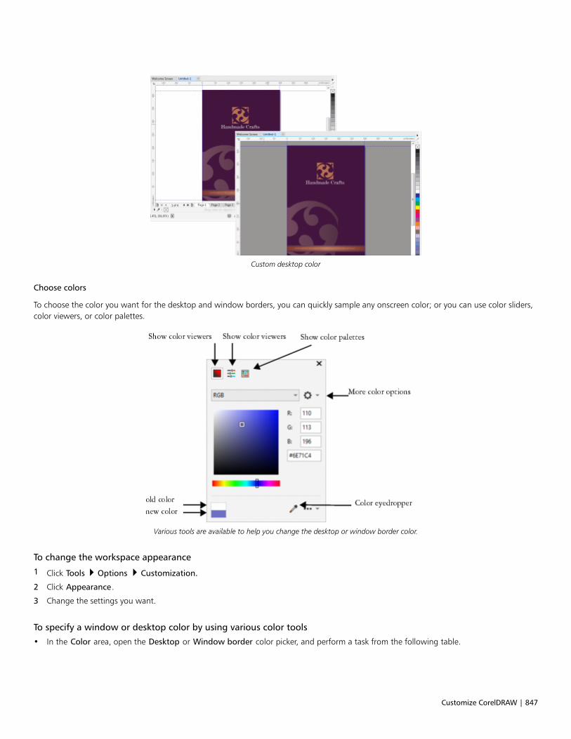
Customize CorelDRAW | 847
Custom desktop color
Choose colors
To choose the color you want for the desktop and window borders, you can quickly sample any onscreen color; or you can use color sliders,color viewers, or color palettes.
Various tools are available to help you change the desktop or window border color.
To change the workspace appearance
1 Click Tools Options Customization.
2 Click Appearance.
3 Change the settings you want.
To specify a window or desktop color by using various color tools
• In the Color area, open the Desktop or Window border color picker, and perform a task from the following table.
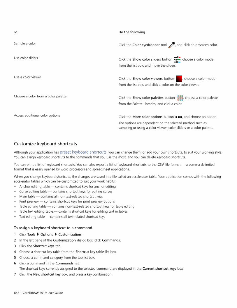
848 | CorelDRAW 2019 User Guide
To Do the following
Sample a color Click the Color eyedropper tool , and click an onscreen color.
Use color sliders Click the Show color sliders button , choose a color mode
from the list box, and move the sliders.
Use a color viewer Click the Show color viewers button , choose a color mode
from the list box, and click a color on the color viewer.
Choose a color from a color palette Click the Show color palettes button , choose a color palette
from the Palette Libraries, and click a color.
Access additional color options Click the More color options button , and choose an option.
The options are dependent on the selected method such assampling or using a color viewer, color sliders or a color palette.
Customize keyboard shortcuts
Although your application has preset keyboard shortcuts, you can change them, or add your own shortcuts, to suit your working style.You can assign keyboard shortcuts to the commands that you use the most, and you can delete keyboard shortcuts.
You can print a list of keyboard shortcuts. You can also export a list of keyboard shortcuts to the CSV file format — a comma delimitedformat that is easily opened by word processors and spreadsheet applications.
When you change keyboard shortcuts, the changes are saved in a file called an accelerator table. Your application comes with the followingaccelerator tables which can be customized to suit your work habits:• Anchor editing table — contains shortcut keys for anchor editing• Curve editing table — contains shortcut keys for editing curves• Main table — contains all non-text-related shortcut keys• Print preview — contains shortcut keys for print preview options• Table editing table — contains non-text-related shortcut keys for table editing• Table text editing table — contains shortcut keys for editing text in tables• Text editing table — contains all text-related shortcut keys
To assign a keyboard shortcut to a command
1 Click Tools Options Customization.
2 In the left pane of the Customization dialog box, click Commands.
3 Click the Shortcut keys tab.
4 Choose a shortcut key table from the Shortcut key table list box.
5 Choose a command category from the top list box.
6 Click a command in the Commands list.
The shortcut keys currently assigned to the selected command are displayed in the Current shortcut keys box.
7 Click the New shortcut key box, and press a key combination.

Customize CorelDRAW | 849
If the key combination is already assigned to another command, that command is listed in the Currently assigned to box.
8 Click Assign.
If the same keyboard shortcut is already assigned to another command, the second assignment overwrites the first. By enablingthe Navigate to conflict on assign check box, you can automatically navigate to the command whose shortcut you reassigned,prompting you to assign a new shortcut.
You can view all of the existing keyboard shortcuts by clicking View all.
To delete a keyboard shortcut
1 Click Tools Options Customization.
2 In the left pane of the Customization dialog box, click Commands.
3 Click the Shortcut keys tab.
4 Choose a shortcut key table from the Shortcut key table list box.
5 Choose a command category from the top list box.
6 Click a command in the Commands list.
7 Click a shortcut key in the Current shortcut keys box.
8 Click Delete.
To print keyboard shortcuts
1 Click Tools Options Customization.
2 In the left pane of the Customization dialog box, click Commands.
3 Click the Shortcut keys tab.
4 Click View all.
5 Click Print.
To export a list of keyboard shortcuts
1 Click Tools Options Customization.
2 In the left pane of the Customization dialog box, click Commands.
3 Click the Shortcut keys tab.
4 Click View all.
5 Click Export to CSV.
6 Choose the folder where you want to save the file.
7 Type a filename in the File name box.
8 Click Save.
Customize menus
Corel customization features let you modify the menu bar and the menus it contains. You can change the order of menus and menucommands; add, remove, and rename menus and menu commands. You can search for a menu command if you do not remember themenu in which it belongs. You can also reset menus to the default setting.
The customization options apply to the menu bar menus as well as to shortcut menus that you access by right-clicking.
850 | CorelDRAW 2019 User Guide
Help topics are based on the application’s default settings. When you customize menus and menu commands, the Help topics associatedwith them do not reflect your changes.
To change the order of menus and menu commands
1 Click Tools Options Customization.
2 In the left pane of the Customization dialog box, click Commands.
3 In the application window, drag a menu on the menu bar to the left or right.
If you want to change the order of menu commands, click a menu on the menu bar, click a menu command, and drag it up or down.
If you want to change the order of context menu commands, right-click in the application window to display the context menu, anddrag a menu command to a new position.
To rename a menu or menu command
1 Click Tools Options Customization.
2 In the left pane of the Customization dialog box, click Commands.
3 Choose a command category from the top list box.
4 Click a menu or command in the list.
5 Click the Appearance tab.
6 Type a name in the Caption box.
An ampersand (&) before a letter in the Caption box indicates a shortcut, also known as an accelerator key. Menus are displayed bypressing Alt + the letter. Commands are invoked by pressing the letter that is underlined when the menu is displayed.
You can reset the name to the default by clicking Restore defaults.
To add or remove an item on the menu bar
1 Click Tools Options Customization.
2 In the left pane of the Customization dialog box, click Commands.
If you want to remove an item, drag it off the menu bar.
3 Choose a command category from the top list box.
4 Drag an item to the menu bar.
To add or remove a command on a menu
1 Click Tools Options Customization.
2 In the left pane of the Customization dialog box, click Commands.
If you want to remove a command from a menu, click the menu name, and when the menu displays, drag the command off the menu.
3 Choose a command category from the top list box.
4 Drag a command to a menu in the application window.
To find a menu command quickly
1 Click Tools Options Customization.
2 In the left pane of the Customization dialog box, click Commands.

Customize CorelDRAW | 851
3 Click the Search button .
4 In the Find text dialog box, type the menu command in the Find what box.
5 Click Find next.
To reset menus to the default setting
1 Click Tools Options Customization.
2 In the left pane of the Customization dialog box, click Command Bars.
3 Choose Menu bar from the list.
4 Click Reset.
Customize toolbars
You can customize toolbar position and display. For example, you can move or resize a toolbar, and you can choose to hide or display atoolbar.
Toolbars can be either docked or floating. Docking a toolbar attaches it to the edge of the application window. Undocking a toolbar pullsit away from the edge of the application window, so it floats and can be easily moved around. You can create, delete, and rename customtoolbars. You can customize toolbars by adding, removing, and arranging toolbar items. You can adjust toolbar appearance by resizingbuttons; and displaying images, captions, or both. You can also edit toolbar button images.
When moving, docking, and undocking toolbars, you use the grab area of the toolbar.
For a The grab area is
Docked and unlocked toolbar Identified by a dotted line at the top or leftedge of the toolbar
Floating toolbar The title bar. If the title is not displayed, thegrab area is identified by a dotted line atthe top or left edge of the toolbar.
If you do not want to move docked toolbars by mistake, you can lock them. Locked toolbars do not have a dotted line along their left edge.
A locked toolbar
To customize toolbar position and display
To Do the following
Move a toolbar Unlock the toolbar, click the toolbar’s grab area, and drag thetoolbar to a new position.
Dock a toolbar Click the toolbar’s grab area, and drag the toolbar to any edge ofthe application window.
Undock a toolbar Unlock the toolbar, click the toolbar’s grab area, and drag thetoolbar away from the edge of the application window.
852 | CorelDRAW 2019 User Guide
To Do the following
Resize a floating toolbar Point to the edge of the toolbar and, using the two-directionalarrow, drag the edge of the toolbar.
Hide or display a toolbar Click Tools Options Customization. Click Command bars, anddisable or enable the check box next to the toolbar name.
Reset a toolbar to its default setting Click Tools Options Customization. Click Command bars,click a toolbar, and click Reset.
Docked toolbars cannot be moved when they are locked. For information about unlocking toolbars, see “To lock or unlock toolbars”on page 853.
To add, delete, or rename a custom toolbar
To Do the following
Add a custom toolbar Click Tools Options Customization. Click Command bars,click New, and type a name in the Command bars list. Close thedialog box. Holding down Alt + Ctrl, drag a tool or button in theapplication window to the new toolbar.
You can also drag commands from the Commands list in theCustomization dialog box.
Delete a custom toolbar Click Tools Options Customization. Click Command bars,click a toolbar, and click Delete.
Rename a custom toolbar Click Tools Options Customization. Click Command bars,click a toolbar name twice, and type a new name.
To add or remove an item on a toolbar
1 Click Tools Options Customization.
2 In the left pane of the Customization dialog box, click Commands.
3 Choose a command category from the top list box.
4 Drag a toolbar item from the list to a toolbar in the application window.
If you want to remove an item from a toolbar, drag the toolbar item off the toolbar.
To arrange toolbar items
1 Click Tools Options Customization.
2 In the left pane of the Customization dialog box, click Commands.
Customize CorelDRAW | 853
3 On the toolbar in the application window, drag the toolbar item to a new position.
If you want to move a toolbar item to another toolbar, drag the toolbar item icon from one toolbar to the other.
You can copy a toolbar item to another toolbar by holding down Ctrl while dragging a toolbar item. If the Options dialog box is notopen, you must hold down Alt+Ctrl.
To modify toolbar appearance
1 Click Tools Options Customization.
2 In the left pane of the Customization dialog box, click Command Bars.
3 Click a toolbar name in the list.
If you want to choose multiple toolbars, hold down Ctrl, and click the other toolbar names.
4 Choose a size from the Button list box.
5 From the Default button appearance list box, choose one of the following:
• Caption only
• Caption to right of image
• Default
• Image only
If you want to hide the title when the toolbar is floating, disable the Show title when toolbar is floating check box.
You can reset a built-in toolbar to its default settings by clicking Reset.
To edit a toolbar button image
1 Click Tools Options Customization.
2 In the left pane of the Customization dialog box, click Commands.
3 Choose a command category from the top list box.
4 Click a toolbar command.
5 Click the Appearance tab.
6 Edit the button image using the options in the Imagearea.
When you choose either Small or Medium in the Size list box, you edit the small or medium versions of a particular button image.You cannot edit the large version of a button image. For information about how to display all buttons as small, medium, or large, see“To modify toolbar appearance” on page 853.
You can reset toolbar button images to the default settings by clicking Restore defaults.
To lock or unlock toolbars
• Click Windows Toolbars Lock toolbars.
The Lock toolbars command is enabled when a check mark appears beside it. When you launch the application for the first time, thetoolbars are locked by default.

854 | CorelDRAW 2019 User Guide
Floating toolbars cannot be locked.
You can also lock or unlock toolbars by right-clicking a toolbar and clicking Lock toolbars.
Customize the toolbox
You can add or remove tools from the toolbox. If you modify the toolbox, you can reset the default settings at any time.
To customize the toolbox
1 On the toolbox, click the Quick customize button .
2 Enable or disable any of the check boxes.
You can also
Reset the toolbox Click the Reset toolbar button.
Customize the toolbox Click the Customize button.
Customize the property bar
You have control over the placement and content of the property bar. You can move the property bar anywhere on screen. Placing it insidethe application window creates a floating property bar. Placing it on any of the four sides of the application window docks it, making it partof the window border.
When moving, docking, or undocking the property bar, you use the grab area of the property bar, which is the same as the grab area of atoolbar. For more information about the grab area, see “Customize toolbars” on page 851.
You can also customize the property bar by adding or removing tools. This lets you customize what appears on the property bar when youchoose various tools. For example, when the Text tool is active, you can have the property bar display additional commands for text-relatedtasks such as increasing or decreasing font size, or changing case. You can also reset the property bar to its default settings.
To position the property bar
To Do the following
Move the property bar Unlock the property bar, click the property bar’s grab area, anddrag the property bar to a new position.
Undock the property bar Click the property bar’s grab area, and drag the property bar awayfrom the edge of the application window.
Customize CorelDRAW | 855
To Do the following
Dock the property bar Click the property bar’s grab area, and drag the property bar to anyedge of the application window.
To add or remove a toolbar item on the property bar
1 On the property bar, click the Quick customize button .
2 Enable or disable the check boxes next to the items that you want to add or remove.
You can also
Reset the toolbox Click the Reset toolbar button.
Customize the toolbox Click the Customize button.
The new item is displayed on the property bar for the active tool or task. When the property bar content changes, the item is notdisplayed. The new item is displayed again when the related tool or task is activated.
You can also customize the property bar by clicking Tools Options Customization. In the left pane of the Customization dialogbox, click Commands, choose a command category from the top list box, and then drag a toolbar item from the list to the propertybar. If you want to remove an item from the property bar, drag the toolbar item icon off the property bar.
To rearrange toolbar items on the property bar
1 Click Tools Options Customization.
2 In the left pane of the Customization dialog box, click Commands.
3 Drag the toolbar item icon to a new position on the property bar.
Customize the status bar
The status bar displays information about selected objects, such as color, fill type, and outline. The status bar also shows the current cursorposition and relevant commands. In addition, it displays document color information, such as the document color profile and color proofingstatus. You can customize the status bar by changing the information that is displayed and by resizing it. You can also customize the statusbar by adding, removing, and resizing toolbar items. In addition, you can restore the status bar to its default settings. You can also place thestatus bar at the top of the application window to see the displayed information more easily.
To change the information the status bar displays
• Click the flyout button next to the displayed information and choose one of the following options:
• Tool Hints
• Object Details
• Cursor Coordinates
• Document Color Settings

856 | CorelDRAW 2019 User Guide
To resize the status bar
1 Click Tools Options Customization.
2 Click Command bars.
3 Click Status bar, and enable the check box.
4 Type 1 or 2 in the Number of lines when docked box.
To add or remove a toolbar item on the status bar
1 Click Tools Options Customization.
2 Click Commands.
3 Choose a command category from the top list box.
4 Drag a toolbar item from the list to the status bar.
If you want to remove a toolbar item from the status bar, drag the item off the status bar.
To resize toolbar items on the status bar
1 Click Tools Options Customization.
2 Click Command bars.
3 Click Status bar, and enable the check box.
4 Choose one of the following options from the Button list box:
• Small
• Medium
• Large
Only toolbar items you have added to the status bar are affected by resizing. The size of the default icons remains unchanged.
To change the position of the status bar• Right-click the status bar, click Customize Status bar Position, and click Top or Bottom.
To restore the status bar default settings
• Right-click the status bar, and click Customize Status bar Reset to default.
Customize filters
Filters are used to convert files from one format to another. They are organized into four types: raster, vector, animation, and text. You cancustomize filter settings by adding or removing filters so that only the filters you need are loaded. You can also change the order of the listof filters and reset filters to the default setting.
To add a filter
1 Click Tools Options Global.
2 Click File Formats.
3 Click a type of filter in the Available file types list.
4 Click a filter.
5 Click Add.

Customize CorelDRAW | 857
To remove a filter
1 Click Tools Options Global.
2 Click File Formats.
3 Click a filter in the Active filters list.
4 Click Remove.
To change the order of the list of filters
1 Click Tools Options Global.
2 Click File Formats.
3 Click a filter in the Active filters list.
4 Click one of the following:
• Move Up — moves the filter up the list
• Move Down — moves the filter down the list
You can reset the Active filters list to the default setting by clicking Reset to Default.

858 | CorelDRAW 2019 User Guide

Use macros and scripts to automate tasks | 859
Use macros and scripts to automate tasks
You can use macros and scripts to speed up repetitive tasks, combine multiple or complex actions, or make an option more easily accessible.You create macros by using the built-in features for Visual Basic for Applications (VBA) or Visual Studio Tools for Applications (VSTA), andyou can create scripts by using the built-in JavaScript features.
Using a macro (or script) is similar to using the speed-dialing feature on a phone. On many phones, you can set a frequently dialed numberto a speed-dial button; then, the next time you need to dial that number, you can save time by pressing its speed-dial button. Similarly, amacro lets you set the actions that you want to repeat; then, the next time that you need to repeat those actions, you can save time byplaying that macro.
This section contains the following topic:
• “Macros” (page 859)
• “JavaScript scripts” (page 866)
Macros
You can save time by using a macro to automate a series of repetitive tasks. A macro lets you specify a sequence of actions so that you canquickly repeat those actions later.
You don’t need any programming experience to use macros — in fact, the basic tools for working with macros are available within themain application window. However, if you want to have more control over your macros, you can use the following built-in programmingenvironments:
• Microsoft Visual Studio Tools for Applications (VSTA) — the successor to VBA, and an excellent choice for developers and otherprogramming experts. VSTA provides the tools and features that you need to create the most advanced macro projects.
• Microsoft Visual Basic for Applications (VBA) — a subset of the Microsoft Visual Basic (VB) programming environment, and an excellentchoice for beginners. You can use VBA to create basic macros for personal use, but you can also use it to create more advanced macroprojects.
For detailed information on the differences between VBA and VSTA, please see the programming guide on the Developer area on theCorelDRAW community website.
Getting started with macros
The macro features for VBA and VSTA are installed with the software by default, but you can manually install these features if necessary. Youcan specify options for the VBA feature.

860 | CorelDRAW 2019 User Guide
To use VSTA macro features with CorelDRAW, you must have Microsoft Visual Studio 2017 installed. To use the VSTA Editor, youmust first install Microsoft Visual Studio 2017, Community, Professional, Premium, Ultimate or Enterprise Edition; and then reinstallMicrosoft Visual Studio Tools for Applications 2017 from microsoft.com.
If you install Microsoft Visual Studio after installing CorelDRAW Graphics Suite, you must re-install the VSTA macro features bymodifying your CorelDRAW Graphics Suite installation. For more information, see “To manually install the macro features” on page861.
The macro features provide several tools for working with macros in the main application window:• Macros toolbar — provides easy access to common macro functions• Scripts docker — provides easy access to all available macro projects for VBA, and to basic functions for working with those projects• Script Editor (formerly the Visual Basic Editor) — provides advanced functions for creating VBA-based macro projects• Visual Studio Editor — provides advanced functions for creating VSTA-based macro projects. The VSTA Editor is accessible only if you
have Microsoft Visual Studio 2017 installed.
Creating macros
Macros are stored in modules (also called “code modules”), which are stored in macro projects. The Scripts docker lets you view and manageall of the macro projects, modules, and macros that are available to you.
You can use the Scripts docker to create macro projects in the form of Global Macro Storage (GMS) files or Corel VSTA Projects (CGSaddon).Using such files is an excellent way to bundle the components of your macro project for sharing with others. You can use the Scripts dockerto open (or “load”) the macro projects that you create, as well as the macro projects that install with the software or that are otherwisemade available to you. You can also use the Scripts docker to rename macro projects, as well as to copy and close (or “unload”) GMS-basedand VSTA macro projects.
Some macro projects are locked and cannot be modified.
When you create a document, a macro project for that document is automatically added to the Scripts docker. Although you canstore macros within the macro project for a document — for example, to create an all-in-one template — it is recommended that youinstead use GMS files to store your macro projects.
Each macro project contains at least one module. You can use the Scripts docker to add a module to a VBA-based macro project, or to openexisting modules for editing. You can also use the Scripts docker to rename or delete VBA modules.
The editing feature is disabled for some modules.
Finally, you can use the Scripts docker to create macros within the available modules. You don’t need any programming experience to createmacros; however, if you have programming experience and want to edit VBA macros, you can do so by using the Script Editor. You can alsouse the Scripts docker to rename and delete VBA macros.
Recording macros
You can record macros and save them for later use.
You can also record temporary macros for actions that you need to repeat only a few times. A temporary macro is accessible until a newtemporary macro is recorded.
The recording feature is disabled for some macro projects.

Use macros and scripts to automate tasks | 861
Before recording a macro, make sure that you know exactly which actions you want to record and the order in which you wantto record them. When you start recording, the macro recorder captures every change that you make in a drawing. For example, ifyou create a shape, resize the shape, and then change its color, the macro records all the changes. When you are done making thechanges, you must stop recording the macro.
Playing macros
You can perform the actions that are associated with a macro by playing that macro.
You can also play a temporary macro.
Learning more about macros
The Developer area on the CorelDRAW community website can help you with its wealth of useful resources: a programming guide, detailedObject Model reference documentation with code samples, object model diagrams, and in-depth programming articles and tutorials.
The Object Model reference documentation, also referred to as API documentation, includes help on every feature and function that canbe automated in the applications. (Collectively, these features and functions are called an “object model.”) You can easily access relevantdocumentation from within the Script Editor.
The Object Model diagrams provide a hierarchical representation of the features and functions that can be automated in CorelDRAW, CorelPHOTO-PAINT, and Corel DESIGNER.
For more detailed information about VBA and its programming environment, please consult the Microsoft Visual Basic Help from theHelp menu in the Script Editor.
For more detailed information about VSTA and its programming environment, please consult the Help menu in the VSTA Editor.
To manually install the macro features
1 On the Windows Control Panel, click Uninstall a program.
2 Double-click CorelDRAW Graphics Suite 2019 on the Uninstall or change a program page.
3 Enable the Modify option in the wizard that appears, and follow the instructions.
4 On the Features page of the installation wizard, enable the following check boxes in the Utilities list box:
• Visual Basic for Applications
• Visual Studio Tools for Applications
The macro features for VBA and VSTA are installed with the software by default.
To specify VBA options
1 Click Tools Options CorelDRAW.
2 Click VBA.
3 In the Security area, specify how to control the risk of running malicious macros by clicking Security Options.
If you want to bypass this security feature, enable the Trust all installed GMS modules check box, and then proceed to step 6.
4 On the Security level page of the Security dialog box, enable one of the following options:
• Very high — allows only macros installed in trusted locations to run. All other signed and unsigned macros are disabled.
• High — allows only signed macros from trusted sources to run. Unsigned macros are automatically disabled.

862 | CorelDRAW 2019 User Guide
• Medium — lets you choose which macros run, even if they are potentially harmful
• Low (not recommended) — allows all potentially unsafe macros to run. Enable this setting if you have virus-scanning softwareinstalled, or if you check the safety of all documents that you open.
5 On the Trusted publishers page of the Security dialog box, review which macro publishers are trusted. Click View to display details onthe selected macro publisher, or click Remove to delete the selected macro publisher from the list.
If desired, you can enable or disable the Trust access to Visual Basic project check box for the selected macro publisher.
6 Disable the Delay load VBA check box if you want to load the VBA feature at start-up.
To access the macro tools
To Do the following
Display the Macros toolbar Click Window Toolbars Macros.
A check mark next to the command indicates that the toolbar isdisplayed.
Display the Scripts docker Click Tools Scripts Scripts.
Display the Script Editor Do one of the following:•Click Tools Scripts Script Editor.•Click the Script Editor button on the Macros toolbar.
•Right-click Visual Basic for Applications in the Scripts docker,and then click Show IDE.
Display the Visual Studio Editor Click Tools Scripts Visual Studio Editor. (VSTA must beinstalled on your computer.)
To create a macro project
• In the Scripts docker, do one of the following:
• Click Visual Studio Tools for Applications in the list, click New, and then click New macro project.
• Click Visual Basic for Applications in the list, click New, and then click New macro project.
You can also
Open (or “load”) a macro project Do one of the following:•Click Visual Studio Tools for Applications in the list, click Load,
and then choose the project.•Click Visual Basic for Applications in the list, click Load, and
then choose the project.
Rename a macro project Right-click the project in the list, and then click Rename.
Copy a GMS-based macro project Right-click the project in the list, click Copy to, and then choose thetarget location for the copied project.

Use macros and scripts to automate tasks | 863
You can also
You cannot copy a document-based macro project. Such projectsare stored within a document and cannot be managed separatelyfrom that document.
Display or hide all modules in the list Click the Simple mode button .
Add a module to a VBA macro project Do one of the following:•Click the project in the list, click New, and then click New
module.•Right-click the project in the list, and then click New module.
Edit a module in a VBA macro project Do one of the following:•Click the module in the list, and then click the Edit button .
•Right-click the module in the list, and then click Edit.
Rename a module in a macro project Right-click the module in the list, and then click Rename.
Delete a module from a macro project Do one of the following:•Click the module in the list, and then click the Delete button
.
•Right-click the module in the list, and then click Delete.
Close (or “unload”) a GMS-based macro project Right-click the macro project in the list, and then click Unloadmacro project.
You can close a document-based macro project only by closing thedocument in which it is stored.
Some macro projects are locked and cannot be modified.
To create a macro
• In the Scripts docker, do one of the following:
• Click the container you want, click New, and then click New macro.
• Right-click the desired container module, and then click New macro.
You can also
Edit a macro Do one of the following:•Click the macro in the list, and then click the Edit button .
•Right-click the macro in the list, and then click Edit.
Delete a macro Do one of the following:•Click the macro in the list, and then click the Delete button .

864 | CorelDRAW 2019 User Guide
You can also
•Right-click the macro in the list, and then click Delete.
Some macro projects are locked and cannot be modified.
To record a macro
1 Click Tools Scripts Start Recording.
The Record macro dialog box appears.
2 In the Macro name box, type a name for the macro.
Macro names can contain numerals, but they must begin with a letter. Macro names cannot contain spaces or non-alphanumericcharacters other than underscores ( _ ).
3 In the Save Macro In box, choose the macro project to which you want to save the macro.
4 Type a description of the macro in the Description box, and then click OK.
5 Perform the actions that you want to record.
The application begins recording your actions. If you want to pause recording, click Tools Macros Pause recording. Repeat this stepto resume recording.
6 To stop recording, click File Scripts Stop Recording.
You can also
Save the actions in the Undo list as a VBA macro or a script Click Window Dockers History, perform the actions that you
want to record, and then click the Save as a script button in
the History docker.
You cannot record a macro if all available macro projects are locked.
Not all actions can be recorded — some because of their complexity (although many such actions can be manually coded inthe Script Editor). When an action cannot be recorded, a comment is placed in the macro code (“The recording of thiscommand is not supported.”), but the recording process continues until you stop it. You can view any comments in the codeby opening the macro in the Script Editor.
By default, macros are recorded in the GlobalMacros project so that they can be accessed from other documents. However, youcan change the default macro project for recordings by right-clicking another project in the Scripts docker, and then clicking Set asrecording project. You cannot specify a locked macro project.
You can cancel recording a macro, and discard any commands recorded thus far, by clicking Tools Macros Cancel recording.
You can also record, pause, and stop recording a macro by using the Macros toolbar or the Scripts docker (File Scripts Scripts).
To record a temporary macro
1 Click Tools Scripts Record Temporary Script.
2 Perform the actions that you want to record.
The application begins recording your actions. If you want to pause recording, click Tools Scripts Pause Recording. Repeat this stepto resume recording.
Use macros and scripts to automate tasks | 865
3 To stop recording, click File Scripts Stop Recording.
The macro is temporarily saved to the default recording project. When the current session is ended, the macro is deleted from thatproject.
You cannot record a temporary macro if all available macro projects are locked.
Not all actions can be recorded.
By default, macros are recorded in the GlobalMacros project so that they can be accessed from other documents. However, youcan change the default recording project by right-clicking another project in the Scripts docker, and then clicking Set as recordingproject. (You cannot specify a locked macro project.) If you want, you can create multiple temporary recordings by assigning eachone to its own macro project.
You can cancel recording a macro, and discard any commands recorded thus far, by clicking Tools Scripts Cancel Recording.
You can also pause and stop recording a temporary macro by using the Macros toolbar or the Scripts docker (Tools Scripts Scripts).
To play a macro
• Do any of the following:
• Click Tools Scripts Run Script, or click the Run macro button on the Macros toolbar. From the Macros in list box, choose
the project or file in which the macro is stored. From the Macro name list, choose the macro. Click Run.
• In the Scripts docker, double-click the macro in the list.
• In the Scripts docker, click the macro in the list, and then click the Run button .
• In the Scripts docker, right-click the macro in the list, and then click Run.
To play a temporary macro
• Click Tools Scripts Run Temporary Script.
This option is enabled only after you record a temporary macro.
If you have created multiple temporary macros, you must specify which macro project contains the one that you want to run. Right-click the project in the Scripts docker, and then click Set as recording project.
To access Object Model reference documentation from within the Script Editor
1 While in Microsoft Visual Basic for Applications, press F2 to display the Object Browser.
The Object Browser displays all the features and functions that can be automated in the Script Editor.
2 Choose VGCore from the Library list box.
The Object Browser is updated to display only the features and functions of CorelDRAW that can be automated in the Script Editor.Collectively, these features and functions are called an “object model.”
3 Click an item in the Object Browser, and press F1.
You can also display information for any item in the Code window of the Script Editor by clicking that item and pressing F1.

866 | CorelDRAW 2019 User Guide
JavaScript scripts
You can save time by using a JavaScript script to automate a series of repetitive tasks.
The Scripts docker (Tools Scripts Scripts) provides easy access to scripts. Scripts are organized in modules. You can use the Scriptsdocker to create new modules, and to load and record scripts. You can also use the Scripts docker to rename and delete scripts.
You can record scripts and save them for later use. You can also record temporary scripts for actions that you need to repeat only a fewtimes. A temporary script is accessible until a new temporary script is recorded.
Before recording a script, make sure that you know exactly which actions you want to record and the order in which you wantto record them. When you start recording, the script recorder captures every change that you make in a drawing. For example, ifyou create a shape, resize the shape, and then change its color, the script records all the changes. When you are done making thechanges, you must stop recording the script.
You can perform the actions that are associated with a script by playing that script. You can also play a temporary script
To create a script module
• In the Scripts docker, click User Scripts, and then, click New New Module.
To hide all modules in the list and show only the list of scripts, click the Simple mode button .
To load a script
• In the Scripts inspector, click Load, and then choose a script.
To record a script
1 Click Tools Scripts Start Recording.
The Record script dialog box appears.
2 In the Macro name box, type a name for the script.
3 In the Save Macro In box, choose the macro project to which you want to save the macro.
4 Type a description of the script in the Description box, and then click OK.
5 Perform the actions that you want to record.
The application begins recording your actions. If you want to pause recording, click Tools Scripts Pause recording. Repeat this stepto resume recording.
6 To stop recording, click Tools Scripts Stop Recording.
You can cancel recording a macro, and discard any commands recorded thus far, by clicking Tools Scripts Cancel Recording.
You can also record, pause, and stop recording a macro by using the Scripts docker (Tools Scripts Scripts).
To record a temporary script
1 Click Tools Scripts Record Temporary Script.
2 Perform the actions that you want to record.

Use macros and scripts to automate tasks | 867
The application begins recording your actions. If you want to pause recording, click Tools Scripts Pause Recording. Repeat this stepto resume recording.
3 To stop recording, click Tools Scripts Stop Recording.
The script is temporarily saved to the default recording project. When the current session is ended, the script is deleted from that project.
Not all actions can be recorded.
You can cancel recording a script, and discard any commands recorded thus far, by clicking Tools Scripts Cancel Recording.
You can also pause and stop recording a temporary macro by using the Scripts docker (Tools Scripts Scripts).
To play a script
• In the Scripts docker, click the script in the list, and then click the Run button .
To edit a script
• In the Scripts docker, click the script in the list, and then click the Edit button .
To rename a script
• In the Scripts docker, click the script name twice and type the new name.
To delete a script
• In the Scripts docker, click the script in the list, and then click the Delete button .

868 | CorelDRAW 2019 User Guide

Reference | 869
Reference
CorelDRAW for Adobe Illustrator users................................................................................................................................................ 871
Glossary............................................................................................................................................................................................... 877

870 | CorelDRAW 2019 User Guide
CorelDRAW for Adobe Illustrator users | 871
CorelDRAW for Adobe Illustrator users
Adobe Illustrator and CorelDRAW have many similarities, which makes it easy to move from one graphics application to the other. Althoughthey share most basic drawing and design capabilities, Adobe Illustrator and CorelDRAW are distinguished by some differences in bothterminology and tools. Understanding these differences lets you make a quick transition to CorelDRAW.
This section contains the following topics:• “Comparing terminology” (page 871)• “Comparing tools” (page 872)• “Using the Adobe Illustrator workspace” (page 875)
Comparing terminology
The terms and concepts in Adobe Illustrator and CorelDRAW differ for some features. Adobe Illustrator terms are listed below with theirCorelDRAW equivalents.
Adobe Illustrator term CorelDRAW term
Actions/Scripts Macros/Scripts
Anchor points Nodes
Artwork Drawing
Clipping mask PowerClip
Direction points Control handles
Guides Guidelines
Smart guides Dynamic guides
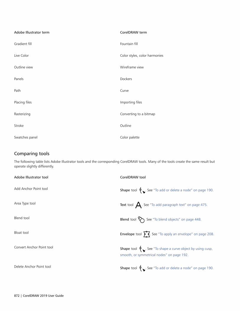
872 | CorelDRAW 2019 User Guide
Adobe Illustrator term CorelDRAW term
Gradient fill Fountain fill
Live Color Color styles, color harmonies
Outline view Wireframe view
Panels Dockers
Path Curve
Placing files Importing files
Rasterizing Converting to a bitmap
Stroke Outline
Swatches panel Color palette
Comparing tools
The following table lists Adobe Illustrator tools and the corresponding CorelDRAW tools. Many of the tools create the same result butoperate slightly differently.
Adobe Illustrator tool CorelDRAW tool
Add Anchor Point tool Shape tool . See “To add or delete a node” on page 190.
Area Type tool Text tool . See “To add paragraph text” on page 475.
Blend tool Blend tool . See “To blend objects” on page 448.
Bloat tool Envelope tool . See “To apply an envelope” on page 208.
Convert Anchor Point tool Shape tool . See “To shape a curve object by using cusp,
smooth, or symmetrical nodes” on page 192.
Delete Anchor Point tool Shape tool . See “To add or delete a node” on page 190.

CorelDRAW for Adobe Illustrator users | 873
Adobe Illustrator tool CorelDRAW tool
Direct Selection tool Shape tool . See “To select a node” on page 177.
Drop Shadow tool Drop shadow tool . See “To add a drop shadow” on page
442.
Gradient tool Interactive fill tool . See “Fountain fills” on page 366.
Line Segment tool Freehand tool . See “To draw a curve by using the 3-point
curve tool ” on page 129.
Polyline tool . See “Lines” on page 121.
Live Paint Bucket tool Smart fill tool . See “To apply a fill to an enclosed area” on
page 384.
Live Trace command Bitmaps Quick Trace command
Bitmaps Centerline Trace command
Bitmaps Outline Trace command. See “To trace a bitmap byusing the Outline Trace method” on page 707.
Measure tool Dimension tool . See “Dimension lines” on page 157.
Mesh tool Mesh fill tool . See “To apply a mesh to an object” on page
381.
Paintbrush tool Artistic media tool . See “To draw a calligraphic line ” on page
131.
Brush tool . See “Brushstrokes” on page 148.
Pan tool Pan tool . See “To pan in the drawing window” on page 51.
Path Type tool Text tool . See “To fit text to a path” on page 489.
Pathfinder effects Object Shaping commands. See “Trim objects ” on page 220and “Weld and intersect objects” on page 225.

874 | CorelDRAW 2019 User Guide
Adobe Illustrator tool CorelDRAW tool
Pencil tool Freehand tool . See “To draw a line by using the Freehand
tool” on page 124.
Pucker tool Envelope tool . See “To apply an envelope” on page 208.
Reflect tool Mirror buttons. See “To mirror an object” on page 293.
Reshape tool Shape tool . See “To stretch, scale, rotate, or skew nodes” on
page 193.
Rotate tool Pick tool . See “To rotate an object” on page 292.
Rounded Rectangle tool Rectangle tool . See “To draw a rectangle or square with
rounded, scalloped, or chamfered corners” on page 165.
Save For Microsoft Office command File Export For Office command
Scale tool Pick tool . See “Size and scale objects” on page 290.
Scissors tool Knife tool . See “To split an object” on page 219.
Selection tool Pick tool . See “To select objects” on page 253.
Shear tool Pick tool . See “Skew and stretch objects” on page 195.
Star tool Star and Complex star tools. See “To draw a star” on
page 168.
Symbol Sprayer tool Sprayer tool . See “To spray a pattern” on page 151.
Twirl tool Distort tool . See “To distort an object” on page 204.
Type tool Text tool . See “To add paragraph text ” on page 475 and “To
add artistic text” on page 473.

CorelDRAW for Adobe Illustrator users | 875
Adobe Illustrator tool CorelDRAW tool
Vertical Type tool Paragraph formatting docker. See “To choose a text orientation forAsian text” on page 523.
Warp tool Smudge tool . See “To smudge an object” on page 197.
Envelope tool. See “Shape objects by using envelopes” on page206.
Wrinkle tool Roughen tool . See “To roughen an object” on page 199.
Using the Adobe Illustrator workspace
CorelDRAW includes a workspace that has the look and feel of Adobe Illustrator. This workspace can help you find menu commands andtools more easily. For information about changing your workspace, see “To choose a workspace” on page 85.

876 | CorelDRAW 2019 User Guide
Glossary | 877
Glossary
A B C D E F G H I J K L M N O P Q R S T U V W Z
A
accelerator table
A file that contains a list of shortcut keys. Different tables are active depending on the task that you are performing.
add-in
A separate module that extends the functionality of an application.
alignment guides or live guides
Temporary guidelines that help align objects as you create, resize, or move them in relation to other nearby objects.
anchor point
The point that remains stationary when you stretch, scale, mirror, or skew an object. Anchor points correspond to the eight handles thatappear when an object is selected, as well as the center of a selection box marked by an X.
animation file
A file that supports moving images; for example, animated GIF and QuickTime (MOV).
anti-aliasing
A method of smoothing curved and diagonal edges in images. Intermediate pixels along edges are filled to smooth the transition betweenthe edges and the surrounding area.
arrow keys
Direction keys that move or “nudge” selected objects in small increments. You can also use arrow keys to position the cursor when you typeor edit text on-screen or in a dialog box.
artistic text
A type of text created with the Text tool. Use artistic text to add short lines of text, such as titles, or to apply graphic effects, such asfitting text to a path, creating extrusions and blends, and creating all other special effects. An artistic text object can contain up to 32,000characters.
aspect ratio
The ratio of the width of an image to its height (expressed mathematically as x:y). For example, the aspect ratio of an image that is 640 x480 pixels is 4:3.

878 | CorelDRAW 2019 User Guide
B
base color
The color of the object that appears under a transparency. The base color and the color of the transparency combine in various waysdepending on the merge mode you apply to the transparency.
baseline
An invisible line upon which text characters sit.
baseline grid
A series of evenly spaced horizontal lines that follow the pattern of a ruled notebook and help align text and objects.
baseline shift
The process of moving text characters above or below the baseline.
Bézier line
A straight or curved line made up of segments connected by nodes. Each node has control handles that allow the shape of the line to bemodified.
bit depth
The number of binary bits that define the shade or color of each pixel in a bitmap. For example, a pixel in a black-and-white image has adepth of 1 bit, because it can only be black or white. The number of color values that a given bit depth can produce is equal to 2 to the
power of the bit depth. For example, a bit depth of 1 can produce two color values (2 1=2), and a bit depth of 2 can produce 4 color values
(2 2 = 4).
Bit depth ranges between 1 and 64 bits per pixel (bpp) and determines the color depth of an image.
bitmap
An image composed of grids of pixels or dots.
See also vector graphic.
black point
A brightness value that is considered black in a bitmap image. In Corel PHOTO-PAINT, you can set the black point to improve the contrast ofan image. For example, in a histogram of an image, with a brightness scale of 0 (dark) to 255 (light), if you set the black point at 5, all pixelswith a value greater than 5 are converted to black.
black-and-white color mode
A 1-bit color mode that stores images as two solid colors — black and white — with no gradations. This color mode is useful for line art andsimple graphics. To create a black-and-white photo effect, you can use the grayscale color mode.
See also grayscale.
bleed
The part of the printed image that extends beyond the edge of the page. The bleed ensures that the final image goes right to the edge ofthe paper after binding and trimming.
blend
An effect created by transforming one object into another through a progression of shapes and colors.
bookmark
An indicator for marking an address on the Internet.
bounding box
The invisible box indicated by the eight selection handles surrounding a selected object.
Glossary | 879
brightness
The amount of light that is transmitted or reflected from a given pixel. In the HSB color mode, brightness is a measure of how much white acolor contains. For example, a brightness value of 0 produces black (or shadow in photos), and a brightness value of 255 produces white (orhighlight in photos).
C
calligraphic angle
The angle that controls the orientation of a pen to the drawing surface, like the slant of the nib on a calligraphy pen. A line drawn at thecalligraphic angle has little or no thickness, but widens as its angle gets farther from the calligraphic angle.
cascading style sheet (CSS)
An extension to HTML that allows styles such as color, font, and size to be specified for parts of a hypertext document. Style information canbe shared by multiple HTML files.
See also HTML.
center of rotation
The point around which an object rotates.
CGI script
An external application that is executed by an HTTP server in response to an action you perform in a web browser, such as clicking a link,image, or another interactive element of a webpage.
character
A letter, number, punctuation mark, or other symbol.
child color
A color style created as a shade of another color style. For most of the available color models and palettes, child colors share the same hue asthe parent, but have different saturation and brightness levels.
See also parent color.
choke
In commercial printing, a form of trapping created by extending the background object into the foreground object.
clipart
Ready-made images that can be imported into Corel applications and edited if required.
Clipboard
An area that is used to temporarily store cut or copied information. The information is stored until new information is cut or copied to theClipboard, replacing the old.
clone
A copy of an object or an area of an image that is linked to a master object or image area. Most changes made to the master areautomatically applied to its clones.
See also symbol.
closed object
An object defined by a path whose start point and end point are connected.
closed path
A path whose start point and end point are connected.
color cast
A color tint that often occurs in photos as a result of lighting conditions or other factors. For example, taking a photo indoors in dimincandescent light can result in a yellow color cast, and taking a photo outdoors in bright sunlight can result in a blue color cast.

880 | CorelDRAW 2019 User Guide
color depth
The maximum number of colors an image can contain. Color depth is determined by the bit depth of an image and the displaying monitor.For example, an 8-bit image can contain up to 256 colors, while a 24-bit image can contain roughly up to 16 million colors. A GIF image isan example of an 8-bit image; a JPEG image is an example of a 24-bit image.
control object or control group
An object or a group of objects to which a special effect, such as an extrusion, blend, drop shadow, or contour, is applied. You can edit thecontrol object or group by changing its shape, color or position or by applying a transformation, thus modifying the overall appearance ofthe special effect.
With blends, the start and end objects of the blend are the control objects.
CMY
A color mode made up of cyan (C), magenta (M), and yellow (Y). This mode is used in the three-color printing process.
CMYK
A color mode made up of cyan (C), magenta (M), yellow (Y), and black (K). CMYK printing produces true blacks and a wide tonal range. Inthe CMYK color mode, color values are expressed as percentages; therefore, a value of 100 for an ink means that the ink is applied at fullsaturation.
code page
A code page is a table in the DOS or Windows operating system that defines which ASCII or ANSI character set is used for displaying text.Different character sets are used for different languages.
color channel
An 8-bit grayscale version of an image. Each channel represents one level of color in the image; for example, RGB has three color channels,while CMYK has four. When all the channels are printed together, they produce the entire range of colors in the image.
See also RGB and CMYK.
color gamut
The range of colors that can be reproduced or perceived by any device. For example, a monitor displays a different color gamut than aprinter, making it necessary to manage colors from original images to final output.
color mode
A system that defines the number and kind of colors that make up an image. Black-and-white, grayscale, RGB, CMYK, and paletted areexamples of color modes.
color model
A simple color chart that defines the range of colors displayed in a color mode. RGB (red, green, blue), CMY (cyan, magenta, yellow), CMYK(cyan, magenta, yellow, black), HSB (hue, saturation, brightness), HLS (hue, lightness, saturation), and CIE L*a*b (Lab) are examples of colormodels.
color palette
A collection of solid colors from which you can choose colors for fills and outlines.
color profile
A description of the color-handling capabilities and characteristics of a device.
color separation
In commercial printing, the process of splitting colors in a composite image to produce a number of separate grayscale images, one for eachprimary color in the original image. In the case of a CMYK image, four separations (one for cyan, magenta, yellow, and black) must be made.
color space
In electronic color management, a virtual representation of a device or the color gamut of a color model. The boundaries and contours of adevice’s color space are mapped by color management software.
See also color gamut.
Glossary | 881
color swatch
A solid-colored patch in a color palette.
color trapping
A printing term used to describe a method of overlapping colors to compensate for misaligned color separations (misregistration). Thismethod avoids white slivers that appear between adjoining colors on a white page.
See also spread, choke, and overprinting.
color value
A set of numbers that define a color in a color mode. For example, in the RGB color mode, color values of 255 for red (R) and zero for bothgreen (G) and blue (B) result in the color red.
combined object
An object created by combining two or more objects and converting them into a single curve object. A combined object takes on the filland outline attributes of the last selected object. Sections where an even number of objects overlapped have no fill. Sections where an oddnumber of objects overlapped are filled. The outlines of the original objects remain visible.
compound blend
A blend created by blending the start or end object of one blend with another object.
concave
Hollowed or rounded inward like the inside of a bowl.
content
The object or objects that appear inside a container object when you apply PowerClip effects.
This term is also used to describe graphics resources included with the product such as clipart, photos, symbols, fonts, and objects.
constrain key
A key you hold to constrain drawing and editing to a shape or at an angle. The default key is Ctrl. You can change the default key to Shift,the Windows standard, on the Pick tool page of the Options dialog box.
contour
An effect created by adding evenly spaced concentric shapes inside or outside the borders of an object. This effect can also be used forcreating cuttable outlines for devices, such as plotters, engraving machines, and vinyl cutters.
contrast
The difference in tone between the dark and light areas of an image. Higher contrast values indicate greater differences and fewergradations between dark and light.
control object
The original object used to create effects such as envelopes, extrusions, drop shadows, contours, and objects created with the Artistic mediatool. Changes made to the control object control the appearance of the effect.
control handles (CorelDRAW)
The handles that extend from a node along a curve that is being edited with the Shape tool. Control handles determine the angle at whichthe curve passes through the node.
convex
Curved or rounded outwards like the exterior of a sphere or circle.
crop
To cut unwanted areas of an image without affecting the resolution of the part that remains.
curve object
An object that has nodes and control handles, which you can manipulate to change the object’s shape. A curve object can be any shape,including a straight or curved line.

882 | CorelDRAW 2019 User Guide
cusp
A point or corner created where two curves meet.
D
desktop
The area in a drawing where you can experiment and create objects for future use. This area is outside the borders of the drawing page. Youcan drag objects from the desktop area to the drawing page when you decide to use them.
DeviceN
A type of color space and device color model. This color space is multi-component, allowing color to be defined by other than the standardset of three (RGB) and four (CMYK) color components.
diacritical mark
An accent mark above, below, or through a written character; for example, the acute (é) and cedilla (ç) accents.
dimension line
A line that displays the size of objects or the distance or angle between objects.
dithering
A process used to simulate a greater number of colors when only a limited number of colors are available.
document grid
A series of evenly spaced horizontal and vertical lines that are used to help draw and arrange objects.
document navigator
The area at the bottom-left of the application window that contains controls for moving between pages and adding pages. The documentnavigator also displays the page number of the active page and the total number of pages in a drawing.
dpi (dots per inch)
A measure of a printer’s resolution in dots per inch. Typical desktop laser printers print at 600 dpi. Imagesetters print at 1270 or 2540 dpi.Printers with higher dpi capabilities produce smoother and cleaner output. The term dpi is also used to measure scanning resolution and toindicate bitmap resolution.
drawing
A document you create in CorelDRAW.
drawing page
The portion of a drawing window enclosed by a rectangle with a shadow effect.
drawing window
The portion of the application window on which you can create, add, and edit objects.
drop shadow
A three-dimensional shadow effect that gives objects a realistic appearance.
duotone
An image in the duotone color mode is an 8-bit grayscale image that has been enhanced with one to four additional colors.
dynamic guides
Temporary guidelines that appear from the following snap points in objects — center, node, quadrant, and text baseline.
E
embedding
The process of placing an object created in one application into a document created in a different application. Embedded objects areincluded entirely in the current document; they are not linked to their source files.

Glossary | 883
encoding
Determines the character set of text, letting you correctly display text in the appropriate language.
envelope
A closed shape that can be placed around an object to change the object’s shape. An envelope consists of segments connected by nodes.After an envelope has been placed around an object, the nodes can be moved to change the shape of the object.
exposure
A photographic term referring to the amount of light used to create an image. If not enough light is permitted to interact with the sensor (ina digital camera) or film (in a traditional camera), the image appears too dark (underexposed). If too much light is permitted to interact withthe sensor or film, the image appears too light (overexposed).
extrusion
A feature that lets you apply a three-dimensional perspective by projecting lines from an object to create the illusion of depth.
F
feathering
The level of sharpness along the edges of a drop shadow.
fill
A color, bitmap, fountain, or pattern applied to an area of an image.
filter
An application that translates digital information from one form to another.
floating object
A bitmap with no background. Floating objects are also referred to as photo objects or cutout images.
font
A set of characters with a single style (such as italic), weight (such as bold), and size (such as 10 point) for a typeface such as Times NewRoman.
fountain fill
A smooth progression of two or more colors applied to an area of an image that follow a linear, radial, conical, or square path. Two-colorfountain fills have a direct progression from one color to another, while custom fills may have a progression of many colors.
fountain step
The shades of color that make up the appearance of a fountain fill. The more steps in a fill, the smoother the transition from the beginningcolor to the end color.
freehand marquee select
To marquee select objects or nodes while dragging the Shape tool and controlling the shape of the marquee box enclosure as if you weredrawing a freehand line.
See also marquee select.
FTP (File Transfer Protocol)
A method of moving files between two computers. Many Internet sites have established repositories of material that can be accessed byusing FTP.
G
GIF
A graphic file format designed to use a minimum of disk space and be easily exchanged between computers. This format is commonly usedto publish images of 256 or fewer colors to the Internet.
884 | CorelDRAW 2019 User Guide
glyph
Diamond-shaped handles that can be dragged to alter the form of a shape.
glyph (typographic)
A typographic glyph corresponds to a single character of a typeface.
grab area
The area of a command bar that can be dragged. Dragging the grab area moves the bar, while dragging any other area of the bar has noeffect. The location of the grab area depends on the operating system you are using, the orientation of the bar, and whether the bar isdocked or undocked. Command bars with grab areas include toolbars, the toolbox, and the property bar.
grayscale
A color mode that displays images by using 256 shades of gray. Each color is defined as a value between 0 and 255, where 0 is darkest(black) and 255 is lightest (white). Grayscale images, especially photos, are commonly referred to as “black and white.”
greeking
A method of representing text by using either words that have no meaning or a series of straight lines.
grid
A series of evenly spaced horizontal and vertical lines that are used to help draw and arrange objects.
See also document grid.
group
A set of objects that behave as one unit. Operations you perform on a group apply equally to each of its objects.
guideline
A horizontal, vertical, or slanted line that can be placed anywhere in the drawing window to aid in object placement.
gutter
The space between columns of text, also called the alley. In printing, the white space formed by the inside margins of two facing pages.
H
halftone
An image that has been converted from a continuous tone image to a series of dots of various sizes to represent different tones.
handles
A set of eight black squares that appear at the corners and sides of an object when the object is selected. By dragging individual handles,you can scale, resize, or mirror the object. If you click a selected object, the shape of the handles changes to arrows so that you can rotateand skew the object.
highlight, shadow, and midtone
Terms used to describe the brightness of pixels in a bitmap image. Brightness values range from 0 (dark) to 255 (light). Pixels in the firstthird of the range are considered shadows, pixels in the middle third of the range are considered midtones, and pixels in the last third ofthe range are considered highlights. You can lighten or darken specific areas in images by adjusting the highlights, shadows, or midtones. Ahistogram is an excellent tool for viewing and evaluating the highlights, shadows, and midtones of images.
histogram
A histogram consists of a horizontal bar chart that plots the brightness values of the pixels in your bitmap image on a scale from 0 (dark) to255 (light). The left part of the histogram represents the shadows of an image, the middle part represents the midtones, and the right partrepresents the highlights. The height of the spikes indicates the number of pixels at each brightness level. For example, a large number ofpixels in the shadows (the left side of the histogram) indicates the presence of image detail in the dark areas of the image.
hotspot
The area of an object that you can click to jump to the address specified by a URL.
Glossary | 885
hotspotting
The process of adding data to objects or groups of objects so that they respond to events, such as pointing or clicking. For example, you canassign a URL to an object, making it a hyperlink to an external website.
hot zone
The distance from the right margin at which hyphenation begins.
HSB (hue, saturation, brightness)
A color model that defines three components: hue, saturation, and brightness. Hue determines color (yellow, orange, red, and so on);brightness determines perceived intensity (lighter or darker color); and saturation determines color depth (from dull to intense).
HTML
The World Wide Web authoring standard comprised of markup tags that define the structure and components of a document. The tags areused to tag text and integrate resources (such as images, sound, video, and animation) when you create a webpage.
hue
The property of a color that allows it to be classified by its name. For example, blue, green, and red are all hues.
hyperlink
An electronic link that provides access directly from one place in a document to another place in that document or to another document.
I
icon
A pictorial representation of a tool, object, file, or other application item.
input stroke
A stroke that you make as you sketch with the LiveSketch tool. Input strokes are adjusted and converted to Bézier curves based on the timeand distance between them.
image map
A graphic in an HTML document that contains clickable areas that link to locations on the World Wide Web, to other HTML documents, orto graphics.
image resolution
The number of pixels per inch in a bitmap measured in ppi (pixels per inch) or dpi (dots per inch). Low resolutions can result in a grainyappearance of the bitmap; high resolutions can produce smoother images but result in larger file sizes.
imagesetter
A high-resolution device that creates film or film-based paper output used in the production of plates for printing presses.
insert
To import and place a photo image, clipart object, or sound file into a drawing.
intensity
Intensity is a measure of the brightness of the light pixels in a bitmap compared with the darker midtones and dark pixels. An increase inintensity increases the vividness of whites while maintaining true darks.
interlacing
In GIF images, a method that lets you display a web-based image on the screen at a low, blocky resolution. As the image data loads, theimage quality improves.
intersection
The point at which one line crosses another.

886 | CorelDRAW 2019 User Guide
J
JavaScript
A scripting language used on the web to add interactive functions to HTML pages.
JPEG
A format for photographic images that offers compression with some loss of image quality. Because of their compression (up to 20 to 1)and small file size, JPEG images are widely used in Internet publishing.
JPEG 2000
An improved version of the JPEG file format that features better compression and allows you to attach image information and assign adifferent compression rate to an image area.
justify
To modify the spacing between characters and words so that the edges on the left, right, or both margins of a block of text are even.
K
kerning
The space between characters, and the adjustment of that space. Often, kerning is used to place two characters closer together than usual,for example WA, AW, TA, or VA. Kerning increases readability and makes letters appear balanced and proportional, especially at larger fontsizes.
knockout
A printing term that refers to an area where underlying colors have been removed so that only the top color prints. For example, if you printa small circle on a large circle, the area under the small circle is not printed. This ensures that the color used for the small circle remains trueinstead of overlapping and mixing with the color used for the large circle.
L
Lab
A color model that contains a luminance (or lightness) component (L) and two chromatic components: “a” (green to red) and “b” (blue toyellow).
layer
A transparent plane on which you can place objects in a drawing.
leader tabs
A row of characters placed between text objects to help the reader follow a line across white space. Leader tabs are often used in place oftab stops, especially before text that is flush right such as in a list or table of contents.
leading
The spacing between lines of text. Leading is important for both readability and appearance.
linking
The process of placing an object created in one application into a document created in a different application. A linked object remainsconnected with its source file. If you want to change a linked object in a file, you have to modify the source file.
library
A collection of symbol definitions that are included in a CorelDRAW (CDR) file. To share a library between drawings, you can export it to theCorel Symbol Library (CSL) file format.
ligature
A character consisting of two or more letters joined together.

Glossary | 887
lightness
The level of brightness that is shared between a transparency and the object to which it is applied. For example, if a transparency is appliedto an object whose color appears bright, the transparency color takes on a comparable brightness. The same is true for a transparency that isapplied to an object whose color appears dark — the transparency takes on a comparable darkness.
lossless
A kind of file compression that maintains the quality of an image that has been compressed and decompressed.
lossy
A kind of file compression that results in noticeable degradation of image quality.
LZW
A lossless file compression technique that results in smaller file size and faster processing time. LZW compression is commonly used on GIFand TIFF files.
M
marquee select
To select objects or nodes by dragging the Pick tool or Shape tool diagonally and enclosing objects in a marquee box with a dotted outline.
master object
An object that has been cloned. Most changes you make to the master object are automatically applied to the clone.
master layer
A layer on a master page whose objects appear on every page of a multipage drawing. A master page can have more than one master layer.
master page
A virtual page that contains global objects, guidelines, and grid settings that apply to all pages in your document.
mesh fill
A type of fill that lets you add patches of color to the inside of a selected object.
metadata
Information about an object or a file. Examples of metadata include: title, name, tags, keywords, comments.
micro nudge
To move an object in small increments.
See also nudge and super nudge.
midpoint
The point of a Bézier line that divides it into two parts of equal length.
miter limit
A value that determines when two lines that meet at a sharp angle switch from a pointed (mitered) joint to a squared-off (beveled) joint.
moiré pattern
The visual effect of radiating curves created by superimposing two regular patterns. For example, a moiré pattern can result fromoverlapping two halftone screens of different angles, dot spacing, and dot size. Moiré patterns are the undesirable result of rescreening animage with a different halftone screen or with the same halftone screen on an angle different from the original.
multiple select
To select multiple objects by using the Pick tool, or multiple nodes by using the Shape tool.
N
nested group
A group of two or more groups that behaves as one object.

888 | CorelDRAW 2019 User Guide
nested PowerClip objects
Containers that hold other containers to form complex PowerClip objects.
nodes
The square points at each end of a line or curve segment. You can change the shape of a line or curve by dragging one or more of its nodes.
noise
In bitmap editing, random pixels on the surface of a bitmap, resembling static on a television screen.
nonprinting characters
Items that appear on the screen but do not print. They include the rulers, guidelines, table gridlines, hidden text, and formatting symbols,such as spaces, hard returns, tabs, and indents.
nudge
To move an object in increments.
See also micro nudge and super nudge.
O
object (CorelDRAW)
A generic term for any item you create or place in a drawing. Objects include lines, shapes, graphics, and text.
one-point perspective
An effect created by lengthening or shortening one side of an object to create the impression that the object is receding from view in onedirection.
opacity
The quality of an object that makes it difficult to see through. If an object is 100 percent opaque, you cannot see through it. Opacity levelsunder 100 percent increase the transparency of objects.
See also transparency.
open object
An object defined by a path whose start point and end point are not connected.
origin
The point in the drawing window at which the rulers intersect.
output resolution
The number of dots per inch (dpi) that an output device, such as an imagesetter or laser printer, produces.
outline
The line that defines the shape of an object.
overexposure
Excessive light in an image that gives it a washed-out appearance.
See also exposure.
overprinting
Overprinting is achieved by printing one color over another. Depending on the colors you choose, the overprinted colors mix to create a newcolor, or the top color covers the bottom color. Overprinting a dark color on a light color is often used to avoid registration problems thatoccur when color separations are not precisely aligned.
See also color trapping, choke, and spread.

Glossary | 889
P
paletted color mode
An 8-bit color mode that displays images of up to 256 colors. You can convert a complex image to the paletted color mode to reduce filesize and to achieve more precise control of the colors used throughout the conversion process.
pan (CorelDRAW)
To move the drawing page around in the drawing window. Panning changes the page view in the same way that scrolling moves thedrawing up, down, to the left, or to the right in the drawing window. When working at high magnification levels where not all of thedrawing is displayed, you can quickly pan to see parts of the drawing that were previously hidden.
PANOSE font matching
A feature that lets you choose a substitute font if you open a file that contains a font not installed on your computer. You can make asubstitution for the current working session only, or you can make a permanent substitution, so that the new font is automatically displayedwhen you save and reopen the file.
PANTONE process colors
The colors that are available through the PANTONE Process Color System, which is based on the CMYK color model.
paragraph text
A text type that allows you to apply formatting options and directly edit large blocks of text.
parent color
An original color style that you can save and apply to objects in a drawing. You can create child colors from the parent color.
See also child color.
path
The basic component from which objects are constructed. A path can be open (for example, a line) or closed (for example, a circle), and itcan be made up of a single line or curve segment or many joined segments.
pattern fill
A fill consisting of a series of repeating vector objects or images.
Perfect Shapes
Predefined shapes, such as basic shapes, arrows, stars, and callouts. Perfect Shapes often have glyphs, which let you modify theirappearance.
perpendicular line
A line that intersects another line at a right angle.
pixel
A colored dot that is the smallest part of a bitmap.
See also resolution.
PNG (Portable Network Graphics)
A graphic file format designed for use in online viewing. This format can import 24-bit color graphics.
point
A unit of measure used primarily in typesetting to define type sizes. There are approximately 72 points to an inch and 12 points to a pica.
PostScript fill
A type of texture fill designed using the PostScript language.
PowerClip effect
A way of arranging objects that lets you contain one object inside another.

890 | CorelDRAW 2019 User Guide
PowerClip object
An object created by placing objects (contents objects) inside other objects (container objects). If the contents object is larger than thecontainer object, the contents object is automatically cropped. Only the contents that fit inside the container object are visible.
pressure-sensitive pen
A stylus that you can use to access commands and draw your images. To use with CorelDRAW, you must install the pressure-sensitive pen,along with a pressure-sensitive tablet and its corresponding drivers.
process color
In commercial printing, colors that are produced from a blend of cyan, magenta, yellow, and black. This is different from a spot color, whichis a solid ink color printed individually (one printing plate is required for each spot color).
progressive
In JPEG images, a method of having the image appear on screen in its entirety, at a low, blocky resolution. As the image data loads, theimage quality progressively improves.
Q
QuickCorrect™
A feature that automatically displays the fully worded form for abbreviations or the correct form for errors as you type. You can useQuickCorrect to capitalize words or to correct common spelling and typographic errors automatically; for example, QuickCorrect can replace“asap” with “as soon as possible” and “hte” with “the.”
R
radius
As applied to the Dust & Scratch filter, sets the number of pixels surrounding the damaged area that are used to apply the filter.
range sensitivity
A paletted color mode option that lets you specify a focus color for the paletted conversion. You can adjust the color and specify itsimportance to guide converting.
rasterized image
An image that has been rendered into pixels. When you convert vector graphic files to bitmap files, you create rasterized images.
render
To capture a two-dimensional image from a three-dimensional model.
resample
To change the resolution and dimensions of a bitmap. Upsampling increases the size of the image; downsampling decreases the size ofthe image. Resampling with fixed resolution lets you maintain the resolution of the image by adding or subtracting pixels while varying theimage size. Resampling with variable resolution keeps the number of pixels unchanged while changing the image size, resulting in lower orhigher resolution than that of the original image.
resolution
The amount of detail that an image file contains, or that an input, output, or display device is capable of producing. Resolution is measuredin dpi (dots per inch) or ppi (pixels per inch). Low resolutions can result in a grainy appearance; high resolutions can produce higher qualityimages but result in larger file sizes.
rich text
Rich text supports text formatting, such as bold, italics, and underlining, as well as different fonts, font sizes, and colored text. Rich textdocuments can also include page formatting options, such as custom page margins, line spacing, and tab widths.
RGB
A color mode in which the three colors of light (red, green, and blue) are combined in varying intensities to produce all other colors. A valuebetween 0 and 255 is assigned to each channel of red, green, and blue. Monitors, scanners, and the human eye use RGB to produce ordetect color.

Glossary | 891
rollover
An interactive object or group of objects that changes its appearance when you click or point to it.
round-tripping
The conversion of a document saved in one file format, such as Portable Document Format (PDF), to another format, such asCorel DESIGNER (DES) and then back again.
rotate
To reposition and reorient an object by turning it around its center of rotation.
ruler
A horizontal or vertical bar marked off in units and used to determine the size and position of objects. By default, the rulers appear on theleft side and along the top of the application window, but they can be hidden or moved.
S
saturation
The purity or vividness of a color, expressed as the absence of white. A color that has 100 percent saturation contains no white. A color with0 percent saturation is a shade of gray.
scale
To change an object’s horizontal and vertical dimensions proportionally by a specified percentage. For example, scaling a rectangle that is 1inch high and 2 inches wide by 150 percent results in a rectangle that is 1.5 inches high and 3 inches wide. The aspect ratio of 1:2 (heightto width) is maintained.
segment
The line or curve between nodes in a curve object.
selection box
An invisible rectangle with eight visible handles that appears around any object you select using the Pick tool.
shape recognition
The ability to recognize and convert hand-drawn shapes into perfect forms. To take advantage of shape recognition, you must use the Smartdrawing tool. For example, you can draw four pen strokes to sketch a rectangle, and the application will convert your hand-drawn lines intoa perfect rectangle.
simple wireframe view
An outline view of a drawing that hides fills, extrusions, contours, and intermediate blend shapes. Bitmaps are displayed in monochrome.
See also wireframe view.
size
To change an object’s horizontal and vertical dimensions proportionally by changing one of the dimensions. For example, a rectangle with aheight of 1 inch and a width of 2 inches can be sized by changing the value of the height to 1.5 inches. A width of 3 inches automaticallyresults from the new height value. The aspect ratio of 1:2 (height to width) is maintained.
skew
To slant an object vertically, horizontally, or both.
snap
To force an object that is being drawn or moved to align automatically to a point on the grid, a guideline, or another object.
source object
The object you use to perform a shaping action on another object, such as welding, trimming, or intersecting. The source object receives thefill and outline attributes of the target object.
See also target object.
892 | CorelDRAW 2019 User Guide
splash screen
The screen that appears when CorelDRAW starts. It monitors the progress of the startup process and provides information about copyrightand registration.
split blend
A single blend that is broken into two or more components to create a compound blend. The object where the blend is split becomes theend object for one component of the blend and start object for the other.
spot color
In commercial printing, a solid ink color that prints individually, one plate per spot color.
spread
In commercial printing, a type of trap that is created by extending the foreground object into the background object.
style
A set of attributes that controls the appearance of a specific type of object. There are three style types: graphic styles, text styles (artistic andparagraph), and color styles.
stylus
A pen device, used in conjunction with a pen tablet, that allows you to draw paint strokes. A pressure-sensitive stylus allows you to vary yourstrokes with subtle changes in pressure.
subpaths (CorelDRAW)
Subpaths are the basic curves and shapes from which a single curve object is constructed.
subscript
Text characters that are positioned below the baseline of the other characters in a line of text.
subtractive color model
A color model, such as CMYK, that creates color by subtracting wavelengths of light reflected from an object. For example, a colored inkappears blue if it absorbs all colors except blue.
super nudge
To move an object in large increments by pressing Shift and an Arrow key. The super nudge value is multiplied by the nudge value to obtainthe distance by which the object is moved.
See also nudge and micro nudge.
superscript
Text characters that are positioned above the baseline of the other characters in a line of text.
swap disk
Hard drive space used by applications to artificially increase the amount of memory available in your computer.
swatch
One of a series of solid-colored patches used as a sample when selecting color. A printed booklet of swatches is called a swatchbook. Swatchalso refers to the colors contained in the color palette.
symbol
A reusable object or group of objects. A symbol is defined once and can be referenced many times in a drawing.
symbol instance
An occurrence of a symbol in a drawing. A symbol instance automatically inherits any changes made to the symbol. You can also applyunique properties to each instance, including size, position, and uniform transparency.
Glossary | 893
T
tangent
A straight line that touches a curve or an ellipse at a point, but does not cross the curve or ellipse at that point.
target object
The object you perform a shaping action on, such as welding, trimming, or intersecting with another object. The target object retains its filland outline attributes while copying these attributes to the source objects used to perform the action.
See also source object.
temperature
A way of describing light in terms of degrees Kelvin — lower values correspond to dim lighting conditions that cause an orange cast, such ascandlelight or the light from an incandescent light bulb. Higher values correspond to intense lighting conditions that cause a blue cast, suchas sunlight.
template
A predefined set of information that sets the page size, orientation, ruler position, and grid and guideline information. A template may alsoinclude graphics and text that can be modified.
text baseline
The imaginary horizontal line that text characters appear to be placed on.
text frame
The rectangle that appears as a series of dashed lines around a block of paragraph text created using the Text tool.
text style
A set of attributes that controls the appearance of text. There are two text style types: artistic text styles and paragraph text styles.
texture fill
A fractally generated fill that, by default, fills an object or image area with one image instead of with a series of repeating images.
threshold
A level of tolerance for tonal variation in a bitmap.
thumbnail
A miniature, low-resolution version of an image or illustration.
tick
Invisible divisions to which your pointer gravitates.
tiling
The technique of repeating a small image across a large surface. Tiling is often used to create a patterned background for webpages.
tint
In photo editing, a tint often refers to a semitransparent color applied over an image. Also called a color cast.
In printing, a tint refers to a lighter shade of a color created with halftone screening — for example, a spot color.
See also halftone.
tonal range
The distribution of pixels in a bitmap image from dark (a value of zero, indicating no brightness) to light (a value of 255, indicating fullbrightness). Pixels in the first third of the range are considered shadows, pixels in the middle third of the range are considered midtones,and pixels in the last third of the range are considered highlights. Ideally, the pixels in an image should be distributed across the entire tonalrange. A histogram is an excellent tool for viewing and evaluating the tonal range of images.
tone
The variations in a color or the range of grays between black and white.

894 | CorelDRAW 2019 User Guide
transparency
The quality of an object that makes it easy to see through. Setting lower levels of transparency causes higher levels of opacity and lessvisibility of the underlying items or image.
See also opacity.
trapping
See color trapping.
TrueType fonts
A font specification developed by Apple. TrueType fonts print the way they appear on the screen and can be resized to any height.
TWAIN
By using the TWAIN driver supplied by the manufacturer of the imaging hardware, Corel graphics applications can acquire images directlyfrom a digital camera or scanner.
two-point perspective
An effect created by lengthening or shortening two sides of an object to create the impression that the object is receding from view in twodirections.
U
underexposure
Insufficient light in an image.
See also exposure.
uniform fill
A type of fill used to apply one solid color to your image.
See also fill.
Unicode
A character encoding standard that defines character sets for all written languages in the world by using a 16-bit code set and more than65, 000 characters. Unicode lets you handle text effectively regardless of the language of the text, your operating system, or the applicationyou are using.
URL (Uniform Resource Locator)
A unique address that defines where a webpage is located on the Internet.
V
vanishing point
A marker that appears when you select an extrusion or an object to which perspective has been added. With an extrusion, the vanishingpoint marker indicates the depth (parallel extrusion) or the point at which the extruded surfaces would meet if extended (perspectiveextrusion). In both cases, the vanishing point is indicated by an X.
vector graphic
An image generated from mathematical descriptions that determine the position, length, and direction in which lines are drawn. Vectorgraphics are created as collections of lines rather than as patterns of individual dots or pixels.
See also bitmap.
vector object
A specific object within a drawing that is created as a collection of lines rather than as patterns of individual dots or pixels. Vector objects aregenerated from mathematical descriptions that determine the position, length, and direction in which lines are drawn.

Glossary | 895
W
watermark
A small amount of random noise added to the luminance component of the image pixels which carries information about the image. Thisinformation survives normal editing, printing, and scanning.
weld
To combine two objects into a single curve object with a single outline. A source object is welded to a target object to create a new objectthat takes on the fill and outline attributes of the target object.
white point
The measurement of white on a color monitor that influences how highlights and contrast appear.
In image correction, the white point determines the brightness value that is considered white in a bitmap image. In Corel PHOTO-PAINT, youcan set the white point to improve the contrast of an image. For example, in a histogram of an image, with a brightness scale of 0 (dark) to255 (light), if you set the white point at 250, all pixels with a value greater than 250 are converted to white.
Windows Image Acquisition (WIA)
A standard interface and driver, created by Microsoft, for loading images from peripheral devices, such as scanners and digital cameras.
wireframe view
An outline view of a drawing that hides fills but displays extrusions, contour lines, and intermediate blend shapes. Bitmaps are displayed inmonochrome.
See also simple wireframe view.
workspace
A configuration of settings that specifies how the various command bars, commands, and buttons are arranged when you open theapplication.
Z
zoom
To reduce or magnify the view of a drawing. You can zoom in to see details or zoom out for a broader view.
ZIP
A lossless file compression technique that results in smaller file size and faster processing time.