
User Manual - New Life Games LLC
52
www.mikohn.com SUPREME DISPLAY ™ User Manual P.N. 990-241-40 August 30, 2000
-
Upload
khangminh22 -
Category
Documents
-
view
1 -
download
0
Transcript of User Manual - New Life Games LLC

www.mikohn.com
SUPREME DISPLAY™
User ManualP.N. 990-241-40August 30, 2000

www.mikohn.com
© 2000 MIKOHN CORPORATION This document is provided to the customers and authorized service personnel of Mikohn Corporation. It is intended for their use only and no other. No part of this publication may be stored in a retrieval system, transmitted, or reproduced in any way, including but not limited to photocopy, photograph, and magnetic or other record, without the prior agreement and written permission of the publisher. All other trademarks and service marks are the property of their respective owners.
i
License Agreement
IMPORTANT Initial use of this product in a commercial or engineering environment indicates acceptance of the terms and conditions of this License Agreement, and represents and warrants legal capacity to enter this agreement and authority to bind its employer. If not in agreement with these terms and conditions, promptly return the package for refunding. This license is not a sale of Mikohn Corporation (hereinafter MIKOHN) proprietary software or of the engineering concepts employed in the hardware. The customer assumes the responsibility for product configuration, installation and intended results.
1. CUSTOMER OBLIGATION The customer assumes full responsibility that the MIKOHN hardware and software received upon purchase meets the specifications, capacities, versatility, capability and any other requirements of the customer. Furthermore, the customer assumes full responsibility for the condition and effectiveness of the operating environment in which the products (hardware and software) are to function, and for installation procedures.
2. COPYRIGHT © MIKOHN Corporation, 1989-2000. All rights are reserved worldwide. No part of this publication may be reproduced, transmitted, stored in a retrieval system, or translated into any foreign language without PRIOR written permission from MIKOHN. MIKOHN reserves all rights to look, feel, and design of the company products, the company and product logos and trademarks. All MIKOHN software programs are copyrighted, and are the exclusive property of MIKOHN. This includes the compression technology of the Storyboard Plus Interpreter. Any attempt or action to reproduce, modify, encrypt, decompile, reverse engineer or otherwise attempt to interpret existing code or engineering concepts is strictly beyond the intent of this agreement.
3. DISCLAIMER Neither MIKOHN, nor its distributors, make any representation, either expressed or implied, with respect to liability for software or products described in this manual, their quality, performance, merchantability, or suitability for any specific purpose. In no event will MIKOHN, nor its distributors, be liable for direct, indirect, incidental, special, or consequential damages, including the expressed warranty described in this document, resulting from any defect of the manual, software, hardware, or supporting products. Furthermore, MIKOHN reserves the right to revise any of its publications, software or hardware and to make changes from time to time, without obligation of MIKOHN to notify any person or organization of such changes. MIKOHN assumes no responsibility for failure of the purchaser to receive such information, either in whole or in part. Publications could include technical inaccuracies or typographical errors. As a result, the purchaser assumes the entire risk as to the quality and performance of the software and products. The publications, software, and hardware are purchased "AS IS". Some states or countries do not allow an express or implied warranty disclaimer; therefore this section may not apply.
4. LIMITED WARRANTY AND DISCLAIMER OF WARRANTY All MIKOHN products, hardware and software, are covered by a limited one year warranty to the original customer. This license warranty is transferable only if prior written permission is obtained from MIKOHN. If possession of the product or any portion of the product is transferred to another party, the license agreement and this warranty is automatically terminated. The License Agreement can only be extended to another party if written notification of such transfer is provided to MIKOHN, and the concurrence of MIKOHN to the transfer. The warranty is void if any of the hardware or software components are serviced by an unauthorized technician or if abnormal use has occurred. MIKOHN is under no obligation to replace or repair expendable items. The warranty begins as soon as the product leaves the factory and is evidenced by the date noted on the sale receipt. MIKOHN assumes no responsibility for, and the warranty does not include, damage done to any of its products during transportation and delivery. Should such damages occur in transportation and delivery, the liability is between the carrier and the purchaser.
Enforcement of the warranty is under the sole discretion of MIKOHN. MIKOHN assumes no responsibility for coding or compiling errors that may exist in its proprietary software programs. All vendor-supplied programs are provided "AS IS". Neither MIKOHN nor its distributors, make any warranty, either expressed or implied, as to the quality and performance of these programs. Should any of these programs prove defective, MIKOHN will not assume any cost for service, repair, correction, or lost revenue. These include programs supplied by any outside vendor, such as IBM, Microsoft, or Tandy. MIKOHN warrants the media on which the software resides to be free from defects in materials and workmanship for the period of one year, under normal use, to the original customer. The "normal use" clause designates that the hardware and software has been installed according to the instruction procedures and proper care has been demonstrated in maintenance operations. Normal use also includes operating MIKOHN equipment according to and within specifications and design limitations.
MIKOHN reserves the right as final judge in any software or hardware arbitration. In no case, under any circumstance, will MIKOHN assume liability for lost revenue.

ii
5. LIMITATIONS OF REMEDIES MlKOHN's entire liability and the customer’s exclusive remedy shall be as follows:
A. Transportation of defective software or hardware The cost of transportation from the customer to MIKOHN is paid by the customer. The cost of transportation from MIKOHN to the customer is paid by MIKOHN. MIKOHN assumes no liability caused by delay in either direction, to or from the customer.
B. Defective Software In all situations involving performance or nonperformance of software during the one-year warranty period, the exclusive remedy is at MlKOHN's discretion. Software must be returned to MIKOHN, or its distributor, with a copy of the receipt. All such software will be examined by MIKOHN and a determination made. MIKOHN will replace software that it determines defective and meets the warranty time period.
C. Defective Hardware In all situations involving performance or nonperformance of hardware during the one-year warranty period, the exclusive remedy is at MlKOHN's discretion. Hardware must be returned to MIKOHN, or its distributor, with a copy of the receipt. All such hardware will be examined by MIKOHN and a determination made. MIKOHN will replace hardware that it determines defective and meets the warranty time period.
D. Liability In no event will MIKOHN or its distributors be liable for any damages, including interruption of service, lost profits, lost savings, lost anticipatory profits, or consequential damages arising out of the use or inability to use any MIKOHN or supportive products, even if MIKOHN or its distributors has been advised of the possibility of damages or any claim by another party.
E. Limited Jurisdiction Some jurisdictions do not allow the limitation or exclusion of liability clauses for incidental or consequential damages. In these areas, the limitation or exclusion provisions may not apply.
6. APPLICATION OF WARRANTY The warranty and remedies set forth above are exclusive and in lieu of all others, oral and written, expressed or implied. This warranty may be appended or replaced by an authorized MIKOHN employee that is endorsed to make such modification, extension, or addition. The warranty may not be appended or replaced by a distributor, agent, or unauthorized employee.
7. OTHER CUSTOMER RIGHTS This license and warranty give the customer specific legal rights, along with the other rights that may exist from jurisdiction to jurisdiction.
8. LICENSE Mikohn grants the customer a non-exclusive license to use its proprietary products subject to the following conditions:
A. Customer may make as many copies of the MIKOHN proprietary software as necessary for normal business practices or for archiving purposes.
B. Customer may make any number of copies of original MIKOHN documentation for personal use or the instruction of other employees of the original purchaser. All copies of the original documentation must contain the original copyright notice.
C. Customer may sell, give, or loan the complete product (hardware and or software) to another party and transfer the license agreement by providing written notification to MIKOHN.
D. Customer is granted title to the medium on which the software is recorded (diskette or cassette) or stored (ROM, PROM, EPROM, or similar unit) but not the title to the software or firmware.
E. Customer is granted title to the hardware, but not to MlKOHN's proprietary conceptual design or engineering logic employed to create the hardware. The hardware may not be "reverse engineered" or otherwise disassembled in order to study or examine the components for research purposes.
F. Customer may resell or distribute the software to another party provided the customer has purchased from MIKOHN one copy of the software for each one sold or distributed.
MIKOHN hereby agrees to grant the purchaser a non-exclusive license to use its software and associated products, subject to the terms and conditions set forth in this License Agreement.
Mikohn Corporation • 1045 Palms Airport Drive • P.O. Box 98686 • Las Vegas, NV 89193-8686 • 1-800-366-8449 • (702) 896-3890 • FAX (702) 896-2461• www.mikohn.com

iii
MIKOHN CORPORATION OVERVIEW There is a Mikohn product in every casino in the world. This simple statement is a testimony to Mikohn’s influence as a key supplier to the international gaming industry. Within its three core divisions, Mikohn’s diversified portfolio encompasses high-tech player tracking and management information systems, an advanced system for the automation of table games, turn-key design and manufacturing for high impact interior and exterior signage and lighting displays, and a wide and growing number of proprietary specialty games.
SYSTEMS Heralded as the dominant leader in progressive jackpot systems, Mikohn continues to expand its offerings of sophisticated electronic systems to include the linking of multi-site casinos, advanced management information and player tracking innovations, related module enhancements, and bonusing technology.
TABLE GAMES Mikohn continues to broaden its staple of proprietary table games which include our new branded specialty games. Designed to bring variety to the gaming floor and attract players, these games encourage greater play through their novel looks and concepts, progressive jackpot systems, and outstanding display features.
GAMING OPERATIONS Mikohn’s slot division continues to create unique and different products that will stand on their own merit. We will strive to introduce high margin products in games, predict and beat the changes in the industry, and drive that change while building a strong base of products that will gain market share, maintain a competitive edge, and focus on products with recurring revenue. Creating high demand and competitive slot products with a strong emphasis in differentiation added entertainment value and immediate brand recognition remains the focus of our Gaming Operations division.
EQUIPMENT SALES As the pioneer and industry leader in the development of interior signage and displays in casinos, Mikohn is renowned for its unique, sensory-stimulating displays. This specialized form of artwork features multi-dimensional and 3-D elements, thematic progressive displays, meters, robotics/animatronic technology, and computer-coordinated sound and light shows. Mikohn can also customize slot glass to a particular theme, color, and style, enhancing the overall effect of any game. Mikohn’s award-winning exterior lighting and signage design team invents displays that not only illuminate buildings, but also magnify their presence and theme.
Mikohn Customer Service Hotline Mikohn Corporate Headquarters Inside Nevada (702) 798-1942 1045 Palms Airport Drive US excluding NV 1-800-798-1942 P.O. Box 98686 FAX: (702) 263-2834 Las Vegas, NV 89193-8686 E-mail: [email protected] Telephone: 1-800-336-8449 We are here to help you 7 days (702) 896-3890 a week, 24 hours a day FAX: (702) 896-2461 WEB: www.mikohn.com

iv
THIS PAGE INTENTIONALLY LEFT BLANK

DOCUMENTATION FEEDBACK FORM
PLEASE RETURN THIS FORM TO THE DOCUMENTATION DEPARTMENT CARE OF CUSTOMER SERVICE: FAX: (702) 263-2834 E-MAIL: [email protected] PHONE: (800) 798-1942 or Las Vegas area (702) 798-1942 POST: Customer Service Attn: Documentation Dept., 6700 S. Paradise Rd. Suite D, Las Vegas, NV 89119 9/21/2000
Mikohn would appreciate you taking a few minutes to respond to the items below so we can continue to provide you with high quality products and the best possible service.
TODAY’S DATE: / /
ABOUT YOU Name Mikohn Customer Business Mikohn Employee Position Testing Lab Contact Compliance Department Information Other
ABOUT THE DOCUMENT Title Part Number Release/Revision Date USEFULNESS EXCELLENT GOOD AVERAGE FAIR POOR ♦ Appearance ♦ Organization ♦ Easy to hold and store ♦ Durability (paper and binding) ♦ Easy to read and understand ♦ Technical accuracy ♦ Timeliness ♦ Improvement
over previous versions
How did you receive this documentation?
With the product E-mail from Mikohn Postal mail Mikohn employee. Who? ___________________________ Other (explain) ________________________________________
COMMENTS


SUPREME DISPLAY™ Table of Contents User Manual
August 30, 2000 v 990-241-40
TABLE OF CONTENTS
1. OVERVIEW ........................................................................................................................................ 1
2. SUPREME HARDWARE................................................................................................................... 2 2.1 CONNECTOR PORTS................................................................................................................................................... 3 2.2 STATUS LEDS .............................................................................................................................................................. 5 2.3 MEMORY....................................................................................................................................................................... 5 2.4 CONFIGURATION SWITCHES .................................................................................................................................... 6
3. SUPREME FIRMWARE .................................................................................................................... 7
4. SUPREME CONFIGURATION........................................................................................................ 8
5. SUPREME SETTINGS .................................................................................................................... 10 5.1 CHANGING SUPREME SETTINGS ........................................................................................................................... 10 5.2 ADDRESS GROUP SETTINGS................................................................................................................................... 12
5.2.1 Protocol (PROTO).............................................................................................................................................. 12 5.2.2 Group Address (GRADR)................................................................................................................................. 12 5.2.3 ID Address (IDADR) ....................................................................................................................................... 12
5.3 DISPLAY GROUP SETTINGS .................................................................................................................................... 12 5.3.1 Jackpot Group (JP GROUP) ............................................................................................................................. 12 5.3.2 Panel ................................................................................................................................................................... 12 5.3.3 Panels Wide......................................................................................................................................................... 12 5.3.4 Panels Tall .......................................................................................................................................................... 12 5.3.5 Meter File (MFILE) .......................................................................................................................................... 13 5.3.6 Odometer Speed (ODSPEED)........................................................................................................................... 14 5.3.7 Save To ............................................................................................................................................................... 14 5.3.8 Timeout ............................................................................................................................................................... 14
5.4 SYSTEM GROUP SETTINGS...................................................................................................................................... 15 5.4.1 Test ..................................................................................................................................................................... 15 5.4.2 Runbirth.............................................................................................................................................................. 15 5.4.3 Down Baud ......................................................................................................................................................... 15 5.4.4 Show Load .......................................................................................................................................................... 15 5.4.5 Show C1.............................................................................................................................................................. 16 5.4.6 Symbol................................................................................................................................................................. 16 5.4.7 Sound .................................................................................................................................................................. 16 5.4.8 Show Learn ......................................................................................................................................................... 16
6. DISPLAYING TEXT AND ANIMATION...................................................................................... 17 6.1 BATCH FILES.............................................................................................................................................................. 17 6.2 BATCH FILE COMMANDS ........................................................................................................................................ 17
6.2.1 Remark (REM) Command................................................................................................................................. 17 6.2.2 Progressive (PRGSV) Command ........................................................................................................................ 18 6.2.3 TEXT Command............................................................................................................................................... 21 6.2.4 PLAY Command ............................................................................................................................................... 23
6.3 OTHER COMMANDS ................................................................................................................................................. 24 6.3.1 REMOTE Command ........................................................................................................................................ 24 6.3.2 REPEAT Command............................................................................................................................................ 26 6.3.3 Sound Command ................................................................................................................................................. 26
SUPREME DISPLAY™ Table of Contents User Manual
August 30, 2000 vi 990-241-40
6.3.4 Storyboard (ST) Command ..................................................................................................................................27 6.4 CREATING .BAT, .PDF, AND .TXT FILES ................................................................................................................27 6.5 CONVERTING ANIMATION FILES ..........................................................................................................................28
LIST OF FIGURES Figure 2.1 Supreme logic board ....................................................................................................................................................2
Figure 4.1 The controller sends progressive data to the Supreme ....................................................................................................8
Figure 4.2 RS-485 wiring harness...............................................................................................................................................9
Figure 6.1 REM and PRGSV commands ................................................................................................................................17
Figure 6.2 Example of a .pdf file...............................................................................................................................................18
Figure 6.3 Example of a text file ..............................................................................................................................................22
LIST OF TABLES Table 2.1 Supreme pinout information .........................................................................................................................................4
Table 2.2 Supreme LED status indicators ..................................................................................................................................5
Table 3.1 Supreme Versions ...................................................................................................................................................7
Table 5.1 Supreme Address, Display, and System settings .........................................................................................................11
Table 5.2 MFILE values and descriptions ................................................................................................................................13
Table 6.1 Supreme fonts ............................................................................................................................................................20
Table 6.2 Optional parameters ..................................................................................................................................................21
Table 6.3 List of codes the controller sends to the Supreme in remote mode ..................................................................................24
Table 6.4 Remote Commands ...................................................................................................................................................25
Table A.1 Display error codes....................................................................................................................................................29
Table A.2 Controller error codes ................................................................................................................................................29
SUPREME DISPLAY™ Chapter 1 User Manual Overview
August 30, 2000 1 990-241-40
1. Overview Casinos constantly look for ways to attract customers. One way they do this is by having exciting games and eye-catching displays. Displays that present continuously increasing jackpot amounts and celebrate jackpot wins with high-resolution graphics and stimulating sounds create excitement and attract players. Mikohn offers state-of-the-art display products, such as the SUPREME, that are designed to help you draw attention to slot machines and create a stimulating, fun environment.
All displays consist of three main elements: the display (also referred to as meter), a power supply, and a logic board. The capability of the logic board determines what and how something appears on the display. The SUPREME logic board supports linked progressives for all major slot machines, and enables dazzling display effects and graphics that capture player attention.
The SUPREME receives progressive jackpot information from the controller and displays it. It also controls jackpot celebrations, displaying graphics and text when a machine hits a jackpot. Several SUPREME logic boards can connect to one controller enabling you to display jackpot amounts in several locations of a casino at the same time. When you combine several of these progressive display systems, with the MIKOHN SUPERLINK system, you can manage and monitor multi-site progressives from one central location. This provides you constant information on how your progressives are doing.
The SUPREME can display MIKOHN-formatted graphics files that you download to it, as well as show jackpot information in exciting fonts, such as 3D numbers that rotate or flip. These capabilities allow you to create a unique for your casino and attract customers to a particular bank of machines.
This document describes how to configure and use the SUPREME display, including how to configure and use it. This manual replaces the SUPREME Display User Manual, P.N. 990-015-02.

SUPREME DISPLAY™ Chapter 2 User Manual SUPREME Hardware
2. SUPREME Hardware The SUPREME logic board, P.N. 321-035-00, provides the power, memory, and interfacing and configuring capability for the display. Figure 2.1 shows the SUPREME board and identifies the location of connectors, status LEDs, memory, and configuration switches.
U7 & U8
FlashMemory
U5 & U6RAM
U3EPROM
S2Configuration
Switch
SW3FunctionSwitch
SW4Value
Switch
August 30, 2000 2 990-241-40
Figure 2.1 SUPREME logic board
J1Power (5VDC)
Status LEDsJ2
Power (12VDC)J3
RS-485 Download Port
J4RS-422 Contoller Port
R18
LED8
J5
J6
AT93C46
U12
FB1
R28
U8
FB2
LED1
U7
SW4SW3S2 J7
R2
R3
U6
R4
R5
TP1
R6
R7
C52
RP4
J8
74HC05 U1
C46
J1
2 1
JP6
Am27C
4096
U3
C41
74HC
04
U10
J46 1
75174
U17
C44
MAX 232
U18
C50
SCC
2691
U11
75LBC180
U15
C21
C9
LT1070
VR1
D2
C28
F1
C33
C38
JP11
PWR
MAX691
U2
C26R8
C34XC
1736
U14
C32
R16
R9
JP12
JP5
JP4 JP8
JP7JP1
JP2
C22
R25
R26
C24
C23C1
R24
R23
R20
R22
R21
R12 R14
R13
R10 R11
JP13
C47
C37
RP1
D1
C42
C43R
29
RP3
C3
XTAL2
LED2LED3 LED6LED5LED4
C2
C10 C11
JP3
JP10
JP9
74HC
04
U9
RP2
C13
C45
C12
R27
R1
BATTERY
C19
C15C14
C18
C17
C16
C7 C8C5 C6R30
C31
C30
C53
2730
U19
C49C48
C51
C20
C39C40
C27
TP2
C35
C25
J2
2 1 J361
R15
U5
XC3030-70
U13
XTAL1
TP3
C29
C4
LED7
R17
R19
RX-
FIBE
RTX
-FIB
ER
75451
U16
U4
VR2
C54
10uH
L2
IND
UC
TORuH
L1
OSC1
CONFIGURATION VALUEFUNCTION
VPF
DOWN LOAD CONTROLLER+12 VOLTS DC+5 VOLTS DC
32
25
10 2625
PIN 1
74
5333
12
PIN 1
+12VDC
4 AM
P FU
SE
GNDVCC
TX-FiberRX-Fiber
J8RS-232 Output Port
J6Secondary Display
J5Primary Display
U12EEPROM
CYC
LE ST
EAL
ER S
UPR
EME
#321
-035
-00
Rev.
F
SUPREME Logic Board IdentificationP.N. 321-035-00 Rev. F
SUPREME DISPLAY™ Chapter 2 User Manual SUPREME Hardware
August 30, 2000 3 990-241-40
2.1 Connector Ports As shown in Figure 2.1, the SUPREME logic board has 9 connector ports—J1 through J8. Table 2.1 lists the pinout information for each connector port.
• J1, Power: receives power (5 volt DC) for the SUPREME circuitry.
• J2, Power: receives power (12 volt DC) for the SUPREME circuitry.
NOTE Use the appropriate power input jack for the power source.
• J3, RS-485 Download Port: I/O port that uses a 6-pin IDC connector to daisy chain one SUPREME to another. You can set the download port baud rate to 2400, 4800, 9600 or 19200.
• J4, RS-422 Controller Port: I/O port that uses a 6-pin IDC connector to daisy chain one SUPREME to another. This port is fixed at 9600 baud. The TX-Fiber, RX-Fiber, and RS-422 for this port become disabled if J8 has pins 1 and 5 jumped.
• J5, Primary Display: Outputs to the primary display.
• J6, Secondary Display: Outputs to the secondary display.
• J7, Display: The SUPREME uses the J7 port in a table game configuration. This port performs the same functions as the J5 and J6 ports together.
• J8, RS-232 Output Port: Connects to a sound device (pins 1 and 5 should not be jumped). This port is fixed at 9600 baud.

SUPREME DISPLAY™ Chapter 2 User Manual SUPREME Hardware
August 30, 2000 4 990-241-40
Table 2.1 Supreme pinout information
Connector Ports Pins J1 J2 J3 J4 J5 J6 J7 J8
1 GRND GRND GRND GRND GRND GRND LCLK_BOT CD
2 5vDC 9-12 vDC TX+ TXDI+ BLANK BLANK LDATA TXDC
3 TX- TXDI- GRND GRND LSTRB RXDC
4 RX- RXD- LSTRB LSTRB BLANK No Connection
5 RX+ RXD+ GRND GRND LCLK_TOP GRND
6 VCC No Connection
No Connection
GRND No Connection
7 GRND GRND GRND No Connection
8 LDATA LDATA GRND No Connection
9 GRND GRND GRND No Connection
10 LCLK_TOP LCLK_BOT
SUPREME DISPLAY™ Chapter 2 User Manual SUPREME Hardware
August 30, 2000 5 990-241-40
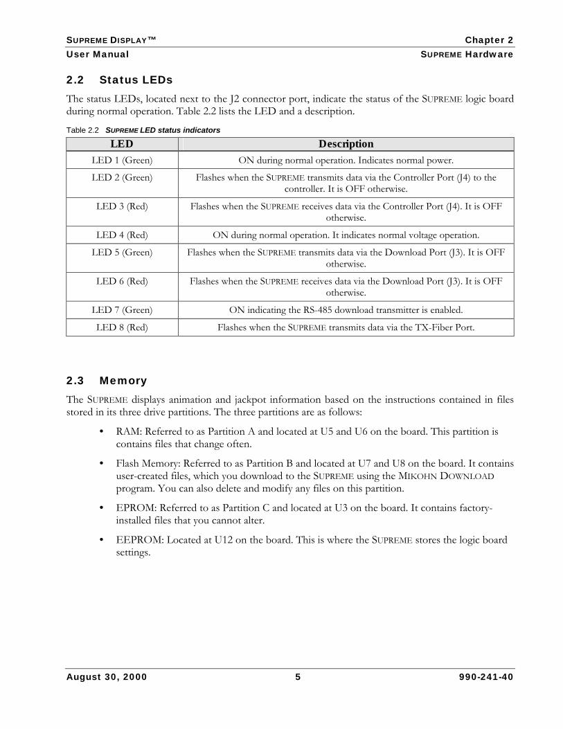
2.2 Status LEDs The status LEDs, located next to the J2 connector port, indicate the status of the SUPREME logic board during normal operation. Table 2.2 lists the LED and a description.
Table 2.2 SUPREME LED status indicators
LED Description LED 1 (Green) ON during normal operation. Indicates normal power.
LED 2 (Green) Flashes when the SUPREME transmits data via the Controller Port (J4) to the controller. It is OFF otherwise.
LED 3 (Red) Flashes when the SUPREME receives data via the Controller Port (J4). It is OFF otherwise.
LED 4 (Red) ON during normal operation. It indicates normal voltage operation.
LED 5 (Green) Flashes when the SUPREME transmits data via the Download Port (J3). It is OFF otherwise.
LED 6 (Red) Flashes when the SUPREME receives data via the Download Port (J3). It is OFF otherwise.
LED 7 (Green) ON indicating the RS-485 download transmitter is enabled.
LED 8 (Red) Flashes when the SUPREME transmits data via the TX-Fiber Port.
2.3 Memory The SUPREME displays animation and jackpot information based on the instructions contained in files stored in its three drive partitions. The three partitions are as follows:
• RAM: Referred to as Partition A and located at U5 and U6 on the board. This partition is contains files that change often.
• Flash Memory: Referred to as Partition B and located at U7 and U8 on the board. It contains user-created files, which you download to the SUPREME using the MIKOHN DOWNLOAD program. You can also delete and modify any files on this partition.
• EPROM: Referred to as Partition C and located at U3 on the board. It contains factory-installed files that you cannot alter.
• EEPROM: Located at U12 on the board. This is where the SUPREME stores the logic board settings.
SUPREME DISPLAY™ Chapter 2 User Manual SUPREME Hardware
August 30, 2000 6 990-241-40
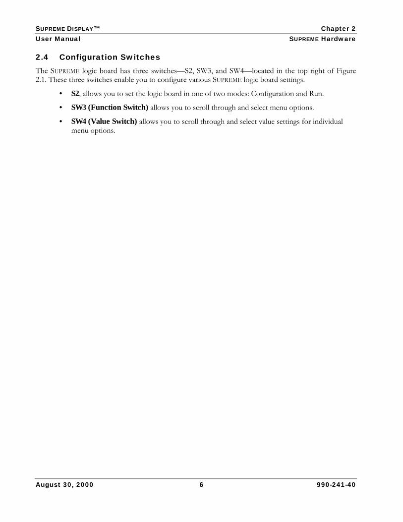
2.4 Configuration Switches The SUPREME logic board has three switches—S2, SW3, and SW4—located in the top right of Figure 2.1. These three switches enable you to configure various SUPREME logic board settings.
• S2, allows you to set the logic board in one of two modes: Configuration and Run.
• SW3 (Function Switch) allows you to scroll through and select menu options.
• SW4 (Value Switch) allows you to scroll through and select value settings for individual menu options.
SUPREME DISPLAY™ Chapter 3 User Manual SUPREME Firmware
August 30, 2000 7 990-241-40
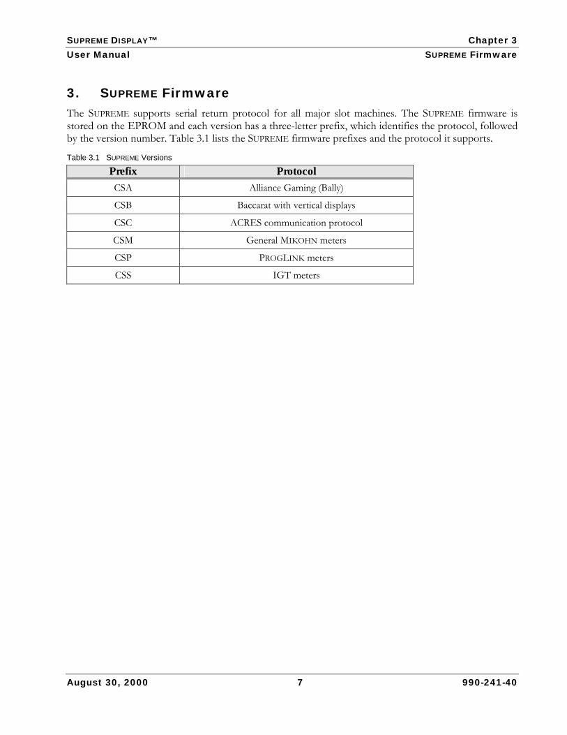
3. SUPREME Firmware The SUPREME supports serial return protocol for all major slot machines. The SUPREME firmware is stored on the EPROM and each version has a three-letter prefix, which identifies the protocol, followed by the version number. Table 3.1 lists the SUPREME firmware prefixes and the protocol it supports.
Table 3.1 SUPREME Versions
Prefix Protocol CSA Alliance Gaming (Bally)
CSB Baccarat with vertical displays
CSC ACRES communication protocol
CSM General MIKOHN meters
CSP PROGLINK meters
CSS IGT meters

SUPREME DISPLAY™ Chapter 4 User Manual SUPREME Configuration
4. SUPREME Configuration In the SUPREME hardware configuration, a controller calculates and controls the progressive jackpots for several machines and overhead displays. Each machine has a SUPREME logic board located inside that connects to the controller (at J4). The controller is located at the bottom of either the first or last machine in the bank of machines.
Upon receiving a coin-in signal from a machine, the controller calculates the new jackpot value and sends this information to each SUPREME in the bank of machines to display on its in-machine display. The controller also sends the jackpot value to the overhead display.
August 30, 2000 8 990-241-40
Figure 4.1 The controller sends progressive data to the SUPREME
$800,000.00SUPREME Logic Board(Located Inside Each
Machine)
Controller
$ 800,000.00
(Located In the First or LastMachine of a Bank of Machines)
$800,000.00 $800,000.00
Linker Configuration

SUPREME DISPLAY™ Chapter 4 User Manual SUPREME Configuration
The machines can also be configured so that you can download SUPREME settings to a particular machine or several machines. In this configuration, the PC connects to the Supreme via an RS-485 interface harness, which connects to the Supreme at J3. Figure 4.2 shows the RS-485 wiring harness.
Part #321-035-00 Rev. FSUPREME
J4J3DOWN LOAD CONTROLLER
Part #321-035-00 Rev. FSUPREME
J4J3DOWN LOAD CONTROLLER
August 30, 2000 9 990-241-40
Figure 4.2 RS-485 wiring harness
J5
J4
J3
J2
MIK
OH
N G
AMIN
G C
OR
P.R
S485
DIS
TRIB
UTO
R#3
21-0
06-9
5 R
ev. A
Rx+Rx-
Tx-Tx+
Rx+Rx-
Tx-Tx+
ncnc
nc
6 1
Tx+
Tx-
6 5 4 3 2 1
ncnc
RX+
RX-
6 5
4 3
2 1
6 5
4 3
2 1
6 5
4 3
2 1
6 5
4 3
2 1
nc
Tx+
T x-
RX+
RX-
6 16 5 4 3 2 1
ncnc
SUPREME DISPLAY™ Chapter 5 User Manual SUPREME Settings
August 30, 2000 10 990-241-40
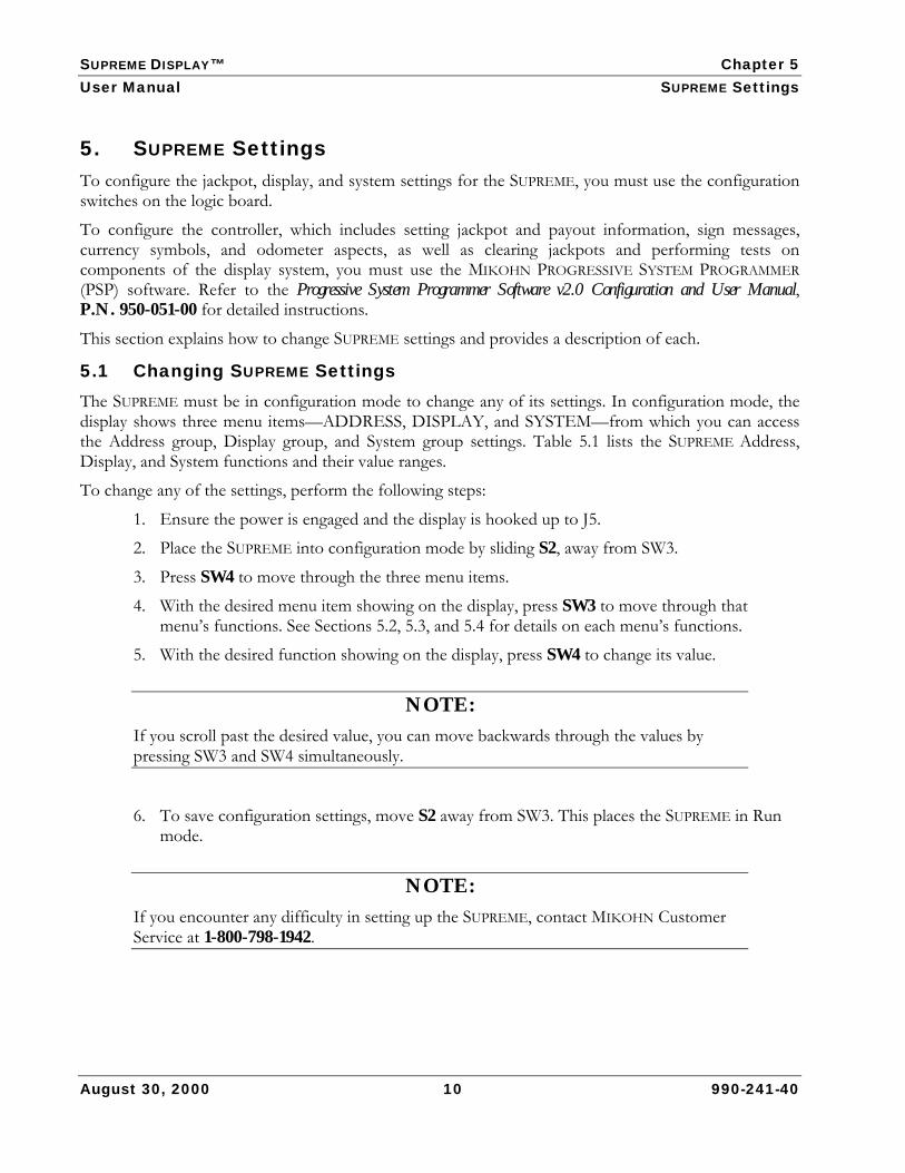
5. SUPREME Settings To configure the jackpot, display, and system settings for the SUPREME, you must use the configuration switches on the logic board.
To configure the controller, which includes setting jackpot and payout information, sign messages, currency symbols, and odometer aspects, as well as clearing jackpots and performing tests on components of the display system, you must use the MIKOHN PROGRESSIVE SYSTEM PROGRAMMER (PSP) software. Refer to the Progressive System Programmer Software v2.0 Configuration and User Manual, P.N. 950-051-00 for detailed instructions.
This section explains how to change SUPREME settings and provides a description of each.
5.1 Changing SUPREME Settings The SUPREME must be in configuration mode to change any of its settings. In configuration mode, the display shows three menu items—ADDRESS, DISPLAY, and SYSTEM—from which you can access the Address group, Display group, and System group settings. Table 5.1 lists the SUPREME Address, Display, and System functions and their value ranges.
To change any of the settings, perform the following steps:
1. Ensure the power is engaged and the display is hooked up to J5.
2. Place the SUPREME into configuration mode by sliding S2, away from SW3.
3. Press SW4 to move through the three menu items.
4. With the desired menu item showing on the display, press SW3 to move through that menu’s functions. See Sections 5.2, 5.3, and 5.4 for details on each menu’s functions.
5. With the desired function showing on the display, press SW4 to change its value.
NOTE: If you scroll past the desired value, you can move backwards through the values by pressing SW3 and SW4 simultaneously.
6. To save configuration settings, move S2 away from SW3. This places the SUPREME in Run mode.
NOTE: If you encounter any difficulty in setting up the SUPREME, contact MIKOHN Customer Service at 1-800-798-1942.

SUPREME DISPLAY™ Chapter 5 User Manual SUPREME Settings
August 30, 2000 11 990-241-40
Table 5.1 SUPREME Address, Display, and System settings
Menu Function Value PROTO Mikohn (default value), CCOM7 (CSM v3.00 only), CCOM1 (CSM v3.00
only)
GRADR 1-255 (default value is 255) MENU = ADDRESS
IDADR 1-64 (default value is 64)
JP GROUP 0-7, All (default value is 0)
Panel Graphics or Overhead (default value is Graphics)
Panels Wide Supreme displays the width of display. This is non-configurable.
Panels Tall Supreme displays the height of display. This is non-configurable.
MFILE jpot.do or FILE 1-16
ODSPEED 5-100 (default speed is 50)
Save To RAM Drive or Flash Drive
MENU = DISPLAY
Timeout 0-120 (CSP v3.11 only)
OFF (default value)
Display
Burn In
UART
Normal (all memory)
All (all above)
Runtest
Advanced
Runbirth OFF or ON
Down Baud 2400; 4800; 9600; 19200 (default value is 9600)
Sound DISABLED or ENABLED
Show Loading YES or NO
Show C1 YES or NO
Symbol None or Country Code
MENU = SYSTEM
Show Learn YES or NO
SUPREME DISPLAY™ Chapter 5 User Manual SUPREME Settings
August 30, 2000 12 990-241-40
5.2 Address Group Settings From the Address menu, you can set the protocol, group address, and ID address. The following sections describe the Address menu functions.
5.2.1 Protocol (PROTO) PROTO defines the communication protocol the SUPREME will use. This function has one setting—MIKOHN. SUPREME firmware CSS v3.00 has two additional options—CCOM7 (which supports IGT System Type 7) and CCOM1.
5.2.2 Group Address (GRADR) GRADR identifies the display address for a group of machines and tells the SUPREME where to send the progressive display data. This value ranges from 0 to 255.
5.2.3 ID Address (IDADR) IDADR identifies the address of the display and tells the SUPREME where to send display data. This value ranges from 1 to 64. The ID address represents the type of display.
• 1 to 32 – In-machine displays
• 33 to 63 – Reserved for future display types
• 64 – Overhead display
5.3 Display Group Settings From the Display menu, you can set the number of jackpot groups, MFILE, odometer speed, where to save the settings, and other firmware-specific options, as well as view the number of panels that make up the width and height of the display. The following sections describe the Display menu functions.
5.3.1 Jackpot Group (JP GROUP) JP GROUP specifies the number of jackpot groups and can support up to eight jackpot groups. The JP GROUP value ranges from 0 to 7.
5.3.2 Panel Panel specifies the type of SUPREME display. This setting has two options—Graphics or Overhead.
5.3.3 Panels Wide Panels Wide is the width of the display. Only a MIKOHN Customer Service Representative should change this value.
5.3.4 Panels Tall Panels Tall is the height of the display. Only a MIKOHN Customer Service Representative should change this value.

SUPREME DISPLAY™ Chapter 5 User Manual SUPREME Settings
August 30, 2000 13 990-241-40
5.3.5 Meter File (MFILE) The MFILE specifies how jackpot amounts appear on the display. Table 5.2 lists the MFILE values and descriptions. When the MFILE value is jpot.do, the SUPREME displays the jackpot as defined in the jpot.do file. The jpot.do is a binary file that you can create and download to the controller using PSP software.
MFILE values FILE 1 through FILE 16 are pre-set display formats. Justify refers to the alignment of the jackpot amount on the display. Paint means that the jackpot value will change colors from top to bottom. Color refers to the color of the jackpot amount on the display. The color is Red, Green, Yellow, or dazzle (each digit of the jackpot value appears in a different color).
NOTE: If you specify jpot.do, you must also have a valid mess.do (message) file. Use PSP software
to create the mess.do file.
Table 5.2 MFILE values and descriptions
Value Justify Paint Color Description jpot.do N/A N/A N/A User defined jpot.do file FILE 1 Center No Red Internal message with token for active JP Group
FILE 2 Center No Green Internal message with token for active JP Group
FILE 3 Center No Yellow Internal message with token for active JP Group
FILE 4 Center No Dazzle Internal message with token for active JP Group
FILE 5 Center Yes N/A Internal message with token for active JP Group
FILE 6 Center Yes N/A Internal message with token for active JP Group
FILE 7 Center Yes N/A Internal message with token for active JP Group
FILE 8 Center Yes N/A Internal message with token for active JP Group
FILE 9 Right No Red Internal message with token for active JP Group
FILE 10 Right No Green Internal message with token for active JP Group
FILE 11 Right No Yellow Internal message with token for active JP Group
FILE 12 Right No Dazzle Internal message with token for active JP Group
FILE 13 Right Yes N/A Internal message with token for active JP Group
FILE 14 Right Yes N/A Internal message with token for active JP Group
FILE 15 Right Yes N/A Internal message with token for active JP Group
FILE 16 Right Yes N/A Internal message with token for active JP Group

SUPREME DISPLAY™ Chapter 5 User Manual SUPREME Settings
August 30, 2000 14 990-241-40
5.3.6 Odometer Speed (ODSPEED) ODSPEED indicates how fast the displayed jackpot amount increments to catch up to the actual jackpot amount. The ODSPEED value ranges from 5 to 100. The lower the value the less the lag is between the displayed and the actual jackpot amounts, which means the displayed and actual amounts are very close.
5.3.7 Save To Save To lets you specify where to save downloaded jpot.do and mess.do files. This function has two options: RAM drive (Partition A) and Flash drive (Partition B).
5.3.8 Timeout TIMEOUT is available only in SUPREME firmware CSP v3.11 and higher. The TIMEOUT value ranges from 0 to 120 seconds. If the SUPREME does not receive information for a particular jackpot group within the specified TIMEOUT period, it will display Ln DOWN (where n is the link number) followed by the JP GROUP number.

SUPREME DISPLAY™ Chapter 5 User Manual SUPREME Settings
August 30, 2000 15 990-241-40
5.4 System Group Settings From the System menu, you can test different aspects of the display and configure various system settings. The following sections describe the System menu functions.
5.4.1 Test The TEST function allows you to run built-in tests for various aspects of the SUPREME logic board and the display, individually or all together. The TEST function has seven options: Off, Display, Burn-In, UART, Normal, All, and Advanced. OFF is the default value and the TEST function must be set to OFF for the SUPREME to function properly. All other options are for testing purposes only.
• OFF: Default condition. TEST must be off in order for the SUPREME to work.
• Display: Tests the display for column and row shorts, as well as color matching. In this testing mode, the display will show the SUPREME firmware version and then flash various colors and patterns across the display.
• Burn-In: Tests the RAM. In this testing mode, the display will show various colors and patterns, the Resets value, and the results of the RAM test.
• UART: Tests the serial ports. Only MIKOHN Customer Service can perform this test, as special adapters are required for the test to pass. See Page 10 for the MIKOHN Customer Service phone number.
• Normal: Tests the memory to ensure it is functioning normally. In this testing mode, the display will show the SUPREME firmware version; Resets value; results of the RAM, ROM and Flash tests; and how long the display has been running.
• All: Runs through all the Display, Burn-In, Normal, and UART tests.
• Advanced: Tests the processor, CPU speed and performance, RAM, ROM, and Flash memory.
5.4.2 Runbirth RUNBIRTH is a factory reset function that clears the RAM (except the RAM drives) and resets all the SUPREME settings to the factory default values. RUNBIRTH has two settings: OFF and ON. MIKOHN recommends this function always read OFF, unless advised by a MIKOHN Service Technician to change this setting to ON.
5.4.3 Down Baud DOWN BAUD is the download baud rate. You can set the rate to either 2400; 4800; 9600; or 19200. 9600 is the default setting.
5.4.4 Show Load Show Load has two settings: YES and NO. When this is set to YES, the display shows when it receives new downloaded settings, such as a new jpot.do or mess.do file. (Use PSP software to create jpot.do and mess.do files.)
SUPREME DISPLAY™ Chapter 5 User Manual SUPREME Settings
August 30, 2000 16 990-241-40
5.4.5 Show C1 The SUPREME shows error codes on the display when the system is experiencing an error. Refer to Appendix A for a list of error codes. The C1 error code, which indicates the display is not receiving data from the controller, is the only error code that you can set to display or not display when this error occurs. SHOW C1 has two settings: YES and NO.
5.4.6 Symbol Symbol represents the type of currency shown on the display, such as dollars or pound sterling. This setting is either NONE or any country symbols available with the SUPREME. If the SUPREME setting is NONE, and you have downloaded a symbol setting to the controller, then the SUPREME will display this symbol.
5.4.7 Sound Sound has two settings: ENABLED and DISABLED. If you set this function to ENABLED, the SUPREME will transmit sound to the sound device connected at J8. You can download sound commands to the SUPREME using DOWNLOAD software.
5.4.8 Show Learn Show Learn is available for CSM v3.11 and above. Show Learn has two settings: YES and NO. If you set this function to YES and you reset the display values (RUNBIRTH), the SUPREME will run through all its settings and will display this. If you set Show Learn to NO, when you reset the display values, the display will appear blank for a few moments as the SUPREME runs through all its settings.
SUPREME DISPLAY™ Chapter 6 User Manual Displaying Text and Animation
August 30, 2000 17 990-241-40
6. Displaying Text and Animation The SUPREME comes with default factory-installed files (stored in Partition C). These include default batch files (.bat), progressive definition files (.pdf), and font files (.fnt). The SUPREME looks for user-defined .bat, .pdf, and .fnt files in Partition A and then Partition B. If it does not find any files in either of these two partitions, it will read the defaults in Partition C.
6.1 Batch Files Batch files are ASCII text files that contain commands telling the SUPREME what to display and when to display it. The SUPREME reads batch files from top to bottom and then back to the top when it reaches the last line in the file. There are two batch files the SUPREME reads—backgrnd.bat and jpwinX.bat. The SUPREME continuously reads the backgrnd.bat file until the machine hits a jackpot, at which time it reads the jpwinX.bat file, where X is the jackpot group number. If the SUPREME does not find a jpwinX.bat file, it performs the default celebration.
If the SUPREME does not find a jpwinX.bat, then it will display the machine number in red followed by the jackpot, also in red, and then the machine ID (if enabled) in green. It cycles through this two times. It then displays the current progressive in yellow, once, before repeating this series starting with the jackpot amount.
The SUPREME will return to reading the backgrnd.bat file after someone has cleared the jackpot.
6.2 Batch File Commands Frequently used batch files commands include REM, PRGSV, TEXT, and PLAY. Other useful commands include REMOTE, REPEAT, SOUND, and ST. These are explained in the following sections.
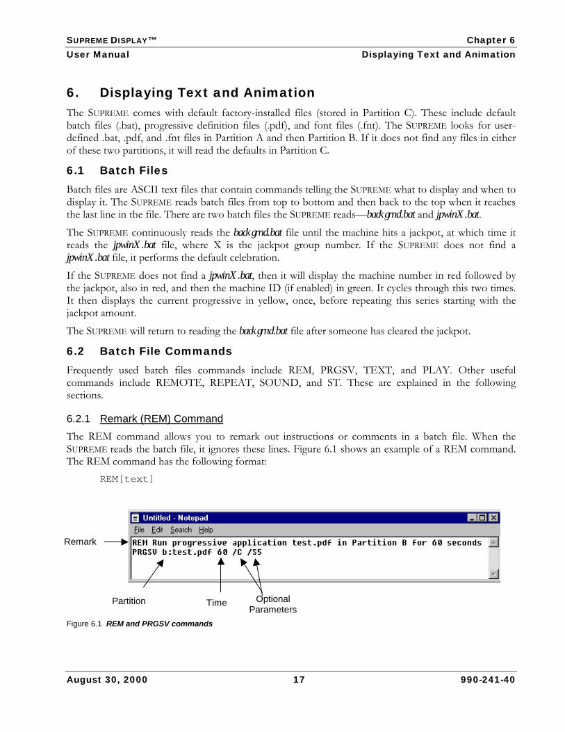
6.2.1 Remark (REM) Command The REM command allows you to remark out instructions or comments in a batch file. When the SUPREME reads the batch file, it ignores these lines. Figure 6.1 shows an example of a REM command. The REM command has the following format:
REM[text]
Figure 6.1 REM and PRGSV commands
Remark
Time Optional Parameters
Partition

SUPREME DISPLAY™ Chapter 6 User Manual Displaying Text and Animation
August 30, 2000 18 990-241-40
6.2.2 Progressive (PRGSV) Command The PRGSV command tells the SUPREME to execute the progressive application (.pdf file). See Figure 6.1 for an example of this command. It has the following format: PRGSV [partition]:[filename.pdf] [time] [optional parameters]
• Time is the number of seconds the SUPREME will run the application. If this is not specified, the progressive application will run continuously.
• Optional Parameters include /C to clear the screen before starting the progressive application and /S[n] to play sound command n, where n is a number between 0 and 110 that represents a sound file on the sound device.
NOTE: The jpwinX.bat file should not contain the PRGSV command because it will cause the SUPREME to display $0.00.
The progressive application (.pdf file) is an ASCII file that contains Template commands and all the details about the windows that make up the display, including the window locations and sizes, and the message files for each window. Figure 6.2 shows a .pdf file.
Figure 6.2 Example of a .pdf file
MFILE JackpotGroup
Primary Font File
Optional Parameters
x1,y1,x2,y2
Wn

SUPREME DISPLAY™ Chapter 6 User Manual Displaying Text and Animation
August 30, 2000 19 990-241-40
The Template command specifies a background image file that will appear in the displays. This command has the format:
Template: [partition]:[filename.pic]
The window coordinates have the following format: Wn:x1,y1,x2,y2,[jackpot group],[MFILE],[font file],[optionalparameters]
• Wn is a particular window of a display, where n is the window number. Because the SUPREME display can support up to eight windows, you can have settings for W0 through W7, where W0 represents Window 1, W1 represents Window 2, and so on.
• x1,y1,x2,y2 are the window coordinates (in pixels). The coordinates (x1, y1) are the top left corner of the window, while (x2,y2) are the coordinates for lower right corner. In Figure 6.2, W0 has the x1,y1 coordinates of (0,0) and the x2,y2 coordinates of (180,32).
• A machine can have up to eight jackpot groups. Jackpot group represents the particular jackpot group information that will display in that window. For example, in Figure 6.2, Jackpot Group 1 information will display in W0 and Jackpot Group 2 in W1. You can also use * or ? instead of the jackpot group number, which tells the SUPREME to use the jackpot group defined using the SUPREME logic board switches. Refer to Section 5 to set the jackpot group using the SUPREME switches.
• The MFILE value is a predefined format that specifies how jackpot amounts appear on the display. See Section 5.3.5 for a list and description of MFILE values. You can also set this value using the SUPREME switches, instead of defining it in the .pdf file.
• The primary font file is the font that the SUPREME will use for meter display and messages in that particular window. You can select a different font for each window. The SUPREME does not support characters in the special effect fonts (these fonts have an asterisk beside the font name in Table 6.1). If the primary font is a special effect font, you must specify a secondary font, which it will use for displaying messages.
NOTE: Because the SUPREME stores the fonts in RAM, if you download too many fonts, some applications that need extra RAM (such as storyboard) will not operate or the display will appear blank while the SUPREME loads the font files.
MIKOHN does not recommend using multiple effect fonts in the .pdf file due to memory constraints.

SUPREME DISPLAY™ Chapter 6 User Manual Displaying Text and Animation
August 30, 2000 20 990-241-40
Table 6.1 SUPREME fonts
Font Description Meter Effect # of Colors
BLO16 16 pixels high single color font. Has the complete ASCII character set. Odometer 1
BLO32 32 pixels high single color font. Has the complete ASCII character set. Odometer 1
CEN32 32 pixels high single color font. Includes numbers and characters. Odometer 1
CHAR16 16 pixels high 3D fonts. Has the complete ASCII character set. Odometer 2
CHAR32 32 pixels high 3D fonts. Has the complete ASCII character set. Odometer 2
DECO16 16 pixels high single color font. Includes numbers and characters. Odometer 1
FLIP16 * 16 pixels high 3D numbers. Use CHAR16 font for characters.
Rotate numbers 90° vertically. 2
FLIP32 * 32 pixels high 3D numbers. The CHAR32.fnt can be used as the secondary font for characters.
Rotate numbers 90° vertically. 2
LAP32 32 Pixels high single color font. Includes numbers and characters. Odometer 1
MORF16 * 16 pixels high 3D numbers. Use CHAR16 font for characters.
Morph one number to the next number. 2
MORF32 * 32 pixels high 3D numbers. The CHAR32.fnt can be used as the secondary font for characters.
Morph one number to the next number 2
ROT16 * 16 pixels high 3D numbers. Use CHAR16 font for characters.
Rotate numbers 90° horizontally. 2
ROT32 * 32 pixels high 3D numbers. The CHAR32.fnt can be used as the secondary font for characters
Rotate numbers 360° horizontally. 2
S481 48 pixels high 3D fonts. Odometer 2
* Special effect fonts are used for the meter presentation only. These fonts do not contain the standard character set.

SUPREME DISPLAY™ Chapter 6 User Manual Displaying Text and Animation
August 30, 2000 21 990-241-40
• Optional parameters allow you to specify additional formatting, such as character spacing and currency symbol positioning. Table 6.2 lists the optional parameters.
Table 6.2 Optional parameters
Parameter Default Description
/S[n] 1 pixel Space between characters (number of pixels). Note: In a .bat file this parameter refers to sound and not spacing.
/L[n] 0 pixel Character position on the display (starting row position of characters in pixels).
/D[n] 0 pixel Currency Symbol position (starting row position of currency symbol in pixels).
/F[Partition]:File Name]
6 high error font
Secondary font type (file name with drive). Refer to Table 6.1 for a list of fonts that the Supreme supports.
/M[c] N/A
[c] is the color for the currency symbol and monetary punctuation (period and commas), where R is Red, G is green, and Y is yellow.
For example: /M[R], /M[G], and /M[Y].
/O[n][+or -] N/A
[n] is an option, where 0 is small commas; 1 is small period; 2 is no currency symbol; 3 is no comma; 4 is no period;5 is small cents symbol (checkbook mode).
+ adds the option and - removes it.
6.2.3 TEXT Command The TEXT command tells the SUPREME to execute a particular text (.txt or .cmd) file. The TEXT command has the following format:
TEXT [partition]:[filename.txt] /[time] /level /pending /no blanking/[sound]
For example, TEXT b:win0.txt /60 /level /pending /no blanking /S5
• Time is the number of seconds the SUPREME will play the text file. If no time is specified, the SUPREME will display the text and then immediately execute the next command.
• Level tells the SUPREME to show the jackpot level during a jackpot celebration.
• Pending tells the SUPREME to show that the jackpot level is pending during a jackpot celebration.
• No blanking tells the SUPREME not to clear the screen before executing the text file.
• Sound is represented by /S[n], where n is a number between 0 and 110 that represents a sound file on the sound device. To repeat the sound use /S[n] R.

SUPREME DISPLAY™ Chapter 6 User Manual Displaying Text and Animation
The text file is an ASCII file that contains various text file commands. In the TEXT command example above, win0.txt is a text file. Figure 6.3 shows a text file that contains the PRINT command. PRINT tells the SUPREME to display Winner! and insert a new line (\n). See Appendix B for a list of text file commands.
NOTE: Ensure all text file commands end with a semicolon.
August 30, 2000 22 990-241-40
Figure 6.3 Example of a text file
Use PRINT to display a winning amount, machine number, machine ID, progressive amount, and comment text by including a statement like PRINT(n) where n is one of the following parameters. An example of this statement is PRINT(\JW).
• \JW: Jackpot winning amount
• \JM: Jackpot winning machine number
• \JI: Jackpot winning machine ID
• \JP: Current progressive amount
• \JC: Comment or location text message available only with SUPREME firmware version CSP v.3.1X)
NOTE: You can specify the alignment of the jackpot information by including \c (center) or \r (right flush) on a separate line before the text command.
Insert anew line
SUPREME DISPLAY™ Chapter 6 User Manual Displaying Text and Animation
August 30, 2000 23 990-241-40
6.2.4 Play Command The PLAY command tells the SUPREME to display a MIKOHN animation file. The PLAY command has the following format:
PLAY [partition]:[filename.mik] [times] [milliseconds per frame]/[sound]
For example, PLAY b:logo.mik 1 80 /S5
• Times is the number of times the Supreme will play the animation file. This parameter must be 1 or more. If no time is specified, the Supreme will display the animation and then immediately execute the next command.
• Milliseconds per frame is the length of time the Supreme will play each frame. In the above example, the animation will play once at 80 milliseconds per frame.
• Sound is represented by /S[n], where n is a number between 0 and 110 that represents a sound file on the sound device. To repeat the sound use /S[n] R.
To create an animation file, refer to Section 0.
SUPREME DISPLAY™ Chapter 6 User Manual Displaying Text and Animation
August 30, 2000 24 990-241-40
6.3 Other Commands
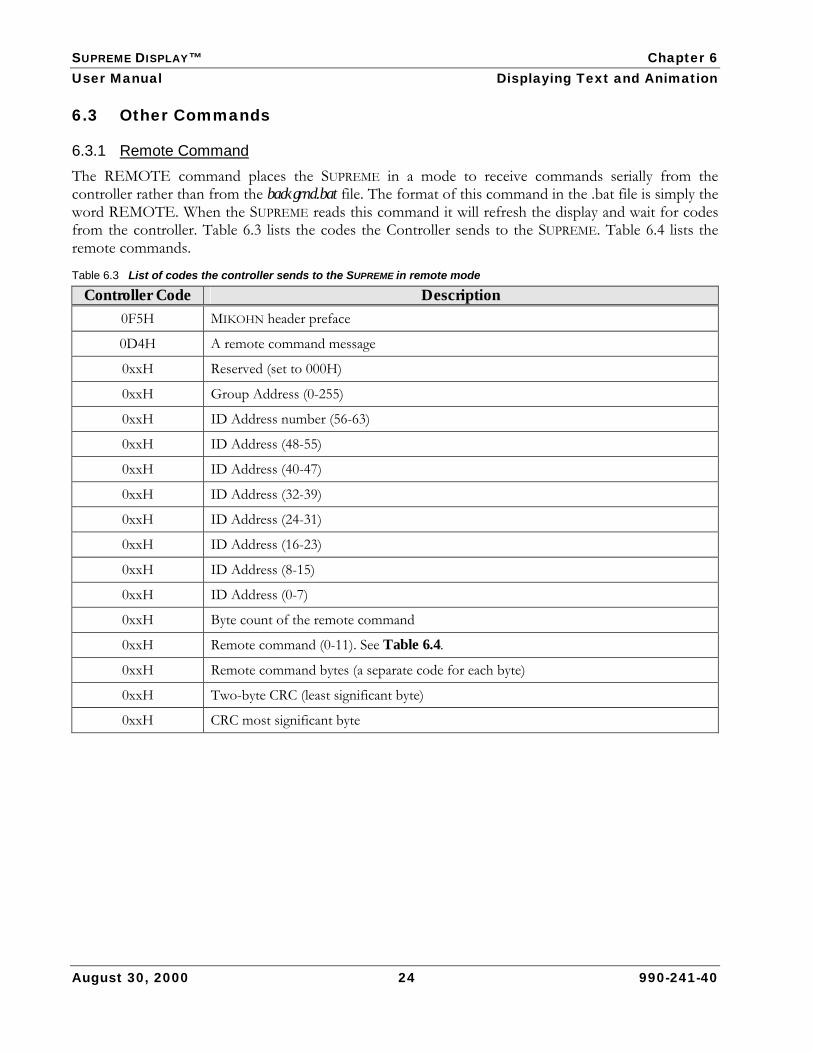
6.3.1 Remote Command The REMOTE command places the SUPREME in a mode to receive commands serially from the controller rather than from the backgrnd.bat file. The format of this command in the .bat file is simply the word REMOTE. When the SUPREME reads this command it will refresh the display and wait for codes from the controller. Table 6.3 lists the codes the Controller sends to the SUPREME. Table 6.4 lists the remote commands.
Table 6.3 List of codes the controller sends to the SUPREME in remote mode
Controller Code Description 0F5H MIKOHN header preface
0D4H A remote command message
0xxH Reserved (set to 000H)
0xxH Group Address (0-255)
0xxH ID Address number (56-63)
0xxH ID Address (48-55)
0xxH ID Address (40-47)
0xxH ID Address (32-39)
0xxH ID Address (24-31)
0xxH ID Address (16-23)
0xxH ID Address (8-15)
0xxH ID Address (0-7)
0xxH Byte count of the remote command
0xxH Remote command (0-11). See Table 6.4.
0xxH Remote command bytes (a separate code for each byte)
0xxH Two-byte CRC (least significant byte)
0xxH CRC most significant byte

SUPREME DISPLAY™ Chapter 6 User Manual Displaying Text and Animation
August 30, 2000 25 990-241-40
Table 6.4 Remote Commands
Remote Commands Action Required Parameters
0 Play MIK
[times to play] [delay] [.mik filename (including extension)]
• If times to play is 0, then SUPREME will play the file until it receives another command from the controller
• Delay default is 35 seconds
1 Clear Screen No parameters
2 Font [font name (including drive)]
3 GOTOXY [X][Y]
• X and Y are window coordinates (in pixels)
4 SET COLOR [fore color] [back color]
• fore color and back color is a number that represents a particular color. The options are 0 (black), 1 (green), 2 (red) or 3 (yellow)
5 Print String [string]
• string has maximum length of 78 characters
6 SET PIXEL
[X][Y][fore color]
• X and Y are window coordinates (in pixels)
• fore color is a number that represents a particular color. The options are 0 (black), 1 (green), 2 (red) or 3 (yellow)
LINE
[X1][Y1][X2][Y2][ [fore color]
• X1,Y1,X2 and Y2 are window coordinates (in pixels)
• fore color is a number that represents a particular color. The options are 0 (black), 1 (green), 2 (red) or 3 (yellow)
BOX
[X1][Y1][X2][Y2][ [fore color]
• X1,Y1,X2 and Y2 are window coordinates (in pixels)
• fore color is a number that represents a particular color. The options are 0 (black), 1 (green), 2 (red) or 3 (yellow)
NEXTLINE No parameters
TEMPLATE [template name (including drive)]
SOUND
[sound byte]
• sound byte is either 0 (no sound) or a number from 1 to 110, which represents the sound file on the sound device.
EXIT Note: this will cause the SUPREME exit remote mode to go to the next item in the backgrnd.bat file
SUPREME DISPLAY™ Chapter 6 User Manual Displaying Text and Animation
August 30, 2000 26 990-241-40
6.3.2 Repeat Command The REPEAT command tells the SUPREME to repeat a particular batch file command after a specified amount of time has elapsed. The format of the command is:
REPEAT [time] [batch file command]
For example, REPEAT 15 PLAY b:win1.mik
• Time is the number of minutes that will elapse before the SUPREME repeats the batch file command. This must be between 1 and 1439 minutes. In the REPEAT example above, the SUPREME will play the win1.mik file every 15 minutes.
NOTE: You can use up to 10 REPEAT commands in your backgrnd.bat file.
6.3.3 Sound Command The SOUND command tells the SUPREME to execute sound. The format of this command is: SOUND/[sound]
For example, SOUND/S5 R
• Sound is represented by /S[n], where n is a number between 0 and 110 that represents a sound file on the sound device. To repeat the sound use /S[n] R.
NOTE: You can also include a sound parameter in a PLAY, ST, and TEXT Commands instead of using the SOUND command.
To enable sound, ensure you set the SUPREME sound function to ENABLED. Refer to Section 5. Also ensure the sound device operates at the same baud rate as the device on the Controller port (J4).

SUPREME DISPLAY™ Chapter 6 User Manual Displaying Text and Animation
August 30, 2000 27 990-241-40
6.3.4 Storyboard (ST) Command The ST command tells the SUPREME to execute the Storyboard Animation file. The ST command has the following format:
ST [partition]:[filename.sh~] [times] [milliseconds per frame]/[sound
For example, ST b:cartoon.sh~ 5 80 /S5
• Times is the number of times the Supreme will play the storyboard file. This parameter must be 1or more.
• Milliseconds per frame is the length of time the Supreme will play each frame. In the above example, the storyboard will play 5 times at 80 milliseconds per frame.
• Sound is represented by /S[n], where n is a number between 0 and 110 that represents a sound file on the sound device. To repeat the sound use /S[n] R.
6.4 Creating .bat, .pdf, and .txt Files If you have MIKOHN DOWNLOAD for Windows® v2.0 software, you can use it to create .bat, .pdf, and .txt files. Refer to the DOWNLOAD for Windows v2.0 User Manual, P.N. 990-241-18. Older versions of Mikohn DOWNLOAD software do not include this capability, so you will have to use a separate text editor program to create these files. To download the files to the SUPREME, refer to the DOWNLOAD for Windows v2.0 User Manual, P.N. 990-241-18 or Animation Display Configuration and User Manual, P.N. 990-250-00 (for older versions of DOWNLOAD software).
To create .bat, .pdf, and .txt files using a text editor program, perform the following steps:
1. Open a text editor program, such as the Microsoft Windows Notepad application.
2. Type command statements for the type of file you are creating. Refer to Section 6.2 for specific file commands.
3. On the File menu, select Save As.
4. Select the drive from the Save in list.
5. Select All Files from the Save as type list. 6. Type the filename with the appropriate extension in File name. Type .bat for a batch file, .pdf
for a progressive definition file, or .txt for a text file at the end of the file name.
7. Click Save.
8. Download the file to the SUPREME using the MIKOHN Download software.
SUPREME DISPLAY™ Chapter 6 User Manual Displaying Text and Animation
August 30, 2000 28 990-241-40
6.5 Converting Animation Files If you create your own animation files (.fli or .flc), you will need to convert these to the MIKOHN file format (.mik) using the MIKOHN FLI2MIK converter software and download them to the SUPREME using the MIKOHN DOWNLOAD software. Refer to the DOWNLOAD for Windows v2.0 User Manual, P.N. 990-241-18 or the Animation Display Configuration and User Manual, P.N. 990-250-00 (for older versions of DOWNLOAD software).
To convert an .fli or .flc file to an .mik file, perform the following steps:
1. Open the MS-DOS command prompt screen.
2. Change the directory to one where you want to save the animation file.
3. At the MS-DOS prompt, type FLI2MIK filename.fli filename.mik, where filename.fli is the name of your .fli file and filename.mik is the name of the .mik file that you are creating. For example, FLI2MIK cartoon.fli cartoon.mik.
4. Download the .mik file to the SUPREME using the MIKOHN DOWNLOAD software.
SUPREME DISPLAY™ Appendix A User Manual Error Codes
August 30, 2000 29 990-241-40
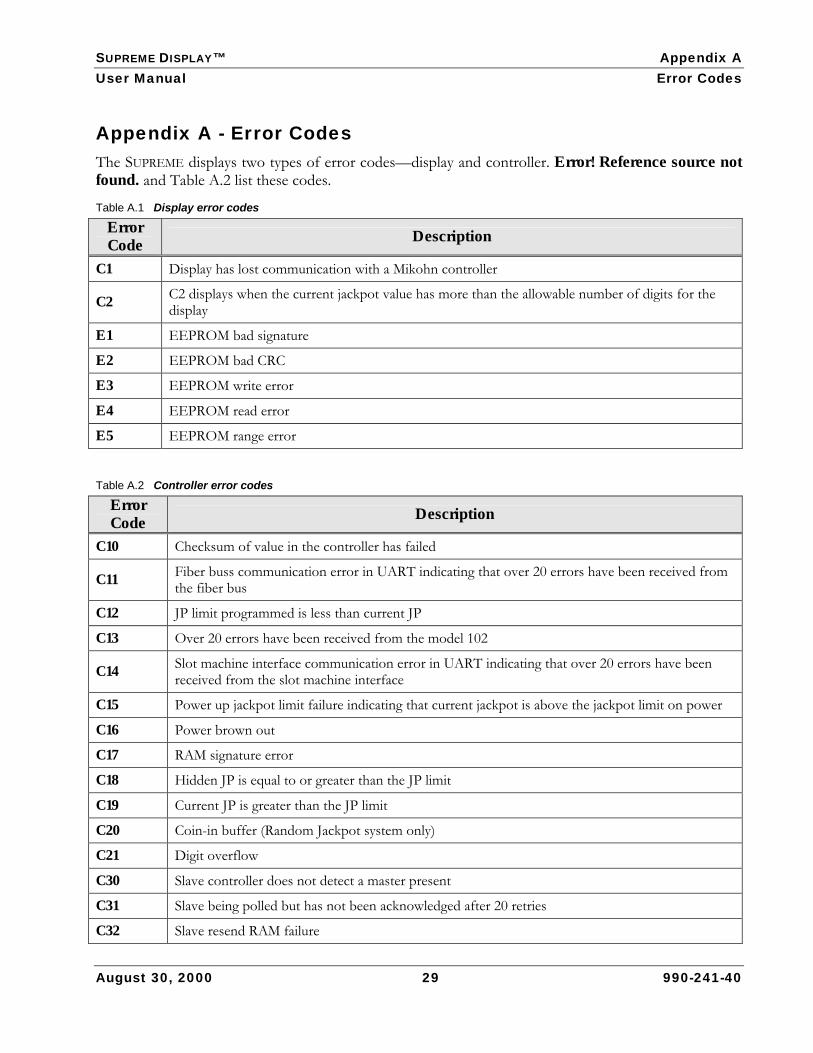
Appendix A - Error Codes The SUPREME displays two types of error codes—display and controller. Error! Reference source not found. and Table A.2 list these codes.
Table A.1 Display error codes
Error Code Description
C1 Display has lost communication with a Mikohn controller
C2 C2 displays when the current jackpot value has more than the allowable number of digits for the display
E1 EEPROM bad signature
E2 EEPROM bad CRC
E3 EEPROM write error
E4 EEPROM read error
E5 EEPROM range error
Table A.2 Controller error codes
Error Code Description
C10 Checksum of value in the controller has failed
C11 Fiber buss communication error in UART indicating that over 20 errors have been received from the fiber bus
C12 JP limit programmed is less than current JP
C13 Over 20 errors have been received from the model 102
C14 Slot machine interface communication error in UART indicating that over 20 errors have been received from the slot machine interface
C15 Power up jackpot limit failure indicating that current jackpot is above the jackpot limit on power
C16 Power brown out
C17 RAM signature error
C18 Hidden JP is equal to or greater than the JP limit
C19 Current JP is greater than the JP limit
C20 Coin-in buffer (Random Jackpot system only)
C21 Digit overflow
C30 Slave controller does not detect a master present
C31 Slave being polled but has not been acknowledged after 20 retries
C32 Slave resend RAM failure
SUPREME DISPLAY™ Appendix A User Manual Error Codes
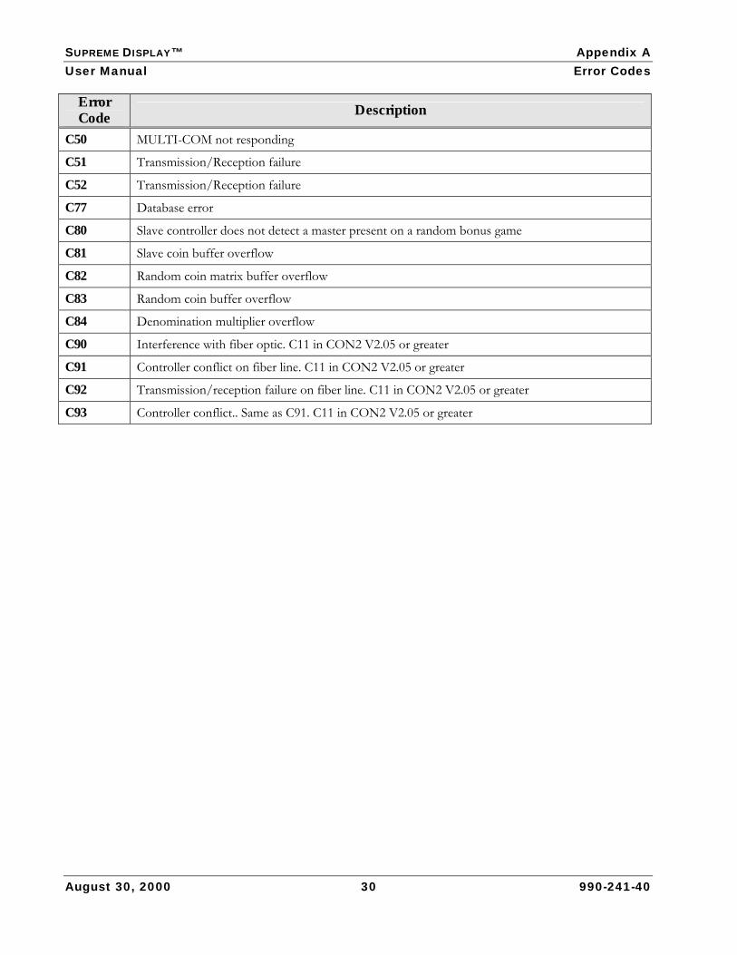
August 30, 2000 30 990-241-40
Error Code Description
C50 MULTI-COM not responding
C51 Transmission/Reception failure
C52 Transmission/Reception failure
C77 Database error
C80 Slave controller does not detect a master present on a random bonus game
C81 Slave coin buffer overflow
C82 Random coin matrix buffer overflow
C83 Random coin buffer overflow
C84 Denomination multiplier overflow
C90 Interference with fiber optic. C11 in CON2 V2.05 or greater
C91 Controller conflict on fiber line. C11 in CON2 V2.05 or greater
C92 Transmission/reception failure on fiber line. C11 in CON2 V2.05 or greater
C93 Controller conflict.. Same as C91. C11 in CON2 V2.05 or greater
SUPREME DISPLAY™ Appendix B User Manual Text File Commands
August 30, 2000 31 990-241-40
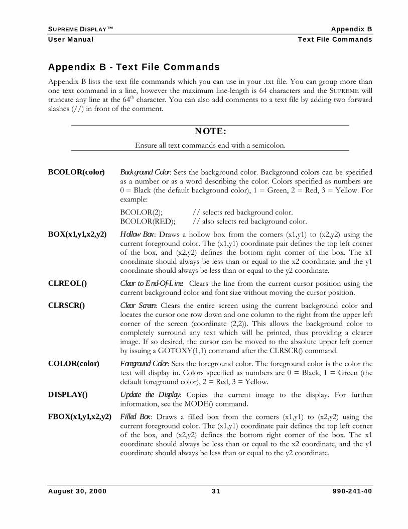
Appendix B - Text File Commands Appendix B lists the text file commands which you can use in your .txt file. You can group more than one text command in a line, however the maximum line-length is 64 characters and the SUPREME will truncate any line at the 64th character. You can also add comments to a text file by adding two forward slashes (//) in front of the comment.
NOTE: Ensure all text commands end with a semicolon.
BCOLOR(color) Background Color: Sets the background color. Background colors can be specified as a number or as a word describing the color. Colors specified as numbers are 0 = Black (the default background color), 1 = Green, 2 = Red, 3 = Yellow. For example:
BCOLOR(2); // selects red background color. BCOLOR(RED); // also selects red background color.
BOX(x1,y1,x2,y2) Hollow Box: Draws a hollow box from the corners (x1,y1) to (x2,y2) using the current foreground color. The (x1,y1) coordinate pair defines the top left corner of the box, and (x2,y2) defines the bottom right corner of the box. The x1 coordinate should always be less than or equal to the x2 coordinate, and the y1 coordinate should always be less than or equal to the y2 coordinate.
CLREOL() Clear to End-Of-Line: Clears the line from the current cursor position using the current background color and font size without moving the cursor position.
CLRSCR() Clear Screen: Clears the entire screen using the current background color and locates the cursor one row down and one column to the right from the upper left corner of the screen (coordinate (2,2)). This allows the background color to completely surround any text which will be printed, thus providing a clearer image. If so desired, the cursor can be moved to the absolute upper left corner by issuing a GOTOXY(1,1) command after the CLRSCR() command.
COLOR(color) Foreground Color: Sets the foreground color. The foreground color is the color the text will display in. Colors specified as numbers are 0 = Black, 1 = Green (the default foreground color), 2 = Red, 3 = Yellow.
DISPLAY() Update the Display: Copies the current image to the display. For further information, see the MODE() command.
FBOX(x1,y1,x2,y2) Filled Box: Draws a filled box from the corners (x1,y1) to (x2,y2) using the current foreground color. The (x1,y1) coordinate pair defines the top left corner of the box, and (x2,y2) defines the bottom right corner of the box. The x1 coordinate should always be less than or equal to the x2 coordinate, and the y1 coordinate should always be less than or equal to the y2 coordinate.
SUPREME DISPLAY™ Appendix B User Manual Text File Commands
August 30, 2000 32 990-241-40
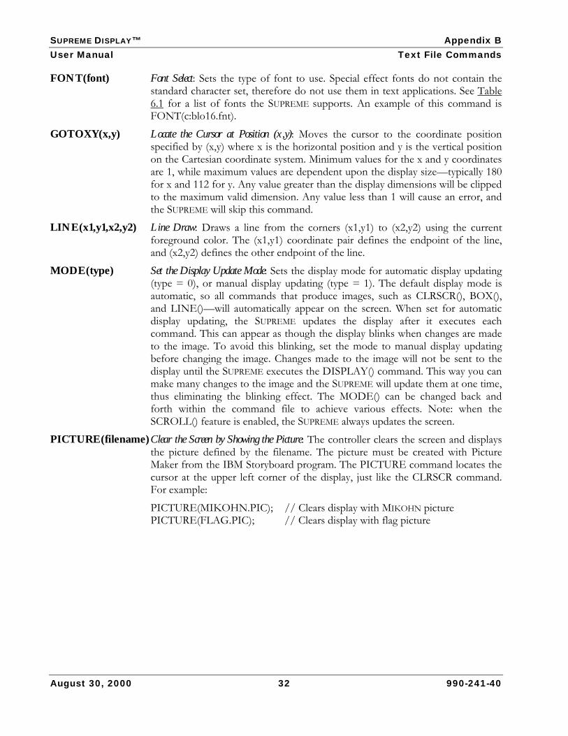
FONT(font) Font Select: Sets the type of font to use. Special effect fonts do not contain the standard character set, therefore do not use them in text applications. See Table 6.1 for a list of fonts the SUPREME supports. An example of this command is FONT(c:blo16.fnt).
GOTOXY(x,y) Locate the Cursor at Position (x,y): Moves the cursor to the coordinate position specified by (x,y) where x is the horizontal position and y is the vertical position on the Cartesian coordinate system. Minimum values for the x and y coordinates are 1, while maximum values are dependent upon the display size—typically 180 for x and 112 for y. Any value greater than the display dimensions will be clipped to the maximum valid dimension. Any value less than 1 will cause an error, and the SUPREME will skip this command.
LINE(x1,y1,x2,y2) Line Draw: Draws a line from the corners (x1,y1) to (x2,y2) using the current foreground color. The (x1,y1) coordinate pair defines the endpoint of the line, and (x2,y2) defines the other endpoint of the line.
MODE(type) Set the Display Update Mode: Sets the display mode for automatic display updating (type = 0), or manual display updating (type = 1). The default display mode is automatic, so all commands that produce images, such as CLRSCR(), BOX(), and LINE()—will automatically appear on the screen. When set for automatic display updating, the SUPREME updates the display after it executes each command. This can appear as though the display blinks when changes are made to the image. To avoid this blinking, set the mode to manual display updating before changing the image. Changes made to the image will not be sent to the display until the SUPREME executes the DISPLAY() command. This way you can make many changes to the image and the SUPREME will update them at one time, thus eliminating the blinking effect. The MODE() can be changed back and forth within the command file to achieve various effects. Note: when the SCROLL() feature is enabled, the SUPREME always updates the screen.
PICTURE(filename) Clear the Screen by Showing the Picture: The controller clears the screen and displays the picture defined by the filename. The picture must be created with Picture Maker from the IBM Storyboard program. The PICTURE command locates the cursor at the upper left corner of the display, just like the CLRSCR command. For example:
PICTURE(MIKOHN.PIC); // Clears display with MIKOHN picture PICTURE(FLAG.PIC); // Clears display with flag picture

SUPREME DISPLAY™ Appendix B User Manual Text File Commands
August 30, 2000 33 990-241-40
PRINT(string) Print the String Starting at the Cursor Position: Prints the string using the font and color from the current cursor position. If the string is too long for the line, then it will wrap around to the next line. If this happens at the bottom line, then the string is truncated.To display the winning amount, machine number, machine ID, progressive amount, and comment text, use the PRINT with any of the following jackpot parameters. For example, PRINT(\JW).
• \JW – Jackpot winning amount • \JM – Jackpot winning machine number • \JI – Jackpot winning machine ID (if the ID is set up in the controller) • \JP – Current progressive amount (this value has no odometering on,
just the current amount • \JC – Jackpot machine message (only available in CSP V3.1X)
Use each command on a new line in the text file (do not put text in front or behind the \JW). You can also include the following commands in the string:
• \n – New line: Moves the cursor down one line and to the left edge (much like a carriage return).
• \f – Form feed: Causes the entire display to scroll up and reveal a new page (similar to the way a printer works). After a form feed the cursor is located at position (2,2).
• \t – Tab: Causes the cursor to move to the next column on the same line. If, however, the tab causes the cursor to go off the right edge of the display, then the cursor will be located at the first column of the next line.
The following three examples show the PRINT command followed by an example of how this would appear on the display.
Example 1 PRINT(MIKOHN\nDISPLAYS\n);
Example 2 PRINT(TAB\tEXAMPLE\n);
MIKOHN DISPLAYS
TAB EXAMPLE

SUPREME DISPLAY™ Appendix B User Manual Text File Commands
Example 3
PRINT(\n\nFORMFEED EXAMPLE\n); PRINT(THIS WILL SCROLL\n); PRINT(\fAFTER FORMFEED\n);
The text is near the center of the display as a result of the two new line commands. The arrows indicate that the text is scrolling up.
FORMFEED EXAMPLE THIS WILL SCROLL
August 30, 2000 34 990-241-40
The text scrolls up, pushing the first line off the top of the display.
Once the first and second lines have completely scrolled off the top of the display, the next text displays.
SCROLL(type) Set the scrolling method: Specifies the type of scrolling to be used. A value of 0
disables scrolling (the default method). A value of 1 is the fastest scroll, while 10 is the slowest. All other values are in error and will cause the command to be ignored.
TSPACE(col, row) Set the Text Spacing: Specifies the blank columns between characters in the col parameter and blank rows between lines of text in the row parameter. The minimum value is 0, while the maximum values are the width of the display for the col parameter, and the height of the display for the row parameter. The default text spacing is one blank column and one blank row. For example:
TSPACE(2,3); // Sets two blank columns between characters, and // Three blank rows between lines of text.
WAIT(time) Wait for Specified Time: Causes the display to wait for the specified time before moving on to the next command. The time is specified in 1/10 second intervals. The maximum value for the time is 6500 seconds. If a time setting of 0 is specified, then the display will wait indefinitely. For example:
WAIT(10); // Waits for 1 second WAIT(600); // Waits for 1 minute (60 seconds) WAIT(0); // Waits forever
THIS WILL SCROLL
AFTER FORMFEED

SUPREME DISPLAY™ Appendix B User Manual Text File Commands
Examples of Command Files Example 1: BCOLOR(0); CLRSCR(); // clear the screen
COLOR(1); FONT(0); // define the font and color PRINT(This is example one\n); // print a title PRINT(Hello, World\n); // print a greeting
This is example one Hello, World
August 30, 2000 35 990-241-40
Example 2: This example uses the tab \t to align data along columns.
BCOLOR(0); CLRSCR(); // clear the screen COLOR(1); FONT(0); // define the font and color PRINT(Item\t\t#\tCost\n); // print a heading COLOR(2); // change colors before printing items PRINT(Widget\t\t1\t$1.50\n); // print an item PRINT(Ball\t\t2\t$2.95\n); // print another item PRINT(Cube\t\t3\t$5.99\n); // print the last item
Item # Cost Widget 1 $1.50 Ball 2 $2.95 Cube 3 $5.99
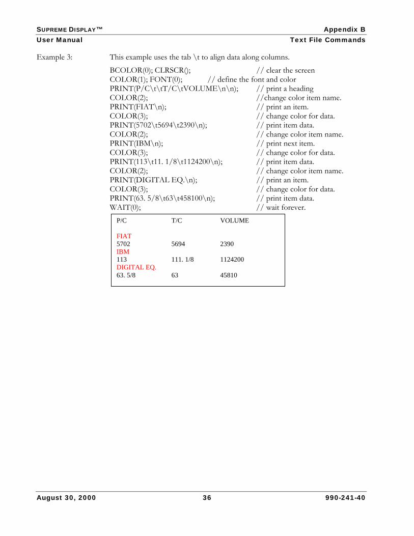
SUPREME DISPLAY™ Appendix B User Manual Text File Commands
August 30, 2000 36 990-241-40
Example 3: This example uses the tab \t to align data along columns.
BCOLOR(0); CLRSCR(); // clear the screen COLOR(1); FONT(0); // define the font and color PRINT(P/C\t\tT/C\tVOLUME\n\n); // print a heading COLOR(2); //change color item name. PRINT(FIAT\n); // print an item. COLOR(3); // change color for data. PRINT(5702\t5694\t2390\n); // print item data. COLOR(2); // change color item name. PRINT(IBM\n); // print next item. COLOR(3); // change color for data. PRINT(113\t11. 1/8\t1124200\n); // print item data. COLOR(2); // change color item name. PRINT(DIGITAL EQ.\n); // print an item. COLOR(3); // change color for data. PRINT(63. 5/8\t63\t458100\n); // print item data. WAIT(0); // wait forever.
P/C T/C VOLUME FIAT 5702 5694 2390 IBM 113 111. 1/8 1124200 DIGITAL EQ. 63. 5/8 63 45810

SUPREME DISPLAY™ Glossary User Manual
August 30, 2000 37 990-241-40
Glossary
ASCII American Standard Code for Information Exchange. A code that represents alphanumeric information.
Batch File An ASCII text file that contains one or more command lines for the controller. A batch file determines the appearance sequence of animation and progressive information on a display.
Baud Data transmission speed in bits per second.
Binary File A file type that contains printable and non-printable characters and requires a special program to interpret it.
Burn-in A SUPREME Test function setting that tests the RAM.
CRC Cyclic Redundancy Check. A method for detecting data transmission errors.
Casino Also Site or Venue. A gaming location.
CASINOLINK A Mikohn real-time management system that offers a fully integrated suite of modules to provide concise slot accounting, player and revenue tracking, progressive and mystery jackpots, and overall management functions for stand-alone and multi-site gaming operations.
Coin In The value of coins wagered in a gaming machine. Also known as Turnover, (Coin) Credits Played, and (Coin) Credits Wagered.
CON2 A MIKOHN Controller. See Controller.
Controller A device that controls progressive game information such as jackpot amounts and contribution percentages.
Display Electronic sign using LED technology to communicate a wide range of information, such as Jackpot values and win celebrations, promotions, and advertising. Displays connect to the system network and receive data files from machines and the IOC that determine jackpot values, wins, and other information.
Down Baud The SUPREME download data transmission speed in bits per second.
EEPROM Electronically Erasable Programmable Read Only Memory
EPROM Erasable Programmable Read Only Memory. A chip that stores programs or data.
Flash A type of NVRAM, named for the speed with which its memory cells can be erased.
Font A set of text characters with a particular format and size.
Function A program or one part of a module that may be represented by icons or text in menus or taskbars.
GRADR Group Address. The address assigned to a group of items, such as jackpots, visual displays, jackpot trigger devices, or machines. There are up to 255 group addresses.
Harness The assembly of wiring that connects two or more components.
SUPREME DISPLAY™ Glossary User Manual
August 30, 2000 38 990-241-40
IDADR ID Address. The address assigned to a group of items with a group (see GRADR), such as jackpots, visual displays, jackpot trigger devices, or machines. There are up to 64 ID addresses.
I/O Input/Output serial port.
Jackpot A prize awarded to a game player upon receiving a winning combination in a game.
Jackpot Reset Switch A key-activated switch that enables option selections within some self-test pages; enters and advances through the statistical data mode; and resets the machine’s internal progressive parameters (if applicable) after a jackpot.
JP GROUP Jackpot Group. The SUPREME handles up to eight different progressive jackpot amounts, also called jackpot groups, for a single machine.
LED Light-Emitting Diode. The technology used in Visual Displays.
Level A classification of jackpot amounts. A machine can have up to eight jackpots. The top award is designated as Level 0, the next highest is Level 1, and so on.
Link A group of machines that jointly contribute to the same Progressive.
Logic Board A circuit board that contains the power supply connection, the memory, chips for controlling the serial and parallel ports, and status LEDs.
Meter An overhead Visual Display showing the incrementing numbers of a Progressive Jackpot.
MFILE Meter File. MFILE is a SUPREME display setting where the MFILE value corresponds to a pre-defined jackpot amount format.
MIKOHN DOWNLOAD Software
A MIKOHN application that allows transfer of files back and forth between a computer and CHAMII, AGL, and SUPREME logic boards.
MIKOHN DOWNLOAD for Windows software
A MIKOHN application that allows transfer of files back and forth between a computer running MICROSOFT WINDOWS 95®, 98®, or NT®, and a SUPREME, AGL, or MARK 2 logic board.
NVRAM Non-Volatile Random Access Memory.
ODSPEED Odometer Speed. The rate at which the SUPREME displayed jackpot value increases to catch up to the actual jackpot value.
PGID Progressive Group Identification. The PGID is the number, from 0-7, given to a particular progressive jackpot group. A Progressive Group is a collection of Progressive Levels.
Pinout A functional description of each pin in a connection interface.
PROGLINK The progressive protocol module of the MIKOHN CASINOLINK system.
Progressive (Jackpot) A gaming machine or network of machines that each contribute a fixed percentage of wagers to a continuously incrementing Jackpot. A player wins the Progressive Jackpot by playing a progressive game with qualifying wagers. An overhead visual display usually installed above the bank of machines linked to the progressive shows the current amount of the jackpot.

SUPREME DISPLAY™ Glossary User Manual
August 30, 2000 39 990-241-40
PSP Progressive System Programmer MIKOHN software that allows you to program the controller’s settings and the progressive jackpot information.
PRGSV A batch file command that tells the SUPREME to read a particular progressive definition file.
PROTO Protocol. Rules for communicating between two end points.
RAM Random Access Memory. Used for temporary data storage. REM The REM command allows you to remark out instructions or
comments in a batch file. When the controller reads the file, it ignores these lines.
RS-232 Recommended Standard 232. An interface that supports one transmitter and one receiver locally and is used to communicate serially.
RS-422 Recommended Standard 422. A serial line standard that is used for communications between a circuit board and a receiver.
RS-485 Recommended Standard 485. A distribution board used to increase the number of devices connected to a DCU display port. It supports 32 drivers and 32 receivers. Its serial communication protocol is used typically to connect a PC with other devices that share a common cable. The communication cable that meets the requirements for this interface is referred to as RS-485 cable.
ROM Read Only Memory. RUNBIRTH The SUPREME factory reset function that restores the settings stored in the
RAM (except the RAM drive) to its default values and the test counters back to zero.
SUPREME A visual display logic board that uses LED technology to display progressive values.
Test Function Software mode that allows processor board input and output tests and enables option selections.
TEXT A batch file command that tells the SUPREME to read a particular text file.
Site Also Casino or Venue. A gaming location.
SUPERLINK The computer that links a number of MIKOHN Super Controllers.
UART Universal Asynchronous Receiver Transceiver. An integrated circuit that enables serial communication between a transmitter (parallel-to-serial converter) and a receiver (serial-to-parallel converter).

SUPREME DISPLAY™ Index User Manual
August 30, 2000 40 990-241-40
Index
A ACRES ..........................................................................10 address group settings .......................................... 15, 18 Alliance Gaming...........................................................10 animation......................................................6, 31, 36, 45 Animation Display Configuration and User Manual
...................................................................................36 ASCII................................................... 24, 25, 27, 30, 45
B backgrnd.bat ..............................................24, 32, 33, 34 Bally................................................................................10 batch file ................................................................. 24, 45 batch file command
PLAY...........................................................24, 31, 34 PRGSV ........................................................24, 25, 47 REM.............................................................24, 25, 47 REMOTE ......................................................... 24, 32 REPEAT........................................................... 24, 34 SOUND ......................................................24, 33, 34 ST .................................................................24, 34, 35 TEXT.....................................................24, 29, 30, 47
binary file.......................................................................45 BLO16 ...........................................................................27 BLO32 ...........................................................................27 burn-in ...........................................................................21
C CASINOLINK ................................................................45 CCOM1.........................................................................18 CCOM7.................................................................. 17, 18 CEN32...........................................................................27 CHAR16................................................................. 27, 28 CHAR32................................................................. 27, 28 CON2 ..................................................................... 38, 45 configuration.................................................................13 configuration switches .................................................. 8
S2 8, 15 SW3, Function Switch........................................8, 15 SW4, Value Switch..............................................8, 15
connector ports ..........................................................4, 5 J1, power ................................................................4, 5 J2, power ........................................................... 4, 5, 6 J3, RS-485....................................................4, 5, 6, 14 J4, RS-422..............................................4, 5, 6, 13, 34 J5, primary display.......................................... 4, 5, 15 J6, secondary display.............................................4, 5 J7, table game display ...........................................4, 5
J8, RS-232........................................................ 4, 5, 22 controller port............................................................ 4, 6 CRC......................................................................... 32, 45 CSA ................................................................................10 CSB.................................................................................10 CSC.................................................................................10 CSM................................................................................10 CSP............................................................. 10, 17, 30, 41 CSS .................................................................................10
D daisy chain .......................................................................4 dazzle..............................................................................19 DECO16 .......................................................................27 display...............................................................................1 display group settings ........................................... 15, 18 down baud.............................................................. 21, 45 download port ........................................................... 4, 6 DOWNLOAD software ......................................6, 22, 46
E EEPROM...........................................................7, 37, 45 EPROM.................................. 6, 10, 45. See Partition C
F factory reset..................................................See runbirth firmware
CSA ...........................................................................10 CSB............................................................................10 CSC............................................................................10 CSM...........................................................................10 CSP........................................................ 10, 17, 30, 41 CSS ............................................................................10
flash ........................................................6, 17, 20, 21, 45 FLI2MIK.......................................................................36 FLIP16...........................................................................27 FLIP32...........................................................................27 font ....................................................................40, 43, 44
BLO16 ......................................................................27 BLO32 ......................................................................27 CEN32......................................................................27 CHAR16............................................................ 27, 28 CHAR32............................................................ 27, 28 DECO16 ..................................................................27 FLIP16......................................................................27 FLIP32......................................................................27 LAP32 .......................................................................28 MORF16...................................................................28 MORF32...................................................................28

SUPREME DISPLAY™ Index User Manual
August 30, 2000 41 990-241-40
ROT16 ..................................................................... 28 ROT32 ..................................................................... 28
function switch ...............................................................8
G GRADR........................................................................ 45 group address ......................................17, 18, 32, 45, 46
H harness........................................................................... 46
I ID address ................................................. 17, 18, 32, 46 IDADR ......................................................................... 46 IGT..........................................................................10, 18
J J1,connector port....................................................... 4, 5 J2,connector port...................................................4, 5, 6 J3, connector port .......................................... 4, 5, 6, 14 J4, connector port .................................... 4, 5, 6, 13, 34 J5, connector port ...............................................4, 5, 15 J6, connector port ..................................................... 4, 5 J7, connector port ..................................................... 4, 5 J8, connector port ...............................................4, 5, 22 jackpot group ............................................ 18, 24, 26, 46 JP GROUP................................................ 17, 18, 20, 46 jpot.do ........................................................ 17, 19, 20, 21 jpwinX.bat ..............................................................24, 25
L LAP32 ........................................................................... 28 LED.............................................................. 6, 45, 46, 47 logic board............................1, 3, 4, 6, 8, 13, 21, 26, 46
M machine ID................................................................... 41 mess.do............................................................. 19, 20, 21 meter file ..............................................17, 18, 19, 26, 46 MFILE .................................................17, 18, 19, 26, 46 MIKOHN DOWNLOAD.....................................6, 36, 46 MIKOHN DOWNLOAD for Windows® v2.0........... 36 MORF16....................................................................... 28 MORF32....................................................................... 28
O odometer speed ........................................................... 18 ODSPEED ..................................................... 17, 20, 46 output port ......................................................................4
P panel.........................................................................17, 18 panels tall.................................................................17, 18 panels wide..............................................................17, 18 Partition A........................................ 6, 20, 24. See RAM Partition B..........................................6, 20, 24. See flash Partition C.........................................6, 24. See EPROM pinout.....................................................................4, 5, 46 PLAY................................................................ 24, 31, 34 power
12 volt DC ................................................................. 4 5 volt DC ................................................................... 4
PRGSV............................................................. 24, 25, 47 primary display ............................................................... 4 PROGLINK..............................................................10, 47 progressive .................................................................... 47 progressive definition file ........................................... 24 PROGRESSIVE SYSTEM PROGRAMMER software .. 15,
19, 21, 47 Progressive System Programmer software v2.0
Configuration and User Manual........................... 15 PROTO............................................................ 17, 18, 47 PSP.................................................................... 19, 21, 47
R RAM .6, 17, 20, 21, 26, 37, 38, 45, 47. See Partition A REM ................................................................. 24, 25, 47 REMOTE...............................................................24, 32 REPEAT.................................................................24, 34 ROM.............................................................................. 47 ROT16........................................................................... 28 ROT32........................................................................... 28 RS-232 .......................................................................4, 47 RS-422 .......................................................................4, 47 RS-485 ............................................................ 4, 6, 14, 47 runbirth ............................................................ 21, 22, 47
S S2 8, 15 save to......................................................................17, 20 secondary display ........................................................... 4 show C1...................................................................17, 22 show learn...............................................................17, 22 show load ................................................................17, 21 sound .............................................17, 22, 29, 31, 34, 35 SOUND........................................................... 24, 33, 34 ST ...................................................................... 24, 34, 35 status LEDs .................................................................. 46 storyboard...............................................................26, 35 SUPERLINK...............................................................1, 47 SUPREME

SUPREME DISPLAY™ Index User Manual
August 30, 2000 42 990-241-40
configuration............................................................13 firmware ...................................................................10 hardware ..................................................................... 1 hardware .......................... 1, 3, 4, 6, 8, 13, 21, 26, 46
SW3............................................................................8, 15 SW4............................................................................8, 15 symbol...............................................................17, 22, 29 system group settings ........................................... 15, 21
T test ..................................................................................21 TEXT..........................................................24, 29, 30, 47
timeout.................................................................... 17, 20
U UART................................................................17, 21, 48
V value switch.....................................................................8
W wiring harness ...............................................................14