USER MANUAL - ibse.hk
201
USER MANUAL
-
Upload
khangminh22 -
Category
Documents
-
view
0 -
download
0
Transcript of USER MANUAL - ibse.hk

USER MANUAL

Copyright © 2005 Carmel Software Corporation
All Rights Reserved.
April 2005 Ver. 6.0.0.2
The Loadsoft 6.0 User Manual contains information proprietary to Carmel Software Corporation. It is intended only to be used in conjunction with the Loadsoft 6.0 software package. This User Manual contains information protected by copyright. No part of this manual may be photocopied or reproduced without prior written consent from Carmel Software Corporation. Information contained in this manual is subject to change without notice.
Carmel Software Corporation 950 Northgate Dr., Suite 207 San Rafael, CA 94903 USA
Tel: 1-800-339-6030 Fax: 214-242-2639
[email protected] www.carmelsoft.com
Installshield® Copyright © 2005 Installshield Corporation. Microsoft® Copyright © 2005 Microsoft Corporation. ASHRAE® Copyright © 2005 American Society of Heating, Refrigeration, and Air Conditioning Engineers, Inc.

2
Chapter 1 - Overview Section 1.1: What is Loadsoft 6.0............................................................. 6 Section 1.2: Installing Loadsoft 6.0.......................................................... 7 Section 1.3: New Features........................................................................ 7 Section 1.4: Terminology…....................................................................... 9 Chapter 2 – Opening and Navigating a Project Section 2.1: Open/Create a Project........................................................... 12 Section 2.2: Project Navigation.................................................................. 15 Chapter 3 – Project Inputs Section 3.1: Overview................................................................................ 24 Section 3.2: Project Inputs......................................................................... 25 Section 3.3: System Inputs........................................................................ 34 Section 3.4: Zone Inputs............................................................................ 48 Section 3.5: Area Inputs............................................................................. 48 Chapter 4 – Edit and Check Inputs Section 4.1: Rotate Areas……................................................................... 82 Section 4.2: Globally Edit Area.................................................................. 83 Section 4.3: Search Systems..................................................................... 87 Section 4.4: Search Areas…….................................................................. 88 Section 4.5: Checks/Outputs….................................................................. 89 Chapter 5 - Outputs Section 5.1: Overview................................................................................ 92 Section 5.2: Calculation Month and Hour Range ………………………….. 93 Section 5.3: Standard Outputs................................................................... 94 Section 5.4: Standard Outputs – Report Descriptions............................... 97 Section 5.5: Exporting to Microsoft Office.................................................. 104 Section 5.6: What-if Scenario Outputs……................................................ 106
Table of Contents

3
Chapter 6 –Manage the Data Tables Section 6.1: Manage Construction U-Values............................................. 110 Section 6.2: Manage Internal Appliance List............................................. 112 Section 6.3: Manage Weather Data........................................................... 114 Section 6.4: Manage HVAC Equipment List.............................................. 117 Section 6.5: Manage People Activity Levels.............................................. 119 Section 6.6: Manage Ventilation Standards.............................................. 120 Section 6.7: Manage Schedule Templates................................................ 122 Section 6.8: View Roof Conduction Time Series Data............................... 126 Section 6.9: View Wall Conduction Time Series Data............................... 128 Section 6.10: View Window SHGC Data...................................................... 130 Section 6.11: View Interior Solar Attenuation Coefficients for Shading....... 133 Chapter 7 – Tools Section 7.1: Check for Input Errors……..................................................... 136 Section 7.2: Manage External HVAC Equipment Database...................... 138 Section 7.3: Manage System Templates.................................................... 142 Section 7.4: Manage Area Templates........................................................ 144 Section 7.5: Purge and Restore Projects................................................... 145 Section 7.6: Manage Project Database..................................................... 146 Chapter 8 – Software Settings Section 8.1: English (IP) or Metric (SI) Units............................................. 150 Section 8.2: General Settings................................................................... 151 Section 8.3: Report Format Settings......................................................... 155 Section 8.4: Loadsoft Database Settings.................................................. 156 Section 8.5: Common Database Settings.................................................. 157 Chapter 9 – Create Microsoft Office Templates Section 9.1: Overview................................................................................. 160 Chapter 10 – Import Loadsoft 4.0 Project(s) Section 10.1: Overview…........................................................................... 178 Chapter 11 – Export Project Inputs to XML Section 11.1: Overview............................................................................... 182

4
Chapter 12 – Setup a Networked Version of the Database Section 12.1: Overview............................................................................... 184 Chapter 13 – Menu Options Section 13.1: Overview............................................................................... 186 Appendix A – Software License Index

5

6
Section 1.1 - What is Loadsoft 6.0? Loadsoft 6.0 by Carmel Software is a commercial and industrial HVAC (Heating, Ventilation, and Air Conditioning) load calculation software package whose calculations are based upon the ASHRAE 2001 Fundamentals radiant time series (RTS) method. The purpose of this software is to provide you with total cooling and heating loads for a building so that you may properly specify the correct size HVAC equipment (whether it is a packaged rooftop unit or a boiler). This program is geared specifically toward the HVAC engineer, architect, design/build mechanical contractor, and building maintenance supervisor. The Loadsoft software package and its various incarnations have evolved over 10 years. Loadsoft 1.0 was the first ever Windows-based commercial load calculation package on the market. Since then we have added many features that have been requested by current users of the software. Loadsoft 6.0 is a culmination of all this feedback. In addition, we have updated the database information and back-end technologies to work with the latest versions of Windows. The Loadsoft 6.0 includes the following basic features:
1. Inputs for HVAC system characteristics such as supply cooling and heating temperatures, ventilation rates, fan characteristics, cooling and heating setpoints, duct sizing,and safety factors
2. Inputs for HVAC area (room) characteristics such as wall, window, roof, door, skylight, and partition areas. In addition, there are inputs for # of people, electrical appliances, infiltration, lighting, miscellaneous, exhaust, and plenum loads
3. Weather data from over 800 cities throughout the world 4. A complete u-value database for common wall, roof, window, floor, and
door types 5. A complete appliance list for determining internal electrical equipment
load contributions 6. Many reports including summary, detailed, psychrometric, wall/window
breakdown, 24-hour load breakdown, and graphical reports 7. A feature that allows the user to export all inputs and outputs to custom
Microsoft Word and Excel documents 8. Equipment selection 9. Support for both English (IP) and Metric (SI) units
Chapter 1 – Overview

7
Section 1.2 - Installing the Software The installation of the Loadsoft 6.0 involves running the Installshield® setup program from the CD-ROM or executable. This installs all of the files onto your hard-drive into the proper directories. Please take the following steps:
1. Very Important: Make sure that you have Windows 2000/2003/XP administrative permissions while installing the software.
2. Run the "Setup.exe" program located on the CD-ROM. (If you have downloaded the executable, then just run that file.)
3. When asked, input the directory where you want the software installed. (The default is "c:\program files\carmel\ls60").
If you wish to install the database that stores all of the project information onto a “shared” or “network” drive so that more than one user can use the Loadsoft software and share the same data, go to Chapter 12 for more information. Section 1.3 - New Features The following is a list of new features of the Loadsoft 6.0 software package:
1. The Loadsoft 6.0 software has been entirely re-written to take advantage of the latest programming and back-end database technologies. In addition, the cooling and heating load calculations have been updated to conform to the ASHRAE 2001 Fundamentals radiant time series (RTS) calculations from Chapters 29 and 30. The RTS calculations more accurately model the load analysis of a building, taking into account latency of load contributions throughout the day.
2. A new and improved user interface (UI) has been designed making the input process much faster and more intuitive than previously. This improved UI includes a tree-like navigation area that allows the user to view all systems, zones, and areas and their relationships.
3. The user can easily replicate entire projects so as to reuse common information.
4. An additional 300 cities have been added to the weather database making the total 800.
5. Individual areas can be grouped by zones for each system. 6. An unlimited number of system and area templates can now be created
so that the user can create new systems and areas using common data from the templates.
7. The user can input separate cooling and heating ventilation rates. 8. The number of air changes can be specified for the system ventilation
inputs. 9. Chiller Cooling and boiler heating temperature differences and boiler
efficiency values can be specified for each system. 10. Simple duct sizes are now calculated for each area based upon CFM.

8
11. The user can specify system-wide preheating properties. 12. The user can perform cooling and heating equipment selection for each
system. 13. The software can easily integrate with third-party equipment databases
used for the equipment selection discussed above. 14. A local equipment database has also been added allowing the user to
create a customized equipment list. 15. The user can easily move or copy systems, zones, and areas within a
project. 16. The user can specify door types along with the door widths, heights, u-
values, and quantities. 17. Up to 10 different types of walls and windows can be specified for each
area. 18. Up to 7 different types of roofs can be specified for each area. 19. Skylight inputs are now separate from the window inputs. 20. The user can now specify electrical equipment latent loads in addition to
sensible loads. 21. The appliance database has been expanded to include more specialized
office and home equipment. 22. The u-value construction material database has been expanded to include
more common materials. 23. The user can now assign individual occupancy and diversity schedules to
people, lighting, equipment, and miscellaneous load contributions. 24. Input checks have been incorporated so the user can confirm that inputs
are correct be calculating 25. Quick calculation functionality has been added to each area so that the
user can instantly see the cooling and heating load contributions for the area.
26. All input and output data can be exported to Microsoft Word and Excel templates.
27. Reports can be exported to XML format so that they can be shared with others across networks and operating systems other than Windows.
28. The "what-if scenario" functionality includes more inputs to perform the what-if analysis.
29. You can specify the space relative humidity separately from the coil conditions. Previously, the coil leaving conditions were always set at 90% relative humidity. Now, you can alter this value to allow you more flexibility in specifying coil conditions to satisfy exact space air conditions.
30. Includes new “simple” and “detailed” modes for all room envelope inputs. This makes it easier for users to input information for standard HVAC jobs.
31. Includes more accurate psychrometric calculations for standard and non-standard conditions.
32. The summary report now displays room-by-room loads without pro-rated coil loads included.
33. . . . and more.

9
Section 1.4 - Terminology Before using this program, you should become familiar with the following terminology. Areas, Zones, Systems, Projects The user inputs in Loadsoft 6.0 are broken down into four types: areas, zones, systems, and projects:
1. Area: An area represents a room or single "area" within the building. For example, most houses have bedrooms, a living room, a kitchen, a dining room, and so on. Each of these rooms represents an "area." The inputs for each area include wall, window, and roof dimensions, # of people, lighting/area, and many other inputs.
2. Zone: A zone represents a group of "areas" that are located within proximity of one-another. For example, the first floor of a house, which contains many different areas, is considered a zone. In Loadsoft 6.0, zones are merely used to group areas and have no affect upon total cooling and heating load calculations.
3. System: A system represents a group of zones (and areas) that is serviced by a piece of HVAC equipment such as a furnace or a rooftop unit. A small house may only have one system, while a large small commercial building may have many systems.
4. Project: When you want to begin a new job and calculate the total loads for a building, then you open what's called a project. Just as a Microsoft Word document is a separate file that can contain many pages, paragraphs, and words, the Loadsoft project is a separate virtual "file" that contains all the systems, zones, and areas for a building.
Envelopes Each "area" contains various properties. If an area (such as a bedroom) contains walls and/or a roof that are exposed to the outside, then these walls, windows, and/or roof are considered envelopes. Envelopes contribute not only heating and/or cooling transmission loads to a system, but also solar loads which further compound the effects of the total cooling loads. U-values U-values are the inverse of R-Values (i.e. - 1/R-Value). An R-Value is the rating given to piece of construction material (whether it is a roof, wall, window, or door) that determines how much heating or cooling is able to pass through it. The higher the R-Value (inversely, the lower the U-value), the less heat is able to pass through it. You may have heard of R-30 insulation. This translates into a 0.033 U-value. Loadsoft 6.0 contains a database of U-values for many different types of construction materials for roofs, walls, windows, doors, and floors.

10
Sensible Load The sensible load applies to cooling loads. This is the total heat that a user can actually "feel" when in a room. In HVAC mathematical terms, the sensible load is a function of the total CFM and the difference in outside versus setpoint temperatures. Latent Load The latent load also applies to cooling loads. This is a cooling load, but one that a person cannot actually "feel". In HVAC mathematical terms, the latent load is a function of the total CFM and difference in outside versus inside humidity ratios. Radiant Heat Load Heat sources transfer energy to a room by a combination of convection and radiation. The convection part of heat gain immediately becomes a cooling load. The radiation (or radiant) part must first be absorbed by components in the interior space and becomes a cooling load only when it is later transferred by convection to the room air. Entering Coil Conditions The entering coil conditions describe the state of the air entering the cooling coil. This air is a mixture of the outside air and the return air from the occupied space. The ratio of the volumes of outside versus return air determine the final temperature of the mixed air. The entering coil conditions are described by the dry-bulb temperature and wet-bulb temperatures located in the psychrometric report described in Chapter 6.3. Leaving Coil Conditions The leaving coil conditions describe the state of the air exiting the cooling coil. The leaving coil dry-bulb temperature is always less than the entering coil dry-bulb temperature. Also, in most cases the leaving coil air will almost be saturated (i.e. – 90% relative humidity). However, Residential 5.0 allows you to specify relative humidities lower than 90% so you can model many different types of cooling scenarios. The leaving coil conditions are described by the dry-bulb temperature and wet-bulb temperatures located in the psychrometric report described in Chapter 6.3. Supply Air The supply air is the the air that enters the occupied space. The dry-bulb temperature of the supply air is either equal to or greater than the leaving coil dry-bulb temperature described above. The reason the supply air is greater is that as the air travels, it is slightly heated by the fan (if it is a draw-through type) and friction along the duct run. Usually, the supply air temperature is 1 to 5 degrees warmer than the leaving coil temperature.

11
The supply air temperature is displayed in the psychrometric report described in Chapter 6.3.

12
This chapter discusses how to create a new and open an existing Loadsoft project, and also how to navigate an open project. Section 2.1 - Open/Create a Project When you first start the program, the following screen will appear:
Chapter 2 – Opening and Navigating a Project

13
Select the “Open Project” sub-menu option from the “File” main menu to display the following form:
This form lists all of the active Loadsoft projects. It displays columns with the project name, customer name, a brief description, and the date the project was created. You can sort by any of these columns by clicking the column title. Creating a new project To create a new project, click the "New" button and the following form will display:
Type in a new project name. If the name you type in is the same as an existing project, then an error message will display. Every project must have a unique name.

14
Once you have typed in the new project name, the main input form will open allowing you to begin work on the new project. Opening an existing project To open an existing project, select the project that you want to open and click the "Open" button. The main input form will open allowing you to begin work on the existing project. Copying an existing project You can copy an existing project to a new project so that you can easily replicate information that you wish to reuse. To do so, select the project that you want to replicate, and click the "Copy selected project" button. A form will appear asking you for the name of the new project. Depending upon the size of the existing project, it may take 10 to 20 seconds to copy it. Delete a project You can delete a project by selecting the project to delete and pressing the "Delete" button on your keyboard. You will be asked for confirmation prior to deletion. Filter the project list You can filter the project list by selecting either the "Display All" or the "Filter" radio buttons located beneath the project list. The "Display All" option displays all the active projects. The "Filter" option allows you to filter the project list. The button next to the "Filter" option displays the following form:
This form allows you to enter names and dates by which you can filter the project list: Filter Project Name: To filter by the project name, type in the first few letters (or the entire name) in this field.

15
Filter Customer Name: To filter by the customer name in the project, type in the first few letters (or the entire name) in this field. Start Date and End Date: To filter by project creation date, select the start and end dates. Click the "Save" button to save these settings and return to the main “open project” form. The list of projects will update according to the filter options you selected. Section 2.2 - Project Navigation Once you have opened or created a project, the project input form will appear. The white area to the left of the inputs is the project navigation area.
The project navigation area allows you to perform all the necessary functions for adding, editing, deleting, copying and navigating the various systems, zones, and
areas. You can expand the width of the navigation area by pressing the button located above the navigation area. Likewise, you can compress it by
pressing the button. In addition, you can change the font of the text in the navigation area by inputting a value in the "Font Size" text box above the navigation area. You can input values from 6 to 20.

16
Project Pop-up Menu Options When you begin a new project, only the project name appears in the project navigation area. To begin adding systems, zones, and areas, right-click over the project name, and the following pop-up menu will appear (In addition, you can press the “Insert” button on your computer to add systems below the project, zones below the systems, etc.):
Insert New System Select this menu option to insert a new system. The following form will appear:
This form allows you to input the system name. The system name must be unique for the project or an error message will appear. You also must select a system template from which the new system is based upon. If you leave the "Use Default System Template" option selected, then the new system will be derived from the default system template that was specified in the general settings form. You can select another system template by unclicking the "Use Default System Template" option, and selecting the template name from the drop down box. After pressing the "Ok" button, a new system will appear in the project navigation area.

17
Globally Edit all Areas Within this Project This menu option allows you to globally edit area inputs within a project. For example, you may want to change all the roof U-values in the system to the same value. See Chapter 4 for more details. Rotate all Areas within this Project This menu option allows you to globally rotate areas within the selected system. For example, you may want to rotate a building 45 degrees to see the effects it has upon total loads. See Chapter 4 for more details. Expand all Nodes This menu option expands the entire project navigation area list so that you can view all the nodes. Contract all Nodes This menu option contracts the entire project navigation area list so that only the project name appears. System Pop-up Menu Options After adding a system, you can right-click over the system name, and the following submenu will appear:
Insert New System This inserts another system into the navigation area. See explanation above.

18
Insert New Zone under this System This menu option allows you to add a new zone to the system. The following form appears:
This form allows you to input a zone name. After pressing the "Ok" button, the zone will appear in the project navigation area under the selected system. Delete this System This menu option allows you to delete the selected system. In addition, all the zones and areas within the system will be deleted. A message will first appear asking for confirmation. Rename this System This menu option allows you to rename a system. The new name must be unique or an error message will appear. Copy System Select this menu option, or press the Ctrl-C key combination, to place a system into the local clipboard. This means that when you paste within the project (see below), the copied system and all its zones and areas will appear under a new system name. Paste System After copying a system (see above), select this menu option, or press the Ctrl-V key combination, to paste a new system (and all of its zones and areas) into the project navigation area. You will be prompted for a new system name. Globally Edit all Areas Within this System Select this menu option to globally edit all areas within the system. See explanation above. Rotate all Areas within this System Select this menu option to rotate all areas within the system. See explanation above.

19
Save as System Template Select this menu option to save the selected system as a template. System templates are used as the base system for all new systems being created. See Chapter 7.3 for more information about system templates. Expand all Nodes See above. Contract all Nodes See above. Zone Pop-up Menu Options After adding a zone, you can right-click over the zone name, and the following submenu will appear:
Insert New Zone Select this option to insert another zone. See explanation above. Insert New Area under this Zone Select this menu option to insert a new area. The following form will appear:

20
This form allows you to input the area name. The area name must be unique for the zone or an error message will appear. You also must select an area template from which the new area is based upon. If you leave the "Use Default Area Template" option selected, then the new area will be derived from the default area template that was specified in the general settings form. You can select another area template by unclicking the "Use Default Area Template" option, and selecting the template name from the drop down box. After pressing the "Ok" button, a new area will appear in the project navigation Area under the selected zone. Delete this Zone This menu option allows you to delete the selected zone. In addition, all the areas within the zone will be deleted. A message will first appear asking for confirmation. Rename this Zone This menu option allows you to rename a zone. The new name must be unique for all zones in the current system or an error message will appear. Copy Zone Select this menu option, or press the Ctrl-C key combination, to place a zone in the local clipboard. This means that when you paste (see below), the copied zone and all its areas will appear under a new zone name. Paste Item After copying a zone (see above), select this menu option, or press the Ctrl-V key combination, over a system or zone to paste a new zone (and all of its areas) into the project navigation area. You will be prompted for a new zone name. Globally Edit all Areas Within this Zone Select this menu option to globally edit all areas within the zone. See explanation above. Rotate all Areas within this Zone Select this menu option to rotate all areas within the zone. See explanation above. Expand all Nodes See above. Contract all Nodes See above.

21
Area Pop-up Menu Options After adding an area to a zone, you can right-click over the area name, and the following submenu will appear:
Insert New Area This allows you to insert a new area within the same zone as the selected area. See explanation above. Delete this Area This menu option allows you to delete the selected area. A message will first appear asking for confirmation. Rename this Area This menu option allows you to rename an area. The new name must be unique or an error message will appear. Copy Area Select this menu option, or press the Ctrl-C key combination, to place an area in the local clipboard. This means that when you paste (see below), the copied area will appear under a new area name. Paste Area After copying an area (see above), select this menu option, or press the Ctrl-V key combination, over a zone or area to paste a new area into the project navigation area. You will be prompted for a new area name. Globally Edit this Area(s) Select this menu option to globally edit the selected area. If you wish to edit more than one area, press the "Ctrl" key along with clicking the additional areas with your mouse. See the explanation above for information about globally editing areas.

22
Rotate this Area(s) Select this menu option to rotate the selected area. If you wish to rotate more than one area, press the "Ctrl" key along with clicking the additional areas with your mouse. See explanation above about rotating areas. Save as Area Template Select this menu option to save the selected area as a template. Area templates can be used as the base area for all new areas being created. See Chapter 7.4 for more information about area templates. Expand all Nodes See above. Contract all Nodes See above. Dragging and Dropping Areas and Zones You can drag (move) individual areas to other zones and drag individual zones (with their areas) to other systems. With your mouse, click over the area or zone that you want to move, and then drag it to the destination zone or system. You will receive an error message if you try to drag an area to a system or a zone to an area.

23

24
Section 3.1 – Overview Once you have opened a new or existing project, the following form will appear. This is the main input form that allows you to enter all the project, system, zone, and area inputs.
Basic Navigation The white area to the left of the screen contains the project navigation area that allows you to add, edit, delete, copy and navigate to the various systems, zones, and areas. See the previous chapter for details on how to use the navigation area. Project Inputs The very first "node" located at the top of the navigation area is the name of the project. Select this node to display the tabbed interface that is displayed in the picture above. This tabbed interface contains all the basic project inputs. You can enter information that applies to the entire project including a basic project description, building information, weather data, and more. In addition, the final
Chapter 3 – Project Inputs

25
tab allows you to perform all the project calculations. See Chapter 3.2 for more information about project inputs. System Inputs The system inputs allow you to input all information associated with HVAC systems, including air supply values, ventilation, exhaust, setpoints, and safety values. See Chapter 3.3 for more information about system inputs. Zone Inputs The zone inputs allow you to enter a zone name and description that applies to a like-group of areas. See Chapter 3.4 for more information about zone inputs. Area Inputs The area inputs allow you to input all the information associated with building areas, including wall, window, and roof envelope values, door dimensions, and internal inputs. See Chapter 3.5 for more information about area inputs. Mathematical Functionality At any time, you may access the mathematics form in any numerical input by typing any suitable operand such as +, -, /, *, and x after the number. For example, you can type “10,000 *", and the mathematics form will appear. Continue typing another number and either type another operand to continue the routine or type “=“ or "ENTER" to return to the text box with the final value. Saving the Project Data At any time while inputting data for a project, you can save the data by selecting the "Save Project" menu option from the "File" main menu or pressing the corresponding button. If you attempt to close a project without first saving, you will be prompted whether you want to close prior to saving. Closing the Project Input Form After you have completed entering project information, you can close the project by selecting the "Close Project" menu option from the "File" main menu or by pressing the corresponding button. Section 3.2 – Project Inputs The project input section allows you to specify general project information, the building or house address, and weather data. Four tabs are associated with the system inputs: “Your Company Information”, “Customer/Building Info”, “Project Information and Conditions”, “Schedules”, and “Weather”.

26
Your Company Information The “Your Company Information “ tab allows you to input information about your company. This information is the same for all projects, so if you edit this information in one project, it will update all of the other projects. The company information is displayed at the top of all printed reports.
Company Name: Input your company name. Contact Name: Input the name of a contact at your company. Address 1: Input your main street address. Address 2: Input an additional street address component. City: Input your city name. State: Input your state name. Zip Code: Input your zip code. Country: Input your country name.

27
Phone: Input your main phone number. Fax: Input your fax number. Email: Input a company email address. If you double-click inside this text box, it will automatically open your email client (i.e. - Microsoft Outlook) and place the email address in the "To:" box. Web Address: Input the company web address. If you double-click inside this text box, it will automatically open your web browser (i.e. - Microsoft Explorer) and go to this web address. Description: Input a general description of your company. Customer/Building Information The “Customer/Building Information” tab allows you to input address information for the building or house that you are performing an HVAC load analysis on.
Building Name: This input contains the name of the building that you are performing the HVAC analysis on. Contact Name: Input the name of a contact at the building or company.

28
Address 1: Input the main street address. Address 2: Input an additional street address component. City: Input the city name. State: Input the state name. Zip Code: Input the zip code. Country: Input the country name. Phone: Input the main phone number. Fax: Input the fax number. Email: Input a company email address. Press the button located to the right of this text box, and it will automatically open your email client (i.e. - Microsoft Outlook) and place the email address in the "To:" box. Web Address: Input a company web address. Press the button located to the right of this text box, and it will automatically open your web browser (i.e. – Microsoft Explorer) and go to this web address. Description: Input a general description of the building or customer.

29
Project Information and Conditions The “Project Information and Conditions” tab allows you to input information about the project and the surrounding conditions.
Project Name: This input contains the unique name of the current project. User Name: This input contains the name of the user who is performing the project load calculations. Date: This input contains the original date that the project was created. You can update this date. Description: This input contains a general description of the project. Clearness Conditions: This is a drop down box that allows you to select the overall clearness conditions surrounding the building. You have 3 options:
1. Clear/Dry 2. Average Clearness (Default) 3. Hazy Humid
Item #2 is the default selection and is applicable to most locations in the United

30
States. Ground Type that Surrounds Building: This drop down input allows you to select the type of ground that surrounds the building. It is used to determine the solar reflectances off the ground. You have the following 5 options:
1. New concrete 2. Old concrete 3. Bright green grass 4. Crushed rock (Default) 5. Bituminous parking lot
Item #4 is the default selection and is applicable to many commercial buildings throughout the world. Schedules The “Schedules” tab allows you to input various time schedules associated with the project.
Building Hours Specify the generally occupied building hours from opening to closing time. This is used to determine which cooling setpoint value to use when calculating cooling
31
loads. If calculations are performed for hours during which the building is open, the occupied cooling setpoint is used. If calculations are performed for hours during which the building is closed, the unoccupied cooling setpoint is used. Default Schedules for this Project These inputs allow you to specify default time schedules used for the specific internal load components of the areas in a system. These schedules tell the software when the building is occupied by people or when certain load components are "on" (lighting, equipment and miscellaneous loads). In addition, at each hour you can specify the percentage of people, lighting, equipment, or miscellaneous loads that are present or "on". You can override any of these project-level schedules by assigning a specific schedule to the specific load component.
1. People Schedule: Select the button to the right of this input to display the schedule form that allows you to select from a schedule template and then override it. This schedule applies to the people occupied times for all areas in the project.
2. Lighting Schedule: Select the button to the right of this input to display the schedule form that allows you to select from a schedule template and then override it. This schedule applies to the times lights are on and off for all areas in the project.
3. Equipment Schedule: Select the button to the right of this input to display the schedule form that allows you to select from a schedule template and override it. This schedule applies to the times equipment and appliances are on or running for all areas in the project.
4. Miscellaneous Schedule: Select the button to the right of this input to display the schedule form that allows you to select from a schedule template and override it. This schedule applies to the times miscellaneous loads are on for all areas in the project.
See Chapter 6.7 for more information about schedule templates.

32
Weather Data Tab The “Weather Data” tab allows you to specify the physical location of the building anywhere in the world. The weather database contains over 800 cities throughout the world. Each city includes elevation, temperature, latitude, and longitude values that are used in the HVAC load calculations.
The following data is stored for each city: Latitude: This is the city’s latitude value in degrees North or South Latitude. After the latitude value type an "S" for southern latitudes or an "N" or nothing for northern latitudes (i.e. 42N for Boston, USA or 52S for Sydney, Australia) Longitude: This is the city’s longitude value in degrees West or East Longitude. After the longitude value, type a "W" for western longitudes or an "E" for eastern longitudes (i.e. 71W for Boston, USA or 151.2E for Sydney, Australia). Elevation (feet or meters) : This is the city’s elevation above sea level in feet (meters). Summer Design Dry-Bulb (F or C): This is the ASHRAE 1% summer design dry-bulb temperature for the city. This means that the summer temperature has been equaled or exceeded by 1% of the totals hours during the months of June

33
through September. See ASHRAE 2001 Fundamentals, Chapter 27 for more detailed information. Summer Coincidental Wet-Bulb (F or C): This is the wet-bulb temperature that occurs coincidentally with the 1% summer dry-bulb temperature listed above. Winter Design Dry-Bulb (F or C): This is the ASHRAE 99% winter design dry-bulb temperature for the city. This means that the winter temperature has been equaled or exceeded by 99% of the total in the months of December, January, and February. Mean Daily Range: This is the average daily range of temperatures during any summer day. This value is used to determine temperatures at different times of the day. See ASHRAE Fundamentals for more details. Radio Button Options United States and Canada: Click this option for the list of United States or Canadian Provinces. World Countries: Click this option for the list of countries throughout the world. At anytime, click any state or country in the left list box and the right list box will display all the cities associated with it. Click any city, and the weather text input boxes will display all the appropriate information. Add a New Country or State
1. Right-click over the left list box that contains the list of states or countries. 2. Select the "New State/Province" or "New Country" menu option from the
pop-up menu. 3. Input a new unique state or country name. 4. Click the "Update" button.
Add a New City
1. Right-click over the right list box that contains the list of cities. 2. Select the "Insert City" menu option from the pop-up menu. 3. Input a new unique city name. 4. Input new latitude, elevation and temperature values for the city. 5. Click the "Update" button.
Edit the Name of a State/County/City Right-click over the name of the state, country, or city that you want to rename, then select the "rename" menu option. Type in the new name.

34
Delete a State/County/City Right-click over the name of the state, country, or city that you want to delete, then select the "delete" menu option. Press the "Yes" button for confirmation. Please note, that if you delete a state or country, all the cities within that state or country will also be deleted. Section 3.3 – System Inputs The system input section allows you to input all information associated with HVAC systems, including air supply values, ventilation, fan characteristics, setpoints, safety values, pretreated air information, temperature differences, and equipment selection. Four tabs are associated with the system inputs: “General / Air and Fan”, “System Setpoints / Safety / Other”, “Air Volume Calc Type / Pretreating”, and “Equipment Selection”. General / Air and Fan This tab allows you to input basic information about the system. Below this screenshot is detailed explanation about each input.

35
System Name: This input displays the name of the system. You cannot edit the name here. However, you can rename the system by right-clicking over the system name in the project navigation area. System Description: This input allows you to specify a description of the system. This description is for informational purposes, only, and it does not affect actual calculations. System Multiplier: Input the number of times you want to duplicate this system. All final load calculations will be multiplied by this number. The default value is 1. Date Created: This input displays the date that the system was created. It is a read-only value, and you are not able to edit it. Active: This checkbox allows you to specify whether a system is active or not. If the system is active, then it will appear in the calculation list box allowing you to calculate total loads. If it is not active, then it will not appear in this list. By default, all systems are active. System Type: The system type input describes the type of central cooling and heating plant for the system. The selection does not affect actual cooling and heating loads values. However, it does alter the formats in which the values are displayed (i.e. - BTUh vs. gpm):
• DX Cooling and Warm Air: The cooling plant is a DX system. The heating plant is forced air heating (gas furnace, package rooftop, gas heating, etc.). The outputs display cooling and heating values in BTUh or Watts.
• DX Cooling and Heating Hydronic: The cooling plant is a DX system. The
heating plant is a steam or hot water boiler with heating coils located in separate air handlers or in baseboard heating. The outputs display BTUh cooling values and GPM (gallons per minute) or Liters/s values for heating, based upon a delta temperature drop specified in the delta heating temperature input for the system.
• DX Cooling and Heating Electrical: The cooling plant is a DX system. The
heating plant is electric heat located in the packaged rooftop unit or in the baseboard heating. The outputs display BTUh cooling values and Kilowatt heating values.
• Chilled Water Cooling and Heating Warm Air: The cooling plant is a
chilled water system. The heating plant is forced air heating (gas furnace, package rooftop, gas heating, etc.). The outputs display GPM or Liters/s cooling values (based upon a delta temperature drop specified in the delta cooling temperature input) and BTUh heating values.

36
• Chilled Water Cooling and Heating Hydronic: The cooling plant is a chilled water system. The heating plant is a steam or hot water boiler with heating coils located in separate air handlers or in baseboard heating. The outputs display GPM or Liters/s cooling values (based upon a delta temperature drop specified in the delta cooling temperature input) and GPM or Liters/s values for heating, based upon a delta temperature drop specified in the delta heating temperature input.
• Chilled Water Cooling and Heating Electrical: The cooling plant is a chilled
water system. The outputs display GPM or Liters/s cooling values (based upon a delta temperature drop specified in the delta cooling temperature input). The heating outputs display kilowatt heating values.
• Warm Air Only: The heating plant is forced air heating (gas furnace,
package rooftop, gas heating, etc.). The outputs provide only heating values in BTU/hr or Watts and no cooling values are displayed.
• Heating Hydronic Only: The heating plant is a steam or hot water boiler
with heating coils located in separate air handlers or in baseboard heating. The outputs provide GPM or Liters/s values based upon a delta temperature drop specified in the delta heating temperature input. The outputs display no cooling values.
• Heating Electrical Only: The heating plant is electric heat located in the
packaged rooftop unit or in the baseboard heating. The output displays heating values in Kilowatts. The outputs display no cooling values.
Cooling Supply Temp/% Humidity/CFM per SqFt/Total CFM: This option allows you to input the cooling coil supply values. You can select from four types of cooling supply values by either pressing the F3 key, pressing the button adjacent to the text box, or selecting from the drop down box at the top of the form to scroll through the various options.
• Cooling Temperature: You can input the cooling supply air temperature (the temperature of the air exiting the cooling coil). The software will calculate the corresponding airflow rate (CFM or L/s) based upon the psychrometric equations provided in the ASHRAE Fundamentals text. The input can range from 35 to 110 degrees F (2 - 44 degrees C).
• Coil % Humidity: Input the desired relative humidity % of the air exiting the
coil. Most of the time, this value ranges between 90 to 100% since the coil temperature often approaches the saturation dew point temperature of the incoming air. However, you can input values down to 50% to see how it affects the supply air temperature.

37
• CFM/SqFt: (L/s/SqM): This input requires a fan CFM airflow rate per square foot of total area space for the system. The CFM for each area is divided based upon the percentage of area load versus total system load.
• CFM (Liters/s): This input requires a total fan CFM (L/s) airflow rate value.
The CFM for each area is divided based upon the percentage of area load versus total system load.
Heating Supply Temperature/CFM Per SqFt/Total CFM: This input allows you to specify heating coil values that represent the condition of the air exiting the heating coil. You can select from three types of heating supply values by either pressing the F3 key, pressing the button adjacent to the text box, or selecting from the drop down box at the top of the screen to scroll through the various options.
• Heating Temperature: You can input the heating supply air temperature (the temperature of the air exiting the heating coil). The software will calculate the corresponding airflow rate (CFM or L/s) based upon the equations provided in the ASHRAE Fundamentals text.
• CFM/SqFt: (L/s/SqM): This input requires a fan CFM airflow rate per
square foot of total area space. The software finds the corresponding heating supply air temperature based upon the heating conditions. Note: This value is not utilized when calculating cooling loads. The cooling CFMs take precedence.
• CFM (Liters/s): This input requires a total fan CFM (L/s) airflow rate value.
The software finds the corresponding supply air temperature based upon the heating conditions. Note: This value is not utilized when calculating cooling loads. The cooling CFMs take precedence.
Cooling Ventilation CFM Per Person/CFM Per SqFt/Total CFM/% of Total Supply CFM/# of Air Changes: This input allows you to specify the amount of outside air ventilation entering the air handler during cooling season (Please Note: This is NOT infiltration. Infiltration is specified in the area inputs). Ventilation air is defined as any outside air that is conditioned prior to entering the occupied zone. You can select from five types of ventilation values by either pressing the F3 key, pressing the button adjacent to the input box, or selecting from the drop down box at the top of the screen to scroll through the various options.
• CFM (L/s)/Person: This option allows you to specify the amount of ventilation air per person in the occupied areas of the system. ASHRAE indicates 20 CFM (7.1 L/s)/person as the standard. Press the F4 key to display the "Ventilation Standards" form that allows you to select from a
38
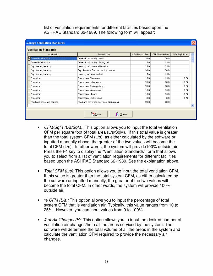
list of ventilation requirements for different facilities based upon the ASHRAE Standard 62-1989. The following form will appear:
• CFM/SqFt (L/s/SqM): This option allows you to input the total ventilation CFM per square foot of total area (L/s/SqM). If this total value is greater than the total system CFM (L/s), as either calculated by the software or inputted manually above, the greater of the two values will become the total CFM (L/s). In other words, the system will provide100% outside air. Press the F4 key to display the "Ventilation Standards" form that allows you to select from a list of ventilation requirements for different facilities based upon the ASHRAE Standard 62-1989. See the explanation above.
• Total CFM (L/s): This option allows you to input the total ventilation CFM.
If this value is greater than the total system CFM, as either calculated by the software or inputted manually, the greater of the two values will become the total CFM. In other words, the system will provide 100% outside air.
• % CFM (L/s): This option allows you to input the percentage of total
system CFM that is ventilation air. Typically, this value ranges from 10 to 25%. However, you can input values from 0 to 100%.
• # of Air Changes/Hr: This option allows you to input the desired number of
ventilation air changes/hr in all the areas serviced by the system. The software will determine the total volume of all the areas in the system and calculate the ventilation CFM required to provide the necessary air changes.

39
Heating Ventilation CFM Per Person/CFM Per SqFt/Total CFM/% of Total Supply CFM/# of Air Changes: This input allows you to specify the amount of outside air ventilation entering the air handler during heating season (Please Note: This is NOT infiltration. Infiltration is specified in the area inputs). Ventilation air is defined as any outside air that is conditioned prior to entering the occupied zone. You can select from five types of ventilation values by either pressing the F3 key, pressing the button adjacent to the input box, or selecting from the drop down box at the top of the screen to scroll through the various options.
• CFM (L/s)/Person: This option allows you to specify the amount of ventilation air per person in the occupied areas of the system. ASHRAE indicates 20 CFM (7.1 L/s)/person as the standard. Press the F4 key to display the "Ventilation Standards" form that allows you to select from a list of ventilation requirements for different facilities based upon the ASHRAE Standard 62-1989. The following form will appear:
• CFM/SqFt (L/s/SqM): This option allows you to input the total ventilation CFM per square foot of total area (L/s/SqM). If this total value is greater than the total system CFM (L/s), as either calculated by the software or inputted manually above, the greater of the two values will become the total CFM (L/s). In other words, the system will provide100% outside air. Press the F4 key to display the "Ventilation Standards" form that allows you to select from a list of ventilation requirements for different facilities based upon the ASHRAE Standard 62-1989. See the explanation above.
• Total CFM (L/s): This option allows you to input the total ventilation CFM.
If this value is greater than the total system CFM, as either calculated by the software or inputted manually, the greater of the two values will

40
become the total CFM. In other words, the system will provide 100% outside air.
• % CFM (L/s): This option allows you to input the percentage of total
system CFM that is ventilation air. Typically, this value ranges from 10 to 25%. However, you can input values from 0 to 100%.
• # of Air Changes/Hr: This option allows you to input the desired number of
ventilation air changes/hr in all the areas serviced by the system. The software will determine the total volume of all the areas in the system and calculate the ventilation CFM required to provide the necessary air changes.
Fan Configuration: This input specifies the type of fan configuration for the system. You can select either a “draw-through” or “blow-through” type fan configuration. The fan blower and motor adds additional heat to the air and is considered an additional load upon the cooling system. A “draw-through” configuration means that the fan is located ahead of the cooling coil. This adds additional sensible heat load to the room load. The “blow-through” fan is located behind the cooling coil. The blow-through fan increases the dry-bulb temperatures of the air entering the coil. Fan Static: Fan static pressure is the difference in pressure across the fan This is used to calculate the contribution of heat from the fan to the air supply (see “Fan Configuration” explanation above). The higher the fan static pressure, the greater the heat load. Values may range from 0 to 6.0 w.g. or (0 to .030 kPA). Fan Efficiency: Fan efficiency is also important for determining the fan contribution of heat to the total cooling load. The more efficient the fan, the less energy that is lost as heat, and the less heat will be contributed to the system. Fan efficiencies may range from 50 to 100%. Coil Bypass: The coil bypass input indicates the percentage of air that bypasses the cooling coils without being conditioned. This occurs since not all the air passing through the coils actual comes in contact with it. The more air that is bypassed, the warmer the supply air will be. This affects the amount of CFM that is required to supply the system. Suggested values range from 5 to 25%.

41
System Setpoints / Safety / Other This tab allows you to input cooling and heating setpoint information, safety percentage values, hydronic settings, and duct sizing settings.
Occupied Cooling Setpoint: This is the temperature that you want to maintain (during the summer) in all the areas of the system during occupied hours (Occupied hours for the building as a whole are specified in the “Schedules” tab discussed in Section 3.2). Most values range from 65 to 80 degrees F (18 - 27 degrees C). You can override this system-wide setpoint by specifying an occupied cooling setpoint for each area. Occupied Cooling Humidity (%): This is the relative humidity percentage of the occupied space. This value usually ranges from 45 to 55%. However, there exist special applications, such as printing plants, which require lower humidity values. The software will calculate the corresponding coil supply air dry-bulb and wet-bulb temperatures that will provide the desired humidity. If extreme humidity values are inputted, or calculated wet bulb temperatures are above the 100% saturation line for the corresponding coil dry-bulb temperature (which is not possible in real applications), then an error will display in the Psychrometric Summary report. Unoccupied Cooling Setpoint: This is the temperature that you want to maintain (during summer) in all the areas of the system during unoccupied hours. Most values range from 65 to 80 degrees F (18 - 27 degrees C).

42
Occupied Heating Setpoint: This is the temperature that you want to maintain (during the winter) in all the areas of the system. Most values range from 60 to 90 degrees F (21 - 27 degrees C). Sensible Cooling Safety: This is a percentage value that is used to calculate additional sensible loads above and beyond the total cooling sensible load. For example, if the total sensible load is 1,000 BTUh and the cooling safety value is 10%, then the new sensible load will be 1,100 BTUh. The sensible safety value is calculated based upon all area loads and does not include ventilation, fan heat, duct heat, reheat, or coil loads. Latent Cooling Safety: This is a percentage value that is used to calculate additional latent loads above and beyond the total cooling latent load. For example, if the total latent load is 1,000 BTUh and the latent safety value is 10%, then the new latent load will be 1,100 BTUh. The latent safety value is calculated based upon all area loads and does not include ventilation loads. Heating Safety: This is a percentage value that is used to calculate additional heating loads above and beyond the total heating load. For example, if the total heating load is 1,000 BTUh and the heating safety value is 10%, then the new heating load will be 1,100 BTUh. The heating safety value is calculated based upon all area loads and does not include ventilation loads. Duct Heat Gains/Losses: This value takes into account air friction along the sides of the duct leading into and away from the fan that causes the air to heat up. This imposes an additional cooling load upon the system. Typically, duct heat gain values range from 5 to 15%. However, you may also enter a negative value for any heat loss through the ductwork, due to colder conditions outside the ductwork. Cooling Delta Temperature: This value is the cooling temperature difference across that cooling coil that is used to determine the GPM (gallons/minute) or Liters/s flows for the cooling load outputs. This value is utilized to display load values in the output reports for hydronic cooling systems only. The following equation is used to calculate total loads:
500 x DeltaT x GPM = Total BTUh load. Heating Delta Temperature: This value is the heating temperature difference across that heating coil that is used to determine the GPM (gallons/minute) or Liters/s flows for the heating load outputs. This value is utilized to display load values in the output reports for hydronic heating systems only. The following equation is used to calculate total loads:
500 x DeltaT x GPM = Total BTUh load.

43
Boiler Efficiency (%):This value is used to display the total input BTUh for the boiler or furnace. The calculated boiler load is divided into this boiler efficiency value to calculate the input value. This value is displayed in the psychrometric output report. Steam Energy: This value is the BTUh/lb of steam being used in a steam system. This value is divided into the final heating BTUh load to determine the total weight (lbs or kgs) of steam that will be required to heat the system. Duct Shape: Select the shape of the duct (rectangular or round) that will be servicing the areas in the system. This will force the software to calculate all duct sizes in either "width x height" or "diameter" dimensions. Duct Roughness Factor: Input a factor that best describes the relative roughness of the duct material. Most values range from 0.0001 to 0.01. The smoother the duct, the lower the roughness factor. Use Air Velocity (fpm or mps) : Select this option and specify the velocity of the air traveling through the duct work. Use Friction Factor (in w.g./100 ft) : Select this option and specify the friction factor per 100 feet of duct. Most often this value is 0.100.

44
Air Volume Calc Type / Pretreating This tab allows you to specify the air volume calculation type and the pretreated air conditions, if any.

45
Air Volume Calculation Type This set of options allows you to specify how to perform the final air quantity CFM calculations for each area in a system. If you select "constant volume", then the total air quantity CFM calculated during the peak load time for the system will be allotted to each area. If you select "Variable Air Volume", then the peak load time for each area will be calculated, individually, and the calculated air volume CFM during the peak time will be allotted to the area. Therefore, the total of all the individual area CFMs will be greater than the "constant volume" CFM option. Select the "Variable Air Volume" option if you want to size the HVAC equipment for the sum of all individual room peak loads. Pretreated Outside Air This set of options allows you to specify whether outside air is mechanically cooled or heated prior to entering the fan. If not, specify the "Outside air is not pretreated." If the air is pretreated, then specify one of the other three options (cooling, only; heating, only; both cooling and heating). If you specify the "cooling, only" or "both cooling and heating" options, then input a new summer temperature in the "Summer Dry-Bulb Temp." input. This temperature will take precedence over the outside summer dry-bulb temperature specified in the weather tab. If you specify the "heating, only" or "both cooling and heating" options, then input a new winter temperature in the "Winter Dry-Bulb Temp." input. This temperature will take precedence over the outside winter dry-bulb temperature specified in the weather tab.

46
Equipment Selection The equipment selection input section of the system tab allows you to select from an unlimited number of vendor equipment databases, and assign the equipment to a system. You can either utilize the built-in HVAC equipment list or extract information from other third-party vendor equipment databases. See Chapter 7.2 for more information.
Equipment Selection - Cooling To begin specifying HVAC cooling equipment, select the type of equipment from the "Equip. Type" drop down list. For cooling equipment, you will want to select either the "Air Conditioner" or "Heat Pump" options. Based upon the option that you select, then "Manuf. Data" drop down list will populate with manufacturers of either heat pumps or air conditioners or both. If you wish to use the built-in equipment database, specify the "Loadsoft Equipment Database - Cooling" option. Once you have selected a manufacturer, press the "Connect to DB" button. (Please note: You do not need to press this button if you selected the "Loadsoft Equipment Database - Cooling" option, since this database is built-in to the program). This connects to the third-party equipment database. Make sure that the connections to the database are current. If the connection is successful, then the "Model No" drop down box will populate with all the equipment model numbers from the database. Select any model number and the input boxes

47
below it will automatically populate with values associated with the model number: SEER (%):This is the efficiency rating of the model number that was selected. Air Volume: This is the total CFM (L/s) output of the fan associated with this model number. Capacity: This is the total capacity rating (MBH) of the model number. Sensible Load: This is the total sensible load output (MBH) of the model number. Latent Load: This is the total latent load output (MBH) of the model number. If you want the software to automatically pick a cooling equipment model number based upon the total system loads, press the "Pick Model" button. If a model number exists that is able to supply the sensible and latent loads for the system, it will appear in the drop down. Equipment Selection - Heating To begin specifying HVAC heating equipment, select the type of equipment from the "Equip. Type" drop down list. For heating equipment, you will want to select either the "Boiler", "Furnace" or "Heat Pump" options. Based upon the option that you select, the "Manuf. Data" drop down box will populate with manufacturers of either heat pumps, boilers, furnaces or all the above. If you wish to use the built-in equipment database, specify the "Loadsoft Equipment Database - Heating" manufacturer. Once you have selected a manufacturer, press the "Connect to DB" button. (Please note: You do not need to press this button if you selected the "Loadsoft Equipment Database - Heating" option, since this database is built-in to the program). This connects to the third-party (or internal) equipment database. Make sure that the connections to the database are current. If the connection is successful, then the "Model No" drop down box will populate with all the equipment model numbers from the database. Select any model number and the input boxes below it will automatically populate with values associated with the model number: Effic. (%): This is the efficiency of the model number that was selected. Air Volume: This is the total CFM (L/s) output of the fan associated with this model number. Capacity: This is the total capacity rating (MBH) of the model number.

48
If you want the software to automatically pick a heating equipment model number based upon the total system heating loads, press the "Pick Model" button. If a model number exists that is able to supply the heating loads for the system, it will automatically appear in the drop down. Section 3.4 – Zone Inputs A zone is defined as a like group of areas within a system. For example, a zone can be a "first floor" of a house or an "east wing" of a small building. Many zones can exist within each system. There is no formulaic importance to zones, meaning that they have not effect upon final load calculations. Zones are merely "placeholders" that allow you to organize the areas within a system.
The zone inputs are few and simple. They include the following: Zone Name: This displays the name of the zone. You are not able to edit the name within this text box, but you can rename the zone by right-clicking over the zone name in the navigation area and selecting the "Rename Zone" option. Zone Description: This input allows you to enter a zone description. Section 3.5 – Area Inputs The area input section allows you to input all information associated with a building area, including area square footages, envelope values and internal values. A building area is defined as a room or a common area in a building. Six tabs are associated with the area inputs: “General Area / Air Values”, “Wall

49
and Roof Envelope”, “Window and Shading”, “Skylight / Doors / Partition”, “Internal / Other”, and “Checks / Output” tabs. General Area The top area of this tab allows you to input basic information about the area.
Area Name: This input contains the area name. You are not able to edit the name here, but you can rename the area by right-clicking over the area name in the project navigation area. Total Area (SqFt/SqM): This input allows you to specify the total square area (SqFt or SqM) of the room. The button located to the right of this text box allows you to set the first roof area in the roof list equal to this total area. In addition, this button sets the ceiling area equal to the room total area (See below). Avg. Area Height (Ft or M): This input contains the average height of the room in feet or meters. This value is used to calculate room volume for ventilation and infiltration purposes. The button located to the right of this text box allows you to set all the wall heights equal to this value. Area Temperature Setpoint (F or C): You can specify the area cooling temperature setpoint here. If you also specified a system cooling setpoint (See Chapter 3.3), this area setpoint will take precedence. If you set this setpoint

50
equal to less than 32 F (or 0 C), the system setpoint takes precedence. You can override this functionality in the general settings form by having the system cooling setpoint always take precedence (See Chapter 8.2). Area Multiplier: This input allows you to specify a multiplier value for the area. This is useful for performing load calculations on one or more rooms that are exactly the same in terms of load profile characteristics. All load values will be multiplied by this value. The default value is 1. Carpeting: This check box allows you to specify whether the area is carpeted. If it is carpeted, check this input. If it is not carpeted, do not check it. Construction Weight: This drop down allows you to specify the overall construction weight of the area. You can select light, medium, or heavy. The following lists typical wall construction types for light, medium, and heavy walls.
1. Light weight construction for a wall would be something similar to steel siding with 2 in. insulation.
2. Medium weight construction for a wall would be 4 in. face brick and 2 in. insulation.
3. Heavy weight construction for a wall would be 4 in. face brick and 8 in. HW concrete air space with 2 in. insulation.
When in doubt as to the overall construction weight, select "medium". Area Description: Input an area description here. Date Created: This input displays the date the area was created. It is read-only. Active: This checkbox allows you to specify whether an area is active or not. If it is active, then it will be included in all load calculations for the system. If it is not active, then it will not be included in the system load calculations. Air Values The bottom area of this tab allows you to input air values related to the room, including infiltration, exhaust, and minimum supply air volumes.

51
Infiltration Infiltration takes into account natural air leakage into commercial structures. Any unconditioned air that enters the space needs to be conditioned. Therefore, it will contribute to the total cooling and heating loads. You can specify infiltration CFM values for both cooling and heating seasons. Cooling Infiltration: This input allows you to specify the CFM of infiltration during the summer. You can specify the CFM value in four different ways:
1. Cooling Infiltration CFM/SqFt (L/s/SqM): Input the infiltration CFM/square foot of area.
2. Cooling Infiltration CFM (L/s): Input the total infiltration CFM for the area. 3. Cooling Infiltration CFM (L/s)/Person: Input the amount of infiltration CFM
per person in the occupied area. 4. Cooling Infiltration # of Air Changes/Hr: Input the desired number of
infiltration air changes/hour in this area. Either press the F3 key, the button to the right of the text box, or select from the drop down box at the top of the form to toggle between the four options. Heating Infiltration: This input allows you to specify the CFM of infiltration during the winter. You can specify the CFM value in four different ways:
1. Heating Infiltration CFM/SqFt (L/s/SqM): Input the infiltration CFM/square foot of area.
2. Heating Infiltration CFM (L/s): Input the total infiltration CFM for the area. 3. Heating Infiltration CFM (L/s)/Person: Input the amount of infiltration CFM
per person in the occupied area. 4. Heating Infiltration # of Air Changes/Hr: Input the desired number of
infiltration air changes/hour in this area. Either press the F3 key, the button to the right of the text box, or select from the drop down box at the top of the form to toggle between the four options. Exhaust The exhaust input allows you to specify the CFM (L/s) of air exhausted from the area by a fan. If the amount of air exhausted from the area is greater than the ventilation air supplied to the area, then Loadsoft will automatically increase the ventilation to a specific room to ensure there is no negative pressure loss (i.e. - the ventilation CFM will be set equal to the exhaust CFM). This input allows you to specify the CFM of exhaust during the summer and winter. You can specify the CFM value in four different ways:
1. Exhaust CFM/SqFt (L/s/SqM): Input the exhaust CFM/square foot of area. 2. Exhaust CFM (L/s): Input the total exhaust CFM for the area.

52
3. Exhaust CFM (L/s)/Person: Input the amount of exhaust CFM per person in the occupied area.
4. Exhaust Air Changes/Hr: Input the number of air changes/hour due to exhaust from this area.
Either press the F3 key, the button to the right of the text box, or select from the drop down box at the top of the form to toggle between the four options. Minimum Supply Air The minimum supply air input allows you to specify the minimum amount of air in CFM (L/s) that you want supplied to the area (including ventilation and return air). If the calculated supply CFM is less than the minimum CFM specified in this input, then the actual supply CFM for this area will be set to this minimum. If you input a set total supply CFM for the entire system, and this minimum supply CFM value causes the supply CFM to exceed the value that you inputted, then this new supply CFM will be used. This input allows you to specify the CFM of minimum supply air in four different ways:
1. Min. Supply CFM/SqFt (L/s/SqM): Input the minimum supply air CFM/square foot of area.
2. Min. Supply CFM (L/s): Input the total minimum supply air CFM for the area.
3. Min. Supply CFM (L/s)/Person: Input the amount of minimum supply air CFM per person in the occupied area.
4. Min. Supply Air Changes/Hr: Input the number of air changes/hour due to minimum supply air from this area.
Either press the F3 key, the button to the right of the text box, or select from the drop down box at the top of the form to toggle between the four options.

53
Wall Envelope The top area of this tab allows you to input wall envelope information. A wall envelope is described as a vertical (or angled) wall that is exposed to the outside.
You can input up to ten different types of walls for each area. Each wall has seven sets of characteristics that must be specified to accurately calculate cooling and heating load contributions.
Click this button to add more walls to the list.
Click this button to remove a wall from the list. You cannot have fewer than one wall.
This button allows you to toggle between the "simple" and "detailed" input mode. If you would prefer to have fewer inputs (and allow the program to make certain assumptions), then toggle to the simple mode. Fewer input boxes will be displayed. If you would prefer to have greater control over the values inputted, then set it to detailed mode, where all wall-envelope inputs will be displayed. The descriptions below for each input specify whether they are displayed in the simple or detailed input mode.

54
Orientation: This drop down box allows you to specify the orientation (i.e. – which direction it faces) of the wall: north, south, east, west, northeast, northwest, southeast, southwest. (Displayed in simple and detailed modes). Wall CTS No.: This drop down allows you to select a wall conduction time series (CTS) number. The wall CTS numbers are derived from Table 20, Chapter 29 in the ASHRAE 2001 Fundamentals. When you select an item in this drop down or if you press the F4 key, a form will appear listing all the wall CTS numbers and their descriptions:
Select the wall number that most closely approximates the wall that you want to model. The u-value input box will automatically fill in with the selected wall CTS u-value. See Chapter 6 for more information about the wall CTS numbers. (Displayed in simple and detailed modes). Width (Ft or M): Specify the width of the wall in feet or meters. (Displayed in simple and detailed modes). Height (Ft or M): Specify the height of the wall in feet or meters. This value is automatically set equal to the area height (see above) if you pressed the button next to the "Avg. Area Height" text box. (Displayed in simple and detailed modes). Wall U-value: The wall U-value is a conduction factor expressed in BTU/hr/SqFt/F (Watt/SqM/K). It is actually the reciprocal of the R-Value that is more commonly used to describe different types of insulation and walls. The U-value may be determined by adding the R-Values of several different types of layers of wall material and taking the reciprocal of the total. The higher the U-value, the more heating and cooling can be conducted through it, causing greater heat losses or gains. The lower the U-value, the less heating and cooling can be conducted, causing less heat loss and heat gain. The range of

55
allowable U-values ranges from 0 to 6.0 (0 - 35.0 W/SqM/K). (Displayed in detailed mode). The U-value is automatically selected based upon the wall CTS number that you chose above. However, you can choose to override it by either manually inputting another value or pressing the F4 key to display a form that lists common commercial wall types:
Wall Color: This input allows you to specify the overall color of the wall. Three options exist: "light" for light color (white or gray), "medium" for medium color (dark gray, red, light brown), and "dark" for darker colors such as dark brown and black. If you are in doubt about the color, specify "medium". (Displayed in detailed mode). Wall Angle: Many walls are not constructed perfectly vertical and any variation in wall angles may significantly affect cooling loads depending upon orientation and time of day. You can specify a wall angle relative to the VERTICAL plane. For example, if you have a north-facing wall that has a 10-degree angle with the vertical, then you would enter 10 for this input. You can specify angles up to 90 degrees. (Displayed in detailed mode). Total Area: This is a read-only input the displays the gross total area of the wall. The wall area is equal to:

56
Wall Width x Wall Height Any walls with 0 width or height values will be ignored in the load calculations. Roof Envelope The roof envelope inputs allow you to specify properties for up to seven different types of roofs for each area. Each roof has seven sets of characteristics that must be specified to accurately calculate cooling and heating load contributions.
Click this button to add more roofs to the list.
Click this button to remove a roof from the list. You cannot have fewer than one roof.
This button allows you to toggle between the "simple" and "detailed" input mode. If you would prefer to have fewer inputs (and allow the program to make certain assumptions), then toggle to the simple mode. Fewer input boxes will be displayed. If you would prefer to have greater control over the values inputted, then set it to detailed mode, where all roof envelope inputs will be displayed. The descriptions below for each input specify whether they are displayed in the simple or detailed input mode. Roof CTS No.: This drop down allows you to select a roof conduction time series (CTS) number. The roof CTS numbers are derived from Table 21, Chapter 29 in the ASHRAE 2001 Fundamentals. When you select an item in this drop down or if you press the F4 key, a form will appear listing all the roof CTS numbers and their descriptions:
Select the roof number that most closely approximates the roof that you want to model. The u-value input box will automatically fill in with the selected roof CTS u-value. See Chapter 6 for more information about the roof CTS numbers. (Displayed in simple and detailed modes).

57
Width (Ft or M) : Specify the width of the roof in feet or meters. (Displayed in simple and detailed modes). Length (Ft or M): Specify the length of the roof in feet or meters. (Displayed in simple and detailed modes). Roof U-value: The roof U-value is a conduction factor expressed in BTU/hr/SqFt/F (Watt/SqM/K). It is actually the reciprocal of the R-Value that is more commonly used to describe different types of insulation and roofs. The U-value may be determined by adding the R-Values of several different types of layers of roofing material and taking the reciprocal of the total. The higher the U-value, the more heating and cooling can be conducted through it, causing greater heat losses or gains. The lower the U-value, the less heating and cooling can be conducted, causing less heat loss and heat gain. A typical R-20 Roof has a U-value of 0.05. The range of allowable U-values ranges from 0 to 6.0 (0 - 35.0 W/SqM/K). (Displayed in detailed mode). The U-value is automatically selected based upon the roof CTS number that you chose above. However, you can choose to override it by either manually inputting another value or pressing the F4 key to display a form that lists common commercial roof types:

58
Roof Color: This input allows you to specify the overall color of the roof. Three options exist: "light" for light color (white or gray), "medium" for medium color (dark gray, red, light brown), and "dark" for darker colors such as dark brown and black. If you are in doubt about the color, specify "medium". (Displayed in detailed mode). Orientation: This drop down box allows you to specify the orientation of the roof. Many roofs are flat, so you can specify the "Flat" orientation drop down option. However, there are a number of angled roofs. Therefore, you will need to specify the direction that the angled roof faces: north, south, east, west, northeast, northwest, southeast, southwest. (Displayed in detailed mode). Roof Angle: Many roofs are not constructed perfectly horizontal and any variation in roof angles may significantly affect cooling loads, depending upon orientation and time of day. You can specify a roof angle relative to the HORIZONTAL plane. For example, if you have a north-facing roof that has a 10-degree angle with the horizontal plane, then you would enter 10 for this input. You can specify angles up to 90 degrees. (Displayed in detailed mode). Total Area: This is a read-only input the displays the gross total area of the roof. The roof area is equal to:
Roof Width x Roof Length Please note that you can have the first roof area automatically equal the area square area by pressing the button next to the area total area text box This will then set the roof width and length equal to the square root of the roof area. You do not need to input values for all roofs for each area. Any roofs with 0 width or length values will be ignored in the load calculations.

59
Window Envelope The window envelope inputs allow you to specify properties for up to ten different types of windows for each area. Each window has seven sets of characteristics that must be specified to accurately calculate cooling and heating load contributions:
Click this button to add more windows to the list.
Click this button to remove a window from the list. You cannot have fewer than one window.
This button allows you to toggle between the "simple" and "detailed" input mode. If you would prefer to have fewer inputs (and allow the program to make certain assumptions), then toggle to the simple mode. Fewer input boxes will be displayed. If you would prefer to have greater control over the values inputted, then set it to detailed mode, where all window envelope inputs will be displayed. The descriptions below for each input specify whether they are displayed in the simple or detailed input mode. Corresponding Wall: This input allows you to specify which wall in the previous tab this window is located on. This is important for determining the orientation and angle of the window. You can specify a value from 1 to 10. (Displayed in simple and detailed modes).

60
Window No.: This drop down allows you to select a window solar heat gain coefficient (SHGC) number. The SHGC numbers are derived from Table 13, Chapter 30 in the ASHRAE 2001 Fundamentals. When you select an item in this drop down or if you press the F4 key, a form will appear listing all the window SHGC numbers and their descriptions:
Select the window number that most closely approximates the window that you want to model. See Chapter 6 for more information about window SHGC numbers. (Displayed in simple and detailed modes).

61
Window Material: This input allows you to select from a list of common commercial window types. By selecting an item in this drop down or pressing the F4 key, the following form will appear:
Select the window that most approximates the window that you are modeling. After selecting the window and closing the form, the u-value input will automatically fill in. The difference between this input and the "Window No." input discussed previously is the following:
1. The "Window No." input is used to calculate summer solar cooling load contributions (including solar contributions) of the window to the occupied space.
2. The "Window Material" input is used to determine the u-value which is then used to calculate summer conduction cooling and winter conduction heating loads to the occupied space.
(Displayed in simple and detailed modes). Width (Ft or M): Specify the width of the window in feet or meters. (Displayed in simple and detailed modes).

62
Height (Ft or M): Specify the height of the window in feet or meters. (Displayed in simple and detailed modes). Multiplier: This input allows you to specify how many of this type of window exists. The total area will include the width and height of the window times this multiplier value. (Displayed in detailed mode). Window U-value: The window U-value is a conduction factor expressed in BTU/hr/SqFt/F (Watt/SqM/K). This value is automatically filled in based upon the window material selected above. You can also manually input a value. (Displayed in detailed mode). Total Area: This is a read-only input the displays the total area of the window. The window area is equal to:
Window Width x Window Height x Multiplier Value The total area of all windows assigned to a wall is subtracted from the wall total area, so that the net wall area is used to calculate wall load contributions. Also, the total area of windows (plus the total area of all doors) that are assigned to a corresponding wall cannot be greater than the total area of the wall. An error will occur when you are trying to calculate the cooling and heating loads. Please note that you do not need to input values for all seven types of windows for each area. Any windows with 0 width or height values will be ignored in the load calculations. Window Shading The window shading inputs allow you to specify the shading properties (both internal and external) for each of the windows. The following is an explanation of each of the inputs associated with window shading: Shading?: Select this check box if there is some type of internal shading associated with the window. This could either be glazing, blinds, shades, or draperies. If this check box is not checked, then no internal shading calculations will be performed for the window, even if the various drop down boxes discussed next are selected. Internal Shading Glazing System Type: This drop down contains a list of different types of internal shading types including blinds/shades, in-between glass glazing, and draperies. These items correspond to tables 19, 20, and 22 of Chapter 30 in the ASHRAE 2001 Fundamentals. Depending upon the glazing system selected, it will determine the interior solar attenuation coefficient (IAC) that is used to calculate shading values.

63
Either select an item in this drop down or press the F4 key. The following form will appear:
This form contains 3 tabs: the first for venetian blinds and shades, the second for between-glass shading, and the third for draperies. Select the tab with the type of glazing system that best represents the actual shading type for the window. Then, select the specific glazing system type and press the "Select" button to return to the shading inputs. See Chapter 6 for more information about this form. Shading Color/Type or Yarn Reflectance: This drop down allows you to select the specific shading color, shading type, or yarn reflectance, depending upon the glazing system type you selected above:
1. If you selected a blind or shade glazing system type above, then you can choose from the first five items in this drop down: venetian or shading colors.
2. If you selected a between-glass glazing system type above, then you can choose from items 6 to 8 in this drop down: between-glass tint or louvered sun screen.
3. If you selected a drapery glazing system type above, then you can choose from items 9 to 18 in this drop down: yarn reflectance letter. This can be derived from Table 22, Chapter 30 in the ASHRAE 2001 Fundamentals.
If you attempt to select a shading color or yarn reflectance for a glazing system that does not support one of these options, then an error message will display. For example, if you selected a type of blind or shade for the glazing system type and you attempt to select a yarn reflectance letter, the software will not allow you to select it.

64
External Shading Horizontal Depth: This input allows you to specify the width (in inches or centimeters) of any horizontal fins located outside and above the window. The width and offset of this fin will determine how much of the window receives direct sunlight, and helps reduce solar loads due to external shading. External Shading Vertical Depth: This input allows you to specify the width (in inches or centimeters) of any vertical fins located outside and to the left or right of the window. The width and offset of this fin will determine how much of the window receives direct sunlight, and helps reduce solar loads due to external shading. External Shading Horizontal Offset: This input allows you to specify the offset (in inches or centimeters) of any horizontal fins located outside and above the top of the window. External Shading Vertical Offset: This input allows you to specify the offset (in inches or centimeters) of any vertical fins located outside and to the left or right of the window.

65
Roof Skylights Skylights are "glass windows" located on a roof and can contribute significant amounts of solar loads to the building. The skylight inputs allow you to specify properties for up to seven different types of roof skylights for each area. Each skylight has seven sets of characteristics that must be specified to accurately calculate cooling and heating load contributions:
Click this button to add more skylights to the list.
Click this button to remove a skylight from the list. You cannot have fewer than one skylight.
This button allows you to toggle between the "simple" and "detailed" input mode. If you would prefer to have fewer inputs (and allow the program to make certain assumptions), then toggle to the simple mode. Fewer input boxes will be displayed. If you would prefer to have greater control over the values inputted, then set it to detailed mode, where all skylight envelope inputs will be displayed. The descriptions below for each input specify whether they are displayed in the simple or detailed input mode.

66
Corresponding Roof: This input allows you to specify which roof in the previous tab this skylight is located on. This is important for determining the orientation and angle of the skylight. You can specify a value from 1 to 7. (Displayed in simple and detailed modes). Skylight No.: This drop down allows you to select a window SHGC (solar heat gain coefficient) number. This list of SHGC numbers is derived from Table 13, Chapter 30 in the ASHRAE 2001 Fundamentals. When you select an item in this drop down or if you press the F4 key, a form will appear listing all of the window SHGC numbers and their descriptions:
Select the window number that most closely approximates the skylight that you want to model. See Chapter 6 for more information about window SHGC numbers. (Displayed in simple and detailed modes).

67
Skylight Material: This input allows you to select from a list of common commercial window types. By selecting an item in this drop down or pressing the F4 key, the following form will appear:
Select the window that most approximates the skylight that you are modeling. After selecting the window and closing the form, the u-value input will automatically fill in. The difference between this input and the "Skylight No." input is the following:
1. The "Skylight No." input is used to calculate summer solar cooling load contributions of the window to the occupied space.
2. The "Window Material" input is used to determine the u-value which is then used to calculate summer conduction cooling and winter conduction heating loads to the occupied space.
(Displayed in simple and detailed modes). Width (Ft or M): Specify the width of the skylight in feet or meters. (Displayed in simple and detailed modes). Length (Ft or M): Specify the length of the skylight in feet or meters. (Displayed in simple and detailed modes).

68
Multiplier: This input allows you to specify how many of this type of skylight exists. The total area will include the width and length of the skylight times this multiplier value. (Displayed in detailed mode). Skylight U-value: The skylight U-value is a conduction factor expressed in BTU/hr/SqFt/F (Watt/SqM/K). This value is automatically filled in based upon the skylight material selected above. In addition, you can manually input a value. (Displayed in detailed mode). Total Area: This is a read-only input the displays the gross total area of the skylight. The skylight area is equal to:
Skylight Width x Skylight Length x Multiplier Value The total area of all skylights assigned to a roof is subtracted from the total roof area, so that the net roof area is used to calculate roof load contributions. The total area of skylights that are assigned to a corresponding roof cannot be greater than the total area of the roof. An error will occur when you are trying to calculate the cooling and heating loads. You do not need to input values for all seven types of skylights for each area. Any skylights with 0 width or length values will be ignored in the load calculations. Doors Doors are located on the wall envelopes. Since doors consist of material that differ from the walls they are attached to, the load contributions of the door area will differ from that of the wall. The door inputs allow you to specify properties for up to six different types of doors for each area. Each door has six sets of characteristics that must be specified to accurately calculate cooling and heating load contributions:
Click this button to add more doors to the list.
Click this button to remove a door from the list. You cannot have fewer than one door.
This button allows you to toggle between the "simple" and "detailed" input mode. If you would prefer to have fewer inputs (and allow the program to make certain assumptions), then toggle to the simple mode. Fewer input boxes will be displayed. If you would prefer to have greater control over the values inputted, then set it to detailed mode, where all door envelope inputs will be displayed. The descriptions below for each input specify whether they are displayed in the simple or detailed input mode. Corresponding Wall: This input allows you to specify which wall in the previous tab this door is located on. This is important for determining the orientation and

69
angle of the door. You can specify a value from 1 to 10. (Displayed in simple and detailed modes). Door Material: This input allows you to specify the material of the door. This is used to determine the door U-value. You can either click the drop down box arrow to display the entire list of door materials or press the F4 key to display the U-value construction material form that lists all door materials with U-values and R-values. Once you select a material, the U-value will automatically populate the U-value text box discussed next. (Displayed in simple and detailed modes). Width (Ft or M): Specify the width of the door in feet or meters. (Displayed in simple and detailed modes). Height (Ft or M): Specify the height of the door in feet or meters. (Displayed in simple and detailed modes). Multiplier: This input allows you to specify how many of this type of door exists. The total area of the door will include the width and height of the door times this multiplier value. (Displayed in detailed mode). Door U-value: The door U-value is a conduction factor expressed in BTU/hr/SqFt/F (Watt/SqM/K). The U-value is used to calculate both cooling and heating loads. The range of allowable U-values ranges from 0 to 6.0 (0 - 35.0 W/SqM/K). (Displayed in detailed mode). Total Area: This is a read-only input the displays the total area of the door. The door area is equal to:
Door Width x Door Height x Multiplier Value The total area of all doors assigned to a wall is subtracted from the wall total area, so that the net wall area is used to calculate wall load contributions. Also, the total area of doors (plus the total area of all windows) that are assigned to a corresponding wall cannot be greater than the total area of the wall. An error will occur when you are trying to calculate the cooling and heating loads. Please note that you do not need to input values for all types of doors for each area. Any doors with 0 width or height values will be ignored in the load calculations. Wall or Floor Partition A partition separates a conditioned space from an unconditioned space. A partition is very similar to a wall envelope, except for one major difference: since a partition does not face the outside, there are no solar load contributions. As a result, partitions contribute far less cooling loads than an outside wall.

70
A partition can be any number of things, such as:
• A wall separating a conditioned office space from an unconditioned warehouse area.
• An above-slab floor that is located above an unconditioned space like a crawl-space.
The partition inputs in this tab allow you to specify properties for up to three different types of partitions for each area. Each partition has four sets of characteristics that must be specified to accurately calculate heating and cooling load contributions: Partition Area: This input allows you to enter the total square footage (or SqM) of the partition. U-value: This input allows you to specify a U-value for the partition type. The U-value ranges from 0 to 6.0 (35.0 Watt/SqM/K). Press the F4 key to display the U-value construction form that provides a list of common floor and wall partition types. Summer Temperature: This input allows you to enter the maximum temperature of the unconditioned space in the cooling season. For example, a warehouse space may reach 100 degrees F (32 degrees C) in the middle of summer. The range of acceptable values is from 0 degrees to 150 degrees F (66 degrees C). Winter Temperature: Input the minimum temperature of the unconditioned space during the heating season. For example, a warehouse space may reach 10 degrees F (-17 degrees C) in the middle of winter. The range of acceptable inputs is from 0 to 150 degrees (66 degrees C). Please note that you do not need to input values for all three types of partitions for each area. Any partition with 0 area value will be ignored in the load calculations.

71
Internal / Other The internal inputs represent load contribution components such as people, equipment, lighting, infiltration, and miscellaneous values.
People People contribute both sensible and latent loads to the space. Only cooling loads are affected by people since our bodies add heat, not cooling, to the space. Total People: You can input the maximum number of people that will occupy this area at any one time. The following input, SqFt/Person, is automatically updated according to the square footage that was entered in the previous tabs. SqFt/Person: This input will automatically be updated according to the previous input (see above). However, you may input a value here, and the previous input will update accordingly.

72
People Activity Level: Select from this drop down the appropriate activity level for the people in this area. The more active a person is, the more heat they will contribute to the room. Either select an item from this drop down or press the F4 key while the cursor is within the drop down, and the following form will appear:
After selecting an activity level, the sensible and latent people load input boxes will automatically fill in with the values that you selected. See Chapter 6 for more information about this form. Sensible and Latent People BTUh: These two inputs represent the sensible and latent BTUh contributions per person. These values are derived from the people activity level that you chose above. You can also manually override these values. People Schedule: This input allows you to assign a schedule to the people occupying the area. You can set the times that people are occupying the area at any hour during the day, and also the percentage of people present at any one hour (i.e. – diversity factor). If you do not specify a people schedule for the area, then the project schedule (if any) will take precedence (See Chapter 3.2).

73
To display the schedule form, press the button to the right of this text box or press the F4 key while the cursor is inside the text box:
This form allows you to enter schedule information for the people occupancy. For each hour, enter the average percentage of total people that will be located in the room: 0 to 100%. You can also copy a schedule from an existing schedule template by pressing the “Copy Schedule Template” button and selecting from an existing schedule template. Lighting Lighting Wattage: Lighting also contributes a significant amount of loads to the room. Once again, only cooling loads are affected by lighting. This input allows

74
you to specify lighting wattage in two formats: Watts/Area SqFt (SqM) or Total Wattage. Either press the F3 key, the button to the right of the text box, or select from the drop down box at the top of the form to toggle between the two formats. Lighting Fixture Type: Select one of three lighting fixture types that best describes the majority of lighting in the current area:
1. Suspended, unvented: Select this option if lighting is suspended from the ceiling and not vented in any way.
2. Recessed, vented to R.A.: Select this option if the lighting is recessed within the ceiling, and it is vented to the return air system (i.e. - plenum).
3. Recessed, vented to R.A. and S.A.: Select this option if the lighting is recessed within the ceiling, and it is vented to both the return air plenum and the actual space.
Lighting Schedule: This input allows you to assign a lighting schedule for the area. You can set the times that lighting is on at any hour during the day, and also the percentage of lighting that is on at any one hour. If you do not specify a lighting schedule for the area, then the project schedule (if any) will take precedence.

75
To display the schedule form, press the button to the right of this text box or press the F4 key while the cursor is inside the text box:
This form allows you to enter schedule information for the lighting. You can also copy a schedule from an existing schedule template. For each hour, enter the average percentage of lighting that will be on in the area: 0 to 100%. Equipment Sensible Equipment Wattage/SqFt: Electrical appliances such as refrigerators, copy machines, and computers contribute heat to the space. This input allows you to specify electrical wattage in two formats: Watts/Area SqFt or Total Wattage. Either press the F3 key, the button to the right of the text box, or

76
select from the drop down box at the top of the form to toggle between the two formats. You will notice that as you toggle between Watts/Sqft and total wattage, the "Latent Electric" input just below it also toggles. You can also press the F4 key to display the "Assign Appliance List" form which displays a list of common appliances and their respective wattages and radiant percentages. You can select one or more appliances, and the total sensible and latent wattages and radiant percentages will automatically fill in the sensible, latent, and radiant % text boxes for the area. Press the F4 key, again, and the list returns allowing you to edit it or add items. Each list is unique to each area.
Once the “Appliance List” form opens, do the following:
1. Select the appliance category from the drop down box at the top of the form. This will display all the appliances for the selected category in the "list of all appliances" drop down box located underneath. The default category is "Office Building".
2. As you select each appliance, its sensible, latent, and radiant % values
display in the text boxes below the drop down. To add the selected appliance to the spreadsheet list, press the "Enter" key or press the "Add" button. As you add each appliance, the total sensible and latent wattages and radiant % values will update in the spreadsheet. You can update the

77
quantities of each appliance by changing the quantity value in the spreadsheet, itself.
3. When you are completed, press the "Ok" button to return to the main area
input form. The new total sensible and latent wattage values and average radiant % will appear in the respective text boxes.
4. If you press the "Cancel" button when in this form, no updated values will
be passed into the area text boxes.
5. This list of appliances can always be accessed by pressing the F4 key in any of the area electric input boxes. You can edit this information by adding more appliances or editing the quantities and wattage values in the spreadsheet, itself. Press the "Ok" button to save any changes.
Latent Equipment Wattage/SqFt: Electrical appliances such as water coolers and coffee machines contribute latent loads to the space. This input allows you to specify electrical wattage in two formats: Watts/Area SqFt or Total Wattage. Either press the F3 key, the button to the right of the text box, or select from the drop down box at the top of the form to toggle between the two formats. As you toggle this option, the sensible electric option above will also toggle. Once again, you can press the F4 key to display the "Assign Appliance List" form which displays the list of common appliances. Any appliances with latent wattages will automatically fill in this input. Average Equipment Radiant %: This input specifies how much radiant heat the equipment emits. Values usually range from 20% to 80%. If you selected equipment or appliances from the "Assign Appliance List" form discussed above, the radiant % will automatically fill in for those items which have this value assigned. Equipment Schedule: This input allows you to assign an equipment schedule for the area. You can set the times that equipment is on at any hour during the day, and also the percentage of equipment that is on at any one hour. If you do not specify an equipment schedule for the area, then the project schedule (if any) will take precedence.

78
To display the schedule form, press the button to the right of this text box or press the F4 key while the cursor is inside the text box:
This form allows you to enter schedule information for the equipment. You can also copy a schedule from an existing schedule template. For each hour, enter the average percentage of equipment that will be on in the area: 0 to 100%. Miscellaneous Miscellaneous Sensible BTUh: This input allows you to specify positive or negative values for any additional sensible cooling loads. The maximum or minimum value that may be entered is absolute 10,000,000 BTUh (3.0 million Watts).

79
Miscellaneous Latent BTUh: This input allows you to input positive or negative values for any additional latent cooling loads. The maximum or minimum value that may be entered is absolute 10,000,000 BTUh (3.0 million Watts). Miscellaneous Heating BTUh: This input allows you to input positive or negative values for any additional heating loads. The maximum or minimum value that may be entered is absolute 10,000,000 BTUh (3.0 million Watts). Miscellaneous Schedule: This input allows you to assign a "miscellaneous" schedule for the area. You can set the times that the miscellaneous cooling loads will be "on" at any hour during the day, and also the percentage of miscellaneous cooling loads that are on at any one hour. If you do not specify a miscellaneous loads schedule for the area, then the project schedule (if any) will take precedence.

80
To display the schedule form, press the button to the right of this text box or press the F4 key while the cursor is inside the text box:
This form allows you to enter schedule information for the miscellaneous cooling loads. You can also copy a schedule from an existing schedule template. For each hour, enter the average percentage of miscellaneous loads that will be on in the area: 0 to 100%. Ceiling These two inputs allow you to specify the area and u-value of the room reflective or drop ceiling. This information is used to calculate any plenum loss contributions to the space.

81
Below-Plenum Ceiling Area: Input the total area of the reflective ceiling in square feet or meters. This value can automatically be set to the room area by pressing the button next to the room area input discussed in the beginning of Section 3.5. Ceiling U-Value: Input the average u-value for the reflective ceiling. Most reflective ceilings have a u-value of 0.330. Plenum Contributions This set of inputs allows you to input the percentage of HVAC cooling loads for lighting, walls, and roofs (from 0 to 100%) that contribute to the return air plenum located above the ceiling. This is assuming that the return-air is NOT ducted in any way. The best way to determine these percentages is as follows: Lighting: Consult the manufacturer of the lighting fixture to determine the percentage of light heat released through the plenum. Fixtures that are ventilated will release more heat than unventilated lighting fixtures. The percentage of heat contributed to return air ranges from 40 to 60% for ventilated fixtures or 15 to 25% for unventilated fixtures. Walls: The best way to determine the wall load contributions to the plenum is to take the area of wall located above the ceiling plenum and divide it into the total area of the wall. Roofs: Since most drop ceilings separate the entire roof from the occupied space, it can be argued that 100% of the roof loads are contributed to the plenum. However, there are radiant loads that will bypass the plenum, so it is best to input a percentage value ranging from 80 to 90%. If you specify percentages for one or more of these items, then you must also input values for the ceiling area and u-value discussed above. A combination of all these values is used to accurately calculate the total plenum load contributions to the occupied space.

82
This chapter discusses how you can rotate areas, globally edit inputs, search for inputs, check the validity of inputs, and display “quick load” values. Section 4.1 – Rotate Areas When a project is open, select the "Rotate Area(s)" submenu option from the "Edit" main menu option, or right-click over the system, zone, or area(s) in the navigation area. The following form appears:
This feature allows you to rotate one or more areas either 45, 90 or 180 degrees clockwise. When you select a rotation option, all the walls, windows, doors, angled roofs and skylights for the area will rotate accordingly. Click any one of the following options:
• 45 Degrees: Selecting this option rotates the building 45 degrees clockwise (i.e. north to northeast, south to southeast).
• 90 Degrees: Selecting this option rotates the building 90 degrees clockwise (i.e. north to east, east to south).
• 180 Degrees: Selecting this option rotates the building 180 degrees clockwise (i.e. north to south, east to west).
Click the "Rotate" button to perform the rotation. When you return to the area or areas that you have selected, all the envelope orientations will reflect the new direction. Click "Cancel" to forgo any rotation.
Chapter 4 – Edit and Check Inputs

83
Section 4.2 - Globally Edit Areas When a project is open, select the "Globally Edit Area Inputs" submenu option from the "Edit" main menu option, or right-click over the system, zone, or area(s) in the navigation area. The following form appears:
Using this feature, you can change one or more area inputs to the same value over multiple areas. For example, you may want to change all the people quantity values for all areas in a system to 3. Type of Input to Globally Edit The list box in this form lists all the area input types that you can globally edit. The following is the list:
• Area Height • Area Setpoint • Area Multiplier • Area Carpeting • Area Weight • Cooling Infiltration/Area • Heating Infiltration/Area • Exhaust Air Volume/Area

84
• Min. Supply Air Volume/Area • Quantity of People • People Activity Level • People Schedule • Lighting Wattage/Area • Lighting Fixture Type • Lighting Schedule • Equipment Sensible Watt/Area • Equipment Latent Watt/Area • Equipment Radiant % • Equipment Schedule • Miscellaneous Sensible • Miscellaneous Latent • Miscellaneous Heating • Miscellaneous Schedule • Ceiling U-Value • Lighting Plenum Contribution • Roof Plenum Contribution • Wall Plenum Contribution • Roof Number • Roof U-value • Roof Color • Wall Number • Wall U-value • Wall Color • Window Number • Window U-value • Skylight Number • Skylight U-value • Skylight Type • Door Number • Door U-value • Partition U-value • Partition Area • Partition Cooling Temp. • Partition Heating Temp.
Selecting any of the input types in the list box will enable or disable the drop down list and text boxes located below it. The following is an explanation of each input type and the values you can edit: Area Height: Input the area height in feet or meters. Area Setpoint: Input the area temperature setpoint in F or C.

85
Area Multiplier: Input the area multiplier. Area Carpeting: Select "Yes" or "No" if the area has carpeting or not. Area Weight: Select "Light", "Medium", or "Heavy" for the average construction type of the room. Cooling Infiltration/Area or Heating Infiltration/Area: Input the cooling infiltration CFM (L/s) per SqFt (SqM) of area. Exhaust Air Volume/Area: Input the exhaust CFM (L/s) per SqFt (SqM) of area. Min. Supply Air Volume/Area: Input the minimum supply air CFM (L/s) per SqFt (SqM) of area that should be supplied to the area. Number of People: You can select to edit either the total quantity of people or the square area/person by selecting it from the drop down list below the list box. Input the actual number of people or Area/person in the text box below it. People Activity Level: Select the person activity level from the drop down list and the sensible and latent values will update in the two text boxes. You can override these values if you desire. Lighting Wattage/Area or Equipment Sensible Wattage/Area, Equipment Latent Wattage/Area: Input the total wattage per square foot (or meter). Lighting Fixture Type: Select the lighting fixture type from the drop down. People Schedule, Lighting Schedule, Equipment Schedule, Misc. Schedule: Select the schedule template from the drop down. Equipment Radiant %: Input the equipment radiant emission percentage. Misc. Sensible, Latent, or Heating: Input the total miscellaneous sensible cooling, latent cooling, or heating BTUh (Watts). Ceiling U-value: Input the average ceiling u-value. Lighting, Roof, Wall Plenum Contribution: Input the percentage of lighting, roof, or wall loads that contribute to the plenum. Roof U-value, Wall U-value, Window U-value, Skylight U-value, Partition U-value or Door U-value: Input the U-value in the text box. All the roofs, walls, windows, skylights, partitions, or doors for the selected area(s) will be updated.

86
Roof Color or Wall Color: Select the color from the drop down list. All the roofs or walls for the selected area(s) will be updated. Roof Number, Wall Number: Select the appropriate roofing or wall material from the drop down list. This list originates from ASHRAE tables in Chapter 29 of the 2001 Fundamentals. The roof or wall u-value will also update according to the corresponding construction material that you select. Window Number or Skylight Number: Select the window or skylight SHGC number from the drop down. This list originates from ASHRAE tables in Chapter 30 of the 2001 Fundamentals. All the windows or skylights for the selected area(s) will be updated. Door Number: Select the door material from the drop down list. This list originates from the construction material list discussed in Chapter 6. The door u-value will also update according to the corresponding construction material that you select. Partition Summer or Winter Temperature: Input the summer or winter partition temperature in the text box. All the partitions for the selected area(s) will be updated. Once you have selected or entered a value that you want to replicate, press the "Update" and all the area(s) that you selected will be updated.

87
Section 4.3 - Search Systems
Press the button or select the "Search System" submenu option from the "Edit" main menu option. This functionality is only enabled when a project is open, and it allows you to search for systems by specific input values. For example, you can search for all systems in a project whose supply air temperature is 55 degrees F.
Search Criteria Specify the field name whose values you want to search for by selecting it from the "Field Name" drop down list. This drop down list includes all system inputs. When you select an option in the "Field Name" drop down list, the "Search For" drop down list will display all the different values that populate that specific field for all the systems in the current project. Select a value, and then press the "Search" button. All the systems that contain the selected value for the selected field will appear in the spreadsheet. In the spreadsheet, select the system you want to go to, and either press the "Goto" button or double-click the spreadsheet entry. The search form will close, and the selected system will become the current system in the project navigation area.

88
Section 4.4 - Search Areas
Press the button or select the "Search Area" submenu option from the "Edit" main menu option. This functionality is only enabled when a project is open, and it allows you to search for areas by specific input values. For example, you can search for all areas in a project whose miscellaneous sensible BTUh is 300 BTUh.
Search Criteria Specify the field name whose values you want to search for by selecting it from the "Field Name" drop down list. This drop down list includes most of the area inputs. When you select an option in the "Field Name" drop down list, the "Search For" drop down list will display all the different values that populate that specific field for all the areas in the current project. Select a value, and then press the "Search" button. All the areas that contain the selected value for the selected field will appear in the spreadsheet. In the spreadsheet, select the area you want to go to, and either press the "Goto" button or double-click the spreadsheet entry. The search form will close, and the selected area will become the current area in the project navigation area.

89
Section 4.5 – Checks/Outputs The "Checks/Outputs" tab of the main area input tab allows you to perform input checks and quick load calculations for the currently selected area.
Check for Area Input Errors This section allows you to quickly check for any area input errors. Before calculations can be performed upon the area, these errors must be resolved. The following types of input errors are checked:
1. Total area SqFt (or SqM) = 0: The total square area for an area must be greater than 0 since so many of the calculations rely upon the area square area.
2. Total area height = 0: The average height of the area must be greater than 0.
3. Total area of skylights > the total gross area of the corresponding roof: The total area of the skylights must be less than the gross area of its corresponding roof.
4. Total area of all windows and doors > the total gross area of the corresponding wall: The total area of the windows and doors must be less than the gross area of their corresponding wall.

90
5. No city selected from the weather selection tab: You must select a city that the building is located in, since the city weather data is used to calculate heating and cooling loads.
6. No latitude value has been assigned to the city selected for this project: A latitude value must be present in the weather data for calculations to occur.
7. No longitude value has been assigned to the city selected for this project: A longitude value must be present in the weather data for calculations to occur.
8. You must assign a ceiling area when you specify plenum contributions from lights, roofs, or walls: If you specified a lighting, roof, or wall plenum percentage value in the internal input tab, then a ceiling area must also be specified.
9. The system supply cooling value = 0: The value in the system supply cooling input must be greater than 0.
10. The system supply heating value = 0: The value in the system supply heating input must be greater than 0.
To check for errors, press the "Check Errors" button and the list of errors will appear in the spreadsheet list just above the button. Display Area Quick Loads This section allows you to quickly calculate cooling and heating loads for the area. All the load components are calculated and displayed in the spreadsheet. In addition, the month and time of maximum system load will be displayed. Press the "Calculate" button to begin calculations. If any input errors occur (see above), then the results will not be calculated, and the errors will appear in the spreadsheet list discussed above. Once the calculations are performed and displayed in the spreadsheet, you can save the results by right-clicking over the spreadsheet and selecting the "Save Results to Text File" menu option or pressing the "Write to TextFile" button . You will be asked to input a file name. The results are saved as a ".csv" file which will automatically open as a Microsoft Excel if you double-click it in Windows Explorer. In addition, it will open in a text editor as a comma-delimited file.

91

92
This chapter discusses all the outputs produced by the Loadsoft 6.0 software. Section 5.1 - Overview The outputs section of the Loadsoft program can be accessed by selecting the project name in the project navigation area and selecting the "Outputs" tab. You can also select the “Calculate and Display Outputs” sub-menu option of the “File” main menu to display the following:
Calculation Month and Time Range The “Calculation Month and Time Range” tab allows you to select the range of months and hours to perform the HVAC load calculations. See Chapter 5.2 for more information on this. Standard Outputs The “Standard Outputs” tab allows you to display standard output reports such as load summary, breakdown, psychrometric, graphic, and input reports. See Chapter 5.3 for more details about the standard outputs. What-If Scenario Outputs The “What-If Scenario Outputs” tab allows you to perform "what-if" scenarios allowing you to automatically change individual input values and see how they affect the total cooling and heating loads. See Chapter 5.6 for more details about the what-if scenario outputs.
Chapter 5 – Outputs

93
Section 5.2 – Calculation Month and Hour Range The ASHRAE Radiant Time Series (RTS) calculations perform monthly and hourly calculations of all cooling load components and find the month and hour (on the 21st day of each month) that the maximum cooling load will occur. Instead of having the software calculate for all 12 months in a year and all 24 hours in a day, you can specify a range of months and hours. This will not only save time, but there also may be instances where you want to find the maximum cooling load for a specific time range, not necessarily during the maximum cooling load months. For example, many schools are not occupied during the summer months, so maximum cooling loads need be determined for the late spring months, only. You can set the "default" monthly and hourly ranges by checking the "Set to default months and hours" option. This will set the beginning and ending months and hours according to the settings in the "General Settings" form. For the northern hemisphere, you should specify a summer peak-load monthly range of May to September and an hourly range from 10:00 am to 6:00 pm. For the southern hemisphere (where summer occurs during the northern's winter months), you should specify a monthly range of November to March and an hourly range from 10:00 am to 6:00 pm.
Click the button to display the next tab and automatically begin calculations on the first system listed in the list box.

94
Section 5.3 – Standard Outputs You can display standard output reports such as load summary, breakdown, psychrometric, graphic, and input reports. Select the "Standard Outputs" tab located under the "Outputs" tab of the project.
Before displaying the reports, you need to calculate the cooling and heating load values that are displayed in these reports. Do the following:
1. Select the calculation month and time range from the previous tab. 2. Select one or more systems from the system list box. You can also click
the "Select All" check box to select all the systems in the list. 3. Check the "Calculate 24-Hour Load Profile" checkbox if you want to
calculate the total cooling loads for all 24-hours on the 21st day of the month that maximum load occurs. This will lengthen the time it takes to calculate the loads.
4. Press the "Calculate" button to begin calculating. The calculation status is displayed in the panel just below the "Calculate" button.
5. The buttons in the "Display Reports" section will become enabled after the calculations are performed. Press any of these buttons to display the report to print.

95
The following is a list of the reports that you can display. They are discussed in more detail below: Reports 1
• System/Area Heating and Cooling Load Summary • Breakdown of All Load Components • Detailed Psychrometric Analysis • Wall and Window Load Summary • Duct Sizing by Area • Project Inputs
Reports 2
• Graph Outputs • Microsoft Office Export Options • 24-Hour Load Profile
You can change the display format of the above reports by pressing the "Format" button. See Chapter 8.3 for information about the “Report Format Settings” form. By default, you can preview the reports on the computer screen prior to printing.

96
You can also export the reports to the following formats:
• HTML files: Select the "Export to HTML" option prior to displaying a report to export it to HTML format. You will be asked for a filename for the HTML file.
• Text files: Select the "Export to Text File" option prior to displaying the report to export to a text file. You will be asked for a filename for the text file. If you export to a text file, you can open this text file in Microsoft Word and use it to create various types of documents.
• XML files: You can export several of the reports to an XML file. XML (eXtensible Markup Language) is the lingua-franca of the World Wide Web and allows you to share the project outputs with other users who are able parse XML files. The following is an explanation.
Exporting to XML Files XML is a file format that allows you to share data across a wide variety of operating systems, browsers, and other platforms. Loadsoft 6.0 allows you to export several of the output reports to XML so that you can share the data with users who may want to utilize the data. For example, you can export the summary heating and cooling report to XML, then send the file to a user who is using the new Microsoft InfoPath program to parse the data and utilize it for their own needs. You can export the following reports to XML:
• System/Area Heating and Cooling Load Summary • Breakdown of All Load Components • Wall and Window Load Breakdown • Duct Sizing by Area • 24-Hour Load Profile • Project Inputs
To export the reports to XML, do the following:
1. After pressing the “Calculate” button, select the "Export to XML File" option located in the middle of the form.
2. Press one of the buttons of the reports that are listed above. 3. An "Open File" dialog box will appear asking you to specify an XML file
name. 4. Use the default name or specify your own. 5. The file will be created immediately. Go to Microsoft Windows Explorer,
and open the file in Internet Explorer version 4.0 or greater to view it.

97
The following screen shot is a sample of an XML file appearing in Internet Explorer:
Section 5.4 – Standard Outputs – Report Descriptions System/Area Heating and Cooling Load Summary Report This report displays a list of all the individual areas for one or more calculated systems and provides a concise summary of sensible and total loads, and total CFM (L/s) values. The following information is displayed:
• Area quantities (multipliers) • Total square feet or square meter for each area • Area sensible cooling load by area (does not include additional coil load
components) • Area latent cooling load by area (does not include additional coil load
components)

98
• Area total cooling load by area (does not include additional coil load components)
• Area total heating load by area (does not include additional coil load components)
• Area summer CFM (L/s) air volume by area • Area winter CFM (L/s) air volume by area • Totals by zone and system for all the above values, including additional
coil loads, and grand totals This report also displays grand total loads and tonnages across all systems. Breakdown of All Load Components Report This report displays a complete breakdown (i.e. – by roof, wall, window, etc.) of all the components of the total sensible, latent, and heating loads by system. It also displays a grand total report page that summarizes all the systems that you chose to calculate. The following provides a detailed explanation of each individual component: Roofing Load: The roofing sensible loads include both transmission and fenestration (solar) effects based upon inputted square footage’s, U-values, weights, and climatic data. There is no latent load associated with the roofing loads. The heating load includes transmission effects only. Wall Load: The wall sensible loads include both transmission and fenestration effects from outside walls based upon the inputted values discussed above. The heating loads include transmission effects only. Window Load: The window sensible loads include transmission, fenestration, and shading effects. These loads are calculated based upon the inputted square footage’s, U-values, glass factors, shading coefficients, etc. These values include both the vertical windows (i.e. located on walls) and the roof skylights. The heating loads include transmission effects only. Door Load: The door sensible loads include both transmission and fenestration effects from outside doors based upon the inputted values discussed above. The heating loads include transmission effects only. People Load: The people loads are calculated based upon the number of people in the system and the activity level of these people. People loads include both sensible and latent components. No people loads are incorporated into the heating calculations since people contribute heat to the space, not cooling. Lighting: The lighting loads include a sensible component only and are based upon the total wattages for the area. No lighting loads are incorporated into the heating calculations.
99
Electrical: The electrical loads include both sensible and latent components and are based upon the total equipment electrical wattages for the zone. No electrical loads are incorporated into the heating calculations. Partition: Partition loads include a sensible component only. This value only includes transmission effects since partitions are assumed to be located within the interior of the building adjacent to an unconditioned area (i.e. a warehouse or garage). Miscellaneous: Miscellaneous sensible, latent, and heating loads are added to the total load values. These are taken directly from the area miscellaneous inputs Infiltration: Infiltration loads include any additional loads due to the air infiltration values from the outside. Sensible, latent, and heating loads are included. These loads are based upon the inputted infiltration CFMs (L/s) (or room volume converted to CFM) and the temperature difference between the occupied area and the outside air. Safety Factors: The safety factors are calculating by multiplying the totals of all the above load components by the sensible, latent, and heating safety factors for the system. Cooling Ventilation: Cooling ventilation loads include sensible and latent loads due to ventilation air (i.e. outside air) incorporated into the system from either a fresh air intake or an economizer system. The ventilation load values are based upon the total ventilation CFMs (L/s) and the difference between the outside and setpoint temperatures. Ventilation loads can be quite significant relative to the total loads, especially due to the fact that ASHRAE now recommends 20 CFM/person ventilation requirements. Heating Ventilation: Heating ventilation loads include heating loads due to ventilation air (i.e. outside air) incorporated into the system from either a fresh air intake or an economizer system. The ventilation load values are based upon the total ventilation CFMs (L/s) and the difference between the indoor setpoint and outside temperatures. Ventilation loads can be quite significant relative to the total loads, especially due to the fact that ASHRAE now recommends 20 CFM/person ventilation requirements. Plenum Load: The plenum load includes any losses due to a return-air plenum located above the conditioned space. Often walls, roofs, and lighting contribute heat to a return-air plenum. Therefore, this heat passes through the reflective ceiling tiles and contributes to the space cooling load.

100
The total plenum loads are calculated using a number of different factors including percentage contributions of lighting, wall and roof loads, ceiling u-value, and ceiling area. Fan Heat: This value includes fan heating loads for a draw-through fan only, since these loads are traditionally added to the occupied room loads. The fan loads are based upon the type of fan, the fan efficiency, and the fan static pressure system inputs. Fan heat load can be quite significant at lower efficiencies and higher static pressures. The blow-through fan loads are incorporated into the coil loads discussed below. Duct Heat Loss: This value includes duct heating gains due to friction between the air and the duct walls. This value is based upon the percentage duct heat gain factor that was inputted for the system. Duct heat loss is determined by increasing the supply air temperature the inputted percentage and calculating the additional cooling load based upon CFM (L/s). There are no latent or heating loads associated with this component. Reheat Load: This value is utilized only if the latent load is exceptionally high and conventional cooling will not lower the latent load. This software package will incorporate reheat so that there is no threat of supplying cooling temperatures below 32 degrees F (0 degrees C), thereby causing the coils to freeze. See engineering texts for more detailed discussion of reheat effects. Coil Load: This value includes the sensible loads from a blow-through fan. Total Loads: The total loads sum all of the sensible, latent, total, and heating load components. Detailed Psychrometric Analysis Report This is a standard report that displays psychrometric, summary load, and rule-of-thumb values for each system. It displays two sections, one for cooling and the other for heating. Cooling Section This section displays the following:
• Total sensible, latent and ventilation loads (BTUh or Watts) • Total system and ventilation air volumes (CFM or L/s) • Entering and leaving coil temperatures • Coil supply air temperatures • Average humidity • Total system area/ton for DX system or total GPM (L/s) for hydronic
system • Total system cooling loads (BTUh or Watts) per system area (SqFt or
SqM)

101
• Total air volume (CFM or L/s) per square foot • Total air volume (CFM or L/s) per person • Total system tonnage • Comments if the coil air conditions are not able to condition the air to the
state inputted by the user Heating Section This section displays the following:
• Total heating and ventilation loads (BTUh or Watts) • Total boiler input loads based upon boiler efficiency (BTUh or Watts) • Total heating ventilation air volume (CFM or L/s) • Total heating air volume (CFM or L/s) • Total weight of steam for a steam system • Total heating loads per square area for furnace or total GPM (L/s) for
hydronic systems Wall and Window Load Summary Report This is a standard report that displays a breakdown by orientation of all wall, door, and window loads for a system. Wall Cooling and Heating Breakdown This section displays the total wall areas (SqFt or SqM), cooling load contributions (BTUh or Watts) for walls and doors, and heating load contributions (BTUh or Watts) for walls and doors, broken down by orientation (i.e. - north, south, east, west, etc.). Window Cooling and Heating Breakdown This section displays the total window and roof skylight areas (SqFt or SqM), cooling load contributions (BTUh or Watts), fenestration load contributions (BTUh or Watts), and heating load contributions (BTUh or Watts) broken down by orientation (i.e. - north, south, east, west, etc.). Grand totals are displayed at the bottom of each section. Duct Sizing by Area Report This report displays a list of all the individual areas for one or more calculated systems and provides a concise summary of sensible and total loads and duct sizing values. The following information is displayed:
• Area quantities (multipliers) • Total square feet or meter for each area • Total cooling load by area • Total heating load by area • Summer CFM (L/s) air volume by area

102
• Winter CFM (L/s) air volume by area • Duct height (or diameter if round) in inches or centimeters for air entering
the area • Duct width in inches or centimeters for air entering the area
Project Inputs Report This is a standard report that displays all the project inputs including data from the project, systems, zones, and areas inputs. After clicking the button, the report will display the following information in the following order:
• All project information including company data, customer data, project data, schedules, and selected weather data
• All the system inputs for the current project including air data, setpoints, and equipment selection
• All the roof, wall, and door envelope area inputs • All the window, skylight, and partition area inputs • All the internal inputs
24-Hour Load Profile Report This is a standard report that displays the total cooling loads for each hour during the 21st day of the month that the maximum cooling load occurs. For example, if the maximum cooling load was calculated to occur in June at 1:00 pm, then the 24-Hour Load Profile report will display all the loads from 12:00 am to 11:00 pm on the 21st day of June. A grand total of all the loads for the day is displayed at the end of this report.

103
Graph Outputs This is a standard report that displays a graphical version of the heating and cooling load summary and breakdown reports. You can print pie, bar, and line graphs for the summary and breakdown reports. When you click the "Graph Outputs" button, a form appears allowing you to select the type of graph to display:
Output Type This section allows you to select the type of information to graph: either the cooling load summary or breakdown values. If you select the summary output, either a comparison of all area total cooling loads in the system will be displayed or, if you selected multiple systems, a comparison of the systems will be displayed. If you select the breakdown output, the breakdown of all the load components will be displayed. See the first part of Section 5.3 for more explanations about these reports.
104
Chart Type Select the type of chart to display:
• Vertical Bar chart • Horizontal Bar Chart • Pie Chart • Line Chart • Area Chart
Miscellaneous This section allows you to determine whether to display a legend at the bottom of the graph. In addition, you can choose to export the graph to a bitmap (.bmp) file to be used in other applications. After you have completed selecting the options above, press the "Go" button to display the graph. At the bottom of the graph form, press the "Print" button to print it. Section 5.5 – Exporting to Microsoft Office You can export all the input and output information to Microsoft Word and Excel. You need to create Word or Excel "templates" by inserting special "parse" codes throughout the document. The Loadsoft program will replace those parse codes with actual values from the project. See Chapter 9 for information about creating Word and Excel templates. Please Note: The Loadsoft software only works with the following versions of Microsoft Word and Excel:
• Microsoft Word XP and 2003 • Microsoft Excel 2000, XP, 2003

105
To output to a Microsoft Word or Excel template, press the "Microsoft Office Export Options" from the standard report section. The following form appears:
Type in the "To" and "From" information if you want this information displayed in the document if it has the corresponding parse codes. Then, press the "Open Word" or "Open Excel" buttons to display an "Open File" dialog box that displays a list of Microsoft Word templates. The default directory that this dialog box opens to is specified in the general settings form. Select the Word or Excel template that you want to use. After you select it, the Word or Excel file will open and automatically replace the parse codes with actual values. After it is completed, another dialog box will appear allowing you to save the template under a new filename so that the original template is spared. Click the "Close" button to close the form. Please Note: You may want to set the properties of all the Word and Excel template files to "Read-Only" status so that a user does not accidentally over-write the template.

106
Section 5.6 - What-If Scenario Outputs The "what-if scenario" report displays total cooling and heating load values for a range of input values. This allows you to see how changing the properties of, say, a wall envelope U-value or the # of people affects the total cooling and heating loads. The what-if scenario functionality is accessed via the "What-If Scenario Outputs" tab located under the “Outputs” tab.
The following steps describe how to use the what-if scenario functionality:
1. Select a system whose loads you want to view from the "Select System(s) and Calculate" list box.
2. Select an input type whose value you want to change from the "Scenario
#1" drop down list. The following inputs are available:
• Wall U-Value • Roof U-Value • Window U-Value • Window External Shade Horizontal Depth • Window External Shade Vertical Depth

107
• Window External Shade Horizontal Offset • Window External Shade Vertical Offset • Skylight U-Value • Door U-Value • Partition U-Value • Number of People • People Sensible Load • People Latent Load • Lighting Wattage/SqFt • Equipment Sensible Watt/SqFt • Equipment Latent Watt/SqFt • Cooling Infiltration/Area • Heating Infiltration/Area • Floor U-Value • Ceiling U-Value • Lighting Plenum Contribution • Roof Plenum Contribution • Wall Plenum Contribution • Cooling Supply Temperature • Coil Air Humidity % • Cool Supply Air CFM/SqFt • Cooling Vent. CFM/Person • Cooling Vent. CFM/SqFt • Cooling Vent. CFM • Heating Vent. CFM/Person • Heating Vent. CFM/SqFt • Heating Vent. CFM • Cooling Setpoint • Heating Setpoint
3. If you select any of the wall, roof, window, skylight, door, or partition input
types, the text box located below the drop down will enable. This allows you to specify which of the input types for each area you want to change. For example, all areas have up to 10 different types of wall inputs. You can specify whether to change 1, 2 or all 10 of the wall inputs for a specific area.
4. Enter a beginning or starting value for the input that you have selected.
For example, if you selected the "number of people" input, you may want to start the what-if analysis with 2 people.
5. Enter an ending value for the input that you have selected. Again, if you
selected the "number of people" input, you may want to end the what-if analysis with 20 people.

108
6. Enter the # of steps that you want to increment between the beginning and ending values you specified above. Continuing with the above example, you may want to step 10 times. This means that the what-if analysis will provide total cooling and heating loads for 10 interval values between 2 and 20 people. The analysis will start with 2, then 4, 6, 8, 10, 12, 14, 16, 18, and 20. You are limited to a maximum of 10 steps.
7. The increment value in the next text box automatically updates according
to the # of steps you inputted above. In this example, the increment will be 2. You can also override the increment value, and the # of steps above will update accordingly.
8. If you want to perform a second what-if scenario analysis in conjunction
with the first one, then select an input type from the "Scenario #2" drop down list. You must select a different input type than the one selected from "Scenario #1". Also, you cannot edit the # of steps and increment value, since they must be the same as the # of steps from the first scenario
9. After all of your settings are complete, press the "Calculate" button to
perform the what-if scenario calculations. The status of the calculations will update in the panel just below this button.
10. After the calculations are complete, press the "Display Report" button
below the list box to display the report. What-If Scenario Report The report itself deserves a brief explanation: First of all, you will notice that the report displays one more set of results than you originally specified. For example, if you specified 10 steps, the report displays 11 sets of results. The reason for this is that to include the starting, ending, and all the intermediate values, it must calculate n+1 steps, where "n" was the # of steps you originally specified. The first two columns display the input values for scenarios 1 and 2 (if applicable) as they are incrementing. The remaining five columns display the sensible cooling, total cooling, total heating, total CFM (L/s) and ventilation CFM (L/s) values for each iteration. If you experiment with a wide variety of scenario 1 and 2 combinations, you will be surprised at how different inputs affect total load values in different ways.

109

110
This chapter discusses the various data tables used by the Loadsoft software, such as the construction material database, the appliance database, the weather data, and others. Section 6.1 – Manage Construction U-values
Press the button or select the "Manage Construction U-values" submenu option from the "Data Tables" main menu option to display the following form:
This form allows you to update construction material U-value information and also select a construction material when your cursor is located in the wall, window, roof, door, or partition u-value text boxes. The "Material List Category" drop down box allows you to select the category (i.e.- residential, commercial, etc.) of that construction materials that you want to display. When the form is first opened, the selection is automatically set to “commercial”. You can change this to “residential” if you wish to view residential construction materials.
Chapter 6 –Managing the Data Tables

111
The "Material Type" drop down box allows you to select from different types of materials:
• Roofs • Walls • Windows • Floors • Doors • All (lists all the above)
As you select each material type, the list in the spreadsheet will list only those materials that fall under the selected material type. Construction Material List The construction material list displays the list of materials according to the selections in the drop down boxes discussed above. The following is an explanation of each of the columns: Code: This column displays a unique material code which is used for reference purposes only. Name: This column displays the full name of the material including a description. U-value: This column displays the actual U-value in English or Metric units. R-Value: This column displays the R-value (1 / U-value) in English units, only. You can sort the material list by any of these columns by clicking the column titles. Adding a New Construction Material You can add a new construction material only when the "Material Type" drop down box lists an option other than "All". To add a new material, right-click over the U-value material list and select the "Insert Construction Item" menu option. A form will appear asking you to input the new material code and name. Once the new material is added, you can edit its U-value, shading factor (only if a window) and description using the text boxes located to the right and bottom of the material list. Click the "Save" button to save any changes. Editing an Existing Construction Material You can edit an existing construction material by selecting the material you want to edit, changing the material code, U-value, shading factor, or description, and then pressing the "Save" button.

112
Deleting a Construction Material You can delete a construction material by selecting the material you want to delete, and either pressing the "Delete" button or right-clicking and selecting the "Delete construction item" menu option. You will be asked for confirmation prior to deletion. Section 6.2 – Manage Internal Appliance List
Press the button or select the "Manage Internal Appliance List" submenu option from the "Data Tables" main menu option to display the following form:
This form allows you to update the internal appliance list that can be used to determine total equipment loads for each area. This list includes such items as office equipment, kitchen appliances, and other household appliances. See Chapter 3.5 for more information about selecting appliances for an area.

113
Select an Appliance Category The drop down box with this label allows you to select the appliance list category that you want to view. As you select each category, the list of appliances for the category will appear in the list box on the left-hand side of the form. You can add and delete categories by pressing the "Insert" or "Delete" buttons when your cursor is located in the drop down box. If you choose to delete a category, you must first delete all the appliances located within the category. Display the List of Appliances The list box on the left-hand side of the form lists all the appliances for the selected category. As you select each appliance, the text boxes on the right reflect the name, description, and sensible and latent wattage values, and minimum and maximum radiant % values. You can edit any of these values, and press the "Update" button to save the changes. Sensible and Latent Load Values (watts) The sensible and latent load values associated with each appliance represent that average total wattage of heat emitted. This heat contributes to the total cooling load of the system and must be accounted for when sizing HVAC cooling equipment. All electrical appliances give off some sort of sensible heat while appliances that heat water will give off latent loads (i.e. - coffee makers, humidifiers, etc.) Minimum and Maximum Radiant % Values Radiant heat gain is absorbed by surfaces that enclose the space and the objects in the space. When these surfaces become warmer than the surrounding air, some of their heat is transferred to the air by convection and conduction. The minimum and maximum radiant % values inputted here set a range of the percentage of heat load that is radiant versus conductive. This will affect when certain portions of the equipment heat load are emitted. Add a New Appliance You can add a new appliance by either right-clicking over the list box and selecting the "Add Appliance" option or pressing the "Insert" key. You will be asked for a new appliance name. This new appliance will be assigned to the category that is currently selected in the "Select an Appliance Category" drop down box. If "All" is selected, you will not be able to add an appliance.

114
Delete an Appliance You can delete an appliance by either right-clicking over the list box and selecting the "Delete Appliance" option or pressing the "Delete" key. You will be asked for confirmation prior to deletion. Section 6.3 - Manage Weather Data Select the "Manage Weather Data" submenu option from the "Data Tables" main menu option to display the following form:
This form allows you to manage the weather data for over 800 cities throughout the world. This form is very similar to the weather data tab located in the project form. In the project form, you not only can manage the weather data, but also assign a city to the project. In this form, you manage the weather data, only, and you can only open this form when a project is not currently open.

115
The following data is stored for each city: Latitude: This is the city’s latitude value in degrees North or South Latitude. After the latitude value type an "S" for southern latitudes or an "N" or nothing for northern latitudes (i.e. 42N for Boston, USA or 52S for Sydney, Australia) Longitude: This is the city’s longitude value in degrees West or East Longitude. After the longitude value, type a "W" for western longitudes or an "E" for eastern longitudes (i.e. 71W for Boston, USA or 151.2E for Sydney, Australia). Elevation (feet or meters): This is the city’s elevation above sea level in feet (meters). Summer Design Dry-Bulb (F or C): This is the ASHRAE 1% summer design dry-bulb temperature for the city. This means that the summer temperature has been equaled or exceeded by 1% of the totals hours during the months of June through September. See ASHRAE 2001 Fundamentals, Chapter 27 for more detailed information. Summer Coincidental Wet-Bulb (F or C): This is the wet-bulb temperature that occurs coincidentally with the 1% summer dry-bulb temperature listed above. Winter Design Dry-Bulb (F or C): This is the ASHRAE 99% winter design dry-bulb temperature for the city. This means that the winter temperature has been equaled or exceeded by 99% of the total in the months of December, January, and February. Mean Daily Range: This is the average daily range of temperatures during any summer day. This value is used to determine temperatures at different times of the day. See ASHRAE for more details. Radio Button Options United States and Canada: Click this option for the list of US States or Canadian Provinces. World Countries: Click this option for the list of countries throughout the world. At anytime, click any state or country in the left list box and the right list box will display all the cities associated with it. Click any city, and the text input boxes will display all the appropriate information. Add a New Country or State
1. Right-click over the left list box that contains the list of states or countries. 2. Select the "New State/Province" or "New Country" menu option from the
pop-up menu. 3. Input a new unique state or country name.

116
4. Click the "Update" button. Add a New City
1. Right-click over the right list box that contains the list of cities. 2. Select the "Insert City" menu option from the pop-up menu. 3. Input a new unique city name. 4. Input new latitude, elevation and temperature values for the city. 5. Click the "Update" button.
Edit the Name of a State/Country/City Right-click over the name of the state, country, or city that you want to rename, then select the "rename" menu option. Type in the new name. Delete a State/County/City Right-click over the name of the state, country, or city that you want to delete, then select the "delete" menu option. Press the "Yes" button for confirmation. Please note that if you delete a state or country, all the cities within that state or country will also be deleted. English or Metric Units If you want to switch the units that are displaying in the weather form, go to the general settings form and select the units that you want to work with.

117
Section 6.4 – Manage HVAC Equipment List Select the "Manage HVAC Equipment List" submenu option from the "Data Table" main menu option to display the following form:
This form allows you to manage the internal HVAC equipment list. In addition to being able to link to third-party equipment databases such as Carrier and Lennox (discussed above), you can build your own equipment list within the program. When you first open the form, you need to select what type of equipment you want to manage: cooling or heating equipment. Depending upon which option you select in the "Equipment Type" drop down list, the "List of Equipment" list box will display either the cooling or heating equipment.

118
Add Equipment To add equipment to the list, either right-click over the list box and select the "Add Equipment" menu option or press the "Insert" key. The following form will appear:
Input the manufacturer name and model number of the equipment. Press the "Ok" button to return to the form, and then input the rest of the information that is appropriate for the equipment model, including:
• Equipment Description • SEER % or Efficiency % (Cooling or heating efficiency rating) • Air Volume (CFM or L/s) • Total capacity in MBH or kW • Total Sensible Load in MBH or kW (Cooling only) • Total Latent Load in MBH or kW (Cooling only)
Once you have inputted the information, press the "Update" button to save it. Delete Equipment To delete equipment in the list, either right-click over the list box and select the "Delete Equipment" menu option or press the "Delete" key. You will be asked for confirmation prior to deletion.

119
Section 6.5 – Manage People Activity Levels Select the "Manage People Activity Level" submenu option from the "Data Tables" main menu option to display the following form:
This form allows you to manage the people activity levels. These levels represent the rates at which heat and moisture are given off by human beings in different states of activity. This form can also be accessed by selecting the various options in the "People Activity Level" drop down box located on the "Internal / Other" tab. You can also press the "F4" key when the cursor is inside the drop down. After selecting an activity level, the sensible and latent load values will be passed into the "Sensible People BTUh" and "Latent People BTUh" inputs. Explanation of People Activity Level Data Each column contains information pertinent to the degree of people activity: Description: This is the general description of the people activity level. Location: This is the type of location where the people activity will usually occur. Sensible (BTUh): This is the BTU/hr of sensible heat given off by a human at this activity level. Latent (BTUh): This is the BTU/hr of latent (moisture) heat given off by a human at this activity level. Low Radiant %: This is the low end of the % of heat given off by a human that is radiant heat. High Radiant %: This is the high end of the % of heat given off by a human that is radiant heat.

120
Editing the People Activity Information You can edit this information when you open this form from the "Manage People Activity Levels" menu option. Click the "Save" button to save your changes. Selecting the People Activity Information When you open this form from "People Activity Level" drop down in the area input form, select the level that you want to use, and press the "Select" button to return to the main input form. The sensible and latent values of the selected activity level will automatically fill in the input boxes. Section 6.6 – Manage Ventilation Standards Select the "Manage Ventilation Standards" submenu option from the "Data Tables" main menu option to display the following form:
This form allows you to manage ventilation standards that apply to various types of locations and facilities. These standards are based upon the ASHRAE Standard 62-1989. This information is used to specify CFM (L/s) per person or CFM/SqFt (L/s/SqM) values for the system ventilation inputs. The form is accessed from the system ventilation inputs (for both cooling and heating) by pressing the F3 key (See Chapter 3.3). Explanation of the Ventilation Standard Data Each column contains information pertinent to the ventilation standard: Application: This is the general type of location for the ventilation standard based upon ASHRAE Standard 62-1989.

121
Description: This is a more detailed description of the location and application of the ventilation standard. CFM/Person Recommended: This is the recommended CFM (L/s) per person for this application. CFM/Person Minimum: This is the minimum CFM (L/s) per person recommended for this application. CFM/SqFt Floor: This is the recommended CFM/SqFt (L/s/SqM) of floor space for this application. Editing the Ventilation Standard Information You can edit this information when you open this form from the "Manage Ventilation Standards" menu option. Click the "Save" button to save your changes. Selecting the Ventilation Standard Information When you open this form from one of the ventilation inputs in the system tab, you can choose to pass either the CFM/person or CFM/SqFt value back into the ventilation input. Select either the "Use CFM/Person Value" to pass in the CFM/Person or the "Use CFM/SqFt of Floor Value" to pass in the CFM/Sqft.

122
Section 6.7 – Manage Schedule Templates
Press the button or select the "Manage Schedule Templates" submenu option from the "Data Tables" main menu option. This form allows you to work in two modes: "simple" and "detailed". Simple Mode You can enter the simple mode by toggling the "Display Detailed/Simple Inputs" button.
The "simple" mode allows you to enter only two values:
1. The percentage occupied or "on" for all times the building is open 2. The percentage occupied or "on" for all times the building is closed
The hours that the building is open or closed is determined by the inputs under the "Schedules" sub-tab of the Project main-tab. See Chapter 3.2 for details. Detailed Mode You can enter the detailed mode by toggling the "Display Detailed/Simple Inputs" button. The "detailed" mode allows you to enter percentage occupied or "on" for all hours of the day. You may notice that if you entered values in the simple mode described above, and you toggle to the detailed mode, then all of the hours during the time the building is open will be filled in with the #1 input value

123
discussed above, and all of the hours during the time the building is closed will be filled in with the #2 input value discussed above.
Adding a Schedule Template To add a schedule template, right-click your mouse over the "Schedule Name" drop down at the top of the form, and select the "Insert New Schedule" option. A small form will appear asking you to name the new schedule template. After inputting the name, select the template you just created from the drop down. Schedule Description In the "Schedule Description" text box, input a general description of the schedule template.

124
Simple Mode Percentage Occupied or "On" For each of the inputs, input the percentage occupied or "on" for all times the building is open, and input the percentage occupied or "on" for all times the building is closed. These percentage values can also represent the "diversity" factor for people, lighting, equipment, and miscellaneous load. Detailed Mode Percentage Occupied or "On" at Each Hour For each hour, input the percentage of occupancy (for people) or the percentage of lighting, equipment, or miscellaneous loads that are "on". This percentage value can also represent the "diversity" factor for people, lighting, equipment, and miscellaneous load. Save After inputting the above information, click the "Save" button to save the changes. Editing an Existing Schedule Template To edit an existing schedule template, select the template name that you want to edit from the "Schedule Name" drop down. Schedule Description In the "Schedule Description" text box, input a general description of the schedule template. Simple Mode Percentage Occupied or "On" For each of the inputs, input the percentage occupied or "on" for all times the building is open, and input the percentage occupied or "on" for all times the building is closed. These percentage values can also represent the "diversity" factor for people, lighting, equipment, and miscellaneous load. Detailed Mode Percentage Occupied or "On" at Each Hour For each hour, input the percentage of occupancy (for people) or the percentage of lighting, equipment, or miscellaneous loads that are "on". This percentage value can also represent the "diversity" factor for people, lighting, equipment, and miscellaneous load. Save, Clear, Rename After inputting the above information, click the "Save" button to save the changes. If you want to clear all the information from the form, press the "Clear" button.

125
If you want to rename an existing schedule template, select it from the "Schedule Name" drop down, and right-click over the drop down with your mouse, and select the "Rename Schedule" menu option. Copy a Schedule Template To copy an existing schedule into the current schedule that you are editing, press the "Copy Schedule Template" button. The following form will appear:
Select the schedule template that you want to copy from. After pressing "Ok", then values from the selected schedule template will copy into the current template. Deleting a Schedule Template To delete a schedule template, select the template name from the "Schedule Name" drop down, and press the "delete" button or right-click over the drop down with your mouse, and select the "Delete Schedule" option. You will be asked for confirmation prior to deletion.

126
Section 6.8 – View Roof Conduction Time Series Data Select the "View Roof Conduction Time Series Data" submenu option from the "Data Tables" main menu option to display the following form:
This form allows you to view the roof conduction time series data. This data is derived from Table 21, Chapter 29 in the ASHRAE 2001 Fundamentals, and it is used to calculate the total roofing cooling loads. When you display this form by selecting the "View Roof Conduction Time Series Data" menu option, you can only view this information. When you display this form from the roofing input drop down in the area input form, you can select any one of the roof numbers that best represents the type of roof you want to use. If the "Use Selected U-Value for Current Roof" option is selected, then the u-value for the selected roof number will automatically fill into the u-value input for the current roof. The following is a list of all the roof conduction time series entries and their descriptions: 1 Sloped Frame Roof - 1 Sloped Frame Roof - Metal roof, R-19 batt
insulation, gyp board 2 Sloped Frame Roof – 2 Sloped Frame Roof - Metal roof, R-19 batt
insulation, suspended acoustical ceiling 3 Sloped Frame Roof – 3 Sloped Frame Roof - Metal roof, R-19 batt
insulation 4 Sloped Frame Roof – 4 Sloped Frame Roof - Metal roof, R-19 batt
insulation 5 Sloped Frame Roof – 5 Sloped Frame Roof - Slate or tile, wood
sheathing, R-19 batt insulation, gyp board 6 Sloped Frame Roof – 6 Sloped Frame Roof - Wood shingles, wood
sheathing, R-19 batt insulation, gyp board 7 Wood Deck – 7 Wood Deck - Membrane, sheathing, R-10

127
insulation board, wood deck 8 Wood Deck – 8 Wood Deck - Membrane, sheathing, R-10
board, wood deck, suspended acoustical ceiling 9 Wood Deck – 9 Metal Deck Roof - Membrane, sheathing, R-10
insulation board, metal deck 10 Wood Deck – 10 Metal Deck Roof - Membrane sheathing, R-10
insulation board, metal deck, suspended acoustical ceiling
11 Wood Deck – 11 Metal Deck Roof - Membrane, sheathing, R-15 insulation board, metal deck
12 Wood Deck – 12 Metal Deck Roof - Membrane, sheathing, R-10 plus R-15 insulation boards, metal deck
13 Wood Deck – 13 Metal Deck Roof - 2-in. concrete roof ballast, membrane, sheathing, R-15 insulation board, metal deck
14 Concrete Roof – 14 Concrete Roof - Membrane, sheathing, R-15 insulation board, 4-in LW concrete
15 Concrete Roof – 15 Concrete Roof - Membrane, sheathing, R-15 insulation board, 6-in LW concrete
16 Concrete Roof – 16 Concrete Roof - Membrane, sheathing, R-15 insulation board, 8-in LW concrete
17 Concrete Roof – 17 Concrete Roof - Membrane, sheathing, R-15 insulation board, 6-in HW concrete
18 Concrete Roof – 18 Concrete Roof - Membrane, sheathing, R-15, insulation board, 8-in. HW concrete
19 Concrete Roof – 19 Membrane, 6-in HW concrete, R-19 batt insulation, suspended acoustical ceiling

128
Section 6.9 – View Wall Conduction Time Series Data Select the "View Wall Conduction Time Series Data" submenu option from the "Data Tables" main menu option to display the following form:
This form allows you to view the wall conduction time series data. This data is derived from Table 20, Chapter 29 in the ASHRAE 2001 Fundamentals, and it is used to calculate the total wall cooling loads. When you display this form by selecting the "View Wall Conduction Time Series Data" menu option, you can only view this information. When you display this form from the wall input drop down in the area input form, you can select any one of the wall numbers that best represents the type of wall you want to use. If the "Use Selected U-Value for Current Roof" option is selected, then the u-value for the selected wall number will automatically fill into the u-value input for the current wall. The following is a list of all the wall conduction time series entries and their descriptions: 1 Curtain Wall – 1 Curtain Wall - Spandrel glass, R-10 insulation
board, gyp board 2 Curtain Wall – 2 Curtain Wall - Metal wall panel, R-10 insulation
board, gyp board 3 Curtain Wall – 3 Curtain Wall - 1 in. stone, R-10 insulation
board, gyp board 4 Stud Wall – 4 Stud Wall - Metal wall panel, sheathing, R-11
batt insulation, gyp board 5 Stud Wall – 5 Stud Wall - 1 in. stone, sheathing, R-11 batt
insulation, gyp board 6 Stud Wall – 6 Stud Wall - Wood siding, sheathing, R-11 batt
insulation, 1/2 in. wood 7 Stud Wall – 7 Stud Wall - 1 in. stucco, sheathing, R-11 batt

129
insulation, gyp board 8 EIFS – 8 EIFS - EIFS finish, R-5 insulation board,
sheathing, gyp board 9 EIFS – 9 EIFS - EIFS finish, R-5 insulation board,
sheathing, R-11 batt insulation, gyp board 10 EIFS – 10 EIFS - EIFS finish, R-5 insulation board,
sheathing, 8 in. LW CMU, gyp board 11 Brick Wall – 11 Brick Wall - Brick, R-5 insulation board,
sheathing, gyp board 12 Brick Wall – 12 Brick Wall - Brick, sheathing, R-11 batt
insulation, gyp board 13 Brick Wall – 13 Brick Wall - Brick, R-5 insulation board,
sheathing, R-11 batt insulation, gyp board 14 Brick Wall – 14 Brick Wall - Brick, R-5 insulation board, 8 in.
LW CMU 15 Brick Wall – 15 Brick Wall - Brick, 8 in. LW CMU, R-11 batt
insulation, gyp board 16 Brick Wall – 16 Brick Wall - Brick, R-5 insulation board, 8 in.
HW CMU, gyp board 17 Brick Wall – 17 Brick Wall - Brick, R-5 insulation board, brick 18 Brick Wall – 18 Brick Wall - Brick, R-5 insulation board, 8 in.
LW concrete, gyp board 19 Brick Wall – 19 Brick Wall - Brick, R-5 insulation board, 12 in.
HW concrete, gyp board 20 Brick Wall – 20 Brick Wall - Brick, 8 in. HW concrete, R-11
batt insulation, gyp board 21 Concrete Block Wall – 21 Concrete Block Wall - 8 in. LW CMU, R-11
batt insulation, gyp board 22 Concrete Block Wall – 22 Concrete Block Wall - 8 in. LW CMU with fill
insulation, R-11 batt insulation, gyp Board
23 Concrete Block Wall – 23 Concrete Block Wall - 1 in. stucco, 8 in. HW CMU, R-11 batt insulation, gyp board
24 Concrete Block Wall – 24 Concrete Block Wall - 8 in. LW CMU with fill insulation
25 Concrete Block Wall – 25 Concrete Block Wall - 8 in. LW CMU with fill insulation, gyp board
26 Concrete Block Wall – 26 Concrete Block Wall - 12 in. LW CMU with fill insulation, gyp board
27 Precast and Cast-in-Place Concrete Walls – 27
Precast and Cast-in-Place Concrete Wall - 4 in. LW concrete, R-5 board insulation, gyp board
28 Precast and Cast-in-Place Concrete Walls – 28
Precast and Cast-in-Place Concrete Wall - 4 in. LW concrete, R-11 batt insulation, gyp board
29 Precast and Cast-in- Precast and Cast-in-Place Concrete Wall - 4

130
Place Concrete Walls – 29
in. LW concrete, R-10 board insulation, 4 in. LW concrete
30 Precast and Cast-in-Place Concrete Walls – 30
Precast and Cast-in-Place Concrete Wall - EIFS finish, R-5 insulation board, 8 in. LW concrete, gyp board
31 Precast and Cast-in-Place Concrete Walls – 31
Precast and Cast-in-Place Concrete Wall - 8 in. LW concrete, R-11 batt insulation, gyp board
32 Precast and Cast-in-Place Concrete Walls – 32
Precast and Cast-in-Place Concrete Wall - EIFS finish, R-10 insulation board, 8 in. HW concrete, gyp board
33 Precast and Cast-in-Place Concrete Walls – 33
Precast and Cast-in-Place Concrete Wall - 8 in. HW concrete, R-11 batt insulation, gyp board
34 Precast and Cast-in-Place Concrete Walls – 34
Precast and Cast-in-Place Concrete Wall - 12 in. HW concrete, R-19 batt insulation, gyp board
35 Precast and Cast-in-Place Concrete Walls - 35
Precast and Cast-in-Place Concrete Wall - 12 in. HW concrete
Section 6.10 – View Window SHGC Data Select the "View Window SHGC Data" submenu option from the "Data Tables" main menu option to display the following form:
This form allows you to view the window solar heat gain coefficient (SHGC) data. This data is derived from Table 13, Chapter 30 in the ASHRAE 2001 Fundamentals. It is used to calculate the total window solar cooling loads. When you display this form by selecting the "View Window SHGC Data" menu option,

131
you can only view this information. When you display this form from the window input drop down in the area input form (See Chapter 3.5), you can select any one of the window id's that best represents the window you want to use. The following is a list of all the window SHGC entries and their descriptions: 1a Uncoated single glazing - 1/8" thick glass – CLR 1b Uncoated single glazing - 1/4" thick glass – CLR 1c Uncoated single glazing - 1/8" thick glass – BRZ 1d Uncoated single glazing - 1/8" thick glass – BRZ 1e Uncoated single glazing - 1/8" thick glass – GRN 1f Uncoated single glazing - 1/4" thick glass – GRN 1g Uncoated single glazing - 1/8" thick glass – GRY 1h Uncoated single glazing - 1/8" thick glass – GRY 1i Uncoated single glazing - 1/4" thick glass - BLUGRN 1j Reflective single glazing - 1/4" thick glass - SS on CLR 8% 1k Reflective single glazing - 1/4" thick glass - SS on CLR 14% 1l Reflective single glazing - 1/4" thick glass - SS on CLR 20% 1m Reflective single glazing - 1/4" thick glass - SS on GRN 14% 1n Reflective single glazing - 1/4" thick glass - TI on CLR 20% 1o Reflective single glazing - 1/4" thick glass - TI on CLR 30% 5a Uncoated double glazing - 1/8" thick glass - CLR CLR 5b Uncoated double glazing - 1/4" thick glass - CLR CLR 5c Uncoated double glazing - 1/8" thick glass - BRZ CLR 5d Uncoated double glazing - 1/4" thick glass - BRZ CLR 5e Uncoated double glazing - 1/8" thick glass - GRN CLR 5f Uncoated double glazing - 1/4" thick glass - GRN CLR 5g Uncoated double glazing - 1/8" thick glass - GRY CLR 5h Uncoated double glazing - 1/4" thick glass - GRY CLR 5i Uncoated double glazing - 1/4" thick glass - BLUGRN CLR 5j Uncoated double glazing - 1/4" thick glass - HI-P GRN CLR 5k Reflective double glazing - 1/4" thick glass - SS on CLR 8%, CLR 5l Reflective double glazing - 1/4" thick glass - SS on CLR 14%, CLR 5m Reflective double glazing - 1/4" thick glass - SS on CLR 20%, CLR 5n Reflective double glazing - 1/4" thick glass - SS on GRN 14%, CLR 5o Reflective double glazing - 1/4" thick glass - TI on CLR 20%, CLR 5p Reflective double glazing - 1/4" thick glass - TI on CLR 30%, CLR 17a Low-e double glazing, e = 0.2 on surface 2 - 1/8" thick glass - LE CLR 17b Low-e double glazing, e = 0.2 on surface 2 - 1/4" thick glass - LE CLR 17c Low-e double glazing, e = 0.2 on surface 3 - 1/8" thick glass - CLR LE 17d Low-e double glazing, e = 0.2 on surface 3 - 1/4" thick glass - CLR LE 17e Low-e double glazing, e = 0.2 on surface 3 - 1/8" thick glass - BRZ LE 17f Low-e double glazing, e = 0.2 on surface 3 - 1/4" thick glass - BRZ LE 17g Low-e double glazing, e = 0.2 on surface 3 - 1/8" thick glass - GRN LE 17h Low-e double glazing, e = 0.2 on surface 3 - 1/4" thick glass - GRN LE

132
17i Low-e double glazing, e = 0.2 on surface 3 - 1/8" thick glass - GRY LE 17j ow-e double glazing, e = 0.2 on surface 3 - 1/4" thick glass - GRY LE 17k Low-e double glazing, e = 0.2 on surface 3 - 1/4" thick glass - BLUGRN
LE 17l Low-e double glazing, e = 0.2 on surface 3 - 1/4" thick glass - HI-P GRN
LE 21a Low-e double glazing, e = 0.1 on surface 2 - 1/8" thick glass - LE CLR 21b Low-e double glazing, e = 0.1 on surface 2 - 1/4" thick glass - LE CLR 21c Low-e double glazing, e = 0.1 on surface 3 - 1/8" thick glass - CLR LE 21d Low-e double glazing, e = 0.1 on surface 3 - 1/4" thick glass - CLR LE 21e Low-e double glazing, e = 0.1 on surface 3 - 1/8" thick glass - BRZ LE 21f Low-e double glazing, e = 0.1 on surface 3 - 1/4" thick glass - BRZ LE 21g Low-e double glazing, e = 0.1 on surface 3 - 1/8" thick glass - GRN LE 21h Low-e double glazing, e = 0.1 on surface 3 - 1/4" thick glass - GRN LE 21i Low-e double glazing, e = 0.1 on surface 3 - 1/4" thick glass - GRY LE 21j Low-e double glazing, e = 0.1 on surface 3 - 1/8" thick glass - GRY LE 21k Low-e double glazing, e = 0.1 on surface 3 - 1/4" thick glass - BLUGRN
LE 21l Low-e double glazing, e = 0.1 on surface 3 - 1/4" thick glass - HI-P GRN
W/LE CLR 25a Low-e double glazing, e = 0.05 on surface 2 - 1/8" thick glass - LE CLR 25b Low-e double glazing, e = 0.05 on surface 2 - 1/4" thick glass - LE CLR 25c Low-e double glazing, e = 0.05 on surface 2 - 1/4" thick glass - BRZ W/LE
CLR 25d Low-e double glazing, e = 0.05 on surface 2 - 1/4" thick glass - GRN
W/LE CLR 25e Low-e double glazing, e = 0.05 on surface 2 - 1/4" thick glass - GRY W/LE
CLR 25f Low-e double glazing, e = 0.05 on surface 2 - 1/4" thick glass - BLUE
W/LE CLR 25g Low-e double glazing, e = 0.05 on surface 2 - 1/4" thick glass - HI-P GRN
W/LE CLR 29a Triple glazing - 1/8" thick glass - CLR CLR CLR 29b Triple glazing - 1/4" thick glass - CLR CLR CLR 29c Triple glazing - 1/4" thick glass - HI-P GRN CLR CLR 32a Triple glazing, e = 0.2 on surface 2 - 1/8" thick glass - LE CLR CLR 32b Triple glazing, e = 0.2 on surface 2 - 1/4" thick glass - LE CLR CLR 32c Triple glazing, e = 0.2 on surface 5 - 1/8" thick glass - CLR CLR LE 32d Triple glazing, e = 0.2 on surface 5 - 1/4" thick glass - CLR CLR LE 40a Triple glazing, e = 0.1 on surface 2 and 5 - 1/8" thick glass - LE CLR LE 40b Triple glazing, e = 0.1 on surface 2 and 5 - 1/4" thick glass - LE CLR LE 40c Triple glazing, e = 0.1 on surface 2 and 5 - 1/4" thick glass - LE CLR LE 40d Triple glazing, e = 0.05 on surface 2 and 4 - 1/4" thick glass - LE LE CLR

133
Section 6.11 – View Interior Solar Attenuation Coefficients for Shading Select the "View Interior Solar Attenuation Coefficients for Shading" submenu option from the "Data Tables" main menu option to display the following form:
This data is derived from Tables 19, 20, and 22 from Chapter 30 of the ASHRAE 2001 Fundamentals. Each table is represented by a tab in this form. The first tab lists the "Venetian Blinds and Shades" data. The second tab lists the "Between-Glass Shading" data. The third tab lists the "Draperies" data. This data is used to calculate internal shading characteristics of windows, and it will affect the total solar cooling loads. When you display this form by selecting the "View Interior Solar Attenuation Coefficients for Shading" menu option, you can only view this information. When you display this form from the window glazing system drop down in the area input form, you can select any one of the items to assign it to the particular window. Each tab in this form displays a set of shading devices. The first tab lists the "Venetian Blinds and Shades" data. The second tab lists the "Between-Glass Shading" data. The third tab lists the "Draperies" data. Select the tab of the shading device you want to use and then select the row which best represents the type of this shading device. For example, if a window has single blinds or shades that are heat absorbing, then you would select blinds/shades item #8 from the first tab. The following is a list of venetian blinds and shades derived from Table 19, Chapter 30 of the ASHRAE Fundamentals: 1 Blinds/Shades - Single - Clear, residential 2 Blinds/Shades - Single - Clear, commercial 3 Blinds/Shades - Single - Clear, pattern

134
4 Blinds/Shades - Single - Clear, pattern 5 Blinds/Shades - Single – Tinted 6 Blinds/Shades - Single - Above glazings, automated blinds 7 Blinds/Shades - Single - Above glazings, tightly closed vertical blinds 8 Blinds/Shades - Single - Heat absorbing 9 Blinds/Shades - Single - Heat absorbing, pattern 10 Blinds/Shades - Single – Tinted 11 Blinds/Shades - Single - Heat absorbing or pattern - 0.44 to 0.30 solar
transmittance 12 Blinds/Shades - Single - Heat absorbing 13 Blinds/Shades - Single - Heat absorbing or pattern - 0.29 to 0.15 solar
transmittance 14 Blinds/Shades - Single - Reflective coated glass 15 Blinds/Shades - Double - Clear double, residential 16 Blinds/Shades - Double - Clear double, commercial 17 Blinds/Shades - Double - Heat absorbing double 18 Blinds/Shades - Double - Reflective double 19 Blinds/Shades - Other The following is a list of between-glass shading types derived from Table 20, Chapter 30 of the ASHRAE Fundamentals: 1 Between-Glass - Clear out, Clear in (1/8 in.) 2 Between-Glass - Clear out, Clear in (1/4 in.) 3 Between-Glass - Heat-absorb. out, Clear in 4 Between-Glass - Heat-absorb. out, Clear in (1/4 in.) The following is a list of draperies derived from Table 22, Chapter 30 of the ASHRAE Fundamentals: 1 Drapery - Single Glass - 1/8" Clear 2 Drapery - Single Glass - 1/4" Clear 3 Drapery - Single Glass - 1/2" Clear 4 Drapery - Single Glass - 1/4" Heat Absorbing 5 Drapery - Single Glass - 1/2" Heat Absorbing 6 Drapery - Single Glass - 1/2" Heat Absorbing 7 Drapery - Insulated Glass, 1/4" Space - 1/8" out and 1/8" in 8 Drapery - Insulated Glass, 1/4" Space - 1/8" out and 1/8" in 9 Drapery - Insulated Glass, 1/4" Space - 1/8" out and 1/8" in 10 Drapery - Insulated Glass, 1/4" Space - 1/8" out and 1/8" in

135

136
This chapter discusses the various tools used to manage the inputs and data that are used by the Loadsoft software, such as checking for input errors, managing the external equipment database, managing the system and area templates, purging and restoring projects, and others. Section 7.1 – Check for Input Errors This form allows you to check for system and area input errors. You can choose to check one or more of the systems in the current project.
The functionality in this form is similar to the functionality in the area "Checks/Outputs" tab (See Chapter 4.5). However, this form can check for input errors in all the systems and areas in the project that is currently open. Before calculations can be performed on one or more systems, all input errors must be resolved. The following types of input errors are checked:
Chapter 7 – Tools

137
1. Total area SqFt (or SqM) = 0: The total square area for an area must be greater than 0 since many of the calculations rely upon the area square area.
2. Total area height = 0: The average height of the area must be greater than 0.
3. Total area of skylights > the total gross area of the corresponding roof: The total area of the skylights must be less than the gross area of its corresponding roof.
4. Total area of all windows and doors > the total gross area of the corresponding wall: The total area of the windows and doors must be less than the gross area of their corresponding wall.
5. No city selected from the weather selection tab: You must select a city that the building is located in, since the weather data is used to calculate heating and cooling loads.
6. No latitude value has been assigned to the city selected for this project: A latitude value must be present in the weather data for calculations to occur.
7. No longitude value has been assigned to the city selected for this project: A longitude value must be present in the weather data for calculations to occur.
8. You must assign a ceiling area when you specify plenum contributions from lights, roofs, or walls: If you specified a lighting, roof, or wall plenum percentage value in the internal input tab, then a ceiling area must also be specified.
9. The system supply cooling value = 0: The value in the system supply cooling input must be greater than 0.
10. The system supply heating value = 0: The value in the system supply heating input must be greater than 0.
To check for errors, first select one or more systems in the "System List" list box. Then, press the "Check" button to begin checking. The results will appear in the spreadsheet. The first column displays the error message. The remaining three columns display the area, zone, and system name of the area or system where the error occurred. You can also display the list of errors in a printable report. Press the "Print Report" button to preview a report that you can print.

138
Section 7.2 – Manage External HVAC Equipment Databases Select the "Manage External HVAC Equipment Database" submenu option from the "Data Tables" main menu option to display the following form:
This form allows you to specify third-party HVAC equipment databases from which you can extract equipment model numbers, air volume quantities, and cooling and heating capacities. These values are used in the system input equipment selection tab of the project form. These third-party databases should be compatible with Microsoft ODBC or OLEDB protocols, such as SQL Server, Oracle, Access, dBase, Paradox, PowerBuilder, and many more. Please perform the following steps to successfully connect to a third-party database: Step 1: Select the equipment database connection name from the very top drop down box: This drop down box contains the list of all the equipment database connections you have created. You can also add a new connection by pressing

139
the "Insert" key on your keyboard when the cursor is located in the drop down box. Step 2: Select the equipment type from the 2nd drop down box. This option allows you to specify the type of equipment the database you are connecting to contains. Four options exist:
• Air Conditioner • Boiler • Furnace • Heat Pump
Step 3: If this is a new database connection you are creating, input the database connection settings. This allows the program to connect to the third-party database. Input the following: Provider: The OLE provider, such as SQL Server, Oracle, etc. Server Name: This is the server name or database location and name. Database Name: The name of the database. Database User Id: The database login, if necessary. Database Password: This is the database password, if necessary. Click the "Test" button to test the connection to the third-party database. If it is successful, then you can continue below. Step 4: If the database connection is successful, then a list of database tables should appear in the "Available Tables" list box at the bottom left-side of the form. Select one or more tables that contain the equipment information that you want to use. Such tables should include the equipment model number, name, a unique id, air volumes, and capacities. As you select each table, press the "right-hand" button to move it to the right list box. If you wish to remove a table from the right list box, then select it, and press the "left-hand" button. Step 5: After all the tables that you are using are listed in the "Tables in Use" list box, you need to establish the relationship between the tables. (This requires knowledge of SQL programming.) In other words, you need to specify the primary and foreign keys of each table and the types of "JOINS" connecting the tables. The "Foreign Key" drop-down allows you to select the field within the selected table that corresponds to the primary field in the related table. Please note that not all tables will have foreign keys. The "Primary Key" drop-down allows you to select the field in the corresponding table that relates to the foreign key in the selected table. If the table has no foreign key, then select its own primary key.

140
The "Join Type" drop-down box allows you to select the type of join between the two tables:
• "Inner Join": This join displays rows where only the foreign key and primary key from both tables exist.
• "Left Join": This join displays all rows from the first table in the relationship even if there are not any corresponding rows in the second table
• "Right Join": This join displays all rows from the second table in the relationship even if there are not any corresponding rows in the first table.
• "Outer Join": This join displays all rows from both tables even if foreign and primary keys from both do not exist.

141
Step 6: Now that you have selected the tables and established their relationships, you need to select the fields from these tables that correspond to the required data. Select the "Equipment Data" tab to display the following:
This tab allows you to select the tables and fields which contain the HVAC equipment data that we want to extract. First, select the table from the left drop down list (It should only list those tables from the "Tables in Use" list box.) Next, select the field from the right drop down list that contains the information specified in the label to the left of each table drop-down box. For example, in the screen-shot above, the equipment id is derived from the "AC File" table and the "ModelID" field. Do this for each field type, unless there is no corresponding field in the third-party table. Step 7: After you are completed, press the "Save" button to save the information. The next time you open a project and specify equipment from the database that

142
you have established a connection to, you will have access to all this equipment information. Section 7.3 – Manage System Templates Select the "Manage System Templates" submenu option from the "Tools" main menu option to display the following form:
This option allows you to manage all the system templates. System templates are used to create new systems in a project. Each time you create a new system, a form appears listing all the system templates from which you can create the new system with. For example, you may want to create one system template that you use for small shopping centers and another for two-story houses.

143
Once the new system is created, all the values from the system template appear in the new system. However, you can override any of these values in the new system. Create a New System Template To create a new system template, highlight the "Select System Template" drop down list and press the "Insert" key. A form will appear asking you to input a new system template name. After pressing "Ok", select the new system template name from the drop down and begin editing the system inputs. Editing an Existing System Template To edit an existing system template, select the template you want to work with from the "Select System Template" drop down list. Next, begin editing inputs as if you were working with an actual system in a project. Click the "Save" button when you are completed. Delete a System Template Select the system template name from the "Select System Template" drop down and press the "Delete" key to delete a template. You will be asked for confirmation prior to deletion.

144
Section 7.4 – Manage Area Templates Select the "Manage Area Templates" submenu option from the "Tools" main menu option to display the following form:
This option allows you to manage all the area templates. Area templates are used to create new areas in a project. Each time you create a new area, a form appears listing all the area templates from which you can create the new area with. For example, you may want to create one area template that you use for bedrooms and another template for kitchens. Once the new area is created, all the values from the area template appear in the new area. However, you can override any of these values in the new system.

145
Create a New Area Template To create a new area template, highlight the "Select Area Template" drop down list and press the "Insert" key. A form will appear asking you to input a new area template name. After pressing "Ok", select the new area template name from the drop down and begin editing the area inputs. Editing an Existing Area Template To edit an existing area template, select the template you want to work with from the "Select Area Template" drop down list. Next, begin editing inputs as if you were working with an actual area in a project. Click the "Save" button when you are completed. Delete an Area Template Select the area template name from the "Select Area Template" drop down and press the "Delete" key to delete a template. You will be asked for confirmation prior to deletion. Section 7.5 – Purge and Restore Projects Select the "Purge and Restore" submenu option from the "Tools" main menu option. This option allows you to purge and restore Loadsoft projects after deleting them from the "Open New/Existing Projects" form. The following form appears:
When you delete projects from the "Open New/Existing Projects" form (See Chapter 2.1), the projects are actually archived. In other words they are still

146
accessible to be "restored" if you want to utilize them again, or purged (deleted) for good. This form allows you to perform the restoring and purging of archived projects. Purging Projects To purge, or delete, a project for good, select it from the list of archived projects, and press the "Purge" button. You will be asked for confirmation prior to purging. If you want to purge all projects older than 6 months, select the check box located below the list of projects, then press the "Purge" button. Restoring Projects To restore a project that you previously archived, select the project from the list and press the "Restore" button. You will be asked for confirmation prior to restoring. When you next open the "Open New/Existing Projects" form, the project that you just restored will appear in this list. Section 7.6 – Manage the Project Database
Press the button or select the "Manage Project Database" submenu option from the "Tools" main menu option to display the following form:

147
This option allows you to manage the project database that stores all the data used by the Loadsoft software program. The project database used by the Loadsoft program is a Microsoft Access database located in the "common" directory of the "carmel" subdirectory. The database name is "Carmel_Ls.mdb", and it stores all of the project information used by the program. The "Manage Project Database" form allows you to manage the database in the following ways:
1. Backup the database 2. Compact the database
Backup the Database It is important that you backup this database so that in the event the database becomes corrupted or the computer hard drive fails, you will have a backup database to rely upon. Automatically backup the database before the program closes: Select this option to automatically backup the database every time you close the program. Backup Directory: Select the local or network directory where you want the backup database stored. Press the button to the right of this text box to display a directory dialog form that allows you to search for the appropriate directory. Delete archived backups after certain # of days: Each time the database is backed up, it is renamed according to the current date. For example, if today's date is 8/11/2004, then the backed up filename will be:
"Carmel_bak_08112004.mdb" After a certain number of days, you can delete backed up databases by selecting this check box and entering a value in this text box just below it. You can manually backup the database by pressing the "Backup" button. Compact the Database The more you use the Loadsoft program, the larger the database becomes. Every once in a while you should compact the database so it gets rid of any extraneous data and becomes smaller. Click the "Maintenance" tab in the current form, then press the "Compact" button to compact the database. Make sure no other users are using the database when you do this.

148
PLEASE NOTE: The "Common" database (“Carmel_Common.mdb”) that is located in the "x:\..\carmel\common" directory is NOT automatically backed up. This database contains data common to all the Carmel Software programs such as weather data, construction types, appliance data, and more. You need to manually back this file up if you desire a copy of it.

149

150
This chapter describes the various Loadsoft software settings. Chapter 8.1 – English (IP) or Metric (SI) Units The Loadsoft program allows you to work with both English (IP) and Metric (SI) units. When you first use the Loadsoft program, the default units are English. Therefore, each time you create a new project, all units will be in English. To change this default so that metric units will be used each time you open the program or create a new project, select the correct option in the General Settings form discussed below. No matter what units are the default units, you can still toggle the units for a
specific project. When a project is open, press the button located at the top of the form (or select the "Toggle SI/IP Units" submenu option from the "Settings" main menu option) to toggle between English and Metric units. The status of which units are currently being used will display in the status bar in the bottom left-hand corner of the form. When you press this button, the list of systems, zones, and areas in the project navigation area will contract. Depending upon how many systems and areas are in a project will determine how long it takes to toggle between the units. Every input form in the project will reflect the units you are currently using. If you close a project and return to it later, the units will reflect the units that you last used for the project. If you do not open a project, yet you want to work with the weather data in the weather form (or any other form with values) using English or Metric units, go to the general settings form discussed in Section 8.2 and select the units that you want to work with. The following are useful HVAC English to Metric conversions utilized by this software package: Units Multiply By Feet to Meters 0.304 SqFt to SqM 0.092 BTUh to Watts 0.293 BTUh/SqFt/F to Watt/SqM/C 5.678
Chapter 8 – Software Settings

151
Fahrenheit to Celsius -32 + 1.8 x CFM to Liters/s 0.472 Other useful Metric-English conversions are available by typing the conversion text into Google . Section 8.2 – General Loadsoft Settings Select the "General Settings" submenu option from the "Settings" main menu option to display the following form:
The general settings form allows you to select general settings which apply to the entire Loadsoft program. The following is a detailed description of each setting:

152
General Tab Default Units This option allows you to specify which units (English or Metric) are the default units for the program. Each time you open the program or create a new project, the units you select here will be the units that are used. Within a specific project, you can toggle the units for that project. However, it will not affect the default units selected here. See Chapter 8.1 above for more information about toggling between English and Metric units. Other Settings This option allows you to specify the default template system and area used when you want to create a new system or area in a project. Each time you create a new system or area, a form pops up asking you to select a template upon which the new system or area is based. You can either select from a list of templates in the drop down box that appears or just accept the default template which is specified here. Display system/area list as expanded when first open a project Select this item to display the system, zone, and area items in the tree view project navigation area as expanded when you first open the project.

153
Calculations Click the “Calculations” tab to display the following:
Calculation Month and Hour Range Select the default start and end month and the start and end hour that you want used when you select the "Set to default months and hours" option in the project output tab (See Chapter 5.2). This will also cause all new projects to initially be set to these month and hour selections. Miscellaneous Calculation Defaults Display Negative Ventilation and Infiltration Loads: Check this option to include any negative ventilation or infiltration load values that are calculated. Negative values for ventilation and infiltration will occur due to the fact the latent loads are negative from the humidity being lower outside than inside the occupied space. By checking this option, you are "giving back" some cooling loads to the system and reducing the total load. By not checking this option, the negative loads will not be included in the final cooling loads. Always Use System Temperature Setpoint: Select this option to always use the system cooling temperature setpoint, even if an area temperature setpoint was specified for an area in a system.

154
Other Click the “Other” tab to display the following:
Office Template Directory This directory specifies the location where the Microsoft Office templates are located. In the “Outputs” tab, when you choose to create Word or Excel documents from these templates, the file dialog box will automatically open to this directory. This directory is saved locally for each user. Therefore, if several users are using the Loadsoft program on different systems, this directory will be specific to each user.

155
Section 8.3 – Report Format Settings
Press the button or select the "Report Format Settings" submenu option from the "Settings" main menu option to display the following form:
This form allows you to determine how the output reports will appear. You can specify the margin widths, fonts, and header information. Fonts Press the "Fonts" button to select the text font that you want used in all the reports. A common dialog box will appear allowing you to select the font type, size and color.

156
Header Text The two header text boxes allow you to specify two lines of large bold text that will appear in the header of all reports. You can leave these blank if you do not want any text to appear. Header Color The header color drop down box allows you to select from a wide variety of colors for the header area located at the top of all the reports. Margins You can specify the width of the top, bottom, left, and right margins (in inches) of all the reports. Include Company Information in Title Header Select this option to display your company information (See Chapter 3.2) in the bottom left-hand corner of all the report headers. Section 8.4 – Loadsoft Database Settings Select the "Loadsoft Database Settings" submenu option from the "Settings" main menu option to display the following form:
The Loadsoft software program stores all the project data in a Microsoft Access database. To access this database, the program requires a "connection string" so that it knows where the database is located and how to log into it. If the database connection setting is not correct, and you open the Loadsoft program, an error will occur and the following form will display (If the connection setting is

157
correct, then you need not ever have to use this form unless you physically move the database to another directory): Provider: This is the name of the type of database the program needs to connect to. Make sure the following provider is specified:
"Microsoft.Jet.OLEDB.4.0" Server Name: Specify the exact directory location and name of the Microsoft Access database. The database is usually located in the "x:\..\carmel\ls60\" subdirectory and the name of the database is "Carmel_Ls.MDB". However, you can relocate the database to any directory, including a network drive. Make sure to specify the new directory in this text box. Database Name: Ignore this input. Database User Id: The default database user id is "Admin". Database Password: Ignore this input. Press the "Test" button to test the connection. If the program is able to connect to the database, it will display a "success" message. Section 8.5 – Common Database Settings Select the "Common Database Settings" submenu option from the "Settings" main menu option to display the following form:

158
All of the newer Carmel Software programs store common data in a Microsoft Access database located in the "x:\..\carmel\common" directory. This database contains data used by most or all of the software programs including weather data, construction types, appliances, and more. To access this database, the program(s) require a "connection string" so that they know where the database is located and how to log into it. If the database connection setting is not correct, and you open the Loadsoft program, an error will occur and the above form will display (If the connection setting is correct, then you need not ever have to use this form unless you physically move the database to another directory): Provider: This is the name of the type of database the program needs to connect to. Make sure the following provider is specified:
"Microsoft.Jet.OLEDB.4.0" Server Name: Specify the exact directory location and name of the Microsoft Access database. The database is usually located in the "x:\..\carmel\common\" subdirectory and the name of the database is "Carmel_Common.MDB". However, you can relocate the database to any directory, including a network drive. Make sure to specify the new directory in this text box. Database Name: Ignore this input. Database User Id: The default database user id is "Admin". Database Password: Ignore this input. Press the "Test" button to test the connection. If the program is able to connect to the database, it will display a "success" message.

159

160
This chapter discusses creating Microsoft Office templates in Word and Excel. Section 9.1 - Overview You can create Microsoft Word or Excel templates that allow you to automatically insert input and output values from a project. These templates contain regular text and "parse codes" which represent the actual project inputs and outputs. In the “Standard Outputs” section (See Chapter 5.3), you can choose to open a Word or Excel template and create a new document based upon the templates. Please Note: The Loadsoft software only works with the following versions of Microsoft Word and Excel:
• Microsoft Word XP and 2003 • Microsoft Excel 2000, XP, 2003
Creating and Accessing a Word Template The following describes how to create and access Microsoft Word and Excel templates:
1. First, open Microsoft Word or Excel and create a template file. This template can include all the usual text that is included in a proposal or engineering report. In addition, you can insert the "parse codes" that correspond to the inputs and outputs from the Loadsoft software (See a list of parse codes below).
2. After creating the template file, save it in the “Templates” sub-directory specified in the general settings form.
3. After you have completed inputting a Loadsoft project, press the "Microsoft Office Export Options" button in the “Standard Outputs” section. Select the template that you want to export to and after it has completed converting, save the new document under a new filename.
Chapter 9 – Create Microsoft Office Templates

161
The following is a sample Word document that contains parse codes:
Parse Code Descriptions The following is a list of all the allowable parse codes and their descriptions. To insert a parse-code into a Word template, please adhere to the following rules:
• When you place two parse codes next to each other in a document (without any other characters in between them) (i.e. - <<!JobNumber!>> <<!JobName!>>), make sure to separate them by a “TAB”, and NOT a space. You can, however, place characters (commas, colons, etc.) after a tag, like “<<!City!>>, <<!State!>>”.
• Make sure to adhere to all the semantics of the codes below. For example, do not insert a space between “Job” and “Number” in the “<<!JobNumber!>>” tag. Make sure it is one word, like "JobNumber”.

162
Parse Code Corresponds To <<!ProjectName!>> This is the project name <<!ProjectDescr!>> This is the project description <<!ProjectUserName!>> This is the user name of the person
creating the project <<!ProjectTimeStamp!>> This is the date that the project was first
created <<!ProjectSchedulePeople!>> This is the schedule assigned to all
people in all areas of the project. Individual areas may override this project schedule.
<<!ProjectScheduleLighting!>> This is the schedule assigned to all lighting in all areas of the project. Individual areas may override this project schedule.
<<!ProjectScheduleEquip!>> This is the schedule assigned to all equipment in all areas of the project. Individual areas may override this project schedule.
<<!ProjectScheduleMisc!>> This is the schedule assigned to all miscellaneous loads in all areas for the project. Individual areas may override this project schedule.
<<!CustBuildingName!>> This is the name of the building upon which the project is based
<<!CustContact!>> This is the customer contact name <<!CustAddress1!>> This is the customer address, part 1 <<!CustAddress2!>> This is the customer address, part 2 <<!CustCity!>> This is the customer city <<!CustState!>> This is the customer state <<!CustZipCode!>> This is the customer zip code <<!CustCountry!>> This is the customer country <<!CustPhone1!>> This is the customer phone <<!CustFax!>> This is the customer fax <<!CustEmail!>> This is the customer email <<!CustWebAddress!>> This is the customer web address URL <<!CustDescr!>> This is a customer description <<!CompanyName!>> This is your company name <<!CompanyContact!>> This is your company contact <<!CompanyAddress1!>> This is your company address <<!CompanyCity!>> This is your company city <<!CompanyState!>> This is your company state <<!CompanyZipCode!>> This is your company zip code <<!CompanyCountry!>> This is your company country

163
<<!CompanyPhone!>> This is your company phone <<!CompanyFax!>> This is your company fax <<!CompanyEmail!>> This is your company email <<!CompanyWebAddress!>> This is your company web address <<!CompanyDescr!>> This is your company description <<!WeatherStateCountry!>> This is the currently selected state or
country for the project <<!WeatherCity!>> This is the currently selected city for the
project <<!WeatherLatitude!>> This is the latitude value for the
currently selected city for the project <<!WeatherLongitude!>> This is the longitude value for the
currently selected city for the project <<!WeatherElevation!>> This is the elevation value for the
currently selected city for the project <<!WeatherSummerDBulb!>> This is the summer dry-bulb value for
the currently selected city for the project <<!WeatherSummerWBulb!>> This is the summer wet-bulb value for
the currently selected city for the project <<!WeatherWinterDBulb!>> This is the winter dry-bulb for the
currently selected city for the project <<!WeatherMeanDaily!>> This is the mean daily temperature
range for the currently selected city for the Project
<<!System Name #!>> This is the name of a system in the project. The "#" needs to be replaced with the order number of the system name that you want to display. For example, in the navigation area, if five systems are listed, and you want to display the name of the fourth system in the list, then specify <<!System Name 4!>>
<<!System Descr #!>> This is the system description. The "#" needs to be replaced with the order number of the system name that you want to display. See the explanation above.
<<!System TimeStamp #!>> This is the system creation date. The "#" needs to be replaced with the order number of the system name that you want to display. See the explanation above.
<<!System CoolingSupply #!>> This is the system cooling supply value. The "#" needs to be replaced with the order number of the system name that

164
you want to display. See the explanation above.
<<!System HeatingSupply #!>> This is the system heating supply value. The "#" needs to be replaced with the order number of the system name that you want to display. See the explanation above.
<<!System VentilationCool #!>> This is the system cooling ventilation value. The "#" needs to be replaced with the order number of the system name that you want to display. See the explanation above.
<<!System VentilationHeat #!>> This is the system heating ventilation value. The "#" needs to be replaced with the order number of the system name that you want to display. See the explanation above.
<<!System FanStatic #!>> This is the system fan static value. The "#" needs to be replaced with the ordernumber of the system name that you want to display. See the explanation above.
<<!System FanEffic #!>> This is the system fan efficiency value. The "#" needs to be replaced with the order number of the system name that you want to display. See the explanation above.
<<!System FanCoil #!>> This is the system fan coil bypass value. The "#" needs to be replaced with the order number of the system name that you want to display. See the explanation above.
<<!System SetpointCool #!>> This is the system cooling setpoint value. The "#" needs to be replaced with the order number of the system name that you want to display. See the explanation above.
<<!System SetpointHumidity #!>> This is the system cooling humidity ratio value. The "#" needs to be replaced with the order number of the system name that you want to display. See the explanation above.
<<!System UnoccSetpont #!>> This is the system unoccupied cooling setpoint value. The "#" needs to be replaced with the order number of the system name that you want to display.

165
See the explanation above. <<!System SetpointHeat #!>> This is the system heating setpoint
value. The "#" needs to be replaced with the order number of the system name that you want to display. See the explanation above.
<<!System SafetySensible #!>> This is the system sensible safety value. The "#" needs to be replaced with the order number of the system name that you want to display. See the explanation above.
<<!System SafetyLatent #!>> This is the system latent safety value. The "#" needs to be replaced with the order number of the system name that you want to display. See the explanation above.
<<!System SafetyHeating #!>> This is the system heating safety value. The "#" needs to be replaced with the order number of the system name that you want to display. See the explanation above.
<<!System DuctHeatGain #!>> This is the system duct heat gain percentage value. The "#" needs to be replaced with the order number of the system name that you want to display. See the explanation above.
<<!System CoolingDeltaT #!>> This is the system cooling delta temperature value. The "#" needs to be replaced with the order number of the system name that you want to display. See the explanation above.
<<!System HeatingDeltaT #!>> This is the system heating delta temperature value. The "#" needs to be replaced with the order number of the system name that you want to display. See the explanation above.
<<!System BoilerEfficiency #!>> This is the system boiler efficiency percentage value. The "#" needs to be replaced with the order number of the area name that you want to display. See the explanation above.
<<!System SteamEnergy #!>> This is the system steam energy (BTUh/lb) value. The "#" needs to be replaced with the order number of the system name that you want to display. See the explanation above.

166
<<!System DuctShape #!>> This is the shape of duct that you want sized for the areas in the system. The "#" needs to be replaced with the order number of the system name that you want to display. See the explanation above.
<<!System DuctAirVelocity #!>> This is the average duct air velocity for the areas in the system. The "#" needs to be replaced with the order number of the system name that you want to display. See the explanation above.
<<!System DuctAirFriction #!>> This is the average duct air friction for the areas in the system. The "#" needs to be replaced with the order number of the system name that you want to display. See the explanation above.
<<!System DuctRoughness #!>> This is the average duct roughness factor. The "#" needs to be replaced with the order number of the system name that you want to display. See the explanation above.
<<!System PretreatedSummerTemp #!>>
This is the summer dry-bulb temperature for any air that is pretreated before entering the fan. The "#" needs to be replaced with the order number of the system name that you want to display. See the explanation above.
<<!System PretreatedWinterTemp #!>>
This is the winter dry-bulb temperature for any air that is pretreated before entering the fan. The "#" needs to be replaced with the order number of the system name that you want to display. See the explanation above.
<<!Area Name #!>> This is the name of the area. The "#" needs to be replaced with the order number of the area. For example, in the navigation area, if 12 areas are listed under two different systems, and you want to display the name of the fourth area in the list, then specify <<!Area Name 4!>>
<<!Area AreaTotal #!>> This is the total area (SqFt or SqM) of the area. The "#" needs to be replaced with the order number of the area. See the explanation above.

167
<<!Area Height #!>> This is the average height (Ft or M) of the area. The "#" needs to be replaced with the order number of the area. See the explanation above.
<<!Area Setpoint #!>> This is the temperature setpoint of the area. The "#" needs to be replaced with the order number of the area. See the explanation above.
<<!Area Multiplier #!>> This is the multiplier value of the area. The "#" needs to be replaced with the order number of the area. See the explanation above.
<<!Area Carpet #!>> This specifies whether the area is carpeted. The "#" needs to be replaced with the order number of the area. See the explanation above.
<<!Area Weight #!>> This is the area weight of the area. The "#" needs to be replaced with the order number of the area. See the explanation above.
<<!Area Descr #!>> This is a description of the area. The "#" needs to be replaced with the order number of the area. See the explanation above.
<<!Area TimeStamp #!>> This is the date the area was created of the area. The "#" needs to be replaced with the order number of the area. See the explanation above.
<<!Area InfilCool #!>> This is the cooling infiltration air volume of the area. The value that displays is the same format as the infiltration input. For example, if the input is a CFM/SqFt value then the value that replaces this parse code will be the CFM/SqFt value. The "#" needs to be replaced with the order number of the area.
<<!Area InfilHeat #!>> This is the heating infiltration air volume of the area. The value that displays is the same format as the infiltration input. For example, if the input is a CFM/SqFt value then the value that replaces this parse code will be the CFM/SqFt value. The "#" needs to be replaced with the order number of the area.

168
<<!Area Exhaust #!>> This is the exhaust air volume of the area. The value that displays is the same format as the exhaust input. For example, if the input is a CFM/SqFt value then the value that replaces this parse code will be the CFM/SqFt value. The "#" needs to be replaced with the order number of the area.
<<!Area MinSupplyAir #!>> This is the minimum supply air volume of the area. The value that displays is the same format as the min. supply input. For example, if the input is a CFM/SqFt value then the value that replaces this parse code will be the CFM/SqFt value. The "#" needs to be replaced with the order number of the area.
<<!Area WallUVal #!>> This is the wall U-value of the area. The "#" needs to be replaced with both the order number of the area and the wall number for the area separated by a "-". For example, if the area is the 5th in the list and the wall you want to display is the 3rd of 7 in the wall list for the area, then the # should be replaced with "5-3".
<<!Area WallOrient #!>> This is the wall orientation of the area. The "#" needs to be replaced with both the order number of the area and the wall number for the area separated by a "-". See the explanation above which provides an example.
<<!Area WallNumber #!>> This is the wall CTS number. The "#" needs to be replaced with both the order number of the area and the wall number for the area separated by a "-". See the explanation above which provides an example.
<<!Area WallColor #!>> This is the wall color. The "#" needs to be replaced with both the order number of the area and the wall number for the area separated by a "-". See the explanation above which provides an example.
<<!Area WallWidth #!>> This is the wall width of the area. The "#" needs to be replaced with both the

169
order number of the area and the wall number for the area separated by a "-". See the explanation above which provides an example.
<<!Area WallHeight #!>> This is the wall height of the area. The "#" needs to be replaced with both the order number of the area and the wall number for the area separated by a "-". See the explanation above which provides an example.
<<!Area WallAngle #!>> This is the wall angle of the area. The "#" needs to be replaced with both the order number of the area and the wall number for the area separated by a "-". See the explanation above which provides an example.
<<!Area WallArea #!>> This is the wall square area. The "#" needs to be replaced with both the order number of the area and the wall number for the area separated by a "-". See the explanation above which provides an example.
<<!Area RoofUVal #!>> This is the roof U-value of the area. The "#" needs to be replaced with both the order number of the area and the wall number for the area separated by a "-". See the explanation above which provides an example.
<<!Area RoofWeight #!>> This is the roof weight of the area. The "#" needs to be replaced with both the order number of the area and the wall number for the area separated by a "-". See the explanation above which provides an example.
<<!Area RoofWidth #!>> This is the roof width of the area. The "#" needs to be replaced with both the order number of the area and the wall number for the area separated by a "-". See the explanation above which provides an example.
<<!Area RoofHeight #!>> This is the roof height of the area. The "#" needs to be replaced with both the order number of the area and the wall number for the area separated by a "-". See the explanation above which provides an example.

170
<<!Area RoofOrient #!>> This is the roof orientation of the area. The "#" needs to be replaced with both the order number of the area and the wall number for the area separated by a "-". See the explanation above which provides an example.
<<!Area RoofAngle #!>> This is the roof angle of the area. The "#" needs to be replaced with both the order number of the area and the wall number for the area separated by a "-". See the explanation above which provides an example.
<<!Area RoofArea #!>> This is the roof square area of the window. The "#" needs to be replaced with both the order number of the area and the wall number for the area separated by a "-". See the explanation above which provides an example.
<<!Area WinNumber #!>> This is the window SHGC number. The "#" needs to be replaced with both the order number of the area and the wall number for the area separated by a "-". See the explanation above which provides an example.
<<!Area WinUVal #!>> This is the window U-value of the area. The "#" needs to be replaced with both the order number of the area and the wall number for the area separated by a "-". See the explanation above which provides an example.
<<!Area WinWidth #!>> This is the window width of the area. The "#" needs to be replaced with both the order number of the area and the wall number for the area separated by a "-". See the explanation above which provides an example.
<<!Area WinHeight #!>> This is the window height of the area. The "#" needs to be replaced with both the order number of the area and the wall number for the area separated by a "-". See the explanation above which provides an example.
<<!Area WinMat #!>> This is the window material. The "#" needs to be replaced with both the order number of the area and the wall number for the area separated by a "-".

171
See the explanation above which provides an example.
<<!Area WinMult #!>>
This is the window multipler. The "#" needs to be replaced with both the order number of the area and the wall number for the area separated by a "-". See the explanation above which provides an example.
<<!Area WinInternalShading #!>> This is the window internal shading boolean. The "#" needs to be replaced with both the order number of the area and the wall number for the area separated by a "-". See the explanation above which provides an example.
<<!Area WinGlazingSystem #!>> This is the window shading glazing system type. The "#" needs to be replaced with both the order number of the area and the wall number for the area separated by a "-". See the explanation above which provides an example.
<<!Area WinExtShadeHorizontalDepth #!>>
This is the window shading glazing system type. The "#" needs to be replaced with both the order number of the area and the wall number for the area separated by a "-". See the explanation above which provides an example.
<<!Area WinInternalShadeColor #!>>
This is the window shading color. The "#" needs to be replaced with both the order number of the area and the wall number for the area separated by a "-". See the explanation above which provides an example.
<<!Area WinExtShadeHorizontalDepth #!>>
This is the window external shading horizontal depth. The "#" needs to be replaced with both the order number of the area and the wall number for the area separated by a "-". See the explanation above which provides an example.
<<!Area WinExtShadeVerticalDepth #!>>
This is the window external shading horizontal depth for the area. The "#" needs to be replaced with both the order number of the area and the wall number for the area separated by a "-".

172
See the explanation above which provides an example.
<<!Area WinExtShadeHorizontalOffset #!>>
This is the window external shading horizontal offset for the area. The "#" needs to be replaced with both the order number of the area and the wall number for the area separated by a "-". See the explanation above which provides an example.
<<!Area WinExtShadeVerticalOffset #!>>
This is the window external shading vertical offset for the area. The "#" needs to be replaced with both the order number of the area and the wall number for the area separated by a "-". See the explanation above which provides an example.
<<!Area SkyMult #!>> This is the skylight multiplier of the area. The "#" needs to be replaced with both the order number of the area and the wall number for the area separated by a "-". See the explanation above which provides an example.
<<!Area SkyUVal #!>> This is the skylight U-value of the area. The "#" needs to be replaced with both the order number of the area and the wall number for the area separated by a "-". See the explanation above which provides an example.
<<!Area SkyWidth #!>> This is the skylight width of the area. The "#" needs to be replaced with both the order number of the area and the wall number for the area separated by a "-". See the explanation above which provides an example.
<<!Area SkyLength #!>> This is the skylight length of the area. The "#" needs to be replaced with both the order number of the area and the wall number for the area separated by a "-". See the explanation above which provides an example.
<<!Area SkyType #!>> This is the skylight window type of the area. The "#" needs to be replaced with both the order number of the area and the wall number for the area separated by a "-". See the explanation above which provides an example.

173
<<!Area SkyNumber #!>> This is the skylight SHGC number. The "#" needs to be replaced with both the order number of the area and the wall number for the area separated by a "-". See the explanation above which provides an example.
<<!Area SkyArea #!>> This is the skylight area. The "#" needs to be replaced with both the order number of the area and the wall number for the area separated by a "-". See the explanation above which provides an example.
<<!Area DoorMult #!>> This is the door multiplier of the area. The "#" needs to be replaced with both the order number of the area and the wall number for the area separated by a "-". See the explanation above which provides an example.
<<!Area DoorUVal #!>> This is the door U-value of the area. The "#" needs to be replaced with both the order number of the area and the wall number for the area separated by a "-". See the explanation above which provides an example.
<<!Area DoorWidth #!>> This is the door width of the area. The "#" needs to be replaced with both the order number of the area and the wall number for the area separated by a "-". See the explanation above which provides an example.
<<!Area DoorHeight #!>> This is the door height of the area. The "#" needs to be replaced with both the order number of the area and the wall number for the area separated by a "-". See the explanation above which provides an example.
<<!Area DoorType #!>> This is the door material type of the area. The "#" needs to be replaced with both the order number of the area and the wall number for the area separated by a "-". See the explanation above which provides an example.
<<!Area DoorArea #!>> This is the door total area. The "#" needs to be replaced with both the order number of the area and the wall number for the area separated by a "-".

174
See the explanation above which provides an example.
<<!Area PartArea #!>> This is the partition area of the area. The "#" needs to be replaced with both the order number of the area and the wall number for the area separated by a "-". See the explanation above which provides an example.
<<!Area PartUVal #!>> This is the partition U-value of the area. The "#" needs to be replaced with both the order number of the area and the wall number for the area separated by a "-". See the explanation above which provides an example.
<<!Area PartSummer #!>> This is the partition summer temperature of the area. The "#" needs to be replaced with both the order number of the area and the wall number for the area separated by a "-". See the explanation above which provides an example.
<<!Area PartWinter #!>> This is the partition winter temperature for the area. The "#" needs to be replaced with both the order number of the area and the wall number for the area separated by a "-". See the explanation above which provides an example.
<<!Area PeopleTotal #!>> This is the total number of people of the area. The "#" needs to be replaced with the order number of the area.
<<!Area AreaPerPerson #!>> This is the total area (SqFt or SqM) per person of the area. The "#" needs to be replaced with the order number of the area.
<<!Area PeopleSense #!>> This is the people sensible load of the area. The "#" needs to be replaced with the order number of the area.
<<!Area PeopleLatent #!>> This is the people latent load of the area. The "#" needs to be replaced with the order number of the area.
<<!Area PeopleSchedule #!>> This is the people schedule of the area. The "#" needs to be replaced with the order number of the area.
<<!Area Lighting #!>> This is the lighting wattage of the area. The value that displays is the same

175
format as the area input. For example, if the input is a Wattage/SqFt value then the value that replaces this parse code will be the Wattage/SqFt value. The "#" needs to be replaced with the order number of the area.
<<!Area LightingSchedule #!>> This is the lighting schedule of the area. The "#" needs to be replaced with the order number of the area.
<<!Area EquipSensible #!>>
This is the electrical equipment sensible wattage of the area. The value that displays is the same format as the area input. For example, if the input is a Wattage/SqFt value then the value that replaces this parse code will be the Wattage/SqFt value. The "#" needs to be replaced with the order number of the area.
<<!Area EquipLatent #!>>
This is the electrical latent wattage of the area. The value that displays is the same format as the area input. For example, if the input is a Wattage/SqFt value then the value that replaces this parse code will be the Wattage/SqFt value. The "#" needs to be replaced with the order number of the area.
<<!Area EquipRadiantPerc #!>> This is the equipment radiant percentage of the area. The "#" needs to be replaced with the order number of the area.
<<!Area EquipmentSchedule #!>>
This is the equipment scedule of the area. The "#" needs to be replaced with the order number of the area.
<<!Area MiscSense #!>> This is the miscellaneous sensible load of the area. The "#" needs to be replaced with the order number of the area.
<<!Area MiscLatent #!>> This is the miscellaneous latent load of the area. The "#" needs to be replaced with the order number of the area.
<<!Area MiscHeating #!>> This is the miscellaneous heating load of the area. The "#" needs to be replaced with the order number of the area.
<<!Area MiscSchedule #!>> This is the miscellaneous schedule of the area. The "#" needs to be replaced

176
with the order number of the area. <<!Area CeilingArea #!>> This is the ceiling area of the area. The
"#" needs to be replaced with the order number of the area.
<<!Area CeilingUVal #!>> This is the ceiling u-value of the area. The "#" needs to be replaced with the order number of the area.
<<!Area PlenumLight #!>> This is the percentage of lighting load that goes to the plenum. The "#" needs to be replaced with the order number of the area.
<<!Area PlenumRoof #!>> This is the percentage of roof load that goes to the plenum. The "#" needs to be replaced with the order number of the area.
<<!Area PlenumWall #!>> This is the percentage of wall load that goes to the plenum. The "#" needs to be replaced with the order number of the area.
<<!OutputSummary #!>> This code displays all the values in the output summary report in a tabular format. See Chapter 5.2 for more information about this report.
<<!OutputBreakdown #!>> This code displays all the values in the output breakdown report in a tabular format. See Chapter 5.2 for more information about this report. The "#" needs to be replaced the number of the system that you want to select since this report displays totals by system.
<<!OutputPsych #!>> This code displays all the values in the output psychrometric report in a tabular format. See Chapter 5.2 for more information about this report.
<<!OutputWallWin #!>> This code displays all the values in the output wall and window report in a tabular format. See Chapter 5.2 for more information about this report. The "#" needs to be replaced the number of the system that you want to select since this report displays totals by system.
<<!Output24HourProfile #!>> This code displays all the values in the output 24-hour load profile report in a tabular format.
<<!HeadingTo!>> This is the "To" information you input in the form that allows you to export to

177
Word or Excel. <<!HeadingFrom!>> This is the "From" information you input
in the form that allows you to export to Word or Excel.

178
Section 10.1: Overview Users of Loadsoft 4.0 can easily upgrade their projects to the current 6.0 version. Please perform the following steps:
• Select the "Import Loadsoft 4.0 Project(s)" submenu option from the "File" main menu. The following form will appear:
• In the "Loadsoft 4.0 Project Directory" text box, select the directory where all the projects are located. In Loadsoft 4.0, each project is located in a separate directory under the "x:\program files\carmel\ls\files" directory, where “x” is the drive you initially installed the program.
• You can press the button to the right of this text box to display a directory dialog box that allows you to find the correct directory.
• Once you have selected the directory, the list of sub-directories (or projects) should appear in the list box above the text box.
Chapter 10 – Import Loadsoft 4.0 Project(s)

179
• You can select one or more projects to convert. Just click over the project name with your mouse, then press the "Shift" key to perform continuous highlighting of project names, or the "Ctrl" key to perform sporadic highlighting of project names.
• After you have selected all of the project names that you want to convert, press the "Go" button to begin importing the projects. Depending upon the size and quantity of projects, it could take a number of minutes to import the information.
• After the importing has completed, press the "Close" button, then select the "Open Project" sub-menu option from the "File" main menu to view the list of Loadsoft 6.0 projects. The ones you just imported should appear in the list.
Import Limitations There are several limitations to the importing functionality due to the architectural differences between Loadsoft Versions 4.0 and 6.0. These limitations are: (Please note: In Loadsoft 6.0, "Loadsoft 4.0 zones" are now called "areas".)
• In Loadsoft 4.0, you were able to create unassigned zones. In Loadsoft 6.0, all areas must be assigned to systems and zones. Therefore, any unassigned zones in Loadsoft 4.0 will not be imported into Loadsoft 6.0.
• The area height in Loadsoft 6.0 will not be filled in unless a “master height was selected” in Loadsoft 4.0. Therefore, you will need to manually fill in all the area heights prior to calculating.
• Some appliance (equipment in Loadsoft 6.0) data may not be imported if the data is not located in the Loadsoft 6.0 database. If it is not found, then appliance name will be set to "Miscellaneous". The total sensible and latent electric will still be the same as Loadsoft 4.0.
• The spreadsheet columns for wall and window areas type 2 and 3 in Loadsoft 4.0 are ignored and not imported.
• No window shading heights are imported. • No material construction types are imported for the walls, roofs, and
floors. Only the u-values are imported. • In Loadsoft 4.0, you were able to assign a zone to multiple systems. In
Loadsoft 6.0, this same zone (area) will become two or more separate areas.
• Any Loadsoft 4.0 projects using Metric units will be converted to a Loadsoft 6.0 project in English units. However, once you open the new project in Loadsoft 6.0, just toggle the English/Metric button to convert back to Metric units.
• The Loadsoft 4.0 project address will be combined into the “Address 1” and “Address 2” fields in Loadsoft 6.0. You may want to parse the address into the “City”, “State”, and “Zip Code” fields.
• If the areas that you import are carpeted, then you must select the "Carpeting" check box in the area input form.

180
• No wall or roof conduction time series (CTS) numbers are selected for imported walls and roofs. You must select CTS numbers for calculations to occur. Please note, that when you select a wall or roof CTS number, it will override the u-value for the roof or wall. You can disable this by unchecking the "Use Selected U-value for Current Roof (or Wall)" checkbox.
• No window or skylight SHGC numbers are selected for imported windows and skylights. You must select SHGC numbers for calculations to occur.
• "Recessed, no vented" and "free hanging" lighting fixtures in Loadsoft 4.0 will become "suspended, unvented" lighting fixtures in Loadsoft 6.0.
• "Recessed, vented" lighting fixtures in Loadsoft 4.0 will become "suspended, vented to R.A" lighting fixtures in Loadsoft 6.0.
• People, lighting, equipment, and miscellaneous load schedules are derived from the standard area template. You may need to edit these values to better reflect the occupancy and "on" times of these items.
• Any system supply air cooling value that was of a humidity ratio type (for the occupied space) will become the humidity ratio for the cooling coil. You will probably need to update this value to better reflect humidity ratios for the cooling coil.

181

182
Section 11.1: Overview You can easily export all of the project, system, zone, and area inputs from a Loadsoft 6.0 project to an XML file. This is a structured text file that can be parsed by many programs so that the information can be shared with users of other applications such as Microsoft Excel, Access, InfoPath, Linux applications, and even other Loadsoft 6.0 users who may be located in branch offices. To export a specific project inputs to an XML file, select the "Export Project Inputs to XML" menu option under the "File" main menu. The following form will appear:
Chapter 11 – Export Project Inputs to XML

183
Select the project that you want to export, then press the "Save" button. A dialog box will appear asking you to name the XML file and also where to save it. If the project is a large one, then it may take some time to create the file. After it has been created, open the file using Microsoft Internet Explorer or Netscape Navigator. The following is a screen shot of a sample project input XML file:
You can also export the inputs for a project when a project is open.
184
Section 12.1: Overview You can easily set up Loadsoft 6.0 so that several users on different computers can use the program and share all of the same project data. To setup a networked version of Loadsoft 6.0, do the following: Copy the Loadsoft Project Database
1. Copy the "Carmel_Ls.MDB" database (This database stores all of the project data.) onto a central server that all users are able to access. This file is initially located in the "x:\...\carmel\ls60" directory by default (x = the hard drive, and ".." is the hierarchical folder structure where you initially installed the Loadsoft software.)
2. Select the " Loadsoft Database Settings" submenu option from the "Settings" main menu.
3. In the "Server Name" text box, type in the new directory and file name. For example, if the remote server directory is mapped to the "T" drive and the directory that the database is located in is called "Loadsoft", then enter:
"t:\ Loadsoft\Carmel_Ls.mdb"
4. Press the "Test" button to test the new connection. If it fails, then re-enter
the drive, directory, and filename, and also make sure you have the correct permissions to access the directory and file.
Copy the Common Project Database
1. Copy the "Carmel_Common.MDB"" database (This database stores all common data such as weather data, construction u-values, and appliances. It is used by most of the Carmel Software programs.) onto a central server that all users are able to access. This file is initially located in the "x:\...\carmel\common" directory by default (x = the hard drive, and ".." is the hierarchical folder structure where you initially installed the Loadsoft software.)
2. Select the "Common Database Settings" submenu option from the "Settings" main menu.
Chapter 12 – Create a Networked Version of the Database

185
3. In the "Server Name" text box, type in the new directory and file name. For example, if the remote server directory is mapped to the "T" drive and the directory that the database is located in is called "Loadsoft", then enter:
"t:\Loadsoft\Carmel_Common.mdb"
4. Press the "Test" button to test the new connection. If it fails, then re-enter
the drive, directory, and filename, and also make sure you have the correct permissions to access the directory and file.

186
Section 13.1: Overview The following is a list of all the Loadsoft 6.0 menu options and what chapter in this manual discusses them in more detail: File
• Open Project: Chapter 2.1 • Save Project: Chapter 2.1 • Close Project: Chapter 2.1 • Calculate and Display Outputs: Chapter 5.1 • Import Loadsoft 4.0 Project(s): Chapter 10.1 • Export Project Info to XML: Chapter 11.1 • Exit Program
Edit (Only available when a project is open)
• Insert New System, Insert New Zone or Insert New Area: Chapter 2.2 • Delete System, Delete Zone or Delete Area: Chapter 2.2 • Rename System, Rename Zone or Rename Area: Chapter 2.2 • Copy System, Copy Zone or Copy Area: Chapter 2.2 • Paste System, Paste Zone or Paste Area: Chapter 2.2 • Globally Edit Area Inputs: Chapter 4.2 • Rotate Areas: Chapter 4.1 • Search for Systems: Chapter 4.3 • Search for Areas: Chapter 4.4
Settings
• Toggle SI/IP Units: Chapter 8.1 • General Loadsoft Settings: Chapter 8.2 • Report Format Settings: Chapter 8.3 • Loadsoft Database Settings: Chapter 8.4 • Common Database Settings: Chapter 8.5
Data Tables
• Manage Construction U-Values: Chapter 6.1 • Manage Internal Appliance List: Chapter 6.2 • Manage Weather Data: Chapter 6.3
Chapter 13 - Menu Options

187
• Manage HVAC Equipment List: Chapter 6.4 • Manage People Activity Levels: Chapter 6.5 • Manage Ventilation Standards: Chapter 6.6 • Manage Schedule Templates: Chapter 6.7 • View Roof Conduction Time Series Data: Chapter 6.8 • View Wall Conduction Time Series Data: Chapter 6.9 • View Window SHGC Data: Chapter 6.10 • View Interior Solar Attenuation Coefficients for Shading: Chapter 6.11
Tools
• Check Input Errors: Chapter 7.1 • Manage External HVAC Equipment Databases: Chapter 7.2 • Manage System Templates: Chapter 7.3 • Manage Area Templates: Chapter 7.4 • Purge and Restore Projects: Chapter 7.5 • Manage Project Database: Chapter 7.6
Help
• Help – Contents • Help – Sample Walk-Through • Help – Main Menus and Buttons • Carmel Software Website • About Loadsoft 6.0: Chapter 1.1

188
APPENDIX

189

190
SOFTWARE LICENSE AGREEMENT
This Agreement ("Agreement") is between you (both the individual installing the Software and any single legal entity on behalf of which such individual is acting) ("Licensee") and Carmel Software Corporation (“Carmel Software”), and contains the terms and conditions on which Carmel Software provides a version of its software for production. This Agreement is entered into as of the date of installment (“Effective Date”). TAKING ANY STEP TO SET-UP OR INSTALL ANY SOFTWARE CONSTITUTES LICENSEE’S ASSENT TO AND ACCEPTANCE OF THIS AGREEMENT. WRITTEN OR ELECTRONIC APPROVAL IS NOT A PREREQUISITE TO THE VALIDITY OR ENFORCEABILITY OF THIS AGREEMENT AND NO SOLICITATION OF ANY SUCH WRITTEN OR ELECTRONIC APPROVAL BY OR ON BEHALF OF LICENSEE SHALL BE CONSTRUED AS AN INFERENCE TO THE CONTRARY. IF LICENSEE DOES NOT AGREE WITH ALL THE TERMS OF THIS AGREEMENT, LICENSEE MUST RETURN THE SOFTWARE TO CARMEL SOFTWARE. 1. DEFINITIONS
1.1. “Documentation” means the user guides and manuals for installation and use of the Software that Carmel Software has prepared for use with the Software.
1.2. “Intellectual Property Rights” means patent, copyright, trademark, trade secret, and any other intellectual property rights.
1.3 “Software” means the current version of Carmel Software’s software, in object code form only, and the media and Documentation provided by Carmel Software to Licensee and for which Licensee is granted a use license pursuant to this Agreement. 2. USE LICENSE
2.1. Limited License. Subject to the terms and conditions herein, Carmel Software hereby grants to Licensee a non-exclusive, non-transferable license (without the right to sublicense): (i) to use the Software solely for internal purposes, including, at Licensee’s option and its sole risk, in a production environment, and solely for Licensee’s own business operations; and (ii) to use the Documentation in support of Licensee’s authorized use of the Software.
2.2. Restrictions. Licensee may not modify, copy, relicense, sublicense, rent, or lease the Software or Documentation or use the Software for third-party training, commercial time-sharing or service bureau use. Licensee will not, and will not permit any third party to, reverse engineer (except to the minimum extent required to be permitted under applicable law), disassemble, or decompile the Software. The Software and all performance data and test results relating to the Software are the Confidential Information of Carmel Software, and will be treated in accordance with the terms of Section 5.1 of this Agreement.
2.3. Ownership. Carmel Software will retain all rights, title, and interest in and to the Intellectual Property Rights in the Software and any derivative works thereof, subject only to the limited license set forth herein. Licensee does not acquire any other rights, express or implied, in the Software. 3. DISCLAIMER OF WARRANTY
3.1. Carmel Software does not represent that the Software will meet any expectations or specifications of Licensee. Further, the results of any testing or operation of the Software by Licensee will not constitute representations or warranties of Carmel Software or give rise to any rights of reliance or otherwise for the benefit of Licensee or any third party. THE SOFTWARE IS PROVIDED BY CARMEL SOFTWARE TO LICENSEE “AS IS”, WITHOUT WARRANTY OF ANY KIND. CARMEL SOFTWARE DISCLAIMS ALL WARRANTIES OF ANY KIND, WHETHER EXPRESS OR IMPLIED, INCLUDING BUT NOT LIMITED TO THE IMPLIED WARRANTIES OF MERCHANTABILITY, FITNESS FOR A PARTICULAR PURPOSE, SATISFACTORY QUALITY, AND NONINFRINGEMENT. Without limitation of the generality of the foregoing, Carmel Software hereby disclaims any and all liability for any damage to or other impact on Licensee’s equipment, hardware, software, data, or other information or materials, whether or not caused by or related to (either directly or indirectly) Licensee’s use of the Software, including but not limited to claims relating to faulty, malfunctioning, or inoperable Software.

191
4. TERM AND TERMINATION
4.1. License Term. Subject to Section 4.2, Licensee’s rights with respect to the Software will terminate indefinitely from the Effective Date of this Agreement, unless otherwise agreed to by the parties in writing.
4.2. Termination of Agreement. Carmel Software may terminate this Agreement at any time upon fifteen days’ written notice to Licensee. Licensee may terminate this Agreement at any time upon fifteen days’ written notice to Carmel Software.
4.3. Effect of Termination. Termination of this Agreement will not limit either party from pursuing other remedies available to it, including injunctive relief. The parties’ rights and obligations under Sections 2.2, 3, 4, 5, and 6 will survive termination of this Agreement. Upon termination, Licensee will cease using, and will return to Carmel Software, the Software and copies thereof licensed hereunder.
5. CONFIDENTIALITY
5.1. Confidentiality. By virtue of this Agreement, the parties may have access to information that is confidential to one another (“Confidential Information”), including without limitation the Software, performance data, and test results relating to the Software (whether or not obtained by or through Licensee’s testing of the Software), the terms of this Agreement, and all information clearly identified as confidential. A party’s Confidential Information will not include information that: (i) is or becomes generally known to the public through no act or omission of the other party; (ii) was in the other party’s lawful possession prior to the disclosure and had not been obtained by the other party either directly or indirectly from the disclosing party; (iii) is lawfully disclosed to the other party by a third party without restriction on disclosure; or (iv) is independently developed by the other party without use of or reference to the other party’s Confidential Information. Licensee will not disclose the results of any benchmark tests of the Software to any third party without Carmel Software’s prior written approval. The parties will hold each other’s Confidential Information in confidence during the term of this Agreement and for a period of three years after termination of this Agreement. The parties will not make each other’s Confidential Information available in any form to any third party for any purpose except to the extent necessary to exercise its rights under this Agreement, and will treat Confidential Information of the other party with the same degree of care with which it would treat its own confidential information of a like nature, and in no case with less than a reasonable degree of care. It shall not be a breach of this section if Confidential Information is disclosed pursuant to subpoena or other compulsory judicial or administrative process, provided the party served with such process promptly notifies the other party and provides reasonable assistance so that the other party may seek a protective order against public disclosure. Each party will limit the disclosure of Confidential Information to those of its employees and agents who have a need to know such Confidential Information, and each party will take all reasonable steps to ensure that Confidential Information is not disclosed or distributed by its employees or agents in violation of the terms of this Agreement. Neither party will use the other party’s Confidential Information for any purpose other than the performance of this Agreement.
6. GENERAL TERMS
6.1. Relationship Between the Parties. Carmel Software is an independent contractor under this Agreement. Nothing in this Agreement creates a partnership, joint venture, or agency relationship between the parties.
6.2. Law. This Agreement and all matters arising out of or relating to this Agreement will be governed by the internal laws of the State of California without giving effect to any choice of law rule. In the event of any controversy, claim, or dispute between the parties arising out of or relating to this Agreement, such controversy, claim, or dispute may be tried solely in a state or federal court for San Francisco County, California, and the parties hereby irrevocably consent to the jurisdiction and venue of such courts.
6.3. Limitation of Liability. In no event will Carmel Software be liable for any indirect, incidental, special, consequential, or punitive damages; or damages for loss of profits, revenue, business, savings, data, use, or cost of substitute procurement, incurred by Licensee or any third party, whether in an action in contract or tort, even if the other party has been advised of the possibility of such damages or if such damages are foreseeable. Carmel Software’s liability for damages hereunder will in no event exceed one thousand United States dollars. The parties acknowledge that the limitations of liability in this Section 6.3 and in the other provisions of this Agreement and the allocation of risk herein are an essential element of the bargain between the parties, without which Carmel Software would not have entered into this Agreement. Carmel Software’s pricing reflects this allocation of risk and the limitation of liability specified herein.
6.4. Severability and Waiver. If any provision of this Agreement is held to be illegal, invalid, or otherwise unenforceable, such provision will be enforced to the extent possible consistent with the stated intention of the parties, or, if incapable of such enforcement, will be deemed to be severed and deleted from this Agreement, while the remainder of

192
this Agreement will continue in full force and effect. The waiver by either party of any default or breach of this Agreement will not constitute a waiver of any other or subsequent default or breach.
6.5. No Assignment. Licensee may not assign, sell, transfer, delegate, or otherwise dispose of, whether voluntarily or involuntarily, by operation of law or otherwise, this Agreement or any rights or obligations under this Agreement without the prior written consent of Carmel Software. Any purported assignment, transfer, or delegation by Licensee will be null and void. Subject to the foregoing, this Agreement will be binding upon the parties and their respective successors and assigns.
6.6. Entire Agreement. This Agreement constitutes the complete agreement between the parties and supersedes all prior or contemporaneous agreements or representations, written or oral, concerning the subject matter of this Agreement. This Agreement may not be modified or amended except in writing signed by a duly authorized representative of each party; no other act, document, usage, or custom will be deemed to amend or modify this Agreement.

193

194
Index

195

180 Degrees, 82 45 Degrees, 82 90 Degrees, 82 Activity Level, 72 Address, 26, 28 Air Conditioner, 139 Appliance, 76, 112 Area, 49
Active, 50 Carpeting, 50 Construction Weight, 50 Copy, 21 Delete, 21 Door, 68 Envelope, 53 Exhaust, 51 Global Edit, 83 Height, 49 Infiltration, 51 Inputs, 48 Insert, 19 Internal, 71 Minimum Supply Air, 52 Multiplier, 50 Partition, 69 Paste, 21 Rename, 21 Roof, 56 Roof Color, 58 Roof CTS Number, 56 Roof Orientation, 58 Rotate, 82 Save as Template, 22 Search, 88 Setpoint, 49 Skylight, 65 Template, 144 Total Area, 49 Wall, 53 Wall Color, 55 Wall CTS Number, 54 Window, 59
ASHRAE, 6 ASHRAE Standard 62-1989, 120 Between-Glass, 63 Boiler, 139 Boiler Efficiency, 43 Building, 27 Building Hours, 30 Calculation Month and Time Range, 93 Capacity, 47 Carmel Software Corporation, 1 Carmel_Common.mdb, 184 Carmel_Ls.mdb, 184 Cccupied Cooling Setpoint, 41
Ceiling, 80 Area, 81 U-Value, 81
CFM, 37 Checks, 89 Chilled Water Cooling, 35 City, 116 Clearness Conditions, 29 Close, 25 Code, 111 Coil, 100 Coil Bypass, 40 Company, 26 Company Name, 26 Conditions, 29 Conduction, 54 Constant Volume, 45 Construction U-Values, 111 Convert, 178 Cooling Supply, 36 Country, 116 Customer, 27 Data Tables
Construction U-Values, 110 HVAC Equipment List, 117 Interial Solar Attenuation Coefficients, 133 Internal Appliance List, 112 People Activity Levels, 119 Roof Conduction Time Series, 126 Schedule Templates, 122 Ventilation Standards, 120 Wall Conduction Time Series, 128 Weather Data, 114 Window SHGC, 130
Database, 146 Backup, 147 Common, 157 Compact, 147 Loadsoft, 156 Networked, 184
Delta Temperature, 42 Door, 68
Area, 69 Height, 69 Material, 69 Multiplier, 69 U-value, 69 Width, 69
Drapery, 63 Duct Air Velocity, 43 Duct Friction Factor, 43 Duct Heat, 42 Duct Roughness, 43 Duct Shape, 43 DX Cooling, 35

Edit, 82 Electrical Heat, 35 Elevation, 115 Email, 27, 28 English, 150 Envelope, 53 Equipment, 75
Internal, 117 Latent, 77 Radiant Percentage, 77 Schedule, 77 Sensible, 75 Third-Party, 138
Equipment List, 117 Equipment Selection, 46 Errors, 136 Excel, 104 Export to XML, 182 External Shading, 63 F3, 36, 37, 39, 74 Fan, 40 Fan Efficiency, 40 Fan Static, 40 Features, 6 Fenestration, 98 Filter, 14 Fonts, 155 Foreign Key, 139 Format, 155 Furnace, 139 Glazing, 63 Glazing System, 62 Global Edit, 83 Graphing, 103 Ground Type, 30 Heat Pump, 139 Heating Supply, 37 Humidity, 36 HVAC, 6 Hydronic System, 35 IAC, 133 Import, 178 Import Limitations, 179 InfoPath, 96 Inputs, 24 Install, 7 Installshield, 7 Interial Solar Attenuation Coefficients, 133 Internal, 71 Join Type, 140 Latitude, 115 Lighting, 73
Fixture Type, 74 Recessed, 74 Schedule, 74 Suspended, 74
Loadsoft 4.0, 178 Loadsoft 6.0 User Manual, 1 Longitude, 115 Math, 25 Mathematical, 25 Menu, 186 Metric, 150 Microsoft
InfoPath, 96 Internet Explorer, 96 Windows Explorer, 96
Microsoft Office, 104, 160 Miscellaneous, 78
Schedule, 79 Month, 93 Name, 26 Navigation, 15 Network, 184 New Features, 7 Occupied Humidity, 41 Open, 12 Orientation, 54 Outputs, 90, 92
Breakdown of All Load Components, 98 Calculation Month and Time Range, 93 Duct Sizing by Area, 101 Export to Microsoft Office, 104 Graphing, 103 Project Inputs, 102 Psychrometric Analysis, 100 Standard, 94 System/Area Heating and Cooling Load
Summary, 97 Wall and Window Load Summary, 101 What-if Scenario, 106
Parse Code, 161 Partition, 69
Area, 70 Temperature, 70 U-value, 70
People, 71 Activity Level, 72 Schedule, 72
People Activity Levels, 119 Plenum, 81
Lighting, 81 Roofs, 81 Walls, 81
Pop-up Menu, 16 Pretreating, 44, 45 Primary Key, 139 Project
Contract Nodes, 17 Copy, 14 Delete, 14 Drag and Drop, 22

Expand Nodes, 17 Filter List, 14 Inputs, 25 Navigation, 15 New, 13 Open, 12 Pop-up Menu, 16
Project Database, 146 Project Info, 29 Project Name, 29 Provider, 139 Purge, 145 Quick Calc, 90 Quick Load, 90 Radiant Heat Load, 10 Radiant Time Series, 6 Reheat, 100 Report
Company Information, 156 Format, 155 Header, 156 Margin, 156
Reports, 92, 95 XML, 96
Restore, 145 Roof, 56
Angle, 58 Length, 57 Total Area, 58 U-value, 57 Width, 57
Roof Color, 58 Roof Conduction Time Series, 126 Roof CTS Number, 56 Rotate, 82 RTS, 6 R-value, 111 Safety, 42 Save, 25 Schedules, 30, 122
Default, 31 Equipment, 31 Lighting, 31 Misc, 31 People, 31
Search, 87, 88 SEER, 47 Server Name, 139 Setpoint, 49 Setpoints, 41 Settings, 150
Calculation Month and Hour Range, 153 Calculations, 153 Common Database, 157 Fonts, 155 General, 151
Header, 156 Loadsoft Database, 156 Margin, 156 Office Directory, 154 Other, 154 Report Format, 155 Units, 150
Shade, 63 Shading, 62 Shading Color, 63 SHGC, 60, 130 Skylight, 65
Area, 68 Length, 67 Material, 67 Multiplier, 68 Number, 66 U-value, 68 Width, 67
Software License, 190 Steam Energy, 43 System
Active, 35 Air and Fan, 34 Air Volume Calc Type, 44 CFM, 37 Copy, 18 Delete, 18 Equipment Selection, 46 General, 34 Inputs, 34 Insert, 16 Multiplier, 35 Name, 35 Paste, 18 Pop-up Menu, 17 Rename, 18 Safety, 42 Save as Template, 19 Search, 87 Setpoints, 41 Template, 142 Type, 35
Template, 142, 144 Create, 160 Parse Code, 161
Terminology, 9 Area, 9 Entering Coil Conditions, 10 Envelopes, 9 Latent Load, 10 Leaving Coil Conditions, 10 Project, 9 Radiant Heat Load, 10 Sensible Load, 10 Supply Air, 10

System, 9 U-values, 9 Zone, 9
Third-Party Equipment Database, 138 Time, 93 Tools, 136
Check for Input Errors, 136 Manage Area Templates, 144 Manage External HVAC Equipment DB,
138 Manage Project Database, 146 Manage System Templates, 142 Purge and Restore Projects, 145
Unoccupied Cooling Setpoint, 41 U-value, 54, 57, 62, 68, 69, 70 VAV, 45 Venetian, 63 Ventilation
Air Changes, 38, 40 Cooling, 37 Heating, 39
Ventilation Standards, 120 Wall, 53
Angle, 55 Height, 54 Orientation, 54 Total Area, 55 U-value, 54 Width, 54
Wall Color, 55 Wall Conduction Time Series, 128 Wall CTS Number, 54 Warranty, 190 Weather, 32, 114
City, 33 Elevation, 32 Latitude, 32 Longitude, 32 Manage Data, 114
Mean Daily Range, 33 Summer Dry-Bulb, 32 Summer Wet-Bulb, 33 United States, 33 Winter Dry-Bulb, 33 World, 33
Web Address, 27, 28 What-if Scenario, 106 Window, 59
Area, 62 External Shading, 63 Glazing System, 62 Height, 62 Horizontal Depth, 64 Horizontal Offset, 64 Material, 61 Multiplier, 62 Number, 60 Shading, 62 Shading Color, 63 SHGC, 60 U-value, 62 Vertical Depth, 64 Vertical Offset, 64 Width, 61 Yarn Reflectance, 63
Window SHGC, 130 Word, 104 XML, 96, 182 Yarn Reflectance, 63 Zone
Copy, 20 Delete, 20 Inputs, 48 Insert, 18 Name, 48 Paste, 20 Rename, 20