User Manual - EAGLE
102
-
Upload
khangminh22 -
Category
Documents
-
view
1 -
download
0
Transcript of User Manual - EAGLE


1
TABLE OF CONTENTS
1. INTRODUCTION ............................................................................................................................ 5
2. SYMBOLS ...................................................................................................................................... 6
3. WARNINGS AND PRECAUTIONS .................................................................................................... 8
3.1. WARNINGS AND/OR CAUTION DURING TRANSPORTATION AND STORAGE ............................. 8
3.2. TRANSPORTATION OR STORAGE ENVIRONMENTAL CONDITIONS ............................................ 8
3.3. OPERATIONAL ENVIRONMENTAL CONDITIONS ........................................................................ 8
3.4. INSTALLED EQUIPMENT CONDITIONS BETWEEN OPERATIONS ................................................ 8
3.5. ADDITIONAL PROCEDURES PRIOR TO EQUIPMENT USE ............................................................ 9
3.6. WARNINGS AND/OR CAUTION TO BE ADOPTED ....................................................................... 9 3.6.1. WARNINGS AND/OR CAUTION DURING EQUIPMENT INSTALLATION ................................... 9 3.6.2. WARNING AND/OR CAUTION DURING EQUIPMENT USE ....................................................... 9 3.6.3. WARNING AND/OR CAUTION AFTER EQUIPMENT USE/OPERATION .................................. 10
3.7. PRECAUTIONS TO REDUCE ENVIRONMENTAL IMPACT ........................................................... 11
3.8. PRECAUTION IN CASE OF ABNORMAL EQUIPMENT FUNCTION .............................................. 11
4. COMPUTERIZED TOMOGRAPHY SYSTEM OVERVIEW .................................................................. 12
4.1. DIGITAL PAN-CBCT CONFIGURATION ...................................................................................... 12
4.2. DIGITAL PAN-CBCT-CEPH CONFIGURATION ............................................................................ 13
4.3. DIGITAL SNAP-ON CONFIGURATION ....................................................................................... 14
4.4. DIGITAL FIXED CONFIGURATION ............................................................................................. 15
4.5. ANALOG CONFIGURATION ...................................................................................................... 16
4.6. POWER SUPPLY UNIT OPTIONS ............................................................................................... 17
4.7. FREE STANDING BASE (OPTIONAL) .......................................................................................... 17
4.8. LIST OF ACCESSORIES ............................................................................................................... 18
5. COMPUTER SYSTEM.................................................................................................................... 20
5.1. RECOMMENDED SPECIFICATIONS ........................................................................................... 20
5.2. NETWORK ADAPTER CONFIGURATION ................................................................................... 20
5.3. SOFTWARE INSTALLATION ...................................................................................................... 22
6. IMAGING PROGRAMS ................................................................................................................. 27
6.1. PANORAMIC PROFILES: ........................................................................................................... 27
6.2. CEPHALOMETRIC PROFILES ..................................................................................................... 29
6.1. TOMOGRAPHY PROFILE ........................................................................................................... 30
7. CONTROL PANEL ......................................................................................................................... 31
7.1. INTRODUCTION ....................................................................................................................... 31
7.2. MAIN SCREEN .......................................................................................................................... 31

2
7.3. CONTROL KEYS......................................................................................................................... 36
7.4. CONTROL PANEL INDICATING LIGHTS ..................................................................................... 38
7.5. REMOTE EXPOSURE SWITCH (OPTIONAL) ............................................................................... 38
8. PREPARING FOR THE EXPOSURE ................................................................................................. 39
8.1. TURNING THE EQUIPMENT ON ............................................................................................... 39
8.2. BEFORE POSITIONING THE PATIENT ........................................................................................ 40
8.3. RECOMMENDATIONS FOR PEDIATRIC EXAMINATIONS .......................................................... 40
9. PANORAMIC EXPOSURES ............................................................................................................ 44
9.1. GETTING THE SOFTWARE READY ............................................................................................ 45
9.2. POSITIONING THE PATIENT ..................................................................................................... 46
9.3. TAKING A PANORAMIC EXPOSURE .......................................................................................... 47
9.4. ETTINGS AND DOSE INFORMATION ........................................................................................ 49
10. CEPHALOMETRIC EXPOSURE ....................................................................................................... 50
10.1. GETTING THE SOFTWARE READY ............................................................................................ 50
10.2. POSITIONING THE PATIENT ..................................................................................................... 51
10.3. TAKING A CEPHALOMETRIC EXPOSURE ................................................................................... 51
10.4. SETTINGS AND DOSE INFORMATION ....................................................................................... 53
11. TOMOGRAPHY ............................................................................................................................ 55
11.1. GETTING THE SOFTWARE READY ............................................................................................ 55
11.2. POSITIONING THE PATIENT ..................................................................................................... 56
11.3. TAKING A TOMOGRAPHIC EXPOSURE ..................................................................................... 58
11.4. SETTINGS AND DOSE INFORMATION ....................................................................................... 59
12. PROCEDURES FOR REUSE ............................................................................................................ 61
12.1. CLEANING ................................................................................................................................ 61
12.2. DISINFECTION .......................................................................................................................... 61
13. TROUBLESHOOTING GUIDE......................................................................................................... 62
13.1. UNIT OPERATION PROBLEM .................................................................................................... 62
13.2. PATIENT POSITIONING PROBLEM1 .......................................................................................... 63
14. QUALITY ASSURANCE ................................................................................................................. 69
14.1. INITIAL PROCEDURE ................................................................................................................ 70
14.2. QA DIAGNOSIS FOR PANORAMIC ............................................................................................ 72 14.2.1. BEAM POSITION ................................................................................................................... 72 14.2.2. CALIBRATION ........................................................................................................................ 73 14.2.3. MAXIMUM CONTRAST RESOLUTION................................................................................... 73
14.3. QA DIAGNOSIS FOR CEPHALOMETRIC ..................................................................................... 75 14.3.1. BEAM POSITION ................................................................................................................... 75 14.3.2. CALIBRATION ........................................................................................................................ 75 14.3.3. MAXIMUM CONTRAST RESOLUTION................................................................................... 76

3
14.4. QA DIAGNOSIS FOR TOMOGRAPHY ......................................................................................... 77 14.4.1. PREPARING X-RAY UNIT ....................................................................................................... 77 14.4.2. CONTRAST SCALE ................................................................................................................. 78 14.4.3. NOISE AND UNIFORMITY ..................................................................................................... 79 14.4.4. SLICE THICKNESS .................................................................................................................. 80 14.4.5. HIGH CONTRAST SPATIAL RESOLUTION .............................................................................. 80 14.4.6. LOW CONTRAST DETECTABILITY .......................................................................................... 80
14.5. DOSE MEASUREMENT ............................................................................................................. 81
14.6. QA REPORT .............................................................................................................................. 82
15. INSTALLATION, INSPECTION AND MAINTENANCE ...................................................................... 83
15.1. INSTALLATION ......................................................................................................................... 83
15.2. PERIODIC INSPECTION ............................................................................................................. 83
15.3. PREVENTIVE MAINTENANCE ................................................................................................... 84
15.4. CORRECTIVE MAINTENANCE ................................................................................................... 84
15.5. DISPOSAL OF THE UNIT ............................................................................................................ 85
15.6. WARRANTY .............................................................................................................................. 85
16. TECHNICAL SPECIFICATIONS ....................................................................................................... 86
16.1. REGULATORY INFORMATION .................................................................................................. 86
16.2. GENERAL INFORMATION ......................................................................................................... 86
16.3. RADIOLOGICAL INFORMATION ................................................................................................ 87
16.4. X-RAY GENERATOR .................................................................................................................. 88 16.4.1. SPECIFICATIONS ................................................................................................................... 88 16.4.2. CHARACTERIZATION ............................................................................................................. 88
16.5. X-RAY TUBE .............................................................................................................................. 89 16.5.1. SPECIFICATIONS ................................................................................................................... 89 16.5.1. TUBE CHARACTERIZATION ................................................................................................... 90
16.6. MAXIMUM SYMMETRICAL RADIATION FIELD ......................................................................... 94 16.6.1. ANALOG AND DIGITAL PANORAMIC EXAM (PAN: ADULT AND CHILD – TMJ – MAXILLARY SINUS) ............................................................................................................................................... 94 16.6.2. DIGITAL CEPH EXAM: ........................................................................................................... 94 16.6.3. ANALOG CEPH - LATERAL EXAM .......................................................................................... 95 16.6.4. ANALOG CEPH - FRONTAL EXAM ......................................................................................... 95 16.6.5. TOMOGRAPHIC EXAM: ........................................................................................................ 95
16.7. TESTED STANDARDS ................................................................................................................ 97
17. ELECTROMAGNETIC COMPATIBILITY ........................................................................................... 98
17.1. ELECTROMAGNETIC EMISSIONS .............................................................................................. 98
17.2. ELECTROMAGNETIC IMMUNITY .............................................................................................. 98
4
Attention For greater safety:
Read and understand all instructions written in this manual before installation or use of the equipment.
This instruction manual should be read by all operators of the equipment.
This instruction manual was originally written in Portuguese.
Intended Use
Intended for dental radiographic examination and diagnosis of diseases of the teeth, jaw and oral structures.
US FEDERAL LAW RESTRICTS THIS DEVICE TO SALE BY OR ON THE ORDER OF A DENTIST OR PHYSICIAN.
Warning Statement
Only personnel authorized by Alliage are qualified to install and service this equipment. Any attempt to install or service this equipment by anyone not so authorized will void the warranty.
It is imperative that this equipment be installed, serviced, and used by personnel familiar with the precautions required to prevent excessive exposure to both primary and secondary radiation. This equipment features protective designs for limiting both the primary and secondary radiation produced by the X-ray beam. However, design features cannot prevent carelessness, negligence, or lack of knowledge.
Alliage requires anyone moving or transporting their machine to contact
the service network Alliage.
5
1. INTRODUCTION
The Eagle 3D Machine is a complete 3-in-1 system for dental imaging capable of:
Analog Panoramic Profiles Analog Cephalometric Profiles Digital Panoramic Profiles Digital Cephalometric Profiles CBCT Profiles The digital machines use a digital sensor and auto image processing that
allow a speed up the diagnostic and improve the clinic workflow. The configuration 3D use a Cone beam Computed Tomography. The equipment has three movement axes (two in orthogonal directions
and one rotational) making it possible to execute elaborate imaging profiles. It features a complex profile movement around the dental arch and
radiographic emission compensation in the spinal region, when necessary reconstructing the dental arch into a plane image. Each individual profile prioritizes a set of characteristics improving diagnostic capabilities. For example, the standard panoramic prioritizes image layer width, constant vertical magnification and homogeneous exposure along the whole image. Likewise, the low dosage profile prioritizes the reduction of dosage (time and anodic current).
The profiles can be applied to a variety of patients: adult or child; small,
medium or large. The equipment has predefined exposure parameters depending on patient type. However, the user can apply whatever is best for the situation.
The user interface is composed of a control panel located close to the
patient chin rest and an exposure switch. A remote exposure switch installed outside the radiation room is optional. The exposure switch is a dead-man type switch.
Ease of patient positioning is complimented by the patient entry into the
machine from the side. There are three lasers available for positioning: Mid-Sagittal plane, Frankfurt Plane and Image Layer Plane (canine). These features make it possible for the user to precisely position the patient.
For patient comfort, a demonstration mode is also available making it
possible to inform the patient of the procedure prior to exposure.

6
2. SYMBOLS Use the icons below to identify the symbols on your equipment.
Fragile, handle with
care
Stacking limit by number
Keep away from rain
Temperature limit
This way up
Humidity limitation
Keep away from
sunlight
Center of gravity
Do not walk or stand
here
Electrostatic Sensitive
Devices (ESD)
Recyclable
Manufacturer
Type B applied part
Indicates that the product
should be taken to a
special waste disposal site
at the end of its life cycle.
Applies to both the device
and accessories.
Ionizing Radiation
To indicate the
presence or potential
presence of ionizing
Radiation /
Physiological Effect
Alternate current
Fuse
Focal Spot Localization
Protective ground
Dangerous voltage

7
Off (power: disconnect from
the main switch)
On (power: connect to the
main switch)
Caution
Emission of ionizing
radiation
General warning
Warning;
High voltage
Warning;
Crushing of hands
Warning;
Ionizing radiation
Warning;
Laser diode
Action required

8
3. WARNINGS AND PRECAUTIONS
3.1. WARNINGS AND/OR CAUTION DURING TRANSPORTATION AND STORAGE
The equipment must be transported and stored by observing the following:
Care should be taken to prevent falls and impact.
The arrows must be pointing upwards.
Do not stack.
Protect against moisture, rainwater aspersion and wet ground. This equipment must be unpacked and installed by an authorized
technician. Premature unpacking does not generate safety risks, but leads to the equipment warranty voidance.
3.2. TRANSPORTATION OR STORAGE ENVIRONMENTAL CONDITIONS
Environmental temperature range for transportation and storage
0ºC to +55ºC (+32°F to 131°F)
Transportation and storage relative humidity range
30% to 75% (non condensing)
Atmospheric pressure range 700 hPa to 1060 hPa (525 mmHg to 795 mmHg)
3.3. OPERATIONAL ENVIRONMENTAL CONDITIONS
Operation ambient temperature range +18°C to +25°C (+64.4°F to 77°F)
Ambient temperature range recommended +21°C a +26°C (69.8°F to 78.8°F)
Operation relative humidity range 30% to 75% (non condensing)
Atmospheric pressure range 700 hPa to 1060 hPa (525 mmHg to 795 mmHg)
3.4. INSTALLED EQUIPMENT CONDITIONS BETWEEN OPERATIONS
Storage ambient temperature range +5°C to +45°C (+41°F to 113°F)
Ambient temperature range recommended by manufacturer
+15°C a +30°C (+59°F to 86°F)
Storage relative humidity range 30% to 75% (non-condensing)
Atmospheric pressure range 700 hPa to 1060 hPa (525 mmHg to 795 mmHg)

9
3.5. ADDITIONAL PROCEDURES PRIOR TO EQUIPMENT USE
Even prior to its first use, the equipment must be cleaned and disinfected; the same additional procedures must be followed for reuse, as described in Chapter 0.
3.6. WARNINGS AND/OR CAUTION TO BE ADOPTED
3.6.1. WARNINGS AND/OR CAUTION DURING EQUIPMENT INSTALLATION
The equipment must be installed only by service technicians authorized by the manufacturer.
Place the equipment on a site where it will not be in contact with moisture or water.
Install the unit on a site where it will not be damaged by pressure, temperature, moisture, direct sunlight, dust or salts.
The equipment must not be submitted to inclination, excessive vibration or shock (including during transportation and handling).
This equipment has not been designed for use in facilities where vapors, flammable anesthetic mixtures in contact with air, oxygen or nitrous oxide can be detected.
Check the equipment’s voltage when performing electric installation. Failure to do so may damage the equipment.
The equipment must be properly grounded. Failure to do so may result in “Safety Hazard”.
Depending on local regulation the X-Ray emission control may require installation outside the facility where the equipment is placed, and the operator may need visual contact with the patient through a window with radiological glass or similar, since the operator must not lose visual contact with the patient.
Mobile and portable RF communication equipment can affect the Eagle 3D CT Scanner.
This equipment must be solely used by health care professionals as it may cause radio interference or interrupt the operation of nearby equipment. Mitigatory measures, such as equipment re-orientation or replacement and the facility’s screening, may be necessary.
3.6.2. WARNING AND/OR CAUTION DURING EQUIPMENT USE
The equipment must be operated only by qualified and trained professionals (dentists, radiology technicians, hygienists or engineers).
Always observe the display messages, the equipment as a whole and the patient in order to detect any arising problems early.
In case occasional maintenance is required, use only services provided by Authorized Service Technicians.

10
The equipment has been designed to withstand continual and intermittent operation; therefore, follow the cycles described in these operation instructions.
Since radiation exposure can cause damage to human cells, it is recommended that no one should remain in the radiographic examination room, unless the patient requires restraint. In this case, such individual must be properly protected against X-Ray emission.
Although this equipment has been designed according to electromagnetic compatibility standards, it may, under very extreme conditions, interfere with other equipment. Do not use it with other devices that are sensitive to interference or with devices that create high electromagnetic disturbances.
NOT RECOMMENDED THE USE OF X-RAY EQUIPMENT FOR PREGNANT WOMEN.
THE MANUFACTURER SHALL NOT BE LIABLE IN CASE:
THE X-RAY MACHINE IS USED FOR PURPOSES OTHER THAN THOSE FOR WHICH IT HAS BEEN DESIGNED.
DAMAGE CAUSED TO THE EQUIPMENT, THE OPERATOR AND/OR PATIENT AS A RESULT OF IMPROPER INSTALLATION AND MAINTENANCE PROCEDURES IN DISAGREEMENT WITH THE OPERATION INSTRUCTIONS ACCOMPANYING THE EQUIPMENT.
IMPROPER EQUIPMENT OPERATION..
3.6.3. WARNING AND/OR CAUTION AFTER EQUIPMENT USE/OPERATION
Turn off the x-ray machine's master switch when it is not used for long periods of time.
Always keep the equipment clean for its next operation.
If the equipment is defective, do not try to fix it yourself, instead call for authorized technical assistance.
Do not replace any equipment parts. Do not disconnect the cable or other connections unnecessarily.
The Eagle 3D CT Scanner must be off when other equipment such as an electric scalpel or other similar devices are being used.
After using the equipment, clean and disinfect all parts that may have been in contact with the patient.

11
3.7. PRECAUTIONS TO REDUCE ENVIRONMENTAL IMPACT
Alliage S/A aims to achieve an environmental policy to promote supply of
environmentally conscious medical and dental products that continuously
minimize environmental impact and that are friendlier to the environment and
human health.
To maintain a minimal impact to the environment, consider the
recommendations below:
After installation, send the recyclable materials to the recycling
process.
During the life cycle of the equipment, turn it off when not in use.
To prevent environmental contamination, the disposal of plastic
protective covers and other consumables should follow the normal
procedure for biomedical waste.
Biomedical waste shall include non-acute materials which may cause
diseases or suspicions of sheltering pathogenic organisms which should be
stored in a yellow bag, duly labeled with a biohazard symbol, stored in a leak-
tight, watertight container until collection and incineration.
3.8. PRECAUTION IN CASE OF ABNORMAL EQUIPMENT FUNCTION
In case the equipment shows abnormal heating, noise or any other type of abnormality, check if the problem is related to any of the items listed in this manual. If the problem cannot be solved, turn off the equipment and call for Authorized Technical Assistance. Use the website http:// www.dabiatlante.com.br or call Customer Service at telephone number: +55 (16) 3512-1288.

12
4. COMPUTERIZED TOMOGRAPHY SYSTEM OVERVIEW
4.1. DIGITAL PAN-CBCT CONFIGURATION
The following image shows the whole system without optional Ceph arm
mounted.
Control Panel
Patient Handles
X-Ray Tube Head
Rotating Arm
Moving
Mechanism
Base (optional)
Pan Sensor
Sensor Holder
Head Holder
Column
CBCT Sensor
Sensor Holder

13
4.2. DIGITAL PAN-CBCT-CEPH CONFIGURATION
The following image shows the whole system with optional Ceph arm mounted.
Control Panel
Patient Handles
X-Ray Tube
Head
Rotating Arm
Moving
Mechanism
Base (optional)
CBCT Sensor
Holder
Head Support
Ear Rods
Column
Cephalostat
Ceph Sensor
Holder
Nose Support
Secondary
Collimator
Pan Sensor
Holder

14
4.3. DIGITAL SNAP-ON CONFIGURATION
The following image shows the whole system with optional Ceph arm
mounted.
THE SECOND SENSOR IS OPTIONAL
Control Panel
Patient Handles
Cephalostat (Optional)
SNAP-ON Sensor
X-Ray Tube
Head
Rotating Arm
Moving
Mechanism
Base (optional)
SNAP-ON
Sensor Holder
Cephalostat Arm
Secondary
Collimator
Ear rods
Nose Support
Head Support
Column

15
4.4. DIGITAL FIXED CONFIGURATION
The following image shows the whole system. No optional ceph arm is
available in this configuration.
Control Panel
Patient Handles
SNAP-ON Sensor
X-Ray Tube
Head
Rotating Arm
Moving
Mechanism
Base (optional)
Head Support
Column

16
4.5. ANALOG CONFIGURATION
The following image shows the whole system with optional Ceph arm
mounted.
Packages of the Panoramic X-Ray Eagle are made of wood, cardboard,
plastic and expanded polystyrene (EPS) which are 100% recyclable
materials.
DIMENSIONS:
Main unit: 1896 x 682 x 1315mm /gross: approximately: 240 Kg
Cephalostat: 1654 x 774 x 445 mm /gross: approximately: 56 Kg
Base: 1162 x 1012 x 231 mm /gross: approximately: 57 Kg
Control Panel
Patient Handles
Cephalostat (Optional)
Film Holder
X-Ray Tube
Head
Rotating Arm
Moving
Mechanism
Base (optional)
Film
Holder
Cephalostat Arm
Ear rods
Nose Support
Head Support
Column
17
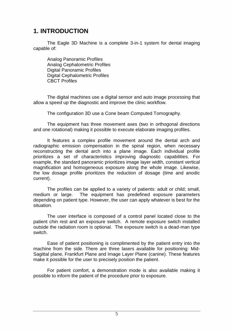
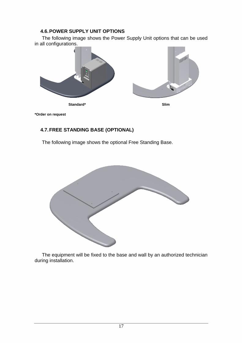
4.6. POWER SUPPLY UNIT OPTIONS
The following image shows the Power Supply Unit options that can be used in all configurations.
Standard*
Slim *Order on request
4.7. FREE STANDING BASE (OPTIONAL)
The following image shows the optional Free Standing Base.
The equipment will be fixed to the base and wall by an authorized technician during installation.

18
4.8. LIST OF ACCESSORIES
1 Bite Guide
2 Silicon chin rest cover
3 Chin rest for CT
4 Chin rest for patient with teeth
5 TMJ and Sinus nose support
6 Chin rest for patient without teeth
7 Head Holder acrylic bars
8 Head Holder

19
1 Nose Support
2 Carpus Support
ALL PARTS, ACCESSORIES AND OPTIONS DESCRIBED IN THIS OWNER'S MANUAL ARE FOR EXCLUSIVE USE. USE OF ANY PARTS, ACCESSORIES OR MATERIAL NOT SPECIFIED OR PROVIDED IN THIS OWNER'S MANUAL IS USER'S FULL RESPONSIBILITY.

20
5. COMPUTER SYSTEM
5.1. RECOMMENDED SPECIFICATIONS
It is imperative that this computer system be dedicated for the Eagle 3D
CBCT Machine.
Table 1 – Recommended Computer Specifications
Operating System
Windows 7 Professional – 64-bit Windows 8 Professional Windows 8.1 Professional Windows 10 Professional
CPU Intel ® Core ™ i7 4.0 GHz or higher
HDD 1TB or higher
RAM 16 GB
PCI PCI Express (PCIe) slot
NIC Gigabit Ethernet dedicated
Video Card NVIDIA GEFORCE GTX 1060 6GB or higher
Power Supply 400 RMS with supplementary power connectors PCI express compatible with video plate
Monitor 21.5” - Resolution 1920x1080 or higher
AN EXCLUSIVE NETWORK ADAPTER IS SHIPPED WITH THE EQUIPMENT. THE HARDWARE MUST BE INSTALLED BY AN AUTHORIZED TECHNICIAN, OTHERWISE MAY RESULT IN A VOID OF WARRANTY.
5.2. NETWORK ADAPTER CONFIGURATION
To verify installation of the network card, follow the procedure:
1 – Verify the Windows system automatically installed the driver for the capture card.
Control Panel All items Control Panel System Device Manager Network Adapters

21
2 - Make sure the network adapter is installed. If not, install the network card drive using the CD shipped with the equipment.
3 - After installation restart the computer.
To configure the network card, follow the procedure:
1 - Go to Control Panel Network Internet and Network Connections
2 - Click the right mouse button on the connection DESKTOP Intel Gigabit CT, and visit the properties.
3 - Go to Settings Advanced tab and search for item “Receive Buffer” 4 - Initially, this setting is disabled. Change the value to 2048 and then
click OK.
5 - Go to Settings Advanced tab and search for item “Transmit Buffer” 6 - Initially, this setting is disabled. Change the value to 2048 and then
click OK.
7 - Go to Settings Advanced tab and search for item “Jumbo Frames” 8 - Initially, this setting is disabled. Change the value to 9014 bytes and
then click OK.

22
9 - Go to Settings Power Management tab and uncheck all items. 10 – Select Internet Protocol TCP/IP Version Proprieties 11 – Define the IP address 192.168.5.10 and Subnet Mask
255.255.255.0
5.3. SOFTWARE INSTALLATION
Insert the accompanying media and execute the Setup.exe. The
following screen should be displayed.

23
1 – Select the language
2 - Press NEXT:
3 – Read carefully the EULA and if you agree select “ I accept the agreement” and press NEXT
4 – Click on the Checkbox if you want create a desktop icon and Press NEXT

24
5 - Press INSTALL to start the installation.
6- The software will install all required software, please wait until if finish.

25
7 - Press FINISH to close the setup.
8- After installation, access Windows Start Menu / All Programs / Dental
Imaging Software/ Dental Imaging Software. The main software window should display as follows:

26
A DIGITAL VERSION OF THE SOFTWARE USER MANUAL WILL BE AVAILABLE WITH TECHNICAL CHARACTERISTICS AND GUIDELINES ON THE SOFTWARE OPERATION.
IN THE ACT OF PURCHASE YOU WILL RECEIVE A SOFTWARE MANUAL, WHERE TO FIND ALL INFORMATION AND TECHNICAL FEATURES.

27
6. IMAGING PROGRAMS
The Eagle 3D CT Scanner contains a set of profiles.
6.1. PANORAMIC PROFILES:
There are eight panoramic profiles available: from P1 to P6, P17 and P23:
Program Description
LCD Display Touch Screen Display
P1
Standard Panoramic: This exposure has constant vertical magnification of the dental arch region, optimal layer width, and prioritizes homogeneous exposure during the entire imaging.
P2
Temporomandibular Joint: This double exposure fits the condyle in both closed and open mouth configuration into a single image.
P3
Sinus: This exposure focuses on the maxillary sinus region.
P4
Improved Orthogonally*: This exposure is the standard panoramic profile optimized for the beam to be more orthogonal in respect to the dental arch.

28
P5
Low Dosage Panoramic*: This exposure is the standard panoramic profile with faster execution and lower dosage. The patient will receive less exposure, so as a result the overall image quality is decreased.
P6
Child Panoramic: This exposure has a 15% size reduction with respect to the standard panoramic profile.
P17
Bitewing*: This exposure is a bitewing-like image profile from premolar and molar area including parts of maxilla, mandible and rami.

29
P23
Improved Orthogonally Bitewing *: This exposure is the bitewing-like image profile optimized for the beam to be more orthogonal in respect to the dental arch.
6.2. CEPHALOMETRIC PROFILES
Program Description
LCD Display Touch Screen Display
P7
Film Cephalometric: With this profile it is possible to execute the following images:
PA: Posterior-Anterior
AP: Anterior-Posterior
45º Degrees
Lateral
Carpal With this profile it is possible to adjust the exposure time from 0.1 to 3.0 seconds, in 0.1 step increments.
P8
Digital Cephalometric*: With this profile it is possible to execute the following digital images:
PA: Posterior-Anterior
AP: Anterior-Posterior
45º Degrees
Lateral
Carpal
P9
Low Dosage Digital Cephalometric*: With this profile it is possible to execute a lateral ceph with a small exposure area and thus

30
with a lower dose to the patient.
6.1. TOMOGRAPHY PROFILE
Program Description
Tomography: With this profile it is possible to select the interesting region and get 3D image and tomography cuts.
Fast Scout: With this profile it is possible to make a fast lateral image to position the patient before the tomography image.
Full Scout: With this profile it is possible to make a lateral and frontal image to position the patient before the tomography image.

31
7. CONTROL PANEL
7.1. INTRODUCTION
The equipment has a touch screen display with six buttons and also has important information of the current status of the machine to help the user operate the unit.
7.2. MAIN SCREEN
The main screen for panoramic and ceph mode is shown below. Swap
the functions by touching the screen.
FUNCTION DESCRIPTION EXPLANATION
INFO LINE Displays current status of the machine.
Select X-ray:
Equipment is not ready to expose x-rays. If exposure switch is pressed the equipment will operate in demonstration mode (no x-ray exposure).
Ready to Expose! Equipment is ready to expose x-rays.
Cooling: 00:30 Equipment is cooling down. Wait until counter reaches zero.
mA CHIN REST ADJUST
PROFILE
FOCAL SPOT Kv
SMALL/ MEDIUM/ LARGE
ADULT /
CHILD
INFO
COLUMN
ADJUST
EXAM
SELECTION
LASER RESTART POSITION
EXPOSURE
POSITION

32
ADULT / CHILD
Displays the selected patient age (ADULT / CHILD ) to pre-select the kV. Please be aware that the values of kV indicated are for reference only.
No selection
Child selected
Adult selected
SMALL / MEDIUM / LARGE
Displays the selected patient biotype (SMALL/MEDIUM/LARGE) to pre-select the kV. Please be aware that the values of kV indicated are for reference only.
Size not selected
Small patient selected
Medium patient selected
Large patient selected
kV Display the selected kV The value of kV is 85kV If the kV is left unchanged the equipment will be in demonstration mode. In this mode no x-ray is exposed.
No kV selected: Demonstration mode.
Example of kV selection: 75 kV.

33
mA The anodic current is not user adjustable. The value indicated is optimum for image generation in each profile.
Indication that current profile uses 8mA of anodic current.
TIME In all profiles the value is not user adjustable.
Value indicating that current profile has 14 seconds of x-ray exposure.
IMAGE LAYER POSITION
This function allows the user to adjust the image layer towards the back or front of the dental arch in panoramic profiles. The adjustment is made using the following keys:
↑: moves layer
towards back of dental arch.
↓: moves layer
towards front of dental arch.
PROFILE SELECTION
The image and text indicate the selected profile.
Example with standard panoramic selected.
EXPOSURE POSITION
This function allows the user to move the equipment to the start position, speeding up the examination
Ready?
34
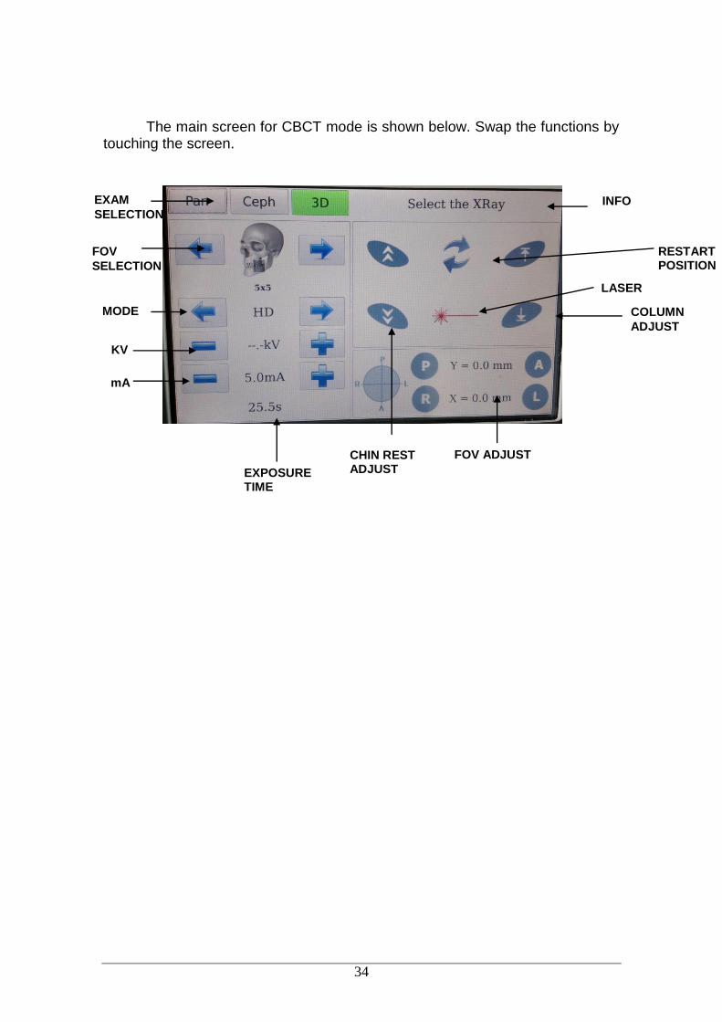
The main screen for CBCT mode is shown below. Swap the functions by touching the screen.
CHIN REST ADJUST
KV
FOV
SELECTION
INFO
COLUMN
ADJUST
EXAM
SELECTION
LASER
RESTART POSITION
mA
EXPOSURE TIME
FOV ADJUST
MODE

35
FUNCTION DESCRIPTION EXPLANATION
INFO LINE Displays current status of the machine.
Select X-ray:
Equipment is not ready to expose x-rays. If exposure switch is pressed the equipment will operate in demonstration mode (no x-ray exposure).
Ready to Expose! Equipment is ready to expose x-rays.
Cooling: 00:30 Equipment is cooling down. Wait until counter reaches zero.
FOV Displays the selected FOV
Example of FOV selection: 8x8.
kV
Display the selected kV The value of kV is 85kV If the kV is left unchanged the equipment will be in demonstration mode. In this mode no x-ray is exposed.
No kV selected: Demonstration mode.
85.0kV Example of kV selection: 85 kV.
mA
Display the selected mA The value of mA is from 4 to 8mA
4mA Indication that current profile uses 4mA of anodic current.
TIME In all profiles the value is not user adjustable.
32.0 s Value indicating that current profile has 32 seconds.

36
7.3. CONTROL KEYS
a) Membrane keyboard
Plus Key: Used to increase kV, exposure time (for analog ceph), select patient age (child and adult), size (small, medium and large) and radiography type (i.e. standard panoramic and low dosage).
Minus Key: Used to decrease kV, exposure time (for analog ceph), select the patient age (child and adult), size (small, medium and large) and radiography type.
Select Key: Used to change between adjustable functions: (patient size, biotype, kV, exposure time in analog ceph, image layer position (canine) and radiography type).
Laser key: Used to turn on/off positioning lasers: Mid-Sagittal, Frankfurt and Image layer Position (Canine).
Key Up: Used to increase the column height. The equipment has a soft-start system that ramps up the column for 5 seconds until it reaches its cruise speed. The system stops automatically when it reaches the upper height limit.
Key Down: Used to decrease the column height. The equipment has a soft-start system that ramps up the column for 5 seconds until it reaches its cruise speed. The system stops automatically when it reaches the lower height limit.
b) Touch screen display
The controls are shown and their functions on the main screen are shown below:
37
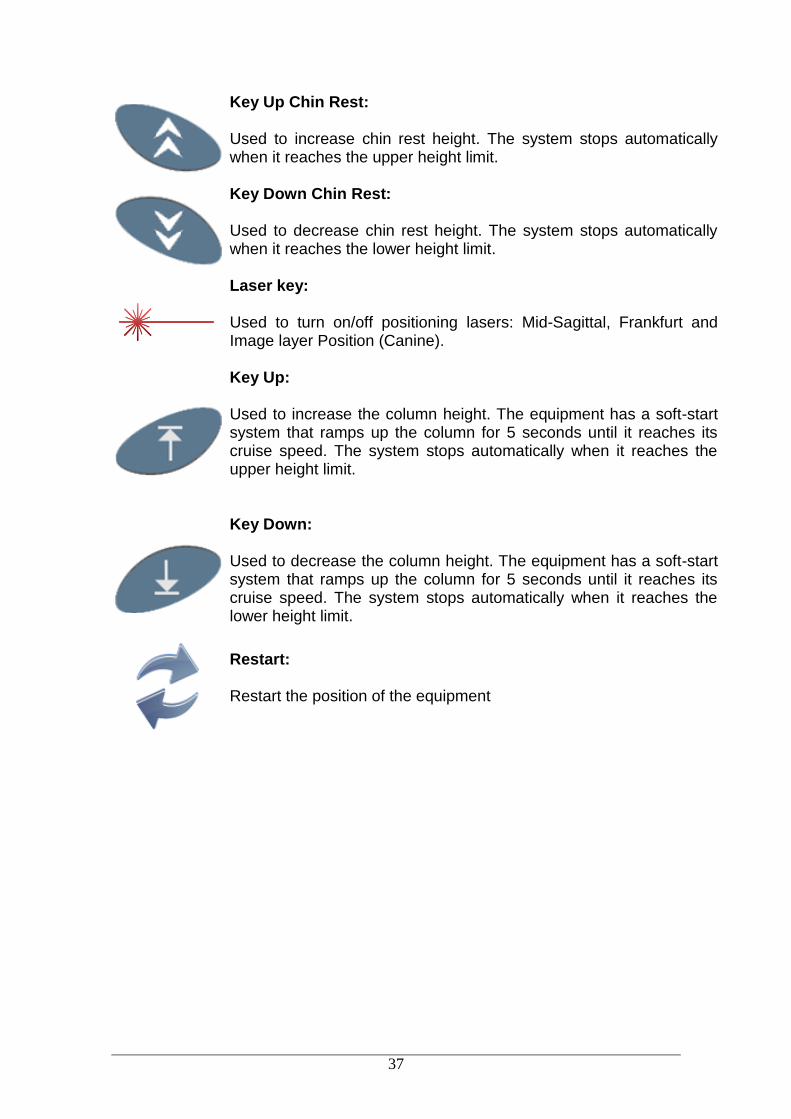
Key Up Chin Rest: Used to increase chin rest height. The system stops automatically when it reaches the upper height limit.
Key Down Chin Rest: Used to decrease chin rest height. The system stops automatically when it reaches the lower height limit.
Laser key: Used to turn on/off positioning lasers: Mid-Sagittal, Frankfurt and Image layer Position (Canine).
Key Up: Used to increase the column height. The equipment has a soft-start system that ramps up the column for 5 seconds until it reaches its cruise speed. The system stops automatically when it reaches the upper height limit.
Key Down: Used to decrease the column height. The equipment has a soft-start system that ramps up the column for 5 seconds until it reaches its cruise speed. The system stops automatically when it reaches the lower height limit.
Restart: Restart the position of the equipment

38
7.4. CONTROL PANEL INDICATING LIGHTS
Exposure-Signaling: The LED at the center of the symbol will light up during x-ray exposure. An audible warning will also sound.
7.5. REMOTE EXPOSURE SWITCH (OPTIONAL)
A remote exposure switch installed outside of the radiation exposure room is available upon request or as required by state or country.
The remote exposure switch is a dead-man-like switch and illuminates
during an exposure. In order for the remote exposure switch to work properly the wall connector
must have the proper cable (supplied) connected to the equipment. This is done during installation.
Wall remote exposure button

39
8. PREPARING FOR THE EXPOSURE
This section describes operations required for exposing images. This section describes the steps required before positioning the patient on
the machine.
8.1. TURNING THE EQUIPMENT ON
THE UNIT IS CONFIGURED FOR A LINE VOLTAGE DURING INSTALLATION BY THE TECHNICIAN ONLY. THIS IS A TECHNICAL PROCEDURE AND CANNOT BE DONE BY THE USER.
BEFORE TURNING ON THE UNIT MAKE SURE THE UNIT IS CONNECTED TO THE CORRECT VOLTAGE.
To turn on or off the unit use the on/off switch on the base of the equipment.
When the main switch is turned on, the machine will perform a self-check. During the self-check, the following screen will be shown on the display:
The machine can be configured to display an exposure counter that is displayed after the machine initialization and after each exposure. Note: The exposure counter can be hidden by an authorized technician.

40
8.2. BEFORE POSITIONING THE PATIENT
Ask the patient to remove any glasses, hearing aids, dentures, and personal jewelry such as earrings, necklaces, and hairpins.
If required, place a protective lead apron over the patient’s body, especially for pediatric patients. Always follow local regulation.
8.3. RECOMMENDATIONS FOR PEDIATRIC EXAMINATIONS
Radiographs should be taken only when there is an expectation that the diagnostic yield will affect patient care. The dentist must weigh the benefits of obtaining radiographs against the patient’s risk of radiation exposure.
Because the effects of radiation exposure accumulate over time, every effort must be made to minimize the patient’s exposure.
Use protective lead apron and thyroid collars,
Use pediatric profile or low dosage and select the lowest permissible exposure time.
There may be clinical circumstances for which a radiograph is indicated, but a diagnostic image cannot be obtained. For example, the patient may be unable to cooperate for the dentist.
41
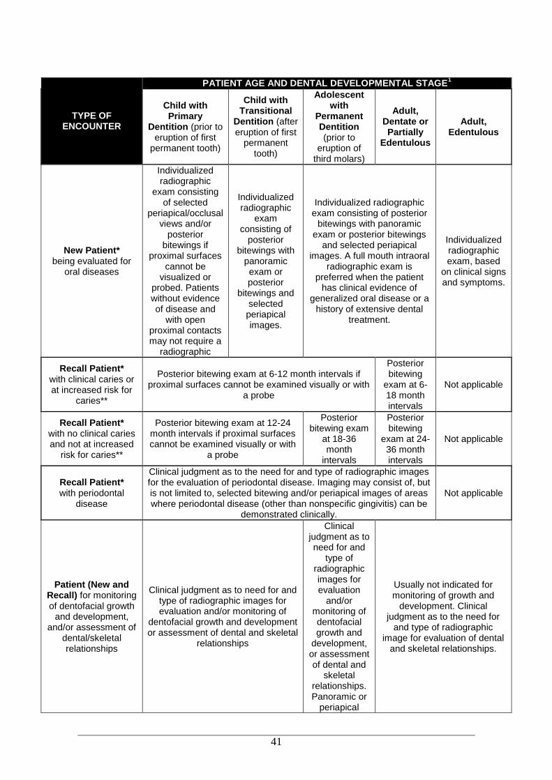
TYPE OF ENCOUNTER
PATIENT AGE AND DENTAL DEVELOPMENTAL STAGE1
Child with Primary
Dentition (prior to eruption of first
permanent tooth)
Child with Transitional
Dentition (after eruption of first
permanent tooth)
Adolescent with
Permanent Dentition (prior to
eruption of third molars)
Adult, Dentate or Partially
Edentulous
Adult, Edentulous
New Patient* being evaluated for
oral diseases
Individualized radiographic
exam consisting of selected
periapical/occlusal views and/or
posterior bitewings if
proximal surfaces cannot be
visualized or probed. Patients without evidence of disease and
with open proximal contacts may not require a
radiographic
Individualized radiographic
exam consisting of
posterior bitewings with
panoramic exam or posterior
bitewings and selected periapical images.
Individualized radiographic exam consisting of posterior
bitewings with panoramic exam or posterior bitewings
and selected periapical images. A full mouth intraoral
radiographic exam is preferred when the patient
has clinical evidence of generalized oral disease or a
history of extensive dental treatment.
Individualized radiographic exam, based
on clinical signs and symptoms.
Recall Patient* with clinical caries or at increased risk for
caries**
Posterior bitewing exam at 6-12 month intervals if proximal surfaces cannot be examined visually or with
a probe
Posterior bitewing
exam at 6-18 month intervals
Not applicable
Recall Patient* with no clinical caries and not at increased
risk for caries**
Posterior bitewing exam at 12-24 month intervals if proximal surfaces cannot be examined visually or with
a probe
Posterior bitewing exam
at 18-36 month
intervals
Posterior bitewing
exam at 24-36 month intervals
Not applicable
Recall Patient* with periodontal
disease
Clinical judgment as to the need for and type of radiographic images for the evaluation of periodontal disease. Imaging may consist of, but is not limited to, selected bitewing and/or periapical images of areas where periodontal disease (other than nonspecific gingivitis) can be
demonstrated clinically.
Not applicable
Patient (New and Recall) for monitoring of dentofacial growth
and development, and/or assessment of
dental/skeletal relationships
Clinical judgment as to need for and type of radiographic images for evaluation and/or monitoring of
dentofacial growth and development or assessment of dental and skeletal
relationships
Clinical judgment as to need for and
type of radiographic images for evaluation
and/or monitoring of dentofacial growth and
development, or assessment of dental and
skeletal relationships. Panoramic or
periapical
Usually not indicated for monitoring of growth and
development. Clinical judgment as to the need for
and type of radiographic image for evaluation of dental
and skeletal relationships.
42
exam to assess
developing third molars
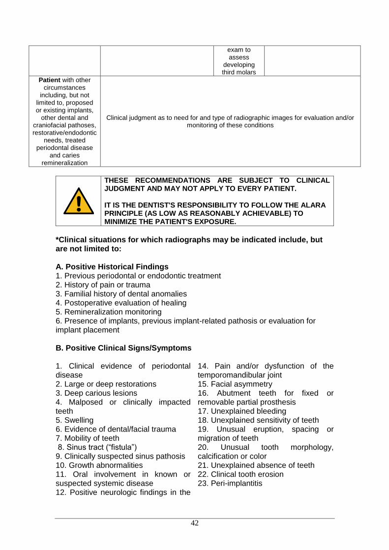
Patient with other circumstances
including, but not limited to, proposed or existing implants,
other dental and craniofacial pathoses, restorative/endodontic
needs, treated periodontal disease
and caries remineralization
Clinical judgment as to need for and type of radiographic images for evaluation and/or monitoring of these conditions
THESE RECOMMENDATIONS ARE SUBJECT TO CLINICAL JUDGMENT AND MAY NOT APPLY TO EVERY PATIENT. IT IS THE DENTIST'S RESPONSIBILITY TO FOLLOW THE ALARA PRINCIPLE (AS LOW AS REASONABLY ACHIEVABLE) TO MINIMIZE THE PATIENT'S EXPOSURE.
*Clinical situations for which radiographs may be indicated include, but are not limited to: A. Positive Historical Findings 1. Previous periodontal or endodontic treatment 2. History of pain or trauma 3. Familial history of dental anomalies 4. Postoperative evaluation of healing 5. Remineralization monitoring 6. Presence of implants, previous implant-related pathosis or evaluation for implant placement B. Positive Clinical Signs/Symptoms 1. Clinical evidence of periodontal disease 2. Large or deep restorations 3. Deep carious lesions 4. Malposed or clinically impacted teeth 5. Swelling 6. Evidence of dental/facial trauma 7. Mobility of teeth 8. Sinus tract (“fistula”) 9. Clinically suspected sinus pathosis 10. Growth abnormalities 11. Oral involvement in known or suspected systemic disease 12. Positive neurologic findings in the
14. Pain and/or dysfunction of the temporomandibular joint 15. Facial asymmetry 16. Abutment teeth for fixed or removable partial prosthesis 17. Unexplained bleeding 18. Unexplained sensitivity of teeth 19. Unusual eruption, spacing or migration of teeth 20. Unusual tooth morphology, calcification or color 21. Unexplained absence of teeth 22. Clinical tooth erosion 23. Peri-implantitis

43
head and neck 13. Evidence of foreign objects
Factors increasing risk for caries may be assessed using the ADA Caries Risk Assessment forms (0 – 6 years of age and over 6 years of age).
1U.S. Department of Health and Human Services. Dental Radiographic Examinations:
Recommendations for Patient Selection and Limiting Radiation Exposure. Available at http://www.ada.org/~/media/ADA/Member%20Center/FIles/Dental_Radiographic_Examinations_2012.ashx. Accessed November 2, 2015. 2The American Academy of Pediatric Dentistry. Guideline on Prescribing Dental
Radiographs for Infants, Children, Adolescents, and Persons with Special Health Care Needs. Available at http://www.aapd.org/media/policies_guidelines/e_radiographs.pdf. Accessed November 2, 2015. 3U.S. Department of Health and Human Services. Pediatric X-ray Imaging
. Available at http://www.fda.gov/Radiation-EmittingProducts/RadiationEmittingProductsandProcedures/MedicalImaging/ucm298899.htm. Accessed November 2, 2015.

44
9. PANORAMIC EXPOSURES
This section uses operation concepts described on previous sections. Please refer to those sections when needed.
This procedure will produce a full size panoramic exposure. If the child program is selected, the width and height of the exposed area will be slightly reduced.
For this procedure it is necessary to use a chin rest. There are three different type of chin rest, as you can see in the picture below.
Chin rest for patient
with teeth Chin rest for patient without
teeth Chin rest for Sinus
and TMJ
The first one is used for a patient with teeth and it has three parts (bite
guide, chin rest and a silicon chinrest cover). The second is used for a patient without teeth and it has two parts (chin rest support and a plastic chin rest). The third is used for both kinds of patients (with or without teeth) for only the Sinus and TMJ profiles.
Insert the appropriated chin rest into the adapter. Insert the adapter into the holes on the patient support table. Please see the picture below for reference to usage of the bite guide.
Head positioner
Bite guide
Chin rest
Silicon
chinrest
cover

45
Before positioning the patient, completely open the head support. Select the required panoramic profile (from P1 to P23). Select the correct exposure parameters in accordance with the patient
characteristics.
9.1. GETTING THE SOFTWARE READY
Open the Imaging software and make sure the green light is on before start.
Press New Pan. A form screen will be shown.
Fill out the form with the patient information, select the configuration and profile. Press OK. The software will start a 150-second countdown. During the countdown take an exposure.

46
9.2. POSITIONING THE PATIENT
Guide the patient to the unit in front of the chin rest. If necessary, adjust the
height of the unit using the Up and Down keys of the control panel. For a patient with teeth, ask them to step forward, grasp the patient handles,
stretch up and bite the bite guide. The incisal edges of the maxillary and mandibular teeth must be in the groove of the bite guide.
For a patient without teeth use the specific chin rest that doesn´t have a bite guide. Ask patient to lean his/her chin against it.
Press the laser key to operate the patient positioning laser lights in order to assist with proper patient positioning. The laser diodes will automatically switch off after a period of time, or if the exposure button has been pressed. If the laser diodes turn off before you complete the patient positioning, press the laser key again. Use the laser to position the Mid-Sagittal plane, the Frankfurt plane and adjust the Image layer position.
If required adjust the Frankfurt laser position using the indicated adjusting key on the tubehead.

47
If required, adjust the image layer position using the plus and minus key while in layer positioning mode on the main screen.
THE LASERS USED ON THE EQUIPMENT ARE CLASS I LASERS INDICATING THAT THE POWER OUTPUT IS MINIMAL. HOWEVER, AS GOOD PRACTICE, AVOID INTENTIONALLY EXPOSING USER AND PATIENT EYES TO THE LASER BEAM.
For Sinus and TMJ profiles you need to use a specific chin rest. This chin
rest has a nose support and the patient needs to lean his/her nose against it.
9.3. TAKING A PANORAMIC EXPOSURE
When "Ready to Expose" is shown on the display the system is ready to take
an exposure. Ask the patient to close their lips on the bite guide, swallow, place their
tongue flat against the roof of their mouth, breathe normally, and stand as still as possible.
Move to a protected area without losing direct eye contact to the patient.
Laser adjusting key

48
Press and hold down the exposure button. The machine will first move to the start position and then it will proceed with the exposure. During exposure, a visual LED and audible beeping will indicate the presence of x-ray emission.
The exposure switch is a dead-man like switch. If released, the x-ray
exposure will stop immediately. Otherwise, after the rotation has completed and audible beeping stops you may release the exposure switch.
Upon completion of the exposure, the arm will rotate to the patient exit position. At this point, you may guide the patient out of the machine.
MAINTAIN AUDIAL AND VISUAL CONTACT WITH THE PATIENT AND UNIT DURING THE WHOLE EXPOSURE PROCESS. IF THE EXPOSURE OR MOVEMENT STOPS DURING THE PROCESS DUE TO AN INTERNAL ERROR, RELEASE THE SWITCH AND ASSIST THE PATIENT OUT OF THE MACHINE.
After a fell seconds the rotating arm will rotate to the start position for the
next patient.
TMJ PROFILE, P2, IS A DOUBLE EXPOSURE. AFTER THE FIRST EXPOSURE, POSITION THE PATIENT WITH OPEN MOUTH AND PROCEED WITH THE SECOND EXPOSURE.
The machine will enter a cool down process to setup for the next exposure.
The display will indicate the status of the machine. Cool down time will vary based on the kV, mA and exposure time selected at the exposure taken last.

49
9.4. ETTINGS AND DOSE INFORMATION
The table below shows the factory programmed parameters suggested
for each profile based on patient´s size and age as well as the Dose Area Product (DAP) for the parameter combinations. The dose area product (DAP) meter is a measure of dose in Gray multiplied by the area irradiated. Please use these factory programmed parameters as a reference only. If necessary, change the values according to your needs.
Dose Area Product (mGy.cm²)
Profile Exposure Time (s)
Current (mA)
Children Adult
Small Medium Large Small Medium Large
65 kV 70 kV 75 kV 70 kV 75 kV 80 kV
Standard Panoramic
14 8 49.6 56.4 63.4 56.4 63.4 70.7
TMJ 10 8 35.4 40.3 45.3 40.3 45.3 50.5
Sinus 8 8 28.3 32.2 36.2 32.2 36.2 40.4
Improved Orthogonally
14 8 49.6 56.4 63.4 56.4 63.4 70.7
Low Dosage 13 6.3 30.3 35.1 40.0 35.1 40.0 45.2
Children Panoramic
11.5 6.3 26.8 31.1 35.4 31.1 35.4 39.9
Bitewing 7.6 8 26.9 30.6 34.4 30.6 34.4 38.4
Bitewing Improved
Orthogonally 7.6 8 26.9 30.6 34.4 30.6 34.4 38.4
*Due to measurement errors and variation of equipment, consider a tolerance of 20%
DAP VALUES VARY FROM UNIT TO UNIT IN RELATION TO THE X-RAY TUBE OUTPUT. THUS ABOVE VALUES INDICATE AVERAGE DAP VALUES.

50
10. CEPHALOMETRIC EXPOSURE
This section will occasionally use procedures described in previous sections. Please refer to those sections when needed.
This procedure will produce a cephalometric exposure as selected:
- PA - Waters PA - AP - Lateral - Basal-Hirtz axial - 45 degrees - Carpal
BEFORE START, OPEN THE HEAD POSITIONER AND REMOVE THE CHIN REST AND BITE GUIDE FROM THE PATIENT SUPPORT.
10.1. GETTING THE SOFTWARE READY
Open the Imaging software and make sure the green light is on before start.
Press New Ceph. A form screen will be shown.

51
Fill out the form with the patient information, select the configuration and profile.
Press OK before starting the exposure. The software will start a 150-second countdown. During the countdown take an exposure.
10.2. POSITIONING THE PATIENT
Guide the patient to the unit in front of the ceph arm rest. Adjust the height of
the unit using the UP and DOWN keys on the control panel or ceph head as necessary.
Ask the patient to step forward and hold still while you prepare the ceph head.
Rotate the ceph head into the desired position (PA,AP, WATERS PA,
CARPAL, BASAL-HIRTZ AXIAL, LATERAL OR 45 DEGREE). Open the ear holders. Position the patient and close the ear holders so that
the patient will be securely positioned. Press the light key to turn the patient positioning laser lights on in order to
properly align the patient's head. The laser diodes will automatically switch off after a period of time, or if the exposure button has been pressed. If the laser diodes turn off during patient positioning, press the light key again.
Use the laser to position the Frankfurt plane.
THE LASERS USED ON THE EQUIPMENT ARE CLASS I LASERS INDICATING THAT THE POWER OUTPUT IS MINIMAL. HOWEVER, AS GOOD PRACTICE, AVOID INTENTIONALLY EXPOSING USER AND PATIENT EYES TO THE LASER BEAM.
10.3. TAKING A CEPHALOMETRIC EXPOSURE
When "Ready to Expose" is shown on the display the system is ready to
take an exposure.
Move to a protected area without losing direct eye contact with the patient.
KEEP CONSTANT EYE CONTACT WITH THE PATIENT AND ASSURE HE/SHE HAS BOTH HANDS DOWN DURING THE PROCESS. IN DIGITAL CEPH THIS IS ESPECIALLY IMPORTANT SINCE THE MECHANISM IS AUTOMATIC. IF THE PATIENT BEHAVES UNEXPECTEDLY STOP THE EXPOSURE AT ONCE.
Press and hold down the exposure button. The rotating arm will first move to
the start position and then begin exposure. During this period, an audible beeping and visual LED will indicate the presence of x-rays.

52
The exposure switch is a dead-man like switch. If released, the x-ray exposure will stop immediately. Otherwise, after the rotation has completed and audible beeping stops you may release the exposure switch.
Upon completion of the exposure, the arm will rotate to the patient exit
position. At this point, you may guide the patient out of the machine.
The machine will enter a cool down process to setup for the next exposure. The display will indicate the status of the machine. Cool down time will vary based on the kV, mA and exposure time selected at the exposure taken last.

53
10.4. SETTINGS AND DOSE INFORMATION
The table below shows the factory programmed parameters suggested
for each profile based on patient´s size and age as well as the Dose Area Product (DAP) for the parameter combinations. The dose area product (DAP) meter is a measure of dose in Gray multiplied by the area irradiated. Please use these factory programmed parameters as a reference only. If necessary, change the values according to your needs.
Dose Area Product (mGy.cm²)
Profile Exposure Time (s)
Current (mA)
Children Adult
Small Medium Large Small Medium Large
60 kV 65 kV 70 kV 70 kV 75 kV 80 kV
Film Ceph.
0.3 8 11.6 13.4 15.2 19.0 17.1 19.1
0.4 8 15.5 17.8 20.3 25.4 22.8 25.4
0.5 8 19.4 22.3 25.4 31.7 28.5 31.8
0.6 8 23.2 22.3 30.4 38.1 34.2 38.1
0.7 8 27.1 31.2 35.5 44.4 39.9 44.5
0.8 8 31.0 35.7 40.6 50.8 45.6 50.9
0.9 8 34.9 40.2 45.6 57.1 51.3 57.2
1.0 8 38.7 44.6 50.7 63.4 57.0 63.6
1.1 8 42.6 49.1 55.8 69.8 62.7 69.9
1.2 8 46.5 53.5 60.9 76.1 68.4 76.3
1.3 8 50.4 58.0 65.9 82.5 74.1 82.6
1.4 8 54.2 62.5 71.0 88.8 79.9 89.0
1.5 8 58.1 66.9 76.1 95.2 85.6 95.4
1.6 8 62.0 71.4 81.2 101.5 91.3 101.7
1.7 8 65.9 75.9 86.2 107.9 97.0 108.1
1.8 8 69.7 80.3 91.3 114.2 102.7 114.4
1.9 8 73.6 84.8 96.4 120.5 108.4 120.8
2.0 8 77.5 89.2 101.4 126.9 114.1 127.1
2.1 8 81.3 93.7 106.5 133.2 119.8 133.5
2.2 8 85.2 98.2 111.6 139.6 125.5 139.9
2.3 8 89.1 102.6 116.7 145.9 131.2 146.2
2.4 8 93.0 107.1 121.7 152.3 136.9 152.6
2.5 8 96.8 111.5 126.8 158.6 142.6 158.9
2.6 8 100.7 116.0 131.9 165.0 148.3 165.3
2.7 8 104.6 120.5 136.9 171.3 154.0 171.6
2.8 8 108.5 124.9 142.0 177.6 159.7 178.0
2.9 8 112.3 129.4 147.1 184.0 165.4 184.4
3.0 8 116.2 133.9 152.2 190.3 171.1 190.7

54
Dose Area Product (mGy.cm²)
Profile Exposure Time (s)
Current (mA)
Children Adult
Small Medium Large Small Medium Large
75 kV 77.5 kV 80 kV 80 kV 82.5 kV 85 kV
Digital Ceph. 16.5 8 27.3 28.8 30.4 30.4 32.0 33.6
10.0 8 16.5 17.5 18.4 18.4 19.4 20.4
Digital Ceph Low Dosage
11.0 8 18.2 19.2 20.3 20.3 21.3 22.4
6.6 8 10.9 11.5 12.2 12.2 12.8 13.5
*Due to measurement errors and variation of equipment, consider a tolerance of 20%
DAP VALUES VARY FROM UNIT TO UNIT IN RELATION TO THE X-RAY TUBE OUTPUT. THUS ABOVE VALUES INDICATE AVERAGE DAP VALUES.

55
11. TOMOGRAPHY This section will occasionally use procedures described in previous sections.
Please refer to those sections when needed. This procedure will produce tomographic images. To do this use the chin rest support and head support.
Chin rest for tomography exposure
11.1. GETTING THE SOFTWARE READY
Open the Imaging software and make sure the green light is on before start.
Press New 3D. If you would like make a scout image before the exposure
select Scout. A form screen will be shown.

56
Fill out the form with the patient information, select the FOV configuration, mode and mA. After that select the position of the FOV and press OK.
No area selected Area selected
11.2. POSITIONING THE PATIENT
Guide the patient to the unit in front of the chin rest. If necessary, adjust the
height of the unit using the Up and Down keys of the display. For this procedure is necessary use a head holder. Insert the appropriated
chin rest into the adapter. Insert the adapter into the holes on the patient support table. Please see the picture below for reference to usage of the head support.

57
Before positioning the patient fully open head positioner. Ask the patient to rest his chin against the chin rest. Adjust the height of
the head holder and secure firmly using the tape. Make sure that the patient is immobilized.
If you selected the scout image, the machine will make snapshots and show the position image. Use these images to position with precision the patient.
Head Holder
Chin rest
Head positioner

58
Make sure the volume position is correct. If necessary adjust its position.
11.3. TAKING A TOMOGRAPHIC EXPOSURE
When "Ready to Expose" is shown on the display the system is ready to take an exposure.
Move to a protected area without losing direct eye contact with the patient.
KEEP CONSTANT EYE CONTACT WITH THE PATIENT AND ASSURE HE/SHE HAS BOTH HANDS DOWN DURING THE PROCESS. IN DIGITAL CBCT THIS IS ESPECIALLY IMPORTANT SINCE THE MECHANISM IS AUTOMATIC. IF THE PATIENT BEHAVES UNEXPECTEDLY STOP THE EXPOSURE AT ONCE.
Press and hold down the exposure button. The rotating arm will first move to
the start position and then begin exposure. During this period, an audible beeping and visual LED will indicate the presence of x-rays.
The exposure switch is a dead-man like switch. If released, the x-ray
exposure will stop immediately. Otherwise, after the rotation has completed and audible beeping stops you may release the exposure switch.

59
Upon completion of the exposure, the arm will rotate to the patient exit position. At this point, you may guide the patient out of the machine.
After a fell seconds the rotating arm will rotate to the start position for the next patient.
The machine will enter a cool down process to setup for the next exposure. The display will indicate the status of the machine. Cool down time will vary based on the kV, mA and exposure time selected at the exposure taken last.
11.4. SETTINGS AND DOSE INFORMATION
The table below shows the factory programmed parameters suggested
for each profile based on patient´s size and age as well as the Dose Area Product (DAP) for the parameter combinations. The dose area product (DAP) meter is a measure of dose in Gray multiplied by the area irradiated. Please use these factory programmed parameters as a reference only. If necessary, change the values according to your needs.
Dose Area Product (mGy.cm²)
85 kV @ 4 mA
FOV 5x5 6x8 8x8 - 8x12 - 8x16
Mode LD STD HD UHD LD STD HD UHD LD STD HD UHD
Time (s) 16.5 20.5 25.5 32.0 16.5 20.5 25.5 32.0 16.5 20.5 25.5 32.0
DAP (mGy.cm²) 382.9 475.8 591.8 742.7 620.2 770.5 958.4 1202.8 732.6 910.2 1132.2 1420.8
Dose Area Product (mGy.cm²)
85 kV @ 5 mA
FOV 5x5 6x8 8x8 - 8x12 - 8x16
Mode LD STD HD UHD LD STD HD UHD LD STD HD UHD
Time (s) 16.5 20.5 25.5 32.0 16.5 20.5 25.5 32.0 16.5 20.5 25.5 32.0
DAP (mGy.cm²) 483.5 600.8 747.3 937.8 783.1 972.9
1210.2 1518.7 925.1
1149.3 1429.7 1794.1
Dose Area Product (mGy.cm²)
85 kV @ 6.3 mA
FOV 5x5 6x8 8x8 - 8x12 - 8x16
Mode LD STD HD UHD LD STD HD UHD LD STD HD UHD
Time (s) 16.5 20.5 25.5 32.0 16.5 20.5 25.5 32.0 16.5 20.5 25.5 32.0
DAP (mGy.cm²) 611.8 760.1 945.5 n/a 990.7
1230.9
1531.1 n/a
1170.4
1454.1 1808.8 n/a

60
Dose Area Product (mGy.cm²)
85 kV @ 8 mA
FOV 5x5 6x8 8x8 - 8x12 - 8x16
Mode LD STD HD UHD LD STD HD UHD LD STD HD UHD
Time (s) 16.5 20.5 25.5 32.0 16.5 20.5 25.5 32.0 16.5 20.5 25.5 32.0
DAP (mGy.cm²) 776.8 965.1 n/a n/a
1258.0
1562.9 n/a n/a
1486.1
1846.4 n/a n/a
*Due to measurement errors and variation of equipment, consider a tolerance of 20%
DAP VALUES VARY FROM UNIT TO UNIT IN RELATION TO THE X-RAY TUBE OUTPUT. THUS ABOVE VALUES INDICATE AVERAGE DAP VALUES.

61
12. PROCEDURES FOR REUSE
12.1. CLEANING
Using a clean moist cloth product, clean the equipment’s surface such as
the head positioner, patient handles, nose support, silicon chin rest cover, chin rest, ear rods, temple stabilizers on a regular basis.
It is recommended to use a moist cloth product with the following chemical properties: corrosion inhibitor, humectants effect, flotator; high tension-active power, anti-static effect, biodegradable, non-toxic, non-flammable.
The use of other chemical products is not recommended as it may damage the equipment.
DO NOT USE ORGANIC SOLVENTS, SUCH AS THINNER, TO CLEAN THE EQUIPMENT. IN CASE THE DEVELOPING SOLUTION IS SPILLED ON THE PANEL, CLEAN IT IMMEDIATELY, SINCE SUCH SOLUTIONS MAY DISCOLOR IT.
12.2. DISINFECTION
To ensure the prevention of cross-contamination, the operator must dispose of the bite guide after each usage.
ALWAYS TURN OFF THE MAIN SWITCH BEFORE PERFORMING DAILY MAINTENANCE PROCEDURES.
AVOID SPILLING WATER OR OTHER SOLUTIONS INSIDE THE EQUIPMENT, AS IT COULD CAUSE SHORT CIRCUITS.
FOR CLEANING, DO NOT USE MICRO ABRASIVE MATERIALS, STEEL WOOL, ORGANIC SOLVENTS OR SOLVENT-CONTAINING DETERGENTS, SUCH AS ETHER, STAIN REMOVER, GASOLINE, ETC.

62
13. TROUBLESHOOTING GUIDE
13.1. UNIT OPERATION PROBLEM
Symptom Possible Cause Action required
Equipment does not turn on
Mains voltage not available
Wait for mains voltage to be available.
Power supply cable is unplugged from back of equipment
Plug it into the equipment
Power supply cable is unplugged from wall socket
Plug it into the wall socket
Unit circuit breaker turned off
Turn on unit circuit breaker
Main ON/OFF switch turned off
Turn on main ON/OFF switch.
Blown fuse Replace the fuse
Digital image doesn't appear on the screen
Cable disconnected Connect the cable
Image acquisition software
Reinstall the software
Acquisition button wasn´t selected
Select the acquisition button
Remote exposure button not actuating
Remote exposure cable disconnected
Connect remote exposure cable again
63
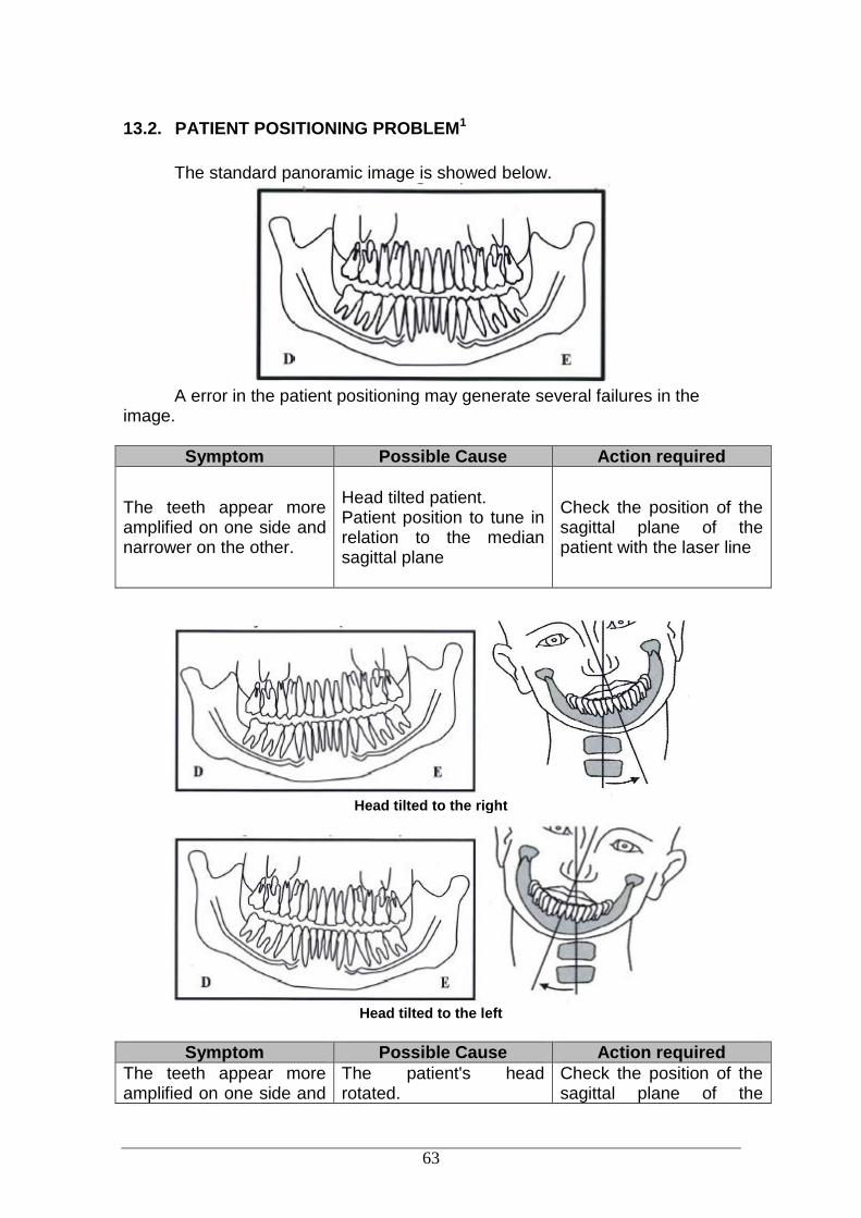
13.2. PATIENT POSITIONING PROBLEM1
The standard panoramic image is showed below.
A error in the patient positioning may generate several failures in the
image.
Symptom Possible Cause Action required
The teeth appear more amplified on one side and narrower on the other.
Head tilted patient. Patient position to tune in relation to the median sagittal plane
Check the position of the sagittal plane of the patient with the laser line
Head tilted to the right
Head tilted to the left
Symptom Possible Cause Action required
The teeth appear more amplified on one side and
The patient's head rotated.
Check the position of the sagittal plane of the

64
narrower on the other. Patient position for posterior teeth in relation to the focal plane
patient with the laser line
Head turned to the right
Head turned to the left
Symptom Possible Cause Action required
Incisors and canines narrow
and unsharp.
Position of the arch is anterior of the focal plane.
Adjust the focal plane of the equipment by positioning the Canine red laser on the tooth Canine tooth.
Symptom Possible Cause Action required
65
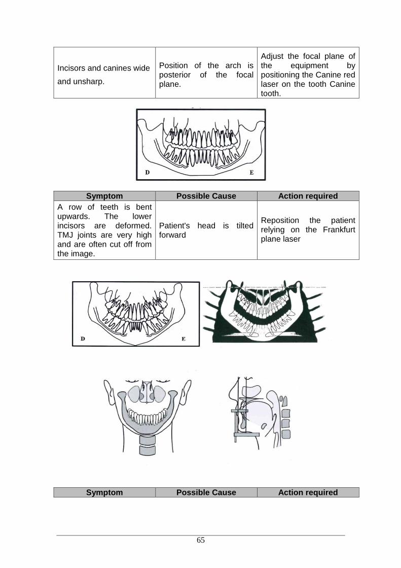
Incisors and canines wide
and unsharp.
Position of the arch is posterior of the focal plane.
Adjust the focal plane of the equipment by positioning the Canine red laser on the tooth Canine tooth.
Symptom Possible Cause Action required
A row of teeth is bent upwards. The lower incisors are deformed. TMJ joints are very high and are often cut off from the image.
Patient's head is tilted forward
Reposition the patient relying on the Frankfurt plane laser
Symptom Possible Cause Action required

66
A row of flat teeth. Unable to see the roots of the upper teeth.
Patient's head is tilted back
Reposition the patient relying on the Frankfurt plane laser
Symptom Possible Cause Action required
Central area of the image is very clear and deformed. Shadow of the column.
Patient neck is not stretched
Ask the patient to take a step forward and stretch your neck.
Contrast and brightness setting is incorrect in software
Adjust the contrast and brightness in the software

67
Symptom Possible Cause Action required
Incisors and canines teeth blurred.
Anterior teeth behind the focal plane Adjust the focal plane by
positioning the Canine red laser on Canine tooth.
Anterior teeth ahead of the focal plane
Anterior teeth behind the focal plane
Anterior teeth ahead of the focal plane
Symptom Possible Cause Action required
Upper arch outside the image area
chin is not leaning against chin rest
Ask the patient to rest his chin on the support.

68
Symptom Possible Cause Action required
The patient's shoulders touch the X-ray head or digital sensor / cassette holder.
Patient is too large for the unit
Reverse the patient's hands on the patient handles: Left on the right side and vice-versa
The nape of the patient touch the X-ray head
The inclination of the patient's head is not correct
Check the positioning of the patient head and reposition the patient
Patient is too large for the unit
Ask for the patient to more forward bite and adjust the equipment using the canine laser to reposition the equipment
You cannot see the bottom edge of the jaw in the cortical cross-sectional images.
The inclination of the patient's head is not correct
Reposition the patient
Patient without teeth (molar-premolar) in the molar plate
Use cotton rolls and take a new exposure.
You cannot see the cortical bone cross-sectional images.
The patient wasn´t placed correctly. The patient's position is oblique to the image layer.
Reposition the patient
Rows of teeth overexposed.
Tongue was not against the roof of palate
Ask patient to swallow and place tongue against the roof of palate
Artefact in the image Patient did not remove the metal artifacts
Ask the patient to remove eyeglasses, hearing aids, dentures, and personal jewelry, such as earrings, necklaces and hooks.

69
14. QUALITY ASSURANCE
This section will occasionally use procedures described in previous sections. Please refer to those sections when needed.
In order to assure image quality of the equipment, Quality Assurance (QA) Phantoms will be provided (Reference 21CFR 1020.33 (d)(1)) to test of the system performance and quality. These phantoms were designed to provide maximum performance information with minimum effort.
During the installation or after a repair this QA procedure will create a baseline performance data.
Make a periodic evaluation and compare with the baseline data. If degradation in image quality or a change in QA values is noticed, contact
the Alliage Service Department. For 2D images it will be validating the beam position, geometric calibration
and the maximum contrast resolution. The QA phantoms are show below.
QA Phantom for Panoramic* Resolution Test Phantom* *Not included. Order on request
For 3D images, it will be validating six aspects of image quality
Contrast Scale
High Contrast Spatial Resolution
Low Contrast Detectability
Noise and Uniformity
Slice Thickness
Measuring Reference Material The QA phantoms are show below.

70
QA Phantom for Small FOV* QA Phantom for Large FOV*
*Not included. Order on request
Theses QA phantoms contain two sections design to measurement of all
parameters with a single scan. The projection image of the phantom with these sections is showed below.
14.1. INITIAL PROCEDURE
Open the Imaging software and make sure the green light is on before start.
Access Tools QA Diagnosis

71
The follow screen will be opened
Fill the fields with the information required and select the desired diagnosis
to be performed. You can select more than one diagnosis. Press Start to start the procedures.
After finish press Report to generate a QA Report.
THE SOFTWARE WILL INDICATE THE DATE AND REPORT OF THE LAST DIAGNOSIS PERFORMED

72
14.2. QA DIAGNOSIS FOR PANORAMIC
This procedure will produce panoramic images.
14.2.1. BEAM POSITION
The software will indicate that the beam position will be checked. Remove the chin rest support. When it´s ready press OK, the software will start a 9-second countdown.
During the countdown take an exposure. The following screen will be show.
Verify if the beam is visible in the area.
73
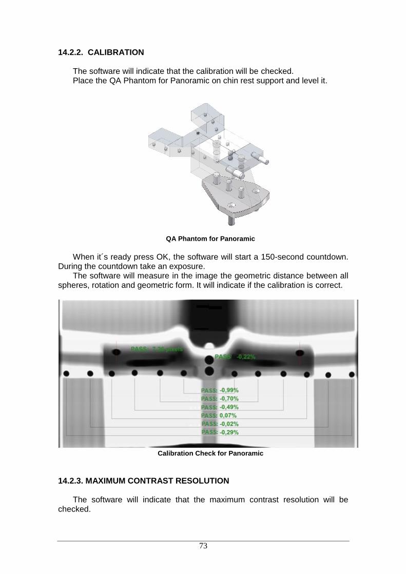
14.2.2. CALIBRATION
The software will indicate that the calibration will be checked. Place the QA Phantom for Panoramic on chin rest support and level it.
QA Phantom for Panoramic
When it´s ready press OK, the software will start a 150-second countdown.
During the countdown take an exposure. The software will measure in the image the geometric distance between all
spheres, rotation and geometric form. It will indicate if the calibration is correct.
Calibration Check for Panoramic
14.2.3. MAXIMUM CONTRAST RESOLUTION
The software will indicate that the maximum contrast resolution will be checked.

74
Remove the Top part of the QA Phantom for Panoramic from the support and place the Resolution Test Phantom as shown below.
Resolution Test Phantom
When it´s ready press OK, the software will start a 150-second countdown.
During the countdown take an exposure. The software will display the following image.
Maximum Contrast Resolution
Verify if the lines of the contrast element are visible.
75
14.3. QA DIAGNOSIS FOR CEPHALOMETRIC
This procedure will produce cephalometric images.
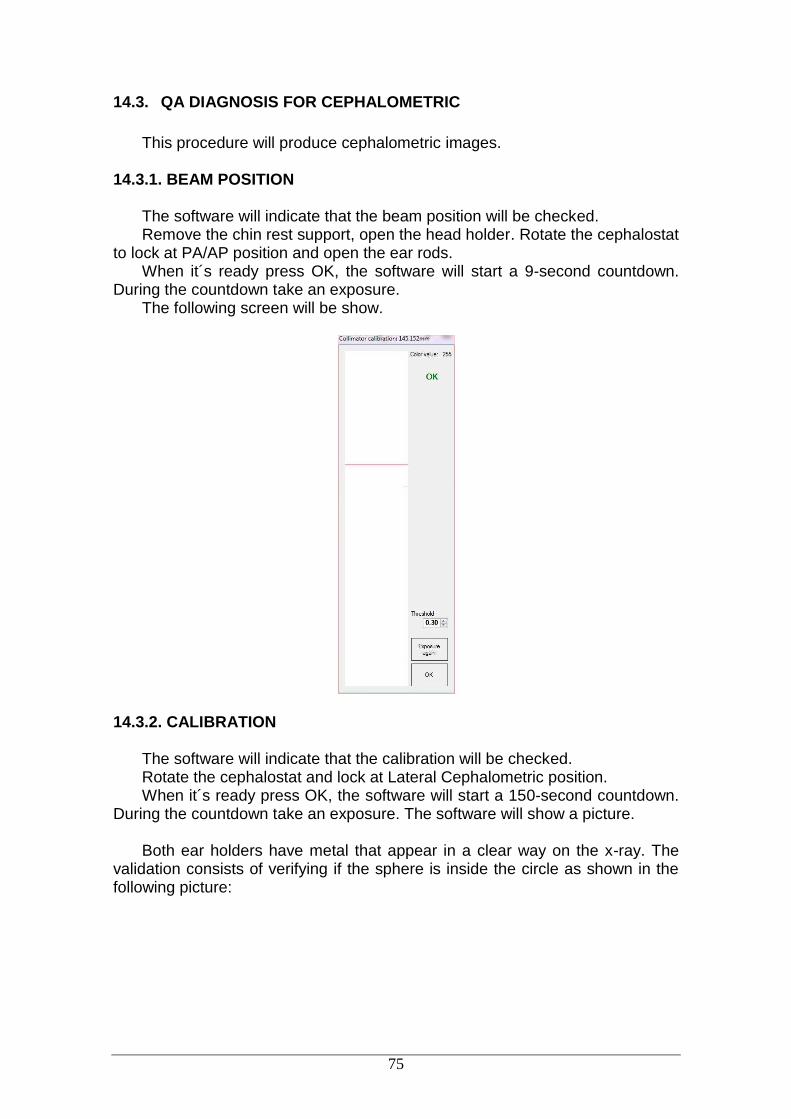
14.3.1. BEAM POSITION
The software will indicate that the beam position will be checked. Remove the chin rest support, open the head holder. Rotate the cephalostat
to lock at PA/AP position and open the ear rods. When it´s ready press OK, the software will start a 9-second countdown.
During the countdown take an exposure. The following screen will be show.
14.3.2. CALIBRATION
The software will indicate that the calibration will be checked. Rotate the cephalostat and lock at Lateral Cephalometric position. When it´s ready press OK, the software will start a 150-second countdown.
During the countdown take an exposure. The software will show a picture. Both ear holders have metal that appear in a clear way on the x-ray. The
validation consists of verifying if the sphere is inside the circle as shown in the following picture:
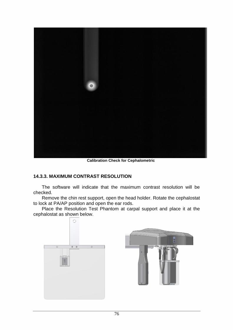
76
Calibration Check for Cephalometric
14.3.3. MAXIMUM CONTRAST RESOLUTION
The software will indicate that the maximum contrast resolution will be checked.
Remove the chin rest support, open the head holder. Rotate the cephalostat to lock at PA/AP position and open the ear rods.
Place the Resolution Test Phantom at carpal support and place it at the cephalostat as shown below.

77
Resolution Test Phantom
Carpal support position
When it´s ready press OK, the software will start a 150-second countdown. During the countdown take an exposure. The software will show a picture below.
Maximum Contrast Resolution
Verify if the lines of the contrast element are visible.
14.4. QA DIAGNOSIS FOR TOMOGRAPHY
14.4.1. PREPARING X-RAY UNIT
This procedure will produce tomographic images. It will be necessary take an exposure 8x8 HD mode and 8x12 HD mode.
The software will indicate which phantom should be prepared.
a) Small FOV Place the Small FOV QA phantom on chin rest support and level it. Fill water the density phantom
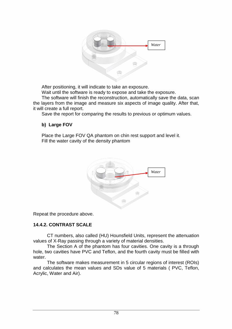
78
After positioning, it will indicate to take an exposure. Wait until the software is ready to expose and take the exposure. The software will finish the reconstruction, automatically save the data, scan
the layers from the image and measure six aspects of image quality. After that, it will create a full report.
Save the report for comparing the results to previous or optimum values. b) Large FOV Place the Large FOV QA phantom on chin rest support and level it. Fill the water cavity of the density phantom
Repeat the procedure above.
14.4.2. CONTRAST SCALE
CT numbers, also called (HU) Hounsfield Units, represent the attenuation values of X-Ray passing through a variety of material densities.
The Section A of the phantom has four cavities. One cavity is a through hole, two cavities have PVC and Teflon, and the fourth cavity must be filled with water.
The software makes measurement in 5 circular regions of interest (ROIs) and calculates the mean values and SDs value of 5 materials ( PVC, Teflon, Acrylic, Water and Air).
Water
Water

79
Hounsfield validation
The CT values of water and air in the phantom will be used to evaluate
contrast scale over time.
14.4.3. NOISE AND UNIFORMITY
The Section B of the phantom is an area with acrylic only, the software select 5 ROIs and measure the pixels values within the ROIs. After that, it calculates the mean value and SDs for them.
Noise and Uniformity Section
After the calculation of the uniformity, and using same flat-field image (slice), the software evaluates the noise power spectrum (NPS). The NPS is defined as:
𝑁𝑃𝑆(𝛼, 𝜑) = 𝑁𝑥𝑁𝑦∆𝑥∆𝑦⟨|𝐹𝑇{∆𝑃(𝑥, 𝑦)}|2⟩
where Nx and Ny are the number of pixels and Δx and Δy are the pixel widths in the X and Y directions, respectively. The term ΔP(x,y) represents the deviation of the pixel value at the coordinate (x,y) from the mean pixel value in the image, and FT{ΔP(x,y)} represents the Fourier transform of the pixel value deviation matrix.
This equation yields a 2-dimensional NPS, which is integrated over all phase angles φ to give a 1-dimensional representation:

80
𝑁𝑃𝑆1𝐷(𝛼) = ∫ 𝑁𝑃𝐷(𝛼,𝜑)
2𝑥
0
𝑑𝜑
14.4.4. SLICE THICKNESS
For this evaluation the software will use the Section A area. The software will make a scan in the slices and identify the start and end for the through hole. Once the length of this area is known it is possible to measure the number of slices and calculate their thickness.
14.4.5. HIGH CONTRAST SPATIAL RESOLUTION
The Modulation Transfer Function (MTF) mathematically quantifies contrast resolution. MTF measures the contrast preserved for a sine wave pattern as a function of frequency. An MTF curve begins at 1 for zero frequency, and decreases as frequency increases. The limiting resolution equals the frequency at which MTF falls to 0. Measure Frequency is in line pairs per millimeter.
For calculation of the MTF the software will use the Slanted-Edge MTF technique that is an edge gradient MTF method specifically suited to MTF calculations for spatially sampled capture devices.
For this evaluation the software will use the Section A area. For the high contrast it will be used the conical through hole with air. The air and acrylic will create a black-white transition of the slanted edge with high contrast.
Using the generated image the software will select a rectangular region-of-interest (ROI) around the black-white transition of the slanted edge.
Black-white transition of the slanted edge Air/Acrylic
A particular column is selected, and all pixel values in this column are
recorded to generate the Spatial Frequency Response (SFR). Line Spread Function (LSF) is generated by numerically calculating the first derivative of the SFR. Once the LSF is known, the magnitude of the FFT of this LSF is calculated. Plotting the FFT magnitude versus spatial frequency results the MTF.
14.4.6. LOW CONTRAST DETECTABILITY The low-contrast detectability (LCD) measures the ability of a CT equipment to differentiate a low-contrast object from its background. The visibility of objects depends on their size and contrast level to the background.

81
As the size of these objects decreases, it turns more difficult to recognize them for the same contrast level. In order to determine the LCD, the software will use a homogeneous slice from section B of the phantom. The center region of this slice is divided in a number of circular ROIs with same diameter. The mean pixel value of each ROI is calculated, and the standard deviation of the means is obtained. The contrast of an object with the same size of these ROIs is set to 3.29 times the standard deviation to be distinguished from the background. This analysis is repeated with different ROIs sizes and a contrast-detail diagram is created in the report.
14.5. DOSE MEASUREMENT
For periodic measurement of the dose it will use air kerma-area product (KAP).
A KAP-meter dosimeter is required for this inspection. Place the dosimeter at the tube exit and measure KAP value for all available
examination protocols. Access Tools Dose measurement Insert all values into the software to generate a report that can be saved to
compare the results to previous or optimum values.

82
14.6. QA REPORT
After diagnosis the software will create a QA report that can be saved to
compare the results to previous or optimum values. An example of this report is shown below.

83
15. INSTALLATION, INSPECTION AND MAINTENANCE
15.1. INSTALLATION
This equipment must be installed by authorized service technicians from
Alliage because only he/she has the tools, information, and training needed to perform this task.
15.2. PERIODIC INSPECTION
It is imperative that this equipment be inspected regularly to ensure the
operational safety and functional reliability. This inspection must be done by personnel familiar with the precautions required to prevent excessive exposure to both primary and secondary radiation. This equipment features protective designs for limiting both the primary and secondary radiation produced by the X-ray beam. However, design features cannot prevent carelessness, negligence, or lack of knowledge.
A regular inspection must be performed at regular intervals (at least once a year) to ensure that the product is permanently safe and operational. All components subject to normal wear and tear should be checked and, if necessary, replaced.
The manufacturer and the assembler/installer are relieved from
responsibility in those cases where noncompliance with the standard results from the user's failure to have the manufacturer's recommended maintenance performed.
Neither the inspection nor service is part of the equipment warranty. The performed maintenance must be documented and kept with the unit. The following chart gives a description of the main inspection items and
recommended frequency inspection
Item Inspection description Frequency
recommended*
Safety systems Collision, warning lights, and interlocks Daily
Internal and Exposure Switch
Operation Daily
Electronic Parts Overheating/Noise/Burning smell Monthly
Fans Operation / Noise/ Burning smell Monthly
Digital Sensor Communication/Operation/Overheating Monthly
Tubehead Operation/Noise/Overheating/Oil Leak Monthly
QA diagnosis1 Performance Monthly
Column Operation/Noise/Vibration Annual
Chin Rest Operation/Noise/Vibration Annual
Moving mechanism Operation/Noise/Vibration Annual

84
Display Operation, Fading or Too Bright, Annual
Membrane keyboard
Operation/Damage Annual
Laser Operation/ Intensity Annual
Accessories General damages that may cause risk Annual
Dose measurements1
Performance Annual
* Recommendation according ICRP Publication 129 1 Refer to procedures described in item 14. If during the inspection problems are detected, contact the Alliage Service
Department
15.3. PREVENTIVE MAINTENANCE
In addition to the annual inspection, to ensure a long life and proper
operation of your machine, it´s important performance a preventive maintenance in a maximum period of three (3) years.
Please contact Alliage Service Department about our periodic review and preventative maintenance program.
15.4. CORRECTIVE MAINTENANCE
All instructions to use the equipment as intended are provided in this user manual. If problems are detected and cannot be corrected with the instructions in the troubleshooting section, contact the Alliage Service Department.
DO NOT OPEN THE EQUIPMENT OR TRY FIX TO IT YOURSELF OR WITH THE HELP OF SOMEONE WITHOUT TRAINING/AUTHORIZATION. THIS COULD WORSEN THE PROBLEM OR PRODUCE A FAILURE THAT COULD ENDANGER THE SAFETY OF THE EQUIPMENT.
Warranty will be voided if original parts are removed/replaced by non-
authorized Service technicians.

85
15.5. DISPOSAL OF THE UNIT
In order to prevent environmental contamination or improper disposal of
the Eagle 3D CT Scanner, the equipment must be disposed of (according to local, state, or federal regulations) at an appropriate site.
The equipment contains materials and solutions listed below which, upon completion of its useful life, must be disposed of at the appropriate sites.
In particular, the equipment contains the following materials and/or components:
Tubehead: non-conductive oil, lead, copper, iron, aluminum, glass, tungsten.
Control panel and shooter: iron, copper, aluminum, glass resin, non-biodegradable plastic material.
Column, rotating arm and extensions: iron, lead, aluminum, copper, glass resin and non-degradable plastic material.
The manufacturer and/or its distributors are not responsible for
improper disposal by the buyer.
15.6. WARRANTY
The Warranty Certificate should be completed by the Authorized Technical
Alliage and one copy must be left with owner to prove the equipment warranty. The remaining copies will be send to the Distributor and to the factory.
The warranty is limited to repair or replacement of parts with manufacturing defects, not including the repair of defects originating in: - Failure to observe the operating and maintenance instructions; - Falls or knocks; - Improper storage; - Action of nature agents; - Installation and service performed by persons not authorized by Alliage; - Damage to the painted parts and plastic painted or not, caused by misuse;
The warranty period is 1 (one) years from the date of installation, provided that the equipment has not been stored for more than 1 (one) years from the date of issue of the invoice customer billing, first owner, until the date of installation.

86
16. TECHNICAL SPECIFICATIONS
16.1. REGULATORY INFORMATION
Alliage S/A Industrias Médico Odontológico Rodovia Abrão Assed, Km 53 - CEP 14097-500 Ribeirão Preto - SP - Brazil Phone: +55 (16) 3512-1212
Name CT Dental Scanner
Model Eagle 3D
Equipment classification according to FDA
Classification class (risk class) CLASS II
Equipment classification according to standard NBR IEC 60601-1
Protection against electric shock “Type-B” applied parts“ CLASS I (NBR IEC 60601-1)
Protection against harmful water penetration
Ordinary equipment - IPX0 (Sealed equipment without protection against water penetration)
Application safety level in the presence of a flammable anesthetic mixture with air, oxygen or nitrous oxide
Unsuitable equipment
Operation mode Operation Intermittent
16.2. GENERAL INFORMATION
Mains power voltage 110/127/220 or 240 V
Number of phases 1 or 2
Current type AC (alternating current)
Mains power frequency 50 or 60 Hz
Delay fuses 10A -110/127V 5A -220/240A
Power consumption 1.25 kVA
Stand by consumption 0.070 kVA
Net weight without a cephalostat 253.5 lb
Net weight with a cephalostat 335.1 lb
Net weight of X-Ray generator 34.2 lb
Column height adjustment 2.30 ft
Minimum room sizes for installation 5.90 x 8.20 ft
Warning: pieces of the equipment may cause shock
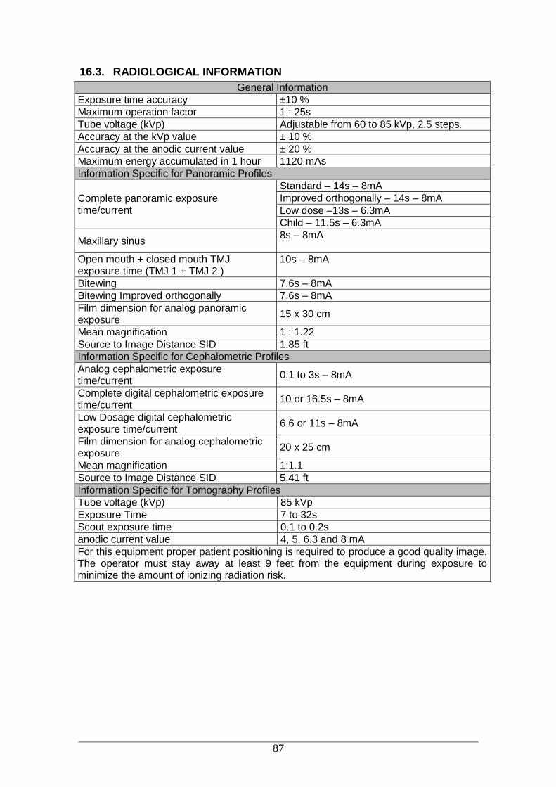
87
16.3. RADIOLOGICAL INFORMATION
General Information
Exposure time accuracy ±10 %
Maximum operation factor 1 : 25s
Tube voltage (kVp) Adjustable from 60 to 85 kVp, 2.5 steps.
Accuracy at the kVp value ± 10 %
Accuracy at the anodic current value ± 20 %
Maximum energy accumulated in 1 hour 1120 mAs
Information Specific for Panoramic Profiles
Complete panoramic exposure time/current
Standard – 14s – 8mA
Improved orthogonally – 14s – 8mA
Low dose –13s – 6.3mA
Child – 11.5s – 6.3mA
Maxillary sinus 8s – 8mA
Open mouth + closed mouth TMJ exposure time (TMJ 1 + TMJ 2 )
10s – 8mA
Bitewing 7.6s – 8mA
Bitewing Improved orthogonally 7.6s – 8mA
Film dimension for analog panoramic exposure
15 x 30 cm
Mean magnification 1 : 1.22
Source to Image Distance SID 1.85 ft
Information Specific for Cephalometric Profiles
Analog cephalometric exposure time/current
0.1 to 3s – 8mA
Complete digital cephalometric exposure time/current
10 or 16.5s – 8mA
Low Dosage digital cephalometric exposure time/current
6.6 or 11s – 8mA
Film dimension for analog cephalometric exposure
20 x 25 cm
Mean magnification 1:1.1
Source to Image Distance SID 5.41 ft
Information Specific for Tomography Profiles
Tube voltage (kVp) 85 kVp
Exposure Time 7 to 32s
Scout exposure time 0.1 to 0.2s
anodic current value 4, 5, 6.3 and 8 mA
For this equipment proper patient positioning is required to produce a good quality image. The operator must stay away at least 9 feet from the equipment during exposure to minimize the amount of ionizing radiation risk.
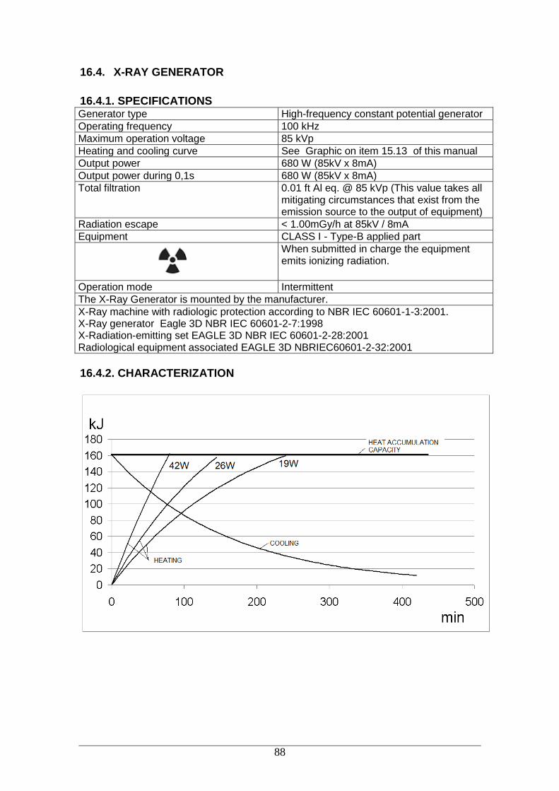
88
16.4. X-RAY GENERATOR
16.4.1. SPECIFICATIONS Generator type High-frequency constant potential generator
Operating frequency 100 kHz
Maximum operation voltage 85 kVp
Heating and cooling curve See Graphic on item 15.13 of this manual
Output power 680 W (85kV x 8mA)
Output power during 0,1s 680 W (85kV x 8mA)
Total filtration 0.01 ft Al eq. @ 85 kVp (This value takes all mitigating circumstances that exist from the emission source to the output of equipment)
Radiation escape < 1.00mGy/h at 85kV / 8mA
Equipment CLASS I - Type-B applied part
When submitted in charge the equipment emits ionizing radiation.
Operation mode Intermittent
The X-Ray Generator is mounted by the manufacturer.
X-Ray machine with radiologic protection according to NBR IEC 60601-1-3:2001. X-Ray generator Eagle 3D NBR IEC 60601-2-7:1998 X-Radiation-emitting set EAGLE 3D NBR IEC 60601-2-28:2001 Radiological equipment associated EAGLE 3D NBRIEC60601-2-32:2001
16.4.2. CHARACTERIZATION

89
16.5. X-RAY TUBE 16.5.1. SPECIFICATIONS Manufacturer Canon
Model D-054
Focus size 0.5 – IEC 60336
Equivalent filtration 0.003 ft Al equiv.
Anode angle 5º
Anode material Tungsten
Maximum voltage 100 kVp
Thermal capacity 35 kJ
Max thermal capacity and cooling time curve
See graphic thermal curve on item 0.
Maximum current 24mA rectified by half or whole wave and 20mA constant potential
Maximum filament current 3,5A / 4,2V
Frequency DC
Maximum exposure time 20s
Max anodic power 680kW
Maximum continuous thermal dissipation 2.2 kW
ATTENTION: The X-ray tube Canon D-054 model , is the EXCLUSIVE USE of the EAGLE 3D CT scanner
Note: If the temperature inside the tubehead reaches 55°C, exposure to X-rays will be interrupted and a message will be displayed. The exposure will be enabled again after the internal temperature of the generator reaches 54.5°C.

90
16.5.1. TUBE CHARACTERIZATION

91
Reference axis between the target angle and the focal point of the X-ray tube: 90º With axis of anode and cathode, respective Target angle with reference axis:
5º Reference axis angle between the target and the focal point of the x-ray generator mounted: measurements of x-ray generator mounted: 318mm x 440mm x 212mm weight of X-ray generator mounted: 34.6 lb. Tolerances of the focal point in relation in relation to the axes of reference:
X= 0.5mm (lateral)
Y= 0.5mm (depth)
Z= 0.5mm (height)

92

93
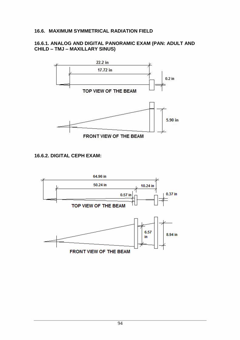
94
16.6. MAXIMUM SYMMETRICAL RADIATION FIELD
16.6.1. ANALOG AND DIGITAL PANORAMIC EXAM (PAN: ADULT AND CHILD – TMJ – MAXILLARY SINUS)
16.6.2. DIGITAL CEPH EXAM:

95
16.6.3. ANALOG CEPH - LATERAL EXAM
16.6.4. ANALOG CEPH - FRONTAL EXAM
16.6.5. TOMOGRAPHIC EXAM:
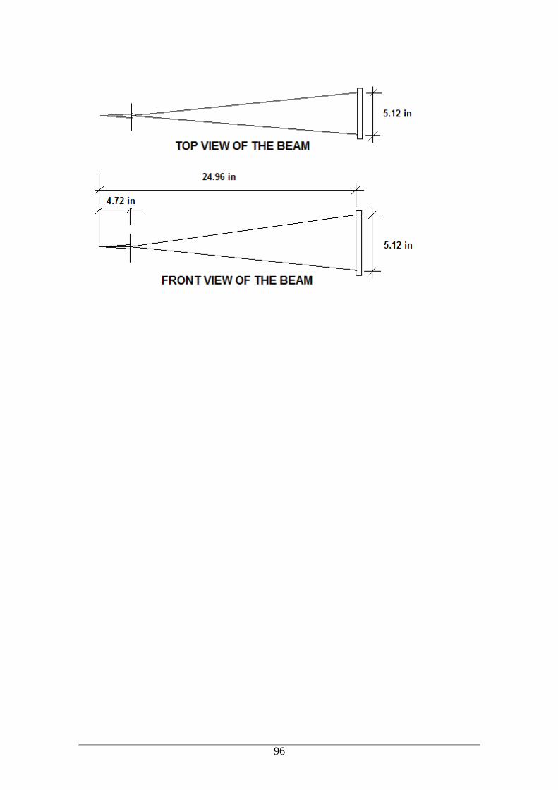
96

97
16.7. TESTED STANDARDS
EN 60601-1 (1990); Amendment 1 EN 60601-1 (1992); Amendment 2 EN 60601-1 (1995); Amendment13 EN 60601-1 (1995); UL 60601- 60601-1-4-2004 EN 60601-1-3 (2001); EN 60601-2-7 (2001); EN 60601-2-28 (2001); EN 60601-2-32 (2001); IEC 60601-1; Emenda 1 IEC 601-1; IEC 60601-1-2; CISPR 11, edição 3.1 (1999); IEC 61000-4-2 (1999); IEC 61000-4-3 (1998); IEC 61000-4-4 (1995); IEC 61000-4-5 (1995); IEC 61000-4-6 (1996); IEC 61000-4-11 (1996); IEC series 60601-1 Medical Electrical Equipment - Part 1: General requirements for safety; EN 980:2003 (Ed. 2) - Graphical symbols for use in the labeling of medical devices; ISO 14971 - Medical devices - application of risk management medical devices; ISO 9687: 1993 - Dental equipment - graphical symbols; ISO 7494 - Norma dental units; ISO 13485-2 - Quality systems - medical devices; ISO 780 - Packaging - pictorial marking for handling goods; ISO 11144 - Norma dental equipment - connections for supply and waste lines.

98
17. ELECTROMAGNETIC COMPATIBILITY 17.1. ELECTROMAGNETIC EMISSIONS Manufacturer’s guidelines and declaration - electromagnetic emissions
The EAGLE 3D CT Scanner is intended for use in the electromagnetic environment specified below. Should the buyer or user of the EAGLE 3D CT Scanner ensure that it is used in such an environment.
Emission assays Compliance Electromagnetic Environment Guidelines
RF emissions CISPR 11
Group 1
The EAGLE 3D Computerized Tomography uses RF energy only for its internal functions. However, RF emissions are very low and are not likely to cause any interference with electronic equipment nearby.
RF emissions CISPR 11
Class B
The EAGLE 3D CT Scanner is suitable for use in all types of facilities, including residential facilities and those directly connected to the public system of low-voltage electric power supply for residential buildings.
Harmonic emissions IEC 61000-3-2
Class A
Emissions due to voltage/scintillation
fluctuation IEC 61000-3-3
In compliance
17.2. ELECTROMAGNETIC IMMUNITY Manufacturer’s guidelines and declaration - electromagnetic immunity
The EAGLE 3D CT Scanner has been designed for use in electromagnetic environments, according to the specifications below. The client or X-Ray Machine operator must ensure that the equipment is used in such type of environment.
Immunity Assays ABNT NBR IEC 60601
Assay Level Compliance Level
Electromagnetic environment -Guidelines
Electrostatic discharge (ESD) IEC 61000-4-2
± 6 kV by contact ± 8 kV by the air
± 6 kV by contact ± 8 kV by the air
Floors must be finished with wood, concrete or ceramics. In case the floor is covered with synthetic material, relative humidity must be at least 30%.
Fast electric transients /pulse
train (“Burst”) IEC 61000-4-4
± 2 kV on the mains supply line
± 1 kV on the input/output line
± 2 kV on the mains supply line
± 1 kV on the input/output line
The quality of power supply must be that of hospital facilities or of typical business facilities.
Impulses IEC 61000-4-5
±1 kV - differential mode
± 2 kV - regular mode
±1 kV - differential mode
± 2 kV regular mode
The quality of power supply must be that of hospital facilities or of typical business facilities.
Voltage drops, short interruptions
and voltage variations on the
mains supply input
< 5% Ut (>95% of voltage drop
in Ut) per 0.5 cycle 40% Ut
(60% of voltage drop in
< 5% Ut (>95% of voltage
drop in Ut) per 0.5 cycle
40% Ut
The quality of power supply must be that of hospital facilities or of typical business facilities. In case the user of the
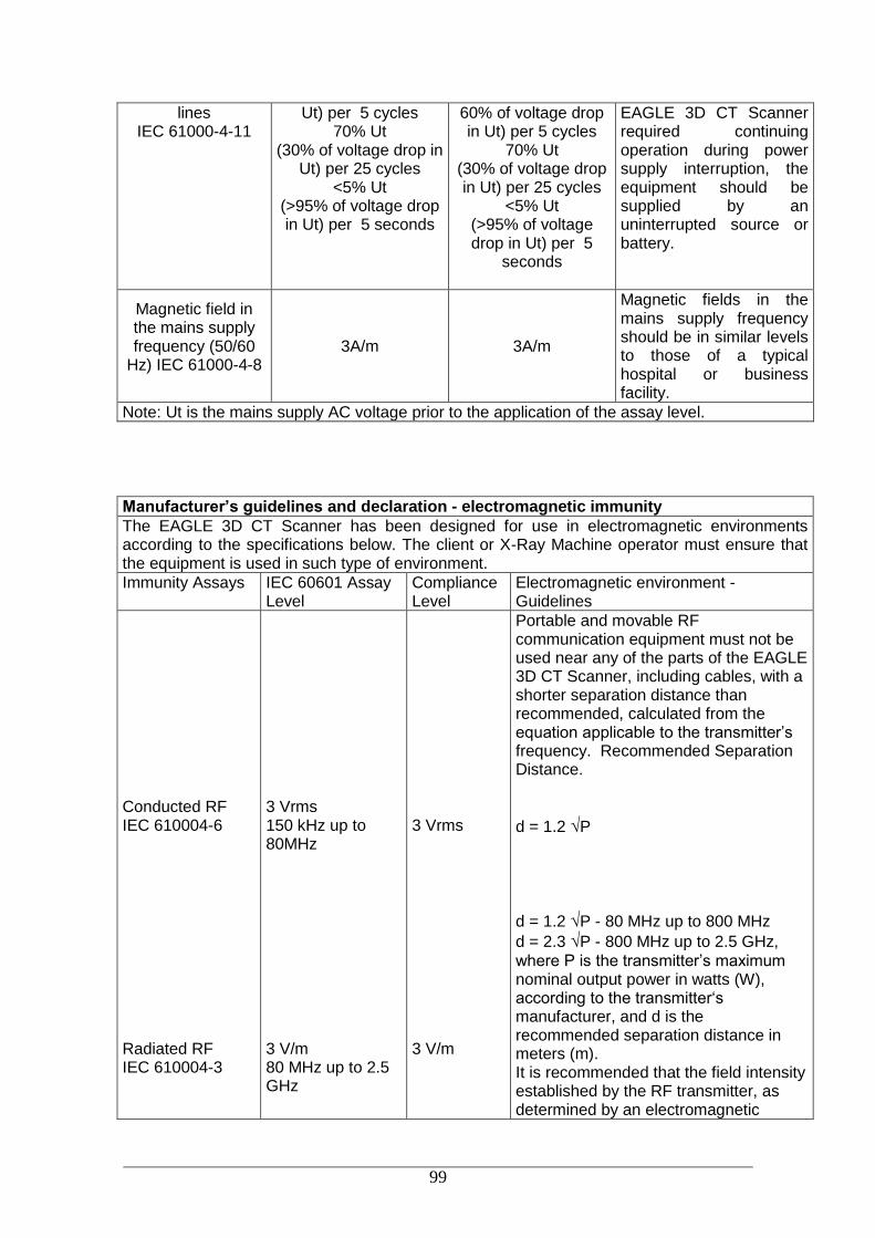
99
lines IEC 61000-4-11
Ut) per 5 cycles 70% Ut
(30% of voltage drop in Ut) per 25 cycles
<5% Ut (>95% of voltage drop in Ut) per 5 seconds
60% of voltage drop in Ut) per 5 cycles
70% Ut (30% of voltage drop in Ut) per 25 cycles
<5% Ut (>95% of voltage drop in Ut) per 5
seconds
EAGLE 3D CT Scanner required continuing operation during power supply interruption, the equipment should be supplied by an uninterrupted source or battery.
Magnetic field in the mains supply frequency (50/60
Hz) IEC 61000-4-8
3A/m 3A/m
Magnetic fields in the mains supply frequency should be in similar levels to those of a typical hospital or business facility.
Note: Ut is the mains supply AC voltage prior to the application of the assay level.
Manufacturer’s guidelines and declaration - electromagnetic immunity
The EAGLE 3D CT Scanner has been designed for use in electromagnetic environments according to the specifications below. The client or X-Ray Machine operator must ensure that the equipment is used in such type of environment.
Immunity Assays IEC 60601 Assay Level
Compliance Level
Electromagnetic environment -Guidelines
Conducted RF IEC 610004-6 Radiated RF IEC 610004-3
3 Vrms 150 kHz up to 80MHz 3 V/m 80 MHz up to 2.5 GHz
3 Vrms 3 V/m
Portable and movable RF communication equipment must not be used near any of the parts of the EAGLE 3D CT Scanner, including cables, with a shorter separation distance than recommended, calculated from the equation applicable to the transmitter’s frequency. Recommended Separation Distance.
d = 1.2 √P
d = 1.2 √P - 80 MHz up to 800 MHz
d = 2.3 √P - 800 MHz up to 2.5 GHz,
where P is the transmitter’s maximum nominal output power in watts (W), according to the transmitter‘s manufacturer, and d is the recommended separation distance in meters (m). It is recommended that the field intensity established by the RF transmitter, as determined by an electromagnetic

100
inspection on the site, a should be less than the compliance level in each frequency range. b Interference may occur around the equipment marked by the following symbol:
NOTE 1: In 80 MHz and 800MHz, the higher frequency range is applied. NOTA 2: These guidelines may not be applicable in all situations. Electromagnetic propagation is affected by absorption and reflection by structures, objects and people. a Field intensities established by fixed transmitters, such as stations for base radio, telephone (cellular/wireless), mobile ground radios, amateur radio, AM and FM radio transmission and TV broadcast cannot be theoretically predicted accurately. In order to evaluate the electromagnetic environment due to fixed RF transmitters, an electromagnetic inspection of the site is recommended. If the measurement of the field intensity on the site where the EAGLE 3D CT Scanner is used exceeds the applicable RF compliance level described above, the equipment’s operation should be checked in order to ensure it is within normal standards. In case abnormal performance is observed, additional procedures, such as re-orientation and replacement of the EAGLE 3D CT Scanner may be required. b It is recommended that field intensity should be lower than 3 V/m above the frequency range of 150 kHz to 80 MHz.
Recommended separation distances between portable and mobile RF communication equipment and the EAGLE 3D CT Scanner
The EAGLE 3D CT Scanner has been designed for use in electromagnetic environments where RF radiated perturbations are controlled. The client or user of the EAGLE 3D CT Scanner can help prevent electromagnetic interference by keeping a minimum distance between portable and movable RF communication equipment (transmitters) and the EAGLE 3D CT Scanner, as recommended below, according to the maximum output power of the communication equipment.
Maximum nominal output power of the transmitter (W)
Separation distance according to the transmitter’s frequency (m)
150 kHz up to 80 MHz
d = 1.2 √P
80 MHz up to 800 MHz
d = 1.2 √P
800 MHz up to 2.5 GHz
d = 2.3 √P
0.01 0.12 0.12 0.23
0.1 0.38 0.38 0.73
1 1.2 1.2 2.3
10 3.8 3.8 7.3
100 12 12 23
For transmitters with maximum nominal output powers that are not listed above, the recommended separation distance d in meters (m) can be determined by using the equation applicable for the transmitter’s frequency, where P is the transmitter’s maximum nominal output power in watts (W) according to the transmitter’s manufacturer. NOTE 1: In 80 MHz and 800MHz, the separation distance for the higher frequency range is applied. NOTA 2: These guidelines may not be applicable in all situations. Electromagnetic propagation is affected by absorption and reflection by structures, objects and people.

101
THE EQUIPMENT SHOULD NOT BE USED ADJACENT TO OR STACKED ON OTHER EQUIPMENT, RECOMMENDATIONS OF THIS MANUAL MUST BE FOLLOWED.
TO ENSURE SAFE OPERATION, THE OPERATOR MUST TURN AWAY FROM EQUIPMENT FOR SAFETY TO AVOID COLLISION WITH MOVING PARTS. THE PATIENT SHOULD BE INFORMED OF ALL MOVEMENTS THAT THE EQUIPMENT WILL PERFORM. THE PATIENT SHOULD ALSO BE TOLD NOT TO MOVE DURING THE EXPOSURE. IT IS THE RESPONSIBILITY OF THE OPERATOR TO WATCH THE PATIENT AND INTERRUPT THE EXPOSURE IN SUCH EVENTS. IMPORTANT: THE STRENGTH OF THE MOVEMENT IS NOT ENOUGH TO HARM THE OPERATOR OR PATIENT.
DO NOT USE ACCESSORIES, TRANSDUCERS, PARTS OF INTERNAL COMPONENTS AND CABLES OTHER THAN THOSE SPECIFIED AND PROVIDED BY THE MANUFACTURER. DOING SO CAN RESULT IN INCREASED EMISSIONS OR DECREASED ELECTROMAGNETIC IMMUNITY.
Document Version: 08 Date: March, 2018