User Description, Radio Network Statistics
341
User Description, Radio Network Statistics USER DESCRIPTION 216/1553-HSC 103 12/20 Uen C
-
Upload
independent -
Category
Documents
-
view
3 -
download
0
Transcript of User Description, Radio Network Statistics

User Description, Radio Network Statistics
USER DESCRIPTION
216/1553-HSC 103 12/20 Uen C

Copyright
© Ericsson AB 2011-2012. All rights reserved. No part of this document may bereproduced in any form without the written permission of the copyright owner.
Disclaimer
The contents of this document are subject to revision without notice due tocontinued progress in methodology, design, and manufacturing. Ericsson shallhave no liability for any error or damage of any kind resulting from the useof this document.
216/1553-HSC 103 12/20 Uen C | 2012-05-23

Contents
Contents
1 Introduction 1
2 Capabilities 3
3 Measurement Tools for Radio Network Performance 5
3.1 General 5
3.2 Monitoring and Performance Tools 5
3.3 Implementation Tools 6
3.4 Troubleshooting Tools 7
4 STS 9
4.1 General 9
4.2 STS on APG 10
4.3 Statistical Analysis 11
4.4 Object Types Used for the Radio Network 11
4.5 Object Types Used for GPRS 27
4.6 Object Types for DTM 34
4.7 Object Types for GSM to UTRAN 35
4.8 Main Changes in Ericsson GSM System G12B/BSS G12B 36
5 GSM Radio Network Performance Monitoring 39
5.1 Introduction 39
5.2 Definitions and Explanations 39
5.3 General Traffic Information 40
5.4 Accessibility 42
5.5 Retainability 55
5.6 Speech Quality 64
5.7 Performance Measurement of Specific Radio NetworkFeatures 75
6 GPRS/EGPRS/EGPRS2-A Radio Network PerformanceMonitoring 103
6.1 Introduction 103
6.2 Level One - IP Data Volume and GPRS Availability 106
6.3 Level One - IP Throughput 109
6.4 Level One - IP Latency 119
216/1553-HSC 103 12/20 Uen C | 2012-05-23

User Description, Radio Network Statistics
6.5 Level One - IP Transfer Interrupts Downlink (IP BufferDiscards) 124
6.6 Level One - IP Transfer Interrupts Uplink (MS to BSSConnection Issues) 128
6.7 GPRS user session counters for active users 133
6.8 Level One - Streaming Connection Negotiations 134
6.9 Level Two - Radio Link Quality 136
6.10 GPRS/EDGE Coding Scheme Statistics 155
6.11 Level Two - GPRS Traffic Load 169
6.12 Level Two – GPRS Capacity Lock Counters 180
6.13 Level Two - CS Traffic Load and PDCH Allocation 182
6.14 Level Two - Multislot use (PDCH Reservation) 185
6.15 Level Two - Mobility 192
6.16 Level Two - GSL Device Use 194
6.17 Level Two - GPH RP Load 196
6.18 Additional Counters 199
7 Packet Abis over IP and Packet Abis over TDMMeasurements and Counters 225
7.1 Frame Loss Ratio Formulas for Packet Abis 225
7.2 Delay measurements Formulas for Packet Abis 227
7.3 Additional Measurements for Packet Abis over TDM andPacket Abis over IP 231
7.4 STN counters used in Formulae 239
7.5 Summary of STS Counters for Packet Abis over IP andPacket Abis over TDM 240
8 Packet Abis Influence on Important BSS KPI and PIMeasurements 255
8.1 IP Transfer interrupts 255
8.2 GPRS Availability 255
8.3 IP Latency GPRS 255
8.4 IP Throughput and Radio Link Bitrate measurements 256
8.5 IP User Data Volume (measured per hour) 257
8.6 CS Accessibility - Random access success rate 257
8.7 CS Accessibility - SDCCH Time Congestion 257
8.8 CS Accessibility - SDCCH Drop rate 257
8.9 CS Accessibility - TCH Assignment success rate 257
8.10 CS Retainability - TCH Drop rate 257
216/1553-HSC 103 12/20 Uen C | 2012-05-23

Contents
8.11 CS Retainability – Handover Success Rate and Lost Rate 258
8.12 CS Integrity SQI 258
8.13 CS Traffic Volume 258
9 A over IP Measurements and Counters 259
9.1 Counters for AGW RP CPU Load 259
9.2 Counters for AGW RP Traffic 260
9.3 RTP Configuration Changes Counters for A over IP 263
9.4 Capacity Locks for the A over IP Interface 263
10 GPRS/EGPRS/EGPRS2-A Radio Network DimensioningUsing STS Counters 265
10.1 How to Use This Dimensioning Methodology 266
10.2 Dimensioning Concepts 267
10.3 How to Dimension a Network 268
10.4 Simulation Results Presented in Graphs 269
10.5 Adjust Cells with Only B-PDCHs 273
10.6 Adjust Cells with B-PDCHs and G-PDCHs 281
10.7 Adjust Cells with B-PDCHs and E-PDCHs 291
10.8 Adjust Cells with B-PDCHs, E-PDCHs and E2A-PDCHs 299
10.9 Example of Dimensioning a Cell with Only E-PDCHs 309
11 GSM to UTRAN Performance Monitoring 313
11.1 Introduction 313
11.2 Monitoring GSM to UTRAN Handovers 313
12 IP Transport Statistics 315
12.1 Introduction 315
12.2 SNMP Infrastructure 315
12.3 IP Network Layers 316
12.4 SNMP-Based Counters 316
12.5 Formulae 322
13 Concepts 325
Glossary 329
Reference List 333
216/1553-HSC 103 12/20 Uen C | 2012-05-23

User Description, Radio Network Statistics
216/1553-HSC 103 12/20 Uen C | 2012-05-23

Introduction
1 Introduction
The purpose of this user description is to present different methods to measurethe radio network performance and subscriber perceived quality. It contains abrief description of Statistics and Traffic Measurement Subsystem (STS) butfocuses on the evaluation of the statistics for both general and feature specificperformance in the radio part of Ericsson's GSM system. A brief description ofsome other performance measurement functions is also included. For moredetailed information regarding counter units etc. see Reference [1].
1216/1553-HSC 103 12/20 Uen C | 2012-05-23

User Description, Radio Network Statistics
2 216/1553-HSC 103 12/20 Uen C | 2012-05-23

Capabilities
2 Capabilities
Monitoring of statistical measurements is a very important part of the Operationand Maintenance (O&M) of a radio network. The radio network statistic andrecording functions can be used for:
• Monitoring and optimization of the radio network performance
• Evaluation and optimization of the radio network features
• Dimensioning of the radio network
• Troubleshooting
3216/1553-HSC 103 12/20 Uen C | 2012-05-23

User Description, Radio Network Statistics
4 216/1553-HSC 103 12/20 Uen C | 2012-05-23

Measurement Tools for Radio Network Performance
3 Measurement Tools for Radio NetworkPerformance
3.1 General
There are several different measurement tools for monitoring and improvingthe radio network performance. They could roughly be categorized in thethree areas: monitoring and problem detection, help for implementation andsupport for troubleshooting. The monitoring tools are used for supervision andtrouble detection in the whole network and the implementation tools support theoperator at expansion or reallocation of resources, such as frequency planningor neighbor relation definitions. The troubleshooting tools could be used inspecific areas or cells where the performance is deteriorated. Some of the mostuseful tools are presented in this chapter.
3.2 Monitoring and Performance Tools
The monitoring tools are used for monitoring the network performance but alsofor continuous supervision acting as a support for expansions, reallocations,problem detection and general improvement activities.
STN The Site Transport Node (STN) is used on the BTSsite to terminate IP when using Packet Abis over IP. Inorder to monitor the STN there are several countersavailable which can be collected via an open interfaceor OSS for post-processing. For detailed information,please see Reference [40].
STS Statistics and Traffic Measurement Subsystem (STS) isimplemented in the BSC (and MSC). It gives statisticsabout events in different parts of the system such ascells and equipment. By continuously supervising theresults from STS the operator can obtain a very goodoverview of the radio network performance which canhelp to detect problems early. For further information,see Reference [1].
MRR Measurement Result Recording (MRR) collectsinformation from the measurement results sent bythe BTSs to the BSC. Information such as RXLEV,RXQUAL etc. is included. The tool is for instance usedfor routine supervision or for checking specific cells.MRR is a part of the Radio Network Optimization (RNO)package in OSS, see Reference [27].
5216/1553-HSC 103 12/20 Uen C | 2012-05-23

User Description, Radio Network Statistics
TEMS AutomaticTems Automatic is a tool within the TEMS productportfolio, where several special mobile stations areplaced in for instance taxis and buses. The set ofmobiles are supervised centrally and the measurementsare sent directly to this center. TEMS automaticprovides the operator with information about subscriberperceived quality from many parts of the network.
R-PMO The real-time performance monitor provides real-timestatistics in order to receive instant feedback ofperformance from sudden changes of the network,either by the network itself (for example hardware faults)or by operator initiated changes (that is parameter,feature or frequency changes). For operator initiatedchanges, faster tuning can be achieved. R-PMO alsoprovides a high degree of detailed information, suchas timestamps on events, and flexibility, such as userdefined reports. See Reference [30].
3.3 Implementation Tools
The tools for implementation are used during expansions, tuning orimprovement activities and work as an assistant for the operator during theplanning. The previously mentioned tools STS and MRR are also useful withinthis area.
NOX Neighboring Cell List Optimization Expert (NOX) is atool meant as a support for the operator for optimizationof the neighboring cell relations. This is done bycollecting and handling data from measurement reports,handover statistics and general network configurations.The outcome are suggestions to remove superfluousor add new neighboring cell relations. The user canset whether the changes should be implementedautomatically or require an approval by the user.SeeReference [28] .
FOX Frequency Optimization Expert (FOX) measuresfor possible interferers in order to find suitablefrequencies to define in cells. FOX supplies theoperator with suggestions about frequencies at forexample network/hardware expansions or frequencyreallocations. See Reference [18] .
SYROX Synchronized Radio Network Optimization Expert(SYROX) is a tool intended to support the operatorwith planning of parameters that control the frequencyhopping for a group of Synchronized Cells in order tominimize the interference in the network. Apart fromthe fact that a group of mutually synchronized cells is
6 216/1553-HSC 103 12/20 Uen C | 2012-05-23

Measurement Tools for Radio Network Performance
required, SYROX also requires that the optional BSSfeatures FAS (FOX recording mode), and Flexible MAIOManagement are available. For more information seeReference [32].
NOX and FOX are included in the RNO package in OSS, and are based on therecording functions Frequency Allocation Support (FAS) and Neighboring CellSupport (NCS) respectively.
3.4 Troubleshooting Tools
After detecting problems anywhere in the network, the troubleshooting toolscan be used specifically in the area concerned. While the monitoring covers thewhole area, these tools are more suitable for handling certain cells or relations.
TEMS InvestigationTEMS Investigation is a drive test tool within the TEMSproduct family. It consists of a TEMS mobile station, aPC with the TEMS Investigation software and a GPSreceiver. The uplink and downlink information on theair-interface is monitored and recorded together withthe positioning data from the GPS. TEMS Investigation,here referred to as TEMS, is a very powerful tool forfield measurements during troubleshooting in specificareas of the network.
MTR Mobile Traffic Recording (MTR) records the eventsand measurements on both the uplink and downlinkconnected to a certain subscription, which can be usefulwhen a subscriber complains and the cause is to beinvestigated. MTR is also very useful together withTEMS. From TEMS geographical information can beretrieved but not from MTR.
CER Channel Event Recording (CER) measures interferenceon the frequencies defined in the cell and is used whenthe performance of the channel allocation strategyis investigated. Idle Channel Measurement (ICM)or Differential Channel Allocation (DCA) is requiredfor this recording, see Reference [24]and Reference[14]respectively.
CTR Cell Traffic Recording (CTR) collects data aboutconnections in specific cells. Certain events can beused as triggers and all communication on up- anddownlink is recorded. CTR could be used if thereare specific problems found in any cell, such as anabnormal number of Traffic Channel (TCH) drops.
For detailed information regarding CTR, MTR and CER, see Reference [6].
7216/1553-HSC 103 12/20 Uen C | 2012-05-23

User Description, Radio Network Statistics
8 216/1553-HSC 103 12/20 Uen C | 2012-05-23

STS
4 STS
4.1 General
Different events occurring in an Ericsson GSM network are counted andcollected by a subsystem called Statistics and Traffic Measurement Subsystem(STS). STS is available in one version, STS on APG. STS on APG is availableon APG40/43 equipped BSCs.
The central part in STS is the Measurement Database (MDB) where allmeasurements are collected from different blocks in the Central Processor(CP). The contents of the MDB are written to STS report files defined by theuser. These STS files are then fetched from the BSC and processed by OSS ora user defined external tool.
By combining and comparing different counters a general understanding of theradio network behavior can be obtained.
The data base consists of several object types. The object types correspondsto different types of equipment, logical units or functions in the BSC. Everyobject type contains several objects (for example one per cell, compare withrecords) that have a number of counters (compare with record fields).
Example: The object type CELEVENTD handles normal disconnections foreach cell (object) and contains the counters, DISNORM (normal disconnection),DISBQA (disconnection at bad radio link quality), DISBSS (disconnection atlow signal strength), DISETA (disconnection at excessive timing advance),DISFER (disconnection at high FER), DISRET3G (disconnections with requestto immediately connect to UTRAN network) and DISRETLTE (disconnectionswith request to immediately connect to LTE network). For each cell the differentevents are recorded to the data base and accumulated.
In the BSC these events can be handovers, call setups, dropped calls,allocation of different channels etc. There are also a number of status counters,reporting the status of equipment within the network such as the current numberof occupied channels.
During a call several counters are affected. The allocation of a Stand-aloneDedicated Control Channel (SDCCH) can be successful or fail due tocongestion or the SDCCH could later drop due to low signal strength. Eachevent will result in different counters to be stepped.
The reason for a handover decision can be normal or due to different conditionslike bad quality urgency, HCS etc. All these events are recorded by the STSand can be used for further analysis.
9216/1553-HSC 103 12/20 Uen C | 2012-05-23

User Description, Radio Network Statistics
4.2 STS on APG
The frequency of the collection from the CP to the APG is determined by theBasic Recording Period (BRP) parameter, which can be set to 5 or 15 minutes.The collected data stored in the STS measurement data base consists ofseveral object types.
The object types can be reported to external systems in two different formats,ASN.1 files or load files. Please, note that the STFIOP format is not availablefrom APG.
The ASN.1 file format is based on the 3GPP IRP PM file format (see Reference[7]) and are used for transfer of statistics information to ENIQ in OSS. The loadfiles are suitable for loading in to relational databases. It is possible to selectformats for different types of data bases.
The report interval can be set to a multiple of the BRP but may not exceed 24hours. It may include data summarized over several BRPs.
One report file may include counter data for several report intervals. Thereport file output interval may not exceed 24 hours and must be a multipleof the report interval.
4.2.1 Setup
The setup of STS measurements contains several steps and can be done ineither the STS application in OSS or in an interface application. SSH shouldbe used to issue the commands to configure the APG. SFTP will be used fortransfer of the report files. In Reference [8] the setup and definition of STS onAPG are discussed in detail, and the necessary steps can briefly be describedas follows:
1 Consider which counters and time intervals that are needed for the analysis,for example drop counters for TCH during busy hour.
2 Start the data collection in STS, that is initiate the CP to collect data fromthe subsystems to the MDB in APG.
3 Define report identities and connect the object types to them, that is groupthe MDB information which is to be written to each file.
4 Define report intervals and time schedule, that is time, date and intervalfor the output to files.
Please, see Reference [10], for further information about STS file definitionsand counter calculations.
10 216/1553-HSC 103 12/20 Uen C | 2012-05-23

STS
4.3 Statistical Analysis
The file output from STS should be processed to provide more information.In OSS the Ericsson Network IQ tool (ENIQ) can be used for the analysis,presentation and reporting of data.
To obtain useful values and measures, counters from different object typesusually have to be combined and compared. By using different formulas,figures for drop rate, handover success, congestion etc. can be obtained foreach cell or BSC. As an example, the number of dropped TCH connections in acell due to low Signal Strength (SS) can be compared to the total number ofdropped TCH connections. The performance of different cells can also then becompared, see Section 5.5.2 on page 56.
4.4 Object Types Used for the Radio Network
4.4.1 Introduction
The following object types concern the most important statistics measurementsin the radio network part of an Ericsson GSM system. They include suchmatters as handovers, call setup, call drop and radio resource administration.
4.4.2 Structure of Object Types and Counters
The naming of object types and counters follows some rules. For the objecttypes the following is useful to know:
Table 1 Mnemonic for Object Types
CCH Control channel, in most cases in STS it means SDCCH.
N Neighboring cell.
NI BSC-internal neighbor, for example NICELHO.
NE BSC-external neighbor, for example NECELHO.
NU UTRAN neighbor, for example NUCELLRELCNT.
F/H Full rate/half rate, for example CELTCHDRF/CELTCHDH .
V1/V2/V3 Speech Version 1/2/3, for example CELTCHFV1.
O/U Overlaid/underlaid subcell, for example IDLEOTCHF.
For the counters there are similar rules:
Table 2 Mnemonic for Counters
C SDCCH, for example CDISSS.
TF/TH or F/H Full rate/half rate TCH, for example TFNDROP/TH NDROP.
11216/1553-HSC 103 12/20 Uen C | 2012-05-23

User Description, Radio Network Statistics
Table 2 Mnemonic for Counters
TFV1/TFV2/TFV3
THV1/THV3
TCH full rate Speech Version 1/2/3, TCH half rate SpeechVersion 1/3, for example TFV1CALLS.
UL/DL/BL or UP/DWN Uplink/downlink/both links, for example TFDISSULorCSMSUP .
SUB Overlaid subcell. If omitted the counter designates underlaidsubcell or both under- and overlaid subcell, for exampleTFSUDLOS or TFSUDLOSSUB.
OL(UL) Handover from underlaid to overlaid subcell (underlaid tooverlaid), for example HOSUCOL or HOSUCUL.
SS/TA/QA Signal strength/ Timing advance/ Bad quality, for exampleDISBSS, DISETA, DISBQA
HO Handover, for example CCHHOCNT
0 Channel group zero.
A AMR
G GPRS only capable MSs or B- and G-TBFs.
E or EG EGPRS capable MSs or E-TBFs.
4.4.3 Object Types - Summary
The list below shows the BSC object types related to radio network statistics. Abrief explanation and the counters in the object type are presented along withthe object types. A more detailed description of the counters and the objecttypes can be found in Reference [1] and Reference [4].
The object types described in these documents are sometimes sorted accordingto Speech Versions, half- or full-rate, neighbor type, subcell structures etc.When possible these object types are grouped and described together.
Table 3 A Summary of Object Types Related to Enhanced Relocation per MSC and CELL(IURG).
Object Type Short Description STS Counters
MSCENHREL Counters for Enhanced Relocationper MSC
HOREQ, HOREQACK,HOFAILNOAW, HOFAILNOAF,HOFAILNOEFR, HOFAILNOAH,HOFAILNOFR, HOFAILNOHR.
CLENHREL Counters for Enhanced Relocationper cell
ENHRELREQ, ENHRELRESP.
12 216/1553-HSC 103 12/20 Uen C | 2012-05-23

STS
Table 4 A Summary of Object Types Related to the Radio Network on BSC or TRC Level
Object Type Short Description STS Counters
AGW Counters for AGW RP CPU Load. G2AGW0040LOAD, G2AGW4160LOAD, G2AGW6180LOAD,G2AGW8190LOAD, G2AGW9100LOAD, EPB1AGW0040LOAD,EPB1AGW4160LOAD,EPB1AGW6180LOAD,EPB1AGW8190LOAD,EPB1AGW9100LOAD.
AGWTRAF Counters for AGW RP Traffic. FDELAY, FDELAYSCAN, REPLF,TRALACC, TRALSCAN, SENTSPF,RECSPF, KBSENT, KBREC,SENTSPFPCM, RECSPFPCM,SENTDFPCM, RECDFPCM,KBSENTPCM, KBRECPCMSENTMUXPKTMBS, SENTMUXPKTMBT, KBRECMUX, KBSENTMUX,SENTSPFMUX, RECSPFMUX,SENTSPFPCMMUX, RECSPFPCMMUX, SENTDFPCMMUX,RECDFPCMMUX, LOSTRTPPKTS,INTARRJIT, INTARRJITSCAN.
AOIP Counters for A over IP. CODECCHATT, CODECCHSUCC,TRMCHATT, TRMCHSUCC, CODECSETCATT, CODECSETCSUCC.
AOIPCAP Counters for capacity lock for the Aover IP interface
AOIPATT, AOIPCONGCL,AOIPCONGOTH, AOIPPEAK,AOIPTCONG
BSC Paging and MS sessions BSCCUMMS, BSCMAXMS,GSM800CUMMS, GSM800MAXMS, GSM900CUMMS, GSM900MAXMS, GSM1800CUMMS,GSM1800MAXMS, TOTPAG,TOTCONGPAG
BSCAMSG Measurements for Messages on AInterface per BSC
SPEECHCALL, FRSPV1, FRSPV2,FRSPV3, FRSPV5, HRSPV1,HRSPV3
BSCMSLOT Multislot connections TMASSALL, TMCASSALL,TMCNCMATT, TMCNCMSUCC,TMCNCBATT, TMCNCBSUCC,TMHOATT, TMHOSUCC,TMCHREQACC, TMCHRECACC,TMCHSCAN
BSCRFSUP RF output power supervision ALRFPERFACC, ALNOTRAFACC,ALLOWDLQUALACC, ALNSCAN.
13216/1553-HSC 103 12/20 Uen C | 2012-05-23

User Description, Radio Network Statistics
Table 4 A Summary of Object Types Related to the Radio Network on BSC or TRC Level
Object Type Short Description STS Counters
BSCSCCCL Counters for Capacity Locks for SCCstatistics
TCONGAFR, TCONGAHR,TCONGAWB, TCONGEFR,TCONGHR, TRAFAFR, TRAFAHR,TRAFAWB, TRAFEFR, TRAFHR,TRAFSCAN, TCONGV, TRAFV,PEAKSCCBV, PEAKSCCAFR,PEAKSCCAHR, PEAKSCCAWB,PEAKSCCEFR, PEAKSCCHR.
LOADREG Load regulation in the CP NREJPCH, NFTDEMC, NREJORG,NREJEMC, NREJPRIO,NREJNPRIO, NREJIEX
PGW Counters for PGW RP CPU Load PBPGW0040LOAD, PBPGW4160LOAD, PBPGW6180LOAD,PBPGW8190LOAD, PBPGW9100LOAD, G2PGW0040LOAD,G2PGW4160LOAD, G2PGW6180LOAD, G2PGW8190LOAD,G2PGW9100LOAD, EPB1PGW0040LOAD, EPB1PGW4160LOAD,EPB1PGW6180LOAD,EPB1PGW8190LOAD,EPB1PGW9100LOAD.
PGWLDIST Counters for PGW Load Distribution VHLSCGREL, SVHLSCGREL,HLSCGREL, SHLSCGREL,PGWHLRPP.
TRH Counters for TRH RP CPU Load. G2TRH0040LOAD, G2TRH4160LOAD, G2TRH6180LOAD,G2TRH8190LOAD, G2TRH9100LOAD, EPB1TRH0040LOAD,EPB1TRH4160LOAD,EPB1TRH6180LOAD,EPB1TRH8190LOAD andEPB1TRH9100LOAD.
14 216/1553-HSC 103 12/20 Uen C | 2012-05-23

STS
Table 5 A Summary of Object Types Related to the Radio Network on MCPA Level,Transceiver Group Level or super channel level
Object Type Short Description STS Counters
ABISIP The counters are stored andpresented per Transceiver Group(TG) and indicate the amount of IPtraffic between BSC and BTS.
IPSENTKBYTES, IPRECKBYTES,IPLOSTPACKUL, IPNUMSCAN,IPULRECPACK, IPDLSENTPACK,DL7075STNLOAD, DL7680STNLOAD, DL8185STNLOAD,DL8690STNLOAD, DL9195STNLOAD, DL9600STNLOAD,UL7075STNLOAD, UL7680STNLOAD, UL8185STNLOAD,UL8690STNLOAD, UL9195STNLOAD, UL9600STNLOAD, DL100STNLOAD, UL100STNLOAD,IPOVLL1, IPOVLL2, PSDISCOVL,CSDISCOVL, IPOVLCSREGIPOVLPSREG.
ABISTG The counters are stored andpresented per Transceiver Group(TG) and treat jitter buffer delay,jitter buffer drops and bundling groupdelay for Packet Abis over IP.
DL0025JITBUFDEL, DL2650JITBUFDEL, DL5175JITBUFDEL,DL7600JITBUFDEL, DL100JITBUFDEL, DLJITBUFAVDEL, UL0025JITBUFDEL, UL2650JITBUFDEL,UL5175JITBUFDEL, UL7600JITBUFDEL, UL100JITBUFDEL,ULJITBUFAVDEL, DLDROPJBUF,ULDROPJBUF, BUNDG0AVEDL,BUNDG1AVEDL, BUNDG2AVEDL,BUNDG3AVEDL, BUNDG4AVEDL.
MOMCTR The counters are stored andpresented per Multi Carrier PowerAmplifier (MCPA) and show poweruse and service quality impact.
BPWRO100, BPWR90100,BPWR8090, BPWR7080,BPWR6070, BPWR5060,BPWR0050, NUMTCHB, NUMTCHBRED, ACCTCHBREDDB,NUMPDCHB, NUMPDCHBRED,ACCPDCHBREDDB, NUMOB,NUMOBRED, ACCOBREDDB,NUMSDCCHB, NUMSDCCHBRED,ACCSDCCHBREDDB
NONRES64K Status of the non-64K pool of Abispaths
MIN16K, MAX16K, AVG16K.
RES64K Status of the 64K pool of Abis paths MIN64K, MAX64K, AVG64K,FRAG64K.
15216/1553-HSC 103 12/20 Uen C | 2012-05-23

User Description, Radio Network Statistics
Table 5 A Summary of Object Types Related to the Radio Network on MCPA Level,Transceiver Group Level or super channel level
Object Type Short Description STS Counters
SCABISDEL Delay measurements per superchannel for Packet Abis
FJBUFDELDL, FJBUFDLSCAN,FJBUFDELUL, FJBUFULSCAN,FSCBUFDELDL, FSCBUFDLSCAN, FSCBUFDELUL,FSCBUFULSCAN.
SUPERCH Super Channel quality counters SCGR, SC, KBSENT, KBREC,KBSCAN, KBMAXSENT,KBMAXREC, THRULPACK,THRDLPACK, LOSTULPACK,LOSTDLPACK, AVDELDLSCBUF,AVDELULSCBUF, TOTFRDLSCBUF, ULSCBUFTHR, TOTFRULSCBUF, ULPSSCBUFTHR,DLCSSCBUFTHR, DLPSSCBUFTHR, TOTDLPSSCFRBUF,TOTULPSSCFRBUF, FCSLOSTUL,FPSLOSTUL, FCSLOSTDL,FPSLOSTDL.
SUPERCH2 Superchannel load counters. DL7075SCLOAD, DL7680SCLOAD,DL8185SCLOAD, DL8690SCLOAD,DL9195SCLOAD, DL9600SCLOAD,UL7075SCLOAD, UL7680SCLOAD,UL8185SCLOAD, UL8690SCLOAD,UL9195SCLOAD, UL9600SCLOAD,SCOVLCSREG SCOVLPSREG.
Table 6 A Summary of Object Types Related to the Radio Network on Cell Level
Object Type Short Description STS Counters
CELEVENTD Subscriber initiated disconnections DISNORM, DISBQA, DISBSS,DISETA, DISFER, DISRET3G,DISRETLTE
CELEVENTH Cell load sharing and handoversdue to operation and maintenanceintervention
CLSTIME, TOTCLSTIME,HOATTLS, HOSUCLS, HOATTBL,HOSUCBL
CELEVENTI Intra cell channel change BCDTCBCOM, BCDTCBSUC,BCLOSSCOM, BCLOSSSUC,HOSUCTCHOPT, HOINUQA,HOINDQA, HOINBQA, HOINSUC,HOINBOCH, HOATTHRPACK,HOSUCHRPACK, HOINSRTL2BOCH
16 216/1553-HSC 103 12/20 Uen C | 2012-05-23

STS
Table 6 A Summary of Object Types Related to the Radio Network on Cell Level
Object Type Short Description STS Counters
CLEVENTIV Intra-cell handover for VAMOS andde-VAMOS
ATLDDEVAMOSHO, SUCLDDEVAMOSHO, HOINUQAV, HOINDQAV,HOINBQAV, HOINSUCV,HOINBOCHV, HOATTVPACK,HOSUCVPACK, HOATEVALV,HOSUCEVALV
CELEVENTS Handover between overlaid andunderlaid subcells
HOAATUL, HOSUCUL, HOAATOL,HOSUCOL, HOATTULMAXIHO,HOSUCULMAXIHO, HOATTOLMAXIHO, HOSUCOLMAXIHO
CELEVENTSC Handover from overlaid to underlaidsubcell, additional causes
SCLDCOMUL, SCLDSUCUL,DTCBCOMUL, DTCBSUCUL,LOLCOMUL, LOLSUCUL,OLSCLDCOM, OLSCLDSUC,TAOLCOMUL, TAOLSUCUL
CELLAFFER FER intervals in SQS data Collectionfor codec type AMR FR
TAF1ULFER, TAF2ULFER,TAF3ULFER, TAF4ULFER,TAF5ULFER, TAF1ULSUBFER,TAF2ULSUBFER, TAF3ULSUBFER, TAF4ULSUBFER, TAF5ULSUBFER, TAF1DLFER, TAF2DLFER,TAF3DLFER, TAF4DLFER,TAF5DLFER, TAF1DLSUBFER,TAF2DLSUBFER, TAF3DLSUBFER, TAF4DLSUBFER,TAF5DLSUBFER
CELLAHFER FER intervals in SQS data Collectionfor codec type AMR HR
TAH1ULFER, TAH2ULFER,TAH3ULFER, TAH4ULFER,TAH5ULFER, TAH1ULSUBFER,TAH2ULSUBFER, TAH3ULSUBFER, TAH4ULSUBFER, TAH5ULSUBFER, TAH1DLFER, TAH2DLFER,TAH3DLFER, TAH4DLFER,TAH5DLFER, TAH1DLSUBFER,TAH2DLSUBFER, TAH3DLSUBFER, TAH4DLSUBFER,TAH5DLSUBFER
17216/1553-HSC 103 12/20 Uen C | 2012-05-23

User Description, Radio Network Statistics
Table 6 A Summary of Object Types Related to the Radio Network on Cell Level
Object Type Short Description STS Counters
CELLAWFER Registration of FER intervals inSQS data Collection for Codec TypeAMR-WB per cell.
TAW1DLFER, TAW2DLFER,TAW3DLFER, TAW4DLFER,TAW5DLFER, TAW1DLSUBFER,TAW2DLSUBFER, TAW3DLSUBFER, TAW4DLSUBFER,TAW5DLSUBFER, TAW1ULFER,TAW2ULFER, TAW3ULFER,TAW4ULFER, TAW5ULFER, TAW1ULSUBFER, TAW2ULSUBFER,TAW3ULSUBFER, TAW4ULSUBFER, TAW5ULSUBFER,
CELLBTSPS Counters for BTS Power Savings TRXOFF, TRXON, NUMTRXOFFPS, NUMTRXSCAN.
CELLCBCH Counters for SMS Cell Broadcastper cell.
AVAILSLOTS, AVAILSLOTSACK,CBSMSGDATAVOL, CBSSENT,CBSSENTACK, CBCHLOAD0020,CBCHLOAD2040, CBCHLOAD4060, CBCHLOAD6080,CBCHLOAD80100.
CELLCCHDR Dropped connections for controlchannels
CDISQA, CDISSS1...5, CDISTA,CDISQASUB, CDISSS,CDISSSSUB, CLUDISTA,CLUDISQA, CLUDISQASUB,CLUDISSS, CLUDISSSSUB
CELLCCHHO Handovers on SDCCH CCHHOCNT, CCHHOSUC,CCHHOTOCH
CELLCONF Adaptive configuration of logicalchannels
CONFATTC, CONFATTT
CELLDUALT Statistics on MSs capable of900/1800 dual band. MSs with900/1800 + extra band/bands willalso be included
TFDUALTRALACC, TFDUALNDROP, TFDUALASSALL,TFDUALCASSALL
CELLDYNPC Counters for dynamic BTS and MSpower control
BSINITDREGHO,
MSINITDREGHO
18 216/1553-HSC 103 12/20 Uen C | 2012-05-23

STS
Table 6 A Summary of Object Types Related to the Radio Network on Cell Level
Object Type Short Description STS Counters
CELLEFFER FER intervals in SQS data Collectionfor codec type EFR
TEF1ULFER, TEF2ULFER,TEF3ULFER, TEF4ULFER,TEF5ULFER, TEF1ULSUBFER,TEF2ULSUBFER, TEF3ULSUBFER, TEF4ULSUBFER, TEF5ULSUBFER, TEF1DLFER, TEF2DLFER,TEF3DLFER, TEF4DLFER,TEF5DLFER, TEF1DLSUBFER,TEF2DLSUBFER, TEF3DLSUBFER, TEF4DLSUBFER,TEF5DLSUBFER
CELLFERF Frame erasure rate (FER) counters,full-rate
TFV3FERCM1, TFV3FERCM2,TFV3FERCM3, TFV3FERCM4,TFV1FER, TFV2FER, TFV3TFCM1,TFV3TFCM2, TFV3TFCM3,TFV3TFCM4, TFV1FERTF,TFV2FERTF, TFV5FERCM1,TFV5FERCM2, TFV5FERCM3,TFV5TFCM1, TFV5TFCM2 andTFV5TFCM3
CELLFERH Frame erasure rate (FER) counters,half-rate
THV3FERCM1, THV3FERCM2,THV3FERCM3, THV3FERCM4,THV1FER, THV3TFCM1,THV3TFCM2, THV3TFCM3,THV3TFCM4, THV1FERTF
CELLFFER FER intervals in SQS data Collectionfor codec type FR
TF1ULFER, TF2ULFERTF3ULFER, TF4ULFERTF5ULFER, TF1ULSUBFER,TF2ULSUBFER, TF3ULSUBFER,TF4ULSUBFER, TF5ULSUBFER,TF1DLFER TF2DLFER, TF3DLFERTF4DLFER, TF5DLFER,TF1DLSUBFER, TF2DLSUBFER,TF3DLSUBFER, TF4DLSUBFER,TF5DLSUBFER
CELLFLXAB Counters on cell level for flexiblyallocated Abis paths per cell.
FLX8SUCC, FLX16ATT,FLX16SUCC, FLX64ATT,FLX64SUCC, FLXCS16ATT,FLXCS16SUCC.
19216/1553-HSC 103 12/20 Uen C | 2012-05-23

User Description, Radio Network Statistics
Table 6 A Summary of Object Types Related to the Radio Network on Cell Level
Object Type Short Description STS Counters
CELLMSQ Counters for the feature PrioritisedMS Queuing
NQPCCNT, RQHIGHCNT,NIQLOWCNT, RQT11CNT,NPCALLOCCNT, RQLOSSCNT,NQVGCS, NQPCUTRANCNT,RQHIUTRANCNT, NIQLOWUTRANCNT, RQTQHOCNT,RQLOSSUTRANCNT.
CELLPAG Paging counters on cell level PAGPCHCONG, PAGETOOOLD
CELLHCS Locating measurements for HCS TIMEHCSOUT, LOCEVAL,BRHILAYER
CELLHFER FER intervals in SQS data Collectionfor codec type HR
TH1ULFER, TH2ULFER,TH3ULFER, TH4ULFER,TH5ULFER, TH1ULSUBFER,TH2ULSUBFER, TH3ULSUBFER,TH4ULSUBFER, TH5ULSUBFER,TH1DLFER, TH2DLFER,TH3DLFER, TH4DLFER,TH5DLFER, TH1DLSUBFER,TH2DLSUBFER, TH3DLSUBFER,TH4DLSUBFER, TH5DLSUBFER
CELLHSCSD Measurement for High Speed CircuitSwitched Data
TFHSCSDMAIN. TFHSCSDMAINSUB, TFHSCSDNESEC, TFHSCSDNESECSUB, TFHSCSDESEC,TFHSCSDESECSUB
CELLMSCAP Counters for MSs with MiscellaneousCapabilities per Cell
SAICSCAN, SAICTRALACC, THSAICTRALACC, VAMOS1TRALACC,THVAMOS1TRALACC, VAMOS2TRALACC, THVAMOS2TRALACC.
CELLSQI Speech quality supervisionmeasurements for TCH/Fs uplink.
TSQIGOOD, TSQIACCPT,TSQIBAD, TSQIGOODSUB,TSQIACCPTSUB, TSQIBADSUB,TSQIGOODAF, TSQIGOODAH,TSQIGOODSUBAF, TSQIGOODSUBAH, TSQIACCPTAF, TSQIACCPTAH, TSQIACCPTSUBAF,TSQIACCPTSUBAH, TSQIBADAF,TSQIBADAH, TSQIBADSUBAF,TSQIBADSUBAH, TSQIGOODAW,TSQIGOODSUBAW, TSQIACCPTAW, TSQIACCPTSUBAW,TSQIBADAW andTSQIBADSUBAW
20 216/1553-HSC 103 12/20 Uen C | 2012-05-23

STS
Table 6 A Summary of Object Types Related to the Radio Network on Cell Level
Object Type Short Description STS Counters
CELLSQIDL Speech quality supervision downlink TSQIGOODDL, TSQIGOODSUBDL, TSQIACCPTDL,TSQIACCPTSUBDL, TSQIBADDL,TSQIBADSUBDL, TSQIGOODAFDL, TSQIGOODAHDL,TSQIGOODSUBAFDL,TSQIGOODSUBAHDL, TSQIACCPTAFDL, TSQIACCPTAHDL,TSQIACCPTSUBAFDL,TSQIACCPTSUBAHDL,TSQIBADAFDL, TSQIBADAHDL,TSQIBADSUBAFDL, TSQIBADSUBAHDL, TSQIGOODAWDL,TSQIGOODSUBAWDL,TSQIACCPTAWDL, TSQIACCPTSUBAWDL, TSQIBADAWDL andTSQIBADSUBAWDL
CLCCCH CCCH Availability CCCHAVAACC, CCCHSCAN.
CLTCHDRAW Traffic measurements for droppedconnections per cell level for TCH/FSPV5
TWDISTAA, TWSUDLOSA,TWSUDLOSSUBA, TWDISSDLA,TWDISSDLSUBA, TWDISSULA,TWDISSULSUBA, TWDISSBLA,TWDISSBLSUBA, TWDISQADLA,TWDISQADLSUBA, TWDISQAULA, TWDISQAULSUBA,TWDISQABLA, TWDISQABLSUBA,TWDISFERULA, TWDISFERDLA,TWDISFERBLA, TWDISFERULSUBA, TWDISFERDLSUBA,TWDISFERBLSUBA
CELTCHF TCH/FR connections TFNCEDROP, TFNCEDROPSUB,TFNDROP, TFCASSALL, TFMSESTB, TFMSESTBSUB, TFCALLS,TFCALLSSUB, TFTCONGS,TFTCONSUB, TFTRALACC,TFNSCAN, TFTRALSUB,TFNDROPSUB, TFCASSALLSUB,TFCONGSAS, TFCONGSASSUB,TFCONGSHO, TFCONGSHOSUB,TFNRELCONG, TFNRELCONGSUB, TFTHARDCONGS,TFTHARDCONGSSUB
21216/1553-HSC 103 12/20 Uen C | 2012-05-23

User Description, Radio Network Statistics
Table 6 A Summary of Object Types Related to the Radio Network on Cell Level
Object Type Short Description STS Counters
CELTCHH TCH/HR connections THTHARDCONGS, THTHARDCONSUB, THNCEDROP,THNCEDROPSUB, THNDROP,THCASSALL, THMSESTB,THMSESTBSUB, THCALLS,THCALLSSUB, THTCONGS,THTCONSUB, THTRALACC,THNSCAN, THTRALSUB,THNDROPSUB, THCASSALLSUB,THCONGSAS, THCONGSASSUB,THCONGSHO, THCONGSHOSUB,THNRELCONG, THNRELCONGSUB
CELTCHHV TCH/H connections for VAMOS percell
THNDROPV, THNDROPVSUB,THTCONGSV, THTCONVSUB,THTHARDCONGSV, THTHARDCONVSUB, THTRALACCV,THTRALVSUB, THNVSCAN
CELTCHFP Primary band TFESTPGSM, TFESTPGSMSUB,TFCONGPGSM, TFDROPPGSM,TFDROPPGSMSUB, TFTRALPACC, TFTRALPACCSUB,
CELTCHFV TCH/F connections for VAMOS percell
TFNDROPV, TFNDROPVSUB,TFTCONGSV, TFTCONVSUB,TFTHARDCONGSV, TFTHARDCONVSUB, TFTRALACCV,TFTRALVSUB, TFNVSCAN
CHGRP0F Counters on cell level for monitoringselected performance indicatorsseparately for channel group zero.
See Section 5.7.17 on page 91.
CHGRP0H Counters on cell level for monitoringselected performance indicatorsseparately for channel group zero.
See Section 5.7.17 on page 91.
CHGRP0SQI Speech quality supervision downlinkfor channel group zero
TSQ0GOODDL, TSQ0ACCPTDL,TSQ0BADDL, TSQ0AHGOODDL,TSQ0AHACCPTDL, TSQ0AHBADDL, TSQ0AFGOODDL,TSQ0AFACCPTDL, TSQ0AFBADDL, TSQ0AWGOODDL,TSQ0AWACCPTDL andTSQ0AWBADDL.
22 216/1553-HSC 103 12/20 Uen C | 2012-05-23

STS
Table 6 A Summary of Object Types Related to the Radio Network on Cell Level
Object Type Short Description STS Counters
CLRATECHG To monitor Dynamic FR/HR modeadaptation.
AMRABHOSUCFRHR,NAMRABHOSUCFRHR,HOATFRHRAMR, HOATFRHRNAMR, HOSUCFRHRAMR,HOSUCFRHRNAMR, HOATHRFRAMR, HOATHRFRNAMR,HOSUCHRFRAMR, HOSUCHRFRNAMR, ATAMRLDHRFRHO,SUCAMRLDHRFRHO,ATNAMRLDHRFRHO,SUCNAMRLDHRFRHO,HOATFRHRAW, HOSUCFRHRAWand AWABHOSUCFRHR.
CLRXQUAL Counters on cell level for monitoringthe distribution of downlink anduplink RXQUAL values.
See Section 5.6.10 on page 74.
CLSDCCH,CLSDCCHO
Traffic measurements for SDCCHper cell. SDCCH counters (O = OL=> SUB)
CSCSTCONG, CSCSOPTCONG,CESTCHACTIV, CESTIMMASS,CCALLS, CCONGS, CTCONGS,CTRALACC, CNSCAN, CNDROP,CNUCHCNT, CAVAACC,CAVASCAN, CMSESTAB,CNRELCONG, CCALLSSUB,CCONGSSUB, CTCONSUB,CTRALSUB, CNSCANSUB,CNUCHSUB, CAVASUB,CAVASCANSUB, CMSESTABSUB,CNRELCONGSUB, CLUNDROP,CLUMSESTAB, CLUMSESTABSUB.
CLSMS Short Message Service counters CSMSDWN, CSMSUP, TSMSDWN,TSMSUP
23216/1553-HSC 103 12/20 Uen C | 2012-05-23

User Description, Radio Network Statistics
Table 6 A Summary of Object Types Related to the Radio Network on Cell Level
Object Type Short Description STS Counters
CLSQIDLV Speech quality supervision forVAMOS per cell, downlink.
TSQIGOODDLV, TSQIGOODSUBDLV, TSQIACCPTDLV,TSQIACCPTSUBDLV,TSQIBADDLV, TSQIBADSUBDLV,TSQIGOODAWDLV, TSQIGOODSUBAWDLV, TSQIACCPTAWDLV,TSQIACCPSUBAWDLV,TSQIBADAWDLV, TSQIBADSUBAWDLV, TSQIGOODAHDLV,TSQIGOODSUBAHDLV, TSQIACCPTAHDLV, TSQIACCPSUBAHDLV,TSQIBADAHDLV, TSQIBADSUBAHDLV, TSQIGOODAFDLV,TSQIGOODSUBAFDLV,TSQIACCPTAFDLV, TSQIACCPSUBAFDLV, TSQIBADAFDLV,TSQIBADSUBAFDLV.
CLSQIULV Speech quality supervision forVAMOS per cell, uplink.
TSQIGOODV, TSQIGOODSUBV,TSQIACCPTV, TSQIACCPTSUBV,TSQIBADV, TSQIBADSUBV,TSQIGOODAWV, TSQIGOODSUBAWV, TSQIACCPTAWV,TSQIACCPSUBAWV,TSQIBADAWV, TSQIBADSUBAWV, TSQIGOODAHV,TSQIGOODSUBAHV, TSQIACCPTAHV, TSQIACCPSUBAHV,TSQIBADAHV, TSQIBADSUBAHV,TSQIGOODAFV, TSQIGOODSUBAFV, TSQIACCPTAFV, TSQIACCPSUBAFV, TSQIBADAFV,TSQIBADSUBAFV.
CLTCH Traffic channel connections countersand Packet Abis Overload counterfor CS.
TNUCHCNT, TNUCHSUB,TAVAACC, TAVASCAN, TAVASUB,TAVASCANSUB, TASSALL,TCASSALL, NONAVFCH,NONAVHCH, TASSATT,TCHSIG, OVERLOADREJCON,TTCONGSCCV, PEAKSCCCV.
CLTCHEAS Counters for Enhanced AMRCoverage.
EASULACTMREP, EASULCAPMREP, EASDLACTSBL,EASDLCAPSBL
24 216/1553-HSC 103 12/20 Uen C | 2012-05-23

STS
Table 6 A Summary of Object Types Related to the Radio Network on Cell Level
Object Type Short Description STS Counters
CLTCHDRF Counters for dropped connectionson all FR traffic channels
TFDISFERDL/UL/BL, TFDISFERDLSUB/ULSUB/BLSUB,TFDISTA,TFDISSS1...5, TFSUDLOS, TFSUDLOSSUB, TFDISSDL/UL/BL,TFDISSDLSUB/ULSUB/BLSUB,TFDISQADL/UL/BL, TFDISQADLSUB/ULSUB/BLSUB
CLTCHDRAF Counters for dropped connectionson AMR full rate
TFDISFERDLA/ULA/BLA,TFDISFERDLSUBA/ULSUBA/BLSUBA, TFDISTAA,TFSUDLOSA, TFSUDLOSSUBA,TFDISSDLA/ULA/BLA, TFDISSDLSUBA/ULSUBA/BLSUBA,TFDISQADLA/ULA/BLA, TFDISQADLSUBA/ULSUBA/BLSUBA
CLTCHDRH Counters for dropped connectionsfor all HR traffic channels
THDISFERUL/DL/BL,THDISFERULSUB/DLSUB/BLSUB,THDISTA, THDISSS1...5,THSUDLOS, THSUDLOSSUB,THDISSDL/UL/BL, THDISSDLSUB/ULSUB/BLSUB, THDISQADL/UL/BL, THDISQADLSUB/ULSUB/BLSUB
CLTCHDRAH Counters for dropped connectionson AMR half rate
THDISFERULA/DLA/BLA,THDISFERULSUBA/DLSUBA/BLSUBA, THDISTAA,THSUDLOSA, THSUDLOSSUBA,THDISSDLA/ULA/BLA, THDISSDLSUBA/ULSUBA/BLSUBA,THDISQADLA/ULA/BLA, THDISQADLSUBA/ULSUBA/BLSUBA
CLTCHFV1 Counters for TCH use for SpeechVersion 1 FR
TFV1CALLS, TFV1CALLSSUB,TFV1TCONGS, TFV1TCONSUB,TFV1TRALACC, TFV1NSCAN,TFV1TRALSUB, TFV1CONGSAS,TFV1CONGSASSUB, TFV1CONGSHO, TFV1CONGSHOSUB
CLTCHFV2,CLTCHHV1,CLTCHFV3,CLTCHHV3 andCLTCHFV5
Counters for TCH use and SCCcapacity locks statistics for optionalspeech codecs (Counters inCLTCHFV2 shown here)
TFV2CALLS, TFV2CALLSSUB,TFV2TCONGS, TFV2TCONSUB,TFV2TRALACC, TFV2NSCAN,TFV2TRALSUB, TFV2CONGSAS,TFV2CONGSASSUB,TFV2CONGSHO, TFV2CONGSHOSUB, TFV2TCONGSCC,TFV2PEAKSCC.
25216/1553-HSC 103 12/20 Uen C | 2012-05-23

User Description, Radio Network Statistics
Table 6 A Summary of Object Types Related to the Radio Network on Cell Level
Object Type Short Description STS Counters
CLTCHFV3C Counters for codec mode use forAMR full rate
TFV3CM1UL, TFV3CM2UL,TFV3CM3UL, TFV3CM4UL,TFV3CM1DL, TFV3CM2DL,TFV3CM3DL, TFV3CM4DL
CLTCHHV3C Counters for codec mode use forAMR half rate
THV3CM1UL, THV3CM2UL,THV3CM3UL, THV3CM4UL,THV3CM1DL, THV3CM2DL,THV3CM3DL, THV3CM4DL
CLTCHFV5C Codec Mode use measurements forTCH/F Speech Version 5 on celllevel.
TFV5CM1UL, TFV5CM2UL,TFV5CM3UL, TFV5CM1DL,TFV5CM2DL, TFV5CM3DL
DOWNTIME Downtime statistics TDWNACC, TDWNSCAN,BDWNACC.
IDLEUTCHF (4object types)
Counters for idle traffic channels (H= HR or F = FR) per subcell (U =UL,O = OL)
NOACCUF, ITFUSIB1...5
PREEMP Preemptive allocation attempts VGCSPH, HOATTPH, FAILPH,DISPH.
RANDOMACC Random access CNROCNT, RAACCFA, RAEMCAL,RACALRE, RAANPAG, RAOSREQ,RAOTHER, RATRHFAEMCAL,RATRHFAREG, RATRHFAANPAG,RATRHFAOTHER
RNDACCEXT Random access, extended RACALR1...2, RAAPAG1...2,RAAPOPS, RAORSPE, RAORDAT
Table 7 A Summary of Object Types Related to the Radio Network and Neighboring CellRelations.
Object Type Short Description STS Counters
NCELLREL,NECELLREL
Handover counters (internal/external)
HOVERCNT, HOVERSUC,HORTTOCH
NICELASS,NECELASS
Counters for handovers atassignment (internal/external)
HOASBCL, HOASWCL,HOSUCBCL, HOSUCWCL
NICELHO,NECELHO
Counters for handover decisions(internal/external)
HOTOLCL, HOTOKCL, HOTOHCS,HOUPLQA, HODWNQA,HOEXCTA, HODUPFT
NICELHOEX,NECELHOEX
Handover attempts at high handoverrate and classifying serving cell(internal/external)
HOATTHR, HOSUCHR,HOATTLSS, HOATTHSS
26 216/1553-HSC 103 12/20 Uen C | 2012-05-23

STS
4.5 Object Types Used for GPRS
The list below shows the BSC object types related to radio network statisticsfor GPRS. A brief explanation of GPRS related object types and their countersare presented.
Table 8 A Summary of Object Types Related to GPRS and the Radio Network on BSC, GPHRP and Cell Level.
Object Type Short Description STS Counters
BSCGPRS Counters for GPRS on BSC level.Mixed use.
AQMDELIVDATA, AQMRECDATA,ALLPDCHPCUFAIL, DISCDL,DISCUL, PAGCSBSC,PAGCSCONG, PAGPSBSC,FAILMOVECELL, NACCPCO,ESUTONRM, ESUDLTBF,DELRELTONRM, DELRELDLTBF,EXULTIP, EXULNRM, GSL0040,GSL4160, GSL6180, GSL8190,GSL9100, GSLMAX, GSLUTIL,GSLSCAN, ALLPDCHPCUATT.
BSCGPRS2 Counters for GPRS on BSC level.Currently used to monitor GPH RPload per PCU and NC2 performance,respectively.
RPP0040, RPP4160, RPP6180,RPP8190, RPP9100,NC2ORDER, NC2CONF,NC2PCO, G2GPH0040LOAD,G2GPH4160LOAD, G2GPH6180LOAD, G2GPH8190LOAD,G2GPH9100LOAD, PSHOCAP,PSSESSIONEST, EPB1GPH0040LOAD, EPB1GPH4160LOAD,EPB1GPH6180LOAD,EPB1GPH8190LOAD,EPB1GPH9100LOAD
BSCQOS QoS monitoring on BSS level (not tobe used to monitor the overall userIP throughput for the BSC).
See Section 6.18.6 on page 206.
CCCHLOAD Number of CS and PS immediateassignment and immediateassignment reject messages sent onthe CCCH. Cell level.
CSIMMASS, DISCIMMASS,REJCSIMMASS, PSIMMASS,REJPSIMMASS.
27216/1553-HSC 103 12/20 Uen C | 2012-05-23

User Description, Radio Network Statistics
Table 8 A Summary of Object Types Related to GPRS and the Radio Network on BSC, GPHRP and Cell Level.
Object Type Short Description STS Counters
CELLEIT Counters on cell level to monitor theperformance of EIT with respect tothe Push-To-Talk service.
EITDLGTBF, EITULGTBF,EITDLETBF, EITULETBF,EITTBFSCAN, Q1TDDLEIT,Q2TDDLEIT, Q3TDDLEIT,Q1TDULEIT, Q2TDULEIT,Q3TDULEIT, RLCGDLEITSCHED,RLCGULEITSCHED, RLCEDLEITSCHED, RLCEULEITSCHED,EITDLGPDCH, EITULGPDCH,EITDLEPDCH, EITULEPDCH,EITDLBPDCH, EITULBPDCH.
CELLEIT2 Counters on cell level to monitor theperformance of EIT with respect tothe Push-To-Talk service.
ACREQEIT, ACREJEIT, RLCGDLVOLEIT, RLCGULVOLEIT,RLCEDLVOLEIT, RLCEULVOLEIT,LLCVOLDLEIT, LLCVOLULEIT.
CELLGPRS Counters for GPRS on cell level.Mixed use including PDCH allocationcounters and radio link qualitymeasures for all uplink transfers anddownlink CS-1/2 mode transfers.
Counters to monitor number of RLCdata blocks used for EGPRS modeTBFs at optimum coding schemeaccording to LQC algorithm.
Counters to monitor DL TBFestablishment.
ALLPDCHACC, ALLPDCHACTACC, ALLPDCHPEAK,ALLPDCHSCAN, PAGCSBVCI,PPAGCSBVCI, PCHALLATT,PCHALLFAIL, PREEMPTPDCH,PDRAC,CS12ULSCHED,CS12DLSCHED, CS12ULACK,CS12DLACK, MC19ULSCHED,MC19ULACK, DLTBFEST, FAILDLTBFEST, TBFPREEMPPEST,PREEMPTTBF, MOVECELLTBF,CELLMOVED, MC19QULSCHED,MC19QULACK, MSESTDLTBF,LDISEST, FAILDLANSW,PAGPSBVCI.
28 216/1553-HSC 103 12/20 Uen C | 2012-05-23

STS
Table 8 A Summary of Object Types Related to GPRS and the Radio Network on BSC, GPHRP and Cell Level.
Object Type Short Description STS Counters
CELLGPRS2 Counters to monitor GPRS on celllevel.
• IP transfer interrupts DL (IP bufferdiscards) and IP transfer interruptsUL
• On-demand PDCH preemptionattempts and failures
• Number of RLC data blocks usedfor CS-1/2/3/4 and EGPRS modeTBFs.
• Counters to monitor number of RLCdata blocks used for CS-1/2/3/4 andEGPRS mode TBFs at optimumcoding scheme according to LQCalgorithm.
• Cell Reselections UL.
LDISTFI, LDISRR, LDISOTH,PSCHREQ, PREJTFI,PREJOTH, IAULREL, FLUDISC,FLUMOVE, PMTATT, PMTREF,CS14DLSCHED, MC19DLSCHED,PREEMPTULREL, OTHULREL,MSESTULTBF, CS14DLACK,MC19DLACK, CS14QDLSCHED,CS14QDLACK, MC19QDLSCHED,MC19QDLACK, CRSULREL.
CELLGPRS3 Counters for GPRS on cell level.GPRS availability, IP latency and IPdata volume and rejected new PSsession setups due to Packet Abiscongestion.
Counters for counting the user datavolume generated by SAIC capablemobiles
PMTCSABCONG, PMTPSABCONG, GPRSCELLAVA, AVAILRBLKS,USEDDLRBLKS, USEDULRBLKS,GPRSAVA, ACCEGEXTIPLAT,ACCEGNOEXTIPLAT,ACCGEXTIPLAT, ACCGNOEXTIPLAT, EGEXTIPLAT,EGNOEXTIPLAT, GEXTIPLAT,GNOEXTIPLAT, DLSTRVOL,DLINTBGVOL, ULINTBGVOL,DLGMMVOL, ULGMMVOL,PREEMPDCHVG, PREEMTBFVG,LCCLRELBUSYHI3, DLSAICVOL,ULSAICVOL, PREJABISCONG,ACCEGRLIPLAT, EGRLIPLAT,DLEFTAVOL, ULEFTAVOL.
CELLGPRS4 Counters for GPRS on cell level.Throughput counters based onMS EGPRS/GPRS capability andnumber of counters for active GPRSand EGPRS users.
DLMSGTHR, ULMSGTHR,DLMSEGTHR, ULMSEGTHR,DLMSGDATA, ULMSGDATA,DLMSEGDATA, ULMSEGDATA,IRATPREV, ACTGUSE,ACTEUSE, ACTUSESCAN,ACTE2AUSE, ALLEPDCHACC,ALLE2APDCHACC ,ALLEPDCHSCAN.
29216/1553-HSC 103 12/20 Uen C | 2012-05-23

User Description, Radio Network Statistics
Table 8 A Summary of Object Types Related to GPRS and the Radio Network on BSC, GPHRP and Cell Level.
Object Type Short Description STS Counters
CELLGPRSO Counters for GPRS for the overlaidsubcell. Mixed use.
ALLPDCHSCANSUB, PREEMPTPDCHSUB, ALLPDCHACCSUB,ALLPDCHACTACCSUB,MC19DLSCHEDSUB,MC19DLACKSUB, MC19ULSCHEDSUB, MC19ULACKSUB,CS14DLSCHEDSUB,CS14DLACKSUB, CS12DLSCHEDSUB, CS14ULACKSUB,CS12ULSCHEDSUB,LDISRRSUB, IAULRELSUB,CS14QDLSCHEDSUB,CS14QDLACKSUB, MC19QDLSCHEDSUB, MC19QDLACKSUB,MC19QULSCHEDSUB,MC19QULACKSUB, CRSULRELSUB, ALLEPDCHACCSUB,ALLE2APDCHACCSUB,ALLEPDCHSCANSUB.
CELLQOSG IP throughput on cell level for Basicand GPRS mode TBFs.
See Section 6.3 on page 109.
CELLQOSEG IP throughput on cell level forEGPRS mode TBFs.
See Section 6.3 on page 109.
CELLQOSS IP throughput on cell level forstreaming.
See Section 6.3 on page 109.
CLCTRLBL Counters for total number ofRLC/MAC control blocks.
TOTCTRLBLDL, TOTCTRLBLDMYDL, TOTCTRLBLUL,TOTCTRLBLDMYUL.
CLE2ADBL Counters for total number ofEGPRS2-A RLC data blocks, percoding scheme.
TOTDBLDAS5DL, TOTDBLDAS6DL, TOTDBLDAS7DL,TOTDBLDAS8DL, TOTDBLDAS9DL, TOTDBLDAS10DL,TOTDBLDAS11DL, TOTDBLDAS12DL, TOTDBLUAS7UL,TOTDBLUAS8UL, TOTDBLUAS9UL, TOTDBLUAS10UL,TOTDBLUAS11UL.
30 216/1553-HSC 103 12/20 Uen C | 2012-05-23

STS
Table 8 A Summary of Object Types Related to GPRS and the Radio Network on BSC, GPHRP and Cell Level.
Object Type Short Description STS Counters
CLE2ARTDL Counters for EGPRS2-A RLCdata block retransmissions on thedownlink, per coding scheme.
DBLDAS5DL, DBLDAS6DL,DBLDAS7DL, DBLDAS8DL,DBLDAS9DL, DBLDAS10DL,DBLDAS11DL, DBLDAS12DL,RETRDAS5DL, RETRDAS6DL,RETRDAS7DL, RETRDAS8DL,RETRDAS9DL, RETRDAS10DL,RETRDAS11DL, RETRDAS12DL.
CLE2ARTUL Counters for EGPRS2-A RLC datablock retransmissions on the uplink,per coding scheme.
DBLUAS7UL, DBLUAS8UL,DBLUAS9UL, DBLUAS10UL,DBLUAS11UL, RETRUAS7UL,RETRUAS8UL, RETRUAS9UL,RETRUAS10UL, RETRUAS11UL.
CLEDBL Counters for total number of EGPRSRLC data blocks, per coding scheme.
TOTDBLMCS1DL, TOTDBLMCS2DL, TOTDBLMCS3DL,TOTDBLMCS4DL, TOTDBLMCS5DL, TOTDBLMCS6DL,TOTDBLMCS7DL, TOTDBLMCS8DL, TOTDBLMCS9DL,TOTDBLMCS1UL, TOTDBLMCS2UL, TOTDBLMCS3UL,TOTDBLMCS4UL, TOTDBLMCS5UL, TOTDBLMCS6UL, TOTDBLMCS7UL, TOTDBLMCS8UL,TOTDBLMCS9UL.
CLERETRDL Counters for EGPRS RLC data blockretransmissions on the downlink, percoding scheme.
DBLMCS1DL, DBLMCS2DL,DBLMCS3DL, DBLMCS4DL,DBLMCS5DL, DBLMCS6DL,DBLMCS7DL, DBLMCS8DL,DBLMCS9DL, RETRMCS1DL,RETRMCS2DL, RETRMCS3DL,RETRMCS4DL, RETRMCS5DL,RETRMCS6DL, RETRMCS7DL,RETRMCS8DL, RETRMCS9DL.
CLERETRUL Counters for EGPRS RLC data blockretransmissions on the uplink, percoding scheme.
DBLMCS1UL, DBLMCS2UL,DBLMCS3UL, DBLMCS4UL,DBLMCS5UL, DBLMCS6UL,DBLMCS7UL, DBLMCS8UL,DBLMCS9UL, RETRMCS1UL,RETRMCS2UL, RETRMCS3UL,RETRMCS4UL, RETRMCS5UL,RETRMCS6UL, RETRMCS7UL,RETRMCS8UL, RETRMCS9UL.
31216/1553-HSC 103 12/20 Uen C | 2012-05-23

User Description, Radio Network Statistics
Table 8 A Summary of Object Types Related to GPRS and the Radio Network on BSC, GPHRP and Cell Level.
Object Type Short Description STS Counters
CLGDBL Counters for total number of GPRSRLC data blocks, per coding scheme.
TOTDBLCS1DL, TOTDBLCS2DL,TOTDBLCS3DL, TOTDBLCS4DL,TOTDBLCS1UL, TOTDBLCS2UL.
CLGPRSE2 EGPRS Level 2 Radio Link Bitratecounters per cell.
MCE2ADLACK, MCE2AULACK,MCE2ADLSCHED, MCE2AULSCHED, MCE2AQDLACK, MCE2AQULACK, MCE2AQDLSCHED,MCE2AQULSCHED.
CLGPRSE2O EGPRS Level 2 Radio Link Bitratecounters per overlaid cell.
MCE2ADLACKSUB, MCE2AULACKSUB, MCE2ADLSCHEDSUB,MCE2AULSCHEDSUB,MCE2AQDLACKSUB,MCE2AQULACKSUB,MCE2AQDLSCHEDSUB,MCE2AQULSCHEDSUB.
CLGRETR Counters for GPRS RLC data blockretransmissions, per coding scheme.
DBLCS1DL, DBLCS2DL,DBLCS3DL, DBLCS4DL,DBLCS1UL, DBLCS2UL,RETRCS1DL, RETRCS2DL,RETRCS3DL, RETRCS4DL,RETRCS1UL, RETRCS2UL.
CLPSDLPC Statistics for PS Downlink PowerControl.
GPCDL0, GPCDL2, GPCDL4,GPCDL6, GPCDL8, GPCDL10,EPCDL0, EPCDL2, EPCDL4,EPCDL6, EPCDL8, EPCDL10,E2APCDL0, E2APCDL2,E2APCDL4, E2APCDL6,E2APCDL8, E2APCDL10.
CLQOSE2A EGPRS Level 2 Quality of servicecounters per cell
ULTHP1E2ATHR, DLTHP1E2ATHR, ULTHP2E2ATHR, DLTHP2E2ATHR, ULTHP3E2ATHR,DLTHP3E2ATHR, ULBGE2ATHR,DLBGE2ATHR, ULTHP1E2APFC,DLTHP1E2APFC, ULTHP2E2APFC, DLTHP2E2APFC, ULTHP3E2APFC, DLTHP3E2APFC,ULBGE2APFC, DLBGE2APFC,ULTHP1E2ADATA, DLTHP1E2ADATA, ULTHP2E2ADATA,DLTHP2E2ADATA, ULTHP3E2ADATA, DLTHP3E2ADATA,ULBGE2ADATA, DLBGE2ADATA.
32 216/1553-HSC 103 12/20 Uen C | 2012-05-23

STS
Table 8 A Summary of Object Types Related to GPRS and the Radio Network on BSC, GPHRP and Cell Level.
Object Type Short Description STS Counters
CLQOSSCONand CLQOSSCON2
Counters on cell level for streamingnegotiation for resources.
See Section 6.8 on page 134.
DELSTRTBF Counters on BSC level to assist withthe setting of parameters for TBF“keep alive” mechanisms related tostreaming.
STARTSTRTBF, STARTCONTSTRTBF, PENDSTRTBF,PENDCONTSTRTBF.
EMGPRS Counter to monitor the GPHprocessor load per RP (for all typesof RP platforms in the PCU).
RPPLOAD.
GPHLOADREG GPH Overload Protection functioncounters per BSC.
LCCELLMOV, LCCELLMOVREJ,LCHIRPPLOAD, LCPARREJ,LCMSSUPRFC, LCRELBUSYHI3,LCRELIDLEHI3, LCLRPARREJ.
GPRSCAP Packet Switched Capacity LocksCounters per BSC
GBTRAFVOL, GBTRAFPEAK,GBTIMECONG, ALLPDCHEQ,HIGHALLPDCHEQ, ALLPDCHEQPEAK, USEDPDCHEQ, PDCHEQSCAN, MAXNUMPDCHEQ.
RLINKBITR Radio link quality measures fordownlink CS-1/2/3/4 and EGPRSmode transfers on cell level.
See Section 6.9 on page 136.
RLBITRE2A EGPRS Level 2 Radio Link Bitratecounters per cell
See Section 6.9 on page 136.
TRAFE2DL1 Counters for EGPRS level 2 trafficload per cell DL.
TRAFE2DL1SCAN, TBFDLE2A,DLE2APDCH, DLTBFPE2APDCH,DLACTE2APDCH, DLACTTBFPE2APDCH, E2APDCHE2AGE,E2AGETBFONPDCH,GENOE2ATBFONPDCH.
TRAFE2DL2 Counters for EGPRS level 2 trafficload per cell DL.
TRAFE2DL2SCAN, MAXE2ATSDL,MUTILE2A, TRAFE2ATBF,TBFDLE2ACAP.
TRAFE2UL1 Counters for EGPRS level 2 trafficload per cell UL.
TRAFE2UL1SCAN, TBFULE2A,ULE2APDCH, ULTBFPE2APDCH,ULACTE2APDCH, ULACTTBFPE2APDCH.
TRAFE2UL2 Counters for EGPRS level 2 trafficload per cell UL.
TRAFE2UL2SCAN, MAXE2ATSUL,MUTILE2AUL, E2AULTBF,TBFULE2ACAP.
33216/1553-HSC 103 12/20 Uen C | 2012-05-23

User Description, Radio Network Statistics
Table 8 A Summary of Object Types Related to GPRS and the Radio Network on BSC, GPHRP and Cell Level.
Object Type Short Description STS Counters
TRAFEEVO Traffic load measurements for EdgeEvolution
TBFDCDLCAP, TRAFDCDLTBF,MAXDCTSDL, MUTILDCDL,TRAFEEVOSCAN, TSDCDL.
TRAFDLGPRS GRPS/EGRPS traffic load countersfor the downlink on cell level.
See Section 6.11 on page 169.
TRAFULGPRS GRPS/EGRPS traffic load countersfor the uplink on cell level.
See Section 6.11 on page 169.
TRAFGPRS2 Multislot use counters for thedownlink on cell level.
See Section 6.14 on page 185.
TRAFGPRS3 Multislot use counters for the uplinkon cell level.
See Section 6.14 on page 185.
TRAFGPRS4 Multislot use counters for EGPRSlevel 2 on cell level.
See Section 6.14 on page 185.
4.6 Object Types for DTM
The list below shows the BSC object types related to the radio network statisticsfor DTM.
Table 9
Object Type Short Description STS Counters
CLDTMEST Counters on cell level for DTMconnection set-up attempts andsuccessful establishments perchannel service.
TDTMALLOCATT, TDTMATT,TFSPV1DTMSUC,TFSPV2DTMSUC,TFSPV3DTMSUC,THSPV1DTMSUC,THSPV3DTMSUC,TFSPV5DTMSUC.
34 216/1553-HSC 103 12/20 Uen C | 2012-05-23

STS
Table 9
Object Type Short Description STS Counters
CLDTMPER Counters on cell level for themultislot use for DTM TBFs. AlsoDL IP buffer discards and ULaccessibility/retainability for DTMconnections.
Counters for number of activeGPRS and EGPRS users in DTM
MSESTULDTMTBF,DTMDLTBFSCAN, DTMULTBFSCAN, DTMDLMUTIL,DTMULMUTIL, DTMDLMAXTS,DTMULMAXTS, DTMFILDIS,DTMRRLDIS, DTMOTHLDIS,DTMULSUCRES,DTMULTFIFAILRES,DTMULOTHFAILRES,DTMULRELLOST,DTMPREEMPTULREL,DTMOTHULREL, DTMACTGUSE, DTMACTEUSE,DTMACTUSESCAN,DTMHOULREL,DTMULABISFAILRES,DTMACTE2AUSE.
CLDTMQOS Counters on cell level for IP datavolume and IP throughput forDTM connections.
DTMGULTHP, DTMGDLTHP,DTMEGULTHP, DTMEGDLTHP, DTMULGDATA,DTMDLGDATA, DTMULEGDATA, DTMDLEGDATA,DTMULSTRDATA,DTMDLSTRDATA.
4.7 Object Types for GSM to UTRAN
The list below shows the BSC object types related to the radio network statisticsfor interaction between GSM and UTRAN.
Table 10
Object Type Short Description STS Counters
NUCELLREL GSM to UTRAN handovers HOATTSHOULDUTRAN,URGHOVERUTRAN,SUCURGHOUTRAN,HOVERCNTUTRAN,HOVERSUCUTRAN,HORTTOCHUTRAN,HOREQCNTUTRAN.
35216/1553-HSC 103 12/20 Uen C | 2012-05-23

User Description, Radio Network Statistics
4.8 Main Changes in Ericsson GSM System G12B/BSSG12B
There are a number of new STS object types and counters implemented.Some of the counters give enhanced possibilities for performance monitoringand some are for monitoring of new features. A complete listing of all counterrelated changes, including secondary impacts on legacy counters, can be foundin BSS G12B Network Impact Report.
Existing object types with new counters:
New Peak Counters for SCC and VAMOS Licensing
The following new licensing peak counters have been introduced in objecttypes BSCSCCCL, CLTCH, CLTCHFV2, CLTCHFV3, CLTCHFV5, CLTCHHV1and CLTCHHV3: PEAKSCCAFR, PEAKSCCAHR, PEAKSCCAWB,PEAKSCCEFR, PEAKSCCHR, TFV2PEAKSCC, TFV3PEAKSCC,TFV5PEAKSCC, THV1PEAKSCC, THV3PEAKSCC, PEAKSCCBV,PEAKSCCCV.
New SQI Counters for VAMOS
The following new counters for Speech Quality Index measurements have beenadded to the object types CLSQIDLV and CLSQIULV:
TSQIGOODAFDLV, TSQIGOODSUBAFDLV, TSQIACCPTAFDLV, TSQIACCPSUBAFDLV, TSQIBADAFDLV, TSQIBADSUBAFDLV, TSQIGOODAFV,TSQIGOODSUBAFV, TSQIACCPTAFV, TSQIACCPTSUBAFV, TSQIBADAFV,TSQIBADSUBAFV.
New Counters for Load Measurements on EPB1
The following new counters for load measurements on EPB1 have beenintroduced in the object types BSCGPRS2, AGW, PGW and TRH:
EPB1GPH0040LOAD, EPB1GPH4160LOAD, EPB1GPH6180LOAD,EPB1GPH8190LOAD, EPB1GPH9100LOAD, EPB1AGW0040LOAD,EPB1AGW4160LOAD, EPB1AGW6180LOAD, EPB1AGW8190LOAD,EPB1AGW9100LOAD, EPB1PGW0040LOAD, EPB1PGW4160LOAD,EPB1PGW6180LOAD, EPB1PGW8190LOAD, EPB1PGW9100LOAD,EPB1TRH0040LOAD, EPB1TRH4160LOAD, EPB1TRH6180LOAD,EPB1TRH8190LOAD and EPB1TRH9100LOAD.
New object types:
• None
Modified Object types and Counters:
The function of the counter DTMHOULREL in object type CLDTMPER hasbeen changed from "Not Used in BSC" to measure "The total number of times,
36 216/1553-HSC 103 12/20 Uen C | 2012-05-23

STS
per cell, that an established uplink TBF in DTM was released due to a CSinitiated handover."
Object types removed:
• None
37216/1553-HSC 103 12/20 Uen C | 2012-05-23

User Description, Radio Network Statistics
38 216/1553-HSC 103 12/20 Uen C | 2012-05-23

GSM Radio Network Performance Monitoring
5 GSM Radio Network PerformanceMonitoring
5.1 Introduction
This chapter contains important performance indicators within the radio part ofEricsson's GSM system. The main focus is on how to monitor the GSM radionetwork performance in the areas of accessibility, retainability and speechquality. Resource use is briefly mentioned together with some more generaltraffic measurement statistics. The focus is on subscriber perceived quality.
Accessibility The accessibility area in a radio network covers randomaccess, congestion on SDCCH and TCH and call setup.
Retainability Retainability covers the ability to keep up a call. Calldrop rate, handover performance and interference areincluded in this area.
Speech Quality In GSM networks the speech quality is very difficult tomeasure. However, the Speech Quality Supervisionfunction (SQS) provides STS with counters, giving anobjective measure of the speech quality. TEMS hassupport for the same algorithm, but is in general not anefficient method to get information about the speechquality in the whole network.
5.2 Definitions and Explanations
The examples in this chapter are usually given for one of the alternativesof channels, speech coding, subcells etc. such as TCH/FR/UL (Full RateTraffic Channels in the Underlaid subcell). STS counters and user formulas arestructured and named in the same way for HR channels, overlaid subcells etc.where applicable. A user formula is composed of several STS counters. Theformulas can be used to simplify the comparison between cells and to relatedifferent counters. For some important counters information is given abouthow the counter is stepped.
Counters are written as they appear in STS while formulas presented havenames defined and used in the current document.
The following parameter is fetched from STS although no counter:
PERLEN Measurement period length used in STS (minutes).
39216/1553-HSC 103 12/20 Uen C | 2012-05-23

User Description, Radio Network Statistics
5.3 General Traffic Information
The main scope with this area is to check the traffic on BSC and cell level.On cell level also congestion is important. This is discussed in Section 5.4.8on page 50.
By monitoring the TCH traffic load on BSC level a comparison can be madewith planned or installed capacity.
By ranking cells according to traffic level, priority can be given to problem cellswith a high amount of traffic. The following counters can be found in the objecttypes CELTCHF and CELTCHH for full- and half-rate respectively and also inCLTCH.
TFTRALACC Traffic level accumulator for full-rate TCH. Thecorresponding counter for half-rate is THTRALACC.
TFNSCAN Number of accumulations of traffic level counter forfull-rate TCH. The corresponding counter for half-rate isTHNSCAN.
TAVAACC Available Basic Physical Channels (BPCs) for trafficchannels accumulator. Also available for overlaidsubcell, TAVAACCSUB.
TAVASCAN Number of accumulations of available BPCs for trafficchannels counter. Also available for overlaid subcell,TAVASCANSUB.
TFNVSCAN Number of accumulations of traffic level counter forVAMOS full-rate. The corresponding counter forVAMOS half-rate is THNVSCAN.
The following formula Equation 1 shows the average TCH full-rate traffic levelin a cell (underlaid + overlaid) in Erlang or, more accurate, the mean numberof allocated full-rate TCH channels.
������� ��������
������� ����
Equation 1 TCH Full-Rate Traffic Level in a cell
The following formula, Equation 2 shows the average level of all TCH trafficin a cell (underlaid + overlaid) in Erlang or, more accurate, the mean numberof allocated TCH channels.
� ����� ��������
������������
������� ����
Equation 2 Total (FR+HR) TCH Traffic Level in a cell
The value can be calculated for the whole BSC by adding all cells together. Thetraffic can also be calculated for cells and subcells. In the subcell case there is a
40 216/1553-HSC 103 12/20 Uen C | 2012-05-23

GSM Radio Network Performance Monitoring
specific counter for overlaid subcell TCH traffic, THTRALSUB and TFTRALSUB(half- and full-rate respectively). The values for underlaid cell can be obtainedby subtracting the value of the overlaid from THTRALACC or TFTRALACCrespectively. A similar formula can be used for SDCCH traffic using thecounters CTRALACC and CNSCAN in the object types CLSDCCH (underlaid +overlaid) and CLSDCCHO (for statistics in overlaid cells). Location area bordercells can be expected to have a higher SDCCH load than other cells.
The following counters are available in the object types CELTCHFV ANDCELTCHHV for VAMOS full-rate and half rate-rate respectively.
TFTRALACCV: Traffic level accumulator for VAMOS full-rate /AMR WBTCH. The corresponding counter for overlaid subcell isTFTRALVSUB.
THTRALACCV Number of accumulations of traffic level counter forVAMOS half-rate/AMR HR TCH. The correspondingcounter overlaid subcell is THTRALVSUB.
The following formula Equation 3 shows the average level of VAMOS TCHtraffic in a cell (underlaid + overlaid) in Erlang or, more accurate, the meannumber of allocated TCH channels.
� ������ ��������
���� ����� �����
� �� �����������
Equation 3 Total VAMOS (FR+HR) TCH Traffic Level in a cell
The value can be calculated for the whole BSC by adding all cells together.The traffic can also be calculated for cells and sub cells separately. The NonVAMOS traffic in a cell can be obtained by subtracting total VAMOS trafficfrom THTRALACC or TFTRALACC.
The traffic level can be compared with the number of available number of BasicPhysical Channels (BPCs) to get information about subscriber behavior orthe need for new hardware. This calculation can be made on both BSC andcell level. The channel use for a network without any half-rate traffic can bewritten as:
� ���� �������� � ��� ����
��� ��� ��� ���
Equation 4 TCH Channel use of Available TCH Channels in a Full-Rate Network
The formula can also be used for SDCCH (object types CLSDCCH andCLSDCCHO) and for subcells. By comparing the installed channel resourceswith the actually used the efficiency of the resource planning can be checked.Usually there are areas with low traffic despite a high number of installedTRXs. By using these TRXs elsewhere more traffic can be handled by thesystem. However, be very careful before moving TRXs as the capacity mightbe planned for fairs etc.
41216/1553-HSC 103 12/20 Uen C | 2012-05-23

User Description, Radio Network Statistics
The mean holding time for SDCCH or TCH is obtained by taking the numberof MS establishments into account when calculating the traffic. The followingcounters are situated in the object types CELTCHF, CELTCHH, CLSDCCHand CLSDCCHO.
TFMSESTB Successful MS establishment on TCH full-rate. Thecorresponding counter for half-rate is THMSESTB.These counters are sums of both overlaid andunderlaid. To get overlaid only, the TFMSESTBSUB orTHMSESTBSUB can be used.
CMSESTAB Successful MS establishment on SDCCH. This counteris a sum of both overlaid and underlaid. To get overlaidonly, the CMSESTABSUB can be used.
CLUMSESTAB Successful MS establishment on SDCCH. This counteris a sum of both overlaid and underlaid. To get overlaidonly, the CLUMSESTABSUB can be used. Thecounters CLUMSESTAB and CLUMSESTABSUB areonly incremented in case of location area update, whileCMSESTAB and CMSESTABSUB are incremented forall traffic cases.
������� ������ � �� �� � ��
�����������
Equation 5 TCH Mean Holding Time in Seconds on Full-Rate Channels
TFtraff is the full-rate TCH traffic and PERLEN is the STS reporting periodlength given in minutes. The expression can be modified to contain the meanholding time for both half- and full-rate. The corresponding formula for SDCCHuses the counter CMSESTAB (object type CLSDCCH). CLSDCCHO containscounters for the overlaid cell statistics only. The SDCCH mean holding timeshould be as short as possible to decrease the risk for SDCCH congestion.
The values for TCH mean holding time must not be mistaken for call meanholding time. The call can be handed over to a new TCH which causes theTCH holding time to be shorter than the call length. To get a rough valueof the average call length on BSC level, TFMSESTB can be exchanged forTFCASSALL in the formula above. Please note that the calls handed over to orfrom external cells are affecting the values.
5.4 Accessibility
5.4.1 General
The accessibility is defined as the ability to set up a call. This ranges from thearrival of the random access burst to the event TCH assignment.
42 216/1553-HSC 103 12/20 Uen C | 2012-05-23

GSM Radio Network Performance Monitoring
5.4.2 Availability
The channel availability is very difficult to measure despite counters such asTAVAACC, number of available TCHs. This is due to the fact that TNUCHCNT,number of defined TCHs, depends on whether the number is system defined oroperator defined.
System defined means that the number of TCHs is based on the number ofallocated frequencies instead of the number of installed TRXs.
Operator defined means that the number of defined TCH channels is calculatedas the required number of Basic Physical Channels (BPCs) defined bycommand (parameter NUMREQBPC) for the cell/channel group minus thenumber of BPCs used for BCCH and SDCCH in the cell/channel group. Thisis especially useful when synthesizer hopping is used (more frequenciesthan hardware). The equation below can be used to calculate the number ofavailable TCHs of total number of defined TCHs but the result will not be correctif the feature Adaptive configuration of logical channels is used. If Adaptiveconfiguration of logical channels is activated the number of TCHs might changein the cell depending on the SDCCH traffic level.
If the number of TCHs are operator defined or if synthesizer hopping is notactive the following formula can be used:
������ ���� ����
��� ���� � ������ ��� ���
Equation 6 Available TCHs of Total Number of Defined TCHs
If BTS power savings or Adaptive Configuration of Logical Channels (ACLC) isused the formula for available TCHs of Total Number of Defined TCHs mustbe compensated as follows:
������ � ��� ������ �������� ���� � � � ����� �������
��������
�����
���� � �������������������
����� � �� � ����� � ���� �������� ���� ��
�� � ��� ��������������
Equation 7 Available TCHs of Total Number of Defined TCHs when using BTS powersavings and Adaptive Configuration of Logical Channels (ACLC). The factor(1-TDWNACC/TDWNSCAN) compensate for cell down time.
Note: If there are TRXs in operation which have no TCH channels configuredthe TCH availability formula for BTS power savings may show too highvalues. This is due to that when BTS power savings turns off a TRXwhich have no TCH channels defined the counter NUMTRXOFFPS willbe stepped while TAVAACC will not change (as TAVAACC only relatesto defined TCH channels).
43216/1553-HSC 103 12/20 Uen C | 2012-05-23

User Description, Radio Network Statistics
For BTS Power Savings counter descriptions please see chapterSection 5.4.3BTS Power Savings Counters on page 44.
Other useful indicators for availability are the counters for cell downtimestatistics in the object type DOWNTIME.
TDWNACC The counter is stepped every tenth second if there areno TCHs in IDLE or BUSY state in the cell and the cellstate is ACTIVE.
TDWNSCAN The counter is stepped every tenth second when thecell state is ACTIVE.
BDWNACC Accumulated number of scans of the cell where theBCCH was unavailable.
The total cell downtime in percentage is then expressed as:
���� ��������
�������� ��� ���
Equation 8 TCH Downtime Percentage
5.4.3 BTS Power Savings Counters
The counters described in this section belong to Object Type CELLBTSPS andare used for measurements for BTS Power Savings. The counters describedare accumulated for all TRXs in a cell.
TRXOFF Number of times a TRX (no matter which one in the cell)has been disabled because of BTS Power Savings.
TRXON Number of times a TRX (no matter which one in the cell)has been enabled because of BTS Power Savings.
NUMTRXOFFPS Number of disabled TRXs because of BTS PowerSavings. The number of TRXs that are currentlydisabled because of BTS Power Savings is scannedevery 10 s and the value is accumulated to the counter.
NUMTRXSCAN Number of scans (accumulations) to counterNUMTRXOFFPS. This counter is incremented by oneevery time the number of TRXs that are currentlydisabled because of BTS Power Savings is scanned.
5.4.4 Paging
The object type CELLPAG consists of two counters related to paging on celllevel. The location area dimensioning guideline, see Reference [5], and the idlemode behavior user description Reference [25] contains a full description ofhow to use the counters in object type CELLPAG to determine if there is acongestion problem on the PCH (from the ratio of pages discarded in the BTS
44 216/1553-HSC 103 12/20 Uen C | 2012-05-23

GSM Radio Network Performance Monitoring
to pages received in the BTS) and how to calculate the load on the CCCH. Thecounters are only for the PCH queue in the BTS.
PAGPCHCONG Number of paging messages discarded due to full cellpaging queue.
PAGETOOOLD Number of paging messages discarded due to beingtoo long in the paging queue. At the point when a pageis taken from the paging queue, its age is calculatedand compared to the BTS parameter AGE-OF-PAGING(the parameter is set to 5 seconds in Ericsson BSS).If it is too old, it is discarded and PAGETOOLD isincremented.
The object type BSC consists of two counters related to paging on BSC level:
TOTPAG Number of paging messages received from the MSC.
TOTCONGPAG Number of paging messages discarded due to lack ofcapacity in the BSC or due to congestion in the BSCpaging queues or due to no Data Link Individual isavailable for a paging request taken from the pagingqueue.
The rate of discarded paging messages can then be expressed as:
������� ���������
������� ��� ���
Equation 9 Rate of Discarded Paging Messages in the BSC
Statistics from the MSC are outside the scope of this document. However, theEricsson MSC provides some further counters related to paging. The objecttype LOCAREAST can for instance be used to calculate the paging successrate for a Location Area (LA):
��� �� ����������� �����������
������������ ��� ���
Equation 10 Successful First and Repeated Page Attempts of Total Number of First PageAttempts
Related to the paging success rate is the Location Update (LU) performance.The following ratio can be calculated:
��� �� �������
�������� ��� ���
Equation 11 Successful LU Attempts of Total Number of LU Attempts on LA Level
Some useful counters in the MSC object type LOCAREAST:
NLAPAG1LOTOT Number of first page attempts to an LA.
45216/1553-HSC 103 12/20 Uen C | 2012-05-23

User Description, Radio Network Statistics
NLAPAG2LOTOT Number of repeated page attempts to an LA.
NLAPAG1RESUCCNumber of page responses to first page to an LA.
NLAPAG2RESUCCNumber of page responses to repeated page to an LA.
NLALOCTOT Total number of LU attempts in the LA.
NLALOCSUCC Number of successful LUs in the LA.
5.4.5 Random Access
The object types RANDOMACC, RNDACCEXT and CELLGPRS contain thecounters for Random Access (RA) reasons and performance. The number ofsuccessful and failed random accesses are registered and information aboutthe distribution of the reasons for random access is also available. A failedrandom access burst does not necessarily lead to a call setup failure, as theMS sends many RA bursts each time it tries to connect to the network. A highnumber of RA failures might be caused by bad BSIC planning or interference.
RAACCFA Number of Failed Random Accesses. This counter isincremented for a Random access received with toohigh TA, values that are not used or in case of "softwarefile congestion" (that is when the internal storage area inthe BSC is full which is a very rare case only occurringat very high loads).
CNROCNT Number of Accepted Random Accesses. This counteris also incremented for TRXT connections.
PDRAC The counter value is incremented when a 44.058CHANNEL REQUIRED containing 44.018 CHANNELREQUEST with establishment cause "One PhasePacket Access" or "Single Block Packet Access" isreceived on RACH.
The following formula can be used to calculate the random access failure rate:
������ ��������
�������� ����� � ������ ��� ���
Equation 12 The Random Access Failure Rate
There are also some load related rejects covered by object type LOADREG.
46 216/1553-HSC 103 12/20 Uen C | 2012-05-23

GSM Radio Network Performance Monitoring
5.4.6 Call Attempts
The call attempts go from the successful random access to TCH via an SDCCH.Some of the counters connected with this process are as follows. They aresituated in the object types CLSDCCH, CLSDCCHO, CLTCH and CELTCHF/H.
CCALLS Channel allocation attempt counter (on SDCCH).
CMSESTAB Successful MS channel establishments on SDCCH.
CCONGS Congestion counter for underlaid subcell. Stepped percongested allocation attempt. The counter for overlaidsubcell is CCONGSSUB.
CESTCHACTIV Number of SDDCH establishment failure that occursunder channel allocation and channel activation.Please, note that this counter is stepped also in case ofSDCCH congestion.
CESTIMMASS Number of SDCCH establishment failure due to time-outafter sending Immediate Assignment, timer T3101expired.
TFCASSALL Number of assignment complete messages for all MSpower classes in underlaid subcell, full-rate. Thereis also an identical counter for overlaid subcells,TFCASSALLSUB. There are corresponding countersfor half-rate, THCASSALL and THCASSALLSUB,respectively.
TASSATT Number of first assignment attempts on TCH for allMS power classes. Both successful and unsuccessfulattempts are counted in the target cell.
TASSALL Number of first assignment attempts on TCH for all MSpower classes. Successful attempts are counted in thetarget cell and failed attempts are counted in the servingcell. The serving cell is the cell where the mobile stationwas tuned to an SDCCH or TCH for signalling.
TCASSALL Number of assignment complete messages on TCHfor all MS power classes.
The counter CCALLS can be stepped several times during a call setup, dueto for instance congestion or several received Random Accesses (RAs) froma mobile. This could result in very high values for these counters in problemcells and should be considered with care in those cases. The formula belowhas compensated for the attempts at congestion.
The number of SDCCH establishments in relation to the number of seizureattempts (when no SDCCH congestion) can be calculated as follows:
47216/1553-HSC 103 12/20 Uen C | 2012-05-23

User Description, Radio Network Statistics
���� ��������
���� � ����� � � ���� ����� ��� ���
Equation 13 SDCCH Establishment Success Rate for Over- and Underlaid Subcell
The expression measures the success rate for establishing an SDCCH channelfor valid random accesses that have been received. The reasons for SDCCHestablishment failures can be analyzed by looking at the counters CCONGS,CCONGSUB, CESTCHACTIV and CESTIMMASS.
The following expression measures the performance of assignments (changefrom SDCCH to TCH). By compensating for handover during assignment theformula shows the TCH assignment success rate for calls started in the cell:
������ ������� � ��� �� ��� � ����� �� ��� �
����� � ��� �� � �� � ����� �� ��� �� ��� ���
Equation 14 Assignment Success Rate for Over- and Underlaid Subcell
Where
Inc Sum of all incoming handovers to a cell from all itsneighbors.
Outg Sum of all outgoing handovers from a cell to all itsneighbors.
AW Number of successful assignments to worse cell,counter HOSUCWCL.
AB Number of successful assignments to better cell,counter HOSUCBCL.
Note: This formula may give negative values when traffic is very low(for example night time) due to that counters for Handover DuringAssignment may step several times.
5.4.7 Drops on SDCCH
Object types concerned are CLSDCCH, CLSDCCHO and CELLCCHDR.
CNDROP The total number of dropped SDCCH channels in a cell.
CNRELCONG Number of released connection on SDCCH due toTCH— and transcoder congestion in underlaid andoverlaid subcell. The subset for overlaid subcells isCNRELCONGSUB. The two counters are located inCLSDCCH and CLSDCCHO respectively. CNDROP isstepped at the same time.
CDISTA Dropped SDCCH connection at excessive TimingAdvance (TA).
48 216/1553-HSC 103 12/20 Uen C | 2012-05-23

GSM Radio Network Performance Monitoring
CDISSS Dropped SDCCH connection at low signal strengthon down— or uplink in underlaid subcell that is belowLOWSSDL and/or LOWSSUL. There is also a counterfor overlaid subcell, CDISSSSUB.
CDISQA Dropped SDCCH connection at bad quality down— oruplink per cell in underlaid subcell that is worse thanBADQDL and/or BADQUL. There is also a counter foroverlaid subcell, CDISQASUB.
CLUNDROP The total number of dropped SDCCH channels duringlocation area update in a cell. The counter CLUNDROPis incremented for abnormal terminations that occurduring location area update.
CLUDISTA Dropped SDCCH connection during location areaupdate at excessive Timing Advance (TA). CLUDISTAworks as CDISTA, but is only incremented for dropsduring location area update.
CLUDISSS Dropped SDCCH connection during location areaupdate at low signal strength on down— or uplinkin underlaid subcell that is below LOWSSDL and/orLOWSSUL. There is also a counter for overlaid subcell,CLUDSSSUB. CLUDISSS and CLUDISSSSUB worksas CDISSS and CDISSSSUB respectively, but are onlyincremented for drops during location area update.
CLUDISQA Dropped SDCCH connection during location areaupdate at bad quality down— or uplink per cell inunderlaid subcell that is worse than BADQDL and/orBADQUL. There is also a counter for overlaid subcell,CLUDISQASUB. CLUDISQA and CLUDISQASUBworks as CDISQA and CDISQASUB respectively, butare only incremented for drops during location areaupdate.
The different drop reasons are ranked in the order excessive TA, low signalstrength, bad quality or sudden loss of connection. This means that ifconnection suffers from excessive TA and low signal strength and drops, thedrop reason will be registered as excessive TA. The urgency condition badquality is triggered by a high bit error rate on up- or downlink. Please, notethat there are separate counters which only step for the above reasons duringlocation area updates.
The formula for drop on SDCCH, drop due to TCH congestion excluded, is:
��� ������� � �������
���� ��� ��� ���
Equation 15 Drop Rate on SDCCH, Drops Due to TCH Congestion Excluded
49216/1553-HSC 103 12/20 Uen C | 2012-05-23

User Description, Radio Network Statistics
5.4.8 Congestion
A low congestion rate is very important for the general performanceimprovement. A lot of revenue gain is to be made if the congestion is kept aslow as possible. The object types concerned are CLSDCCH, CLSDCCHO,CELTCHF, CELTCHH.
CCONGS Congestion counter for underlaid subcell. Steppedeach time an allocation attempt fails due to SDCCHcongestion. Also available for overlaid subcells,CCONGSSUB.
CTCONGS Congestion time counter for underlaid subcell. Thecounter is stepped each second all available SDCCHchannels are busy. Also available for overlaid subcells,CTCONSUB.
CSCSTCONG Congestion time counter for signalling connection setupfor procedures requiring a TCH. Starts incrementingwhen a signalling connection setup attempt for aprocedure requiring a TCH fails and stops incrementingwhen there is a successful signalling connection setupof any kind on a SDCCH or a TCH.
CSCSOPTCONG Congestion time counter for signalling connection setupfor procedures that can be completed on a SDCCH.Starts incrementing when a signalling connection setupattempt for a procedure that can be completed on anSDCCH fails and stops incrementing when there is asuccessful signalling connection setup of any kind on aSDCCH.
CNRELCONG Number of released connections on SDCCH dueto TCH— or Transcoder (TRA) congestion in bothunderlaid and overlaid subcell. The subset for overlaidsubcells is CNRELCONGSUB. CNDROP is stepped atthe same time.
TFNRELCONG Number of released TCH signalling connections dueto transcoder resource congestion during immediateassignment on TCH. The corresponding counter forhalf-rate is THNRELCONG. These counters are alsoavailable for overlaid subcell as TFNRELCONGSUBand THNRELCONGSUB. TFNDROP is stepped at thesame time.
TFCONGSAS Number of failed channel allocation attempts atassignment or immediate assignment in underlaidsubcell. The counter is also available for half-rate andfor overlaid subcells, for example THCONGSASSUB.
50 216/1553-HSC 103 12/20 Uen C | 2012-05-23

GSM Radio Network Performance Monitoring
TFCONGSHO Number of congestion at incoming handover in underlaidsubcell. The counter is also available for half-rate andfor overlaid subcells, for example THCONGSHOSUB.
TFTCONGS Soft congestion time counter for underlaid subcell. Thecounter starts to increment when a channel is requestedbut no full rate idle channels are available. There stillmay be VAMOS Full Rate Idle channels available in thecell. The corresponding counter for overlaid subcellsis named TFTCONSUB. The corresponding countersfor half rate are called THTCONGS and THTCONSUB.In the case of GPRS no consideration is made as towhether on-demand PDCHs exist in the cell or not thatis both on-demand and fixed PDCHs are regarded asbusy.
TFTHARDCONGS Hard congestion time counter for underlaid subcell.The counter starts to increment only when it has notbeen possible to allocate a channel with the help ofany type of preemption. There still may be VAMOSFull Rate Idle channels available for allocation.The corresponding counter for overlaid subcellsis named TFTHARDCONSUB. The correspondingcounters for half rate are called THTHARDCONGSand THTHARDCONSUB In the case of GPRS noconsideration is made as to whether on-demand PDCHsexist in the cell, simply whether the preemption hasfailed or not.
TFTCONGSV Soft congestion time counter for underlaid subcellincluding VAMOS Channels. The counter starts toincrement when a channel is requested but neither fullrate nor VAMOS full rate idle channels are available.The corresponding counter for overlaid subcells isnamed TFTCONVSUB. The corresponding counters forhalf rate are called THTCONGSV and THTCONVSUB.In the case of GPRS no consideration is made as towhether on-demand PDCHs exist in the cell or not thatis both on-demand and fixed PDCHs are regarded asbusy.
51216/1553-HSC 103 12/20 Uen C | 2012-05-23
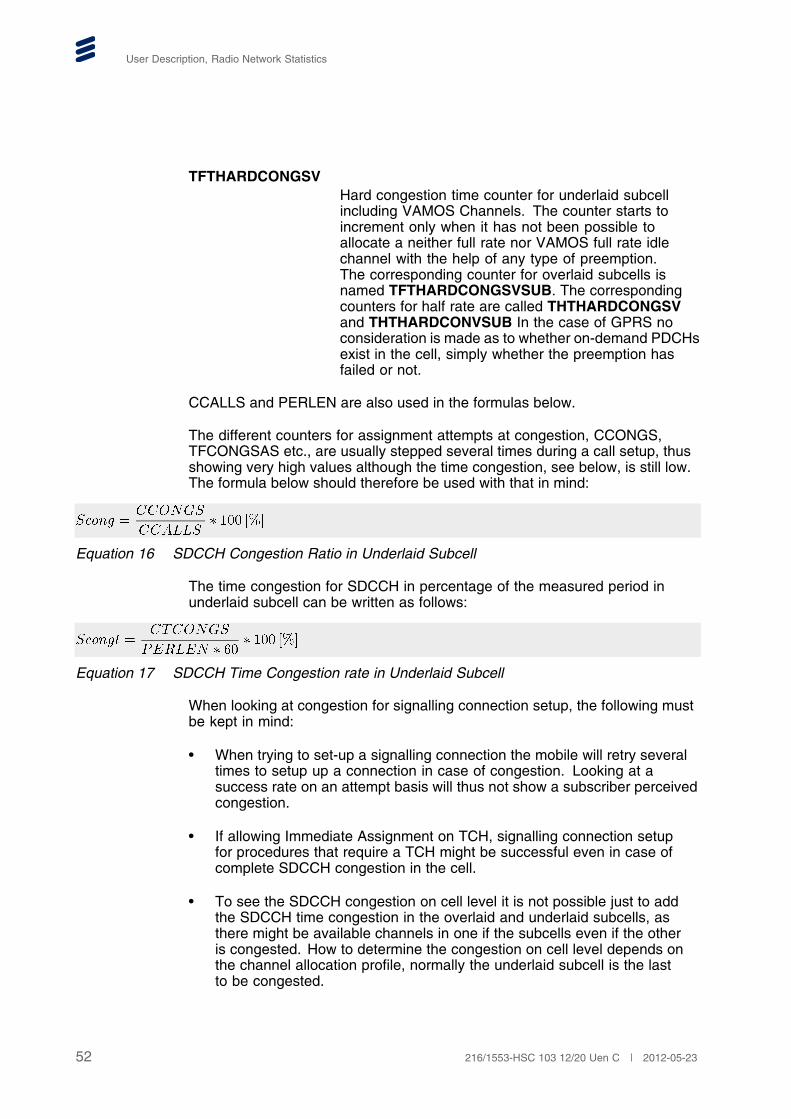
User Description, Radio Network Statistics
TFTHARDCONGSVHard congestion time counter for underlaid subcellincluding VAMOS Channels. The counter starts toincrement only when it has not been possible toallocate a neither full rate nor VAMOS full rate idlechannel with the help of any type of preemption.The corresponding counter for overlaid subcells isnamed TFTHARDCONGSVSUB. The correspondingcounters for half rate are called THTHARDCONGSVand THTHARDCONVSUB In the case of GPRS noconsideration is made as to whether on-demand PDCHsexist in the cell, simply whether the preemption hasfailed or not.
CCALLS and PERLEN are also used in the formulas below.
The different counters for assignment attempts at congestion, CCONGS,TFCONGSAS etc., are usually stepped several times during a call setup, thusshowing very high values although the time congestion, see below, is still low.The formula below should therefore be used with that in mind:
����� �������
���� ��� ���
Equation 16 SDCCH Congestion Ratio in Underlaid Subcell
The time congestion for SDCCH in percentage of the measured period inunderlaid subcell can be written as follows:
������ ��������
���� � ��� ��� ���
Equation 17 SDCCH Time Congestion rate in Underlaid Subcell
When looking at congestion for signalling connection setup, the following mustbe kept in mind:
• When trying to set-up a signalling connection the mobile will retry severaltimes to setup up a connection in case of congestion. Looking at asuccess rate on an attempt basis will thus not show a subscriber perceivedcongestion.
• If allowing Immediate Assignment on TCH, signalling connection setupfor procedures that require a TCH might be successful even in case ofcomplete SDCCH congestion in the cell.
• To see the SDCCH congestion on cell level it is not possible just to addthe SDCCH time congestion in the overlaid and underlaid subcells, asthere might be available channels in one if the subcells even if the otheris congested. How to determine the congestion on cell level depends onthe channel allocation profile, normally the underlaid subcell is the lastto be congested.
52 216/1553-HSC 103 12/20 Uen C | 2012-05-23

GSM Radio Network Performance Monitoring
The counter CSCSTCONG and CSCSOPTCONG give a picture of thesignalling congestion setup congestion on cell level separately for proceduresrequiring a TCH and other procedures, for example SMS and location areaupdate, that can be completed on an SDCCH. On cell level it is not possible toget a consistent definition of time congestion that is connected to availabilityof resources (for example MSs outside the overlaid coverage area may suffercongestion even if there are free channels in the overlaid subcell), insteadthese counters consider successful and unsuccessful signalling connectionsetups. The counter CSCSTCONG starts incrementing when a signallingconnection setup attempt for a procedure requiring a TCH fails and stopsincrementing when there is a successful signalling connection setup of anykind on a SDCCH or a TCH. The counter CSCSOPTCONG on the other handstarts incrementing when a signalling connection setup attempt for a procedurethat can be completed on an SDCCH fails and stops incrementing when thereis a successful signalling connection setup of any kind on a SDCCH. As thecounters consider successful establishments rather than resource availabilitythe actual congestion time might be slightly exaggerated in cells with lowSDCCH traffic and capacity. It should be noted that BSS cannot in all casesdetermine if a connection is for a procedure requiring a TCH or signalling only, ifnot known it is assumed that it is for a procedure requiring a TCH. The formulabelow shows the congestion time for procedures that require a TCH
�������� ��������
� �� � � ��� ��� ���
Equation 18 Signalling Connection Setup Time Congestion for Procedures that Require a TCH
The counters TFCONGSAS, THCONGSAS etc. might be stepped severaltimes during an assignment attempt. Instead, a more accurate measure ofthe number of call attempts failing due to TCH congestion is the number ofsignalling channel drops due to lack of radio resources, that is TCH congestion.The counter to use is CNRELCONG situated in the object type CLSDCCHand the TFNRELCONG counters. The expression below is a good measureof the subscriber perceived Grade of Service (GoS) in the cell. The formulacompares the failed TCH assignment attempts due to congestion with the totalnumber of TCH assignment attempts. Successful attempts are counted in thetarget cell and failed attempts are counted in the serving cell. By compensatingfor handover during assignment the formula shows the congestion for callsstarted in the cell.
���� ���� ����� ����� � �����
������ � ��� ��� � �� ���� ��� ��� � ��� ���
����� � ��� ���� � ��� �������
����� � ��� ���� � ��� �������
Equation 19 Subscriber Perceived TCH Congestion.
The expressions above can be described as:
TCONG Total number of dropped calls due to TCH congestiondivided by the total number of TCH assignments.
53216/1553-HSC 103 12/20 Uen C | 2012-05-23

User Description, Radio Network Statistics
TFrelC Total number of dropped TCH connections dueto transcoder resource congestion at immediateassignment on TCH for full-rate in both underlaid andoverlaid subcell.
THrelC Total number of dropped TCH connections dueto transcoder resource congestion at immediateassignment on TCH for half-rate in both underlaid andoverlaid subcell.
The TCH time congestion is also a useful measure. The time congestion forTCH full-rate in percentage of the measured period in underlaid subcell canbe written as follows:
������ �������
� �� � ��� ��� ���
Equation 20 Full-Rate TCH Time Congestion rate in Underlaid Subcell
Similarly, the time congestion for VAMOS full-rate TCH Channels includingin percentage of the measured period in underlaid subcell can be written asfollows:
������� ��������
� �� � ��� ��� ���
Equation 21 VAMOS Full-Rate TCH Time Congestion rate in Underlaid Subcell
5.4.9 RF Output Power Supervision Measurements per BSC
The counters described in this section belong to the object type BSCRFSUPand Measurements are done per BSC. The main purpose of these countersis to monitor the RF performance and quality and is associated with RFperformance alarms.
ALRFPERFACC The accumulated number of RADIO X-CEIVERADMINISTRATION MANAGED OBJECT FAULTalarms with alarm slogan RF PERFORMANCE andRADIO X-CEIVER ADMINISTRATION TRANSCEIVERGROUP FAULT alarms with alarm slogan RFPERFORMANCE. The number of currently activealarms is scanned every five minutes.
ALNOTRAFACC The accumulated number of CELL RF OUTPUTPOWER SUPERVISION alarms with the reason NOTRAFFIC. The number of currently active alarms isscanned every five minutes.
54 216/1553-HSC 103 12/20 Uen C | 2012-05-23

GSM Radio Network Performance Monitoring
ALLOWDLQUALACCThe accumulated number of CELL RF OUTPUTPOWER SUPERVISION alarms with the reason LOWDL QUALITY. The number of currently active alarms isscanned every five minutes.
ALNSCAN The counter is incremented by one every five minuteswhen the number of currently active alarms is scannedin order to update the counters ALRFPERFACC,ALNOTRAFACC and ALLOWDLQUALACC.
5.5 Retainability
5.5.1 General
The retainability area within the radio network covers the performanceregarding dropped calls, lost handovers and disconnections during abnormalcircumstances etc.
The following BSC exchange properties are affecting counters for droppedcalls and handover:
HIGHFERDLFR Threshold value for FER downlink for fullrate. FilteredFER measurements on the downlink for fullrate arecompared to HIGHFERUL when evaluating urgencyconditions. The evaluated condition is used forstatistical counter incrementation only. There areseparate BSC exchange properties for uplink, downlinkand per codec halfrate, fullrate, enhanced fullrate,AMR halfrate and AMR fullrate. For example thecorresponding parameter for uplink and AMR halfrateis HIGHFERULAHR. Please, note that evaluationof the FER threshold requires the feature EnhancedMeasurement Reporting (EMR). Value range: 0-96 FERunits. Default value: 4 FER Units.
BADQDL Threshold value for Bad Quality downlink basedon RXQUAL. Filtered quality measurements on thedownlink are compared to BADQx when evaluatingurgency conditions. The evaluated condition isused for statistical counter incrementation only. Thecorresponding parameter for uplink is BADQUL. Valuerange: 0-100dtqu. Default value: 55dtqu.
LOWSSDL Threshold values for attenuation of Signal Strengthdownlink. Filtered downlink signal strength valuesare compared with LOWSSx when analyzing urgencyconditions. The evaluated condition is used for statisticalcounter incrementation only. The corresponding
55216/1553-HSC 103 12/20 Uen C | 2012-05-23

User Description, Radio Network Statistics
parameter for uplink is LOWSSULValue range:-47-(-110)dBm. Default value: -104dBm.
5.5.2 Dropped Calls
Object types concerned are CELTCHF, CELTCHH, CLTCHDRF andCLTCHDRH.
TFNDROP The total number of dropped full-rate TCH in underlaidsubcell. The counter is also available for half-rate andfor overlaid subcells, for example THNDROPSUB.
TFNCEDROP The total number of dropped full rate TCH connectionsin underlaid subcell that occur when a subscriber tosubscriber connection has already been established.The counter is incremented when a connection isdropped after any of the three messages 44.018ASSIGNMENT COMPLETE, 44.018 HANDOVERCOMPLETE, 44.018 CHANNEL MODE MODIFYACKNOWLEDGE and before one of the DTAPmessages 24.008 RELEASE or 24.008 DISCONNECTis received by the BSC.
For inter BSC handovers and inter system handovers,the target BSC assumes that the call connection isalready established, and the counter is incremented inthe target BSC in case of dropped connection. Thecounter is also available for half-rate and for overlaidsubcells, for example THNCEDROPSUB.
TFDISTA Total number of dropped full-rate TCH connections atexcessive TA. Also available for half-rate, for exampleTHDISTA.
TFDISSSUL Total number of dropped full-rate TCH connection atlow signal strength on uplink in underlaid subcell thatis below LOWSSUL. There are counters for differentcombinations of overlaid subcell, up/down and both-waylink and half-rate, for example THDISSSBLSUB is thesignal strength drop counter for half-rate, both links inoverlaid subcell. If both links have low signal strength,only the both link counters are stepped.
TFDISFERUL Total number of dropped full-rate TCH connectionsat high FER on uplink in underlaid subcell that isworse than (above) HIGHFERULFR. There arecounters for different combinations of overlaid subcell,up/down and both-way link and half-rate, for exampleTHDISFERBLSUB is the bad quality drop counter forhalf-rate, both links in overlaid subcell. If both links havebad quality, only the both link counters are stepped.
56 216/1553-HSC 103 12/20 Uen C | 2012-05-23

GSM Radio Network Performance Monitoring
TFDISQAUL Total number of dropped TCH connection due tobad quality based on RXQUAL on uplink in underlaidsubcell that is worse than (above) BADQUL. There arecounters for different combinations of overlaid subcell,up/down and both-way link and half-rate, for exampleTHDISQABLSUB is the bad quality drop counter forhalf-rate, both links in overlaid subcell. If both links havebad quality, only the both link counters are stepped.
TFSUDLOS Sudden loss of connection in underlaid subcell. Suddenloss apply when the locating algorithm indicatesmissing measurement results, but none of the urgencyconditions mentioned above (that is excessive TA, lowsignal strength, high FER or bad quality) apply. Thecounter is also available for half-rate and for overlaidsubcells, for example THSUDLOSSUB.
The different drop reasons are ranked in the order excessive TA, low signalstrength, high FER, bad quality or sudden loss of connection. This means thatif connection suffers from excessive TA and low signal strength and drops, thedrop reason will be registered as excessive TA.
The number of drops due to other reasons is obtained by subtracting thedrops with known reasons from the total number of drops. This applies to bothSDCCH and TCH.
To obtain a subscriber perceived drop rate the number of drops should becompared to the number of calls terminated in the cell, but when calculatingthis, the net sum of incoming calls via all relations have to be included. Thefollowing list shows the components included:
Ncalls Number of calls terminated in a cell.
Icalls Number of initiated calls in a cell, for example the sumof the four “CASSALL” counters for TCH or CMSESTABfor SDCCH.
Inc Sum of all incoming handovers to a cell from all itsneighbors.
Outg Sum of all outgoing handovers from a cell to all itsneighbors.
AW Number of successful assignments to worse cell,counter HOSUCWCL.
AB Number of successful assignments to better cell,counter HOSUCBCL.
The total number of terminated calls in a cell is then expressed as:
57216/1553-HSC 103 12/20 Uen C | 2012-05-23
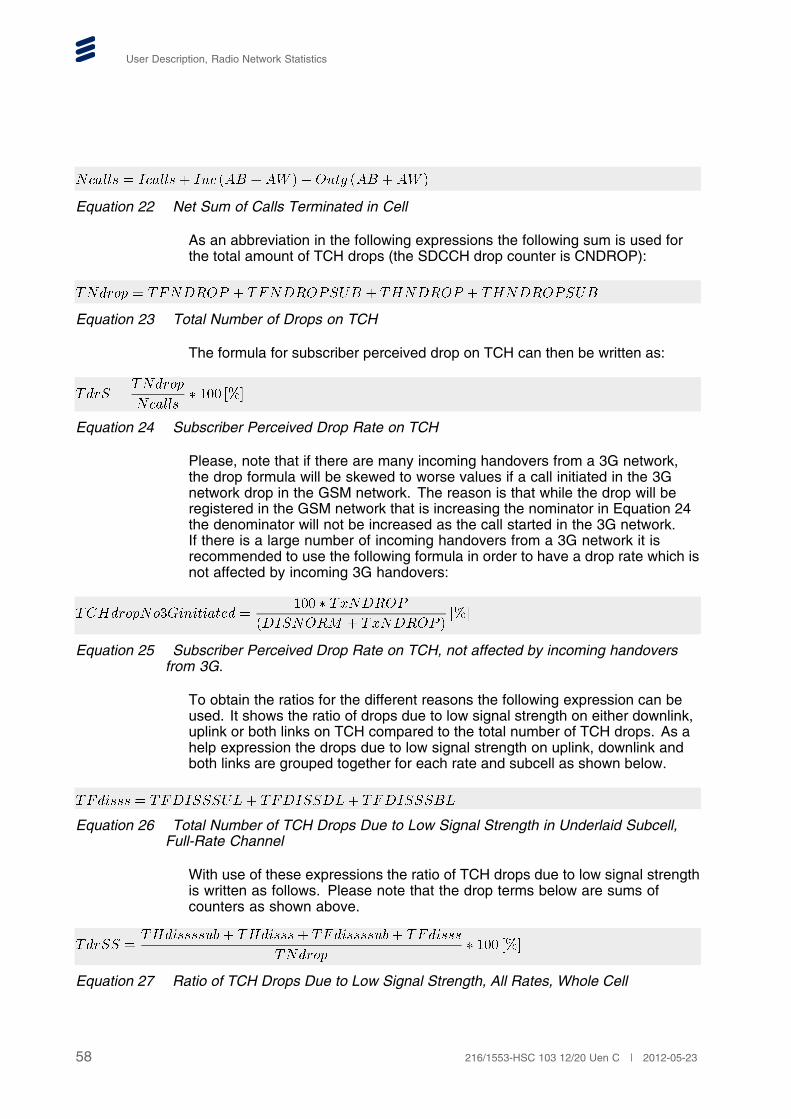
User Description, Radio Network Statistics
������ � ������ � ��� ��� �� ���� ��� �� �
Equation 22 Net Sum of Calls Terminated in Cell
As an abbreviation in the following expressions the following sum is used forthe total amount of TCH drops (the SDCCH drop counter is CNDROP):
������ � ������ � ��������� � ������ � ���������
Equation 23 Total Number of Drops on TCH
The formula for subscriber perceived drop on TCH can then be written as:
���� �������
������� ��� ���
Equation 24 Subscriber Perceived Drop Rate on TCH
Please, note that if there are many incoming handovers from a 3G network,the drop formula will be skewed to worse values if a call initiated in the 3Gnetwork drop in the GSM network. The reason is that while the drop will beregistered in the GSM network that is increasing the nominator in Equation 24the denominator will not be increased as the call started in the 3G network.If there is a large number of incoming handovers from a 3G network it isrecommended to use the following formula in order to have a drop rate which isnot affected by incoming 3G handovers:
������������������� ���� � ������
������� � ������ ����
Equation 25 Subscriber Perceived Drop Rate on TCH, not affected by incoming handoversfrom 3G.
To obtain the ratios for the different reasons the following expression can beused. It shows the ratio of drops due to low signal strength on either downlink,uplink or both links on TCH compared to the total number of TCH drops. As ahelp expression the drops due to low signal strength on uplink, downlink andboth links are grouped together for each rate and subcell as shown below.
������� � �������� � ������� � ��������
Equation 26 Total Number of TCH Drops Due to Low Signal Strength in Underlaid Subcell,Full-Rate Channel
With use of these expressions the ratio of TCH drops due to low signal strengthis written as follows. Please note that the drop terms below are sums ofcounters as shown above.
����� ����������!� �������� ���������!� �������
������� ��� ���
Equation 27 Ratio of TCH Drops Due to Low Signal Strength, All Rates, Whole Cell
58 216/1553-HSC 103 12/20 Uen C | 2012-05-23

GSM Radio Network Performance Monitoring
The same method can be used to calculate the following drop reasons forboth full-rate and half-rate calls:
TdrBQ The rate of TCH drops at bad quality on either uplink,downlink or both for the whole cell.
TdrFER The rate of TCH drops at high FER on either uplink,downlink or both for the whole cell.
TdrTA The rate of TCH drops due to excessive TimingAdvance for the whole cell.
TdrSUD The rate of TCH drops due to sudden loss of theconnection for the whole cell.
TdrOTH The rate of TCH drops due to other reasons than theabove known reasons.
A cell with a very high rate of TCH drops due to other reasons should beinvestigated in terms of consistent parameter settings (both cell and managedobjects), BTS alarms, software status, antenna faults, link problems andtranscoder problems.
A useful value for comparing performance is to calculate the number of callminutes per drop, for example the average time period between full-rate TCHdrops in minutes per call. This measure takes the traffic level into account.The following formula applies to TCH:
�������� ����� � ��������
������ � ����� ��� � �� �������
Equation 28 Average Time Period between Full-Rate TCH Drops in Minutes per Call
The expression above can be altered to include for instance drop reasonsinstead.
To get a better picture of the subscriber impact due to dropped calls, thecounters that are only stepped for dropped calls when a call connection isestablished can be used (for example the counter TFNCEDROP for full rateunderlaid subcell). It is assumed that the subscriber perceived disturbance isgreater if the call drops when the call connection has been established. Theratio of calls for full rate connections that are dropped when a call connection isestablished of all TCH drops can be calculated as:
�������� �������� � ������� ��
����� � ����� ��� ��� ���
Equation 29 Percentage Full Rate TCH Drops when a Call Connection Is Established of AllTCH Drops
59216/1553-HSC 103 12/20 Uen C | 2012-05-23

User Description, Radio Network Statistics
5.5.3 AMR and Dropped Calls
Counters are available for the number of dropped calls that occurred on AMRcodecs and the reason for these dropped calls. The object type CLTCHDRAFcontains 21 counters for AMR full rate, the object type CLTCHDRAH contains21 counters for AMR half rate and the object type CLTCHDRAW contains 21counters for AMR wideband. Separate counters are provided per reason(timing advance, low signal strength, high FER, bad quality and sudden loss)and also per underlaid and overlaid subcell in a similar manner as the moregeneral counters. Some examples of the naming convention are given below:
TFDISTAA Total number of dropped AMR full-rate TCH connectionsat excessive TA. Also available for half-rate, for exampleTHDISTAA .
TFDISSULA Total number of dropped AMR full-rate TCH connectionsdue to low signal strength on uplink in underlaid subcellthat is below LOWSSUL. There are counters for differentcombinations of overlaid subcell, up/down and both-waylink and half-rate, for example THDISSBLSUBA is thesignal strength drop counter for AMR half-rate, bothlinks in overlaid subcell. If both links have low signalstrength, only the both link counters are stepped.
TFDISFERULA Total number of dropped AMR full rate TCH connectionsat high FER on uplink in underlaid subcell. There arecounters for different combinations of overlaid subcell,up/down and both-way link and half-rate, for exampleTHDISFERBLSUBA is the bad quality drop counter forAMR half-rate, both links in overlaid subcell. If bothlinks have bad quality, only the both link counters arestepped.
TFDISQAULA Total number of dropped AMR full-rate TCH connectionsat bad quality on uplink in underlaid subcell. There arecounters for different combinations of overlaid subcell,up/down and both-way link and half-rate, for exampleTHDISQABLSUBA is the bad quality drop counter forAMR half-rate, both links in overlaid subcell. If bothlinks have bad quality, only the both link counters arestepped.
TFSUDLOSA Sudden loss of AMR full-rate connection in underlaidsubcell. Sudden loss apply when the locating algorithmindicates missing measurement results, but none of theurgency conditions mentioned above (that is excessiveTA, low signal strength, high FER or bad quality) apply.The counter is also available for AMR half-rate and foroverlaid subcells, for example THSUDLOSSUBA.
The general counters for dropped calls on all full-rate codecs are still steppedwhen one of these counters specific to AMR codecs is stepped. For example
60 216/1553-HSC 103 12/20 Uen C | 2012-05-23

GSM Radio Network Performance Monitoring
if an AMR full-rate connection is dropped because of low signal strength onthe downlink in the overlaid subcell then TFNDROP, TFDISSSDLSUB andTFDISSDLSUBA are all stepped.
5.5.4 VAMOS and Dropped Calls
Counters are available for the number of dropped calls that occurred on VAMOScodecs. The object type CLTCHFV contains counters for VAMOS full rate, theobject type CLTCHHV counters for VAMOS half rate. Separate counters areprovided per underlaid and overlaid subcell in a similar manner as the moregeneral counters. An example of the naming convention is given below:
TFNDROPV The total number of dropped VAMOS full-rate TCHconnections in underlaid subcell. The counter is alsoavailable for half-rate, for example THNDROPV .
A useful value for comparing VAMOS performance is to calculate the number ofcall minutes per drop, for example the average time period between VAMOSdrops in minutes per call. This measure takes the traffic level into account.The following formula applies to TCH:
�������� ����� � ������ � ���� ����� � ����
������ � ��������� � ����� ���
����� �
����� � ��� � ����������������
����� � ��� � ����������������
����� � ��� � ������ � ������ ���
����� � ��� � ������ � ������ ���
Equation 30 Average Time Period between VAMOS Drops in call minutes
It is suggested to construct Similar expression for VAMOS half rate and foroverlaid subcells.
5.5.5 Enhanced AMR Coverage
Counters to monitor the feature Enhanced AMR Coverage is available in theobject type CLTCHEAS. These counters act for terminals having repeatedSACCH capability. Repeated SACCH capability enhances the terminals abilityto decode signalling under bad radio conditions, see Ref. Reference [39] fordetails.
EASULACTMREP The counter is stepped for each Measurement Reportthat is received while the terminal is in repeated SACCHmode on the uplink.
61216/1553-HSC 103 12/20 Uen C | 2012-05-23

User Description, Radio Network Statistics
EASULCAPMREP The counters is stepped for each Measurement Reportthat is received from an MS capable of repeatedSACCH, while the feature Enhanced AMR Coverage isactivated in the BSC.
EASDLACTSBL The counter is stepped for each DL SACCH blockreceived by the MS while in repeated SACCH modeon the downlink.
EASDLCAPSBL The counters is stepped for each DL SACCH blockreceived by an MS capable of repeated SACCH, whilethe feature Enhanced AMR Coverage is activated inthe BSC.
Using the above counters it is possible to calculate the fraction of time repeatedSACCH is used on the Uplink and Downlink, respectively.
����� �����������
����������� ��� ���
Equation 31 The fraction of the in repeated SACCH mode on the uplink.
����� ���� ������
��� ������� ��� ���
Equation 32 The fraction of the in repeated SACCH mode on the uplink.
5.5.6 Disconnection
This section concerns normal disconnections of speech TCHs. There arecounters to get information about the circumstances when the disconnectionwas made, thus getting indicators about subscriber perceived quality althoughno call drops are registered. The object type for disconnections is CELEVENTD.
DISNORM Normal disconnection.
When DISNORM is stepped during urgency state also the following countersare stepped:
DISETA Normal disconnection at excessive timing advance.
DISBSS Normal disconnection at low signal strength.
DISBQA Normal disconnection at bad quality.
DISRET3G Disconnection with request to immediately connect toUTRAN network.
The counters are stated in order of urgency status, for example if a call suffersfrom both bad signal strength and too high timing advance the disconnection iscounted by DISETA. For instance, to get the ratio of disconnected calls duringbad quality the formula below can be used.
62 216/1553-HSC 103 12/20 Uen C | 2012-05-23

GSM Radio Network Performance Monitoring
������ �����
���� ��� ��� ���
Equation 33 Ratio of Subscriber Initiated Disconnections at Bad Quality
5.5.7 Handover
The counters in this section belongs to the object types NCELLREL, NICELHOand NICELASS. If Ericsson 3 locating algorithm is used, the object typeNICELHOEX have to be considered. NICELHOEX can also be used tomeasure high handover rate. There are corresponding counters for handoversto external neighbour cells; NECELLREL, NECELHO, NECELSASS andNECELHOEX respectively, which contain the same set of counters.
The most important counters are:
HOVERCNT Number of Handover Commands sent to the MS.
HOVERSUC Number of successful handover to the neighboring cell.
HORTTOCH Number of handover attempts where the MS returns tothe old channel or has been ordered by the network andsucceeded in getting back to the old channel.
HODUPFT Number of successful handovers back to old cell within10 seconds.
HOTOKCL Handover attempt made to better K-cell (only for theEricsson 1 locating algorithm). The corresponding forbetter L-cell is called HOTOLCL.
HOTOHCS Handover attempt due to HCS.
HODWNQA Number of handover attempts due to bad downlinkquality. There is one HO counter for bad uplink qualitycalled HOUPLQA and one for excessive timing advancecalled HOEXCTA.
HOASBCL Number of assignment attempts to better cell. Thecorresponding counter for assignment to worse cell iscalled HOASWCL.
HOSUCBCL Number of successful assignment attempts to bettercell. The corresponding counter for assignment toworse cell is called HOSUCWCL.
HOATTLSS Number of handover attempts when the serving cell is alow signal strength cell. The corresponding counter forattempts at high signal strength is called HOATTHSS.
63216/1553-HSC 103 12/20 Uen C | 2012-05-23

User Description, Radio Network Statistics
HOATTHR Number of handover attempts at high handover rate.The counter for successful handovers at high handoverrate is HOSUCHR.
Note: What is meant by “attempt” for the counters above is before a channelhas been allocated that is in the case of congestion the “attempt” willfail. A better way to express this would be to use the term “decision”and to use the term “attempt” for the actual attempt to perform forexample a handover (when handover command is sent).
The number of lost handovers is counted by subtracting HOVERSUC andHORTTOCH from HOVERCNT and the ratio of all handovers is given by:
����� ���� ��� ���� ��� ��������
��� ���� ��� ���
Equation 34 Ratio of Handovers Lost of Total Number of Handover Commands
To see the ratio on cell level, all cell relations have to be summarized.
5.6 Speech Quality
5.6.1 General
From BSS R12 speech quality measurements only step STS counters whena call connection is established, to make better correlation to the subscriberperceived speech quality. If a call connection has been established it isdetected by the DTAP message Connect Acknowledge and if the callconnection has been terminated is determined by the DTAP messagesRelease or Disconnect (which ever comes first). For inter BSC handoversit is assumed that the call connection is established. This applies to SQI,FER and RXQUAL measurements in the object types CLRXQUAL, CELLSQI,CELLFERF, CELLFERH, CHGRP0H, CHGRP0F, CELLAFFER, CELLAHFER,CELLEFFER, CELFFER, CELLHFER, CELLSQIDL, CHGRP0SQI andCELLAWFER.
More information about the FER and SQI measurements can be found inReference [31].
5.6.2 Speech Quality Supervision for Speech Version 1 and 2 Codecs
The object type CELLSQI contains three counters that show how the speechquality indexes are distributed UL, according to subscriber perceived quality, asgood, acceptable and bad for the underlaid subcell. These counters only stepfor Speech Version 1 (FR and HR) and Speech Version 2 (EFR) codecs. Thereare three matching counters for overlaid subcells.
The object type CELLSQIDL contains the corresponding counters but for DL.The counters have the same name as the UL counters, but with the suffix
64 216/1553-HSC 103 12/20 Uen C | 2012-05-23

GSM Radio Network Performance Monitoring
DL. Please, note that SQI DL requires the feature Enhanced MeasurementReporting.
TSQIGOOD Accumulated number of SQI samples that representedgood speech quality. The corresponding counter foroverlaid subcell is TSQIGOODSUB
TSQIACCPT Accumulated number of SQI samples that representedacceptable speech quality. The corresponding counterfor overlaid subcell is TSQIACCPTSUB
TSQIBAD Accumulated number of SQI samples that representedunsatisfactory speech quality. The correspondingcounter for overlaid subcell is TSQIBADSUB
Shown below is the percentage of SQI samples in the range good out ofthe total number of SQI samples. The same measure can be calculated foracceptable and unsatisfactory samples. As a help expression, the total numberof SQI samples in underlaid subcell is calculated first.
������ � �������� � ������ � ������
Equation 35 Total Number of SQI Samples
��� ��� ���������
������� ��� ���
Equation 36 Percentage Good SQI Samples of Total Number of SQI Samples
For further information about SQI, see Reference [31].
5.6.3 Speech Quality Supervision for Speech Version 3 and 5 (AMR FR,AMR HR and AMR Wideband)
The counters in the object type CELLSQI is used to monitor the speechquality UL, separately for AMR wideband, AMR full rate and AMR half rateand per underlaid/overlaid subcell. The object type CELLSQIDL contains thecorresponding counters but for DL. The counters have the same name as theUL counters, but with the suffix DL. Please, note that SQI DL requires thefeature Enhanced Measurement Reporting.
TSQIGOODAW Accumulated number of SQI samples for AMRwideband that represented good speech quality.The corresponding counter for overlaid subcell isTSQIGOODSUBAW
TSQIACCPTAW Accumulated number of SQI samples for AMRwideband that represented acceptable speech quality.The corresponding counter for overlaid subcell isTSQIACCPTSUBAW
65216/1553-HSC 103 12/20 Uen C | 2012-05-23

User Description, Radio Network Statistics
TSQIBADAW Accumulated number of SQI samples for AMRwideband that represented unsatisfactory speechquality. The corresponding counter for overlaid subcellis TSQIBADSUBAW
TSQIGOODAF Accumulated number of SQI samples for AMRfull rate that represented good speech quality.The corresponding counter for overlaid subcell isTSQIGOODSUBAF
TSQIACCPTAF Accumulated number of SQI samples for AMR fullrate that represented acceptable speech quality.The corresponding counter for overlaid subcell isTSQIACCPTSUBAF
TSQIBADAF Accumulated number of SQI samples for AMR fullrate that represented unsatisfactory speech quality.The corresponding counter for overlaid subcell isTSQIBADSUBAF
TSQIGOODAH Accumulated number of SQI samples for AMRhalf rate that represented good speech quality.The corresponding counter for overlaid subcell isTSQIGOODSUBAH
TSQIACCPTAH Accumulated number of SQI samples for AMR halfrate that represented acceptable speech quality.The corresponding counter for overlaid subcell isTSQIACCPTSUBAH
TSQIBADAH Accumulated number of SQI samples for AMR halfrate that represented unsatisfactory speech quality.The corresponding counter for overlaid subcell isTSQIBADSUBAH
It is suggested to construct similar formulas as in Section 5.6.2 on page 64above.
5.6.4 Speech Quality Supervision for VAMOS
The counters in the object type CLSQIULV is used to monitor the speech qualityUL, for VAMOS and per underlaid/overlaid subcell. The object type CLSQIDLVcontains the corresponding counters but for DL. The counters have the samename as the UL counters, but with the term DL embedded in the name. Please,note that SQI DL requires the feature Enhanced Measurement Reporting.
TSQIGOODV Accumulated number of SQI samples for VAMOSspeech codecs FR, EFR and HR that represented goodspeech quality. The corresponding counter for overlaidsubcell is TSQIGOODSUBV
66 216/1553-HSC 103 12/20 Uen C | 2012-05-23

GSM Radio Network Performance Monitoring
TSQIACCPTV Accumulated number of SQI samples for VAMOSspeech codecs FR, EFR and HR that representedacceptable speech quality. The corresponding counterfor overlaid subcell is TSQIACCPTSUBV
TSQIBADV Accumulated number of SQI samples for VAMOSspeech codecs FR, EFR and HR that representedunsatisfactory speech quality. The correspondingcounter for overlaid subcell is TSQIBADSUBV
TSQIGOODAWV Accumulated number of SQI samples for VAMOSAMR Wide band that represented good speech quality.The corresponding counter for overlaid subcell isTSQIGOODSUBAWV
TSQIACCPTAWV Accumulated number of SQI samples for VAMOSAMR Wide band that represented acceptable speechquality. The corresponding counter for overlaid subcellis TSQIACCPTSUBAWV
TSQIBADAWV Accumulated number of SQI samples for VAMOS AMRWide band that represented unsatisfactory speechquality. The corresponding counter for overlaid subcellis TSQIBADSUBAWV
TSQIGOODAHV Accumulated number of SQI samples for VAMOSAMR half rate that represented good speech quality.The corresponding counter for overlaid subcell isTSQIGOODSUBAHV
TSQIACCPTAHV Accumulated number of SQI samples for VAMOSAMR half rate that represented acceptable speechquality. The corresponding counter for overlaid subcellis TSQIACCPTSUBAHV
TSQIBADAHV Accumulated number of SQI samples for VAMOSAMR half rate that represented unsatisfactory speechquality. The corresponding counter for overlaid subcellis TSQIBADSUBAHV
TSQIGOODAFV Accumulated number of SQI samples for VAMOSAMR full rate that represented good speech quality.The corresponding counter for overlaid subcell isTSQIGOODSUBAFV
TSQIACCPTAFV Accumulated number of SQI samples for VAMOSAMR full rate that represented acceptable speechquality. The corresponding counter for overlaid subcellis TSQIACCPTSUBAFV
TSQIBADAFV Accumulated number of SQI samples for VAMOSAMR full rate that represented bad speech quality.
67216/1553-HSC 103 12/20 Uen C | 2012-05-23

User Description, Radio Network Statistics
The corresponding counter for overlaid subcell isTSQIBADSUBAFV
It is suggested to construct similar formulas as in Section 5.6.2 on page 64above.
5.6.5 Speech Codec Congestion
In object type BSCSCCCL, there are counters on BSC level which givestatistics about speech codec use and indicate potential quality problem causedby speech codec congestion due to the SCC capacity lock mechanism. Thereare counters per optional speech codec,(that is AMR FR, AMR HR, AMR WB,EFR and HR) as listed below.
TCONGAFR Total time in seconds when no speech resource forAMR FR has been available for new traffic due to SCCcapacity lock mechanism.
TCONGAHR Total time in seconds when no speech resource forAMR HR has been available for new traffic due to SCCcapacity lock mechanism.
TCONGAWB Total time in seconds when no speech resource forAMR WB has been available for new traffic due to SCCcapacity lock mechanism.
TCONGEFR Total time in seconds when no speech resource for EFRhas been available for new traffic due to SCC capacitylock mechanism.
TCONGHR Total time in seconds when no speech resource for HRhas been available for new traffic due to SCC capacitylock mechanism.
TCONGV Total time in seconds when no resource for VAMOS hasbeen available for new traffic due to VAMOS capacitylock mechanism.
TRAFAFR Accumulated traffic level (number of calls) using AMRFR speech codec.
TRAFAHR Accumulated traffic level (number of calls) using AMRHR speech codec.
TRAFAWB Accumulated traffic level (number of calls) using AMRWB speech codec.
TRAFEFR Accumulated traffic level (number of calls) using EFRspeech codec.
68 216/1553-HSC 103 12/20 Uen C | 2012-05-23

GSM Radio Network Performance Monitoring
TRAFHR Accumulated traffic level (number of calls) using HRspeech codec.
TRAFV Accumulated traffic level (number of calls) usingVAMOS .
TRAFSCAN Number of accumulations of traffic level counters.
PEAKSCCBV The peak value of the number of VAMOS licenses usedin the BSC during the last 60 minutes.
PEAKSCCAFR The peak value of the number of AMR FR, licensesused in the BSC during the last 60 minutes.
PEAKSCCAHR The peak value of the number of AMR HR licensesused in the BSC during the last 60 minutes.
PEAKSCCAWB The peak value of the number of AMR WB licensesused in the BSC during the last 60 minutes.
PEAKSCCEFR The peak value of the number of EFR licenses used inthe BSC during the last 60 minutes.
PEAKSCCHR The peak value of the number of HR licenses used inthe BSC during the last 60 minutes.
In order to calculate the current traffic level on BSC level for a specific optionalspeech codec one can for example use the formula in Equation 37 which isshowing the AMR FR traffic in Erlang on BSC level. The optional speech codecuse on BSC level can be calculated by dividing the calculated traffic level (forexample Equation 37) with the BSC capacity limit (c.f. AXE parameter, printoutRACLP). Formulas for other codecs or VAMOS can be constructed in the sameway.
����������� ��������
������� ��������
Equation 37 AMR Full-Rate Traffic Level in a BSC
In order to monitor the details of speech codec capacity with respect to the SCCcapacity lock mechanism on cell level, the object types CLTCH, CLTCHFV2,CLTCHHV1, CLTCHFV3, CLTCHHV3 and CLTCHFV5 (with counters usedfor cell level measurements for All Speech Versions) contain the followingcongestion and peak counters:
THV1TCONGSCC Total congestion time (in seconds) when no speechcodec resource for HR has been available to setup newtraffic due to the SCC capacity lock mechanism.
THV1PEAKSCC Maximum number of HR licenses used during the last60 minutes.
69216/1553-HSC 103 12/20 Uen C | 2012-05-23

User Description, Radio Network Statistics
TFV2TCONGSCC Total congestion time (in seconds) when no speechcodec resource for EFR has been available to setupnew traffic due to the SCC capacity lock mechanism.
TFV2PEAKSCC Maximum number of EFR licenses used during the last60 minutes.
TFV3TCONGSCC Total congestion time (in seconds) when no speechcodec resource for AMR FR has been available to setupnew traffic due to the SCC capacity lock mechanism.
TFV3PEAKSCC Maximum number of AMR FR licenses used during thelast 60 minutes.
THV3TCONGSCC Total congestion time (in seconds) when no speechcodec resource for AMR HR has been available to setupnew traffic due to the SCC capacity lock mechanism.
THV3PEAKSCC Maximum number of AMR HR licenses used during thelast 60 minutes.
TFV5TCONGSCC Total congestion time (in seconds) when no speechcodec resource for AMR WB has been available to setupnew traffic due to the SCC capacity lock mechanism.
TFV5PEAKSCC Maximum number of AMR WB licenses used during thelast 60 minutes.
TTCONGSCCV Total congestion time (in seconds) when no resourcefor VAMOS has been available to setup new traffic dueto the VAMOS capacity lock mechanism.
PEAKSCCCV Shows the maximum number of VAMOS licenses usedin the cell during the last 60 minutes.
5.6.6 Speech Quality Supervision with Frame Erasure Rate (FER)Counters, UL
The object types CELLFERF and CELLFERH contain counters to allow theframe erasure rate, as measured by the BTS on the uplink, to be calculatedper cell. Please, note that the counters also allow the frame erasure rate forSpeech Version 1 and Speech Version 2 to be calculated.
TFV3FERCM1 Number of frames erased by the BTS for full rate AMRcodec mode 1. TFV3FERCM2 is the correspondingcounter for AMR codec mode 2. TFV3FERCM3 isthe corresponding counter for AMR codec mode 3.TFV3FERCM4 is the corresponding counter for AMRcodec mode 4.
TFV3TFCM1 Total number of frames transmitted by the MS forfull rate AMR codec mode 1. TFV3TFCM2 is the
70 216/1553-HSC 103 12/20 Uen C | 2012-05-23

GSM Radio Network Performance Monitoring
corresponding counter for AMR codec mode 2.TFV3TFCM3 is the corresponding counter for AMRcodec mode 3. TFV3TFCM4 is the correspondingcounter for AMR codec mode 4.
TFV5FERCM1 Number of frames erased by the BTS for full rateAMR Wideband codec mode 1. TFV5FERCM2 is thecorresponding counter for AMR Wideband codec mode2. TFV5FERCM3 is the corresponding counter for AMRWideband codec mode 3.
TFV5TFCM1 Total number of frames transmitted by the MS forAMR wideband codec mode 1. TFV5TFCM2 is thecorresponding counter for AMR wideband codec mode2. TFV5TFCM3 is the corresponding counter for AMRwideband codec mode 3.
TFV1FER Number of frames erased by the BTS for full rateSpeech Version 1. TFV2FER is the correspondingcounter for full rate Speech Version 2 (EFR).
TFV1FERTF Total number of frames transmitted by the MS for fullrate full rate Speech Version 1. TFV2FERTF is thecorresponding counter for full rate Speech Version 2(EFR).
THV3FERCM1 Number of frames erased by the BTS for half rate AMRcodec mode 1. THV3FERCM2 is the correspondingcounter for AMR codec mode 2. THV3FERCM3 isthe corresponding counter for AMR codec mode 3.THV3FERCM4 is the corresponding counter for AMRcodec mode 4.
THV3TFCM1 Total number of frames transmitted by the MS forhalf rate AMR codec mode 1. THV3TFCM2 is thecorresponding counter for AMR codec mode 2.THV3TFCM3 is the corresponding counter for AMRcodec mode 3. THV3TFCM4 is the correspondingcounter for AMR codec mode 4.
THV1FER Number of frames erased by the BTS for half rateSpeech Version 1.
THV1FERTF Total number of frames transmitted by the MS for halfrate Speech Version 1.
The FER is calculated by dividing the number of frames erased by the totalnumber of frames received. If the FER for a certain codec mode is too highthen the C/I threshold for the change of codec mode may need to be adjustedto ensure optimal speech quality.
71216/1553-HSC 103 12/20 Uen C | 2012-05-23

User Description, Radio Network Statistics
5.6.7 Detailed FER measurements (available using EBA)
Detailed FER calculation Distribution Monitors are introduced in EBA in 07B.The Detailed FER input data (UL/DL) to the monitors are calculated in the BSCand requires the features Speech Quality Supervision, Enhanced MeasurementReporting (EMR) and EMR capable terminals. The Detailed FER values aremeasured by the BSC over a user definable interval N (set by BSC commandRLSQC using parameter WINSIZE), having the value range 2-40 SACCHperiods with default value 4. Furthermore, a Sliding Window mechanism is usedto measure the new Detailed FER and Detailed RXQUAL values, meaning thatafter WINSIZE number of SACCH periods with allowed FER values, there willbe a Detailed FER measure reported each SACCH period. Please, note thatonly SACCH periods with allowed data are contributing to the measurements.This means that the Detailed FER measurements are calculated over WINSIZEnumber of SACCH periods with allowed values. The Detailed FER calculationcan be filtered in EBA on for example Last Codec Mode used by the terminalin the measurement interval.
The Detailed FER values calculated in the BSC are integer values in the range0-1000 representing the value range 0.0-100.0 %, with 0.1% resolution. TheDetailed FER values are converted to percentage values in EBA and shown inthe ‘Detailed FER Distribution Monitor’.
SACCH periods where the terminal is in DTX mode are not contributing to theDetailed FER calculation, while a measurement report that is lost is included inthe calculation using the assumption that the loss is due to bad quality that isNBR_RCVD_BLOCKS = 0.
Note: The detailed FER values are not affecting any ordinary FERmeasurements and is only used as input to the new EBA Detailed FERmonitor. This monitor treats all codec types (HR, FR, EFR and AMR)and also all codec modes for applicable codec types.
5.6.8 Detailed RXQUAL Measurements (Available using EBA)
Detailed RXQUAL measurements Distribution Monitors are introduced in EBAin 07B. The Detailed RXQUAL input data (UL/DL) to the monitors requiresthe optional features Speech Quality Supervision, Enhanced MeasurementReporting (EMR) and EMR capable terminals. The Detailed RXQUALvalues are measured by the BSC over a user definable interval N (set byBSC command RLSQC using parameter WINSIZE), having the value range2-40 SACCH periods with default value 4. Furthermore, a Sliding Windowmechanism is used to measure the Detailed RXQUAL values, meaning thatafter WINSIZE number of SACCH periods there will be a Detailed RXQUALmeasure reported each SACCH period. The Detailed RXQUAL measurementscan be filtered in EBA on for example Last Codec Mode used by the terminalin the measurement interval.
The Detailed RXQUAL values measured are based on MEAN_BEP reportedby BTS (UL) and MS (DL) reported to the BSC. In the BSC the reportedMEAN_BEP values are mapped to dtqu units, which are integer values in therange 0-76. This mapping corresponds to having decimal granularity of the
72 216/1553-HSC 103 12/20 Uen C | 2012-05-23

GSM Radio Network Performance Monitoring
traditional RXQUAL values, please see Table 11. The Detailed RXQUALvalues are shown in the EBA ‘Detailed RXQUAL Distribution Monitor’.
Note: The detailed RXQUAL values are not affecting any ordinary RXQUALmeasurements but is only used as input to the new EBA DetailedRXQUAL monitor. This monitor treat all codec types (HR, FR, EFR andAMR) and also all codec modes for applicable codec types.
Note: Since Detailed RxQual is based on MEAN_BEP, which is based ondifferent measurements on bit errors than RXQUAL, there will not bea 10:1 relation, not even between the average Detailed RxQual andaverage RxQual. The mapping between MEAN_BEP, RXQUAL andDetailed RxQual is shown in Table 11.
Table 11 Mapping of MEAN_BEP and dtqu (RxQual indicated as reference)
MEAN_BEP RXQUALDetailedRXQUAL
(dtqu)MEAN_BEP RXQUAL
DetailedRXQUAL
(dtqu)
0 7 76 12 4 37
1 7 73 13 3 33
2 7 70 14 3 30
3 7 66 15 3 27
4 6 63 16 2 23
5 6 60 17 2 20
6 6 56 18 2 17
7 5 53 19 1 13
8 5 50 20 1 10
9 5 46 21 1 7
10 4 43 22 0 3
11 4 40 23-31 0 0
5.6.9 Frame Erasure Rate (FER) Distribution Counters, UL and DL
There are counters that allow the distribution of FER occurrences to be plottedseparately per codec type. The counters are divided in five different intervals(bins), the threshold for each bin can be set separately with parameters. Thereare counters separate for
• Uplink and downlink
• Underlaid and Overlaid subcell (if no subcell structure is used the Underlaidcounter shows the whole cell)
• Codec type (AMR Wideband, AMR FR, AMR HR, EFR, FR and HR)
73216/1553-HSC 103 12/20 Uen C | 2012-05-23

User Description, Radio Network Statistics
• Separated in five different bins (intervals)
The counters are located in the object types CELLAWFER for AMR wideband,CELLAFFER for AMR FR, CELLAHFER for AMR HR, CELLEFFER for EFR,CELLFFER for FR and CELLHFER for HR.
The table below shows an example of the counters in object type CELLFFERfor FR (Speech Version 1), SUB denotes the counter for Overlaid subcell.
Table 12 FER Distribution Counters in Object Type CELLFFER for FR (Speech Version 1)
BIN1 BIN2 BIN3 BIN4 BIN5
UL TF1ULFER TF2ULFER TF3ULFER TF4ULFER TF5ULFER
UL/
SUB
TF1UL-
SUBFER
TF2UL-
SUBFER
TF3UL-
SUBFER
TF4UL-
SUBFER
TF5UL-
SUBFER
DL TF1DLFER TF2DLFER TF3DLFER TF4DLFER TF5DLFER
DL/
SUB
TF1DL-
SUBFER
TF2DL-
SUBFER
TF3DL-
SUBFER
TF4DL-
SUBFER
TF5DL-
SUBFER
Counters in the other object types are constructed the same way, for examplethe counter name for AMR HR, Overlaid subcell, DL and bin 1 in object typeCELLAHFER is TAH1DLSUBFER. More information can be found in Reference[31].
5.6.10 Speech Quality Supervision with RXQUAL Counters, UL and DL
The counters described below makes it possible to monitor the distribution ofdownlink and uplink RXQUAL values per cell using STS counters.
The distribution of the RXQUAL values is not directly related to the speechquality. For example a network using tight frequency reuse with synthesizerhopping will have a higher number of RXQUAL = 7 samples than a traditional4/12 network with baseband hopping. However the speech quality for the usersmay actually be better in the tight frequency reuse network. The RXQUALdistribution is available for both the DL and UL though and is therefore stillinteresting to compare cells within the same network which use the samefrequency planning method. It cannot be used to compare the speech qualitybetween different networks or different areas in the same network that usedifferent frequency planning methods.
A more detailed investigation can then be performed using the MRR tool ofRNO for different channel groups and speech codecs.
Only RXQUAL values from measurement results for TCH connections areincluded in the counters (SDCCH excluded).
74 216/1553-HSC 103 12/20 Uen C | 2012-05-23

GSM Radio Network Performance Monitoring
The decision on whether to use the RXQUAL_FULL value or RXQUAL_SUBvalue in the measurement result to increment the counters is taken using thesame method as used by the MRR tool.
Object type: CLRXQUAL.
Title: Counters for monitoring the distribution of downlink and uplink RXQUALvalues, 16 counters per cell.
QUAL00DL Number of quality 0 reported on downlink.
QUAL10DL Number of quality 1 reported on downlink.
QUAL20DL Number of quality 2 reported on downlink.
QUAL30DL Number of quality 3 reported on downlink.
QUAL40DL Number of quality 4 reported on downlink.
QUAL50DL Number of quality 5 reported on downlink.
QUAL60DL Number of quality 6 reported on downlink.
QUAL70DL Number of quality 7 reported on downlink.
QUAL00UL Number of quality 0 reported on uplink.
QUAL10UL Number of quality 1 reported on uplink.
QUAL20UL Number of quality 2 reported on uplink.
QUAL30UL Number of quality 3 reported on uplink.
QUAL40UL Number of quality 4 reported on uplink.
QUAL50UL Number of quality 5 reported on uplink.
QUAL60UL Number of quality 6 reported on uplink.
QUAL70UL Number of quality 7 reported on uplink.
5.7 Performance Measurement of Specific Radio NetworkFeatures
5.7.1 General
For monitoring and tuning of radio network features there are several differentSTS counters implemented. In this chapter, STS counters and user formulasrelated to some features are outlined. In general, when tuning radio networkfeatures, all the performance measures described in Section 5 on page 39
75216/1553-HSC 103 12/20 Uen C | 2012-05-23

User Description, Radio Network Statistics
should be monitored, but sometimes there is a need for focusing on specificareas. Therefore some of the counters are defined also in this chapter.
For information about the different radio network features outlined in thischapter, see the User Descriptions and Engineering Guidelines for theconcerned feature.
5.7.2 Intra-Cell Handover
The object type CELEVENTI consists of counters related to Intra-cell Handover(IHO). It is possible to monitor the percentage of successful IHOs, IHOs dueto bad quality on uplink, downlink and both links. There are similar countersdue to the features Tight BCCH Frequency Reuse and VAMOS. The countersfor feature Tight BCCH Frequency Reuse monitor the IHOs out from theBCCH channel group. The counters for feature VAMOS monitor the IHOsfrom VAMOS to non VAMOS.
HOINUQA Number of intra cell handover attempts (decisions) atbad uplink quality. The corresponding counter for thedownlink is HOINDQA and for both links is HOINBQA.Only HOINBQA is stepped at bad quality on both links.
HOINSUC Number of successful intra cell handovers.
HOINBOCH Number of unsuccessful intra-cell handover attemptswhere the MS returns to the old channel or has beenordered by the network and succeeded in getting backto the old channel.
HOINSRTL2BOCHNot used in BSC. This counter is reserved for future use.
BCDTCBCOM Number of intra-cell handover attempt out of BCCHchannel group, BCCHDTCB criteria.
BCLOSSCOM Number of intra-cell handover attempt out of BCCHchannel group, BCCHLOSS criteria.
BCDTCBSUC Number of successful intra-cell handover out of BCCHchannel group, BCCHDTCB criteria.
BCLOSSSUC Number of successful intra-cell handover out of BCCHchannel group, BCCHLOSS criteria.
HOINUQAV Number of intra cell handover attempts, due to VAMOSto NON VAMOS change triggered by bad uplink quality.
HOINDQAV Number of intra cell handover attempts, due to VAMOSto NON VAMOS change triggered by bad downlinkquality.
76 216/1553-HSC 103 12/20 Uen C | 2012-05-23

GSM Radio Network Performance Monitoring
HOINBQAV Number of intra cell handover attempts, due to VAMOSto NON VAMOS change triggered by bad quality in boththe links.
HOINSUCV Number of successful VAMOS to NON VAMOS intracell handover .
HOINBOCHV Number of unsuccessful VAMOS to non VAMOS IntraCell handover, MS back to old channel.
The intra cell handover feature can be triggered by bad quality (if the signalstrength is above predefined levels), which in most cases means a high level ofinterference. If the number of intra cell handovers due to bad quality becometoo high the cell- and/or frequency planning needs to be improved. In cellswith congestion, intra cell handover should be switched off, as two TCHs areseized during the handover process.
Another possible cause of intra cell handovers are the FR/HR changes dueto the features Dynamic FR/HR Mode Adaptation and ABIS Triggered HRAllocation. The object type CLRATECHG contains counters to monitor thenumber of attempted and successful intra cell handovers due to these features.The FR to HR counters may be stepped both if the handover is triggered bycell load and if triggered by Abis load.
HOATFRHRAMR Number of intra cell handover attempts, due to FR toHR channel rate change triggered by high cell loador high Abis load, made by a mobile capable of AMRNarrowband, but not capable of AMR Wideband.
HOSUCFRHRAMRNumber of successful intra cell handovers, due to FRto HR channel rate change triggered by high cell loador high Abis load, made by a mobile capable of AMRNarrowband, but not capable of AMR Wideband.
HOATFRHRAW Number of intra cell handover attempts, due to FR to HRchannel rate change triggered by high cell load or highAbis load, made by an AMR Wideband capable mobile.
HOSUCFRHRAW Number of successful intra cell handovers, due to FRto HR channel rate change triggered by high cell loador high Abis load, made by an AMR Wideband capablemobile.
HOATFRHRNAMR Number of intra cell handover attempts, due to FR toHR channel rate change triggered by high cell load orhigh Abis load, made by a mobile not capable of AMR.
HOSUCFRHRNAMRNumber of successful intra cell handovers, due to FR toHR channel rate change triggered by high cell load orhigh Abis load, made by a mobile not capable of AMR.
77216/1553-HSC 103 12/20 Uen C | 2012-05-23

User Description, Radio Network Statistics
HOATHRFRAMR Number of Intra Cell Handover Attempts due to HR toFR channel rate change triggered by bad quality, madeby an AMR capable mobile.
HOSUCHRFRAMRNumber of successful Intra Cell Handovers due to HR toFR channel rate change triggered by bad quality, madeby an AMR capable mobile.
HOATHRFRNAMR Number of Intra Cell Handover attempts due to HR toFR channel rate change triggered by bad quality, madeby a mobile not capable of AMR.
HOSUCHRFRNAMRNumber of successful intra cell handovers, due to HR toFR channel rate change triggered by bad quality, madeby a mobile not capable of AMR.
ATAMRLDHRFRHONumber of intra cell handover attempts, due to HR toFR channel rate change triggered by low cell load andlow Abis load, for AMR/HR calls.
SUCAMRLDHRFRHONumber of successful intra cell handovers, due to HR toFR channel rate change triggered by low cell load andlow Abis load, for AMR/HR calls.
ATNAMRLDHRFRHONumber of intra cell handover attempts, due to HR toFR channel rate change triggered by low cell load andlow Abis load, for non AMR/HR calls.
SUCNAMRLDHRFRHONumber of successful intra cell handovers, due to HR toFR channel rate change triggered by low cell load andlow Abis load, for non AMR/HR calls.
The subset of the handovers that are caused by Abis congestion only arecounted by the following counters in the object type CLRATECHG:
AMRABHOSUCFRHRNumber of successful intra cell handovers due to FR toHR channel rate change triggered by high Abis load,made by a mobile capable of AMR Narrowband, but notcapable of AMR Wideband.
NAMRABHOSUCFRHRNumber of successful intra cell handovers due to FR toHR channel rate change triggered by high Abis load bya mobile not capable of AMR.
78 216/1553-HSC 103 12/20 Uen C | 2012-05-23

GSM Radio Network Performance Monitoring
AWABHOSUCFRHRNumber of successful intra cell handovers due to FR toHR channel rate change triggered by high Abis load,made by a mobile capable of AMR Wideband.
The FR/HR changes due to the features VAMOS cause intra cell handovers.The object type CLEVENTIV contains counters to monitor the number ofattempted and successful intra cell handovers due to VAMOS.
ATLDDEVAMOSHONumber of intra cell handover attempts, due to HRVAMOS TO HR non VAMOS, or due to FR VAMOS toFR non VAMOS changes due to low cell load.
SUCLDDEVAMOSHONumber of successful intra cell handover attempts,due to HR VAMOS TO HR non VAMOS, or due to FRVAMOS to FR non VAMOS changes due to low cellload.
Another reason for intra cell hand-over is channel repacking, see Reference[13]. The number of handovers due to channel repacking can be monitored bythe following counter in the object type CELEVENTI:
HOSUCTCHOPT Number of successful Intra Cell Handover due to TCHoptimization.
In terms of Intra cell hand-over due to HR packing the following counters in theobject type CELEVENTI can be used to monitor this function. These countersmay be stepped both if the HR packing is triggered by cell load and if triggeredby Abis load.
HOATTHRPACK Number of intra cell handover attempts due to half ratepacking.
HOSUCHRPACK Number of successful intra cell handovers due to halfrate packing.
For Intra cell hand-over due to VAMOS packing the following counters in theobject type CELEVENTI can be used to monitor this function.
HOATTVPACK Number of intra cell handover attempts due to VAMOSpacking.
HOSUCVPACK Number of successful intra cell handovers due toVAMOS packing.
For channel allocation during high cell load VAMOS allocations may beattempted. The following counters in the object type CLEVENTIV can be usedto monitor VAMOS quality evaluations for such attempts.
79216/1553-HSC 103 12/20 Uen C | 2012-05-23

User Description, Radio Network Statistics
HOATEVALV Number of VAMOS quality evaluations. VAMOS qualityevaluations are made to find MS candidates for creationof active VAMOS pairs. Such an evaluation is performedat every attempt to create an active VAMOS pair.
HOSUCEVALV Number of successful VAMOS quality evaluations.This means that MS candidates for creation of activeVAMOS pairs have been found.
5.7.3 Dynamic BTS and MS Power Control
When tuning the power control features, general performance measures relatedto quality, such as dropped calls or normal disconnections at bad quality or lowsignal strength, are used (see Section 5.5 on page 55). A high rate of intra cellhandovers or bad quality can indicate interference. It is also very important toget information about the subscriber perceived quality. For this purpose, therecording functions MRR, CTR, MTR and TEMS can be used. With these tools,up- and downlink quality, received signal strength and the distribution of usedpower levels could be monitored, see Section 3 on page 5.
The following counters in object type CELLDYNPC are on cell level and usedfor the optional feature Reduced Power Level After Handover. Using thesecounters it is possible to monitor the accumulated initial down regulation afterhandover for BTS and MS power control, respectively.
BSINITDREGHO Accumulated initial BTS power down regulation afterhandover, in dB.
MSINITDREGHO Accumulated initial MS power down regulation afterhandover in, dB.
Due to reduced interference when using this feature in the Radio Network, theKPI for SQI is expected to improve. To what extent is highly depending onradio network design and existing frequency plan. Also note that no powerlevels are affected until the handover is completed, that is FACCH signalling isnot affected.
5.7.4 Immediate Assignment on TCH
The object type CLTCH contains the counter TCHSIG which counts the numberof TCH connections used for signalling.
TCHSIG Number of TCH connections for signalling. Object typeCLTCH.
TFNRELCONG Number of released full-rate TCH used for signallingin underlaid subcell, due to radio resource congestion(TCH, transcoder etc.), TFNRELCONGSUBfor overlaid.Object type CELTCHF. Corresponding countersfor half-rate exist and is called THNRELCONGandTHNRELCONGSUBrespectively.
80 216/1553-HSC 103 12/20 Uen C | 2012-05-23

GSM Radio Network Performance Monitoring
If the percentage of TCH connections used for signalling becomes too high,more SDCCH channels need to be defined. However, this depends on thechannel allocation strategy and how the feature adaptive configuration oflogical channels is used.
5.7.5 Assignment to Other Cell
The object type NICELASS contains counters regarding assignment to othercell. For external cell the object type is NECELASS.
HOASBCL Number of assignment attempts to better cell.Corresponding counter for assignment to worse cell isHOASWCL .
HOSUCBCL Number of successful assignment attempts to bettercell. Corresponding counter for assignment to worsecell is HOSUCWCL.
For instance, the success rate for assignment to better cell can be calculatedaccordingly:
������� ��������
������� ��� ���
Equation 38 Success Rate for Assignment to Better Cell
The success rate calculation for assignment to worse cell is similar. In order tocompare the assignments with the total number of assignments, TFCASSALL,TFCASSALLSUB etc. must be included.
5.7.6 Dynamic Overlaid/Underlaid Subcell
The object type CELEVENTS contains counters regarding handovers betweenunderlaid and overlaid subcell.
HOAATOL Number of handover attempts from underlaid to overlaidsubcell. The corresponding counter for handover tounderlaid subcell is called HOAATUL.
HOSUCOL Number of successful assignment attempts to overlaidsubcell. The corresponding counter for underlaidsubcell is called HOSUCUL.
HOATTULMAXIHONumber of handover attempts from overlaid to underlaidsubcell due to maximum number of intra-cell handoversin overlaid subcell.
81216/1553-HSC 103 12/20 Uen C | 2012-05-23

User Description, Radio Network Statistics
HOSUCULMAXIHONumber of successful handover attempts from overlaidto underlaid subcell due to maximum number ofintra-cell handovers in overlaid subcell.
HOATTOLMAXIHONumber of handover attempts from underlaid to overlaidsubcell due to maximum number of intra-cell handoversin underlaid subcell.
HOSUCOLMAXIHONumber of successful handover attempts from underlaidto overlaid subcell due to maximum number of intra-cellhandovers in underlaid subcell.
The success rate for handover from underlaid to overlaid subcell can becalculated accordingly:
������� ��������
������� ��� ���
Equation 39 Success Rate for Handover From Underlaid Subcell to Overlaid Subcell
Most of the drop, congestion and call setup counters are divided into subcelllevel. Those counters and related formulas are described in Section 5 onpage 39.
The object type CELEVENTSC contains counters related to additional reasonswhy subcell change to an underlaid subcell may occur. Please, note that thecounters HOATTOL and HOSUCOL or HOAATUL and HOSUCUL are alsostepped for each of these attempts and success respectively.
LOLCOMUL Subcell change attempts from overlaid to underlaidwhen reaching LOL criteria for subcell change.
LOLSUCUL Successful subcell changes from overlaid to underlaidwhen the LOL criterion was the reason for the subcellchange.
DTCBCOMUL Subcell change attempts from overlaid to underlaidwhen reaching DTCB criteria for subcell change.
DTCBSUCUL Successful subcell changes from overlaid to underlaidwhen the DTCB criterion was the reason for the subcellchange.
TAOLCOMUL Subcell change attempts from overlaid to underlaidwhen reaching TAOL criteria for subcell change.
TAOLSUCUL Successful subcell changes from overlaid to underlaidwhen the TAOL criterion was the reason for the subcellchange.
82 216/1553-HSC 103 12/20 Uen C | 2012-05-23

GSM Radio Network Performance Monitoring
SCLDCOMUL Subcell change attempts from overlaid to underlaid dueto dynamic underlaid/overlaid subcell load distribution.
SCLDSUCUL Successful subcell changes from overlaid to underlaidwhen subcell load distribution (SCLD) was the reasonfor change.
OLSCLDCOM Subcell change attempts from underlaid to overlaidwhen subcell load distribution (SCLD) was the reasonfor change.
OLSCLDSUC Successful subcell changes from underlaid to overlaidwhen subcell load distribution (SCLD) was the reasonfor change
5.7.7 Hierarchical Cell Structure
Counters in the object types CELLHCS and NICELHO/NECELHO can be usedto monitor how HCS affects the traffic distribution:
HOTOHCS Number of handover attempts due to HCS.
LOCEVAL Accumulated number of locating evaluations.
BRHILAYER Accumulated number of locating evaluations whereHCS ranking differs from basic ranking.
TIMEHCSOUT Accumulated time in seconds when the servings cellschannel availability is below or equal to HCSOUT.Please, note that the counter is only stepped it thefeature HCS Traffic Distribution is active.
An important measure in multi layered networks is the traffic that the lowerlayer cell captures from the higher layer cells due to HCS. The traffic off-loadcan be expressed as:
���������� ����� �
����� ��� ��� ���
Equation 40 Traffic off-Load Due to HCS
The formula together with the counter HOTOHCS above can be used whentuning the thresholds for HCS handover. When HCS is used to priorities a cell,for example a layer 1 microcell, the handovers triggered by quality becomesespecially important to monitor since the handovers out of the microcell arecaused by bad quality to a larger extent. Observe, that the statistics regardingHCS is highly dependent on parameter settings.
The object type NICELHOEX contains counters for monitoring the handoverattempts and successful handovers at high handover rate. The correspondingobject type for external cells is NECELHOEX.
HOATTHR Number of handover attempts at high handover rate.
83216/1553-HSC 103 12/20 Uen C | 2012-05-23

User Description, Radio Network Statistics
HOSUCHR Number of successful handovers at high handover rate.
5.7.8 Multiband Operation
There exists an object type, CELTCHFP, for the primary GSM 900 band.Statistics about full-rate TCH channels in the primary 900 band can be retrievedwhich make it easier to differ between the primary 900 and the extended band.The counters can also be useful in dual band networks, at least for statisticson BSC level.
The counters in object type CELTCHFP give valuable full-rate traffic informationabout the primary GSM 900 band. Some important counters:
TFESTPGSM Number of connections successfully established,TFESTPGSMSUBfor overlaid subcells.
TFDROPPGSM Number of dropped connections due to failure,TFDROPPGSMSUBfor overlaid subcells.
TFCONGPGSM Congestion time, TFCONGPGSMSUB for overlaidsubcells.
TFTRALPACC Traffic level accumulator, TFTRALPACCSUBforoverlaid subcells.
If statistics are collected on BSC level the performance of the 900 part of thedual band network can be filtered out in an easy way.
Other counters to use are those concerning hierarchical cell structure or cellload sharing which are indirectly related to multiband.
Handover statistics between two bands is treated in the same way as in singleband systems. In order to check statistics for multiband relations, those mustbe specially picked out and then analyzed as normal relations, containingexactly the same measurements.
5.7.9 Idle Channel Measurement
For idle channel measurement there are four object types for FR/HR andunderlaid/overlaid, for example IDLEUTCHF (TCH/F in underlaid subcell). Inthis object type there are counters for the accumulated number of idle channelsin each interference band.
ITFUSIB1 Accumulated number of idle TCH/F in the underlaidsubcell in interference band 1. The correspondingcounter for half-rate and overlaid subcell is ITHOSIB1.
Shown below is the percentage of idle channels in interference band 1 out ofthe total idle channels. The same measure can be calculated for interferenceband 2 to 5. As a help expression, the total number of idle full-rate TCH inunderlaid subcell is calculated first.
84 216/1553-HSC 103 12/20 Uen C | 2012-05-23

GSM Radio Network Performance Monitoring
�
������� ��
��������
� �
Equation 41 Total Number of Idle Full-Rate TCH Channels in Underlaid Subcell
��� � ���������
�������� ��� ���
Equation 42 Percentage of Idle Full-Rate TCH in Underlaid Subcell in Interference Band 1
5.7.10 Cell Load Sharing
The object type CELEVENTH contains counters related to the Cell LoadSharing (CLS) feature.
CLSTIME Accumulated time in seconds when CLS evaluation isperformed in the cell.
TOTCLSTIME Total time for the CLS feature being activate in seconds.
HOATTLS Handover attempts due to CLS.
HOSUCLS Successful handovers due to CLS.
The percentage of CLS handovers out of all handovers during busy hourand the percentage of the time when CLS evaluation was performed couldfor example be monitored. The number of attempts leading to a successfulhandover due to CLS is written as follows.
��� ��� �������
�������� ��� ���
Equation 43 Success Rate for Handovers Due to Cell Load Sharing
If needed, the number of CLS handovers can be compared with the total numberof handovers. These counters are described in Section 5.5.7 on page 63.
5.7.11 High Speed Circuit Switch Data
The object type BSCMSLOT contains several counters for monitoring of HighSpeed Circuit Switch Data (HSCSD) channels. on BSC level.
TMASSALL Assignment attempts for multislot connections.
TMCASSALL Successful assignment attempts for multislotconnections.
TMHOATT Handover attempts for multislot connections.
TMHOSUCC Successful handovers for multislot connections.
85216/1553-HSC 103 12/20 Uen C | 2012-05-23

User Description, Radio Network Statistics
TMCHREQACC Number of requested channels for multislot connections.
TMCHRECACC Number of received channels for multislot connections.
TMCNCMATT Configuration change attempts for multislot connectionsinitiated by the MSC.
TMCNCBATT Configuration change attempts for multislot connectionsinitiated by the BSC. The attempts are made internal inthe BSC and do not necessarily lead to sending anymessages to the MS or the MSC. In a situation where aconnection has less channels than required for a longerperiod, the counter will be incremented every 5 seconds.
Stepping of counters in CELTCHF in the case of an allocation attempt of TCH/Ffor an HSCSD connection:
• The counters TFCALLS and TFCALLSSUB are stepped by one regardlessof the number of channels requested in the allocation attempt. Thecounters are not incremented for configuration change attempts for multislotconnections initiated by the MSC or by the BSC.
• The counters TFCONGSAS, TFCONGSASSUB, TFCONGSHO andTFCONGSHOSUB are stepped by one only if the allocation fails, that isno new channels allocated.
• The counters are not incremented for configuration change attempts formultislot connections initiated by the MSC or by the BSC.
The object type CELLHSCSD contains counters for monitoring seizure ofdifferent channels in overlaid and underlaid subcells.
TFHSCSDMAIN Traffic level accumulator for seized HSCSD mainchannels.
TFHSCSDNESEC Traffic level accumulator for seized non essentialHSCSD secondary channels.
TFHSCSDESEC Traffic level accumulator for seized essential HSCSDsecondary channels.
The corresponding counters for an overlaid subcell are TFHSCSDMAINSUB,TFHSCSDNESECSUBand TFHSCSDESECSUB.
5.7.12 Enhanced Multi-Level Precedence and Preemption
The object type PREEMP contains three counters related to the enhancedpriority handling feature.
HOATTPH Number of handover attempts due to preemption.
DISPH Number of disconnections due to preemption.
86 216/1553-HSC 103 12/20 Uen C | 2012-05-23

GSM Radio Network Performance Monitoring
FAILPH Number of preemption failures.
These counters should be monitored when using different priority levels fordifferent subscriber segments. Additional information about the performance fordifferent subscriber segments could be monitored by means of the recordingfunction Channel Event Recording (CER), see Reference [6].
5.7.13 Adaptive Configuration of Logical Channels
The object type CELLCONF contains two counters for channel re-configurationbetween TCH and SDCCH.
CONFATTC Number of all re-configuration attempts from TCH toSDCCH.
CONFATTT Number of all re-configuration attempts from SDCCH toTCH.
When analyzing the counters above it is important to have the chosen SDCCHdimensioning strategy clear. If for example the chosen strategy is to keep asmany TCHs configured as possible the counters above will be stepped manytimes when the SDCCH traffic is changing to high and low values during the day.
If the strategy is to dimension the network with the needed amount of SDCCHsub-channels, the counters can be used for finding cells which need moreSDCCH sub-channels.
The counters can also be used for optimizing the feature Adaptive configurationof logical channels per cell.
5.7.14 Dual Band MS Statistics
The object type CELLDUALT contains counters that are incremented for MSscapable of dual band 900/1800. If the MSs can handle more bands than900/1800 they will also be considered in the CELLDUALT, since they canhandle both 900 and 1800.
TFDUALTRALACC Traffic level accumulator for dual band MSs. Thenumber of accumulations of the counter is counted inTFNSCAN in the object type CELTCHF, see Section5.3 on page 40.
TFDUALNDROP Dropped dual band MS connections due to failure.
TFDUALCASSALL Assignment complete for all (dual band) MS powerclasses.
TFDUALASSALL Assignment attempts for all (dual band) MS powerclasses.
87216/1553-HSC 103 12/20 Uen C | 2012-05-23

User Description, Radio Network Statistics
The following formula shows the average TCH full-rate traffic level in a cell,generated by dual band MSs, and the percentage of the TCH traffic level thatare generated by dual band MSs.
����������� �����������
��� �����������
Equation 44 TCH Dual Band MS Traffic Level
���������� ������������
������� � �������� ��� ���
Equation 45 Percentage TCH Traffic Level Generated by Dual Band Mss
An accurate measure of the dual band MS drop rate on cell level is not possibleto obtain, since this requires handover information for the dual band MSs. Itis therefore recommended to only use the dual band drop rate counter whenanalyzing drop rate performance on BSC level.
5.7.15 Adaptive Multi Rate
A number of counters are available to help monitor the service provided toadaptive multi rate users. Adaptive multi rate (AMR Narrowband) is alsoreferred to as Speech Version 3, while AMR Wideband is also refered to asSpeech Version 5.
5.7.15.1 Accessibility
The counters provided for monitoring TCH connections (call attempts,congestion and traffic levels) specifically for Speech Version 1 and SpeechVersion 2 are replicated for AMR full-rate, AMR half-rate and AMR widebandin the object types CLTCHFV3, CLTCHHV3 and CLTCHFV5, respectively.Please, note that the corresponding counters for all TCH full-rate connections(CELTCHF) and TCH half-rate connections (CELTCHH) are still stepped forAMR.
5.7.15.2 Retainability
The object types CLTCHDRAW, CLTCHDRAF and CLTCHDRAH contain percell counters for the drop call reasons specifically for AMR wideband, AMRfull-rate and half-rate. These are further described in Section 5.5.3 on page 60.
5.7.15.3 Speech Quality
The speech quality supervision function is extended with counters specificallyfor AMR Narrowband and AMR Wideband. More details are given in Section5.6 on page 64.
Finally, the object types CLTCHFV3C and CLTCHHV3C contain counters percell for AMR codec mode use, while the object type CL TCHFV5C contain
88 216/1553-HSC 103 12/20 Uen C | 2012-05-23

GSM Radio Network Performance Monitoring
counters per cell for AMR Wideband codec mode use. These allow, for aspecific direction (DL/UL) and AMR Narrowband version (FR/HR) and AMRWideband, to calculate a distribution of the fraction of time spent in each codecmode of the total time. Since the use of a specific codec mode correspondsto a certain C/I range this can also be interpreted as a basic distribution of theradio link quality in the cell. Improving the radio link quality in the cell will reducethe time spent in the lower codec modes and improve the speech quality asperceived by the users.
TFV3CM1DL Time spent on full rate AMR (Speech Version 3) codecmode 1 (of the codec set as defined in the BSC)downlink. TFV3CM2DL is the corresponding counter forAMR codec mode 2. TFV3CM3DL is the correspondingcounter for AMR codec mode 3. TFV3CM4DL is thecorresponding counter for AMR codec mode 4.
TFV3CM1UL Time spent on full rate AMR (Speech Version 3) codecmode 1 uplink. TFV3CM2UL is the correspondingcounter for AMR codec mode 2. TFV3CM3UL isthe corresponding counter for AMR codec mode 3.TFV3CM4UL is the corresponding counter for AMRcodec mode 4.
THV3CM1DL Time spent on half rate AMR (Speech Version 3) codecmode 1 downlink. THV3CM2DL is the correspondingcounter for AMR codec mode 2. THV3CM3DL isthe corresponding counter for AMR codec mode 3.THV3CM4DL is the corresponding counter for AMRcodec mode 4.
THV3CM1UL Time spent on half rate AMR (Speech Version 3) codecmode 1 uplink. THV3CM2UL is the correspondingcounter for AMR codec mode 2. THV3CM3UL isthe corresponding counter for AMR codec mode 3.THV3CM4UL is the corresponding counter for AMRcodec mode 4.
TFV5CM1DL Time spent on full rate AMR Wideband (Speech Version5) codec mode 1 (of the codec set as defined in theBSC) downlink. TFV5CM2DL is the correspondingcounter for AMR Wideband (Speech Version 5) codecmode 2. TFV5CM3DL is the corresponding counter forAMR Wideband (Speech Version 5) codec mode 3.
TFV5CM1UL Time spent on full rate AMR Wideband (SpeechVersion 5) codec mode 1 uplink. TFV5CM2UL is thecorresponding counter for AMR Wideband (SpeechVersion 5) codec mode 2. TFV5CM3UL is thecorresponding counter for AMR Wideband (SpeechVersion 5) codec mode 3.
89216/1553-HSC 103 12/20 Uen C | 2012-05-23

User Description, Radio Network Statistics
5.7.16 Prioritized MS Queuing (PMSQ)
The object type CELLMSQ contains 6 counters to monitor the prioritized MSQueuing feature per cell.
NQPCCNT The total number of queued GSM priority connections.Only stepped once per received Assignment Requestmessage where the MS gets queued.
RQHIGHCNT The total number of GSM priority connections removedfrom the queue due to the arrival of a higher rankedGSM or UTRAN priority connection (and the queue wasfull).
NIQLOWCNT The total number of GSM priority connections notinserted in the queue when the queue was full, due totoo low ranking.
RQT11CNT The total number of GSM priority connections removedfrom the queue due to time-out of GSM queuing timerT11.
NPCALLOCCNT The total number of times a GSM or UTRAN non-priorityconnection allocates a channel in a cell where a queueexists.
RQLOSSCNT The total number of queued GSM priority connectionsreleased from the queue due to loss of radio contact withthe MS or because the Service User abandon the call.
NQPCUTRANCNT Number of queued UTRAN Priority Connections. Thecounter is only stepped once per received HANDOVERREQUEST message where MS gets queued.
RQHIUTRANCNT Number of UTRAN Priority Connections removed fromthe queue when queue is full, due to arrival of a higherranked GSM or UTRAN Priority Connection.
NIQLOWUTRANCNTNumber of UTRAN Priority Connections not inserted inthe queue when queue is full, due to low ranking.
RQTQHOCNT Number of UTRAN Priority Connections that have beenremoved from the queue due to timeout of TQHO.
RQLOSSUTRANCNTNumber of queued UTRAN Priority Connections thatare released due to reception of CLEAR COMMANDmessage from the MSC.
90 216/1553-HSC 103 12/20 Uen C | 2012-05-23

GSM Radio Network Performance Monitoring
5.7.17 Counters for Channel Group Zero (CHGRP0)
The counters described below makes it possible to monitor selectedperformance indicators separately for channel group zero.
A limited number of counters are provided in three areas:
Accessibility Separate traffic level counters for full-rate, half-rate andPS traffic. Congestion counters would not be relevantfor an individual channel group.
Retainability Separate dropped call and reason for drop counters forfull-rate and half-rate.
Quality A full set of Speech Quality Supervision counters plusintra-cell handover counters.
These counters are useful when the CHGRP0 frequency plan is differentcompared to the rest of the cell/subcell. For example a cell that has aunderlaid/overlaid subcell structure where the underlaid subcell contains bothCHGRP1, which uses a hopping 1/1 tight frequency reuse, and CHGRP0, whichuses a non-hopping 4/12 frequency plan for the BCCH carrier. The CHGRP1performance can be extracted by subtracting the CHGRP0 counter values fromthe equivalent underlaid subcell counter values. There are counters for SQI DLseparately for channel group zero in the object type CHGRP0SQI.
Object type: CHGRP0F.
Title: Counters for monitoring selected performance indicators separately forchannel group zero. The counters are per cell.
TFTRALACC0 Full-rate traffic level accumulator.
TAVACC0 Number of available TCH accumulator. Both FR andHR.
TACCSCAN0 Number of scans taken for traffic level accumulators inchannel group zero. Both FR and HR.
ALLPDCHSCAN0 Number accumulations of allocated PDCHs in channelgroup zero.
ALLPDCHACC0 Number of allocated PDCHs on channel group zeroaccumulator.
TFNDROP0 Number of dropped TCH/F connections in channelgroup zero.
TFQADLDIS0 Number of dropped TCH/F connections at bad qualitydownlink.
91216/1553-HSC 103 12/20 Uen C | 2012-05-23

User Description, Radio Network Statistics
TFQAULDIS0 Number of dropped TCH/F connections at bad qualityuplink.
TFQABLDIS0 Number of dropped TCH/F connections at bad qualityboth links.
TFFERDLDIS0 Number of dropped TCH/F connections at high FERdownlink
TFFERULDIS0 Number of dropped TCH/F connections at high FERuplink
TFFERBLDIS0 Number of dropped TCH/F connections at high FERboth links
TFSSDLDIS0 Number of dropped TCH/F connections at low signalstrength downlink.
TFSSULDIS0 Number of dropped TCH/F connections at low signalstrength uplink.
TFSSBLDIS0 Number of dropped TCH/F connections at low signalstrength both links.
TFSUDLOS0 Number of suddenly lost TCH/F connections.
TFTADIS0 Number of dropped TCH/F connections at excessiveTA.
TSQ0GOOD Number of measurements with good speech quality ULin channel group zero when the channel rates are FRand HR and when the speech version is SPV1 or SPV2.
TSQ0AFGOOD Number of measurements with good speech quality ULin channel group zero when an AMR Narrowband codecis used and the channel rate is FR.
TSQ0AWGOOD Number of measurements with good speech quality ULin channel group zero when an AMR Wideband codecis used.
TSQ0ACCPT Number of measurements with acceptable speechquality UL in channel group zero when the channelrates are FR and HR and when the speech version isSPV1 or SPV2.
TSQ0AFACCPT Number of measurements with acceptable speechquality UL in channel group zero when an AMRNarrowband codec is used and the channel rate is FR.
92 216/1553-HSC 103 12/20 Uen C | 2012-05-23

GSM Radio Network Performance Monitoring
TSQ0AWACCPT Number of measurements with acceptable speechquality UL in channel group zero when an AMRWideband codec is used.
TSQ0BAD Number of measurements with unsatisfactory speechquality UL in channel group zero when the channelrates are FR and HR and when the speech version isSPV1 or SPV2.
TSQ0AFBAD Number of measurements with unsatisfactory speechquality UL in channel group zero when an AMRNarrowband codec is used and the channel rate is FR.
TSQ0AWBAD Number of measurements with unsatisfactory speechquality UL in channel group zero when an AMRWideband codec is used.
ALLEPDCHACC0 Number of allocated E-PDCHs in channel group zero
ALLE2APDCHACC0Number of allocated E2A-PDCHs in channel group zero
ALLEPDCHSCAN0Number of accumulations of allocated E-PDCHs andE2A-PDCHs in channel group zero.
Object type: CHGRP0H.
Title: Counters for monitoring selected performance indicators separately forchannel group zero, counters are per cell.
THTRALACC0 Half-rate traffic level accumulator.
THNDROP0 Number of dropped TCH/H connections in channelgroup zero.
THQADLDIS0 Number of dropped TCH/H connections at bad qualitydownlink.
THQAULDIS0 Number of dropped TCH/H connections at bad qualityuplink.
THQABLDIS0 Number of dropped TCH/H connections at bad qualityboth links.
THFERDLDIS0 Number of dropped TCH/H connections at high FERdownlink
THFERULDIS0 Number of dropped TCH/H connections at high FERuplink
93216/1553-HSC 103 12/20 Uen C | 2012-05-23

User Description, Radio Network Statistics
THFERBLDIS0 Number of dropped TCH/H connections at high FERboth links
THSSDLDIS0 Number of dropped TCH/H connections at low signalstrength downlink.
THSSULDIS0 Number of dropped TCH/H connections at low signalstrength uplink.
THSSBLDIS0 Number of dropped TCH/H connections at low signalstrength both links.
THSUDLOS0 Number of suddenly lost TCH/H connections.
THTADIS0 Number of dropped TCH/H connections at excessiveTA.
HOINUQA0 Number of intra cell handover attempts at bad uplinkquality. Both FR and HR.
HOINDQA0 Number of intra cell handover attempts at bad downlinkquality. Both FR and HR.
HOINBQA0 Number of intra cell handover attempts at bad qualityUL on both links. Both FR and HR.
TSQ0AHGOOD Number of measurements with good speech quality ULin channel group zero when an AMR Narrowband codecis used and the channel rate is HR.
TSQ0AHACCPT Number of measurements with acceptable speechquality UL in channel group zero when an AMRNarrowband codec is used and the channel rate is HR.
TSQ0AHBAD Number of measurements with unsatisfactory speechquality UL in channel group zero when an AMRNarrowband codec is used and the channel rate is HR.
Object type: CHGRP0SQI.
Title: Counters for monitoring selected performance indicators separately forchannel group zero. Counters are per cell.
TSQ0GOODDL Number of measurements with good speech quality DLin channel group zero when channel rates are FR andHR and when the speech version is SPV1 or SPV2.
TSQ0ACCPTDL Number of measurements with acceptable speechquality DL in channel group zero when channel ratesare FR and HR and when the speech version is SPV1or SPV2.
94 216/1553-HSC 103 12/20 Uen C | 2012-05-23

GSM Radio Network Performance Monitoring
TSQ0BADDL Number of measurements with unsatisfactory speechquality in DL channel group zero when channel ratesare FR and HR and when the speech version is SPV1or SPV2.
TSQ0AFGOODDL Number of measurements with good speech quality DLin channel group zero when an AMR Narrowband codecis used and the channel rate is FR.
TSQ0AFACCPTDLNumber of measurements with acceptable speechquality DL in channel group zero when an AMRNarrowband codec is used and the channel rate is FR.
TSQ0AFBADDL Number of measurements with unsatisfactory speechquality DL in channel group zero when an AMRNarrowband codec is used and the channel rate is FR.
TSQ0AWGOODDLNumber of measurements with good speech quality DLin channel group zero when an AMR Wideband codecis used and the channel rate is FR.
TSQ0AWACCPTDLNumber of measurements with acceptable speechquality DL in channel group zero when an AMRWideband codec is used and the channel rate is FR.
TSQ0AWBADDL Number of measurements with unsatisfactory speechquality DL in channel group zero when an AMRWideband codec is used and the channel rate is FR.
TSQ0AHGOODDLNumber of measurements with good speech quality DLin channel group zero when an AMR Narrowband codecis used and the channel rate is HR.
TSQ0AHACCPTDLNumber of measurements with acceptable speechquality DL in channel group zero when an AMRNarrowband codec is used and the channel rate is HR.
TSQ0AHBADDL Number of measurements with unsatisfactory speechquality DL in channel group zero when an AMRNarrowband codec is used and the channel rate is HR.
5.7.18 Dual Transfer Mode (DTM)
The object type CLDTMEST contains per cell counters to monitor DTMconnection setup attempts and successful establishments per channel service.
95216/1553-HSC 103 12/20 Uen C | 2012-05-23

User Description, Radio Network Statistics
TDTMATT Number of attempts to establish a DTM connection,stepped before the MS is allowed to enter DTM mode.
TDTMALLOCATT Number of attempts to allocate channels for a DTMconnection. This counter is stepped when all checks tosee if the MS is allowed to enter DTM are performed.
TFSPV1DTMSUC Number of successful establishments of a DTMconnection, TCH/FR Speech Version 1.
TFSPV2DTMSUC Number of successful establishments of a DTMconnection, TCH/FR Speech Version 2.
TFSPV3DTMSUC Number of successful establishments of a DTMconnection, TCH/FR Speech Version 3.
TFSPV5DTMSUC Number of successful establishments of a DTMconnection, TCH/FR Speech Version 5.
THSPV1DTMSUC Number of successful establishments of a DTMconnection, TCH/HR Speech Version 1.
THSPV3DTMSUC Number of successful establishments of a DTMconnection, TCH/HR Speech Version 3.
The percentage of all DTM establishments that result in a CS half rateconnection can be calculated as:
������� �
�
�������
����� �������
�
���������
�� �� �������� ��
�������
����� �������� ��� ���
Equation 46 Percentage of All DTM Establishments that Result in a CS Half Rate Connection
A failure to allocate a DTM connection could be due to lack of PS or CSresources. The percentage of all DTM allocation attempts that are successfulcalculated as:
�������� �
�
���������
�� �� �������� ��
�������
����� �������
������������ ��� ���
Equation 47 DTM Allocation Success Rate.
Other DTM related counters are described in Section 6.18.10 on page 212.
5.7.19 Counters for Single Antenna Interference Cancellation (SAIC)Mobiles
BSS provides statistics and measurements specifically for SAIC capablemobiles. These measures can be used to monitor the behavior of SAIC
96 216/1553-HSC 103 12/20 Uen C | 2012-05-23

GSM Radio Network Performance Monitoring
capable mobiles in a network and to determine the traffic level penetration ofSAIC capable mobiles. It is believed that a high penetration of SAIC mobileswill allow for making tighter frequency planning of the network and simulationhave shown that the speech capacity gain is: about 6% at a SAIC terminalpenetration of 10%, about 37% at a SAIC terminal penetration of 50%, about99% at a SAIC terminal penetration of 100%.
Traffic level penetration of SAIC mobiles in CS domain
The object type CELLMSCAP contains per cell counters to monitor the trafficlevel penetration of SAIC capable mobiles in the CS area.
SAICTRALACC Traffic level counter (accumulation counter) that givescontinuous information about the number of active SAIC(Single Antenna Interference Cancellation) capable MSsper cell. SAIC is in 3GPP TS 24.008 called “DownlinkAdvanced Receiver Performance”. The correspondinginternal traffic level counter is incremented whenClassmark 3 information for a SAIC capable MS isreceived.
Note: SAICTRALACC treats SAIC terminals with bothchannel rate FR and HR.
THSAICTRALACC Traffic level accumulator for SAIC capable MSs withchannel rate HR.
SAICSCAN Number of accumulations of the counter SAICTRALACCand THSAICTRALACC, respectively.
The Traffic Level penetration of SAIC capable mobiles in the CS domain canbe calculated as:
������������ ��������
�������������
Equation 48 Traffic level penetration (in terms of ‘number of SAIC mobiles with an establishedconnection’) of SAIC capable terminals with channel rate FR and HR in the CSdomain.
Traffic level penetration of SAIC mobiles in PS domain
The object type CELLGPRS3 contains 2 per cell counters to monitor the userdata volume generated by SAIC capable mobiles in the PS area. Thesecounters works in a similar fashion to the existing counters for total LLC datavolume in order to be comparable, but is only tracking data volume generatedby terminals which are SAIC capable in the PS area.
ULSAICVOL The LLC user data volume generated by SAIC capablemobiles on the uplink. (GMM/SM signalling is notincluded).
97216/1553-HSC 103 12/20 Uen C | 2012-05-23

User Description, Radio Network Statistics
Note: The counter ULSAICVOL includes transfers forboth DTM and non-DTM.
DLSAICVOL The LLC user data volume generated by SAIC capablemobiles on the downlink. (GMM/SM signalling is notincluded).
Note: The counter DLSAICVOL includes transfers forboth DTM and non-DTM.
In order to determine the traffic level penetration, or rather the percentageof data volume generated by SAIC capable terminals, in the PS domain thefollowing formulas for UL and DL, respectively, can be used:
�� �������� ��
���� � ���� ��� ���
�� � �
��� � ��������� ��� � ���������� � ���� ������� �������������
Equation 49 Traffic level penetration (in terms of ‘LLC user data volume generated’) of SAICcapable terminals in the PS domain.
�� �������� ��
���� � ��������� ��������� ��� ��� ���
Equation 50 Traffic level penetration (in terms of ‘LLC user data volume generated’) of SAICcapable terminals in the PS domain.
In order to determine how SAIC mobiles behave in the network, qualitymeasurements are available using Event Based Monitoring. A selected set ofmonitors as described below can be filtered on SAIC capable mobiles in orderto provide valuable quality measurements for SAIC terminals.
Quality measurements related to SAIC capable mobiles in the CS domain
In the CS domain, the network is made aware of is a terminal is SAIC capable ornot, via the ‘Classmark 3 INFORMATION’ message. This information is handledin the system using the event ‘Classmark 3 INFORMATION’. For a certain setof quality monitors (see below), it is possible to filter on the following values:
• SAIC
• non-SAIC
• All
The following monitors have the above filters:
• RXQUAL UL/DL
• FER DL/UL (%)
98 216/1553-HSC 103 12/20 Uen C | 2012-05-23

GSM Radio Network Performance Monitoring
• HandOver Attempts (#)
• Handover Success (%)
• Extended Drop (Cause %)*
• TCH Drop (%)*
• TCH Drop (#)*
Note: * In addition, a special case applies to the drop monitors, whichhave been updated to also allow filtering on the following codecmodes: HR, FR, EFR, AMRHR and AMRFR, respectively.
Finally, measures for ‘msPwr’ and ‘bsPwr reduction’ are available through RawEvent Data Export.
Quality measurements related to SAIC capable mobiles in the PS domain
In the PS domain, the network is made aware of if a terminal is SAIC capableor not, via the ‘MS RAC’ message. This information is handled in the systemusing the following events: ‘‘TBF Ends’, 'Data Activity Ends' and 'GPRS FlushEvent’, respectively. For a certain set of quality monitors (see below), it ispossible to filter on the following values:
• SAIC
• non-SAIC
• All
• Unknown’ (this value is used if the MS RAC has not been received in thePCU).
The following monitors have the above filters:
• IP Throughput (PFC)
• Radio Link Bit rate
• BEP at CRS (GSM)
• RXQUAL at CRS (GSM)
• Abnormal TBF Releases (cause #)
• Abnormal TBF Releases, per TBF minute (#)
5.7.20 TRH Load measurements
In order to monitor the TRH load there are counters showing the TRH loaddistribution on GARP-2 and EPB1, respectively.
99216/1553-HSC 103 12/20 Uen C | 2012-05-23

User Description, Radio Network Statistics
Object type: TRH
Title: TRH Load on GARP-2 or EPB1
G2TRH0040LOAD Total number of scans where the GARP-2 load wasbetween 0% and 40%.
G2TRH4160LOAD Total number of scans where the GARP-2 load wasbetween 41% and 60%.
G2TRH6180LOAD Total number of scans where the GARP-2 load wasbetween 61% and 80%.
G2TRH8190LOAD Total number of scans where the GARP-2 load wasbetween 81% and 90%.
G2TRH9100LOAD Total number of scans where the GARP-2 load wasbetween 91% and 100%.
EPB1TRH0040LOADTotal number of scans where the EPB1 load wasbetween 0% and 40%.
EPB1TRH4160LOADTotal number of scans where the EPB1 load wasbetween 41% and 60%.
EPB1TRH6180LOADTotal number of scans where the EPB1 load wasbetween 61% and 80%.
EPB1TRH8190LOADTotal number of scans where the EPB1 load wasbetween 81% and 90%.
EPB1TRH9100LOADTotal number of scans where the EPB1 load wasbetween 91% and 100%.
5.7.21 MCPA Related Statistics
The counters in object type MOMCTR are applicable to TRXs running onMCPA based radio units. For details please see MCPA Guideline, Reference[44]. Please, note that the term MCTR is equivalent to MCPA in this context.
The following counters are used to evaluate and dimension the cells so thatenough power is available for all TRXs. For example, at low average power useit may be possible to configure another TRX for this MCPA. At high averagepower use it may be necessary to add another MCPA to the cell.
100 216/1553-HSC 103 12/20 Uen C | 2012-05-23

GSM Radio Network Performance Monitoring
BPWRO100 Number of TDMA bursts when the sum of requestedpower on the TRXs > 100% of the available power.
BPWR90100 Number of TDMA bursts when the sum of requestedpower on the TRXs <= 100% and > 90% of the availablepower.
BPWR8090 Number of TDMA bursts when the sum of requestedpower on the TRXs <= 90% and > 80% of the availablepower.
BPWR7080 Number of TDMA bursts when the sum of requestedpower on the TRXs <= 80% and > 70% of the availablepower.
BPWR6070 Number of TDMA bursts when the sum of requestedpower on the TRXs <= 70% and > 60% of the availablepower.
BPWR5060 Number of TDMA bursts when the sum of requestedpower on the TRXs <= 60% and > 50% of the availablepower.
BPWR0050 Number of TDMA bursts when the sum of requestedpower on the TRXs <= 50% of the available power.
Below counters are listed which can be used to find possible impact from toohigh average power use, that is power overbooking (under dimensioning). Theeffect of too much power overbooking is that some DL bursts must be sent withlower power than intended. Normally the MCPAs will handle power overbookingwell so that no power reduction is needed, but at times or at too much poweroverbooking the DL bursts with lowest priority will be power reduced (backedoff). PS bursts have lowest priority and are backed off first.
Note:
• If PDCH bursts are backed off much and/or often it could be areason for reduced DL throughput, and possibly increased IPtransfer interrupts DL.
• If TCH bursts are backed off much and/or often it could be a reasonfor worsened DL speech quality.
• If SDCCH bursts are backed off much and/or often it could be areason for worsened SDCCH handover success rate.
• Other bursts includes BCCH, SACCH and FACCH bursts. Thesebursts have the highest priorities, and should normally not bebacked off. However, if these bursts are backed of much and/oroften it could be a reason for worsened TCH handover successrate or increased drop call rate.
101216/1553-HSC 103 12/20 Uen C | 2012-05-23

User Description, Radio Network Statistics
NUMTCHB Total number of TCH bursts.
NUMTCHBRED Number of TCH bursts with reduced power due topower back-off.
ACCTCHBREDDB Accumulated TCH power reduction in dB.
NUMPDCHB Total number of PDCH bursts.
NUMPDCHBRED Number of PDCH bursts with reduced power due topower back-off.
ACCPDCHBREDDBAccumulated PDCH power reduction in dB.
NUMOB Total number of other bursts.
NUMOBRED Number of other bursts with reduced power due topower back-off.
ACCOBREDDB Accumulated other power reduction in dB.
NUMSDCCHB Total number of SDCCH bursts
NUMSDCCHBREDNumber of SDCCH bursts with reduced power due topower back-off
ACCSDCCHBREDDBAccumulated SDCCH power reduction in dB
In order to show some examples of formulas consider the case where theMCPA overbooking is determine using the following formulas:
��� �����������
�����������
Equation 51 Grade of back-off for PS
��� ���������
���������
Equation 52 Grade of back-off for CS Speech and Data
��� ������������
������������
Equation 53 Grade of back-off for SDCCH Signalling
��� ��������
��������
Equation 54 Grade of other back-off (TCH Signalling, BSCCH and Carrier 0 filling)
102 216/1553-HSC 103 12/20 Uen C | 2012-05-23

GPRS/EGPRS/EGPRS2-A Radio Network Performance Monitoring
6 GPRS/EGPRS/EGPRS2-A Radio NetworkPerformance Monitoring
6.1 Introduction
In the telecom world we are used to defining network performance in terms ofaccessibility, retainability and integrity (see Section 5.1 on page 39). Theseterms work well for circuit switched networks; accessibility relates to blockedcalls, retainability to dropped calls and integrity to speech quality. All of thesecan be measured in the BSS and roughly translated into a user perceptionof service quality.
However, for packet switched networks, it is much more difficult to define STScounters in the BSS and relate these to the users perception of service quality.There are two main reasons for this:
• The GPRS/EGPRS/EGPRS2-A system has many layers of protocols. Asession where a TBF is dropped for some reason, a retainability problemon BSS level, will normally be kept alive by TCP until a new TBF isestablished. To the user this seems like an integrity problem, one sessionthat included a short delay.
• The GPRS/EGPRS/EGPRS2-A network is a bearer for a number ofdifferent applications. These are affected by events in the radio networkin different ways. For example if the BSS failed to transfer any data for 5seconds this would appear as a serious performance problem to a WAPuser. It would hardly be noticed by a user performing downloading ofe-mails in the background.
The terms accessibility, retainability and integrity can be applied to theGPRS/EGPRS/EGPRS2-A system, but only on higher layers, and byconsidering events, which are invisible to the BSS. A full set of end-to-endKPIs have been defined and are available from Ericsson. None of these canbe fully measured in the BSS.
Basically all IP service KPIs in BSS will be experienced as integrity problemsto the end user.
Rather the counters focus on the main task of the BSS which is the transferof IP packets between the core network and the GPRS/EGPRS/EGPRS2-Aterminals. The counters are grouped into three areas:
103216/1553-HSC 103 12/20 Uen C | 2012-05-23

User Description, Radio Network Statistics
Level one performance indicatorsThese counters are directly related to the ability of theBSS to transport IP packets. Typically they are sets ofcounters that focus on one area of BSS performance(which could usually be affected by a number ofdifferent factors) which impacts the user perception ofthe service. For example the IP throughput counters oncell level measure the speed with which the BSS cantransfer IP packets.
Level two performance indicatorsThese counters are indirectly related to the ability ofthe BSS to transport IP packets. They should be usedfor trouble-shooting purposes to identify the specificfactors that are causing the level one indicators toshow poor performance. For example the GPRS trafficload counters show how the number of users sharingthe available PDCHs is affecting the measured IPthroughput. They should not be used on their own forany dimensioning purposes.
Additional performance indicatorsAre usually for monitoring of specific features andimpacts.
The figure below illustrates how the STS counters are grouped into the threeareas (along with the object type names):
104 216/1553-HSC 103 12/20 Uen C | 2012-05-23

GPRS/EGPRS/EGPRS2-A Radio Network Performance Monitoring
Level one BSS performanceindicators
Level two BSS performanceindicators
Additional BSS performanceindicators
Trouble shooting performed with level two counters
IP throughput- CELLQOSG- CELLQOSEG- CELLGPRS4- CELLQOSS- CLDTMQOS- CLQOSE2A
IP transfer interrupts DL(IP buffer discards)- CELLGPRS2- TRAFDLGPRS- TRAFE2DL1- CLDTMPER
IP transfer interrupts UL(MS to BSS connection)- CELLGPRS2- TRAFULGPRS- TRAFE2UL1- CELLGPRS3- CLDTMPER
Streaming connection negotitations- CLQOSSCON- CLQOSSCON2
Radio link quality- CELLGPRS- CELLGPRS2- CELLGPRSO- RLINKBTR- RLBITRE2A- CLGPRSE2
GPRS traffic load- TRAFDLGPRS- TRAFULGPRS- TRAFEEVO- TRAFE2DL1- TRAFE2UL1
CS traffic load- CELTCHF- CELTCHH- CLTCH- CELTCHFV- CELTCHHV
PDCH allocation- CELLGPRS- CELLGPRSO- TRAFE2DL1- TRAFE2UL1Multilsot utilisation
(PDCH reservation)- TRAFGPRS2- TRAFGPRS3- CLDTMPER- TRAFE2DL2- TRAFE2UL2
Mobility- CELLGPRS2
GSL device utilisation- BSCGPRS
RPP load- BSCGPRS2- EMGPRS
PDCH allocation and pre-emption- CELLGPRS- CELLGPRSO- TRAFE2DL1- TRAFE2UL1
Additional counters for streaming- CLQOSSCON- CLQOSSCON2- DELSTRTBF
Counters for QoS feature on BSC level- BSCQOS
TBF establishment and release- CELLGPRS- CELLGPRS2- TRAFE2DL1- TRAFE2UL1- TRAFEEVO
CCCH load- CCCHLOAD- CELLPAG
Additional BSC counters for GPRS - BSCGPRS - BSCGPRS2
Counters for TBF keep alive mechanisms- BSCGPRS
IP latency - CELLGPRS3
IP data volume & GPRS availability - CELLGPRS3
Additional counters for DTM- CLDTMQOS- CLDTMPER
Flexible Abis for GPRS/EGPRS - CELLFLXAB
PCCCH load- CELLGPRS- CELLGPRS2
EIT transfer delay- CELLEIT
Packet Abis - SUPERCH- SUPERCH2- ABISTG- ABISIP- SCABISDEL
Figure 1 The Structure for GPRS/EGPRS/EGPRS2-A Counters with ObjectTypes
Of course there are other factors which will determine how the user perceivesthe overall GPRS/EGPRS service. For example the effects of higher layerprotocols (TCP slow start for example) and the type of application being used (ifit is delay sensitive or throughput sensitive for example). However such thingsare transparent to the BSS and therefore cannot be measured in the BSS.
The figure below indicates the factors that can affect the users perception ofthe GPRS/EGPRS service. The factors that cannot be measured in the BSSare in grey text:
Factors that could affect the GPRS / EGPRS service
Quality of the radio link
Channel allocation and reservation MS capability
CS traffic load
User's mobility
PS traffic load
User's QoS profile BSS parameter setting
TCP/IP effects Other effects outside the BSS
Figure 2 Factors that Can Affect the GPRS/EGPRS/EGPRS2-A UserPerceived Performance
105216/1553-HSC 103 12/20 Uen C | 2012-05-23

User Description, Radio Network Statistics
Note: STS counters should not be used for benchmarking purposes betweendifferent vendors, the STS counters should only be used for evaluatingand dimensioning the GPRS/EGPRS/EGPRS2-A network.
Note: If special traffic types such as EIT and DTM are excluded from theobject types or counters it is explicitly stated. Otherwise all traffic typesare included.
Note: EGPRS2-A is short for EGPRS level 2-A, and thus EGPRS2-A isa special case of EGPRS. Nevertheless, there are many countersthat are dedicated to EGPRS2-A only. For these counters, thecorresponding EGPRS counters do not include level 2-A transfers.For other performance indicators, there are no specific EGPRS2-Acounters. For these counters, the EGPRS counters include the level2-A transfers. This is further detailed in the counter descriptions.
6.2 Level One - IP Data Volume and GPRS Availability
6.2.1 Introduction
6.2.1.1 IP Data Volume
The five counters described here make it possible to measure the total datavolume of all LLC data transferred in the cell, including GMM/SM signalling,and to calculate the percentage GMM/SM signalling.
Strictly speaking IP data volume cannot be classified as a key performanceindicator. But if performance problems are identified using other KPIs thenthe IP user data volume must be used to evaluate if these are worth fixing.However, in general if the performance of the network improves then the userswill be able to transfer a greater volume of data within the same time.
These other main uses for these counters are to:
• Help decide if poor performance identified with other GPRS STS countersis worth fixing.
• Indicate if there is enough statistical significance for the other GPRS STScounters to have meaningful values.
• Identify possible downtime for the GPRS service together with the GPRSavailability counters.
All five counters include all types of transfers.
106 216/1553-HSC 103 12/20 Uen C | 2012-05-23

GPRS/EGPRS/EGPRS2-A Radio Network Performance Monitoring
Note: Strictly speaking what is actually measured inside the BSS is the datavolume and throughput on the LLC layer (since the layers above LLCare transparent to the BSS). Therefore to be technically correct theLLC terminology is used in the description given below. However, anLLC-PDU is just one IP packet or one segment of a larger IP packetplus some LLC and SNDCP header data. There are only 11 byte ofheader data in each LLC-PDU. So, for example, an IP packet of 1500byte was segmented into four LLC-PDUs of (3 * (489+11) byte) + (1* (33+11) byte). The measured LLC throughput for this small transferwould then be only 2.33% higher than the actual IP throughput.
IP Packet Data Unit
SNDCP Payload
LLC Payload
entire LLC-PDU = "LLC data"
H
H
max. ~500 bytes
7 bytes
4 bytes
"IP packet"
max. ~1500 bytes
RLC Payload
H+C
37 bytes 20 bytes
LLC-PDU packaged into RLC data blocks until entire LLC_PDU is sent Example using CS-1
RLC Payload
H+C
37 bytes 20 bytes
RLC Payload = "RLC payload data"
Figure 3 Transfer and Packing of Data between the Different Layers in theGPRS System.
6.2.1.2 Counters for GPRS Availability
The task of the GPRS availability measurement is to identify cells with nopacket switched data transfer during the last 5 minutes, and therefore indicatinga possible fault in the cell for Packet Switched traffic.
If GPRS service is active and the downlink or uplink transferred data volumehas been zero in the cell during the last 5 minutes an attempt is made to
107216/1553-HSC 103 12/20 Uen C | 2012-05-23

User Description, Radio Network Statistics
inject Packet Switched traffic in the cell. Traffic is injected by forcing a limitednumber of suspended GPRS attached MSs present in the cell to perform a“Routing Area Update”. If the number of traffic injection attempts over a periodis non-zero, but the data transferred is still zero the cell is suspected to beunavailable for GPRS. Each injection is counted by the GPRSAVA counter. Ifat least 5 traffic injections have been made in a five minute interval withoutany data still being transferred in the cell, the counter GPRSCELLAVA isstepped once for every subsequent five-minute period until Packet Switchedtraffic is detected again in the cell. Please, note that new traffic injections willbe continuously attempted in each five minute period until packet switchedtraffic is generated in the cell.
6.2.2 Object Types and Counters
Object types: CELLGPRS3
Title: IP data volume counters per cell.
DLSTRVOL Total LLC data volume transferred for all types ofstreaming (EIT) PFCs downlink.
Units: kbit
DLINTBGVOL Total LLC data volume transferred in interactive andbackground PFCs downlink.
Units: kbit
ULINTBGVOL Total LLC data volume transferred in interactive andbackground PFCs uplink.
Units: kbit
DLGMMVOL Total LLC data volume of GMM/SM signallingtransferred downlink.
Units: kbit
ULGMMVOL Total LLC data volume of GMM/SM signallingtransferred uplink.
Units: kbit
GPRSAVA Total number of “traffic injections”, which are attemptedin the cell every 5 minutes.
GPRSCELLAVA Number of five-minute intervals the cell is suspected tobe unavailable for GPRS. Will be incremented for eachfive-minute interval there is no Packet Switched traffic,after at least 5 traffic injections have been attemptedwithin a five minute interval.
108 216/1553-HSC 103 12/20 Uen C | 2012-05-23

GPRS/EGPRS/EGPRS2-A Radio Network Performance Monitoring
DLEFTAVOL User data volume for DL EFTA TBFs for all QoSclasses, per cell
ULEFTAVOL User data volume for UL EFTA TBFs for all QoSclasses, per cell
6.2.3 Suggested Formulae
IP data volume is a measure of the traffic in the GPRS network.
The following formula is one example of how to calculate the total IP datavolume DL:
������� ����� �������� � ��
� � ���� ��������
��
� �� ���
Equation 55 LLC Data Volume DL for the Whole Cell Including All Traffic Classes ExceptGMM/SM Signalling. Please, note that, B = byte = 8 bits and; MB = megabyte= 10^6 byte.
The following formula is one example of how to calculate the total IP datavolume UL:
������� ������
� � ���� ��������
��
� �� ���
����� �
����� � � ��������� � ��� ������� ������������� ����� � ��
Equation 56 LLC Data Volume UL for the Whole Cell Including All Traffic Classes ExceptGMM/SM Signalling. Please, note that, B = byte = 8 bits and; MB = megabyte= 10^6 byte.
The following formula shows how to calculate the percentage of time a cell issuspected to be unavailable for GPRS:
���������� � ��������� �
������ ��� ���
Equation 57 Percentage of Time the Cell Is Suspected to Be Unavailable for GPRS.
6.3 Level One - IP Throughput
6.3.1 Introduction
The objective with this set of counters is to allow the operator check the speedwith which the BSS manages to transport IP packets to the users in each cell.
109216/1553-HSC 103 12/20 Uen C | 2012-05-23

User Description, Radio Network Statistics
Note: There are similar counters for the BSC, described in Section 6.18.6 onpage 206, but these are not suitable for measuring the IP throughputas perceived by the users (the cell level counters must be accumulatedover the BSC for this purpose). The BSC level counters should only beused to compare how resources are shared between different TrafficClasses and MBRs.
The IP throughput can be thought of as similar to the “modem speed” conceptfor fixed internet. A 56 kbps modem has the capacity to transmit 56 kbit of IPpackets per second (but the end-user throughput will often be lower than thisdepending on the application used).
A number of factors can affect the measured IP throughput, for example:
• Poor radio link quality (level two counters — “Radio link quality”)
• Less PDCH reserved than requested by the user (level two counters”Multislot use”, “PDCH allocation”, “GSL device use” and “GPH RP load”)
• Reserved PDCH shared by other users (level two counters “GPRS trafficload”)
• QoS scheduling prioritizing another user (there are separate IP throughputcounters for each QoS Traffic Class. Also level two counters — “GPRStraffic load” give the average QoS weight per PDCH).
• Delays in setup of downlink TBFs, for example no allocated PDCHs orno CCCH capacity to send the assignment/channel request messages(included in the IP throughput counters). A very minor effect comparedto those listed above.
• MCPA overload
Other factors that could affect the “modem speed” IP throughput but are notincluded in the measured IP throughput:
• Discard of the contents of the IP buffer in the MS or in the PCU (level onecounters — “IP buffer discard”, “IP transfer interrupts uplink” ).
• Cell reselection during transfer. The IP throughput counters are on celllevel. Therefore when the mobile moves between two cells the additionaltransfer time cannot be considered (the level one counter — “discards dueto flush” and the level two counters — “Mobility” can be used to evaluatethe impact of mobility on the users).
• Delays in setup of uplink TBFs, for example no allocated PDCHs or noCCCH capacity to send the assignment/channel request messages (thePCU has no way of knowing when the MS first tried to setup the TBF).
Additional factors that could affect the final end-user throughput (and are alsonot included in the measured IP throughput).
110 216/1553-HSC 103 12/20 Uen C | 2012-05-23

GPRS/EGPRS/EGPRS2-A Radio Network Performance Monitoring
• The total time to perform a data transfer (the download of a web page forexample) will include a number of TCP hand-shake procedures plus thetransfers of the actual data content. The time waiting for these handshakemessages to complete, basically a number of Round Trip Times, is notincluded in the IP throughput. These times are not limited by the throughputachieved in the BSS for these small IP packets.
• Effects of protocol layers above the LLC layer (for example TCP slow start).Times in-between the transfer of IP packets in the BSS caused by higherlevel protocols are not measured in the BSS.
• Events outside of the BSS that cause IP packets to be retransmitted by theTCP protocol. These are just seen as new IP packets by the BSS.
The MS capability is another factor that can impact the measured IP throughput(in a rather complex way). Factors are:
• GPRS, EGPRS or EGPRS2-A capable.
• Multislot capability (level two counters— “Multislot use” can help).
• Frequency band capability
• 3GPP Release of the mobile (that is R4 mobile is capable of NetworkAssisted Cell Change and Extended UL TBF mode).
6.3.2 Object Types and Counters
Object type: CELLQOSG.
Title: GPRS Quality of Service counters for cell
All these counters exclude DTM transfers.
“xy”GTHR Accumulated (LLC throughput * LLC data volume) forBasic and GPRS mode transfers where x = UL or DLand y = THP1 or THP2 or THP3 or BG. With FlexibleAbis the counter values will be slightly lower.
Units: kbit*kbps
“xy”GDATA Accumulated LLC data volume for Basic and GPRSmode transfers where x = UL or DL and y = THP1 orTHP2 or THP3 or BG.
Units: kbit
“xy”GPFC Accumulated number of Basic and GPRS mode datatransfers or rather PFC activity periods where x = UL orDL and y = THP1 or THP2 or THP3 or BG.
Units: integer
111216/1553-HSC 103 12/20 Uen C | 2012-05-23

User Description, Radio Network Statistics
Object type: CELLQOSEG.
Title: EGPRS Quality of Service counters for cell.
All these counters exclude DTM transfers or attempted transfers. The countersalso exclude EGPRS level 2-A transfers.
“xy”EGTHR Accumulation of (LLC throughput * LLC data volume)for EGPRS mode transfers where x = UL or DL and y =THP1 or THP2 or THP3 or BG. With Flexible Abis thecounter values will be slightly lower.
Units: kbit*kbps
“xy”EGDATA Accumulated LLC data volume for EGPRS modetransfers where x = UL or DL and y = THP1 or THP2or THP3 or BG.
Units: kbit
“xy”EGPFC Accumulated number of EGPRS mode data transfersor rather PFC activity periods where x = UL or DL andy = THP1 or THP2 or THP3 or BG.
Units: integer
Some examples of the full counter names:
ULTHP3EGPFC Accumulated number of EGPRS mode data transfersor rather PFC activity periods for QoS class InteractiveTHP3
Units: integer
ULTHP1GTHR Accumulation of (LLC throughput * LLC data volume)for all uplink GPRS mode transfers for QoS classInteractive THP1.
Units: kbit*kbps
DLBGGDATA Accumulated total LLC data received on the downlink inGPRS mode transfers for QoS class Background.
Units: kbit
Object type: CLQOSE2A.
Title: EGPRS2-A Quality of Service counters for cell.
All these counters exclude DTM transfers or attempted transfers.
“xy”E2ATHR Accumulation of (LLC throughput * LLC data volume)for EGPRS2-A mode transfers where x = UL or DL and
112 216/1553-HSC 103 12/20 Uen C | 2012-05-23

GPRS/EGPRS/EGPRS2-A Radio Network Performance Monitoring
y = THP1 or THP2 or THP3 or BG. With Flexible Abisthe counter values will be slightly lower.
Units: kbit*kbps
“xy”E2ADATA Accumulated LLC data volume for EGPRS2-A modetransfers where x = UL or DL and y = THP1 or THP2or THP3 or BG.
Units: kbit
“xy”E2APFC Accumulated number of EGPRS2-A mode datatransfers or rather PFC activity periods where x = UL orDL and y = THP1 or THP2 or THP3 or BG.
Units: integer
Some examples of the full counter names:
ULTHP3E2APFC Accumulated number of EGPRS2-A mode datatransfers or rather PFC activity periods for QoS classInteractive THP3
Units: integer
ULTHP1E2ATHR Accumulation of (LLC throughput * LLC data volume)for all uplink EGPRS2-A mode transfers for QoS classInteractive THP1.
Units: kbit*kbps
DLBGE2ADATA Accumulated total LLC data received on the downlink inEGPRS2-A mode transfers for QoS class Background.
Units: kbit
Object type: CELLQOSS.
Title: GPRS Quality of Service counters for streaming per cell.
All these counters exclude contribution from TBFs carrying EIT. The countersalso exclude DTM transfers or attempted transfers.
WTHR“xx”STRACCAccumulated (LLC throughput * LLC data volume)for all downlink streaming transfers where xx meansthe requested GBR. If for example xx = 10 then therequested GBR was in the interval 10 to 19 kbps.Please note that if using Flexible Abis the countervalues will be slightly lower.
Units: kbit*kbps
113216/1553-HSC 103 12/20 Uen C | 2012-05-23

User Description, Radio Network Statistics
VOL“xx”STRACC Accumulated LLC data volume for all downlinkstreaming transfers where xx means the requestedGBR. If for example xx = 10 then the requested GBRwas in the interval 10 to 19 kbps.
Units: kbit
VOLULSTRACC Accumulated LLC data volume for all uplink TBF withTraffic Class = Streaming.
Units: kbit
Object type: CELLGPRS4.
Title: Throughput based on MS GPRS or EGPRS capability.
All these counters exclude DTM transfers or attempted transfers. The termGRPS and EGPRS here relates to the MS capability. The EGPRS throughputcounters ("x"MSEGTHR and "x"MSEGDATA) include all MS capable ofEGPRS, including those that are capable of EGPRS2-A.
DLMSGTHR Accumulation of (LLC throughput * LLC data volume)for GPRS capable MSs downlink, traffic classesbackground and interactive.
Units: kbit*kbps
DLMSEGTHR Accumulation of (LLC throughput * LLC data volume)for EGPRS capable MSs downlink, traffic classesbackground and interactive.
Units: kbit*kbps
ULMSGTHR Accumulation of (LLC throughput * LLC data volume) forGPRS capable MSs uplink, traffic classes backgroundand interactive.
Units: kbit*kbps
ULMSEGTHR Accumulation of (LLC throughput * LLC data volume) forEGPRS capable MSs uplink, traffic classes backgroundand interactive.
Units: kbit*kbps
DLMSEGDATA Accumulated LLC data volume for EGPRS capable MSsdownlink, traffic classes background and interactive.
Units: kbit
DLMSGDATA Accumulated LLC data volume for GPRS capable MSsdownlink, traffic classes background and interactive.
114 216/1553-HSC 103 12/20 Uen C | 2012-05-23

GPRS/EGPRS/EGPRS2-A Radio Network Performance Monitoring
Units: kbit
ULMSEGDATA Accumulated LLC data volume for EGPRS capableMSs uplink, traffic classes background and interactive.
Units: kbit
ULMSGDATA Accumulated LLC data volume for GPRS capable MSsuplink, traffic classes background and interactive.
Units: kbit
IRATPREV The number of times, per cell, that MSs were preventedto do a cell reselection to UTRAN, at least once, duringan NC2 session.
ACTGUSE The accumulated number of active users with GPRScapable MSs. DTM is not included.
ACTEUSE The accumulated number of active users with EGPRSbut not EGPRS2-A capable MSs. DTM is not included
ACTUSESCAN The number of scans for active users in non-DTM
ACTE2AUSE The accumulated number of active users withEGPRS2-A capable MSs. DTM is not included.
ALLEPDCHACC Accumulated number of allocated E-PDCHs per cell.
ALLE2APDCHACCAccumulated number of allocated E2A-PDCHs per cell.
ALLEPDCHSCAN Number of accumulations of allocated E-PDCHsand E2A-PDCHs per cell. The counter value isincremented every time the counters ALLEPDCHACCand ALLE2APDCHACC are updated.
Note: The throughput counters, xyGTHR, xyEGTHR and WTHRxxSTRACC,are affected by the interrupt that occur when PDCHs are up ordowngraded due to Flexible Abis.
Since an EGPRS mobile sometimes is reserved on one E-PDCH evenif several B-PDCHs give better throughput, these counter values willnot be comparable with the counter values received when Flexible Abisis not activated. This is because the mobile will not be able to receivethe maximum number of PDCHs that it can handle, that is according tothe multislot class and the number of E-PDCHs is limited.
6.3.3 Description
Say that during a TBF there is a period of Packet Flow Context (PFC) activitywith the following specific combination of characteristics: GPRS type = EGPRS;
115216/1553-HSC 103 12/20 Uen C | 2012-05-23

User Description, Radio Network Statistics
Direction = downlink; QoS class = THP1. See Reference [21] for more detailson the terminology associated with the QoS feature.
When the first LLC-PDU, for a period of activity for this PFC within the TBF,arrives in the PCU on the Gb interface, it triggers the start of an “active PFClifetime” timer. The PCU will then attempt to start to segment the LLC-PDUsinto RLC data blocks for transfer. After some time the flow of LLC-PDUs fromthe SGSN will stop. Eventually all the LLC-PDUs received on the Gb interfacewill have been successfully transferred to the MS as RLC data blocks. At thispoint the PCU buffer will have become empty. The “active PFC lifetime” timeris then stopped and the amount of LLC data sent in this individual period ofPFC activity recorded.
The basic principle is that the “active PFC lifetime” timer is alwaysrunning in the PCU while there is user data to be sent to the MS. Please,note that even if the TBF is kept alive artificially by the system, with the feature“Delayed release of DL TBF” for example, the timer is still stopped since thereis no user data in the buffer. Also note that GMM/SM signalling is not includedin these counters (it has a separate Traffic Class of its own).
The time taken for the PCU to send a given amount of LLC data will depend onif and how often the system could schedule a transmission to the mobile, thecoding scheme used for the transmitted RLC data blocks and the number ofretransmissions of RLC data blocks required.
TimeRadiotransmission
LLC PDUs
from SGSN
Period of PFC activity (TE - TS)
TE
TS
Figure 4 Example of a Period of PFC Activity for a Downlink Transfer
During the same TBF the characteristics of the PFC could be changed or theremay be other parallel active PFCs ongoing for the same user. However, at theend of each PFC activity period the following counters will be stepped:
1 The total amount of LLC data sent during the PFC activity period iscalculated. This value is accumulated to the relevant "xy"GDATA,"xy"EGDATA, "xy"E2ADATA or VOL"xy"STRACC counter.
116 216/1553-HSC 103 12/20 Uen C | 2012-05-23

GPRS/EGPRS/EGPRS2-A Radio Network Performance Monitoring
2 For the period of PFC activity the LLC data volume is divided by the PFCactivity lifetime to obtain the LLC throughput. This value is then weighted(multiplied) by the LLC data volume transferred in the period of PFC activityand accumulated to the relevant ; "xy"GTHR, "xy"EGTHR, "xy"E2ATHR orWTHR"xy"STRACC counter.
3 The relevant "xy"GPFC, "xy"EGPFC or "xy"E2APFC counter is incrementedby one.
With the method outlined above, for each transfer the LLC data volume is usedto weight the LLC throughput value (that will contribute to the overall average).This is because it is more important for the users that the IP throughput isoptimized for long FTP transfers, for example, than for short WAP downloads.Also that the radio link quality (which impacts the IP throughput) should beoptimized for the locations from where the majority of the data is being sent.However, by improving the IP throughput for large transfers we also improvethe situation for small transfers.
The figure below shows how the counters work together with the “delayedrelease of downlink TBF” feature and what PFCs are included in themeasurements. The shaded areas represent times when there is data in thedownlink buffer for the PFC — a period of PFC activity (or one transfer). Theweighted LLC throughput is calculated separately for each transfer.
= Contributes to xxPFC, xxTHR and xxDATA counters
= Do not contribute to xxPFC, xxTHR and xxDATA counters
Example for one DL, GPRS mode TBF:
DLTHP1GPFC incremented by 2, DLBGPFC incremented by1
Figure 5 Example of Stepping of Counters for One DL TBF with SeveralTransfers and Parallel Active PFCs
On the downlink it is possible for one user to have more than one activePFC in parallel during a single TBF. In that case, to maintain the throughputas a measurement of the BSS performance, only the PFC with the highestscheduling priority contributes to the accumulated LLC volume, number ofPFCs and PFC activity time. PFCs with traffic class GMM/SM signalling have
117216/1553-HSC 103 12/20 Uen C | 2012-05-23

User Description, Radio Network Statistics
highest scheduling priority, however since they normally are very small theyare not considered when excluding parallel PFCs. The reason for runningparallel PFCs would typically be running an interactive PFC with applicationlevel signalling in parallel with a streaming PFC (for example for EIT). If thereare two parallel PFCs with the same scheduling priority they are both excluded.
For an uplink TBF the counters are handled in a similar way. However, the“active PFC lifetime” counter is started when the first RLC data block for thePFC arrives at the PCU to be assembled into an LLC-PDU. It is stopped eitherwhen the transfer ends or when the PFC is changed to another PFC duringthe same TBF. Please, note it is not possible for more than one active PFCto occur in parallel during a single TBF on the uplink. Furthermore, if the QoSfeature is switched off then the counters can still be used but all transfers areclassified as Traffic Class “Background”.
If a TBF is released abnormally (for example at cell reselection) then thecounters are still stepped for that TBF but any partially sent/received LLC-PDUsare not considered.
For the throughput counters in the object types CELLQOSG, CELLQOSEG andCLQOSE2A the terms EGPRS2-A, EGPRS and GPRS relate to the TBF mode.This shows the throughput for GPRS, EPGRS and EGPRS2-A TBFs separately.In the object type CELLGPRS4 there is a subset of counters where the termGPRS and EGPRS relates to the capability of the MS. This is a better measureof the subscriber perception as an EGPRS capable MSs might be allocated aGPRS TBFs. The formulas for the counters in CELLGPRS4 are constructedthe same way as for the counters in CELLQOSG and CELLQOSEG. Thecounters for EGPRS capable MS in CELLGPRS4 include all EGPRS capableMS, regardless of EGPRS2-A capability.
6.3.4 Suggested Formulae
An example of the formula used to calculate the weighted average IPthroughput for QoS classes Interactive and Background for Basic and GPRSmode TBFs is given below. Similar formulas can be constructed for EGPRSand EGPRS2-A mode TBFs.
������������ �
���������
�������
����������
�������� ��
�������
�������������������
Equation 58 Weighted Average IP Throughput UL for Qos Classes Interactive and Backgroundfor GPRS.
������������� ���������
�����������������
Equation 59 Weighted Average IP Throughput UL per Data Transfer (Active PFC Is GPRS,Uplink, Qos Class = THP1) During the Measurement Period
118 216/1553-HSC 103 12/20 Uen C | 2012-05-23

GPRS/EGPRS/EGPRS2-A Radio Network Performance Monitoring
It is of course important to know the amount of IP data for which a certainIP throughput was achieved. For the above formula this is simply given byULTHP1GDATA.
Only the raw counter values are output from STS.
The counters for streaming must not be used to evaluate the IPthroughput performance of the cell. The IP throughput for these counters isdetermined by the GBRs requested by the users. They can be useful though tocheck that the actual average IP throughput provided is in-line with what wasrequested in the GBR. Please, note though that this is the IP level throughput— when the DL PCU buffer becomes empty no IP throughput is measured.An example formula is given below.
������������ �����������
� � ����������������
Equation 60 Weighted Average IP Throughput per Data Transfer (Active PFC Is Downlink,Traffic Class = Streaming, Requested GBR in Range 10 to 19 kbps) During theMeasurement Period
6.4 Level One - IP Latency
6.4.1 Introduction
Each data session consists of a number of latency periods where the applicationserver is waiting for a response from the user or vice versa. For example:
• A user initiates the download of an e-mail from his server. A number of“handshake” exchanges must be completed before the download of thee-mail can begin.
• At the very beginning of each data transfer TCP must receive an ACKmessage for the first IP packet sent before the next two IP packets aresent (TCP slow start).
The length of each latency period is determined by how quickly the IP packetcontaining the “request” message can be sent through the system, processedby the receiver, and an IP packet containing the “response” sent back.
These IP latency counters measure the delay Gb - BSS - MS - BSS - Gb. Inthe majority of GPRS networks the IP Latency measured in the described waycontributes with more than 90% of the total client-server round-trip time.
For applications such as WAP, where only short bursts of data are transferred,the IP latency is a major factor in determining the total time taken for eachtransfer.
119216/1553-HSC 103 12/20 Uen C | 2012-05-23

User Description, Radio Network Statistics
For applications like the download of a single large file the total transfer time isdominated by the IP throughput. The IP latency only has a very small impact(at the beginning of the transfer).
For applications like web browsing (where one web-page contains a number ofmedium sized objects) there will be a number of latency periods and transferperiods. So both the IP throughput and IP latency are important in determiningthe total transfer time.
Each application can be modeled as a number of latency periods and a numberof transfer periods. The important thing to note is that by optimizing themeasured IP throughput and the IP latency the user perceived performance isimproved for all applications.
6.4.2 Object Types and Counters
Object type: CELLGPRS3.
Title: IP Latency counters and data volume for Enhanced Flexible TimeslotAssignment (EFTA) per cell.
The counters for EGPRS include all MS capable of EGPRS, including thosethat are capable of EGPRS2-A.
ACCEGEXTIPLAT Accumulated IP Latency measured for EGPRS capableand Extended UL capable but with no Reduced Latencycapability MSs.
Units: ms
ACCEGNOEXTIPLATAccumulated IP Latency measured for EGPRS capableand not Extended UL capable MSs.
Units: ms
ACCGEXTIPLAT Accumulated IP Latency measured for GPRS capableand Extended UL MSs.
Units: ms
ACCGNOEXTIPLATAccumulated IP Latency measured for GPRS capableand not Extended UL capable MSs.
Units: ms
ACCEGRLIPLAT Accumulated IP Latency for an EGPRS capable MSwith Reduced Latency capability (3GPP R7).
Units: ms
120 216/1553-HSC 103 12/20 Uen C | 2012-05-23

GPRS/EGPRS/EGPRS2-A Radio Network Performance Monitoring
EGEXTIPLAT Number of accumulations of IP latency for all validsamples for EGPRS capable and Extended UL capablebut with no Reduced Latency capability MSs.
EGNOEXTIPLAT Number of accumulations of IP latency for all validsamples for EGPRS capable and not Extended ULcapable MSs.
GEXTIPLAT Number of accumulations of IP latency for all validsamples for GPRS capable and Extended UL MSs.
GNOEXTIPLAT Number of accumulations of IP latency for all validsamples for GPRS capable and not Extended ULcapable MSs.
EGRLIPLAT Number of accumulations of IP latency measurementsfor an EGPRS Reduced Latency capable MS (3GPPR7).
DLEFTAVOL Cell counter for data volume for downlink EFTA TBFsfor all QoS classes. GMM/SM signalling is not included.
ULEFTAVOL Cell counter for data volume for uplink EFTA TBFs forall QoS classes. GMM/SM signalling is not included.
6.4.3 Description
It is impossible to measure in the BSC the IP Latency from the perspective of theMS (like a “ping” measurement) since the PCU never knows when the MS firsttries to access the system (the first attempt could be lost over the air-interface).
Instead the IP latency is measured in the reversed direction.
For every small IP packet received on the Gb interface into an empty downlinkmanagement buffer in the PCU a timer is started. Normally a small IP packetwill be received on the uplink in response. If so, the timer is stopped when this“response” IP packet is sent out from the uplink management buffer onto theGb interface. This is a valid sample of the IP latency.
121216/1553-HSC 103 12/20 Uen C | 2012-05-23

User Description, Radio Network Statistics
BSC IP Latency
MS PCU SGSN
"Request"IP packet
"Response"IP packet
Gb
Figure 6 Measure of IP Latency.
Note: The time from the MS receiving the “request” IP packet until the“response” IP packet is sent from the MS is also included in themeasure.
The PCU only deals in LLC PDUs and is not aware of what an IP packet is,but we can assume that a small, isolated LLC PDU received in the PCU toan empty DL buffer is indeed a “request” IP packet. To ensure this and tominimize the impact from the size of the IP packet (a large IP packet will have alarger transmission time) only very small packets contribute to the IP latencymeasure. Therefore there is an upper limit on the size of LLC PDUs thatcontributes to the IP Latency measure. If either the downlink or uplink LLC PDUexceeds these sizes then the IP latency sample is considered invalid and thecounters will not be stepped.
The internal parameter IPLATTIME gives the maximum time an IP Latencymeasurement is reported for. If the IP latency sample exceeds this value it isconsidered invalid and the counters will not be stepped.
The IP Latency measured as described will be dependent on a number offactors:
• The processing delays in the PCU.
• The processing delays in the MS.
• If an uplink TBF needs to be setup using the RACH. This is extremelyunlikely since the new uplink TBF can usually be requested using thePACCH of the downlink TBF (which is being kept alive with the featureDelayed release of DL TBF).
• If the MS is compliant with 3GPP R4 and therefore capable of “ExtendedUL TBF”. If the session was initiated by a request from the MS for an
122 216/1553-HSC 103 12/20 Uen C | 2012-05-23

GPRS/EGPRS/EGPRS2-A Radio Network Performance Monitoring
uplink TBF then this TBF can be reused, no new uplink TBF needs to berequested.
• How quickly the MS was scheduled with a USF on the uplink. Theparameter settings for the feature Persistent UL Scheduling and if the MSis 3GPP R4 compliant will have a large impact. The USF scheduling willtake longer if many users are sharing the same PDCH. Furthermore, Ifthere is a large amount of Reduced Latency Capable terminals (3GPPR7) and the associated BSS feature is active in the network the EGPRSlatency will be lowered.
• The transmission times for the DL and UL IP packets that is the radio linkquality and coding schemes used. Even though the IP packet size is limited(usually to around 80 byte) there may still be a small impact.
The counters are split so that samples for mobiles that are capable of ExtendedUL TBF mode are collected separately from those that are not.
The counters are also split so that samples for mobiles that are capable ofEGPRS are collected separately from those that are not. The counters forEGPRS capable MS include all EGPRS capable MS, regardless of EGPRS2-Acapability.
The latency in BSS will differ depending on when in a session the IP latency ismeasured. There are two different IP latencies that can be measured:
• Out of session latency – latency for transfers that are not within a session(that is no DL TBF is set-up).
• In session latency – latency for transfers that are within a session (that isDL TBFs are already set-up).
In session latency
The KPI for BSS IP latency measures the in session latency.
For end-users running TCP/IP applications (which are predominant in thenetworks today) it is the in session latency that is important while the out ofsession latency impacts the end-user performance only marginally.
Out of session latency
The out of session latency (measured for example by the first ping in a pingseries) corresponds to the first access after a period of end-user idleness. Theout of session latency is important only for a very limited set of applications.The out of session latency (first Ping) will be consistently longer than the insession latency (consecutive Pings). This is because the time for the first pingincludes setup times for one UL and one DL TBF (which takes 300–500 ms intotal). In contrast the following Pings in the series use already established ULTBFs. If two-phase access is used for EGPRS/EGPRS2-A, the first ping takes~200 ms longer time for EGPRS/EGPRS2-A than for GPRS while the latencyfor the following pings is equal for GPRS, EGPRS and EGPRS2-A.
123216/1553-HSC 103 12/20 Uen C | 2012-05-23

User Description, Radio Network Statistics
The out of session latency is not measured by counters in BSS.
6.4.4 Suggested Formulae
The following formula Equation 61 shows the total average IP Latency forGPRS and EGPRS (including EGPRS2-A) capable Mobiles including ReducedLatency capable (3GPP R7) Mobiles.
�������� ������� ������
� ������ � � �������� ��
����� �
����� � �������������� ����������������
������ � ������������ �������������� �������������
� ������ � ����������� � ������������
� ������� � ��������� ����������� ����������
Equation 61 Total average IP Latency for GPRS and EGPRS terminals, including ReducedLatency capable (3GPP R7) Mobiles.
'
And this formula Equation 62 shows the average IP Latency for GPRS capableonly mobiles that are not capable of Extended UL TBF.
�������� ���������������
������������ ��
Equation 62 Average IP Latency for GPRS Capable Only Mobiles that Are Not Capable ofExtended UL TBF.
6.5 Level One - IP Transfer Interrupts Downlink (IP BufferDiscards)
6.5.1 Introduction
The IP throughput counters measure the speed with which the BSS ships IPpackets to and from the users. But what happens when the BSS has receivedIP packets from the SGSN but cannot transfer these to the MS for some reason(perhaps the BSS could not setup a connection to the MS or the connectionwas broken mid-transfer)? Then the entire contents of the buffer in the PCUand SGSN will be discarded.
Even if, as is likely in most cases, the data transfer is automaticallyreestablished fairly quickly by the higher layer protocols (TCP or UDP), therewill still be some impact on the transfer of IP packets from the discard.
124 216/1553-HSC 103 12/20 Uen C | 2012-05-23

GPRS/EGPRS/EGPRS2-A Radio Network Performance Monitoring
For TCP transfers this will usually result in a temporary reduction in the sendrate of the TCP connection (TCP congestion avoidance and/or slow start).
For UDP transfers the application may request re-sending of the discarded data.
The user experience of an IP buffer discard is heavily dependent on theapplication he/she is running. But there will be some interruption in the transfersince the buffer is empty after the discard. It is the number of these interruptionsin service that are important to measure rather than the amount data discarded.
With the feature Loss Free Preemption, the downlink buffer will be kept for 10seconds when a TBF has been interrupted or is delayed during setup, (then theentire content of the buffer will be discarded). During that 10 seconds attemptswill be made to setup a new TBF in the cell. And if that succeeds no data is lostand the impact to the end user is minor.
The contents of the PCU buffer may also be discarded due to an inter RoutingArea or inter PCU cell reselection and a counter is included to monitor these.However, these are impossible to optimize completely to zero in any system.
6.5.2 Object Types and Counters
Object type: CELLGPRS2.
Title: IP buffer discard counters per cell (subset of all counters in object type).
All these counters exclude DTM transfers or attempted transfers.
LDISTFI Number of times the entire contents of a downlinkbuffer in the PCU were discarded due to the reason noavailable PDCH or TFI. This can be at TBF setup or atTBF release due to preemption. Please, note that thiscounter only relates to lack of resources over the airinterface. Allowing more basic physical channels to beallocated as PDCH will generally have a positive effecton this counter. The number of TFIs is limited to 32 perPSET and the parameters DLDELAY, ESDELAY andTFILIMT may also have an effect and are described inReference [20]. GMM/SM signalling is not included inthe counts.
Units: integer
LDISRR The counter LDISRR counts the total number of times,per cell, that the entire content of the downlink LLC PDUbuffer was discarded due to radio reasons (GMM/SMsignalling is not included in the counts):
• TBF cannot be setup due to no answer from MS
• TBF released due to lost contact with the MS
125216/1553-HSC 103 12/20 Uen C | 2012-05-23

User Description, Radio Network Statistics
Note: For cells at BSC boundaries it could be possiblefor this counter to step due to long outagetimes for cell reselection between PCUs (thatis radio contact could be lost and the bufferdiscarded before the Flush message is receivedfrom the SGSN). If Packet Abis are used fortransmission and there is an overload situationresulting in that there are interrupts persistingfor longer times, TBFs will be lost. This willbe visible in counters LDISRR, LDISRRSUB,IAULREL and IAULRELSUB and also in anincreased total frame/packet loss ratio on thePacket Abis interface (Section 7.1 Frame LossRatio Formulas for Packet Abis on page 225).
Units: integer
Object type: CELLGPRS.
Title: TBF establishment counters downlink per cell (subset of all counters inobject type).
All these counters exclude DTM transfers or attempted transfers.
LDISEST The counter LDISEST counts the number of timesthe entire content of the downlink LLC PDU bufferwas discarded during downlink TBF establishmentregardless of reason. GMM/SM signalling is notincluded in the counts.
MSESTDLTBF The counter MSESTDLTBF counts the number ofsuccessfully established DL TBFs where at least onedata block has been sent and acknowledged.
LDISOTH Number of times the entire contents of a downlink bufferin the PCU were discarded for any other reason thanthose listed here. GMM/SM signalling is not included inthe counts.
Units: integer
FLUDISC Number of times the entire contents of a downlink bufferin the PCU were discarded due to an inter RA cellreselection or inter PCU cell reselection (that is a Flushmessage was received in PCU to delete the contents ofa PCU buffer).
Units: integer
Object type: CELLGPRSO.
126 216/1553-HSC 103 12/20 Uen C | 2012-05-23

GPRS/EGPRS/EGPRS2-A Radio Network Performance Monitoring
Title: IP buffer discards in the overlaid subcell, 1 counter (subset of all countersin object type).
LDISRRSUB The counter LDISRRSUB counts the total number oftimes, per overlaid subcell, that the entire content ofthe downlink LLC PDU buffer was discarded due toradio reasons (GMM/SM signalling is not included inthe counts):
• TBF cannot be setup due to no answer from MS
• TBF released due to lost contact with the MS
• TBF released due to exceeded border for overlaidsubcell, while not possible to reserve in underlaidsubcell. Please, note that this is only applicable incombined normal and extended range cells.
Note: For cells at BSC boundaries it could be possiblefor this counter to step due to long outagetimes for cell reselection between PCUs (thatis radio contact could be lost and the bufferdiscarded before the Flush message is receivedfrom the SGSN). If Packet Abis are used fortransmission and there is an overload situationresulting in that there are interrupts persistingfor longer times, TBFs will be lost. This willbe visible in counters LDISRR, LDISRRSUB,IAULREL and IAULRELSUB and also in anincreased total frame/packet loss ratio on thePacket Abis interface (Section 7.1 Frame LossRatio Formulas for Packet Abis on page 225).
Units: integer
6.5.3 Description
The downlink buffer in the PCU actually contains LLC-PDUs. However adiscard of at least one LLC-PDU is the same thing as a discard of at least oneIP packet. Therefore the counters are called “IP buffer discards”.
One of the counters is stepped whenever the decision is taken to discard theentire contents of the downlink PCU buffer. There is one condition — thecounters are not stepped if the PCU buffer was empty when the decision wastaken, since such a “discard” will not have any affect on the TCP or UDPprotocols. Also a PCU buffer that contains only GMM/SM signalling LLC-PDUsis considered to be an empty buffer.
127216/1553-HSC 103 12/20 Uen C | 2012-05-23
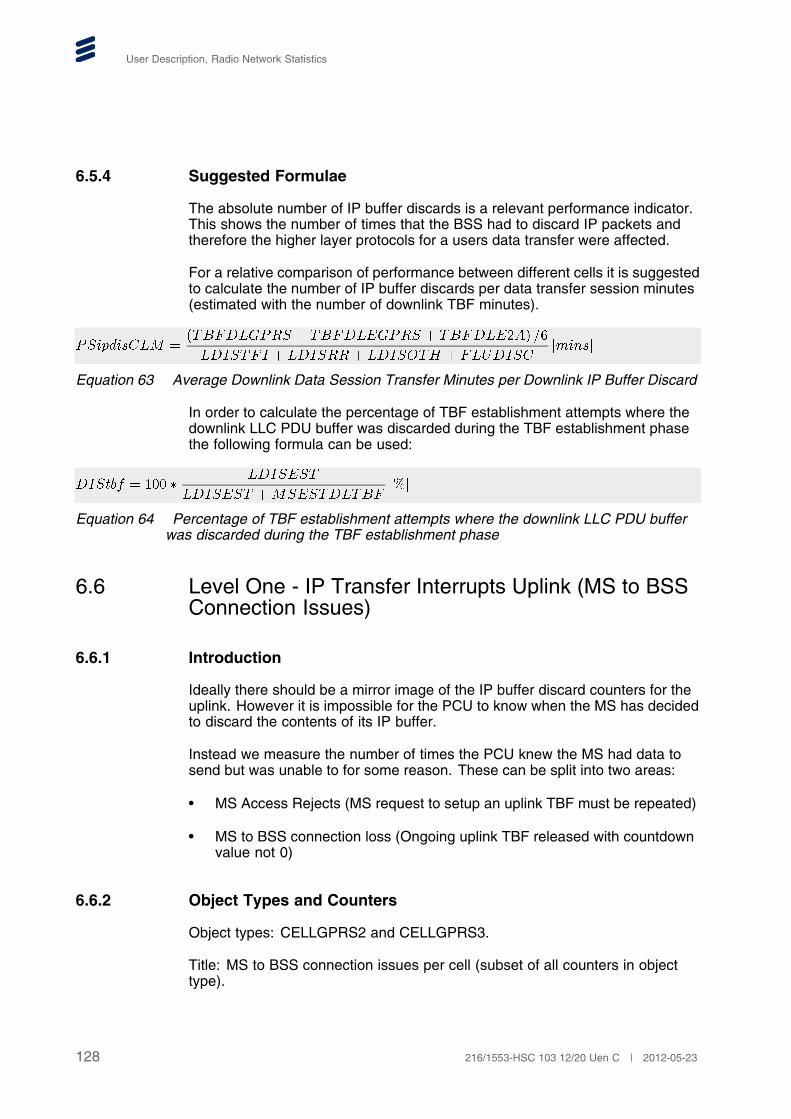
User Description, Radio Network Statistics
6.5.4 Suggested Formulae
The absolute number of IP buffer discards is a relevant performance indicator.This shows the number of times that the BSS had to discard IP packets andtherefore the higher layer protocols for a users data transfer were affected.
For a relative comparison of performance between different cells it is suggestedto calculate the number of IP buffer discards per data transfer session minutes(estimated with the number of downlink TBF minutes).
���������� ����� ��� � ���� ��� � ������� ��
������ � ������� ������ � �������������
Equation 63 Average Downlink Data Session Transfer Minutes per Downlink IP Buffer Discard
In order to calculate the percentage of TBF establishment attempts where thedownlink LLC PDU buffer was discarded during the TBF establishment phasethe following formula can be used:
������ � � �������
������ ����������
Equation 64 Percentage of TBF establishment attempts where the downlink LLC PDU bufferwas discarded during the TBF establishment phase
6.6 Level One - IP Transfer Interrupts Uplink (MS to BSSConnection Issues)
6.6.1 Introduction
Ideally there should be a mirror image of the IP buffer discard counters for theuplink. However it is impossible for the PCU to know when the MS has decidedto discard the contents of its IP buffer.
Instead we measure the number of times the PCU knew the MS had data tosend but was unable to for some reason. These can be split into two areas:
• MS Access Rejects (MS request to setup an uplink TBF must be repeated)
• MS to BSS connection loss (Ongoing uplink TBF released with countdownvalue not 0)
6.6.2 Object Types and Counters
Object types: CELLGPRS2 and CELLGPRS3.
Title: MS to BSS connection issues per cell (subset of all counters in objecttype).
128 216/1553-HSC 103 12/20 Uen C | 2012-05-23

GPRS/EGPRS/EGPRS2-A Radio Network Performance Monitoring
All these counters exclude DTM transfers or attempted transfers.
Object type: CELLGPRS2
PSCHREQ Number of packet access requests in the cell receivedin the PCU on any channel: RACH or PACCH (inPacket Downlink Ack/Nack). A packet access requestis normally to setup an uplink TBF.
Units: integer
PREJTFI Number of rejected packet access requests for thereason “no PDCH, no USF or no TFI”. Request isrejected by sending either “Immediate AssignmentReject” message or “Packet Access Reject” message.Increasing the number of basic physical channels thatcan be allocated as PDCH will generally have a positiveeffect on this counter. The parameters ULDELAY,USFLIMIT and TFILIMIT may also have an effect andare described in Reference [20].
Units: integer
PREJOTH Number of rejected access requests for any otherreason than “no PDCH, no USF or no TFI” and PacketAbis overload. Request is rejected by sending either“Immediate Assignment Reject” message or “PacketAccess Reject” message. Please, note that PREJOTHalso include Packet Access Requests rejected dueto GPH Load Control mechanism, that is, the rejectsthat are separately counted by LCLRPARREJ andLCPARREJ.
Units: integer
IAULREL Number of times an already established uplink TBF hasbeen closed down because radio contact has been lostwith the mobile. The counter is only stepped if there isan ongoing transfer that is the MS have sent at leastone RLC block in the TBF and not yet reached CV = 0.
129216/1553-HSC 103 12/20 Uen C | 2012-05-23

User Description, Radio Network Statistics
Note: On the uplink it is impossible for the BSS todifferentiate between radio contact lost due tobad radio conditions or release due to DTMsetup. This counter will sometimes step forTBFs abnormally released due to DTM setupfrom packet transfer mode. In terms of CellReselections, the counter CRSULREL hasbeen introduced in 06B to count the number ofuplink TBFs released due to cell re-selections. Cell re-selections were previously includedin IAULREL. Hence, the value of IAULRELwill decrease compared to previous releases.If Packet Abis are used for transmission andthere is an overload situation resulting inthat there are interrupts persisting for longertimes, TBFs will be lost. This will be visiblein counters LDISRR, LDISRRSUB, IAULRELand IAULRELSUB and also in an increasedtotal frame/packet loss ratio on the PacketAbis interface (Section 7.1 Frame Loss RatioFormulas for Packet Abis on page 225).
Units: integer
CRSULREL The total number of times, per cell, that an establisheduplink TBF was released due to a successful cellreselection.
Units: integer
PREEMPTULREL Total number of UL TBFs abnormally released dueto preemption (either due to CS channel congestion,Abis congestion (for CS only) or VGCS). The counteris only stepped if there is an established uplink TBF.The impact on the user (that is interruption in service)is likely to be smaller than when a TBF is released dueto lost radio contact.
OTHULREL Total number of UL TBFs abnormally released due toall other reasons than preemption, cell re-selections orradio contact lost. The counter is only stepped if thereis an established uplink TBF. The impact on the user(that is interruption in service) is likely to be smallerthan when a TBF is released due to lost radio contact.The most common reason for OTHULREL is that thehandling of a cell is moved to another RP.
MSESTULTBF Number established uplink TBFs were the MS hasstarted to send data (at least one RLC block received).
Units: integer
130 216/1553-HSC 103 12/20 Uen C | 2012-05-23

GPRS/EGPRS/EGPRS2-A Radio Network Performance Monitoring
Object type: CELLGPRS3
PREJABISCONG Number of UL Temporary Block Flows (TBFs) for newMSs (not in DTM) that have been rejected on PDCHscarried on traffic session that have Abis congestion, forPacket Abis.
Object type: CELLGPRSO.
Title: Counters for GPRS in the overlaid subcell (subset of all counters inobject type).
IAULRELSUB Number of times an uplink TBF has been closed downbecause radio contact has been lost with the mobile inthe overlaid subcell only. The counter is only stepped ifthere is an ongoing transfer that is the MS have sent atleast one RLC block in the TBF and not yet reached CV= 0. The radio conditions in the overlaid subcell couldbe very different to those in the whole cell (overlaid andunderlaid subcell together).
Note: In 06B The counter CRSULRELSUB hasbeen introduced to count the number ofuplink TBFs released due to cell re-selections.Cell re-selections were previously includedin IAULRELSUB. Hence, the value ofIAULRELSUB will decrease compared toprevious releases. If Packet Abis are used fortransmission and there is an overload situationresulting in that there are interrupts persistingfor longer times, TBFs will be lost. This willbe visible in counters LDISRR, LDISRRSUB,IAULREL and IAULRELSUB (if there is acontact to MS) and also in an increasedtotal frame/packet loss ratio on the PacketAbis interface (Section 7.1 Frame Loss RatioFormulas for Packet Abis on page 225).
Units: integer
CRSULRELSUB The total number of times, per overlaid subcell, thatan established uplink TBF was released due to asuccessful cell reselection.
Units: integer
6.6.3 Description
A rejected packet access means that the MS has to retry its attempt to accessthe system. Normally the MS is prevented from attempting packet accessesin the same cell until the Wait Indication has expired (T3412 specified inthe Immediate Assignment Reject message or T3172 (optional) specified
131216/1553-HSC 103 12/20 Uen C | 2012-05-23

User Description, Radio Network Statistics
in the Packet Access Reject message). This value is always 5 seconds inthe Ericsson BSS.
A rejected packet access does not directly relate to a failure to transfer IPpackets on the uplink since a packet access procedure is still required for otherpurposes (for example for the transfer of GMM/SM signalling). However theratio of rejected packet access will give a good indication if there are problemsin the cell.
There are some situations where the MS will be forced to repeat an attempt toaccess the system. For all cases though the access attempt will be repeatedalmost immediately, hence the negative impact on the user perception of theservice is likely to be small. Case two and three below can be calculatedby subtracting the number of access rejects (PREJOTH and PREJTFI andPREJABISCONG) and established uplink TBFs (MSESTULTBF) from the totalnumber of access requests (PSCHREQ).
• The first case is when the packet access attempt message gets lost or iscorrupted over the air interface. However, only the packet access attemptsthat successfully reach the BSS can ever be counted in the BSS.
• The second case is when the Access Grant Channel (on CCCH) iscompletely congested over the air-interface and assignment messagesare discarded in the BTS. However, this situation is unlikely to arise sinceImmediate Assignment messages have priority over pages in the CCCHqueue and its capacity (number of Immediate Assignment messages persecond) is extremely high. The congestion situation on CCCH can bechecked using the counters in object type CELLPAG and using the processdescribed in the Location Area Dimensioning Guideline. Finally if there is areal congestion problem on the CCCH in a cell there is also likely to be realcongestion problems on the traffic channels in the cell.
• The third case is if the TBF setup procedure fails for other reason, and thePCU cannot send the assignment or the assignment does not reach theMS, for example if a DL TBF is terminated before an assignment can besent on PACCH or if the assignment gets lost over the air interface.
When the MS to BSS connection is lost due to radio reasons, again, this doesnot indicate a direct impact on the users in terms of a failure to transfer IPpackets on the uplink, but does gives an indication that there may be coverageand/or interference problems in the cell. Again though it should be noted that itis impossible for the BSS to distinguish between radio contact lost due to cellreselection (non-NACC) and other radio reasons on the uplink. It is the MS thatmakes the decision to leave the old cell without the involvement of the BSS.
6.6.4 Suggested Formulae
The average UL data session transfer in minutes per abnormally released TBFUL and access rejects. A combined user integrity measure for mobility, TBFretainability and TBF accessibility (assuming the delay or interruption to theuser transfer is similar in all cases).
132 216/1553-HSC 103 12/20 Uen C | 2012-05-23

GPRS/EGPRS/EGPRS2-A Radio Network Performance Monitoring
���������� ����� ��� � ���� ��� � ������� ��
����� � �������������������
����� �
������� � ������ � �������� ��������
������������� � ������ � ������ � ����������� � ����������
Equation 65 Average UL Data Session Transfer in Minutes per Abnormally Released TBFUL and Access Rejects
It is recommended to calculate the percentage of packet access requests thatwere rejected compared to the total number of requests.
�� !�� ������� � ������ � ����������
������"� ���
Equation 66 Percentage of All Packet Access Requests that Were Rejected
6.7 GPRS user session counters for active users
In order to have a measure for active users in the system which is independentof the implementation of the TBFs there is a special set of counters allowingmeasurements of the session time for active users (mobiles) in the system. Thisis a valuable measure as an indication of the traffic in the system (comparableto Erlang in the CS domain) and can also be used to normalize other countersinto formulas or KPIs, for example number of lost TBFs per session minute.
The counters in this section count the number of active users (MSs) of GPRS,EGPRS and EGPRS2-A, in non-DTM and DTM mode, respectively. This isdone by scanning the number of active MSs every tenth second. An MS isregarded as active if there is an ongoing data transfer uplink or downlink, orif there has been a data transfer uplink or downlink during the last second.GMM/SM signalling and PCU induced traffic (due to “Delayed Release ofDownlink TBF” mode, “Extended Uplink” mode or “Early Setup of DownlinkTBF” mode) is, in this matter, not regarded as active use.
For non-DTM transfers the following counters are introduced:
ACTGUSE The accumulated number of active users with GPRScapable mobiles. DTM is not included.
Units: number of users
ACTEUSE The accumulated number of active users with EGPRSbut not EGPRS2-A capable mobiles. DTM is notincluded.
Units: number of users
133216/1553-HSC 103 12/20 Uen C | 2012-05-23

User Description, Radio Network Statistics
ACTE2AUSE The accumulated number of active users withEGPRS2-A capable MSs. DTM is not included.
ACTUSESCAN The counter ACTUSESCAN is incremented by oneevery time the number of active users is scanned. DTMis not included.
Units: number of scans
For DTM transfers the following counters are introduced:
DTMACTGUSE The accumulated number of active users with GPRScapable mobiles in DTM.
Units: number of users
DTMACTEUSE The accumulated number of active users with EGPRSbut not EGPRS2-A capable mobiles in DTM.
Units: number of users
DTMACTE2AUSE The accumulated number of active users withEGPRS2-A capable MSs in DTM.
DTMACTUSESCANThe counter ACTUSESCAN is incremented by oneevery time the number of active users in DTM isscanned.
Units: number of scans
6.8 Level One - Streaming Connection Negotiations
6.8.1 Introduction
At the initiation of a downlink streaming transfer an attempt is made by thesystem to reserve a number of PDCH on which the streaming transfer willhave absolute priority — “Effective streaming PDCH”. This request is alwaysdone in accordance with the “requested GBR” that is stored in the ABQP. SeeReference [21] for more details.
By monitoring the outcome of these attempts to reserve resources it can beseen if the users get the GBR, and hence the quality of service, they requested.The importance of the parameters BPDCHBR, GPDCHBR, EPDCHBR andE2APDCHBR in matching the number of “Effective streaming PDCH” to theactual bit rate received by the user should be kept in mind. These parameterscan be set with the help of the radio link bit rate counters described in Section6.9 on page 136. Please, note that the measured radio link bit rates are onRLC level while the parameters are set on LLC level (that is the additionaloverhead for LLC described in the referenced chapter should be consideredwhen setting these parameters).
134 216/1553-HSC 103 12/20 Uen C | 2012-05-23

GPRS/EGPRS/EGPRS2-A Radio Network Performance Monitoring
The number of preemptions of on-demand PDCH that were effective streamingPDCH are also counted to keep track of degradations in service after the PDCHhave been reserved.
6.8.2 Object Types and Counters
Object types: CLQOSSCON and CLQOSSCON2
Title: Streaming connection negotiation counters, 28 counters per cell in totalfor both object types. All these counters exclude contribution from TBFscarrying EIT.
GBR10REQ Accumulated number of streaming TBFs that havebeen reserved on the required number of “EffectiveStreaming PDCH” in the requested GBR interval 10–19.Similar counters for GBR ranges 20–29, 30–39, 40–59,60–79, 80–119, 120–159, 160 and over.
Units: integer
GBR10LOW Accumulated number of streaming TBFs that have beenreserved on fewer “Effective Streaming PDCH” thanrequired in the requested GBR interval 10–19. Similarcounters for GBR ranges 20–29, 30–39, 40–59, 60–79,80–119, 120–159, 160 and over.
With Flexible Abis the counter values will be slightlyhigher.
Units: integer
GBR10FAIL The accumulated number of streaming TBFs that havefailed to reserve any “Effective Streaming PDCH” forexclusive use for streaming (due to resource shortageor unavailability of support) and hence have beenreserved in accordance with the QOSSTREAMPRIOparameter in the requested GBR interval 10–19. Similarcounters for GBR ranges 20–29, 30–39, 40–59, 60–79,80–119, 120–159, 160 and over.
With Flexible Abis the counter values will be slightlyhigher.
Units: integer
CELLPPRS Accumulated number of “Effective Streaming PDCH”that were preempted.
TBFUPS Number of times a streaming TBF has been successfullyupgraded.
135216/1553-HSC 103 12/20 Uen C | 2012-05-23

User Description, Radio Network Statistics
With Flexible Abis the counter values will be slightlylower.
6.8.3 Suggested Formulae
It is suggested to construct formulas for the fraction of the total requests thatresulted in:
1 The required number of PDCH being reserved,
2 Less PDCH than the required number being reserved,
3 Failures.
It is recommended to construct formulas per GBR interval and also for therequests for all GBR intervals combined.
A measure of the systems ability to provide the GBR, and hence the qualityof service, the users requested. The following formula gives the percentageof QoS negotiations resulting in the requested GBR. “xx” relates to the GBRintervals the counters are divided in.
������ ���� �������
��� ���� �� � � ��� ������� � � ��� �������� ��� ���
Equation 67 Percentage of Qos Negotiations Resulting in the Requested GBR.
Note: The success rate will vary with the type of streaming traffic in the cell(higher requested GBRs are more difficult to serve).
6.9 Level Two - Radio Link Quality
6.9.1 Introduction
The quality of each user's radio link determines the maximum IP throughputthey can achieve. The counters described here are used to measure theradio link bit rate per PDCH. If each PDCH is thought of as a “pipe” throughwhich data can be transferred then the measured radio link bit rate representsthe average size of each pipe.
There are many different influences on the quality of a radio link: signalstrength; interference; time dispersion and more. However, it is important tounderstand that for GPRS/EGPRS/EGPRS2-A of all these aspects combine togive a certain bit rate that the radio link can support, and this is the only thingthat matters to the end-user. A radio link that can support 12 kbps per PDCH isalways 50% more useful to the end-user than a radio link that supports only 8kbps per PDCH. Therefore all radio-related optimization and parameter settingshould aim to maximize the bit rate of the radio channels, which will in-turnimprove the IP throughput.
136 216/1553-HSC 103 12/20 Uen C | 2012-05-23

GPRS/EGPRS/EGPRS2-A Radio Network Performance Monitoring
The concept of counters to measure the Block Error Rate (BLER) has beenused in previous releases to measure the radio link quality which, with fixedcoding schemes, was an indirect way to measure the radio link bit rate.However, with the features Link Adaptation and Link Quality Control thisconcept is no longer valid. Instead the radio link bit rate is measured directly.
The maximum number of radio blocks that can be transferred over the airinterface on one PDCH is 50 per second. So the channel time used to send1 radio block is 20 ms. By measuring the volume of RLC data that could besent within a certain channel time (number of radio blocks * 20 ms) we obtain avalue for the radio link bit rate per PDCH. It does not matter if the data sent onthe PDCH came from one user or if the PDCH is shared by many users.
The perfect radio link quality is represented by:
• Close to 12 kbps per PDCH for CS-1/2 transfers (on B-PDCH, G-PDCHor E-PDCH).
• Close to 20 kbps per PDCH for CS-1/2/3/4 transfers (on G-PDCH orE-PDCH).
• Close to 59 kbps per PDCH for EGPRS transfers (on E-PDCH).
• Close to 99 kbps per PDCH for EGPRS2-A transfers (on E2A-PDCH).
Of course the “perfect” radio link quality for CS-1/2/3/4, EGPRS and EGPRS2-Atransfers needs to be of much better quality than the “perfect” radio link qualityrequired for CS-1/2 transfers. For example if a transfer uses CS-2 then differentcounters must be stepped depending on which TBF mode is used. When CS-2is used during a CS-1/2/3/4 mode TBF it results in a radio link bit rate of, atbest, 12 kbps which indicates a problem with radio link quality for this transfer.When CS-2 is used for a CS-1/2 mode TBF the best possible radio link bitrateis still only 12 kbps but this does not indicate a problem with the radio linkquality for this transfer.Therefore the radio link bit rate must be measuredwith completely separate counters for CS–1/2, CS–1/2/3/4, EGPRS andEGPRS2-A data transfers.
Counters are provided that allow the following to be calculated:
• Average radio link bit rate and RLC data volume in the whole cell (underlaidsubcell plus overlaid subcell) for all uplink and for downlink CS-1/2,EGPRS and EGPRS2-A transfers. In addition , CS-1/2/3/4 transferscan be measured downlink. There are counters that count the numberof RLC/MAC data blocks scheduled for the transmission of user dataand GMM/SM signalling (the xSCHED counters), this allows the usedchannel time to be calculated (each radio block occupies 20 ms). Thereare also counters showing the volume of user data and GMM/SM signallingdata (the xACK counters). Object types are CELLGPRS, CELLGPRS2,CELLGPRSO, CLGPRSE2, CLGPRSE2O.
• Distributions of the radio link bit rate versus RLC data volume in the wholecell (underlaid subcell plus overlaid subcell) for downlink CS-1/2/3/4,
137216/1553-HSC 103 12/20 Uen C | 2012-05-23

User Description, Radio Network Statistics
downlink EGPRS and downlink EGPRS2-A, transfers. These are intervalcounters (the INTx counters ) that count the downlink RLC data volume incertain bit rate intervals, allowing a distribution of the radio link bit rate to bepresented. This gives an excellent picture of the distribution of the radio linkquality in the cell. Object types to be used are RLINKBTR and RLBITE2A.
• Average radio link bit rate and RLC data volume separately for all types oftransfers in the overlaid subcell can be measured using counters in objecttypes CELLGPRSO and CLGPRSE2O.
6.9.2 Object Types and Counters
Object types: CELLGPRS, CELLGPRS2, CELLGPRSO, CLGPRSE2 andCLGPRSE2O.
Title: Radio link bit rate counters per cell for all DL and UL transfers (subsetof all counters in object type) in the whole cell (underlaid + overlaid subcells).Radio link bit rate counters for all transfers in the overlaid subcell (subset of allcounters in the object type). These counters are stepped also for abnormallyreleased TBFs up until the last correctly received block.
Note: To get an accurate measure of the radio link quality the counters forRLC data on the uplink (the xACK counters) are under some conditionsalso stepped for repeated radio blocks, see Section 6.9.3 on page 146.
There is also histogram counters available for downlink measurements in objecttypes RLINKBITR and RLBITRE2A.
Object types: CELLGPRS, CELLGPRS2 and CELLGPRSO.
CS12DLSCHED Total number of DL RLC data blocks scheduled byPCU for the transmission of user data or GMM/SMsignalling in CS-1/2, RLC acknowledged modeTBFs. Retransmissions are included. RLC/MACsignalling blocks and RLC dummy blocks are excluded.CS12DLSCHEDSUB is the counter for transfers in theoverlaid subcell.
Units: Integer (number of blocks)
CS12DLACK Counts the total amount of RLC data successfullyreceived in the MSs for CS-1/2, RLC acknowledgedmode TBFs. CS12DLACKSUB is the counter fortransfers in the overlaid subcell.
Units: bits
CS12ULSCHED Total number of RLC data blocks scheduled byMSs for the transmission of user data or GMM/SMsignalling in CS-1/2, RLC acknowledged modeTBFs. Retransmissions are included. RLC/MAC
138 216/1553-HSC 103 12/20 Uen C | 2012-05-23

GPRS/EGPRS/EGPRS2-A Radio Network Performance Monitoring
signalling blocks and RLC dummy blocks are excluded.CS12ULSCHEDSUB is the counter for transfers in theoverlaid subcell.
Units: Integer (number of blocks)
CS12ULACK Counts the total amount of RLC data successfullyreceived in the PCU for CS-1/2, RLC acknowledgedmode TBFs. CS12ULACKSUB is the counter fortransfers in the overlaid subcell.
Units: bits
CS14DLSCHED Total number of DL RLC data blocks scheduled byPCU for the transmission of user data or GMM/SMsignalling in CS-1/2/3/4, RLC acknowledged modeTBFs. Retransmissions are included. RLC/MACsignalling blocks and RLC dummy blocks are excluded.CS14DLSCHEDSUB is the counter for transfers in theoverlaid subcell.
Units: Integer (number of blocks)
CS14DLACK Total amount of RLC data volume successfullyacknowledged by MSs with a GPRS mode TBF (CS-1to CS-4) in RLC acknowledged mode, downlink.
Units: bits
CS14DLACKSUB Counts the total amount of RLC data sent on the DLsuccessfully received by the MSs in the overlaid subcellfor CS-1/2/3/4, RLC acknowledged mode TBFs.
Units: bits
MC19DLSCHED Total number of 20 ms periods of channel time (1or 2 RLC data blocks) scheduled by PCU for thetransmission of user data or GMM/SM signalling inEGPRS (excluding EGPRS2-A), RLC acknowledgedmode TBFs. Retransmissions are included. RLC/MACsignalling blocks and RLC dummy blocks are excluded.MC19DLSCHEDSUB is the counter for transfers in theoverlaid subcell.
Units: Integer (number of blocks)
MC19DLACK Total amount of RLC data volume successfullyacknowledged by MSs with a EGPRS (excludingEGPRS2-A) mode TBF (MCS-1 to MCS-9) in RLCacknowledged mode, downlink.
Units: bits
139216/1553-HSC 103 12/20 Uen C | 2012-05-23

User Description, Radio Network Statistics
MC19DLACKSUB Counts the total amount of RLC data sent on the DLsuccessfully received by the MSs in the overlaid subcellfor EGPRS (excluding EGPRS2-A), RLC acknowledgedmode TBFs.
Units: bits
MC19ULSCHED Total number of 20 ms periods of channel time (1or 2 RLC data blocks) scheduled by MSs for thetransmission of user data or GMM/SM signalling inEGPRS (excluding EGPRS2-A), RLC acknowledgedmode TBFs. Retransmissions are included. RLC/MACsignalling blocks and RLC dummy blocks are excluded.MC19ULSCHEDSUB is the counter for transfers in theoverlaid subcell.
Units: Integer (number of blocks)
MC19ULACK Counts the total amount of RLC data successfullyreceived by the PCU for EGPRS (excluding EGPRS2-A),RLC acknowledged mode TBFs. MC19ULACKSUB isthe counter for transfers in the overlaid subcell.
Units: bits
Object types: CLGPRSE2 and CLGPRSE2O.
MCE2ADLACK Total amount of RLC data volume successfullyacknowledged by MSs with an E2A-TBF in RLCacknowledged mode, downlink.MCE2ADLACKSUB isthe counter for transfers in the overlaid subcell.
Units: bits
MCE2AULACK Total amount of RLC data volume successfully receivedin the PCU with an E2A-TBF in RLC acknowledgedmode, uplink. MCE2AULACKSUB is the counter fortransfers in the overlaid subcell.
Units: bits
MCE2ADLSCHED The number of 20 ms channel time periods (one tothree EGPRS2-A RLC data blocks) scheduled foran E2A-TBF in RLC acknowledged mode, downlink.MCE2ADLSCHEDSUB is the counter for transfers inthe overlaid subcell.
Units: Integer (number of blocks)
MCE2AULSCHED The number of 20 ms channel time periods (oneto three EGPRS2-A RLC data blocks) scheduledfor an E2A-TBF in RLC acknowledged mode,
140 216/1553-HSC 103 12/20 Uen C | 2012-05-23

GPRS/EGPRS/EGPRS2-A Radio Network Performance Monitoring
uplink.MCE2AULSCHEDSUB is the counter fortransfers in the overlaid subcell.
Units: bits
Object type: RLINKBITR.
Title: Radio link quality counters per cell for downlink CS-1/2/3/4 and EGPRSmode transfers. All these counters exclude contribution from TBFs carrying EIT.The EGPRS counters exclude contributions from EGPRS TBFs of level 2-A.The counters are only stepped for normally released TBFs. All units are (kbit).
INT8BRGPRSTBF Volume of RLC data successfully received by the MSin TBFs with a radio link bit rate in the 8 kbps (X < 9 )interval for CS-1/2/3/4, RLC acknowledged mode TBFs.
Unit: kbit
INT10BRGPRSTBFVolume of RLC data successfully received by the MSin TBFs with a radio link bit rate in the 10 kbps interval(9 <= X < 11) for CS-1/2/3/4, RLC acknowledged modeTBFs.
Unit: kbit
INT12BRGPRSTBFVolume of RLC data successfully received by the MS inTBFs with a radio link bit rate in the 12 kbps interval (11<= X < 13) for CS-1/2/3/4, RLC acknowledged modeTBFs.
Unit: kbit
INT14BRGPRSTBFVolume of RLC data successfully received by the MS inTBFs with a radio link bit rate in the 14 kbps interval (13<= X < 15) for CS-1/2/3/4, RLC acknowledged modeTBFs.
Unit: kbit
INT16BRGPRSTBFVolume of RLC data successfully received by the MS inTBFs with a radio link bit rate in the 16 kbps interval (15<= X < 17) for CS-1/2/3/4, RLC acknowledged modeTBFs.
Unit: kbit
141216/1553-HSC 103 12/20 Uen C | 2012-05-23

User Description, Radio Network Statistics
INT18BRGPRSTBFVolume of RLC data successfully received by the MS inTBFs with a radio link bit rate in the 18 kbps interval (X=> 17) for CS-1/2/3/4, RLC acknowledged mode TBFs.
Unit: kbit
INT10BREGPRSTBFVolume of RLC data successfully received by the MS inTBFs with a radio link bit rate in the 10 kbps interval (X< 12.5) for EGPRS, RLC acknowledged mode TBFs.
Unit: kbit
INT15BREGPRSTBFVolume of RLC data successfully received by the MSin TBFs with a radio link bit rate in the 15 kbps interval(12.5 <= X < 17.5) for EGPRS, RLC acknowledgedmode TBFs.
Unit: kbit
INT20BREGPRSTBFVolume of RLC data successfully received by the MSin TBFs with a radio link bit rate in the 20 kbps interval(17.5 <= X < 22.5) for EGPRS, RLC acknowledgedmode TBFs.
Unit: kbit
INT25BREGPRSTBFVolume of RLC data successfully received by the MSin TBFs with a radio link bit rate in the 25 kbps interval(22.5 <= X < 27.5) for EGPRS, RLC acknowledgedmode TBFs.
Unit: kbit
INT30BREGPRSTBFVolume of RLC data successfully received by the MSin TBFs with a radio link bit rate in the 30 kbps interval(27.5 <= X < 32.5) for EGPRS, RLC acknowledgedmode TBFs.
Unit: kbit
142 216/1553-HSC 103 12/20 Uen C | 2012-05-23

GPRS/EGPRS/EGPRS2-A Radio Network Performance Monitoring
INT35BREGPRSTBFVolume of RLC data successfully received by the MSin TBFs with a radio link bit rate in the 35 kbps interval(32.5 <= X < 37.5) for EGPRS, RLC acknowledgedmode TBFs.
Unit: kbit
INT40BREGPRSTBFVolume of RLC data successfully received by the MSin TBFs with a radio link bit rate in the 40 kbps interval(37.5 <= X < 42.5) for EGPRS, RLC acknowledgedmode TBFs.
Unit: kbit
INT45BREGPRSTBFVolume of RLC data successfully received by the MSin TBFs with a radio link bit rate in the 45 kbps interval(42.5 <= X < 47.5) for EGPRS, RLC acknowledgedmode TBFs.
Unit: kbit
INT50BREGPRSTBFVolume of RLC data successfully received by the MSin TBFs with a radio link bit rate in the 50 kbps interval(47.5 <= X < 52.5) for EGPRS, RLC acknowledgedmode TBFs.
Unit: kbit
INT55BREGPRSTBFVolume of RLC data successfully received by the MS inTBFs with a radio link bit rate in the 55 kbps interval (X=> 52.5) for EGPRS, RLC acknowledged mode TBFs.
Unit: kbit
Object type: RLBITRE2A.
Title: Radio link quality counters per cell for downlink EGPRS2-A modetransfers. All these counters exclude contribution from TBFs carrying EIT. Thecounters are only stepped for normally released TBFs. All units are (kbit).
INT10BRE2ATBF Volume of RLC data successfully received by the MSin TBFs with a radio link bit rate in the < 12.5 kbit persecond interval for EGPRS2-A, RLC acknowledgedmode TBFs.
Unit: kbit
143216/1553-HSC 103 12/20 Uen C | 2012-05-23

User Description, Radio Network Statistics
INT15BRE2ATBF Volume of RLC data successfully received by the MSin TBFs with a radio link bit rate in the 12.5 <= Bit Rate< 17.5 kbit per second interval for EGPRS2-A, RLCacknowledged mode TBFs.
Unit: kbit
INT20BRE2ATBF Volume of RLC data successfully received by the MSin TBFs with a radio link bit rate in the 17.5 <= Bit Rate< 22.5 kbit per second interval for EGPRS2-A, RLCacknowledged mode TBFs.
Unit: kbit
INT25BRE2ATBF Volume of RLC data successfully received by the MSin TBFs with a radio link bit rate in the 22.5 <= Bit Rate< 27.5 kbit per second interval for EGPRS2-A, RLCacknowledged mode TBFs.
Unit: kbit
INT30BRE2ATBF Volume of RLC data successfully received by the MSin TBFs with a radio link bit rate in the 27.5 <= Bit Rate< 32.5 kbit per second interval for EGPRS2-A, RLCacknowledged mode TBFs.
Unit: kbit
INT35BRE2ATBF Volume of RLC data successfully received by the MSin TBFs with a radio link bit rate in the 32.5 <= Bit Rate< 37.5 kbit per second interval for EGPRS2-A, RLCacknowledged mode TBFs.
Unit: kbit
INT40BRE2ATBF Volume of RLC data successfully received by the MSin TBFs with a radio link bit rate in the 37.5 <= Bit Rate< 42.5 kbit per second interval for EGPRS2-A, RLCacknowledged mode TBFs.
Unit: kbit
INT45BRE2ATBF Volume of RLC data successfully received by the MSin TBFs with a radio link bit rate in the 42.5 <= Bit Rate< 47.5 kbit per second interval for EGPRS2-A, RLCacknowledged mode TBFs.
Unit: kbit
INT50BRE2ATBF Volume of RLC data successfully received by the MSin TBFs with a radio link bit rate in the 47.5 <= Bit Rate
144 216/1553-HSC 103 12/20 Uen C | 2012-05-23

GPRS/EGPRS/EGPRS2-A Radio Network Performance Monitoring
< 52.5 kbit per second interval for EGPRS2-A, RLCacknowledged mode TBFs.
Unit: kbit
INT55BRE2ATBF Volume of RLC data successfully received by the MSin TBFs with a radio link bit rate in the 52.5 <= Bit Rate< 57.5 kbit per second interval for EGPRS2-A, RLCacknowledged mode TBFs.
Unit: kbit
INT60BRE2ATBF Volume of RLC data successfully received by the MSin TBFs with a radio link bit rate in the 57.5 <= Bit Rate< 62.5 kbit per second interval for EGPRS2-A, RLCacknowledged mode TBFs.
Unit: kbit
INT65BRE2ATBF Volume of RLC data successfully received by the MSin TBFs with a radio link bit rate in the 62.5 <= Bit Rate< 67.5 kbit per second interval for EGPRS2-A, RLCacknowledged mode TBFs.
Unit: kbit
INT70BRE2ATBF Volume of RLC data successfully received by the MSin TBFs with a radio link bit rate in the 67.5 <= Bit Rate< 72.5 kbit per second interval for EGPRS2-A, RLCacknowledged mode TBFs.
Unit: kbit
INT75BRE2ATBF Volume of RLC data successfully received by the MSin TBFs with a radio link bit rate in the 72.5 <= Bit Rate< 77.5 kbit per second interval for EGPRS2-A, RLCacknowledged mode TBFs.
Unit: kbit
INT80BRE2ATBF Volume of RLC data successfully received by the MSin TBFs with a radio link bit rate in the 77.5 <= Bit Rate< 82.5 kbit per second interval for EGPRS2-A, RLCacknowledged mode TBFs.
Unit: kbit
INT85BRE2ATBF Volume of RLC data successfully received by the MSin TBFs with a radio link bit rate in the 82.5 <= Bit Rate< 87.5 kbit per second interval for EGPRS2-A, RLCacknowledged mode TBFs.
145216/1553-HSC 103 12/20 Uen C | 2012-05-23

User Description, Radio Network Statistics
Unit: kbit
INT90BRE2ATBF Volume of RLC data successfully received by the MSin TBFs with a radio link bit rate in the 87.5 <= Bit Rate< 92.5 kbit per second interval for EGPRS2-A, RLCacknowledged mode TBFs.
Unit: kbit
INT95BRE2ATBF Volume of RLC data successfully received by the MS inTBFs with a radio link bit rate in the Bit Rate <= 92.5 kbitper second interval for EGPRS2-A, RLC acknowledgedmode TBFs.
Unit: kbit
6.9.3 Description
The purpose of the radio link bitrate counters is to reflect the perceived radiolink quality, which impact the throughput for the end-user. This sections detailshow the counters are stepped. If not otherwise stated the xSCHED/xACKcounters in object types CELLGPRS and CELLGPRSO and the INTx countersobject type RLINKBITR are stepped according to the same logic.
RLC Payload
RLC data blocks are used for the data transfer. These blocks contain eitheruser data or GMM/SM signalling. Actual RLC payload data is defined as totalRLC/MAC data volume excluding RLC control blocks and keep alive blocks.
Only RLC payload data that has been successfully received, in the PCU for theuplink and in the MSs for the downlink, contributes to the total RLC payloaddata.
The total amount of RLC payload data transferred is not exactly the same as thetotal amount of LLC data transferred. Each RLC data block contains LLC dataplus one or more additional octets of spare bits. Also, if the final LLC PDU in theTBF does not completely fill the last RLC data block, filler octets are used to fillthe remainder of the RLC data block. For example, if an EGPRS TBF consistedof one LLC PDU with size 70 octets, the RLC protocol might send one MCS-5block (56 octets) and one MCS-1 block (22 octets). The total RLC payload datasent would be 78 octets, while the total LLC data sent would be 70 octets.
RLC Acknowledged data
The radio link bitrate counters only consider RLC acknowledged data, whereretransmissions may occur. The volume of RLC unacknowledged data can bemonitored on BSC level using counters in Object Type BSCQOS.
RLC Data Blocks Used for Keep Alive Mechanisms
146 216/1553-HSC 103 12/20 Uen C | 2012-05-23

GPRS/EGPRS/EGPRS2-A Radio Network Performance Monitoring
RLC data blocks created by the RLC layer containing dummy LLC data, sentwith the purpose to keep a downlink TBF alive, are excluded from the radio linkbitrate counters. Packet Uplink Dummy Control Blocks received from a mobileduring temporary inactive periods are also excluded from the radio link bitratecounters. This applies to data blocks sent on the uplink for TBFs in “ExtendedUplink” mode and to data blocks sent on the downlink for TBFs in “Early Setupof Downlink TBF” mode or “Delayed Release of Downlink TBF” mode.
Retransmissions
Retransmissions are needed in case transmitted RLC data blocks are notsuccessfully received. These retransmitted blocks are counted as scheduled,but the acknowledged data will only be counted once in the ACK counters. Thismeans that the number of transmitted RLC data blocks exceeds the number oforiginal RLC data blocks needed, which in turn will decrease the bitrate.
Impact from coding schemes used
A lower coding scheme is normally used at the beginning of a data transfer,independent of the radio quality. It will not be possible to switch to highercoding schemes until the PCU begins to receive measurement reports. For adownlink EGPRS/EGPRS2-A transfer a number of radio block periods (up to30) will elapse before the PCU can receive the first measurement report. Notusing the highest possible coding scheme from the beginning of a transfer willhave an effect on the radio link bitrate for small transfers.
At the end of a data transfer the coding scheme might change as well. Thecoding scheme chosen for the last RLC data block in a transfer is not reallydependent on the radio link quality, but rather on the number of octets thatneed to be transferred. Also, a lower coding scheme at the end will increasethe possibility of a successful transfer and minimize the risk of retransmissions.This will only have a minor effect on the measured radio link bitrate.
To eliminate the effect of low radio link bitrate due to nonoptimal codingschemes, there are counters (please see Section 6.9.4 Radio Link Bitrate atoptimum coding scheme according to LQC on page 151) that exclude the datablocks during coding scheme ramp-up at the beginning and ramp-down at theend of a data transfer. This way it will be possible to find out if a low radiolink bitrate depends on a bad radio environment or if it is an effect of codingscheme ramp-up in combination with small transfers.
Abnormally released TBFs
Abnormally released TBFs occur when the contact with the MS is lost.For a downlink TBF the PCU will keep on scheduling radio blocks, ask foracknowledgements and retransmit data. After ten consecutive unansweredacknowledgement requests the TBF will be released and the data transmissionwill stop. For an uplink TBF the PCU will wait up to ten seconds since the lastcontact with the mobile before the TBF is released. In these cases, scheduledblocks up until the last successfully sent or received block contribute to thecounters. This is because when the MS has lost contact with the BSS, the MSis no longer able to send any more data and counting these scheduled blocks
147216/1553-HSC 103 12/20 Uen C | 2012-05-23

User Description, Radio Network Statistics
would have a negative impact on the radio link bitrate measurements and doesnot have any relevance for the radio quality either. This also means that forTBFs where the MS never turns up, after the assignment has been sent, noscheduled blocks are counted.
Scheduled Blocks and Measured RLC Payload on the Uplink
The total number of times the PCU assigned a USF for the transmission ofan uplink radio block is not the same as the number of times the MS actuallyscheduled a transmission of a new RLC data block. Occasionally the MSresponds to a USF scheduling with a control block. These should not step thexSCHED counters. However, if the MS does not respond to a USF scheduling,the PCU interprets this as a lost data block and the xSCHED counter isstepped. The result could be that the xSCHED counters show slightly highervalues than used for data transfer.
Even if RLC control blocks are omitted, all scheduled USFs are not used by theMS to send new or to retransmit RLC data blocks that were not successfullyreceived. As the uplink TBFs are normally very small (only a few radio blocks),this can potentially have a large impact on the measured radio link bit rate. Tostill obtain a radio link bit rate that is a good measure of the radio quality, thefollowing special cases have been considered:
• Mobiles often do not react to the first 20 ms scheduling period. Thereforeno scheduled blocks are counted on the uplink until an RLC data blockhas been correctly received.
• At the end of a transfer there are a number of extra scheduling periodswhere the MS repeats the last sent blocks. This is due to the fact that ittakes the radio block about 50 ms to travel between the MS and the PCU.When the uplink radio block is received in the PCU and the scheduling canbe stopped, there are already a number of schedulings on their way. Duringthis time the MS will keep on repeating the last RLC data block even thoughno retransmission has been ordered by the system. In these cases the RLCpayload and the number of scheduled blocks are counted for the repeateduplink RLC blocks up until all previous blocks, including the CV = 0 block,have been successfully received in the PCU. Then the counting stops. Therepeated blocks are counted in these cases as the PCU cannot distinguishif an erroneous block was a repeated block or a new block. The countingstarts again when a new RLC data block has been correctly received.
• If the MS reaches the end of its send window it will resend previouslynon-acknowledged blocks. Again, for these repeated blocks the RLCpayload and the number of scheduled blocks are counted by the system,as the PCU cannot distinguish a repeated erroneous block from a newerroneous block.
Total RLC Payload Data Uplink per Cell
As the repeated blocks on the uplink to a certain extent are included in thexACK counters (see above), it is not possible to use these counters to calculate
148 216/1553-HSC 103 12/20 Uen C | 2012-05-23

GPRS/EGPRS/EGPRS2-A Radio Network Performance Monitoring
the actual RLC payload data in the cell. Please use the counters ULINTBGVOLand ULGMMVOL in Object Type CELLGPRS3 instead.
Multiple RLC data blocks per 20 ms channel time period
For the higher Modulation and Coding Schemes of EGPRS, MCS-7, MCS-8and MCS-9, and for the Modulation and Coding Schemes DAS-8, DAS-9 andDAS-10 of EGPRS2-A downlink and UAS-7, UAS-8 and UAS-9 for EGPRS2-Auplink, two RLC data blocks are sent in one 20 ms channel time period. For theModulation and Coding Schemes DAS-11 and DAS-12 of EGPRS2-A downlinkand UAS-10 and UAS-11 for EGPRS2-A uplink, three RLC data blocks are sentin one 20 ms channel time period. In these cases it is the number of 20 mschannel time periods that is counted and not the number of RLC data blocks.
Summary
The following table summarizes what is included in the different counters.
Table 13 Summary of the Radio Link Bitrate Counters
xSCHED/xACK counters inCELLGPRS, CELLGPRS2,CELLGPRSO, CLGPRSE2
and CLGPRSE2O
INTx counters inRLINKBITR and
RLBITRE2A
Retransmissions Included (xSCHED) / Excluded(xACK)
Included (channel timeconsidered, but no RLCpayload volume)
Repeated block on the UL(not ordered by the system)
Included both in xSCHED andxACK counters up until all blocksincluding CV = 0 have beencorrectly received
Not applicable as the INTxcounters only concerns thedownlink
RLC Acknowledged mode Included Included
RLC Unacknowledged mode Excluded Excluded
Abnormally released TBFs Included up until last correctlyreceived radio block
Included up until last radioblock acknowledged by theMS
Keep alive scheduling Excluded Excluded
Start of TBF Included from first correctlyreceived block
Included from first radioblock acknowledged by theMS
DTM Included Included
EIT Excluded Excluded
149216/1553-HSC 103 12/20 Uen C | 2012-05-23

User Description, Radio Network Statistics
6.9.3.1 Radio Link Bit Rate Distributions for the Whole Cell (underlaid + overlaidSubcells)
Counters are provided for CS-1/2/3/4, EGPRS and EGPRS2-A transfers on thedownlink that allow a distribution of the radio link bit rates to be plotted.
The formula used for CS–1/2/3/4 is : RLC_bitrate_GPRS(kbps) =((nr_of_first_sent_block_CS1 * 20*8) + (nr_of_first_sent_block_CS2 * 30*8) +(nr_of_first_sent_block_CS3 * 36*8) + (nr_of_first_sent_block_CS4 * 50*8)) /(total_nr_of_blocks * 20ms)
The formula used for EGPRS is : RLC_bitrate_EGPRS(kbps) =((nr_of_first_sent_block_MCS1 * 22*8) + (nr_of_first_sent_block_MCS2 * 28*8)+ (nr_of_first_sent_block_MCS3 * 37*8) + (nr_of_first_sent_block_MCS4 * 44*8)+ (nr_of_first_sent_block_MCS5 * 56*8) + (nr_of_first_sent_block_MCS6 * 74*8)+ (nr_of_first_sent_block_MCS7 * 2*56*8) + (nr_of_first_sent_block_MCS8* 2*68*8) + (nr_of_first_sent_block_MCS9 * 2*74*8)) / (total_nr_of_blocks* 20ms)
The formula used for EGPRS2-A is : RLC_bitrate_E2A(kbps) =((nr_of_first_sent_block_MCS1 * 22*8) + (nr_of_first_sent_block_MCS2 * 28*8)+ (nr_of_first_sent_block_MCS3 * 37*8) + (nr_of_first_sent_block_MCS4 *44*8) + (nr_of_first_sent_block_DAS5 * 56*8) + (nr_of_first_sent_block_DAS6 *68*8) + (nr_of_first_sent_block_DAS7 * 82*8) + (nr_of_first_sent_block_DAS8* 2*56*8) + (nr_of_first_sent_block_DAS9 * 2*68*8) + (nr_of_first_sent_block_DAS10 * 2*82*8) + (nr_of_first_sent_block_DAS11 * 3*68*8) +(nr_of_first_sent_block_DAS12 * 3*82*8)) / (total_nr_of_blocks * 20ms)
A comment on the denominators in these formulas. Each radio block occupies20 ms of air interface or channel time. The total amount of time taken to sendthe information is defined as the total number radio blocks (transmissions andretransmissions) multiplied by 20 ms. Depending on the number of PDCHreserved for the users and how many users are sharing these PDCHs the MACprotocol may be able to schedule RLC data blocks often or only occasionally.However, this is of no relevance for these measures. All we are concerned withis the total number of RLC data blocks sent during the lifetime of the TBF.
The STS counters for CS—1/2/3/4 are labelled [8 10 12 14 16 18]. Each ofthese counters represents a bit rate interval. At the end of every DL, RLCacknowledged, CS-1/2/3/4 mode TBF one of these counters is incremented bythe volume of RLC payload data successfully sent in the TBF. Therefore theSTS counters give the amount of RLC payload data that was successfullytransferred within one of the specified bit rate intervals.
The STS counters for EGPRS are labelled [10 15 20 25 30 35 40 45 50 55].Each of these counters represents a bit rate interval. At the end of everyDL, RLC acknowledged, TBF that used EGPRS one of these counters isincremented by the volume of RLC payload data successfully sent in the TBF.Therefore the STS counters give the amount of RLC payload data that wassuccessfully received by the MS within one of the specified bit rate intervals.
150 216/1553-HSC 103 12/20 Uen C | 2012-05-23

GPRS/EGPRS/EGPRS2-A Radio Network Performance Monitoring
The STS counters for EGPRS2-A are labelled [10 15 20 25 30 35 40 45 50 5560 65 70 75 80 85 90 95]. Each of these counters represents a bit rate interval.At the end of every DL, RLC acknowledged, TBF that used EGPRS2-A one ofthese counters is incremented by the volume of RLC payload data successfullysent in the TBF. Therefore the STS counters give the amount of RLC payloaddata that was successfully received by the MS within one of the specified bitrate intervals.
As an example say that in one CS–1/2/3/4 mode TBF eight RLC data blocksare coded using CS-2 and transmitted for the first time. The radio link qualitythen improves and in the same TBF seven RLC data blocks are coded usingCS-3 and transmitted for the first time. However, twenty-one RLC data blocksactually needed to be sent before the information contained in the originalfifteen blocks was successfully received by the mobile and the TBF ended (itdoes not matter what coding scheme was used for the retransmitted blocks onlythat an additional 6*20 ms were required for the information to be successfullyreceived). Within the BSC the radio link bit rate for the TBF is calculated as(8*240 info. bits)+(7*293 info. bits)/(21*20ms) = 9.45 kbps. As a result thecounter INT10BRGPRSTBF is incremented by 3.971 kbit.
6.9.3.2 Radio Link Bit Rate Averages for the Whole Cell (underlaid + overlaidSubcells)
For all uplink and downlink transfer modes counters are provided which allowthe average radio link bit rate over all TBFs to be calculated.
6.9.3.3 Radio Link Bit Rate Averages for the overlaid Subcell Only
Counters are provided which allow the radio link quality for the overlaid subcellto be analyzed separately.
It is also interesting to see the volume of RLC payload data that was transferredin the overlaid subcell as a percentage of the whole cell.
6.9.4 Radio Link Bitrate at optimum coding scheme according to LQC
When using the radio link bit rate counters described in previous sections andobserving a low radio link bit rate, it may be difficult to determine if the low radiolink bit rate is due to bad radio environment quality or due to large numbers ofsmall transfers. This is because the above radio link bit rate counters includevalues taken during Coding Scheme ramp-up and ramp-down, respectively.(For small transfers the optimum coding scheme according to the LQC maynever be reached).
In order to simplify interpretations of a low observed radio link bit rate, asupplementary set of radio link bit rate counters is provided only operating at theoptimum coding scheme according to the LQC algorithm, that is these countersexclude data blocks during coding scheme ramp-up at the beginning andramp-down at the end of a data transfer. Hence, these counters reflect the radiolink bit rate achieved when the coding scheme is controlled by radio quality only.
151216/1553-HSC 103 12/20 Uen C | 2012-05-23

User Description, Radio Network Statistics
These counters are found in object types CELLGPRS, CELLGPRS2,CELLGPRSO, CLGPRSE2 and CLGPRSE2O, respectively, and are listedbelow.
Note: Except for that these counters exclude data during coding ramp-up andramp-down, they work in a similar fashion to the above discussed radiolink bit rate counters in order to make counters comparable.
CS14QDLSCHED Number of RLC data blocks scheduled for CS-1 toCS-4 and RLC acknowledged mode, downlink. Datablocks during coding scheme ramp-up at the beginningand ramp-down at the end of a transfer, are excluded.CS14QDLSCHEDSUB is the counter for transfers inthe overlaid subcell.
Units: Integer (number of blocks)
CS14QDLACK Total amount of RLC data volume successfullyacknowledged by MSs with a GPRS mode TBF (CS-1to CS-4) in RLC acknowledged mode, downlink. Datablocks during coding scheme ramp-up at the beginningand ramp-down at the end of a transfer, are excluded.
Units: bits
CS14QDLACKSUBTotal amount of RLC data volume successfullyacknowledged by MSs in the overlaid subcell only, forCS-1 to CS-4 and RLC acknowledged mode, downlink.Data blocks during coding scheme ramp-up at thebeginning and ramp-down at the end of a transfer, areexcluded.
Units: bits
MC19QDLSCHED Total number of 20 ms channel time periods (one ortwo EGPRS RLC data blocks) scheduled for EGPRS(excluding EGPRS2-A) mode TBFs (MCS-1 to MCS-9)and RLC acknowledged mode, downlink. Data blocksduring coding scheme ramp-up at the beginning andramp-down at the end of a transfer, are excluded.MC19QDLSCHEDSUB is the counter for transfers inthe overlaid subcell.
Units: Integer (number of blocks)
MC19QDLACK Total amount of RLC data volume successfullyacknowledged by MSs with an EGPRS (excludingEGPRS2-A) mode TBF (MCS-1 to MCS-9) in RLCacknowledged mode, downlink. Data blocks duringcoding scheme ramp-up at the beginning andramp-down at the end of a transfer, are excluded.
152 216/1553-HSC 103 12/20 Uen C | 2012-05-23

GPRS/EGPRS/EGPRS2-A Radio Network Performance Monitoring
Units: bits
MC19QDLACKSUBTotal amount of RLC data volume successfullyacknowledged by the MSs in the overlaid subcell only,for EGPRS (excluding EGPRS2-A) mode TBFs (MCS-1to MCS-9) and RLC acknowledged mode, downlink.Data blocks during coding scheme ramp-up at thebeginning and ramp-down at the end of a transfer, areexcluded.
Units: bits
MC19QULSCHED Total number of 20 ms channel time periods (one ortwo EGPRS RLC data blocks) scheduled for EGPRS(excluding EGPRS2-A) mode TBFs (MCS-1 to MCS-9)and RLC acknowledged mode, uplink. Data blocksduring coding scheme ramp-up at the beginning andramp-down at the end of a transfer, are excluded.MC19QULSCHEDSUB is the counter for transfers inthe overlaid subcell.
Units: Integer (number of blocks)
MC19QULACK Total amount of RLC data volume successfullyacknowledged in the PCU for EGPRS (excludingEGPRS2-A) mode TBFs (MCS-1 to MCS-9), RLCacknowledged mode uplink. Data blocks during codingscheme ramp-up at the beginning and ramp-down at theend of a transfer, are excluded. MC19QULACKSUB isthe counter for transfers in the overlaid subcell.
Units: bits
MCE2AQDLACK Total amount of RLC data volume successfullyacknowledged by MSs with an E2A-TBF in RLCacknowledged mode, downlink. Data blocks duringcoding scheme ramp-up at the beginning andramp-down at the end of a transfer, are excluded.MCE2AQDLACKSUB is the counter for transfers in theoverlaid subcell.
Units: bits
MCE2AQULACK Total amount of RLC data volume successfully receivedin the PCU with an E2A-TBF in RLC acknowledgedmode, uplink. Data blocks during coding schemeramp-up at the beginning and ramp-down at the end ofa transfer, are excluded.MCE2AQULACKSUB is thecounter for transfers in the overlaid subcell.
Units: bits
153216/1553-HSC 103 12/20 Uen C | 2012-05-23

User Description, Radio Network Statistics
MCE2AQDLSCHEDThe number of 20 ms channel time periods (one tothree EGPRS2-A RLC data blocks) scheduled foran E2A-TBF in RLC acknowledged mode, downlink.Data blocks during coding scheme ramp-up at thebeginning and ramp-down at the end of a transfer, areexcluded.MCE2AQDLSCHEDSUB is the counter fortransfers in the overlaid subcell.
Units: bits
MCE2AQULSCHEDThe number of 20 ms channel time periods (one tothree EGPRS2-A RLC data blocks) scheduled for anE2A-TBF in RLC acknowledged mode, uplink. Datablocks during coding scheme ramp-up at the beginningand ramp-down at the end of a transfer, are excluded.MCE2AQULSCHEDSUB is the counter for transfers inthe overlaid subcell.
Units: Integer (number of blocks)
6.9.5 Suggested Formulae
The table below gives a summary of the formulas that should be used for thecalculation of the radio link bit rates. Since the units for the counters thataccumulate the total amount of RLC payload data (for example CS12DLACK) isbits then dividing by the (number of RLC data blocks * 20ms) gives the averageradio link bit rate in kbps. The units for the radio link bit rate interval counters(for example INT10BREGPRSTBF) are kbps.
It is of course also important to assess the impact of the radio link quality bylooking at the volume of RLC payload data for which a certain radio link bitrate was achieved.
154 216/1553-HSC 103 12/20 Uen C | 2012-05-23

GPRS/EGPRS/EGPRS2-A Radio Network Performance Monitoring
Downlink Uplink Whole cell OL subcell Whole cell OL subcell
CS-1/2 DLSCHED*20msCS
DLACKCS12
12 DLSCHEDSUB*20msCS
DLACKSUBCS12
12
ULSCHED*20msCS ULACKCS
1212
ULSCHEDSUB*20msCS
ULACKSUBCS12
12
CS-1/2/3/4
Distribution using INTXXGPRSTBF counters*
or average
DLSCHED*20msCSDLACKCS
1414
DLSCHEDSUB*20msCS
DLACKSUBCS14
14 N/A (CS-1/2 only
allowed on UL) N/A (CS-1/2 only allowed on UL)
EGPRS
Distribution using INTXXEGPRSTBF counters**
or average
DLSCHED*20msMCDLACKMC
1919
DLSCHEDSUB*20msMC
DLACKSUBMC19
19
ULSCHED*20msMC ULACKMC
1919
ULSCHEDSUB*20msMC
ULACKSUBMC19
19
EGPRS2-A
Distribution using INTXXE2ATBF counters***
or average
ADLSCHED*20msMCEADLACKMCE
22
ADLSCHEDSUB*20msMCE
ADLACKSUBMCE2
2
AULSCHED*20msMCEAULACKMCE
22
AULSCHEDSUB*20msMCE
AULACKSUBMCE2
2
Figure 7 Formulas for Calculation of the Radio Link Bit Rates
Note: * Average is also possible to evaluate with (Sum INTXXBRGPRSTBF) /(CS14DLSCHED * 0.02s).
** Average is also possible to evaluate with (Sum INTXXBREGPRSTBF)/ (MC19DLSCHED * 0.02s).
*** Average is also possible to evaluate with (Sum INTXXBRE2ATBF) /(MCE2ADLSCHED * 0.02s).
The radio link bitrate is slightly underestimated due to abnormallyreleased TBFs are not included in the INTx counters but in the xSCHEDcounters.
6.10 GPRS/EDGE Coding Scheme Statistics
In order to monitor the PS performance per coding scheme there are threetypes of counters available in the system as described below. The countersare on cell level and, hence, if OL/UL structure is used the counters includethe whole cell.
Type 1 Type 1 counters belong to the object types CLE2ADBL,CLEDBL and CLGDBL and count the total number ofsent (downlink) and received (uplink) RLC data blocksper coding scheme. All RLC data blocks are included.
Please see Section 6.10.1.1 on page 156 for details anda complete list of available counters.
Type 2 Type 2 counters belong to the object types CLE2ARTDL,CLE2ARTUL, CLERETRDL, CLERETRUL andCLGRETR and count the number of sent (downlink) and
155216/1553-HSC 103 12/20 Uen C | 2012-05-23

User Description, Radio Network Statistics
received (uplink) RLC data blocks per coding scheme,with focus on effective transmission. This means thatsome RLC data blocks are omitted from the statistics.
Please see Section 6.10.2 on page 158 for details anda complete list of available counters.
Type 3 Type 3 counters belong to the object types CLE2ARTDL,CLE2ARTUL, CLERETRDL, CLERETRUL andCLGRETR and count the total number of RLCdata block retransmissions per coding scheme anddirection (uplink and downlink) for calculation of theretransmission rate. These counters have the samerestrictions as the Type 2 counters discussed above.
Please see Section 6.10.3 on page 161 for details anda complete list of available counters.
In addition to the counter types mentioned above, there are also counters forcounting the number of RLC/MAC control blocks. These counters belong toobject type CLCTRLBL. As control blocks always are sent using the mostrobust coding scheme in each coding scheme group, these counters are notavailable per coding scheme but divided into direction (UL and DL), controlblocks including dummy blocks and control blocks excluding dummy blocks.
Please see Section 6.10.4 on page 163 for details and a complete list ofavailable counters.
6.10.1 Total Number of RLC Data Blocks
6.10.1.1 Total Number of RLC Data Blocks
These counters count the total number of RLC data blocks per coding schemeand direction. No RLC data blocks are excluded.
The counters are named TOTDBLxDL for downlink and TOTDBLxUL for uplink,where x shall be replaced by the coding scheme. Please see Table 14, Table15 and Table 16 for a complete listing of available counters.
Example: The counter TOTDBLCS1UL counts the number of uplink RLC datablocks using CS-1.
Example: The counter TOTDBLMCS7DL counts the number of downlink RLCdata blocks using MCS-7. It is incremented for EGPRS and EGPRS2-A.
156 216/1553-HSC 103 12/20 Uen C | 2012-05-23

GPRS/EGPRS/EGPRS2-A Radio Network Performance Monitoring
Table 14 Type 1 Counters: Total Number of RLC Data Blocks for GPRS on Downlink andUplink
Coding Scheme RLC Data Blocks,Downlink
RLC Data Blocks,Uplink
CS-1 TOTDBLCS1DL TOTDBLCS1UL
CS-2 TOTDBLCS2DL TOTDBLCS2UL
CS-3 TOTDBLCS3DL -
CS-4 TOTDBLCS4DL -
Table 15 Type 1 Counters: Total Number of RLC Data Blocks for EGPRS and EGPRS2-Aon Downlink
Modulation andCoding Scheme
RLC Data Blocks,Downlink
Applicable toEGPRS
Applicable toEGPRS2-A
MCS-1 TOTDBLMCS1DL Yes Yes
MCS-2 TOTDBLMCS2DL Yes Yes
MCS-3 TOTDBLMCS3DL Yes Yes
MCS-4 TOTDBLMCS4DL Yes Yes
MCS-5 TOTDBLMCS5DL Yes No
MCS-6 TOTDBLMCS6DL Yes Yes
MCS-7 TOTDBLMCS7DL Yes Yes
MCS-8 TOTDBLMCS8DL Yes Yes
MCS-9 TOTDBLMCS9DL Yes Yes
DAS-5 TOTDBLDAS5DL No Yes
DAS-6 TOTDBLDAS6DL No Yes
DAS-7 TOTDBLDAS7DL No Yes
DAS-8 TOTDBLDAS8DL No Yes
DAS-9 TOTDBLDAS9DL No Yes
DAS-10 TOTDBLDAS10DL No Yes
DAS-11 TOTDBLDAS11DL No Yes
DAS-12 TOTDBLDAS12DL No Yes
Table 16 Type 1 Counters: Total Number of RLC Data Blocks for EGPRS and EGPRS2-Aon Uplink
Modulation andCoding Scheme
RLC Data Blocks,Uplink
Applicable toEGPRS
Applicable toEGPRS2-A
MCS-1 TOTDBLMCS1UL Yes Yes
157216/1553-HSC 103 12/20 Uen C | 2012-05-23

User Description, Radio Network Statistics
Table 16 Type 1 Counters: Total Number of RLC Data Blocks for EGPRS and EGPRS2-Aon Uplink
Modulation andCoding Scheme
RLC Data Blocks,Uplink
Applicable toEGPRS
Applicable toEGPRS2-A
MCS-2 TOTDBLMCS2UL Yes Yes
MCS-3 TOTDBLMCS3UL Yes Yes
MCS-4 TOTDBLMCS4UL Yes Yes
MCS-5 TOTDBLMCS5UL Yes Yes
MCS-6 TOTDBLMCS6UL Yes Yes
MCS-7 TOTDBLMCS7UL Yes No
MCS-8 TOTDBLMCS8UL Yes No
MCS-9 TOTDBLMCS9UL Yes No
UAS-7 TOTDBLUAS7UL No Yes
UAS-8 TOTDBLUAS8UL No Yes
UAS-9 TOTDBLUAS9UL No Yes
UAS-10 TOTDBLUAS10UL No Yes
UAS-11 TOTDBLUAS11UL No Yes
6.10.2 Number of RLC Data Blocks during Effective Transmission
These counters count the number of RLC data blocks per coding scheme anddirection during effective transmission. Hence, some types of blocks are omittedfrom the counters (see bullet lists below), while RLC data block retransmissions(please see Section 6.10.3 on page 161) are included in these counters.
The downlink counters exclude the following type of RLC data blocks:
• Early Setup of Downlink TBF
• Delayed Release of Downlink TBF
• Pre-emptive retransmissions
• Coding scheme ramp-up and ramp-down
• EFTA retransmissions for TBFs in EFTA mode
• EIT
The uplink counters exclude RLC data blocks related to:
• Extended Uplink
• Pre-emptive retransmissions
158 216/1553-HSC 103 12/20 Uen C | 2012-05-23

GPRS/EGPRS/EGPRS2-A Radio Network Performance Monitoring
• Coding scheme ramp-up and ramp-down
• EIT
Note: A special case apply for GPRS CS-1 and CS-2 uplink retransmissions.Uplink blocks where the coding scheme can not be decoded are omittedfrom the uplink retransmission counters. The uplink retransmissionrate for GPRS (CS-1/CS-2) can also be estimated using the countersCS12ULACK and CS12ULSCHED and the following formula: 100*(1 -(CS12ULACK / (240*CS12ULSCHED) ), there 240 is the size of CS-2data block.
The counters are named DBLxDL for downlink and DBLxUL for uplink, where xshall be replaced by the coding scheme. Please see Table 17, Table 18 andTable 19 for a complete listing of available counters.
Example: The counter RETRCS1UL counts the number of uplink RLC datablock retransmissions using CS-1. For restrictions see list in Section 6.10.2on page 158.
Example: The counter RETRMCS7DL counts the number of downlink RLCdata block retransmissions using MCS-7. It is incremented for EGPRS andEGPRS2-A. For restrictions see list in Section 6.10.2 on page 158.
Table 17 Type 2 Counters: Number of RLC Data Blocks for GPRS on Downlink and Uplink,with Restrictions
Coding Scheme RLC Data Blocks,Downlink
RLC Data Blocks,Uplink
CS-1 DBLCS1DL DBLCS1UL
CS-2 DBLCS2DL DBLCS2UL
CS-3 DBLCS3DL -
CS-4 DBLCS4DL -
Table 18 Type 2 Counters: Number of RLC Data Blocks for EGPRS and EGPRS2-A onDownlink, with Restrictions
Modulation andCoding Scheme
RLC Data Blocks,Downlink
Applicable toEGPRS
Applicable toEGPRS2-A
MCS-1 DBLMCS1DL Yes Yes
MCS-2 DBLMCS2DL Yes Yes
MCS-3 DBLMCS3DL Yes Yes
MCS-4 DBLMCS4DL Yes Yes
MCS-5 DBLMCS5DL Yes No
MCS-6 DBLMCS6DL Yes Yes
MCS-7 DBLMCS7DL Yes Yes
159216/1553-HSC 103 12/20 Uen C | 2012-05-23

User Description, Radio Network Statistics
Table 18 Type 2 Counters: Number of RLC Data Blocks for EGPRS and EGPRS2-A onDownlink, with Restrictions
Modulation andCoding Scheme
RLC Data Blocks,Downlink
Applicable toEGPRS
Applicable toEGPRS2-A
MCS-8 DBLMCS8DL Yes Yes
MCS-9 DBLMCS9DL Yes No
DAS-5 DBLDAS5DL No Yes
DAS-6 DBLDAS6DL No Yes
DAS-7 DBLDAS7DL No Yes
DAS-8 DBLDAS8DL No Yes
DAS-9 DBLDAS9DL No Yes
DAS-10 DBLDAS10DL No Yes
DAS-11 DBLDAS11DL No Yes
DAS-12 DBLDAS12DL No Yes
Table 19 Type 2 Counters: Number of RLC Data Blocks for EGPRS and EGPRS2-A onUplink, with Restrictions
Modulation andCoding Scheme
RLC Data Blocks,Uplink
Applicable toEGPRS
Applicable toEGPRS2-A
MCS-1 DBLMCS1UL Yes Yes
MCS-2 DBLMCS2UL Yes Yes
MCS-3 DBLMCS3UL Yes Yes
MCS-4 DBLMCS4UL Yes Yes
MCS-5 DBLMCS5UL Yes Yes
MCS-6 DBLMCS6UL Yes Yes
MCS-7 DBLMCS7UL Yes No
MCS-8 DBLMCS8UL Yes No
MCS-9 DBLMCS9UL Yes No
UAS-7 DBLUAS7UL No Yes
UAS-8 DBLUAS8UL No Yes
UAS-9 DBLUAS9UL No Yes
UAS-10 DBLUAS10UL No Yes
UAS-11 DBLUAS11UL No Yes
160 216/1553-HSC 103 12/20 Uen C | 2012-05-23

GPRS/EGPRS/EGPRS2-A Radio Network Performance Monitoring
6.10.3 Number of RLC Data Block Retransmissions
These counters count the number of RLC data block retransmissions per codingscheme and direction, during effective transmission. Some blocks are omittedfrom the counters to make them suitable for calculation of retransmission rate.To see the restrictions on the downlink and uplink RLC data blocks, please referto the bullet lists in Section 6.10.2 on page 158. The number of retransmissionscan be related to the number of RLC data blocks counted by the countersdescribed in Section 6.10.2 on page 158.
The counters are named RETRxDL for downlink and RETRLxUL for uplink,where x shall be replaced by the coding scheme. Please see Table 20, Table21 and Table 22 for a complete listing of available counters.
Example: The counter RETRCS1UL counts the number of uplink RLC datablock retransmissions using CS-1. For restrictions see list in Section 6.10.2on page 158.
Example: The counter RETRMCS7DL counts the number of downlink RLCdata block retransmissions using MCS-7. It is incremented for EGPRS andEGPRS2-A. For restrictions see list in Section 6.10.2 on page 158.
Note: Uplink blocks for which the coding scheme cannot be decoded arenot counted by the uplink retransmission counters. For CS-1 andCS-2, coding schemes that work well even in less than optimal radioconditions, there are not that many retransmissions. In a good radioenvironment it is possible that the amount of blocks with unknowncoding scheme is no longer insignificant compared to the total amountof retransmitted blocks for CS-1 and CS-2. If this is the case it ispossible to estimate the uplink retransmission rate for GPRS (bothCS-1 and CS-2) instead of basing the retransmission rate on thecounters RETRCS1UL and RETRCS2UL. The estimate is based on thecounters CS12ULACK and CS12ULSCHED and calculated accordingto the following formula, where 240 is the size of a CS2 RLC data block:������������ �
�� � ���������
���������������
�� ��� ���
Table 20 Number of Retransmitted RLC Data Blocks for GPRS on Downlink and Uplink, withRestrictions
Coding Scheme Retransmitted RLC DataBlocks, Downlink
Retransmitted RLC DataBlocks, Uplink
CS-1 RETRCS1DL RETRCS1UL
CS-2 RETRCS2DL RETRCS2UL
CS-3 RETRCS3DL -
CS-4 RETRCS4DL -
161216/1553-HSC 103 12/20 Uen C | 2012-05-23

User Description, Radio Network Statistics
Table 21 Number of Retransmitted RLC Data Blocks for EGPRS and EGPRS2-A on Downlink,with Restrictions
Modulation andCoding Scheme
Retransmitted RLCData Blocks,
DownlinkEGPRS EGPRS2-A
MCS-1 RETRMCS1DL Yes Yes
MCS-2 RETRMCS2DL Yes Yes
MCS-3 RETRMCS3DL Yes Yes
MCS-4 RETRMCS4DL Yes Yes
MCS-5 RETRMCS5DL Yes No
MCS-6 RETRMCS6DL Yes Yes
MCS-7 RETRMCS7DL Yes Yes
MCS-8 RETRMCS8DL Yes Yes
MCS-9 RETRMCS9DL Yes No
DAS-5 RETRDAS5DL No Yes
DAS-6 RETRDAS6DL No Yes
DAS-7 RETRDAS7DL No Yes
DAS-8 RETRDAS8DL No Yes
DAS-9 RETRDAS9DL No Yes
DAS-10 RETRDAS10DL No Yes
DAS-11 RETRDAS11DL No Yes
DAS-12 RETRDAS12DL No Yes
Table 22 Number of Retransmitted RLC Data Blocks for EGPRS and EGPRS2-A on Uplink,with Restrictions
Modulation andCoding Scheme
Retransmitted RLCData Blocks,
UplinkEGPRS EGPRS2-A
MCS-1 RETRMCS1UL Yes Yes
MCS-2 RETRMCS2UL Yes Yes
MCS-3 RETRMCS3UL Yes Yes
MCS-4 RETRMCS4UL Yes Yes
MCS-5 RETRMCS5UL Yes Yes
MCS-6 RETRMCS6UL Yes Yes
MCS-7 RETRMCS7UL Yes No
MCS-8 RETRMCS8UL Yes No
162 216/1553-HSC 103 12/20 Uen C | 2012-05-23

GPRS/EGPRS/EGPRS2-A Radio Network Performance Monitoring
Table 22 Number of Retransmitted RLC Data Blocks for EGPRS and EGPRS2-A on Uplink,with Restrictions
Modulation andCoding Scheme
Retransmitted RLCData Blocks,
UplinkEGPRS EGPRS2-A
MCS-9 RETRMCS9UL Yes No
UAS-7 RETRUAS7UL No Yes
UAS-8 RETRUAS8UL No Yes
UAS-9 RETRUAS9UL No Yes
UAS-10 RETRUAS10UL No Yes
UAS-11 RETRUAS11UL No Yes
6.10.4 Total Number of RLC/MAC Control Blocks
The counters in this section belong to the object type CLCTRLBL and count thetotal number of RLC/MAC control blocks in UL and DL directions. For controlmessages with more than one segment, each segment will increment thecounter by one.
Total Number of RLC/MAC Control Blocks, Downlink
Counter: TOTCTRLBLDL
Total number of downlink RLC/MAC control blocks, excluding Packet DownlinkDummy Control Blocks.
Counter: TOTCTRLBLDMYDL
Total number of Packet Downlink Dummy Control Blocks.
Total Number of RLC/MAC Control Blocks, Uplink
Counter: TOTCTRLBLUL
Total number of uplink RLC/MAC control blocks, excluding Packet UplinkDummy Control Blocks.
Counter: TOTCTRLBLDMYUL
Total number of Packet Uplink Dummy Control Blocks.
6.10.5 Summary of Available Counters per Coding Scheme
In summary, GPRS, EGPRS and EGPRS2-A services use different codingscheme structures which must be taken into consideration when constructingformulas. Furthermore, in some detailed calculations the number of bits carried
163216/1553-HSC 103 12/20 Uen C | 2012-05-23

User Description, Radio Network Statistics
in a data block using a particular coding scheme must be know. Table 23provides a comprehensive summary of for which PS services each codingscheme is applicable and the number of bits carried in one data block by eachcoding scheme.
Table 23 Number of bits carried in a data block per Coding Scheme and which service anddirection each Coding Scheme is used for
Modulation andCoding Scheme
Number of bits perdata block for eachcoding scheme
Applicable toGPRS
Applicable toEGPRS
Applicable toEGPRS2-A
CS-1 176 UL/DL No No
CS-2 256 UL/DL No No
CS-3 304 DL No No
CS-4 416 DL No No
MCS-1 176 No UL/DL UL/DL
MCS-2 224 No UL/DL UL/DL
MCS-3 296 No UL/DL UL/DL
MCS-4 352 No UL/DL UL/DL
MCS-5 448 No UL/DL UL
MCS-6 592 No UL/DL UL/DL
MCS-7 (2 datablocks)
2*448 No UL/DL DL
MCS-8 (2 datablocks)
2*544 No UL/DL DL
MCS-9 (2 datablocks)
2*592 No UL/DL No
UAS-7 (2 datablocks)
2*448 No No UL
UAS-8 (2 datablocks)
2*512 No No UL
UAS-9 (2 datablocks)
2*592 No No UL
UAS-10 (3 datablocks)
3*448 No No UL
UAS-11 (3 datablocks)
3*512 No No UL
DAS-5 448 No No DL
DAS-6 544 No No DL
DAS-7 656 No No DL
164 216/1553-HSC 103 12/20 Uen C | 2012-05-23

GPRS/EGPRS/EGPRS2-A Radio Network Performance Monitoring
Table 23 Number of bits carried in a data block per Coding Scheme and which service anddirection each Coding Scheme is used for
DAS-8 (2 datablocks)
2*448 No No DL
DAS-9 (2 datablocks)
2*544 No No DL
DAS-10 (2 datablocks)
2*656 No No DL
DAS-11 (3 datablocks)
3*544 No No DL
DAS-12 (3 datablocks)
3*656 No No DL
6.10.6 Recommended use of GPRS/EDGE Coding Scheme Counters
The GPRS/EDGE Coding Scheme Statistics primarily focus on giving detailedinformation about the codec scheme use in the system. Please, note thatthe Coding Scheme counters are not recommended to be used KPI/PImeasurements such as end-user perceived Throughput, Radio Link Bitrate andpayload Data Volumes. The reason for this is among others that the systemfocus on maximizing the end-user perceived quality-of-service which meansthat all transfers are a trade of between used coding scheme, retransmissionand the effective payload Throughput. Depending on the current radioenvironment the system may choose a lower coding scheme giving fewerretransmission which in the end results in a higher payload Throughput. Hence,for KPI/PI-measurements of end-user perceived Throughput, Radio Link Bitrateand payload Data Volumes please use the counters and methodology referredto in sections Section 6.2 on page 106, Section 6.9 on page 136 and Section6.3 on page 109.
Recommended use of Coding Scheme Counters:
• High MCS use measurements,
• Retransmission Rate per Coding Scheme measurements,
• Radio blocks per active PDCH.
6.10.6.1 Use Ratio of Higher Coding Schemes
In order to calculate the use of higher coding schemes versus the total numberof data sent in order to have additional information about the radio environmentand system behavior, it is recommended to perform the calculation by lookingat the number of radio blocks for a particular set of coding schemes versus thetotal amount of radio blocks uplink and downlink. In Equation 68 - Equation 69examples of formulas for EGPRS are presented where MCS7-9 have beenchosen as "high coding schemes" as these schemes use two radio blocks for
165216/1553-HSC 103 12/20 Uen C | 2012-05-23

User Description, Radio Network Statistics
transmission while the other ones are using only one. For a more complete listof recommended formulas please see Reference [46].
The same kind of formulas as shown in the examples can be constructed forboth GPRS, EGPRS and EGPRS2-A coding schemes. Please see Table 17- Table 22 for a complete view of counters available for GPRS, EGPRS andEGPRS2-A.
Note: Please, note that for EGPRS2-A some MCS coding schemes are usedbut not all as defined in 3GPP. Please, see Table 23 for a complete listof which service a certain coding scheme can be used for and also thenumber of bits carried in one radio block for each coding scheme.
6.10.6.1.1 Suggested Formulae
���
�������������
���
������������ � ���
�������������
� ��� ���
�� �
���
������������ ���
��
����� ���� � ����� ����
���
������������� ���
��
����� ���� � ����� ����
Equation 68 High EGPRS MCS use DL - Radio (RLC/MAC) Blocks
���
�������������
���
������������ � ���
�������������
� ��� ���
�� �
���
������������ ���
��
����� ���� � ����� ����
���
������������� ���
��
����� ���� � ����� ����
Equation 69 High EGPRS MCS use UL - Radio (RLC/MAC) Blocks
6.10.6.2 Retransmission Rate per Coding Scheme
In order to calculate the retransmission rate for a certain coding scheme,formulas can be constructed by dividing Type 3 counters (Section 6.10.3 onpage 161) with Type 2 counters (Section 6.10.2 on page 158) In Section6.10.6.2.1 on page 167 a few examples of formulas for EGPRS and EGPRS2-Aare presented, while Reference [46] gives a more complete presentation ofrecommended formulas.
166 216/1553-HSC 103 12/20 Uen C | 2012-05-23

GPRS/EGPRS/EGPRS2-A Radio Network Performance Monitoring
The same kind of formulas as shown in the examples can be constructed forboth GPRS, EGPRS and EGPRS2-A coding schemes. Please see Table 17- Table 22 for a complete view of counters available for GPRS, EGPRS andEGPRS2-A.
Note: Please, note that for EGPRS2-A some MCS coding schemes are usedbut not all as defined in 3GPP. Please, see Table 23 for a complete listof which service a certain coding scheme can be used for and also thenumber of bits carried in one radio block for each coding scheme.
Note: A special case apply for GPRS CS-1 and CS-2 uplink retransmissions.Uplink blocks where the coding scheme can not be decoded are omittedfrom the uplink retransmission counters. The uplink retransmissionrate for GPRS (CS-1/CS-2) can also be estimated using the countersCS12ULACK and CS12ULSCHED and the following formula: 100*(1 -(CS12ULACK / (240*CS12ULSCHED) ), there 240 is the size of CS-2data block.
6.10.6.2.1 Suggested Formulae
����������
���������� ��� ���
Equation 70 Retransmission Rate for EGPRS MCS-5 on Downlink
��������
�������� ��� ���
Equation 71 Retransmission Rate for EGPRS2-A UAS-11
6.10.6.3 Radio blocks per active PDCH
In order to calculate the radio block load per PDCH, formulas can beconstructed using the control block counters (Section 6.10.4 on page 163) andType 1 counters (Section 6.10.1.1 on page 156) and divide by the numberof active PDCHs. In Section 6.10.6.3.1 Suggested Formulae on page 168afew examples of formulas are presented, while Reference [46] gives a morecomplete presentation of recommended formulas.
Note: For EGPRS2-A the coding scheme use is not identical UL and DLand the highest MCS coding schemes are not used for EGPRS2-Aaccording to 3GPP. Please, see Table 23 for a complete list of numberof bits carried in one data block by each coding scheme and for whichservice and direction each coding scheme can be used.
167216/1553-HSC 103 12/20 Uen C | 2012-05-23

User Description, Radio Network Statistics
6.10.6.3.1 Suggested Formulae
��� ��������������� � ���������� � � ���
��������������� � ������� � �����
�����
������������� � ����������� � ���������� ��
��������� ���
���
������!"��
���
���
�������!#� ���
���
�������!��
��
���
���
������!$� ����
���
������!%�
�
���
����
������!&�
�
��������������� ������ � �'��� � �����
���((�'��!!���
��������
���(����!���
Equation 72 Radio blocks per active PDCH Downlink, %. The numbers "2" and "3" in thedenominator refer to that two or three RLC data blocks is sent per RLC/MAC block(radio block) for certain EGPRS and EGPRS2-A coding schemes.
168 216/1553-HSC 103 12/20 Uen C | 2012-05-23

GPRS/EGPRS/EGPRS2-A Radio Network Performance Monitoring
��� ��������������� � � � ������� � �� ���
���������������� � ������� � �����
�����
������������� � ����������� � ���������� ! ��
� � ������ ���
���
�������"#��
���
���
������ �"$� ���
���
������ �"��
��
���
���
�������"%�
��
���
����
�������"&�
�
���������������� ������� � �'���� � ������
���((�'��""���
���������
���(����"���
Equation 73 Radio blocks per active PDCH Uplink, %. The numbers "2" and "3" in thedenominator refer to that two or three RLC data blocks is sent per RLC/MAC block(radio block) for certain EGPRS and EGPRS2-A coding schemes.
6.11 Level Two - GPRS Traffic Load
6.11.1 Introduction
The GPRS traffic load counters primarily measure the number of TBFs thatare sharing (or are “stacked up” on) the used PDCHs. This can have a largeimpact on the IP throughput that can be provided to each user and so is a veryimportant level two performance measure.
The following is measured (please note that Dual Carrier DL is possible tomeasure separately using counters in Object Type TRAFEEVO):
• Average number of simultaneous TBFs (or active users) in the cell
• Average number of used PDCHs in the cell.
• Average number of active PDCHs in the cell.
• Average number of simultaneous TBFs per used PDCH in the cell.
• Average number of simultaneous active TBFs per active PDCH in the cell.
• Average QoS weight per used PDCH in the cell
• Average number of effective streaming PDCHs in the cell
169216/1553-HSC 103 12/20 Uen C | 2012-05-23

User Description, Radio Network Statistics
A used PDCH is defined as a PDCH that carried at least one TBF (even if theTBF is in “Delayed release of DL TBF”, “Extended UL TBF”, or “Early Setupof DL TBF”).
An active PDCH is defined as a PDCH that carried at least one TBF that is not in“Delayed release of DL TBF”, “Extended UL TBF”, or “Early Setup of DL TBF”.
An active TBF is defined as a TBF sending payload data or having data in thedownlink buffer, that is that is not artificially kept alive by “Delayed release ofDL TBF”, “Extended UL TBF”, or “Early Setup of DL TBF”.
If the average number of active TBFs per active PDCH = 2 then the availableresources, the “pipes” that deliver the IP throughput, must be shared between 2users (in a way determined by the QoS scheduling algorithms).
The QoS weight per used PDCH shows the relative importance of the TBFsthat are stacked up on the PDCHs. A high QoS weight per used PDCH meanstougher competition for resources.
These counters are implemented as scanning counters. A sample or scan of allTBFs in the cell is done every 10 seconds. The traffic situation in a cell canbe very dynamic but the roughly 360 scans, taken in a 1 hour measurementperiod, give an accurate enough picture.
The counters are implemented separately for B-PDCH, G-PDCH, E-PDCH andE2A-PDCH so that the traffic load on these separate resource types can bemonitored separately.
Another aspect of the GPRS traffic load is to look at the total number ofavailable RLC blocks and occupied RLC blocks. There are counters in theobject type CELLGPRS3 for total number of available RLC blocks on allallocated PDCHs (will be the same for the uplink and downlink) and numberof occupied RLC blocks, separate for the uplink and downlink. Also PDCHsin the packet idle list are considered as allocated. The number of occupiedradio blocks considers all scheduled blocks regardless of use and includesdata blocks, control blocks, retransmissions, repetitions, dummy blocks andall scheduled blocks for abnormally released TBFs.
Counters for GPRS use on EGPRS PDCH Counter:
The 'EGPRS prioritized over GPRS' feature is used to increase the PSbandwidth by prioritizing EGPRS over GPRS on EGPRS capable PDCHs andby prioritizing EGPRS2-A over EGPRS and GPRS on EGPRS2-A capablePDCHs. In order to monitor EGPRS prioritization over GPRS there are threecounters included in object type TRAFDLGPRS: EPDCHGE, GETBFONPDCHand GNOETBFONPDCH. The values are scanned and accumulated to thesecounters every 10 seconds. The counter TRAFFDLGPRSSCAN is used asscanning counter and contains the number of samples. To monitor EGPRS2-Aprioritization over EGPRS and GPRS, there are corresponding countersin object type TRAFE2DL1: E2APDCHE2AGE, E2AGETBFONPDCH andGENOE2ATBFONPDCH. For these counters, the counter TRAFE2DL1SCANis used as scanning counter and contains the number of samples. Please
170 216/1553-HSC 103 12/20 Uen C | 2012-05-23
GPRS/EGPRS/EGPRS2-A Radio Network Performance Monitoring
note that Dual Carrier DL is possible to measure separately using countersin Object Type TRAFEEVO.
The following conditions are valid for the counters for GPRS use on EGPRSPDCHs and for GPRS/EGPRS use on EGPRS2-A PDCHs:
• Traffic classes Background, Interactive and Streaming (normal and EIT)are included
• GMM/SM signalling is excluded
• The downlink send buffer must not be empty
• The MS must not be in DTM.
6.11.2 Object Types and Counters
Object type: TRAFDLGPRS.
Title: GPRS/EGPRS Traffic Load counters for the downlink per cell.
TRAFFDLGPRSSCANTotal number of scans (accumulations).
TBFDLGPRS Accumulated number of Basic and GPRS mode DLTBFs (active users), for all types of traffic, includingeffective streaming PDCH and PDCH used for EIT, inthe cell.
TBFDLEGPRS Accumulated number of EGPRS mode DL TBFs(active users), for all types of traffic, including effectivestreaming PDCH and PDCH used for EIT, in the cell.
DLBPDCH Accumulated number of B-PDCH that carried one ormore DL TBFs of any mode in the cell (a B-PDCHused on the DL). Valid for all types of traffic, includingeffective streaming PDCH and PDCH used for EIT.
DLGPDCH Accumulated number of G-PDCH that carried one ormore DL TBFs of any mode in the cell (a G-PDCHused on the DL). Valid for all types of traffic, includingeffective streaming PDCH and PDCH used for EIT.
DLEPDCH Accumulated number of E-PDCH that carried one ormore DL TBFs of any mode in the cell (an E-PDCHused on the DL). Valid for all types of traffic, includingeffective streaming PDCH and PDCH used for EIT.
DLTBFPBPDCH Accumulated number of simultaneous DL TBFs of anymode per used B-PDCH in the cell. Valid for all types of
171216/1553-HSC 103 12/20 Uen C | 2012-05-23

User Description, Radio Network Statistics
traffic, including effective streaming PDCH and PDCHused for EIT.
DLTBFPGPDCH Accumulated number of simultaneous DL TBFs of anymode per used G-PDCH in the cell. Valid for all types oftraffic, including effective streaming PDCH and PDCHused for EIT.
DLTBFPEPDCH Accumulated number of simultaneous DL TBFs of anymode per used E-PDCH in the cell. Valid for all types oftraffic, including effective streaming PDCH and PDCHused for EIT. With Flexible Abis the counter values willbe slightly higher.
DLACTBPDCH Accumulated number of B-PDCH that carried oneor more DL active TBFs of any mode in the cell (anactive B-PDCH on the DL). Valid for all types of traffic,including effective streaming PDCH and PDCH usedfor EIT.
DLACTGPDCH Accumulated number of G-PDCH that carried oneor more active DL TBFs of any mode in the cell (anactive G-PDCH on the DL). Valid for all types of traffic,including effective streaming PDCH and PDCH usedfor EIT.
DLACTEPDCH Accumulated number of E-PDCH that carried oneor more active DL TBFs of any mode in the cell (anactive E-PDCH on the DL). Valid for all types of traffic,including effective streaming PDCH and PDCH usedfor EIT.
DLACTTBFPBPDCHAccumulated number of simultaneous active DL TBFsthat are not in “Delayed release of DL TBF” or “EarlySetup of DL TBF” of any mode per active B-PDCH inthe cell. Valid for all types of traffic, including effectivestreaming PDCH and PDCH used for EIT.
DLACTTBFPGPDCHAccumulated number of simultaneous active DL TBFsthat are not in “Delayed release of DL TBF” or “EarlySetup of DL TBF” of any mode per active G-PDCH inthe cell. Valid for all types of traffic, including effectivestreaming PDCH and PDCH used for EIT.
172 216/1553-HSC 103 12/20 Uen C | 2012-05-23
GPRS/EGPRS/EGPRS2-A Radio Network Performance Monitoring
DLACTTBFPEPDCHAccumulated number of simultaneous active DL TBFsthat are not in “Delayed release of DL TBF” or “EarlySetup of DL TBF” of any mode per active E-PDCH inthe cell. Valid for all types of traffic, including effectivestreaming PDCH and PDCH used for EIT.
STRBPDCH Accumulated number of effective streaming B-PDCH,excluding PDCH used for EIT.
STRGPDCH Accumulated number of effective streaming G-PDCH,excluding PDCH used for EIT.
STREPDCH Accumulated number of effective streaming E-PDCH,excluding PDCH used for EIT.
QOSWDLBASIC Accumulated QoS weights on each used B-PDCH in thecell, for all types of traffic, excluding effective streamingPDCH, but including PDCH used for EIT. EIT TBFs onthese PDCH are counted with a QoS weight of zero.
QOSWDLGPRS Accumulated QoS weights on each used G-PDCH in thecell, for all types of traffic, excluding effective streamingPDCH, but including PDCH used for EIT. EIT TBFs onthese PDCH are counted with a QoS weight of zero.
QOSWDLEGPRS Accumulated QoS weights on each used E-PDCH in thecell, for all types of traffic, excluding effective streamingPDCH, but including PDCH used for EIT. EIT TBFs onthese PDCH are counted with a QoS weight of zero.
EPDCHGE The counter EPDCHGE counts the accumulatednumber of EGPRS PDCHs that are simultaneouslyreserved by at least one downlink EGPRS mode TBFand at least one downlink Basic mode or GPRS modeTBF. The counter is per cell.
GETBFONPDCH The counter GETBFONPDCH contains the accumulatednumber of downlink Basic mode and downlink GPRSmode TBFs on each EGPRS PDCH reserved by atleast one downlink EGPRS mode TBF. The counter isper cell.
GNOETBFONPDCHThe counter GNOETBFONPDCH contains theaccumulated number of downlink Basic mode anddownlink GPRS mode TBFs on each EGPRS PDCHnot reserved by any downlink EGPRS mode TBF. Thecounter is per cell.
Object type: TRAFULGPRS.
173216/1553-HSC 103 12/20 Uen C | 2012-05-23

User Description, Radio Network Statistics
Title: GPRS/EGPRS Traffic Load counters for the uplink per cell.
TRAFFULGPRSSCANTotal number of scans (accumulations).
TBFULGPRS Accumulated number of Basic and GPRS mode ULTBFs (active users), for all types of traffic, includingeffective streaming PDCH and PDCH used for EIT, inthe cell.
TBFULEGPRS Accumulated number of EGPRS mode UL TBFs(active users), for all types of traffic, including effectivestreaming PDCH and PDCH used for EIT, in the cell.
ULBPDCH Accumulated number of B-PDCH that carried one ormore UL TBFs of any mode in the cell (a B-PDCHused on the UL). Valid for all types of traffic, includingeffective streaming PDCH and PDCH used for EIT.
ULGPDCH Accumulated number of G-PDCH that carried one ormore UL TBFs of any mode in the cell (a G-PDCHused on the UL). Valid for all types of traffic, includingeffective streaming PDCH and PDCH used for EIT.
ULEPDCH Accumulated number of E-PDCH that carried one ormore UL TBFs of any mode in the cell (an E-PDCHused on the UL). Valid for all types of traffic, includingeffective streaming PDCH and PDCH used for EIT.
ULTBFPBPDCH Accumulated number of simultaneous UL TBFs of anymode per used B-PDCH in the cell. Valid for all types oftraffic, including effective streaming PDCH and PDCHused for EIT.
ULTBFPGPDCH Accumulated number of simultaneous UL TBFs of anymode per used G-PDCH in the cell. Valid for all types oftraffic, including effective streaming PDCH and PDCHused for EIT.
ULTBFPEPDCH Accumulated number of simultaneous UL TBFs of anymode per used E-PDCH in the cell. Valid for all types oftraffic, including effective streaming PDCH and PDCHused for EIT. With Flexible Abis the counter values willbe slightly higher.
ULACTBPDCH Accumulated number of B-PDCH that carried oneor more active UL TBF of any mode in the cell (anactive B-PDCH on the DL). Valid for all types of traffic,including effective streaming PDCH and PDCH usedfor EIT.
174 216/1553-HSC 103 12/20 Uen C | 2012-05-23

GPRS/EGPRS/EGPRS2-A Radio Network Performance Monitoring
ULACTGPDCH Accumulated number of G-PDCH that carried oneor more active UL TBF of any mode in the cell (anactive G-PDCH on the DL). Valid for all types of traffic,including effective streaming PDCH and PDCH usedfor EIT.
ULACTEPDCH Accumulated number of E-PDCH that carried oneor more active UL TBF of any mode in the cell (anactive E-PDCH on the UL). Valid for all types of traffic,including effective streaming PDCH and PDCH usedfor EIT.
ULACTTBFPBPDCHAccumulated number of simultaneous active UL TBFsthat are not in “Extended UL TBF” of any mode peractive B-PDCH in the cell. Valid for all types of traffic,including effective streaming PDCH and PDCH usedfor EIT.
ULACTTBFPGPDCHAccumulated number of simultaneous active UL TBFsthat are not in “Extended UL TBF” of any mode peractive G-PDCH in the cell. Valid for all types of traffic,including effective streaming PDCH and PDCH usedfor EIT.
ULACTTBFPEPDCHAccumulated number of simultaneous active UL TBFsthat are not in “Extended UL TBF” of any mode peractive E-PDCH in the cell. Valid for all types of traffic,including effective streaming PDCH and PDCH usedfor EIT.
QOSWULBASIC Accumulated QoS weights on each used B-PDCH in thecell, for all types of traffic, excluding effective streamingPDCH, but including PDCH used for EIT. EIT TBFs onthese PDCH are counted with a QoS weight of zero.
QOSWULGPRS Accumulated QoS weights on each used G-PDCH in thecell, for all types of traffic, excluding effective streamingPDCH, but including PDCH used for EIT. EIT TBFs onthese PDCH are counted with a QoS weight of zero.
QOSWULEGPRS Accumulated QoS weights on each used E-PDCH in thecell, for all types of traffic, excluding effective streamingPDCH, but including PDCH used for EIT. EIT TBFs onthese PDCH are counted with a QoS weight of zero.
Object type: TRAFE2DL1
Cell level Traffic Load Counters for EGPRS2-A for the downlink per cell
175216/1553-HSC 103 12/20 Uen C | 2012-05-23

User Description, Radio Network Statistics
DLACTE2APDCH Accumulated number of E2A-PDCH that carried one ormore active downlink TBF of any mode.
DLACTTBFPE2APDCHAccumulated number of simultaneous active downlinkTBFs of any mode per active E2A-PDCH. TBFs in”Delayed release of downlink TBF” mode or ”Early setupof downlink TBF” mode are not included.
DLE2APDCH Accumulated number of E2A-PDCH that carried one ormore downlink TBF of any mode.
DLTBFPE2APDCHAccumulated number of simultaneous downlink TBFsof any mode per used E2A-PDCH.
E2AGETBFONPDCHThe accumulated number of downlink B-TBFs, downlinkG-TBFs and downlink E-TBFs on each E2A-PDCHreserved by at least one downlink E2A- TBF.
E2APDCHE2AGE The accumulated number of E2A-PDCHs that aresimultaneously reserved by at least one downlinkE2A-TBF and at least one downlink B-TBF, G-TBF orE-TBF.
GENOE2ATBFONPDCHThe accumulated number of downlink B-TBFs, downlinkG-TBFs and downlink E-TBFs on each E2A-PDCH notreserved by any downlink E2A-TBF.
TBFDLE2A Number of simultaneous downlink E2A-TBFs.
TRAFE2DL1SCAN Number of scans for the counters in this object type.
Object type: TRAFE2UL1
Cell level Traffic Load Counters for EGPRS2-A for the uplink per cell
TBFULE2A Number of simultaneous uplink E2A-TBFs.
TRAFE2UL1SCAN Number of scans for the counters in this object type.
ULACTE2APDCH Accumulated number of E2A-PDCH that carried one ormore active uplink TBF of any mode.
ULACTTBFPE2APDCHAccumulated number of simultaneous active uplinkTBFs of any mode per active E2A-PDCH. TBFs in”Extended Uplink” mode are not included.
176 216/1553-HSC 103 12/20 Uen C | 2012-05-23

GPRS/EGPRS/EGPRS2-A Radio Network Performance Monitoring
ULE2APDCH Accumulated number of E2A-PDCH that carried one ormore uplink TBF of any mode.
ULTBFPE2APDCHAccumulated number of simultaneous uplink TBFs ofany mode per used E2A-PDCH.
Object type: TRAFEEVO.
Cell level Traffic Load Counters for EDGE Evolution.
This object type gives the operator the possibility to obtain statistics aboutthe use of dual carriers.
Please, note that all counters, except TSDCDL, in object type TRAFEEVOstep only for TBFs with traffic class Background or Interactive. TBFs are onlycounted if there is enough data (> 500 B) in the send buffer (downlink).
TBFDCDLCAP Number of downlink TBFs where the MS is capable ofusing dual carriers.
TRAFDCDLTBF Number of downlink TBFs, in EGPRS mode, reservedon dual carriers.
MAXDCTSDL Maximum possible number of time slots reservable forMSs on downlink TBFs in EGPRS mode, reserved ondual carriers.
MUTILDCDL Sum of percentage shares of reserved time slots for allEGPRS mode downlink TBFs reserved on dual carriersrelated to the maximum possible reservable time slots.
TRAFEEVOSCAN Number of scans for the counters in this object type.This counter is only valid for counters in object typeTRAFEEVO.
TSDCDL Number of time slots with one or more uplink or downlinkTBFs currently reserved on dual carriers.
Object type: CELLGPRS3.
Title: Counters for number of available and used RLC blocks.
AVAILRBLKS Total number of available 20 ms RLC blocks on allallocated PDCHs. The counters shows the number ofavailable RLC blocks in one direction and will be thesame for the uplink and the downlink. Also PDCHs inthe packet idle list are considered.
USEDDLRBLKS Total number of occupied (scheduled) 20 ms RLCblocks on the downlink. All types of RLC blocks countedincluding data blocks, control blocks, retransmissions,
177216/1553-HSC 103 12/20 Uen C | 2012-05-23

User Description, Radio Network Statistics
dummy blocks and all blocks for abnormally releasedTBFs
USEDULRBLKS Total number of occupied (scheduled) 20 ms RLCblocks on the uplink. All types of RLC blocks countedincluding data blocks, control blocks, retransmissions,repetitions, dummy blocks and blocks for abnormallyreleased TBFs
6.11.3 Description
Every 10 seconds one scan of the cell is performed and a number of valuesrecorded.
B B B E E
DLB-TBF
B-TBF
E-TBF
B-TBF
B-TBF
E-TBF
E-TBF UL
Figure 8 Example Showing a 1 TRX Cell with 3 B-PDCH and 2 E-PDCH
If the situation shown in the figure above existed in the cell when one scan wastaken then the counters would be incremented by the following amounts.
For the uplink: TRAFFULGPRSSCAN = ++1; TBFULGPRS = ++2;TBFULEGPRS = ++2; ULBPDCH = ++3 ; ULEPDCH = ++2; ULTBFPBPDCH= ++5 (2 + 2 + 1 for the TBFs on the 3 used UL B-PDCH); ULTBFPEPDCH =++4 (2 + 2 for the TBFs on the 2 used UL E-PDCH).
For the downlink: TRAFFDLGPRSSCAN = ++1; TBFDLGPRS = ++2;TBFDLEGPRS = ++1; DLBPDCH = ++2 ; DLEPDCH = ++2; DLTBFPBPDCH =++3 (1 + 2 for the TBFs on the 2 used DL B-PDCH); DLTBFPEPDCH = ++4 (3+ 1 for the TBFs on the 2 used DL E-PDCH).
The QoS weights on each TBF are summed vertically for each used PDCH (ina similar manner as for the TBF per PDCH counters). Please, note that theQoS weight per PDCH is not calculated for those PDCH that were effectivestreaming PDCH since streaming has absolute priority on those time slots.
The total accumulation of all the counters over the measurement period isthe output from STS.
Please, note that there are separate counters for PDCHs and TBFs per PDCHthat only consider TBFs that are not in “keep alive” mode. These counters
178 216/1553-HSC 103 12/20 Uen C | 2012-05-23

GPRS/EGPRS/EGPRS2-A Radio Network Performance Monitoring
will provide a better picture of how the air interface resources are shared inthe cell. Please, note though that even a TBF in “keep alive” mode will alsobe scheduled to a certain extent with dummy data.
6.11.4 Suggested Formulae
It will normally only be the busy hour traffic levels that are of interest.
Some examples of suggested formulae:
���������� ���� ���
������� �����
Equation 74 Average Number of Simultaneous EGPRS2-A TBFs (Active Users) on theDownlink
��������� ���� �����
������ ��������
Equation 75 Average Number of Simultaneous EGPRS TBFs (Active Users) on the Uplink
�������� �� �������
� ����
Equation 76 Average Number of Simultaneous TBFs of Any Mode per B-PDCH on the Uplink
����������� �� ������������
� �������
Equation 77 Average Number of Simultaneous Active TBFs of Any Mode per Active B-PDCHon the Uplink.
Please, note that idle PDCHs, which are not carrying a TBF, are not countedat all. Therefore the minimum number of simultaneous TBF per PDCH = 1.Using these counters it is possible to see if changing parameters or adding newhardware to create more available PDCH (of a certain type) will improve theIP throughput for the users.
��������� �� �!� ��"�
�� ���� � ��������
Equation 78 Average Qos Weight per B-PDCH on the Downlink
The number of times a user with a certain QoS weight is scheduled by thesystem (and so the users IP throughput) is also dependent on the QoS weightsfor the other users that share the PDCHs. A high average QoS weight perPDCH compared to other cells in the network means that there is toughercompetition to be scheduled on the PDCHs. The effective streaming PDCHsmust be compensated for in the downlink (it is assumed that there will be noeffective streaming PDCHs in the uplink).
It should be noted that QoS weight is also calculated for PDCHs carrying EITwhere EIT transfers do not contribute to QoS weight. Therefore compensation
179216/1553-HSC 103 12/20 Uen C | 2012-05-23

User Description, Radio Network Statistics
is done for the bandwidth allocated by EIT. Following formula gives thepercentage of the bandwidth in the cell used by EIT DL:
����� ������������� �������������
���� �������� ������������� ��� ��
�����
���� ��� � ����������� � �����������
���� ���� ������� � �������
Equation 79 Percentage of RLC Data Blocks in the Cell Used by EIT DL
The percentage of used RLC blocks compared to the total number of availableRLC blocks on all allocated PDCHs can be calculated as (a similar formulacan be created for the uplink):
������� ��������
�� �������� ��� ��
Equation 80 Percentage Occupied RLC Blocks Downlink of All Available RLC Blocks on AllAllocated PDCHs
6.12 Level Two – GPRS Capacity Lock Counters
6.12.1 Introduction
The following two categories of counters are available:
• Counters to measure average traffic volume, peak values and timecongestion over the Gb interface (GBTRAFVOL, GBTRAFPEAK andGBTIMECONG),
• Counters to measure the number of PDCH Equivalents in relation tothe PDCH Allocation Capacity Lock (ALLPDCHEQ, HIGHALLPDCHEQ,ALLPDCHEQPEAK, USEDPDCHEQ, PDCHEQSCAN andMAXNUMPDCHEQ).
6.12.2 Object Types and Counters
Object type: GPRSCAP
Title: GPRS capacity locks counters in BSC.
GBTRAFVOL Accumulated GPRS downlink data volume (LLC data +layer 2 and layer 3 headers) over Gb (in kbit). Layer 1(FR/IP) headers are excluded.
GBTRAFPEAK GBTRAFPEAK provides the peak value of Gb trafficthroughput downlink (that is the minute with highest
180 216/1553-HSC 103 12/20 Uen C | 2012-05-23

GPRS/EGPRS/EGPRS2-A Radio Network Performance Monitoring
data volume) during a STS measurement period upto 60 min. Please, note that for longer measurementperiods the counter will give the peak value from thelast measured hour.
GBTIMECONG Accumulated time when the Gb capacity limit hasbeen exceeded. Please note that GPRS data rate iscalculated as average values per minute. The counteris only valid for Gb over IP.
ALLPDCHEQ Accumulated number of allocated PDCH equivalents.
HIGHALLPDCHEQAccumulated number of scans where the numbers ofallocated PDCH equivalents were > 95% of the PDCHallocation Capacity Lock.
ALLPDCHEQPEAKPeak number of allocated PDCH equivalents during lasthour.
USEDPDCHEQ Accumulated number of used PDCH equivalentscarrying PS traffic.
PDCHEQSCAN Number of accumulations (scans) of countersALLPDCHEQ, HIGHALLPDCHEQ and USEDPDCHEQ.
MAXNUMPDCHEQThe value of the PDCH Allocation Capacity Lock *10.
6.12.3 Description
Average GPRS data rate over Gb is obtained by dividing the counterGBTRAFVOL with the period length of the STS measurement report period(unit: kbps). It is suggested to compare average GPRS throughput and peakvalues to available BSC capacity, that is AXE parameter GBCAPACITY (printcommand DBTSP).
PDCH allocation counters are measured in PDCH Equivalents, where an
• EGPRS2-A PDCH corresponds to 10 PDCH equivalents.
• EGPRS PDCH corresponds to 10 PDCH equivalents.
• GPRS PDCH with coding scheme 3-4 corresponds to 10 PDCH equivalents.
• GPRS PDCH with coding scheme 1-2 corresponds to 5 PDCH equivalents.
181216/1553-HSC 103 12/20 Uen C | 2012-05-23

User Description, Radio Network Statistics
6.13 Level Two - CS Traffic Load and PDCH Allocation
6.13.1 Introduction
The circuit switched traffic load is an extremely important factor for theperformance of the GPRS system. Depending on the relative priority setbetween CS and PS traffic it can completely define the number of PDCHthat are available for GPRS. Therefore if the GPRS traffic load counters areshowing higher than wanted values for the average number of TBF per PDCHthen the level of CS traffic should be checked, to see the average number ofchannels that were available for GPRS, together with the number of PDCHthat actually were used.
The diagram below shows some possible scenarios for two different cellswithin the packet switched busy hour — with the traffic channels used forcircuit switched calls and the allocated PDCH varying over, a few samplesof 10 seconds each.
0
5
10
15
20
25
CS used TS
Cell A
Cell B
Idle TS
PS allocated TS
0
5
10
15
20
25
CS used TS
Idle TS
PS allocated TS
Figure 9 CS and PS Traffic Variation Over Time for Two Cells
Say that the average value for the number of TBF per PDCH is higher thanwanted in both Cell A and Cell B.
In Cell A there is tough competition for the Basic Physical Channels (time slots).It is probable that the high level of CS traffic is limiting the number of PDCHthat could be allocated. Actions to consider for reducing the average numberof TBFs per used PDCH are:
• Add a TRX
182 216/1553-HSC 103 12/20 Uen C | 2012-05-23

GPRS/EGPRS/EGPRS2-A Radio Network Performance Monitoring
• Improve the packet switched GOS at the expense of the circuit switchedGOS (PDCHPREEMPT and/or FPDCH and SPDCH)
• Move CS traffic to other cells
In Cell B there are a large number of idle channels. Actions to consider forreducing the average number of TBFs per used PDCH are:
• Reduce the TBFULLIMIT and/or the TBFDLLIMIT
• Check the GSL device use in the PCU
• Define additional dedicated and/or semi-dedicated PDCH (FPDCH andSPDCH)
The counters listed in this section help to determine which of the abovescenarios is relevant . More details regarding appropriate actions can be foundin the sections on “Adjusting the PDCH use” in Section 10 on page 265.
Please, note that there will always be some small number of idle Basic PhysicalChannels. This is due to the random nature of the traffic and the efficiency ofthe PDCH allocation and CS allocation algorithms
6.13.2 PDCH Preemption
PDCH preemption can be initiated due to different reasons: due to lack ofCS TCHs, due to Abis congestion and due to PCU load regulation. Somecounters include impact due to all types of preemption and can be used to seethe subscriber impact due to preemption:
• PREEMPTTBF shows the number of downlink and uplink TBFs releaseddue to preemption, see Section 6.18.3 on page 201.
• PREEMPTULREL shows the number of uplink TBFs released due topreemption, see Section 6.6 on page 128
• LDISTFI includes downlink IP buffer discards due to preemption, seeSection 6.5 on page 124.
Additionally there are a number of counters showing preemptions of PDCHsthat makes it possible to see the resons for preemptions:
• PREEMPTPDCH Total number of used PDCHs, either carrying packettraffic, being in delayed release mode, early setup of downlink TBF modeor being in extended uplink mode, that have been preempted by CS traffic,either due to CS channel congestion, due to Abis congestion (CS only) ordue to VGCS, see Section 6.18.1 on page 199.
• PMTCSABCONG and PMTPSABCONG shows the number preemptedPDCHs due to Abis congestion, see Section 7.3 on page 231.
183216/1553-HSC 103 12/20 Uen C | 2012-05-23

User Description, Radio Network Statistics
6.13.3 Object Types and Counters
Object type: CELLGPRS (subset of all counters in object type) andCELLGPRSO (subset of all counters in object type).
ALLPDCHACC Number of allocated PDCHs accumulator. Every 10seconds the number of allocated PDCH in the cell isrecorded and added to an accumulator. Divide byALLPDCHSCAN to get the average number of allocatedPDCH during the measurement period. Number ofallocated PDCHs on channel group zero are countedseparately by ALLPDCHACC0see Section 5.7.17 onpage 91.ALLPDCHACCSUB is the counter for theoverlaid subcell.
ALLPDCHACTACCNumber of used PDCHs accumulator. Every 10seconds the number of used PDCH (carrying an uplinkand/or downlink TBF) in the cell is recorded andadded to an accumulator. Divide by ALLPDCHSCANto get the average number of used PDCH during themeasurement period.
ALLPDCHACTACCSUB is the counter for the overlaidsubcell.
With Flexible Abis the counter values will be slightlylower.
ALLPDCHPEAK Maximum number of PDCHs used, either carryingpacket traffic, being in delayed release mode or beingin extended uplink mode, per cell during the last 60minutes.
With Flexible Abis the counter values will be slightlylower.
ALLPDCHSCAN Number of accumulations. The same valuefor both the allocated and active accumulators.ALLPDCHSCANSUB is the counter for the overlaidsubcell.
The other counters referred to in this section (in object types CELTCHF,CELTCHH and CLTCH) are described in Section 5.3 on page 40.
6.13.4 Suggested Formulae
Again, it will normally only be the busy hour traffic levels that are of interest.
The formula below gives the average number of basic physical channels thatare usable as traffic channels but are not used for CS calls (the result is “IdleTS”
184 216/1553-HSC 103 12/20 Uen C | 2012-05-23

GPRS/EGPRS/EGPRS2-A Radio Network Performance Monitoring
+ “PS allocated TS” in the graphs above). These are, or could potentially be,allocated as PDCH.
��������� ���� ����
��� ������
��������
���������������
� � �������
�
Equation 81 Average Number of Available (Working) Traffic Channels that Are Not Used forCS Calls
The average number of PDCH actually allocated in the cell is given by:
�� ���������� �����������
�����������
Equation 82 Average Number of Allocated PDCHs
The use of the PDCH that are allocated in the cell (100*ALLPDCHACTACC/ALLPDCHACC)) may also be monitored. Attempts can be made to improve thePDCH use (and so the GSL device use) by reducing the average number ofPDCH allocated in the cell (through PILTIMER settings for example). But theremay still be some impact on the overall IP throughput due to the time requiredto allocate additional on-demand PDCH.
6.14 Level Two - Multislot use (PDCH Reservation)
6.14.1 Introduction
The number of timeslots that each MS manages to reserve compared tothe maximum it was capable of is an important factor in determining the IPthroughput achieved for a user.
These counters are implemented as scanning counters. That is every 10seconds all TBFs in the cell, that are engaged in the transfer of interactiveor background data, are scanned to see how many time slots are actuallyreserved out of the maximum number possible according to the multislot class.This allows statistics for the multislot use to be calculated and is much lesscomplex than trying to keep track of the result of all reservations, upgradesand re-reservations in the cell.
If the GPRS traffic load counters are thought of as showing how all the TBFsare stacked vertically on the allocated PDCH then the multislot use counterscomplete the overall picture by showing how all the TBFs have been reservedhorizontally on the allocated PDCH.
The multislot use is primarily dependent on the number of adjacent PDCH thatcan be allocated by the system. The counters are implemented separatelyfor Basic, GPRS and EGPRS mode TBFs so that the reservations for thesedifferent TBF modes can be monitored separately.
The counters can also be used to help:
185216/1553-HSC 103 12/20 Uen C | 2012-05-23

User Description, Radio Network Statistics
• Estimate the maximum achievable IP throughput in the cell. This canbe done using the counters which give the average “maximum numberof reservable time slots” separately for B-TBFs/G-TBFs, E-TBFs andE2A-TBFs. The measured average IP throughput can then be comparedwith the estimated maximum achievable IP throughput.
• Dimension the optimal number of E-PDCHs and E2A-PDCHs. This canbe done by comparing the average number of simultaneous E-TBFs withthe average number of simultaneous TBFs for EGPRS capable MSs andby comparing the average number of simultaneous E2A-TBFs with theaverage number of simultaneous TBFs for EGPRS2-A capable MSs.
6.14.2 Object Types and Counters
The multislot use counters count when conditions are such that optimizationfor performance is valid. Samples where TBFs are optimized to save PDCHresources are excluded. The multislot use counters step only for TBFs used fortransfer of Background or Interactive data. Downlink TBFs are only counted ifthere is enough data (> 500 B) in the send buffer. Uplink TBFs are only countedif there is an ongoing data transfer. The following TBFs are thus excluded:
• TBFs in keep alive mode (“Early Setup of Downlink TBF” mode, “DelayedRelease of Downlink TBF” mode or “Extended Uplink” mode)
• TBFs used for GMM/SM signalling
• TBFs used for the Streaming (normal and EIT) Traffic Class
• TBFs used for DTM transfers (or attempted transfers)
Object type: TRAFGPRS2 and TRAFEEVO.
Title: GPRS/EGPRS multislot use counters per cell downlink.
MUTILBASIC Accumulation of the percentage of number of timeslots actually reserved versus maximum number oftimeslots possible for the MS to reserve, calculatedfor every DL Basic mode TBFs scanned. One scanof all downlink TBFs in the cell carried out every 10seconds. Counter for GPRS mode TBFs MUTILGPRS.Counter for EGPRS (excluding EGPRS2-A) mode TBFsMUTILEGPRS. With Flexible Abis the counter value ofMUTILEGPRS will be slightly lower.
Units: Percent
TRAFGPRS2SCANTotal number of scans of the cell carried out for thenumber of DL TBFs. This counter is only valid forcounters in object type TRAFGPRS2.
186 216/1553-HSC 103 12/20 Uen C | 2012-05-23

GPRS/EGPRS/EGPRS2-A Radio Network Performance Monitoring
TRAFF2BTBFSCANTotal number DL TBFs scanned which were ofmode Basic. Counter for GPRS mode TBFsTRAFF2GTBFSCAN. Counter for EGPRS mode TBFsTRAFF2ETBFSCAN.
MAXGTSDL Accumulation of maximum possible number of timeslots reservable by the MS for all DL B-TBFs andG-TBFs scanned.
MAXEGTSDL Accumulation of maximum possible number of timeslots reservable by the MS for all DL E-TBFs scanned.
MUTIL15 Number of DL TBFs (of any mode) scanned where only1 out of a possible 5 time slots were reserved. AlsoMUTIL25, MUTIL35, MUTIL45, MUTIL55.
With Flexible Abis the counter values will be affected.For MUTIL15, MUTIL25, MUTIL35 and MUTIL45 thevalues will be slightly higher and for MUTIL55 slightlylower.
MUTIL14 Number of DL TBFs (of any mode) scanned where only1 out of a possible 4 time slots were reserved. AlsoMUTIL24, MUTIL34, MUTIL44.
With Flexible Abis the counter values will be affected.For MUTIL14, MUTIL24 and MUTIL34 the values will beslightly higher and for MUTIL44 slightly lower.
MUTIL13 Number of DL TBFs (of any mode) scanned where only1 out of a possible 3 time slots were reserved. AlsoMUTIL23, MUTIL33.
With Flexible Abis the counter values will be affected.For MUTIL13 and MUTIL23 the values will be slightlyhigher and for MUTIL33 slightly lower.
MUTIL12 Number of DL TBFs (of any mode) scanned where only1 out of a possible 2 time slots were reserved. AlsoMUTIL22.
With Flexible Abis the counter values will be affected.For MUTIL12 the values will be slightly higher and forMUTIL22 slightly lower.
TBFDLGPRSCAP Number of simultaneous DL TBFs for GPRS onlycapable mobiles in a cell.
TBFDLEGPRSCAPNumber of simultaneous DL TBFs for EGPRS capablemobiles in a cell.
187216/1553-HSC 103 12/20 Uen C | 2012-05-23

User Description, Radio Network Statistics
TRAFDCDLTBF Number of downlink TBFs, in EGPRS mode, reservedon dual carriers.
MAXDCTSDL Maximum possible number of time slots reservable forMSs on downlink TBFs in EGPRS mode, reserved ondual carriers.
MUTILDCDL Sum of percentage shares of reserved time slots for allEGPRS mode downlink TBFs reserved on dual carriersrelated to the maximum possible reservable time slots.
Object type: TRAFGPRS3.
Title: GPRS/EGPRS multislot use counters per cell uplink.
MUTILBASICUL Accumulation of the percentage of number of time slotsactually reserved versus. Maximum number of timeslots possible for the MS to reserve, calculated for everyUL Basic mode TBFs scanned. One scan of all uplinkTBFs in the cell carried out every 10 seconds. Counterfor GPRS mode TBFs MUTILGPRSUL. Counter forEGPRS mode TBFs MUTILEGPRSUL
TRAFGPRS3SCANTotal number of scans of the cell carried out for thenumber of UL TBFs. This counter is only valid forcounters in object type TRAFGPRS3.
BULTBFSCAN Total number UL TBFs scanned which were of modeBasic. Counter for GPRS mode TBFs GULTBFSCAN.Counter for EGPRS mode TBFs EULTBFSCAN.
MAXGTSUL Accumulation of maximum possible number of timeslots reservable by the MS for all UL B-TBFs andG-TBFs scanned.
MAXEGTSUL Accumulation of maximum possible number of timeslots reservable by the MS for all UL E-TBFs scanned.
MUTIL14UL Number of UL TBFs scanned where 1 out of 4 maximumreservable time slots were reserved. Also MUTIL24UL,MUTIL34UL, MUTIL44UL.
MUTIL13UL Number of UL TBFs scanned where 1 out of 3 maximumreservable time slots were reserved. Also MUTIL23UL,MUTIL33UL.
MUTIL12UL Number of UL TBFs scanned where 1 out of 2 maximumreservable time slots were reserved. Also MUTIL22UL.
TBFULGPRSCAP Accumulation of number of simultaneous UL TBFs forGPRS only capable mobiles in a cell.
188 216/1553-HSC 103 12/20 Uen C | 2012-05-23

GPRS/EGPRS/EGPRS2-A Radio Network Performance Monitoring
TBFULEGPRSCAPAccumulation of number of simultaneous UL TBFs forEGPRS capable mobiles in a cell.
Object type: TRAFGPRS4.
Title: Additional EGPRS multislot use counters per cell.
MUTIL146 Number of downlink TBFs scanned where 1, 2, 3 or 4out of 6 PDCHs are reserved.
MUTIL566 Number of downlink TBFs scanned where 5 or 6 outof 6 PDCHs are reserved.
MUTIL148 Number of downlink TBFs scanned where 1, 2, 3 or 4out of 8 PDCHs are reserved.
MUTIL568 Number of downlink TBFs scanned where 5 or 6 outof 8 PDCHs are reserved.
MUTIL788 Number of downlink TBFs scanned where 7 or 8 outof 8 PDCHs are reserved.
MUTIL145UL Number of uplink TBFs scanned where 1, 2, 3 or 4 outof 5 PDCHs are reserved.
MUTIL55UL Number of uplink TBFs scanned where 5 out of 5PDCHs are reserved.
TRAFGPRS4SCANTotal number of scans of the cell carried out for thenumber of TBFs. This counter is valid for counters inobject type TRAFGPRS4.
Object type: TRAFE2DL2.
Title: EGPRS2-A multislot use counters per cell downlink.
MAXE2ATSDL The number of maximum possible timeslots downlinkfor E2A-TBFs scanned.
MUTILE2A The sum of percentage shares of reserved timeslots fordownlink E2A-TBFs scanned.
TBFDLE2ACAP Number of simultaneous downlink TBFs for EGPRS2-Acapable MS in a cell.
TRAFE2ATBF Number of downlink E2A-TBFs scanned during themeasurement period.
TRAFE2DL2SCAN Number of scans for the counters in this object type.
189216/1553-HSC 103 12/20 Uen C | 2012-05-23

User Description, Radio Network Statistics
Object type: TRAFE2UL2.
Title: EGPRS2-A multislot use counters per cell uplink.
E2AULTBF Number of uplink E2A-TBFs scanned during themeasurement period
MAXE2ATSUL The number of maximum possible time slots uplink forE2A-TBFs scanned.
MUTILE2AUL The sum of percentage shares of reserved time slots foruplink E2A-TBFs scanned.
TBFULE2ACAP Number of simultaneous uplink TBFs for EGPRS2-Acapable MS in a cell
TRAFE2UL2SCAN Number of scans for the counters in this object type
6.14.3 Description
Every 10 seconds a scan is made of all the downlink TBFs in the cell. Thefollowing values are recorded for each downlink TBF:
• The maximum number of time slots possible for the MS to reserve
• The percentage of number of time slots actually reserved versus maximumnumber of time slots reservable by the MS.
• The TBF mode (Basic, GPRS, EGPRS, EGPRS2-A)
For most multislot classes the maximum number of timeslots reservable by theMS in the downlink and uplink is the same as the maximum number of time slotsallowed by the mulitslot class. However, for some multislot classes it could alsobe limited by reservations in the opposite direction. For example a class12 MSmay have a maximum of 5 time slots reserved at any one time — but this couldbe, for example, 2 TS reserved on the UL (then the maximum number of timeslots reservable by the MS on the DL = 3) or 3 TS reserved on the UL (then themaximum number of time slots reservable by the MS on the DL = 2 and so on).
The accumulation of the maximum number of time slots reservable by the MSfor all DL TBFs scanned over the measurement period is given by MAXGTSDL,MAXEGTSDL and MAXE2ATSDL.
The sum of the percentages, number of time slots actually reserved versusmaximum number of time slots reservable by the MS, for each DL Basic modeTBFs scanned = MUTILBASIC (and similar for MUTILGPRS, MUTILEGPRSand MUTILE2A).
In addition there are a group of counters that increment depending on the valueof the fraction calculated for each TBF. For example if the fraction (numberof time slots actually reserved/max number of time slots possible for the MS
190 216/1553-HSC 103 12/20 Uen C | 2012-05-23

GPRS/EGPRS/EGPRS2-A Radio Network Performance Monitoring
to reserve) = 3/4 for one of the TBFs scanned then the counter MUTIL34is incremented by 1.
Note: To allow better correlations with the throughput counters the countersonly steps for TBFs that are actively engaged in the transfer ofinteractive or background user data and exclude small transfers with abuffer size less than 500 byte (DL only). This means that the followingTBFs are excluded:
• TBFs in keep alive mode sending dummy data
• TBFs used for the Streaming traffic class
• TBFs used for GMM/SM signalling
6.14.4 Suggested Formulae
The average number of maximum possible timeslots that were reservable bymobiles on the downlink is given by:
����� � �����������������������������
�� ������� ��� ������� ��� ������� �����������
Equation 83 Average Maximum Number of TS Reservable by MSs for Downlink TBFs
For calculating the average maximum number of TS reservable by MSs forDual Carrier Downlink EGPRS TBFs the following formula applies:
�������� �� ����
�� ���� �� �
Equation 84 Average Maximum Number of TS Reservable by MSs for Dual Carrier DownlinkEGPRS TBFs
The average use of those timeslots is given by:
������� �� � ��������������������������������������
�� ������� ��� ������� ��� ������� ����������� ���
Equation 85 Average Multislot use for All DL TBFs
The multislot use for each TBF mode can also be calculated separately:
�������� �� ������� ��
�� �������� ����
Equation 86 Average Multislot use for DL Basic Mode Tbfs
For calculating multislot use for Dual Carrier the following formula applies:
�������� �������
�� ���� �� ����
Equation 87 Average Multislot use for Dual Carrier DL EGPRS TBFs
The ratio of E-TBFs to TBFs for EGPRS capable mobiles is given by:
191216/1553-HSC 103 12/20 Uen C | 2012-05-23

User Description, Radio Network Statistics
���������� ��� ����������
��� ���� ����� ��� ���
Equation 88 Ratio of E-TBFs to TBFs for EGPRS Capable Mobiles
An example of a distribution that can be constructed from the MUTIL”X”4counters:
0
10
20
30
40
50
1/4 2/4 3/4 4/4
%
Per
cent
age
of s
cann
ed D
L T
BF
s
Multislot utilisationMaximum reservable TS =4
Figure 10 Multislot use Distribution for Maximum Reservable TS = 4
6.15 Level Two - Mobility
6.15.1 Introduction
The mobility of the user will affect the IP throughput that a user receives. If theyremain in one cell for the duration of the data session then there will be noimpact. If they move rapidly between cells there will be a large impact.
The counters described here enable cells in which users experience a relativelyhigh number of cell re-selections to be identified.
A discard of the contents of a downlink buffer has a larger impact on the usercompared to a move of the contents of the buffer. It is also worth stating againthat how the user experiences an interruption due to cell reselection is verydependent on the type of application he/she is running.
192 216/1553-HSC 103 12/20 Uen C | 2012-05-23

GPRS/EGPRS/EGPRS2-A Radio Network Performance Monitoring
6.15.2 Object Types and Counters
Object type: CELLGPRS2.
Title: Mobility, 2 counters (subset of all counters in object type).
FLUDISC Number of times the entire contents of a downlink bufferin the PCU were discarded due to an inter RA cellreselection or inter PCU cell reselection (that is Flushmessage received in PCU that deleted the contents ofa PCU buffer). Same counter as described in Section6.5 on page 124.
Units: integer
FLUMOVE Number of times the contents of a downlink buffer inthe PCU were moved to another queue due to a flushmessage received in the PCU.
6.15.3 Description
Please, note that the counters are not stepped if the PCU buffer was emptywhen the decision was taken since there is no impact to the user in this case.A PCU buffer that contains only GMM/SM signalling LLC-PDUs is consideredto be an empty buffer (since a discard will not have any affect on the TCP orUDP protocols).
For DTM transfers the contents of the PCU buffer will already be discarded bythe PCU before the FLUSH message is received from the SGSN.
6.15.4 Suggested Formulae
The absolute number of flush discards and flush moves are relevantperformance indicators since this shows that the higher layer protocols for oneusers data transfer have been impacted.
For a relative comparison of performance between different cells it is suggestedto calculate the number of DL buffer discards or moves per data transfersession minutes (estimated with the number of downlink TBF minutes).
�������� ������� � � ������ � � ������� ��
������ � ����� �������
Equation 89 Average Downlink Data Session Transfer Minutes per Flush Discard or Move
193216/1553-HSC 103 12/20 Uen C | 2012-05-23

User Description, Radio Network Statistics
6.16 Level Two - GSL Device Use
6.16.1 Introduction
Counters are provided that allow the average GSL device use and a distributionof the GSL device use to be calculated.
This is an extremely important measure to confirm that service quality providedto the GPRS users is not being limited by lack of GSL devices and for longerterm dimensioning of the PCU. The impact of changing parameter settings onthe GSL device use, such as the PILTIMER parameter and the number fixedPDCH per cell, can also be assessed.
6.16.2 Object Types and Counters
Object type: BSCGPRS.
Title: GSL device use counters, (subset of all counters in object type)
GSLMAX The counter GSLMAX is the maximum number of GSLSub devices possible to use at each scan.
Note: GSLMAX may differ between each scan. Itdepends on the following factors: Seized GSLCapacity Remaining Processing Capacity inthe physical link layer Remaining Idle GSL SubDevice Capacity First a calculation is performedto obtain the remaining Processing Capacity inthe physical link layer. Then the remaining IdleGSL Sub Device Capacity is calculated. Thesmallest of these values is used as the figurefor how sub many devices that could be usedas GSL sub channels. The result is added tothe current number or Seized GSL devices toobtain GSLMAX.
GSLMAX can also be expressed with thefollowing algorithm: GSLMAX = GSL Sub DevSeized as B-PDCH + (GSL Dev Seized as G-or E-PDCH * 4) + min[GSL Sub Dev Availabledue to processing capacity limits of the physicallink layer, Number of Idle GSL Sub Devices].
GSLUTIL Accumulation of the percentages (GSL devices in use /maximum GSL devices possible to use) taken at eachscan.
Units: sum of percentages for each scan
194 216/1553-HSC 103 12/20 Uen C | 2012-05-23

GPRS/EGPRS/EGPRS2-A Radio Network Performance Monitoring
GSLSCAN Total number of scans of the PCU taken in relation tothe GSL device use.
GSL0040 Number scans where the fraction of (GSL devicesin use / maximum GSL devices possible to use) isbetween 0% and 40%.
GSL4160 Number scans where the fraction of (GSL devices in use/ maximum GSL devices possible to use) is between41% and 60%.
GSL6180 Number scans where the fraction of (GSL devices in use/ maximum GSL devices possible to use) is between61% and 80%.
GSL8190 Number scans where the fraction of (GSL devices in use/ maximum GSL devices possible to use) is between81% and 90%.
GSL9100 Number scans where the fraction of (GSL devicesin use / maximum GSL devices possible to use) isbetween 91% and 100%.
6.16.3 Description
Every 11 seconds a scan of the PCU is carried out the following valuesrecorded:
• The maximum number of 16 kbps GSL devices that were available for use.Two separate calculations are done for this part. The first calculates themaximum according to the remaining processing capacity in the physicallink layer. The second calculates the maximum according to the physicallyavailable (deblocked) 16 kbps GSL devices. The smallest value is thentaken as the number of GSL devices that were available for use.
• The fraction of (used GSL 16 kbit / maximum GSL devices available foruse).
One 64 kbps GPRS signalling link is assumed to use 1.5 times the DSPcapacity of one 16 kbps GPRS signalling link. One 64 kbps GPRS signallinglink requires four physical 16 kbps GSL devices.
Devices that are allocated to the Gb interface are not considered in either ofthese calculations. that is it is only GSL devices that are usable for the Abisinterface that are considered.
6.16.4 Suggested Formulae
���������� �
����
���� �
Equation 90 Average Number of Usable 16 kbps GSL Devices
195216/1553-HSC 103 12/20 Uen C | 2012-05-23

User Description, Radio Network Statistics
The average use of those time slots is given by:
��������� �����
��� �����
Equation 91 Average use of the Usable 16 kbps GSL Devices.
A graph of the GSL device use can also be plotted:
0
10
20
30
40
50
Num
ber
of scans [%
]
GSL device utilisation at scan [%]
0-40 41-60 61-80 81-90 91-100
Figure 11 Graph of the 16 kbps GSL Device use.
The counter FAILMOVECELL described in Section 6.18.5 on page 205can alsobe useful in identifying lack of GSL devices in the PCU.
6.17 Level Two - GPH RP Load
6.17.1 Introduction
Counters are available that allow a distribution of the CPU load on all GPH RPsto be presented as a distribution (per PCU). An additional counter per GPH RPis provided that can pinpoint high load on a specific GPH RP.
Another way to verify that the PCU is properly dimensioned with respect toPCU load are the counters connected to PCU Load Control, see Section6.18.12 on page 221.
196 216/1553-HSC 103 12/20 Uen C | 2012-05-23

GPRS/EGPRS/EGPRS2-A Radio Network Performance Monitoring
6.17.2 Object Types and Counters
Object type: BSCGPRS2.
Title: RPP load per PCU.
RPP0040 Total number of scans where the RPP load wasbetween 0% and 40%
RPP4160 Total number of scans where the RPP load wasbetween 41% and 60%.
RPP6180 Total number of scans where the RPP load wasbetween 61% and 80%
RPP8190 Total number of scans where the RPP load wasbetween 81% and 90%
RPP9100 Total number of scans where the RPP load wasbetween 91% and 100%
Object type: BSCGPRS2.
Title: GARP-2 load per PCU.
G2GPH0040LOADTotal number of scans where the GARP-2 load wasbetween 0% and 40%.
G2GPH4160LOADTotal number of scans where the GARP-2 load wasbetween 41% and 60%.
G2GPH6180LOADTotal number of scans where the GARP-2 load wasbetween 61% and 80%.
G2GPH8190LOADTotal number of scans where the GARP-2 load wasbetween 81% and 90%.
G2GPH9100LOADTotal number of scans where the GARP-2 load wasbetween 91% and 100%.
EPB1GPH0040LOADTotal number of scans where the EPB1 load wasbetween 0% and 40%.
197216/1553-HSC 103 12/20 Uen C | 2012-05-23

User Description, Radio Network Statistics
EPB1GPH4160LOADTotal number of scans where the EPB1 load wasbetween 41% and 60%.
EPB1GPH6180LOADTotal number of scans where the EPB1 load wasbetween 61% and 80%.
EPB1GPH8190LOADTotal number of scans where the EPB1 load wasbetween 81% and 90%.
EPB1GPH9100LOADTotal number of scans where the EPB1 load wasbetween 91% and 100%.
Object type: EMGPRS.
Title: Load per RP.
RPPLOAD The counter value is incremented each time (scan) theRP processor load is greater than 80%. Please, notethat the counter is used for all RP platforms in the PCU.
6.17.3 Description
Every 500 ms each working GPH RP in the PCU is scanned and the load forthat RP recorded.
Say there is a PCU with three RPPs. If the load on RPP1 = 45%, on RPP2 =82% and on RPP3 = 75% at one scan then:
• RPP4160 is incremented by 1, RPP8190 is incremented by 1 and RPP6180is incremented by 1.
• RPPLOAD is incremented by 1 for the counter related to RPP2.
The counters for GPH RP on GARP-2 works in the same way as describedabove, but for GARP-2 platform.
6.17.4 Suggested Formulae
It is suggested to plot a distribution of the GPH RP load per PCU.
198 216/1553-HSC 103 12/20 Uen C | 2012-05-23

GPRS/EGPRS/EGPRS2-A Radio Network Performance Monitoring
6.18 Additional Counters
6.18.1 PDCH Allocation and Preemption
This section details the counters, in the object types CELLGPRS andCELLGPRS2, related to access attempts by the GPRS MS on specificchannels, CS pages received in the PCU via the SGSN (Gs interface) andsome additional counters for PDCH allocation and preemption.
Object type: CELLGPRS
Title: GPRS counters per cell.
PCHALLATT Number of packet channel allocation attempts. Thecounter value is incremented at each request to allocatePDCHs in the cell. The counter value is incrementedby one independently of the number of channelsrequested and the result of the request. Requests toallocate PDCHs occurs when the operator increasesthe number of dedicated PDCHs and when the packetdata traffic demands on-demand PDCHs. No requestto allocate PDCHs is done if there are no deblockedtraffic channels in the cell.
Note: Please note that this counter is notrecommended to use for PS resourceuse as it is affected by code changesbetween projects. To determine PCU/GSLdevice allocation failure rate, please usethe following counters/formula instead:100*ALLPDCHPCUFAIL/ALLPDCHPCUATT[%].
PCHALLFAIL Number of packet channel allocation failures. A failureis when zero PDCH could be allocated due to lack ofbasic physical channels over the air interface. Please,note that the failure relates to the inability of the systemto allocate resources and, in most cases, not to anyfailure to reserve channels experienced by the user.“Failures” are normal, frequent, occurrences in asituation where PS traffic must compete with CS trafficfor basic physical channels.
Note: Please note that this counter is notrecommended to use for PS resourceuse as it is affected by code changesbetween projects. To determine PCU/GSLdevice allocation failure rate, please usethe following counters/formula instead:100*ALLPDCHPCUFAIL/ALLPDCHPCUATT[%].
199216/1553-HSC 103 12/20 Uen C | 2012-05-23

User Description, Radio Network Statistics
PREEMPTPDCH Total number of used PDCHs preempted by CS traffic,per cell, either due to CS channel congestion, dueto Abis congestion (CS only) or due to VGCS. Thecounter value is incremented in the RP of the PCUwhen the packet data traffic has been removed from thepreempted PDCH. PREEMPTPDCHSUB in object typeCELLGPRSO is the counter for the overlaid subcell.The level two counters for multislot use give a morecomprehensive picture of channel reservations for theusers.
Object type: CELLGPRS2
Title: GPRS counters per cell.
PMTATT Total number of PDCH preemption attempts per cell.Preemption attempts are only counted if there is at leastone PDCH possible to preempt, that is, the PDCH mustbe an on-demand PDCH and conditions for frequencyband and sub cell must be fulfilled.
Note: Each CS call attempt can result in PDCHpreemption attempts in several cells
PMTREF Total number of attempts to preempt on-demand PDCHrefused because of the PDCHPREEMPT parameter.The system will then attempt other types of preemption(that is HSCSD and priority preemptions with the featureeMLPP). If these preemptions also fail a blocked call inthe cell will result. The call attempt may still succeed inanother cell through the feature Assignment to OtherCell.
Note: Each CS call attempt can result in PDCHpreemption attempts in several cells
6.18.2 Packet Switched Downlink Power Control
The Packet Switched Downlink Power Control feature minimize the excessiveoutput power. With the introduction of the RBS 6000 MCPA the output powerwill be a common resource which makes it important for individual users andservices not to use more power than necessary. Apart from the MCPA basedbase stations also SCPA based base stations may benefit from the feature.
The feature reduce the power without affecting the coding scheme currentlyused and the power reduction is only active when running on the highestconfigured coding scheme. This means that the impact on end-userperformance will be minimal. Benefits which can be gained by this feature are:
• More effective power use when using MCPA.
• Less interference on the air interface.
200 216/1553-HSC 103 12/20 Uen C | 2012-05-23

GPRS/EGPRS/EGPRS2-A Radio Network Performance Monitoring
In order to monitor the Packet Switched Downlink Power Control STS providea basic set of counters, while EBA provides more detailed measurementsReference [30]. There are separate counters to monitor GPRS, EGPRS andEGPRS2-A as listed in Table 24. The counters operate on cell level and arefound in object type CLPSDLPC. Please, note that the counters refer to thepower order given by the BSC and not the output power as such.
Table 24 PS Downlink Power Control
Power orderreduction level GPRS EGPRS EGPRS2-A
0 dB BSC power orderreduction level
GPCDL0 EPCDL0 E2APCDL0
2 dB BSC power orderreduction level
GPCDL2 EPCDL2 E2APCDL2
4 dB BSC power orderreduction level
GPCDL4 EPCDL4 E2APCDL4
6 dB BSC power orderreduction level
GPCDL6 EPCDL6 E2APCDL6
8 dB BSC power orderreduction level
GPCDL8 EPCDL8 E2APCDL8
10 dB BSC powerorder reduction level
GPCDL10 EPCDL10 E2APCDL10
6.18.3 TBF Establishment and Release
This section details the counters related to TBF establishment and release oncell level in the object type CELLGPRS.
Object type: CELLGPRS
Title: GPRS counters per cell.
DLTBFEST The total number of attempts to establish a downlinkTBF.
FAILDLTBFEST The total number of attempts to establish a downlinkTBF that resulted in a failure due to lack of resources.Lack of resources could mean: no PDCH allocated onwhich the TBF could be reserved; no TFIs available(that is maximum allowed number of TBF reserved onall allocated PDCH); the PDCH was preempted beforeit could be reserved; some other channel fault thatprevented the reservation; congestion in MAC (that isno frame number could be returned); congestion in theCP prevented the request being processed.
201216/1553-HSC 103 12/20 Uen C | 2012-05-23

User Description, Radio Network Statistics
PREEMPTTBF The counter PREEMPTTBF is incremented each timea downlink or uplink TBF is released due to PDCHpreemption. Reasons for PDCH preemptions are CSchannel congestion, Abis congestion (CS only) andVGCS.
MOVECELLTBF Number of released TBFs due to move of cell fromone GPH RP to another. This is may be due to highRPP GPH processor load or lack of GSL devices. AllTBFs are taken down and GPRS support in the cell isremoved while the BVC is reallocated.
FAILDLANSW The counter FAILDLANSW counts the number of DLTBF establishment attempts that failed due to one of thefollowing reasons: No answer from MS, Access Delay >max TA, Packet Control Ack syntax error.
CELLMOVED Counts the number of times a cell has been successfullymoved from one RPP to another. Move of cell can eitherbe initiated due to lack of GSL devices or due to highGPH processor load. The number of cells moved dueto high GPH processor load can be monitored on BSClevel, see Section 6.18.12 on page 221. This countershould be summed over all cells in order to comparewith the counter FAILMOVECELL on BSC level.
TBFPREEMPEST Each time a TBF is released due to preemption a timeris started that counts the time until the next TBF wassuccessfully established in the cell. TBFPREEMPESTis the sum of these times in milliseconds. Dividingby PREEMPTTBF gives the average time between arelease due to preemption and the next successful TBFestablishment in the cell. Under high GPRS traffic loadsthis indicates the average length of the interruption tothe users service at BSS level for each preemption.If the time between the TBF release (due to PDCHpreemption) and the next successful establishmentexceeds 30 seconds, the counter will be incrementedwith 30000 ms.
6.18.4 Counters for CCCH/PACCH Messages and Load
6.18.4.1 AGCH/PCH/PACCH
All Paging messages to be sent on the PCH and all Access Grant messages tobe sent on the AGCH are queued in the BTS.
The location area dimensioning guideline, see Reference [5], contains a fulldescription of how to use the counters in object type CELLPAG to determine ifthere is a congestion problem on the PCH (from the ratio of pages discardedin the BTS to pages received in the BTS). One counter shows the number of
202 216/1553-HSC 103 12/20 Uen C | 2012-05-23

GPRS/EGPRS/EGPRS2-A Radio Network Performance Monitoring
messages for the AGCH that are discarded by the BTS, the messages areonly discarded if the queue is full in the BTS. Please, note that Access Grantmessages have priority over Paging messages
There are additional counters for checking the number of messages for theAGCH sent from the BSC/PCU. There is also one counter for the number ofCS pages that are to be sent on the PCH in one specific cell. These countersare listed below:
Object type: CCCHLOAD
Title: Counters for messages transmitted on the AGCH.
CSIMMASS Number of CS IMMEDIATE ASSIGNMENT messagessent on the CCCH.
REJCSIMMASS Number of CS IMMEDIATE ASSIGNMENT REJECTmessages sent on the CCCH.
PSIMMASS Number of PS IMMEDIATE ASSIGNMENT messagessent on the CCCH. The counter is stepped twice for asegmented PS IMMEDIATE ASSIGNMENT message(that is two messages are actually sent over the CCCHwhen the original message has been segmented).
REJPSIMMASS Number of PS IMMEDIATE ASSIGNMENT REJECTmessages sent on the CCCH. Timer T3142 (as specifiedin the WAIT INDICATION information element) is startedin the GPRS MS on receipt of this message. The MS isnot allowed to attempt to access the system again, fromthe same cell, until this timer has expired. If the timerexpires before a relevant IMMEDIATE ASSIGNMENTmessage is received then “TBF establishment failure”will be notified to the layers above RLC/MAC in theGPRS MS.
DISCIMMASS Number of PS and CS IMMEDIATE ASSIGNMENTand IMMEDIATE ASSIGNMENT REJECT messagesthat are discarded in the BTS. The messages are onlydiscarded due to full queue in the BTS.
PPAGCSBVCI Number of received 48.018 PAGING CS and 48.008PAGING messages, which will generate an attempt topage in one specific cell by using the 44.060 PACKETPAGING REQUEST message on PACCH. The 48.018PAGING CS message includes in this case an orderto page in one specific cell only, since the MS still isin Ready state.
203216/1553-HSC 103 12/20 Uen C | 2012-05-23

User Description, Radio Network Statistics
Note: The 48.008 PAGING message has in this casebeen routed to the PS domain using the pagingcoordination function that is provided if DTMis activated on BSC level. This enables CSpaging of MS's in packet transfer mode.
Object type: CELLGPRS
Title: GPRS counters per cell (subset of all counters in the object type).
PPAGCSBVCI Number of received 48.018 PAGING CS and 48.008PAGING messages, which will generate an attempt topage in one specific cell by using the 44.060 PACKETPAGING REQUEST message on PACCH. The 48.018PAGING CS message includes in this case an orderto page in one specific cell only, since the MS still isin Ready state.
Note: The 48.008 PAGING message has in this casebeen routed to the PS domain using the pagingcoordination function that is provided if DTMis activated on BSC level. This enables CSpaging of MS's in packet transfer mode.
PAGCSBVCI Number of 48.018 PAGING CS messages to be sent onthe PCH in the cell, sent from the SGSN on cell levelonly (that is sent only to this specific cell since the MS isstill in Ready state in the cell).
PAGPSBVCI Number of 48.018 PAGING PS messages to be sent onthe PCH in the cell, sent from the SGSN on cell levelonly (that is sent only to this specific cell since the MS isstill in Ready state in the cell).
The percentage discarded AGCH messages in a cell can be calculated as:
������ ���������
����� � ������ ��� ����� ��� ������� ��� ���
Equation 92 Percentage Discarded AGCH Messages Due to Full Queue in the BTS
6.18.4.2 RACH
A large load on the RACH will create a large load on the AGCH, which willin turn steal resources from the PCH. Therefore, again, if the ratio of pagesdiscarded in the BTS to pages received in the BTS is very small a congestionproblem on the RACH is very unlikely. However there is one counter for thenumber of Channel Request messages for PS received in the PCU.
Object type: CELLGPRS
Title: GPRS counters per cell (subset of all counters in the object type).
204 216/1553-HSC 103 12/20 Uen C | 2012-05-23

GPRS/EGPRS/EGPRS2-A Radio Network Performance Monitoring
PDRAC Incremented once for each Channel Request messagefor PS, originating from a set of random access burstson RACH, successfully received by the PCU from theBSC.
6.18.5 Additional BSC Counters for GPRS
The object types BSCGPRS and BSCGPRS2 contains counters forGPRS/EGPRS/EGPRS2-A on BSC level in addition to those provided in thequality of service counters.
ALLPDCHPCUATTTotal number of attempts to allocate GSL resources fora set of one or more PDCHs.
ALLPDCHPCUFAILNumber of failed PDCH allocations in the measurementperiod due to lack of GSL devices in one GPH RP.Please, note that a move of a cell to a new GPH RP(perhaps with spare capacity) is usually initiated afterthis counter has stepped.
AQMDELIVDATA Total amount of data delivered by AQM in kbit.
AQMRECDATA Total amount of data received by AQM in kbit.
FAILMOVECELL Number of times an attempt to move a cell from oneGPH RP to another has failed. Move of cells canbe initiated due to lack of GSL devices or high GPHprocessor load. Failure to move of cell due to high GPHprocessor load can also be monitored by a separatecounter LCCELLMOVREJ, see Section 6.18.12 onpage 221. When the FAILMOVECELL counter beginsto step, and it is not due to high GPH processor load,it indicates a lack of GSL devices in the entire PCU.Consider that some GSL devices may be reserved foruse as on-demand PDCH by parameter setting.
DISCDL Discarded PCU frames per PCU on the downlink. SeeReference [1] for details.
DISCUL Discarded PCU frames per PCU on the uplink. SeeReference [1] for details.
PAGCSBSC Number of 48.018 PAGING CS messages (arriving atthe BSC from the SGSN) with paging area includingmore than one cell.
PAGCSCONG Number of 48.018 PAGING CS messages (arriving atthe BSC from the SGSN) rejected due to congestionin the CP.
205216/1553-HSC 103 12/20 Uen C | 2012-05-23

User Description, Radio Network Statistics
PAGPSBSC Number of 48.018 PAGING PS messages (arriving atthe BSC from the SGSN) with paging area includingmore than one cell.
NACCPCO The counter NACCPCO is incremented each time thePACKET CELL CHANGE ORDER message is sent tothe MS due to an MS initiated NACC procedure
NC2ORDER The number of times per BSC that MSs were orderedto NC2 and remained in NC2 long enough to be giventhe opportunity to send at least one 44.060 PACKETMEASUREMENT REPORT message.
NC2CONF The number of times per BSC that MSs have sent atleast one 44.060 PACKET MEASUREMENT REPORTmessage after being ordered to enter NC2.
NC2PCO The number of 44.060 PACKET CELL CHANGEORDER messages sent per BSC while the MS was inNC2. The counter NACCPCO is not affected.
The PCU device allocation failure rate can be calculated as:
���������� �������������
��������� � ��� ���
Equation 93 PCU Device Allocation Failure Rate
6.18.6 Counters for QoS Feature on BSS Level
6.18.6.1 Introduction
The main objective of these measures is to allow the operator to check thattheir QoS parameter settings result in the system sharing resources in thedesired way. Please, note that the overall performance for the “IP throughput”on a BSC level should be obtained by summation of the cell level counters,these BSC level counters should not be used since they are calculated using aslightly different method.
6.18.6.2 Object Types and Counters
Object type: BSCQOS
Title: GPRS Quality of Service counters per BSC.
NUMBERTBF The accumulated total number of data transfers orperiods of PFC activity for a given combinationof GPRS/EGPRS, Uplink/Downlink, RLCAck/Unacknowledged mode, MaximumBitrate[8values: 20, 40, 60, 80, 100, 120, 140, 160 for GPRS;
206 216/1553-HSC 103 12/20 Uen C | 2012-05-23

GPRS/EGPRS/EGPRS2-A Radio Network Performance Monitoring
60, 120, 180, 240, 300, 360, 420, 480 for EGPRS] andQoS class[THP1,THP2,THP3, Background].
Units: integer
NUMBERLLCPDU The accumulation of the amount of transmittedLLC PDU data for all data transfers for a givencombination of GPRS/EGPRS, Uplink/Downlink, RLCAck/Unacknowledged mode, MaximumBitrate[8 values:20, 40, 60, 80, 100, 120, 140, 160 for GPRS; 60, 120,180, 240, 300, 360, 420, 480 for EGPRS] and QoSclass[THP1,THP2,THP3, Background].
Units: kbit
PFCLIFETIME The accumulation of the lifetimes of all data transfers fora given combination of GPRS/EGPRS, Uplink/Downlink,RLC Ack/Unacknowledged mode, MaximumBitrate[8values: 20, 40, 60, 80, 100, 120, 140, 160 for GPRS;60, 120, 180, 240, 300, 360, 420, 480 for EGPRS] andQoS class[THP1,THP2,THP3, Background].
Units: seconds
Up to two hundred records can exist related to the object type BSCQOS, onefor each possible combination of characteristics. Each of these records has onedata field which contains a number that uniquely identifies this combination.There is a translation table QOSTRANTAB that relates the numeric code in thedata field to a specific combination of characteristics. The remaining data fieldsin each record contain the values for the three counters described above.
6.18.6.3 Description
The counters work in a similar way to the cell level counters described inSection 6.3 on page 109. The major difference is that the total data sent foreach combination of characteristics and the time it took to send this is justsummed over the measurement period.
If the QoS feature is switched off then only the background class countersare used.
The Maximum Bit Rate (MBR) does not apply for the background QoS class.This means there are (2*2*2*3*8) + (2*2*2*1) = 200 possible combinations ofcharacteristics and therefore 600 new counters are required per BSC for thethree separate measures.
207216/1553-HSC 103 12/20 Uen C | 2012-05-23

User Description, Radio Network Statistics
6.18.6.4 Suggested Formulae
������� ������� ���
�� �������������
Equation 94 Average LLC Throughput for All Data Transfers (One Combination ofCharacteristics) During the Measurement Period
�������� ������� ���
�������������
Equation 95 Average LLC Throughput for All Data Transfers (One Combination ofCharacteristics) During the Measurement Period
The total number of data transfers or periods of PFC activity (with a specificcombination of characteristics) is given directly by the relevant NUMBERTBFcounter. There can be more than one data transfer per TBF due to the TBFkeep alive mechanisms.
Please, note that only the raw counter values are output from STS. However,reports defined in the ENIQ application of OSS display these in a set of easy tointerpret tables.
6.18.7 Counters for TBF Keep Alive Mechanisms
The counters below can be used to tune the parameters related to the TBFkeep alive mechanisms. Please, note that the features are triggered for someGMM/SM signalling and heartbeat messages for e-mail devices that typicallyend before receiving further data from the SGSN. So the absolute value for the“success” rates are not so important — but the relative improvement when theparameters related to the timers are changed.
Object type: BSCGPRS
Title: TBF keep alive mechanisms, 6 counters per BSC (subset of all countersin object type).
ESUDLTBF Total number of TBFs that were setup in “Early setup ofDL TBF” mode.
ESUTONORM Number of TBFs in “Early setup of DL TBF” modethat receive data from SGSN before ESDELAY timerexpires.
DELRELDLTBF Total number of TBFs for which the release is delayedby the “Delayed Release of DL TBF mode” feature.
DELRELTONRM Number of TBFs in “Delayed Release of DL TBF mode”that receive data from SGSN before DLDELAY timerexpires.
208 216/1553-HSC 103 12/20 Uen C | 2012-05-23

GPRS/EGPRS/EGPRS2-A Radio Network Performance Monitoring
EXULTIP Number of TBFs that enter “temporary inactive period”(Extended Uplink TBF mode).
EXULNRM Number of TBFs entering “temporary inactive period”that receive “real” data from the MS before ULDELAYtimer expires.
6.18.8 Additional Counters for Streaming
The counters below can be used to tune the parameters related to thestreaming TBF keep alive mechanisms:
Object type: DELSTRTBF
Title: TBF keep alive mechanisms for streaming, 4 counters per BSC.
STARTSTRTBF Total number of times TSTREAMSTART has beentriggered.
STARTCONTSTRTBFNumber of times a streaming TBF continues afterTSTREAMSTART has been triggered.
PENDSTRTBF Total number of times TSTREAMPENDING has beentriggered.
PENDCONTSTRTBFNumber of times a streaming TBF continues afterTSTREAMPENDING has been triggered.
6.18.9 Counters for Flexible Abis
The counters below are used for to monitor the Abis use if Flexible Abis is used,for more information see Reference [17].
Object type: CELLFLXAB
Title: 7 counters for flexibly allocated Abis paths per cell.
FLX16ATT The counter is incremented by one for every attemptto allocate a 16 kbps flexibly allocated Abis path. Thecounter is also incremented by one when 64 kbps Abispath was requested but 16 kbps was allocated. Anattempt is made when a TCH with flexibly allocated Abispath has been allocated at the following situations:— The allocation is for an on-demand Packet Switch(PS) connection with 16 kbps flexibly allocated Abis path– 16 kbps flexibly allocated Abis paths is requested fora semi dedicated Packet Data Channel (PDCH)— The allocation is for an on-demand Packet Switch(PS) connection with 64 kbps flexibly allocated Abispath but 16 kbps was allocated
209216/1553-HSC 103 12/20 Uen C | 2012-05-23

User Description, Radio Network Statistics
– 64 kbps flexibly allocated Abis paths is requested fora semi dedicated Packet Data Channel (PDCH) but 16kbps was allocated.
Note: The counter will step double when a half rateconnection is used.
FLX16SUCC The counter is incremented by one for every successfulallocation of 16 kbps flexibly allocated Abis path for PSconnections. The allocation will be successful if thereare available Abis paths in the pool of 16 or 64 kbpsAbis paths for PS connections.
Note: The counter will step double when a half rateconnection is used.
FLX64ATT Number of allocation attempts of a 64 kbps Abis path.
FLX64SUCC Number of successful allocations of a 64 kbps Abis path.
FLXCS16ATT Number of attempts to allocate a 16k Abis path for CS.
FLXCS16SUCC Number of successful allocations of a 16k Abis pathfor CS.
FLX8SUCC Number of successful allocations for an AMR FR usinga 8 kbps Abis path.
Regarding the CS Abis path allocations, it should be noticed that the ratio ofnumber of successful allocations of a 16k Abis path to number of attempts forallocation of a 16k Abis path (that is FLXCS16SUCC/FLXCS16ATT) does notreflect the subscriber perceived congestion in 16k Abis paths since for eachCS call connection setup a maximum of 8 attempts for allocation of a 16k Abispath are done.
In the object type CELLGPRS3 there are two counter for PDCH preemptionsdue to Abis congestion.
Object type: CELLGPRS3
Title: 2 counters for PDCH preemptions due to Abis congestion per cell.
PMTCSABCONG Number of CS initiated preemptions of Abis pathdone either by preemption of an idle PDCH or bydowngrading of a E-PDCH not carrying any EGPRStraffic from E-PDCH to B-PDCH. Flexible on-demandand semi-dedicated PDCHs on the same TG as theoriginating TS are effected.
If it was not possible to free any Abis resourcesin this way, the ordinary procedure for preemptionwill take over. Preemptions will in that case be
210 216/1553-HSC 103 12/20 Uen C | 2012-05-23

GPRS/EGPRS/EGPRS2-A Radio Network Performance Monitoring
included in the counters PREEMPTPDCH and possiblyPREEMTPDCHSUB, but PMTCSABCONG will not bestepped.
PMTPSABCONG Number of PS initiated preemptions of Abis pathdone either by preemption of an idle PDCH or bydowngrading of a E-PDCH not carrying any EGPRStraffic from E-PDCH to B-PDCH. Flexible on-demandand semi-dedicated PDCHs on the same TG as theoriginating TS are effected.
In the object types RES64K and NONKRES64K there are counters for status ofAbis paths, separate for the 64K and non–64K pools.
Object type: RES64K
Title: 4 counters showing status of the 64KRES pool of Abis paths per TG.
MIN64K Minimum number of idle 64 kbps Abis paths in 64K poolduring last 15 minutes, calculated from samples takenevery minute.
MAX64K Maximum number of idle 64 kbps Abis paths in 64Kpool during last 15 minutes, calculated from samplestaken every minute.
AVG64K Average number of idle 64 kbps Abis paths in 64K poolduring last 15 minutes, calculated from samples takenevery minute.
FRAG64K Fragmentation level of the 64K pool, that is the numberof fragmented (partly used) 64 kbps Abis paths in the64K pool.
Object type: NONRES64K
Title: Counters showing status of the non–64KRES pool of Abis paths per TG.
MIN16K Minimum number of idle 16 kbps Abis paths in non-64Kpool during last 15 minutes, calculated from samplestaken every minute.
MAX16K Maximum number of idle 16 kbps Abis paths in non–64Kpool during last 15 minutes, calculated from samplestaken every minute.
AVG16K Average number of idle 16 kbps Abis paths in non–64Kpool during last 15 minutes, calculated from samplestaken every minute.
The TG level counters above both for the 64KRES and non-64KRES pools ofAbis path give an indication of the Abis resource situation within the TG. As an
211216/1553-HSC 103 12/20 Uen C | 2012-05-23

User Description, Radio Network Statistics
example, we have a lack of Abis path resources within the non-64KRES pool inthe TG if the counter MIN16K has a value of zero and the value of AVG16Kis very low. Similarly, a lack of Abis path resources within the 64KRES poolin the TG is valid if the counter MIN64K has a value of zero and the value ofAVG64K is very low.
In object type CLRATECHG there counters for intra cell handover due to FR toHR channel rate change due to Abis congestion.
Object type: CLRATECHG
Title: Two counters for intra cell handover due to FR to HR channel rate changedue to Abis congestion.
AMRABHOSUCFRHRNumber of successful intra cell handovers due to FR toHR channel rate change at Abis congestion made by anmade by a mobile capable of AMR Narrowband, but notcapable of AMR Wideband.
AWABHOSUCFRHRNumber of successful intra cell handovers due to FR toHR channel rate change at Abis congestion made by anAMR wideband capable mobile.
NAMRABHOSUCFRHRNumber of successful intra cell handovers due to FR toHR channel rate change made at Abis congestion by amobile not capable of AMR.
6.18.10 Additional Counters for DTM
6.18.10.1 Introduction
Counters for monitoring of some main PS performance indicators for DTMconnections are available. The objective is to be able to monitor these indicatorsseparately for packet transfers being performed on its own (see Section 6.2 onpage 106, Section 6.3 on page 109, Section 6.4 on page 119, and Section 6.11on page 169) and for packet transfers being performed simultaneously with aCS connection by use of DTM. Since the need for coordination of the CS andPS channels might make it harder to achieve the best possible PS channelsfor DTM connections this separation is necessary.
6.18.10.2 Object Types and Counters
The object type CLDTMQOS contains 10 per cell counters to monitor theaverage throughput of LLC-PDUs per active PFC and the total amount ofLLC-PDU data for DTM connections
212 216/1553-HSC 103 12/20 Uen C | 2012-05-23

GPRS/EGPRS/EGPRS2-A Radio Network Performance Monitoring
Please, note that the counters for streaming exclude EIT, while the otherdata volume counters and the throughput counters include traffic classesBackground and Interactive.
The counters for EGPRS mode TBFs include E2A-TBFs.
DTMGULTHP Accumulated weighted throughput (throughput * datavolume) for LLC PDUs per TPF UL. Counts for trafficclasses background and interactive, MSs in DTM andGPRS mode TBFs.
With Flexible Abis the counter value will be slightlylower.
Unit: kb*kbps
DTMGDLTHP Accumulated weighted throughput (throughput * datavolume) for LLC PDUs per TPF DL. Counts for trafficclasses background and interactive, MSs in DTM andGPRS mode TBFs.
With Flexible Abis the counter value will be slightlylower.
Unit: kb*kbps
DTMEGULTHP Accumulated weighted throughput (throughput * datavolume) for LLC PDUs per TPF UL. Counts for trafficclasses background and interactive, MSs in DTM andEGPRS mode TBFs.
With Flexible Abis the counter value will be slightlylower.
Unit: kb*kbps
DTMEGDLTHP Accumulated weighted throughput (throughput * datavolume) for LLC PDUs per TPF DL. Counts for trafficclasses background and interactive, MSs in DTM andEGPRS mode TBFs.
With Flexible Abis the counter value will be slightlylower.
Unit: kb*kbps
DTMULGDATA Accumulated LLC PDU data volume UL per TPF.Counts for traffic classes background and interactive,MSs in DTM and GPRS mode TBFs.
Unit: kb
213216/1553-HSC 103 12/20 Uen C | 2012-05-23

User Description, Radio Network Statistics
DTMDLGDATA Accumulated LLC PDU data volume DL per TPF.Counts for traffic classes background and interactive,MSs in DTM and GPRS mode TBFs.
Unit: kb
DTMULEGDATA Accumulated LLC PDU data volume UL per TPF.Counts for traffic classes background and interactive,MSs in DTM and EGPRS mode TBFs.
Unit: kb
DTMDLEGDATA Accumulated LLC PDU data volume DL per TPF.Counts for traffic classes background and interactive,MSs in DTM and EGPRS mode TBFs.
Unit: kb
DTMULSTRDATA Accumulated LLC PDU data volume UL per TPF.Counts for traffic class streaming (EIT excluded), MSsin DTM and EGPRS/GPRS mode TBFs.
Unit: kb
DTMDLSTRDATA Accumulated LLC PDU data volume DL per TPF.Counts for traffic class streaming (EIT excluded), MSsin DTM and EGPRS/GPRS mode TBFs.
Unit: kb
The object type CLDTMPER contains per cell counters to monitor the averagenumber of reserved PDCHs for DTM TBFs compared to the maximum possiblePDCHs for the multislot class regardless of the TBF mode in both UL and DL. Italso gives statistics about DL IP buffer discards and UL accessibility/retainabilityfor DTM connections.
The counters for EGPRS mode TBFs include E2A-TBFs.
Note: To allow better correlations with the throughput counters the countersDTMDLTBFSCAN, DTMULTBFSCAN, DTMDLMUTIL, DTMULMUTIL,DTMDLMAXTS and DTMULMAXTS are only stepped for TBFs that areactively engaged in the transfer of interactive or background user dataand exclude small transfers with a buffer size less than 500 byte (DLonly). This means that the following TBFs are excluded:
• TBFs in keep alive mode sending dummy data
• TBFs used for the Streaming traffic class
• TBFs used for GMM/SM signalling
DTMDLTBFSCAN Number of DL DTM TBFs in modes BASIC, GPRS andEGPRS scanned during the measurement period.
214 216/1553-HSC 103 12/20 Uen C | 2012-05-23

GPRS/EGPRS/EGPRS2-A Radio Network Performance Monitoring
DTMULTBFSCAN Number of UL DTM TBFs in modes BASIC, GPRS andEGPRS scanned during the measurement period.
DTMDLMUTIL Accumulation of the percentage of number of time slotsactually reserved versus. maximum number of timeslots possible for the MS to reserve, calculated forevery DL DTM TBF in modes BASIC, GPRS or EGPRSscanned.
DTMULMUTIL Accumulation of the percentage of number of time slotsactually reserved versus. maximum number of timeslots possible for the MS to reserve, calculated forevery UL DTM TBF in modes BASIC, GPRS or EGPRSscanned.
DTMDLMAXTS The accumulation of the maximum possible reservabletime slots DL for DTM TBFs
DTMULMAXTS The accumulation of the maximum possible reservabletime slots UL for DTM TBFs
DTMTFILDIS Total number of times the entire contents of thedownlink LLC PDU buffer was discarded due to thereason, “No available PDCH or TFI” for DTM TBFs
DTMRRLDIS Total number of times the entire contents of thedownlink LLC PDU buffer was discarded due to radioreasons for DTM TBFs
DTMOTHLDIS Total number of times the entire contents of thedownlink LLC PDU buffer was discarded due to anyother reason than no available PDCH/TFI or radioreasons for DTM TBFs.
DTMULSUCRES Total number of successful setups of uplink TBFs whenthe MS is in Dedicated mode or DTM. It is incrementedwhen the assignment message has been sent to theMS and the USF scheduling has started.
DTMULTFIFAILRESTotal number of failed UL reservations for the reason“No PDCH, USF or TFI” as a result of the messageDTM REQUEST or as a result of failed UL reservationswhile the MS is in DTM
DTMULOTHFAILRESTotal number of 44.060 PACKET ACCESS REJECTand 44.018 DTM REJECT sent to the MS during TBFestablishment for any other reason than “No PDCH,no USF, no TFI or Abis Overload”, when the MS is inDedicated mode or DTM.
215216/1553-HSC 103 12/20 Uen C | 2012-05-23

User Description, Radio Network Statistics
DTMULABISFAILRESThe counter DTMULABISFAILRES counts the numberof 44.060 PACKET ACCESS REJECT and 44.018 DTMREJECT sent to the MS during TBF establishmentfor the reason “Abis Overload”, when the MS is inDedicated mode or DTM.
Note: The indicator for Abis Overload is valid whenusing Packet Abis over IP or Packet Abis overTDM.
DTMULRELLOST Total number of times that an established uplink TBFis released because of lost radio contact with the MS,when the MS is in Dual Transfer Mode.
DTMPREEMPTULRELThe total number of times that an established uplinkTBF is released due to PDCH preemption, when the MSis in Dual Transfer Mode.
DTMHOULREL The total number of times (per cell) where anestablished uplink TBF in DTM was released due to aCS initiated handover.
DTMOTHULREL The total number of times an established uplink TBFis abnormally released due to other reasons thanpreemption, CS initiated handover or radio contact lost,when the MS is in Dual Transfer Mode.
MSESTULDTMTBFNumber established uplink DTM TBFs were the MS hasstarted to send data and at least one RLC block hasbeen received by the BSC.
DTMACTGUSE The accumulated number of active users with GPRScapable mobiles in DTM.
DTMACTEUSE The accumulated number of active users with EGPRScapable mobiles in DTM.
DTMACTE2AUSE The accumulated number of active users withEGPRS2-A capable MSs in DTM.
DTMACTUSESCANThe number of scans for active users in DTM.
216 216/1553-HSC 103 12/20 Uen C | 2012-05-23

GPRS/EGPRS/EGPRS2-A Radio Network Performance Monitoring
Note: The throughput counters, DTMGULTHP, DTMDLTHP, DTMEGULTHPand DTMEGDLTHP, are affected by the interrupt that occurs whenPDCHs are up- or downgraded.
Since an EGPRS mobile is sometimes reserved on E-PDCHs evenif B-PDCHs give better throughput, these counter values will not becomparable with the counter values received when Flexible Abis is notactivated. This is because the mobile will not be able to receive themaximum number of PDCHs that it can handle, that is according to themultislot class and the number of E-PDCHs is limited.
6.18.10.3 Description
The counters in object type CLDTMQOS are similar to the ones in object typeCELLGPRS4, CELLQOSG, CELLQOSEG and CELLQOSS, see Section 6.3on page 109. The counters in CLDTMQOS are not separated for all differentQoS classes and they are separated for GPRS/EGPRS capable MSs as thecounters in the object type CELLGPRS4.
The counters in object type CLDTMPER is similar to the ones in object typeCELLGPRS2, see Section 6.6 on page 128. and Section 6.5 on page 124, andin object type TRAFFGPRS2, see Section 6.14 on page 185. The differenceis for the multislot use counters that there is no separation for different TBFmodes, and that there are no separate counters for each combination ofnumber of reserved time slots out of possible reservable time slots. The DLIP buffer discards and UL accessibility/retainability counters are stepped forsomewhat different reasons.
All counters only contain data sent during DTM.
6.18.10.4 Suggested Formulae
The percentage of the failed DTM UL establishment requests can be calculatedas:
��������� ���� � ��������� �� ���������� ���
������� �� ��������� �� �������� �� �����
Equation 96 Percentage of the Failed DTM UL Establishment Requests
The average number of maximum possible time slots that were reservable bymobiles on the downlink is given by:
������������ ����������
����������
Equation 97 Average Number of Maximum Possible Time slots that Were Reservable byMobiles on the Downlink
The average use of those time slots is given by:
217216/1553-HSC 103 12/20 Uen C | 2012-05-23

User Description, Radio Network Statistics
������������� ������� ���
������������� ��� ���
Equation 98 Average use of Time slots
6.18.11 Counters for Ericsson Instant Talk (EIT)
6.18.11.1 Introduction
The features EIT Performance and Admission Control for EIT improves theability for GPRS/EGPRS to be used as a bearer for the new application EIT,Ericsson Instant Talk over a Streaming bearer. EIT is a kind of Walkie-talkieservice over GPRS (and WCDMA) and may be characterized as a voice over IPapplication. The delay requirements for PTT are more relaxed than for exampleordinary speech but more stringent than for Streaming of video or audio clips.
The counters can be used to monitor the quality of the EIT traffic and to give ahint what is the source to the bad quality; number of EIT TBFs, resources perEIT TBF, radio link quality etc.
With the introduction of Admission Control, only the traffic that get EITStreaming priority will contribute to the below described counters. Moreinformation about EIT admission control can be found in Reference [21].
6.18.11.2 Object Types and Counters
The object type CELLEIT contains 21 per cell counters for measure of theperformance of EIT with respect to the Push-To-Talk service.
Q1TDDLEIT Total number of DL TBFs where the percentage ofLLC-PDUs that achieved the QoS attribute transferdelay (or better) in the TBF was 80% or less.
Q2TDDLEIT Total number of DL TBFs where the percentage ofLLC-PDUs that achieved the QoS attribute transferdelay (or better) in the TBF was between 81% and 95%.
Q3TDDLEIT Total number of DL TBFs where the percentage ofLLC-PDUs that achieved the QoS attribute transferdelay (or better) in the TBF was between 96% and100%.
Q1TDULEIT Total number of UL TBFs where the percentage ofLLC-PDUs that achieved the QoS attribute transferdelay (or better) in the TBF was 80% or less.
Q2TDULEIT Total number of UL TBFs where the percentage ofLLC-PDUs that achieved the QoS attribute transferdelay (or better) in the TBF was between 81% and 95%.
218 216/1553-HSC 103 12/20 Uen C | 2012-05-23

GPRS/EGPRS/EGPRS2-A Radio Network Performance Monitoring
Q3TDULEIT Total number of UL TBFs where the percentage ofLLC-PDUs that achieved the QoS attribute transferdelay (or better) in the TBF was between 96% and100%.
EITDLGTBF Number of DL EIT streaming TBFs in modes BASICand GPRS.
EITULGTBF Number of UL EIT streaming TBFs in modes BASICand GPRS.
EITDLETBF Number of DL EIT streaming TBFs in mode EGPRS.
EITULETBF Number of UL EIT streaming TBFs in mode EGPRS.
EITTBFSCAN Total number of scans for counting PDCHs and TBFsfor EIT.
RLCGDLEITSCHEDNumber of EIT GPRS RLC blocks scheduled DL, bothfirst time and re-transmission. Dummy and controlblocks excluded.
RLCGULEITSCHEDNumber of EIT GPRS RLC blocks scheduled UL, bothfirst time and re-transmission. Dummy and controlblocks excluded.
RLCEDLEITSCHEDNumber of EIT EGPRS RLC blocks scheduled DL,both first time and re-transmission. Dummy and controlblocks excluded.
RLCEULEITSCHEDNumber of EIT EGPRS RLC blocks scheduled UL,both first time and re-transmission. Dummy and controlblocks excluded.
EITDLGPDCH Number of PDCHs carried at least one EIT TBF of modeGPRS, DL.
EITULGPDCH Number of PDCHs carried at least one EIT TBF of modeGPRS, UL.
EITDLEPDCH Number of PDCHs carried at least one EIT TBF of modeEGPRS, DL.
EITULEPDCH Number of PDCHs carried at least one EIT TBF of modeEGPRS, UL.
EITDLBPDCH Number of PDCHs carried at least one EIT TBF of modeBASIC, DL.
219216/1553-HSC 103 12/20 Uen C | 2012-05-23

User Description, Radio Network Statistics
EITULBPDCH Number of PDCHs carried at least one EIT TBF of modeBASIC, UL.
The object type CELLEIT2 contains 8 per cell counters for measure of theperformance of EIT with respect to the Push-To-Talk service.
RLCGDLVOLEIT Payload data in GPRS RLC blocks scheduled for EIT,DL. Only first time. Re-transmitted, dummy and controlblocks excluded.
Unit: bits
RLCGULVOLEIT Payload data in GPRS RLC blocks scheduled for EIT,UL. Only first time. Re-transmitted, dummy and controlblocks excluded.
Unit: bits
RLCEDLVOLEIT Payload data in EGPRS RLC blocks scheduled for EIT,DL. Only first time. Re-transmitted, dummy and controlblocks excluded.
Unit: bits
RLCEULVOLEIT Payload data in EGPRS RLC blocks scheduled for EIT,UL. Only first time. Re-transmitted, dummy and controlblocks excluded.
Unit: bits
LLCVOLDLEIT Volume data in LLC blocks sent for EIT, DL.
Unit: bits
LLCVOLULEIT Volume data in LLC blocks sent for EIT, UL.
Unit: bits
ACREQEIT Total number of requests for TBFs to be admitted withEIT priority. The counter is stepped for every databurst (TPF) that is requested to be transferred with EITStreaming priority
ACREJEIT Total number of times admission was rejected. Thecounter is stepped every time an EIT data burst (TPF)cannot be transferred according to the requested EITpriority
220 216/1553-HSC 103 12/20 Uen C | 2012-05-23

GPRS/EGPRS/EGPRS2-A Radio Network Performance Monitoring
6.18.11.3 Suggested Formulae
The following formula can be used to calculate the EIT admittance ratio. Thiswill give an indication of how well the system is dimensioned, given the currentEIT traffic intensity.
���������� �������� �������� �
������� ��� ���
Equation 99 EIT Admittance Rate
The following formula can be used to calculate the percentage of EIT TBFswhere more than 96% of the LLC-PDUs achieved the QOS attribute transferdelay for the uplink (a similar formula can be created for the downlink). This willgive an indication of the quality of EIT from the end-user perspective.
��������� ��� �����
��� ����� � ����� �� ����� �� ��� ���
Equation 100 Transfer Delay Success, UL.
6.18.12 PCU Load Control
6.18.12.1 Introduction
The Load Control feature increases the PCU capacity in the terms of moreeffective use of the resources, which makes the use of the hardware to anoptimum considering the CPU load. The feature also strives for a balanced loadand increases the robustness of the PCU. The load Control feature is dividedinto the areas Load Regulation, Load Distribution and Overload Protection.
The load regulation dynamically regulates non-critical software to use just asmuch of the CPU that it does not interfere with the critical processes. No STScounters are stepped by this function.
The CPU load in different RP's changes randomly depending on the usersactivity. The benefit from Load Distribution is that the traffic load is dynamicallydistributed between RP's, which will increase the overall capacity for a largerPCU node. The Load Distribution function is a fairly slow regulating functionand prevents the PCU from being load regulated or overload protected duringlonger intervals. The load is distributed by move of handling of cells and amove of handling of a cell is triggered either by an uneven distribution of theload or when an RP is overloaded. The Load Distribution function continuouslymonitors the individual load of each RP and compares it with the other RPswithin the PCU. If a certain RP is extremely loaded, and at the same time thereare RPs with much less load, then a Move of Cell is triggered. RPs beneath adefined CPU load level are treated as target candidates for a cell move. Whena cell move attempt is successful the STS counter LCCELLMOV is stepped byone. If an attempt to move a cell because of RP overload fails, due to that nosuitable target RPs are found the STS counter LCCELLMOVREJ is steppedby one. The counters MOVECELLTBF, CELLMOVED and FAILMOVECELL
221216/1553-HSC 103 12/20 Uen C | 2012-05-23

User Description, Radio Network Statistics
described in chapters Section 6.18.3 on page 201 and Section 6.18.5 on page205 are also stepped for cell move intiated by the PCU Load Distribution.
The STS counter LCHIRPPLOAD is stepped each minute when more than2% of all Channel Requests are rejected due to load regulation or overloadprotection.
The counter LCLRPARREJ in Object Type GPHLOADREG shows theaccumulated the number of rejected Packet Access Requests due to high CPUload in the GPH.
When the Overload Protection mechanism detects a risk for lack of memorythe first action is to reduce the bucket size for all MSs in the next flow controlmessage. This will reduce the buffer sizes and will have a negative effect onthe throughput in the system. The STS counter LCMSSUPRFC is steppedonce every 20 seconds as long as this action is in use. If the memory situationbecomes even worse the next action is to prevent MSs to set up any newuplink connections. This is done by rejecting packet access requests, whichare received in a C` hannel Request', P` acket Channel Request', or E` GPRSPacket Channel Request' message. The concerned MS is not allowed to doany new packet access requests in the same cell for at least 30 seconds. TheSTS counter LCPARREJ is stepped once for every rejected packet accessrequest, the counter PREJOTH, see Section 6.6 on page 128, is also steppedin these cases.
6.18.12.2 Object Types and Counters
The object type GPHLOADREG contains counters to monitor the PCU LoadControl.
LCCELLMOV Number of succeeded cell move attempts by PCU LoadControl.
LCCELLMOVREJ Number of failed cell move attempts by PCU LoadControl due to lack of GPH RP candidates with low load(only valid for forced move of cell).
LCHIRPPLOAD Accumulated number of minutes where more than2% of all Channel Requests are rejected due to loadregulation or overload protection.
LCLRPARREJ The accumulated number of rejected Packet AccessRequests due to high CPU load in the GPH.
LCPARREJ Number of rejected Packet Access Request per BSCdue to lack of GPH RP memory.
LCMSSUPRFC The time when MS Flow Control has been sent with areduced bucket size due to lack of PCU-RP memory.The counter is increased by one every 20th second aslong as this action is in use.
222 216/1553-HSC 103 12/20 Uen C | 2012-05-23

GPRS/EGPRS/EGPRS2-A Radio Network Performance Monitoring
LCRELBUSYHI3 Not used.
LCRELIDLEHI3 Not used.
Please, also note that the following counter in object type CELLGPRS3 is notused any longer.
LCCLRELBUSYHI3Not used.
223216/1553-HSC 103 12/20 Uen C | 2012-05-23

User Description, Radio Network Statistics
224 216/1553-HSC 103 12/20 Uen C | 2012-05-23

Packet Abis over IP and Packet Abis over TDM Measurements and Counters
7 Packet Abis over IP and Packet Abis overTDM Measurements and Counters
In order to supervise the Packet Abis features (see Reference [36] andReference [37], respectively) as a “black box” it is recommended to look at thetotal frame loss ratio and total delay. These measures are the most important totrack for Packet Abis as speech quality, throughput and latency will be affectedby frame loss and delay on Packet Abis.
Note: Abis Local Connectivity (ALC) introduced in BSS 08A changes thetraffic pattern on Abis as all traffic present on Abis Lower do not needto be present on Abis Upper. This impacts several counters on AbisUpper as they will only show part of the total traffic from a RBS. In thefollowing sections, counters and formulas affected by ALC will havea note regarding this issue and a reference to the User Description,Abis Local Connectivity, Reference [42], where details about the ALCimpact on a particular counter can be found. Using ALC means that theamount of traffic sent on Abis Lower does not directly correspond to theamount of traffic sent on Abis Upper. This means that it is not reallymeaningful to calculate KPIs for the entire Abis path from the BSC tothe BTS. The KPI formulas “Downlink frame loss ratio per TG for PacketAbis over IP CS traffic”, "Uplink frame loss ratio per TG for Packet Abisover IP PS traffic” and “Downlink frame loss ratio per TG for PacketAbis over IP PS traffic” will however give reasonable values and can beused to monitor Abis performance from a general perspective.
7.1 Frame Loss Ratio Formulas for Packet Abis
Frame loss will occur in a number of places in the Packet Abis system:
• In super channel buffers in BTS and BSC, when congestion on the superchannel occurs.
• By IP shaping and policing in STN and BSC, to prevent congestion onthe Abis Upper link.
• In jitter buffers in BSC and BTS, when packets arrive too late.
• On the Abis Upper transmission link, due to congestion or bit errors.
In all these parts of Packet Abis the frame loss is counted in the Packet Abissystem, but please note that these detailed measurements are described inReference [38] and Reference [36], respectively, while in this document onlyformulas for the total frame loss ratio for the Packet Abis system are treated.For voice traffic, the acceptable frame loss rate depends on the codec in usebut is typically in the 0.5-1% range mouth-to-ear. In order to achieve this, thetotal loss rate on Abis should be below 0.1 % since most of the losses areexpected in the air interface.
225216/1553-HSC 103 12/20 Uen C | 2012-05-23

User Description, Radio Network Statistics
The total frame loss ratio for Packet Abis over TDM and Packet Abis over IPin the uplink and downlink direction can be calculated as shown in Equation101 - Equation 102. The corresponding formulas separated in CS and PS areshown in Equation 103 - Equation 106, respectively. The counters used in theformulas are explained in Section 7.5 on page 240
Object type: SUPERCH
������������ ��� �������
������ ������ � ������� ����� ��� ���
Equation 101 Total frame loss ratio per Super Channel UL for Packet Abis over TDM andPacket Abis over IP
������������ ��� �������
������ ������ � ������� ����� ��� ���
Equation 102 Total frame loss ratio per Super Channel DL for Packet Abis over TDM andPacket Abis over IP
The total frame loss ratio for Packet Abis over IP in the uplink and downlinkdirection can be calculated as shown in formulas Equation 101 - Equation102. In is also possible to separate the Frame Loss in CS and PS by using theformulas Equation 103 - Equation 106.
��� �������� ��� �� ���
������� ����� ��� ���
Equation 103 Total CS traffic frame loss ratio per Super Channel UL for Packet Abis overTDM and Packet Abis over IP.
Note: This formula will not give a correct value when the Abis LocalConnectivity is used. For details, please, see the User Description,Abis Local Connectivity, Reference [42].
������������ ��� �� ���
������� ����� ��� ���
Equation 104 Total CS traffic frame loss ratio per Super Channel DL for Packet Abis overTDM and Packet Abis over IP
��� �������� ��� �� ���
������ ������� ��� ���
Equation 105 Total PS traffic frame loss ratio per Super Channel UL for Packet Abis overTDM and Packet Abis over IP
��� �������� ��� �� ���
������ ������� ��� ���
Equation 106 Total PS traffic frame loss ratio per Super Channel DL for Packet Abis overTDM and Packet Abis over IP
226 216/1553-HSC 103 12/20 Uen C | 2012-05-23

Packet Abis over IP and Packet Abis over TDM Measurements and Counters
7.2 Delay measurements Formulas for Packet Abis
Delay may occur in a number of places in the Packet Abis link:
• In super channel buffers in BTS and BSC, whenever congestion on thesuper channel occurs.
• In bundling buffers in STN and BSC, to collect packets into bundles.
• By IP shaping in STN and BSC to prevent congestion on the Abis Upperlink.
• In jitter buffers in BSC and BTS to restore inter-packet timing.
• In the Abis Upper transmission link due to transmission delay or queuing inswitches or routers.
In all the Packet Abis functions listed above packet delay is measured. Pleasenote that these detailed measurements are described in Reference [36] andReference [37], respectively, while in this document only formulas for the totaldelay for the Packet Abis system are treated. The total delay for Packet Abiscan be separated for CS and PS traffic and is measured separately in uplinkand downlink directions. Please see Equation 107 - Equation 114 for detailedformulas for total Packet Abis delay.
������������� � ��� �����
��� ������
��� �����
��� ���������
Equation 107 Packet Abis over TDM total delay per SC for CS traffic in the downlink direction.
Note: The formula above is only valid when using Packet Abis over TDMand not valid when using Packet Abis over IP as the Super Channelbuffer resides in STN when using Packet Abis over IP. FSCBUFDELDLincludes both CS and PS traffic frames but the delay in the SuperChannel buffer is the same for both kinds of frames.
The formula shown in Equation 107 is the sum of the delay in the super channelbuffers in BSC and in the jitter buffers in BTS. In all normal cases this totaldelay is equal to the configured jitter buffer delay. FSCBUFDELUL includesboth CS and PS traffic frames but the delay in the Super Channel buffer is thesame for both kinds of frames.
������������� � ��� �����
��� ������
��� �����
��� ���������
Equation 108 Packet Abis over TDM total delay per Super Channel for CS traffic in the uplinkdirection.
The formula shown in Equation 108 is the sum of the delay in the super channelbuffers in BSC and in the jitter buffers in BTS. In all normal cases this totaldelay is equal to the configured jitter buffer delay. The formula does not takeAbis link delay into consideration. FSCBUFDELUL includes both CS and PS
227216/1553-HSC 103 12/20 Uen C | 2012-05-23

User Description, Radio Network Statistics
traffic frames but the delay in the Super Channel buffer is the same for bothkinds of frames.
������������� � ���� �����
���� ����������
Equation 109 Packet Abis over TDM total delay per SC for PS traffic in the downlink direction.
Note: FSCBUFDELDL includes both CS and PS traffic frames but the delayin the Super Channel buffer is the same for both kinds of frames.
Note: The formula above is only valid when using Packet Abis over TDM andnot valid when using Packet Abis over IP as the Super Channel bufferresides in STN when using Packet Abis over IP.
The formula in Equation 109 shows the PS traffic total delay downlinkapproximated by the delay in the Super Channel buffers in BSC.
������������� � ���� �����
���� ����������
Equation 110 Packet Abis over TDM total delay per SC for PS traffic in the uplink direction.
Note: FSCBUFDELUL includes both CS and PS traffic frames but the delayin the Super Channel buffer is the same for both kinds of frames.
The formula in Equation 110 shows the PS traffic total delay uplink,approximated by the delay in the Super Channel buffers in BSC. The formuladoes not take Abis link delay into consideration.
������������� � ��������� �������� � �������� �� ��� �����
��� ����������
��� �
�������� ���� � �!� �"� #�$��%$" ����� ���������� � ��
������ ���� ���$�� � � %$"������!� �"���� ����� ��� ������ ��� ������ � �!� �"� �!� ��� �� � �� ������
Equation 111 Packet Abis over IP total delay per TG for CS traffic in the downlink direction.BUNDG1AVEDL, IPdelay and the Summation of (FJBUFDELDL/FJBUFDLSCAN)are defined in the list below:
Note: The formula above is only valid when using Packet Abis over IP.IPdelay includes both CS and PS traffic frames but the delay is thesame for both kinds of frames.
The formula shown in Equation 111 is the sum of the bundling delay for speech(SAPI = 10) in BSC (BUNDG1AVEDL), the IP link delay (IPDELAY) and thejitter buffer delay in BTS (DLJITBUFAVDEL). The IP link delay is measured asroundtrip delay as it is not possible to measure the one-way delay betweenBSC and STN. The IPDELAY is measured by sending ICMP ECHO REQUEST
228 216/1553-HSC 103 12/20 Uen C | 2012-05-23

Packet Abis over IP and Packet Abis over TDM Measurements and Counters
packets (also known as “ping” packets). The measurement assumes that the IPlink delay of these packets is the same as the delay of the traffic packets.
������������ � � ������� �������� � �������� � ��� � � ��� ����
�����
������ ���� ������� ����� �� ����� ! ���� �!�� ���
������ �!�� "������� ����������������� ����
� �� � � ���� �##�� ��!�� � �� �����"������ �� � � �� �
����"� ����� �� �"� ������
Equation 112 Abis over IP total delay per TG for PS traffic in the downlink direction.BUNDG1AVEDL and IPdelay are defined in the list below:
• BUNDG1AVEDL, shows the average bundling delay for CS speech traffic(SAPI = 10)
• IPdelay (STN counter for SIU) = PingDelayAverage/10 [ms]
Note: PTA delay is not included in the formula above and the formula is onlyvalid when using Packet Abis over IP. IPdelay include both CS and PStraffic frames but the delay is the same for both kinds of frames.
The formula shown in Equation 112 is the sum of the bundling delay forGPRS/EDGE traffic (SAPI = 12) in BSC (BUNDG3AVEDEL) and the IP linkdelay (IPDELAY). The IP link delay is measured as roundtrip delay. The IPlink delay is measured as roundtrip delay as it is not possible to measure theone-way delay between BSC and STN. The IPDELAY is calculated in differentways depending on the supported IWD of the STN node. The IPDELAY ismeasured by sending ICMP ECHO REQUEST packets (also known as “ping”packets). The measurement assumes that the IP link delay of these packets isthe same as the delay of the traffic packets.
���������"��� $%���� � �������� �� &� �&�����
&� �&��!%���
�� �����!% �& ����
�����
$%���� ���� �� �#��������$%���� �������� �� �����
������ �!�� "������� ����������������� �����&� �&������&� �&��!%�� ������� ���� ��� !% �� �����%���
�� �����!% �& ������������ �!��� %������ �##����
Equation 113 Abis over IP total delay per TG for CS traffic in the uplink direction. MCLTUL,IPdelay and the Summation of (FJBUFDELDL/FJBUFDLSCAN) are defined inthe list below:
• MCLTUL, is the setting of parameter MCLTUL (range 0-20 ms, default =1, recommended = 5)
229216/1553-HSC 103 12/20 Uen C | 2012-05-23

User Description, Radio Network Statistics
• IPdelay (STN counter for SIU) = PingDelayAverage/10 [ms]
• FJBUFDELDL/FJBUFDLSCAN shall either be averaged over all SuperChannels or the worst case (SC) taken depending on investigation.
Note: The formula above is only valid when using Packet Abis over IP.MCLTUL and IPdelay include both CS and PS traffic frames but thedelay is the same for both kinds of frames.
The formula shown in Equation 113 is the sum of the bundling delay in BSC(MCLTUL), the IP link delay (IPDELAY) and the jitter buffer delay in BSC(ULJITBUFAVDEL). The bundling delay is approximated with the configuredmaximum bundling delay. The actual delay is not measurable and can belower, when the Abis link load is high. The IP link delay is measured as roundtrip delay as it is not possible to measure the one-way delay between BSC andSTN. The IPDELAY is measured by sending ICMP ECHO REQUEST packets(also known as “ping” packets). The measurement assumes that the IP linkdelay of these packets is the same as the delay of the traffic packets.
����������� ��� �� � �������� ����� � ����� ����
����� �
�� �� � ������� ������������ �� �������� �� �����
������ ���� �!����� � ���������"������� ����
�� �� � ����� � �"���������� ���!�� ������� �!���� �
Equation 114 Abis over IP total delay per TG for PS traffic in the uplink direction. MCLTUL andIPdelay are defined in the list below:
• MCLTUL, is the setting of parameter MCLTUL (range 0-20 ms, default =1, recommended = 5)
• IPdelay (STN counter for SIU) = PingDelayAverage/10 [ms]
Note: The formula above is only valid when using Packet Abis over IP.MCLTUL and IPdelay include both CS and PS traffic frames but thedelay is the same for both kinds of frames.
The formula shown in Equation 114 is the sum of the bundling delay inBSC (MCLTUL) and the IP link delay (IPDELAY). The bundling delay isapproximated with the configured maximum bundling delay. The actual delayis not measurable and can be lower, when the Abis link load is high. The IPlink delay is measured as round trip delay as it is not possible to measurethe one-way delay between BSC and STN. The IPDELAY is measured bysending ICMP ECHO REQUEST packets (also known as “ping” packets). Themeasurement assumes that the IP link delay of these packets is the same asthe delay of the traffic packets.
230 216/1553-HSC 103 12/20 Uen C | 2012-05-23

Packet Abis over IP and Packet Abis over TDM Measurements and Counters
7.3 Additional Measurements for Packet Abis over TDMand Packet Abis over IP
If there is changes found in the supervision of total packet loss ratio or delay forPacket Abis over TDM or one suspect that the available resources are closeto its limits, there are several useful measurements available. The followingmeasurements are recommended in order to isolate the reason for an observedchange in total packet loss rate or delay :
• Packet Abis over TDM Average and maximum use [%] (UL, DL)
• Packet Abis over IP Average use (IP only) [kbps] (UL, DL)
• Packet Abis over IP Average Throughput (IP only) [KB/s] (UL, DL)
• Packet Abis Load
• Packet Abis congestion (UL, CS)
• Total Packet Abis Jitter [ms] (UL, DL, CS, PS)
• Rejected (due to overload) Call attempt ratio [%]
7.3.1 Packet Abis over TDM Average and Maximum use
Formulas for calculating Packet Abis over TDM average and maximum use areas shown in Equation 115 - Equation 118. The SCSIZE value in the formulas isthe super channel size which is calculated by multiplying 'the number of definedAbis devices (64 kbps Abis timeslots) for the super channel' by 64000.
The values of SCSIZE can be found using the MML-command RRSCP
���������� ����� � � ����
� ��� � � ���� ��� ���
Equation 115 Average Abis Link use UL.
���������� ����� � � �� ���
� ��� � � ���� ��� ���
Equation 116 Average Abis Link use DL.
���������� ����� � � �������
� ���� ��� ���
Equation 117 Maximum Abis Link use UL.
���������� ����� � � ����� ���
� ���� ��� ���
Equation 118 Maximum Abis Link use DL
231216/1553-HSC 103 12/20 Uen C | 2012-05-23

User Description, Radio Network Statistics
7.3.2 Packet Abis over IP Average use and Throughput
For Packet Abis over IP It is possible to calculate Abis average throughput anduse uplink and downlink, respectively. The calculations are done using theformulas shown in Equation 119 - Equation 122. In addition to these formulas,there are also counters available for plotting histograms over the PGW - STNlink use in the uplink and downlink directions, respectively, as described inSection 7.3.9 on page 238.
���������� �� ��� ���� �� � �
����������������
Equation 119 Average Packet Abis over IP uplink throughput measured on IP level during themeasurement period.
���������� ��� ��� ���� �� � �
����� � ���������� ��� ���
Equation 120 Average Packet Abis over IP use of available uplink bandwidth during themeasurement period. MBWUL is the configured maximum available bandwidth inUL direction. The unit for MBWUL is kbps.
���������� �� ��������� �� � �
����������������
Equation 121 Average Packet Abis over IP downlink throughput measured on IP level duringthe measurement period.
���������� ��� ��������� �� � �
����� � ���������� ��� ���
Equation 122 Average Packet Abis over IP use of available downlink bandwidth during themeasurement period. MBWDL is the configured maximum available bandwidth inUL direction. The unit for MBWDL is kbps.
7.3.3 Overload Handling for Packet Abis
At overload on Packet Abis reduction of PS traffic is done as a first step. Ifthis isn't enough to remove the overload, reduction of CS traffic is done as asecond step.
The following counters will step during Abis overload for Packet Abis over IP.These counters are on TG-level and IPOVLPSREG will normally be steppedprior to IPOVLCSREG.
IPOVLPSREG Indicates how long time the PS traffic reduction hasbeen active for Packet Abis over IP. Measured inseconds. Stepping of this counter indicates that anumber of PS data scheduling has been omitted.
IPOVLCSREG Indicates how long time the CS traffic reduction hasbeen active for Packet Abis over IP. Measured in
232 216/1553-HSC 103 12/20 Uen C | 2012-05-23

Packet Abis over IP and Packet Abis over TDM Measurements and Counters
seconds. Stepping of this counter indicates that almostall PS data scheduling has been omitted. Stepping ofthis counter also indicates a decreased level of new andexisting CS calls.
The following counters will step during Abis overload for Packet Abis over TDM.These counters are on Super channel level and SCOVLPSREG will normallybe stepped prior to SCOVLCSREG.
SCOVLPSREG Indicates how long time (in seconds) the PS trafficreduction has been active for Packet Abis over TDM.Stepping of this counter indicates that a number of PSdata scheduling has been omitted.
SCOVLCSREG Indicates how long time (in seconds) the CS trafficreduction has been active for Packet Abis over TDM.Stepping of this counter indicates that almost all PSdata scheduling has been omitted. Stepping of thiscounter also indicates a decreased level of new andexisting CS calls.
7.3.4 Overload Handling Packet Abis over IP
In order to check if there is a high overload situation on Packet Abis over IPand the feature 'IP Overload Robustness' is used, there are some countersof interest as listed below. For details about Packet Abis over IP overloadhandling please see Reference [36].
IPOVLL1 This counter counts the number of seconds that actionsto reduce severe overload have been initiated. Loadreduction is in this case performed by completelyremoving PS traffic frames from the Abis interface, ULand DL. This is triggered by a high number (level 1threshold) of RSL signalling (SAPI 0) retransmissionsor OML signalling (SAPI 62) retransmissions on LAPDin the downlink, or when the CS-regulation functionshave be active for a long time (45 seconds). ForCS-regulation see Section 7.3.3 on page 232.
Note: IPOVLL1 can be stepped even if the 'IPOverload Robustness' feature isn't active andthe CS-regulation functions have been activefor more than 45 seconds.
IPOVLL2 This counter counts the number of seconds that actionsto reduce severe overload have been initiated. Loadreduction is in this case performed by completelyremoving both PS and CS traffic frames from theAbis interface, UL and DL. This is triggered by ahigh number (level 2 threshold) of RSL signalling(SAPI 0) retransmissions or OML signalling (SAPI 62)retransmissions on LAPD in the downlink.
233216/1553-HSC 103 12/20 Uen C | 2012-05-23

User Description, Radio Network Statistics
PSDISCOVL Indicates the number of discarded PS traffic frames DLat overload actions.
CSDISCOVL Indicates the number of discarded CS traffic frames DLat overload actions.
Note: This counter will show different valuesdepending on if the Abis Local Connectivity(ALC) introduced in BSS 08A is used or not.Please, see the User Description, Abis LocalConnectivity, Reference [42], regarding detailsabout the ALC impact on this counter.
The overload handling is active as long as the overload situation remains,which for Level 1 actions is typically in the order of 30 sec for PS data and forLevel 2 actions typically 2 - 4 seconds for CS data, and is then terminated. Inorder to estimate the ratio of discarded CS and PS traffic frames, respectively,due to overload protection in the downlink direction, the following two formulascan be used:
����������� �� ��������� �
����������� ��� ���
Equation 123 Discarded CS traffic frames ratio DL at Packet Abis over IP overload
����������� �� ��������� �
����������� ��� ���
Equation 124 Discarded PS traffic frames ratio DL at Packet Abis over IP overload, whereFRAMECOUNT = SUM over all SCs in TG: SIU counter SC_FramesDownlink
7.3.5 Overload handling Packet Abis over TDM
In order to calculate the ratio for discarded frames due to overload handlingwhen using Packet Abis over TDM the following formulas can be used:
������ ������� ������������� � ����������
������������ � ��������������� ��� ���
Equation 125 Discarded frames ratio (CS+PS) UL at Packet Abis over TDM overload.
������ ������� ������������ �������������
�������������� � ������������� ��� ���
Equation 126 Discarded frames ratio (CS+PS) DL at Packet Abis over TDM overload.
7.3.6 TCH or TBF seizure rejects due to Packet Abis Overload
An important measure for CS calls related to Packet Abis overload is tocompare the number of times an attempt to seize a TCH (for CS) has beenrejected due to Packet Abis overload. The ratio of rejections as compared toassignment attempts can be estimated by the formula shown in Equation 127.
234 216/1553-HSC 103 12/20 Uen C | 2012-05-23

Packet Abis over IP and Packet Abis over TDM Measurements and Counters
�������������� �� ������������
������� � �������� ��� ���
Equation 127 Percentage of TCH seizure attempts (for CS) that failed due to Abis overloadprotection.
OVERLOADREJCONThis counter counts the number of new CS connectionsthat were rejected due to Abis overload. The counteris stepped when an attempt to allocate an idle TCHfails, due to Abis overload. The counter is valid for thefeatures Packet Abis over TDM and Packet Abis over IP.
TFCALLS Number of channel allocation attempts for a TCH fullrate channel.
THCALLS Number of channel allocation attempts for a TCH halfrate channel
Regarding PS, the ratio of UL TBF rejects due to congestion on Packet Abiscan be calculated using the formula shown in Equation 128.
������������ ���� � ������������
������������� ������� � ������� ��������������
Equation 128 Percentage of seizure attempts (for PS) that failed due to Abis overloadprotection.
PREJABISCONG Description can be found at page Page 131
PREJTFI Description can be found at page Page 129
PREJOTH Description can be found at page Page 129
MSESTULTBF Description can be found at page Page 130
7.3.7 PGW-RP CPU Load
The PGW-RP CPU Load measurements described below, are supported bySTS counters, and thus possible to use in OSS.
The operator is able to monitor the CPU load across all non-blocked PGW-RPs.Every 0,5 seconds, and for every PGW, one of the counters (depending onCPU load and if PGWB or GARP-2 is used) will have its value increased by one.
235216/1553-HSC 103 12/20 Uen C | 2012-05-23

User Description, Radio Network Statistics
Object type: PGW
Title: Counters for PGW load
The following STS counters are used for PGWB or GARP-2 load, for detailsplease see Reference [38]:
PBPGW0040LOADNumber of scans where the PGW CPU load on PGWBwas between 0% and 40%
PBPGW4160LOADNumber of scans where the PGW CPU load on PGWBwas between 41% and 60%.
PBPGW6180LOADNumber of scans where the PGW CPU load on PGWBwas between 61% and 80%.
PBPGW8190LOADNumber of scans where the PGW CPU load on PGWBwas between 81% and 90%.
PBPGW9100LOADNumber of scans where the PGW CPU load on PGWBwas between 91% and 100%.
G2PGW0040LOADNumber of scans where the GARP-2 CPU Load wasbetween 0% and 40%.
G2PGW4160LOADNumber of scans where the GARP-2 CPU Load wasbetween 41% and 60%.
G2PGW6180LOADNumber of scans where the GARP-2 CPU Load wasbetween 61% and 80%.
G2PGW8190LOADNumber of scans where the GARP-2 CPU Load wasbetween 81% and 90%.
G2PGW9100LOADNumber of scans where the GARP-2 CPU Load wasbetween 91% and 100%.
EPB1PGW0040LOADTotal number of scans where the EPB1 load wasbetween 0% and 40%.
236 216/1553-HSC 103 12/20 Uen C | 2012-05-23

Packet Abis over IP and Packet Abis over TDM Measurements and Counters
EPB1PGW4160LOADTotal number of scans where the EPB1 load wasbetween 41% and 60%.
EPB1PGW6180LOADTotal number of scans where the EPB1 load wasbetween 61% and 80%.
EPB1PGW8190LOADTotal number of scans where the EPB1 load wasbetween 81% and 90%.
EPB1PGW9100LOADTotal number of scans where the EPB1 load wasbetween 91% and 100%.
7.3.8 PGW Load Distribution
The statistics of SCGR relocations described below, are supported by STScounters, and thus possible to use in OSS.
The operator is able to monitor the success/attempt ratio for all SCGRrelocations, that is, some measurement of quality can be shown for this feature.
The first four counters in the list below, are continuously updated with theattempted and successful number of SCGR relocations, and, also sorted on thecauses of load being above the “high” or “very high” thresholds.
The last counter is continuously updated with the number of PGW-RPs wherehigh CPU-load have been detected, please see Reference [38] for details.
237216/1553-HSC 103 12/20 Uen C | 2012-05-23

User Description, Radio Network Statistics
Object type: PGWLDIST
Title: Counters for PGW load distribution
The following STS counters are used for PGW load distribution:
VHLSCGREL Number of attempted SCGR relocations caused by“very high” load.
SVHLSCGREL Number of successful SCGR relocations caused by“very high” load.
HLSCGREL Number of attempted SCGR relocations caused by“high” load.
SHLSCGREL Number of successful SCGR relocations caused by“high” load.
PGWHLRPP Number of PGW-RPs where the CPU load hasexceeded the "high" load Threshold.
7.3.9 PGW-STN Link Use
In order to check the PGW-STN link load, the counters (shown in the listbelow) in object type ABISIP shall be used to plot a histogram for the loadsituation uplink or downlink, respectively. The use is measured per STN andmeasurements are relative the total engineered bandwidth set by parametersMBWDL and MBWUL, respectively. The traffic load on the PGW - STN link iscalculated as the quotient between the accumulated throughput for the TGsconnected to the same STN and the accumulated engineered bandwidth set forthose TGs. The load is calculated once per second, as a percentage value.The counter for the appropriate interval is then incremented by one. As thesecounters are calculated per STN, but presented per TG, the counter values willbe the same for all TGs connected to the same STN.
Note: The engineered bandwidth normally is set with over-provisioning ina multiple TG case. This will have the effect that the PGW-STN linkload counters indicate a lower load on the link compared to the realload situation. Hence, the level of over-provisioning must be taken intoconsideration when interpreting the link load counters.
Object type: ABISIP
Title: Counters for STN load distribution
The following STS counters are used for STN load distribution histograms:
DL7075STNLOAD Number of scans where the traffic load on the PGW -STN link was between 70% and 75%, DL.
DL7680STNLOAD Number of scans where the traffic load on the PGW -STN link was between 76% and 80%, DL.
238 216/1553-HSC 103 12/20 Uen C | 2012-05-23

Packet Abis over IP and Packet Abis over TDM Measurements and Counters
DL8185STNLOAD Number of scans where the traffic load on the PGW -STN link was between 81% and 85%, DL.
DL8690STNLOAD Number of scans where the traffic load on the PGW -STN link was between 86% and 90%, DL.
DL9195STNLOAD Number of scans where the traffic load on the PGW -STN link was between 91% and 95%, DL.
DL9600STNLOAD Number of scans where the traffic load on the PGW -STN link was between 96% and 100%, DL.
DL100STNLOAD Number of scans where the traffic load on the PGW -STN link was above 100%, DL.
UL7075STNLOAD Number of scans where the traffic load on the PGW -STN link was between 70% and 75%, UL.
UL7680STNLOAD Number of scans where the traffic load on the PGW -STN link was between 76% and 80%, UL.
UL8185STNLOAD Number of scans where the traffic load on the PGW -STN link was between 81% and 85%, UL.
UL8690STNLOAD Number of scans where the traffic load on the PGW -STN link was between 86% and 90%, UL.
UL9195STNLOAD Number of scans where the traffic load on the PGW -STN link was between 91% and 95%, UL.
UL9600STNLOAD Number of scans where the traffic load on the PGW -STN link was between 96% and 100%, UL.
UL100STNLOAD Number of scans where the traffic load on the PGW -STN link was above 100%, UL
7.3.10 Super Channel load
In order to check the super channel load distribution, the super channelcounters in object type SUPERCH2 shall be used in order to plot a histogramfor the load situation uplink or downlink, respectively. Please see Section 7.5.2on page 244 for details.
Please, note that the counters in SUPERCH2 do not yield any values whenPacket Abis over IP is used.
7.4 STN counters used in Formulae
There are a number of counters available from the STN node, but only a fewwhich is used in formulas in Section 7.1 Frame Loss Ratio Formulas for PacketAbis on page 225 - Section 7.2 Delay measurements Formulas for Packet Abis
239216/1553-HSC 103 12/20 Uen C | 2012-05-23

User Description, Radio Network Statistics
on page 227 are presented in this section. In order to have information aboutall available STN counters, please see Reference [40].
PingDelayAverageAverage delay of packets received measured in tenthsof milliseconds.
Unit: 1/10 ms
7.5 Summary of STS Counters for Packet Abis over IPand Packet Abis over TDM
7.5.1 Object Type SUPERCH
Object type: SUPERCH
The counters in this object type are used to monitor Abis use for Packet Abisover TDM (for more information please see Reference [37]) and frames lost forboth Packet Abis over TDM and Packet Abis over IP.
Please, note that some counters do not yield any values when Packet Abis overIP is used (as indicated below on a per counter basis).
The operator can monitor the use of the Abis links to each base station in orderto determine when new Abis resources needs to be added or when resourcescan be removed.
KBSENT Accumulated number of kilo byte sent by the PGW.
Unit: KB
KBREC Accumulated number of kilo byte received by the PGW.
Unit: KB
KBSCAN The time for which the counters KBSENT and KBREChave been accumulated.
Unit: sec
To be able to detect any traffic peaks, the following counters is used withPacket Abis over TDM:
KBMAXSENT Maximum number of kilo byte per second sent by thePGW during the last 15-minute interval.
Note: This counter is only valid for Packet Abis overTDM and will show value 0 for a super channelgroup where Packet Abis over IP is used fortransmission.
240 216/1553-HSC 103 12/20 Uen C | 2012-05-23

Packet Abis over IP and Packet Abis over TDM Measurements and Counters
Unit: KB
KBMAXREC Maximum number of kilo byte per second received bythe PGW during the last 15-minute interval.
Note: This counter is only valid for Packet Abis overTDM and will show value 0 for a super channelgroup where Packet Abis over IP is used fortransmission.
Unit: KB
THRULPACK This counter shows the number of CS traffic frames andPS traffic frames discarded on the UL by the BTS dueto Abis overload. The same information can also beobtained by ULPSSCBUFTHR+ULSCBUFTHR.
Note: This counter is only valid for Packet Abis overTDM and will show value 0 for a super channelgroup where Packet Abis over IP is usedfor transmission. However, please note thatULPSSCBUFTHR+ULSCBUFTHR is workingboth for Packet Abis over IP and Packet Abisover TDM.
THRDLPACK This counter shows the total number of CS trafficframes and PS traffic frames discarded on the DL bythe PGW due to Abis overload. Please note that thesum DLPSSCBUFTHR+DLCSSCBUFTHR is equal tothe value shown by THRDLPACK.
Note: These counters are only valid for Packet Abisover TDM and will show value 0 for a superchannel group where Packet Abis over IP isused for transmission.
LOSTULPACK Number of lost CS and PS traffic frames on the ULduring last recording period. This includes all framesthat are missing in PGW, that is frames that werecorrupted in transmission network as well as framesthat were not sent by the BTS due to super channeloverload.
Please, note that LOSTULPACK = FCSLOSTUL+FPSLOSTUL.
FPSLOSTUL This counter counts the total number of lost PS trafficframes on the uplink. The number of lost PS trafficframes on the uplink includes all frames that are missingin the PGW, that is frames that were corrupted intransmission network as well as frames that were not
241216/1553-HSC 103 12/20 Uen C | 2012-05-23

User Description, Radio Network Statistics
sent by the BTS due to super channel overload. Thisis calculated in the PGW.
FCSLOSTUL This counter counts the total number of lost CS trafficframes on the uplink. The number of lost CS trafficframes on the uplink includes all frames that are missingin the PGW, that is frames that were corrupted intransmission network as well as frames that were notsent by the BTS due to super channel overload. Thisis calculated in the PGW.
LOSTDLPACK Number of lost CS and PS traffic frames on the DLduring last recording period. This includes all framesthat are missing in BTS, that is frames that werecorrupted in transmission network as well as framesthat were not sent by the PGW due to super channeloverload.
Please, note that LOSTDLPACK = FCSLOSTDL+FPSLOSTDL.
Note: This counter will show different valuesdepending on if the Abis Local Connectivity(ALC) introduced in BSS 08A is used or not.Please, see the User Description, Abis LocalConnectivity, Reference [42], regarding detailsabout the ALC impact on this counter.
FPSLOSTDL This counter counts the total number of lost PS trafficframes on the downlink. The number of lost PS trafficframes on the downlink includes all frames that aremissing in the BTS, that is frames that were corruptedin transmission network as well as frames that were notsent by the PGW due to super channel overload. Thisis calculated in the BTS.
FCSLOSTDL This counter counts the total number of lost CS trafficframes on the downlink. The number of lost CS trafficframes on the downlink includes all frames that aremissing in the BTS, that is frames that were corruptedin transmission network as well as frames that were notsent by the PGW due to super channel overload. Thisis calculated in the BTS.
Note: This counter will show different valuesdepending on if Abis Local Connectivity(ALC) introduced in BSS 08A is used or not.Please, see the User Description, Abis LocalConnectivity, Reference [42], regarding detailsabout the ALC impact on this counter.
242 216/1553-HSC 103 12/20 Uen C | 2012-05-23

Packet Abis over IP and Packet Abis over TDM Measurements and Counters
AVDELDLSCBUF This counter indicates the average delay of CS and PStraffic frames in the super channel buffers downlink, inthe PGW.
Note: The counter contains the average value for thelast 15 minutes.
Note: This counter is only valid for Packet Abis overTDM and will show value 0 for a super channelgroup where Packet Abis over IP is used fortransmission.
Unit: ms
AVDELULSCBUF This counter indicates the average delay of CS andPS traffic frames in the super channel buffers uplink,in the BTS.
Note: The downlink jitter buffer delay is measured inthe BTS and reported every 5 minutes to theBSC. The counter value is a moving averageover the last 15 minutes, calculated from threeconsecutive values from the BTS.
Unit: ms
TOTFRDLSCBUF This counter counts the total number of CS trafficframes entering the super channel buffers downlink, inthe PGW. Please, note that this counter does includediscarded frames in the super channel buffer.
TOTFRULSCBUF This counter counts the total number of CS trafficframes entering the super channel buffers uplink, in theBTS. Please, note that this means that this counter doesinclude frames discarded in the super channel buffer.
TOTDLPSSCFRBUFThis counter counts the total number of PS trafficframes entering the super channel buffers downlink, inthe PGW. Please, note that this counter does includediscarded frames in the super channel buffer.
TOTULPSSCFRBUFThis counter counts the total number of PS traffic framesentering the super channel buffers uplink, in the BTS.Please, note that this means that this counter doesinclude frames discarded in the super channel buffer.
DLCSSCBUFTHR This counter counts the number of CS traffic framesdiscarded in the super channel buffers downlink, in thePGW
243216/1553-HSC 103 12/20 Uen C | 2012-05-23

User Description, Radio Network Statistics
Note: This counter is only valid for Packet Abis overTDM and will show value 0 for a super channelgroup where Packet Abis over IP is used fortransmission.
ULSCBUFTHR This counter counts the number of CS traffic framesdiscarded in the super channel buffers uplink, in theBTS.
DLPSSCBUFTHR This counter counts the number of PS traffic framesdiscarded in the super channel buffers downlink, in thePGW.
Note: This counter is only valid for Packet Abis overTDM and will show value 0 for a super channelgroup where Packet Abis over IP is used fortransmission.
ULPSSCBUFTHR This counter counts the number of PS traffic framesdiscarded in the super channel buffers uplink, in theBTS.
7.5.2 Object Type SUPERCH2
In order to check the super channel load distribution, the load counters inobject type SUPERCH2 shall be used in order to plot a histogram for the loadsituation uplink or downlink, respectively. In this Object type there are alsocounters to monitor if and for how long time Abis load handling have reducedPS or CS traffic.
Note: The counters in SUPERCH2 do not yield any values when Packet Abisover IP is used.
Object type: SUPERCH2
Title: Counters for super channel load distribution and load handling.
The following STS counters are used for super channel load distributionhistograms:
DL7075SCLOAD Number of scans where the traffic load was between70% and 75%, DL. Calculated in PGW.
DL7680SCLOAD Number of scans where the traffic load was between76% and 80%, DL. Calculated in PGW.
DL8185SCLOAD Number of scans where the traffic load was between81% and 85%, DL. Calculated in PGW.
DL8690SCLOAD Number of scans where the traffic load was between86% and 90%, DL. Calculated in PGW.
244 216/1553-HSC 103 12/20 Uen C | 2012-05-23

Packet Abis over IP and Packet Abis over TDM Measurements and Counters
DL9195SCLOAD Number of scans where the traffic load was between91% and 95%, DL. Calculated in PGW.
DL9600SCLOAD Number of scans where the traffic load was between96% and 100%, DL. Calculated in PGW.
UL7075SCLOAD Number of scans where the traffic load was between70% and 75%, UL. Calculated in PGW.
UL7680SCLOAD Number of scans where the traffic load was between76% and 80%, UL. Calculated in PGW.
UL8185SCLOAD Number of scans where the traffic load was between81% and 85%, UL. Calculated in PGW.
UL8690SCLOAD Number of scans where the traffic load was between86% and 90%, UL. Calculated in PGW.
UL9195SCLOAD Number of scans where the traffic load was between91% and 95%, UL. Calculated in PGW.
UL9600SCLOAD Number of scans where the traffic load was between96% and 100%, UL. Calculated in PGW.
SCOVLPSREG Indicates how long time (in seconds) the PS trafficreduction has been active for Packet Abis over TDM.Stepping of this counter indicates that a number of PSdata scheduling has been omitted.
SCOVLCSREG Indicates how long time (in seconds) the CS trafficreduction has been active for Packet Abis over TDM.Stepping of this counter indicates that almost all PSdata scheduling has been omitted. Stepping of thiscounter also indicates a decreased level of new andexisting CS calls.
7.5.3 Object Type ABISIP
The counters described in object type ABISIP are used to monitor Packet Abisover IP and counters are per TG. For more information see Reference [36]
Object type: ABISIP
IPSENTKBYTES Accumulated number of kilo byte of DL data sent bythe BSC, reported per TG. The measurement includesall Speech, CS data, GPRS, RSL signalling and OMLsignalling frames. The measurement includes the lengthof the entire IP packets including IP header.
245216/1553-HSC 103 12/20 Uen C | 2012-05-23

User Description, Radio Network Statistics
Note: This counter will show different valuesdepending on if Abis Local Connectivity(ALC) introduced in BSS 08A is used or not.Please, see the User Description, Abis LocalConnectivity, Reference [42], regarding detailsabout the ALC impact on this counter.
Unit: KB
IPRECKBYTES Accumulated number of kilo byte of UL data received bythe BSC, reported per TG. The measurement includesall Speech, CS data, GPRS, RSL signalling and OMLsignalling frames. The measurement includes the lengthof the entire IP packets including IP header.
Note: This counter will show different valuesdepending on if Abis Local Connectivity(ALC) introduced in BSS 08A is used or not.Please, see the User Description, Abis LocalConnectivity, Reference [42], regarding detailsabout the ALC impact on this counter.
Unit: KB
IPNUMSCAN The time for which the counters IPSENTKBYTES andIPRECKBYTES have been accumulated
Unit: sec
IPULRECPACK Accumulated number of IP packets received UL on thePGW - STN link, reported per TG.
Note: This counter will show different valuesdepending on if Abis Local Connectivity(ALC) introduced in BSS 08A is used or not.Please, see the User Description, Abis LocalConnectivity, Reference [42], regarding detailsabout the ALC impact on this counter.
IPDLSENTPACK Accumulated number of IP packets sent DL on thePGW - STN link, reported per TG.
Note: This counter will show different valuesdepending on if Abis Local Connectivity(ALC) introduced in BSS 08A is used or not.Please, see the User Description, Abis LocalConnectivity, Reference [42], regarding detailsabout the ALC impact on this counter.
IPLOSTPACKUL Accumulated number of IP packets either lost on the ULor received with a checksum error, reported per TG.
246 216/1553-HSC 103 12/20 Uen C | 2012-05-23

Packet Abis over IP and Packet Abis over TDM Measurements and Counters
Note: This counter will show different valuesdepending on if Abis Local Connectivity(ALC) introduced in BSS 08A is used or not.Please, see the User Description, Abis LocalConnectivity, Reference [42], regarding detailsabout the ALC impact on this counter.
DL7075STNLOAD Number of scans where the traffic load on the PGW -STN link was between 70% and 75%, DL
Note: This counter will show different valuesdepending on if Abis Local Connectivity(ALC) introduced in BSS 08A is used or not.Please, see the User Description, Abis LocalConnectivity, Reference [42], regarding detailsabout the ALC impact on this counter.
DL7680STNLOAD Number of scans where the traffic load on the PGW -STN link was between 76% and 80%, DL
Note: This counter will show different valuesdepending on if Abis Local Connectivity(ALC) introduced in BSS 08A is used or not.Please, see the User Description, Abis LocalConnectivity, Reference [42], regarding detailsabout the ALC impact on this counter.
DL8185STNLOAD Number of scans where the traffic load on the PGW -STN link was between 81% and 85%, DL
Note: This counter will show different valuesdepending on if Abis Local Connectivity(ALC) introduced in BSS 08A is used or not.Please, see the User Description, Abis LocalConnectivity, Reference [42], regarding detailsabout the ALC impact on this counter.
DL8690STNLOAD Number of scans where the traffic load on the PGW -STN link was between 86% and 90%, DL
Note: This counter will show different valuesdepending on if Abis Local Connectivity(ALC) introduced in BSS 08A is used or not.Please, see the User Description, Abis LocalConnectivity, Reference [42], regarding detailsabout the ALC impact on this counter.
DL9195STNLOAD Number of scans where the traffic load on the PGW -STN link was between 91% and 95%, DL
247216/1553-HSC 103 12/20 Uen C | 2012-05-23

User Description, Radio Network Statistics
Note: This counter will show different valuesdepending on if the Abis Local Connectivity(ALC) introduced in BSS 08A is used or not.Please, see the User Description, Abis LocalConnectivity, Reference [42], regarding detailsabout the ALC impact on this counter.
DL9600STNLOAD Number of scans where the traffic load on the PGW -STN link was between 96% and 100%, DL
Note: This counter will show different valuesdepending on if the Abis Local Connectivity(ALC) introduced in BSS 08A is used or not.Please, see the User Description, Abis LocalConnectivity, Reference [42], regarding detailsabout the ALC impact on this counter.
DL100STNLOAD Number of scans where the traffic load on the PGW -STN link was above 100%, DL
Note: This counter will show different valuesdepending on if the Abis Local Connectivity(ALC) introduced in BSS 08A is used or not.Please, see the User Description, Abis LocalConnectivity, Reference [42], regarding detailsabout the ALC impact on this counter.
UL7075STNLOAD Number of scans where the traffic load on the PGW -STN link was between 70% and 75%, UL
Note: This counter will show different valuesdepending on if the Abis Local Connectivity(ALC) introduced in BSS 08A is used or not.Please, see the User Description, Abis LocalConnectivity, Reference [42], regarding detailsabout the ALC impact on this counter.
UL7680STNLOAD Number of scans where the traffic load on the PGW -STN link was between 76% and 80%, UL
Note: This counter will show different valuesdepending on if the Abis Local Connectivity(ALC) introduced in BSS 08A is used or not.Please, see the User Description, Abis LocalConnectivity, Reference [42], regarding detailsabout the ALC impact on this counter.
UL8185STNLOAD Number of scans where the traffic load on the PGW -STN link was between 81% and 85%, UL
248 216/1553-HSC 103 12/20 Uen C | 2012-05-23

Packet Abis over IP and Packet Abis over TDM Measurements and Counters
Note: This counter will show different valuesdepending on if the Abis Local Connectivity(ALC) introduced in BSS 08A is used or not.Please, see the User Description, Abis LocalConnectivity, Reference [42], regarding detailsabout the ALC impact on this counter.
UL8690STNLOAD Number of scans where the traffic load on the PGW -STN link was between 86% and 90%, UL
Note: This counter will show different valuesdepending on if the Abis Local Connectivity(ALC) introduced in BSS 08A is used or not.Please, see the User Description, Abis LocalConnectivity, Reference [42], regarding detailsabout the ALC impact on this counter.
UL9195STNLOAD Number of scans where the traffic load on the PGW -STN link was between 91% and 95%, UL
Note: This counter will show different valuesdepending on if the Abis Local Connectivity(ALC) introduced in BSS 08A is used or not.Please, see the User Description, Abis LocalConnectivity, Reference [42], regarding detailsabout the ALC impact on this counter.
UL9600STNLOAD Number of scans where the traffic load on the PGW -STN link was between 96% and 100%, UL
Note: This counter will show different valuesdepending on if the Abis Local Connectivity(ALC) introduced in BSS 08A is used or not.Please, see the User Description, Abis LocalConnectivity, Reference [42], regarding detailsabout the ALC impact on this counter.
UL100STNLOAD Number of scans where the traffic load on the PGW -STN link was above 100%, UL
Note: This counter will show different valuesdepending on if the Abis Local Connectivity(ALC) introduced in BSS 08A is used or not.Please, see the User Description, Abis LocalConnectivity, Reference [42], regarding detailsabout the ALC impact on this counter.
IPOVLL1 This counter counts the number of seconds that actionsto reduce severe overload have been initiated. Loadreduction is in this case performed by completelyremoving PS traffic frames from the Abis interface, ULand DL. This is triggered by a high number (level 1
249216/1553-HSC 103 12/20 Uen C | 2012-05-23

User Description, Radio Network Statistics
threshold) of RSL signalling (SAPI 0) retransmissionsor OML signalling (SAPI 62) retransmissions on LAPDin the downlink, or when the CS-regulation functionshave be active for a long time (45 seconds). ForCS-regulation see Section 7.3.3 on page 232.
Note: IPOVLL1 can be stepped even if the 'IPOverload Robustness' feature isn't active andthe CS-regulation functions have been activefor more than 45 seconds.
IPOVLL2 This counter counts the number of seconds that actionsto reduce severe overload have been initiated. Loadreduction is in this case performed by completelyremoving both PS and CS traffic frames from theAbis interface, UL and DL. This is triggered by ahigh number (level 2 threshold) of RSL signalling(SAPI 0) retransmissions or OML signalling (SAPI 62)retransmissions on LAPD in the downlink.
PSDISCOVL Indicates the number of discarded PS traffic frames DLat overload actions.
CSDISCOVL Indicates the number of discarded CS traffic frames DLat overload actions.
Note: This counter will show different valuesdepending on if the Abis Local Connectivity(ALC) introduced in BSS 08A is used or not.Please, see the User Description, Abis LocalConnectivity, Reference [42], regarding detailsabout the ALC impact on this counter.
IPOVLPSREG Indicates how long time the PS traffic reduction hasbeen active for Packet Abis over IP. Measured inseconds. Stepping of this counter indicates that anumber of PS data scheduling has been omitted.
IPOVLCSREG Indicates how long time the CS traffic reduction hasbeen active for Packet Abis over IP. Measured inseconds. Stepping of this counter indicates that almostall PS data scheduling has been omitted. Stepping ofthis counter also indicates a decreased level of new andexisting CS calls.
7.5.4 Object Type ABISTG
The counters described in this chapter are used to monitor buffer delays anddrops in Packet Abis (over TDM and IP) and counters are per TG. For moreinformation see Reference [36] and Reference [37]
Object type: ABISTG
250 216/1553-HSC 103 12/20 Uen C | 2012-05-23

Packet Abis over IP and Packet Abis over TDM Measurements and Counters
DL0025JITBUFDELNumber of CS traffic frames where the jitter buffer delayDL was between 0% and 25% of the jitter buffer sizesetting. Calculated in BTS.
DL2650JITBUFDELNumber of CS traffic frames where the jitter buffer delayDL was between 26% and 50% of the jitter buffer sizesetting. Calculated in BTS.
DL5175JITBUFDELNumber of CS traffic frames where the jitter buffer delayDL was between 51% and 75% of the jitter buffer sizesetting. Calculated in BTS.
DL7600JITBUFDELNumber of CS traffic frames where the jitter buffer delayDL was between 76% and 100% of the jitter buffer sizesetting. Calculated in BTS
DL100JITBUFDEL Number of CS traffic frames where the jitter buffer delayDL was more than 100% of the jitter buffer size setting.Calculated in BTS.
DLJITBUFAVDEL Average jitter buffer delay DL [ms]. Calculated in BTS
Unit: ms
Note: The downlink jitter buffer delay is measured inthe BTS and reported every 5 minutes to theBSC. The counter value is a moving averageover the last 15 minutes, calculated from threeconsecutive values from the BTS.
Note: To have a measure that works for anyselected reporting period, please use thefollowing measure of jitter buffer delay:FJBUFDELDL/FJBUFDLSCAN. These twocounters report on Super Channel level and arefound in object type SCABISDEL.
UL0025JITBUFDELNumber of CS traffic frames where the jitter buffer delayUL was between 0% and 25% of the jitter buffer sizesetting. Calculated in PGW.
UL2650JITBUFDELNumber of CS traffic frames where the jitter buffer delayUL was between 26% and 50% of the jitter buffer sizesetting. Calculated in PGW.
251216/1553-HSC 103 12/20 Uen C | 2012-05-23

User Description, Radio Network Statistics
UL5175JITBUFDELNumber of CS traffic frames where the jitter buffer delayUL was between 51% and 75% of the jitter buffer sizesetting. Calculated in PGW.
UL7600JITBUFDELNumber of CS traffic frames where the jitter buffer delayUL was between 76% and 100% of the jitter buffer sizesetting. Calculated in PGW.
UL100JITBUFDEL Number of CS traffic frames where the jitter buffer delayUL was more than 100% of the jitter buffer size setting.Calculated in PGW.
ULJITBUFAVDEL Average jitter buffer delay UL [ms]. Calculated in PGW
Unit: ms
Note: The counter contains the average value for thelast 15 minutes.
Note: To have a measure that works for anyselected reporting period, please use thefollowing measure of jitter buffer delay:FJBUFDELUL/FJBUFULSCAN. These twocounters report on Super Channel level and arefound in object type SCABISDEL.
DLDROPJBUF Number of discarded CS traffic frames in jitter buffer,DL. Calculated in BTS
ULDROPJBUF Number of discarded CS traffic frames in jitter buffer,UL. Calculated in PGW.
Note: This counter will show value 0 for Packet Abisover TDM as no packets in the jitter buffer willbe dropped.
BUNDG0AVEDL Average bundling delay in the bundling group containingSAPI = 0 (RSL).
Unit: 0.1 ms
Note: The counter contains the average value for thelast 15 minutes.
Note: This counter will show value 0 for Packet Abisover TDM as the bundling groups is only usedfor Packet Abis over IP.
BUNDG1AVEDL Average bundling delay in the bundling group containingSAPI = 10 (Speech).
252 216/1553-HSC 103 12/20 Uen C | 2012-05-23

Packet Abis over IP and Packet Abis over TDM Measurements and Counters
Unit: 0.1 ms
Note: The counter contains the average value for thelast 15 minutes.
Note: Tthis counter will show value 0 for Packet Abisover TDM as the bundling groups is only usedfor Packet Abis over IP.
BUNDG2AVEDL Average bundling delay in the bundling group containingSAPI = 11 (CS Data).
Unit: 0.1 ms
Note: The counter contains the average value for thelast 15 minutes.
Note: This counter will show value 0 for Packet Abisover TDM as the bundling groups is only usedfor Packet Abis over IP.
BUNDG3AVEDL Average bundling delay in the bundling group containingSAPI = 12 (GPRS/EDGE data).
Unit: 0.1 ms
Note: The counter contains the average value for thelast 15 minutes.
Note: This counter will show value 0 for Packet Abisover TDM as the bundling groups is only usedfor Packet Abis over IP.
BUNDG4AVEDL Average bundling delay in the bundling group containingSAPI = 62.
Unit: 0.1 ms
Note: The counter contains the average value for thelast 15 minutes.
Note: This counter will show value 0 for Packet Abisover TDM as the bundling groups is only usedfor Packet Abis over IP.
7.5.5 Object Type SCABISDEL
The counters in object type SCABISDEL are used for measurements onjitter buffer delay and super channel buffer delay per super channel . Themeasurements are valid for Packet Abis over IP and Packet Abis over TDM.
253216/1553-HSC 103 12/20 Uen C | 2012-05-23

User Description, Radio Network Statistics
Note: In the jitter buffer only CS frames are handled, while in the SuperChannel buffer both CS and PS frames are handled.
Object type: SCABISDEL
FJBUFDELDL Accumulated jitter buffer delay in milliseconds in thedownlink direction. Calculated in BTS.
Unit: milliseconds
FJBUFDLSCAN Number of accumulations for counter FJBUFDELDL.
FJBUFDELUL Accumulated jitter buffer delay in milliseconds in theuplink direction. Calculated in PGW.
Unit: milliseconds
FJBUFULSCAN Number of accumulations for counter FJBUFDELUL.
FSCBUFDELDL Accumulated super channel buffer delay in millisecondsin the downlink direction. Calculated in PGW.
Unit: milliseconds
Note: This counter only is valid when Packet Abisover TDM is used. For Packet Abis over IP thesuper channel buffer is located in STN.
FSCBUFDLSCAN Number of accumulations for counter FSCBUFDELDL.
Note: This counter only is valid when Packet Abisover TDM is used. For Packet Abis over IP thesuper channel buffer is located in STN.
FSCBUFDELUL Accumulated super channel buffer delay in millisecondsin the uplink direction. Calculated in BTS.
Unit: milliseconds
FSCBUFULSCAN Number of accumulations for counter FSCBUFDELUL.
254 216/1553-HSC 103 12/20 Uen C | 2012-05-23
Packet Abis Influence on Important BSS KPI and PI Measurements
8 Packet Abis Influence on Important BSSKPI and PI Measurements
In the following sections, the influence on important BSS KPI (Reference[41]) and PIs due to Packet Abis is described. The descriptions is only validwhen Packet Abis is not down, as a complete interruption in the transmission(for example problems with a leased IP-link) will result in strange effects onthe BSS KPIs.
8.1 IP Transfer interrupts
These KPIs will be influenced by Packet Abis, but this is not directly measurableusing Packet Abis counters as Packet Abis is not aware of connections (it justshuffles single packets). If the interrupts persist for longer times, there will beTBFs lost and this will be visible in counters LDISRR, LDISRRSUB, IAULREL,IAULRELSUB.
In order to judge if IP Interrupts are due to Packet Abis over IP overload pleaseuse counters IPOVLL1 (Level 1 actions) and IPOVLL2 (Level 1 actions) andformulas for frames lost due to overload ratio (Section 7.3.4 Overload HandlingPacket Abis over IP on page 233), respectively. Overload handling is active aslong as the overload situation remains (Level 1: typically 30 sec for PS data,Level 2: typically 2 - 4 sec for CS data) and is then terminated.
In order to judge if IP interrupts are due to Packet Abis over TDM, please useformulas for discarded frames due to overload (Section 7.3.5 Overload handlingPacket Abis over TDM on page 234).
Note: Short interrupts on Packet Abis will not necessarily cause an interrupton the BSS level. Retransmission procedures will save the BSStransfer (TBF) if the Abis disturbance is short enough (a few seconds).
8.2 GPRS Availability
This KPI is influenced by Abis outage, and indirectly Abis outage can beindicated by looking at Abis overload counters IPOVLL1 and IPOVLL2,respectively.
8.3 IP Latency GPRS
Under normal Packet Abis conditions the BSS latency KPIs are valid andincludes Packet Abis delays. However, if packets are arriving to early or to lateas compared to the measuring window used for BSS latency measurementsthe BSS latency measurements will not include the Packet Abis delay samples.
255216/1553-HSC 103 12/20 Uen C | 2012-05-23

User Description, Radio Network Statistics
8.4 IP Throughput and Radio Link Bitrate measurements
Today three LQC algorithms exist in the BSS system: LA, LA/IR andLA/IR-BLER.
When using LA/IR or LA the LQC algorithm uses MeanBEP for measuring radiolink quality, frames lost on the Packet Abis link will yield retransmissions whichwill lower the observed BSS Throughput and Radio Link Bit-rate. However, inthis case the system will not misinterpret this as due to bad radio conditionsand the coding scheme will not be changed.
Using LA/IR-BLER the LQC algorithm uses BLER as the measure of airinterface quality. If frames are lost on the Packet Abis link this will yield a lowerobserved BSS Throughput and Radio Link Bit-rate as discussed above. Inaddition to this the system will misinterpret the situation as due to bad radioconditions and change to a lower coding scheme. This results in a lower bit rateon both Packet Abis and the air interface which will yield an additional loweringof the observed BSS Radio Link Bit-rate and Throughput.
Hence, in both cases discussed above, large frame losses (not single frames)on Packet Abis will result in a lower BSS Radio Link Bit rate and Throughputobserved. However, it is not possible to directly judge from these KPIs and PIsif the effect is due to Packet Abis or air interface problems.
Note: In the case where LA/IR or LA is used, the effect is probably smalleras the LQC will not lower the coding scheme due to packets lost onthe Packet Abis interface.
BSS Throughput and Radio Link Bit Rate measurements are affected by largepacket losses and delays on the Packet Abis links. In order to judge if PacketAbis influence BSS Throughput measurements one can look at Packet Abislost frame ratio measurements (Section 7.1 Frame Loss Ratio Formulas forPacket Abis on page 225), Packet Abis delay measurements (Section 7.2Delay measurements Formulas for Packet Abis on page 227), and PacketAbis overload measurements (Section 7.3.4 Overload Handling Packet Abisover IP on page 233 - Section 7.3.5 Overload handling Packet Abis over TDMon page 234).
If there is an Abis overload situation, this may result in fewer available PDCHs.This will be visible in multislot use and traffic load counters found in object typesTRAFDLGPRS, TRAFULGPRS, TRAFGPRS2 and TRAFGPRS3, respectively.
Note: The GPRS throughput KPIs will be affected due to the overload actionsthat is taken when counters IPOVLL1, IPOVLL2, IPOVLPSREG,IPOVLCSREG, SCOVLPSREG and SCOVLCSREG are stepped.When these counters are stepped an impact on the number of TBFswill occur.
256 216/1553-HSC 103 12/20 Uen C | 2012-05-23

Packet Abis Influence on Important BSS KPI and PI Measurements
8.5 IP User Data Volume (measured per hour)
These KPIs are influenced by Packet Abis but it is not possible to measure PSpayload volume on Packet Abis. If Packet Abis is under-dimensioned, this mayaffect the end user services negatively, which may result in lower traffic volumedue to changed end users behavior. In order to have an idea about the PacketAbis situation one can use formulas for total Packet Abis loss ratio (Section7.1 Frame Loss Ratio Formulas for Packet Abis on page 225) and overloadcounters (Section 7.3.4 Overload Handling Packet Abis over IP on page 233 -Section 7.3.5 Overload handling Packet Abis over TDM on page 234).
8.6 CS Accessibility - Random access success rate
This KPI will not be influenced by Packet Abis as overload mechanism onPacket Abis try to keep CHANNEL REQUIRED message.
8.7 CS Accessibility - SDCCH Time Congestion
Under normal operation this KPI will not be affected by Packet Abis as, attemptsto allocate SDCCH resources will not be rejected even at high Packet Abis load.However, at Packet Abis at link outage the KPI will be affected, but this cannotbe directly measured using Packet Abis counters.
8.8 CS Accessibility - SDCCH Drop rate
This KPI will not be influenced by Packet Abis.
8.9 CS Accessibility - TCH Assignment success rate
Packet Abis overload handling or outage will affect this KPI. In order to judgePacket Abis influence on the KPI, please use formulas for Packet Abis overload(Section 7.3.4 Overload Handling Packet Abis over IP on page 233 - Section7.3.5 Overload handling Packet Abis over TDM on page 234). The percentageof rejected CS connection attempts due to Abis overload can be measured byPage 234. If the Abis link is continuously overloaded new call set up on TCHwill be rejected the counter OVERLOADREJCON will step.
Note: The counter OVERLOADREJCON works for both Packet Abis overTDM and Packet Abis over IP and will step if a TCH allocation (for CS)is rejected due to ABIS overload.
8.10 CS Retainability - TCH Drop rate
This KPI will not be influenced by Packet Abis.
257216/1553-HSC 103 12/20 Uen C | 2012-05-23

User Description, Radio Network Statistics
8.11 CS Retainability – Handover Success Rate and LostRate
These KPIs will not be influenced by Packet Abis. This is because the handovercounters start counting after which a Handover Command message has beenissued, and at that stage Abis resources are already secured.
8.12 CS Integrity SQI
These KPIs are designed to measure speech quality related to the radio linkquality and will not be influenced by Packet Abis. In order to have an idea aboutpossible Packet Abis impact on speech quality, one can look at the total packetloss ratio (Section 7.1 Frame Loss Ratio Formulas for Packet Abis on page225) and total delay (Section 7.2 Delay measurements Formulas for PacketAbis on page 227) for Packet Abis. As a rule-of-thumb the acceptable framediscard rate depends on the codec in use but is typically in the 0.5-1% rangeend-to-end. In order to achieve this, the discard rate on Abis should be below0.1 % since most of the losses are expected in the air interface.
8.13 CS Traffic Volume
If Packet Abis is properly dimensioned this KPI will not be infuenced by PacketAbis. However, at Packet Abis congestion may result in a lower observedtraffic volume. In order to indirectly measure if a lower CS traffic volume isdue to problems on Packet Abis, one can use the formulas for Packet Abisoverload handling discussed in Section 7.3.4 Overload Handling Packet Abisover IP on page 233 and Section 7.3.5 Overload handling Packet Abis overTDM on page 234).
258 216/1553-HSC 103 12/20 Uen C | 2012-05-23

A over IP Measurements and Counters
9 A over IP Measurements and Counters
The BSS feature A-Interface over IP uses IP networks, instead of Time-DivisionMultiplexing (TDM) networks, for transport of A-interface user plane data(speech and circuit switched data) between BSS and the Core Network (CN).
A-interface over IP is the enabler for achieving transmission bandwidth savingsand improved speech quality in MS-MS calls. As transcoders can be placedin CN, compressed speech can be transmitted over the A-interface instead ofsending speech with 64-kbps Pulse-Code Modulation (PCM) over a TDM link.The feature also enables Transcoder Free Operation (TrFO) when codec typesused in both ends of a call are compatible and no transcoders are involved inthe call.
In order to supervise the A over IP feature (see Reference [43]) the countersdiscussed in this chapter can be used. There are a number of STS countersdefined for A-interface over IP:
• AGW CPU load counters are found in object type AGW
• Traffic level counters are found in object type AGWTRAF
• Counter for RTP configuration changes are found in object type AOIP.
• Counters for monitoring the capacity lock for the A over IP interface arefound in object type AOIPCAP.
9.1 Counters for AGW RP CPU Load
9.1.1 Object Types and Counters
Object type: AGW
Title: Counters for AGW RP CPU Load.
G2AGW0040LOADTotal number of scans where the GARP-2 load wasbetween 0% and 40%.
G2AGW4160LOADTotal number of scans where the GARP-2 load wasbetween 41% and 60%.
G2AGW6180LOADTotal number of scans where the GARP-2 load wasbetween 61% and 80%.
259216/1553-HSC 103 12/20 Uen C | 2012-05-23

User Description, Radio Network Statistics
G2AGW8190LOADTotal number of scans where the GARP-2 load wasbetween 81% and 90%.
G2AGW9100LOADTotal number of scans where the GARP-2 load wasbetween 91% and 100%.
EPB1AGW0040LOADTotal number of scans where the AGW load wasbetween 0% and 40%.
EPB1AGW4160LOADTotal number of scans where the AGW load wasbetween 41% and 60%.
EPB1AGW6180LOADTotal number of scans where the AGW load wasbetween 61% and 80%.
EPB1AGW8190LOADTotal number of scans where the AGW load wasbetween 81% and 90%.
EPB1AGW9100LOADTotal number of scans where the AGW load wasbetween 91% and 100%.
9.1.2 Description
The counters in object type AGW are defined per TRC.
The counters show a distribution of processor load, comprising all the regionalprocessors of type GARP-2 in the AGW. The operating system in the regionalprocessor traces the processor load continuously. The load in percent iscollected every 500 ms. Depending on the current load, the appropriate counteris incremented. Please, note that measurements for regional processors onstandby are included in the counter values.
9.2 Counters for AGW RP Traffic
9.2.1 Object Types and Counters
Object type: AGWTRAF
Title: Counters for AGW RP Traffic.
FDELAY The counter FDELAY counts the accumulated downlinkframe delay through the jitter buffers in the AGW. For
260 216/1553-HSC 103 12/20 Uen C | 2012-05-23

A over IP Measurements and Counters
each frame, the frame delay is calculated and the valueis accumulated to the counter FDELAY.
FDELAYSCAN The number of accumulations for the counter FDELAY.
REPLF The counter REPLF counts the total number of RTPpackets that are considered lost in transmission network(lost or delayed packets so that the jitter buffer in AGWis empty). The counter includes RTP packets withcompressed format and RTP packets with PCM format.
TRALACC The accumulated number of ongoing connections inthe AGW
TRALSCAN The number of accumulations for the counter TRALACC
SENTSPF The number of RTP packets with compressed speechformat sent over non-multiplexed connections.
RECSPF The number of RTP packets with compressed speechformat received over non-multiplexed connections.
KBSENT The amount of data (in kilo byte) sent by the AGW withthe compressed speech format over non-multiplexedconnections. The amount includes payload, RTPheader and UDP header.
KBREC The amount of data (in kilo byte) received by theAGW with the compressed speech format overnon-multiplexed connections. The amount includespayload, RTP header and UDP header.
SENTSPFPCM The number of RTP packets with speech frames usingPCM format sent over non-multiplexed connections.
RECSPFPCM The number of RTP packets with speech frames usingPCM format received over non-multiplexed connections.
SENTDFPCM The number of RTP packets with CS data in PCMformat sent over non-multiplexed connections.
RECDFPCM The number of RTP packets with CS data in PCMformat received over non-multiplexed connections.
KBSENTPCM The amount of data (in kilo byte) sent by the AGW, jnPCM format over non-multiplexed connections. Theamount includes payload, RTP header and UDP header.
KBRECPCM The amount of data (in kilo byte) received by the AGW,in PCM format over non-multiplexed connections. Theamount includes payload, RTP header and UDP header.
261216/1553-HSC 103 12/20 Uen C | 2012-05-23

User Description, Radio Network Statistics
SENTMUXPKTMBSThe number of UDP/IP multiplexed packets sent due tomaximum bundling size reached.
SENTMUXPKTMBTThe number of UDP/IP multiplexed packets sent due tomaximum bundling time reached.
KBRECMUX The received number of kilobytes over multiplexedconnections (UDP header + RTP headers + payload +multiplexed headers).
KBSENTMUX The sent number of kilobytes over multiplexedconnections (UDP headers + RTP headers + payload +multiplexed headers).
SENTSPFMUX The number of RTP packets with compressed speechformat sent over multiplexed connections.
RECSPFMUX The number of RTP packets with compressed speechformat received over multiplexed connections.
SENTSPFPCMMUXThe number of RTP packets with speech in PCM formatsent over multiplexed connections.
RECSPFPCMMUXThe number of RTP packets with speech in PCM formatreceived over multiplexed connections.
SENTDFPCMMUX The number of RTP packets with CS data in PCMformat sent over multiplexed connections.
RECDFPCMMUX The number of RTP packets with CS data in PCMformat received over multiplexed connections.
9.2.2 Description
The counters in object type AGWTRAF are defined per TRC.
Traffic level
The counters in object type AGWTRAF can be used to determine Traffic levelin the AGW, Frame Delay through the jitter buffers in the AGW and numberof jitter buffer under-runs. Throughput both when using compressed formatand PCM format for both non-multiplexed and multiplexed connections can bedetermined.
262 216/1553-HSC 103 12/20 Uen C | 2012-05-23

A over IP Measurements and Counters
9.3 RTP Configuration Changes Counters for A over IP
9.3.1 Object Types and Counters
Object type: AOIP
Title: Counters for A over IP
CODECCHATT The number of attempts to change codec type. Validfor CS speech calls.
CODECCHSUCC The number of successful changes of codec type. Validfor CS speech calls.
TRMCHATT The number of attempts to change transmission type(TDM or IP). Valid for CS speech calls and CS datacalls.
TRMCHSUCC The number of successful changes of transmission type(TDM or IP). Valid for CS speech calls and CS datacalls.
CODECSETCATT Counter is reserved for future use.
CODECSETCSUCCCounter is reserved for future use.
9.3.2 Description
The counters in object type AOIP are defined per TRC.
The counters step in case of Intra BSC Handovers where a change ofconfiguration is needed, for example changing codec type, codec set for AMRor transmission type. In these cases the MSC is supporting the handover.
9.4 Capacity Locks for the A over IP Interface
9.4.1 Object Types and Counters
Object type: AOIPCAP
Title: Counters for monitoring the capacity lock for the A over IP interface
AOIPATT Number of attempts to seize or pre-seize AGWresources.
AOIPCONGCL Number of attempts to seize or pre-seize AGWresources rejected due to capacity lock.
263216/1553-HSC 103 12/20 Uen C | 2012-05-23

User Description, Radio Network Statistics
AOIPCONGOTH Number of attempts to seize or pre-seize AGWresources rejected due to lack of AGW resources.
AOIPPEAK Peak number of AoIP calls during last hour.
AOIPTCONG Total time in seconds when no A over IP resourceshave been available for new traffic due to capacity lockmechanism.
9.4.2 Description
The counters in object type AOIPCAP are defined per TRC. The countersare used to monitor peak use, congestion and capacity lock for the A overIP interface.
264 216/1553-HSC 103 12/20 Uen C | 2012-05-23

GPRS/EGPRS/EGPRS2-A Radio Network Dimensioning Using STS Counters
10 GPRS/EGPRS/EGPRS2-A Radio NetworkDimensioning Using STS Counters
Please, note that the discussion in the following chapters is done under theassumption that the Abis link is not congested.
When dimensioning the GPRS/EGPRS/EGPRS2-A radio network theobjective is to place load on each channel (kbps/PDCH) so that theGPRS/EGPRS/EGPRS2-A users will experience an estimated throughput(kbps) on application level.
The throughput achieved in a GPRS/EGPRS/EGPRS2-A radio networkis primarily depended on the channel capabilities and the amount ofGPRS/EGPRS/EGPRS2-A traffic. Furthermore it is dependent on theinterference environment, MS multislot class and the type of traffic generatedby the users.
This User Description presents Ericsson's method to dimension theGPRS/EGPRS/EGPRS2-A radio network for a certain median end-userthroughput for TCP/IP traffic with the help of STS counters. The method issuitable for:
• Dimensioning the GPRS/EGPRS/EGPRS2-A radio network for a certainmedian end-user throughput.
• Retaining the current GPRS/EGPRS/EGPRS2-A end-user throughput atincreased PS traffic.
The dimensioning is based on the peak hour when the PDCH use is at peak.This could either be at CS peak hour (few PDCHs available) or at PS peakhour (high load on available PDCHs).
This dimensioning methodology does not consider impact from streaming. Away to consider streaming is to reduce a certain amount of bandwidth that isnot available for interactive and background traffic, for example if streamingis estimated to take 10 kbps per PDCH dimensioning should be done for 10kbps more than the required end user throughput. Please, note also that thesimulations are not valid for UDP (for example streaming) since it has othercharacteristics than TCP.
The dimensioning method described in document only considers the airinterface. Proper dimensioning of the BSC requires support for more PDCHsin the PCU in order not to jeopardize GPRS performance. For PCU and Gbinterface dimensioning, see Reference [2].
In this dimensioning method semi-dedicated PDCHs should be treated inthe same way as dedicated PDCHs, that is whenever dedicated PDCHs are
265216/1553-HSC 103 12/20 Uen C | 2012-05-23

User Description, Radio Network Statistics
mentioned in the formulas also semi-dedicated PDCHs are applicable. In theformulas when FPDCH is mentioned also SPDCH shall be included.
When dimensioning resources for DTM consideration need to be taken thatfewer time slots will be available for PS, since one time slot is used for CS.
Note: This method is based on STS statistics, therefore the result can bemisleading if only low volumes of packet switched traffic exist in theGPRS network.
10.1 How to Use This Dimensioning Methodology
There are four important concepts in dimensioning GPRS/EGPRS/EGPRS2-Athat the reader should be familiar with. These are:
• PDCH use
• Radio link bandwidth
• Object Size
• End-user Throughput
These four quantities are defined and described in Section 10.2 on page 267.Once familiar with the concepts in Section 10.2 on page 267, the reader shouldproceed to Section 10.3 on page 268, where the methodology for dimensioningGPRS/EGPRS/EGPRS2-A cells is described. After that the reader is ready touse this methodology to dimension their GPRS/EGPRS/EGPRS2-A network.Dependent of the below described network capability go to the relevant section:
For Basic GPRS cellsThis is a cell containing only B-PDCHs, that is MSs canuse CS-1 to CS-2 coding schemes. Go to Section 10.5on page 273.
For GPRS cells This is a cell containing B-PDCHs and/or G-PDCHs,that is MSs can use CS-1 to CS-2 coding schemeson B-PDCHs and CS-1 to CS-4 coding schemes onG-PDCHs. Go to Section 10.6 on page 281.
For GPRS/EGPRS cellsThis is a cell containing B-PDCHs and/or E-PDCHs,that is MSs can use CS-1 to CS-2 coding schemeson B-PDCHs and use CS-1 to CS-4 and/or MCS-1 toMCS-9 coding schemes on E-PDCHs. Go to Section10.7 on page 291.
266 216/1553-HSC 103 12/20 Uen C | 2012-05-23

GPRS/EGPRS/EGPRS2-A Radio Network Dimensioning Using STS Counters
For GPRS/EGPRS/EGPRS2-A cellsThis is a cell containing B-PDCHs, E-PDCHs and/orE2A-PDCHs, that is MSs can use CS-1 to CS-2 codingschemes on B-PDCHs, CS-1 to CS-4 and/or MCS-1 toMCS-9 coding schemes on E-PDCHs and CS-1 to CS-4and/or EGPRS coding schemes and/or EGPRS2-Acoding schemes on E2A-PDCHs. Go to Section 10.8on page 299.
10.2 Dimensioning Concepts
10.2.1 PDCH Use
PDCH use is the filling factor for the allocated PDCHs. Each PDCH has thecapacity to transmit 50 radio block downlink per second. A PDCH where theGPRS load is such that in average 30 radio blocks are transmitted per secondis then said to have a PDCH use of 60%
The proposed way to measure this is to take a “snap shot” of the availableBPCs and calculate the percentage of them that carry GPRS/EGPRS trafficat the time.
Note: It is important to understand the difference between “(Average) PDCHuse” and “PDCH load (on active PDCHs)”.
The “PDCH load” only considers active PDCHs, that is PDCHs thatcarry at least one TBF. The “PDCH load” measures the averagenumber of active TBFs on active channels. Hence “PDCH load” is anumber equal or greater than one (because there is minimum of oneTBF on each active PDCH).
In contrast, “PDCH use” is the fraction of time a PDCH (or potentialPDCH) is active (meaning carrying at least one TBF). This is a numberbetween 0 (the PDCH is always idle) and 1 (the PDCH is always busycarrying data).
A high PDCH use usually impacts the end-user throughput negatively.
10.2.2 Radio Link Bandwidth
The Radio Link Bandwidth is the bandwidth one user would get if he was theonly active user in the cell. The Radio Link Bandwidth is determined by theRadio Link Bit rate per PDCH and the MS Multislot class. Example:
• Radio link bit rate is 10 kbps
• MS supports 3 timeslots in downlink.
then the radio link bandwidth is 3 x 10 = 30 kbps in downlink.
267216/1553-HSC 103 12/20 Uen C | 2012-05-23

User Description, Radio Network Statistics
10.2.3 Object Size
The object size is the size (in kilo byte) of objects downloaded to the client.One object can be an e-mail, a data file (FTP) or a component of a webpage, for example an image, a text string or a background frame. Experienceand simulations show that the size of an object significantly impacts theend-user throughput with which the object can be downloaded. Normalizedwith respect to object size, small objects are slower to download than largerobjects. Therefore performance graphs (Section 10.4 on page 269) show threedifferent scenarios with object sizes 5 KB, 20 KB and 50 KB respectively.Which combination of graphs to use in the dimensioning process dependson the traffic type.
Table 25 Recommended Mapping From Applications to Object Sizes.
MMS WAP WWW FTP E-mail withoutattachment
E-mail withattachment
5 KB X X X X
20 KB X X X
50 KB X X X
10.2.4 End-User Throughput
The end-user throughput is the throughput an end user experiences when usingTCP/IP based applications.
��������� ���� ��������������
� ����� � �������� �� ����� �� ������� � ����� � ����� �� ����� ���������������
Equation 129 Definition for End-User Throughput
10.3 How to Dimension a Network
A number of simulations have been performed to obtain the graphs in Section10.4 on page 269. By combining the simulation results with network informationfrom the STS counters, a median end-user throughput can be estimated for acell.
There are 4 variables in the graphs:
• Object size (which graph to use)
• Median end—user throughput [kbps] (vertical axis)
• Average radio link bandwidth [kbps] (which curve to use)
• PDCH use [ratio 0–1], where 1 indicates that the PDCHs are used to 100%(horizontal axis).
268 216/1553-HSC 103 12/20 Uen C | 2012-05-23

GPRS/EGPRS/EGPRS2-A Radio Network Dimensioning Using STS Counters
If three of the variables are known then the fourth can be derived, for examplefor GPRS users:
• The mapped object size is 20 KB and Figure 13 should be used.
• The average radio link bandwidth is collected from STS counters and asuitable curve is chosen in the graph
• The PDCH use of PDCHs in the cell is collected from the STS counters anda suitable point on the horizontal axis is chosen.
then an estimate of the median end-user throughput can be read off on thevertical axis.
10.4 Simulation Results Presented in Graphs
The throughput is presented on an end-to-end level, including higher protocollevels such as TCP. As a consequence the results vary depending on thecharacteristics of the data objects transferred. In order to describe thisaccurately, results for three different application object sizes are presented. Ifthe feature Persistent Uplink Scheduling is active the round trip time for 3GPPrelease 4 mobiles is significantly better and the throughput is therefore higherthan in the graphs below. This has most impact on the throughput for smallsize application objects.
269216/1553-HSC 103 12/20 Uen C | 2012-05-23

User Description, Radio Network Statistics
10kbps
40kbps
60kbps
80kbps100kbps
120kbps
140kbps
180kbps
160kbps
20kbps
80
70
60
50
40
30
20
10
0
PDCH utilisation0.1 0.2 0.3 0.4 0.5 0.6 0.7 0.8 0.9
Med
ian
end-
user
thro
ughp
ut (k
bps)
Object size: 5 kbyte
Figure 12 The Median End-User Throughput versus the PDCH use for 5 KB ApplicationObjects. Each Line Represents a Specific Average Radio Link Bandwidth.
270 216/1553-HSC 103 12/20 Uen C | 2012-05-23

GPRS/EGPRS/EGPRS2-A Radio Network Dimensioning Using STS Counters
10kbps
40kbps
60kbps
80kbps
100kbps 120kbps
140kbps
180kbps
160kbps
20kbps
80
70
60
50
40
30
20
10
0
PDCH utilisation0.1 0.2 0.3 0.4 0.5 0.6 0.7 0.8 0.9
Med
ian en
d-us
er th
roug
hput
(kbp
s)
Object size: 20 kbyte
90
100
120
110
130
140
Figure 13 The Median End-User Throughput versus the PDCH use for 20 KB ApplicationObjects. Each Line Represents a Specific Average Radio Link Bandwidth.
271216/1553-HSC 103 12/20 Uen C | 2012-05-23

User Description, Radio Network Statistics
10kbps
40kbps
60kbps
80kbps
100kbps
120kbps
140kbps
180kbps
160kbps
20kbps
150
706050403020100
PDCH utilisation0.1 0.2 0.3 0.4 0.5 0.6 0.7 0.8 0.9
Med
ian en
d-us
er th
roug
hput
(kbp
s)
Object size: 50 kbyte
90100
120110
130140
80
160
Figure 14 The Median End-User Throughput versus the PDCH use for 50 KB ApplicationObjects. Each Line Represents a Specific Average Radio Link Bandwidth.
272 216/1553-HSC 103 12/20 Uen C | 2012-05-23

GPRS/EGPRS/EGPRS2-A Radio Network Dimensioning Using STS Counters
10.5 Adjust Cells with Only B-PDCHs
There are two tracks to follow to achieve the goals set for a median end-userthroughput for PS traffic:
• Adjust PDCH use
• Adjust average radio link bandwidth
10.5.1 PDCH Use
The PDCH use depends primarily on traffic load (CS & PS) and HWconfiguration (number of TRXs). In addition there is a set of parameters.
10.5.1.1 Controlling Parameters
• TBFDLLIMIT
• TBFULLIMIT
• PILTIMER
• FPDCH
• SPDCH
For more information about the parameters, see Reference [19].
10.5.1.2 STS Counters
To get the actual PDCH use in the network the following counters should beused.
• DLACTBPDCH, see Section 6.11 on page 169.
• TRAFFDLGPRSSCAN, Section 6.11 on page 169.
• ULACTBPDCH, see Section 6.11 on page 169.
• TRAFFULGPRSSCAN, Section 6.11 on page 169.
• TFTRALACC, see Section 5.3 on page 40.
• THTRALACC, see Section 5.3 on page 40.
• TFNSCAN, see Section 5.3 on page 40.
• THNSCAN, see Section 5.3 on page 40.
• TAVAACC, see Section 5.3 on page 40.
• TAVASCAN, see Section 5.3 on page 40.
273216/1553-HSC 103 12/20 Uen C | 2012-05-23

User Description, Radio Network Statistics
10.5.1.3 Formulae
���� �������������� �������
�� ���������� ������ � �������
Equation 130 Downlink PDCH use
���� ����������� ��� �������
�� ���������� ������ � �������
Equation 131 Uplink PDCH use
���� � �������� � ���� ���������� � ���� ���������
���� ���������� � ��� � �� ������� �������
�� ������� ������� � �������
����� � ��
����� ��
���� � ��
� � ����� �
�
��� �� ��
� �� �� �����
Equation 132 Number of BPC Available for the PS Domain. Ceiling means that the result of theexpression within the parenthesis should be rounded to the closest higher integer.
Note: if TBFDLLIMIT& TBFULLIMITis set higher than 10 (1.0), then BSS isa bit restricted to use all available BPCs as PDCHs. If TBFDLLIMIT&TBFULLIMIT>10 (1.0), then PDCHAvailable is overestimating the actualnumber of available PDCHs. If TBFDLLIMIT& TBFULLIMITis set high,for example 60 (6.0), then a better estimation for PDCHAvailable wouldbe the value of ALLPDCHACC/ALLPDCHSCAN, see .Section 6.13on page 182
10.5.1.4 Adjust PDCH Use
There are seven ways to reduce the PDCH use:
1 Lower the values of TBFDLLIMIT & TBFULLIMIT
Action Lower the values of TBFDLLIMIT &TBFULLIMIT.
Effect This lowers the traffic threshold forthe system to allocate OPDCHs, thatis the number of OPDCHs increases.Please, note that it will not decreasePDCHAvailable, it will just make theestimate more accurate.
274 216/1553-HSC 103 12/20 Uen C | 2012-05-23

GPRS/EGPRS/EGPRS2-A Radio Network Dimensioning Using STS Counters
Verification This action can be verified with thecounters ALLPDCHACC/ALLPDCHSCAN, see Section 6.13 on page182.
Caution Shortage of GSL devices.This can be seen with thecounters ALLPDCHPCUFAIL,FAILMOVECELL, see Section 6.16on page 194and Section 6.18.5 onpage 205.
2 Increase the value of PILTIMER
Action Increase the value of PILTIMER.
Effect After the last TBF is released onan OPDCH the OPDCHs is keptallocated longer before it is returnedto the CS domain.
Verification This action can be verified with thecounters ALLPDCHACC/ALLPDCHSCAN, see Section 6.13 on page182.
Caution Shortage of GSL devices.This can be seen with thecounters ALLPDCHPCUFAIL,FAILMOVECELL, see Section 6.16on page 194and Section 6.18.5 onpage 205.
3 Increase FPDCH and/or SPDCH
Action Increase FPDCH and/or SPDCH.
Effect Protect GPRS against CSpreemption, that is more dedicatedPDCHs in the cell.
275216/1553-HSC 103 12/20 Uen C | 2012-05-23

User Description, Radio Network Statistics
Verification This action can be verified with thecounters ALLPDCHACC/ALLPDCHSCAN, see Section 6.13 on page182.
Caution Shortage of GSL devices.This can be seen with thecounters ALLPDCHPCUFAIL,FAILMOVECELL, see Section 6.16on page 194and Section 6.18.5 onpage 205and blocking in the CSdomain which can be seen with thecounter CCONGS, see Section 5.4.8on page 50.
4 Change the setting of the PDCHPREEMPT parameter
Action Change the setting of thePDCHPREEMPT parameter.
Effect Protect GPRS against CSpreemption.
Verification This action can be verified with thecounters ALLPDCHACC/ALLPDCHSCAN, see Section 6.13 on page182.
Caution Shortage of GSL devices.This can be seen with thecounters ALLPDCHPCUFAIL,FAILMOVECELL, see Section 6.16on page 194and Section 6.18.5 onpage 205and blocking in the CSdomain which can be seen with thecounter CCONGS, see Section 5.4.8on page 50.
5 Offload cell from voice traffic
276 216/1553-HSC 103 12/20 Uen C | 2012-05-23

GPRS/EGPRS/EGPRS2-A Radio Network Dimensioning Using STS Counters
Action Offload cell from voice traffic, seeUser Descriptions:
• Reference [14]
• Reference [16]
• Reference [26]
• Reference [11]
• Reference [29]
• Reference [25]
Effect & Verification This action can be verified with adecreased CSServed Traffic in the cell,see Equation 130.
Caution Shortage of GSL devices.This can be seen with thecounters ALLPDCHPCUFAIL,FAILMOVECELL, see Section 6.16on page 194and Section 6.18.5 onpage 205and blocking in the CSdomain which can be seen with thecounter CCONGS, seeSection 5.4.8on page 50.
6 Redistribute GPRS traffic
Action Redistribute GPRS traffic, see UserDescription, Idle Mode Behaviour.
Effect & Verification This action can be verified with thesecond-level traffic load countersdescribed in Section 6.11 on page169.
Caution Shortage of GSL devices.This can be seen with thecounters ALLPDCHPCUFAIL,FAILMOVECELL, see Section 6.16on page 194 and Section 6.18.5 onpage 205and blocking in the CSdomain which can be seen with thecounter CCONGS, see Section 5.4.8on page 50.
7 Increase the number of TRXs in the cell
277216/1553-HSC 103 12/20 Uen C | 2012-05-23

User Description, Radio Network Statistics
Action Increase the number of TRXs in thecell.
Effect Increasing the number of BPCavailable for OPDCHs.
Verification This action can be verified with thecounters ALLPDCHACC/ALLPDCHSCAN, see Section 6.13 on page182.
Caution Shortage of GSL devices.This can be seen with thecounters ALLPDCHPCUFAILand FAILMOVECELL, see Section6.16 on page 194and Section 6.18.5on page 205.
10.5.1.5 PS Traffic
If the PS-traffic is increased or forecast to be increased, the PDCH use will go upif no action is taken, hence lowered “median end—user throughput”in the cell.The history of the “xy”GDATA (see Section 6.3 on page 109) counter valuescan indicate a tendency how the PS data is increasing/decreasing on cell level.
10.5.2 Average Radio Link Bandwidth
10.5.2.1 STS Counters
To get the current Average Radio Link Bandwidth in the network use the STScounters for CS-1/2 transfers as described in Section 6.9 on page 136.
10.5.2.2 Adjust Average Radio Link Bandwidth
The only way to improve the average radio link bandwidth is to generallyimprove the C/I.
10.5.3 Example of Dimensioning a Cell with Only B-PDCHs
Task: The quality requirement is that the time to deliver fromthe server to the MS an MMS of size 30 KB shall takeno longer than 8 seconds (median value). Please,note that in addition to the 8 seconds the end-user willexperience an additional delay due to MMS signallingand handshakes. This is typically a few RTTs (Roundtrip times) and depends on the MMS set-up. Thisadditional delay is outside the scope of this document.
278 216/1553-HSC 103 12/20 Uen C | 2012-05-23

GPRS/EGPRS/EGPRS2-A Radio Network Dimensioning Using STS Counters
Present Configuration:
• One TRX cell with combined BCCH/SDCCH
• FPDCH = 1 (one dedicated PDCH in the cell)
• Coding scheme used: CS-2
• MMS users primarily using 4-slot mobiles
STS information:
• (CS12DLACK)/(CS12SCHED*20 ms) = 10 kbps(average radio-link bit rate per PDCH)
• TFTRALACC/TFNSCAN = 2.2 Erlang traffic in thecell
• THTRALACC/THNSCAN = 0
• DLACTBPDCH/TRAFFDLGPRSSCAN = 1.6(Average number of PDCHs carrying at least oneactive TBF)
Workflow: 1 Radio-link bandwidth = 4x10 kbps = 40 kbps
2 Anticipated GPRS load: (DLACTBPDCH/TRAFFDLGPRSSCAN)x1.5 = 2.4 (50% anticipated volumeincrease due to MMS)
3 From quality requirement: Required throughput =30 KB/8 seconds = 30 kbps.
4 Which graph to use, 20 KB or 50 KB? Therequirement is on MMSs with object size 30 KBwhich is closer to 20 than to 50. Hence use graphwith Object Size = 20 KB.
5 Using the graph in the figure below, follow thecurve corresponding to Radio Link Bandwidth of40 kbps. Using this curve the requirement of 30kbps translates into a PDCH use of no more than0.4 (40%).
6 From the anticipated load (2) and the requiredPDCH use (5) we get the minimum required numberof PDCHs in the cell = 2.4/0.4 PDCHs = 6 PDCHs.
279216/1553-HSC 103 12/20 Uen C | 2012-05-23

User Description, Radio Network Statistics
10kbps
40kbps
60kbps
80kbps
100kbps 120kbps
140kbps
180kbps
160kbps
20kbps
80
70
60
50
40
30
20
10
0
PDCH utilisation
0.1 0.2 0.3 0.4 0.5 0.6 0.7 0.8 0.9
Med
ian
end-
user
thro
ughp
ut (k
bps)
Object size: 20 kbyte
90
100
120
110
130
140
------
------
------
----------------------------------
0.4
30
Figure 15 The Requirement of 30 kbps Translates into a PDCH use of No More than 0.4 (40%).
The conclusion is that to meet the anticipated traffic growth with requiredGPRS quality, then at least an average of 6 PDCHs must be available in
280 216/1553-HSC 103 12/20 Uen C | 2012-05-23

GPRS/EGPRS/EGPRS2-A Radio Network Dimensioning Using STS Counters
the cell. With the present configuration, average 4.8 PDCHs are available(TFTRALACC/TFNSCAN = 2.2 and one TRX) . There are three options to getthe required average 6 PDCHs in the cell:
a Offload the cell from voice traffic to get TFTRALACC/TFNSCAN = 1 orlower.
b Dedicate 6 FPDCHs in the cell (not a realistic option).
c Expand the cell with a second TRX.
As a final note we can see that if no action is taken, the anticipated traffic growthwill generate channel load of 50% (average 2.4 active PDCHs with average 4.8PDCHs available). From the graph this would correspond to a median end-userthroughput of 27 kbps, a download time of 8.9 seconds of the 30 KB MMSs.
10.6 Adjust Cells with B-PDCHs and G-PDCHs
There are two tracks to follow to achieve the goals set for a median end-userthroughput for PS traffic:
• Adjust PDCH use
• Adjust average radio link bandwidth
10.6.1 PDCH Use
The PDCH use depends primarily on traffic load (CS & PS) and HWconfiguration (number of TRXs). In addition there is a set of parameters.
10.6.1.1 Controlling Parameters
• TBFDLLIMIT
• TBFULLIMIT
• PILTIMER
• FPDCH
• SPDCH
• NUMREQCS3CS4BPC
For more information about the parameters, see Reference [19].
10.6.1.2 STS Counters
To get the actual PDCH use in the network the following counters should beused.
281216/1553-HSC 103 12/20 Uen C | 2012-05-23

User Description, Radio Network Statistics
• DLACTBPDCH, see Section 6.11 on page 169.
• ULACTBPDCH, see Section 6.11 on page 169.
• DLACTGPDCH, see Section 6.11 on page 169.
• ULACTGPDCH, see Section 6.11 on page 169.
• TRAFFDLGPRSSCAN, see Section 6.11 on page 169.
• TRAFFULGPRSSCAN, see Section 6.11 on page 169.
• TFTRALACC, see Section 5.3 on page 40.
• THTRALACC, see Section 5.3 on page 40.
• TFNSCAN, see Section 5.3 on page 40.
• THNSCAN, see Section 5.3 on page 40.
• TAVAACC, see Section 5.3 on page 40.
• TAVASCAN, see Section 5.3 on page 40.
10.6.1.3 Formulae
���� ����������� ��� ������� ��� �������
�� ���������� ������ � �������
Equation 133 Downlink Channel use
[Stefan: Formula above corrected (UL counters were used)]
���� ����������� ��� ������� � �� �������
�� ���������� ������ � �������
Equation 134 Uplink Channel use
���� � ������� � ���� ���������� � ���� ���������
���� ���������� � ��� � �� ������� �������
�� ������� ������� � �������
����� � ��
����� ��
���� � ��
� � ����� �
�
��� �� ��
� �� �� �����
Equation 135 Number of BPC Available for the PS Domain. Ceiling means that the result of theexpression within the parenthesis should be rounded to the closest higher integer.
282 216/1553-HSC 103 12/20 Uen C | 2012-05-23

GPRS/EGPRS/EGPRS2-A Radio Network Dimensioning Using STS Counters
Note: if TBFDLLIMIT& TBFULLIMITis set higher than 10 (1.0), then BSS isa bit restricted to use all available BPCs as PDCHs. If TBFDLLIMIT&TBFULLIMIT>10 (1.0), then PDCHAvailable is overestimating the actualnumber of available PDCHs. If TBFDLLIMIT& TBFULLIMITis set high,for example 60 (6.0), then a better estimation for PDCHAvailable wouldbe the value of ALLPDCHACC/ALLPDCHSCAN, see Section 6.13on page 182.
10.6.1.4 Adjust PDCH Use
There are eight ways to reduce the PDCH use:
1 Lower the values of TBFDLLIMIT & TBFULLIMIT
Action Lower the values of TBFDLLIMIT &TBFULLIMIT.
Effect This lowers the traffic threshold forthe system to allocate OPDCHs, thatis the number of OPDCHs increases.Please, note that it will not decreasePDCHAvailable, it will just make theestimate more accurate.
Verification This action can be verified with thecounters ALLPDCHACC/ALLPDCHSCAN, see Section 6.13 on page182.
Caution Shortage of GSL devices.This can be seen with thecounters ALLPDCHPCUFAIL,FAILMOVECELL, see Section 6.16on page 194and Section 6.18.5 onpage 205.
2 Increase the value of PILTIMER
Action Increase the value of PILTIMER.
Effect After the last TBF is released onan OPDCH the OPDCHs is keptallocated longer before it is returnedto the CS domain.
283216/1553-HSC 103 12/20 Uen C | 2012-05-23

User Description, Radio Network Statistics
Verification This action can be verified with thecounters ALLPDCHACC/ALLPDCHSCAN, see Section 6.13 on page182.
Caution Shortage of GSL devices.This can be seen with thecounters ALLPDCHPCUFAIL,FAILMOVECELL, Section 6.16 onpage 194and Section 6.18.5 onpage 205.
3 Increase FPDCH and/or SPDCH
Action Increase FPDCH and/or SPDCH.
Effect Protect GPRS against CSpreemption, that is more dedicatedPDCHs in the cell.
Verification This action can be verified with thecounters ALLPDCHACC/ALLPDCHSCAN, see Section 6.13 on page182.
Caution Shortage of GSL devices.This can be seen with thecounters ALLPDCHPCUFAIL,FAILMOVECELL, see Section 6.16on page 194and Section 6.18.5 onpage 205and blocking in the CSdomain which can be seen with thecounter CCONGS, see Section 5.4.8on page 50.
4 Change the setting of the PDCHPREEMPT parameter
Action Change the setting of thePDCHPREEMPT parameter.
Effect Protect GPRS against CSpreemption.
284 216/1553-HSC 103 12/20 Uen C | 2012-05-23

GPRS/EGPRS/EGPRS2-A Radio Network Dimensioning Using STS Counters
Verification This action can be verified with thecounters ALLPDCHACC/ALLPDCHSCAN, see Section 6.13 on page182.
Caution Shortage of GSL devices.This can be seen with thecounters ALLPDCHPCUFAIL,FAILMOVECELL, see Section 6.16on page 194and Section 6.18.5 onpage 205and blocking in the CSdomain which can be seen with thecounter CCONGS, see Section 5.4.8on page 50.
5 Offload cell from voice traffic
Action Offload cell from voice traffic, seeUser Descriptions:
• Reference [14]
• Reference [16]
• Reference [26]
• Reference [11]
• Reference [29]
• Reference [25]
Effect & Verification This action can be verified with adecreased CSServed Traffic in the cell,see Equation 133.
Caution Shortage of GSL devices.This can be seen with thecounters ALLPDCHPCUFAIL,FAILMOVECELL, see Section 6.16on page 194and Section 6.18.5 onpage 205and blocking in the CSdomain which can be seen with thecounter CCONGS, see Section 5.4.8on page 50.
6 Redistribute GPRS traffic
285216/1553-HSC 103 12/20 Uen C | 2012-05-23

User Description, Radio Network Statistics
Action Redistribute GPRS traffic, see UserDescription, Idle Mode Behaviour.
Effect & Verification This action can be verified with thesecond-level traffic load countersdescribed in Section 6.11 on page169.
Caution Shortage of GSL devices.This can be seen with thecounters ALLPDCHPCUFAIL,FAILMOVECELL, see Section 6.16on page 194and Section 6.18.5 onpage 205and blocking in the CSdomain which can be seen with thecounter CCONGS, see Section 5.4.8on page 50.
7 Increase the number of TRXs in the cell
Action Increase the number of TRXs in thecell.
Effect Increasing the number of BPCavailable for OPDCHs.
Verification This action can be verified with thecounters ALLPDCHACC/ALLPDCHSCAN, see Section 6.13 on page182.
Caution Shortage of GSL devices.This can be seen with thecounters ALLPDCHPCUFAILand FAILMOVECELL, see Section6.16 on page 194and Section 6.18.5on page 205.
8 Increase NUMREQCS3CS4
Action Increase NUMREQCS3CS4.
Effect Increase the ratio G-PDCH/B-PDCH.
Verification This action can be verified with theChannelUse measure, see Equation135.
Caution Shortage of GSL devices.This can be seen with thecounters ALLPDCHPCUFAILand FAILMOVECELL, see Section6.16 on page 194and Section 6.18.5on page 205.
286 216/1553-HSC 103 12/20 Uen C | 2012-05-23

GPRS/EGPRS/EGPRS2-A Radio Network Dimensioning Using STS Counters
10.6.1.5 PS Traffic
If the PS-traffic is increased, the PDCH use will go up. If no action is taken,this results in a lower“median end—user throughput”in the cell. The history ofthe “xy” GDATA (see Section 6.3 on page 109) counter values can indicate atendency how the PS data is increasing/decreasing on cell level.
10.6.2 Average Radio Link Bandwidth
10.6.2.1 Controlling Parameters
• PDCHALLOC, see Reference [19].
• CHALLOC, see Reference [12].
10.6.2.2 STS Counters
To get the current Average Radio Link Bandwidth in the network the followingcounters are needed:
• The counters to calculate the average for CS-1/2 transfers and ULCS-1/2/3/4 transfers, seeSection 6.9 on page 136.
• The interval counters for DL CS-1/2/3/4 transfers, INTXXGPRSTBF, seeSection 6.9 on page 136.
10.6.2.3 Adjust Average Radio Link Bandwidth
There are three ways to improve the average radio link bandwidth:
1 Generally improve the radio condition in the cell
Action Generally improve the radiocondition in the cell.
Effect Improved Radio Link Bit rate.
Verification This action can be verified with thecounters listed in Section 6.9 onpage 136.
Caution -
2 Change the initial coding scheme for DL
Action Change the initial coding scheme forDL, see Reference [22].
Effect Improved Radio Link Bit rate.
287216/1553-HSC 103 12/20 Uen C | 2012-05-23

User Description, Radio Network Statistics
Verification This action can be verified with thecounters INT”x”BRGPRSTBF, seeSection 6.9 on page 136.
Caution Worse Radio Link Bit rate.
3 Change settings of PDCHALLOC
Action Change settings of PDCHALLOC.
Effect Use the sparser frequency reuse forBCCH.
Verification This action can be verified with thecounters listed in Section 6.9 onpage 136.
Caution Can contradict with settings ofCHALLOC.
10.6.3 Example of Dimensioning a Cell with B-PDCHs and G-PDCHs
Task: The quality requirement is that the time to deliver fromthe server to the MS an MMS of size 30 KB shall takeno longer than 6.5 seconds (median value). Please,note that in addition to the 6.5 seconds the end-user willexperience an additional delay due to MMS signallingand handshakes. This is typically a few RTTs (Roundtrip times) and depends on the MMS set-up. Thisadditional delay is outside the scope of this document.
Present Configuration:
• One TRX cell with combined BCCH/SDCCH
• FPDCH = 1 (one dedicated PDCH in the cell)
• MMS users primarily using 4-slot mobiles
STS information:
• Median value of INT”x”BRGPRSTBF = 14 kbps(average radio-link bit rate per PDCH)
• TFTRALACC/TFNSCAN = 2.2 Erlang traffic in thecell
• THTRALACC/THNSCAN = 0
• (DLACTBPDCH + DLACTGPDCH)/TRAFFDLGPRSSCAN = 1.92 (Average number of PDCHs carryingat least one active TBF)
288 216/1553-HSC 103 12/20 Uen C | 2012-05-23

GPRS/EGPRS/EGPRS2-A Radio Network Dimensioning Using STS Counters
Workflow: 1 Radio-link bandwidth = 4x14 kbps = 56 kbps
2 Anticipated GPRS load: ((DLACTBPDCH +DLACTGPDCH)/TRAFFDLGPRSSCAN)x1.5 = 2.88(50% anticipated volume increase due to MMS)
3 From quality requirement: Required throughput =30 KB/6.5 seconds = 37 kbps.
4 Which graph to use, 20 KB or 50 KB? Therequirement is on MMSs with object size 30 KBwhich is closer to 20 than to 50. Hence use graphwith Object Size = 20 KB.
5 Using the graph in the figure below, follow thecurve corresponding to Radio Link Bandwidth of 56kbps. Using this curve the requirement of 37 kbpstranslates into a PDCH use of no more than 0.48(48%).
6 From the anticipated load (2) and the requiredPDCH use (5) we get the minimum required numberof PDCHs in the cell = 2.88/0.48 PDCHs = 6PDCHs.
289216/1553-HSC 103 12/20 Uen C | 2012-05-23

User Description, Radio Network Statistics
10kbps
40kbps
60kbps
80kbps
100kbps 120kbps
140kbps
180kbps
160kbps
20kbps
80
70
60
50
40
30
20
10
0
PDCH utilisation0.1 0.2 0.3 0.4 0.5 0.6 0.7 0.8 0.9
Med
ian
end-
user
thro
ughp
ut (k
bps)
Object size: 20 kbyte
90
100
120
110
130
140
------
------
------
------
---
-------------------------------------
0.48
37
Figure 16 The Requirement of 56 kbps Translates into a PDCH use of No More than 0.48(48%).
The conclusion is that to meet the anticipated traffic growth with requiredGPRS quality, then at least an average of 6 PDCHs must be available inthe cell. With the present configuration, average 4.8 PDCHs are available(TFTRALACC/TFNSCAN = 2.2 and one TRX) . There are three options to getthe required average 6 PDCHs in the cell:
290 216/1553-HSC 103 12/20 Uen C | 2012-05-23

GPRS/EGPRS/EGPRS2-A Radio Network Dimensioning Using STS Counters
a Offload the cell from voice traffic to get TFTRALACC/THNSCAN = 1 orlower.
b Dedicate 6FPDCHs in the cell (not a realistic option).
c Expand the cell with a second TRX.
As a final note we can see that if no action is taken, the anticipated traffic growthwill generate channel load of 60% (average 2.88 active PDCHs with average 4.8PDCHs available). From the graph this would correspond to a median end-userthroughput of 30 kbps, a download time of 8 seconds of the 30 KB MMSs.
10.7 Adjust Cells with B-PDCHs and E-PDCHs
There are two tracks to follow to achieve the goals set for a median end-userthroughput for PS traffic:
• Adjust PDCH use
• Adjust average radio link bandwidth
10.7.1 PDCH Use
The PDCH use depends primarily on traffic load (CS & PS) and HWconfiguration (number of TRXs). In addition there is a set of parameters.
10.7.1.1 Controlling Parameters
• TBFDLLIMIT
• TBFULLIMIT
• PILTIMER
• FPDCH
• SPDCH
• NUMREQEGPRSBPC
For more information about these parameter see Reference [19].
10.7.1.2 STS Counters
To get the actual PDCH use in the network the following counters should beused.
• DLACTBPDCH, seeSection 6.11 on page 169.
• DLACTEPDCH, see Section 6.11 on page 169.
291216/1553-HSC 103 12/20 Uen C | 2012-05-23

User Description, Radio Network Statistics
• ULACTBPDCH, see Section 6.11 on page 169.
• ULACTEPDCH, see Section 6.11 on page 169.
• TRAFFDLGPRSSCAN, see Section 6.11 on page 169.
• TRAFFULGPRSSCAN, see Section 6.11 on page 169.
• TFTRALACC, see Section 5.3 on page 40.
• THTRALACC, see Section 5.3 on page 40.
• TFNSCAN, see Section 5.3 on page 40.
• THNSCAN, see Section 5.3 on page 40.
• TAVAACC, see Section 5.3 on page 40.
• TAVASCAN, see Section 5.3 on page 40.
10.7.1.3 Formulae
� � ���� ����������� �� ��������
������ �������������� �������� �
Equation 136 Downlink B-PDCH Channel use
� � ���� ����������� �� ��������
������ �������������� ���������
Equation 137 Uplink B-PDCH Channel use
� � ���� ����������� �� ��������
������ �������������� ���������
Equation 138 Downlink E-PDCH Channel use
� � ���� ����������� �� ��������
������ �������������� ���������
Equation 139 Uplink E-PDCH Channel use
292 216/1553-HSC 103 12/20 Uen C | 2012-05-23

GPRS/EGPRS/EGPRS2-A Radio Network Dimensioning Using STS Counters
�� ����� ���� �� �������������� �
����� ������� � ����� ������ ��� � ����� ���������
����� ������ ��� � �����
� � ���� ��������� � ��� ��������������� � ������ �� � �� � �������
� � ���� ������� � ����� ������ ��� ������ ���������
����� ������ ��� � �
� � ���� ��������� � ��!
� �" ����
�" ������ �� � ��������������������� � �
�
�� � ������ � �����#
� � ��$���
�������
� ��$���
� ������
�
�� � �" ����
�" ������ �����
Equation 140 Formulas to Be Used for Number of Available BPCs for PS if There Are LessDedicated PDCHs in the Cell than Maximum Allowed E-PDCHs. Ceiling meansthat the result of the expression within the parenthesis should be rounded to theclosest higher integer.
�� ����� �#�� %� �&' % �������������� �
� � ���� ������� � � � ���� ������ ��� �� � ���� ����������
� � ���� ������ ��� � ��������������
� � ���� ���������� � �
� � ���� ������� � � � ���� ������ ��� �� � ���� ����������
� � ���� ������ ��� � ����� ���������������
� � ���� ���������� � �� � �� ������� ������
�� ������� ������ � �����#
� � ��$���
�������
� ��$���
� ������
�
�� � �" ����
�" ������ �����
Equation 141 Formulas to Be Used for Number of Available BPCs for PS if There Are Moreor Equal Dedicated PDCHs in the Cell than Maximum Allowed E-PDCHs. Ceilingmeans that the result of the expression within the parenthesis should be roundedto the closest higher integer.
Note: if TBFDLLIMIT& TBFULLIMITis set higher than 10 (1.0), then BSS isa bit restricted to use all available BPCs as PDCHs. If TBFDLLIMIT&TBFULLIMIT>10 (1.0), then PDCHAvailable is overestimating the actualnumber of available PDCHs. If TBFDLLIMIT& TBFULLIMITis set high,for example 60 (6.0), then a better estimation for PDCHAvailable wouldbe the value of ALLPDCHACC/ALLPDCHSCAN, see Section 6.13on page 182.
10.7.1.4 Adjust PDCH Use
There are eight ways to reduce the PDCH use:
293216/1553-HSC 103 12/20 Uen C | 2012-05-23

User Description, Radio Network Statistics
1 Lower the values of TBFDLLIMIT & TBFULLIMIT
Action Lower the values of TBFDLLIMIT &TBFULLIMIT.
Effect This lowers the traffic threshold forthe system to allocate OPDCHs, thatis the number of OPDCHs increases.Please, note that it will not decreasePDCHAvailable, it will just make theestimate more accurate.
Verification This action can be verified with thecounters ALLPDCHACC/ALLPDCHSCAN, see Section 6.13 on page182.
Caution Shortage of GSL devices.This can be seen with thecounters ALLPDCHPCUFAIL,FAILMOVECELL, see Section 6.16on page 194 and Section 6.18.5 onpage 205.
2 Increase the value of PILTIMER
Action Increase the value of PILTIMER.
Effect After the last TBF is released onan OPDCH the OPDCHs is keptallocated longer before it is returnedto the CS domain.
Verification This action can be verified with thecounters ALLPDCHACC/ALLPDCHSCAN, see Section 6.13 on page182.
Caution Shortage of GSL devices.This can be seen with thecounters ALLPDCHPCUFAIL,FAILMOVECELL, Section 6.16 onpage 194 and Section 6.18.5 onpage 205.
3 Increase FPDCH and/or SPDCH
Action Increase FPDCH and/or SPDCH.
Effect Protect GPRS/EGPRS against CSpreemption, that is more dedicatedPDCHs in the cell.
294 216/1553-HSC 103 12/20 Uen C | 2012-05-23

GPRS/EGPRS/EGPRS2-A Radio Network Dimensioning Using STS Counters
Verification This action can be verified with thecounters ALLPDCHACC/ALLPDCHSCAN, see Section 6.13 on page182.
Caution Shortage of GSL devices.This can be seen with thecounters ALLPDCHPCUFAIL,FAILMOVECELL, see Section 6.16on page 194 and Section 6.18.5on page 205 and blocking in theCS domain which can be seen withthe counter CCONGS, see Section5.4.8 on page 50.
4 Change the setting of the PDCHPREEMPT parameter
Action Change the setting of thePDCHPREEMPT parameter.
Effect Protect GPRS against CSpreemption.
Verification This action can be verified with thecounters ALLPDCHACC/ALLPDCHSCAN, see Section 6.13 on page182.
Caution Shortage of GSL devices.This can be seen with thecounters ALLPDCHPCUFAIL,FAILMOVECELL, see Section 6.16on page 194 and Section 6.18.5on page 205 and blocking in theCS domain which can be seen withthe counter CCONGS, see Section5.4.8 on page 50.
5 Offload cell from voice traffic
295216/1553-HSC 103 12/20 Uen C | 2012-05-23

User Description, Radio Network Statistics
Action Offload cell from voice traffic, seeUser Descriptions:
• Reference [14]
• Reference [16]
• Reference [26]
• Reference [11]
• Reference [29]
• Reference [25]
Effect & Verification This action can be verified with adecreased CSServed Traffic in the cell,see Equation 136.
Caution Shortage of GSL devices.This can be seen with thecounters ALLPDCHPCUFAIL,FAILMOVECELL, see Section 6.16on page 194 and Section 6.18.5on page 205 and blocking in theCS domain which can be seen withthe counter CCONGS, see Section5.4.8 on page 50.
6 Redistribute GPRS/EGPRS traffic
Action Redistribute GPRS/EGPRS traffic,see User Description, Idle ModeBehaviour.
Effect & Verification This action can be verified with thesecond-level traffic load countersdescribed in Section 6.11 on page169.
Caution Shortage of GSL devices.This can be seen with thecounters ALLPDCHPCUFAIL,FAILMOVECELL, see Section 6.16on page 194 and Section 6.18.5on page 205 and blocking in theCS domain which can be seen withthe counter CCONGS, see Section5.4.8 on page 50.
7 Increase the number of TRXs in the cell
296 216/1553-HSC 103 12/20 Uen C | 2012-05-23

GPRS/EGPRS/EGPRS2-A Radio Network Dimensioning Using STS Counters
Action Increase the number of TRXs in thecell.
Effect Increase the number of BPCavailable for OPDCHs.
Verification This action can be verified with thecounters ALLPDCHACC/ALLPDCHSCAN, see Section 6.13 on page182.
Caution Shortage of GSL devices.This can be seen with thecounters ALLPDCHPCUFAILand FAILMOVECELL, see Section6.16 on page 194 and Section 6.18.5on page 205.
8 Increase NUMREQEGPRSBPC
Action Increase NUMREQEGPRSBPC.
Effect Increase the ratio E-PDCH/B-PDCH.
Verification This action can be verified with theChannel Use measure, see Equation140 or Equation 141.
Caution Shortage of GSL devices.This can be seen with thecounters ALLPDCHPCUFAILand FAILMOVECELL, see Section6.16 on page 194 and Section 6.18.5on page 205.
10.7.1.5 PS Traffic
If the PS-traffic is increased, the PDCH use will go up. If no action is taken,this results in a lower “median end—user throughput”in the cell. The history of“xy” GDATA & “xy” EGDATA (see Section 6.3 on page 109) counter values canindicate a tendency how the PS data is increasing/decreasing on cell level.
10.7.2 Average Radio Link Bandwidth
10.7.2.1 Controlling Parameters
• PDCHALLOC, see Reference [19].
• CHALLOC, see Reference [12].
297216/1553-HSC 103 12/20 Uen C | 2012-05-23

User Description, Radio Network Statistics
10.7.2.2 STS Counters
To get the current Average Radio Link Bandwidth in the network the followingcounters are needed:
• The counters to calculate the averages for CS-1/2 transfers, UL CS-1/2/3/4and EGPRS transfers, seeSection 6.9 on page 136.
• The interval counters for DL CS-1/2/3/4 transfers, INTXXGPRSTBF, andDL EGPRS transfers, INTXXEGPRSTBF, see Section 6.9 on page 136.
10.7.2.3 Adjust Average Radio Link Bandwidth
There are four ways to improve the average radio link bit rate:
1 Generally improve the radio condition in the cell
Action Generally improve the radiocondition in the cell.
Effect Improved Radio Link Bit rate.
Verification This action can be verified with thecounters listed in Section 6.9 onpage 136.
Caution -
2 Change the initial coding scheme for DL
Action Change the initial coding scheme forDL, see Reference [22]
Effect Improved Radio Link Bit rate.
Verification This action can be verified with thecounters INT”x”BRGPRSTBF, seeSection 6.9 on page 136.
Caution Worse Radio Link Bit rate.
3 Change settings of PDCHALLOC
Action Change settings of PDCHALLOC.
Effect Use the sparser frequency reuse forBCCH.
Verification This action can be verified with thecounters listed in Section 10.7.2 onpage 297.
Caution Can contradict with settings ofCHALLOC.
298 216/1553-HSC 103 12/20 Uen C | 2012-05-23

GPRS/EGPRS/EGPRS2-A Radio Network Dimensioning Using STS Counters
4 Change the LQC settings for EGPRS TBFs
Action Change the LQC settings for EGPRSTBFs, see Reference [14].
Effect Improved Radio Link Bit rate.
Verification This action can be verified with thecounters INT”x”BREGPRSTBF, seeSection 6.9 on page 136.
Caution Worse Radio Link Bit rate.
10.8 Adjust Cells with B-PDCHs, E-PDCHs andE2A-PDCHs
There are two tracks to follow to achieve the goals set for a median end-userthroughput for PS traffic:
• Adjust PDCH use
• Adjust average radio link bandwidth
10.8.1 PDCH Use
The PDCH use depends primarily on traffic load (CS & PS) and HWconfiguration (number of TRXs). In addition there is a set of parameters.
10.8.1.1 Controlling Parameters
• TBFDLLIMIT
• TBFULLIMIT
• PILTIMER
• FPDCH
• SPDCH
• NUMREQEGPRSBPC
• NUMREQE2ABPC
For more information about these parameter see Reference [19].
10.8.1.2 STS Counters
To get the actual PDCH use in the network the following counters should beused.
299216/1553-HSC 103 12/20 Uen C | 2012-05-23

User Description, Radio Network Statistics
• DLACTBPDCH, seeSection 6.11 on page 169.
• DLACTEPDCH, see Section 6.11 on page 169.
• DLACTE2APDCH, see Section 6.11 on page 169.
• ULACTBPDCH, see Section 6.11 on page 169.
• ULACTEPDCH, see Section 6.11 on page 169.
• ULACTE2APDCH, see Section 6.11 on page 169.
• TRAFFDLGPRSSCAN, see Section 6.11 on page 169.
• TRAFE2DL1SCAN, see Section 6.11 on page 169.
• TRAFFULGPRSSCAN, see Section 6.11 on page 169.
• TRAFFULGPRSSCAN, see Section 6.11 on page 169.
• TRAFE2UL1SCAN, see Section 6.11 on page 169.
• TFTRALACC, see Section 5.3 on page 40.
• THTRALACC, see Section 5.3 on page 40.
• TFNSCAN, see Section 5.3 on page 40.
• THNSCAN, see Section 5.3 on page 40.
• TAVAACC, see Section 5.3 on page 40.
• TAVASCAN, see Section 5.3 on page 40.
10.8.1.3 Formulae
� � ���� ����������� �� ��������
������ �������������� �������� �
Equation 142 Downlink B-PDCH Channel use
� � ���� ����������� �� ��������
������ �������������� ���������
Equation 143 Uplink B-PDCH Channel use
� � ���� ����������� �� ��������
������ �������������� ���������
Equation 144 Downlink E-PDCH Channel use
� � ���� ����������� �� ��������
������ �������������� ���������
Equation 145 Uplink E-PDCH Channel use
300 216/1553-HSC 103 12/20 Uen C | 2012-05-23

GPRS/EGPRS/EGPRS2-A Radio Network Dimensioning Using STS Counters
���� ���� ��������� � �������������
��������������������� ���������
Equation 146 Downlink E2A-PDCH Channel use
��� � ���� ��������� � �������������
��������������������� ���������
Equation 147 Uplink E2A-PDCH Channel use
Available BPCs for traffic channels (TAVA)
CSServed Traffic OPDCH FPDCH
TCH
NUMREQE2ABPC
E2A-PDCHDedicated E-PDCHDedicated B-PDCHOn-Demand B-PDCHDedicated
NUMREQEGPRSBPC
If FPDCH ≥ NUMREQEGPRSBPC ≥ NUMREQE2ABPC:
E2A-PDCHAvailable = E2A-PDCHDedicated + E2A-PDCHOn-Demand E-PDCHAvailable = E-PDCHDedicated + E-PDCHOn-Demand B-PDCHAvailable = B-PDCHDedicated + B-PDCHOn-Demand E2A-PDCHDedicated = NUMREQE2ABPC E2A-PDCHOn-Demand = 0 E-PDCHDedicated = NUMREQEGPRSBPC – NUMREQE2ABPC E-PDCHOn-Demand = 0 B-PDCHDedicated = FPDCH – NUMREQEGPRSBPC B-PDCHOn-Demand = TCH – CSServed Traffic TAVA = TAVAACC/TAVASCAN TCH = TAVA - FPDCH CSServed Traffic = ceil(TFTRALACC/TFNSCAN + 0.5*THTRALACC/THNSCAN)
Figure 17 Formulas to Be Used for Number of Available BPCs for PS if ThereAre More or Equal Dedicated PDCHs in the Cell than MaximumAllowed E-PDCHs.
301216/1553-HSC 103 12/20 Uen C | 2012-05-23

User Description, Radio Network Statistics
Available BPCs for traffic channels (TAVA)
CSServed Traffic OPDCH FPDCH
TCH
NUMREQE2ABPC
E2A-PDCHDedicated E-PDCHDedicated B-PDCHOn-Demand E-PDCHOn-Demand
NUMREQEGPRSBPC
If NUMREQEGPRSBPC ≥ FPDCH ≥ NUMREQE2ABPC:
E2A-PDCHAvailable = E2A-PDCHDedicated + E2A-PDCHOn-Demand E-PDCHAvailable = E-PDCHDedicated + E-PDCHOn-Demand B-PDCHAvailable = B-PDCHDedicated + B-PDCHOn-Demand E2A-PDCHDedicated = NUMREQE2ABPC E2A-PDCHOn-Demand = 0 E-PDCHDedicated = min( NUMREQEGPRSBPC – NUMREQE2ABPC ;
FPDCH – NUMREQE2ABPC ) E-PDCHOn-Demand = min( TCH – CSServed Traffic ; NUMREQEGPRSBPC – FPDCH ) B-PDCHDedicated = 0 B-PDCHOn-Demand = max(TAVA – CSServed Traffic – NUMREQEGPRSBPC ; 0) TAVA = TAVAACC/TAVASCAN TCH = TAVA - FPDCH CSServed Traffic = ceil(TFTRALACC/TFNSCAN + 0.5*THTRALACC/THNSCAN)
Figure 18 Formulas to Be Used for Number of Available BPCs for PS if ThereAre More or Equal Dedicated PDCHs in the Cell than MaximumAllowed E2A-PDCHs but less than Maximum Allowed E-PDCHs.
302 216/1553-HSC 103 12/20 Uen C | 2012-05-23

GPRS/EGPRS/EGPRS2-A Radio Network Dimensioning Using STS Counters
Available BPCs for traffic channels (TAVA)
CSServed Traffic OPDCH FPDCH
TCH
NUMREQE2ABPC
E2A-PDCHDedicated E2A-PDCHOn-Demand B-PDCHOn-Demand E-PDCHOn-Demand
NUMREQEGPRSBPC
If NUMREQEGPRSBPC ≥ NUMREQE2ABPC ≥ FPDCH:
E2A-PDCHAvailable = E2A-PDCHDedicated + E2A-PDCHOn-Demand E-PDCHAvailable = E-PDCHDedicated + E-PDCHOn-Demand B-PDCHAvailable = B-PDCHDedicated + B-PDCHOn-Demand E2A-PDCHDedicated = FPDCH E2A-PDCHOn-Demand = min( NUMREQE2ABPC – FPDCH ; TCH – CSServed Traffic ) E-PDCHDedicated = 0 E-PDCHOn-Demand = min( NUMREQEGPRSBPC – NUMREQE2ABPC ;
max(TAVA – CSServed Traffic – NUMREQE2ABPC ; 0) ) B-PDCHDedicated = 0 B-PDCHOn-Demand = max ( TAVA – CSServed Traffic – NUMREQEGPRSBPC ; 0 ) TAVA = TAVAACC/TAVASCAN TCH = TAVA - FPDCH CSServed Traffic = ceil(TFTRALACC/TFNSCAN + 0.5*THTRALACC/THNSCAN)
Figure 19 Formulas to Be Used for Number of Available BPCs for PS if ThereAre Less Dedicated PDCHs in the Cell than Maximum AllowedE2A-PDCHs.
Note: If TBFDLLIMIT & TBFULLIMIT is set higher than 10 (1.0), then BSSis a bit restricted to use all available BPCs as PDCHs. Therefore,PDCHAvailable is overestimating the actual number of available PDCHs.If TBFDLLIMIT & TBFULLIMIT is set high, for example 60 (6.0),then a better estimation for PDCHAvailable would be the value ofALLPDCHACC/ALLPDCHSCAN, see Section 6.13 on page 182.
10.8.1.4 Adjust PDCH Use
There are eight ways to reduce the PDCH use:
1 Lower the values of TBFDLLIMIT & TBFULLIMIT
303216/1553-HSC 103 12/20 Uen C | 2012-05-23

User Description, Radio Network Statistics
Action Lower the values of TBFDLLIMIT &TBFULLIMIT.
Effect This lowers the traffic threshold forthe system to allocate OPDCHs, thatis the number of OPDCHs increases.Please, note that it will not decreasePDCHAvailable, it will just make theestimate more accurate.
Verification This action can be verified with thecounters ALLPDCHACC/ALLPDCHSCAN, see Section 6.13 on page182.
Caution Shortage of GSL devices.This can be seen with thecounters ALLPDCHPCUFAIL,FAILMOVECELL, see Section 6.16on page 194 and Section 6.18.5 onpage 205.
2 Increase the value of PILTIMER
Action Increase the value of PILTIMER.
Effect After the last TBF is released onan OPDCH the OPDCHs is keptallocated longer before it is returnedto the CS domain.
Verification This action can be verified with thecounters ALLPDCHACC/ALLPDCHSCAN, see Section 6.13 on page182.
Caution Shortage of GSL devices.This can be seen with thecounters ALLPDCHPCUFAIL,FAILMOVECELL, Section 6.16 onpage 194 and Section 6.18.5 onpage 205.
3 Increase FPDCH and/or SPDCH
Action Increase FPDCH and/or SPDCH.
Effect Protect GPRS/EGPRS/EGPRS2-Aagainst CS preemption, that is morededicated PDCHs in the cell.
304 216/1553-HSC 103 12/20 Uen C | 2012-05-23

GPRS/EGPRS/EGPRS2-A Radio Network Dimensioning Using STS Counters
Verification This action can be verified with thecounters ALLPDCHACC/ALLPDCHSCAN, see Section 6.13 on page182.
Caution Shortage of GSL devices.This can be seen with thecounters ALLPDCHPCUFAIL,FAILMOVECELL, see Section 6.16on page 194 and Section 6.18.5on page 205 and blocking in theCS domain which can be seen withthe counter CCONGS, see Section5.4.8 on page 50.
4 Change the setting of the PDCHPREEMPT parameter
Action Change the setting of thePDCHPREEMPT parameter.
Effect Protect GPRS against CSpreemption.
Verification This action can be verified with thecounters ALLPDCHACC/ALLPDCHSCAN, see Section 6.13 on page182.
Caution Shortage of GSL devices.This can be seen with thecounters ALLPDCHPCUFAIL,FAILMOVECELL, see Section 6.16on page 194 and Section 6.18.5on page 205 and blocking in theCS domain which can be seen withthe counter CCONGS, see Section5.4.8 on page 50.
5 Offload cell from voice traffic
305216/1553-HSC 103 12/20 Uen C | 2012-05-23

User Description, Radio Network Statistics
Action Offload cell from voice traffic, seeUser Descriptions:
• Reference [14]
• Reference [16]
• Reference [26]
• Reference [11]
• Reference [29]
• Reference [25]
Effect & Verification This action can be verified with adecreased CSServed Traffic in the cell,see Equation 142.
Caution Shortage of GSL devices.This can be seen with thecounters ALLPDCHPCUFAIL,FAILMOVECELL, see Section 6.16on page 194 and Section 6.18.5on page 205 and blocking in theCS domain which can be seen withthe counter CCONGS, see Section5.4.8 on page 50.
6 Redistribute GPRS/EGPRS/EGPRS2-A traffic
Action Redistribute GPRS/EGPRS/EGPRS2-A traffic, see User Description,Idle Mode Behaviour.
Effect & Verification This action can be verified with thesecond-level traffic load countersdescribed in Section 6.11 on page169.
Caution Shortage of GSL devices.This can be seen with thecounters ALLPDCHPCUFAIL,FAILMOVECELL, see Section 6.16on page 194 and Section 6.18.5on page 205 and blocking in theCS domain which can be seen withthe counter CCONGS, see Section5.4.8 on page 50.
7 Increase the number of TRXs in the cell
306 216/1553-HSC 103 12/20 Uen C | 2012-05-23

GPRS/EGPRS/EGPRS2-A Radio Network Dimensioning Using STS Counters
Action Increase the number of TRXs in thecell.
Effect Increase the number of BPCavailable for OPDCHs.
Verification This action can be verified with thecounters ALLPDCHACC/ALLPDCHSCAN, see Section 6.13 on page182.
Caution Shortage of GSL devices.This can be seen with thecounters ALLPDCHPCUFAILand FAILMOVECELL, see Section6.16 on page 194 and Section 6.18.5on page 205.
8 Increase NUMREQEGPRSBPC and/or NUMREQE2ABPC
Action Increase NUMREQEGPRSBPCand/or NUMREQE2ABPC.
Effect Increase the ratio E-PDCH/B-PDCHand/or E2A-PDCH/E-PDCH.
Verification This action can be verified with theChannel Use measure, see Figure17, Figure 18 or Figure 19.
Caution Shortage of GSL devices.This can be seen with thecounters ALLPDCHPCUFAILand FAILMOVECELL, see Section6.16 on page 194 and Section 6.18.5on page 205.
10.8.1.5 PS Traffic
If the PS-traffic is increased, the PDCH use will go up. If no action is taken,this results in a lower “median end—user throughput” in the cell. Thehistory of “xy” GDATA, “xy” EGDATA and "xy"E2ADATA (see Section 6.3on page 109) counter values can indicate a tendency how the PS data isincreasing/decreasing on cell level.
10.8.2 Average Radio Link Bandwidth
10.8.2.1 Controlling Parameters
• PDCHALLOC, see Reference [19].
• CHALLOC, see Reference [12].
307216/1553-HSC 103 12/20 Uen C | 2012-05-23

User Description, Radio Network Statistics
10.8.2.2 STS Counters
To get the current Average Radio Link Bandwidth in the network the followingcounters are needed:
• The counters to calculate the averages for CS-1/2 transfers, UL CS-1/2/3/4,EGPRS and EGPRS2-A transfers, seeSection 6.9 on page 136.
• The interval counters for DL CS-1/2/3/4 transfers, INTXXGPRSTBF, DLEGPRS transfers, INTXXEGPRSTBF, and DL EGPRS2-A transfers,INTXXE2ATBF, see Section 6.9 on page 136.
10.8.2.3 Adjust Average Radio Link Bandwidth
There are four ways to improve the average radio link bit rate:
1 Generally improve the radio condition in the cell
Action Generally improve the radiocondition in the cell.
Effect Improved Radio Link Bit rate.
Verification This action can be verified with thecounters listed in Section 6.9 onpage 136.
Caution -
2 Change the initial coding scheme for DL
Action Change the initial coding scheme forDL, see Reference [22].
Effect Improved Radio Link Bit rate.
Verification This action can be verified with thecounters INT”x”BRGPRSTBF, seeSection 6.9 on page 136.
Caution Worse Radio Link Bit rate.
3 Change settings of PDCHALLOC
Action Change settings of PDCHALLOC.
Effect Use the sparser frequency reuse forBCCH.
308 216/1553-HSC 103 12/20 Uen C | 2012-05-23

GPRS/EGPRS/EGPRS2-A Radio Network Dimensioning Using STS Counters
Verification This action can be verified with thecounters listed in Section 10.7.2 onpage 297.
Caution Can contradict with settings ofCHALLOC.
4 Change the LQC settings for EGPRS TBFs and/or EGPRS2-A TBFs
Action Change the LQC settings for EGPRSTBFs and/or EGPRS2-A TBFs, seeReference [14].
Effect Improved Radio Link Bit rate.
Verification This action can be verified with thecounters INT”x”BREGPRSTBF andINT”x”BRE2ATBF, see Section 6.9on page 136.
Caution Worse Radio Link Bit rate.
10.9 Example of Dimensioning a Cell with Only E-PDCHs
Task: The quality requirement is that the time to deliver fromthe server to the MS an MMS of size 30 KB shall takeno longer than 4.3 seconds (median value). Please,note that in addition to the 4.3 seconds the end-user willexperience an additional delay due to MMS signallingand handshakes. This is typically a few RTTs (Roundtrip times) and depends on the MMS set-up. Thisadditional delay is outside the scope of this document.
Present Configuration:
• Two TRX cell with non-combined BCCH/SDCCH
• FPDCH = 3 (three dedicated PDCHs in the cell)
• NUMREQEGPRSBPC = 3 (maximum threeE-PDCHs in the cell)
• MMS users primarily using 2-slot EGPRS capablemobiles
309216/1553-HSC 103 12/20 Uen C | 2012-05-23

User Description, Radio Network Statistics
STS information:
• Median value of INT”x”BREGPRSTBF = 40 kbps(average radio-link bit rate per PDCH)
• TFTRALACC/TFNSCAN = 5.8 Erlang traffic in thecell (2% blocking rate from Erlang B tables)
• THTRALACC/THNSCAN = 0
• DLACTEPDCH/TRAFFDLGPRSSCAN = 0.93(Average number of PDCHs carrying at least oneactive TBF)
Workflow: 1 Radio-link bandwidth = 2x40 kbps = 80 kbps
2 Anticipated EGPRS load: DLACTEPDCH/TRAFFDLGPRSSCANx1.5 = 1.4 (50% anticipated volumeincrease due to MMS)
3 From quality requirement: Required throughput =30 KB/4.3 seconds = 56 kbps.
4 Which graph to use, 20 KB or 50 KB? Therequirement is on MMSs with object size 30 KBwhich is closer to 20 than to 50. Hence use graphwith Object Size = 20 KB.
5 Using the graph in the figure below, follow thecurve corresponding to Radio Link Bandwidth of 80kbps. Using this curve the requirement of 80 kbpstranslates into a PDCH use of no more than 0.35(35%).
6 From the anticipated load (2) and the requiredPDCH use (5) we get the minimum required numberof PDCHs in the cell = 1.4/0.35 PDCHs = 4 PDCHs.
310 216/1553-HSC 103 12/20 Uen C | 2012-05-23

GPRS/EGPRS/EGPRS2-A Radio Network Dimensioning Using STS Counters
10kbps
40kbps
60kbps
80kbps
100kbps 120kbps
140kbps
180kbps
160kbps
20kbps
80
70
60
50
40
30
20
10
0
PDCH utilisation0.1 0.2 0.3 0.4 0.5 0.6 0.7 0.8 0.9
Med
ian
end-
user
thro
ughp
ut (k
bps) Object size: 20 kbyte
90
100
120
110
130
140
------
------
------
------
------
------
----------------------------
0.35
56
Figure 20 The Requirement of 56 kbps Translates into a PDCH use of No More than 0.35(35%).
The conclusion is that to meet the anticipated traffic growth with requiredEGPRS quality, then an average of 4 E-PDCHs should be available in the cell.
311216/1553-HSC 103 12/20 Uen C | 2012-05-23

User Description, Radio Network Statistics
With the present configuration 3 E-PDCHs are available (NUMREQEGPRSBPC= 3 & FPDCH = 3) . There are two main options to get more E-PDCHs in thecell:
a Increase NUMREQEGPRSBPC to 4, that is make it possible for BSS toallocate an on-demand E-PDCH. With this the blocking rate will remainat 2% for speech and the E-OPDCH will in average be available forEGPRS 98% of the time (1–GoS). The PDCH use is then 1.4/(3+0.98) =0.352(35.2%) and the target is reached with remained quality for speech.
b Dedicate 4 PDCHs in the cell for EGPRS (NUMREQEGPRSBPC = 4& FPDCH = 4), which will lead to an increased blocking rate of 3.7% forspeech (not recommended).
As a final note we can see that if no action is taken, the anticipated traffic growthwill generate channel load of 47% (average 1.4 active PDCHs with average 3PDCHs available). From the graph this would correspond to a median end-userthroughput of 48 kbps, a download time of 5 seconds of the 30 KB MMSs.
312 216/1553-HSC 103 12/20 Uen C | 2012-05-23

GSM to UTRAN Performance Monitoring
11 GSM to UTRAN Performance Monitoring
11.1 Introduction
This chapter details the performance measures available between GSM andUTRAN.
11.2 Monitoring GSM to UTRAN Handovers
The number of handovers from a GSM cell to a UTRAN cell can be monitored.Please, note that only outgoing handovers from the GSM system are counted,similar counters exist in the UMTS system to count outgoing handovers to theGSM system. More information about GSM to UTRAN handovers can be foundin Reference [23]. The counters are defined per cell relation.
11.2.1 Object Types and Counters
Object type: NUCELLRELCNT
HOVERCNTUTRANThe number of handover attempts to the neighboringUTRAN cell.
HOVERSUCUTRANThe number of successful handovers to the neighboringUTRAN cell.
HORTTOCHUTRANThe number of handover attempts to the neighboringUTRAN cell resulting in the MS returning to the oldchannel on the GSM cell.
HOREQCNTUTRANThe number of handover required sent to theneighboring UTRAN cell.
HOATTSHOULDUTRANNumber of handover attempts to a neighboring UTRANcell when the MSC, with use of the Service HandoverInformation Element, has indicated that a handover toUTRAN should be performed.
URGHOVERUTRANNumber of handover attempts to the neighbor UTRANcell in case of urgency conditions.
313216/1553-HSC 103 12/20 Uen C | 2012-05-23

User Description, Radio Network Statistics
SUCURGHOUTRANNumber of successful handover attempts to theneighbor UTRAN cell in case of urgency conditions.
314 216/1553-HSC 103 12/20 Uen C | 2012-05-23

IP Transport Statistics
12 IP Transport Statistics
12.1 Introduction
IP network statistics can be obtained from the BSC LAN switches in the BSC,and the STN on RBS site (Reference [36]).
The following three types of traffic pass through the switch:
• O&M traffic between the APG40/43, STOC, GPH and NMS
• Gb/IP traffic between the GPH and SGSN
• BSC internal Ethernet traffic between the GPH/PCU magazines
• Packet Abis over IP
• Packet Abis over TDM (in some configurations).
For more details on IP connectivity in BSS, please see Reference [38].
The O&M traffic consist both of general management traffic and bulk transfersof data from the APG40/43.
The purpose of this chapter is to give an overview of the capabilities of theswitch and give a brief description of the technologies used.
12.2 SNMP Infrastructure
The Simple Network Management Protocol (SNMP) is specified by IETF in anumber of RFCs. The SNMP infrastructure consists of SNMP agents in theBSC LAN switches and an SNMP manager in the NMS.
The SNMP agents access data that is stored in different ManagementInformation Bases (MIBs) in the managed device. The MIBs contain scalarobjects (single object instances) and tabular objects (lists of related objects).
The managed objects contains information about the device, for example:
• Static information like the name of the system.
• Status information such as status about network interfaces or thetemperature of the device.
• Statistics about network traffic (counters)
• Configuration information such as payload size, TTL values etc.
315216/1553-HSC 103 12/20 Uen C | 2012-05-23

User Description, Radio Network Statistics
For more information on the structure of MIBs for TCP/IP based networks seeRFC 1155.
12.3 IP Network Layers
Network statistics can be obtained from the different layers of the networkstack. TCP/IP networks, as used in the BSS, consist of the following layers:
• Gb, SSH etc. (Application layer)
• TCP/UDP (Transport layer)
• IP (Network layer)
• Ethernet (Datalink layer)
Traffic passes down in the network stack from the application layer down to thedata link layer and is transferred to the next node in the network. When the datareaches its destination it traverses the network stack up to the application level.
Network infrastructure uses addressing on the Ethernet layer (local switching)and Network layer (routing).
Network statistics can be obtained on the data link, Network and Transportlayers. The counters provide statistics on events applicable to the specificlayers.
12.4 SNMP-Based Counters
There are three SNMP MIBs that provide different types of network statistics:
• MIB-II (RFC 1213) provides different types of system managementinformation as well as statistics on higher level protocols such as IP,TCP, UDP etc. The counters provide information on different errors in thereceived packets as well as the number of received packets.
• RMON (RFC 1757) provide network statistics on Ethernet level and canbe used to identify errors on the Ethernet level or to monitor network use.RMON only gives information about the raw throughput on an interface andno information about higher level protocols.
• sFlow (RFC 3176) is a more advanced statistics tool that takes samples ofthe traffic on the network layer which makes it possible to create statisticson different VLANs and IP hosts.
This chapter gives a brief description of the content of the different MIBs andprovides the names of the different counters to give an idea of the statisticsavailable.
316 216/1553-HSC 103 12/20 Uen C | 2012-05-23

IP Transport Statistics
See the RFCs referenced above are available from IETF at http://www.ietf.orgfor a complete description of the MIBs and the different counters.
12.4.1 MIB-II (RFC 1213)
The switch supports RFC 1213, Management Information Base for NetworkManagement of TCP/IP-based internets: MIB-II.
The MIB contains statistics counters as well as configuration information andconfigurable control objects. Because of the lack of security in SNMP v1/v2only control objects that could do limited damage if they were manipulatedare included.
The following groups are available in MIB-II:
• System: System information including name and location of the node.
• Interfaces: Information about the nodes network interfaces such as networkprotocols, status, physical address and traffic statistics.
• Address Translation (deprecated): The Address Translation group isdeprecated but have been kept for backward compatibility with MIB-1.
• The IP group: IP specific counters.
• The ICMP group: ICMP specific counters.
• The TCP group: TCP specific counters.
• The UDP group: UDP specific counters.
• The EGP group: EGP specific counters.
• The Transmission group: Information about the underlying media.
• The SNMP group: SNMP specific counters.
12.4.1.1 Counters in the IP Group
ipInReceives CounteripInHdrErrors CounteripInAddrErrors CounteripForwDatagrams CounteripInUnknownProtos CounteripInDiscards CounteripInDelivers CounteripOutRequests CounteripOutDiscards CounteripOutNoRoutes CounteripReasmTimeout CounteripReasmReqds Counter
317216/1553-HSC 103 12/20 Uen C | 2012-05-23

User Description, Radio Network Statistics
ipReasmOKs CounteripReasmFails CounteripFragOKs CounteripFragFails CounteripFragCreates CounteripRoutingDiscards Counter
The following counters can be helpful to diagnose network problems:
• ipInHdrErrors : The number of input datagrams discarded due to errorsin their IP headers, including bad checksums, version number mismatch,other format errors, time-to-live exceeded, errors discovered in processingtheir IP options, etc.
• ipOutNoRoutes : The number of IP datagrams discarded because noroute could be found to transmit them to their destination. Please, note thatthis counter includes any packets counted in ipForwDatagrams whichmeet this n` o-route' criterion. Please, note that this includes any datagramswhich a host cannot route because all of its default gateways are down.
12.4.1.2 Counters in the ICMP Group
The following counters are available on the different ICMP packets received:
icmpInMsgs CountericmpInErrors CountericmpInDestUnreachs CountericmpInTimeExcds CountericmpInParmProbs CountericmpInSrcQuenchs CountericmpInRedirects CountericmpInEchos CountericmpInEchoReps CountericmpInTimestamps CountericmpInTimestampReps CountericmpInAddrMasks CountericmpInAddrMaskReps CountericmpOutMsgs CountericmpOutErrors CountericmpOutDestUnreachs CountericmpOutTimeExcds CountericmpOutParmProbs CountericmpOutSrcQuenchs CountericmpOutRedirects CountericmpOutEchos CountericmpOutEchoReps CountericmpOutTimestamps CountericmpOutTimestampReps CountericmpOutAddrMasks CountericmpOutAddrMaskReps Counter
318 216/1553-HSC 103 12/20 Uen C | 2012-05-23

IP Transport Statistics
The following counter can be helpful to diagnose network problems:
• icmpInDestUnreachs : The number of received ICMP destinationunreachable packets received which indicates that another router failed toforward a packet to its destination.
ICMP destination unreachable packets indicate that a host is unreachable, itcould be down or a router could have faulty or missing routing information.Please, note that this indicates problems in other parts of the network, not inthis device.
12.4.1.3 Counters in the TCP Group
Please, note that instances of object types that represent information abouta particular TCP connection are transient; they persist only as long as theconnection in question.
tcpActiveOpens CountertcpPassiveOpens CountertcpAttemptFails CountertcpEstabResets CountertcpCurrEstab GaugetcpInSegs CountertcpOutSegs CountertcpRetransSegs CountertcpInErrs CountertcpOutRsts Counter
12.4.1.4 Counters in the UDP Group
udpInDatagrams CounterudpNoPorts CounterudpInErrors CounterudpOutDatagrams Counter
12.4.2 RMON (RFC 1757)
The switch has support for the RMON MIB (Remote Network MonitoringManagement Information Base) according to RFC 1757. The RFC specifiesnine groups that are all optional to implement.
The switch has support for the following four groups:
• Statistics
• History
• Alarm
319216/1553-HSC 103 12/20 Uen C | 2012-05-23

User Description, Radio Network Statistics
• Event
All implemented groups must contain all objects as specified in the RFC.
12.4.2.1 The Ethernet Statistics Group
The Ethernet statistics group contains statistics measured by the probe foreach monitored interface on this device. These statistics take the form of freerunning counters that start from zero when a valid entry is created.
This group currently has statistics defined only for Ethernet interfaces. EachetherStatsEntry contains statistics for one Ethernet interface. There is oneetherStats entry for each monitored Ethernet interface on the device.
etherStatsIndex INTEGER (1..65535)etherStatsDataSource OBJECT IDENTIFIERetherStatsDropEvents CounteretherStatsOctets CounteretherStatsPkts CounteretherStatsBroadcastPkts CounteretherStatsMulticastPkts CounteretherStatsCRCAlignErrors CounteretherStatsUndersizePkts CounteretherStatsOversizePkts CounteretherStatsFragments CounteretherStatsJabbers CounteretherStatsCollisions CounteretherStatsPkts64Octets CounteretherStatsPkts65to127Octets CounteretherStatsPkts128to255Octets CounteretherStatsPkts256to511Octets CounteretherStatsPkts512to1023Octets CounteretherStatsPkts1024to1518Octets CounteretherStatsOwner OwnerStringetherStatsStatus EntryStatus
12.4.2.2 The History Control Group
The history control group controls the periodic statistical sampling of data fromvarious types of networks. The historyControlTable stores configurationentries that each define an interface, polling period, and other parameters.
Once samples are taken, their data is stored in an entry in a media-specifictable. Each such entry defines one sample, and is associated with thehistoryControlEntry that caused the sample to be taken. Each counter in theetherHistoryEntry counts the same event as its similarly-named counterpart inthe etherStatsEntry, except that each value here is a cumulative sum during asampling period.
historyControlIndex INTEGER (1..65535)
320 216/1553-HSC 103 12/20 Uen C | 2012-05-23

IP Transport Statistics
historyControlDataSource OBJECT IDENTIFIERhistoryControlBucketsRequested INTEGER (1..65535)historyControlBucketsGranted INTEGER (1..65535)historyControlInterval INTEGER (1..3600)historyControlOwner OwnerStringhistoryControlStatus EntryStatus
12.4.2.3 The Ethernet History Group
The Ethernet History group records periodic statistical samples from a networkand stores them for later retrieval. Once samples are taken, their data is storedin an entry in a media-specific table.
Each such entry defines one sample, and is associated with thehistoryControlEntry that caused the sample to be taken. This group definesthe etherHistoryTable, for Ethernet networks.
Counters in the Ethernet History Group:
etherHistoryIndex INTEGER (1..65535)etherHistorySampleIndex INTEGER (1..2147483647)etherHistoryIntervalStart TimeTicksetherHistoryDropEvents CounteretherHistoryOctets CounteretherHistoryPkts CounteretherHistoryBroadcastPkts CounteretherHistoryMulticastPkts CounteretherHistoryCRCAlignErrors CounteretherHistoryUndersizePkts CounteretherHistoryOversizePkts CounteretherHistoryFragments CounteretherHistoryJabbers CounteretherHistoryCollisions CounteretherHistoryUtilization INTEGER (0..10000)
12.4.2.4 The Alarm Group
The alarm group periodically takes statistical samples from variables in theprobe and compares them to previously configured thresholds. If the monitoredvariable crosses a threshold, an event is generated. A hysteresis mechanismis implemented to limit the generation of alarms. This group consists of thealarmTable and requires the implementation of the event group.
12.4.2.5 The Event Group
The event group controls the generation and notification of events from thisdevice. This group consists of the eventTable and the logTable.
321216/1553-HSC 103 12/20 Uen C | 2012-05-23

User Description, Radio Network Statistics
12.4.3 sFLOW (RFC 3176)
sFlow is a technology for monitoring traffic in data networks containing switchesand routers. In particular, it defines the sampling mechanisms implemented inan sFlow Agent for monitoring traffic, the sFlow MIB for controlling the sFlowAgent, and the format of sample data used by the sFlow Agent when forwardingdata to a central data collector.
The architecture and sampling techniques used in the sFlow monitoringsystem are designed to provide continuous site-wide (and network-wide) trafficmonitoring for high speed switched and routed networks.
The design specifically addresses issues associated with:
• Accurately monitoring network traffic at Gigabit speeds and higher.
• Scaling to manage tens of thousands of agents from a single point.
• Extremely low cost agent implementation.
The sFlow monitoring system consists of an sFlow Agent (embedded in aswitch or router or in a stand alone probe) and a central data collector, orsFlow Analyzer.
The sFlow Agent uses sampling technology to capture traffic statistics from thedevice it is monitoring. sFlow Datagrams are used to immediately forward thesampled traffic statistics to an sFlow Analyzer for analysis.
The sFlow MIB differs from the MIB-2 and RMON MIB in that it doesn’t in itselfprovide statistics counters. Instead the MIB contains configuration parametersfor the sFlow agent on how the sampling should be performed and where thesamples should be sent. It is then up to the sFlow analyzer to interpret the data.
12.5 Formulae
12.5.1 Ethernet Throughput
The counter etherStatsOctets in the RMON MIB can be used as a reasonableestimate of ethernet use. If greater precision is desired, the etherStatsPktsand etherStatsOctets objects should be sampled before and after a commoninterval.
The differences in the sampled values are Delta_Pkts and Delta_Octets,respectively, and the number of seconds in the interval is Interval. Thesevalues are used to calculate the throughput as follows:
���������� ����� �� � ��� � ��� � ��������� � ��
������� � ���� ����
Equation 148 Ethernet Throughput
322 216/1553-HSC 103 12/20 Uen C | 2012-05-23

IP Transport Statistics
12.5.2 Ethernet Use
The Ethernet throughput formula could be extended to provide statistics onnetwork use by dividing with the total bandwidth of the interface. The bandwidthof the interface can be extracted from the MIB-II.
323216/1553-HSC 103 12/20 Uen C | 2012-05-23

User Description, Radio Network Statistics
324 216/1553-HSC 103 12/20 Uen C | 2012-05-23

Concepts
13 Concepts
Abis Upper The interface between STN and PGW.
B-PDCH A Packet Data Channel used for the transfer of CS-1 toCS-2 packet data and control signalling.
B-TCH Traffic Channel, which in the PSD is capable of carryingGPRS (CS-1 to CS-2) packet data.
Channel Group (CHGR)A channel group is a group of frequencies within onecell. A frequency may only be in one channel groupper cell. Channel groups are operator controlled andfacilitate control over groups of frequencies in a cell.CHGR-0 contains BCCH and is defined automaticallyat cell definition.
Channel set indicatorThe channel set indicator says if new channels are to beestablished or if the old channels should be kept. Thechannels may be kept at a resource level upgrade.
CS Traffic FrameA CS traffic frame is a HDLC frame containing CSspeech traffic (SAPI 10) or CS data traffic (SAPI 11).
CSD The domain where circuit switched calls are handled(speech, data, signalling).
Dedicated PDCH A PDCH permanently allocated in a cell by operatorcommand. A dedicated PDCH cannot be PDCHpreempted by the CSD, it may only be PDCHdeallocated by operator command.
Dual Band The ability to access both GSM 900 and GSM 1800band.
Dual transfer modeA mobile station in dual transfer mode hassimultaneously a CS and a PS connection. Theallocated radio resources are coordinated by BSS.
EGPRS EGPRS is an enhanced GPRS feature using EDGEmodulation and coding schemes. EGPRS can have netbit rates up to 59.2 kbps per time slot.
325216/1553-HSC 103 12/20 Uen C | 2012-05-23

User Description, Radio Network Statistics
Established Uplink TBFAn uplink TBF is considered established when the MShas started to send data uplink and at least one RLCdata block has been received by the BSC.
E-PDCH A Packet Data Channel used for the transfer of EGPRSand GPRS CS-1 to CS-4 packet data and controlsignalling.
E-TCH Traffic Channel, which in the PS-domain is capable ofcarrying GPRS/EGPRS.
G-PDCH A Packet Data Channel used for the transfer of GPRSCS-1 to CS-4 data and control signalling.
GPRS GPRS is a feature that makes it possible to send packetdata over the GSM network with GMSK coding schemes(CS-1 to CS-4). GPRS can have net bit rates up to 21.4kbps per timeslot.
GPRS Attach An MS performs a GPRS Attach to the network in orderto obtain access to the GPRS/EGPRS services.
GPRS network operation modeThis concept is valid also for EGPRS. The network mayprovide coordination of paging for CS and PS servicesin different ways depending on if the Gs interface ispresent or not. See Reference [19] for a detailedexplanation of the different operation modes.
GPRS paging messageThis message is used to page an MS supporting GPRSand/or EGPRS.
G-TCH Traffic Channel, which in the PSD is capable carryingGPRS (CS-1 to CS-4) packet data.
MBWDL This parameter defines the maximum bandwidth indownlink.
MBWUL This parameter defines the maximum bandwidth inuplink.
Packet Abis Common term used for the features 'Packet Abis overIP' and 'Packet Abis over TDM'.
PCU Responsible for all PDCH allocated channels.
326 216/1553-HSC 103 12/20 Uen C | 2012-05-23

Concepts
PS Traffic FrameA PS traffic frame is a HDLC frame containing PS traffic(SAPI 12). The PS traffic includes payload, signallingon PDCHs and P-GSL control traffic.
PSD The domain where packet switched connections arehandled (GPRS/EGPRS connections). The PSD isdependent on the CSD to provide it with channelsusable for PS connections.
PSD idle list A list of on-demand PDCHs not carrying traffic.
PSET A set of PDCHs possible to use together for aTemporary Block Flow (TBF). A PSET can contain up toeight on-demand and/or (semi-)dedicated PDCHs. It iscomplete when no more PDCHs is possible to allocatein the TCHGRP due to the number of deblocked TCHs.Maximum one PSET can be allocated on the sameTCHGRP.
Selection indicatorThe selection indicator indicates whether dedicated oron-demand PDCHs are to be allocated.
Semi-dedicated PDCHA semi-dedicated PDCH is a PDCH that is permanentlyallocated in a cell by operator command but not alwaysactivated. A semi-dedicated PDCH cannot be PDCHpreempted, but it can be deallocated by operatorcommand.
SIU SIU is the hardware used to implement the STN forMacro base stations.
STN The Site Transport Node for RBS, is the logical name fornetwork equipment used by RBSs for IP RAN transport.
TBF A PS connection, that can be either uplink or downlink.
TBF limit The application parameters in the uplink or downlinkdirection for when new on-demand PDCHs arerequested. The limits correspond to the average amountof TBFs on all PDCHs in a cell. They are howevercalculated separately for E-, G- and B-PDCHs. Thus ifthe TBF limit is exceeded for any type of PDCHs, onlyPDCHs of the same type will be requested.
Used PDCH PDCH carrying a TBF, regardless if the TBFs are inDelayed Release Mode or Extended UL TBF Mode.
327216/1553-HSC 103 12/20 Uen C | 2012-05-23

User Description, Radio Network Statistics
328 216/1553-HSC 103 12/20 Uen C | 2012-05-23

Glossary
Glossary
8-PSK8-Phase Shift Keying
AQMActive Queue Management
BPCBasic Physical Channel
BRPBasic Recording Period
BSICBase Station Identity Code
BSCBase Station Controller
BTSBase Transceiver Station
CeNACellular Network Analyzer
CERChannel Event Recording
CHGRP0Channel Group zero
CLSCell Load Sharing
CPCentral Processor
CTRCell Traffic Recording
DCADifferential Channel Allocation
DTMDual Transfer Mode
EBAEvent Based Applications
EFTAEnhanced Flexible Timeslot Assignment
EGPRSEnhanced General Packet Radio Service (akaEDGE)
EITEricsson Instant Talk
EMREnhanced Measurement Reporting
ENIQEricsson Network IQ
FASFrequency Allocation Support
FRFull Rate
GMSKGaussian Minimum Shift Keying
GoSGrade of Service
GPHGPRS Packet Handler
GPRSGeneral Packet Radio Service
GSLGPRS Signalling Link
HCSHierarchical Cell Structure
HRHalf Rate
HSCSDHigh Speed Circuit Switched Data
329216/1553-HSC 103 12/20 Uen C | 2012-05-23

User Description, Radio Network Statistics
ICMIdle Channel Measurements
IETFInternet Engineering Task Force
IHOIntra-cell Handover
IPIncremental Redundancy
LALink Adaptation
LALocation Area
LLC PDULogical Link Control Packet Data Unit
LQCLink Quality Control
LULocation Update
MAIOMobile Allocation Index Offset
MCPAMulti Carrier Power Amplifier
MCTRMulti Carrier Transmitter Receiver
MDBManagement Information Base
MIBMeasurement Database
MRRMeasurement Result Recording
MSMobile Station
MSCMobile Services Switching Center
MTRMobile Traffic Recording
NCSNeighboring Cell Support
NMSNetwork Management Station
OPDCHOn-demand PDCH
OSSOperation and Support System
PCPower Control
PCUPacket Control Unit
PDCHPacket Data Channel
PFCPacket Flow Context
PSPacket Switched
PSDPacket Switched Domain
PSETPDCH Set
PTAP-GSL Timing Advance
QoSQuality of Service for GPRS/EGRPS
RARandom Access
RFRadio Frequency
RFCRequest For Comments
RNORadio Network Optimization
SCCSimultaneous Call Connections
330 216/1553-HSC 103 12/20 Uen C | 2012-05-23

Glossary
SDCCHStand-alone Dedicated Control Channel
SNMPSimple Network Management Protocol
SPSupport Processor
SQISpeech Quality Index
SQSSpeech Quality Supervision
SSSwitching System
STSStatistics and Traffic Measurement Subsystem
TATiming Advance
TBFTemporary Block Flow
TCHTraffic Channel
TRCTranscoder Controller
TRXTransceiver
331216/1553-HSC 103 12/20 Uen C | 2012-05-23

User Description, Radio Network Statistics
332 216/1553-HSC 103 12/20 Uen C | 2012-05-23

Reference List
Reference List
[1] BSC Object Types and Counters, (User Guide)
[2] BSC/TRC and BSC Hardware Dimensioning Handbook, (Description)
[3] BSS G12B Network Impact Report, (User Description)
[4] Flow graphs for incrementing and decrementing selected STS counters,(User Guide)
[5] Location Area Dimensioning Guideline the Ericsson GSM System, (UserDescription)
[6] Performance Management, Traffic Recording (PMR)
[7] Statistics and Traffic Measurement, ASN.1 FILE, (Printout Description)
[8] Statistics and Traffic Measurement Subsystem on the APG40, (UserGuide)
[9] STFIOPFILE, (Printout Description)
[10] User Description, BSS File Definitions - STS and Recording Functions,(User Description)
[11] User Description, Cell Load Sharing, (User Description)
[12] User Description, Channel Administration, (User Description)
[13] User Description, Channel Allocation Optimization, (User Description)
[14] User Description, Differential Channel Allocation, (User Description)
[15] User Description, EGPRS Link Quality Control, (User Description)
[16] User Description, Enhanced Multi-Level Precedence and Pre-emptionService, (User Description)
[17] User Description, Flexible Abis, (User Description)
[18] User Description, Frequency Optimization Expert (FOX), (UserDescription)
[19] User Description, GPRS/EGPRS Channel Administration, (UserDescription)
[20] User Description, GPRS/EGPRS Connection Control and Transfer, (UserDescription)
333216/1553-HSC 103 12/20 Uen C | 2012-05-23

User Description, Radio Network Statistics
[21] User Description, GPRS/EGPRS Quality of Service, (User Description)
[22] User Description, GPRS Link Adaptation, (User Description)
[23] User Description, GSM-UMTS-LTE Cell Reselection and Handover, (UserDescription)
[24] User Description, Idle Channel Measurements, (User Description)
[25] User Description, Idle Mode Behaviour, (User Description)
[26] User Description, Locating, (User Description)
[27] User Description, Measurement Result Recording (MRR), (UserDescription)
[28] User Description, Neighbouring Cell List Optimization Expert (NOX),(User Description)
[29] User Description, Overlaid/Underlaid Subcells, (User Description)
[30] User Description, Event Based Applications, (User Description)
[31] User Description, Speech Quality Supervision, (User Description)
[32] User Description, Synchronized Radio Network Optimization Expert(SYROX), (User Description)
[33] User Description, Tandem Free Operation, (User Description)
[34] User Description, Voice Group Call Service, (User Description)
[35] BSS IP RAN System Description, (User Description)
[36] User Description, ABIS over IP, (User Description)
[37] User Description, ABIS Optimization, (User Description)
[38] User Description, PGW Load Distribution, (User Description)
[39] User Description, Handover and Signalling Robustness, (User Description)
[40] STN Performance Statistics, Description
[41] BSS RADIO NETWORK KEY PERFORMANCE INDICATOR (KPI)GUIDELINE, (Guide Line)
[42] User Description, Abis Local Connectivity, (User Description)
[43] User Description, A-Interface over IP, (User Description)
[44] MCPA Guideline, (Guide Line)
334 216/1553-HSC 103 12/20 Uen C | 2012-05-23

Reference List
[45] User Description, VAMOS, (User Description)
[46] BSS KPI/Resource-PI Recommendations (Appendix to Guideline),(Appendix to Guideline)
[47] User Description, Idle Mode Behaviour, (User Description)
335216/1553-HSC 103 12/20 Uen C | 2012-05-23