MAXIMUM POWER POINT EVALUATION OF PHOTOVOLTAIC MODULES UNDER SHADING EFFECT
Upload
khangminh22Category
view
6download
0
�����������������
Citation: Szczepaniak, M.; Otreba, P.;
Otreba, P.; Sikora, T. Use of the
Maximum Power Point Tracking
Method in a Portable Lithium-Ion
Solar Battery Charger. Energies 2022,
15, 26. https://doi.org/10.3390/
en15010026
Academic Editor: Agnieszka Iwan
Received: 22 November 2021
Accepted: 14 December 2021
Published: 21 December 2021
Publisher’s Note: MDPI stays neutral
with regard to jurisdictional claims in
published maps and institutional affil-
iations.
Copyright: © 2021 by the authors.
Licensee MDPI, Basel, Switzerland.
This article is an open access article
distributed under the terms and
conditions of the Creative Commons
Attribution (CC BY) license (https://
creativecommons.org/licenses/by/
4.0/).
energies
Article
Use of the Maximum Power Point Tracking Method in aPortable Lithium-Ion Solar Battery Charger
Marcin Szczepaniak 1,† , Paweł Otreba 1,*,† , Piotr Otreba 1,† and Tomasz Sikora 2
1 Military Institute of Engineer Technology, Obornicka 136 Str., 50-961 Wrocław, Poland;[email protected] (M.S.); [email protected] (P.O.)
2 Military Institute of Chemistry and Radiometry, 105 A. Chrusciela “Montera” Ave. 105,00-910 Warsaw, Poland; [email protected]
* Correspondence: [email protected]; Tel.: +48-71-347-44-07† The authors contributed equally to this work.
Abstract: The use of solar panels in low-power applications is an increasingly developing topic.Various methods are currently used to obtain the highest possible solar panel power generationefficiency. The methods of determining the maximum power point (MPP) and its tracking are underconstant development, resulting in the creation of new algorithms to accelerate the operationalefficiency while maintaining good parameters. Typically, these methods are only used in high-powerphotovoltaic installations. Due to the problems resulting from the adjustment to MPP workingconditions for low-power solar panels used to charge a Li-Ion battery, an attempt was made tocheck the feasibility of operating control based on a Pulse Width Modulation (PWM) method and aMaximum Power Point Tracking (MPPT) algorithm like the one used in high-power solar systemsalso for low-power systems. The article presents adaptation of PWM and MPPT methods for smallchargers, including the stages of modelling a solar charger and the results of a computer simulationof the charger operation. The stages of building a real, physical device are also presented. From theanalysis of the test results of the constructed charger in real- and laboratory conditions with the use ofa device imitating sunlight, the so-called solar box, and comparisons with computer simulations showthat the assumed goal was achieved. The results obtained with the PWM method were comparedwith the MPPT method. The optimization of the device operation parameters and improvementof the algorithms used in the MPPT method resulted in better optimalization of maximum pointtracking, improving the efficiency of energy storage from solar cells.
Keywords: lithium-ion batteries; photovoltaic charger; maximum operating point tracking; computermodelling; energy storage system design; battery energy storage
1. Introduction
The development of silicon photovoltaic (PV) cells as renewable energy sources andbatteries as energy storage devices allowed for the construction of charging stations and/orsolar chargers with energy storage devices/battery banks [1,2]. Figure 1a presents a generalscheme of connections between the solar panel and a storage unit.
From the point of view of the system output, the PV cell—battery—electrical load, thefundamental and most important parameters include [2]:
• load rated voltage;• load rated current;• load operating time.
To provide the above-mentioned receiver operating parameters, the parameters ofboth the power source and the energy storage device should be tailored appropriately [3–5].Right now, the most widespread photovoltaic systems include electrical storage based onelectrochemical principles: batteries, ultracapacitor, etc. (Figure 1b) [1,5].
Energies 2022, 15, 26. https://doi.org/10.3390/en15010026 https://www.mdpi.com/journal/energies

Energies 2022, 15, 26 2 of 14
Energies 2022, 15, 26 2 of 15
5]. Right now, the most widespread photovoltaic systems include electrical storage based on electrochemical principles: batteries, ultracapacitor, etc. (Figure 1b) [1,5].
(a)
(b)
Figure 1. General scheme of connections between the solar panel and a storage unit. (a) Block diagram illustrating typical connection: PC cell—energy storage device—receiver, (b) block diagram of energy storage process within the battery.
Therefore, the technical parameters of the energy storage device are key parameters for the entire silicon PV cell—battery connection, as they determine the parameters of the power source, the PV cell [6–9].
For more advanced systems at the design stage, a part of the listed battery parameters, other factors need to be considered [9–12]: • the number of photovoltaic cells in the so-called stack (series-connected cells,
providing relevant rated voltage of the stack); • number stacked photovoltaic cells (connected in parallel, yielding proper rated
current). The specific in series or parallel connections are important from the point of view of
both the future load [12], which is characterized by a specific voltage and current, as well as the PV cell/stack. This is due to the fact that incorrectly selected parameters of the power source will cause damage to the energy storage device/battery or will never be charged to its full load capacity [13,14].
As for the PV panels available on the market, they have different current–voltage characteristics which allow the selection of such a PV panel, having the desired output parameters. Knowledge of the output parameters of the PV panel at the stage when intermediary circuits are being designed facilitates the battery charger design process. The solar charger was supposed to work in various conditions; therefore, it was necessary to adapt the intermediary system in charging the battery to changing operating conditions [15,16]. It can be assumed that, over a wide range of solar conditions, the voltage at the maximum power point (VMPP) varies to a small extent, but due to the impact of temperature on the operation of the solar cell, it should be assumed that the VMPP value will change over a wider range [17–19]. Therefore, despite the precise selection of voltage
Figure 1. General scheme of connections between the solar panel and a storage unit. (a) Blockdiagram illustrating typical connection: PC cell—energy storage device—receiver, (b) block diagramof energy storage process within the battery.
Therefore, the technical parameters of the energy storage device are key parametersfor the entire silicon PV cell—battery connection, as they determine the parameters of thepower source, the PV cell [6–9].
For more advanced systems at the design stage, a part of the listed battery parameters,other factors need to be considered [9–12]:
• the number of photovoltaic cells in the so-called stack (series-connected cells, providingrelevant rated voltage of the stack);
• number stacked photovoltaic cells (connected in parallel, yielding proper rated current).
The specific in series or parallel connections are important from the point of view ofboth the future load [12], which is characterized by a specific voltage and current, as well asthe PV cell/stack. This is due to the fact that incorrectly selected parameters of the powersource will cause damage to the energy storage device/battery or will never be charged toits full load capacity [13,14].
As for the PV panels available on the market, they have different current–voltagecharacteristics which allow the selection of such a PV panel, having the desired outputparameters. Knowledge of the output parameters of the PV panel at the stage when inter-mediary circuits are being designed facilitates the battery charger design process. The solarcharger was supposed to work in various conditions; therefore, it was necessary to adaptthe intermediary system in charging the battery to changing operating conditions [15,16].It can be assumed that, over a wide range of solar conditions, the voltage at the maximumpower point (VMPP) varies to a small extent, but due to the impact of temperature on theoperation of the solar cell, it should be assumed that the VMPP value will change over awider range [17–19]. Therefore, despite the precise selection of voltage parameters of thePV panel and the battery used, in several cases, it is impossible to ensure the maximumpower of the panel.
Typically, MPP is near or above the battery upper voltage limit since the solar paneloutput voltage has to be higher than the battery voltage for the charging to occur (Figure 2).Connect the solar cell with an Li-Ion battery and maintain intermediate protection elements,

Energies 2022, 15, 26 3 of 14
such as a battery management system (BMS). The BMS safeguards the battery againstexceeding the maximum possible battery voltage [17–19]. The use of converters withcharge controllers used in typical Li-Ion chargers enables more efficient battery charging.However, in many cases, the PV cell does not work at the optimal—maximum—powerpoint, causing ineffective energy storage [13].
Energies 2022, 15, 26 3 of 15
parameters of the PV panel and the battery used, in several cases, it is impossible to ensure the maximum power of the panel.
Typically, MPP is near or above the battery upper voltage limit since the solar panel output voltage has to be higher than the battery voltage for the charging to occur (Figure 2). Connect the solar cell with an Li-Ion battery and maintain intermediate protection elements, such as a battery management system (BMS). The BMS safeguards the battery against exceeding the maximum possible battery voltage [17–19]. The use of converters with charge controllers used in typical Li-Ion chargers enables more efficient battery charging. However, in many cases, the PV cell does not work at the optimal—maximum—power point, causing ineffective energy storage [13].
Figure 2. Typical Li-Ion INR battery voltage range relative to MPP of the PV panel.
There are better alternatives to store solar energy more efficiently, and they include the use of charge controllers (regulators) based on the Pulse Width Modulation (PWM) or MPPT technology. It is possible to purchase a ready-made controller; however, they do have many limitations in terms of simplicity of the design; the minimum and maximum panel voltage, as well as the voltage of the connected battery force the use of additional current converters [20–23]. Those devices are mainly prepared for installations based on batteries with a nominal voltage of usually 12 V or 24 V and PV panels, ranging from 20 W to even several kW. A number of papers describe attempts to create the authors’ own installations and controllers using the PWM and MPPT methods to charge the batteries [23–28]. These papers present the possibilities of using both methods to improve the efficiency of energy storage in batteries. In most cases, those projects were based on stationary installations utilizing PV panels with a power exceeding 100 W [23–28]. The high power of the PV panels is due to the physical size of the active area. Constructing a portable charger requires focusing on solutions for smaller PV devices, having in mind the limited amount of power provided by the photovoltaic panel.
In the Pulse Width Modulation, the charge controller enables constant voltage battery charging by adjusting the switch duty ratio. The PWM method relies on a switch (usually using MOSFET) between the photovoltaic panels and the battery [29]. This switching circuit is controlled by an oscillator whose pulse width varies with the amount of energy stored in the battery. If the energy in the battery is low, then the high state will last longer, and the low state will last for a very short period of time [30]. When a battery voltage reaches the regulation set point, the PWM algorithm starts to slowly reduce the charging current to avoid heating and overcharging as the battery is being charged fully, prolonging the battery life. When the battery is fully charged, for most of the time, PWM will be in a low state only, and short spikes will appear in the high state. This state is just to establish the battery level. When the system is charging the battery, the PWM method adjusts the power produced in the photovoltaic panels to the battery charging voltage. If
Figure 2. Typical Li-Ion INR battery voltage range relative to MPP of the PV panel.
There are better alternatives to store solar energy more efficiently, and they includethe use of charge controllers (regulators) based on the Pulse Width Modulation (PWM) orMPPT technology. It is possible to purchase a ready-made controller; however, they do havemany limitations in terms of simplicity of the design; the minimum and maximum panelvoltage, as well as the voltage of the connected battery force the use of additional currentconverters [20–23]. Those devices are mainly prepared for installations based on batterieswith a nominal voltage of usually 12 V or 24 V and PV panels, ranging from 20 W to evenseveral kW. A number of papers describe attempts to create the authors’ own installationsand controllers using the PWM and MPPT methods to charge the batteries [23–28]. Thesepapers present the possibilities of using both methods to improve the efficiency of energystorage in batteries. In most cases, those projects were based on stationary installationsutilizing PV panels with a power exceeding 100 W [23–28]. The high power of the PVpanels is due to the physical size of the active area. Constructing a portable charger requiresfocusing on solutions for smaller PV devices, having in mind the limited amount of powerprovided by the photovoltaic panel.
In the Pulse Width Modulation, the charge controller enables constant voltage batterycharging by adjusting the switch duty ratio. The PWM method relies on a switch (usuallyusing MOSFET) between the photovoltaic panels and the battery [29]. This switchingcircuit is controlled by an oscillator whose pulse width varies with the amount of energystored in the battery. If the energy in the battery is low, then the high state will last longer,and the low state will last for a very short period of time [30]. When a battery voltagereaches the regulation set point, the PWM algorithm starts to slowly reduce the chargingcurrent to avoid heating and overcharging as the battery is being charged fully, prolongingthe battery life. When the battery is fully charged, for most of the time, PWM will be in alow state only, and short spikes will appear in the high state. This state is just to establishthe battery level. When the system is charging the battery, the PWM method adjusts thepower produced in the photovoltaic panels to the battery charging voltage. If this methodis used, the situation presented in Figure 2 is very likely to occur, the battery operatingpoint is slightly below the maximum power point, and power loss occurs. For this reason,it is recommended that the voltage of the photovoltaic panels be adjusted to the batterycharging voltage [31]. The PWM system has a number of advantages. It minimizes thestress on the battery, reduces battery overheating and gassing possibility, it has the abilityto recognize lost battery capacity, as well as automatically adjust for battery ageing. The

Energies 2022, 15, 26 4 of 14
main disadvantage is that the voltage of the PV array will be pulled down to nearly that ofthe battery, which results in power loss.
On the other hand, the MPPT-based regulators are equipped with a DC-to-DC con-verter and a microcontroller implementing an algorithm which allows the maximum powerpoint to be tracked [18,19]. A step-down DC–DC converter scales the higher voltage fromthe solar panel down to the charging voltage level of the battery. As a result, regardless ofthe charging voltage, the regulator ensures the appropriate energy adjustment of the PVmodule, forcing the PV cell to operate with the optimal voltage and current, contributingto the increase of the stored energy [32,33]. In simple terms, MPPT can be executed bysweeping the entire solar panel power range and memorizing the operating conditionsunder which maximum power was found [34]. The forced change in operating voltageallows the current to be measured and the power generated at a given operating pointto be determined [11]. When the search for the maximum power value is completed, thecircuit forces the panel parameters to return to the maximum power point [17]. Then,the system monitors the current–voltage parameters in real time and tracks the changeof the measured parameters in relation to the measurements stored in the memory orhysteresis data. The procedure is repeated cyclically at predetermined time intervals toachieve consistent performance at the point of maximum power.
There are different approaches to the MPPT technique, and these can be parametric- ornonparametric ones. The parametric techniques are based on already available characteris-tics of the solar panel to which the coefficient is adapted. The nonparametric techniquesinvolve using only the actual data that have been measured, i.e., voltage and current. Usingthese techniques, the control system will determine the MPPT for the weather conditionsprevailing at that time. Many algorithms based on Particle Swarm Optimization, FuzzyLogic, or more simple solutions, such as Perturb and Observe (P&O method), are proposedin the literature.
Devices equipped with microcontrollers that allow tracking and determining themaximum power point are widely used in commercial applications. Manufacturers statethat these sort of devices are used for PV installations with an output power of 10 Wupwards. In case of such installations, the minimum power consumption of the devicespecified by the manufacturers ranges from 50 to 200 mW, which is quite low, while thebenefits of using the MPPT technology are much greater. The situation differs wheresmaller PV installations of much lower power are concerned, the power of which is, forexample, 1 W at the maximum panel insolation. Due to changing weather conditions,e.g., cloud cover, it may turn out that 100 mW is the total output power harvested, whichinstead of charging the battery itself would be used to power the controller which allowsMPPT calculation.
The two represented technologies, PWM and MPPT, are quite different, and each onehas its own advantages. Proper selection between the two depends on site conditions,the components used as a storage system—batteries, PV string as the power source, andthe cost of the charger. Widely available information shows that MPPT will outperformPWM in a cold climate (it is 20 to 40% more efficient at a low temperature), while bothwill demonstrate approximately the same performance in a hot (subtropical or tropical)climate. In case of solar panels in hot climates, there is no excess voltage to be transferred,causing alignment of the PWM and the MPPT. The main advantage of using MPPT solarcharge controllers, over the PWM ones, is that the MPPT allows users to use PV modulewith voltage output higher than battery operating voltage [35]. Additionally, the MPPTcontroller forces the PV module to operate at a voltage close to MPP to draw maximumavailable power. This method is widely used to correct for variations in the solar cell I–Vcharacteristics in real time resulting from the temperature or irradiation changes, or whena solar panel string is partially shaded. MPPT has several drawbacks, compared to thePWM-based method: it is more expensive, and it contains a greater number of electroniccomponents in its structure. MPPT is recommended for use in larger systems, where itsbenefits are substantial [30]. When rapid changes in weather conditions appear (e.g., sun
Energies 2022, 15, 26 5 of 14
exposure under partial cloud cover), they may cause a constant search for the MPP, andthat, in turn, it will affect the efficiency of energy harvesting.
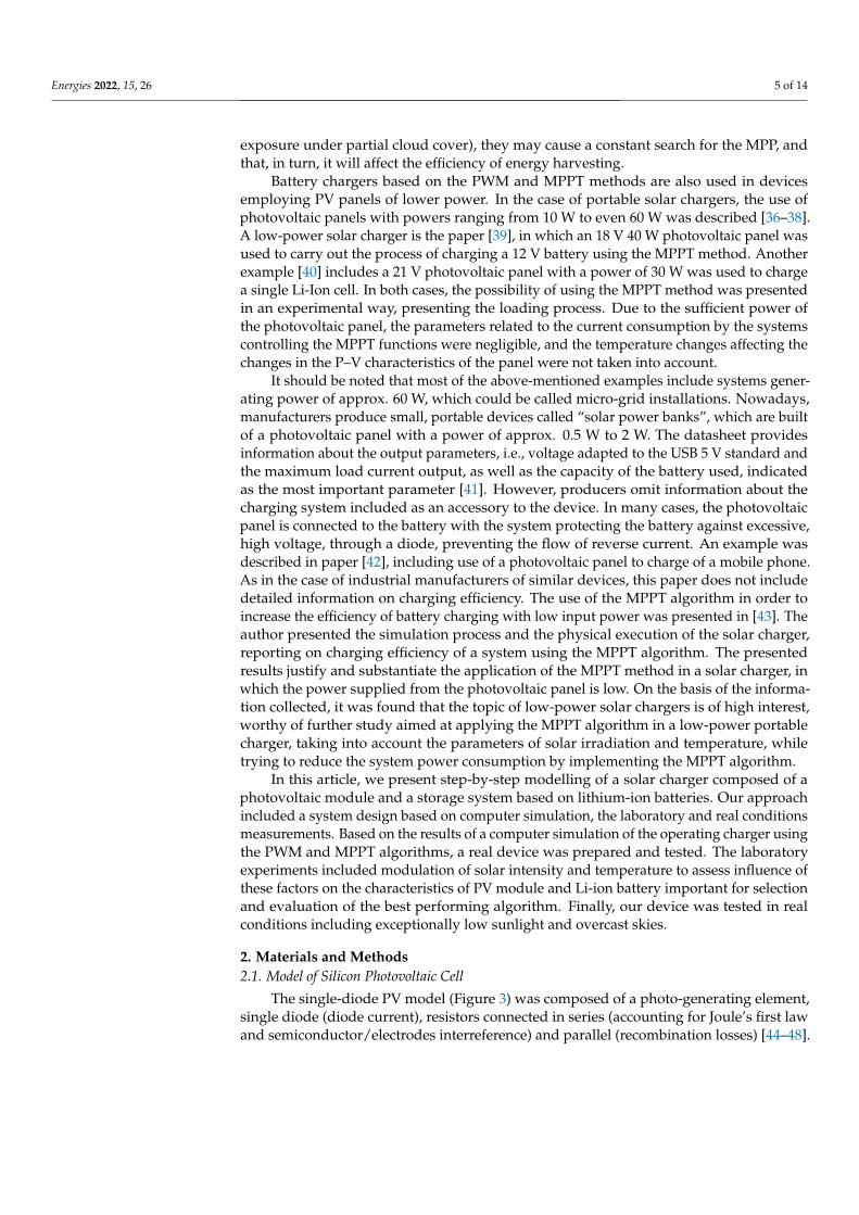
Battery chargers based on the PWM and MPPT methods are also used in devicesemploying PV panels of lower power. In the case of portable solar chargers, the use ofphotovoltaic panels with powers ranging from 10 W to even 60 W was described [36–38].A low-power solar charger is the paper [39], in which an 18 V 40 W photovoltaic panel wasused to carry out the process of charging a 12 V battery using the MPPT method. Anotherexample [40] includes a 21 V photovoltaic panel with a power of 30 W was used to chargea single Li-Ion cell. In both cases, the possibility of using the MPPT method was presentedin an experimental way, presenting the loading process. Due to the sufficient power ofthe photovoltaic panel, the parameters related to the current consumption by the systemscontrolling the MPPT functions were negligible, and the temperature changes affecting thechanges in the P–V characteristics of the panel were not taken into account.
It should be noted that most of the above-mentioned examples include systems gener-ating power of approx. 60 W, which could be called micro-grid installations. Nowadays,manufacturers produce small, portable devices called “solar power banks”, which are builtof a photovoltaic panel with a power of approx. 0.5 W to 2 W. The datasheet providesinformation about the output parameters, i.e., voltage adapted to the USB 5 V standard andthe maximum load current output, as well as the capacity of the battery used, indicatedas the most important parameter [41]. However, producers omit information about thecharging system included as an accessory to the device. In many cases, the photovoltaicpanel is connected to the battery with the system protecting the battery against excessive,high voltage, through a diode, preventing the flow of reverse current. An example wasdescribed in paper [42], including use of a photovoltaic panel to charge of a mobile phone.As in the case of industrial manufacturers of similar devices, this paper does not includedetailed information on charging efficiency. The use of the MPPT algorithm in order toincrease the efficiency of battery charging with low input power was presented in [43]. Theauthor presented the simulation process and the physical execution of the solar charger,reporting on charging efficiency of a system using the MPPT algorithm. The presentedresults justify and substantiate the application of the MPPT method in a solar charger, inwhich the power supplied from the photovoltaic panel is low. On the basis of the informa-tion collected, it was found that the topic of low-power solar chargers is of high interest,worthy of further study aimed at applying the MPPT algorithm in a low-power portablecharger, taking into account the parameters of solar irradiation and temperature, whiletrying to reduce the system power consumption by implementing the MPPT algorithm.
In this article, we present step-by-step modelling of a solar charger composed of aphotovoltaic module and a storage system based on lithium-ion batteries. Our approachincluded a system design based on computer simulation, the laboratory and real conditionsmeasurements. Based on the results of a computer simulation of the operating charger usingthe PWM and MPPT algorithms, a real device was prepared and tested. The laboratoryexperiments included modulation of solar intensity and temperature to assess influence ofthese factors on the characteristics of PV module and Li-ion battery important for selectionand evaluation of the best performing algorithm. Finally, our device was tested in realconditions including exceptionally low sunlight and overcast skies.
2. Materials and Methods2.1. Model of Silicon Photovoltaic Cell
The single-diode PV model (Figure 3) was composed of a photo-generating element,single diode (diode current), resistors connected in series (accounting for Joule’s first lawand semiconductor/electrodes interreference) and parallel (recombination losses) [44–48].
Energies 2022, 15, 26 6 of 14
Energies 2022, 15, 26 6 of 15
2. Materials and Methods 2.1. Model of Silicon Photovoltaic Cell
The single-diode PV model (Figure 3) was composed of a photo-generating element, single diode (diode current), resistors connected in series (accounting for Joule’s first law and semiconductor/electrodes interreference) and parallel (recombination losses) [44–48].
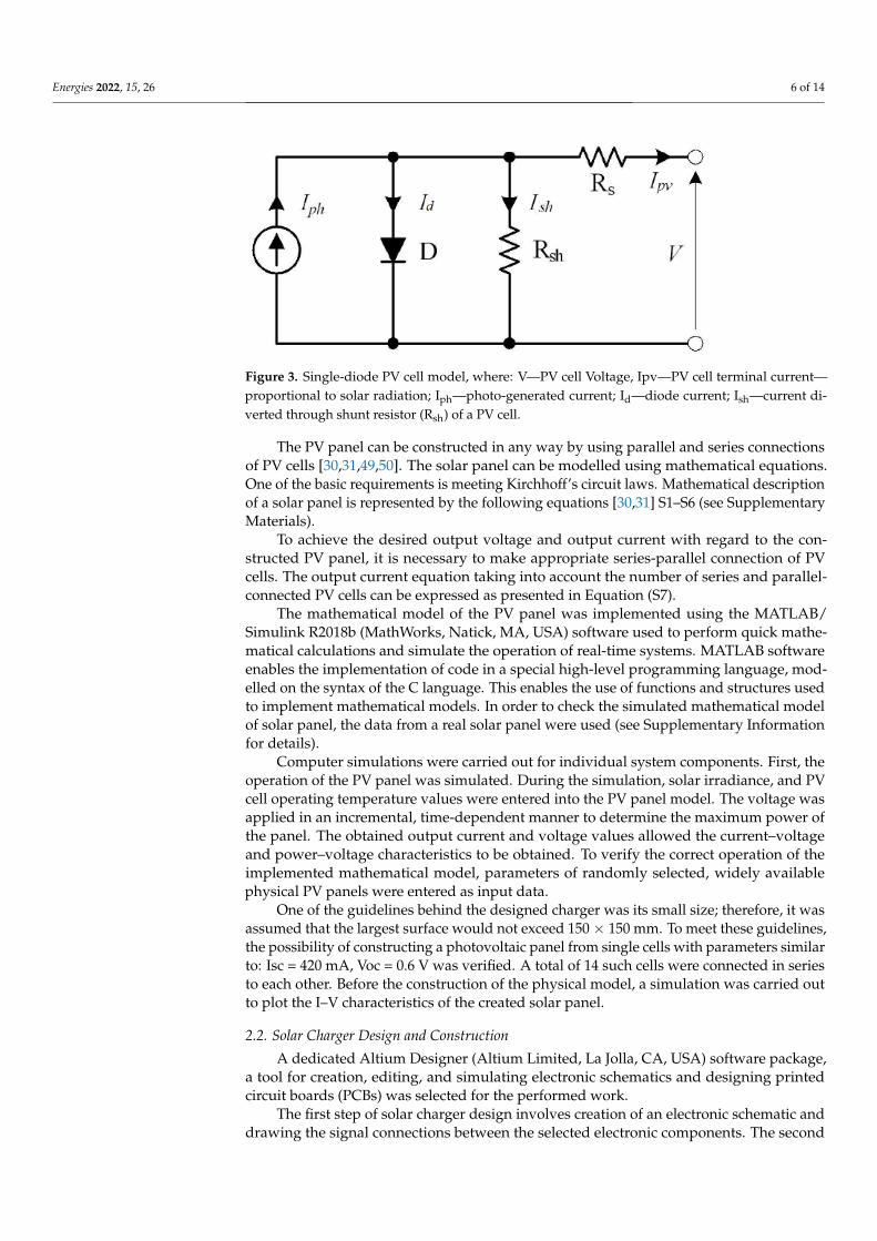
Figure 3. Single-diode PV cell model, where: V—PV cell Voltage, Ipv—PV cell terminal current—proportional to solar radiation; Iph—photo-generated current; Id—diode current; Ish—current di-verted through shunt resistor (Rsh) of a PV cell.
The PV panel can be constructed in any way by using parallel and series connections of PV cells [30,31,49,50]. The solar panel can be modelled using mathematical equations. One of the basic requirements is meeting Kirchhoff’s circuit laws. Mathematical descrip-tion of a solar panel is represented by the following equations [30,31] S1–S6 (see Supple-mentary Materials).
To achieve the desired output voltage and output current with regard to the con-structed PV panel, it is necessary to make appropriate series-parallel connection of PV cells. The output current equation taking into account the number of series and parallel-connected PV cells can be expressed as presented in Equation (S7).
The mathematical model of the PV panel was implemented using the MATLAB/Sim-ulink R2018b (MathWorks, Natick, MA, USA) software used to perform quick mathemat-ical calculations and simulate the operation of real-time systems. MATLAB software ena-bles the implementation of code in a special high-level programming language, modelled on the syntax of the C language. This enables the use of functions and structures used to implement mathematical models. In order to check the simulated mathematical model of solar panel, the data from a real solar panel were used (see Supplementary Information for details).
Computer simulations were carried out for individual system components. First, the operation of the PV panel was simulated. During the simulation, solar irradiance, and PV cell operating temperature values were entered into the PV panel model. The voltage was applied in an incremental, time-dependent manner to determine the maximum power of the panel. The obtained output current and voltage values allowed the current–voltage and power–voltage characteristics to be obtained. To verify the correct operation of the implemented mathematical model, parameters of randomly selected, widely available physical PV panels were entered as input data.
One of the guidelines behind the designed charger was its small size; therefore, it was assumed that the largest surface would not exceed 150 × 150 mm. To meet these guide-lines, the possibility of constructing a photovoltaic panel from single cells with parameters similar to: Isc = 420 mA, Voc = 0.6 V was verified. A total of 14 such cells were connected in series to each other. Before the construction of the physical model, a simulation was carried out to plot the I–V characteristics of the created solar panel.
Figure 3. Single-diode PV cell model, where: V—PV cell Voltage, Ipv—PV cell terminal current—proportional to solar radiation; Iph—photo-generated current; Id—diode current; Ish—current di-verted through shunt resistor (Rsh) of a PV cell.
The PV panel can be constructed in any way by using parallel and series connectionsof PV cells [30,31,49,50]. The solar panel can be modelled using mathematical equations.One of the basic requirements is meeting Kirchhoff’s circuit laws. Mathematical descriptionof a solar panel is represented by the following equations [30,31] S1–S6 (see SupplementaryMaterials).
To achieve the desired output voltage and output current with regard to the con-structed PV panel, it is necessary to make appropriate series-parallel connection of PVcells. The output current equation taking into account the number of series and parallel-connected PV cells can be expressed as presented in Equation (S7).
The mathematical model of the PV panel was implemented using the MATLAB/Simulink R2018b (MathWorks, Natick, MA, USA) software used to perform quick mathe-matical calculations and simulate the operation of real-time systems. MATLAB softwareenables the implementation of code in a special high-level programming language, mod-elled on the syntax of the C language. This enables the use of functions and structures usedto implement mathematical models. In order to check the simulated mathematical modelof solar panel, the data from a real solar panel were used (see Supplementary Informationfor details).
Computer simulations were carried out for individual system components. First, theoperation of the PV panel was simulated. During the simulation, solar irradiance, and PVcell operating temperature values were entered into the PV panel model. The voltage wasapplied in an incremental, time-dependent manner to determine the maximum power ofthe panel. The obtained output current and voltage values allowed the current–voltageand power–voltage characteristics to be obtained. To verify the correct operation of theimplemented mathematical model, parameters of randomly selected, widely availablephysical PV panels were entered as input data.
One of the guidelines behind the designed charger was its small size; therefore, it wasassumed that the largest surface would not exceed 150 × 150 mm. To meet these guidelines,the possibility of constructing a photovoltaic panel from single cells with parameters similarto: Isc = 420 mA, Voc = 0.6 V was verified. A total of 14 such cells were connected in seriesto each other. Before the construction of the physical model, a simulation was carried outto plot the I–V characteristics of the created solar panel.
2.2. Solar Charger Design and Construction
A dedicated Altium Designer (Altium Limited, La Jolla, CA, USA) software package,a tool for creation, editing, and simulating electronic schematics and designing printedcircuit boards (PCBs) was selected for the performed work.
The first step of solar charger design involves creation of an electronic schematic anddrawing the signal connections between the selected electronic components. The second

Energies 2022, 15, 26 7 of 14
step of designing a printed circuit is to arrange the circuit elements on the target surface ofthe PCB. The charger design provides for the use of a microcontroller to measure the circuitparameters and to implement the PV panel MPP tracking algorithm.
PCB was manufactured and soldered, and then all the systems were initiated. Con-verter operation tests have been performed, as well as tests of system control and batterycharging algorithm. System initiation enabled the study of MPP designation and its tracing.
3. Results and Discussion
In the step-by-step modelling of a solar charger, its physical elements and the algorithmplay a vital role in enhancing the efficiency of the energy storage. In order to assess the bestapproach, the subject matter analysis relative to the state of the art was conducted.
Our approach proposes using an MPPT with a specific algorithm called the P&Omethod. It is a simple method that involves checking the parameters at adjacent pointsof the PV characteristic by comparing the currently measured energy with the energymeasured at the previous point. On this basis, the controller constantly oscillates aroundthe MPP. Due to the small computing power requirement, this method was chosen, andpredefined elements of the current–voltage characteristics of the attached PV panel wereadded. In the presented method, we assumed a quick check of several predefined pointsin which the MPP can be located, and then a temporary oscillation aimed at determiningthe MPP in accordance with the P&O method. Finally, after determining the MPP point,the microcontroller goes into the power-saving phase. Return to work (wake-up) and re-verification of parameters takes place cyclically or when the defined boundary atmosphericconditions exceeding have been exceeded.
3.1. Results of Computer Simulations
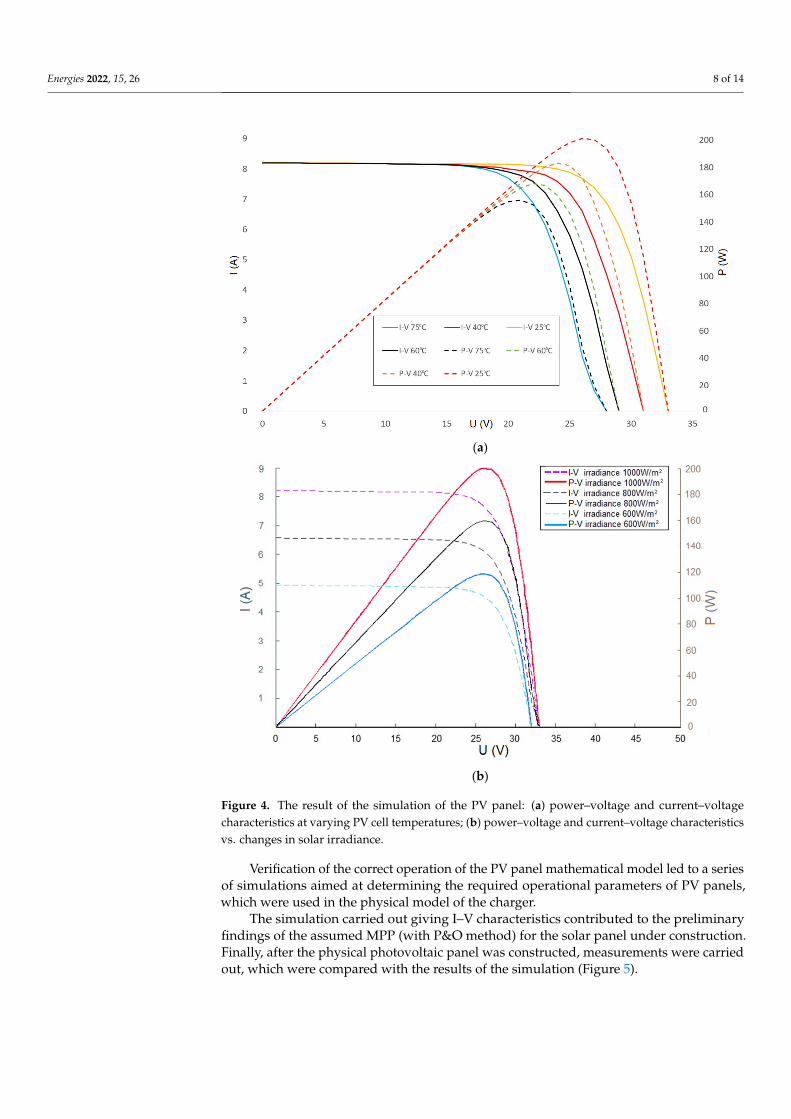
A simulation was carried out to determine the behaviour of the PV panel under thesame irradiance varying the temperature factor. The simulation was performed for thetemperatures: 25 ◦C, as standard conditions and elevated temperature of 75 ◦C (Figure 4a).Verification of the current–voltage characteristic of the real model (Figure S4) and of thesimulated model revealed slight differences, assigned by the use of additional electroniccomponents in the real model. Based on the comparison of the theoretical and real charac-teristics, it can be stated that the temperature change impacts the shift of the current–voltagecharacteristic, as expected. The power–voltage characteristics showed deterioration in thesolar panel efficiency caused by the increase in the cell operating temperature, consistentwith the theory. Another verification involved performing a simulation for a constant celloperating temperature, at different incident solar irradiance on the PV panel. The simula-tions were made for the irradiance of 600 W/m2, 800 W/m2 and 1000 W/m2 (Figure 4b).
Along with the change in the value of the irradiance, the current at the output of thePV panel changed. Less sunlight affects the lower current generation at the panel. As aresult of comparing the current–voltage characteristics of the simulated model with the realKC200GT PV panel from Kyocera (Kyoto, Japan) (Figure S4), a regularity can be observed inthe change in the current value resulting from the decrease of the solar irradiance. Analysisof the power–voltage characteristic of the simulated model indicated a regularity related tothe decrease in the value of the generated output power.
Both the simulations conducted and the comparison of the mathematical model ofa PV panel simulated in MATLAB software with the technical documentation of the realmodel led to the conclusion that the model had been generated correctly. The comparison ofthe current–voltage characteristics shows that the simulated model is in agreement with itsphysical counterpart. The technical documentation of the KC200GT PV panel from Kyocerashows that the maximum power is 200.143 W. As a result of simulating the operation of themodel using the same conditions, a value similar to that provided by the manufacturer wasobtained, and it amounted to 199.7 W.
Energies 2022, 15, 26 8 of 14Energies 2022, 15, 26 8 of 15
(a)
(b)
Figure 4. The result of the simulation of the PV panel: (a) power–voltage and current–voltage char-acteristics at varying PV cell temperatures; (b) power–voltage and current–voltage characteristics vs. changes in solar irradiance.
Along with the change in the value of the irradiance, the current at the output of the PV panel changed. Less sunlight affects the lower current generation at the panel. As a result of comparing the current–voltage characteristics of the simulated model with the real KC200GT PV panel from Kyocera (Kyoto, Japan) (Figure S4), a regularity can be ob-served in the change in the current value resulting from the decrease of the solar irradi-ance. Analysis of the power–voltage characteristic of the simulated model indicated a reg-ularity related to the decrease in the value of the generated output power.
Both the simulations conducted and the comparison of the mathematical model of a PV panel simulated in MATLAB software with the technical documentation of the real model led to the conclusion that the model had been generated correctly. The comparison of the current–voltage characteristics shows that the simulated model is in agreement with
Figure 4. The result of the simulation of the PV panel: (a) power–voltage and current–voltagecharacteristics at varying PV cell temperatures; (b) power–voltage and current–voltage characteristicsvs. changes in solar irradiance.
Verification of the correct operation of the PV panel mathematical model led to a seriesof simulations aimed at determining the required operational parameters of PV panels,which were used in the physical model of the charger.
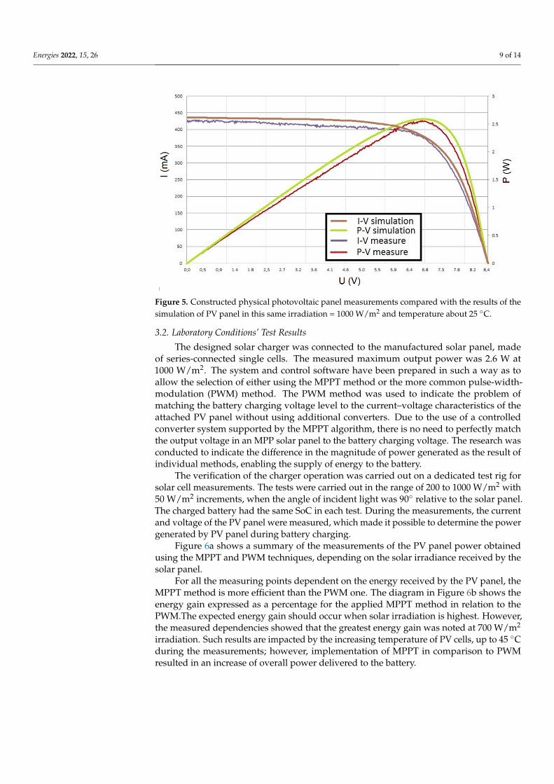
The simulation carried out giving I–V characteristics contributed to the preliminaryfindings of the assumed MPP (with P&O method) for the solar panel under construction.Finally, after the physical photovoltaic panel was constructed, measurements were carriedout, which were compared with the results of the simulation (Figure 5).
Energies 2022, 15, 26 9 of 14
Energies 2022, 15, 26 9 of 15
its physical counterpart. The technical documentation of the KC200GT PV panel from Kyocera shows that the maximum power is 200.143 W. As a result of simulating the oper-ation of the model using the same conditions, a value similar to that provided by the man-ufacturer was obtained, and it amounted to 199.7 W.
Verification of the correct operation of the PV panel mathematical model led to a series of simulations aimed at determining the required operational parameters of PV panels, which were used in the physical model of the charger.
The simulation carried out giving I–V characteristics contributed to the preliminary findings of the assumed MPP (with P&O method) for the solar panel under construction. Finally, after the physical photovoltaic panel was constructed, measurements were carried out, which were compared with the results of the simulation (Figure 5).
Figure 5. Constructed physical photovoltaic panel measurements compared with the results of the simulation of PV panel in this same irradiation = 1000 W/m2 and temperature about 25 °C.
3.2. Laboratory Conditions’ Test Results The designed solar charger was connected to the manufactured solar panel, made of
series-connected single cells. The measured maximum output power was 2.6 W at 1000 W/m2. The system and control software have been prepared in such a way as to allow the selection of either using the MPPT method or the more common pulse-width-modulation (PWM) method. The PWM method was used to indicate the problem of matching the bat-tery charging voltage level to the current–voltage characteristics of the attached PV panel without using additional converters. Due to the use of a controlled converter system sup-ported by the MPPT algorithm, there is no need to perfectly match the output voltage in an MPP solar panel to the battery charging voltage. The research was conducted to indi-cate the difference in the magnitude of power generated as the result of individual meth-ods, enabling the supply of energy to the battery.
The verification of the charger operation was carried out on a dedicated test rig for solar cell measurements. The tests were carried out in the range of 200 to 1000 W/m2 with 50 W/m2 increments, when the angle of incident light was 90° relative to the solar panel. The charged battery had the same SoC in each test. During the measurements, the current and voltage of the PV panel were measured, which made it possible to determine the power generated by PV panel during battery charging.
Figure 6a shows a summary of the measurements of the PV panel power obtained using the MPPT and PWM techniques, depending on the solar irradiance received by the solar panel.
Figure 5. Constructed physical photovoltaic panel measurements compared with the results of thesimulation of PV panel in this same irradiation = 1000 W/m2 and temperature about 25 ◦C.
3.2. Laboratory Conditions’ Test Results
The designed solar charger was connected to the manufactured solar panel, madeof series-connected single cells. The measured maximum output power was 2.6 W at1000 W/m2. The system and control software have been prepared in such a way as toallow the selection of either using the MPPT method or the more common pulse-width-modulation (PWM) method. The PWM method was used to indicate the problem ofmatching the battery charging voltage level to the current–voltage characteristics of theattached PV panel without using additional converters. Due to the use of a controlledconverter system supported by the MPPT algorithm, there is no need to perfectly matchthe output voltage in an MPP solar panel to the battery charging voltage. The research wasconducted to indicate the difference in the magnitude of power generated as the result ofindividual methods, enabling the supply of energy to the battery.
The verification of the charger operation was carried out on a dedicated test rig forsolar cell measurements. The tests were carried out in the range of 200 to 1000 W/m2 with50 W/m2 increments, when the angle of incident light was 90◦ relative to the solar panel.The charged battery had the same SoC in each test. During the measurements, the currentand voltage of the PV panel were measured, which made it possible to determine the powergenerated by PV panel during battery charging.
Figure 6a shows a summary of the measurements of the PV panel power obtainedusing the MPPT and PWM techniques, depending on the solar irradiance received by thesolar panel.
For all the measuring points dependent on the energy received by the PV panel, theMPPT method is more efficient than the PWM one. The diagram in Figure 6b shows theenergy gain expressed as a percentage for the applied MPPT method in relation to thePWM.The expected energy gain should occur when solar irradiation is highest. However,the measured dependencies showed that the greatest energy gain was noted at 700 W/m2
irradiation. Such results are impacted by the increasing temperature of PV cells, up to 45 ◦Cduring the measurements; however, implementation of MPPT in comparison to PWMresulted in an increase of overall power delivered to the battery.

Energies 2022, 15, 26 10 of 14Energies 2022, 15, 26 10 of 15
(a)
(b)
Figure 6. Summary of the measurements of the PV panel power obtained using the MPPT and PWM techniques. (a) PV panel power dependence on irradiance and the selected technique; (b) illustration of power gain generated by the PV panel using the MPPT method.
For all the measuring points dependent on the energy received by the PV panel, the MPPT method is more efficient than the PWM one. The diagram in Figure 6b shows the energy gain expressed as a percentage for the applied MPPT method in relation to the PWM.The expected energy gain should occur when solar irradiation is highest. However, the measured dependencies showed that the greatest energy gain was noted at 700 W/m2 irradiation. Such results are impacted by the increasing temperature of PV cells, up to 45 °C during the measurements; however, implementation of MPPT in comparison to PWM resulted in an increase of overall power delivered to the battery.
A series of measurements was made to illustrate how the temperature change affects the power generated by the PV panel. During the measurements, the solar irradiance value was kept constant. The algorithm controlling the operation of the converter was set to measure each point of the current–voltage characteristic, then return to the MPP and oscillate around it, until the set power loss threshold is exceeded. At this point, the task of the system was not to determine the MPP as quickly as possible and not to efficiently manage the MPPT, but to indicate how the changing temperature influences the set and maintained MPP. This was done to assess what sort of dynamics should be finally imple-mented into the MPPT algorithm. The graphs in Figure 7 show the impact of temperature on the power produced when the MPPT method or the PWM method were used. In the case of the PWM method, an increase in the power generated was visible due to the in-creased irradiation; however, its level was unproportionally low compared to what was
Figure 6. Summary of the measurements of the PV panel power obtained using the MPPT and PWMtechniques. (a) PV panel power dependence on irradiance and the selected technique; (b) illustrationof power gain generated by the PV panel using the MPPT method.
A series of measurements was made to illustrate how the temperature change affectsthe power generated by the PV panel. During the measurements, the solar irradiancevalue was kept constant. The algorithm controlling the operation of the converter wasset to measure each point of the current–voltage characteristic, then return to the MPPand oscillate around it, until the set power loss threshold is exceeded. At this point,the task of the system was not to determine the MPP as quickly as possible and not toefficiently manage the MPPT, but to indicate how the changing temperature influencesthe set and maintained MPP. This was done to assess what sort of dynamics should befinally implemented into the MPPT algorithm. The graphs in Figure 7 show the impact oftemperature on the power produced when the MPPT method or the PWM method wereused. In the case of the PWM method, an increase in the power generated was visible dueto the increased irradiation; however, its level was unproportionally low compared to whatwas obtained in comparison to the MPPT method. In some cases, the power generationfrom the MPPT supported system was almost double in value. During the experiment, apunctual overheating was observed due to random heating points before the temperaturereached an equilibrium.

Energies 2022, 15, 26 11 of 14
Energies 2022, 15, 26 11 of 15
obtained in comparison to the MPPT method. In some cases, the power generation from the MPPT supported system was almost double in value. During the experiment, a punc-tual overheating was observed due to random heating points before the temperature reached an equilibrium.
(a) (b)
(c) (d)
Figure 7. Different in the power generated by the PV panel for PWM and MPPT dependent on tem-perature changes for irradiation: 300 W/m2 (a), 350 W/m2 (b), 400 W/m2 (c), 450 W/m2 (d).
Tests performed using the PWM method did not show a significant temperature ef-fect on the power generated. This was related to the PWM method’s operation principle which involves loading the PV panel to carry out the battery charging process without verification of optimum current–voltage parameters. When the MPPT method was em-ployed, the temperature impact was in some cases substantial. The power generated by the PV panel was changing by MPP according to the PV panel current–voltage character-istic, affected by the solar panel temperature.
As has been already noted, such a step-by-step temperature change rate does not occur in natural conditions, but the test allowed the study of the great impact of temper-ature parameter on the operation of the solar panel in its MPP to be conducted. It was also indicated that the operating temperature may not be of great importance when the PWM method is applied, in cases where the PV panel was not optimally selected for the system.
Figure 7. Different in the power generated by the PV panel for PWM and MPPT dependent ontemperature changes for irradiation: 300 W/m2 (a), 350 W/m2 (b), 400 W/m2 (c), 450 W/m2 (d).
Tests performed using the PWM method did not show a significant temperature effecton the power generated. This was related to the PWM method’s operation principle whichinvolves loading the PV panel to carry out the battery charging process without verificationof optimum current–voltage parameters. When the MPPT method was employed, thetemperature impact was in some cases substantial. The power generated by the PV panelwas changing by MPP according to the PV panel current–voltage characteristic, affected bythe solar panel temperature.
As has been already noted, such a step-by-step temperature change rate does not occurin natural conditions, but the test allowed the study of the great impact of temperatureparameter on the operation of the solar panel in its MPP to be conducted. It was alsoindicated that the operating temperature may not be of great importance when the PWMmethod is applied, in cases where the PV panel was not optimally selected for the system.
3.3. Real Conditions’ Test Results
In order to confirm the correct operation of the system presented in the theoreticaland laboratory studies, performance testing under real conditions was carried out. Aspreviously described, the best power conversion was registered for the MPPT system basedon the P&O algorithm; therefore, this system was selected for further studies. The testswere performed in Wroclaw, Poland (51.1079◦ N, 17.0385◦ E) in March, during warmerwinter days. The measurements were made at noon, with good weather conditions andthe ambient temperature of 13 ◦C. The incident solar irradiance on the solar panel was

Energies 2022, 15, 26 12 of 14
constant, reaching approx. 550 W/m2. The charging current obtained under such con-ditions at the designated MPP was 419 mA. This value was similar to the measurementobtained in laboratory conditions under similar conditions (425 mA with irradiance of550 W/m2). The most interesting findings were observed at exceptionally low sunlightand overcast skies. The measured solar irradiance varied, reaching 55 W/m2. Under suchconditions, the control algorithm, whose task was to control the possibility of chargingand determination of MPP, showed errors in the implementation of MPPT, related to themomentary fluctuations in the current supplied to the system, exceeding the adopted limitvalue of the microcontroller wake-up. The designed MPPT enabled charging the batterywith the lowest current value of approx. 10 mA, which is 2% of the maximum possiblecurrent. The tests performed with the MPPT function deactivated still gave better resultsthan PWM under the same conditions highlighting the advantage of MPPT. In the case ofPWM, the converter loaded the PV panel too much, making it impossible to supply thebattery with any current.
4. Conclusions
The main purpose of these studies was to assess the most optimal power controlsystem for constructing a portable, small size solar Li-Ion battery charger utilizing thePWM and MPPT. Our approach included design optimization of designed simplified solarcharger based on a PV panel and Li-Ion batteries. Simplified design of the electronichardware, connecting PV to the battery, allowed reduction of its required current, andinitiation of the battery charging for efficiencies above 2% of total possible current generatedby the solar module. Additionally, an important point of the solar charger design involvedtailoring the voltage levels of the PV characteristics supplied via converter to the Li-Ionbattery with optimized supplied power. This article, presenting the measurements’ resultsbased on theoretical models, tests in a laboratory and real conditions. A series of testscarried out gave an objective comparison of the most used strategies using PWM and MPPT.The use of hardware and software solutions contributed to the possibility of constructinga solar charger implementing the MPPT algorithm, using the P&O method with the bestresults. The use of the MPPT method contributed not only to increasing the possibilityof gaining more energy through proper control of PV parameters with a gain of 50 mW,but it also allowed the use of PV panels, the characteristics of which were not perfectlymatched to the voltage levels of the Li-Ion battery being charged with a reduced amountof electronic elements. When charging the battery using the PWM method, the chargingperformance was significantly inferior, due to the need to match the PV panel voltage levelto the load voltage.
The proposed solution was based on a low-power PV panel, as well as the use ofthe functionality of putting the micro controller to sleep and the use of elements aimedat minimizing power consumption. The test conducted allowed the authors to concludethat the use of the MPPT method is justified not only in the commonly used, high-powerinstallations, but also in exceedingly small installations.
5. Patents
The result of the project was submitted under utility model No. WIPO ST 10/CPL129425U from 31.08.2020 for the solar charger to The Patent Office of the Republicof Poland.
Supplementary Materials: The following are available online at https://www.mdpi.com/article/10.3390/en15010026/s1. Figure S1: Implementation of the equation describing photogenerated currentusing MATLAB software. Figure S2: PV panel model. Figure S3: Simulated PV module. Table S1:Parameters of KC200GT solar panel. Figure S4: Current–voltage characteristics for Kyocera KC200GTPV module —constant irradiance (1 kW/m2) and variable cell temperatures on the left, and constantcell temperature (25 ◦C) and variable irradiance on the right. Figure S5: Fragment of a schematicpresenting a microcontroller and signals. Figure S6: Ready PCB with all the system components.

Energies 2022, 15, 26 13 of 14
Author Contributions: The article has several authors. Conceptualization, P.O. (Paweł Otreba), T.S.and M.S.; methodology, P.O. (Paweł Otreba); software, P.O. (Paweł Otreba); validation, P.O. (PiotrOtreba), P.O. (Paweł Otreba), T.S. and M.S.; writing—original draft preparation, P.O. (Paweł Otreba)and P.O. (Piotr Otreba); writing—review and editing, T.S. and M.S. All authors have read and agreedto the published version of the manuscript.
Funding: The research was funded by the Polish National Centre of Research and Development,Grant No. TECHMATSTRATEG1/347431/14/NCBR/2018.
Institutional Review Board Statement: Not applicable.
Informed Consent Statement: Not applicable.
Acknowledgments: The authors are grateful for financial support from the Polish National Centre ofResearch and Development (TECHMATSTRATEG1/347431/14/NCBR/2018).
Conflicts of Interest: The authors declare no conflict of interest.
References1. Manimekalai, P.; Harikumar, R.; Raghavan, S. An Overview of Batteries for Photovoltaic (PV) Systems. Int. J. Comput. Appl. 2013,
82, 12. [CrossRef]2. Mahlia, T.M.I.; Saktisahdan, T.J.; Jannifar, A.; Hasan, M.H.; Matseelar, H.S.C. A review of available methods and development on
energy storage; technology update. Renew. Sustain. Energy Rev. 2014, 33, 532–545. [CrossRef]3. Luo, X.; Wang, J.; Dooner, M.; Clarke, J. Overview of current development in electrical energy storage technologies and the
application potential in power system operation. Appl. Energy 2015, 137, 511–536. [CrossRef]4. Weitzel, T.; Glock, C.H. Energy Management for Stationary Electric Energy Storage Systems: A Systematic Literature Review. Eur.
J. Oper. Res. 2018, 264, 582–606. [CrossRef]5. Pegueroles-Queralt, J.; Bianchi, F.D.; Gomis-Bellmunt, O. Control of a lithium-ion battery storage system for microgrid applications.
J. Power Sources 2014, 272, 531–540. [CrossRef]6. Liu, Y.; Yu, S.; Zhu, Y.; Wang, D.; Liu, J. Modeling, planning, application and management of energy systems for isolated areas: A
review. Renew. Sustain. Energy Rev. 2018, 82, 460–470. [CrossRef]7. Goebel, C.; Hesse, H.; Schimpe, M.; Jossen, A.; Jacobsen, H.A. Model-Based Dispatch Strategies for Lithium-Ion Battery Energy
Storage Applied to Pay-as-Bid Markets for Secondary Reserve. IEEE Trans. Power Syst. 2017, 32, 2724–2734. [CrossRef]8. Richardson, D.B. Electric vehicles and the electric grid: A review of modeling approaches, Impacts, and renewable energy
integration. Renew. Sustain. Energy Rev. 2013, 19, 247–254. [CrossRef]9. Andrea, D. Battery Management Systems for Large Lithium-Ion Battery Packs; Artech House: Norwood, MA, USA, 2010.10. Ishaque, K.; Salam, Z. A review of maximum power point tracking techniques of PV system for uniform insolation and partial
shading condition. Renew. Sustain. Energy Rev. 2013, 19, 475–488. [CrossRef]11. Raman, S.R.; Xue, X.D.; Cheng, K. Review of charge equalization schemes for Li-ion battery and super-capacitor energy storage
systems. In Proceedings of the 2014 International Conference on Advances in Electronics, Computers and Communications(ICAECC), Bangalore, India, 10–11 October 2014; pp. 1–6.
12. Fernandes, N.T.D.; Rocha, A.; Brandao, D.; Filho, B. Comparison of Advanced Charge Strategies for Modular Cascade BatteryChargers. Energies 2020, 14, 3361. [CrossRef]
13. Thounthong, P.; Chunkag, V.; Sethakul, P.; Sikkabut, S.; Pierfederici, S.; Davat, B. Energy management of fuel cell/solarcell/supercapacitor hybrid power source. J. Power Sources 2011, 196, 313–324. [CrossRef]
14. Thanh, H.P.; Collet, A.; Crebier, J.C. An Optimized Topology for Next-to-Next Balancing of Series-Connected Lithium-ion Cells.IEEE Trans. Power Electron. 2014, 29, 4603–4613.
15. Lu, L.; Han, X.; Li, J.; Hua, J.; Ouyang, M. A review on the key issues for lithium-ion battery management In electric vehicles. J.Power Sources 2013, 226, 272–288. [CrossRef]
16. Rahimi-Eichi, H.; Ojha, U.; Baronti, F.; Chow, M. Battery management system: An overview of its application in the smart gridand electric vehicles. IEEE Ind. Electron. Mag. 2013, 7, 4–16. [CrossRef]
17. Gao, X.; Li, S.; Gong, R. Maximum power point tracking control strategies with variable weather parameters for photovoltaicgeneration systems. Sol. Energy 2013, 93, 357–367. [CrossRef]
18. Huang, Y.-P. A rapid maximum power measurement system for high-concentration photovoltaic modules using the fractionalopen-circuit voltage technique and controllable electronic load. IEEE J. Photovolt. 2014, 4, 1610–1617. [CrossRef]
19. Nguyen, T.L.; Low, K.-S. A global maximum power point tracking scheme employing DIRECT search algorithm of photovoltaicsystems. IEEE Trans. Ind. Electron. 2010, 57, 3456–3467. [CrossRef]
20. SmartSolar Charge Controller MPPT Datasheet, Maufacturer’s Website. Available online: https://www.victronenergy.pl/upload/documents/Datasheet-SmartSolar-charge-controller-MPPT-75-10,-75-15,-100-15,-100-20_48V-EN.pdf (accessed on 10 November2021).

Energies 2022, 15, 26 14 of 14
21. BlueSolar PWM Charge Controller Datasheet, Maufacturer’s Website. Available online: https://www.victronenergy.pl/upload/documents/Datasheet-BlueSolar-and-SmartSolar-charge-controller-overview-EN-.pdf (accessed on 10 November 2021).
22. EP Solar MPPT Dual Battery Solar Charge Controller Datasheet, Maufacturer’s Website. Available online: www.epever.com(accessed on 10 November 2021).
23. PWM Solar Charge Controller Datasheet, Maufacturer’s Website. Available online: www.fullcirclesolar.co.za (accessed on 10November 2021).
24. Górecki, K.; Szmajda, M. The Power Quality in Low-Power Solar Off-Grid System. In Proceedings of the International Conferenceon Harmonics and Quality of Power (ICHQP 2014), Bucharest, Romania, 25–28 May 2014.
25. Espi, J.M.; Castello, J. A Novel Fast MPPT Strategy for High Efficiency PV Battery Chargers. Energies 2019, 12, 1152. [CrossRef]26. Gibson, T.L.; Kelly, N.A. Solar photovoltaic charging of lithium-ion batteries. In Proceedings of the IEEE Vehicle Power and
Propulsion Conference, Dearborn, MI, USA, 7–11 September 2009.27. Li, L.; Wang, H.; Chen, X.; Bukhari, A.A.S.; Cao, W.; Chai, L.; Li, B. High Efficiency Solar Power Generation with Improved
Discontinuous Pulse Width Modulation (DPWM) Overmodulation Algorithms. Energies 2019, 12, 1765. [CrossRef]28. Jiménez-Castillo, G.; Muñoz-Rodríguez, F.J.; Rus-Casas, C.; Gómez-Vidal, P. Improvements in Performance Analysis of Photo-
voltaic Systems: Array Power Monitoring in Pulse Width Modulation Charge Controllers. Sensors 2019, 19, 2150. [CrossRef]29. Majew, T.; Deka, R.; Roy, S.; Goswami, B. Solar Charger Controllers using MPPT and PWM: A Review. ADBU J. Electr. Electron.
Eng. (AJEEE) 2018, 2, 1–4.30. Acharya, P.S.; Aithal, P.S. A Comparative Study of MPPT and PWM Solar Charge Controller and their Integrated System. In
Journal of Physics: Conference Series; IOP Publishing: Bristol, UK, 2020; Volume 1712, p. 012023.31. Osarentin, C.A.; Edeko, F.O. Desing and Implementation of a Solar Charger Controller with Variable Output. JEEE 2015, 12, 2.32. Al Nabulsi, A.; Dhaouadi, R. Efficiency optimization of a DSPbased standalone PV system using fuzzy logic and dual-MPPT
control. IEEE Trans. Ind. Inform. 2012, 8, 573–584. [CrossRef]33. Villalva, M.; Gazoli, J.; Ruppert, E. Analysis and simulation of the P&O MPPT algorithm using alinearized array model. In
Proceedings of the 2009 35th Annual Conference of IEEE Industrial Electronics, Porto, Portugal, 3–5 November 2009; pp. 189–195.34. Femia, N.; Petrone, G.; Spagnuolo, G.; Vitelli, M. Optimization of perturb and observe maximum power point tracking method.
IEEE Trans. Power Electron. 2005, 4, 963–973. [CrossRef]35. Hayder, W.; Ogliari, E.; Dolara, A.; Abid, A.; Hamed, M.B.; Sbita, L. Improved PSO: A Comparative Study in MPPT Algorithm for
PV System Control under Partial Shading Conditions. Energies 2020, 13, 2035. [CrossRef]36. Almutairi, A.; Abo-Khalil, A.G.; Sayed, K.; Albagami, N. MPPT for a PV Grid-Connected System to Improve Efficiency under
Partial Shading Conditions. Sustainability 2020, 12, 10310. [CrossRef]37. Chiu, H.; Lo, Y.; Lee, T.; Chen, Q.; Yu, W.L. A battery charger with maximum power point tracking function for low-power
photovoltaic system applications. Int. J. Circuit Theory Appl. 2011, 39, 241–256. [CrossRef]38. Kuperman, A.; Sitbon, M.; Gadelovit, S.; Averbukh, M.; Suntio, T. Single-Source Multi-Battery Solar Charger: Analysis and
Stability Issues. Energies 2015, 8, 6427–6450. [CrossRef]39. Guo, L.; Kors, J., Jr. Design of a Laboratory Scale Solar Microgrid Cyber-Physical System for Education. Electronics 2021, 10, 1562.
[CrossRef]40. Kim, J.; Huh, J.; Ko, J. Optimization Design and Test Bed of Fuzzy Control Rule Base for PV System MPPT in Micro Grid.
Sustainability 2020, 12, 3763. [CrossRef]41. Solar Power Bank 15,000 mAh, Renogy, Datasheet, Maufacturer’s Website. Available online: www.renogy.com (accessed on 11
November 2021).42. Malla, S.G.; Deepu, D.J.; Kumar, D.P.; Malla, J.M.R. Solar Powered Mobile Phone: An Innovative Experiment. In Proceedings of the
2016 International Conference on Signal Processing, Communication, Power and Embedded System (SCOPES), Paralakhemundi,India, 3–5 October 2016.
43. Zhang, L.; Wang, Z.; Cao, P.; Zhang, S. A Maximum Power Point Tracking Algorithm of Load Current Maximization-Peturbationand Observation Method with Variable Step size. Symmetry 2020, 12, 244. [CrossRef]
44. Rodrigo, P.; Fern’andez, E.F.; Almonacid, F.; P’erez-Higueras, P.J. Models for the electrical characterization of high concentrationphotovoltaic cells and modules: A review. Renew. Sustain. Energy Rev. 2013, 26, 752–760. [CrossRef]
45. Segev, G.; Mittelman, G.; Kribus, A. Equivalent circuit models for triple-junction concentrator solar cells. Sol. Energy Mater. Sol.Cells 2012, 98, 57–65. [CrossRef]
46. Gow, J.A.; Manning, C.D. Development of a photovoltaic array model for use in power-electronics simulation studies. IEEProc.-Electr. Power Appl. 1999, 146, 193–200. [CrossRef]
47. Walker, G. Evaluating MPPT converter topologies using a MATLAB PV model. J. Electr. Electron. Eng. 2001, 21, 49–55.48. Gontean, A.; Lica, S.; Bularka, S.; Szabo, R.; Lascu, D. A Novel High Accuracy PV Cell Model Including Self Heating and
Parameter Variation. Energies 2018, 11, 36. [CrossRef]49. Emery, K. Measurement and Characterization of Solar Cells and Modules. In Handbook of Photovoltaic Science and Engineering,
2nd ed.; Luque, A., Hegedus, S., Eds.; John Wiley & Sons: Hoboken, NJ, USA, 2011.50. Kim, W.; Choi, W. A novel parameter extraction method for the one-diode solar cell model. Sol. Energy 2010, 84, 1008–1019.
[CrossRef]
Copyright © 2022 FDOKUMEN