Use of the BrainLAB ExacTrac X-Ray 6D system in image-guided radiotherapy
11
doi:10.1016/j.meddos.2008.02.005 USE OF THE BRAINLAB EXACTRAC X-RAY 6D SYSTEM IN IMAGE-GUIDED RADIOTHERAPY JIAN-YUE JIN,PH.D., FANG-FANG YIN,PH.D., STEPHEN E. TENN,PH.D., PAUL M. MEDIN,PH.D., and TIMOTHY D. SOLBERG,PH.D. Department of Radiation Oncology, Henry Ford Health System, Detroit, MI; Department of Radiation Oncology, Duke University Medical Center, Durham, NC; Department of Radiation Oncology, David Geffen School of Medicine at UCLA, Los Angeles, CA; and Department of Radiation Oncology, University of Nebraska, Nebraska Medical Center, Omaha, NE (Received 1 November 2007; accepted 29 February 2008) Abstract—The ExacTrac X-Ray 6D image-guided radiotherapy (IGRT) system will be described and its performance evaluated. The system is mainly an integration of 2 subsystems: (1) an infrared (IR)-based optical positioning system (ExacTrac) and (2) a radiographic kV x-ray imaging system (X-Ray 6D). The infrared system consists of 2 IR cameras, which are used to monitor reflective body markers placed on the patient’s skin to assist in patient initial setup, and an IR reflective reference star, which is attached to the treatment couch and can assist in couch movement with spatial resolution to better than 0.3 mm. The radiographic kV devices consist of 2 oblique x-ray imagers to obtain high-quality radiographs for patient position verification and adjustment. The position verification is made by fusing the radiographs with the simulation CT images using either 3 degree-of- freedom (3D) or 6 degree-of-freedom (6D) fusion algorithms. The position adjustment is performed using the infrared system according to the verification results. The reliability of the fusion algorithm will be described based on phantom and patient studies. The results indicated that the 6D fusion method is better compared to the 3D method if there are rotational deviations between the simulation and setup positions. Recently, the system has been augmented with the capabilities for image-guided positioning of targets in motion due to respiration and for gated treatment of those targets. The infrared markers provide a respiratory signal for tracking and gating of the treatment beam, with the x-ray system providing periodic confirmation of patient position relative to the gating window throughout the duration of the gated delivery. © 2008 American Association of Medical Dosimetrists. Key Words: Image-guided radiation therapy, X-ray guidance, Image fusion, Respiratory gating. INTRODUCTION Image guidance plays an important role in radiosurgery and intensity modulated radiotherapy (IMRT) because it supports accurate target localization and avoidance of adjacent organs-at-risks (OAR). A number of imaging modalities including: ultrasound, 1,2 video imaging, 3,4 2-dimensional radiographic imaging (kV and MV), 5–7 computed tomography (CT) (conventional CT as well as kV and MV cone beam CT), 8 –12 and magnetic resonance imaging (MRI) 13–15 are used in image-guided radiotherapy (IGRT). Several IGRT systems are now commercially available and have been successfully implemented for clin- ical applications. The BrainLAB ExacTrac X-Ray 6D ste- reotactic IGRT system (BrainLAB AG, Feldkirchen, Ger- many) uses a combination of optical positioning and kV radiographic imaging to accurately position patients and make online positioning corrections. It has been success- fully used clinically for intra-cranial and extra-cranial ra- diosurgery. 16 –19 The ExacTrac X-Ray 6D system is mainly an integration of 2 subsystems: (1) an infrared (IR)-based optical positioning system (ExacTrac) for initial patient setup and precise control of couch movement, and (2) a radiographic kV x-ray imaging system (X-Ray 6D) for position verification and readjustment based on the in- ternal anatomy or implanted fiducials. In addition, the IR system can be used to monitor a patient’s respiration and provide a signal to the linac for tracking and gating of the treatment beam. Used in conjunction with the x-ray system, image-guided verification of target position rel- ative to the gating window can be performed throughout the duration of the gated delivery. It should be pointed out that besides the IR devices and the x-ray imagers, the system includes a digital video camera for monitoring a patient’s position during treatment. In addition, the system software supports an ultrasound module that could replace the radiographic kV x-ray imagers for positioning guidance around soft tissue targets such as the prostate. This article will present a detailed de- scription of the ExacTrac X-Ray 6D system including evaluations of performance and limitations, only for the infrared and x-ray components. SYSTEM DESCRIPTION Infrared The infrared tracking component of the ExacTrac X-Ray 6D system includes 2 IR cameras, passive IR- Reprint requests to: Jian-Yue Jin, Ph.D., Department of Radia- tion Oncology, Henry Ford Hospital, Detroit, MI 48202. E-mail: [email protected] Medical Dosimetry, Vol. 33, No. 2, pp. 124-134, 2008 Copyright © 2008 American Association of Medical Dosimetrists Printed in the USA. All rights reserved 0958-3947/08/$–see front matter 124
Transcript of Use of the BrainLAB ExacTrac X-Ray 6D system in image-guided radiotherapy
Iasam2cki(airmrmfdao
tJ
Medical Dosimetry, Vol. 33, No. 2, pp. 124-134, 2008Copyright © 2008 American Association of Medical Dosimetrists
doi:10.1016/j.meddos.2008.02.005
USE OF THE BRAINLAB EXACTRAC X-RAY 6D SYSTEM INIMAGE-GUIDED RADIOTHERAPY
JIAN-YUE JIN, PH.D., FANG-FANG YIN, PH.D., STEPHEN E. TENN, PH.D.,PAUL M. MEDIN, PH.D., and TIMOTHY D. SOLBERG, PH.D.
Department of Radiation Oncology, Henry Ford Health System, Detroit, MI; Department of Radiation Oncology,Duke University Medical Center, Durham, NC; Department of Radiation Oncology, David Geffen School of
Medicine at UCLA, Los Angeles, CA; and Department of Radiation Oncology, University of Nebraska, NebraskaMedical Center, Omaha, NE
(Received 1 November 2007; accepted 29 February 2008)
Abstract—The ExacTrac X-Ray 6D image-guided radiotherapy (IGRT) system will be described and itsperformance evaluated. The system is mainly an integration of 2 subsystems: (1) an infrared (IR)-based opticalpositioning system (ExacTrac) and (2) a radiographic kV x-ray imaging system (X-Ray 6D). The infrared systemconsists of 2 IR cameras, which are used to monitor reflective body markers placed on the patient’s skin to assistin patient initial setup, and an IR reflective reference star, which is attached to the treatment couch and can assistin couch movement with spatial resolution to better than 0.3 mm. The radiographic kV devices consist of 2oblique x-ray imagers to obtain high-quality radiographs for patient position verification and adjustment. Theposition verification is made by fusing the radiographs with the simulation CT images using either 3 degree-of-freedom (3D) or 6 degree-of-freedom (6D) fusion algorithms. The position adjustment is performed using theinfrared system according to the verification results. The reliability of the fusion algorithm will be describedbased on phantom and patient studies. The results indicated that the 6D fusion method is better compared to the 3Dmethod if there are rotational deviations between the simulation and setup positions. Recently, the system has beenaugmented with the capabilities for image-guided positioning of targets in motion due to respiration and for gatedtreatment of those targets. The infrared markers provide a respiratory signal for tracking and gating of the treatmentbeam, with the x-ray system providing periodic confirmation of patient position relative to the gating windowthroughout the duration of the gated delivery. © 2008 American Association of Medical Dosimetrists.
Printed in the USA. All rights reserved0958-3947/08/$–see front matter
Key Words: Image-guided radiation therapy, X-ray guidance, Image fusion, Respiratory gating.
srptsptsatospscptset
I
INTRODUCTION
mage guidance plays an important role in radiosurgerynd intensity modulated radiotherapy (IMRT) because itupports accurate target localization and avoidance ofdjacent organs-at-risks (OAR). A number of imagingodalities including: ultrasound,1,2 video imaging,3,4
-dimensional radiographic imaging (kV and MV),5–7
omputed tomography (CT) (conventional CT as well asV and MV cone beam CT),8–12 and magnetic resonancemaging (MRI)13–15 are used in image-guided radiotherapyIGRT). Several IGRT systems are now commerciallyvailable and have been successfully implemented for clin-cal applications. The BrainLAB ExacTrac X-Ray 6D ste-eotactic IGRT system (BrainLAB AG, Feldkirchen, Ger-any) uses a combination of optical positioning and kV
adiographic imaging to accurately position patients andake online positioning corrections. It has been success-
ully used clinically for intra-cranial and extra-cranial ra-iosurgery.16–19 The ExacTrac X-Ray 6D system is mainlyn integration of 2 subsystems: (1) an infrared (IR)-basedptical positioning system (ExacTrac) for initial patient
Reprint requests to: Jian-Yue Jin, Ph.D., Department of Radia-
Xion Oncology, Henry Ford Hospital, Detroit, MI 48202. E-mail:[email protected]
124
etup and precise control of couch movement, and (2) aadiographic kV x-ray imaging system (X-Ray 6D) forosition verification and readjustment based on the in-ernal anatomy or implanted fiducials. In addition, the IRystem can be used to monitor a patient’s respiration androvide a signal to the linac for tracking and gating of thereatment beam. Used in conjunction with the x-rayystem, image-guided verification of target position rel-tive to the gating window can be performed throughouthe duration of the gated delivery. It should be pointedut that besides the IR devices and the x-ray imagers, theystem includes a digital video camera for monitoring aatient’s position during treatment. In addition, theystem software supports an ultrasound module thatould replace the radiographic kV x-ray imagers forositioning guidance around soft tissue targets such ashe prostate. This article will present a detailed de-cription of the ExacTrac X-Ray 6D system includingvaluations of performance and limitations, only forhe infrared and x-ray components.
SYSTEM DESCRIPTION
nfraredThe infrared tracking component of the ExacTrac
-Ray 6D system includes 2 IR cameras, passive IR-
rrflmatbrmIstWImmtaHrtc
qpriosi
X
komxxdisl
iT3rrt3tspgmaF
F
Use of the Brainlab ExacTrac X-ray 6D System ● J.- Y. JIN et al. 125
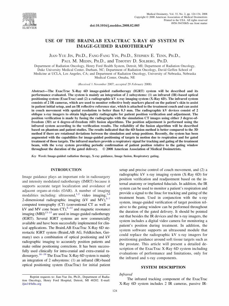
eflecting spheres placed on a patient’s surface, and aeference device (the reference star) that contains 4 re-ective circles (Fig. 1). The IR cameras are rigidlyounted to a metal bar attached to the ceiling and emitlow IR signal that is reflected and analyzed for posi-
ioning information. A 2-step calibration procedure haseen established to ensure that the IR cameras can accu-ately determine the position of IR reflectors in the treat-ent room. The first step corrects for distortions in the
R system and creates a coordinate space, while theecond step provides the system with the location ofhe linear accelerator (LINAC) isocenter. Studies by
ang et al.20 have demonstrated that the position of eachR-reflecting sphere can be determined to less than 0.3m. Automatic setup can then be easily achieved byoving the couch to match the marker’s position with
hose recorded in a CT image. In addition, the softwarelso provides rotational offsets along 3 primary axes.owever, the external markers have to be positioned in a
elatively stable location to achieve accurate setup. Withhe use of the reference star attached to the couch, theouch’s movement can be precisely determined.
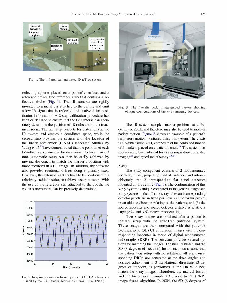
ig. 2. Respiratory motion from a patient at UCLA, character-
Fig. 1. The infrared camera-based ExacTrac system.
iized by the 3D F-factor defined by Baroni et al. (2000).
The IR system samples marker positions at a fre-uency of 20 Hz and therefore may also be used to monitoratient motion. Figure 2 shows an example of a patient’sespiratory motion monitored using this system. The y-axiss a 3-dimensional (3D) composite of the combined motionf 5 markers placed on a patient’s chest.21 The system hasubsequently been adopted for use in respiratory correlatedmaging22 and gated radiotherapy.23,24
-rayThe x-ray component consists of 2 floor-mounted
V x-ray tubes, projecting medial, anterior, and inferiorbliquely into 2 corresponding flat panel detectorsounted on the ceiling (Fig. 3). The configuration of this
-ray system is unique compared to the general diagnostic-ray systems in that: (1) the x-ray tubes and correspondingetector panels are in fixed positions, (2) the x-rays projectn an oblique direction relating to the patients, and (3) theource isocenter and source detector distance is relativelyarge (2.24 and 3.62 meters, respectively).
Two x-ray images are obtained after a patient isnitially setup with the ExacTrac (infrared) system.hese images are then compared with the patient’s-dimensional (3D) CT simulation images with the cor-esponding isocenter in terms of digital reconstructedadiography (DRR). The software provides several op-ions for matching the images. The manual match and theD (3 degrees of freedom) fusion methods assume thathe patient was setup with no rotational offsets. Corre-ponding DRRs are generated at the fixed angles andosition adjustment in 3 translational directions (3 de-rees of freedom) is performed in the DRRs to bestatch the x-ray images. Therefore, the manual fusion
nd 3D fusion use a simple 2D (x-ray) to 2D (DRR)
ig. 3. The Novalis body image-guided system showingoblique configurations of the x-ray imaging devices.
mage fusion algorithm. In 2004, the 6D (6 degrees of

fTD3iswitgi2s6ocspaittaij
mtst2mmffi
R
mitipf
dtrimtfiobtpc
tfiued
rdraippajsm
tbopocplcWirmwpttpp
ttdpGcerenliripea
Medical Dosimetry Volume 33, Number 2, 2008126
reedom) fusion option has been clinically implemented.he 6D fusion software first generates various sets ofRRs with position variations in both 3 translational androtational directions (6 degrees of freedom) for the CT
mages. It then compares these DRRs with the corre-ponding x-ray images and obtained the set of DRRsith the maximal similarity to the corresponding x-ray
mages. The best match is thus determined and the 3ranslational and 3 rotational position variations used toenerate the set of DRRs are the 6D offsets to fuse themages. Therefore, the 6D fusion method is actually a-dimensional (x-ray) to 3-dimensional (CT) image fu-ion algorithm. It should be pointed out that both 3D andD fusion methods have the choice of selecting a regionf interest for fusion and can exclude any structures thatould potentially increase uncertainty in the fusion. Theoftware also provides a match method of using im-lanted markers. The patient position accuracy and themount of offsets can be determined by comparing themplanted markers’ position in the x-ray images withhose in the CT images. For all of these methods, oncehe offsets are given, a patient’s position can be preciselydjusted using IR guidance. A set of verification x-raymages can be obtained to check the position after read-ustment.
The x-ray image fusion-guided position readjust-ent is usually performed once for each fraction before
reatment. Due to the special configuration of the x-rayystem, a set of x-ray images can only be obtained whenhe linac gantry is at around 0°, 80° to 100°, and 260° to80°. Therefore, monitoring patient position during treat-ent using the x-ray system is not always possible forany treatment field settings. However, the x-ray image
usion can be performed to readjust position between twoelds if position drift is a concern.
espiratory gatingIn 2005, the basic ExacTrac system has been aug-
ented to include a module for image-guided position-ng of targets in motion due to respiration and for gatedreatment of those targets. The ExacTrac Adaptive Gat-ng system uses stereoscopic kilovoltage radiographs foratient positioning and the IR marker detection systemor respiratory tracking and gating of the treatment beam.
Although it may be possible to track lung tumorsirectly using plane radiography,25 the ExacTrac Adap-ive Gating system is currently designed to be used withadiopaque fiducial markers implanted near the targetsocenter.26–29 These markers are implanted before treat-ent planning begins and should be placed close enough
o the target anatomy so that they can be seen within theeld of view of the x-ray localization system at the timef treatment. It is assumed that the spatial relationshipetween markers and target anatomy will remain rela-ively fixed.30 After fiducial markers have been im-lanted, a CT scan is obtained and a treatment plan is
reated. The CT planning information is then transferred co the ExacTrac system software. The user locates theducials in this CT dataset and their 3D coordinates aresed with the pinhole camera model to generate thexpected 2D image coordinates for each x-ray imagingetector.
For treatment, a patient is set up in the treatmentoom and IR reflective markers are attached to the ab-omen so that breathing motion can be monitored. Theeference star is also used here, both as a referencegainst which the movement of patient mounted markerss measured, and also to track couch location during theatient positioning process. The 3D movement of theatient’s anterior surface is tracked via the IR markersnd the anterior-posterior (A-P) component of this tra-ectory is used to monitor breathing motion. Target po-ition is expected to be correlated with this breathingotion.
The ExacTrac system plots breathing motion vs.ime, and a gating reference level is specified on thisreathing trace (Fig. 4). The gating level is the amplitudef the breathing trace at which the kV x-ray images foratient localization will be triggered. The images arebtained sequentially at the instant the breathing tracerosses this level during the exhale phase. Because theatient will be localized based on these images, the gatingevel should be set at the same phase in the breathingycle at which the planning CT data was obtained.ithin each image, the user locates the positions of the
mplanted fiducials. From these positions, the systemeconstructs the 3D geometry of the implants and deter-ines the shifts necessary to bring them into alignmentith the implants’ orientation as determined from thelanning CT. These localization shifts are then made tohe patient just as with the basic ExacTrac system. Oncehe patient has been positioned in this way, the target willass through the linac isocenter as the breathing traceasses through the gating level.
A high degree of correlation between the breathingrace and internal target motion is important for accuratearget coverage. Recent correlation studies have ad-ressed the ability of external surrogates of breathing toredict the position of internal target locations.27,31–39
enerally, these studies have shown a good degree oforrelation but may be dependent on the location of bothxternal markers and internal target. Results of clinicalesearch by Schweikard et al.36 showed that correlationrrors less than 2 mm between internal target and exter-al surface motion is possible over treatment times asong as 70 minutes. However, several authors have notedntrafractional changes in the relationship between respi-atory signal and tumor position due to unstable breath-ng.27,33,37,38 Breathing instruction might be able to im-rove predictability of tumor location with respect toxternal respiratory signal, thus increasing treatmentccuracy.40
Due to the uncertain nature of respiratory surrogate
orrelation with tumor position, intrafraction verification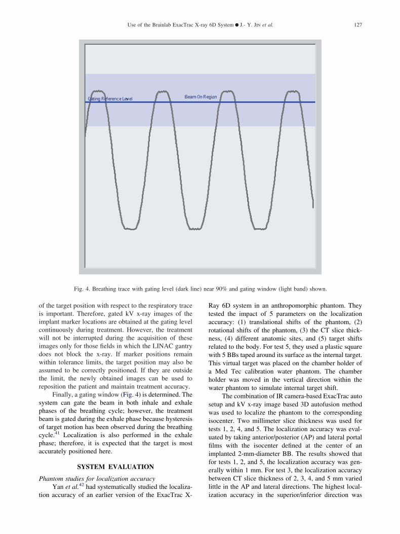
oiicwidwatr
spbocpa
P
t
RtarnrwTahw
switufiifebl
ne) ne
Use of the Brainlab ExacTrac X-ray 6D System ● J.- Y. JIN et al. 127
f the target position with respect to the respiratory traces important. Therefore, gated kV x-ray images of themplant marker locations are obtained at the gating levelontinuously during treatment. However, the treatmentill not be interrupted during the acquisition of these
mages only for those fields in which the LINAC gantryoes not block the x-ray. If marker positions remainithin tolerance limits, the target position may also be
ssumed to be correctly positioned. If they are outsidehe limit, the newly obtained images can be used toeposition the patient and maintain treatment accuracy.
Finally, a gating window (Fig. 4) is determined. Theystem can gate the beam in both inhale and exhalehases of the breathing cycle; however, the treatmenteam is gated during the exhale phase because hysteresisf target motion has been observed during the breathingycle.41 Localization is also performed in the exhalehase; therefore, it is expected that the target is mostccurately positioned here.
SYSTEM EVALUATION
hantom studies for localization accuracyYan et al.42 had systematically studied the localiza-
Fig. 4. Breathing trace with gating level (dark li
ion accuracy of an earlier version of the ExacTrac X- i
ay 6D system in an anthropomorphic phantom. Theyested the impact of 5 parameters on the localizationccuracy: (1) translational shifts of the phantom, (2)otational shifts of the phantom, (3) the CT slice thick-ess, (4) different anatomic sites, and (5) target shiftselated to the body. For test 5, they used a plastic squareith 5 BBs taped around its surface as the internal target.his virtual target was placed on the chamber holder ofMed Tec calibration water phantom. The chamber
older was moved in the vertical direction within theater phantom to simulate internal target shift.
The combination of IR camera-based ExacTrac autoetup and kV x-ray image based 3D autofusion methodas used to localize the phantom to the corresponding
socenter. Two millimeter slice thickness was used forests 1, 2, 4, and 5. The localization accuracy was eval-ated by taking anterior/posterior (AP) and lateral portallms with the isocenter defined at the center of an
mplanted 2-mm-diameter BB. The results showed thator tests 1, 2, and 5, the localization accuracy was gen-rally within 1 mm. For test 3, the localization accuracyetween CT slice thickness of 2, 3, 4, and 5 mm variedittle in the AP and lateral directions. The highest local-
ar 90% and gating window (light band) shown.
zation accuracy in the superior/inferior direction was

albb
ttdaaribisa
fpmtbmrtlmasarw
iJ
mioBCisafcrprblesMl
8tCpcuttr
brpa
s are s
Medical Dosimetry Volume 33, Number 2, 2008128
chieved with the 2-mm slice thickness. For test 4, theocalization accuracy in the head-and-neck region wasetter than in the thoracic and pelvis regions, most likelyecause the x-ray image quality was better.
Many factors have to be considered to interprethese results. The LINAC isocenter shifts slightly whenhe gantry rotates from the AP direction to a lateralirection. The agreement between the radiation isocenternd the isocenter defined by the wall-mounted lasers hastolerance of about 0.7 mm, as demonstrated by the
outine Winston-Lutz test. The evaluation method usedn this study was not able to detect localization accuracyetter than 0.7 mm; therefore, the observation that local-zation accuracy does not vary significantly with CT-lice thickness is likely due to a limitation of the evalu-tion method.
The results showed excellent localization accuracyor phantom with rotational shifts. This is because thehantom is a rigid object, and the external marker setupethod could detect potential rotational shifts and made
he correction. Clinically, a patient’s contour can changeetween setup and simulation and the external markersay be placed in locations with motion resulting in
otational and translational errors during the first step ofhe positioning procedure. This study also tested theocalization accuracy in a scenario where 1 of 5 internalarkers was shifted 2 cm, and found that the localization
ccuracy was degraded to less than 1.5 mm.42 Thisuggests that the 3D fusion localization method could notchieve desirable accuracy even in a rigid phantom ifotational and translational error existed when the x-raysere taken.
Recently, the 6D fusion localization software takingnto account the rotational errors was clinically released.
Fig. 5. Two verification kV x-ray images for evaluating thdistance between the isocenter of the x-ray system (reprby the center of the BB). The treatment isocenter seems
in this pair of images. Only some of the 8 BB
in et al.43 have studied the accuracy of this localization s
ethod in a phantom. Eight BBs of 2-mm diameter werenserted into different locations of a head phantom. Onef the BBs was used as the isocenter, while the rest of theBs served as the implanted markers. Both 2- and 3-mmT slices were studied. The head phantom was placed
ntentionally with certain rotational and translationalhifts. Localization methods using 3D fusion, 6D fusion,nd implanted markers were used. For both 3D and 6Dusions, the image areas with implanted BBs were ex-luded for the fusion. The localization methods wereepeated 8 times at different locations, with the isocenterlaced at the center of different BBs. Localization accu-acy was evaluated using the portal film method reportedy Yan et al.42 The results from the implanted markerocalization study were used as an additional standard tovaluate the 3D and 6D fusion methods. Figures 5 and 6how a set of kV verification x-ray images and a set ofV portal film images, respectively, with the isocenter
ocalized at the center of a BB.Table 1 shows the average localization accuracy for
isocenters determined by the kV x-ray images and byhe MV portal films, and for 2- and 3-mm slice thicknessT images. We note that both kV x-ray images andortal films demonstrated that excellent localization ac-uracy was achieved for all different isocenter locationssing the 6D fusion method. Using 2- and 3-mm CT slicehickness seemed to produce no significant difference tohe localization accuracy. This was consistent with theesults from Yan et al.42
Table 2 gives the comparison of localization accuracyetween the 3D fusion and 6D fusion methods at 2 differentotational settings and 2 different positions: the randomosition had about 3- to 5-cm translational deviations; theligned position had no translational deviation. Rotational
lization accuracy, which is determined by measuring theby the cross) and the treatment isocenter (represented
excellently coincided with the x-ray system’s isocenterhown in the images due to limited view size.
e locaesentedto be
etting no. 1 and setting no. 2 had slightly different phantom

rb
lrahdtacarwTttdi
P
tolt
wiftl�Yutrrlttio
●
●
●
●
●
ited po
Use of the Brainlab ExacTrac X-ray 6D System ● J.- Y. JIN et al. 129
otational angles. The localization accuracy was evaluatedy the implanted markers method.
We note that the 6D fusion localization had excel-ent accuracy for both angular settings, and for both theandom and the aligned positions. In addition, the 3ngular deviations, determined by the 6D fusion method,ad almost no variation for different isocenters and forifferent positions. However, for the 3D fusion method,here was a significant localization error, even at theligned position. The localization error seemed to in-rease with the angular deviations. This is understand-ble because the isocenters were selected at the brainegion, while the fusion was based on the bony structure,hich was about 5 to 10 cm away from the isocenter.hese results suggest that using 6D fusion could improve
he localization accuracy for real patients compared withhe 3D fusion method, especially when large rotationaleviations exist at the initial setup when localizationmages were taken.
atient studies for localization accuracyWeiss et al.44 evaluated the localization accuracy of
he infrared body-marker–based ExacTrac system (with-ut the x-ray component) in patients treated for gyneco-ogic carcinomas, and compared it with patients posi-ioned using the conventional room laser system. Patients
Table 1. 6D fusion localization accuracy evaluated byanthropomorphic head phantom w
CT Slice Thickness
By kV X-Rays
Image 1 (mm) Image 2 (mm)
2 mm 0.42 � 0.21 0.48 � 0.18
Fig. 6. AP and lateral MV portal images for evaluating thdistance between the LINAC isocenter (center of the 9.8lines) and the treatment isocenter (represented by the cent
due to lim
3 mm 0.60 � 0.13 0.56 � 0.17 0.72
ere treated in a prone position. The electronic portalmaging device (EPID) was used for the evaluation. Theyound that there was no significant difference betweenhe ExacTrac system and the room laser system. Theocalization error for the ExacTrac system ranged from
5.5 to 12.1, �14.4 to 7.3, and �4.1 to 15.6 mm at X,, and Z directions, respectively. This large localizationncertainty is understandable because patients were inhe prone position. Respiratory motion in the abdominalegion would transfer to the pelvis area. When the infra-ed markers were placed at locations of a patient witharge movement, it seems that there was no any advan-age of using the ExacTrac (infrared) system comparedo using room laser system to align the patient to thesocenter tattoo. However, the ExacTrac system doesffer the following benefits:
Faster and automatic setupMotion trackingWhen the isocenter tattoo has to be marked at thelocation with large movement, the external markerscan be placed at relative small motion locations toimprove the localization repeatability and consistencyProvides quantitative rotational errorsPrecisely controls the table position with the referencestar attached to the table
cation kV x-ray images and MV portal images in anslice thickness of 2 and 3 mm
By MV Portal Film
verall Image 1 Image 2 Overall
� 0.14 0.56 � 0.19 0.60 � 0.12 0.72 � 0.12
lization accuracy, which is determined by measuring thecm portal represented by the intersection of 2 diagonale BB). Only some of the 8 BBs are shown in the imagesrtal size.
verifiith CT
O
0.57
e loca� 9.8er of th
� 0.16 0.60 � 0.17 0.58 � 0.21 0.74 � 0.15
sir0lwctbtttupuad
6aMpwcfrcpeFdItd46tmc
R
Eapso
tsdgs
aImpmHopAldl
mStpMmai
0.17
Ft
Medical Dosimetry Volume 33, Number 2, 2008130
Yin et al. reported the localization accuracy for 25pine patients using the combination of ExacTrac and 3Dmage fusion localization method.45 The average accu-acy for the 25 patients was reported to be 0.7 � 0.7,.8 � 0.9, and 0.9 � 0.5 mm at anterior-posterior,eft-right, and superior-inferior directions, respectively,ith an overall average of 1.6 � 0.9 mm. This result was
onsistent with the accuracy demonstrated in the phan-om study. Note that the data were acquired and analyzedased on pseudo-rigid vertebral body with a stable pa-ient immobilization device. The errors reported here forhe portal films did not include linac isocenter inconsis-ency, which was in the order of about 0.7 mm, and thencertainty of defining bony land markers in DRRs andortal films, especially for the MV portal films, whichsually have poor image quality. The error defined waslso strictly for the isocenter and did not include anyeviations related to rotations around the isocenter.
Jin et al. have studied the localization accuracy ofD fusion localization method in patients for both cranialnd spinal lesions.43,46 Verification kV x-ray images andV portal film after localization were taken and com-
ared to the corresponding DRRs. The bony structuresere clearly seen in cranial kV x-ray images for all
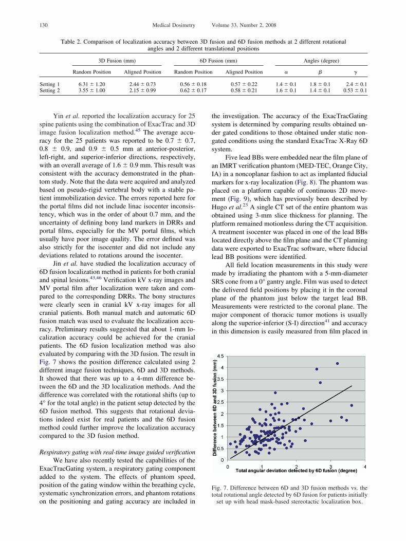
ranial patients. Both manual match and automatic 6Dusion match was used to evaluate the localization accu-acy. Preliminary results suggested that about 1-mm lo-alization accuracy could be achieved for the cranialatients. The 6D fusion localization method was alsovaluated by comparing with the 3D fusion. The result inig. 7 shows the position difference calculated using 2ifferent image fusion techniques, 6D and 3D methods.t showed that there was up to a 4-mm difference be-ween the 6D and the 3D localization methods. And theifference was correlated with the rotational shifts (up to° for the total angle) in the patient setup detected by theD fusion method. This suggests that rotational devia-ions indeed exist for real patients and the 6D fusionethod could further improve the localization accuracy
ompared to the 3D fusion method.
espiratory gating with real-time image guided verificationWe have also recently tested the capabilities of the
xacTracGating system, a respiratory gating componentdded to the system. The effects of phantom speed,osition of the gating window within the breathing cycle,ystematic synchronization errors, and phantom rotations
Table 2. Comparison of localization accuracy betweenangles and 2 differe
3D Fusion (mm)
Random Position Aligned Position Random P
Setting 1 6.31 � 1.20 2.44 � 0.73 0.56 �Setting 2 3.55 � 1.00 2.15 � 0.99 0.62 �
n the positioning and gating accuracy are included in
he investigation. The accuracy of the ExacTracGatingystem is determined by comparing results obtained un-er gated conditions to those obtained under static non-ated conditions using the standard ExacTrac X-Ray 6Dystem.
Five lead BBs were embedded near the film plane ofn IMRT verification phantom (MED-TEC, Orange City,A) in a noncoplanar fashion to act as implanted fiducialarkers for x-ray localization (Fig. 8). The phantom was
laced on a platform capable of continuous 2D move-ent (Fig. 9), which has previously been described byugo et al.23 A single CT set of the entire phantom wasbtained using 3-mm slice thickness for planning. Thelatform remained motionless during the CT acquisition.
treatment isocenter was placed in one of the lead BBsocated directly above the film plane and the CT planningata were exported to ExacTrac software, where fiducialead BB positions were identified.
All field location measurements in this study wereade by irradiating the phantom with a 5-mm-diameterRS cone from a 0° gantry angle. Film was used to detect
he delivered field positions by placing it in the coronallane of the phantom just below the target lead BB.easurements were restricted to the coronal plane. Theajor component of thoracic tumor motions is usually
long the superior-inferior (S-I) direction41 and accuracyn this dimension is easily measured from film placed in
sion and 6D fusion methods at 2 different rotationalslational positions
sion (mm) Angles (degree)
Aligned Position � � �
0.57 � 0.22 1.4 � 0.1 1.8 � 0.1 2.4 � 0.10.58 � 0.21 1.6 � 0.1 1.4 � 0.1 0.53 � 0.1
ig. 7. Difference between 6D and 3D fusion methods vs. theotal rotational angle detected by 6D fusion for patients initially
3D funt tran
6D Fu
osition
0.18
set up with head mask-based stereotactic localization box.

tarl
21asapsgtcmgggutraddbmilw
l
Fsl
Use of the Brainlab ExacTrac X-ray 6D System ● J.- Y. JIN et al. 131
he coronal plane. Five pins in the phantom mark the filmnd allow exposed films to be registered into a commoneference frame for comparison. Field center or massocations were used to determine accuracy.
ig. 8. X-ray image from one of the localization imaging unitshowing the 5 fiducial lead BBs implanted in the phantom. Thearger circles in the image are the IR reflectors attached to the
phantom surface.
Fig. 9. The IMRT phantom can be seen resting on our mmarkers are attached to the phantom and the table, respectiv
x-ray tubes can be seen as well. All fields were delivered usi
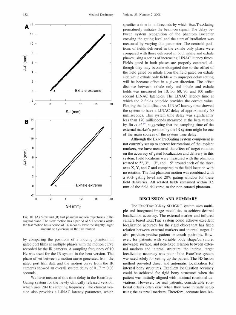
The effect of phantom speed was investigated usingdifferent 2D motions moving in the sagittal plane (Fig.
0). The first motion (10A) had a period of 5.7 seconds,n S-I range of 1.8 cm, and an A-P range of 1.2 cm. Theecond motion (10B) had the same displacement rangess the first but had a shorter period of 3.6 seconds. Targetosition under gating conditions, represented by the po-ition of the target BB in the film, was measured withating levels of 10%, 50%, and 90% of the breathingrace peak-to-peak height, and was compared with theorresponding position under static condition. A sym-etric gating window of 20% was placed around the
ating level for every condition except for the 50%ating level and fast motion combination, for which aating window of 30% was used. A 30% window wassed for the specified condition because the beam-onime interval was too short for the LINAC to deliver anyadiation using a 20% window. Fields gated at the 50%nd 90% amplitude levels were not different from fieldselivered under static conditions by more than one stan-ard deviation (0.1 mm). Fields gated at 10% were offsety approximately 1 mm. This could be because muchore radiation fluence was delivered to the target when
t was below the 10% gating level than it was above thisevel (the target had the slowest motion speed when itas at the exhale peak).
Jin and Yin24 have determined the overall systematency in a beta version of the ExacTracGating system
ical motion platform. IR reflective patient and referenceeiling-mounted aSi detectors and one of the floor-mounted
echanely. C
ng our Novalis linac from the 0° gantry angle shown.
bgrHpgcs
Gws
sptcmtcpFttswdfiswPtmlbeo
nmosranafim
plclraemnlwmicpvt
Fst
Medical Dosimetry Volume 33, Number 2, 2008132
y comparing the positions of a moving phantom inated port films at multiple phases with the motion curveecorded by the IR cameras. A sampling frequency of 10z was used for the IR system in the beta version. Thehase offset between a motion curve generated from theated port film data and the motion curve from the IRameras showed an overall system delay of 0.17 � 0.03econds.
We have measured this time delay in the ExacTrac-ating system for the newly clinically released version,hich uses 20-Hz sampling frequency. The clinical ver-
ig. 10. (A) Slow and (B) fast phantom motion trajectories in theagittal plane. The slow motion has a period of 5.7 seconds whilehe fast motion has a period of 3.6 seconds. Note the slightly larger
amount of hysteresis in the fast motion.
ion also provides a LINAC latency parameter, which u
pecifies a time in milliseconds by which ExacTracGatingrematurely initiates the beam-on signal. The delay be-ween system recognition of the phantom isocenterrossing the gating level and the start of irradiation waseasured by varying this parameter. The centroid posi-
ions of fields delivered in the exhale only phase wereompared with those delivered in both inhale and exhalehases using a series of increasing LINAC latency times.ields gated in both phases are properly centered, al-
hough they may become elongated due to the offset ofhe field gated on inhale from the field gated on exhaleide while exhale only fields with improper delay settingill be become offset in a given direction. The offsetistance between exhale only and inhale and exhaleelds was measured for 10, 50, 60, 70, and 100 milli-econd LINAC latencies. The LINAC latency time athich the 2 fields coincide provides the correct value.lotting the field offsets vs. LINAC latency time showed
he system to have a LINAC delay of approximately 60illiseconds. This system time delay was significantly
ess than 170 milliseconds measured at the beta versiony Jin et al.24, suggesting that the sampling time of thexternal marker’s position by the IR system might be onef the main sources of the system time delay.
Although the ExacTracGating system component isot currently set up to correct for rotations of the implantarkers, we have measured the effect of target rotation
n the accuracy of gated localization and delivery in thisystem. Field locations were measured with the phantomotated to 5°, 3°, �3°, and �5° around each of the threexes X, Y, and Z and compared to the field location witho rotation. The fast phantom motion was combined with90% gating level and 20% gating window for these
eld deliveries. All rotated fields remained within 0.5m of the field delivered to the non-rotated phantom.
DISCUSSION AND SUMMARY
The ExacTrac X-Ray 6D IGRT system uses multi-le and integrated image modalities to achieve desiredocalization accuracy. The external marker and infraredamera based ExacTrac system could achieve excellentocalization accuracy for the rigid object that has fixedelation between external markers and internal target. Itlso provides precise patient or couch positions. How-ver, for patients with variable body shape/curvature,oveable surface, and non-fixed relation between exter-
al markers and internal structure, the internal targetocalization accuracy was poor if the ExacTrac systemas used solely for setting up the patient. The 3D fusionethod provided direct and automatic localization for
nternal bony structures. Excellent localization accuracyould be achieved for rigid bony structures when theatient was initially aligned with minimal rotational de-iations. However, for real patients, considerable rota-ional offsets often exist when they were initially setup
sing the external markers. Therefore, accurate localiza-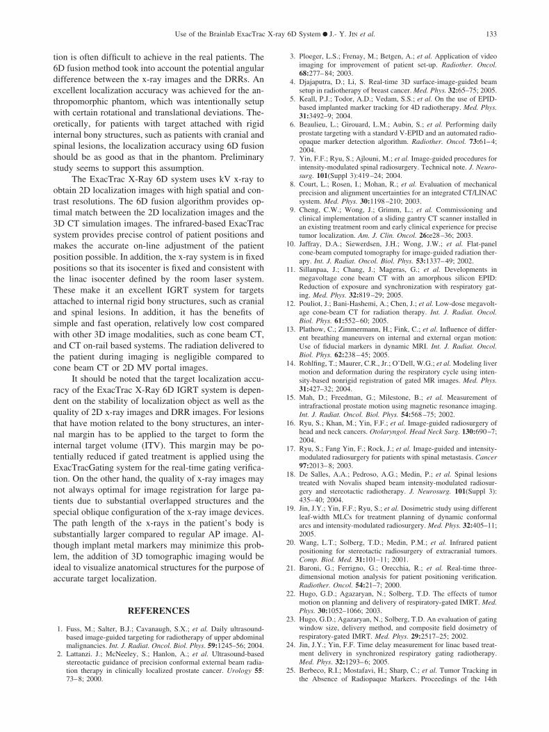
t6detwoisss
ott3smpptTaaswatc
rdqtnitEtntsTstlia
1
1
1
1
1
1
1
1
1
1
2
2
2
2
2
2
Use of the Brainlab ExacTrac X-ray 6D System ● J.- Y. JIN et al. 133
ion is often difficult to achieve in the real patients. TheD fusion method took into account the potential angularifference between the x-ray images and the DRRs. Anxcellent localization accuracy was achieved for the an-hropomorphic phantom, which was intentionally setupith certain rotational and translational deviations. The-retically, for patients with target attached with rigidnternal bony structures, such as patients with cranial andpinal lesions, the localization accuracy using 6D fusionhould be as good as that in the phantom. Preliminarytudy seems to support this assumption.
The ExacTrac X-Ray 6D system uses kV x-ray tobtain 2D localization images with high spatial and con-rast resolutions. The 6D fusion algorithm provides op-imal match between the 2D localization images and theD CT simulation images. The infrared-based ExacTracystem provides precise control of patient positions andakes the accurate on-line adjustment of the patient
osition possible. In addition, the x-ray system is in fixedositions so that its isocenter is fixed and consistent withhe linac isocenter defined by the room laser system.hese make it an excellent IGRT system for targetsttached to internal rigid bony structures, such as cranialnd spinal lesions. In addition, it has the benefits ofimple and fast operation, relatively low cost comparedith other 3D image modalities, such as cone beam CT,
nd CT on-rail based systems. The radiation delivered tohe patient during imaging is negligible compared toone beam CT or 2D MV portal images.
It should be noted that the target localization accu-acy of the ExacTrac X-Ray 6D IGRT system is depen-ent on the stability of localization object as well as theuality of 2D x-ray images and DRR images. For lesionshat have motion related to the bony structures, an inter-al margin has to be applied to the target to form thenternal target volume (ITV). This margin may be po-entially reduced if gated treatment is applied using thexacTracGating system for the real-time gating verifica-
ion. On the other hand, the quality of x-ray images mayot always optimal for image registration for large pa-ients due to substantial overlapped structures and thepecial oblique configuration of the x-ray image devices.he path length of the x-rays in the patient’s body isubstantially larger compared to regular AP image. Al-hough implant metal markers may minimize this prob-em, the addition of 3D tomographic imaging would bedeal to visualize anatomical structures for the purpose ofccurate target localization.
REFERENCES
1. Fuss, M.; Salter, B.J.; Cavanaugh, S.X.; et al. Daily ultrasound-based image-guided targeting for radiotherapy of upper abdominalmalignancies. Int. J. Radiat. Oncol. Biol. Phys. 59:1245–56; 2004.
2. Lattanzi. J.; McNeeley, S.; Hanlon, A.; et al. Ultrasound-basedstereotactic guidance of precision conformal external beam radia-
tion therapy in clinically localized prostate cancer. Urology 55:73–8; 2000.3. Ploeger, L.S.; Frenay, M.; Betgen, A.; et al. Application of videoimaging for improvement of patient set-up. Radiother. Oncol.68:277–84; 2003.
4. Djajaputra, D.; Li, S. Real-time 3D surface-image-guided beamsetup in radiotherapy of breast cancer. Med. Phys. 32:65–75; 2005.
5. Keall, P.J.; Todor, A.D.; Vedam, S.S.; et al. On the use of EPID-based implanted marker tracking for 4D radiotherapy. Med. Phys.31:3492–9; 2004.
6. Beaulieu, L.; Girouard, L.M.; Aubin, S.; et al. Performing dailyprostate targeting with a standard V-EPID and an automated radio-opaque marker detection algorithm. Radiother. Oncol. 73:61–4;2004.
7. Yin, F.F.; Ryu, S.; Ajlouni, M.; et al. Image-guided procedures forintensity-modulated spinal radiosurgery. Technical note. J. Neuro-surg. 101(Suppl 3):419–24; 2004.
8. Court, L.; Rosen, I.; Mohan, R.; et al. Evaluation of mechanicalprecision and alignment uncertainties for an integrated CT/LINACsystem. Med. Phys. 30:1198–210; 2003.
9. Cheng, C.W.; Wong, J.; Grimm, L.; et al. Commissioning andclinical implementation of a sliding gantry CT scanner installed inan existing treatment room and early clinical experience for precisetumor localization. Am. J. Clin. Oncol. 26:e28–36; 2003.
0. Jaffray, D.A.; Siewerdsen, J.H.; Wong, J.W.; et al. Flat-panelcone-beam computed tomography for image-guided radiation ther-apy. Int. J. Radiat. Oncol. Biol. Phys. 53:1337–49; 2002.
1. Sillanpaa, J.; Chang, J.; Mageras, G.; et al. Developments inmegavoltage cone beam CT with an amorphous silicon EPID:Reduction of exposure and synchronization with respiratory gat-ing. Med. Phys. 32:819–29; 2005.
2. Pouliot, J.; Bani-Hashemi, A.; Chen, J.; et al. Low-dose megavolt-age cone-beam CT for radiation therapy. Int. J. Radiat. Oncol.Biol. Phys. 61:552–60; 2005.
3. Plathow, C.; Zimmermann, H.; Fink, C.; et al. Influence of differ-ent breathing maneuvers on internal and external organ motion:Use of fiducial markers in dynamic MRI. Int. J. Radiat. Oncol.Biol. Phys. 62:238–45; 2005.
4. Rohlfing, T.; Maurer, C.R., Jr.; O’Dell, W.G.; et al. Modeling livermotion and deformation during the respiratory cycle using inten-sity-based nonrigid registration of gated MR images. Med. Phys.31:427–32; 2004.
5. Mah, D.; Freedman, G.; Milestone, B.; et al. Measurement ofintrafractional prostate motion using magnetic resonance imaging.Int. J. Radiat. Oncol. Biol. Phys. 54:568–75; 2002.
6. Ryu, S.; Khan, M.; Yin, F.F.; et al. Image-guided radiosurgery ofhead and neck cancers. Otolaryngol. Head Neck Surg. 130:690–7;2004.
7. Ryu, S.; Fang Yin, F.; Rock, J.; et al. Image-guided and intensity-modulated radiosurgery for patients with spinal metastasis. Cancer97:2013–8; 2003.
8. De Salles, A.A.; Pedroso, A.G.; Medin, P.; et al. Spinal lesionstreated with Novalis shaped beam intensity-modulated radiosur-gery and stereotactic radiotherapy. J. Neurosurg. 101(Suppl 3):435–40; 2004.
9. Jin, J.Y.; Yin, F.F.; Ryu, S.; et al. Dosimetric study using differentleaf-width MLCs for treatment planning of dynamic conformalarcs and intensity-modulated radiosurgery. Med. Phys. 32:405–11;2005.
0. Wang, L.T.; Solberg, T.D.; Medin, P.M.; et al. Infrared patientpositioning for stereotactic radiosurgery of extracranial tumors.Comp. Biol. Med. 31:101–11; 2001.
1. Baroni, G.; Ferrigno, G.; Orecchia, R.; et al. Real-time three-dimensional motion analysis for patient positioning verification.Radiother. Oncol. 54:21–7; 2000.
2. Hugo, G.D.; Agazaryan, N.; Solberg, T.D. The effects of tumormotion on planning and delivery of respiratory-gated IMRT. Med.Phys. 30:1052–1066; 2003.
3. Hugo, G.D.; Agazaryan, N.; Solberg, T.D. An evaluation of gatingwindow size, delivery method, and composite field dosimetry ofrespiratory-gated IMRT. Med. Phys. 29:2517–25; 2002.
4. Jin, J.Y.; Yin, F.F. Time delay measurement for linac based treat-ment delivery in synchronized respiratory gating radiotherapy.Med. Phys. 32:1293–6; 2005.
5. Berbeco, R.I.; Mostafavi, H.; Sharp, C.; et al. Tumor Tracking in
the Absence of Radiopaque Markers. Proceedings of the 14th
2
2
2
2
3
3
3
3
3
3
3
3
3
3
4
4
4
4
4
4
4
Medical Dosimetry Volume 33, Number 2, 2008134
International Conference on Computer Use in Radiation Therapy(ICCR). Seoul, South Korea; 2004.
6. Harada, T.; Shirato, H.; Ogura, S.; et al. Real-time tumor-trackingradiation therapy for lung carcinoma by the aid of insertion of agold marker using bronchofiberscopy. Cancer 95:1720–7; 2002.
7. Ozhasoglu, C.; Murphy, M.J. Issues in respiratory motion com-pensation during external-beam radiotherapy. Int. J. Radiat. Oncol.Biol. Phys. 52:1389–99; 2002.
8. Shirato, H.; Harada, T.; Harabayashi, T.; et al. Feasibility ofinsertion/implantation of 2.0-mm-diameter gold internal fiducialmarkers for precise setup and real-time tumor tracking in radio-therapy. Int. J. Radiat. Oncol. Biol. Phys. 56:240–7; 2003.
9. Whyte, R.I.; Crownover, R.; Murphy, M.J.; et al. Stereotacticradiosurgery for lung tumors: Preliminary report of a phase I trial.Ann Thorac. Surg. 75:1097–10; 2003.
0. Ebe, K.; Shirato, H.; Hiyama, A.; et al. Integration of fluoroscopicreal-time tumor-tracking system and tomographic scanner on therail in the treatment room. Int. J. Radiat. Oncol. Biol. Phys.60:S604; 2004.
1. Vedam, S.S.; Kini, V.R.; Keall, P.J.; et al. Quantifying the pre-dictability of diaphragm motion during respiration with a nonin-vasive external marker. Med. Phys. 30:505–13; 2003.
2. Ahn, S.; Yi, B.; Suh, Y.; et al. A feasibility study on the predictionof tumour location in the lung from skin motion. Br. J. Radiol.77:588–96; 2004.
3. Hoisak, J.D.; Sixel, K.E.; Tirona, R.; et al. Correlation of lungtumor motion with external surrogate indicators of respiration. Int.J. Radiat. Oncol. Biol. Phys. 60:1298–306; 2004.
4. Koch, N.; Liu, H.H.; Starkschall, G.; et al. Evaluation of internallung motion for respiratory-gated radiotherapy using MRI: PartI--correlating internal lung motion with skin fiducial motion. Int. J.Radiat. Oncol. Biol. Phys. 60:1459–72; 2004.
5. Liu, H.H.; Koch, N.; Starkschall, G.; et al. Evaluation of internallung motion for respiratory-gated radiotherapy using MRI: PartII-margin reduction of internal target volume Int. J. Radiat. Oncol.Biol. Phys. 60:1473–83; 2004.
6. Schweikard, A.; Shiomi, H.; Adler, J. Respiration tracking in
radiosurgery Med. Phys. 31:2738–41; 2004.7. Tsunashima, Y.; Sakae, T.; Shioyama, Y.; et al. Correlation be-tween the respiratory waveform measured using a respiratory sen-sor and 3D tumor motion in gated radiotherapy. Int. J. Radiat.Oncol. Biol. Phys. 60:951–8; 2004.
8. Berbeco, R.I.; Nishioka, S.; Shirato, H.; et al. Residual motion oflung tumours in gated radiotherapy with external respiratory sur-rogates. Phys. Med. Biol. 50:3655–67; 2005.
9. Plathow, C.; Zimmermann, H.; Fink, C.; et al. Influence of differ-ent breathing maneuvers on internal and external organ motion:Use of fiducial markers in dynamic MRI. Int. J. Radiat. Oncol.Biol. Phys. 62:238–45; 2005.
0. George. R.; Ramakrishnan, V.; Siebers, J.; et al. Investigation ofvariables affecting residual motion for respiratory gated radiother-apy. Med. Phys. 32:2124; 2005.
1. Seppenwoolde, Y.; Shirato, H.; Kitamura, K.; et al. Precise andreal-time measurement of 3D tumor motion in lung due to breath-ing and heartbeat, measured during radiotherapy. Int. J. Radiat.Oncol. Biol. Physz. 53:822–34; 2002.
2. Yan, H.; Yin, F.F.; Kim, J.H. A phantom study on the positioningaccuracy of the Novalis Body system. Med. Phys. 30:3052–60;2003.
3. Jin, J.Y.; Ryu, S.; Faber, K.; et al. 2D/3D image fusion for accuratetarget localization and evaluation of a mask based stereotacticsystem in fractionated stereotactic radiotherapy of cranial lesions.Med. Phys. 33:4557–66; 2006.
4. Weiss, E.; Vorwerk, H.; Richter, S.; et al. Interfractional andintrafractional accuracy during radiotherapy of gynecologic carci-nomas: A comprehensive evaluation using the ExacTrac system.Int. J. Radiat. Oncol. Biol. Phys. 56:69–79; 2003.
5. Yin, F.F.; Ryu, S.; Ajlouni, M.; et al. A technique of intensity-modulated radiosurgery (IMRS) for spinal tumors. Med. Phys.29:2815–22; 2002.
6. Jin, J.Y.; Ryu, S.; Rock, J.; et al. Image-guided target localizationfor stereotactic surgery: accuracy of 6D versus 3D image fusion.In: Kondziolka, D., ed. Radiosurgery (Vol. 6). Basel: Karger; 2006:
50-59.