Use of simple finite elements for mechanical systems impact analysis based on stereomechanics,...
13
Journal of Mechanical Science and Technology 25 (3) (2011) 783~795 www.springerlink.com/content/1738-494x DOI 10.1007/s12206-011-0125-5 Use of simple finite elements for mechanical systems impact analysis based on stereomechanics, stress wave propagation, and energy method approaches † Michael L. McCoy, Rasoul Moradi and Hamid M. Lankarani * Department of Mechanical Engineering, Wichita State University, 1845 N. Fairmount, Wichita, Kansas, 67260-0133, USA (Manuscript Received April 20, 2010; Revised November 15, 2010; Accepted November 22, 2010) ---------------------------------------------------------------------------------------------------------------------------------------------------------------------------------------------------------------------------------------------------------------------------------------------- Abstract This paper examines the effectiveness of analyzing impact events in mechanical systems for design purposes using simple or low or- dered finite elements. Traditional impact dynamics analyses of mechanical systems namely stereomechanics, energy method, stress-wave propagation and contact mechanics approaches are limited to very simplified geometries and provide basic analyses in making predic- tions and understanding the dominant features of the impact in a mechanical system. In engineering practice, impacted systems present a complexity of geometry, stiffness, mass distributions, contact areas and impact angles that are impossible to analyze and design with the traditional impact dynamics methods. In real cases, the effective tool is the finite element (FE) method. The high-end FEA codes though may be not available for typical engineer/designer. This paper provides information on whether impact events of mechanical systems can be successfully modeled using simple or low-order finite elements. FEA models using simple elements are benchmarked against theo- retical impact problems and published experimental impact results. As a case study, an FE model using simple plastic beam elements is further tested to predict stresses and deflections in an experimental structural impact. Keywords: Impact dynamics; Stereomechanics; Stress wave; Energy method; FEA impact simulation; FEA impact benchmarks ---------------------------------------------------------------------------------------------------------------------------------------------------------------------------------------------------------------------------------------------------------------------------------------------- 1. Introduction The nature of impact involves a minimum of a two body mechanical system. Impact phenomena is quite varied de- pending on the velocity of the impactor and the characteristics of the target or struck system. Zukus [1, 2] presents that for high velocity impacts, the response of the impacted system to the impact is very local and is highly dependent on the consti- tution of the material type impacted. For low velocity impacts, both the geometry and material respond to the impactor. Shi- vaswamy [3] showed through his experimental work that the nature of impacts involves very short contact times combined with large contact forces. In addition, the stiffness of the im- pacted system greatly influences the contact time and force. It was shown that contact force, contact time and system stiff- ness are inversely related. As system stiffness increases, con- tact forces increase, but contact time decreases. In an attempt to classify at what defines an impact condition, Blake [4], Faupel [5] and Juvinall [6] present loading classifi- cations. For a load whose rise time is greater than three times the fundamental period of free vibration of the mechanical system, the loading is considered static and conventional de- flection and stress analysis techniques using classical material properties apply. For a loading rise time of less than three, but greater than one and one-half times the fundamental period, is classified as rapid loading. Vibration methods for stress and deflection analysis should be incorporated for rapid loading conditions. However, in practice for rapid loading conditions, classical methods of static stress and deflection analysis are used with multiplying the stresses and deflections by a factor of two. Craig [7] demonstrates how the factor of two rule is derived from classical vibration theory. If the time of load application is less than 0.5 times the fundamental period of the mechanical system, the loading is defined as impact. The static methods of stress, strain and deflection analyses are meaningless under impact conditions. This is due to propaga- tion, reflection and interference of elastic/plastic waves travel- ing within the engineering solid. Accurate calculation of stresses and strains need to be based on wave analysis meth- ods, which are exceedingly complex for practical use and thus used to solve a limited number of simple cases [6]. Other methods such as contact mechanics, energy methods and the FEA method are required to be implemented in order to esti- mate the effects of impact conditions on mechanical systems that exhibit any degree of complexity. Faik [8] divides the modeling of impact systems into four † This paper was recommended for publication in revised form by Associate Editor Chang-Wan Kim * Corresponding author. Tel.: +1 316 978 6307, Fax.: +1 316 978 6307 E-mail address: [email protected] © KSME & Springer 2011
-
Upload
independent -
Category
Documents
-
view
3 -
download
0
Transcript of Use of simple finite elements for mechanical systems impact analysis based on stereomechanics,...

Journal of Mechanical Science and Technology 25 (3) (2011) 783~795
www.springerlink.com/content/1738-494x DOI 10.1007/s12206-011-0125-5
Use of simple finite elements for mechanical systems impact analysis based on
stereomechanics, stress wave propagation, and energy method approaches† Michael L. McCoy, Rasoul Moradi and Hamid M. Lankarani*
Department of Mechanical Engineering, Wichita State University, 1845 N. Fairmount, Wichita, Kansas, 67260-0133, USA
(Manuscript Received April 20, 2010; Revised November 15, 2010; Accepted November 22, 2010)
----------------------------------------------------------------------------------------------------------------------------------------------------------------------------------------------------------------------------------------------------------------------------------------------
Abstract This paper examines the effectiveness of analyzing impact events in mechanical systems for design purposes using simple or low or-
dered finite elements. Traditional impact dynamics analyses of mechanical systems namely stereomechanics, energy method, stress-wave propagation and contact mechanics approaches are limited to very simplified geometries and provide basic analyses in making predic-tions and understanding the dominant features of the impact in a mechanical system. In engineering practice, impacted systems present a complexity of geometry, stiffness, mass distributions, contact areas and impact angles that are impossible to analyze and design with the traditional impact dynamics methods. In real cases, the effective tool is the finite element (FE) method. The high-end FEA codes though may be not available for typical engineer/designer. This paper provides information on whether impact events of mechanical systems can be successfully modeled using simple or low-order finite elements. FEA models using simple elements are benchmarked against theo-retical impact problems and published experimental impact results. As a case study, an FE model using simple plastic beam elements is further tested to predict stresses and deflections in an experimental structural impact.
Keywords: Impact dynamics; Stereomechanics; Stress wave; Energy method; FEA impact simulation; FEA impact benchmarks ---------------------------------------------------------------------------------------------------------------------------------------------------------------------------------------------------------------------------------------------------------------------------------------------- 1. Introduction
The nature of impact involves a minimum of a two body mechanical system. Impact phenomena is quite varied de-pending on the velocity of the impactor and the characteristics of the target or struck system. Zukus [1, 2] presents that for high velocity impacts, the response of the impacted system to the impact is very local and is highly dependent on the consti-tution of the material type impacted. For low velocity impacts, both the geometry and material respond to the impactor. Shi-vaswamy [3] showed through his experimental work that the nature of impacts involves very short contact times combined with large contact forces. In addition, the stiffness of the im-pacted system greatly influences the contact time and force. It was shown that contact force, contact time and system stiff-ness are inversely related. As system stiffness increases, con-tact forces increase, but contact time decreases.
In an attempt to classify at what defines an impact condition, Blake [4], Faupel [5] and Juvinall [6] present loading classifi-cations. For a load whose rise time is greater than three times the fundamental period of free vibration of the mechanical
system, the loading is considered static and conventional de-flection and stress analysis techniques using classical material properties apply. For a loading rise time of less than three, but greater than one and one-half times the fundamental period, is classified as rapid loading. Vibration methods for stress and deflection analysis should be incorporated for rapid loading conditions. However, in practice for rapid loading conditions, classical methods of static stress and deflection analysis are used with multiplying the stresses and deflections by a factor of two. Craig [7] demonstrates how the factor of two rule is derived from classical vibration theory. If the time of load application is less than 0.5 times the fundamental period of the mechanical system, the loading is defined as impact. The static methods of stress, strain and deflection analyses are meaningless under impact conditions. This is due to propaga-tion, reflection and interference of elastic/plastic waves travel-ing within the engineering solid. Accurate calculation of stresses and strains need to be based on wave analysis meth-ods, which are exceedingly complex for practical use and thus used to solve a limited number of simple cases [6]. Other methods such as contact mechanics, energy methods and the FEA method are required to be implemented in order to esti-mate the effects of impact conditions on mechanical systems that exhibit any degree of complexity.
Faik [8] divides the modeling of impact systems into four
† This paper was recommended for publication in revised form by Associate EditorChang-Wan Kim
*Corresponding author. Tel.: +1 316 978 6307, Fax.: +1 316 978 6307 E-mail address: [email protected]
© KSME & Springer 2011

784 M. L. McCoy et al. / Journal of Mechanical Science and Technology 25 (3) (2011) 783~795
analysis methods. Depending on the parameters desired from the analysis such as: velocities, stresses, deflections, plastic deformation or energy absorption along with the types of sim-plifying assumptions about the impact event, each method has its advantages and disadvantages. These four basic methods are: 1) Stereomechanics, 2) Stress Wave Propagation, 3) Con-tact Mechanics and 4) Plastic Deformation Methods.
Stereomechanics is the application of classical Newtonian mechanics to impacting bodies to predict pre and post-impact velocities. This method uses the conservation of energy and momentum laws along with the impulse-momentum law [9]. The momentum law is a vector equation. For collisions where energy is dissipated, the method uses the coefficient of restitu-tion. The coefficient of restitution is used to relate the effect between the pre and post-impact velocities as the result of energy dissipation. The advantage of stereomechanics is that it is algebraic and thus, easy to apply and accessible to practic-ing engineers. The disadvantage is the lack of analytical tools to define the coefficient of restitution [10], thus collisions involving energy dissipation are typically analyzed experi-mentally as evident by vehicle crash testing. Another disad-vantage is that neither the contact duration nor the contact force is predicted by stereomechanics approach.
Stress wave theory addresses the phenomenon when an im-pactor strikes elastic solid. At impact, a strain wave is initiated at the contact region and transverses or radiates throughout the solid at a velocity of 1/ 2( / )E ρ , the speed of sound in a solid where E is the Young’s modulus and ρ is the mass den-sity of the struck material. As time progresses, these original waves contact the boundary surfaces of the solid and reflect inward. This generates standing or interfering strain waves, which produce the larger strains and stresses associated with impact condition than that of ordinary static loading. In theory, the advantage of stress wave method is an accurate stress analysis on the impacted elastic solid. Also, the variation of local strain/stress levels in the solid can be identified as a function of time and space. On the other hand, stress wave propagation is highly mathematical and requires a large amount of simplification of the impacted mechanical system. This limits it to mainly one-dimensional problems such as a rigid body impactor impacting the end of an elastic cantilever rod.
The contact mechanics approach to impact of a mechanical system is through the examination of the contact stress in the contained area of deformation between the colliding bodies. Contact mechanics uses force-deformation equations to esti-mate local stresses along with elastic/plastic deformations and contact duration times. The method originated with Hertz theory of elastic contact for two spheres in contact [1, 11]. Several investigators including Lankarani, have extended the Hertz theory to include the effects of this contained plastic deformation [12]. The force-deformation equations have also included viscous terms to model energy dissipation at the con-tact area as discussed by Wu [13]. Contact mechanics is a very powerful method of introducing the forces developed in im-
pacts to be included in multibody dynamics analysis. The disadvantages are the analytical selection of a force-deformation equation and establishing the parameters, which are required, to define the force-deformation equation. Shi-vaswamy [3] does provide an experimental method to deter-mine parameters, which govern contact force-deformation equations. However, this method does not yield global stresses or displacement results. The classical system solved by con-tact mechanics is the mid-span impact of a simple beam with a sphere. This problem includes the effect of the indention of the sphere in the beam. Timoshenko [14] was the first to ex-amine this impact scenario. No closed solutions exist for this problem; it has been solved by a numerical method [15].
For impacts where plastic strains occur outside of the con-tact area, some form of plastic analysis is required. The perfect elastic-plastic analysis exhibits the most practicality in predict-ing large plastic strains due to impact loading. Bohnenblust [16], Conroy [17, 18] and Symonds [19] developed methods to analyzed beams undergoing plastic deformations using rigid perfect-plastic and elastic-perfect plastic material consti-tutes.
Faik [8] ignores the use of energy methods to understand impact problems. Blake [4], Faupel [5], and Junvinall [6] all present treatise on the energy method, sometimes referred to as the equivalent load method. The basis for the method is that mechanical energy is conserved in the elastic compression of the impacted system bodies. The kinetic energy of the impac-tor body is converted into potential energy, which is stored within the struck body or structure. The maximum deflections and stresses of the impacted system occur when the velocity of the impactor is become zero, as all of the impactor’s energy has been transferred to target body. Equating the impactor’s energies to the system’s strain energy yields the maximum deflection of the system. From the known deflections, the stresses of the mechanical system can be approximated as the result of the impact, thus aiding in design of the system. The advantage of the energy method is its practicality. The disad-vantage is that the basic energy method ignores the inertial effects of the target and energy conversion. Cox [20] improves on the basic energy method by including inertial effects of the target.
As discussed, these classical methods are quite limited to simple impacts of mechanical systems. The use of the FEA method is the analysis tool of choice for examining an im-pacted system. FEA has the capability of solving complex systems for which the classical methods cannot. However, incompetently using FEA without knowledge of its inner workings and proper modeling techniques can be disastrous. Zukus [2] evaluating young engineers found it took several months of familiarity of the FEA code before reasonable solu-tions to practical engineering problems could be achieved. Element types [1], aspect ratios [21], element arrangement [22], mesh type and quality [23], and time step profoundly impact the accuracy of an impacted system when using the FEA method to solve it. This paper extends the use of classi-

M. L. McCoy et al. / Journal of Mechanical Science and Technology 25 (3) (2011) 783~795 785
cal impact analysis approaches for simple systems, namely the stereomechanics, stress wave propagation, and energy method, to more general mechanical systems by the incorporation of simple or low ordered finite elements.
Simple finite elements are element types that possess the following characteristics: 1) low-order DOF vs high-order DOF, 2) simpler spatial representation verses complex spatial representation or 3) low-order integration verses high order integration.
For low order DOF element simplification, the use of 2D planar and 3D solid elements without mid-side nodes will be shown to produce engineering acceptable prediction (typically within 5%) to closed solution to classical impact problems. An example of a low order simplification is a quadrilateral planar element which would exhibit a total of 8 DOF (4 nodes, 2 DOF each node) per element. An example of a higher order DOF element would be a quadrilateral planar element with mid-nodes which would exhibit a total 16 DOF (8 nodes, 2 DOF each node) per element. Order size is important at com-putational computer time increases linearly with of the num-ber of DOF in the model. Thus the 16-DOF element would require a twofold computation effort and computer memory size per element than that of the simple 8-DOF element which is important for non-linear FEA methods used for impact analysis on a PC basis.
For simpler spatial representation, the use of axisymmetric elements which produces a 2D computation field can repre-sent a 3D geometry. Using more spatial complex elements such 4, 6 and 8-node solid elements increases computational effort due to increased DOF in the solid elements. The axi-symmetric triangular element would exhibit a total of 6 DOF per element while a axisymmetric quadrilateral 2D element would exhibit a total of the 8-DOF. This compares to a total of 12-DOF, 18-DOF or 24-DOF for the more complex 4, 6 and 8-node solid elements. The more complex solid elements when used in a model would increase computation time in the range of 3 fold over that of the 2D representation.
Order of element integration impacts computation time to the third power of the order. Elements like 4-node tetrahe-drons or meshes will irregular shaped elements produce ele-ments with high distortions requiring high ordered integration for accurate results. For uniform non-distorted shaped ele-ments, 2nd Order integration can be used with satisfactory results reducing computation time. For moderately distorted elements, 3rd ordered should be used and for extremely dis-torted elements, 4th ordered should be used. Thus, simple uni-formed shaped elements help reduce computation time in impact analysis using FEA.
In this paper, FEA analysis of closed-form solution impact problems are examined using simple finite elements as de-fined above to determine their effectiveness in analyzing im-pacts.
2. Current classical methods of approach to impact analyses
2.1 Stereomechanics approach to impact analysis
Stereomechanics is the classical theory of impact. The main focus of this theory is to determine the post velocities of im-pacted bodies given initial velocities and contact angles. The theory is based on the impulse-momentum equation for rigid bodies. The impulse-momentum for a mass m traveling with linear velocity v is given by the vector equation [9]:
2
1
t
f i tmv mv J Fdt− = = ∫ . (1)
Eq. (1), the change in linear momentum of a mass due to an
impact with no other external forces acting on the body is equal to the impulse J acting upon it. The impulse J is de-fined by the integral expression on the RHS of Eq. (1). Be-cause stereomechanics does not provide a means to determine the contact force F nor the duration of contact, 2 1t t− , the use of Eq. (1) in impact analysis is limited.
Two limiting cases exist in this simplest of impact models. The first case is the impact of perfect elastic bodies. The sec-ond case is the impact of perfect plastic bodies. For the first case, both conservation laws of momentum and kinetic energy apply and these two equations are used to determine the vector quantity post impact velocities. As for the second case, the conservation of momentum and the first law apply, but the conservation of kinetic energy does not. However, due to the bodies being perfect plastic, the bodies stick together and thus their post impact velocities are common.
The theory is extended to help accommodate that most im-pacts fall between the two extreme cases of being perfect elas-tic or perfect plastic. For these impact phenomena, a portion of the impact kinetic energy is transformed to heat and non-conservative work via material damping and plastic deforma-tions. The energy loss accounted for by the coefficient of resti-tution (COR) symbolized by e. The COR relates the pre-impact (subscripted with i) and post-impact velocities by (sub-scripted with f) of body 1 and body 2 by the following equa-tion:
1 2 1 2( )f f i iv v e v v− = − − . (2)
With the use of the COR and the momentum conservation law, the post-impact of the bodies from a central (direct) impact is determined by [15]:
2 1 2
1 11 2
(1 ) ( )i if i
e m v vv vm m
+ −= −
+ (3)
1 1 22 2
1 2
(1 ) ( )i if i
e m v vv vm m
+ −= +
+. (4)
The coefficient of restitution is a dimensionless parameter

786 M. L. McCoy et al. / Journal of Mechanical Science and Technology 25 (3) (2011) 783~795
ranging from 0 to 1 with e =0 representing a perfect plastic and e =1 representing rigid body or perfectly-elastic impact. The COR is not a material property, but various with the ma-terial types impacted, impact velocities and surface geometry such as sphere-sphere contact or sphere-plate contact [4]. Ex-perimental testing has shown that impact velocity has a trend in decreasing the COR. This would be expected as higher velocity impacts would produce more damping and plastic energy dissipation.
The major advantage of using COR to define the impact en-ergy loss is the use of simple algebraic equations to determine post-impact velocities. The major disadvantage of this method is that the COR cannot be effectively determined analytically for any other type of geometry much more sophisticated than sphere-sphere contact [11] and thus, the COR has to be ex-perimentally determined. For the use of momentum-impulse method as an engineering analysis, accurate prior knowledge of the COR for the particular impact circumstances is required.
2.2 Stress-wave impact approach to impact analysis
The theory of elasticity provides the basis for wave analysis in solids. The stress wave approach for impact analysis for a mechanical system is very complicated and in practicality only yields solutions in 1D solids, such as the classical prob-lem of an end impact load applied to a prismatic bar [6]. This approach is also limited to small elastic strains. The wave equations are derived from the combination of: 1) the strain-displacement relations (kinematics), 2) strain compatibility conditions and 3) equations of motion (equilibrium) applied to an infinitesimal element.
An example of stress wave analysis applied to a 1D elastic problem follows. Fig. 1(a) diagrams an impact of rigid body mass M with a velocity 0v into an elastic rod with properties of density ρ , Young’s modulus E and Fig. 1 also shows the elastic stress wave propagating and reflecting in the bar at various time frames. At impact, shown in Fig. 1(b), a stress wave is generated in the solid and this wave travels at the speed of sound 1/ 2( / )c E ρ= towards the opposite side the rod. Also at impact, the differential element of rod mass of
Adxρ experiences a change in velocity of 0v due to the im-pulse generated upon it by the impacting rigid body over a differential of time dt . Equating this impulse-momentum relation gives:
0 0 .dv Adx E uAdt Adtdx
ρ σ= =
(5)
Re-arranging Eq. (5) for the initial impact stress 0σ at the rod end and noting that dx / dt is the wave front velocity c ,
0σ at impact can be established as:
0 0 .v Eσ ρ= (6)
2.3 Energy method approach to impact analysis
The energy method is an approximation technique for the analysis of impact problems. This method has a great deal of design practicality as it can be readily used in the design office to analyze mechanical components with impact loading [6]. This method is also referred to in the literature as the equiva-lent load method. The basis for the method is that mechanical energy is conserved. The potential and kinetic energies of the impactor are converted into strain energy, which is stored within the struck system or structure. The maximum deflec-tions and stresses of the impacted system occur when the ve-locity of the impactor becomes zero when all of the impactor’s energy has transferred to the target. Equating the impactor’s energy to the system’s strain energy yields the maximum de-flection of the system. From the known deflections, the stresses of the mechanical system can be approximated as the result of the impact, thus aiding in design of the system.
Assumptions of this method are: 1) stresses are instantane-ous distributed through the target object, 2) the impact stresses and deflections of the system are identical to that produced by a static load application multiplied by a Dynamic Load Factor ( DLF ), 3) non-conservative energy losses are not considered and 4) inertia of the target is ignored. Fig. 2 diagrams an ideal case of a mass impacting a mechanical system. The spring analogy of the mechanical system represents the fact that all mechanical systems will possess some degree of elasticity. Equating the impactor kinetic energy to the elastic energy of the system, the system’s maximum deflection mw due to the impact may be estimated as:
2 2
01 12 2 mmv kw= . (7)
Fig. 1. Rod end impact diagramming stress wave in struck elastic ob-ject.
M. L. McCoy et al. / Journal of Mechanical Science and Technology 25 (3) (2011) 783~795 787
0mmw vk
= .
An improvement can be made to Eq. (7) by accounting for
the change of potential energy of the impactor as it deflects mw with the beam. Equating the energies:
2 20
1 12 2m mmv mgw kw+ = (8)
20
2(1 1 )mmg kvwk mg
= + +
where g is the acceleration of gravity. Noting that mgk
is
the static deflection stw of the impactor’s mass upon the system, the dynamic load factor for the impact is:
201 1m
st st
w vDLFw gw
= = + + . (9)
Eq. (9) indicates that the dynamic deflection mw of the me-
chanical system can be determined by knowing the deflection stw of the system under static conditions and then multiplying
the static condition by the DLF .
3. Simple FEM approach to impact analyses
3.1 FEA emulation of stereomechanics
The advantage of the FEA method over stereomechanics approach in analyzing impacts is that the prior knowledge COR would not be a prerequisite to conduct the analysis. This is illustrated by the examination of a two spheres colliding by the FEA method. The two limiting cases, a perfect elastic or
rigid bodies impact ( e =1) and an elastic bodies impact (0 < e < 1) impact were examined.
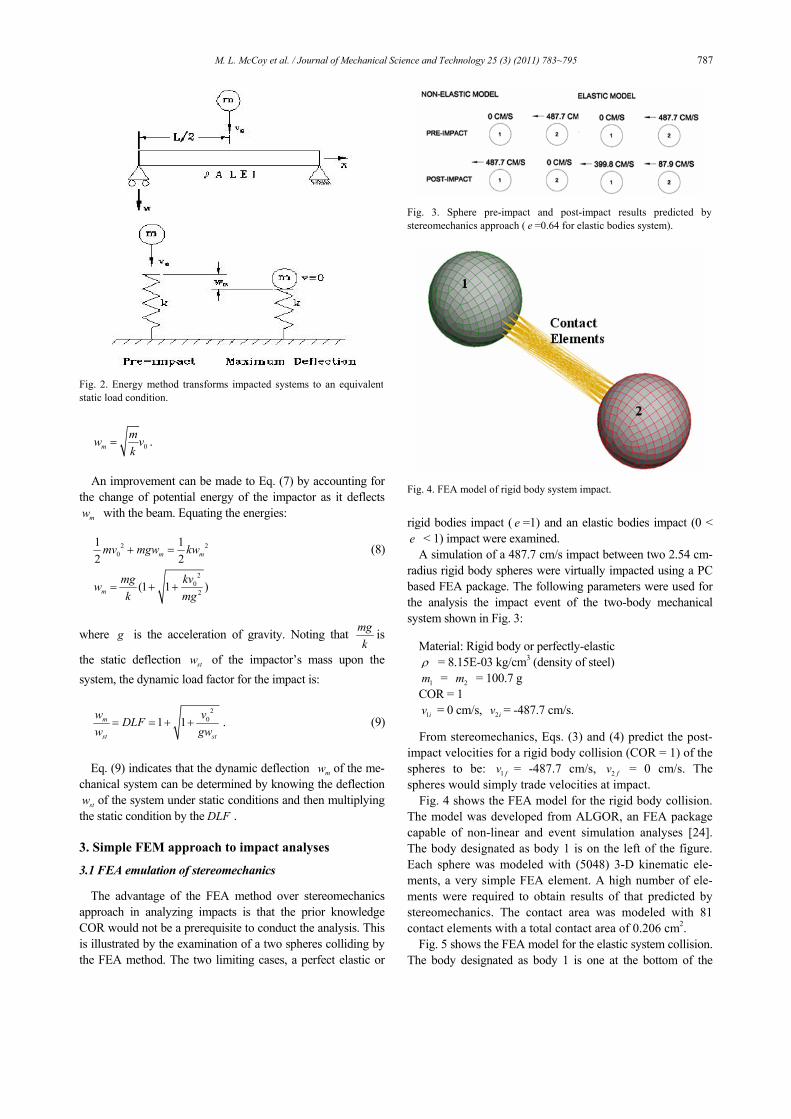
A simulation of a 487.7 cm/s impact between two 2.54 cm-radius rigid body spheres were virtually impacted using a PC based FEA package. The following parameters were used for the analysis the impact event of the two-body mechanical system shown in Fig. 3:
Material: Rigid body or perfectly-elastic ρ = 8.15E-03 kg/cm3 (density of steel)
1m = 2m = 100.7 g COR = 1
1iv = 0 cm/s, 2iv = -487.7 cm/s. From stereomechanics, Eqs. (3) and (4) predict the post-
impact velocities for a rigid body collision (COR = 1) of the spheres to be: 1 fv = -487.7 cm/s, 2 fv = 0 cm/s. The spheres would simply trade velocities at impact.
Fig. 4 shows the FEA model for the rigid body collision. The model was developed from ALGOR, an FEA package capable of non-linear and event simulation analyses [24]. The body designated as body 1 is on the left of the figure. Each sphere was modeled with (5048) 3-D kinematic ele-ments, a very simple FEA element. A high number of ele-ments were required to obtain results of that predicted by stereomechanics. The contact area was modeled with 81 contact elements with a total contact area of 0.206 cm2.
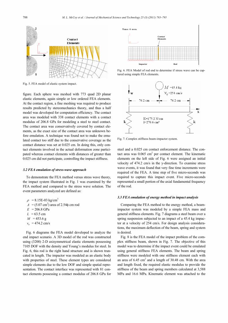
Fig. 5 shows the FEA model for the elastic system collision. The body designated as body 1 is one at the bottom of the
Fig. 2. Energy method transforms impacted systems to an equivalentstatic load condition.
Fig. 3. Sphere pre-impact and post-impact results predicted by stereomechanics approach ( e =0.64 for elastic bodies system).
Fig. 4. FEA model of rigid body system impact.
788 M. L. McCoy et al. / Journal of Mechanical Science and Technology 25 (3) (2011) 783~795
figure. Each sphere was meshed with 773 quad 2D planar elastic elements, again simple or low ordered FEA elements. At the contact region, a fine meshing was required to produce results predicted by stereomechanics theory, and thus a half model was developed for computation efficiency. The contact area was modeled with 338 contact elements with a contact modulus of 206.8 GPa for modeling a steel to steel contact. The contact area was conservatively covered by contact ele-ments, as the exact size of the contact area was unknown be-fore emulation. A technique was found not to make the emu-lated contact too stiff due to the conservative coverage as the contact distance was set at 0.025 cm. In doing this, only con-tact elements involved in the actual deformation zone partici-pated whereas contact elements with distances of greater than 0.025 cm did not participate, controlling the impact stiffness. 3.2 FEA emulation of stress-wave approach
To demonstrate the FEA method versus stress wave theory, the impact system illustrated in Fig. 1 was examined by the FEA method and compared to the stress wave solution. The event parameters analyzed are defined as:
ρ = 8.15E-03 kg/cm3 A = (5.07 cm2) area of 2.54φ cm rod
E = 206.8 GPa
L = 63.5 cm M = 453.6 g
0v = 474.2 cm/s
Fig. 6 diagrams the FEA model developed to analyze the
end impact scenario. A 3D model of the rod was constructed using (3200) 2-D axisymmetrical elastic elements possessing 7105 DOF with the density and Young’s modulus for steel. In Fig. 6, this rod is the right hand structure and is shown trun-cated in length. The impactor was modeled as an elastic body with properties of steel. These element types are considered simple elements due to the low DOF and simple spatial repre-sentation. The contact interface was represented with 81 con-tact elements possessing a contact modulus of 206.8 GPa for
steel and a 0.025 cm contact enforcement distance. The con-tact area was 0.065 cm2 per contact element. The kinematic elements on the left side of Fig. 6 were assigned an initial velocity of 474.2 cm/s in the y-direction. To examine stress wave events, it was found that very fine time increments were required of the FEA. A time step of five micro-seconds was required to capture this impact event. Five micro-seconds represented a small portion of the axial fundamental frequency of the rod.
3.3 FEA emulation of energy method in impact analysis
Comparing the FEA method to the energy method, a beam-impactor system was modeled by a simple FEA mass and general stiffness elements. Fig. 7 diagrams a steel beam over a spring suspension subjected to an impact of a 45.4 kg impac-tor at a velocity of 254 cm/s. For design analysis considera-tions, the maximum deflection of the beam, spring and system is desired.
Fig. 8 is the FEA model of the impact problem of the com-plex stiffness beam, shown in Fig. 7. The objective of this model was to determine if the impact event could be emulated using general stiffness FEA elements. The beam and spring stiffness were modeled with one stiffness element each with an area of 6.45 cm2 and a length of 30.48 cm. With the area and length fixed, the required elastic modulus to provide the stiffness of the beam and spring members calculated at 3,588 MPa and 16.6 MPa. Kinematic element was attached to the
Fig. 5. FEA model of elastic system impact.
Impactor Rod
Contact Elements
Fig. 6. FEA Model of rod end to determine if stress wave can be cap-tured using simple FEA elements.
Fig. 7. Complex stiffness beam-impactor system.

M. L. McCoy et al. / Journal of Mechanical Science and Technology 25 (3) (2011) 783~795 789
end of the general stiffness element to provide a momentum transfer. Without this element, it was found that an end contact to a beam or truss element was not possible. Contact elements communicated the momentum of the impactor to the kine-matic elements. The contact element modulus was 66.7 GPa and exhibited a total contact area of 6.54 cm2.
4. Results and discussion
4.1 Comparison of stereomechanics approach with FEA approach to impact analysis
Fig. 9 shows velocity traces for the two bodies from the re-sults of the FEA analysis with the rigid body or perfectly-elastic elements. Stereomechanics theory predicts that body 1 would acquire a post-impact velocity of -487.7 cm/s and body 2 would come to a standstill. As seen in these velocity traces, the FEA model was well within engineering accuracy. Body 2 does exhibit a small residual velocity. The model would likely be improved by increasing the contact modulus to provide a better representation of a rigid body system. Using the same impact parameters as the rigid body system, the stereome-chanics Eq. (2) and (3) predict the post-impact velocities for an elastic system collision of steel spheres to be; 1 fv = -399.8 cm/s along with 2iv =-87.9 cm/s. A COR of 0.64 was used for the stereomechanics computations taken from experimental steel sphere impacts [15], illustrating the disadvantage of stereomechanics.
Fig. 10 diagrams the velocity traces for the two bodies from the results of the FEA analysis of the elastic system. Body 1 exhibited a post velocity of -384.8 cm/s while body 2 had a post impact velocity of -104.9 cm/s. The difference between the FEA analysis and the experiment using the COR of 0.64 was likely in the type of steels and thus differences in yield strength. The exact steel classification from the impact test from reference [15] could not be determined. The material in this FEA analysis exhibited yield strength of 248.2 MPa and an ultimate of 400 MPa. From the FEA analysis, the COR computed to be at 0.58.
4.2 Comparison of stress-wave propagation approach with
FEA approach to impact analyses
Using Eq. (6) and the above system parameters, the local stress predicted at the end of the rod immediately after impact is 0σ = 194.6 MPa while the theoretical velocity of the stress wave in steel is calculated to be 5,038 m/s.
Fig. 11 presents the results of the FEA analysis for end im-pact of the rod. The initial local end stress in the rod immedi-ately after impact exhibited an axial compressive stress of 182.0 MPa. The FEA stress result is 3.9% lower than pre-
Fig. 8. FEA model of beam-impactor system.
Fig. 9. FEA prediction on rigid body system impact.
Fig. 10. FEA prediction on elastic body system impact.

790 M. L. McCoy et al. / Journal of Mechanical Science and Technology 25 (3) (2011) 783~795
dicted theoretically by Eq. (6). As for the propagation speed, an analysis of the FEA results using distances, times and an estimation of the position of the wave front yielded a propaga-tion wave speed of 5418 m/s, within 7% the theoretical result of 5,038 m/s.
As a comparison to using the simpler axisymmetric ele-ments, a 3D model of the impacted rod of Fig. 6 was modeled with 3335 8-node 24-DOF brick elements. These elements are considered complex due to high DOF and complex spatial representation. As seen in table 1, the computation effort was threefold of that of using the simple elements. The simple element model was within 4% of the closed-form solution while the complex element model was over 9%.
4.3 Comparison of energy method with FEA approach to impact analyses
Using the energy method to calculate the benchmark results for the FEA analysis, the static deflection for the beam and spring compute as:
_ 1.272st springPw cmk
= =
3
_ 0.006 ,48st beamPlw cm
EI= =
in which P = 445 N, k = 175.2 N/cm, l = 152.4 cm, E = 206.8 GPa, and I = 270.6 cm4.
Adding the deflection of the spring plus the beam, the total system static deflection is 1.276 cm. With the system static deflection of the impactor known, the DLF maybe calculated from Eq. (9), for the 254 cm/s impact:
2
01 1 8.25m
st st
w vDLFw gw
= = + + = .
The dynamic deflections and stresses are predicted by the
energy method to be 8.25 times the respective static deflec-tions due to the static force of the impactor alone. Calculating the dynamic deflections:
_
_
_
8.25(1.27) 10.48
8.25(0.006) 0.049
8.25(1.276) 10.53 .
m spring
m beam
m system
cm
cm
cm
w
w
w
=
=
=
=
=
=
Fig. 12 shows the results of this FEA analysis. The maxi-mum deflection predicted by the FEA analysis for the system was 10.33 cm. The FEA results compare very favorable to the equivalent load theory prediction of 10.53 cm for the total system deflection. From the FEA analysis, the deflection of beam was predicted at 0.047 cm and the spring deflection was
Table 1. Comparison of simple vs complex element simulation.
Element Type Axisymmetric 4-node 8-DOF Brick 8-node 24-DOF
Number of Elements 3200 3335
Element Classification
Simple by low DOF and 2D spatial representation
Complex by high DOF and 3D spatial representation
Total DOF 7,105 11,490 Event Time, microsecond 75 75
Computational Time, min:sec 03:26 09:33
Theoretical Stress, MPa -189.09 -189.09
FEA Model Stress, MPa -182.00 -171.49
Fig. 11. FEA stress results of rod end impact (MPa).
Fig. 12. FEA results of beam-impactor system.
M. L. McCoy et al. / Journal of Mechanical Science and Technology 25 (3) (2011) 783~795 791
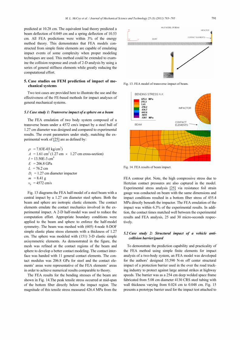
predicted at 10.28 cm. The equivalent load theory predicted a beam deflection of 0.049 cm and a spring deflection of 10.53 cm. All FEA predictions were within 3% of the energy method theory. This demonstrates that FEA models con-structed from simple finite elements are capable of emulating impact events of some complexity when proper modeling techniques are used. This method could be extended to exam-ine the collision response and crush of 2-D analysis by using a series of general stiffness elements while greatly reducing the computational effort. 5. Case studies on FEM prediction of impact of me-
chanical systems
Two test cases are provided here to illustrate the use and the effectiveness of the FE-based methods for impact analyses of general mechanical systems.
5.1 Case study 1: Transverse impact of a sphere on a beam
The FEA emulation of two body system composed of a transverse beam under a 4572 cm/s impact by a steel ball of 1.27 cm diameter was designed and compared to experimental results. The event parameters under study, matching the ex-perimental work of [25] are as defined by:
ρ = 7.83E-03 kg/cm3) A = 1.61 cm2 (1.27 cm × 1.27 cm cross-section)
I = 13.50E-3 cm4 E = 206.8 GPa L = 76.2 cm
1D = 1.27 cm diameter impactor m = 8.41 g
0v = 4572 cm/s Fig. 13 diagrams the FEA half-model of a steel beam with a
central impact by a 1.27 cm diameter steel sphere. Both the beam and sphere are isotropic elastic elements. The contact elements emulate the contact mechanics involved in the ex-perimental impact. A 2-D half-model was used to reduce the computation effort. Appropriate boundary conditions were applied to the beam and sphere to enforce the half-model symmetry. The beam was meshed with (605) 4-node 8-DOF simple elastic plane stress elements with a thickness of 1.27 cm. The sphere was modeled with (151) 3-D elastic simple axisymmetric elements. As demonstrated in the figure, the mesh was refined at the contact regions of the beam and sphere to develop a better contact modeling. The contact inter-face was handed with 11 general contact elements. The con-tact modulus was 206.8 GPa for steel and the contact ele-ments’ areas were representative of the FEA elements’ areas in order to achieve numerical results comparable to theory.
The FEA results for the bending stresses of the beam are shown in Fig. 14.The peak tensile stress occurred at mid-span of the bottom fiber directly below the impact region. The magnitude of this tensile stress measured 426.4 MPa from the
FEA contour plot. Note, the high compressive stress due to Hertzian contact pressures are also captured in the model. Experimental stress analysis [25] via resistance foil strain gauge was conducted on beam with the same dimensions and impact conditions resulted in a bottom fiber stress of 455.4 MPa directly beneath the impactor. The FEA emulation of the impact was within 6.3% of the experimental results. In addi-tion, the contact times matched well between the experimental results and FEA analysis, 25 and 30 micro-seconds respec-tively.
5.2 Case study 2: Structural impact of a vehicle anti-
collision barrier/guard
To demonstrate the prediction capability and practicality of the FEA method using simple finite elements for impact analysis of a two-body system, an FEA model was developed for the authors’ designed 55,590 N-m off center structural impact of a protection barrier used in the over the road truck-ing industry to protect against large animal strikes at highway speeds. The barrier was as a 254 cm deep welded space frame fabricated from 5.08 cm diameter 4130 CRS steel tubing with wall thickness varying from 0.024 cm to 0.048 cm. Fig. 15 presents a prototype barrier used for the impact test attached to
Fig. 13. FEA model of transverse impact of beam.
Fig. 14. FEA results of beam impact.

792 M. L. McCoy et al. / Journal of Mechanical Science and Technology 25 (3) (2011) 783~795
its test bed. Stresses and deflections predicted by the FEA model were compared to experimental stresses and deflections to assess the performance of the FEA using simple finite ele-ments.
Fig. 16 presents the FEA model of barrier. The barrier was virtually impacted with flexible impactor consisting of (1,270) 24-DOF plastic brick elements. The impactor weighed 1419 N and was assigned an initial velocity of 99.8 km/hr representing impact energy of 55,590 N-m. This impactor represented the size, shape and stiffness of a modified drum used as the im-pactor in the actual test. The guard was modeled with (328) 12-DOF plastic beam elements. All material constitutes were of Von Mises isotropic hardening. The material properties for the tubing were modeled as 4130 CRS and for the impactor it was mild steel. The contact was managed with 198 contact elements with a contact modulus of 206.8 GPa representing steel.
The prototype barrier was instrumented with nine 350Ω re-sistance foil strain gages for experimental stress analysis dur-ing the structural testing. The strain gages were located in the areas that exhibited high stress levels observed in the FEA analyses. Fig. 17 presents a typical gage installation. The in-strumented barrier was impacted with 55,590 N-m of energy delivered by dropping a 202.8 liter steel drum with ballast of 1419 N for 39.17 m acting as the impactor. Fig. 18 shows the drum on top of a grain elevator that was temporarily used as a drop tower. The impactor/drum was hoisted to the drop height
and filled with water for ballast pumped up by a fire truck. The drum was guided down to the guard via a guide wire that transverses through the drum center. The drum was released and allowed to free fall until it hit the barrier. The center of the strike was the roadside inner stanchion at the second row of horizontal tubes. The model exhibited 774 nodes, 1796 ele-ments totaling to 3322-DOF predicted the barrier to perform as follows the 55,590 N-m off center impact:
Maximum Total Deflection: 4.8 cm Plastic Set: 2.4 cm (left side of guard) Energy Absorption: 84.7% Contact Time: 6-7 milliseconds
Figs. 19 and 20 present sample results on predictions of the
impact on the barrier by the FEA model. Fig. 21 presents the guard after the impact. At the center of
the strike, a plastic set was exhibited in the barrier. This set measured approximately 2.0 cm as shown in the figure. The FEA model prediction of plastic set was quite comparable at 2.4 cm. Fig. 22 presents the data from strain gage #3 during the impact event using a high speed data acquisition system (5000 Hz). The contact time measured from the strain gage data was in the 9-11 millisecond range. The FEA predicted a contact time of 6-7 milliseconds, which is comparable.
Fig. 15. Truck animal anti-collision barrier.
Fig. 16. FEA model of animal anti-collision barrier.
Fig. 17. Instrumentation of barrier with strain gages.
Fig. 18. The 39-meter temporary drop tower.

M. L. McCoy et al. / Journal of Mechanical Science and Technology 25 (3) (2011) 783~795 793
As shown in Fig. 23, the FEA model predicted the peak stresses in the barrier within 15% of the strain gage measure-ments on the instrumented barrier at seven of nine instrumen-tation locations. Six of nine locations were within 10%. The FEA model predicted the impact event well within engineer-ing expectations using simple finite elements.
6. Conclusions
A study was conducted to determine if an FEA analysis us-ing simple (low ordered) finite elements would be robust enough to accurately predict impact events in terms of stresses and deflections in order to aid in the design of structures, mechanisms and products.
First, impact problems solved by the classical methods of stereomechanics, stress-wave and energy methods were emu-lated by the FEA method based on these approaches with simple elements. In addition, an experimental impact analysis found in literature was analyzed by the FEA method using low ordered elements. It was found that the proper elements, boundary conditions, contact elements and material constitutes selection that an FEA could indeed produce engineering ac-ceptable results in predicting velocities, deflections and stresses involved in an impact without extraordinary hardware or computation times for reasonable design problems. FEA results of the above benchmarks were within 1% to 7% of the theoretical and/or experimental results. With this work, a small set of benchmarks for impact analysis by FEA was es-tablished.
Secondly, a 55,590 N-m impact event of a trucking impact protection barrier was modeled by the FEA method using simple plastic beams. The actual impact of the barrier was compared to the predictions of FEA. The plastic set predicted by the FEA model was within 0.4 cm of the actual permanent deformation. Stress levels predicted by the FEA model were generally within 10% of measured values, demonstrating that an FEA utilizing simple or low ordered finite elements can be used as a valid engineering tool for a medium sized manufac-turer in for designing products exhibiting impact requirements.
Fig. 19. Maximum deflection during impact (cm).
Fig. 20. Plastic set prediction post impact (cm).
Fig. 21. Actual plastic set post impact.
Fig. 22. Strain vs. time on strain gage #3.
Fig. 23. FEA predicted vs. experimental stress results.
794 M. L. McCoy et al. / Journal of Mechanical Science and Technology 25 (3) (2011) 783~795
Nomenclature------------------------------------------------------------------------
A : Area, in2 (cm2) c : Extreme beam fiber distance, in (cm) di : Diameter, inner, in (cm) do : Diameter, outer, in (cm) E : Elastic modulus, psi (Gpa) e : Coefficient of restitution Et : Tangent modulus, psi (Gpa) F : Force, lbf (N) G : Shear modulus, psi (Gpa) I : Area moment of inertia, in4 (cm)4 J : Impulse, lbf-sec (N-sec) k : Stiffness, lbf/in (N/cm) L : Length, in (cm) m : Mass, lbf-sec2/in (g) T : Kinetic energy, in-lbf (N-cm) x, u : Displacement, in (cm) U : Total energy, in-lbf (N-cm) v : Velocity, ips (cmps) w : Beam transverse displacement, in (cm) V : Potential energy, in-lbf (N-cm)
Z : Beam elastic section modulus ΔV : Change in velocity due to impact, ips (cmps) ε : Strain, in/in (cm/cm) γ : Specific density, lbf/in^3 (N/cm3) ρ : Mass density, lbf-sec2/in4 (g/cm3) σ : Stress, psi (Mpa) ω : Natural radial frequency, rad/sec ν : Possion’s ratio CRS : Cold Rolled Steel DLF : Dynamic Load Factor FEA : Finite Element Analysis DOF : Degrees Of Freedom HRS : Hot Rolled Steel PC : Personal Computer ips : Inches per second cmps : Centimeters per second fps : Feet per second mps : Meters per second f : Final condition i, 0 : Initial condition References
[1] J. Zukas, Impact dynamics, John Wiley & Sons (1982). [2] J. Zukus, Practical aspects of numerical simulations of dy-
namic events: effects of meshing, Int. J. Impact Engineering (2000) 925-945.
[3] S. Shiviaswamy, Modeling contact forces and energy dissi-pation during impact in mechanical systems, Ph.D. Disserta-tion, Wichita State University, Wichita, KS, USA (1997).
[4] A. Blake, Practical stress analysis in engineering design, 2nd edition, Dekker (1990).
[5] J. Faupel, Engineering design, 2nd edition, John Wiley & Sons (1981).
[6] R. Juvinall, Stress, strain and strength, McGraw-Hill (1967). [7] R. Craig, Structural dynamics, John Wiley & Sons (1981). [8] S. Faik, Modeling of impact dynamics: A literature survey,
International ADAMS User Conference (2000). [9] D. Halliday, Fundamentals of physics, 2nd edition, John
Wiley & Sons (1981). [10] L. Vu-Quoc, Modeling the dependency of the coefficient of
restitution on the impact velocity of elasto-plastic collisions, Int. J. of Impact Eng. (2002) 317-241.
[11] K. Johnson, Contact mechanics, Cambridge University Press (1985).
[12] H. M. Lankarani and P. E. Nikravesh, Continuous contact force model for impact in multibody systems, Nonlinear Dy-namics (1994) 193-207.
[13] F. Wu, Modeling crash dynamic responses of high energy absorbing materials by multibody non-linear finite element and optimization methods, Ph.D. Dissertation, Wichita State University, Wichita, KS, USA (1995).
[14] S. Timoshenko, Vibration problems in engineering, 5th Edition, Van Norstrand (1955).
[15] W. Goldsmith, Impact, Edward Arnold Publishing (1960). [16] H. Bohnenblust, The behavior of long beams under impact
loading, Journal of Applied Mechanics (1950) 27-36. [17] M. Conroy, Plastic deformation of semi-infinite beams
subject to transverse loading at the free end, Journal of Ap-plied Mechanics (1956) 239-243.
[18] M. Conroy, Plastic-rigid analysis of a special class of prob-lems involving beams subject to dynamic transverse loading, Journal of Applied Mechanics (1955) 48-52.
[19] P. Symonds, Dynamic load characteristics in plastic bend-ing of beams, Journal of Applied Mechanics (1953) 475-481.
[20] H. Cox, On impacts on elastic beams, Trans. Camb. Phil. Soc., 73 (1949).
[21] B. Creighton, Numerical resolution calculation for elastic-plastic impact problems, U.S. Army Research Laboratory, MR-3418 (1984).
[22] C. Nagtegall, On numerical accurate finite element solution in the fully plastic range, Computer Methods Application, Mechanical Engineering (1974) 153-178.
[23] D. Littlefield, A study on zoning requirements for 2-D and 3-D long rod penetrations, American Institute of Physics (1996) 1131-1134.
[24] Algor, Inc., 150 Beta Drive, Pittsburg, PA (2009). [25] D. Cunningham, An experimental investigation of beam
stresses produced by impact of a steel sphere, Journal of Ap-plied Mechanics, 606 (1956).

M. L. McCoy et al. / Journal of Mechanical Science and Technology 25 (3) (2011) 783~795 795
Micheal L. McCoy is a practicing en-gineer with twenty-five years experi-ence specializing in product develop-ment for the transportation, aerospace and engineering consulting industries. His current position is a Senior Techni-cal Fellow for Electromech Technolo-gies developing flight controls. He has
held other positions with the Boeing Company and Spirit Aerosystems. He also is an adjunct professor of mechanical engineering at Wichita State University. Dr. McCoy has mul-tiple patents and has been of author of several journals. Dr. McCoy holds a Ph.D. in mechanical engineering and a MBA, both from Wichita State University and is a Licensed Profes-sional Engineer.
Rasoul Moradi is a Ph.D candidate in mechanical engineering at Wichita State University, Wichita, KS, USA. His re-search interests include impact and crash dynamics, automotive and avia-tion crashworthiness, and impact injury biomechanics of occupants. He received his B.Sc. (1997) and M.Sc. (2000) de-
grees in mechanical engineering from University of Tehran, Iran. He has also held academic faculty position for 7 years. He has worked as a chief engineer of vehicle dynamics, vehi-cle passive safety, and homologation department of ITRAC, IKCO, Iran for 10 years and has served as a type approval consultant for several vehicle manufacturers in Iran.
Hamid M. Lankarani is a professor of mechanical engineering and a senior fellow of the National Institute for Avia-tion Research, at Wichita State Univer-sity. He is one of the world’s leading researchers and educators in the field of impact dynamics, automotive and air-craft crashworthiness, occupant protec-
tion, and injury biomechanics. Dr. Lankarani has directed over 250 graduate student MS theses and PhD dissertations, and has been the author of over 300 articles in journals, book chapters and conference proceedings. Dr. Lankarani has served as a Technical Editor or a member of Editorial Board for several international journals, and is an ASME fellow.