Untitled - ARLIS
229
-
Upload
khangminh22 -
Category
Documents
-
view
0 -
download
0
Transcript of Untitled - ARLIS


I
!..
- - -----------------------
Fya5 ADULT ANADROMOUS FISHERIES STUDY
PROCEDURES MANUAL - DRAFT
ARLISAlaska Resources
Library & Information ServIcesAnchorage, Alaska
, .
enenvMI'I'-oooLOLOI'MM
•
INTRODUCTI ON
The Susitna River, a major Southcentral Alaska river system, flows into
Cook Inlet near the city of Anchorage. The drainage encompasses an area
of 19,400 square miles and extends north of Mt. Denali and east almost
to the town of Glennallen. The mainstem river and its major tributaries
are of gl aci a1 ori gi n and carry a heavy si 1t load duri ng ice-free
months. Many of the smaller tributaries are perennially silt:free.
Construction of hydroelectric dams will affect portions of the fish and
wildlife resources of the Susitna River Basin. The two dam system
proposed would inundate approximately 45,8000 acres of aquatic and
terrestrial habitat upstream of Devil Canyon. Historically, the long
and short term environmental impacts of hydroelectric dams have
adversely altered the sport and commercial fisheries of affected
drainages (Keller, 1980; Hagen et al., 1973). Regulation of the
mainstem river will substantially alter the natural flow regime
downstream. The transmission line corridor, substations, road corridor!
and construction pad sites will also impact aquatic and terrestrial
communities and their habitat.
The proposed hydroelectric development necessitates gaining a
substantial knowledge of its chemical, physical and biological
parameters pri or to fi na1 dam des i gn approval and constructi on
authorization.

To insure adequate information is available to determine the impacts of
the p~oposed hydroelectric project and to design proper mitigative
strate~ies, a data collection program has been developed. This manual
addresses field sampling procedures to be conducted within the proposed
study area in FY85.

--------~ -_.. _--
I. OBJECTIVES
Adult Salmon
1. Determine the abundance and seasonal timing of the sockeye, pink,
chum and coho salmon escapem~nts in the Susitna and Yentna rivers
at Flathorn (RM 20), Yentna (TRM 04), Sunshine (RM 80), Talkeetna
(RM 103) and Curry (RM 120) stations.
2. Determine the abundance~nd timing of the chinook salmon escapement
in the Susitna River at Sunshine (RM 80), Talkeetna (RM 103) and
Curry (RM 120) stations.
3. Define the age, length, sex composition and migrational
characteristics of sockeye, pink, chum and coho salmon in the
Susitna and Yentna rivers at Flathorn (RM 20), Yentna (TRM 04),
Sunshine (RM 80), Talkeetna (RM 103) and Curry (RM 120) stations.
In addition, evaluate tpe same parameters for chinook salmon at
Sunshine, Talkeetna and Curry stations.
4. Define where and when and to what level chinook, sockeye, pink,
chum and coho salmonspawn in streams, s1 oughs, stde channel s _and
the main channel of the Susitna River between RM 28 and 161.0.
5. Determine the average stream or spawning life of sockeye and chum
salmon in sloughs as necessary to define total escapements into
sloughs.
, .
-----------------
I
II. TECHNICAL PROCEDURES - Adult Salmon
Main Channel Escapement Monitoring
Operations Dates
Main channel escapement monitoring using side scan sonar (SSS) counters
and tag/recapture fishwheels will begin and end on the following dates t
by station:
Flathorn Station (RM 20)
Ventna Station (TRM 04)
Sunshine Station (RM 80)
Talkeetna Station (RM 103)
Curry Station (RM 120)
Methods
Sonar and Tag/Recapture
July 1 to September 3
July 1 to September 5
June 4 to September 10
June 7 to September 12
June 10 to September 14
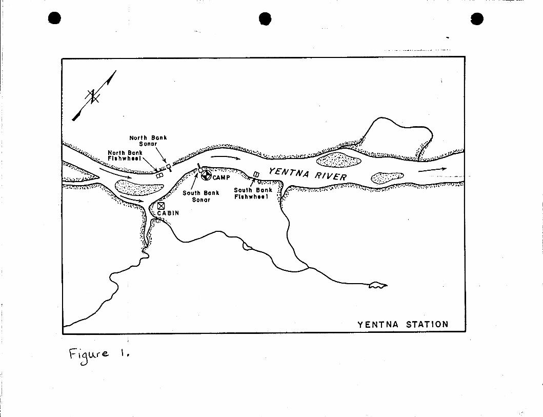
At Ventna Station (TRM 04) two side scan sonar counters will be deployed
as-shown in Figure!. Specific methods for substrate deployment t
counter set-up and counter operation will be in accordance to procedures
outlined in the 1980 Side Scan Sonar Counter Installation and Operation
Manual (Appendix 1).
--
F" \3lJ..(e. \ ,
•L, .... ,.,l •
. .,~.,~.. --.,,-..~;t(.;.: :;:"}.... i-'~ .:'1."~'V. ,:.1:,;-.:, . -. ..;,( ••• • _. ·V "
,.
Y ENTNA STATION
e
~I
To prevent under and over counting adult salmon due to differential fish
velocity between species counters will be monitored, at minimum, four
times daily. This is accomplished by hand-ta11yingJfish related echos
displayed on an oscilloscope and comparing them to S~S counts (Appendix
2). When the ratio of oscilloscope counts to SSS c~unts deviates from
one by greater than 10 percent the fish ve10cit~ control will be
adjusted as outlined in the above cited operations manual.
Important items concerning SSS operations which may not appear in the
operational instructions (Appendix 1) are:
1. When large numbers of pink salmon pass over the substrate it is
possible for the counter 'logic' to interpret the counts as
debris. On these occasions the debris notation on the counter
printout should be ignored.
2. When checking the battery conditions itis preferable to do so
when a load, such as the printer, is befng applied.
3. Alight print problem may be resolved by applying rUbbing
alcoho1 to the paper and pu11 i ng through the pri nter roll ers.
4. At times the printer may print over the previous hours
printout. This problem may be solved by applying a light coat
of rubbing alcohol to the paper and attaching a weight to the
end of the printer paper.
•
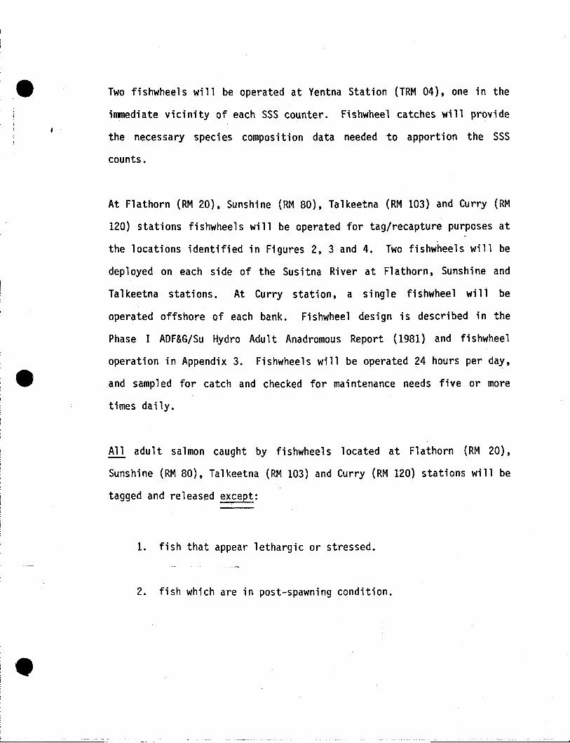
Two fishwheels will be operated at Yentna Station (TRM 04), one in the
immediate vicinity of each SSS counter. Fishwheel catches will provide
the necessary species composition data needed to apportion the SSS
counts.
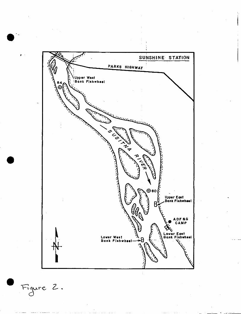
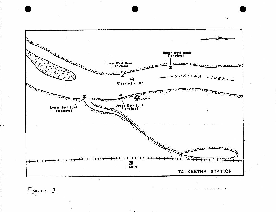
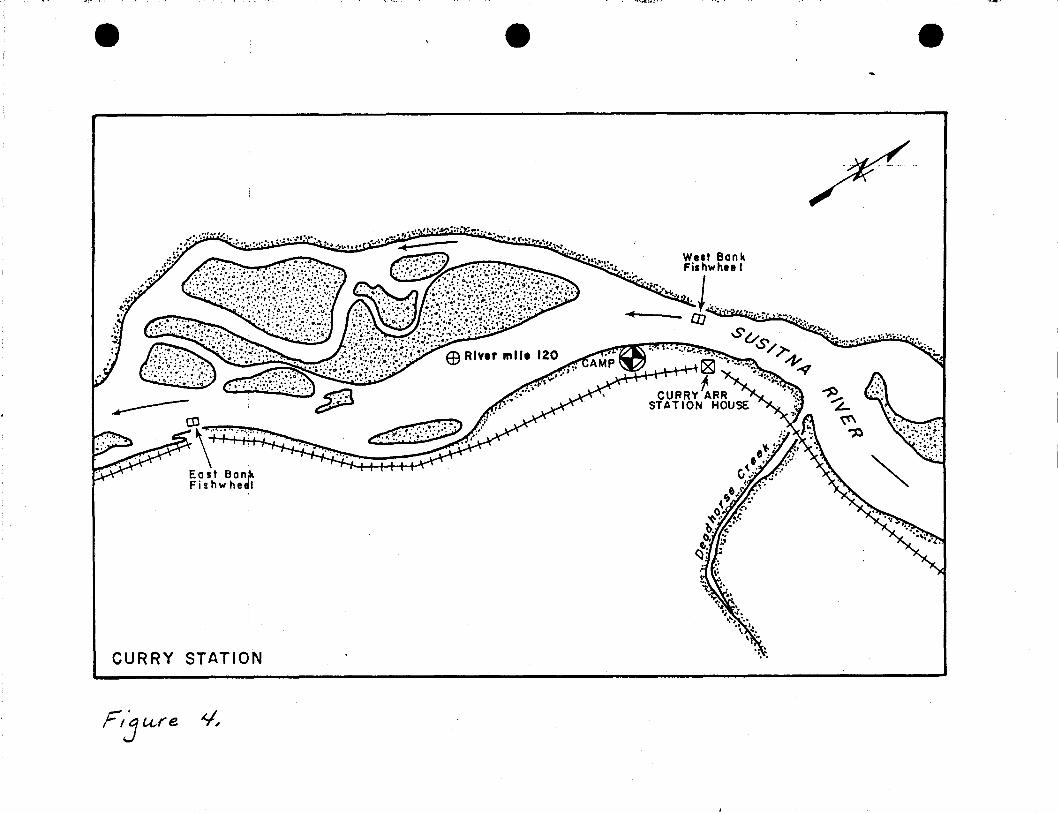
At Flathorn (RM 20), Sunshine (RM 80), Talkeetna (RM 103) and Curry (RM
120) stations fishwheels will be operated for tag/recapture purposes at
the locations identified in Figures 2, 3 and 4. Two fishwheels will be
deployed on each side of the Susitna River at Flathorn, Sunshine and
Talkeetna stations. At Curry station, a single fishwheel will be
operated offshore of each bank. Fishwheel design is described in the
Phase I ADF&G/Su Hydro Adult Anadromous Report (l981) and fishwheel
operation in Appendix 3. Fishwheels will be operated 24 hours per day,
and sampl ed for catch and checked for mai ntenance needs five or more
times daily.
All adult salmon caught by fishwheels located at Flathorn (RM 20),
Sunshine (RM 80), Talkeetna (RM 103) and Curry (RM 120) stations will be
tagged and released except:
1. fish that appear lethargic or stressed.
2. fish which are in post-spawning condition •
, -SUNSHINE- STATION
PARkS HIGHWAY
'.
e e e
RIVE/? __
___~~zs-
4"'::'of ;~. f.-i'''':: :(1; ;:-~~ to ":'. '0- ...,. ·L~.•,..... "
' ..I;:t'
_.YI ~., .. .i;';
,..-... ~.:.: ;.A.-.:..~~. ~'\:.,~:y;.~_!. ¥".... _
Upp.r East BankFishwheel
;::.;f.;:,..o ._ •
Upp.r Wnt Ban kFishwheel
Low.r W.st Bank """~: ,,..:.... ;..,;. ;: jr:••••• ". • •.Flshwh••1 •./r...... f- ...··· ..e.:t;.·.· .""", ..... ,:, ••.,..;....,...
.."f.·. CD to "P"'" .. ) , • ,( •..;~;-....;.,... • \ ::,,:,,~, •.~·i· .': .
~"~~"-;'(jfH '":~ ~en ~ -SUS/rNA
E9River mil. 103
""r~('
"':~ .;:.~: :-.,:,,>....... ~.,.':l:-.
""~,.~. en"-"'::~A .
/' :~Low.r East Bank \: ..
Fis hwhee I ": f{.".: >:'i~. _, _' ......;.., to
18ICABIN
TALKEETNA STAT ION
r~Ufe 3. 1;,"',.,' •
e
CURRY STATION
F'j u,re ii,
e e
I
eT~t~ \.
e e
River Percent of Tag TagStation Mile Species Length Catch Tagged Type Color
,
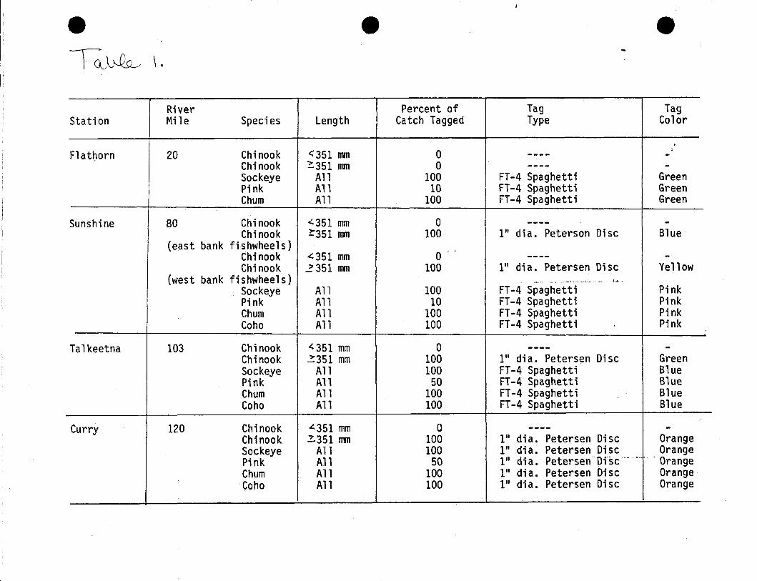
Flathorn 20 Chinook <351 mm 0 I---- -Chinook ~351 mm 0 ---- -Sockeye All 100 FT-4 Spaghetti GreenPink All 10 FT-4 Spaghetti GreenChum All 100 FT-4 Spaghetti Green
Sunshine 80 Chinook c(.351 mm 0 ---- -Chinook ?351 mm 100 1" dia. Peterson Disc Blue
(east bank fishwheels)Chinook "'351 mm 0 ---- -Chinook .z 351 mm 100 1" dia. Petersen Disc Yellow
(west bank fishwheels) ......" " .....", ".".,... ~;, "'. ,j, ••.• '. ...,., •... i,~.,.
Sockeye All 100 FT-4 Spaghetti PinkPink All 10 FT-4 Spaghetti PinkChum All 100 FT-4 Spaghetti PinkCoho All 100 FT-4 Spaghetti Pink
Talkeetna 103 Chinook c(.351 mm 0 ---- -Chinook ~351 mm 100 1" dia. Petersen Disc GreenSockeye All 100 FT-4 Spaghetti BluePink All 50 FT-4 Spaghetti BlueChum All 100 FT-4 Spaghetti BlueCoho All 100 FT-4 Spaghetti Blue
Curry 120 Chinook 4351 mm 0 ---- -Chinook 2.351 rrm 100 1" dia. Petersen Disc OrangeSockeye All 100 1" dia. Petersen Disc OrangePink All 50 1" dia. Petersen Di'st-" . OrangeChum All 100 1" dia. Petersen Disc OrangeCoho All 100 1" dia. Petersen Disc Orange
-------------~~---
3. chinook salmon less than 351 mm in fork length (FL).
4. fish previously tagged at another tagging site.
These fish will be released without being tagged.
Procedures for tagging fish are defined in Appendix 4. The type of
tags, colors and percent of each species tagged at Flathorn, Sunshine,
Talkeetna and Curry stations are defined in the following table:

: ,J
- -- -- _._---------------------
Special tagging instructions:
i
1. Chinook s~lmon at Sunshine Station will be tagged with two
different colored tags; one for the east bank (blue) and one
for the west bank (yellow).
2. At Talkeetna Station odd one hundred series (x!xx) tags will
be used for fish captured in west bank fishwheels and even one
hundred series tags will be used for fi sh captured in east
bank fishwheels. For example, a carcass bearing Talkeetna
tag, number 1312 shoul d have been captured in a west bank
fishwheel and a carcass bearing Talkeetna tag, number 2613
. should have been captured in a east bank fishwheel (note: tags
0-99 are considered even one hundred series).
3. Large numbered Petersen Discs will be deployed at Curry
Station. These discs are to be used for sockeye and chum
salmon only.
Fish which are recaptured from other tagging locations are to be
released with the original tag in place following species identification
and recording of tag type, color and number (Sectlon. III, DATA
PROCEDURES). All non-salmon catches will be identified to species, and
if time allows, tagged and released.
Fishwheel catch, sonar and tag deployment and recapture data will be
transmitted to the Anchorage offi ce every two weeks from Fl athorn {RM

t '
- - ------------------------- - -
20), Yentna (TRM 04), Sunshine (RM 80), Talkeetna (RM 103) and Curry (RM
120) stations. All data will be edited by the Operations Control Leader
and then submitted to the Data Processing Section.
Age, Length and Sex Composition Sampling:
At Flathorn (RM 20), Yentna (TRM 04), Sunshine (RM 80), Talkeetna
(RM 103) and Curry (RM 120) statlons age, length and sex data (Section
III, DATA PROCEDURES) will be collected daily for each species as
follows:
Chinook salmon: Age, length and sex samples from 30 consecutively
(regardless of size) caught fish.
Except: At Sunshine Station-age, length and sex samples
from 30 consecutively (regardless of size) caught
fish from east bank fishwheels and 30
consecutively (regardleSs of size) caught fish
from west bank fishwheels.
Sockeye salmon: Age, length and sex samples daily from 30
consecutively (regardleSs of size) caught fish.
Pink salmon: Length and sex samples daily from 30 consecutively
(regardless of size) caught fish.

, .
- ._._--~--------~
Chum salmon: Age, length and sex samples da)ly from 20
consecutively (regardless of sex) caught fish.
Coho salmon: Age, length and sex samples daily from 20
consecutively (regardless of size) caught fish.
Age, length and sex composition data will be forwarded to the Anchorage
office every two weeks from Flathorn (RM 20), Yentna (TRM 04), Sunshine
(RM 80), Talkeetna (RM 103) and Curry (RM 120) stations.
Stream, Slough, Side Channel and Main Channel Surveys
Lower River
Operation Period and Reach
Streams will be surveyed for salmon escapements weekly from July 21 to
October 7. The geographic areas of responsibility for two Lower River
survey crews (RM 28.0-98.7) are:
Flathorn Station Survey
Sunshine Station Survey
RM 28 to Kashwitna River
__ Kas hwi tna iR iver__to Ta1keetna
Stream surveys will be in accordance to the schedule defined in Table 2.
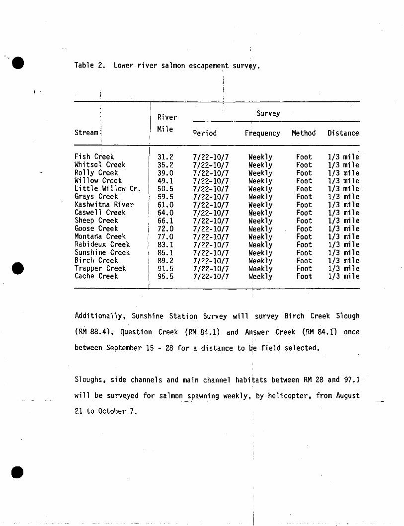
I.-_ Table 2. lower river salmon escapeme~t survey.
~
River Survey
Stream; Mile Period Frequency Method Distance
;
Fish Creek 31.2 7/22-10/7 Weekly Foot 1/3 mileWhitsol Creek 35.2 7/22-10/7 Weekly Foot 1/3 mileRolly Creek 39.0 7/22-10/7 Weekly Foot 1/3 mileWi 11 ow Cree k 49.1 7/22-10/7 Weekly Foot 1/3 milelittle Willow Cr. 50.5 7/22-10/7 Weekly Foot 1/3 mi leGrays Creek 59.5 7/22-10/7 Weekly Foot 1/3 mileKashwitna River 61.0 7/22-10/7 Weekly Foot 1/3 mi leCaswell Creek 64.0 7/22-10/7 Weekly Foot 1/3 mileSheep Creek 66.1 7/22-10/7 Weekly Foot 1/3 mileGoose Creek 72.0 7/22-10/7 Weekly Foot 1/3 mileMontana Creek 77.0 7/22-10/7 Weekly Foot 1/3 mileRabideux Creek 83.1 7/22-10/7 Weekly Foot 1/3 mileSunshine Creek 85.1 7/22-10/7 Weekly Foot 1/3 mile
e Birch Creek 89.2 7/22-10/7 Weekly Foot 1/3 mileTrapper Creek 91.5 7/22-10/7 Weekly Foot 1/3 mileCache Creek 95.5 7/22-10/7 Weekly Foot 1/3 mile
Additionally, Sunshine Station Survey will survey Birch Creek Slough
(R!'188.4), Question Creek (RM 84.1) and Answer Creek (RM 84.0 once
between September 15 - 28 for a distance to qe field selected.
Sloughs, side channels and main channel habitats between RM 28 and 97.1
will be surveyed for salmon spawning weekly, by helicopter, from August
21 to October 7.
- ...._-_..._-_._----------- -_ ..- ----
Methods
All spawni ng ground and tag recovery surveys wi 11 be conducted by
trai ned observers. Stream surveys will be conducted on foot' for a
distance of one third mile from the confluence of the Susitna River
except Bi rch Creek whi ch wi 11 be surveyed one thi rd mi 1e frdm its
confluence with Birch Creek Slough. Amarker will be established at the
upper survey limit on the first survey of each stream to ensure
repetitive surveys throughout the season. Surveyors will wear polarized
glasses to reduce surface water glare and use hand held tally counters
to record live tagged and untagged adult salmon and carcasses.
Surveyors will map the distribution of salmon spawning activity and give
a brief description of the habitat for any adult salmon found spawning
in the stream survey reach. Survey data and maps of salmon spawning
distribution will be recorded on the appropriate forms (Section III,
DATA PROCEDURES) and transmitted to the Anchorage office once every two
weeks. The data forms will be edited by the Operations Control Leader
and then forwarded to the Data Processing Section.
Sloughs, side channel and main channel habitats will be surveyed for
salmon spawning by helicopter. All suspected spawning areas Will be
visited by boat and will be defined as true spawning sites if_ the
following criteria are met:
1. Fish exhibits spawning and morphology.
2. Fish expells eggs or milt when slight pressure is exerted on
the abdomen. ,

3. Fish is in vigorous condition, with 25 percent or more of the
eggs or milt remaining in the body cavity.
4. Additional fish meeting criteria 1 through 3 are present.
Once a spawning area has been located the appropriate data forms will be
filled out (Section III, DATA PROCEDURES) and forwarded to the Anchorage
office every two or three weeks.
Middle River
Operation Period and Reach
Salmon stream escapement surveys wi 11 be conducted from July 22 to
October 7. Chi nook salmon escapement surveys will be conducted as
outlined in Table 3. Additionally, between July 22 and August 5
specific chinook salmon tag recovery surveys will be conducted as
scheduled in Table 4.
Between August 6 and October 7 all streams and sloughs of known and
suspected adult salmon use from RM 98.6 to 161. 0 wi 11 be surveyed as
close to weekly as possible._The sloughs wilL~be surveyed in their
entirety and streams to a standard index limit or the upper spawning
limit as defined in Table 5.
Side channel and main channel habitats will be surveyed for salmon
spawni ng by hel i copter a minimum of two times between September 1 and
October 7.

Table 3. Chinook salmon escapement survey schedule.
,Survey ,
IRM 11 Frequency 'f./ Distance 1/, Stream Peri9d Method
•-Chase Creek 106.9 7/22..8/5 Once Foot 1 MileLane Creek 113.6 7/22 i 8/5 Twice Foot Upper Spawning LimitFifth of July Cr. 123.7 7/22~8/5 Twice Foot Upper Spawning LimitSherman Creek 130.8 7/22+8/5 Twice Foot Upper Spawning LimitFourth of July Cr. 131.1 7/22~8/5 Twice Foot Upper Spawning LimitGold Creek 136.7 7/22-8/5 Twice Foot or Hel. Upper Spawning Limit-Indian River 138.9 7/22-8/5 Twice Helicopter Upper Spawning LimitPortage Creek 148.9 7/22-8/5 Twice Helicopter Upper Spawning LimitCheechako Creek 152.4 . 7/22-8/5 Twice Helicopter Upper Spawning LimitChinook Creek 157.0 . 7/22-8/5 Twice Helicopter Upper Spawning LimitDevi 1 Creek 161.0 7/22-8/5 Twice Helicopter Upper Spawning Limit
11 RM = River Mile!I Conduct surveys no less than 7 days apart under notation of 'twice.'~I Distance either expressed in standard distance to be surveyed from mouth or to
upper spawning limit.
Table 4. Specific chinook salmon tag recovery survey schedule.
-----------------
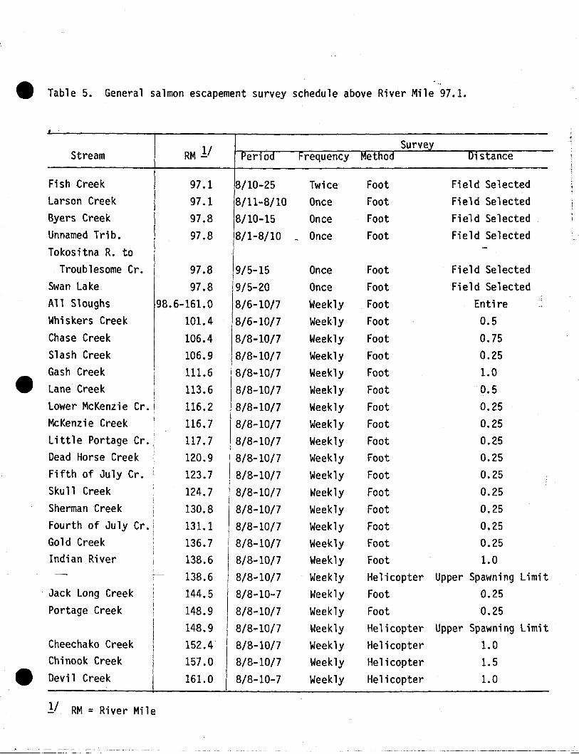
4It Table 5. General salmon escapement survey schedule above River Mile 97.1.
0.250.250.250.250.250.251.0
Upper Spawning Limit0.250.25
Upper Spawning Limit1.01.51.0
FootFootFootFootFootFootFootHelicopterFootFootHelicopterHelicopterHelicopterHelicopter
WeeklyWeeklyWeeklyWeeklyWeeklyWeeklyWeeklyWeeklyWeeklyWeeklyWeeklyWeeklyWeeklyWeekly
I 8/8 10/7I B/8-10/7
18/8-10/7I 8/8-10/7/8/8-10/7I 8/8-10/7I 8/8-10/7-8/8-10/78/8-10-78/8-10/78/8-10/78/8-10/78/8-10/78/8-10-7
120.9123.7124.7130.8131.1136.713B.6138.6144.5148.9148.9152.4157.0161.0
Dead Horse CreekFifth of July Cr.Skull CreekSherman CreekFourth of July Cr.Gold CreekIndian River
. .
RM 1/Survey
Stream PerlOd Frequency Metnod Dlstance
Fish Creek 97.1 8/10-25 Twice Foot Field SelectedLarson Creek 97.1 8/11-8/10 Once Foot Field SelectedByers Creek 97.8 8/10-15 Once Foot Field SelectedUnnamed Trib. 97.8 8/1-8/10 - Once Foot Field SelectedTokositna R. to
~
Troublesome Cr. 97.8 9/5-15 Once Foot Field SelectedSwan Lake 97.8 9/5-20 Once Foot Field SelectedAll Sloughs 98.6-161.0 8/6-10/7 Weekly Foot Entire -.Whiskers Creek 101.4 8/6-10/7 Weekly Foot 0.5Chase Creek 106.4 8/8-10/7 Weekly Foot 0.75Slash Creek 106.9 8/8-10/7 Weekly Foot 0.25Gash Creek 111.6 8/8-10/7 Weekly Foot 1.0Lane Creek 113.6 8/8-10/7 Weekly Foot 0.5Lower McKenzie Cr. 116.2 8/8-10/7 Weekly Foot 0.25McKenzi e Creek 116.7 8/8-10/7 Weekly Foot 0.25Little Portage Cr. 117.7 8/8-10/7 Weekly Foot 0.25
I
-
. Jack Long CreekPortage Creek
Cheechako CreekChinook Creek
~ Devil Creek
1/ RM = River Mile
•
-_.__._---------~--~-----
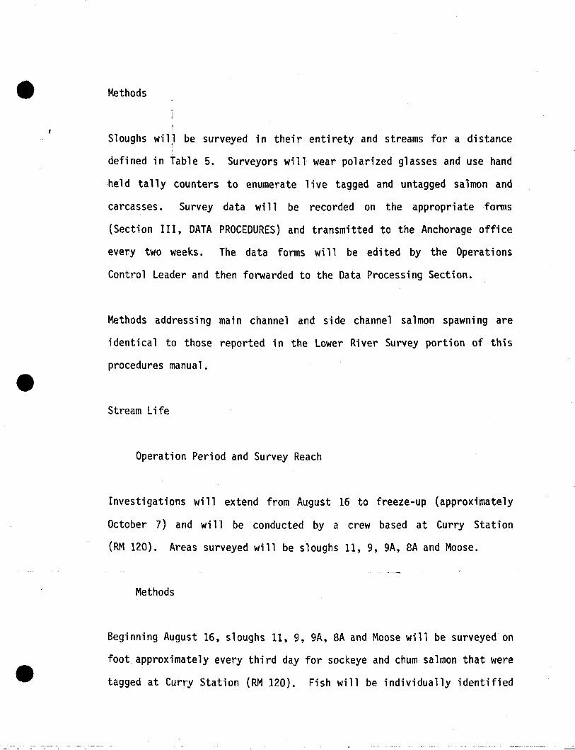
Methods
Sloughs wi l~l be surveyed in thei r enti rety and streams for a di stance
defined in Table 5. Surveyors will wear polarized glasses and use hand
held tally counters to enumerate live tagged and untagged salmon and
carcasses. Survey data will be recorded on the appropriate forms
(Section III, DATA PROCEDURES) and transmitted to the Anchorage office
every two weeks. The data forms will be edited by the Operations
Control Leader and then forwarded to the Data Processing Section.
Methods addressing main channel and side channel salmon spawning are
identical to those reported in the Lower River Survey portion of this
procedures manual.
Stream Life
Operation Period and Survey Reach
Investigations will extend from August 16 to freeze-up (approximately
October 7) and wi 11 be conducted by a crew based at Curry Station
(RM 120). Areas surveyed will be sloughs 11, 9, 9A, 8A and Moose.
Methods
Beginning August 16, sloughs 11, 9, 9A, 8A and Moose will be surveyed on
foot approximately every third day for sockeye and chum salmon that were
tagged at Curry Station (RM 120). Fish will be individually identified

•
---------- - ---
by orange one inch Petersen discs bearing full size identification
numbers. Surveyors will wear polaroid glasses and record observations
as outlined in Section III, DATA PROCEDURES.
Survey data will be forwarded to the Ancborage office every three weeks.
The data forms will be edited by the Operations Control leader and then
forwarded to the Data Processing Section.
•, .
- .._--~-----------_._ ...__ .. _.._----
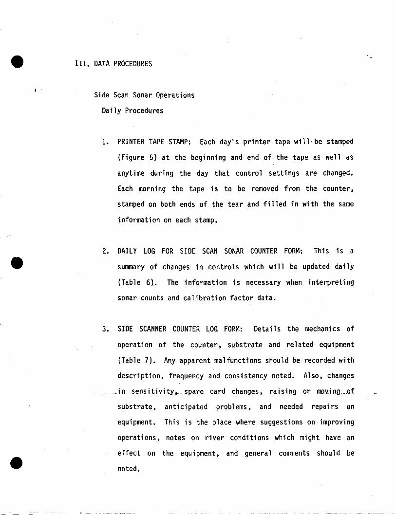
III. DATA PROCEDURES
Side Scan Sonar Operations
Daily Procedures
1. PRINTER TAPE STAMP: Each day's printer tape will be stamped
(Figure 5) at the beginning and end of the tape as well as
anytime during the day that control settings are changed.
Each morni ng the tape is to be removed from the counter,
stamped on both ends of the tear and filled in with the same
information on each stamp.
2. DAILY LOG FOR SIDE SCAN SONAR COUNTER FORM: Th is is a
summary of changes in controls which will be updated daily
(Table 6). The information is necessary when interpreting
sonar counts and calibration factor data.
3. SIDE SCANNER COUNTER LOG FORM: Details the mechanics of
operation of the counter, substrate and related equipment
(Table 7). Any apparent malfunctions should be recorded with
description, frequency and consistency noted. Also, changes
__ insensitivity, __spare card changes, raising or moving_of
substrate, anticipated problems, and needed repairs on
equipment. This is the place where suggestions on·improving
operations, notes on river conditions which might have an
effect on the equipment, and general comments should be
noted.

,
•'.. ~,
Figure 5 .

~f.n.
Page _ of _
Station: YENTNA
l-
eAA-84-l2
DAILY LOG FOR SIDE SCAN SONAR COUNTER
Bank: _
e
SIN: _
Command AutoFish Beam Dead Counting Print Printout Test
Date Time Velocity Angle Range Range Time Time Time..,
,
;~ .,It
""
...,.~ ............' ,.,,;1, ....... ;...,i •.,;" ,.0,:.• ,1",.1,~ .•1••
.
"

,-.--....-_.~_.~--,--.----. ....-.,-~_.~., ,"~' ·'-'--'-·-·'~··"-'--"-_···'"'·----_·_""-'·"··r
-r_k 7.Page _ of _
Station: YENTNA
Bank:
eAA-84-l4
SIDE SCAN SONAR COUNTER LOG
--
Date Time Remarks (i.e., Substrate lifted, any controls reset, etc.)
i
:
J
,,
I
;.

I
I
I
I
-------------- - -----------
4. SIDE SCAN SONAR COUNTER FIELD COUNTER CALIBRATION LOG FORM:
Calibration of the sonar counter to a~just for differential
fish veflocities. between salmon specie~ ·will be accomplished
by visual monitoring of the counters with an oscilliscope.
Counters will be calibrated a minimum of four times daily.
All calibration counts are to be recorded on the Side
Scan Sonar Counter Field Calibration Log from (Table 8).
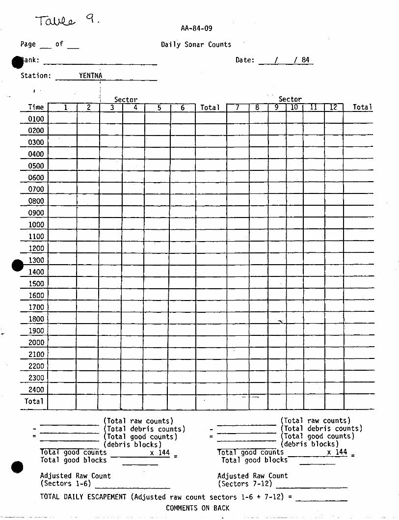
5. DAILY SONAR COUNT FORM: Sonar counts from printer tapes will
be entered by hour and sector (Table 9) • Counts whi ch
register debris or are skipped in printing should be noted
with a "d" or "s" in the appropriate hour-sector box. When
counters are shut off for a portion of one hour, data will be
interpolated for the hour as follows:
Adj. hourly count = min~~e~i~~~~:ted x counts for minutes operatedin hour in hour
For peri ods when the counter is off more than 50 mi nutes in
one hour that hour will be treated as a debris block. After
all blocks have been filled counts should be totalled for all
good blocks in each sector and each hour : The grand total is_
the total of all sectors or all hours (they should be equal).
Th is is known as the "daily raw count". After each days
counts are tabul ated and reported, pri nter tapes and SSS
count forms are to be placed in notebooks and sent to the
main office every two weeks. The Operations Control Leader

~B~
Station: YENTNA
eAA-84-10
SIDE SCAN SONAR COUNTER FIELD CALIBRATION LOG
Bank:
e
SIN: --------
I Percent Beam FishTime Scope Sonar Agreement Width: ve1ocit)
Date Observer Start Stop Count Count (1-:2)100 A1t. , (Sec/ft Sensi tivi ty Comments(1 ) (2) 2°, 4°
)
:
,
,
,I
,
~" ..... ,; • .~... J; ",,,., '
- -------------~------~~~~~~~~~---- -----
T~ '1.AA-84-09
Page of Daily Sonar Counts
/ 84/Date:_-..:-_--:.-~-
YENTNAi
.ank: _
Station: -----+------Sector Sector
Time 1 2 3 4 5 6 Total 7 8 9 10 11 12 Total010002000300040005000600070008000900100011001200130014001500160017001800 .,.,.
19002000 .
2100220023002400
--
Total
(Total raw counts)--------- (Total debris counts)
= (Total good counts)(debris blocks)
"To':"';t~a"""-g-:-:o~o-:rd-c---o-u-nts x 144 =Total good blocks
(Total raw counts)----------- (Total debris counts)
= (Total good counts)(debris blocks)
-To""t-a"'-'-g-o-odr--:"co-=-:-u":"::"nts x 144 =Total good blocks
Adjusted Raw Count(Sectors 7-12) __
(Adjusted raw count sectors 1-6 + 7-12) =-----COMMENTS ON BACK
Adjusted Raw Count(Sectors 1-6) --------TOTAL DAILY ESCAPEMENT
will edit the forms and then forward them to the Data
Processing Section.
6. All raw daily SSS counts are to be entered in the Epson
microcomputer daily (App,endix 10). All data entered onto
microcassettes will be '''backed up" by microcomputer paper
printouts. The microcassettes and pri ntouts wi 11 be
forwarded- to the Anchorage offi ce every two weeks. After
editing, the Operations Control leader will convey the data
to the Data Processing Section.
Tag/Recapture Operations
Da i ly Procedures
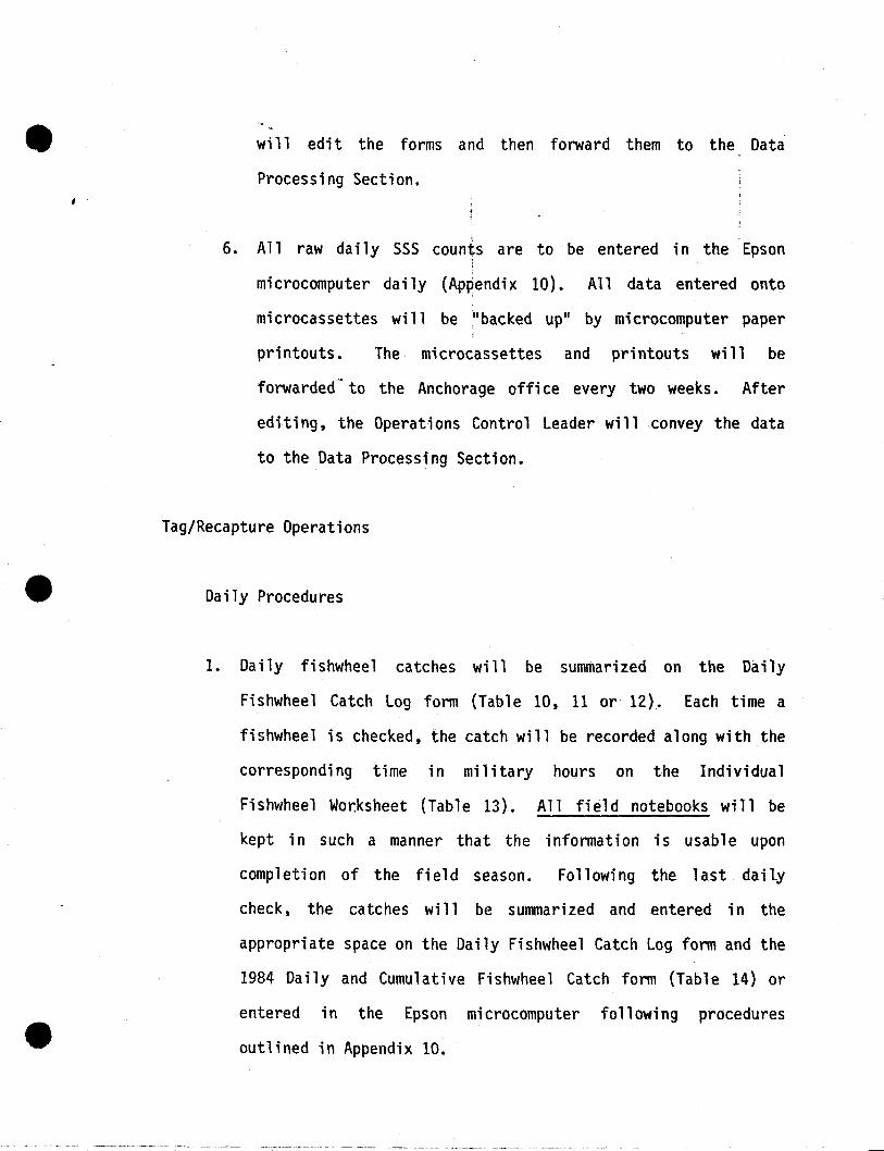
1. Daily fishwhee1 catches will be summarized on the Daily
Fishwheel Catch log form (Table 10, 11 or 12). Each time a
fi shwhee1 is checked, the catch will be recorded along wi th the
corresponding time in military hours on the Individual
Fishwheel Wor.ksheet (Table 13). All field notebooks will be
kept in such a manner that the information is usable upon
completion of the field season. Following the last daily
check, the catches will be summarized and entered in the
appropriate space on the Daily Fishwheel Catch log form and the
1984 Daily and Cumulative Fishwheel Catch form (Table 14) or
entered in the Epson mi crocomputer fo 11 owi ng procedures
outlined in Appendix 10.
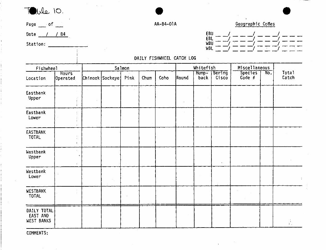
\e~ \0.
Page _ of _
Date I I 84
Station: _
eAA-84-01A
DAILY FISHWHEEL CATCH LOG
eGeographi c Cotles
EBU I / IEBL - -/ - - -/ - - -/ - - -WSU - -/ - - -/ - - -/ - - -
WBL ==1 =-=1 =.=1 =_=Fishwheel Salmon Whitefish Miscellaneous
Hours Hump- Ben n9 Specles No. TotalLocation Operated Chinook Sockeye Pink Chum Coho Round back Cisco Code # Catch
EastbankUpper
I
EastbankLower
EASTBANKTOTAL
WestbankUpper .
,
WestbankLower
WESTBANK i
TOTAL!
DAILY TOTALEAST AND
WEST BANKS ,
COMMENTS:
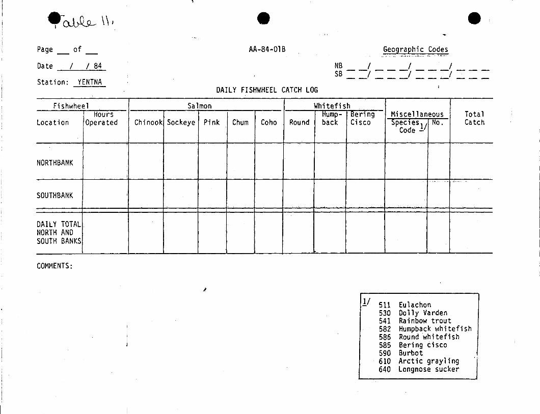
e~\\",
Page _ of _
Date / / 84
Station: YENTNA
or
eAA-84-01B
DAILY FISHWHEEL CATCH LOG
--Geographic Codes
_.' ", .._ •• "',_".~ •. ; ""; .1".,," .
NB / / /SB ==/ _==/ ==-/_-_
Fishwheel Salmon WhitefishHours Hump- Ben ng Miscellaneous Total
Location Operated Chinook Sockeye Pink Chum Coho Round back Cisco Specles 1/ No. CatchCode -
NORTH BANK
.. ...- ,~" ..., .
SOUTH BANK i
DAILY TOTALNORTH ANDSOUTH BANKS
COMMENTS:
I
1/ 511 Eu1achon530 Dolly Varden541 Rainbow trout582 Humpback whitefish586 Round whitefish585 Bering cisco590 Burbot610 Arctic grayling640 Longnose sucker

-~ \(..,
Page _ of _
Date 1 1 84
Station: CURRY
eAA-84-01C
DAILY FISHWHEEl CATCH lOG
eGeographic Codes
EB 1 1 1WB ==1 ===1 ==-I _ ==
,Fishwheel Salmon Whitefish
Hours ·Hump- Berlng Mi sce11 aneous Totallocation Operated Chinook Sockeye Pink Chum Coho Round back Cisco Speclesl/ No. Catch
Code -
EASTBANK I
WESTBANK ,
DAILY TOTALEAST AND ,
I
WEST BANKS
COMMENTS:
L.. ,.,>"
11 511 Eulachon530 Dolly Varden541 Rainbow trout582 Humpback ~hitefish
586 Round whitefish585 Bering cisco590 Burbot610 Arctic grayling640 longnose sucker

INDIVIDUAL FISHWHEEL WORKSHEET
• Date / / 84
Station: ---------'.
Fishwheel location: -----------Time Number of Fish Captured
(Mil i tary) Chinook Sockeye Pink Chum Coho Other *
--
1-' ---'--
Hours Operated: __* Identify species
and number caught.

- - - -------------------------,
TDv~ l4.ofPage
e Station ----------
AA-84-04
1984 DAILY AND CUMULATIVE FISHWHEEl CATCH;
~
Chinook ; Socke e Pink Chum CohoDate Daily Cuml Daily Cum Daily Cum Daily Cum Daily Cum
,;
l
,
,
-
.- .- - - --- -._--- -----.----. - ._--- _._._.
, .
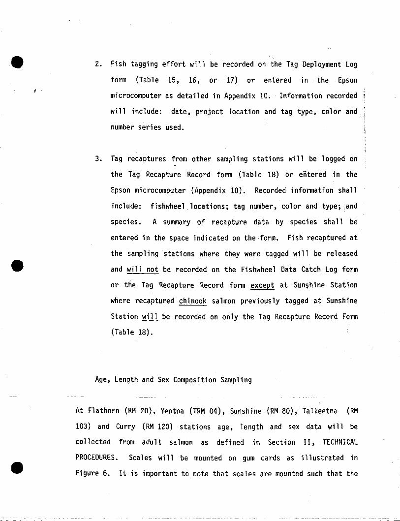
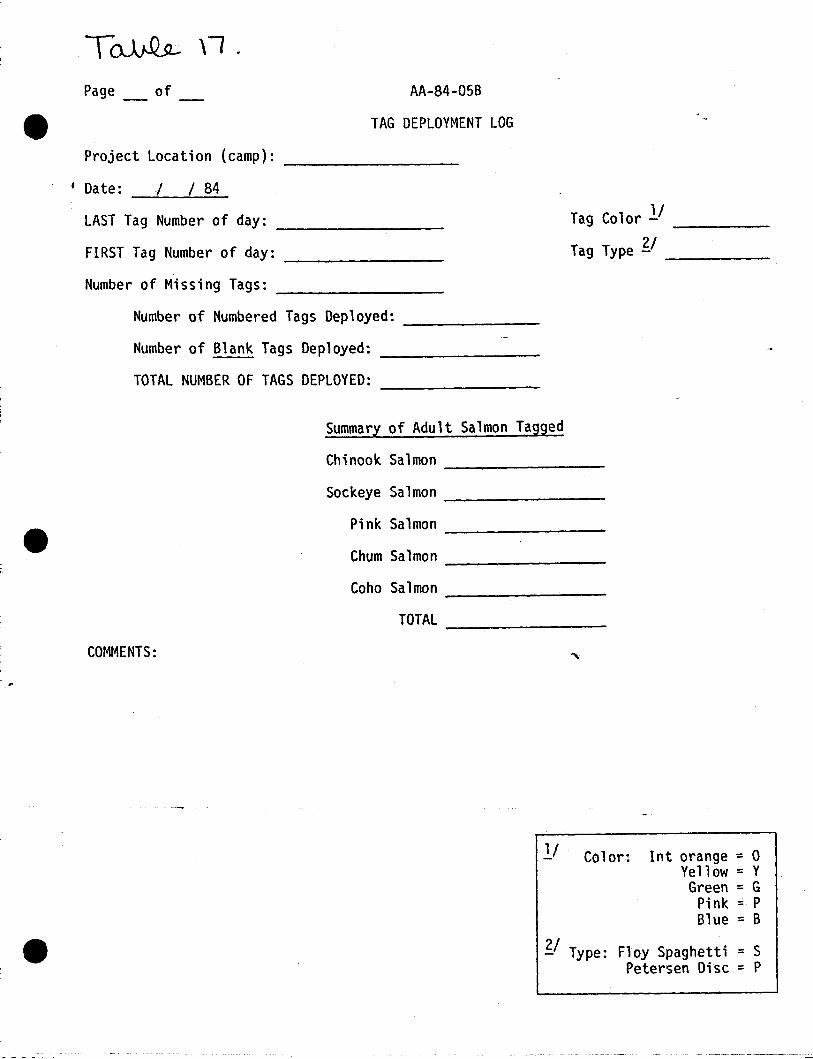
2. Fish tagging effort will be recorded on the Tag Deployment Log
form (Table 15, 16, or 17) or entered in the Epson
microcomputer as detailed in Appendix 10.. Information recorded 1
will include: date, project location and tag type, color and
number series used.
3. Tag recaptures from other sampling stations will be logged on
the Tag Recapture Record form (Table 18) or entered in the
Epson microcomputer (Appendix 10). Recorded information shall
include: fishwheel locations; tag number, color and type; and
speci es. A summary of recapture data by speci es shall be
entered in the space indicated on the form. Fish recaptured at
the sampling stations where they were tagged will be released
and will not be recorded on the Fishwheel Data Catch Log form
or the Tag Recapture Record form except at Sunshine Station
where recaptured chi nook salmon previ ous ly tagged at Sunshi ne
Station will be recorded on only the Tag Recapture Record Form
(Table 18).
Age, Length and Sex Composition Sampling
At Flathorn (RM 20), Yentna (TRM 04), Sunshine (RM 80), Talkeetna (RM
103) and Curry (RM 120) stations age, length and sex data will be
collected from adult salmon as defined in Section II, TECHNICAL
PROCEDURES. Scales will be mounted on gum cards as illustrated in
Figure 6. It is important to note that scales are mounted such that the

T~ \5.Page _ of_
~- - -_.~~--------------------------.
EAST BANK ONLYAA-84-05E
TAG DEPLOYMENT LOG
Project Locafion (camp): __
, Da te: ~/ j / 84
LAST Tag Number of day: __
FIRST Tag Number of day: ____
Number of Missing Tags: __
Number of Numbered Tags Deployed: _
Number of Blank Tags Deploy~d:
TOTAL NUMBER OF TAGS DEPLOYED:
Tag Color 1/ __
Tag Type '5:./ _
Summary of Adult Salmon Tagged
Chinook Salmon _
Sockeye Salmon ------------
Pink Salmon ---
Chum Salmon ___
Coho Salmon -------------------TOTAL _
COMMENTS:
1/ Color: Int orange = 0Yellow = YGreen = G
Pink = PBlue = B
~/ Type: Floy Spaghetti = SPetersen Disc = P

T~ \<t>.
Page ofWEST BANK ONLY
AA-84-05W
TAG DEPLOYMENT LOG
Project Location (camp): ----------Date: / / 84
LAST Tag Number of day: .--------i---FIRST Tag Number of day:
------~-
Number of Missing Tags: ---------Number of Numbered Tags Deployed:
Nun:tber of Blank Tagi Deployed: _
TOTAL NUMBER OF TAGS DEPLOYED: --------
Tag Color 11 _Tag Type 'fl ___
1-- . ~
Summary of Adult Salmon Tagged
Chinook Salmon --------Sockeye Salmon ___
Pink Salmon ----------Chum Salmon --------Coho Salmon ----------
TOTAL _
COMMENTS:
11 Color: lnt orange = 0Yellow = YGreen =G
Pink = PBlue = B
~I Type: Flay Spaghetti = SPetersen Disc = P
T~\I.
Page of AA-84-05B
TAG DEPLOYMENT LOG
Project Location (camp):
, Date: I I 84
LAST Tag Number of day: _
FIRST Tag Number of day: _
Number of Missing Tags: _
Number of Numbered Tags Deployed: _
Number of Blank Tags Deployed: _
TOTAL NUMBER OF TAGS DEPLOYED: _
Tag Color II _
Tag Type ?:/ _
Summary of Adult Salmon Tagged
Chinook Salmon _
Sockeye Salmon _
Pink Salmon ----------------Chum Salmon ------------Coho Salmon --------
TOTAL ------------COMMENTS:
11 Color: Int orange = 0Yellow =YGreen =G
Pink = PBlue = B
~I Type: Floy Spaghetti = SPetersen Disc = P

Page of AA-84-19TAG RECAPTURE RECORD
• Project Station: _
, ;,
;
; TagBank
;
Leave BlankDate"' Captured Species; Number Color ]/ Type ?:l (Office Use Only)
~I Type: Floy Spaghetti = SPetersen Disc = P
SHEET SUMMARYNo. Recaptures
Chinook (41)Sockeye (42) ------
Coho (43)Pink (44) _Chum (45) ------
TOTAL ------
11 Color: lnt; orange = 0Yellow = YGreen = GPink = PBlue = B

J-BOVE
un:.lU.!- 'L;NE
OORSAl FIN
Do not turn seales over whentransfering frQII fish to gum card.
If the preferred. scale is lIIissir<9take a SCale ~ain CX\ the left.side of the fish 110 IIlOre thanfour rows above the latterA.l. linewithin the a(ea behind the corsalfin and aheaa of the anal fin.
\Place an t in colLIM E oCM. foCt It the preferred scalewas not saapled.
f!*.;~-----___~
TaJce the preferred scale on theleft side of the fish, two tOWSabove .the lattera~ line and on thediagonal frQII behind the base ofthe anal fin.
, .
------_-.....~
Place scales ciirectly over number ongUll card.
7 6 5 • 3 2 ~10 9 6
17 16 \S l4. 13 1.2 II20 19 18
Z1 26 2S U 2,." 22 :J.30 :l3 28
31 :Ja 35 34 33 32- 3L40 39 38

I
I
~
- -- ------~------_~--- -- ----
ridged surface is facing out and the anterior portion of the scale
orientated toward the top of the scale card. All length measurements are
taken from mid-eye to fork of tail (FL) and are recorded to the nearest
five millimeters.
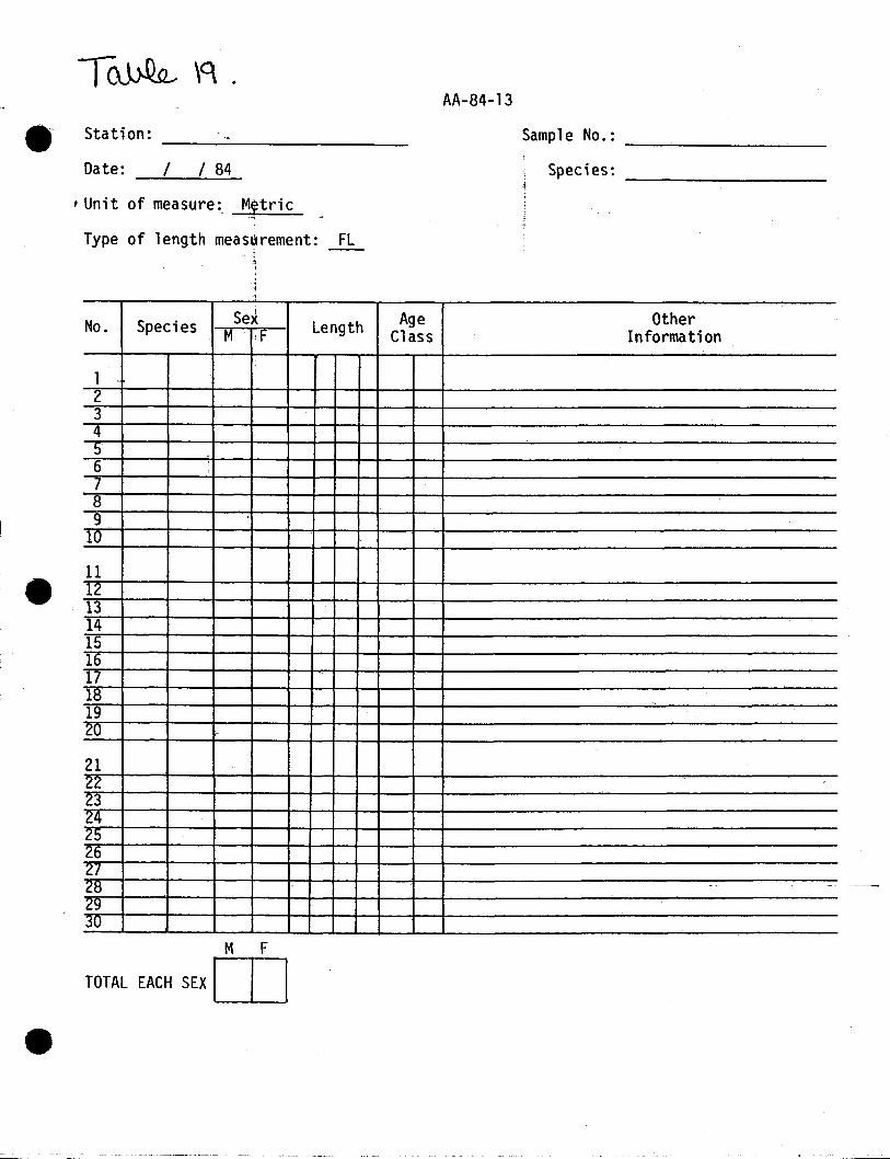
Length and sex data are recorded on the Age and Length (AL) form (Table
19). Scale cards are numbered to correspond with the proper AL form
(i.e. scale card 001 contains scales collected from samples recorded on
AL form 001).
Length and sex data along with the corresponding scale cards will be
returned to the Operations Control Leader every two weeks.
Stream, Slough, Side Channel and Main Channel Surveys
Lower River
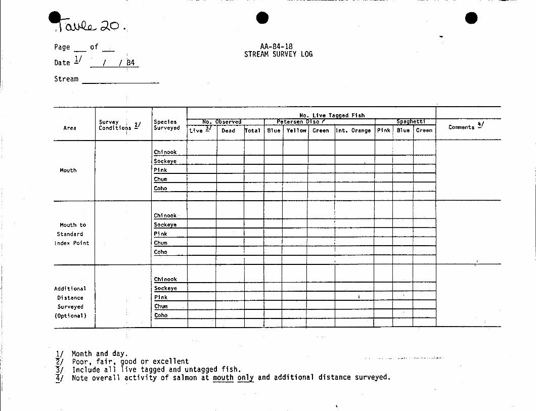
Stream survey resu1 ts wi 11 be recorded on the Stream Survey Log Form
(Table 20). Data recorded on each survey will include date, stream,
survey conditions, distance surveyed, live and dead fish counted by
speci es and number of 1i ve tagged fi sh by tag type and color. The
"comments" column will include namas of survey staff and reference to
tag loss. Tags on carcasses will be removed as schedules permit and the
information recorded on the back side of the Stream Survey Log form.
Adult salmon spawning distribution in the first one-third mile of each
stream will be mapped on the lower River Stream Survey Spawner
Distribution Map form {Table 21}. In addition, a brief description of
the habitat will also be recorded on this form.
/ / 84
e Station: ------ ~
Date:
AA-84-l3
Sample No.: _
Species: ~
-
No. Species Se~ Length Age OtherM iF Class Information
12345
"
6789
10
11121314151617181920
2122232425262728 ...
2930
, Unit of measure: M~tric
Type of length measurement: FL
M F
TOTAL EACH SEX~
~-------------------~-~.~ 'y-.---'-' .••.•••._--_•. _.
~~;;(O e eAA-84-18
STREAM SURVEY LOG/ 84
Page _ of
Date 1/ I-~--=-.....:::...::-.
Stream ---------
No. Live Taqqed FishSurvey , I Species No. )bserved Petersen lisc r Sllaghettl
Comnenh ,!-/Area ConditioDs ! Surveyed Live ~I Dead ~otal Blue Yellow Green Int. Orange Pink Blue Greeni
ChinookSockeYe
Mouth PinkChumCoho
ChinookMouth to Sockeye
Standard PinkIndex Point Chum
Coho
-
ChinookAdditional Sockeve
Distance Pink I
Surveyed Chum(Optional) Coho
1/"2/3/4/
Month and day.Poor, fair, good or excellentInclude all live tagged and untagged fish.Note overall activity of salmon at mouth only and additional distance surveyed.
..",...... .•.• L •• ; "",' I,... ,,,.

T~ d\.AA-84-07
Lower River StreamSurvey Spawner
Distribution Map
S~ream _
Date ----------Observers---------
General Habitat Description of Spawning Area(s):
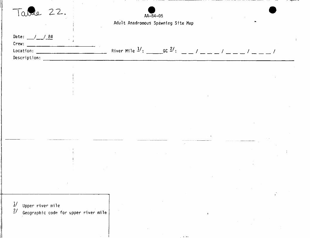
Main channel, slough and side channel spawning will be recorded on the
Adult Anadromous Spawning Site Map form (Table 22). Information
recorded will include date,lriver mile, geographic code, ~ map of the
spawning site, number of fis~ and a general habitat description.
Egg deposition sampling data will be recorded on the Egg Deposition
Sampling form (Table 23). Information collected will include: date,
location, number of plots sampled, number of live eggs and number of
dead eggs.
All survey data wi 11 be returned to the Operati ons Control Leader every
three weeks, who will edit the data and forward it to the Data
Processing Section.
Middle River
Stream survey, main channel and side channel spawning and egg deposition
sampling data procedures are the same as those discussed for the Lower
River Surveys.
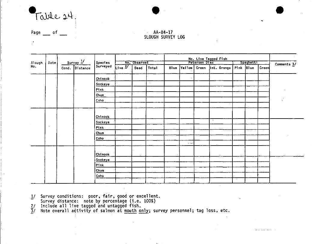
Escapement surveys of sloughs will be recorded on the Slough Survey Log
(Table 24). For each survey a recording by species of the live and dead
fish count, tagged and untagged fish numbers and survey conditions and
distance surveyed in percentage will be made. Under the comments column
include surveyors name(s) and reference to tag loss.
I~ 22.
Date: / / 84Crew:Location: -------------Description:
I -----
1/ Upper river mile~/ Geographic code for upper river mile
ii
eAA-84-05
Adult Anadromous Spawning Site Map
River Mile 1/: GC ~/:
e
/ / / /

Page of AA-84-07
EGG DEPOSITIONI lOGI
Date / / 84
location: River Mile ---- Geographic Code: . / / /-i-- --- --- ---
!
Plot Number Number of Eg< s REMARKS .!I(Sequential) live Dead Total
I
!
- --- ----
Include names of survey staff and.!.I substrate dfscriPtion.
~~~~~-...-...-..--------------I........,......~~~~---=----=-...-
~o..\J.l~ ~k.\, .
Page _ of _
•AA-84-17
SLOUGH SURVEY LOG
e
Survey 11No. Live Tagged Fish
Slough Date Species NO. Observet2 t'eter$en 01SC :;paohettl Comments YNo. Condo Distance Surveyed Live Y Dead Total Blue Yellow Green Int. Orange Pink Blue Greer
ChinookSoekeyePinkChumCoho ,
ChinookSockeye
,
PinkChumCoho
~ ,.1,
ChinookSockeyePinkChumCoho •
Ii II21~I
Survey conditions: poor, fair, good at excellent.Survey distance: note by percentage (i.e. 100%)Include all live tagged and untagged fish.Note overall a¢tivi ty of salmon at mouth only; survey personnel; tag loss, etc.
All carcasses bearing Tal keetna Station tags will be examined and the
number, species, date and location recorded on the back side of the
Stream Survey Log form or the Slough Survey· Log form. Similar
procedures will be followed for carcasses bearing tags from other
stations as schedule permits.
All survey forms will be returned to the Operations Control Leader once
every three weeks. The data wi 11 be edited and forwarded to the Data
Processing Section.
Stream Life
The Stream Life Log form will be used to record site observations of
sockeye and chum salmon tagged at Curry Station (RM 120) (Table 24).
Data recorded will include site location, date, fish identification
number, species and behavior and or condition of fish (i .e., mill ing,
spawning, post-spawning, carcass).

I-
APPENDICES
ADULT ANADROMOUS;FISHERIES STUDIES
~
AppeQdix 1 Sonar Installation &Operation Manual,
Appe~dix 2 Oscilloscope Operationi
Appe~dix 3 Fishwheel Operation
Appendix 4 Fish Tagging
Appendix 5 Geographic Location Code &General Maps
Appendix 6 General Equipment, Camp Maintenance and Camp Policy
Appendix 7 Fish Identification
Appendix 8 Side Band Radio
Appendix 9 First Aid and Safety
Appendix 10 Epson

APPENDIX 1
ADULT ANADROMOUS FISHERIES STUDIES
Sonar Installation and Operation Manual

THE BENDIX CORPORATION
ElectrodynamicsDivisionNorth HollywoodCalifornia
INSTALLATION
AND
OPERATION
MANUAL
SIDE SCAN
SALMON COUNTER
(1980 model)
Report No.SP-78-01710 March 1980
Prepared for:The State of AlaskaDepartment of Fish and GameAnchorage, Alaska
Revised October 1981 bySusan L. Ell isSu Hydro Project

- - - ----------
TAB LEO F CON TEN T S
Section I Fu~ction of Front Panel Controls
Section II Initial Setup and System Test
Section III Troubleshooting
Section IV Side Scan Sonar Artificial Substrate
~~~~~~~- -~~- -
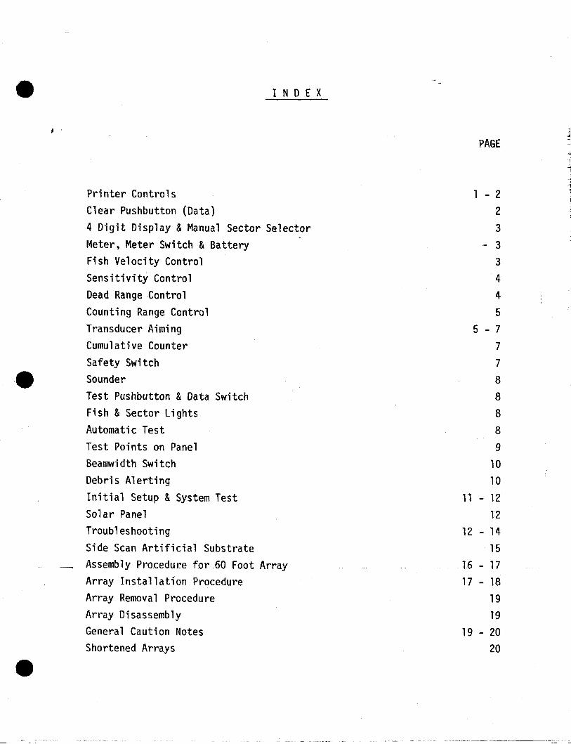
I NDE X
Printer ControlsClear Pushbutton (Data)4 Digit Display &Manual Sector SelectorMeter, Meter Switch &BatteryFish Velocity ControlSensitivity ControlDead Range ControlCounting Range ControlTransducer AimingCumulative CounterSafety SwitchSounderTest Pushbutton &Data SwitchFish &Sector LightsAutomatic TestTest Points on PanelBeamwidth SwitchDebris AlertingInitial Setup &System TestSolar PanelTroubleshootingSide Scan Artificial SubstrateAssembly Procedure for 60 Foot ArrayArray Installation ProcedureArray Removal ProcedureArray DisassemblyGeneral Caution NotesShortened Arrays
PAGE
1 - 2
2
3
- 3
3
4
4
5
5 - 7
7
7
8
8
8
8
9
10
10
11 - 12
12
12 - 14
15
16 - 17
17 - 18
1919
19 - 2020
I NT ROD UC T ION
Before attempting to operate or install the Side Scanner, thoroughly read this
manual to become familiar with the system operation.
Section I will familiarize you with all the controls and their purpose. It
is probably the most important section of this manual.
Section III will aid you in pinpointing any source of problems and in making
any necessary field repairs by replacing printed circuit cards.
Section V will show you how to install the artificial substrate in the river.
• I. FUNCTiON OF FRONT P~NEL COUTROLS
A. PRINTER
1. Printout,..
The printer prints out 12 1ines or data.c-The nUlilber atleft designates the river sector, the next column is a 1ett~r
identifying various conditions suc~ as normal, command printor auto test. These letters are explained on the front panel.If normal, the letter "A" will be printed. This may appearas a dot on the 1978oode1. The following four digits arethe number of fish counts that have been accumulated in eachsector. Each sector represents a length of river, perpendicularto the shore that is equal in length to 1/12 of the '~OUNTING
RANGE" control setttng, with sector 1 being clos~st to shore.For exar.Jp1e, if the "COUNTING RANGE" control is set to 60 feet,then each sector represents 5 feet, in distance. A "+" in thethird column indicates debris has been detected in the corresponding s~ctor. Anytime PRINTOUT TIME OR AUTOTEST TIME ischanged, the time must be reset.
2. Set Time (Printer)
The purpose of this pushbutton is to initially set theprintout time and auto test time at any point. The "SAFETYSWITCH" must be off to do thi s. Set time to pri nt out on thehour.
3. Print Command
The printer may be commanded to print its contents at anytime without affecting the timing. The letter "C" isprinted when this pushbutton is depressed to permit you toknow that this is a command print and not in the normaltime sequence. The printout t~ming is not affected butthe counts are erased after printout. , Erasure of data on1978 and '79 models can be avoided by setting theDAfA CLEARTIME switch to the NEVER position until printout is over.On 1980 models the command printout should be added to thenext hourly printout.
4. Printer On-Off Switch
This switch does not affect the timing or data in any wayand is merely used to shut off the printer. The sounder\'1i11 sound to alert you to put the printer ON-OFF s\'1itchback on. It normally takes only a minute to change paperso try to plan your paper change between prints or acomplete pr,intout may be missed without your knowledge. Onmodels usitng the IIDAfEL" printer, be sure to shut off theprinter switch when changing printer paper.
•
B
5. Replacing Printer Paper
A blue line on the paper alerts you about 1 day in advance ofpaper depletion. To change paper. shut off the printerswitch and unscrew the 2 small silver knurled scre~s on theprinter face. Lay a new pad of paper in-the rear tray withthe blu~ lines toward the tray bottom. Feed the paper overthe silver roller in front and between the plastic face andrubber roller. Start the paper by revolving the rubber "rollerwith your finger. During operation place a binder clip onthe end of the tape as it comes out of the counter. Hangingthe clip over the edge of the counter stand will allow tapeto move smoothly out of the counter. eliminating printermalfunction. If the printer tape doesn't f~ed smoo~hly and hourly-- ..(printouts are superimposed on each other. clean the blackrubber roller thoroughly with alcohol. When the paper runsl~~ the printer may skip printouts. so it is important toavoid letting the paper run too close to the end of the roll.When replacing the printer. push it in whil~ making surethe paper is not pinched between the'printer~and panel bymanually pulling some paper out of the slot. Make sure theprinter seats completely flush with the panel since an electricalconnector must make contact. Retighten the two knurled screwsas tightly as possible with your fingers.l1 If the ink becomesdim after 2 to 4 years of operation. loosen the two blackscrews on the printer face and pullout the ink pad. A newpad may then be screwed in. Spare pads have been suppliedto the State of Alaska and spare printers- have been included.Any printers may be interchanged b2tween systems.• as they areidentical.
DATA CLEAR TIME
Data is cleared (erased from menory) after each printout.Set for AT PRINT Rosition on 1978 and 1979 models.
C. CLEAR PUSHBUTTON
The red CLEAR pushbutton located on the left side of thepanel will clear the data in the memories controlling theprinter and 4 digit liquid crystal display. It does notaffect the cumulative counter at right. To clear the data.the lISAFETY" s\~itch must be "OFF". The sounder alerts youw~en this switch fs left off.
411 11 SCrew on printers must be tightened daily as vibrations can cause themto loosen.
• D.
;
Ei.1
F.
4 Digit Display and J1anual Sector Selector
The liquid crystal display shows you the number of countsaccumulated in any of theil2 sectors that is selected by theblack thumbwheel switch above it. It is always on since ituSes only 1 microamp of cu.rrent. Being liqUid crystal, it isa reflective display and requires some ambient light to be seenAt night a flashlight or match may be necessary to see it.
Meter, Meter Switch and Battery
When in the "BATT" position, the meter reads the condition ofthe GEL- CELL battery. When in the "SOLAR CHARGE" position,the meter reads the output of the solar panel. In full,unobscured sunlight the meter will read at the extreme fightindicating the solar panel is supplying 12 times the currentthat the Side Scanner is using with the excess going to chargethe supplied GEL-CELL battery. When the meter is at the pointwhere the red and green meet (such as cloudy weather) the solarpanel is supplying twice as much current as the Side Scanneris consuming with the excess going to charge the GEL-CELL battery.This would be enough to indefinitely carry it through the nighthours. Although a 12V, 16 amp hour rechargeable GEL- CELL batteryis sU2p1ied with each system, any 12V battery of equal or greatercapacity may be used. The supplied battery, when fully charged,will operate the Side Scanner for approximately 300 hours, orabout 2 weeks, day and night, with no solar charging. Internalprotection is provided against battery overcharging in the eventof constant full sun.
Fish Velocity Control
This thumbwhee1 switch controls the transmit repetition rateof the system. It has been observed that salmon migrate upstream at about 1.75 feet per second (ground speed). Since theswitch is labeled in seconds per foot, the reciprocal of 1.75feet per second is 0.571 seconds per foot so until new fish speedinfonnation is obtained, set the control to 0.571. To determineoptimum velocity use the following formula after monitoring theoscilloscope for a minimum of 250 cumulative fish spikes:
Fish counts on the SSS counter x existing velocity =Fish spikes observed on oscilloscope
new velocity
e.g., if the SSS count is 200 and the scope count is 250,200/250 x 0.571 = .457, the new velocity setting. If the ratioof sonar counts to scope counts is within 0.8 and 1.2, do notadjust velocity. The reason pehind this is as follows: Whenthe side scan sonar isovercounting the fish are in the beamtoo long; the pulse repetition rate is too high. The solutionis to decrease pulse repetition rate by dialing fish velocity ~(remember, the velocity dial is the reciprocal of fish swimmingspeed). likewise, when the sonar is undercounting, the fish are
r 11I.; I; !i:
':;0V'f,! :
1L'
ififnU
F.
G.
".
Fish Velocity Control Cont. "-
not in the beam long enough; the pulse repetition rate istoo slow and the fish velocity should be dialed down.
It has been observed that at the lower extreme of the velocitysetting (i.e.( .150) the side scan sonar counters tend tofunction erratically. Such settings should be avoid~d. Ifundercounting problems persist at higher settings, the transducermay be misaimed or the sensitivity set too low.
Sensitivity Control
This controls the amount of power transmitted to the transducerand is essentially a system sensitivity control.
To adjust it initially requires a fine bladed screwdriver orknife and an oscilloscope. It is adjusted as ~olla~s:
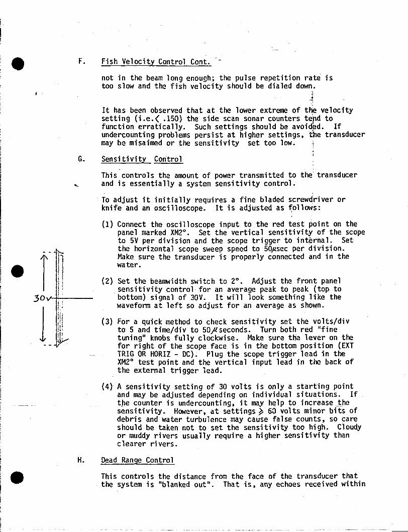
(1) Connect the oscilloscope input to the red test point on thepanel marked XM2°. Set the vertical sensitivity of the scopeto 5V per division and the scope trigger to internal. Setthe horizontal scope sweep speed to 50#sec per division.Make sure the transducer is properly connected and in thewater.
(2) Set the beamwidth switch to 2°. Adjust the front panelsensitivity control· for an average peak to peak (top tobottom) signal of 30V. It will look something like thewaveform at left so adjust for an average as shown.
(3) For a quick method to check sensitivity set the volts/divto 5 and time/div to 50ft seconds. Turn both red ':finetuning" knobs fully clockwise. Make sure the lever on thefor right of the scope face is in the bottom position (EXTTRIG OR HORIZ - DC). Plug the scope trigger lead in theXr~2° test point and the vertical input lead in the back ofthe external trigger lead.
(4) A sensitivity setting of 30 volts is only a starting pointand may be adjusted depending on individual situations. Ifthe counter is undercounting, it may help to increaseJhesensitivity. However, at settings~ 60 volts minor bits ofdebris and water turbulence may cause false counts, so careshould be taken not to set the sensitivity too high. Cloudyor muddy rivers usually require a higher sensitivity thanclearer rivers.
H. Dead Range Control
This controls the distance from the face of the transducer thatthe system is "blanked out". That is, any echoes received within
H.
-- ------------------------
Dead Range Control (Cont.)
this preset range will not be accepted for processing. The control may be set from 0 to 10 feet. This control is necessary toblank out transducer II r inging ll which occurs for about 2-1/2 feetand would result in false counts. Sometimes a source of airbubbles near shore exists which could false counts. In this case,increase the DEAD RANGE control until the count stops in sector 1(as evidenced by the #1 fish light blinking). The fish \-,ould thenhave to be wei red out to beyond the dead range.
During periods of extreme high water false counts may register inthe first one or two sectors possibly due to increased watervelocity, increased turbidity or a combination of the two. Inthis case the dead range may be dialed out to 3 or mor~rfeet to_avoid overcounting until the river returns to a normal level.
I. Counting Range Control
This controls the total perpendicular distance to which fish coun~s
will be accepted. This preset distance starts immediately after 0
the DEAD RANGE ceases, thus the total range from the face of thetransducer is the total of both the "DEAD RANGE" and "COUNTINGRANGE II setti ngs.
J. Transducer Aiming
The end of the artificial substrate contains a target, approximately60 feet from the transducer face. This is necessary for initialaiming of the transducer beam. Prior to submersion the transducerplate should be flushed on all sides with the transducer housing.This can be accomplished by IIfeel ll or using a straight edge.
An oscilloscope should be used in lieu of the #12 FISH LIGHT formore precise aiming. To do so, trigger the oscilloscope from theXM2° panel test point, connect the scope ground to the GND testpoint and the scope input to the RCVR test point. Set the scopevertical control to 1 V/CM and the horizontal control to 5 millimeters per em. 1/. The target will be observed on the scope 24milliseconds from the start of the trace and the transducer may bemanipulated for a maximum II spike" at that point. If the transduceris aimed to low, early echoes coming from rough surfaces on thepipe will be seen before 24 milliseconds.2/
The new (1978) artificial substrates have an improved method oftransducer adjustment and have transducers modified for the newsubstrates (see figure on the last sheet.) The transducer plate
11 See section titled Oscilloscope Operation for the Side Scanner.
2/ See section titled Typical Side Scanner Oscilloscope Waveformsfor various transducer aiming conditions.
J. Transducer Aiming (Cont.)
should be installed in the shroud on the: shore end member. The3 studs attached to the plate will be secured to the plate with
. th~ 3/8-16, locknuts. Use lockwashers an~ tighten with channellock plier:s. About 1 1/2 inches away there ·will be a 1/2-20 nutfollowed by a flat washer, a spring and flat washer in that order.The threelstuds should be pushed through the three correspondingholes in the shroud with the last flat \'Iasher against the insideof the sh~ud. A hand wheel should then be screwed onto theoutside 011 the shroud on each of the portruding studs. Extremecare should be taken \'Ihen installing or removing the transducerfrom the housing as the springs tend to falloff and get lostin the river. To avoid this, tape the springs to the s~uds witha small piece of tape. The transducer and transducer tablesshould be fed over the top of the transducer and back to shore,securing 1;hem with tape to prevent chafing and to provi.de a littleservice loop to prevent their being torn off the transducer. Thethree, hand wheels should be tightened with an equal amount of studprott-uding through the wheel. The transducer will nO\'1 be approximately aimed at the target end 60 feet away. (The remaining threehand wheels should be used after final transducer adjustment byrunning them up the stud and tightening them against the firstwheel to lock them in place.)
To aim the transducer with the oscilloscope, set the bea~'Iidth
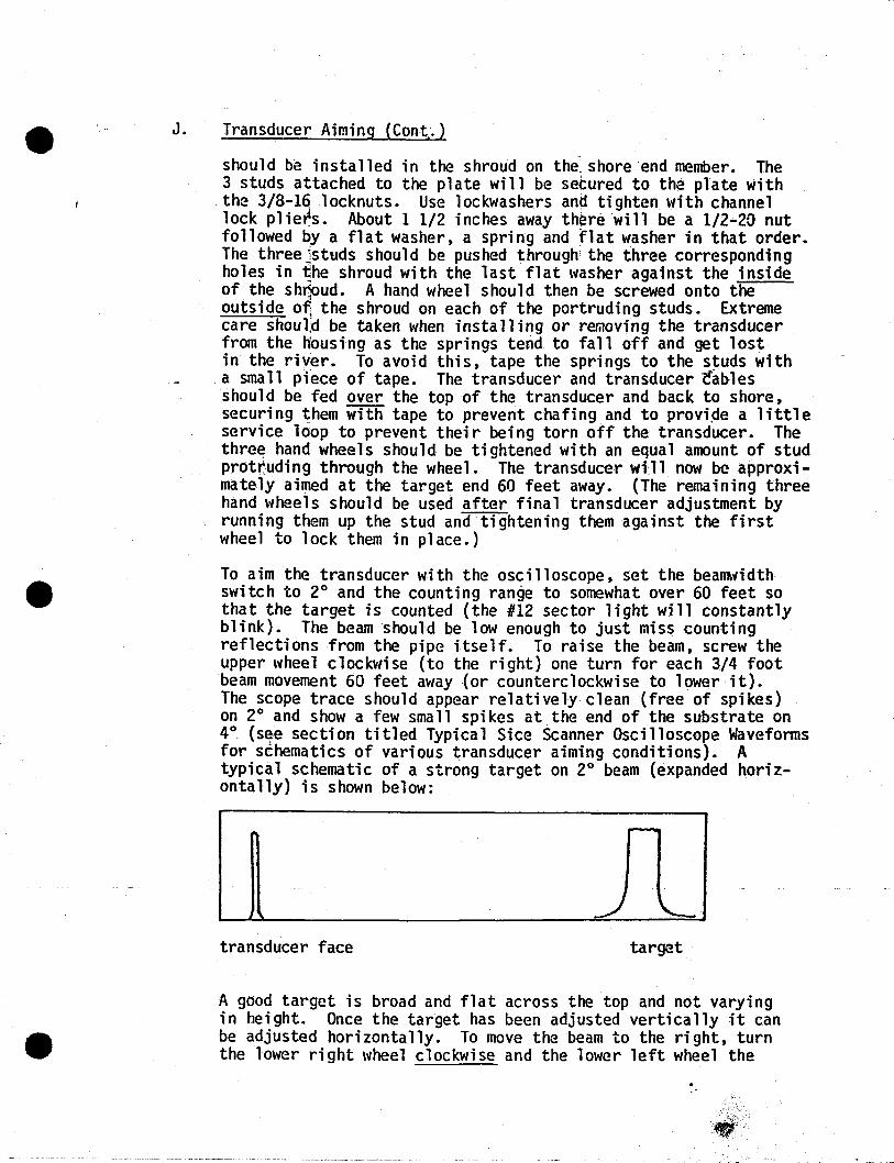
switch to 2° and the counting range to somewhat over 60 feet sothat the target is counted (the #12 sector light will constantlyblink). The beam should be low enough to just miss countingreflections from the pipe itself. To raise the beam, screw theupper wheel clockwise {to the right} one turn for each 3/4 footbeam movement 60 feet away {or counterclockwise to lower it}.The scope trace should appear relatively clean {free of spikes}on 2° and show a few small spikes at the end of the substrate on4° {se,e secti on titled Typical Sice Scanner Osci lloscope Waveformsfor schematics of various transducer aiming conditions}. Atypical schematic of a strong target on 2° beam {expanded horizontally} is shown below:
transducer face target
A good target is broad and flat across the top and not varyingin height. Once the target has been adjusted vertically it canbe adjusted horizontally. To move the beam to the right, turnthe lower right wheel clockwise and the lower left wheel the
ieI
,!L-- -- --
• •
K.
L.
--~------
-same amount counterclockwise at the same time. To move thebeam to the left, reverse the procedure. Horizontal movementsshould involve exactly the same amount of turning on each wheelto avoid "skewing" the beam out and up or down. Each full turnof both wheels together will move the beam horizontally 1 1/2feet. By turning them together, the vertical aiming remainsunchanged. Likewise. adjusting the upper knob does not affecthorizontal beam movement.
frofil the "flushed" position, the transd'ucer should be moved upor down stream as much as necessary to achieve a strong target.In a strong current the pipe tends to bow out so the t~nsducer
may need to be aimed a bit upstream to compensate. In cases'where fish tend to migrate close to the surface over the substrate,the beam may need to be aimed high and downstream. Frequentmonitoring of the oscilloscope and experience with aiming are __~the surest means of achie"ving a good target and counting maxim~
numbers of fi she
It has been observed that when water level rises considerablyover a short period of time the target becomes weak or disappearscompletely. This may be caused by the increased velocity bendingthe tube, requiring an adjustment of the horizontal positionof the beam. If no target can be found when making verticaladjustments of the beam, it may be due to irregularities of theriver bottom. If the end of the tube is hanging over a ledgeor if the tube is resting on a rock, the target end will be lowerthan the rest of the tube and may not be locatable by aiming thetransducer. In this case the beam should be aimed low enough tojust avoid reflecting echoes from the surface of the tube. Whenno target can be found at all and the printouts are all zeroes,it may be that a large piece of debris is lodged on the transducetblocking transmission of the beam. This should be checked before'adjusting the transduce~~
Cumulative Counter
This counter maintains a running total of all counts. It is an8-digit counter and being of the L.E.D. type, consumes a fairamount of power when lit. For this reason a "READ" pushbutton
- --f5 provided below it to read the total when desi red. To clearthe cumulative counter, shut off the SAFETY switch and depressthe CLEAR pushbutton located below the counter. The alarm willalert you that the SAFETY switch is OFF.
Safety Swi tch
This s\'1itch is an interlock provided to prex~nt accidental clearing of the data or accidental resetting of,rpRlNTER time or
AUTor4ATIC TEST time. Whenever it is left in the OFF positiont~e sounder wi 11 sound, alerti ngyou to thi s fact.
~1. Sounderi
T~e ~ounder will alert you whenever any of the following threeswitches are left in the "wrong" position to prevent walkingaway from the unit in that condition: (The sounder will "click"whenever a fish is counted).
a. Sounds \'Ihen "DATA" switch is left OFF.b. Sounds when "PRINTER" switch is left OFF.c. Sounds \'Ihen "SAFETY" switch is left OFF.
Speaker may be covered when working to lessen obnoxious noise.However, the speaker is not a gum repository.
N. Test Pushbutton and Data Switch
The purpose of this testisto verify proper functioning of almost'the entire system (except the transmitter). This button, whendepressed, electronically simulates fish in the first 11 sectors.When the system is operating properly, the first 11 fish lightswill blink, the sounder will sound, the cumulative counter and the4-digit counter at left will record these counts. If only a partialsystem test is desired, without interfering with data already presentin the memories or the cumulative counter, the DATA switch should beleft OFF. This will prevent these IIfalse counts" from being recordedbut will permit the FISH lights to blink. When a full system testis desired at the cost of losing the data already present, theDATA switch may be left ON.
O. Fish and Sector Lights
The two red SECTOR L.E.D.'s indicate that the electronics logiccard is probably functioning properly. The sector lights mustalways blink. If a light(s) does not blink, the cause may bemerely a burned out lig~t. This can be verified by dialing thelarge·thumbwheel switch to the sector in question and simulatingfish by depressing the TEST pushbutton with the DATA switch ON.If data is recorded in that sector, it merely means that eitherthe light is bad or the L.E.D. card in the system is bad, whichwill not affect proper operation.
To check sector 12, merely increase the RANGE control settinga few feet to "count" the target at the end of the substrate. TheFISH lights will blink whenever fish are detected in the corresponding sector and the sounder will sound.
P. Automatic Test
This feature permits automatic self testing of the entire system
• •
including the transducer and its proper almlng. It functionsautomatically each 12 hours-(1978 and 1979 models can be set at6, 12 or 24 hours. Set at 24 hours) as follows: To start tOe12 hour timing sequence at any point in time, press the SET ]IMESred pushbutton. This initiates both the printer and auto tes.ttimes. Precisely 2 seconds af~er the~ormal printout 12 hOU~s .later, the system will go intoJan automatic test mode. It wtllautomatically electronicallY$jmulate between 2 and 7 fish in eachof the first 11 sectors and it]will automatically extend its rangeby 3 feet, thus counting the artificial target 60 feet away andrecording these counts in sector 12. It will then print out allthese counts and the letter Ein the second column to indicate aself start. 1978 and 1979 mod~ls will have letter I in the secondcolumn. None of these counts will enter the cumulative counter atright~ and Will_be erased right after the print.
Q. Test Points on Panel
The test points have the following purposes:-~ .
1. X~~LT. This test point is connected to the 4° section of thetransducer which shows t~ transmitted voltage when the unit istransmitting at 4°.
2. The XM2° test point is directly connected to the transducersector that is selected by the beamwidth switch and permitsoscilloscope reading of the transmitted voltage, thus checkingthe transmitter card in the system. The 4° transmit willalways by considerably higher than the 2° transmitted voltageexcept when the beamwidth switch is set to 2°. When the BEAMWIDTH switch is in the ALT position, the transmitted voltagecan be seen to alternately go high and low as the 2° and 4°sectors are automatically selected.
3. RCVR test point. Thisitest point is the receiver output andgives a true "analog plcture" on an oscilloscope of what ishappening in the water. Any echoes received are amplifiedand presented at thi S test point. Any time the echo exceeds3 volts at this point for the proper pre-programmmed number of"hits" it will result in a count. To use this feature, thescope input is connected to the RCVR test point, the scopeground connected to the GND test point and the scope may betriggered from either the "XM" test point which permits observation of the entire 60 feet or from any one of the "SCOPE .. TRIG" test points which starts the scope trace at the beginningof any of the 12 sector "listening times". The scope triggermust be set to -. By doing this and properly expanding thescope sweep speed, anyone or- more of the 12 sectors may beindividually observed. ---
--------_.~-=-=----------
R. Beamwidth Switch
·'
This switch electronically controls the transducer beamwidth byconnecting only the center section of the transducer for a 40
beamwidth or paralleling both the center and outer transducersections for-a 20 beamwidth. Any of the three'modesmay beselected, but for optimum coverage, the ALT position should be usedsince this tends to make the lateral coverage more unifonn. Whenin the ALT position, the system alternately transmits on the 20
sector then on the 40 sector and back to the 20 sector, etc.'After transmittimg on the 40 sector, only those echoes receivedduring the first half of the active range are accepted (sectors1 through 6). When transmitting on the 2°sector, only thoseechoes received during the last half of the active range areaccepted (sectors 7 through 12). The system electronically givesmore weight to sectors closer to the transducer face since thefish will be in the beam a shorter period of time because of thefact that the closer to the transducer, the narrower the beamwidth.Anumber of samples of each fish are taken, permitting different"aspects" of the fish to be sampled as it crosses the beam. Avarying number of valid "hits" are required before the system
'''decides'' the target is a fish and enters it into permanent memory.The number of valid hits required for detection is a function ofwhich of the 12 sectors the fish was detected. For example,although a fish travelling at 1.75 feet/sec is sampled 9 times,if it is detected in sector 9, only 5 valid "hits" are required tocount, so if 5,6,7,8 or 9 hits are made during the passage of the fishonly 1 count will result.
This feature essentially eliminates downstream passing debris whichtypically is travelling at the river velocity which is usuallymuch faster than 1.75 ft/sec and which would not be in the beamlong enough to count. To prevent single debris counts occurringover a period of time from adding up to the num~r required for avalid fish count, the temporary fish decision memories are automatically cleared 4 transmissions after receipt of any single echo.
S. - Debri sAl erting
Any time 24 counts are made in anyone of the 12 sectors in a 35second period (starting from the first count), the system assumesthat this cannot be fish and is probably a piece of debris hung upon the artificial substrate. When the next printout occurs, thecorresponding sector column wi 11 contain the symbol "+ " in thethird column next to the sector identification number. Afterprintout, the debris detector is cleared and starts out "fresh"again. If the debris is still present, the system will againaccept up to 24 counts in 35 seconds and indicate II + "again. Ifthe debris has washed away~ it will resume normal operation.
NOTE: Some of the front panel switches are of the PULL TO CHANGEtypes. This is to prevent inadvertent changiil~ of the switchpositions. The switch 11andle must be pulled away from the panel andthen changed. Make sure that the switch is firmly seated in the
• -J desired position. 1
II•.~ INITIAL SET UP AND SYSTEM TEST~
To verify proper system operation when first turned on or anytimedesired, do the following:
Before the battery is plugged in, which turns on the system, place thefollowing switches in the noted positions:
(1) PRINTER OFF.
(2) TRANSDUCER NOT PLUGGED IN.
(3) SAFETY SWITCH OFF.
(4) METER SWITCH IN BATT POSITION.
(5) FISH VELOCITY to 0.571.
(6) DATA ON.
(7) ACTIVE RANGE to about 50 feet.
1
_.
The remainder of the controls may be left in any position.
Next, plug in the battery and then press the SET TIMES pushbutton(this synchronizes the system). Some of the FISH lights may remainon. To clear the system, press and hold the red TEST pushbutton,noting that each of the FISH lights blink in sectors 1 through 11.The system is now cleared and ready for operation. At this time. theSECTOR lights should be blinking and the BATTERY CONDITION METERshould be in the green. Press the two red CLEAR pushbuttons to eraseany counts from the memories. Press and hold the red TEST pushbutton,Thiswi1l simulate counts on sectors 1 through 11. Hold it i.l untila few hundred counts appear on the CUMUL counter. (You have to pressthe black" READ pushbutton to see this.)
The next step will be to verify that counts have been registered oneach section of the 4-di git-l iquid crystal di splay and that the printeris functioning, and that all counts agree. To do this, turn on thePRINTER switch and momentarily press the black PRINT COMM pushbutton.The printer should now print out 12 Jines of data. The col umn atleft will be the sector identification number and should sequentiallyread 1, 2,3,4,5,6,7,8,9, 0, 1,2. The next column should have
• printed the letter IIC II • Dial the large black thumbwheel switchthro~gh its 12 positions and compare the numbers in the 4-digitnumerical display with the corresponding blue printed columns. Theyshould agree.
~Next, add up the column of figures. The total shottld agree ~ith ~he
total CUMUL count within one or two digits.
Solar Panel'i
The purpose of the solar panel is to charge the 16AH GEL-CELL batteryc<
supplied with the system.
~bunt the solar panel such that it will receive a maximum averageamount of light throughout the day. Plug it into the side connectormarked SOLAR PANEL, observing polarity (this means red to red and blackto black). If the solar panel is connected backward,. no damage willresult, but the meter will read no solar charge whe'n exposed to light.Put the METER switch in the SOLAR CHARGE position.> If full sunlightis falling directly on the solar panel, the meter \'/i11 be at the extremeright. In very cloudy weather the meter will'probably be in the red.When it is at the red/green crossover point, the solar panel is supplyingtwice as much current as the system is consuming, with the excessgoing to the battery. This condition \'Ii11 be adequate to indefinitelycarry the system through the night hours. Make sure no part of thesolar panel is shaded because shading one cell is the same as shadingthe entire panel.
III. TROUBLESHOOTING
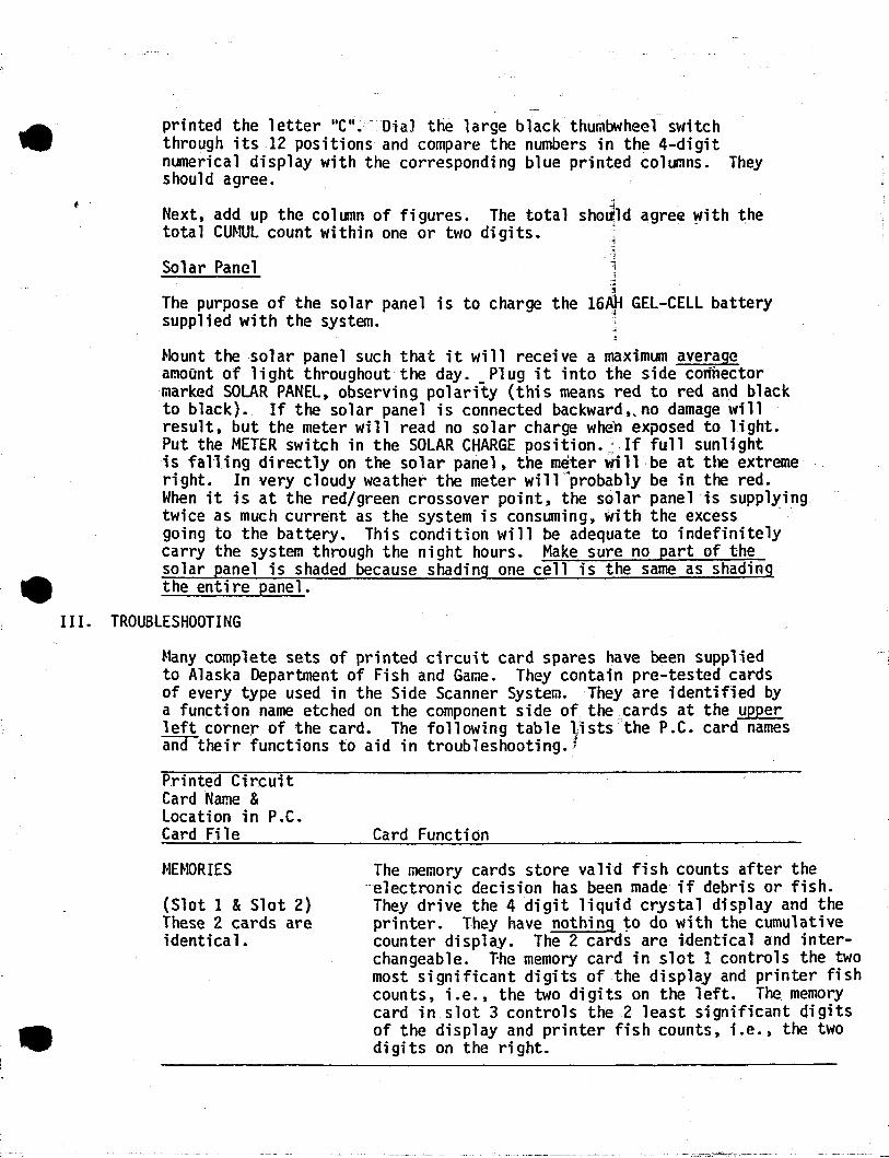
~1any complete sets of printed circuit card spares have been suppliedto Alaska Department of Fish and Game. They contain pre-tested cardsof every type used in the Side Scanner System. They are identified bya function narne etched on the component side of the ;;cards at the upperleft corner of the card. The following table ~lsts the P.C. card namesand their functions to aid in troubleshooting. f
Printed CircuitCard Name &location in P.C.Card Fi le
r-1HtORIES
(Slot 1 &Slot 2)These 2 cards areidentica1.
Card Function
The memory cards store valid fish counts after the. electronic decision has been made if debris or fish.They drive the 4 digit liquid crystal display and theprinter. They have nothing to do with the cumulativecounter display. The 2 cards are identical and interchangeable. T-he memory card in slot 1 controls the twomost significant digits of the display and printer fishcounts, i.e., the two digits on the left. The memorycard in slot 3 controls the 2 least significant digitsof the display and printer fish counts, i.e., the twodigits on the right.
t '
Printed CircuitCard Name &Location in P.C.Card File
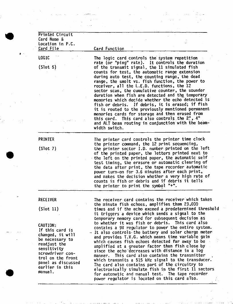
LOGIC
(Slot 5)
PRINTER
(Slot 7)
RECEIVER
(Slot 11)
CAUTION:If this card ischanged, it willbe necessary toreadjust thesensitivityscrewdriver control on the frontpanel as discussedearlier in thismanua1.
, -"----------
Card Function
The logic card controls the system repetitionrate (or "ping" rate). It controls the durationof the transmit signal. the 11 simulated fishcounts for test, the automatic range extensionduring auto test, the counting range, the deadrange, the smolt vs. fish function, the power toreceiver, all the L.EoO. functions, the 12sector scan, the cumulative counter, the sounderduration when fish are detected and th~ temporarymemories which decide whether the echo detected isfish or debris. If debris, it is erased; if fishit is routed to the previously mentioned permanentmemories cards for storage and then erased fromthi s card. This card also controls.. the 27~, 40
. _
and ALT beam routing in conjunction \'Iithf'he beamwidth switch.
The printer card controls the printer time clockthe printer command, the 12 print sequencing,the printer sector 1.0. number printed on the leftof the printed paper, the letters printed next to
. the left on the printed paper, the automatic selftest timing, the erasure or automatic clearing ofthe data after print, the tape recorder automaticpower turn-on for 3.6 ~inutes after each print,and makes the decision whether a very high rate ofcounts is fish or debris and if debris it tellsthe printer to print the symb~l "+".
The receiver card contains the receiver which takesthe minute fish echoes, amplifies them 23,ODOtimes and if the echo exceed a predetermined thresholdit triggers a device which sends a signal to thetemporary memory card for subsequent decision asto whether it was fish or debris. This card alsocontains a 9V regulator to power the entire system.
'- It also controls the battery andsolar€harge meterand provides T.V.G. which means time variable gainwhich causes fish echoes detected far away to beampl ified at a greater factor than fi sh close bysince the echo"decreases with distance in a logmanner. This card also contains the transmitterwhich transmits a 515 kHz signal to the transducer.The card also contains part of the circuitry toelectronically simulate fish in the first 11 sectorsfor automatic and manual test. The tape recorderpower regulator is located on this card also.
"

'. Printed Ci rcuitCard Name &Location in P.C.Card Fi lej
-;;I
LIQUID CR'tjSTALDISPLAY CARD
'"j.Located oli frontpanel. ~
.:;4
Card Function--,i
This card contains a 4-digit liquid crystaldisplay on the f.ront panel. If it becomes 'defective it may be removed from the inside byremoving the two retaining 6-32 nuts and replacingit with a spare display card. If this is done,be sure the two flat plugs that are inserted inits connector are firmly inserted in the new cardin identical orientation. The display has anaverage life of about 7 years. It will benoticed that in cold weather the display takeslonger to change its numbers. This is a normalcharacteristic of liquid crystal displays.
Most of the card functions are self-explanatory so that in the event oftrouble, ,a card may be replaced. Since many of the card functions areinter-related, a problem may sometimes not be definitely localized to aspecific card and more than one card may have to be interchanged to curethe problem (one at a time).
To change a printedRemove the 6 screwspanel straight up.electronics.
circuit card, disconnect the battery and solar panel.holding the front panel and carefully lift the frontIt may then be turned and laid down next to the
CAUTION: The electronic components on the cards are susceptible toimmediate destruction by static electricity. They should never behandl~d in an office where carpets generate static electri.city.
Repla~e the suspect card with a nBi one and !etest. The system can beoperated in the open position so it will not be necessary to close thesystem to test it, but be very careful not to short anything_
To remove a card, pull up on the tw~card ejectors. To replace acard, press the card firmly down and hook the combination black cardejector/inserter under the ridge of the card file and push the two blackinserters down. These will fo.rce the card into its sockets and may haveto alternately be "rocked" until the card is firmly seated in itssocket.
CAUTION: NEVER remove or replace a card with power from the batteryor solar panel connected.
To replace the panel, reverse the removal procedure being careful not to
i·
pinch any cables between the panel and the case. The 6 nuts are onsliding plates and may have to be repositioned \'Iith a knife blade ifthey were moved.
Some problems with the counter can be solved without changing cards., . If the ~rinter is malfunctioning t check to see that_ it is flush withJ
the counter and thescr~s are fully tightened. Also make sure the itape is feeding out ~mooth1y. If it is pulled out crookedly, the paperwill become jammed. If the printer begins skipping hours and changingcards does not help, there is plenty of paper, the roller is clean aQdthe battery is tightly plugged in, the problem may be a faulty power~
inverter. This requires repair by Bendix.
IV.. SIDE SCAN ARTIFICIAL SUBSTRATE
General Description
The array (Figure lA, 1B and 3) is made up of three· 18i foot longsections of tubes that plug together with an 18 inch overlap forminga single tUbe. Offshore and onshore.sections terminate the assembly, ends.A 1 inch diameter wire rope runs through the assembly and is pinned to'the offshore cap. The onshore cap has a threaded shaft and handwhee1which is used to provide tension holding the array sections together,by tensioning the cable. Cable should be threaded on the downstrea~
side of bolts \'lhich hold sections together. Alignment of the vortexshedding fins on each section is required in order to prevent oscillation or vibration of the array in fast currents. Install and tightenthe 1" bolts on the welded brackets. These will squeeze the slotstogether thus securingsthe pipes together. On 1978 and 1979 arraystighten bolts to 45 ft/lbs (second bolt from target end - tighten to20 ft/lbs only). If too loose, the array will bend excessively, allowingfish to escape under the beam. If tightened to greater than 60 ft/1bsthe bolts will break or the tube deform.
NOTE: The bolts should be tightened with the pipe upside downfrom the way it will lie on the river bottom. This Willhelp straighten the pipe. '
The offshore cap provides the ~ire rope termination, has a water checkvalve used for blowing out and floating the array~ mounts the offshorecable attachment point and has a target attached for acoustic signalalignment. The onshore cap has a 2 inch diameter hole in the end whichis used to stake the array in position on the shore. A second 2 inchhole may be used to tie off the array forsafety. A mount for thetransducer is provided on the cap. Both· vertical and horizontal adjustment of the transducer is possible. A I inch diameter x 2 ft. long baris provided to use as a lever for aligning the transducer on the 1976systems. The n~l systems have adjustment handwheels. Mount the transducer in the upper 3 holes of its housing. A traveler, attached to thecable swivel, rides on a bar preventing rotation of the cable whentightening.
NOTE: The cable must be as tight as possible to prevent arraybreakup in fast river. Hand tighten only •
. _.......•........__._ _ ~_ __ _.- -'.'-' .~

I
l~- -
-- ---~~~~~~~~~~--_.__. ------- -------
A i inch threaded plug is provided for an air hose to blowout andfloat the array prior to removal from the river bed. Netting is tied~o the lower vortex fin. 1/8 inch diameter holes spaced at Ii inch~ntervals provide net tie points. Holes are provided on both top andbottom fJns as installation on the opposite shore f~quires turning thearray end for end and rotating 180°.
NOTE: It has been found by A.D.F.& G. that if no air is available,the array may be raised by allowing the pipe to tilt downinthe direction of the water flow. The fairings act asailerons and will raise the pipe to the surface. Conversely,when sinking the array, the stake on the shore end shouldbe attached vi a a "corae-along" to a tree and should betilted upstream a few degrees to help sink the arr.fty andhold it firmly on the river bottom.
Assembly Procedure for 60 Foot Array
1. Layout the following parts on a reasonably level surface parallelto the river bed inthe order listed. Leave 1 foot of space betweenparts.
1 each Offshore Cap.
2 each 18i foot section with couplers attached.
1 each 18i foot section without coupler.
1 each Onshore Cap (screw in tension screw handwheel all the way).
2. Attach swivel end of i inch cable to eye on threaded tension screw.
3. Feed opposite end of cable (with eye) through the l8i foot tubesections. Cable must pass through center hole in bulkheads (twoplaces), and on downstream side of 3/8 inch bolts.
4. With the onshore cap transducer housing straight up, slip the first18i foot section onto the shore cap (male), reduced diameter, alignthe bolt holes and install i inch diameter bolts. Fitting couplersections into 18i foot sections is made much easier by spreading ~he
welded brackets apart with 2 or ~ disc brake pad spreaders. Beforefitting sections together, coat the outside of coupler sections withclear silicone to prevent airl.eal<s~ Also coat b()th~ndsofbo1ts,
cable anchor bolt, endplate and offshore cap. Be sure l8i footsections face in the right direction. Fins go downstream.
5. Install second and third section to similar manner. If couplingshang up and do not seat, the cable'and tension screw can be usedto pull the couplings together. However, care must be taken toalign the fins during coupling insertion as turning the sectionsafter complete assembly may be difficult.

, .
6. Insert cable eye through the offshore cap and install cap onlast section. Insert bolt. Target (curved projection) should beup. ~
7. Install end plate (with slot for pin) onto offshore ca~. Cableshould project through ~p center hole and extend out ~bout 12inches if all couplings ~re seated. ;
.'!
8. Start to tighten the han~wheel inside onshore cap until cable eyeis aligned with slot in ~nd plate.
"i
9. Install pin through eye ~nd seat in slot of end plate.~
10. Tighten cable hand tight~ using hand\'/heel. All couplings shouldnow be fully seated. Whim tightening, insert a long screwtiriverin the far end of the swivel assembly to keep the traveler barfrom twisting as the cable is tightened. The cable tightens byturning the knob counterclockwise and loosens by turning it clockwise. Two nuts should be screwed on both in front of and behindthe handwheel to al1low the shaft to turn as the knob is turned
11. Install coupling bolts and cap nuts not previously installed.Tighten to 20 ft/lbs only, apply silicone.
12. Install end cap onto end plate covering cable.
13. All seams must be sealed to prevent air leaks when raising the tube.Apply silicone generously to each joint and wrap with insulationtape (such as 3M Scotchfill Insulation Putty Tape). Cover thistightly with gray 2" PVC tape, overlapping the seam 2 inches oneach side. Place 2 connected 8 inch hose clamps on each side ofthe seam and over tape. Tighten clamps, being careful to keepclamp nuts to the downstream side of the tube and out of the beampath. ,
14. The array is now reddy for placing into the river.
Array Installation Procedure.1. Before placing the array in the river, the chain anchoring the
net should be tied up to prevent it from snagging on debrisduring deployment. It is easiest to thread a line through the linksand tie it to the holes in the fins. This can be readily cut whenreleasing the net. Make sure the i inch plug on top and 3 inchfloodcap on the side are in before putting the array in the water.
2. Attach an appropriate shore cable 1- inch minimum diameter toupstream end of collar provided on offshore cap. The longer thecable, the easier it will be to move the array in and out. Attachthe other end of the cable to a stake, tree or other availableattachment point. CAUTION: In 7 foot per second currents cabletension of floating array will be as high as 850 pounds.
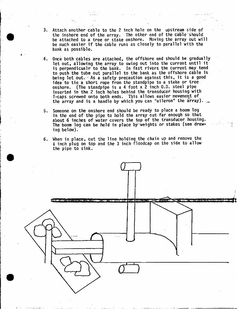
, .
3. Attach another cable to the 2 inch hole on the upstream side ofthe inshore end of the array. The other end of the cable 'shou1dbe attached to a tree or stake onshore. Moving the array out willbe much easier if the cable runs as closely to parallel with thebank as possible.
4. Once both cables are attached, the offshore end should be graduallylet out, allowing the array to swing out into the current .unti1 itis perpendicualr to the bank. In fast rivers the current may tendto push the tube out parallel to the bank as the offshore cable isbeing let out.- As a safety precaution against this, it is a goodidea to tie a short rope from the standpipe to a stake or treeonshore. (The standpipe is a 4 foot x 2 inch 0.0. steel pipeinserted in the 2 inch holes behind the transducer housing withT-caps screwed onto both ends. This allows easier movement ofthe array and is a handle by which you can "aileron" the array).
5. Someone on the onshore end should be ready to place a boom login the end of the pipe to hold the array out far enough so thatabout 6 inches.of water covers the tpp of the transducer housing.The boom log can be held in place by~weights or stakes (see drawing belm.,).
6. When in place, cut the line holding the chain up and remove thei inch plug on top and the 3 inch f100dcap on the side to allowthe pipe to sink.
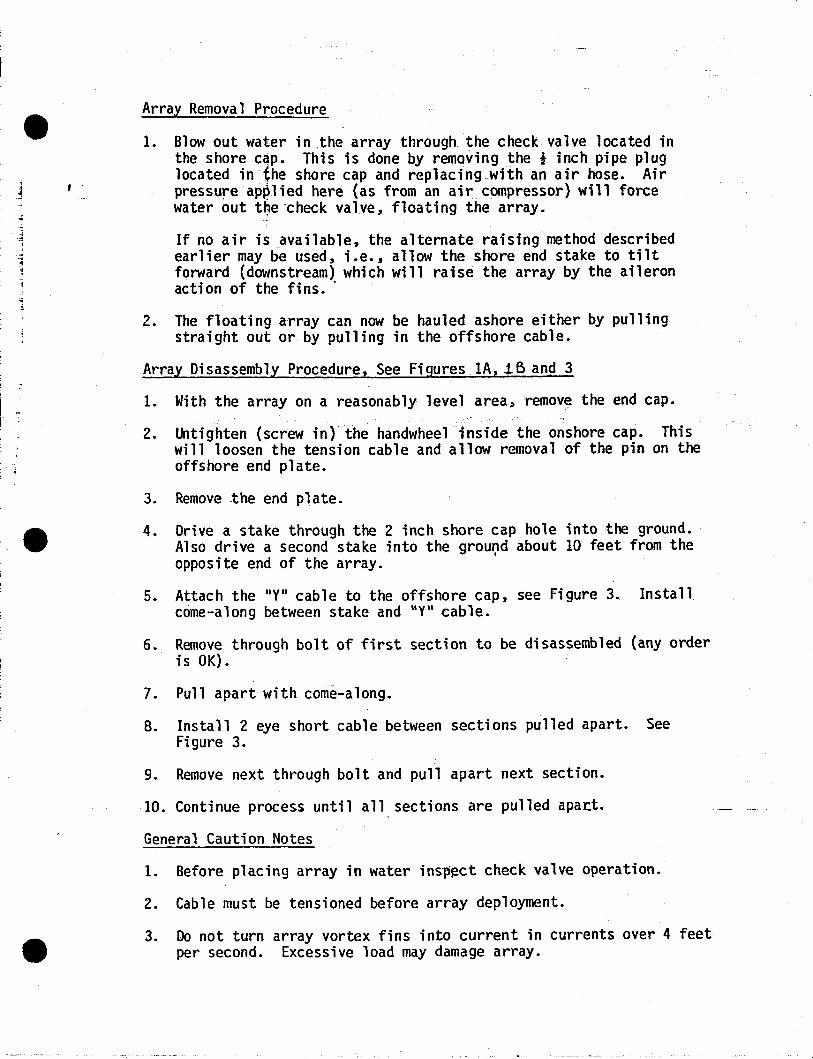
.~
Array Removal Procedure
1. Blowout water in the array through the check valve located inthe shore c~p. This is done by removing the I inch pipe pluglocated in the shore cap and replacing with an air hose. Airpressure applied here (as from an air compressor) will forcewater out th,e ·check valve, floating the array.
If no air is available, the alternate raising method describedearlier may be used, i.e.; allow the shore end stake to tiltforward (downstream) which will raise the array by the aileronacti on of the fi ns. .
2. The floating array can now be hauled ashore either by pullingstraight out or by pulling in the offshore cable.
Array Disassembly Procedure, See Figures lA, if> and 3
1. With the array on a reasonably level area~ remove the end cap.
2. Untighten (screw in) the handwheel inside the onshore cap. Thiswill loosen the tension cable and allow removal of the pin on theoffshore end plate.
3. Remove the end plate.
4. Drive a stake through the 2 inch shore cap hole into the ground.Also drive a second stake into the ground about 10 feet from theopposite end of the array. .
5. Attach the lIyll cable to the offshore cap, see Figure 3. Installcome-along between stake and llyn cable.
6. Remove through bolt of first section to be disassembled (any orderis OK).
7. Pull apart with come-along.
8~ Install 2 eye short cable between sections pulled apart. SeeFigure 3.
9. Remove next through bolt and pull apart next section.
10. Continue process until a11 sections are pulled apart.
General Caution Notes
1. Before placing array in water insll~ct check valve operation.
2. Cable must be tensioned before array deployment.
3. Do not turn array vortex fins into current in currents over 4 feetper second. Excessive load may damage array.
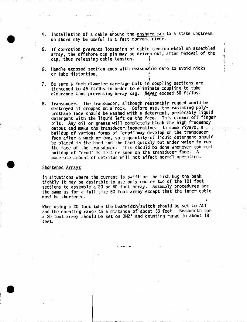
.-
_._-
4. Installation of a_cable around the onshore cap to a stake upstreamon shore maybe useful in a fast current river.
5. If corrosion prevents loosening of cable tension wheel on assembledarray, the offshore cap pin may be driven out; after removal of thecap, -thus releasing cable tension. j
-
6. Handle exposed section ends with reasonable care to avoid nicksor tube distortion. i
7. Be sure * inch diameter carriage bolt i~coup1ing sections aretightened to 45 ft/1bs in order to e1imi~ate coupling to tubeclearance thus preventing array sag. Neyer exceed 50 ft/1bs.
8. Transducer. The transducer, although reasonably rugged would bedestroyed if dropped on a~rock. Before use, the radiating polyurethane face should be washed with a detergent, preferably liquiddetergent with the liquid left on the face. This cleans off fingeroils. Any oil or grease will completely block the high frequencyoutput and make the transducer inop,erative~ InsoClerivers,abuildup of various forms of "crud"'may develop on the transducerface after a week or two, so a quantity;of liquid detergent shouldbe placed in the hand and the hand quic~ly put under water to rubthe face of the transducer. This should be done whenever too muchbui 1dup of "crud II is fe1t or seen on the transducer face. Amoderate amount of detritus will not affect normal operation.
Shortened Arrays
In situations where the current is swift or the fish· hug the banktightly it may be desirable to use only one or two of the 18i footsections to assemble a 20 or 40 foot array. Assembly procedures arethe same as for a full size 60 foot array except that the inner cablemust be shortened.
When using a 40 foot tube the beamwidth!switch should be set to ALTand the counting range to a distance of about 38 feet. Beamwidth fora 20 foot array should be set on XM2° and counting range to about 18feet.
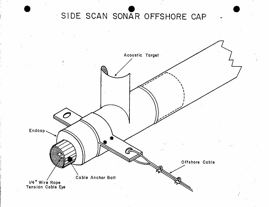
e eSIDE SCAN SONAR OFFSHORE CAP
e
1/4 II Wire RopeTens ion Cable Eye
Target
Offshore Cable
~,/
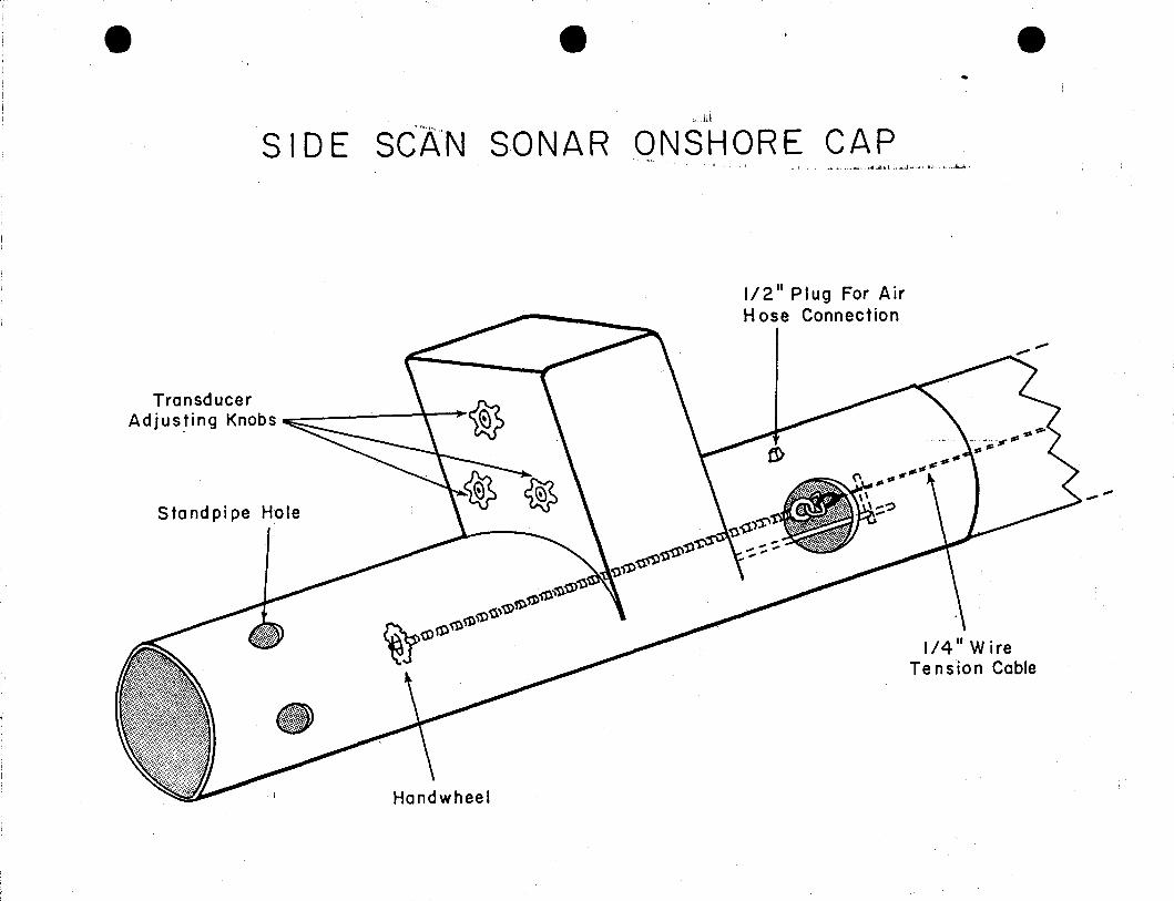
e e~~b
SIDE St~N SONAR ONSHORE CAP••",j" ,: ", ...... ",.ii.:.ilIo.i. t ,,;, ,j.jj, ~ •. i,;l "ji, ,i, J,...,...~;
-
1/2" Plug For AirHose Connection
TransducerAdjus~ing Knobs --- \ •
Standpipe Hole
1/4" WireTension Cable
-'"
"'I~ - -----.....-.-.-~....,.--,---
'r;~ ---,--,---,. •.. ;;--..------;-, •..--~-~
. ._/_/ ~ .. // 1'< i?--L j'/. .{- ..--__-e
c:
~._-
~ a:-
~
a::>-C-~ ~---.... .- ·----pQSSITIONEIr'
CABL~ ..-.. ~. ARRAY~"-- ~··'----·~I .~. '" ~ /'.... ~..,......-••• ....... t!- ..
ICE , . n~Vliln ~
~Tv/u7·ISUdOmSTED ·K ON SHORE 1-:7--7';;-7-77/ 7:7 ;;:7 ~//777ARMY t\l:t:q~t)MENT) STAKE
ARRAYINSTALLED INIllVER
STAl{E
POSSITIONED
~~~! -nIVER .... --..•,.,,,J
~ _.............. =-
ALTERNATE ARRA Y DEPLOYMENT METHOP. (SLOW cunnEN'l' S'l'ItEAMS)
ARRAYREADY TO SYrnN'Q
OUT(FLOATINO)
~.
STAKE,.-
-I/d/,/,~·,/,// aCABLE
~ ~
e eCABLE
e, .• ": ..•.;10. iJl , ,...... .ll_ e'.b.~ .. ,;" " ;Ii-
VERTICAL ADJUSTMENT
(TIGHTEtI 1 TURN CLOCKWISE FOR EACII3/4 FOOT DEAH RISE AT 6Q FEET, AWAY)OR VICE VEnSA TO LOWER,BEN'
1I0RIZONTI\L I\I)JUSTHENT
. TIGIITEN LEFT KNOB AND LOOSENnI GilT KtlOIl 51t1ULTANEOUSLY1 TURN FOR EAell1Js FT. OEM SU IFT TOTilE LEFf AT 60 Ff. AWAY J
OR VICE VERSA TO SHIFT RIGIIT
INITIALLY TlGHTEtI KNOOS TO COMPRESS TUE SrRlt/GSTO ADour 2/3 OF THEIR NO-TENSIOU LElIGTH. BEFOREHlSTALLlNG III WAfER. ADJUST TilE 3 Kt/OOS 50 THATTRM50UCER FACE IS PERPEUOICU~I\R TO PIPE.
tOl'E1 Use upper three holes.
SIIOREk~
~
FLEXIBLE COUPLINGS'(TI GUTENnrn'IN /\GA INST TRI\NSDUCERPLATE)
e - e
j. j~"..... .j
THRU BOLT
STAKEDRIVENINTO
.-GRqUND
ON SHORE CAP-
EXTRA TJlRU BOLT
\, 2. EYE SHORT CABLE
2ND JOINT TO BE PVLLED APARD
'--- THRU BOLT) eu .. 1'yIlCI\BLE
""t''''iki,
20''Str:CTI<;)NS
STAKE nRVENINTOaROUND
OFF.SHOnJi:CAP
A ,~\~"y \:J \ ~/~~S e. M ~ LY

•
--------------- ------~--~-
APPENDIX 2
ADULT ANADROMOUS FISHERIES STUDIES
Oscilloscope Operation

OSCILLOSCOPE OPERATION
for the
SIDE SCANNER
July 16, 1979
A. Menin
ihis manual describes how to use the oscilloscope .in conjunction with theside scanner. Although it.fs specificially written arounc the Tektronix modele 323 "scope" t the same basic rules apply to ·v.irtually any model scqpe exceptfor the location of controls.
THEORY OF SCOPE OPERATION
.;~.
,
\
it
I!
,;The scope is basically a time variable voltmeter. A bright dot moves-1 -
across the screen at a constant rate from left to right. The speed at which;
it moves is determined by the TIME/DIV control setting on the scope. At mostsettings,the dot moves so quickly that it looks like a continuous horizontalline to the human eye.
The VERTICAL INPUT of the scope (on the left side of scope) is the sameas the + &- input l~ads on a voltmet~r except that a voltage connected toVERTICAL INPUT scope connector will cause an upward vertical deflection ofthe moving dot of 1ight proportional to the amount. of voltage at t~e.. input atthe point in time that the moving dot happens to be when tnat voltage is connected. For example. if there is no voltage on the scope input for the fir~t.
half of the trace, you will see a straight line. If a + voltage is then appliedduring the middle of the trace (orisweep a~ it is usually called), the bright1
'~~
dot will go vertically up to the corresponding place on the scope's face asdetermined by the VOLTS/DIY setting of the scope. Example: With a 2V/DIVsetting. the dot would rise three divisions at the precise- instant in timethat you connected the + of a 6V battery to the scope's VERTICAL INPUT withthe - of the battery connected to the scope ground.
TRIGGERING
INPUT of the scope (on the left side of scope) to start· the dot moving at the
I
IIi~.,-•.. ·········-c----·.·-- _._-~ ~-..--
The bright dot on the screen requires an electrical voltage on the TRIGGER
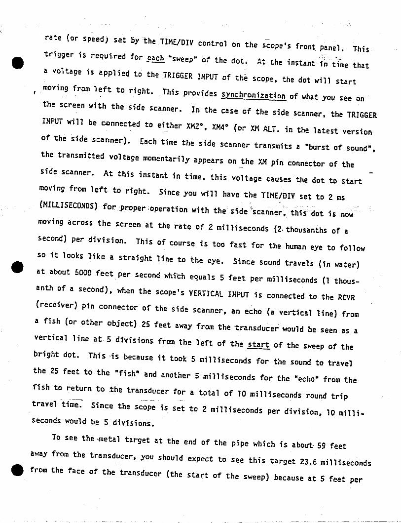
--rate (or speed) set bytheTIME/DIV control on the scope's front panel. This·trigger is required for each "sweep" of the dot. At the instant fit ti-me thata voltage is applied to the TRIGGER INPUT of the scope, the dot will start
.moving from left to right. This provides synchronization of what you see on. -
the screen with the side scanner. In the case of the side scanner. the TRIGGERINPUT will be connected to either XM2°, XM4° (or XM ALT. in the latest versionof the side scanner). Each time the side scanner transmits a "burst of sound",the transmitted voltage momentarily appears on the XM pin connector of theside scanner. At this instant in time, this voltage causes the dot to startmoving from left to right. Since you will have the TIME/DIV set to 2 ms(MILLISECONDS) for-proper.operation with the side ''£canner. this dot is nowmoving across the screen at the rate of Z milliseconds (2·thousanths of asecond) per division. This of course is too fast for the human eye to followso it looks like a straight line to the eye. Since sound travels (in water)tit at about 5000 feet per second which equals 5 feet per milliseconds (1 thousanth of a second), when the scope's VERTICAL INPUT is connected to the RCVR(receiver) pin connector of the side scanner, an echo (a vertical line) froma fish (or other object) 25 feet away from the transducer would be seen as avertical Jine at 5 divisions from the left of the start of the sweep of thebright dot. This -is because it took 5 milliseconds for the sound to travelthe 25 feet to the "fish" and another 5 milliseconds for the "echo" from thefish to return to the transducer for a total of 10 milliseconds round triptravel time. Since the scope is set to 2 milliseconds per division, 10 mil1i-seconds would be 5 divisions.
To see the-metal target at the end of the pipe which is about 59 feetaway from the transducer, you should expect to see this target 23.6 milliseconds4It from the face of the transducer (the start of the sweep) because at 5 feet per
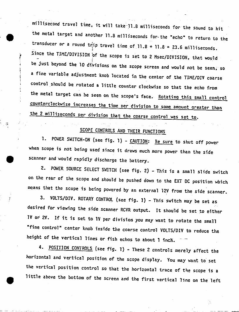
ie
J
milli.second travel time. it will take 11.8 milliseconds 'for the sound to hitthe metal target and another ll.a milliseconds for. the -echo· to return to thetransducer or a round t~ip travel time of 11.8 + 11.8 = 23.6 milliseconds., .
~
.Since the TIME/DIVISION?f the ·scope is set to 2 Msec/DIVISION, that would,
be just beyond the 1.0 divisions on the scope screen and would not be seen; soa fine variable adjustment knob located in the center of the TIME/DIV coarsecontrol .should be .rotated a little counter clockwise so that the echo fromthe metal target can be seen on the scope's face. Rotatina this small controlcounterclockwise increases the time Der division to some amount oreater thanthe 2 milliseconds Der division that the coarse control was set to.
SCOPE CONTROLS AND THEIR FUNCTIONS1. POWER SWITCH-oN (see fig. 1) - CAUTION: Be sure to shut off power
when scope is not being used since it draws much more power than the sidescanner and·would rapidly discharge the battery.
2. POWER SOURCE SELECT SWITCH (see fig. 2) - This is a small slide switchon the rear of the scope and should be pushed down to the EXT DC position whichmeans that the scope is being powered by an external l2V from the side scanner.
3. VOLTS/DIY. ROTARY CONTROL (see fig. ]) -This switch may be set asdesired for viewing the side scanner RCVR output. It should be set to eitherlV or 2V. If it is set to lV per division you may want to rotate the small·fine control" center knob inside the coarse control VOLTS/DIY to reduce theheight of the vertical lines or fish echos to about 1 incn.
4. POSITION CONTROLS (see fig. 1) - These 2 controls merely affect thehorizontal and vertical position of the scope d~splay. You may want to setthe vertical position control so that the horizontal trace of the scope is alittle above the bottom of the screen and the first vertical line on the left

is about 1/4 inch inside of the screen. (This corresponds to the transmittedburst of sound or the transducer position).
5. INPUT LEVER SWITCH (see fig. 1) - This should be down (in the DCposition).
6. TRIGGER LEVER SWITCH (see fig. 1) - This imp,ortant switch should be- ,~in one of the 2 bottom external triooer positions, e~therAC or DC. This switch~:,jis located on the right side of the model 323 scope.;
7. TRIGGER KNOB (see fig. 1) - This is probably! the most important (andmost often mis-set control). Its function is to assure that the start of thesweep of the scope picture exactly coincides with the" instant the side scannertransmits its burst of sound. This will cause the tr.ansmit burst vertical line">;; . • . '·l
.:'.··l
to be at the start of the sweep (the extreme left side of the trace). If thisknob is rotated comoletell clockwise or completely counterclockwise, the scopetrace will hfree run", that is to say, it will never be synchronized with thetransmit burst and therefore the transmit burst vertical 'line on the scope'sface may occur anywhere along the scope sweep.
8. TIME/DIV. ROTARY CONTROL (see fig. 1) - This controls the speed atwhich the bright dot crosses the screen. For use with the side 'scanner, itshould be set to the 2 Ms (MILLISECONDS) position}
9. ATTEN. SLIDE SWITCH (see fig. 1) - This switch is located on the leftside of the scope. Although it can be operated in either position, stabletriggering is a little easier to adjust if this slide switch is in the lOXposition•.
10. FOCUS AND INTENSITY (see fig. 1) - These two controls are located ontop of the scope.
The intensity control should be rotated fully clockwise for maximum brightness of the trace. After adjusting the brightness, rotate the focus controlfor the sharpest vertical lines.
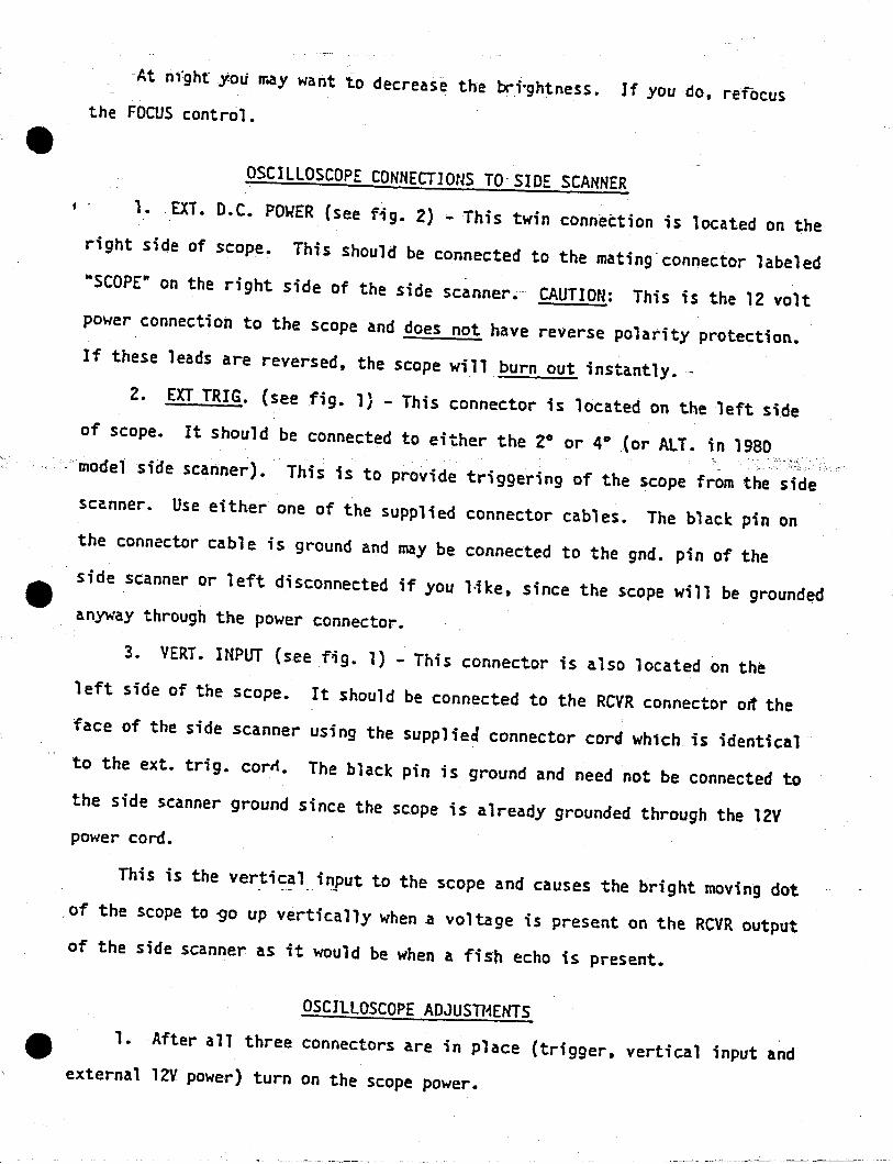
At night y.oti rr.ay want to decrease the lrioghtness. If you do, rerocusthe FOCUS control.
OSCILLOSCOPE CONNECTIONS TO' SIDE SCANNERf . 1•. EXT. D.C. POWER (see fig. 2) - This twin connection is located on the
right side of scope. This should be connected to the mating connector labeled··SCOPE Il on the right side of the side scanner. CAUTION: This is the 12 voltpower connection to the scope and does not have reverse polarity protection.If these leads are reversed, the scope will burn out instantly.-
2. EXT TRIG. (see fig. l} - This connector is located on the left sideof scope. It should be connected to either the 2° or 4°.(or ALT. in 1980
.. model side scanner). This is to provide triggering of the scope from the sidescanner. Use either one of the supplied connector cables. The black pin onthe connector cable is ground and may be connected to the gnd. pin of theside scanner or left disconnected if you l1ke. since the scope will be ground~d
anyway through the power connector.
3. VERT. INPUT (see fig. 1) - This connector is also located on theleft side of the scope. It should be connected to the RCVR connector ort theface of the side scanner using the supplied connector cord whlch is identicalto the ext. trig. corrl. The black pin is ground and need not be connected tothe side scanner ground since the scope is already grounded through the l2Vpower cord.
This is the vertic~l input to the scope.and causes the bright moving dotof the scope to -go up vertically when .a voltage is present on the RCVR outputof the side scanner as it would be when a fisn echo is present.
OSCILLOSCOPE ADJUSn~ENTS
1. After all three connectors are in place (trigger. vertical input andexternal lZV power) turn on the scope power.
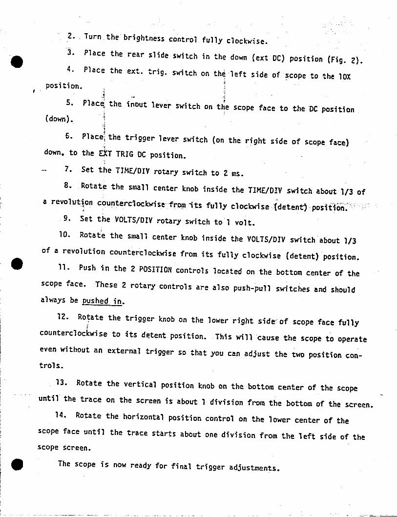
2. Turn the brightness control fully clocKwise.
3. Place the rear slide switch in the down (ext DC) position (Fig. 2).4. Place the ext. trig. switch on th~ left side of scope to the lOX
position. ,.~
, .
5.
(down) •
6.
,Plac~ the inout lever switch on the scope face to the "DC position
.",,"';•Placej the trigger lever switch (on the right side of scope face) "",
down. to the ~T TRIG DC position.
7. Set the TIME/DIY rotary switch to 2 ms.
8. Rotate the small center knob inside the TIME/DIV switch about 1/3 ofa revolut~on counterc1od:wisefrorn ;ts fully clockwise :1detentj position':..
"9. Set the VOLTS/DIY rotary switch tol volt.;
10. Rotate the small center knob inside the VOLTS/DIV switch about 1/3of a revolution counterclockwise from its fully clockwise (detent) position.
4It 11. Push in the 2 POSITION controls located on the bottom center of thescope face. These 2 rotary controls are also push-pull switches and shouldalways be pushed in.
12. Ro~ate the trigger knob on the lower right sidecof scope face fullycounterclockwise to its d~tent position. This will "~ause the scope to operateeven without an external trigger so that you can adjust the two position controls.
13. Rotate the vertical position knob on the bottom center of the scopeuntil the trace on the screen is about 1 division from the bottom of the screen.
14. Rotate the horizontal position control on the lower center of thescope face until the trace starts about one division from the left side of thescope screen.
4It The scope is now ready for final trigger adjustments.
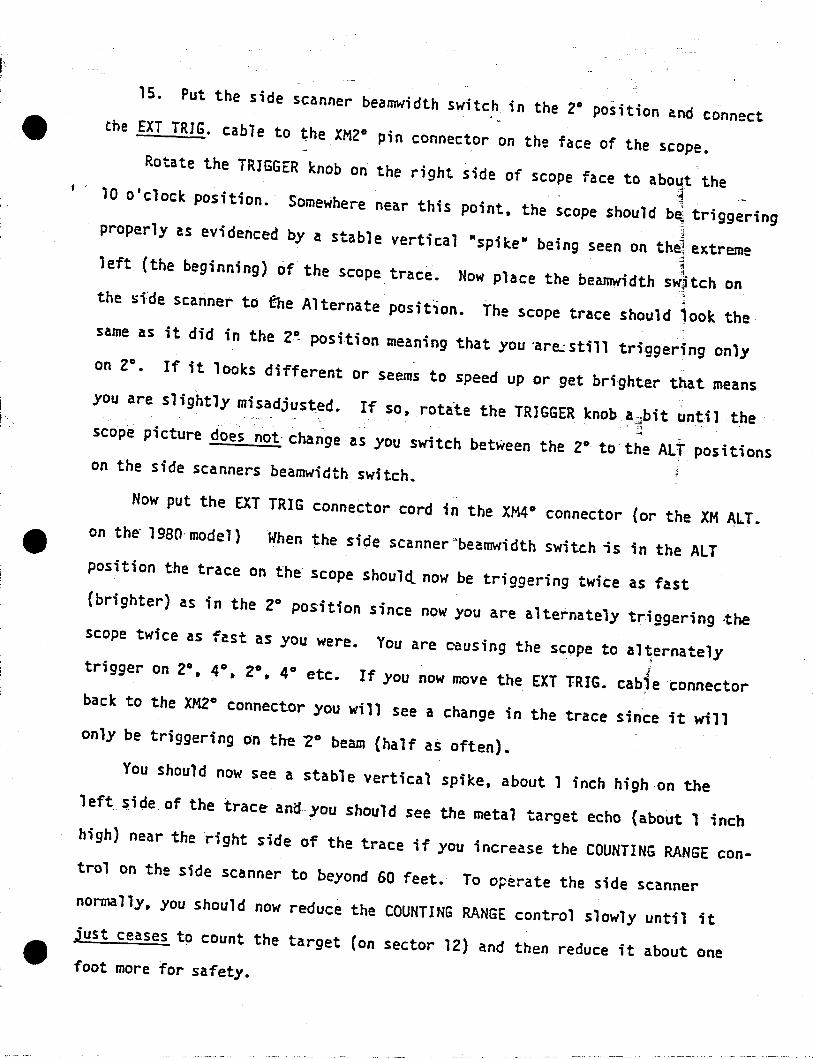
1S. Put the side scanner beamwidth switch in the 2° position and connect4It Che EXT TRIG. cable to the XM2° pin connector on the face of the scope.
Rotate the TRIGGER knob on the right side of scope face to abo~t the~, - I
10 0 clock position.' Somewhere near this point. the scope should b~ triggeringproperly as evidenced by a stable vertical "spike" being seen on the1 extreme
-;•left (the beginning) of the scope trace. Now place the bea~dth sw~tch on,~the sfde scanner to the A1ternate'posit10n. The scope trace should jook the
same as it did in the 2! position meaning that you -are.: still triggering onlyon 20
• If it looks different or seems to speed up or get bri-ghter that meansyou are slightly misadjusted. If so. rotate the TRIGGER knob a~bit un~il the
~scope picture does not- change as you switch between the 2° to the ALT positionson the side scanners beamwidth switch.
Now put the EXT TRIG connector cord in the XM4°connector (or the XM ALT.on th~ 19BO-model) When the side scannerubeamwidth switch;s in the ALTposition the trace on the scope should.. now be triggering twice as fast(brighter) as in the 2° position since now you are alternately triggering ~he
scope twice as fast as you were. You are causing the scope to al~ernately
Itrigger on 2°, 4°. 2°. 4° etc. If you now move the EXT TRIG. cab)e connectorback to the XMlo connector you will ,see a change in the trace since it willonly be triggering on the "20 beam (half as often).
You should now see a stable vertical spike. about 1 inch high on theleft_ side of the trace- anCfyou should see the metal target echo (about 1 inchhigh) near the right side of the trace if you increase the COUNTING RANGE control on the side scanner to beyond 60 feet. To operate the side scannernonnal1y. you should now reduce the COUNTING RANGE control slowly until itjust ceases to count the target (on sector 12) and then reduce it about onefoot more for safety.

, .
Ff}GE OF 5Co?£\lOLTS/OIV
S .05
TIME/DIY
~r.s~1 .2IIIS0 .1
€ ([)..~\;,0 5"~1 -;>{s_.2, 1ft 1 r
-- ...., lIlT"AI 1•
.}-<6~:.~I \. \.. -I...;. AUTO"'"
LocATED cON LEPr lXT TAlC Olt HOka Y1I1lT IHMIfCAL OUT C )
"'!"'" IIC1 ..• LA~I:
~S1 DF of seD Fe ..rn~·~ 0 0 '(!h\....... >- - .... ....--,
Oscilloscope controls. Sony Tektronix type 324 oscilloscope.

, .
,j
...e,.._ !". ,.,...,.di.. "i
fUT 77ft> 5/-JOE SW J Tefl
III o[N/AI (EXT Dc) POSJI/tJN
Oscilloscope adjustments. Sony Tektronix type 324 oscilloscope.
C••••• ••c.,r'''t:'act._

A. Menin - T. Namtvedt, 6-18-79
CONDITION
PROPER VERTICAL AIMING. 2°
PROPER VERTICAL AIMING. ALT. BUT SCOPE TRIG. ON 4°
PROPER VERTICAL AIMING. AlT: BUT SCOPE TRIG. ON 2°
IMPROPER VERTICAL AIMING. (AIMED TOO LOW)
IMPROPER VERTICAL AIMING. (AI~EDTOO HIGH). 2°
IMPROPER VERTICAL AIMING. (AIMED TOO HIGH). 4°
IMPROPER HORIZONTAL AIMING. (AIMED TOO FAR DOWNSTREAM)
PROPER HORIZONTAL AIMING.
IMPROPER VERTICAL AIMING. (TOO lOW AND BOUNCING OFF SUBSTRATE)
ECHOS FROM BOAT WAKE
IMPROPER VERTICAL AIMING IN SHAllOW WATER
Table 11-1. TYPICAL SIDE SCANNER OSCIllOSCOPE WAVEFORMS FOR VARIOUS
TRANSDUCER AIMING CONDITIONS, .
FIGURE *11-3.
11-4.
II-5.
II-6.
II-] .
II-8.
II-9.
I1-l0.
II-11.
II-12.
I1-13.
~.;....,
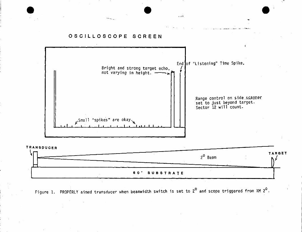
e e •:";..ii ~
~ ~i";"I',. "'"
..". :.... ~..... , ':.., ;,1 ... ; ,;, .Ii., I~".. I ..•
OSCILLOSCOPE SCREEN
Range control on side",s,c.anuerset to just beyond target.Sector 12 will count •
of "Listening" Time Spike.End (Bright and strong target echo, (
not varying in height. -~~ r
...Small "spikes" are okay.~
I.II~I I I. I 1.1 •• 11 .
TRANSDUCER\-'1
I-
2° BeamTARGET
D1
80' SUBSTRATE
Figure 1. PROP[RLY aimed transducer when beamwidth switch is set to 20 and scope triggered from XM 2°.
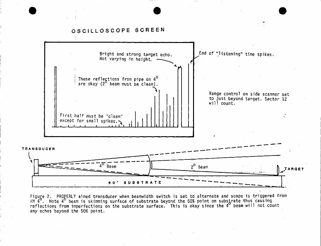
e e eOSCILLOSCOPE SCREEN
Bright and strong target echo.Not varying in height. ~
~~
End of "listening" time spikes.V J
f
These refle8tions from pipe 0n 40are okay (2 beam must be clean).
~Range control on side scanner setto just beyond target. Sector 12will count.
First half must be "clean"except for small spikes.~• I I • I • • I • I I ,I II I II
Fi guse 2. PROgERL Y aimed transducer when beamwi dth switch is set to alternate and scope is tri ggered fromXM 4. Note 4 beam is skimming surface of substrate beyond the 50% point on sUbsSrate thus causingreflections from imperfections on the substrate surface. This is okay since the 4 beam will not countany echos beyond the 50% point.
--------------------- T
_. ~ARGET RAN SOU C E R 20 Beam ". I....... "A:"
\il:=~~~#~;~==~~~~ ....~;:~1 • 8:S-:TRA;E------------ _8 0
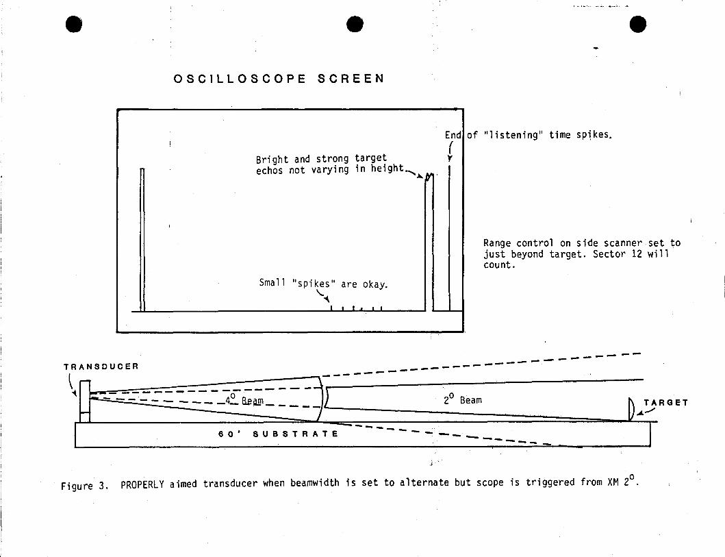
e e'.M.•,""" ••.. ,,", , ;.
e
OSCILLOSCOPE SCREEN
End
Bright and strong target(r
echos not varying in height-... .....~
l
Small "spikes" are okay."'''\
I ••.••
of "1 i stening" time SPl kes.
Range control on side scanner set tojust beyond target. Sector 12 willcount.
I~ TARGETU..t.----
----- - - - -- - -----SUBSTRATE8 0 '
__ 0 ------ - - - __4_ B.eaJ!l )r------=-------~_---__c- -- -- 20
Beam
f
Figure 3. PROPERLY aimed transducer when beamwidth is set to alternate but scope is triggered from XM 2°.
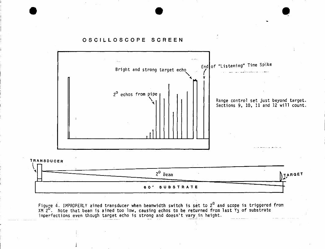
1--
e e
OSCILLOSCOPE SCREEN
Bright and strong target echo
"~~20 echos from pipe
\
. 11
e,
Endlof lIListening" Time Spike( ,............ ,,~ ..•.
y
Range control set just beyond target.Sections 9, 10, 11 and 12 will count .
\R~.OUCEA~ a
2 Beam T
' ''0' .UB.TRATE ¥Figuse 4. IMPROPERLY aimed transducer when beamwidth switch is set to 20 and scope is triggered fromXM 2. Note that beam is aimed too low, causing echos to be returned from last Y3 of substrateimperfections even though target echo is strong and doesn't vary in height.
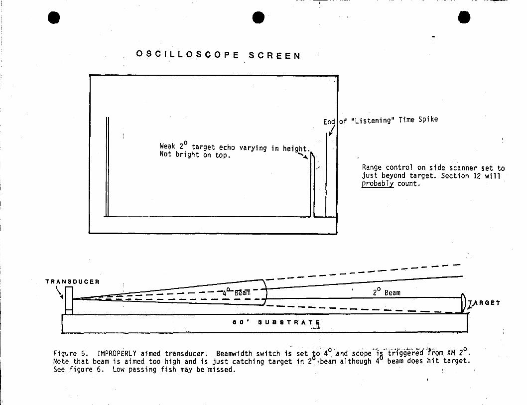
e e e
OSCILLOSCOPE SCREEN
Range control on side scanner set tojust beyond target. Section 12 willprobably count.
of "Listening" Time SpikeEnd I
IWeak 2° target echo varying in height.Not bright on top. '~
I,j
T,AROET~
-------------~--- --, sL~U~C~E~R~~~~;::;~;::;~~~~~~e-~~~~_~,-4- i 2
0Beam ).... - - - - -4 sealll ,------=----------7---- ----------------r.. ·o' 8 U 8 8 T If A 'Ui
TRA
\
Figure 5. IMPROPERLY aimed transducer. Beamwidth switch is set ~O'l 4° 'and scope"'lr:t'"rfgg'eired,if'r'om,. XM 2°Note that beam is aimed too high and is just catching target in 2· beam although 4 beam does hit target.See figure 6. Low passing fish may be missed.
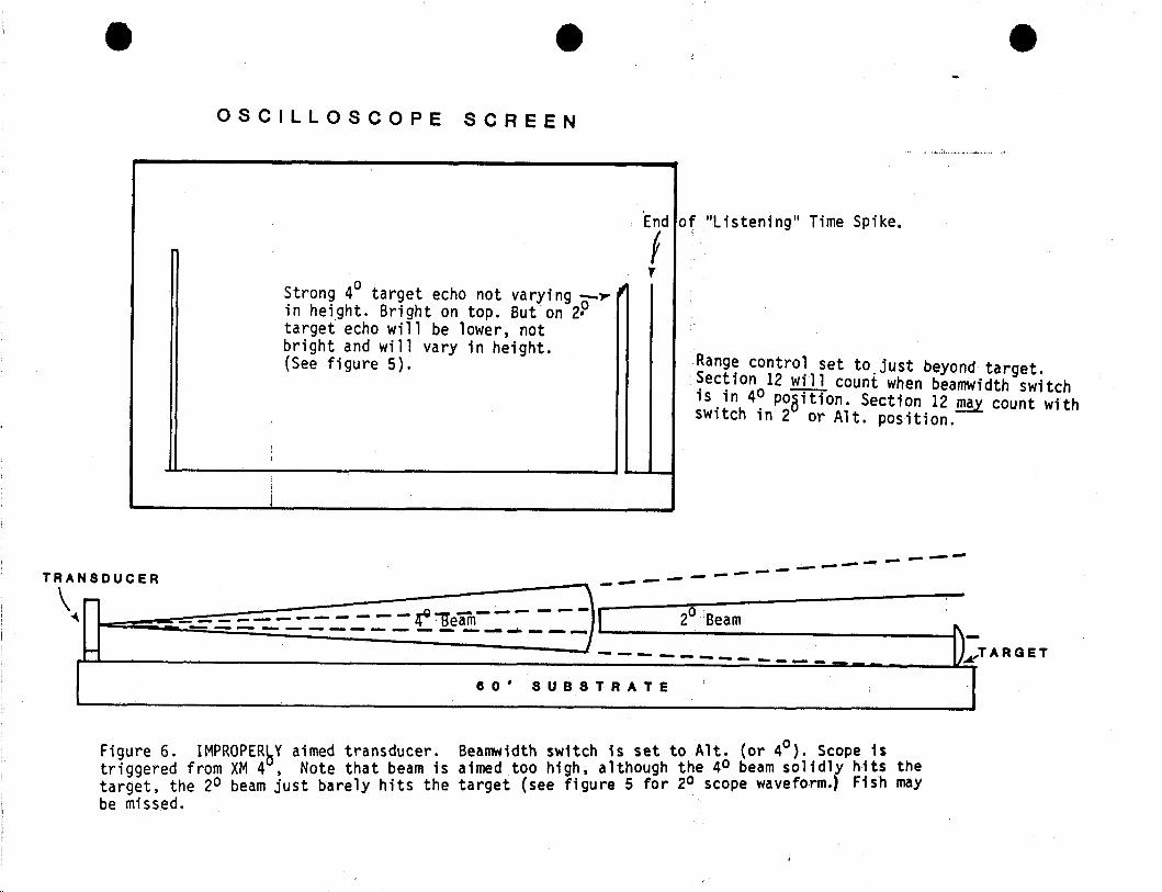
• e
OSCILLOSCOPE SCREEN
e
End
f,Strong 40 target echo not varying o-~ ~in hei9ht. Bright on top. But on 2.target echo will be lower, notbright and will vary in height.(See figure 5).
of "Listening" Time Spike.
Range control set to,just beyond target.Section 12 will count when beamwidth switchis in 40 poaition. Section 12 may count withswitch in 2 or Alt. position.
------ -- ---- --_ .... --TRANSDUCER _- --
\ ~ - - - - - - - I 20 B... - -,= =.-:::-_-:==-=-.: _1!'a.'!!. -- - - - .. earn D-
_ _ _ __ __ _ _ _ _ _ __ ~TARGET
80' SUBSTRATE
Figure 6. IMPROPERbY aimed transducer. Beamwidth switch is set to Alt. (or 4°). Scope 1striggered from XM 4, Note that beam is aimed too high. although the 40 beam solidly hits thetarget, the 20 beam just barely hits the target (see figure 5 for 20 scope waveform.) Fish maybe missed.
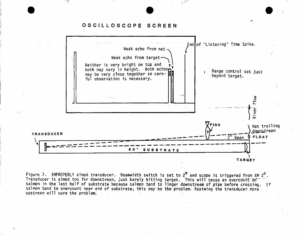
It e,J".'>
eOSCILLOSCOPE SCREEN
Weak echo from net !ndr
Weak echo from target~Neither is very bright on top and Tboth may va ry in he i gh t. Both echos~ Tmay be very close together so care- ~
ful observation is necessary.
",.... ji
""'1
.,
of lIListeningli Time Spike.
Range control set justbeyond target.
~r-
>l...~<~.,....~
FISHI"f '\ Net trailing
~_=-=--=-=-:-=__-_._-__-__-_·V}L-__-_-_~~2::.-lB~e-~am -6~~;eamL---- .......----~-r - -- -- -- - ----------- - -------- -- ------- ---
80' SUBSTRATE
TRANSDUCER
\\
TARG:ET
Figure 7. IMPROPERLY aimed transducer. Beamwidth switch is set to 2° and scope is triggered from XM 20 •Transducer is aimed too far downstream, just barely hitting target. This will cause an overc6iin't"o,,"""P >,.
salmon in the last half of substrate because salmon tend to linger downstream of pipe before crossing. Ifsalmon tend to overcount near end of substrate, this may be the prOblem. Reaiming the transducer moreupstream will cure the problem.
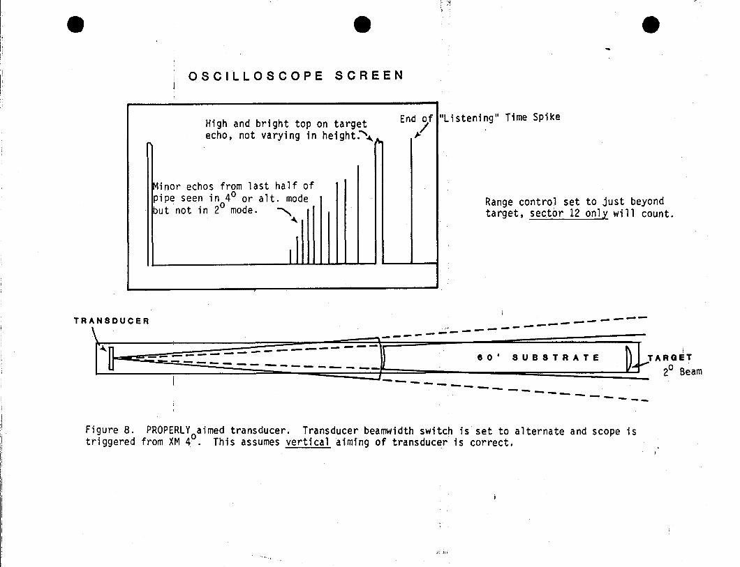
e e,
OSCILLOSCOPE SCREEN
-High and bright top on targetecho, not varying in height.~~
~indr echos from last half ofpipe seen in 40 or alt. mode~ut not in 20 mode. ~
~
I
End ofl"Listening" Time Spike/
Range control set to just beyondtarget, sector 12 only will count.
_....~------- ---,~' ---~-
----- - 1\ TARGETTRANSDUCER , '.0' SUS S T RAT E V.......' 2
0
Beam- ----'fr ----~ ---- ---- -- ---- -------
-- ----- -- ----- - -- ---i
Figure 8. PROPEiRLY aimed transducer. Transducer beamwidth switch is set to alternate and scope istriggered from XM 40
. This assumes vertical aiming of transducer is correct.
;.i.;,:d.::
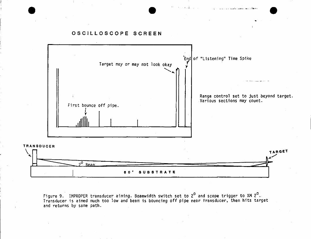
e e
OSCILLOSCOPE SCREEN
d. ...... ,.;oli.;.Jr.I~ ......,i,"hl,: i :a..;., " ~",L"..l., e
-..
Target mayor may not look okayE(d
""-.....
)'
First bounce off pipe.Iy-
.1 11111 I I
TRANSDUCER
\~~
H ------=:.::=::-?o RQ;:I m'
80' SUBSTRATE
of "Listening" Time Spike
Range control set to just beyond target.Various sections may count.
T1.RGET::::::=r/I
Figure 9. IMPROPER transducer aiming. Beamwidth switch set to 20 and scope trigger to XM 20.
Transducer is aimed much too low and beam is bouncing off pipe near transducer t then hits targetand returns by same path.
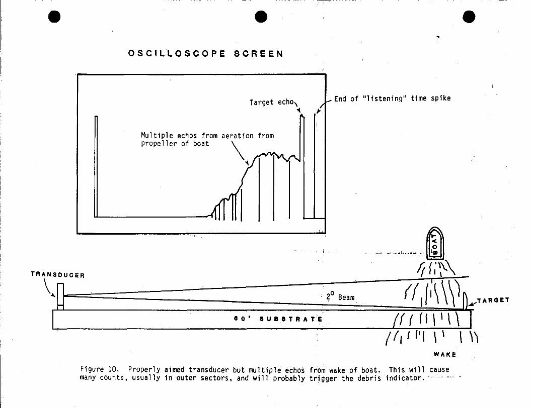
e eOSCILlOSCOPE SCREEN
Target echo,'(
I
J- End of "l istening" time spike/~
e
TRANSDUCER
\ r-
~
I-
Multiple echos from aeration frompropeller of boat ~
'(
~ -<f111
80' SUBSTRATE
20 Beam
",""",,-,. "mIf (;~\\
,. \\)(f I{i\ ~TARQET/(((1\'\\
/ I, / {. ( \ \ \ \'\WAKE
Figure 10. Properly aimed transducer but multiple echos from wake of boat. This will causemany counts, usually in outer sectors, and will probably trigger the debris indicator;·····",,·····

e eOSCILLOSCOPE SCREEN
EndI
Target echos weak ~\'(
j Echos from river surface rI
"'"
Ii, . • • • I 11111 ~
e..
of ilL istening" Time Spike
Range control set just beyond targetWill probably count on sectors 10, 11and 12.
~
....,lRANSDUCER
I-
~ -WATER 8URFACE-
o
., 0' 8 U'8 8 T RAT E
.-
TARGET
~~
Figure 11. Improperly aimed transducar. Beamwidth switch set to 20 andNote water is too shallow even for 2 beam which is boxed in. Countinghave to be reduced to about 50' to prevent surface echos from counting.surface echos.
scope triggered from 20.
range on side scanner wouldTarget will be obscured by

, .. ~
APPENDIX 3
ADULT ANADROMOUS FISHERIES STUDIES
Fishwheel Operation
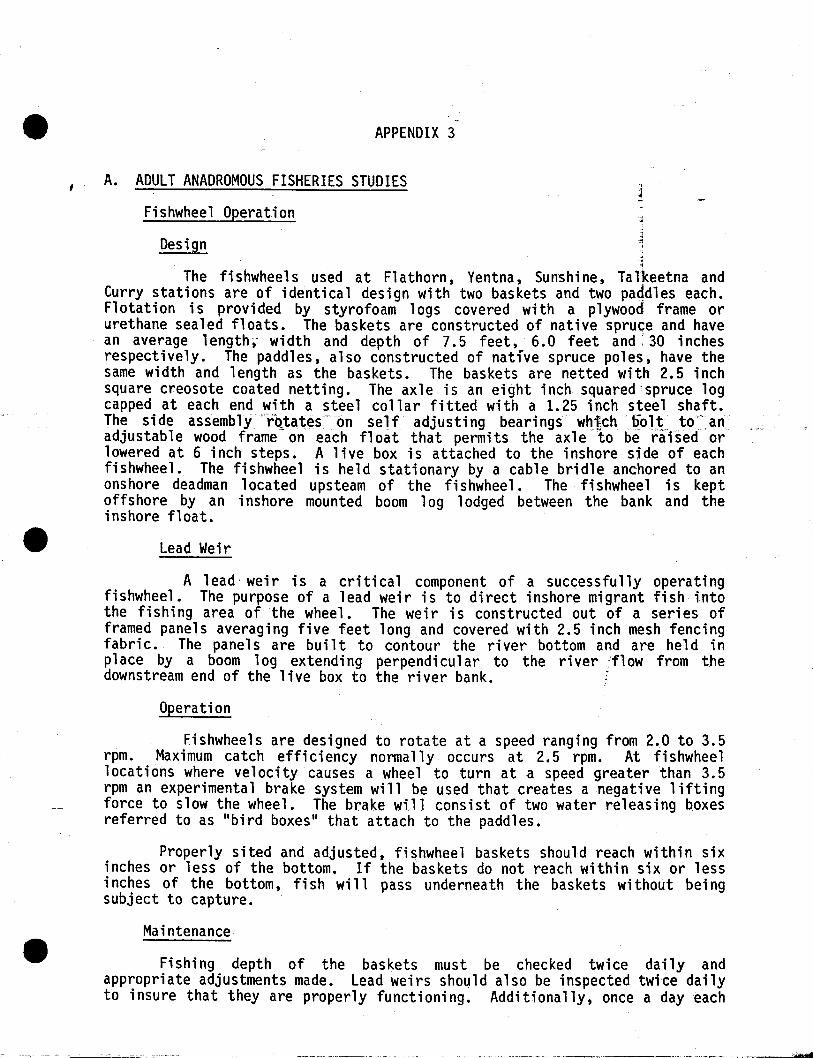
APPENDIX 3
A. ADULT ANADROMOUS FISHERIES STUDIES
Fishwheel Operation
Design
,1
,-
The fishwheels used at Flathorn, Ventna, Sunshine, Talkeetna andCurry stations are of identical design with two baskets and two paqdles each.Flotation is provided by styrofoam logs covered with a plywood frame orurethane sealed floats. The baskets are constructed of native spruce and havean average 1ength " wi dth and depth of 7.5 feet, 6.0 feet and· 30 inchesrespectively. The paddles, also constructed of native spruce poles, have thesame width and length as the baskets. The baskets are netted with 2.5 inchsquare creosote coated netting. The axle is an eight inch squared'spruce logcapped at each end with a steel collar fitted with a 1.25 inch steel shaft.The side assembly~rQ.ta.teson self adjusting bearings. whj]chliolt. to" anadjustable wood frame on each float that permits the axle to be raised orlowered at 6 inch steps. A live box is attached to the inshore side of eachfishwheel. The fishwheel is held stationary by a cable bridle anchored to anonshore deadman located upsteam of the fishwheel. The fishwheel is keptoffshore by an inshore mounted boom log lodged between the bank and theinshore float.
Lead Weir
A lead weir is a critical component of a successfully operatingfishwheel. The purpose of a lead weir is to direct inshore migrant fish intothe fishing area of the wheel. The weir is constructed out of a series offramed panels averaging five feet long and covered with 2.5 inch mesh fencingfabric. The panels are built to contour the river bottom and are held inplace by a boom log extending perpendicular to the river ,flow from thedownstream end of the live box to the river bank. f
Operation
Fishwheels are designed to rotate at a speed ranging from 2.0 to 3.5rpm. Maximum catch efficiency normally occurs at 2.5 rpm. At fishwheellocations where velocity causes a wheel to turn at a speed greater than 3.5rpm an experimental brake system will be used that creates a negative liftingforce to slow the wheel. The brake wiJ 1 consist of two water releasing boxesreferred to as "bird boxes" that attach to the paddles.
Properly sited and adjusted, fishwheel baskets should reach within sixinches or less of the bottom. If the baskets do not reach within six or lessinches of the bottom, fish will pass underneath the baskets without beingsubject to capture.
Maintenance
Fishing depth of the baskets must be checked twice daily andappropriate adjustments made. Lead weirs should also be inspected twice dailyto insure that they are properly functioning. Additionally, once a day each

-----------~---------
e wheel should be rigorously inspected for wear, damaged components, looserigging and protuding nails or rough surfaces which can inflict injuries tocaptured fish. Appropriate repairs must be effected at the first indicationof a problem.

-- ._._---------------
APPENDIX 4
ADUtiT ANADROMOUS FISHERIES STUDIES
Fish Tagging
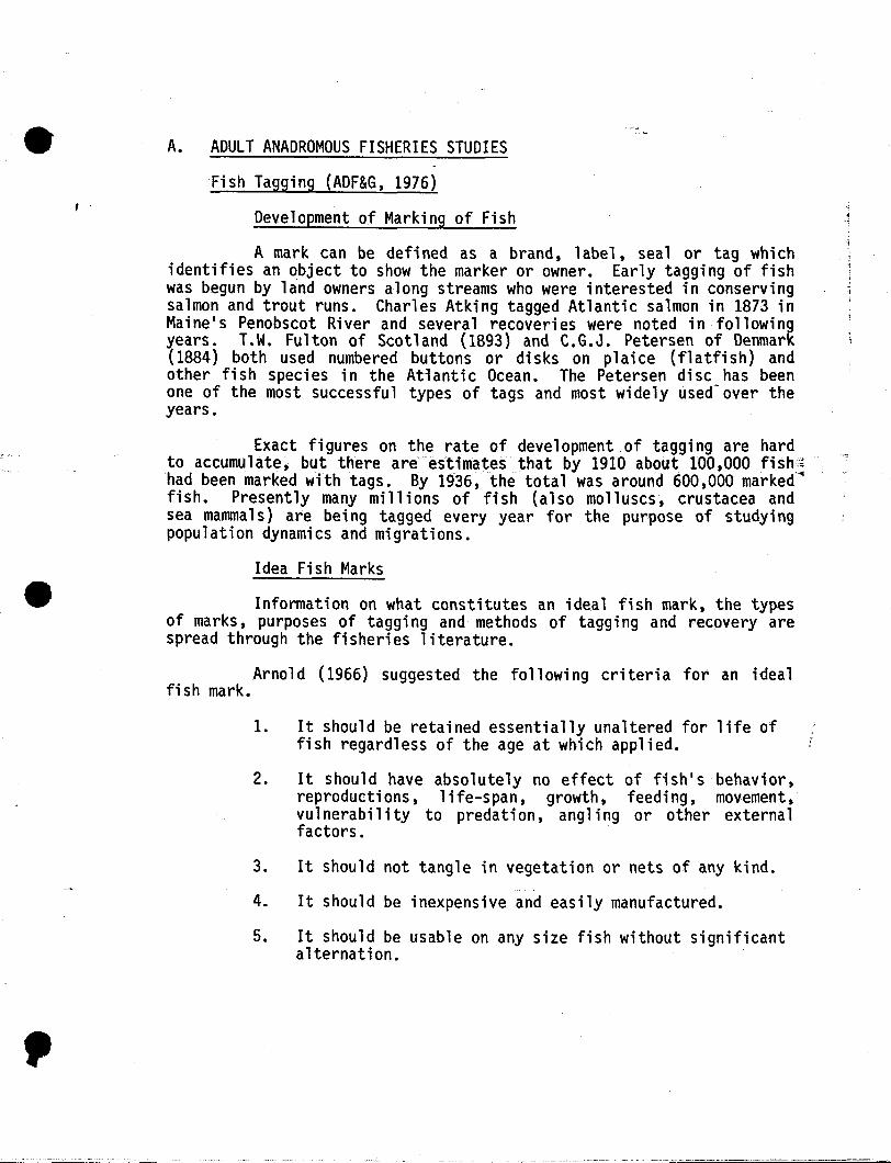
,
, .
------------------
A. ADULT ANADROMOUS FISHERIES STUDIES
Fish Tagging (ADF&G, 1976)
Development of Marking of Fish
A mark can be defined as a brand, label, seal or tag whichidentifies an object to show the marker or owner. Early tagging of fishwas begun by land owners along streams who were interested in conservingsalmon and trout runs. Charles Atking tagged Atlantic salmon in 1873 inMaine's Penobscot River and several recoveries were noted in followingyears. T.W. Fulton of Scotland (1893) and C.G.J. Petersen of Denmark(1884) both used numbered buttons or disks on plaice (flatfish) andother fish species in the Atiantic Ocean. The Petersen disc has beenone of the most successful types of tags and most widely used-over theyears.
Exact figures on the rate of development of tagging are hardto accumulate, but there areeslimates that by 1910 about 100,000 fish,~
had been marked with tags. By 1936, the total was around 600,000 marked~fish. Presently many millions of fish (also molluscs, crustacea andsea mammals) are be; ng tagged every year for the purpose of studyi ngpopulation dynamics and migrations.
Idea Fish Marks
Information on what constitutes an ideal fish mark, the typesof marks, purposes of tagging and methods of tagging and recovery arespread through the fisheries literature.
Arno1d (1966) suggested the fo 11 owi ng cri teri a for an idealfish mark.
1. It should be retained essentially unaltered for life offish regardless of the age at which applied.
2. It should have absolutely no effect of fish's behavior,reproductions, life-span, growth, feeding, movement,vulnerability to predation, angling or other externalfactors.
3. It should not tangle in vegetation or nets of any kind.
4. It should be inexpensive and easily manufactured.
5. It should be usable on any size fish without significantalternation.
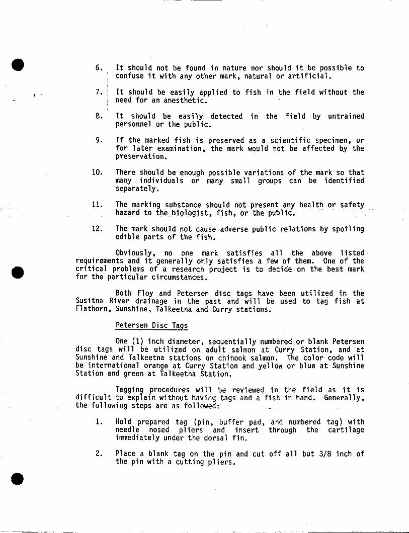
, ,
6. It should not be found in nature nor should it be possible toconfuse it with any other mark, natural or artificial.
7. It should be easily applied to fish in the field without theneed for an anesthetic.
8. It should be easily detected in the field by untrainedpersonnel or the public.
9. If the marked fish is preserved as a scientific specimen, orfor later examination, the mark would not be affected by thepreservation.
10. There should be enough possible variations of the mark so thatmany individuals or many small groups can be identifiedseparately.
11. The marking substance should not present any health or safetyhazard to the,biologist, fish, or the public.
12. The mark should not cause adverse public relations by spoilingedible parts of the fish.
Obviously, no one mark satisfies all the above listedrequirements and it generally only satisfies a few of them. One of thecritical problems of a research project is to decide on the best markfor the particular circumstances.
Both F10y and Petersen disc tags have been utilized in theSusitna River drainage in the past and will be used to tag fish atF1athorn, Sunshine, Talkeetna and Curry stations.
Petersen Disc Tags
One (1) inch diameter, sequentially numbered or blank Petersendisc tags will be utilized on adult salmon at Curry Station, and atSunshine and Talkeetna stations on chinook salmon. The color code willbe international orange at Curry Station and yellow or blue at SunshineStation and green at Talkeetna Station.
Tagging procedures will be reviewed in the field as it isdifficult to explain without having tags and a fish in hand. Generally,the following steps are as followed:
1. Ho1d prepared tag (pi n, buffer pad, and numbered tag) wi thneedle nosed pliers and insert through the cartilageimmediately under the dorsal fin.
2. Place a blank tag on the pin and cut off all but 3/8 inch ofthe pin with a cutting pliers.
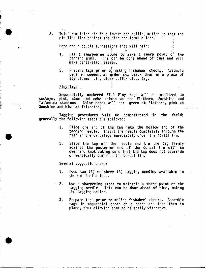
• 3. Twist remalnlng pin in a inward and rolling motion so that thepin lies flat against the disc and forms a loop.
Here are a couple suggesttons that will help:
1. Use a sharpening st.one to make a sharp point on thetagging pins. This ,can be done ahead of time and willmake penetration eas;ler.
1
2. Prepare tags prior to making fishwheel checks. Assembletags in sequenti a1 order and sti ck them ina pi ece ofstyrofoam: pin, clear buffer disc, tag.
Floy Tags_
Sequentially numbered FT-4 Floy tags will be utilized onsockeye, pink, chum and coho salmon at the Flathorn, Sunshine andTalkeetna stations. Color codes will be: green at Flathorn, pink atSunshine and blue at Talkeetna1 -
'1
Tagging procedures will be demonstrated in the field;generally the following steps are followed:
1. Slide one end of the tag into the hollow end of thetagging needle. Insert the needle completely through thefish in the cartilage immediately under the dorsal fin.
2. Sl i de the tag off the needl e and ti e the tag fi rmlyaga i nst the posteri or end of the dorsal fi n wi th anoverhand knot making sure that the tag does not overrideor vertically compress the dorsal fin.
Several suggestions are:
1. Keep two (2) or three (3) tagging needles available inthe event of a loss.
2. Use a sharpening stone to maintain a sharp point on thetagging needle. This can be done ahead of time, makingthe tagging easier.
3. Prepare tags prior to making fishwheel checks. Assembletags in sequentia1 order on a board and tape them inplace, thus allowing them to be easily withdrawn.

I -
, -
- ---~--~--~~~~~
APPENDIX 5
ADULT ANADROMOUS FISHERIES STUDIES
Geographic Location Code and General Maps

System of Specifying Geographic locations
For conciseness and for ,use in the computer processing, itis convenient to use a modification of the General land Office method ofspecifying locations as developed~by federal and state agencies in
, -Montana (MDFWP,. 1979). 1 ..-= ~.: . In this report, loqations of features such as sampling
points are specified by using 12 characters. The first three charactersof ~he location give the township, the next three characters the range.The;next two give the section number within the township, and the nexttraqt, the quarter-quarter section (40-acre tract), and the quarterqua~ter-quarter section (lO-acre tract). These subdivisions of the 640acre section in the northeast quadrant. If there is more than onefeature in a 10-acre tract, consecutive digits beginning with 2 areadded to the number. For example, if a sample was collected in Section21, Township 9 North, Range 20 West, it would be numbered 09N20E21DAA2.The:letters DAA indicate that!the site is in the Nl/4 of the Nl/4 of theSE1/4, and the number 2 following the letters DAA indicates .there are atleast two samplinglocations'in'this"-lO-acre:.,tract~'·w,.<. '~~""7' .,.
\,,,,,,'~' '":~:,:;"">,.,~ ..:'.~:~'i:~4.:""";~i.~~~;.,,;;;",,,, '. c~,,;~j~,.,><';'_._<-.,:;""',>: --~.>';,,j._;h; - ."
9N20W21DAA2
System used by ADF&G in this study to specify geographiclocations.

f"I,iiii_ii:;III('
IIeI
~I
~
~
~~I,
,.•[ -
I
lII
(,
~-----------
ALASKA POWER AUTHORITYSUSITNA HYDROELECTRIC PROJECT
,j-"
ATTACHMENT D: SUSITNA RIVER MILE INDEXMOUTH TO SUSI!NA GLACI ER
DECEMBER 1981
Prepared by:
R&M CONSULTANTS, INC.5024 Cordova Street
Anchorage, Alaska 99502
Prepared for:
ACRES AMERICAN INCORPORATED1000 Liberty Bank Building
Main at CourtBuffalo, New York 14202Telephone (716) 853-7525

~ t
i eI
, '..I ,
II'
II[
r e,.I
f,
---~-----~
ATTACHMENT D
SUSITNA RIVER MILE INDEX
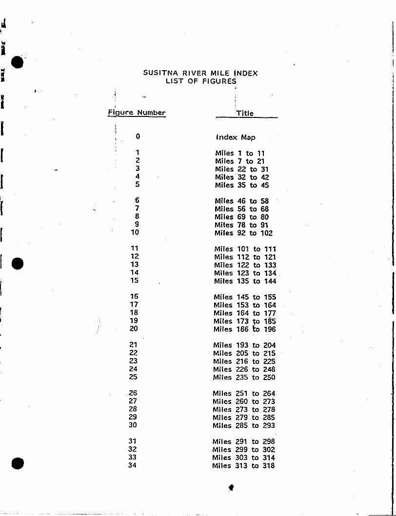
itI
Iif
II
l(
Ief
, .
~~~~~~ ---- ----
SUSITNA RIVER MILE INDEXLIST OF FIGURES
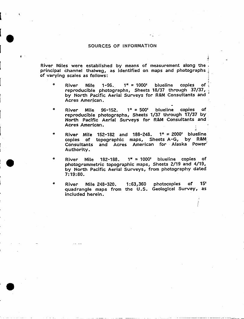
l
SOURCES OF INFORMATION
River Miles were established by means of measurement along theprincipal channel thalweg, as identified on maps and photographsof varying scales as follows:
o
o
River Mile 1-96. 1" = 1000' blueline copie.s ofreproducible photographs, Sheets 18/37 through 37/37,by North Pacific Aerial Surveys for R&M Consultants andAcres Amerjcan.
River Mile 96-152. 1" = 500' blueline copies ofreproducible photographs, Sheets 1/37 through 17/37 byNorth Pacific Aerial Surveys for R&M Consultants andAcres American.
o River Milecopies ofConsultantsAuthority.
152"182 and 188-248. 1" =2000' bluelinetopographic maps, Sheets A-G, by R&M
and Acres American for Alaska Power'
o
o
River Mile 182-188. ", = 1000' blueline copies ofphotogrammetric topographic maps, Sheets 2/19 and 4/19,by North Pacific Aerial Surveys, from photography dated7: 19:80.
River Mile 248..320. 1:63,360 photocopies of 15'quadrangle maps from the U.S. Geological Survey, asincluded herein.
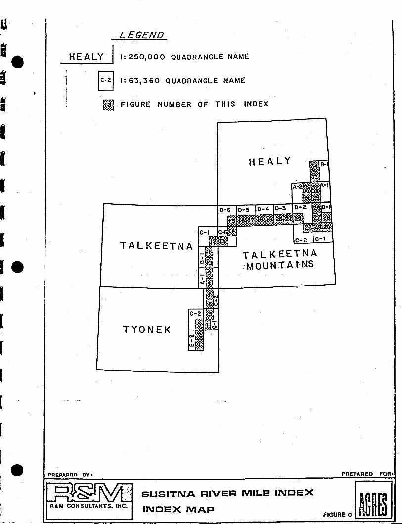
It•
LEGEND
HEALY 1':250,000 QUADRANGLE NAME
1~21 1:63,360 QUADRANGLE NAME
[dj1 FIGURE NUMBER OF TH IS INDEXllifl
PREPARED FOR'
~REO[iiiJSUSITNA RIVER MILE INDEX
INDEX MAP
HE A LY
>.-:-.'•••:..... ... .... • t~' ~~
C-Iffj.~~f. b.·· ...:...:...'12 a~~t C-2 0-1TALKEETNA ·.·· :::t
_1='fJI~ TALKEETNAm~!g·MOUNTA.t·NS
i:9.~-.:.:.::J<9t"!:
TYONEK
R & M CON SUlTANTS. INC.
PREPARltD BY'
IIII
IIIelIIII[
[
[
[
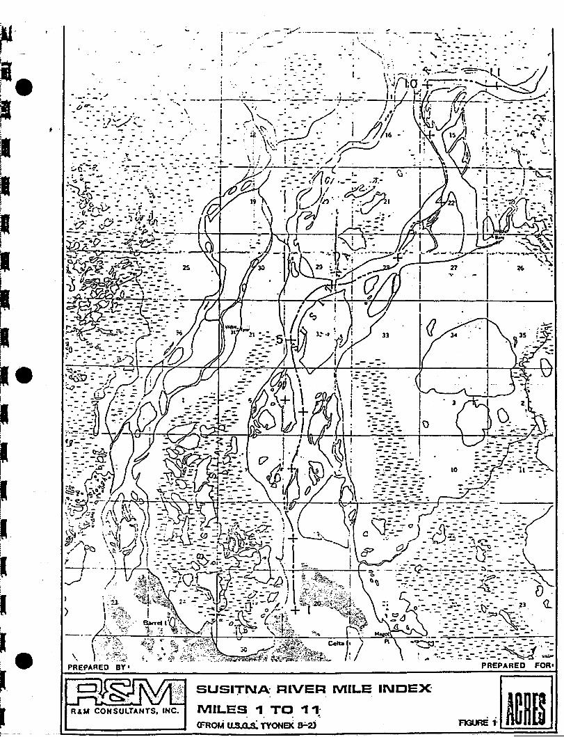
--~. -:--- -._......_. - - .
.' - - .
.- - '; -----.i .::. ~-:I .~--:::~I __ -.. - -.- ---.. -= ~---- -.- - . -- ....-..... .
'-:--=-::. .J::.-:':' ~--:}..,..--=_. i . ~---=- --=~
f}l!-?:_ _ 10 _~:!jf~~;'~-:-:--,.
~!f~fr·_:{;~~~ _-. /M;::~ 0) -2)--.:-:~= :~-.;_-:----',~:~
c "!:;-- ,..- -=t".:r5 ~'- - ---:: -_-..:-:~)2J --,.,--,\~ --I
c? Q ~ - .:.. - ..;. -:.- :!'i-" -~. -..:_~ ---:-_...=~:....:. ..;-:---,:.-~ - - - - . - ~- - -
-r-""""""''''=;--'-~-+- - :=:_ .~~~-:~::~ :-:---:-._ ...-. ~- -'=--.~ _-..: - , - - =-- .:. - ../~ - - - ., ......... .- - '-'.:.-:-- - -~:- - - -= n
__-.--_~ --_- - V·
,. .-- ~.......:..._._- - --.. --.".. .'.._ r ....... ,
'"..'
SUSI"TNA RIVER MILE INDEX
MILES ., TO .,.,." . ":
(FRoM "S Q S TYONeK e.:.2i
.-
R&M CONSULTANTS, INC.
, .
!I
I eiI
I!
II
~~ilI )
l eJ.
~1---
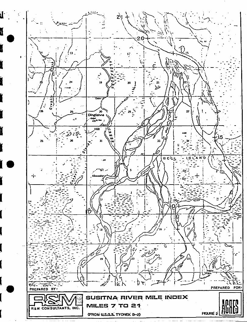
..
". .-.. .. . .
(FROM .. S G s.:. TYONEK &-2)
SUSITN~ RIVER MILE INDEX
MILES 7 TO 2 '1'R&M CONSULTANTS. INC.
\I
f!
'.
,'.
'.
I . ::, I:
/ .: '"-; ~,
/26~' .\"" ;
~:-J-.::;-':---- -:'t---:-:,:~'::::fb"-+----.:~~~74~~--~~) . ,.,:.' --c --~. \'
. , ~. ~. : ..2.' • !? - •. '_,. - ·I~'''..0 _ • -
3$ ;. _ J6 31 1._ ]A".. • r ..-., .I . . ~ I : -_.' _ .= •
~~I zo ~ ,-: :<"::'~.'~-~.' ..; -..•--: '.."., . \. ~ B E:t;;!- '. ,-S L~A-N"';"D--i-TI".,-:.. ~+r-\~-._":;:-_-_-..:-1
~.. =~ -_ 1 I ' • .; •• ::. ~'" ~ - - .. ~ , .~. -..\--:. :.. ~
.: I _ ~~ I. -: _..z-: ,'"_ ".'.::~ \\::...;;t:.' .. - .; -'" - ' g l~ ; :.. j.~~. ! --z.:.~ ,jS.+ " .~ -:. ..-" .: I ....J- . ~ ...~,'
I -;': .....;:7 . ; 1':- ~~:. '.: · .~ . :'.' '\" ""
~. .~-=--_:- fJ"'· , I , .. " . '':;: ..-. --4+-!.-.- - . -~., .-,--- --
:: -':=::?..;'~ :: I. ,••_.1." '. j .-:.:-::-:-:-.•••.:~ -••" ~. J(!?"-": - -~---::- - I J j .. ~ {I,.. ---~._-.;.. ., --'.' A
.. - - - - -- .' __.,~_--:_-:._.' ..=-=- ;-10
-: • ~. \\.. "':-:.. - ~--= =..;-....,:. _.~ .:t' . ':J0~"/:-'•.:.. :: ; ·~:·..;jl \\9 ~. ii ~~'.cE7~~- /f~" ~.. . _ . r ' _ ~·i=__=-.:=__~::.: I ~ \W - ,.'to_ /.... _-- _. --" - ... -/. : ---~ -_--;::-: . '1- 'n "I. "..., f;': --.- • - - -:. . -: 7 _.( --- .. -.:.--:: -:'::"- ~·,....---..vn -....;: -.J . :::.•. .. :r _ - _. _,. _ "- _ -_ - - - .\ .~:-' r· . -.. -_.....:-;- .' .. .;--__ - . - - - ~ - ~ , .! I - .,:.-
-_<-'~":;:_-~--: _a:. _ -~-r-.:-'-. :~ -' .. ~; j" --j~ii ,.:,- ==-::.":--~~~._ ~ .. ' ./ e- - - . . _.. - _. I ' I I ;" , - .~-
.<.:/-~ .~.:..- .:.. -..... -::: ','. : : -~":'.:,.::: ;'•. i .II i ; JV~~~.~ I:' -;:-- -'l.}o "..<...... _-~ --~-.:-:.E .-__ '-(ia~ -..;: ,J: ~//16~' '\ t~1 'I'~ ::1.c:'~:-,
• _ _ _ __ -. "")' ,. \ I
.~:. :.: : :'..-~;. __~'~"_ : ._, - \ I . i ::::.-::~ ,~ ._ ! . ~ t·· ~: ., i
.,:,:: ..=:...;,:;~~.:~==:.::-:._:;.~~-~. ~/ J/ ! ~:_;._-/.' ;' - .. l:-, .~ ~:-.- \ -j ~••.~~---., .,-'",~-- •• _ ---'. -: 11/" -- fi ( ~ ~.. _. - _.. !'\. ~_ .. _ .-.. _.- ~..'-_-" . - _- ....;,.-:- _": /~ :: -_ ;.. ;.; tr: _ ~ _, I . - .. ~ ~I
_ _ - - .. _' '.. l'~ --." -" I vI - -, ._1f.., - -.'. I
~~;- .::: ~:.i-·'~~:~ :'~:r- -. I ~ 19 -1~-7)~ "~~I i/~1tJ22 : ~~': ~~:.,:.~-~ -,"---
:C-l..7. ._-.!: ~... i -=-.-':' .:~//. \ \ .' ~'- / : ::.:C/.' Y. \ i:: ~.<i.. ~-') (;- ..• ., - .~ f1 .'1.)) :. -' \~: ? · I .:' It'! ~ j.~ ,r \.r. - - .
-,J- --"\,,.-' ." -- '.,-1? . \1.\ )\ ... :::,,\,
..-t:~::·~;~~~':~-?---~I~ ~?' A~' iV,0i-W-;.':-:'~~;"\)'; 11 ~:"~.±"" ~:,:oj.~.::~~~
_ - - --:i -c--•.-. -. C1 . - . .: r I . '-.;io -.,....... "'" .., • I I' I L. . - ...~~:..:-. Ch--¥~·_:::-_-:--· '''-J_C
'' ~,. '. Hi'~ '. 1;~; .. '. ,... r- :.:::..:;7'-; .... ---. ~ \. ~.~PREPARED BY' PREPARED FOR'
• •
a· ...
I.
-
I
IIre
(
IIIII
I.I
I
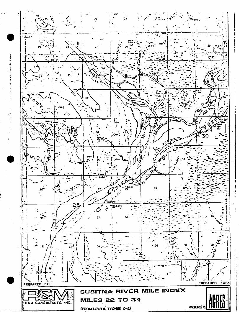
.. .1"
'0
.tn-
II '.
",
I
. :.r ,--.-..:. :'. \ .j ~
'1 " '--~.40. \ .. 11; :..!11JI6 Ii ~ •. : V'
\ :;
.. .!......". -."-..;. .....~.;.
! ,
~.. ' :
"/"
- :?9
. ". .--'..'--
......
'-
Ii!
~1 .
; -I ~
: "
.'
27 ._i·
-~i
....~ I. I-
... -""- -' ------- -..~--. :. ~----~-. ' ..-:' .- -... .. .----_.
) i_ 18 -- -i- . ."-_-lL":-"; =-_:-~.J.i~.-:-=:~~~,;:
'. -.; :;~~- -:-----_.-
R&M CONSULTANTS. INC.
----···--·....1·...- ......
SUSITNA RIVER MILE
MILES 22 -rO 31
INDEX
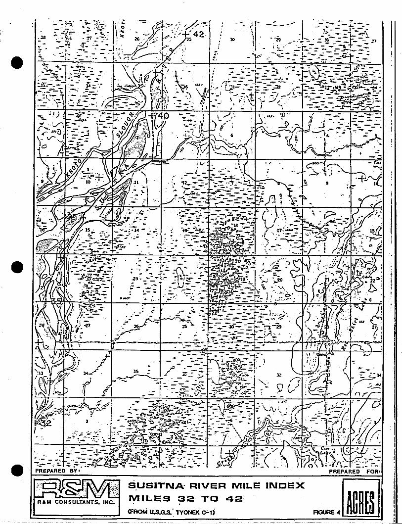
~----' I ':..-~~-:~ :'1"::'=-:. ._- - -1- ~\
• '"2'9 . "'-. - .. - - - - ~.L_..~.. - .. ..:.m - -t- - ~7; (. .,... - '-1- =-_:::---_~ . -.=- -.- - - ~---
~, -. - -' I-- - - - ~ - -- r-~ -: -=- - -:- ~ -:--;;:: -::---=-.., .L:..-_
"':jF
\\.,
I-~-..'~.
_ . _ 1_'- 7.. ...,- .. .:l.-;-", 7' - -= ;.t": =- -. -_.-.. --s --f'-;... r-.....,-'..-:-- -to....., _ r-..=. _ • _ """::.... ,..-. - _ -A- :7:'=' - .-, .- - - t -- -,)" . ~---- ..... ::;,~~......;--:. ,':.-:__-_~ ..- .. ,- ~t:.. ~~..;;tf~-
I. - ; r ..,,- -.. - - - ~. '-r-- ~~-t~;a £-tr.- ~.... -.. 'i~ ... --:- '- - - .'. - - - \&~.--..... -0f-_•• : - _ -~ _ -, .;/" "';"'ta • __--....... _:. .-JII;_.• -
..-': ~ '''',.:-('~ .....: ~ /:-.....-. "'..-:-= - ~~~tf~.. :_ •. ', ~ j ,,",0 -=__.....-:~~.~_:_.
, .1. '.. _ ...A .... ',""" .,.
1'..\.. ..\..~ UI,
'.~:' ~8.....\ ...,- .. , ,-'~ ~.. _ °0 ..,;,. •..... :,
SUSITNA· RIVER MILE INDEX
MILES 32 TO 42
(FA()f.f us 0 S ~ TYONEK ~1)
R&M CONSULTANTS. INC.
~
'- .. .;e
e .t-----~---~_- """'-~----":"""""""'::""'""F-O-R_t.
-JiiJ
. eI,
II'
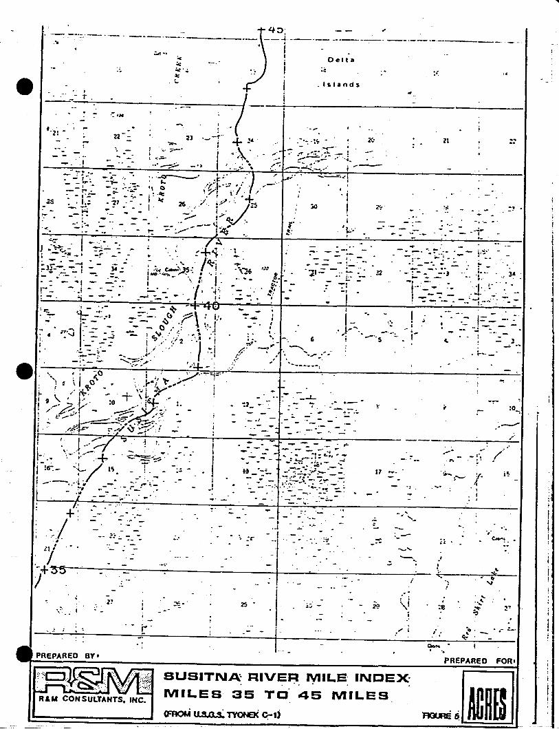
-------
LII
j
\I1,1I
,',.,.e-.!.
..,
....~
.~'?
y-·'1
:- -I .... ·.,,.
''1.::
,.-:~;.
.- ;=.:-:j --.
,--
,;'8
.._.- ...... ....
::-
ZI
"-jre, .
..-0:'--_·_----:---..:...·1
!I
.- --I
;., I....
_.'-
..,._.,
17
_...I
I..
.... '::,. ,t"~ .... ·.. --.....
; --"5 _.
'l;.'
,!. .. ..--
.'. .--. -.~ ... "-
Del ta
:
.......--=--·.,;'1I
. Islands
6
. . -- .. :.:.......'21-= -::. ~
;..
'-. ...
.....
. _..J.."7
- e'
-
I.... co.~,....,
If=>'---l
II
iI
Ij
)
_ .1
-r.-
...-_.~-
25 -
----e. \t_
.1IIII.
";.;. ,.~' --..
I:' "'.; ,
-- .'
iI.iI.'
~.'
,-
.,
••#.'
.:..: ...
+/~;:;"..,
• ~ '1. ~
j, ',' ,'l~ii.w;.~~~.:J~·, • ','"; oo.. \.:: I.
'{. ','".. ' ,;....:-. -
-.
---_.__.. _--_.__.--
" -. -..:...0---- ,~:., :/. ." ~;' .~...~.....--:._ : I. ..-l·j:..":;- ~:. ...-:.. .
~ () '/,1 ,./ ..'_ ;,. - , .. lIi: , I '.'~
: ac 26 .,,' i<'" J~S
- - ._~ ._J....·V<t: ~->..--- 1~
.-.J" _
, -
- ~ '1" ....\:1-, ,. -"'\_ - -'. V ';;;;;.0"' : I...
- - ,:>,cr .;- - 0,'.: '4 ';'.1~ ~ V .. ": .,. ... ,
, ~ '. -'; 2 .'.' 'iI " .'. '/'! . ..-1/ . ,.1
_.... ..... I
,,-;::;~;" , -~.\,.-". ,'~-
~.:-.
.77
-.,..~
_...'.
.1
_.-. ':.!" ~:.,... -! ...- : :... ~.': : [~.--;:.-- ~._. _.•-,-
.• ·oo-'-1::-- :..~:.- t
;r,-" ·f·:~'; ---• 'oJ : -:- __~
- , -..::....":-~•.--1·_-·
..
...
--:---:;-1" ~':-'H-~.,-, 'Z': '~-' ~.' (
22 2] ·,_-t· +'4'.'., '7"--. ,'\'... ' .
-:.:=- ,.~" •oo.e ---:.;:., _ .. J •.•••; .,
'-r..
; .
j -:;~ I-- ~..:~• •.:..~:!~ -' -!" .· - .. --.. .:3F--..... :· - - -,- •..-
+:.•.. ;
.-, .
11 :
, I-+35/ .
I! ' J ;;-r ";I . .! '.
II '> I.:'::'" +.. ..:::~.. -.-.... • t.. ... -.- ~.
"
-;~- "-L/'I'l 'r: -1 •, - .,.,.--...........~-;., . -_... ... ,.. .:"'"1 • -. t-_: .....-
- .11
I --' - .....f
.'
i,.. -.. '
~
PREPARED BY'
~~~!WR&M CONSULTANTS. INC.
SUSITNA:' RIVER MILE' INDEX'. . .. ..
MILES' 35 TO' 45 MILES
PREPARED FOR'
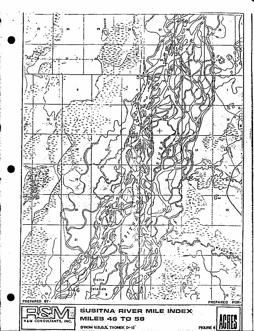
R&M CONSULTANTS. INC.
:... --t...f:ii~ .~.. &.: ._. n .• :. -: )0- ..e -,",:. '-~.--r~~-
.~ ... ~, .... ,-\ ';"·i :- --~ _~ . .. ;.:: ~~.: - 0. .. •• _~• , -_ .; ".i.
1_'1-·'.;' 1. _.. :..-
,. ..~.
: _0.;..} • t... ,~_r
r.-· •(' ~ .
--_. -.:...- .4_ -~
.• _t
.:--_t:- -.---:.--.-;: ~l'
/: ---:.":~~. ./:{=-=:-~-(". :..-- - .~.,. - -:- ':-- - - ."-:.- ~ -:-.:-.--~ -- - --:--.
i
L---=-=-~...................~--~
$USITNA: RIVER. MILE INDEX'
MILES 46· TO sa
..
.= ...
-s::J.-
. '12 :""..:_-r _ •PREPARED FOR'
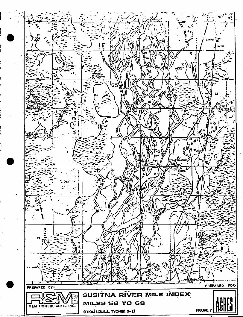
PREPARED BY'
I
[ "
9
i':- ,
I~~~'ii-:" . •1'-' -20 7; . !....
':lJ•
R & M CON SULTANTS. INC.
SUSITNA RIVER MILE "INDEX-. ... .MILES "56 TO S8
"<FROM II:S 0 S· TYOfEK o-;.d

RAM CONSULTANTS. INC.
4"1 ..~ y... ~ ..........;• .;~----.:--; -•. p
-.-. ----:~ ---- ..... ~ -.=.-t:_
SUSITNA: RIVER
MILES G~- TO
(fROM " so s:. TAI..KEE1'NA 1t-1l
MILE- INDEX-~ .
BO
..- . -- ....... ~.
• • 1 .,...
i -t •t 1F6-I
-":,.'.---'---Ittt
ItI
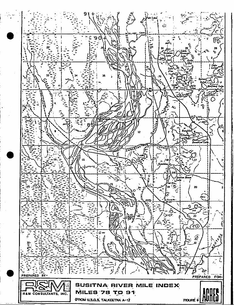
----------------------
FGRI
INDEX,SUSITNA' RIVER MILE. . .. .MILES '78 TO 9~'
• • • ",.0. •
<FRoM II S 0 s' TAI.KEEl'HA A-1;
32-
.., ".
-- ....--_.--- -: .. -- ~--.- ".- - • -. \'l,
· . 5 -- - \~
~- --. \'i
:'~." ~ \.. -'. \~ - \· ---=, \
- L- --..
~';(j. :.- _ e •. -- ... -
I ~~:. ~
). ~:a.-: ;· ~ =.-- .· '":' .--(~~i~i "_-
.'
1:-.._i ;.-.:;.-~_
r----- ~~ --:. ....;·..:-;,.-.:-~..;=.-~..-::....;:;~:+__+\_\\_111_--+_.:.:~
~:--.~_.1.- --_.:._-r ~ /-- _": _ :.- _ '--
R & M CON SUlTANTS. INC.
I • • --j~' -,-~ '''~r" !~~-=----:{::;~-.:: "=~-:...-~ .::-_:---:... =r: 0·_- 22-:-::~ :- ---lr-~" -:-'7('\...-f~=-- -. ~.. - --. _".\r_- !--.....::::::-. -. -- - . -\. ---~ -- - .'- -= ~_=...: .~_.A. •__- _ -: .. .;.:- -:..--:
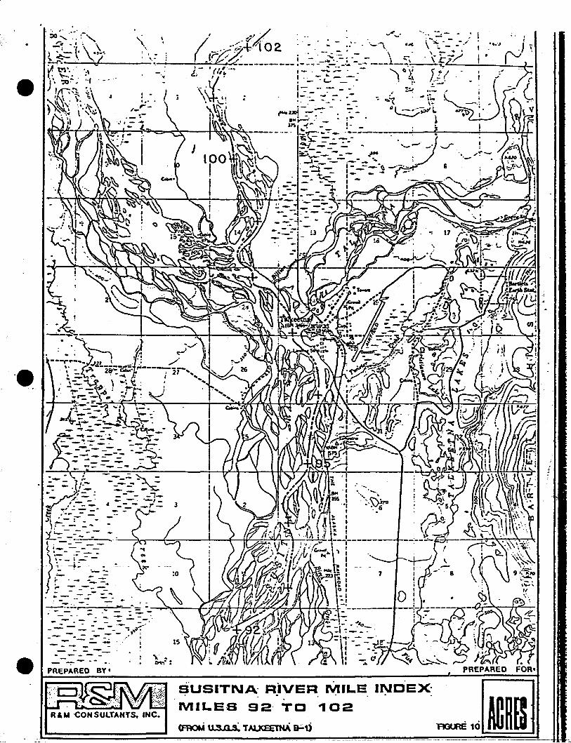
\. ~..
. -- -.... - "';'::: .. ::--- - .- - ~ -= -=- : -:.-~: ~:--~-:><..- - ---- - - - -
·e
---------~- ------
~:-: ,:-- ---~~~::- .-,. --..- .. ,._~. - - ~.. ,'- . - - - -:-
,~':--' .---~--,- J. . - - - • - _r-t.lIf ~' - ~ -- ~:- "-'>i .• -- - ••.)1 .:..- : - - -).1.---- -
1...'"=-=---- --- -( ~ ..,.;..:. -- _ _ --3.,.....-+-=-_-L-_-;f--+I;'-~~
f~ \::t--:= .-- . 0_-..p-.- ~-~,.. - ---
. F=--....=- ..:- ~~. .
'\ '"~.:
PREPARED BY'
(~~__ -_/ I
.FOR'
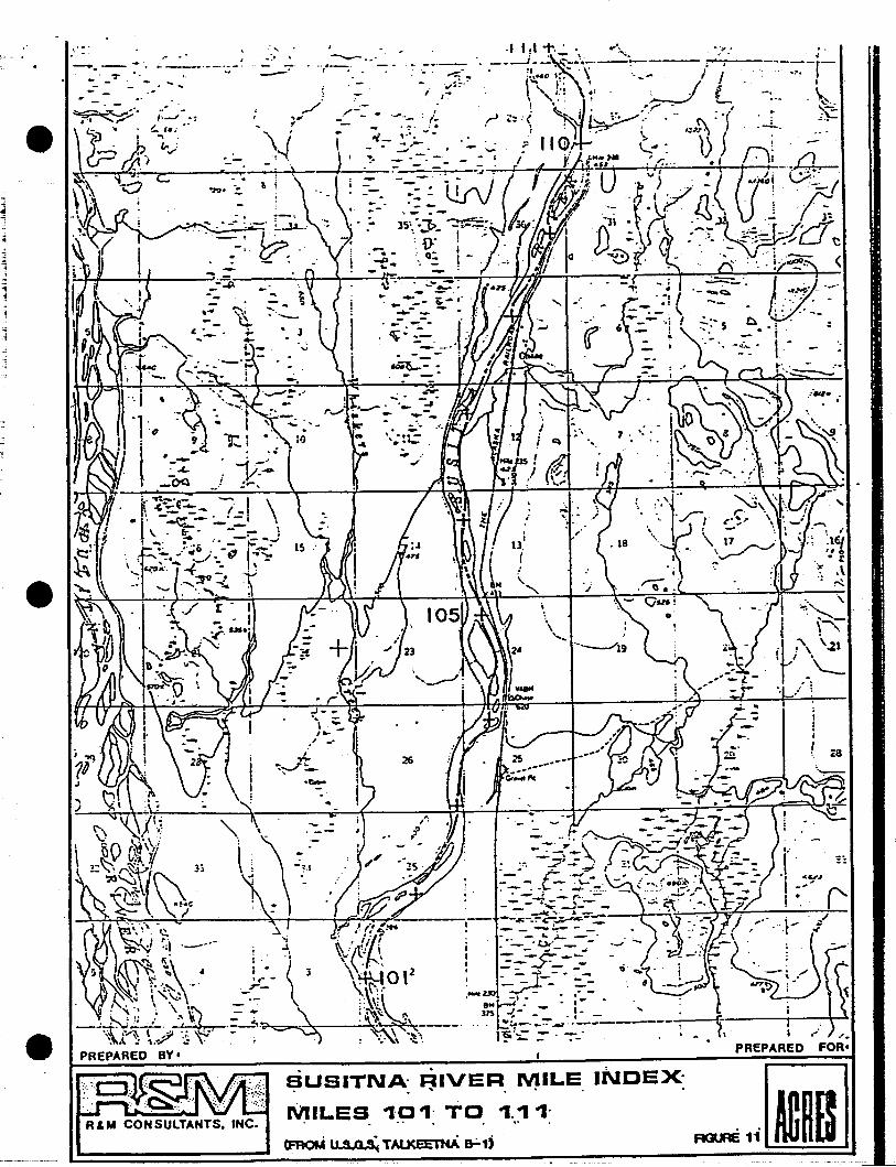
IiI
( 28
•----r-_:0.I
I -'.PREPARED FOR.
- ... --_._--,-'-.-.. _T.
'.': ..
-.
!;iUSITNA: ~IVER. ~ILE INDEX- iiJ__________ l~R=&=M=C=O=N=S=UL:=:t:=AN=T=S=. :::IN:::C::"~:M::-.:I:L.:E::::S:.~-':·P=-':::T:..:O:.::. :..-,_._.~_-,_- ..:~.==1r'IC.~':-1.!:=1P::D:[@=::!I_ _ <FROM " S Q~ TAI.J<EETNA Er1) ~ lIDn[d
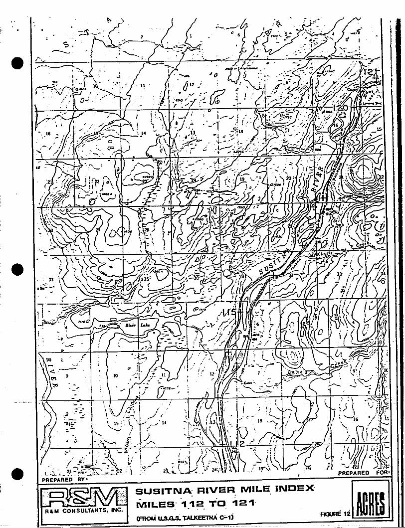
gr ./ <J.~~/J; c./~-r...o / I,IJ (/ (', \-:
• _, ~I, \ :::-I, 'oJ' om I ,.J. 'It:
PREPARED FOR."
10
. ))
~.. . -I~; ... 0,- ;,t. ,.~
.,' ,~... lo' .\. .j., iI ~'--.' -_~ ~! ! r
..... I •...,~ • _ :, '17 .....
. L':;.,_ ~1."~"·~~~~:-::2~."\ '.'PREPARED BY'
~' -;0 ~. ,1'
\,~ .--::/.\ t"1 '"
I '<0 •J -_:".
-~' .•s.--"....
i"
Rio'" CONSULTANTS, INC.
SUSITNA' RIVER MILE INDEX'. .- . .'MILES' ~ ~2 TO ~2~'
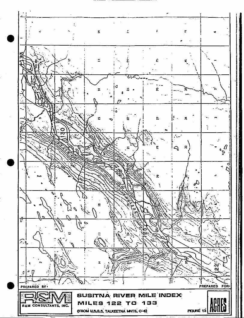
•• I
~-------------------~I
..--------- '.
SUSITNA' RIVI!R MILE"INDEX-. . .MILES 122 TO· 133
(F'AOt.i II S 0 s·. TAL.KEE't'NA was:.~
.'
-,:;!
1
.... ." '--
PREPARED FOR'
'.
1'\I \,
\\
\
'-.\
\
.....-
\'~~. hi \\~!-'-... '" --' ., -'. .'. ,,- -:' \--I·.·· ..... ~
- I •. '-'.:
.-..~
-...
-..-
...N'
Ii.
: ;
o
. .
.---..:
; .'! 0
'.~ ~.
...r.
-.... i
I
i
......
I..~
R&M CONSULTANTS. INC.
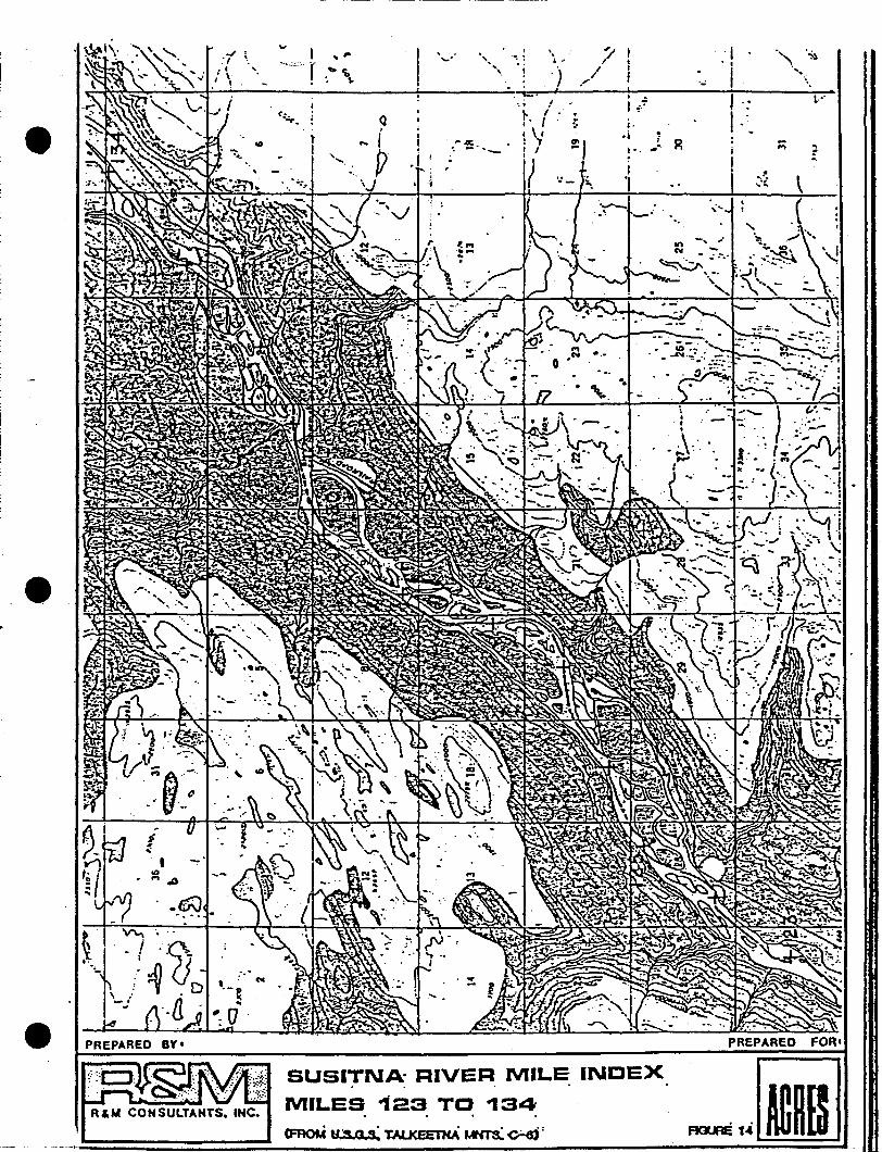
..~.
.'. ',-
.."~ ...--
.......
,.-.),
/,.~/
I •
1,;7j.
.it - ...-
I"
?-.
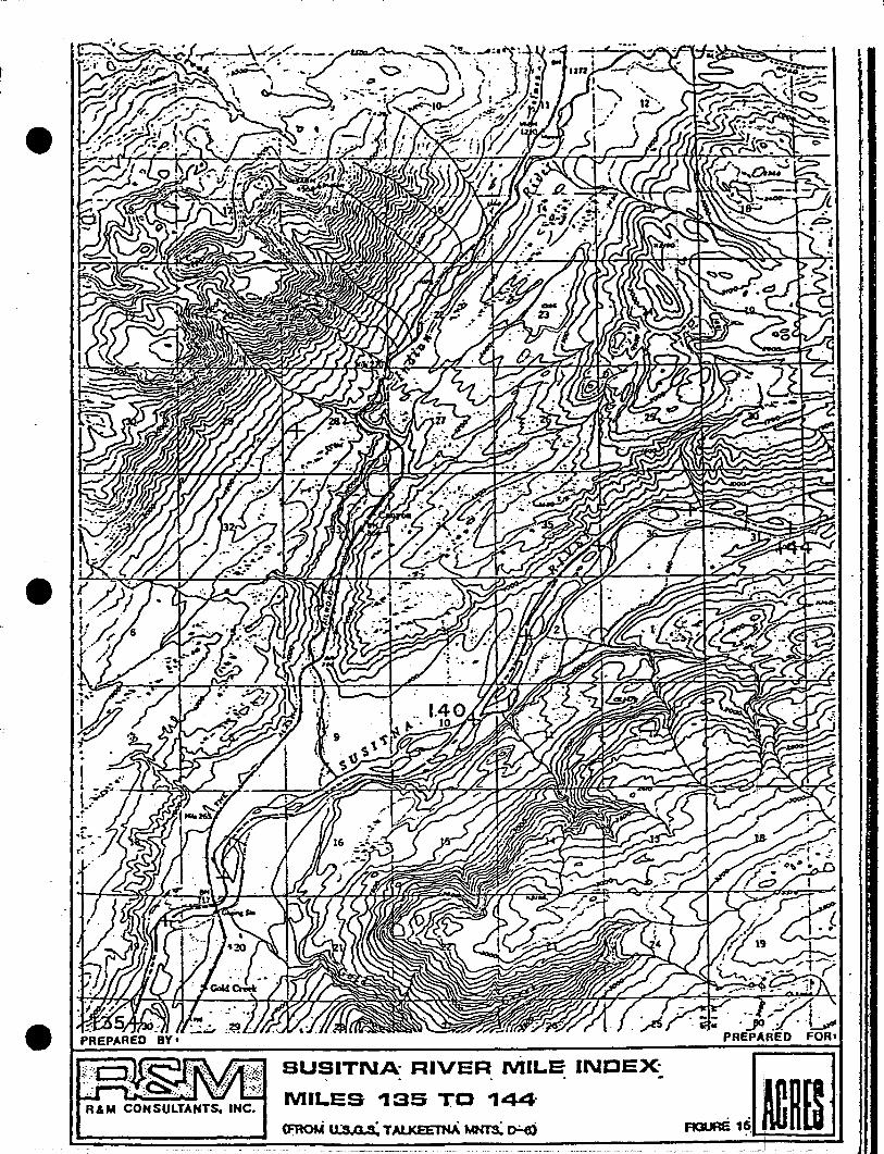
R&M CONSULTANTS. INC.
SUSITNA RIVER MILE INDEX·, . ,
MILES 135 TO 144'
G:ROM I"S 0 s~ TAl..KEETNA~ IHJ)
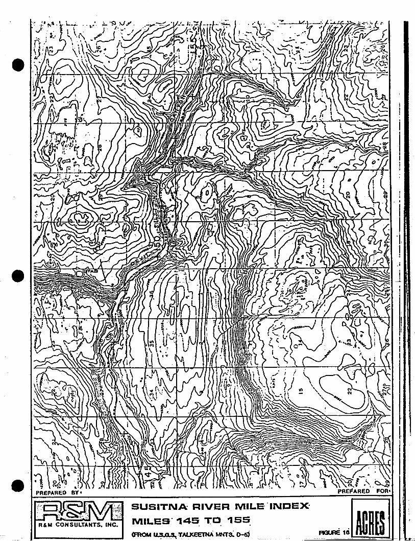
SUSITNA RIVER MILE·INDEX
MILEso145 T~ 155.
<FROM usa~ TAL.JCEE1"NA MNTS:~

.'.
-.
j:
i, ~.1.
~.
~;.:.:..-._.._.
PREPARED FOR'
~_.. .""
. :../'. -::-~._.-I ' ., .,
./ .:-,,: .~ ...-.( :i'~_,-~
() ~"4 ............,.---
~ .:-=; - /- - .- - .' ...--\. • O· .----.- .-1'".. . •••_-- /"
- ~ ~~'-"~/)"'--.. 'j ~~~~ \~-- - . ..-y-" ..--~O ..... - .• ""
~- I .~" ',.Ii' ".'
-'~--' ---
.- ,- ..",.,:. =~'-, ,.J"..•••- ... .... _' ....
.. .. i.. •. t ..~.
~. .. t\~ -; '.:~
. ,
SUSITNA RIVER MILE' INDEX
MILES 153 TO 164
~II~9~~TAl..KEETNA~~
II
../
R&M CONSULTANTS, INC.
-PREPARED BY'
:.i

\ '.
,<0
."
.'...""".......
"
...;
....-...
---..- -
,~'f,;>l~
" I, t
"
SUSITNA' RIVER MILE' U\ICEX', ..
. MILES· '164 TO· '177
.4FROM 11:1 0 s'. TAI..XEETlCA~~;
t'
;'~..
. - .i,.4IW..>... ..-_-::-.- . ('- :::- " ,.: .''-'' f"'l:._ w .,."
.,' ... j''''' /. . .
.,.... _I .-'~
.. ' : i iI: - ..- -,...:- .:
./." .
-----~ "., ./;. "\ • l.... ---. ,;,r:,. -~. ~ "',
1:' - .. ,... ~ I/. '~~'tl.:.:-~ .~- '.I . \...:. '\ '• ... .... .#'. -.
./,j...- .......,.. .Yeo "J
f'\I ~
.-
./i .....~
I
1...·1 '" r.
;" .·f l~
:!
.-- !,
\,!I
•• 0.
'.
"
..- , ....,.~ .~
... ~.
. "" .:-..... .~~. ' ....•
"
(
)
(,.Ji
/
'--
/
t'
, .f...... '
,.
RU", CONSULTANTS. INC.
-. ) I. \ .'
---'h'!d'f
;
ttJ:.. I
e ,~' -\Y'.' ~..: -t'; ---'-' ~.... ;..-- •'~---.. ,.~
\ ; '-~, r:- .~ ... -.., po. I ~ ~~
,/ I -. :'10 • '~' ...
-::-~, . <7 <==>,:. I
I "I.". 0.' ,.. \ I.v .';
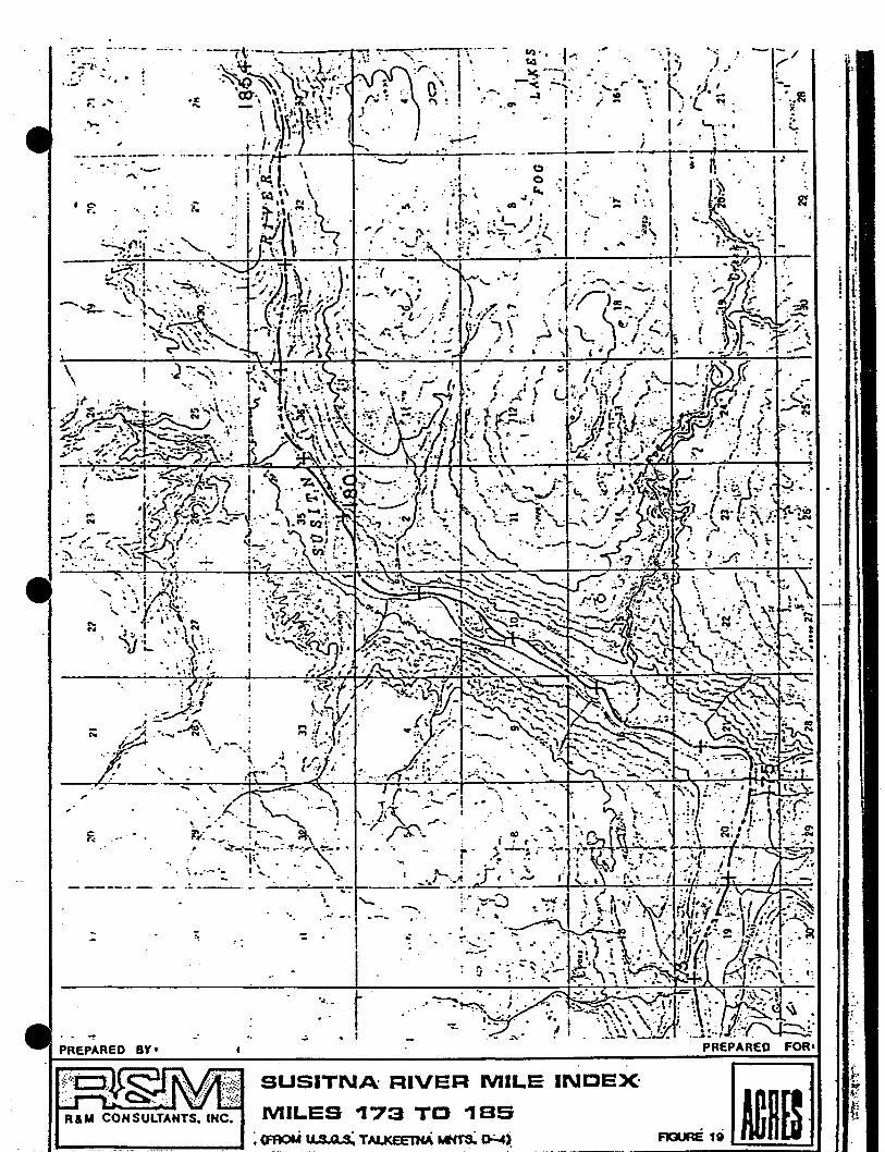
I
•.?-
.;
-,... ";'.0
.-r~.1i. ••- eo.:,
: ,
"!
':: ".'~
".....-.,.
.. . '.
t° I
'-._. -··1 --..
II
SUSITNA RIVER MILE INDEX
MILES 173 TO 1BS: (FROM II S Q s.: TAI..KEE1HA~0-:.4~
-- ---_. - . -'-......,,....:----..
.:'.'~ ... ,'-·-..::-.-:,~-...:.a-"\;---b_4t,.....,_+...::;;..:.:.:..t-::":'2--;':""~"::"_:'-_"""":'-"+_"'::'l-~~~-:-=-~..lo.c....:.~~-t+.t~~~r "-. .,. ,.... f '-,'"
, ,I~''" '" - • . ,_., •• \, ~ I. .. -'. , • A\ -.' • (Lii' i
'. :.'. '-J.. '.'i',~,_,.r.:t\. I _.'. ..N'. '~ ... : .. ';' \ .... ",,_:~:., ... ''''0':.''''(-:-' •
~, ..~_ ..=- !"- .. " .. -.. \~.
'-'
" .
,
,'.
-.....
• o. ': /.,-
• • I.
,.-:AJ,~ .J,....
t'lf "';A ...,......-~ .,..r~ '..,"-·,1P.,' . '. \.
/..'
;:: .......
CN
...••
o..
,.
.r··..-
\
.~..,.~, :.
.-- ~. ... .''.-
RU' CONSULTANTS. INC.
- .• - - .• ---,\:.-~- .., -:-~"--,~;"-" - 111', ·t ....··, -·.i.. ' ..:} -\- /
·~,~~~'~\\1:.~:~. .:~:~. ':r;,~,.· 1"" ._.. _;.~.:!-:... . ,. ,... .',1 OJ ,J ~. r'"00'. \\.. :)1' I. , . \j I ' .:i' I' ·.....oil ~. kl' ,;> L_
.~ _' \\tt . t \ -. .rv .. ':"\ ! ! •. G' " ~ 'f.. ~. .'..ra\"'"r·'·' · .. . I· L
h
•••••
. . \\\':=.; ~\.;:. • .' I; '"',., f _
,. "jll J ~~ i _~~~•. ~- '-r-r-r- ._.-t-:;."._--:....~~- a:
,.·r':{1 \ ~ .!. Co) ,'11..; Ie;, , ·,.f 0. : .~ t' \. . ~ I.. , ~ Co. "'". t! ~~~I:::' \h ,.~.;. :1' '. flO; II ~"
t!'~ '{\' '.., ; I'. i ~l::'~ ';'~ I: ....., . : . ~ . ,,, ..... .., • ...,.,.,~. ..,.'- :: . t l .. :~,
:"-~"'Hi .', "- -' 1.,.:'1 t.· ". ' "--!":.,' ':,:. ~ ...._'. L' ... - :.. ·,~ ... t ........~ .., .• t:...t.." ~ to • i . ......, .'. , ~.; . - ... . ., . ,...;.. ~~.....-----.,.!_++_:_-
&..:-:.:>';1 • " -~ •. m ),... ~'"::..:.~:;: ".~. :~:-t!/~:"J~' ":' , t.:( .~. . l\-.....'- ..... ;'.,:'..':' ':. ~"," ,.,..';',. ~," : II')" .' . ,. , ,." • '.-', , I
--..~... . :~.," ... ' ,.. /,;{~.; ..". " ~\ . l ., V': ..._. t'-.;;: , : of ','. r ,. 't·' :'; ·t·~!/.·· ..,
.~ ~,..... •. ...-....,•.!: ~ :. \. )..:'..... _~ ..... ,- t··.., \: \~..., ':.',. " -; ... :\.',-t '\ '"'......,. ;.......1 , • :I .,
""" ,. ~ '(. ..' .•'" .J':"" ~ .... , ,",. .. .,,;;) ....{ --........ :"... (
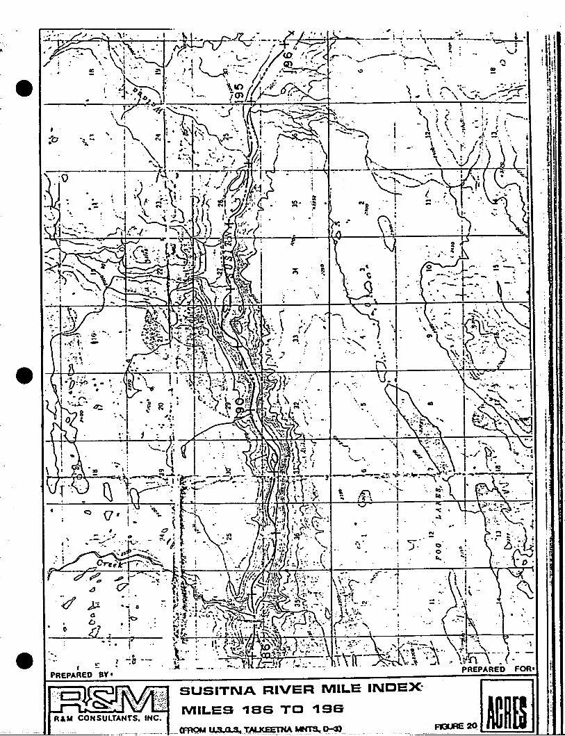
i.I
. ~
~,.'.
~i .
. --... .
~.
.J .
-'
\ 1 " •·'VI· . ,I
11; . '> ."~J
~-:
·t •
I'"
i.. I
'. I.. .
! ••••• \ ~.~: .:.
I .". ". \ \ 'f;1 ~.:.:. . '---'-.-,1:-.. .''.t'':~!···::-:-·1·'· ..~: ·A\. \ '.~ r'; t ..... - . \' '... ' ,. ···1 -... ,.. (.. ..:~
... ,.l. \-.:.l' -I .- ..e;.'" ,. _ •.PREPARED FORI
, i.." '.
?~- - -1,.i
I'...1.
.'. '~ ........~ . ~1'. '. • 1; ....
!
.'..., .7!:::::~~"7'-"" I· \ -... . ,. ,,----~-: _...-,~. ..-:--- .~ ..
. '..~. ;
.. .....'t;)
SUSITNA RIVER MILE INDEX:
MILES .. as TO .. sa
.. ~ aIl~
• !
._..-
):!.oD
C .._·~~-·---'i~='--
-:&--
",
.0.
R&M CONSULTANTS. INC.
•
fPREPARED BY I
"
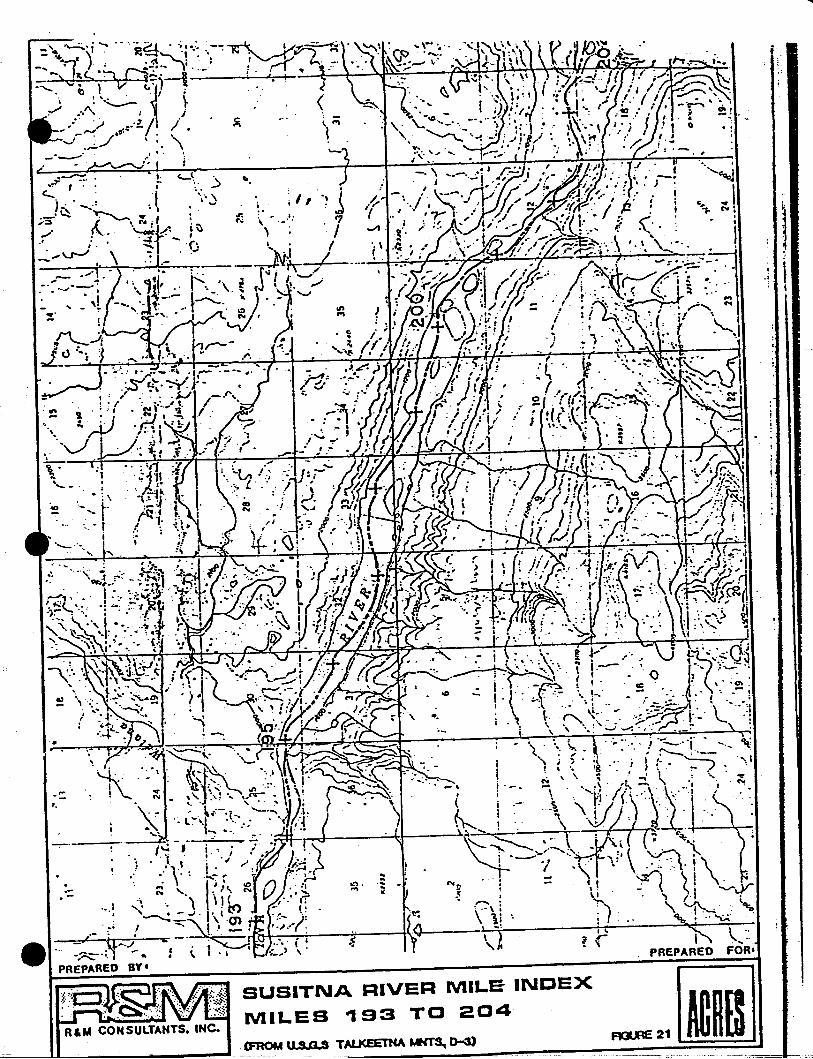
I! t
'1 II
~21(FROM II S a.s TALJ<.EE1'HA MNTS, D-3)
SUSITNA RIVER MILE INDEX
MILES "193 TO 204
,..
1.,'._~ F
... .-...!
i' ...."
.-
RIM CONSULTANTS. INC.
.::
'",.... - .
: .
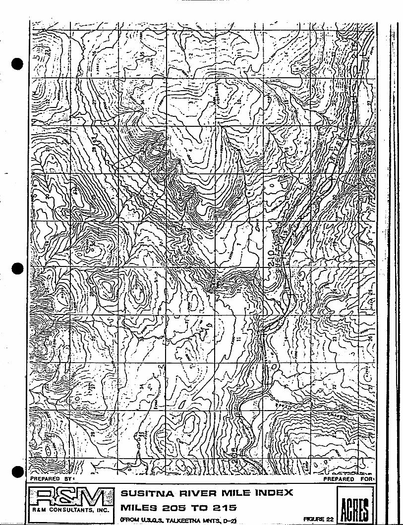
R&M CONSULTANTS, INC.
SUSITNA RIVER MILE INDEX
MILES 205 TO 2"15
L::.._=-=-=-.. =~:::.J'~~~~~~ ............__..... <FAOM US 0 S TAlKEET'HA.~ D-2i
. ..0-~~--'
PREPARED FOR'
AGURE22
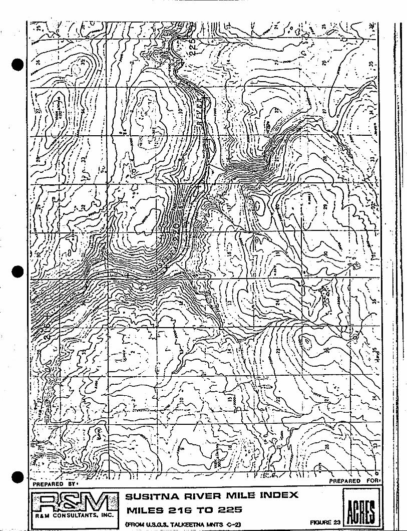
li
tr
! I
i.
."I.
I;I ~
~ "" '--..' f' ~\, ....~\." i ·or.
\ ,-" ~L~'-..---". ...N· ....
:. ,- I '. .. . .- "") . •~ . \ \"" ... .. . .--.',-- ,~ '":.
.-SUSITNA RIVER MILE INDEX
MILES 216 TO 225R&M CONSULTANTS. INC.
l .......... -----......,......jL. (FROM I' S a !II. TAl.J<EETNA tMTS -c-2)_.~~~~-------------.....................~
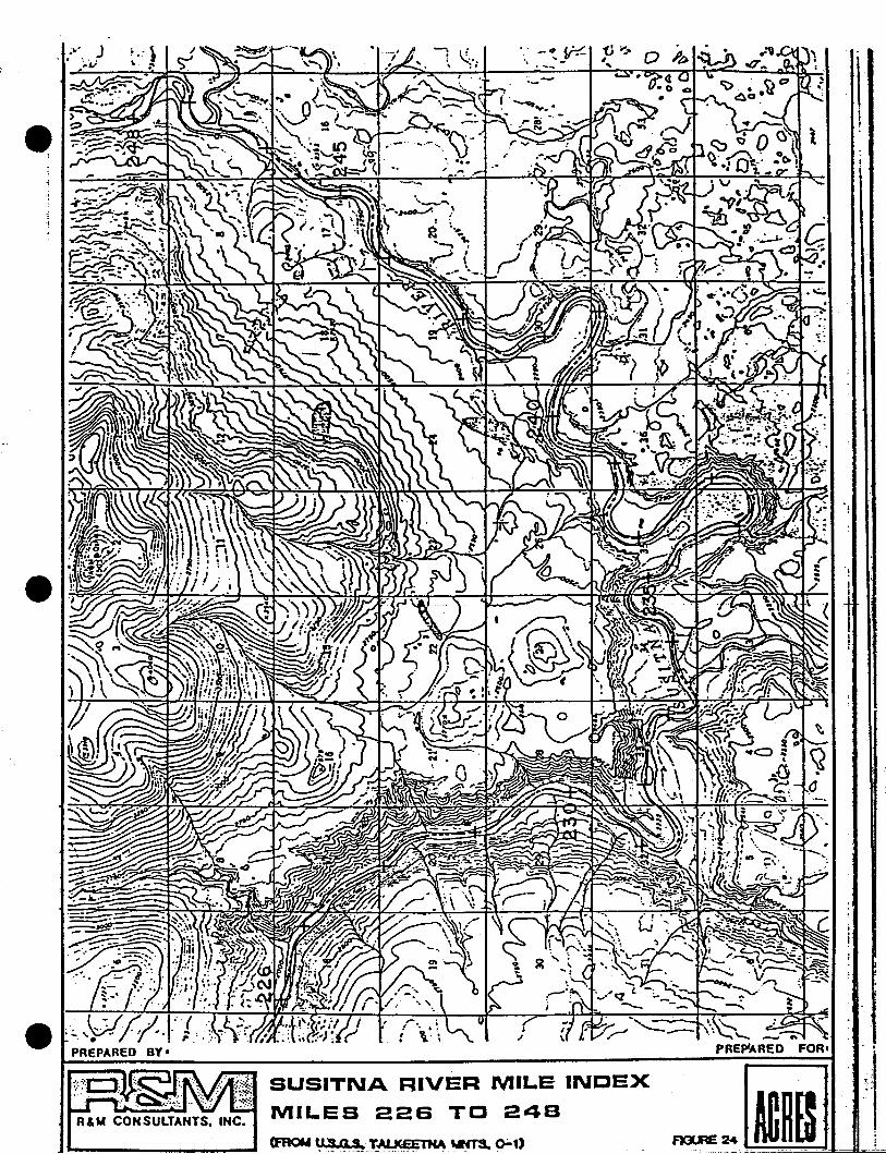
•
R&M CONSULTANTS. INC.
(.. \ -~y~ ;
'--
SUSITNA RIVER MILE INDEX
MILES 226 TO 248
-
-.'-.;.
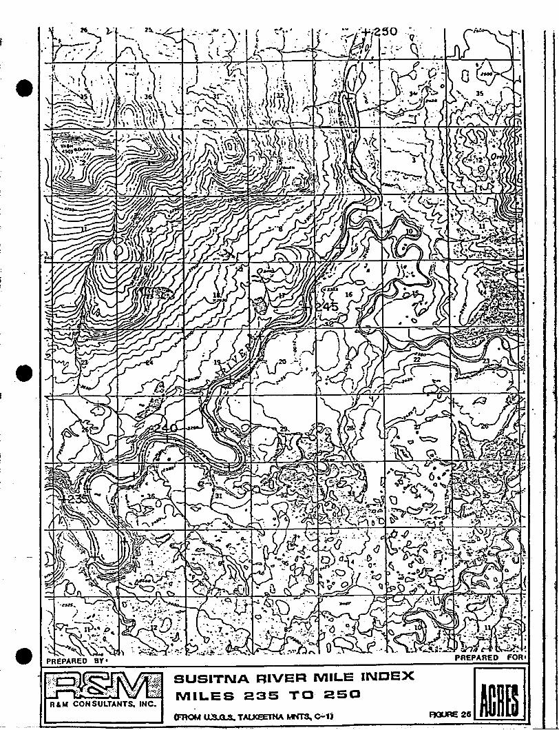
i
R&M CONSULTANTS. INC.
SUSITNA RIVER MILE INDEX
MILES 235 TO 250
(FROM II:S a S TAlJCEETHA MN'l"S. 0-1)
SUSITNA RIVER MILE INDEX
MILES 251 TO 264
(FROM u SJ1 S, TAI.JCE'E'l"HA MNTS. 0-1)
FORt
...~.

...
J.;
\.
i"-
\
------------- ~---~--
SUSITNA RIVER MILE INDEXMILES 260 TO 273
(fROM u.s 0 s TAl I(~.a ...- ..a-d
•

1
SUSITNA RIVER MILE 'INDEX
MILES 273 TO 278
·'-
.i -
\. \\ t' I. 0 """0I \ 'I.
elVt.
R&M CONSULTANTS. INC.
SUSITNA RIVER MILE INDEX
MILES 279 TO 2SS
(FROM "SO S t£AL.y 1.-1)
FOR'
-I'
I ~ l,- -.-...:..--i,...----;
R&M CONSULTANTS. INC.
/
."
r....· ,... --'.
~ .-
SUSITNA RIVER MILE INDEX ~
::~':Q:":~,:TO 293 __om.__.I;;===:;::::::::===--~=-=='::=-=--=------_::=:...=..!:=':::::::::~
i,

•
----,.~-...
. .: It,
RAM CONSULTANTS. INC.
, ...
SUSITNA RIVER MILE INDEX
MILES 291 TO 2SB
(FROM us 0 S HEALY A-2)
.,
'''--'.' .. ..--~~ IPREPARED
RAM CONSULTANTS. INC.
SUSITNA RIVER MILE INDEX
MILES 2S9 TO 302
(FROM tI S 0 S. HEAlY A-1)
l;I
--i

--I .
J
.~/.'
.•..
.-..~
,...,' .-.'
:'."\
i
j-"-. ~
. \. :. )--•. ~ .• "'r~
/,6/
r'"3 -4-
'.
12
_0-
\
..'
2
11
.!
,.'!
:'-•• '-,i. ., ~
/';...
,----.~--------
iI
PI.,
I)
"'21
SUSITNA RIVER MILE INDEX
MILES 303 TO 3-.4
- 'J!
...! .
• I
\ '.-·'l. _.0' -
iII
-.,8
,. 1 _.__:.\ " .._,.-
..~ :," ~. "
.'
. ; I'......... :
I
(\I
30'0 '
~..'---.,
/,......
R&M CONSULTANTS. INC,
I
./ C'
.( ~ J~.
,.''s
---,---------,-----
'..
'.
.,' -"";... :.'{'"..-~ ·i./';Ci 19
: ~.: ....
--...::,....::.~ ~-n:.:~
PREPARED BY'
~( 19r~'
V
"eJ
IJ
• i ,- f ;, ,~
,..t I .
18 ':""'r'- .-\
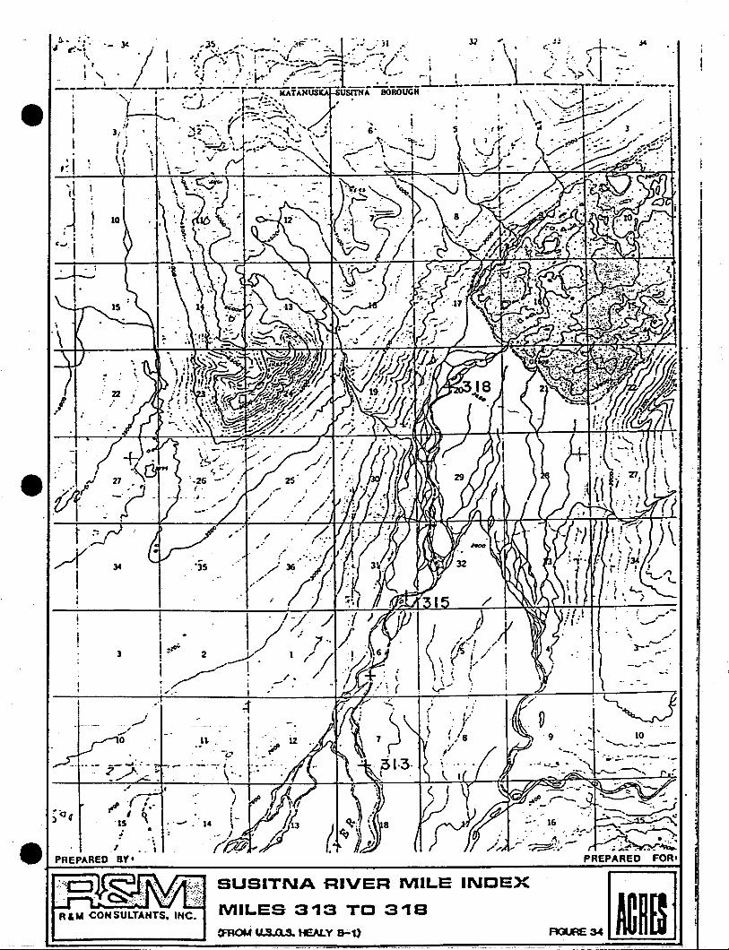
,--,---_.-..
SUSITNA RIVER MILE INDEX
MILES 313 TO 318a=RoM us Q S. tEALY a.;.t)
'35
...U ..
.~
(
0 ,
~. l·-lSi ~
R"" CONSULTANTS. IHC.
I
,~ I
3
t ::.-1rr·I
,
£'..- .,.....j
. ....,o- .
.• .1•••- .7- i:·· ;,; ,......,./'" '. - .- ..
- ~e .I,PREPARED BY't--~---------------~::':":":':':'''='''':''::~
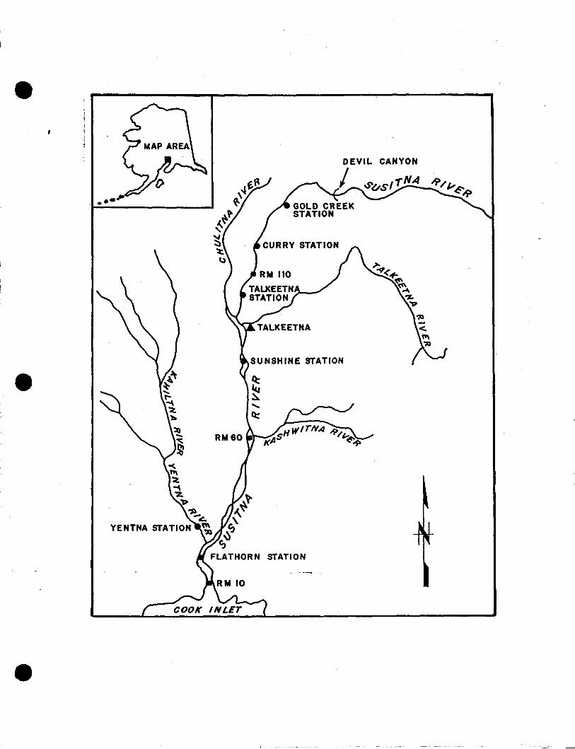
STATION
CANYON
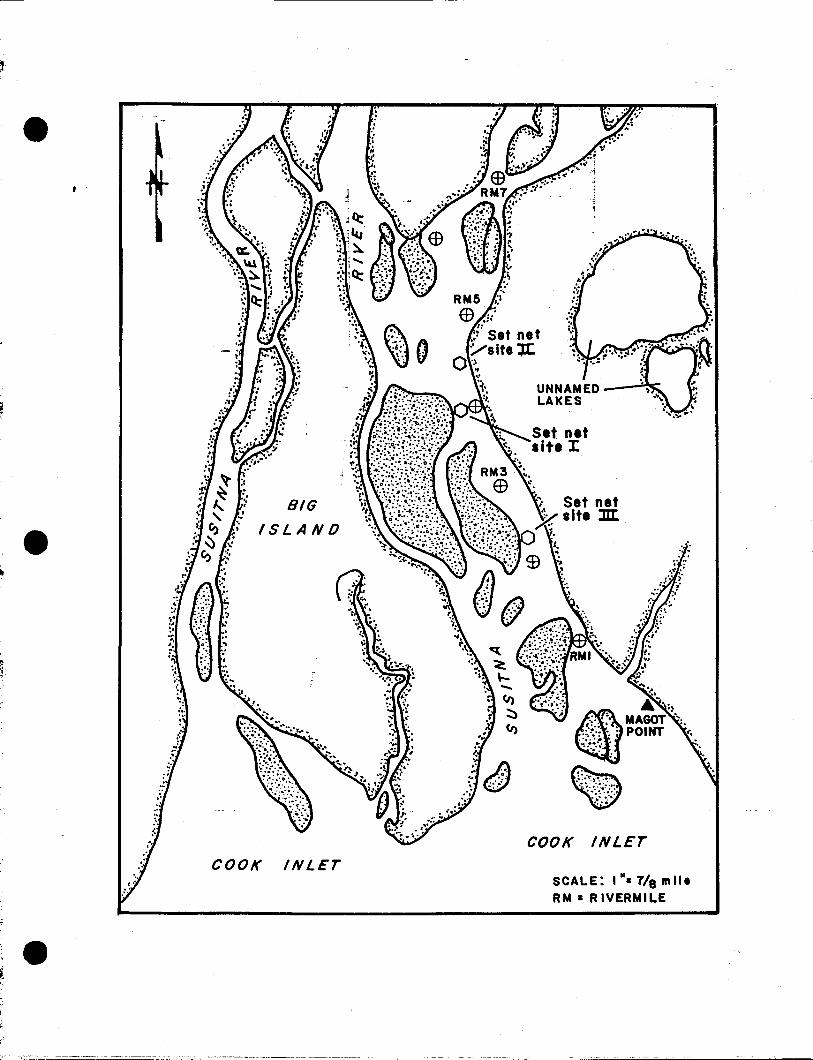
SCALE: I". 7/e millRM • R IVERMILE
INLEr
'-::,
(;i): JA. ':~
..,.... MAGOT ...·:~::',~,,: POINT ' .
. .•. _. t'•
., ...;:~. : ':
~.; ...... ~.,.":, ....
0"' ~~:~;.~.:~~~#"'...
COOK
INLErCOOK
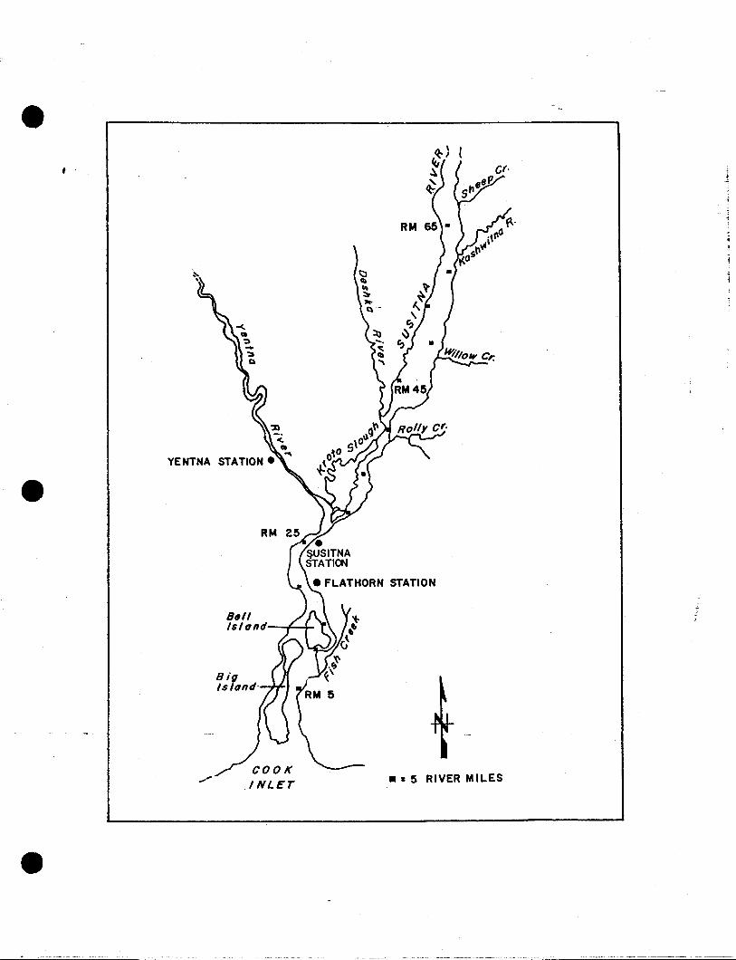
, .
YENTNA
RM
a."1$If1nd--+-~
•• 5 RIVER MILES
..,--~~_ .._'-=======
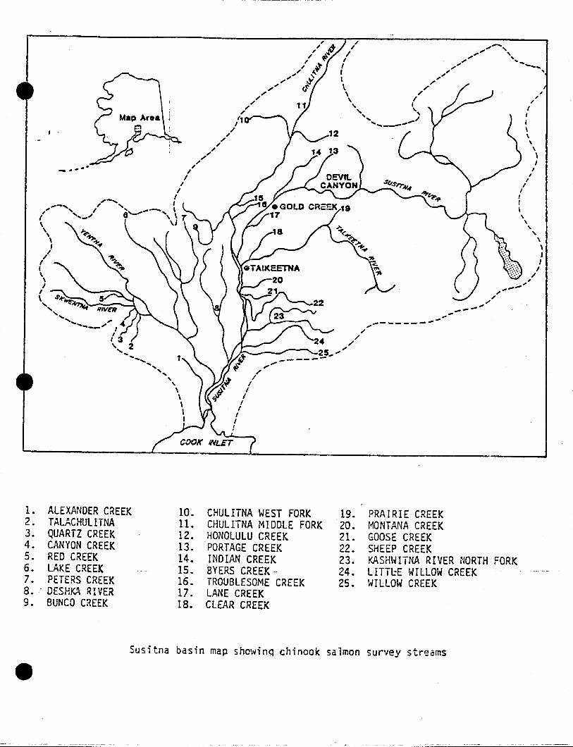
~ ....
l. ALEXANDER CREEK 10. CHULITNA WEST FORK 19. PRAIRIE CREEK2. TALACHUllTNA 11. CHULITNA MIDDLE FORK 20. HONTANA CREEK3. QUARTZ CREEK 12. HONOLULU CREEK 2l. GOOSE CREEK4. CANYON CREEK 13. PORTAGE CREEK 22. SHEEP CREEK5. RED CREEK 14. INDIAN CREEK 23. KASHWITNA RIVER NORTH FORK6. LAKE CREEK 15. BYERS CREEK 24. LITftE WILLOW CREEK7. PETERS CREEK 16. TROUBLESOME CREEK 25. WILLOW CREEK8. . DESHKA RIVER 17. LANE CREEK9. BUNCO CREEK 18. CLEAR CREEK
Susitna basin map showinQ chinook salmon survey streams

TALKEETNA
I- -5 River Mil •• \
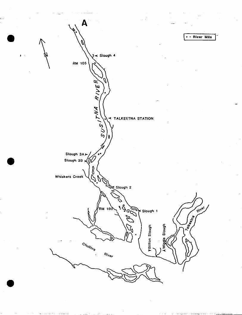
, • - River Mile 1-
TALKEETNA STATION.
Whiskers Creek
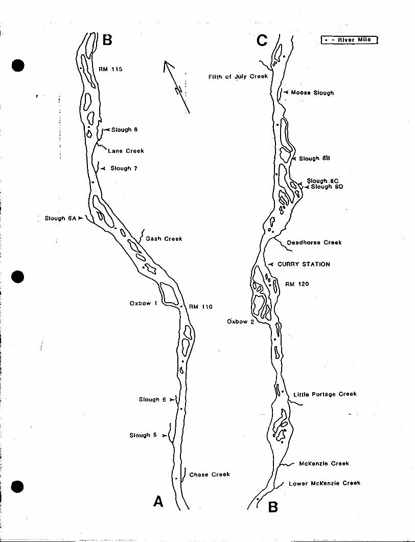
;et!
'.'
. Slougtl ~A ~
B
115
Lane Creek
Oxbow
Slougll 5 ~
A
110
I . - River Mile
~ Moose Siougl'l
Slougtl a13
~Iougl'l .8C~ Slougl'l 80
RM 120
Little Portage Creek
McKenzie Creek
Lower McKenzie Creek
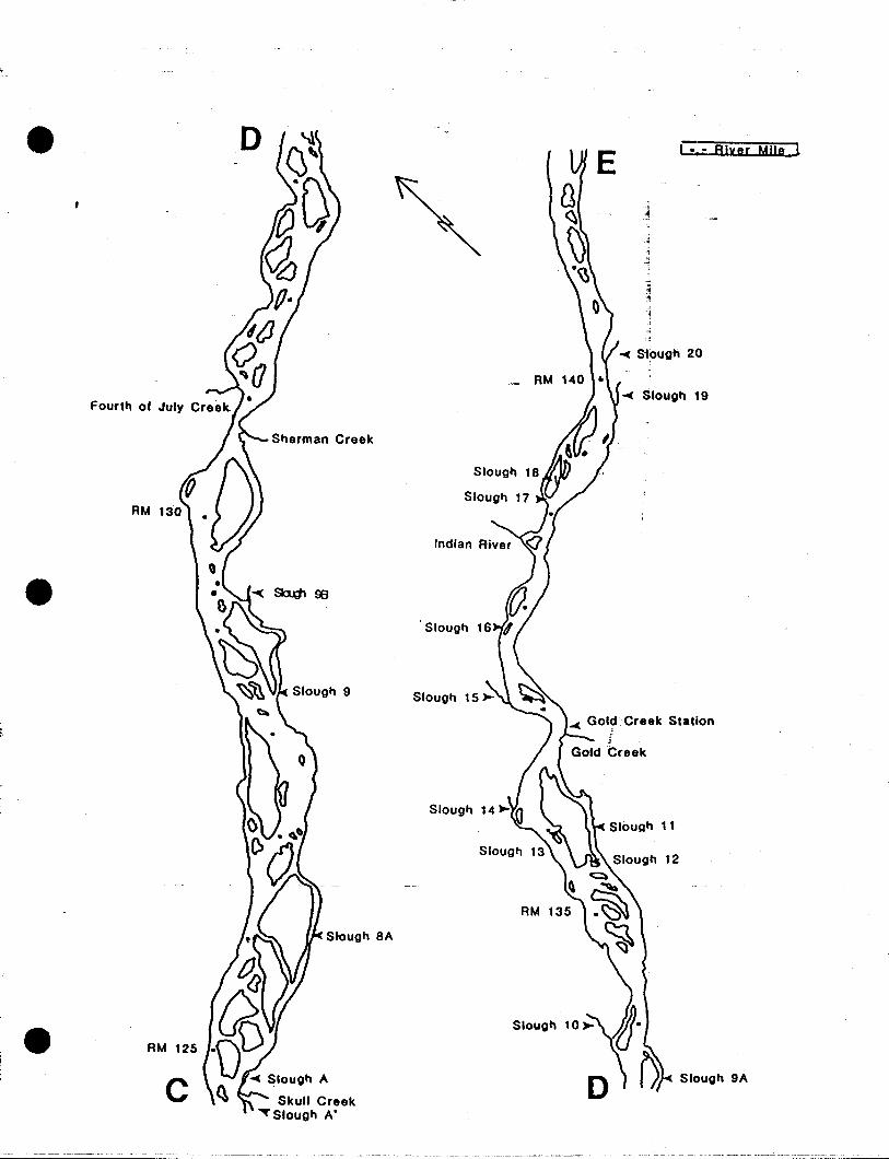
Slough 9A
12
I .:- Rlyer Mile 1
-~
...c Si,ough 20
~ GOljCreek Station
_ AM
AM
Siougll
Siougll 17
Slough
Slough SA
Sherman Creek
...c Slough A
Skull Creek""'f Slough A'
o
c
AM
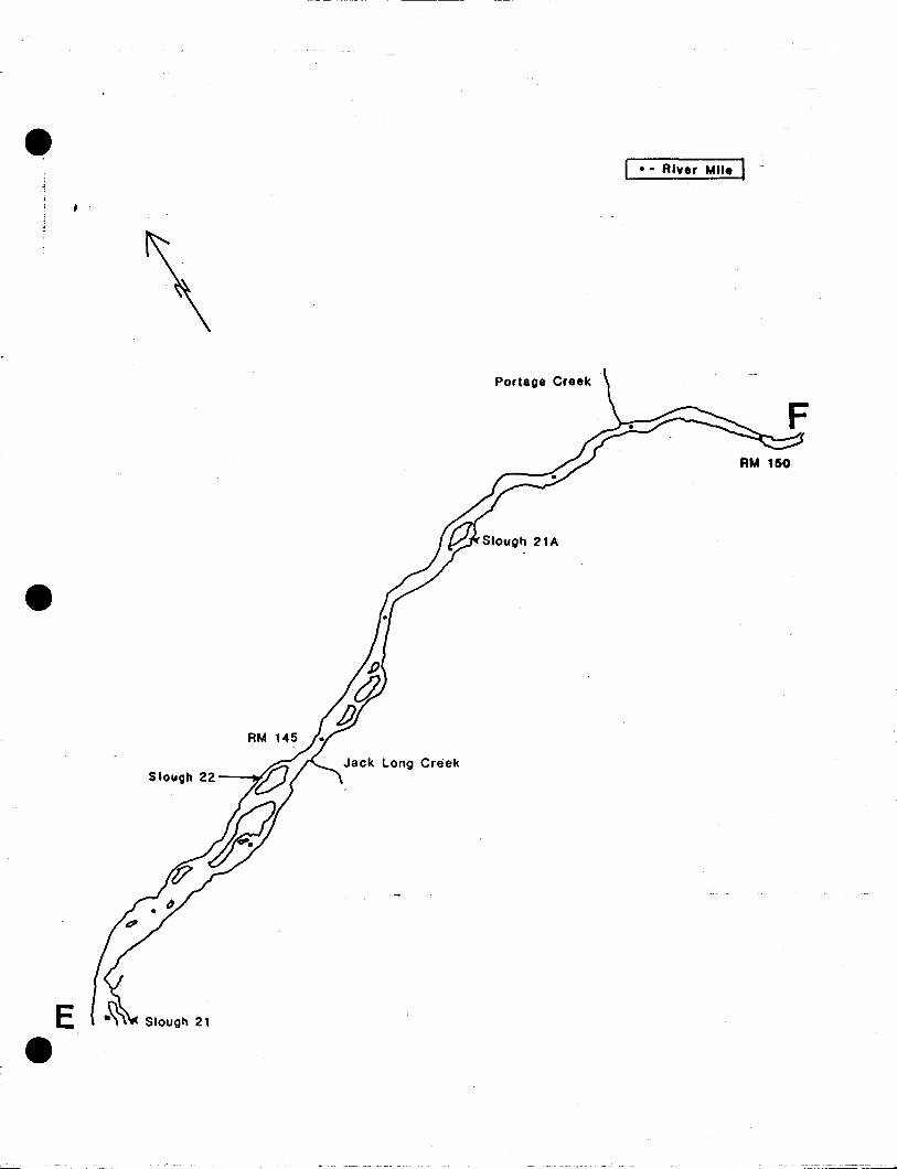
, .
Ee
SlouQh 22
Siougll 21
Jack Long Creek
Portage Creek
I .. River Mile I-
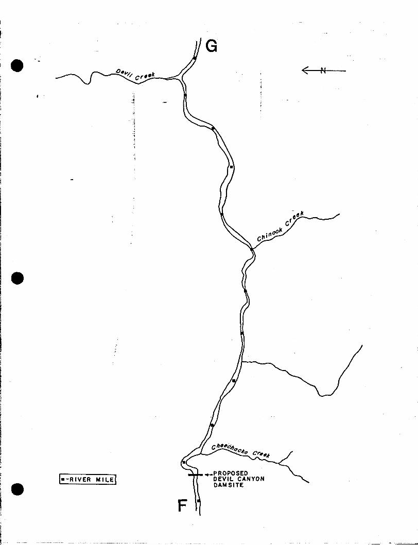
!II
II,f
I--RIVER MILE]
F
.-PROPOSEDDEVIL CANYONDAMSITE
< N
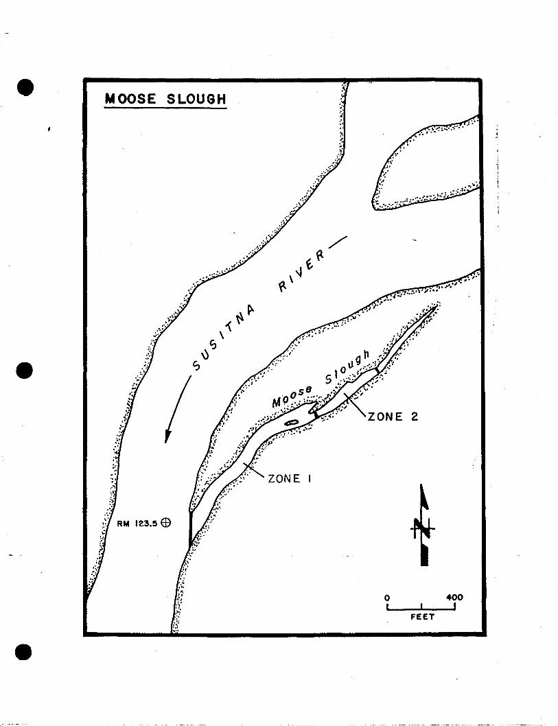
MOOSE SLOUGH
RM 123.5 E9
~.
';
~.
""
oI
2
FEET
400I
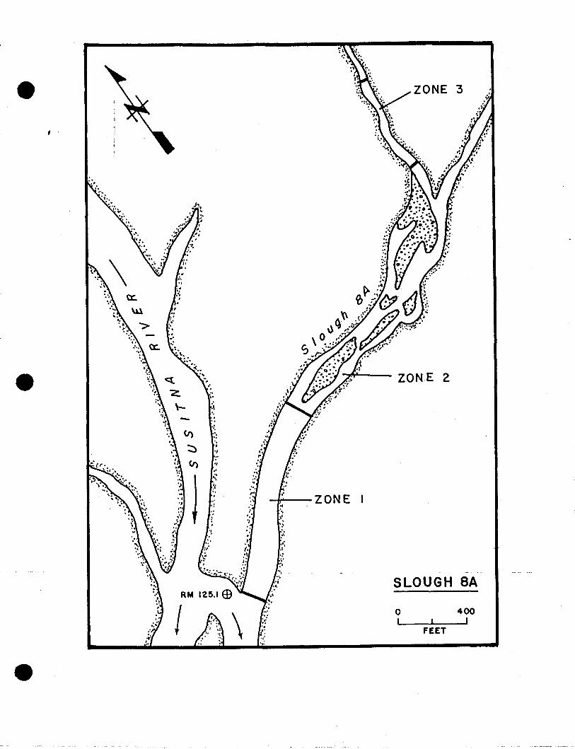
ZONE 2
SLOUGH SA
\
"
','";,
./
'"
-4f'--- Z 0 NE:'"
""...,',.',
.;,s,)
','
oI
FEET
400I

: f:". ,-
.", :.
.''{
...
:3
ZONE 2
SLOUGH 9o, 400_ ......_~,__--.-J,
FEET
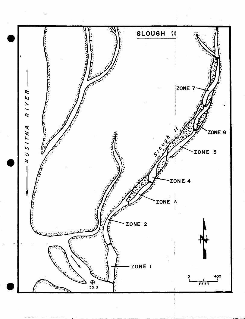
400I
oI
2
SLOUGH
ZONE
:\.~
.'
""t'..,.....~
..'.,.
Q::'!'.
~:"
~
.....Q::
'q:
<:...........CI)
~5
">

; ,-~
APPENDIX 6
ADULT ANADROMOUS FISHERIES STUDIES
General Equipment, Camp Maintenance and Camp Policy
GENERAL EQUIPMENT AND CAMP MAINTENANCE, AND CAMP POLICY
Camp Maintenance
Maintaining a clean and efficient camp site is required. A few of thethings to check are:
1.
2.
3.
4.
5.
6.
Maintenance of tent camp and other installations will beperformed as necessary. All materials neciessary will beprovided. .
Grounds will be kept free of liter. All garbage will be baggedup and at minimum disposed of at the nearest sanitary landfillonce a week. Special precautions should De observed to insurethat garbage does not attract bears and o~her scavenger species.
Upon completion of the summer season, all camp equipment will becleaned preparatory to win~er storage.
All sampling nets, tents and tarps must be dry before beingstored.
A comrlete camp inventory will be taken by the crew leader atthe c ose of the field season. .
All equipment will be brought in when the field station isdisbanded in the fall.
Camp Pol icy
1. No alcoholic beverages are to be stored in areas open to publicview including cook tents. If alcohol is consumed at a camp anemployee must be off-dut~ and under no circumstances shall he orshe engage in the operatlon of any state equipment, includingboats and motors nor shall he or she return to duty status underthe influence of alcohol.
2. The crew leader of each sampling station shall establish a policyon living standards and personnel behavior in accordance withnormal guidelines.
3. All sampling stations will operate seven days a week, 24 hours aday. No crew leader shall be off location for more than 24 hoursunless specifically authorized by the AlA Project leader or oneof his assistants. Time-off for individual crew members shall bescheduled by the crew leader and it shall be his option as towhether sampling duties allow time-off from the Jocation.
4. All AlA employees will be required to act in a professionalmanner at all times and shall be especially courteous to thepublic.
5. It will be the responsibility of the crew leader to report anyequipment abuse to the AlA Project leader or one of hisassistants and to insure that no abuse does occur. Additionally,the crew leader must also report within 24 hours to the abovecited authority, any line 500 equipment loss which occurs.
Equipment Maintenance
Equipment maintenance is perhaps one of the most important operations youwill perform during the field season. The outboard motors and generatorsmust be kept in good operating condition or the whole program will suffer.
It will be the crew leader's responsibility to assign the mostknowledgeable member of the crew to the job of maintaining and servicingthe equi pment. It wi 11 be thi s persons respons ibil ity to see that allequipment is kept in operating condition.
Outboard Motors
9.
8.
10.
6.7.
4.5.
Your outboard motor will perform longer and give less trouble if thesesuggestions are followed:
1. The correct outboard fuel mixture is 50:1. Always pour the oilinto the tank first, then add 2 or 3 gaTTons of gas and mixthoroughly, then fill tank to capacity always using a largefunnel and chamois filter.
2. Chainsaws have a fuel mixture of 25:1. Chainsaw gas should bemixed in a 5 gallon can and clearly marked that it is chainsawfuel.
3. When mixing gasoline or filling the tanks of the generator, stoveor lantern, keep the following in mind:
a. Always mix fuel tanks or equipment under cover to preventwater contamination. Always use a funnel and filter.
b. Fill camp stoves and lanterns outside as the danger of fireis very real.
c. A little extra effort toward cleanliness will pay in hoursof trouble free operation.
Always place outboard in neutral when starting.Check dai1* the clamp screws that hold the outboard to thetransom.lso routinely check the motor for loose screws andbolts, cracks, and break, especially in the area of the lowerunit.Never start or run an outboard in the tilted position.In the normal operation of a water pump, a "tell-tale" stream ofwater is discharged from a hole in the bottom edge of the cowlingor from the back of the shaft. If this stream of water stops,the water pump is not working and the motor should be shut off.The side plate over the water intake can be removed for temporaryrelief as it may be plugged. If the pump continues not tofunction, the outboard should not be run, and a report to basecampshould---h.e made.Check the grease in the lower unit of prop outboards once a week,and drain and replace grease ever{ three weeks. Jet unlts mustbe greased daily. This is crucia. Special grease guns will beprovided.If the skeg or jet unit hits bottom, check the screws fortightness and housing damage.If your outboard will not start, check the following:a. Check to see if the fuel line is connected to the motor and
the tank and not pinched or kinked.b. Check to see if there is water in the gasoline.c. Check to see that the engine is not flooded.
, .
d. Check the spark plugs as they may be fouled or defective(replace if needed).
11. All outboards are to be tilted in the up position when moored atmainstem stations to preclude silt accumulation in the jet unitor water pump and skeg or housin~ damage.
Lastly, it should be emphasized that the salmon enumeration counts andsampling mU,st continue, as they are very; important to the program. Allstations wi11 be provided with a spare out,board and Anchorage will replaceall inopera~ive outboards as soon as possible.
Boats
1. BQats are to be kept clean and free of loose tools and debris,a~d moored at locations where they are not subject to damage bywave action or through contact with the river bottom in rockladen areas.
2. Each crew leader will be responsible for maintaining mooringstakes on the river bank sufficient for the boats assigned to hissubproject plus one transient craft. Further responsibilityincludes maintaining a skookum bow line on each assigned craftand insuring that each boat is properly moored at the end of eachwork day to preclude possible loss or damage.
Generators;
Portable generators will be supplied to all field camps. Their maintenancefo11 ows the same li ne as for the outboards. Si nce the generators have4-cycle engines, mixed gas must not be used. The crankcase oil reservoirshould be checked daily and maintained at the full level. After 25 hoursof operation the oil should be changed. Spark plugs should be checkedafter every five (5) hours of operation.
Food Orders
Grocery orders wi 11 be placed wi th the Anchorage offi ce once a week. Agrocery request list will be supplied to each camp. Please order all foodby correspondi ng numbers. Thi s saves a lot of time on the radi 0 and/ortelephone and also lessens the changes of mix-ups of orders.
CANNED MEALS COND-IMENTS
1. baked beans 44. molasses2. chili 45. cucumber pickles3. kidney beans 46. dill pickles4. pork and beans 47. sweet pickles ~~
5. chow mein 48. honey6. hash 49. horseradish7. sloppy joes 50. ketchup8. stew, "Dinty Moore" 51. mustard
52. relishBEVERAGES 53. mayonaise
54. mixed nuts9. canned soda 55. olives
10. canned soda, diet 56. syrup11. coffee, instant 57. vinegar12. coffee, regular grind 58. tarter suace13. tea, bags14. tea, ins tant DAIRY15. Swiss Miss
59. "Coffeemate"BREAD AND CRACKERS 60. canned milk
6l. Milkman16. pretzels17. hot dog buns DESSERTS (cookies, jello, candy, gum)18. hamburger buns19. triscuits 62. chocolate chips20. pilot bread 63. candy bars21. ritz crackers 64. chocolate chip cookies22. soda crackers 65. Oreo cookies23. whi te, loaf 66. fig newtons24. wheat, loaf 67. gum, assorted25. assorted crackers 68. Jello gelatin
69. LifesaversCAKE AND MUFFIN MIXES 70. chocolate puddings _
71. vanilla puddings26. blueberry muffins 72. butterscotch puddings27. brownie mix 73. marshmallows28. chocolate cake 74. oatmeal cookies29. white cake 75. Chocolate mint cookies30. ye11 ow ca ke31. other cake DETERGENTS AND CLEANSERS32. corn bread muffins33. snack-n-cake 76. Ajax
77. bar soapCEREALS 78. bleach
79. Borax34. Frosted Flakes 80. cold water "All"35. cream of rice 8l. liquid dishwashing soap36. cream of wheat 82. scouring pads (Brillo &S.O.S)37. quick rolled oats 83. sponges38. variety packe 39. wheaties40. grape nuts41. instant oatmeal42. regular oatmeal43. gnts

CHEESE FLOUR
, . 84.: Parmesan (canned) 116. bisquick85.' mozzarella 117. krusteaz86.: monterey jack 118. white87. swiss 119. whole wheat88. mil d cheddar89. sharp cheddar NON EDIBLE90. mozzarella
120. wax paperFROSTING MIX 12l. saran wrap
122. plastic bags, small9l. chocolate 123. garbage bags92. white 124. aluminum foil93. other 125. "Cutters"
126. matchesFRESH FRUIT 127. paper towels
128. napkins94. apples 129. mosqu i to coil s95. bananas 130. toilet paper96. grapes 13l. toothpicks97. melons98. oranges OIL AND BUTTER99. peaches
100. pears 132. butter, canned10I. grapefruits 133. margarine102. other, in season 134. olive oil
135. shortening, cannedCANNED FRUIT 136. "Wesson" oil
137. creamy peanut butter103. applesauce 138. chunky peanut butter104. apricots105. fruit cocktail POULTRY106. grapefruit slices107. mandarin oranges 139. chi cken, fresh108. peaches 140. chicken, canned109. pears 14l. eggs, 1 dozen110. pineappleIll. raisins PRESERVES
GRAIN PRODUCTS 142. apple butter~~ 143. apricot
112. egg noodles 144. blackberry113. elbow macaroni 145. boysenberry114. spaghetti 146. grape115. lasagna noodles 147. raspberry
148. strawberry149. Peach


VEGETABLES, FRESH
229. 1ettuce230. mushrooms231. onions232. potatoes, 10 lb. sac233. radi shes234. tomatoes235. cabbage236. zucchini237. cucumbers238. misc., in season
- ----------~-----------------------~~~-

APPENDIX 7
ADULT ANADROMOUS FISHERIES STUDIES
Fish Identification

THEFRESHWATER
reprinted with the permissiun uf:
Alaska NurthWest Publishing Cu.130 Secund Ave. SuuthEdmunds. Washingtun 98020

, .
~RIRSHRNORTHWESTPUBllSHINDCOMPRNYAnchorage, Alaska
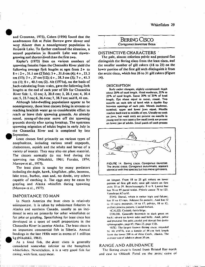
eand Crossman. 1973). Cohen (1954) found that theanadromous fish at Point Barrow grew slower andwere thinner than ,a nonmigratory population inIkrba~ik Lake. To (urther confound the situation, asecond population ;in Ikroavik Lake was slowergrowing and shorter~livedthan the first two.
Kepler's (1973) 1fata on various numbers ofspawning females fr~m theChatanika River yield thefollowing average fork lengths at ages from 2+ to8 +: 2+.31.1 em (2 'fish); 3 +,31.6 em (4); 4+.33.3em (15); 5+. 37 cm(12); 6 +. 38.3 em (5): 7 +. 41.3em (I); 8+ , 40.5 em (2). Alt (l971a), on the basis of
_baek-calculating from scales, gave the following forklengths at the end of each year of life for ChatanikaRiver fish: I, 12 em; 2. 20.8 em; 3, 26.I.cm; 4. 30.4em; 5. 33.7 em; 6. 36.4 em; 7, 38.7 em; and 8, 41 em.
Although lake-dwelling populations appear to benonmigratory, those least ciscocs living in streams orreaching brackish water go to considerable effort tor~ach or leave their spawning grounds. As alreadynot~d. young-of-the-year move off the spawninggrounds shortly after spring breakup. The upstreamspawning migration of adults begins in early July inthe Chatanika River and is completed by late
_ September.• Least ciscoes feed primarily on various types of
zooplankton, including various small copepods,c1adocerans. mysids and the adults and larvae of avariery of insecrs. They may also eat plant material.The ciscoes normally do not feed during rhespawning run (Nikolskii. 1961; Furniss. 1974;~10rrow et al.. 1977).
The least Cisco is sought - by many predatorsincluding the tagle. hawk. kingfisher. pike. inconnu.lake troUl, burbot, man and. no doubt. any otherscapable of carching it. The eggs may be earen bygrayling and Alaska whitefiSh during spawning(Morrow et al.. 1977).
IMPORTANCE TO MANIn Nonh America rhe least cisco is relatively
unimponant. ([ is raken by subsistence fisheries inAlaska and nonhern Canada. usually as an incidental in nets ser primarily for other whirefishes orfor. pike or grayling. Spearfishing for leasr cisco hasdeveloped as a spon of small proponions in theChatanika River in interior Alaska. The least cisco isan important commercial fish in Siberia. Annuallandings in the late 1930s were in excess of I million
_ kg(Nikolskii. 1961).• :\s a food fish. the ,least cisco is generally
,"onsidcred somewhat inferior to the humpback\\ hitcfishes. Nevertheless. it is a very good fish forl'aling. wilh firm. tasty meat.
Whitefishes 29
BERING CISCOCoregonus (oureltae Bean
DISTINCTIVE CHARACTERSThe pale. almost colorless pelvic and pectoral fins
distinguish the Bering cisco from the least cisco. andthe smaller number of gill rakers (18 to 25) on thelower portion of the first gill atch distinguish it fromthe arctic cisco. which has 26 to 31 gill rakers (Figure14).
DESCRIPTIONBody rather elongate. slightly compressed: depth
about 2001. of totallcngth. Head moderate. 22.,. to25". of lotal length. Snout 20.,. to·'25.,. of headlength. Eye about equal to snout, round. Twonoslrils on each side of head. with a double flapbetween openings of each pair. Mouth moderate,terminal: upper and lower jaws equal. Maxillareaches backward to middle of eye. Usually no teethon jaws. but weale teeth are present on maxilla inyoung and in rare cases a few small tCCl.h are presenton lower jaw of adults. Small patch of teeth present
'1'1~'/~:.
"OC"'" .. ~... ~ -.,....:~.~~'.", .j~ .\..,~
FIGURE 14. Bering cisco. Coregonus laureltae.The arctic CISCO. Coregonus aurumnalis. appearsIdenlical with Ihis species but has more gill rakers.
on longue. From 18 to 15 gill rakers on lowerponion of lirsl gill arch: 10lal gill rakers on limJrch: 35 10 39. Branchioslegals: 8 10 9. Lalerallinehas 761095 pored scales. Pyloric cae.:a: 71 10 123.Vcnebrae: 6210 65.
FINS: Dorsal. which is ralher high and fakalc.has II 10 IJ rays. Adipose lin prescnI. Anal has 1210 I~ rays:p<.'Clorals.l-~10 17: p<="·ics. 10 10 12.J'llIary pro<:css preseOl. Caudal forked.
"CALES. Cycloid. fairly large.COLOR. Generally brownish 10 dark green on
hack: "h'erYon lower sides and belly. Anal. pc"'icand p...'Cloral lins pale; caudal and dorsal lins dus""lpholographs. page 115: 1'\ale22. pa~c 1331.
'iIZE: The largesl known Bcring .:is.:o. re...·ordcd~w :\11 11'1731. was a femalc: .,f ~ll cm fork lcnglhfrom the Inwer SIXI ItI of Hess Creek, Alaska. The.1\er3\!e Sile of adults is abt,ul 3() cm.
RANGEANDABUNDANCEThe Ikring ..:i,,"o is found from Bristol Bay north
and casl III OhllO" Poini on the ~Hcti..: ..:oa,t of
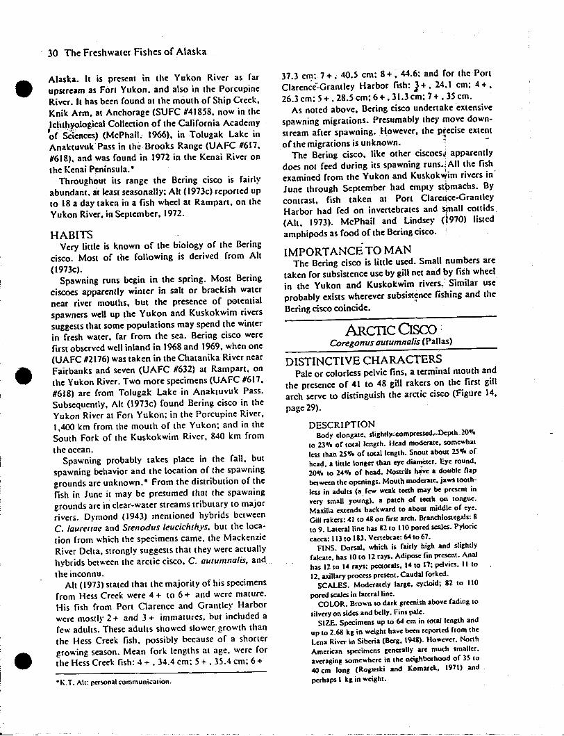
30 The Freshwater Fishes of Alaska
Alaska. It is present in the Yukon River as far
upstream as Fort Yukon. and also in the Porcupine
River. It has been found at the mouth of Ship Creek.
Knik Arm. at Anchorage (SUFC #41858. now in the
,1c~tl;ay()logical Collection of the California Academy
of Sciences) (McPhail. 1966). in Tolugak Lake in
Anaktuvul(Pass in the Brooks Range (UAFC #617.
#618). and was found in 1972 in the Kenai River on
the Kenai Peninsula.·
Throughout its range the Bering cisco is fairly
abundant. at least seasonally; All (l973c) reponed up
to 18 a day taken in a fish wheel at Rampart. on the
Yukon River. in September, 1972.
HABITSVery little is known of the biology of the Bering
cisco. Most of the following is derived from All
(I97Jc).Spawning runs begin in the spring. Most Bering
ciscoes apparently wimer in salt or brackish water
near river mouths, but the presence of potential
spawners well up the Vukon and Kuskokwim rivers
suggests that some populations may spend the winter
in fresh water. far from the sea. Bering cisco were
first observed well inland in 1968 and 1969, when one
(UAFC #2176) was taken in the Chatanika River near
Fairbanks and seven (UAFC #632) at Rampart. on
the Yukon River. Two more specimens (UAFC #617,
#618) are from Tolugak Lake in Anakwvuk Pass.
Subsequently. Aft (I973c) found Bering cisco in the
Yukon River at FOri Yukon; in the Porcupine River.
1.400 km from the mouth of the Yukon; and in the
South Fork of the Kuskokwim River. 840 km from
the ocean.Spawning probably takes place in the fall. but
spawning behavior and the location of the spawning
grounds are unknown.· From the distribution of the
fish in June it may be presumed that the spawning
grounds are in clear-water streams tributary to major
rivers. Dymond (1943) mentioned hybrids between
C. laureuae and Stenodus leucichthys. but the loca
tion from which the specimens came. the Mackenzie
River Delta. strongly suggests that they were actually
hybrids between the arctic cisco. C. autumnalis. and
the inconnu.Aft (1973) stated that the majority of his specimens
from Hess Creek were 4 + to 6 + and were malOre.
His fish from Port Clarence and Grantley Harbor
were mostly 2 + and 3 + immawres. but included a
few adults. These adults showed slower growth than
the Hess Creek fish. possibly because of a shorter
growing season. Mean fork lengths at age. were for
the Hess Creek fish: 4 + • 34.4 cm; 5 + • 35.4 cm; 6 +
°K.T. All: pcrwnal communication.
37.3 em.; 7 +. 40.5 cm; 8 +. 44.6: and for the Port
Clarence':Grantley Harbor fish: J+. 24.1 cm; 4 + •
26.3 cm; 5 +.28.5 em; 6+.31.3 em; 7 +.35 cm.
As noted above. Bering cisco undertake extensive
spawning migrations. Presumably they move down
stream after spawning. However. the precise extent
of the migrations is unkno~n. ~ -
The Bering cisco. like other ciscoes,' apparently
does not feed during itS spawning runs.~AII the fish
examined from the Yukon and Kuskokwim rivers in'
June through September had empty sl~machs. By
contrast. fish taken at Port Clarence-Grantley
Harbor had fed on invertebrates and small eottids
(Alt. 1973). McPhail and Lindsey <l970) listed
amphipods as food of the Bering cisco.
IMPORTANCE TO MANThe Bering cisco is little used. Small numbers are
taken for subsistence use by gill net and by fish wheel
in the Vukon and Kuskokwim rivers. Similar use
probably exists wherever sUbsist~nce fishing and the
Bering cisco coincide.
ARCTIC CIsco ;Coregonus autumnalis (Pallas)
DISTINCTIVE CHARACTERSPale or colorless pelvic fins. a terminal mouth and
the presence of 41 to 48 gill rakers on the first gill
arch serve to distinguish the arctic cisco (Figure 14.
page 29).
DESCRIPTIONBody elongate. slighlty..compressed.-.Dcpth.. 20o;,
10 23'" of total length. Head moderale. somewhat
less Ihan 25'1. of total Ienglh. Snoul about 25.,. of
heac,1. a little longer than eye dia~er. Eye round.
20'1, 10 24'1, of head. NOSlrils h,ve a double nap
between Ihe openings. Mouth moderale. jaws looth·
less in adults (a. few weak leeth may be presenl in
very small young). a palch of leeth on longue.
Maxilla extends backward to about middle of eye.
Gill rakers: 41 to 48 on lirst arch. BranchioSlegals: 8
109. Laleralline has 8210 110 pored scales. Pyloric
caeca: 113 to 183. Venebrae:641067.
FINS. Dorsal. which is fairly high and slightly
falcate. has 1010 12 rays. Adipose fin present. Anal
has 1210 14 rays; pectorals. 1410 17; pelvics. 11 to
12. axillary process presenl. Caudal forked.
SCALES. Moderalely large. cycloid; 82 10 110
pored scales in lateral line.COLOR. Brown 10 dark greenish above fading 10
silvery on sides and belly. Fins pale.
SIZE. Specimens up 10 64 cm in lotal length and
up 10 2.68 kg in weighl have b«n reponed from Ihe
Lena River in Siberia (Berg. 1948). However. Nonh
American specimens generally are much smaller.
averaging wmewhere in Ihe neighborhood of 3S to
.co cm tong (Roguski and Komarek. 1971) and
perhaps 1 kg in weight.

32 The Freshwater Fishes of Alaska
.stems in Washington. Montana. British Columbia
~nd the, Yukon Territory; and from the Chignik.
Naknek: and Wood river syStems in southwestern
Alaska.; It is not known outside of North America.
Whetever it is foun~. it seems to be quite abundant.
HABITSDetails of breeding behavior of the pygmy white·
fish arc unknown. Spawning takes place at night in
late fall and early winter (November to January) at
water temperatures of about 4°C or colder.
Spawning grounds appear to be on gravel in lake
shallows and in streams. Presumably the eggs are
broadcast; then they settle into interstices in the
gravel and hatch the following spring. In the Bristol
Bay region. the eggs are about .24 cm in diameter
(Heard and Hartman. 1966). somewhat larger than
the .2 cm reported for Lake Superior fish (Eschmeyer
and Bailey. (955). Egg number varies between 103
and 1.153 per'female in Bristol Bay fish. a greater
average number than in Lake Superior fish. Males
may become sexually mature at as early an age as a
year; females. a yearlater(Weisel et at., 1973).
Growth of the pygmy whitefish is very slow and
shows considerable variation from one population to
..another. In general, females grow faster than males.
_although in some populations the males grow faster
than females during the first year (Eschmeyer and
Bailey. 1955). (n Brooks Lake. Alaska, the average 3
year-old fish was about 7 cm in fork length. while in
South Bay, Naknek Lake. fish of the same age
averaged about 11.6 cm. The maximum age recorded
for fish in the Naknek system was 5 + (Heard and
Hartman. (966). but ages up to 9+ have been nOted
in Maclure Lake. British Columbia (McCart. 1965).
The pygmy whitefish does not make extended
migrations. However. it does move on to the
spawning areas in the early winter and presumably"
back into deeper water after spawning.
Food of the pygmy whitefish includes a rather wide
variety of items. Listed as most important in the
Naknek system were c1adocerans. dipteran (chiefly
Chironomidae) larvae and pupae. adult Diptera and
nymphs of Plecoptera. Other food included diatoms
and other algae, pelecypods, nematodes. arachnids
and fish eggs (Kendall, In I; Heard and Hartman.
1966). In Lake Superior. ostracods and amphipods
were the principal foods (Eschmeyer and Bailey.
1955). The pygmy whitefish feeds almost exclusively
during daylight hours, making "short distinct jabs or
darts, apparently at specific food items. such as
_ insect larvae. when picking up mouthfuls of boltom
material." They may also rise off the bOllom and
take specific items from the current (Heard and
Hartman. 1966).
There is a distinCt positive correlation between the
diet and the average size of individu~s in a popu
lation. Fish belonging to groups in which .insects are
the dietary mainstay are, on the average. much larger
than those in which zooplankton is the chief food
(Heard and Hartman. (966).,McCart (1970) found
forms with high and low gill raker counts in
Aleknagik. Naknek and Chignik lakes in Alaska and
suggested that these represented sibling species. The
high-count form. which was found almost exclusively
in deep water. fed on plankton and grew more
slowly. By contrast. the low-count form was found in
both shallow and deep water, ate mostly insects and
grew faster. However. the difference in growth rates
through age IV in Chignik Lake does not appear to
be significant. More careful analyses of larger
samples are needed.As noted above. the pygmy whitefish is found in
both deep and shallow water., In Lake Superior. it
was reported as most abundant at depths of 46 to
71 m (Eschmeyer and Bailey. 1955; Dryer. 1966). In
the Naknek system. the species was found at depths
to 168 m but was also abundant in the shallows
(Heard and Hartman. (966). McCart (1970) found
that in Chignik Lake beach seine samples were
composed entirely of the form with the low gill raker
count, while in gill nets set at 30 m ordeeper, the
high-count form accounted for 36.2010 of the fish
taken.
IMPORTANCE TO MANThe pygmy whitefish is of no direct importance to
man. It is too small and scarce and of too limited
distribution to be profitable for any kind of fishery.
However, it is undoubtedlY fed upon by predatory
fishes such as charr, pike and burbot and may
contribute to the overall scheme of competition for
food. In this respect. it is interesting to note that the
pygmy whitefish attains its greatest size in waters
where there is no competition from other coregonids
(McCart. 1965).
ROUND WHITEFlSHProsopium cylindraceum-(Pallas)
DISTINCTIVE CHARACTERSThe narrow, rather pointed snout, the 74 or more
pored scales in the lateral line. and the 50 or more
pyloric caeca distinguish the round whitefish (Figure
16).
DESCRIPTIONBody elongate. cylindrical. slender: depth IS'" to
20'" of fork length. Head rdativel~' shon. its length
averaging 20.,. of fork length. Snout shon. aboUt
22-;-. of head. pointed when secn from above. Eye
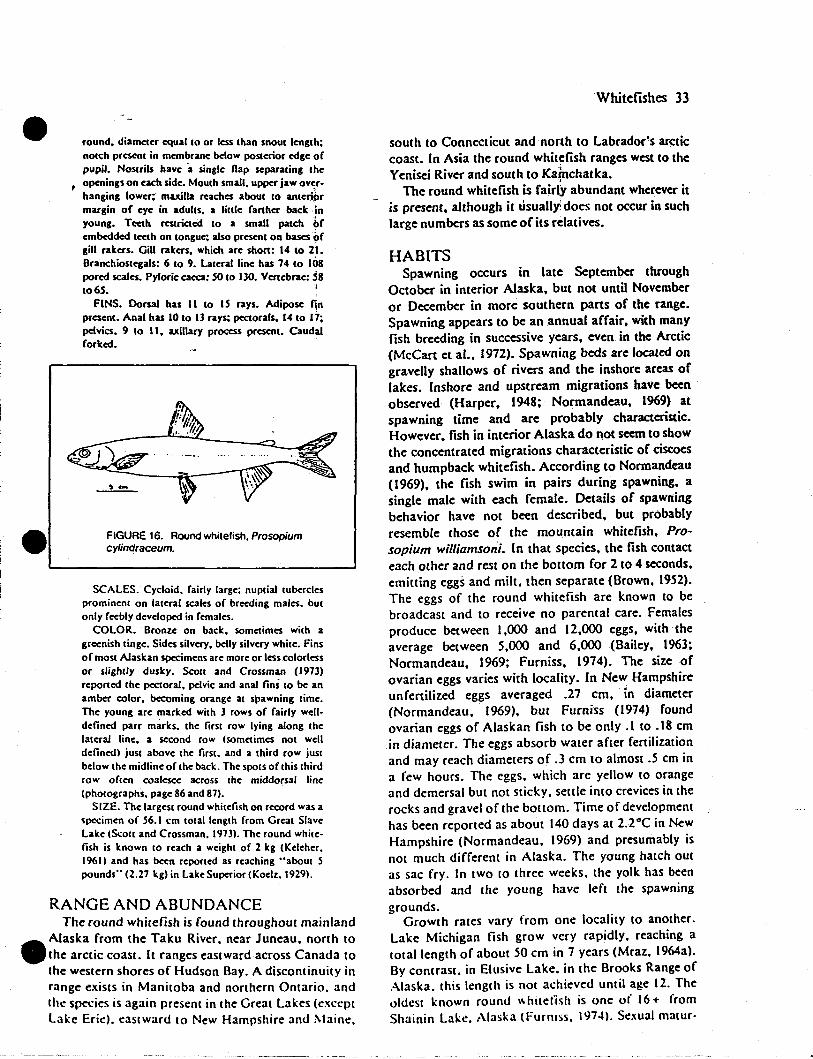
round. diameter equal to or less than snout length;notch present in membrane below posterior cdge ofpupil. Noscrils have "a single flap separating the
, openings on each sidc. Mouth small. upper jaw ov~r·
hanging Iowcr; maxilla reachc:s about to antcri.~r
margin of eyc in adults. a littlc farther back inyoung. Teeth restricted to a small patch ofembedded teeth on tongue; also present on bases ~fgill rakers. Gill rakers. which are short: 14 to 2l.Branchiostegals: 6 to 9. lateral linc has 74 to 108porcd scales. Pyloric caeca: 50 to 130. Vertebrac:'8to 65.
FINS. Dorsal has II to 15 rays. Adipose finpresent. Anal has 10 to lJ rays; pectorals. 14 to 17;pdvics. 9 to II. axillary process present. Caudalforlecd.
, ....
FIGURE 16. Round whitelish. Prosopiumcylindraceum.
SCALES. Cycloid. fairly large; nuptial tuberclesprominent on lateral scales of breeding males. butonly feebly dcvelopc:d in females.
COLOR. Bronze on back. sometimes wilh agreenish tinge. Sides silvery. belly silvery whilC. Finsof most Alaskan specimcns are more or less colorlessor slightly dusley. ScOll and Crossman (1973)reportcd the pectoral, pelvic and anal fins 10 be anamber color. becoming orange al spawning lime.The young are markcd with J rows of fairly welldefined parr marks. the first row lying along thelaleral line. a second row (sometimes nOl welldefincd) just above the firsl, and a lhird row justbelow lhe midline of lhe back. The SPOlS of lhis lhirdrow oflen coalescc across lhc middorsal linc(pholographs. pagc 86 and 87).
SIZE. Thc largesl round whilefish on record was aspecimen of 56.1 cm 10lal Ienglh from Greal SlaveLake (ScOl( and Crossman. 1973). The round while·fish is known 10 reach a weighl of 2 kg (Keleher.1961) and has been reported as reaching "aboUl 5pounds" (2.27 kg) in Lake Superior (Koelz. 1929).
RANGE AND ABUNDANCEThe round whitefish is found throughout mainland
..Alaska from the Taku River. near Juneau. north to
.the arctic coast. It ranges eastward across Canada tothe western shores of Hudson Bay. A discontinuity inrange exists in ManilOba and northern Ontario. andIhe species is again present in the Great Lakes (exceptlake Erie). eastward to New Hampshire and ~taine.
Whitefishes 33
south to Connecticut and north to Labrador·s arcticcoast. (n Asia the round whit~fish ranges west to theYenisei River and south to Ka!nchatka.
The round whitefish is fairlY abundant wherever itis present. although it usually does not occur in suchlarge numbers as some of its relatives.
HABITSSpawning occurs in late September through
October in interior Alaska. but not until Novemberor December in more southern pans of the range.Spawning appears to be an annual affair. with manyfish breeding in successive years. even in the Arctic(McCan et al.. 1972). Spawning beds are located ongravelly shallows of rivers and the inshore areas oflakes. Inshore and upstream migrations have beenobserved (Harper. 1948; Normandeau. 1969) atspawning time and are probably characteristic.However. fish in interior Alaska do not seem to showthe concentrated migrations characteristic of ciscoesand humpback Whitefish. According to Normandeau(1969). the fish swim in pairs during spawning. asingle male with each female. Details of spawningbehavior have not been described. but probablyresemble those of the mountain whitefish. Prosopium williamsoni. (n that species. the fish contacteach other and rest on the bottom for 2 to 4 seconds.emitting eggs and milt. then separate (Brown. 1952).The eggs of the round whitefish are known to bebroadcast and to receive no parental care. Femalesproduce between 1.000 and 12.000 eggs. with theaverage between 5.000 and 6.000 (Bailey. 1963;Normandeau. 1969; Furniss. 1914). The size ofovarian eggs varies with locality. In New Hampshireunfenilized eggs averaged .21 cm. in diameter(Normandeau. 1969). but Furniss (1914) foundovarian eggs of Alaskan fish to be only .1 to .18 cmin diameter. The eggs absorb water after fertilizationand may reach diameters of .3 cm to almost .5 cm ina few hours. The eggs. which are yellow to orangeand demersal but not stickY. settle into crevices in therocks and gravel of the boltom. Time of developmenthas been reported as about 140 days at 2.rC in NewHampshire (Normandeau. 1969) and presumably isnot much different in Alaska. The young hatch outas sac fry. (n two to three weeks. the yolk has beenabsorbed and the young have left the spawninggrounds.
Growth rates vary from one locality to another.Lake Michigan lish grow very rapidly. reaching atotal length of about 50 cm in 7 years (Mraz. 1964a).By contrast. in Elusive Lake. in the Brooks Range ofAlaska. this length is not achieved until age 12. Theoldest known round \\ hitefish is one of 16 + fromShainin Lake. Alaska (Furniss. 1914). Sexual matur-
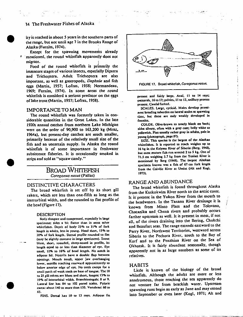
I •
e
34 The Freshwater Fishes of Alaska
ity is reached in about 5 years in the southern parts ofthe range. but not unlil age 7 in the Brooks Range ofAlaska (Furniss. 1974). '
Except for the spawning movemerlts already. mentioned. the rou~d whitefish apparen~ly docs notmigrate. i
Food of the round whitefish is primarily theim~ature stages of various insects. especially Dipteraand Trichoptera. Adult Trichoptera are alsoimportant. as well as gastropods. Daphnia and fisheggs (Martin. 1957; Loftus. 1958; Normandeau.1969; Furniss. 1974). In some areas the roundwhitefish is considerd a serious predator on the eggsoflake trout {Martin. 1957; Loftus. 1958). .
IMPORTANCE TO MANThe round whitefish was formerly taken in con
siderable quantities in the Great Lakes. In the late1920s annual catches from northern Lake Michiganwere on the order of 90.900 to 163.200 kg (Mraz.1964a). but present-day catches are much smaller.primarily because of the relatively small size of thefish and an uncertain supply. In Alaska the roundwhitefish is of some importance in freshwatersubsistence fisheries. It is occasionally smoked instrips and sold as "squaw candy."
BROAD WillTEFISHCoregonus nasus (Pallas)
DISTINCTIVE CHARACTERSThe broad whitefish is set off by its short gill
rakers. which are less than one-fifth as long as..the.interorbital width. and the rounded to fiat profile ofthe head (Figure 17).
DESCRIPTIONBody c10ngate and compressed. especially in large
specimens; sides a bit nailer than in most otherwhitefishes. Dc:pth of body 23'1. to 31.,. of forklength in adults. less in young. Head Short. IS.,. to20"1. of fork length. Dorsal profile rounded to nat(may be slightly concave in large specimens). Snoutblunt. short. rounded. sheep-nosed in profile. itslength equal to or less than diameter of eye. Eyesmall. 12.,. to 16'1. of head length. No notch inadipose .lid. Nostrils have a double nap betweenopenings. Mouth small. upper jaw overhanginglower. maxilla reaching rearward approximately tobelow anterior edge of eye. No teeth except for asmall patch of wealt teeth on base of tongue. The 18to 2S gill ralters arc blunt and short. longest 13.,. to19.,. of interorbital width. Branchiostcgals: 8 or 9.Lateral line has 84 to 102 pored scales. Pyloriccaeca: about 140 to more than ISO. Vertebrae: 60 to6S.
FINS. Dorsal has 10 to 13 rays. Adipose lin
FIGURE 17. Broad whitefish. Coregonus nasus.
present and fairly large. Anal. II to 14 rays;pectorals. 16 to 17; pcIvics. II to 12. axillary processpresent. Caudal forlted.
SCALES. Large. cycloid. Males develop prominent breeding tuberdes on lateral scales at spawningtime. but these arc only wealtly developed infemales.
COLOR. OIivc-brown to nearly black on baa;sides silvery. often with. &RY cast; belly white toyellowish. Fins usually rather gray in adults. pale inyoung (photograph. page 87).
SIZE. This species is the largest of the Alaskanwhitefishes. It is reported to rcach weights up to16 kg in the Kolyma River of Siberia (Berg. 1948).but most mature fISh run around 2 to S kg. One of71.S em weighing S.7 kg from the Yenisci River ismentioned by Berg (/948). The largest Alaskanspecimen !cnown was a fish of 67 em fork lengthfrom the Colville River at Umiat (A1t and Kog(.1973).
RANGE AND ABUNDANCEThe broad whitefish is found throughout Alaska
from the Kuskokwim River north to the arctic coast.It is present in the Yukon River from the mouth tothe headwaters. In the Tanana River drainage it isknown from Minto Rats and the Tolovana.Chatanika and Chena rivers and probably occursfarther upstream as well. It is present in most. if notall. of the rivers draining into the Bering, Chukchiand Beaufort seas. The range extends eastward to thePerry River. Northwest Territories. westward acrossSiberia to the Pechora River. south to the Bay ofKorf and to the Penzhina River on the Sea ofOkhotsk. It is fairly abundant seasonally. thoughapparently not in as large numbers as some of itsrelatives.
HABITSLittle is known of the biology of the broad
whitefish. Although the adults are more or lessanadromous. those reaching the sea apparently donot venture far from brackish water. Upstreamspawning runs begin as early as June and may extendinto September or even later (Kogi. 1971; Alt and
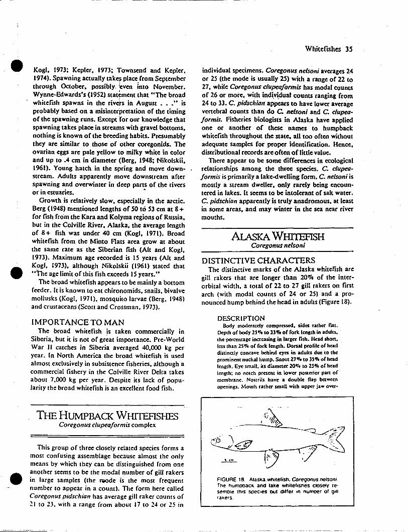
Kogl, 1913: Kepler, 1913; Townsend and Kepler,1914). Spawning actually tak~ place from Septemberthrough October, possibly. ~even into November.Wynne-Edwards's (1952) stattment that uThe broad
- whitefish spawns in the rive'rs in August • • ." isprobably based on a misinterpretation of the timingof the spawning runs. Except for our knowledge thatspawning takes place in streams with gravel bottoms,nothing is known of the breeding habits. Presumablythey are similar to those of other coregonids. Theovarian eggs are pale yellow to milky white in colorand up to .4 cm in diameter (Berg, 1948; Nikolskii,1961). Young hatch in the spring and move downstream. Adults apparently move downstream afterspawning and overwinter in deep parts of the riversor in estuaries. -
Growth is relatively slow, especially in the aretic.Berg (1948) mentioned lengths of SO to S3 cm at 8+for fish froom the Kara and Kolyma regions of Russia,but in the Colville River, Alaska, the average lengthof 8 + fish was under 40 cm (Kogl, 1911). Broadwhitefish from the Minto flats area grow at aboutthe same rate as the Siberian fish (Alt and Kogl,1913). Maximum age recorded is IS years (Alt andKogl, 1973), although Nikolskii (1961) stated that"the age limit of this fish exceeds IS years."
The broad whitefish appears to be mainly a bottomfeeder. It is known to eat chironomids, snails. bivalvemollusks (Kogi. 1971). mosquito larvae (Berg. 1948)and crustaceans (Scott and Crossman. 1973).
IMPORTANCE TO MANThe broad whitefish is taken commercially in
Siberia. but it is not of great importance. Pre-WorldWar II catches in Siberia averaged 40,000 kg peryear. In North America the broad whitefish is usedalmost exclusively in subsistence fisheries, although acommercial fishery in the Colville River Delta takesabout 7.000 kg per year. Despite its lack of popularity the broad whitefish is an excellent food fish.
THE HUMPBACK WHITEFISHESCoregonus clupeaformis complex
This group of three closely related species forms amost confusing assemblage because almost the onlymeans by which they can be distinguished from oneanother seems to be the modal number of gill rakersin large samples (the ~de is the most frequentnumber to appear in a count). The form here calledCoregonus pidschian has average gill raker COUnts of:!l to 23. with a range from about 17 to 24 or :!5 in
Whitefishes 35
individual specimens. Coregonus nelsoni averages 24or 25 (the mode is usually 25) with a range of 22 to27, while Coregonus clupeaformis has modal countsof 26 or more, with indi.vi~ual counts ranging from24 to 33. C. pidschian appears to have lower averagevertebral counts than do C. nelsoni and C. clupeaformis. Fisheries biologists in Alaska have appliedone or another of these names to humpbackwhitefish throughout the state, all too often withoutadequate samples for proper identification. Hence,distributional records are often of little value.
There appear to be some diffc.cences in ecologicalrelationships among the three species. C. clupeaformis is primarily a lake-dwelling form. C. nelsoni ismostly a stream dweller, only rarely being encountered in lakes. It seems to be intolerant of salt water.C. pidschian apparently is truly anadromous, at leastin some areas, and may winter in the sea near rivermouths.
AlAsKA WIllTEFISHCoregonus nelsoni
DISTINCTIVE CHARACfERSThe distinctive marks of the Alaska whitefish are
gill rakers that are longer than 20OTo of the interorbital width. a total of 22 to 21 gill rakers on firstarch (with modal counts of 24 or 25) and a pronounced hump behind the head in adults (Figure 18).
DESCRIPTIONBody moderately compressed. sides rather nat.
Depth of body 25'1. 1033.,. of forle length in adults.the percentage increasing in larg« fish. Head shan.less than 25 'I. of forle length. Dorsal profile of headdistinctly concave behind eyes in adults due to theprominent nuchal hump. Snout l7'1.lo 35'1. of headlength. Eye small. ils diameter 20'1. 10 25'1. of headlength; no notch present in lower posterior pan ofmembrane. Nostrils have a double nap betweenopenings. Mouth rather small with upper jaw over-
FIGURE 18 Alaska whitefish. eoreQOllUS nelsoni.The humooack and lake whiteltsnes closelv reosemole rn,s soec,es out dIffer tn numoer 01 g.1trakers.
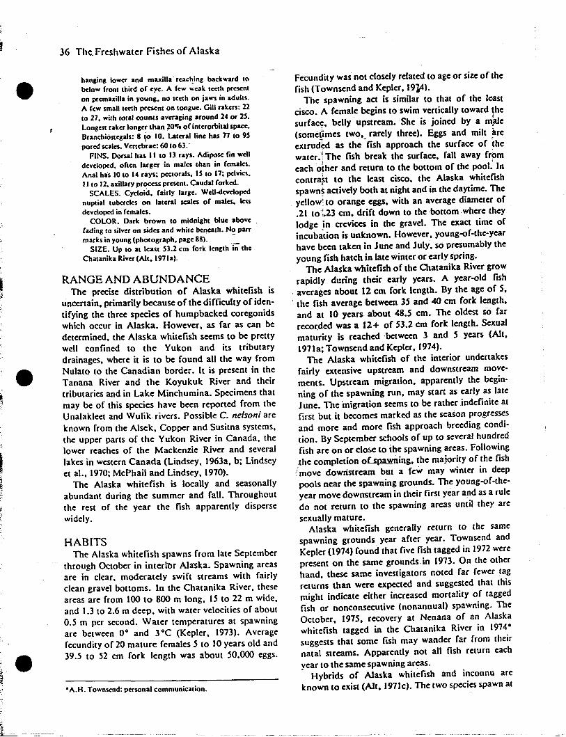
36 The Freshwater Fishes of Alaska
hanging lower and maxilla reaclting backward tobelow front third of eye. A few weak teeth prescnlon premaxilla in young. no teeth on ja..·s in adults.A few small teeth present on tongue. Gill rakers: 22to 27. with total counts averaging around 24 or 25.Longest raker longer than 20.,. of interorbital space.Branchiostegals: 8 ~o 10. Lateral linc has 77 to 9Spored scales. Vcnebrac: 60 to 63.'
FINS. Dorsal hu. II to 13 rays. Adipose fin welldcveloped. oftcn larger in males than in females.Anal has 10 to 14 rays; pectorals. IS to 17; pdvia.II to 12. axillary proccss present. Caudal forked.
SCALES. CYcloid. fairly large. Wcll-dcvdopednuptial tubercles on latcral scales of males. lessdeveloped in females.
COLOR. Dark brown to midnight blue abovefading to silvcr on sides and while beneath. No parrmarks in young (photograph. page 881. -
SIZE. Up to at least S3.2 cm fork length i;;- theChatanika River (Alt. 197Ia).
RANGE AND ABUNDANCEThe precise distribution of Alaska whitefish is
uncertain. primarily because of the difficulty of identifying the three species of humpbacked coregonidswhich occur in Alaska. However. as far as can bedetermined. the Alaska whitefish seems to be prettywell confined to the Yukon and its tributarydrainages, where it is to be found all the way fromNulato to the Canadian border. It is present in theTanana River and the Koyukuk River and theirtributaries and in Lake Minchumina. Specimens thatmay be of this species have been reported from theUnalakleet and Wulik rivers. Possible C. nelson; areknown from the Alsek, Copper and Susitna systems,the upper parts of the Yukon River in Canada, thelower reaches of the Mackenzie River and severallakes in western Canada (Lindsey, 1963a, b; Lindseyet aI., 1970; McPhail and Lindsey, 1970).
The Alaska whitefish is locally and seasonallyabundant during the summer and fall. Throughoutthe rest of the year the fish apparently dispersewidely.
HABITSThe Alaska whitefish spawns from late September
through October in interior Alaska. Spawning areasare in clear, moderately swift streams with fairlyclean gravel bottoms. In the Chatanika River, theseareas are from 100 to 800 m long, 15 to 22 m wide,and 1.3 to 2.6 m deep, with water velocities of about0.5 m per second. Water temperatures at spawningare between 0° and 3°C (Kepler, 1973). Averagefecundity of 20 mature females 5 to 10 years old and39.5 to 52 cm fork length was about 50.000 eggs.
• A.H. Townsend: personal communication.
Fecundity was not closely related to age or size of thefish (Townsend and Kepler, 19}4).
The spawning act is similar to that of the leastcisco. A female begins to swim vertically toward ~he
surfac~, belly upstream. She is joined by a m~ale
(sometimes two, rarely three). Eggs and milt areextrud~d as the ~fish approach the surface of thewater.j The fish break the surface, fall away fromeach other and return to the bottom of the pool. Incontrast to the least cisco, the Alaska whitefishspawn~ actively both at night and in the daytime. Theyellow1 to orange eggs, with an average diameter of.21 to1.23 em. drift down to the bottom where theylodge in crevices in the gravel. The exact time ofincubation is unknown. However, young-of-the-yearhave been taken in June and July, so presumably theyoung fish hatch in late winter or early spring.
The Alaska whitefish of the Chatanika River growrapidly during their early years. A year-old fish
. averages about 12 em fork length. By the age of 5,, the fish average between 35 and 40 em fork length,and at 10 years about 48.5 cm. The oldest so farrecor.ded was a 12+ of 53.2 em fork length. Sexualmaturity is reached ·between 3 and 5 years (AIt,1971a; Townsend and Kepler, 1974).
The Alaska whitefish of the interior undertakesfairly extensive upstream and downstream movements. Upstream migration. apparently the begin·ning of the spawning run, may start as early as lateJune. The 'migration seems to be rather indefinite atfirst but it becomes marked as the season progressesand more and more fish approach breeding condition. By September schools of up to several hundredfish are on or c10!JC to the spawning areas. Followingthe completion oLsp.aY{rting, the majority of the fish
tmove downstream but a few may winter in deeppools near the spawning grounds. The young-of-theyear move downstream in their first year and as a ruledo not return to the spawning areas until they aresexually mature.
Alaska whitefish generally return to the samespawning grounds year after year. Townsend andKepler (1974) found that five fish tagged in 1972 werepresent on the same grounds in 1973. On the otherhand, these same investigators noted far fewer tagreturns than were expected and suggested that thismight indicate either increased mortality of taggedfish or nonconsecutive (nonannual) spawning. TheOctober. 1975. recovery at Nenana of an Alaskawhitefish tagged in the Chatanika River in 1974suggests that some fish may wander far from theirnatal streams. Apparently not all fish reLUrn eachyear to the same spawning areas.
Hybrids of Alaska whitefish and inconnu areknown to exist (Alt. 197Ic). The two species spawn at
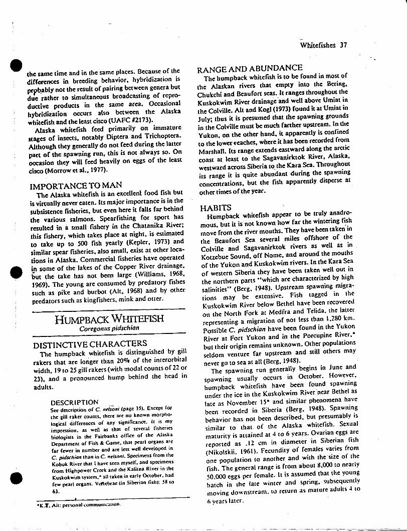
the same time and in the same places. Because of the
differences in breeding behavior, hybridization is
prpb.ably not the result of pairing between genera but
due rather to simultaneous broadcasting of repro
ductive products in the same area. Occasional
hybridization occurs also between the Alaska
whitefish and the least cisco (UAFC #2113).
Alaska whitefish feed primarily on immature
stages of insects. notably Diptera and Trichoptera.
Although they generally do not feed during the latter
part of the spawning run, this is not always so. On
oocasion they will feed heavily on eggs of the least
cisco (Morrow et al., 1971).
IMPORTANCE TO MANThe Alaska whitefish is an excellent food fish but
is virtually never eaten. Its major importance is in the
subsistence fisheries, but even here it falls far behind
the various salmons. Spearfishing for sport has
resulted in a small fishery in the Chatanika River;
this fishery, which takes place at night, is estimated
to take up to SOO fish yearly (Kepler, 1913) and
similar spear fisheries, also small, exist at other loca
tions in Alaska. Commercial fisheries have operated
Ln some of the lakes of the Copper River drainage,
but the take has not been large (Williams, 1968,
1969). The young are consumed by predatory fishes
such as pike and burbot (Alt, 1968) and by other
predators such as kingfishers, mink and o((er.
HUMPBACK WHITEFISHCoregonus pidschian
DISTINCTIVE CHARACTERSThe humpback whitefish is distinguished by gill
rakers that are longer than 20070 of the interorbital
width, 19 to 25 gill rakers (with modal COURtS of 22 or
23), and a pronounced hump behind the head in
adults.
DESCRIPTIONSee description of C.;'~lsoni (page 3S). E."ept for
the gill raker counts. there are no known morpho
logical differences of any significance. It is my
impression. as well as that of several lisheries
biologists in the Fairbanks office of the Alaska
Department of Fish &. Game. that pearl organs are
far fewer in number and arc less well developed in
C. pidschian lhan in C. nelsoni. Specimens from the
Kobuk River that I have seen myself. and specimens
from Highpower Creek and lhe Kalitna River in the
Kuskokwim system. 0 all taken in early October. had
few pearl organs. V..~ebrae (in Siberian lishl: 58 to
63.
°K.t'. All: pa-sonal.:ommuRl.:allon.
Whitefishes 37
RANGE AND ABUNDANCEThe humpback whitefish is to be found in most of
the Alaskan rivers that empty into the Bering,
Chukchi and Beaufort seas. It ranges throughout the
Kuskokwim River drainage "and well above Umiat in
the Colville. Alt and Kogl (1913) found it at Umiat in
July; thus it is presumed that the spawning grounds
in the Colville must be much farther upstream. In the
Yukon, on the other hand, it apparently is confined
to the lower ("eaches, wherdt has been recorded from
Marshall. Its range extends eastward along the arctic
coast at least to the Sagavanirktok River, Alaska,
westward across Siberia to. the Kara Sea. Throughout
its range it is quite abundant during the spawning
concentrations, but the fish apparently disperse at
other times of the year.
HABITSHumpback whitefish appear to be truly anadro
mous, but it is n.ot known how far the wintering ~~h
move from the fiver mouths. They have been taken In
the Beaufort Sea several miles offshore of the
Colville and Sagavanirktok rivers as well as in
Kotzebue Sound, off Nome, and around the mouths
of the Yukon and Kuskokwim rivers. In the Kara Sea
of western Siberia they have been taken well out in
the northern parts "which are characterized by high
salinities" (Berg, 1948). Upstream spawning migra
tions may be extensive. Fish tagged in the
Kuskokwim River below Bethel have been recovered
on the North Fork at Medfra and Telida, the latter
representing a migration of not less than 1,280 km.
Possible C. pidschian have been found in the Yukon
River at Fort Yukon and in the Porcupine River.·
but their origin remains unknown. Other populations
seldom venture far upstream and still others may
never go to sea at all (Berg, 1948).The spawning run generally begins in June and
spawning usually occurs in October. However,
humpback whitefish have been found spawning
under the ice in the Kuskokwim River near Bethel as
late as November IS· and similar phenomena have
been recorded in Siberia (Berg, 1948). Spawning
behavior has not been described. but presumably is
similar to that of the Alaska whitefish. Sexual
maturity is attained at 4 to 6 years. Ovarian eggs are
reported as .12 em in diameter in Siberian fish
(Nikolskii. 196\). Fecundity of females varies from
one population to another and with the size of the
fish. The general range is from about 8,000 to nearly
50.000 eggs per female. It is assumed that the young
hatch in the late winter and spring. subsequcntly
moving downstream. to return as mature adults -l to
nyears latcr.
38 The Freshwater Fishes of Alaska
The young feed mainly on zooplankton. bUI adults
feed mostly on mollusks. crustaceans and chiro·
nomid larvae (Nikolskii. 1961).
Growth rates vary greatly from place to place and
, even in different sections of the same river (Nikolskli.
1961). Itt Alaska.-fish in arctic rivers such as the
Colville.; Kobuk and Agiakpuk grow much more
slowly t~an do those in the Kuskokwim and lower
Yukon drainages. Humpback whitefish from the first,three rivers average about 26.7 cm fork length at 5 +
and 40.S1cm at 10+ while those from the latter areas
average '4.7 cm and 44.5 cm at the same ages (Alt.
1973b).
IMPORTANCE TO MANThe humpback whitefish of Alaska is of little
direct importance except in local subsistence
fisheries. A commercial operation on the Colville
River Delta takes about 1.000 fish annually (Alt and
Kogi. 1973). However. this fish is an important
commercial species in Siberia (Berg. 1948; Nikolskii.
1961).
LAKE WHITEFISHCoregonus c1upeaformis (Mitchill)
DISTINCTIVE CHARACTERSThe lake whitefish is differentiated from the other
two humpback whitefishes of Alaska by its higher gill
raker count. which ranges from 26 to 33.
DESCRIPTIONSec description of C. ndsoni (page lSI. Except for
the gill raker counts. there are no known differences
in appearance of any significance. Pyloric caeca: 140
to 222. Venebrae: SS to 64.
RANGE AND ABUNDANCEThe lake whitefish is widely distributed across
Canada and the northern United States. from the
upper Yukon and Northwest Territories south to
Montana. Minnesota and the Great Lakes. and east
to New England. Quebec and Labrador. Records of
its distribution in Alaska are not completely reliable
due to the confusion with closely related species.
However. the lake whitefish has been recorded with
reasonable certainty from Paxson and Crosswind
lakes in the Copper River drainage and from Lake
Louise and the Tyone Lakes in the Susitna drainage
(Williams. 1968; Van Wyhe and Peck. 1969). Lindsey
et al.. (1970) show a possible record of lake whitefish
from Old John Lake at the head of the Sheenjek
·C. Lindsey: personal communication.
River. but the record is based on only two
specimens.· Wherever it is foutld. the lake whitefish
is quite abundant. especially when schooled up for
spawning.
HABITSBreeding behavior of the" lake whitefish is similar
to that of the Alaska whitefish hcept that spawning
generally takes place in the inshore regions of lakes.
Stream populations. of course. use the rivers and
creeks. Spawning takes place o~er rocky or gravelly
bOllom in depths of I to 3 m. A female and one or
more males rise to the surface. eXlrude eggs and milt.
then descend separately toward the bottom.
Spawning occurs at night (Bean. 1903; Hart. 1930;
Everhart. 1958). Adults breed annually in the
southern parts of the"range. but apparently only
every other year or even every third year in the arctic
and sub-arctic (Kennedy. 1953).Fecundity varies greatly from one population to
another. averaging around 50.000 eggs per female.
with a reported range of less than 6.000 to more than
150.000. Spawning occurs from October to Decem·
ber. depending on locality. and seems to be
associated with water temptratures of about 6°C or
less. Hatching normally occurs in late April.
Development of the eggs takes 140 days at .soC.
which seems to be the optimum temperature for the
eggs. In laboratory studies. no eggs survived at 0° or
at 12°C. Mortalities through hatching increased from
27% at .5° to 41 '10 or 42'10 at 2° to 6°. 81'10 at 8° and
9911jo at 10°C. Abnormalities also increased from
none at .5 ° to 2°C to 50'10 at 10·C (Price. 1940).
The larvae are 1.1 to 1.4 cm long at hatching and
grow rapidly during the summer. In Lake Huron the
larvae at'"e close inshore from soon after breakup to
the end of the summer (Fabe~. 1970).their location
often being associated with emergellt vegetation.
They stay at or near areas with temperatures of 17°C
(Reckahn. 1970). descending with it to the metalim
nion. Van Wyhe and Peck (1969) found similar
movements of young-of-the-year that were believed
to be lake whitefish in Paxson Lake. Alaska.
Growth slows abruptly in September so that-by the
end of October the larvae are about 12 cm long. This
slowing of growth is associated with descent into the
colder water of the hypolimnion.Growth rates vary with locality and population.
Average tOlallengths at age. covering a wide variety
of localities in the U.S. and southern Canada. are:
1+. 13 cm; 2+.21.6 cm; 5+.38.6 cm; 10+. SLI
cm; 15 +. 62.7 cm (Carlander. 1969). By contrast.
lake whitefish in Paxson Lake. Alaska. had the
following age-length relationShips: 1+. 4 cm; 2 + •
• 7.7 cm; 5+, 20.2 cm; 10+,37.3 cm; 15+,46 cm(Van Wyhe and Peck, 1969). Maximum age reportedwas that of a fish of 28 years from Great Slave lake(Kennedy, 1953), while the largest size was of a fishof 19 kg ta:ken in lake Superior in 1918 (Van Oosten,1946). If ,the length-weight relationship given byDryer (1963) for lake Superior whitefish can beapplied to this second specimen, then the fish musthave been on the order of 135 cm total length. Thenext largest known weighed just over half as much,10.9 kg (Keleher, 1961).
The lake whitefish appears to be a rather sedentaryfish, at least in the Great lakes. Tagging studies(Budd, 1957; Dryer, 1964) indicate that the majorityof fish stay within 16 km of their spawning ground,although one fish in lake Huron was recaptured 240lem from the point of release. There seems also to bea tendency toward movement in definite directions,although no well-defined routes have been determined (Budd, 1957). In general, movement of lakewhitefish in large lakes consists of four stages: travelfrom deep to shallow water in the spring; movementback into deep water during the summer as the shoalwater warms; migration back to the shallow-waterspawning areas in the fall and early winter; and postspawning movement back to deeper water.
Within each of the Great lakes, and probably inmost large lakes, the lake whitefish form more or lessseparate populations. These are usual1y characterizedby different growth rates rather than by morphological differences (Budd, 1957; Roelofs, 1958;Dryer, 1963, 1964; Mraz, 1964b). It is not knownwhether these populations are genetically distinct orare produced by environmental factors. In any case,the lack of migratory habits probably tends to keepthem separate.
Food of the lake whitefish varies with size and ageof the fish, location. and the type of food available.The initial food of the young consists of copepods.later on of c1adocerans. By early summer they beginto feed on bottom organisms, but Cladocera.especially Bosmina. remain a dominant food item forsome time (Reckahn. 1970). Adults feed mainly onbenthic organisms. but pelagic and semipelagic formsalso are important. Kliewer (1970) found a significant negative correlation between gill raker length
Whitefishes 39
and the proportion of benthic food, and a strongpositive correlation between the number of gill rakersand the amount of benthic food. He listed thefol1owing food items for lake ~whitefish from the
- -4
Cranberry Portage area in northern Manitoba:Pelecypods, gastropods, amphipods, Diptera(tendepedid larvae and pupae, culicid andceratopogonid larvae), EphemerQptera, Trichoptera,Megaloprera, plant material, fi~h eggs, Hirudinea,Cladocera, Copepoda, my$ids, Hemiptera(Corixidae), Hymenoptera and; fishes. In Paxsonlake, Alaska, adult whitefish we~e seen to prey uponyoung sockeye salmon until the fry grew too big forthe whitefish (Van Wyhe and Peck, 1969).
Although extensive hatchery programs for thepropagation of lake whitefish have'been carried onfor years on the Great lakes and other places, thereis no evidence to show that these programs have everinfluenced the strength of year classes (Koelz, 1929;Christie, 1963). Weather seerps to be the mostimportant factor. Cold water temperatures atspawning time-below 6°C-fol1owed by a steadynonfluctuating decrease to .5°C and by warmtemperatures at hatching time, produce the strongestyear classes (Christie, 1963; lawler, 1965a).
IMPORTANCE TO MANThe lake whitefish has long been one of the most
valuable freshwater species in North America.Deterioration of its environment, depletion of thestocks and other factors led to a decline in yield fromthe 5.5 million kg per year of the 1880s to the 700,000leg per year of the 1920s (Koelz, 1929), but in the late1960s the catch was incre~ing. In 1970 the U.S. andCanadian landings from 'the Great lakes and theInternational lakes between Minnesota and Ontarioamounted to about 1.69 million kg (Anonymous.1973). In addition. there are considerable Canadianfisheries in the northern lakes such as lake Winnipegand Great Slave lake. In Alaska, however. the lakewhitefish is virtually unused. Attempts at commercialfishing for lake whitefish have been made inCrosswind lake in the upper Copper River drainageand in lake louise and Tyone lake in the upperSusitna. These have not. however. been especial1ysuccessful (Wil1iams. 1968, 1969).

APPENDIX 8
ADULT ANADROMOUS FISHERIES STUDIES
Side Band Radio

e-
TR I DENTHF -!RADIO TELEPHONE COMMUNICATIONS
•HOW TO USE A SINGLE SIDE) BAND RADIO
PRODUCED FOR OUR CUSTOMERS
byJack and Viroinia Ree~
and t he Trident Staff:
P.O. BOX 10- 1158 • ANCHORAGE r ALASKA 99511
''''-._-'-----'---- --------
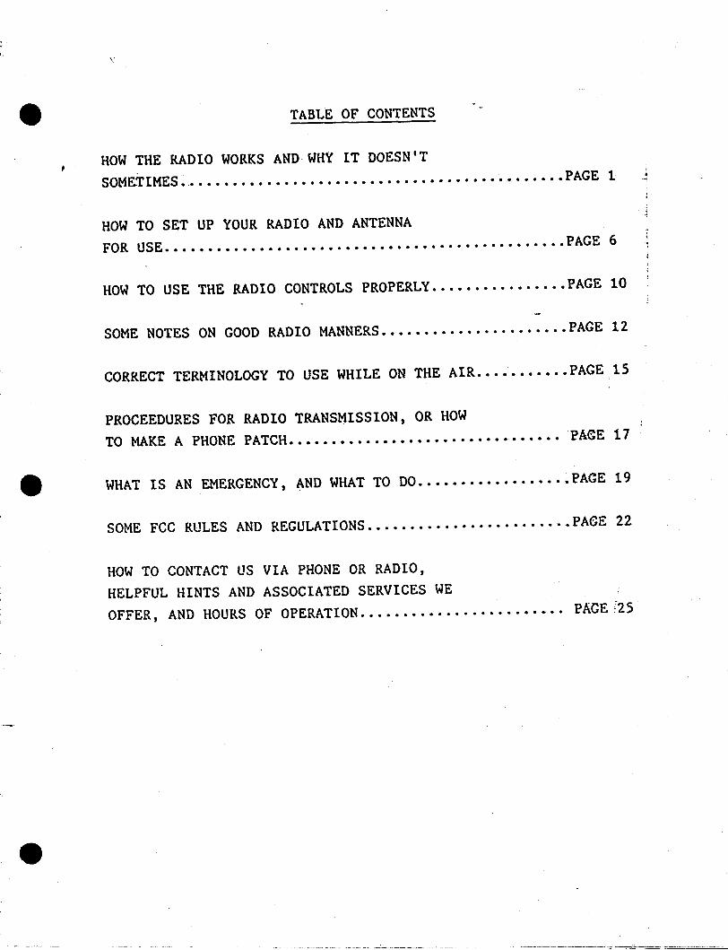
\ '
TABLE OF CONTENTS
HOW THE RADIO WORKS AND· WHY IT DOESN'TSOME-TIMES •.••••••••••••••••••••••••••••••••••••.••••••• •PAGE 1 J
HOW TO SET UP YOUR RADIO AND ANTENNAFOR US·E •••• ft.•••••••••••••••••••••••••••••••••••••••••• PAG·E 6
HOW TO USE THE RADIO CONTROLS PROPERLY ••.••••.•••••••. PAGE 10
SOME NOTES ON GOOD RADIO MANNERS ••••••••••••••.•.••••• PAGE 12
CORRECT TERMINOLOGY TO USE WHILE ON THE AIR •••••••••.• PAGE 15
PROCEEDURES FOR RADIO TRANSMISSION, OR HOWTO MAKE A PHONE PATCH••••••••.••••••••••••••••••••••• PA&E 17
4It WHAT IS AN EMERGENCY, AND WHAT TO DO ••.••••••••..•••.• PAGE 19
SOME FCC RULES AND REGULATIONS ...•..•....•..••.•.••... PA6E 22
HOW TO CONTACT US VIA PHONE OR RADIO,HELPFUL HINTS AND ASSOCIATED SERVICES WEOFFER, AND HOURS OF OPERATION ....•..............•.••• PAGE!25
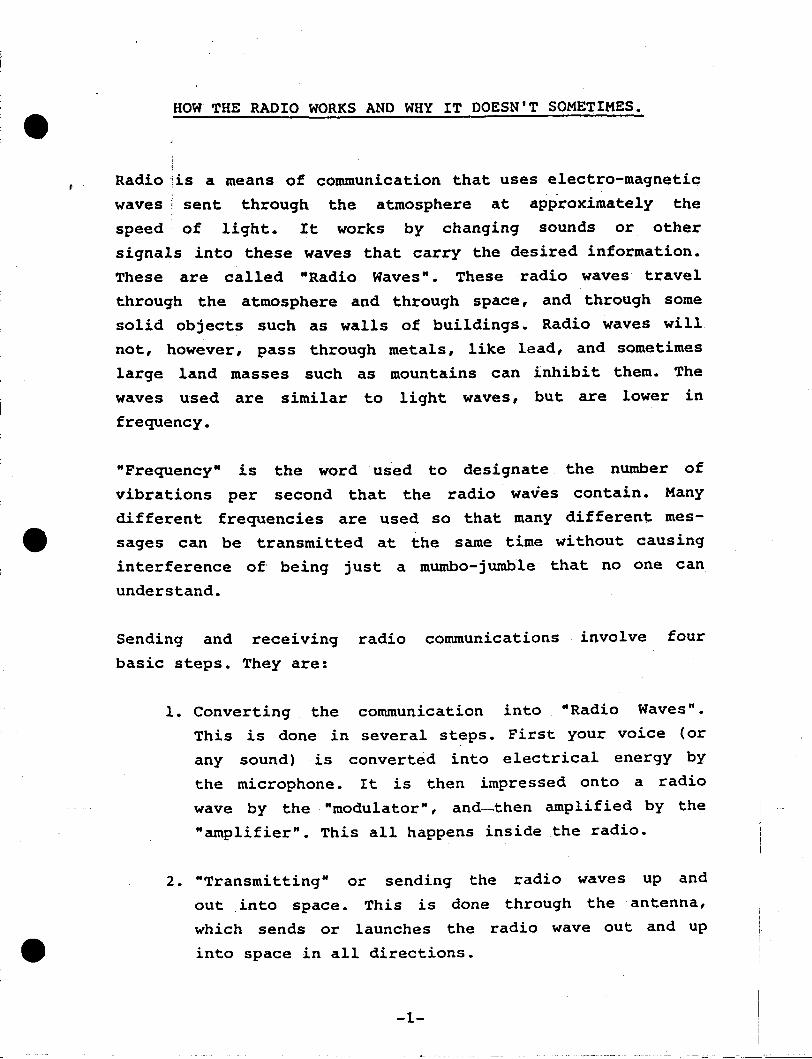
HOW THE RADIO WORKS AND WHY IT DOESN'T SOMETIMES.
Radio ;is a means of communication that uses electro-magnetic
waves 'sent through the atmosphere at approximately the
speed of light. It works by changing sounds or other
signals into these waves that carry the desired information.
These are called "Radio Waves". These radio waves travel
through the atmosphere and through space, and through some
solid objects such as walls of buildings. Radio waves will
not, however, pass through metals, like lead, and sometimes
large land masses such as mountains can inhibit them. The
waves used are similar to light waves, but are lower in
frequency.
"Frequency" is the word used to designate the number of
vibrations per second that the radio waves contain. Many
different frequencies are used so that many different mes
sages can be transmitted at the same time without causing
interference of· being just a mumbo-jumble that no one can
understand.
Sending and receiving radio communications involve four
basic steps. They are:
1. Converting the communication into "Radio Waves".
This is done in several steps. First your voice (or
any sound) .is converted into electrical energy by
the microphone. It is then impressed onto a radio
wave by the "modulator", and--then amplified by the
"amplifier". This all happens inside the radio.
radio waves up and
through the antenna,
radio wave out and up
2. "Transmitting" or sending the
out .into space. This is done
which sends or launches the
into space in all directions.
-1-
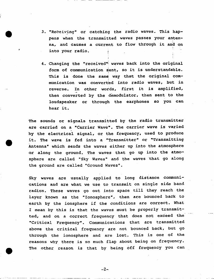
_. ---_.~----------------
3. "Receiv~ng" or catching the radio waves. This hap
pens when the transmitted waves passes your an'ten
na, and causes a current to flow through it ana on
into your radio.
4. Changing the "received~ waves back into the original
form of communication ~ent, so it is understandable.
This is done the same way tha1: the original com
munication was convert~d into radio waves, but in
reverse. In other words, first it is amplified,
then converted by the demodulator, then sent to the
loudspeaker or through the earphones so you can
hear it.
The sounds or signals transmitted by the radio transmitter
are carried on a "Carrier Wave". The carrier wave is varied
by the electrical signal, or the frequency, used to produce
it. The wave is fed into a "Transmitter" or "Transmitting
Antenna" which sends the waves either up into the atmosphere
or along the ground. The waves that go up into the atmo
sphere are called "Sky Waves" and the waves 'that go along
the ground are called "Ground Waves".
Sky waves are usually applied to long distance communi
cations and are what we use to transmit on single side band
radios. These waves go out into space till they reach the
layer known as the "Ionosphere", then are bounced back to
earth by the ionsphere if the conditions are correct. What
I mean by this is that the waves must be properly transmit
ted, and on a correct frequency that does not exceed the
"Critical Frequency". Communications that are transmitted
above the critical frequency are not bounced back, but go
through the ionosphere and are lost. This is one of the
reasons why there is so much flap about being on frequency.
The other reason is that by being off frequency you can
-2-
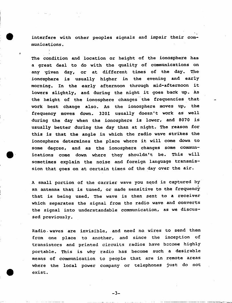
---- ~- ~ --~------------------~
interfere with other peoples signals and impair their com
munications.
The condition and location or height of the ionosphere has
a great deal to do with the quality of communications on
any 'given day, or at different times of the day. The
ionosphere is usually higher in the evening and early
morning. In the early afternoon through mid-afternoon it
lowers slightly, and during the night it goes back up. As
the height of the ionosphere changes -. the frequencies that
work best change also. As the ionosphere moves up, the
frequency moves down. 3201 usually doesn't work as well
during the day when the ionosphere is lower, and 8070 is
usually better during the day than at night. The reason for
this is that the angle in which the radio wave strikes the
ionosphere determines the place where it will come down to
some degree, and as the ionosphere changes some commun-
4It. ications come down where they shouldn't be. This will
sometimes explain the noise and foreign language transmis
sion that goes on at certain times of the day over the air.
A small portion of the carrier wave you s~nd is captured by
an antenna that is tuned, or made sensitive to the frequency
that is being used. The wave is then sent to a receiver
which separates the signal from the radio wave and converts
the signal into understandable communication, as we discus
sed previously.
Radio- waves are invisible, and need no wires to send~. them
from one place to another, and since the inception of
transistors and printed circuits radios have b~come highly
portable. This is why radio has become such a desirable
means of communication to people that are in remote areas
'Where the local power company or telephones just do note exist.
-3-
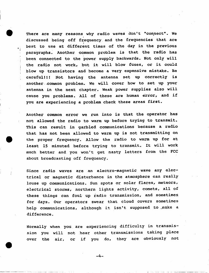
There are many reasons why radio waves don' t "con.nect". We
discussed being off fr;equency and the frequencies that are4
best to use at different times of the day in the previous
paragraphs. Another ccimmon problem is that the radio has
been connected to the power supply backwards. Not only will
the radio not work, but it will blow fuses, or it could
blow up transistors and become a very expensive mistake. Be
careful!!! Not having the antenna set up correctly is
another ..common problem. We will cover how to set up your
antenna in the next chapter. Weak power supplies also will
cause you problems. All of these are human Efrror, and if
you are experiencing a problem check these areas first.
Another conunon error we run into is that the operator has
not allowed the radio to warm up before trying to transmit.
This can result in garbled communications bec'ause a radio
that has not been allowed to warm up is not transmitting one the proper frequency. Allow the radio to warm up for at
least 15 minuted before trying to transmit. It will work
much better and you won' t get nasty letters from the FCC
about broadcasting off frequency.
Since radio waves are an electro-magnetic wave any elec
trical or magnetic disturbance in the atmosphere can really
louse. up communications. Sun spots or solar flares., meteors,
electrical storms, northern lights activity, comets, all of
these things can foul up radio transmission, and sometime$
for days. Our operators swear that cloud covers sometimes
help communications, although it isn' t supposed to_make a
difference.
Normally when you are experiencing difficulty in transmis
sion you will not hear other transmissions taking place
over the air, or if you do, they are obviously not
-4-
~~~~~~~~~~~~~~---~ -~
successful. In other words, if communications are down~
they are down for everybody. If you do hear communications
taking. place and you are not able to g~t thr~ugh, check,
your antenna "location and attachment, poweJ:' supply strength, .
and attachment, your microphone attachment~ and your fuses,
and if. all is well there, you could have ~ a radio problem.1
This happens infrequently, but if it does! you have to get
the thing in for repairs, We cover that in the last chapter.
This doesn't cover all the-contingencies,. but from our
experience these are the problems that we run into most
often, I hope· this chapter answers some of your questions,
and gives some insight into how the radio works, and 'how to
handle problems that might come up.
-5-

HOW TO SET YOUR RADIO AND ANTENNA UP FOR USE
We discussed allowing your radio to warm up in the. last
chapter. Don't forget.... at least 15 minutes. The best
possible set up is never to turn off the radio at all, but
this is not usually possible when you are out in the bush.
You do need a CONSTANT SOURCE OF POWER. A gasoline or
diesel generator is not the best source of power to connect
directly to the radio because they tend to be off frequency
and create power surges. These power surges will blow your
fuses, or worse yet the transistors, and the radio won't
work. The best and most efficient arrangement is to hook up
a 6 amp minimum, automatic battery charger to the generator,
attach a designated type of battery or batteries to the
charger, and the radio to the batteries. This will give you
the constant power you need. The second best, and more
temporary and portable solution is just to use alkaline or
lead acid batteries only, depending on the make, model and
type of radio you are using. The technician that delivers
the radio to you should tell you which type of power source
the radio needs.
Another very important pOint is to make sure you know which
terminal is positive and which is negative on your radio.
This may sound like a simple thing to ask about, but these.
are not always marked clearly, and hooking up a radio
backwards can really~ put it out of commission quickly and
permanently. We fix. at least a dozen radios that have been
hooked up backward every season. This is a common mistake,
and a very inconvenient and expensive one. Pay Attention!!!!!
Your antenna should be set up as
the page following this chapter.
-6-
per the illustration
The ideal height is
on
50

•
---~--------------
feet, but when you are out in the' bush you can' t always
find 50 foot trees. The min~mum height you should use is 20
feet. 30 fe:et. is ~.better, 40 feet better yet,. and 50 is the~ ~ .
best, but 20 will wC?rk. Do the best you can. The antenna. ,
should be set up in a straight a line, .as possible..... or
as straight: a line as you can create under bush conditions.
The rule is! that the antenna should be at 90 degree angles,
or crosswise from the direction that you wish to transmit
toward, however this is only really important at heights
that are greater than the ones we are talking about here.
It still will help a little, but isn' t as critical. Get it
as high as you can, up to 50 feet, and in as straight a
line as possible, and it will work. More important than the
direction of broadcast is to set up the antenna at right
angles to any power lines in the area to reduce the
electric noise coupled into the antenna.
The length of the antenna varies with the frequency or
frequencies that the antenna is built to utilize. Our three
frequency antennas for 3201, 5167.5 and 8070 are 110 feet
long. A single frequency antenna or antennas that operate
on other than· these frequencies can range from about 60
feet t()T 190 feet long. If you are out in the bush, you
usually will use trees to mount your antenna on, so the
length isn' t that important, but before you build a perma
nent structure to use as a mount, be sure to check the
length of the antenna that you will be using.
We will be discussing our frequencies which are used by
Trident only in a later chapter. These are 5134.5/5370 and
3362/3238. Our standard 110 foot antenna will work for
these frequencies as well as the Alaska Public Fixed Freq
uencies which are 3201, 5167.5 and 8070. However •..• if you
have the aeronautical enroute frequency, (which is 3449),
-7-

!I
or one of the marine frequencies on your radio, you will
need separate antennas for them.
Just as an after thought, REMEMBER TO TURN THE RADIO OFFBEFORE CONNECTING OR DISCONNECTING ANY POWER SOURCES!!!
-8-.. -----_._.._--
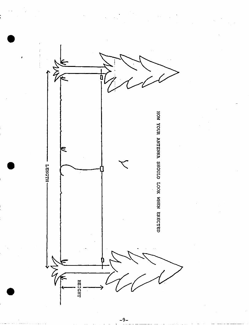
:I:
ttJ ~--71-4-__ H
G1:I:..,
-9-
HOW TO USE THE RADIO CONTROLS PROPERLY.
~
:Now that you have wrestled with the antenna, set up your
power source, and allowed the radio to warm up, you are
ready to transmit. You ~ust "KEY" the microphone, ("mike");
to talk, that is, push the button on it IN to talk, and let
it OUT to listen. Hold the mike about 4 inches from the lips
and speak in a clear, nor,mal voice. Do not shout into the
mike, as this will result in a garbled communication and
loss of clarity. (Not to speak of what it does to the ears
of the poor pe~son on the other end.)
All radios have some or all of the following ~ontrols on the
face plate. The technician or salesperson that delivers your
radio to you should go over your particular model with you,
but the following will give you an idea of what the different
types of dials or buttons are and what they do.
The ON/OFF or POWER switch or button has an obivious func
tion. Some radios combine this switchwith another dial or
switch such as VOLUME or CHANNEL SELECTOR•. Your salesperson
will point this out. f
The' CHANNEL SELECTOR switch selects which channel you want
to be on. Different radios have different channel capacities
that range anywhere from one to twenty or more. Each
frequency is assigned to a specific channel, and should be
marked on a channel selector plaquet on the front of the
radio. Again your technician or salesperson will help you.
VOLUME or LOUDNESS control is another one with a pretty
obvious function.
-10-
SQUELCH modifiys the noise coming in over the air. Too much
SQUELCH interferes with communication and as a general rule
should be left OFF.
CLARITY or CLARIFIER is the control that will help when a
communication sounds distorted or garbled.
Some radios have a SPEAKER/PHONE -switch. This switch causes
the noise the radio makes to be channeled either to the
loudspeaker or to the headphones, depending on the position
the switch is in.
The "VOLUME CONTROL" should be left at mitl-range and the
"SQUELCH" button or dial should be left OFF, since loud
volume decreases clarity and the Squelch can interfere with
your hearing any weak communications that are directed at
you. The "CLARIFIER" control will help you out if the person
that is transmitting to you sounds like Mickey Mouse, or
Donald Duck.
I may have missed some of the controls on your particular
radio, but these are the importa.nt ones that you will use.
Once agai.n, when you pick up your particular radio, ~he
technician or salesperson should go over all the features of
your specific make and model with you. This list should help
you to remember the most important ones, and what to use
~!tem for.
-11-
f,
SOME NOTES ON GOOD RADIO MANNERS
- The two bigg~st c?mplaints we seem to hear from people who. ~
use radios ~ll the time are about' people who spend an
inordinate afnount of time gabbing about nothing over the
air, and pepp~e who continually "walk on", or interrupt
other transm~ssions that are taking place.
First we'll cover the amount of time spent on the air.
There is a'n FCC regulation that states that the radio is
not to be used for "superfluous or frivilous conversation",
and it (the regulation) also limits the amount of time
spent on each call, and the number of calls allowed each
call sign within a 24 hour period. This rule is not often
enforced, unless the station REALLY abuses the privilege,
and infringes on the rigHts of other users. We here at
Trident try to limit calls to six minutes or less, and try
to discourage' people from calling thier wives, sweethearts,
mothers, husbands and friends just to gab and pass the time
of day. Aside from the fact that you are preventing people
from using the frequency who might need to. make important
calls, you are being list~ned.to by hundreds of people who
really aren't interested in Old Charlie's lumbago, and/or
Nina's sweet/ugly new baby/boyfriend or affair with the
postman. Try to keep your calls as businesslike as possible,
and again, under six minutes. If you have a grocery list or
parts order that you know will take longer than the alloted
time, make two calls, or wait till after hours when the
radio is not so busy, such as after 9 at night. You can
often give lists like these to a friend, and have them
relay' the order, or reservations or whatever to the neces
sary people involved. This usually saves difficulty anyway,
as ,most clerks that answer phones don't really know what is
-12-
• going on when they receive a radio phone patch.
The second most common breach of etiquitte is-"walking on",
or interrupting another transmission. I;f you are aware of
another communication going on, do not 1interrupt unless it
is ~ -bona-fied emergency, and then on~y with the correct
"buzz words". We will cover what is a 1bona-fied emergency
and what these words are in a later chapter. Wait till the
air is cleared, which will be signaled by both parties
saying "Call sign, Clear", (like, ABC 21, Clear, followed
by BCB 21, Clear). Then you race like mad to get your call
in before someone else gets on the air. Sometimes a person
does interrupt a transmission because they couldn • t hear
the traffic going on. If you accidentally ~o interrupt
someone, they will usually tell you to "Stand By for
Traffic" , which loosely translated means to shut up and
wait till it's your turn.
Once again let me remind you that people are listening to
the conversations that go on over the air. This is a point
that you should try never to forget. Don't discuss things
of a delicate or personal nature, don't discuss bank ac
counts, credit card numbers, dollar {figures, and so on. If
you want your business pUblic that's OK with us, but be
warned that it will be pUblic if you broadcast it over the
air, and we are not take responsiblili ty for charges made
to credit cards, etc., whose numbers have been broadcasted.
If you want to guarantee payments to a credit card number,
call on a land line and give the operator the credit card
number and the OK to use it, and she will give the party
that should have it the information after you have cleared
the air. Our operators are bondable, and your information
is secure with us.
---- ------------ - ----------------------~ - - ---

On the sUbject of confidential information, we will not
give out any information about you, neither. ;will we give
you information on anyone else. Please do not discuss other
customers affairs on the air with our operato~s, and don I t
gossip. As I said before, hundreds of other p~ople are out
there listening.
Most good manners are just common sense and consideration
of the rights and feelings of others. Follow a few simple
guidelines, and you will remain on good terms with your
neighbors and our operators.
-14-
----- ~_.-~---
~---_._-~
~~~~~~~~------
CORRECT TERMINOLOGY TO USE WHILE ON THE AIR
This -is a brief glossary of term:s you'll use over the air.
!Rememb~rj NEVER- to use CB jargon, ,such as 10-4, Breaker, and,so on.
"ROGER" means yes, or OK.
"AFFIRMATIVE" means yes, or OK.
"NEGATIVE", or "THAT'S A NEGATIVE" means no.
"DO YOU COpy" or "HOW DO YOU COpy" means how can you
hear me, or how well can you hear me.
"TRAFFIC" is a term used to describe the transmissions_
going on at the time, or, Is there much traffic
today'?" would mean has there been broadcasting going
on, or not.
"STAND BY" means hold on, or wait till you are called
BY YOUR CALL SIGN for a resumption of tran~missi-on.
Other stations are permitted to transmit while a
:station is on stand by. This means that you -are not
finished with your transmission, but are temporarily
off the air. This is used when you have to get paper,
numbers, and so forth.
"SAY AGAIN" means to repeat what you just said.
"OVER" should be said at the end of a transmitted
phrase to signal the operator and the other party that
you are finished speaking and are waiting for a
response. Not all radio operators use this phrase, but
it is good practice.
-15-

• "GO AHEAD" is sometimes used instead of over.
"CLEAR", preceeded by your call letters, such as ABC
21, Clear, means that you are finished with your,transmission, and are clearing the air for others use.
;
"1 BY 1, 2 BY 2, 3 BY 3, 4 BY 4, and 5 BY 5" or ~ny
combination of the preceeding numbers is the way to
communicate the quality of the transmission you are
receiving or.sending. One (1) is the worst, or totally
unreadable, and five (5) is the best, -or very clear.
The first number given represents the loudness of the
communication, the second number represents the
clarity. For instance, if a communication is loud, but
garbled, it should be classified as a 5 by 3. When
someone asks you "How do you copy", or "How do you
read. me", you should answer with the numbers that give
the caller the best indication as to how they are
transmitting. This is also the way our operators will
communicate to you how you are transmitting when you
call for r~dio checks, or if you are having trouble
with a transmission. In cases of 1 X 1 or 2 X 2
transmission, you usually should try again later.
"SIGNALS ARE DOWN" means that for some or all of the
reasons described in the first chapter, that radio
transmission is lousy that day, forget about being
understood.
-16-
,PROCEEDURES FOR RADIO TRANSMISSION,OR
HOW TO MAKE A RADIO CALL
rt'he corre'ct form for calling 4nother station is "Call sign,~ ..
this is Call Sign. (Such as, :ABC 21 this is BCB 23.) .This
can be repeated three times over the air at 10 second
intervals, and, at that point. if you havn' t received an
answer, you must clear the air. You do this by saying,
"Negative Contact, Call Sign Clear, or just Call Sign,
Clear, (such as, Negative Contact, ABC 21, Clear, or ABC
21, Clear.)
If the station you are calling is monitering the radio, and
wants to talk to you, they will answer you by saying Call
sign, this is Call Sign, Go Ahead Please, (such as ABC 21,
this is BCB 23, Go Ahead Please). At this point you can go
on with your communication, say what you have to say, and
clear the air.
You clear the air by saying Call Sign, Clear, (or ABC 21,
Clear,) and are answered by the other call sign saying
Their Call sign, Clear, (or BCB 23, Clear.) Always remember
to use YOUR ENTIRE CALL SIGN, AND NOT JUST A PORTION OF IT.
Using just your letters, as some people have been known to
do will get you a violation letter from the FCC really fast.
If you need to interrupt a communication that is in progress
for some reason, such as to find a number or get something
you need, do so by saying Calleg Call Sign, Stand By. (For
instance, if your call sign is ABC 21, and you were talking
to BCB 23, you should say BCB 23, Stand By, and BCB 23
should answer by saying BCB 23, Standing By). After a stand
by, you must re-call the station you were talking to in the
same manner that you would use to call a new station.
-17-

Remembe~ to use both of the call signs in thie~ enti~ity.
Othe~ stations a~e allowed to b~oadcast while
on' stand by t so if yoU; ~etu~.n and find the
use t just wait till the station t~ansmitting
then continue you~ t~ans~ission.
-18-
a station is
air waves in,
has clea~ed t
.:
~..
WHAT IS AN EMERGENCY, AND WHAT TO DO
This is a difficult chapter to write, because in most
emergency cases your own jUdgement is what determines the,
action to take. I'll try to define a true emergency, anc. to.
explain what the normal procedures are. You have to take it
from there.
According to the FCC, a true emergency is "a situation that
imminently endangers the safety of life and/or property".
This rather broad definition covers aircraft that are lost,
missing, crashed or in trouble, boats lost, missing or in
trouble, lost or missing persons, crimes, or medical emergen
cies such as heart attack, bur~s, excessive bleeding, appendi
citus, broken bones, athasma attacks, and so on.
A person that is already dead is not an emergency. They
feel, and rightly so, that there is nothing more that can be
done for them.
The FCC frowns on people that use an "emergency" signal to
get through when it is not really a bona-fied emergengy. A
wife, husband or girl friend that is not home at 11 o'clock
when someone trys to reach him or her is not an emergency.
Neither is a hunter or fisherman that is weathered in out in
the bush and needs to call his office and cancel a business
-meeting on Monday morning.
A crime is defined as some nut shooting up the streets of
Kotzebue, or someone holding hostages, or things of that type.
There are some terms to use on the air when an emergency
situation is taking place. The use of these terms will cease
-19-

--~- ----------------
any radio transmission that is going on at the moment, so
that the emerg~ncy can be broadcasted, and resolved. These
terms are as follows:
Distress Signal MAYDAY
MAYDAY is the most familliar emergency term to us all
because, of all those 1940' s war movies. The FCC definition
of a MAYDAY communication is that it is to be used only in
cases where there is immediate danger of loss of life and/or
property. MAYDAY takes priority over all other communications.
Urgency Signal PAN
PAN is used when the safety of life and lor property is in
jeopardy. PAN takes priority over all communications except
MAYDAY.
Safety Signal SECURITY
SECURITY is used mainly
concerning the safety of
bulletins and warnings.
by the coast guard for messages
navigation or giving metorological
The proceedure to follow is to clear the air, and stay off,
unless you can provide additional and helpful information,
or if you can pass along an unclear transmission. This
includes things such as sightings of the plane or boat in
question and the location, or as I said, relaying an unclear
transmission. If you can't help, keep quiet.
When the emergency has been resolved, that is, some action
taken, communications will begin again.
-20-

The people that will help· you in emergency situations arethe Search and Rescue People, The State Police, Flight,Service, and in some cases the Coast Guard. You should tryto have the numbers of these agenci~s posted near yourradio in case of a problem. All of, the Agencies workclosely together in emergency situatiolls and if you shouldcall the wrong one to help you with Your problem they willset you aright very quickly. They are very efficient, andhave solved alot of problems in the past wi th remarkable. ~,
speed and dexterity. These people know what they are doing.Give them all the information you have, and let them dothier work. If there is anything that can possibly be donethey will do it.
Once again, DO NOT USE "EMERGENCY" FOR ANYTHING BUT ABONA-FIED EMERGENCY AND ABOVE ALL •••••••
DON'T PANIC !!!11
-21-
•
- -~---------------
SOME FCC RULES AND REGULATIONS
He~e is a VERY b~ief summary of the things you need to know
to prevent getting in trouble with ,the FCC. They DO monite~
the airwaves, and the DO send out qotices of violations and
fines. PAY ATTENTION !!!
There a~e seve~al f~equencies avail'able for use in Alaska.
The most com.'1lon a~e 3201, 5167.5, 8070, 3449, 5472., and a
bunch of them fo~ boats. Our OWN f~equency is 5134.5/5370.
All of these have special licensing and useage rules
applicable, and to cove~- it all would (DOES) fill a LARGE
book. I'll cove~ the most impo~tant ones he~e. 3201, 5167.5
and 8070 a~e the f~equencies used fo~ public communication.
They a~e open to everyone, and the rest~ictions (b~iefly)
are as follows:
1. 3201 may be used at any time, and at any distance.
2. 5167.5 may only be used between the hours of 6: OOAM and
9:00PM (2100 hours), and only with distances of 50 miles
between transmitter and receiver.
3. 8070 is only useable for the same hours ,- and only at
distances of 200 Miles between users.
4. Calls should be kept to 6 minutes, and not more than 5 a
day. This is not a commonly enforced rule, but if
someone abuses the air, we will all have problems.
5. "Supe~flouos and Frivilous" conversation is not allowed.
6. Obscene Language is not permitted.
7. You may NOT speak to boats or planes on the above noted
frequencies unless there is an emergency
-e
_ ...._- -----~-~----- ---
8. During Daylight Savings Time Months the hours of useage
change to 7:00 AM to 10:00 PM.
3449 an9 5472 are the aeronautical enroute frequencies.
These ar.e used to talk to planes~ but only from the ground.
You may;not talk from plane to plane on these frequencies.
You. also may not talk from one station to another on the
g~ound on these frequencies.
The marine frequencies are too numerous to mention. You may
not talk to boats at allover any of the above mentioned
frequencies. If you need to talk to a boat, you have-too
patch a phone call to a marine operator, and let her handle
it.
Most Alaska call signs have three letters and two numbers.
Some Government issued call signs have three letters and
three numbers, but there aren't too many of these. Planes
have some numbers (no specific format) and 1 letter,
preceeded by "N". Planes use the number on the tail as a
call sign. Boats are not uniform, but usually have three
letters and four numbers. This as sometimes how you can
tell who you are talking to- and who NOT to talk to. I know
this is rather vague, but it's the best we can do.
Our frequency is 5134.5/5370, and according to the FCC it is
now illegal to make phone patches on 5167 or the others.
This is why we have our own. This will be for phone calls
only.
The FCC really yells
frequency. Be sure to
for this.
if your radio is not operating on
have your radio checked once a year
You are supposed to keep a log of all calls ·including the
_7'\_
Time, Date, Frequency Used, Your Call Sign Thier CallSign, and approximate content of the conversation. You alsoneed to have a FCC license (personal). which we can ~iveyou a form for, and station license. which should i beposted near the radio at all times.
If you should get a violation from the FCC, it usua~lyneeds answering in writing within 10 days. Failure to do'soresults in losses of license, fines and thunderbolts.
As I said before, this is VERY brief, but I think you getthe idea. If you have any problems, call us and we'll helpyou straighten it out if we can.
According to the FCC. you should also have a copy of the FCCRules and Regulations, Part 81. near the radio, and a copyof FCC Form 1079 attached to your lisence. You can obtain theFCC part 81 from the FCC. Form 1079 you can get from us ifyou need one.
-24-
• HOW TO CONTACT US VIA PHONE OR RADIO,
HELPFUL-HINTS AND ASSOCIATED SERVICES WE OFFER,
AND HOURS OF OPERATION
Trident has two telephone lines into the radio room. One is
a message line only, the other is the phone patch line. The
message line is for the times that people may want a call
sign to get a message, but do not need to talk to anyone at
the call :sign directly. The operator will take the message
and deliver it to the call sign as soon ~s contact with the
call sign is made. The other line is the phone patch line,
~nd should be called when someone desires to contact a call
sign directly. Our customers should try to make sure that
all the people that will be trying to contact them at thier
call signs have the correct call sign, and the name of th~
camp, such as ABC 21, Lake Lovely. This will expiditee service and make everyone involved more popular with our
operators. Our customers should also try to make the people
who might be calling them aware that the radio is not the
same as a telephone, and if the call sign at camp is not
monitoring the frequency, they can I t be reached, and the
operator can do nothing except take a message. This is
difficult for many people to understand, especially if they
hav.e never heard of a Single Side Band Radio.
Our two telephone numbers are as follows:
Message Phone 90]-345-1140
Patch Phone 907-345-1160
We also have a business office phone. It is in a different
building and cannot be used for messages or phone patches.
This is the place to call for information, prices, repairs,
-25-
• and questions about your bills and/or service. This number
is as follows:
Business Office 907-345-1170
The way to call TRIDENT over the air is WKD 22, Anchorage.
This is our call sign. Just follow the instructions on
mapualo pages 17 0& 18-, using' this call sign and your own, and
we will answer you!
SOME HELPFUL HINTS ON GETTING ALONG WITH OUR OPERATORS
I'll try to give you some helpful tips on protocol within
our organization and how to save yourself and your callers
some time and money. Most of this information is meant to
be directed at people calling on the phone, and we encourage
our customers to pass it along to the people who will be
calling them. Try to remember that our operators are trained
to give the radio first priority over the phones. If
someone calls and there is a radio transmission taking
place, they will be asked to hold. Often they will be left
holding while the operator takes information from several
different call signs 6n the air. He or she is not picking
on the caller they are following instructions. Please
explain this to your callers.
Our operators are instructed to inquire if the caller Ls
calling long distance. Unfortunately they sometimes forget,
and if you could spend an hour or so in the radio room on a
bUSy day you would understand why. If someone is calling
long distance I suggest that you tell them to inform the
operator of that fact quickly, and then to tell him or her
which call sign they are trying to contact, and leave a
-26-
II
number where they can be reached so that he or she can get:.
back to -them -..,hen their turn comes up.· This is much cheaper
and less frustrating than.holding on a lo~g distance line.
Another .thing to remember is that you sh~re air space with
the entire State .of Alaska. Only one co~unication' can' take
place at a time on any (requency•••• sort of like your
phone ••••when· it's bUsy nobody else can get through. The
problem is that there aren't nearly 'as many available
frequencies.as phone lines, so while several thousand people
can call into Anchorage at the same time by phone, only a
few can use the radio frequencies that exsist. :There is
often a wait during the summer months for communications to
go .through.. Not only does the operator have to answer the.
radio calls and telephone calls, he or she· has to take
messages, deliver messages, make phone calis, keep' a:· log
and keep it all straight besides. While the operators'-are
doing this juggling act, they are often keeping track of 10
or 15 calls waiting ahead of yours, so try to be patient
and tell your callers- to do the same. A 45 minute wait for
communications is not uncommon during the summer months.
Just keep cool.
Another thing that is helpful to our operators is for the
people calling in on the radio to have the phone numbers
that they wish to call. The operators have thier hands full
with the phones and the radio •••• they will look up a number
for you, or assist you in any way they can, but try to be
considerate of thet~ time.
We get a lot of good feedback and compliments on most of
our operators most of the time. We feel that they all do a
good and necessary job, but even they have bad days and
-27-

once in a while they make a mistake. If you have acomplaint or pro,?le,m we can't help you i. f we don't knowabout it. Please ·le't us kn~w immediately if you encounterany difficulties with our service. On thing we DO ask isthat you make your complaints known to Jack or Virginia byland line or by mail •••• not on the air, and please discusscomplaints with us and not our operators. This saves lotsof confusion. I assure you that._ we will do whatever we canto solve any difficulties that come up. Virginia hand opensall the mail... all you have to do is jot a note on yourmonthly statement and when we get your payment, she willsee it, and reply.
Speaking of billing, we biTl on the ·15th of the previousmonth for our monthly services. In other words, you will bebilled on the 15th of July for August's phone patch service,and we bill twice a month, on the 1st and 15th for anyrepairs done to your radio during ~hat period. All of ourbilling is due within 30 days. Following this chapter is ashort, rough summary on our charges, and what they mean. Wealso ask that you supply us with·a credit card number or athird party billing number so we can charge any longdistance charges to it. In the event that there 1s amistake made and a long distance call is charged to ourphone, it will be passed on to you on your monthly statementlabeled LO CHGS.
We hold the customer responsible for informing· us-when theywish to interrupt their service, and will continue tocharge our monthly service charges as agreed upon until weare notified differently.
Associated Services
Trident offers a com'Jlete line of communications materials.
-28-
----------~-~.~~ -
and services. We s~ll, service, install and in some casesmanufacture, as well as offer consulting and engineeringservices. If you have any communications problems orquestions, call us. If we can't help you solve it ourselves,we probably will know who else will be able to help.
HOURS OF OPERATION
Our hours of operation are as follows:
6 AM through 12 Midnight, Seven Days A Week
Thanksgiving and Christmas day are the only days of theyear that we are closed completely so that our employeesmay spend these hot"idays with their families. On these twodays we close at 9 PM the night before, and re-open at 7 AMthe day after.
I hope we have covered most of the questions that you have,and most of the informat.ion that you need to operate aradio in the bush. If there is anything we forgot or failedto cover, or any additional questions that you may have,please don'~ hesitate to contact us here at Trident. It isour wish that you enjoy the best communications servicespossible and we try to ensure that for all our customers.
- ----·~~,,___A n-

•
·_---------------------------
APPENDIX 9
ADULT ANADROMOUS FISHERIES STUDIES
First Aidand
Safety
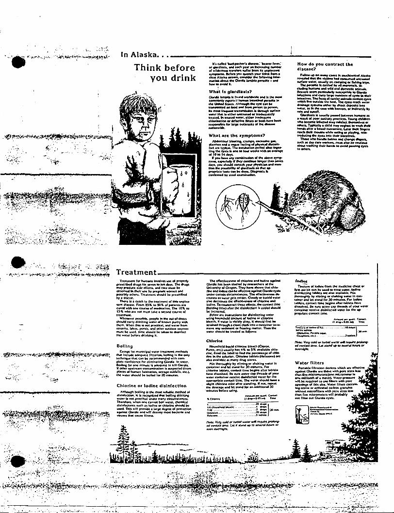
In Alaska... .-;... _
How do you contract thedisease?
Fallow..... ""_c_... .....-or_--_ -..1
twf_ """'"" "" compIftg ... n .....The,.._ ..__ ....olI_....cludlnt "-' ...., wild end _Ie-.1lc ,...IcuIotty__IG_inl'4td and earlY -eeftUlnbcts of cyItIlft &heir.... Thehceo"'__.. canlOlnCYOO.- he ....._ The <yoU ",oct.._••,- tytt_ loy dftect dopatfU """
~:.er~.=c.M ~ra. .. indI~"by
Clo<dIotl_ .. _Iy putod ...._ "-'..._"'_......" ..._V_chl.........._InI....ed"""''''''''....--............ TrfIIc.l\y. child ""'"__ ...... _......._. -.._.Lot.. _nn"...._ while ployInQ._.<OCludno <yoU - ......
lMM ....,-.... ..........MICh ...,Cate WOft.'eta. mwc H QUI'"- - .......... - <YOU.a ........
te', catted 1Mdpede.", dlteaM: "bene; te.et:01 ."d",I.. aM NCh re" 1ft Incf••'k\t ........of wlkkrnltu "eveeen lUff... 'rom kl ....• ymjII...... _ ...... II I .
cte. Aa.-'e "reem. COftSkIef ttwfoI~Wor·",aU. abfWl the 0IM'dI. ,.,.... ",,"'e - end
~".-.oW".
What are the symptoms?AbdomINI bIoetlng. CI.......1ICe.........
dt~. and • 'f'-tlotC '_1"'1 of~ dllCOIfto''''' ore 'n>kMo The _Ion po<Iad or .......ting the C)'ItS It one lO fOYI' week. with 8ft ege""0 ""4cloyt........_...,_Ion"'.........,......I...... eopocNIly lIllley _ ..... Jonver.--cloyt. ........., phrtIc end ......
•Ion paulllliky "' ........... '" ..propN•• Inc., C8ft be doneo~. IIconflf1Md by ..oat .............
What Is glardl..ls?GWtflO ......... Ie ""'"" _ 0IId ............""""""'" _'d"-............ ,.,_ 1ft.IM Unk.., SCM.. Akhouefllhc C)"IC eM beI,..-nkted Oft 'ood end 'rom penon to penon..k. motI1_".- """"'" twf_.....cr tIwlt Is either ""', or IN4equMctrIr••_ed. 1ft ,"-,ecI-.tet. dtheflN4equMechla""otlon ... tlef....... fIIt_ ... _ ho.. beenresponsible for ....ge OtItbrtekt 01 the dlsu.....Ion_.
Think beforeyou drink
.:".. ...;.'.
II
. .
···~:.4~~a.;.;.:,;;~!'·._~~~.~,,!~.•f"'·
I.~l.~~~~~'~:~~t~~·t~4~~Ai~,,-:
"0 ..:~::k~i;":~ t~ ." o:/~~1. ~.'··:;i.,.'·· ;~'iii '-'.:'.~~~~;.!..'*~~~
Treatment _
IodInen.;.~ of iochnc f,om lbe nwdklftc chnt: Of
tv... aiel kh can be uMd to If'" -...leI. Iodinedisinfecting tablet. aN' ".0 ~..WtIe. MiaIhorouQhI, ~ ltirrlnciJ 01 shIIklng ••ter 1ft cona.irtef .-did ...nd for )0 rnm..ccs. FOI iodinel~" Contae1 time begins .'ter t.tJlc\.hevcdiuol.,ed. Be lure screW cap .hreedt. 01 )'OW ..letcontainct recti.... disinfected w.ter for the appropriate contKt, lime.
Treatment for huttwns kwoIve. use of prGpftlyprc.crlMd ."1' for H¥eft to ten 6IyI. The drug......,. ptoduce.ick effect.. and eMf: muse beobserved In ll\efr UN' by prcgnent women .netpossibly oc.her-. T'Ulmcnl should be pre.cr~by. dodor.
There hi • catch to the (reatment of this unpte.wnt diseas.e. From 8~~ to 9OY. of petienll .tccured 'Wh" one COUrse of medication. The IO~ lO1'~ who .re not must take.~ course ofUe.tment.
Whenever possible. pcopte in the out-of-dootsshould carry drlnkiOg waler of known purity withthem. When thb is not practkel. and water fromstreams. lekn. ponds••nd ocher outdoor sourcesmust be u5ed. lime should be toen to dllinfectthe water before dfinki"l it.
The eff............ "'-... ...., Iadl.. ogotntlCiI.llna. hu been studied br rcKatehen .. theUnlverlitr of,Otegon. They ha¥e: thown thet chl4>rlne 8nd iodine e.,. be: cfl'ectl.. -ealmt CitMdta cystsundct certain c1f'CVtfta1ancu. The effcctl¥eMU deenaau al ..let gets colder. Cloudy Of turbid weieralto dcctcatctlM cfl'ectlveness of ch&otlne -.dk)dlnc. Tocount.eract~M clfcets. the eontact dme(hold.....lmel_"...he d'.............. oddcd _be Incteased.
Below afe instfuctloN for dlllnfecting wateru.ing houtddd tincWte: of kNtlne Of chtortneblead\. If .atet II visibly eIItty. It thoutd tint belualned through. clean doth Into a container to retnOVC any tedlmcnl or ftoatlng mattct'. Then thew.tCf shoutd be t«...ed .. follows:
T~",.""""'(2"'1.. _........ ,~........... ht........c~etc.J
....... ,o },._
.....•2 .......
Water filtersPonable flltr.lton dcYka whIch·are cft"ectlve~ Q.arcIN. we lhoH wUhpore llaa 'uslhanRvc mkromeCers (one mkromd«"one mlllkNtIh of • meter). Water preuurewlQ be rcqut,ed 10 use nlleR.with pore~ of Ihlssice. Waler 'liteR containk'9 raiftI or Ktlvaled c.rbon gt.mdnwithout mlcroflltenwkh pO'. alaes Ieu__IhM fiwcmic'omctctI w«t probablynot fIltet out o.rdia cyslS.
~-------...,.. ~__I'
1'Io«c VCtV cold IN 'wbid IN'....requft"""'"eft cont«t Ume. Let.u.MIIP to MWrMIIocn«......../gfII.
...........}....... ...,.
....1 .... )OrNR.. ..20...,.
....,~.A-'I"' ..... COftt«t
(1 .....0.OS"". T......
I ····· - -.....~ edl._ .. _1.10 .....UnII-..........-..
CltlorineHouoehold liquid chI<M.... bleoch (CkKo••
P.....e-. etc.) usually .... 4~ 10 ~~ paUable chlorine. Read lhe labod to find lhe percentage of chl0rine In the toIudon. Chlorine ..bI~ts (Hat-cone) Mealso avaU.b1e al many d"", tlOfCl.
Mia lhoroughl)' by Slirring Of ....king walet InconlalMr and let sland 'Of )0 minutes. Forcblorlne~ contaeI "me begml .fter hbletshave cHuoIwd. Be ICIU acrcw eap thl'e.da 01 )'OUI"water conIalner tteelve disinfected walet for lhe.ppr....e contael Ume. The water thoukl tMve a.Ught chk)rtne odor after standing. If noI. rcpc"lhe do.e.ge and let tland fot an additional 30mlnulet before uslno.
Note: Vef1I cold or turlHd 1IMl_ - tequit'c ptOIottg.H c:onf«f 11nW. Uf • stMtd up 10 HW''' hout'JI 0#'"""'-
Although bolU/'Ifll. the mott t.'t.b1e method 01cAslnfcetk>n. k Is tt'COGnbcd that botUng drlnldngwater I. not practical under many drcumtlant'n.TMreforc.whcn CM'M:: c.nnot boll WM-et. chemlc.1di.lnfectantl such· .. iodine Of d\IorInc thould beuMd. Thl. wflt provide a "fge degree of protectiona9l'''1& o:.rca. aNI wiff delltO)' most INc'Icri. andvtN.eS that CNH lllne...
Chlorine or Iodine disinfection
Bollinguc~ fOf municiINl water tteatment methodl
that inc:luck adeq~te fittrM-1on. boiling .1 the onlytechnique t~t can be tecommended with c0m
plete wnfidencc fot elimlNtlng GlMdi. In water.Bolli", tOf~ minute II adequatc to kill oY'd14.I' other upstfeam contamlnat'on II svspec:tcd (fromplaces of humen habitation_ sewage outf.UI. etc.).the water should tNt boiled fOf 20 mkMllu...,. .
.;:.I"f.-
1 r
.....-~.
.~.~~~
.'
~~~~f"1~'~~N~.•:.;..,t 'f,r4-;~~4}~~~"'-~r ':' .
.~i~X"'·~<' f"<-:" -..--_
I .i.:;~.:'.·.:.:•.·..~~..·...•..:::.~•...~..•...:.-.- ·.·.:.-.•.·,,'.',':~ \:.·..;..~.t··.~.\.·.':.,.;,:.~.•..•..:•.•.'.;•..-.,.•..:.,:~..'.•..•::.;,=·..:..:.~i:,·..:~~:.•...:·.·.',~··.•.....•:,;,..-~;.:..:~;.;,.,~..•..•....:.:.~...•.~ ··,.· ,..i.., . .:••.•: .•:.~••.•.•,I.~•.•..""""'••.•.••..,......•' :.•.·;!;•••~~v._.::.;••.•JU:r-.
h\;,"i , 'l.:..~.•..~·\' ..,.•.....·..::.: ~.:~.:i•..•.., ..•..•.:~••.-.:"'.<•.,..:~~~.'~~~ ., •.
,..... ...;.-.:;., "'..-<•. :-;..:~: .•o. ~~...' 0...·.-- • " ._#~ ,;;;""'0"..._ ".r,;~.."~-~.~".~;1i;\~:~~l1,~,~'.l.,,.~•..~.~,:.;..•~.~.;.:.'~~.";.~.~,'._',:.~.:.•::.~.(.'~~,¥. :,~~~:;~~: .~;if~t~~~;~~1-.·-·. . 0 --.--.-:.-----.----.-:-7: ..~~'~:~~.'.._- -..-.~.•...;.. , , '.. :..·.:::.;~.•..~;;..:; ..·~..•:.I ..•• :.· ·.•~..~.;.;.~..~~.·.•~.·.·.·._.·•..·•...•.. ;.•~:••·:.•.·,·.'-W.F..---.:.' ,:: ".<:..0:...... .' •• ,'L.... ".'-, ••: 0'" ;'.~. ••. 0"'" • --:. ~.~, .. -~::~:~-L?/!f!;~::~;···
Basic CPR is a simple ~rocedure. assimple as A-B-e. Airway. Breathing and
Circulation. or~
Airway~ ~.If you find a collapsed person. determine .ifvictim is conscious by shaking the shoulderand sh:>uting "Areyouall right! It00 resPonse.shout tor help. Then open the airway. If victimis not lying flat on his back. roll victim over.moving the entire bodyatone time as atotal unit.
b open the victim's airway, liftup theneck (or chin) gentlywith one hand whilepushing down on the forehead with theotherto tilt head back. Once the airway is open,place your ear close to the victim's mouth:I:R look-at the chest and stomach for
movement.ESllisten- for soundsofbrea1hing.era Feel-forbreath on your cheek.
If ooneat these signs is present. victimis not breathing..
If opening the airway does not~ ..the victim to begin to breathe spontaneously,you must provide rescue breafhing.
BrecrlhingThe best way to provide rescue breathing isby using the mouth-to-mouth1echnique.Takeyour hand that is on the victim's forehead andtum it so that you can pinch the victim's noseshut while keeping the heel of100 hand inplace 10 maintain head tilt. Yourotherhandshould remain underthe victim's neck (orchin). lifting up. .
Immediately give four quick, full breathsin rapid succession using the mouth-to-mouthmethod.
-<
Y':~' .-." .;"-'.:'. - ~ ....
CPRIn Basic Life Support
ForCardiac Arrest
The most comrron signal ofa heortattack is:~uncomfortoble pressure. squeezing.
fullness or pain in the centerof the chestbehind the breastbone.Other signals may be:
~sweating
~nauseo
E::::l shortnessof breath. or~a feeling of weaknessSometimes these signals subside and retum.
After you have completed the trainingcourse in cardiopulmonary resuscitation(CPR). you will wont 10 keep this leaflet as areview of what ydu have leamed until youtoke your next refresher course.
There are many causesofsudden death:poisoning. drowning. suffocation. choking.electrocution and smoke inhalation. But themost common cause is heart attock. Everyonesh:>uld know the usual earty signalsof heartattock and hove an emergency plan ofaction.
RATIO OFCOMPRESSIONS RATE OF
RESCUERS TO BREATHS COMPRESSIONS
ONE 15:2 80 times/min.
TWO 5:1 60 times/min.
For Infants cndSmaiJ ChildrenBasic life support for infantsand small childrenis similar to that for adults. A few importantdifferences to remember are given below.
AirwayBe careful when handling an infantthat YCXJdo not exaggerate the backward positionofthe head tilt. An infant's neck is so pliable1hatforceful backward tilling might block .breathing passages instead ofopening them.
BreathingDon't try to pinch off the nose. Cover both themouth and nose of an infant or smell childwto is not breathing. Use small breaths withless volume to inflate the lungs. Give one smallbreath every three seconds..
between compressions. Relaxation andcompression should be of equal duration.
If you are the only rescuer, you mustprovide both rescue breathing and cardiaccompression. The proper ratio is 15 chestcompressions to 2 quick breaths. You must
. compress at the rate of 80 times per "minutewhen you are working alone since you willstop compressions when you take timeto breathe.
When there is another rescuer to helpyOu, position yourselves on opposite sides ofthe victim if possible. One of you should beresponsible for interposing a breathdu~ng therelaxation after each fifth compression. Theother rescuer, who compresses the chest.should use a rate of60 compressions perminute.
I
Check Pulse 1.--
After giving the four quick breaths, locate thevictim's carotid pulse to see if the heart isbeating. To find the carotid artery, take yourhand.that is under thevictim's neckand locatethe voice box. Slide the tips of your index andmiddle fingers into the groove beside thevoice box. Feel for the pulse. Cardiac arrestoon be recognized bY absent breathing andan absent pulse in the carotid artery in
.1heneck.If you cannot find the pulse, you must
provide artificiol circulation in addition torescue breathing.Activate The Emergency MedicatServices 'System (EMSS) Sendsomeone to call 911 or Your localEmergency Number
Cardiac Compression~~ificiaJcirculation is provided by external~rdiaccompression. In effect. when you
apply rhyttmic pressure on the lower halfo!1he"victim's breastbone, you are forcing hisheart to pump blood. b perform externaloorolOc compression property, kneel at the"icfim'sside nearhischest. Locate the rotchat the lowest portionof the sternum. Place theheel of one hand on the sternum 1% to 2irr...,hesabovetheootch.Placeyourotherhandon top of the one that is in position. Be sure 10keep your fingers off the chest wall. You mayfind it easier to do this if you inter10ckyour fingers.
Bring your srculders directly over thevictim's sterrun as you compress downward,keeping your arms straight. Depress thesiernum about1% to 2 inches for an adultvictim. Then relex pressure on the sternum .'completely.l-bwever, do not remove yourhands from the victim's stemum, but do allowlhe chest to return to its normal position
2 c..._-_._---------
Check Pulse
The absenceof a pulse may be more easilydetermined by feeling over the left nipple.
Circulation
The technique for cardiac e:ompression isdifferent for infants and small children. In oothcases. only one hand is used for compression.The other hand may be slipped under thechild to provide a firm suPfX>rt for his back.
For infants. use only the tipsof the indexand middle fll1Qers to compress the chest atmid-sternum. Depress the sternum betweenV:z to ¥.4 inch at a fast rate of 80 to 100 timesa minute.
For small children. use only the heel ofone hand to compress the chest. Depress thesternum between ¥4 and lv:z inches. .depending upon the size of the child. The rateshould be 80 to 100 times perminute.
In the case of both intants and smallchildren. breaths should be administeredduring the relaxation after every fifth chestcompre~ior1;
Porto' Hand Depress Ral.ofHand PosItion stemum Compression
IHfAHlS l~oti'Oell md-slerrLm ....b~ 80bnJand ITW:lcIe nc:h permruter~
CHIlDREN heelothOnd mid-~emoJll v..bl.... 8ObiOOnc:nes permirute
Neck InjuryIf you suspect the victim has suffered a neckinjury. you roost notopen the airway in the ..usual manner. If the victim is injured in a divingor automobile accident. you should considerthe possibili1yof such 9 neck injury. In thesecases. the airway should beopened by using G modifiedjaw thrust. keeping the
.victim's head in a fIXed.neutral position.
3
•
Choking~The tlrgency of choking cannot be overemphasized. Immediate recognition andproper action are essential. If the victim hasgood air exchange. or only partial obstruction.and is still able to speak or cough effectively.do not interfere with his attempts to'exoel aforeign body.
When you recognize complete airwayobstruction byobserving the conscious victim':iinability to speak. breathe or cough. thefollowing sequence should be performed
. quicldyon the victim in ffle sifting. standing orlying position: .
a. 4 Bock blowsb. 4 Manual thrusts (abdominal or chest)c. Aftemafe bad< blows and manual
thrusts until effective. or the personbecomes unconsciousIf the victim beComes unconscious.
sJx>ut for help. Place him on his back. face up.Open the airway and attemPt to ventilate. If ."unsuccessful. deliver 4 back blows. 4 rnan..JOlthrusts. probe the mouth with fhe fll1gefand~
atteinpt to ventilate. It may be necess6iYlOrepeat these steps. BE PERSISTENT.
Infants and Smell ChildrenTo dislodge an objecf in the airwayof achild. 1um him upside down overonearm anddeliverblows between nis shoulder blades.
Other Causesof Airway ObsfrucfionAn adequate open airway musf bemaintained atall times in all unconsciouspatients. '-
Other conditions which may couseunconsciousness and airway obstructioninclude: stroke. epilepsy. head injury.alcoholic intoxication. drug overdose.diabetes.

---- --.- ---------------------
r.~AaER
1.Ke victim lD1COnscious?2. It so. sroutforhelp.open the airway. and
i check for breathing .3. If no breathing. give 4 quick breaths4. OIeck carotid pulse
i 5. Activate the EMSS: Send someone to call"'911" or your tocal emergency number
6. If no pulse. begin extemal cardiaccompression by depressing lower-holt ofthe sternum lV2 to 2 inches
7. Continue uninterrupted CPR unfif advancedlife support is available
CPR for ONE RESCUER: 15:2~pressions tobreaths at a rate of80 compressions aminute (4 cycles perminute)
CPR for TWO RESCUERS: 5:1 COmpressions10breaths at a rateof{;(J compressions aminute
Periodic practice in CPR is essential to insurec tisfactory level ofprofICiency. A life maydE"Ald upon row well you hover~beredthe proper steps of CPR androw to apply them. You should be sure to have
I tested both your skill and knoWledge ofCPRat leastonce a year. It could meanromeone's life.
t:mergency ~iledical
SerV3ces System (EMS.S)Any victim on wOOm you begin resuscitationmJst be considered to need advanced liteSt.pport. He or she will have the best chance ofsurviving if your community hos a totalemergency medical services system. This
i inclt.!des on efficient communications alertsystem. such as 911. wi!!:.' public awareness of
, how or where to coli: well trained rescueI personnel woo con respond rapidly; vehiclesthol ore properly equipped; an emergencyfacility troot is open 24 hours a day to provide
, advanced life support; and on intensive coreI section in the hospifal for the victims. You
4
.,should work with all interested agencies toachieve such a system.
Signals endActions For SurvivalKnow the signals: an uncomfortable pressure.squeezing. fullness orpain in the center of thechest. behind the breastbone. which mayspread to the shoulder. neck or arms (the painmay not be severe); other signals may includesweating. nausea. shortnessof breath and afeeling of weakness.
1. Recognize the -signals".2. Stop activity and sitor lie down.3. If signals persist. call your local EMSS
number. or if not available. go to 1henearest h:::>spital emergency roomwhich provides emergency cardiac·care.
"b activate your EMSS. call1 _." .. ,-.-"
Nearest Emergency Department:
(JAmerican Heart Association-1'1 ....",,1 c-"",~",. n~ Gr"""..ilk A......., • noOn..... T~ 7$:!J I

• I l; -.,, ; 1 ,-"Iii!
, r·',i. .. J \..
.]A r S. HAMMOND, GOVERNOR
June 9, 1982
Lt. Col. Jack G. SautterCommanding OfficerAAC/RCC Elmendorf Airforce BaseAnchorage, Alaska 99506
Si r:
Su Hydro Aquatic Studies2207 Spenard RoadAnchorage, Alaska 99503
Several weeks ago I contacted members of your command regarding assistanceand information that we may provide in the event personnel deployed alongthe Susitna River by the Alaska Department of Fish and Game Aquatic StudyTeam would need your rescue services. Your subordinates suggested weprovide your team with detailed maps showing the locations of our camps andthe possible helicopter landing sites along with other information such asradio frequencies and the names and telephone numbers of Anchorage basedpersons that could act as guides on short notice.
The maps which accompany this letter indicate the locations of camps andnearby potential helicopter landing sites. Radio frequencies monitoredthrough "Trident Communications", a commercial company, are 5167.5 and 3201mHz. Communication through the Fish and Game reserved frequency of 3230mHz is also possible. Each camp is equipped with a single sideband radio.
Anchorage based persons that could act as guides are:
Tom TrentBruce BarrettSusan Wick
344-6187349-7138276-4508
Each of our camps are equipped with aerial flares to guide pilots tolanding sites in darkness or marginal light conditions.
If you office could provide us with a reference number to draw attention tothese maps it may save time in the event of emergency.
I am hopeful that we will not require your services but want~to fie preparedin the event we do.
Sincerely,
~ ~AU-h1H~~tmtAssistant Aquatic Studies Coordinator
cc: T. TrentS. ~~ick
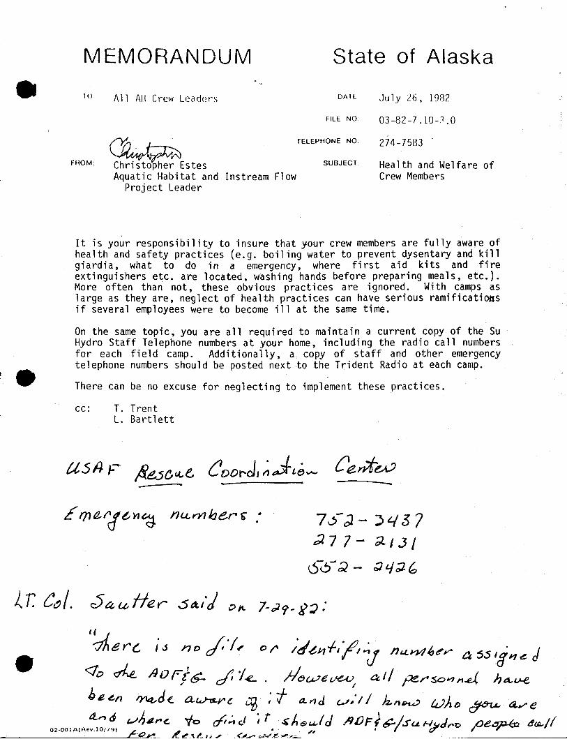
MEMORANDUM State of Alaska
• 10
FROM:
All AH Crew Leaders
~Christopher EstesAquatic Habitat and
Project LeaderInstream Flow
OAIEc
FILE NO
TELEPHONE NO
SUBJECT:
,July 26, 1982
03-82-7.10-:'.0
274-7583 .
Health and Welfare ofCrew Members
It is your responsibility to insure that your crew members are fully aware ofhealth and safety practices (e.g. boiling water to prevent dysentary and killgiardia, what to do in a emergency, where first aid kits and fireextinguishers etc. are located, washing hands before preparing meals, etc.).More often than not, these obvious practices are ignored. With camps aslarge as they are, neglect of health practices can have serious ramificatiOftsif several employees were to become ill at the same time.
On the same topic, you are all required to maintain a current copy of the SuHydro Staff Telephone numbers at your home, including the radio call numbersfor each field camp. Additionally, a copy of staff and other emergencytelephone numbers should be posted next to the Trident Radio at each camp.
There can be no excuse for neglecting to implement these practices.
cc: T. TrentL. Bartlett
7 -.)-;). - ') t.{ 3 7;;17 7- ;;1./J/
6-6-;;} - ;; L/ ;;l b
~ r. C~ I. c:54 U lie r S de./J ,:;> It- 7- OJ 9 _}(;) :
Cl
'-i.eY'G loS no /"/, 0 I' /d~J1f,"//~ IILLn4(,e'r ~ 5S 'i J1 « d<10 ~ !Jor-!s_ c::fi1~. ;I(jweV"~ 4,// pe~SOrln.d, ha.-LH:,
hi!. ~n 'Y14..-de. a.~~c ~ : t a,.",d l.-'~'/ / k.,,~ !.VAf) ~ 4,.,,-e
02-00IA(Re~:7~' ':.~~~~ ~!:;_.,~;, ;~~i~~.~~~6),::1 d .AIJFf?/su ~J~o /Je~ 4~11