
UNIT –I- INTRODUCTION TO EMBEDDED SYSTEM SECA1603
104
1 UNIT –I- INTRODUCTION TO EMBEDDED SYSTEM SECA1603 SCHOOL OF ELECTRICAL & ELECTRONICS ENGINEERING DEPARTMENT OF ELECTRONICS AND COMMUNICATION ENGINEERING
-
Upload
khangminh22 -
Category
Documents
-
view
0 -
download
0
Transcript of UNIT –I- INTRODUCTION TO EMBEDDED SYSTEM SECA1603

1
UNIT –I- INTRODUCTION TO EMBEDDED SYSTEM
SECA1603
SCHOOL OF ELECTRICAL & ELECTRONICS ENGINEERING
DEPARTMENT OF ELECTRONICS AND COMMUNICATION ENGINEERING

2
I INTRODUCTION TO EMBEDDED SYSTEM
Embedded system- characteristics of embedded system- categories of embedded system-
requirements of embedded systems- challenges and design issues of embedded system-
trends in embedded system- system integration- hardware and software partition-
applications of embedded system- control system and industrial automation-biomedical-
data communication system-network information appliances- IVR systems- GPS systems
Introduction to Embedded system
An embedded system is one kind of a computer system mainly designed to perform
several tasks like to access, process, store and also control the data in various electronics- based
systems. Embedded systems are a combination of hardware and software where software is
usually known as firmware that is embedded into the hardware. One of its most important
characteristics of these systems is, it gives the o/p within the time limits. Embedded systems
support to make the work more perfect and convenient. So, we frequently use embedded
systems in simple and complex devices too. The applications of embedded systems mainly
involve in our real life for several devices like microwave, calculators, TV remote control,
home security and neighborhood traffic control systems
Fig:1.1:Block Diagram of Embedded system
The embedded system basics are the combination of embedded system hardware and embedded
system software. Embedded System Hardware
An embedded system uses a hardware platform to perform the operation. Hardware of the
embedded system is assembled with a microprocessor/microcontroller. It has the elements

3
such as input/output interfaces, memory, user interface and the display unit. Generally, an
embedded system comprises of the following
Power Supply
Memory
Processor
Timers
Output/Output circuits
Serial communication ports
SASC (System application specific circuits)
Embedded System Software
The software of an embedded system is written to execute a particular function. It is normally
written in a high-level setup and then compiled down to offer code that can be stuck within a
non-volatile memory in the hardware. An embedded system software is intended to keep in
view of the following three limits
Convenience of system memory
Convenience of processor‘s speed
When the embedded system runs constantly, there is a necessity to limit power dissipation for
actions like run, stop and wake up.
Embedded System Characteristics
Generally, an embedded system executes a particular operation and does the similar
continually. For instance: A pager is constantly functioning as a pager.
All the computing systems have limitations on design metrics, but those can be especially tight.
Design metric is a measure of an execution features like size, power, cost and also performance.
It must perform fast enough and consume less power to increase battery life.
Several embedded systems should constantly react to changes in the system and also calculate
particular results in real time without any delay. For instance, a car cruise controller; it
continuously displays and responds to speed & brake sensors. It must calculate acceleration/de-
accelerations frequently in a limited time; a delayed computation can consequence in letdown
to control the car.
It must be based on a microcontroller or microprocessor based.
It must require a memory, as its software generally inserts in ROM. It does not require any
secondary memories in the PC.
It must need connected peripherals to attach input & output devices.
An Embedded system is inbuilt with hardware and software where the hardware is used for
security and performance and Software is used for more flexibility and features.
Embedded System Applications
The applications of an embedded system basics include smart cards, computer networking,
satellites, telecommunications, digital consumer electronics, missiles, etc.

4
Categories of Embedded System
Embedded systems are classified into four categories based on their performance and functional
requirements:
Standalone embedded systems
Real time embedded systems
Networked embedded systems
Mobile embedded systems
Embedded Systems are classified into three types based on the performance of the
microcontroller such as
Small scale embedded systems
Medium scale embedded systems
Sophisticated embedded systems Stand Alone Embedded Systems
Standalone embedded systems do not require a host system like a computer, it works by itself.
It takes the input from the input ports either analog or digital and processes, calculates and
converts the data and gives the resulting data through the connected device- Which either
controls, drives or displays the connected devices. Examples for the stand alone embedded
systems are mp3 players, digital cameras, video game consoles, microwave ovens and
temperature measurement systems.
Real Time Embedded Systems
A real time embedded system is defined as, a system which gives a required o/p in a particular
time. These types of embedded systems follow the time deadlines for completion of a task. Real
time embedded systems are classified into two types such as soft and hard real time systems.
Further this Real-Time Embedded System is divided into two type‘s i.e.
Soft Real Time Embedded Systems
In these types of embedded systems time/deadline is not so strictly followed. If deadline of the
task is passed (means the system didn‘t give result in the defined time) still result or output is
accepted.
Hard Real-Time Embedded Systems –
In these types of embedded systems time/deadline of task is strictly followed. Task must
be completed in between time frame (defined time interval) otherwise result/output may not be
accepted.
Examples
Traffic control system
Military usage in defense sector
Medical usage in health sector

5
Networked Embedded Systems These types of embedded systems are related to a network to access the resources. The
connected network can be LAN, WAN or the internet. The connection can be any wired or
wireless. This type of embedded system is the fastest growing area in embedded system
applications. The embedded web server is a type of system wherein all embedded devices are
connected to a web server and accessed and controlled by a web browser. Example for the LAN
networked embedded system is a home security system wherein all sensors are connected and
run on the protocol TCP/IP
Mobile Embedded Systems Mobile embedded systems are used in portable embedded devices like cell phones,
mobiles, digital cameras, mp3 players and personal digital assistants, etc. The basic limitation
of these devices is the other resources and limitation of memory.
Small Scale Embedded Systems These types of embedded systems are designed with a single 8 or 16-bit microcontroller
that may even be activated by a battery. For developing embedded software for small scale
embedded systems, the main programming tools are an editor, assembler, cross assembler and
integrated development environment (IDE).
Medium Scale Embedded Systems These types of embedded systems design with a single or 16 or 32 bit microcontroller,
RISCs or DSPs. These types of embedded systems have both hardware and software
complexities. For developing embedded software for medium scale embedded systems, the
main programming tools are C, C++, JAVA, Visual C++, RTOS, debugger, source code
engineering tool, simulator and IDE.
Sophisticated Embedded Systems These types of embedded systems have enormous hardware and software complexities,
that may need ASIPs, IPs, PLAs, scalable or configurable processors. They are used for cutting-
edge applications that need hardware and software Co-design and components which have to
assemble in the final system.
Requirements of Embedded system
Reliability
Cost-effectiveness
Low power consumption Efficient use of processing power Efficient use of memory
Appropriate execution time
Reliability
Embedded system have to work without the need for resetting or rebooting. This call for
a very reliable hardware and software. For example : if an embedded system comes to a halt
because of hardware error, the system must reset itself without the need for human intervention.
However the embedded software developers must make the reliability of the hardware as well
as that of the software.
Cost-effectiveness

6
If an embedded system is designed for a very special purpose such as for deep space or
for nuclear power plant station cost may not be an issue. However if the embedded system is
designed for a mass market purpose like CD players, toys and mobile devices cost is a major
concern. Application Specific Integrated Circuit (ASIC) is used by the designers to reduce the
hardware components and hence the cost also reduces.
Low power consumption
Most of the embedded systems are powered by battery, rather than a main supply. In
such case the power consumption should be minimized to avoid draining the Batteries. For
example : by reducing the number of hardware component the power consumption can be
reduced. As well as by designing the processor to revert to low power or sleep mode when there
is no operation to perform
Efficient use of processing power
A wide variety of processors with varying processing powers are available to embedded
systems. Developers must keep processing power, memory and cost in mind while choosing the
right processor. The processing power requirement is specified in ,Million Instruction Per
Second (MIPS). With the availability of so many processor, choosing a processor has become a
tough task nowadays
Efficient use of memory
Most of the embedded systems do not have secondary storage such as hard disk. The
memory chip available on the embedded systems are only Read Only memory and Random
Access memory. As most of the embedded systems do not have secondary storage, ―flash
memory‖ is used to store the program. Nowadays micro-controller and Digital signal processors
also comes with onboard memory. Such processors are used for small embedded system as the
cost generally is low and the execution generally is fast
Appropriate execution time
In real time embedded systems, certain task must be performed within a specified period
of time. Normally desktop pc cannot achieve real time performance. Therefore, special
operating system known as real time operating systems run on these embedded systems. In hard
real time embedded system deadlines has to be strictly met but whereas in soft real time
embedded system the task may not be performed in a timely manner. The software developer
needs to ascertain whether the embedded system is a hard real time or soft one and has to
perform the performance analysis accordingly
Challenges and issues in embedded system
Co-design
Embedding an operating system
Code optimization
Efficient input or output
Testing and debugging
Co-design
An embedded system consists of hardware and software, deciding which function of the
system should be implemented in hardware and software is of a major consideration. For

7
example in hardware implementation the task execution is faster compared with the other one.
On the downside a chip cost money, consumes valuable power and occupies space. A software
implementation is better if these are the major concern. This issue of choosing between
hardware and software implementation is known as a co-design issue
Embedding an operating system
It is possible to write embedded software without any operating system embedded into
the system. Developers can implement services such as memory management, input/output
management and so on. Writing your own routines necessary for a particular application results
in compact and efficient coding. Embedded operating system provide the necessary Application
Programming Interfaces (API).
Code optimization
Developers need not worry much about the code optimization, because the processor is
highly powerful, plenty of memory is generally available. Memory and Execution time are the
important constraints in embedded system. Sometimes to achieve the required response time the
programmer has to write certain portion of coding in assembly language. Of course, with the
availability of sophisticated development tools, this is less of an issue in recent years.
Efficient input or output
In most of the embedded system, the input interfaces have limited functionality. Writing
embedded software is a different ball game compared with writing a user interface with a full-
fledged keyboard, a mouse and a large display. Many systems available in process control take
electrical signal as input and produce electrical signal as output, since they don‘t use I/O
devices. Developing, testing and debugging such systems is much more challenging than doing
the same with the desktop systems.
Testing and debugging
Software for an embedded system cannot be tested on the target hardware during the
development phase because debugging will be extremely difficult. Testing and debugging the
software on the host system by actual simulation of field conditions is very challenging.
Nowadays, the job is made a bits simpler with the availability of ―profilers‖ that tell you clearly
which line of code are executed and which lines are not executed. Using the output of such
profilers we can locate the untested lines of code and ensure that they are also executed by
providing the necessary test input data. It is these challenges that made embedded software
development a ―black art‖ in earlier days. This is no longer the case, however the developments
in embedded software are changing the scenario completely.
Recent trends in embedded system
Processors
Memory
Operating Systems
Programming Languages
Development Tools
Processors
In an effort to cater to different applications, several semiconductor electronics vendors

8
have released many processors. We can find 8-bit, 16-bit, and 32 bit processors with different
processing powers and memory addressing capabilities. Many sophisticated DSP are available
to cater to numerous application needs including audio and video coding and image processing.
The processor boards around which the embedded systems can be built come with the necessary
RAM and ROM as well as peripherals such as a serial port, USB port and Ethernet
connectivity.
Memory
Both RAM and ROM memory devices are becoming increasingly cheaper paving the way
for devices that can store large numbers of programs and their data. Secondary devices such as
Hard disk are also being integrated into embedded systems such as mobile communication and
computing devices . Devices that do not have secondary storage use flash memory and the
capacity of flash memory chips is also rising very rapidly making it possible to incorporate
heavy OS
Operating Systems
As most everyone knows Microsoft currently holds the lion share of the market in
operating systems that run desktop computers. Many operating systems which are available
nower days are categorized as embedded operating systems, real time operating systems and
mobile operating system. These operating system occupies much less memory. This reduces the
development time and the effort considerably
Programming Languages
The era of writing the embedded software in assembly languages is now almost history.
High level languages are extensively used for embedded software development. Object oriented
programming languages are also extensively used. Another important development is the use of
JAVA. Because of JAVA platform independence it has become very popular for embedded
software development
Development Tools
Many advances in development tools are accelerating embedded software development.
These development tools include Cross compiler, Debbugers and Emulators. Using these tools
developers can write programs on host machines, test the software thoroughly and port to the
target hardware. The cycle time for the development has been reduced considerably in recent
years because of these development tools. Many of them are available free of cost from major
software vendors
Control System and Industrial Automation

9
Fig:1.2:Block Diagram of control system and industrial automation
The embedded system takes electrical signals as input. Generally sensors or transducers
are used to convert the physical entity into an electrical signal. The processor can process only
digital signals, the ADC(Analog to Digital Convertor) converts the analog signals to its
equivalent digital signals, which is an electrical representation of a bit stream of 0s and 1s.
RAM is used to store the volatile data. A DAC(Digital to Analog Convertor) is used to convert
the output digital signal to analog format. The processor board also includes input/output
interface, such as serial interface , USB port and an Ethernet port for connectivity to the
external systems. For the user interaction LCD and LED and a keypad are provided. These
modules may or may not be required depending on the application. Depending on the
application the designer chooses the necessary modules and carries out the design. While
designing the reliability, performance and the cost need to be kept in the mind. Some of the
typical process control applications in nuclear plants and telemetry and tele command units in
satellite communication systems. Some of the embedded systems have to operate in very hostile
environments
Biomedical systems
Much of the progress made in the health care industry is due to the development in the
electronic industry Hospitals are full of embedded systems, including X-ray control units, EEG
and ECG units and equipments used for diagnostic testing such as endoscopy and so on. These
systems use PC add on cards which take the ECG signals and process them and the PC monitor
is used for the display. Even the PC secondary storage is used to store the ECG records.
Biometric systems for finger print and face recognition are gaining wide
use in the agencies concerned with the securities

10
The input fingerprint must be processed and compared with the available database using
pattern recognition algorithm, which requires intensive processing. The biometric systems use a
Digital Signal Processor(DSP) for signal processing such as filtering and edge enhancement of
the image. And a general purpose processor for implementing the pattern matching algorithms
Data communication system
Internet has acted as the catalyst for the embedded system. Modem that connects two
computers is an embedded system. Dialup modems normally used to access the internet are
embedded systems with a DSP inside. Using the DSP and the associated software the modem
establishes the connection using the standard protocols. As the digital signal is modulated a lot
of signal processing is involved therefore, DSP is used.
Fig:1.3:Multimedia Communication over IP Network
―Convergence‖ is the mantra nowadays. For years we used different networks for different
services. Telephone network (PSTN) for making voice call and sending fax messages. Internet
for data rate services such as email, file transfer and web services. WAN act as the backbone
network supporting the data, voice and video communication services

11
Telecommunication Telecommunication infrastructure element includes networking components such as
Telephone switches, Loop carriers, terminal adapters, ATM switches, frame relays and so on.
Mobile communication components includes base station, Mobile switching centers and so on.
Satellite communication equipment includes earth station controller, onboard processing
elements, telemetry and so on
Audio codec
Normally when voice is transmitted over the telephone network the voice is coded at the
rate of 64kbps using a technique known as PCM. In radio system speech is compressed to save
the bandwidth. At the transmitting side the audio signal are compressed to achieve data rates
and at the receiving end the audio signal is expanded to retrieve the original Signal. These
codecs use DSP extensively and gets embedded into cell phones and equipment of mobile and
fixed communication systems. MP3 player is a good example, where are the signals are
encoded and transmitted from a music kiosk to be played on the MP3 device
Automatic speech generation system
Fig:1.4: Human speech model
Video codec
Video conferencing has become very popular in recent years. Video occupies very large
bandwidth however and to transmit video over the internet, video signals must be compressed
to reduce the data Standards such as MPEG and JPEG are used to achieve

12
video compression. To compress the video signal a video coder is used and to bring to the
original signal a decoder is used. These embedded systems use DSP to implement video
compression Algorithm
IVR System
It is a stand alone embedded system connected to the computer through a parallel port or
USB port or it can be implemented on a PC with an add on card. IVR system is an embedded
system connected to the computer holding the bank database. IVR system also has a telephone
interface and it is connected in parallel to a telephone line. Once the bank assigns a specific
number to the IVR system any subscriber can call this number to get the information about
his/her bank account details. IVR system comprises of PSTN interface, ADC and DAC, S to P
and P to S Convertors and an interface circuitry with microphone and speaker PSTN interface
receives the telephone calls and answers them. Filters limit the audio signal to the desired
frequency band up to 4khz. ADC converts input to digital format and digitized voice data is
converted to parallel format using S to P convertor and vice versa. FIFO are buffers that
temporarily holds the speech data. An IC MT8880 is used. Using this technology coupled with
speech recognition and speech synthesis we can develop applications to browse the web
through voice commands
GPS System
Fig:1.5:Block Diagram of GPS Receiver
It is a gift from the U.S from DOD to the humankind. Using a set of 24 NAVSTAR
satellites, the DOD provides the GPS service for any moving or fixed object. A GPS receiver
receives the satellite signals and process them to find the position parameters of the GPS
receiver location. GPS receiver is a powerful embedded system that uses a DSP to process the
satellite signals. GPS receiver computes its latitude, longitude, altitude, velocity and so on. It
has an RS 232 serial communication interface or a USB interface from which the position data
is available.

13
TEXT / REFERENCE BOOKS
1.KVKK Prasad, “Embedded / Real Time Systems”, Dreamtech Press, 2005.
2.David Simon, “An Embedded Software Primer”, Pearson Education Asia, First Indian
Reprint 2000.
3.Raj Kamal, „Embedded system-Architecture, Programming, Design‟, Tata McGraw
Hill, 2011.
4.Arnold Berger, “Embedded system design”, CMP books, 1st Edition, 2005
5.Wayne Wolf, “Computers as components”, Morgan Kaufmann publishers, 2nd Edition,
2008.
6.Tammy Noergaard, “Embedded Systems Architecture”, Elsevier, 2006
Model Question Bank
Part-A
1. What is an embedded system? What are the components of embedded system?
2. What are the applications of an embedded system?
3. What are the main components of an embedded system?
4. What are the various classifications of embedded systems?
5. List the important considerations when selecting a processor
6. List the characteristics of an embedded system.
7. What is hard real time system 8. What is turnaround tim 9. What is general purpose system 10. What are the challenges of embedded system?
Part-B
1. Explain about significance of embedded system and classification of the embedded systems
2. Explain the characteristics of embedded systems
3. Explain about hard real time system and soft real time system with an example
4. Explain the major application areas of embedded systems
5. Explain in detail about the function of IVR system with necessary block diagram
6. Write about the Architecture Design of GPS System by refining the system into hardware
and software components.

1
UNIT –II- EMBEDDED SOFTWARE DEVELOPMENT AND TOOLS
SECA1603
SCHOOL OF ELECTRICAL & ELECTRONICS ENGINEERING
DEPARTMENT OF ELECTRONICS AND COMMUNICATION ENGINEERING

2
II EMBEDDED SOFTWARE DEVELOPMENT AND TOOLS
Software architectures, Round - Robin, Round-Robin with Interrupts, Function Queue
Scheduling architecture, Introduction to assembler - Compiler -Cross compilers and
Integrated Development Environment IDE, Linker/ Locators, Simulators, Getting
Embedded software into target System- Debugging Strategies
A system that must respond rapid1y to many different events and that has various
processing requirements, all with different deadlines and different priorities, will require a
more complex architecture. We will discuss four architectures, starting with the simplest
one, which others you practically no control of your response and priorities, and moving on
to others that give you greater control but at the cost of increased complexity. The four are
round-robin, round-robin with interrupts, function-queue-scheduling, and real-time
operating system
Round-Robin Architecture
The simplest possible software architecture is called ―round robin.‖ Round robin
architecture has no interrupts; the software organization consists of one main loop wherein the
processor simply polls each attached device in turn, and provides service if any is required. After
all devices have been serviced, start over from the top. One can think of many examples where
round robin is a perfectly capable architecture: A vending machine, ATM, or household
appliance such as a microwave oven (check for a button push, decrement timer, update display
and start over). Basically, anything where the processor has plenty of time to get around the
loop, and the user won‘t notice the delay. The main advantage to round robin is that it‘s very
simple, and often it‘s good enough. On the other hand, If a device has to be serviced in less time
than it takes the processor to get around the loop, then it won‘t work. The worst case response
time for round robin is the sum of the execution times for all of the task code
• Very simple
• No interrupts
• No shared data „
• No latency concerns
Main loop: „ checks each I/O device in turn „ services any device requests „ E.g.:
Digital Multimeter
Round-Robin Architecture
Void main( void)
{
while(TRUE)
{
if (!! I/O Device A needs service)

3
{
!!Take care of I/O Device A
!! Handle data to or from I/O Device A
}
if (!! I/O Device B needs service)
{
etc. etc.
!!Take care of I/O Device B
!! Handle data to or from I/O Device B
}
if (!! I/O Device Z needs service)
{
!!Take care of I/O Device Z
!! Handle data to or from I/O Device Z
}
}
}
Fig:2.1: Digital Multimeter
This is a marvelously simple architecture-no interrupts, no shared data, no latency
concerns—and therefore always an attractive potential architecture, as long as you can get
away with it. Simple as it is, the round-robin architecture is adequate fot some jobs.
Consider, for example, a digital multimeter such as the one shown in Figure. A digital
multimeter measures electrical resistance, current, and potential in units of ohms, amps, and
volts, each in several different ranges. A typical multimeter has two probes that the user
touches to two points on the circuit to be measured, a digital display, and a big rotary switch
that selects which measurement to make and in what range. The system makes continuous
measurements and changes the display to reflect the most recent measurement. Each time
around its loop, it checks the position of the rotary switch and then branches to code to
make the appropriate measurement, to format its results, and to write the results to the
display. Even a very modest microprocessor can go around this loop many times each
second.

4
Code for Digital Multimeter
Void v Digital Multimeter Main( void)
{
enum{OHMS_1, OHMS_10,…..VOLTS_100} eswitchPosition;
while(TRUE)
{
eswitchPosition = !! Read the position of the switch;
switch(eswitch position)
{
case OHMS_1;
!!Read hardware to measure ohms
!! Format result
break;
}
case OHMS_10;
!!Read hardware to measure ohms
!! Format result break;
.
.
.
case VOLTS_100;
!!Read hardware to measure volts
!! Format result break;
}
!!write result to display
}
}
• This architecture is fragile.
• Even if you manage tune it up so that the microprocessor gets around the loop quickly enough
to satisfy all the requirements
• A single additional device or requirement may break everything
• Because of these shortcomings, a round robin architecture is probably suitable only for very
simple devices such as digital watches and microwave ovens
Round-Robin with Interrupt Architecture
This is somewhat more sophisticated architecture, which we will call as round robin
with interrupts. In this architecture interrupt routines deal with very urgent needs of the
hardware and then set flags. The main loop polls the flags and does not follow up processing
required by the interrupts. This interrupt gives a little more control over priorities. The
interrupt routines can get good response because the hardware interrupt signal causes the
microprocessor to stop whatever it is doing in the main function and execute the interrupt
routine instead.

5
Effectively, all of the processing that you put into the interrupt routines has a higher
priority than the task code in the main routine. Further, since you can usually assign
priorities to the various interrupts in your system.
In this, urgent tasks get handled in an interrupt service routine, possibly with a flag set
for follow-up processing in the main loop. If nothing urgent happens (emergency stop button
pushed, or intruder detected), then the processor continues to operate round robin, managing
more mundane tasks in order around the loop. The obvious advantage to round robin with
interrupts is that the response time to high-priority tasks is improved, since the ISR always has
priority over the main loop (the main loop will always stop whatever it‘s doing to service the
interrupt), and yet it remains fairly simple. The worst case response time for a low priority task
is the sum of the execution times for all of the code in the main loop plus all of the interrupt
service routines.
Fig:2.2: Priority levels for Round robin Architecture
It offers more control over priorities via hardware interrupts . Interrupt handlers implement
higher priority functions (allowing the assignment of levels of priority among devices/handlers).
The handlers set flags, which are polled by the task code to continue when the handlers
complete their job
• Advantage: Setting and controlling using priorities
• Disadvantage: Danger of having shared data Priorities set in hardware
• Round robin with interrupt –A simple communication bridge
Fig:2.3:Communications Bridge
Whenever a character is received on one of the communication link, it causes an interrupt and
that interrupt must be serviced quickly. Because the microprocessor must read character out of
the I/O hardware before the next character arrives. Microprocessor must write characters to the

6
I/O hardware one at a time. There is no hardware deadline by which the microprocessor must
write the next character to the hardware unit. The encryption and decryption routine can encrypt
and decrypt characters one at a time
Round-Robin-with-Interrupts Example: The Cordless Bar- Code Scanner
Similarly, the round robin-with-interrupts architecture would work well for the
cordless bar-code scanner. Although more complicated than the simple bridge the bar-
code scanner is essentially a device that gets the data from the laser that reads the bar
codes and sends that data out on the radio. In this system, as in the bridge, the only real
response requirements are to service the hardware quickly enough. The task code
processing will get done quickly enough in a round-robin loop.
Characteristics of the Round-Robin-with-Interrupts Architecture The primary shortcoming of the round-robin-with-interrupts
architecture (other than that it is not as simple as the plain round-robin architecture) is
that all of the task code executes at the same priority. Suppose that the parts of the that
deal with devices A, B, and C take 200 milliseconds each. If devices A, B, and C all
interrupt when the microprocessor is executing the statements at the top of the loop,
then the task code for device C may have to wait for 400 milliseconds before it starts to
execute.
If this is not acceptable, one solution is to move the task code for device C into the
interrupt routine for device C. Putting code into interrupt routines is the only way to get it
to execute at a higher priority in this architecture. This, however, will make the interrupt
routine for device C take 200 milliseconds more than before, which increases the response
times for the interrupt routines for lower-priority devices D, E, and F by 200 milliseconds,
which may also be unacceptable.
Alternatively, you could have your main loop test the flags for the devices in a
sequent e something like this: A, C, B, C, D, C, E, C, ... , testing the flag more frequently.
This will improve the response for the task code for device C ... at the expense the task
code for every other device
Function scheduling architecture Function queue scheduling provides a method of assigning priorities to interrupts. In
this architecture, interrupt service routines accomplish urgent processing from interrupting
devices, but then put a pointer to a handler function on a queue for follow-up processing. The
main loop simply checks the function queue, and if it‘s not empty, calls the first function on the
queue. Priorities are assigned by the order of the function in the queue – there‘s no reason that
functions have to be placed in the queue in the order in which the interrupt occurred. They may
just as easily be placed in the queue in priority order: high priority functions at the top of the
queue, and low priority functions at the bottom. The worst case timing for the highest priority
function is the execution time of the longest function in the queue (think of the case of the
processor just starting to execute the longest function right before an interrupt places a high
priority task at the front of the queue). The worst case timing for the lowest priority task is
infinite: it may never get executed if higher priority code is always being inserted at the front of
the queue. The advantage to function queue scheduling is that priorities can be assigned to
tasks; the disadvantages are that it‘s more complicated than the other architectures discussed
previously, and it may be subject to shared data problems

7
Fig:2.4:Comparison of priority level
Embedded software Development Tools
Compiler
Cross-compiler
Linker
Loader
Locators
Simulator and
IDE
Compiler
A compiler is a special program that processes statements written in a particular
programming language and turns them into machine language or "code" that a computer's
processor uses. The name "compiler" is primarily used for programs that translate source code
from a high level programming language to a lower level language (e.g., assembly language,
object code, or machine code) to create an executable program.
Cross-compiler
It is a type of compiler that can create executable code for different machines other than
the machine it runs on. It includes a cross-compiler, one which runs on the host but produces
code for the target processor. Cross-compiling doesn‘t guarantee correct target code due to (e.g.,
differences in word sizes, instruction sizes, variable declarations, library functions)
Cross-Assemblers
Host uses cross-assembler to assemble code in target‘s instruction syntax for the target.
A cross assembler which can convert instructions into machine code for a computer other than
that on which it is run.
Linker
A linker or link editor is a computer system program that takes one or more object files
(generated by a compiler or an assembler) and combines them into a single executable file,
library file, or another 'object' file. Linking is process of collecting and maintaining piece of
8
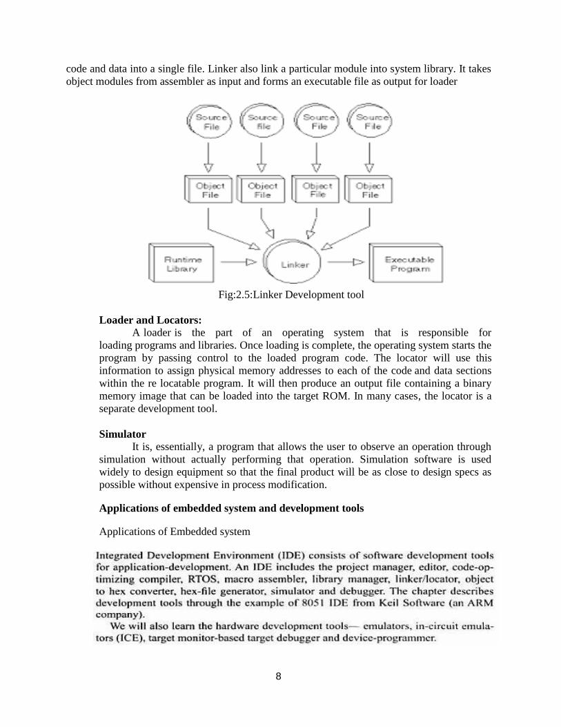
code and data into a single file. Linker also link a particular module into system library. It takes
object modules from assembler as input and forms an executable file as output for loader
Fig:2.5:Linker Development tool
Loader and Locators:
A loader is the part of an operating system that is responsible for
loading programs and libraries. Once loading is complete, the operating system starts the
program by passing control to the loaded program code. The locator will use this
information to assign physical memory addresses to each of the code and data sections
within the re locatable program. It will then produce an output file containing a binary
memory image that can be loaded into the target ROM. In many cases, the locator is a
separate development tool.
Simulator
It is, essentially, a program that allows the user to observe an operation through
simulation without actually performing that operation. Simulation software is used
widely to design equipment so that the final product will be as close to design specs as
possible without expensive in process modification.
Applications of embedded system and development tools
Applications of Embedded system

9
Development phases of a microcontroller based system
Integrated Development Environment
An integrated development environment (IDE) is software for building applications
that combines common developer tools into a single graphical user interface (GUI). An IDE,
or Integrated Development Environment, enables programmers to consolidate the different
aspects of writing a computer program. IDEs increase programmer productivity by
combining common activities of writing software into a single application: editing source
code, building executable, and debugging.
Getting Embedded Software into Target System
The locator will build a file as an image for the target software. There are few ways to getting
the embedded software file into target system.
PROM programmers
ROM emulators
In circuit emulators
Flash
Monitors
PROM Programmers:
The classic way to get the software from the locator output file into target system by

10
creating file in ROM or PROM. Creating ROM is appropriate when software development
has been completed, since cost to build ROMs is quite high. Putting the program into
PROM requires a device called PROM programmer device. PROM is appropriate if
software is small enough, if you plan to make changes to the software and debug. To do
this, place PROM in socket on the Target than being soldered directly in the circuit (the
following figure shows). When we find bug, you can remove the PROM containing the
software with the bug from target and put it into the eraser (if it is an erasable PROM) or
into the waste basket. Otherwise program a new PROM with software which is bug fixed
and free, and put that PROM in the socket. We need small tool called chip puller
(inexpensive) to remove PROM from the socket. We can insert the PROM into socket
without any tool than thumb (see figure8). If PROM programmer and the locator are from
different vendors, its upto us to make them compatible.
Moving maps into ROM or PROM, is to create a ROM using hardware tools or a PROM
programmer (for small and changeable software, during debugging). If PROM programmer
is used (for changing or debugging software), place PROM in a socket (which makes it
erasable – for EPROM, or removable/replaceable) rather than ‗burnt‘ into circuitry.
PROM‘s can be pushed into sockets by hand, and pulled using a chip puller. The PROM
programmer must be compatible with the format (syntax/semantics) of the Map
Fig: 2.5 : Schematic edge view of a socket
Getting Embedded Software into Target System – 1
ROM Emulators – Another approach is using a ROM emulator (hardware) which
emulates the target system, has all the ROM circuitry, and a serial or network interface to the
host system. It is used to get software into target. ROM emulator is a device that replaces the
ROM into target system. It just looks like ROM, as shown figure9; ROM emulator consists of
large box of electronics and a serial port or a network connection through which it can be
connected to your host. Software running on your host can send files created by the locator to
the ROM emulator. Ensure the ROM emulator understands the file format which the locator
creates. The locator loads the Map into the emulator, especially, for debugging purposes.
Software on the host that loads the Map file into the emulator must understand (be compatible
with) the Map‘s syntax/semantics

11
Fig: 2.6: ROM Emulator
In circuit emulators: If we want to debug the software, then we can use overlay memory which
is a common feature of in-circuit emulators. In-circuit emulator is a mechanism to get software
into target for debugging purposes. Flash: If your target stores its program in flash memory,
then one option you always have is to place flash memory in socket and treat it like an EPROM
.However, If target has a serial port, a network connection, or some other mechanism for
communicating with the outside world, link then target can communicate with outside world,
flash memories open up another possibility: you can write a piece of software to receive new
programs from your host across the communication link and write them into the flash memory.
Although this may seem like difficult
The reasons for new programs from host:
You can load new software into your system for debugging, without pulling chip out of socket
and replacing.
Downloading new software is fast process than taking out of socket, programming and
returning into the socket.
If customers want to load new versions of the software onto your product. The following are
some issues with this approach:
Here microprocessor cannot fetch the instructions from flash.
The flash programming software must copy itself into the RAM, locator has to take care all
these activities how those flash memory instructions are executing.
We must arrange a foolproof way for the system to get flash programming software into the
target i.e target system must be able to download properly even if earlier download crashes in
the middle.
To modify the flash programming software, we need to do this in RAM and then copy to
flash.
Monitors: It is a program that resides in target ROM and knows how to load new programs onto
the system. A typical monitor allows you to send the data across a serial port, stores the
software in the target RAM, and then runs it. Sometimes monitors will act as locator also, offers
few debugging services like setting break points, display memory

12
and register values. You can write your own monitor program
Getting Embedded Software into Target System – 2.
Using Flash Memory
For debugging, a flash memory can be loaded with target Map code using a software on
the host over a serial port or network connection (just like using an EPROM)
Advantages:
• No need to pull the flash (unlike PROM) for debugging different embedded code
• Transferring code into flash (over a network) is faster and hassle-free
DEBUGGING TECHNIQUES
Testing on host machine
Using laboratory tools
An example system
Introduction: While developing the embedded system software, the developer will develop the
code with the lots of bugs in it. The testing and quality assurance process may reduce the
number of bugs by some factor. But only the way to ship the product with fewer bugs is to write
software with few fewer bugs. The world extremely intolerant of buggy embedded systems.
The testing and debugging will play a very important role in embedded system software
development process.
Testing on host machine :
Goals of Testing process are
Find bugs early in the development process
Exercise all of the code
Develop repeatable , reusable tests
Leave an audit trail of test results
Find the bugs early in the development process: This saves time and money. Early
testing gives an idea of how many bugs you have and then how much trouble you are in. But
the target system is available early in the process, or the hardware may be buggy and unstable,
because hardware engineers are still working on it.
Exercise all of the code: Exercise all exceptional cases, even though, we hope that they
will never happen, exercise them and get experience how it works. It is impossible to exercise
all the code in the target. For example, a laser printer may have code to deal with the situation
that arise when the user presses the one of the buttons just as a paper jams, but in the real time
to test this case. We have to make paper to jam and then press the button within a millisecond,
this is not very easy to do. Develop reusable, repeatable tests: It is frustrating to see the bug
once but not able to find it. To make refuse to happen again, we need to repeatable tests. It is
difficult to create repeatable tests at target environment. Example: In bar code scanner, while
scanning it will show the pervious scan results every time, the bug will be difficult to find and
fix.

13
TEXT / REFERENCE BOOKS
1. KVKK Prasad, “Embedded / Real Time Systems”, Dreamtech Press, 2005.
2. David Simon, “An Embedded Software Primer”, Pearson Education Asia, First Indian
Reprint 2000.
3. Raj Kamal, „Embedded system-Architecture, Programming, Design‟, Tata McGraw Hill,
2011.
4. Arnold Berger, “Embedded system design”, CMP books, 1st Edition, 2005
5. Wayne Wolf, “Computers as components”, Morgan Kaufmann publishers, 2nd Edition,
2008.
6. Tammy Noergaard, “Embedded Systems Architecture”, Elsevier, 2006
Model Question Bank
Part-A
1. Define device driver.
2. How the software is embedded on to the system?
3. Explain the need for software in embedded systems
4. What are the programming languages used in embedded systems?
5. Define ISR.
6. Compare simulator and emulator.
7. Compare linker and locators.
8. Define interrupt latency.
9. What is the use of the debugger?
PART-B
1. Explain following concepts with example program.
a) Round robin Architecture
b) Round robin with interrupts
2. Explain following concepts with example
a) Function queue scheduling architectures
b) Compiler and cross compiler
3. Real Time operating systems (RTOS)
4. Explain the concept of selection of architecture for saving the memory space.
5. Compare the software architectures of embedded systems.
6. What are the advantages & disadvantages of software architectures?
7. Explain the Interrupt service routines (ISRs). What are the advantages of ISR?

1
UNIT –III- EMBEDDED NETWORKING
SECA1603
III EMBEDDED NETWORKING
SCHOOL OF ELECTRICAL & ELECTRONICS ENGINEERING
DEPARTMENT OF ELECTRONICS AND COMMUNICATION ENGINEERING

2
III EMBEDDED NETWORKING
Embedded Networking: Introduction, I/O Device Ports - Serial Bus communication protocols-
RS232 standard- RS485 - CAN Bus - RS485 - Serial Peripheral Interface (SPI) - Inter-Integrated Circuits
(I2C) - PC Parallel port communication Protocols - Bluetooth- network using ISA, PCI- Wireless and
Mobile System Protocols.
IO port types- Serial and parallel IO ports
A port is a device to receive the bytes from external peripheral(s) [or device(s) or processor(s) or
controllers] for reading them later using instructions executed on the processor to send the bytes to
external peripheral or device or processor using instructions executed on processor. A Port connects to
the processor using address decoder and system buses. The processor uses the addresses of the port-
registers for programming the port functions or modes, reading port status and for writing or reading
bytes.
Example
SI serial interface in 8051
SPI serial peripheral interface in 68HC11
PPI parallel peripheral interface 8255
Ports P0, P1, P2 and P3 in 8051 or PA, PB,PC and PD in 68HC11
COM1 and COM2 ports in an IBM PC IO Port Types
Types of Serial ports
Synchronous Serial Input
Synchronous Serial Output
Asynchronous Serial UART input
Asynchronous Serial UART output (both as input and as output, for example,modem.)
Types of parallel ports
Parallel port one bit Input
Parallel one bit output
Parallel Port multi-bit Input
Parallel Port multi-bit
Output Synchronous Serial Input Example
Inter-processor data transfer, reading from CD or hard disk, audio input, video input, dial tone, network
input, transceiver input, scanner input, remote controller input, serial I/O bus input, writing to flash
memory using SDIO (Secure Data Association IO based card).
Fig:3.1: Synchronous Serial Input

3
The sender along with the serial bits also sends the clock pulses SCLK (serial clock) to the
receiver port pin. The port synchronizes the serial data input bits with clock bits. Each bit in each
byte as well as each byte in synchronization Synchronization means separation by a constant
interval or phase difference.
If clock period = T, then each byte at the port is received at input in period = 8T. The bytes
are received at constant rates. Each byte at input port separates by 8T and data transfer rate or the
serial line bits is (1/T) bps. [1bps = 1 bit per s] Serial data and clock pulse-inputs On same input
line − when clock pulses either encode or modulate serial data input bits suitably. Receiver
detects the clock pulses and receives data bits after decoding or demodulating. On separate input
line − When a separate SCLK input is sent, the receiver detects at the middle or+ ve edge or –ve
edge of the clock pulses that whether the data-input is 1 or 0 and saves the bits in an 8-bit shift
register. The processing element at the port (peripheral) saves the byte at a port register from
where the microprocessor reads the byte.
Master output slave input (MOSI) and Master input slave output (MISO)
MOSI when the SCLK is sent from the sender to the receiver and slave is forced to synchronize
sent inputs from the master as per the inputs from master clock.
MISO when the SCLK is sent to the sender (slave)from the receiver (master) and slave is forced
to synchronize for sending the inputs to master as per the master clock outputs.
Synchronous serial input is used for inter processor transfers, audio inputs and streaming data
inputs.
Fig:3.2: Synchronous Serial Output
Inter-processor data transfer, multiprocessor communication, writing to CD or hard disk,
audio Input/output, video Input/output,dialer output, network device output, remote TV
Control, transceiver output, and serial I/O bus output or writing to flash memory using
SDIO
Synchronous Serial Output
Each bit in each byte sent in synchronization with a clock. Bytes sent at constant rates. If
clock period= T, then data transfer rate is (1/T) bps.
Sender either sends the clock pulses at SCLK pin or sends the serial data output and clock
pulse-input through same output line with clock pulses either suitably modulate or encode
the serial output bits.
Synchronous serial output using shift register
The processing element at the port (peripheral) sends the byte through a shift register at the port to where
the microprocessor writes the byte. Synchronous serial output is used for inter processor transfers, audio
outputs and streaming data outputs.

4
Fig:3.3: Synchronous Serial Input/output
Each bit in each byte is in synchronization at input and each bit in each byte is in
synchronization at output with the master clock output. The bytes are sent or received at
constant rates. The I/Os can also be on same I/O line when input/output clock pulses either
suitably modulate or encode the serial input/output, respectively. If clock period= T, then data
transfer rate is (1/T)bps. The processing element at the port (peripheral)sends and receives the
byte at a port register to or from where the microprocessor writes or reads the byte
Fig:3.4: Asynchronous Serial port line
Asynchronous Serial port line RxD (receive data). Does not receive the clock pulses or
clock information along with the bits.
Each bit is received in each byte at fixed intervals but each received byte is not in
synchronization. Bytes separate by the variable intervals or phase differences. Asynchronous
serial input also called UART input if serial input is according to UART protocol.
Example Serial Asynchronous Input

5
Asynchronous serial input is used for keypad inputs and modem inputs in computers
Keypad controller serial data-in, mice, keyboard controller, modem input, character send inputs
on serial line [also called UART (universal receiver and transmitter) input when according to
UART mode
Starting point of receiving the bits for each byte is indicated by a line transition from 1to 0 for a
period = T. [T−1 called baud rate.
If senders shift-clock period = T, then a byte at the port is received at input in period=
10.T or 11.T due to use of additional bits at start and end of each byte. Receiver detects n bits at
the intervals of T from the middle of the start indicating bit. The n = 0, 1, …, 10 or 11 and finds
whether the data-input is 1 or 0 and saves the bits in an 8-bit shift register.
Processing element at the port (peripheral)saves the byte at a port register from where the
microprocessor reads the byte.
Asynchronous Serial Output
Asynchronous output serial port line TxD(transmit data).
Each bit in each byte transmit at fixed intervals but each output byte is not in synchronization
(separates by a variable interval or phase difference). Minimum separation is 1 stop bit interval
TxD. Does not send the clock pulses along with the bits. Sender transmits the bytes at the
minimum intervals of n.T. Bits receiving starts from the middle of the start indicating bit, n = 0, 1,
…, 10 or 11 and sender sends the bits through a 10 or 11 -bit shift register. The processing
element at the port(peripheral) sends the byte at a port register to where the microprocessor is to
write the byte.
Synchronous serial output is also called UART output if serial output is according to UART
protocol
Example Serial Asynchronous Output. Output from modem, output for printer, the output on a
serial line [also called UART output when according to UART
Parallel Data Communication Half Duplex

6

7

8

9

10

11

12
Serial Data Communication
Data Communication is one of the most challenging fields today as far as technology
development is concerned. Data, essentially meaning information coded in digital form, that is, 0s
and 1s, is needed to be sent from one point to the other either directly or through a network. And
when many such systems need to share the same information or different information through the
same medium, there arises a need for proper organization (rather, ―socialization‖) of the whole
network of the systems, so that the whole system works in a cohesive fashion. Therefore, in order
for a proper interaction between the data transmitter (the device needing to commence data
communication) and the data receiver (the system which has to receive the data sent by a
transmitter) there has to be some set of rules or (―protocols‖) which all the interested parties must
obey. The requirement above finally paves the way for some data communication standards.
Depending on the requirement of applications, one has to choose the type of communication
strategy. There are basically two major classifications, namely SERIAL and PARALLEL, each
with its variants.
Serial data communication strategies and, standards are used in situations having a limitation
of the number of lines that can be spared for communication. This is the primary mode of transfer
in long-distance communication. But it is also the situation in embedded systems where various
subsystems share the communication channel and the speed is not a very critical issue. Standards
incorporate both the software and hardware aspects of the system while buses mainly define the
cable characteristics for the same communication type. Serial data communication is the most
common low-level protocol for communicating between two or more devices. Normally, one
device is a computer, while the other device can be a modem, a printer, another computer, or a
scientific instrument such as an oscilloscope or a function generator. As the name suggests, the
serial port sends and receives bytes of information, rather characters (used in the other modes of
communication), in a serial fashion - one bit at a time. These bytes are transmitted using either a
binary (numerical) format or a text format.
The most common serial communication system protocols can be studied under the following
categories: Asynchronous, Synchronous and Bit-Synchronous communication standards
RS-232
This is the original serial port interface ―standard‖ and it stands for ―Recommended
Standard Number 232‖ or more appropriately EIA Recommended Standard 232 is the oldest and
the most popular serial communication standard. It was first introduced in 1962 to help ensure
connectivity and compatibility across manufacturers for simple serial data communications.

13
Applications
Peripheral connectivity for PCs (the PC COM port hardware), which can range beyond modems
and printers to many different handheld devices and modern scientific instruments.
All the various characteristics and definitions pertaining to this standard can be summarized
according to the following
The maximum bit transfer rate capability and cable length. • Communication Technique: names,
electrical characteristics and functions of signals. • The mechanical connections and pin
assignments.
The Standard
Maximum Bit Transfer Rate, Signal Voltages and Cable Length
• RS-232‟s capabilities range from the original slow data rate of up to 20 kbps to over 1 Mbps
for some of the modern applications.
• RS-232 is mainly intended for short cable runs, or local data transfers in a range up to 50
feet maximum, but it must be mentioned here that it also depends on the Baud Rate
It is a robust interface with speeds to 115,200 baud, and
• It can withstand a short circuit between any 2 pins.
• It can handle signal voltages as high / low as ±15 volts.
Signal States and the Communication Technique Signals can be in either an active state or an
inactive state. RS232 is an Active LOW voltage driven interface where:
ACTIVE STATE: An active state corresponds to the binary value 1. An active signal state can
also be indicated as logic ―1‖, ―on‖, ―true‖, or a ―mark‖.
INACTIVE STATE: An inactive signal state is stated as logic ―0‖, ―off‖, ―false‖, or a ―space‖.
• For data signals, the ―true‖ state occurs when the received signal voltage is more negative than -
3 volts, while the "false" state occurs for voltages more positive than 3 volts.
• For control signals, the "true" state occurs when the received signal voltage is more positive
than 3 volts, while the "false" state occurs for voltages more negative than -3 volts.
Transition or “Dead Area”
Signal voltage region in the range >-3.0V and < +3.0V is regarded as the 'dead area' and
allows for absorption of noise. This same region is considered a transition region, and the signal
state is undefined.
To bring the signal to the "true" state, the controlling device un asserts (or lowers) the value for
data pins and asserts (or raises) the value for control pins. Conversely, to bring the signal to the
"false" state, the controlling device asserts the value for data pins and unasserts the value for
control pins. The "true" and "false" states for a data signal and for a control signal are as shown
below.
Fig:3.5: Graphical representation of communication technique

14
A factor that limits the distance of reliable data transfer using RS-232 is the signaling technique
that it uses.
This interface is ―single-ended‖ meaning that communication occurs over a SINGLE WIRE
referenced to GROUND, the ground wire serving as a second wire. Over that single wire, marks
and spaces are created. • While this is very adequate for slower applications, it is not suitable for
faster and longer applications.
The communication technique
RS-232 is designed for a unidirectional half-duplex communications mode. That simply means
that a transmitter (driver) is feeding the data to a receiver over a copper line. The data always
follows the direction from driver to receiver over that line. If return transmission is desired,
another set of driver- receiver pair and separate wires are needed. In other words, if bi-directional
or full-duplex capabilities are needed, two separate communications paths are required.
Fig:3.7: Single ended, Unidirectional, Half Duplex
Disadvantages
Being a single-ended system it is more susceptible to induced noise, ground loops and ground
shifts, a ground at one end not the same potential as at the other end of the cable
e.g. in applications under the proximity of heavy electrical installations and machineries Some
Modern Perspectives/Advantages
Most applications for RS-232 today are for data connectivity between portable handheld devices
and a PC. Some of the differences between the modern RS-232 integrals from the older versions
are:
Such devices require that the RS-232 IC to be very small, have low current drain, operate
from a +3 to +5-V supply.
They provide ESD protection on all transmit and receive pins. For example, some RS232
interfaces have specifically been designed for handheld devices and support data rates
greater than 250 kbps, can operate down to +2.7 V.
They can automatically go into a standby mode drawing very small currents of the order
of only 150 nA when not in use, provide 15 kV ESD protection on data pins and are in the
near- chip-scale 5 X 5 mm quad flat no-lead package. Nevertheless, for portable and
handheld applications the older RS-232 is still the most popular one.
RS-485
This is an improved RS-422 with the capability of connecting a number of devices
(transceivers) on one serial bus to form a network.
The Standard Maximum Bit Transfer Rate, Signal Voltages and Cable Length
Such a network can have a "daisy chain" topology where each device is connected to two
other devices except for the devices on the ends.
• Only one device may drive data onto the bus at a time. The standard does not
specify the rules for deciding who transmits and when on such a network. That solely

15
depends upon the system designer to define.
• Variable data rates are available for this standards but the standard max. data rate
is 10 Mbps, however ,some manufacturers do offer up to double the standard range i.e.
around 20 Mbps,but of course, it is at the expense of cable width.
• It can connect upto 32 drivers and receivers in fully differential mode similar to the
RS – 422.
Communication Technique
EIA Recommended Standard 485 is designed to provide bi-directional half-duplex multi- point
data communications over a single two-wire bus.
Like RS-232 and RS-422, full-duplex operation is possible using a four-wire, two-bus
network but the RS-485 transceiver ICs must have separate transmit and receive pins to
accomplish this.
RS-485 has the same distance and data rate specifications as RS-422 and uses differential
signaling but, unlike RS-422, allows multiple drivers on the same bus. As depicted in the
Figure below, each node on the bus can include both a driver and receiver forming a
multi- point star network. Each driver at each node remains in a disabled high impedance
state until called upon to transmit. This is different than drivers made for RS422 where
there is only one driver and it is always enabled and cannot be disabled.
With automatic repeaters and tri-state drivers the 32-node limit can be greatly exceeded.
In fact, the ANSI-based SCSI-2 and SCSI-3 bus specifications use RS-485 for the physical
(hardware) layer.
Fig:3.8:RS 485-Differential signaling, Bidirectional, Half duplex, Multipoint
Advantages
Among all of the asynchronous standards mentioned above this standard offers the
maximum data rate.
Apart from that special hardware for avoiding bus contention and ,
A higher receiver input impedance with lower Driver load impedances are its other assets.
Differences between the various standards at a glance
All together the important electrical and mechanical characteristics for application purposes may
be classified and summarized according to the table below.

16
Data Communication buses
The role of networking in present-day data communication hardly needs any elaboration. The situation
is also similar in the case of embedded systems, particularly those which are distributed over a larger
geographical region – the so-called distributed embedded systems. Unfortunately, the most common
network standard, namely the Ethernet, is not suitable for such distributed systems, especially when there
are real- time constraints to be satisfied. This is due to the lack of any service time guarantee in the
Ethernet standard. On the other hand, alternatives like Token Ring, which do provide a service-time
guarantee, are not very suitable because of the requirement of a ring-type topology not very convenient to
implement in the industrial environment. The industry therefore proposed a standard called „Token-bus‟
(and got it approved as the IEEE 802.5 specification) to cater to such requirements. However, the
standard became too complex and inefficient as a result. Subsequently different manufacturers have come
up with their own standards, which are being implemented in specific applications. In this lesson we
learn about three such standards, namely
I 2 C Bus
Field Bus
CAN Bus
CAN BUS
CAN was the solution developed by Robert Bosch GmbH, Germany in 1986 for the development
of a communication system between three ECUs (electronic control units) in vehicles being designed by
Mercedes. The UART, which had been in use for, long, had been rendered unsuitable in their situation
because of its point-to-point communication methodology. The need for a multi-master communication
system became a stringent requirement. Intel then fabricated the first CAN in 1987. Controller Area
Network (CAN) is a very reliable and message-oriented serial network that was originally designed for
the automotive industry, but has become a sought after bus in industrial automation as well as other
applications. The CAN bus is primarily used in embedded systems, and is actually a network established
among micro controllers. The main features are a two-wire, half duplex, high-speed network system
mainly suited for high-speed applications using short messages. Its robustness, reliability and
compatibility to the design issues in the semiconductor industry are some of the remarkable aspects of the
CAN technology.

17
Main Features
1. CAN can link up to 2032 devices (assuming one node with one identifier) on a single network. But
accounting to the practical limitations of the hardware (transceivers), it may only link up to110 nodes
(with 82C250, Philips) on a single network. ‰
2. It offers high-speed communication rate up to 1 Mbits/sec thus facilitating real- time control. ‰
3. It embodies unique error confinement and the error detection features making it more trustworthy and
adaptable to a noise critical environment.
CAN Versions
Originally, Bosch provided the specifications. However the modern counterpart is
designated as Version 2.0 of this specification, which is divided into two parts:
Version 2.0A or Standard CAN; Using 11 bit identifiers.
Version 2.0B or Extended CAN; Using 29 bit identifiers.
The main aspect of these Versions is the formats of the MESSAGE FRAME; the main difference being
the IDENTIFIER LENGTH.
CAN Standards There are two ISO standards for CAN. The two differ in their physical layer descriptions.
1. ISO 11898 handles high-speed applications up to 1Mbit/second.
2. ISO 11519 can go upto an upper limit of 125kbit/second. The Can Protocol/Message Formats
In a CAN system, data is transmitted and received using Message Frames.
Message Frames carry data from any transmitting node to single or multiple receiving nodes.
CAN protocol can support two Message Frame formats:
Version 2.0A - Standard CAN
Version 2.0B - Extended CAN

18
BASIC CAN Controller
The basic topology for the CAN Controller has been shown in figure 2 below. The basic
controller involves FIFOs for message transfers and it has an enhanced counterpart in
Full-CAN controller, which uses message BUFFERS instead.
Fig:3.9: Basic CAN Controller
Distributed Control Area Network example - a network of embedded systems in automobile
CAN-bus line usually interconnects to a CAN controller between line and host at the node. It
gives the input and gets output between the physical and data link layers at the host node.
The CAN controller has a BIU (bus interface unit consisting of buffer and driver), protocol
controller, status-cum control registers, receiver-buffer and message objects. These units connect
the host node through the host interface circuit Wireless and mobile system protocols Wireless Personal Area Network (WPAN)
IrDA (Infrared Data Association) Bluetooth 2.4 GHz
802.11 WLAN and 802.11b WiFi ZigBee 900 MHz
IrDA (Infrared Data Association)
Used in mobile phones, digital cameras, keyboard, mouse, printers to communicate to
laptop computer and for data and pictures download and synchronization.
Used for control TV, air-conditioning, LCD projector, VCD devices from a distance
Use infrared (IR) after suitable modulation of the data bits.
Communicates over a line of sight Phototransistor receiver for infrared rays
Fig:3.10: Block diagram of IrDA

19
IrDA protocol suite
Supports data transfer rates of up to 4 Mbps
Supports bi-directional serial communication over viewing angle between ± 15°
and distance of nearly 1 m
At 5 m, the IR transfer data can be up to data transfer rates of 75 kbps
Should be no obstructions or wall in between the source and receiver
Five levels of communication
Level 1─ minimum required communication.
Level 2 ─ access-based communication.
Level 3 ─index-based communication.
Level 4 ─ sync communication. Synchronization software, for example, ActiveSync
or HotSync is used.
Level 5 ─ SyncML (synchronization markup language) based communication. A
SyncML protocol is used for device management and synchronization with server and
client devices connected by IrDA.
IrDA Physical Layer
Lower layer─ physical layer 1.0 or 1.1.
1.0─ supports data transfer rates of 9.6 kbps to 115.2 kbps 1.1─ 115.2 kbps to 4 Mbps
5 layers of IrDA

20
Two sub-layers at IrDA data-link layer
IrLMP (IR link management protocol) upper sub-layer
IrLAP (IR link access protocol) lower sub-layer.
IrLAP─ HDLC synchronous communication
IrDA upper layer protocols
for Transport
for Session
for Application
IrDA Transport layer protocol During transmission specifies ways of flow control, segmentation
of data and packetization.
During reception, specifies assembling of the segments and packets.
Tiny TP (transport protocol).
IrLMIAS (IR Link Management Information Access Service Protocol).
IrDA Session Layer
IrLAN
IrBus
IrMC
IrTran
IrOBEX (Object Exchange) and
IrCOMM (IR communication) standard serial port emulator protocol
IrBus to provide serial bus access to game ports, joysticks, mice and keyboard.
IrDA Application layer protocol
Specifies security and application
For example, IrDA Alliance Sync protocol used to synchronize mobile devices
personal information manager (PIM) data−supports Object Push (PIM) or Binary File
Transfer.
Windows and the several operating systems support
Infrared Monitor in Windows monitors the IR port of the IR device.
Detects a nearby IR source.
Controls, detects and selects the IR communication activity.
On command, the device sets up connection using IrDA.
On command starts the IR communication.
When IR communication is inactive, the Monitor enables plug and play (unless
disabled).
Advantages:
IrDA protocol overhead between 2% to 50% of Bluetooth device overhead. Communication setup
latency is just few milliseconds.

21
Disadvantages:
Line of sight and unobstructed communication
ZigBee Wireless Personal Area connected devices
IEEE standard 802.15.4 protocol.
Physical layer radio operates 2.4 GHz band carrier frequencies with DSSS
(direct sequence spread spectrum).
Supports range up to 70 m.
Data transfer rate supported 250 kbps.
Supports sixteen channels.
ZigBee network feature
Self-organising and supports peer-to-peer and mesh networks. Self-organising means detects
nearby Zigbee device and establishes communication and network.
Peer-to-peer and mesh network
Each node at network function as requesting device as well as responding device.
Mesh network means the each nodes network function as a mesh.
A node can connect to another directly or through mutually interconnected
intermediate nodes. Data transfer is between two devices in Peer-to-Peer or between a
device
Fig:3.11: ZigBee supporting devices
ZigBee protocol supports large number of sensors, lighting devices, air conditioning,
industrial controller and other devices for home and office automation and their remote
control and formation of WPAN (wireless personal area network).
ZigBee network
Zigbee router - Transfers packets received from a neighboring source to nearby node
in the path to destination.
Zigbee coordinator - Connects one Zigbee network with another, or connects to
WLAN or cellular network.
Zigbee end devices – Transceiver of data

22
ZigBee features
Communication latency 30 ms
Protocol stack overhead 28 kB
802.11 Wireless LAN connected devices
IEEE standards 802.11a to 802.11g
802.11a data transfer rates─ 1 Mbps and 2 Mbps
802.11b data transfer rates─ 5.5 Mbps and 2 Mbps
FHSS or DSSS or Infrared 250 ns
802.11b
Called wireless fidelity (WiFi)
802.11b support data rates of 5.5 Mbps by mapping 4 bits
11 Mbps mapping 8 bits simultaneously during modulation.
Basic service set (BSS)
Has one wireless station, which communicates to an access point, also called hotspot.
BSS support ad-hoc network, which as and when node come nearby in range of
access point it forms the network through extended service set (ESS).
A node free to move from one BSS to another.
Fig:3.12: Basic service set
Independent basic service set (IBSS)
No access point.
Does not connect to the distribution system.
May have multiple stations, which also cannot communicate among themselves.
IBSS support ad-hoc network, which as and when nodes come nearby in range they form
the network

23
Fig:3.13: Independent basic service set
LAN-station access-points networked together
Called extended service set (ESS)
Backbone distribution system.
A backbone set may network through Internet
ESS support fixed infrastructure network
Fig:3.14: Called extended service set
802.11 protocol data link layer
Specifies a MAC layer
MAC layer specifies power management, handover and registration of roaming
mobile node within the backbone network at a new BSS within the ESS

24
Fig:3.15: 802.11 physical and data link layers 802.11 packet for MAC
Packet called request to send (RTS), which is first sent
If other end responses by the packet called clear to send (CTS), then the layer data is
transmitted.
MAC layer
Uses carrier sense multiple access and collision avoidance (CSMA/CA) protocol.
A station listens to the presence of carrier during a time interval is called distributed
inter-frame spacing (DIFS) interval.
If carrier is not sensed (detected) during DIFS then the station backs off for a random
time interval to avoid collision and retries after that interval.
802.11 protocol MAC Acknowledgment
A receiver always acknowledges within a short inter-frame spacing (SIFS)
Acknowledgment after successful CRC (cyclic redundancy check)
If there is no acknowledgement within SIFS, then transmitter retransmits and upto 7
retransmission attempts are made

25
802.11 Physical Layer communication methods
Three─ FHSS or DSSS or Infrared 250 ns pulses.
802.11a Physical layer has two sublayers
One is Physical Medium Dependent (PMD) protocol, Physical Layer
Convergence Protocol (PLCP)
802.11b additional sub-layer for specifying Complementary Code Keying (CCK)
Physical Medium Dependent (PMD) protocol 802.11 sublayer - Specifies the modulation and
coding methods.
Physical Layer Convergence Protocol (PLCP) 802.11 sub-layer - Specifies the header and
payload for transmission. It specifies the sensing of the carrier at receiver. It specifies how
packet formation takes place at the transmitter and packets assemble at the receiver. It
specifies ways to converge MAC (Medium Access Control) to PMD at transmitter and
separate MAC (Medium Access Control) from PMD at the receiver.
An additional sub-layer in 802.11b- Specifying Complementary Code Keying (CCK).
BLUETOOTH
Bluetooth enabled devices:
Synchronizing music, image, PIM (personal information
manager) files with Computer using Serial emulator at Bluetooth device
Large number of CD players mobile devices are Bluetooth Digital camera
Bluetooth enabled ear buds─ Hands free listening of Bluetooth enabled iPod or CD
music player or mobile phone.
Bluetooth - serial COM port interface
Fig:3.16: Bluetooth wireless protocol
WPAN using Bluetooth wireless protocol
Software embeds in the system to support WPAN using Bluetooth wireless protocol
Bluetooth devices─ piconet within 10m
Bluetooth devices─ scatternet within 100m

26
Data transfer between two devices or between a device and multiple devices
Bluetooth PICONET
Fig:3.17: Bluetooth PICONET
Fig:3.18:Bluetooth scatternet

27
Fig:3.19:Bluetooth Protocol
Hopping interval is 625 μs and number of hopped frequencies are 79
Bluetooth 1.x data transfer rate supported = 1 Mbps
Bluetooth 2.0 enhanced maximum data rate of 3.0 Mbps over 100 m
IEEE standard 802.15.1 protocol
Physical layer radio communicates at carrier frequencies in 2.4 GHz band with FHSS
(frequency hopping spread spectrum)
Bluetooth Protocol Features
• Supports automatic self-discovery
•Supports self-organization of network in number of devices.
•Bluetooth device self discovers nearby devices (< 10m) and they synchronize and form WPAN
(wireless personal area network).
• Bluetooth protocol supports power control so that the devices communicate at minimum
required power level
• This prevents drowning of signals by superimpositions of high power signals with lower
level signals
Bluetooth protocol Power control features
Bluetooth protocol supports power control so that the devices communicate at minimum
required power level
This prevents drowning of signals by superimpositions of high power signals with lower
level signals
Bluetooth Physical Layer
Three sub-layers- radio, baseband and link manager or host controller interface
There are two types of links, best effort traffic links and real-time voice traffic

28
links
The real-time traffic uses reserved bandwidth. Packet is of about 350 bytes
Physical layer─ radio, baseband and link manager or host controller interface
Link manager sub-layer
.
Specifies formation of device pairs for Bluetooth communication.
Gives specifications for state transmission mode, supervision, power level monitoring,
synchronization, and exchange of capability, packet flow latency, peak data rate,
average data rate, maximum burst size parameters from lower and higher layers.
Manages the master and slave link
Specifies data encryption and device authentication handling.
Host Controller Interface (HCI) interface
Provides for emulation of serial port, for example, 3-wire UART emulation.
Hardware abstraction sub-layer
Used in place of link manager sub-layer
Bluetooth device can thus interface to COM port of computer
Bluetooth protocol features
Communication latency is 3 s.
Large protocol stack overhead of 250kB.
Provision of encrypted secure communication, self-discovery and self- organization
and radio based communication between tiny antennae are three main features of
Bluetooth
TEXT / REFERENCE BOOKS
1. KVKK Prasad, “Embedded / Real Time Systems”, Dreamtech Press, 2005.
2. David Simon, “An Embedded Software Primer”, Pearson Education Asia, First
Indian Reprint 2000.
3. Raj Kamal, „Embedded system-Architecture, Programming, Design‟, Tata McGraw
Hill, 2011.
4. Arnold Berger, “Embedded system design”, CMP books, 1st Edition, 2005
5. Wayne Wolf, “Computers as components”, Morgan Kaufmann publishers, 2nd
Edition, 2008.
6. Tammy Noergaard, “Embedded Systems Architecture”, Elsevier, 2006
Model Question Bank
Part-A
1. Analyze the concept of RS232 standard.
2. Distinguish between Synchronous and Asynchronous communication.
3. Define half duplex and full duplex communication
4. Discuss few serial bus communication protocols.
5. Distinguish the differentiate between RS232 and RS485.
6. Define synchronous communication.
7. Explain about the limitations of I2C.
8. Illustrate the features of CAN and SPI serial interfaces.

29
Part-B
1. Illustrate the synchronous and asynchronous communications from serial devices.
2. Discuss the types of serial port devices.
3. Elaborate the architecture of CAN with necessary sketches
4. Describe one type of serial communication bus with its communication protocol
5. Explain in detail about SPI communication protocol and its interfacing techniques.
6. Illustrate the signal using a transfer of byte when using the I 2C bus and also the format of bits at
the I2C bus with diagram.
7. Discuss the I/O devices & its interfacing concepts?

1
UNIT –IV- EMBEDDED PROGRAMMING
SECA1603
SCHOOL OF ELECTRICAL & ELECTRONICS ENGINEERING
DEPARTMENT OF ELECTRONICS AND COMMUNICATION ENGINEERING

2
IV EMBEDDED PROGRAMMING
Programming in assembly language (ALP) vs High Level Language - C Program Elements:-
Macros and functions, Use of Date Types, Structure, Pointers, Function Calls - Concepts of
Embedded Programming in C++- Objected Oriented Programming, Embedded
Programming in C++,„C‟ Program compilers - Cross compiler - Optimization of
memory needs-Java programming advantages, disadvantages and J2ME concept.
SOFTWARE PROGRAMMING IN ASSEMBLY LANGUAGE (ALP) AND IN HIGH
LEVEL LANGUAGE „C‟
Assembly language coding of an application has the following advantages:
1. It gives a precise control of the processor internal devices and full use of processor
specific features in its instruction set and its addressing modes.
2. The machine codes are compact. This is because the codes for declaring the
conditions, rules, and data type do not exist. The system thus needs a smaller memory.
Excess memory needed does not depend on the programmer data type selection and
rule-declarations. It is also not the compiler specific and library functions specific.
3. Device driver codes may need only a few assembly instructions. For example,
consider a small-embedded system, a timer device in a microwave oven or an
automatic washing machine or an automatic chocolate vending machine. Assembly
codes for these can be compact and precise,
and are conveniently written.
It becomes convenient to develop the source files in C or C++ or Java for complex
systems because of the following advantages of high-level languages for such systems.
1. The development cycle is short for complex systems due to the use of functions
(procedures),standard library functions, modular programming approach and top down
design. Application programs are structured to ensure that the software is based on
sound software engineering principles.
(a) Let us recall Example 4.8 of a UART serial line device driver. Direct use of this
function makes the repetitive coding redundant as this device is used in many systems.
We simply change some of the arguments (for the variables) passed when needed and
use it at another instance of the device use.
(b) Should the square root codes be written again whenever the square root of another
value (argument) is to be taken? The use of the standard library function, square root (
), saves the programmer time for coding. New sets of library functions exist in an
embedded system specific C or C++ compiler. Exemplary functions are the delay ( ),
wait ( ) and sleep ( ).
(c) Modular programming approach is an approach in which the building blocks are
reusable software components. Consider an analogy to an IC (Integrated Circuit). Just
as an IC has several circuits integrated into one, similarly a building block may call
several functions and library functions. A module should however, be well tested. It
must have a well-defined goal and the well- defined data inputs and outputs. It should
have only one calling procedure. There should be one return point from it. It should
not affect any data other than that which is targeted. [Data Encapsulation.] It

3
must return (report) error conditions encountered during its execution.
(d) Bottom up design is a design approach in which programming is first done for the sub-
modules of the specific and distinct sets of actions. An example of the modules for
specific sets of actions is a program for a software timer, RTCSWT:: run. Programs
for delay, counting, finding time intervals and many applications can be written. Then
the final program is designed. The approach to this way of designing a program is to
first code the basic functional modules and then use these to build a bigger module.
(a) Top-Down design is another programming approach in which the main program is first
designed, then its modules, sub-modules, and finally, the functions.
2. Data type declarations provide programming ease. For example, there are four types of
integers, int, unsigned int, short and long. When dealing with positive only values, we
declare a variable as unsigned int. For example, numTicks (Number of Ticks of a
clock before the timeout) has to be unsigned. We need a signed integer, int (32 bit) in
arithmetical calculations. An integer can also be declared as data type, short (16 bit) or
long (64 bit).To manipulate the text and strings for a character, another data type is
char. Each data type is an abstraction for the methods to use, to manipulate, to
represent, and for a set of permissible operations.
3. Type checking makes the program less prone to error. For example, type checking
does not permit subtraction, multiplication and division on the char data types.
Further, it lets + be used for concatenation. [For example, micro + controller
concatenates into microcontroller, where micro is an array of char values and
controller is another array of char values.]
4. Control Structures (for examples, while, do - while, break and for) and Conditional
Statements (for examples, if, if- else, else - if and switch - case) make the program-
flow path design tasks simple.
5. Portability of non-processor specific codes exists. Therefore, when the hardware
changes, only the modules for the device drivers and device management,
initialization and locator modules [Section 2.5.2] and initial boot up record data need
modifications.
Additional advantages of C as a high level languages are as follows:
It is a language between low (assembly) and high level language. Inserting the assembly
language codes in between is called in-line assembly. A direct hardware
Control is thus also feasible by inline assembly and the complex part of the program can be in
high-level language. Example 4.5 showed the use of in-line assembly codes in C for a Port A
Driver Program.
High level language programming makes the program development cycle short, enables use
of the modular programming approach and lets us follow sound software engineering
principles. It facilitates the program development with Bottom up design‟ and „top down
design‟ approaches. Embedded system programmers have long preferred C for the following
reasons: (i) The feature of embedding assembly codes using in-line assembly. (ii) Readily
available modules in C compilers for the embedded system and library codes that can directly
port into the system- programmer codes.

4
PROGRAM ELEMENTS: MACROS ANDFUNCTIONS
Preprocessor Macros: A macro is a collection of codes that is defined in a program by a name. It
differs from a function in the sense that once a macro is defined by a name, the compiler puts the
corresponding codes for it at every place where that macro name appears. The
„enable_Maskable_Intr ( )‟ and „disable_Maskable_Intr ( )‟ are the macros [The pair of brackets is
optional. If it is present, it improves readability as it distinguishes a macro from a constant].
Whenever the name enable_Maskable_Intr appears, the compiler places the codes designed for it.
Macros, called test macros or test vectors are also designed and used for debugging a system.
How does a macro differ from a function? The codes for a function are compiled once only. On
calling that function, the processor has to save the context, and on return restore the context. Further,
a function may return nothing (void declaration case) or return a Boolean value, or an integer or any
primitive or reference type of data. [Primitive means similar to an integer or character. Reference
type means similar to an array or structure.] The enable_PortA_Intr ( ) and disable_PortA_Intr ( ) are
the function calls . [The brackets are now not optional]. Macros are used for short codes only. This is
because, if a function call is used instead of macro, the overheads (context saving and other actions
on function call and return) will take a time, Toverheads that is the same order of magnitude as the time,
Texec for execution of short codes within a function. We use a function when the Toverheads<< Texec, and
a macro when Toverheads ~= or > Texec.
Macros and functions are used in C programs. Functions are used when the requirement is that the
codes should be compiled once only. However, on calling a function, the processor has to save the
context, and on return, restore the context. Further, a function may return nothing (void declaration
case) or return a Boolean value, or an integer or any primitive or reference type of data. Macros are
used when short functional codes are to be inserted in a number of places or functions.
Use of Data Types
Whenever a data is named, it will have the address(es) allocated at the memory. The number of
addresses allocated depends upon the data type. „C‟ allows the following primitive data types. The
char (8 bit) for characters, byte (8 bit), unsigned short (16 bit), short (16 bit), unsigned int (32 bit), int
(32 bit),long double (64 bit), float (32 bit) and double (64 bit). [Certain compilers do not take the
„byte‟ as a data type definition. The char‟ is then used instead of „byte‟. Most C compilers do not
take a Boolean variable as data type. As in second line of Example 4.6, typedefis used to create a
Boolean type variable in the C program.]
A data type appropriate for the hardware is used. For example, a 16-bit timer can have only the
unsigned short data type, and its range can be from 0 to 65535 only. The typedef is also used. It is
made clear by the following example. A compiler version may not process the declaration as an
unsigned byte. The „unsigned character‟ can then be used as a data type. It can then be declared as
follows:
typedef unsigned character portAdata #define Pbyte portAdata Pbyte = 0xF1

5
Use of Data Structures: Queues, Stacks, Lists and Trees
Marks (or grades) of a student in the different subjects studied in a semester are put in a proper table.
The table in the mark-sheet shows them in an organised way. When there is a large amount of data, it
must be organised properly. A data structure is a way of organising large amounts of data. A data
element can then be identified and accessed with the help of a few pointers and/or indices and/or
functions. [The reader may refer to a standard textbook for the data structure algorithms in C and
C++. For example, ―Data Structures and Algorithms in C++‖ by Adam Drozdek from Brooks/Cole
Thomson Learning (2001).]
The queues, stacks and lists, respectively. Table 5.2 gives the uses and show exemplary uses of
queues, stacks, arrays, lists and trees.
Table:5.1:Use of the various data structures in a program element
Table 5.1
Uses of the Various Data Structures in a Program Element
Data
Definition and when used
Example (s) of its
use Structure
Queue It is a structure with a series of elements with the first
(1) Print buffer. Each character is
element waiting for an operation. An operation can be done
to be printed in FIFO mode.
only in the first in first out (FIFO) mode. It is used when
(2) Frames on a network [Each
an element is not to be accessible by any index and pointer
frame also has a queue of a stream
directly, but only through the FIFO. An element can be
of bytes.] Each byte has to be
inserted only at the end in the series of elements waiting for
sent for receiving as a FIFO.
an operation. There are two pointers, one for deleting after
(3) Image frames in a sequence.
the operation and other for inserting. Both increment after
an operation.
[These have to be processed
as a FIFO.]
Stack
It is a structure with a series of elements with its last
(1) Pushing of variables on
element waiting for an operation. An operation can be done
interrupt or call to another
only in the last in first out (LIFO) mode. It is used when an
function. (2) Retrieving the
element is not to be accessible by any index or pushed data onto a pointer stack.
directly, but only through the LIFO. An element can be
pushed (inserted) only at the top in the series of elements
still waiting for an operation. There is only one pointer used
for pop (deleting) after the operation as well as for push

6
Array
(one
dimension
al
(inserting). Pointers increment or decrement after an
operation. It depends on insertion or deletion.
It is a structure with a series of elements with
each element
accessible by an identifier name and an index. Its element
ts = 12 * s(1); Total salary, ts is
12 times the first month salary.
vector) can be used and operated easily. It is used when each element
Multi-
dimension
al
array
marks_weight [4] =
of the structure is to be given a distinct identity by an index
for easy operation. Index stars from 0 and is +ve integers.
It is a structure with a series of elements each having another
sub-series of elements. Each element is accessible by
identifier name and two or more indices. It is used when
every element of the structure is to be given a distinct
identity by two or more indices for easy operation. The
dimension of an array equals the number of indices that are
needed to distinctly identify an array-element. Indices start
from 0 and are +ve integers.
marks_weight [0]; Weight of
marks in the subject with index 4
is assigned the same as in the
subject with index 0.
Handling a matrix or
tensor.
Consider a pixel in an image
frame. Consider Quarter-CIF
image pixel in 144 x 176 size
image frame. [Recall Section
1.2.7.] pixel [108, 88] will
represent a pixel at 108-th
horizontal row and 88-th
vertical column. #See
following note also.
Each element has a pointer to its next element. A series of tasks
List Only the first
element is identifiable and it is done by list- top pointer
(Header). No other element is identifiable and hence is not
accessible directly. By going through the first element, and
then consecutively through all the succeeding
which are
active Each task has pointer for
the next task. Another example
is a menu that point to a
elements, an submenu.
element can be read, or read and deleted, or can be added to
a neighbouring element or replaced by another
element.

7
Data
Structure
Definition and when used Example (s) of its use
Tree
There is a root element. It has two or more branches each
having a daughter element. Each daughter element has two or
more daughter elements. The last one does not have
An example is a directory. It has number of file-folders. Each file-
folder has a number of other file
daughters. Only the root element is identifiable folders and so on In the and it is done
by the treetop pointer (Header). No other
end is a
element is file.
identifiable and hence is not accessible directly. By traversing
the root element, then proceeding continuously through all
the succeeding daughters, a tree element can be read or read
and deleted, or can be added to another daughter or replaced
by another element. A tree has data elements arranged as
branches. The last daughter, called node has no
further daughters. A binary tree is a tree with a maximum of two
daughters (branches) in each element.
Use of Pointers, NULL Pointers
Pointers are powerful tools when used correctly and according to certain basic principles. Exemplary
uses are as follows. Let a byte each be stored at a memory address.
1. Let a port A in system have a buffer register that stores a byte. Now a program using a pointer
declares the byte at port A as follows: „unsigned byte
*portA‟. [or Pbyte *portA.] The * means „the contents at‟. This declaration means that there is
apointer and an unsigned byte for portA, The compiler will reserve one memory address for
that byte. Consider „unsigned short *timer1‟. A pointer timer1 will point to two bytes, and the
compiler will reserve two memory addresses for contents of timer1.
2. Consider declarations as follows. void *portAdata; The void means the undefined data type
for portAdata. The compiler will allocate for the
*portAdata without any type check.
3. A pointer can be assigned a constant fixed address as in Example 4.5. Recall two preprocessor
directives: „# define portA (volatile unsigned byte *) 0x1000‟ and „# define PIOC (volatile
unsigned byte *) 0x1001‟. Alternatively, the addresses in afunction can be assigned as follows.
„volatile unsigned byte * portA = (unsigned byte *) 0x1000‟ and „volatile unsigned byte
*PIOC = (unsigned byte *) 0x1001‟. An instruction, „portA ++;‟ will make the portA pointer
point to the next address and to which is the PIOC.

8
4. Consider, unsigned byte portAdata; unsigned byte *portA = &portAdata. The first statement
directs the compiler to allocate one memory address for portAdata because there is a byte
each at an address. The & (ampersand sign) means „at the address of‟. This declaration means
the positive number of 8 bits (byte) pointed by portA is replaced by the byte at the address of
portAdata. The right side of the expression evaluates the contained byte from the address, and
the left side puts that byte at the pointed address. Since the right side variable portAdata is not
a declared pointer, the ampersand sign is kept to point to its address so that the right side
pointer gets the contents (bits) from that address. [Note: The equality sign in a program
statement means „is replaced by‟].
5. Consider two statements, „unsigned short *timer1;‟ and „timer1++;‟. The second
statement adds 0x0002 in the address of timer1. Why? timer1 ++ means point to next address,
and unsigned short declaration allocated two addresses for timer1. [timer1 ++; or timer1 +=1
or timer = timer +1; will have identical actions.] Therefore, the next address is 0x0002 more
than the address of timer1 that was originally defined. Had the declaration been „unsigned int‟
(in case of 32 bit timer), the second statement would have incremented the address by
0x0004.
When the index increments by 1 in case of an array of characters, the pointer to the previous element
actually increments by 1, and thus the address will increment by 0x0004 in case of an array of
integers. For array data type, * is never put before the identifier name, but an index is put within a
pair of square brackets after the identifier. Consider a declaration, „unsigned
charportAMessageString [80];‟. The port A message is a string, which is an array of 80
characters.Now, portAMessageString is itself a pointer to an address without the star sign before it.
[Note: Array is therefore known as a reference data type.] However,
*portAMessageString will now
refer to all the 80 characters in the string. portAMessageString [20] will refer to the twentieth element
(character) in the string. Assume that there is a list of RTCSWT (Real Time Clock interrupts
triggered Software Timers) timers that are active at an instant. The top of the list can be pointed as
„*RTCSWT_List.top‟ using the pointer. RTCSWT_List.top is now the pointer to the top of the
contents in a memory for a list of the active RTCSWTs. Consider the statement
„RTCSWT_List.top ++;‟ It increments this pointer in a loop. It will not point to the next top of another
object in the list (another RTCSWT) but to some address that depends on the memory addresses
allocated to an item in the RTCSWT_List. Let ListNow be a pointer within the memory block of the
list top element. A statement
„*RTCSWT_List. ListNow =*RTCSWT_List.top;‟ will do the following.
RTCSWT_List pointer is now replaced byRTCSWT list-top pointer and now points to the next list
element (object). [Note: RTCSWT_List.top ++ for pointer to the next list-object can only be used
when RTCSWT_List elements are placed in an array. This is because an array is analogous to
consecutively located elements of the list at the memory. Recall Table 5.2.]
1. A NULL pointer declares as following: „#define NULL (void*) 0x0000‟. [We can assign any
address instead of 0x0000 that is not in use in a given hardware.] NULL pointer is very
useful. Consider a statement: „while (* RTCSWT_List. ListNow ->state != NULL) {
numRunning++;‟. When a pointer to ListNow in a list of software timers that are running at
present is notNULL, then only execute the set of statements in the given pair of opening and
closing curly braces. One of the important uses of the NULL pointer is in a list. The last
element to point to the end of a list, or to no more contents in a queue or empty stack, queue
or list.

9
Use of Function Calls
There are functions and a special function for starting the program execution, void main (void)‟.
Given below are the steps to be followed when using a function in the program.
1. Declaring a function: Just as each variable has to have a declaration, each function must be
declared. Consider an example. Declare a function as follows: „intrun (int
indexRTCSWT,unsigned int maxLength, unsigned int numTicks, SWT_Type swtType,
SWT_Action swtAction, boolean loadEnable);‟. Here int specifies the returned data type. The
run is the function name. There are arguments inside the brackets. Data type of each argument
is also declared. A modifier is needed to specify the data type of the returned element
(variable or object) from any function. Here, the data type is specified as an integer. [A
modifier for specifying the returned element may be also be static, volatile, interrupt and
extern.]
2. Defining the statements in the function: Just as each variable has to be given the contents
orvalue, each function must have its statements. Consider the statements of the function „run‟.
These are within a pair of curly braces as follows: „int RTCSWT:: run (int
indexRTCSWT,unsigned int maxLength, unsigned int numTicks, SWT_Type swtType,
SWT_Action swtAction, boolean loadEnable) {...};‟. The last statement in a function is for the
return and may also befor returning an element.
3. Call to a function: Consider an example:„if (delay_F = = true && SWTDelayIEnable = =
true)ISR_Delay ( );‟. There is a call on fulfilling a condition. The call can occur several times
and can be repeatedly made. On each call, the values of the arguments given within the pair of
bracket pass for use in the function statements.
(i) Passing the Values (elements)
The values are copied into the arguments of the functions. When the function is executed in this way,
it does not change a variable‟s value at thecalled program. A function can only use the copied values
in its own variables through the arguments. Consider a statement, „run (int indexRTCSWT, unsigned
int maxLength, unsigned int numTicks, SWT_Type swtType, SWT_Action swtAction,
booleanloadEnable) {...}‟. Function „run‟ arguments indexRTCSWT, maxLength, numTick, swtType,
and loadEnable original values in the calling program during execution of the codes will remain
unchanged.The advantage is that the same values are present on return from the function. The
arguments that are passed by the values are saved temporarily on a stack and retrieved on return from
the function.
(ii) Reentrant Function
Reentrant function is usable by the several tasks and routines synchronously (at the same time). This
is because all its argument values are retrievable from the stack. A function is calledreentrant func-
tion when the following three conditions are satisfied.
1. All the arguments pass the values and none of the argument is a pointer (address) whenever a
calling function calls that function. There is no pointer as an argument in the above example
offunction „run‟.
2. When an operation is not atomic, that function should not operate on any variable, which is
declared outside the function or which an interrupt service routine uses or which is a global
variable but passed by reference and not passed by value as an argument into the function.
[The value of such a variable or variables, which is not local, does not save on the stack when
there is call to another program.]
The following is an example that clarifies it further. Assume that at a server (software), there is a
32 bit variable count to count the number of clients (software) needing service. There is no option
except to declare the count as a global variable that shares with all clients. Each client on a
connection to a server sends a call to increment the count. The implementation by the assembly
code for increment at that memory location is non-atomic when (i) the processor is of eight bits,
and (ii) the server-compiler design is such that it does not account for the possibility of interrupt
in-between the four instructions that implement the increment of 32-bit count on 8-bit processor.
There will be a wrong value with the server after an instance when interrupt occurs midway
during implementing an increment of count.
1. That function does not call any other function that is not itself Reentrant. Let
RTI_Count be aglobal declaration. Consider an ISR, ISR_RTI. Let an„RTI_Count
++;‟ instruction be where the RTI_Count is variable for counts on a real- time clock
interrupt. Here ISR_RTI is a not a Reentrant routine because the second condition may not be

10
fulfilled in the given processor hardware. There is no precaution that may be taken here by the
programmer against shared data problems at the address of the RTI_Count because there may
be no operation that modifies RTI_Counts in any other routine or function than the IST_RTI.
But if there is another operation that modifies the RTI_Count the shared-data problem will
arise.
Passing the References
When an argument value to a function passes through a pointer, the function can change this
value. On returning from this function, the new value will be available in the calling program or
another function called by this function. [There is no saving on stack of a value that either (a) passes
through a pointerin the function- arguments or (b) operates in the function as a global variable or (c)
operates through a variable declared outside the function block.4.7 Multiple Function Calls in Cyclic
Order in the Main
One of the most common methods is for the multiple function-calls to be made in a cyclic order in
an infinite loop of the main. Recall the 64 kbps network problem. Let us design the C codes for an
infinite loop for this problem. Example 5.4 shows how the multiple function calls are defined in the
main for execution in the cyclic orders. Figure 5.1 shows the model adopted here.
Fig:5.1: Programming model for multiple function calls
.
Example 5.4
typedef unsigned char
int8bit; # define int8bit
boolean
# define false 0
# define true 1
void main (void) {
/* The Declarations of all variables, pointers, functions here and also
initializations here */
unsigned char *portAdata;

11
boolean charAFlag;
boolean checkPortAChar ( );
void inPortA (unsigned char
*);
void decipherPortAData (unsigned char
*); void encryptPortAData (unsigned
char *); void outPortB (unsigned char
*);
.
while (true) {
/* Codes that repeatedly execute */
/* Function for availability check of a
character at port A*/ while (charAFlag !=
true) checkPortAChar ( );
/* Function for reading PortA
character*/ inPortA (unsigned char
*portAdata);
/* Function for deciphering */
decipherPortAData (unsigned char *portAdata);
/* Function for encoding */
encryptPortAData (unsigned char *portAdata);
/* Function for retransmit output to
PortB*/ outPort B (unsigned char
*portAdata);
};
}
Function Pointers, Function Queues and Interrupt Service Routines Queues
Let the * sign not be put before a function name, but there are arguments within the
pair of brackets, and the statements for those executed on a call for the function. The
statements are inside a pair of the curly braces. Consider a declaration in the Example
5.4, „boolean checkPortAChar ( );‟.„checkPortAChar‟ is a function, which returns
a Boolean value. Now, checkPortAChar is itself a pointer to the starting address of the
statements of the function inside the curly braces without the star sign before it. The
program counter will fetch the address of checkPortAChar, and CPU sequentially
executes the function-statements from here. Now, let the * sign be put before the function. „* checkPortAChar‟ will now refer to all
the compiled form statements in the memory that are specified within the curly braces.
Consider a declaration in the example, „void inPortA (unsigned char *);‟.
1. inPortAmeans a pointer to the statements of the function. Inside the bracket, there
is anunsigned character pointed by some pointer.
2. *inPortA will refer to all the compiled form statements of inPortA.
3. (* inPortA) will refer to calls to the statements of inPortA.
4. What will a statement, „void create (void (*inPortA) (unsigned char *), void
*portAStack, unsigned char port Apriority);‟ mean?
(a) First modifier „void‟ means create function does not return anything.
(b) „create‟ is another function.
(c) Consider the argument of this function „void (*inPortA) (unsigned char
*portAdata)‟. (*inPortA) means call the statements of inportA the argument of
which is „unsigned char *portAdata‟.
(d) The second argument of create function is a pointer for the portA stack at the
memory.
(e) The third argument of create function is a byte that defines the portA priority.
An important lesson to be remembered from above discussion is that a returning data

12
type specifi-cation (for example, void) followed by „(*functionName)
(functionArguments)‟ calls the statements of the functionName using the
functionArguments, and on a return it returns the specified data object.
We can thus use the function pointer for invoking a call to the function.When there are
multiple ISRs, a high priority interrupt service routine is executed first and the lowest
priority, last. [Refer Section 4.6.4.] It is possible that function calls and statements in any
of the higher priority interrupts may block the execution of low priority ISR within the
deadline. How is the deadline problem for low priority routines to be solved? One
solution is by using the function pointers in the routines, and forming a queue for them.
The functions are then executed at a later stage. Pointers are needed in number of
situations, for example, port bit manipulation and read or write. Software designers must
learn the uses of pointers in depth. An innovative concept is use of function queues and
the queues of the function pointers built by the ISRs. It reduces significantly the ISR
latency periods. Each device ISR is therefore able to execute within its stipulated
deadline.
Objected Oriented Programming
An objected oriented language is used when there is a need for re-usability of the defined
object or set of objects that are common within a program or between the many
applications. When a large pro-gram is to be made, an object-oriented language offers
many advantages. Data encapsulation, design of reusable software components and
inheritance are the advantages derived from the OOPs.
An object-oriented language provides for defining the objects and methods that
manipulate the objects without modifying their definitions. It provides for the data and
methods for encapsulation. An object can be characterized by the following:
An identity (a reference to a memory block that holds its state and behavior). A
state (its data, property, fields and attributes).
A behavior (method or methods that can manipulate the state of the object).
In a procedure-based language, like FORTRAN, COBOL, Pascal and C, large
programs are split into simpler functional blocks and statements. In an object- oriented
language like Smalltalk, C++ or Java, logical groups (also known as classes) are first
made. Each group defines the data and the methods of using the data. A set of these
groups then gives an application program. Each group has internal user-level fields for
the data and the methods of processing that data at these fields. Each group can then
create many objects by copying the group and making it functional. Each object is
functional. Each object can interact with other objects to process the user‟s data. The
language pro-vides for formation of classes by the definition of a group of objects having
similar attributes and common behavior. A class creates the objects. An object is an
instance of a class.
Embedded Programming in C++
1. What are programming advantages of C++?
C++ is an object oriented Program (OOP) language, which in addition, supports the
procedure ori-ented codes of C. Program coding in C++ codes provides the advantage of
objected oriented program-ming as well as the advantage of C and in-line assembly.
Programming concepts for embedded pro-gramming in C++ are as follows:
(i) A class binds all the member functions together for creating objects. The objects
will have memory allocation as well as default assignments to its variables that are
not declaredstatic. Let us assume that each software timer that gets the count input
from a real time clock is an object. Now consider the codes for a C++ class
RTCSWT. A number of software timer objects can be created as the instances of
RTCSWT.
(ii) A class can derive (inherit) from another class also. Creating a child class from
RTCSWT as a parent class creates a new application of the RTCSWT.
(iii) Methods (C functions) can have same name in the inherited class. This is

13
called method over loading. Methods can have the same name as well as the same
number and type of arguments in the inherited class. This is called method
overriding. These are the two significant features that are extremely useful in a
large program.
(iv
) Operators in C++ can be overloaded like in method overloading. Recall the following
statements
and expressions in Example 5.8. The operators ++ and ! are overloaded to perform
a set of
operations. [Usually the++ operator is used for post-increment and pre-
increment
and the !
operator is used for a not operation.]
const OrderedList & operator ++ ( ) {if (ListNow != NULL) ListNow =
ListNow -
> pNext;
return *this;}
boolean int OrderedList & operator ! ( ) const {return (ListNow != NULL) ;};
[Java does not support operator overloading, except for the + operator. It is used for
summation as well string-concatenation.]
There is struct that binds all the member functions together in C. But a C++ class has
object features. It can be extended and child classes can be derived from it. A number of
child classes can be derived from a common class. This feature is called polymorphism.
A class can be declared as public or private. The data and methods access is restricted
when a class is declared private. Struct does not have these features.
2. What are then the disadvantages of C++ ?
Program codes become lengthy, particularly when certain features of the standard C++
are used.
Examples of these features are as follows:
(a) Template.
(b) Multiple Inheritance (Deriving a class from many parents).
(c) Exceptional handling.
(d) Virtual base classes.
(e) Classes for IO Streams. [Two library functions are cin (for character (s) in) and
cout (for character (s) out). The I/O stream class library provides for the input and
output streams of characters (bytes). It supports pipes, sockets and file management
features. Refer to Section 8.3 for the use of these in inter task communications.]
3. Can optimization codes be used in Embedded C++ programs to eliminate the
disadvan-tages?
Embedded system codes can be optimised when using an OOP language by the following
(a) Declare private as many classes as possible. It helps in optimising the
generated codes.
(b) Use char, int and boolean (scalar data types) in place of the objects (reference
data types) as arguments and use local variables as much as feasible.
(c) Recover memory already used once by changing the reference to an object to
NULL.
A special compiler for an embedded system can facilitate the disabling of specific
features provided in C++. Embedded C++ is a version of C++ that provides for a
selective disabling of the above features so that there is a less runtime overhead and less
runtime library. The solutions for the library functions are available and ported in C
directly. The IO stream library functions in an embedded C++ compiler are also
reentrant. So using embedded C++ compilers or the special compilers make the

14
C++ a significantly more powerful coding language than C for embedded systems.
GNU C/C++ compilers (called gcc) find extensive use in the C++ environment in
embedded soft-ware development. Embedded C++ is a new programming tool with a
compiler that provides a small runtime library. It satisfies small runtime RAM needs by
selectively de-configuring features like, tem-plate, multiple inheritance, virtual base class,
etc. when there is a less runtime overhead and when the less runtime library using solutions
are available. Selectively removed (de-configured) features could be template, run time
type identification, multiple Inheritance, exceptional handling, virtual base classes, IO
streams and foundation classes. [Examples of foundation classes are GUIs (graphic user
interfaces). Exemplary GUIs are the buttons, checkboxes or radios.]
An embedded system C++ compiler (other than gcc) is Diab compiler from Diab Data. It
also provides the target (embedded system processor) specific optimisation of the codes.
[Section 5.12] The run-time analysis tools check the expected run time error and give a
profile that is visually interactive.
! Embedded C++ is a C++ version, which makes large program development simpler by
providing object-oriented programming (OOP) features of using an object, which binds
state and behavior and which is defined by an instance of a class. We use objects in a way
that minimizes memory needs and run-time overheads in the system. Embedded system
programmers use C ++ due to the OOP features of software re-usability, extendibility,
polymorphism, function overriding and overloading along portability of C codes and in-
line assembly codes. C++ also provides for overloading of operators. A compiler, gcc, is
popularly used for embedded C++ codes compilation. Diab compiler has two special
features: (i) processor specific code optimization and (ii) Run time analysis tools for
finding expected run-time errors.
Object Oriented Programming
An object oriented language is used when there is a need for re-usability of the
defined object or set of object that are common within a program or between many
applications. When a large program is to be made an object oriented programming language
offers many advantages. Data encapsulations, design of reusable software components and
inheritance are the advantages derived from the OOPs.
An object oriented language provides for defining the objects and methods that
manipulate the objects without modifying their definitions. It provides for the data and the
methods for encapsulation. An object can be characterized by the following;
1. An identity
2. A state
3. A behavior
In a procedure Based Language like FORTRAN, COBOL, Pascal and C, large programs
are split into simpler functional blocks and statements. In an object oriented language like
small talk, C++ or java logical groups are first made. Each group defines the data and the
methods of using the data. Each group has internal user level fields for the data and the
methods of processing that data at these fields. Each group can then create many objects to
process the user data. The language provides the formation of classes by the definition of a
group of objects having similar attributes and common behavior. A class creates the objects.
An object is an instance of a class
Embedded Programming in C++
C++ is an object oriented language which in addition supports the procedure oriented
codes of C. program coding in C++ codes provides the advantage of object oriented
programming as well as the advantage of C and in-line assembly.

15
Programming concepts for embedded programming in C++ are as follows;
i. A class binds all the member function together for creating objects. The objects will
have memory allocation as well as default assignments to its variables that are not
declared static. Let us assume that each software timer that gets the count input from a
real time clock is an object. A number of software timer objects can be created as the
instances of RTCSWT
ii. A class can derive from another class also. Creating a child class from RTCSWT as a
parent class creates a new application of the RTCSWT
ii. Methods can have same name in the inherited class. This is called method overloading.
Methods can have the same name aswell as the same number and type of arguments
in the inherited class. This is called method overriding. These are the two significant
features that are extremely useful in a large program
iv. Operators in C++ can be overloaded like in method overloading. There is
„struct‟ that binds all the member function together in C. but a C++ class has object
features. It can be extended and child classes can be derived from it. A number of
child classes can be derived from a common class. This feature is called
polymorphism. A class can be declared as private or public. The data and methods
access is restricted when a class is declared as private. „struct‟ does not have
thesefeatures
Disadvantages of C++
Program codes become lengthy particularly when certain features of the standard used.
Example of these features are as follows;
a. Template
b. Multiple inheritance
c. Exceptional handling
d. Virtual base classes
e. Classes for IO streams
Embedded system codes can be optimized when using the OOP language
i. Declare private as many classes as possible. It helps in optimizing the generated codes
ii. Use „char‟, int and Boolean in place of the objects as arguments and use local
variables as much as feasible
iii. Recover memory already used once by changing the reference to an object to NULL
A Special compiler for an embedded system can facilitate the disabling of specific
features provided in C++. The solution for the library functions are available and ported
in C directly. The IO stream library function is an embedded C++ compiler are also
reentrant. So using embedded C++ compilers or the special compilers make the C++
significantly more powerful coding language than C for embedded systems
4.2 C Program compilers and cross compilers
Two compilers are needed. One is c program compiler and the other one is cross
compiler. Compiler is for the host computer which does the development and design and
also the testing and debugging.
The second compiler is the cross compiler. The cross compiler runs on the host but
develops the machine codes for a targeted system. There is a popular free ware called
GNU. A GNU compiler is configurable both as host compiler as well as cross compiler. A
compiler generates an object file. For compilation of the host alone the compiler can be
turbo C, turbo C++ and Borland C++. The target system specific or multi choice cross
compilers that are available commercially may be used. These are available for most of
the embedded systems, microprocessor and microcontrollers. The host runs the cross
compilers that offer an integrated development environment. It means that a target system
can emulate and simulate the application

16
system on the host.
Use of appropriate compilers and cross compilers is essential in any embedded
software development
Optimization of memory needs
When codes are made compact and fitted in small memory areas without affecting the
code performance, it is called memory optimization. It also reduces the total number of
CPU cycles and thus the total energy requirements. The following are used to optimize
the use of memory in a system;
i. Use declaration as unsigned byte if there is a variable, which always has a value
between 0 and 255. When using the data structures, limit the maximum size of
queues, list and stacks size to 256. Byte arithmetic takes less time than integer
arithmetic
ii. Avoid use of library functions if a simpler coding is possible. Library functions
are the general functions. Use of general function needs more memory in several
cases
iii. When the software designer knows fully the instruction set of the target processor,
assembly codes must be used. This also allows the efficient use of memory. The
device driver programs in assembly especially provides efficiency due to the need
to use the bit set-reset instruction for the control and status registers. Only the few
assembly codes for using the device IO port, addresses and control and status
registers are needed. Assembly coding also helps in coding for atomic operations.
A modifier register can be used in the C program for a fast access to a frequently
used variable
iv. Calling a function causes context saving on a memory stack and on return the
context is retrieved. This involves time and can increase the worst case interrupt-
latency. There is a modifier in-line. When the in-line modifier is used the compiler
inserts the actual code at all the places where these operations are used. This
reduces the time and stack overheads in the function call and return. Using
modifier directs the compiler to put the codes for the function instead of calling
that function
v. As long as shared data problem doesnot arise, the use of global variables can be
optimized. These are not used as the arguments for passing the values. A good
function is one that has no arguments to be passed. The passed values are saved
on the stacks in case of interrupt service calls and other function calls. Besides
obviating the need for repeated declaration the use of global variables will thus
reduce the worst case interrupt latency and the time and the stack overheads in the
function call and return. But this is at the cost of the codes for eliminating shared
data problem. When a variable is declared static the processor access with less
instruction than from the stack.
vi. Combine two function if possible. The search function for finding pointers to a list
item and pointers of previous list items combine into one. It present is false the
pointer of the previous list item retrieves the one that has the item
vi. All the timers and a conditional statement that changes the count input in case of a
running count and does not change it in case of ideal state timers could have also
been used. More number of calls will however be needed and not once but
repeatedly on each real time clock interrupt tick. The RAM memory needed will
be more. Their fore creating a list of running counts is a more efficient way,
similarly bringing the task first into an initiated task list will reduce the frequent

17
interaction with the OS and context savings and retrieval stack and time
overheads.
vii. Use of feasible alternatives to the switch statements with a table of pointers to the
functions. This saves processor time in deciding which set of statements to
execute while performing the conditional tests all down a chain.
ix. Use the delete function when there is no longer a need for a set of statements after
that execute. As a rule to free the RAM used by a set of statements use the delete
function and destructor functions.
x. When using C++, configure the compiler for not permitting the multi- inheritance,
templates,exceptional handling,new style casts, virtual base classes and name
spaces.
Embedded programming in Java Java programming advantages
Java has advantages for embedded programming as
i. Java is completely an OOP language
ii. Java has an in-built support for creating multiple threads. It obviates the need for an
operating system based scheduler for handling the tasks.
iii. Java is the language for the most web applications and allows machines of different
types to communicate on the web.
iv. There is a huge class library on the network that makes program development quick.
v. Platform independence in hosting the compiled codes on the network is because java
generates the byte codes. These are executed on an installed JVM (Java Virtual
Machine) on a machine. Platform independence gives portability with respect to the
processor used.
vi. Java doesnot permit pointer manipulation instructions. So it is robust in the sense that
memory leaks and memory related errors do not occur. A memory leak occurs, for
example when attempting to write to the end of a boundary array
vii. Java byte codes that are generated need a large memory when a method has more than
three or four local variables
viii. Java being platform independent is expected to run on a machine with an RISC like
instruction execution with few addressing modes only.
Java programming disadvantages
Use of J2ME (Java 2 Micro Edition) or java card or embedded java helps in reducing
the code size to 8KB for the usual applications like smart card.
i. Use core classes only. Classes for basic run time environment form the VM internal
format and only the programmers new java classes are not in internal format.
ii. Provide for configuring the run time environment.
iii. Create one object at a time when running the multiple threads.
iv. Reuse the objects instead of using a larger number of objects
v. Use scalar type only as long as feasible
A smart card is an electronic circuit with a memory and CPU or a synthesized VLSI
circuit. It is packed like an ATM card. For smart cards, there is Java card technology.
Internal formats for the run time environment are available mainly for the few classes in
Java card technologies. Java classes used are the connections, data

18
grams, input, output and streams, security and cryptography. Hence these are the
advantages and disadvantages of Java applications in the embedded system. Java card,
embedded Java and J2ME are the three versions of Java that generate a reduced code size.
Cons.
Consider an embedded system such as a smart card, it is a simple application that uses
a running Java card. The Java advantage of platform independency in byte codes is an
asset. The smart card connects to a remote server. The card stores the user account past
balance and user details for the remote server information in an encrypted format. It
deciphers and communicates to the server the user needs after identifying and certifying
the user. The intensive codes for the complex applications run at the server. A restricted
run time environment exist in java classes for connections, datagrams, character input,
output and streams, security and cryptography only
J2ME (Java 2 Micro Edition) concept
J2ME provides the optimized run time environment. Instead of the use of packages,
J2ME provides for the codes for the core classes only. These codes are stored at the ROM of
the embedded system. It provides for two alternative configurations.
Connected Device Configuration(CDC) and
Connected Limited Device Configuration (CLDC).
CDC inherits a few classes from packages for net, security, input output, reflect, until,
jar and zip. CLDC doesnot provide for the applets, beans, math, security and text packages in
java. Lang. A Personal Digital Assistant uses CDC or CLDC.
There is a scalable OS feature in J2ME. There is a new virtual machine, KVM as an
alternative to JVM. When using the KVM, the system needs a 64KB instead of 512KB run
time environment.
J2ME need not be restricted to configure the SVM to limit the classes. The
configuration can be augmented by profiler classes. For example Mobile Information Device
Profiler (MIDP). A profile defines the support of Java to a device family. The profiler is a
layer between the application and the configuration. For example MIDP is between CLDC
and application. Between the devices and configuration there is an OS, which is specific to
the device needs
TEXT / REFERENCE BOOKS
1. KVKK Prasad, ―Embedded / Real Time Systems‖, Dreamtech Press, 2005.
2. David Simon, ―An Embedded Software Primer‖, Pearson Education Asia, First Indian
Reprint 2000.
3. Raj Kamal, ‗Embedded system-Architecture, Programming, Design‘, Tata McGraw Hill,
2011.
4. Arnold Berger, ―Embedded system design‖, CMP books, 1st Edition, 2005
5. Wayne Wolf, ―Computers as components‖, Morgan Kaufmann publishers, 2nd Edition,
2008.
6. Tammy Noergaard, ―Embedded Systems Architecture‖, Elsevier, 2006
Question Bank
Part-A
1. List the advantages of assembly language coding.
2. Define Macros.
3. What are the primitive data types of C?
4. What is a queue?
5. What is reentrant function?
6. List of the disadvantages of C++.
7. Define Cross Compiler.
8. What are the needs of good program level performance analysis?

19
9. What is schedule program index?
10. List out the different types of validation testing.
Part-B
1. Explain briefly about program level analysis.
2. Describe in detail about user function calls.
3. Explain various data structures used with example.
4. Elaborate in detail about the pointers.
5. Explain importance of validation testing and its types.

UNIT –V- ARDUINO
SECA1603
SCHOOL OF ELECTRICAL AND ELECTRONICS
DEPARTMENT OF ELECTRONICS AND COMMUNICATION ENGINERING

V ARDUINO
Introduction to ARDUINO, Architecture, overview of its I/O Ports, Serial Ports, PWM,
ADC, Interfacing with different type of Sensors and Communication modules, Hardware
timers, watchdogs and interrupt handling in Arduino. Controlling embedded system
based devices using Arduino. Introduction to ARDUINO
Arduino is a prototype platform (open-source) based on an easy-to-use hardware and
software. It consists of a circuit board, which can be programed (referred to as a
microcontroller) and a ready-made software called Arduino IDE (Integrated Development
Environment), which is used to write and upload the computer code to the physical board.
The key features are:
Arduino boards are able to read analog or digital input signals from different sensors and
turn it into an output such as activating a motor, turning LED on/off, connect to the cloud
and many other actions.
You can control your board functions by sending a set of instructions to the
microcontroller on the board via Arduino IDE (referred to as uploading software).
Unlike most previous programmable circuit boards, Arduino does not need an extra piece
of hardware (called a programmer) in order to load a new code onto the board. You can
simply use a USB cable.
Additionally, the Arduino IDE uses a simplified version of C++, making it easier to learn
to program. Finally, Arduino provides a standard form factor that breaks the functions of
the microcontroller into a more accessible package.
Architecture
Basically, the processor of the Arduino board uses the Harvard architecture where the
program code and program data have separate memory. It consists of two memories such as
program memory and data memory. Wherein the data is stored in data memory and the
code is stored in the flash program memory. The Atmega328 microcontroller has 32kb of
flash memory, 2kb of SRAM 1kb of EPROM and operates with a 16MHz clock speed.

Figure 5.1 Arduino Architecture
The Arduino Uno is an open-source microcontroller board that is based on the Microchip
ATmega328P (for Arduino UNO R3) or Microchip ATmega4809 (for Arduino UNO WIFI
R2) micro-controller by Atmel and was the first USB powered board developed by
Arduino. Atmega 328P based Arduino UNO pinout and specifications are given in figure
below. Both Atmega328 and ATmega4809 have a built-in bootloader, which makes it very
convenient to flash the board with our code. Like all Arduino boards, we can program the
software running on the board using a language derived from C and C++. The easiest
development environment is the Arduino IDE

Figure 5.2 Pin details of Arduino Uno Board
Analog pins
The Arduino UNO board has five analog input pins A0 through A5. These pins can read
the signal from an analog sensor like the humidity sensor or temperature sensor and
convert it into a digital value that can be read by the microprocessor.
Main microcontroller
Each Arduino board has its own microcontroller (11). You can assume it as the brain of
your board. The main IC (integrated circuit) on the Arduino is slightly different from
board to board. The microcontrollers are usually of the ATMEL Company. You must
know what IC your board has before loading up a new program from the Arduino IDE.
This information is available on the top of the IC. For more details about the IC
construction and functions, you can refer to the data sheet.
ICSP pin

Mostly, ICSP (12) is an AVR, a tiny programming header for the Arduino consisting of
MOSI, MISO, SCK, RESET, VCC, and GND. It is often referred to as an SPI (Serial
Peripheral Interface), which could be considered as an "expansion" of the output.
Actually, you are slaving the output device to the master of the SPI bus.
Power LED indicator
This LED should light up when you plug your Arduino into a power source to indicate
that your board is powered up correctly. If this light does not turn on, then there is
something wrong with the connection. TX and RX LEDs
On your board, you will find two labels: TX (transmit) and RX (receive). They appear in
two places on the Arduino UNO board. First, at the digital pins 0 and 1, to indicate the
pins responsible for serial communication. Second, the TX and RX led (13). The TX led
flashes with different speed while sending the serial data. The speed of flashing depends
on the baud rate used by the board. RX flashes during the receiving process.Digital I/O
The Arduino UNO board has 14 digital I/O pins [numbered 0-13] of which 6 provide
PWM (Pulse Width Modulation) output. These pins can be configured to work as input
digital pins to read logic values (0 or 1) or as digital output pins to drive different
modules like LEDs, relays, etc. The pins labeled ―~‖ can be used to generate PWM.
AREF
AREF stands for Analog Reference. It is sometimes, used to set an external reference
voltage (between 0 and 5 Volts) as the upper limit for the analog input pin.
Pins Configured as INPUT
Arduino pins are by default configured as inputs, so they do not need to be explicitly
declared as inputs with pinMode() when you are using them as inputs. Pins configured
this way are said to be in a high-impedance state. Input pins make extremely small
demands on the circuit that they are sampling, equivalent to a series resistor of 100
megaohm in front of the pin.
This means that it takes very little current to switch the input pin from one state to
another. This makes the pins useful for such tasks as implementing a capacitive touch
sensor or reading an LED as a photodiode.
Pins configured as pinMode(pin, INPUT) with nothing connected to them, or with wires
connected to them that are not connected to other circuits, report seemingly random
changes in pin state, picking up electrical noise from the environment, or capacitively
coupling the state of a nearby pin.
Pull-up Resistors
Pull-up resistors are often useful to steer an input pin to a known state if no input is
present. This can be done by adding a pull-up resistor (to +5V), or a pull-down resistor
(resistor to ground) on the input. A 10K resistor is a good value for a pull-up or pull-
down resistor.

Using Built-in Pull-up Resistor with Pins Configured as Input
There are 20,000 pull-up resistors built into the Atmega chip that can be accessed from
software. These built-in pull-up resistors are accessed by setting the pinMode() as
INPUT_PULLUP. This effectively inverts the behavior of the INPUT mode, where
HIGH means the sensor is OFF and LOW means the sensor is ON. The value of this pull-
up depends on the microcontroller used. On most AVR-based boards, the value is
guaranteed to be between 20kΩ and 50kΩ. On the Arduino Due, it is between 50kΩ and
150kΩ. For the exact value, consult the datasheet of the microcontroller on your board.
When connecting a sensor to a pin configured with INPUT_PULLUP, the other end
should be connected to the ground. In case of a simple switch, this causes the pin to read
HIGH when the switch is open and LOW when the switch is pressed. The pull-up
resistors provide enough current to light an LED dimly connected to a pin configured as
an input. If LEDs in a project seem to be working, but very dimly, this is likely what is
going on.
Same registers (internal chip memory locations) that control whether a pin is HIGH or
LOW control the pull-up resistors. Consequently, a pin that is configured to have pull-up
resistors turned on when the pin is in INPUTmode, will have the pin configured as HIGH
if the pin is then switched to an OUTPUT mode with pinMode(). This works in the other
direction as well, and an output pin that is left in a HIGH state will have the pull-up
resistor set if switched to an input with pinMode().
Pins Configured as OUTPUT
Pins configured as OUTPUT with pinMode() are said to be in a low-impedance state.
This means that they can provide a substantial amount of current to other circuits.
Atmega pins can source (provide positive current) or sink (provide negative current) up
to 40 mA (milliamps) of current to other devices/circuits. This is enough current to
brightly light up an LED (do not forget the series resistor), or run many sensors but not
enough current to run relays, solenoids, or motors.
Attempting to run high current devices from the output pins, can damage or destroy the
output transistors in the pin, or damage the entire Atmega chip. Often, this results in a
"dead" pin in the microcontroller but the remaining chips still function adequately. For
this reason, it is a good idea to connect the OUTPUT pins to other devices through 470Ω
or 1k resistors, unless maximum current drawn from the pins is required for a particular
application.
pinMode() Function
The pinMode() function is used to configure a specific pin to behave either as an input or
an output. It is possible to enable the internal pull-up resistors with the mode
INPUT_PULLUP. Additionally, the INPUT mode explicitly disables the internal pull-
ups.
Serial
Serial communication on pins TX/RX uses TTL logic levels (5V or 3.3V
depending on the board). Don't connect these pins directly to an RS232 serial
port; they operate at +/- 12V and can damage your Arduino board. Serial is used
for communication between the Arduino board and a computer or other devices.
All Arduino boards have at least one serial port (also known as a UART or

USART): Serial. It communicates on digital pins 0 (RX) and 1 (TX) as well as
with the computer via USB. Thus, if you use these functions, you cannot also use
pins 0 and 1 for digital input or output.
You can use the Arduino environment's built-in serial monitor to communicate
with an Arduino board. Click the serial monitor button in the toolbar and select the same
baud rate used in the call to begin ().
The Arduino Mega has three additional serial ports: Serial1 on pins 19 (RX)
and 18 (TX), Serial2 on pins 17 (RX) and 16 (TX), Serial3 on pins 15 (RX) and 14
(TX). To use these pins to communicate with your personal computer, you will need an
additional USB-to-serial adaptor, as they are not connected to the Mega's USB-to-serial
adaptor. To use them to communicate with an external TTL serial device, connect the TX
pin to your device's RX pin, the RX to your device's TX pin, and the ground of your
Mega to your device's ground.
The Arduino Due has three additional 3.3V TTL serial ports: Serial1 on pins 19
(RX) and 18 (TX); Serial2 on pins 17 (RX) and 16 (TX), Serial3 on pins 15 (RX) and 14
(TX). Pins 0 and 1 are also connected to the corresponding pins of the ATmega16U2
USB-to-TTL Serial chip, which is connected to the USB debug port. Additionally, there
is a native USB-serial port on the SAM3X chip, SerialUSB'.
The Arduino Leonardo board uses Serial1 to communicate via TTL (5V) serial on
pins 0 (RX) and 1 (TX). Serial is reserved for USB CDC communication. For more
information, refer to the Leonardo getting started page and hardware page.
PWM
The Fading example demonstrates the use of analog output (PWM) to fade an
LED. It is available in the File->Sketchbook->Examples->Analog menu of the Arduino
software.
Pulse Width Modulation, or PWM, is a technique for getting analog results with
digital means. Digital control is used to create a square wave, a signal switched between
on and off. This on-off pattern can simulate voltages in between the full Vcc of the board
(e.g., 5 V on Uno, 3.3 V on a MKR board) and off (0 Volts) by changing the portion of
the time the signal spends on versus the time that the signal spends off. The duration of
"on time" is called the pulse width. To get varying analog values, you change, or
modulate, that pulse width. If you repeat this on-off pattern fast enough with an LED for
example, the result is as if the signal is a steady voltage between 0 and Vcc controlling
the brightness of the LED.
In the graphic below, the green lines represent a regular time period. This duration
or period is the inverse of the PWM frequency. In other words, with Arduino's PWM
frequency at about 500Hz, the green lines would measure 2 milliseconds each. A call to
analogWrite() is on a scale of 0 - 255, such that analogWrite(255) requests a 100% duty
cycle (always on), and analogWrite(127) is a 50% duty cycle (on half the time) for
example.


Once you get this example running, grab your arduino and shake it back and forth. What you
are doing here is essentially mapping time across the space. To our eyes, the movement blurs
each LED blink into a line. As the LED fades in and out, those little lines will grow and
shrink in length. Now you are seeing the pulse width.
ADC on the Arduino
It can vary greatly between microcontroller. The ADC on the Arduino is a 10-bit ADC
meaning it has the ability to detect 1,024 (2^10) discrete analog levels. Some microcontrollers
have 8-bit ADCs (2^8 = 256 discrete levels) and some have 16-bit ADCs (2^16 = 65,536
discrete levels).
The way an ADC works is fairly complex. There are a few different ways to achieve this feat
(see Wikipedia for a list), but one of the most common technique uses the analog voltage to
charge up an internal capacitor and then measure the time it takes to discharge across an
internal resistor. The microcontroller monitors the number of clock cycles that pass before the
capacitor is discharged. This number of cycles is the number that is returned once the ADC is
complete.
Interfacing with different type of Sensors and Communication modules
1. Bluetooth Module
Bluetooth module HC-05 is a MASTER/SLAVE module. The Role of the module (Master or
Slave) can be configured only by AT COMMANDS It provides full duplex wireless
communication. The slave modules cannot initiate a connection to another Bluetooth device,
but can accept connections. Master module can initiate a connection to other devices. The user
can use it simply for a serial port replacement to establish connection between MCU and GPS,
PC This module can also be used to communicate between two microcontrollers like Arduino
Uno. Or the microcontroller can communicate with Bluetooth enabled devices like phone or
laptop. The module uses USART at 9600 baud rate for communication. Bluetooth network can
be established in a point to point master-slave method, master and upto 7 slave piconet
networks and scatter net.
2. ZigBee
It is mainly built to control the sensor networks and follows IEEE 802.15.4 standard for
wireless area network (WPAN). It uses physical and media access control layer in order to
handle many devices at low data rates. It is low cost and low powered with mesh network
which can be deployed for controlling and monitoring the application. It covers a range of 10
100 meters. Zigbee system structure consist of three different types of devices such as ZigBee
coordinator, router and end device. Coordinator is responsible for handling and storing the
information. While performing receiving and data operations. Zigbee routers acts as
intermediate devices that permit the data to pass to and fro from them to other devices. End
devices has limited functionality to communicate to the parent nodes. ZigBee supports multiple
network structures, which mainly include star, tree, and mesh network

3. Wi-Fi Module
ESP8266 is a self-contained SOC (system on chip). It has an integrated TCP/IP stack. It is also
a 32-bit microcontroller. Using the TCP/IP protocol the microcontroller can access Wi-Fi
network. ESP8266 is an extremely cost effective board and is powerful enough on board
processing and storage capability. So that it can be integrated with the sensors and other
application specific devices through its GPOIs.
4. RF-Module
RF module is an electronic device which is used to transmit or receive radio signals between
two devices wirelessly. RF communication has two components transmitter and receiver. It can
transmit up to a range of 500 feet. Frequency ranges from 30Khz to 300Ghz. Signals. Since RF
signals can travel long distances it is suitable for long range application and also RF
transmission is stronger than IR. And it is also reliable. Also RF communication uses specific
frequency.
What is a timer?
A timer or to be more precise a timer / counter is a piece of hardware builtin the Arduino
controller (other controllers have timer hardware, too). It is like a clock, and can be used to
measure time events.
The timer can be programmed by some special registers. You can configure the prescaler for
the timer, or the mode of operation and many other things.
The controller of the Arduino is the Atmel AVR ATmega168 or the ATmega328. These chips
are pin compatible and only differ in the size of internal memory. Both have 3 timers, called
timer0, timer1 and timer2. Timer0 and timer2 are 8bit timer, where timer1 is a 16bit timer. The
most important difference between 8bit and 16bit timer is the timer resolution. 8bits means
256 values where 16bit means 65536 values for higher resolution.
The controller for the Arduino Mega series is the Atmel AVR ATmega1280 or the
ATmega2560. Also identical only differs in memory size. These controllers have 6 timers.
Timer 0, timer1 and timer2 are identical to the ATmega168/328. The timer3, timer4 and timer5
are all 16bit timers, similar to timer1.
All timers depends on the system clock of your Arduino system. Normally the system clock
is 16MHz, but for the Arduino Pro 3,3V it is 8Mhz. So be careful when writing your own
timer functions.
The timer hardware can be configured with some special timer registers. In the Arduino
firmware all timers were configured to a 1kHz frequency and interrupts are gerally enabled.
Timer0:
Timer0 is a 8bit timer.
In the Arduino world timer0 is been used for the timer functions,
like delay() 986, millis() 2.2k and micros() 989. If you change timer0 registers, this may
influence the Arduino timer function. So you should know what you are doing.

Timer1:
Timer1 is a 16bit timer.
In the Arduino world the Servo library 1.5k uses timer1 on Arduino Uno (timer5 on Arduino
Mega).
Timer2:
Timer2 is a 8bit timer like timer0.
In the Arduino work the tone() 1.3k function uses timer2.
Timer3, Timer4, Timer5:
Timer 3,4,5 are only available on Arduino Mega boards. These timers are all 16bit timers.
Timer Register
You can change the Timer behaviour through the timer register. The most important timer
registers are:
TCCRx - Timer/Counter Control Register. The prescaler can be configured here.
TCNTx - Timer/Counter Register. The actual timer value is stored here. OCRx - Output Compare
Register
ICRx - Input Capture Register (only for 16bit timer)
TIMSKx - Timer/Counter Interrupt Mask Register. To enable/disable timer interrupts. TIFRx -
Timer/Counter Interrupt Flag Register. Indicates a pending timer interrupt.
Clock select and timer frequency
Different clock sources can be selected for each timer independently. To calculate the timer
frequency (for example 2Hz using timer1) you will need:
1. CPU frequency 16Mhz for Arduino
2. maximum timer counter value (256 for 8bit, 65536 for 16bit timer)
3. Divide CPU frequency through the choosen prescaler (16000000 / 256 = 62500)
4. Divide result through the desired frequency (62500 / 2Hz = 31250)
5. Verify the result against the maximum timer counter value (31250 < 65536 success) if
fail, choose bigger prescaler.

Timer modes
Timers can be configured in different modes.
PWM mode. Pulth width modulation mode. the OCxy outputs are used to generate PWM signals
CTC mode. Clear timer on compare match. When the timer counter reaches the compare match
register, the timer will be cleared.
A watchdog timer (WDT) is a hardware timer that automatically generates a system reset if
the main program neglects to periodically service(reset) it. The Watchdog Timer is clocked
from a separate On-chip Oscillator which runs at 1 MHz. This is the typical value at V CC =
5V. It is often used to automatically reset an Arduino that hangs because of a software or
hardware fault. Some systems may also refer to it as a computer operating properly (COP)
timer. All Arduino boards have watchdog timer hardware.
What is an interrupt?
The program running on a controller is normally running sequentially instruction by
instruction. An interrupt is an external event that interrupts the running program and runs a
special interrupt service routine (ISR). After the ISR has been finished, the running program is
continued with the next instruction. Instruction means a single machine instruction, not a line
of C or C++ code.
Before an pending interrupt will be able to call a ISR the following conditions must be true:
Interrupts must be generally enabled
the according Interrupt mask must be enabled

Interrupts can generally enabled / disabled with the
function interrupts() 402 / noInterrupts() 93. By default in the Arduino firmware interrupts are
enabled. Interrupt masks are enabled / disabled by setting / clearing bits in the Interrupt mask
register (TIMSKx).
When an interrupt occurs, a flag in the interrupt flag register (TIFRx) is been set. This interrupt
will be automatically cleared when entering the ISR or by manually clearing the bit in the
interrupt flag register.The Arduino functions attachInterrupt() 476 and detachInterrupt() 82 can
only be used for external interrupt pins. These are different interrupt
sources, not discussed here.
Timer Interrupts
A timer can generate different types of interrupts. The register and bit definitions can be found
in the processor data sheet (Atmega328 463 or Atmega2560 439) and in the I/O definition
header file (iomx8.h for Arduino, iomxx0_1.h for Arduino Mega in
the hardware/tools/avr/include/avr folder). The suffix x stands for the timer number (0..5), the
suffix y stands for the output number (A,B,C), for example TIMSK1 (timer1 interrupt mask
register) or OCR2A (timer2 output compare register A).
Timer Overflow:
Timer overflow means the timer has reached is limit value. When a timer overflow interrupt
occurs, the timer overflow bit TOVx will be set in the interrupt flag register TIFRx. When the
timer overflow interrupt enable bit TOIEx in the interrupt mask register TIMSKx is set, the
timer overflow interrupt service routine ISR(TIMERx_OVF_vect) will be called.
Output Compare Match:
When a output compare match interrupt occurs, the OCFxy flag will be set in the interrupt flag
register TIFRx . When the output compare interrupt enable bit OCIExy in the interrupt mask
register TIMSKx is set, the output compare match interrupt service
ISR(TIMERx_COMPy_vect) routine will be called.
Timer Input Capture:
When a timer input capture interrupt occurs, the input capture flag bit ICFx will be set in the
interrupt flag register TIFRx. When the input capture interrupt enable bit ICIEx in the
interrupt mask register TIMSKx is set, the timer input capture interrupt service routine
ISR(TIMERx_CAPT_vect) will be called.
PWM and timer
There is fixed relation between the timers and the PWM capable outputs. When you look in the
data sheet or the pinout of the processor these PWM capable pins have names like OCRxA,
OCRxB or OCRxC (where x means the timer number 0..5). The PWM functionality is often
shared with other pin functionality.
The Arduino has 3Timers and 6 PWM output pins. The relation between timers and PWM
outputs is:
Pins 5 and 6: controlled by timer0
Pins 9 and 10: controlled by timer1

Pins 11 and 3: controlled by
timer2On the Arduino Mega we have
6 timers and 15 PWM outputs:
Pins 4 and 13: controlled by timer0
Pins 11 and 12: controlled by timer1
Pins 9 and10: controlled by timer2
Pin 2, 3 and 5: controlled by timer 3
Pin 6, 7 and 8: controlled by timer 4
Pin 46, 45 and 44:: controlled by timer 5
PWM and timer
There is fixed relation between the timers and the PWM capable outputs. When you look in the
data sheet or the pinout of the processor these PWM capable pins have names like OCRxA,
OCRxB or OCRxC (where x means the timer number 0..5). The PWM functionality is often
shared with other pin functionality.
The Arduino has 3Timers and 6 PWM output pins. The relation between timers and PWM
outputs is:
Pins 5 and 6: controlled by timer0
Pins 9 and 10: controlled by timer1
Pins 11 and 3: controlled by timer2
Controlling Embedded system based devices
The following example reads a pushbutton connected to a digital input and turns on an
LED connected to a digital output when the button is pressed. The circuit is shown in Fig.
5.3
Figure 5.3 Circuit layout for digital signal read and write

The following example reads an analog value from an analogy input pin, converts the value
by dividing by 4, and outputs a PWM signal on a PWM pin (Fig. 5.4).
Figure 5.4 Circuit layout for analogy signal read and write

In this example, we will be using the 74HC595 8-bit shift register, which you can pick up
from most places at a very reasonable price. This shift register will provide us with a total of
eight extra pins to use. The layout is as follows (Fig. 5.5). In this example, we increment the
currentLED variable and pass it to the bitSet method. The bit is set to the left of the previous
one to 1 every time, thereby informing the shift register to activate the output to the left of the
previous one. As a result, the LEDs light up one by one.
Figure 5.5 Circuit layout for the shift register

In this example, we blink the built-in LED every 500 ms, during which time both interrupt pins
are monitored. When the button on the interrupt 0 is pressed, the value for micros() is
displayed on the Serial Monitor, and when the button on the interrupt 1 is pressed, the value for
millis() is displayed (Fig. 5.6).

Figure 5.6 The circuit for interrupts and time functions
Light Sensitive Sensors
Introduction Light sensitive sensors are electromagnetic radiation detectors that function in the

ultraviolet to far infrared spectral range. The electric signal of a light sensor can be produced
by either a quantum or thermal response from a sensing material when photons are absorbed by
such material. Therefore, light sensors can be divided into two major groups, quantum and
thermal. Light sensors rely on the interaction of individual photons with a crystalline lattice of
semiconductor materials. Their operations are based on the photo-effect, which requires, at the
least, the energy of a single photon concentrated into localized bundles under certain
circumstances.
Photodiodes
A photodiode is a reverse-biased semiconducting optical sensor that is biased against its easy
flow direction so that the current is very low. Such a device has a band structure (such as a P-N
junction) in which the permitted energies in the structure change. In a photodiode, an electron
is freed when a photon is absorbed, it may pass over the energy barrier if it possesses enough
energy. In this respect, the photodiode only produces a current if the absorbed photon has more
energy than that needed to traverse the P-N junction. The photodiode is said to have a cutoff
wavelength because the lesser the wavelength of light responses the greater the energy.
Therefore, a photodiode produces detectable currents for photons with wavelength less than the
cutoff, while a current is not produced if the wavelengths of the photons are greater than the
cutoff. The voltage of the PIN port changes when Q1 absorbs photons with wavelengths
greater than the cutoff. Else, Q1 is not available for the current conduction.
Demonstration
Components
1. • DFRobot UNO R3 board and USB cable 1.
2. • DFR0026 (analog ambient light sensor) 1.
3. • LED 1. • Resistor (220 X) 1.
4. • Jumper wires n.
Hardware Setting
DFR0026 has three pins: VCC, Output, and GND. The VCC should be connected to 5 V and
the GND to a common ground with your Arduino. The Output pin of DFR0026 should be
plugged into a defined pin on the DFRobot UNO R3 board (here, analog input PIN 0)

Results
After uploading the code, you can shine a flashlight on the photodiode to alter the light
levels in the environment. When it is dark, the LED should light up. When it is bright, the
LED should turn off. Light Sensitive Sensors 47 Furthermore, you can open the serial
monitor (Baudrate = 9600) and see what outputs the photodiode provides. Then, use the
number you receive as a comparison number to alter the sensitivity of the circuit (Fig. 5.7 ).

Figure 5.7 A diagram of the layout of the DFR0026 and UNO R3
Figure 5.8 Output specifications

Electromechanical Control Using the Arduino
DC Motor
DC motors are becoming increasingly common in a variety of motor applications such as fans,
pumps, appliances, automation, and automotive drive. The reasons for their increased
popularity are better speed versus torque characteristics, high efficiency, long operating life,
and noiseless operation. In addition to these advantages, the ratio of torque delivered to the size
of the motor is higher, making it useful in applications where space and weight are critical
factors. This makes them attractive options for designers who are interested in robotics. You
can run a DC motor by supplying a voltage difference across its leads. However, you need to
overcome certain challenges in order to drive them effectively. The most common goals are
variable speed and direction. To control the direction of the spin of DC motors, without
changing the way that the leads are connected, an H-Bridge is commonly used.
Figure 5.9 H Bridge
An H-bridge is an electronic circuit that can drive the motor in both directions. As shown in
Fig. 5.9n, one H-bridge uses four transistors connected in such a way that the schematic
diagram appears like an ―H‖. The basic operating mode of an H-bridge is fairly simple: if Q1
and Q3 are turned on, the left lead of the motor is connected to the power supply, while the
right lead is connected to the ground. Current starts flowing through the motor, which
energizes the motor in (let us say) the forward direction and the motor shaft starts spinning. If
Q4 and Q2 are turned on, the reverse happens, the motor gets energized in the reverse
direction, and the shaft will start spinning backwards.
In a bridge, you should never ever close both Q1 and Q2 (or Q3 and Q4) at the same time. If
you did that, you may create a really low-resistance path between the power and GND,
effectively short-circuiting your power supply. This condition is called ―shoot-through‖ and is
an almost guaranteed way to quickly destroy your bridge, or something else in your circuit.

Driven Circuit Design
In a number of cases, especially for little toy motors, you do not need to build a whole H-
bridge circuit from scratch. In fact, using a chip can save you a considerable amount of trouble
with regard to offset voltages; if you have a different motor supply voltage than your logic
voltage, you will need drivers between the logic and the power transistors. There are several
packaged IC chips (such as L293D, L298N, TA7257P, SN754410, etc.) that are inexpensive
and easy to build into a circuit. The common L293N dual motor controller is a 16-DIP IC chip
that contains two protected driver circuits capable of delivering up to 600 mA of continuous
current to each motor at up to 36 VDC (see Fig. 5.10). L298N is a similar chip that can deliver
2 amps to each motor. These chips (and others) accept standard 0–5 V input signals and have
internal logic gates to prevent accidental overloading and commanding the controller into a
destructive state. Notice in Fig. 5.10 that there are six pins labeled IN1, IN2, IN3, IN4, ENA,
and ENB. You can use digital pins on the Arduino to control the four input pins and set the
motor direction, while using a PWM signal on each enable pin (ENA and ENB) to set the
speed of each motor. It should be pointed out that L298N does not have
Figure 5.10 Schematic of L298N driven circuit
built-in protection diodes, so you will need to add those. The datasheet for the L298N specifies
―fast recovery‖ 1-amp diodes; an inexpensive selection is the 1N4933, available from most
online electronic parts outlets. Let us look at how to control just one of the motors, Motor1. In
order to activate the motor, the pin ENA must be high. You then control the motor and its
direction by applying a low or high signal to the Input1 and Input2 lines, as shown in Table .

The L298N H-bridge module can be used with motors that have a voltage of between 5 and 35
V DC.
Demonstration
Components • DFRobot Romeo board and USB cable 1 • DC motor 1 • 9 V battery 1 •
Jumper wires n
Hardware Setting
Connect four motor wires to motor terminal. Then, apply power through the motor power
terminal (Fig. 5.11). The PWM DC motor control is implemented by manipulating two digital
IO pins and two PWM pins. As illustrated in the diagram above (Fig. 5.11), Pins 4 and 7 are
motor direction control pins, Pins 5 and 6 are motor speed control pins (shown in Table 5.11).
Figure 5.11 Motor connection diagram


61.
6’4.
67.
’6 9’
76 l
break.’
ca se {
break:
case {
break,’
i * ( i. *'. :: '. < : : i' ' •:.:- ' '
r a t ur n ”-. .'
HO: :li M- b : (‹.’. i..:V) :

In this example, the PWM DC motor control is implemented by manipulating two digital
IO pins and two PWM pins. Furthermore, the move direction is controlled by the button-
on-board:
―S0—move forward‖, ―S1—move backward‖, ―S2—turn left‖, ―S3—turn right‖, ―S4—stop‖ .
The schematic of button-on-board is shown as follows. It can be seen that if no button is
pressed, the voltage of Pin A0 is 5 V (1023). If any button is pressed, the voltage of Pin
A0 is less than 5 V.
Key Design of Controllable Lock
The controllable lock consists of an electric bolt, Arduino, relay, and buzzer. In this
section, we focus on the principle of electric bolt and the usage of relay.
1. Electric Bolt An electric bolt is an electronic control lock, and the extension or
retraction of its lock tongue is determined by the on–off status of input current. When the
input current is broken, the lock tongue will retract. According to the number of input
wires, the electric bolt can be classified into four categories: two-wire, four-wire, five-
wire, and eight-wire. Among these categories, the two-wire electric bolt is used most
frequently and we also select it for our demonstration system. Figure shows a picture of a
two-wire electric bolt. As its name indicates, the two-wire electric bolt has two input
wires, neutral wire (black) and live wire (red). The neutral wire should be connected to
ground (GND), and the live wire should be connected to the power supply. If any one of
these wires is cut off, the lock tongue will retract automatically, and then the door can be
opened. Because it can be easily controlled by an input current, it is frequently used on
various occasions as a controllable door. Further, it is also suitable for an occasion with
high security requirement owing to its characteristic of implicit installation.
2. Relay A relay is an electrically operated switch, which has a control system (also known as

the input circuit) and the controlled system (also known as the output circuit), usually used in
automatic control circuit. It is an ―automatic switch‖, using a small electric current to control a
larger current. Therefore, the relay has the effects of automatic adjustment, security,
conversion circuit in the circuit, and so on.
Relays are used where it is necessary to control a circuit by a low-power signal (with complete
electrical isolation between control and controlled circuits), or where several circuits must be
controlled by one signal. In the demonstration project, we select a 16A relay module of
Arduino suite, and this module can be used to control solenoid valves, lamps, and other
equipment. Obviously, it is suitable for controlling the electric bolt. It can be controlled
through the digital I/O port of Arduino . Specification Contact Rating (Res. Load): 16A
277VAC/24VDC Maximum switching voltage: 400VAC(NO) Max. switching current: 16A
Max. switching power: 4700VA Operate time (at nomi. Vot.): 10ms max Release time (at
nomi. Vot.): 5ms max Type: Digital Single relay board Digital Interface Control signal: TTL
level. Relay Module Pinout: There are a total of 7 pins on the relay module board. (1) Link
Arduino Side: Signal, VCC, and GND. (2) Link Appliance Side
• COM (IN): Input positive wire from appliance • N/A (NC): Not connected • NC (OUT1):
Normally closed, which means that when the relay is off (a digital low ―0‖ is received from
Arduino) the device is on • NO (OUT2): Normally open, which means that when the relay is
on (a digital high ―1‖ is received from Arduino) the device is on.
Figure 5.12 Relay control
Plugging in Electric Bolt or Lamp We will use ―out1‖ for connecting the electric bolt, use
―out2‖ to simply reverse the logic, as explained above. It gives an example of plugging in an
appliance such as a lamp, we can replace the lamp to the electric bolt, and the connection
relationship is the same.
Step 1: Cut and strip a portion of the positive wire so that you end up with two ends of the wire
as shown in figure.

Step 2: The relay should have a positive wire of the device being used connected to ―IN‖ and to
―Out 1‖ as shown in , and any digital signal pin on the Arduino end.
Figure 5.12 Electronic bolt with lamp
Step 3: Sending a digital high or a ―1‖ will trigger the relay. Sending a digital low or ―0‖ will
disable the relay. If the relay is disabled, the lock tongue of electric bolt will retract; then, the
door will be opened.
Sample Code This sample code is used to test if the relay module works normally.

TEXT/REFERENCE BOOKS
1. A.Hayes,Arduino:AQuick Start Beginner‟s Guide (Create Space Indep
endent Publishing Platform, 2017)
2. M. Banzi, M. Shiloh, Getting Started with Arduino: The Open Source
Electronics Prototyping Platform (Maker Media, Inc., 2014)
3. Francis,Arduino:TheCompleteBeginner‟sGuide(CreateSpaceIndepende
nt Publishing Platform, 2016)
4. Massimo Banzi, ―Getting Started with Arduino: The Open Source‖,
Shroff Publishers & Distributors Pvt Ltd, 2014
5. Simon Monk, ―Programming Arduino: Getting Started with
Sketches‖, McGraw-Hill Education, Second Edition,2016
6. Margolis, ―Arduino Cookbook‖, Shroff/O'Reilly Publication, 2nd
edition 2012
7. https://www.arduino.cc/
Model Question Bank
Part-A
1. Define Arduino
2. Explain how Arduino works?
3. How relays are used with an Arduino?
4. Summarize the concept of PWM on Arduino
5. A pushbutton is connected to a digital input and turns on an LED when
that button is pressed-Write a Arduino code to execute the above given
sequence.
6. How to calculate the timer frequency for 2Hz?
7. State and Express the concept of watchdog timer.
8. Analyse how to detect the 8 bit/16 bit ADCs levels?
9. To reads an analog value from an analogy input pin, converts the value by
dividing by 4, and outputs a PWM signal on a PWM pin- Write a program
using Arduino interfacing.
10. List the different type of Communication modules interfacing with
Arduino
11. Interpret in your own words AREF description in Arduino Uno Board
12. Sketch the schematic of L298N driven circuit.
Part-B
1. Explain the Arduino Architecture in detail.
2. Analyse the Pin details of Arduino Uno Board
3. Design a 8-bit shift register which increment the LED variable using bit Set
method.
4. Note:The bit is set to the left of the previous one to 1 every time, thereby
informing the shift register to activate the output to the left of the previous
one. As a result, the LEDs light up one by one.
5. Design a flashlight on the photodiode which alters the light levels in the
environment using Arduino.
6. Design a DC motor electromechanical Control system Using the Arduino.
7. Design a electronic bolt with the usage of relay Using Arduino.