UNICORN™ 6.3 - Method Manual
394
GE Healthcare Life Sciences UNICORN™ 6.3 Method Manual
-
Upload
khangminh22 -
Category
Documents
-
view
0 -
download
0
Transcript of UNICORN™ 6.3 - Method Manual

GE HealthcareLife Sciences
UNICORN™ 6.3Method Manual


Table of Contents71 Introducing the UNICORN Method Editor ........................................................81.1 About the UNICORN Method Editor ..............................................................................................
101.2 About this manual ................................................................................................................................121.3 UNICORN 6.3 user documentation ...............................................................................................
132 The UNICORN Method Editor .............................................................................142.1 The Method Editor ................................................................................................................................202.2 Methods in UNICORN 6.3 ..................................................................................................................
263 Create and edit methods ....................................................................................273.1 Working with methods - Overview ...............................................................................................323.2 Open a method ......................................................................................................................................353.3 Working with predefined methods ...............................................................................................363.3.1 Predefined methods and phases ................................................................................................483.3.2 Create a predefined method .........................................................................................................503.3.3 Edit phase properties ........................................................................................................................583.3.4 Fraction collection ..............................................................................................................................613.4 Working with wizard generated methods ................................................................................623.4.1 Create a wizard generated method ...........................................................................................643.4.2 Wizard generated methods ...........................................................................................................673.4.3 Frac-950 .................................................................................................................................................693.5 Working with empty methods ........................................................................................................703.5.1 Create an empty method ................................................................................................................723.5.2 Edit an empty method ......................................................................................................................743.6 Working with methods in general ................................................................................................753.6.1 Edit the method outline ...................................................................................................................853.6.2 Set general method options for the method ..........................................................................983.6.3 Print a method .....................................................................................................................................
1003.6.4 Sign methods electronically ...........................................................................................................1023.7 Save methods and phases ...............................................................................................................1083.8 Scale or convert methods ................................................................................................................1183.9 Import and export methods ............................................................................................................
1314 Scouting .................................................................................................................1324.1 Overview ...................................................................................................................................................1344.2 Set up and edit a Scouting scheme .............................................................................................
1445 Design of Experiments ........................................................................................1455.1 Introduction to Design of Experiments .......................................................................................1575.2 Create an experimental design ......................................................................................................1585.2.1 Set up an experimental design ....................................................................................................1675.2.2 Add responses and factors to an experimental design .....................................................1745.2.3 Change design and design settings in a Design of Experiments setup ......................1785.2.4 Divide the DoE runs into several scouting runs ....................................................................
UNICORN 6.3 Method Manual 29-0218-12 AA 3
Table of Contents

1835.3 Run a scouting created with DoE ..................................................................................................1855.4 Evaluation of Design of Experiments ...........................................................................................1865.4.1 Workflow ................................................................................................................................................1885.4.2 Generate model ..................................................................................................................................1975.4.3 Analyze and evaluate the model - basic analysis ................................................................2095.4.4 Analyze and evaluate the model - extended analysis .......................................................2165.4.5 Edit the model ......................................................................................................................................2195.4.6 Use the model ......................................................................................................................................2265.4.7 Create and print reports ..................................................................................................................
2296 BufferPro ................................................................................................................2306.1 BufferPro - Overview ...........................................................................................................................2326.2 Create a method using BufferPro .................................................................................................2336.3 Create and edit BufferPro recipes .................................................................................................2346.3.1 Create and edit a BufferPro recipe .............................................................................................2396.3.2 Rename a BufferPro recipe ............................................................................................................2416.3.3 Delete a BufferPro recipe ................................................................................................................2436.4 Print a BufferPro recipe ......................................................................................................................2456.5 Calculate buffer composition using BufferPro ........................................................................2496.6 Export and import BufferPro recipes ...........................................................................................2536.7 Predefined BufferPro recipes ..........................................................................................................
2567 Method queues .....................................................................................................2577.1 Method queues - overview ..............................................................................................................2587.2 Create a method queue .....................................................................................................................2627.3 Edit a method queue ...........................................................................................................................
2688 Column Handling ..................................................................................................2698.1 Overview ...................................................................................................................................................2758.2 Handling column types ......................................................................................................................2888.3 Handling individual columns ...........................................................................................................2898.3.1 Individual column identification ..................................................................................................2908.3.2 Register a new individual column ...............................................................................................2938.3.3 Find an individual column ..............................................................................................................2958.3.4 Edit individual columns ....................................................................................................................2988.3.5 Export and import individual columns .....................................................................................3018.3.6 Print and view individual column information ......................................................................3038.4 Column performance .........................................................................................................................3078.5 Intelligent Packing of AxiChrom columns ..................................................................................3098.5.1 AxiChrom column types and individual AxiChrom columns ...........................................3138.5.2 Predefined Intelligent Packing method .....................................................................................3158.5.3 Wizard generated Intelligent Packing method ......................................................................
3209 Text edit methods ................................................................................................3219.1 Overview ...................................................................................................................................................3229.1.1 Working with text instructions .....................................................................................................
4 UNICORN 6.3 Method Manual 29-0218-12 AA
Table of Contents

3249.1.2 The Text Instructions pane .............................................................................................................3299.2 Working with methods in the Text Instructions pane ..........................................................3309.2.1 Base instruction ..................................................................................................................................3349.2.2 Working with phases and blocks ................................................................................................3429.2.3 Working with text instructions .....................................................................................................3489.2.4 Method variables ................................................................................................................................3599.3 Specific instructions ............................................................................................................................3609.3.1 Gradients and eluent concentrations ........................................................................................3639.3.2 Alarm instructions ..............................................................................................................................3669.3.3 Watch instructions .............................................................................................................................3739.3.4 Pause or hold a method ..................................................................................................................3769.3.5 Messages and Set marks ................................................................................................................
37910 Troubleshooting ...................................................................................................
385Index .......................................................................................................................
UNICORN 6.3 Method Manual 29-0218-12 AA 5
Table of Contents


1 Introducing the UNICORN MethodEditor
IntroductionThis chapter contains:
• A general introduction to creating methods using the UNICORN software.
• Information about the user documentation for UNICORN, including an overview ofrelated documents describing the use of the software.
Software declaration ofconformity
UNICORN 6.3 is technically compatible with all relevant sections of FDA 21 CFR Part 11.
A part 11-system assessment checklist is available on request from your local GEHealthcare representative.
In this chapterThis chapter contains these sections:
See pageSection
81.1 About the UNICORN Method Editor
101.2 About this manual
121.3 UNICORN 6.3 user documentation
UNICORN 6.3 Method Manual 29-0218-12 AA 7
1 Introducing the UNICORN Method Editor

1.1 About the UNICORN Method Editor
IntroductionThis section is a brief introduction to creating methods in UNICORN and a description ofthe scope of this manual.
What is UNICORN?UNICORN is a complete software package for:
• control and supervision of chromatography systems.
• evaluation and analysis of the results from separation runs.
WorkflowThe workflow in UNICORN can be divided into four distinct stages. The flow chart belowshows the workflow stages.
2. Run the method
1. Create a method
3. Evaluate the results
4. Compile a report
This manual describes step 1 of this workflow.
Step 2, how to performmethod runs, is described in the UNICORN 6.3 SystemControl Manual. Step 3, evaluate the results, and step 4, compile a report, aredescribed in the UNICORN 6.3 Evaluation Manual.
Tip:
8 UNICORN 6.3 Method Manual 29-0218-12 AA
1 Introducing the UNICORN Method Editor1.1 About the UNICORN Method Editor

Create a methodA method in UNICORN is a user-defined set of instructions that can be used to run anentire process on a system, for example a purification run or a column performancetest. A method is composed of one or several predefined or user defined phases whichare reusable sets of instructions. Examples of predefined phases are equilibration andeluation phases. An empty user defined phase is also available.
The UNICORN Method Editor module is a comprehensive tool for creating or editingmethods either by using predefined methods and phases, wizard generated methodsor user defined text edited methods. Depending on the system, the Method Editor canfor example be used to:
• build a method from a library of phases.
• build a method with guidance from a method wizard.
• create custom phases.
• create method queues to run multiple methods on up to three separate systems.
• keep track of column types or individual columns using the Column Handling tool.
• design and optimize purification schemes using the Design of Experiments andScouting tools.
• automatically mix and titrate buffers using the BufferPro tool.
UNICORN 6.3 Method Manual 29-0218-12 AA 9
1 Introducing the UNICORN Method Editor1.1 About the UNICORN Method Editor

1.2 About this manual
IntroductionThis section describes the purpose of the manual, the general structure and conventionsapplied in the text, and some prerequisites that should be fulfilled before you start toapply any of the procedures described in the following chapters.
The purpose of the UNICORNMethod Manual
The purpose of the UNICORN Method Manual is to provide a comprehensive guide tocreating methods that can be run on an ÄKTA™ system. It covers the features and toolsincluded in the Method Editor module of the UNICORN software with practical instructions.Some functionality is only available for some systems.
The manual covers the following:
• how to create methods and phases.
• how to use BufferPro.
• how to design and optimize experiments usingDesign of Experimentsand Scouting.
• how to use method queues.
• how to handle column types and individual columns.
• how to convert and scale methods.
For advanced users, an overview of how to edit methods at the level of individual instruc-tions is also given.
The Method Manual does not describe the function of every command in allpanes and dialogs of the user interface. Refer to the online help for informationabout commands that are not described in this manual. The online help in theMethod Editormodule is accessed either by clicking Help buttons in softwaredialogs, by pressing the F1 key, or selecting Help:Help for Method Editor.
Note:
10 UNICORN 6.3 Method Manual 29-0218-12 AA
1 Introducing the UNICORN Method Editor1.2 About this manual

Document structureEach chapter starts with a brief overview that presents the contents and the headingsfor the sections that the chapter contains. Most sections begin with an introduction thatsummarizes the content. Some sections are divided into sub-sections, each with anoverview of the contents.
A section is divided into blocks of information with separating lines. The blocks areidentified by a label extending into the margin (such as the label Document structureabove). This makes it easier for you to quickly scan a page to find the exact topic youare looking for.
Typographical conventionsMenu commands, field names and other text items from the software are quoted exactlyas they appear on the screen, in a bold italic typeface:
Example: Method Navigator
Search paths are shown in a bold italic typeface with a separating colon between eachlevel:
Example: Edit:Import:Import Phase... i.e., the menu option Import Phase... in the sub-menu Import from the Edit-menu.
Controls on the instrument, computer or keyboard keys are shown with a bold, regulartypeface:
Example: Press the Delete key.
Text that the user must either type exactly as shown in the manual, or that UNICORNdisplays as a response (not a regular part of the graphic user interface), is representedby a monotype typeface within quotation marks:
Example: "Connection change"
PrerequisitesThe following prerequisites must be fulfilled before you can use this manual the way itis intended:
• You need to have a general understanding of how your PC and Windows™ work. Inmost cases universal computer functions will not be explained.
• UNICORN must be installed and configured correctly on your computer.
• Your user profile and access group must be set up, and you must be able to log onto UNICORN and access a database.
• You need to understand the general concepts of liquid chromatography. Terminologyand functionalities will be explained only when they differ from normal practice.
UNICORN 6.3 Method Manual 29-0218-12 AA 11
1 Introducing the UNICORN Method Editor1.2 About this manual

1.3 UNICORN 6.3 user documentation
IntroductionThis section describes the user documentation that is delivered with UNICORN.
User documentationThe user documentation listed in the table below is available from the Help menu inUNICORN.
Instrument-specific manuals are also available at the same location as thesoftware documentation.
Note:
Main contentsDocument
Dialog descriptions for UNICORN (from the Help menu).UNICORN Help
Overview and detailed descriptions of the method cre-ation features in UNICORN. Instructions on how to usethe software. Workflow descriptions for common oper-ations.
UNICORN 6.3 MethodManual
Overview and detailed descriptions of the evaluationfeatures in UNICORN. Instructions on how to use thesoftware. Workflow descriptions for common operations.
UNICORN 6.3 EvaluationManual
Overview and detailed description of network setup andcomplete software installation. Administration ofUNICORN and the UNICORN database.
UNICORN 6.3 Administra-tion and Technical Manual
Overview and detailed description of the system controlfeatures in UNICORN. Includes general operation, systemsettings and instructions on how to perform a run.
UNICORN6.3 SystemCon-trol Manual
12 UNICORN 6.3 Method Manual 29-0218-12 AA
1 Introducing the UNICORN Method Editor1.3 UNICORN 6.3 user documentation

2 The UNICORN Method Editor
About this chapterThis chapter gives an introduction to the Method Editor in UNICORN 6.3. It gives a briefdescription of the Method Editor interface and describes the concept of methods inUNICORN 6.3.
For information about how to create, open and edit methods as well as signing methodsand importing/exporting methods, see Chapter 3 Create and edit methods, on page 26.
In this chapterThis chapter contains the following sections:
See pageSection
142.1 The Method Editor
202.2 Methods in UNICORN 6.3
UNICORN 6.3 Method Manual 29-0218-12 AA 13
2 The UNICORN Method Editor
2.1 The Method Editor
IntroductionThe Method Editor provides complete facilities for:
• creating and editing methods.
• copying, saving and deleting methods.
• converting methods for use with different system types.
The Method Editor also provides a number of tools to assist the user in optimizing runsand a tool for handling column types and individual columns (see below for more infor-mation). Functions like signing methods electronically and importing/exporting methodsare also included.
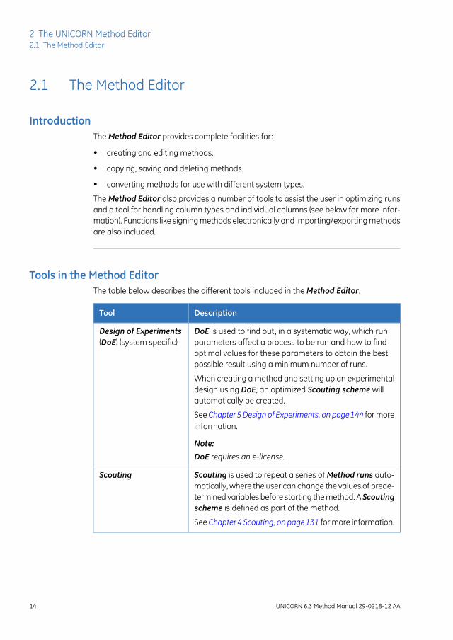
Tools in the Method EditorThe table below describes the different tools included in the Method Editor.
DescriptionTool
DoE is used to find out, in a systematic way, which runparameters affect a process to be run and how to findoptimal values for these parameters to obtain the bestpossible result using a minimum number of runs.
Design of Experiments(DoE) (system specific)
When creating a method and setting up an experimentaldesign using DoE, an optimized Scouting scheme willautomatically be created.
SeeChapter5Design of Experiments, on page144 for moreinformation.
Note:
DoE requires an e-license.
Scouting is used to repeat a series of Method runs auto-matically, where the user can change the values of prede-termined variables before starting the method. A Scoutingscheme is defined as part of the method.
Scouting
SeeChapter4 Scouting, on page131 for more information.
14 UNICORN 6.3 Method Manual 29-0218-12 AA
2 The UNICORN Method Editor2.1 The Method Editor

DescriptionTool
BufferPro allows a buffer of defined pH, and with definedsalt concentrations to be prepared from four stock solu-tions (one Buffer stock solution, one Titrant, Water and aSalt stock solution). pH and salt concentration can be usedas variable scouting parameters included in a Scoutingscheme or in a Design of Experiments (DoE). BufferProis optimized for cation and anion exchange chromatogra-phy, but can also be used when running other chromato-graphic techniques.
BufferPro
(system specific)
SeeChapter6 BufferPro, on page229 for more information.
Column Handling enables handling of column types andindividual columns.
Column Handling
See Chapter8 Column Handling, on page268 for more in-formation.
Note:
Parts of Column Handling requires an e-license.
Illustration of the Method EditorThe basic Method Editor interface consists of two panes, the Method outline and thePhase Properties/Text Instructions pane.
By default, the Toolbar, Phase Library pane and Gradient pane are also displayed inthe Method Editor. The display of these panes is however optional. Two more panesmay be displayed in the Method Editor, the Method Navigator and Process Picture.
The illustration below shows the Method Editor with all the optional panes displayed.
UNICORN 6.3 Method Manual 29-0218-12 AA 15
2 The UNICORN Method Editor2.1 The Method Editor

DescriptionArea
Method Navigator (optional pane): Shows all the user folders, methodsand method queues that are available in the database.
1
Phase Library (optional pane): Contains all available phases.2
Method Outline: Shows the phases included in the opened method.3
Phase Properties tab: Select to display the Phase Properties. PhaseProperties shows the settings for the highlighted phase in the MethodOutline. For wizard generated and text edited methods, thePhase Proper-ties shows a list of variables.
4
16 UNICORN 6.3 Method Manual 29-0218-12 AA
2 The UNICORN Method Editor2.1 The Method Editor

DescriptionArea
Text Instructions tab: Select to display the Text Instructions. Text Instruc-tions shows the method in a text format. The illustration below shows theText Instructions pane.
5
Toolbar (optional pane): Shows the toolbar icons.6
Gradient (optional pane): Shows the programmed gradient and breakpoints for included phases and blocks.
7
Process Picture (optional pane): Illustrates the flow path of the instrumentgraphically.
8
For detailed information on the Toolbar and the different panes in theMethodEditor, see "GettingHelp on the Toolbar and panes in theMethod Editor" below.
Note:
Display optional panesThe optional panes in the Method Editor are displayed by selecting them in the Viewmenu. To restore the appearance of the Method Editor to display the default panes,select Restore to Default in the View menu. Then, the Toolbar, Gradient and Phase Li-brary are displayed. The appearance of the optional panes can also be controlled usingthe Auto Hide function (see below for more information).
Settings made by a user are automatically remembered by the software andare applied next time the same user opens theMethod Editor.
Note:
The illustration below shows the View menu with the default panes selected.
UNICORN 6.3 Method Manual 29-0218-12 AA 17
2 The UNICORN Method Editor2.1 The Method Editor
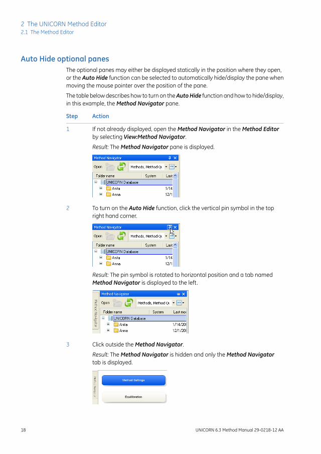
Auto Hide optional panesThe optional panes may either be displayed statically in the position where they open,or the Auto Hide function can be selected to automatically hide/display the pane whenmoving the mouse pointer over the position of the pane.
The table below describes how to turn on theAutoHide function and how to hide/display,in this example, the Method Navigator pane.
ActionStep
If not already displayed, open the Method Navigator in the Method Editorby selecting View:Method Navigator.
1
Result: The Method Navigator pane is displayed.
To turn on the Auto Hide function, click the vertical pin symbol in the topright hand corner.
2
Result: The pin symbol is rotated to horizontal position and a tab namedMethod Navigator is displayed to the left.
Click outside the Method Navigator.3
Result: The Method Navigator is hidden and only the Method Navigatortab is displayed.
18 UNICORN 6.3 Method Manual 29-0218-12 AA
2 The UNICORN Method Editor2.1 The Method Editor

ActionStep
• To display the Method Navigator again, move the mouse pointer overthe Method Navigator tab.
• To turn off the Auto Hide function, click the horizontal pin symbol in thetop right hand corner of the Method Navigator pane.
Result: The Method Navigator pane is displayed statically.
4
Getting help on the Toolbar andpanes in the Method Editor
The table below describes how to find detailed information about the Toolbar and thedifferent panes in the Method Editor by opening the Online Help.
ActionStep
To display detailed information about the Toolbar and different panes inthe Method Editor interface, select Help:Help For Method Editor.
1
Result: The online help opens displaying the Method Editor help start page.
To display help for a specific pane, click in the pane and press the F1 key-board key.
2
Result: The online help page describing that pane is opened.
UNICORN 6.3 Method Manual 29-0218-12 AA 19
2 The UNICORN Method Editor2.1 The Method Editor

2.2 Methods in UNICORN 6.3
About methodsThe program instructions for a chromatography run are defined in aMethod. The instruc-tions are specific for each instrument configuration and component set up and followcertain syntactical and hierarchical rules.
Instructions are combined into blocks. Individual instructions and minor blocks arecombined into the major method blocks, called Phases. In a predefined method (onlyavailable for some systems) each phase reflects a step in the chromatography run, forexample, equilibration or sample application. A number of settings are available for eachtype of phase. By building methods in this way, methods are easily created and edited.
See Chapter 3 Create and edit methods, on page 26 for information about creating andediting methods in the Method Editor.
The illustration below shows the phases in a predefined method in the Method Outlineand the corresponding settings for the highlighted phase in the Phase Properties pane.The image is specific for systems that can use predefined methods.
20 UNICORN 6.3 Method Manual 29-0218-12 AA
2 The UNICORN Method Editor2.2 Methods in UNICORN 6.3
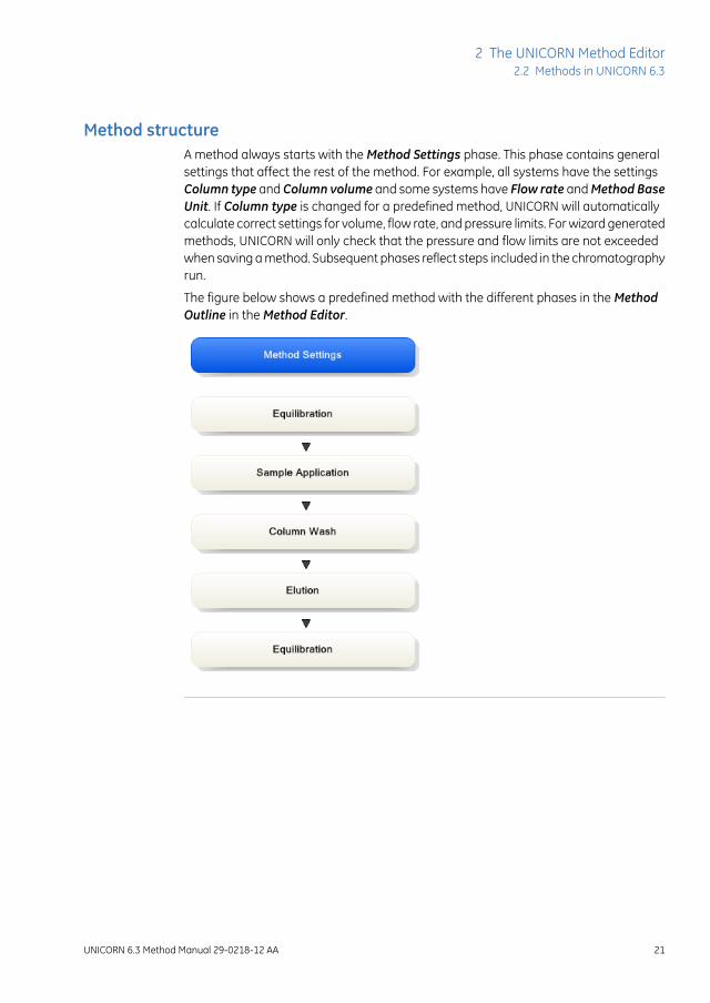
Method structureA method always starts with the Method Settings phase. This phase contains generalsettings that affect the rest of the method. For example, all systems have the settingsColumn type and Column volume and some systems have Flow rate andMethod BaseUnit. If Column type is changed for a predefined method, UNICORN will automaticallycalculate correct settings for volume, flow rate, and pressure limits. For wizard generatedmethods, UNICORN will only check that the pressure and flow limits are not exceededwhen saving a method. Subsequent phases reflect steps included in the chromatographyrun.
The figure below shows a predefined method with the different phases in the MethodOutline in the Method Editor.
UNICORN 6.3 Method Manual 29-0218-12 AA 21
2 The UNICORN Method Editor2.2 Methods in UNICORN 6.3

Working with methodsIt is recommended to create and edit methods using Phase Properties. Phases caneasily be dragged-and-dropped into the Method Outline from the Phase Library andthe phases are easily rearranged. Settings for each phase are set in the Phase Propertiespane. When working like this, the text method is automatically built up in the Text Instruc-tions pane and settings for blocks and instructions are updated accordingly.
The illustrations below show the text instructions and the phase properties settings forthe Method Settings phase in a predefined method.
A wizard generated method consists of a basic method settings phase and auser defined phase that contains the variable list.
Note:
22 UNICORN 6.3 Method Manual 29-0218-12 AA
2 The UNICORN Method Editor2.2 Methods in UNICORN 6.3

It is possible to use the text editor in Text Instructions to create a phase from scratchand to edit methods. Instructions are then created or edited one by one. This can be anoption for fine-tuning or optimization of a method. If the text editor is used for a prede-fined phase, Phase Properties will subsequently only show a list of variables for thephase, as shown in the following illustration. For a predefined phase this can always berestored by clicking on the Restore Phase Properties button.
Phases that have been edited in the text editor are noted with a blue letter T as shownin the illustration below.
UNICORN 6.3 Method Manual 29-0218-12 AA 23
2 The UNICORN Method Editor2.2 Methods in UNICORN 6.3

The phase User Defined is an empty phase designed for text editing methods. Suchphases will only be displayed as a variable list in Phase Properties, and may be savedin the personal or global phase library for reuse in other methods.
SeeChapter9 Text editmethods, on page320 for information about text editing methods.
Do not mix text-edited and non-text-edited phases unless you clearly under-stand the implications for the entire method of the instructions in the text-edited phases.
Note:
Method typesUNICORN supplies a number of Predefinedmethods for different separation techniquesand maintenance applications (e.g., preparation and cleaning of the system and columns).The phase Method Settings is mandatory in all methods.
See Chapter 3 Create and edit methods, on page26 for information about how to createnew methods.
24 UNICORN 6.3 Method Manual 29-0218-12 AA
2 The UNICORN Method Editor2.2 Methods in UNICORN 6.3

The table below gives a general description of the different method types.
DescriptionMethod
Predefinedmethods include a number of relevant phasesappropriate for the purification or maintenance to beperformed. You may use the predefined methods as theyare, or with adjusted settings as needed.
Predefined
See Section Section3.3.1 Predefinedmethods and phases,on page 36 for descriptions of the Predefined methodssupplied with the software.
Note:
The Predefinedmethods are included in the instrumentconfiguration files for each specific instrument.
Wizard generated methods contain a Method Settingsphase and a User Defined phase with a variable list.
Wizard generated
Empty methods include the mandatory phase MethodSettings. Other phases are then added by the user andsettings adjusted as needed.
Empty
Predefined phasesUNICORN provides aUserDefinedphase which is available for all systems, and a numberof other Predefined Phases which are available for some systems.
Predefined phases (for example Equilibration and Column CIP) can be used whenbuilding or editing methods in the Method Editor. A predefined phase contains all nec-essary instructions to be run, exceptMethod Settingswhich is mandatory in all methods.The User Defined phase is an empty phase that can be built by adding text instructionsin the text editing field.
See Section 3.3.1 Predefined methods and phases, on page 36 for descriptions of thepredefined phases supplied with the software. See alsoChapter3 Create and editmethods,on page 26.
UNICORN 6.3 Method Manual 29-0218-12 AA 25
2 The UNICORN Method Editor2.2 Methods in UNICORN 6.3

3 Create and edit methods
About this chapterThis chapter describes how to create, edit and handle chromatography and maintenancemethods in UNICORN 6.3 using the Phase Properties pane. It also describes overallmethod options, how to sign methods electronically, how to print methods, how toconvert and scale methods from one ÄKTA system type to another, and how to import/ex-port methods. Descriptions of the predefined methods and phases supplied with thesoftware are also included.
It is recommended toworkwith phases using the Phase Properties pane. Thischapter does not cover how to editmethods using the Text Instructionspane.For information about text editing methods, see Chapter 9 Text edit methods,on page 320.
Note:
In this chapterThis chapter contains the following sections:
See pageSection
273.1 Working with methods - Overview
323.2 Open a method
353.3 Working with predefined methods
613.4 Working with wizard generated methods
693.5 Working with empty methods
743.6 Working with methods in general
1023.7 Save methods and phases
1083.8 Scale or convert methods
1183.9 Import and export methods
26 UNICORN 6.3 Method Manual 29-0218-12 AA
3 Create and edit methods

3.1 Working with methods - Overview
IntroductionIn UNICORN 6.3 the predefined methods are built up using phases, where each phasecorresponds to a step in a chromatography run with a number of properties associatedwith that phase. The wizard generated methods consist of a method settings phase anda user defined phase containing all instructions for the method. See Section2.2 Methodsin UNICORN 6.3, on page 20 for more information about method structure, definitionsand concepts of methods in UNICORN 6.3.
There are three different ways of creating and editing methods in UNICORN 6.3:
• Creating and editing methods using phases and the phase properties in the Phase-Properties pane.
• Creating methods using the wizard.
• Creating methods by text editing, creating and editing text instructions one-by-one.
Main steps when defining a newmethod using phases
The main steps when defining a method are:
1 Create/open a method
• Create a Predefined method (including a set of phases that may be edited)
or
• Open an existing method that can be edited and saved with a new name oroverwritten
2 Build/edit the Method Outline and/or edit the Phase Properties for the appropriatephases
• Predefined methods: use as they are, or edit the Method Outline and/or PhaseProperties
• Opened methods: edit the Method Outline and/or Phase Properties
3 Save the method
UNICORN 6.3 Method Manual 29-0218-12 AA 27
3 Create and edit methods3.1 Working with methods - Overview

Main steps when defining a newmethod using the wizard
The main steps when defining a method are:
1 Create/open a method
• Create a method using the method wizard
or
• Open an existing method that can be edited and saved with a new name oroverwritten
2 Build/edit the Method Outline and/or edit the Phase Properties for the appropriatephases
• Wizard generated methods: use as they are, or edit the Phase variable list inthe user defined phase
• Opened methods: edit the Method Outline and/or Phase variable list
3 Save the method
Main steps when defining anempty method
The main steps when defining an empty method are:
1 Create/open a method
• Create a new Empty method containing the Method Settings phase.
2 Build/edit the Method Outline and edit the Text instructions for the phases
• Add user defined or predefined phases to the method (i.e., build the MethodOutline) and edit the phases as appropriate.
3 Save the method
Main steps when editing amethod
The main steps when editing a method are:
1 Open the method to be edited
2 • Edit the Method Outline
and/or
28 UNICORN 6.3 Method Manual 29-0218-12 AA
3 Create and edit methods3.1 Working with methods - Overview

• Edit the Phase Properties for the appropriate phases or the phase variables fora wizard generated or text created method.
and/or
• Text edit user defined phases
3 Save the method
UNICORN 6.3 Method Manual 29-0218-12 AA 29
3 Create and edit methods3.1 Working with methods - Overview

Illustration of workflow whencreatingor editinganewmethod
The illustration below shows the workflow in theMethod Editorwhen creating or editinga method. The available options depend on the instrument configuration.
1. Create methodOpen an existing methodCreate new method using phases
or
Create new method using the wizard
or
2a. Edit methods using phases
Add/delete, rearrange phases
Build/edit Method Outline Edit Phase Properties
Save phase (optional)
Edit Phase Variables
Text edit instructions
Text edit instructions2b. Edit wizard created methods
3. Save method
Save method
or
or or
and/orand/or
and/or
30 UNICORN 6.3 Method Manual 29-0218-12 AA
3 Create and edit methods3.1 Working with methods - Overview

Overall method optionsIn addition to creating, editing and saving the method in the Method Editor, a numberof more general method options are available. These are settings for the method andare saved with the method.
Overall method settings can be divided into two groups. The table below shows the dif-ferent groups.
DescriptionMethod option
• setting result name and the location of the results
• setting up start protocols
• adding/editing notes to the method
• choosing to include evaluation procedures to be per-formed after the run
• viewing and printing an estimate of the method dura-tion time and the variables in the method
See Section 3.6.2 Set general method options for themethod, on page 85 for more information.
General method options
• Scouting
See Chapter 4 Scouting, on page 131 for information.
• Design of Experiments (DoE)
See Chapter 5 Design of Experiments, on page144 forinformation.
• BufferPro
See Chapter 6 BufferPro, on page229 for information.
Method options intend-ed to assist the user inoptimizing runs inUNICORN
UNICORN 6.3 Method Manual 29-0218-12 AA 31
3 Create and edit methods3.1 Working with methods - Overview

3.2 Open a methodThe table below describes how to open an existing method in the database:
ActionStep
In the Method Editor:1
• Click the Open Method Navigator icon in the Toolbar
or
• select File:Open...
or
• select View:Method Navigator
Result: The Method Navigator is displayed.
32 UNICORN 6.3 Method Manual 29-0218-12 AA
3 Create and edit methods3.2 Open a method

ActionStep
Select the method to be opened in the Folder name column.2
UNICORN 6.3 Method Manual 29-0218-12 AA 33
3 Create and edit methods3.2 Open a method

ActionStep
To open the method,3
• Click the Open button located in the toolbar of the Method Navigatorpane
or
• double-click the selected method
or
• Right-click on the method name and selectOpen from the context menu
Result: The method is opened and displayed in the Method Outline panewith included phases. You can continue to edit the phases of the methodusing Phase Properties.
34 UNICORN 6.3 Method Manual 29-0218-12 AA
3 Create and edit methods3.2 Open a method

3.3 Working with predefined methods
About this sectionThis section describes how to work with methods and phases in systems that have accessto the full phase library and predefined methods.
In this sectionThis section contains these subsections:
See pageSection
363.3.1 Predefined methods and phases
483.3.2 Create a predefined method
503.3.3 Edit phase properties
583.3.4 Fraction collection
UNICORN 6.3 Method Manual 29-0218-12 AA 35
3 Create and edit methods3.3 Working with predefined methods

3.3.1 Predefined methods and phases
IntroductionA predefined method contains a set of phases, each phase reflecting a specific stage ofa chromatography or maintenance run. You can select additional phases from the phaselibraries and add these to an existing method, or remove phases that are not required.
The predefined purification methods have default values with suitable running conditionsfor the chosen column type such as flow and pressure limits. Other settings (e.g., sampleapplication technique, sample volume, elution profile and fractionation) are set on thePhase Properties pane in the appropriate phases.
This section describes the predefined methods and phases.
Predefined purificationmethodsThe Method Editor has predefined methods for different separation techniques. Themethods include a number of relevant phases.
The table below describes the available predefined purification methods and whichphases that are included.
Included phasesPrinciplePredefined purificationmethod
After equilibration and sample application,the protein of interest is adsorbed to thecolumn ligand. After a wash to removeunbound sample, elution is performed ei-ther by using a buffer containing a competi-tor to displace the protein of interest, or bychanging the pH or ionic strength. Finally,the column is re-equilibrated with startbuffer.
Affinity Chromatography(AC)
36 UNICORN 6.3 Method Manual 29-0218-12 AA
3 Create and edit methods3.3 Working with predefined methods3.3.1 Predefined methods and phases
Included phasesPrinciplePredefined purificationmethod
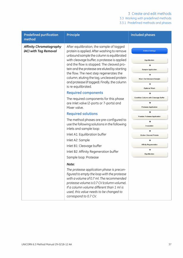
After equilibration, the sample of taggedprotein is applied. After washing to removeunbound sample the column is equilibratedwith cleavage buffer, a protease is appliedand the flow is stopped. The cleaved pro-tein and the protease are eluted by startingthe flow. The next step regenerates thecolumn, eluting the tag, uncleaved proteinand protease (if tagged). Finally, the columnis re-equilibrated.
Required components
The required components for this phaseare Inlet valve (2-ports or 7-ports) andMixer valve.
Required solutions
The method phases are pre-configured touse the following solutions in the followinginlets and sample loop:
Inlet A1: Equilibration buffer
Inlet A2: Sample
Inlet B1: Cleavage buffer
Inlet B2: Affinity Regeneration buffer
Sample loop: Protease
Note:
The protease application phase is precon-figured to empty the loopwith the proteasewith a volume of 0.7ml. The recommendedprotease volume is 0.7 CV (column volume).If a column volume different than 1 ml isused, this value needs to be changed tocorrespond to 0.7 CV.
Affinity Chromatography(AC) with Tag Removal
UNICORN 6.3 Method Manual 29-0218-12 AA 37
3 Create and edit methods3.3 Working with predefined methods3.3.1 Predefined methods and phases

Included phasesPrinciplePredefined purificationmethod
After equilibration and sample application,negatively charged proteins are adsorbedto the column ligand. After a wash, to re-move unbound sample, elution is per-formed using a gradient of increasing saltconcentration (of e.g. NaCl). Finally, thecolumn is washed and re-equilibrated withstart buffer.
Anion Exchange Chro-matography (AIEX)
After equilibration and sample application,positively charged proteins are adsorbedto the column ligand. After a wash, to re-move unbound sample, elution is per-formed using a gradient of increasing saltconcentration (of e.g. NaCl). Finally, thecolumn is washed and re-equilibrated withstart buffer.
Cation Exchange Chro-matography (CIEX)
38 UNICORN 6.3 Method Manual 29-0218-12 AA
3 Create and edit methods3.3 Working with predefined methods3.3.1 Predefined methods and phases

Included phasesPrinciplePredefined purificationmethod
After equilibration and sample application,elution is performed using a pH gradient.The proteins separate and elute accordingto their isoelectric points. Finally, the col-umn is re-equilibrated.
Chromatofocusing (CF)
After equilibration and sample application,the proteins are eluted isocratically. Thistechnique is commonly used for buffer ex-change.
Desalting
After equilibration and sample application,proteins separate and elute according totheir size (largest first).
Gel filtration (GF)
UNICORN 6.3 Method Manual 29-0218-12 AA 39
3 Create and edit methods3.3 Working with predefined methods3.3.1 Predefined methods and phases

Included phasesPrinciplePredefined purificationmethod
After equilibration and sample application(use a buffer containing a high salt concen-tration, for example 2 M ammonium sul-fate) hydrophobic proteins are adsorbedto the column ligand. After a wash to re-move unbound sample, elution is per-formed using a gradient of decreasing saltconcentration. Finally, the column iswashed and re-equilibrated with startbuffer.
Hydrophobic InteractionChromatography (HIC)
The sample application loops of the loopvalve are manually filled with samples. Themethod will guide the user through theprocess by pausing and displaying on-screen instructions. Up to five loops canbe filled with different samples. Partial orcomplete loop fill can be chosen. Automat-ic washing of loops and flow path are inte-grated in the method.
Manual Loop Fill
The required components for this phaseare Inlet valve (2-ports or 7-ports) andMixer valve.
40 UNICORN 6.3 Method Manual 29-0218-12 AA
3 Create and edit methods3.3 Working with predefined methods3.3.1 Predefined methods and phases

Included phasesPrinciplePredefined purificationmethod
A column packed with NHS-activatedSepharose™ is washed with 1 mM HCl,followed by immediate application of theprotein for covalent coupling onto the col-umn. After incubation the nonspecificallybound protein is washed out and the re-maining active groups are deactivated withethanolamine buffer, followed by furtherwashes.
Required components
The required component for this phase isan Inlet valve (2-ports or 7-ports).
Required solutions
The method phases are preconfigured touse the following solutions in the followinginlets and sample loop:
Inlet A1: Coupling buffer, for example 0.2M NaHCO3 + 0.5 M NaCl pH 8.3.
Inlet A2: Activation solution, for example 1mM HCl
Inlet B1: High pH buffer, for example 0.5 Methanolamine, 0.5 M NaCl pH 8.3
Inlet B2: Low pH buffer, for example 0.1 MSodium acetate, 0.5 M NaCl pH 4.0
Sample loop: Ligand in coupling buffer
Note:
The NHS coupling phase is preconfiguredto empty the loop with the ligand with avolume of 1 ml. The recommended ligandvolume is 1 CV (column volume). If a columnvolume different than 1ml is used, this val-ue needs to be changed to correspond to1 CV.
NHS-coupling
UNICORN 6.3 Method Manual 29-0218-12 AA 41
3 Create and edit methods3.3 Working with predefined methods3.3.1 Predefined methods and phases

Included phasesPrinciplePredefined purificationmethod
After equilibration and sample application,hydrophobic proteins adsorb to the columnligand. After a wash to remove unboundsample, elution is performed by generatinga gradient of a non-polar, organic solventsuch as acetonitrile. Finally, the column iswashed and re-equilibrated.
Reversed Phase Chro-matography (RPC)
WARNINGBuilt-in fraction collector. Do not fractionate flammable liquidson instruments with built-in fraction collector. Flammable gas mightbe formed inside the closed cabinet. When running RPC methods,or other procedures using organic solvents, collect fractions throughthe Outlet valve.
Predefined maintenancemethods
A number of predefined methods for preparation and cleaning are available. Thesemaintenance methods are used to prepare the system, clean the system, and to fill thesystem with storage solution.
The table below describes the available predefined maintenance methods.
42 UNICORN 6.3 Method Manual 29-0218-12 AA
3 Create and edit methods3.3 Working with predefined methods3.3.1 Predefined methods and phases

Included phasesPrinciplePredefined maintenancemethod
The column is filled with a cleaning solu-tion. Select inlet positions. Enter the solu-tion identity, volume, flow rate and incuba-tion time. By adding steps, several cleaningsolutions can be used. Suggestions forcleaning steps are available for a numberof column types.
Column CIP
After equilibration of the column, sampleis injected via a capillary loop and elutedisocratically. A non-adsorbing sample likeacetone or salt should be used. After therun, calculate column performance in theEvaluation module. The efficiency of thecolumn is determined in terms of heightequivalent to a theoretical plate (HETP),and the peak asymmetry factor (As). Theresult is logged in the column logbook.
Column Performance Test
The column is filled with buffer solution.Select inlet positions. Enter the solutionidentity, volume, flow rate and incubationtime. By adding steps, several preparationsolutions can be used.
Column Preparation
Packs AxiChrom™ columns, with a prede-termined column type, by motorized poweror by a flow of hydraulic liquid that pushesthe adaptor down. The user initiates thestart of compression at the exact pointwhen the adapter reaches the consolidat-ed bed surface. The adapter compressesthe bed according to the packing factor ortarget bed height as selected. Two ColumnPerformance Test phases (upflow and/ordownflow) can be performed after theAxiChrom column has been packed.
Intelligent Packing
Only available for some types of AxiChromcolumns.
Note:
Intelligent packing is also available for sys-tems that use wizard generated methods.
UNICORN 6.3 Method Manual 29-0218-12 AA 43
3 Create and edit methods3.3 Working with predefined methods3.3.1 Predefined methods and phases

Included phasesPrinciplePredefined maintenancemethod
The system is filled with cleaning solution.Select for example inlets, outlets and col-umn positions to be cleaned. Three SystemCIP phases are included in the method tofacilitate the use of three different cleaningsolution. AdditionalSystemCIPphases canbe added from the Phase Library if de-sired.
System CIP
The system is filled with preparation solu-tion. Select for example inlets, outlets andcolumn positions to be prepared. TwoSystem Preparation phases are includedin the method. AdditionalSystemPrepara-tion phases can be added from the PhaseLibrary if desired.
System Preparation
44 UNICORN 6.3 Method Manual 29-0218-12 AA
3 Create and edit methods3.3 Working with predefined methods3.3.1 Predefined methods and phases

Predefined phasesThe table below describes the predefined phases.
DescriptionPhase Name
The first, and mandatory, phase in any method. Defines commonparameters used in the subsequent phases.
Method Set-tings
The Method Settings phase defines:
• Column type
• Pressure limits
• Flow rate
• Option to control the flow to avoid overpressure
Note:
Default values for pressure limits and flow rate are given for theselected column type.
• Column position
• Flow restrictor use
• Buffer preparation:
- Manual, or
- BufferPro (automatic buffer preparation)
• Unit selection for Method base and Flow rate
• Monitor settings:
- pH monitor
- Air sensor alarm settings
- UV monitor
Note:
The first wavelength of U9-M and the fixed wavelength forU9-L or U9-L 2nd is always turned on. The second and thirdwavelengths for UV monitor U9-M can be set on or off.
• Settings for Column Logbook
• Start Protocol
• Result name and location
Note:
UNICORN 6.3 Method Manual 29-0218-12 AA 45
3 Create and edit methods3.3 Working with predefined methods3.3.1 Predefined methods and phases

DescriptionPhase Name
Some of these options may not be required by certain methods.
Note:
TheMethod Settings phase differs for systems that have theMethod settings phase and the User defined phase as the onlyavailable predefined phases.
Equilibrates the column before purification, or re-equilibrates thecolumn after purification.
Equilibration
Applies sample to the column. Defines the sample applicationtechnique, the sample volume, and the handling of flowthrough.
SampleApplica-tion
Washes out unbound sample after sample application or removesstrongly bound proteins after elution.
ColumnWash
Elutes the sample from the column. Defines parameters for theelution and fractionation settings.
Elution
Prepares the column before use by removing the storage solutionand equilibrating the column. By adding steps, several preparationsolutions can be used sequentially.
Column Prepa-ration
Cleans the column after purification runs by rinsing the columnwith a cleaning solution to remove nonspecifically bound proteins.By adding steps, several cleaning solutions can be used sequen-tially.
Column CIP
Prepares the system before a run by removing storage solutionand filling the system and inlets with buffer solution. One prepara-tion solution is used per phase.
SystemPrepara-tion
Cleans the system after purification runs by rinsing the systemwith a cleaning solution. One cleaning solution is used per phase.
System CIP
Tests the efficiency of a packed column in terms of height equiv-alent to a theoretical plate (HETP), and the peak asymmetry factor(As).
Columnperfor-mance test
Is used to manually fill the additional sample loops mounted onthe loop valve. The filling options are:
Manual LoopFill
• Partial loop fill
• Complete loop fill
46 UNICORN 6.3 Method Manual 29-0218-12 AA
3 Create and edit methods3.3 Working with predefined methods3.3.1 Predefined methods and phases

DescriptionPhase Name
Can be added to any method at suitable places. The instructionscan help the user to better organize the graphical output of theresults or introduce a controlled delay in the method run.
Miscellaneous
A flow of hydraulic liquid pushes the adapter down. The user initi-ates the start of compression at the exact point when the adapterreaches the consolidated bed surface. The adapter compressesthe bed according to the packing factor or target bed height asselected.
IntelligentPacking
Only available for some systems and some types of AxiChromcolumns.
UNICORN 6.3 Method Manual 29-0218-12 AA 47
3 Create and edit methods3.3 Working with predefined methods3.3.1 Predefined methods and phases

3.3.2 Create a predefined methodThe table below describes how to create a new method using phases:
ActionStep
In the Method Editor:1
• click the Create a new method icon in the Toolbar
or
• select File:New Method...
Result: The New Method dialog opens.
48 UNICORN 6.3 Method Manual 29-0218-12 AA
3 Create and edit methods3.3 Working with predefined methods3.3.2 Create a predefined method

ActionStep
In the New Method dialog:2
• select a System
• select a Predefined Method
• click OK
Result: The Method Outline pane shows the included phases for the chosenmethod and the Phase Properties pane shows the default settings for thecurrently highlighted phase.
UNICORN 6.3 Method Manual 29-0218-12 AA 49
3 Create and edit methods3.3 Working with predefined methods
3.3.2 Create a predefined method

3.3.3 Edit phase properties
IntroductionWhen editing Phase Properties for a phase, the changes affect either
• the whole method, when editing the Method Settings phase
or
• only the phase that is being edited, when editing phases other than the MethodSettings phase
50 UNICORN 6.3 Method Manual 29-0218-12 AA
3 Create and edit methods3.3 Working with predefined methods3.3.3 Edit phase properties

Getting helpwhen editing PhaseProperties
The table below describes how to get help information for the properties in a phase:
ActionStep
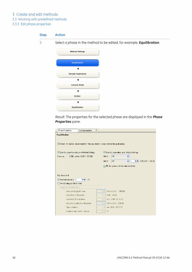
Select a phase in the method to be edited, for example, Equilibration.1
Result: The properties for the selected phase are displayed in the PhaseProperties pane.
UNICORN 6.3 Method Manual 29-0218-12 AA 51
3 Create and edit methods3.3 Working with predefined methods
3.3.3 Edit phase properties

ActionStep
Click anywhere in the Phase Properties area to make it the active area inthe software.
2
• Press the F1 keyboard key.
or
• Select Help:Contextual Help
Result: The Online help for the selected phase is displayed.
3
View and edit phases usingPhase Properties
The following table describes how to edit a method phase in the Phase Properties tab:
ActionStep
Make sure the Phase Properties tab is selected.1
52 UNICORN 6.3 Method Manual 29-0218-12 AA
3 Create and edit methods3.3 Working with predefined methods3.3.3 Edit phase properties

ActionStep
• Select the Method Settings phase if you want to edit basic settings af-fecting the whole method (e.g., Column type, Flow rate and MethodBase Unit). Continue with steps 3-4.
Note:
You can also edit the Result name & Location, the Start Protocol andMethodNotes from theMethodSettingsphase. These are overallmethodoptions that also can be set using the corresponding Toolbar options andnot described in this section. See Section3.6.2 Set generalmethod optionsfor the method, on page85 for information on how to edit these settings.
or
• Select any other phase to edit the properties for that specific phase.Continue with step 5.
2
UNICORN 6.3 Method Manual 29-0218-12 AA 53
3 Create and edit methods3.3 Working with predefined methods
3.3.3 Edit phase properties

ActionStep
To edit the properties for the Method Settings phase, click Method Settingsin the Method Outline.
3
Result: The Phase Properties of the Method Settings phase is displayed.
54 UNICORN 6.3 Method Manual 29-0218-12 AA
3 Create and edit methods3.3 Working with predefined methods3.3.3 Edit phase properties

ActionStep
Edit the settings for the Method Settings phase in the Phase Propertiespane as appropriate. If changing Column type, UNICORN will automaticallycalculate correct settings for volume, flow rate, and pressure limits.
Note:
Settings in this phase will affect the whole method.
4
Note:
Allowed parameter ranges are shown in parentheses beside the text boxes.
Result: The method is updated with the new settings.
UNICORN 6.3 Method Manual 29-0218-12 AA 55
3 Create and edit methods3.3 Working with predefined methods
3.3.3 Edit phase properties
ActionStep
Select a phase in the method to be edited, for example, Equilibration.5
Result: The properties for the selected phase are displayed in the PhaseProperties pane.
56 UNICORN 6.3 Method Manual 29-0218-12 AA
3 Create and edit methods3.3 Working with predefined methods3.3.3 Edit phase properties

ActionStep
• Edit the settings as appropriate.
Note:
If there are, for example, two predefined Equilibration phases in yourmethod, changing settings in one of them will not affect the other. To beable to see that they are different, it is recommended to rename one ofthem. See Section3.6.1 Edit themethod outline, on page75 for informationabout how to rename a phase.
• Repeat steps 5-6 until the appropriate phases have been edited.
Result: The method is updated with the new settings. The edited settingsremain in place while subsequent phases are edited. If the method is closedand not saved, the settings will revert back to the earlier values.
6
Save the method.7
UNICORN 6.3 Method Manual 29-0218-12 AA 57
3 Create and edit methods3.3 Working with predefined methods
3.3.3 Edit phase properties

3.3.4 Fraction collection
IntroductionFor many purification schemes it is convenient to collect fractions of the eluent. Severalof the predefined phases and methods include options for fraction collection in the PhaseProperties pane.
This section describes briefly the various options available for fractionation in predefinedmethods and phases, and how to set up fraction collection when editing a method. Moredetailed information for individual settings can be found using the online help for thephase, see Getting help when editing Phase Properties, on page 51.
Fractionation overviewFractionation is available in thePhase Propertiespane in the predefined phases SampleApplication, ColumnWash and Elution. These three phases are included in many ofthe predefined methods in UNICORN. This option will also be available in personal orglobal phases derived from these. See Section 3.3.3 Edit phase properties, on page 50for details on how to edit methods and phases.
For each phase, fractions can either be collected using the outlet valve or the fractioncollector. If there is no risk of sample loss, the eluate may be sent to the waste and notcollected. When fractionating to the outlet valve, a specific outlet valve position is selected.When collecting fractions in the fraction collector a tube or plate type is chosen and thefractions will be collected in the first available tube or plate of that type.
WARNINGBuilt-in fraction collector. Do not fractionate flammable liquidson instruments with built-in fraction collector. Flammable gas mightbe formed inside the closed cabinet. When running RPC methods,or other procedures using organic solvents, collect fractions throughthe Outlet valve.
Fractionation setupThe following table is an example of how to set up fraction collection in the PhaseProperties pane:
The setup can vary between different fraction collectors.Note:
58 UNICORN 6.3 Method Manual 29-0218-12 AA
3 Create and edit methods3.3 Working with predefined methods3.3.4 Fraction collection

ActionStep
Select the phase for which fractionation is required in the method outlineand select the Phase Properties pane.
1
Note:
Text edited phases will show the fractionation options as variables in thePhase Variables list, see Chapter 9 Text edit methods, on page 320.
UNICORN 6.3 Method Manual 29-0218-12 AA 59
3 Create and edit methods3.3 Working with predefined methods
3.3.4 Fraction collection
ActionStep
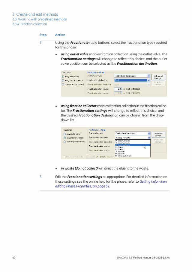
Using the Fractionate radio buttons, select the fractionation type requiredfor this phase:
2
• using outlet valve enables fraction collection using the outlet valve. TheFractionation settings will change to reflect this choice, and the outletvalve position can be selected as the Fractionation destination.
• using fraction collector enables fraction collection in the fraction collec-tor. The Fractionation settings will change to reflect this choice, andthe desired Fractionation destination can be chosen from the drop-down list.
• in waste (do not collect) will direct the eluent to the waste.
Edit the Fractionation settings as appropriate. For detailed information onthese settings see the online help for the phase, refer to Getting help whenediting Phase Properties, on page 51.
3
60 UNICORN 6.3 Method Manual 29-0218-12 AA
3 Create and edit methods3.3 Working with predefined methods3.3.4 Fraction collection

3.4 Working with wizard generated methods
About this sectionFor instruments with an instrument configuration that includes a method wizard, it ispossible to create wizard generated methods. This section describes how to create andedit wizard generated methods. The wizard generated methods only contain a methodsettings phase and a user defined phase. The sections also describes Frac-950 fraction-ation.
In this sectionThis section contains these subsections:
See pageSection
623.4.1 Create a wizard generated method
643.4.2 Wizard generated methods
673.4.3 Frac-950
UNICORN 6.3 Method Manual 29-0218-12 AA 61
3 Create and edit methods3.4 Working with wizard generated methods

3.4.1 Create a wizard generated methodThe table below describes how to create a new method using the wizard:
ActionStep
In the Method Editor:1
• click the Create a new method icon in the Toolbar
or
• select File:New Method...
Result: The New Method dialog opens.
62 UNICORN 6.3 Method Manual 29-0218-12 AA
3 Create and edit methods3.4 Working with wizard generated methods3.4.1 Create a wizard generated method

ActionStep
In the New Method dialog:2
• select a System
Note:
The dialog changes depending on the type of the selected system. Forsystems that use predefined methods, refer to Section 3.3 Working withpredefined methods, on page 35.
• select the Method Wizard radio button
• click OK
Result: The Method Wizard opens.
• Perform the Method Wizard sequence until the final dialog is reached.
Note:
Performance tests, CIP and other special methods are also created in theMethod Wizard.
Refer to Wizard Help for more information.
• Click Finish.
3
UNICORN 6.3 Method Manual 29-0218-12 AA 63
3 Create and edit methods3.4 Working with wizard generated methods
3.4.1 Create a wizard generated method

3.4.2 Wizard generated methodsThe methods generated by the wizard will consist of two phases.
• The Method Settings phase, which contains column type, result name and location,start protocol and method notes. Logging of Column performance test and ColumnCIP is selected in this phase.
• The User Defined phase, which contains a list of Phase variables that can be textedited.
Edit phase variablesEditing a variable includes renaming and deleting the variable and choosing whetherthe variable should be a detailed variable or not.
The table below describes how to edit a variable for a selected phase:
ActionStep
Select the Text Instructions tab to display the phase variables, select thevariable Value and click Edit Variable....
1
Result: The Edit Variable dialog opens displaying all the phase variables.
64 UNICORN 6.3 Method Manual 29-0218-12 AA
3 Create and edit methods3.4 Working with wizard generated methods3.4.2 Wizard generated methods

ActionStep
Select the variable to be edited (if not already selected). Do one or severalof the following as appropriate:
2
• Type in a new name in the New name field and click Rename.
• Check the Set visible in details only if the variable should be a detailedvariable. Uncheck the box to set it to a normal variable.
• Click Delete to delete the variable.
Confirm that you want to delete the variable in the dialog that appears.
Click Close to close the dialog.3
Edit variable valuesThe table below describes how to edit default variable values in the Phase Variableslist. For information on how to edit variables from Text Instructions, see Section 9.2Working with methods in the Text Instructions pane, on page 329.
ActionStep
Select the Phase Properties tab to display the Phase Variables list.1
UNICORN 6.3 Method Manual 29-0218-12 AA 65
3 Create and edit methods3.4 Working with wizard generated methods
3.4.2 Wizard generated methods
ActionStep
Change the variable value for the appropriate variable in the Value field bychoosing a new value in the drop-down list or typing in the field.
Tip:To show detailed variables, check the Show details box.
2
Result: The variable value is updated.
Repeat this procedure for the appropriate variables.3
Changes made in the Phase Properties tab are automatically updated on the Text In-structions tab and vice versa.
66 UNICORN 6.3 Method Manual 29-0218-12 AA
3 Create and edit methods3.4 Working with wizard generated methods3.4.2 Wizard generated methods

3.4.3 Frac-950
IntroductionFor many purification schemes it is convenient to collect fractions of the eluent. Thewizard generated methods include options for fraction collection in the Phase Propertiespane using Frac-950 if Frac-950 has been chosen as a component for the system.
This section describes how to edit a Frac-950 fractionation. More detailed informationfor individual settings can be found in the online help.
Frac-950 is a system specific option.
FractionationFor many purification schemes it is convenient to collect fractions of the eluent.
The fractionation settings are available in thePhaseProperties tab in theMethodSettingsphase. Wizard generated methods support fractionation if Frac 950 has been chosenas a component for the system.
Scouting is not available for Frac 950 variables.Note:
The following table describes how to edit a Frac-950 fractionation for a Wizard generatedmethod.
UNICORN 6.3 Method Manual 29-0218-12 AA 67
3 Create and edit methods3.4 Working with wizard generated methods
3.4.3 Frac-950

ActionStep
• Click the Frac-950... button in the Phase Properties tab in the Methodsettings phase.
or
• Select Edit:Frac-950...
Result: The Frac-950 dialog opens.
1
Note:
The button is only active if Frac-950 has been chosen as a component for thesystem.
• Select Rack for the fractionation in the drop down list.
• Select what kind of Fraction order to use in the fractionation.
• Click OK.
2
68 UNICORN 6.3 Method Manual 29-0218-12 AA
3 Create and edit methods3.4 Working with wizard generated methods3.4.3 Frac-950

3.5 Working with empty methods
About this sectionThis section describes how to work with methods and phases in systems that createmethods using text instructions. From the start, an empty method only contains a methodsettings phase.
In this sectionThis section contains these subsections:
See pageSection
703.5.1 Create an empty method
723.5.2 Edit an empty method
UNICORN 6.3 Method Manual 29-0218-12 AA 69
3 Create and edit methods3.5 Working with empty methods
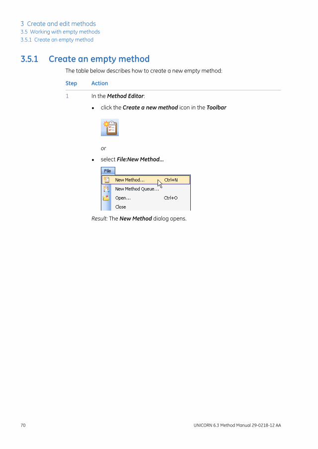
3.5.1 Create an empty methodThe table below describes how to create a new empty method:
ActionStep
In the Method Editor:1
• click the Create a new method icon in the Toolbar
or
• select File:New Method...
Result: The New Method dialog opens.
70 UNICORN 6.3 Method Manual 29-0218-12 AA
3 Create and edit methods3.5 Working with empty methods3.5.1 Create an empty method

ActionStep
The New Method dialog looks different depending on the system.2
In the New Method dialog:
• select a System
• select the Empty Method radio button
• click OK
Result: An empty method that consists of the mandatoryMethodSettingsphase is created.
UNICORN 6.3 Method Manual 29-0218-12 AA 71
3 Create and edit methods3.5 Working with empty methods
3.5.1 Create an empty method

3.5.2 Edit an empty method
IntroductionA new empty method only has the Method Settings phase in the Method Outline. UserDefined and Predefined phases can be added, rearranged, renamed and deleted fromthe Method Outline.
Add a phase to the methodoutline
The table below describes how to add a phase to the method outline using drag-and-drop:
ActionStep
Select the phase in the Phase Library pane and drag-and-drop the phaseto the requested position in the Method Outline pane. In the example, aUser Defined phase is used.
1
Result: The phase is included in the method at the requested position.
When the User Defined phase has been added to the Method Outline, thephase name is enabled for editing.
2
Type a name for the phase and press the Return keyboard key.
Note:
The User Defined phase is marked with the letter T, meaning that it is textedited. This phase contains only Base and End_Block instructions, so anyfunctional instructions must be added manually.
72 UNICORN 6.3 Method Manual 29-0218-12 AA
3 Create and edit methods3.5 Working with empty methods3.5.2 Edit an empty method

ActionStep
To include instructions for the User Defined phase, select the Text Instruc-tions tab and text edit the method.
3
For detailed instructions on how to text edit methods, refer to Chapter9 Textedit methods, on page 320
Note:
The Phase Properties tab will then show a list of variables used in the phase.
UNICORN 6.3 Method Manual 29-0218-12 AA 73
3 Create and edit methods3.5 Working with empty methods
3.5.2 Edit an empty method

3.6 Working with methods in general
About this sectionThis section includes descriptions of how to work with methods and phases in general.
In this sectionThis section contains these subsections:
See pageSection
753.6.1 Edit the method outline
853.6.2 Set general method options for the method
983.6.3 Print a method
1003.6.4 Sign methods electronically
74 UNICORN 6.3 Method Manual 29-0218-12 AA
3 Create and edit methods3.6 Working with methods in general
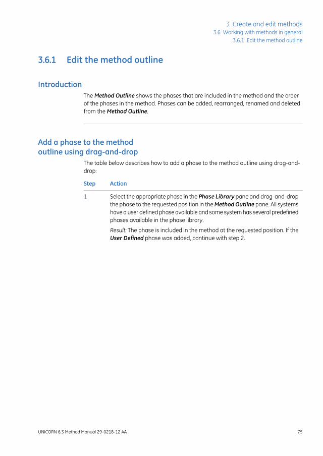
3.6.1 Edit the method outline
IntroductionThe Method Outline shows the phases that are included in the method and the orderof the phases in the method. Phases can be added, rearranged, renamed and deletedfrom the Method Outline.
Add a phase to the methodoutline using drag-and-drop
The table below describes how to add a phase to the method outline using drag-and-drop:
ActionStep
Select the appropriate phase in the Phase Library pane and drag-and-dropthe phase to the requested position in theMethodOutline pane. All systemshave a user defined phase available and some system has several predefinedphases available in the phase library.
1
Result: The phase is included in the method at the requested position. If theUser Defined phase was added, continue with step 2.
UNICORN 6.3 Method Manual 29-0218-12 AA 75
3 Create and edit methods3.6 Working with methods in general
3.6.1 Edit the method outline

ActionStep
When the User Defined phase has been added to the Method Outline, thephase name is enabled for editing.
2
Type a name for the phase and press the Return keyboard key.
Note:
The User Defined phase is marked with the letter T, meaning that it is textedited. This phase contains only Base and End_Block instructions, so anyfunctional instructionsmust be added by hand. To include instructions for theUser Defined phase, select the Text Instructions tab. The Phase Propertiestab will only show the variables used in this phase. See Chapter 9 Text editmethods, on page320 for information about how toworkwith instructions inthe text Instructions pane.
76 UNICORN 6.3 Method Manual 29-0218-12 AA
3 Create and edit methods3.6 Working with methods in general3.6.1 Edit the method outline

Add a phase to the methodoutline using a button or menucommand
The table below describes how to add a phase to the method outline using a button ora menu command. It is possible to define several phases and store in the library to usein new methods.
ActionStep
• Select the appropriate phase (e.g., Equilibration or User Defined) in thePhase Library
• Select the appropriate phase (e.g., the Method Settings phase) in theMethod Outline to determine where to place the new phase
Note:
When adding a phase to theMethod Outline using a button or menucommand, the newphase is always inserted below the currently selectedphase in theMethod Outline.
Result: The selected phase in the Phase Library is indicated by a blue dottedframe and the selected phase in the Method Outline is highlighted in blue.
1
UNICORN 6.3 Method Manual 29-0218-12 AA 77
3 Create and edit methods3.6 Working with methods in general
3.6.1 Edit the method outline

ActionStep
• Click the Insert button located below the Phase Library
or
• double-click the selected phase
or
• select Phases:Insert Phase from Library...
or
• right-click the phase in the Phase Library and select Insert...
Result: The phase is included in the method and highlighted in blue. Continuewith step 3 if adding the User Defined phase.
2
78 UNICORN 6.3 Method Manual 29-0218-12 AA
3 Create and edit methods3.6 Working with methods in general3.6.1 Edit the method outline

ActionStep
When the User Defined phase has been added to the Method Outline, thephase name is enabled for editing.
3
Type a name for the phase and press the Return keyboard key.
Note:
The User Defined phase is marked with the letter T, meaning that it is textedited. This phase contains only Base and End_Block instructions, so anyfunctional instructionsmust be added by hand. To include instructions for theUser Defined phase, select the Text Instructions tab. The Phase Propertiestab will show a list of variables used in this phase. See Chapter 9 Text editmethods, on page320 for information about how toworkwith instructions inthe text instructions pane.
Rename phasesIt is only possible to rename phases in theMethod Outline pane, not in thePhase Library.
Note:
The table below describes how to rename a phase in the method:
ActionStep
Select the phase to be renamed in the Method Outline pane.1
UNICORN 6.3 Method Manual 29-0218-12 AA 79
3 Create and edit methods3.6 Working with methods in general
3.6.1 Edit the method outline

ActionStep
• right-click the phase and select Rename
or
• press the F2 keyboard key
or
• select Edit:Rename
Result: The name in the phase becomes editable.
2
80 UNICORN 6.3 Method Manual 29-0218-12 AA
3 Create and edit methods3.6 Working with methods in general3.6.1 Edit the method outline
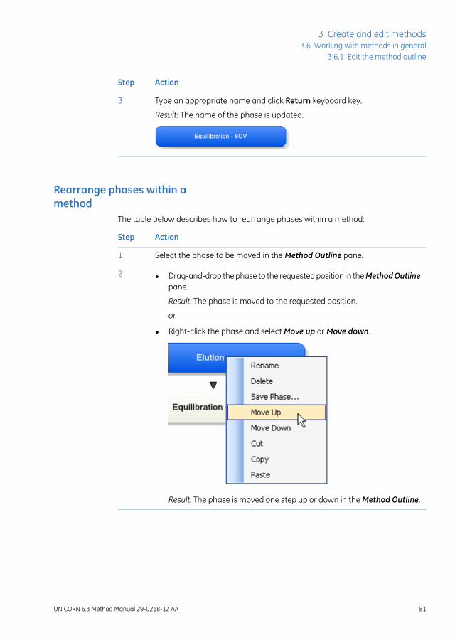
ActionStep
Type an appropriate name and click Return keyboard key.3
Result: The name of the phase is updated.
Rearrange phases within amethod
The table below describes how to rearrange phases within a method:
ActionStep
Select the phase to be moved in the Method Outline pane.1
• Drag-and-drop the phase to the requested position in theMethodOutlinepane.
Result: The phase is moved to the requested position.
or
• Right-click the phase and select Move up or Move down.
Result: The phase is moved one step up or down in the Method Outline.
2
UNICORN 6.3 Method Manual 29-0218-12 AA 81
3 Create and edit methods3.6 Working with methods in general
3.6.1 Edit the method outline

Delete a phase from the MethodOutline
The table below describes how to delete a phase from the Method Outline:
ActionStep
Select the phase to delete from the method in the Method Outline.1
82 UNICORN 6.3 Method Manual 29-0218-12 AA
3 Create and edit methods3.6 Working with methods in general3.6.1 Edit the method outline

ActionStep
• Click the Delete button below the Method Outline pane.
or
• Press the Delete key on the keyboard.
or
• select Edit:Delete
or
• Right-click on the phase and select Delete from the context menu.
Result: The phase is removed from the method.
2
UNICORN 6.3 Method Manual 29-0218-12 AA 83
3 Create and edit methods3.6 Working with methods in general
3.6.1 Edit the method outline

Copy, cut and paste phases in amethod
It is only possible to copy, cut and paste phases in theMethod Outline pane,not in the Phase Library.
Note:
The features copy, cut and paste phases can be used to add/delete and rearrangephases in theMethodOutline. The table below describes the copy, cut and paste a phasefeatures.
then...To...
select the phase and:copy a phase
• right-click the phase and select Copy
or
• use the shortcut Ctrl +C
or
• select Edit:Copy
select the phase and:cut a phase
• right-click the phase and select Cut
or
• use the shortcut Ctrl +X
or
• select Edit:Cut
Note:
The phase to be pasted will be pasted below the phasehighlighted in theMethod Outline.
paste a phase
Select the appropriate phase in theMethodOutline. Then:
• right-click the highlighted phase in theMethodOutlineand select Paste
or
• use the shortcut Ctrl +V
or
• select Edit:Paste
84 UNICORN 6.3 Method Manual 29-0218-12 AA
3 Create and edit methods3.6 Working with methods in general3.6.1 Edit the method outline

3.6.2 Set general method options for the method
IntroductionThis section describes how to set and view options for an entire method. The followingare covered in this section:
• Defining the name and location for the results.
• How to set up a Start Protocol that will be displayed before each method run.
• Adding or changing method notes.
• How to include evaulation procedures which can be executed during the run.
• Viewing the method duration time and volume.
• Viewing the variables used in the method.
UNICORN 6.3 Method Manual 29-0218-12 AA 85
3 Create and edit methods3.6 Working with methods in general
3.6.2 Set general method options for the method

Define Result Name & LocationThe table below describes how to define the name of the result file created after the runand how to specify the folder in which to save the result file.
ActionStep
In the Method Editor:1
• click the Result Name & Location icon
or
• select Edit:Result Name & Location...
or
• click theMethod Settings phase and click theResult Name& Location...button in the Phase Properties tab
Result: The Result Name & Location dialog opens.
86 UNICORN 6.3 Method Manual 29-0218-12 AA
3 Create and edit methods3.6 Working with methods in general3.6.2 Set general method options for the method

ActionStep
2
In the Result Name & Location dialog:
• Set Result location by clicking the Browse button and select a folder inwhich to save the results. By default, the results will be saved in yourhome folder.
• Select Result name.
- Name: The result name can be typed in manually
- Variable: The result name will be generated from the chosen variable(see Section 9.2.4 Method variables, on page 348)
- Method name (default): The result name will be generated from thename of the method
- Date: The result name will be generated from the date of the run
• Check the Add unique identifier box if you want to include a uniqueidentifier number to the file name. The number will be generated byUNICORN based on the run time of the method.
• Click OK to confirm and close the dialog.
UNICORN 6.3 Method Manual 29-0218-12 AA 87
3 Create and edit methods3.6 Working with methods in general
3.6.2 Set general method options for the method

Set up a Start ProtocolThe table below describes how to set up a Start Protocol to be displayed before the runstarts.
ActionStep
In the Method Editor:1
• click the Start Protocol icon
or
• select Tools:Start Protocol...
or
• click the Method Settings phase and click the Start Protocol... buttonin the Phase Properties tab
Result: The Start Protocol dialog opens.
In the Start Protocol dialog:2
• Select items to display at method start. When selecting a method item,a description is shown to the right.Result Nameand Location is selectedby default.
• Click OK to confirm and close the dialog.
88 UNICORN 6.3 Method Manual 29-0218-12 AA
3 Create and edit methods3.6 Working with methods in general3.6.2 Set general method options for the method

Add/edit Method NotesThe table below describes how to add/edit notes to a method.
ActionStep
In the Method Editor:1
• click the Method Notes icon
or
• select Edit:Method Notes...
or
• click the Method Settings phase and click the Method Notes... buttonin the Phase Properties tab
Result: The Method Notes dialog opens.
UNICORN 6.3 Method Manual 29-0218-12 AA 89
3 Create and edit methods3.6 Working with methods in general
3.6.2 Set general method options for the method

ActionStep
2
In the Method Notes dialog:
• Enter/edit notes about the method. If notes already have been entered,it is possible to search for specific words using the Find... button.
• Click OK to confirm and close the dialog.
Note:
For some systems information will automatically be added to theMethodNotes if the method has been converted for use with another system typethan it was originally created for, or scaled for another column type thanwasoriginally selected, or if it is a wizard generated intelligent packing method.
90 UNICORN 6.3 Method Manual 29-0218-12 AA
3 Create and edit methods3.6 Working with methods in general3.6.2 Set general method options for the method

Include Evaluation Proceduresafter the run
The table below describes how to include an evaluation procedure in the method. Theevaluation procedure will be performed automatically after the run has finished. Theevaluation procedures must have been defined in the Evaluation module, see theUNICORN 6.3 Evaluation Manual.
ActionStep
In the Method Editor:1
• click the Evaluation Procedures icon
or
• select Tools:Evaluation Procedures...
Result: The Evaluation Procedures dialog opens.
UNICORN 6.3 Method Manual 29-0218-12 AA 91
3 Create and edit methods3.6 Working with methods in general
3.6.2 Set general method options for the method

ActionStep
2
• If there are no evaluation procedures listed in the Evaluation Proceduresdialog, click the Import... button to import an evaluation procedure.
Result: The Import Evaluation Procedure dialog opens. Continue withstep 3.
• If an evaluation procedure that should be used in the run has been savedin the method earlier, it is shown in the Evaluation Procedures dialog.Continue with step 4.
92 UNICORN 6.3 Method Manual 29-0218-12 AA
3 Create and edit methods3.6 Working with methods in general3.6.2 Set general method options for the method

ActionStep
3
In the Import Evaluation Procedures dialog:
• Select the appropriate procedure to import in the Select procedure toimport field.
• It is possible to change the name of the procedure to be displayed inyour method by changing the name in the Import as field.
• Click Import to import the procedure
Note:
Only Global procedures and your own Personal procedures are shown inthe list.
Note:
It is also possible to import a procedure saved in anothermethod by browsingto the appropriate folder and selecting themethod containing the procedure.The procedure will be listed in the Select procedure to import field and canbe imported as described above.
Result: The evaluation procedure is listed in theEvaluationProceduresdialog.
UNICORN 6.3 Method Manual 29-0218-12 AA 93
3 Create and edit methods3.6 Working with methods in general
3.6.2 Set general method options for the method

ActionStep
4
Make sure the box in front of the evaluation procedure is checked to includeit in the method.
Click Close.
Result: The evaluation procedure is included in the method.
Note:
It is possible to edit an existing evaluation procedure by selecting it andclicking Edit.... The edits will only change the procedure that is included in themethod. See the UNICORN 6.3 Evaluation Manual for information about howto edit an evaluation procedure.
94 UNICORN 6.3 Method Manual 29-0218-12 AA
3 Create and edit methods3.6 Working with methods in general3.6.2 Set general method options for the method

View and print the methodduration time and variables
The table below describes how to view and print an estimation of the method durationtime and the variables in the method:
ActionStep
In the Method Editor:1
• click the Duration & Variables button below the Method Outline pane
or
• select View:Duration & Variables
Result: TheMethodDuration&Variablesdialog opens displaying theMethodDuration tab.
UNICORN 6.3 Method Manual 29-0218-12 AA 95
3 Create and edit methods3.6 Working with methods in general
3.6.2 Set general method options for the method

ActionStep
2
TheMethodDuration tab shows an estimation of the accumulated methodtime and volume for the current method below the text method.
If the method includes a Scouting series, an estimation of the accumulatedmethod time and volume for the total series of runs is displayed below thetext method.
Note:
Click the arrow buttons to display the different scouting runs.
The accumulated time/volume is an approximation and does not take intoaccount time or volume forWatch blocks,Wash commands or programmedHold.
• Select Time as Base to show the time in minutes in the text method.
• Select Volume as Base to show the volume in the text method.
3
To view the variables in the method, click the Variable List tab.4
Result: The Variable List is displayed.
96 UNICORN 6.3 Method Manual 29-0218-12 AA
3 Create and edit methods3.6 Working with methods in general3.6.2 Set general method options for the method

ActionStep
5
The Variable List shows the variables in the method. It is also possible tosee in which phases the variables are included and the different values.Variables with an ellipsis (...) after their name are used in multiple phases orblocks. It is not possible to change any values in this dialog.
• Check the Show details box to view variables classified as detailed. Theletter D will be shown to the left of the detailed variables.
• Check the Show unused variables box to view unused variables in themethod. The letter U will be shown to the left of unused variables.
To print the information in the Method Duration & Variables dialog, clickthe Print... button.
6
Result: The Print dialog opens.
Select a Printer from the drop-down list and click OK.7
Result: The information is printed.
UNICORN 6.3 Method Manual 29-0218-12 AA 97
3 Create and edit methods3.6 Working with methods in general
3.6.2 Set general method options for the method

3.6.3 Print a method
IntroductionThis section describes how to print a method’s text instructions and variables. UNICORNuses the printers and printer settings that are installed on your computer.
Print a methodThe table below describes how to print an opened method:
ActionStep
• Click the Print icon in the Toolbar
or
• select File:Print...
Result: The Print dialog opens.
1
98 UNICORN 6.3 Method Manual 29-0218-12 AA
3 Create and edit methods3.6 Working with methods in general3.6.3 Print a method

ActionStep
In the Print dialog:2
• select Printer
• select which Print items to be printed
• select to print all phases in the method or a specific phase in the Phaserange field
By default, information about the overall method settings as well as anysignatures and specific columns used in the method are printed. To excludeor add information, click Options>> and check/uncheck the appropriateboxes.
3
Note:
Only options that are used in a method can be printed. Options that are notused are grayed out in the Print dialog.
Click OK.4
Result: The method is printed.
UNICORN 6.3 Method Manual 29-0218-12 AA 99
3 Create and edit methods3.6 Working with methods in general
3.6.3 Print a method

3.6.4 Sign methods electronically
IntroductionMethods can be signed electronically to enhance data file security. Once a method hasbeen signed, it is not possible to edit the method.
To edit a signedmethod create a newmethod using the settings in the signedmethod by selecting File:Save As... and save the method with a new name.
Tip:
Sign a method electronically inthe Method Editor
The table below describes how to sign a method electronically in the Method Editor:
ActionStep
Select File:Sign Method....1
Result: The Sign Method dialog opens.
100 UNICORN 6.3 Method Manual 29-0218-12 AA
3 Create and edit methods3.6 Working with methods in general3.6.4 Sign methods electronically

ActionStep
2
• The Signing user field shows the user currently logged on.
Note:
If you want to Use Windows Authentication, select the check box, andlog in as a network user.
If you want to sign the method but are not logged on to UNICORN, selectyour user name in the Signing user drop-down list. Your Full name andJob title are displayed.
• Type your Log on password to UNICORN.
• Type a Signature description if appropriate.
• Type your Signature password and click OK.
Result: The method has been signed.
UNICORN 6.3 Method Manual 29-0218-12 AA 101
3 Create and edit methods3.6 Working with methods in general
3.6.4 Sign methods electronically

3.7 Save methods and phases
IntroductionMethods and phases are saved in the UNICORN database.
Individual, edited phases may be saved to the Phase Library for later use in othermethods on systems having the same instrument configuration and component config-uration.
You cannot save an edited method/phase to replace a predefined method orphase. If you want to save an edited variant of a predefined method or phasewith specific settings, you must save it under another name. A predefinedmethod or phase cannot be overwritten.
Note:
Save a methodThe table below describes how to save a method in UNICORN.
ActionStep
• Click the Save the Method icon
or
• select File:Save or File:Save As.
Result:
1
• If the method has been named and saved previously, the changes aresaved immediately.
If not
• The Save As dialog opens. Proceed with steps 2-4 below.
102 UNICORN 6.3 Method Manual 29-0218-12 AA
3 Create and edit methods3.7 Save methods and phases

ActionStep
Browse for an appropriate folder, or create a new one.2
• Select the folder in which to save the results.
• Enter a method Name.
• Select for which System to save the method
3
Click Save.4
Result: The method is saved in the database.
Note:
For some systems an error message will appear if you are trying to save themethod for:
• a systemusing another instrument configuration and/or another compo-nent configuration than the method originally was created for
and
• the settings in the method depend on the component configuration (e.g.,if an extra inlet A valve is used in the method, this setting cannot be usedin a system lacking the extra inlet A valve.)
It will still be possible to save the method but the phases in the method willbe marked with an error symbol. In order to be able to subsequently run themethod, either themethodmust be text-edited or the component configurationof the system changed in the Administrationmodule.
UNICORN 6.3 Method Manual 29-0218-12 AA 103
3 Create and edit methods3.7 Save methods and phases

Adapt a methodFor ÄKTA pure it is possible to open and save methods created with systems with anotherset of components than the currently used system. When a method is opened for asystem that has been changed or if a method is saved for a different system, a dialogis opened where the user can choose to either adapt the method or to keep the textmethod unchanged.
Then..If you se-lect..
the method will be adapted to a new set of components. All functionsand positions that are still available will be unchanged. For example,valve positions present on both the original and the new system willbe unchanged in the adapted method. Non compatible settings willbe adjusted in order to properly adapt the method for new compo-nents. Settings that have been changed are described and saved inMethod Notes, which are displayed after the method has beenadapted.
Adaptmethod
Change the settings in Phase Properties if required.
the text method will be kept and nothing in the text method will bechanged. Non-compatible settings will still be present in the methodbut they will not be functional. All Phase Properties of the methodwill be replaced by tables of Phase Variables.
Note:
Somepredefinedmethods require certain components to be functional.Adapting these methods to systems that do not include the requiredcomponents is not possible.
Keep textmethod
Save a phaseThe table below describes how to save a phase to the Phase Library:
ActionStep
Select the phase to be saved in the method outline.
Note:
AMethod Settings phase cannot be saved as a separate phase with a newname. If properties for theMethod Settings phase are changed, the changeswill be saved with the method.
1
104 UNICORN 6.3 Method Manual 29-0218-12 AA
3 Create and edit methods3.7 Save methods and phases
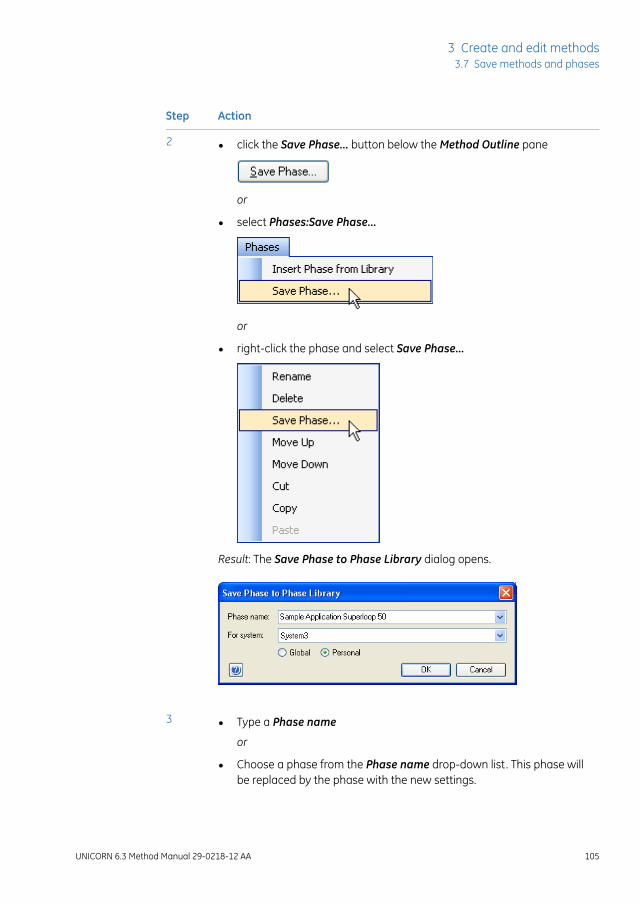
ActionStep
• click the Save Phase... button below the Method Outline pane
or
• select Phases:Save Phase...
or
• right-click the phase and select Save Phase...
Result: The Save Phase to Phase Library dialog opens.
2
• Type a Phase name
or
• Choose a phase from the Phase name drop-down list. This phase willbe replaced by the phase with the new settings.
3
UNICORN 6.3 Method Manual 29-0218-12 AA 105
3 Create and edit methods3.7 Save methods and phases

ActionStep
In the For system field, the system that was selected when the currentmethod was set up will be displayed by default. To save the phase for anothersystem, choose the appropriate system from the For system drop-downlist.
Note:
Only systems using the same instrument configuration and component con-figuration as the system that was selected when the current method was setup will be displayed in the For system field.
4
• Select if the phase shall be Global (available for all users) or Personal(for your own use only).
• Click OK.
Note:
It is not possible to replace a predefined phase by saving an existing phase.
5
Result: The phase is saved and is available in the Global Phases or PersonalPhases panel of the Phase Library.
Delete a phase from the PhaseLibrary
It is possible to delete personal and global phases from the Phase Library. Predefinedphases cannot be deleted.
The table below describes how to delete a personal or global phase from the phase library:
106 UNICORN 6.3 Method Manual 29-0218-12 AA
3 Create and edit methods3.7 Save methods and phases

ActionStep
Select the appropriate phase library: Personal Phases or Global Phases atthe bottom of the Phase Library pane.
1
Result: The phases in that phase library are displayed.
Select the phase to delete from the library.2
• Click the Delete button at the bottom of the Phase Library pane.
or
• Right-click the phase and select Delete.
Result: The phase is removed from the Phase Library.
3
UNICORN 6.3 Method Manual 29-0218-12 AA 107
3 Create and edit methods3.7 Save methods and phases

3.8 Scale or convert methods
IntroductionUNICORN methods are always created specifically for a designated system and thusalso for a specific system type. However, it is often useful to convert a method that wasoriginally created for a system of one type, for use with a system of another type. Theconverted method is created as a copy of the original method. The original method re-mains unchanged.
The possibility to scale or convert methods is only available for some systems, and onlybetween systems that use the same instructions.
A method can also be scaled for use with a different column type than it was originallycreated for, when the method is converted. Conversion and scaling is described in thissection.
If you wish to use a method for another system of the same system type thatit was originally created for, you only need to choose File:Save As, select thenew system and save the method with another name. This is possible for allsystems.
Tip:
Instructions marked with a red cross must be edited.To only change the selected column type, you should edit themethod, changethe column selection and save the edited method.
PrerequisitesThe following items should be considered to ensure that the method conversion andscaling is successful:
• The original method should use column volume (CV) as base
• All parameters that will require scaling should be defined as variables
• If linear flow is to be maintained in the scaled method, it must have been applied inthe original method as well
• Scaling of the column type is not possible if the Any column type was selected in theoriginal method
• Text edited phases will not be automatically updated during the conversion
108 UNICORN 6.3 Method Manual 29-0218-12 AA
3 Create and edit methods3.8 Scale or convert methods
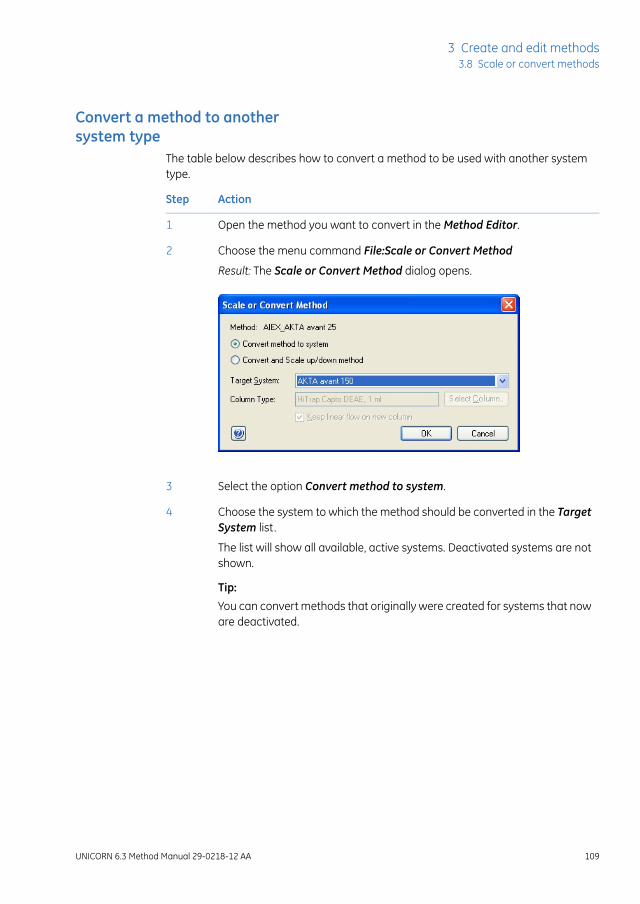
Convert a method to anothersystem type
The table below describes how to convert a method to be used with another systemtype.
ActionStep
Open the method you want to convert in the Method Editor.1
Choose the menu command File:Scale or Convert Method2
Result: The Scale or Convert Method dialog opens.
Select the option Convert method to system.3
Choose the system to which the method should be converted in the TargetSystem list.
4
The list will show all available, active systems. Deactivated systems are notshown.
Tip:You can convert methods that originally were created for systems that noware deactivated.
UNICORN 6.3 Method Manual 29-0218-12 AA 109
3 Create and edit methods3.8 Scale or convert methods

ActionStep
Click the OK button.5
Result: The method is converted as an untitled copy (UNTITLED converted*).The Method Notes dialog opens, showing basic information about the con-version.
Note:
The information shown in theMethodNoteswill not include notes concerningmethod instructions that may have become invalid as a result of conversionbetween systems with different components and instrument configurations.You must verify that there are no phases with invalid instructions (i.e. phasesmarked with a red cross) in the new method before it can be used. See notebelow this instruction.
• Type any additional notes you wish to add in the text field
and
• click the OK button to close the Method Notes dialog.
6
• Choose the File:Save Asmenu command to save the converted method
or
• click the Save icon
Result: The Save As dialog opens, with the folder where the original methodis saved open by default.
7
110 UNICORN 6.3 Method Manual 29-0218-12 AA
3 Create and edit methods3.8 Scale or convert methods
ActionStep
• Select the desired target folder,
• type a new method name in the Name field
and
• click the Save button.
8
The original method remains after the converted method is saved. However,the converted method will replace the original if you choose to save the con-verted method with the same name in the same folder as the original.
Note:
The flow rate and/or pressure settings in the method will automatically beadjusted if themaximum flow rate and/or pressure values for the target systemis exceeded after the conversion. Themaximum settings for the target systemwill be used by default.
Note:
In case the original method contains instructions that are not supported bythe new system, this will be indicated in the method outline of the convertedmethod as a red cross on the phase containing these instructions.
Note:
To be able to run themethod on the new system you need to replace or removethe invalid instructions in the Text Instructions pane. Invalid instructions areindicated with red square symbols in the text instructions.You can also replace the phasewith a predefined phase from the phase library.
Convert and scale a method upor down
The table below describes how to convert a method to be used with another systemtype, and at the same time scale the method to be used with another column size.
ActionStep
Open the method you want to convert and scale in the Method Editor.1
Choose the menu command File:Scale or Convert Method2
Result: The Scale or Convert Method dialog opens.
Select the option Convert and Scale up/down method.3
Choose the system to which the method should be converted in the TargetSystem list.
4
UNICORN 6.3 Method Manual 29-0218-12 AA 111
3 Create and edit methods3.8 Scale or convert methods

ActionStep
By default, the same column type that was selected in the original methodis shown in the Column Type field.
5
• Click the Select Column... button to select a new column type.
Result: The Select Column Type dialog opens.
112 UNICORN 6.3 Method Manual 29-0218-12 AA
3 Create and edit methods3.8 Scale or convert methods

ActionStep
• Select the column type from the list of available column types
and
• click the OK button.
Result: The Select Column Type dialog closes and the selected column isshown in the Column Type field of the Scale or Convert Method dialog.
6
If desired, select the Keep linear flow on new column option.
Note:
This option is applicable only if linear flowwas selected in the originalmethod.If linear flow is not selected, the default flow settings for the selected columntype will be used.
7
UNICORN 6.3 Method Manual 29-0218-12 AA 113
3 Create and edit methods3.8 Scale or convert methods

ActionStep
Click the OK button.8
Result: The method is scaled as an untitled copy (UNTITLED converted*).The Method Notes dialog opens, showing basic information about the con-version.
Note:
The information shown in theMethod Notes will not include details aboutscaled system related parameters (e.g. wash or delay volumes) or notes con-cerning method instructions that may have become invalid as a result ofconversion between systems with different components and instrumentconfigurations. You must verify that there are no phases with invalid instruc-tions (i.e. phases marked with a red cross) in the new method before it canbe used. See note below this instruction.
• Type any additional notes you wish to add in the text field
and
• click the OK button to close the Method Notes dialog.
9
114 UNICORN 6.3 Method Manual 29-0218-12 AA
3 Create and edit methods3.8 Scale or convert methods

ActionStep
• Choose the File:Save As menu command
or
• click the Save icon
Result: The Save As dialog opens, with the folder where the original methodis saved open by default.
10
• Select the desired target folder,
• type a new method name in the Name field
and
• click the Save button.
11
The original method remains after the converted method is saved. However,the converted method will replace the original if you choose to save the con-verted method with the same name in the same folder as the original.
Note:
The flow rate and/or pressure settings in the method will automatically beadjusted if themaximum flow rate and/or pressure values for the target systemis exceeded after the conversion. Themaximum settings for the target systemwill be used by default.
Note:
In case the original method contains instructions that are not supported bythe new system, this will be indicated in the method outline of the convertedmethod as a red cross on the phase containing these instructions.
Note:
To be able to run themethod on the new system you need to replace or removethe invalid instructions in the Text Instructions pane. Invalid instructions areindicated with red square symbols in the text instructions.You can also replace the phasewith a predefined phase from the phase library.
The method after conversionThe conversion will adjust the following settings to the appropriate values for the selectednew system:
• Gradient delay
• System wash volume (i.e. Fill system value)
• Volume for finalization of sample application (only applicable when Inject sampledirectly onto column and then Inject all sample using air sensor is selected)
UNICORN 6.3 Method Manual 29-0218-12 AA 115
3 Create and edit methods3.8 Scale or convert methods

The following settings may require manual adjustment after the conversion:
• Sample volume
• Fractionation volumes
• User defined volumes in System CIP and System preparation
• System related settings in text edited phases
(However, column related settings will be scaled also in text edited phases, providedthey have been defined as variables)
Converting a method for use ina different database
The table below describes the necessary steps to be performed if you wish to convert amethod for use with another system type, in another database than where the originalmethod was created.
This proceduremust be followed in order to convert methods from one stand-alone system to another stand-alone system.
Tip:
ActionStep
Set up a new system in the target database. Use the same instrument con-figuration as the system for which the method was originally created.
Tip:This system is created for the conversion only, and should be set up inacti-vated.
1
Since the new system will not be used for anything other than the methodconversion, the system name, IP address and serial number can be selectedat random. For example:
• System name: Method conversion system
• Instrument serial number: 123456789
• Fixed IP address: 10.1.1.1
Refer to UNICORN 6.3 Administration and Technical Manual, Define a newsystem for more information on how to set up a new system.
Export the method from the original database.2
Import the method into the target database, for use with the new, inactivatedsystem.
3
116 UNICORN 6.3 Method Manual 29-0218-12 AA
3 Create and edit methods3.8 Scale or convert methods

ActionStep
Convert the method from the inactivated system to be used with the targetsystem, as described in the applicable instruction above (i.e. with or withoutscaling of the column size).
4
UNICORN 6.3 Method Manual 29-0218-12 AA 117
3 Create and edit methods3.8 Scale or convert methods

3.9 Import and export methods
IntroductionUNICORN methods are stored internally in the UNICORN database. It is however possibleto export entire methods or individual phases to a zip file on the local computer so thatthey can be imported again later into the same database installation, or imported intoanother database installation.
Alternatively methods or phases can be exported as plain text files or Excel files, whichmay be useful for documentation purposes.
118 UNICORN 6.3 Method Manual 29-0218-12 AA
3 Create and edit methods3.9 Import and export methods

Export a phase or method toUNICORN
The following table outlines the steps needed to export a method or a phase for laterimport into UNICORN.
ActionStep
In the Method Navigator, select the method to be exported.
Note:
Severalmethods in the same folder can be selected and exported at the sametime. You can select several results at once by using the Shift orCtrl keywhenselecting.
1
or
In the Phase Library pane, select the phase to be exported.
Note:
Only Personal or Global phases may be exported.
Note:
Only single phases may be exported.
UNICORN 6.3 Method Manual 29-0218-12 AA 119
3 Create and edit methods3.9 Import and export methods
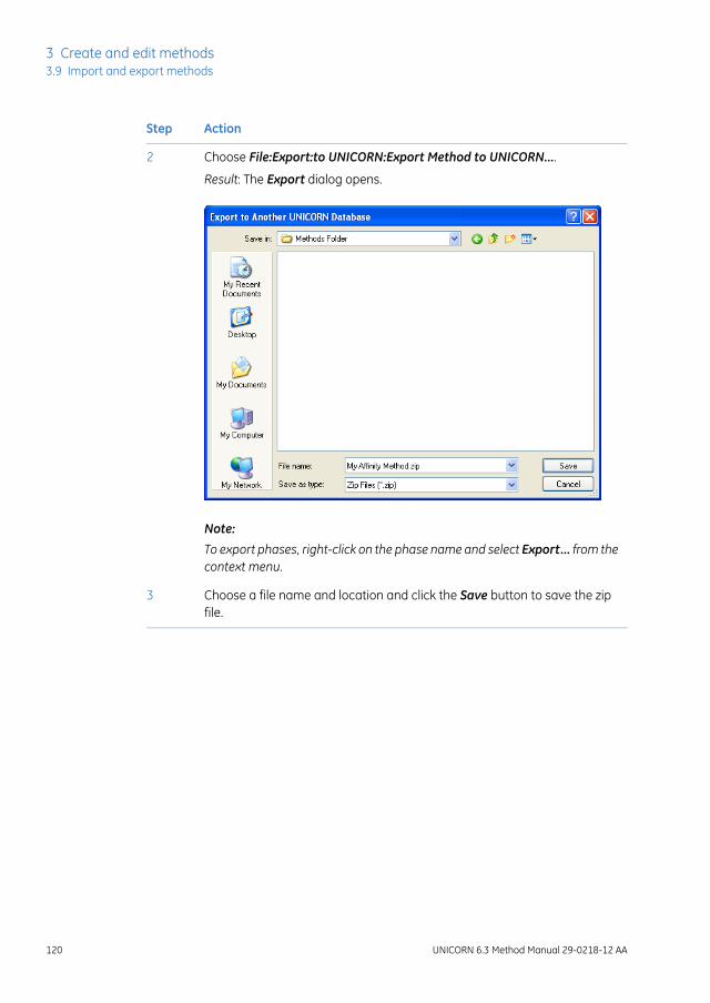
ActionStep
Choose File:Export:to UNICORN:Export Method to UNICORN....2
Result: The Export dialog opens.
Note:
To export phases, right-click on the phase name and select Export... from thecontext menu.
Choose a file name and location and click the Save button to save the zipfile.
3
120 UNICORN 6.3 Method Manual 29-0218-12 AA
3 Create and edit methods3.9 Import and export methods

Export a method to a plain textfile
The following table outlines the steps needed to export a method as a plain text file orto Excel.
ActionStep
In the Method Navigator, select the method to be exported. It is only possibleto export one method at a time to an external file.
1
Choose File:Export:Export Method Externally....2
Result: The Export Externally dialog opens.
Choose which Export items to include by checking the appropriate boxes.3
Choose whether to include All phases or only a specific Phase by selectingthe appropriate Phase range option.
4
UNICORN 6.3 Method Manual 29-0218-12 AA 121
3 Create and edit methods3.9 Import and export methods

ActionStep
To add further information to export, click the Options >> button.5
Result: The Include options will be expanded.
Select information to add to the text file by checking the appropriate options.
Note:
Information that is not included in the method will appear grayed out andcannot be selected.
6
To save the text file with the selected information included click the SaveAs... button.
7
Result: The Export dialog opens.
122 UNICORN 6.3 Method Manual 29-0218-12 AA
3 Create and edit methods3.9 Import and export methods

ActionStep
Choose whether to save to an ASCII file or to an Excel file from the Save astype drop-down menu.
8
Choose a file name and location and click the Save button to save the zipfile.
9
Import a phase into UNICORNPhases that have previously been exported as zip files can be imported back intoUNICORN. The following table outlines the steps needed to import a phase.
ActionStep
Select File:Import:Import Phase....1
Result: The Import dialog opens.
Browse to the required zip file in the Import dialog.2
UNICORN 6.3 Method Manual 29-0218-12 AA 123
3 Create and edit methods3.9 Import and export methods

ActionStep
Open the file by selecting it and clicking the Open button, or by double-clicking on the file name.
3
Result: The Import Phase Library dialog opens.
Type a new Phase Name if required, and select whether the phase shouldbe imported as Global or Personal. Global phases are available to all users,Personal phases only to the currently logged-on user.
4
Click the OK button to import the phase.5
124 UNICORN 6.3 Method Manual 29-0218-12 AA
3 Create and edit methods3.9 Import and export methods
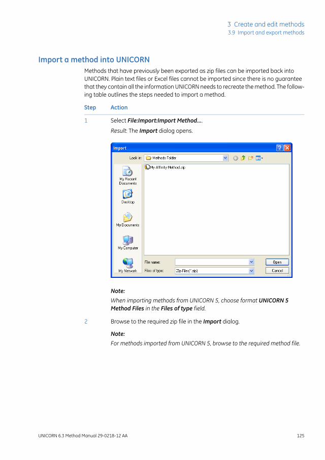
Import a method into UNICORNMethods that have previously been exported as zip files can be imported back intoUNICORN. Plain text files or Excel files cannot be imported since there is no guaranteethat they contain all the information UNICORN needs to recreate the method. The follow-ing table outlines the steps needed to import a method.
ActionStep
Select File:Import:Import Method....1
Result: The Import dialog opens.
Note:
When importing methods from UNICORN 5, choose format UNICORN 5Method Files in the Files of type field.
Browse to the required zip file in the Import dialog.
Note:
For methods imported from UNICORN 5, browse to the required method file.
2
UNICORN 6.3 Method Manual 29-0218-12 AA 125
3 Create and edit methods3.9 Import and export methods

ActionStep
Open the file by selecting it and clicking the Open button, or by double-clicking on the file name.
Note:
Severalmethods in the same folder can be selected and imported at the sametime. You can select several results at once by using the Shift orCtrl keywhenselecting.
3
Result: The Import Method dialog opens.
Browse to the required folder in the database and type in a new Name ifnecessary.
4
Select a System for the method from the drop-down menu.5
Click the Import button to import the method.6
Result: The imported method will be opened in the Method Editor.
If several methods were chosen in the first step, repeat the procedure in theImport Method(s) dialog for each method.
Note:
If the imported method contains instructions that are not supported by theselected system, the phases containing these instructionswill bemarkedwithan error symbol.
126 UNICORN 6.3 Method Manual 29-0218-12 AA
3 Create and edit methods3.9 Import and export methods

Import a method fromUNICORN 5
Methods that have been created in UNICORN 5.11 and subsequent versions can be im-ported into UNICORN 6.3 in the same way as described above. However, some informationwill not be imported.
The Data collection utility can only be used if UNICORN 5 is installed on Win-dows XP.
Note:
Changes in data after importWhen methods are imported from UNICORN 5, there is some information that will notbe included and some information that will be added. It is important to review the methodafter import, to verify that all essential information is there. The method can be manuallyedited, after the import. All functionality in UNICORN 6.3 is not available for importedmethods, since necessary data might be missing.
DescriptionAffected information
Installation test methods that were generated bythe method wizard in UNICORN 5 do not work inUNICORN 6.3. These methods must be regeneratedby the method wizard in UNICORN 6.3.
Installation test methods
Scouting on any of the Frac-950 instructions (Frac-tionation and Peak_Fractionation) parameters villnot be migrated.
Scouting data
Reference curves are not migrated since this func-tionality is not available in UNICORN 6.3.
Reference curves
UNICORN 6.3 Method Manual 29-0218-12 AA 127
3 Create and edit methods3.9 Import and export methods

DescriptionAffected information
Delta pressure
A UNICORN 5 method with an included column canbe migrated, but where UNICORN 5 uses Max pres-sure in the method, UNICORN 6.3 uses the termsMax delta column pressure and Max pre columnpressure. UNICORN 6.3 will set both Max delta col-umn pressure and Max pre column pressure to bethe Max pressure value from UNICORN 5 when amethod without these parameters is imported.
Column data
Max flow rate
A UNICORN 5 method with an included column canbe migrated, but Max flow rate is not mandatory inUNICORN 5 and may not have been set. When amethod withoutMax flow rate is migrated UNICORN6.3 will set the Max flow rate to be the same as thedefault flow rate for the column.Column type
The UNICORN 6.3 Column list differs from theUNICORN 5 Column list. Any column type includedin a method is migrated and the values are notchanged, but the column type will not be importedto the UNICORN 6.3 Column list. The column type ofpre-packed columns from GE Healthcare from theUNICORN 5 Column list should be exchanged for thecorresponding column type in the UNICORN 6.3Column list.
Custom packed columns from the UNICORN 5 Col-umn list have to be redefined in Column handling inUNICORN 6.3, in order to get the full use of the Col-umn handling tool.
128 UNICORN 6.3 Method Manual 29-0218-12 AA
3 Create and edit methods3.9 Import and export methods

DescriptionAffected information
If an evaluation procedure instruction is invalid inUNICORN 5 the instruction is removed from themethod during migration.
Evaluation procedures
Non-imported instructions
Some evaluation procedure instructions are not im-ported. A removed instruction is replaced inUNICORN 6.3 by a comment that informs the userthat an instruction is missing.
The following evaluation procedure instructions willnot be imported:
• CURVE_OPEN
• PEAKTABLE_OPEN
• EXPORT_DOC_ASCII
• EXPORT_DOC_WKS
• EXPORT_DOC_XLS
• COPY_CHROM
• CREATE_NEW_CHROM
• OPEN_CHROM
• DELETE_CHROM
• RENAME_CHROM
• SIMULATE_PEAK_FRAC
• POOL_FRACTIONS
• RET_MUL
• EXPORT_DOC_400_xxx
• EXPORT_NORMALISE_RETENTION
• Export of curves in AIA
• Quantitate functions
• All instructions for exporting to WKS format
UNICORN 6.3 Method Manual 29-0218-12 AA 129
3 Create and edit methods3.9 Import and export methods

DescriptionAffected information
Changed instruction
The following evaluation procedure instructions arechanged when imported:
• The evaluation procedure instruction EX-PORT_MULTI_CURVES_XLS is migrated fromUNICORN 5 to the equivalent instruction EX-PORT_MULTI_CURVES_CSV in UNICORN 6.3.
• The instruction RUN_PROGRAM is implementedin UNICORN 6.3 but programs that have a userinterface cannot be launched.
Report layouts are not migrated.Report layouts
If a non-imported report layout is referred to in anevaluation procedure, the layout will be replacedwith the default layout.
130 UNICORN 6.3 Method Manual 29-0218-12 AA
3 Create and edit methods3.9 Import and export methods

4 Scouting
About this chapterScouting is used to repeat a series of method runs automatically using different settingsor with predetermined changes in the values for one or more Variables. A Scoutingscheme is defined as part of the method. This chapter gives an overview of scoutingand the scouting workflow and describes how to set up and edit a Scouting scheme.
Scouting is ideal for relatively simple variable combinations. When designing experimentsto analyse several variables at the same time, it is advantageous to use the Design ofExperiments (DoE) tool. This tool applies statistical methods for generating scouting runsthat provide the most information with as few runs as possible, thus economizing ontime and sample amounts. For details on DoE, see Chapter 5 Design of Experiments, onpage 144.
In this chapterThis chapter contains the following sections:
See pageSection
1324.1 Overview
1344.2 Set up and edit a Scouting scheme
UNICORN 6.3 Method Manual 29-0218-12 AA 131
4 Scouting

4.1 Overview
IntroductionScouting can be used to generate a series of method runs where one or more Variableparameters are varied in the same method. The resulting Scouting scheme is definedand saved in the method.
This section gives an overview of scouting and the scouting workflow.
When to use scoutingSome typical situations where scouting is useful are for instance when the objective isto:
• screen for the best column
• find the optimal pH
• test column capacity (sample volume)
• find the optimal flow rate for binding and elution
• optimize gradient length and slope
• optimize step gradients.
Scouting workflow overviewTo perform a scouting experiment the following steps must be performed:
• Create a method and decide appropriate run parameters (i.e.,variables) to bevaried in the experiment
See Chapter 3 Create and edit methods, on page 26 for information about how tocreate methods.
• Set up a scouting scheme
This includes selecting variables, inserting runs/series of runs with different variablesettings.
To define new variables for a method, see Section9.2.4Method variables, on page348for information.
• Start and monitor the scouting run
132 UNICORN 6.3 Method Manual 29-0218-12 AA
4 Scouting4.1 Overview

This is performed in System Control. See UNICORN 6.3 System Control Manual forinformation.
The Start protocolwill only be displayed before the first run in the Scoutingexperiment.
Note:
• Evaluate the results of the scouting run
This is performed in the Evaluationmodule. All results from Scouting runs performedat any one time are stored in the same folder. See UNICORN 6.3 Evaluation Manualfor information.
UNICORN 6.3 Method Manual 29-0218-12 AA 133
4 Scouting4.1 Overview

4.2 Set up and edit a Scouting scheme
IntroductionAny parameter can be scouted, provided that it can be defined as a variable in themethod.
Fractionation using Frac-950 is an exception and cannot be scouted.Note:
This section describes how to set up and edit a Scouting scheme.
Set up a scouting schemeThe table below describes how to set up a Scouting scheme where the flow rate is varied.In this example, the flow rate is varied between 0.5 and 3 ml/min.
The Start protocolwill only be displayed before the first run in the Scoutingexperiment.
Note:
ActionStep
Create a method and decide appropriate run parameters to be varied in theexperiment. The run parameters to be varied should be defined asVariablesin your method.
1
See Chapter 3 Create and edit methods, on page 26 for information abouthow to create methods.
See Section 9.2.4 Method variables, on page 348 for information about howto define new variables.
Tip:Many variables that can be used for scouting are already defined in eitherthe Method Settings phase or the predefined phases. Note that some vari-ables may be hidden or unused in the method. New variables often do notneed to be defined.
134 UNICORN 6.3 Method Manual 29-0218-12 AA
4 Scouting4.2 Set up and edit a Scouting scheme

ActionStep
In the Method Editor:2
• Click the Scouting icon in the toolbar
or
• Select Tools:Scouting
Result: The Scouting dialog opens with the Scouting Variables dialog dis-played on top.
Note:
When editing a scouting scheme, only the Scouting dialog is displayed.
UNICORN 6.3 Method Manual 29-0218-12 AA 135
4 Scouting4.2 Set up and edit a Scouting scheme

ActionStep
• In the Scouting Variables dialog, select the appropriate variable(s) to bevaried by checking the appropriate box(es).
- Check the Show details box if you want to display variables definedas detailed variables in your method. These are rarely used asscouting variables.
- Check theShowunusedvariablesbox if you want to display variablescurrently not used in the method.
• Click OK.
Result: The Scouting dialog is updated with the selected variable(s) and theirdefault value(s).
3
It is possible to insert runs one by one (see step 4) or insert series of runs(see step 5).
136 UNICORN 6.3 Method Manual 29-0218-12 AA
4 Scouting4.2 Set up and edit a Scouting scheme

ActionStep
To insert runs one by one:4
• In the Scouting dialog, select a row in the Scouting parameters table
and click .
Result: A new row is added below the selected run. The variable valuefrom the selected row is copied to the new run. Each chosen variable isdisplayed in a separate column.
• In this example, click in the Flow rate {ml/min} column for the appropriaterun and edit the flow rate value.
Note:
Changing variable values in the scouting scheme does not change thevalues in the Variable List in theDuration and Variables dialog or in thetext instructions. The actual variable values used for each run in thescouting scheme are saved in the result file. To change the default values,the variable values must be edited in the Phase Properties pane.
• Repeat until all runs are included using the correct variable values.
Note:
The scouting scheme can also be edited just prior to starting the methodrun in the Start Protocol. Here variable values can be changed and indi-vidual runs included or excluded.
UNICORN 6.3 Method Manual 29-0218-12 AA 137
4 Scouting4.2 Set up and edit a Scouting scheme
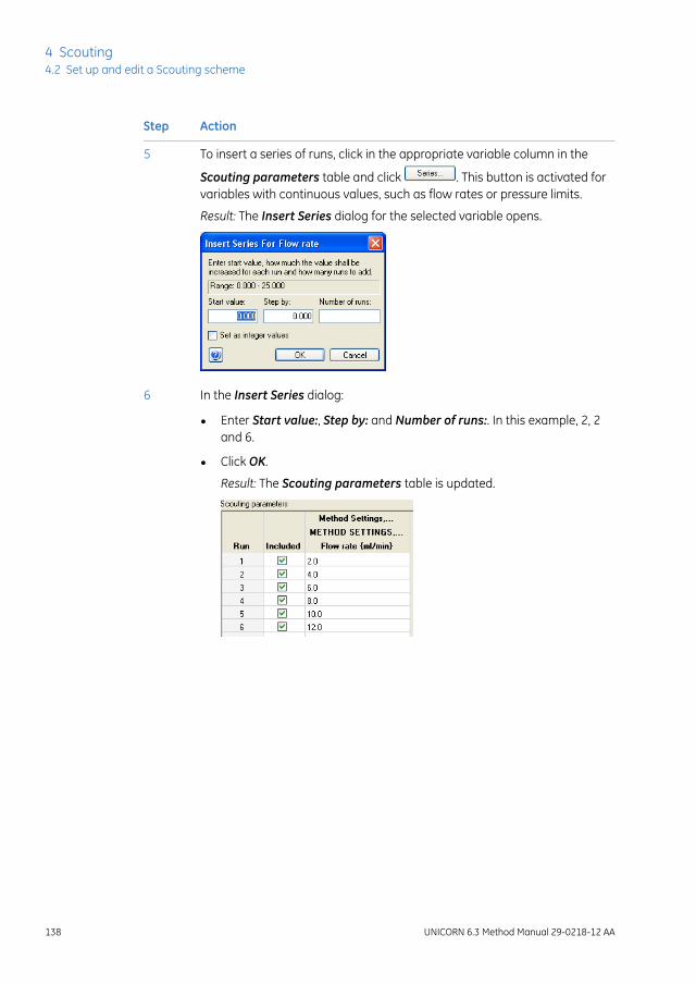
ActionStep
To insert a series of runs, click in the appropriate variable column in the
Scouting parameters table and click . This button is activated forvariables with continuous values, such as flow rates or pressure limits.
5
Result: The Insert Series dialog for the selected variable opens.
In the Insert Series dialog:6
• Enter Start value:, Step by: and Number of runs:. In this example, 2, 2and 6.
• Click OK.
Result: The Scouting parameters table is updated.
138 UNICORN 6.3 Method Manual 29-0218-12 AA
4 Scouting4.2 Set up and edit a Scouting scheme

ActionStep
Alternatively, to enter either consecutive or non-consecutive integer values:7
• Check the Set as integer values box in the Insert Series dialog.
Result: The following alternative Insert Series dialog for the selectedvariable opens.
• Enter the appropriate range, for example: 1-3,5-7
• Click OK.
Result: The Scouting parameters table is updated.
Click OK in the Scouting dialog to save the scouting scheme.8
Save the method.
UNICORN 6.3 Method Manual 29-0218-12 AA 139
4 Scouting4.2 Set up and edit a Scouting scheme

Add, delete or edit variables inthe Scouting scheme
The table below describes how to add, delete or edit variables in the Scouting scheme.
ActionStep
Open the Scouting scheme (see Set up a scouting scheme, on page 134).1
To add or delete variables in the Scouting scheme, click in theScouting dialog.
2
Result: The Scouting Variables dialog opens.
140 UNICORN 6.3 Method Manual 29-0218-12 AA
4 Scouting4.2 Set up and edit a Scouting scheme

ActionStep
• To add a variable to the Scouting scheme, check the appropriate boxin front of the variable.
• To delete a variable from the Scouting scheme, clear the box in front ofthe variable.
If you cannot find the appropriate variable:
3
• Check the Show details box to display variables defined as detailedvariables in your method.
• Check the Showunused variables box to display variables currently notused in the method.
To define a new variable, see Section9.2.4Method variables, on page348 forinformation.
Click OK.
Result: The Scouting parameters table is updated with the changes.
To edit a variable value for a run:4
• Select the appropriate row and the variable value cell in the Scoutingparameters table.
• Type a new value for the variable.
Result: The variable value is updated.
Note:
Changing variable values in the scouting scheme does not change the valuesin theVariable List in theDuration andVariables dialog or in the text instruc-tions. The actual variable values used for each run in the scouting schemeare saved in the result file. To change the default values, the variable valuesmust be edited in the Phase Properties pane.
Click OK.5
Result: The Scouting parameters table is updated with the changes.
Add new scouting runs to the scouting scheme as required.6
Click OK in the Scouting dialog to save the scouting scheme.7
Save the method.
UNICORN 6.3 Method Manual 29-0218-12 AA 141
4 Scouting4.2 Set up and edit a Scouting scheme

Add/delete runs in the Scoutingscheme
The table below describes how to add runs and series of runs to the Scouting schemeand how to delete runs.
ActionStep
Open the Scouting scheme (see Set up a scouting scheme, on page 134).1
142 UNICORN 6.3 Method Manual 29-0218-12 AA
4 Scouting4.2 Set up and edit a Scouting scheme

ActionStep
• To insert a run after an existing run:
Select the appropriate row in the Scouting parameters table and click
.
Result: A new row is added below the selected run to the Scouting pa-rameters table. The variable value from the selected row is copied tothe new run. Edit the variable value as appropriate.
• To insert a new series of runs:
- Click in the appropriate variable column in the Scouting parameters
table and click .
- Set up a series in the Insert series dialog and click OK (see Set up ascouting scheme, on page 134).
Result: The new set of runs are inserted in the Scouting schemewiththe values provided.
• To delete runs from the Scouting scheme:
- Select the row(s) in the Scouting parameters table and click
.
Result: The selected runs are removed from the Scouting scheme.
or
- Click .
Result: All runs are removed from the Scouting scheme. No scoutingwill be performed when starting the run.
• To exclude a run from being used in the Scouting experiment but keep itin the Scouting scheme:
Clear the Included box in front of the appropriate run.
2
ClickOK in the Scouting dialog to save the changes to the scouting scheme.3
Save the method.
UNICORN 6.3 Method Manual 29-0218-12 AA 143
4 Scouting4.2 Set up and edit a Scouting scheme

5 Design of Experiments
About this chapterThis chapter gives a brief overview of Design of Experiments and describes some basicterms and concepts used in theDesign of Experiments tool in UNICORN. It also describeshow to set up an experimental design plan using the Design of Experiments (DoE) toolin the Method Editor and how to evaluate the results of the runs in the Evaluationmodule.
Design of Experiments is only available for some systems.
In this chapterThis chapter contains the following sections:
See pageSection
1455.1 Introduction to Design of Experiments
1575.2 Create an experimental design
1835.3 Run a scouting created with DoE
1855.4 Evaluation of Design of Experiments
144 UNICORN 6.3 Method Manual 29-0218-12 AA
5 Design of Experiments

5.1 Introduction to Design of Experiments
IntroductionThis section gives a brief introduction to the basic terms and concepts used in Designof Experiments (DoE).
What is Design of Experiments?Design of Experiments is a way to systematically vary several parameters simultane-ously to obtain as much information about a process with as few experiments as possible.
Why use DoE?Maximize the amount of information using a minimum number of runsWhen trying to find optimal conditions for a process to obtain the best results, it is usu-ally not possible to perform all experiments needed due to time or cost using a randomexperiment approach. The number of runs to be performed needs to be minimized atthe same time as the information from the runs are maximized. DoE facilitates this byusing a systematic approach for experimental set-up and statistical modelling for theresults.
For example, it could be enough to obtain 80% information about a process. This levelof information can be reached using a significantly lower number of experiments usingDoE than using a random experiment approach as illustrated in the figure below.
8 16 32 64 128
100% ****
*
R andom experiment approach
DoE s tructured approach
Number of experiments
Info
rma
tion
UNICORN 6.3 Method Manual 29-0218-12 AA 145
5 Design of Experiments5.1 Introduction to Design of Experiments

Estimate parameter interactionsIn the simplest traditional approach to optimization experiments, one parameter is variedwhile all others are fixed. In this way optimal values may be found for each parameter.Using this approach, interaction effects between parameters might be missed that couldlead to better optimization of a process.
In the DoE approach, process parameters are allowed to vary simultaneously, thus al-lowing the effect of each parameter individually as well as the combined effect of pa-rameters to be estimated. Each parameter may have an optimum, but when combiningthe parameters, values may be found that together give a new optimum, even betterthan the optima for the separate parameters. The illustration below shows the differentapproaches in a graphical way.
Parameter 1
Parameter 2
Parameter 1
Para
met
er 2
Optimum
Traditional approach DoE approach
Optimum
Obtain reliable maps of the systemExperiments are performed to assess the conditions for best processes or to obtain theproduct characteristics required. In order to make the necessary decisions we need toolsor ways to make this as intuitive and easy as possible. In the evaluation of DoE results,different plots are created from the model. Decision making becomes more reliablewhen using tools that benefit from the created model. This "map" of the process helpsto decide on, for example, how to progress, or whether the process is already optimized.Is the process robust? What experiments can be performed to verify the process?
DoE in UNICORNIn UNICORN, DoE is used to systematically create an optimized set of experiments to berun. Depending on the objective and the number of parameters, a suitable design issuggested. An experimental plan is presented and a Scouting scheme is generated asa result from DoE containing the method runs to be performed. When the runs havebeen performed, the results can be analyzed in the Evaluation module. A model is cre-ated and a number of plots are generated to aid evaluation of the results. The modelcan be used to predict responses for new parameter settings and to optimize the param-eter settings for a desired combination of responses (e.g., optimize the response combi-nation "minimize the level of impurities and maximize the yield").
146 UNICORN 6.3 Method Manual 29-0218-12 AA
5 Design of Experiments5.1 Introduction to Design of Experiments

Factors and responsesThe table below lists the definitions of the DoE terms factors and responses and how touse them in UNICORN.
In UNICORNDefinitionTerm
The factors are connected to a variablein the method. For example, the factorpH may be connected to the variableBufferPro pH.
The different parameters that may af-fect the process to be run.
Factors may be either quantitative orqualitative.
Factor
In predefined methods, most usefulparameters are already defined asvariables.
Note:
To be able to vary a value for a processparameter in the method it must be de-fined as a variable.
• Quantitative factors are character-ized by being found on a continuousscale for example, pH, flow rate andconductivity.
• Qualitative factors are character-ized by being discrete (discontinu-ous), for example, column type,media type and buffer substance. Low and high values are entered for the
quantitative factors. The factors will bevaried within this range.
When evaluating the DoE runs, themeasured response values for eachexperiment are entered in UNICORN.
The output parameter(s) from a process.For example, capacity, yield and purity.
Response
DoE designThe design is the setup of experiments with different combinations of factor settingsresulting in a minimum number of experiments to be run to obtain as much informationas possible.
UNICORN suggest a suitable design to be used in the experiment based on the:
• number of factors
• type of factors (quantitative or qualitative)
• experimental objective (screening, optimization or robustness testing)
There are different objectives and design types included in the DoE tool in UNICORN.See the following blocks for more information about design objectives and design types.
UNICORN 6.3 Method Manual 29-0218-12 AA 147
5 Design of Experiments5.1 Introduction to Design of Experiments

Design objectivesThe table below describes the different design objectives:
Used when you want to...Design objective
Determine which factors are important in your processand the appropriate ranges for these factors.
Screening
Find the optimal factor settings for your process, that is,factor settings that give the desired responses.
Optimization
Determine the process robustness by making minor ad-justments of the factor settings and see if the responsesare within the set specification limits. If the responses donot vary significantly due to the factor changes, the pro-cess is considered to be robust.
Robustness Testing
Example of how to use DoE for different objectivesTo obtain maximum amount of protein after purification of a sample using a minimumnumber of runs, use DoE to find:
• important parameters (e.g., pH, conductivity) and the appropriate parameter rangesaffecting this process
• the optimal parameter settings and any dependencies (interaction) between theparameters affecting the response of the product or process (e.g., yield or impuritylevel)
When the parameters affecting the process as well as their settings have been determinedit is appropriate to test if the process is robust, that is, not affected by minor changes inthe parameter settings. Neither the parameter settings selected or their interactionsshould affect the process if the process is to be considered robust.
A specificDoE setup is required for each step (i.e., screening for parameters or parametersettings, for optimization of parameter settings and for robustness testing). Each setupis a balance between the amount of information obtainable and the number of experi-ments that can be afforded. The process can be iterated and the initial screening resultsfrom one DoE can logically be used as input for the next DoE and so on.
148 UNICORN 6.3 Method Manual 29-0218-12 AA
5 Design of Experiments5.1 Introduction to Design of Experiments

Design typesA design can be graphically illustrated by a box. The design box in the following examplesillustrates designs where three different factors (X1, X2 and X3) are varied simultaneously.Each corner point is the experiment for a specific combination of the settings of thethree factors (e.g., low value for X1 and X2 and high value for X3). The center point is theexperiment where the different factors have the closest distance to all other factor set-tings, that is, the mean value.
The corner points are used to assess factor interaction effects. The center points areused to estimate the pure error and detect curvature. SeeModel, on page153 for detailedinformation about the terms interaction, curvature and pure error.
Illustration of the design boxThe illustration below (to the left) shows a design box with corner- and center points forthe different factors X1, X2 and X3. The illustration below (to the right) shows the factorvalues for one of the corner points. The arrow directions along the box edges denotethe parameter change from low to high.
Corner point
X1
X2
X3
Center point
X1
= Low
X2
= High
X3
= High
X2
X1
X3
Different designs in UNICORNThere are several types of design available in UNICORN.
The table below describes three design variants illustrated by the design box. Differentdesigns are used based on the objective and the experiment setup. The center pointexperiments are always included in all designs.
UNICORN 6.3 Method Manual 29-0218-12 AA 149
5 Design of Experiments5.1 Introduction to Design of Experiments

DescriptionDesign type
In the Fractional Factorial design, some of the corner point experimentsare excluded as illustrated to the left (i.e., the white circles). This designwill not give as much information as when using all corner point exper-iments but by excluding the corner points as shown in the illustration,the information loss is minimized.
Fractional Factorial
Information about which factors are important (main effects) and someinformation about factor interaction effects are obtained. This designtype is good to use when you need to obtain information about theparameter settings and reduce the number of factors in your experimentbefore optimization.
Fractional designs are suggested when performing:
• Screening (because the information provided using this design isoften enough to find the factors affecting the process)
• Robustness Testing (because then optimal factor settings have al-ready been found and only minor changes in the factor settings arestudied)
Less experiments are needed compared to using Full Factorial andOptimization designs.
The Full Factorial design uses all corner point experiments. This designis often suggested when performing Screening.
Full Factorial
Information about which factors are important (main effects) and moreinformation about factor interaction effects are obtained.
150 UNICORN 6.3 Method Manual 29-0218-12 AA
5 Design of Experiments5.1 Introduction to Design of Experiments

DescriptionDesign type
For optimization studies and especially if curvatures are detected, theFull Factorial design can be extended with additional experiments out-side the box, called star point experiments.
Optimization designs
The design box illustrates the experimental space (the low and highvalues of the different factors) and experiments outside the box, thatis, star points enhancing the detection capability for curvatures.
The default star point distance (CCC design, see below) can be editedin UNICORN.
This design results in a higher number of experiments but more infor-mation can be obtained. It may be suggested when performing Opti-mization but often not as the first choice because a higher number ofexperiments must be performed.
Information about which factors are important (main effects), informa-tion about factor interaction effects and curvature are obtained. Seealso Model, on page 153 for information.
Designs supported by UNICORNThe table below briefly describes the design types that are supported by UNICORN.
DescriptionDesign type
L-designs are a type of Fractional Factorial design. Different variants are availablein UNICORN. The table below gives a short description of the designs.
L-designs
DescriptionL-design
Fractional design at three levels for up to four factors.You can estimate quadratic terms but not all interac-tions.
L9
Fractional design with one factor at two levels andwith up to 7 factors at three levels.
L18
Fractional design at three levels for up to 13 factors.You can estimate square terms but not all interactions.
L27
Fractional design at three levels for up to 13 factors.You can estimate square terms but not all interactions.
L36
L-designs are useful when performing Screening or Robustness Testing.
UNICORN 6.3 Method Manual 29-0218-12 AA 151
5 Design of Experiments5.1 Introduction to Design of Experiments

DescriptionDesign type
Plackett Burman is a type of Fractional Factorial design with a lower resolution.This means that it is not possible to estimate any two-factor interactions usingthis design.
Plackett Burman
Plackett Burman designs are useful when performing Screening or RobustnessTesting.
Rechtschaffner is a saturated fraction of the 2n and 3n factorial designs thatsupports all the first order interactions and quadratic terms.
Rechtschaffner
Rechtschaffner is useful when performing Optimization and you have at leastthree factors in your experimental plan.
Full Factorial 2 levels is an orthogonal (balanced) design with all combinations ofthe factor levels. Main effects and all interactions are clear of each other (notconfounded).
Full Factorial 2levels
Full Factorial 2 levels designs are useful when performing Screening orRobustnessTesting.
Full Factorial 3 levels is a full factorial design with every factor varied at threelevels. You can estimate the full quadratic model.
Full Factorial 3levels
Full Factorial 3 levelsdesigns are useful when performing Screening,Optimizationor Robustness Testing. They are however not the primary choice for Screeningor Robustness Testing.
The Central Composite Circumscribed (CCC) design is composed of a full orfractional factorial design and star points.
CCC
CCC designs are useful when performing Optimization.
The Central Composite Face (CCF) design is composed of a full or fractional fac-torial design and star points placed on the faces of the sides.
CCF
CCF designs are useful when performing Optimization.
Box Behnken is a three level Response Surface Modelling (RSM) design. All designpoints, except the center points, are located at the center of the edges of the hy-percube, and are also on the surface of a sphere. You can estimate the fullquadratic model.
Box Behnken
Box Behnken is useful when performingOptimization and you have at least threefactors in your experimental plan.
Doehlert is a RSM design constructed from regular simplexes.Doehlert
Doehlert designs are useful when performing Optimization.
152 UNICORN 6.3 Method Manual 29-0218-12 AA
5 Design of Experiments5.1 Introduction to Design of Experiments

ModelA model is created in the Evaluation module based on the response values measuredor entered for each experiment in the DoE setup.
The model is a mathematical fit to all data (Multiple Linear Regression, MLR) and can beexpressed as:
Yn = f (X1, X2,....., Xn)
where Y is response and X is factor
The model can be explained in a graphical way as shown in the illustration below. In thiscase the "model" is a linear relationship. The residual (error) between the measured dataand theoretical data according to the model is minimized.
Response Yn
Factor Xn
Residual
Measured data
“Model” - in this case a linear relationshipY = b0 + b1X1
Model detailsA more detailed description of the model is provided by the following formula as shownin the illustration below. The example is valid for three factors, X1, X2 and X3 respectively.
UNICORN 6.3 Method Manual 29-0218-12 AA 153
5 Design of Experiments5.1 Introduction to Design of Experiments

Model
X1, X2, ... , XM are the input variables to the equation
They correspond to the low and high factor values entered in the Method Editor.
Y1, Y2, ... , YM are the output variables to the equation
They correspond to the measured response values entered in the Evaluation module.
Known variables (entered in UNICORN)
b0 is the unknown Constant Term. It is the response of Y when the main effects are 0.
b1, b2, ... , bM are unknown constants determined by the model in UNICORN.
Unknown constants determined by the model selected in UNICORN
Description of the variables and constants in the model
Y = b0 + b1X1 + b2X2 + b3X3 + b12X1X2 + b13X1X3 + b23X2X3 + b7X1 + b8X2 + b9X3 2
Linear terms(main effects)
Constant Term
Two-way Interaction terms Quadratic terms
2 2
As seen in the illustration above, the model can be divided into four parts, the ConstantTerm, the Linear Terms (main effects), the Two-way interaction terms and the Quadraticterms. The b-values are determined by the selected model. The Y-values are the responsevalues that are entered in UNICORN.
The table below gives a brief description on how to interpret the different terms in themodel.
DescriptionGraphical illustrationTerm
b0 is the unknown constant term. It is the responseof Y when the main effects are 0.
N/AConstant
b0
154 UNICORN 6.3 Method Manual 29-0218-12 AA
5 Design of Experiments5.1 Introduction to Design of Experiments

DescriptionGraphical illustrationTerm
The main effects are described by the linear terms.In the graphical illustration, this part of the modelcan be viewed as an undistorted plane.
Undistorted planeLinear (main effects)
b1X1 + b2X2 + b3X3
It will give an overall idea of where the optimumfor your process is but not details on how thesampling plane is twisted or which curvature theplane has.
This part of the model usually gives sufficient infor-mation when the objective is screening or robust-ness testing. The fractional factorial designs willgive enough input to create the linear part of themodel.
The two-way interaction terms describe how theeffect of one factor depends on the level of a sec-ond factor. In the graphical illustration, this partof the model can be viewed as twisted plane.
Twisted planeTwo-way interaction
b12X1X2 + b13X1X3 +b23X2X3
This part is added to the model when the objectiveis screening. The fractional and full factorial de-signs will give input to the two-way interactionpart of the model.
The curvature of the sampling plane is describedby the quadratic terms.
Curved planeQuadratic
b7X1 + b8X2 + b9X3 2 2 2 This part is added to the model when the objectiveis optimization. The optimization designs will giveenough information to create the quadratic partof the model.
UNICORN 6.3 Method Manual 29-0218-12 AA 155
5 Design of Experiments5.1 Introduction to Design of Experiments

DoE workflow in UNICORNThe main steps when performing a Design of Experiments in UNICORN are:
ActionStep
Create amethod for your process to be screened, optimized or tested forrobustness
1
This includes defining the appropriate variables (if not already defined) thatshould be connected to the factors in DoE.
See Chapter 3 Create and edit methods, on page 26 for information abouthow to create a method.
Set up an experimental design2
This is performed in the Method Editor in the Design of Experiments tool.
See Section5.2 Create an experimental design, on page157 for more informa-tion.
Perform the runs in the Scouting scheme generated from DoE3
See UNICORN 6.3 System Control Manual for information about startingscouting runs.
Note:
The Scouting scheme generated from DoE does not normally need to beedited. If for some reason this is absolutely necessary, care must be taken sothat the results can be used during evalulation of the DoE results.
Perform statistical evaluation of a DoE scouting4
This is performed in the Evaluation module.
See Section 5.4 Evaluation of Design of Experiments, on page 185 for moreinformation.
156 UNICORN 6.3 Method Manual 29-0218-12 AA
5 Design of Experiments5.1 Introduction to Design of Experiments

5.2 Create an experimental design
About this sectionThis section describes how to set up a DoE in the Method Editor. A Scouting scheme isgenerated as a result containing the method runs to be run in System Control.
In this sectionThis section contains these subsections:
See pageSection
1585.2.1 Set up an experimental design
1675.2.2 Add responses and factors to an experimental design
1745.2.3 Change design and design settings in a Design of Experiments setup
1785.2.4 Divide the DoE runs into several scouting runs
UNICORN 6.3 Method Manual 29-0218-12 AA 157
5 Design of Experiments5.2 Create an experimental design
5.2.1 Set up an experimental design
IntroductionThis section describes how to set up a Design of Experiments in the Method Editor.
Create a methodCreate a method for the process to be optimized. The table below briefly describes howto create a method.
ActionStep
Create a method for the process to be optimized. See Chapter 3 Create andedit methods, on page 26 for detailed information about how to createmethods.
1
Decide which run parameters that should be screened for or optimized inthe experiment. If the run parameters are not already defined as variables,define the parameters as variables to be able to vary the values i the DoEsetup and to connect them to the appropriate factors.
2
See Section 9.2.4 Method variables, on page 348 for information about howto define new variables.
Note:
In the DoE setup factors are connected to the variables in the method.
Save the method.3
158 UNICORN 6.3 Method Manual 29-0218-12 AA
5 Design of Experiments5.2 Create an experimental design5.2.1 Set up an experimental design

Set up a new Design ofExperiments
The table below describes how to set up a new Design of Experiments in the MethodEditor.
ActionStep
In the Method Editor:1
• click the Design of Experiments icon in the Toolbar
or
• select Tools:Design of Experiments
Result: The Design of Experiments dialog opens.
UNICORN 6.3 Method Manual 29-0218-12 AA 159
5 Design of Experiments5.2 Create an experimental design
5.2.1 Set up an experimental design

ActionStep
To add responses to the Design of Experiments, click Add...2
Result: The Add Response dialog opens.
For detailed information about how to define and add a response, see Sec-tion5.2.2 Add responses and factors to an experimental design, on page167.
Note:
It is possible to add new responses to the experimental design in Evaluation.These new responses will not be added to the method file as opposed to re-sponses added in theMethod Editor.
When all responses are defined, select the Factors & Design tab.3
160 UNICORN 6.3 Method Manual 29-0218-12 AA
5 Design of Experiments5.2 Create an experimental design5.2.1 Set up an experimental design

ActionStep
To add factors to the Design of Experiments, click Add...4
Result: The Add Factor dialog opens.
For detailed information about how to define and add a factor, see Sec-tion5.2.2 Add responses and factors to an experimental design, on page167.
UNICORN 6.3 Method Manual 29-0218-12 AA 161
5 Design of Experiments5.2 Create an experimental design
5.2.1 Set up an experimental design

ActionStep
When all responses and factors have been defined, select the objective forthe Design of Experiments:
5
• In the Design selection area in the Factors & Design tab, select the ap-propriate objective from the Objective drop-down list.
Result:Depending on the selected objective, UNICORN suggests a suitabledesign to obtain sufficient resolution with as few experiments as possiblein theDesign list. The total number of runs are displayed for the suggest-ed design.
• It is possible to select the 2nd choice design in the Design drop-downlist if appropriate. The 2nd choice design usually either requires a highernumber of runs to be performed, or the resolution of the design is lower.
For information about how to view details for the selected design and/or tochange to another design than the 1st or 2nd choice designs, see Sec-tion5.2.3 Change design and design settings in aDesign of Experiments setup,on page 174.
162 UNICORN 6.3 Method Manual 29-0218-12 AA
5 Design of Experiments5.2 Create an experimental design5.2.1 Set up an experimental design

ActionStep
Click the Experiment tab.6
Result: The Experimental Plan is displayed.
The Run column shows the run order for the optimized Scouting schemethat is generated from the DoE when clicking OK.
Note:
If any of the runs in the Experimental Plan are excluded, the results may notbe reliable for use in the DoE evaluation.
UNICORN 6.3 Method Manual 29-0218-12 AA 163
5 Design of Experiments5.2 Create an experimental design
5.2.1 Set up an experimental design

ActionStep
In some cases it may be necessary to divide the DoE runs into two or morescouting runs, for example if there are too few sample inlet valves. Some ofthe runs can be excluded the first time and run during further rounds.
7
If limitations in the hardware exist this will be indicated in the ExperimentalPlan on the Experiment tab by the text Not Enough Positions. For informa-tion about how to proceed when, for example, the available sample inletpositions are not sufficient, see Section5.2.4 Divide the DoE runs into severalscouting runs, on page 178.
164 UNICORN 6.3 Method Manual 29-0218-12 AA
5 Design of Experiments5.2 Create an experimental design5.2.1 Set up an experimental design

ActionStep
To view the system setup, click Edit System Setup....8
Result: The Edit System Setup dialog opens.
In this example the variable connected to both factors is the Sample inletvalve.
The Load pH and Load Conductivity values are set for each sample inlet.
To change the position for a certain combination of Load pH and LoadConductivity:
• Select the appropriate position in the correspondingPositiondrop-downlist.
Note:
It is not possible to change to a position already used.
• Click OK.
Result: The changes are saved and you return to theDesign of Experimentsdialog.
UNICORN 6.3 Method Manual 29-0218-12 AA 165
5 Design of Experiments5.2 Create an experimental design
5.2.1 Set up an experimental design

ActionStep
• In the Design of Experiments dialog, click OK.
Result: The following dialog opens.
• Click OK.
Result: A Scouting scheme is generated with the runs to be performed.The method is displayed in the Method Editor.
Note:
If you change the Scouting scheme, the DoE experimental plan is changedand the results may not be reliable for use in the DoE evaluation.
9
Save the method including DoE.10
166 UNICORN 6.3 Method Manual 29-0218-12 AA
5 Design of Experiments5.2 Create an experimental design5.2.1 Set up an experimental design

5.2.2 Add responses and factors to an experimental design
IntroductionThis section describes how to add responses and factors to the Design of Experimentssetup in the Method Editor.
Add responsesThe table below describes how to add responses to an experimental design:
ActionStep
Select the Responses tab.1
UNICORN 6.3 Method Manual 29-0218-12 AA 167
5 Design of Experiments5.2 Create an experimental design
5.2.2 Add responses and factors to an experimental design

ActionStep
To add a response, click Add...2
Result: The Add Response dialog opens.
Note:
It is possible to add new responses to the experimental design in Evaluation.These new responses will not be added to the method file as opposed to re-sponses added in theMethod Editor.
• To add a predefined response:
Select the response to be added in the Predefined drop-down list.
• To add a user defined response:
Select User defined and type in your own response
Result: Abbreviation is automatically filled in.
• If applicable, enter unit for the response.
3
168 UNICORN 6.3 Method Manual 29-0218-12 AA
5 Design of Experiments5.2 Create an experimental design5.2.2 Add responses and factors to an experimental design

ActionStep
Click OK.4
Result: The selected response is added to the Responses list in the Designof Experiments dialog.
Add factorsThe table below describes how to add factors to a Design of Experiments:
ActionStep
Select the Factors & Design tab.1
UNICORN 6.3 Method Manual 29-0218-12 AA 169
5 Design of Experiments5.2 Create an experimental design
5.2.2 Add responses and factors to an experimental design

ActionStep
To define factors, click Add...2
Result: The Add Factor dialog opens.
170 UNICORN 6.3 Method Manual 29-0218-12 AA
5 Design of Experiments5.2 Create an experimental design5.2.2 Add responses and factors to an experimental design
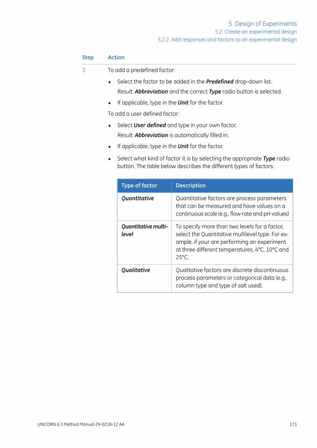
ActionStep
To add a predefined factor:3
• Select the factor to be added in the Predefined drop-down list.
Result: Abbreviation and the correct Type radio button is selected.
• If applicable, type in the Unit for the factor.
To add a user defined factor:
• Select User defined and type in your own factor.
Result: Abbreviation is automatically filled in.
• If applicable, type in the Unit for the factor.
• Select what kind of factor it is by selecting the appropriate Type radiobutton. The table below describes the different types of factors:
DescriptionType of factor
Quantitative factors are process parametersthat can be measured and have values on acontinuous scale (e.g., flow rate and pH values)
Quantitative
To specify more than two levels for a factor,select the Quantitative multilevel type. For ex-ample, if your are performing an experimentat three different temperatures, 4°C, 10°C and25°C.
Quantitativemulti-level
Qualitative factors are discrete discontinuousprocess parameters or categorical data (e.g.,column type and type of salt used).
Qualitative
UNICORN 6.3 Method Manual 29-0218-12 AA 171
5 Design of Experiments5.2 Create an experimental design
5.2.2 Add responses and factors to an experimental design
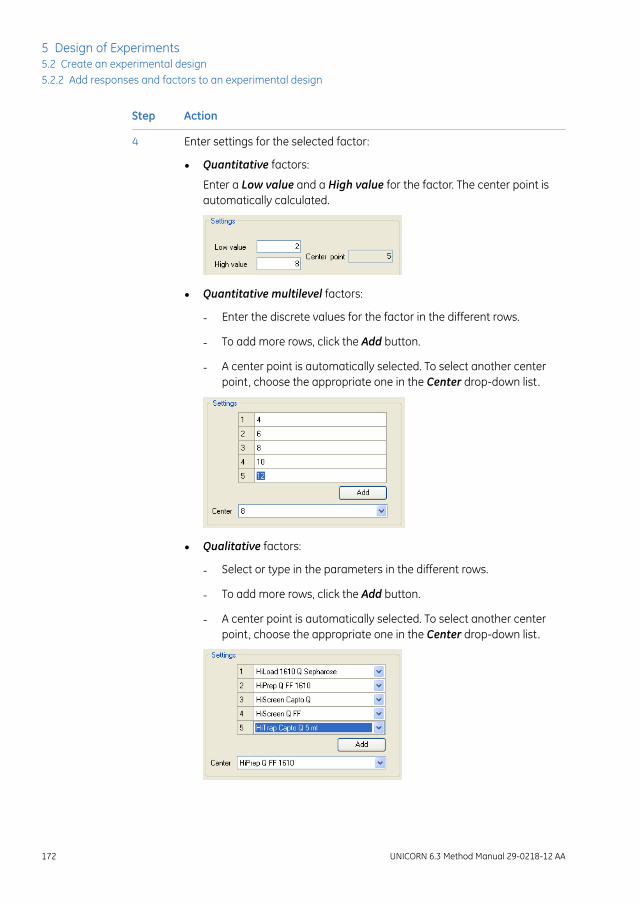
ActionStep
Enter settings for the selected factor:4
• Quantitative factors:
Enter a Low value and a High value for the factor. The center point isautomatically calculated.
• Quantitative multilevel factors:
- Enter the discrete values for the factor in the different rows.
- To add more rows, click the Add button.
- A center point is automatically selected. To select another centerpoint, choose the appropriate one in the Center drop-down list.
• Qualitative factors:
- Select or type in the parameters in the different rows.
- To add more rows, click the Add button.
- A center point is automatically selected. To select another centerpoint, choose the appropriate one in the Center drop-down list.
172 UNICORN 6.3 Method Manual 29-0218-12 AA
5 Design of Experiments5.2 Create an experimental design5.2.2 Add responses and factors to an experimental design
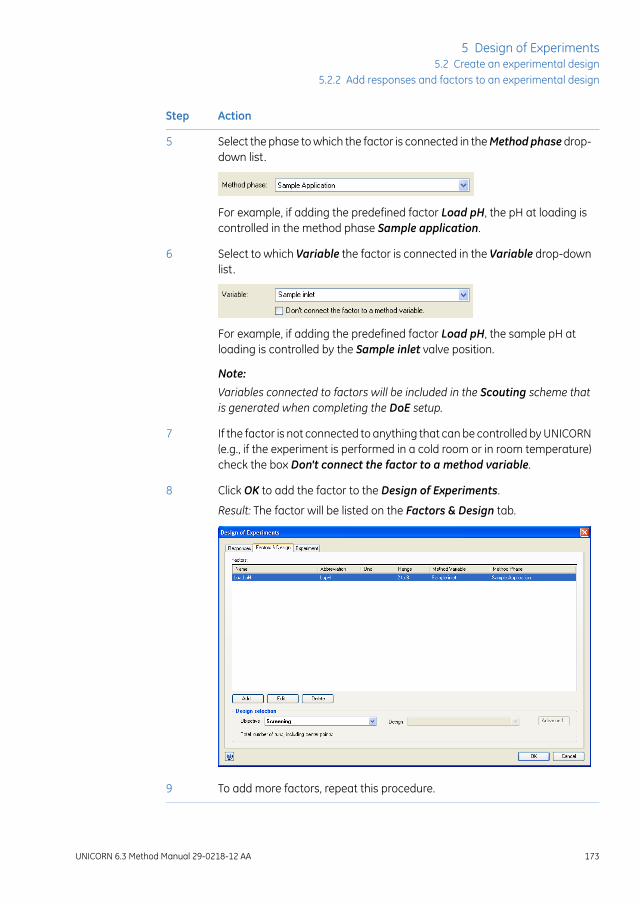
ActionStep
Select the phase to which the factor is connected in theMethod phase drop-down list.
5
For example, if adding the predefined factor Load pH, the pH at loading iscontrolled in the method phase Sample application.
Select to which Variable the factor is connected in the Variable drop-downlist.
6
For example, if adding the predefined factor Load pH, the sample pH atloading is controlled by the Sample inlet valve position.
Note:
Variables connected to factors will be included in the Scouting scheme thatis generated when completing the DoE setup.
If the factor is not connected to anything that can be controlled by UNICORN(e.g., if the experiment is performed in a cold room or in room temperature)check the box Don't connect the factor to a method variable.
7
Click OK to add the factor to the Design of Experiments.8
Result: The factor will be listed on the Factors & Design tab.
To add more factors, repeat this procedure.9
UNICORN 6.3 Method Manual 29-0218-12 AA 173
5 Design of Experiments5.2 Create an experimental design
5.2.2 Add responses and factors to an experimental design

5.2.3 Change design and design settings in a Design of Experi-ments setup
Change design in a Design ofExperiments setup
The design suggested by UNICORN can be changed to another design in the setup ofthe Design of Experiments. The settings for a selected design can also be edited. Thetable below describes how to change the default design and design settings (i.e., thenumber of center points and replicates) in a Design of Experiments setup:
ActionStep
In the Factors & Design tab of the Design of Experiments dialog, the sug-gested design is displayed in Design drop-down list.
1
174 UNICORN 6.3 Method Manual 29-0218-12 AA
5 Design of Experiments5.2 Create an experimental design5.2.3 Change design and design settings in a Design of Experiments setup

ActionStep
Click the Advanced... button to:2
• change to another design than the 1st or 2nd choice design availablein the Design drop-down list (continue with step 3)
and/or
• edit the settings for the currently selected design in the Design table(continue with step 4)
Result: The Change Design dialog opens displaying the designs that maybe used for the current experimental setup and selected objective.
To change to another design, select the appropriate design in the Designtable.
3
Result: TheDescription field shows a short description of the selected design.
For a description of which designs are supported by UNICORN and whenthey may be proposed, see Designs supported by UNICORN, on page 151.
UNICORN 6.3 Method Manual 29-0218-12 AA 175
5 Design of Experiments5.2 Create an experimental design
5.2.3 Change design and design settings in a Design of Experiments setup

ActionStep
The Design setup area shows the settings for the selected design.4
• Change the settings forNoof Center Points andReplicates as appropri-ate.
The table below describes the different settings:
DescriptionSetting
TheNoof Center Pointsmeans that the centerpoint experiment will be run the selectednumber of times.
It is recommended to use at least three centerpoints to be able to estimate the pure error,that is, the variation in the measurements.
No of CenterPoints
Replicatesmeans that the whole experimentsseries (corner and center points) will be replicat-ed the selected number of times.
Replicates
This field lists the total number of runs to beperformed based on the number of centerpoints and replicates.
Total no of runs
• The Settings... button is only active if a CCC design using star points isselected. To change the default star point distance in relation to the de-sign box, click Settings....
Result: The Star Distance dialog opens.
Change the Star distance as appropriate and click OK. To return to thedefault value, click Default.
176 UNICORN 6.3 Method Manual 29-0218-12 AA
5 Design of Experiments5.2 Create an experimental design5.2.3 Change design and design settings in a Design of Experiments setup

ActionStep
In the Change Design dialog, click OK.5
Result: Changes in the Change Design dialog are saved and the settings inthe Design setup area in the Design of Experiments dialog are updated.
Note:
If additional variables have been defined in the scouting scheme for a previ-ously saved DoE method, these will be lost and need to be redefined.
UNICORN 6.3 Method Manual 29-0218-12 AA 177
5 Design of Experiments5.2 Create an experimental design
5.2.3 Change design and design settings in a Design of Experiments setup

5.2.4 Divide the DoE runs into several scouting runs
IntroductionIf hardware limitations exist, for example too few sample inlet valve positions are availablefor the number of runs to be performed, the DoE runs can be divided into severalscouting runs. This section describes how to divide a DoE run into several smaller runs.
Divide DoE runs into severalscouting runs directly in theScouting scheme
It is possible to include/exclude runs directly in the generated Scouting scheme andedit, for example, the sample inlet positions. However, for complex experimental plansit is recommended to create multiple DoE methods, each using the same design butwith different sub-sets of scouting runs (see below). As long as the designs are identical,the results can then be merged for analysis.
178 UNICORN 6.3 Method Manual 29-0218-12 AA
5 Design of Experiments5.2 Create an experimental design5.2.4 Divide the DoE runs into several scouting runs

Divide DoE runs into severalscouting runs in the DoE setup
The table below describes how to identify hardware limitations in a DoE run.
ActionStep
In the Design of experiments dialog, select the Experiment tab.1
Result: The Experimental Plan is displayed.
If limitations in the hardware exist this will be indicated in the ExperimentalPlan by the text Not Enough Positions for the run(s) in the Design of exper-iments dialog. These runs are also excluded from the Experimental Plan.
2
Clear the Included box in front of the experiments to be excluded in the firstset of runs. In the example below Run 009 and Run 010 are excluded fromthe first set of runs.
3
Note:
Include at least one center point (runs 5, 9 and 11 in the above example) ineach scouting run to have control of experimental variations.
UNICORN 6.3 Method Manual 29-0218-12 AA 179
5 Design of Experiments5.2 Create an experimental design
5.2.4 Divide the DoE runs into several scouting runs
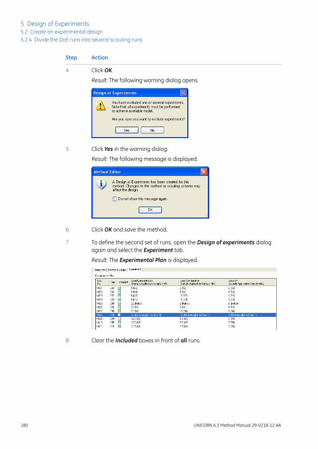
ActionStep
Click OK.4
Result: The following warning dialog opens.
Click Yes in the warning dialog.5
Result: The following message is displayed.
Click OK and save the method.6
To define the second set of runs, open the Design of experiments dialogagain and select the Experiment tab.
7
Result: The Experimental Plan is displayed.
Clear the Included boxes in front of all runs.8
180 UNICORN 6.3 Method Manual 29-0218-12 AA
5 Design of Experiments5.2 Create an experimental design5.2.4 Divide the DoE runs into several scouting runs
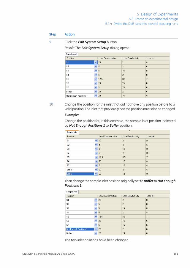
ActionStep
Click the Edit System Setup button.9
Result: The Edit System Setup dialog opens.
Change the position for the inlet that did not have any position before to avalid position. The inlet that previously had the position must also be changed.
10
Example:
Change the position for, in this example, the sample inlet position indicatedby Not Enough Positions 1 to Buffer position.
Then change the sample inlet position originally set toBuffer toNot EnoughPositions 1.
The two inlet positions have been changed.
UNICORN 6.3 Method Manual 29-0218-12 AA 181
5 Design of Experiments5.2 Create an experimental design
5.2.4 Divide the DoE runs into several scouting runs

ActionStep
Click OK in the Edit System Setup dialog.11
In the Experiment tab, check the boxes in front of the runs to be includedin the second set of runs.
12
Note:
In the example shown here, one of the center points (run 9) is also included.
Click OK in the Design of experiments dialog.13
Result: A new Scouting scheme is generated. Click Yes and OK in anywarning and messages dialog that appear.
Save the method with a new name.14
Result: The two scouting runs are ready to be run in sequence.
Note:
In this example, you must change samples in one of the sample inlets beforestarting the second scouting run. It is not possible to just create a methodqueue, start it and leave the system.
182 UNICORN 6.3 Method Manual 29-0218-12 AA
5 Design of Experiments5.2 Create an experimental design5.2.4 Divide the DoE runs into several scouting runs

5.3 Run a scouting created with DoE
IntroductionThis section describes how to view the optimized Scouting scheme generated fromDoEand how to print the method including DoE. For information about how to start andmonitor Scouting runs, see UNICORN 6.3 System Control Manual.
View the Scouting schemegenerated from DoE
When creating aDesign of Experiments the final step is the generation of the optimizedScouting scheme. The table below describes how to view the Scouting scheme gener-ated from DoE:
ActionStep
In the Method Editor:1
• Click the Scouting icon
or
• Select Tools:Scouting.
Result: The following dialog is displayed as a reminder of that a DoE hasbeen created for the method. If you change the Scouting scheme, the DoEexperimental plan is changed and the results may not be reliable for use inthe DoE evaluation.
UNICORN 6.3 Method Manual 29-0218-12 AA 183
5 Design of Experiments5.3 Run a scouting created with DoE

ActionStep
Click OK.2
Result: The Scouting dialog opens displaying the Scouting scheme whereit is possible to view the Scouting runs to be performed.
Click Cancel or OK to close the Scouting dialog.3
Print method including DoEBefore starting the run, it is useful to print the method information to see, for example,which sample positions are used for the different runs. See Section3.6.3 Print a method,on page 98 for information about how to print the method.
184 UNICORN 6.3 Method Manual 29-0218-12 AA
5 Design of Experiments5.3 Run a scouting created with DoE

5.4 Evaluation of Design of Experiments
About this sectionThis section describes how to perform statistical evaluation of a DoE scouting.
In this sectionThis section contains these subsections:
See pageSection
1865.4.1 Workflow
1885.4.2 Generate model
1975.4.3 Analyze and evaluate the model - basic analysis
2095.4.4 Analyze and evaluate the model - extended analysis
2165.4.5 Edit the model
2195.4.6 Use the model
2265.4.7 Create and print reports
UNICORN 6.3 Method Manual 29-0218-12 AA 185
5 Design of Experiments5.4 Evaluation of Design of Experiments

5.4.1 Workflow
IntroductionThis section describes the workflow when evaluating aDesign of Experiments scouting.
WorkflowThe main steps when performing statistical evaluation of an experimental design are:
1 Generate model
This includes evaluating single DoE runs, opening the DoE result, and entering re-sponse data. The software will then generate a model.
2 Analyze and edit the model
This includes checking that the raw data is OK and performing a basic analysis ofthe model. The model may need refinement by removing insignificant terms, whichshould be done with care. Extended analysis can be performed for additional infor-mation.
3 Use the model
This includes generating a response surface plot as well as using the predictor andthe optimizer.
• Generate response surface plot to get a map of the experimental area and infor-mation about how to proceed with new experiments.
• Use the predictor to predict response values based on entered factor settings(optimization experiments only).
• Use the optimizer to optimize responses based on entered criteria for factorsand responses (optimization experiments only), for example maximizing response1 and minimizing response 2 while keeping factor 1 constant and allowing theother factors to vary within a defined range.
Basic and extended reports can also be created for the experiment.
186 UNICORN 6.3 Method Manual 29-0218-12 AA
5 Design of Experiments5.4 Evaluation of Design of Experiments5.4.1 Workflow

Illustration of workflowThe illustration below shows a possible workflow for evaluating aDesign of Experimentsscouting:
1. Generate model
2. Analyze and evaluate the model
3. Use the model
A. Evaluate single runs included in DoE
B. Open DoE result C. Check experiment setup and enter response values
D. Software generates model
Check raw data
Response Yn
Factor Xn
Y = f(x) +e
Raw data not OK (e.g., outlier found)
Raw data OK
Analysis and evaluation of model
Replicate plot
Normal probability plot
Summary of Fit plot
Normal probability plot
Coefficient plot
Basic analysis Extended analysis
Interaction plot
ANOVA table
Main effects plot Observed vs. predicted plot
Residuals vs. variable plot
Residuals vs. run order plot
Correlation matrix
Model OK Model not OK
Response surface plot Use Prediction list (only optimization) Use Optimizer (only optimization)
Edit model p > 0.05, R2, Q2
Exclude/replace outlier R2, Q2
Use the model (step 3)
Add/delete responses Insert missing run results
Coefficient plot
UNICORN 6.3 Method Manual 29-0218-12 AA 187
5 Design of Experiments5.4 Evaluation of Design of Experiments
5.4.1 Workflow

5.4.2 Generate model
IntroductionThis section describes how to open single DoE runs for evaluation, how to open DoEresults and how to generate a model.
Evaluate the results of the singleDoE runs
Before opening the DoE result in the Evaluation module, it is recommended to evaluatethe single runs included in the Scouting run.
The table below describes how to open and evaluate single runs in the Evaluationmodule:
ActionStep
In the Evaluation module, click the Open Result Navigator icon in theToolbar.
1
Result: The Result Navigator is displayed.
Browse for the result and double-click the result name (single runs are indi-cated by the chromatogram icon).
2
Result: The result of the run is opened and displayed in the Evaluationmodule.
188 UNICORN 6.3 Method Manual 29-0218-12 AA
5 Design of Experiments5.4 Evaluation of Design of Experiments5.4.2 Generate model

ActionStep
Inspect the results visually and check that the runs have been performedas expected.
3
Evaluate the results for the run as appropriate. See UNICORN 6.3 EvaluationManual for information about how to perform evaluation.
4
Save any changes.
Tip:It is possible to have a Scouting run result open at the same time even if aDoE result is open.
5
Repeat this procedures for all the runs included in the DoE result.6
Open the DoE resultThe table below describes how to open a DoE result:
ActionStep
In the Evaluation module, click the Open Result Navigator icon in theToolbar.
1
Result: The Result Navigator is displayed.
UNICORN 6.3 Method Manual 29-0218-12 AA 189
5 Design of Experiments5.4 Evaluation of Design of Experiments
5.4.2 Generate model

ActionStep
Browse for the DoE result and double-click the result name (DoE results areindicated by the design box icon).
2
Result: The Design of Experiments box opens displaying the DoE scoutingrun.
Generate modelThe table below describes how to generate a model for the DoE result:
ActionStep
Responses defined in the method appear in the result in the Design of Ex-periments box.
1
To add or delete responses to the experiment, use the Add Response... andDelete Response... buttons. See Add responses, on page 192 and Delete re-sponses, on page 193 for more information.
190 UNICORN 6.3 Method Manual 29-0218-12 AA
5 Design of Experiments5.4 Evaluation of Design of Experiments5.4.2 Generate model

ActionStep
To enter response data:2
• Click in a response cell for the appropriate response and experiment,and type in the data (the Yield column in the example shown here).
Result: The data is entered in the cell.
Tip:
Response data can be obtained from:
- external measurements (e.g., biological activity)
- peak data from UNICORN (e.g., HETP tests or resolution)
• Repeat this procedure for all experiments and responses.
Select the runs to be included in the calculations for generating the modelby checking the Included box for the appropriate runs (usually all runs).
3
To insert a new run or to replace a failed run with a new run use the ReplaceResult... and Insert Result... buttons. See Replace run results, on page 195and Insert new runs, on page 193 for more information about inserting andreplacing runs.
Tip:Instead of replacing a failed run with a new run, the run can be excludedfrom the model calculations by clearing the Included box in front of the ap-propriate run. This will however often result in some loss of information.
Click the Analysis tab.4
Result: A model is fitted to the entered data. For information about how toanalyze the model, see Section5.4.3 Analyze and evaluate the model - basicanalysis, on page 197.
UNICORN 6.3 Method Manual 29-0218-12 AA 191
5 Design of Experiments5.4 Evaluation of Design of Experiments
5.4.2 Generate model

Add responsesResponses added in the Evaluationmodulewill not be included in the originalmethod.
Note:
The table below describes how to add a new response to the experiment:
ActionStep
In the Design of Experiments tab in the Evaluation module, click the AddResponse... button.
1
Result: The Add Response dialog opens.
Select the response to be added in the Predefined drop-down list or defineyour own response by selectingUser definedand type in your own response.
Note:
Abbreviation is automatically filled in.
2
Enter the Unit for the response, if appropriate.3
Click OK.4
Result: The response is added to the DoE experiment.
192 UNICORN 6.3 Method Manual 29-0218-12 AA
5 Design of Experiments5.4 Evaluation of Design of Experiments5.4.2 Generate model
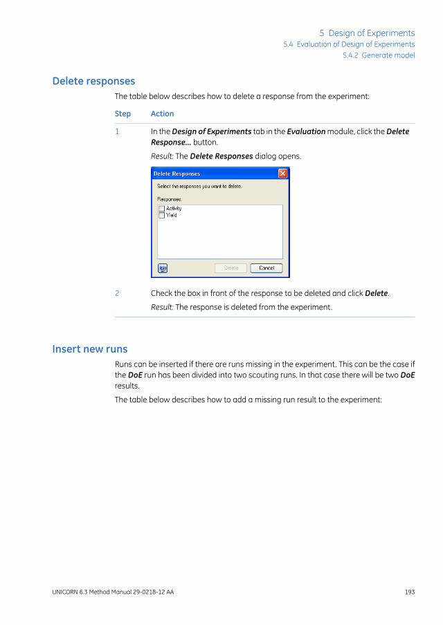
Delete responsesThe table below describes how to delete a response from the experiment:
ActionStep
In theDesign of Experiments tab in the Evaluationmodule, click theDeleteResponse... button.
1
Result: The Delete Responses dialog opens.
Check the box in front of the response to be deleted and click Delete.2
Result: The response is deleted from the experiment.
Insert new runsRuns can be inserted if there are runs missing in the experiment. This can be the case ifthe DoE run has been divided into two scouting runs. In that case there will be two DoEresults.
The table below describes how to add a missing run result to the experiment:
UNICORN 6.3 Method Manual 29-0218-12 AA 193
5 Design of Experiments5.4 Evaluation of Design of Experiments
5.4.2 Generate model

ActionStep
If runs are missing in the experiment, the rows for the missing runs are blank.1
To insert the missing runs, click the Insert Result... button.2
Result: The Insert Result dialog opens.
Browse and select the run(s) that should be inserted.
Tip:The run order number is found at the end of the result name. This numberis the same as in the Run column. This makes it easier to locate the runs tobe inserted.
3
194 UNICORN 6.3 Method Manual 29-0218-12 AA
5 Design of Experiments5.4 Evaluation of Design of Experiments5.4.2 Generate model

ActionStep
Click OK.4
Result: The runs are inserted in the experiment.
If a run does not match any of the missing runs in the experiment an errormessage will be displayed. Repeat from step 2 to insert the correct run.
5
Note:
The run to be inserted must have the appropriate factor settings.
Replace run resultsRuns can be replaced with a new run if, for example, the run has failed.
If a run has failed, there is always a risk that experimental conditions thatcannot be controlledmay have affected the result (e.g., temperature in the lab,different batches of buffer preparation etc.) Therefore, it is not always a goodidea to replace a failed run with a new one. Rerunning a center point experi-ment will help in keeping track of uncontrolled variations.
Note:
The table below describes how to replace a run result:
ActionStep
In the Experiment tab of the Design of Experiments box, select the resultto be replaced in the Result column in the Experiment table.
1
UNICORN 6.3 Method Manual 29-0218-12 AA 195
5 Design of Experiments5.4 Evaluation of Design of Experiments
5.4.2 Generate model

ActionStep
Click the Replace Result... button.2
Result: The Replace Result dialog opens.
Browse and select the run that should replace the selected run.3
Click OK.4
Result: The new run is listed in the Experiment table.
If the run does not match the run to be replaced an error message will bedisplayed. Repeat from step 2 to insert the correct run.
5
Note:
The run to be inserted must have the appropriate factor settings.
196 UNICORN 6.3 Method Manual 29-0218-12 AA
5 Design of Experiments5.4 Evaluation of Design of Experiments5.4.2 Generate model
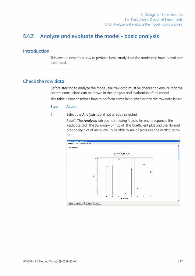
5.4.3 Analyze and evaluate the model - basic analysis
IntroductionThis section describes how to perform basic analysis of the model and how to evaluatethe model.
Check the raw dataBefore starting to analyze the model, the raw data must be checked to ensure that thecorrect conclusions can be drawn in the analysis and evaluation of the model.
The table below describes how to perform some initial checks that the raw data is OK:
ActionStep
Select the Analysis tab, if not already selected.1
Result: The Analysis tab opens showing 4 plots for each response: theReplicate plot, the Summary of fit plot, the Coefficient plot and the Normalprobability plot of residuals. To be able to see all plots use the vertical scrollbar.
UNICORN 6.3 Method Manual 29-0218-12 AA 197
5 Design of Experiments5.4 Evaluation of Design of Experiments
5.4.3 Analyze and evaluate the model - basic analysis

ActionStep
For each response, look at the replicate plot. This plot displays the variationin the response for replicated experiments and the variation among thereplicates in relation to the variation across the entire design ("reproducibil-ity").
2
Each arrow in the plot represents an experiment.
In a good replicate plot (as shown in the example above), the replicate runsshould show as small a variation as possible (experiments 9, 10 and 11).
There should normally be some variation across the dataset of non-replicateexperiments. However a single experiment should not deviate dramaticallyfrom the rest.
Note:
When a robustness test has been performed, variations in the data shouldinstead be as small as possible.
198 UNICORN 6.3 Method Manual 29-0218-12 AA
5 Design of Experiments5.4 Evaluation of Design of Experiments5.4.3 Analyze and evaluate the model - basic analysis

ActionStep
The replicate plots can also be used to identify outliers. If, for example, asingle experiment deviates a lot from the rest of the experiments (see plotto the left below), or if a replicate deviates a lot from the rest of the replicates(see plot to the right below), this run could be an outlier.
3
UNICORN 6.3 Method Manual 29-0218-12 AA 199
5 Design of Experiments5.4 Evaluation of Design of Experiments
5.4.3 Analyze and evaluate the model - basic analysis

ActionStep
Look at the normal probability plot of residuals. The residuals, or minimizederrors between the measured data and the theoretical data calculated ac-cording to the model, should normally be distributed as shown in the diagrambelow.
4
In a normal distribution of residuals for a good model, the experiments shouldbe distributed close to a straight line and also should lie within a Standard-ized Residuals range of -4 to +4 SD (standard deviations). Single experimentsthat deviate from this may be outliers.
A non-linear distribution of experiments may also indicate the presence ofinsignificant missing terms, for example curvature of the model. SeeAnalyzeand interpret themodel - basic analysis, on page201and Section5.4.4 Analyzeand evaluate the model - extended analysis, on page 209.
If the raw data is OK, continue with the basic analysis of the model describedin Analyze and interpret the model - basic analysis, on page 201.
5
200 UNICORN 6.3 Method Manual 29-0218-12 AA
5 Design of Experiments5.4 Evaluation of Design of Experiments5.4.3 Analyze and evaluate the model - basic analysis

ActionStep
If outliers are detected, try to identify why. The table below gives a few ex-amples of why outliers may be detected. You may also look at the plots inthe extended analysis to get more information about the experiment.
6
See...What to doWhyoutli-er?
Replace run results, onpage195 for informationabout how to replace arun result.
Check the individual result, andthat correct response values havebeen entered.
If the run has failed, consider per-forming new experiments and re-place the run.
Badrepli-cates
Generate model, onpage190 for informationabout how to exclude arun from the experiment
The run may also be excludedfrom the experiment setup. Resultsthat are true outliers should beexcluded.
See Section5.4.2 Gener-ate model, on page 188for how to check en-tered response data.
Check that the correct responsevalues have been entered.
Check the individual result.
Consider performing new experi-ments to verify the deviation.
If the results are indeed valid, themodel may be inappropriate forthe area.
Deviat-ing ex-peri-ments
Analyze and interpret themodel- basic analysis
Before you can use the model and draw conclusions from it, the model needs to be an-alyzed to investigate if the model gives a good reflection of the experiment data.
The plots must be analyzed for each response. A model can be good for oneresponse but not for another. In some cases a goodmodel cannot be obtainedwhen several responses are included in the samemodel. In this case, try fittingan individual model for each response separately.
Note:
The table below describes how to perform a basic analysis of the model:
UNICORN 6.3 Method Manual 29-0218-12 AA 201
5 Design of Experiments5.4 Evaluation of Design of Experiments
5.4.3 Analyze and evaluate the model - basic analysis

ActionStep
Select the Analysis tab, if not already selected.1
Result: The Analysis tab opens showing four plots for each response: theReplicate plot, the Summary of Fit plot, the Coefficient plot and the Normalprobability plot of residuals. To be able to see all plots use the vertical scrollbar.
202 UNICORN 6.3 Method Manual 29-0218-12 AA
5 Design of Experiments5.4 Evaluation of Design of Experiments5.4.3 Analyze and evaluate the model - basic analysis
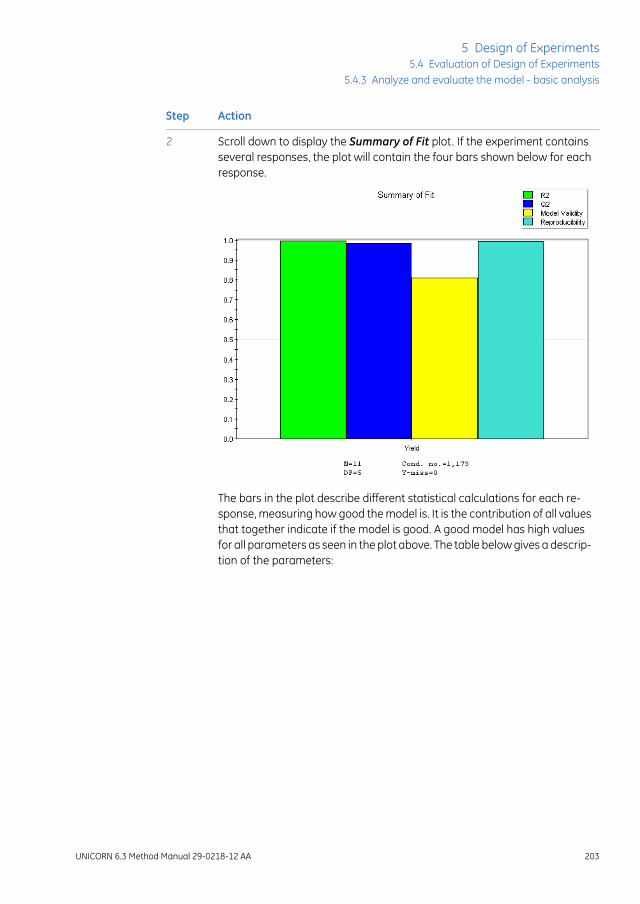
ActionStep
Scroll down to display the Summary of Fit plot. If the experiment containsseveral responses, the plot will contain the four bars shown below for eachresponse.
2
The bars in the plot describe different statistical calculations for each re-sponse, measuring how good the model is. It is the contribution of all valuesthat together indicate if the model is good. A good model has high valuesfor all parameters as seen in the plot above. The table below gives a descrip-tion of the parameters:
UNICORN 6.3 Method Manual 29-0218-12 AA 203
5 Design of Experiments5.4 Evaluation of Design of Experiments
5.4.3 Analyze and evaluate the model - basic analysis

ActionStep
DescriptionCoefficient valuefor...
R2 describes how well the model fits the currentdata. It can vary between 0 and 1, where 1 equalsa perfect model and 0 corresponds to no modelat all. A high R2-value is necessary for a goodmodel but not sufficient on its own.
A value of 0.75 indicates a rough but stable anduseful model.
Note:
R2 Adj is the fraction of variations in the responsedata that is explained by the model, adjusted fordegrees of freedom.
R2 does not take into account degrees of freedom.
R2
Q2 describes how well the model will predict newdata. It can vary between -∞ and 1. The higherQ2-value, the better indicator of how well themodel will predict new data.
Q2>0.5 is good and Q2>0.9 is excellent.
Q2 is a better indicator of the usefulness of themodel than R2.
Note:
R2 should not exceed Q2 bymore than 0.2-0.3 fora good model.
Q2
Model validity is only available if replicated exper-iments have been performed.
A model validity>0.25 indicates a good model.
A model validity<0.25 indicates a significant "lackof fit", that is the model error is significantly largerthan the pure error (reproducibility).
Model Validity
A reproducibility<0.5 indicates that there is a largepure error and poor control of the experimentalsetup (high noise level).
Reproducibility
If the Summary of Fit plot does not look good, there may be several reasonsfor this. The table below lists a few.
204 UNICORN 6.3 Method Manual 29-0218-12 AA
5 Design of Experiments5.4 Evaluation of Design of Experiments5.4.3 Analyze and evaluate the model - basic analysis

ActionStep
What to doPossible causeSummary ofFit plot value
Look at the coefficient plot(see step 3) and the Interac-tion plot to see if there are in-teraction effects.
Non-significant two-way interactions maybe present
Low Q2 andmodel validity
Look at the Residual vs. vari-ableplot (seeResiduals versusvariables plot, on page 209)and the ANOVA table (seeANOVA table, on page 213) tosee if these also indicate cur-vature in the model. If yoususpect curvature, try addinga quadratic term to the mod-el.
Curvature in the mod-el. Is there a need ofadding quadraticterms to the model?
If needed, perform more ex-periments.
Important factors maybe missing. Are thereuncontrolled factorsthat may affect theexperiment?
Model withmoderate R2
(~0.6) and Q2
(~0.4)
Consider dividing the experi-ment in two or more to beable to fit one model/re-sponse.
It might be difficult tofit the same model toall responses.
The model isgood for oneresponse butnot the other
UNICORN 6.3 Method Manual 29-0218-12 AA 205
5 Design of Experiments5.4 Evaluation of Design of Experiments
5.4.3 Analyze and evaluate the model - basic analysis

ActionStep
Look at the normal probability plot of residuals. If the model describes theexperimental data well, the experiments should be distributed close to astraight line, and lie within a Standardized Residuals range of -4 to +4 SD(standard deviations). See Check the raw data, on page 197.
3
If the center points (points 9, 10 and 11 in the illustration below) are not lin-early distributed, this may indicate curvature in the model rather than trueoutliers. A low Q2, model validity and significant lack of fit may also indicatecurvature.
If you suspect curvature, try adding a quadratic term to the model. SeeSection 5.4.5 Edit the model, on page 216 for more information.
206 UNICORN 6.3 Method Manual 29-0218-12 AA
5 Design of Experiments5.4 Evaluation of Design of Experiments5.4.3 Analyze and evaluate the model - basic analysis

ActionStep
Look at the coefficient plot for each response. The coefficient plot can beused to see which factors that affect your response, in which way they affectthe response(s) and if there are any non-significant terms in the model.
4
In the example below the following terms have been included in the model:
• the main effects, that is, the loading conditions for mass, pH and conduc-tivity (LoMa, LoCo and LopH)
• the two-way interaction effects for LoMa/LopH and LoCo/LopH
Note:
If an optimization design (CCC or CCF) has been used, quadratic terms for themodel will also be included in the coefficient plot.
In the example above, the confidence limits (the black error bars shown oneach green bar in the plot) do not cross zero. All of the terms are thus signif-icant, with the LoCo*LopH two-way interaction term being least significant.
Positive bars have a positive influence on the response, in this example theYield, and negative bars a negative influence. From the above plot it is evidentthat increasing the LoMa (Load Mass) and LoCo (Load Conductivity) values,and decreasing the LopH (Load pH) value have a positive effect on the re-sponse.
UNICORN 6.3 Method Manual 29-0218-12 AA 207
5 Design of Experiments5.4 Evaluation of Design of Experiments
5.4.3 Analyze and evaluate the model - basic analysis

ActionStep
Non-significant terms can be identified by the confidence limits for a coeffi-cient (the black error bars) crossing zero. The diagram below shows the ex-treme example where no terms are significant.
5
Insignificant terms should be removed from the model one at a time beforereanalysing the model.
If the model does not look good or non-significant terms are present, editthe model or continue with the extended analysis before editing the model.
6
See Section 5.4.4 Analyze and evaluate the model - extended analysis, onpage209and Section5.4.5 Edit themodel, on page216 for more information.
If the model looks good and all terms are significant, continue with Sec-tion 5.4.6 Use the model, on page 219.
7
208 UNICORN 6.3 Method Manual 29-0218-12 AA
5 Design of Experiments5.4 Evaluation of Design of Experiments5.4.3 Analyze and evaluate the model - basic analysis

5.4.4 Analyze and evaluate the model - extended analysis
IntroductionIf you want to perform further analysis of the model in order to decide how to proceed,an extended report can be generated. The following plots and tables are displayed inthe extended report in addition to the basic analysis:
• Residuals versus variables plot
• Residual versus run order plot
• Interaction plot
• Observed versus Predicted
• Main effects plot
• ANOVA table
• Correlation matrix
This section describes the plots in the extended report and gives information about howto evaluate the plots.
Open and view plots forextended analysis
To be able to view the plots for extended analysis create an extended report.
SeeCreate a report, on page226 for information about how to create an extended report.
Residuals versus variables plotThe Residuals Plot vs. Variable shows the residuals (i.e., the minimized error betweenthe measured and theoretical data according to the model) for one factor and one re-sponse.
The residuals should be randomly distributed with no pattern. When a curved patterncan be seen in the plot this may indicate that a quadratic term is missing in the model.In this case try adding a quadratic term to the model and see if the model is improved.
See Section 5.4.5 Edit the model, on page 216 for information about how to add aquadratic term to the model.
The illustration below shows an example of a plot indicating that a quadratic term ismissing in the model.
UNICORN 6.3 Method Manual 29-0218-12 AA 209
5 Design of Experiments5.4 Evaluation of Design of Experiments
5.4.4 Analyze and evaluate the model - extended analysis

The illustration below shows the plot for the same experiment when a quadratic termhas been added to the model. Now the residuals are randomly distributed with no pattern.
When you find curvature in the model, the design for the experiment in theDoE setup should be changed to design allowing quadratic terms to be addedto the model (Full factorial 3 levels, CCC, CCF, Box Behnken, Rechtschaffner orDoehlert). If the experimental setup is sufficiently stable the star point experi-ments alone can be run, otherwise it is recommended to rerun all experiments.
Note:
210 UNICORN 6.3 Method Manual 29-0218-12 AA
5 Design of Experiments5.4 Evaluation of Design of Experiments5.4.4 Analyze and evaluate the model - extended analysis

Residual versus run order plotTheResiduals Plot vs. Run order shows the residuals for the run order and one response.
The residuals should be randomly distributed with no pattern. A pattern in the plot indi-cates a change in residuals over time. This could, for example, be the result when ran-domization errors exist in the experiment.
The illustration below shows a plot where the residuals are randomly distributed withno pattern.
Interaction plotThe Interaction plot shows if there is any interaction (i.e., when the effect of one factordepends on another factor) between two factors. The illustration below shows an exampleof an interaction plot. In this example there is an interaction between load mass (LoMa)and load conductivity (LoCo).
The table below describes how to interpret different interactions plot in a schematicway:
DescriptionPlot
The two lines are parallel. This plot shows an example of no interac-tion between the two factors.
UNICORN 6.3 Method Manual 29-0218-12 AA 211
5 Design of Experiments5.4 Evaluation of Design of Experiments
5.4.4 Analyze and evaluate the model - extended analysis

DescriptionPlot
The two lines are not parallel. This plot shows an example of inter-action between the two factors.
The two lines are crossing. This plot shows an example of stronginteraction between the two factors.
Observed versus Predicted foreach Response plot
The Observed vs. Predicted for each Response (Y) plot can be used to judge the qualityof the model. With a good model all the points will fall on the 45° line (illustrated in theplot below).
212 UNICORN 6.3 Method Manual 29-0218-12 AA
5 Design of Experiments5.4 Evaluation of Design of Experiments5.4.4 Analyze and evaluate the model - extended analysis
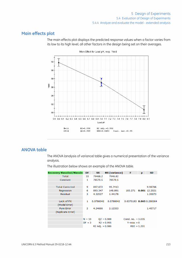
Main effects plotThe main effects plot displays the predicted response values when a factor varies fromits low to its high level, all other factors in the design being set on their averages.
ANOVA tableThe ANOVA (analysis of variance) table gives a numerical presentation of the varianceanalysis.
The illustration below shows an example of the ANOVA table.
UNICORN 6.3 Method Manual 29-0218-12 AA 213
5 Design of Experiments5.4 Evaluation of Design of Experiments
5.4.4 Analyze and evaluate the model - extended analysis
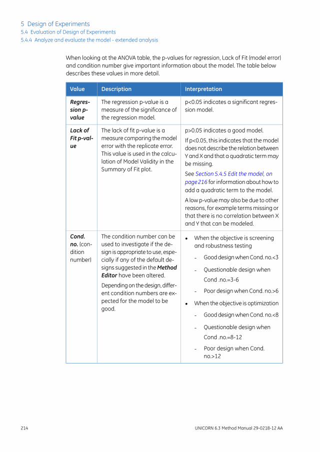
When looking at the ANOVA table, the p-values for regression, Lack of Fit (model error)and condition number give important information about the model. The table belowdescribes these values in more detail.
InterpretationDescriptionValue
p<0.05 indicates a significant regres-sion model.
The regression p-value is ameasure of the significance ofthe regression model.
Regres-sion p-value
p>0.05 indicates a good model.The lack of fit p-value is ameasure comparing the modelerror with the replicate error.This value is used in the calcu-lation of Model Validity in theSummary of Fit plot.
Lack ofFit p-val-ue
If p<0.05, this indicates that the modeldoes not describe the relation betweenY and X and that a quadratic term maybe missing.
See Section 5.4.5 Edit the model, onpage216 for information about how toadd a quadratic term to the model.
A low p-value may also be due to otherreasons, for example terms missing orthat there is no correlation between Xand Y that can be modeled.
• When the objective is screeningand robustness testing
- Good design when Cond. no.<3
- Questionable design when
Cond .no.=3-6
- Poor design when Cond. no.>6
• When the objective is optimization
- Good design when Cond. no.<8
- Questionable design when
Cond .no.=8-12
- Poor design when Cond.no.>12
The condition number can beused to investigate if the de-sign is appropriate to use, espe-cially if any of the default de-signs suggested in theMethodEditor have been altered.
Depending on the design, differ-ent condition numbers are ex-pected for the model to begood.
Cond.no. (con-ditionnumber)
214 UNICORN 6.3 Method Manual 29-0218-12 AA
5 Design of Experiments5.4 Evaluation of Design of Experiments5.4.4 Analyze and evaluate the model - extended analysis

Correlation matrixThe correlation matrix gives a numerical presentation of the correlation between factorsand responses and shows if the fit of the model is reasonable. The linear correlationcoefficients R between all the terms in the model and all the responses are displayed inthe correlation matrix.
Process factors are log-transformed, scaled, and centered and responses are logtransformed. The value of the correlation coefficient R represents the extent of the linearassociation between two terms. The value of R ranges from -1 to 1. When R is near zerothere is no linear relationship between the terms. Correlation coefficients above thethreshold between a term in the model and the responses are colored green.
The illustration below shows an example of the correlation matrix.
UNICORN 6.3 Method Manual 29-0218-12 AA 215
5 Design of Experiments5.4 Evaluation of Design of Experiments
5.4.4 Analyze and evaluate the model - extended analysis

5.4.5 Edit the model
IntroductionEditing of the model may be necessary after analysis of the model, if the current modeldoes not give a good fit. In the analysis you may for example:
• find insignificant terms that need to be removed
• find that the model may have curvature and that a quadratic term needs to be added
The refined model can be analysed to see if it better fits the data.
This section describes how to edit the model.
Edit the modelThe table below describes how to edit a model:
ActionStep
In the Analysis tab, click .1
Result: The Edit Model dialog opens.
216 UNICORN 6.3 Method Manual 29-0218-12 AA
5 Design of Experiments5.4 Evaluation of Design of Experiments5.4.5 Edit the model

ActionStep
Note the R2 Adj and Q2 values for the response(s) before starting to edit themodel. Select different responses in the Select a response drop-down list.
2
When editing the model, theR2AdjandQ2 values are updated. Higher valuesindicate a better model. See also Analyze and interpret the model - basicanalysis, on page 201 for a description of the values.
Non-significant terms may have been found in the analysis of the model (forexample in the coefficient plot).
3
To remove a non-significant term, select the term in the Model terms tableand click Remove. If the P-value>0.05, the term is not significant.
Note:
Always remove non-significant terms from the model one by one, startingwith the least significant interaction or quadratic term. When the first termhas been removed, the significance of the other terms changes. The P-valuecan be used to determine which term to be removed next.
Note:
If you fit amodel to two ormore responses, amodel term that is not significantfor one response may be significant for another response. Then the termshould not be removed. Before removing a term, always check that the termis not significant for any of the other responses by selecting the response inthe Select a response drop-down list and checking the P-value for the termyou want to remove.
Note:
If a main term is not significant but one of its interaction terms is significantthe main term should not be removed.
Note:
If a main term is removed its interaction terms are also removed.
Result: The term is removed from the model and the R2 Adj and Q2 valuesare updated. If the model refinement gives a higher Q2 value, the model re-finement is justified. If one model is fitted to several responses, view the R2Adj and Q2 values for all responses.
UNICORN 6.3 Method Manual 29-0218-12 AA 217
5 Design of Experiments5.4 Evaluation of Design of Experiments
5.4.5 Edit the model

ActionStep
Based on the previous analysis, add the appropriate terms to the model.4
• Add an interaction term by selecting the appropriate factors in the Fac-tors table and clicking Add Interaction.
Tip:
Use the Ctrl or Shift keyboard key to select multiple factors.
• Add a quadratic term to the model by selecting the appropriate factorin the Factors table and clicking Add Square.
Note:
Quadratic terms can be added if any of the plots in the analyses indicatesthat a quadratic term is missing (in the Residuals vs. Variables plot, forexample).
Note:
When you find curvature (i.e., a quadratic term needs to be added) in themodel, the design for the experiment in theDoE setup should be changedto an extended Full Fractional (CCC or CCF) design. If the experimentalsetup is sufficiently stable the star point experiments alone can be added,otherwise it is recommended to rerun all experiments.
Result: The terms are added to the model. If the model refinement giveshigher R2 Adj and Q2 values, the model refinement is justified. If one modelis fitted to several responses, view theR2 Adj andQ2 values for all responses.
To return to the original model settings, click Reset.5
When you are satisfied with the editing, click OK.6
Result: The Edit Model dialog is closed and the Analysis tab displayedshowing the new plots for the edited model.
Perform an analysis of the edited model to see if the new model is OK. SeeAnalyze and interpret themodel - basic analysis, on page201 for informationabout how to analyze the model.
7
218 UNICORN 6.3 Method Manual 29-0218-12 AA
5 Design of Experiments5.4 Evaluation of Design of Experiments5.4.5 Edit the model

5.4.6 Use the model
IntroductionWhen you have found a good model, use the model to draw conclusions and to decideif more experiments are needed and what experiments to perform. The following plotsand tools can be used in the evaluation:
• Response surface plot
Generate a response surface plot to get a graphical representation of the experimen-tal region. From this, the most interesting area can be used to plan new experiments,verifying experiments and to better understand the impact of large interactions be-tween factors.
• Prediction
Use the predictor to predict response values for entered factor settings.
• Optimization
Use the optimizer to enter response and factor settings criteria and obtain suitablefactor setting combinations for the set response criteria.
Informationabout significant termsandhow they influence the response valueshas already been found in the analysis of themodel by looking at the coefficientplot, interaction plot, main effects plot and correlationmatrix. See Analyze andinterpret themodel - basic analysis, on page201 and Section5.4.4 Analyze andevaluate the model - extended analysis, on page 209 for information abouthow to evaluate these plots.
Note:
This section describes how to use the model.
Generate response surface plotand edit settings
The response surface plot graphically displays the experimental region. It is helpful whenyou want to:
• get an overview of how different factor settings affect the response
• find the interesting experimental area
• get help in deciding where to start a new investigation
• get help in deciding where to make verifying experiments
• understand the impact of large interactions
The underlyingmodelmust be goodandhave a highQ2-value. See Section5.4.3Analyze and evaluate the model - basic analysis, on page 197.
Note:
UNICORN 6.3 Method Manual 29-0218-12 AA 219
5 Design of Experiments5.4 Evaluation of Design of Experiments
5.4.6 Use the model

The table below describes how to generate a response surface plot and how to evaluatethe plot:
ActionStep
In the Analysis tab, click .1
Result: The Response Surface Plot dialog opens.
The Contour Plot shows a "map" of the model. The plot has a color scalefrom blue to red. For each color, the response value is displayed.
The factors selected are displayed on the X axis and Y axis in the ContourPlot (from Low to High as selected in the Factors at the plot axes area).
If you have more than two factors, the other factors will have constant values.The currently entered constant value(s) is displayed to the right of the contourplot. This means that this value is kept constant while the factors on the X-and Y-axes are varied.
The red area indicates the area where the response is maximized using thefactor settings within this area and the current constant value(s).
220 UNICORN 6.3 Method Manual 29-0218-12 AA
5 Design of Experiments5.4 Evaluation of Design of Experiments5.4.6 Use the model

ActionStep
It is possible to change the factors and their corresponding settings for theresponse surface plot as well as the constant values for the other factor(s).This is done per response if you have several responses.
2
In this way you can see what happens if constant values are changed andif other factors and/or factor settings are set on the contour plot axes. Thiswill help you to decide if/which complementary experiments need to beperformed.
For example, you may want to investigate which factor settings to use innewDoE setup to narrow down the area of interest. The coefficient plot canbe used to see which terms have the greatest positive or negative effect onthe response. This information can be tested by changing the contour plotsettings and updating the plot.
To change the Contour Plot settings:3
• Select the response for the contour plot in the Response drop-down list.
• Select factors for the X axis and Y axis and their corresponding ranges.To return to the default values, click the Reset default button.
• Select or enter values for the Constant factors by choosing in the Set-tingsdrop-down list as shown in the diagram below. If selectingCUSTOM,click in the Value field and enter a value.
Click the Update Plot button.4
Result: The Contour Plot is updated.
When you have obtained the appropriate information to help you in thedecision on how to proceed it is possible to print the Contour Plot.
5
• Click the Print... button.
Result: The Print Preview dialog opens.
• Click Print....
Result: The standard Print dialog opens.
• Select the appropriate printer and click Print.
UNICORN 6.3 Method Manual 29-0218-12 AA 221
5 Design of Experiments5.4 Evaluation of Design of Experiments
5.4.6 Use the model

Predict response valuesIt is possible to predict response values based on entered factor settings using themodel. This is useful when you want to find out how detailed factor settings influencethe response(s) in an optimization experiment. Factor settings are entered and responsevalues are calculated when using the Prediction list.
The table below describes how to use the Prediction list:
ActionStep
Select the Prediction tab in the Design of Experiments box.1
Result: The Prediction list opens.
Enter the appropriate settings for the different factors in their respectivefields.
2
Click the Predict button.3
Result: The response value is calculated and displayed in the Yield field, to-gether with the LowerandUpper confidence limits. The larger the confidenceinterval, the more uncertain the calculation is.
222 UNICORN 6.3 Method Manual 29-0218-12 AA
5 Design of Experiments5.4 Evaluation of Design of Experiments5.4.6 Use the model

ActionStep
To enter other factor settings, enter the settings in the empty row below andclick Predict. In this way it is possible to compare different response valuesfor different factor settings.
4
Repeat this procedure until you are satisfied.
Optimize response values andfactor settings
It is possible to optimize the response values using the optimizer. When using the opti-mizer, criteria for the response values and factor settings are entered (e.g., Yield>90%)and factor settings are calculated. In this way, the experimental region can be movedto an optimum.
The table below describes how to use the optimizer:
ActionStep
Select the Optimization tab in the Design of Experiments box.1
Result: The Optimization Criteria and Result tables are displayed.
UNICORN 6.3 Method Manual 29-0218-12 AA 223
5 Design of Experiments5.4 Evaluation of Design of Experiments
5.4.6 Use the model

ActionStep
In the Responses area, select the Criteria for the response.2
The following choices are available:
• Minimize
The response value should be minimized. Enter Target value and Maxvalue for the response.
• Maximize
The response value should be maximized. Enter Target value and Minvalue for the response.
• Target
The response value should be optimized to reach the Target value. EnterMin, Target and Max values for the response.
• Exclude
The response should not be included in the optimization (if you haveseveral responses)
Result: The entered values are displayed.
In the Factors area, select Role and settings for each factor:3
• If the role Free is selected, the factor settings to be calculated for theresponse can have values within the entered Low Value andHigh valuerange. Enter the Low Value and High value as appropriate (to get anidea of the new region of interest, use the response surface plot).
• If the role Constant is selected, the factor setting is constant. Enter thefactor value in the Value field.
224 UNICORN 6.3 Method Manual 29-0218-12 AA
5 Design of Experiments5.4 Evaluation of Design of Experiments5.4.6 Use the model

ActionStep
In the Result area, click the Calculate Optimal Settings button.4
Result: The results are displayed in the Experiment table.
It is possible to see the combination of factor settings that will give a certainresponse. The number of iterations for optimization is indicated in the Itercolumn. Lower (or more negative) Log(D) values (the logarithm of the distanceto the target) indicate better results.
UNICORN 6.3 Method Manual 29-0218-12 AA 225
5 Design of Experiments5.4 Evaluation of Design of Experiments
5.4.6 Use the model

5.4.7 Create and print reports
IntroductionThis section describes how to create basic and extended reports and how to print thereports.
Create a reportThe table below describes how to create a report:
ActionStep
In the Analysis tab, click .1
Result: The Report dialog opens displaying the Basic report by default. Itdisplays the Replicate, Summary of Fit, Normal probability and Coefficientplots.
226 UNICORN 6.3 Method Manual 29-0218-12 AA
5 Design of Experiments5.4 Evaluation of Design of Experiments5.4.7 Create and print reports

ActionStep
To display the extended report select the Extended Report radio button.2
Result: The ExtendedReport opens in theReport dialog. This report includesall available plots as well as the experiment setup, objective and design usedin the experiment.
To view the information in the report use the vertical scrollbar.3
UNICORN 6.3 Method Manual 29-0218-12 AA 227
5 Design of Experiments5.4 Evaluation of Design of Experiments
5.4.7 Create and print reports

Print a reportThe table below describes how to print a report:
ActionStep
In the Report dialog, click the Print... button.1
Result: The Print Preview dialog opens.
Click the Print... button.2
Result: The standard Print dialog opens.
Select the appropriate printer and click the Print button.3
Result: The report is printed.
228 UNICORN 6.3 Method Manual 29-0218-12 AA
5 Design of Experiments5.4 Evaluation of Design of Experiments5.4.7 Create and print reports
6 BufferPro
About this chapterThis chapter describes how to create, edit and use buffer recipes created using theBufferPro tool in UNICORN.
BufferPro is only available for some systems.
In this chapterThis chapter contains the following sections:
See pageSection
2306.1 BufferPro - Overview
2326.2 Create a method using BufferPro
2336.3 Create and edit BufferPro recipes
2436.4 Print a BufferPro recipe
2456.5 Calculate buffer composition using BufferPro
2496.6 Export and import BufferPro recipes
2536.7 Predefined BufferPro recipes
UNICORN 6.3 Method Manual 29-0218-12 AA 229
6 BufferPro

6.1 BufferPro - Overview
IntroductionThis section gives an introduction to the BufferPro tool in UNICORN, and includes a briefoverview of the BufferPro recipes that are predefined.
What is BufferPro?The full use of BufferPro is only available for some systems but all systems have thepossibility to use the BufferPro recipes and calculate buffer composition as describedin Section 6.5 Calculate buffer composition using BufferPro, on page 245.
The BufferPro tool allows automatic mixing of buffers during a run. Four stock solutionsare generally used in a recipe, the buffering agent, a titrant, a salt stock solution andwater. BufferPro facilitates Scouting or Design of Experiments runs using pH as avariable.
BufferPro is optimized for use with anion or cation exchange chromatography, but canalso be used with gel filtration where the salt concentration may also be used as avariable during Scouting or Design of Experiements.
Commonly used buffer systems have predefined recipes in UNICORN from which newrecipes can easily be created. New or edited recipes may be stored as personal orglobal recipes.
UNICORN uses a robust algorithm to calculate pH ranges for optimal buffering takinginto account the buffer type, concentration, temperature and ionic strength. Once anoptimal buffer has been found, it is possible using BufferPro to calculate the buffercomposition for the production of bulk-scale buffer solutions if required.
See...For details on...
Chapter 4 Scouting, on page 131Scouting
Chapter 5 Design of Experiments, on page 144Design of Experiments
Workflow• If required, create a new BufferPro recipe.
Generally the predefined recipes will be sufficient.Tip:
• Create a method including BufferPro.
• Save the method.
230 UNICORN 6.3 Method Manual 29-0218-12 AA
6 BufferPro6.1 BufferPro - Overview

pH ranges for predefined buffersThe following diagrams show the optimal pH ranges for buffers commonly used in anionand cation exchange chromatography. Recipes for these buffers are predefined inUNICORN.
Anion exchange chromatography
Cation exchange chromatography
UNICORN 6.3 Method Manual 29-0218-12 AA 231
6 BufferPro6.1 BufferPro - Overview

6.2 Create a method using BufferPro
IntroductionThis section describes the how to use BufferPro recipes in a method. For details on howto edit methods see Chapter 3 Create and edit methods, on page 26.
Creating a BufferPro method
ActionStep
In the Method Settings phase of a method, select the Use BufferPro (auto-matic buffer preparation) option.
1
Note:
It is not necessary to have the Enable pH monitoring option checked. Theoutput from the pH monitor is not used by the BufferPro algorithm.
Select Recipe and enter pH and buffer concentration (Conc) within thespecified range.
Note:
For broad pH range multi-component buffers the concentration is fixed. Forfurther information see Section6.7 Predefined BufferPro recipes, on page253.
2
Note:
To obtain an even gradient, the gradient should run for at least 10 minutes,and the Flow rate should be not lower than 1 ml/min for ÄKTA avant 25 and2 ml/min for ÄKTA avant 150.
Save the method.3
232 UNICORN 6.3 Method Manual 29-0218-12 AA
6 BufferPro6.2 Create a method using BufferPro
6.3 Create and edit BufferPro recipes
About this sectionThis section describes how to create, edit, rename and delete BufferPro recipes. Prede-fined recipes may not be overwritten, renamed or deleted. Edited recipes, includingedited predefined recipes, can be saved as global or personal recipes. Global recipesare available for all users, personal recipes only for the current user.
The predefined recipes can be used in the majority of cases. There is often noneed to create a new recipe before creating a BufferPromethod.
Note:
For systems that do not have the BufferPro tool, it is still possible to editBufferPro recipes in imported methods.
Note:
In this sectionThis section contains these subsections:
See pageSection
2346.3.1 Create and edit a BufferPro recipe
2396.3.2 Rename a BufferPro recipe
2416.3.3 Delete a BufferPro recipe
UNICORN 6.3 Method Manual 29-0218-12 AA 233
6 BufferPro6.3 Create and edit BufferPro recipes

6.3.1 Create and edit a BufferPro recipe
General considerationsThe concentration of the buffer stock will affect the pH range and the settable concen-tration range in the method. The pH range will in general increase with increasing bufferconcentration and decrease when lowered.
The titrant and buffer agent concentrations should be the same, since there may other-wise not be sufficient titrant to reliably obtain the entire pH range. For recipes titratedwith strong acid/base, the concentration range that can be achieved is 15-25% of thebuffer stock concentration. For conjugate acid/base titrants the corresponding range is25-50% of the buffer stock concentration.
The following table describes how to create a new recipe and how to edit existing recipes.
Create/edit a recipeThe following table describes how to create or edit a BufferPro recipe:
ActionStep
In the Method Editor, select Tools:BufferPro Recipes....1
234 UNICORN 6.3 Method Manual 29-0218-12 AA
6 BufferPro6.3 Create and edit BufferPro recipes6.3.1 Create and edit a BufferPro recipe

ActionStep
To create a new recipe, click New... in the BufferPro Recipe dialog.2
To edit an existing recipe, select the recipe to be edited from the list andclick Edit....
Note:
The available recipes may be filtered by type (All, Predefined, Global or Per-sonal) by using the Show drop-down list.
UNICORN 6.3 Method Manual 29-0218-12 AA 235
6 BufferPro6.3 Create and edit BufferPro recipes
6.3.1 Create and edit a BufferPro recipe

ActionStep
Select a Buffer substance from the drop-down list.3
Note:
For ÄKTA avant, up to five buffer substances may be included in the recipefor the Q1 inlet. If more than one substance is used, the concentration of thefinal buffer in BufferPro will be fixed, and is then dependent on the concen-tration of the stock solutions.
Note:
To choose a conjugate acid-base pair as the buffer, select the base form asBuffer substance apart from phosphate where the acidic or basic formmaybe chosen. The conjugate acid or base will appear as an option in the Acidor Base drop-down list.
Select the concentration and edit the value.4
236 UNICORN 6.3 Method Manual 29-0218-12 AA
6 BufferPro6.3 Create and edit BufferPro recipes6.3.1 Create and edit a BufferPro recipe

ActionStep
Choose a titrant (Acid or Base) from the drop-down list and if required editits Concentration.
Note:
The titrant and the stock solution should generally have the same concentra-tion. This is set as default for Acid or Base concentration.
5
Choose a Salt from the drop-down list and edit itsConcentration if required.
Note:
The salt concentration of the stock solution should be four times larger thanthe desired maximum salt concentration for the gradient.
6
Enter a description of the buffer.7
Note:
Although the description is optional, it is highly recommended to add therecipe details for future reference.
Select to save the edited recipe as Global or Personal and click Save as...or Save.
8
Note:
Recipes can be changed from Personal to Global and vice versa by editingthe recipe, changing the type then clicking on Save.
Result: The Save As dialog opens.
UNICORN 6.3 Method Manual 29-0218-12 AA 237
6 BufferPro6.3 Create and edit BufferPro recipes
6.3.1 Create and edit a BufferPro recipe

ActionStep
Enter a name and click Save.9
238 UNICORN 6.3 Method Manual 29-0218-12 AA
6 BufferPro6.3 Create and edit BufferPro recipes6.3.1 Create and edit a BufferPro recipe

6.3.2 Rename a BufferPro recipe
IntroductionThe following table describes the steps for renaming a BufferPro recipe.
Predefined recipes (shown as PD in the Type column) cannot be renamed.Note:
Rename a recipe
ActionStep
In the Method Editor, select Tools:BufferPro Recipes....1
UNICORN 6.3 Method Manual 29-0218-12 AA 239
6 BufferPro6.3 Create and edit BufferPro recipes
6.3.2 Rename a BufferPro recipe

ActionStep
In the BufferPro Recipes dialog, select the recipe to be renamed.2
Note:
The available recipes may be filtered by type (All, Predefined, Global or Per-sonal) by using the Show drop-down list.
Click Rename and enter the new name.3
240 UNICORN 6.3 Method Manual 29-0218-12 AA
6 BufferPro6.3 Create and edit BufferPro recipes6.3.2 Rename a BufferPro recipe
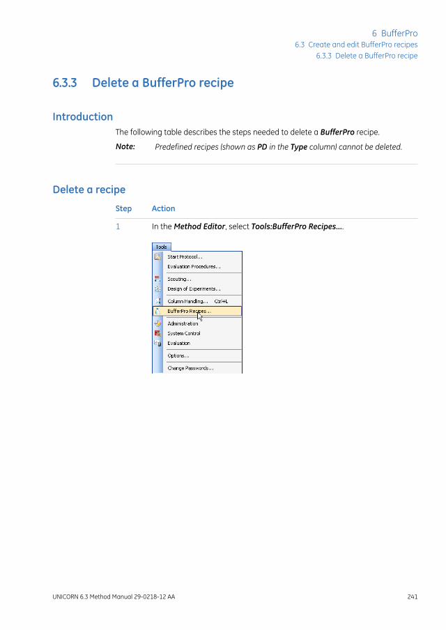
6.3.3 Delete a BufferPro recipe
IntroductionThe following table describes the steps needed to delete a BufferPro recipe.
Predefined recipes (shown as PD in the Type column) cannot be deleted.Note:
Delete a recipe
ActionStep
In the Method Editor, select Tools:BufferPro Recipes....1
UNICORN 6.3 Method Manual 29-0218-12 AA 241
6 BufferPro6.3 Create and edit BufferPro recipes
6.3.3 Delete a BufferPro recipe
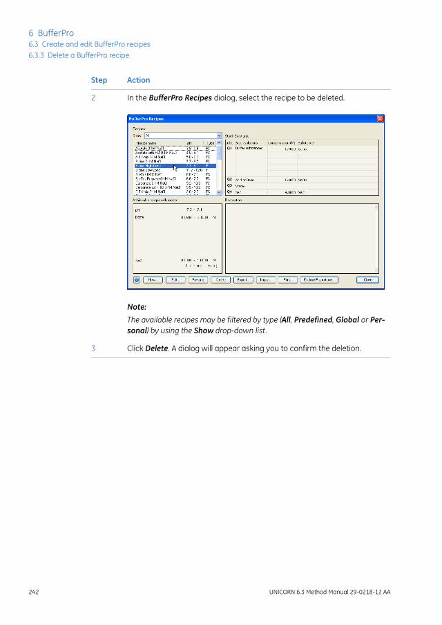
ActionStep
In the BufferPro Recipes dialog, select the recipe to be deleted.2
Note:
The available recipes may be filtered by type (All, Predefined, Global or Per-sonal) by using the Show drop-down list.
Click Delete. A dialog will appear asking you to confirm the deletion.3
242 UNICORN 6.3 Method Manual 29-0218-12 AA
6 BufferPro6.3 Create and edit BufferPro recipes6.3.3 Delete a BufferPro recipe
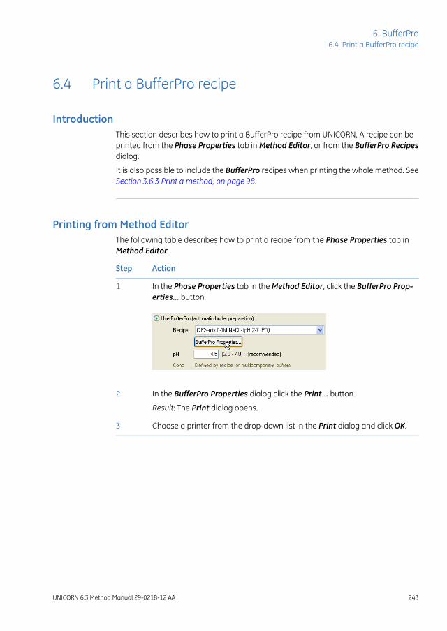
6.4 Print a BufferPro recipe
IntroductionThis section describes how to print a BufferPro recipe from UNICORN. A recipe can beprinted from the Phase Properties tab in Method Editor, or from the BufferPro Recipesdialog.
It is also possible to include the BufferPro recipes when printing the whole method. SeeSection 3.6.3 Print a method, on page 98.
Printing from Method EditorThe following table describes how to print a recipe from the Phase Properties tab inMethod Editor.
ActionStep
In the Phase Properties tab in the Method Editor, click the BufferPro Prop-erties... button.
1
In the BufferPro Properties dialog click the Print... button.2
Result: The Print dialog opens.
Choose a printer from the drop-down list in the Print dialog and click OK.3
UNICORN 6.3 Method Manual 29-0218-12 AA 243
6 BufferPro6.4 Print a BufferPro recipe

Printing from BufferPro Recipesdialog
The following table describes how to print a recipe from the BufferPro Recipes dialog.
ActionStep
In the Method Editor, select Tools:BufferPro Recipes.1
Choose the recipe to be printed from the list in theBufferPro Recipes dialog.2
Click the Print... button.3
Result: The Print dialog opens.
Choose a printer from the drop-down list in the Print dialog and click OK.4
244 UNICORN 6.3 Method Manual 29-0218-12 AA
6 BufferPro6.4 Print a BufferPro recipe

6.5 Calculate buffer composition using BufferPro
IntroductionThis section describes how to calculate an exact buffer composition for a buffer previ-ously optimized usingBufferPro. This is desirable when scaling up a purification procedurein order to prepare bulk-scale buffer solutions, for example ion exchange A and B buffers.
Calculating buffer compositionThe following table describes the steps needed to calculate the buffer composition of aBufferPro recipe at a particular pH, buffer and gradient concentration, and temperature.In the examples shown in the table, a pH optimization scouting run has been performed.The buffer at which optimal separation was obtained was 50 mM HEPES, pH 7.8 at 25 °C,and the required peak eluted at 25% of the gradient.
ActionStep
In the Method Editor, select Tools:BufferPro Recipes....1
UNICORN 6.3 Method Manual 29-0218-12 AA 245
6 BufferPro6.5 Calculate buffer composition using BufferPro

ActionStep
Choose the appropriate recipe from the list in the BufferPro Recipes dialog.2
Click the Explore Proportions... button.3
246 UNICORN 6.3 Method Manual 29-0218-12 AA
6 BufferPro6.5 Calculate buffer composition using BufferPro

ActionStep
In the Explore Proportions dialog, enter the pH, Buffer concentrations, thedesired Gradient concentration and Temperature.
4
Note:
The buffer concentrationsmay not exceed the limits of the recipe. If this isthe case the Calculate button will be grayed out.
Click Calculate.
Note:
If the pH given is beyond the optimal buffering range of the buffer recipe, awarning will be displayed.
5
The actual concentrations of the components in the required buffer will bedisplayed.
6
Note:
It is important that the molar amounts are as exact as possible when mixingthe buffers. It has been found that four decimal places inmolar concentrationgives reproducible results.
UNICORN 6.3 Method Manual 29-0218-12 AA 247
6 BufferPro6.5 Calculate buffer composition using BufferPro

ActionStep
The buffer composition can be printed by pressing the Print... button.7
248 UNICORN 6.3 Method Manual 29-0218-12 AA
6 BufferPro6.5 Calculate buffer composition using BufferPro

6.6 Export and import BufferPro recipes
IntroductionBufferPro recipes are stored internally in the UNICORN database. It is possible to exportthese recipes to a zip file on the local computer so that the recipe can be imported againlater into the same database installation, or imported into another. This section describeshow to export and import BufferPro recipes.
Exporting BufferPro recipesThe following table illustrates the steps required to export one or several recipes.
Predefined recipes cannot be exported, since these recipes will always befound in a UNICORN installation.
Note:
DescriptionStage
In the Method Editor, select Tools:BufferPro Recipes....1
UNICORN 6.3 Method Manual 29-0218-12 AA 249
6 BufferPro6.6 Export and import BufferPro recipes

DescriptionStage
Choose the recipe to be exported from the list in theBufferProRecipesdialog.2
Note:
Several recipes may be exported to the same zip file. To select a continuousrange, click on the first recipe then Shift-click the last. To add single recipesto a selection, Ctrl-click them.
Click Export....3
Result: The Export dialog opens.
Choose a location on the computer disk and a filename for the zip file.4
Save the file.5
250 UNICORN 6.3 Method Manual 29-0218-12 AA
6 BufferPro6.6 Export and import BufferPro recipes

Importing BufferPro recipesThe following table illustrates the steps required to import one or several recipes.
DescriptionStage
In the Method Editor, select Tools:BufferPro Recipes....1
Result: The BufferPro Recipes dialog opens.
Click on the Import... button.2
Result: The Import dialog opens.
UNICORN 6.3 Method Manual 29-0218-12 AA 251
6 BufferPro6.6 Export and import BufferPro recipes

DescriptionStage
Browse to the zip file containing the BufferPro recipe(s) on the computerdisk and Open the file.
3
Result: The Import BufferPro Recipes dialog opens.
In the Import BufferPro Recipes dialog, uncheck any recipe(s) that you donot wish to import. Select whether the recipe(s) should be imported asglobal, otherwise they will be imported as personal recipes.
4
Click OK to import the recipe(s).5
252 UNICORN 6.3 Method Manual 29-0218-12 AA
6 BufferPro6.6 Export and import BufferPro recipes
6.7 Predefined BufferPro recipes
IntroductionThis section describes in detail the predefined buffer systems inBufferPro that are deliv-ered with UNICORN.
General pointsThe following points should be taken into consideration:
• The pKa of certain buffer substances can vary significantly with temperature. Thismeans that the working pH range for optimal buffering will vary with temperature.It is possible to estimate the appropriate pH ranges using the Explore Proportionstool, see Section 6.5 Calculate buffer composition using BufferPro, on page 245.
• The two broad-range buffer systems, AIEX-mix 0-1MNaCl and CIEX-mix 0-1MNaClmay only be used at fixed concentration, since these are multi-component buffers.
• The working concentration for buffers that are mixed using conjugate acid-basepairs is 25-50% of the stock solution concentration. For buffers mixed using strongacid or base solutions the working concentration is 15-25% of the stock solutionconcentration. Although it may be possible to mix solutions outside this range,UNICORN will show a warning since the pH of the resulting buffer may not be reliable.If in doubt, check the pH of the eluent after running an experiment using a reliablelab pH meter.
• The pH range given is based on the narrowest range for effective buffering for theentire gradient (0-1M NaCl). The ionic strength of the mixed solution affects the ap-parent pKa of the buffering agent. For pH outside the recommended range thebuffering capacity is unreliable and should be avoided. UNICORN will display awarning in case either the required concentrations or pH will not provide adequatebuffering. If in doubt, check the pH of the eluent after running an experiment usinga reliable lab pH meter.
• Certain buffer substances are not recommended for anion exchange and others notfor cation exchange. For example, phosphate buffers are not suitable for anion ex-change. Buffer suitability is noted in the predefined recipes in UNICORN.
UNICORN 6.3 Method Manual 29-0218-12 AA 253
6 BufferPro6.7 Predefined BufferPro recipes

pHand concentration ranges forpredefined recipes
The following table gives the optimal pH and concentration ranges for buffer recipesthat are predefined in BufferPro at 25 °C.
CommentConcentrationrange (M)
pH range at25 °C
Buffer system
Broad range buffer sys-tem for Anion exchangechromatography.
Fixed at 25% ofthe concentra-tion of the stocksolution.
pH 5.8-8.9AIEX-mix 0-1M NaCl
Broad range buffer sys-tem for Cation ex-change chromatogra-phy.
Fixed at 25% ofthe concentra-tion of the stocksolution.
pH 2.0-7.0CIEX-mix 0-1M NaCl
Titrated with conjugateacid
0.05 - 0.1pH 3.8-5.4Acetate 0-1M NaCl
Titrated with strong acid0.03 - 0.05pH 4.0-5.1Acetate with HCl 0-1M NaCl
Titrated with strongbase
0.03 - 0.05pH 7.7-8.7Bicine 0-1M NaCl
Titrated with strong acid0.03 - 0.05pH 6.0-7.1Bis-Tris 0-1M NaCl
Titrated with strong acid0.03 - 0.05pH 6.6-7.7Bis-Tris Propane 0-1MNaCl
Titrated with conjugateacid
0.05 - 0.1pH 9.2-10.5Carbonate 0-1M NaCl
Titrated with strong acid0.03 - 0.05pH 9.5-10.2Carbonate with HCl0-1M NaCl
Titrated with conjugateacid
0.05 - 0.1pH 2.3-6.0Citrate 0-1M NaCl
Titrated with strong acid0.03 - 0.05pH 3.7-5.7Citrate with HCl 0-1MNaCl
Titrated with strong acid0.03 - 0.05pH 8.6-9.7Diethanolamine 0-1MNaCl
Titrated with strong acid0.03 - 0.05pH 9.2-10.2Ethanolamine 0-1MNaCl
254 UNICORN 6.3 Method Manual 29-0218-12 AA
6 BufferPro6.7 Predefined BufferPro recipes
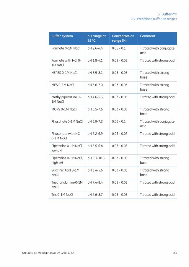
CommentConcentrationrange (M)
pH range at25 °C
Buffer system
Titrated with conjugateacid
0.05 - 0.1pH 2.6-4.4Formate 0-1M NaCl
Titrated with strong acid0.03 - 0.05pH 1.8-4.1Formate with HCl 0-1M NaCl
Titrated with strongbase
0.03 - 0.05pH 6.9-8.1HEPES 0-1M NaCl
Titrated with strongbase
0.03 - 0.05pH 5.6-7.0MES 0-1M NaCl
Titrated with strong acid0.03 - 0.05pH 4.6-5.3Methylpiperazine 0-1M NaCl
Titrated with strongbase
0.03 - 0.05pH 6.5-7.6MOPS 0-1M NaCl
Titrated with conjugateacid
0.05 - 0.1pH 5.9-7.2Phosphate 0-1M NaCl
Titrated with strong acid0.03 - 0.05pH 6.2-6.9Phosphate with HCl0-1M NaCl
Titrated with strong acid0.03 - 0.05pH 5.5-6.4Piperazine 0-1M NaCl,low pH
Titrated with strongbase
0.03 - 0.05pH 9.3-10.5Piperazine 0-1M NaCl,high pH
Titrated with strongbase
0.03 - 0.05pH 3.4-5.6Succinic Acid 0-1MNaCl
Titrated with strong acid0.03 - 0.05pH 7.4-8.4Triethanolamine 0-1MNaCl
Titrated with strong acid0.03 - 0.05pH 7.6-8.7Tris 0-1M NaCl
UNICORN 6.3 Method Manual 29-0218-12 AA 255
6 BufferPro6.7 Predefined BufferPro recipes

7 Method queues
IntroductionThis chapter describes how to create and edit method queues in UNICORN. For informa-tion on how to create and edit individual methods, seeChapter3 Create and editmethods,on page 26.
In this chapterThis chapter contains the following sections:
See pageSection
2577.1 Method queues - overview
2587.2 Create a method queue
2627.3 Edit a method queue
256 UNICORN 6.3 Method Manual 29-0218-12 AA
7 Method queues

7.1 Method queues - overview
IntroductionA method queue in UNICORN is a linked set of methods to be run. The method queuecan contain methods to be run on up to three different systems. Each system may haveup to ten methods queued.
For example, a method queue might be useful on a single system when a wash procedureis programmed in a separate method. This method can then be linked to a series of dif-ferent process methods ensuring the same wash procedure is used in each process. Onmultiple systems, the product of a separation on the first system might be the startingmaterial for a separation on the next, allowing fully automatic multi-step processing.
When amethod queue is started, an option is available to run the start protocolfor the method queue only once. Notification limit warnings related to thenumber of times a column has been used, for example since the last CIP wasperformed, are only issuedwhen the start protocol is performed. See Set noti-fication limits for an individual column, on page 296. In a method queue thismay therefore not always be shown exactly when the notification limit isreached. Each run will however be noted in the column history, which shouldbe checked before critical runs in amethod queue. See View individual columnhistory, on page 301.
Note:
Main steps when creating amethod queue
The main steps when creating a method queue are:
ActionStep
Create methods for the required system(s). See Chapter 3 Create and editmethods, on page 26.
1
Create/open a method queue2
• Create a new method queue
or
• Open an existing method queue that can be edited and saved with anew name
Save the method queue3
UNICORN 6.3 Method Manual 29-0218-12 AA 257
7 Method queues7.1 Method queues - overview

7.2 Create a method queue
Creating a method queueThe following table describes how to create a method queue.
ActionStep
In the Method Editor:1
• click the New Method Queue icon in the Toolbar
or
• Select File:New Method Queue...
Result: The Method Queue dialog opens.
In the Method Queue dialog, choose the Number of included systems fromthe drop down list.
2
Result: A separate method queue block will be added to the dialog for eachadditional system if required.
258 UNICORN 6.3 Method Manual 29-0218-12 AA
7 Method queues7.2 Create a method queue

ActionStep
Choose a system for each method queue block from the System drop downlist.
3
Choose aMethod to add to a method queue by pressing the browse button.4
Result: The Select Method dialog opens.
In the Select Method dialog, browse to the required method and click OK.5
Result: The method is added to the method queue.
Note:
For reasons of system compatibility, the individual methods should be savedfor the system on which they are queued.
UNICORN 6.3 Method Manual 29-0218-12 AA 259
7 Method queues7.2 Create a method queue
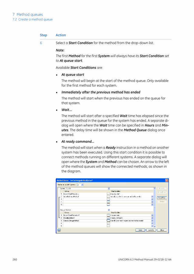
ActionStep
Select a Start Condition for the method from the drop-down list.
Note:
The firstMethod for the first Systemwill always have its Start Condition setto At queue start.
6
Available Start Conditions are:
• At queue start
The method will begin at the start of the method queue. Only availablefor the first method for each system.
• Immediately after the previous method has ended
The method will start when the previous has ended on the queue forthat system.
• Wait...
The method will start after a specified Wait time has elapsed since theprevious method in the queue for the system has ended. A separate di-alog will open where the Wait time can be specified in Hours and Min-utes. The delay time will be shown in the Method Queue dialog onceentered.
• At ready command...
The method will start when a Ready instruction in a method on anothersystem has been executed. Using this start condition it is possible toconnect methods running on different systems. A separate dialog willopen where the System andMethod can be chosen. An arrow to the leftof the method queues will show the connected methods, as shown inthe diagram.
260 UNICORN 6.3 Method Manual 29-0218-12 AA
7 Method queues7.2 Create a method queue

ActionStep
Repeat steps 4 to 6 to add further methods to the Method list for each re-quired system.
7
Click Save or Save As to save the completed method queue.
Note:
An error dialog will be displayed if any of the methods are incompatible withthe system on which they are queued.
8
UNICORN 6.3 Method Manual 29-0218-12 AA 261
7 Method queues7.2 Create a method queue

7.3 Edit a method queue
IntroductionThis section describes how to open, delete and edit existing method queues. Methodscan be inserted and deleted from a method queue, and their order in the queue can bechanged.
Opening a method queueThe table below describes how to open an existing method queue in the database:
ActionStep
In the Method Editor:1
• Click the Open Method Navigator icon in the Toolbar
or
• select File:Open...
or
• select View:Method Navigator
Result: The Method Navigator is displayed.
262 UNICORN 6.3 Method Manual 29-0218-12 AA
7 Method queues7.3 Edit a method queue

ActionStep
Select the method queue to be opened in the Folder name column.2
To open the method queue,3
• Click the Open button located in the toolbar of the Method Navigatorpane
or
• double-click the selected method queue
Result: The Method Queue dialog is opened with the details for the openedmethod queue.
Note:
If a method contained in the method queue has been altered since the lasttime it was saved, an information dialog will be displayed.
Delete a method queueThe table below describes how to delete a method queue from the database:
UNICORN 6.3 Method Manual 29-0218-12 AA 263
7 Method queues7.3 Edit a method queue

ActionStep
In the Method Editor:1
• Click the Open Method Navigator icon in the Toolbar
or
• select File:Open...
or
• select View:Method Navigator
Result: The Method Navigator is displayed.
Select the method queue to be deleted in the Folder name column.2
To delete the method queue,3
• select Edit:Delete
or
• press the Delete key
or
• right-click the selected method queue and selectDelete from the contextmenu.
Result: A dialog will appear asking to confirm the delete operation.
264 UNICORN 6.3 Method Manual 29-0218-12 AA
7 Method queues7.3 Edit a method queue

Insert a method into a methodqueue
The following table describes how to insert a method into the Method list for a system.
ActionStep
Open the method queue, see Opening a method queue, on page 262.1
Result: The Method Queue dialog opens with the details for the chosenmethod queue.
In theMethodQueue dialog, select the position in the list at which a methodwill be inserted by clicking on the Method column.
2
Insert a new row by clicking on the Insert Row button.3
Result: An empty row will be inserted.
Add aMethod and Start Condition to theMethod list. See Section7.2 Createa method queue, on page 258.
4
Save the method queue.5
UNICORN 6.3 Method Manual 29-0218-12 AA 265
7 Method queues7.3 Edit a method queue

Delete a method from a methodqueue
The following table describes how to delete a method from the method queue for asystem.
ActionStep
Open the Method Queue, see Opening a method queue, on page 262.1
Result: The Method Queue dialog opens with the details for the chosenmethod queue.
In the Method Queue dialog, select the method to be removed by clickingon its name in the Method list.
2
Delete the selected row by clicking on the Delete button.3
Result: The method will be deleted from the method queue.
Save the method queue.4
Change order of methods in amethod queue
The following table describes how to change the order of methods in an existing methodqueue.
ActionStep
Open the method queue, see Opening a method queue, on page 262.1
Result: The Method Queue dialog opens with the details for the chosenmethod queue.
266 UNICORN 6.3 Method Manual 29-0218-12 AA
7 Method queues7.3 Edit a method queue
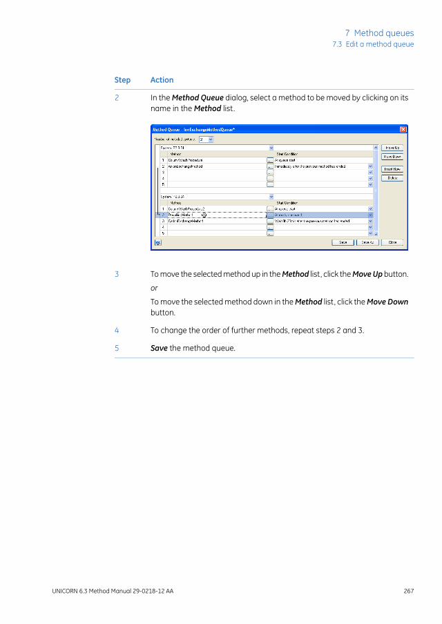
ActionStep
In the Method Queue dialog, select a method to be moved by clicking on itsname in the Method list.
2
To move the selected method up in theMethod list, click theMoveUp button.3
or
To move the selected method down in theMethod list, click theMove Downbutton.
To change the order of further methods, repeat steps 2 and 3.4
Save the method queue.5
UNICORN 6.3 Method Manual 29-0218-12 AA 267
7 Method queues7.3 Edit a method queue

8 Column Handling
About this chapterTheColumnHandling tool in UNICORN enables handling of column types and, if enabled,handling of individual columns using the Column Logbook. The Column Handling toolcan be opened from all available modules in UNICORN.
This chapter gives an overview of the Column Handling and Column Logbook tools.
In this chapterThis chapter contains the following sections:
See pageSection
2698.1 Overview
2758.2 Handling column types
2888.3 Handling individual columns
3038.4 Column performance
3078.5 Intelligent Packing of AxiChrom columns
268 UNICORN 6.3 Method Manual 29-0218-12 AA
8 Column Handling

8.1 Overview
IntroductionThis section gives an overview of the Column Handling tool and suggests a workflowwhen working with column types and individual columns.
Definitions
DescriptionTerm
A type of column consisting of a particular hardware and mediawith a defined bed height.
Column type
An individual column of a column type.Column
or
Individual col-umn
ExampleA laboratory has two Mono Q™ HR 16/10 columns used in different projects. Howevereach individual column may be treated and logged separately using Column Logbookin UNICORN, assuming this option has been enabled.
When creating methods and performing method runs, the bed height for thecolumn type will be used. If you wish to use a custom packed column (e.g. anAxiChrom column), you must create a specific column type with the definedhardware and media, and the obtained bed height.
Note:
Open the Column Handlingdialog
To open the Column Handling dialog:
• select Tools:Column Handling... in any of the UNICORN modules
or
• click the Column Handling icon in the Toolbar where available
UNICORN 6.3 Method Manual 29-0218-12 AA 269
8 Column Handling8.1 Overview

The Column Handling dialogThe illustration below shows the Column Handling dialog displaying the Column TypeParameters tab.
FunctionPart
Select Column Types by area:1
Shows the available column types in the Column Handling dialog. The listcan be filtered to display column types for a specific technique and/oraccess label.
Column Type Parameters tab:2
Shows the parameters for the selected column type in the Column typeslist. SeeSection8.2Handling column types, onpage275 for more information.
270 UNICORN 6.3 Method Manual 29-0218-12 AA
8 Column Handling8.1 Overview
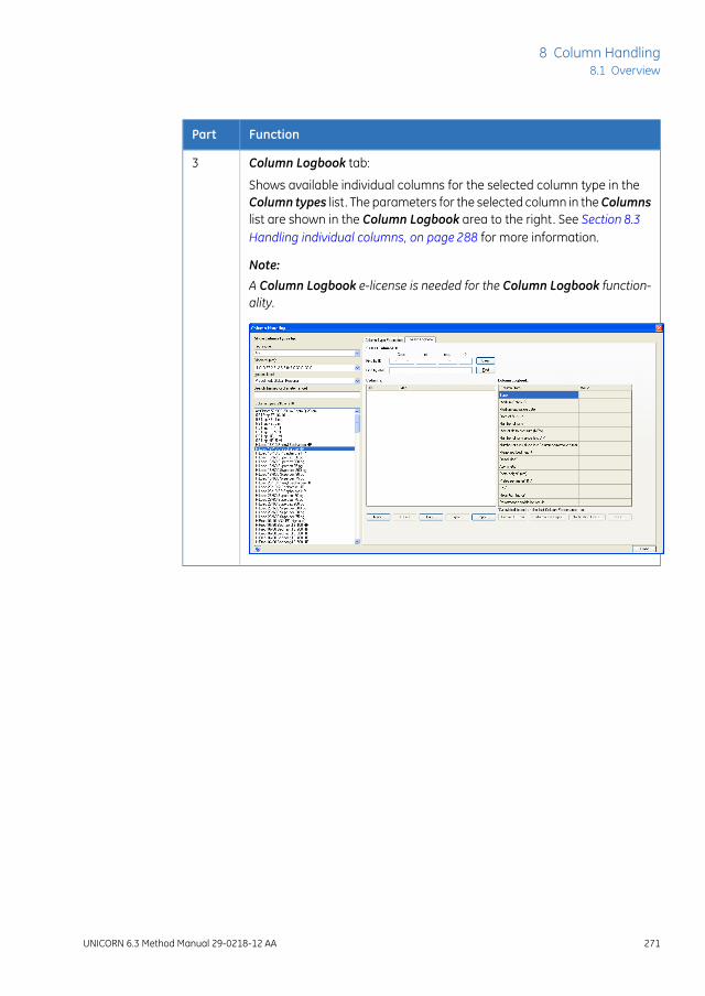
FunctionPart
Column Logbook tab:3
Shows available individual columns for the selected column type in theColumn types list. The parameters for the selected column in theColumnslist are shown in the Column Logbook area to the right. See Section 8.3Handling individual columns, on page 288 for more information.
Note:
A Column Logbook e-license is needed for the Column Logbook function-ality.
UNICORN 6.3 Method Manual 29-0218-12 AA 271
8 Column Handling8.1 Overview

Main Column Handling tasksThere are many possible workflows when working with column types and individualcolumns in UNICORN. The table below lists the main tasks that are performed in theColumnHandling tool or the Select columns dialog in the Start Protocol (when startingthe run in System Control).
the main tasks are...When working with...
• Create new column types
• Import/export column types
- Used to transfer column type data between differ-ent databases
• Edit column types
- Edit parameters and delete column types
• Print information about column types
Column types
272 UNICORN 6.3 Method Manual 29-0218-12 AA
8 Column Handling8.1 Overview
the main tasks are...When working with...
• Register new columns
- scan or manually type in the barcode
- add notes (optional)
Tip:
New columns can be registered using theColumnHandling dialog or before the run is started.
• Select columns to be used in the run
- view column history (optional)
- view performance report (optional)
- scan column barcode
Tip:
Individual columns to be used for a specific runcan only be selected via the Start Protocol. Beforeselecting a previously used column, it is possibleto view the run history and a performance report(if available) in the Column Handling dialog.
• Edit columns
- add/edit notes
- set notification limits
- delete unused columns
• Print column information
• Generate a performance report
• Export and import columns from UNICORN
Individual columns
UNICORN 6.3 Method Manual 29-0218-12 AA 273
8 Column Handling8.1 Overview

Illustration of Column Handlingworkflow
The illustration below shows a possible workflow when working with column types andindividual columns:
Create new column type/ import column type
1. Create method
Select column type in the Method Settings phase
If the appropriate column type is not available in the database
2 . Select column for the run and start the run
- View column history (optional)
- Scan column barcode
In the Column Handling dialog:
- View column performance report if available (optional)
In the Start Protocol:
or
- Select column manually
- Create a new column type
- Import the column type
or
In the Column Handling dialog:
If the appropriate column is not available in the database
Register new column/import column
- Register new column
- Import the column
In the Column Handling dialog or Start Protocol:
a. Click
b. Scan column barcode or type in ID manually
c. Enter column information and notes
or
3. Generate report (optional)
In the Column Handling dialog:
- If a column performance test (HETP) has been run, evaluate the results in the Evaluation module
In the Evaluation module:
In the Column Handling dialog:
- View column performance report
The report lists:
- Column Logbook data
- Selected performance graphs
- Run history and path to result files for all runs performed using the column
274 UNICORN 6.3 Method Manual 29-0218-12 AA
8 Column Handling8.1 Overview

8.2 Handling column types
IntroductionWhen you create a new method and select a column type in theMethod Settings phaseor in the wizard window, the column volume and column pressure limits are automati-cally set. For systems using predefined methods, the default flow rate and the pressurefor the column are automatically set as well. Most of the work regarding handling ofcolumn types is performed in theMethod Editor. The column type to be used in a methodis selected when creating the method as shown in the illustration below.
Column types are either globally available to all users, or only personally available. Anumber of column types are predefined in UNICORN (see below for more informationabout predefined column types).
When creating methods and performing method runs, the bed height for thecolumn type will be used. The measured bed height of a custom packed indi-vidual column (e.g an AxiChrom column) may differ from the bed height of theparental column type, if the column type was used in the packing method. Ifyou wish to use the correct bed height for method creation, you can edit thecolumn type and enter the measured bed height of the individual column.
Note:
This section describes how to add, edit and delete column types. It also describes howto import and export column types and how to print information about selected columntypes.
Predefined column typesA number of column types from GE Healthcare are predefined in UNICORN. For eachcolumn type, as many individual columns as needed can be registered. Parameters forthe predefined column types can be edited by saving the column type with a new nameand as a Personal or Global column type. The complete list of predefined column typescan be found in the Column Handling dialog.
UNICORN 6.3 Method Manual 29-0218-12 AA 275
8 Column Handling8.2 Handling column types

Create a new column typeThe table below describes how to add a new column type with the Column Handlingtool:
ActionStep
In the Column Type Parameters tab in the Column Handling dialog, click
.
1
Result: The New Column Type dialog opens.
If adding a column type for which the column hardware and medium arenot made by GE Healthcare, continue to step 4.
2
276 UNICORN 6.3 Method Manual 29-0218-12 AA
8 Column Handling8.2 Handling column types

ActionStep
• Select theGEHealthcare hardware type for the new column type in thedrop-down list.
To filter the drop-down list to only show hardware types with certaindiameters, enter the diameter range in cm in the Min and Max fields forShow hardware types by diameter (cm) above.
• Select the GE Healthcare medium type for the new column type in thedrop-down list.
To filter the drop-down list to only show medium types for a specificseparation technique, choose the appropriate technique in the Showmedium types by technique drop-down list above.
Result: The following parameters are automatically filled in (can be editedas required):
3
Enter the remaining parameter values for the new column type in the RunParameters, Details and Ordering Information tabs. Fields marked with *must be filled in.
4
Values in the gray fields are calculated and automatically filled in based onentered values for the corresponding parameters.
For systems that cannot utilize the delta column pressure signal, it is recom-mended to use the same pressure as the pre-column pressure.
Select whether the the new column type should be Global (available for allusers) or Personal (only available for the current user).
5
UNICORN 6.3 Method Manual 29-0218-12 AA 277
8 Column Handling8.2 Handling column types

ActionStep
Click Save As... to save the column type.6
Result: The Save As dialog opens.
Type in a Column type name and click Save.7
Result: The column type is saved in the database and displayed in theColumntypes list.
278 UNICORN 6.3 Method Manual 29-0218-12 AA
8 Column Handling8.2 Handling column types

Edit parameters for a columntype
The table below describes how to edit parameters for a column type:
ActionStep
Choose filtering options from the drop-down lists to show the column typesby Technique,Diameter orAccess label. Select the appropriate column typefor which to edit parameters in the Column types list.
1
Result: The parameters for the selected column type are displayed in theColumn Type Parameters tab to the right.
UNICORN 6.3 Method Manual 29-0218-12 AA 279
8 Column Handling8.2 Handling column types

ActionStep
In the Column Type Parameters tab, click .2
Result: The Edit Column Type dialog opens.
Edit the column type parameters as appropriate on the Run Parameters,Details and Ordering Information tabs.
3
Select whether the edited column type should be Global (available for allusers) or Personal (only available for the current user).
4
280 UNICORN 6.3 Method Manual 29-0218-12 AA
8 Column Handling8.2 Handling column types

ActionStep
When parameters for a predefined column type are edited, the column typemust be saved with a new name.
5
• Click Save As... to save the edited column type.
Result: The Save As dialog opens.
• Edit the Column type name and click Save.
Result: The column type is saved in the database and displayed in theColumn types list.
When parameters for a Global or Personal column type are edited, thecolumn type can be saved with a new name (see step 5 above) or thechanges can be applied to the current column type name.
6
• Click Save.
Result: The changes for the column type are saved.
Note:
When editing parameters forGlobal column types, it is recommended to savethe edited column type with a new name. Other users may otherwise not beaware that the parameters have been changed for that column type.
Note:
Methods that use the edited column type should be updated.
Delete column typesIt is not possible to delete predefined column types from the database. If acolumn type has any registered columns, it cannot be deleted unless the indi-vidual columns are first deleted. See Section8.3 Handling individual columns,on page288 for information about how to delete individual columns. If an indi-vidual column of a certain type has been used, it will not be possible to deleteeither the individual column or the column type.
Note:
The table below describes how to delete Global and Personal column types from thedatabase:
UNICORN 6.3 Method Manual 29-0218-12 AA 281
8 Column Handling8.2 Handling column types

ActionStep
In the Select ColumnType area, clear the Predefined types box in theAccesslabel drop-down list.
1
Result:OnlyGlobal and Personal column types are displayed in theColumntypes list.
Select the column type(s) to be deleted in the Column types list. To selectseveral column types use the Ctrl or Shift keyboard keys.
2
In the Column Type Parameters tab, click .3
Result: The Confirm Column Type Delete dialog opens.
Click Yes to delete the column type.4
Result: The column type is permanently deleted from the database.
Export column typesIt is not possible to export predefined column types from the database.Note:
The table below describes how to export Global and Personal column types from thedatabase:
282 UNICORN 6.3 Method Manual 29-0218-12 AA
8 Column Handling8.2 Handling column types

ActionStep
In the Select ColumnType area, clear the Predefined types box in theAccesslabel drop-down list.
1
Result:OnlyGlobal and Personal column types are displayed in theColumntypes list.
Select the column type(s) to be exported in the Column types list. To selectseveral column types use the Ctrl or Shift keyboard keys.
2
In the Column Type Parameters tab, click .3
Result: The Export Column Type dialog opens.
Select in which folder to save the information and type a name for the zipfile to be exported.
4
Result: The column type information is exported. This information can beimported into another database.
UNICORN 6.3 Method Manual 29-0218-12 AA 283
8 Column Handling8.2 Handling column types

Import column typesThe table below describes how to import column types into the database:
ActionStep
In the Column Type Parameters tab in the Column Handling dialog, click
.
1
Result: The Import dialog opens.
Note:
It is not possible to import column types from UNICORN 5. They have to bere-created in UNICORN 6.3.
284 UNICORN 6.3 Method Manual 29-0218-12 AA
8 Column Handling8.2 Handling column types

ActionStep
Locate the zip file with the column type information to be imported and clickOpen.
2
Result: The Import Column Type dialog opens displaying the names of thecolumn types included in the zip file.
Make sure that the check boxes in front of the column types to be importedare checked. If a column type should not be imported clear the correspondingcheck box.
3
Check the Import as Global box if the column types should be global (i.e.,available for all users) when imported. Otherwise, the column types will beimported as personal column types.
4
Click OK.5
Result: The column types are imported into the database.
Note:
If a column type to be imported has the same name as an existing columntype in the database, youwill be prompted to type a newname for that columntype. Type in a name and click OK.
UNICORN 6.3 Method Manual 29-0218-12 AA 285
8 Column Handling8.2 Handling column types

Import new column listUpdated lists of predefined column types may be provided by GE Healthcare. When anew list is imported, it will replace all the predefined column types in the database withthe updated column types. Only predefined column types will be replaced. User definedcolumn types, both personal and global, will remain in the database. The import of anew column list will also update the column hardware list and the approved media list.
A column list is available in theMisc folder of the UNICORN 6.3 installationDVD.
Tip:
The table below describes how to import a new column list into the database:
ActionStep
In the Column Type Parameters tab in the Column Handling dialog, click
.
1
Result: The Import dialog opens.
Locate the zip file with the column list to be imported and click Open.2
Result: The Import confirmation dialog opens, explaining what will happenwhen the zip file is imported.
Click Yes.3
Result: The new list of predefined column types is imported into the database.
Print information about columntypes
The table below describes how to print information about column types:
ActionStep
Select the column type(s) for which to print information in theColumn typeslist. To select several column types use the Ctrl or Shift keyboard keys.
1
286 UNICORN 6.3 Method Manual 29-0218-12 AA
8 Column Handling8.2 Handling column types
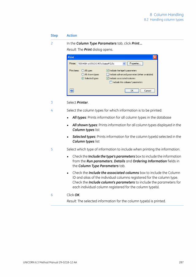
ActionStep
In the Column Type Parameters tab, click Print...2
Result: The Print dialog opens.
Select Printer.3
Select the column types for which information is to be printed:4
• All types: Prints information for all column types in the database
• All shown types: Prints information for all column types displayed in theColumn types list
• Selected types: Prints information for the column type(s) selected in theColumn types list
Select which type of information to include when printing the information:5
• Check the Include the type's parameters box to include the informationfrom the Run parameters, Details and Ordering Information fields inthe Column Type Parameters tab.
• Check the Include the associated columns box to include the ColumnID and alias of the individual columns registered for the column type.Check the Include column's parameters to include the parameters foreach individual column registered for the column type(s).
Click OK.6
Result: The selected information for the column type(s) is printed.
UNICORN 6.3 Method Manual 29-0218-12 AA 287
8 Column Handling8.2 Handling column types
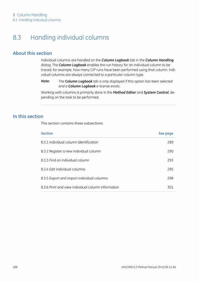
8.3 Handling individual columns
About this sectionIndividual columns are handled on the Column Logbook tab in the Column Handlingdialog. The Column Logbook enables the run history for an individual column to betraced, for example, how many CIP runs have been performed using that column. Indi-vidual columns are always connected to a particular column type.
The Column Logbook tab is only displayed if this option has been selectedand a Column Logbook e-license exists.
Note:
Working with columns is primarily done in the Method Editor and System Control, de-pending on the task to be performed.
In this sectionThis section contains these subsections:
See pageSection
2898.3.1 Individual column identification
2908.3.2 Register a new individual column
2938.3.3 Find an individual column
2958.3.4 Edit individual columns
2988.3.5 Export and import individual columns
3018.3.6 Print and view individual column information
288 UNICORN 6.3 Method Manual 29-0218-12 AA
8 Column Handling8.3 Handling individual columns

8.3.1 Individual column identification
Matrix barcodeMost prepacked GE Healthcare columns are marked with a matrix barcode on the columnlabel. This barcode can be scanned using the 2D barcode scanner to register new indi-vidual columns or to find columns in the database.
Columns can also be labeled with UniTag labels. A UniTag label is a unique identifier forindividual columns that are not prelabelled with a matrix barcode, such as HiTrap™columns, manually packed columns or columns from other sources. A number of UniTaglabels may be supplied with the system, and they can also be purchased separately.
The diagram below shows an example of a column label and a UniTag label with theirmatrix barcodes.
UNICORN 6.3 Method Manual 29-0218-12 AA 289
8 Column Handling8.3 Handling individual columns
8.3.1 Individual column identification

8.3.2 Register a new individual column
IntroductionIn order to take advantage of the column handling features of UNICORN, each individualcolumn needs to be registered in the software.
It is essential that the individual column is registered before a column perfor-mance test is performed. Otherwise the results will not be entered in the Col-umn Logbook. It is not possible to enter the performance test results after-wards.
Note:
Register an individual columnThe following table describes how to register an individual column in theColumnLogbook.
ActionStep
Select the Column Logbook tab and then click New.1
Result: The first New Column dialog opens.
290 UNICORN 6.3 Method Manual 29-0218-12 AA
8 Column Handling8.3 Handling individual columns8.3.2 Register a new individual column

ActionStep
Register the column using the 2D barcode scanner as follows:2
• Make sure that the mouse pointer is placed in the first position of theCode field.
• Point the 2D barcode scanner towards the data matrix tag on the columnlabel or the UniTag label.
• Press and hold the trigger.
• When the 2D barcode scanner beeps, the column ID is registered andthe second New Column dialog opens.
If no 2D barcode scanner is available, enter the column ID manually:3
• If the column has a column label, enter the column ID shown in theCodefield.
• If the column has a UniTag label, check the box Add column by manu-ally entering UniTag lot and ID and manually enter the number for thelot, expiration date (exp) and ID fields.
• Click Continue to open the second New Column dialog.
Note:
The lot field should contain eight digits, and the ID field should contain fourdigits. If the lot or ID numbers of the column contains fewer than eight or fourdigits respectively, insert leading zeros before the number.
Note:
If the column has no GE Healthcare label and you have run out of UniTag la-bels, check the box Add column by manually entering UniTag lot and ID,then enter an arbitrary lot and ID. This procedure is possible, but not recom-mended.
UNICORN 6.3 Method Manual 29-0218-12 AA 291
8 Column Handling8.3 Handling individual columns
8.3.2 Register a new individual column

ActionStep
In the second New Column dialog:4
• Enter an Alias (optional).
Tip:
Alias can be used for easy identification of an individual column.
• Select Technique and Column type.
Note:
For prepacked GE Healthcare columns with a matrix barcode, these arefilled in automatically.
• Check the Use medium batch ID and type in the batch number of themedium.
• Check the Set medium expiration date and select expiration date forthe medium to get a notification in UNICORN when this date is reached.If an expiration date was set in the column ID field, this date will besuggested in the medium expiration date. The expiration date of themedium overrules the expiration date of the column.
Note:
The expiration date cannot be set or changed after a column has beenregistered.
• Enter notes for the column by clicking the Notes... button and enternotes in the Notes dialog that opens.
• Click OK.
Result: The entered information is saved and the registered column is dis-played in the Column Handling dialog.
292 UNICORN 6.3 Method Manual 29-0218-12 AA
8 Column Handling8.3 Handling individual columns8.3.2 Register a new individual column

8.3.3 Find an individual column
IntroductionMany features of the ColumnHandling tool require an individual column to be selected.This section describes how to find a column.
Find and select an individualcolumn
The table below describes how to find/select a registered column in theColumnLogbook:
ActionStep
Select the Column Logbook tab.1
Filter the list of column types by:2
• choosing the required technique in the drop-down menu Technique
and/or
• choosing the diameter in the drop-down menu Diameter
and/or
• choosing the access labels in the drop-down menu Access label
and/or
• enter a search criteria in the Search field.
Then select the column type to which the individual column belongs.
UNICORN 6.3 Method Manual 29-0218-12 AA 293
8 Column Handling8.3 Handling individual columns8.3.3 Find an individual column

ActionStep
To select several column types, use the Ctrl and Shift keyboard keys.3
Result: The individual columns registered for the selected column type(s) aredisplayed in the Columns list. The Column Logbook area to the right showsparameters and information for the selected column.
Tip:To show all registered individual columns, select all the available columntypes by checking the boxes for Predefined,Global and Personal types, thenselect all the Column Types in the list.
• If you have a short list of individual columns registered for the columntype, just select the appropriate column in the Columns list. To selectseveral columns, use the Ctrl and Shift keyboard keys.
• If you have many individual columns registered, find and select the ap-propriate column as described below:
- position the cursor in the first position of the Code field, scan thecolumn barcode or UniTag and click Find
or
- type in the barcode in the Find by ID field and click Find
or
- type in the alias in the Find by alias field and click Find
Result: The individual column is selected in the Columns list.
4
294 UNICORN 6.3 Method Manual 29-0218-12 AA
8 Column Handling8.3 Handling individual columns8.3.3 Find an individual column

8.3.4 Edit individual columns
IntroductionThis section describes the ways in which individual columns may be edited. This includesadding and editing notes, setting notification limits and deleting individual columns.
Add/edit notes for a columnThe table below describes how to add/edit notes for an individual column:
ActionStep
Select the individual column for which to add/edit notes in the Columns listin the Column Logbook tab. See Section 8.3.3 Find an individual column, onpage 293 for information about how to find and select a column.
1
In the Column Logbook tab, click .2
Result: The Notes dialog for the selected column opens.
Add/edit notes by typing in the dialog and click OK.3
Result: The notes for the column are updated.
UNICORN 6.3 Method Manual 29-0218-12 AA 295
8 Column Handling8.3 Handling individual columns
8.3.4 Edit individual columns

Set notification limits for anindividual column
Notification limits can be set for individual columns. Once the limit is reached, the userreceives a message stating what action should be taken before the column is used. Ex-amples of such limits are the Medium expiration date, that the column has been useda given number of times since the last CIP or column performance test were performed,or that the column performance parameters are poor so the medium should be repacked.
Warnings related to the number of times a columnhas been used, for examplesince the last CIP was performed, are only issued when the start protocol isperformed. In a method queue this may not always be shown for every run.Each run will however be noted in the column history.
Note:
The table below describes how to set notification limits for an individual column:
ActionStep
Select the individual column for which to set Notification Limits in theColumns list in theColumn Logbook tab. See Section8.3.3 Find an individualcolumn, on page293 for information about how to find and select a column.
1
In the Column Logbook tab, click .2
Result: The Notification Limits dialog for the selected column opens.
Check the appropriate boxes and enter notification values.3
When the values are reached or a value is outside the defined range, awarning will be displayed that action should be taken.
Click OK.4
Result: The settings are saved and the dialog is closed.
296 UNICORN 6.3 Method Manual 29-0218-12 AA
8 Column Handling8.3 Handling individual columns8.3.4 Edit individual columns

Delete individual columnsThe table below describes how to delete an individual column from the database:
ActionStep
Select the individual column to be deleted in the Columns list in the ColumnLogbook tab. See Section8.3.3 Find an individual column, on page293 for in-formation about how to find and select a column.
1
To select several columns in the Columns list, use the Ctrl and Shift keys.
In the Column Logbook tab, click .2
Result: The Confirm Column Delete dialog opens.
Click Yes in the Confirm Column Delete dialog.3
Result: The individual column is deleted.
Note:
Individual columns that have been used cannot be deleted.
UNICORN 6.3 Method Manual 29-0218-12 AA 297
8 Column Handling8.3 Handling individual columns
8.3.4 Edit individual columns

8.3.5 Export and import individual columns
IntroductionThe information for individual columns is stored in the UNICORN database. This informa-tion may be exported to a zip file in order to move the information to another UNICORNinstallation. This section describes how to export individual columns from UNICORN andhow to import previously exported columns.
Export individual columnsIndividual columns can be exported from the database to a zip file. The columns canthen be imported to another database if appropriate.
The table below describes how to export individual columns from the database:
ActionStep
Select the individual column(s) to be exported in the Columns list in theColumnLogbook tab. See Section8.3.3 Find an individual column, onpage293for information about how to find and select a column.
1
To select several columns in the Columns list, use the Ctrl and Shift keys.
In the Column Logbook tab, click .2
Result: The Export Column Type dialog opens.
Select in which folder to save the information and type a name for the zipfile to be exported.
3
Result: The individual column information is exported. The column informationcan be imported into another database.
Import individual columnsIndividual columns that have been exported and saved locally can be imported intoanother database.
The table below describes how to import individual column information to a database:
298 UNICORN 6.3 Method Manual 29-0218-12 AA
8 Column Handling8.3 Handling individual columns8.3.5 Export and import individual columns

ActionStep
In the Column Logbook tab, click .1
Result: The Import dialog opens.
Locate the zip file with the column type information to be imported and clickOpen.
2
Result: The Import Column dialog opens displaying the barcodes and aliasesof the individual columns included in the *.zip file.
UNICORN 6.3 Method Manual 29-0218-12 AA 299
8 Column Handling8.3 Handling individual columns
8.3.5 Export and import individual columns

ActionStep
Make sure that the check boxes in front of the individual columns to be im-ported are checked. If a column should not be imported clear the correspond-ing check box.
3
Click OK.4
Result: The columns are imported into the database.
Note:
If an individual column to be imported has the same barcode or alias nameas an existing column in the database, a dialog will be displayed saying thatthe column already exists in the database and that it will not be imported.
300 UNICORN 6.3 Method Manual 29-0218-12 AA
8 Column Handling8.3 Handling individual columns8.3.5 Export and import individual columns

8.3.6 Print and view individual column information
IntroductionThis section describes how to view the run history for an individual column, and how toprint column information.
View individual column historyIt is possible to view the run history for an individual column to see how many runs thathave been performed using the column. The path to the result files for each run is alsodisplayed. If the run was a column performance test or CIP run, this is shown as a remark.
The table below describes how to view the Column History for a column:
ActionStep
Select the individual column for which to view Column History in theColumns list in theColumn Logbook tab. See Section8.3.3 Find an individualcolumn, on page293 for information about how to find and select a column.
1
In the Column Logbook tab, click .2
Result: The Column History dialog for the selected column opens.
The runs performed using the column are listed. The date, result name andlocation and any remarks for the run are displayed.
Click Close to close the dialog.3
UNICORN 6.3 Method Manual 29-0218-12 AA 301
8 Column Handling8.3 Handling individual columns
8.3.6 Print and view individual column information

Print information aboutindividual columns
The table below describes how to print information for individual columns:
ActionStep
Select the appropriate column(s) for which to print information in theColumns list in theColumn Logbook tab. See Section8.3.3 Find an individualcolumn, on page293 for information about how to find and select a column.
1
To select several columns in the Columns list, use the Ctrl and Shift keys.
In the Column Logbook tab, click .2
Result: The Print dialog opens.
Select Printer.3
Select for which individual column(s) to print information:4
• Selected columns: Prints information for the column(s) selected in theColumns list
• All shown columns: Prints information for all columns displayed in theColumns list
• All columns: Prints information for all columns in the database
Click OK.5
Result: The Column ID, alias and parameters for the columns are printed.
302 UNICORN 6.3 Method Manual 29-0218-12 AA
8 Column Handling8.3 Handling individual columns8.3.6 Print and view individual column information

8.4 Column performance
IntroductionColumn performance can be tested by measuring the height equivalent to a theoreticalplate (HETP) and asymmetry factor (As) values. Tests should be run directly after packingor obtaining a new column, regularly during the lifetime of the column and when sepa-ration performance is seen to deteriorate. By regularly monitoring the performance ofan individual column, UNICORN can generate appropriate warnings when a cleaningprocedure needs to be applied, or even when the column lifetime is approaching its end.For a description of how to set such notification limits see Set notification limits for anindividual column, on page 296.
This section describes the workflow to run a Column Performance Test, and how togenerate a performance report for a specific column.
Column performance testThe following table describes the workflow for generating and analyzing a Column Per-formance Test result.
ActionStep
Create a Column Performance Test method, or a method containing a col-umn performance test. For details how to create methods see Chapter 3Create and edit methods, on page 26.
Note:
For methods created using phases, the option Enable logging of ColumnPerformance Test should be automatically selected in the Phase Propertiesfor the Method Settings phase when this method is created. This can be des-elected if logging of the performance test is not desired, but it should normallybe kept selected.
For wizard created methods and text created methods the Enable loggingof Column Performance Test is not automatically selected, and must be se-lected in the method settings phase for a column performance test to belogged.
1
UNICORN 6.3 Method Manual 29-0218-12 AA 303
8 Column Handling8.4 Column performance

ActionStep
Run the method. For details on running a method, see UNICORN 6.3 SystemControl Manual.
Note:
The individual column must be selected when the method run is started inorder to register the results from the column performance test in the columnlogbook. The result cannot be logged for the individual column at a later time.
When using a predefined intelligent packing method the column type is re-quested to be selected and an individual column will also be requested atmethod start. When creating a wizard generated intelligent packing methodit is an option to create separate methods for the packing and for the columnperformance test and therefore the column type and the individual columnmay only be needed for the column performance test method.
Suitable samples that can be used to monitor the column performance arefor example 1% acetone (measuring the absorbance at 280 nm), or 2.0 MNaCl and eluting with 0.5 M NaCl.
2
Note:
A sample volume between 0.5% and 3% of the column volume and a flowvelocity between 15 and 30 cm/h is recommended.
The calculated number of plates and the asymmetry factorwill in part dependon the selected flow rate. To ensure that test results are comparable, alwaysuse the same flow rate for the tests.
Evaluate the Column Performance Test, see UNICORN 6.3 Evaluation Man-ual.
3
Create a performance reportA column performance report can be created before using an individual column. Thereport shows if the column is in good condition for use. The performance report containsthe following information:
• Run and performance parameters
• Notes
• Performance graphs (optional)
• Run history
The table below describes how to generate a column performance report:
304 UNICORN 6.3 Method Manual 29-0218-12 AA
8 Column Handling8.4 Column performance
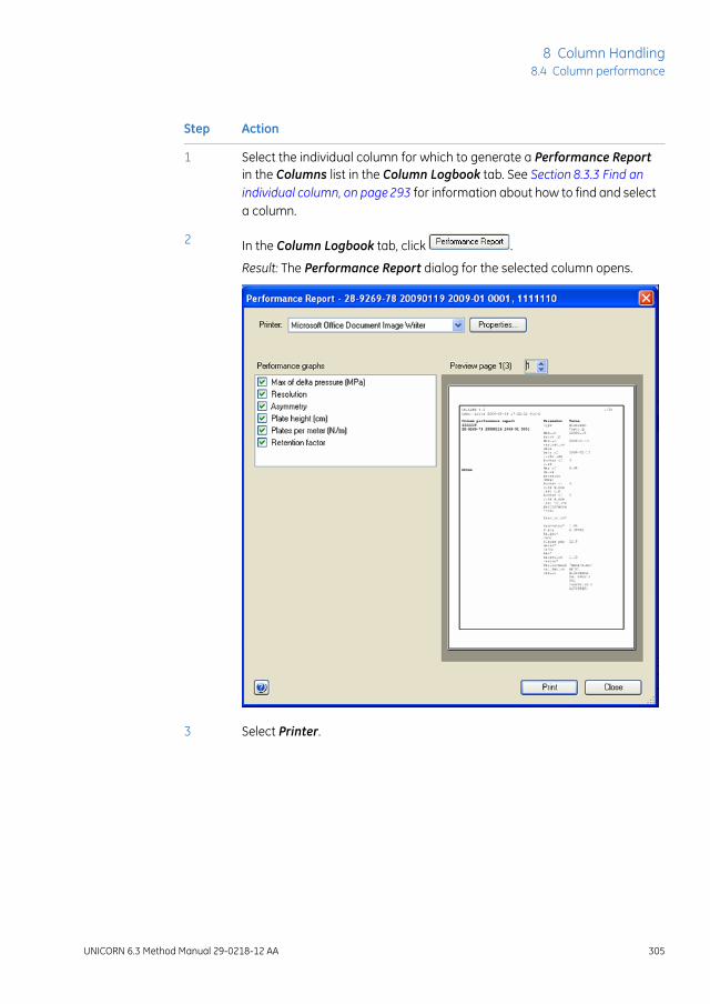
ActionStep
Select the individual column for which to generate a Performance Reportin the Columns list in the Column Logbook tab. See Section 8.3.3 Find anindividual column, on page293 for information about how to find and selecta column.
1
In the Column Logbook tab, click .2
Result: The Performance Report dialog for the selected column opens.
Select Printer.3
UNICORN 6.3 Method Manual 29-0218-12 AA 305
8 Column Handling8.4 Column performance

ActionStep
Check the appropriate boxes in the Performance graphs area to includethe corresponding graphs in the report.
Note:
The parameters and the corresponding values from the Column Logbookare always included on the first page in the report together with the latestperformance test results. All runs are listed in the Run History at the end ofthe report, including Column Performance Test and CIP runs which are la-beled.
4
Note:
Not all systems have feedback on the max delta pressure.
A preview of the report is shown on the right side of the dialog. Use thebuttons above the report to scroll the preview.
5
Click Print to print the information.6
Click Close to close the dialog.7
306 UNICORN 6.3 Method Manual 29-0218-12 AA
8 Column Handling8.4 Column performance

8.5 Intelligent Packing of AxiChrom columns
Introduction
UNICORN 6.3 features a solution for IntelligentPacking of AxiChrom columns. The AxiChrom col-umn family features hands-free packing using in-ternal hydraulic axial compression. Intelligentpacking of AxiChrom columns can be performedin several ways.
For systems that create methods using phases,the Intelligent Packing method can be performedusing either a predefined Intelligent Packingmethod, or by creating a user defined method in-cluding an Intelligent Packing phase.
For systems that have the Method Wizard, the In-telligent Packing method is created using the In-telligent Packing Wizard.
The workflows for the systems can differ. For apredefined Intelligent Packing method the ColumnPeformance tests are included, but for a wizardcreated Intelligent Packing method, it is possibleto separate the packing and the Column perfor-mance test in two different methods.
If Column Handling is used, and the method con-tains a Column Performance test, it is essential touse the correct column type, previously createdin column handling, in the method settings phase.
In this sectionThis section contains these subsections:
See pageSection
3098.5.1 AxiChrom column types and individual AxiChrom columns
UNICORN 6.3 Method Manual 29-0218-12 AA 307
8 Column Handling8.5 Intelligent Packing of AxiChrom columns

See pageSection
3138.5.2 Predefined Intelligent Packing method
3158.5.3 Wizard generated Intelligent Packing method
308 UNICORN 6.3 Method Manual 29-0218-12 AA
8 Column Handling8.5 Intelligent Packing of AxiChrom columns

8.5.1 AxiChrom column types and individual AxiChrom columnsIt is essential to create an individual column before a Column Performance test is donesince it is impossible to afterwards manually register the results from the Column Perfor-mance test in theColumnLogbook. This is described below inCreate anAxiChromcolumntype.
When the evaluation of the tests is performed, the actual packed bed height should beused. This bed height will be registered in theColumnLogbook. The evaluation procedureis described in the UNICORN 6.3 Evaluation Manual.
If it is essential that the exact packed bed height is usedwhen runningmethods,a column type for each individual AxiChrom column should be created withthe exact bed height value each time the column is repacked.
Tip:
Create anAxiChromcolumn typeThe table below describes how to create the AxiChrom column type:
If a column typewas usedwhen running a columnpackingmethod, the columntype bed height might need to be updated with the achieved bed height toensure that the actual packed bed height is applied when creating or runningmethods using the column type.
Note:
ActionStep
Choose the Tools:Column Handling menu command.1
Result: The Column Handling dialog opens.
In the Column Type Parameters tab in the Column Handling dialog, click
.
2
Result: The New Column Type dialog opens.
UNICORN 6.3 Method Manual 29-0218-12 AA 309
8 Column Handling8.5 Intelligent Packing of AxiChrom columns
8.5.1 AxiChrom column types and individual AxiChrom columns

ActionStep
• Select the appropriate AxiChrom column hardware in theGEHealthcarehardware type drop-down list.
• Select the GE Healthcare medium type for the new AxiChrom columntype in the drop-down list.
Tip:Only some of the available media are approved by GE Healthcare for use inthe Intelligent Packing of AxiChrom columns. For systems equipped withpredefined methods and phases it is possible to click theGEapprovedmediabutton in the Intelligent Packing phase to view a list of the approved mediaand bed heights.
Systems that use the intelligent packing wizard will be guided to the approvedmedia in the wizard.
Other media can also be selected, but the packing procedure will then beperformed with a set of general default settings.
3
Result: Based on the selections, some of the column type parameters areautomatically filled in.
Enter the remaining parameter values for the new column type in the RunParameters, Details and Ordering Information tabs, for example
4
• target bed height
• max flow rate
• max delta column pressure (the max delta column pressure value isused as the max pressure value for systems that cannot utilize the deltacolumn pressure)
Fields marked with * must be filled in.
Values in the gray fields are calculated and automatically filled in based onentered values for the corresponding parameters.
Select whether the new column type should beGlobal (available for all users)or Personal (only available for the current user).
5
Click Save As... to save the column type.6
Result: The Save As dialog opens.
310 UNICORN 6.3 Method Manual 29-0218-12 AA
8 Column Handling8.5 Intelligent Packing of AxiChrom columns8.5.1 AxiChrom column types and individual AxiChrom columns

ActionStep
Type in a Column type name and click Save.
Tip:To simplify identification, it is recommended to choose a name for the columntype composed of hardware name, media name and bed height. However,the Method Editor will recognize the column from the selected hardware ir-respective of the name.
7
Result: The AxiChrom column type is saved in the database and displayedin the Column types list.
Create an individual AxiChromcolumn
Once a column type consisting of the AxiChrom hardware and selected media is created,you can proceed to register an individual column.
It is essential to create an individual column before a Column Performancetest since it is impossible to afterwards manually register the results from theColumn Performance test in the Column Logbook.
Note:
ActionStep
Select the Column Logbook tab and then click New.1
Result: The first New Column dialog opens.
• Register the column either by scanning a UniTag or manually as de-scribed in Section 8.3.2 Register a new individual column, on page 290
and
• click Continue.
Result: The second New Column dialog opens.
2
UNICORN 6.3 Method Manual 29-0218-12 AA 311
8 Column Handling8.5 Intelligent Packing of AxiChrom columns
8.5.1 AxiChrom column types and individual AxiChrom columns

ActionStep
In the second New Column dialog:3
• Enter an Alias (optional).
Tip:
Alias can be used for easy identification of an individual column.
• Select Techniqueand the AxiChromColumn type you previously created.
• Check the Use medium batch ID and type in the batch number of themedium in the column.
• Check the Set medium expiration date and select expiration date forthe medium to get a notification in UNICORN when this date is reached.
Note:
The expiration date cannot be set or changed after a column has beenregistered.
Enter notes for the column by clicking the Notes... button and typing infor-mation in the Notes dialog that opens.
4
Click OK.5
Result: The entered information is saved and the registered column is dis-played in the Column Handling dialog.
For a predefined intelligent packing method, the packing has not been per-formed at this point and the bed height for the column will be a target bedheight based on the selected AxiChromcolumn type. This value can be adjustedafter the Column Performance tests are evaluated and the Column Logbookis updated. For systems using the method wizard it is possible to pack thecolumn first and then run the Column Performance. In this case the columntype and individual column can be created after the packing and selectedonly for the column performance test method.
Note:
312 UNICORN 6.3 Method Manual 29-0218-12 AA
8 Column Handling8.5 Intelligent Packing of AxiChrom columns8.5.1 AxiChrom column types and individual AxiChrom columns

8.5.2 Predefined Intelligent Packing methodFor systems that support predefined methods, use the Intelligent Packing method toprepare a method for packing the AxiChrom column.
ActionStep
Open a new, predefined Intelligent Packing method.1
In the Method Settings phase:2
• Select the AxiChrom column type you created previously
Note:
All the default settings for an Intelligent Packing method will be generatedwhen the AxiChromcolumn is selected, including target bed height andmedia.The default column positionwill be selected. It is recommended not to changeany settings in theMethod Settings phase of the method.
In the Intelligent Packing phase:3
• Select GE approved packing settings (default)
or
• Custom packing settings
Tip:The GE approved packing settings have been validated by GE Healthcare.If you wish to use other settings, for example other media or other bed heightsettings, you must select Custom packing settings.
If you selected to enter your own Custom packing settings, you can editthe following settings:
4
• Select to
- Pack by Packing Factor and choose a packing factor value
or
- Pack to the target bed height
• Change the adapter velocity
and
• Select to use flow conditioning
If you selected to use GE approved packing settings, proceed with the stepbelow.
Note:
It is not recommended to change the default position selections in the subse-quent steps.
UNICORN 6.3 Method Manual 29-0218-12 AA 313
8 Column Handling8.5 Intelligent Packing of AxiChrom columns8.5.2 Predefined Intelligent Packing method

ActionStep
If necessary, select the Inlets for hydraulic chamber liquid and for the mobilephase.
5
If necessary, select the column position for the hydraulic chamber (onlycolumn position A is used)
Tip:Click theColumnConnection button to view information about the connec-tions, including an illustration.
6
Enter the slurry start concentration to generate a slurry recipe, which isshown in a summary in the Start Notes at the start of the method run. Youcan view this recipe by clicking the Slurry Recipe button.
Note:
The accuracy of the slurry preparation will affect the packed bed height.
7
Note:
This function is not available when Custom packing settings is selected.
Verify the settings in the Equilibration phase.8
Verify the settings in the downflow Column Performance Test phase.9
Verify the settings in the upflow Column Performance Test phase.10
Save the method.11
Run themethodandevaluate thepacking
Once the Intelligent Packing method is ready, you can proceed to perform the actualpacking of the individual column you have registered. Refer to the AxiChrom operatinginstruction for instructions how to prepare the column, connect it to the chromatographysystem and perform the packing run.
The Intelligent Packing method includes two Column Performance Test phases, evalu-ating both the column upflow and downflow performance. Evaluate the results fromthese test as described in the UNICORN 6.3 EvaluationManual and adjust the actual bedheight according to the results if necessary.
314 UNICORN 6.3 Method Manual 29-0218-12 AA
8 Column Handling8.5 Intelligent Packing of AxiChrom columns8.5.2 Predefined Intelligent Packing method

8.5.3 Wizard generated Intelligent Packing methodFor systems that support the method wizard, use the Intelligent Packing wizard toprepare a method for packing the AxiChrom column.
If column handling is used, it is essential to select hardware, media and bedheight in the wizard as well as creating the corresponding column type andindividual column in column handling.
Note:
The table below describes how to create an Intelligent Packingmethod using the Wizard.
ActionStep
Create a new method in the Method Editor.1
In the New Method window:2
• Choose the correct system in the drop-down menu
and
• choose Method Wizard and click OK.
Follow the wizard to create a new method. Intelligent packing is found inthe Special method droplist. Press F1 to use the Wizard help if needed.
Note:
The Intelligent packingmethod is only active if Intelligent packing has beenchosen as a component for the system.
3
UNICORN 6.3 Method Manual 29-0218-12 AA 315
8 Column Handling8.5 Intelligent Packing of AxiChrom columns
8.5.3 Wizard generated Intelligent Packing method

ActionStep
The created method opens in the Method Editor.
Note:
If column handling is used, replace the column type Any in theMethod Set-tingsphasewith the corresponding column type created in columnhandling.It is important to use a column type with the same hardware, media and bedheight as defined in themethod. Information about the column type forwhichthe method was created can be found inMethod Notes.
When the column type has been created in column handling it is found in thecolumn type list. See Create a new column type, on page276, for informationon how to create column types.
4
Note:
Columns that do not use the AxiChromMaster for packing will get a warningwhen saving the method, if the column type was replaced with the columntype corresponding to the defined type in the intelligent packingmethod,. Thisis because the packing pressure is, and shall be, higher than the maximumpressure for the column. Save the method with correct packing pressure bypressing Save anyway. This warning will appear every time the method isused.
Tip:To avoid the pressure warning it is advised to generate two separatemethods, one for packing and one for column performance test, and onlyreplace the column type for the column performance test method.
Select the Phase properties tab in the Method Settings phase and selectthe Enable logging of Column Performance Test check box.
5
316 UNICORN 6.3 Method Manual 29-0218-12 AA
8 Column Handling8.5 Intelligent Packing of AxiChrom columns8.5.3 Wizard generated Intelligent Packing method

ActionStep
• Click the Start Protocol... button.
Result: The Start Protocol dialog opens.
• Select the check boxes of the items you want to display at the start ofthe method.
Tip:
It is recommended to select the Notes checkbox. This will allow themethod summary page inMethodNotes to be available at method start.
6
UNICORN 6.3 Method Manual 29-0218-12 AA 317
8 Column Handling8.5 Intelligent Packing of AxiChrom columns
8.5.3 Wizard generated Intelligent Packing method

ActionStep
Warning
When saving a created packing method for AxiChrom columns that do notuse the AxiChrom master for packing, a warning appears if the column typehas been replaced in the method with the corresponding column type cre-ated in column handling.
This warning is issued because UNICORN compares the column type maxpressure and the method max pressure at saving and method start, andthe packing pressure for the AxiChrom column has to be higher than themaximum pressure for the column during run. Press Save Anyway to savethe method and keep the correct packing pressure. This warning will appearevery time the packing method is used.
Tip:
To avoid the message it is advised to generate two separate methods, onefor packing and one for column performance test (packing test) and replacethe column type for the column performance test method but not for thepacking method. This will also allow to generate the column type afterpacking and thereby apply the measured bed height rather than the targetbed height for the column type.
Save the method.7
It is recommendednot to change any variables in awizard generated intelligentpacking method.
Note:
318 UNICORN 6.3 Method Manual 29-0218-12 AA
8 Column Handling8.5 Intelligent Packing of AxiChrom columns8.5.3 Wizard generated Intelligent Packing method

Run themethodandevaluate thepacking
Once the Intelligent Packing method is ready, you can proceed to perform the actualpacking of the column. If a column type is used, it is also necessary to create and selecta column individual prior to start.
Refer to the AxiChrom operating instruction for instructions on how to prepare the column,connect it to the chromatography system and perform the packing run.
UNICORN 6.3 Method Manual 29-0218-12 AA 319
8 Column Handling8.5 Intelligent Packing of AxiChrom columns
8.5.3 Wizard generated Intelligent Packing method

9 Text edit methods
IntroductionFor some instruments it is necessary to create and edit methods or phases using TextInstructions. But it can also be an option for fine-tuning or optimizing a method.
This chapter gives an overview of the Text Instructions pane and describes how to usethe Text Instructions pane to create and edit methods. It also describes some text in-struction applications and how to access information about the text instructions.
Text instructionmay differ depending on instrument configuration. The instruc-tions shown in this chapter are examples.
Note:
In this chapterThis chapter contains these sections:
See pageSection
3219.1 Overview
3299.2 Working with methods in the Text Instructions pane
3599.3 Specific instructions
320 UNICORN 6.3 Method Manual 29-0218-12 AA
9 Text edit methods

9.1 Overview
IntroductionThis section gives an overview of working with text instructions and a description of theText Instruction pane.
In this sectionThis section contains the following sub-sections:
See pageSection
3229.1.1 Working with text instructions
3249.1.2 The Text Instructions pane
UNICORN 6.3 Method Manual 29-0218-12 AA 321
9 Text edit methods9.1 Overview

9.1.1 Working with text instructions
IntroductionIf a predefined phase in the Method Editor is selected, the corresponding phase blockis selected in the Text Instructions when changing to the Text Instructions tab.
Changes made in the Phase Properties pane are automatically updated on the TextInstructions pane. If a predefined method or a method based on predefined phases isedited in the Text Instructions pane, the settings in the Phase Properties pane will bereplaced by a list of the phase variables. A wizard generated method or an empty methodconsists of a method settings phase and a user defined phase. The user defined phasewill always have a list of the phase variables.
Text editing a methodAdding, editing or deleting any blocks or instructions in a phase in the Text Instructionsarea means text editing of the method. When a method has been text edited, one orseveral of the phases displayed in the Method Editor window are affected dependingon the type of editing performed.
The letter T next to the phase name in the Method Editor window indicates that thephase has been text edited.
The illustration below shows thePhase Propertiespane when a phase generated methodhas been text edited and the indication (T) on the phase that has been text edited. ThePhase Properties pane shows a list of phase variables.
322 UNICORN 6.3 Method Manual 29-0218-12 AA
9 Text edit methods9.1 Overview9.1.1 Working with text instructions
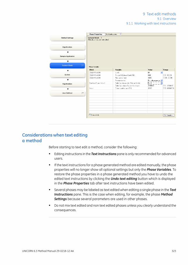
Considerationswhen text editinga method
Before starting to text edit a method, consider the following:
• Editing instructions in the Text Instructions pane is only recommended for advancedusers.
• If the text instructions for a phase generated method are edited manually, the phaseproperties will no longer show all optional settings but only the Phase Variables. Torestore the phase properties in a phase generated method you have to undo theedited text instructions by clicking the Undo text editing button which is displayedin the Phase Properties tab after text instructions have been edited.
• Several phases may be labeled as text edited when editing a single phase in the TextInstructions pane. This is the case when editing, for example, the phase MethodSettings because several parameters are used in other phases.
• Do not mix text edited and non text edited phases unless you clearly understand theconsequences.
UNICORN 6.3 Method Manual 29-0218-12 AA 323
9 Text edit methods9.1 Overview
9.1.1 Working with text instructions

9.1.2 The Text Instructions pane
IntroductionThis section gives an overview of the Text Instructions pane in the Method Editor andthe structure of a text method.
Illustration of the TextInstructions pane
The Text Instructions pane consists of two areas, the Text Instructions area and theInstruction Box.
The illustration below shows the Method Editor window when creating a method for asystem that allows phase generated methods. The Text Instructions tab is selected. Thephase Equilibration is selected in the Text Instructions area and the correspondingphase is highlighted in blue in the Method Outline and the Gradient panes.
2
1
The table below describes the different areas in the Text Instructions pane:
324 UNICORN 6.3 Method Manual 29-0218-12 AA
9 Text edit methods9.1 Overview9.1.2 The Text Instructions pane

DescriptionArea
Text Instructionsarea: Shows the method as a list of individual text instruc-tions. The instructions are grouped into blocks (denoted by blue squaresymbols in the figure below) to obtain a logical overview of the method.
1
Instruction Box: Shows the available instructions. It can be displayed usingthe Auto Hide function (see Auto Hide optional panes, on page18 for moreinformation).
2
Use the Instruction Box to:
• insert, change, replace and delete blocks and instructions in the method
• delete phases
• specify breakpoints, parameters and variables
Note:
It is not possible to add phases using the Instruction Box. For informationabout how to add phases, see Section 3.6.1 Edit the method outline, onpage 75.
Structure of the text methodA method in the Text Instructions area consists of a Main block that contains the Baseinstruction (mandatory) and the appropriate phases and blocks to be used in the method.Blocks containing valid instructions are denoted by blue square symbols (for a descriptionof other icons that may appear, see Description of icons and text formats in the textmethod, on page 327).
Structuring the method into blocks enables reuse of instructions in the method. It alsomakes it possible to perform a sequence of instructions using watches (see Section9.3.3Watch instructions, on page 366 for more information about watch instructions).
The illustration below shows an example of a phase generated method in the Text In-structions area:
UNICORN 6.3 Method Manual 29-0218-12 AA 325
9 Text edit methods9.1 Overview
9.1.2 The Text Instructions pane
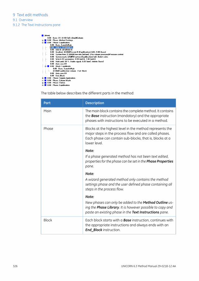
The table below describes the different parts in the method:
DescriptionPart
The main block contains the complete method. It containsthe Base instruction (mandatory) and the appropriatephases with instructions to be executed in a method.
Main
Blocks at the highest level in the method represents themajor steps in the process flow and are called phases.Each phase can contain sub-blocks, that is, blocks at alower level.
Note:
If a phase generated method has not been text edited,properties for the phase can be set in the Phase Propertiespane.
Phase
Note:
A wizard generated method only contains the methodsettings phase and the user defined phase containing allsteps in the process flow.
Note:
New phases can only be added to theMethod Outline us-ing the Phase Library. It is however possible to copy andpaste an existing phase in the Text Instructions pane.
Each block starts with a Base instruction, continues withthe appropriate instructions and always ends with anEnd_Block instruction.
Block
326 UNICORN 6.3 Method Manual 29-0218-12 AA
9 Text edit methods9.1 Overview9.1.2 The Text Instructions pane

DescriptionPart
A sub-block is a block at a lower level than a phase thatmay contain conditional instructions or other instructionsfor specific events within a phase.
Sub-block
Each sub-block starts with a Base instruction, continueswith the appropriate instructions and always ends withan End_Block instruction.
Description of icons and textformats in the text method
The table below describes the icons and text formats that may appear in the Text In-structions pane:
DescriptionIcon/text format
A block containing instructions that can be run.Blue square beside text
A block containing one or more instructions that are notpossible to run due to instrument configuration incompat-ibility (syntax errors).
Blue square with a redcross
Instructions that can be run.Bold text
Instructions that are not possible to run. All such instruc-tions must be deleted or changed before a method canbe run. See Section 9.2.3 Working with text instructions,on page 342.
Red dot
The errors in the instructions may be of the following types:
• Instructions that apply to a different instrument con-figuration (can occur if a method is written for onesystem and saved for another).
• Instructions for deselected components in the SystemSetup.
• References to blocks that are not defined in themethod (e.g., a Watch instruction but no instructionsto be executed when the Watch is activated).
UNICORN 6.3 Method Manual 29-0218-12 AA 327
9 Text edit methods9.1 Overview
9.1.2 The Text Instructions pane
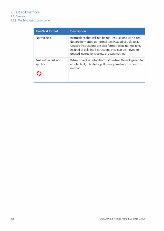
DescriptionIcon/text format
Instructions that will not be run. Instructions with a reddot are formatted as normal text instead of bold text.Unused instructions are also formatted as normal text.Instead of deleting instructions they can be moved tounused instructions below the text method.
Normal text
When a block is called from within itself this will generatea potentially infinite loop. It is not possible to run such amethod.
Text with a red loopsymbol
328 UNICORN 6.3 Method Manual 29-0218-12 AA
9 Text edit methods9.1 Overview9.1.2 The Text Instructions pane

9.2 Working with methods in the Text Instructions pane
IntroductionThis section describes how to create or edit methods using specific text instructions. Thegeneral structure of the text method syntax is described, including the major hierarchyof the text method parts (phases and blocks).
In this sectionThis section contains these sub-sections:
See pageSection
3309.2.1 Base instruction
3349.2.2 Working with phases and blocks
3429.2.3 Working with text instructions
3489.2.4 Method variables
UNICORN 6.3 Method Manual 29-0218-12 AA 329
9 Text edit methods9.2 Working with methods in the Text Instructions pane

9.2.1 Base instruction
IntroductionEvery method block must start with a Base instruction, defining the base for calculatingbreakpoints (see also Structure of the textmethod, on page325). Different blocks can usedifferent bases.
This section describes how to choose and edit settings for the Base instruction.
What base should I use?Depending on the experiment, different bases should be used. Use the base that mostclosely suits the purpose of the block. Column volume (CV) is recommended as the basefor most steps in a run. In some situations, however, it may be more suitable to use atime or volume base for individual blocks.
The table follows lists few examples when different bases should be used:
When...Use...
the method should be adjusted according to the selectedcolumn. In this way, you do not need to edit the methodwhen changing column size.
CV
the same volume should be used regardless of whichcolumn is used.
Volume
a defined time is required and the volume used is notcritical, or if the flow rate is zero.
Time
330 UNICORN 6.3 Method Manual 29-0218-12 AA
9 Text edit methods9.2 Working with methods in the Text Instructions pane9.2.1 Base instruction

Edit settings for a baseinstruction
The following table describes how to edit settings for a base instruction:
ActionStep
Select the base instruction for which to edit the settings in the Text Instruc-tions area.
1
Result:
• The settings for the selectedBase instruction are displayed in theParam-eters for Base area in the Instruction Box.
• If a Base instruction in a phase or block was selected using the sameparameter settings as theMain block, this is displayed in the InstructionBox.
• Select the appropriate Base from the Base drop-down list:
- Volume (the unit depends on which Instrument Configurationused)
- Time (minutes)
- CV, column volume (the corresponding volume in for example mlcan be defined numerically or taken from the Column Type list)
- SameAsMain (does not apply for the main block). The block will inheritthe base defined in the main block.
Result: The settings in the Parameters for Base area are updated.
2
UNICORN 6.3 Method Manual 29-0218-12 AA 331
9 Text edit methods9.2 Working with methods in the Text Instructions pane
9.2.1 Base instruction

ActionStep
Select the appropriate Column Type in the drop-down list.3
The table below gives a short descriptions of the available options:
DescriptionColumn parameter
Any column can be used in the block.
If the Column Type is set to Any and the Base isset toCV, enter the column volume in theVolumefield.
Any
The same column as in the main block will beused.
When the Base is set to Volume but the flow stillgoes through the column, the Column Type canbe set to SameAsMain to provide information on,for example, pressure limits for the column.
ColumnSameAs-Main
The named column type will be used in the block.
The volume specified in the selected column def-inition will automatically be used for Volume pa-rameter in the method block, and thus used tocalculate column volumes (CV). The Volume pa-rameter may then not be edited manually.
The Column Type parameter can be defined as avariable. This may be useful if it is desirable tochange column type when starting the methodrun in the Variable List during the Start Protocol(see Set up a Start Protocol, on page 88).
See Section 9.2.4 Method variables, on page 348for information about how to define variables.
Named columntype (e.g., HiTrap QHP, 1 ml)
332 UNICORN 6.3 Method Manual 29-0218-12 AA
9 Text edit methods9.2 Working with methods in the Text Instructions pane9.2.1 Base instruction

ActionStep
ClickChangeorReplace to save the settings for the selectedBase instruction.4
Result: The parameters for the Base instruction are updated.
Note:
If the column type is changed, the Column Value Update warning dialogopens, displaying the changes that will be made in the methods, based onthe column default values (see diagram below). If these changes are correct,click OK, otherwise click Cancel.
UNICORN 6.3 Method Manual 29-0218-12 AA 333
9 Text edit methods9.2 Working with methods in the Text Instructions pane
9.2.1 Base instruction

9.2.2 Working with phases and blocks
IntroductionThis section describes how to add, delete and edit phases and blocks in the text method.It also describes how to import blocks from other methods.
Phases vs blocksBecause phases are blocks at the highest level in the text method, the same editing op-erations can be performed. In this section the name block will be used both for phaseblocks and other blocks unless otherwise stated.
ExceptionIt is not possible to add a phase using the Instruction Box. A new phase must be addedfrom the Phase Library. The User Defined phase is intended for this purpose, but anyphase may be text edited.
See Section 3.6.1 Edit the method outline, on page 75 for information about how to addphases to the Method Outline.
Method blocksInstructions in each block are executed in the order they are written. The instructionswithin a block are executed until the block is finished or the End_Block instruction isexecuted. Any settings made in a block are valid throughout the method until the settingsare changed.
However, if a conditional instruction, e.g., a Watch instruction controlling the start of asub-block, is included in a phase the instructions in the sub-block are executed whenthe condition for thatWatch is met (e.g., when a particular monitor signal meets a givencondition).
Block lengthThe length of a block is determined by the breakpoint of the last instruction in the block.Even if all breakpoints are set to 0, the instructions might take some time/volume becausethey are executed sequentially.
The illustration below shows an example of a method where Equilibration has abreakpoint set to 5:
334 UNICORN 6.3 Method Manual 29-0218-12 AA
9 Text edit methods9.2 Working with methods in the Text Instructions pane9.2.2 Working with phases and blocks

In the example above, the value 5.00 will be 5 column volumes (CV) if the Base in theMain block is set to CV, 5 minutes if Base is set to Time or 5 ml if Base is set to Volume.
To extend the length of a block without performing any other operation, set the breakpointof the End_block instruction appropriately, for example, as in the illustration below:
In this example, the block will end after 0.5 ml, since Base is set to Volume.
An estimation of the time for running the method can be obtained in theMethodDurationand Variables window. See View and print the method duration time and variables, onpage 95.
View/hide instructions in blocksThe table below describes how to view or hide blocks and instructions in the Text Instruc-tions pane:
then...If you want to...
double-click Mainexpand all blocks in themethod
• click the “+” symbol
or
• double-click the block name.
view the instructions ina block
UNICORN 6.3 Method Manual 29-0218-12 AA 335
9 Text edit methods9.2 Working with methods in the Text Instructions pane
9.2.2 Working with phases and blocks

then...If you want to...
• click the “-” symbol
or
• double-click the block name.
hide the instructions ina block
Add phasesPhases can be added to a text method by:
• adding any phase to the method from the Phase library. The phase User Defined isdesigned for use in creating text methods from scratch, and consists only of Baseand End_block instructions. See Section 3.6.1 Edit the method outline, on page 75for information about how to add a phase to the Method Outline.
or
• by copying/pasting an existing phase in the text method and then edit it. See Copyand paste blocks, on page 337 for information about how to copy and paste blocks.
It is not possible to add a new phase using the Instruction Box.Note:
Add blocks in a phaseThe table below describes how to add blocks in a phase:
ActionStep
Select the instruction or block after which you want to insert the new block.1
Select Other:Block in the Instruction Box.2
• Enter a name for the block in the Block field.
• Click the Insert button.
Result: The block is inserted after the block that was selected in step 1.
3
336 UNICORN 6.3 Method Manual 29-0218-12 AA
9 Text edit methods9.2 Working with methods in the Text Instructions pane9.2.2 Working with phases and blocks

Copy and paste blocksThe table below describes how to copy and paste a block.
ActionStep
Select the block you want to copy.1
• click the Copy icon in the Toolbar
or
• right-click the block and choose Copy
or
• select Edit:Copy (Ctrl+C)
Select the instruction line just above the point where you want the block tobe pasted.
2
• click the Paste icon in the Toolbar
or
• right-click the instruction line and choose Paste
or
• select Edit:Paste (Ctrl+V)
Result: A Rename dialog opens.
• Click Yes to rename the block after insertion
A new block is created. The variables in the block will get new names sothe variable values can be changed without affecting the original block.
or
• Click No to just insert the copied block with the same name.
The block and variables names in the block are copied. If changingvariable values in the pasted block, the values will be changed in theoriginal block as well.
Result: The block is inserted in position.
Note:
The pasted block is inserted with the same breakpoint value as the block orinstruction selected for point of insertion.When a Phase is copied and pastedthe Rename dialog is not opened.
3
UNICORN 6.3 Method Manual 29-0218-12 AA 337
9 Text edit methods9.2 Working with methods in the Text Instructions pane
9.2.2 Working with phases and blocks

Import blocksThe table below describes how to import blocks from other methods:
ActionStep
Click the Import Block... button.1
Result: The Import Block dialog opens.
Locate and select the method you wish to import the block from in theMethod folder structure.
2
Result: All available blocks are listed in the Select block field.
Select a block to import from the method in the Select block list.3
• Select the block where the imported block will be inserted in the Callfrom drop-down list.
• Type the breakpoint that the imported block will be called at in the Callat text box.
• If necessary, type a new name for the block in the Block name text box(optional).
4
338 UNICORN 6.3 Method Manual 29-0218-12 AA
9 Text edit methods9.2 Working with methods in the Text Instructions pane9.2.2 Working with phases and blocks

ActionStep
• Click the Import button.
• Confirm if you also want to import sub-blocks (if any)
Result: The block is imported into the method you are editing. Unless youhave specified a breakpoint that is earlier, the block will be inserted at theend of the block that it is called from.
Note:
If you are importing a block with the same name as a block that already isincluded in the method you are editing, a warning will open and you will beasked to confirm that you wish to replace the original block with that namein the method.
5
Move blocksBlocks can be moved by drag and drop within the method. You can also use Cut andPaste as described below:
ActionStep
Select the block you want to move.1
• click the Cut icon in the Toolbar
or
• right-click the block and choose Cut
or
• select Edit:Cut
UNICORN 6.3 Method Manual 29-0218-12 AA 339
9 Text edit methods9.2 Working with methods in the Text Instructions pane
9.2.2 Working with phases and blocks

ActionStep
Select the instruction line just above the point where you want the block tobe moved.
2
• click the Paste icon in the Toolbar
or
• right-click the instruction line and choose Paste
or
• select Edit:Paste
Result: The block is now removed from its original breakpoint and pasted atthe new breakpoint.
Note:
The pasted block is inserted with the same breakpoint value as the block orinstruction selected for point of insertion.
Rename blocksThe table below describes how to rename a block:
ActionStep
Right-click the block in the text pane and select Rename.1
Result: The block name is highlighted in a box.
340 UNICORN 6.3 Method Manual 29-0218-12 AA
9 Text edit methods9.2 Working with methods in the Text Instructions pane9.2.2 Working with phases and blocks

ActionStep
Type in a new name.
Note:
If the block you renamed is called in a Block orWatch instruction, the blockname in these instructions will be changed automatically.
2
Delete blocksThe table below describes how to delete a block:
ActionStep
• Right-click a block and choose Delete.
or
• Select a block and click Delete in the Instruction box.
or
• Select a block and press the Delete key on the keyboard.
Result: A dialog will appear asking if the block should be deleted permanentlyor moved to unused blocks.
1
Note:
If deleting a phase, the phase will be deleted right away.
• Click Delete to delete the block permanently.
• Click Move to <Unused> to delete the block from the method and placeit after the method.
2
UNICORN 6.3 Method Manual 29-0218-12 AA 341
9 Text edit methods9.2 Working with methods in the Text Instructions pane
9.2.2 Working with phases and blocks

9.2.3 Working with text instructions
IntroductionInstead of editing the method in the Phase Properties pane, instructions may be editedone at a time in the Text Instructions pane. The instructions in a block are always exe-cuted sequentially. This section describes the general principles for how to edit instruc-tions.
Help texts for the instructionsIt is possible to display help texts for the instructions that can be inserted in the Instruc-tion Box.
The table below describe how to display the help text for an instruction:
ActionStep
In the Instruction Box, select the appropriate instruction for which to displayhelp text.
1
Press F1 on the keyboard.2
Result: A dialog with help text for the selected instruction will be displayed.
Insert a new instructionThe table below describes how to insert a new text instruction in the Text Instructionsarea:
ActionStep
Select a block and display the instructions within the block.1
Select the instruction in the block after which you want to add the new in-struction.
2
342 UNICORN 6.3 Method Manual 29-0218-12 AA
9 Text edit methods9.2 Working with methods in the Text Instructions pane9.2.3 Working with text instructions

ActionStep
Open the Instruction Box if it is hidden. Do the following:3
• Set the appropriate breakpoint in the Breakpoint box.
• Choose the instruction type and the instruction in the Instructions field.For basic help on each instruction, select the instruction and press F1.
• Type values for instruction parameters in the Parameters text boxes.
The allowed range is shown in brackets beside the text box. If a scrollbar appears at the right side of the Parameters field, additional param-eters are available.
Click the Insert button.4
Result: The instruction will be inserted in the block:
• at the position of the breakpoint of the new instruction, if there are noother instructions at that breakpoint
• immediately after the currently highlighted instruction, if the highlightis at the same breakpoint as the new instruction
• as the last instruction at the breakpoint, if there are several instructionsat the same breakpoint and none of these is highlighted.
Once a phase generated method has been edited in text editing mode, thephases affected by the edited instruction are indicated with the letter "T", andthe Phase Properties pane changes to show a variable list, as shown below.For a phase generated method you can click the Restore Phase Propertiesbutton to return themethod to the state before the text edit. Any changes thatwere made in the Text Instructions pane will be removed.
Note:
New phases from the Phase Librarymay be inserted in the method after textediting and the settings for these new phases can be edited in the PhaseProperties pane or Text Instructions pane.
UNICORN 6.3 Method Manual 29-0218-12 AA 343
9 Text edit methods9.2 Working with methods in the Text Instructions pane
9.2.3 Working with text instructions

Changeor replace an instructionThe table below describes how to edit instructions in the Text Instructions area:
ActionStep
Select an instruction in the text method.1
Result: The current Breakpoint and parameters for the selected instructionis displayed in the Instruction Box.
Edit or select parameter values in the Instruction Box:2
344 UNICORN 6.3 Method Manual 29-0218-12 AA
9 Text edit methods9.2 Working with methods in the Text Instructions pane9.2.3 Working with text instructions

ActionStep
To add the edited or a new instruction to the method, click one of the follow-ing buttons:
3
• Insert
• Change
• Replace
Note:
The Insertbuttonadds the edited instruction immediately below the instructionthat was selected in the method.
The Change and Replace buttons are equivalent unless changes are madeto the breakpoint or gradient length. Both buttons replace the highlighted in-struction with the newly edited instruction. The differences are explained be-low.
Effects of theChangebutton andthe Replace button onbreakpoints
The table below describes the difference in function between the Change and Replacebuttons when changing breakpoints:
FunctionButton
This button shifts all subsequent instructions in the blockaccording to the change in the breakpoint. Change doesnot affect the relative order of instructions in the method.You cannot change the breakpoint of an instruction toearlier than the nearest previous breakpoint in a block.
Change
This button moves the selected instruction but does notchange the breakpoint of any other instruction. Replacecan change the relative order of instructions in themethod.
Replace
UNICORN 6.3 Method Manual 29-0218-12 AA 345
9 Text edit methods9.2 Working with methods in the Text Instructions pane
9.2.3 Working with text instructions

Effects of theChangebutton andthe Replace button on gradientlength
The Length parameter in the Gradient instruction affects the length of a gradient. Thechange will have different results depending on which button is used. The table belowdescribes this:
FunctionCommand
If this button is used to change the length of a gradient,the breakpoints for any instructions issued during theprogress of the gradient will be adjusted proportionatelyso that they are always placed at the same relative posi-tion within the gradient. Instructions issued after the endof the gradient will be shifted by the amount of thechange. Since the gradient works over time, any instruc-tion that you want to insert after a gradient should beplaced after the combined breakpoint and gradient length.
Note:
Moving the End_block instruction in a gradient block withthe Change button does not affect the length of the gradi-ent.
Change
If this button is used to change the length of a gradient,other instructions are not affected.
Replace
Move instructionsA selected instruction may be dragged-and-dropped in a new location to change theorder of instructions. The symbol shown in the illustration below will be displayed if theinstruction cannot be dropped in a specific location.
346 UNICORN 6.3 Method Manual 29-0218-12 AA
9 Text edit methods9.2 Working with methods in the Text Instructions pane9.2.3 Working with text instructions

Delete instructionsThe table below describes how to delete method instructions in the Text Instructionspane:
ActionStep
Select the instruction in the Text Instructions pane.1
• Right-click the instruction and choose Delete.
or
• Click the Delete button in the Instruction box.
or
• Press the Delete key on your keyboard.
2
End_Block instructionIf you delete the End_Block instruction, the block will end at the last instruction in theblock. If a gradient is currently being formed, the gradient will continue into the nextblock.
UNICORN 6.3 Method Manual 29-0218-12 AA 347
9 Text edit methods9.2 Working with methods in the Text Instructions pane
9.2.3 Working with text instructions

9.2.4 Method variables
IntroductionVariables are used when you want to vary parameter values in a method. Variables mustbe defined when you want to:
• perform scouting and Design of Experiments (DoE) where different parameters arevaried to find, for example, optimal settings for a process.
SeeChapter4 Scouting, on page131andChapter5Design of Experiments, on page144for more information.
• change parameter values in the Start Protocol immediately before the start of amethod run without using the Method Editor, allowing one method to be used forruns under a variety of conditions. Each parameter defined as a variable is assigneda default value, which is used if no changes are made to variable values at the startof a run.
Viewing method variablesAll variables in a method are listed on the Variable List tab in the Method and Durationdialog, grouped according to the phase and block in which they appear. For informationabout how to view the variables in a method, see View and print the method durationtime and variables, on page 95 for more information.
If a method has been text edited or created using the wizard the phase variables for theselected phase will be displayed in the Phase Properties pane. If the Method Settingsphase has been edited, some additional parameters will also be displayed. It is possibleto edit variable names, values and the other settings displayed in the Phase Propertiespane.
348 UNICORN 6.3 Method Manual 29-0218-12 AA
9 Text edit methods9.2 Working with methods in the Text Instructions pane9.2.4 Method variables

Identifying variables in the TextInstructions area
Parameters that are defined as variables in the text method are indicated in the TextInstructions area.
The parameter is given as the default value in parentheses followed by the variablename. The illustration below shows an example of this:
For example, in (1.000)#Flow rate {ml/min}:
• (1.000) is the default value for the variable
• {ml/min} is the variable unit
• Flow rate is the variable name
UNICORN 6.3 Method Manual 29-0218-12 AA 349
9 Text edit methods9.2 Working with methods in the Text Instructions pane
9.2.4 Method variables

Identifying variables in theInstruction Box
Parameters that are defined as variables in the text method are also indicated in theInstruction Box for the selected instruction in the Text Instructions area.
When the instruction is shown in the Instructions field of the Instruction box, the VAR...button beside the parameter field is displayed in capital letters for variables (that is:VAR... not Var...).
Variable name conventionsVariables are defined with names that can be explicit descriptions of the variable function,for example Sample volume and Gradient length. Suitable choices of variable namescan make the method easier to read and understand, and also help the operator insetting variable values at the start of a method run.
When defining and/or renaming variables, consider the following:
• The names can be up to 50 characters long and the following characters can beused:
- Letters (A-Z)
- Digits (0-9)
- The underscore character (_)
- The Space character
• The case of letters is retained, but not significant. The names Flow Rate and FLOWRATE are treated as identical.
For information about defining and renaming variables, see Define new variables, onpage 351 and Edit variables, on page 353.
350 UNICORN 6.3 Method Manual 29-0218-12 AA
9 Text edit methods9.2 Working with methods in the Text Instructions pane9.2.4 Method variables

Define new variablesOnly one variable that affects block length (breakpoint or gradient length) may be definedwithin each block. However, any number of parameters may be defined as variableswithin a block. The table below describes how to define a new variable.
ActionStep
Select the instruction where you want to define the variable in the Text In-structions area.
1
Result: The parameters for the instruction are shown in the Instruction box.
UNICORN 6.3 Method Manual 29-0218-12 AA 351
9 Text edit methods9.2 Working with methods in the Text Instructions pane
9.2.4 Method variables
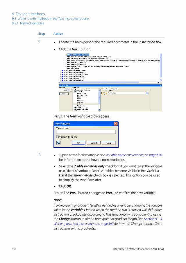
ActionStep
• Locate the breakpoint or the required parameter in the Instruction box.
• Click the Var... button.
Result: The New Variable dialog opens.
2
• Type a name for the variable (seeVariable name conventions, on page350for information about how to name variables).
• Select the Visible in details only check box if you want to set the variableas a "details" variable. Detail variables become visible in the VariableList if the Show details check box is selected. This option can be usedto simplify the workflow later.
• Click OK.
Result: The Var... button changes to VAR... to confirm the new variable.
Note:
If a breakpoint or gradient length is defined as a variable, changing the variablevalue in the Variable List tab when the method run is started will shift otherinstruction breakpoints accordingly. This functionality is equivalent to usingthe Change button to alter a breakpoint or gradient length (see Section9.2.3Workingwith text instructions, on page342 for how theChange button affectsinstructions within gradients).
3
352 UNICORN 6.3 Method Manual 29-0218-12 AA
9 Text edit methods9.2 Working with methods in the Text Instructions pane9.2.4 Method variables

ActionStep
Click Change.4
Result: The variable is saved and displayed in the Text Instructions area.
Edit variablesEditing a variable includes renaming and deleting the variable and choosing whetherthe variable should be a detailed variable or not. For information about how to edit thevariable values, see Edit variable values, on page 357.
Edit a variable using the Edit variable buttonThe table below describes how to edit a variable using the Edit Variable button:
UNICORN 6.3 Method Manual 29-0218-12 AA 353
9 Text edit methods9.2 Working with methods in the Text Instructions pane
9.2.4 Method variables

ActionStep
• In the Instruction Box, click Edit Variable....
• Alternatively, if the phase containing the variable has been text edited,select the Phase Properties tab to display the phase variables, selectthe variable and click Edit Variable....
Result: The Edit Variable dialog opens displaying all variables (if openedfrom the Text Instructions pane) or the phase variables (if opened from thePhase Properties tab).
1
354 UNICORN 6.3 Method Manual 29-0218-12 AA
9 Text edit methods9.2 Working with methods in the Text Instructions pane9.2.4 Method variables

ActionStep
Select the variable to be edited (if not already selected). Do one or severalof the following as appropriate:
2
• Type in a new name in the New name field and click Rename.
• Check the Set visible in details only if the variable should be a detailedvariable. Uncheck the box to set it to a normal variable.
• Click Delete to delete the variable.
Confirm that you want to delete the variable in the dialog that appears.
Click Close to close the dialog.3
Edit a variable using the VAR.. button in the Instruction BoxThe table below describes how to edit a variable using the Instruction Box:
UNICORN 6.3 Method Manual 29-0218-12 AA 355
9 Text edit methods9.2 Working with methods in the Text Instructions pane
9.2.4 Method variables

ActionStep
Select the instruction containing the variable to be edited in the Text Instruc-tions area.
1
Result: The parameters for the instruction are shown in the Instruction box.
Click the VAR... button for the appropriate variable.2
Result: The Edit Variable dialog opens.
Do one or several of the following as appropriate:3
• Type in a new name in the Variable name field.
• Check the Visible in details only if the variable should be a detailedvariable. Uncheck the box to set it to a normal variable.
• Click Clear to delete the variable.
Click OK.4
To save the changes, click Change in the Instruction Box.5
Result: The text instruction is updated.
356 UNICORN 6.3 Method Manual 29-0218-12 AA
9 Text edit methods9.2 Working with methods in the Text Instructions pane9.2.4 Method variables

Edit variable valuesTo edit default variable values, you can either
• edit the value in the Phase Properties tab if the text method has been edited.
or
• edit the instruction in the Instruction box of the Text Instructions.
Changes made in the Phase Properties tab are automatically updated on the Text In-structions tab and vice versa.
Edit variable values in the phase variables listIf the phase containing the variable value to be edited has been text edited, it is possibleto edit the variable value on the Phase Properties tab. The table below describes howto edit variable values in the Phase Properties tab for a text edited phase:
ActionStep
Select the Phase Properties tab to display the Phase Variables list.1
Change the variable value for the appropriate variable in the Value field bychoosing a new value in the drop-down list or typing in the field.
Tip:To show detailed variables, check the Show details box.
2
Result: The variable value is updated.
Repeat this procedure for the appropriate variables.3
Edit variable values in the Instruction BoxThe table below describes how to edit variable values in the Instruction Box:
UNICORN 6.3 Method Manual 29-0218-12 AA 357
9 Text edit methods9.2 Working with methods in the Text Instructions pane
9.2.4 Method variables

ActionStep
Select the instruction containing the variable value to be edited in the TextInstructions area.
1
Result: The parameters for the instruction are shown in the Instruction box.
Change the value for the appropriate variable(s) (indicated by VAR...).2
Click Change.3
Result: The settings are saved and the text instruction updated in the TextInstructions area.
358 UNICORN 6.3 Method Manual 29-0218-12 AA
9 Text edit methods9.2 Working with methods in the Text Instructions pane9.2.4 Method variables

9.3 Specific instructions
IntroductionThis section describes some text instruction applications, for example:
• Gradient instructions
• Alarms
• Conditional instructions
• Messages, set marks, pause and hold instructions
In this sectionThis section contains these sub-sections:
See pageSection
3609.3.1 Gradients and eluent concentrations
3639.3.2 Alarm instructions
3669.3.3 Watch instructions
3739.3.4 Pause or hold a method
3769.3.5 Messages and Set marks
UNICORN 6.3 Method Manual 29-0218-12 AA 359
9 Text edit methods9.3 Specific instructions

9.3.1 Gradients and eluent concentrations
IntroductionGradient instructions allow definition of an A- and B-buffer mix. The starting point forthe Gradient is always the current eluent composition. The instruction can be read asfollows: “form a Gradient to reach Target after Length”. Linear gradients and step gra-dients can be created using Gradient instructions.
Gradient instructions are given in the Text Instructions editor of theMethod Editor. Thistype of instruction defines gradients and immediate changes in eluent concentration.
Linear gradientsA gradient can be defined as a linear gradient. The eluent composition changes linearlyover time.
Example of instruction10.00 Gradient 50{%B}, 20{base}
The example instruction above forms a gradient to 50%B (Target) starting at breakpoint10 with duration 20 method base units (Length). The example instruction will finish atbreakpoint 30. If the current eluent concentration is greater than 50%, the gradient willbe negative.
Step gradientsA gradient can be defined in several steps. A step gradient is an immediate change ineluent composition. To form a step gradient, set the Length parameter to 0 in the Gra-dient instruction.
Example of instruction10.00 Gradient 50{%B}, 0{base}
The example instruction above forms a step from the current eluent composition to50%B at breakpoint 10. The method continues with 50%B.
360 UNICORN 6.3 Method Manual 29-0218-12 AA
9 Text edit methods9.3 Specific instructions9.3.1 Gradients and eluent concentrations

Insert aGradient text instructionThe table below describes how to insert a Gradient instruction:
ActionStep
At a suitable Breakpoint in the method, select the instruction line immedi-ately before where you want to insert the gradient (this decides when thegradient begins).
1
• Expand the Pumps and pressures item in the Instructions field of theInstruction Box.
• Select Gradient.
• In the Parameters for Gradient field, select appropriate values for:
- Target (final eluent composition expressed in % eluent B)
- Length (duration of the gradient)
Tip:
To form a step gradient, set the Length parameter to zero.
Tip:
For many purposes, it can be useful to define the length of the gradientas a variable. When this is done, breakpoints for instructions issuedduring or after the gradient in the same block are automatically shiftedin proportion to the length of the gradient when the variable value ischanged. This is the same functionality as theChange button commandin the Instruction Box.
2
UNICORN 6.3 Method Manual 29-0218-12 AA 361
9 Text edit methods9.3 Specific instructions
9.3.1 Gradients and eluent concentrations

ActionStep
Edit the Breakpoint for the gradient, if appropriate.
Note:
The breakpoint for aGradient instruction defines the time or volume (accord-ing to method base) for the start of the gradient. A gradient with a non-zeroduration occupies time and volume in the method, and breakpoints for otherinstructionsmay be set to occur before the gradient is completed. The instruc-tion is simply carried out at the requested breakpoint, while the gradient isforming.
3
Click the Insert button.4
Result: The new Gradient instruction is inserted in the method in the TextInstructions area.
Instruction after a gradientAny instruction that you want to insert after a gradient should be placed after the com-bined breakpoint and gradient length, since gradients function over time.
Instructions that affect gradientsThe table below describes the instructions that affect the gradient:
EffectInstruction
A new gradient will start at the requested breakpoint. Theremaining duration of any previous gradient is ignored.
Gradient
The eluent flow rate will change at the requested break-point. If the current base is volume or column volume, theduration of the gradient will be changed. If the methodbase is time, the volume of the gradient will be changed.
Note:
If the flow is changed, the slope of the gradient will alsochange.
Flow
The gradient formation will continue uninterrupted unlessa new Gradient instruction is issued. For example, thismeans that a block can be called conditionally duringgradient formation without interrupting the gradient.
End_Block
362 UNICORN 6.3 Method Manual 29-0218-12 AA
9 Text edit methods9.3 Specific instructions9.3.1 Gradients and eluent concentrations

9.3.2 Alarm instructions
IntroductionThis section is a description of how alarms work in UNICORN and of the Alarms text in-structions. It also describes the differences between Alarms and Warnings.
Alarms and WarningsTheAlarms parameter settings define the high and lowAlarm limits for process monitorsignals. You can define these limits either in the system settings or as part of a method.Settings in the method will override the system settings.
The limits that will generate a Warning from the system are defined in the instrumentconfiguration files and you cannot edit these settings.
Conditions can also be applied to process monitor signals such that a block of instructionswill execute when a particular condition is satisfied (for example, when the absorbanceof the eluent exceeds a certain limit). This is done using Watch instructions which aredescribed in Section 9.3.3 Watch instructions, on page 366.
The table below describes the general difference between Alarms and Warnings.
then...If the signal exceeds...
• an alarm sounds
Note:
The alarm can be disconnected in System Settings.
• an alarm message is displayed
• the process is paused (i.e., the method execution issuspended and all pumps are stopped)
• the alarm is noted in the Run log.
The situation must be acknowledged and corrected beforethe process can be continued.
Alarm limits
• a warning message is displayed
• the process continues
• the warning is noted in the Run log.
Warning limits
The Alarms are not active unless the mode is set to Enabled.Note:
UNICORN 6.3 Method Manual 29-0218-12 AA 363
9 Text edit methods9.3 Specific instructions9.3.2 Alarm instructions
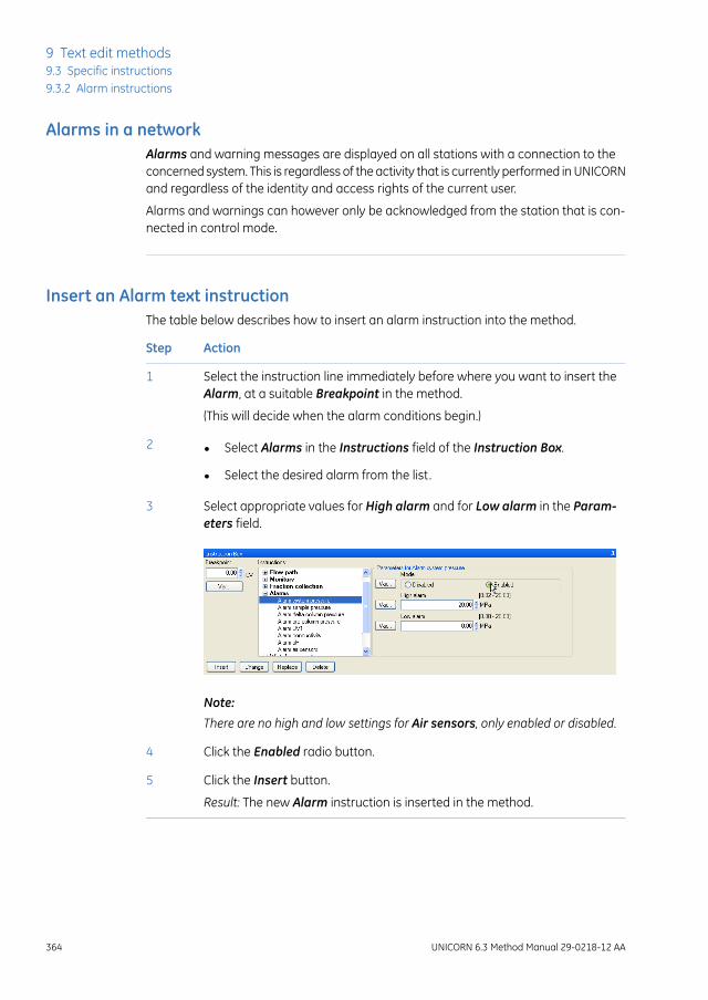
Alarms in a networkAlarms and warning messages are displayed on all stations with a connection to theconcerned system. This is regardless of the activity that is currently performed in UNICORNand regardless of the identity and access rights of the current user.
Alarms and warnings can however only be acknowledged from the station that is con-nected in control mode.
Insert an Alarm text instructionThe table below describes how to insert an alarm instruction into the method.
ActionStep
Select the instruction line immediately before where you want to insert theAlarm, at a suitable Breakpoint in the method.
1
(This will decide when the alarm conditions begin.)
• Select Alarms in the Instructions field of the Instruction Box.
• Select the desired alarm from the list.
2
Select appropriate values for High alarm and for Low alarm in the Param-eters field.
3
Note:
There are no high and low settings for Air sensors, only enabled or disabled.
Click the Enabled radio button.4
Click the Insert button.5
Result: The new Alarm instruction is inserted in the method.
364 UNICORN 6.3 Method Manual 29-0218-12 AA
9 Text edit methods9.3 Specific instructions9.3.2 Alarm instructions

Available alarmsThe alarms available depend on the instrument configuration. Alarms for the followingmonitor readings may be set:
• System pressure
• Sample pressure
• Delta column pressure
• Pre-column pressure
• UV1
• Conductivity
• pH
• Air sensors
UNICORN 6.3 Method Manual 29-0218-12 AA 365
9 Text edit methods9.3 Specific instructions9.3.2 Alarm instructions

9.3.3 Watch instructions
IntroductionWatch instructions allow the progress of a method run to be determined by eventsduring the method run. For example, start collecting fractions when the first peak elutes.
The Instrument Configuration files includeWatch instructions for each monitor definedin the system. These instructions are used to monitor method runs, and instruct thesystem to call a specified block or an instruction when a particular signal meets a givencondition. As long as the condition is not met, the block is not activated.
Watch instructions available for the instrument configuration are listed in theInstruction box.
Note:
When is a Watch active?The breakpoint when theWatch instruction is issued determines when the watch begins,not when the block is activated.
A watch is active from the point at which it is issued until:
• the Watch condition is met.
• a new watch is set for the same monitor.
• a Watch off instruction is issued for the monitor.
or
• the method ends.
Insert a Watch text instructionThe table below describes how to insert a watch instruction in the text method. Settingup additional Watch parameters is described afterwards, see Insert aWatch parametersinstruction, on page 370.
ActionStep
At a suitable Breakpoint in the method, select the instruction line immedi-ately before where you want to insert the watch (this decides when thewatch begins).
1
366 UNICORN 6.3 Method Manual 29-0218-12 AA
9 Text edit methods9.3 Specific instructions9.3.3 Watch instructions

ActionStep
• expand Watch in the Instructions field.
• select the desired Watch type:
- Hold until
Subsequent instructions in the block will execute when the conditionshave been met
- Watch
A specified action will be performed when the conditions have beenmet
- Watch off
Cancels the watch on the specified signal
2
Select a signal for the watch from the Signal drop-down menu.3
See Monitor signals to watch, on page 368 for available signals that can beselected.
For watch types Hold until or Watch, select the appropriate Parametersfor Watch:
4
• Test
See Test options in the Parameters field, on page368 for a description ofthe different Test options.
• Value/Slope/Minutes/Factor depending on the selected test
• select an appropriate Action.
SeeActionswhen aWatch condition ismet, on page369 for a descriptionof the different Watch Action options.
UNICORN 6.3 Method Manual 29-0218-12 AA 367
9 Text edit methods9.3 Specific instructions
9.3.3 Watch instructions
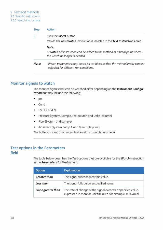
ActionStep
Click the Insert button.5
Result: The new Watch instruction is inserted in the Text Instructions area.
Note:
AWatch off instruction can be added to the method at a breakpoint wherethe watch no longer is needed.
Watch parameters may be set as variables so that the method easily can beadjusted for different run conditions.
Note:
Monitor signals to watchThe monitor signals that can be watched differ depending on the Instrument Configu-ration but may include the following:
• pH
• Cond
• UV (1,2 and 3)
• Pressure (System, Sample, Pre-column and Delta-column)
• Flow (System and sample)
• Air sensor (System pump A and B, sample pump)
The buffer concentration may also be set as a watch parameter.
Test options in the Parametersfield
The table below describes the Test options that are available for the Watch instructionin the Parameters for Watch field:
ExplanationOption
The signal exceeds a certain value.Greater than
The signal falls below a specified value.Less than
The rate of change of the signal exceeds a specified value,expressed in monitor units/minute (for example, mAU/min).
Slope greater than
368 UNICORN 6.3 Method Manual 29-0218-12 AA
9 Text edit methods9.3 Specific instructions9.3.3 Watch instructions

ExplanationOption
The rate of change of the signal falls below a specified value,expressed in, for example, mAU/min.
Slope less than
The signal falls below a specified value or a valley is detected.A valley is detected only after a Peak max has been detected,and the valley is defined by a local minimum followed by anincrease to 102% of the local minimum value plus the Deltapeak value (see The Delta peak setting, on page 371).
Less than or valley
The signal falls to a specified fraction of the most recent peakmaximum minus the Delta peak value.
Peak max
The signal is stable, within the accepted fluctuation given bythe relevantWatchparameters instruction (see Insert aWatchparameters instruction, on page 370), for the period specifiedby the minutes parameter.
Stable signal
Air sensor test parameter, explained below.Equals
In order to set a valid slope value, use the Differentiate function in the Evalu-ationmodule to measure the slope of the test chromatogram.
Note:
Actionswhen aWatch conditionis met
The selection in the Action drop-down list will determine what happens when the condi-tion of a Watch instruction is met. The table below describes the possible actions:
EffectInstruction
Calls the named block.
Note:
All availablemethod blocks are listed in alphabetical orderin the drop-down list, before the general actionswhich arelisted below.
Block name
Continues the method if paused or held.Continue
Ends the current block and return to the point from whichthe block was called.
End_block
Holds the method, the flow continues. SeeHold instruction,on page 373.
Hold
UNICORN 6.3 Method Manual 29-0218-12 AA 369
9 Text edit methods9.3 Specific instructions
9.3.3 Watch instructions

EffectInstruction
Ends the method.End_method
Indicates that the run may execute the next breakpoint.Next_breakpoint
Pauses the method, the flow is stopped. SeePause instruc-tion, on page 373.
Pause
Insert a Watch parametersinstruction
Watch parameters instructions are used to define accepted limits and fluctuations fora signal in a Watch instruction. Watch parameters instructions should therefore be in-serted just before the Watch instruction on which the limits are required.
ActionStep
Select the instruction line immediately before theWatch instruction to whichthe parameters will apply.
1
• Expand Watch parameters in the Instructions field of the InstructionBox.
• Select the desired watch parameters from the list.
• Select appropriate values for the Accepted fluctuation and Delta peak(for theWatchUVparametersandWatchcondparameters instructions)in the Parameters field.
For information about the Delta peak setting and how to use it, see TheDelta peak setting, on page 371.
2
Click the Insert button.3
Result: The new Watch parameters instruction is inserted in the method inthe text area.
370 UNICORN 6.3 Method Manual 29-0218-12 AA
9 Text edit methods9.3 Specific instructions9.3.3 Watch instructions

The Delta peak settingThe Delta peak setting in the Watch parameters helps the software to detect valleys,peaks and peak maxima, and to filter noise in the chromatogram.
The Delta peak value should be set
• large enough so that signal noise does not activate the conditions
and
• small enough so that the condition is activated close to the valley or peak.
As a general guideline, set the value to 2-3 times the noise level and 5-10% of thesmallest expected peak height. If you set a too high value you can prevent a new peakfrom being detected after a local minimum.
Use of the Delta peak settingThe Delta peak setting in the Watch parameters
• sets the threshold for signal increase after a local minimum that will be interpretedas a valley for the Less than or valley condition. A valley and a new peak are detectedwhen the signal increases to 102% of the local minimum plus the Delta peak value.
A valley is detected only after a Peak max has been detected.Note:
Example:
If there is a local minimum at 50 mAU and a Delta peak of 10 mAU, a valley will bedetected at:
(1.02 x 50) + 10 = 61 mAU
• sets the threshold for signal decrease after a local maximum that will activate thePeak max condition. Peak max is detected when the signal falls to the specifiedfraction of the most recent peak maximum minus the Delta peak value.
The schematic figure below illustrates the Delta peak setting where Peak max isdetected when the signal falls by Delta peak from a local maximum if the PeakmaxFactor is set to 1 in Watch:Watch:Parameters for Watch:
UNICORN 6.3 Method Manual 29-0218-12 AA 371
9 Text edit methods9.3 Specific instructions
9.3.3 Watch instructions

Watch test parameter for airsensors
Two Watch conditions are available for air sensors. The table below describes the con-ditions and their explanations:
ExplanationEquals
No air detected.No air
Air detected.Air
To use theWatch parameters for an air sensor, the corresponding Alarm airsensors setting must be disabled.
Note:
372 UNICORN 6.3 Method Manual 29-0218-12 AA
9 Text edit methods9.3 Specific instructions9.3.3 Watch instructions

9.3.4 Pause or hold a method
IntroductionA method can be programmed to be delayed at critical points. There are three instructionsfor this purpose: Pause, Hold and Hold until. These instructions are described below.
Pause instructionThe Pause instruction suspends execution of the method and stops the pumps so thatthe system comes to a standstill. The valves remain in the position they were in beforethe pause.
The pause may be defined as Infinite or for a specified number of minutes.
Resume the methodIt is possible to define the pause time for the method in the Pause instruction. The methodwill continue when the set time has elapsed.
The method may also be resumed if you click the Continue icon on the System Controltoolbar:
If the pause is set to Infinite, themethodmust be resumedmanually by clickingthe Continue icon.
Note:
Hold instructionThe Hold instruction suspends the execution of the method, but continues to pumpeluent at the current flow rate and concentration settings. For example, this instructionis useful for giving the operator time to load a sample loop.
Resume the methodThe method may be resumed if you click the Continue icon on the System Controltoolbar:
With the Hold instruction, the method must always be resumed manually byclicking the Continue icon.
Note:
UNICORN 6.3 Method Manual 29-0218-12 AA 373
9 Text edit methods9.3 Specific instructions
9.3.4 Pause or hold a method

Hold until instructionThe Hold until instruction is a special kind of Watch instruction. The method is put onhold until a specific condition is met (Signal, Test or Value) or the Timeout is reached.Thereafter the remaining instructions in the method are executed. See Section 9.3.3Watch instructions, on page 366 for a description of Watch instructions.
Insert a Pause, Hold orHold untilinstruction
The table below describes how to insert a Pause, Hold or Hold until instruction:
ActionStep
At a suitable Breakpoint in the method, select the instruction line immedi-ately before where you want to insert the Pause, Hold or Hold until instruc-tion (this decides when the instruction begins).
1
To insert a Hold instruction, select Other:Hold in the Instructions field ofthe Instruction Box.
2
To insert a Pause instruction, select Other:Pause and enter the Time for themethod to be paused in the Time field. To pause the method for infinite time,check the Infinite box.
3
374 UNICORN 6.3 Method Manual 29-0218-12 AA
9 Text edit methods9.3 Specific instructions9.3.4 Pause or hold a method

ActionStep
To insert a Hold until instruction:4
• select Watch:Hold until in the Instructions field of the Instruction Box
• select the appropriate parameters for the Hold until instruction in theParameters for Hold until area.
See Section9.3.3 Watch instructions, on page366 for descriptions of theavailable settings.
Click the Insert button.5
Result: The new instruction is inserted in the Text Instructions area.
Note:
Instructions that share the same breakpoint as theHold until instruction, butare placed after it in the method, will be executed after the Hold until condi-tions have been met.
UNICORN 6.3 Method Manual 29-0218-12 AA 375
9 Text edit methods9.3 Specific instructions
9.3.4 Pause or hold a method

9.3.5 Messages and Set marks
When to use a messageMessages are used to inform the operator of the progress of the run or to prompt theuser for an action. It is a good idea to issue messages at critical points in the method,for example, in combination with a Pause instruction to inform the operator that the inlettube needs to be moved to another inlet.
Insert a Message instructionThe Message instruction can be used to set up a message that will be displayed for theuser during the execution of the method run. The message can be for information in ascreen only, or it can require a signature before the user can control the system. Themessages are all added to the logbook text.
The table below describes how to add a Message instruction to the method.
ActionStep
• Select Other in the Instructions field of the Instructions box.
• Select Message in the instructions list.
1
Type a message in the Message text box in the Parameters field.2
Select one of the display options on the Mode menu:3
• Screen, that is, only a text message is displayed.
• Noscreen, that is, the message will not be displayed but only insertedinto the logbook.
• Authorize, that is, the message will require a signature from the userbefore the user can interact with the system again.
376 UNICORN 6.3 Method Manual 29-0218-12 AA
9 Text edit methods9.3 Specific instructions9.3.5 Messages and Set marks

ActionStep
• Select a sound on the Sound menu if desired.
• Click the Insert button.
4
If theMessage instruction is inserted in a conditional block it will only be dis-played if the conditions of the block (for example aWatch) is fulfilled.
Note:
When to use a Set markSet mark instructions are useful text messages. They can be used
• to highlight certain stages in a method
• to insert manual notes, for example, when a specific event occurs in a run (only inSystem Control)
Set marks differ from Messages in that they are inserted into the chromatogram at setpoints as well as into the logbook during a method run.
Example of a Set markThe illustration below shows an example where Setmarks are used to highlight the startand end of fractionation in a method:
UNICORN 6.3 Method Manual 29-0218-12 AA 377
9 Text edit methods9.3 Specific instructions
9.3.5 Messages and Set marks

Insert a Set markSet marks are inserted from the Instructions box. The table below describes how to dothis:
ActionStep
Select Other:Set mark in the Instructions field.1
Type the message in the Mark text field.2
Click the Insert button.3
Result: A new line with the Set mark is added to the text method.
378 UNICORN 6.3 Method Manual 29-0218-12 AA
9 Text edit methods9.3 Specific instructions9.3.5 Messages and Set marks

10 Troubleshooting
IntroductionThis chapter describes different problems which may arise when creating methods inUNICORN, and how to solve the problems.
The Phase Properties tab onlyshows a Phase Variables table
The table below describes how to restore the options and settings to thePhase Propertiestab:
SolutionProblem description
The phase has been edited in theText Instruc-tions tab. Click the Undo text editing buttonto return to the default settings and restorethe Phase Properties options and settings.
ThePhase Properties tab shows onlya list of variables and not the regularoptions and settings for the selectedphase. The phase is marked with theletter "T" in the method outline.
Note:
User defined phases only have a listof variables.
Note that if the text edited settings also in-volve subsequent phases and the generalMethod Settings, all these phases arechanged as well and you must restore themall individually.
Options are not available in thephase properties
The table below describes what to do if the standard settings available in the PhaseProperties for a predefined phase are not suitable for your specific application needs:
SolutionProblem description
• Add aUserDefinedphase to the methodand edit the properties in theText Instruc-tions tab
or
• Text edit the phase where the option isrequired.
Options that you need are not avail-able for selection or editing in thePhase Properties.
UNICORN 6.3 Method Manual 29-0218-12 AA 379
10 Troubleshooting

There are red instructions in amethod
Red instructions (instructions with a red dot) in a method are syntax errors and mayhave several causes. A phase containing syntax errors is marked in the method outlinewith a red cross. The table below describes some solutions to syntax error problems:
SolutionProblem description
Check your system components under Sys-temProperties in theAdministrationmoduleand that the correct instrument configurationis selected.
The method instructions do not corre-spond to the components you havechosen for your system.
Close and reopen the method.Syntax errors are not corrected bychanging the component configura-tion.
• Edit the method so it can be run on thecurrently chosen system.
• Save the method for a system that hasall components installed.
Note:
The red instructions must be replaced orremoved.
• Reselect the required component underSystemProperties in theAdministrationmodule (if the component is actuallypresent on the system). Reopen themethod and replace the red instructionswith the corresponding instruction forthe added component.
Syntax errors appear because themethod was connected to the wrongsystem. That is, the instrument config-uration of the system is incompatiblewith the method.
Select the red instruction and either deleteit or replace it with a corresponding instruc-tion (if available) from the Instruction box.Repeat this for all red instructions beforesaving the method.
Syntax errors appear because thesystem's instrument configurationhas been updated with a new instru-ment configuration that differs in theinstruction set.
Select the red instruction and either deleteit or replace it with a corresponding instruc-tion (if available) from the Instruction box.Repeat this for all red instructions beforesaving the method.
Syntax errors appear because themethod was converted for use witha system with a component set updiffer from the component set up ofthe system for which the method wasoriginlly created.
380 UNICORN 6.3 Method Manual 29-0218-12 AA
10 Troubleshooting

SolutionProblem description
Replace the phase with a compatible prede-fined phase from the Phase Library. Thisphase will automatically be adapted to thecurrent instrument configuration and com-ponent settings.
Note:
If predefined phases are not available for thesystem, the red instructions in the phase haveto be deleted or replaced.
A phase is marked as incorrect (witha red cross).
This may appear if
• the instrument configuration hasbeen changed
• components have been removed
or
• the method was converted froma system with a different compo-nent set up
Breakpoints are not correctlycalculated
The table below describes how to solve problems with calculation of breakpoints in themethod, for example in the Method Duration and Variables dialog.
SolutionProblem description
If the method block uses volume or columnvolume base, the breakpoints are calculatedfrom the pump flow rate. Check that the flowrate is not zero.
Method breakpoints are not calcu-lated. All values are shown as zero.
UNICORN 6.3 Method Manual 29-0218-12 AA 381
10 Troubleshooting

A converted method generatesunexpected results
The table below describes how to solve problems when a converted method generatesunexpected results.
SolutionProblem description
• Ensure that the method uses Column Volume (CV)as base unit
• Verify that all parameter settings that need man-ual adjustments after the conversion are updated
and
• Review all text edited phases to locate systemparameters that must be edited.
For more information, see Section3.8 Scale or convertmethods, on page 108.
When running the method,volumes are generallysmaller or larger than expect-ed
A column cannot be selectedwhen converting and scaling amethod
The table below describes how to solve problems when a column cannot be selectedfor conversion and scaling of a method.
SolutionProblem description
The reason for this may be that either the optionScale was not selected, or that the Any column wasselected in the original method. If Scalewas selected,either
When converting the methodincluding scaling of the col-umn, the field for columnscaling is inactive
• select a column in the original method and re-peat the conversion
or
• convert the method to the new system first andselect a column in the converted method after-wards.
382 UNICORN 6.3 Method Manual 29-0218-12 AA
10 Troubleshooting
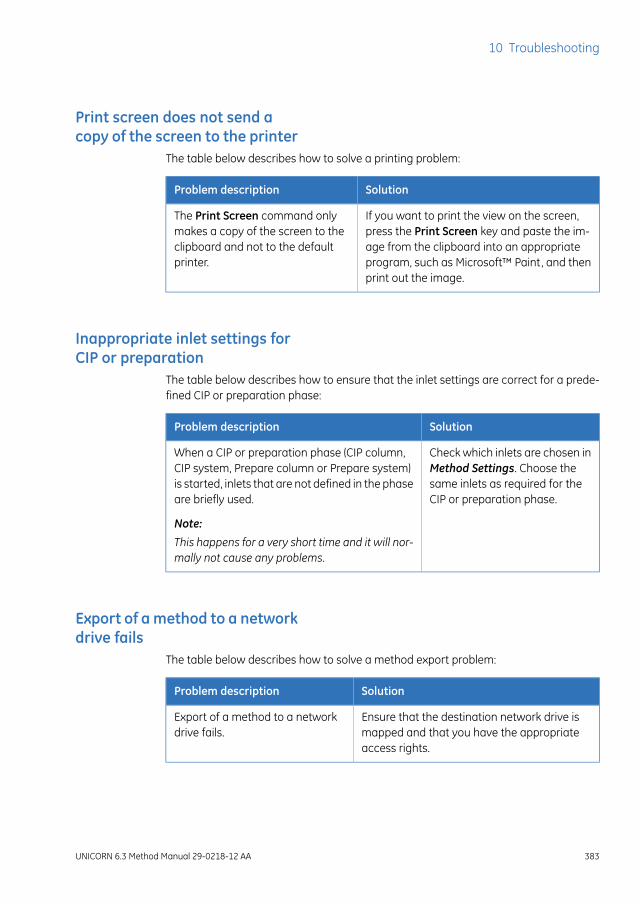
Print screen does not send acopy of the screen to the printer
The table below describes how to solve a printing problem:
SolutionProblem description
If you want to print the view on the screen,press the Print Screen key and paste the im-age from the clipboard into an appropriateprogram, such as Microsoft™ Paint, and thenprint out the image.
The Print Screen command onlymakes a copy of the screen to theclipboard and not to the defaultprinter.
Inappropriate inlet settings forCIP or preparation
The table below describes how to ensure that the inlet settings are correct for a prede-fined CIP or preparation phase:
SolutionProblem description
Check which inlets are chosen inMethod Settings. Choose thesame inlets as required for theCIP or preparation phase.
When a CIP or preparation phase (CIP column,CIP system, Prepare column or Prepare system)is started, inlets that are not defined in the phaseare briefly used.
Note:
This happens for a very short time and it will nor-mally not cause any problems.
Export of amethod to a networkdrive fails
The table below describes how to solve a method export problem:
SolutionProblem description
Ensure that the destination network drive ismapped and that you have the appropriateaccess rights.
Export of a method to a networkdrive fails.
UNICORN 6.3 Method Manual 29-0218-12 AA 383
10 Troubleshooting

Predefined method cannot becreated after new InstrumentConfiguration installation
The table below describes how to solve a predefined method creation problem:
SolutionProblem description
The Method Editor must be restartedafter importing the new instrumentconfiguration.
A new instrument configuration is installed.After this, it is still impossible to create a new,predefined method.
Incorrect Bar code reader usagecloses Column Handling dialog
The table below describes how to solve a bar code reader usage problem:
SolutionProblem description
Use the bar code reader only asdescribed in the user documenta-tion.
Using the bar code reader to read column barcodes without first selecting a proper input fieldwill cause the Column Handling dialog to close.
384 UNICORN 6.3 Method Manual 29-0218-12 AA
10 Troubleshooting

IndexAAdd runs
DoE, 193Scouting, 142
Affinity chromatographypredefined method, 36, 37
AlarmsAvailable monitors, 365General description, 363Insert alarm in method, 364
Anion exchangepredefined method, 38
ANOVA (analysis of variance)table
Design of Experiments, 213Auto Hide
Optional Method Editorpanes, 18
BBarcodes
Column identification, 289Base instruction
CV (Column volume), 330Edit settings, 331Text instructions, 330Time, 330Volume, 330
BlocksAdding, 336Copy/paste, 337Deleting, 341Import from other meth-ods, 338Moving, 339Rename, 340Text editing, 334
BreakpointsIn methods, 381
BufferProConsiderations whenpreparing buffers, 253Create method using, 232Create recipe, 234Delete recipe, 241
Edit recipe, 234Explore proportions, 245Export recipe, 249Import recipe, 251Overview, 230pH ranges, 254Predefined buffers, anionexchange, 231Predefined buffers, cationexchange, 231Predefined recipes, 254Print recipe, 243, 244Rename recipe, 239Workflow, 230
BuffersAnion exchange, 231Calculate compositionof, 245Cation exchange, 231Considerations whenpreparing, 253pH ranges, 254Predefined, 231
CCation exchange
predefined method, 38Chromatofocusing
predefined method, 39CIP
column maintenancemethod, 43column predefinedphase, 46System, predefinedphase, 104system maintenancemethod, 44system predefinedphase, 46
Column CIPmaintenance method, 43predefined phase, 46
Column HandlingBarcodes, 289Column types, 275
UNICORN 6.3 Method Manual 29-0218-12 AA 385
Index

Individual columns, 288Overview, 269Registering new individualcolumns, 290Workflow, 274
Column listImporting predefined col-umn types, 286
Column performance testmaintenance method, 43predefined phase, 46Predefined phase, 104
Column preparationmaintenance method, 43predefined phase, 46
ColumnsAdding or editing notes, 295Barcodes, 289Column HandlingOverview, 269Column Handling Work-flow, 274Column performancetest, 303Column types, 275Create an AxiChrom columntype, 309Create new columntype, 276Deleting column types, 281Deleting individualcolumns, 297Editing column type, 279Editing individualcolumns, 295Exporting column types, 282Exporting individualcolumns, 298Find an individual col-umn, 293Handling individualcolumns, 288Importing columntypes, 284Importing individualcolumns, 298Importing new columnlists, 286Notification limits, 296Performance report, 304
Predefined columntypes, 275Predefined Intelligent Pack-ing method, 313Printing column type infor-mation, 286Printing individual columninformation, 302Registering new individualcolumns, 290Scale a method for use withanother column type, 111Unable to select for methodscaling, 382View column history, 301Wizard generated IntelligentPacking method, 315
Column typesCreate new columntype, 276Deleting, 281Editing, 279Exporting, 282Importing, 284Predefined columntypes, 275Printing information, 286
Column volume (CV)Base instruction, 330
Column washpredefined phase, 46
Correlation matrixDesign of Experiments, 215
Create methodWorkflow, 30
CV (Column volume)Base instruction, 330
DDesalting
predefined method, 39Design of Experiments
Add factors in experimentaldesign, 169Add responses, 167, 192Add runs, 193Analysis, advanced, 209Analysis, basic, 201ANOVA (analysis of vari-ance) table, 213
386 UNICORN 6.3 Method Manual 29-0218-12 AA
Index

Change experimental de-sign, 174Check data, 197Coefficient plot, 207Correlation matrix, 215Create report, 226Delete responses frommodel, 193Edit model, 216Evaluation of results,overview, 186Evaluation of singleruns, 188Experimental design, set-up, 158Experimental designs, 151Fractional Factorial de-sign, 150Full Factorial design, 150Generate model, 190Interaction plot, 211Main effects plot, 213Model curvature, 200, 210Models, overview, 153Multiple scouting runs, 179Normal probability plot ofresiduals, 200, 206Observed vs predictedplot, 212Open result, 189Optimization designs, 151Optimize response val-ues, 223Outliers, 197Overview, 145Predict response values, 222Print method, 184Print report, 228Replace run results, 195Replicate plot, 198Report, creating, 226Report, printing, 228Residual vs run orderplot, 211Residual vs variableplot, 209Response surface plot, 220Summary of Fit plot, 203View scouting scheme, 183Workflow, 156
Documentation, 12Downscale
Scale a method for a small-er column type, 111
EEdit
BufferPro recipe, 234Column, individual, 295Column type, 279DoE model, 216Method notes, 89Method outline, 75Method phases, 52Method queue, 262Scouting scheme, 134Text instructions, 344Variables, 353
Electronic signatureSigning a method, 100
Elutionpredefined phase, 46
End_BlockText instruction, 334
Equilibrationpredefined phase, 46
EvaluationDoE results, overview, 186Single DoE runs, 188
Evaluation proceduresInclude after run, 91
Experimental designAdd factors in DoE, 169Add responses in DoE, 167Change design in DoE, 174Design types inUNICORN, 151Setup in DoE, 158
ExportingBufferPro recipes, 249Column types, 282Individual columns, 298Methods, 119Phases, 119
FFractional Factorial design
Description, 150Fraction collection
Frac 950, 67
UNICORN 6.3 Method Manual 29-0218-12 AA 387
Index
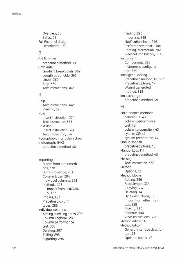
Overview, 58Setup, 58
Full Factorial designDescription, 150
GGel filtration
predefined method, 39Gradients
Gradient breakpoints, 362Length as variable, 361Linear, 360Step, 360Text instructions, 362
HHelp
Text instructions, 342Viewing, 19
HoldInsert instruction, 374Text instruction, 373
Hold untilInsert instruction, 374Text instruction, 374
Hydrophobic interaction chro-matography (HIC)
predefined method, 40
IImporting
Blocks from other meth-ods, 338BufferPro recipe, 251Column types, 284Individual columns, 298Methods, 125
Import from UNICORN5, 127
Phases, 123Predefined columntypes, 286
Individual columnsAdding or editing notes, 295Column Logbook, 288Column performancetest, 303Deleting, 297Editing, 295Exporting, 298
Finding, 293Importing, 298Notification limits, 296Performance report, 304Printing information, 302View column history, 301
InstrumentComponents, 380Instrument configura-tion, 380
Intelligent PackingPredefined method, 43, 313Predefined phase, 47Wizard generatedmethod, 315
Ion exchangepredefined method, 38
MMaintenance methods
column CIP, 43column performancetest, 43column preparation, 43system CIP, 44system preparation, 44
Manual loop fillpredefined phase, 46
Manual Loop Fillpredefined method, 40
MessageText instruction, 376
MethodOptions, 31
Method blocksAdding, 336Block length, 334Copying, 337Deleting, 341Hide instructions, 335Import from other meth-ods, 338Moving, 339Rename, 340View instructions, 335
Method editor, 14Method Editor
General interface descrip-tion, 15Optional panes, 17
388 UNICORN 6.3 Method Manual 29-0218-12 AA
Index

Saving a method, 102Saving a phase, 104Tools available in, 14Viewing help topics, 19
Method notesAdd to method, 89Edit, 89
Method outlineDescription, 21Duration time and vol-ume, 95Edit method outline, 75
Method queues, 256Change method order, 266Create, 258Delete method from, 266Deleting, 263Editing, 262Insert method into, 265Mulitple systems, 258Opening, 262
MethodsAdd notes, 89affinity chromatogra-phy, 36, 37After conversion, 115anion exchange, 38Breakpoints in, 381BufferPro, 232BufferPro, using, 232cation exchange, 38chromatofocusing, 39CIP mehods, 383Convert a method to anoth-er system type, 109Convert and scale a methodfor another system type andcolumn type, 111Convert method for use ina different database, 116Create empty method, 70Create new method, 48, 62Definition, 20desalting, 39Duration time and vol-ume, 95Edit empty method, 72Edit method outline, 75Edit methods, 52Edit notes, 89
Edit phase variables, 64Electronic signature, 100Empty method
Edit method outline, 72Empty methods, 24Evaluation procedures, in-clude, 91Export a method, 119Export as text, 121gel filtration, 39hydrophobic interactionchromatography (HIC), 40Import a method, 125Import a method from UNI-CORN 5 , 127Intelligent Packing, 43manual loop fill, 40Method outline, 75NHS-coupling, 41Open a method, 32predefined maintenancemethods, 42predefined methods, 36Predefined methods, 24Prepare methods, 383Print, 98Print duration time and vol-ume, 95Print variables, 95Result name and loca-tion, 86reverse phase chromatogra-phy (RPC), 42Saving, 102Saving a phase, 104Start protocol, setup, 88Structure of, 21Syntax errors in, 380Text editing, 320Troubleshooting, 379unable to create predefinedmethod, 384unable to export mehod tonetwork drive, 383Unexpected results fromconverted methods, 382Variables, 348View variables, 95Wizard generated method
Phases, 64
UNICORN 6.3 Method Manual 29-0218-12 AA 389
Index

Working with, 22Method settings
predefined phase, 45Method variables
Viewing, 348Miscellaneous
predefined phase, 47Model curvature
Design of Experiments, 200, 206, 210
NNHS-coupling
predefined method, 41Notes
Column notes, 295Method notes, 89
PPause
Insert instruction, 374Text instruction, 373
Phase propertiesEdit phase, 52Help, 51
PhasesCIP phases, 383column CIP, 46column performancetest, 46Column performancetest, 104column preparation, 46column wash, 46Deleting phases from li-brary, 106Edit phases, 52elution, 46equilibration, 46Export a phase, 119Help, 51Import a phase, 123Intelligent Packing, 47manual loop fill, 46method settings, 45miscellaneous, 47Phase library, 381Phase properties, 52, 379predefined phases, 45Predefined phases, 25
Prepare phases, 383sample application, 46Syntax errors in, 380system CIP, 46System CIP, 104system preparation, 46Text editing, 334, 379
Phase variablesEdit, 64Edit values, 65
pH rangeBufferPro predefinedbuffers, 254Common buffers, 231
PlotsCoefficient plot, DoE, 207Interaction plot, DoE, 211Main effects plot, DoE, 213Normal probability plot ofresiduals, DoE, 200, 206Observed vs predicted plot,DoE, 212Replicate plot, DoE, 198Residual vs run order plot,DoE, 211Residual vs variable plot,DoE, 209Response surface plot,DoE, 220Summary of Fit, DoE, 203
PrintMethods, 98
PrintingBufferPro recipe, 243, 244Column performance re-port, 304Column type informa-tion, 286DoE methods, 184DoE report, 228Individual column informa-tion, 302Method duration time andvariables, 95Print screen, 383Response surface plot,DoE, 220
RResponse surface plot
390 UNICORN 6.3 Method Manual 29-0218-12 AA
Index

Generating in DoE, 220Response values
Optimize in DoE, 223Predicting in DoE, 222
ResultName and location, 86Open DoE result, 189
Reverse phase chromatogra-phy (RPC)
predefined method, 42
SSample application
predefined phase, 46Scouting
Add runs, 142Add variable, 140Change variable val-ues, 137, 141Delete runs, 142Delete variable, 140Edit variable, 140Overview, 132Scouting scheme, 134Usage, 132Variables in, 140Workflow, 132
Scouting schemeAdd runs, 142Delete runs, 142Editing, 134How to set up, 134View in DoE, 183
Set markInsert instruction, 378Usage, 377
Start protocolSet up start protocol, 88
Syntax errorsIcons in text instruc-tions, 327In methods, 380In phases, 380In text instructions, 380
SystemComponents, 380Instrument configura-tion, 380
System CIPmaintenance method, 44
predefined phase, 46Predefined phase, 104
System preparationmaintenance method, 44predefined phase, 46
TText editing
Blocks, 334Help texts, 342Methods, 320Phases, 334Text instructions, 322
Text instructionsAdd a new instruction, 342Alarm instructions, 364Base instruction, 330Change, 345Change and Replace, differ-ences, 345Delete instructions, 347Delta peak settings, 371Edit an instruction, 344End_Block, 334Gradient breakpoints, 362Gradient instructions, 362Help, 342Hold instruction, 373Hold until, 374Icons and text formats, 327Linear gradient, 360Message, 376Message instructions, 376Move an instruction, 346Pause instruction, 373Replace, 345Set mark, 377Step gradient, 360Syntax errors in, 380Text editing a method, 322Text instructions pane, 324Text method symbols, 327Watch instructions, 366Watch parameters, 370Watch parameter test op-tions, 368
TimeBase instruction, 330
ToolsIn Method Editor, 14
UNICORN 6.3 Method Manual 29-0218-12 AA 391
Index

TroubleshootingMethods, 379
UUNICORN workflow, 8Upscale
Scale a method for a largercolumn type, 111
VVariables
Breakpoints or gradientlengths, 352Defining, 351Deleting, 353Edit values, 357Identification in text instruc-tions, 349, 350Method variables, 348Renaming, 353Scouting, use in, 140
Variable names, 350Viewing, 348
VolumeBase instruction, 330
WWarnings
Compared to Alarms, 363Watch instructions
Actions, 369Air sensors, 372Delta peak settings, 371Description, 366Insert instruction, 366Parameter test options, 368Signals available, 368
Watch parametersDelta peak settings, 371
Watch parameters instructionsInsert text instruction, 370
392 UNICORN 6.3 Method Manual 29-0218-12 AA
Index


GE, imagination at work and GE monogram are trademarks of General ElectricCompany.
ÄKTA, AxiChrom, HiTrap, Mono Q, Sepharose and UNICORN are trademarks ofGE Healthcare companies.
Windows and Microsoft are trademarks of Microsoft Corporation.
© 2009 - 2012 General Electric Company – All rights reserved.First published Sep. 2009
All goods and services are sold subject to the terms and conditions of sale ofthe company within GE Healthcare which supplies them. A copy of these termsand conditions is available on request. Contact your local GE Healthcare repre-sentative for the most current information.
UNICORN: Any use of this software is subject to GE Healthcare Standard SoftwareEnd-User License Agreement for Life Sciences Software Products. A copy of thisStandard Software End-User License Agreement is available on request.
GE Healthcare Europe GmbHMunzinger Strasse 5, D-79111 Freiburg, Germany
GE Healthcare UK LimitedAmersham Place, Little Chalfont, Buckinghamshire, HP7 9NA, UK
GE Healthcare Bio-Sciences Corp.800 Centennial Avenue, P.O. Box 1327, Piscataway, NJ 08855-1327, USA
GE Healthcare Japan CorporationSanken Bldg. 3-25-1, Hyakunincho Shinjuku-ku, Tokyo 169-0073, Japan
For local office contact information, vis-itwww.gelifesciences.com/contact
GE Healthcare Bio-Sciences ABBjörkgatan 30751 84 UppsalaSweden
www.gelifesciences.com/unicorn
29-0218-12 AA 06/2012
imagination at work