FERROELECTRIC PROPERTIES OF POLYVINYLIDENEFLUORIDE-TRIFLUOROETHYLENE (PVDF-TRFE) ANNEALED THIN FILM

This article was downloaded by: [Dr Martin A. Masuelli]On: 07 October 2013, At: 05:21Publisher: Taylor & FrancisInforma Ltd Registered in England and Wales Registered Number: 1072954 Registered office: Mortimer House,37-41 Mortimer Street, London W1T 3JH, UK
Desalination and Water TreatmentPublication details, including instructions for authors and subscription information:http://www.tandfonline.com/loi/tdwt20
Ultrafiltration of oil/water emulsions using PVDF/PCblend membranesMartin A. Masuelli aa Instituto de Física Aplicada, CONICET , Universidad Nacional de San Luis , Chacabuco 917(ZC: 5700), San Luis , Argentina Phone: Tel./Fax: +54 2652 432068Published online: 07 Oct 2013.
To cite this article: Martin A. Masuelli , Desalination and Water Treatment (2013): Ultrafiltration of oil/water emulsions usingPVDF/PC blend membranes, Desalination and Water Treatment, DOI: 10.1080/19443994.2013.846539
To link to this article: http://dx.doi.org/10.1080/19443994.2013.846539
PLEASE SCROLL DOWN FOR ARTICLE
Taylor & Francis makes every effort to ensure the accuracy of all the information (the “Content”) containedin the publications on our platform. However, Taylor & Francis, our agents, and our licensors make norepresentations or warranties whatsoever as to the accuracy, completeness, or suitability for any purpose of theContent. Any opinions and views expressed in this publication are the opinions and views of the authors, andare not the views of or endorsed by Taylor & Francis. The accuracy of the Content should not be relied upon andshould be independently verified with primary sources of information. Taylor and Francis shall not be liable forany losses, actions, claims, proceedings, demands, costs, expenses, damages, and other liabilities whatsoeveror howsoever caused arising directly or indirectly in connection with, in relation to or arising out of the use ofthe Content.
This article may be used for research, teaching, and private study purposes. Any substantial or systematicreproduction, redistribution, reselling, loan, sub-licensing, systematic supply, or distribution in anyform to anyone is expressly forbidden. Terms & Conditions of access and use can be found at http://www.tandfonline.com/page/terms-and-conditions
Ultrafiltration of oil/water emulsions using PVDF/PC blendmembranes
Martin A. Masuelli
Instituto de Fısica Aplicada, CONICET, Universidad Nacional de San Luis, Chacabuco 917 (ZC: 5700), San Luis,ArgentinaTel./Fax: +54 2652 432068; email: [email protected]
Received 17 June 2013; Accepted 1 September 2013
ABSTRACT
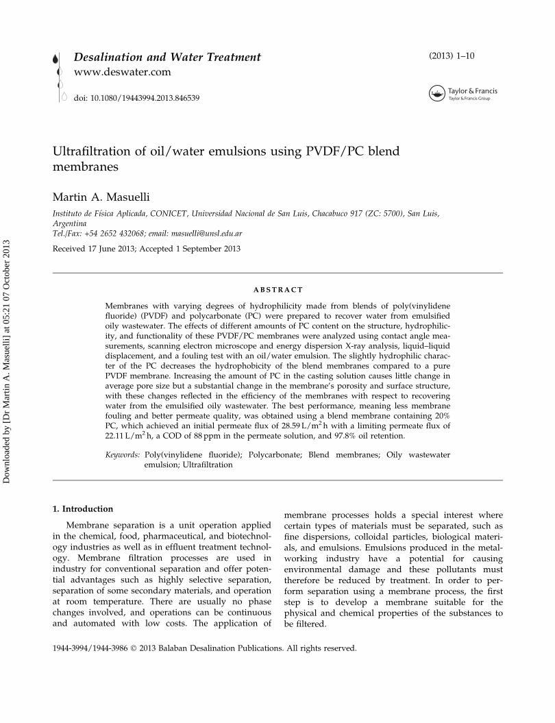
Membranes with varying degrees of hydrophilicity made from blends of poly(vinylidenefluoride) (PVDF) and polycarbonate (PC) were prepared to recover water from emulsifiedoily wastewater. The effects of different amounts of PC content on the structure, hydrophilic-ity, and functionality of these PVDF/PC membranes were analyzed using contact angle mea-surements, scanning electron microscope and energy dispersion X-ray analysis, liquid–liquiddisplacement, and a fouling test with an oil/water emulsion. The slightly hydrophilic charac-ter of the PC decreases the hydrophobicity of the blend membranes compared to a purePVDF membrane. Increasing the amount of PC in the casting solution causes little change inaverage pore size but a substantial change in the membrane’s porosity and surface structure,with these changes reflected in the efficiency of the membranes with respect to recoveringwater from the emulsified oily wastewater. The best performance, meaning less membranefouling and better permeate quality, was obtained using a blend membrane containing 20%PC, which achieved an initial permeate flux of 28.59 L/m2h with a limiting permeate flux of22.11 L/m2h, a COD of 88 ppm in the permeate solution, and 97.8% oil retention.
Keywords: Poly(vinylidene fluoride); Polycarbonate; Blend membranes; Oily wastewateremulsion; Ultrafiltration
1. Introduction
Membrane separation is a unit operation appliedin the chemical, food, pharmaceutical, and biotechnol-ogy industries as well as in effluent treatment technol-ogy. Membrane filtration processes are used inindustry for conventional separation and offer poten-tial advantages such as highly selective separation,separation of some secondary materials, and operationat room temperature. There are usually no phasechanges involved, and operations can be continuousand automated with low costs. The application of
membrane processes holds a special interest wherecertain types of materials must be separated, such asfine dispersions, colloidal particles, biological materi-als, and emulsions. Emulsions produced in the metal-working industry have a potential for causingenvironmental damage and these pollutants musttherefore be reduced by treatment. In order to per-form separation using a membrane process, the firststep is to develop a membrane suitable for thephysical and chemical properties of the substances tobe filtered.
1944-3994/1944-3986 � 2013 Balaban Desalination Publications. All rights reserved.
Desalination and Water Treatmentwww.deswater.com
doi: 10.1080/19443994.2013.846539
(2013) 1–10
Dow
nloa
ded
by [
Dr
Mar
tin A
. Mas
uelli
] at
05:
21 0
7 O
ctob
er 2
013
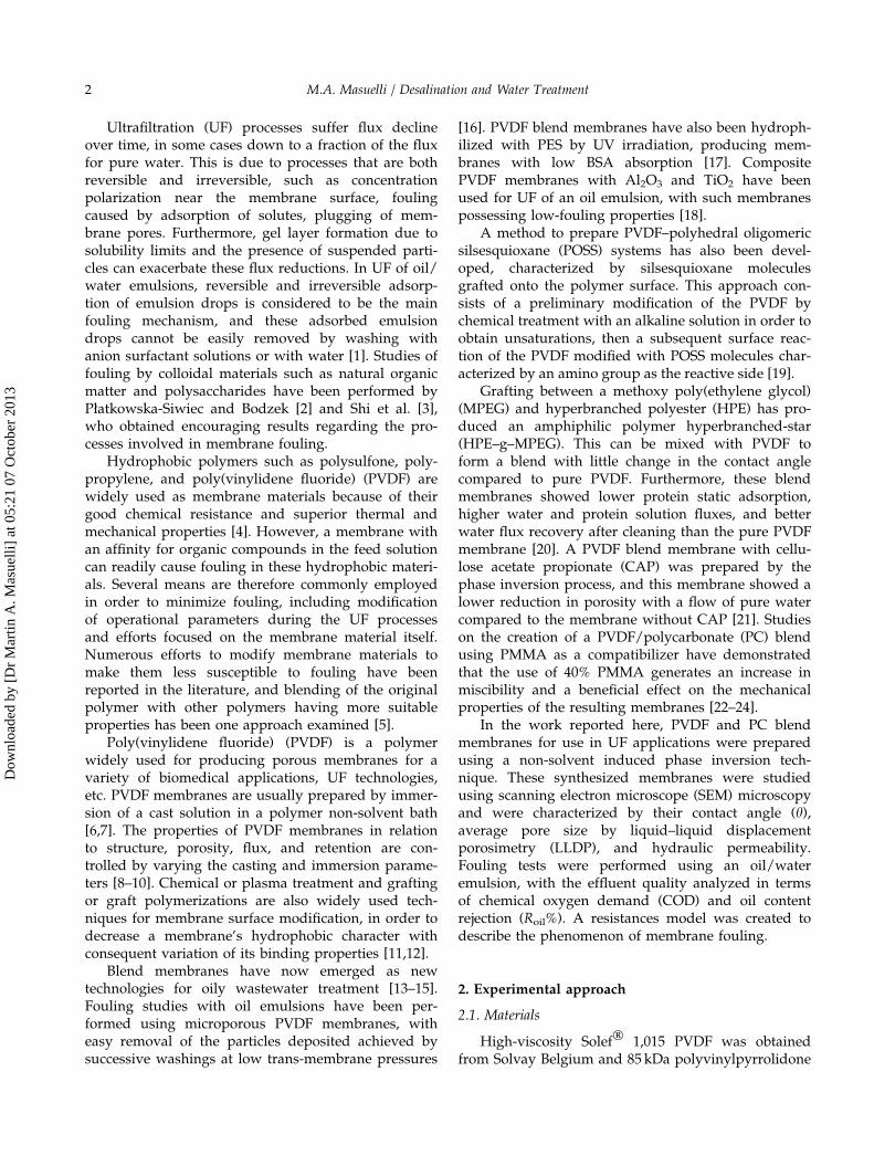
Ultrafiltration (UF) processes suffer flux declineover time, in some cases down to a fraction of the fluxfor pure water. This is due to processes that are bothreversible and irreversible, such as concentrationpolarization near the membrane surface, foulingcaused by adsorption of solutes, plugging of mem-brane pores. Furthermore, gel layer formation due tosolubility limits and the presence of suspended parti-cles can exacerbate these flux reductions. In UF of oil/water emulsions, reversible and irreversible adsorp-tion of emulsion drops is considered to be the mainfouling mechanism, and these adsorbed emulsiondrops cannot be easily removed by washing withanion surfactant solutions or with water [1]. Studies offouling by colloidal materials such as natural organicmatter and polysaccharides have been performed byPłatkowska-Siwiec and Bodzek [2] and Shi et al. [3],who obtained encouraging results regarding the pro-cesses involved in membrane fouling.
Hydrophobic polymers such as polysulfone, poly-propylene, and poly(vinylidene fluoride) (PVDF) arewidely used as membrane materials because of theirgood chemical resistance and superior thermal andmechanical properties [4]. However, a membrane withan affinity for organic compounds in the feed solutioncan readily cause fouling in these hydrophobic materi-als. Several means are therefore commonly employedin order to minimize fouling, including modificationof operational parameters during the UF processesand efforts focused on the membrane material itself.Numerous efforts to modify membrane materials tomake them less susceptible to fouling have beenreported in the literature, and blending of the originalpolymer with other polymers having more suitableproperties has been one approach examined [5].
Poly(vinylidene fluoride) (PVDF) is a polymerwidely used for producing porous membranes for avariety of biomedical applications, UF technologies,etc. PVDF membranes are usually prepared by immer-sion of a cast solution in a polymer non-solvent bath[6,7]. The properties of PVDF membranes in relationto structure, porosity, flux, and retention are con-trolled by varying the casting and immersion parame-ters [8–10]. Chemical or plasma treatment and graftingor graft polymerizations are also widely used tech-niques for membrane surface modification, in order todecrease a membrane’s hydrophobic character withconsequent variation of its binding properties [11,12].
Blend membranes have now emerged as newtechnologies for oily wastewater treatment [13–15].Fouling studies with oil emulsions have been per-formed using microporous PVDF membranes, witheasy removal of the particles deposited achieved bysuccessive washings at low trans-membrane pressures
[16]. PVDF blend membranes have also been hydroph-ilized with PES by UV irradiation, producing mem-branes with low BSA absorption [17]. CompositePVDF membranes with Al2O3 and TiO2 have beenused for UF of an oil emulsion, with such membranespossessing low-fouling properties [18].
A method to prepare PVDF–polyhedral oligomericsilsesquioxane (POSS) systems has also been devel-oped, characterized by silsesquioxane moleculesgrafted onto the polymer surface. This approach con-sists of a preliminary modification of the PVDF bychemical treatment with an alkaline solution in order toobtain unsaturations, then a subsequent surface reac-tion of the PVDF modified with POSS molecules char-acterized by an amino group as the reactive side [19].
Grafting between a methoxy poly(ethylene glycol)(MPEG) and hyperbranched polyester (HPE) has pro-duced an amphiphilic polymer hyperbranched-star(HPE–g–MPEG). This can be mixed with PVDF toform a blend with little change in the contact anglecompared to pure PVDF. Furthermore, these blendmembranes showed lower protein static adsorption,higher water and protein solution fluxes, and betterwater flux recovery after cleaning than the pure PVDFmembrane [20]. A PVDF blend membrane with cellu-lose acetate propionate (CAP) was prepared by thephase inversion process, and this membrane showed alower reduction in porosity with a flow of pure watercompared to the membrane without CAP [21]. Studieson the creation of a PVDF/polycarbonate (PC) blendusing PMMA as a compatibilizer have demonstratedthat the use of 40% PMMA generates an increase inmiscibility and a beneficial effect on the mechanicalproperties of the resulting membranes [22–24].
In the work reported here, PVDF and PC blendmembranes for use in UF applications were preparedusing a non-solvent induced phase inversion tech-nique. These synthesized membranes were studiedusing scanning electron microscope (SEM) microscopyand were characterized by their contact angle (h),average pore size by liquid–liquid displacementporosimetry (LLDP), and hydraulic permeability.Fouling tests were performed using an oil/wateremulsion, with the effluent quality analyzed in termsof chemical oxygen demand (COD) and oil contentrejection (Roil%). A resistances model was created todescribe the phenomenon of membrane fouling.
2. Experimental approach
2.1. Materials
High-viscosity Solef� 1,015 PVDF was obtainedfrom Solvay Belgium and 85 kDa polyvinylpyrrolidone
2 M.A. Masuelli / Desalination and Water Treatment
Dow
nloa
ded
by [
Dr
Mar
tin A
. Mas
uelli
] at
05:
21 0
7 O
ctob
er 2
013

(PVP) was obtained from Stanton (Argentina). N,N-dimethylacetamide (DMAc) was obtained from Merck,and Lexan PC was purchased from General Electricand used as provided. Viledon 2431 non-woven sup-port (thickness: 0.14mm; air permeability at 200 Pa:500L/m2h) was provided by Carl Freudenberg,Germany.
Commercial oil (Insignia� oil) was purchasedfrom JyM Lubricantes. (Argentina). An oil/wateremulsion was prepared by mixing 1 g of Insignia� oilin 1 L of distilled water (0.1% w/v oil concentration)by stirring with an UltraTurrax-T50 stirrer at 500 rpm.The emulsion had the following characteristics: pH 7,viscosity g= 1.058� 10�3 Pa s, COD 1,700mgL�1, andaverage oil droplet diameter 2.5lm, measured with aCarl Zeiss Pol II microscope [25].
2.2. Membrane preparation
The general procedure used for membrane prepa-ration was as follows: 15% w/v of PVDF and 2% w/vof PVP were dissolved in DMAc at 50˚C by stirringwith a magnetic bar for 10 h. Next, different amountsof PC (5, 10, and 20% w/w with respect to PVDF)were added and dissolved. The final mixture was castonto the non-woven support (FO2430, Freudenberg) at25˚C using a film extensor. The supported polymericfilm solution was then coagulated in bi-distilled waterat 25˚C. Finally, the membrane was placed in a 5Lwater bath for 12 h. Higher PC concentrations (i.e. 25–30% w/w) were found to produce a water flux-tightcomposite membrane.
In order to evaluate the hydrophilic/hydrophobiccharacteristics of the PC material, a dense membranewas synthesized from a 5% w/w solution of PC indichloromethane. The polymer solution was cast ontoa flat glass, and the dense membrane was obtainedafter solvent evaporation at 298K.
2.3. Contact angle measurement
The hydrophobic character of the PVDF/PC blendmembranes was determined by measuring the water-membrane contact angle (h) using the sessile-droptechnique and a contact angle device (MicromeriticsInstrument Corporation, Norcross, GA, USA). Thecontact angle value was measured 3min after drop-ping water on the membrane surface, and three dropsof water were measured for each membrane sample.The average contact angles (h) with a standard devia-tion of ±2 were determined using the followingexpression [26]:
cos h ¼ 1�ffiffiffiffiffiffiffiffiffiffiffiffiffiffiffiffiffi
Bh2
ð1� Bh2
2Þ
sð1Þ
B ¼ qg2c
ð2Þ
with g being gravity acceleration (980 cm/s2), q thedensity of bi-distilled water (0.9971 g/cm3), c the inter-facial tension of bi-distilled water (71.97 erg/cm2), andh the height of the liquid drop.
2.4. SEM and energy dispersion X-ray (EDX) measurements
The morphologies of the blend membranes wereobserved using a LEO 1450VP SEM, with EDX analy-sis performed with a Genesis 2000 at an accelerationvoltage of 120 kV. For the morphological analysis,cross-section samples were prepared by fracturing themembranes after immersion in liquid nitrogen andcoating with carbon.
2.5. Pore size and porosity measurements by LLDP
A three-liquid mixture of isobutanol/methanol/water (15/7/25 by vol., surface tension c= 0.35mN/m)was used analyze the pores by applying relatively lowpressures [14]. The procedure used consists of fillingthe membrane with a liquid (wetting liquid, aqueousphase) and then displacing it from the pores with theorganic phase (isobutanol saturated with water andmethanol). Flux through the membrane was obtainedby using a syringe pump (Isco 500D) to graduallyincrease the flux on the organic-phase side. Simulta-neously, equilibrium pressure is measured at eachincremental stage using a pressure transducer(OMEGA DP200). By monitoring the applied pressureand the flux through the membrane, the radii of theopened pores at each applied pressure can be calcu-lated using Cantor’s equation. This equation is valid ifit is assumed that the liquid effectively wets the mem-brane (i.e. with null contact angle).
rp ¼ 2c�p
ð3Þ
where Dp= applied pressure, c= interfacial tension,and rp = equivalent pore radius. Assuming cylindricalpores, the Hagen–Poiseuille relationship can then beused to correlate volumetric flux density Jvi to a givenpore radius rp. For each incremental stage of volumet-ric flux density, the corresponding pressure (Dpi) wasmeasured. From these data, the distribution of the
M.A. Masuelli / Desalination and Water Treatment 3
Dow
nloa
ded
by [
Dr
Mar
tin A
. Mas
uelli
] at
05:
21 0
7 O
ctob
er 2
013

number of pores (ni) vs. pore radius was calculatedaccording to:
dni
drpi¼ � gs‘Dp6i
16pc6d2JvidDp2i
ð4Þ
where g=dynamic viscosity, s= tortuosity, andℓ=pore length, which corresponds to the active layerthickness of the membrane, ℓ= 0.75lm is obtainedfrom SEM image. A value accepted by several authors[27,28] to the tortuosity is 1.4, since its measurementis very difficult to perform correctly.
The membrane surface porosity (e) can be then cal-culated using [29]:
e ¼ pnr2pAm
ð5Þ
where Am is the membrane surface area(2.46� 10�3m2), and n is pores number.
2.6. Hydraulic permeability and fouling tests
Fig. 1 presents a schematic diagram of the com-plete retentate recycling, lab-scale UF device used inthis study. The polymeric membrane was placed inthe permeation cell with a transfer area ofA= 3� 10�3m2. The pure water or oil–water emulsionwas pumped through the top side of the membranesurface using a peristaltic pump (Masterflex), with7,000 s of fouling operation. The operating conditionsin terms of hydraulic permeability measurements(LH), feed flow rate (v= 1L/min), and temperature
(T= 25˚C) were kept constant, while the trans-mem-brane pressure Dp was varied from 50 to 80 kPa. Theoil emulsion flux experiments were performed atv= 1L/min, T= 25˚C, and Dp= 67 kPa. These maxi-mum values for feed velocity and pressure used inthe experimental runs were constrained by the opera-tional capacity of the pump. The recycled retentateflow was measured with a flowmeter and the perme-ate flux was determined by time weighing the perme-ate solution; with an analytical balance interfaced witha computer used to collect and process the mass datafor permeate vs. time.
In order to analyze the fouling phenomena, mem-branes were cleaned in situ after the emulsion UF test-ing using the following protocol: an anionic surfactant(sodium dodecilsulfate) was pumped through themembrane surface for 30min, and then, the membranewas washed with pure water for 30min. After eachcleaning procedure, the hydraulic permeability of thetreated membranes (LHC) was evaluated at T= 25˚C.
2.7. Chemical oxygen demand (COD)
COD measurements were performed by placingthe samples under reflux in a strongly acidic solutionwith a predetermined excess of potassium dichromate.Consumed oxygen was measured against standards at600 nm using a Hitachi U-2001 UV–vis spectrophotom-eter (standard methods for the examination of waterand wastewater 5220D).
2.8. Oil content
Oil content was evaluated by UV–vis spectroscopy(wavelength of 220 nm) using the calibration curveobtained from oil pattern solutions. Oil contentrejection (Roil%) was evaluated using the followingequation:
Roil% ¼ 100coil;F � coil;P
coil;Fð6Þ
where coil,F and coil,P are the oil/water concentrationsin the feed and permeate, respectively.
3. Results and discussion
3.1. Structural and chemical characteristics of the membrane
The micrographs seen in Figs. 2(b) and 3 show thatthe PC significantly affects the membrane’s porosityand surface structure, while the PVDF membrane canbe seen in Fig. 2(a) and (c) to have a finger-like porousstructure [30]. Backscattered electron images allowobservation of phase changes in a given material, as
Fig. 1. UF device: (1) feed solution reservoir (Haake 1C),(2) peristaltic pump, (3) pressure gauge, (4) permeationcell (Minitan S), (5) membrane, (6) needle valve, (7)flowmeter, (8) retentate, (9) permeate, (10) analyticalbalance (Ohaus explorer), and (11) data acquisition system.
4 M.A. Masuelli / Desalination and Water Treatment
Dow
nloa
ded
by [
Dr
Mar
tin A
. Mas
uelli
] at
05:
21 0
7 O
ctob
er 2
013
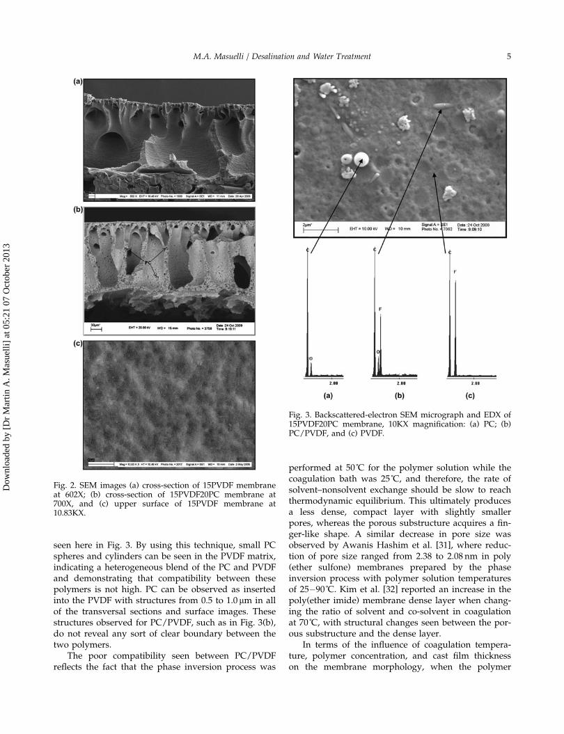
seen here in Fig. 3. By using this technique, small PCspheres and cylinders can be seen in the PVDF matrix,indicating a heterogeneous blend of the PC and PVDFand demonstrating that compatibility between thesepolymers is not high. PC can be observed as insertedinto the PVDF with structures from 0.5 to 1.0 lm in allof the transversal sections and surface images. Thesestructures observed for PC/PVDF, such as in Fig. 3(b),do not reveal any sort of clear boundary between thetwo polymers.
The poor compatibility seen between PC/PVDFreflects the fact that the phase inversion process was
performed at 50˚C for the polymer solution while thecoagulation bath was 25˚C, and therefore, the rate ofsolvent–nonsolvent exchange should be slow to reachthermodynamic equilibrium. This ultimately producesa less dense, compact layer with slightly smallerpores, whereas the porous substructure acquires a fin-ger-like shape. A similar decrease in pore size wasobserved by Awanis Hashim et al. [31], where reduc-tion of pore size ranged from 2.38 to 2.08 nm in poly(ether sulfone) membranes prepared by the phaseinversion process with polymer solution temperaturesof 25�90˚C. Kim et al. [32] reported an increase in thepoly(ether imide) membrane dense layer when chang-ing the ratio of solvent and co-solvent in coagulationat 70˚C, with structural changes seen between the por-ous substructure and the dense layer.
In terms of the influence of coagulation tempera-ture, polymer concentration, and cast film thicknesson the membrane morphology, when the polymer
Fig. 2. SEM images (a) cross-section of 15PVDF membraneat 602X; (b) cross-section of 15PVDF20PC membrane at700X, and (c) upper surface of 15PVDF membrane at10.83KX.
Fig. 3. Backscattered-electron SEM micrograph and EDX of15PVDF20PC membrane, 10KX magnification: (a) PC; (b)PC/PVDF, and (c) PVDF.
M.A. Masuelli / Desalination and Water Treatment 5
Dow
nloa
ded
by [
Dr
Mar
tin A
. Mas
uelli
] at
05:
21 0
7 O
ctob
er 2
013

concentration in the casting dope increases, the mem-branes obtained by coagulation under the same condi-tions show a morphology with a denser spongiousphase and fewer macrovoids. Such a change in mem-brane morphology is expected, since a more concen-trated polymer solution leads to a higher polymerconcentration in the system at the bi-nodal phase sep-aration point (hence a denser spongious structure), aswell as a reduced possibility of solvent extractionfrom the surrounding polymer solution to the poly-mer-lean phase during formation of the macrovoids.The pore structure of the skin formed on the face incontact with water would also change in the sameway, that is, porosity and the pore size woulddecrease with increasing polymer concentration in thecasting dope. When the PVDF/PC is blended with theoriginal PVDF, the morphology of the coagulatedmembranes is different than that of single polymermembranes: irregular macrovoids, and eventuallypolymer nodules, instead of finger-like macrovoids.These would be generated by compressive strains thatappear in the skin layer bonded to a soft substrate(liquid polymer dope) during the departure of thesolvent from the nascent membrane toward thecoagulation bath. A decrease either in coagulationtemperature or in the total polymer in the castingdope led to larger and more numerous macrovoids,probably due to an increase in the phase separationtime before gelling of the system [33].
The SEM imaging results were complemented byEDX measurements. Fig. 3 shows the SEM surfaceimage of the 15PVDF20PC membrane with the EDXspectra for dark, bright, and intermediate zones. Smallspheres and agglomerates from 0.5 to 1.0 lm can beobserved in the images as inserted into the PVDFupper surface. The SEM-EDX analysis of the15PVDF20PC membrane shows that the sphere on thesurface of the membrane (bright zone, Fig. 3(a)) corre-sponds to pure PC (C= 8 8.4% and O= 11.6%), theintermediate zone (Fig. 3(b)) indicates a PC/PVDFblend agglomerate (C= 60.4%, O= 9.6%, and F= 30%),and the dark zone (Fig. 3(c)) corresponds to pure
PVDF (C= 57.3% and F= 42.7%). This demonstratesthat the polymeric blend of PC and PVDF was hetero-geneous and indicates a low affinity between the twopolymeric materials [22–24].
3.2. Hydrophobic character and mean pore radius of themembranes
Table 1 shows the membrane contact angles, meanpore radius, hydraulic permeabilities, COD, and Roil%with their standard deviations. The contact anglevalues for PC (60< h< 70) reflect its slightly hydro-philic character, related to the dipole–dipole andinduced dipole–dipole contributions. The hydrophobiccharacter of PVDF (h> 80) is related to the van derWaals interactions and that of the PC/PVDF blendmembranes is related to the contributions of thehydroxyl and fluor groups.
Pore size distributions for the membranes rangedbetween 27.31 and 31.88 nm (Table 1 and Fig. 4), witha considerable population of pores having a radiuslarger than rp. It can be seen that there is a decreasein average pore radius for the membranes with PC.This phenomenon can be explained by the phaseinversion process, where a solvent–nonsolventexchange results in a loss of stability for the polymerin the casting solution, with PC particles trapped inthe polymer matrix. During the phase inversionprocess, the entry of non-solvent generates interfacialdefects between the PC phase and polymer phaseleading to a slight decrease in rp.
3.3. Emulsion permeability and fouling
Water flux values (Jv) at different Dp were used toevaluate water permeability (LH) by use of Darcy’slaw as follows:
LH ¼ J
�p¼ 1
gRm
ð7Þ
Table 1Structural and functional characteristics of the synthesized membranes
Membrane h rp (nm) e Jvo(L/m2h)
LHI
(L/m2 kPah)LHC
(L/m2 kPah)COD ppm O2 Roil%
15PVDF 80± 3.6 31.88 ± 1.3 0.70 ± 0.11 72.36 ± 5.6 1.064 ± 0.144 0.283 ± 0.023 214± 2.12 86.5 ± 1.12
15PVDF5PC 76± 3.3 29.21 ± 2.1 0.53 ± 0.15 57.45 ± 6.8 0.836 ± 0.124 0.265 ± 0.014 167± 1.99 89.0 ± 1.44
15PVDF10PC 74± 2.9 28.45 ± 2.5 0.47 ± 0.14 35.54 ± 7.9 0.522 ± 0.121 0.234 ± 0.011 135± 1.87 93.6 ± 1.89
15PVDF20PC 71± 3.1 27.31 ± 1.7 0.35 ± 0.12 28.59 ± 5.7 0.433 ± 0.075 0.223 ± 0.012 88± 1.55 97.8 ± 1.53
PC 68± 2.2 – – – – – – –
6 M.A. Masuelli / Desalination and Water Treatment
Dow
nloa
ded
by [
Dr
Mar
tin A
. Mas
uelli
] at
05:
21 0
7 O
ctob
er 2
013

where Rm is the intrinsic membrane resistance and gis solvent viscosity.
From Table 1, it can be observed that the LHC val-ues for all of the membranes were similar(LHC= 0.283–0.223L/hm2 kPa), with a 73.41% decreasein hydraulic permeability for the 15PVDF membranecompared to its initial value (LHI = 1.0645L/hm2 kPa),but with only a 48.59% decrease for the 15PVDF20PCmembrane. This suggests that after the cleaning proce-dure the surfaces and/or the porous structures of allof the membranes were modified, with the modifiedmembranes showing little difference in the LHC val-ues, as seen in table 1.
Oil separation efficiency was determined for themembranes by their retention coefficient (Eq. (6)),while the hydraulic permeability test was performedby comparing hydraulic permeability values afterfouling and cleaning with a water-SDS solution (LHC)to the initial hydraulic permeability (LHI) values. Thedata seen in Table 1 clearly indicate a decrease in ini-tial hydraulic permeability paralleling an increase inPC content. This phenomenon may be explained byconsidering that increasing PC levels in the polymericcasting solution led to a decrease in porosity in thedense layer. This LHI decrease, from 1.0645 to 0.4338(L/m2 kPah), may also be related to the more uniformpore size distribution seen in the PC membranes. Thedata plotted for LHC are similar up to 10% PC, withthe lowest value seen in the 20% PC membrane. This15PVDF20PC membrane shows a recovery of theinitial permeate flow in its LHC value after washingwith SDS.
The blend membranes have excellent propertiesfor water recovery. The membranes with PC showed
lower h values, along with a decrease in rp [15]. Thisis due to the low porosity of the PC membranes,which can be explained qualitatively from SEMimages showing the low affinity of PVDF/PC. Themost interesting point observed after fouling (perme-ate flow drop in Fig. 5) is that the LHI is partiallyrecovered with the 15PVDF20PC membrane afterwashing.
The measured porosities (e) as determined by theLLDP method are also shown in Table 1. As can beseen, the membranes with PC all show LH y e valueslower than those of the 15PVDF membrane [14,15].
Fig. 6 shows the normalized flow decline withthe oil/water emulsion for the prepared membranes.The most marked flow decline is seen in the mem-brane with no PC and therefore the highest fouling.As the PC content increases in the membrane, thisreduction in flux decreases, with the lowest amountseen in the 15PVDF20PC membrane.
0
50
100
150
200
250
0 5 10 15 20 25% PC
R x
10 -1
0 (m-1
)
RM
RT
RF
RRev FRIrrev F
Fig. 5. Membrane resistances as a function of PC/PVDFcontent.
0
0.2
0.4
0.6
0.8
1
1.2
0 1000 2000 3000 4000 5000 6000 7000t (s)
15PVDF15PVDF5PC15PVDF10PC15PVDF20PC
Jv/
Jvo
Fig. 6. Jv/Jvo vs. time for the synthesized membranes.
LLDP
0
2
4
6
8
10
12
14
16
18
0 10 20 30 40 50 60rp (nm)
dnp/d
r px
1024
(m-3)
15PVDF15PVDF5PC15PVDF10PC15PVDF20PC
Fig. 4. Pore size distribution for the synthesizedmembranes.
M.A. Masuelli / Desalination and Water Treatment 7
Dow
nloa
ded
by [
Dr
Mar
tin A
. Mas
uelli
] at
05:
21 0
7 O
ctob
er 2
013

Mass permeate flux during filtration can beexpressed in terms of a resistance model as follows:
Jv ¼ dV
Adt¼ Dp
gðRM þ RFÞ ð8Þ
where JV is the permeate flux (m3/m2 s), Dp theapplied pressure (Pa), RT the total resistance ofpermeation (m�1), and g (Pa s) the permeate viscosity.RT includes the membrane’s intrinsic resistance (RM)and the fouling resistance (RF), or RT =RM+RF. Theosmotic effect, the effect of polarization by concentra-tion, and the effect of fouling are all included in RF,which is in turn subdivided into reversible fouling(RRevF) and irreversible fouling (RIrrevF).
RF ¼ RRevF þ RIrrevF ð9Þ
To determine the values of RIrrevF and RRevF, weproceeded to wash with aqueous solution of SDS(30min), then washed with water (30min) and fromthe extent of flux density (Jv) was calculated the resis-tance reversible fouling and subtracting this value tothe fouling resistance (RF) is calculated irreversiblefouling resistance.
The resistance model data are shown in Fig. 5. Theblend membranes present less fouling compared tothe PVDF membranes. The PVDF membranes presentreversible and irreversible fouling, while those with5% PC content (h= 68) can markedly reduce irrevers-ible fouling. As h decreases, the value of LHI decreasesfor the 15PVDF10PC and 15PVDF20PC membranes,fouling resistance is lowered and irreversible foulingis reduced. Only a small decrease in permeate fluxoccurs in these membranes [34–36]. This decrease isdiminished by washing with a flux of pure water,thus removing particles that are weakly adhered topores and to the membrane surface.
Washes with SDS (LHC) did not allow recovery ofthe initial permeability (LHI), suggesting that the irre-versible fouling is well adsorbed, and this procedurehas difficulty in removing the emulsion droplets onthe surface and in the pores of the membrane. Thisphenomenon is due to an increase in the membrane’shydrophilicity and does not result in a reduction ofirreversible fouling. The interaction between the mem-brane and the emulsion during fouling generates astrong deposition of emulsion droplets on the surfaceand in the pores of the membrane. Washing withwater easily removes the more weakly adsorbed emul-sion droplets but it does not remove the morestrongly adsorbed. However, washing with SDS pro-duced enough interaction to remove the strongly
adsorbed emulsion droplets, which is manifested inthe LHC values.
The PVDF/PC blend membranes prepared showincreased hydrophilicity with increasing PC content,although they do not fully recover their initial levelsof permeate flow after fouling. In spite of this, PVDFmembranes containing 10 and 20% PC have high oilcontent rejection (Roil%) and COD values of less than100 ppm O2. This means that the permeate qualityfalls within Argentina’s existing water quality regula-tions for surface irrigation [37].
4. Conclusions
Blend membranes were prepared using the wetphase inversion process, by adding increasingamounts of PC to a PVDF casting solution. This blend-ing process allowed production of PVDF/PC mem-branes with a hydrophilic character, while alsoproducing a new pore structure due to phase separa-tion. The results of this study indicate that PVDF andPC are not very compatible, and that the interfacemicrovoid produced therefore results from the shal-low phase separation in PVDF/PC. The hydrophilicityof PVDF/PC membranes is evidently improved byincreasing the PC in the blends, as demonstrated bydecreasing contact angles and hydraulic permeabilitymeasurements. However, increasing the PC content inthe blend membranes resulted in similar mean poreradius measurements (rp of 27.31�31.88 nm). Thistrend is attributed to the finger-like pores becominglarger and the skin layer becoming more compactwith increasing PC content. Moreover, PC can resultin improved low-fouling properties for PVDF/PCmembranes [9,38,39]. The contact angle is affected byaspects of the surface morphology such as surfaceroughness and membrane pore size. There is currentlyno experimental method to measure hydrophilicity asa unique property of a membrane’s chemistry [40].Increasing PC content generated a decrease in thehydraulic permeability of these membranes and aslight decrease in mean pore radius. The 15PVDF20PCmembrane has a low stain resistance and low irrevers-ible fouling, with its permeate COD being below thelimit established by law in Argentina [37], or in otherwords less than 100 ppm O2. Oil content rejection forthe membranes containing PC was higher than 86.50%in all cases.
Acknowledgements
This work was supported by grants from theUniversidad Nacional de San Luis/FONCYT/INFAP-CONICET.
8 M.A. Masuelli / Desalination and Water Treatment
Dow
nloa
ded
by [
Dr
Mar
tin A
. Mas
uelli
] at
05:
21 0
7 O
ctob
er 2
013

Symbols
B — constant measure of contact angle
G — acceleration of gravity
H — height of the liquid
JV — permeate flux
Jvi — volumetric flux density
L — pore longitude
nk — pore numbers
Dp, Dp — applied pressure
Qi — distribution of pore radius by LLDP
RF — fouling resistance
RIrrevF — irreversible fouling
RM — membrane resistance
Roil% — oil content rejection percent
rp — pore equivalent radium
rp — porous radius by LLDP
RRevF — reversible fouling
RT — total resistance of permeation
Greek
c — interfacial tension
g — dynamic viscosity
h — contact angle
q — liquid density
s — pore tortuosity
References
[1] P. Ramesh Babu, V.G. Gaikar, Membrane characteristics asdeterminant in fouling of UF membranes, Sep. Purif. Technol.24 (2001) 23–34.
[2] A. Płatkowska-Siwiec, M. Bodzek, The influence of membraneand water properties on fouling during ultrafiltration, Desal.Wat. Treat. 35 (2011) 235–241.
[3] X. Shi, R. Field, N. Hankins, Review of fouling by mixedfeeds in membrane filtration applied to water purification,Desalin. Water Treat. 35 (2011) 68–81.
[4] F. Liu, N.A. Hashim, Y. Liu, M.R. Abed, K. Li, Progress inthe production and modification of PVDF membranes,J. Membr. Sci. 375 (2011) 1–27.
[5] A. Bottino, G. Capannelli, A. Comite, Novel porousmembranes from chemically modified poly(vinylidene fluo-ride), J. Membr. Sci. 273 (2006) 20–24.
[6] T.-H. Young, L.-W. Chen, Pore formation mechanism ofmembranes from phase inversion process, Desalination 103(1995) 233–247.
[7] D.-J. Lin, C.-L. Chang, F.-M. Huang, L.-P. Cheng, Effect ofsalt additive on the formation of microporous poly(vinylidenefluoride) membranes by phase inversion from LiClO4/Water/DMF/PVDF system, Polymer 44 (2003) 413–422.
[8] X. Tan, S.P. Tan, W.K. Teo, K. Li, Polyvinylidene fluoride(PVDF) hollow fibre membranes for ammonia removal fromwater, J. Membr. Sci. 271 (2006) 59–68.
[9] E. Fontananova, J.C. Jansen, A. Cristiano, E. Curcio, E. Drioli,Effect of additives in the casting solution on the formation ofPVDF membranes, Desalination 192 (2006) 190–197.
[10] J.-H. Kim, K.-H. Lee, Effect of PEG additive on membraneformation by phase inversion, J. Membr. Sci. 138 (1998)153–163.
[11] D.M. Brawls, I. Mathieson, I. Sutherland, R.A. Cayless, R.H.Dahm, Pretreatment of poly(vinyl fluoride) and poly(vinyli-dene fluoride) with potassium hydroxide, Int. J. Adhes.Adhes. 16 (1996) 87–95.
[12] G. Botelho, M.M. Silva, A.M. Goncalves, V. Sencadas, J. Serrado-Nunes, S. Lanceros-Mendez, Performance of electroactive poly(vinylidene fluoride) against UV radiation, Polym. Testing 27(2008) 818–822.
[13] Y.W. Kim, D.K. Lee, K.J. Lee, J.H. Kim, Single-step synthesisof proton conducting poly(vinylidene fluoride) (PVDF) graftcopolymer electrolytes, Eur. Polym. J. 44 (2008) 932–939.
[14] N.A. Ochoa, M. Masuelli, J. Marchese, Effect of hydrophilicityon fouling of an emulsified oil wastewater with PVDF/PMMA membranes, J. Membr. Sci. 226 (2003) 203–211.
[15] M. Masuelli, J. Marchese, N.A. Ochoa, SPC/PVDF mem-branes for emulsified oily wastewater treatment, J. Membr.Sci. 326 (2009) 688–693.
[16] Y. Wang, X. Chen, J. Zhang, J. Yin, H. Wang, Investigation ofmicrofiltration for treatment of emulsified oily wastewaterfrom the processing of petroleum products, Desalination 249(2009) 1223–1227.
[17] M. Zhang, Q.T. Nguyen, Z. Ping, Hydrophilic modification ofpoly (vinylidene fluoride) microporous membrane, J. Membr.Sci. 327 (2009) 78–86.
[18] Q. Zhao, H. Lu, S. Yu, Study on oilfield wastewater treatmentwith composite nanoparticles modified PVDF UF membrane,in: K. Starkey (Ed.), 5th International Conference on Bioinfor-matics and Biomedical Engineering, ICBBE 2011, Berlin, Glo-bal Community Technology, art. N˚ 5780984, ISSN 978-1-4244-5089-3/11/2011 IEEE.
[19] O. Monticelli, P. Waghmare, A. Chincarini, On the preparationand application of novel PVDF–POSS systems, J. Mater. Sci. 44(2009) 1764–1771.
[20] Y.-H. Zhao, B.-K. Zhu, L. Kong, Y.-Y. Xu, Improving hydro-philicity and protein resistance of poly(vinylidene fluoride)membranes by blending with amphiphilic hyperbranched-starpolymer, Langmuir 23 (2007) 5779–5786.
[21] Hui-Hsin Tseng, Guo-Liang Zhuang, S. Yun-Chieh, Theeffect of blending ratio on the compatibility, morphology,thermal behavior and pure water permeation of asymmet-ric CAP/PVDF membranes, Desalination 284 (2012)269–278.
[22] N. Moussaif, P. Marechal, R. Jerome, Ability of PMMA toimprove the PC/PVDF interfacial adhesion, Macromolecules30 (1997) 658–659.
[23] N. Moussaif, C. Pagnoulle, R. Jerome, Reactive compatibiliza-tion of PC/PVDF polymer blends by zinc carboxylate con-taining poly(methylmethacrylate) ionomers, Polymer 41(2000) 5551–5562.
[24] N. Moussaif, R. Jerome, Compatibilization of immiscible poly-mer blends (PC/PVDF) by the addition of a third polymer(PMMA): Analysis of phase morphology and mechanicalproperties, Polymer 40 (1999) 3919–3932.
[25] N.A. Ochoa, M. Masuelli, J. Marchese, Development ofcharged ion exchange resin-polymer ultrafiltration membranesto reduce organic fouling, J. Membr. Sci. 278 (2006) 457–463.
[26] J.I. Calvo, A. Bottino, G. Capannelli, A. Hernandez, Compari-son of liquid–liquid displacement porosimetry and scanningelectron microscopy image analysis to characterize ultrafiltra-tion track-etched membranes, J. Membr. Sci. 239 (2004) 189–197.
[27] M.H.V. Mulder, Basic Principles of Membrane Technology,Kluiwer Academic, Dordrecht, 1991.
[28] F.P. Cuperus, C.A. Smolders, Characterization of UF mem-branes, membrane characteristics and characterization tech-niques, Adv. Colloid Interface Sci. 34 (1991) 135–173.
[29] S.J. Gregg, K.S.W. Sing, Adsorption, Surface Area andPorosity, 2nd ed., Academic Press, New York, NY, 1992.
[30] M.A. Masuelli, M. Grasselli, J. Marchese, N.A. Ochoa, Prepa-ration, structural and functional characterization of modifiedporous PVDF membranes by c-irradiation, J. Membr. Sci. 389(2012) 91–98.
M.A. Masuelli / Desalination and Water Treatment 9
Dow
nloa
ded
by [
Dr
Mar
tin A
. Mas
uelli
] at
05:
21 0
7 O
ctob
er 2
013
[31] N. Awanis Hashim, F. Liu, K. Li, A simplified method forpreparation of hydrophilic PVDF membranes from an amphi-philic graft copolymer, J. Membr. Sci. 345 (2009) 134–141.
[32] Y. Kim, D. Rana, T. Matsuuraa, W.-J. Chung, K.C. Khulbe,Relationship between surface structure and separation perfor-mance of poly(ether sulfone) ultra-filtration membranesblended with surface modifying macromolecules, Sep. Purif.Technol. 72 (2010) 123–132.
[33] J. Zhou, J. Ren, L. Lin, M. Deng, Morphology evolution ofthickness-gradient membranes prepared by wet phase-inver-sion process, Sep. Purif. Technol. 63 (2008) 484–486.
[34] J.-F. Blanco, J. Sublet, Q.T. Nguyen, P. Schaetzel, Formationand morphology studies of different polysulfones-basedmembranes made by wet phase inversion process, J. Membr.Sci. 283 (2006) 27–37.
[35] M. Zhang, Q.T. Nguyen, Z. Ping, Hydrophilic modification ofpoly (vinylidene fluoride) microporous membrane, J. Membr.Sci. 327 (2009) 78–86.
[36] D. Wang, K. Li, W.K. Teo, Preparation and characterizationof polyvinylidene fluoride (PVDF) hollow fiber membranes,J. Membr. Sci. 163 (1999) 211–220.
[37] Ley Nacional de Residuos Peligrosos (Hazardous ResidueNational Law). N˚ 24051. Available from: http://www.infoleg.mecon.gov.ar/infolegInternet/verNorma.do?id=450.
[38] N. Li, C. Xiao, S. An, X. Hu, Preparation and properties ofPVDF/PVA hollow fiber membranes, Desalination 250 (2010)530–537.
[39] M.G. Buonomenna, L.C. Lopez, P. Favia, R. d’Agostino,A. Gordano, E. Drioli, New PVDF membranes: The effect ofplasma surface modification on retention in nanofiltration ofaqueous solution containing organic compounds, Water Res.41 (2007) 4309–4316.
[40] D. Rana, T. Matsuura, Surface modifications for antifoulingmembranes, Chem. Rev. 110 (2010) 2448–2471.
10 M.A. Masuelli / Desalination and Water Treatment
Dow
nloa
ded
by [
Dr
Mar
tin A
. Mas
uelli
] at
05:
21 0
7 O
ctob
er 2
013
Copyright © 2022 FDOKUMEN