
Kunststoff PVDF Plastique PVDF Plastic PVDF - Winnson
470
2 Kunststoff PVDF Verschraubungen Plastique PVDF Raccords Plastic PVDF Unions
-
Upload
khangminh22 -
Category
Documents
-
view
0 -
download
0
Transcript of Kunststoff PVDF Plastique PVDF Plastic PVDF - Winnson
2
Kunststoff PVDF
Verschraubungen
Plastique PVDF
Raccords
Plastic PVDF
Unions

2.4KlemmringBague de serrageCompression ferrule
SO 20001
2.4AbschlusszapfenBouchon d‘arrêtPlug
SO 20002
2.5RändelmutterEcrou moletéKnurled nut
SO 20020
2.6ÜbergangsmuffeAdaptateur femelleFemale adaptor
SO 20030
2.7SchlauchtülleDouille cannelée pour tuyauHose nozzle
SO 20503
2.7Gerade VerschraubungUnion doubleStraight union
SO 21021
2.8-2.11Gerade EinschraubverschraubungUnion mâleMale adaptor union
SO 21121
2.12Gerade AufschraubverschraubungUnion simple femelleFemale adaptor union
SO 21221
2.13VerbindungsnippelPièce folleTube stub
SO 21300
2.14Gerade SchottverschraubungUnion double pour passage de cloisonPanel mount union
SO 21521
2.15-2.17EinstellnippelUnion orientable mâleAdjustable male adapter
SO 21600
2.18ReduktionsverschraubungRéductionReduced union
SO 21821
2.18WinkelverschraubungCoudeElbow union
SO 22021
2.19WinkelverschraubungCoudeElbow union
SO 22221
2.20Winkel-EinschraubverschraubungCoude mâleMale adaptor elbow union
SO 22421
2.21EinstellwinkelCoude orientableAdjustable elbow union
SO 22621
2.21WinkelschottverschraubungCoude pour passage cloisonPanel mount elbow union
SO 22721
2.22T-VerschraubungTéTee union
SO 23021
2.23T-VerschraubungTéTee union
SO 23221
2.24Einstellbare T-VerschraubungTé orientableAdjustable tee union
SO 23621
2.25T-EinschraubverschraubungTé mâleMale adaptor tee union
SO 23721
2.26ReduziermuffeRéduction femelle-femelleFemale reduction socket
SO 20031
2.26ReduziernippelRéduction femelle-mâleMale reduction nipple
SO 20041
2.27Sechskant-VerschlussschraubeBouchon mâle à 6 pansMale hexagon plug
SO 20371
Seite/Page/Page Seite/Page/Page Seite/Page/Page
Übersicht Aperçu Overview
2.1

2.27EinschraubtülleDouille cannelée à visserMale adaptor hose nozzle
SO 20511
2.28Doppelnippel konisch-konischMamelon mâle-mâle conique-coniqueMale adaptor tapered-tapered
SO 21109
Sonderausführungen:Exécution en option:Optional Services:
Spezialreinigung - entfettetTraitement spécial - sans siliconeSpecial treatment - degreased
Vorbeschichtete Gewinde mit Loctite 5061Filetages pré enduits avec Loctite 5061Pre-coated threads with Loctite 5061
Vorbeschichtete Gewinde PTFE-Band umwickeltFiletages pré enduits avec ruban en PTFEPre-coated threads with PTFE-tape
Spezialbehandlung für Einsatz mit SauerstoffTraitement spécial pour utilisation sous oxygèneSpecial treatment for use with oxygen
Spezialbehandlung - silikonfreiTraitement spécial - sans siliconeSpecial treatment - silicone free
Sonderausführung für Adaptersiehe Kapitel 9
Exécution en option pour adaptateurs voir chapitre 9
Option services for adaptors see chapter 9
Seite/Page/Page
Übersicht Aperçu Overview
2.2
i
s
2

300°250°200°150°100°60° 80°0°-40° -20°
60% 50%75%
40°23°C° -100°
100%75%
Kunststoff PVDF Plastique PVDF Plastic PVDF
Eigenschaften, Besonderheiten- einfache, schnelle Montage- grosse Sortimentsvielfalt- höchste Chemikalienbeständigkeit
Funktionsprinzipsiehe Anhang
AnwendungZur Verbindung von Kunststoffrohren und Schläuchen, besonders bei aggressiven Medien oder Umgebungen.
WerkstoffPolyvinylidenfluorid PVDF zeichnet sich aus durch hohe Beständigkeit insbesondere gegen korrodierende Agentien und aliphatische, aromatische und chlorierte Kohlenwasserstoffe, Carbonsäuren, Alkohole, Mercaptane. Nicht widerstandsfähig ist PVDF gegen stark basische Amine, Alkalien und Alkalimetalle.
BeständigkeitslisteDetaillierte Angaben enthält die Beständigkeitsliste im Anhang. Diese Angaben erheben keinen Anspruch auf Vollständigkeit. Nichtnennung von Chemikalien und Temperaturen ist nicht gleichbedeutend mit einer Aussage über die Einsatzfähigkeit. Die Eignung im Einzelfall ist unter Praxisbedingungen zu prüfen.
Betriebsdruck PN10 bar bei +23°C (3fache Sicherheit)
Temperaturbereich-40°C bis +100°C
Anzuschliessende RohreToleranzhaltige Rohre und Schläuche mit sauberer Oberfläche und gleichmässiger Wandung. Siehe auch Kapitel Rohre und Schläuche.
FDA-KonformitätPolyvinylidenfluorid (PVDF) entspricht der CFR* 21,§ 177.2510 der FDA (Food and Drug Administration, USA) und kann für den Einsatz im Kontakt mit Lebensmittel verwendet werden.
*Code of Federal Regulations
Généralités- montage facile et rapide- gamme complète- excellente résistance chimique
Principe de fonctionnementvoir annexe
ApplicationPour l’assemblage de tubes et tuyaux en matières plastique dans les domaines les plus importants.
MatériauFluorure de polyvinylidène PVDF est résistant aux agents corrosifs et aux hydrocarbures ali-phatiques, aromatiques et chlorés, aux acides carboxyliques, aux alcools et aux hydrocar-bures mercaptans. Le PVDF ne résiste pas aux amines fortements basiques, aux alcalis et aux métaux alcalins.
Les résistances chimiquesLes tableaux dans l’annexe donnent les détails de sa résistance chimique. Ces données ne sont pas limitatives. L’omission, dans les tableaux, de certains produits chi-miques et de certaines températures n’indique rien sur la possibilité ou l’impossibilité d’une utilisation. Dans chaque cas, il est recommandé de procéder à des vérifications préalables.
Pression de service PN10 bar à +23°C (facteur de sécurité 3)
Plage de température admissible-40°C à +100°C
Tubes à utiliserTubes et tuyaux flexibles respectant les tolé-rances avec surface propre et d’épaisseur de paroi régulier. Voir aussi chapitre tubes et tuyaux.
Conformité FDAFluorure de polyvinylidène (PVDF) est en confor-mité avec le CFR* 21,§ 177.2510 de la FDA (Food and Drug Administration, USA) et peut être utilisé en contact avec aliments.
*Code of Federal Regulations
Characteristics, specialities- easy and fast to install- extensive range- high resistance to chemicals
Operating principlesee appendix
ApplicationPrimary designed for connecting in important fields of application.
MaterialPolyvinylidene fluoride PVDF is especially resi-stant to corrosives and aliphatic, aromatic and chlorinated hydrocarbons, carboxylic acids, alcohol and mercaptanes hydrocarbons. PVDF is not resistant to alkaline amines, alkalis and alkaline metals.
Resistance to chemicalsFor details regarding resistance to chemicals see appendix. This information does not claim to be complete. The absence of information referring to chemi-cals and temperatures is not to be regarded as a statement of their suitability. This should be tested in each individual case under operatio-nal conditions.
Working pressure PN10 bar at +23°C (safety factor of 3)
Temperature range-40°C to +100°C
Tubes to useTolerance complying tubes and hoses with clean surface and uniform wall thickness. See also chapter tubes and hoses.
FDA-CompliancePolyvinylidene fluoride complies with the CFR* 21,§ 177.2510 of FDA (Food and Drug Administration, USA) and can be used in contact with food.
*Code of Federal Regulations
Coefficient de pression de service admissible en % de PN
Pressure coefficient % of PNDruckauswertungsgrad in % des PN
2.3

KlemmringBague de serrageCompression ferrule
SO 20001Type -d Mat.-Nr. bar L D kg/100 SO 20001-6-4 RED 126.0014.110 10 9.0 8.6 0.034SO 20001-6 126.0010.060 10 6.4 8.6 0.019SO 20001-8 126.0010.080 10 6.4 10.7 0.025SO 20001-10 126.0010.100 10 6.9 12.7 0.032SO 20001-12 126.0010.120 10 7.5 14.8 0.043SO 20001-16 126.0010.160 10 9.4 19.8 0.104
AbschlusszapfenBouchon d‘arrêtPlug
SO 20002Type -d Mat.-Nr. bar L D kg/100 SO 20002-6 126.0020.060 10 12.0 8.8 0.057SO 20002-8 126.0020.080 10 12.5 10.8 0.080SO 20002-10 126.0020.100 10 15.0 12.8 0.122SO 20002-12 126.0020.120 10 17.0 14.8 0.165SO 20002-16 126.0020.160 10 22.0 20.0 0.416
Anwendungsbeispiele: Exemples d‘utilisation: Sample combinations:
Der Abschlusszapfen SO 20002 lässt sich in jede Verschraubung anstelle eines Klemmringes der gleichen Grösse d einsetzen.
Le bouchon d’arrêt SO 20002 peut remplacer la bague de serrage de même dimension d dans chaque raccord.
The plug SO 20002 can be used in every union instead of a compression ferrule of the same size d.
Kunststoff PVDF Plastique PVDF Plastic PVDF
d=Rohraussen-øL=Mass in montiertem Zustand
d=ø extérieur du tubeL=après montage
d=tube outside diameterL=installed length
2.4
i
s
2

SechskantmutterEcrou à six pansHexagon nut
SO 20006 METRType -Mz Mat.-Nr. SW s kg/100 Mz=metrisches Gewinde (zylindrisch) Mz=Filetage métrique (cylindrique) Mz=Metric thread (straight)SO 20006-M10X1 126.0063.150 14 4.50 0.085SO 20006-M12X1 126.0063.190 17 4.50 0.124SO 20006-M14X1 126.0063.220 19 4.50 0.143SO 20006-M16X1 126.0063.260 22 5.00 0.214SO 20006-M22X1,5 126.0063.375 30 5.00 0.380
Sechskantmutter für SO 21521 und Ventile Ecrou à six pans pour SO 21521 et robinets Hexagon nut for SO 21521 and valves
RändelmutterEcrou moletéKnurled nut
SO 20020Type -d Mat.-Nr. bar M SW L D kg/100 SO 20020-6 126.0100.060 10 10x1 12 14.5 14.0 0.215SO 20020-8 126.0100.080 10 12x1 14 16.0 16.0 0.276SO 20020-10 126.0100.100 10 14x1 17 17.5 19.0 0.479SO 20020-12 126.0100.120 10 16x1 19 19.5 22.0 0.636SO 20020-16 126.0100.160 10 22x1.5 24 25.0 27.0 1.166
Kunststoff PVDF Plastique PVDF Plastic PVDF
d=Rohraussen-øL=Mass in montiertem Zustands=Wandstärke
d=ø extérieur du tubeL=après montages=épaisseur de la paroi
d=tube outside diameterL=installed lengths=wall thickness
2.5

ÜbergangsmuffeAdaptateur femelleFemale adaptor
SO 20030Type -d -G Mat.-Nr. bar M L SW D i z e kg/100 G=Rohrgewinde (zylindrisch) G=Filetage-gaz BSP (cylindrique) G=BSP thread (straight)SO 20030-6-1/8 126.0301.100 10 10x1 20.5 14 13.0 9.0 3.0 4.0 3.010SO 20030-6-1/4 126.0301.110 10 10x1 21.5 17 13.0 10.0 3.0 4.0 4.210SO 20030-8-1/4 126.0301.170 10 12x1 23.0 17 15.0 10.0 3.0 6.0 4.680SO 20030-10-1/4 126.0301.270 10 14x1 23.5 17 18.0 10.0 3.0 8.0 5.510SO 20030-10-3/8 126.0301.280 10 14x1 24.5 22 18.0 11.0 3.0 8.0 7.730SO 20030-12-3/8 126.0301.390 10 16x1 25.5 22 21.0 11.0 3.0 10.0 8.920SO 20030-12-1/2 126.0301.400 10 16x1 29.0 27 21.0 14.0 3.5 10.0 14.180SO 20030-16-3/8 126.0301.564 10 22x1.5 34.0 22 26.0 11.0 6.0 13.0 14.150SO 20030-16-1/2 126.0301.566 10 22x1.5 37.5 27 26.0 14.0 6.5 13.0 18.850SO 20030-16-3/4 126.0301.568 10 22x1.5 39.0 32 26.0 15.0 7.0 13.0 21.540
Anwendungsbeispiele: Exemples d‘utilisation: Sample combinations:
Die Übergangsmuffe SO 20030 kann an jedes SERTO-Formteil mit dem passenden zylindrischen Gewinde M (d) aufgeschraubt werden.
Dichtungsprinzip:Bei der Montage drückt sich die Dichtkante des Übergangsstückes in das SERTO-Formteil ein, dadurch entsteht eine einwandfreie Dichtung.
L‘adaptateur femelle SO 20030 peut être monté sur toutes les pièces de forme SERTO avec le filetage cylindrique M (d) correspondant.
Principe d‘étanchéité:Lors du serrage, le bourrelet s‘enfonce dans la pièce de forme SERTO et donne un joint parfait.
The female adaptor SO 20030 can be scre-wed onto every SERTO union body with the appropriate straight thread M (d).
Sealing principle:On being installed, the lip of the adaptor presses into the SERTO union body, forming a sound seal.
Kunststoff PVDF Plastique PVDF Plastic PVDF
d=Rohraussen-øe=kleinste BohrungL=Mass in montiertem Zustand
d=ø extérieur du tubee=ø-min. de passageL=après montage
d=tube outside diametere=minimum boreL=installed length
2.6
i
s
2

SchlauchtülleDouille cannelée pour tuyauHose nozzle
SO 20503Type -Ad -d1 Mat.-Nr. bar L b e kg/100 SO 20503-A6-4 126.0500.045 10 24.0 11.0 3.0 0.052SO 20503-A6-6 126.0500.060 10 30.0 17.0 4.0 0.098SO 20503-A8-6 126.0500.063 10 31.0 17.0 4.0 0.123SO 20503-A8-8 126.0500.080 10 31.0 17.0 6.0 0.140SO 20503-A10-8 126.0500.083 10 32.0 17.0 6.0 0.169SO 20503-A12-10 126.0500.103 10 38.0 19.0 7.0 0.291SO 20503-A12-12 126.0500.120 10 38.0 19.0 10.0 0.265
Mit dieser Schlauchtülle können Gummischläucheund Rohre aus Teflon, Weich-PVC, Polyamid usw.direkt an SERTO-Verschraubungen angeschlossenwerden.
Für die Schlauchsicherung verwenden Sie bitteunsere Schlauchklemme SO 40512(Stahl promatverzinkt).
Avec cette douille cannelée, les tuyaux encaoutchouc et les tubes en téflon, en PVC souple,en polyamide et autres peuvent être fixésdirectement aux raccords SERTO.
Afin d’assurer la bonne tenue des tuyaux,utiliser nos colliers de serrage SO 40512(Acier zingué passivé).
With this hose nozzle, rubber hoses and plastichoses of teflon, soft PVC, polyamide can beconnected directly to the SERTO unions.
Please use our hose clip SO 40512(zinc promatised) for securing the hose.
Gerade VerschraubungUnion doubleStraight union
SO 21021Type -d Mat.-Nr. bar M SW1 SW2 L z e kg/100
SO 21021-4 128.1000.040 10 10x1 12 12 39.0 16.5 2.8 0.718 SO 21021-6 128.1000.060 10 10x1 10 12 39.0 16.5 2.8 0.730 SO 21021-8 128.1000.080 10 12x1 12 14 42.0 17.5 4.8 0.976 SO 21021-10 128.1000.100 10 14x1 14 17 45.5 17.5 6.6 1.550
SO 21021-10/7 128.1000.102 10 14x1 14 17 45.5 17.5 5.6 1.574 SO 21021-12 128.1000.120 10 16x1 17 19 49.0 16.0 8.0 2.105
SO 21021-12/9 128.1000.122 10 16x1 17 19 49.0 16.0 7.0 2.126 SO 21021-16/13 128.1000.160 10 22x1.5 22 24 69.5 24.0 11.0 4.445
Reduktionen siehe SO 21821 Réductions voir SO 21821 Reductions please see SO 21821
Kunststoff PVDF Plastique PVDF Plastic PVDF
d=Rohraussen-ø / mit Wandung 1 mmd1=RohrinnendurchmesserAd=Aussen-ø der Andrehung=für Rohre mit Wandung 1,5 mm*=mit reduziertem Klemmring
d=ø extérieur du tube / avec paroi de 1 mmd1=ø diam. intérieur du tubeAd=ø extérieur de la portée cylindrique=pour tubes avec paroi de 1,5 mm d’épaisseur*=avec bague de serrage de réduction
d=tube outside diameter / with wall thickness 1 mmd1=tube inside diameterAd=outside diameter of cyl. stub=for tubes with wall thickness of 1,5 mm*=with reduction compression ferrule
2.7

Gerade EinschraubverschraubungUnion mâleMale adaptor union
SO 21121Type -d -R Mat.-Nr. bar M SW SW1 L a z e kg/100 R=Rohrgewinde (kegelig) R=Filetage-gaz BSP (conique) R=BSP thread (tapered)
SO 21121-4-1/8 128.1101.060 10 10x1 12 10 30.0 19.0 11.0 2.8 0.452 SO 21121-4-1/4 128.1101.065 10 10x1 12 14 35.5 24.5 12.5 2.8 0.702 SO 21121-4-3/8 128.1101.068 10 10x1 12 17 36.0 25.0 13.0 2.8 0.948 SO 21121-4-1/2 128.1101.070 10 10x1 12 22 41.0 30.0 14.0 2.8 1.480 SO 21121-6-1/8 128.1101.100 10 10x1 12 12 30.0 19.0 11.0 2.8 0.256 SO 21121-6-1/4 128.1101.110 10 10x1 12 14 35.5 24.5 12.5 2.8 0.281 SO 21121-6-3/8 128.1101.120 10 10x1 12 17 36.0 25.0 13.0 2.8 0.458 SO 21121-6-1/2 128.1101.125 10 10x1 12 22 41.0 30.0 14.0 2.8 1.486 SO 21121-8-1/8 128.1101.160 10 12x1 14 12 31.2 19.0 11.0 4.8 0.576 SO 21121-8-1/4 128.1101.170 10 12x1 14 14 36.5 24.5 12.5 4.8 0.815 SO 21121-8-3/8 128.1101.180 10 12x1 14 17 37.0 25.0 13.0 4.8 1.061 SO 21121-8-1/2 128.1101.185 10 12x1 14 22 42.0 30.0 14.0 4.8 1.595 SO 21121-10-1/4 128.1101.270 10 14x1 17 14 38.0 24.0 12.0 6.6 1.063 SO 21121-10-3/8 128.1101.280 10 14x1 17 17 38.5 24.5 12.5 6.6 1.370 SO 21121-10-1/2 128.1101.285 10 14x1 17 22 43.5 29.5 13.5 6.6 1.818
SO 21121-10/7-1/4 128.1101.320 10 14x1 17 14 38.0 24.0 12.0 5.6 1.074 SO 21121-10/7-3/8 128.1101.330 10 14x1 17 17 38.5 24.5 12.5 5.6 1.319 SO 21121-10/7-1/2 128.1101.335 10 14x1 17 22 43.5 29.5 13.5 5.6 1.824 SO 21121-12-1/4 128.1101.380 10 16x1 19 14 39.5 23.0 11.0 8.0 0.646 SO 21121-12-3/8 128.1101.390 10 16x1 19 17 40.0 23.5 11.5 8.0 0.885 SO 21121-12-1/2 128.1101.400 10 16x1 19 22 45.0 28.5 12.5 8.0 1.414
SO 21121-12/9-1/4 128.1101.410 10 16x1 19 14 39.5 23.0 11.0 7.0 0.660 SO 21121-12/9-3/8 128.1101.412 10 16x1 19 17 40.0 23.5 11.5 7.0 0.905 SO 21121-12/9-1/2 128.1101.414 10 16x1 19 22 45.0 28.5 12.5 7.0 1.420 SO 21121-16/13-3/8 128.1101.564 10 22x1.5 24 17 49.5 27.0 15.0 8.0 1.399 SO 21121-16/13-1/2 128.1101.566 10 22x1.5 24 22 57.5 32.0 16.0 11.0 1.988 SO 21121-16/13-3/4 128.1101.568 10 22x1.5 24 27 61.5 33.5 17.0 11.0 2.563
Zum Abdichten der Einschraubgewindeempfehlen wir Teflonband.
Reduktionen siehe SO 21821
Pour assurer l’étanchéité des filetages mâles,nous recommandons notre téflon en bande.
Réductions voir SO 21821
For sealing the adaptor threads we recommend teflon tape.
Reductions please see SO 21821
Kunststoff PVDF Plastique PVDF Plastic PVDF
d=Rohraussen-ø / mit Wandung 1 mmL=Mass in montiertem Zustande=kleinste Bohrung=für Rohre mit Wandung 1,5 mm*=mit reduziertem Klemmring
d=ø extérieur du tube / avec paroi de 1 mmL=après montagee=ø-min. de passage=pour tubes avec paroi de 1,5 mm d’épaisseur*=avec bague de serrage de réduction
d=tube outside diameter / with wall thickness 1 mmL=installed lengthe=minimum bore=for tubes with wall thickness of 1,5 mm*=with reduction compression ferrule
2.8
i
s
2
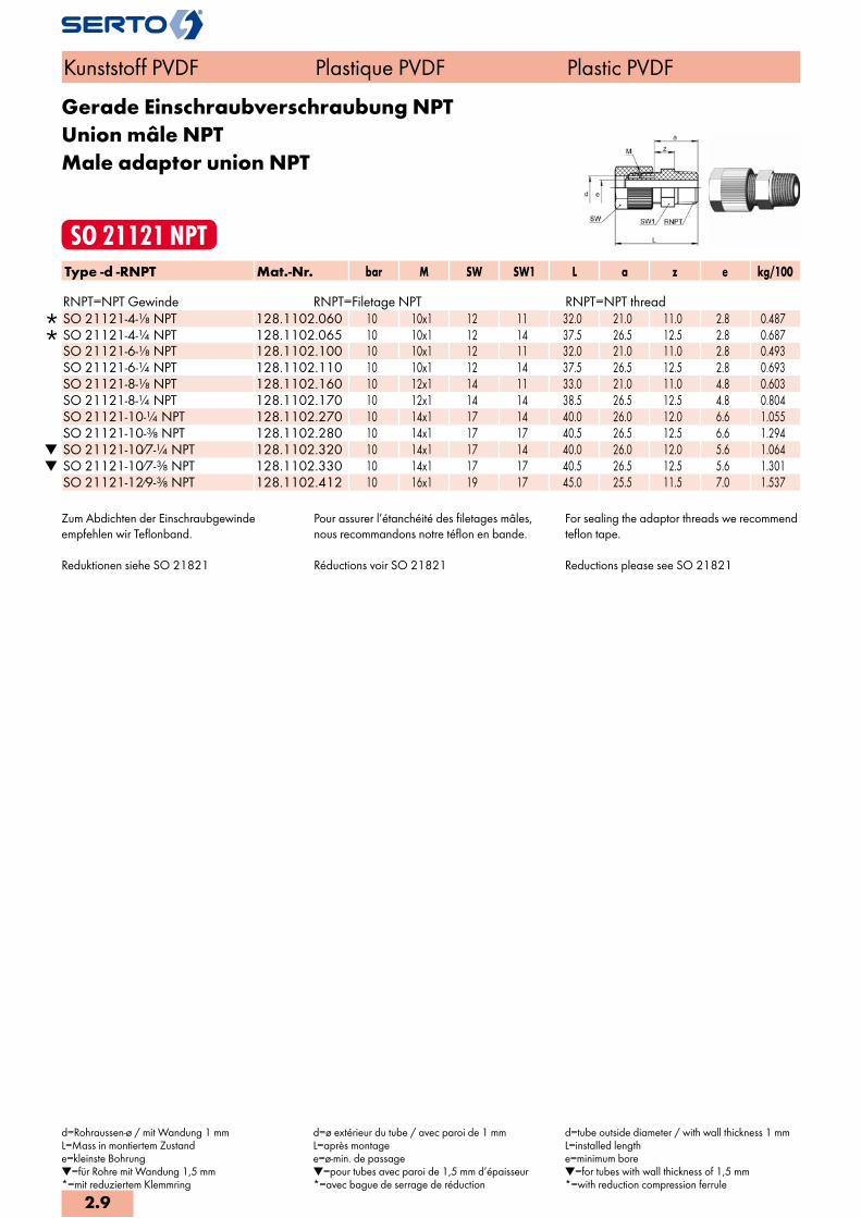
Gerade Einschraubverschraubung NPTUnion mâle NPTMale adaptor union NPT
SO 21121 NPTType -d -RNPT Mat.-Nr. bar M SW SW1 L a z e kg/100 RNPT=NPT Gewinde RNPT=Filetage NPT RNPT=NPT thread
SO 21121-4-1/8 NPT 128.1102.060 10 10x1 12 11 32.0 21.0 11.0 2.8 0.487 SO 21121-4-1/4 NPT 128.1102.065 10 10x1 12 14 37.5 26.5 12.5 2.8 0.687 SO 21121-6-1/8 NPT 128.1102.100 10 10x1 12 11 32.0 21.0 11.0 2.8 0.493 SO 21121-6-1/4 NPT 128.1102.110 10 10x1 12 14 37.5 26.5 12.5 2.8 0.693 SO 21121-8-1/8 NPT 128.1102.160 10 12x1 14 11 33.0 21.0 11.0 4.8 0.603 SO 21121-8-1/4 NPT 128.1102.170 10 12x1 14 14 38.5 26.5 12.5 4.8 0.804 SO 21121-10-1/4 NPT 128.1102.270 10 14x1 17 14 40.0 26.0 12.0 6.6 1.055 SO 21121-10-3/8 NPT 128.1102.280 10 14x1 17 17 40.5 26.5 12.5 6.6 1.294
SO 21121-10/7-1/4 NPT 128.1102.320 10 14x1 17 14 40.0 26.0 12.0 5.6 1.064 SO 21121-10/7-3/8 NPT 128.1102.330 10 14x1 17 17 40.5 26.5 12.5 5.6 1.301 SO 21121-12/9-3/8 NPT 128.1102.412 10 16x1 19 17 45.0 25.5 11.5 7.0 1.537
Zum Abdichten der Einschraubgewindeempfehlen wir Teflonband.
Reduktionen siehe SO 21821
Pour assurer l’étanchéité des filetages mâles,nous recommandons notre téflon en bande.
Réductions voir SO 21821
For sealing the adaptor threads we recommend teflon tape.
Reductions please see SO 21821
Kunststoff PVDF Plastique PVDF Plastic PVDF
d=Rohraussen-ø / mit Wandung 1 mmL=Mass in montiertem Zustande=kleinste Bohrung=für Rohre mit Wandung 1,5 mm*=mit reduziertem Klemmring
d=ø extérieur du tube / avec paroi de 1 mmL=après montagee=ø-min. de passage=pour tubes avec paroi de 1,5 mm d’épaisseur*=avec bague de serrage de réduction
d=tube outside diameter / with wall thickness 1 mmL=installed lengthe=minimum bore=for tubes with wall thickness of 1,5 mm*=with reduction compression ferrule
2.9

Gerade Einschraubverschraubungmit Dichtkante
Union mâleavec arête d‘étanchéité
Male adapter unionwith edge seal
SO 21124Type -d -G Mat.-Nr. bar M SW1 SW2 L D i z e kg/100 G=Rohrgewinde (zylindrisch) G=Filetage-gaz BSP (cylindrique) G=BSP thread (straight)
SO 21124-4-1/8 128.1161.060 10 10x1 12 10 34.5 16.0 8.0 15.5 2.8 0.571 SO 21124-4-1/4 128.1161.065 10 10x1 12 13 36.5 19.5 10.0 15.5 2.8 0.740 SO 21124-4-3/8 128.1161.068 10 10x1 12 17 37.5 23.5 10.0 16.5 2.8 1.055 SO 21124-4-1/2 128.1161.070 10 10x1 12 19 42.5 30.0 12.0 19.5 2.8 1.535 SO 21124-6-1/8 128.1161.100 10 10x1 12 10 34.5 16.0 8.0 15.5 2.8 0.577 SO 21124-6-1/4 128.1161.110 10 10x1 12 13 36.5 19.5 10.0 15.5 2.8 0.746 SO 21124-6-3/8 128.1161.120 10 10x1 12 17 37.5 23.5 10.0 16.5 2.8 1.061 SO 21124-6-1/2 128.1161.125 10 10x1 12 19 42.5 30.0 12.0 19.5 2.8 1.541 SO 21124-8-1/8 128.1161.160 10 12x1 14 10 35.5 16.0 8.0 15.5 4.8 0.690 SO 21124-8-1/4 128.1161.170 10 12x1 14 13 37.5 19.5 10.0 15.5 4.8 0.846 SO 21124-8-3/8 128.1161.180 10 12x1 14 17 38.5 23.5 10.0 16.5 4.8 1.170 SO 21124-8-1/2 128.1161.185 10 12x1 14 19 43.5 30.0 12.0 19.5 4.8 1.654 SO 21124-10-1/4 128.1161.270 10 14x1 17 13 39.0 19.5 10.0 15.0 6.6 1.097 SO 21124-10-3/8 128.1161.280 10 14x1 17 17 40.0 23.5 10.0 16.0 6.6 1.398 SO 21124-10-1/2 128.1161.285 10 14x1 17 19 45.5 30.0 12.0 19.0 6.6 1.908 SO 21124-12-1/4 128.1161.380 10 16x1 19 13 41.5 19.5 10.0 14.0 8.0 1.317 SO 21124-12-3/8 128.1161.390 10 16x1 19 17 41.5 23.5 10.0 15.0 8.0 1.632 SO 21124-12-1/2 128.1161.400 10 16x1 19 19 46.5 30.0 12.0 18.0 8.0 2.137
SO 21124-12/9-1/4 128.1161.410 10 16x1 19 13 41.5 19.5 10.0 14.0 7.0 1.360 SO 21124-12/9-3/8 128.1161.412 10 16x1 19 17 41.5 23.5 10.0 15.0 7.0 1.640 SO 21124-12/9-1/2 128.1161.414 10 16x1 19 19 46.5 30.0 12.0 18.0 7.0 2.140
Reduktionen siehe SO 21821 Réductions voir SO 21821 Reductions please see SO 21821
Kunststoff PVDF Plastique PVDF Plastic PVDF
d=Rohraussen-ø / mit Wandung 1 mmL=Mass in montiertem Zustande=kleinste Bohrung*=mit reduziertem Klemmring
d=ø extérieur du tube / avec paroi de 1 mmL=après montagee=ø-min. de passage*=avec bague de serrage de réduction
d=tube outside diameter / with wall thickness 1 mmL=installed lengthe=minimum bore*=with reduction compression ferrule
2.10
i
s
2

Gerade EinschraubverschraubungDichtung mit O-Ring (FPM)
Union mâleavec joint torique (FPM)
Male adapter unionwith O-Ring seal (FPM)
SO 21124 ORType -d -G Mat.-Nr. bar M SW1 SW2 L D i z e kg/100 G=Rohrgewinde (zylindrisch) G=Filetage-gaz BSP (cylindrique) G=BSP thread (straight)
SO 21124-4-1/8 OR 128.1171.060 10 10x1 12 10 34.5 16.0 8.0 15.5 2.8 0.576 SO 21124-4-1/4 OR 128.1171.065 10 10x1 12 13 36.5 19.5 10.0 15.5 2.8 0.739 SO 21124-4-3/8 OR 128.1171.068 10 10x1 12 17 37.5 23.5 10.0 16.5 2.8 1.045 SO 21124-4-1/2 OR 128.1171.070 10 10x1 12 19 42.5 30.0 12.0 19.5 2.8 1.516 SO 21124-6-1/8 OR 128.1171.100 10 10x1 12 10 34.5 16.0 8.0 15.5 2.8 0.583 SO 21124-6-1/4 OR 128.1171.110 10 10x1 12 13 36.5 19.5 10.0 15.5 2.8 0.746 SO 21124-6-3/8 OR 128.1171.120 10 10x1 12 17 37.5 23.5 10.0 16.5 2.8 1.051 SO 21124-6-1/2 OR 128.1171.125 10 10x1 12 19 42.5 30.0 12.0 19.5 2.8 1.522 SO 21124-8-1/8 OR 128.1171.160 10 12x1 14 10 35.5 16.0 8.0 15.5 4.8 0.661 SO 21124-8-1/4 OR 128.1171.170 10 12x1 14 13 37.5 19.5 10.0 15.5 4.8 0.661 SO 21124-8-3/8 OR 128.1171.180 10 12x1 14 17 38.5 23.5 10.0 16.5 4.8 1.126 SO 21124-8-1/2 OR 128.1171.185 10 12x1 14 19 43.5 30.0 12.0 19.5 4.8 1.558 SO 21124-10-1/4 OR 128.1171.270 10 14x1 17 13 39.0 19.5 10.0 15.0 6.6 1.072 SO 21124-10-3/8 OR 128.1171.280 10 14x1 17 17 40.0 23.5 10.0 16.0 6.6 1.364 SO 21124-10-1/2 OR 128.1171.285 10 14x1 17 19 45.5 30.0 12.0 19.0 6.6 1.812 SO 21124-12-1/4 OR 128.1171.380 10 16x1 19 13 41.5 19.5 10.0 14.0 8.0 1.289 SO 21124-12-3/8 OR 128.1171.390 10 16x1 19 17 41.5 23.5 10.0 15.0 8.0 1.594 SO 21124-12-1/2 OR 128.1171.400 10 16x1 19 19 46.5 30.0 12.0 18.0 8.0 2.039
SO 21124-12/9-1/4 OR 128.1171.410 10 16x1 19 13 41.0 19.5 10.0 24.0 7.0 1.334 SO 21124-12/9-3/8 OR 128.1171.412 10 16x1 19 17 42.0 23.5 10.0 25.0 7.0 1.599 SO 21124-12/9-1/2 OR 128.1171.414 10 16x1 19 19 47.0 30.0 12.0 30.0 7.0 1.989
Reduktionen siehe SO 21821 Réductions voir SO 21821 Reductions please see SO 21821
Kunststoff PVDF Plastique PVDF Plastic PVDF
d=Rohraussen-ø / mit Wandung 1 mmL=Mass in montiertem Zustande=kleinste Bohrung=für Rohre mit Wandung 1,5 mm*=mit reduziertem Klemmring
d=ø extérieur du tube / avec paroi de 1 mmL=après montagee=ø-min. de passage=pour tubes avec paroi de 1,5 mm d’épaisseur*=avec bague de serrage de réduction
d=tube outside diameter / with wall thickness 1 mmL=installed lengthe=minimum bore=for tubes with wall thickness of 1,5 mm*=with reduction compression ferrule
2.11

Gerade AufschraubverschraubungUnion simple femelleFemale adaptor union
SO 21221Type -d -G Mat.-Nr. bar M SW SW1 L a z e kg/100 G=Rohrgewinde (zylindrisch) G=Filetage-gaz BSP (cylindrique) G=BSP thread (straight)
SO 21221-4-1/8 128.1201.060 10 10x1 12 14 29.0 18.0 9.0 2.8 0.506 SO 21221-4-1/4 128.1201.065 10 10x1 12 17 30.0 19.0 9.0 2.8 0.618 SO 21221-4-3/8 128.1201.068 10 10x1 12 22 31.0 20.0 9.0 2.8 0.853 SO 21221-4-1/2 128.1201.070 10 10x1 12 27 34.5 23.0 9.5 2.8 1.392 SO 21221-6-1/8 128.1201.100 10 10x1 12 14 29.0 18.0 9.0 2.8 0.484 SO 21221-6-1/4 128.1201.110 10 10x1 12 17 30.0 19.0 9.0 2.8 0.594 SO 21221-6-3/8 128.1201.120 10 10x1 12 22 31.0 20.0 9.0 2.8 0.824 SO 21221-6-1/2 128.1201.125 10 10x1 12 27 34.5 23.0 9.5 2.8 1.354 SO 21221-8-1/8 128.1201.160 10 12x1 14 14 32.5 20.5 10.5 5.1 0.710 SO 21221-8-1/4 128.1201.170 10 12x1 14 17 31.0 19.0 9.0 4.8 0.709 SO 21221-8-3/8 128.1201.180 10 12x1 14 22 33.0 20.0 9.0 4.8 0.919 SO 21221-8-1/2 128.1201.185 10 12x1 14 27 35.5 23.0 9.5 4.8 1.469 SO 21221-10-1/4 128.1201.270 10 14x1 17 17 33.5 18.0 8.5 6.6 0.943 SO 21221-10-3/8 128.1201.280 10 14x1 17 22 34.5 19.0 8.5 6.6 1.163 SO 21221-10-1/2 128.1201.285 10 14x1 17 27 37.0 23.0 9.0 6.6 1.683
SO 21221-10/7-1/4 128.1201.320 10 14x1 17 17 33.0 18.0 8.5 5.0 0.963 SO 21221-10/7-3/8 128.1201.330 10 14x1 17 22 34.0 19.0 8.5 5.0 1.183 SO 21221-10/7-1/2 128.1201.335 10 14x1 17 27 37.0 23.0 9.0 5.0 1.713 SO 21221-12-3/8 128.1201.390 10 16x1 19 22 35.0 18.0 7.5 7.0 1.383 SO 21221-12-1/2 128.1201.400 10 16x1 19 27 37.5 22.0 8.0 8.0 1.933
SO 21221-12/9-3/8 128.1201.412 10 16x1 19 22 35.0 18.0 7.5 7.0 1.423 SO 21221-12/9-1/2 128.1201.414 10 16x1 19 27 37.5 22.0 8.0 8.0 1.963 SO 21221-16/13-3/8 128.1201.564 10 22x1.5 24 22 43.5 22.0 11.0 11.0 1.374 SO 21221-16/13-1/2 128.1201.566 10 22x1.5 24 27 47.0 25.0 11.5 11.0 2.884
Reduktionen siehe SO 21821 Réductions voir SO 21821 Reductions please see SO 21821
Kunststoff PVDF Plastique PVDF Plastic PVDF
d=Rohraussen-ø / mit Wandung 1 mmL=Mass in montiertem Zustande=kleinste Bohrung=für Rohre mit Wandung 1,5 mm*=mit reduziertem Klemmring
d=ø extérieur du tube / avec paroi de 1 mmL=après montagee=ø-min. de passage=pour tubes avec paroi de 1,5 mm d’épaisseur*=avec bague de serrage de réduction
d=tube outside diameter / with wall thickness 1 mmL=installed lengthe=minimum bore=for tubes with wall thickness of 1,5 mm*=with reduction compression ferrule
2.12
i
s
2
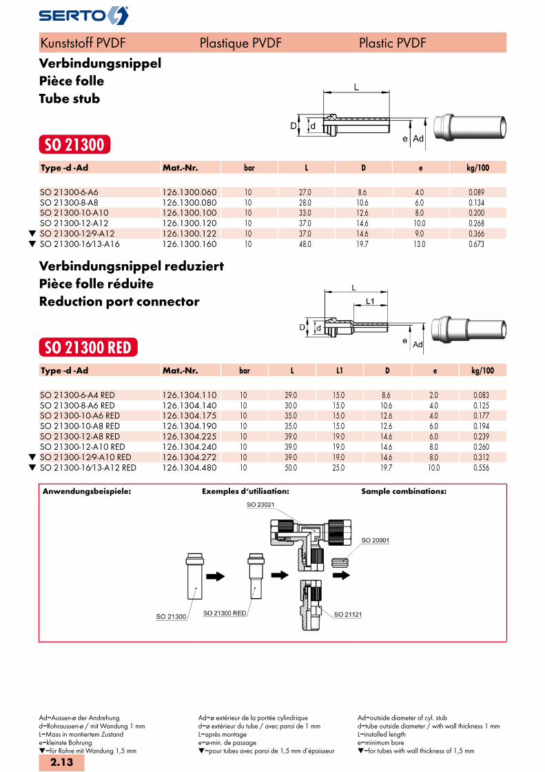
VerbindungsnippelPièce folleTube stub
SO 21300Type -d -Ad Mat.-Nr. bar L D e kg/100
SO 21300-6-A6 126.1300.060 10 27.0 8.6 4.0 0.089 SO 21300-8-A8 126.1300.080 10 28.0 10.6 6.0 0.134 SO 21300-10-A10 126.1300.100 10 33.0 12.6 8.0 0.200 SO 21300-12-A12 126.1300.120 10 37.0 14.6 10.0 0.268
SO 21300-12/9-A12 126.1300.122 10 37.0 14.6 9.0 0.366 SO 21300-16/13-A16 126.1300.160 10 48.0 19.7 13.0 0.673
Verbindungsnippel reduziertPièce folle réduiteReduction port connector
SO 21300 REDType -d -Ad Mat.-Nr. bar L L1 D e kg/100
SO 21300-6-A4 RED 126.1304.110 10 29.0 15.0 8.6 2.0 0.083 SO 21300-8-A6 RED 126.1304.140 10 30.0 15.0 10.6 4.0 0.125 SO 21300-10-A6 RED 126.1304.175 10 35.0 15.0 12.6 4.0 0.177 SO 21300-10-A8 RED 126.1304.190 10 35.0 15.0 12.6 6.0 0.194 SO 21300-12-A8 RED 126.1304.225 10 39.0 19.0 14.6 6.0 0.239 SO 21300-12-A10 RED 126.1304.240 10 39.0 19.0 14.6 8.0 0.260
SO 21300-12/9-A10 RED 126.1304.272 10 39.0 19.0 14.6 8.0 0.312 SO 21300-16/13-A12 RED 126.1304.480 10 50.0 25.0 19.7 10.0 0.556
Anwendungsbeispiele: Exemples d‘utilisation: Sample combinations:
Kunststoff PVDF Plastique PVDF Plastic PVDF
Ad=Aussen-ø der Andrehungd=Rohraussen-ø / mit Wandung 1 mmL=Mass in montiertem Zustande=kleinste Bohrung=für Rohre mit Wandung 1,5 mm
Ad=ø extérieur de la portée cylindriqued=ø extérieur du tube / avec paroi de 1 mmL=après montagee=ø-min. de passage=pour tubes avec paroi de 1,5 mm d’épaisseur
Ad=outside diameter of cyl. stubd=tube outside diameter / with wall thickness 1 mmL=installed lengthe=minimum bore=for tubes with wall thickness of 1,5 mm
2.13

Gerade SchottverschraubungUnion double pour passage de cloisonPanel mount union
SO 21521Type -d Mat.-Nr. bar M SW SW1 SW2 L L1 B z1 z e kg/100
SO 21521-4 128.1500.040 10 10x1 12 10 14 24.0 28.0 10.5 17.0 13.0 2.8 0.979 SO 21521-6 128.1500.060 10 10x1 12 14 14 24.0 28.0 10.5 17.0 13.0 2.8 0.991 SO 21521-8 128.1500.080 10 12x1 14 12 17 26.0 30.0 12.5 18.0 14.0 4.8 1.344 SO 21521-10 128.1500.100 10 14x1 17 14 19 28.5 31.5 14.5 17.5 14.0 6.6 2.007
SO 21521-10/7 128.1500.102 10 14x1 17 19 19 28.5 27.5 14.5 17.5 14.0 5.6 2.054 SO 21521-12 128.1500.120 10 16x1 19 17 19 30.0 28.5 16.5 20.0 13.5 8.0 2.812
SO 21521-12/9 128.1500.122 10 16x1 19 17 19 30.0 28.5 16.5 20.0 13.5 7.0 2.870 SO 21521-16/13 128.1500.160 10 22x1.5 24 30 22 41.0 51.0 22.5 27.0 18.0 11.0 4.634
Sechskantmutter SO 20006Reduktionen siehe SO 21821
Ecrou à six pans SO 20006Réductions voir SO 21821
Hexagon nut SO 20006Reductions please see SO 21821
Kunststoff PVDF Plastique PVDF Plastic PVDF
d=Rohraussen-ø / mit Wandung 1 mme=kleinste BohrungL=Mass in montiertem Zustand*=mit reduziertem Klemmring=für Rohre mit Wandung 1,5 mm
d=ø extérieur du tube / avec paroi de 1 mme=ø-min. de passageL=après montage *=avec bague de serrage de réduction=pour tubes avec paroi de 1,5 mm d'épaisseur
d=tube outside diameter / with wall thickness 1 mme=minimum boreL=installed length*=with reduction compression ferrule=for tubes with wall thickness of 1,5 mm
2.14
i
s
2
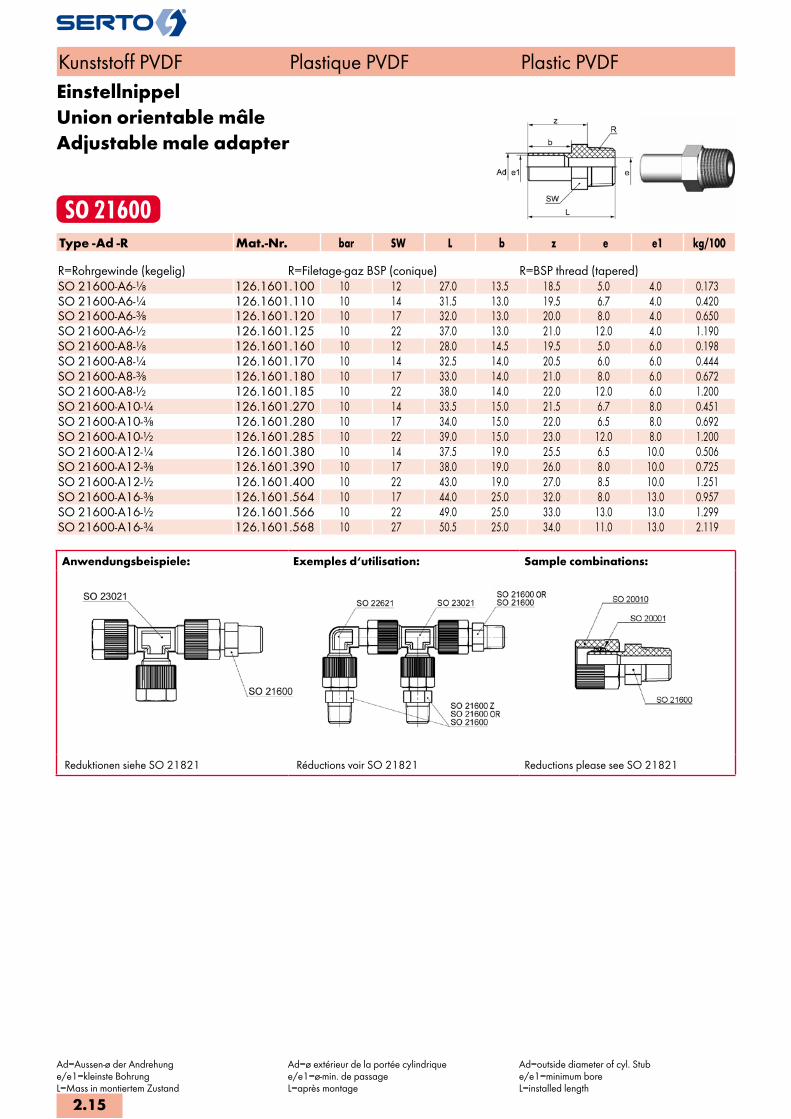
EinstellnippelUnion orientable mâleAdjustable male adapter
SO 21600Type -Ad -R Mat.-Nr. bar SW L b z e e1 kg/100 R=Rohrgewinde (kegelig) R=Filetage-gaz BSP (conique) R=BSP thread (tapered)SO 21600-A6-1/8 126.1601.100 10 12 27.0 13.5 18.5 5.0 4.0 0.173SO 21600-A6-1/4 126.1601.110 10 14 31.5 13.0 19.5 6.7 4.0 0.420SO 21600-A6-3/8 126.1601.120 10 17 32.0 13.0 20.0 8.0 4.0 0.650SO 21600-A6-1/2 126.1601.125 10 22 37.0 13.0 21.0 12.0 4.0 1.190SO 21600-A8-1/8 126.1601.160 10 12 28.0 14.5 19.5 5.0 6.0 0.198SO 21600-A8-1/4 126.1601.170 10 14 32.5 14.0 20.5 6.0 6.0 0.444SO 21600-A8-3/8 126.1601.180 10 17 33.0 14.0 21.0 8.0 6.0 0.672SO 21600-A8-1/2 126.1601.185 10 22 38.0 14.0 22.0 12.0 6.0 1.200SO 21600-A10-1/4 126.1601.270 10 14 33.5 15.0 21.5 6.7 8.0 0.451SO 21600-A10-3/8 126.1601.280 10 17 34.0 15.0 22.0 6.5 8.0 0.692SO 21600-A10-1/2 126.1601.285 10 22 39.0 15.0 23.0 12.0 8.0 1.200SO 21600-A12-1/4 126.1601.380 10 14 37.5 19.0 25.5 6.5 10.0 0.506SO 21600-A12-3/8 126.1601.390 10 17 38.0 19.0 26.0 8.0 10.0 0.725SO 21600-A12-1/2 126.1601.400 10 22 43.0 19.0 27.0 8.5 10.0 1.251SO 21600-A16-3/8 126.1601.564 10 17 44.0 25.0 32.0 8.0 13.0 0.957SO 21600-A16-1/2 126.1601.566 10 22 49.0 25.0 33.0 13.0 13.0 1.299SO 21600-A16-3/4 126.1601.568 10 27 50.5 25.0 34.0 11.0 13.0 2.119
Anwendungsbeispiele: Exemples d‘utilisation: Sample combinations:
Reduktionen siehe SO 21821 Réductions voir SO 21821 Reductions please see SO 21821
Kunststoff PVDF Plastique PVDF Plastic PVDF
Ad=Aussen-ø der Andrehunge/e1=kleinste BohrungL=Mass in montiertem Zustand
Ad=ø extérieur de la portée cylindriquee/e1=ø-min. de passageL=après montage
Ad=outside diameter of cyl. Stube/e1=minimum boreL=installed length
2.15
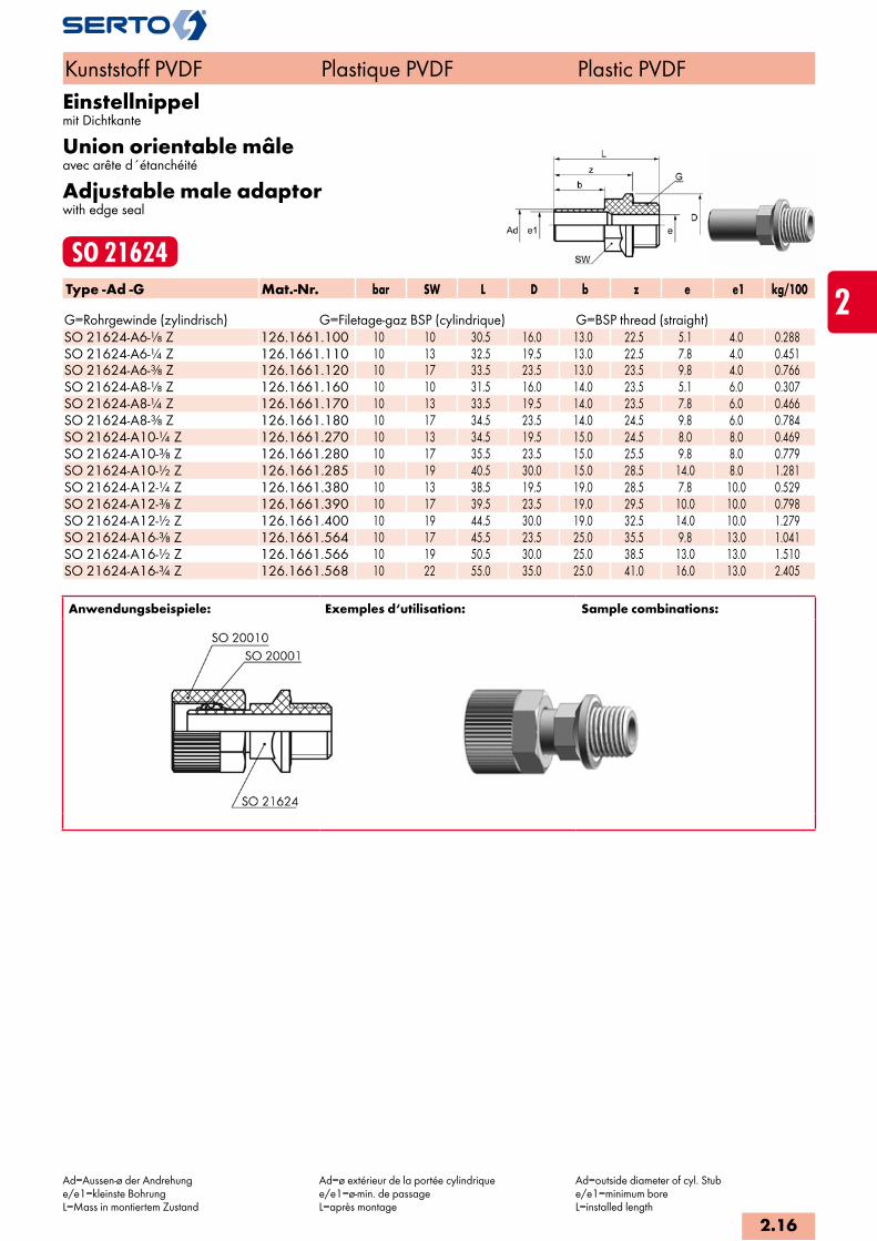
Einstellnippelmit Dichtkante
Union orientable mâleavec arête d´étanchéité
Adjustable male adaptorwith edge seal
SO 21624Type -Ad -G Mat.-Nr. bar SW L D b z e e1 kg/100 G=Rohrgewinde (zylindrisch) G=Filetage-gaz BSP (cylindrique) G=BSP thread (straight)SO 21624-A6-1/8 Z 126.1661.100 10 10 30.5 16.0 13.0 22.5 5.1 4.0 0.288SO 21624-A6-1/4 Z 126.1661.110 10 13 32.5 19.5 13.0 22.5 7.8 4.0 0.451SO 21624-A6-3/8 Z 126.1661.120 10 17 33.5 23.5 13.0 23.5 9.8 4.0 0.766SO 21624-A8-1/8 Z 126.1661.160 10 10 31.5 16.0 14.0 23.5 5.1 6.0 0.307SO 21624-A8-1/4 Z 126.1661.170 10 13 33.5 19.5 14.0 23.5 7.8 6.0 0.466SO 21624-A8-3/8 Z 126.1661.180 10 17 34.5 23.5 14.0 24.5 9.8 6.0 0.784SO 21624-A10-1/4 Z 126.1661.270 10 13 34.5 19.5 15.0 24.5 8.0 8.0 0.469SO 21624-A10-3/8 Z 126.1661.280 10 17 35.5 23.5 15.0 25.5 9.8 8.0 0.779SO 21624-A10-1/2 Z 126.1661.285 10 19 40.5 30.0 15.0 28.5 14.0 8.0 1.281SO 21624-A12-1/4 Z 126.1661.380 10 13 38.5 19.5 19.0 28.5 7.8 10.0 0.529SO 21624-A12-3/8 Z 126.1661.390 10 17 39.5 23.5 19.0 29.5 10.0 10.0 0.798SO 21624-A12-1/2 Z 126.1661.400 10 19 44.5 30.0 19.0 32.5 14.0 10.0 1.279SO 21624-A16-3/8 Z 126.1661.564 10 17 45.5 23.5 25.0 35.5 9.8 13.0 1.041SO 21624-A16-1/2 Z 126.1661.566 10 19 50.5 30.0 25.0 38.5 13.0 13.0 1.510SO 21624-A16-3/4 Z 126.1661.568 10 22 55.0 35.0 25.0 41.0 16.0 13.0 2.405
Anwendungsbeispiele: Exemples d‘utilisation: Sample combinations:
Kunststoff PVDF Plastique PVDF Plastic PVDF
Ad=Aussen-ø der Andrehunge/e1=kleinste BohrungL=Mass in montiertem Zustand
Ad=ø extérieur de la portée cylindriquee/e1=ø-min. de passageL=après montage
Ad=outside diameter of cyl. Stube/e1=minimum boreL=installed length
2.16
i
s
2
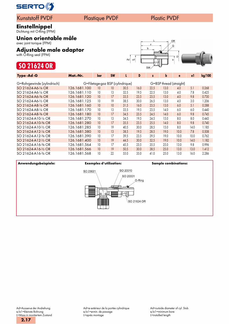
EinstellnippelDichtung mit O-Ring (FPM)
Union orientable mâleavec joint torique (FPM)
Adjustable male adaptorwith O-Ring seal (FPM)
SO 21624 ORType -Ad -G Mat.-Nr. bar SW L D z b e e1 kg/100 G=Rohrgewinde (zylindrisch) G=Filetage-gaz BSP (cylindrique) G=BSP thread (straight)SO 21624-A6-1/8 OR 126.1681.100 10 10 30.5 16.0 22.5 13.0 4.0 5.1 0.268SO 21624-A6-1/4 OR 126.1681.110 10 13 32.5 19.5 22.5 13.0 4.0 7.8 0.425SO 21624-A6-3/8 OR 126.1681.120 10 17 33.5 23.5 23.5 13.0 4.0 9.8 0.730SO 21624-A6-1/2 OR 126.1681.125 10 19 38.5 30.0 26.5 13.0 4.0 3.0 1.206SO 21624-A8-1/8 OR 126.1681.160 10 10 31.5 16.0 23.5 13.0 6.0 5.1 0.288SO 21624-A8-1/4 OR 126.1681.170 10 13 33.5 19.5 23.5 14.0 6.0 6.0 0.440SO 21624-A8-3/8 OR 126.1681.180 10 17 34.5 23.5 24.5 14.0 6.0 9.8 0.745SO 21624-A10-1/4 OR 126.1681.270 10 13 34.5 19.5 24.5 15.0 8.0 8.0 0.443SO 21624-A10-3/8 OR 126.1681.280 10 17 35.5 23.5 25.5 14.0 8.0 9.8 0.740SO 21624-A10-1/2 OR 126.1681.285 10 19 40.5 30.0 28.5 15.0 8.0 14.0 1.185SO 21624-A12-1/4 OR 126.1681.380 10 13 38.5 19.5 28.5 19.0 10.0 7.8 0.508SO 21624-A12-3/8 OR 126.1681.390 10 17 39.5 23.5 29.5 19.0 10.0 10.0 0.762SO 21624-A12-1/2 OR 126.1681.400 10 19 44.5 30.0 32.5 19.0 10.0 14.0 1.182SO 21624-A16-3/8 OR 126.1681.564 10 17 45.5 23.5 35.5 25.0 13.0 9.8 0.996SO 21624-A16-1/2 OR 126.1681.566 10 19 50.5 30.0 38.5 25.0 13.0 13.0 1.412SO 21624-A16-3/4 OR 126.1681.568 10 22 55.0 35.0 41.0 25.0 13.0 16.0 2.286
Anwendungsbeispiele: Exemples d‘utilisation: Sample combinations:
Kunststoff PVDF Plastique PVDF Plastic PVDF
Ad=Aussen-ø der Andrehunge/e1=kleinste BohrungL=Mass in montiertem Zustand
Ad=ø extérieur de la portée cylindriquee/e1=ø-min. de passageL=après montage
Ad=outside diameter of cyl. Stube/e1=minimum boreL=installed length
2.17

ReduktionsverschraubungRéductionReduced union
SO 21821Type -Ad -d Mat.-Nr. bar M SW SW1 L b z e e1 kg/100
SO 21821-A8 -4 128.1800.132 10 10x1 12 10 35.5 14.0 26.0 3.1 6.0 0.428 SO 21821-A8 -6 128.1800.140 10 10x1 12 10 35.5 14.0 26.0 2.8 6.0 0.435 SO 21821-A10-6 128.1800.175 10 10x1 12 10 38.0 15.0 27.5 2.8 6.5 0.446 SO 21821-A10-8 128.1800.190 10 12x1 14 12 39.5 15.0 27.5 4.8 6.5 0.588 SO 21821-A12-6 128.1800.215 10 10x1 12 10 42.0 19.0 32.0 2.8 10.0 0.509 SO 21821-A12-8 128.1800.225 10 12x1 14 12 43.5 19.0 32.0 4.8 10.0 0.621 SO 21821-A12-10 128.1800.240 10 14x1 17 14 45.0 19.0 31.5 6.6 10.0 0.934
SO 21821-A12-10/7 128.1800.242 10 14x1 17 14 45.0 19.0 31.5 5.6 10.0 0.941 SO 21821-A16-12 128.1800.480 10 16x1 19 17 54.0 25.0 37.5 8.0 13.0 1.441
Anwendungsbeispiele: Exemples d‘utilisation: Sample combinations:
Mit dieser Reduktion können Verschraubungen reduziert werden.
Cette réduction permet de réduire les raccords. Unions can be reduced with this reduction.
WinkelverschraubungCoudeElbow union
SO 22021Type -d Mat.-Nr. bar M SW SW1 L z e kg/100
SO 22021-4 128.2000.040 10 10x1 12 8 25.0 14.0 2.8 0.770 SO 22021-6 128.2000.060 10 10x1 12 8 25.0 14.0 2.8 0.782 SO 22021-8 128.2000.080 10 12x1 14 10 26.5 14.5 4.8 1.040 SO 22021-10 128.2000.100 10 14x1 17 12 30.0 16.0 6.6 1.679
SO 22021-10/7 128.2000.102 10 14x1 17 12 30.0 16.0 5.6 1.727 SO 22021-12 128.2000.120 10 16x1 19 13 32.5 16.0 8.0 2.188
SO 22021-12/9 128.2000.122 10 16x1 19 13 32.5 16.0 7.0 2.242 SO 22021-16/13 128.2000.160 10 22x1.5 24 19 45.5 23.0 11.0 4.989
Reduktionen siehe SO 21821 Réductions voir SO 21821 Reductions please see SO 21821
Kunststoff PVDF Plastique PVDF Plastic PVDF
d=Rohraussen-ø / mit Wandung 1 mmAd=Aussen-ø der AndrehungL=Mass in montiertem Zustand*=mit reduziertem Klemmring=für Rohre mit Wandung 1,5 mm
d=ø extérieur du tube / avec paroi de 1 mmAd=ø extérieur de la portée cylindriqueL=après montage*=avec bague de serrage de réduction=pour tubes avec paroi de 1,5 mm d’épaisseur
d=tube outside diameter / with wall thickness 1 mmAd=outside diameter of cyl. stubL=installed length*=with reduction compression ferrule=for tubes with wall thickness of 1,5 mm
2.18
i
s
2
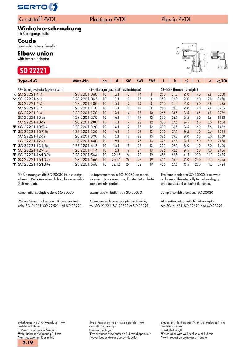
Winkelverschraubungmit Übergangsmuffe
Coudeavec adaptateur femelle
Elbow unionwith female adaptor
SO 22221Type -d -G Mat.-Nr. bar M SW SW1 SW2 L b zR z e kg/100 G=Rohrgewinde (zylindrisch) G=Filetage-gaz BSP (cylindrique) G=BSP thread (straight)
SO 22221-4-1/8 128.2201.060 10 10x1 12 14 8 25.0 31.0 22.0 14.0 2.8 0.550 SO 22221-4-1/4 128.2201.065 10 10x1 12 17 8 25.0 32.0 22.0 14.0 2.8 0.670 SO 22221-6-1/8 128.2201.100 10 10x1 12 14 8 25.0 31.0 22.0 14.0 2.8 0.535 SO 22221-6-1/4 128.2201.110 10 10x1 12 17 8 25.0 32.0 22.0 14.0 2.8 0.655 SO 22221-8-1/4 128.2201.170 10 12x1 14 17 10 26.5 33.5 23.5 14.5 4.8 0.769 SO 22221-10-1/4 128.2201.270 10 14x1 17 17 12 30.0 36.5 26.5 16.0 6.6 1.062 SO 22221-10-3/8 128.2201.280 10 14x1 17 22 12 30.0 37.5 26.5 16.0 6.6 1.284
SO 22221-10/7-1/4 128.2201.320 10 14x1 17 17 12 30.0 36.5 26.5 16.0 5.6 1.062 SO 22221-10/7-3/8 128.2201.330 10 14x1 17 22 12 30.0 37.5 26.5 16.0 5.6 1.284 SO 22221-12-3/8 128.2201.390 10 16x1 19 22 13 32.5 39.0 28.0 16.0 8.0 1.560 SO 22221-12-1/2 128.2201.400 10 16x1 19 27 13 32.5 42.5 28.5 16.0 8.0 2.086
SO 22221-12/9-3/8 128.2201.412 10 16x1 19 22 13 32.5 39.0 28.0 16.0 7.0 1.560 SO 22221-12/9-1/2 128.2201.414 10 16x1 19 27 13 32.5 42.5 28.5 16.0 7.0 2.086 SO 22221-16/13-3/8 128.2201.564 10 22x1.5 24 22 19 45.5 52.5 41.5 23.0 11.0 2.685 SO 22221-16/13-1/2 128.2201.566 10 22x1.5 24 27 19 45.5 56.0 42.0 23.0 11.0 3.155 SO 22221-16/13-3/4 128.2201.568 10 22x1.5 24 32 19 45.5 57.5 42.5 23.0 11.0 3.424
Die Übergangsmuffe SO 20030 ist lose aufge-schraubt. Beim Anziehen dichtet die angedrehteDichtkante ab.
Kombinationsbeispiele siehe SO 20030
Weitere Verschraubungen mit Innengewindesiehe SO 21221, SO 22521 und SO 23221.
L’adaptateur femelle SO 20030 est montélibrement. Lors du serrage, l’arête d’étanchéitéforme un joint parfait.
Exemples d’utilisation voir SO 20030
Autres raccords avec adaptateur femelle,voir SO 21221, SO 22521 et SO 23221.
The female adaptor SO 20030 is screwedon loosely. The integrally turned sealing lipproduces a seal on being tightened.
Sample combinations see SO 20030
Alternative unions with female adaptorsee SO 21221, SO 22521 and SO 23221.
Kunststoff PVDF Plastique PVDF Plastic PVDF
d=Rohraussen-ø / mit Wandung 1 mme=kleinste BohrungL=Mass in montiertem Zustand=für Rohre mit Wandung 1,5 mm*=mit reduziertem Klemmring
d=ø extérieur du tube / avec paroi de 1 mme=ø-min. de passageL=après montage=pour tubes avec paroi de 1,5 mm d’épaisseur*=avec bague de serrage de réduction
d=tube outside diameter / with wall thickness 1 mme=minimum boreL=installed length=for tubes with wall thickness of 1,5 mm*=with reduction compression ferrule
2.19
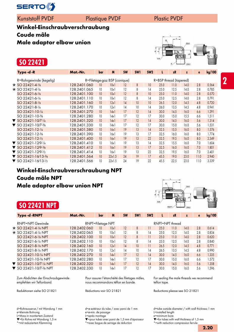
Winkel-EinschraubverschraubungCoude mâleMale adaptor elbow union
SO 22421Type -d -R Mat.-Nr. bar M SW SW1 SW2 L zR z e kg/100 R=Rohrgewinde (kegelig) R=Filetage-gaz BSP (conique) R=BSP thread (tapered)
SO 22421-4-1/8 128.2401.060 10 10x1 12 8 10 25.0 11.0 14.0 2.8 0.564 SO 22421-4-1/4 128.2401.065 10 10x1 12 8 14 25.0 12.5 14.0 2.8 0.785 SO 22421-6-1/8 128.2401.100 10 10x1 12 8 10 25.0 11.0 14.0 2.8 0.570 SO 22421-6-1/4 128.2401.110 10 10x1 12 8 14 25.0 12.5 14.0 2.8 0.791 SO 22421-8-1/8 128.2401.160 10 12x1 14 10 10 26.5 12.0 14.5 4.8 0.720 SO 22421-8-1/4 128.2401.170 10 12x1 14 10 14 26.0 13.5 14.5 4.8 0.941 SO 22421-10-1/4 128.2401.270 10 14x1 17 12 14 30.0 14.5 16.0 6.6 1.291 SO 22421-10-3/8 128.2401.280 10 14x1 17 12 17 30.0 15.0 15.5 6.6 1.511
SO 22421-10/7-1/4 128.2401.320 10 14x1 17 12 14 30.0 14.5 16.0 5.6 1.314 SO 22421-10/7-3/8 128.2401.330 10 14x1 17 12 17 30.0 15.0 16.0 5.6 1.531 SO 22421-12-1/4 128.2401.380 10 16x1 19 13 14 32.5 15.5 16.0 8.0 1.576 SO 22421-12-3/8 128.2401.390 10 16x1 19 13 17 32.5 16.0 16.0 8.0 1.774 SO 22421-12-1/2 128.2401.400 10 16x1 19 13 22 32.5 19.5 16.0 8.0 2.349
SO 22421-12/9-1/4 128.2401.410 10 16x1 19 13 14 32.5 15.5 16.0 7.0 1.604 SO 22421-12/9-3/8 128.2401.412 10 16x1 19 13 17 32.5 16.0 16.0 7.0 1.801 SO 22421-12/9-1/2 128.2401.414 10 16x1 19 13 22 32.5 19.5 16.0 7.0 2.401 SO 22421-16/13-3/8 128.2401.564 10 22x1.5 24 19 17 45.5 19.0 23.0 11.0 2.940 SO 22421-16/13-1/2 128.2401.566 10 22x1.5 24 19 22 45.5 22.5 23.0 11.0 3.339
Winkel-Einschraubverschraubung NPTCoude mâle NPTMale adaptor elbow union NPT
SO 22421 NPTType -d -RNPT Mat.-Nr. bar M SW SW1 SW2 L zR z e kg/100 RNPT=NPT Gewinde RNPT=Filetage NPT RNPT=NPT thread
SO 22421-4-1/8 NPT 128.2402.060 10 10x1 12 8 11 25.0 11.0 14.0 2.8 0.614 SO 22421-4-1/4 NPT 128.2402.065 10 10x1 12 8 14 25.0 12.5 14.0 2.8 0.834 SO 22421-6-1/8 NPT 128.2402.100 10 10x1 12 8 11 25.0 11.0 14.0 2.8 0.620 SO 22421-6-1/4 NPT 128.2402.110 10 10x1 12 8 14 25.0 12.5 14.0 2.8 0.840 SO 22421-8-1/8 NPT 128.2402.160 10 12x1 14 10 11 26.5 12.0 14.5 4.8 0.771 SO 22421-8-1/4 NPT 128.2402.170 10 12x1 14 10 14 26.5 13.5 14.5 4.8 0.990 SO 22421-10-1/4 NPT 128.2402.270 10 14x1 17 12 14 30.0 14.5 16.0 6.6 1.335 SO 22421-10-3/8 NPT 128.2402.280 10 14x1 17 12 17 30.0 15.0 16.0 6.6 1.572
SO 22421-10/7-1/4 NPT 128.2402.320 10 14x1 17 12 14 30.0 14.5 16.0 5.6 1.358 SO 22421-10/7-3/8 NPT 128.2402.330 10 14x1 17 12 17 30.0 15.0 16.0 5.6 1.596
Zum Abdichten der Einschraubgewindeempfehlen wir Teflonband.
Reduktionen siehe SO 21821
Pour assurer l’étanchéité des filetages mâles,nous recommandons téflon en bande.
Réductions voir SO 21821
For sealing the male threads we recommendteflon tape.
Reductions please see SO 21821
Kunststoff PVDF Plastique PVDF Plastic PVDF
d=Rohraussen-ø / mit Wandung 1 mme=kleinste BohrungL=Mass in montiertem Zustand=für Rohre mit Wandung 1,5 m*=mit reduziertem Klemmring
d=ø extérieur du tube / avec paroi de 1 mme=ø-min. de passageL=après montage=pour tubes avec paroi de 1,5 mm d’épaisseur *=avec bague de serrage de réduction
d=tube outside diameter / with wall thickness 1 mmL=installed lengthe=minimum bore=for tubes with wall thickness of 1,5 mm*=with reduction compression ferrule
2.20
i
s
2

EinstellwinkelCoude orientableAdjustable elbow union
SO 22621Type -d -Ad Mat.-Nr. bar M SW SW1 L f zA z e kg/100
SO 22621-4-A6 128.2600.045 10 10x1 12 8 25.0 14.0 24.0 14.0 2.8 0.516 SO 22621-6-A6 128.2600.060 10 10x1 12 8 25.0 14.0 24.0 14.0 2.8 0.507 SO 22621-8-A8 128.2600.080 10 12x1 14 10 26.5 16.0 25.0 14.5 4.8 0.695 SO 22621-10-A10 128.2600.100 10 14x1 17 12 30.0 18.0 29.0 16.0 6.6 1.082 SO 22621-12-A12 128.2600.120 10 16x1 19 13 32.5 21.0 32.0 16.0 8.0 1.399
Anwendungsbeispiele: Exemples d‘utilisation: Sample combinations:
WinkelschottverschraubungCoude pour passage cloisonPanel mount elbow union
SO 22721Type -d Mat.-Nr. bar M SW1 SW2 SW3 L L1 z z1 T e kg/100
SO 22721-4 128.2700.040 10 10x1 10 14 12 25.0 36.0 14.0 13.0 6.0 2.8 1.142 SO 22721-6 128.2700.060 10 10x1 10 14 12 25.0 40.0 14.0 13.0 6.0 2.8 1.122 SO 22721-8 128.2700.080 10 12x1 12 17 14 26.5 43.0 14.5 15.0 6.0 4.8 1.506 SO 22721-10 128.2700.100 10 14x1 14 19 17 30.0 46.0 16.0 16.5 6.0 6.6 2.136
SO 22721-10/7 128.2700.102 10 14x1 14 19 17 30.0 46.0 16.0 16.5 6.0 5.6 3.062 SO 22721-12 128.2700.120 10 16x1 17 22 19 32.5 48.5 16.0 17.5 5.0 8.0 2.869
SO 22721-12/9 128.2700.122 10 16x1 17 22 19 32.5 48.5 16.0 17.5 5.0 7.0 2.949 SO 22721-16/13 128.2700.160 10 22x1.5 22 30 24 45.5 54.0 23.0 19.5 3.0 11.0 5.848
Sechskantmutter SO 20006 Ecrou à six pans SO 20006 Hexagon nut SO 20006
Kunststoff PVDF Plastique PVDF Plastic PVDF
d=Rohraussen-ø / mit Wandung 1 mmAd=Aussen-ø der AndrehungL=Mass in montiertem Zustand=für Rohre mit Wandung 1,5 mm*=mit reduziertem Klemmring
d=ø extérieur du tube / avec paroi de 1 mmAd=ø extérieur de la portée cylindriqueL=après montage=pour tubes avec paroi de 1,5 mm d’épaisseur*=avec bague de serrage de réduction.
d=tube outside diameter / with wall thickness 1 mmAd=outside diameter of cyl. StubL=installed length=for tubes with wall thickness of 1,5 mm*=with reduction compression ferrule
2.21

T-VerschraubungTéTee union
SO 23021Type -d Mat.-Nr. bar M SW SW1 L z e kg/100
SO 23021-4 128.3000.040 10 10x1 12 8 25.0 14.0 2.8 1.132 SO 23021-6 128.3000.060 10 10x1 12 8 25.0 14.0 2.8 1.149 SO 23021-8 128.3000.080 10 12x1 14 10 26.5 14.5 4.8 1.520 SO 23021-10 128.3000.100 10 14x1 17 12 30.0 16.0 6.6 2.449
SO 23021-10/7 128.3000.102 10 14x1 17 12 30.0 16.0 5.6 2.512 SO 23021-12 128.3000.120 10 16x1 19 13 32.5 16.0 8.0 3.202
SO 23021-12/9 128.3000.122 10 16x1 19 13 32.5 16.0 7.0 3.275 SO 23021-16/13 128.3000.160 10 22x1.5 24 19 45.5 23.0 11.0 7.211
Reduktionen siehe SO 21821 Réductions voir SO 21821 Reductions please see SO 21821
T-Verschraubung reduziertTé réduitTee reduction union
SO 23021 REDType -d -d2 -d3 Mat.-Nr. bar M M1 SW1 SW2 SW3 L L1 z e e1 kg/100 SO 23021-8-12-8 128.3004.107 10 12x1 16x1 14 19 10 27.5 31.0 14.5 4.8 8.0 2.100SO 23021-12-8-12 128.3004.210 10 16x1 12x1 19 14 13 33.5 29.5 16.0 8.0 4.8 2.800
Kunststoff PVDF Plastique PVDF Plastic PVDF
d=Rohraussen-ø / mit Wandung 1 mme=kleinste BohrungL=Mass in montiertem Zustand=für Rohre mit Wandung 1,5 mm*=mit reduziertem Klemmring
d=ø extérieur du tube / avec paroi de 1 mme=ø-min. de passageL=après montage=pour tubes avec paroi de 1,5 mm d’épaisseur*=avec bague de serrage de réduction
d=tube outside diameter / with wall thickness 1 mme=minimum boreL=installed length=for tubes with wall thickness of 1,5 mm*=with reduction compression ferrule
2.22
i
s
2

T-Verschraubungmit Übergangsmuffe
Téavec adaptateur femelle
Tee unionwith female adaptor
SO 23221Type -d -G Mat.-Nr. bar M SW SW1 L b D zR z e kg/100 G=Rohrgewinde (zylindrisch) G=Filetage-gaz BSP (cylindrique) G=BSP thread (straight)
SO 23221-4-1/8-4 128.3201.060 10 10x1 12 14 24.5 36.0 16.0 27.0 13.5 3.1 1.280 SO 23221-4-1/4-4 128.3201.065 10 10x1 12 17 24.5 37.0 22.0 27.0 13.5 3.1 1.420 SO 23221-6-1/8-6 128.3201.100 10 10x1 12 14 24.5 36.0 16.0 27.0 13.5 3.1 1.240 SO 23221-6-1/4-6 128.3201.110 10 10x1 12 17 24.5 37.0 22.0 27.0 13.5 3.1 1.380 SO 23221-8-1/4-8 128.3201.170 10 12x1 14 17 29.0 39.0 22.0 29.0 17.0 5.1 1.930 SO 23221-10-1/4-10 128.3201.270 10 14x1 17 19 32.5 38.5 22.0 28.5 18.5 6.7 2.810 SO 23221-10-3/8-10 128.3201.280 10 14x1 17 22 32.5 44.0 25.5 33.0 18.5 6.7 3.290
SO 23221-10/7-1/4-10/7 128.3201.320 10 14x1 17 19 32.5 38.5 22.0 28.5 18.5 5.2 2.640 SO 23221-10/7-3/8-10/7 128.3201.330 10 14x1 17 22 32.5 44.0 25.5 33.0 18.5 5.2 3.120 SO 23221-12-3/8-12 128.3201.390 10 16x1 19 22 34.0 44.5 25.5 33.5 17.5 7.2 4.040 SO 23221-12-1/2-12 128.3201.400 10 16x1 19 27 34.0 48.5 30.5 34.5 17.5 7.2 4.670
SO 23221-12/9-3/8-12/9 128.3201.412 10 16x1 19 22 34.0 44.5 25.5 33.5 17.5 7.2 4.020 SO 23221-12/9-1/2-12/9 128.3201.414 10 16x1 19 27 34.0 48.5 30.5 34.5 17.5 7.2 4.650 SO 23221-16/13-3/8-16/13 128.3201.564 10 22x1.5 24 27 50.5 61.5 30.6 50.5 28.0 11.0 8.000 SO 23221-16/13-1/2-16/13 128.3201.566 10 22x1.5 24 27 50.5 61.5 30.6 47.5 28.0 11.0 8.200 SO 23221-16/13-3/4-16/13 128.3201.568 10 22x1.5 24 32 50.5 61.5 36.6 46.5 28.0 11.0 8.600
Anwendungsbeispiele: Exemples d‘utilisation: Sample combinations:
Die Übergangsmuffe SO 20030 ist lose auf-geschraubt und kann mit der Rändelmutter SO 20020 gewechselt werden. Beim Anziehen dich-tet die angedrehte Dichtkante ab.
Kombinationsbeispiele siehe SO 20030.
Weitere Verschraubungen mit Innengewinde siehe SO 21221 und SO 22221.
L’adaptateur femelle SO 20030 est monté libre-ment. Lors du serrage, l’arête d’étanchéité forme un joint parfait.
Exemples d’utilisation voir SO 20030.
Autres raccords avec adaptateur femelle, voir SO 21221 et SO 22221.
The female adaptor SO 20030 is screwed on loosely and can be exchanged with the knurled nut SO 20020. The integrally turned sealing lip produces a seal on being tighte-ned.
Sample combinations see SO 20030.
Alternative unions with female adaptor see SO 21221 and SO 22221.
Kunststoff PVDF Plastique PVDF Plastic PVDF
d=Rohraussen-ø / mit Wandung 1 mme=kleinste BohrungL=Mass in montiertem Zustand=für Rohre mit Wandung 1,5 mm*=mit reduziertem Klemmring
d=ø extérieur du tube / avec paroi de 1 mme=ø-min. de passageL=après montage=pour tubes avec paroi de 1,5 mm d’épaisseur*=avec bague de serrage de réduction
d=tube outside diameter / with wall thickness 1 mme=minimum boreL=installed length=for tubes with wall thickness of 1,5 mm*=with reduction compression ferrule
2.23

Einstellbare T-VerschraubungTé orientableAdjustable tee union
SO 23621Type -d -Ad -d Mat.-Nr. bar M SW SW1 L f zA z e kg/100 SO 23621-6-A6-6 128.3600.060 10 10x1 12 8 25.0 14.0 24.0 14.0 2.8 0.880SO 23621-8-A8-8 128.3600.080 10 12x1 14 10 26.5 16.0 25.0 14.5 4.8 1.190SO 23621-10-A10-10 128.3600.100 10 14x1 17 12 30.0 20.0 29.0 16.0 6.6 1.830SO 23621-12-A12-12 128.3600.120 10 16x1 19 13 32.5 21.0 30.0 16.0 8.0 2.395
Anwendungsbeispiele: Exemples d‘utilisation: Sample combinations:
Kunststoff PVDF Plastique PVDF Plastic PVDF
d=Rohraussen-ø / mit Wandung 1 mmAd=Aussen-ø der Andrehunge=kleinste BohrungL=Mass in montiertem Zustand
d=ø extérieur du tube / avec paroi de 1 mmAd=ø extérieur de la portée cylindriquee=ø-min. de passageL=après montage
d=tube outside diameter / with wall thickness 1 mmAd=outside diameter of cyl. Stube=minimum boreL=installed length
2.24
i
s
2

T-EinschraubverschraubungTé mâleMale adaptor tee union
SO 23721Type -d -R -d3 Mat.-Nr. bar M SW SW1 SW2 L zR z e kg/100 R=Rohrgewinde (kegelig) R=Filetage-gaz BSP (conique) R=BSP thread (tapered)
SO 23721-4-1/8-4 128.3701.040 10 10x1 12 10 10 25.0 11.0 14.0 2.8 0.926 SO 23721-4-1/4-4 128.3701.045 10 10x1 12 14 14 25.0 12.5 14.0 2.8 1.148 SO 23721-6-1/8-6 128.3701.100 10 10x1 12 10 10 25.0 11.0 14.0 2.8 0.938 SO 23721-6-1/4-6 128.3701.110 10 10x1 12 14 14 25.0 12.5 14.0 2.8 1.160 SO 23721-8-1/8-8 128.3701.160 10 12x1 14 10 10 26.5 12.0 14.5 4.8 1.197 SO 23721-8-1/4-8 128.3701.170 10 12x1 14 10 14 26.5 13.5 14.5 4.8 1.300 SO 23721-10-1/4-10 128.3701.270 10 14x1 17 14 14 30.0 14.5 16.0 6.6 2.058 SO 23721-10-3/8-10 128.3701.280 10 14x1 17 17 17 30.0 15.0 16.0 6.6 1.720
SO 23721-10/7-1/4-10/7 128.3701.320 10 14x1 17 14 14 30.0 14.5 16.0 5.6 1.544 SO 23721-10/7-3/8-10/7 128.3701.330 10 14x1 17 17 17 30.0 15.0 16.0 5.6 1.762
Zum Abdichten der Einschraubgewindeempfehlen wir Teflonband.
Reduktionen siehe SO 21821
Pour assurer l’étanchéité des filetages mâles,nous recommandons le téflon en bande.
Réductions voir SO 21821
For sealing the adaptor threads we recommend teflon tape.
Reductions please see SO 21821
Kunststoff PVDF Plastique PVDF Plastic PVDF
d=Rohraussen-ø / mit Wandung 1 mme=kleinste BohrungL=Mass in montiertem Zustand=für Rohre mit Wandung 1,5 mm*=mit reduziertem Klemmring
d=ø extérieur du tube / avec paroi de 1 mme=ø-min. de passageL=après montage=pour tubes avec paroi de 1,5 mm d’épaisseur*=avec bague de serrage de réduction
d=tube outside diameter / with wall thickness 1 mme=minimum boreL=installed length=for tubes with wall thickness of 1,5 mm*=with reduction compression ferrule
2.25

ReduziermuffeRéduction femelle-femelleFemale reduction socket
SO 20031Type -G -G2 Mat.-Nr. bar SW L b kg/100G=Rohrgewinde (zylindrisch) G=Filetage-gaz BSP (cylindrique) G=BSP thread (straight)G2=Rohrgewinde (zylindrisch) G2=Filetage-gaz BSP (cylindrique) G2=BSP thread (straight)SO 20031-1/8-1/8 126.0311.042 10 14 16.0 8.0 0.199SO 20031-1/8-1/4 126.0311.044 10 17 17.0 11.0 0.323SO 20031-1/8-3/8 126.0311.046 10 22 18.0 12.0 0.546SO 20031-1/8-1/2 126.0311.048 10 27 21.0 14.0 1.081SO 20031-1/4-1/4 126.0311.104 10 17 17.5 9.0 0.331SO 20031-1/4-3/8 126.0311.106 10 22 19.0 12.0 0.568SO 20031-1/4-1/2 126.0311.108 10 27 22.0 14.0 1.083SO 20031-3/8-3/8 126.0311.166 10 22 19.0 9.5 0.558SO 20031-3/8-1/2 126.0311.168 10 27 22.5 14.0 1.081
ReduziernippelRéduction femelle-mâleMale reduction nipple
SO 20041Type -G -R2 Mat.-Nr. bar SW L L1 L2 e kg/100G=Rohrgewinde (zylindrisch) G=Filetage-gaz BSP (cylindrique) G=BSP thread (straight)R2=Rohrgewinde (kegelig) R2=Filetage-gaz BSP (conique) R2=BSP thread (tapered)SO 20041-1/8-1/8 126.0411.042 10 14 20.0 8.0 7.0 6.0 0.242SO 20041-1/8-1/4 126.0411.044 10 14 24.0 12.0 7.0 8.6 0.327SO 20041-1/8-3/8 126.0411.046 10 17 25.0 12.0 7.0 8.6 0.701SO 20041-1/8-1/2 126.0411.048 10 22 30.0 16.0 7.0 8.6 1.154SO 20041-1/4-1/8 126.0411.102 10 17 21.0 8.0 8.0 6.0 0.363SO 20041-1/4-1/4 126.0411.104 10 17 25.0 12.0 8.0 6.5 0.515SO 20041-1/4-3/8 126.0411.106 10 17 25.0 12.0 8.0 11.5 0.497SO 20041-1/4-1/2 126.0411.108 10 22 30.0 16.0 8.0 11.5 1.106SO 20041-3/8-1/4 126.0411.164 10 22 26.0 12.0 8.5 6.7 0.731SO 20041-3/8-3/8 126.0411.166 10 22 26.0 12.0 8.5 8.0 0.862SO 20041-3/8-1/2 126.0411.168 10 22 30.0 16.0 8.5 15.0 0.916
Kunststoff PVDF Plastique PVDF Plastic PVDF
2.26
i
s
2

Sechskant-VerschlussschraubeBouchon mâle à 6 pansMale hexagon plug
SO 20371Type -R Mat.-Nr. SW L L1 kg/100R=Rohrgewinde (kegelig) R=Filetage-gaz BSP (conique) R=BSP thread (tapered) SO 20371-1/8 126.0721.020 10 13.0 8.0 0.141SO 20371-1/4 126.0721.040 14 18.5 12.0 0.379SO 20371-3/8 126.0721.060 17 19.0 12.0 0.356SO 20371-1/2 126.0721.080 22 24.0 16.0 1.810
EinschraubtülleDouille cannelée à visserMale adaptor hose nozzle
SO 20511Type -d1 -R Mat.-Nr. bar SW L a b e kg/100R=Rohrgewinde (kegelig) R=Filetage-gaz BSP (conique) R=BSP thread (tapered)
SO 20511-4-1/8 126.0511.060 10 10 24.0 13.0 8.0 3.0 0.157SO 20511-6-1/8 126.0511.100 10 10 30.0 13.0 12.0 4.0 0.201SO 20511-6-1/4 126.0511.110 10 14 35.5 18.5 12.0 4.0 0.438SO 20511-8-1/4 126.0511.170 10 14 35.5 18.5 12.0 6.0 0.456SO 20511-10-3/8 126.0511.280 10 17 38.0 19.0 14.0 7.0 0.764SO 20511-12-3/8 126.0511.390 10 17 38.0 19.0 14.0 10.0 0.649SO 20511-12-1/2 126.0511.400 10 22 43.0 24.0 14.0 10.0 1.262
Für die Schlauchsicherung verwenden Sie bitteunsere Schlauchklemme SO 40512(Stahl promatverzinkt).
d1 = Schlauchinnen-Øe = kleinste Bohrung
Afin d’assurer la bonne tenue des tuyaux, utilisernos colliers de serrage SO 40512(Acier zingué passivé).
d1 = Ø intérieur du tuyaue = Ø min. de passage
Please use our hose clip SO 40512(zinc promatised) for securing the hose.
d1 = hose inside diametere = minimum bore
Kunststoff PVDF Plastique PVDF Plastic PVDF
2.27
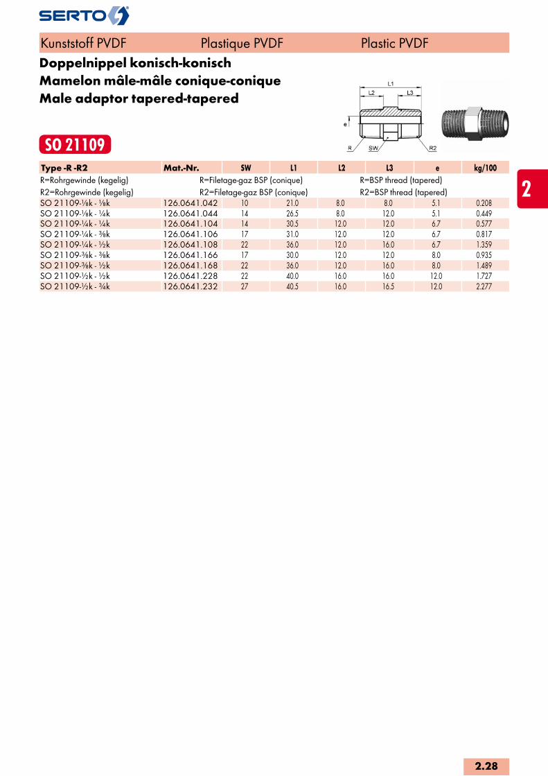
Doppelnippel konisch-konischMamelon mâle-mâle conique-coniqueMale adaptor tapered-tapered
SO 21109Type -R -R2 Mat.-Nr. SW L1 L2 L3 e kg/100R=Rohrgewinde (kegelig) R=Filetage-gaz BSP (conique) R=BSP thread (tapered)R2=Rohrgewinde (kegelig) R2=Filetage-gaz BSP (conique) R2=BSP thread (tapered)SO 21109-1/8k - 1/8k 126.0641.042 10 21.0 8.0 8.0 5.1 0.208SO 21109-1/8k - 1/4k 126.0641.044 14 26.5 8.0 12.0 5.1 0.449SO 21109-1/4k - 1/4k 126.0641.104 14 30.5 12.0 12.0 6.7 0.577SO 21109-1/4k - 3/8k 126.0641.106 17 31.0 12.0 12.0 6.7 0.817SO 21109-1/4k - 1/2k 126.0641.108 22 36.0 12.0 16.0 6.7 1.359SO 21109-3/8k - 3/8k 126.0641.166 17 30.0 12.0 12.0 8.0 0.935SO 21109-3/8k - 1/2k 126.0641.168 22 36.0 12.0 16.0 8.0 1.489SO 21109-1/2k - 1/2k 126.0641.228 22 40.0 16.0 16.0 12.0 1.727SO 21109-1/2k - 3/4k 126.0641.232 27 40.5 16.0 16.5 12.0 2.277
Kunststoff PVDF Plastique PVDF Plastic PVDF
2.28
i
s
2


3
Kunststoff PA
Verschraubungen
Plastique PA
Raccords
Plastic PA
Unions
3.3KlemmringBague de serrageCompression ferrule
SO 30001
3.3AbschlusszapfenBouchon d‘arrêtPlug
SO 30002
3.4RändelmutterEcrou moletéKnurled nut
SO 30020
3.4Gerade VerschraubungUnion doubleStraight union
SO 31021
3.5-3.6Gerade EinschraubverschraubungUnion mâleMale adaptor union
SO 31121
3.7Gerade AufschraubverschraubungUnion femelleFemale adaptor union
SO 31221
3.8VerbindungsnippelPièce folleTube stub
SO 31300
3.9Gerade SchottverschraubungUnion double pour passage de cloisonPanel mount union
SO 31521
3.10-3.11EinstellnippelUnion orientable mâleAdjustable male adaptor
SO 31600
3.12ReduktionsverschraubungRéductionReduced union
SO 31821
3.12WinkelverschraubungCoudeElbow union
SO 32021
3.13Winkel-EinschraubverschraubungCoude mâleMale adaptor elbow union
SO 32421
3.14EinstellwinkelCoude orientableAdjustable elbow union
SO 32621
3.14WinkelschottverschraubungCoude pour passage cloisonPanel mount elbow union
SO 32721
3.15SchwenkverschraubungCoude banjoSingle banjo
SO 32821
3.162-fach WinkelschwenkverschraubungCoude banjo multipleDouble banjo
SO 32921
3.17T-VerschraubungTéTee union
SO 33021
3.17Einstellbare T-VerschraubungTé orientableAdjustable tee union
SO 33621
3.18T-EinschraubverschraubungTé mâleMale adaptor tee union
SO 33721
3.19SchwenkverschraubungCoude banjoSingle banjo
SO 37621
3.20EinschraubtülleDouille cannelée à visserMale adaptor hose nozzle
SO 30511
Sonderausführungen:Exécution en option:Optional Services:
Spezialreinigung - entfettetTraitement spécial - sans siliconeSpecial treatment - degreased
Vorbeschichtete Gewinde mit Loctite 5061Filetages pré enduits avec Loctite 5061Pre-coated threads with Loctite 5061
Vorbeschichtete Gewinde PTFE-Band umwickeltFiletages pré enduits avec ruban en PTFEPre-coated threads with PTFE-tape
Seite/Page/Page Seite/Page/Page Seite/Page/Page
Übersicht Aperçu Overview
3.1
300°250°200°150°100°60° 80°0°-40° -20°
60% 50%75%
40°23°C° -100°
100%75%
Kunststoff PA Plastique PA Plastic PA
Eigenschaften, Besonderheiten- einfache, schnelle Montage- preisgünstige Verschraubungsreihe- Kombinationsmöglichkeit mit Messing-, Stahl- und Edelstahl-Verschraubungen- grosse Sortimentsvielfalt
Funktionsprinzipsiehe Anhang
AnwendungHervorragend für Pneumatikanwendungen geeignet. Nicht direkter Sonnenbestrahlung aussetzen.
WerkstoffFormteile und Nippel aus hitzestabilisiertem Polyamid 6.6, grau.
Betriebsdruck PN10 bar bei +23°C (3fache Sicherheit)
Temperaturbereich-40°C bis +80°C.
Anzuschliessende RohreToleranzhaltige Rohre und Schläuche mit sauberer Oberfläche und gleichmässiger Wandung. Siehe auch Kapitel Rohre und Schläuche.
Généralités- montage facile et rapide- prix avantageux- combinaison possible avec des raccords en matière laiton, acier et acier inoxydable- gamme complète
Principe de fonctionnementvoir annexe
ApplicationLes systèmes pneumatiques comme domaine d’application principal. Ne pas exposer directe-ment aux rayons du soleil.
MatériauLe raccord est réalisé en polyamide 6.6 gris stabilisé à la chaleur.
Pression de service PN10 bar à +23°C (facteur de sécurité 3)
Plage de température admissible-40°C à +80°C.
Tubes à utiliserTubes et tuyaux flexibles respectant les tolérances avec surface propre et d’épaisseur de paroi régulier. Voir aussi chapitre tubes et tuyaux.
Characteristics, specialities- easy and fast to install- advantageous price- combinations possible with unions of brass, steel and stainless steel- extensive range
Operating principlesee appendix
ApplicationThe main field of application is pneumatic tubing. Should not be subjected to direct sun-light.
MaterialMoulded body, union nut and ferrule are made of heat-stabilized grey polyamide 6.6.
Working pressure PN10 bar at +23°C (safety factor 3)
Temperature range-40°C to +80°C.
Tubes to useTrue to tolerance tubes and hoses with clean surface and uniform wall thickness. See also chapter tubes and hoses.
Druckauswertungsgrad in % des PN
Coefficient de pression de service admissible en % de PN
Pressure coefficent % of PN
3.2
i
s
3
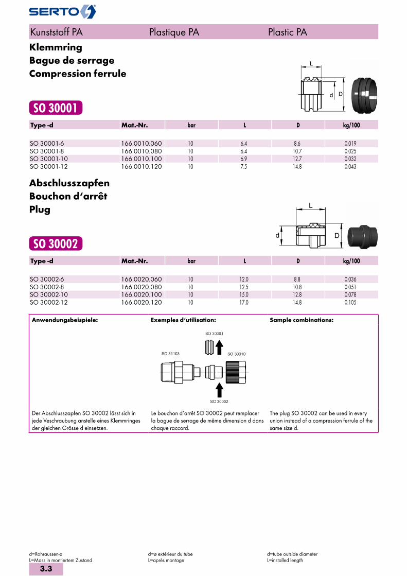
KlemmringBague de serrageCompression ferrule
SO 30001Type -d Mat.-Nr. bar L D kg/100 SO 30001-6 166.0010.060 10 6.4 8.6 0.019SO 30001-8 166.0010.080 10 6.4 10.7 0.025SO 30001-10 166.0010.100 10 6.9 12.7 0.032SO 30001-12 166.0010.120 10 7.5 14.8 0.043
AbschlusszapfenBouchon d‘arrêtPlug
SO 30002Type -d Mat.-Nr. bar L D kg/100 SO 30002-6 166.0020.060 10 12.0 8.8 0.036SO 30002-8 166.0020.080 10 12.5 10.8 0.051SO 30002-10 166.0020.100 10 15.0 12.8 0.078SO 30002-12 166.0020.120 10 17.0 14.8 0.105
Anwendungsbeispiele: Exemples d‘utilisation: Sample combinations:
Der Abschlusszapfen SO 30002 lässt sich in jede Veschraubung anstelle eines Klemmringes der gleichen Grösse d einsetzen.
Le bouchon d‘arrêt SO 30002 peut remplacer la bague de serrage de même dimension d dans chaque raccord.
The plug SO 30002 can be used in every union instead of a compression ferrule of the same size d.
Kunststoff PA Plastique PA Plastic PA
d=Rohraussen-øL=Mass in montiertem Zustand
d=ø extérieur du tubeL=après montage
d=tube outside diameterL=installed length
3.3

RändelmutterEcrou moletéKnurled nut
SO 30020Type -d Mat.-Nr. bar M SW L D kg/100 SO 30020-6 166.0100.060 10 10x1 12 14.5 14.0 0.160SO 30020-8 166.0100.080 10 12x1 14 16.0 16.0 0.210SO 30020-10 166.0100.100 10 14x1 17 17.5 19.5 0.360SO 30020-12 166.0100.120 10 16x1 19 19.5 22.0 0.480
Gerade VerschraubungUnion doubleStraight union
SO 31021Type -d Mat.-Nr. bar M SW1 L z e kg/100
SO 31021-6 168.1000.060 10 10x1 10 39.0 16.0 2.8 0.513 SO 31021-8 168.1000.080 10 12x1 12 42.0 17.5 4.8 0.702 SO 31021-10 168.1000.100 10 14x1 14 45.5 17.5 6.6 1.096
SO 31021-10/7 168.1000.102 10 14x1 14 45.5 17.5 5.6 1.111 SO 31021-12 168.1000.120 10 16x1 17 49.0 16.0 8.0 1.492
SO 31021-12/9 168.1000.122 10 16x1 17 49.0 16.0 7.0 1.506
Reduktionen siehe SO 31821 Réductions voir SO 31821 Reductions please see SO 31821
Kunststoff PA Plastique PA Plastic PA
d=Rohraussen-ø / mit Wandung 1 mmL=Mass in montiertem Zustande=kleinste Bohrung=für Rohre mit Wandung 1,5 mm
d=ø extérieur du tube / avec paroi de 1 mmL=après montagee=ø-min. de passage=pour tubes avec paroi de 1,5 mm d’épaisseur
d=tube outside diameter / with wall thickness 1 mmL=installed lengthe=minimum bore=for tubes with wall thickness of 1,5 mm
3.4
i
s
3

Gerade EinschraubverschraubungUnion mâleMale adaptor union
SO 31121Type -d -R Mat.-Nr. bar M SW SW1 L a z e kg/100 R=Rohrgewinde (kegelig) R=Filetage-gaz BSP (conique) R=BSP thread (tapered)
SO 31121-6-1/8 168.1101.100 10 10x1 12 12 30.0 19.0 11.0 2.8 0.143 SO 31121-6-1/4 168.1101.110 10 10x1 12 14 35.5 24.5 12.5 2.8 0.302 SO 31121-6-3/8 168.1101.120 10 10x1 12 17 36.0 25.0 13.0 2.8 0.460 SO 31121-8-1/8 168.1101.160 10 12x1 14 12 31.2 19.0 11.0 4.8 0.175 SO 31121-8-1/4 168.1101.170 10 12x1 14 14 36.5 24.5 12.5 4.8 0.328 SO 31121-8-3/8 168.1101.180 10 12x1 14 17 37.5 25.0 13.0 4.8 0.485 SO 31121-10-1/4 168.1101.270 10 14x1 17 14 38.0 24.0 12.0 6.6 0.352 SO 31121-10-3/8 168.1101.280 10 14x1 17 17 38.5 24.5 12.5 6.6 0.508
SO 31121-10/7-1/4 168.1101.320 10 14x1 17 14 38.0 24.0 12.0 5.6 0.360 SO 31121-10/7-3/8 168.1101.330 10 14x1 17 17 38.5 24.5 12.5 5.6 0.516 SO 31121-12-1/4 168.1101.380 10 16x1 19 14 39.5 23.0 11.0 6.6 0.385 SO 31121-12-3/8 168.1101.390 10 16x1 19 17 40.0 23.5 11.5 8.0 0.538 SO 31121-12-1/2 168.1101.400 10 16x1 19 22 45.0 28.5 12.5 8.0 0.876
SO 31121-12/9-1/4 168.1101.410 10 16x1 19 14 39.5 23.0 11.0 6.6 0.394 SO 31121-12/9-3/8 168.1101.412 10 16x1 19 17 40.0 23.5 11.5 7.0 0.551 SO 31121-12/9-1/2 168.1101.414 10 16x1 19 22 45.0 28.5 12.5 7.0 0.879
Gerade Einschraubverschraubung NPTUnion mâle NPTMale adaptor union NPT
SO 31121 NPTType -d -RNPT Mat.-Nr. bar M SW SW1 L a z e kg/100 RNPT=NPT Gewinde RNPT=Filetage NPT RNPT=NPT thread
SO 31121-6-1/8 NPT 168.1102.100 10 10x1 12 11 32.0 21.0 11.0 2.8 0.165 SO 31121-6-1/4 NPT 168.1102.110 10 10x1 12 14 37.5 26.5 12.5 2.8 0.293 SO 31121-8-1/8 NPT 168.1102.160 10 12x1 14 11 33.0 21.0 11.0 4.8 0.193 SO 31121-8-1/4 NPT 168.1102.170 10 12x1 14 14 38.5 26.5 12.5 4.8 0.321 SO 31121-10-1/4 NPT 168.1102.270 10 14x1 17 14 40.0 26.0 12.0 6.6 0.347 SO 31121-10-3/8 NPT 168.1102.280 10 14x1 17 17 40.5 26.5 12.5 6.6 0.500
SO 31121-10/7-1/4 NPT 168.1102.320 10 14x1 17 14 40.0 26.0 12.0 5.6 0.353 SO 31121-10/7-3/8 NPT 168.1102.330 10 14x1 17 17 40.5 26.5 12.5 5.6 0.508 SO 31121-12/9-3/8 NPT 168.1102.412 10 16x1 19 17 45.0 25.5 11.5 7.0 1.164
Zum Abdichten der Einschraubgewinde empfeh-len wir unseren Dichtstift «Plasto-Joint» AC 833. Reduktionen siehe SO 31821
Pour assurer l’étanchéité des filetages mâles, nous recommandons notre bâton «Plasto-Joint» AC 833. Réductions voir SO 31821
For sealing the male threads we recommend our sealing stick «Plasto-Joint» AC 833. Reductions please see SO 31821
Kunststoff PA Plastique PA Plastic PA
d=Rohraussen-ø / mit Wandung 1 mme=kleinste BohrungL=Mass in montiertem Zustand=für Rohre mit Wandung 1,5 mm
d=ø extérieur du tube / avec paroi de 1 mme=ø-min. de passageL=après montage=pour tubes avec paroi de 1,5 mm d’épaisseur
d=tube outside diameter / with wall thickness 1 mme=minimum boreL=installed length=for tubes with wall thickness of 1,5 mm
3.5

Gerade Einschraubverschraubungmit Dichtkante
Union mâleavec arête d‘étanchéité
Male adapter unionwith edge seal
SO 31124Type -d -G Mat.-Nr. bar M SW1 SW2 L D i z e kg/100 G=Rohrgewinde (zylindrisch) G=Filetage-gaz BSP (cylindrique) G=BSP thread (straight)SO 31124-6-1/8 168.1161.100 10 10x1 12 10 34.5 16.0 8.0 15.5 2.8 0.577SO 31124-6-1/4 168.1161.110 10 10x1 12 13 36.5 19.5 10.0 15.5 2.8 0.746SO 31124-8-1/8 168.1161.160 10 12x1 14 10 35.5 16.0 8.0 15.5 4.8 0.690SO 31124-8-1/4 168.1161.170 10 12x1 14 13 37.5 19.5 10.0 15.5 4.8 0.846SO 31124-10-1/4 168.1161.270 10 14x1 17 13 39.0 19.5 10.0 15.0 6.6 1.097SO 31124-10-3/8 168.1161.280 10 14x1 17 17 40.0 23.5 10.0 16.0 6.6 1.398SO 31124-12-1/4 168.1161.380 10 16x1 19 13 41.5 19.5 10.0 14.0 8.0 1.317SO 31124-12-3/8 168.1161.390 10 16x1 19 17 41.5 23.5 10.0 15.0 8.0 1.632
Reduktionen siehe SO 31821 Réductions voir SO 31821 Reductions please see SO 31821
Gerade EinschraubverschraubungDichtung mit O-Ring (NBR)
Union mâleavec joint torique (NBR)
Male adaptor unionwith O-Ring seal (NBR)
SO 31124 ORType -d -G Mat.-Nr. bar M SW1 SW2 L D i z e kg/100 G=Rohrgewinde (zylindrisch) G=Filetage-gaz BSP (cylindrique) G=BSP thread (straight)SO 31124-6-1/8 OR 168.1171.100 10 10x1 12 10 34.5 16.0 8.0 15.5 2.8 0.378SO 31124-6-1/4 OR 168.1171.110 10 10x1 12 13 36.5 19.5 10.0 15.5 2.8 0.482SO 31124-6-3/8 OR 168.1171.120 10 10x1 12 17 37.5 23.5 10.0 16.5 2.8 0.695SO 31124-8-1/8 OR 168.1171.160 10 12x1 14 10 35.5 16.0 8.0 15.5 4.8 0.462SO 31124-8-1/4 OR 168.1171.170 10 12x1 14 13 37.5 19.5 10.0 15.5 4.8 0.557SO 31124-8-3/8 OR 168.1171.180 10 12x1 14 17 38.5 23.5 10.0 16.5 4.8 0.758SO 31124-10-1/4 OR 168.1171.270 10 14x1 17 13 39.0 19.5 10.0 15.0 6.6 0.737SO 31124-10-3/8 OR 168.1171.280 10 14x1 17 17 40.0 23.5 10.0 16.0 6.6 0.924SO 31124-10-1/2 OR 168.1171.285 10 14x1 17 19 45.0 30.0 12.0 19.0 6.6 1.210SO 31124-12-1/4 OR 168.1171.380 10 16x1 19 13 41.5 19.5 10.0 14.0 8.0 0.897SO 31124-12-3/8 OR 168.1171.390 10 16x1 19 17 41.5 23.5 10.0 15.0 8.0 1.092SO 31124-12-1/2 OR 168.1171.400 10 16x1 19 19 46.5 30.0 12.0 18.0 8.0 1.376
Kunststoff PA Plastique PA Plastic PA
d=Rohraussen-ø / mit Wandung 1 mme=kleinste BohrungL=Mass in montiertem Zustand
d=ø extérieur du tube / avec paroi de 1 mme=ø-min. de passageL=après montage
d=tube outside diameter / with wall thickness 1 mme=minimum boreL=installed length
3.6
i
s
3
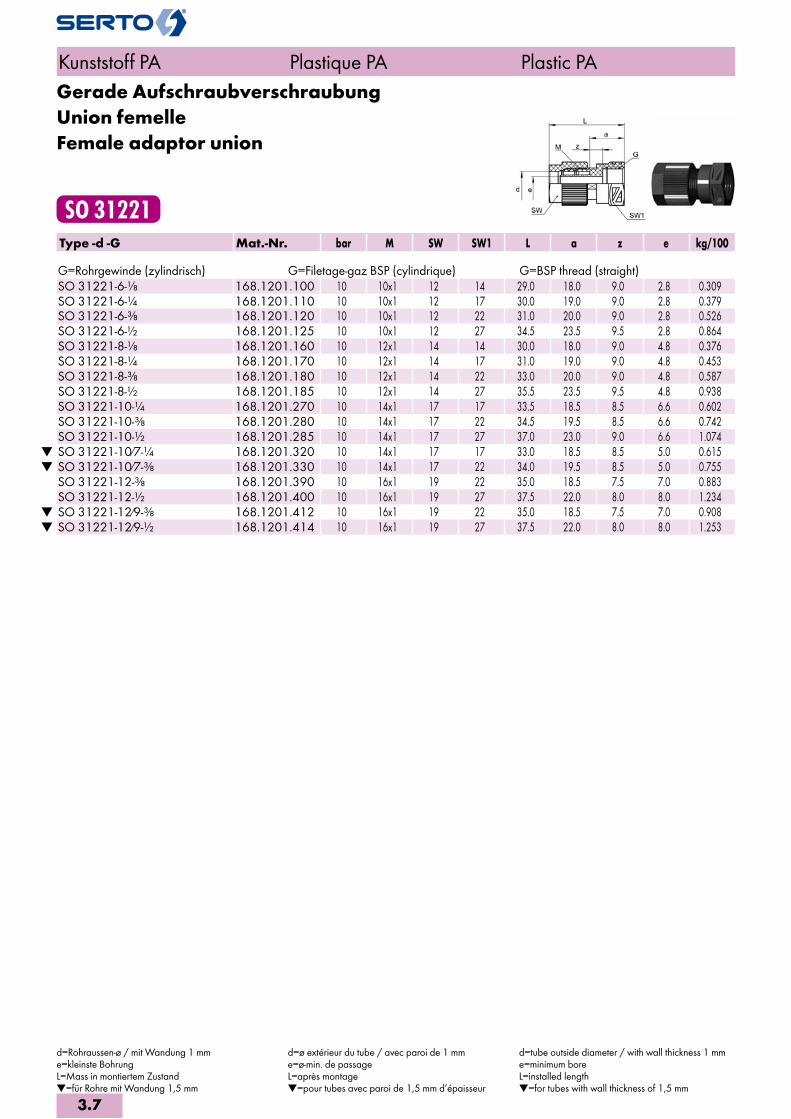
Gerade AufschraubverschraubungUnion femelleFemale adaptor union
SO 31221Type -d -G Mat.-Nr. bar M SW SW1 L a z e kg/100 G=Rohrgewinde (zylindrisch) G=Filetage-gaz BSP (cylindrique) G=BSP thread (straight)
SO 31221-6-1/8 168.1201.100 10 10x1 12 14 29.0 18.0 9.0 2.8 0.309 SO 31221-6-1/4 168.1201.110 10 10x1 12 17 30.0 19.0 9.0 2.8 0.379 SO 31221-6-3/8 168.1201.120 10 10x1 12 22 31.0 20.0 9.0 2.8 0.526 SO 31221-6-1/2 168.1201.125 10 10x1 12 27 34.5 23.5 9.5 2.8 0.864 SO 31221-8-1/8 168.1201.160 10 12x1 14 14 30.0 18.0 9.0 4.8 0.376 SO 31221-8-1/4 168.1201.170 10 12x1 14 17 31.0 19.0 9.0 4.8 0.453 SO 31221-8-3/8 168.1201.180 10 12x1 14 22 33.0 20.0 9.0 4.8 0.587 SO 31221-8-1/2 168.1201.185 10 12x1 14 27 35.5 23.5 9.5 4.8 0.938 SO 31221-10-1/4 168.1201.270 10 14x1 17 17 33.5 18.5 8.5 6.6 0.602 SO 31221-10-3/8 168.1201.280 10 14x1 17 22 34.5 19.5 8.5 6.6 0.742 SO 31221-10-1/2 168.1201.285 10 14x1 17 27 37.0 23.0 9.0 6.6 1.074
SO 31221-10/7-1/4 168.1201.320 10 14x1 17 17 33.0 18.5 8.5 5.0 0.615 SO 31221-10/7-3/8 168.1201.330 10 14x1 17 22 34.0 19.5 8.5 5.0 0.755 SO 31221-12-3/8 168.1201.390 10 16x1 19 22 35.0 18.5 7.5 7.0 0.883 SO 31221-12-1/2 168.1201.400 10 16x1 19 27 37.5 22.0 8.0 8.0 1.234
SO 31221-12/9-3/8 168.1201.412 10 16x1 19 22 35.0 18.5 7.5 7.0 0.908 SO 31221-12/9-1/2 168.1201.414 10 16x1 19 27 37.5 22.0 8.0 8.0 1.253
Kunststoff PA Plastique PA Plastic PA
d=Rohraussen-ø / mit Wandung 1 mme=kleinste BohrungL=Mass in montiertem Zustand=für Rohre mit Wandung 1,5 mm
d=ø extérieur du tube / avec paroi de 1 mme=ø-min. de passageL=après montage=pour tubes avec paroi de 1,5 mm d’épaisseur
d=tube outside diameter / with wall thickness 1 mme=minimum boreL=installed length=for tubes with wall thickness of 1,5 mm
3.7

VerbindungsnippelPièce folleTube stub
SO 31300Type -d -Ad Mat.-Nr. bar L D e kg/100
SO 31300-6-A6 166.1300.060 10 27.0 8.7 4.0 0.060 SO 31300-8-A8 166.1300.080 10 28.0 10.8 6.0 0.085 SO 31300-10-A10 166.1300.100 10 33.0 12.8 8.0 0.127 SO 31300-12-A12 166.1300.120 10 37.0 14.7 10.0 0.171
SO 31300-12/9-A12 166.1300.122 10 37.0 14.7 9.0 0.233
Verbindungsnippel reduziertPièce folle réduiteReducing port connector
SO 31300 REDType -d -Ad Mat.-Nr. bar L L1 D e kg/100 SO 31300-8-A6 RED 166.1304.140 10 30.0 15.0 10.6 4.0 0.080SO 31300-10-A6 RED 166.1304.175 10 35.0 15.0 12.6 4.0 0.113SO 31300-10-A8 RED 166.1304.190 10 35.0 15.0 12.6 6.0 0.124SO 31300-12-A8 RED 166.1304.225 10 39.0 19.0 14.6 6.0 0.150SO 31300-12-A10 RED 166.1304.240 10 39.0 19.0 14.6 8.0 0.166
Anwendungsbeispiele: Exemples d‘utilisation: Sample combinations:
Kunststoff PA Plastique PA Plastic PA
d=Rohraussen-ø / mit Wandung 1 mmAd=Aussen-ø der Andrehunge=kleinste BohrungL=Mass in montiertem Zustand=für Rohre mit Wandung 1,5 mm
d=ø extérieur du tube / avec paroi de 1 mmAd=ø extérieur de la portée cylindriquee=ø-min. de passageL=après montage=pour tubes avec paroi de 1,5 mm d’épaisseur
d=tube outside diameter / with wall thickness 1 mmAd=outside diameter of cyl. Stube=minimum boreL=installed length=for tubes with wall thickness of 1,5 mm
3.8
i
s
3
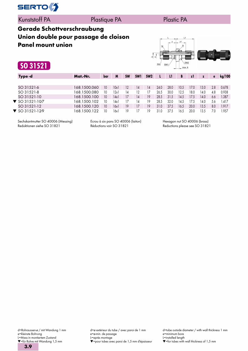
Gerade SchottverschraubungUnion double pour passage de cloisonPanel mount union
SO 31521Type -d Mat.-Nr. bar M SW SW1 SW2 L L1 B z1 z e kg/100
SO 31521-6 168.1500.060 10 10x1 12 14 14 24.0 28.0 10.5 17.0 13.0 2.8 0.678 SO 31521-8 168.1500.080 10 12x1 14 12 17 26.5 30.0 12.5 18.0 14.0 4.8 0.938 SO 31521-10 168.1500.100 10 14x1 17 14 19 28.5 31.5 14.5 17.5 14.0 6.6 1.387
SO 31521-10/7 168.1500.102 10 14x1 17 14 19 28.5 32.0 14.5 17.5 14.0 5.6 1.417 SO 31521-12 168.1500.120 10 16x1 19 17 19 31.0 37.5 16.5 20.0 13.5 8.0 1.917
SO 31521-12/9 168.1500.122 10 16x1 19 17 19 31.0 37.5 16.5 20.0 13.5 7.0 1.957
Sechskantmutter SO 40006 (Messing)Reduktionen siehe SO 31821
Ecrou à six pans SO 40006 (laiton)Réductions voir SO 31821
Hexagon nut SO 40006 (brass)Reductions please see SO 31821
Kunststoff PA Plastique PA Plastic PA
d=Rohraussen-ø / mit Wandung 1 mme=kleinste BohrungL=Mass in montiertem Zustand=für Rohre mit Wandung 1,5 mm
d=ø extérieur du tube / avec paroi de 1 mme=ø-min. de passageL=après montage=pour tubes avec paroi de 1,5 mm d'épaisseur
d=tube outside diameter / with wall thickness 1 mme=minimum boreL=installed length=for tubes with wall thickness of 1,5 mm
3.9

EinstellnippelUnion orientable mâleAdjustable male adaptor
SO 31600Type -Ad -R Mat.-Nr. bar SW L b z e e1 kg/100 R=Rohrgewinde (kegelig) R=Filetage-gaz BSP (conique) R=BSP thread (tapered)SO 31600-A6-1/8 166.1601.100 10 12 27.0 13.0 18.5 5.0 4.0 0.110SO 31600-A6-1/4 166.1601.110 10 14 31.5 13.0 19.5 6.7 4.0 0.268SO 31600-A6-3/8 166.1601.120 10 17 32.0 13.0 20.0 8.0 4.0 0.410SO 31600-A8-1/8 166.1601.160 10 12 28.0 14.0 20.0 5.0 6.0 0.124SO 31600-A8-1/4 166.1601.170 10 14 32.5 14.0 20.5 6.0 6.0 0.282SO 31600-A8-3/8 166.1601.180 10 17 33.0 14.0 21.0 8.0 6.0 0.429SO 31600-A10-1/4 166.1601.270 10 14 33.5 15.0 21.5 6.7 8.0 0.285SO 31600-A10-3/8 166.1601.280 10 17 34.0 15.0 22.0 6.5 8.0 0.442SO 31600-A10-1/2 166.1601.285 10 22 39.0 15.0 23.0 12.0 8.0 0.760SO 31600-A12-1/4 166.1601.380 10 14 37.5 19.0 25.5 6.7 10.0 0.315SO 31600-A12-3/8 166.1601.390 10 17 38.0 19.0 26.0 8.0 10.0 0.464SO 31600-A12-1/2 166.1601.400 10 22 43.0 19.0 27.0 8.5 12.0 0.798
Anwendungsbeispiele: Exemples d‘utilisation: Sample combinations:
Kunststoff PA Plastique PA Plastic PA
d=Rohraussen-ø / mit Wandung 1 mme/e1=kleinste BohrungL=Mass in montiertem Zustand
d=ø extérieur du tube / avec paroi de 1 mme/e1=ø-min. de passageL=après montage
d=tube outside diameter / with wall thickness 1 mme/e1=minimum boreL=installed length
3.10
i
s
3
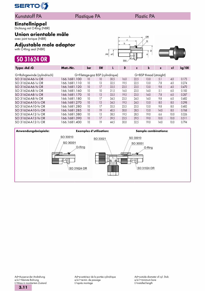
EinstellnippelDichtung mit O-Ring (NBR)
Union orientable mâleavec joint torique (NBR)
Adjustable male adaptorwith O-Ring seal (NBR)
SO 31624 ORType -Ad -G Mat.-Nr. bar SW L D z b e e1 kg/100 G=Rohrgewinde (zylindrisch) G=Filetage-gaz BSP (cylindrique) G=BSP thread (straight)SO 31624-A6-1/8 OR 166.1681.100 10 10 30.5 16.0 22.5 13.0 5.1 4.0 0.175SO 31624-A6-1/4 OR 166.1681.110 10 13 32.5 19.5 22.5 13.0 7.8 4.0 0.274SO 31624-A6-3/8 OR 166.1681.120 10 17 33.5 23.5 23.5 13.0 9.8 4.0 0.470SO 31624-A8-1/8 OR 166.1681.160 10 10 31.5 16.0 23.5 14.0 5.1 6.0 0.183SO 31624-A8-1/4 OR 166.1681.170 10 13 33.5 19.5 23.5 14.0 7.8 6.0 0.287SO 31624-A8-3/8 OR 166.1681.180 10 17 34.5 23.5 24.5 14.0 9.8 6.0 0.482SO 31624-A10-1/4 OR 166.1681.270 10 13 34.5 19.5 24.5 15.0 8.0 8.0 0.298SO 31624-A10-3/8 OR 166.1681.280 10 17 35.5 23.5 25.5 15.0 9.8 8.0 0.482SO 31624-A10-1/2 OR 166.1681.285 10 19 40.5 30.0 28.5 15.0 14.0 8.0 0.768SO 31624-A12-1/4 OR 166.1681.380 10 13 38.5 19.5 28.5 19.0 6.6 10.0 0.326SO 31624-A12-3/8 OR 166.1681.390 10 17 39.5 23.5 29.5 19.0 10.0 10.0 0.511SO 31624-A12-1/2 OR 166.1681.400 10 19 44.5 30.0 32.5 19.0 14.0 10.0 0.794
Anwendungsbeispiele: Exemples d‘utilisation: Sample combinations:
Kunststoff PA Plastique PA Plastic PA
Ad=Aussen-ø der Andrehunge/e1=kleinste BohrungL=Mass in montiertem Zustand
Ad=ø extérieur de la portée cylindriquee/e1=ø-min. de passageL=après montage
Ad=outside diameter of cyl. Stube/e1=minimum boreL=installed length
3.11

ReduktionsverschraubungRéductionReduced union
SO 31821Type -Ad -d Mat.-Nr. bar M SW SW1 L b z e e1 kg/100
SO 31821-A8-6 168.1800.140 10 10x1 12 10 35.5 14.0 25.8 2.8 6.0 0.301 SO 31821-A10-6 168.1800.175 10 10x1 12 10 39.0 15.0 27.5 2.8 6.5 0.308 SO 31821-A10-8 168.1800.190 10 12x1 14 12 39.5 15.5 27.5 4.8 8.0 0.415 SO 31821-A12-6 168.1800.215 10 10x1 12 10 42.0 19.0 32.0 2.8 10.0 0.348 SO 31821-A12-8 168.1800.225 10 12x1 14 12 43.5 19.0 32.0 4.8 10.0 0.436 SO 31821-A12-10 168.1800.240 10 14x1 17 14 45.0 19.0 32.0 6.6 10.0 0.500
SO 31821-A12-10/7 168.1800.242 10 14x1 17 14 45.0 19.0 31.5 5.6 10.0 0.667
Anwendungsbeispiele: Exemples d‘utilisation: Sample combinations:
Mit dieser Reduktion können Verschraubungen reduziert werden.
Cette réduction permet de réduire les raccords. Unions can be reduced with this reduction.
WinkelverschraubungCoudeElbow union
SO 32021Type -d Mat.-Nr. bar M SW SW1 L z e kg/100
SO 32021-6 168.2000.060 10 10x1 12 8 25.0 14.0 2.8 0.546 SO 32021-8 168.2000.080 10 12x1 14 10 26.5 14.5 4.8 0.743 SO 32021-10 168.2000.100 10 14x1 17 12 30.0 16.0 6.6 1.178
SO 32021-10/7 168.2000.102 10 14x1 17 12 30.0 16.0 5.6 1.209 SO 32021-12 168.2000.120 10 16x1 19 13 32.5 16.0 8.0 1.545
SO 32021-12/9 168.2000.122 10 16x1 19 13 32.5 16.0 7.0 1.580
Reduktionen siehe SO 31821 Réductions voir SO 31821 Reductions please see SO 31821
Kunststoff PA Plastique PA Plastic PA
d=Rohraussen-ø / mit Wandung 1 mmAd=Aussen-ø der Andrehunge=kleinste BohrungL=Mass in montiertem Zustand=für Rohre mit Wandung 1,5 mm
d=ø extérieur du tube / avec paroi de 1 mmAd=ø extérieur de la portée cylindriquee=ø-min. de passageL=après montage=pour tubes avec paroi de 1,5 mm d’épaisseur
d=tube outside diameter / with wall thickness 1 mmAd=outside diameter of cyl. Stube=minimum boreL=installed length=for tubes with wall thickness of 1,5 mm
3.12
i
s
3

Winkel-EinschraubverschraubungCoude mâleMale adaptor elbow union
SO 32421Type -d -R Mat.-Nr. bar M SW SW1 SW2 L zR z e kg/100 R=Rohrgewinde (kegelig) R=Filetage-gaz BSP (conique) R=BSP thread (tapered)
SO 32421-6-1/8 168.2401.100 10 10x1 12 8 10 25.0 11.0 14.0 2.8 0.387 SO 32421-6-1/4 168.2401.110 10 10x1 12 8 14 25.0 12.5 14.0 2.8 0.528 SO 32421-8-1/8 168.2401.160 10 12x1 14 10 10 26.5 12.0 14.5 4.8 0.499 SO 32421-8-1/4 168.2401.170 10 12x1 14 10 14 26.5 13.5 14.5 4.8 0.640 SO 32421-10-1/4 168.2401.270 10 14x1 17 12 14 30.0 14.5 16.0 6.6 0.877 SO 32421-10-3/8 168.2401.280 10 14x1 17 12 17 29.5 15.0 15.5 6.6 1.016
SO 32421-10/7-1/4 168.2401.320 10 14x1 17 12 14 30.0 14.5 16.0 5.6 0.892 SO 32421-10/7-3/8 168.2401.330 10 14x1 17 12 17 30.0 15.0 16.0 5.6 1.031 SO 32421-12-1/4 168.2401.380 10 16x1 19 13 14 32.5 15.5 16.0 8.0 1.080 SO 32421-12-3/8 168.2401.390 10 16x1 19 13 17 32.5 16.0 16.0 8.0 1.207 SO 32421-12-1/2 168.2401.400 10 16x1 19 13 22 32.5 19.5 16.0 8.0 1.574
SO 32421-12/9-1/4 168.2401.410 10 16x1 19 13 14 32.5 15.5 16.0 7.0 1.098 SO 32421-12/9-3/8 168.2401.412 10 16x1 19 13 17 32.5 16.0 16.0 7.0 1.224 SO 32421-12/9-1/2 168.2401.414 10 16x1 19 13 22 32.5 19.5 16.0 7.0 1.607
Winkel-Einschraubverschraubung NPTCoude mâle NPTMale adaptor elbow union NPT
SO 32421 NPTType -d -RNPT Mat.-Nr. bar M SW SW1 SW2 L zR z e kg/100 RNPT=NPT Gewinde RNPT=Filetage NPT RNPT=NPT thread
SO 32421-6-1/8 NPT 168.2402.100 10 10x1 12 8 11 25.0 11.0 14.0 2.8 0.419 SO 32421-6-1/4 NPT 168.2402.110 10 10x1 12 8 14 25.0 12.5 14.0 2.8 0.559 SO 32421-8-1/8 NPT 168.2402.160 10 12x1 14 10 11 26.5 12.0 14.5 4.8 0.532 SO 32421-8-1/4 NPT 168.2402.170 10 12x1 14 10 14 26.5 13.5 14.5 4.8 0.672 SO 32421-10-1/4 NPT 168.2402.270 10 14x1 17 12 14 30.0 14.5 16.0 6.6 0.905 SO 32421-10-3/8 NPT 168.2402.280 10 14x1 17 12 17 30.0 15.0 16.0 6.6 1.057
SO 32421-10/7-1/4 NPT 168.2402.320 10 14x1 17 12 14 30.0 14.5 16.0 5.6 0.920 SO 32421-10/7-3/8 NPT 168.2402.330 10 14x1 17 12 17 30.0 15.0 16.0 5.6 1.072
Zum Abdichten der Einschraubgewinde empfeh-len wir unseren Dichtstift «Plasto-Joint» AC 833.Reduktionen siehe SO 31821
Pour assurer l’étanchéité des filetages mâles, nous recommandons notre bâton «Plasto-Joint» AC 833.Réductions voir SO 31821
For sealing the male threads we recommend our sealing stick «Plasto-Joint» AC 833.Reductions please see SO 31821
Kunststoff PA Plastique PA Plastic PA
d=Rohraussen-ø / mit Wandung 1 mme=kleinste BohrungL=Mass in montiertem Zustand=für Rohre mit Wandung 1,5 mm
d=ø extérieur du tube / avec paroi de 1 mme=ø-min. de passageL=après montage=pour tubes avec paroi de 1,5 mm d’épaisseur
d=tube outside diameter / with wall thickness 1 mmL=installed lengthe=minimum bore=for tubes with wall thickness of 1,5 mm
3.13
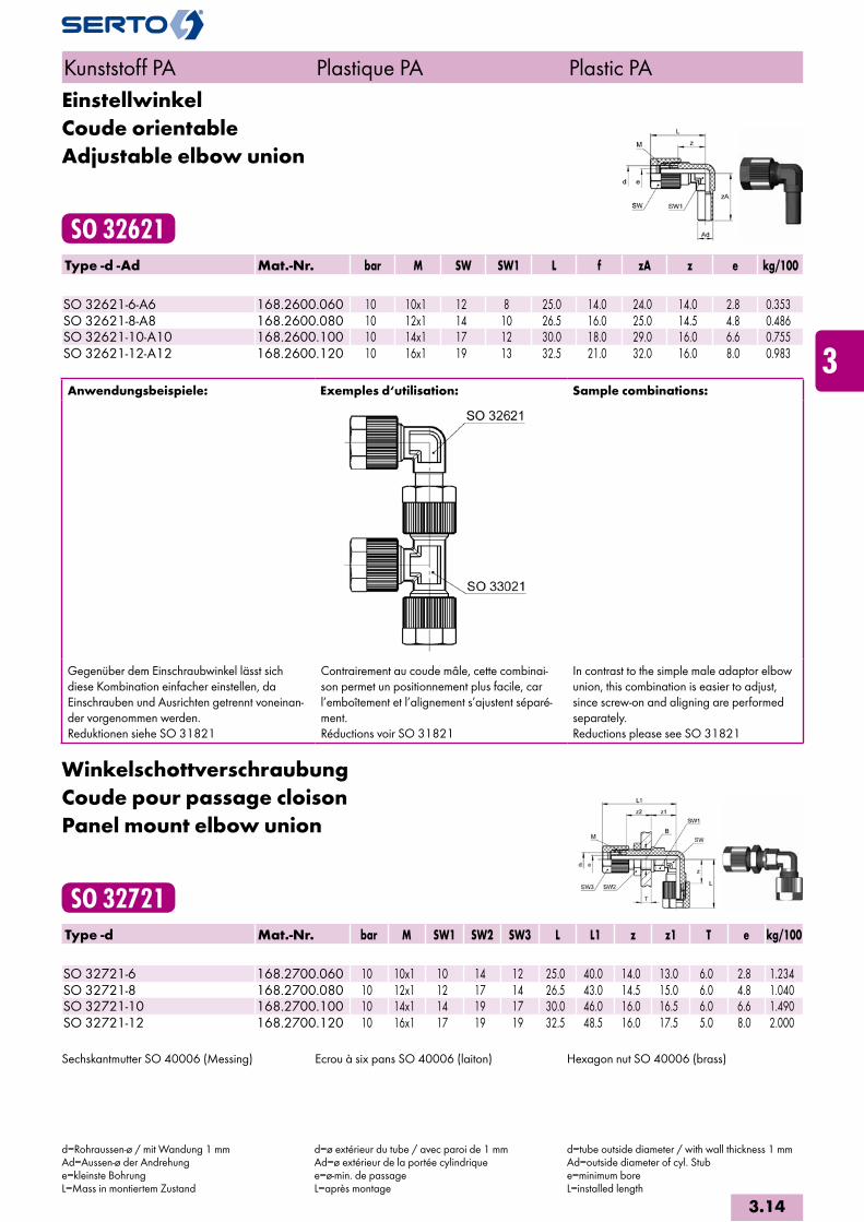
EinstellwinkelCoude orientableAdjustable elbow union
SO 32621Type -d -Ad Mat.-Nr. bar M SW SW1 L f zA z e kg/100 SO 32621-6-A6 168.2600.060 10 10x1 12 8 25.0 14.0 24.0 14.0 2.8 0.353SO 32621-8-A8 168.2600.080 10 12x1 14 10 26.5 16.0 25.0 14.5 4.8 0.486SO 32621-10-A10 168.2600.100 10 14x1 17 12 30.0 18.0 29.0 16.0 6.6 0.755SO 32621-12-A12 168.2600.120 10 16x1 19 13 32.5 21.0 32.0 16.0 8.0 0.983
Anwendungsbeispiele: Exemples d‘utilisation: Sample combinations:
Gegenüber dem Einschraubwinkel lässt sich diese Kombination einfacher einstellen, da Einschrauben und Ausrichten getrennt voneinan-der vorgenommen werden.Reduktionen siehe SO 31821
Contrairement au coude mâle, cette combinai-son permet un positionnement plus facile, car l’emboîtement et l’alignement s’ajustent séparé-ment.Réductions voir SO 31821
In contrast to the simple male adaptor elbow union, this combination is easier to adjust, since screw-on and aligning are performed separately.Reductions please see SO 31821
WinkelschottverschraubungCoude pour passage cloisonPanel mount elbow union
SO 32721Type -d Mat.-Nr. bar M SW1 SW2 SW3 L L1 z z1 T e kg/100 SO 32721-6 168.2700.060 10 10x1 10 14 12 25.0 40.0 14.0 13.0 6.0 2.8 1.234SO 32721-8 168.2700.080 10 12x1 12 17 14 26.5 43.0 14.5 15.0 6.0 4.8 1.040SO 32721-10 168.2700.100 10 14x1 14 19 17 30.0 46.0 16.0 16.5 6.0 6.6 1.490SO 32721-12 168.2700.120 10 16x1 17 19 19 32.5 48.5 16.0 17.5 5.0 8.0 2.000
Sechskantmutter SO 40006 (Messing) Ecrou à six pans SO 40006 (laiton) Hexagon nut SO 40006 (brass)
Kunststoff PA Plastique PA Plastic PA
d=Rohraussen-ø / mit Wandung 1 mmAd=Aussen-ø der Andrehunge=kleinste BohrungL=Mass in montiertem Zustand
d=ø extérieur du tube / avec paroi de 1 mmAd=ø extérieur de la portée cylindriquee=ø-min. de passageL=après montage
d=tube outside diameter / with wall thickness 1 mmAd=outside diameter of cyl. Stube=minimum boreL=installed length
3.14
i
s
3

SchwenkverschraubungCoude banjoSingle banjo
SO 32821Type -d -G Mat.-Nr. bar M SW SW1 L A b D zR z e kg/100 G=Rohrgewinde (zylindrisch) G=Filetage-gaz BSP (cylindrique) G=BSP thread (straight)
SO 32821-6-1/8 168.2841.100 10 10x1 12 14 27.5 21.0 26.0 16.0 10.5 16.5 2.8 1.950 SO 32821-6-1/4 168.2841.110 10 10x1 12 19 27.5 26.0 35.0 20.0 12.5 16.5 2.8 4.080 SO 32821-8-1/8 168.2841.160 10 12x1 14 19 29.0 21.0 26.0 16.0 10.5 17.0 4.8 2.040 SO 32821-8-1/4 168.2841.170 10 12x1 14 19 29.0 26.0 35.0 20.0 12.5 17.0 4.8 4.160 SO 32821-10-1/4 168.2841.270 10 14x1 17 19 32.5 26.0 35.0 20.0 12.5 18.5 6.6 4.360
SO 32821-10/7-1/4 168.2841.320 10 14x1 17 19 32.5 26.0 35.0 20.0 12.5 18.5 5.0 4.450
Hohlschraube aus Messing Vis creuse en laiton Hollow screw of brass
Schwenkverschraubung METRCoude banjo METRSingle banjo METR
SO 32821 METRType -d -Mz Mat.-Nr. bar M SW SW1 L A b D zR z e kg/100 Mz=metrisches Gewinde (zylindrisch) Mz=Filetage métrique (cylindrique) Mz=Metric thread (straight)
SO 32821-6-M10X1 168.2843.180 10 10x1 12 14 27.5 21.0 26.0 16.0 10.5 16.5 2.8 1.960 SO 32821-6-M12X1,5 168.2843.195 10 10x1 12 19 27.5 26.0 35.0 20.0 12.5 16.5 2.8 4.050 SO 32821-6-M14X1,5 168.2843.198 10 10x1 12 19 27.5 26.0 35.0 20.0 12.5 16.5 2.8 4.050 SO 32821-8-M10X1 168.2843.230 10 12x1 14 14 29.0 21.0 26.0 16.0 10.5 17.0 4.8 2.040 SO 32821-8-M12X1,5 168.2843.240 10 12x1 14 19 29.0 26.0 35.0 20.0 12.5 17.0 4.8 4.130 SO 32821-8-M14X1,5 168.2843.245 10 12x1 14 19 29.0 26.0 35.0 20.0 12.5 17.0 4.8 4.160 SO 32821-10-M12X1,5 168.2843.275 10 14x1 17 19 32.5 26.0 35.0 20.0 12.5 18.5 6.6 4.320 SO 32821-10-M14X1,5 168.2843.280 10 14x1 17 19 32.5 26.0 35.0 20.0 12.5 18.5 6.6 4.340
SO 32821-10/7-M12X1.5 168.2843.300 10 14x1 17 19 32.5 26.0 35.0 20.0 12.5 18.5 5.0 4.420 SO 32821-10/7-M14X1.5 168.2843.305 10 14x1 17 19 32.5 26.0 35.0 20.0 12.5 18.5 5.0 4.430
Hohlschraube aus Messing Vis creuse en laiton Hollow screw of brass
Kunststoff PA Plastique PA Plastic PA
d=Rohraussen-ø / mit Wandung 1 mmL=Mass in montiertem Zustande=kleinste Bohrung=für Rohre mit Wandung 1,5 mm
d=ø extérieur du tube / avec paroi de 1 mmL=après montagee=ø min. de passage=pour tubes avec paroi de 1,5 mm d’épaisseur
d=tube outside diameter / with wall thickness 1 mmL=installed lengthe=minimum bore=for tubes with wall thickness of 1,5 mm
3.15

2-fach WinkelschwenkverschraubungCoude banjo multipleDouble banjo
SO 32921Type -d -G Mat.-Nr. bar M SW SW1 L b D H zR z e kg/100 G=Rohrgewinde (zylindrisch) G=Filetage-gaz BSP (cylindrique) G=BSP thread (straight)
SO 32921-2X6-1/8 168.2941.100 10 10x1 12 14 27.5 42.0 16.0 16.0 10.5 16.5 2.8 3.080 SO 32921-2X6-1/4 168.2941.110 10 10x1 12 19 27.5 56.0 20.0 21.0 12.5 16.5 2.8 6.140 SO 32921-2X8-1/8 168.2941.160 10 12x1 14 14 29.0 42.0 16.0 16.0 10.5 17.0 4.8 3.260 SO 32921-2X8-1/4 168.2941.170 10 12x1 14 19 29.0 56.0 20.0 21.0 12.5 17.0 4.8 6.300 SO 32921-2X10⁻¹/4 168.2941.270 10 14x1 17 19 32.5 56.0 20.0 21.0 12.5 18.5 6.6 6.700
SO 32921-2X10/7-1/4 168.2941.320 10 14x1 17 19 32.5 56.0 20.0 21.0 12.5 18.5 5.0 6.810
Hohlschraube aus Messing Vis creuse en laiton Hollow screw of brass
Kunststoff PA Plastique PA Plastic PA
d=Rohraussen-ø / mit Wandung 1 mmL=Mass in montiertem Zustande=kleinste Bohrung=für Rohre mit Wandung 1,5 mm
d=ø extérieur du tube / avec paroi de 1 mmL=après montagee=ø min. de passage=pour tubes avec paroi de 1,5 mm d’épaisseur
d=tube outside diameter / with wall thickness 1 mmL=installed lengthe=minimum bore=for tubes with wall thickness of 1,5 mm
3.16
i
s
3
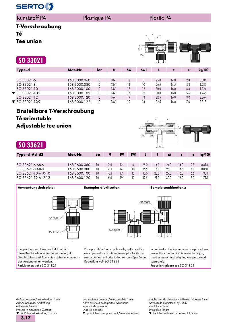
T-VerschraubungTéTee union
SO 33021Type -d Mat.-Nr. bar M SW SW1 L z e kg/100
SO 33021-6 168.3000.060 10 10x1 12 8 25.0 14.0 2.8 0.804 SO 33021-8 168.3000.080 10 12x1 14 10 26.5 14.5 4.8 1.089 SO 33021-10 168.3000.100 10 14x1 17 12 30.0 16.0 6.6 1.724
SO 33021-10/7 168.3000.102 10 14x1 17 12 30.0 16.0 5.6 1.766 SO 33021-12 168.3000.120 10 16x1 19 13 32.5 16.0 8.0 2.267
SO 33021-12/9 168.3000.122 10 16x1 19 13 32.5 16.0 7.0 2.313
Einstellbare T-VerschraubungTé orientableAdjustable tee union
SO 33621Type -d -Ad -d3 Mat.-Nr. bar M SW SW1 L f zA z e kg/100 SO 33621-6-A6-6 168.3600.060 10 10x1 12 8 25.0 14.0 24.0 14.0 2.8 0.618SO 33621-8-A8-8 168.3600.080 10 12x1 14 10 26.5 16.0 25.0 14.5 4.8 0.850SO 33621-10-A10-10 168.3600.100 10 14x1 17 12 30.0 20.0 29.0 16.0 6.6 1.304SO 33621-12-A12-12 168.3600.120 10 16x1 19 13 32.5 21.0 30.0 16.0 8.0 1.715
Anwendungsbeispiele: Exemples d‘utilisation: Sample combinations:
Gegenüber dem Einschraub-T lässt sich diese Kombination einfacher einstellen, da Einschrauben und Ausrichten getrennt voneinan-der vorgenommen werden. Reduktionen siehe SO 31821
Par opposition à un coude mâle, cette combin-aison permet un positionnement plus facile. Le raccordement et l’orientation se font séparément.Réductions voir SO 31821
In contrast to the simple male adaptor elbow union, this combination is easier to adjust, since screw-on and aligning are performed separately.Reductions please see SO 31821
Kunststoff PA Plastique PA Plastic PA
d=Rohraussen-ø / mit Wandung 1 mmAd=Aussen-ø der Andrehunge=kleinste BohrungL=Mass in montiertem Zustand=für Rohre mit Wandung 1,5 mm
d=ø extérieur du tube / avec paroi de 1 mmAd=ø extérieur de la portée cylindriquee=ø-min. de passageL=après montage=pour tubes avec paroi de 1,5 mm d’épaisseur
d=tube outside diameter / with wall thickness 1 mmAd=outside diameter of cyl. Stube=minimum boreL=installed length=for tubes with wall thickness of 1,5 mm
3.17

T-EinschraubverschraubungTé mâleMale adaptor tee union
SO 33721Type -d -R -d3 Mat.-Nr. bar M SW SW1 L zR z e kg/100 R=Rohrgewinde (kegelig) R=Filetage-gaz BSP (conique) R=BSP thread (tapered)
SO 33721-6-1/8-6 168.3701.100 10 10x1 12 10 25.0 11.0 14.0 2.8 0.645 SO 33721-6-1/4-6 168.3701.110 10 10x1 12 14 25.0 12.5 14.0 2.8 0.499 SO 33721-8-1/8-8 168.3701.160 10 12x1 14 10 26.5 12.0 14.5 4.8 0.814 SO 33721-8-1/4-8 168.3701.170 10 12x1 14 10 26.5 13.5 14.5 4.8 0.984 SO 33721-10-1/4-10 168.3701.270 10 14x1 17 14 30.0 14.5 16.0 6.6 1.420 SO 33721-10-3/8-10 168.3701.280 10 14x1 17 17 30.0 15.0 16.0 6.6 1.561
SO 33721-10/7-1/4-10/7 168.3701.320 10 14x1 17 14 30.0 14.5 16.0 5.6 1.448 SO 33721-10/7-3/8-10/7 168.3701.330 10 14x1 17 17 30.0 15.0 16.0 5.6 1.387
Zum Abdichten der Einschraubgewinde empfeh-len wir unseren Dichtstift «Plasto-Joint» AC 833.
Pour assurer l’étanchéité des filetages mâles, nous recommandons notre bâton «Plasto-Joint» AC 833.
For sealing the male threads we recommend our sealing stick «Plasto-Joint» AC 833.
Kunststoff PA Plastique PA Plastic PA
d=Rohraussen-ø / mit Wandung 1 mmkv=Kenngrösse für das Durchflussverhalten (ltr./min)L=Mass in montiertem Zustande=kleinste Bohrung=für Rohre mit Wandung 1,5 mm
d=ø extérieur du tube / avec paroi de 1 mmkv=facteur d'écoulement (ltr./min)L=après montagee=ø min. de passage=pour tubes avec paroi de 1,5 mm d’épaisseur
d=tube outside diameter / with wall thickness 1 mmkv=flow factor (ltr./min)L=installed lengthe=minimum bore=for tubes with wall thickness of 1,5 mm
3.18
i
s
3

Schwenkverschraubungmit Drossel-Ventil
Coude banjoà passage réglable
Single banjowith throttle valve
SO 37621Type -d -G2 Mat.-Nr. bar M SW SW1 L A D i zR z kv kg/10 G2=Rohrgewinde (zylindrisch) G2=Filetage-gaz BSP (cylindrique) G2=BSP thread (straight)SO 37621-6-1/8 168.7600.100 10 10x1 12 14 27.5 25.0 16.0 7.0 10.5 16.5 3.0 0.210SO 37621-6-1/4 168.7600.110 10 10x1 12 19 27.5 32.0 20.0 9.0 12.5 16.5 6.0 0.440SO 37621-8-1/8 168.7600.160 10 12x1 14 14 29.5 25.5 16.0 7.0 10.5 16.5 3.0 0.280SO 37621-8-1/4 168.7600.170 10 12x1 14 19 29.5 30.5 20.0 9.0 12.5 16.5 6.0 0.450SO 37621-10-1/4 168.7600.270 10 14x1 17 19 30.0 30.5 20.0 9.0 12.5 16.0 6.0 0.460
Dieses Drossel-Ventil dient zur Regulierung von Luftströmen in beiden Richtungen. Die Kombination von Verschraubung und Drossel-Ventil erlaubt den Anbau direkt an den Zylinder.Die Spindelfixierung mittels Kontermutter garan-tiert, dass sich die Spindel auch bei Vibration nicht verstellt.
Technische Hinweise:Körper und Anschlussmuttern aus Polyamid 6.6, O-Ringe aus NBR. Hohlschrauben und Ventileinsätze aus Messing.Schwenkverschraubungen siehe SO 32821, SO 32921, SO 33821, SO 33921 und SO 42821, SO 42921, SO 43821 und SO 43921.
Cet élément d’étranglement sert au réglage d’écoulements d’air dans les deux sens. La combi-naison raccord-passage réglable est spécialement destinée au montage sur le cylindre.La fixation de la broche à l’aide d’un contre-écrou garantit la stabilité du réglage même en cas de vibrations.
Données techniques:Corps et écrous de raccordements en polyamide 6.6, joints toriques en NBR. Vis creuse et ponteau en laiton.Coudes banjo voir SO 32821, SO 32921, SO 33821, SO 33921 et SO 42821, SO 42921, SO 43821 et SO 43921.
This throttle valves serve to regulate air flow in both directions. The combination of union and throttle valve permits direct fitting to the cylinder.The spindle fixation via counter-nut assures that the spindle can not shift, even due to vibration.
Technical notes:Bodies and union nuts of polyamide 6.6, O-Rings of NBR. Hollow screws and valve parts of brass.Single banjo please see SO 32821, SO 32921, SO 33821, SO 33921 and SO 42821, SO 42921, SO 43821 and SO 43921.
Schwenkverschraubungmit Drossel-Rückschlag-Ventil
Coude banjoà passage réglable et soupape de retenue
Single banjowith throttle valve and non-return
SO 37721Type -d -G2 Mat.-Nr. bar M SW SW1 L A D i zR z kv kg/10 G2=Rohrgewinde (zylindrisch) G2=Filetage-gaz BSP (cylindrique) G2=BSP thread (straight)SO 37721-6-1/8 168.7700.100 10 10x1 12 14 27.5 25.0 16.0 7.0 10.5 16.5 3.0 0.210SO 37721-6-1/4 168.7700.110 10 10x1 12 19 27.5 32.0 20.0 9.0 12.5 16.5 6.0 0.430SO 37721-8-1/8 168.7700.160 10 12x1 14 14 29.5 25.5 16.0 7.0 10.5 16.5 3.0 0.240SO 37721-8-1/4 168.7700.170 10 12x1 14 19 29.5 30.5 20.0 9.0 12.5 16.5 6.0 0.450SO 37721-10-1/4 168.7700.270 10 14x1 17 19 30.0 30.5 20.0 9.0 12.5 16.0 6.0 0.460
Kunststoff PA Plastique PA Plastic PA
d=Rohraussen-ø / mit Wandung 1 mmkv=Kenngrösse für das Durchflussverhalten (ltr./min)L=Mass in montiertem Zustand
d=ø extérieur du tube / avec paroi de 1 mmkv=facteur d'écoulement (ltr./min)L=après montage
d=tube outside diameter / with wall thickness 1 mmkv=flow factor (ltr./min)L=installed length
3.19

EinschraubtülleDouille cannelée à visserMale adaptor hose nozzle
SO 30511Type -d1 -R Mat.-Nr. bar SW L a b e kg/100 R=Rohrgewinde (kegelig) R=Filetage-gaz BSP (conique) R=BSP thread (tapered)SO 30511-6-1/8 166.0511.100 10 10 30.0 13.0 12.0 4.0 0.120SO 30511-6-1/4 166.0511.110 10 14 35.5 18.5 12.0 4.0 0.280SO 30511-8-1/4 166.0511.170 10 14 35.5 18.5 12.0 6.0 0.290SO 30511-10-3/8 166.0511.280 10 17 38.0 19.0 14.0 7.0 0.480SO 30511-12-3/8 166.0511.390 10 17 38.0 19.0 14.0 10.0 0.410SO 30511-12-1/2 166.0511.400 10 22 43.0 24.0 14.0 10.0 0.800
Für die Schlauchsicherung verwenden Sie bitte unsere Schlauchklemme SO 40512 (Stahl pro-matverzinkt).
d1 = Schlauchinnen-Øe = kleinste Bohrung
Afin d’assurer la bonne tenue des tuyaux, utiliser nos colliers de serrage SO 40512 (Acier zingué passivé).
d1 = Ø intérieur du tuyaue = Ø min. de passage
Please use our hose clip SO 40512(zinc promatised) for securing the hose.
d1 = hose inside diametere = minimum bore
Kunststoff PA Plastique PA Plastic PA
3.20
i
s
3

3F
Kunststoff Flip
Verschraubungen
Plastique Flip
Raccords
Plastic Flip
Unions
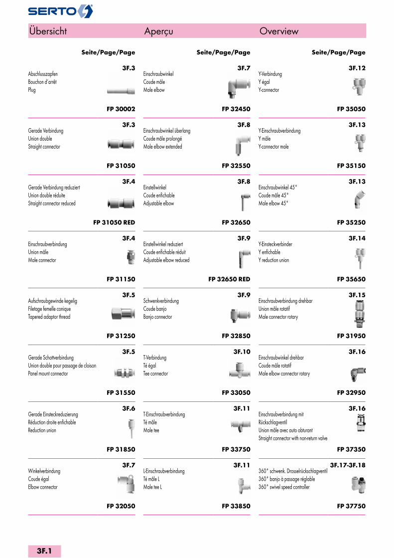
3F.3AbschlusszapfenBouchon d‘arrêtPlug
FP 30002
3F.3Gerade VerbindungUnion doubleStraight connector
FP 31050
3F.4Gerade Verbindung reduziertUnion double réduiteStraight connector reduced
FP 31050 RED
3F.4EinschraubverbindungUnion mâleMale connector
FP 31150
3F.5Aufschraubgewinde kegeligFiletage femelle coniqueTapered adaptor thread
FP 31250
3F.5Gerade SchottverbindungUnion double pour passage de cloisonPanel mount connector
FP 31550
3F.6Gerade EinsteckreduzierungRéduction droite enfichableReduction union
FP 31850
3F.7WinkelverbindungCoude égalElbow connector
FP 32050
3F.7EinschraubwinkelCoude mâleMale elbow
FP 32450
3F.8Einschraubwinkel überlangCoude mâle prolongéMale elbow extended
FP 32550
3F.8EinstellwinkelCoude enfichableAdjustable elbow
FP 32650
3F.9Einstellwinkel reduziertCoude enfichable réduitAdjustable elbow reduced
FP 32650 RED
3F.9SchwenkverbindungCoude banjoBanjo connector
FP 32850
3F.10T-VerbindungTé égalTee connector
FP 33050
3F.11T-EinschraubverbindungTé mâleMale tee
FP 33750
3F.11L-EinschraubverbindungTé mâle LMale tee L
FP 33850
3F.12Y-VerbindungY égalY-connector
FP 35050
3F.13Y-EinschraubverbindungY mâleY-connector male
FP 35150
3F.13Einschraubwinkel 45°Coude mâle 45°Male elbow 45°
FP 35250
3F.14Y-EinsteckverbinderY enfichableY reduction union
FP 35650
3F.15Einschraubverbindung drehbarUnion mâle rotatifMale connector rotary
FP 31950
3F.16Einschraubwinkel drehbarCoude mâle rotatifMale elbow connector rotary
FP 32950
3F.16Einschraubverbindung mit RückschlagventilUnion mâle avec auto obturantStraight connector with non-return valve
FP 37350
3F.17-3F.18360° schwenk. Drosselrückschlagventil360° banjo à passage réglable360° swivel speed controller
FP 37750
Seite/Page/Page Seite/Page/Page Seite/Page/Page
Übersicht Aperçu Overview
3F.1
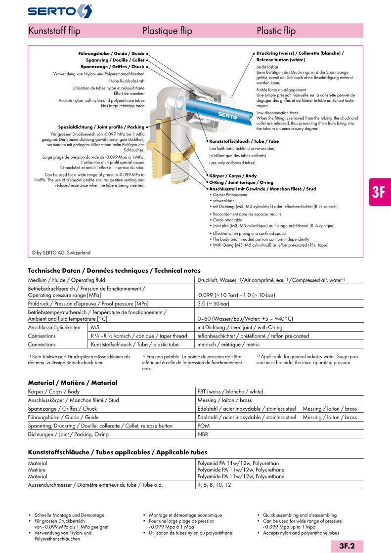
© by SERTO AG, Switzerland
Führungshülse / Guide / Guide Spannring / Douille / Collet
Spannzange / Griffes / Chuck
Verwendung von Nylon- und Polyurethanschläuchen
Hohe Rückhaltekraft
Utilisation de tubes nylon et polyuréthane Effort de maintien
Accepts nylon, soft nylon and polyurethane tubes Has large retaining force
Druckring (weiss) / Collerette (blanche) / Release button (white)
Leicht lösbar Beim Betätigen des Druckrings wird die Spannzange gelöst, damit der Schlauch ohne Be schä digung entfernt werden kann.
Faible force de dégagement Une simple pression manuelle sur la collerette permet de dégager des griffes et de libérer le tube en évitant toute rayure.
Low disconnection force When the fitting is removed from the tubing, the chuck and collet are released, thus preventing them from biting into the tube to an unnecessary degree.
Kunststoffschlauch / Tube / Tube
(nur kalibrierte Schläuche verwenden)
(n’utiliser que des tubes calibrés)
(use only calibrated tubes) Körper / Corps / BodyO-Ring / Joint torique / O-ringAnschlussteil mit Gewinde / Manchon fileté / Stud• Kleiner Einbauraum• schwenkbar• mit Dichtung (M3, M5 zylindrisch) oder teflonbeschichtet (R konisch)
• Raccordement dans les espaces réduits• Corps orientable• Joint plat (M3, M5 cylindrique) ou filetage prétéflonné (R conique)
• Effective when piping in a confined space• The body and threaded portion can turn independently• With O-ring (M3, M5 cylindrical) or teflon pre-coated (R taper)
Technische Daten / Données techniques / Technical notesMedium / Fluide / Operating fluid Druckluft, Wasser 1)/Air comprimé, eau1) /Compressed air, water1)
Betriebsdruckbereich / Pression de fonctionnement / Operating pressure range [MPa] -0.099 (~10 Torr) –1.0 (~10-bar)Prüfdruck / Pression d’épreuve / Proof pressure [MPa] 3.0 (~ 30-bar)
Betriebstemperaturbereich / Température de fonctionnement / Ambient and fluid temperature [°C] 0–60 (Wasser/Eau/Water: +5 – +40°C)Anschlussmöglichkeiten M5 mit Dichtung / avec joint / with O-ringConnextions R –R konisch / conique / taper thread teflonbeschichtet / prétéflonné / teflon pre-coatedConnections Kunststoffschlauch / Tube / plastic tube metrisch / métrique / metric
1) Kein Trinkwasser! Druckspitzen müssen kleiner als der max. zulässige Betriebsdruck sein.
1) Eau non potable. La pointe de pression doit être in férieure à celle de la pression de fonctionnement max.
1) Applicable for general industry water. Surge pres-sure must be under the max. operating pressure.
Material / Matière / MaterialKörper / Corps / Body PBT (weiss / blanche / white)Anschlusskörper / Manchon fileté / Stud Messing / laiton / brassSpannzange / Griffes / Chuck Edelstahl / acier inoxydable / stainless steel Messing / laiton / brassFührungshülse / Guide / Guide Edelstahl / acier inoxydable / stainless steel Messing / laiton / brassSpannring, Druckring / Douille, collerette / Collet, release button POMDichtungen / Joint / Packing, O-ring NBR
Kunststoffschläuche / Tubes applicables / Applicable tubes
Material Polyamid PA 11w/12w, Polyurethan Matière Polyamide PA 11w/12w, Polyurethane Material Polyamide PA 11w/12w, Polyurethane Aussendurchmesser / Diamètre extérieur du tube / Tube o.d. 4, 6, 8, 10, 12
• Schnelle Montage und Demontage• Für grossen Druckbereich
von - 0.099 MPa bis 1 MPa geeignet• Verwendung von Nylon- und
Polyurethanschläuchen
• Montage et démontage économique• Pour une large plage de pression
- 0.099 Mpa à 1 Mpa • Utilisation de tubes nylon ou polyuréthane
• Quick assembling and disassembling• Can be used for wide range of pressure
- 0.099 Mpa up to 1 Mpa • Accepts nylon and polyurethane tubes
Spezialdichtung / Joint profilé / Packing
Für grossen Druckbereich von -0.099 MPa bis 1 MPa geeignet. Die Spezialdich tung gewährleistet gute Dichtheit,
verbunden mit geringem Widerstand beim Einfügen des Schlauches.
Large plage de pression du vide de -0.099-Mpa à 1-MPa. L’utilisation d’un profil spécial assure
l’étanchéité et reduit l’effort à l’insertion du tube.
Can be used for a wide range of pressure -0.099-MPa to 1-MPa. The use of a special profile ensures positive sealing and
reduced resistance when the tube is being inserted.
Kunststoff flip Plastique flip Plastic flip
3F.2
i
s
3F
4M
4G
5
5L
6
7
8
9
10
11
12
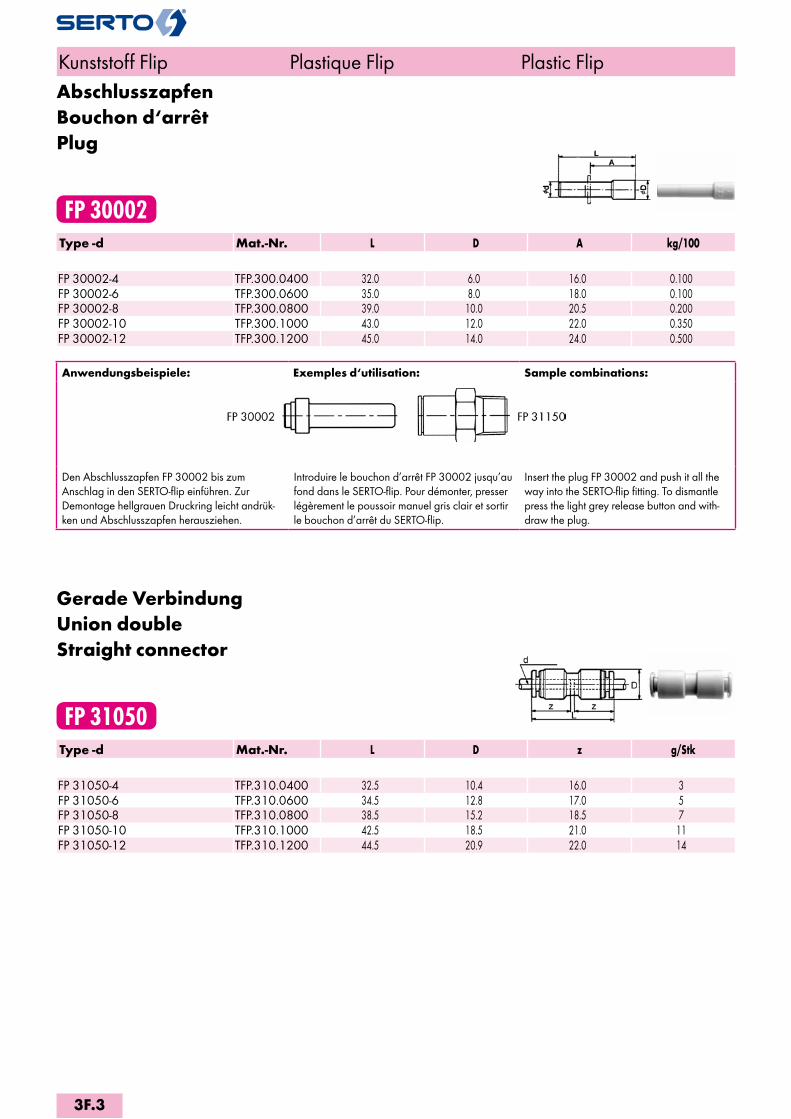
AbschlusszapfenBouchon d‘arrêtPlug
FP 30002Type -d Mat.-Nr. L D A kg/100 FP 30002-4 TFP.300.0400 32.0 6.0 16.0 0.100FP 30002-6 TFP.300.0600 35.0 8.0 18.0 0.100FP 30002-8 TFP.300.0800 39.0 10.0 20.5 0.200FP 30002-10 TFP.300.1000 43.0 12.0 22.0 0.350FP 30002-12 TFP.300.1200 45.0 14.0 24.0 0.500
Anwendungsbeispiele: Exemples d‘utilisation: Sample combinations:
Den Abschlusszapfen FP 30002 bis zum Anschlag in den SERTO-flip einführen. Zur Demontage hellgrauen Druckring leicht andrük-ken und Abschlusszapfen herausziehen.
Introduire le bouchon d’arrêt FP 30002 jusqu’au fond dans le SERTO-flip. Pour démonter, presser légèrement le poussoir manuel gris clair et sortir le bouchon d’arrêt du SERTO-flip.
Insert the plug FP 30002 and push it all the way into the SERTO-flip fitting. To dismantle press the light grey release button and with-draw the plug.
Gerade VerbindungUnion doubleStraight connector
FP 31050Type -d Mat.-Nr. L D z g/Stk FP 31050-4 TFP.310.0400 32.5 10.4 16.0 3FP 31050-6 TFP.310.0600 34.5 12.8 17.0 5FP 31050-8 TFP.310.0800 38.5 15.2 18.5 7FP 31050-10 TFP.310.1000 42.5 18.5 21.0 11FP 31050-12 TFP.310.1200 44.5 20.9 22.0 14
Kunststoff Flip Plastique Flip Plastic Flip
3F.3

Gerade Verbindung reduziertUnion double réduiteStraight connector reduced
FP 31050 REDType -d -d2 Mat.-Nr. L D z1 z g/Stk FP 31050-6-4 TFP.310.0604 34.5 12.8 16.0 17.0 5FP 31050-8-6 TFP.310.0806 38.5 15.2 17.0 18.5 7FP 31050-10-8 TFP.310.1008 42.0 18.5 18.5 21.0 11FP 31050-12-10 TFP.310.1210 44.5 20.9 21.0 22.0 14
EinschraubverbindungUnion mâleMale connector
FP 31150Type -d -R Mat.-Nr. SW L D zR z g/Stk FP 31150-4 M5 TFP.311.0441 8 17.0 9.5 14.0 13.0 2FP 31150-6-M5 TFP.311.0641 10 18.5 11.5 15.0 14.0 3 FP 31150-4-1/8 TFP.311.0411 10 22.0 9.5 18.0 16.0 3FP 31150-4-1/4 TFP.311.0412 14 19.5 9.5 13.5 16.0 16FP 31150-6-1/8 TFP.311.0611 12 22.5 11.5 18.5 17.0 16FP 31150-6-1/4 TFP.311.0612 14 23.0 11.5 17.0 17.0 14FP 31150-6-3/8 TFP.311.0613 17 21.0 11.5 15.5 17.0 27FP 31150-8-1/8 TFP.311.0811 14 28.0 24.0 18.5 21FP 31150-8-1/4 TFP.311.0812 14 26.5 20.5 18.5 19FP 31150-8-3/8 TFP.311.0813 17 22.0 15.5 18.5 26FP 31150-10-1/8 TFP.311.1011 17 30.0 26.0 21.0 19FP 31150-10-1/4 TFP.311.1012 17 33.5 27.5 21.0 30FP 31150-10-3/8 TFP.311.1013 17 29.0 22.5 21.0 30FP 31150-10-1/2 TFP.311.1014 22 26.0 19.0 21.0 53FP 31150-12-1/4 TFP.311.1212 19 34.5 28.5 22.0 42FP 31150-12-3/8 TFP.311.1213 19 30.0 23.5 22.0 34FP 31150-12-1/2 TFP.311.1214 22 30.0 22.0 22.0 51
Kunststoff Flip Plastique Flip Plastic Flip
zR=Richtmass bei eingeschraubtem Gewinde zR=Dépassement après montage zR=Reference dimensions after thread installation
3F.4
i
s
3F
4M
4G
5
5L
6
7
8
9
10
11
12

Aufschraubgewinde kegeligFiletage femelle coniqueTapered adaptor thread
FP 31250Type -d -R Mat.-Nr. SW L D i z g/Stk FP 31250-4-1/8 TFP.312.0411 14 27.0 10.0 11.0 16.0 15FP 31250-4-1/4 TFP.312.0412 17 31.0 10.0 14.0 16.0 22FP 31250-6-1/8 TFP.312.0611 14 27.5 12.0 11.0 17.0 15FP 31250-6-1/4 TFP.312.0612 17 31.0 12.0 13.0 17.0 22FP 31250-6-3/8 TFP.312.0613 19 33.5 12.0 15.0 17.0 24FP 31250-8-1/8 TFP.312.0811 14 29.0 14.0 11.0 18.5 16FP 31250-8-1/4 TFP.312.0812 17 32.5 14.0 13.0 18.5 24FP 31250-8-3/8 TFP.312.0813 19 33.5 14.0 14.0 18.5 23FP 31250-10-1/4 TFP.312.1012 17 34.5 17.0 14.0 21.0 27FP 31250-10-3/8 TFP.312.1013 19 36.5 17.0 15.0 21.0 29FP 31250-12-1/4 TFP.312.1212 19 36.5 19.0 14.0 22.0 35FP 31250-12-3/8 TFP.312.1213 19 37.0 19.0 14.0 22.0 30FP 31250-12-1/2 TFP.312.1214 24 41.0 19.0 18.0 22.0 51
Gerade SchottverbindungUnion double pour passage de cloisonPanel mount connector
FP 31550Type -d Mat.-Nr. SW L M z g/Stk FP 31550-4 TFP.315.0400 14 32.5 12x1 16.0 26FP 31550-6 TFP.315.0600 17 34.5 14x1 17.0 33FP 31550-8 TFP.315.0800 19 38.0 16x1 18.5 52FP 31550-10 TFP.315.1000 24 42.5 20x1 21.0 70FP 31550-12 TFP.315.1200 27 44.0 22x1 22.0 90
Kunststoff Flip Plastique Flip Plastic Flip
L=Mass in montiertem Zustand L=après montage L=installed length
3F.5
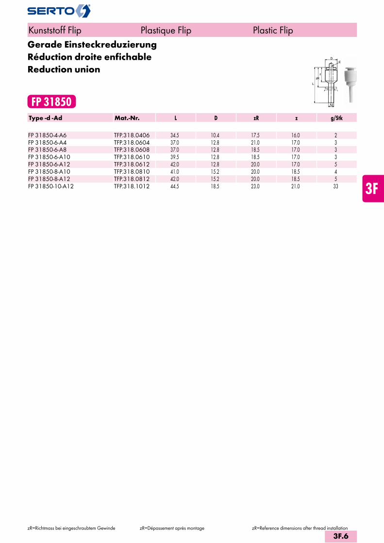
Gerade EinsteckreduzierungRéduction droite enfichableReduction union
FP 31850Type -d -Ad Mat.-Nr. L D zR z g/Stk FP 31850-4-A6 TFP.318.0406 34.5 10.4 17.5 16.0 2FP 31850-6-A4 TFP.318.0604 37.0 12.8 21.0 17.0 3FP 31850-6-A8 TFP.318.0608 37.0 12.8 18.5 17.0 3FP 31850-6-A10 TFP.318.0610 39.5 12.8 18.5 17.0 3FP 31850-6-A12 TFP.318.0612 42.0 12.8 20.0 17.0 5FP 31850-8-A10 TFP.318.0810 41.0 15.2 20.0 18.5 4FP 31850-8-A12 TFP.318.0812 42.0 15.2 20.0 18.5 5FP 31850-10-A12 TFP.318.1012 44.5 18.5 23.0 21.0 33
Kunststoff Flip Plastique Flip Plastic Flip
zR=Richtmass bei eingeschraubtem Gewinde zR=Dépassement après montage zR=Reference dimensions after thread installation
3F.6
i
s
3F
4M
4G
5
5L
6
7
8
9
10
11
12
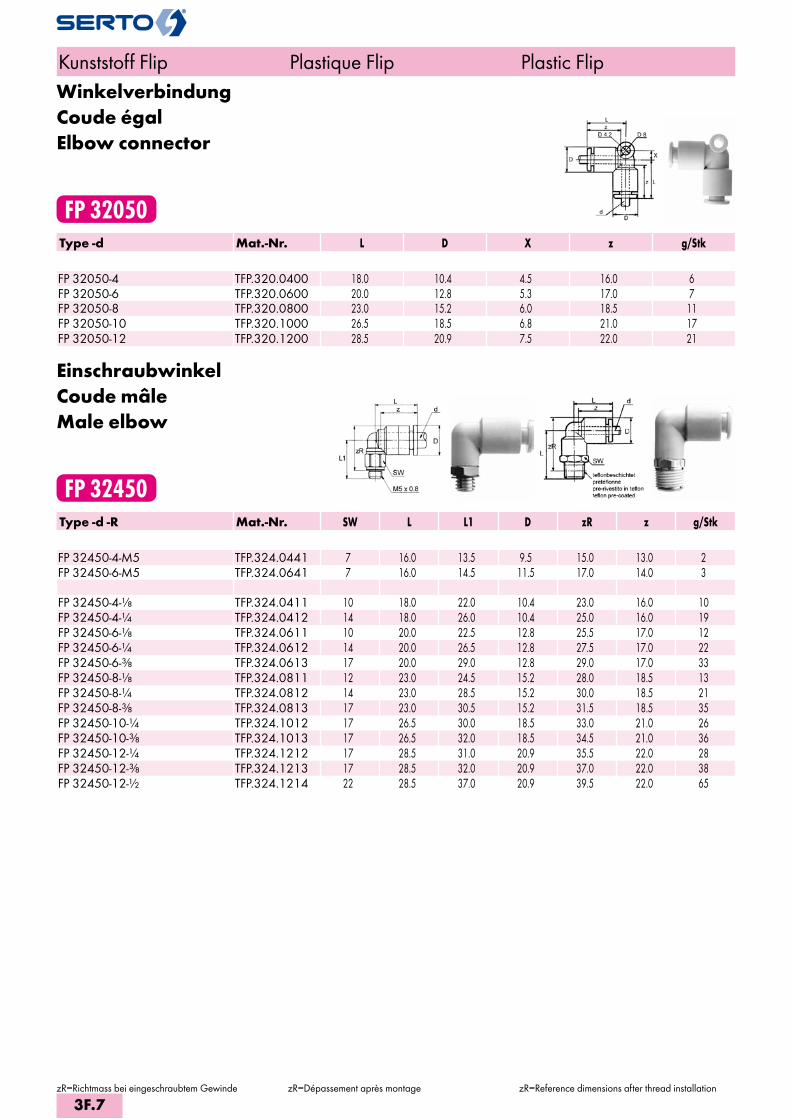
WinkelverbindungCoude égalElbow connector
FP 32050Type -d Mat.-Nr. L D X z g/Stk FP 32050-4 TFP.320.0400 18.0 10.4 4.5 16.0 6FP 32050-6 TFP.320.0600 20.0 12.8 5.3 17.0 7FP 32050-8 TFP.320.0800 23.0 15.2 6.0 18.5 11FP 32050-10 TFP.320.1000 26.5 18.5 6.8 21.0 17FP 32050-12 TFP.320.1200 28.5 20.9 7.5 22.0 21
EinschraubwinkelCoude mâleMale elbow
FP 32450Type -d -R Mat.-Nr. SW L L1 D zR z g/Stk FP 32450-4-M5 TFP.324.0441 7 16.0 13.5 9.5 15.0 13.0 2FP 32450-6-M5 TFP.324.0641 7 16.0 14.5 11.5 17.0 14.0 3 FP 32450-4-1/8 TFP.324.0411 10 18.0 22.0 10.4 23.0 16.0 10FP 32450-4-1/4 TFP.324.0412 14 18.0 26.0 10.4 25.0 16.0 19FP 32450-6-1/8 TFP.324.0611 10 20.0 22.5 12.8 25.5 17.0 12FP 32450-6-1/4 TFP.324.0612 14 20.0 26.5 12.8 27.5 17.0 22FP 32450-6-3/8 TFP.324.0613 17 20.0 29.0 12.8 29.0 17.0 33FP 32450-8-1/8 TFP.324.0811 12 23.0 24.5 15.2 28.0 18.5 13FP 32450-8-1/4 TFP.324.0812 14 23.0 28.5 15.2 30.0 18.5 21FP 32450-8-3/8 TFP.324.0813 17 23.0 30.5 15.2 31.5 18.5 35FP 32450-10-1/4 TFP.324.1012 17 26.5 30.0 18.5 33.0 21.0 26FP 32450-10-3/8 TFP.324.1013 17 26.5 32.0 18.5 34.5 21.0 36FP 32450-12-1/4 TFP.324.1212 17 28.5 31.0 20.9 35.5 22.0 28FP 32450-12-3/8 TFP.324.1213 17 28.5 32.0 20.9 37.0 22.0 38FP 32450-12-1/2 TFP.324.1214 22 28.5 37.0 20.9 39.5 22.0 65
Kunststoff Flip Plastique Flip Plastic Flip
zR=Richtmass bei eingeschraubtem Gewinde zR=Dépassement après montage zR=Reference dimensions after thread installation
3F.7

Einschraubwinkel überlangCoude mâle prolongéMale elbow extended
FP 32550Type -d -R Mat.-Nr. SW L L1 D1 D zR z g/Stk FP 32550-4-M5 TFP.325.0441 8 18.0 30.0 8.0 10.4 32.0 16.0 11FP 32550-6-M5 TFP.325.0641 8 20.0 30.5 8.0 12.8 33.5 17.0 11 FP 32550-4-1/8 TFP.325.0411 10 18.0 37.5 8.0 10.4 38.5 16.0 23FP 32550-6-1/8 TFP.325.0611 14 20.0 40.0 8.0 12.8 42.5 17.0 26FP 32550-6-1/4 TFP.325.0612 10 20.0 46.0 10.0 12.8 46.5 17.0 41FP 32550-8-1/8 TFP.325.0811 14 23.0 43.5 12.0 15.2 47.0 18.0 30FP 32550-8-1/4 TFP.325.0812 17 23.0 49.5 12.0 15.2 51.0 18.0 47FP 32550-10-1/4 TFP.325.1012 17 26.5 56.0 17.0 18.5 59.5 21.0 66FP 32550-10-3/8 TFP.325.1013 17 26.5 58.5 17.0 18.5 61.0 21.0 76FP 32550-12-1/4 TFP.325.1212 17 28.5 59.5 17.0 20.9 63.5 22.0 78FP 32550-12-3/8 TFP.325.1213 22 28.5 66.0 17.0 20.9 68.5 22.0 147
EinstellwinkelCoude enfichableAdjustable elbow
FP 32650Type -d -Ad Mat.-Nr. L L1 D zR z g/Stk FP 32650-4-A4 TFP.326.0400 18.0 25.0 10.4 14.5 16.0 3FP 32650-6-A6 TFP.326.0600 20.0 27.5 12.8 17.0 17.0 3FP 32650-8-A8 TFP.326.0800 22.5 31.5 15.2 21.0 18.5 5FP 32650-10-A10 TFP.326.1000 25.5 35.5 18.5 23.5 21.0 9FP 32650-12-A12 TFP.326.1200 27.0 37.5 21.3 26.0 22.0 10
Kunststoff Flip Plastique Flip Plastic Flip
zR=Richtmass bei eingeschraubtem Gewinde zR=Dépassement après montage zR=Reference dimensions after thread installation
3F.8
i
s
3F
4M
4G
5
5L
6
7
8
9
10
11
12

Einstellwinkel reduziertCoude enfichable réduitAdjustable elbow reduced
FP 32650 REDType -d -Ad Mat.-Nr. L L1 D zR z g/Stk FP 32650-4-A6 TFP.326.0406 18.0 26.0 10.4 14.5 16.0 3FP 32650-4-A8 TFP.326.0408 18.0 35.0 10.4 22.0 16.0 11FP 32650-6-A8 TFP.326.0608 20.0 36.5 12.8 24.5 17.0 12FP 32650-6-A10 TFP.326.0610 20.0 38.5 12.8 24.0 17.0 19FP 32650-8-A10 TFP.326.0810 23.0 39.5 15.2 26.0 18.5 20FP 32650-8-A12 TFP.326.0812 23.0 40.5 15.2 26.0 18.5 27
SchwenkverbindungCoude banjoBanjo connector
FP 32850Type -d -R Mat.-Nr. SW L L2 L1 D F zR z g/Stk FP 32850-4 M5 TFP.328.0441 8 20.5 18.5 11.0 10.4 9.8 15.0 16.0 6FP 32850-6 M5 TFP.328.0641 8 23.5 18.5 12.0 12.8 9.8 15.0 17.0 7 FP 32850-4-1/8 TFP.328.0411 8 22.0 26.5 14.5 10.4 13.4 22.5 16.0 14FP 32850-6-1/8 TFP.328.0611 8 24.0 26.0 14.5 12.8 13.4 22.5 17.0 15FP 32850-6-1/4 TFP.328.0612 10 23.5 30.5 18.5 12.8 15.4 25.0 17.0 26FP 32850-8-1/8 TFP.328.0811 12 28.5 28.5 15.5 15.2 17.6 24.5 18.5 24FP 32850-8-1/4 TFP.328.0812 12 28.5 31.5 18.5 15.2 17.6 25.5 18.5 30FP 32850-8-3/8 TFP.328.0813 14 27.5 36.5 20.5 15.2 20.6 30.0 18.5 47FP 32850-10-1/4 TFP.328.1012 14 31.0 35.5 19.5 18.5 20.6 29.5 21.0 40FP 32850-10-3/8 TFP.328.1013 14 31.0 36.5 20.9 18.5 20.6 30.0 21.0 49FP 32850-12-3/8 TFP.328.1213 17 34.0 38.5 22.0 20.9 25.2 32.0 22.0 63FP 32850-12-1/2 TFP.328.1214 17 34.0 41.5 25.0 20.9 25.2 33.5 22.0 80
Kunststoff Flip Plastique Flip Plastic Flip
zR=Richtmass bei eingeschraubtem Gewinde zR=Dépassement après montage zR=Reference dimensions after thread installation
3F.9

T-VerbindungTé égalTee connector
FP 33050Type -d Mat.-Nr. L D X z g/Stk FP 33050-4 TFP.330.0400 18.0 10.4 4.5 16.0 8FP 33050-6 TFP.330.0600 20.0 12.8 5.3 17.0 11FP 33050-8 TFP.330.0800 23.0 15.2 6.0 18.5 16FP 33050-10 TFP.330.1000 26.5 18.5 6.8 21.0 25FP 33050-12 TFP.330.1200 28.5 20.9 7.5 22.0 29
Kunststoff Flip Plastique Flip Plastic Flip
3F.10
i
s
3F
4M
4G
5
5L
6
7
8
9
10
11
12
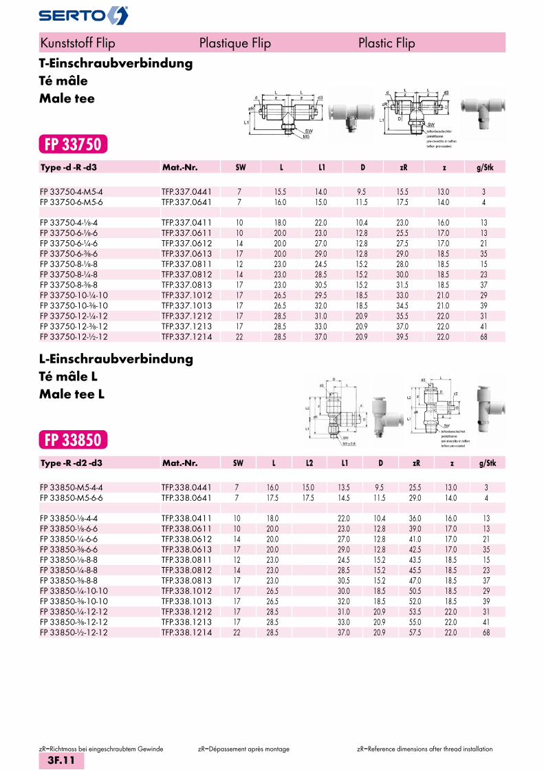
T-EinschraubverbindungTé mâleMale tee
FP 33750Type -d -R -d3 Mat.-Nr. SW L L1 D zR z g/Stk FP 33750-4-M5-4 TFP.337.0441 7 15.5 14.0 9.5 15.5 13.0 3FP 33750-6-M5-6 TFP.337.0641 7 16.0 15.0 11.5 17.5 14.0 4 FP 33750-4-1/8-4 TFP.337.0411 10 18.0 22.0 10.4 23.0 16.0 13FP 33750-6-1/8-6 TFP.337.0611 10 20.0 23.0 12.8 25.5 17.0 13FP 33750-6-1/4-6 TFP.337.0612 14 20.0 27.0 12.8 27.5 17.0 21FP 33750-6-3/8-6 TFP.337.0613 17 20.0 29.0 12.8 29.0 18.5 35FP 33750-8-1/8-8 TFP.337.0811 12 23.0 24.5 15.2 28.0 18.5 15FP 33750-8-1/4-8 TFP.337.0812 14 23.0 28.5 15.2 30.0 18.5 23FP 33750-8-3/8-8 TFP.337.0813 17 23.0 30.5 15.2 31.5 18.5 37FP 33750-10-1/4-10 TFP.337.1012 17 26.5 29.5 18.5 33.0 21.0 29FP 33750-10-3/8-10 TFP.337.1013 17 26.5 32.0 18.5 34.5 21.0 39FP 33750-12-1/4-12 TFP.337.1212 17 28.5 31.0 20.9 35.5 22.0 31FP 33750-12-3/8-12 TFP.337.1213 17 28.5 33.0 20.9 37.0 22.0 41FP 33750-12-1/2-12 TFP.337.1214 22 28.5 37.0 20.9 39.5 22.0 68
L-EinschraubverbindungTé mâle LMale tee L
FP 33850Type -R -d2 -d3 Mat.-Nr. SW L L2 L1 D zR z g/Stk FP 33850-M5-4-4 TFP.338.0441 7 16.0 15.0 13.5 9.5 25.5 13.0 3FP 33850-M5-6-6 TFP.338.0641 7 17.5 17.5 14.5 11.5 29.0 14.0 4 FP 33850-1/8-4-4 TFP.338.0411 10 18.0 22.0 10.4 36.0 16.0 13FP 33850-1/8-6-6 TFP.338.0611 10 20.0 23.0 12.8 39.0 17.0 13FP 33850-1/4-6-6 TFP.338.0612 14 20.0 27.0 12.8 41.0 17.0 21FP 33850-3/8-6-6 TFP.338.0613 17 20.0 29.0 12.8 42.5 17.0 35FP 33850-1/8-8-8 TFP.338.0811 12 23.0 24.5 15.2 43.5 18.5 15FP 33850-1/4-8-8 TFP.338.0812 14 23.0 28.5 15.2 45.5 18.5 23FP 33850-3/8-8-8 TFP.338.0813 17 23.0 30.5 15.2 47.0 18.5 37FP 33850-1/4-10-10 TFP.338.1012 17 26.5 30.0 18.5 50.5 18.5 29FP 33850-3/8-10-10 TFP.338.1013 17 26.5 32.0 18.5 52.0 18.5 39FP 33850-1/4-12-12 TFP.338.1212 17 28.5 31.0 20.9 53.5 22.0 31FP 33850-3/8-12-12 TFP.338.1213 17 28.5 33.0 20.9 55.0 22.0 41FP 33850-1/2-12-12 TFP.338.1214 22 28.5 37.0 20.9 57.5 22.0 68
Kunststoff Flip Plastique Flip Plastic Flip
zR=Richtmass bei eingeschraubtem Gewinde zR=Dépassement après montage zR=Reference dimensions after thread installation
3F.11
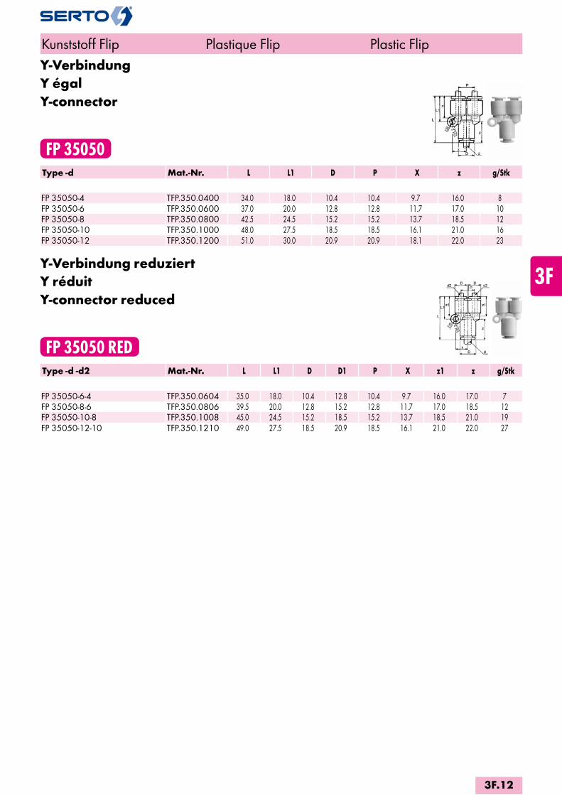
Y-VerbindungY égalY-connector
FP 35050Type -d Mat.-Nr. L L1 D P X z g/Stk FP 35050-4 TFP.350.0400 34.0 18.0 10.4 10.4 9.7 16.0 8FP 35050-6 TFP.350.0600 37.0 20.0 12.8 12.8 11.7 17.0 10FP 35050-8 TFP.350.0800 42.5 24.5 15.2 15.2 13.7 18.5 12FP 35050-10 TFP.350.1000 48.0 27.5 18.5 18.5 16.1 21.0 16FP 35050-12 TFP.350.1200 51.0 30.0 20.9 20.9 18.1 22.0 23
Y-Verbindung reduziertY réduitY-connector reduced
FP 35050 REDType -d -d2 Mat.-Nr. L L1 D D1 P X z1 z g/Stk FP 35050-6-4 TFP.350.0604 35.0 18.0 10.4 12.8 10.4 9.7 16.0 17.0 7FP 35050-8-6 TFP.350.0806 39.5 20.0 12.8 15.2 12.8 11.7 17.0 18.5 12FP 35050-10-8 TFP.350.1008 45.0 24.5 15.2 18.5 15.2 13.7 18.5 21.0 19FP 35050-12-10 TFP.350.1210 49.0 27.5 18.5 20.9 18.5 16.1 21.0 22.0 27
Kunststoff Flip Plastique Flip Plastic Flip
3F.12
i
s
3F
4M
4G
5
5L
6
7
8
9
10
11
12

Y-EinschraubverbindungY mâleY-connector male
FP 35150Type -d -R Mat.-Nr. SW L D P zR z g/Stk FP 35150-4 M5 TFP.351.0441 11 39.5 10.4 10.4 36.0 16.0 4FP 35150-6 M5 TFP.351.0641 13 42.5 12.8 12.8 39.0 17.0 13 FP 35150-4-1/8 TFP.351.0411 11 42.0 10.4 10.4 38.0 16.0 11FP 35150-4-1/4 TFP.351.0412 14 46.0 10.4 10.4 40.0 16.0 20FP 35150-6-1/8 TFP.351.0611 13 45.5 12.8 12.8 41.5 17.0 12FP 35150-6-1/4 TFP.351.0612 14 49.0 12.8 12.8 43.0 17.0 22FP 35150-6-3/8 TFP.351.0613 17 51.0 12.8 12.8 44.5 17.0 35FP 35150-8-1/8 TFP.351.0811 17 52.5 15.2 15.2 48.5 18.5 16FP 35150-8-1/4 TFP.351.0812 17 55.5 15.2 15.2 49.5 18.5 24FP 35150-8-3/8 TFP.351.0813 17 56.5 15.2 15.2 50.0 18.5 36FP 35150-10-1/4 TFP.351.1012 19 61.0 18.5 18.5 55.0 21.0 30FP 35150-10-3/8 TFP.351.1013 19 62.0 18.5 18.5 55.5 21.0 40FP 35150-12-3/8 TFP.351.1213 22 65.5 20.9 20.9 59.0 22.0 40
Einschraubwinkel 45°Coude mâle 45°Male elbow 45°
FP 35250Type -d -R Mat.-Nr. SW L L1 D zR z g/Stk FP 35250-4 M5 TFP.352.0441 8 17.0 14.5 10.4 26.0 16.0 4FP 35250-6 M5 TFP.352.0641 8 18.0 14.5 12.8 26.0 17.0 6 FP 35250-4-1/8 TFP.352.0411 10 17.0 20.5 10.4 32.0 16.0 10FP 35250-4-1/4 TFP.352.0412 14 17.0 24.5 10.4 34.0 16.0 19FP 35250-6-1/8 TFP.352.0611 10 18.0 20.5 12.8 33.0 17.0 12FP 35250-6-1/4 TFP.352.0612 14 18.0 24.5 12.8 35.0 17.0 10FP 35250-8-1/8 TFP.352.0811 12 20.5 22.0 15.2 37.0 18.5 13FP 35250-8-1/4 TFP.352.0812 14 20.5 26.0 15.2 39.0 18.5 21FP 35250-8-3/8 TFP.352.0813 17 20.5 28.0 15.2 40.5 18.5 35FP 35250-10-1/4 TFP.352.1012 17 24.0 27.0 18.5 43.5 21.0 26FP 35250-10-3/8 TFP.352.1013 17 24.0 29.0 18.5 45.0 21.0 36FP 35250-12-3/8 TFP.352.1213 17 25.0 29.5 20.9 47.0 22.0 38FP 35250-12-1/2 TFP.352.1214 22 25.0 33.5 20.9 49.5 22.0 65
Kunststoff Flip Plastique Flip Plastic Flip
zR=Richtmass bei eingeschraubtem Gewinde zR=Dépassement après montage zR=Reference dimensions after thread installation
3F.13

Y-EinsteckverbinderY enfichableY reduction union
FP 35650Type -d -Ad Mat.-Nr. L L1 D P X zR z g/Stk FP 35650-4-A4 TFP.356.0404 51.5 18.0 10.4 10.4 9.7 35.5 16.0 12FP 35650-6-A6 TFP.356.0606 55.5 20.0 12.8 12.8 11.7 38.5 17.0 19FP 35650-8-A8 TFP.356.0808 65.5 24.5 15.2 15.2 13.7 46.0 18.5 22FP 35650-10-A10 TFP.356.1010 71.5 27.5 18.5 18.5 16.1 50.5 21.0 26FP 35650-12-A12 TFP.356.1212 75.5 30.0 20.9 20.9 18.1 53.5 22.0 32
Kunststoff Flip Plastique Flip Plastic Flip
zR=Richtmass bei eingeschraubtem Gewinde zR=Dépassement après montage zR=Reference dimensions after thread installation
3F.14
i
s
3F
4M
4G
5
5L
6
7
8
9
10
11
12

Type -d -R Mat.-Nr. SW D L *zR z **e g
FP 31950-4 M5 TFP.319.0441 8 12 36.5 33.0 16.0 2.5 9FP 31950-6 M5 TFP.319.0641 8 14 37.5 33.5 17.0 2.5 12FP 31950-4- TFP.319.0411 12 12 38.0 34.0 16.0 2.5 14FP 31950-6- TFP.319.0611 14 14 39.5 35.5 17.0 4.0 17FP 31950-6- TFP.319.0612 14 14 42.5 36.0 17.0 4.0 23FP 31950-8- TFP.319.0811 17 17 44.0 40.0 18.5 6.0 23FP 31950-8- TFP.319.0812 17 17 47.0 41.0 18.5 6.0 29FP 31950-8- TFP.319.0813 17 17 48.0 41.5 18.5 6.0 37FP 31950-10- TFP.319.1012 22 22 54.0 48.0 21.0 7.0 55FP 31950-10- TFP.319.1013 22 22 55.0 48.5 21.0 7.0 63FP 31950-10- TFP.319.1014 22 22 57.5 49.5 21.0 7.0 81FP 31950-12- TFP.319.1213 24 24 57.0 50.5 22.0 8.0 75FP 31950-12- TFP.319.1214 24 24 60.0 52.0 22.0 8.0 92
Einschraubverbindung drehbarUnion mâle rotatifMale connector rotary
FP 31950Gleitlager
Ölimprägnierter Kunststoff
Palier lisseMatière plastique imprégnée d’huile
Slide bearingSmooth operating and longer life are provided
from an oil containing slide bearing
RillenkugellagerKugelkäfig aus Messing
Roulement rainuré à billesCage en laiton
Ball bearingA ball bearing ensures
low-torque rotation
Einsteck-Verbindung
Raccord instantané
Cassette
Spezialdichtung NBR
Joint spécial NBR
Rotary seal A special rotary seal minimises friction while providing an excellent seal
Halter Messing vernickelt
Support laiton nickelé
Holder Standard electroless nickel plating allows copper-free applications
Einschraubteil Messing vernickelt
Parti vissée laiton nickelé
Stud Threads are coated with a teflon based sealant for quick assembly
Technische Daten / Données techniques / Technical notesMedium / Fluide / Fluid Druckluft / Air comprimé / Compressed airArbeitsdruck / Pression de travaille / Operating pressure max. [MPa] 1.0 (~ 10 bar)Arbeitsdruck / Pression de travaille / Operating pressure min. [MPa] - 0.0987Prüfdruck / Pression d’épreuve / Proof pressure [MPa] 3.0 (~ 30 bar)Umgebungstemperatur / Température ambiante / Ambient and fluid temperature [°C] 0 – 60Drehzahl / Vitesse / Permissible number of rotation min-1 Ø4 Ø6 Ø8 Ø10 Ø12
500 500 400 300 250Gewinde / Filetage / Thread M5, M6 metrisch/métrique/metric, – konisch/conique/taper
HinweiseDa Miniaturkugellager verwendet werden, müssen die Querkräfte möglichst klein gehalten werden. In diesen Fällen wird empfohlen, Polyurethanschläuche einzusetzen.
CautionMinimise the load shown below to protect the ball bearing. A flexible polyurethane tube is recommended.
** e = Min. ø* Richtmass bei eingeschraubtem Gewinde
** e = Min. ø* Dépassement après montage
** e = Min. ø* Reference dimensions after thread installation
RemarqueEtant donné que des roulements à billes miniatures sont utilisés, les forces trans versales doivent être maintenues aussi faibles que possible. Dans ces cas, il est recommandé d’utiliser des tuyaux en poly uréthane.
Kunststoff Flip Plastique Flip Plastic Flip
3F.15

Einschraubwinkel drehbarCoude mâle rotatifMale elbow connector rotary
FP 32950Type -d -R Mat.-Nr. SW L L1 D zR z e g/Stk FP 32950-4-M5 TFP.329.0441 8 21.0 20.5 10.4 22.0 16.0 2.5 9FP 32950-6 M5 TFP.329.0641 8 23.0 21.0 12.8 23.5 17.0 2.5 12 FP 32950-4-1/8 TFP.329.0411 12 21.0 22.0 10.4 23.5 16.0 2.5 14FP 32950-6-1/8 TFP.329.0611 14 23.0 23.0 12.8 25.5 17.0 4.0 17FP 32950-6-1/4 TFP.329.0612 14 23.0 26.0 12.8 26.5 17.0 4.0 23FP 32950-8-1/8 TFP.329.0811 17 26.0 26.5 15.2 30.0 18.5 6.0 23FP 32950-8-1/4 TFP.329.0812 17 26.0 29.5 15.2 31.0 18.5 6.0 29FP 32950-8-3/8 TFP.329.0813 17 26.0 31.0 15.2 32.0 18.5 6.0 38FP 32950-10-1/4 TFP.329.1012 22 31.5 34.0 18.5 37.5 21.0 7.0 56FP 32950-10-3/8 TFP.329.1013 22 31.5 35.0 18.5 38.0 21.0 7.0 64FP 32950-12-3/8 TFP.329.1213 24 34.0 36.5 20.9 40.5 22.0 8.0 76FP 32950-12-1/2 TFP.329.1214 24 34.0 39.5 20.9 42.0 22.0 8.0 93
Einschraubverbindung mit RückschlagventilUnion mâle avec auto obturantStraight connector with non-return valve
FP 37350Type -d -R Mat.-Nr. SW L zR z g/Stk FP 37350-4-1/8 TFP.373.0411 10 26.1 22.1 18.0 8FP 37350-6-1/8 TFP.373.0611 12 37.4 33.4 19.0 16FP 37350-6-1/4 TFP.373.0612 14 28.9 22.9 19.0 14FP 37350-8-1/4 TFP.373.0812 14 45.7 39.7 21.5 27FP 37350-10-1/4 TFP.373.1012 17 50.5 44.5 24.0 34
Kunststoff Flip Plastique Flip Plastic Flip
zR=Richtmass bei eingeschraubtem Gewinde zR=Dépassement après montage zR=Reference dimensions after thread installation
3F.16
i
s
3F
4M
4G
5
5L
6
7
8
9
10
11
12
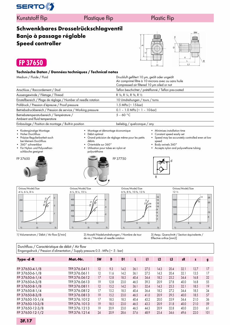
FP 37650
d
R
1
10
200
0
100
5
2
3
06, 0
8, 1
0
04
1) 2) 3)
2
500
4
6
1000
81012
1416
10, 1
2
0806
100
5
15
1) 2) 3)
2
10
200
0
100
5
4
6
300
400
08, 1
0
0604
1) 2) 3)
100
500
5
1000
5
10
20
2512
101500
1) 2) 3)
FP 37650 FP 37750
Type -d -R Mat.-Nr. SW D D1 L L1 L2 L3 zR z g
FP 37650-4-1/8 TFP.376.0411 12 9.3 14.2 36.1 27.5 14.3 20.4 32.1 12.7 17FP 37650-6-1/8 TFP.376.0611 12 11.6 14.2 36.1 27.5 14.3 20.4 32.1 13.5 17FP 37650-6-1/4 TFP.376.0612 17 12.8 18.5 40.4 34.4 18.2 25.2 34.4 16.8 32FP 37650-6-3/8 TFP.376.0613 19 12.8 23.0 46.5 39.3 20.9 27.8 40.0 16.8 55FP 37650-8-1/8 TFP.376.0811 12 15.2 14.2 36.1 32.4 14.3 25.3 32.1 18.5 19FP 37650-8-1/4 TFP.376.0812 17 15.2 18.5 40.4 36.4 18.2 27.2 34.4 18.5 34FP 37650-8-3/8 TFP.376.0813 19 15.2 23.0 46.5 41.0 20.9 29.5 40.0 18.5 57FP 37650-10-1/4 TFP.376.1012 17 18.5 18.5 40.4 43.2 20.0 33.9 34.4 21.0 36FP 37650-10-3/8 TFP.376.1013 19 18.5 23.0 46.5 43.3 20.9 31.8 40.0 21.0 59FP 37650-12-3/8 TFP.376.1213 19 20.9 23.0 46.5 44.3 20.9 32.8 40.0 22.0 61FP 37650-12-1/2 TFP.376.1214 24 20.9 28.6 57.6 48.9 25.4 34.6 49.6 22.0 101
Technische Daten / Données techniques / Technical notesMedium / Fluide / Fluid Druckluft gefiltert 10 µm, geölt oder ungeölt Air comprimé filtre à 10 microns avec ou sans huile Compressed air filtered 10 µm oiled or notAnschluss / Raccordement / Stud Teflon beschichtet / prétéflonné / Teflon pre-coatedAussengewinde / Filetage / Thread R , R , R , R Einstellbereich / Plage de réglage / Number of needle rotation 10 Umdrehungen / tours / turnsPrüfdruck / Pression d’épreuve / Proof pressure 1.5 MPa (~ 15-bar)Betriebsdruckbereich / Pression de service / Working pressure 0.1 – 1.0 MPa (~ 1 – 10-bar)Betriebstemperaturbereich / Température / 5 – 60 °C Ambient and fluid temperatureEinbaulage / Position de montage / Built-in position beliebig / quelconque / any
• Kostengünstige Montage • Hoher Durchfluss• Präzise Regulierbarkeit auch
bei kleinem Durchfluss• 360° schwenkbar• Für Nylon- und Polyurethan- schläuche geeignet
• Montage et démontage économique• Débit optimal• Grand précision de réglage même pour les petits
débits• Orientable sur 360° • Utilisation pour tubes en nylon et
polyuréthane
• Minimises installation time• Constant speed easily set• Speed may be accurately controlled even at low
speed• Body swivels 360° • Accepts nylon and polyurethane tubing
1) Volumenstrom / Débit / Air flow [l/min] 2) Anzahl Nadelumdrehungen / Nombre de tour de vis / Number of needle rotation
3) Aequ. Querschnitt / Section équivalente / Effective orifice [mm2]
Durchfluss / Caractéristique de débit / Air flowEingangsdruck / Pression d’alimentation / Supply pressure 0.5 - MPa (~ 5 - bar)
Grösse/Model/Size 4-, 6-, 8-
Grösse/Model/Size 6-, 8-, 10-
Grösse/Model/Size 6-, 8-, 10-, 12-
Grösse/Model/Size 12
Kunststoff flip Plastique flip Plastic flip
Schwenkbares DrosselrückschlagventilBanjo à passage réglableSpeed controller
3F.17
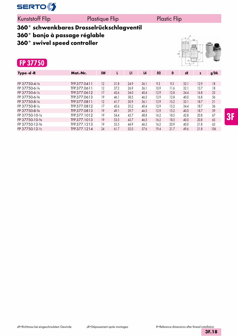
360° schwenkbares Drosselrückschlagventil360° banjo à passage réglable360° swivel speed controller
FP 37750Type -d -R Mat.-Nr. SW L L1 L4 D2 D zR z g/Stk FP 37750-4-1/8 TFP.377.0411 12 31.8 24.9 36.1 9.3 9.3 32.1 12.9 18FP 37750-6-1/8 TFP.377.0611 12 37.2 26.9 36.1 10.9 11.6 32.1 13.7 18FP 37750-6-1/4 TFP.377.0612 17 42.6 34.0 40.4 12.9 12.8 34.4 16.8 33FP 37750-6-3/8 TFP.377.0613 19 46.1 38.5 46.5 12.9 12.8 40.0 16.8 56FP 37750-8-1/8 TFP.377.0811 12 41.7 30.9 36.1 12.9 15.2 32.1 18.7 21FP 37750-8-1/4 TFP.377.0812 17 45.6 35.2 40.4 12.9 15.2 34.4 18.7 36FP 37750-8-3/8 TFP.377.0813 19 49.1 39.7 46.5 12.9 15.2 40.0 18.7 59FP 37750-10-1/4 TFP.377.1012 19 54.4 43.7 48.8 16.2 18.5 42.8 20.8 67FP 37750-10-3/8 TFP.377.1013 19 53.5 43.7 46.5 16.2 18.5 40.0 20.8 63FP 37750-12-3/8 TFP.377.1213 19 55.3 44.9 46.5 16.2 20.9 40.0 21.8 65FP 37750-12-1/2 TFP.377.1214 24 61.7 52.0 57.6 19.4 21.7 49.6 21.8 106
Kunststoff Flip Plastique Flip Plastic Flip
zR=Richtmass bei eingeschraubtem Gewinde zR=Dépassement après montagez R=Reference dimensions after thread installation
3F.18
i
s
3F
4M
4G
5
5L
6
7
8
9
10
11
12


4M
Messing M
Verschraubungen
Laiton M
Raccords
Brass M
Unions
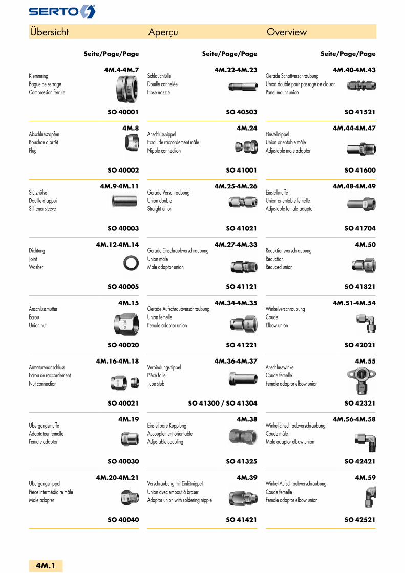
4M.4-4M.7KlemmringBague de serrageCompression ferrule
SO 40001
4M.8AbschlusszapfenBouchon d‘arrêtPlug
SO 40002
4M.9-4M.11StützhülseDouille d‘appuiStiffener sleeve
SO 40003
4M.12-4M.14DichtungJointWasher
SO 40005
4M.15AnschlussmutterEcrouUnion nut
SO 40020
4M.16-4M.18ArmaturenanschlussEcrou de raccordementNut connection
SO 40021
4M.19ÜbergangsmuffeAdaptateur femelleFemale adaptor
SO 40030
4M.20-4M.21ÜbergangsnippelPièce intermédiaire mâleMale adapter
SO 40040
4M.22-4M.23SchlauchtülleDouille canneléeHose nozzle
SO 40503
4M.24AnschlussnippelEcrou de raccordement mâleNipple connection
SO 41001
4M.25-4M.26Gerade VerschraubungUnion doubleStraight union
SO 41021
4M.27-4M.33Gerade EinschraubverschraubungUnion mâleMale adaptor union
SO 41121
4M.34-4M.35Gerade AufschraubverschraubungUnion femelleFemale adaptor union
SO 41221
4M.36-4M.37VerbindungsnippelPièce folleTube stub
SO 41300 / SO 41304
4M.38Einstellbare KupplungAccouplement orientableAdjustable coupling
SO 41325
4M.39Verschraubung mit EinlötnippelUnion avec embout à braserAdaptor union with soldering nipple
SO 41421
4M.40-4M.43Gerade SchottverschraubungUnion double pour passage de cloisonPanel mount union
SO 41521
4M.44-4M.47EinstellnippelUnion orientable mâleAdjustable male adaptor
SO 41600
4M.48-4M.49EinstellmuffeUnion orientable femelleAdjustable female adaptor
SO 41704
4M.50ReduktionsverschraubungRéductionReduced union
SO 41821
4M.51-4M.54WinkelverschraubungCoudeElbow union
SO 42021
4M.55AnschlusswinkelCoude femelleFemale adaptor elbow union
SO 42321
4M.56-4M.58Winkel-EinschraubverschraubungCoude mâleMale adaptor elbow union
SO 42421
4M.59Winkel-AufschraubverschraubungCoude femelleFemale adaptor elbow union
SO 42521
Seite/Page/Page Seite/Page/Page Seite/Page/Page
Übersicht Aperçu Overview
4M.1

4M.60-4M.61EinstellwinkelCoude orientableAdjustable elbow union
SO 42621
4M.62-4M.63Winkel-SchottverschraubungCoude pour passage de cloisonPanel mount elbow union
SO 42721
4M.64-4M.66SchwenkverschraubungCoude banjoSingle banjo
SO 42824
4M.67-4M.73T-VerschraubungTéTee union
SO 43021
4M.74-4M.75Einstell-T und LTé et L orientableAdjustable tee and L union
SO 43621
4M.76-4M.77T- und L-EinschraubverschraubungTé et L mâleMale adaptor tee and L union
SO 43721
4M.78-4M.79T-SchwenkverschraubungTé banjoTee banjo
SO 43824
4M.80KreuzverschraubungCroixCross union
SO 44021
4M.81-4M.82SchwenkverschraubungCoude banjoSingle banjo
SO 47624
4M.86RohrnippelMamelonDouble nipple
AD CNS 40
4M.86Aufschraub-WinkelCoude double femelleFemale elbow
AD FE 40
4M.86Aufschraub-TTé triple femelleFemale tee
AD FT 40
4M.87Sechskant-MuffeManchon doubleHex coupling
AD HC 40
4M.87RohrkappeCapuchon femelleHex cap
AD HCP 40
4M.88-4M.89DoppelnippelAdaptateur mâleMale adaptor
AD HN 40
4M.89-4M.91VerschlussschraubeBouchon d‘obturationScrew plug
AD HPO 40
4M.91-4M.92ReduziermuffeManchon de réductionFemale reduction muff
SO 40031
4M.93-4M.95ReduziernippelRéduction femelle-mâleMale reduction nipple
SO 40041
4M.95-4M.96EinschraubtülleDouille canellèe a visserMale adaptor hose nipple
SO 40511
4M.98SAE FlareSAE FlareSAE Flare
SAE
Sonderausführungen:Exécution en option:Optional Services:
Spezialbehandlung für Einsatz mit SauerstoffTraitement spécial pour utilisation sous oxygèneSpecial treatment for use with oxygen
Spezialbehandlung - silikonfreiTraitement spécial - sans siliconeSpecial treatment - silicone free
Spezialreinigung - entfettetTraitement spécial - sans siliconeSpecial treatment - degreased
Vorbeschichtete Gewinde mit Loctite 5061Filetages pré enduits avec Loctite 5061Pre-coated threads with Loctite 5061
Vorbeschichtete Gewinde PTFE-Band umwickeltFiletages pré enduits avec ruban en PTFEPre-coated threads with PTFE-tape
Chemisch vernickeltNickelage chimiqueChemical nickel-plated
Messing bleifreiLaiton sans plombUnleaded brass
Seite/Page/Page Seite/Page/Page Seite/Page/Page
Übersicht Aperçu Overview
4M.2
i
s
3F
4M
4G
5
5L
6
7
8
9
10
11
12

C° 300°250°200°180°0°-40°-100° 120°
100% 75%
Messing M Laiton M Brass M
Eigenschaften, Besonderheiten- einfache, schnelle Montage- kompakte Baumasse- grosse Sortimentsvielfalt- sehr viele Kombinationsmöglichkeiten- zwei Ausführungen: M = Anschlussmutter metrisch G = Anschlussmutter Rohrgewinde (Zoll) (M und G nicht austauschbar)
Funktionsprinzipsiehe Anhang
WerkstoffMessing CW 617N (CuZn40Pb2). Oberfläche gebeizt.Chemisch vernickelt, siehe Kapitel 8.
Betriebsdruck PNsiehe Produktetabellen (4fache Sicherheit). Dynamische Belastungen auf Anfrage.
Temperaturbereich-40°C bis +180°C.
Helium - Leckrate10-8mbar • l/s *
VakuumBis 10-4mbar, höhere Werte möglich.
Anzuschliessende RohreKunststoffrohre und nahtlose, gezogene Kupferrohre (insbes. EN 12449/1057) mit sau-berer, glatter Oberfläche. Aussendurchmesser innerhalb ± 0,1 mm; Ausnahme: Kunststoffrohre. Siehe auch Kapitel Rohre und Schläuche.Weitere Materialien auf Anfrage.
ZulassungenSVGW, DVGW und ÖVGW
Einschraubzapfen, GewindeRohrgewinde (Zoll) und metrisches Feingewinde DIN 3852, kegelig Form C, zylindrisch Form B, mit Dichtkante Form E. NPT-Gewinde nach ANSI/ASME B1.20.1-1983.
Généralités- montage facile et rapide- compactes dimensions- programme étendu- multiples possibilités de combinaisons- deux exécutions: M = Ecrou SERTO avec filetage métrique G = Ecrou SERTO avec filetage (BSP) gaz (M et G ne sont pas interchangeables)
Principe de fonctionnementvoir annexe
MatériauLaiton CW 617N (CuZn40Pb2). La surface est décapée.Nickelée par voie chimique, voir chapitre 8.
Pression de service PNvoir tableaux des produits (facteur de sécurité 4). Sollicitations dynamique sur demande.
Plage de température admissible-40°C à +180°C.
Débit de fuite avec hélium10-8mbar • l/s *
VideJusqu’à 10-4mbar, plus poussé possible.
Tubes à utiliserTubes en matière plastique et tous les tubes en cuivre sans soudure (selon EN 12449/1057) avec surface propre et lisse. Le diamètre extérieur doit être situé dans une tolérance de ± 0,1 mm; exception: tubes en plastique. Voir chapitre tubes et tuyaux. Autres matériaux sur demande.
HomologationsSSIGE, DVGW et ÖVGW
Embouts mâles, filetagesFiletage gaz (BSP) et filetage métrique à pas fin DIN 3852. Conique selon forme C. Cylindrique selon forme B. Filetage d’étanchéité selon forme E. Filetage NPT selon ANSI/ASME B1.20.1-1983.
Characteristics, specialities- easy and fast to install- compact size- extensive range- many combination possibilities- two models: M = Connection nut with metric thread G = Connection nut with British Standard Pipe (BSP) thread (M and G are not interchangeable)
Operating principlesee appendix
MaterialBrass CW 617N (CuZn40Pb2). The surface is pickled.Chemically nickel plated, see chapter 8.
Working pressure PNsee product table (safety factor 4). Dynamic loads on demand.
Temperature range-40°C to +180°C.
Leak rate with helium10-8mbar • l/s *
VacuumUp to 10-4mbar, higher values are possible.
Tubes to useTubes of plastic and seamless copper tubes (esp. EN 12449/1057) with clean smooth surface. Outside diameter of ± 0,1 mm; excep-tion: plastice tubes. See also chapter tubes and hoses. Further materials on demand.
ApprovalsSVGW, DVGW and ÖVGW
Adaptor stem, male thread British Standard Pipe (BSP) and metric fine thread DIN 3852. Tapered form C, parallel form B. Thread with sealing form E. BSP-thread according to ANSI/ASME B1.20.1-1983.
Druckauswertungsgrad in % des PN
Coefficient de pression de service admissible en % de PN
Pressure coefficient % of PN
* bei fachgerechter Montage; siehe Anhang: - Seite a.6 - Rohre - Seite a.21 - Montageanleitung
* à la base d'un montage dans les règles de l'art ; voir Appendice: - page a.6 - Tubes - page a.21 - Instructions de montage
* when professionally assembled; see Appendix: - page a.6 - Tubes - page a.21 - Installation instructions
4M.3

KlemmringBague de serrageCompression ferrule
SO 40001Type -d Mat.-Nr. bar D L z e kg/100Für metrische Rohre Pour tubes métriques For metric tubes SO 40001-2 016.0010.020 125 5.0 3.5 0.6 1.5 0.015SO 40001-3 016.0010.030 125 5.0 4.5 0.8 2.5 0.030SO 40001-4 016.0010.040 125 6.0 5.0 1.0 3.5 0.060SO 40001-5 016.0010.050 125 6.8 5.5 1.0 4.0 0.060SO 40001-6 * 016.0010.060 250 8.4 6.5 1.2 4.5 0.120SO 40001-8 * 016.0010.080 150 10.5 7.0 1.2 6.5 0.170SO 40001-10 * 016.0010.100 125 12.7 7.8 1.2 8.5 0.250SO 40001-12 * 016.0010.120 100 14.7 8.8 1.2 10.0 0.330SO 40001-14 016.0010.140 40 17.5 10.0 1.4 12.0 0.510SO 40001-15 016.0010.150 40 18.0 10.0 1.4 13.0 0.510SO 40001-16 016.0010.160 40 21.0 11.7 1.4 14.0 0.510SO 40001-17 016.0010.170 40 21.0 11.7 1.4 15.0 0.850SO 40001-18 016.0010.180 40 22.0 11.7 1.4 16.0 0.910SO 40001-22 016.0010.220 25 26.0 13.0 1.4 20.0 1.270SO 40001-28 016.0010.280 16 32.5 15.4 2.0 24.0 2.140SO 40001-35 016.0010.350 16 39.5 17.0 2.0 32.5 3.000
Für Zollrohre Pour tubes pouces For inch tubes SO 40001-3,2 016.0010.032 125 5.0 4.5 0.8 2.5 0.030SO 40001-6,35 016.0010.063 100 8.4 6.5 1.2 4.5 0.120SO 40001-7,94 016.0010.079 150 10.5 7.0 1.2 6.5 0.170SO 40001-9,52 016.0010.095 64 12.0 7.8 1.2 8.0 0.220SO 40001-15.88 016.0010.158 40 21.0 11.7 1.4 14.0 0.510SO 40001-22.22 016.0010.222 25 26.0 13.5 1.4 20.0 1.280
Messing M Laiton M Brass M
d=Rohraussen-ø d=ø extérieur du tube d=tube outside diameter
4M.4
i
s
3F
4M
4G
5
5L
6
7
8
9
10
11
12
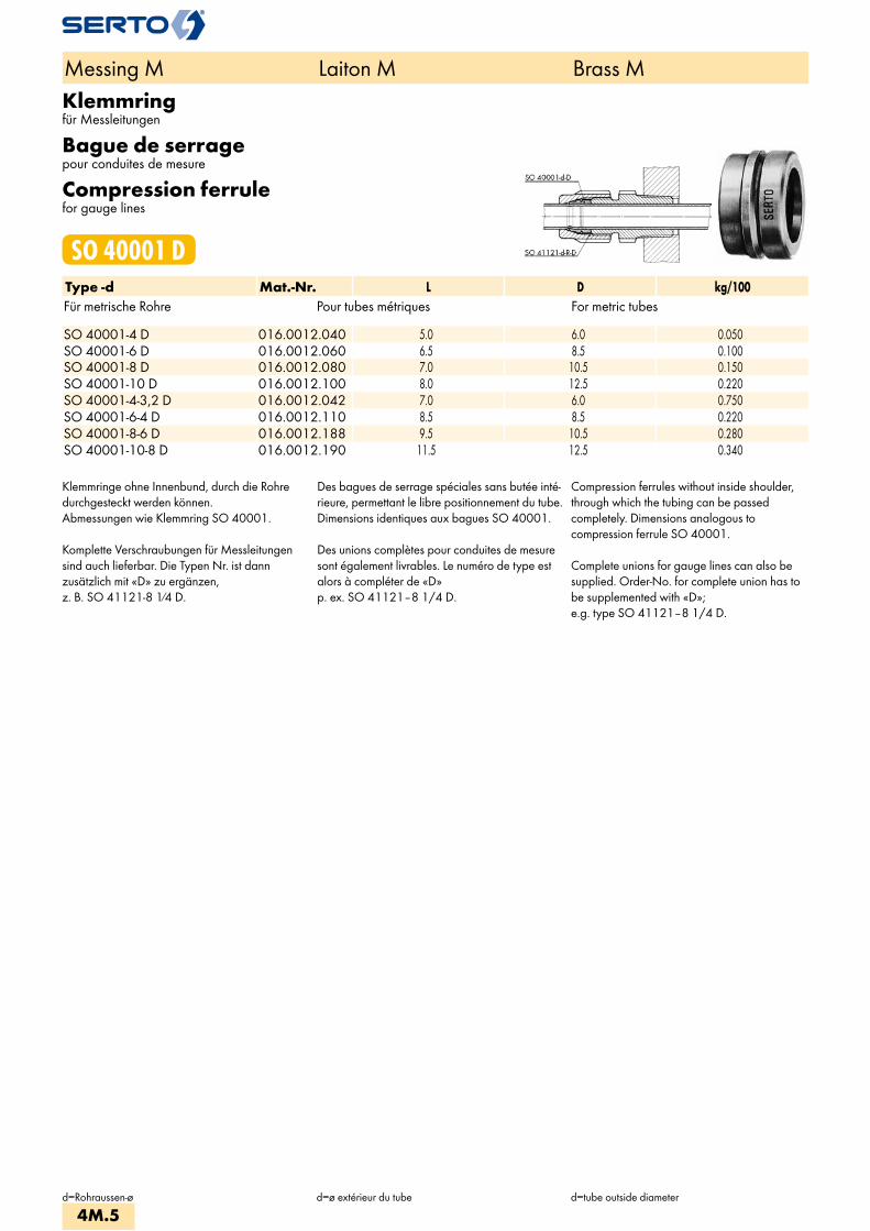
Klemmringfür Messleitungen
Bague de serragepour conduites de mesure
Compression ferrulefor gauge lines
SO 40001 DType -d Mat.-Nr. L D kg/100Für metrische Rohre Pour tubes métriques For metric tubes SO 40001-4 D 016.0012.040 5.0 6.0 0.050SO 40001-6 D 016.0012.060 6.5 8.5 0.100SO 40001-8 D 016.0012.080 7.0 10.5 0.150SO 40001-10 D 016.0012.100 8.0 12.5 0.220SO 40001-4-3,2 D 016.0012.042 7.0 6.0 0.750SO 40001-6-4 D 016.0012.110 8.5 8.5 0.220SO 40001-8-6 D 016.0012.188 9.5 10.5 0.280SO 40001-10-8 D 016.0012.190 11.5 12.5 0.340
Klemmringe ohne Innenbund, durch die Rohredurchgesteckt werden können.Abmessungen wie Klemmring SO 40001.
Komplette Verschraubungen für Messleitungensind auch lieferbar. Die Typen Nr. ist dannzusätzlich mit «D» zu ergänzen,z. B. SO 41121-8 1⁄4 D.
Des bagues de serrage spéciales sans butée inté-rieure, permettant le libre positionnement du tube. Dimensions identiques aux bagues SO 40001.
Des unions complètes pour conduites de mesuresont également livrables. Le numéro de type estalors à compléter de «D»p. ex. SO 41121–8 1/4 D.
Compression ferrules without inside shoulder,through which the tubing can be passedcompletely. Dimensions analogous tocompression ferrule SO 40001.
Complete unions for gauge lines can also besupplied. Order-No. for complete union has tobe supplemented with «D»;e.g. type SO 41121–8 1/4 D.
Messing M Laiton M Brass M
d=Rohraussen-ø d=ø extérieur du tube d=tube outside diameter
4M.5

Klemmring reduziertBague de serrage de réductionReduction compression ferrule
SO 40001 REDType -dr -d Mat.-Nr. bar L D z e kg/100Für metrische Rohre Pour tubes métriques For metric tubes SO 40001-5-3 RED 016.0014.060 125 7.5 6.8 0.8 2.5 0.130SO 40001-6-4 RED 016.0014.110 100 8.5 8.5 1.0 3.5 0.230SO 40001-6-5 RED 016.0014.117 100 8.7 8.5 1.0 4.0 0.180SO 40001-8-6 RED * 016.0014.140 250 9.5 10.5 1.2 4.5 0.330SO 40001-10-8 RED * 016.0014.190 150 11.5 12.7 1.2 6.5 0.450SO 40001-12-10 RED * 016.0014.240 100 12.5 14.7 1.2 8.5 0.610SO 40001-14-12 RED 016.0014.340 40 14.0 17.5 1.4 10.0 0.890SO 40001-15-12 RED 016.0014.420 40 14.0 18.0 1.4 10.0 1.050SO 40001-15-13 RED 016.0014.430 40 14.0 18.0 1.4 11.0 3.030SO 40001-17-14 RED 016.0014.530 40 15.7 21.0 1.4 12.0 1.560SO 40001-18-15 RED 016.0014.610 40 15.7 22.0 1.4 13.0 1.660SO 40001-18-16 RED 016.0014.620 40 15.7 22.0 1.4 14.0 1.430SO 40001-22-17 RED 016.0014.750 25 19.0 26.0 1.4 15.0 3.030SO 40001-22-18 RED 016.0014.755 25 19.0 26.0 1.4 16.0 2.850SO 40001-22-19 RED 016.0014.760 25 19.0 26.0 1.4 16.0 2.600
Für Zollrohre Pour tubes pouces For inch tubes SO 40001-4-3,2 RED 016.0014.042 125 7.0 6.0 0.8 2.5 0.090SO 40001-10-7,94 RED 016.0014.187 150 11.5 12.7 1.2 6.5 0.450SO 40001-15-12,7 RED 016.0014.427 40 14.0 18.0 1.4 11.0 3.030SO 40001-22-19,05 RED 016.0014.762 25 19.0 26.0 1.4 17.0 2.600
Anwendungsbeispiele: Exemples d‘utilisation: Sample combinations:
Einstufige Reduktionen von Rohranschlüssen sindauf einfachste Art durch Auswechseln dernormalen gegen die reduzierten Klemmringemöglich.
Beispiel:Reduktion eines Rohranschlusses ø15mm aufø12 mm: Klemmring SO 40001-15 austauschengegen Klemmring SO 40001-15-12 RED.Anschlussmutter SO 40020-15 bleibt.
Le raccordement de tubes réduits d’unedimension peut s’effectuer très simplement enéchangeant la bague de serrage normale contreune bague de réduction.
Exemple:Réduction d’un raccord ø15 mm àø12 mm: Echanger la bague de serrageSO 40001–15 contre une bague de réductionSO 40001–15–12 RED.L’écrou SO 40020–15 reste le même.
Single stage tube reduction connections areeasily made by replacing the standardcompression ferrule with a reductioncompression ferrule.
Example:Tube reduction connection ø15mm toø12 mm: Replace compression ferruleSO 40001–15 by compression ferruleSO 40001–15–12 RED.Union nut SO 40020–15 remains.
Messing M Laiton M Brass M
dr=Grösse der Anschlussmutterd=Rohraussen-ø
dr=dimension de l'écrou de based=ø extérieur du tube
dr=size of connection nutd=tube outside diameter
4M.6
i
s
3F
4M
4G
5
5L
6
7
8
9
10
11
12

Klemmringmit fixierter Stützhülse
Bague de serrageavec douille d‘appui fixée
Compression ferrulewith fixed stiffener sleeve
SO 40001 FIXType -d -d1 Mat.-Nr. bar L D s z e SO 40001-6-4 FIX 016.0015.110 100 11.0 8.5 0.20 1.0 4.5SO 40001-8-6 FIX 016.0015.140 100 13.0 10.5 0.25 1.0 6.5
Messing M Laiton M Brass M
d=Rohraussen-ø d=ø extérieur du tube d=tube outside diameter
4M.7

AbschlusszapfenBouchon d‘arrêtPlug
SO 40002Type -d Mat.-Nr. L D kg/100Für metrische Rohre Pour tubes métriques For metric tubes SO 40002-2 016.0020.020 5.3 5.0 0.040SO 40002-3 016.0020.030 7.0 5.0 0.080SO 40002-4 016.0020.040 8.0 6.8 0.150SO 40002-5 016.0020.050 8.5 6.8 0.190SO 40002-6 016.0020.060 10.0 8.4 0.310SO 40002-8 016.0020.080 10.5 10.5 0.570SO 40002-10 016.0020.100 13.0 12.7 0.960SO 40002-12 016.0020.120 14.0 14.8 1.470SO 40002-14 016.0020.140 15.0 17.5 2.230SO 40002-15 016.0020.150 15.0 18.0 2.370SO 40002-17 016.0020.170 17.2 21.0 3.680SO 40002-18 016.0020.180 16.8 22.0 4.000SO 40002-22 016.0020.220 19.0 26.0 6.300SO 40002-28 016.0020.280 22.5 32.5 11.900SO 40002-35 016.0020.350 25.2 39.5 20.000
Für Zollrohre Pour tubes pouces For inch tubes SO 40002-6,35 016.0020.063 10.0 8.4 0.310SO 40002-7,94 016.0020.079 10.5 10.5 0.570SO 40002-9,52 016.0020.095 13.0 12.7 0.960SO 40002-12,7 016.0020.127 15.0 17.5 2.230
Anwendungsbeispiele: Exemples d‘utilisation: Sample combinations:
Werkstoff: Messing
Der Abschlusszapfen lässt sich in jede Verschraubung anstelle eines Klemmringesgleicher Grösse d einsetzen.
Anschlussmutter mit 1/4 Drehung anziehen.
Matériau: Laiton
Le bouchon d’arrêt peut remplacer la bague de serrage de même dimension d dans chaque raccord.
Serrer l’écrou avec 1/4 tour.
Material: Brass
The plug can be fitted into any union in place of a compression ferrule of same diameter d.
Tighten the union nut with 1/4 turn.
Messing M Laiton M Brass M
d=Rohraussen-ø d=ø extérieur du tube d=tube outside diameter
4M.8
i
s
3F
4M
4G
5
5L
6
7
8
9
10
11
12
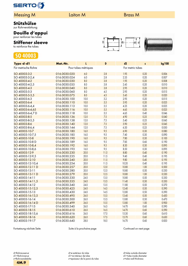
Stützhülsezur Rohrverstärkung
Douille d‘appuipour renforcer les tubes
Stiffener sleeveto reinforce the tubes
SO 40003Type -d -d1 Mat.-Nr. L D d2 s kg/100Für metrische Rohre Pour tubes métriques For metric tubes SO 40003-3-2 016.0030.020 6.0 2.8 1.95 0.20 0.006SO 40003-3-2,4 016.0030.024 6.0 2.8 2.35 0.20 0.007SO 40003-4-2 016.0030.030 8.0 3.8 1.95 0.20 0.008SO 40003-4-2,5 016.0030.035 8.0 3.8 2.45 0.20 0.010SO 40003-4-3 016.0030.040 8.0 3.8 2.95 0.20 0.010SO 40003-5-3 016.0030.060 8.0 4.5 2.95 0.20 0.015SO 40003-5-3,5 016.0030.075 8.0 4.5 3.45 0.20 0.020SO 40003-6-3 016.0030.100 10.0 5.2 2.95 0.20 0.015SO 40003-6-4 016.0030.110 10.0 5.5 3.95 0.20 0.025SO 40003-6-4,4 016.0030.113 10.0 5.5 4.35 0.20 0.025SO 40003-6-4,65 016.0030.116 10.0 5.5 4.65 0.20 0.025SO 40003-6-4,7 D 016.0030.118 10.0 5.5 4.65 0.40 0.046SO 40003-8-5 016.0030.136 12.0 7.5 4.90 0.25 0.040SO 40003-8-5,5 016.0030.138 12.0 7.5 5.40 0.25 0.045SO 40003-8-6 016.0030.140 12.0 7.5 5.90 0.25 0.045SO 40003-8-6,4 016.0030.144 12.0 7.5 6.30 0.25 0.050SO 40003-10-7 016.0030.180 16.0 9.5 6.90 0.30 0.080SO 40003-10-7,5 016.0030.185 16.0 9.5 7.40 0.30 0.090SO 40003-10-8 016.0030.190 16.0 9.5 7.80 0.30 0.100SO 40003-10-8 D 016.0030.189 16.0 9.5 7.85 0.60 0.190SO 40003-10-8,4 016.0030.192 16.0 9.5 8.30 0.30 0.095SO 40003-10-8,6 016.0030.193 16.0 9.5 8.50 0.30 0.095SO 40003-12-9 016.0030.230 20.0 11.5 8.80 0.40 0.190SO 40003-12-9,5 016.0030.235 20.0 11.5 9.40 0.40 0.195SO 40003-12-10 016.0030.240 20.0 11.5 9.80 0.40 0.195SO 40003-12-10,4 016.0030.254 20.0 11.5 10.20 0.40 0.195SO 40003-12-11 D 016.0030.257 20.0 12.0 10.80 1.00 0.500SO 40003-13-11 016.0030.280 20.0 12.5 10.80 0.50 0.330SO 40003-13-11 D 016.0030.279 20.0 12.5 10.80 1.00 0.530SO 40003-14-11 016.0030.330 24.0 13.5 10.80 0.50 0.350SO 40003-14-11,5 016.0030.335 24.0 13.5 11.40 0.50 0.350SO 40003-14-12 016.0030.340 24.0 13.5 11.80 0.50 0.370SO 40003-15-12,5 016.0030.425 24.0 14.5 12.40 0.50 0.390SO 40003-15-13 016.0030.430 24.0 14.5 12.80 0.50 0.390SO 40003-16-13,5 016.0030.495 26.0 15.5 13.40 0.50 0.430SO 40003-16-14 016.0030.500 26.0 15.5 13.80 0.50 0.470SO 40003-16-14 D 016.0030.499 26.0 15.5 13.80 1.00 0.900SO 40003-17-15 016.0030.540 26.0 16.5 14.70 0.60 0.590SO 40003-18-15 016.0030.610 26.0 16.5 14.70 0.60 0.590SO 40003-18-15,6 016.0030.616 26.0 17.5 15.30 0.60 0.610SO 40003-18-16 016.0030.620 26.0 17.5 15.70 0.60 0.630SO 40003-19-17 016.0030.640 28.0 18.5 16.70 0.60 0.820
Fortsetzung nächste Seite Suite à la prochaine page Continued on next page
Messing M Laiton M Brass M
d=Rohraussen-ød1=Rohrinnen-øs=Rohrwandstärke
d=ø extérieur du tubed1=ø intérieur de tubes=epaisseur de la paroi du tube
d=tube outside diameterd1=tube inside diameters=tube wall thickness
4M.9

Stützhülsezur Rohrverstärkung
Douille d‘appuipour renforcer les tubes
Stiffener sleeveto reinforce the tubes
SO 40003Type -d -d1 Mat.-Nr. L D d2 s kg/100Für metrische Rohre Pour tubes métriques For metric tubes SO 40003-20-17 016.0030.690 28.0 19.5 16.70 0.60 0.800SO 40003-20-18 016.0030.700 28.0 19.5 17.70 0.60 0.830SO 40003-22-19 016.0030.760 30.0 21.5 18.70 0.60 0.850SO 40003-22-19,6 016.0030.771 30.0 21.5 19.30 0.60 0.940SO 40003-22-20 016.0030.775 30.0 21.5 19.70 0.60 0.980SO 40003-28-25 016.0030.870 36.0 27.5 24.70 0.80 1.500SO 40003-28-25,6 016.0030.876 36.0 27.5 25.30 0.80 1.600SO 40003-35-32 016.0030.890 41.0 34.0 31.70 0.85 2.500
Für Zollrohre Pour tubes pouces For inch tubes SO 40003-6,35-4,3 016.0030.112 10.0 5.5 4.30 0.20 0.023SO 40003-9,52-6,35 016.0030.160 16.0 9.0 6.25 0.30 0.080SO 40003-12,7-10,7 016.0030.269 20.0 12.5 10.50 0.50 0.200SO 40003-12,7-10,9 016.0030.271 20.0 12.5 10.70 0.50 0.286SO 40003-15,88-14,25 D 016.0030.465 26.0 15.5 14.10 0.50 0.916
Werkstoff: Messing
Verstärken:Dünnwandige und weiche Rohre sowie alle Kunststoffrohre sind vor dem Einführen in die SERTO Verschraubung mit Stützhülsen zu verstärken. Genaue Angaben über das Verstärken sind den einzelnen Verschraubungsreihen zu entnehmen. Zum Entgraten und Kalibrieren der Rohre eignen sich besonders unsere Hilfswerkzeuge (siehe Kapitel 11).
Matériau: Laiton
Renforcement:Les tubes présentant une paroi mince, les tubes en matière souple ainsi que les tubes en matière pla-stique doivent être renforcés à l’aide de douilles d’appui avant d’être introduits dans les raccords SERTO. Des indications plus précises concernant le ren-forcement sont données pour chaque série de raccord. L’ébarbage et le calibrage du tube sont facilités par l’emploi de notre outil spécial (voir chap. 11).
Material: Brass
Reinforcement:Thin walled and soft tubes and all plastic tubes, are to be reinforced with stiffener sleeves before insert them into the SERTO union. Exact details concerning stiffening are to be found in the sections on the relevant model series. Our tools are especially useful for debur-ring and calibrating tubing (see chapter 11).
Messing M Laiton M Brass M
d=Rohraussen-ød1=Rohrinnen-øs=Rohrwandstärke
d=ø extérieur du tubed1=ø intérieur de tubes=epaisseur de la paroi du tube
d=tube outside diameterd1=tube inside diameters=tube wall thickness
4M.10
i
s
3F
4M
4G
5
5L
6
7
8
9
10
11
12

Stützhülsefür SERTOflex-Rohre
Douille d‘appuipour tubes SERTOflex
Stiffener sleevefor SERTOflex tubes
SO 40003 FLEXType -d -d1 Mat.-Nr. L D d2 s kg/100Für metrische Rohre Pour tubes métriques For metric tubes SO 40003-6-4 FLEX 440.0035.110 10.0 5.5 3.85 0.20 0.025SO 40003-8-5,3 FLEX 440.0035.137 12.0 7.5 5.20 0.25 0.045SO 40003-12-8 FLEX 440.0035.225 20.0 11.5 7.85 0.40 0.190
Für Zollrohre Pour tubes pouces For inch tubes SO 40003-6,35-4,35 FLEX 440.0035.113 10.0 5.5 4.35 0.20 0.025SO 40003-10-6,35 FLEX 440.0035.177 16.0 9.5 6.00 0.30 0.080
Werkstoff: Messing
Verstärken:Dünnwandige und weiche Rohre sowie alle Kunststoffrohre sind vor dem Einführen in die SERTO Verschraubung mit Stützhülsen zu verstär-ken. Genaue Angaben über das Verstärken sind den einzelnen Verschraubungsreihen zu entnehmen. Zum Entgraten und Kalibrieren der Rohre eignen sich besonders unsere Hilfswerkzeuge (siehe Kapitel 11).
Matériau: Laiton
Renforcement:Les tubes présentant une paroi mince, les tubes en matière souple ainsi que les tubes en matière pla-stique doivent être renforcés à l’aide de douilles d’appui avant d’être introduits dans les raccords SERTO. Des indications plus précises concernant le ren-forcement sont données pour chaque série de raccord. L’ébarbage et le calibrage du tube sont facilités par l’emploi de notre outil spécial (voir chap. 11).
Material: Brass
Reinforcement:Thin walled and soft tubes and all plastic tubes, are to be reinforced with stiffener sleeves before insert them into the SERTO union. Exact details concerning stiffening are to be found in the sections on the relevant model series. Our tools are especially useful for debur-ring and calibrating tubing (see chapter 11).
Messing M Laiton M Brass M
d=Rohraussen-ød1=Rohrinnen-øs=Rohrwandstärke
d=ø extérieur du tubed1=ø intérieur de tubes=epaisseur de la paroi du tube
d=tube outside diameterd1=tube inside diameters=tube wall thickness
4M.11

Dichtung für InnengewindeJoint pour filetage femelleWasher for female threads
SO 40005Type -d -G Mat.-Nr. D s e kg/100 G=Rohrgewinde (zylindrisch) G=Filetage-gaz BSP (cylindrique) G=BSP thread (straight)SO 40005-4-1/8 016.0050.060 8.5 2.00 4.0 0.070SO 40005-5-1/8 016.0050.082 8.5 2.00 4.0 0.070SO 40005-6-1/4 016.0050.110 11.2 2.00 5.2 0.130SO 40005-8-1/4 016.0050.170 11.2 2.00 6.8 0.090SO 40005-8,2-1/4 016.0050.173 11.2 2.00 8.2 0.080SO 40005-10-3/8 016.0050.280 14.8 2.00 9.0 0.170SO 40005-10,2-3/8 016.0050.283 14.8 2.00 10.2 0.150SO 40005-12-1/2 016.0050.400 18.5 2.00 10.0 0.330SO 40005-14-1/2 016.0050.504 18.5 2.00 13.5 0.210SO 40005-15-1/2 016.0050.534 18.5 2.00 13.5 0.210SO 40005-15-3/4 016.0050.536 24.0 2.00 14.2 0.490SO 40005-17-3/4 016.0050.598 24.0 2.00 16.2 0.410SO 40005-18-7/8 016.0050.650 27.8 2.00 16.2 0.700SO 40005-22-1 016.0050.770 30.0 2.00 20.0 0.670
Anwendungsbeispiele: Exemples d‘utilisation: Sample combinations:
Material: Kupfer, weich
Zu verwenden:Als Auflage für den Klemmring beim Einschraubstutzen SO 41001. Als stirnsei-tige Abdichtung in Anschlussgewinde der Verschraubung SO 40030 und SO 41221.
Matériau: Cuivre, doux
Emploi:Comme appui d’étanchéité pour la bague de serrage SO 41001. Comme joint frontal pour le filetage femelle des pièces SO 40030 et SO 41221.
Material: Copper, soft
Application:As seat for compression ferrule with nipple connection SO 41001. As butt seal for adap-tor thread in unions SO 40030 and SO 41221.
Messing M Laiton M Brass M
d=Rohraussen-ø d=ø extérieur du tube d=tube outside diameter
4M.12
i
s
3F
4M
4G
5
5L
6
7
8
9
10
11
12
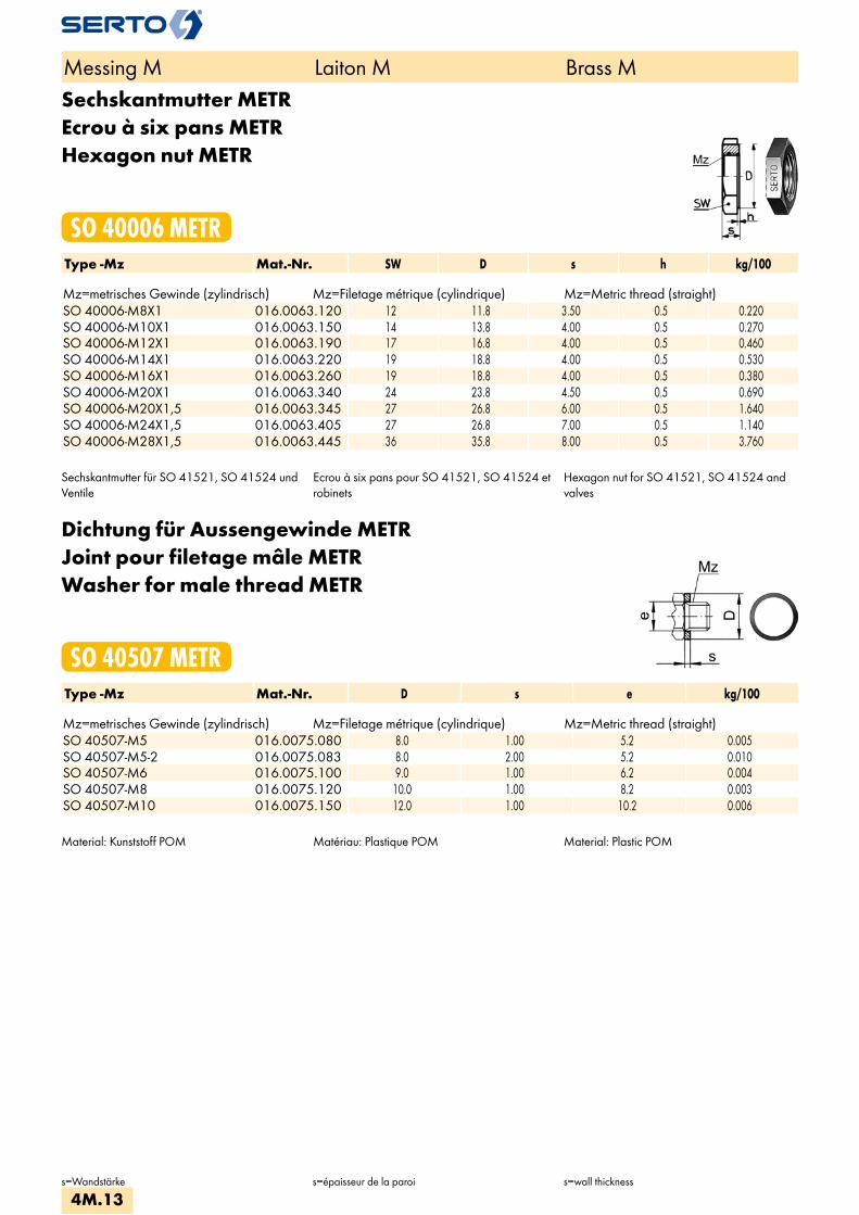
Sechskantmutter METREcrou à six pans METRHexagon nut METR
SO 40006 METRType -Mz Mat.-Nr. SW D s h kg/100 Mz=metrisches Gewinde (zylindrisch) Mz=Filetage métrique (cylindrique) Mz=Metric thread (straight)SO 40006-M8X1 016.0063.120 12 11.8 3.50 0.5 0.220SO 40006-M10X1 016.0063.150 14 13.8 4.00 0.5 0.270SO 40006-M12X1 016.0063.190 17 16.8 4.00 0.5 0.460SO 40006-M14X1 016.0063.220 19 18.8 4.00 0.5 0.530SO 40006-M16X1 016.0063.260 19 18.8 4.00 0.5 0.380SO 40006-M20X1 016.0063.340 24 23.8 4.50 0.5 0.690SO 40006-M20X1,5 016.0063.345 27 26.8 6.00 0.5 1.640SO 40006-M24X1,5 016.0063.405 27 26.8 7.00 0.5 1.140SO 40006-M28X1,5 016.0063.445 36 35.8 8.00 0.5 3.760
Sechskantmutter für SO 41521, SO 41524 und Ventile
Ecrou à six pans pour SO 41521, SO 41524 et robinets
Hexagon nut for SO 41521, SO 41524 and valves
Dichtung für Aussengewinde METRJoint pour filetage mâle METRWasher for male thread METR
SO 40507 METRType -Mz Mat.-Nr. D s e kg/100 Mz=metrisches Gewinde (zylindrisch) Mz=Filetage métrique (cylindrique) Mz=Metric thread (straight)SO 40507-M5 016.0075.080 8.0 1.00 5.2 0.005SO 40507-M5-2 016.0075.083 8.0 2.00 5.2 0.010SO 40507-M6 016.0075.100 9.0 1.00 6.2 0.004SO 40507-M8 016.0075.120 10.0 1.00 8.2 0.003SO 40507-M10 016.0075.150 12.0 1.00 10.2 0.006
Material: Kunststoff POM Matériau: Plastique POM Material: Plastic POM
Messing M Laiton M Brass M
s=Wandstärke s=épaisseur de la paroi s=wall thickness
4M.13

Dichtung für AussengewindeJoint pour filetage mâleWasher for male threads
SO 40007Type -G Mat.-Nr. D s e kg/100 G=Rohrgewinde (zylindrisch) G=Filetage-gaz BSP (cylindrique) G=BSP thread (straight)SO 40007-1/8 016.0070.020 13.4 1.50 10.2 0.050SO 40007-1/4 016.0070.040 17.9 1.50 14.2 0.110SO 40007-3/8 016.0070.060 20.9 1.50 17.2 0.130SO 40007-1/2 016.0070.080 25.9 1.50 21.2 0.220SO 40007-3/4 016.0070.120 31.0 1.50 26.5 0.230
Dichtung für Aussengewinde METRJoint pour filetage mâle METRWasher for male threads METR
SO 40007 METRType -Mz Mat.-Nr. D s e kg/100 Mz=metrisches Gewinde (zylindrisch) Mz=Filetage métrique (cylindrique) Mz=Metric thread (straight)SO 40007-M5 016.0073.080 8.0 1.00 5.2 0.023SO 40007-M6 016.0073.100 8.0 1.00 6.2 0.014SO 40007-M8 016.0073.173 11.2 2.00 8.2 0.080SO 40007-M10 016.0073.150 13.4 1.50 10.2 0.050SO 40007-M12 016.0073.190 15.4 1.50 12.2 0.080SO 40007-M14 016.0073.220 17.9 1.50 14.2 0.110SO 40007-M16 016.0073.260 19.9 1.50 16.2 0.120SO 40007-M18 016.0073.300 22.0 1.50 18.2 0.140SO 40007-M22 016.0073.370 27.0 1.50 22.2 0.225
Anwendungsbeispiele: Exemples d‘utilisation: Sample combinations:
Material: Kupfer, weichErsatzdichtungen für Schwenkverschraubungen und Mehrfachverteiler.
Zu verwenden:Als Abdichtung der Verschraubung mit zylindri-schem Einschraubgewinde.
Matériau: Cuivre, douxJoints de rechange pour coudes banjo et coudes banjo multiples.
Emploi:Rendre étanche un filetage cylindrique mâle
Material: Copper, softReplacement washer for single and double banjo.
Application:As seal for union with straight male adaptor thread.
Messing M Laiton M Brass M
d=Rohraussen-øe=kleinste Bohrungs=Wandstärke
d=ø extérieur du tubee=ø-min. de passages=épaisseur de la paroi
d=tube outside diametere=minimum bores=wall thickness
4M.14
i
s
3F
4M
4G
5
5L
6
7
8
9
10
11
12

AnschlussmutterEcrouUnion nut
SO 40020Type -d Mat.-Nr. bar M SW L kg/100Für metrische Rohre Pour tubes métriques For metric tubes SO 40020-2 016.0200.020 125 6x0.75 8 8.5 0.245SO 40020-3 016.0200.030 125 6x0.75 8 10.0 0.270SO 40020-4 016.0200.040 125 8x1 10 13.0 0.510SO 40020-5 016.0200.050 125 8x1 10 13.5 0.500SO 40020-6 016.0200.060 250 10x1 12 14.5 0.720SO 40020-8 016.0200.080 150 12x1 14 16.0 0.950SO 40020-10 016.0200.100 125 14x1 17 18.5 1.640SO 40020-12 016.0200.120 100 16x1 19 19.5 2.010SO 40020-14 016.0200.140 40 20x1.5 24 21.0 4.050SO 40020-15 016.0200.150 40 20x1.5 24 21.0 3.730SO 40020-16 016.0200.160 40 24x1.5 27 24.0 4.790SO 40020-17 016.0200.170 40 24x1.5 27 24.0 4.680SO 40020-18 016.0200.180 40 24x1.5 27 24.0 4.350SO 40020-22 016.0200.220 25 28x1.5 32 27.5 7.150SO 40020-28 016.0200.280 16 36x2 41 31.5 14.300SO 40020-35 016.0200.350 16 42x2 50 36.0 26.200
Für Zollrohre Pour tubes pouces For inch tubes SO 40020-3,2 016.0200.032 125 6x0.75 8 10.0 0.270SO 40020-6,35 016.0200.063 100 10x1 12 14.5 0.710SO 40020-7,94 016.0200.079 150 12x1 14 16.0 0.950SO 40020-9,52 016.0200.095 64 14x1 17 18.5 1.730SO 40020-15,88 016.0200.158 40 24x1.5 27 24.0 4.790SO 40020-22.22 016.0200.222 25 28x1.5 32 27.0 7.020
Messing M Laiton M Brass M
d=Rohraussen-ø d=ø extérieur du tube d=tube outside diameter
4M.15
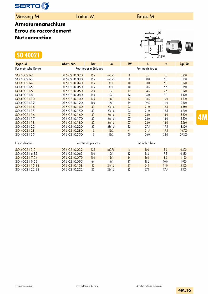
ArmaturenanschlussEcrou de raccordementNut connection
SO 40021Type -d Mat.-Nr. bar M SW L z kg/100Für metrische Rohre Pour tubes métriques For metric tubes SO 40021-2 016.0210.020 125 6x0.75 8 8.5 4.0 0.260SO 40021-3 016.0210.030 125 6x0.75 8 10.0 5.0 0.300SO 40021-4 016.0210.040 125 8x1 10 13.0 6.0 0.570SO 40021-5 016.0210.050 125 8x1 10 13.5 6.5 0.560SO 40021-6 016.0210.060 250 10x1 12 14.5 7.5 0.840SO 40021-8 016.0210.080 150 12x1 14 16.0 8.0 1.120SO 40021-10 016.0210.100 125 14x1 17 18.5 10.0 1.890SO 40021-12 016.0210.120 100 16x1 19 19.5 11.0 2.340SO 40021-14 016.0210.140 40 20x1.5 24 21.0 12.5 4.560SO 40021-15 016.0210.150 40 20x1.5 24 21.0 12.5 4.240SO 40021-16 016.0210.160 40 24x1.5 27 24.0 14.0 5.300SO 40021-17 016.0210.170 40 24x1.5 27 24.0 14.0 5.530SO 40021-18 016.0210.180 40 24x1.5 27 24.0 14.0 5.260SO 40021-22 016.0210.220 25 28x1.5 32 27.5 17.5 8.420SO 40021-28 016.0210.280 16 36x2 41 31.5 19.5 16.700SO 40021-35 016.0210.350 16 42x2 50 36.0 22.0 29.200
Für Zollrohre Pour tubes pouces For inch tubes SO 40021-3,2 016.0210.032 125 6x0.75 8 10.0 5.0 0.300SO 40021-6,35 016.0210.063 100 10x1 12 14.5 7.5 0.830SO 40021-7,94 016.0210.079 100 12x1 14 16.0 8.0 1.120SO 40021-9,52 016.0210.095 64 14x1 17 18.5 10.0 1.950SO 40021-15.88 016.0210.158 40 24x1.5 27 24.0 14.0 5.300SO 40021-22.22 016.0210.222 25 28x1.5 32 27.0 17.5 8.300
Messing M Laiton M Brass M
d=Rohraussen-ø d=ø extérieur du tube d=tube outside diameter
4M.16
i
s
3F
4M
4G
5
5L
6
7
8
9
10
11
12
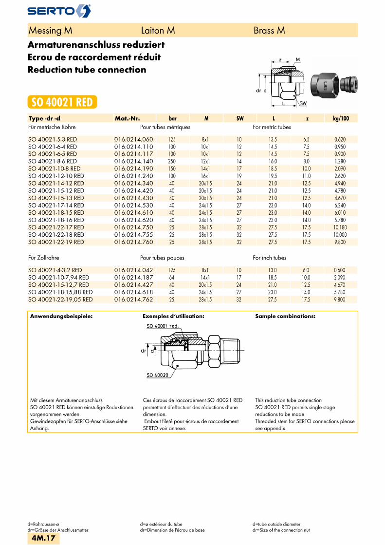
Armaturenanschluss reduziertEcrou de raccordement réduitReduction tube connection
SO 40021 REDType -dr -d Mat.-Nr. bar M SW L z kg/100Für metrische Rohre Pour tubes métriques For metric tubes SO 40021-5-3 RED 016.0214.060 125 8x1 10 13.5 6.5 0.620SO 40021-6-4 RED 016.0214.110 100 10x1 12 14.5 7.5 0.950SO 40021-6-5 RED 016.0214.117 100 10x1 12 14.5 7.5 0.900SO 40021-8-6 RED 016.0214.140 250 12x1 14 16.0 8.0 1.280SO 40021-10-8 RED 016.0214.190 150 14x1 17 18.5 10.0 2.090SO 40021-12-10 RED 016.0214.240 100 16x1 19 19.5 11.0 2.620SO 40021-14-12 RED 016.0214.340 40 20x1.5 24 21.0 12.5 4.940SO 40021-15-12 RED 016.0214.420 40 20x1.5 24 21.0 12.5 4.780SO 40021-15-13 RED 016.0214.430 40 20x1.5 24 21.0 12.5 4.670SO 40021-17-14 RED 016.0214.530 40 24x1.5 27 23.0 14.0 6.240SO 40021-18-15 RED 016.0214.610 40 24x1.5 27 23.0 14.0 6.010SO 40021-18-16 RED 016.0214.620 40 24x1.5 27 23.0 14.0 5.780SO 40021-22-17 RED 016.0214.750 25 28x1.5 32 27.5 17.5 10.180SO 40021-22-18 RED 016.0214.755 25 28x1.5 32 27.5 17.5 10.000SO 40021-22-19 RED 016.0214.760 25 28x1.5 32 27.5 17.5 9.800
Für Zollrohre Pour tubes pouces For inch tubes SO 40021-4-3,2 RED 016.0214.042 125 8x1 10 13.0 6.0 0.600SO 40021-10-7,94 RED 016.0214.187 64 14x1 17 18.5 10.0 2.090SO 40021-15-12,7 RED 016.0214.427 40 20x1.5 24 21.0 12.5 4.670SO 40021-18-15,88 RED 016.0214.618 40 24x1.5 27 23.0 14.0 5.780SO 40021-22-19,05 RED 016.0214.762 25 28x1.5 32 27.5 17.5 9.800
Anwendungsbeispiele: Exemples d‘utilisation: Sample combinations:
Mit diesem ArmaturenanaschlussSO 40021 RED können einstufige Reduktionen vorgenommen werden.Gewindezapfen für SERTO-Anschlüsse siehe Anhang.
Ces écrous de raccordement SO 40021 RED permettent d’effectuer des réductions d’une dimension. Embout fileté pour écrous de raccordementSERTO voir annexe.
This reduction tube connectionSO 40021 RED permits single stagereductions to be made. Threaded stem for SERTO connections please see appendix.
Messing M Laiton M Brass M
d=Rohraussen-ødr=Grösse der Anschlussmutter
d=ø extérieur du tubedr=Dimension de l'écrou de base
d=tube outside diameterdr=Size of the connection nut
4M.17
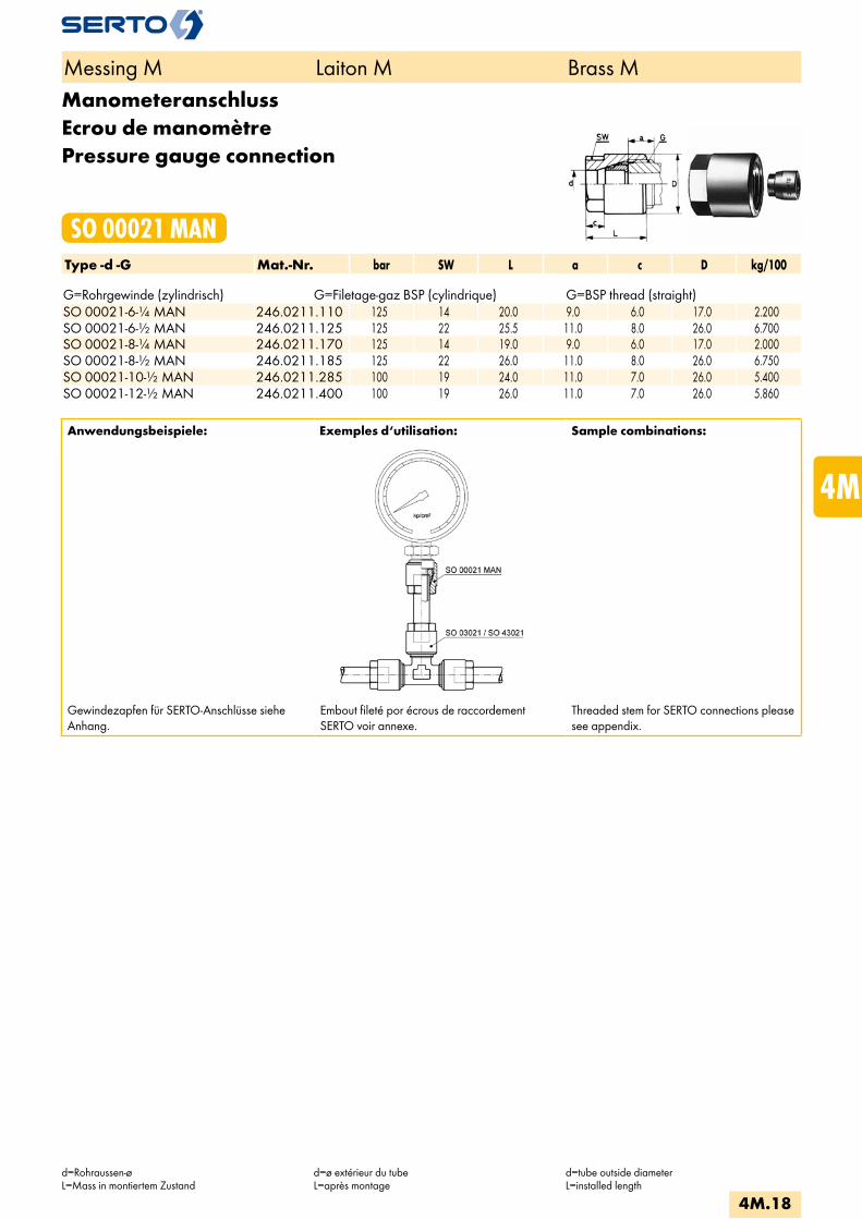
ManometeranschlussEcrou de manomètrePressure gauge connection
SO 00021 MANType -d -G Mat.-Nr. bar SW L a c D kg/100 G=Rohrgewinde (zylindrisch) G=Filetage-gaz BSP (cylindrique) G=BSP thread (straight)SO 00021-6-1/4 MAN 246.0211.110 125 14 20.0 9.0 6.0 17.0 2.200SO 00021-6-1/2 MAN 246.0211.125 125 22 25.5 11.0 8.0 26.0 6.700SO 00021-8-1/4 MAN 246.0211.170 125 14 19.0 9.0 6.0 17.0 2.000SO 00021-8-1/2 MAN 246.0211.185 125 22 26.0 11.0 8.0 26.0 6.750SO 00021-10-1/2 MAN 246.0211.285 100 19 24.0 11.0 7.0 26.0 5.400SO 00021-12-1/2 MAN 246.0211.400 100 19 26.0 11.0 7.0 26.0 5.860
Anwendungsbeispiele: Exemples d‘utilisation: Sample combinations:
Gewindezapfen für SERTO-Anschlüsse siehe Anhang.
Embout fileté por écrous de raccordement SERTO voir annexe.
Threaded stem for SERTO connections please see appendix.
Messing M Laiton M Brass M
d=Rohraussen-øL=Mass in montiertem Zustand
d=ø extérieur du tubeL=après montage
d=tube outside diameterL=installed length
4M.18
i
s
3F
4M
4G
5
5L
6
7
8
9
10
11
12

ÜbergangsmuffeAdaptateur femelleFemale adaptor
SO 40030Type -d -G Mat.-Nr. bar M SW D b c f L z e kg/100 G=Rohrgewinde (zylindrisch) G=Filetage-gaz BSP (cylindrique) G=BSP thread (straight)SO 40030-6-1/8 016.0301.100 250 10x1 14 13.8 14.0 8.0 10.0 20.0 4.0 5.0 1.670SO 40030-6-1/4 016.0301.110 250 10x1 17 16.8 15.0 8.0 11.0 21.0 4.0 5.0 2.530SO 40030-6-3/8 016.0301.120 250 10x1 22 21.8 16.0 10.0 10.0 22.0 4.0 5.0 4.800SO 40030-8-1/8 016.0301.160 150 12x1 17 16.8 14.0 9.0 10.0 21.0 4.0 6.5 2.790SO 40030-8-1/4 016.0301.170 150 12x1 17 16.8 16.0 9.0 12.0 23.0 5.0 6.5 2.540SO 40030-8-3/8 016.0301.180 150 12x1 22 21.8 16.0 10.0 11.0 23.0 4.0 6.5 4.780SO 40030-10-1/4 016.0301.270 125 14x1 17 16.8 15.0 8.0 12.0 22.0 4.0 8.5 2.090SO 40030-10-3/8 016.0301.280 125 14x1 22 21.8 17.0 10.0 11.0 23.0 5.0 8.5 4.760SO 40030-12-1/4 016.0301.380 100 16x1 19 18.8 15.0 9.0 11.0 22.0 4.0 10.0 2.780SO 40030-12-3/8 016.0301.390 100 16x1 22 21.8 16.0 10.0 11.0 23.0 4.0 10.0 4.090SO 40030-12-1/2 016.0301.400 100 16x1 27 26.8 18.0 11.0 12.0 25.0 4.0 10.0 7.270SO 40030-15-3/8 016.0301.532 40 20x1.5 24 23.8 17.0 11.0 12.0 25.0 5.0 13.0 5.100SO 40030-15-1/2 016.0301.534 40 20x1.5 27 26.8 19.0 13.0 12.0 27.0 5.0 13.0 7.130SO 40030-15-3/4 016.0301.536 40 20x1.5 32 31.8 22.0 13.0 15.0 30.0 5.0 13.0 10.980SO 40030-18-1/2 016.0301.646 40 24x1.5 30 29.8 20.0 14.0 12.0 28.0 6.0 15.0 9.410SO 40030-18-3/4 016.0301.648 40 24x1.5 32 31.8 23.0 13.0 16.0 31.0 6.0 15.0 10.350SO 40030-22-3/4 016.0301.768 25 28x1.5 36 35.8 23.0 13.0 16.0 31.0 6.0 19.0 14.320SO 40030-28-1 016.0301.850 16 36x2 41 40.8 27.0 16.0 21.0 37.0 7.0 25.0 16.700SO 40030-35-1 1/4 016.0301.944 16 42x2 50 49.8 29.0 20.0 21.0 41.0 7.0 31.0 27.400
Anwendungsbeispiele: Exemples d‘utilisation: Sample combinations:
Die Übergangsmuffe SO 40030 kann an jedes SERTO-Formteil mit dem passenden zylindrischen Gewinde M aufgeschraubt werden.
Dichtungsprinzip:Bei der Montage drückt sich die Dichkante des Übergangsstückes in das SERTO-Formteil ein, dadurch entsteht eine einwandfrei metallische Dichtung.Wir empfehlen, das Gewinde mit einem geeig-neten Flüssigklebstoff gegen unbeabsichtigtes Lösen zu sichern.
L’adaptateur femelle SO 40030 peut être monté sur toutes les pièces de forme SERTO avec le filetage cylindrique M correspondant.
Principe d’étanchéité:Lors du serrage, le bourrelet s’enfonce dans la pièce de forme SERTO et donne un joint métal-lique parfait.Nous recommandons de freiner le filetage avec une résine appropriée contre un desserrage intempestif.
The female adaptor SO 40030 can be scre-wed onto every SERTO union body with the appropriate straight thread M.
Sealing principle:On being installed, the lip of the adaptor presses into the SERTO union body, forming a sound metallic seal.We recommend to secure the thread with a suitable cement against unintended loosening.
Messing M Laiton M Brass M
d=Rohraussen-øe=kleinste Bohrung
d=ø extérieur du tubee=ø-min. de passage
d=tube outside diametere=minimum bore
4M.19

ÜbergangsnippelPièce intermédiaire mâleMale adapter
SO 40040Type -d -R Mat.-Nr. bar M SW L b c z e kg/100 R=Rohrgewinde (kegelig) R=Filetage-gaz BSP (conique) R=BSP thread (tapered)SO 40040-6-1/8 016.0401.100 250 10x1 12 17.0 11.0 9.0 4.5 5.0 0.800SO 40040-6-1/4 016.0401.110 250 10x1 14 21.0 15.0 9.0 5.3 5.0 1.850SO 40040-6-3/8 016.0401.120 250 10x1 17 20.0 14.0 8.0 4.0 5.0 3.030SO 40040-6-1/2 016.0401.125 250 10x1 22 23.0 17.0 7.0 9.0 4.5 5.700SO 40040-8-1/8 016.0401.160 150 12x1 14 18.0 11.0 10.0 4.5 5.0 0.990SO 40040-8-1/4 016.0401.170 150 12x1 14 22.0 15.0 10.0 5.3 6.5 1.520SO 40040-8-3/8 016.0401.180 150 12x1 17 22.0 15.0 10.0 5.0 6.5 2.970SO 40040-10-1/4 016.0401.270 125 14x1 17 22.0 15.0 10.0 5.3 8.5 1.710SO 40040-10-3/8 016.0401.280 125 14x1 17 22.0 15.0 10.0 4.9 8.5 2.440SO 40040-10-1/2 016.0401.285 125 14x1 22 23.0 16.0 7.0 2.8 8.5 5.030SO 40040-12-1/4 016.0401.380 100 16x1 19 23.0 16.0 11.0 6.3 8.5 2.110SO 40040-12-3/8 016.0401.390 100 16x1 19 23.0 16.0 11.0 5.9 10.0 2.870SO 40040-12-1/2 016.0401.400 100 16x1 22 24.0 17.0 10.0 3.8 10.0 4.840SO 40040-15-3/8 016.0401.532 40 20x1.5 24 24.0 16.0 12.0 5.9 10.0 3.760SO 40040-15-1/2 016.0401.534 40 20x1.5 24 26.0 18.0 12.0 4.8 13.0 4.430SO 40040-15-3/4 016.0401.536 40 20x1.5 27 27.0 19.0 11.0 4.5 13.0 8.250SO 40040-18-1/2 016.0401.646 40 24x1.5 30 27.0 19.0 13.0 5.8 15.0 6.010SO 40040-18-3/4 016.0401.648 40 24x1.5 30 29.0 21.0 13.0 6.5 15.0 8.930SO 40040-22-1/2 016.0401.764 25 28x1.5 36 29.0 21.0 13.0 8.0 15.0 8.910SO 40040-22-3/4 016.0401.768 25 28x1.5 36 29.0 21.0 13.0 6.5 19.0 9.480SO 40040-28-1 016.0401.850 16 36x2 41 38.0 28.0 18.0 11.2 25.0 14.900SO 40040-35-1 1/4 016.0401.944 16 42x2 50 42.0 30.0 20.0 11.0 31.0 26.600
Anwendungsbeispiele: Exemples d‘utilisation: Sample combinations:
Dichtungsprinzip:Bei der Montage drückt sich die Dichtkante des Übergangsstückes in das SERTO-Formteil ein. Dadurch entsteht eine einwandfreie metallische Dichtung. Wir empfehlen, das Gewinde mit einem geeig-neten Flüssigklebstoff gegen unbeabsichtigtes Lösen zu sichern.
Principe d’étanchéité:Lors du serrage, l’arête d’étanchéité s’enfonce dans la pièce de forme SERTO et donne un joint métallique parfait. Nous recommandons de freiner le filetage avec une résine appropriée contre un desserrage intempestif.
Sealing principle:On being installed, the lip of the adaptor presses into the SERTO union body, forming a sound metallic seal.We recommend to secure the thread with a suitable cement against unintended loosening.
Messing M Laiton M Brass M
d=Rohraussen-øe=kleinste BohrungL=Mass in montiertem Zustand
d=ø extérieur du tubee=ø-min. de passageL=après montage
d=tube outside diametere=minimum boreL=installed length
4M.20
i
s
3F
4M
4G
5
5L
6
7
8
9
10
11
12
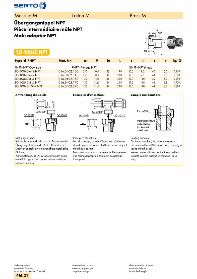
Übergangsnippel NPTPièce intermédiaire mâle NPTMale adapter NPT
SO 40040 NPTType -d -RNPT Mat.-Nr. bar M SW L b c z e kg/100 RNPT=NPT Gewinde RNPT=Filetage NPT RNPT=NPT threadSO 40040-6-1/8 NPT 016.0402.100 250 10x1 12 19.0 13.0 9.0 6.3 5.0 0.910SO 40040-6-1/4 NPT 016.0402.110 250 10x1 14 23.0 17.0 9.0 6.8 5.0 2.030SO 40040-8-1/8 NPT 016.0402.160 150 12x1 14 20.0 13.0 10.0 6.3 6.0 0.990SO 40040-8-1/4 NPT 016.0402.170 150 12x1 14 24.0 17.0 10.0 6.8 6.5 1.730SO 40040-10-1/4 NPT 016.0402.270 125 14x1 17 24.0 17.0 10.0 6.8 8.5 1.800
Anwendungsbeispiele: Exemples d‘utilisation: Sample combinations:
Dichtungsprinzip:Bei der Montage drückt sich die Dichtkante des Übergangsstückes in das SERTO-Formteil ein. Dadurch entsteht eine einwandfreie metallische Dichtung. Wir empfehlen, das Gewinde mit einem geeig-neten Flüssigklebstoff gegen unbeabsichtigtes Lösen zu sichern.
Principe d’étanchéité:Lors du serrage, l’arête d’étanchéité s’enfonce dans la pièce de forme SERTO et donne un joint métallique parfait. Nous recommandons de freiner le filetage avec une résine appropriée contre un desserrage intempestif.
Sealing principle:On being installed, the lip of the adaptor presses into the SERTO union body, forming a sound metallic seal.We recommend to secure the thread with a suitable cement against unintended loose-ning.
Messing M Laiton M Brass M
d=Rohraussen-øe=kleinste BohrungL=Mass in montiertem Zustand
d=ø extérieur du tubee=ø-min. de passageL=après montage
d=tube outside diametere=minimum boreL=installed length
4M.21

SchlauchtülleDouille canneléeHose nozzle
SO 40503Type -Ad -d1 Mat.-Nr. L b e kg/100 SO 40503-A4-2,5 016.0500.035 17.0 8.0 2.0 0.090SO 40503-A5-2,5 016.0500.055 17.0 8.0 2.0 0.120SO 40503-A5-3 016.0500.060 18.0 9.0 2.5 0.140SO 40503-A6-2,5 016.0500.095 22.0 8.0 2.0 0.210SO 40503-A6-3 016.0500.100 23.0 9.0 2.5 0.260SO 40503-A6-4 016.0500.110 25.0 11.0 3.0 0.270SO 40503-A6-6 016.0500.122 31.0 17.0 4.0 0.480SO 40503-A6-8 016.0500.121 31.0 17.0 4.0 0.804SO 40503-A8-4 016.0500.132 25.0 11.0 3.0 0.275SO 40503-A8-5 016.0500.136 27.0 13.0 4.0 0.324SO 40503-A8-6 016.0500.140 31.0 17.0 5.0 0.520SO 40503-A8-8 016.0500.154 31.0 17.0 6.0 0.710SO 40503-A8-10 016.0500.157 33.0 19.0 6.0 1.392SO 40503-A10-8 016.0500.190 35.0 17.0 7.0 0.720SO 40503-A10-10 016.0500.198 37.0 19.0 7.0 1.370SO 40503-A10-12 016.0500.199 37.0 19.0 7.0 1.918SO 40503-A10-13 016.0500.200 39.0 21.0 7.0 2.443SO 40503-A12-10 016.0500.240 37.0 19.0 8.5 1.230SO 40503-A12-13 016.0500.260 39.0 21.0 9.0 2.889SO 40503-A15-13 016.0500.430 41.0 21.0 11.0 2.050SO 40503-A18-16 016.0500.620 47.0 26.0 14.0 3.240SO 40503-A22-19 016.0500.760 50.0 26.0 16.0 4.590
Anwendungsbeispiele: Exemples d‘utilisation: Sample combinations:
Mit dieser Schlauchtülle können Gummischläuche und Rohre aus Teflon, Weich-PVC, Polyamid usw. direkt an SERTO-Verschraubungen angeschlossen werden. Für die Schlauchsicherung verwenden Sie bitte unsere Schlauchklemme SO 40512.
Avec cette douille cannelée, les tuyaux en caoutchouc, les tubes en téflon, en PVC souple, en polyamide et autres peuvent être fixés direc-tement aux raccords SERTO. Afin d’assurer la bonne tenue des tuyaux, utiliser nos colliers de serrage SO 40512.
With this hose nozzle, rubber hoses andplastic hoses made of teflon, soft PVC,polyamide can be connected directly to the SERTO unions. Please use our hose clip SO 40512 to securing the hose.
Messing M Laiton M Brass M
d1=RohrinnendurchmesserAd=Aussen-ø der Andrehunge=kleinste Bohrung
d1=ø diam. intérieur du tubeAd=ø extérieur de la portée cylindriquee=ø-min. de passage
d1=tube inside diameterAd=outside diameter of cyl. Stube=minimum bore
4M.22
i
s
3F
4M
4G
5
5L
6
7
8
9
10
11
12
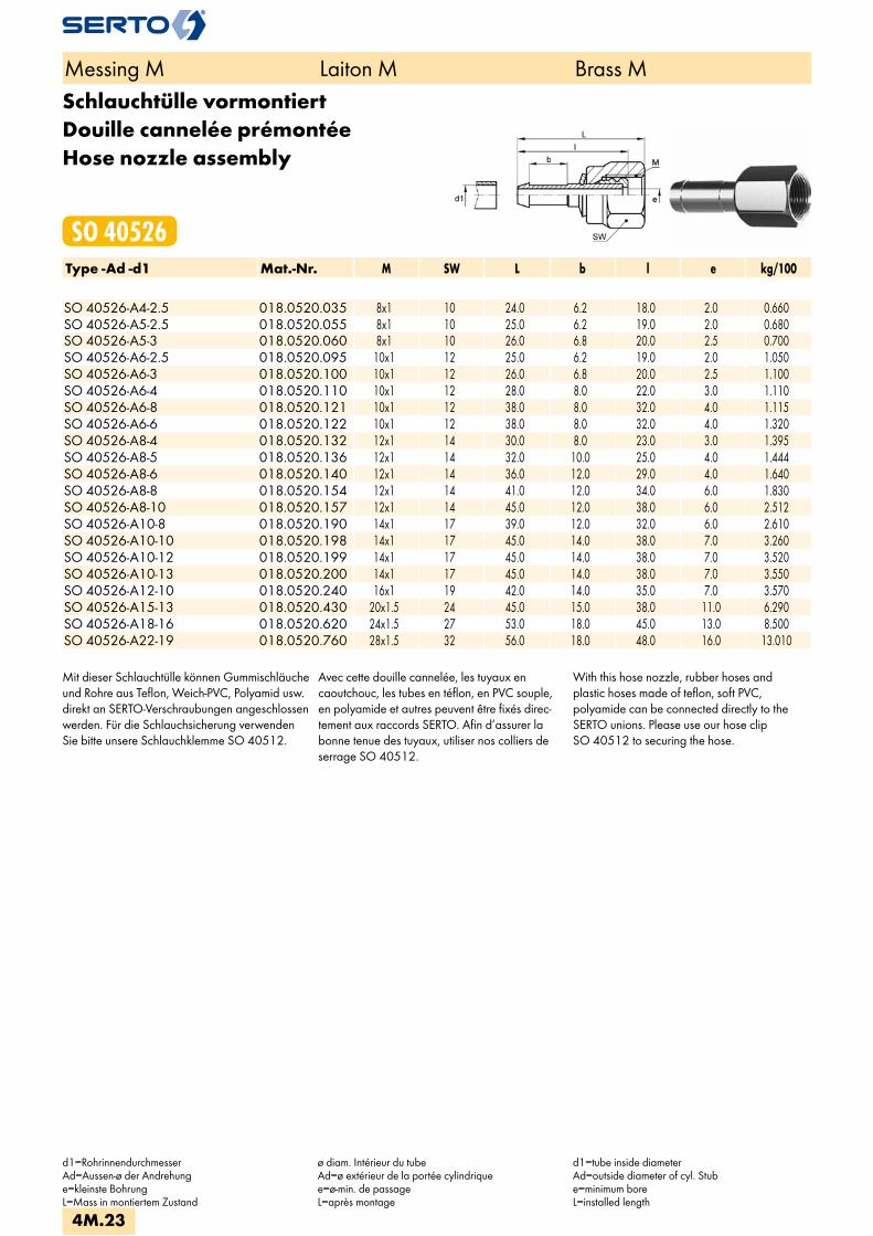
Schlauchtülle vormontiertDouille cannelée prémontéeHose nozzle assembly
SO 40526Type -Ad -d1 Mat.-Nr. M SW L b l e kg/100 SO 40526-A4-2.5 018.0520.035 8x1 10 24.0 6.2 18.0 2.0 0.660SO 40526-A5-2.5 018.0520.055 8x1 10 25.0 6.2 19.0 2.0 0.680SO 40526-A5-3 018.0520.060 8x1 10 26.0 6.8 20.0 2.5 0.700SO 40526-A6-2.5 018.0520.095 10x1 12 25.0 6.2 19.0 2.0 1.050SO 40526-A6-3 018.0520.100 10x1 12 26.0 6.8 20.0 2.5 1.100SO 40526-A6-4 018.0520.110 10x1 12 28.0 8.0 22.0 3.0 1.110SO 40526-A6-8 018.0520.121 10x1 12 38.0 8.0 32.0 4.0 1.115SO 40526-A6-6 018.0520.122 10x1 12 38.0 8.0 32.0 4.0 1.320SO 40526-A8-4 018.0520.132 12x1 14 30.0 8.0 23.0 3.0 1.395SO 40526-A8-5 018.0520.136 12x1 14 32.0 10.0 25.0 4.0 1.444SO 40526-A8-6 018.0520.140 12x1 14 36.0 12.0 29.0 4.0 1.640SO 40526-A8-8 018.0520.154 12x1 14 41.0 12.0 34.0 6.0 1.830SO 40526-A8-10 018.0520.157 12x1 14 45.0 12.0 38.0 6.0 2.512SO 40526-A10-8 018.0520.190 14x1 17 39.0 12.0 32.0 6.0 2.610SO 40526-A10-10 018.0520.198 14x1 17 45.0 14.0 38.0 7.0 3.260SO 40526-A10-12 018.0520.199 14x1 17 45.0 14.0 38.0 7.0 3.520SO 40526-A10-13 018.0520.200 14x1 17 45.0 14.0 38.0 7.0 3.550SO 40526-A12-10 018.0520.240 16x1 19 42.0 14.0 35.0 7.0 3.570SO 40526-A15-13 018.0520.430 20x1.5 24 45.0 15.0 38.0 11.0 6.290SO 40526-A18-16 018.0520.620 24x1.5 27 53.0 18.0 45.0 13.0 8.500SO 40526-A22-19 018.0520.760 28x1.5 32 56.0 18.0 48.0 16.0 13.010
Mit dieser Schlauchtülle können Gummischläuche und Rohre aus Teflon, Weich-PVC, Polyamid usw. direkt an SERTO-Verschraubungen angeschlossen werden. Für die Schlauchsicherung verwenden Sie bitte unsere Schlauchklemme SO 40512.
Avec cette douille cannelée, les tuyaux en caoutchouc, les tubes en téflon, en PVC souple, en polyamide et autres peuvent être fixés direc-tement aux raccords SERTO. Afin d’assurer la bonne tenue des tuyaux, utiliser nos colliers de serrage SO 40512.
With this hose nozzle, rubber hoses andplastic hoses made of teflon, soft PVC,polyamide can be connected directly to theSERTO unions. Please use our hose clipSO 40512 to securing the hose.
Messing M Laiton M Brass M
d1=RohrinnendurchmesserAd=Aussen-ø der Andrehunge=kleinste BohrungL=Mass in montiertem Zustand
ø diam. Intérieur du tubeAd=ø extérieur de la portée cylindriquee=ø-min. de passageL=après montage
d1=tube inside diameterAd=outside diameter of cyl. Stube=minimum boreL=installed length
4M.23

AnschlussnippelEcrou de raccordement mâleNipple connection
SO 41001Type -d -G Mat.-Nr. bar SW L a b c f t kg/100Für metrische Rohre Pour tubes métriques For metric tubesG=Rohrgewinde (zylindrisch) G=Filetage-gaz BSP (cylindrique) G=BSP thread (straight)SO 41001-4-1/8 016.1001.060 125 10 12.0 14.0 6.0 4.0 6.5 6.5 0.650SO 41001-5-1/8 016.1001.082 125 10 12.0 14.0 6.0 4.0 6.5 6.5 0.550SO 41001-6-1/4 016.1001.110 250 14 16.0 18.0 8.5 6.0 8.0 9.5 1.450SO 01001-8-1/4 246.1001.170 125 14 16.0 18.0 8.5 6.0 8.0 9.5 1.200SO 01001-10-3/8 246.1001.280 100 17 17.0 19.0 9.0 6.5 8.5 10.0 2.000SO 41001-12-1/2 016.1001.400 100 22 20.5 25.0 11.0 8.0 9.5 14.0 4.060SO 41001-15-1/2 016.1001.534 40 22 19.5 25.0 11.0 8.0 8.5 14.0 3.010
Für Zollrohre Pour tubes pouces For inch tubes SO 41001-6,35-1/4 016.1001.140 100 14 16.0 18.0 8.5 6.0 8.0 9.5 1.420SO 01001-9,52-3/8 246.1001.235 100 17 17.0 19.0 8.5 6.5 8.5 9.5 2.094
Anwendungsbeispiele: Exemples d‘utilisation: Sample combinations:
Die entsprechende Kupferdichtung SO 40005 ist immer separat zu bestellen.
Les joints correspondants SO 40005 sont à commander séparément.
The relevant copper washer SO 40005 must always be ordered separately.
Messing M Laiton M Brass M
d=Rohraussen-øL=Mass in montiertem Zustand
d=ø extérieur du tubeL=après montage
d=tube outside diameterL=installed length
4M.24
i
s
3F
4M
4G
5
5L
6
7
8
9
10
11
12

Gerade VerschraubungUnion doubleStraight union
SO 41021Type -d Mat.-Nr. bar M SW1 SW2 L z e kg/100Für metrische Rohre Pour tubes métriques For metric tubes
SO 41021-2 018.1020.020 125 6x0.75 8 7 23.5 15.5 2.2 0.810 SO 41021-3 018.1020.030 125 6x0.75 8 7 26.0 16.0 2.2 0.890 SO 41021-4 018.1020.040 125 8x1 10 10 34.0 22.0 3.5 1.770 SO 41021-5 018.1020.050 125 8x1 10 10 35.0 22.0 3.5 1.750 SO 41021-6 018.1020.060 250 10x1 12 10 37.5 22.0 4.5 2.520 SO 41021-8 018.1020.080 150 12x1 14 12 41.0 25.0 6.5 3.530 SO 41021-10 018.1020.100 125 14x1 17 14 46.0 26.0 8.5 5.490 SO 41021-12 018.1020.120 100 16x1 19 17 48.5 26.5 10.5 7.030
SO 41021-13 018.1020.130 40 20x1.5 24 22 57.0 31.0 13.0 12.950 SO 41021-14 018.1020.140 40 20x1.5 24 22 57.0 32.0 13.0 13.160 SO 41021-15 018.1020.150 40 20x1.5 24 22 57.0 32.0 13.0 12.520 SO 41021-16 018.1020.160 40 24x1.5 27 24 61.0 33.0 15.0 16.330 SO 41021-17 018.1020.170 40 24x1.5 27 24 61.0 33.0 15.0 16.350 SO 41021-18 018.1020.180 40 24x1.5 27 24 61.0 33.0 15.0 15.810
SO 41021-19 018.1020.190 25 28x1.5 32 30 69.0 34.0 19.0 27.100 SO 41021-22 018.1020.220 25 28x1.5 32 30 69.0 34.0 19.0 24.380 SO 41021-28 018.1020.280 16 36x2 41 36 81.0 42.0 25.0 49.320 SO 41021-35 018.1020.350 16 42x2 50 46 92.0 48.0 31.0 81.900
Für Zollrohre Pour tubes pouces For inch tubes SO 41021-3,2 018.1020.032 125 6x0.75 8 7 26.0 16.0 2.2 0.850
SO 41021-6,35 018.1020.063 100 10x1 12 10 37.5 22.0 4.5 2.490 SO 41021-9,52 018.1020.095 64 14x1 17 14 46.0 26.0 8.5 5.610
SO 41021-12,7 018.1020.127 40 20x1.5 24 22 57.0 31.0 13.0 12.950 SO 41021-15,88 018.1020.158 40 24x1.5 27 24 61.0 33.0 15.0 16.330
Messing M Laiton M Brass M
d=Rohraussen-øe=kleinste BohrungL=Mass in montiertem Zustand*=mit reduziertem Klemmring
d=ø extérieur du tubee=ø-min. de passageL=après montage*=avec bague de serrage de réduction
d=tube outside diametere=minimum boreL=installed length*=with reduction compression ferrule
4M.25

Gerade Verschraubung reduziertUnion double réduiteStraight reduction union
SO 41021 REDType -d -d2 Mat.-Nr. bar M M red SW1 SW2 SW3 L z e kg/100Für metrische Rohre Pour tubes métriques For metric tubes
SO 41021-3-2 RED 018.1024.020 125 6x0.75 6x0.75 8 7 8 25.0 15.5 2.2 0.850 SO 41021-5-3 RED 018.1024.060 125 8x1 8x1 10 10 10 35.0 22.0 3.5 1.810 SO 41021-5-4 RED 018.1024.080 125 8x1 8x1 10 10 10 34.5 22.0 3.5 0.560
SO 41021-6-4 RED 018.1024.110 125 10x1 10x1 12 10 12 37.5 22.5 4.5 2.630 SO 41021-6-5 RED 018.1024.117 125 10x1 10x1 12 10 12 37.5 22.5 4.5 2.580 SO 41021-8-4 RED 018.1024.132 125 12x1 10x1 14 12 12 39.5 23.5 4.5 3.500 SO 41021-8-5 RED 018.1024.136 125 12x1 10x1 14 12 12 39.5 23.5 4.5 3.500 SO 41021-8-6 RED 018.1024.140 125 12x1 10x1 14 12 12 39.5 24.0 4.5 3.400
SO 41021-10-8 RED 018.1024.190 125 14x1 14x1 17 14 17 46.0 26.5 8.5 5.690 SO 41021-12-8 RED 018.1024.225 100 16x1 14x1 24 22 17 51.0 29.5 8.5 7.210 SO 41021-12-10 RED 018.1024.240 100 16x1 16x1 19 17 19 48.5 30.0 10.5 7.310 SO 41021-14-8 RED 018.1024.308 40 20x1.5 14x1 24 22 17 51.0 29.5 8.5 6.080 SO 41021-14-10 RED 018.1024.320 40 20x1.5 14x1 24 22 17 51.0 29.5 8.5 5.850
SO 41021-14-12 RED 018.1024.340 40 20x1.5 20x1.5 24 22 24 57.0 32.0 13.0 13.540 SO 41021-15-8 RED 018.1024.400 40 20x1.5 14x1 24 22 17 51.0 29.5 8.5 6.080 SO 41021-15-10 RED 018.1024.410 40 20x1.5 14x1 24 22 17 52.0 29.5 8.5 5.850
SO 41021-15-12 RED 018.1024.420 40 20x1.5 20x1.5 24 22 24 57.0 32.0 13.0 13.060 SO 41021-15-13 RED 018.1024.430 40 20x1.5 20x1.5 24 22 24 57.0 32.0 13.0 12.950 SO 41021-16-15 RED 018.1024.510 40 24x1.5 24x1.5 27 24 27 61.0 33.0 15.0 16.400 SO 41021-17-14 RED 018.1024.530 40 24x1.5 24x1.5 27 24 27 61.0 33.0 15.0 17.060 SO 41021-18-15 RED 018.1024.610 40 24x1.5 24x1.5 27 24 27 61.0 33.0 15.0 16.560 SO 41021-18-16 RED 018.1024.620 40 24x1.5 24x1.5 27 24 27 61.0 33.0 15.0 16.330
SO 41021-22-17 RED 018.1024.750 25 28x1.5 28x1.5 32 30 33 69.0 34.0 19.0 26.140 SO 41021-22-18 RED 018.1024.755 25 28x1.5 28x1.5 32 30 33 69.0 34.0 19.0 25.960 SO 41021-22-19 RED 018.1024.760 25 28x1.5 26x1.5 32 30 33 69.0 34.0 19.0 25.700
Für Zollrohre Pour tubes pouces For inch tubes
SO 41021-6-6,35 RED 018.1024.119 100 10x1 10x1 12 10 12 37.5 22.5 4.5 2.480 SO 41021-8-6,35 RED 018.1024.143 100 12x1 10x1 14 12 12 39.5 24.0 4.5 3.400 SO 41021-10-9,52 RED 018.1024.197 64 14x1 14x1 17 14 17 46.0 26.5 8.5 5.600 SO 41021-14-9,52 RED 018.1024.312 40 20x1.5 14x1 24 22 17 51.0 29.5 8.5 5.780 SO 41021-15-9,52 RED 018.1024.408 40 20x1.5 14x1 24 22 17 51.0 29.5 8.5 5.870
SO 41021-15-12,7 RED 018.1024.427 40 20x1.5 20x1.5 24 22 24 57.0 32.0 13.0 12.950
Weitere Reduktionen siehe SO 41821. Autres réductions voir SO 41521 Alternative reductions see SO 41821.
Messing M Laiton M Brass M
d/d2=Rohraussen-øe=kleinste BohrungL=Mass in montiertem Zustand*=mit reduziertem Klemmring
d/d2=ø extérieur du tubee=ø-min. de passageL=après montage*=avec bague de serrage de réduction
d/d2=tube outside diametere=minimum boreL=installed length*=with reduction copmression ferrule
4M.26
i
s
3F
4M
4G
5
5L
6
7
8
9
10
11
12
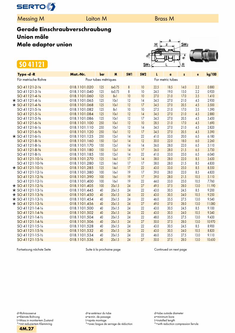
Gerade EinschraubverschraubungUnion mâleMale adaptor union
SO 41121Type -d -R Mat.-Nr. bar M SW1 SW2 L a z e kg/100Für metrische Rohre Pour tubes métriques For metric tubes
SO 41121-2-1/8 018.1101.020 125 6x0.75 8 10 22.5 18.5 14.0 2.2 0.880 SO 41121-3-1/8 018.1101.040 125 6x0.75 8 10 24.5 19.0 15.0 2.2 0.920 SO 41121-4-1/8 018.1101.060 125 8x1 10 10 27.0 21.0 17.0 3.5 1.410
SO 41121-4-1/4 018.1101.065 125 10x1 12 14 34.5 27.0 21.0 4.5 2.930 SO 41121-4-3/8 018.1101.068 125 10x1 12 17 34.5 27.0 20.5 4.5 3.500 SO 41121-5-1/8 018.1101.082 125 8x1 10 10 27.5 21.0 17.0 3.5 1.390 SO 41121-5-1/4 018.1101.084 125 10x1 12 14 34.5 27.0 21.0 4.5 2.880 SO 41121-5-3/8 018.1101.086 125 10x1 12 17 34.5 27.0 20.5 4.5 3.450 SO 41121-6-1/8 018.1101.100 250 10x1 12 10 28.5 21.0 17.0 4.5 1.690 SO 41121-6-1/4 018.1101.110 250 10x1 12 14 34.5 27.0 21.0 4.5 2.820 SO 41121-6-3/8 018.1101.120 250 10x1 12 17 34.5 27.0 20.5 4.5 3.390
SO 41121-6-1/2 018.1101.125 250 12x1 14 22 41.0 33.0 20.0 6.5 6.180 SO 41121-8-1/8 018.1101.160 150 12x1 14 12 30.0 22.0 18.0 6.0 2.260 SO 41121-8-1/4 018.1101.170 150 12x1 14 14 36.0 28.0 22.0 6.5 3.110 SO 41121-8-3/8 018.1101.180 150 12x1 14 17 36.0 28.0 21.5 6.5 3.730 SO 41121-8-1/2 018.1101.185 150 12x1 14 22 41.0 33.0 25.0 6.5 6.040 SO 41121-10-1/4 018.1101.270 125 14x1 17 14 38.0 28.0 22.0 8.5 3.630 SO 41121-10-3/8 018.1101.280 125 14x1 17 17 38.0 28.0 21.5 8.5 4.830
SO 41121-10-1/2 018.1101.285 125 14x1 17 22 43.0 33.0 25.0 8.5 8.550 SO 41121-12-1/4 018.1101.380 100 16x1 19 17 39.0 28.0 22.0 8.5 4.820 SO 41121-12-3/8 018.1101.390 100 16x1 19 17 39.0 28.0 21.5 10.5 5.110 SO 41121-12-1/2 018.1101.400 100 16x1 19 22 44.0 33.0 25.0 10.5 7.760
SO 41121-12-3/4 018.1101.405 100 20x1.5 24 27 49.5 37.5 28.0 13.0 11.190 SO 41121-13-1/4 018.1101.445 40 20x1.5 24 22 43.0 30.5 24.5 8.5 9.200 SO 41121-13-3/8 018.1101.450 40 20x1.5 24 22 43.0 30.5 24.0 10.5 9.250 SO 41121-13-1/2 018.1101.454 40 20x1.5 24 22 46.0 35.5 27.5 13.0 9.540 SO 41121-13-3/4 018.1101.456 40 20x1.5 24 27 49.0 37.0 28.0 13.0 11.080 SO 41121-14-1/4 018.1101.500 40 20x1.5 24 22 43.0 30.5 24.5 8.5 9.100 SO 41121-14-3/8 018.1101.502 40 20x1.5 24 22 43.0 30.5 24.0 10.5 9.340 SO 41121-14-1/2 018.1101.504 40 20x1.5 24 22 48.0 35.5 27.5 13.0 9.430 SO 41121-14-3/4 018.1101.506 40 20x1.5 24 27 50.0 37.5 28.0 13.0 10.970 SO 41121-15-1/4 018.1101.528 40 20x1.5 24 22 43.0 30.5 24.5 8.5 8.900 SO 41121-15-3/8 018.1101.532 40 20x1.5 24 22 43.0 30.5 24.0 10.5 8.820 SO 41121-15-1/2 018.1101.534 40 20x1.5 24 22 46.0 35.5 27.5 13.0 9.110 SO 41121-15-3/4 018.1101.536 40 20x1.5 24 27 50.0 37.5 28.0 13.0 10.650
Fortsetzung nächste Seite Suite à la prochaine page Continued on next page
Messing M Laiton M Brass M
d=Rohraussen-øe=kleinste BohrungL=Mass in montiertem Zustand*=mit reduziertem Klemmring
d=ø extérieur du tubee=ø-min. de passageL=après montage*=avec bague de serrage de réduction
d=tube outside diametere=minimum boreL=installed length*=with reduction compression ferrule
4M.27

Gerade EinschraubverschraubungUnion mâleMale adaptor union
SO 41121Type -d -R Mat.-Nr. bar M SW1 SW2 L a z e kg/100Für metrische Rohre Pour tubes métriques For metric tubesR=Rohrgewinde (kegelig) R=Filetage-gaz BSP (conique) R=BSP thread (tapered)
SO 41121-16-1/2 018.1101.566 40 24x1.5 27 24 50.5 36.5 22.0 15.0 11.280 SO 41121-16-3/4 018.1101.568 40 24x1.5 27 27 51.5 37.5 22.5 15.0 12.970 SO 41121-17-1/2 018.1101.596 40 24x1.5 27 24 50.5 36.5 22.0 15.0 11.030 SO 41121-17-3/4 018.1101.598 40 24x1.5 27 27 51.5 37.5 22.5 15.0 12.720
SO 41121-17-1 018.1101.602 25 28x1.5 32 36 61.0 41.5 26.0 19.0 24.990 SO 41121-18-1/2 018.1101.646 40 24x1.5 27 24 50.5 36.5 22.0 15.0 10.760 SO 41121-18-3/4 018.1101.648 40 24x1.5 27 27 51.5 37.5 22.5 15.0 12.450
SO 41121-18-1 018.1101.652 25 28x1.5 32 36 61.0 41.5 26.0 19.0 24.840 SO 41121-19-3/4 018.1101.678 25 28x1.5 32 30 55.0 37.5 22.5 19.0 17.800 SO 41121-19-1 018.1101.686 25 28x1.5 32 36 61.0 44.5 26.0 19.0 24.540 SO 41121-22-3/4 018.1101.768 25 28x1.5 32 30 55.0 37.5 22.5 19.0 16.440 SO 41121-22-1 018.1101.770 25 28x1.5 32 36 61.0 41.5 26.0 19.0 23.330 SO 41121-28-1 018.1101.850 16 36x2 41 36 64.5 45.0 29.0 25.0 31.300 SO 41121-35-1 1/4 018.1101.944 16 42x2 50 46 75.5 52.0 33.0 31.0 56.300
Für metrische Rohre Pour tubes métriques For metric tubes
SO 41121-3,2-1/8 018.1101.045 125 6x0.75 8 10 27.5 21.0 17.0 2.2 0.900 SO 41121-6,35-1/8 018.1101.135 100 10x1 12 10 28.5 21.0 17.0 4.5 1.680 SO 41121-6,35-1/4 018.1101.140 100 10x1 12 14 34.5 27.0 21.0 4.5 2.810 SO 41121-6,35-3/8 018.1101.145 100 10x1 12 17 34.5 27.0 20.5 4.5 3.350 SO 41121-9,52-1/4 018.1101.230 64 14x1 17 14 38.0 28.0 22.0 8.5 3.690 SO 41121-9,52-3/8 018.1101.235 64 14x1 17 17 38.0 28.0 21.5 8.5 1.890
SO 41121-12,7-1/4 018.1101.430 40 20x1.5 24 22 43.0 30.5 24.5 8.5 9.200 SO 41121-12,7-3/8 018.1101.432 40 20x1.5 24 22 43.0 30.5 24.0 10.5 9.250 SO 41121-12,7-1/2 018.1101.434 40 20x1.5 24 22 48.0 35.5 27.5 13.0 9.540 SO 41121-12,7-3/4 018.1101.436 40 20x1.5 24 27 49.0 37.0 28.0 13.0 11.080 SO 41121-15,88-1/2 018.1101.541 40 24x1.5 27 24 50.5 36.5 22.0 15.0 11.280
SO 41121-19.05-3/4 018.1101.760 25 28x1.5 32 30 55.5 38.0 22.5 19.0 17.800 SO 41121-22,22-1 018.1101.785 25 28x1.5 32 36 62.5 43.0 26.0 19.0 23.300
Messing M Laiton M Brass M
d=Rohraussen-øe=kleinste BohrungL=Mass in montiertem Zustand*=mit reduziertem Klemmring
d=ø extérieur du tubee=ø-min. de passageL=après montage*=avec bague de serrage de réduction
d=tube outside diametere=minimum boreL=installed length*=with reduction compression ferrule
4M.28
i
s
3F
4M
4G
5
5L
6
7
8
9
10
11
12
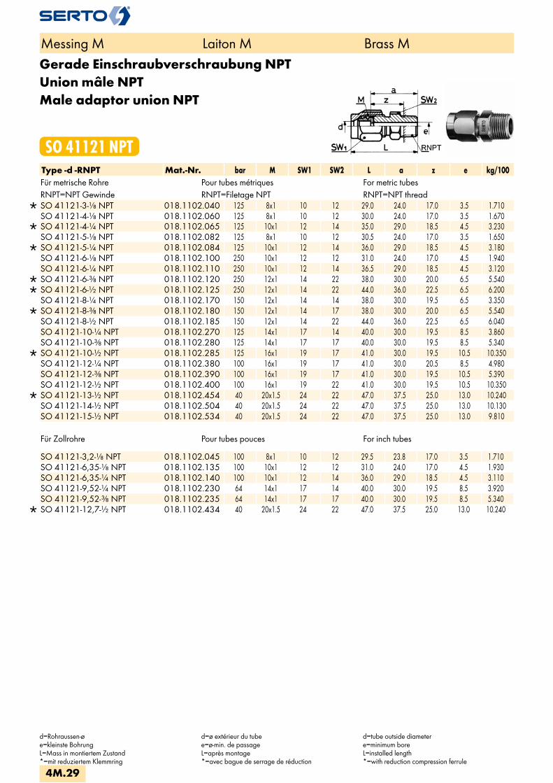
Gerade Einschraubverschraubung NPTUnion mâle NPTMale adaptor union NPT
SO 41121 NPTType -d -RNPT Mat.-Nr. bar M SW1 SW2 L a z e kg/100Für metrische Rohre Pour tubes métriques For metric tubesRNPT=NPT Gewinde RNPT=Filetage NPT RNPT=NPT thread
SO 41121-3-1/8 NPT 018.1102.040 125 8x1 10 12 29.0 24.0 17.0 3.5 1.710 SO 41121-4-1/8 NPT 018.1102.060 125 8x1 10 12 30.0 24.0 17.0 3.5 1.670
SO 41121-4-1/4 NPT 018.1102.065 125 10x1 12 14 35.0 29.0 18.5 4.5 3.230 SO 41121-5-1/8 NPT 018.1102.082 125 8x1 10 12 30.5 24.0 17.0 3.5 1.650
SO 41121-5-1/4 NPT 018.1102.084 125 10x1 12 14 36.0 29.0 18.5 4.5 3.180 SO 41121-6-1/8 NPT 018.1102.100 250 10x1 12 12 31.0 24.0 17.0 4.5 1.940 SO 41121-6-1/4 NPT 018.1102.110 250 10x1 12 14 36.5 29.0 18.5 4.5 3.120
SO 41121-6-3/8 NPT 018.1102.120 250 12x1 14 22 38.0 30.0 20.0 6.5 5.540 SO 41121-6-1/2 NPT 018.1102.125 250 12x1 14 22 44.0 36.0 22.5 6.5 6.200 SO 41121-8-1/4 NPT 018.1102.170 150 12x1 14 14 38.0 30.0 19.5 6.5 3.350
SO 41121-8-3/8 NPT 018.1102.180 150 12x1 14 17 38.0 30.0 20.0 6.5 5.540 SO 41121-8-1/2 NPT 018.1102.185 150 12x1 14 22 44.0 36.0 22.5 6.5 6.040 SO 41121-10-1/4 NPT 018.1102.270 125 14x1 17 14 40.0 30.0 19.5 8.5 3.860 SO 41121-10-3/8 NPT 018.1102.280 125 14x1 17 17 40.0 30.0 19.5 8.5 5.340
SO 41121-10-1/2 NPT 018.1102.285 125 16x1 19 17 41.0 30.0 19.5 10.5 10.350 SO 41121-12-1/4 NPT 018.1102.380 100 16x1 19 17 41.0 30.0 20.5 8.5 4.980 SO 41121-12-3/8 NPT 018.1102.390 100 16x1 19 17 41.0 30.0 19.5 10.5 5.390 SO 41121-12-1/2 NPT 018.1102.400 100 16x1 19 22 41.0 30.0 19.5 10.5 10.350
SO 41121-13-1/2 NPT 018.1102.454 40 20x1.5 24 22 47.0 37.5 25.0 13.0 10.240 SO 41121-14-1/2 NPT 018.1102.504 40 20x1.5 24 22 47.0 37.5 25.0 13.0 10.130 SO 41121-15-1/2 NPT 018.1102.534 40 20x1.5 24 22 47.0 37.5 25.0 13.0 9.810
Für Zollrohre Pour tubes pouces For inch tubes
SO 41121-3,2-1/8 NPT 018.1102.045 100 8x1 10 12 29.5 23.8 17.0 3.5 1.710 SO 41121-6,35-1/8 NPT 018.1102.135 100 10x1 12 12 31.0 24.0 17.0 4.5 1.930 SO 41121-6,35-1/4 NPT 018.1102.140 100 10x1 12 14 36.0 29.0 18.5 4.5 3.110 SO 41121-9,52-1/4 NPT 018.1102.230 64 14x1 17 14 40.0 30.0 19.5 8.5 3.920 SO 41121-9,52-3/8 NPT 018.1102.235 64 14x1 17 17 40.0 30.0 19.5 8.5 5.340
SO 41121-12,7-1/2 NPT 018.1102.434 40 20x1.5 24 22 47.0 37.5 25.0 13.0 10.240
Messing M Laiton M Brass M
d=Rohraussen-øe=kleinste BohrungL=Mass in montiertem Zustand*=mit reduziertem Klemmring
d=ø extérieur du tubee=ø-min. de passageL=après montage*=avec bague de serrage de réduction
d=tube outside diametere=minimum boreL=installed length*=with reduction compression ferrule
4M.29

Gerade Einschraubverschraubungmit Dichtkante
Union mâleavec arête d‘étanchéité
Male adaptor unionwith edge seal
SO 41124Type -d -G Mat.-Nr. bar M SW1 SW2 L a z e kg/100Für metrische Rohre Pour tubes métriques For metric tubesG=Rohrgewinde (zylindrisch) G=Filetage-gaz BSP (cylindrique) G=BSP thread (straight)
SO 41124-2-1/8 018.1141.020 125 6x0.75 8 14 23.5 19.5 11.5 2.2 1.360 SO 41124-3-1/8 018.1141.040 125 6x0.75 8 14 25.0 20.0 12.0 2.2 1.400 SO 41124-4-1/8 018.1141.060 125 8x1 10 14 28.5 22.5 14.5 3.5 1.820
SO 41124-4-1/4 018.1141.065 125 10x1 12 19 35.5 28.0 16.0 4.5 3.840 SO 41124-5-1/8 018.1141.082 125 8x1 10 14 29.0 22.5 14.5 3.5 1.790
SO 41124-5-1/4 018.1141.084 125 10x1 12 19 35.5 28.0 16.0 4.5 3.790 SO 41124-6-1/8 018.1141.100 250 10x1 12 14 30.0 22.5 14.5 4.5 2.070 SO 41124-6-1/4 018.1141.110 250 10x1 12 19 35.5 28.0 16.0 4.5 3.730
SO 41124-6-3/8 018.1141.120 250 12x1 14 22 38.5 30.5 18.5 6.5 5.880 SO 41124-6-1/2 018.1141.125 250 12x1 14 27 42.0 34.0 20.0 6.5 6.900 SO 41124-8-1/8 018.1141.160 150 12x1 14 14 31.5 23.5 15.5 4.5 2.830 SO 41124-8-1/4 018.1141.170 150 12x1 14 19 37.0 29.0 17.0 6.5 3.860 SO 41124-8-3/8 018.1141.180 150 12x1 14 22 38.5 30.5 18.5 6.5 5.720 SO 41124-8-1/2 018.1141.185 150 12x1 14 27 42.0 34.0 20.0 6.5 9.457 SO 41124-10-1/4 018.1141.270 125 14x1 17 19 39.0 29.0 17.0 7.0 4.860 SO 41124-10-3/8 018.1141.280 125 14x1 17 22 40.5 30.5 18.5 8.5 6.250
SO 41124-10-1/2 018.1141.285 125 16x1 19 27 45.0 34.0 20.0 10.5 7.500 SO 41124-12-1/4 018.1141.380 100 16x1 19 19 40.0 29.0 17.0 7.0 5.800 SO 41124-12-3/8 018.1141.390 100 16x1 19 22 41.5 30.5 18.5 10.5 6.500 SO 41124-12-1/2 018.1141.400 100 16x1 19 27 45.0 34.0 20.0 10.5 7.200
Für Zollrohre Pour tubes pouces For inch tubes SO 41124-3,2-1/8 018.1141.045 125 6x0.75 8 14 25.0 20.0 12.0 2.2 1.300SO 41124-6,35-1/8 018.1141.135 100 10x1 12 14 30.0 22.5 14.5 4.5 2.006SO 41124-6,35-1/4 018.1141.140 100 10x1 12 19 35.5 28.0 16.0 4.5 3.720SO 41124-9,52-1/4 018.1141.230 64 14x1 17 19 39.0 29.0 17.0 8.5 4.920SO 41124-9,52-3/8 018.1141.235 64 14x1 17 22 40.5 30.5 18.5 8.5 6.310
Anwendungsbeispiele: Exemples d‘utilisation: Sample combinations:
Die entsprechende Dichtung SO 40007 / SO 40507 ist separat zu bestellen.
Le joint correspondant SO 40007 /SO 40507 doit être commandé séparément.
The appropriate washer SO 40007 /SO 40507 is to be ordered separately.
Messing M Laiton M Brass M
d=Rohraussen-øe=kleinste BohrungL=Mass in montiertem Zustand*=mit reduziertem Klemmring
d=ø extérieur du tubee=ø-min. de passageL=après montage*=avec bague de serrage de réduction
d=tube outside diametere=minimum boreL=installed length*=with reduction compression ferrule
4M.30
i
s
3F
4M
4G
5
5L
6
7
8
9
10
11
12

Gerade Einschraubverschraubung METRmit Dichtkante
Union mâle METRavec arête d‘étanchéité
Male adaptor union METRwith edge seal
SO 41124 METRType -d -Mz Mat.-Nr. bar M SW1 SW2 L a z e kg/100Für metrische Rohre Pour tubes métriques For metric tubesMz=metrisches Gewinde (zylindrisch) Mz=Filetage métrique (cylindrique) Mz=Metric thread (straight)
SO 41124-2-M5 018.1143.020 125 6x0.75 8 8 18.0 14.0 9.5 2.2 0.500 SO 41124-3-M5 018.1143.050 125 6x0.75 8 8 20.0 14.5 10.0 2.2 0.540
SO 41124-3-M6X0,75 018.1143.055 125 8x1 10 8 26.0 19.0 13.0 2.5 1.110 SO 41124-3-M8X1 018.1143.060 125 8x1 10 12 29.5 22.5 14.0 3.5 1.570 SO 41124-4-M5 018.1143.080 125 8x1 10 8 24.0 17.5 13.0 2.2 1.000 SO 41124-4-M6X1 018.1143.086 125 6x1 10 10 24.5 18.0 13.0 2.5 1.050 SO 41124-4-M6X0,75 018.1143.085 125 8x1 10 8 25.5 19.0 13.0 2.5 1.070 SO 41124-4-M8X1 018.1143.090 125 8x1 10 12 29.0 22.5 15.0 3.5 1.530
SO 41124-4-M10X1 018.1143.096 125 10x1 12 14 30.5 22.5 14.5 4.5 1.490 SO 41124-5-M5 018.1143.110 125 8x1 10 8 24.5 17.5 13.0 2.2 0.990 SO 41124-5-M6 018.1143.118 125 6x1 10 10 25.0 18.0 13.0 2.5 1.030 SO 41124-5-M6X0,75 018.1143.115 125 8x1 10 8 26.0 19.0 13.0 2.5 1.050 SO 41124-5-M8X1 018.1143.125 125 8x1 10 12 29.5 22.5 14.5 3.5 1.510
SO 41124-5-M10X1 018.1143.135 125 10x1 12 14 33.5 22.5 14.5 4.5 1.440 SO 41124-6-M5 018.1143.155 250 10x1 12 10 25.5 17.5 13.0 2.2 1.560 SO 41124-6-M8X1 018.1143.170 250 10x1 12 12 30.5 22.5 14.5 3.5 1.450 SO 41124-6-M10X1 018.1143.180 250 10x1 12 14 30.5 22.5 14.5 4.5 2.193
SO 41124-6-M12X1,5 018.1143.195 250 12x1 14 17 37.5 29.0 17.0 6.0 3.760 SO 41124-8-M12X1,5 018.1143.240 150 12x1 14 17 37.5 29.0 17.0 6.0 3.600
SO 41124-8-M14X1,5 018.1143.245 150 14x1 17 19 40.0 29.0 17.0 7.5 5.120 SO 41124-10-M12X1,5 018.1143.275 125 14x1 17 17 40.5 29.0 17.0 6.0 4.940 SO 41124-10-M14X1,5 018.1143.280 125 14x1 17 19 40.5 29.0 17.0 7.5 4.920
SO 41124-10-M16X1,5 018.1143.285 125 16x1 19 22 43.5 31.0 19.0 9.0 5.780 SO 41124-12-M16X1,5 018.1143.330 100 16x1 19 22 44.0 31.0 19.0 9.0 5.500
SO 41124-12-M18X1,5 018.1143.333 100 20x1.5 24 24 48.0 35.0 23.0 11.0 10.820 SO 41124-12-M22X1,5 018.1143.338 100 16x1 19 27 47.0 34.0 20.0 10.5 12.350
SO 41124-13-M18X1,5 018.1143.365 40 20x1.5 24 24 48.0 35.0 23.0 11.0 10.710 SO 41124-13-M22X1,5 018.1143.369 40 20x1.5 24 27 50.0 36.5 22.5 13.0 12.100 SO 41124-14-M18X1,5 018.1143.380 40 20x1.5 24 24 48.0 35.0 23.0 11.0 10.600 SO 41124-14-M22X1,5 018.1143.385 40 20x1.5 24 27 49.5 36.5 22.5 13.0 12.000 SO 41124-15-M18X1,5 018.1143.390 40 20x1.5 24 24 48.0 35.0 23.0 11.0 10.280 SO 41124-15-M22X1,5 018.1143.395 40 20x1.5 24 27 50.0 36.5 25.0 13.0 11.680
Für Zollrohre Pour tubes pouces For inch tubes
SO 41124-3,2-M5 018.1143.067 125 6x0.75 8 8 20.0 14.5 10.0 2.2 0.500 SO 41124-6,35-M5 018.1143.205 100 10x1 12 10 25.5 17.5 13.0 2.2 1.550 SO 41124-6,35-M8X1 018.1143.207 125 10x1 12 12 30.5 22.5 14.5 3.5 1.450 SO 41124-6,35-M10X1 018.1143.210 100 10x1 12 14 30.5 22.5 14.5 4.5 2.090 SO 41124-9,52-M12X1,5 018.1143.261 64 14x1 17 17 40.0 29.0 17.0 6.0 5.000 SO 41124-9,52-M14X1,5 018.1143.265 64 14x1 17 19 40.0 29.0 17.0 7.5 4.980
SO 41124-12,7-M18X1,5 018.1143.354 40 20x1.5 24 24 48.0 35.0 22.5 11.0 10.710 SO 41124-12,7-M22X1,5 018.1143.358 40 20x1.5 24 27 50.0 36.5 22.5 13.0 12.100
Messing M Laiton M Brass M
d=Rohraussen-øe=kleinste BohrungL=Mass in montiertem Zustand*=mit reduziertem Klemmring
d=ø extérieur du tubee=ø-min. de passageL=après montage*=avec bague de serrage de réduction
d=tube outside diametere=minimum boreL=installed length*=with reduction compression ferrule
4M.31

Gerade Einschraubverschraubungmit O-Ringabdichtung (NBR)
Union mâleavec joint torique (NBR)
Male adaptor unionwith O-ring seal (NBR)
SO 41124 ORType -d -G Mat.-Nr. bar M SW1 SW2 L D i s z e kg/100Für metrische Rohre Pour tubes métriques For metric tubesG=Rohrgewinde (zylindrisch) G=Filetage-gaz BSP (cylindrique) G=BSP thread (straight)
SO 41124-4-1/8 OR 018.1171.060 100 10x1 12 14 30.5 15.0 8.0 1.00 14.5 4.5 2.300 SO 41124-4-1/4 OR 018.1171.065 100 10x1 12 19 34.0 19.0 10.0 1.50 16.0 4.5 3.900 SO 41124-5-1/8 OR 018.1171.082 100 10x1 12 14 30.5 15.0 8.0 1.00 14.5 4.5 2.200 SO 41124-5-1/4 OR 018.1171.084 100 10x1 12 19 34.0 19.0 10.0 1.50 16.0 4.5 3.900 SO 41124-6-1/8 OR 018.1171.100 250 10x1 12 14 30.0 15.0 8.0 1.00 14.5 4.5 2.000 SO 41124-6-1/4 OR 018.1171.110 250 10x1 12 19 34.0 19.0 10.0 1.50 16.0 4.5 3.900 SO 41124-8-1/4 OR 018.1171.170 150 12x1 14 19 33.5 19.0 10.0 1.50 17.0 6.5 4.000
SO 41124-8-3/8 OR 018.1171.180 150 14x1 14 22 38.5 23.0 10.0 2.00 18.5 8.5 6.400 SO 41124-10-1/4 OR 018.1171.270 125 14x1 17 19 37.0 19.0 10.0 1.50 17.0 6.5 4.700 SO 41124-10-3/8 OR 018.1171.280 125 14x1 17 22 38.5 23.0 10.0 2.00 18.5 8.5 6.200
SO 41124-10-1/2 OR 018.1171.285 125 16x1 17 27 42.0 27.0 12.0 2.50 19.0 10.5 7.900 SO 41124-12-3/8 OR 018.1171.390 100 16x1 19 22 41.5 23.0 10.0 2.00 18.5 10.5 6.300 SO 41124-12-1/2 OR 018.1171.400 100 16x1 19 27 42.0 27.0 12.0 2.50 19.0 10.5 7.700
SO 41124-13-1/2 OR 018.1171.454 40 20x1.5 24 27 46.0 27.0 12.0 2.50 21.5 13.0 13.600 SO 41124-14-3/8 OR 018.1171.502 40 20x1.5 24 22 44.5 23.0 10.0 2.00 20.0 10.0 11.000 SO 41124-14-1/2 OR 018.1171.504 40 20x1.5 24 27 46.0 27.0 12.0 2.50 21.5 13.0 13.500 SO 41124-15-3/8 OR 018.1171.532 40 20x1.5 24 22 44.5 23.0 10.0 2.00 20.0 10.0 11.000 SO 41124-15-1/2 OR 018.1171.534 40 20x1.5 24 27 46.5 27.0 12.0 2.50 21.5 13.0 13.500 SO 41124-16-1/2 OR 018.1171.566 40 24x1.5 27 27 47.5 27.0 12.0 2.50 21.5 13.0 16.100 SO 41124-17-1/2 OR 018.1171.596 40 24x1.5 27 27 47.5 27.0 12.0 2.50 21.5 13.0 15.500
SO 41124-17-3/4 OR 018.1171.598 40 28x1.5 32 32 52.0 33.0 12.0 2.50 22.5 19.0 23.800 SO 41124-18-1/2 OR 018.1171.646 40 24x1.5 27 27 47.5 27.0 12.0 2.50 21.5 13.0 15.300
SO 41124-18-3/4 OR 018.1171.648 25 28x1.5 32 32 52.0 33.0 12.0 2.50 22.5 19.0 23.600 SO 41124-19-3/4 OR 018.1171.678 25 28x1.5 32 32 52.0 33.0 12.0 2.50 22.5 19.0 23.500 SO 41124-22-3/4 OR 018.1171.768 25 28x1.5 32 32 52.0 33.0 12.0 2.50 22.5 19.0 22.100
Für Zollrohre Pour tubes pouces For inch tubes
SO 41124-6,35-1/8 OR 018.1171.135 100 10x1 12 14 30.0 15.0 8.0 1.00 14.5 4.5 2.100 SO 41124-6,35-1/4 OR 018.1171.140 100 10x1 12 19 33.5 19.0 10.0 1.50 16.0 4.5 3.800 SO 41124-9,52-1/4 OR 018.1171.230 64 14x1 17 19 37.0 19.0 10.0 1.50 17.0 6.5 4.800 SO 41124-9,52-3/8 OR 018.1171.235 64 14x1 17 22 38.5 23.0 10.0 2.00 18.5 8.5 6.100 SO 41124-12,7-1/2 OR 018.1171.434 40 20x1.5 24 27 46.0 27.0 12.0 2.50 21.5 13.0 13.800
SO 41124-15,88-1/2 OR 018.1171.541 40 24x1.5 27 27 48.5 27.0 12.0 2.50 21.5 13.0 16.100
Messing M Laiton M Brass M
d=Rohraussen-øe=kleinste BohrungL=Mass in montiertem Zustand
d=ø extérieur du tubee=ø-min. de passageL=après montage
d=tube outside diametere=minimum boreL=installed length
4M.32
i
s
3F
4M
4G
5
5L
6
7
8
9
10
11
12
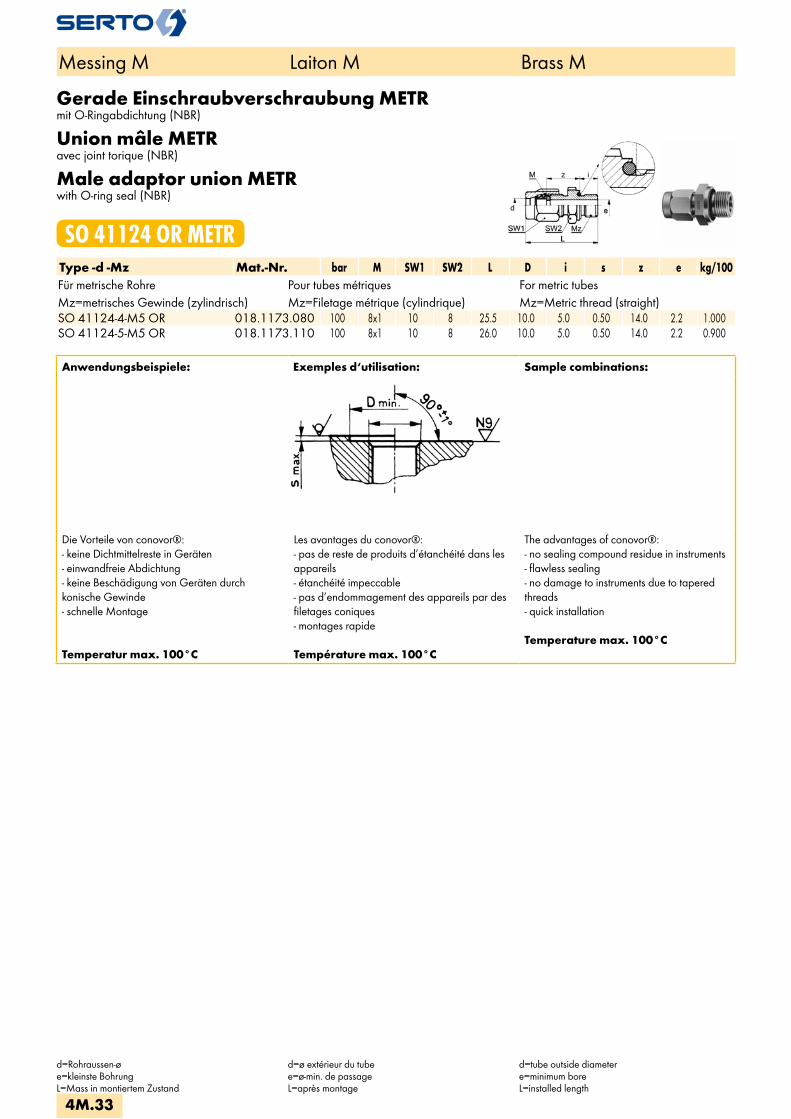
Gerade Einschraubverschraubung METRmit O-Ringabdichtung (NBR)
Union mâle METRavec joint torique (NBR)
Male adaptor union METRwith O-ring seal (NBR)
SO 41124 OR METRType -d -Mz Mat.-Nr. bar M SW1 SW2 L D i s z e kg/100Für metrische Rohre Pour tubes métriques For metric tubesMz=metrisches Gewinde (zylindrisch) Mz=Filetage métrique (cylindrique) Mz=Metric thread (straight)SO 41124-4-M5 OR 018.1173.080 100 8x1 10 8 25.5 10.0 5.0 0.50 14.0 2.2 1.000SO 41124-5-M5 OR 018.1173.110 100 8x1 10 8 26.0 10.0 5.0 0.50 14.0 2.2 0.900
Anwendungsbeispiele: Exemples d‘utilisation: Sample combinations:
Die Vorteile von conovor®:- keine Dichtmittelreste in Geräten- einwandfreie Abdichtung- keine Beschädigung von Geräten durchkonische Gewinde- schnelle Montage
Temperatur max. 100°C
Les avantages du conovor®:- pas de reste de produits d’étanchéité dans les appareils- étanchéité impeccable- pas d’endommagement des appareils par des filetages coniques- montages rapide
Température max. 100°C
The advantages of conovor®:- no sealing compound residue in instruments- flawless sealing- no damage to instruments due to tapered threads- quick installation
Temperature max. 100°C
Messing M Laiton M Brass M
d=Rohraussen-øe=kleinste BohrungL=Mass in montiertem Zustand
d=ø extérieur du tubee=ø-min. de passageL=après montage
d=tube outside diametere=minimum boreL=installed length
4M.33

Gerade AufschraubverschraubungUnion femelleFemale adaptor union
SO 41221Type -d -G Mat.-Nr. bar M SW1 SW2 L a z e kg/100Für metrische Rohre Pour tubes métriques For metric tubesG=Rohrgewinde (zylindrisch) G=Filetage-gaz BSP (cylindrique) G=BSP thread (straight)
SO 41221-3-1/8 018.1201.040 125 8x1 10 14 28.5 22.0 12.0 3.5 2.060 SO 41221-4-1/8 018.1201.060 125 8x1 10 14 28.0 22.0 12.0 3.5 2.000
SO 41221-4-1/4 018.1201.065 125 10x1 12 17 31.5 24.0 13.0 4.5 3.110 SO 41221-5-1/8 018.1201.082 125 8x1 10 14 28.5 22.0 12.0 3.5 2.000
SO 41221-5-1/4 018.1201.084 125 10x1 12 17 31.5 24.0 13.0 4.5 3.060 SO 41221-6-1/8 018.1201.100 250 10x1 12 14 29.5 22.0 12.0 4.5 2.360 SO 41221-6-1/4 018.1201.110 250 10x1 12 17 31.5 24.0 13.0 4.5 3.000
SO 41221-6-3/8 018.1201.120 250 12x1 14 22 34.0 26.0 14.0 6.5 5.100 SO 41221-6-1/2 018.1201.125 250 12x1 14 27 36.0 28.0 14.0 6.5 7.400 SO 41221-8-1/8 018.1201.160 150 12x1 14 14 31.0 23.0 13.0 6.5 2.790 SO 41221-8-1/4 018.1201.170 150 12x1 14 17 33.0 25.0 14.0 6.5 2.430 SO 41221-8-3/8 018.1201.180 150 12x1 14 22 34.0 26.0 14.0 6.5 4.940 SO 41221-8-1/2 018.1201.185 150 12x1 14 27 36.0 28.0 14.0 6.5 7.300 SO 41221-10-1/4 018.1201.270 125 14x1 17 17 35.0 25.0 14.0 8.5 4.180 SO 41221-10-3/8 018.1201.280 125 14x1 17 22 36.0 26.0 14.0 8.5 5.900
SO 41221-10-1/2 018.1201.285 100 16x1 19 27 39.0 28.0 14.0 10.5 9.060 SO 41221-12-1/4 018.1201.380 100 16x1 19 17 36.0 25.0 14.0 8.5 4.790 SO 41221-12-3/8 018.1201.390 100 16x1 19 22 37.0 26.0 14.0 10.5 6.450 SO 41221-12-1/2 018.1201.400 100 16x1 19 27 39.0 28.0 14.0 10.5 8.780
SO 41221-12-3/4 018.1201.405 40 20x1.5 24 32 45.5 33.0 16.0 13.0 14.180 SO 41221-13-1/2 018.1201.454 40 20x1.5 24 27 45.0 32.5 18.5 12.5 11.950 SO 41221-13-3/4 018.1201.456 40 20x1.5 24 32 45.5 33.0 16.0 13.0 14.070 SO 41221-14-1/2 018.1201.504 40 20x1.5 24 27 45.0 32.5 18.5 12.5 11.840 SO 41221-14-3/4 018.1201.506 40 20x1.5 24 32 45.5 33.0 16.0 13.0 13.960 SO 41221-15-1/2 018.1201.534 40 20x1.5 24 27 45.0 32.5 18.5 12.5 11.520 SO 41221-15-3/4 018.1201.536 40 20x1.5 24 32 45.5 33.0 16.0 13.0 13.640 SO 41221-16-1/2 018.1201.566 40 24x1.5 27 27 45.0 31.0 17.0 14.5 13.270 SO 41221-16-3/4 018.1201.568 40 24x1.5 27 32 47.0 33.0 16.0 15.0 15.700 SO 41221-17-1/2 018.1201.596 40 24x1.5 27 27 45.0 31.0 17.0 14.5 13.020 SO 41221-17-3/4 018.1201.598 40 24x1.5 27 32 47.0 33.0 16.0 15.0 15.450 SO 41221-18-1/2 018.1201.646 40 24x1.5 27 27 45.0 31.0 17.0 14.5 12.750 SO 41221-18-3/4 018.1201.648 40 24x1.5 27 32 47.0 33.0 16.0 15.0 15.180
SO 41221-19-3/4 018.1201.678 25 28x1.5 32 32 51.5 34.0 17.0 19.0 20.100 SO 41221-22-3/4 018.1201.768 25 28x1.5 32 32 51.5 34.0 17.0 19.0 18.710 SO 41221-28-1 018.1201.850 16 36x2 41 41 60.5 41.0 21.0 25.0 38.000 SO 41221-35-1 1/4 018.1201.944 16 42x2 50 50 72.5 47.0 25.0 31.0 62.500
Fortsetzung nächste Seite Suite à la prochaine page Continued on next page
Messing M Laiton M Brass M
d=Rohraussen-øe=kleinste BohrungL=Mass in montiertem Zustand*=mit reduziertem Klemmring
d=ø extérieur du tubee=ø-min. de passageL=après montage*=avec bague de serrage de réduction
d=tube outside diametere=minimum boreL=installed length*=with reduction compression ferrule
4M.34
i
s
3F
4M
4G
5
5L
6
7
8
9
10
11
12

Gerade AufschraubverschraubungUnion femelleFemale adaptor union
SO 41221Type -d -G Mat.-Nr. bar M SW1 SW2 L a z e kg/100Für Zollrohre Pour tubes pouces For inch tubes
SO 41221-6,35-1/8 018.1201.135 100 10x1 12 14 29.5 22.0 12.0 4.5 2.350 SO 41221-6,35-1/4 018.1201.140 100 10x1 12 17 31.5 24.0 13.0 4.5 2.990 SO 41221-9,52-1/4 018.1201.230 64 14x1 17 17 35.0 25.0 14.0 8.5 4.240 SO 41221-9,52-3/8 018.1201.235 64 14x1 17 22 36.0 26.0 14.0 8.5 4.860
SO 41221-12,7-1/2 018.1201.434 40 20x1.5 24 27 45.0 32.5 18.5 12.5 11.950 SO 41221-12,7-3/4 018.1201.436 40 20x1.5 24 32 45.5 33.0 16.0 13.0 14.070
Gerade Aufschraubverschraubung NPTUnion femelle NPTFemale adaptor union NPT
SO 41221 NPTType -d -RNPT Mat.-Nr. bar M SW1 SW2 L a z e kg/100Für metrische Rohre Pour tubes métriques For metric tubesRNPT=NPT Gewinde RNPT=Filetage NPT RNPT=NPT thread
SO 41221-6-1/8 NPT 018.1202.100 250 10x1 12 14 29.5 22.0 12.0 4.5 2.360 SO 41221-6-1/4 NPT 018.1202.110 250 10x1 12 17 34.0 26.5 12.5 4.5 2.650
SO 41221-6-3/8 NPT 018.1202.120 250 12x1 14 22 36.0 28.0 14.0 6.5 5.100 SO 41221-8-1/4 NPT 018.1202.170 150 14x1 17 17 37.0 27.0 13.0 8.5 3.000 SO 41221-8-3/8 NPT 018.1202.180 150 12x1 14 22 36.0 28.0 14.0 6.5 5.100 SO 41221-8-1/2 NPT 018.1202.185 150 12x1 14 27 40.5 32.5 14.5 6.5 5.900 SO 41221-10-1/4 NPT 018.1202.270 125 14x1 17 17 37.0 27.0 13.0 8.5 4.180
SO 41221-10-3/8 NPT 018.1202.280 100 16x1 19 22 38.0 28.0 14.0 10.5 7.300 SO 41221-10-1/2 NPT 018.1202.285 100 16x1 19 27 43.5 32.5 14.5 10.5 9.000 SO 41221-12-3/8 NPT 018.1202.390 100 16x1 19 22 39.0 28.0 14.0 10.5 8.900 SO 41221-12-1/2 NPT 018.1202.400 100 16x1 19 27 43.5 32.5 14.5 10.5 9.000
Für Zollrohre Pour tubes pouces For inch tubes SO 41221-6.35-1/8 NPT 018.1202.135 100 10x1 12 14 29.5 22.0 12.0 4.5 2.350SO 41221-6.35-1/4 NPT 018.1202.140 100 10x1 12 17 34.0 26.5 12.5 4.5 2.640SO 41221-9.52-1/4 NPT 018.1202.230 64 14x1 17 17 37.0 27.0 13.0 8.5 4.240
Messing M Laiton M Brass M
d=Rohraussen-øe=kleinste BohrungL=Mass in montiertem Zustand*=mit reduziertem Klemmring
d=ø extérieur du tubee=ø-min. de passageL=après montage*=avec bague de serrage de réduction
d=tube outside diametere=minimum boreL=installed length*=with reduction compression ferrule
4M.35

VerbindungsnippelPièce folleTube stub
SO 41300Type -Ad Mat.-Nr. bar L D e kg/100 SO 41300-A6 016.1300.060 100 19.0 8.4 4.0 0.350SO 41300-A8 016.1300.080 100 22.0 10.5 6.0 0.520SO 41300-A10 016.1300.100 64 27.0 12.7 8.0 0.850SO 41300-A12 016.1300.120 64 30.0 14.7 9.0 1.400SO 41300-A14 016.1300.140 40 31.0 17.5 11.0 2.000SO 41300-A15 016.1300.150 40 31.0 18.0 12.0 2.100SO 41300-A17 016.1300.170 40 37.0 21.0 14.0 2.900SO 41300-A18 016.1300.180 40 36.0 22.0 15.0 3.200SO 41300-A22 016.1300.220 25 40.0 26.0 19.0 4.100SO 41300-A28 016.1300.280 16 47.0 32.5 23.0 9.800
Anwendungsbeispiele: Exemples d‘utilisation: Sample combinations:
Mit der einstellbaren Kupplung lassen sich alle Formteile mit dem gleichen Anschlussgewinde M verbinden. Weitere einstellbare Ver-schraubungen siehe SO 41600, SO 42621, SO 42824, SO 43621, SO 43824, SO 43924.
L’union orientable permet l’assemblage de tous les raccords de même filetage mâle M. Autres raccords orientables, voir SO 41600, SO 42621, SO 42824, SO 43621, SO 43824, SO 43924.
The adjustable coupling permits the connec-tion of all fittings with the same connector thread M. See SO 41600, SO 42621, SO 42824, SO 43621,SO 43824, SO 43924 for other adjustable unions.
Messing M Laiton M Brass M
Ad=Aussen-ø der Andrehunge=kleinste BohrungL=Mass in montiertem Zustand
Ad=ø extérieur de la portée cylindriquee=ø-min. de passageL=après montage
Ad=outside diameter of cyl. Stube=minimum boreL=installed length
4M.36
i
s
3F
4M
4G
5
5L
6
7
8
9
10
11
12
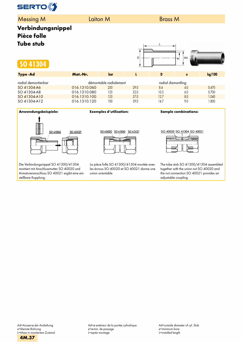
VerbindungsnippelPièce folleTube stub
SO 41304Type -Ad Mat.-Nr. bar L D e kg/100 radial demontierbar démontable radialement radial dismantlingSO 41304-A6 016.1310.060 250 29.0 8.4 4.0 0.470SO 41304-A8 016.1310.080 125 32.0 10.5 6.0 0.700SO 41304-A10 016.1310.100 125 37.0 12.7 8.0 1.040SO 41304-A12 016.1310.120 100 39.0 14.7 9.0 1.800
Anwendungsbeispiele: Exemples d‘utilisation: Sample combinations:
Die Verbindungsnippel SO 41300/41304 montiert mit Anschlussmutter SO 40020 und Armaturenanschluss SO 40021 ergibt eine ein-stellbare Kupplung.
La pièce folle SO 41300/41304 montée avec les écrous SO 40020 et SO 40021 donne une union orientable.
The tube stub SO 41300/41304 assembled together with the union nut SO 40020 and the nut connection SO 40021 provides an adjustable coupling.
Messing M Laiton M Brass M
Ad=Aussen-ø der Andrehunge=kleinste BohrungL=Mass in montiertem Zustand
Ad=ø extérieur de la portée cylindriquee=ø-min. de passageL=après montage
Ad=outside diameter of cyl. Stube=minimum boreL=installed length
4M.37

Einstellbare KupplungAccouplement orientableAdjustable coupling
SO 41325Type -Ad Mat.-Nr. bar M SW l L e kg/100 SO 41325-A6 018.1320.060 250 10x1 12 20.0 31.0 4.0 2.050SO 41325-A8 018.1320.080 150 12x1 14 23.0 35.0 6.0 2.750SO 41325-A10 018.1320.100 125 14x1 17 26.0 38.0 8.0 4.650SO 41325-A12 018.1320.120 100 16x1 19 29.0 41.0 9.0 6.150SO 41325-A14 018.1320.140 40 20x1.5 24 32.0 45.0 11.0 11.100SO 41325-A15 018.1320.150 40 20x1.5 24 32.0 45.0 12.0 10.600SO 41325-A18 018.1320.180 40 24x1.5 27 37.0 51.0 15.0 13.700SO 41325-A22 018.1320.220 25 28x1.5 32 41.0 55.0 19.0 20.900SO 41325-A28 018.1320.280 16 36x2 41 49.0 66.0 23.0 43.200
Einstellbare KupplungAccouplement orientableAdjustable coupling
SO 41326Type -Ad Mat.-Nr. bar M SW l L e kg/100Für metrische Rohre Pour tubes métriques For metric tubes SO 41326-A6 018.1330.060 250 10x1 12 30.0 41.0 4.0 2.150SO 41326-A8 018.1330.080 150 12x1 14 33.0 45.0 6.0 2.950SO 41326-A10 018.1330.100 125 14x1 17 38.0 50.0 8.0 4.800SO 41326-A12 018.1330.120 100 16x1 19 40.0 52.0 9.0 6.500
Mit der einstellbaren Kupplung lassen sich alle Formteile mit dem gleichen Anschlussgewinde M verbinden. Weitere einstellbare Verschraubungen siehe SO 41600, SO 42621, SO 42824, SO 43621, SO 43824.
L’union orientable permet l’assemblage de tous les raccords de même filetage mâle M. Autres raccords orientables, voir SO 41600, SO 42621, SO 42824, SO 43621, SO 43824, SO 43924.
The adjustable coupling permits the connection of all fittings with the same connector thread M. For other adjustable unions see SO 41600, SO 42621, SO 42824, SO 43621, SO 43824.
Messing M Laiton M Brass M
Ad=Aussen-ø der Andrehunge=kleinste BohrungL=Mass in montiertem Zustand
Ad=ø extérieur de la portée cylindriquee=ø-min. de passageL=après montage
Ad=outside diameter of cyl. stube=minimum boreL=installed length
4M.38
i
s
3F
4M
4G
5
5L
6
7
8
9
10
11
12

Verschraubung mit EinlötnippelUnion avec embout à braserAdaptor union with soldering nipple
SO 41421Type -d -f Mat.-Nr. bar M SW1 SW2 L a f z e kg/100Für metrische Rohre Pour tubes métriques For metric tubes
SO 41421-4-6 018.1400.060 125 10x1 12 10 21.5 3.0 6.0 14.0 4.0 1.640 SO 41421-5-6 018.1400.080 125 10x1 12 10 21.5 3.0 6.0 14.0 4.0 1.590 SO 41421-6-6 018.1400.100 250 10x1 12 10 21.5 3.0 6.0 14.0 4.0 1.530 SO 41421-8-9 018.1400.140 150 12x1 14 12 24.0 4.0 9.0 16.0 6.0 2.200 SO 41421-10-11 018.1400.180 125 14x1 17 14 27.0 5.0 11.0 17.0 8.0 3.385 SO 41421-12-14 018.1400.200 100 16x1 19 17 29.0 6.0 14.0 18.0 10.0 4.530
SO 41421-13-17 018.1400.240 40 20x1.5 24 22 33.0 6.0 17.0 20.5 13.0 8.330 SO 41421-14-17 018.1400.260 40 20x1.5 24 22 33.0 6.0 17.0 20.5 13.0 8.220 SO 41421-15-17 018.1400.280 40 20x1.5 24 22 33.0 6.0 17.0 20.5 13.0 7.900 SO 41421-16-19 018.1400.300 40 24x1.5 27 24 35.5 7.0 19.0 21.5 15.0 10.800 SO 41421-17-19 018.1400.320 40 24x1.5 27 24 35.5 7.0 19.0 21.5 15.0 10.550 SO 41421-18-19 018.1400.340 40 24x1.5 27 24 35.5 7.0 19.0 21.5 15.0 10.280
SO 41421-19-23 018.1400.360 25 28x1.5 32 30 41.0 7.0 23.0 23.5 19.0 17.080 SO 41421-22-23 018.1400.400 25 28x1.5 32 30 41.0 7.0 23.0 23.5 19.0 15.680
Für Zollrohre Pour tubes pouces For inch tubes
SO 41421-6,35-6 018.1400.120 100 10x1 12 10 21.5 3.0 6.0 14.0 4.0 1.520 SO 41421-9,52-11 018.1400.160 64 14x1 17 14 27.0 5.0 11.0 17.0 8.0 3.440
SO 41421-12,7-17 018.1400.220 40 20x1.5 24 22 33.0 6.0 17.0 20.5 13.0 8.330
Messing M Laiton M Brass M
d=Rohraussen-øe=kleinste BohrungL=Mass in montiertem Zustand*=mit reduziertem Klemmring
d=ø extérieur du tubee=ø-min. de passageL=après montage*=avec bague de serrage de réduction
d=tube outside diametere=minimum boreL=installed length*=with reduction compression ferrule
4M.39
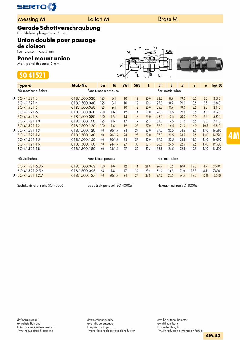
Gerade SchottverschraubungDurchführungslänge max. 5 mm
Union double pour passage de cloisonPour cloison max. 5 mm
Panel mount unionMax. panel thickness 5 mm
SO 41521Type -d Mat.-Nr. bar M SW1 SW2 L L1 B z1 z e kg/100Für metrische Rohre Pour tubes métriques For metric tubes
SO 41521-3 018.1500.030 125 8x1 10 12 20.0 22.5 8.5 19.0 13.5 3.5 2.580 SO 41521-4 018.1500.040 125 8x1 10 12 19.5 25.0 8.5 19.0 13.5 3.5 2.460 SO 41521-5 018.1500.050 125 8x1 10 12 20.0 25.5 8.5 19.0 13.5 3.5 2.440 SO 41521-6 018.1500.060 250 10x1 12 14 21.0 26.5 10.5 19.0 13.5 4.5 3.540 SO 41521-8 018.1500.080 150 12x1 14 17 23.0 28.0 12.5 20.0 15.0 6.5 5.320 SO 41521-10 018.1500.100 125 14x1 17 19 25.5 31.0 14.5 21.0 15.5 8.5 7.710 SO 41521-12 018.1500.120 100 16x1 19 22 27.0 32.0 16.5 21.0 16.0 10.5 9.320
SO 41521-13 018.1500.130 40 20x1.5 24 27 32.0 37.0 20.5 24.5 19.5 13.0 16.510 SO 41521-14 018.1500.140 40 20x1.5 24 27 32.0 37.0 20.5 24.5 19.5 13.0 16.720 SO 41521-15 018.1500.150 40 20x1.5 24 27 32.0 37.0 20.5 24.5 19.5 13.0 16.080 SO 41521-16 018.1500.160 40 24x1.5 27 30 33.5 36.5 24.5 22.5 19.5 15.0 19.500 SO 41521-18 018.1500.180 40 24x1.5 27 30 33.5 36.5 24.5 22.5 19.5 15.0 18.500
Für Zollrohre Pour tubes pouces For inch tubes
SO 41521-6,35 018.1500.063 100 10x1 12 14 21.0 26.5 10.5 19.0 13.5 4.5 3.510 SO 41521-9,52 018.1500.095 64 14x1 17 19 25.5 31.0 14.5 21.0 15.5 8.5 7.830
SO 41521-12,7 018.1500.127 40 20x1.5 24 27 32.0 37.0 20.5 24.5 19.5 13.0 16.510
Sechskantmutter siehe SO 40006 Ecrou à six pans voir SO 40006 Hexagon nut see SO 40006
Messing M Laiton M Brass M
d=Rohraussen-øe=kleinste BohrungL=Mass in montiertem Zustand*=mit reduziertem Klemmring
d=ø extérieur du tubee=ø-min. de passageL=après montage*=avec bague de serrage de réduction
d=tube outside diametere=minimum boreL=installed length*=with reduction compression ferrule
4M.40
i
s
3F
4M
4G
5
5L
6
7
8
9
10
11
12

Gerade Schottverschraubung reduziertDurchführungslänge max. 5 mm
Union double réduite pour passage de cloisonpour cloison max. 5 mm
Panel mount reduction unionmax. panel thickness 5 mm
SO 41521 REDType -d -d2 Mat.-Nr. bar M SW1 SW2 L L1 B z1 z e kg/100Für metrische Rohre Pour tubes métriques For metric tubes
SO 41521-5-3 018.1504.060 125 8x1 10 12 20.0 25.5 8.5 19.0 13.5 3.5 2.500 SO 41521-6-4 018.1504.110 100 10x1 12 14 21.0 26.5 10.5 19.0 13.5 4.5 3.650 SO 41521-6-5 018.1504.117 100 10x1 12 14 21.0 26.5 10.5 19.0 13.5 4.5 3.600 SO 41521-8-6 018.1504.140 250 12x1 14 17 23.0 28.0 12.5 20.0 15.0 6.5 5.480 SO 41521-10-8 018.1504.190 150 14x1 17 19 25.5 31.0 14.5 21.0 15.5 8.5 7.910 SO 41521-12-10 018.1504.240 100 16x1 19 22 27.0 32.0 16.5 21.0 16.0 10.5 9.600 SO 41521-15-12 018.1504.420 40 20x1.5 24 27 30.5 35.5 20.5 24.5 19.5 13.0 16.620 SO 41521-15-13 018.1504.430 40 20x1.5 24 27 30.5 35.5 20.5 24.5 19.5 13.0 16.510 SO 41521-18-15 018.1504.610 40 24x1.5 27 30 33.5 36.5 24.5 24.5 19.5 15.0 18.400
Für Zollrohre Pour tubes pouces For inch tubes
SO 41521-6-6,35 018.1504.119 100 10x1 12 14 21.0 26.5 10.5 19.0 13.5 4.5 3.530 SO 41521-10-9,52 018.1504.197 64 14x1 17 19 25.5 31.0 14.5 21.0 15.5 8.5 7.780
SO 41521-15-12,7 018.1504.427 40 20x1.5 24 27 30.5 35.5 20.5 24.5 19.5 13.0 16.510
Weitere Reduktionen siehe SO 41821 Sechskantmutter siehe SO 40006
Autres réductions voir SO 41821 Ecrou à six pans voir SO 40006
Alternative reductions see SO 41821Hexagon nut see SO 40006
Messing M Laiton M Brass M
d=Rohraussen-øe=kleinste BohrungL=Mass in montiertem Zustand*=mit reduziertem Klemmring
d=ø extérieur du tubee=ø-min. de passageL=après montage*=avec bague de serrage de réduction
d=tube outside diametere=minimum boreL=installed length*=with reduction compression ferrule
4M.41

Gerade SchottverschraubungDurchführungslänge max. 16 mm
Union double pour passage de cloisonpour cloison max. 16 mm
Panel mount unionmax. panel thickness 16 mm
SO 41524Type -d Mat.-Nr. bar M SW1 SW2 L L1 B z1 z e kg/100Für metrische Rohre Pour tubes métriques For metric tubes
SO 41524-4 018.1540.040 125 10x1 12 14 21.0 37.5 10.5 30.0 13.5 4.5 4.130 SO 41524-5 018.1540.050 125 10x1 12 14 21.0 37.5 10.5 30.0 13.5 4.5 4.080 SO 41524-6 018.1540.060 250 10x1 12 14 21.0 37.5 10.5 30.0 13.5 4.5 4.020 SO 41524-8 018.1540.080 150 12x1 14 17 23.0 40.0 12.5 32.0 15.0 6.5 6.030 SO 41524-10 018.1540.100 125 14x1 17 19 25.5 42.0 14.5 32.0 15.5 8.5 8.520 SO 41524-12 018.1540.120 100 16x1 19 22 27.0 43.0 16.5 32.0 16.0 10.5 10.220
SO 41524-13 018.1540.130 40 20x1.5 24 27 32.5 46.0 20.5 33.5 19.5 13.0 17.740 SO 41524-14 018.1540.140 40 20x1.5 24 27 32.0 46.0 20.5 33.5 19.5 13.0 17.950 SO 41524-15 018.1540.150 40 20x1.5 24 27 32.0 46.0 20.5 33.5 19.5 13.0 17.310 SO 41524-16 018.1540.160 40 24x1.5 27 30 33.0 47.5 24.5 33.5 19.5 15.0 25.800
SO 41524-17 018.1540.170 40 24x1.5 27 30 33.5 47.5 24.5 33.5 19.5 15.0 25.350 SO 41524-18 018.1540.180 40 24x1.5 27 30 33.5 47.5 24.5 33.5 19.5 15.0 24.850
SO 41524-19 018.1540.190 40 28x1.5 32 36 38.0 50.0 28.5 35.5 20.5 19.0 34.200 SO 41524-22 018.1540.220 40 28x1.5 32 36 38.0 50.0 28.5 35.5 20.5 19.0 31.500
Für Zollrohre Pour tubes pouces For inch tubes
SO 41524-6,35 018.1540.063 100 10x1 12 14 21.0 37.5 10.5 30.0 13.5 4.5 3.990 SO 41524-9,52 018.1540.095 64 14x1 17 19 25.5 42.0 14.5 32.0 15.5 8.5 8.640
SO 41524-12,7 018.1540.127 40 20x1.5 24 27 32.0 46.0 20.5 33.5 19.5 13.0 17.740
Sechskantmutter siehe SO 40006 Ecrou à six pans voir SO 40006 Hexagon nut see SO 40006
Messing M Laiton M Brass M
d=Rohraussen-øe=kleinste BohrungL=Mass in montiertem Zustand*=mit reduziertem Klemmring
d=ø extérieur du tubee=ø-min. de passageL=après montage*=avec bague de serrage de réduction
d=tube outside diametere=minimum boreL=installed length*=with reduction compression ferrule
4M.42
i
s
3F
4M
4G
5
5L
6
7
8
9
10
11
12
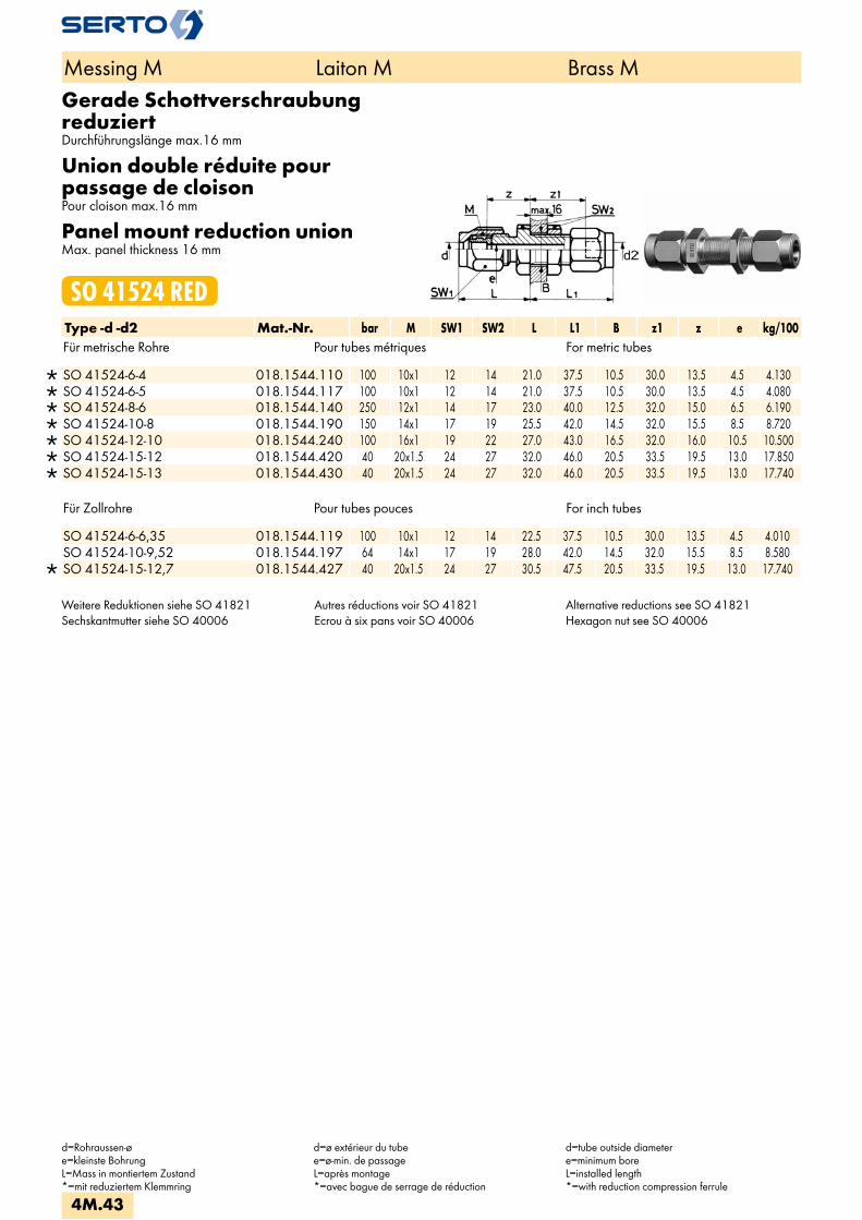
Gerade Schottverschraubung reduziertDurchführungslänge max.16 mm
Union double réduite pour passage de cloisonPour cloison max.16 mm
Panel mount reduction unionMax. panel thickness 16 mm
SO 41524 REDType -d -d2 Mat.-Nr. bar M SW1 SW2 L L1 B z1 z e kg/100Für metrische Rohre Pour tubes métriques For metric tubes
SO 41524-6-4 018.1544.110 100 10x1 12 14 21.0 37.5 10.5 30.0 13.5 4.5 4.130 SO 41524-6-5 018.1544.117 100 10x1 12 14 21.0 37.5 10.5 30.0 13.5 4.5 4.080 SO 41524-8-6 018.1544.140 250 12x1 14 17 23.0 40.0 12.5 32.0 15.0 6.5 6.190 SO 41524-10-8 018.1544.190 150 14x1 17 19 25.5 42.0 14.5 32.0 15.5 8.5 8.720 SO 41524-12-10 018.1544.240 100 16x1 19 22 27.0 43.0 16.5 32.0 16.0 10.5 10.500 SO 41524-15-12 018.1544.420 40 20x1.5 24 27 32.0 46.0 20.5 33.5 19.5 13.0 17.850 SO 41524-15-13 018.1544.430 40 20x1.5 24 27 32.0 46.0 20.5 33.5 19.5 13.0 17.740
Für Zollrohre Pour tubes pouces For inch tubes
SO 41524-6-6,35 018.1544.119 100 10x1 12 14 22.5 37.5 10.5 30.0 13.5 4.5 4.010 SO 41524-10-9,52 018.1544.197 64 14x1 17 19 28.0 42.0 14.5 32.0 15.5 8.5 8.580
SO 41524-15-12,7 018.1544.427 40 20x1.5 24 27 30.5 47.5 20.5 33.5 19.5 13.0 17.740
Weitere Reduktionen siehe SO 41821 Sechskantmutter siehe SO 40006
Autres réductions voir SO 41821 Ecrou à six pans voir SO 40006
Alternative reductions see SO 41821 Hexagon nut see SO 40006
Messing M Laiton M Brass M
d=Rohraussen-øe=kleinste BohrungL=Mass in montiertem Zustand*=mit reduziertem Klemmring
d=ø extérieur du tubee=ø-min. de passageL=après montage*=avec bague de serrage de réduction
d=tube outside diametere=minimum boreL=installed length*=with reduction compression ferrule
4M.43
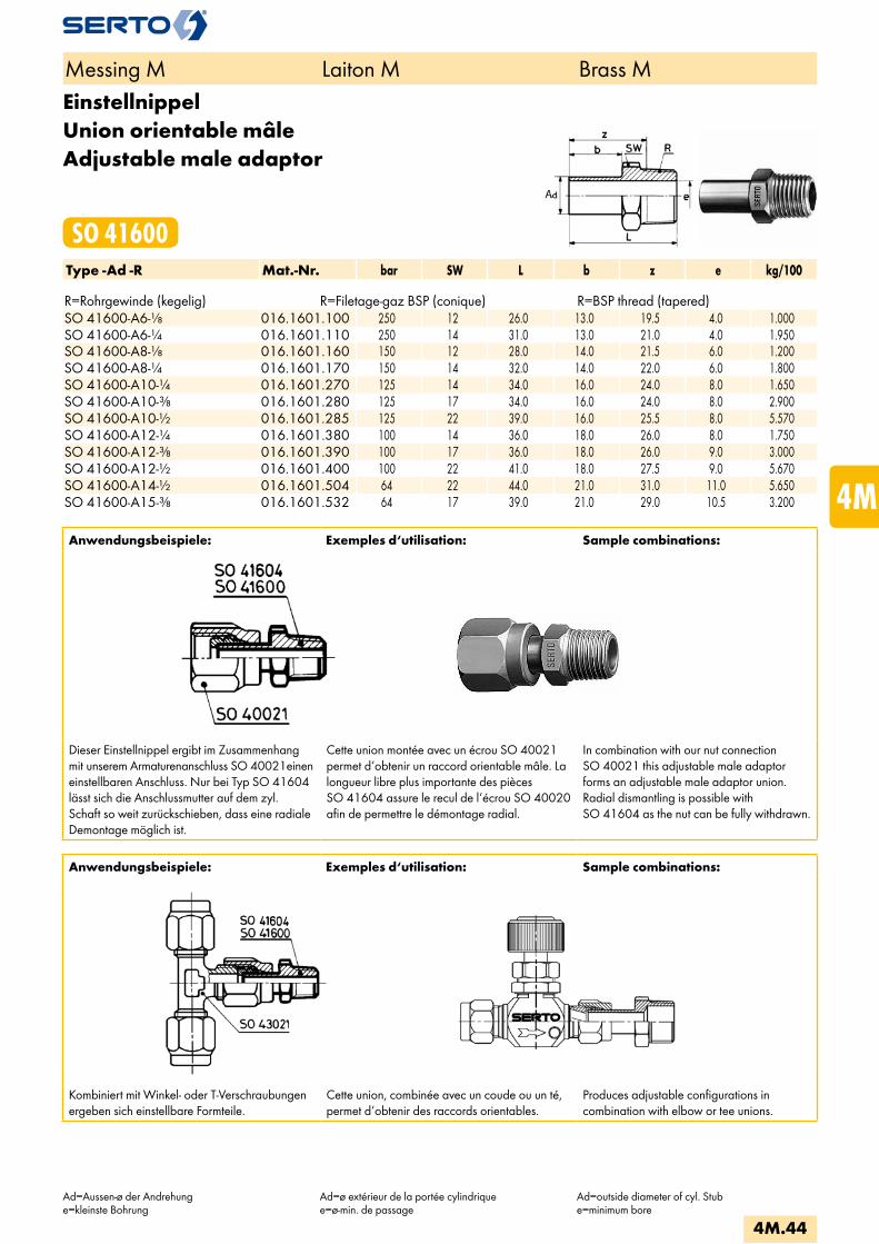
EinstellnippelUnion orientable mâleAdjustable male adaptor
SO 41600Type -Ad -R Mat.-Nr. bar SW L b z e kg/100 R=Rohrgewinde (kegelig) R=Filetage-gaz BSP (conique) R=BSP thread (tapered)SO 41600-A6-1/8 016.1601.100 250 12 26.0 13.0 19.5 4.0 1.000SO 41600-A6-1/4 016.1601.110 250 14 31.0 13.0 21.0 4.0 1.950SO 41600-A8-1/8 016.1601.160 150 12 28.0 14.0 21.5 6.0 1.200SO 41600-A8-1/4 016.1601.170 150 14 32.0 14.0 22.0 6.0 1.800SO 41600-A10-1/4 016.1601.270 125 14 34.0 16.0 24.0 8.0 1.650SO 41600-A10-3/8 016.1601.280 125 17 34.0 16.0 24.0 8.0 2.900SO 41600-A10-1/2 016.1601.285 125 22 39.0 16.0 25.5 8.0 5.570SO 41600-A12-1/4 016.1601.380 100 14 36.0 18.0 26.0 8.0 1.750SO 41600-A12-3/8 016.1601.390 100 17 36.0 18.0 26.0 9.0 3.000SO 41600-A12-1/2 016.1601.400 100 22 41.0 18.0 27.5 9.0 5.670SO 41600-A14-1/2 016.1601.504 64 22 44.0 21.0 31.0 11.0 5.650SO 41600-A15-3/8 016.1601.532 64 17 39.0 21.0 29.0 10.5 3.200
Anwendungsbeispiele: Exemples d‘utilisation: Sample combinations:
Dieser Einstellnippel ergibt im Zusammenhang mit unserem Armaturenanschluss SO 40021einen einstellbaren Anschluss. Nur bei Typ SO 41604 lässt sich die Anschlussmutter auf dem zyl. Schaft so weit zurückschieben, dass eine radiale Demontage möglich ist.
Cette union montée avec un écrou SO 40021 permet d‘obtenir un raccord orientable mâle. La longueur libre plus importante des pièces SO 41604 assure le recul de l‘écrou SO 40020 afin de permettre le démontage radial.
In combination with our nut connection SO 40021 this adjustable male adaptor forms an adjustable male adaptor union. Radial dismantling is possible with SO 41604 as the nut can be fully withdrawn.
Anwendungsbeispiele: Exemples d‘utilisation: Sample combinations:
Kombiniert mit Winkel- oder T-Verschraubungen ergeben sich einstellbare Formteile.
Cette union, combinée avec un coude ou un té, permet d‘obtenir des raccords orientables.
Produces adjustable configurations incombination with elbow or tee unions.
Messing M Laiton M Brass M
Ad=Aussen-ø der Andrehunge=kleinste Bohrung
Ad=ø extérieur de la portée cylindriquee=ø-min. de passage
Ad=outside diameter of cyl. Stube=minimum bore
4M.44
i
s
3F
4M
4G
5
5L
6
7
8
9
10
11
12
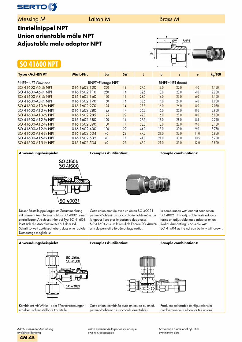
Einstellnippel NPTUnion orientable mâle NPTAdjustable male adaptor NPT
SO 41600 NPTType -Ad -RNPT Mat.-Nr. bar SW L b z e kg/100 RNPT=NPT Gewinde RNPT=Filetage NPT RNPT=NPT threadSO 41600-A6-1/8 NPT 016.1602.100 250 12 27.5 13.0 22.0 4.0 1.150SO 41600-A6-1/4 NPT 016.1602.110 250 14 32.5 13.0 23.0 4.0 2.200SO 41600-A8-1/8 NPT 016.1602.160 150 12 28.5 14.0 23.0 6.0 1.100SO 41600-A8-1/4 NPT 016.1602.170 150 14 33.5 14.0 24.0 6.0 1.900SO 41600-A10-1/4 NPT 016.1602.270 125 14 35.5 16.0 26.0 8.0 2.050SO 41600-A10-3/8 NPT 016.1602.280 125 17 36.0 16.0 26.0 8.0 2.900SO 41600-A10-1/2 NPT 016.1602.285 125 22 42.0 16.0 28.0 8.0 5.800SO 41600-A12-1/4 NPT 016.1602.380 100 14 37.5 18.0 28.0 8.5 2.250SO 41600-A12-3/8 NPT 016.1602.390 100 17 38.0 18.0 28.0 9.0 3.100SO 41600-A12-1/2 NPT 016.1602.400 100 22 44.0 18.0 30.0 9.0 5.750SO 41600-A14-1/2 NPT 016.1602.504 40 22 47.0 21.0 33.0 11.0 5.850SO 41600-A15-3/8 NPT 016.1602.532 40 17 41.0 21.0 33.0 10.5 5.700SO 41600-A15-1/2 NPT 016.1602.534 40 22 47.0 21.0 33.0 12.0 5.800
Anwendungsbeispiele: Exemples d‘utilisation: Sample combinations:
Dieser Einstellnippel ergibt im Zusammenhang mit unserem Armaturenanschluss SO 40021einen einstellbaren Anschluss. Nur bei Typ SO 41604 lässt sich die Anschlussmutter auf dem zyl. Schaft so weit zurückschieben, dass eine radiale Demontage möglich ist.
Cette union montée avec un écrou SO 40021 permet d‘obtenir un raccord orientable mâle. La longueur libre plus importante des pièces SO 41604 assure le recul de l‘écrou SO 40020 afin de permettre le démontage radial.
In combination with our nut connection SO 40021 this adjustable male adaptor forms an adjustable male adaptor union. Radial dismantling is possible with SO 41604 as the nut can be fully withdrawn.
Anwendungsbeispiele: Exemples d‘utilisation: Sample combinations:
Kombiniert mit Winkel- oder T-Verschraubungen ergeben sich einstellbare Formteile.
Cette union, combinée avec un coude ou un té, permet d‘obtenir des raccords orientables.
Produces adjustable configurations incombination with elbow or tee unions.
Messing M Laiton M Brass M
Ad=Aussen-ø der Andrehunge=kleinste Bohrung
Ad=ø extérieur de la portée cylindriquee=ø-min. de passage
Ad=outside diameter of cyl. Stube=minimum bore
4M.45

EinstellnippelUnion orientable mâleAdjustable male adaptor
SO 41604Type -Ad -R Mat.-Nr. bar SW L b z e kg/100R=Rohrgewinde (kegelig) R=Filetage-gaz BSP (conique) R=BSP thread (tapered)radial demontierbar démontable radialement radial dismantlingSO 41604-A15-1/2 016.1611.534 64 22 53.0 30.0 40.0 12.0 5.760SO 41604-A15-3/4 016.1611.536 64 27 55.0 30.0 40.0 12.0 7.800SO 41604-A22-1 016.1611.770 40 36 65.0 36.0 48.5 18.0 16.540SO 41604-A28-1 1/4 016.1611.860 40 46 75.5 41.5 56.5 23.0 33.860
Dieser Einstellnippel ergibt im Zusammenhangmit unserem Armaturenanschluss SO 40021einen einstellbaren Anschluss. Nur bei TypSO 41604 lässt sich die Anschlussmutterauf dem zyl. Schaft so weit zurückschieben,dass eine radiale Demontage möglich ist.
Cette union montée avec un écrou SO 40021permet d‘obtenir un raccord orientable mâle. Lalongueur libre plus importante des piècesSO 41604 assure le recul de l‘écrouSO 40020 afin de permettre le démontageradial.
In combination with our nut connectionSO 40021 this adjustable male adaptorforms an adjustable male adaptor union.Radial dismantling is possible withSO 41604 as the nut can be fullywithdrawn.
Einstellnippel vormontiertEmbout orientable mâle montéAdjustable male adaptor assembly
SO 41625Type -Ad -R Mat.-Nr. bar M SW1 SW2 L l e kg/100Für metrische Rohre Pour tubes métriques For metric tubesR=Rohrgewinde (kegelig) R=Filetage-gaz BSP (conique) R=BSP thread (tapered)SO 41625-A6-1/8 018.1621.100 250 10x1 12 12 32.5 27.0 4.0 1.840SO 41625-A6-1/4 018.1621.110 250 10x1 12 14 37.5 32.0 4.0 2.790SO 41625-A8-1/8 018.1621.160 150 12x1 14 12 35.5 29.0 6.0 2.320SO 41625-A8-1/4 018.1621.170 150 12x1 14 14 39.5 33.0 6.0 2.920SO 41625-A10-1/4 018.1621.270 125 14x1 17 14 41.0 35.0 8.0 3.540SO 41625-A10-3/8 018.1621.280 125 14x1 17 17 41.0 35.0 8.0 6.760SO 41625-A10-1/2 018.1621.285 125 14x1 17 22 46.0 40.0 8.0 7.460SO 41625-A12-1/4 018.1621.380 100 16x1 19 14 43.0 37.0 8.0 4.090SO 41625-A12-3/8 018.1621.390 100 16x1 19 17 43.0 37.0 9.0 5.340SO 41625-A12-1/2 018.1621.400 100 16x1 19 22 48.0 42.0 9.0 8.010SO 41625-A14-1/2 018.1621.504 40 20x1.5 24 22 52.0 45.0 11.0 10.210SO 41625-A15-3/8 018.1621.532 40 20x1.5 24 17 47.0 40.5 10.5 7.440
Messing M Laiton M Brass M
Ad=Aussen-ø der Andrehunge=kleinste Bohrung
Ad=ø extérieur de la portée cylindriquee=ø-min. de passage
Ad=outside diameter of cyl. Stube=minimum bore
4M.46
i
s
3F
4M
4G
5
5L
6
7
8
9
10
11
12

Einstellnippel vormontiert NPTEmbout orientable mâle montée NPTAdjustable male adaptor assembly NPT
SO 41625 NPTType -Ad -RNPT Mat.-Nr. bar M SW1 SW2 L l e kg/100 RNPT=NPT Gewinde RNPT=Filetage NPT RNPT=NPT threadSO 41625-A6-1/8 NPT 018.1622.100 250 10x1 12 12 34.0 28.5 4.0 1.700SO 41625-A6-1/4 NPT 018.1622.110 250 10x1 12 14 39.0 33.5 4.0 1.750SO 41625-A8-1/8 NPT 018.1622.160 150 12x1 14 12 36.0 29.5 6.0 2.250SO 41625-A8-1/4 NPT 018.1622.170 150 12x1 14 14 41.0 34.5 6.0 3.020SO 41625-A10-1/4 NPT 018.1622.270 125 14x1 17 14 42.5 36.5 8.0 3.940SO 41625-A10-3/8 NPT 018.1622.280 125 14x1 17 17 43.0 37.0 8.0 4.790SO 41625-A10-1/2 NPT 018.1622.285 125 14x1 17 22 49.0 43.0 8.0 7.690SO 41625-A12-1/4 NPT 018.1622.380 100 16x1 19 14 44.5 38.5 8.5 4.590SO 41625-A12-3/8 NPT 018.1622.390 100 16x1 19 17 45.0 39.0 9.0 5.440SO 41625-A12-1/2 NPT 018.1622.400 100 16x1 19 22 51.0 45.0 9.0 8.090SO 41625-A14-1/2 NPT 018.1622.504 40 20x1.5 24 22 55.0 48.5 11.0 10.410SO 41625-A15-3/8 NPT 018.1622.532 40 20x1.5 24 17 49.0 42.5 10.5 9.940SO 41625-A15-1/2 NPT 018.1622.534 40 20x1.5 24 22 55.0 48.5 12.0 10.040
Einstellnippel vormontiertEmbout orientable mâle montéAdjustable male adaptor assembly
SO 41626Type -Ad -R Mat.-Nr. bar M SW1 SW2 L l e kg/100R=Rohrgewinde (kegelig) R=Filetage-gaz BSP (conique) R=BSP thread (tapered)radial demontierbar démontable radialement radial dismantlingSO 41626-A15-1/2 018.1631.534 40 20x1.5 22 24 61.0 54.5 12.0 10.000SO 41626-A15-3/4 018.1631.536 40 20x1.5 27 24 63.0 56.5 12.0 12.040SO 41626-A22-1 018.1631.770 25 28x1.5 36 32 73.5 66.5 18.0 24.960SO 41626-A28-1 1/4 018.1631.860 16 36x2 46 41 86.5 77.5 23.0 50.560
Messing M Laiton M Brass M
M=Anschlussgewindel=Einbaulängee=kleinste BohrungL=Mass in montiertem Zustand*=mit reduziertem Klemmring
M=filetagel=longueur encastréee=ø-min. de passageL=après montage*=avec bague de serrage de réduction
M=threadl=fitted lengthe=minimum boreL=installed length*=with reduction compression ferrule
4M.47
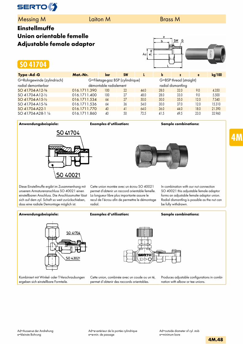
EinstellmuffeUnion orientable femelleAdjustable female adaptor
SO 41704Type -Ad -G Mat.-Nr. bar SW L b z e kg/100G=Rohrgewinde (zylindrisch) G=Filetage-gaz BSP (cylindrique) G=BSP thread (straight)radial demontierbar démontable radialement radial dismantlingSO 41704-A12-3/8 016.1711.390 100 22 44.0 28.0 32.0 9.0 4.350SO 41704-A12-1/2 016.1711.400 100 27 48.0 28.0 33.0 9.0 5.500SO 41704-A15-1/2 016.1711.534 64 27 50.0 30.0 35.0 12.0 7.540SO 41704-A15-3/4 016.1711.536 64 36 54.0 30.0 37.0 12.0 15.310SO 41704-A22-1 016.1711.770 40 41 64.0 36.0 44.0 18.0 21.390SO 41704-A28-1 1/4 016.1711.860 40 50 72.5 41.5 49.5 23.0 32.960
Anwendungsbeispiele: Exemples d‘utilisation: Sample combinations:
Diese Einstellmuffe ergibt im Zusammenhang mit unserem Armaturenanschluss SO 40021 einen einstellbaren Anschluss. Die Anschlussmutter lässt sich auf dem zyl. Schaft so weit zurückschieben, dass eine radiale Demontage möglich ist.
Cette union montée avec un écrou SO 40021 permet d’obtenir un raccord orientable femelle. La longueur libre plus importante assure le recul de l’écrou afin de permettre le démontage radial.
In combination with our nut connection SO 40021 this adjustable female adaptor forms an adjustable female adaptor union. Radial dismantling is possible as the nut can be fully withdrawn.
Anwendungsbeispiele: Exemples d‘utilisation: Sample combinations:
Kombiniert mit Winkel- oder T-Verschraubungen ergeben sich einstellbare Formteile.
Cette union, combinée avec un coude ou un té, permet d‘obtenir des raccords orientables.
Produces adjustable configurations in combi-nation with elbow or tee unions.
Messing M Laiton M Brass M
Ad=Aussen-ø der Andrehunge=kleinste Bohrung
Ad=ø extérieur de la portée cylindriquee=ø-min. de passage
Ad=outside diameter of cyl. stube=minimum bore
4M.48
i
s
3F
4M
4G
5
5L
6
7
8
9
10
11
12
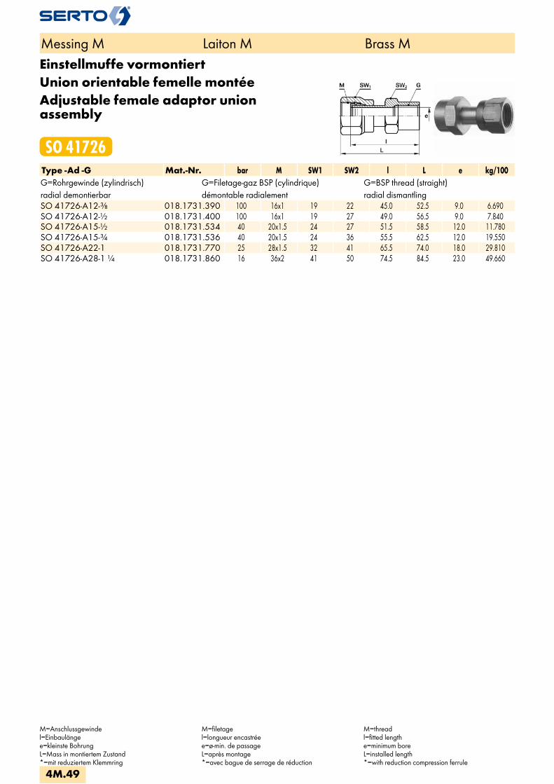
Einstellmuffe vormontiertUnion orientable femelle montéeAdjustable female adaptor union assembly
SO 41726Type -Ad -G Mat.-Nr. bar M SW1 SW2 l L e kg/100G=Rohrgewinde (zylindrisch) G=Filetage-gaz BSP (cylindrique) G=BSP thread (straight)radial demontierbar démontable radialement radial dismantlingSO 41726-A12-3/8 018.1731.390 100 16x1 19 22 45.0 52.5 9.0 6.690SO 41726-A12-1/2 018.1731.400 100 16x1 19 27 49.0 56.5 9.0 7.840SO 41726-A15-1/2 018.1731.534 40 20x1.5 24 27 51.5 58.5 12.0 11.780SO 41726-A15-3/4 018.1731.536 40 20x1.5 24 36 55.5 62.5 12.0 19.550SO 41726-A22-1 018.1731.770 25 28x1.5 32 41 65.5 74.0 18.0 29.810SO 41726-A28-1 1/4 018.1731.860 16 36x2 41 50 74.5 84.5 23.0 49.660
Messing M Laiton M Brass M
M=Anschlussgewindel=Einbaulängee=kleinste BohrungL=Mass in montiertem Zustand*=mit reduziertem Klemmring
M=filetagel=longueur encastréee=ø-min. de passageL=après montage*=avec bague de serrage de réduction
M=threadl=fitted lengthe=minimum boreL=installed length*=with reduction compression ferrule
4M.49

Reduktionsverschraubungfür Grundteile
Réductionpour pièces de base
Reduced unionfor basic components
SO 41821Type -d1 -d Mat.-Nr. bar M M1 SW1 SW2 L a z e kg/100Für metrische Rohre Pour tubes métriques For metric tubes
SO 41821-8-10 018.1820.083 125 14x1 12x1 17 17 34.0 21.0 14.0 6.5 4.310 SO 41821-10-4 018.1800.167 125 10x1 14x1 12 17 27.5 20.0 13.0 4.5 2.580 SO 41821-10-5 018.1800.170 125 10x1 14x1 12 17 27.5 20.0 13.0 4.5 2.530 SO 41821-10-6 018.1800.175 125 10x1 14x1 12 17 27.5 20.0 13.0 4.5 2.470
SO 41821-12-6 018.1800.215 100 12x1 16x1 14 19 29.5 21.5 14.5 6.0 3.500 SO 41821-12-8 018.1800.225 100 12x1 16x1 14 19 29.5 21.5 14.5 6.0 3.340
SO 41821-15-8 018.1800.400 40 14x1 20x1.5 17 24 33.5 23.5 15.5 8.0 5.920 SO 41821-15-10 018.1800.410 40 14x1 20x1.5 17 24 33.5 23.5 15.5 8.0 5.720
SO 41821-18-10 018.1800.575 40 16x1 24x1.5 19 30 35.5 24.5 16.5 10.0 9.100 SO 41821-18-12 018.1800.580 40 16x1 24x1.5 19 30 35.5 24.5 16.5 10.0 8.820
SO 41821-22-12 018.1800.730 25 20x1.5 28x1.5 24 36 39.0 26.5 18.5 12.0 15.140 SO 41821-22-13 018.1800.735 25 20x1.5 28x1.5 24 36 39.0 26.5 18.5 12.0 15.100 SO 41821-22-14 018.1800.740 25 20x1.5 28x1.5 24 36 39.0 26.5 18.5 12.0 14.920 SO 41821-22-15 018.1800.745 25 20x1.5 28x1.5 24 36 39.0 26.5 18.5 12.0 14.600
SO 41821-28-17 018.1800.868 16 28x1.5 36x2 32 41 50.0 32.5 22.5 19.0 25.300 SO 41821-28-18 018.1800.870 16 28x1.5 36x2 32 41 50.0 32.5 22.5 19.0 25.150 SO 41821-28-19 018.1800.875 16 28x1.5 36x2 32 41 50.0 32.5 22.5 19.0 24.840 SO 41821-28-22 018.1800.900 16 28x1.5 36x2 32 41 50.0 32.5 22.5 19.0 23.620
Für Zollrohre Pour tubes pouces For inch tubes
SO 41821-10-6,35 018.1800.177 125 10x1 14x1 12 17 27.5 20.0 13.0 4.5 2.460 SO 41821-15-9,52 018.1800.408 40 14x1 20x1.5 17 24 33.5 23.5 15.5 8.0 5.780
SO 41821-22-12,7 018.1800.732 25 20x1.5 28x1.5 24 36 39.0 26.5 18.5 12.0 15.100
Messing M Laiton M Brass M
d=Rohraussen-øe=kleinste BohrungL=Mass in montiertem Zustand*=mit reduziertem Klemmring
d=ø extérieur du tubee=ø-min. de passageL=après montage*=avec bague de serrage de réduction
d=tube outside diametere=minimum boreL=installed length*=with reduction compression ferrule
Anwendungsbeispiele: Exemples d‘utilisation: Sample combinations:
Die Reduktion SO 41821 kann an jedes SERTO Formteil mit dem passenden Gewinde (d2) auf-geschraubt werden. Durch diese Kombination ergeben sich weitere Rohrreduktionen.
Dichtungsprinzip:Bei der Montage drückt sich die Dichtkante der Reduktion in das SERTO Formteil ein, dadurch entsteht eine einwandfrei metallische Dichtung. Wir empfehlen, das Gewinde mit einem geeig-neten Flüssigklebstoff gegen unbeabsichtigtes Lösen zu sichern.
La réduction SO 41821 peut être montée sur toutes les pièces de forme SERTO avec le fileta-ge (d2) correspondant. De cette combinaison résulte d’autres réductions de tubes.
Principe d’étanchéité:Lors du serrage, l’arête d’étanchéité de la réduc-tion s’enfonce dans la pièce de forme SERTO et donne un joint métallique parfait. Nous recom-mandons de freiner le filetage avec une résine appropriée contre un desserrage intempestif.
The reduction SO 41821 can be screwed onto every SERTO union body with the appropriate thread (d2). From this combinati-on result further tube reductions.
Sealing principle:On being installed, the lip of the reduction presses into the SERTO union body, forming a sound metallic seal. We recommend to secu-re the thread with a suitable cement against unintended loosening.
4M.50
i
s
3F
4M
4G
5
5L
6
7
8
9
10
11
12
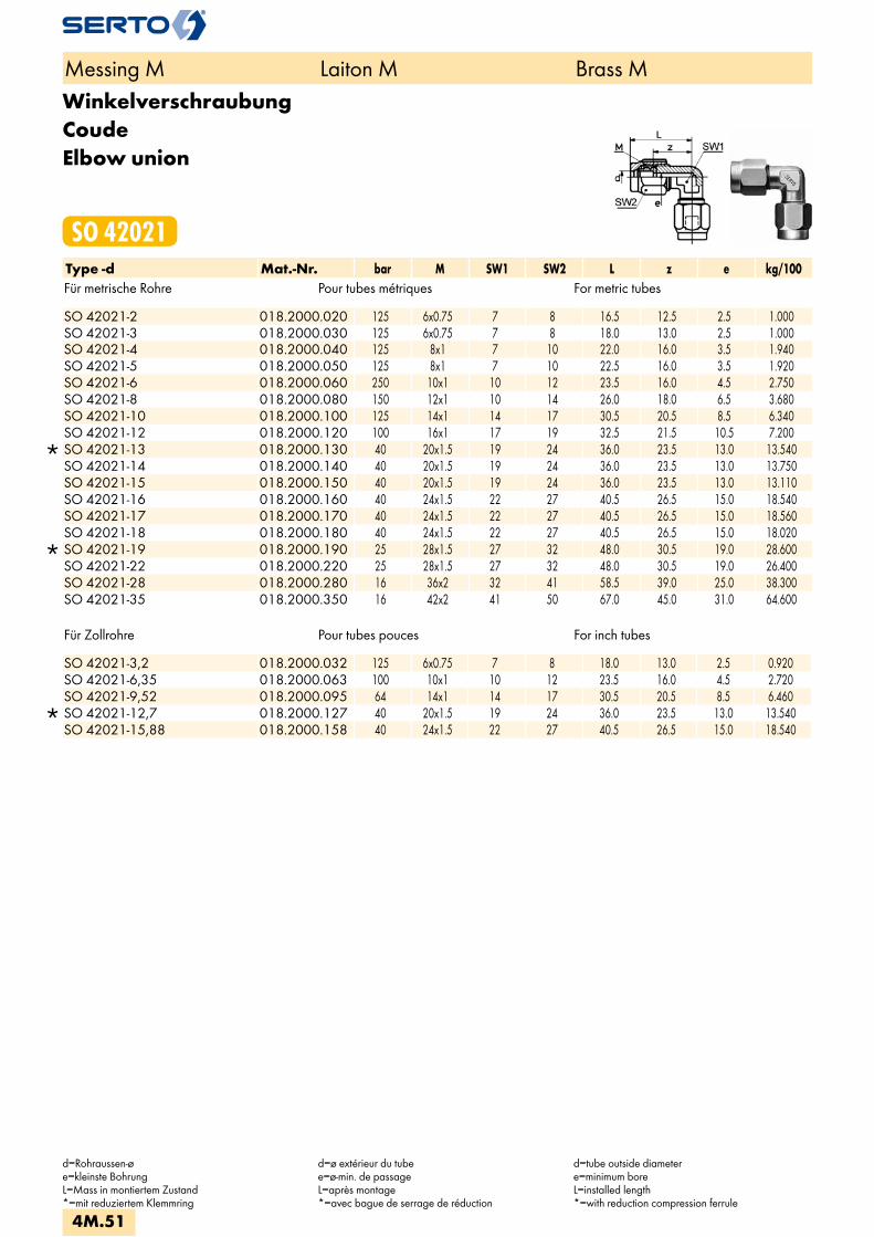
WinkelverschraubungCoudeElbow union
SO 42021Type -d Mat.-Nr. bar M SW1 SW2 L z e kg/100Für metrische Rohre Pour tubes métriques For metric tubes
SO 42021-2 018.2000.020 125 6x0.75 7 8 16.5 12.5 2.5 1.000 SO 42021-3 018.2000.030 125 6x0.75 7 8 18.0 13.0 2.5 1.000 SO 42021-4 018.2000.040 125 8x1 7 10 22.0 16.0 3.5 1.940 SO 42021-5 018.2000.050 125 8x1 7 10 22.5 16.0 3.5 1.920 SO 42021-6 018.2000.060 250 10x1 10 12 23.5 16.0 4.5 2.750 SO 42021-8 018.2000.080 150 12x1 10 14 26.0 18.0 6.5 3.680 SO 42021-10 018.2000.100 125 14x1 14 17 30.5 20.5 8.5 6.340 SO 42021-12 018.2000.120 100 16x1 17 19 32.5 21.5 10.5 7.200
SO 42021-13 018.2000.130 40 20x1.5 19 24 36.0 23.5 13.0 13.540 SO 42021-14 018.2000.140 40 20x1.5 19 24 36.0 23.5 13.0 13.750 SO 42021-15 018.2000.150 40 20x1.5 19 24 36.0 23.5 13.0 13.110 SO 42021-16 018.2000.160 40 24x1.5 22 27 40.5 26.5 15.0 18.540 SO 42021-17 018.2000.170 40 24x1.5 22 27 40.5 26.5 15.0 18.560 SO 42021-18 018.2000.180 40 24x1.5 22 27 40.5 26.5 15.0 18.020
SO 42021-19 018.2000.190 25 28x1.5 27 32 48.0 30.5 19.0 28.600 SO 42021-22 018.2000.220 25 28x1.5 27 32 48.0 30.5 19.0 26.400 SO 42021-28 018.2000.280 16 36x2 32 41 58.5 39.0 25.0 38.300 SO 42021-35 018.2000.350 16 42x2 41 50 67.0 45.0 31.0 64.600
Für Zollrohre Pour tubes pouces For inch tubes
SO 42021-3,2 018.2000.032 125 6x0.75 7 8 18.0 13.0 2.5 0.920 SO 42021-6,35 018.2000.063 100 10x1 10 12 23.5 16.0 4.5 2.720 SO 42021-9,52 018.2000.095 64 14x1 14 17 30.5 20.5 8.5 6.460
SO 42021-12,7 018.2000.127 40 20x1.5 19 24 36.0 23.5 13.0 13.540 SO 42021-15,88 018.2000.158 40 24x1.5 22 27 40.5 26.5 15.0 18.540
Messing M Laiton M Brass M
d=Rohraussen-øe=kleinste BohrungL=Mass in montiertem Zustand*=mit reduziertem Klemmring
d=ø extérieur du tubee=ø-min. de passageL=après montage*=avec bague de serrage de réduction
d=tube outside diametere=minimum boreL=installed length*=with reduction compression ferrule
4M.51

Winkelverschraubung reduziertCoude réduitElbow union reduction
SO 42021 REDType -d -d2 Mat.-Nr. bar M SW1 SW2 L z e kg/100Für metrische Rohre Pour tubes métriques For metric tubes
SO 42021-5-3 018.2004.060 125 8x1 7 10 22.5 16.0 3.5 2.000 SO 42021-6-4 018.2004.110 100 10x1 10 12 23.5 16.0 4.5 2.860 SO 42021-6-5 018.2004.117 100 10x1 10 12 23.5 16.0 4.5 2.810 SO 42021-8-6 018.2004.140 250 12x1 10 14 26.0 18.0 6.5 3.740 SO 42021-10-8 018.2004.190 150 14x1 14 17 30.5 20.5 8.5 6.540 SO 42021-12-10 018.2004.240 100 16x1 17 19 32.5 21.5 10.5 9.000 SO 42021-14-12 018.2004.340 40 20x1.5 19 24 36.0 23.5 13.0 14.130 SO 42021-15-12 018.2004.420 40 20x1.5 19 24 36.0 23.5 13.0 13.650 SO 42021-15-13 018.2004.430 40 20x1.5 19 24 36.0 23.5 13.0 13.540 SO 42021-17-14 018.2004.530 40 24x1.5 22 27 40.5 26.5 15.0 19.270 SO 42021-18-15 018.2004.610 40 24x1.5 22 27 40.5 26.5 15.0 18.720 SO 42021-18-16 018.2004.620 40 24x1.5 22 27 40.5 26.5 15.0 18.530
SO 42021-22-17 018.2004.750 25 28x1.5 27 32 48.0 30.5 19.0 28.060 SO 42021-22-18 018.2004.755 25 28x1.5 27 32 48.0 30.5 19.0 27.880 SO 42021-22-19 018.2004.760 25 28x1.5 27 32 48.0 30.5 19.0 27.620
Für Zollrohre Pour tubes pouces For inch tubes
SO 42021-6-6,35 018.2004.119 100 10x1 10 12 23.5 16.0 4.5 2.740 SO 42021-10-9,52 018.2004.197 64 14x1 14 17 30.5 20.5 8.5 6.450
SO 42021-15-12,7 018.2004.427 40 20x1.5 19 24 36.0 23.5 13.0 13.540
Weitere Reduktionen siehe SO 41821. Autres réductions voir SO 41821 Alternative reductions see SO 41821.
Messing M Laiton M Brass M
d/d2=Rohraussen-øe=kleinste BohrungL=Mass in montiertem Zustand*=mit reduziertem Klemmring
d/d2=ø extérieur du tubee=ø-min. de passageL=après montage*=avec bague de serrage de réduction
d/d2=tube outside diametere=minimum boreL=installed length*=with reduction compression ferrule
4M.52
i
s
3F
4M
4G
5
5L
6
7
8
9
10
11
12

Winkelverschraubungmit Übergangsnippel
Coudeavec adaptateur mâle
Elbow unionwith male adaptor
SO 42121Type -d -R Mat.-Nr. bar M SW1 SW2 L b zR z e kg/100Für metrische Rohre Pour tubes métriques For metric tubesR=Rohrgewinde (kegelig) R=Filetage-gaz BSP (conique) R=BSP thread (tapered)
SO 42121-4-3/8 018.2101.068 125 10x1 12 17 23.5 29.0 19.0 16.0 4.5 5.040 SO 42121-5-3/8 018.2101.086 125 10x1 12 17 23.5 29.0 19.0 16.0 4.5 3.990 SO 42121-6-3/8 018.2101.120 250 10x1 12 17 23.5 29.0 19.0 16.0 4.5 4.930
SO 42121-10-1/2 018.2101.285 100 16x1 19 22 32.5 37.5 24.5 21.5 10.5 10.700 SO 42121-13-3/4 018.2101.456 40 20x1.5 24 27 36.0 41.0 26.5 23.5 13.0 17.550 SO 42121-14-3/4 018.2101.506 40 20x1.5 24 27 36.0 41.0 26.5 23.5 13.0 17.440 SO 42121-28-1 018.2101.850 16 36x2 41 41 58.5 65.0 48.0 39.0 25.0 36.430 SO 42121-35-1 1/4 018.2101.944 16 42x2 50 50 67.0 73.0 54.0 45.0 31.0 62.000
Für Zollrohre Pour tubes pouces For inch tubes
SO 42121-6,35-3/8 018.2101.145 100 10x1 12 17 23.5 29.0 19.0 16.0 4.5 4.920 SO 42121-12,7-3/4 018.2101.436 40 20x1.5 24 27 36.0 41.0 26.5 23.5 13.0 17.550
Winkelverschraubungmit Übergangsnippel NPT
Coudeavec adaptateur mâle NPT
Elbow unionwith male adaptor NPT
SO 42121 NPTType -d -RNPT Mat.-Nr. bar M SW1 SW2 L b zR z e kg/100Für metrische Rohre Pour tubes métriques For metric tubesRNPT=NPT Gewinde RNPT=Filetage NPT RNPT=NPT thread
SO 42121-4-1/4 NPT 018.2102.065 125 10x1 12 14 23.5 32.0 22.0 16.0 4.5 4.040 SO 42121-5-1/4 NPT 018.2102.084 125 10x1 12 14 23.5 32.0 22.0 16.0 4.5 3.990 SO 42121-8-1/8 NPT 018.2102.160 150 12x1 14 14 26.0 30.5 24.0 18.0 6.5 3.550
Für Zollrohre Pour tubes pouces For inch tubes
SO 42121-6,35-1/4 NPT 018.2102.140 100 10x1 12 14 23.5 32.0 22.0 16.0 4.5 3.920
Messing M Laiton M Brass M
d=Rohraussen-øe=kleinste BohrungL=Mass in montiertem Zustand*=mit reduziertem Klemmring
d=ø extérieur du tubee=ø-min. de passageL=après montage*=avec bague de serrage de réduction
d=tube outside diametere=minimum boreL=installed length*=with reduction compression ferrule
4M.53
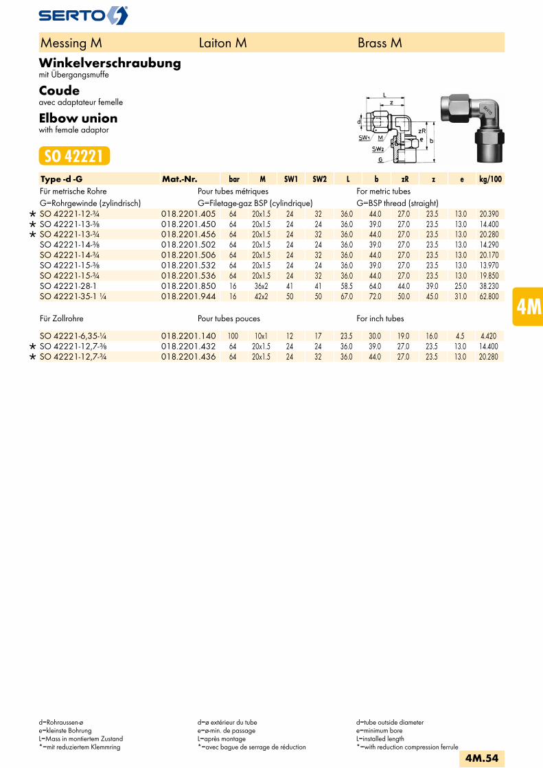
Winkelverschraubungmit Übergangsmuffe
Coudeavec adaptateur femelle
Elbow unionwith female adaptor
SO 42221Type -d -G Mat.-Nr. bar M SW1 SW2 L b zR z e kg/100Für metrische Rohre Pour tubes métriques For metric tubesG=Rohrgewinde (zylindrisch) G=Filetage-gaz BSP (cylindrique) G=BSP thread (straight)
SO 42221-12-3/4 018.2201.405 64 20x1.5 24 32 36.0 44.0 27.0 23.5 13.0 20.390 SO 42221-13-3/8 018.2201.450 64 20x1.5 24 24 36.0 39.0 27.0 23.5 13.0 14.400 SO 42221-13-3/4 018.2201.456 64 20x1.5 24 32 36.0 44.0 27.0 23.5 13.0 20.280 SO 42221-14-3/8 018.2201.502 64 20x1.5 24 24 36.0 39.0 27.0 23.5 13.0 14.290 SO 42221-14-3/4 018.2201.506 64 20x1.5 24 32 36.0 44.0 27.0 23.5 13.0 20.170 SO 42221-15-3/8 018.2201.532 64 20x1.5 24 24 36.0 39.0 27.0 23.5 13.0 13.970 SO 42221-15-3/4 018.2201.536 64 20x1.5 24 32 36.0 44.0 27.0 23.5 13.0 19.850 SO 42221-28-1 018.2201.850 16 36x2 41 41 58.5 64.0 44.0 39.0 25.0 38.230 SO 42221-35-1 1/4 018.2201.944 16 42x2 50 50 67.0 72.0 50.0 45.0 31.0 62.800
Für Zollrohre Pour tubes pouces For inch tubes
SO 42221-6,35-1/4 018.2201.140 100 10x1 12 17 23.5 30.0 19.0 16.0 4.5 4.420 SO 42221-12,7-3/8 018.2201.432 64 20x1.5 24 24 36.0 39.0 27.0 23.5 13.0 14.400 SO 42221-12,7-3/4 018.2201.436 64 20x1.5 24 32 36.0 44.0 27.0 23.5 13.0 20.280
Messing M Laiton M Brass M
d=Rohraussen-øe=kleinste BohrungL=Mass in montiertem Zustand*=mit reduziertem Klemmring
d=ø extérieur du tubee=ø-min. de passageL=après montage*=avec bague de serrage de réduction
d=tube outside diametere=minimum boreL=installed length*=with reduction compression ferrule
4M.54
i
s
3F
4M
4G
5
5L
6
7
8
9
10
11
12
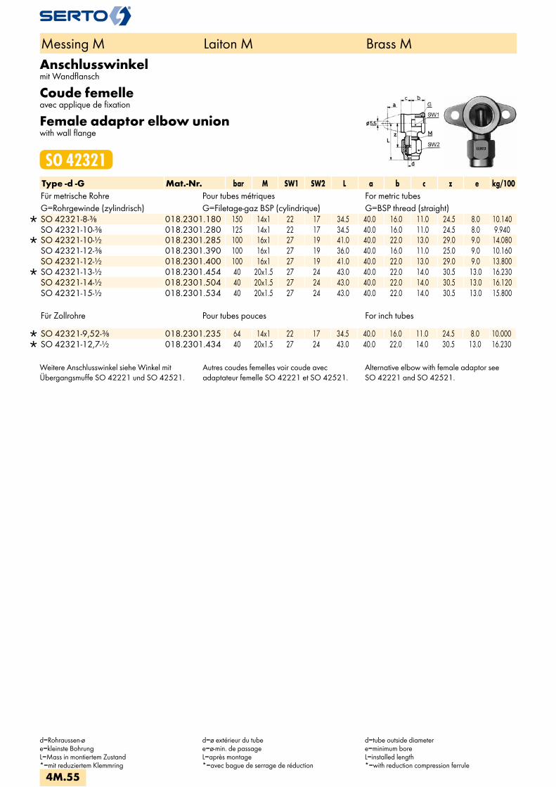
Anschlusswinkelmit Wandflansch
Coude femelleavec applique de fixation
Female adaptor elbow unionwith wall flange
SO 42321Type -d -G Mat.-Nr. bar M SW1 SW2 L a b c z e kg/100Für metrische Rohre Pour tubes métriques For metric tubesG=Rohrgewinde (zylindrisch) G=Filetage-gaz BSP (cylindrique) G=BSP thread (straight)
SO 42321-8-3/8 018.2301.180 150 14x1 22 17 34.5 40.0 16.0 11.0 24.5 8.0 10.140 SO 42321-10-3/8 018.2301.280 125 14x1 22 17 34.5 40.0 16.0 11.0 24.5 8.0 9.940
SO 42321-10-1/2 018.2301.285 100 16x1 27 19 41.0 40.0 22.0 13.0 29.0 9.0 14.080 SO 42321-12-3/8 018.2301.390 100 16x1 27 19 36.0 40.0 16.0 11.0 25.0 9.0 10.160 SO 42321-12-1/2 018.2301.400 100 16x1 27 19 41.0 40.0 22.0 13.0 29.0 9.0 13.800
SO 42321-13-1/2 018.2301.454 40 20x1.5 27 24 43.0 40.0 22.0 14.0 30.5 13.0 16.230 SO 42321-14-1/2 018.2301.504 40 20x1.5 27 24 43.0 40.0 22.0 14.0 30.5 13.0 16.120 SO 42321-15-1/2 018.2301.534 40 20x1.5 27 24 43.0 40.0 22.0 14.0 30.5 13.0 15.800
Für Zollrohre Pour tubes pouces For inch tubes
SO 42321-9,52-3/8 018.2301.235 64 14x1 22 17 34.5 40.0 16.0 11.0 24.5 8.0 10.000 SO 42321-12,7-1/2 018.2301.434 40 20x1.5 27 24 43.0 40.0 22.0 14.0 30.5 13.0 16.230
Weitere Anschlusswinkel siehe Winkel mit Übergangsmuffe SO 42221 und SO 42521.
Autres coudes femelles voir coude avecadaptateur femelle SO 42221 et SO 42521.
Alternative elbow with female adaptor seeSO 42221 and SO 42521.
Messing M Laiton M Brass M
d=Rohraussen-øe=kleinste BohrungL=Mass in montiertem Zustand*=mit reduziertem Klemmring
d=ø extérieur du tubee=ø-min. de passageL=après montage*=avec bague de serrage de réduction
d=tube outside diametere=minimum boreL=installed length*=with reduction compression ferrule
4M.55

Winkel-EinschraubverschraubungCoude mâleMale adaptor elbow union
SO 42421Type -d -R Mat.-Nr. bar M SW1 SW2 L b zR z e kg/100Für metrische Rohre Pour tubes métriques For metric tubesR=Rohrgewinde (kegelig) R=Filetage-gaz BSP (conique) R=BSP thread (tapered)
SO 42421-3-1/8 018.2401.040 125 8x1 7 10 22.5 17.0 11.0 16.0 3.5 1.600 SO 42421-4-1/8 018.2401.060 125 8x1 7 10 22.0 17.0 11.0 16.0 3.5 1.560
SO 42421-4-1/4 018.2401.065 100 10x1 10 12 25.5 22.5 13.0 18.0 4.5 3.000 SO 42421-5-1/8 018.2401.082 125 8x1 7 10 22.5 17.0 11.0 16.0 3.5 1.540
SO 42421-5-1/4 018.2401.084 100 10x1 10 12 25.5 22.5 13.0 18.0 4.5 2.940 SO 42421-6-1/8 018.2401.100 250 10x1 10 12 23.5 17.5 12.0 16.0 4.5 2.150 SO 42421-6-1/4 018.2401.110 250 10x1 10 12 25.5 22.5 13.0 18.0 4.5 2.880 SO 42421-8-1/8 018.2401.160 150 12x1 10 14 26.0 18.0 11.5 18.0 6.0 2.540 SO 42421-8-1/4 018.2401.170 150 12x1 10 14 26.0 22.5 13.0 18.0 6.5 3.090
SO 42421-8-3/8 018.2401.180 150 14x1 14 17 30.5 25.0 15.0 20.5 8.5 5.310 SO 42421-10-1/4 018.2401.270 125 14x1 14 17 30.5 25.0 15.5 20.5 8.5 4.640 SO 42421-10-3/8 018.2401.280 125 14x1 14 17 30.5 25.0 15.0 20.5 8.5 5.110
SO 42421-10-1/2 018.2401.285 100 16x1 19 19 34.0 29.5 16.5 23.0 10.5 9.020 SO 42421-12-1/4 018.2401.380 100 16x1 17 19 32.5 26.0 16.5 21.5 8.5 8.480 SO 42421-12-3/8 018.2401.390 100 16x1 17 19 32.5 26.0 16.0 21.5 10.5 6.120 SO 42421-12-1/2 018.2401.400 100 16x1 19 19 34.0 29.5 16.5 23.0 10.5 8.710
SO 42421-13-1/2 018.2401.454 40 20x1.5 19 24 36.0 29.5 16.5 23.5 13.0 10.380 SO 42421-14-3/8 018.2401.502 40 20x1.5 19 24 36.0 28.0 16.0 23.5 10.5 7.570 SO 42421-14-1/2 018.2401.504 40 20x1.5 19 24 36.0 29.5 16.5 23.5 13.0 10.270
SO 42421-14-3/4 018.2401.506 64 24x1.5 22 27 41.0 35.0 21.0 26.5 15.0 16.100 SO 42421-15-3/8 018.2401.532 40 20x1.5 19 24 36.0 28.0 16.0 23.5 10.5 7.350 SO 42421-15-1/2 018.2401.534 40 20x1.5 22 24 36.0 29.5 16.5 23.5 13.0 9.950
SO 42421-15-3/4 018.2401.536 40 24x1.5 22 27 40.5 35.0 21.0 26.5 15.0 15.900 SO 42421-16-1/2 018.2401.566 40 24x1.5 22 27 40.5 31.5 18.5 26.5 15.0 13.040 SO 42421-16-3/4 018.2401.568 40 24x1.5 22 27 40.5 35.0 21.0 26.5 15.0 15.670 SO 42421-17-1/2 018.2401.596 40 24x1.5 22 27 40.5 31.5 18.5 26.5 15.0 12.790 SO 42421-17-3/4 018.2401.598 40 24x1.5 22 27 40.5 35.0 21.0 26.5 15.0 15.420 SO 42421-18-1/2 018.2401.646 40 24x1.5 22 27 40.5 31.5 18.5 26.5 15.0 12.520 SO 42421-18-3/4 018.2401.648 40 24x1.5 22 27 40.5 35.0 21.0 26.5 15.0 15.150
SO 42421-19-3/4 018.2401.678 25 28x1.5 27 32 48.0 35.5 21.0 30.5 19.0 19.600 SO 42421-22-3/4 018.2401.768 25 28x1.5 27 32 48.0 35.5 21.0 30.5 19.0 18.500
Für Zollrohre Pour tubes pouces For inch tubes
SO 42421-3,2-1/8 018.2401.042 125 8x1 7 10 22.0 17.0 11.0 16.0 3.5 1.600 SO 42421-6,35-1/8 018.2401.135 100 10x1 10 12 23.5 17.5 12.0 16.0 4.5 2.140 SO 42421-6,35-1/4 018.2401.140 100 10x1 10 12 25.5 22.5 13.0 18.0 4.5 2.870 SO 42421-9,52-1/4 018.2401.230 64 14x1 14 17 30.5 25.0 15.5 20.5 8.5 4.700 SO 42421-9,52-3/8 018.2401.235 64 14x1 14 17 30.5 25.0 15.0 20.5 8.5 5.170
SO 42421-12,7-1/2 018.2401.434 40 20x1.5 19 24 36.0 29.5 16.5 23.5 13.0 10.380 SO 42421-15,88-1/2 018.2401.541 40 24x1.5 22 27 40.5 31.5 18.5 26.5 15.0 13.040
Weitere Einschraubwinkel siehe Winkel mit Übergangsnippel SO 42121.
Autres coudes mâles femelles voir coude avec adaptateur mâle SO 42121.
Alternative elbow union with male adaptor see SO 42121.
Messing M Laiton M Brass M
d=Rohraussen-øe=kleinste BohrungL=Mass in montiertem Zustand*=mit reduziertem Klemmring
d=ø extérieur du tubee=ø-min. de passageL=après montage*=avec bague de serrage de réduction
d=tube outside diametere=minimum boreL=installed length*=with reduction compression ferrule
4M.56
i
s
3F
4M
4G
5
5L
6
7
8
9
10
11
12
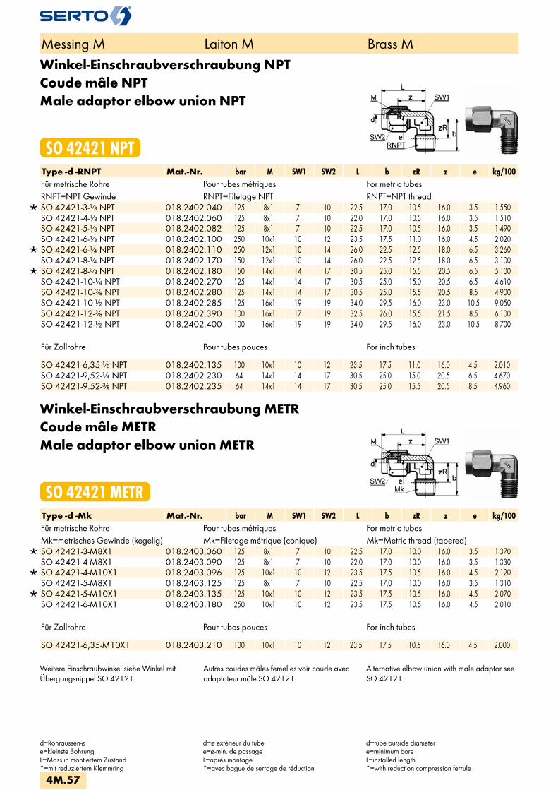
Winkel-Einschraubverschraubung NPTCoude mâle NPTMale adaptor elbow union NPT
SO 42421 NPTType -d -RNPT Mat.-Nr. bar M SW1 SW2 L b zR z e kg/100Für metrische Rohre Pour tubes métriques For metric tubesRNPT=NPT Gewinde RNPT=Filetage NPT RNPT=NPT thread
SO 42421-3-1/8 NPT 018.2402.040 125 8x1 7 10 22.5 17.0 10.5 16.0 3.5 1.550 SO 42421-4-1/8 NPT 018.2402.060 125 8x1 7 10 22.0 17.0 10.5 16.0 3.5 1.510 SO 42421-5-1/8 NPT 018.2402.082 125 8x1 7 10 22.5 17.0 10.5 16.0 3.5 1.490 SO 42421-6-1/8 NPT 018.2402.100 250 10x1 10 12 23.5 17.5 11.0 16.0 4.5 2.020
SO 42421-6-1/4 NPT 018.2402.110 250 12x1 10 14 26.0 22.5 12.5 18.0 6.5 3.260 SO 42421-8-1/4 NPT 018.2402.170 150 12x1 10 14 26.0 22.5 12.5 18.0 6.5 3.100
SO 42421-8-3/8 NPT 018.2402.180 150 14x1 14 17 30.5 25.0 15.5 20.5 6.5 5.100 SO 42421-10-1/4 NPT 018.2402.270 125 14x1 14 17 30.5 25.0 15.0 20.5 6.5 4.610 SO 42421-10-3/8 NPT 018.2402.280 125 14x1 14 17 30.5 25.0 15.5 20.5 8.5 4.900 SO 42421-10-1/2 NPT 018.2402.285 125 16x1 19 19 34.0 29.5 16.0 23.0 10.5 9.050 SO 42421-12-3/8 NPT 018.2402.390 100 16x1 17 19 32.5 26.0 15.5 21.5 8.5 6.100 SO 42421-12-1/2 NPT 018.2402.400 100 16x1 19 19 34.0 29.5 16.0 23.0 10.5 8.700
Für Zollrohre Pour tubes pouces For inch tubes
SO 42421-6,35-1/8 NPT 018.2402.135 100 10x1 10 12 23.5 17.5 11.0 16.0 4.5 2.010 SO 42421-9,52-1/4 NPT 018.2402.230 64 14x1 14 17 30.5 25.0 15.0 20.5 6.5 4.670 SO 42421-9.52-3/8 NPT 018.2402.235 64 14x1 14 17 30.5 25.0 15.5 20.5 8.5 4.960
Winkel-Einschraubverschraubung METRCoude mâle METRMale adaptor elbow union METR
SO 42421 METRType -d -Mk Mat.-Nr. bar M SW1 SW2 L b zR z e kg/100Für metrische Rohre Pour tubes métriques For metric tubesMk=metrisches Gewinde (kegelig) Mk=Filetage métrique (conique) Mk=Metric thread (tapered)
SO 42421-3-M8X1 018.2403.060 125 8x1 7 10 22.5 17.0 10.0 16.0 3.5 1.370 SO 42421-4-M8X1 018.2403.090 125 8x1 7 10 22.0 17.0 10.0 16.0 3.5 1.330
SO 42421-4-M10X1 018.2403.096 125 10x1 10 12 23.5 17.5 10.5 16.0 4.5 2.120 SO 42421-5-M8X1 018.2403.125 125 8x1 7 10 22.5 17.0 10.0 16.0 3.5 1.310
SO 42421-5-M10X1 018.2403.135 125 10x1 10 12 23.5 17.5 10.5 16.0 4.5 2.070 SO 42421-6-M10X1 018.2403.180 250 10x1 10 12 23.5 17.5 10.5 16.0 4.5 2.010
Für Zollrohre Pour tubes pouces For inch tubes
SO 42421-6,35-M10X1 018.2403.210 100 10x1 10 12 23.5 17.5 10.5 16.0 4.5 2.000
Weitere Einschraubwinkel siehe Winkel mit Übergangsnippel SO 42121.
Autres coudes mâles femelles voir coude avec adaptateur mâle SO 42121.
Alternative elbow union with male adaptor see SO 42121.
Messing M Laiton M Brass M
d=Rohraussen-øe=kleinste BohrungL=Mass in montiertem Zustand*=mit reduziertem Klemmring
d=ø extérieur du tubee=ø-min. de passageL=après montage*=avec bague de serrage de réduction
d=tube outside diametere=minimum boreL=installed length*=with reduction compression ferrule
4M.57

Winkel-Einschraubverschraubung METRCoude mâle METRMale adaptor elbow union METR
SO 42424 METRType -d -Mz Mat.-Nr. bar M SW1 SW2 L b zR z e kg/100Für metrische Rohre Pour tubes métriques For metric tubesMz=metrisches Gewinde (zylindrisch) Mz=Filetage métrique (cylindrique) Mz=Metric thread (straight)
SO 42424-2-M5 018.2443.020 125 6x0.75 7 8 16.5 12.0 8.5 12.5 2.2 0.770 SO 42424-3-M5 018.2443.050 125 6x0.75 7 8 18.0 12.0 8.5 13.0 2.2 0.810
SO 42424-3-M6X0,75 018.2443.055 125 8x1 7 10 22.5 14.0 9.0 16.0 2.5 1.260 SO 42424-4-M5 018.2443.080 125 8x1 7 10 22.0 12.5 9.0 16.0 2.2 1.170 SO 42424-4-M6X0,75 018.2443.085 125 8x1 7 10 22.0 14.0 9.0 16.0 2.5 1.220 SO 42424-5-M5 018.2443.110 125 8x1 7 10 22.5 12.5 9.0 16.0 2.2 1.150 SO 42424-5-M6X0,75 018.2443.115 125 8x1 7 10 22.5 14.0 9.0 16.0 2.5 1.200
Die entsprechende Dichtung SO 40007/SO 40507 ist separat zu bestellen.Weitere Einschraubwinkel siehe Winkel mit Übergangsnippel SO 42121.
Le joint correspondant SO 40007/SO 40507 doit être commandé séparément.Autres coudes mâles voir coude avec adaptateur mâle SO 42121.
The appropriate washer SO 40007/SO 40507 is to be ordered separately.Alternative elbow union with male adaptor SO 42121.
Messing M Laiton M Brass M
d=Rohraussen-øe=kleinste BohrungL=Mass in montiertem Zustand*=mit reduziertem Klemmring
d=ø extérieur du tubee=ø-min. de passageL=après montage*=avec bague de serrage de réduction
d=tube outside diametere=minimum boreL=installed length*=with reduction compression ferrule
4M.58
i
s
3F
4M
4G
5
5L
6
7
8
9
10
11
12

Winkel-AufschraubverschraubungCoude femelleFemale adaptor elbow union
SO 42521Type -d -G Mat.-Nr. bar M SW2 SW1 L b z e kg/100Für metrische Rohre Pour tubes métriques For metric tubesG=Rohrgewinde (zylindrisch) G=Filetage-gaz BSP (cylindrique) G=BSP thread (straight)
SO 42521-3-1/8 018.2501.040 125 8x1 10 14 26.5 11.5 20.0 3.5 2.250 SO 42521-4-1/8 018.2501.060 125 8x1 10 14 26.0 11.5 20.0 3.5 2.220 SO 42521-5-1/8 018.2501.082 125 8x1 10 14 26.5 11.5 20.0 3.5 2.190 SO 42521-6-1/8 018.2501.100 250 10x1 12 14 27.5 11.5 20.0 4.0 2.600
SO 42521-6-1/4 018.2501.110 250 12x1 14 19 31.5 13.5 23.5 6.0 4.460 SO 42521-8-1/4 018.2501.170 150 12x1 14 19 31.5 13.5 23.5 6.0 4.300
SO 42521-8-3/8 018.2501.180 150 14x1 17 22 34.5 16.0 24.5 8.0 6.590 SO 42521-10-3/8 018.2501.280 125 14x1 17 22 34.5 16.0 24.5 8.0 6.390 SO 42521-12-3/8 018.2501.390 100 16x1 19 22 35.5 16.0 24.5 9.0 6.860
SO 42521-12-1/2 018.2501.400 40 20x1.5 24 27 42.0 22.0 29.5 13.0 12.950 SO 42521-13-1/2 018.2501.454 40 20x1.5 24 27 42.0 22.0 29.5 13.0 12.840 SO 42521-14-1/2 018.2501.504 40 20x1.5 24 27 42.0 22.0 29.5 13.0 12.730 SO 42521-15-1/2 018.2501.534 40 20x1.5 24 27 42.0 22.0 29.5 13.0 12.410
SO 42521-15-3/4 018.2501.536 40 24x1.5 27 32 47.0 24.0 33.0 15.0 19.160 SO 42521-16-1/2 018.2501.566 40 24x1.5 27 27 45.0 22.0 31.0 15.0 16.350 SO 42521-16-3/4 018.2501.568 40 24x1.5 27 32 47.0 24.0 33.0 15.0 18.930 SO 42521-17-1/2 018.2501.596 40 24x1.5 27 27 45.0 22.0 31.0 15.0 16.100 SO 42521-17-3/4 018.2501.598 40 24x1.5 27 32 47.0 24.0 33.0 15.0 18.680 SO 42521-18-1/2 018.2501.646 40 24x1.5 27 27 45.0 22.0 31.0 15.0 15.830 SO 42521-18-3/4 018.2501.648 40 24x1.5 27 32 47.0 24.0 33.0 15.0 18.410
SO 42521-19-3/4 018.2501.678 25 28x1.5 32 32 52.5 24.0 33.0 19.0 22.360 SO 42521-22-3/4 018.2501.768 25 28x1.5 32 32 52.5 24.0 33.0 19.0 20.960
Für Zollrohre Pour tubes pouces For inch tubes
SO 42521-6,35-1/8 018.2501.135 100 10x1 12 14 27.5 11.5 20.0 4.0 2.590 SO 42521-9,52-3/8 018.2501.235 64 14x1 17 22 34.5 16.0 24.5 8.0 6.450
SO 42521-12,7-1/2 018.2501.434 40 20x1.5 24 27 42.0 22.0 29.5 13.0 12.840
Weitere Anschlusswinkel siehe Winkel mitÜbergangsmuffe SO 42221 und SO 42321
Autres coudes femelles voir coude avecadaptateur femelle SO 42221 et SO 42321
Alternative elbow union with femaleadaptor see SO 42221 and SO 42321
Messing M Laiton M Brass M
d=Rohraussen-øe=kleinste BohrungL=Mass in montiertem Zustand*=mit reduziertem Klemmring
d=ø extérieur du tubee=ø-min. de passageL=après montage*=avec bague de serrage de réduction
d=tube outside diametere=minimum boreL=installed length*=with reduction compression ferrule
4M.59
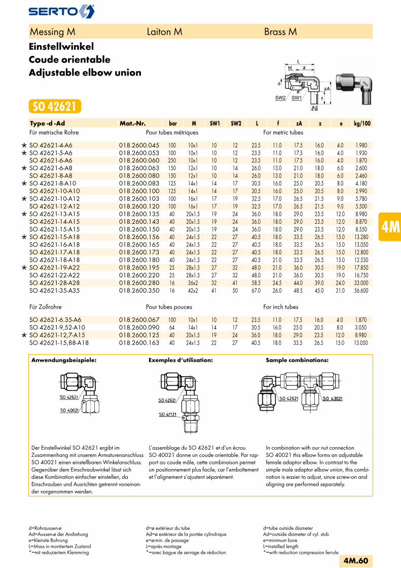
EinstellwinkelCoude orientableAdjustable elbow union
SO 42621Type -d -Ad Mat.-Nr. bar M SW1 SW2 L f zA z e kg/100Für metrische Rohre Pour tubes métriques For metric tubes
SO 42621-4-A6 018.2600.045 100 10x1 10 12 23.5 11.0 17.5 16.0 4.0 1.980 SO 42621-5-A6 018.2600.053 100 10x1 10 12 23.5 11.0 17.5 16.0 4.0 1.930 SO 42621-6-A6 018.2600.060 250 10x1 10 12 23.5 11.0 17.5 16.0 4.0 1.870
SO 42621-6-A8 018.2600.063 150 12x1 10 14 26.0 13.0 21.0 18.0 6.0 2.600 SO 42621-8-A8 018.2600.080 150 12x1 10 14 26.0 13.0 21.0 18.0 6.0 2.460
SO 42621-8-A10 018.2600.083 125 14x1 14 17 30.5 16.0 25.0 20.5 8.0 4.180 SO 42621-10-A10 018.2600.100 125 14x1 14 17 30.5 16.0 25.0 20.5 8.0 3.990
SO 42621-10-A12 018.2600.103 100 16x1 17 19 32.5 17.0 26.5 21.5 9.0 5.780 SO 42621-12-A12 018.2600.120 100 16x1 17 19 32.5 17.0 26.5 21.5 9.0 5.500
SO 42621-13-A15 018.2600.135 40 20x1.5 19 24 36.0 18.0 29.0 23.5 12.0 8.980 SO 42621-14-A15 018.2600.143 40 20x1.5 19 24 36.0 18.0 29.0 23.5 12.0 8.870 SO 42621-15-A15 018.2600.150 40 20x1.5 19 24 36.0 18.0 29.0 23.5 12.0 8.550
SO 42621-15-A18 018.2600.156 40 24x1.5 22 27 40.5 18.0 33.5 26.5 15.0 13.280 SO 42621-16-A18 018.2600.165 40 24x1.5 22 27 40.5 18.0 33.5 26.5 15.0 13.050 SO 42621-17-A18 018.2600.173 40 24x1.5 22 27 40.5 18.0 33.5 26.5 15.0 12.800 SO 42621-18-A18 018.2600.180 40 24x1.5 22 27 40.5 21.0 33.5 26.5 15.0 12.530
SO 42621-19-A22 018.2600.195 25 28x1.5 27 32 48.0 21.0 36.0 30.5 19.0 17.850 SO 42621-22-A22 018.2600.220 25 28x1.5 27 32 48.0 21.0 36.0 30.5 19.0 16.750 SO 42621-28-A28 018.2600.280 16 36x2 32 41 58.5 24.5 44.0 39.0 24.0 33.000 SO 42621-35-A35 018.2600.350 16 42x2 41 50 67.0 26.0 48.5 45.0 31.0 56.600
Für Zollrohre Pour tubes pouces For inch tubes
SO 42621-6.35-A6 018.2600.067 100 10x1 10 12 23.5 11.0 17.5 16.0 4.0 1.870 SO 42621-9,52-A10 018.2600.090 64 14x1 14 17 30.5 16.0 25.0 20.5 8.0 3.050
SO 42621-12,7-A15 018.2600.125 40 20x1.5 19 24 36.0 18.0 29.0 23.5 12.0 8.980 SO 42621-15,88-A18 018.2600.163 40 24x1.5 22 27 40.5 18.0 33.5 26.5 15.0 13.050
Anwendungsbeispiele: Exemples d‘utilisation: Sample combinations:
Der Einstellwinkel SO 42621 ergibt im Zusammenhang mit unserem Armaturenanschluss SO 40021 einen einstellbaren Winkelanschluss. Gegenüber dem Einschraubwinkel lässt sich diese Kombination einfacher einstellen, da Einschrauben und Ausrichten getrennt voneinan-der vorgenommen werden.
L’assemblage du SO 42621 et d’un écrou SO 40021 donne un coude orientable. Par rap-port au coude mâle, cette combinaison permet un positionnement plus facile, car l’emboîtement et l’alignement s’ajustent séparément.
In combination with our nut connection SO 40021 this elbow forms an adjustable female adaptor elbow. In contrast to the simple male adaptor elbow union, this combi-nation is easier to adjust, since screw-on and aligning are performed separately.
Messing M Laiton M Brass M
d=Rohraussen-øAd=Aussen-ø der Andrehunge=kleinste BohrungL=Mass in montiertem Zustand*=mit reduziertem Klemmring
d=ø extérieur du tubeAd=ø extérieur de la portée cylindriquee=ø-min. de passageL=après montage*=avec bague de serrage de réduction
d=tube outside diameterAd=outside diameter of cyl. stube=minimum boreL=installed length*=with reduction compression ferrule
4M.60
i
s
3F
4M
4G
5
5L
6
7
8
9
10
11
12

Winkelverschraubungmit Einstellzapfen vormontiert
Coude orientable montéAdjustable elbow assembly
SO 42625Type -d -Ad Mat.-Nr. bar M SW L l e kg/100Für metrische Rohre Pour tubes métriques For metric tubes
SO 42625-4-A6 018.2620.045 100 10x1 12 23.5 18.5 4.0 2.820 SO 42625-5-A6 018.2620.053 100 10x1 12 23.5 18.5 4.0 2.770 SO 42625-6-A6 018.2620.060 250 10x1 12 23.5 18.5 4.0 2.710
SO 42625-6-A8 018.2620.063 150 12x1 14 28.0 22.0 6.0 3.000 SO 42625-8-A8 018.2620.080 150 12x1 14 28.0 22.0 6.0 3.580
SO 42625-8-A10 018.2620.083 125 14x1 17 32.0 26.0 8.0 6.070 SO 42625-10-A10 018.2620.100 125 14x1 17 32.0 26.0 8.0 5.880
SO 42625-10-A12 018.2620.103 100 16x1 19 33.5 27.5 9.0 8.000 SO 42625-12-A12 018.2620.120 100 16x1 19 33.5 27.5 9.0 7.840
SO 42625-13-A15 018.2620.135 40 20x1.5 24 36.0 30.0 12.0 13.000 SO 42625-14-A15 018.2620.143 40 20x1.5 24 36.0 30.0 12.0 13.000 SO 42625-15-A15 018.2620.150 40 20x1.5 24 36.0 30.0 12.0 12.790
SO 42625-15-A18 018.2620.156 40 24x1.5 27 42.0 35.0 15.0 18.000 SO 42625-16-A18 018.2620.165 40 24x1.5 27 42.0 35.0 15.0 18.000 SO 42625-17-A18 018.2620.173 40 24x1.5 27 42.0 35.0 15.0 18.000
SO 42625-18-A18 018.2620.180 40 24x1.5 27 42.0 35.0 15.0 17.790 SO 42625-19-A22 018.2620.195 25 28x1.5 32 45.0 37.5 19.0 26.000 SO 42625-22-A22 018.2620.220 25 28x1.5 32 45.0 37.5 19.0 25.170 SO 42625-28-A28 018.2620.280 16 36x2 41 52.0 44.0 24.0 49.700 SO 42625-35-A35 018.2620.350 16 42x2 50 60.5 50.5 31.0 85.800
Für Zollrohre Pour tubes pouces For inch tubes SO 42625-6.35-A6 018.2620.067 100 10x1 12 23.5 18.0 4.0 2.000SO 42625-9,52-A10 018.2620.090 64 14x1 17 32.0 26.0 8.0 5.000SO 42625-12,7-A15 018.2620.125 40 20x1.5 24 36.0 30.0 12.0 7.000SO 42625-15,88-A18 018.2620.163 40 24x1.5 27 42.0 35.0 15.0 18.000
Messing M Laiton M Brass M
M=Anschlussgewindel=Einbaulängee=kleinste BohrungL=Mass in montiertem Zustand*=mit reduziertem Klemmring
M=filetagel=longueur encastréee=ø-min. de passageL=après montage*=avec bague de serrage de réduction
M=threadl=fitted lengthe=minimum boreL=installed length*=with reduction compression ferrule
4M.61

Winkel-SchottverschraubungDurchführungslänge max. 5 mm
Coude pour passage de cloisonpour cloison max. 5 mm
Panel mount elbow unionmax. panel thickness 5 mm
SO 42721Type -d Mat.-Nr. bar M SW1 SW2 SW3 L L1 w z1 z e kg/100Für metrische Rohre Pour tubes métriques For metric tubes
SO 42721-4 018.2700.040 100 10x1 10 12 14 25.5 40.5 14.0 19.0 18.0 4.5 4.270 SO 42721-5 018.2700.050 100 10x1 10 12 14 25.5 40.5 14.0 19.0 18.0 4.5 4.220 SO 42721-6 018.2700.060 250 10x1 10 12 14 25.5 40.5 14.0 19.0 18.0 4.5 4.160 SO 42721-8 018.2700.080 150 12x1 11 14 17 28.5 45.0 17.0 20.0 20.5 6.5 6.480 SO 42721-10 018.2700.100 125 14x1 17 17 19 33.5 49.0 18.0 21.0 23.5 8.5 9.560 SO 42721-12 018.2700.120 100 16x1 17 19 19 34.5 50.0 18.0 21.0 23.5 10.5 10.640
SO 42721-13 018.2700.130 40 20x1.5 19 24 27 38.0 57.0 20.0 24.5 25.5 13.0 18.730 SO 42721-14 018.2700.140 40 20x1.5 19 24 27 38.0 57.0 20.0 24.5 25.5 13.0 18.940 SO 42721-15 018.2700.150 40 20x1.5 19 24 27 38.0 57.0 20.0 24.5 25.5 13.0 18.300
Für Zollrohre Pour tubes pouces For inch tubes
SO 42721-6,35 018.2700.063 100 10x1 10 12 14 25.5 40.5 14.0 19.0 18.0 4.5 4.130 SO 42721-9,52 018.2700.095 64 14x1 17 17 19 33.5 49.0 18.0 21.0 23.5 8.5 9.680
SO 42721-12,7 018.2700.127 40 20x1.5 19 24 27 38.0 57.0 20.0 24.5 25.5 13.0 18.730
Messing M Laiton M Brass M
d=Rohraussen-øe=kleinste BohrungL=Mass in montiertem Zustand*=mit reduziertem Klemmring
d=ø extérieur du tubee=ø-min. de passageL=après montage*=avec bague de serrage de réduction
d=tube outside diametere=minimum boreL=installed length*=with reduction compression ferrule
4M.62
i
s
3F
4M
4G
5
5L
6
7
8
9
10
11
12

Winkel-Schottverschraubung reduziertDurchführungslänge max. 5 mm
Coude réduit pour passage de cloisonPour cloison max. 5 mm
Panel mount reduction elbow unionMax. panel thickness 5 mm
SO 42721 REDType -d -d2 Mat.-Nr. bar M SW1 SW2 SW3 L L1 w z1 z e kg/100Für metrische Rohre Pour tubes métriques For metric tubes
SO 42721-6-4 018.2704.110 100 10x1 10 12 14 25.5 40.5 14.0 19.0 18.0 4.5 4.250 SO 42721-6-5 018.2704.117 100 10x1 10 12 14 25.5 40.5 14.0 19.0 18.0 4.5 4.220 SO 42721-8-6 018.2704.140 250 12x1 11 14 17 28.5 45.0 17.0 20.0 20.5 6.5 6.640 SO 42721-10-8 018.2704.190 150 14x1 17 17 19 33.5 49.0 18.0 21.0 23.5 8.5 9.570 SO 42721-12-10 018.2704.240 100 16x1 17 19 19 34.5 50.0 18.0 21.0 23.5 10.5 10.920 SO 42721-15-12 018.2704.420 40 20x1.5 19 24 27 38.0 57.0 20.0 24.5 25.5 13.0 18.840 SO 42721-15-13 018.2704.430 40 20x1.5 19 24 27 38.0 57.0 20.0 24.5 25.5 13.0 18.730 SO 42721-15-14 018.2704.440 40 20x1.5 19 24 27 38.0 57.0 20.0 24.5 25.5 13.0 18.620
Für Zollrohre Pour tubes pouces For inch tubes
SO 42721-6-6,35 018.2704.119 100 10x1 10 12 14 25.5 40.5 14.0 19.0 18.0 4.5 4.150 SO 42721-10-9,52 018.2704.197 64 14x1 17 17 19 33.5 49.0 18.0 21.0 23.5 8.5 9.620
SO 42721-15-12,7 018.2704.427 40 20x1.5 19 24 27 38.0 57.0 20.0 24.5 25.5 13.0 18.730
Weitere Reduktionen siehe SO 41821Sechskantmutter siehe SO 40006
Autres réductions voir SO 41821Ecrou à six pans voir SO 40006
Alternative reductions see SO 41821Hexagon nut see SO 40006
Messing M Laiton M Brass M
d=Rohraussen-øe=kleinste BohrungL=Mass in montiertem Zustand*=mit reduziertem Klemmring
d=ø extérieur du tubee=ø-min. de passageL=après montage*=avec bague de serrage de réduction
d=tube outside diametere=minimum boreL=installed length*=with reduction compression ferrule
4M.63

SchwenkverschraubungCoude banjoSingle banjo
SO 42824Type -d -G Mat.-Nr. bar M SW1 SW2 L A b D zR z e kg/100Für metrische Rohre Pour tubes métriques For metric tubesG=Rohrgewinde (zylindrisch) G=Filetage-gaz BSP (cylindrique) G=BSP thread (straight)
SO 42824-3-1/8 018.2841.040 125 8x1 10 14 24.0 21.5 28.0 15.0 10.0 17.5 3.8 3.710 SO 42824-4-1/8 018.2841.060 125 8x1 10 14 23.5 21.5 28.0 15.0 10.0 17.5 3.8 3.670 SO 42824-5-1/8 018.2841.082 125 8x1 10 14 24.0 21.5 28.0 15.0 10.0 17.5 3.8 3.650 SO 42824-6-1/8 018.2841.100 250 10x1 12 14 25.0 21.5 28.0 15.0 10.0 17.5 3.8 4.050
SO 42824-6-1/4 018.2841.110 250 12x1 14 19 29.0 28.0 36.0 20.0 13.5 21.0 6.5 8.170 SO 42824-8-1/8 018.2841.160 150 12x1 14 14 25.5 21.5 28.0 15.0 10.0 17.5 3.8 4.420 SO 42824-8-1/4 018.2841.170 150 12x1 14 19 29.0 28.0 36.0 20.0 13.5 21.0 6.5 8.010 SO 42824-10-1/4 018.2841.270 125 14x1 17 19 31.0 28.0 36.0 20.0 13.5 21.0 6.5 8.590
SO 42824-10-3/8 018.2841.280 100 16x1 19 22 33.5 31.0 39.0 25.0 15.0 22.5 8.5 13.670 SO 42824-12-3/8 018.2841.390 100 16x1 19 22 33.5 31.0 39.0 25.0 15.0 22.5 8.5 13.390
SO 42824-12-1/2 018.2841.400 100 20x1.5 24 27 39.0 37.0 47.0 30.0 18.0 26.5 10.5 25.600 SO 42824-13-1/2 018.2841.454 40 20x1.5 24 27 39.0 37.0 47.0 30.0 18.0 26.5 10.5 25.490 SO 42824-14-1/2 018.2841.504 40 20x1.5 24 27 39.0 37.0 47.0 30.0 18.0 26.5 10.5 25.320 SO 42824-15-1/2 018.2841.534 40 20x1.5 24 27 39.0 37.0 47.0 30.0 18.0 26.5 10.5 25.060
Für Zollrohre Pour tubes pouces For inch tubes
SO 42824-3,2-1/8 018.2841.045 125 8x1 10 14 24.0 21.5 28.0 15.0 10.0 17.5 3.8 3.710 SO 42824-6,35-1/8 018.2841.135 100 10x1 12 14 25.0 21.5 28.0 15.0 10.0 17.5 3.8 4.050 SO 42824-9,52-1/4 018.2841.230 64 14x1 17 19 31.0 28.0 36.0 20.0 13.5 21.0 6.5 8.590
SO 42824-12,7-1/2 018.2841.434 40 20x1.5 24 27 39.0 37.0 47.0 30.0 18.0 26.5 10.5 25.490
Dichtungen werden mitgeliefert.Ersatzdichtungen siehe SO 40007 / SO 40507.Schwenkverschraubung mit Drossel- bzw. Drosselrückschlagventil siehe SO 47624 und SO 47724.
Les joints sont fournis.Joints de rechange voir SO 40007 / SO 40507.Coude banjo à passage réglable resp. à passage réglable et soupape de retenue voir SO 47624 et SO 47724.
The gaskets are included.Spare washers please see SO 40007 / SO 40507.Single banjo with throttle valve or non-return throttle valve please see SO 47624 and SO 47724.
Messing M Laiton M Brass M
d=Rohraussen-øe=kleinste BohrungL=Mass in montiertem Zustand*=mit reduziertem Klemmring
d=ø extérieur du tubee=ø-min. de passageL=après montage*=avec bague de serrage de réduction
d=tube outside diametere=minimum boreL=installed length*=with reduction compression ferrule
4M.64
i
s
3F
4M
4G
5
5L
6
7
8
9
10
11
12

Schwenkverschraubung METRCoude banjo METRSingle banjo METR
SO 42824 METRType -d -Mz Mat.-Nr. bar M SW1 SW2 L A b D zR z e kg/100Für metrische Rohre Pour tubes métriques For metric tubesMz=metrisches Gewinde (zylindrisch) Mz=Filetage métrique (cylindrique) Mz=Metric thread (straight)
SO 42824-3-M5 018.2843.050 125 8x1 10 8 20.0 17.5 20.5 9.0 6.8 13.5 2.2 1.150 SO 42824-3-M10X1 018.2843.065 125 8x1 10 14 24.0 21.5 28.0 15.0 10.5 17.5 3.8 6.410 SO 42824-4-M5 018.2843.080 125 8x1 10 8 19.5 17.5 20.5 9.0 6.8 13.5 2.2 1.480 SO 42824-4-M10X1 018.2843.096 125 8x1 10 14 24.0 21.5 28.0 15.0 10.5 17.5 3.8 6.360 SO 42824-5-M5 018.2843.110 125 8x1 10 8 20.0 17.5 20.5 9.0 6.8 13.5 2.2 1.470 SO 42824-5-M10X1 018.2843.135 125 8x1 10 14 24.0 21.5 28.0 15.0 10.5 17.5 3.8 6.350 SO 42824-6-M10X1 018.2843.180 250 10x1 12 14 25.0 21.5 28.0 15.0 10.5 17.5 3.8 4.010
SO 42824-6-M12X1,5 018.2843.195 250 12x1 14 19 29.5 28.5 36.0 20.0 13.0 21.5 6.5 8.150 SO 42824-6-M14X1,5 018.2843.198 250 12x1 14 19 29.5 29.0 36.0 20.0 13.0 21.5 6.5 8.110 SO 42824-8-M10X1 018.2843.230 150 12x1 14 14 25.5 21.5 28.0 15.0 10.0 17.5 3.8 4.310 SO 42824-8-M12X1,5 018.2843.240 150 12x1 14 19 29.5 29.0 36.0 20.0 13.0 21.5 6.5 7.990 SO 42824-8-M14X1,5 018.2843.245 150 12x1 14 19 29.5 29.0 36.0 20.0 13.0 21.5 6.5 7.950 SO 42824-10-M12X1,5 018.2843.275 125 14x1 17 19 31.5 29.0 36.0 20.0 13.5 21.5 6.5 8.720 SO 42824-10-M14X1,5 018.2843.280 125 14x1 17 19 31.5 29.0 36.0 20.0 13.5 21.5 6.5 8.680
Für Zollrohre Pour tubes pouces For inch tubes
SO 42824-6,35-M10X1 018.2843.210 100 10x1 12 14 25.0 21.5 28.0 15.0 10.5 17.5 3.8 4.000 SO 42824-9,52-M12X1,5 018.2843.261 64 14x1 17 19 31.5 29.0 36.0 20.0 13.5 21.5 6.5 8.780 SO 42824-9,52-M14X1,5 018.2843.265 64 14x1 17 19 31.5 29.0 36.0 20.0 13.5 21.5 6.5 8.740
Dichtungen werden mitgeliefert.Ersatzdichtungen siehe SO 40007 / SO 40507.Schwenkverschraubung mit Drossel- bzw.Drosselrückschlagventil siehe SO 47624und SO 47724.
Les joints sont fournis.Joints de rechange voir SO 40007 / SO 40507.Coude banjo à passage réglable resp. à passageréglable et soupape de retenue voirSO 47624 et SO 47724.
The gaskets are included.Spare washers please see SO 40007 / SO 40507.Single banjo with throttle valve or non-returnthrottle valve please see SO 47624and SO 47724.
Messing M Laiton M Brass M
d=Rohraussen-øe=kleinste BohrungL=Mass in montiertem Zustand*=mit reduziertem Klemmring
d=ø extérieur du tubee=ø-min. de passageL=après montage*=avec bague de serrage de réduction
d=tube outside diametere=minimum boreL=installed length*=with reduction compression ferrule
4M.65

2-fach Winkel -SchwenkverschraubungCoude banjo multipleDouble banjo
SO 42924Type - n x d -G Mat.-Nr. bar M SW1 SW2 L b D H zR z e kg/100Für metrische Rohre Pour tubes métriques For metric tubesG=Rohrgewinde (zylindrisch) G=Filetage-gaz BSP (cylindrique) G=BSP thread (straight)
SO 42924-2X3-1/8 018.2941.040 125 8x1 10 14 24.0 44.5 15.0 16.0 10.0 17.5 3.8 6.290 SO 42924-2X4-1/8 018.2941.060 125 8x1 10 14 23.5 44.5 15.0 16.0 10.0 17.5 3.8 6.190 SO 42924-2X5-1/8 018.2941.082 125 8x1 10 14 24.0 44.5 15.0 16.0 10.0 17.5 3.8 6.170 SO 42924-2X6-1/8 018.2941.100 250 10x1 12 14 25.0 44.5 15.0 16.0 10.0 17.5 3.8 7.000
SO 42924-2X6-1/4 018.2941.110 250 12x1 14 19 29.0 58.0 20.0 22.0 14.0 21.0 6.5 14.110 SO 42924-2x8-1/8 018.2941.160 150 12x1 14 14 25.5 44.5 15.0 16.0 10.0 17.5 3.8 7.790 SO 42924-2X8-1/4 018.2941.170 150 12x1 14 19 29.0 58.0 20.0 22.0 14.0 21.0 6.5 13.790 SO 42924-2X10⁻¹/4 018.2941.270 125 14x1 17 19 31.0 58.0 20.0 22.0 14.0 21.0 6.5 14.990
Für Zollrohre Pour tubes pouces For inch tubes
SO 42924-2X6,35-1/8 018.2941.135 100 10x1 12 14 25.0 44.5 15.0 16.0 10.0 17.5 3.8 7.000 SO 42924-2X9,52-1/4 018.2941.230 64 14x1 17 19 31.0 58.0 20.0 22.0 14.0 21.0 6.5 15.110
Dichtungen werden mitgeliefert.Ersatzdichtungen siehe SO 40007.
Les joints sont fournis.Joints de rechange voir SO 40007.
The gaskets are included.Spare washers please see SO 40007.
Messing M Laiton M Brass M
n=Anzahl Schwenkkörperd=Rohraussen-øe=kleinste BohrungL=Mass in montiertem Zustand*=mit reduziertem Klemmring
n=nombre d'éléments orientablesd=ø extérieur du tubee=ø-min. de passageL=après montage*=avec bague de serrage de réduction
n=number of swivel bodiesd=tube outside diametere=minimum boreL=installed length*=with reduction compression ferrule
4M.66
i
s
3F
4M
4G
5
5L
6
7
8
9
10
11
12

T-VerschraubungTéTee union
SO 43021Type -d Mat.-Nr. bar M SW1 SW2 L z e kg/100Für metrische Rohre Pour tubes métriques For metric tubes
SO 43021-2 018.3000.020 125 6x0.75 7 8 16.5 12.5 2.2 1.480 SO 43021-3 018.3000.030 125 6x0.75 7 8 18.0 13.0 2.2 1.500 SO 43021-4 018.3000.040 125 8x1 10 10 22.0 16.0 3.5 2.670 SO 43021-5 018.3000.050 125 8x1 10 10 22.5 16.0 3.5 2.630 SO 43021-6 018.3000.060 250 10x1 10 12 23.5 16.0 5.0 4.240 SO 43021-8 018.3000.080 150 12x1 10 14 26.0 18.0 6.5 5.590 SO 43021-10 018.3000.100 125 14x1 14 17 30.5 20.5 8.0 8.840 SO 43021-12 018.3000.120 100 16x1 17 19 32.5 21.5 10.5 11.320
SO 43021-13 018.3000.130 40 20x1.5 19 24 36.0 23.5 13.0 19.180 SO 43021-14 018.3000.140 40 20x1.5 19 24 36.0 23.5 13.0 19.710 SO 43021-15 018.3000.150 40 20x1.5 19 24 36.0 23.5 13.0 18.750 SO 43021-16 018.3000.160 40 24x1.5 22 27 40.5 26.5 15.0 27.160 SO 43021-17 018.3000.170 40 24x1.5 22 27 40.5 26.5 15.0 26.400 SO 43021-18 018.3000.180 40 24x1.5 22 27 40.5 26.5 15.0 25.600
SO 43021-19 018.3000.190 25 28x1.5 27 32 48.0 30.5 19.0 41.400 SO 43021-22 018.3000.220 25 28x1.5 27 32 48.0 30.5 19.0 37.350 SO 43021-28 018.3000.280 16 36x2 32 41 58.5 39.0 25.0 44.500 SO 43021-35 018.3000.350 16 42x2 41 50 67.0 45.0 31.0 78.200
Für Zollrohre Pour tubes pouces For inch tubes
SO 43021-3,2 018.3000.032 125 8x1 10 10 22.0 16.0 3.5 2.700 SO 43021-6,35 018.3000.063 100 10x1 10 12 23.5 16.0 4.5 4.200 SO 43021-9,52 018.3000.095 64 14x1 14 17 30.5 20.5 8.5 9.020
SO 43021-12,7 018.3000.127 40 20x1.5 19 24 36.0 23.5 13.0 19.180 SO 43021-15,88 018.3000.158 40 24x1.5 22 27 40.5 26.5 15.0 27.160
SO 43021-22,22 018.3000.222 25 28x1.5 27 32 48.0 30.5 19.0 37.350
Messing M Laiton M Brass M
d=Rohraussen-øe=kleinste BohrungL=Mass in montiertem Zustand*=mit reduziertem Klemmring
d=ø extérieur du tubee=ø-min. de passageL=après montage*=avec bague de serrage de réduction
d=tube outside diametere=minimum boreL=installed length*=with reduction compression ferrule
4M.67

T-Verschraubung reduziertTé réduitTee reduction union
SO 43021 REDType -d -d2 -d3 Mat.-Nr. bar M M2 M3 SW1 SW2 SW3 SW4 L e e red. z kg/100Für metrische Rohre Pour tubes métriques For metric tubes
SO 43021-5-3-3 018.3004.030 125 8x1 8x1 8x1 10 10 10 10 22.5 3.5 3.5 16.0 2.750 SO 43021-5-3-5 018.3004.034 125 8x1 8x1 8x1 10 10 10 10 22.5 3.5 3.5 16.0 2.690 SO 43021-6-4-4 018.3004.046 100 10x1 10x1 10x1 10 12 12 12 23.5 4.5 4.5 16.0 4.460 SO 43021-6-4-6 018.3004.049 100 10x1 10x1 10x1 10 12 12 12 23.5 4.5 4.5 16.0 4.350 SO 43021-6-8-6 018.3004.058 150 12x1 12x1 12x1 12 14 14 14 26.0 6.5 6.5 18.0 5.910 SO 43021-8-6-6 018.3004.091 150 12x1 12x1 12x1 10 14 14 14 26.0 6.5 6.5 18.0 5.910 SO 43021-8-6-8 018.3004.093 150 12x1 12x1 12x1 10 14 14 14 26.0 6.5 6.5 18.0 5.750 SO 43021-8-10-8 018.3004.104 125 14x1 14x1 14x1 14 17 17 17 30.5 8.5 8.5 20.5 9.240 SO 43021-10-8-10 018.3004.153 125 14x1 14x1 14x1 14 17 17 17 30.5 8.5 8.5 20.5 9.040 SO 43021-10-10-8 018.3004.161 125 14x1 14x1 14x1 14 17 17 17 30.5 8.5 8.5 20.5 9.040 SO 43021-10-12-10 018.3004.165 100 16x1 16x1 16x1 17 19 19 19 32.5 10.5 10.5 21.5 11.880 SO 43021-12-10-10 018.3004.220 100 16x1 16x1 16x1 17 19 19 19 32.5 10.5 10.5 21.5 11.880 SO 43021-12-12-10 018.3004.232 100 16x1 16x1 16x1 17 19 19 19 32.5 10.5 10.5 21.5 11.600 SO 43021-12-14-12 018.3004.246 40 20x1.5 20x1.5 20x1.5 19 24 24 24 36.0 13.0 13.0 23.5 20.470 SO 43021-12-15-12 018.3004.254 40 20x1.5 20x1.5 20x1.5 19 24 24 24 36.0 13.0 13.0 23.5 19.830 SO 43021-14-12-12 018.3004.342 40 20x1.5 20x1.5 20x1.5 19 24 24 24 36.0 13.0 13.0 23.5 20.470 SO 43021-14-12-14 018.3004.346 40 20x1.5 20x1.5 20x1.5 19 24 24 24 36.0 13.0 13.0 23.5 20.090 SO 43021-14-14-12 018.3004.361 40 20x1.5 20x1.5 20x1.5 19 24 24 24 36.0 13.0 13.0 23.5 20.090 SO 43021-14-17-14 018.3004.375 40 24x1.5 24x1.5 24x1.5 22 27 27 27 40.5 15.0 15.0 26.5 27.820 SO 43021-15-12-12 018.3004.417 40 20x1.5 20x1.5 20x1.5 19 24 24 24 36.0 13.0 13.0 23.5 19.830 SO 43021-15-12-15 018.3004.422 40 20x1.5 20x1.5 20x1.5 22 24 24 24 36.0 13.0 13.0 23.5 19.290 SO 43021-15-15-12 018.3004.435 40 20x1.5 20x1.5 20x1.5 19 24 24 24 36.0 13.0 13.0 23.5 19.290 SO 43021-15-18-15 018.3004.447 40 24x1.5 24x1.5 24x1.5 22 27 27 27 40.5 13.0 15.0 26.5 27.100 SO 43021-17-14-14 018.3004.498 40 24x1.5 24x1.5 24x1.5 22 27 27 27 40.5 15.0 15.0 26.5 27.800 SO 43021-17-14-17 018.3004.502 40 24x1.5 24x1.5 24x1.5 22 27 27 27 40.5 15.0 15.0 26.5 27.400 SO 43021-17-17-14 018.3004.518 40 24x1.5 24x1.5 24x1.5 22 27 27 27 40.5 15.0 15.0 26.5 27.400 SO 43021-18-15-15 018.3004.624 40 24x1.5 24x1.5 24x1.5 22 27 27 27 40.5 15.0 15.0 26.5 27.100 SO 43021-18-15-18 018.3004.628 40 24x1.5 24x1.5 24x1.5 22 27 27 27 40.5 15.0 15.0 26.5 26.350 SO 43021-18-18-15 018.3004.644 40 24x1.5 24x1.5 24x1.5 22 27 27 27 40.5 15.0 15.0 26.5 26.350 SO 43021-22-18-22 018.3004.862 25 28x1.5 28x1.5 28x1.5 27 32 32 32 48.0 19.0 19.0 30.5 38.900
T-Verschraubung reduziertTé réduitTee reduction union
SO 43021 RED V1Type -d -d2 -d3 Mat.-Nr. bar M M2 M3 SW1 SW2 SW3 SW4 L e e red. z kg/100Für metrische Rohre Pour tubes métriques For metric tubes
SO 43021-14-14-10 018.3004.359 40 20x1.5 20x1.5 14x1 19 24 24 17 36.0 13.0 8.5 23.5 16.760 SO 43021-15-15-10 018.3004.433 40 20x1.5 20x1.5 14x1 19 24 24 17 36.0 13.0 8.5 23.5 16.230
SO 43021-17-14-12 018.3004.494 40 24x1.5 24x1.5 16x1 22 27 27 19 40.5 15.0 15.0 26.5 23.450 SO 43021-18-15-12 018.3004.619 40 24x1.5 24x1.5 16x1 22 27 27 19 40.5 15.0 15.0 26.5 23.020
Messing M Laiton M Brass M
d=Rohraussen-øe=kleinste BohrungL=Mass in montiertem Zustand*=mit reduziertem Klemmring
d=ø extérieur du tubee=ø-min. de passageL=après montage*=avec bague de serrage de réduction
d=tube outside diametere=minimum boreL=installed length*=with reduction compression ferrule
4M.68
i
s
3F
4M
4G
5
5L
6
7
8
9
10
11
12

T-Verschraubung reduziertTé réduitTee reduction union
SO 43021 RED V2Type -d -d2 -d3 Mat.-Nr. bar M M2 M3 SW1 SW2 SW3 SW4 L e e red. z kg/100Für metrische Rohre Pour tubes métriques For metric tubes
SO 43021-6-10-6 018.3004.062 125 10x1 14x1 10x1 14 12 12 12 30.5 8.5 4.5 20.5 7.440 SO 43021-10-6-10 018.3004.147 125 14x1 10x1 14x1 14 17 12 17 30.5 8.5 4.5 20.5 8.600
SO 43021-12-6-12 018.3004.200 100 16x1 12x1 16x1 17 19 19 19 32.5 10.5 6.5 21.5 10.710 SO 43021-12-8-12 018.3004.210 100 16x1 12x1 16x1 17 19 14 19 32.5 10.5 6.5 21.5 10.540
SO 43021-14-10-12 018.3004.330 40 20x1.5 14x1 20x1.5 19 24 17 24 36.0 13.0 8.5 23.5 18.220 SO 43021-14-10-14 018.3004.334 40 20x1.5 14x1 20x1.5 19 24 17 24 36.0 13.0 8.5 23.5 17.660
SO 43021-15-10-12 018.3004.405 40 20x1.5 14x1 20x1.5 19 24 17 24 36.0 13.0 8.5 23.5 17.800 SO 43021-15-10-15 018.3004.410 40 20x1.5 14x1 20x1.5 19 24 17 24 36.0 13.0 8.5 23.5 17.300 SO 43021-15-22-15 018.3004.453 25 20x1.5 28x1.5 20x1.5 27 24 32 24 43.0 13.0 19.0 30.5 29.500
SO 43021-17-10-17 018.3004.468 40 24x1.5 16x1 24x1.5 22 27 19 27 40.5 15.0 10.5 26.5 23.170 SO 43021-17-12-17 018.3004.480 40 24x1.5 16x1 24x1.5 22 27 19 27 40.5 15.0 10.5 26.5 22.850
SO 43021-18-10-18 018.3004.584 40 24x1.5 16x1 24x1.5 22 27 19 27 40.5 15.0 10.5 26.5 22.750 SO 43021-18-12-18 018.3004.599 40 24x1.5 16x1 24x1.5 22 27 19 27 40.5 15.0 10.5 26.5 22.430
SO 43021-22-12-22 018.3004.740 25 28x1.5 20x1.5 28x1.5 27 32 24 32 48.0 19.0 13.0 30.5 34.600 SO 43021-22-14-22 018.3004.784 25 28x1.5 20x1.5 28x1.5 27 32 24 32 48.0 19.0 13.0 30.5 34.300 SO 43021-22-15-22 018.3004.800 25 28x1.5 20x1.5 28x1.5 27 32 24 32 48.0 19.0 13.0 30.5 34.100
SO 43021-22-17-22 018.3004.824 25 28x1.5 20x1.5 28x1.5 27 32 32 32 48.0 19.0 19.0 30.5 39.100
Für Zollrohre Pour tubes pouces For inch tubes SO 43021-9,52-6,35-9,52 018.3004.126 64 14x1 10x1 14x1 14 17 12 17 30.5 8.5 8.5 20.5 7.440SO 43021-12,7-9,52-12,7 018.3004.270 40 20x1.5 14x1 20x1.5 19 24 17 24 36.0 13.0 8.5 23.5 17.860SO 43021-19,05-12,7-19,05 018.3004.689 25 28x1.5 20x1.5 28x1.5 27 32 24 32 48.0 19.0 13.0 30.5 34.000
T-Verschraubung reduziertTé réduitTee reduction union
SO 43021 RED V3Type -d -d2 -d3 Mat.-Nr. bar M M2 M3 SW1 SW2 SW3 SW4 L e e red. z kg/100Für metrische Rohre Pour tubes métriques For metric tubes SO 43021-10-6-6 018.3004.143 125 14x1 10x1 10x1 14 17 12 12 30.5 8.5 4.5 20.5 7.440SO 43021-14-10-10 018.3004.328 40 20x1.5 14x1 14x1 19 24 17 17 36.0 13.0 8.5 23.5 14.160SO 43021-15-10-10 018.3004.403 40 20x1.5 14x1 14x1 19 24 17 17 36.0 13.0 8.5 23.5 13.770
Weitere reduzierte T-Verschraubungen, z.B. 16 mm, können mit dem Klemmring SO 40001 RED oder der Reduktion SO 41821 zusammengestellt werden.
D’autres tés réduits p.ex. 16 mm peuvent s’obtenir par bague de serrage SO 40001 RED ou par réduction SO 41821.
Further tee reductions e.g. 16 mm can be pro-duced with the ferrule SO 40001 RED or the reduction union SO 41821.
Messing M Laiton M Brass M
d=Rohraussen-øe=kleinste BohrungL=Mass in montiertem Zustand*=mit reduziertem Klemmring
d=ø extérieur du tubee=ø-min. de passageL=après montage*=avec bague de serrage de réduction
d=tube outside diametere=minimum boreL=installed length*=with reduction compression ferrule
4M.69

T-Verschraubungmit Übergangsnippel
Téavec adaptateur mâle
Tee unionwith male adaptor
SO 43121Type -d -R -d3 Mat.-Nr. bar M SW1 SW2 SW3 L b zR z e kg/100Für metrische Rohre Pour tubes métriques For metric tubesR=Rohrgewinde (kegelig) R=Filetage-gaz BSP (conique) R=BSP thread (tapered)
SO 43121-4-3/8-4 018.3101.050 125 10x1 10 12 17 23.5 29.0 19.0 16.0 4.5 6.540 SO 43121-5-3/8-5 018.3101.080 125 10x1 10 12 17 23.5 29.0 19.0 16.0 4.5 6.490 SO 43121-6-3/8-6 018.3101.120 250 10x1 10 12 17 23.5 29.0 19.0 16.0 4.5 6.430 SO 43121-8-3/8-8 018.3101.180 150 12x1 10 14 17 26.0 32.0 22.0 18.0 6.5 7.440 SO 43121-10-3/8-10 018.3101.280 125 14x1 14 17 17 30.5 34.5 24.5 20.5 8.5 9.390
SO 43121-10-1/2-10 018.3101.290 125 16x1 17 19 22 32.5 37.5 24.5 21.5 10.5 14.100 SO 43121-12-1/4-12 018.3101.380 100 16x1 17 19 19 32.5 36.5 27.0 21.5 10.5 11.090 SO 43121-12-3/8-12 018.3101.390 100 16x1 17 19 19 32.5 36.5 26.5 21.5 10.5 11.850 SO 43121-12-1/2-12 018.3101.400 100 16x1 17 19 22 32.5 37.5 24.5 21.5 10.5 13.820
SO 43121-13-1/2-13 018.3101.490 40 20x1.5 19 24 24 36.0 40.0 27.0 23.5 13.0 19.370 SO 43121-13-3/4-13 018.3101.500 40 20x1.5 19 24 27 36.0 41.0 26.5 23.5 13.0 23.190 SO 43121-14-1/2-14 018.3101.540 40 20x1.5 19 24 24 36.0 40.0 27.0 23.5 13.0 19.580 SO 43121-14-3/4-14 018.3101.550 40 20x1.5 19 24 27 36.0 41.0 26.5 23.5 13.0 23.400 SO 43121-15-1/2-15 018.3101.590 40 20x1.5 19 24 24 36.0 40.0 27.0 23.5 13.0 18.940 SO 43121-15-3/4-15 018.3101.600 40 20x1.5 19 24 27 36.0 41.0 26.5 23.5 13.0 22.760 SO 43121-16-1/2-16 018.3101.630 40 24x1.5 22 27 30 40.5 44.0 31.0 26.5 15.0 26.860 SO 43121-16-3/4-16 018.3101.640 40 24x1.5 22 27 30 40.5 46.0 31.5 26.5 15.0 29.800 SO 43121-17-1/2-17 018.3101.680 40 24x1.5 22 27 30 40.5 44.0 31.0 26.5 15.0 26.900 SO 43121-17-3/4-17 018.3101.690 40 24x1.5 22 27 30 40.5 46.0 31.5 26.5 15.0 29.820 SO 43121-18-1/2-18 018.3101.730 40 24x1.5 22 27 30 40.5 44.0 31.0 26.5 15.0 26.330 SO 43121-18-3/4-18 018.3101.740 40 24x1.5 22 27 30 40.5 46.0 31.5 26.5 15.0 29.280
SO 43121-19-3/4-19 018.3101.780 25 28x1.5 27 28 36 48.0 50.0 35.5 30.5 19.0 41.200 SO 43121-22-3/4-22 018.3101.830 25 28x1.5 27 28 36 48.0 50.0 35.5 30.5 19.0 38.500 SO 43121-28-1-28 018.3101.880 16 36x2 32 41 41 58.5 65.0 48.0 39.0 25.0 42.700 SO 43121-35-1 1/4-35 018.3101.920 16 42x2 41 50 50 67.0 73.0 54.0 45.0 31.0 75.600
Für Zollrohre Pour tubes pouces For inch tubes
SO 43121-6,35-3/8-6,35 018.3101.150 100 10x1 10 12 17 23.5 29.0 19.0 16.0 4.5 6.420 SO 43121-9,52-3/8-9,52 018.3101.215 64 14x1 14 17 17 30.5 34.5 24.5 20.5 8.5 9.510
SO 43121-12,7-1/2-12,7 018.3101.460 40 20x1.5 19 24 24 36.0 40.0 27.0 23.5 13.0 19.370 SO 43121-12,7-3/4-12,7 018.3101.465 40 20x1.5 19 24 27 36.0 41.0 26.5 23.5 13.0 23.190
Messing M Laiton M Brass M
d=Rohraussen-øe=kleinste BohrungL=Mass in montiertem Zustand*=mit reduziertem Klemmring
d=ø extérieur du tubee=ø-min. de passageL=après montage*=avec bague de serrage de réduction
d=tube outside diametere=minimum boreL=installed length*=with reduction compression ferrule
4M.70
i
s
3F
4M
4G
5
5L
6
7
8
9
10
11
12

T-Verschraubungmit Übergangsnippel NPT
Téavec adaptateur mâle NPT
Tee unionwith male adaptor NPT
SO 43121 NPTType -d -RNPT -d3 Mat.-Nr. bar M SW1 SW2 SW3 L b zR z e kg/100Für metrische Rohre Pour tubes métriques For metric tubesRNPT=NPT Gewinde RNPT=Filetage NPT RNPT=NPT thread
SO 43121-4-1/8 NPT-4 018.3102.040 125 10x1 10 12 12 23.5 28.0 21.5 16.0 4.5 4.440 SO 43121-4-1/4 NPT-4 018.3102.045 125 10x1 10 12 14 23.5 32.0 22.0 16.0 4.5 5.560 SO 43121-5-1/8 NPT-5 018.3102.070 125 10x1 10 12 12 23.5 28.0 21.5 16.0 4.5 4.390 SO 43121-5-1/4 NPT-5 018.3102.075 125 10x1 10 12 14 23.5 32.0 22.0 16.0 4.5 5.510 SO 43121-6-1/8 NPT-6 018.3102.100 250 10x1 10 12 12 23.5 28.0 21.5 16.0 4.5 4.330 SO 43121-6-1/4 NPT-6 018.3102.110 250 10x1 10 12 14 23.5 32.0 22.0 16.0 4.5 5.450 SO 43121-8-1/8 NPT-8 018.3102.160 150 12x1 10 14 14 26.0 30.0 23.5 18.0 6.5 5.460 SO 43121-8-1/4 NPT-8 018.3102.170 150 12x1 10 14 14 26.0 34.0 24.0 18.0 6.5 6.200 SO 43121-10-1/4 NPT-10 018.3102.270 125 14x1 14 17 17 30.5 36.5 26.5 20.5 8.5 8.750
Für Zollrohre Pour tubes pouces For inch tubes
SO 43121-6,35-1/8 NPT-6,35 018.3102.140 100 10x1 10 12 12 23.5 28.0 21.5 16.0 4.5 4.300 SO 43121-6,35-1/4 NPT-6,35 018.3102.145 100 10x1 10 12 14 23.5 32.0 22.0 16.0 4.5 5.420 SO 43121-9,52-1/4 NPT-9,52 018.3102.210 64 14x1 14 17 17 30.5 36.5 26.5 20.5 8.5 8.870
Messing M Laiton M Brass M
d=Rohraussen-øe=kleinste BohrungL=Mass in montiertem Zustand*=mit reduziertem Klemmring
d=ø extérieur du tubee=ø-min. de passageL=après montage*=avec bague de serrage de réduction
d=tube outside diametere=minimum boreL=installed length*=with reduction compression ferrule
4M.71
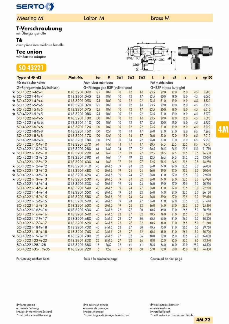
T-Verschraubungmit Übergangsmuffe
Téavec pièce intermédiaire femelle
Tee unionwith female adaptor
SO 43221Type -d -G -d3 Mat.-Nr. bar M SW1 SW2 SW3 L b zR z e kg/100Für metrische Rohre Pour tubes métriques For metric tubesG=Rohrgewinde (zylindrisch) G=Filetage-gaz BSP (cylindrique) G=BSP thread (straight)
SO 43221-4-1/8-4 018.3201.040 125 10x1 10 12 14 23.5 29.0 19.0 16.0 4.5 5.200 SO 43221-4-1/4-4 018.3201.045 125 10x1 10 12 17 23.5 30.0 19.0 16.0 4.5 6.060 SO 43221-4-3/8-4 018.3201.050 125 10x1 10 12 22 23.5 31.0 19.0 16.0 4.5 8.330 SO 43221-5-1/8-5 018.3201.070 125 10x1 10 12 14 23.5 29.0 19.0 16.0 4.5 5.150 SO 43221-5-1/4-5 018.3201.075 125 10x1 10 12 17 23.5 30.0 19.0 16.0 4.5 6.010 SO 43221-5-3/8-5 018.3201.080 125 10x1 10 12 22 23.5 31.0 19.0 16.0 4.5 8.270 SO 43221-6-1/8-6 018.3201.100 100 10x1 10 12 14 23.5 29.0 19.0 16.0 4.5 5.090 SO 43221-6-1/4-6 018.3201.110 100 10x1 10 12 17 23.5 30.0 19.0 16.0 4.5 5.950 SO 43221-6-3/8-6 018.3201.120 100 10x1 10 12 22 23.5 31.0 19.0 16.0 4.5 8.220 SO 43221-8-1/8-8 018.3201.160 100 12x1 10 14 17 26.0 31.0 21.0 18.0 6.5 7.260 SO 43221-8-1/4-8 018.3201.170 100 12x1 10 14 17 26.0 33.0 22.0 18.0 6.5 7.010 SO 43221-8-3/8-8 018.3201.180 100 12x1 10 14 22 26.0 33.0 21.0 18.0 6.5 9.250 SO 43221-10-1/4-10 018.3201.270 64 14x1 14 17 17 30.5 34.5 23.5 20.5 8.5 9.040 SO 43221-10-3/8-10 018.3201.280 64 14x1 14 17 22 30.5 36.5 24.5 20.5 8.5 11.710
SO 43221-10-1/2-10 018.3201.290 64 16x1 17 19 27 32.5 38.5 24.5 21.5 10.5 16.530 SO 43221-12-3/8-12 018.3201.390 64 16x1 17 19 22 32.5 36.5 24.5 21.5 10.5 13.070 SO 43221-12-1/2-12 018.3201.400 64 16x1 17 19 27 32.5 38.5 24.5 21.5 10.5 16.250
SO 43221-12-3/4-12 018.3201.410 40 20x1.5 19 24 32 36.0 44.0 27.0 23.5 13.0 26.030 SO 43221-13-3/8-13 018.3201.480 40 20x1.5 19 24 24 36.0 39.0 27.0 23.5 13.0 20.040 SO 43221-13-1/2-13 018.3201.490 40 20x1.5 19 24 27 36.0 41.0 27.0 23.5 13.0 22.070 SO 43221-13-3/4-13 018.3201.500 40 20x1.5 19 24 32 36.0 44.0 27.0 23.5 13.0 25.920 SO 43221-14-3/8-14 018.3201.530 40 20x1.5 19 24 24 36.0 39.0 27.0 23.5 13.0 20.250 SO 43221-14-1/2-14 018.3201.540 40 20x1.5 19 24 27 36.0 41.0 27.0 23.5 13.0 22.280 SO 43221-14-3/4-14 018.3201.550 40 20x1.5 19 24 32 36.0 44.0 27.0 23.5 13.0 26.130 SO 43221-15-3/8-15 018.3201.580 40 20x1.5 19 24 24 36.0 39.0 27.0 23.5 13.0 19.610 SO 43221-15-1/2-15 018.3201.590 40 20x1.5 19 24 27 36.0 41.0 27.0 23.5 13.0 21.640 SO 43221-15-3/4-15 018.3201.600 40 20x1.5 19 24 32 36.0 44.0 27.0 23.5 13.0 25.490 SO 43221-16-1/2-16 018.3201.630 40 24x1.5 22 27 30 40.5 45.0 31.0 26.5 15.0 30.280 SO 43221-16-3/4-16 018.3201.640 40 24x1.5 22 27 32 40.5 48.0 31.0 26.5 15.0 31.220 SO 43221-17-1/2-17 018.3201.680 40 24x1.5 22 27 30 40.5 45.0 31.0 26.5 15.0 30.300 SO 43221-17-3/4-17 018.3201.690 40 24x1.5 22 27 32 40.5 48.0 31.0 26.5 15.0 31.240 SO 43221-18-1/2-18 018.3201.730 40 24x1.5 22 27 30 40.5 45.0 31.0 26.5 15.0 29.760 SO 43221-18-3/4-18 018.3201.740 40 24x1.5 22 27 32 40.5 48.0 31.0 26.5 15.0 30.700
SO 43221-19-3/4-19 018.3201.780 25 28x1.5 27 32 36 48.0 52.0 35.0 30.5 19.0 46.000 SO 43221-22-3/4-22 018.3201.830 25 28x1.5 27 32 36 48.0 52.0 35.0 30.5 19.0 43.340 SO 43221-28-1-28 018.3201.880 16 36x2 32 41 41 58.5 64.0 44.0 39.0 25.0 44.500 SO 43221-35-1 1/4-35 018.3201.920 16 42x2 41 50 50 67.0 72.0 50.0 45.0 31.0 76.400
Fortsetzung nächste Seite Suite à la prochaine page Continued on next page
Messing M Laiton M Brass M
d=Rohraussen-øe=kleinste BohrungL=Mass in montiertem Zustand*=mit reduziertem Klemmring
d=ø extérieur du tubee=ø-min. de passageL=après montage*=avec bague de serrage de réduction
d=tube outside diametere=minimum boreL=installed length*=with reduction compression ferrule
4M.72
i
s
3F
4M
4G
5
5L
6
7
8
9
10
11
12

Für Zollrohre Pour tubes pouces For inch tubes
SO 43221-6,35-1/8-6,35 018.3201.140 100 10x1 10 12 14 23.5 29.0 19.0 16.0 4.5 5.060 SO 43221-6,35-1/4-6,35 018.3201.145 100 10x1 10 12 17 23.5 30.0 19.0 16.0 4.5 5.920 SO 43221-6,35-3/8-6,35 018.3201.150 100 10x1 10 12 22 23.5 31.0 19.0 16.0 4.5 8.190 SO 43221-9,52-1/4-9,52 018.3201.210 64 14x1 14 17 17 30.5 34.5 23.5 20.5 8.5 9.160 SO 43221-9,52-3/8-9,52 018.3201.215 64 14x1 14 17 22 30.5 36.5 24.5 20.5 8.5 11.830
SO 43221-12,7-3/8-12,7 018.3201.455 40 20x1.5 19 24 24 36.0 39.0 27.0 23.5 13.0 20.040 SO 43221-12,7-1/2-12,7 018.3201.460 40 20x1.5 19 24 32 36.0 41.0 27.0 23.5 13.0 22.070 SO 43221-12,7-3/4-12,7 018.3201.465 40 20x1.5 19 24 32 36.0 44.0 27.0 23.5 13.0 25.920
Messing M Laiton M Brass M
d=Rohraussen-øe=kleinste BohrungL=Mass in montiertem Zustand*=mit reduziertem Klemmring
d=ø extérieur du tubee=ø-min. de passageL=après montage*=avec bague de serrage de réduction
d=tube outside diametere=minimum boreL=installed length*=with reduction compression ferrule
4M.73

Einstellbare T-VerschraubungTé orientableAdjustable tee union
SO 43621 TType -d -Ad -d3 Mat.-Nr. bar M SW1 SW2 L f zA z e kg/100
SO 43621-4-A6-4 018.3600.045 100 10x1 10 12 23.5 12.0 18.0 16.0 4.0 3.540 SO 43621-5-A6-5 018.3600.053 100 10x1 10 12 23.5 12.0 18.0 16.0 4.0 3.500 SO 43621-6-A6-6 018.3600.060 250 10x1 10 12 23.5 12.0 18.0 16.0 4.0 3.160
SO 43621-6-A8-6 018.3600.063 150 12x1 10 14 26.0 14.0 23.0 18.0 6.0 4.670 SO 43621-8-A8-8 018.3600.080 150 12x1 10 14 26.0 14.0 23.0 18.0 6.0 4.230
SO 43621-8-A10-8 018.3600.083 125 14x1 14 17 30.5 16.0 25.5 20.5 7.5 7.940 SO 43621-10-A10-10 018.3600.100 125 14x1 14 17 30.5 16.0 25.5 20.5 7.5 6.970
Einstellbare L-VerschraubungL orientableAdjustable L union
SO 43621 LType -Ad -d2 -d3 Mat.-Nr. bar M SW1 SW2 L f zA z e kg/100
SO 43621-A6-4-4 018.3610.045 100 10x1 10 12 23.5 12.0 18.0 16.0 4.0 3.600 SO 43621-A6-5-5 018.3610.053 100 10x1 10 12 23.5 12.0 18.0 16.0 4.0 3.560 SO 43621-A6-6-6 018.3610.060 250 10x1 10 12 23.5 12.0 18.0 16.0 4.0 3.220
SO 43621-A8-6-6 018.3610.063 150 12x1 10 14 26.0 14.0 23.0 18.0 6.0 4.700 SO 43621-A8-8-8 018.3610.080 150 12x1 10 14 26.0 14.0 23.0 18.0 6.0 4.260
SO 43621-A10-8-8 018.3610.083 125 14x1 14 17 30.5 16.5 26.0 20.5 8.0 7.970 SO 43621-A10-10-10 018.3610.100 125 14x1 14 17 30.5 16.5 26.0 20.5 8.0 7.000
Das Einstell-T SO 43621 ergibt im Zusammenhang mit unserem Armaturenanschluss SO 40021 eine einstellbare T-Kombination.
L‘assemblage du SO 43621 et d‘unécrou SO 40021 donne un Té orientable.
In combination with our nut connectionSO 40021 the adjustable Tee unionSO 43621 forms an adjustable femaleadaptor Tee union.
Anwendungsbeispiele: Exemples d‘utilisation: Sample combinations:
Gegenüber dem Einschraub-T lässt sich diese Kombination einfacher einstellen, da Einschrauben und Ausrichten getrennt voneinan-der vorgenommen werden.
Par opposition à un coude mâle, cette combin-aison permet un positionnement plus facile. Le raccordement et l’orientation se font séparément.
In contrast to the simple male adaptor elbow union, this combination is easier to adjust, since screw-on and aligning are performed separately.
Messing M Laiton M Brass M
d=Rohraussen-øAd=Aussen-ø der Andrehunge=kleinste BohrungL=Mass in montiertem Zustand*=mit reduziertem Klemmring
d=ø extérieur du tubeAd=ø extérieur de la portée cylindriquee=ø-min. de passageL=après montage*=avec bague de serrage de réduction
d=tube outside diameterAd=outside diameter of cyl. Stube=minimum boreL=installed length*=with reduction compression ferrule
4M.74
i
s
3F
4M
4G
5
5L
6
7
8
9
10
11
12
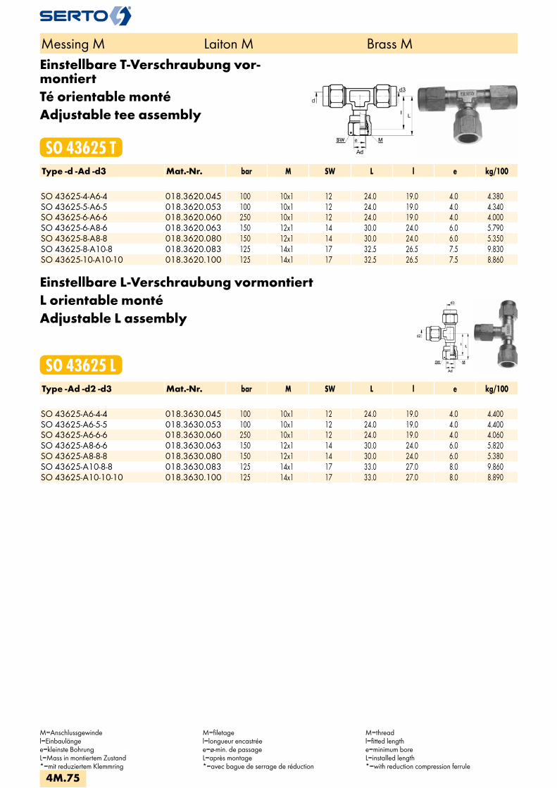
Einstellbare T-Verschraubung vor-montiertTé orientable montéAdjustable tee assembly
SO 43625 TType -d -Ad -d3 Mat.-Nr. bar M SW L l e kg/100 SO 43625-4-A6-4 018.3620.045 100 10x1 12 24.0 19.0 4.0 4.380SO 43625-5-A6-5 018.3620.053 100 10x1 12 24.0 19.0 4.0 4.340SO 43625-6-A6-6 018.3620.060 250 10x1 12 24.0 19.0 4.0 4.000SO 43625-6-A8-6 018.3620.063 150 12x1 14 30.0 24.0 6.0 5.790SO 43625-8-A8-8 018.3620.080 150 12x1 14 30.0 24.0 6.0 5.350SO 43625-8-A10-8 018.3620.083 125 14x1 17 32.5 26.5 7.5 9.830SO 43625-10-A10-10 018.3620.100 125 14x1 17 32.5 26.5 7.5 8.860
Einstellbare L-Verschraubung vormontiertL orientable montéAdjustable L assembly
SO 43625 LType -Ad -d2 -d3 Mat.-Nr. bar M SW L l e kg/100 SO 43625-A6-4-4 018.3630.045 100 10x1 12 24.0 19.0 4.0 4.400SO 43625-A6-5-5 018.3630.053 100 10x1 12 24.0 19.0 4.0 4.400SO 43625-A6-6-6 018.3630.060 250 10x1 12 24.0 19.0 4.0 4.060SO 43625-A8-6-6 018.3630.063 150 12x1 14 30.0 24.0 6.0 5.820SO 43625-A8-8-8 018.3630.080 150 12x1 14 30.0 24.0 6.0 5.380SO 43625-A10-8-8 018.3630.083 125 14x1 17 33.0 27.0 8.0 9.860SO 43625-A10-10-10 018.3630.100 125 14x1 17 33.0 27.0 8.0 8.890
Messing M Laiton M Brass M
M=Anschlussgewindel=Einbaulängee=kleinste BohrungL=Mass in montiertem Zustand*=mit reduziertem Klemmring
M=filetagel=longueur encastréee=ø-min. de passageL=après montage*=avec bague de serrage de réduction
M=threadl=fitted lengthe=minimum boreL=installed length*=with reduction compression ferrule
4M.75

T-EinschraubverschraubungTé mâleMale adaptor tee union
SO 43721 TType -d -R -d3 Mat.-Nr. bar M SW1 SW2 L zR z e kg/100Für metrische Rohre Pour tubes métriques For metric tubesR=Rohrgewinde (kegelig) R=Filetage-gaz BSP (conique) R=BSP thread (tapered)
SO 43721-3-1/8-3 018.3701.030 125 8x1 10 10 22.5 10.5 16.0 3.5 2.390 SO 43721-4-1/8-4 018.3701.040 125 8x1 10 10 22.0 10.5 16.0 3.5 2.350
SO 43721-4-1/4-4 018.3701.045 125 10x1 10 12 25.5 13.0 18.0 4.5 4.110 SO 43721-5-1/8-5 018.3701.070 125 8x1 10 10 22.5 10.5 16.0 3.5 2.330
SO 43721-5-1/4-5 018.3701.075 125 10x1 10 12 25.5 13.0 18.0 4.5 4.060 SO 43721-6-1/8-6 018.3701.100 250 10x1 10 12 23.5 11.0 16.0 4.5 3.240 SO 43721-6-1/4-6 018.3701.110 250 10x1 10 12 25.5 13.0 18.0 4.5 4.000 SO 43721-8-1/4-8 018.3701.170 150 12x1 10 14 26.0 13.0 18.0 6.5 4.730 SO 43721-10-1/4-10 018.3701.270 125 14x1 14 17 30.5 15.5 20.5 8.5 7.900
Für Zollrohre Pour tubes pouces For inch tubes SO 43721-6,35-1/8-6,35 018.3701.140 100 10x1 10 12 23.5 11.0 16.0 4.5 3.210SO 43721-6,35-1/4-6,35 018.3701.145 100 10x1 10 12 25.5 13.0 18.0 4.5 3.970SO 43721-9,52-1/4-9,52 018.3701.210 64 14x1 14 17 30.5 15.5 20.5 8.5 7.210
Die entsprechende Dichtung ist immer separat zu bestellen. Weitere Einschraub-T sieheT-Verschraubung mit ÜbergangsnippelSO 43121.
Les joints correspondants sont à commander séparément. Autres Tés mâles voir Té avecadaptateur mâle SO 43121.
The relevant washer must always be ordered separately. Alternative male adaptor Tee see Tee union with male adaptor SO 43121.
T-EinschraubverschraubungTé mâleMale adaptor tee union
SO 43724 TType -d -Mz -d3 Mat.-Nr. bar M SW1 SW2 L zR z e kg/100 Mz=metrisches Gewinde (zylindrisch) Mz=Filetage métrique (cylindrique) Mz=Metric thread (straight)SO 43724-2-M5-2 018.3743.050 125 6x0.75 7 8 16.5 8.5 12.5 2.2 1.210SO 43724-3-M5-3 018.3743.055 125 6x0.75 7 8 18.0 8.5 13.0 2.2 1.290
Die entsprechende Dichtung ist immer separat zu bestellen. Weitere Einschraub-T sieheT-Verschraubung mit ÜbergangsnippelSO 43121.
Les joints correspondants sont à commander séparément. Autres Tés mâles voir Té avecadaptateur mâle SO 43121.
The relevant washer must always be ordered separately. Alternative male adaptor Tee see Tee union with male adaptor SO 43121.
Messing M Laiton M Brass M
d=Rohraussen-øe=kleinste BohrungL=Mass in montiertem Zustand*=mit reduziertem Klemmring
d=ø extérieur du tubee=ø-min. de passageL=après montage*=avec bague de serrage de réduction
d=tube outside diametere=minimum boreL=installed length*=with reduction compression ferrule
4M.76
i
s
3F
4M
4G
5
5L
6
7
8
9
10
11
12

L-EinschraubverschraubungL mâleMale adaptor L union
SO 43721 LType -R -d2 -d3 Mat.-Nr. bar M SW1 SW2 L zR z e kg/100Für metrische Rohre Pour tubes métriques For metric tubesR=Rohrgewinde (kegelig) R=Filetage-gaz BSP (conique) R=BSP thread (tapered)
SO 43721-1/8-3-3 018.3711.030 125 8x1 10 10 22.5 10.5 16.0 3.5 2.410 SO 43721-1/8-4-4 018.3711.050 125 8x1 10 10 22.0 10.5 16.0 3.5 2.370 SO 43721-1/8-5-5 018.3711.070 125 8x1 10 10 22.5 10.5 16.0 3.5 2.350
SO 43721-1/4-4-4 018.3711.140 125 10x1 10 12 25.5 13.0 18.0 4.5 4.180 SO 43721-1/4-5-5 018.3711.160 125 10x1 10 12 25.5 13.0 18.0 4.5 4.130 SO 43721-1/8-6-6 018.3711.100 250 10x1 10 12 23.5 11.0 16.0 4.5 3.520 SO 43721-1/4-6-6 018.3711.180 250 10x1 10 12 23.5 13.0 18.0 4.5 4.070 SO 43721-1/4-8-8 018.3711.220 150 12x1 10 14 26.0 13.0 18.0 6.5 4.750 SO 43721-1/4-10-10 018.3711.260 125 14x1 14 17 30.5 15.5 20.5 8.5 7.040
Für Zollrohre Pour tubes pouces For inch tubes
SO 43721-1/8-6,35-6,35 018.3711.110 100 10x1 10 12 23.5 11.0 16.0 4.5 3.490 SO 43721-1/4-6,35-6,35 018.3711.190 100 10x1 10 12 23.5 13.0 18.0 4.5 4.040 SO 43721-1/4-9,52-9,52 018.3711.240 64 14x1 14 17 30.5 15.5 20.5 8.5 7.160
Die entsprechende Dichtung ist immer separat zu bestellen. Weitere Einschraub-L sieheL-Verschraubung mit ÜbergangsnippelSO 43121.
Les joints correspondants sont à commander séparément. Autres Tés mâles voir Té avecadaptateur mâle SO 43121.
The relevant washer must always be ordered separately. Alternative male adaptor Tee see Tee union with male adaptor SO 43121.
L-EinschraubverschraubungL mâleMale adaptor L union
SO 43724 LType -Mz -d2 -d3 Mat.-Nr. bar M SW1 SW2 L zR z e kg/100 Mz=metrisches Gewinde (zylindrisch) Mz=Filetage métrique (cylindrique) Mz=Metric thread (straight)
SO 43724-M5-2-2 018.3753.050 125 6x0.75 7 8 16.5 8.5 12.5 2.2 1.180 SO 43724-M5-3-3 018.3753.055 125 6x0.75 7 8 18.0 8.5 13.0 2.2 1.260
Die entsprechende Dichtung ist immer separat zu bestellen. Weitere Einschraub-L sieheL-Verschraubung mit ÜbergangsnippelSO 43121.
Les joints correspondants sont à commander séparément. Autres Tés mâles voir Té avecadaptateur mâle SO 43121.
The relevant washer must always be ordered separately. Alternative male adaptor Tee see Tee union with male adaptor SO 43121.
Messing M Laiton M Brass M
d=Rohraussen-øM=Anschlussgewindee=kleinste BohrungL=Mass in montiertem Zustand*=mit reduziertem Klemmring
d=ø extérieur du tubeM=filetagee=ø-min. de passageL=après montage*=avec bague de serrage de réduction
d=tube outside diameterM=threade=minimum boreL=installed length*=with reduction compression ferrule
4M.77
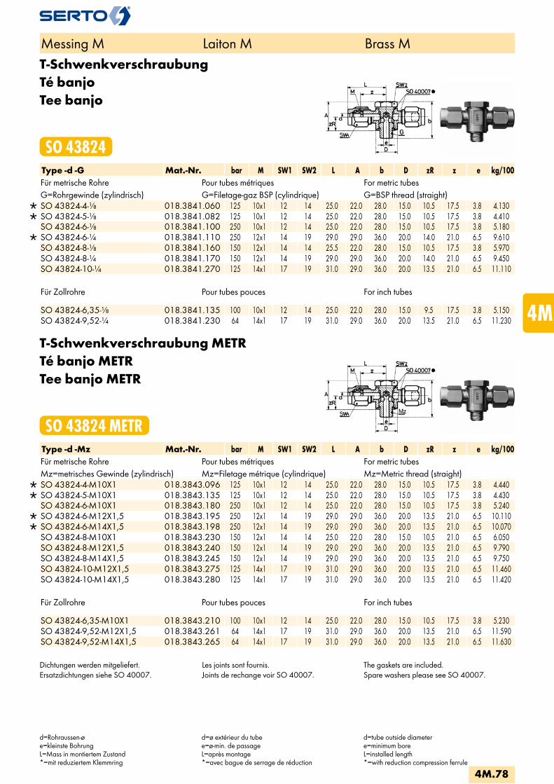
T-SchwenkverschraubungTé banjoTee banjo
SO 43824Type -d -G Mat.-Nr. bar M SW1 SW2 L A b D zR z e kg/100Für metrische Rohre Pour tubes métriques For metric tubesG=Rohrgewinde (zylindrisch) G=Filetage-gaz BSP (cylindrique) G=BSP thread (straight)
SO 43824-4-1/8 018.3841.060 125 10x1 12 14 25.0 22.0 28.0 15.0 10.5 17.5 3.8 4.130 SO 43824-5-1/8 018.3841.082 125 10x1 12 14 25.0 22.0 28.0 15.0 10.5 17.5 3.8 4.410 SO 43824-6-1/8 018.3841.100 250 10x1 12 14 25.0 22.0 28.0 15.0 10.5 17.5 3.8 5.180
SO 43824-6-1/4 018.3841.110 250 12x1 14 19 29.0 29.0 36.0 20.0 14.0 21.0 6.5 9.610 SO 43824-8-1/8 018.3841.160 150 12x1 14 14 25.5 22.0 28.0 15.0 10.5 17.5 3.8 5.970 SO 43824-8-1/4 018.3841.170 150 12x1 14 19 29.0 29.0 36.0 20.0 14.0 21.0 6.5 9.450 SO 43824-10-1/4 018.3841.270 125 14x1 17 19 31.0 29.0 36.0 20.0 13.5 21.0 6.5 11.110
Für Zollrohre Pour tubes pouces For inch tubes
SO 43824-6,35-1/8 018.3841.135 100 10x1 12 14 25.0 22.0 28.0 15.0 9.5 17.5 3.8 5.150 SO 43824-9,52-1/4 018.3841.230 64 14x1 17 19 31.0 29.0 36.0 20.0 13.5 21.0 6.5 11.230
T-Schwenkverschraubung METRTé banjo METRTee banjo METR
SO 43824 METRType -d -Mz Mat.-Nr. bar M SW1 SW2 L A b D zR z e kg/100Für metrische Rohre Pour tubes métriques For metric tubesMz=metrisches Gewinde (zylindrisch) Mz=Filetage métrique (cylindrique) Mz=Metric thread (straight)
SO 43824-4-M10X1 018.3843.096 125 10x1 12 14 25.0 22.0 28.0 15.0 10.5 17.5 3.8 4.440 SO 43824-5-M10X1 018.3843.135 125 10x1 12 14 25.0 22.0 28.0 15.0 10.5 17.5 3.8 4.430 SO 43824-6-M10X1 018.3843.180 250 10x1 12 14 25.0 22.0 28.0 15.0 10.5 17.5 3.8 5.240
SO 43824-6-M12X1,5 018.3843.195 250 12x1 14 19 29.0 29.0 36.0 20.0 13.5 21.0 6.5 10.110 SO 43824-6-M14X1,5 018.3843.198 250 12x1 14 19 29.0 29.0 36.0 20.0 13.5 21.0 6.5 10.070 SO 43824-8-M10X1 018.3843.230 150 12x1 14 14 25.0 22.0 28.0 15.0 10.5 21.0 6.5 6.050 SO 43824-8-M12X1,5 018.3843.240 150 12x1 14 19 29.0 29.0 36.0 20.0 13.5 21.0 6.5 9.790 SO 43824-8-M14X1,5 018.3843.245 150 12x1 14 19 29.0 29.0 36.0 20.0 13.5 21.0 6.5 9.750 SO 43824-10-M12X1,5 018.3843.275 125 14x1 17 19 31.0 29.0 36.0 20.0 13.5 21.0 6.5 11.460 SO 43824-10-M14X1,5 018.3843.280 125 14x1 17 19 31.0 29.0 36.0 20.0 13.5 21.0 6.5 11.420
Für Zollrohre Pour tubes pouces For inch tubes
SO 43824-6,35-M10X1 018.3843.210 100 10x1 12 14 25.0 22.0 28.0 15.0 10.5 17.5 3.8 5.230 SO 43824-9,52-M12X1,5 018.3843.261 64 14x1 17 19 31.0 29.0 36.0 20.0 13.5 21.0 6.5 11.590 SO 43824-9,52-M14X1,5 018.3843.265 64 14x1 17 19 31.0 29.0 36.0 20.0 13.5 21.0 6.5 11.630
Dichtungen werden mitgeliefert.Ersatzdichtungen siehe SO 40007.
Les joints sont fournis.Joints de rechange voir SO 40007.
The gaskets are included.Spare washers please see SO 40007.
Messing M Laiton M Brass M
d=Rohraussen-øe=kleinste BohrungL=Mass in montiertem Zustand*=mit reduziertem Klemmring
d=ø extérieur du tubee=ø-min. de passageL=après montage*=avec bague de serrage de réduction
d=tube outside diametere=minimum boreL=installed length*=with reduction compression ferrule
4M.78
i
s
3F
4M
4G
5
5L
6
7
8
9
10
11
12

2-fach T-SchwenkverschraubungTé banjo multipleTee double banjo
SO 43924Type -n x d -G Mat.-Nr. bar M SW1 SW2 L b D H z e kg/100Für metrische Rohre Pour tubes métriques For metric tubesG=Rohrgewinde (zylindrisch) G=Filetage-gaz BSP (cylindrique) G=BSP thread (straight)
SO 43924-2X4-1/8 018.3941.060 125 10x1 12 14 25.0 44.5 15.0 16.5 17.5 3.8 7.270 SO 43924-2X5-1/8 018.3941.082 125 10x1 12 14 25.0 44.5 15.0 16.5 17.5 3.8 7.830 SO 43924-2X6-1/8 018.3941.100 250 10x1 12 14 25.0 44.5 15.0 16.5 17.5 3.8 9.370
SO 43924-2X6-1/4 018.3941.110 250 12x1 14 19 29.0 58.0 20.0 21.5 21.0 6.5 17.270 SO 43924-2X8-1/8 018.3941.160 150 12x1 14 14 25.5 44.5 15.0 16.5 17.5 3.8 10.950 SO 43924-2X8-1/4 018.3941.170 150 12x1 14 19 29.0 58.0 20.0 21.5 21.0 6.5 16.950 SO 43924-2X10⁻¹/4 018.3941.270 125 14x1 17 19 31.0 58.0 20.0 21.5 21.0 6.5 20.310
Für Zollrohre Pour tubes pouces For inch tubes
SO 43924-2X6,35-1/8 018.3941.135 100 10x1 12 14 25.0 44.5 15.0 16.5 17.5 3.8 9.310 SO 43924-2X9,52-1/4 018.3941.230 64 14x1 17 19 31.0 58.0 20.0 21.5 21.0 6.5 20.550
Dichtungen werden mitgeliefert.Ersatzdichtungen siehe SO 40007.
Les joints sont fournis.Joints de rechange voir SO 40007.
The gaskets are included.Spare washers please see SO 40007.
Messing M Laiton M Brass M
d=Rohraussen-øe=kleinste BohrungL=Mass in montiertem Zustand*=mit reduziertem Klemmring
d=ø extérieur du tubee=ø-min. de passageL=après montage*=avec bague de serrage de réduction
d=tube outside diametere=minimum boreL=installed length*=with reduction compression ferrule
4M.79

KreuzverschraubungCroixCross union
SO 44021Type -d Mat.-Nr. bar M SW1 SW2 L z e kg/100Für metrische Rohre Pour tubes métriques For metric tubes
SO 44021-4 018.4000.040 125 10x1 10 12 25.5 18.0 4.0 4.800 SO 44021-5 018.4000.050 125 8x1 10 10 25.0 19.5 3.5 4.800 SO 44021-6 018.4000.060 250 10x1 10 12 25.5 18.0 4.0 6.030 SO 44021-8 018.4000.080 150 12x1 11 14 28.5 20.5 6.5 7.930 SO 44021-10 018.4000.100 125 14x1 14 17 30.5 20.5 8.5 11.880 SO 44021-12 018.4000.120 100 16x1 14 19 32.5 21.5 9.0 14.650
SO 44021-13 018.4000.130 40 20x1.5 19 24 39.0 26.5 13.0 25.770 SO 44021-14 018.4000.140 40 20x1.5 19 24 39.0 26.5 13.0 26.620 SO 44021-15 018.4000.150 40 20x1.5 19 24 39.0 26.5 13.0 25.340
Für Zollrohre Pour tubes pouces For inch tubes
SO 44021-6,35 018.4000.063 100 10x1 10 12 25.5 18.0 4.0 5.980 SO 44021-9,52 018.4000.095 64 14x1 14 17 30.5 20.5 8.5 12.120
SO 44021-12,7 018.4000.127 40 20x1.5 19 24 39.0 26.5 13.0 25.770
Messing M Laiton M Brass M
d=Rohraussen-øe=kleinste BohrungL=Mass in montiertem Zustand*=mit reduziertem Klemmring
d=ø extérieur du tubee=ø-min. de passageL=après montage*=avec bague de serrage de réduction
d=tube outside diametere=minimum boreL=installed length*=with reduction compression ferrule
4M.80
i
s
3F
4M
4G
5
5L
6
7
8
9
10
11
12
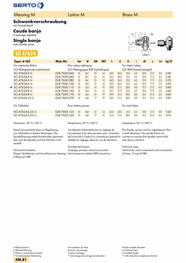
Schwenkverschraubungmit Drossel-Ventil
Coude banjoà passage réglable
Single banjowith throttle valve
SO 47624Type -d -G2 Mat.-Nr. bar M SW SW1 L A D i zR z kv kg/10Für metrische Rohre Pour tubes métriques For metric tubesG2=Rohrgewinde (zylindrisch) G2=Filetage-gaz BSP (cylindrique) G2=BSP thread (straight)
SO 47624-3-1/8 028.7600.040 16 8x1 10 14 24.0 26.0 15.0 6.5 10.0 17.5 3.0 0.400 SO 47624-4-1/8 028.7600.060 16 8x1 10 14 23.5 26.0 15.0 6.5 10.0 17.5 3.0 0.380 SO 47624-5-1/8 028.7600.082 16 8x1 10 14 24.0 26.0 15.0 6.5 10.0 17.5 3.0 0.370 SO 47624-6-1/8 028.7600.100 16 10x1 12 14 25.0 26.0 15.0 6.5 10.0 17.5 3.0 0.430
SO 47624-6-1/4 028.7600.110 16 12x1 14 19 29.0 31.5 20.0 8.0 13.5 21.0 6.0 0.860 SO 47624-8-1/8 028.7600.160 16 12x1 14 14 25.5 31.5 15.0 6.5 10.0 17.5 3.0 0.460 SO 47624-8-1/4 028.7600.170 16 12x1 14 19 29.0 31.5 20.0 8.0 13.5 21.0 6.0 0.840 SO 47624-10-1/4 028.7600.270 16 14x1 17 19 32.0 31.5 20.0 8.0 13.5 21.0 6.0 0.900
Für Zollrohre Pour tubes pouces For inch tubes SO 47624-6,35-1/8 028.7600.135 16 10x1 12 14 25.0 26.0 15.0 6.5 10.0 17.5 3.0 0.420SO 47624-9,52-1/4 028.7600.230 16 14x1 17 19 31.0 31.5 20.0 8.0 13.5 21.0 6.0 0.910
Temperatur -20°C/+80°C
Dieses Drossel-Ventil dient zur Regulierungvon Luftströmen in beiden Richtungen. DieSpindelfixierung mittels Kontermutter garantiert,dass sich die Spindel auch bei Vibration nichtverstellt.
Technische Hinweise:Körper, Ventileinsatz und Anschlüsse aus Messing.O-Ring aus NBR.
Température -20°C/+80°C
Cet élément d’étanchéité sert au réglage del’écoulement d’air dans les deux sens. La fixationde la broche à l’aide d’un contre-écrou garantit lastabilité du réglage même en cas de vibrations.
Données techniques:Soupape, pointeau et écrous en laiton.Joint torique en matière NBR caoutchouc.
Temperature -20°C/+80°C
This throttle can be used for regulating air flowin both directions. The spindle fixture viacounter-nut assures that spindle cannot shift,even due to vibration.
Technical notes:Valve body, valve components and connectionsof brass. O-ring of NBR.
Messing M Laiton M Brass M
d=Rohraussen-øe=kleinste BohrungL=Mass in montiertem Zustand*=mit reduziertem Klemmring
d=ø extérieur du tubee=ø-min. de passageL=après montage*=avec bague de serrage de réduction
d=tube outside diametere=minimum boreL=installed length*=with reduction compression ferrule
4M.81
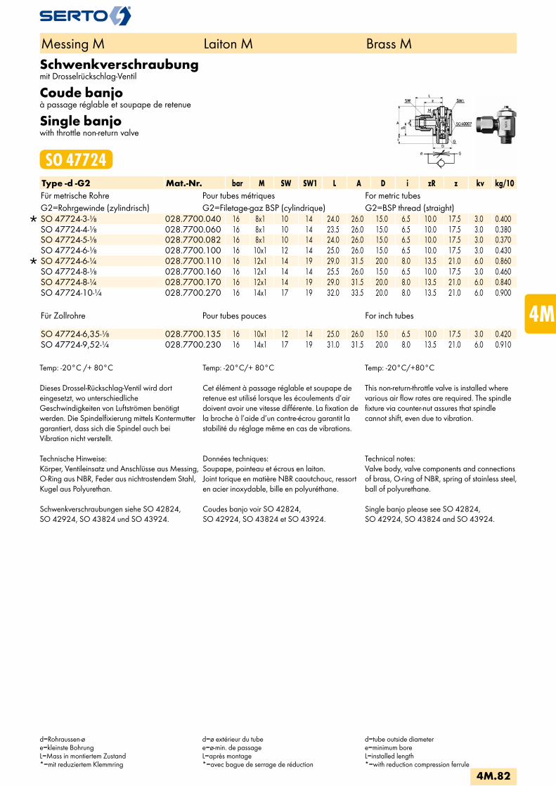
Schwenkverschraubungmit Drosselrückschlag-Ventil
Coude banjoà passage réglable et soupape de retenue
Single banjowith throttle non-return valve
SO 47724Type -d -G2 Mat.-Nr. bar M SW SW1 L A D i zR z kv kg/10Für metrische Rohre Pour tubes métriques For metric tubesG2=Rohrgewinde (zylindrisch) G2=Filetage-gaz BSP (cylindrique) G2=BSP thread (straight)
SO 47724-3-1/8 028.7700.040 16 8x1 10 14 24.0 26.0 15.0 6.5 10.0 17.5 3.0 0.400 SO 47724-4-1/8 028.7700.060 16 8x1 10 14 23.5 26.0 15.0 6.5 10.0 17.5 3.0 0.380 SO 47724-5-1/8 028.7700.082 16 8x1 10 14 24.0 26.0 15.0 6.5 10.0 17.5 3.0 0.370 SO 47724-6-1/8 028.7700.100 16 10x1 12 14 25.0 26.0 15.0 6.5 10.0 17.5 3.0 0.430
SO 47724-6-1/4 028.7700.110 16 12x1 14 19 29.0 31.5 20.0 8.0 13.5 21.0 6.0 0.860 SO 47724-8-1/8 028.7700.160 16 12x1 14 14 25.5 26.0 15.0 6.5 10.0 17.5 3.0 0.460 SO 47724-8-1/4 028.7700.170 16 12x1 14 19 29.0 31.5 20.0 8.0 13.5 21.0 6.0 0.840 SO 47724-10-1/4 028.7700.270 16 14x1 17 19 32.0 33.5 20.0 8.0 13.5 21.0 6.0 0.900
Für Zollrohre Pour tubes pouces For inch tubes
SO 47724-6,35-1/8 028.7700.135 16 10x1 12 14 25.0 26.0 15.0 6.5 10.0 17.5 3.0 0.420 SO 47724-9,52-1/4 028.7700.230 16 14x1 17 19 31.0 31.5 20.0 8.0 13.5 21.0 6.0 0.910
Temp: -20°C /+ 80°C
Dieses Drossel-Rückschlag-Ventil wird dorteingesetzt, wo unterschiedlicheGeschwindigkeiten von Luftströmen benötigtwerden. Die Spindelfixierung mittels Kontermuttergarantiert, dass sich die Spindel auch beiVibration nicht verstellt.
Technische Hinweise:Körper, Ventileinsatz und Anschlüsse aus Messing,O-Ring aus NBR, Feder aus nichtrostendem Stahl,Kugel aus Polyurethan.
Schwenkverschraubungen siehe SO 42824,SO 42924, SO 43824 und SO 43924.
Temp: -20°C/+ 80°C
Cet élément à passage réglable et soupape deretenue est utilisé lorsque les écoulements d’airdoivent avoir une vitesse différente. La fixation dela broche à l’aide d’un contre-écrou garantit lastabilité du réglage même en cas de vibrations.
Données techniques:Soupape, pointeau et écrous en laiton.Joint torique en matière NBR caoutchouc, ressorten acier inoxydable, bille en polyuréthane.
Coudes banjo voir SO 42824,SO 42924, SO 43824 et SO 43924.
Temp: -20°C/+80°C
This non-return-throttle valve is installed wherevarious air flow rates are required. The spindlefixture via counter-nut assures that spindlecannot shift, even due to vibration.
Technical notes:Valve body, valve components and connectionsof brass, O-ring of NBR, spring of stainless steel,ball of polyurethane.
Single banjo please see SO 42824,SO 42924, SO 43824 and SO 43924.
Messing M Laiton M Brass M
d=Rohraussen-øe=kleinste BohrungL=Mass in montiertem Zustand*=mit reduziertem Klemmring
d=ø extérieur du tubee=ø-min. de passageL=après montage*=avec bague de serrage de réduction
d=tube outside diametere=minimum boreL=installed length*=with reduction compression ferrule
4M.82
i
s
3F
4M
4G
5
5L
6
7
8
9
10
11
12
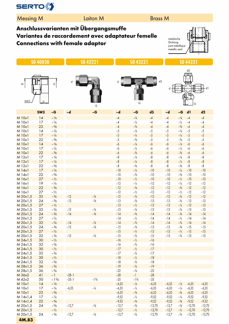
G
d3d
SW3 –G –d –G –d –G d3 –d –G d1 d2M 10x1 14 – –4 – –4 –4 – –4 –4M 10x1 17 – –4 – –4 –4 – –4 –4M 10x1 22 – –4 – –4 –4 – –4 –4M 10x1 14 – –5 – –5 –5 – –5 –5M 10x1 17 – –5 – –5 –5 – –5 –5M 10x1 22 – –5 – –5 –5 – –5 –5M 10x1 14 – –6 – –6 –6 – –6 –6M 10x1 17 – –6 – –6 –6 – –6 –6M 10x1 22 – –6 – –6 –6 – –6 –6M 12x1 17 – –8 – –8 –8 – –8 –8M 12x1 17 – –8 – –8 –8 – –8 –8M 12x1 22 – –8 – –8 –8 – –8 –8M 14x1 17 – –10 – –10 –10 – –10 –10M 14x1 22 – –10 – –10 –10 – –10 –10M 16x1 27 – –10 – –10 –10 – –10 –10M 16x1 19 – –12 – –12 –12 – –12 –12M 16x1 22 – –12 – –12 –12 – –12 –12M 16x1 27 – –12 – –12 –12 – –12 –12M 20x1,5 32 – –12 – –12 – –12 –12 – –12 –12M 20x1,5 24 – –13 – –13 – –13 –13 – –13 –13M 20x1,5 27 – –13 – –13 –13 – –13 –13M 20x1,5 32 – –13 – –13 – –13 –13 – –13 –13M 20x1,5 24 – –14 – –14 – –14 –14 – –14 –14M 20x1,5 27 – –14 – –14 –14 – –14 –14M 20x1,5 32 – –14 – –14 – –14 –14 – –14 –14M 20x1,5 24 – –15 – –15 – –15 –15 – –15 –15M 20x1,5 27 – –15 – –15 –15 – –15 –15M 20x1,5 32 – –15 – –15 – –15 –15 – –15 –15M 24x1,5 30 – –16 – –16M 24x1,5 32 – –16 – –16M 24x1,5 30 – –17 – –17M 24x1,5 32 – –17 – –17M 24x1,5 30 – –18 – –18M 24x1,5 32 – –18 – –18M 28x1,5 36 – –19 – –19M 28x1,5 36 – –22 – –22M 36x2 41 –1 –28–1 –28 –1 –28M 42x2 50 –1 –35–1 –1 –35 –1 –35M 10x1 14 – –6,35 – –6,35 –6,35 – –6,35 –6,35M 10x1 17 – –6,35 – –6,35 – –6,35 –6,35 – –6,35 –6,35M 10x1 22 – –6,35 – –6,35 –6,35 – –6,35 –6,35M 14x1,4 17 – –9,52 – –9,52 –9,52 – –9,52 –9,52M 14x1,4 22 – –9,52 – –9,52 –9,52 – –9,52 –9,52M 20x1,5 24 – –12,7 – –12,7 – –12,70 –12,7 – –12,70 –12,70M 20x1,5 – –12,7 – –12,70 –12,7 – –12,70 –12,70M 20x1,5 24 – –12,7 – –12,7 – –12,70 –12,7 – –12,70 –12,70
G
d
i2
M
SW3
G
S0 44221
Rd2
Rd
RG
Rd1
S0 43221S0 42221S0 40030
Messing M Laiton M Brass M
Anschlussvarianten mit ÜbergangsmuffeVariantes de raccordement avec adaptateur femelleConnections with female adaptor
metalischeDichtungjoint métalliquemetallic seal
4M.83
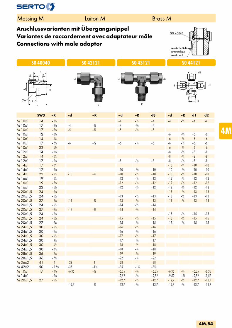
Rd2
Rd
RR
Rd1
R
dd z R
e
cL
b
M
SW
SW3 –R –d –R –d –R d3 –d –R d1 d2M 10x1 14 – –4 – –4 –4 – –4 –4M 10x1 17 – –4 – –4 – –4M 10x1 17 – –5 – –5 – –5M 10x1 12 – –6 – –6 –6M 10x1 14 – –6 – –6 –6M 10x1 17 – –6 – –6 – –6 –6 – –6 –6M 10x1 22 – –6 – –6 –6M 12x1 14 – –8 – –8 –8M 12x1 14 – –8 – –8 –8M 12x1 17 – –8 – –8 –8 – –8 –8M 14x1 17 – –10 – –10 –10M 14x1 17 – –10 – –10 –10 – –10 –10M 14x1 22 – –10 – –10 – –10 –10 – –10 –10M 16x1 19 – –12 – –12 –12 – –12 –12M 16x1 19 – –12 – –12 –12 – –12 –12M 16x1 22 – –12 – –12 –12 – –12 –12M 20x1,5 24 – –13 – –13 –13M 20x1,5 24 – –13 – –13 –13 – –13 –13M 20x1,5 27 – –13 – –13 – –13 –13 – –13 –13M 20x1,5 24 – –14 – –14M 20x1,5 27 – –14 – –14 – –14M 20x1,5 24 – –15 – –15 –15M 20x1,5 24 – –15 – –15 –15 – –15 –15M 20x1,5 27 – –15 – –15 –15 – –15 –15M 24x1,5 30 – –16 – –16M 24x1,5 30 – –16 – –16M 24x1,5 30 – –17 – –17M 24x1,5 30 – –17 – –17M 24x1,5 30 – –18 – –18M 24x1,5 30 – –18 – –18M 28x1,5 36 – –19 – –19M 28x1,5 36 – –22 – –22M 36x2 41 –1 –28 –1 –28 –1 –28M 42x2 50 –1 –35 –1 –35 –1 –35M 10x1 17 – –6,35 – –6,35 – –6,35 –6,35 – –6,35 –6,35M 14x1 – –9,52 – –9,52 –9,52 – –9,52 –9,52M 20x1,5 27 – –12,7 – –12,7 –12,7 – –12,7 –12,7
–12,7 – –12,7 – –12,7 –12,7 – –12,7 –12,7
d3d
R
S0 44121S0 43121S0 42121S0 40040
Anschlussvarianten mit ÜbergangsnippelVariantes de raccordement avec adaptateur mâleConnections with male adaptor
Messing M Laiton M Brass M
4M.84
i
s
3F
4M
4G
5
5L
6
7
8
9
10
11
12

SW –RNPT –d –RNPT –d1 –RNPT d3 –d –RNPT d1 d2M10x1 12 – NPT –4 – NPT –4 –4 – NPT –4 –4M10x1 14 – NPT –4 – NPT –4 – NPT –4 –4 – NPT –4 –4M10x1 12 – NPT –5 – NPT –5 –5 – NPT –5 –5M10x1 14 – NPT –5 – NPT –5 – NPT –5 –5 – NPT –5 –5M10x1 12 – NPT –6 – NPT –6 –6 – NPT –6 –6M10x1 14 – NPT –6 – NPT –6 –6 – NPT –6 –6M12x1 14 – NPT –8 – NPT –8 – NPT –8 –8 – NPT –8 –8M12x1 14 – NPT –8 – NPT –8 –8 – NPT –8 –8M14x1 17 – NPT –10 – NPT –10 –10 – NPT –10 –10M10x1 14 – NPT –6,35 – NPT –6,35 – NPT –6,35 –6,35 – NPT –6,35 –6,35M10x1 14 – NPT –6,35 – NPT –6,35 –6,35 – NPT –6,35 –6,35M14x1 17 – NPT –9,52 – NPT –9,52 –9,52 – NPT –9,52 –9,52
d
M
SW cL
bz RNPT
e
Rd2
Rd
RRNPT
Rd1
S0 44121S0 43121S0 42121S0 40040
RNPT
d d3d
RNPT
Anschlussvarianten mit ÜbergangsnippelVariantes de raccordement avec adaptateur mâleConnections with female adaptor
Messing M Laiton M Brass M
Male adaptor elbow union see also SO 42421
Male adaptor tee union see also SO 43721
Winkel-Einschraubverschraubung siehe auch SO 42421
T-Einschraubverschraubung siehe auch SO 43721
Coude mâle voir aussi SO 42421
Té mâle voir aussi SO 43721
4M.85

Rohrnippelkurz
Mameloncourt
Double nippleshort
AD CNS 40Type -G Mat.-Nr. L e SW kg/100G=Rohrgewinde (zylindrisch) G=Filetage-gaz BSP (cylindrique) G=BSP thread (straight) AD CNS 40-1/8 TAD.4180.042 20.0 6.5 0.480AD CNS 40-1/4 TAD.4180.104 20.0 8.5 0.940AD CNS 40-3/8 TAD.4180.166 20.0 10 1.490AD CNS 40-1/2 TAD.4180.228 25.0 12 3.200AD CNS 40-3/4 TAD.4180.292 26.0 17 4.670AD CNS 40-1 TAD.4180.414 33.0 25.0 8.420
Aufschraub-WinkelCoude double femelleFemale elbow
AD FE 40Type -G Mat.-Nr. L b D H kg/100G=Rohrgewinde (zylindrisch) G=Filetage-gaz BSP (cylindrique) G=BSP thread (straight) AD FE 40-1/8 TAD.4300.042 21.0 8.0 15.0 15.0 2.000AD FE 40-1/4 TAD.4300.104 30.0 10.0 22.0 19.0 4.380AD FE 40-3/8 TAD.4300.166 36.0 11.0 23.0 23.0 5.930AD FE 40-1/2 TAD.4300.228 39.0 12.0 27.0 25.0 7.430AD FE 40-3/4 TAD.4300.292 46.0 15.0 36.0 30.0 12.090AD FE 40-1 TAD.4300.414 57.0 16.0 42.0 35.0 21.100
Aufschraub-TTé triple femelleFemale tee
AD FT 40Type -G Mat.-Nr. L b D H kg/100G=Rohrgewinde (zylindrisch) G=Filetage-gaz BSP (cylindrique) G=BSP thread (straight) AD FT 40-1/8 TAD.4400.060 28.0 8.0 15.0 14.0 2.610AD FT 40-1/4 TAD.4400.160 35.0 10.0 21.0 17.5 5.680AD FT 40-3/8 TAD.4400.350 43.0 11.0 23.0 21.5 9.360AD FT 40-1/2 TAD.4400.450 48.0 12.0 27.0 24.0 9.700AD FT 40-3/4 TAD.4400.520 60.0 15.0 36.0 30.0 16.760AD FT 40-1 TAD.4400.650 68.0 16.0 42.0 34.0 25.850
Messing M Laiton M Brass M
4M.86
i
s
3F
4M
4G
5
5L
6
7
8
9
10
11
12
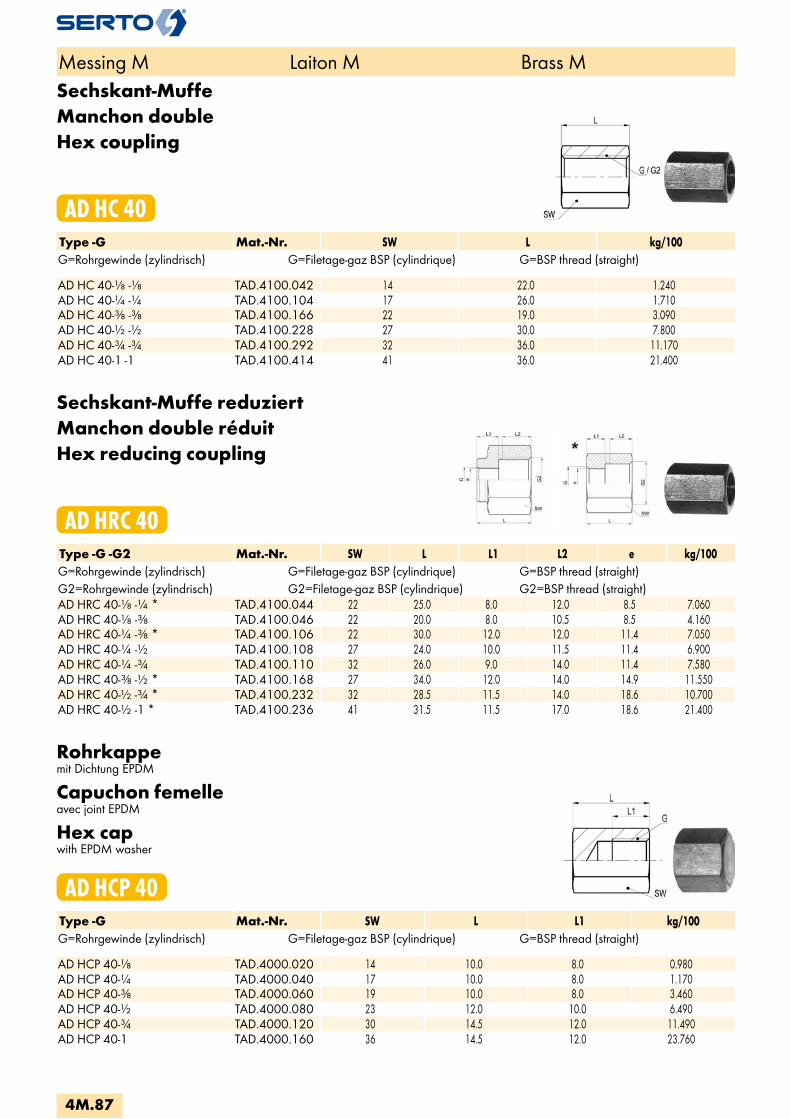
Sechskant-MuffeManchon doubleHex coupling
AD HC 40Type -G Mat.-Nr. SW L kg/100G=Rohrgewinde (zylindrisch) G=Filetage-gaz BSP (cylindrique) G=BSP thread (straight) AD HC 40-1/8 -1/8 TAD.4100.042 14 22.0 1.240AD HC 40-1/4 -1/4 TAD.4100.104 17 26.0 1.710AD HC 40-3/8 -3/8 TAD.4100.166 22 19.0 3.090AD HC 40-1/2 -1/2 TAD.4100.228 27 30.0 7.800AD HC 40-3/4 -3/4 TAD.4100.292 32 36.0 11.170AD HC 40-1 -1 TAD.4100.414 41 36.0 21.400
Sechskant-Muffe reduziertManchon double réduitHex reducing coupling
AD HRC 40Type -G -G2 Mat.-Nr. SW L L1 L2 e kg/100G=Rohrgewinde (zylindrisch) G=Filetage-gaz BSP (cylindrique) G=BSP thread (straight)G2=Rohrgewinde (zylindrisch) G2=Filetage-gaz BSP (cylindrique) G2=BSP thread (straight)AD HRC 40-1/8 -1/4 * TAD.4100.044 22 25.0 8.0 12.0 8.5 7.060AD HRC 40-1/8 -3/8 TAD.4100.046 22 20.0 8.0 10.5 8.5 4.160AD HRC 40-1/4 -3/8 * TAD.4100.106 22 30.0 12.0 12.0 11.4 7.050AD HRC 40-1/4 -1/2 TAD.4100.108 27 24.0 10.0 11.5 11.4 6.900AD HRC 40-1/4 -3/4 TAD.4100.110 32 26.0 9.0 14.0 11.4 7.580AD HRC 40-3/8 -1/2 * TAD.4100.168 27 34.0 12.0 14.0 14.9 11.550AD HRC 40-1/2 -3/4 * TAD.4100.232 32 28.5 11.5 14.0 18.6 10.700AD HRC 40-1/2 -1 * TAD.4100.236 41 31.5 11.5 17.0 18.6 21.400
Rohrkappemit Dichtung EPDM
Capuchon femelleavec joint EPDM
Hex capwith EPDM washer
AD HCP 40Type -G Mat.-Nr. SW L L1 kg/100G=Rohrgewinde (zylindrisch) G=Filetage-gaz BSP (cylindrique) G=BSP thread (straight) AD HCP 40-1/8 TAD.4000.020 14 10.0 8.0 0.980AD HCP 40-1/4 TAD.4000.040 17 10.0 8.0 1.170AD HCP 40-3/8 TAD.4000.060 19 10.0 8.0 3.460AD HCP 40-1/2 TAD.4000.080 23 12.0 10.0 6.490AD HCP 40-3/4 TAD.4000.120 30 14.5 12.0 11.490AD HCP 40-1 TAD.4000.160 36 14.5 12.0 23.760
Messing M Laiton M Brass M
4M.87

DoppelnippelAdaptateur mâleMale adaptor
AD HN 40Type -R -R2 Mat.-Nr. SW L e kg/100R=Rohrgewinde (kegelig) R=Filetage-gaz BSP (conique) R=BSP thread (tapered)R2=Rohrgewinde (kegelig) R2=Filetage-gaz BSP (conique) R2=BSP thread (tapered)AD HN 40-1/8 -1/8 TAD.4110.042 10 21.0 6.0 0.760AD HN 40-1/8 -1/4 TAD.4110.044 14 26.0 6.0 1.200AD HN 40-1/4 -1/4 TAD.4110.104 14 30.0 8.0 1.610AD HN 40-1/4 -3/8 TAD.4110.106 14 31.0 8.0 2.010AD HN 40-1/4 -1/2 TAD.4110.108 17 34.0 8.0 2.980AD HN 40-3/8 -3/8 TAD.4110.166 17 30.0 10.0 3.240AD HN 40-3/8 -1/2 TAD.4110.168 22 34.0 10.0 4.930AD HN 40-1/2 -1/2 TAD.4110.228 22 36.0 14.0 5.420AD HN 40-1/2 -3/4 TAD.4110.232 27 39.0 14.0 8.360AD HN 40-1/2 -1 TAD.4110.236 36 45.0 14.0 15.240AD HN 40-3/4 -3/4 TAD.4110.292 27 41.0 18.0 9.410AD HN 40-1 -1 TAD.4110.414 36 51.0 24.0 17.760
Übergangsnippel R-NPTMamelon double inégal R-NPTConversion hex nipple R-NPT
AD HN 40 R-NPTType -R -RNPT2 Mat.-Nr. SW L e kg/100R=Rohrgewinde (kegelig) R=Filetage-gaz BSP (conique) R=BSP thread (tapered)RNPT2=NPT Gewinde RNPT2=Filetage NPT RNPT2=NPT threadAD HN 40-1/8 -1/8 NPT TAD.4114.042 12 24.5 6.0 1.240AD HN 40-1/4 -1/4 NPT TAD.4114.104 14 32.0 8.0 1.700AD HN 40-3/8 -3/8 NPT TAD.4114.166 17 34.0 10.0 4.370AD HN 40-1/2 -1/2 NPT TAD.4114.228 22 45.0 13.0 8.790AD HN 40-1 -1 NPT TAD.4114.414 36 60.0 23.0 25.060
Doppelnippel NPT-NPTMamelon double NPT-NPTHex nipple NPT-NPT
AD HN 40 NPT-NPTType -RNPT Mat.-Nr. SW L e kg/100RNPT=NPT Gewinde RNPT=Filetage NPT RNPT=NPT thread AD HN 40-1/8 NPT-1/8 NPT TAD.4111.042 12 24.5 6.0 1.230AD HN 40-1/4 NPT-1/4 NPT TAD.4111.104 14 34.0 8.0 2.900AD HN 40-3/8 NPT-3/8 NPT TAD.4111.166 17 34.0 10.0 4.360AD HN 40-1/2 NPT-1/2 NPT TAD.4111.228 22 45.0 13.0 8.770
Messing M Laiton M Brass M
4M.88
i
s
3F
4M
4G
5
5L
6
7
8
9
10
11
12

6kt-Doppelnippelbeidseitig 60°-Innenkonus
Raccord six pansà cône intérieur 60° des deux côtés
Hexagon barrel nipple60° internal taper on both sides
ADH HNC 40Type -G -G2 Mat.-Nr. SW L L1 L2 e kg/100G=Rohrgewinde (zylindrisch) G=Filetage-gaz BSP (cylindrique) G=BSP thread (straight)G2=Rohrgewinde (zylindrisch) G2=Filetage-gaz BSP (cylindrique) G2=BSP thread (straight)ADH HNC 40-1/4 496.4100.104 14 26.0 10.0 10.0 7.5 1.690ADH HNC 40-1/4 -3/8 496.4100.106 14 27.0 10.0 11.0 7.5 2.330ADH HNC 40-3/8 496.4100.166 17 28.0 11.0 11.0 8.5 3.160
Verschlussstopfen 6ktBouchon mâleHex plug
AD HP 40Type -R Mat.-Nr. SW L L1 kg/100R=Rohrgewinde (kegelig) R=Filetage-gaz BSP (conique) R=BSP thread (tapered) AD HP 40-1/8 TAD.4020.020 12 13.0 8.0 0.970AD HP 40-1/4 TAD.4020.040 14 18.0 12.0 2.060AD HP 40-3/8 TAD.4020.060 17 19.0 12.0 3.460AD HP 40-1/2 TAD.4020.080 22 22.0 14.0 6.490AD HP 40-3/4 TAD.4020.120 27 25.0 16.0 11.490AD HP 40-1 TAD.4020.160 36 31.0 20.0 23.760
Verschlussstopfen 6kt NPTBouchon mâle NPTHex plug NPT
AD HP 40 NPTType -RNPT Mat.-Nr. SW L L1 kg/100RNPT=NPT Gewinde RNPT=Filetage NPT RNPT=NPT thread AD HP 40-1/8 NPT TAD.4021.020 12 15.0 10.0 1.130AD HP 40-1/4 NPT TAD.4021.040 14 20.0 14.0 2.320AD HP 40-3/8 NPT TAD.4021.060 17 22.0 14.0 4.400AD HP 40-1/2 NPT TAD.4021.080 22 27.0 19.0 7.720AD HP 40-3/4 NPT TAD.4021.120 27 29.0 20.0 13.600
Messing M Laiton M Brass M
4M.89

Verschlussschraubemit Aussen-6kt und Bund
Vis d‘extrémitésix pans extérieur
Screw plughexagon head
AD HPS 40Type -G Mat.-Nr. SW L L1 kg/100G=Rohrgewinde (zylindrisch) G=Filetage-gaz BSP (cylindrique) G=BSP thread (straight) AD HPS 40-1/8 TAD.4030.020 10 17.0 8.0 0.610AD HPS 40-1/4 TAD.4030.040 13 21.0 12.0 1.430AD HPS 40-3/8 TAD.4030.060 17 21.0 12.0 2.240AD HPS 40-1/2 TAD.4030.080 19 26.0 14.0 4.250AD HPS 40-3/4 TAD.4030.120 24 30.0 16.0 7.410
Verschlussschraube mit O-RingBouchon d‘obturation avec joint toriqueScrew plug with O-Ring
AD HPO 40Type -G Mat.-Nr. SW L L1 kg/100G=Rohrgewinde (zylindrisch) G=Filetage-gaz BSP (cylindrique) G=BSP thread (straight) AD HPO 40-1/8 TAD.4040.020 10 17.0 8.0 1.200AD HPO 40-1/4 TAD.4040.040 13 21.0 12.0 2.460AD HPO 40-3/8 TAD.4040.060 17 21.0 12.0 4.800AD HPO 40-1/2 TAD.4040.080 19 26.0 14.0 7.180AD HPO 40-3/4 TAD.4040.120 24 30.0 16.0 13.040
Verschlussschraube mit Innen-6ktBouchon d‘obturationScrew Plug
AD HSP 40Type -G Mat.-Nr. SW L L1 D kg/100G=Rohrgewinde (zylindrisch) G=Filetage-gaz BSP (cylindrique) G=BSP thread (straight) AD HSP 40-1/8 TAD.4070.020 5 11.0 8.0 14.0 0.610AD HSP 40-1/4 TAD.4070.040 6 15.0 12.0 18.0 1.430AD HSP 40-3/8 TAD.4070.060 8 15.0 12.0 22.0 2.240AD HSP 40-1/2 TAD.4070.080 10 18.0 14.0 26.0 4.250AD HSP 40-3/4 TAD.4070.120 12 20.0 16.0 32.0 7.410AD HSP 40-1 TAD.4070.160 17 21.0 16.0 39.0 11.000
Messing M Laiton M Brass M
4M.90
i
s
3F
4M
4G
5
5L
6
7
8
9
10
11
12
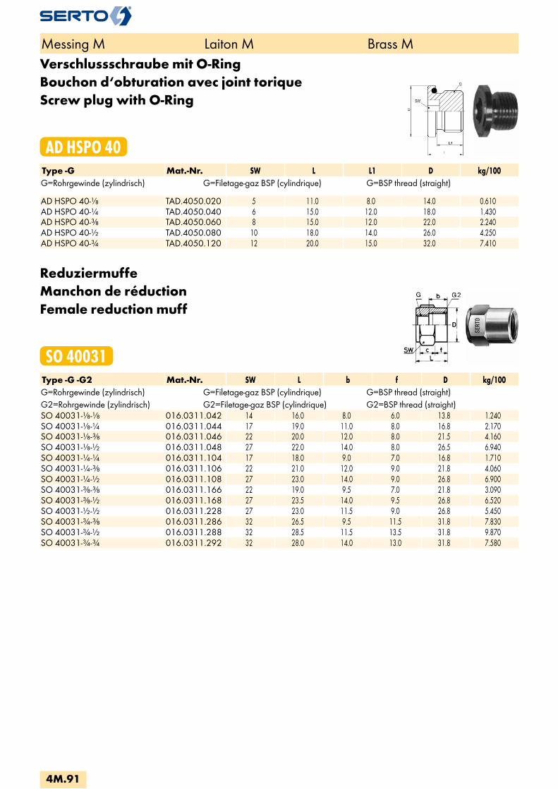
Verschlussschraube mit O-RingBouchon d‘obturation avec joint toriqueScrew plug with O-Ring
AD HSPO 40Type -G Mat.-Nr. SW L L1 D kg/100G=Rohrgewinde (zylindrisch) G=Filetage-gaz BSP (cylindrique) G=BSP thread (straight) AD HSPO 40-1/8 TAD.4050.020 5 11.0 8.0 14.0 0.610AD HSPO 40-1/4 TAD.4050.040 6 15.0 12.0 18.0 1.430AD HSPO 40-3/8 TAD.4050.060 8 15.0 12.0 22.0 2.240AD HSPO 40-1/2 TAD.4050.080 10 18.0 14.0 26.0 4.250AD HSPO 40-3/4 TAD.4050.120 12 20.0 15.0 32.0 7.410
ReduziermuffeManchon de réductionFemale reduction muff
SO 40031Type -G -G2 Mat.-Nr. SW L b f D kg/100G=Rohrgewinde (zylindrisch) G=Filetage-gaz BSP (cylindrique) G=BSP thread (straight)G2=Rohrgewinde (zylindrisch) G2=Filetage-gaz BSP (cylindrique) G2=BSP thread (straight)SO 40031-1/8-1/8 016.0311.042 14 16.0 8.0 6.0 13.8 1.240SO 40031-1/8-1/4 016.0311.044 17 19.0 11.0 8.0 16.8 2.170SO 40031-1/8-3/8 016.0311.046 22 20.0 12.0 8.0 21.5 4.160SO 40031-1/8-1/2 016.0311.048 27 22.0 14.0 8.0 26.5 6.940SO 40031-1/4-1/4 016.0311.104 17 18.0 9.0 7.0 16.8 1.710SO 40031-1/4-3/8 016.0311.106 22 21.0 12.0 9.0 21.8 4.060SO 40031-1/4-1/2 016.0311.108 27 23.0 14.0 9.0 26.8 6.900SO 40031-3/8-3/8 016.0311.166 22 19.0 9.5 7.0 21.8 3.090SO 40031-3/8-1/2 016.0311.168 27 23.5 14.0 9.5 26.8 6.520SO 40031-1/2-1/2 016.0311.228 27 23.0 11.5 9.0 26.8 5.450SO 40031-3/4-3/8 016.0311.286 32 26.5 9.5 11.5 31.8 7.830SO 40031-3/4-1/2 016.0311.288 32 28.5 11.5 13.5 31.8 9.870SO 40031-3/4-3/4 016.0311.292 32 28.0 14.0 13.0 31.8 7.580
Messing M Laiton M Brass M
4M.91
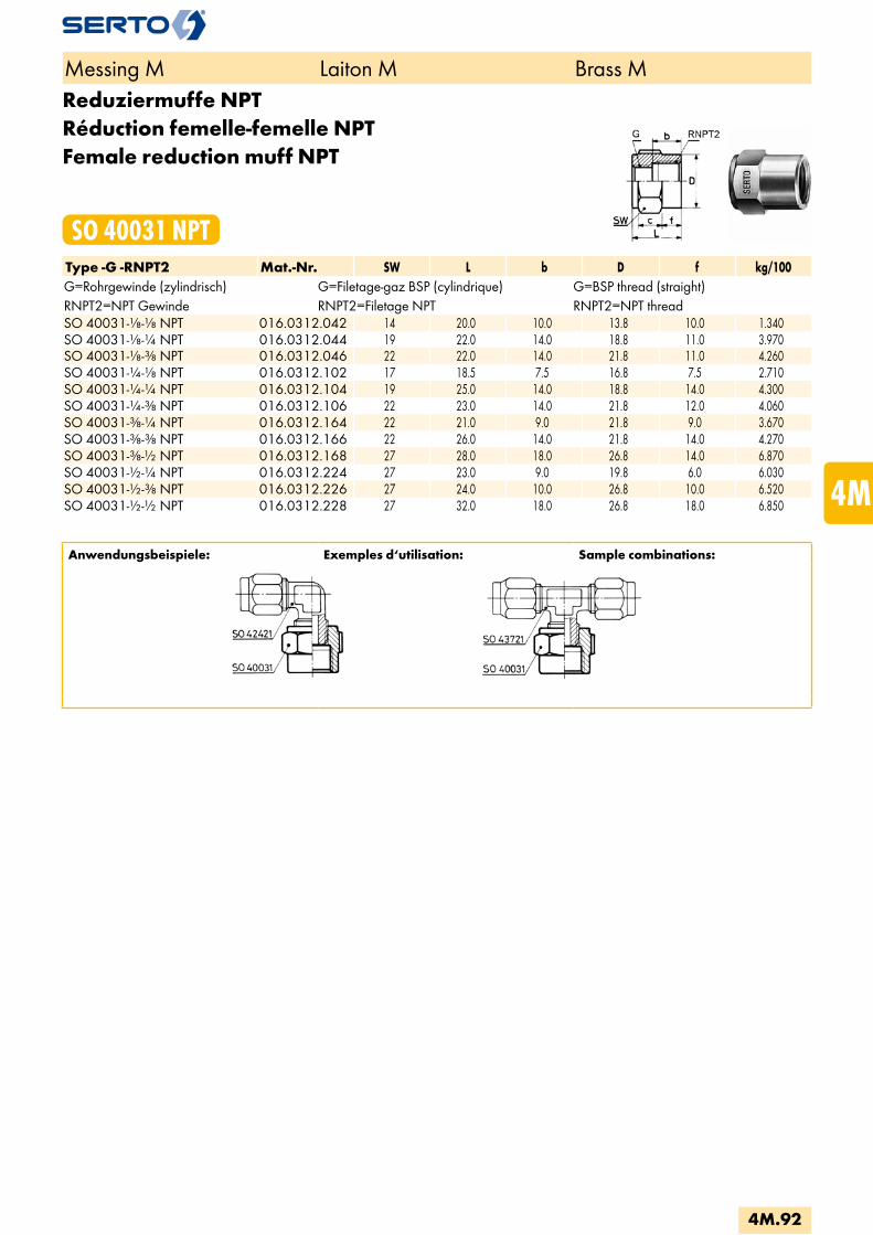
Reduziermuffe NPTRéduction femelle-femelle NPTFemale reduction muff NPT
SO 40031 NPTType -G -RNPT2 Mat.-Nr. SW L b D f kg/100G=Rohrgewinde (zylindrisch) G=Filetage-gaz BSP (cylindrique) G=BSP thread (straight)RNPT2=NPT Gewinde RNPT2=Filetage NPT RNPT2=NPT threadSO 40031-1/8-1/8 NPT 016.0312.042 14 20.0 10.0 13.8 10.0 1.340SO 40031-1/8-1/4 NPT 016.0312.044 19 22.0 14.0 18.8 11.0 3.970SO 40031-1/8-3/8 NPT 016.0312.046 22 22.0 14.0 21.8 11.0 4.260SO 40031-1/4-1/8 NPT 016.0312.102 17 18.5 7.5 16.8 7.5 2.710SO 40031-1/4-1/4 NPT 016.0312.104 19 25.0 14.0 18.8 14.0 4.300SO 40031-1/4-3/8 NPT 016.0312.106 22 23.0 14.0 21.8 12.0 4.060SO 40031-3/8-1/4 NPT 016.0312.164 22 21.0 9.0 21.8 9.0 3.670SO 40031-3/8-3/8 NPT 016.0312.166 22 26.0 14.0 21.8 14.0 4.270SO 40031-3/8-1/2 NPT 016.0312.168 27 28.0 18.0 26.8 14.0 6.870SO 40031-1/2-1/4 NPT 016.0312.224 27 23.0 9.0 19.8 6.0 6.030SO 40031-1/2-3/8 NPT 016.0312.226 27 24.0 10.0 26.8 10.0 6.520SO 40031-1/2-1/2 NPT 016.0312.228 27 32.0 18.0 26.8 18.0 6.850
Anwendungsbeispiele: Exemples d‘utilisation: Sample combinations:
Messing M Laiton M Brass M
4M.92
i
s
3F
4M
4G
5
5L
6
7
8
9
10
11
12

ReduziernippelEinschraubgewinde kegelig
Réduction femelle-mâleFiletage conique
Male reduction nippleTapered adaptor thread
SO 40041 G RType -G -R2 Mat.-Nr. SW L b c z kg/100G=Rohrgewinde (zylindrisch) G=Filetage-gaz BSP (cylindrique) G=BSP thread (straight)R2=Rohrgewinde (kegelig) R2=Filetage-gaz BSP (conique) R2=BSP thread (tapered)SO 40041-1/8-1/8 016.0411.042 14 21.0 8.0 13.0 14.5 2.100SO 40041-1/8-1/4 016.0411.044 14 17.5 8.0 5.5 8.0 1.060SO 40041-1/8-3/8 016.0411.046 17 18.0 8.0 6.0 8.0 2.280SO 40041-1/8-1/2 016.0411.048 22 23.0 8.0 7.0 10.0 3.970SO 40041-1/4-1/8 016.0411.102 17 22.0 9.0 13.0 15.5 1.630SO 40041-1/4-1/4 016.0411.104 17 26.0 6.0 14.0 10.0 2.600SO 40041-1/4-3/8 016.0411.106 17 20.0 9.0 8.0 10.0 1.690SO 40041-1/4-1/2 016.0411.108 22 23.0 9.0 7.0 10.0 3.590SO 40041-1/4-3/4 016.0411.110 27 25.5 9.0 9.0 11.0 9.050SO 40041-3/8-1/8 016.0411.162 22 23.0 9.5 16.0 16.5 3.490SO 40041-3/8-1/4 016.0411.164 22 27.0 9.5 15.0 17.5 3.180SO 40041-3/8-3/8 016.0411.166 22 27.0 6.0 15.0 10.0 4.500SO 40041-3/8-1/2 016.0411.168 22 23.0 9.5 10.0 10.0 2.740SO 40041-3/8-3/4 016.0411.170 27 25.5 9.5 9.0 11.0 7.510SO 40041-1/2-1/4 016.0411.224 27 29.0 11.5 17.0 19.0 5.852SO 40041-1/2-3/8 016.0411.226 27 29.0 11.5 17.0 19.0 5.720SO 40041-1/2-1/2 016.0411.228 27 32.0 8.0 18.0 12.0 8.200SO 40041-1/2-3/4 016.0411.232 27 27.5 11.5 9.0 13.0 5.133SO 40041-1/2-1 016.0411.236 36 31.0 11.5 11.0 14.0 13.100SO 40041-3/4-3/8 016.0411.286 32 33.5 14.0 21.5 23.5 8.900SO 40041-3/4-1/2 016.0411.288 32 37.5 14.0 21.5 24.5 11.000SO 40041-3/4-3/4 016.0411.292 32 38.0 14.0 21.5 23.5 9.400SO 40041-3/4-1 016.0411.296 36 31.0 14.0 14.0 14.0 13.900 SO 40041-M5-1/8 016.0413.050 10 12.0 6.0 4.0 5.5 0.580
Anwendungsbeispiele: Exemples d‘utilisation: Sample combinations:
Messing M Laiton M Brass M
4M.93
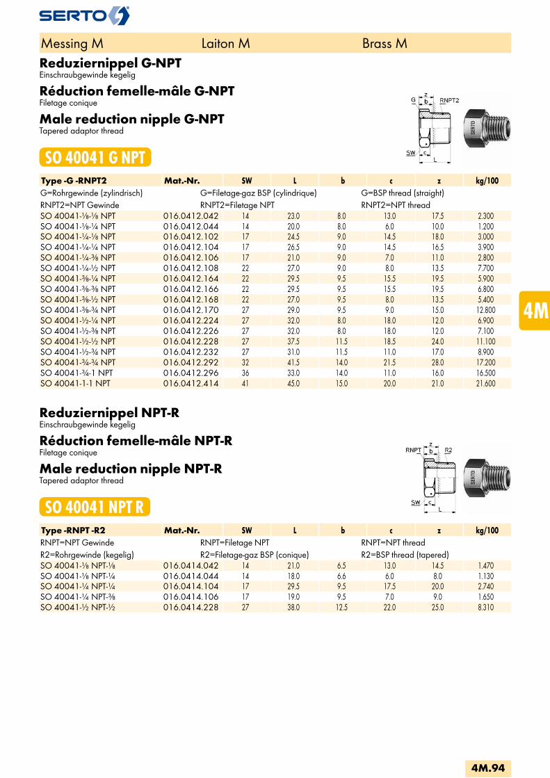
Reduziernippel G-NPTEinschraubgewinde kegelig
Réduction femelle-mâle G-NPTFiletage conique
Male reduction nipple G-NPTTapered adaptor thread
SO 40041 G NPTType -G -RNPT2 Mat.-Nr. SW L b c z kg/100G=Rohrgewinde (zylindrisch) G=Filetage-gaz BSP (cylindrique) G=BSP thread (straight)RNPT2=NPT Gewinde RNPT2=Filetage NPT RNPT2=NPT threadSO 40041-1/8-1/8 NPT 016.0412.042 14 23.0 8.0 13.0 17.5 2.300SO 40041-1/8-1/4 NPT 016.0412.044 14 20.0 8.0 6.0 10.0 1.200SO 40041-1/4-1/8 NPT 016.0412.102 17 24.5 9.0 14.5 18.0 3.000SO 40041-1/4-1/4 NPT 016.0412.104 17 26.5 9.0 14.5 16.5 3.900SO 40041-1/4-3/8 NPT 016.0412.106 17 21.0 9.0 7.0 11.0 2.800SO 40041-1/4-1/2 NPT 016.0412.108 22 27.0 9.0 8.0 13.5 7.700SO 40041-3/8-1/4 NPT 016.0412.164 22 29.5 9.5 15.5 19.5 5.900SO 40041-3/8-3/8 NPT 016.0412.166 22 29.5 9.5 15.5 19.5 6.800SO 40041-3/8-1/2 NPT 016.0412.168 22 27.0 9.5 8.0 13.5 5.400SO 40041-3/8-3/4 NPT 016.0412.170 27 29.0 9.5 9.0 15.0 12.800SO 40041-1/2-1/4 NPT 016.0412.224 27 32.0 8.0 18.0 12.0 6.900SO 40041-1/2-3/8 NPT 016.0412.226 27 32.0 8.0 18.0 12.0 7.100SO 40041-1/2-1/2 NPT 016.0412.228 27 37.5 11.5 18.5 24.0 11.100SO 40041-1/2-3/4 NPT 016.0412.232 27 31.0 11.5 11.0 17.0 8.900SO 40041-3/4-3/4 NPT 016.0412.292 32 41.5 14.0 21.5 28.0 17.200SO 40041-3/4-1 NPT 016.0412.296 36 33.0 14.0 11.0 16.0 16.500SO 40041-1-1 NPT 016.0412.414 41 45.0 15.0 20.0 21.0 21.600
Reduziernippel NPT-REinschraubgewinde kegelig
Réduction femelle-mâle NPT-RFiletage conique
Male reduction nipple NPT-RTapered adaptor thread
SO 40041 NPT RType -RNPT -R2 Mat.-Nr. SW L b c z kg/100RNPT=NPT Gewinde RNPT=Filetage NPT RNPT=NPT threadR2=Rohrgewinde (kegelig) R2=Filetage-gaz BSP (conique) R2=BSP thread (tapered)SO 40041-1/8 NPT-1/8 016.0414.042 14 21.0 6.5 13.0 14.5 1.470SO 40041-1/8 NPT-1/4 016.0414.044 14 18.0 6.6 6.0 8.0 1.130SO 40041-1/4 NPT-1/4 016.0414.104 17 29.5 9.5 17.5 20.0 2.740SO 40041-1/4 NPT-3/8 016.0414.106 17 19.0 9.5 7.0 9.0 1.650SO 40041-1/2 NPT-1/2 016.0414.228 27 38.0 12.5 22.0 25.0 8.310
Messing M Laiton M Brass M
4M.94
i
s
3F
4M
4G
5
5L
6
7
8
9
10
11
12

Reduziernippel NPT-NPTEinschraubgewinde kegelig
Réduction femelle-mâle NPT-NPTFiletage conique
Male reduction nipple NPT-NPTTapered adaptor thread
SO 40041 NPT NPTType -RNPT -RNPT2 Mat.-Nr. SW L b c z kg/100RNPT=NPT Gewinde RNPT=Filetage NPT RNPT=NPT threadRNPT2=NPT Gewinde RNPT2=Filetage NPT RNPT2=NPT threadSO 40041-1/4 NPT 1/8 NPT 016.0415.102 17 27.5 21.0 17.5 22.0 2.450SO 40041-1/4 NPT 1/4 NPT 016.0415.104 17 31.5 21.0 17.5 22.0 2.600SO 40041-1/4 NPT 1/2 NPT 016.0415.108 22 27.0 9.5 8.0 13.5 5.200SO 40041-1/2 NPT-1/4 NPT 016.0415.224 27 37.0 25.0 23.0 14.0 8.600SO 40041-1/2 NPT-3/8 NPT 016.0415.226 27 37.0 25.0 23.0 14.0 9.200
VerschlussschraubeBouchon d‘obturationScrew plug
SO 40371Type -R Mat.-Nr. SW L b kg/100R=Rohrgewinde (kegelig) R=Filetage-gaz BSP (conique) R=BSP thread (tapered) SO 40371-1/8 016.0711.020 5 8.0 5.5 0.340SO 40371-1/4 016.0711.040 7 10.0 7.5 0.750SO 40371-3/8 016.0711.060 8 10.0 6.5 1.320SO 40371-1/2 016.0711.080 10 10.0 6.5 1.940SO 40371-3/4 016.0711.120 12 12.0 7.5 4.110
Einschraubtülle NPTDouille cannelée à visser NPTMale adaptor hose nipple NPT
SO 40511 NPTType -d1 -RNPT Mat.-Nr. SW L a b e kg/100RNPT=NPT Gewinde RNPT=Filetage NPT RNPT=NPT thread SO 40511-6-1/4 NPT 016.0512.110 14 36.5 19.5 12.0 4.0 2.050SO 40511-6-3/8 NPT 016.0512.120 17 37.0 20.0 12.0 4.0 3.150SO 40511-8-1/8 NPT 016.0512.160 12 31.5 14.5 12.0 6.0 1.290
Messing M Laiton M Brass M
4M.95

EinschraubtülleDouille canellèe a visserMale adaptor hose nipple
SO 40511Type -d1 -R Mat.-Nr. SW L a b e kg/100R=Rohrgewinde (kegelig) R=Filetage-gaz BSP (conique) R=BSP thread (tapered) SO 40511-4-1/8 016.0511.060 10 23.0 12.0 8.0 3.0 0.750SO 40511-6-1/8 016.0511.100 10 29.0 12.0 12.0 4.0 0.730SO 40511-6-1/4 016.0511.110 14 34.5 17.5 12.0 4.0 1.920SO 40511-8-1/8 016.0511.160 10 29.0 12.0 12.0 6.0 0.780SO 40511-8-1/4 016.0511.170 14 34.5 17.5 12.0 6.0 1.690SO 40511-8-3/8 016.0511.180 17 35.0 18.0 12.0 6.0 2.910SO 40511-8-1/2 016.0511.185 22 40.0 23.0 12.0 6.0 4.530SO 40511-10-1/8 016.0511.265 12 31.0 12.0 14.0 6.0 1.580SO 40511-10-1/4 016.0511.270 14 36.5 17.5 14.0 7.0 1.640SO 40511-10-3/8 016.0511.280 17 37.0 18.0 14.0 7.0 2.910SO 40511-10-1/2 016.0511.285 22 42.0 23.0 14.0 7.0 4.900SO 40511-13-3/8 016.0511.450 17 39.0 18.0 15.0 10.0 2.910SO 40511-13-1/2 016.0511.454 22 44.0 23.0 15.0 10.0 5.340SO 40511-16-1/2 016.0511.566 22 49.0 23.0 18.0 13.0 5.410SO 40511-19-1/2 016.0511.676 22 49.0 23.0 18.0 15.0 5.800SO 40511-19-3/4 016.0511.678 27 51.0 25.0 18.0 16.0 10.900
SchlauchklemmeStahl promatverzinkt
Collier de serrageAcier zingué passivé
Hose clipZinc promatised steel
SO 40512Type -d Mat.-Nr. B D kg/100 SO 40512-3-5 016.0610.030 5.0 5.0 0.065SO 40512-5-7 016.0610.050 3.0 7.0 0.100SO 40512-7-9 016.0610.070 7.0 9.0 0.220SO 40512-9-11 016.0610.090 7.0 11.0 0.245SO 40512-11-13 016.0610.110 7.0 13.0 0.280SO 40512-13-15 016.0610.130 7.5 15.0 0.385SO 40512-15-18 016.0610.150 8.0 18.0 0.510SO 40512-17-20 016.0610.170 8.5 20.0 0.585SO 40512-20-23 016.0610.200 9.0 23.0 0.920SO 40512-23-27 016.0610.230 10.0 27.0 1.200
Messing M Laiton M Brass M
4M.96
i
s
3F
4M
4G
5
5L
6
7
8
9
10
11
12

SAE Flare
Verschraubung für die Kälte- und Klimaindustrie
Le raccord pour l‘industrie du froid et de la climatisation
Unions for the cooling and air-conditioning industries
4M.97

4M.100Armaturenanschluss SAEEcrou de raccordement SAENut connection SAE
SO 40221 SAE
4M.101Verschraubung mit Anschlussmuffe SAEUnion femelle SAEFemale adaptor union SAE
SO 41221 SAE
4M.101Dichtung für SAE GewindeJoint cuivreCopper seal gasket
SO 40008 SAE
4M.101Aufweitdorn SAECalibreur SAECalibration tool SAE
AC 957200
4M.102Kalibrierwerkzeug SAEOutil de calibrage SAECalibration tool SAE
AC 950116
Sonderausführungen:Exécution en option:Optional Services:
Spezialbehandlung für Einsatz mit SauerstoffTraitement spécial pour utilisation sous oxygèneSpecial treatment for use with oxygen
Spezialbehandlung - silikonfreiTraitement spécial - sans siliconeSpecial treatment - silicone free
Spezialreinigung - entfettetTraitement spécial - sans siliconeSpecial treatment - degreased
Chemisch vernickeltNickelage chimiqueChemical nickel-plated
Seite/Page/Page
Übersicht Aperçu Overview
4M.98
i
s
3F
4M
4G
5
5L
6
7
8
9
10
11
12
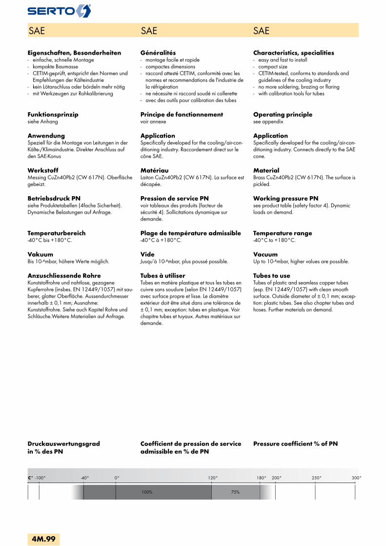
C° 300°250°200°180°0°-40°-100° 120°
100% 75%
SAE SAE SAE
Eigenschaften, Besonderheiten- einfache, schnelle Montage- kompakte Baumasse- CETIM-geprüft, entspricht den Normen und
Empfehlungen der Kälteindustrie - kein Lötanschluss oder bördeln mehr nötig- mit Werkzeugen zur Rohkalibrierung
Funktionsprinzipsiehe Anhang
AnwendungSpeziell für die Montage von Leitungen in der Kälte-/Klimaindustrie. Direkter Anschluss auf den SAE-Konus
WerkstoffMessing CuZn40Pb2 (CW 617N). Oberfläche gebeizt.
Betriebsdruck PNsiehe Produktetabellen (4fache Sicherheit). Dynamische Belastungen auf Anfrage.
Temperaturbereich-40°C bis +180°C.
VakuumBis 10-4mbar, höhere Werte möglich.
Anzuschliessende RohreKunststoffrohre und nahtlose, gezogene Kupferrohre (insbes. EN 12449/1057) mit sau-berer, glatter Oberfläche. Aussendurchmesser innerhalb ± 0,1 mm; Ausnahme: Kunststoffrohre. Siehe auch Kapitel Rohre und Schläuche.Weitere Materialien auf Anfrage.
Généralités- montage facile et rapide- compactes dimensions- raccord attesté CETIM, conformité avec les
normes et recommendations de l'industrie de la réfrigération
- ne nécessite ni raccord soudé ni collerette- avec des outils pour calibration des tubes
Principe de fonctionnementvoir annexe
ApplicationSpecifically developed for the cooling/air-con-ditioning industry. Raccordement direct sur le cône SAE.
MatériauLaiton CuZn40Pb2 (CW 617N). La surface est décapée.
Pression de service PNvoir tableaux des produits (facteur de sécurité 4). Sollicitations dynamique sur demande.
Plage de température admissible-40°C à +180°C.
VideJusqu’à 10-4mbar, plus poussé possible.
Tubes à utiliserTubes en matière plastique et tous les tubes en cuivre sans soudure (selon EN 12449/1057) avec surface propre et lisse. Le diamètre extérieur doit être situé dans une tolérance de ± 0,1 mm; exception: tubes en plastique. Voir chapitre tubes et tuyaux. Autres matériaux sur demande.
Characteristics, specialities- easy and fast to install- compact size- CETIM-tested, conforms to standards and
guidelines of the cooling industry- no more soldering, brazing or flaring- with calibration tools for tubes
Operating principlesee appendix
ApplicationSpecifically developed for the cooling/air-con-ditioning industry. Connects directly to the SAE cone.
MaterialBrass CuZn40Pb2 (CW 617N). The surface is pickled.
Working pressure PNsee product table (safety factor 4). Dynamic loads on demand.
Temperature range-40°C to +180°C.
VacuumUp to 10-4mbar, higher values are possible.
Tubes to useTubes of plastic and seamless copper tubes (esp. EN 12449/1057) with clean smooth surface. Outside diameter of ± 0,1 mm; excep-tion: plastic tubes. See also chapter tubes and hoses. Further materials on demand.
Druckauswertungsgrad in % des PN
Coefficient de pression de service admissible en % de PN
Pressure coefficient % of PN
4M.99
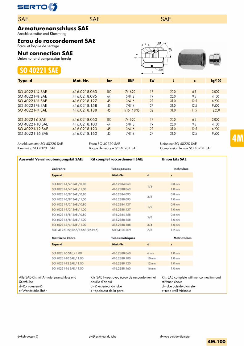
Armaturenanschluss SAEAnschlussmutter und Klemmring
Ecrou de raccordement SAEEcrou et bague de serrage
Nut connection SAEUnion nut and compression ferrule
SO 40221 SAEType -d Mat.-Nr. bar UNF SW L z kg/100 SO 40221-1/4 SAE 416.0218.063 100 7/16-20 17 20.0 6.5 3.000SO 40221-3/8 SAE 416.0218.095 64 5/8-18 19 25.0 9.5 4.100SO 40221-1/2 SAE 416.0218.127 45 3/4-16 22 31.0 12.5 6.200SO 40221-5/8 SAE 416.0218.158 45 7/8-14 27 31.0 12.5 9.500SO 40221-3/4 SAE 416.0218.188 45 1 1/16-14 UNS 32 31.0 11.5 12.200 SO 40221-6 SAE 416.0218.060 100 7/16-20 17 20.0 6.5 3.000SO 40221-10 SAE 416.0218.100 64 5/8-18 19 25.0 9.5 4.100SO 40221-12 SAE 416.0218.120 45 3/4-16 22 31.0 12.5 6.200SO 40221-16 SAE 416.0218.160 45 7/8-14 27 31.0 12.5 9.500
Anschlussmutter SO 40220 SAEKlemmring SO 40201 SAE
Ecrou SO 40220 SAEBague de serrage SO 40201 SAE
Union nut SO 40220 SAECompression ferrule SO 40201 SAE
Auswahl Verschraubungungskit SAE: Kit complet raccordement SAE: Union kits SAE:
Alle SAE-Kits mit Armaturenanschluss und Stützhülsed=Rohraussen-Øs=Wandstärke Rohr
Kits SAE livrées avec écrou de raccordement et douille d‘appuid=Ø éxterieur du tubes =épaisseur de la paroi
Kits SAE complete with nut connection and stiffener sleeved=tube outside diameters=tube wall thickness
SAE SAE SAE
d=Rohraussen-Ø d=Ø extérieur du tube d=tube outside diameter
4M.100
i
s
3F
4M
4G
5
5L
6
7
8
9
10
11
12
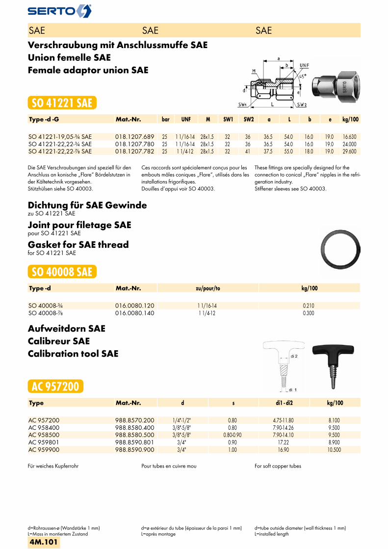
Verschraubung mit Anschlussmuffe SAEUnion femelle SAEFemale adaptor union SAE
SO 41221 SAEType -d -G Mat.-Nr. bar UNF M SW1 SW2 a L b e kg/100 SO 41221-19,05-3/4 SAE 018.1207.689 25 1 1/16-14 28x1.5 32 36 36.5 54.0 16.0 19.0 16.630SO 41221-22,22-3/4 SAE 018.1207.780 25 1 1/16-14 28x1.5 32 36 36.5 54.0 16.0 19.0 24.000SO 41221-22,22-7/8 SAE 018.1207.782 25 1 1/4-12 28x1.5 32 41 37.5 55.0 18.0 19.0 29.600
Die SAE Verschraubungen sind speziell für den Anschluss an konische „Flare“ Bördelstutzen in der Kältetechnik vorgesehen.Stützhülsen siehe SO 40003.
Ces raccords sont spécialement conçus pour les embouts mâles coniques „Flare“, utilisés dans les installations frigorifiques.Douilles d‘appui voir SO 40003.
These fittings are specially designed for the connection to conical „Flare“ nipples in the refri-geration industry.Stiffener sleeves see SO 40003.
Dichtung für SAE Gewindezu SO 41221 SAE
Joint pour filetage SAEpour SO 41221 SAE
Gasket for SAE threadfor SO 41221 SAE
SO 40008 SAEType -d Mat.-Nr. zu/pour/to kg/100 SO 40008-3/4 016.0080.120 1 1/16-14 0.210SO 40008-7/8 016.0080.140 1 1/4-12 0.300
Aufweitdorn SAECalibreur SAECalibration tool SAE
AC 957200Type Mat.-Nr. d s di1 - di2 kg/100 AC 957200 988.8570.200 1/4"-1/2" 0.80 4.75-11.80 8.100AC 958400 988.8580.400 3/8"-5/8" 0.80 7.90-14.26 9.500AC 958500 988.8580.500 3/8"-5/8" 0.80-0.90 7.90-14.10 9.500AC 959801 988.8590.801 3/4" 0.90 17.22 8.900AC 959900 988.8590.900 3/4" 1.00 16.90 10.500
Für weiches Kupferrohr Pour tubes en cuivre mou For soft copper tubes
SAE SAE SAE
d=Rohraussen-ø (Wandstärke 1 mm)L=Mass in montiertem Zustand
d=ø extérieur du tube (épaisseur de la paroi 1 mm)L=après montage
d=tube outside diameter (wall thickness 1 mm)L=installed length
4M.101

Kalibrierwerkzeug SAEOutil de calibrage SAECalibration tool SAE
AC 950116Type Mat.-Nr. d s kg/100Für Zollrohre Pour tubes pouces For inch tubes AC 950116 988.8501.116 1/4" 0.80 0.105AC 950112 988.8501.112 1/4" 1.00 0.105AC 952090 988.8520.190 3/8" 0.76 0.140AC 952085 988.8520.185 3/8" 0.90 0.140AC 952087 988.8520.187 3/8" 1.00 0.140AC 953080 988.8530.280 1/2" 0.81 0.165AC 953081 988.8530.281 1/2" 0.90 0.165AC 953069 988.8530.269 1/2" 1.00 0.165AC 954050 988.8540.500 5/8" 0.90 0.210AC 954150 988.8541.500 5/8" 1.02 0.210AC 955041 988.8550.640 3/4" 0.90 0.230
Für metrische Rohre Pour tubes métriques For metric tubes AC 950060 988.8501.111 6.000 1.00 0.105AC 952000 988.8520.189 10.000 1.00 0.140AC 953020 988.8530.240 12.000 1.00 0.165AC 954160 988.8540.499 16.000 1.00 0.210
Für weiches Kupferrohr Pour tubes en cuivre recuit For soft copper tubes
SAE SAE SAE
d=Rohraussen-Øs=Wandstärke Rohr
d=Ø extérieur du tubes=épaisseur de la paroi
d=tube outside diameters=wall thickness
4M.102
i
s
3F
4M
4G
5
5L
6
7
8
9
10
11
12

4G
Messing G
Verschraubungen
Laiton G
Raccords
Brass G
Unions

4G.4-4G.5KlemmringBague de serrageCompression ferrule
SO 00001
4G.6AbschlusszapfenBouchon d‘arrêtPlug
SO 40002
4G.7-4G.8StützhülseDouille d‘appuiStiffener sleeve
SO 40003
4G.9-4G.11DichtungJointWasher
SO 40005
4G.12AnschlussmutterEcrouUnion nut
SO 00020
4G.13-4G.14ArmaturenanschlussEcrou de raccordementNut connection
SO 00021
4G.15-4G.16ÜbergangsmuffeAdaptateur femelleFemale adaptor
SO 00030
4G.17-4G.19ÜbergangsnippelAdaptateur mâleMale adaptor
SO 00040
4G.20AnschlussnippelEcrou de raccordement mâleNipple connection
SO 01001
4G.22-4G.23Gerade VerschraubungUnion doubleStraight union
SO 01011
4G.24-4G.27Gerade EinschraubverschraubungUnion mâleMale adaptor union
SO 01121
4G.28-4G.29Gerade AufschraubverschraubungUnion femelleFemale adaptor union
SO 01221
4G.30Verschraubung mit EinlötnippelUnion avec embout à braserAdaptor union with soldering nipple
SO 01421
4G.31-4G.32Gerade SchottverschraubungUnion double pour passage de cloisonPanel mount union
SO 01521
4G.33-4G.34EinstellnippelUnion orientable mâleAdjustable male adaptor
SO 41600
4G.34WinkelverschraubungCoudeElbow union
SO 02021
4G.35AnschlusswinkelCoude femelleFemale adaptor elbow union
SO 02321
4G.36-4G.37Winkel-EinschraubverschraubungCoude mâleMale adaptor elbow union
SO 02421
4G.38Winkel-AufschraubverschraubungCoude femelleFemale adaptor elbow union
SO 02521
4G.39WinkelverschraubungCoude orientableAdjustable elbow union
SO 02621
4G.40Winkel-SchottverschraubungCoude pour passage de cloisonPanel mount elbow union
SO 02721
4G.40-4G.43T-VerschraubungTéTee union
SO 03021
4G.44Einstellbare T-VerschraubungTé orientableAdjustable Tee union
SO 03621 T
4G.45Einstellbare L-VerschraubungL orientableAdjustable L union
SO 03621 L
Seite/Page/Page Seite/Page/Page Seite/Page/Page
Übersicht Aperçu Overview
4G.1
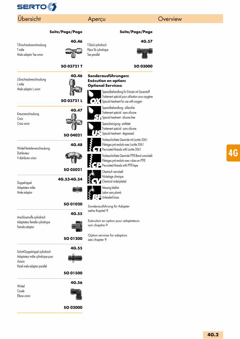
4G.46T-EinschraubverschraubungT mâleMale adaptor Tee union
SO 03721 T
4G.46L-EinschraubverschraubungL mâleMale adaptor L union
SO 03721 L
4G.47KreuzverschraubungCroixCross union
SO 04021
4G.48Winkel-VerteilerverschraubungDistributeurV distributor union
SO 05021
4G.53-4G.54DoppelnippelAdaptateur mâleMale adaptor
SO 01020
4G.55Anschlussmuffe zylindrischAdaptateur femelle cylindriqueFemale adaptor
SO 01200
4G.55Schott-Doppelnippel zylindrischAdaptateur mâle cylindrique pour cloisonPanel male adaptor parallel
SO 01500
4G.56WinkelCoudeElbow union
SO 02000
4G.57T-Stück zylindrischPièce Té cylindriqueTee parallel
SO 03000
Sonderausführungen:Exécution en option:Optional Services:
Spezialbehandlung für Einsatz mit SauerstoffTraitement spécial pour utilisation sous oxygèneSpecial treatment for use with oxygen
Spezialbehandlung - silikonfreiTraitement spécial - sans siliconeSpecial treatment - silicone free
Spezialreinigung - entfettetTraitement spécial - sans siliconeSpecial treatment - degreased
Vorbeschichtete Gewinde mit Loctite 5061Filetages pré enduits avec Loctite 5061Pre-coated threads with Loctite 5061
Vorbeschichtete Gewinde PTFE-Band umwickeltFiletages pré enduits avec ruban en PTFEPre-coated threads with PTFE-tape
Chemisch vernickeltNickelage chimiqueChemical nickel-plated
Messing bleifreiLaiton sans plombUnleaded brass
Sonderausführung für Adaptersiehe Kapitel 9
Exécution en option pour adaptateurs voir chapitre 9
Option services for adaptors see chapter 9
Seite/Page/Page Seite/Page/Page
Übersicht Aperçu Overview
4G.2
i
s
3F
4M
4G
5
5L
6
7
8
9
10
11
12
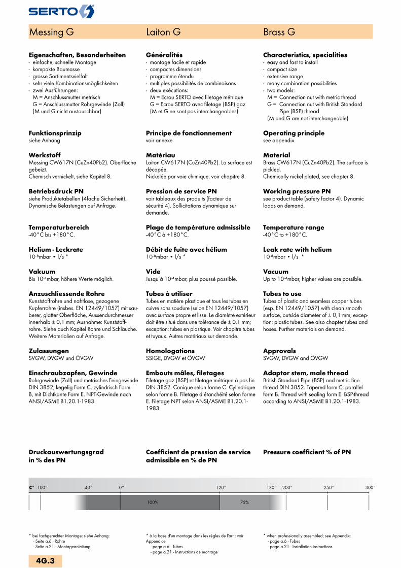
C° 300°250°200°180°0°-40°-100° 120°
100% 75%
Messing G Laiton G Brass G
Eigenschaften, Besonderheiten- einfache, schnelle Montage- kompakte Baumasse- grosse Sortimentsvielfalt- sehr viele Kombinationsmöglichkeiten- zwei Ausführungen: M = Anschlussmutter metrisch G = Anschlussmutter Rohrgewinde (Zoll) (M und G nicht austauschbar)
Funktionsprinzipsiehe Anhang
WerkstoffMessing CW617N (CuZn40Pb2). Oberfläche gebeizt.Chemisch vernickelt, siehe Kapitel 8.
Betriebsdruck PNsiehe Produktetabellen (4fache Sicherheit). Dynamische Belastungen auf Anfrage.
Temperaturbereich-40°C bis +180°C.
Helium - Leckrate10-8mbar • l/s *
VakuumBis 10-4mbar, höhere Werte möglich.
Anzuschliessende RohreKunststoffrohre und nahtlose, gezogene Kupferrohre (insbes. EN 12449/1057) mit sau-berer, glatter Oberfläche, Aussendurchmesser innerhalb ± 0,1 mm; Ausnahme: Kunststoff-rohre. Siehe auch Kapitel Rohre und Schläuche.Weitere Materialien auf Anfrage.
ZulassungenSVGW, DVGW und ÖVGW
Einschraubzapfen, GewindeRohrgewinde (Zoll) und metrisches Feingewinde DIN 3852, kegelig Form C, zylindrisch Form B, mit Dichtkante Form E. NPT-Gewinde nach ANSI/ASME B1.20.1-1983.
Généralités- montage facile et rapide- compactes dimensions- programme étendu- multiples possibilités de combinaisons- deux exécutions: M = Ecrou SERTO avec filetage métrique G = Ecrou SERTO avec filetage (BSP) gaz (M et G ne sont pas interchangeables)
Principe de fonctionnementvoir annexe
MatériauLaiton CW617N (CuZn40Pb2). La surface est décapée.Nickelée par voie chimique, voir chapitre 8.
Pression de service PNvoir tableaux des produits (facteur de sécurité 4). Sollicitations dynamique sur demande.
Plage de température admissible-40°C à +180°C.
Débit de fuite avec hélium10-8mbar • l/s *
VideJusqu’à 10-4mbar, plus poussé possible.
Tubes à utiliserTubes en matière plastique et tous les tubes en cuivre sans soudure (selon EN 12449/1057) avec surface propre et lisse. Le diamètre extérieur doit être situé dans une tolérance de ± 0,1 mm; exception: tubes en plastique. Voir chapitre tubes et tuyaux. Autres matériaux sur demande.
HomologationsSSIGE, DVGW et ÖVGW
Embouts mâles, filetagesFiletage gaz (BSP) et filetage métrique à pas fin DIN 3852. Conique selon forme C. Cylindrique selon forme B. Filetage d’étanchéité selon forme E. Filetage NPT selon ANSI/ASME B1.20.1-1983.
Characteristics, specialities- easy and fast to install- compact size- extensive range- many combination possibilities- two models: M = Connection nut with metric thread G = Connection nut with British Standard Pipe (BSP) thread (M and G are not interchangeable)
Operating principlesee appendix
MaterialBrass CW617N (CuZn40Pb2). The surface is pickled.Chemically nickel plated, see chapter 8.
Working pressure PNsee product table (safety factor 4). Dynamic loads on demand.
Temperature range-40°C to +180°C.
Leak rate with helium10-8mbar • l/s *
VacuumUp to 10-4mbar, higher values are possible.
Tubes to useTubes of plastic and seamless copper tubes (esp. EN 12449/1057) with clean smooth surface, outside diameter of ± 0,1 mm; excep-tion: plastic tubes. See also chapter tubes and hoses. Further materials on demand.
ApprovalsSVGW, DVGW and ÖVGW
Adaptor stem, male threadBritish Standard Pipe (BSP) and metric fine thread DIN 3852. Tapered form C, parallel form B. Thread with sealing form E. BSP-thread according to ANSI/ASME B1.20.1-1983.
Pressure coefficient % of PNCoefficient de pression de service admissible en % de PN
Druckauswertungsgrad in % des PN
* bei fachgerechter Montage; siehe Anhang: - Seite a.6 - Rohre - Seite a.21 - Montageanleitung
* à la base d'un montage dans les règles de l'art ; voir Appendice: - page a.6 - Tubes - page a.21 - Instructions de montage
* when professionally assembled; see Appendix: - page a.6 - Tubes - page a.21 - Installation instructions
4G.3

KlemmringBague de serrageCompression ferrule
SO 00001Type -d Mat.-Nr. bar L D z e kg/100Für metrische Rohre Pour tubes métriques For metric tubes SO 40001-4 016.0010.040 125 5.0 6.0 1.0 3.5 0.060SO 40001-5 016.0010.050 125 5.5 6.8 1.0 4.0 0.060SO 40001-6 * 016.0010.060 250 6.5 8.4 1.2 4.5 0.120SO 00001-8 246.0010.080 125 7.0 11.0 1.0 7.0 0.190SO 00001-10 246.0010.100 100 8.0 13.5 1.0 9.0 0.330SO 00001-12 246.0010.120 100 10.0 16.0 1.2 11.0 0.550SO 00001-14 246.0010.140 64 12.0 18.0 1.5 13.0 0.780SO 00001-15 246.0010.150 64 12.0 18.5 1.5 14.0 0.770SO 00001-18 246.0010.180 64 14.0 23.0 1.5 16.0 1.420SO 00001-22 246.0010.220 40 14.0 27.0 1.5 20.0 1.690
Für Zollrohre Pour tubes pouces For inch tubes SO 40001-6,35 016.0010.063 100 6.5 8.4 1.2 4.5 0.120SO 00001-7,94 246.0010.079 125 7.0 11.0 1.0 7.0 0.190SO 00001-9,52 246.0010.095 100 8.0 13.0 1.0 8.0 0.320SO 00001-12,7 246.0010.127 100 10.0 17.0 1.2 11.0 0.610
Messing G Laiton G Brass G
d=Rohraussen-ø d=ø extérieur du tube d=tube outside diameter
4G.4
i
s
3F
4M
4G
5
5L
6
7
8
9
10
11
12
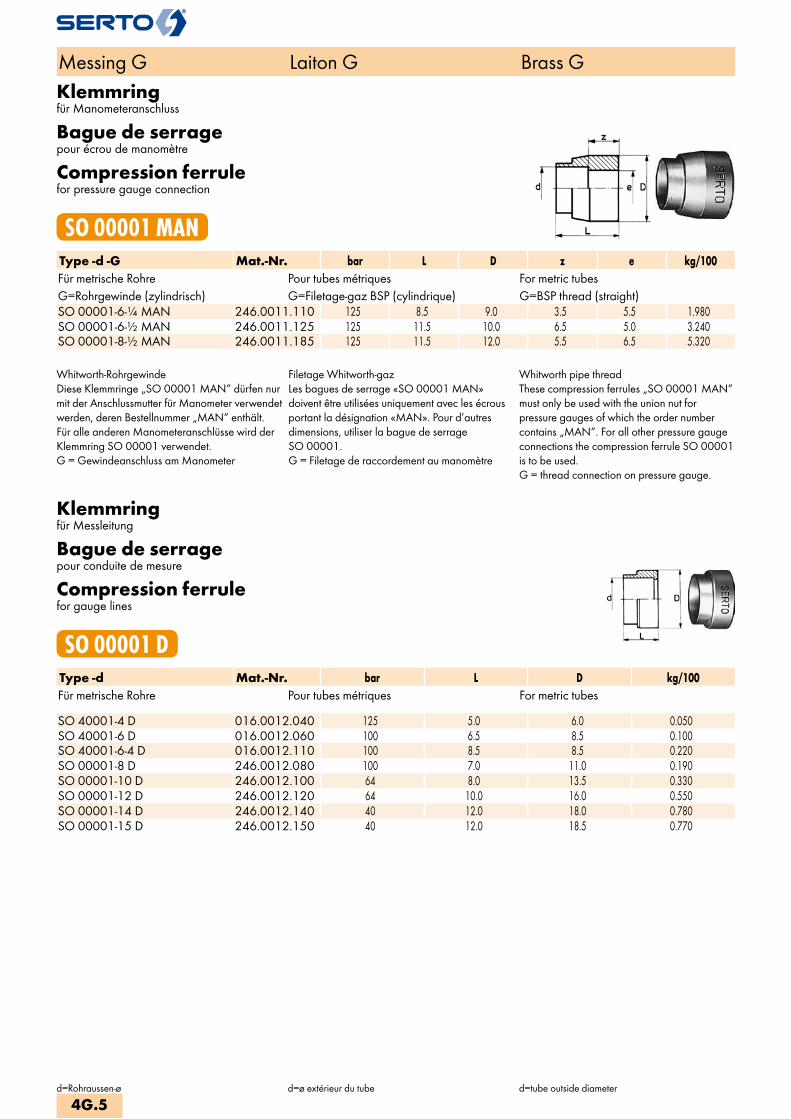
Klemmringfür Manometeranschluss
Bague de serragepour écrou de manomètre
Compression ferrulefor pressure gauge connection
SO 00001 MANType -d -G Mat.-Nr. bar L D z e kg/100Für metrische Rohre Pour tubes métriques For metric tubesG=Rohrgewinde (zylindrisch) G=Filetage-gaz BSP (cylindrique) G=BSP thread (straight)SO 00001-6-1/4 MAN 246.0011.110 125 8.5 9.0 3.5 5.5 1.980SO 00001-6-1/2 MAN 246.0011.125 125 11.5 10.0 6.5 5.0 3.240SO 00001-8-1/2 MAN 246.0011.185 125 11.5 12.0 5.5 6.5 5.320
Whitworth-RohrgewindeDiese Klemmringe „SO 00001 MAN“ dürfen nur mit der Anschlussmutter für Manometer verwendet werden, deren Bestellnummer „MAN“ enthält. Für alle anderen Manometeranschlüsse wird der Klemmring SO 00001 verwendet.G = Gewindeanschluss am Manometer
Filetage Whitworth-gazLes bagues de serrage «SO 00001 MAN» doivent être utilisées uniquement avec les écrous portant la désignation «MAN». Pour d’autres dimensions, utiliser la bague de serrageSO 00001.G = Filetage de raccordement au manomètre
Whitworth pipe threadThese compression ferrules „SO 00001 MAN“ must only be used with the union nut forpressure gauges of which the order numbercontains „MAN“. For all other pressure gaugeconnections the compression ferrule SO 00001is to be used.G = thread connection on pressure gauge.
Klemmringfür Messleitung
Bague de serragepour conduite de mesure
Compression ferrulefor gauge lines
SO 00001 DType -d Mat.-Nr. bar L D kg/100Für metrische Rohre Pour tubes métriques For metric tubes SO 40001-4 D 016.0012.040 125 5.0 6.0 0.050SO 40001-6 D 016.0012.060 100 6.5 8.5 0.100SO 40001-6-4 D 016.0012.110 100 8.5 8.5 0.220SO 00001-8 D 246.0012.080 100 7.0 11.0 0.190SO 00001-10 D 246.0012.100 64 8.0 13.5 0.330SO 00001-12 D 246.0012.120 64 10.0 16.0 0.550SO 00001-14 D 246.0012.140 40 12.0 18.0 0.780SO 00001-15 D 246.0012.150 40 12.0 18.5 0.770
Messing G Laiton G Brass G
d=Rohraussen-ø d=ø extérieur du tube d=tube outside diameter
4G.5

Für Zollrohre Pour tubes pouces For inch tubes SO 40002-6,35 016.0020.063 10.0 8.4 0.310SO 40002-7,94 016.0020.079 10.5 10.5 0.570SO 40002-9,52 016.0020.095 13.0 12.7 0.960SO 40002-12,7 016.0020.127 15.0 17.5 2.230
Messing G Laiton G Brass G
d=Rohraussen-øL=Mass in montiertem Zustand
d=ø extérieur du tubeL=après montage
d=tube outside diameterL=installed length
AbschlusszapfenBouchon d‘arrêtPlug
SO 40002Type -d Mat.-Nr. L D kg/100Für metrische Rohre Pour tubes métriques For metric tubes SO 40002-4 016.0020.040 8.0 6.8 0.150SO 40002-5 016.0020.050 8.5 6.8 0.190SO 40002-6 016.0020.060 10.0 8.4 0.310SO 40002-8 016.0020.080 10.5 10.5 0.570SO 40002-10 016.0020.100 13.0 12.7 0.960SO 40002-12 016.0020.120 14.0 14.8 1.470SO 40002-14 016.0020.140 15.0 17.5 2.230SO 40002-15 016.0020.150 15.0 18.0 2.370
Anwendungsbeispiele: Exemples d‘utilisation: Sample combinations:
Werkstoff: MessingDer Abschlusszapfen lässt sich in jede Verschraubung anstelle eines Klemmringes gleicher Grösse d einsetzen. Anschlussmutter mit 1/4 Drehung anziehen.
Matériau: LaitonLe bouchon d’arrêt peut remplacer la bague de serrage de même dimension d dans chaque rac-cord. Serrer l’écrou avec 1/4 tour.
Material: BrassThe plug can be fitted into any union in place of a compression ferrule of same diameter d. Tighten the union nut with 1/4 turn.
4G.6
i
s
3F
4M
4G
5
5L
6
7
8
9
10
11
12

Stützhülsezur Rohrverstärkung
Douille d‘appuipour renforcer les tubes
Stiffener sleeveto reinforce the tubes
SO 40003Type -d -d1 Mat.-Nr. L D d2 s kg/100Für metrische Rohre Pour tubes métriques For metric tubes SO 40003-3-2 016.0030.020 6.0 2.8 1.95 0.20 0.006SO 40003-3-2,4 016.0030.024 6.0 2.8 2.35 0.20 0.007SO 40003-4-2 016.0030.030 8.0 3.8 1.95 0.20 0.008SO 40003-4-2,5 016.0030.035 8.0 3.8 2.45 0.20 0.010SO 40003-4-3 016.0030.040 8.0 3.8 2.95 0.20 0.010SO 40003-5-3 016.0030.060 8.0 4.5 2.95 0.20 0.015SO 40003-5-3,5 016.0030.075 8.0 4.5 3.45 0.20 0.020SO 40003-6-3 016.0030.100 10.0 5.2 2.95 0.20 0.015SO 40003-6-4 016.0030.110 10.0 5.5 3.95 0.20 0.025SO 40003-6-4,4 016.0030.113 10.0 5.5 4.35 0.20 0.025SO 40003-6-4,65 016.0030.116 10.0 5.5 4.65 0.20 0.025SO 40003-6-4,7 D 016.0030.118 10.0 5.5 4.65 0.40 0.046SO 40003-8-5 016.0030.136 12.0 7.5 4.90 0.25 0.040SO 40003-8-5,5 016.0030.138 12.0 7.5 5.40 0.25 0.045SO 40003-8-6 016.0030.140 12.0 7.5 5.90 0.25 0.045SO 40003-8-6,4 016.0030.144 12.0 7.5 6.30 0.25 0.050SO 40003-10-7 016.0030.180 16.0 9.5 6.90 0.30 0.080SO 40003-10-7,5 016.0030.185 16.0 9.5 7.40 0.30 0.090SO 40003-10-8 016.0030.190 16.0 9.5 7.80 0.30 0.100SO 40003-10-8 D 016.0030.189 16.0 9.5 7.85 0.60 0.190SO 40003-10-8,4 016.0030.192 16.0 9.5 8.30 0.30 0.095SO 40003-10-8,6 016.0030.193 16.0 9.5 8.50 0.30 0.095SO 40003-12-9 016.0030.230 20.0 11.5 8.80 0.40 0.190SO 40003-12-9,5 016.0030.235 20.0 11.5 9.40 0.40 0.195SO 40003-12-10 016.0030.240 20.0 11.5 9.80 0.40 0.195SO 40003-12-10,4 016.0030.254 20.0 11.5 10.20 0.40 0.195SO 40003-12-11 D 016.0030.257 20.0 12.0 10.80 1.00 0.500SO 40003-13-11 016.0030.280 20.0 12.5 10.80 0.50 0.330SO 40003-13-11 D 016.0030.279 20.0 12.5 10.80 1.00 0.530SO 40003-14-11 016.0030.330 24.0 13.5 10.80 0.50 0.350SO 40003-14-11,5 016.0030.335 24.0 13.5 11.40 0.50 0.350SO 40003-14-12 016.0030.340 24.0 13.5 11.80 0.50 0.370SO 40003-15-12,5 016.0030.425 24.0 14.5 12.40 0.50 0.390SO 40003-15-13 016.0030.430 24.0 14.5 12.80 0.50 0.390
Werkstoff: Messing
Verstärken:Dünnwandige und weiche Rohre sowie alle Kunststoffrohre sind vor dem Einführen in die SERTO Verschraubung mit Stützhülsen zu verstär-ken. Genaue Angaben über das Verstärken sind den einzelnen Verschraubungsreihen zu entnehmen. Zum Entgraten und Kalibrieren der Rohre eignen sich besonders unsere Hilfswerkzeuge.
Matériau: Laiton
Renforcement:Les tubes présentant une paroi mince, les tubes en matière souple ainsi que les tubes en matière pla-stique doivent être renforcés à l’aide de douilles d’appui avant d’être introduits dans les raccords SERTO. Des indications plus précises concernant le ren-forcement sont données pour chaque série de raccord. L’ébarbage et le calibrage du tube sont facilités par l’emploi de notre outil spécial.
Material: Brass
Reinforcement:Thin walled and soft tubes and all plastic tubes, are to be reinforced with stiffener sleeves before insert them into the SERTO union. Exact details concerning stiffening are to be found in the sections on the relevant model series. Our tools are especially useful for debur-ring and calibrating tubing.
Messing G Laiton G Brass G
4G.7

Stützhülsefür SERTOflex-Rohre
Douille d‘appuipour tubes SERTOflex
Stiffener sleevefor SERTOflex tubes
SO 40003 FLEXType -d -d1 Mat.-Nr. L D d2 s kg/100Für metrische Rohre Pour tubes métriques For metric tubes SO 40003-6-4 FLEX 440.0035.110 10.0 5.5 3.85 0.20 0.025SO 40003-8-5,3 FLEX 440.0035.137 12.0 7.5 5.20 0.25 0.045SO 40003-12-8 FLEX 440.0035.225 20.0 11.5 7.85 0.40 0.190
Für Zollrohre Pour tubes pouces For inch tubes SO 40003-6,35-4,35 FLEX 440.0035.113 10.0 5.5 4.35 0.20 0.025SO 40003-10-6,35 FLEX 440.0035.177 16.0 9.5 6.00 0.30 0.080
Werkstoff: Messing
Verstärken:Dünnwandige und weiche Rohre sowie alle Kunststoffrohre sind vor dem Einführen in die SERTO Verschraubung mit Stützhülsen zu verstär-ken. Genaue Angaben über das Verstärken sind den einzelnen Verschraubungsreihen zu entnehmen. Zum Entgraten und Kalibrieren der Rohre eignen sich besonders unsere Hilfswerkzeuge.
Matériau: Laiton
Renforcement:Les tubes présentant une paroi mince, les tubes en matière souple ainsi que les tubes en matière pla-stique doivent être renforcés à l’aide de douilles d’appui avant d’être introduits dans les raccords SERTO. Des indications plus précises concernant le ren-forcement sont données pour chaque série de raccord. L’ébarbage et le calibrage du tube sont facilités par l’emploi de notre outil spécial.
Material: Brass
Reinforcement:Thin walled and soft tubes and all plastic tubes, are to be reinforced with stiffener sleeves before insert them into the SERTO union. Exact details concerning stiffening are to be found in the sections on the relevant model series. Our tools are especially useful for debur-ring and calibrating tubing.
Messing G Laiton G Brass G
4G.8
i
s
3F
4M
4G
5
5L
6
7
8
9
10
11
12

Dichtung für InnengewindeJoint pour filetage femelleWasher for female threads
SO 40005Type -d -G Mat.-Nr. D s e kg/100 G=Rohrgewinde (zylindrisch) G=Filetage-gaz BSP (cylindrique) G=BSP thread (straight)SO 40005-4-1/8 016.0050.060 8.5 2.00 4.0 0.070SO 40005-5-1/8 016.0050.082 8.5 2.00 4.0 0.070SO 40005-6-1/4 016.0050.110 11.2 2.00 5.2 0.130SO 40005-8-1/4 016.0050.170 11.2 2.00 6.8 0.090SO 40005-8,2-1/4 016.0050.173 11.2 2.00 8.2 0.080SO 40005-10-3/8 016.0050.280 14.8 2.00 9.0 0.170SO 40005-10,2-3/8 016.0050.283 14.8 2.00 10.2 0.150SO 40005-12-1/2 016.0050.400 18.5 2.00 10.0 0.330SO 40005-14-1/2 016.0050.504 18.5 2.00 13.5 0.210SO 40005-15-1/2 016.0050.534 18.5 2.00 13.5 0.210SO 40005-15-3/4 016.0050.536 24.0 2.00 14.2 0.490SO 40005-17-3/4 016.0050.598 24.0 2.00 16.2 0.410SO 40005-18-7/8 016.0050.650 27.8 2.00 16.2 0.700SO 40005-22-1 016.0050.770 30.0 2.00 20.0 0.670
Anwendungsbeispiele: Exemples d‘utilisation: Sample combinations:
Material: Kupfer, weich
Zu verwenden:Als Auflage für den Klemmring beim Einschraubstutzen SO 41001. Als stirn-seitige Abdichtung in Anschlussgewinde der Verschraubung SO 40030 und SO 41221.
Matériau: Cuivre, doux
Emploi:Comme appui d’étanchéité pour la bague de serrage SO 41001. Comme joint frontal pour le filetage femelle des pièces SO 40030 et SO 41221.
Material: Copper, soft
Application:As seat for compression ferrule with nipple connection SO 41001. As butt seal for adaptor thread in unions SO 40030 and SO 41221.
Messing G Laiton G Brass G
d=Rohraussen-ø d=ø extérieur du tube d=tube outside diameter
4G.9
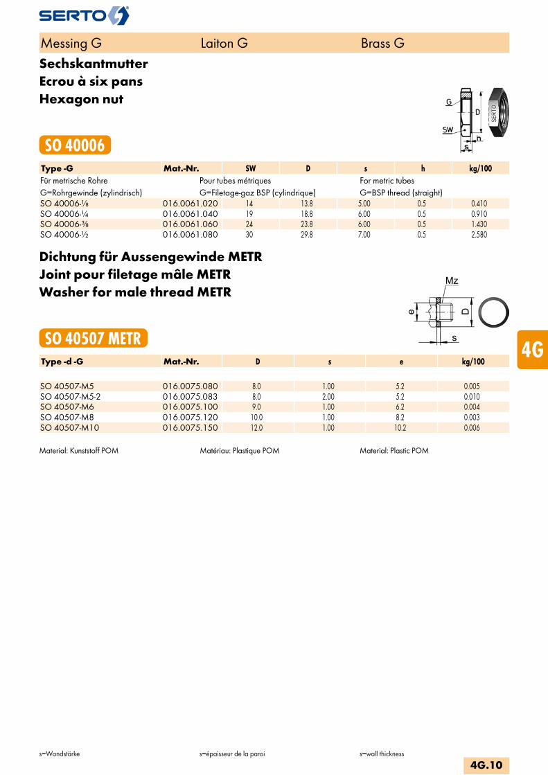
SechskantmutterEcrou à six pansHexagon nut
SO 40006Type -G Mat.-Nr. SW D s h kg/100Für metrische Rohre Pour tubes métriques For metric tubesG=Rohrgewinde (zylindrisch) G=Filetage-gaz BSP (cylindrique) G=BSP thread (straight)SO 40006-1/8 016.0061.020 14 13.8 5.00 0.5 0.410SO 40006-1/4 016.0061.040 19 18.8 6.00 0.5 0.910SO 40006-3/8 016.0061.060 24 23.8 6.00 0.5 1.430SO 40006-1/2 016.0061.080 30 29.8 7.00 0.5 2.580
Dichtung für Aussengewinde METRJoint pour filetage mâle METRWasher for male thread METR
SO 40507 METRType -d -G Mat.-Nr. D s e kg/100 SO 40507-M5 016.0075.080 8.0 1.00 5.2 0.005SO 40507-M5-2 016.0075.083 8.0 2.00 5.2 0.010SO 40507-M6 016.0075.100 9.0 1.00 6.2 0.004SO 40507-M8 016.0075.120 10.0 1.00 8.2 0.003SO 40507-M10 016.0075.150 12.0 1.00 10.2 0.006
Material: Kunststoff POM Matériau: Plastique POM Material: Plastic POM
Messing G Laiton G Brass G
s=Wandstärke s=épaisseur de la paroi s=wall thickness
4G.10
i
s
3F
4M
4G
5
5L
6
7
8
9
10
11
12

Dichtung für AussengewindeJoint pour filetage mâleWasher for male threads
SO 40007Type -G Mat.-Nr. D s e kg/100 G=Rohrgewinde (zylindrisch) G=Filetage-gaz BSP (cylindrique) G=BSP thread (straight)SO 40007-1/8 016.0070.020 13.4 1.50 10.2 0.050SO 40007-1/4 016.0070.040 17.9 1.50 14.2 0.110SO 40007-3/8 016.0070.060 20.9 1.50 17.2 0.130SO 40007-1/2 016.0070.080 25.9 1.50 21.2 0.220SO 40007-3/4 016.0070.120 31.0 1.50 26.5 0.230
Dichtung für Aussengewinde METRJoint pour filetage mâle METRWasher for male threads METR
SO 40007 METRType -Mz Mat.-Nr. D s e kg/100 Mz=metrisches Gewinde (zylindrisch) Mz=Filetage métrique (cylindrique) Mz=Metric thread (straight)SO 40007-M5 016.0073.080 8.0 1.00 5.2 0.023SO 40007-M6 016.0073.100 8.0 1.00 6.2 0.014SO 40007-M8 016.0073.173 11.2 2.00 8.2 0.080SO 40007-M10 016.0073.150 13.4 1.50 10.2 0.050SO 40007-M12 016.0073.190 15.4 1.50 12.2 0.080SO 40007-M14 016.0073.220 17.9 1.50 14.2 0.110SO 40007-M16 016.0073.260 19.9 1.50 16.2 0.120SO 40007-M18 016.0073.300 22.0 1.50 18.2 0.140SO 40007-M22 016.0073.370 27.0 1.50 22.2 0.225
Anwendungsbeispiele: Exemples d‘utilisation: Sample combinations:
Material: Kupfer, weichErsatzdichtungen für Schwenkverschraubungen und Mehrfachverteiler.
Zu verwenden:Als Abdichtung der Verschraubung mit zylindri-schem Einschraubgewinde.
Matériau: Cuivre, douxJoints de rechange pour coudes banjo et coudes banjo multiples.
Emploi:Rendre étanche un filetage cylindrique mâle
Material: Copper, softReplacement washer for single and double banjo.
Application:As seal for union with straight male adaptor thread.
Messing G Laiton G Brass G
d=Rohraussen-øe=kleinste Bohrungs=Wandstärke
d=ø extérieur du tubee=ø-min. de passages=épaisseur de la paroi
d=tube outside diametere=minimum bores=wall thickness
4G.11

AnschlussmutterEcrouUnion nut
SO 00020Type -d -G Mat.-Nr. bar SW D L kg/100Für metrische Rohre Pour tubes métriques For metric tubesG=Rohrgewinde (zylindrisch) G=Filetage-gaz BSP (cylindrique) G=BSP thread (straight)SO 00020-4-1/8 * 246.0200.060 125 12 15.5 0.930SO 00020-5-1/8 * 246.0200.082 125 12 15.5 0.900SO 00020-6-1/8 * 246.0200.100 125 12 16.5 0.880SO 00020-6-1/4 246.0200.110 125 14 17.0 18.5 1.960SO 00020-6-3/8 246.0200.120 125 17 21.0 21.0 3.490SO 00020-8-1/4 246.0200.170 125 14 17.0 19.0 1.810SO 00020-8-3/8 246.0200.180 125 17 21.0 21.0 3.260SO 00020-8-1/2 246.0200.185 125 19 26.0 23.5 5.360SO 00020-10-3/8 246.0200.280 100 17 21.0 21.5 2.970SO 00020-10-1/2 246.0200.285 100 19 26.0 24.0 4.970SO 00020-12-1/2 246.0200.400 100 19 26.0 26.0 5.100SO 00020-14-1/2 246.0200.504 64 22 26.0 28.5 5.520SO 00020-15-1/2 246.0200.534 64 22 26.0 28.5 9.930
Für Zollrohre Pour tubes pouces For inch tubes SO 00020-6,35-1/8 * 246.0200.135 125 12 16.5 0.850SO 00020-6,35-1/4 246.0200.140 125 14 17.0 18.5 2.010SO 00020-9,52-3/8 246.0200.235 100 17 21.0 21.5 2.840SO 00020-12,7-1/2 246.0200.434 100 22 26.0 27.0 5.590
Messing G Laiton G Brass G
d=Rohraussen-øL=Mass in montiertem Zustand
d=ø extérieur du tubeL=après montage
d=tube outside diameterL=installed length
4G.12
i
s
3F
4M
4G
5
5L
6
7
8
9
10
11
12

ArmaturenanschlussEcrou de raccordementNut connection
SO 00021Type -d -G Mat.-Nr. bar SW L a c D kg/100Für metrische Rohre Pour tubes métriques For metric tubesG=Rohrgewinde (zylindrisch) G=Filetage-gaz BSP (cylindrique) G=BSP thread (straight)SO 00021-4-1/8 246.0210.060 125 12 15.5 8.0 4.0 12.0 0.856SO 00021-5-1/8 246.0210.082 125 12 15.5 8.0 6.0 12.0 0.909SO 00021-6-1/8 246.0210.100 125 12 16.5 8.0 6.5 12.0 0.972SO 00021-6-1/4 246.0210.110 125 14 18.5 9.0 6.0 17.0 2.000SO 00021-6-3/8 246.0210.120 125 17 21.0 9.5 6.5 21.0 3.000SO 00021-8-1/4 246.0210.170 125 14 19.0 9.0 6.0 17.0 2.000SO 00021-8-3/8 246.0210.180 125 17 21.0 9.5 6.5 21.0 3.000SO 00021-8-1/2 246.0210.185 125 19 23.5 11.0 7.0 26.0 5.000SO 00021-10-3/8 246.0210.280 100 17 21.5 9.5 6.5 21.0 3.000SO 00021-10-1/2 246.0210.285 100 19 24.0 11.0 7.0 26.0 5.000SO 00021-12-1/2 246.0210.400 100 19 26.0 11.0 7.0 26.0 5.000SO 00021-14-1/2 246.0210.504 64 22 28.5 11.0 8.0 26.0 6.000SO 00021-15-1/2 246.0210.534 64 22 28.5 11.0 8.0 26.0 6.000SO 00021-15-3/4 246.0210.536 64 27 30.0 12.0 9.0 32.0 10.150
Für Zollrohre Pour tubes pouces For inch tubes SO 00021-6,35-1/8 246.0210.135 125 12 16.5 8.0 6.5 12.0 0.938SO 00021-6,35-1/4 246.0210.140 125 14 18.5 9.0 6.0 17.0 2.000SO 00021-7,94-1/4 246.0210.168 125 14 19.0 9.0 6.0 17.0 2.000SO 00021-9,52-3/8 246.0210.235 100 17 21.5 9.5 6.5 21.0 3.000SO 00021-12,7-1/2 246.0210.434 100 22 27.0 11.0 7.0 26.0 6.000
Messing G Laiton G Brass G
d=Rohraussen-ødr=Grösse der AnschlussmutterL=Mass in montiertem Zustand
d=ø extérieur du tubedr=dimension de l'écrou de baseL=après montage
d=tube outside diameterdr=size of the connection nutL=installed length
4G.13

ManometeranschlussEcrou de manomètrePressure gauge connection
SO 00021 MANType -d -G Mat.-Nr. bar SW L a c D kg/100 G=Rohrgewinde (zylindrisch) G=Filetage-gaz BSP (cylindrique) G=BSP thread (straight)SO 00021-6-1/4 MAN 246.0211.110 125 14 20.0 9.0 6.0 17.0 2.200SO 00021-6-1/2 MAN 246.0211.125 125 22 25.5 11.0 8.0 26.0 6.700SO 00021-8-1/4 MAN 246.0211.170 125 14 19.0 9.0 6.0 17.0 2.000SO 00021-8-1/2 MAN 246.0211.185 125 22 26.0 11.0 8.0 26.0 6.750SO 00021-10-1/2 MAN 246.0211.285 100 19 24.0 11.0 7.0 26.0 5.400SO 00021-12-1/2 MAN 246.0211.400 100 19 26.0 11.0 7.0 26.0 5.860
Anwendungsbeispiele: Exemples d‘utilisation: Sample combinations:
Gewindezapfen für SERTO-Anschlüsse siehe Anhang.
Embout fileté por écrous de raccordement SERTO voir annexe.
Threaded stem for SERTO connections please see appendix.
Messing G Laiton G Brass G
d=Rohraussen-øL=Mass in montiertem Zustand
d=ø extérieur du tubeL=après montage
d=tube outside diameterL=installed length
4G.14
i
s
3F
4M
4G
5
5L
6
7
8
9
10
11
12
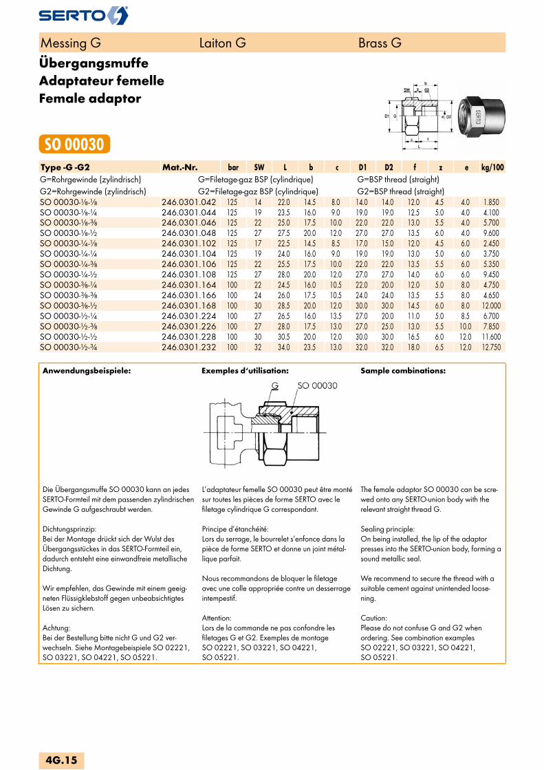
ÜbergangsmuffeAdaptateur femelleFemale adaptor
SO 00030Type -G -G2 Mat.-Nr. bar SW L b c D1 D2 f z e kg/100G=Rohrgewinde (zylindrisch) G=Filetage-gaz BSP (cylindrique) G=BSP thread (straight)G2=Rohrgewinde (zylindrisch) G2=Filetage-gaz BSP (cylindrique) G2=BSP thread (straight)SO 00030-1/8-1/8 246.0301.042 125 14 22.0 14.5 8.0 14.0 14.0 12.0 4.5 4.0 1.850SO 00030-1/8-1/4 246.0301.044 125 19 23.5 16.0 9.0 19.0 19.0 12.5 5.0 4.0 4.100SO 00030-1/8-3/8 246.0301.046 125 22 25.0 17.5 10.0 22.0 22.0 13.0 5.5 4.0 5.700SO 00030-1/8-1/2 246.0301.048 125 27 27.5 20.0 12.0 27.0 27.0 13.5 6.0 4.0 9.600SO 00030-1/4-1/8 246.0301.102 125 17 22.5 14.5 8.5 17.0 15.0 12.0 4.5 6.0 2.450SO 00030-1/4-1/4 246.0301.104 125 19 24.0 16.0 9.0 19.0 19.0 13.0 5.0 6.0 3.750SO 00030-1/4-3/8 246.0301.106 125 22 25.5 17.5 10.0 22.0 22.0 13.5 5.5 6.0 5.350SO 00030-1/4-1/2 246.0301.108 125 27 28.0 20.0 12.0 27.0 27.0 14.0 6.0 6.0 9.450SO 00030-3/8-1/4 246.0301.164 100 22 24.5 16.0 10.5 22.0 20.0 12.0 5.0 8.0 4.750SO 00030-3/8-3/8 246.0301.166 100 24 26.0 17.5 10.5 24.0 24.0 13.5 5.5 8.0 4.650SO 00030-3/8-1/2 246.0301.168 100 30 28.5 20.0 12.0 30.0 30.0 14.5 6.0 8.0 12.000SO 00030-1/2-1/4 246.0301.224 100 27 26.5 16.0 13.5 27.0 20.0 11.0 5.0 8.5 6.700SO 00030-1/2-3/8 246.0301.226 100 27 28.0 17.5 13.0 27.0 25.0 13.0 5.5 10.0 7.850SO 00030-1/2-1/2 246.0301.228 100 30 30.5 20.0 12.0 30.0 30.0 16.5 6.0 12.0 11.600SO 00030-1/2-3/4 246.0301.232 100 32 34.0 23.5 13.0 32.0 32.0 18.0 6.5 12.0 12.750
Anwendungsbeispiele: Exemples d‘utilisation: Sample combinations:
Die Übergangsmuffe SO 00030 kann an jedes SERTO-Formteil mit dem passenden zylindrischen Gewinde G aufgeschraubt werden.
Dichtungsprinzip:Bei der Montage drückt sich der Wulst des Übergangsstückes in das SERTO-Formteil ein, dadurch entsteht eine einwandfreie metallische Dichtung.
Wir empfehlen, das Gewinde mit einem geeig-neten Flüssigklebstoff gegen unbeabsichtigtes Lösen zu sichern.
Achtung:Bei der Bestellung bitte nicht G und G2 ver-wechseln. Siehe Montagebeispiele SO 02221, SO 03221, SO 04221, SO 05221.
L’adaptateur femelle SO 00030 peut être monté sur toutes les pièces de forme SERTO avec le filetage cylindrique G correspondant.
Principe d’étanchéité:Lors du serrage, le bourrelet s’enfonce dans la pièce de forme SERTO et donne un joint métal-lique parfait.
Nous recommandons de bloquer le filetage avec une colle appropriée contre un desserrage intempestif.
Attention:Lors de la commande ne pas confondre les filetages G et G2. Exemples de montage SO 02221, SO 03221, SO 04221, SO 05221.
The female adaptor SO 00030 can be scre-wed onto any SERTO-union body with the relevant straight thread G.
Sealing principle:On being installed, the lip of the adaptor presses into the SERTO-union body, forming a sound metallic seal.
We recommend to secure the thread with a suitable cement against unintended loose-ning.
Caution:Please do not confuse G and G2 when ordering. See combination examples SO 02221, SO 03221, SO 04221, SO 05221.
Messing G Laiton G Brass G
4G.15
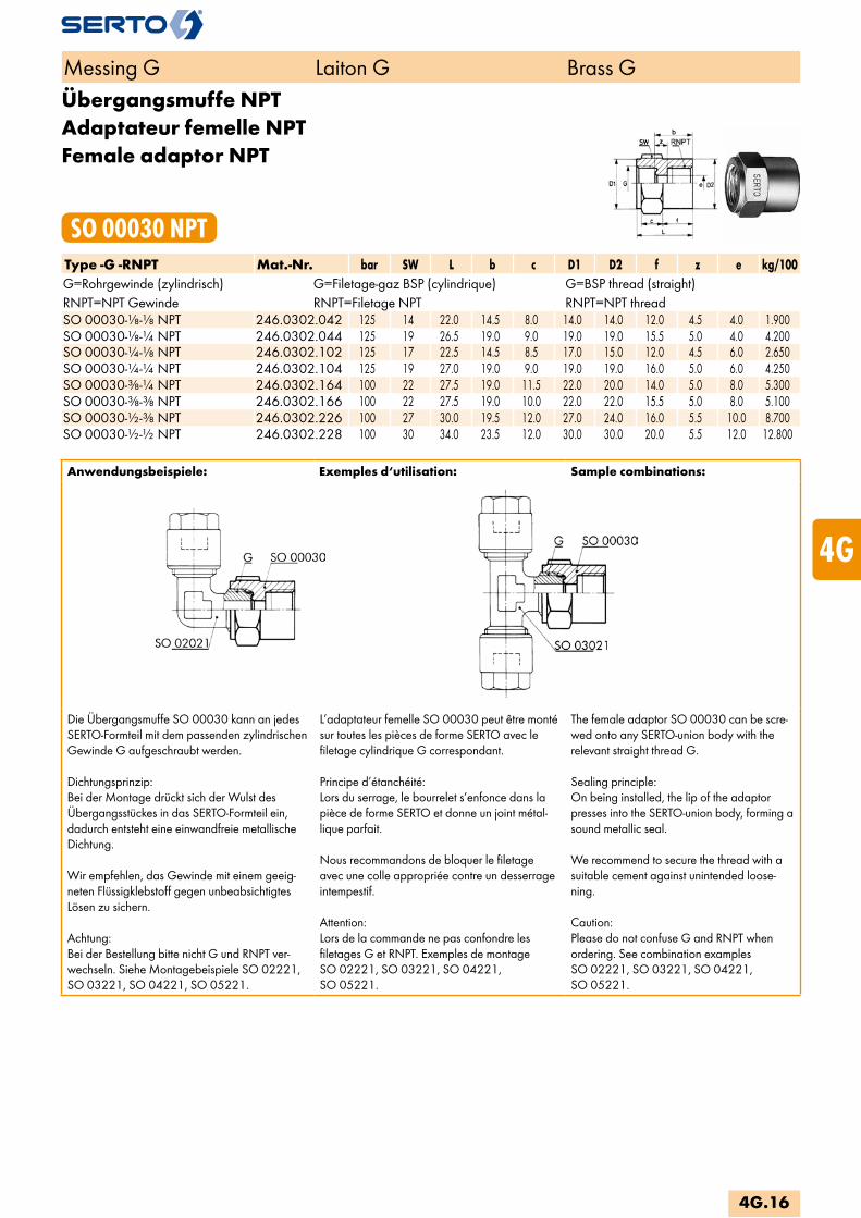
Übergangsmuffe NPTAdaptateur femelle NPTFemale adaptor NPT
SO 00030 NPTType -G -RNPT Mat.-Nr. bar SW L b c D1 D2 f z e kg/100G=Rohrgewinde (zylindrisch) G=Filetage-gaz BSP (cylindrique) G=BSP thread (straight)RNPT=NPT Gewinde RNPT=Filetage NPT RNPT=NPT threadSO 00030-1/8-1/8 NPT 246.0302.042 125 14 22.0 14.5 8.0 14.0 14.0 12.0 4.5 4.0 1.900SO 00030-1/8-1/4 NPT 246.0302.044 125 19 26.5 19.0 9.0 19.0 19.0 15.5 5.0 4.0 4.200SO 00030-1/4-1/8 NPT 246.0302.102 125 17 22.5 14.5 8.5 17.0 15.0 12.0 4.5 6.0 2.650SO 00030-1/4-1/4 NPT 246.0302.104 125 19 27.0 19.0 9.0 19.0 19.0 16.0 5.0 6.0 4.250SO 00030-3/8-1/4 NPT 246.0302.164 100 22 27.5 19.0 11.5 22.0 20.0 14.0 5.0 8.0 5.300SO 00030-3/8-3/8 NPT 246.0302.166 100 22 27.5 19.0 10.0 22.0 22.0 15.5 5.0 8.0 5.100SO 00030-1/2-3/8 NPT 246.0302.226 100 27 30.0 19.5 12.0 27.0 24.0 16.0 5.5 10.0 8.700SO 00030-1/2-1/2 NPT 246.0302.228 100 30 34.0 23.5 12.0 30.0 30.0 20.0 5.5 12.0 12.800
Anwendungsbeispiele: Exemples d‘utilisation: Sample combinations:
Die Übergangsmuffe SO 00030 kann an jedes SERTO-Formteil mit dem passenden zylindrischen Gewinde G aufgeschraubt werden.
Dichtungsprinzip:Bei der Montage drückt sich der Wulst des Übergangsstückes in das SERTO-Formteil ein, dadurch entsteht eine einwandfreie metallische Dichtung.
Wir empfehlen, das Gewinde mit einem geeig-neten Flüssigklebstoff gegen unbeabsichtigtes Lösen zu sichern.
Achtung:Bei der Bestellung bitte nicht G und RNPT ver-wechseln. Siehe Montagebeispiele SO 02221, SO 03221, SO 04221, SO 05221.
L’adaptateur femelle SO 00030 peut être monté sur toutes les pièces de forme SERTO avec le filetage cylindrique G correspondant.
Principe d’étanchéité:Lors du serrage, le bourrelet s’enfonce dans la pièce de forme SERTO et donne un joint métal-lique parfait.
Nous recommandons de bloquer le filetage avec une colle appropriée contre un desserrage intempestif.
Attention:Lors de la commande ne pas confondre les filetages G et RNPT. Exemples de montage SO 02221, SO 03221, SO 04221, SO 05221.
The female adaptor SO 00030 can be scre-wed onto any SERTO-union body with the relevant straight thread G.
Sealing principle:On being installed, the lip of the adaptor presses into the SERTO-union body, forming a sound metallic seal.
We recommend to secure the thread with a suitable cement against unintended loose-ning.
Caution:Please do not confuse G and RNPT when ordering. See combination examples SO 02221, SO 03221, SO 04221, SO 05221.
Messing G Laiton G Brass G
4G.16
i
s
3F
4M
4G
5
5L
6
7
8
9
10
11
12
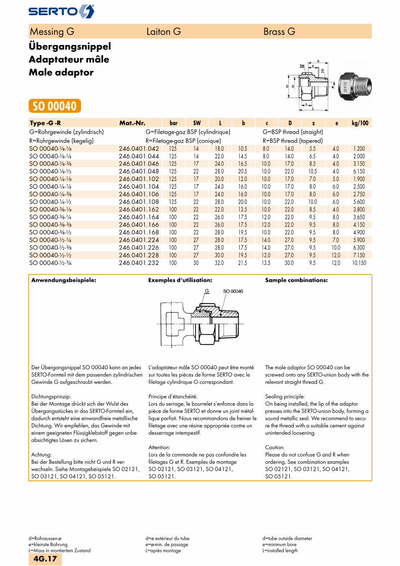
ÜbergangsnippelAdaptateur mâleMale adaptor
SO 00040Type -G -R Mat.-Nr. bar SW L b c D z e kg/100G=Rohrgewinde (zylindrisch) G=Filetage-gaz BSP (cylindrique) G=BSP thread (straight)R=Rohrgewinde (kegelig) R=Filetage-gaz BSP (conique) R=BSP thread (tapered)SO 00040-1/8-1/8 246.0401.042 125 14 18.0 10.5 8.0 14.0 5.5 4.0 1.200SO 00040-1/8-1/4 246.0401.044 125 14 22.0 14.5 8.0 14.0 6.5 4.0 2.000SO 00040-1/8-3/8 246.0401.046 125 17 24.0 16.5 10.0 17.0 8.5 4.0 3.150SO 00040-1/8-1/2 246.0401.048 125 22 28.0 20.5 10.0 22.0 10.5 4.0 6.150SO 00040-1/4-1/8 246.0401.102 125 17 20.0 12.0 10.0 17.0 7.0 5.0 1.900SO 00040-1/4-1/4 246.0401.104 125 17 24.0 16.0 10.0 17.0 8.0 6.0 2.500SO 00040-1/4-3/8 246.0401.106 125 17 24.0 16.0 10.0 17.0 8.0 6.0 2.750SO 00040-1/4-1/2 246.0401.108 125 22 28.0 20.0 10.0 22.0 10.0 6.0 5.600SO 00040-3/8-1/8 246.0401.162 100 22 22.0 13.5 10.0 22.0 8.5 4.0 3.800SO 00040-3/8-1/4 246.0401.164 100 22 26.0 17.5 12.0 22.0 9.5 8.0 3.650SO 00040-3/8-3/8 246.0401.166 100 22 26.0 17.5 12.0 22.0 9.5 8.0 4.150SO 00040-3/8-1/2 246.0401.168 100 22 28.0 19.5 10.0 22.0 9.5 8.0 4.900SO 00040-1/2-1/4 246.0401.224 100 27 28.0 17.5 14.0 27.0 9.5 7.0 5.900SO 00040-1/2-3/8 246.0401.226 100 27 28.0 17.5 14.0 27.0 9.5 10.0 6.300SO 00040-1/2-1/2 246.0401.228 100 27 30.0 19.5 12.0 27.0 9.5 12.0 7.150SO 00040-1/2-3/4 246.0401.232 100 30 32.0 21.5 13.5 30.0 9.5 12.0 10.150
Anwendungsbeispiele: Exemples d‘utilisation: Sample combinations:
Der Übergangsnippel SO 00040 kann an jedes SERTO-Formteil mit dem passenden zylindrischen Gewinde G aufgeschraubt werden.
Dichtungsprinzip:Bei der Montage drückt sich der Wulst des Übergangsstückes in das SERTO-Formteil ein, dadurch entsteht eine einwandfreie metallische Dichtung. Wir empfehlen, das Gewinde mit einem geeigneten Flüssigklebstoff gegen unbe-absichtigtes Lösen zu sichern.
Achtung:Bei der Bestellung bitte nicht G und R ver- wechseln. Siehe Montagebeispiele SO 02121, SO 03121, SO 04121, SO 05121.
L’adaptateur mâle SO 00040 peut être monté sur toutes les pièces de forme SERTO avec le filetage cylindrique G correspondant.
Principe d’étanchéité:Lors du serrage, le bourrelet s’enfonce dans la pièce de forme SERTO et donne un joint métal-lique parfait. Nous recommandons de freiner le filetage avec une résine appropriée contre un desserrage intempestif.
Attention:Lors de la commande ne pas confondre les filetages G et R. Exemples de montage SO 02121, SO 03121, SO 04121, SO 05121.
The male adaptor SO 00040 can bescrewed onto any SERTO-union body with the relevant straight thread G.
Sealing principle:On being installed, the lip of the adaptor presses into the SERTO-union body, forming a sound metallic seal. We recommend to secu-re the thread with a suitable cement against unintended loosening.
Caution:Please do not confuse G and R when ordering. See combination examples SO 02121, SO 03121, SO 04121, SO 05121.
Messing G Laiton G Brass G
d=Rohraussen-øe=kleinste BohrungL=Mass in montiertem Zustand
d=ø extérieur du tubee=ø-min. de passageL=après montage
d=tube outside diametere=minimum boreL=installed length
4G.17

Übergangsnippel NPTAdaptateur mâle NPTMale adaptor NPT
SO 00040 NPTType -G -RNPT Mat.-Nr. bar SW L b c D z e kg/100G=Rohrgewinde (zylindrisch) G=Filetage-gaz BSP (cylindrique) G=BSP thread (straight)RNPT=NPT Gewinde RNPT=Filetage NPT RNPT=NPT threadSO 00040-1/8-1/8 NPT 246.0402.042 125 14 20.0 12.5 8.0 14.0 5.5 4.0 1.400SO 00040-1/8-1/4 NPT 246.0402.044 125 14 24.0 16.5 8.0 14.0 6.5 4.0 2.200SO 00040-1/4-1/8 NPT 246.0402.102 125 17 22.0 14.0 10.0 17.0 7.0 5.0 1.900SO 00040-1/4-1/4 NPT 246.0402.104 125 17 26.0 18.0 10.0 17.0 8.0 6.0 2.750SO 00040-1/4-3/8 NPT 246.0402.106 125 17 27.0 18.0 10.0 17.0 8.0 6.0 3.100SO 00040-3/8-1/4 NPT 246.0402.164 100 22 28.0 19.5 12.0 22.0 9.5 8.0 3.900SO 00040-3/8-3/8 NPT 246.0402.166 100 22 28.0 19.5 12.0 22.0 9.5 8.0 4.600SO 00040-1/2-3/8 NPT 246.0402.226 100 27 30.0 19.5 12.0 27.0 9.5 10.0 6.600SO 00040-1/2-1/2 NPT 246.0402.228 100 27 35.0 24.5 14.0 27.0 10.5 12.0 7.500
Anwendungsbeispiele: Exemples d‘utilisation: Sample combinations:
Der Übergangsnippel SO 00040 kann an jedes SERTO-Formteil mit dem passenden zylindrischen Gewinde G aufgeschraubt werden.
Dichtungsprinzip:Bei der Montage drückt sich der Wulst des Übergangsstückes in das SERTO-Formteil ein, dadurch entsteht eine einwandfreie metallische Dichtung. Wir empfehlen, das Gewinde mit einem geeigneten Flüssigklebstoff gegen unbe-absichtigtes Lösen zu sichern.
Achtung:Bei der Bestellung bitte nicht G und RNPT ver-wechseln. Siehe Montagebeispiele SO 02121, SO 03121,SO 04121, SO 05121.
L’adaptateur mâle SO 00040 peut être monté sur toutes les pièces de forme SERTO avec le filetage cylindrique G correspondant.
Principe d’étanchéité:Lors du serrage, le bourrelet s’enfonce dans la pièce de forme SERTO et donne un joint métal-lique parfait. Nous recommandons de freiner le filetage avec une résine appropriée contre un desserrage intempestif.
Attention:Lors de la commande ne pas confondre les filetages G et RNPT. Exemples de montage SO 02121, SO 03121, SO 04121, SO 05121.
The male adaptor SO 00040 can be scre-wed onto any SERTO-union body with the relevant straight thread G.
Sealing principle:On being installed, the lip of the adaptor presses into the SERTO-union body, forming a sound metallic seal. We recommend to secu-re the thread with a suitable cement against unintended loosening.
Caution:Please do not confuse G and RNPT when ordering. See combination examples SO 02121, SO 03121, SO 04121, SO 05121.
Messing G Laiton G Brass G
d=Rohraussen-øe=kleinste BohrungL=Mass in montiertem Zustand
d=ø extérieur du tubee=ø-min. de passageL=après montage
d=tube outside diametere=minimum boreL=installed length
4G.18
i
s
3F
4M
4G
5
5L
6
7
8
9
10
11
12
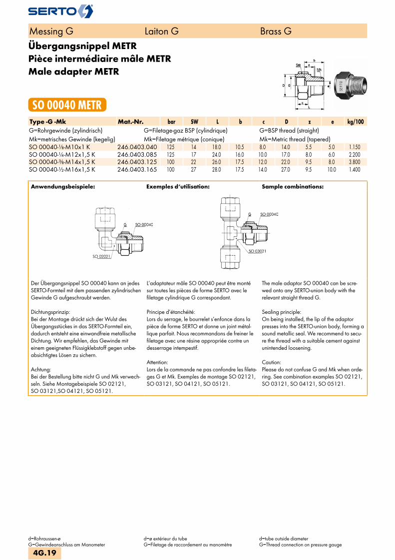
Übergangsnippel METRPièce intermédiaire mâle METRMale adapter METR
SO 00040 METRType -G -Mk Mat.-Nr. bar SW L b c D z e kg/100G=Rohrgewinde (zylindrisch) G=Filetage-gaz BSP (cylindrique) G=BSP thread (straight)Mk=metrisches Gewinde (kegelig) Mk=Filetage métrique (conique) Mk=Metric thread (tapered)SO 00040-1/8-M10x1 K 246.0403.040 125 14 18.0 10.5 8.0 14.0 5.5 5.0 1.150SO 00040-1/4-M12x1,5 K 246.0403.085 125 17 24.0 16.0 10.0 17.0 8.0 6.0 2.200SO 00040-3/8-M14x1,5 K 246.0403.125 100 22 26.0 17.5 12.0 22.0 9.5 8.0 3.800SO 00040-1/2-M16x1,5 K 246.0403.165 100 27 28.0 17.5 14.0 27.0 9.5 10.0 1.400
Anwendungsbeispiele: Exemples d‘utilisation: Sample combinations:
Der Übergangsnippel SO 00040 kann an jedes SERTO-Formteil mit dem passenden zylindrischen Gewinde G aufgeschraubt werden.
Dichtungsprinzip:Bei der Montage drückt sich der Wulst des Übergangsstückes in das SERTO-Formteil ein, dadurch entsteht eine einwandfreie metallische Dichtung. Wir empfehlen, das Gewinde mit einem geeigneten Flüssigklebstoff gegen unbe-absichtigtes Lösen zu sichern.
Achtung:Bei der Bestellung bitte nicht G und Mk verwech-seln. Siehe Montagebeispiele SO 02121, SO 03121,SO 04121, SO 05121.
L’adaptateur mâle SO 00040 peut être monté sur toutes les pièces de forme SERTO avec le filetage cylindrique G correspondant.
Principe d’étanchéité:Lors du serrage, le bourrelet s’enfonce dans la pièce de forme SERTO et donne un joint métal-lique parfait. Nous recommandons de freiner le filetage avec une résine appropriée contre un desserrage intempestif.
Attention:Lors de la commande ne pas confondre les fileta-ges G et Mk. Exemples de montage SO 02121, SO 03121, SO 04121, SO 05121.
The male adaptor SO 00040 can be scre-wed onto any SERTO-union body with the relevant straight thread G.
Sealing principle:On being installed, the lip of the adaptor presses into the SERTO-union body, forming a sound metallic seal. We recommend to secu-re the thread with a suitable cement against unintended loosening.
Caution:Please do not confuse G and Mk when orde-ring. See combination examples SO 02121, SO 03121, SO 04121, SO 05121.
Messing G Laiton G Brass G
d=Rohraussen-øG=Gewindeanschluss am Manometer
d=ø extérieur du tubeG=Filetage de raccordement au manomètre
d=tube outside diameterG=Thread connection on pressure gauge
4G.19

AnschlussnippelEcrou de raccordement mâleNipple connection
SO 01001Type -d -G Mat.-Nr. bar SW L a b c f t kg/100Für metrische Rohre Pour tubes métriques For metric tubesG=Rohrgewinde (zylindrisch) G=Filetage-gaz BSP (cylindrique) G=BSP thread (straight)SO 41001-4-1/8 016.1001.060 125 10 12.0 14.0 6.0 4.0 6.5 6.5 0.650SO 41001-5-1/8 016.1001.082 125 10 12.0 14.0 6.0 4.0 6.5 6.5 0.550SO 41001-6-1/4 016.1001.110 250 14 16.0 18.0 8.5 6.0 8.0 9.5 1.450SO 01001-8-1/4 246.1001.170 125 14 16.0 18.0 8.5 6.0 8.0 9.5 1.200SO 01001-10-3/8 246.1001.280 100 17 17.0 19.0 9.0 6.5 8.5 10.0 2.000SO 01001-12-1/2 246.1001.400 100 19 19.0 19.0 9.5 7.0 9.0 10.5 2.950SO 01001-14-1/2 246.1001.504 64 22 20.5 25.0 13.0 8.0 9.5 14.0 3.700SO 01001-15-3/4 246.1001.536 64 27 22.0 22.5 10.0 9.0 10.0 11.0 6.750
Für Zollrohre Pour tubes pouces For inch tubesG=Rohrgewinde (zylindrisch) G=Filetage-gaz BSP (cylindrique) G=BSP thread (straight)SO 41001-6,35-1/4 016.1001.140 100 14 16.0 18.0 8.5 6.0 8.0 9.5 1.420SO 01001-9,52-3/8 246.1001.235 100 17 17.0 19.0 8.5 6.5 8.5 9.5 2.094SO 01001-12,7-1/2 246.1001.434 100 22 20.0 21.5 10.0 8.0 9.0 11.0 3.210
Anschlussnippel METREcrou de raccordement mâle METRNipple connection METR
SO 01001 METRType -d -Mz Mat.-Nr. bar SW L a b c f t kg/100Für metrische Rohre Pour tubes métriques For metric tubesMz=metrisches Gewinde (zylindrisch) Mz=Filetage métrique (cylindrique) Mz=Metric thread (straight)SO 01001-4-M8x0.75 246.1003.088 125 8 10.5 12.0 6.0 4.0 6.0 6.5 0.330SO 01001-6-M11x0,75 246.1003.183 100 12 13.5 16.5 8.5 5.5 7.0 9.5 0.860
Für Zollrohre Pour tubes pouces For inch tubes SO 01001-6,35-M11x0,75 246.1003.215 100 12 13.5 17.5 9.0 5.5 7.0 10.0 0.820
Messing G Laiton G Brass G
d=Rohraussen-øG=Gewindeanschluss am Manometer
d=ø extérieur du tubeG=Filetage de raccordement au manomètre
d=tube outside diameterG=Thread connection on pressure gauge
4G.20
i
s
3F
4M
4G
5
5L
6
7
8
9
10
11
12

Anwendungsbeispiele: Exemples d‘utilisation: Sample combinations:
Nippel SO 01000 mit Klemmring SO 00001 oder Nippel SO 41000 mit Klemmring SO 40001.
Die entsprechende Kupferdichtung SO 40005 ist immer separat zu bestellen.
Weitere Einschraubgewinde auf Anfrage.
Ecrou mâle SO 01000 avec bague de serrage SO 00001 ou écrou mâle SO 41000 avec bague de serrage SO 40001.
Les joints correspondants SO 40005 sont à commander séparément.
Autres filetages sur demande.
Nipple SO 01000 with compression ferrule SO 00001 or nipple SO 41000 with com-pression ferrule SO 40001.
The relevant copper washer SO 40005 must always be ordered separately.
Other threads on request
Messing G Laiton G Brass G
d=Rohraussen-øG=Gewindeanschluss am Manometer
d=ø extérieur du tubeG=Filetage de raccordement au manomètre
d=tube outside diameterG=Thread connection on pressure gauge
4G.21
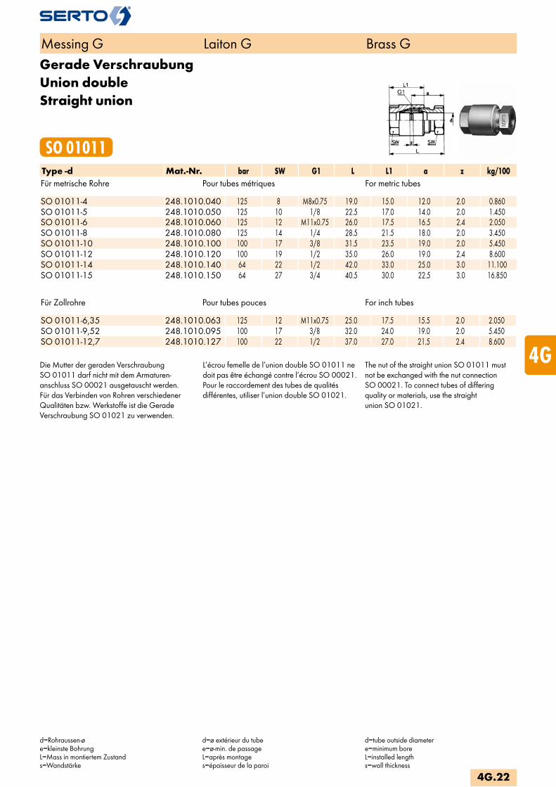
Für Zollrohre Pour tubes pouces For inch tubes SO 01011-6,35 248.1010.063 125 12 M11x0.75 25.0 17.5 15.5 2.0 2.050SO 01011-9,52 248.1010.095 100 17 3/8 32.0 24.0 19.0 2.0 5.450SO 01011-12,7 248.1010.127 100 22 1/2 37.0 27.0 21.5 2.4 8.600
Die Mutter der geraden VerschraubungSO 01011 darf nicht mit dem Armaturen-anschluss SO 00021 ausgetauscht werden.Für das Verbinden von Rohren verschiedenerQualitäten bzw. Werkstoffe ist die GeradeVerschraubung SO 01021 zu verwenden.
L’écrou femelle de l’union double SO 01011 ne doit pas être échangé contre l’écrou SO 00021.Pour le raccordement des tubes de qualitésdifférentes, utiliser l’union double SO 01021.
The nut of the straight union SO 01011 must not be exchanged with the nut connectionSO 00021. To connect tubes of differingquality or materials, use the straightunion SO 01021.
Messing G Laiton G Brass G
d=Rohraussen-øe=kleinste BohrungL=Mass in montiertem Zustands=Wandstärke
d=ø extérieur du tubee=ø-min. de passageL=après montages=épaisseur de la paroi
d=tube outside diametere=minimum boreL=installed lengths=wall thickness
Gerade VerschraubungUnion doubleStraight union
SO 01011Type -d Mat.-Nr. bar SW G1 L L1 a z kg/100Für metrische Rohre Pour tubes métriques For metric tubes SO 01011-4 248.1010.040 125 8 M8x0.75 19.0 15.0 12.0 2.0 0.860SO 01011-5 248.1010.050 125 10 1/8 22.5 17.0 14.0 2.0 1.450SO 01011-6 248.1010.060 125 12 M11x0.75 26.0 17.5 16.5 2.4 2.050SO 01011-8 248.1010.080 125 14 1/4 28.5 21.5 18.0 2.0 3.450SO 01011-10 248.1010.100 100 17 3/8 31.5 23.5 19.0 2.0 5.450SO 01011-12 248.1010.120 100 19 1/2 35.0 26.0 19.0 2.4 8.600SO 01011-14 248.1010.140 64 22 1/2 42.0 33.0 25.0 3.0 11.100SO 01011-15 248.1010.150 64 27 3/4 40.5 30.0 22.5 3.0 16.850
4G.22
i
s
3F
4M
4G
5
5L
6
7
8
9
10
11
12

Gerade VerschraubungUnion doubleStraight union
SO 01021Type -d Mat.-Nr. bar G1 SW1 SW2 L z e kg/100Für metrische Rohre Pour tubes métriques For metric tubes SO 01021-4 248.1020.040 125 1/8 12 12 41.5 28.0 4.5 3.250SO 01021-5 248.1020.050 125 1/8 12 12 41.5 28.0 4.5 3.250SO 01021-6 248.1020.060 125 1/8 12 12 44.5 28.5 4.5 3.300SO 01021-8 248.1020.080 125 1/4 14 14 49.0 30.5 6.5 6.150SO 01021-10 248.1020.100 100 3/8 17 17 56.0 32.0 8.5 10.400SO 01021-12 248.1020.120 100 1/2 22 22 65.0 38.5 12.0 17.750SO 01021-14 248.1020.140 64 1/2 22 22 71.0 39.0 12.0 19.150SO 01021-15 248.1020.150 64 1/2 22 22 71.0 39.0 12.0 19.000
Für Zollrohre Pour tubes pouces For inch tubes SO 01021-6,35 248.1020.063 125 1/8 12 12 44.5 28.0 4.5 3.300SO 01021-9,52 248.1020.095 100 3/8 17 17 61.0 32.0 8.5 10.400SO 01021-12,7 248.1020.127 100 1/2 22 22 71.0 39.0 12.0 19.150
Gerade Verschraubung reduziertUnion double réduiteStraight reduction union
SO 01021 REDType -d -d2 Mat.-Nr. bar G1 G red SW1 SW2 SW3 L z e kg/100Für metrische Rohre Pour tubes métriques For metric tubes SO 01021-6-4 248.1024.110 125 1/8 1/8 12 12 12 43.0 28.0 4.5 3.300SO 01021-8-6 248.1024.140 125 1/4 1/8 14 14 12 46.5 29.0 4.5 5.100SO 01021-10-8 248.1024.190 100 3/8 1/4 17 17 14 53.0 31.5 6.5 8.750SO 01021-12-8 248.1024.225 100 1/2 1/4 19 22 14 58.0 35.0 6.5 10.150SO 01021-12-10 248.1024.240 100 1/2 3/8 19 22 17 61.0 35.5 8.5 15.150SO 01021-14-8 248.1024.300 64 1/2 1/4 22 22 14 61.0 35.5 6.5 16.100SO 01021-14-12 248.1024.340 64 1/2 1/2 22 22 19 68.0 39.0 12.0 18.150SO 01021-15-8 248.1024.400 64 1/2 1/4 22 22 14 61.0 35.5 6.5 13.750SO 01021-15-10 248.1024.410 64 1/2 1/2 22 22 19 63.5 36.0 12.0 15.900SO 01021-15-12 248.1024.420 64 1/2 1/2 22 22 19 68.0 39.0 12.0 18.250
Für Zollrohre Pour tubes pouces For inch tubes SO 01021-6,35-4 248.1024.123 125 1/8 1/8 12 12 12 43.0 28.0 4.5 3.300SO 01021-6,35-5 248.1024.126 125 1/8 1/8 12 12 12 43.0 28.0 4.5 3.300SO 01021-6,35-6 248.1024.128 125 1/8 1/8 12 12 12 44.5 28.5 4.5 3.300SO 01021-10-9,52 248.1024.197 100 3/8 3/8 17 17 17 56.0 32.0 8.5 8.750
Messing G Laiton G Brass G
d/d2=Rohraussen-øe=kleinste BohrungL=Mass in montiertem Zustands=Wandstärke
d/d2=ø extérieur du tubee=ø-min. de passageL=après montages=épaisseur de la paroi
d/d2=tube outside diametere=minimum boreL=installed lengths=wall thickness
4G.23
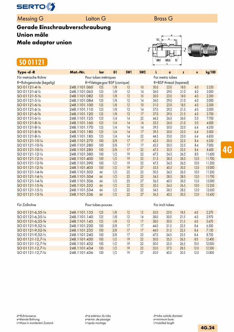
Für Zollrohre Pour tubes pouces For inch tubes SO 01121-6,35-1/8 248.1101.135 125 1/8 12 12 33.0 25.0 18.5 4.0 2.270SO 01121-6,35-1/4 248.1101.140 125 1/8 12 14 38.0 30.0 21.5 4.0 2.970SO 01121-6,35-3/8 248.1101.145 125 1/8 12 17 38.0 30.0 21.5 4.0 3.670SO 01121-9,52-1/4 248.1101.230 100 3/8 17 17 44.0 31.5 22.5 8.4 6.500SO 01121-9,52-3/8 248.1101.235 100 3/8 17 17 44.0 31.5 22.5 8.4 7.150SO 01121-9,52-1/2 248.1101.240 100 3/8 17 22 47.0 34.5 25.5 8.4 8.750SO 01121-12,7-1/4 248.1101.430 100 1/2 19 22 50.0 35.5 26.5 8.0 12.400SO 01121-12,7-3/8 248.1101.432 100 1/2 19 22 50.0 35.5 26.5 10.0 12.000SO 01121-12,7-1/2 248.1101.434 100 1/2 19 22 52.0 37.5 28.5 12.0 12.500SO 01121-12,7-3/4 248.1101.436 100 1/2 19 27 55.0 40.5 30.5 12.0 15.800
Messing G Laiton G Brass G
d=Rohraussen-øe=kleinste BohrungL=Mass in montiertem Zustand
d=ø extérieur du tubee=ø-min. de passageL=après montage
d=tube outside diametere=minimum boreL=installed length
Gerade EinschraubverschraubungUnion mâleMale adaptor union
SO 01121Type -d -R Mat.-Nr. bar G1 SW1 SW2 L a z e kg/100Für metrische Rohre Pour tubes métriques For metric tubesR=Rohrgewinde (kegelig) R=Filetage-gaz BSP (conique) R=BSP thread (tapered)SO 01121-4-1/8 248.1101.060 125 1/8 12 10 30.0 23.0 18.0 4.0 2.250SO 01121-4-1/4 248.1101.065 125 1/8 12 14 36.0 29.0 21.0 4.0 3.000SO 01121-5-1/8 248.1101.082 125 1/8 12 10 30.0 23.0 18.0 4.0 2.300SO 01121-5-1/4 248.1101.084 125 1/8 12 14 36.0 29.0 21.0 4.0 3.000SO 01121-6-1/8 248.1101.100 125 1/8 12 10 31.0 23.0 18.5 4.0 2.300SO 01121-6-1/4 248.1101.110 125 1/8 12 14 37.0 29.5 21.5 4.0 3.000SO 01121-6-3/8 248.1101.120 125 1/8 12 17 37.0 29.5 21.5 4.0 3.700SO 01121-6-1/2 248.1101.125 125 1/4 14 22 44.5 36.0 26.0 5.0 7.700SO 01121-8-1/8 248.1101.160 125 1/4 14 14 35.5 26.0 21.0 5.0 4.000SO 01121-8-1/4 248.1101.170 125 1/4 14 14 39.5 30.0 22.0 6.4 4.350SO 01121-8-3/8 248.1101.180 125 1/4 14 17 39.5 30.0 22.0 6.4 5.000SO 01121-8-1/2 248.1101.185 125 1/4 14 22 44.5 35.0 25.0 6.4 6.850SO 01121-10-1/4 248.1101.270 100 3/8 17 17 42.5 30.5 22.5 8.4 6.350SO 01121-10-3/8 248.1101.280 100 3/8 17 17 42.5 30.5 22.5 8.4 7.000SO 01121-10-1/2 248.1101.285 100 3/8 17 22 47.5 35.5 25.5 8.4 8.600SO 01121-12-1/4 248.1101.380 100 1/2 19 22 47.5 34.5 26.5 8.0 11.600SO 01121-12-1/2 248.1101.400 100 1/2 19 22 51.5 38.5 28.5 12.0 11.700SO 01121-12-3/8 248.1101.390 100 1/2 19 22 47.5 34.5 26.5 10.0 11.200SO 01121-12-3/4 248.1101.405 100 1/2 19 27 53.5 40.5 30.5 12.0 15.000SO 01121-14-3/8 248.1101.502 64 1/2 22 22 50.5 34.5 26.5 10.0 11.200SO 01121-14-1/2 248.1101.504 64 1/2 22 22 54.5 38.5 28.5 12.0 11.700SO 01121-14-3/4 248.1101.506 64 1/2 22 27 56.5 40.5 30.5 12.0 15.000SO 01121-15-3/8 248.1101.532 64 1/2 22 22 50.5 34.5 26.5 10.0 12.250SO 01121-15-1/2 248.1101.534 64 1/2 22 22 54.5 38.5 28.5 12.0 12.650SO 01121-15-3/4 248.1101.536 64 1/2 22 27 56.5 40.5 30.5 12.0 15.450
4G.24
i
s
3F
4M
4G
5
5L
6
7
8
9
10
11
12

Für Zollrohre Pour tubes pouces For inch tubes SO 01121-6,35-1/8 NPT 248.1102.135 125 1/8 12 12 34.5 26.5 19.5 4.0 2.420SO 01121-6,35-1/4 NPT 248.1102.140 125 1/8 12 14 39.5 31.5 21.5 4.0 3.270SO 01121-9,52-1/4 NPT 248.1102.230 100 3/8 17 17 44.5 32.5 22.5 8.0 6.800SO 01121-9,52-3/8 NPT 248.1102.235 100 3/8 17 17 44.5 32.5 22.5 8.4 7.500SO 01121-9,52-1/2 NPT 248.1102.240 100 1/2 17 22 50.5 38.5 24.5 8.4 10.150SO 01121-12,7-3/8 NPT 248.1102.432 100 1/2 22 22 50.5 26.5 26.5 10.0 12.450SO 01121-12,7-1/2 NPT 248.1102.434 100 1/2 22 22 55.5 41.5 27.5 12.0 13.600
Messing G Laiton G Brass G
d=Rohraussen-øe=kleinste BohrungL=Mass in montiertem Zustand
d=ø extérieur du tubee=ø-min. de passageL=après montage
d=tube outside diametere=minimum boreL=installed length
Gerade Einschraubverschraubung NPTUnion mâle NPTMale adaptor union NPT
SO 01121 NPTType -d -RNPT Mat.-Nr. bar G1 SW1 SW2 L a z e kg/100Für metrische Rohre Pour tubes métriques For metric tubesRNPT=NPT Gewinde RNPT=Filetage NPT RNPT=NPT threadSO 01121-4-1/8 NPT 248.1102.060 125 1/8 12 12 33.0 26.0 19.0 4.0 2.400SO 01121-4-1/4 NPT 248.1102.065 125 1/8 12 14 38.0 31.0 21.0 4.0 3.250SO 01121-5-1/8 NPT 248.1102.082 125 1/8 12 12 33.0 26.0 19.0 4.0 2.400SO 01121-5-1/4 NPT 248.1102.084 125 1/8 12 14 38.0 31.0 21.0 4.0 3.250SO 01121-6-1/8 NPT 248.1102.100 125 1/8 12 12 34.5 26.5 19.5 4.0 2.450SO 01121-6-1/4 NPT 248.1102.110 125 1/8 12 14 39.0 31.5 21.5 4.0 3.300SO 01121-6-1/2 NPT 248.1102.125 125 3/8 17 22 50.5 39.5 25.5 5.0 11.000SO 01121-8-1/8 NPT 248.1102.160 125 1/4 14 14 37.5 28.0 21.0 6.4 3.850SO 01121-8-1/4 NPT 248.1102.170 125 1/4 14 14 41.5 32.0 22.0 6.4 4.600SO 01121-8-3/8 NPT 248.1102.180 125 1/4 14 17 41.5 32.0 22.0 6.4 4.450SO 01121-10-1/4 NPT 248.1102.270 100 3/8 17 17 44.5 32.5 22.5 8.0 6.650SO 01121-10-3/8 NPT 248.1102.280 100 3/8 17 17 44.5 32.5 22.5 8.4 7.350SO 01121-10-1/2 NPT 248.1102.285 100 3/8 17 22 50.5 38.5 24.5 8.4 10.000SO 01121-12-3/8 NPT 248.1102.390 100 1/2 19 22 49.5 36.5 26.5 10.0 11.650SO 01121-12-1/2 NPT 248.1102.400 100 1/2 19 22 54.5 41.5 27.5 12.0 12.800SO 01121-14-3/8 NPT 248.1102.502 64 1/2 22 22 49.5 36.5 26.5 10.0 12.550SO 01121-14-1/2 NPT 248.1102.504 64 1/2 22 22 54.5 41.5 27.5 12.0 13.500SO 01121-15-3/8 NPT 248.1102.532 64 1/2 22 22 49.5 36.5 26.5 10.0 12.700SO 01121-15-1/2 NPT 248.1102.534 64 1/2 22 22 54.5 41.5 27.5 12.0 13.700
4G.25

Gerade EinschraubverschraubungUnion mâleMale adaptor union
SO 01124Type -d -G Mat.-Nr. bar G1 SW1 SW2 L a z e kg/100Für metrische Rohre Pour tubes métriques For metric tubesG=Rohrgewinde (zylindrisch) G=Filetage-gaz BSP (cylindrique) G=BSP thread (straight)SO 01124-4-1/8 248.1141.060 125 1/8 12 14 31.5 24.5 16.5 4.0 2.400SO 01124-5-1/8 248.1141.082 125 1/8 12 14 31.5 24.5 16.5 4.0 2.400SO 01124-6-1/8 248.1141.100 125 1/8 12 14 33.0 25.0 17.0 4.0 2.400SO 01124-6-1/4 248.1141.110 125 1/8 12 19 39.0 30.0 18.0 4.0 4.050SO 01124-8-1/8 248.1141.160 125 1/4 14 14 35.0 25.5 17.5 5.0 3.860SO 01124-8-1/4 248.1141.170 125 1/4 14 19 40.5 31.0 19.0 6.0 5.120SO 01124-8-3/8 248.1141.180 125 1/4 14 22 43.5 32.5 20.5 6.0 6.950SO 01124-10-1/4 248.1141.270 100 3/8 17 19 43.5 31.5 19.5 8.5 8.500SO 01124-10-3/8 248.1141.280 100 3/8 17 22 45.0 33.0 21.0 8.5 8.800SO 01124-12-1/4 248.1141.380 100 1/2 19 22 49.0 36.0 23.5 7.0 12.300SO 01124-12-3/8 248.1141.390 100 1/2 19 22 49.0 36.0 23.5 9.0 12.100SO 01124-12-1/2 248.1141.400 100 1/2 19 27 52.5 39.0 25.0 12.0 15.100SO 01124-14-3/8 248.1141.502 64 1/2 22 22 47.5 36.0 24.0 9.0 12.700SO 01124-14-1/2 248.1141.504 64 1/2 22 27 52.5 39.5 25.5 12.0 15.900SO 01124-15-3/8 248.1141.532 64 1/2 22 22 52.0 36.0 24.0 9.0 12.850SO 01124-15-1/2 248.1141.534 64 1/2 22 27 55.5 39.5 25.5 12.0 16.100
Für Zollrohre Pour tubes pouces For inch tubes SO 01124-6,35-1/8 248.1141.135 125 1/4 14 19 38.5 30.0 22.0 4.0 3.980SO 01124-6,35-1/4 248.1141.140 125 1/8 12 14 39.0 30.0 18.0 4.0 2.380SO 01124-9,52-1/4 248.1141.230 100 3/8 17 19 43.5 31.5 19.5 8.5 7.010SO 01124-9,52-3/8 248.1141.235 100 3/8 17 22 45.0 33.0 21.0 8.5 8.910SO 01124-12,7-3/8 248.1141.432 100 1/2 22 22 50.0 36.0 24.0 9.0 12.900
Anwendungsbeispiele: Exemples d‘utilisation: Sample combinations:
Die entsprechende Dichtung SO 40007 ist immer separat zu bestellen.
Les joints correspondants SO 40007 sont à commander séparément.
The relevant washer SO 40007 must always be ordered separately.
Messing G Laiton G Brass G
d=Rohraussen-øe=kleinste BohrungL=Mass in montiertem Zustand
d=ø extérieur du tubee=ø-min. de passageL=après montage
d=tube outside diametere=minimum boreL=installed length
4G.26
i
s
3F
4M
4G
5
5L
6
7
8
9
10
11
12

Gerade Einschraubverschraubung METRUnion mâle METRMale adaptor union METR
SO 01124 METRType -d -Mz Mat.-Nr. bar G1 SW1 SW2 L a z e kg/100Für metrische Rohre Pour tubes métriques For metric tubesMz=metrisches Gewinde (zylindrisch) Mz=Filetage métrique (cylindrique) Mz=Metric thread (straight)SO 01124-4-M10x1 248.1143.096 125 1/8 12 14 31.0 24.5 16.5 4.0 2.500SO 01124-5-M10x1 248.1143.135 125 1/8 12 14 31.5 24.5 16.5 4.0 2.450SO 01124-6-M10x1 248.1143.180 125 1/8 12 14 32.5 24.5 17.0 4.0 2.400SO 01124-8-M12x1,5 248.1143.240 125 1/4 14 17 40.5 31.0 19.0 6.0 4.550SO 01124-8-M14x1,5 248.1143.245 125 1/4 14 19 40.5 31.0 19.0 6.0 5.350SO 01124-10-M14x1,5 248.1143.280 100 3/8 17 19 43.5 31.5 19.5 7.0 7.080SO 01124-12-M16x1,5 248.1143.330 100 1/2 19 22 49.5 36.0 24.0 9.0 11.750SO 01124-12-M22x1,5 248.1143.338 100 1/2 19 27 52.5 39.5 25.0 10.0 14.350SO 01124-14-M22x1,5 248.1143.385 64 1/2 22 27 55.5 39.5 25.5 10.0 15.050SO 01124-15-M22x1,5 248.1143.395 64 1/2 22 27 55.5 39.5 25.5 10.0 15.200
Für Zollrohre Pour tubes pouces For inch tubes SO 01124-6,35-M10x1 248.1143.210 125 1/8 12 14 32.5 24.5 16.5 4.0 2.370SO 01124-9,52-M14x1,5 248.1143.265 125 3/8 17 19 43.5 31.5 19.5 7.0 7.230SO 01124-12,7-M16x1,5 248.1143.350 100 1/2 22 22 50.5 36.0 24.0 9.0 12.550SO 01124-12,7-M22x1,5 248.1143.358 100 1/2 22 27 53.5 39.5 25.0 10.0 15.150
Anwendungsbeispiele: Exemples d‘utilisation: Sample combinations:
Die entsprechende Dichtung SO 40007 ist immer separat zu bestellen.
Les joints correspondants SO 40007 sont à commander séparément.
The relevant washer SO 40007 must always be ordered separately.
Messing G Laiton G Brass G
d=Rohraussen-øe=kleinste BohrungL=Mass in montiertem Zustand
d=ø extérieur du tubee=ø-min. de passageL=après montage
d=tube outside diametere=minimum boreL=installed length
4G.27

Gerade AufschraubverschraubungUnion femelleFemale adaptor union
SO 01221Type -d -G Mat.-Nr. bar G1 SW1 SW2 L a z e kg/100Für metrische Rohre Pour tubes métriques For metric tubesG=Rohrgewinde (zylindrisch) G=Filetage-gaz BSP (cylindrique) G=BSP thread (straight)SO 01221-4-1/8 248.1201.060 125 1/8 12 14 31.0 24.0 14.0 4.0 2.700SO 01221-4-1/4 248.1201.065 125 1/8 12 17 32.5 26.0 15.0 4.0 3.250SO 01221-5-1/8 248.1201.082 125 1/8 12 14 31.0 24.0 14.0 4.0 2.700SO 01221-5-1/4 248.1201.084 125 1/8 12 17 34.0 26.0 15.0 4.0 3.250SO 01221-6-1/8 248.1201.100 125 1/8 12 14 32.0 24.0 14.0 4.0 2.650SO 01221-6-1/4 248.1201.110 125 1/8 12 17 34.0 26.0 15.0 4.0 3.300SO 01221-6-3/8 248.1201.120 125 1/8 12 22 35.0 27.0 15.0 4.0 5.000SO 01221-8-1/8 248.1201.160 125 1/4 14 14 34.5 25.0 15.0 6.0 4.000SO 01221-8-1/4 248.1201.170 125 1/4 14 17 36.5 27.0 16.0 6.0 4.550SO 01221-8-3/8 248.1201.180 125 1/4 14 22 37.5 28.0 16.0 6.4 6.250SO 01221-8-1/2 248.1201.185 125 1/4 14 27 39.5 30.0 16.0 6.4 8.700SO 01221-10-1/4 248.1201.270 100 3/8 17 17 39.5 27.5 16.5 8.4 6.250SO 01221-10-3/8 248.1201.280 100 3/8 17 22 40.5 28.5 16.5 8.5 7.900SO 01221-10-1/2 248.1201.285 100 3/8 17 27 43.0 31.0 17.0 8.5 10.400SO 01221-10-3/4 248.1201.290 100 3/8 17 32 46.0 34.0 20.0 8.5 12.900SO 01221-12-3/8 248.1201.390 100 1/2 19 22 44.5 31.0 19.0 10.0 11.150SO 01221-12-1/2 248.1201.400 100 1/2 19 27 47.0 33.5 19.5 12.5 13.500SO 01221-12-3/4 248.1201.405 100 1/2 19 32 50.0 36.5 19.5 12.5 15.800SO 01221-14-3/8 248.1201.502 64 1/2 22 22 47.5 31.5 19.5 10.0 11.500SO 01221-14-1/2 248.1201.504 64 1/2 22 27 50.0 34.0 20.0 12.5 14.300SO 01221-14-3/4 248.1201.506 64 1/2 22 32 53.0 37.0 20.0 12.5 16.800SO 01221-15-3/8 248.1201.532 64 1/2 22 22 47.5 31.5 19.5 10.0 11.900SO 01221-15-1/2 248.1201.534 64 1/2 22 27 50.0 34.0 20.0 12.5 14.500SO 01221-15-3/4 248.1201.536 64 1/2 22 32 53.0 37.0 20.0 12.5 17.000
Für Zollrohre Pour tubes pouces For inch tubes SO 01221-6,35-1/8 248.1201.135 125 1/8 12 14 32.0 24.0 14.0 4.0 2.620SO 01221-6,35-1/4 248.1201.140 125 1/8 12 17 34.0 25.5 15.0 4.0 3.270SO 01221-6,35-3/8 248.1201.145 125 1/8 12 22 35.5 27.0 15.0 4.5 4.970SO 01221-6,35-1/2 248.1201.150 125 1/4 14 27 38.0 30.5 16.0 6.4 8.900SO 01221-9,52-1/4 248.1201.230 125 3/8 17 17 39.5 27.0 16.5 8.4 6.400SO 01221-9,52-3/8 248.1201.235 125 3/8 17 22 40.5 28.0 16.5 8.5 8.050SO 01221-9,52-1/2 248.1201.240 125 3/8 17 27 43.0 31.0 17.0 8.5 10.550SO 01221-9,52-3/4 248.1201.244 125 3/8 17 32 46.0 33.0 17.0 8.5 13.050SO 01221-12,7-3/8 248.1201.432 100 1/2 22 22 45.5 31.0 19.0 10.0 11.950SO 01221-12,7-1/2 248.1201.434 100 1/2 22 27 48.0 33.5 19.5 12.5 14.300SO 01221-12,7-3/4 248.1201.436 100 1/2 22 32 50.0 36.5 19.5 12.5 16.600
Messing G Laiton G Brass G
d=Rohraussen-øe=kleinste BohrungL=Mass in montiertem Zustand
d=ø extérieur du tubee=ø-min. de passageL=après montage
d=tube outside diametere=minimum boreL=installed length
4G.28
i
s
3F
4M
4G
5
5L
6
7
8
9
10
11
12
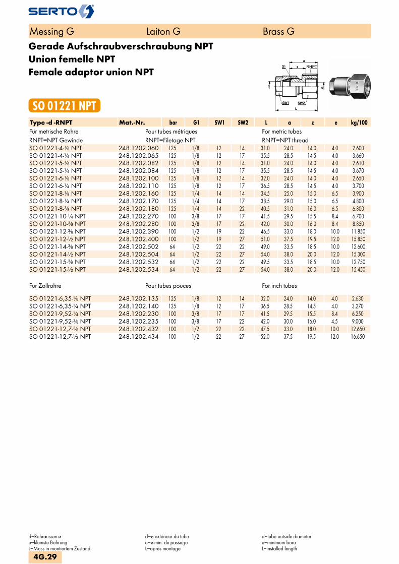
Gerade Aufschraubverschraubung NPTUnion femelle NPTFemale adaptor union NPT
SO 01221 NPTType -d -RNPT Mat.-Nr. bar G1 SW1 SW2 L a z e kg/100Für metrische Rohre Pour tubes métriques For metric tubesRNPT=NPT Gewinde RNPT=Filetage NPT RNPT=NPT threadSO 01221-4-1/8 NPT 248.1202.060 125 1/8 12 14 31.0 24.0 14.0 4.0 2.600SO 01221-4-1/4 NPT 248.1202.065 125 1/8 12 17 35.5 28.5 14.5 4.0 3.660SO 01221-5-1/8 NPT 248.1202.082 125 1/8 12 14 31.0 24.0 14.0 4.0 2.610SO 01221-5-1/4 NPT 248.1202.084 125 1/8 12 17 35.5 28.5 14.5 4.0 3.670SO 01221-6-1/8 NPT 248.1202.100 125 1/8 12 14 32.0 24.0 14.0 4.0 2.650SO 01221-6-1/4 NPT 248.1202.110 125 1/8 12 17 36.5 28.5 14.5 4.0 3.700SO 01221-8-1/8 NPT 248.1202.160 125 1/4 14 14 34.5 25.0 15.0 6.5 3.900SO 01221-8-1/4 NPT 248.1202.170 125 1/4 14 17 38.5 29.0 15.0 6.5 4.800SO 01221-8-3/8 NPT 248.1202.180 125 1/4 14 22 40.5 31.0 16.0 6.5 6.800SO 01221-10-1/4 NPT 248.1202.270 100 3/8 17 17 41.5 29.5 15.5 8.4 6.700SO 01221-10-3/8 NPT 248.1202.280 100 3/8 17 22 42.0 30.0 16.0 8.4 8.850SO 01221-12-3/8 NPT 248.1202.390 100 1/2 19 22 46.5 33.0 18.0 10.0 11.850SO 01221-12-1/2 NPT 248.1202.400 100 1/2 19 27 51.0 37.5 19.5 12.0 15.850SO 01221-14-3/8 NPT 248.1202.502 64 1/2 22 22 49.0 33.5 18.5 10.0 12.600SO 01221-14-1/2 NPT 248.1202.504 64 1/2 22 27 54.0 38.0 20.0 12.0 15.300SO 01221-15-3/8 NPT 248.1202.532 64 1/2 22 22 49.5 33.5 18.5 10.0 12.750SO 01221-15-1/2 NPT 248.1202.534 64 1/2 22 27 54.0 38.0 20.0 12.0 15.450
Für Zollrohre Pour tubes pouces For inch tubes SO 01221-6,35-1/8 NPT 248.1202.135 125 1/8 12 14 32.0 24.0 14.0 4.0 2.630SO 01221-6,35-1/4 NPT 248.1202.140 125 1/8 12 17 36.5 28.5 14.5 4.0 3.270SO 01221-9,52-1/4 NPT 248.1202.230 100 3/8 17 17 41.5 29.5 15.5 8.4 6.250SO 01221-9,52-3/8 NPT 248.1202.235 100 3/8 17 22 42.0 30.0 16.0 4.5 9.000SO 01221-12,7-3/8 NPT 248.1202.432 100 1/2 22 22 47.5 33.0 18.0 10.0 12.650SO 01221-12,7-1/2 NPT 248.1202.434 100 1/2 22 27 52.0 37.5 19.5 12.0 16.650
Messing G Laiton G Brass G
d=Rohraussen-øe=kleinste BohrungL=Mass in montiertem Zustand
d=ø extérieur du tubee=ø-min. de passageL=après montage
d=tube outside diametere=minimum boreL=installed length
4G.29

Verschraubung mit EinlötnippelUnion avec embout à braserAdaptor union with soldering nipple
SO 01421Type -d -f Mat.-Nr. bar G1 SW1 SW2 L a f z e kg/100Für metrische Rohre Pour tubes métriques For metric tubes SO 01421-4-6 248.1400.060 125 1/8 12 12 23.5 3.0 6.0 16.0 4.0 1.940SO 01421-5-6 248.1400.080 125 1/8 12 12 24.0 3.0 6.0 16.0 4.0 1.980SO 01421-6-6 248.1400.100 125 1/8 12 12 24.0 3.0 6.0 16.0 4.0 1.990SO 01421-8-9 248.1400.140 125 1/4 14 14 27.0 4.0 9.0 17.5 6.0 3.640SO 01421-10-12 248.1400.185 100 3/8 17 17 30.5 5.0 12.0 18.5 8.0 6.050SO 01421-12-14 248.1400.200 100 1/2 19 22 35.0 6.0 14.0 21.5 10.0 10.700SO 01421-14-14 248.1400.250 64 1/2 22 22 38.0 6.0 14.0 22.0 10.0 11.500SO 01421-15-14 248.1400.270 64 1/2 22 22 38.0 6.0 14.0 22.0 10.0 11.650
Für Zollrohre Pour tubes pouces For inch tubes SO 01421-6,35-6 248.1400.120 125 1/8 12 12 24.0 3.0 6.0 16.0 4.0 1.960SO 01421-9,52-12 248.1400.164 125 3/8 17 17 30.5 5.0 12.0 18.5 8.0 6.850SO 01421-12,7-14 248.1400.216 100 1/2 22 22 36.0 6.0 14.0 21.5 11.2 11.200
Messing G Laiton G Brass GMessing G Laiton G Brass G
d=Rohraussen-øe=kleinste BohrungL=Mass in montiertem Zustand
d=ø extérieur du tubee=ø-min. de passageL=après montage
d=tube outside diametere=minimum boreL=installed length
4G.30
i
s
3F
4M
4G
5
5L
6
7
8
9
10
11
12

Gerade SchottverschraubungDurchführungslänge max. 5 mm
Union double pour passage de cloisonpour cloison max. 5 mm
Panel mount unionmax. panel thickness 5 mm
SO 01521Type -d Mat.-Nr. bar G1 SW1 SW2 L L1 B z1 z e kg/100Für metrische Rohre Pour tubes métriques For metric tubes SO 01521-4 248.1500.040 125 1/8 12 14 23.0 28.0 10.5 21.0 16.0 4.0 4.250SO 01521-5 248.1500.050 125 1/8 12 14 23.0 28.0 10.5 21.0 16.0 4.0 4.300SO 01521-6 248.1500.060 125 1/8 12 14 24.0 29.0 10.5 21.0 16.0 4.0 4.300SO 01521-8 248.1500.080 125 1/4 14 19 26.5 32.5 14.0 23.0 17.0 6.5 8.300SO 01521-10 248.1500.100 100 3/8 17 24 30.5 35.5 17.0 23.5 18.5 8.5 14.150SO 01521-12 248.1500.120 100 1/2 19 30 35.5 40.5 21.5 27.0 22.0 12.0 26.500SO 01521-15 248.1500.150 100 1/2 22 30 38.5 43.5 21.5 27.5 22.5 12.0 27.700
Für Zollrohre Pour tubes pouces For inch tubes SO 01521-6,35 248.1500.063 125 1/8 12 14 24.0 29.0 10.5 21.0 16.0 4.0 4.270SO 01521-9,52 248.1500.095 100 3/8 17 24 31.0 36.0 17.0 23.5 18.5 8.5 14.950
Gerade SchottverschraubungDurchführungslänge max. 16 mm
Union double pour passage de cloisonpour cloison max. 16 mm
Panel mount unionmax. panel thickness 16 mm
SO 01524Type -d Mat.-Nr. bar G1 SW1 SW2 L L1 B z1 z e kg/100Für metrische Rohre Pour tubes métriques For metric tubes SO 01524-4 248.1540.040 125 1/8 12 14 23.0 38.5 10.5 32.0 16.0 4.0 4.750SO 01524-5 248.1540.050 125 1/8 12 14 23.0 39.0 10.5 32.0 16.0 4.0 4.750SO 01524-6 248.1540.060 125 1/8 12 14 24.0 40.0 10.5 32.0 16.0 4.0 4.800SO 01524-8 248.1540.080 125 1/4 14 19 26.5 43.5 14.0 34.0 17.0 6.5 9.150SO 01524-10 248.1540.100 100 3/8 17 24 30.5 46.5 17.0 34.5 18.5 8.5 15.600SO 01524-12 248.1540.120 100 1/2 19 30 35.5 51.5 21.5 38.0 22.0 12.0 25.700SO 01524-14 248.1540.140 64 1/2 22 30 38.5 54.5 21.5 38.5 22.5 12.0 27.250SO 01524-15 248.1540.150 64 1/2 22 30 38.5 54.5 21.5 38.5 22.5 12.0 27.400
Für Zollrohre Pour tubes pouces For inch tubes SO 01524-6,35 248.1540.063 125 1/8 12 14 24.0 40.0 10.5 32.0 16.0 4.0 4.770SO 01524-9,52 248.1540.095 125 3/8 17 24 30.5 46.5 17.0 34.5 18.5 8.5 16.400SO 01524-12,7 248.1540.127 100 1/2 22 30 36.5 52.5 21.5 38.0 22.5 12.0 26.500
Messing G Laiton G Brass G
d=Rohraussen-øe=kleinste BohrungL=Mass in montiertem Zustand
d=ø extérieur du tubee=ø-min. de passageL=après montage
d=tube outside diametere=minimum boreL=installed length
4G.31

Schottverschraubung reduziertDurchführungslänge max. 5mm
Union double réduite pour passage de cloisonpour cloison max. 5 mm
Panel mount reduction unionmax. panel thickness 5 mm
SO 01528Type -d -d2 Mat.-Nr. bar G1 G red SW1 SW2 SW4 L L1 z1 z e kg/100Für metrische Rohre Pour tubes métriques For metric tubes SO 01528-6-4 248.1504.110 125 1/8 1/8 12 14 12 24.0 27.5 21.0 16.0 4.0 4.260SO 01528-8-6 248.1504.140 125 1/4 1/8 14 14 12 26.5 29.0 21.0 17.0 4.0 5.620SO 01528-10-6 248.1504.175 100 3/8 1/8 17 17 12 30.5 29.0 21.0 18.5 4.0 8.390SO 01528-10-8 248.1504.190 100 3/8 1/4 17 19 14 30.5 32.5 23.0 18.5 6.0 10.500SO 01528-12-10 248.1504.240 100 1/2 3/8 19 24 17 35.5 35.5 23.5 22.0 8.0 17.950SO 01528-14-10 248.1504.320 64 1/2 3/8 22 24 17 38.5 36.0 23.5 22.5 8.0 18.820SO 01528-14-12 248.1504.340 64 1/2 1/2 22 30 19 38.5 51.5 38.0 22.5 12.0 24.850SO 01528-15-10 248.1504.410 64 1/2 3/8 22 24 17 38.5 35.5 23.5 22.5 8.0 19.050SO 01528-15-12 248.1504.420 64 1/2 1/2 22 30 19 38.5 51.5 38.0 22.5 12.0 24.950
Für Zollrohre Pour tubes pouces For inch tubes SO 01528-6,35-4 248.1504.123 125 1/8 1/8 12 14 12 24.0 27.5 21.0 16.0 4.0 4.230SO 01528-8-6,35 248.1504.141 125 1/4 1/8 14 14 12 26.5 29.0 21.0 17.0 4.0 5.590SO 01528-9,52-8 248.1504.162 100 3/8 1/4 17 19 14 30.5 32.5 23.0 18.5 6.0 10.650SO 01528-12-9,52 248.1504.236 100 1/2 3/8 19 24 17 35.5 35.5 23.5 22.0 8.0 18.100SO 01528-12,7-9,52 248.1504.270 100 1/2 3/8 22 24 17 35.5 35.5 23.5 22.0 8.0 18.750SO 01528-12,7-10 248.1504.272 100 1/2 3/8 22 24 17 35.5 35.5 23.5 22.0 8.0 18.600
Messing G Laiton G Brass G
d=Rohraussen-øe=kleinste BohrungL=Mass in montiertem Zustand
d=ø extérieur du tubee=ø-min. de passageL=après montage
d=tube outside diametere=minimum boreL=installed length
4G.32
i
s
3F
4M
4G
5
5L
6
7
8
9
10
11
12

EinstellnippelUnion orientable mâleAdjustable male adaptor
SO 41600Type -Ad -R Mat.-Nr. bar SW L b z e kg/100 SO 41600-A6-1/8 016.1601.100 250 12 26.0 13.0 19.5 4.0 1.000SO 41600-A6-1/4 016.1601.110 250 14 31.0 13.0 21.0 4.0 1.950SO 41600-A8-1/8 016.1601.160 150 12 28.0 14.0 21.5 6.0 1.200SO 41600-A8-1/4 016.1601.170 150 14 32.0 14.0 22.0 6.0 1.800SO 41600-A10-1/4 016.1601.270 125 14 34.0 16.0 24.0 8.0 1.650SO 41600-A10-3/8 016.1601.280 125 17 34.0 16.0 24.0 8.0 2.900SO 41600-A10-1/2 016.1601.285 125 22 39.0 16.0 25.5 8.0 5.570SO 41600-A12-1/4 016.1601.380 100 14 36.0 18.0 26.0 8.0 1.750SO 41600-A12-3/8 016.1601.390 100 17 36.0 18.0 26.0 9.0 3.000SO 41600-A12-1/2 016.1601.400 100 22 41.0 18.0 27.5 9.0 5.670SO 41600-A14-1/2 016.1601.504 64 22 44.0 21.0 31.0 11.0 5.650SO 41600-A15-3/8 016.1601.532 64 17 39.0 21.0 29.0 10.5 3.200
Anwendungsbeispiele: Exemples d‘utilisation: Sample combinations:
Dieser Einstellnippel ergibt im Zusammenhang mit unserem Armaturenanschluss SO 00021 einen einstellbaren Anschluss.
Cette union montée avec écrou SO 00021permet d‘obtenir un raccord orientable mâle.
In combination with our nut connectionSO 00021 this adjustable male adaptorforms an adjustable male adaptor union.
Anwendungsbeispiele: Exemples d‘utilisation: Sample combinations:
Kombiniert mit Winkel- oder T-Verschraubungen ergeben sich einstellbare Formteile.
Cette union, combinée avec un coude ou un té, permet d‘obtenir des raccords orientables.
Produces adjustable configurations incombination with elbow or tee unions.
Messing G Laiton G Brass G
Ad=Aussen-ø der Andrehunge=kleinste Bohrung
Ad=ø extérieur de la portée cylindriquee=ø-min. de passage
Ad=outside diameter of cyl. Stube=minimum bore
4G.33

EinstellnippelUnion orientable mâleAdjustable male adaptor
SO 41604Type -Ad -R Mat.-Nr. bar SW L b z e kg/100 radial demontierbar démontable radialement radial dismantlingSO 41604-A15-1/2 016.1611.534 64 22 53.0 30.0 40.0 12.0 5.760SO 41604-A15-3/4 016.1611.536 64 27 55.0 30.0 40.0 12.0 7.800SO 41604-A22-1 016.1611.770 40 36 65.0 36.0 48.5 18.0 16.540SO 41604-A28-1 1/4 016.1611.860 40 46 75.5 41.5 56.5 23.0 33.860
WinkelverschraubungCoudeElbow union
SO 02021Type -d Mat.-Nr. bar G1 SW1 SW2 L D z e kg/100Für metrische Rohre Pour tubes métriques For metric tubes SO 02021-4 248.2000.040 125 1/8 12 10 26.5 10.4 20.0 4.0 3.620SO 02021-5 248.2000.050 125 1/8 12 10 27.0 12.0 20.0 4.0 3.620SO 02021-6 248.2000.060 125 1/8 12 10 28.0 12.0 20.0 4.0 3.650SO 02021-8 248.2000.080 125 1/4 14 11 31.5 17.0 22.0 6.0 6.550SO 02021-10 248.2000.100 100 3/8 17 14 35.0 21.0 23.0 8.5 10.550SO 02021-12 248.2000.120 100 1/2 19 17 39.5 26.0 26.0 10.0 17.800SO 02021-14 248.2000.140 64 1/2 22 19 45.5 26.0 29.5 12.0 19.750SO 02021-15 248.2000.150 64 1/2 22 19 45.5 26.0 29.5 12.0 19.850
Für Zollrohre Pour tubes pouces For inch tubes SO 02021-6,35 248.2000.063 125 1/8 12 10 28.0 12.0 20.0 4.0 3.620SO 02021-9,52 248.2000.095 100 3/8 17 14 35.0 21.0 23.0 8.5 10.700SO 02021-12,7 248.2000.127 100 1/2 22 19 39.5 26.0 26.0 10.0 18.600
Messing G Laiton G Brass G
Ad=Aussen-ø der Andrehunge=kleinste Bohrung
Ad=ø extérieur de la portée cylindriquee=ø-min. de passage
Ad=outside diameter of cyl. Stube=minimum bore
4G.34
i
s
3F
4M
4G
5
5L
6
7
8
9
10
11
12
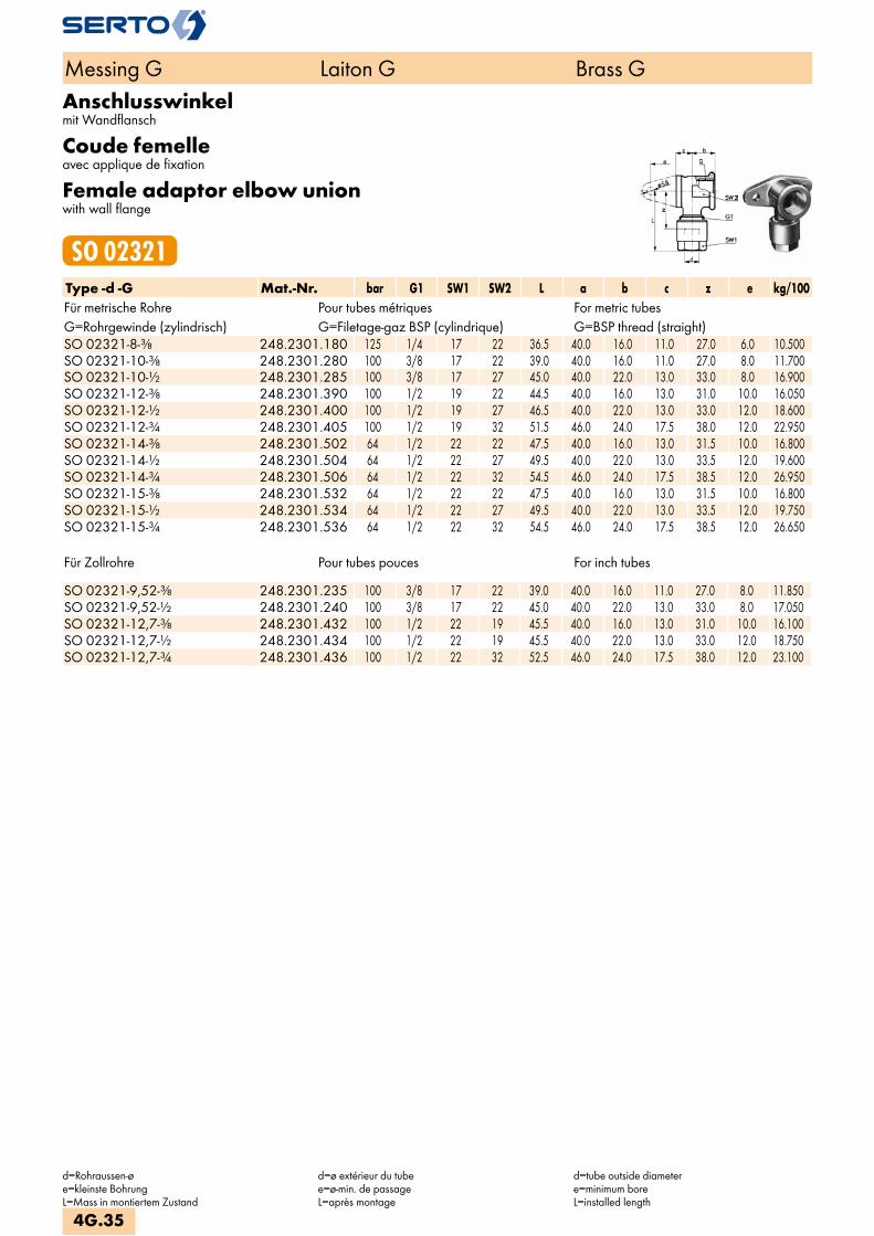
Anschlusswinkelmit Wandflansch
Coude femelleavec applique de fixation
Female adaptor elbow unionwith wall flange
SO 02321Type -d -G Mat.-Nr. bar G1 SW1 SW2 L a b c z e kg/100Für metrische Rohre Pour tubes métriques For metric tubesG=Rohrgewinde (zylindrisch) G=Filetage-gaz BSP (cylindrique) G=BSP thread (straight)SO 02321-8-3/8 248.2301.180 125 1/4 17 22 36.5 40.0 16.0 11.0 27.0 6.0 10.500SO 02321-10-3/8 248.2301.280 100 3/8 17 22 39.0 40.0 16.0 11.0 27.0 8.0 11.700SO 02321-10-1/2 248.2301.285 100 3/8 17 27 45.0 40.0 22.0 13.0 33.0 8.0 16.900SO 02321-12-3/8 248.2301.390 100 1/2 19 22 44.5 40.0 16.0 13.0 31.0 10.0 16.050SO 02321-12-1/2 248.2301.400 100 1/2 19 27 46.5 40.0 22.0 13.0 33.0 12.0 18.600SO 02321-12-3/4 248.2301.405 100 1/2 19 32 51.5 46.0 24.0 17.5 38.0 12.0 22.950SO 02321-14-3/8 248.2301.502 64 1/2 22 22 47.5 40.0 16.0 13.0 31.5 10.0 16.800SO 02321-14-1/2 248.2301.504 64 1/2 22 27 49.5 40.0 22.0 13.0 33.5 12.0 19.600SO 02321-14-3/4 248.2301.506 64 1/2 22 32 54.5 46.0 24.0 17.5 38.5 12.0 26.950SO 02321-15-3/8 248.2301.532 64 1/2 22 22 47.5 40.0 16.0 13.0 31.5 10.0 16.800SO 02321-15-1/2 248.2301.534 64 1/2 22 27 49.5 40.0 22.0 13.0 33.5 12.0 19.750SO 02321-15-3/4 248.2301.536 64 1/2 22 32 54.5 46.0 24.0 17.5 38.5 12.0 26.650
Für Zollrohre Pour tubes pouces For inch tubes SO 02321-9,52-3/8 248.2301.235 100 3/8 17 22 39.0 40.0 16.0 11.0 27.0 8.0 11.850SO 02321-9,52-1/2 248.2301.240 100 3/8 17 22 45.0 40.0 22.0 13.0 33.0 8.0 17.050SO 02321-12,7-3/8 248.2301.432 100 1/2 22 19 45.5 40.0 16.0 13.0 31.0 10.0 16.100SO 02321-12,7-1/2 248.2301.434 100 1/2 22 19 45.5 40.0 22.0 13.0 33.0 12.0 18.750SO 02321-12,7-3/4 248.2301.436 100 1/2 22 32 52.5 46.0 24.0 17.5 38.0 12.0 23.100
Messing G Laiton G Brass G
d=Rohraussen-øe=kleinste BohrungL=Mass in montiertem Zustand
d=ø extérieur du tubee=ø-min. de passageL=après montage
d=tube outside diametere=minimum boreL=installed length
4G.35

Winkel-EinschraubverschraubungCoude mâleMale adaptor elbow union
SO 02421Type -d -R Mat.-Nr. bar G1 SW1 SW2 L b zR z e kg/100Für metrische Rohre Pour tubes métriques For metric tubesR=Rohrgewinde (kegelig) R=Filetage-gaz BSP (conique) R=BSP thread (tapered)SO 02421-4-1/8 248.2401.060 125 1/8 12 10 26.5 19.5 13.5 20.0 4.0 2.700SO 02421-5-1/8 248.2401.082 125 1/8 12 10 27.0 19.5 13.5 20.0 4.0 2.650SO 02421-6-1/8 248.2401.100 125 1/8 12 10 28.0 19.5 13.5 20.0 4.0 2.700SO 02421-6-1/4 248.2401.110 125 1/8 12 11 30.0 25.0 15.0 22.0 4.0 3.650SO 02421-8-1/8 248.2401.160 125 1/4 14 11 31.5 21.0 14.5 22.0 5.0 4.350SO 02421-8-1/4 248.2401.170 125 1/4 14 11 31.5 25.0 15.0 22.0 6.0 4.850SO 02421-8-3/8 248.2401.180 125 1/4 14 14 32.5 25.0 16.0 23.0 6.0 6.250SO 02421-10-1/4 248.2401.270 100 3/8 17 14 35.0 25.0 15.0 23.0 8.5 7.100SO 02421-10-3/8 248.2401.280 100 3/8 17 14 35.0 25.0 16.0 23.0 8.5 7.700SO 02421-10-1/2 248.2401.285 100 3/8 17 19 41.0 31.5 19.0 29.0 8.0 11.650SO 02421-12-1/4 248.2401.380 100 1/2 19 17 39.0 25.5 16.0 26.0 7.0 11.550SO 02421-12-3/8 248.2401.390 100 1/2 19 17 39.0 25.0 16.0 26.0 10.0 11.450SO 02421-12-1/2 248.2401.400 100 1/2 19 19 42.0 31.5 19.0 29.0 12.0 13.650SO 02421-14-3/8 248.2401.502 64 1/2 22 17 42.5 25.0 16.0 26.5 10.0 12.050SO 02421-14-1/2 248.2401.504 64 1/2 22 19 45.5 31.5 19.0 29.5 12.0 14.300SO 02421-14-3/4 248.2401.506 64 1/2 22 22 47.5 34.0 20.0 31.5 12.0 18.450SO 02421-15-3/8 248.2401.532 64 1/2 22 17 42.5 25.0 16.0 26.5 10.0 12.300SO 02421-15-1/2 248.2401.534 64 1/2 22 19 45.5 31.5 19.0 29.5 12.0 14.550SO 02421-15-3/4 248.2401.536 64 1/2 22 22 47.5 34.0 20.0 31.5 12.0 18.650
Für Zollrohre Pour tubes pouces For inch tubes SO 02421-6,35-1/8 248.2401.135 125 1/8 12 10 28.0 19.5 13.5 20.0 4.0 2.700SO 02421-6,35-1/4 248.2401.140 125 1/8 12 11 30.0 25.0 15.0 22.0 4.0 3.650SO 02421-9,52-1/4 248.2401.230 100 3/8 17 14 35.0 25.0 15.0 23.0 8.5 7.100SO 02421-9,52-3/8 248.2401.235 100 3/8 17 14 35.0 25.0 16.0 23.0 8.5 7.700SO 02421-9,52-1/2 248.2401.240 100 3/8 17 19 41.0 31.5 19.0 29.0 8.0 11.650SO 02421-12,7-1/4 248.2401.430 100 1/2 19 17 39.0 25.5 16.0 26.0 7.0 11.550SO 02421-12,7-3/8 248.2401.432 100 1/2 19 17 39.0 25.0 16.0 26.0 10.0 11.450SO 02421-12,7-1/2 248.2401.434 100 1/2 19 19 42.0 31.5 19.0 29.0 12.0 13.350
Messing G Laiton G Brass G
d=Rohraussen-øe=kleinste BohrungL=Mass in montiertem Zustand
d=ø extérieur du tubee=ø-min. de passageL=après montage
d=tube outside diameterL=installed lengthe=minimum bore
4G.36
i
s
3F
4M
4G
5
5L
6
7
8
9
10
11
12

Winkel-Einschraubverschraubung NPTCoude mâle NPTMale adaptor elbow union NPT
SO 02421 NPTType -d -RNPT Mat.-Nr. bar G1 SW1 SW2 L b zR z e kg/100Für metrische Rohre Pour tubes métriques For metric tubesRNPT=NPT Gewinde RNPT=Filetage NPT RNPT=NPT threadSO 02421-4-1/8 NPT 248.2402.060 125 1/8 12 10 26.5 19.5 13.0 20.0 4.0 2.000SO 02421-5-1/8 NPT 248.2402.082 125 1/8 12 10 27.0 19.5 13.0 20.0 4.0 2.000SO 02421-6-1/8 NPT 248.2402.100 125 1/8 12 10 28.0 19.5 13.0 20.0 4.0 2.000SO 02421-6-1/4 NPT 248.2402.110 125 1/8 12 11 30.0 25.0 15.0 22.0 4.0 3.000SO 02421-8-1/8 NPT 248.2402.160 125 1/4 14 11 31.5 21.0 14.0 22.0 5.0 4.000SO 02421-8-1/4 NPT 248.2402.170 125 1/4 14 11 31.5 25.0 15.0 22.0 6.0 4.000SO 02421-10-1/4 NPT 248.2402.270 100 3/8 17 14 35.0 25.0 15.0 23.0 8.5 7.000SO 02421-10-3/8 NPT 248.2402.280 100 3/8 17 14 35.0 25.0 16.0 23.0 8.5 7.000SO 02421-12-3/8 NPT 248.2402.390 100 1/2 19 17 39.0 25.0 16.0 26.0 10.0 11.000SO 02421-12-1/2 NPT 248.2402.400 100 1/2 19 19 42.0 31.5 18.0 29.0 12.0 13.000SO 02421-14-3/8 NPT 248.2402.502 64 1/2 22 17 42.5 25.0 16.0 26.5 10.0 14.000SO 02421-14-1/2 NPT 248.2402.504 64 1/2 22 19 45.5 31.5 18.0 29.5 12.0 13.000SO 02421-15-3/8 NPT 248.2402.532 64 1/2 22 17 42.5 25.0 16.0 26.5 10.0 14.000SO 02421-15-1/2 NPT 248.2402.534 64 1/2 22 19 45.5 31.5 18.0 29.5 12.0 14.000
Für Zollrohre Pour tubes pouces For inch tubes SO 02421-6,35-1/8 NPT 248.2402.135 125 1/8 12 10 28.0 19.5 13.0 20.0 4.0 2.000SO 02421-6,35-1/4 NPT 248.2402.140 125 1/8 12 11 30.0 25.0 15.0 22.0 4.0 3.000SO 02421-9,52-1/4 NPT 248.2402.230 125 3/8 17 14 35.0 25.0 15.0 23.0 8.5 4.000SO 02421-9,52-3/8 NPT 248.2402.235 125 3/8 17 14 35.0 25.0 16.0 23.0 8.5 4.000SO 02421-12,7-3/8 NPT 248.2402.432 100 1/2 19 17 39.0 25.0 16.0 26.0 10.0 11.000SO 02421-12,7-1/2 NPT 248.2402.434 100 1/2 19 19 42.0 31.5 18.0 29.0 12.0 13.000
Messing G Laiton G Brass G
d=Rohraussen-øe=kleinste BohrungL=Mass in montiertem Zustand
d=ø extérieur du tubee=ø-min. de passageL=après montage
d=tube outside diameterL=installed lengthe=minimum bore
4G.37

Winkel-AufschraubverschraubungCoude femelleFemale adaptor elbow union
SO 02521Type -d -G Mat.-Nr. bar G1 SW1 SW2 L b z e kg/100Für metrische Rohre Pour tubes métriques For metric tubesG=Rohrgewinde (zylindrisch) G=Filetage-gaz BSP (cylindrique) G=BSP thread (straight)SO 02521-4-1/8 248.2501.060 125 1/8 12 14 28.5 11.5 22.0 4.0 2.900SO 02521-5-1/8 248.2501.082 125 1/8 12 14 29.0 11.5 22.0 4.0 2.850SO 02521-6-1/8 248.2501.100 125 1/8 12 14 30.0 11.5 22.0 4.0 2.900SO 02521-6-1/4 248.2501.110 125 1/4 14 19 34.0 13.5 25.0 6.0 5.700SO 02521-8-1/4 248.2501.170 125 1/4 14 19 34.5 13.5 25.0 6.0 5.550SO 02521-8-3/8 248.2501.180 125 3/8 17 22 38.0 16.0 27.0 8.0 8.350SO 02521-10-3/8 248.2501.280 100 3/8 17 22 39.0 16.0 27.0 8.0 8.150SO 02521-10-1/2 248.2501.285 100 3/8 17 27 45.0 22.0 33.0 8.0 13.100SO 02521-12-3/8 248.2501.390 100 1/2 19 22 43.0 18.0 29.0 10.0 12.750SO 02521-12-1/2 248.2501.400 100 1/2 19 27 46.0 22.0 32.5 12.0 15.150SO 02521-12-3/4 248.2501.405 100 1/2 19 32 46.5 24.0 33.0 12.0 19.800SO 02521-14-3/8 248.2501.502 64 1/2 22 22 45.5 18.0 29.5 10.0 13.550SO 02521-14-1/2 248.2501.504 64 1/2 22 27 49.0 22.0 33.0 12.0 15.350SO 02521-14-3/4 248.2501.506 64 1/2 22 32 49.5 24.0 33.5 12.0 20.300SO 02521-15-3/8 248.2501.532 64 1/2 22 22 45.5 18.0 29.5 10.0 13.650SO 02521-15-1/2 248.2501.534 64 1/2 22 27 49.0 22.0 33.0 12.0 15.950SO 02521-15-3/4 248.2501.536 64 1/2 22 32 49.5 24.0 33.5 12.0 20.400
Für Zollrohre Pour tubes pouces For inch tubes SO 02521-6,35-1/8 248.2501.135 125 1/8 12 14 30.0 11.5 22.0 4.0 2.870SO 02521-6,35-1/4 248.2501.140 125 1/4 14 19 39.0 11.5 25.0 6.0 5.830SO 02521-9,52-3/8 248.2501.235 100 3/8 17 22 39.0 16.0 27.0 8.0 8.950SO 02521-9,52-1/2 248.2501.240 100 1/2 17 27 45.0 22.0 33.0 8.0 13.900SO 02521-12,7-3/8 248.2501.432 100 3/8 22 22 43.0 18.0 29.0 10.0 13.550SO 02521-12,7-1/2 248.2501.434 100 1/2 22 27 46.0 22.0 32.5 10.0 15.950SO 02521-12,7-3/4 248.2501.436 100 3/4 22 32 47.5 24.0 33.0 10.0 20.600
Messing G Laiton G Brass G
d=Rohraussen-øe=kleinste BohrungL=Mass in montiertem Zustand
d=ø extérieur du tubee=ø-min. de passageL=après montage
d=tube outside diametere=minimum boreL=installed length
4G.38
i
s
3F
4M
4G
5
5L
6
7
8
9
10
11
12

Winkelverschraubungmit Einstellzapfen
Coude orientableAdjustable elbow union
SO 02621Type -d -Ad Mat.-Nr. bar G1 SW1 SW2 L b f z e kg/100Für metrische Rohre Pour tubes métriques For metric tubes SO 02621-6-A6 248.2600.060 125 1/8 12 10 28.0 19.0 13.0 20.0 4.0 2.250SO 02621-8-A8 248.2600.080 125 1/4 14 11 31.5 22.0 14.0 22.0 6.0 4.000SO 02621-10-A10 248.2600.100 100 3/8 17 14 35.5 26.0 16.0 23.0 8.0 6.300SO 02621-12-A12 248.2600.120 100 1/2 19 19 42.0 31.0 18.0 29.0 9.0 12.900SO 02621-14-A14 248.2600.140 64 1/2 22 19 45.5 31.0 21.0 29.5 11.0 12.950SO 02621-15-A15 248.2600.150 64 1/2 22 19 45.5 31.0 21.0 29.5 12.0 13.200
Anwendungsbeispiele: Exemples d‘utilisation: Sample combinations:
Dieser Einstellwinkel ergibt im Zusammenhang mit unserem Armaturenanschluss SO 00021 einen einstellbaren Winkelanschluss.
L’assemblage avec SO 00021 donne un coude parfaitement orientable.
In combination with our nut connection SO 00021, this elbow forms an adjustable female adaptor elbow.
Anwendungsbeispiele: Exemples d‘utilisation: Sample combinations:
Gegenüber dem Einschraubwinkel lässt sich diese Kombination einfacher einstellen, da Einschrauben und Ausrichten getrennt voneinan-der vorgenommen werden.
Par opposition à un coude mâle, cette combin-aison permet un positionnement plus facile. Le raccordement et l’orientation se font séparément.
In contrast to the simple male adaptor elbow union, this combination is easier to adjust, since screw-on and aligning are performed separately.
Messing G Laiton G Brass G
d=Rohraussen-øAd=Aussen-ø der Andrehunge=kleinste BohrungL=Mass in montiertem Zustand
d=ø extérieur du tubeAd=ø extérieur de la portée cylindriquee=ø-min. de passageL=après montage
d=tube outside diameterAd=outside diameter of cyl. stube=minimum boreL=installed length
4G.39
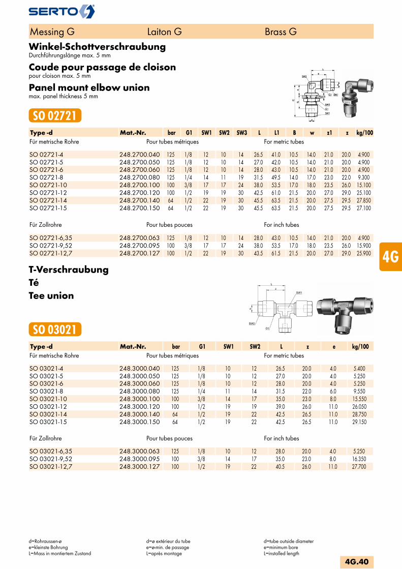
Winkel-SchottverschraubungDurchführungslänge max. 5 mm
Coude pour passage de cloisonpour cloison max. 5 mm
Panel mount elbow unionmax. panel thickness 5 mm
SO 02721Type -d Mat.-Nr. bar G1 SW1 SW2 SW3 L L1 B w z1 z kg/100Für metrische Rohre Pour tubes métriques For metric tubes SO 02721-4 248.2700.040 125 1/8 12 10 14 26.5 41.0 10.5 14.0 21.0 20.0 4.900SO 02721-5 248.2700.050 125 1/8 12 10 14 27.0 42.0 10.5 14.0 21.0 20.0 4.900SO 02721-6 248.2700.060 125 1/8 12 10 14 28.0 43.0 10.5 14.0 21.0 20.0 4.900SO 02721-8 248.2700.080 125 1/4 14 11 19 31.5 49.5 14.0 17.0 23.0 22.0 9.300SO 02721-10 248.2700.100 100 3/8 17 17 24 38.0 53.5 17.0 18.0 23.5 26.0 15.100SO 02721-12 248.2700.120 100 1/2 19 19 30 42.5 61.0 21.5 20.0 27.0 29.0 25.100SO 02721-14 248.2700.140 64 1/2 22 19 30 45.5 63.5 21.5 20.0 27.5 29.5 27.850SO 02721-15 248.2700.150 64 1/2 22 19 30 45.5 63.5 21.5 20.0 27.5 29.5 27.100
Für Zollrohre Pour tubes pouces For inch tubes SO 02721-6,35 248.2700.063 125 1/8 12 10 14 28.0 43.0 10.5 14.0 21.0 20.0 4.900SO 02721-9,52 248.2700.095 100 3/8 17 17 24 38.0 53.5 17.0 18.0 23.5 26.0 15.900SO 02721-12,7 248.2700.127 100 1/2 22 19 30 43.5 61.5 21.5 20.0 27.0 29.0 25.900
T-VerschraubungTéTee union
SO 03021Type -d Mat.-Nr. bar G1 SW1 SW2 L z e kg/100Für metrische Rohre Pour tubes métriques For metric tubes SO 03021-4 248.3000.040 125 1/8 10 12 26.5 20.0 4.0 5.400SO 03021-5 248.3000.050 125 1/8 10 12 27.0 20.0 4.0 5.250SO 03021-6 248.3000.060 125 1/8 10 12 28.0 20.0 4.0 5.250SO 03021-8 248.3000.080 125 1/4 11 14 31.5 22.0 6.0 9.550SO 03021-10 248.3000.100 100 3/8 14 17 35.0 23.0 8.0 15.550SO 03021-12 248.3000.120 100 1/2 19 19 39.0 26.0 11.0 26.050SO 03021-14 248.3000.140 64 1/2 19 22 42.5 26.5 11.0 28.750SO 03021-15 248.3000.150 64 1/2 19 22 42.5 26.5 11.0 29.150
Für Zollrohre Pour tubes pouces For inch tubes SO 03021-6,35 248.3000.063 125 1/8 10 12 28.0 20.0 4.0 5.250SO 03021-9,52 248.3000.095 100 3/8 14 17 35.0 23.0 8.0 16.350SO 03021-12,7 248.3000.127 100 1/2 19 22 40.5 26.0 11.0 27.700
Messing G Laiton G Brass G
d=Rohraussen-øe=kleinste BohrungL=Mass in montiertem Zustand
d=ø extérieur du tubee=ø-min. de passageL=après montage
d=tube outside diametere=minimum boreL=installed length
4G.40
i
s
3F
4M
4G
5
5L
6
7
8
9
10
11
12
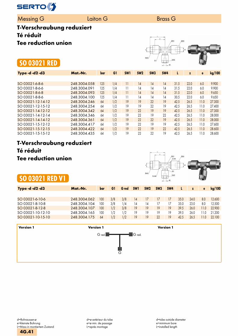
T-Verschraubung reduziertTé réduitTee reduction union
SO 03021 REDType -d -d2 -d3 Mat.-Nr. bar G1 SW1 SW2 SW3 SW4 L z e kg/100 SO 03021-6-8-6 248.3004.058 125 1/4 11 14 14 14 31.5 22.0 6.0 9.900SO 03021-8-6-6 248.3004.091 125 1/4 11 14 14 14 31.5 22.0 6.0 9.900SO 03021-8-6-8 248.3004.093 125 1/4 11 14 14 14 31.5 22.0 6.0 9.650SO 03021-8-8-6 248.3004.100 125 1/4 11 14 14 14 30.5 22.0 6.0 9.650SO 03021-12-14-12 248.3004.246 64 1/2 19 19 22 19 42.5 26.5 11.0 27.300SO 03021-12-15-12 248.3004.254 64 1/2 19 19 22 19 42.5 26.5 11.0 27.400SO 03021-14-12-12 248.3004.342 64 1/2 19 22 19 19 42.5 26.5 11.0 27.300SO 03021-14-12-14 248.3004.346 64 1/2 19 22 19 22 42.5 26.5 11.0 28.000SO 03021-14-14-12 248.3004.361 64 1/2 19 22 22 19 42.5 26.5 11.0 28.000SO 03021-15-12-12 248.3004.417 64 1/2 19 22 19 19 42.5 26.5 11.0 27.600SO 03021-15-12-15 248.3004.422 64 1/2 19 22 19 22 42.5 26.5 11.0 28.600SO 03021-15-15-12 248.3004.435 64 1/2 19 22 22 19 42.5 26.5 11.0 28.600
T-Verschraubung reduziertTé réduitTee reduction union
SO 03021 RED V1Type -d -d2 -d3 Mat.-Nr. bar G1 G red SW1 SW2 SW3 SW4 L z e kg/100 SO 03021-6-10-6 248.3004.062 100 3/8 3/8 14 17 17 17 35.0 24.0 8.0 12.600SO 03021-8-10-8 248.3004.104 100 3/8 1/4 14 14 17 17 35.0 23.0 8.0 12.500SO 03021-8-12-8 248.3004.107 100 1/2 3/8 19 19 19 19 39.5 26.0 11.0 22.900SO 03021-10-12-10 248.3004.165 100 1/2 1/2 19 19 19 19 39.5 26.0 11.0 21.200SO 03021-10-15-10 248.3004.175 64 1/2 1/2 19 19 22 19 42.5 26.5 11.0 22.100
Version 1 Version 1 Version 1
Messing G Laiton G Brass G
d=Rohraussen-øe=kleinste BohrungL=Mass in montiertem Zustand
d=ø extérieur du tubee=ø min. de passageL=après montage
d=tube outside diametere=minimum boreL=installed length
4G.41

T-Verschraubung reduziertTé réduitTee reduction union
SO 03021 RED V2Type -d -d2 -d3 Mat.-Nr. bar G1 G red SW1 SW2 SW3 SW4 L L red z e kg/100 SO 03021-6-6-10 248.3004.143 100 3/8 1/4 14 17 17 19 33.0 33.0 23.0 8.0 12.600SO 03021-8-8-10 248.3004.151 100 3/8 3/8 14 17 17 19 35.5 35.5 23.0 8.0 12.500SO 03021-6-6-12 248.3004.195 100 1/2 3/8 19 17 17 19 38.0 38.0 27.0 8.0 22.700SO 03021-8-8-12 248.3004.206 100 1/2 1/2 19 19 19 19 39.0 39.0 27.0 11.0 20.400SO 03021-10-10-12 248.3004.220 100 1/2 3/8 19 17 17 19 39.0 39.0 26.0 8.0 21.200SO 03021-10-10-15 248.3004.403 64 1/2 3/8 19 17 17 22 39.0 39.0 26.0 8.0 22.900
Version 2 Version 2 Version 2
T-Verschraubung reduziertTé réduitTee reduction union
SO 03021 RED V3Type -d -d2 -d3 Mat.-Nr. bar G1 G red SW1 SW2 SW3 SW4 L L red z e kg/100 SO 03021-10-6-10 248.3004.147 100 3/8 1/4 14 17 14 17 36.5 33.0 23.0 8.0 13.900SO 03021-10-8-10 248.3004.153 100 3/8 1/4 14 17 14 17 36.5 34.0 23.0 8.0 13.900SO 03021-12-6-12 248.3004.200 100 1/2 3/8 19 19 17 19 41.5 39.0 26.0 11.0 23.900SO 03021-12-8-12 248.3004.210 100 1/2 3/8 19 19 17 19 42.0 39.0 26.0 11.0 23.700SO 03021-12-10-12 248.3004.222 100 1/2 3/8 19 19 17 19 42.0 39.5 26.0 11.0 23.500SO 03021-14-8-14 248.3004.320 64 1/2 3/8 19 22 17 22 45.0 39.0 26.5 11.0 26.500SO 03021-14-10-12 248.3004.330 64 1/2 3/8 19 22 17 19 45.0 40.0 26.5 11.0 25.100SO 03021-15-8-15 248.3004.393 64 1/2 3/8 19 22 17 22 44.5 38.5 26.5 11.0 26.500SO 03021-15-10-12 248.3004.405 64 1/2 3/8 19 22 17 19 44.5 39.5 26.5 11.0 25.600SO 03021-15-10-15 248.3004.410 64 1/2 3/8 19 22 17 22 44.5 39.5 26.5 11.0 26.000
Version 3 Version 3 Version 3
Messing G Laiton G Brass G
d=Rohraussen-øe=kleinste BohrungL=Mass in montiertem Zustand
d=ø extérieur du tubee=ø min. de passageL=après montage
d=tube outside diametere=minimum boreL=installed length
4G.42
i
s
3F
4M
4G
5
5L
6
7
8
9
10
11
12
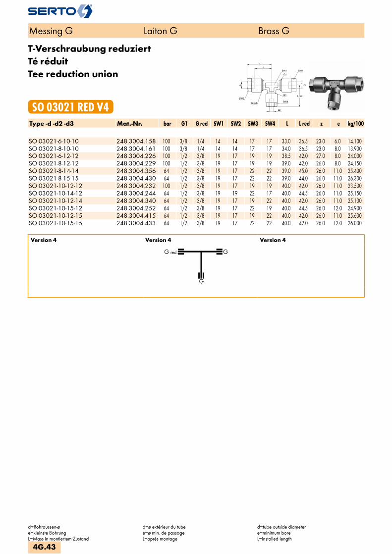
T-Verschraubung reduziertTé réduitTee reduction union
SO 03021 RED V4Type -d -d2 -d3 Mat.-Nr. bar G1 G red SW1 SW2 SW3 SW4 L L red z e kg/100 SO 03021-6-10-10 248.3004.158 100 3/8 1/4 14 14 17 17 33.0 36.5 23.0 6.0 14.100SO 03021-8-10-10 248.3004.161 100 3/8 1/4 14 14 17 17 34.0 36.5 23.0 8.0 13.900SO 03021-6-12-12 248.3004.226 100 1/2 3/8 19 17 19 19 38.5 42.0 27.0 8.0 24.000SO 03021-8-12-12 248.3004.229 100 1/2 3/8 19 17 19 19 39.0 42.0 26.0 8.0 24.150SO 03021-8-14-14 248.3004.356 64 1/2 3/8 19 17 22 22 39.0 45.0 26.0 11.0 25.400SO 03021-8-15-15 248.3004.430 64 1/2 3/8 19 17 22 22 39.0 44.0 26.0 11.0 26.300SO 03021-10-12-12 248.3004.232 100 1/2 3/8 19 17 19 19 40.0 42.0 26.0 11.0 23.500SO 03021-10-14-12 248.3004.244 64 1/2 3/8 19 19 22 17 40.0 44.5 26.0 11.0 25.150SO 03021-10-12-14 248.3004.340 64 1/2 3/8 19 17 19 22 40.0 42.0 26.0 11.0 25.100SO 03021-10-15-12 248.3004.252 64 1/2 3/8 19 17 22 19 40.0 44.5 26.0 12.0 24.900SO 03021-10-12-15 248.3004.415 64 1/2 3/8 19 17 19 22 40.0 42.0 26.0 11.0 25.600SO 03021-10-15-15 248.3004.433 64 1/2 3/8 19 17 22 22 40.0 42.0 26.0 12.0 26.000
Version 4 Version 4 Version 4
Messing G Laiton G Brass G
d=Rohraussen-øe=kleinste BohrungL=Mass in montiertem Zustand
d=ø extérieur du tubee=ø min. de passageL=après montage
d=tube outside diametere=minimum boreL=installed length
4G.43
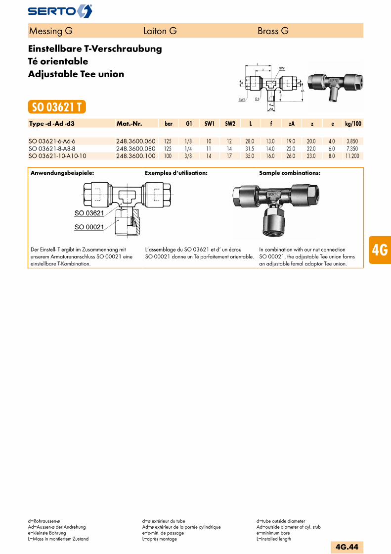
Einstellbare T-VerschraubungTé orientableAdjustable Tee union
SO 03621 TType -d -Ad -d3 Mat.-Nr. bar G1 SW1 SW2 L f zA z e kg/100 SO 03621-6-A6-6 248.3600.060 125 1/8 10 12 28.0 13.0 19.0 20.0 4.0 3.850SO 03621-8-A8-8 248.3600.080 125 1/4 11 14 31.5 14.0 22.0 22.0 6.0 7.350SO 03621-10-A10-10 248.3600.100 100 3/8 14 17 35.0 16.0 26.0 23.0 8.0 11.200
Anwendungsbeispiele: Exemples d‘utilisation: Sample combinations:
Der Einstell- T ergibt im Zusammenhang mit unserem Armaturenanschluss SO 00021 eine einstellbare T-Kombination.
L‘assemblage du SO 03621 et d‘ un écrou SO 00021 donne un Té parfaitement orientable.
In combination with our nut connection SO 00021, the adjustable Tee union forms an adjustable femal adaptor Tee union.
Messing G Laiton G Brass G
d=Rohraussen-øAd=Aussen-ø der Andrehunge=kleinste BohrungL=Mass in montiertem Zustand
d=ø extérieur du tubeAd=ø extérieur de la portée cylindriquee=ø-min. de passageL=après montage
d=tube outside diameterAd=outside diameter of cyl. stube=minimum boreL=installed length
4G.44
i
s
3F
4M
4G
5
5L
6
7
8
9
10
11
12
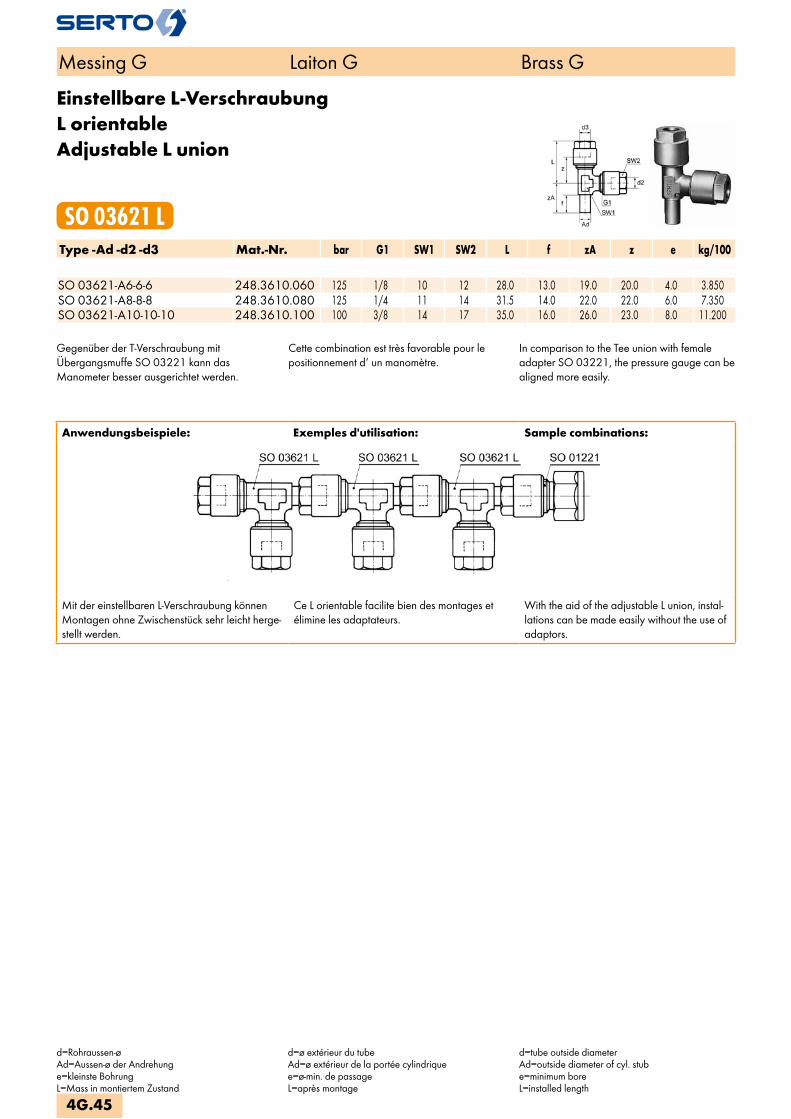
Einstellbare L-VerschraubungL orientableAdjustable L union
SO 03621 LType -Ad -d2 -d3 Mat.-Nr. bar G1 SW1 SW2 L f zA z e kg/100 SO 03621-A6-6-6 248.3610.060 125 1/8 10 12 28.0 13.0 19.0 20.0 4.0 3.850SO 03621-A8-8-8 248.3610.080 125 1/4 11 14 31.5 14.0 22.0 22.0 6.0 7.350SO 03621-A10-10-10 248.3610.100 100 3/8 14 17 35.0 16.0 26.0 23.0 8.0 11.200
Gegenüber der T-Verschraubung mitÜbergangsmuffe SO 03221 kann dasManometer besser ausgerichtet werden.
Cette combination est très favorable pour lepositionnement d‘ un manomètre.
In comparison to the Tee union with femaleadapter SO 03221, the pressure gauge can bealigned more easily.
Messing G Laiton G Brass G
d=Rohraussen-øAd=Aussen-ø der Andrehunge=kleinste BohrungL=Mass in montiertem Zustand
d=ø extérieur du tubeAd=ø extérieur de la portée cylindriquee=ø-min. de passageL=après montage
d=tube outside diameterAd=outside diameter of cyl. stube=minimum boreL=installed length
4G.45
Anwendungsbeispiele: Exemples d'utilisation: Sample combinations:
Mit der einstellbaren L-Verschraubung können Montagen ohne Zwischenstück sehr leicht herge-stellt werden.
Ce L orientable facilite bien des montages et élimine les adaptateurs.
With the aid of the adjustable L union, instal-lations can be made easily without the use of adaptors.

T-EinschraubverschraubungT mâleMale adaptor Tee union
SO 03721 TType -d -R -d3 Mat.-Nr. bar G1 SW1 SW2 L b zR z e kg/100Für metrische Rohre Pour tubes métriques For metric tubesR=Rohrgewinde (kegelig) R=Filetage-gaz BSP (conique) R=BSP thread (tapered)SO 03721-4-1/8-4 248.3701.040 125 1/8 10 12 27.0 20.0 13.5 20.0 4.0 4.250SO 03721-5-1/8-5 248.3701.070 125 1/8 10 12 27.0 20.0 13.5 20.0 4.0 4.250SO 03721-6-1/8-6 248.3701.100 125 1/8 10 12 28.0 20.0 13.5 20.0 4.0 4.350SO 03721-6-1/4-6 248.3701.110 125 1/8 11 12 30.0 25.0 15.0 22.0 4.0 5.550SO 03721-8-1/4-8 248.3701.170 125 1/4 11 14 31.0 25.0 15.0 22.0 6.0 7.900SO 03721-10-1/4-10 248.3701.270 100 3/8 14 17 35.0 25.0 15.0 23.0 7.0 11.950SO 03721-10-3/8-10 248.3701.280 100 3/8 14 17 35.0 25.0 16.0 23.0 8.0 12.550
Für Zollrohre Pour tubes pouces For inch tubes SO 03721-6,35-1/8-6,35 248.3701.140 125 1/8 10 12 28.0 20.0 13.5 20.0 4.0 4.330SO 03721-6,35-1/4-6,35 248.3701.145 125 1/8 11 12 30.0 25.0 15.0 22.0 4.0 5.520SO 03721-9,52-1/4-9,52 248.3701.210 100 3/8 14 17 35.0 25.0 15.0 23.0 7.0 12.100SO 03721-9,52-3/8-9,52 248.3701.215 100 3/8 14 17 35.0 25.0 16.0 23.0 8.0 13.350
L-EinschraubverschraubungL mâleMale adaptor L union
SO 03721 LType -R -d2 -d3 Mat.-Nr. bar G1 SW1 SW2 L b zR z e kg/100Für metrische Rohre Pour tubes métriques For metric tubesR=Rohrgewinde (kegelig) R=Filetage-gaz BSP (conique) R=BSP thread (tapered)SO 03721-1/8-4-4 248.3711.050 125 1/8 10 12 27.0 20.0 13.5 20.0 4.0 4.250SO 03721-1/8-5-5 248.3711.070 125 1/8 10 12 27.0 20.0 13.5 20.0 4.0 4.250SO 03721-1/8-6-6 248.3711.100 125 1/8 10 12 28.0 20.0 13.5 20.0 4.0 4.350SO 03721-1/4-6-6 248.3711.180 125 1/8 11 12 30.0 25.0 15.0 22.0 4.0 5.550SO 03721-1/4-8-8 248.3711.220 125 1/4 11 14 31.5 25.0 15.0 22.0 6.0 7.900SO 03721-1/4-10-10 248.3711.260 100 3/8 14 17 35.0 25.0 15.0 23.0 8.0 11.950SO 03721-3/8-10-10 248.3711.320 100 3/8 14 17 35.0 25.0 16.0 23.0 8.0 12.550
Für Zollrohre Pour tubes pouces For inch tubes SO 03721-1/8-6,35-6,35 248.3711.110 125 1/8 10 12 28.0 20.0 13.5 20.0 4.0 4.330SO 03721-1/4-6,35-6,35 248.3711.190 125 1/8 11 12 30.0 25.0 15.0 22.0 4.0 5.530SO 03721-1/4-9,52-9,52 248.3711.240 100 3/8 14 17 35.0 25.0 15.0 23.0 8.0 12.750SO 03721-3/8-9,52-9,52 248.3711.290 100 3/8 14 17 35.0 25.0 16.0 23.0 8.0 13.350
Messing G Laiton G Brass G
d=Rohraussen-øAd=Aussen-ø der Andrehunge=kleinste BohrungL=Mass in montiertem Zustand
d=ø extérieur du tubeAd=ø extérieur de la portée cylindriquee=ø-min. de passageL=après montage
d=tube outside diameterAd=outside diameter of cyl. stube=minimum boreL=installed length
4G.46
i
s
3F
4M
4G
5
5L
6
7
8
9
10
11
12

KreuzverschraubungCroixCross union
SO 04021Type -d Mat.-Nr. bar G1 SW1 SW2 L z e kg/100Für metrische Rohre Pour tubes métriques For metric tubes SO 04021-4 248.4000.040 125 1/8 10 12 27.0 20.0 4.0 6.750SO 04021-5 248.4000.050 125 1/8 10 12 28.0 20.0 4.0 6.800SO 04021-6 248.4000.060 125 1/8 10 12 28.0 20.0 4.0 6.800SO 04021-8 248.4000.080 125 1/4 11 14 31.5 22.0 6.0 12.550SO 04021-10 248.4000.100 100 3/8 14 17 35.0 23.0 8.0 20.300SO 04021-12 248.4000.120 100 1/2 19 19 42.0 29.0 12.0 33.750SO 04021-14 248.4000.140 64 1/2 19 22 45.0 29.0 12.0 38.700SO 04021-15 248.4000.150 64 1/2 19 22 45.0 29.0 12.0 37.800
Für Zollrohre Pour tubes pouces For inch tubes SO 04021-6,35 248.4000.063 125 1/8 10 12 28.0 20.0 4.0 6.770SO 04021-9,52 248.4000.095 100 3/8 14 17 35.0 23.0 8.0 20.450SO 04021-12,7 248.4000.127 100 1/2 19 22 45.0 29.0 12.0 38.700
Kreuzverschraubung reduziertCroix réduiteCross reduction union
SO 04021 REDType -d -d2 -d3 -d4 Mat.-Nr. bar G1 G red SW SW1 SW2 SW3 SW4 L z e kg/100Für metrische Rohre Pour tubes métriques For metric tubes SO 04021-8-6-6-6 248.4004.076 125 1/4 1/4 11 14 14 14 14 31.5 22.0 6.0 12.750SO 04021-10-8-8-8 248.4004.097 100 3/8 3/8 14 17 17 17 17 35.0 23.0 8.0 20.650SO 04021-12-10-10-10 248.4004.117 100 1/2 1/2 19 19 19 19 19 42.0 29.0 12.0 28.550SO 04021-14-10-10-10 248.4004.135 64 1/2 1/2 19 22 19 19 19 45.0 29.0 12.0 29.250SO 04021-14-12-12-12 248.4004.137 64 1/2 1/2 19 22 19 19 19 45.0 29.0 12.0 36.750SO 04021-15-10-10-10 248.4004.144 64 1/2 1/2 19 22 19 19 19 45.0 29.0 12.0 29.400SO 04021-15-12-12-12 248.4004.146 64 1/2 1/2 19 22 19 19 19 45.0 29.0 12.0 34.650
Messing G Laiton G Brass G
d=Rohraussen-øe=kleinste BohrungL=Mass in montiertem Zustand
d=ø extérieur du tubee=ø-min. de passageL=après montage
d=tube outside diametere=minimum boreL=installed length
4G.47

Winkel-VerteilerverschraubungDistributeurV distributor union
SO 05021Type -d Mat.-Nr. bar G1 SW z L e kg/100Für metrische Rohre Pour tubes métriques For metric tubes SO 05021-4 248.5000.040 125 1/8 12 20.0 27.0 4.0 5.550SO 05021-5 248.5000.050 125 1/8 12 20.0 28.0 4.0 5.600SO 05021-6 248.5000.060 125 1/8 12 20.0 28.0 4.0 5.650SO 05021-8 248.5000.080 125 1/4 14 22.0 31.5 6.0 10.950SO 05021-10 248.5000.100 100 3/8 17 23.0 35.0 8.0 17.850SO 05021-12 248.5000.120 100 1/2 19 29.0 42.5 12.0 29.950SO 05021-14 248.5000.140 64 1/2 22 29.5 45.5 12.0 32.350SO 05021-15 248.5000.150 64 1/2 22 29.5 45.5 12.0 32.450
Für Zollrohre Pour tubes pouces For inch tubes SO 05021-6,35 248.5000.063 125 1/8 12 20.0 28.0 4.0 5.630SO 05021-9,52 248.5000.095 100 3/8 17 23.0 35.0 8.0 18.650SO 05021-12,7 248.5000.127 100 1/2 22 29.5 45.5 12.0 33.250
Winkel-Verteilerverschraubung redu-ziertDistributeur réduitV reduction distributor
SO 05021 REDType -d -d2 -d3 Mat.-Nr. bar G1 G red SW1 SW2 SW3 z L e kg/100 SO 05021-8-6-6 248.5004.091 125 1/4 1/4 14 14 14 22.0 31.5 6.0 11.000SO 05021-10-8-8 248.5004.151 100 3/8 3/8 17 17 17 23.0 35.0 8.0 18.100SO 05021-12-10-10 248.5004.220 100 1/2 1/2 19 19 19 29.0 42.5 12.0 25.700SO 05021-14-10-10 248.5004.328 64 1/2 1/2 22 19 19 29.5 45.5 12.0 28.150SO 05021-14-12-12 248.5004.342 64 1/2 1/2 22 19 19 29.5 45.5 12.0 27.800SO 05021-15-10-10 248.5004.403 64 1/2 1/2 22 19 19 29.5 45.5 12.0 30.900SO 05021-15-12-12 248.5004.417 64 1/2 1/2 22 19 19 29.5 45.5 12.0 31.150
Messing G Laiton G Brass G
d=Rohraussen-øe=kleinste BohrungL=Mass in montiertem Zustand
d=ø extérieur du tubee=ø-min. de passageL=après montage
d=tube outside diametere=minimum boreL=installed length
4G.48
i
s
3F
4M
4G
5
5L
6
7
8
9
10
11
12

G – G1 SW –d –G1 –d –G1 –d –G1 –d –d –d –G1 d – 14 –4 – –4 – –4 – –4 –4 –4 – –4 – 19 –4 – –4 – –4 – –4 –4 –4 – –4 – 22 –4 – –4 – –4 – –4 –4 –4 – –4 – 27 –4 – –4 – –4 – –4 –4 –4 – –4 – 14 –5 – –5 – –5 – –5 –5 –5 – –5 – 19 –5 – –5 – –5 – –5 –5 –5 – –5 – 22 –5 – –5 – –5 – –5 –5 –5 – –5 – 27 –5 – –5 – –5 – –5 –5 –5 – –5 – 14 –6 – –6 – –6 – –6 –6 –6 – –6 – 19 –6 – –6 – –6 – –6 –6 –6 – –6 – 22 –6 – –6 – –6 – –6 –6 –6 – –6 – 27 –6 – –6 – –6 – –6 –6 –6 – –6 – 17 –8 – –8 – –8 – –8 –8 –8 – –8 – 19 –8 – –8 – –8 – –8 –8 –8 – –8 – 22 –8 – –8 – –8 – –8 –8 –8 – –8 – 27 –8 – –8 – –8 – –8 –8 –8 – –8 – 22 –10 – –10 – –10 – –10 –10 –10 – –10 – 24 –10 – –10 – –10 – –10 –10 –10 – –10 – 30 –10 – –10 – –10 – –10 –10 –10 – –10 – 27 –12 – –12 – –12 – –12 –12 –12 – –12 – 27 –12 – –12 – –12 – –12 –12 –12 – –12 – 30 –12 – –12 – –12 – –12 –12 –12 – –12 – 32 –12 – –12 – –12 – –12 –12 –12 – –12 – 27 –14 – –14 – –14 – –14 –14 –14 – –14 – 27 –14 – –14 – –14 – –14 –14 –14 – –14 – 30 –14 – –14 – –14 – –14 –14 –14 – –14 – 32 –14 – –14 – –14 – –14 –14 –14 – –14 – 27 –15 – –15 – –15 – –15 –15 –15 – –15 – 27 –15 – –15 – –15 – –15 –15 –15 – –15 – 30 –15 – –15 – –15 – –15 –15 –15 – –151⁄2 – 3⁄4 32 –15 –3⁄4 –15 –3⁄4 –15 –3⁄4 –15 –15 –15 – –15
d
G1SW
G
G1
G1
G1 G1
d
dd
d dd
d
S0 04221S0 03221S0 02221S0 00030 S0 05221
Messing G Laiton G Brass G
Anschlussvarianten mit ÜbergangsmuffeVariantes de raccordement avec adaptateur femelleConnections with female adaptor
Die Übergangsmuffe SO 00030 kann an jedes SERTO-Formteil anstelle des Armaturenan-schlusses SO 00021 mit dem passenden zylindrischen Gewinde G aufgeschraubt werden. In Verbindung mit den Formteilen ist die Über-gangsmuffe SO 00030 nur lose aufgeschraubt und muss bei der Montage angezogen werden.Dichtungsprinzip siehe SO 00030.
L’adaptateur femelle SO 00030 peut être mon-té sur toutes les pièces de forme SERTO avec le filetage cylindrique G correspondant, au lieu et place de l’écrou SO 00021. En cas de livraison avec des pièces SERTO, l’adaptateur SO 00030 n’est que très légèrement vissé et doit être resserré lors du montage.Principe de l´étanchéité et filetage voir SO 00030.
The female adaptor SO 00030 can be fitted to any SERTO forged body in place of the nut connection SO 00021 with the relevant straight thread G. Combinations are supplied with the female adaptor SO 00030 screwed only loosely on the body. It must be tightened for installation.See SO 00030 for sealing principle.
4G.49
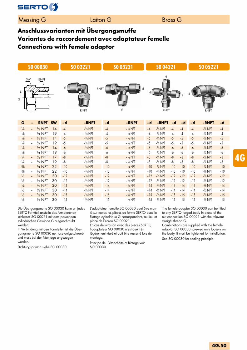
G – RNPT SW –d –RNPT –d –RNPT –d –RNPT –d –d –d –RNPT –d – NPT 14 –4 – NPT –4 – NPT –4 – NPT –4 –4 –4 – NPT –4 – NPT 19 –4 – NPT –4 – NPT –4 – NPT –4 –4 –4 – NPT –4 – NPT 14 –5 – NPT –5 – NPT –5 – NPT –5 –5 –5 – NPT –5 – NPT 19 –5 – NPT –5 – NPT –5 – NPT –5 –5 –5 – NPT –5 – NPT 14 –6 – NPT –6 – NPT –6 – NPT –6 –6 –6 – NPT –6 – NPT 19 –6 – NPT –6 – NPT –6 – NPT –6 –6 –6 – NPT –6 – NPT 17 –8 – NPT –8 – NPT –8 – NPT –8 –8 –8 – NPT –8 – NPT 19 –8 – NPT –8 – NPT –8 – NPT –8 –8 –8 – NPT –8 – NPT 22 –10 – NPT –10 – NPT –10 – NPT –10 –10 –10 – NPT –10 – NPT 22 –10 – NPT –10 – NPT –10 – NPT –10 –10 –10 – NPT –10 – NPT 30 –12 – NPT –12 – NPT –12 – NPT –12 –12 –12 – NPT –12 – NPT 30 –12 – NPT –12 – NPT –12 – NPT –12 –12 –12 – NPT –12 – NPT 30 –14 – NPT –14 – NPT –14 – NPT –14 –14 –14 – NPT –14 – NPT 30 –14 – NPT –14 – NPT –14 – NPT –14 –14 –14 – NPT –14 – NPT 30 –15 – NPT –15 – NPT –15 – NPT –15 –15 –15 – NPT –15 – NPT 30 –15 – NPT –15 – NPT –15 – NPT –15 –15 –15 – NPT –15
RNPTSW
G
RNPT
d ddd
S0 04221S0 03221S0 02221S0 00030 S0 05221d
RNPT
RNPT RNPTd
dd
Messing G Laiton G Brass G
Anschlussvarianten mit ÜbergangsmuffeVariantes de raccordement avec adaptateur femelleConnections with female adaptor
Die Übergangsmuffe SO 00030 kann an jedes SERTO-Formteil anstelle des Armaturenan-schlusses SO 00021 mit dem passenden zylindrischen Gewinde G aufgeschraubt werden. In Verbindung mit den Formteilen ist die Über-gangsmuffe SO 00030 nur lose aufgeschraubt und muss bei der Montage angezogen werden.Dichtungsprinzip siehe SO 00030.
L’adaptateur femelle SO 00030 peut être mon-té sur toutes les pièces de forme SERTO avec le filetage cylindrique G correspondant, au lieu et place de l’écrou SO 00021. En cas de livraison avec des pièces SERTO, l’adaptateur SO 00030 n’est que très légèrement vissé et doit être resserré lors du montage.Principe de l´étanchéité et filetage voir SO 00030.
The female adaptor SO 00030 can be fitted to any SERTO forged body in place of the nut connection SO 00021 with the relevant straight thread G. Combinations are supplied with the female adaptor SO 00030 screwed only loosely on the body. It must be tightened for installation.See SO 00030 for sealing principle.
4G.50
i
s
3F
4M
4G
5
5L
6
7
8
9
10
11
12
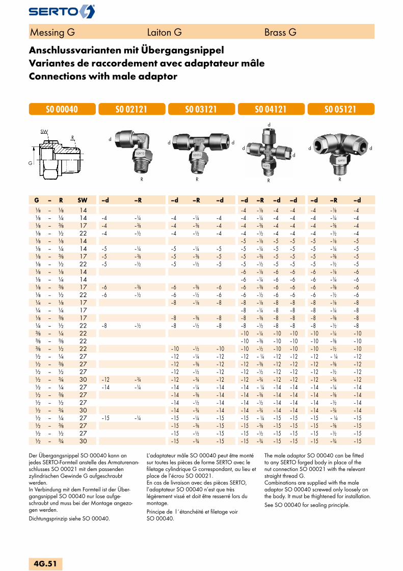
RSW
G
R RR R
G – R SW –d –R –d –R –d –d –R –d –d –d –R –d – 14 –4 – –4 –4 –4 – –4 – 14 –4 – –4 – –4 –4 – –4 –4 –4 – –4 – 17 –4 – –4 – –4 –4 – –4 –4 –4 – –4 – 22 –4 – –4 – –4 –4 – –4 –4 –4 – –4 – 14 –5 – –5 –5 –5 – –5 – 14 –5 – –5 – –5 –5 – –5 –5 –5 – –5 – 17 –5 – –5 – –5 –5 – –5 –5 –5 – –5 – 22 –5 – –5 – –5 –5 – –5 –5 –5 – –5 – 14 –6 – –6 –6 –6 – –6 – 14 –6 – –6 –6 –6 – –6 – 17 –6 – –6 – –6 –6 – –6 –6 –6 – –6 – 22 –6 – –6 – –6 –6 – –6 –6 –6 – –6 – 17 –8 – –8 –8 – –8 –8 –8 – –8 – 17 –8 – –8 –8 –8 – –8 – 17 –8 – –8 –8 – –8 –8 –8 – –8 – 22 –8 – –8 – –8 –8 – –8 –8 –8 – –8 – 22 –10 – –10 –10 –10 – –10 – 22 –10 – –10 –10 –10 – –10 – 22 –10 – –10 –10 – –10 –10 –10 – –10 – 27 –12 – –12 –12 – –12 –12 –12 – –12 – 27 –12 – –12 –12 – –12 –12 –12 – –12 – 27 –12 – –12 –12 – –12 –12 –12 – –12 – 30 –12 – –12 – –12 –12 – –12 –12 –12 – –12 – 27 –14 – –14 – –14 –14 – –14 –14 –14 – –14 – 27 –14 – –14 –14 – –14 –14 –14 – –14 – 27 –14 – –14 –14 – –14 –14 –14 – –14 – 30 –14 – –14 –14 – –14 –14 –14 – –14 – 27 –15 – –15 – –15 –15 – –15 –15 –15 – –15 – 27 –15 – –15 –15 – –15 –15 –15 – –15 – 27 –15 – –15 –15 – –15 –15 –15 – –15 – 30 –15 – –15 –15 – –15 –15 –15 – –15
S0 04121S0 03121S0 02121S0 00040 S0 05121
d
d dd
ddd
d
Messing G Laiton G Brass G
Anschlussvarianten mit ÜbergangsnippelVariantes de raccordement avec adaptateur mâleConnections with male adaptor
Der Übergangsnippel SO 00040 kann an jedes SERTO-Formteil anstelle des Armaturenan-schlusses SO 00021 mit dem passenden zylindrischen Gewinde G aufgeschraubt werden. In Verbindung mit dem Formteil ist der Über-gangsnippel SO 00040 nur lose aufge-schraubt und muss bei der Montage angezo-gen werden.Dichtungsprinzip siehe SO 00040.
L’adaptateur mâle SO 00040 peut être monté sur toutes les pièces de forme SERTO avec le filetage cylindrique G correspondant, au lieu et place de l’écrou SO 00021. En cas de livraison avec des pièces SERTO, l’adaptateur SO 00040 n’est que très légèrement vissé et doit être resserré lors du montage.Principe de l´étanchéité et filetage voir SO 00040.
The male adaptor SO 00040 can be fitted to any SERTO forged body in place of the nut connection SO 00021 with the relevant straight thread G. Combinations are supplied with the male adaptor SO 00040 screwed only loosely on the body. It must be thightened for installation.See SO 00040 for sealing principle.
4G.51

G – RNPT SW –d –RNPT –d –RNPT –d –d –RNPT –d –d –d –RNPT –d – NPT 14 –4 – NPT –4 –4 – NPT –4 –4 –4 – NPT –4 – NPT 14 –4 –NPT –4 – NPT –4 –4 – NPT –4 –4 –4 – NPT –4 – NPT 14 –5 – NPT –5 –5 – NPT –5 –5 –5 – NPT –5 – NPT 14 –5 –NPT –5 – NPT –5 –5 – NPT –5 –5 –5 – NPT –5 – NPT 14 –6 – NPT –6 –6 – NPT –6 –6 –6 – NPT –6 – NPT 14 –6 – NPT –6 –6 – NPT –6 –6 –6 – NPT –6 – NPT 17 –8 – NPT –8 –8 – NPT –8 –8 –8 – NPT –8 – NPT 17 –8 – NPT –8 –8 – NPT –8 –8 –8 – NPT –8 – NPT 17 –8 – NPT –8 – NPT –8 –8 – NPT –8 –8 –8 – NPT –8 – NPT 22 –10 – NPT –10 –10 – NPT –10 –10 –10 – NPT –10 – NPT 22 –10 – NPT –10 –10 – NPT –10 –10 –10 – NPT –10 – NPT 27 –12 – NPT –12 –12 – NPT –12 –12 –12 – NPT –12 – NPT 27 –12 – NPT –12 –12 – NPT –12 –12 –12 – NPT –12 – NPT 27 –14 – NPT –14 –14 – NPT –14 –14 –14 – NPT –14 – NPT 27 –14 – NPT –14 –14 – NPT –14 –14 –14 – NPT –14 – NPT 27 –15 – NPT –15 –15 – NPT –15 –15 –15 – NPT –15 – NPT 27 –15 – NPT –15 –15 – NPT –15 –15 –15 – NPT –15
SW
G
G – Mz SW –d –Mz –d –Mz –d –d –Mz –d –d –d –Mz –d–M10x1 14 –4 –M10x1 –4 –M10x1 –4 –4 –M10x1 –4 –4 –4 –M10x1 –4–M10x1 14 –5 –M10x1 –5 –M10x1 –5 –5 –M10x1 –5 –5 –5 –M10x1 –5–M10x1 14 –6 –M10x1 –6 –M10x1 –6 –6 –M10x1 –6 –6 –6 –M10x1 –6–M12x1,5 17 –8 –M12x1,5 –8 –M12x1,5 –8 –8 –M12x1,5 –8 –8 –8 –M12x1,5 –8–M14x1,5 22 –10 –M14x1,5 –10 –M14x1,5 –10 –10 –M14x1,5 –10 –10 –10 –M14x1,5 –10–M16x1,5 27 –12 –M16x1,5 –12 –M16x1,5 –12 –12 –M16x1,5 –12 –12 –12 –M16x1,5 –12–M16x1,5 27 –14 –M16x1,5 –14 –M16x1,5 –14 –14 –M16x1,5 –14 –14 –14 –M16x1,5 –14–M16x1,5 27 –15 –M16x1,5 –15 –M16x1,5 –15 –15 –M16x1,5 –15 –15 –15 –M16x1,5 –15
S0 04121S0 03121S0 02121S0 00040 S0 05121
RNPT / Mz
RNPT / Mz
RNPT / Mz RNPT / Mz RNPT / Mz
d
d dd
ddd
d
Messing G Laiton G Brass G
Anschlussvarianten mit ÜbergangsnippelVariantes de raccordement avec adaptateur mâleConnections with male adaptor
Der Übergangsnippel SO 00040 kann an jedes SERTO-Formteil anstelle des Armaturenan-schlusses SO 00021 mit dem passenden zylindrischen Gewinde G aufgeschraubt werden. In Verbindung mit dem Formteil ist der Über-gangsnippel SO 00040 nur lose aufge-schraubt und muss bei der Montage angezo-gen werden.Dichtungsprinzip siehe SO 00040.
L’adaptateur mâle SO 00040 peut être monté sur toutes les pièces de forme SERTO avec le filetage cylindrique G correspondant, au lieu et place de l’écrou SO 00021. En cas de livraison avec des pièces SERTO, l’adaptateur SO 00040 n’est que très légèrement vissé et doit être resserré lors du montage.Principe de l´étanchéité et filetage voir SO 00040.
The male adaptor SO 00040 can be fitted to any SERTO forged body in place of the nut connection SO 00021 with the relevant straight thread G. Combinations are supplied with the male adaptor SO 00040 screwed only loosely on the body. It must be thightened for installation.See SO 00040 for sealing principle.
4G.52
i
s
3F
4M
4G
5
5L
6
7
8
9
10
11
12

Doppelnippel zylindrischAdaptateur mâle cylindriqueMale adaptor parallel
SO 01020Type -G Mat.-Nr. bar SW L z1 e kg/100G=Rohrgewinde (zylindrisch) G=Filetage-gaz BSP (cylindrique) G=BSP thread (straight) SO 01020-1/8-1/8 246.1020.060 125 12 26.0 10.0 4.5 1.420SO 01020-1/4-1/4 246.1020.080 125 14 28.0 11.0 6.5 2.150SO 01020-3/8-3/8 246.1020.100 100 17 30.0 11.5 8.5 3.800SO 01020-1/2-1/2 246.1020.140 64 22 36.0 14.0 12.0 6.450
Doppelnippel zylindrisch reduziertAdaptateur mâle cylindrique réduitMale adaptor parallel reduced
SO 01020 REDType -G -G2 Mat.-Nr. bar SW L z1 z e kg/100G=Rohrgewinde (zylindrisch) G=Filetage-gaz BSP (cylindrique) G=BSP thread (straight)G2=Rohrgewinde (zylindrisch) G2=Filetage-gaz BSP (cylindrique) G2=BSP thread (straight)SO 01020-1/4-1/8 246.1024.140 125 14 27.0 10.0 11.0 4.5 2.100SO 01020-3/8-1/4 246.1024.190 100 17 29.5 11.0 11.5 6.5 3.450SO 01020-1/2-3/8 246.1024.240 64 22 33.5 11.5 14.0 8.5 6.200
Messing G Laiton G Brass G
4G.53
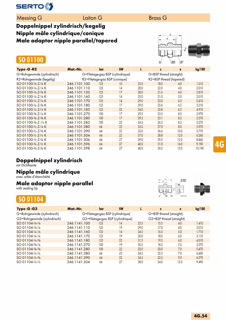
Doppelnippel zylindrisch/kegeligNipple mâle cylindrique/coniqueMale adaptor nipple parallel/tapered
SO 01100Type -G -R2 Mat.-Nr. bar SW L z e kg/100G=Rohrgewinde (zylindrisch) G=Filetage-gaz BSP (cylindrique) G=BSP thread (straight)R2=Rohrgewinde (kegelig) R2=Filetage-gaz BSP (conique) R2=BSP thread (tapered)SO 01100-1/8 Z-1/8 K 246.1101.100 125 10 22.0 18.0 4.0 1.310SO 01100-1/8 Z-1/4 K 246.1101.110 125 14 28.0 22.0 4.0 2.010SO 01100-1/8 Z-3/8 K 246.1101.120 125 17 28.0 21.6 4.0 2.810SO 01100-1/4 Z-1/8 K 246.1101.160 125 14 25.0 21.0 5.0 2.010SO 01100-1/4 Z-1/4 K 246.1101.170 125 14 29.0 23.0 6.5 2.410SO 01100-1/4 Z-3/8 K 246.1101.180 125 17 29.0 22.6 6.5 3.210SO 01100-1/4 Z-1/2 K 246.1101.185 125 22 34.0 25.8 6.5 4.910SO 01100-3/8 Z-1/4 K 246.1101.270 100 17 29.5 23.5 8.5 2.970SO 01100-3/8 Z-3/8 K 246.1101.280 100 17 29.5 23.1 8.5 3.570SO 01100-3/8 Z -1/2 K 246.1101.285 100 22 34.5 26.3 8.5 5.270SO 01100-1/2 Z-1/4 K 246.1101.380 64 22 33.0 27.0 8.0 5.970SO 01100-1/2 Z-3/8 K 246.1101.390 64 22 33.0 26.6 10.0 5.770SO 01100-1/2 Z-1/2 K 246.1101.504 64 22 37.0 28.8 12.0 6.260SO 01100-1/2 Z-3/4 K 246.1101.506 64 27 39.0 29.5 12.0 8.860SO 01100-3/4 Z-1/2 K 246.1101.596 64 27 40.0 31.8 14.0 9.190SO 01100-3/4 Z-3/4 K 246.1101.598 64 27 40.0 30.5 15.0 10.190
Doppelnippel zylindrischmit Dichtkante
Nipple mâle cylindriqueavec arête d‘étanchéité
Male adaptor nipple parallelwith sealing lip
SO 01104Type -G -G2 Mat.-Nr. bar SW L z e kg/100G=Rohrgewinde (zylindrisch) G=Filetage-gaz BSP (cylindrique) G=BSP thread (straight)G2=Rohrgewinde (zylindrisch) G2=Filetage-gaz BSP (cylindrique) G2=BSP thread (straight)SO 01104-1/8-1/8 246.1141.100 125 14 23.5 15.5 4.0 1.410SO 01104-1/8-1/4 246.1141.110 125 19 29.0 17.0 4.0 3.010SO 01104-1/4-1/8 246.1141.160 125 14 24.5 16.5 5.0 1.710SO 01104-1/4-1/4 246.1141.170 125 19 30.0 18.0 6.0 3.110SO 01104-1/4-3/8 246.1141.180 125 22 31.5 19.5 6.0 4.010SO 01104-3/8-1/4 246.1141.270 100 19 30.5 18.5 7.0 3.570SO 01104-3/8-3/8 246.1141.280 100 22 32.0 20.0 7.0 5.470SO 01104-1/2-1/4 246.1141.380 64 22 34.5 22.5 7.0 6.600SO 01104-1/2-3/8 246.1141.390 64 22 34.5 22.5 9.0 6.270SO 01104-1/2-1/2 246.1141.504 64 27 38.0 24.0 12.0 9.490
Messing G Laiton G Brass G
4G.54
i
s
3F
4M
4G
5
5L
6
7
8
9
10
11
12
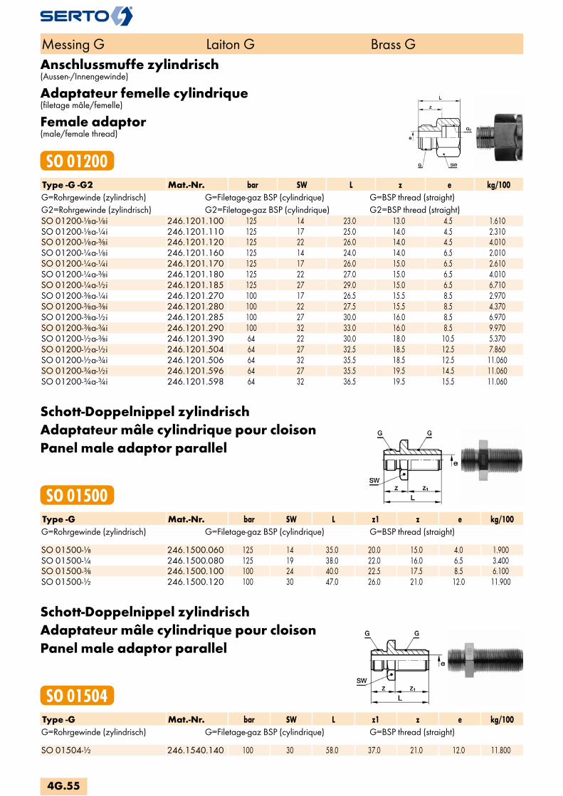
Anschlussmuffe zylindrisch(Aussen-/Innengewinde)
Adaptateur femelle cylindrique(filetage mâle/femelle)
Female adaptor(male/female thread)
SO 01200Type -G -G2 Mat.-Nr. bar SW L z e kg/100G=Rohrgewinde (zylindrisch) G=Filetage-gaz BSP (cylindrique) G=BSP thread (straight)G2=Rohrgewinde (zylindrisch) G2=Filetage-gaz BSP (cylindrique) G2=BSP thread (straight)SO 01200-1/8a-1/8i 246.1201.100 125 14 23.0 13.0 4.5 1.610SO 01200-1/8a-1/4i 246.1201.110 125 17 25.0 14.0 4.5 2.310SO 01200-1/8a-3/8i 246.1201.120 125 22 26.0 14.0 4.5 4.010SO 01200-1/4a-1/8i 246.1201.160 125 14 24.0 14.0 6.5 2.010SO 01200-1/4a-1/4i 246.1201.170 125 17 26.0 15.0 6.5 2.610SO 01200-1/4a-3/8i 246.1201.180 125 22 27.0 15.0 6.5 4.010SO 01200-1/4a-1/2i 246.1201.185 125 27 29.0 15.0 6.5 6.710SO 01200-3/8a-1/4i 246.1201.270 100 17 26.5 15.5 8.5 2.970SO 01200-3/8a-3/8i 246.1201.280 100 22 27.5 15.5 8.5 4.370SO 01200-3/8a-1/2i 246.1201.285 100 27 30.0 16.0 8.5 6.970SO 01200-3/8a-3/4i 246.1201.290 100 32 33.0 16.0 8.5 9.970SO 01200-1/2a-3/8i 246.1201.390 64 22 30.0 18.0 10.5 5.370SO 01200-1/2a-1/2i 246.1201.504 64 27 32.5 18.5 12.5 7.860SO 01200-1/2a-3/4i 246.1201.506 64 32 35.5 18.5 12.5 11.060SO 01200-3/4a-1/2i 246.1201.596 64 27 35.5 19.5 14.5 11.060SO 01200-3/4a-3/4i 246.1201.598 64 32 36.5 19.5 15.5 11.060
Schott-Doppelnippel zylindrischAdaptateur mâle cylindrique pour cloisonPanel male adaptor parallel
SO 01500Type -G Mat.-Nr. bar SW L z1 z e kg/100G=Rohrgewinde (zylindrisch) G=Filetage-gaz BSP (cylindrique) G=BSP thread (straight) SO 01500-1/8 246.1500.060 125 14 35.0 20.0 15.0 4.0 1.900SO 01500-1/4 246.1500.080 125 19 38.0 22.0 16.0 6.5 3.400SO 01500-3/8 246.1500.100 100 24 40.0 22.5 17.5 8.5 6.100SO 01500-1/2 246.1500.120 100 30 47.0 26.0 21.0 12.0 11.900
Schott-Doppelnippel zylindrischAdaptateur mâle cylindrique pour cloisonPanel male adaptor parallel
SO 01504Type -G Mat.-Nr. bar SW L z1 z e kg/100G=Rohrgewinde (zylindrisch) G=Filetage-gaz BSP (cylindrique) G=BSP thread (straight) SO 01504-1/2 246.1540.140 100 30 58.0 37.0 21.0 12.0 11.800
Messing G Laiton G Brass G
4G.55

Winkel zylindrischCoude cylindriqueElbow union parallel
SO 02000Type -G Mat.-Nr. bar SW L e kg/100G=Rohrgewinde (zylindrisch) G=Filetage-gaz BSP (cylindrique) G=BSP thread (straight) SO 02000-1/8 246.2000.060 125 10 19.0 4.0 1.620SO 02000-1/4 246.2000.080 125 11 21.0 6.0 2.520SO 02000-3/8 246.2000.100 100 14 22.0 8.5 3.740SO 02000-1/2 246.2000.140 64 19 28.0 12.0 6.640SO 02000-3/4 246.2000.170 64 22 30.0 15.0 11.580
Winkel zylindrisch/kegeligCoude cylindrique/coniqueElbow union parallel/tapered
SO 02400Type -G -R2 Mat.-Nr. bar SW L zR e kg/100G=Rohrgewinde (zylindrisch) G=Filetage-gaz BSP (cylindrique) G=BSP thread (straight)R2=Rohrgewinde (kegelig) R2=Filetage-gaz BSP (conique) R2=BSP thread (tapered)SO 02400-1/8 Z-1/8 K 246.2401.100 125 10 19.0 13.5 4.0 1.700SO 02400-1/8 Z-1/4 K 246.2401.110 125 11 21.0 15.0 4.0 2.600SO 02400-1/4 Z-1/8 K 246.2401.160 125 11 21.0 13.5 5.0 2.300SO 02400-1/4 Z-1/4 K 246.2401.170 125 11 21.0 15.0 6.0 2.800SO 02400-1/4 Z-3/8 K 246.2401.180 125 14 22.0 16.0 6.0 4.200SO 02400-3/8 Z-1/4 K 246.2401.270 100 14 22.0 15.0 8.5 3.700SO 02400-3/8 Z-3/8 K 246.2401.280 100 14 22.0 16.0 8.5 4.300SO 02400-3/8 Z-1/2 K 246.2401.285 100 19 28.0 19.0 8.0 6.700SO 02400-1/2 Z-1/4 K 246.2401.380 64 17 25.0 16.0 7.0 5.900SO 02400-1/2 Z-3/8 K 246.2401.390 64 17 25.0 16.0 10.0 5.900SO 02400-1/2 Z-1/2 K 246.2401.504 64 19 28.0 19.0 12.0 7.900SO 02400-1/2 Z-3/4 K 246.2401.506 64 22 30.0 20.0 12.0 8.300SO 02400-3/4 Z-1/2 K 246.2401.596 64 22 30.0 19.0 14.0 10.600SO 02400-3/4 Z-3/4 K 246.2401.598 64 22 30.0 20.0 15.0 12.700
Messing G Laiton G Brass G
4G.56
i
s
3F
4M
4G
5
5L
6
7
8
9
10
11
12

T-Stück zylindrischPièce Té cylindriqueTee parallel
SO 03000Type -G Mat.-Nr. bar SW L z e kg/100G=Rohrgewinde (zylindrisch) G=Filetage-gaz BSP (cylindrique) G=BSP thread (straight) SO 03000-1/8 246.3000.060 125 10 38.0 19.0 4.0 2.200SO 03000-1/4 246.3000.080 125 11 42.0 21.0 6.0 3.600SO 03000-3/8 246.3000.100 100 14 44.0 22.0 8.0 5.200SO 03000-1/2 246.3000.120 100 19 50.0 25.0 11.0 9.300SO 03000-3/4 246.3000.170 64 27 64.0 32.0 15.0 15.700
Messing G Laiton G Brass G
4G.57
5Edelstahl
Verschraubungen
Acier inoxydable
Raccords
Stainless steel
Unions
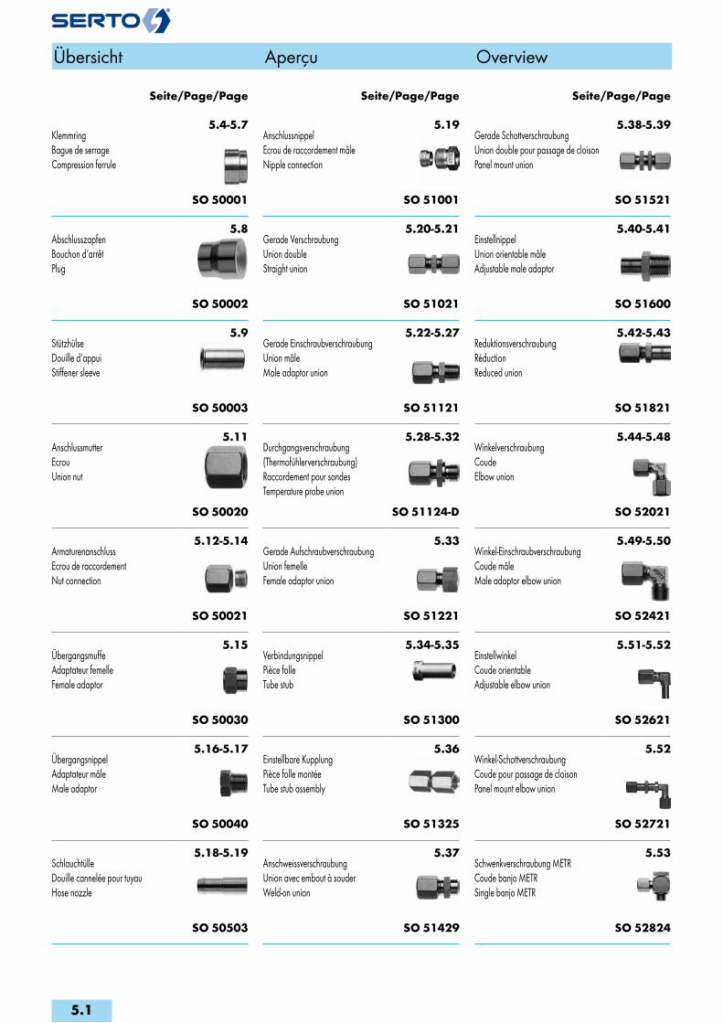
5.4-5.7KlemmringBague de serrageCompression ferrule
SO 50001
5.8AbschlusszapfenBouchon d‘arrêtPlug
SO 50002
5.9StützhülseDouille d‘appuiStiffener sleeve
SO 50003
5.11AnschlussmutterEcrouUnion nut
SO 50020
5.12-5.14ArmaturenanschlussEcrou de raccordementNut connection
SO 50021
5.15ÜbergangsmuffeAdaptateur femelleFemale adaptor
SO 50030
5.16-5.17ÜbergangsnippelAdaptateur mâleMale adaptor
SO 50040
5.18-5.19SchlauchtülleDouille cannelée pour tuyauHose nozzle
SO 50503
5.19AnschlussnippelEcrou de raccordement mâleNipple connection
SO 51001
5.20-5.21Gerade VerschraubungUnion doubleStraight union
SO 51021
5.22-5.27Gerade EinschraubverschraubungUnion mâleMale adaptor union
SO 51121
5.28-5.32Durchgangsverschraubung(Thermofühlerverschraubung)Raccordement pour sondesTemperature probe union
SO 51124-D
5.33Gerade AufschraubverschraubungUnion femelleFemale adaptor union
SO 51221
5.34-5.35VerbindungsnippelPièce folleTube stub
SO 51300
5.36Einstellbare KupplungPièce folle montéeTube stub assembly
SO 51325
5.37AnschweissverschraubungUnion avec embout à souderWeld-on union
SO 51429
5.38-5.39Gerade SchottverschraubungUnion double pour passage de cloisonPanel mount union
SO 51521
5.40-5.41EinstellnippelUnion orientable mâleAdjustable male adaptor
SO 51600
5.42-5.43ReduktionsverschraubungRéductionReduced union
SO 51821
5.44-5.48WinkelverschraubungCoudeElbow union
SO 52021
5.49-5.50Winkel-EinschraubverschraubungCoude mâleMale adaptor elbow union
SO 52421
5.51-5.52EinstellwinkelCoude orientableAdjustable elbow union
SO 52621
5.52Winkel-SchottverschraubungCoude pour passage de cloisonPanel mount elbow union
SO 52721
5.53Schwenkverschraubung METRCoude banjo METRSingle banjo METR
SO 52824
Seite/Page/Page Seite/Page/Page Seite/Page/Page
Übersicht Aperçu Overview
5.1
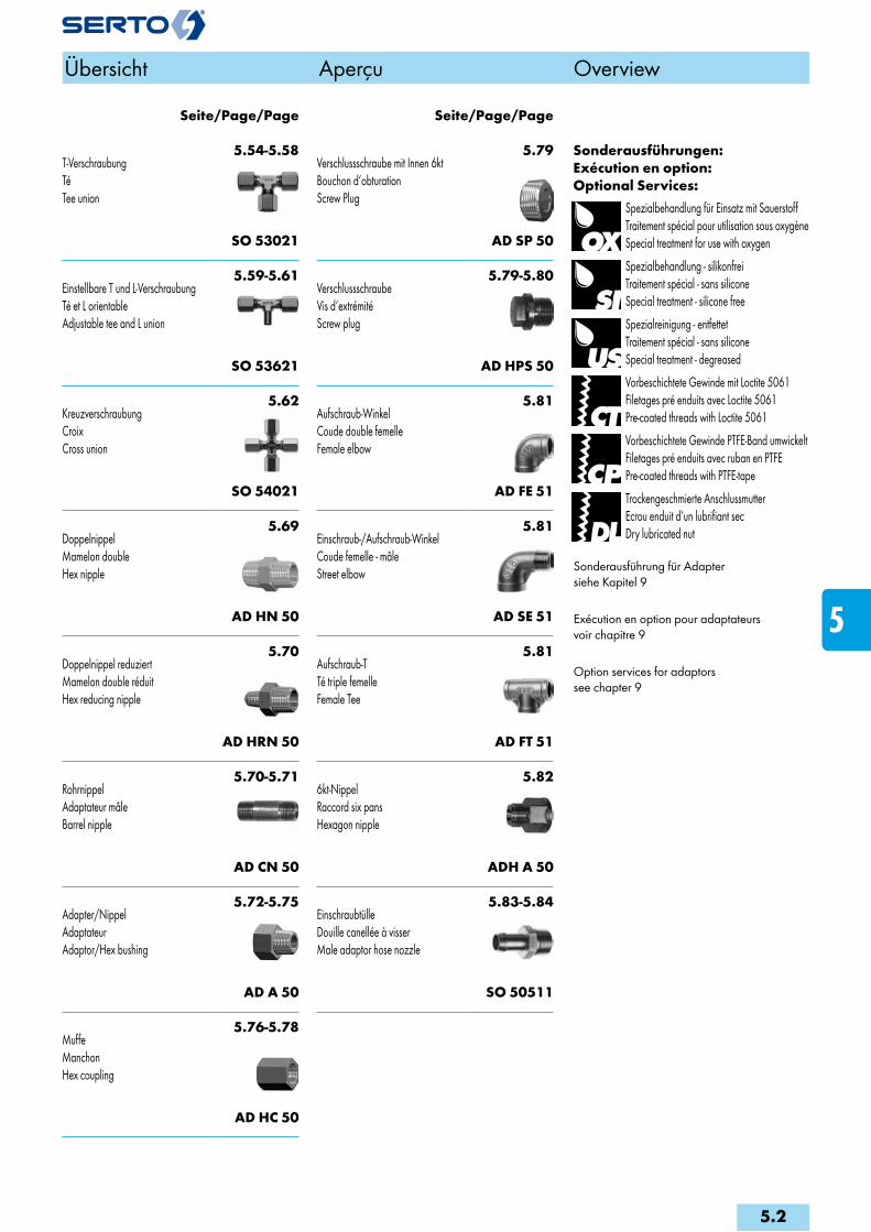
5.54-5.58T-VerschraubungTéTee union
SO 53021
5.59-5.61Einstellbare T und L-VerschraubungTé et L orientableAdjustable tee and L union
SO 53621
5.62KreuzverschraubungCroixCross union
SO 54021
5.69DoppelnippelMamelon doubleHex nipple
AD HN 50
5.70Doppelnippel reduziertMamelon double réduitHex reducing nipple
AD HRN 50
5.70-5.71RohrnippelAdaptateur mâleBarrel nipple
AD CN 50
5.72-5.75Adapter/NippelAdaptateurAdaptor/Hex bushing
AD A 50
5.76-5.78MuffeManchonHex coupling
AD HC 50
5.79Verschlussschraube mit Innen 6ktBouchon d‘obturationScrew Plug
AD SP 50
5.79-5.80VerschlussschraubeVis d‘extrémitéScrew plug
AD HPS 50
5.81Aufschraub-WinkelCoude double femelleFemale elbow
AD FE 51
5.81Einschraub-/Aufschraub-WinkelCoude femelle - mâleStreet elbow
AD SE 51
5.81Aufschraub-TTé triple femelleFemale Tee
AD FT 51
5.826kt-NippelRaccord six pansHexagon nipple
ADH A 50
5.83-5.84EinschraubtülleDouille canellée à visserMale adaptor hose nozzle
SO 50511
Sonderausführungen:Exécution en option:Optional Services:
Spezialbehandlung für Einsatz mit SauerstoffTraitement spécial pour utilisation sous oxygèneSpecial treatment for use with oxygen
Spezialbehandlung - silikonfreiTraitement spécial - sans siliconeSpecial treatment - silicone free
Spezialreinigung - entfettetTraitement spécial - sans siliconeSpecial treatment - degreased
Vorbeschichtete Gewinde mit Loctite 5061Filetages pré enduits avec Loctite 5061Pre-coated threads with Loctite 5061
Vorbeschichtete Gewinde PTFE-Band umwickeltFiletages pré enduits avec ruban en PTFEPre-coated threads with PTFE-tape
Trockengeschmierte AnschlussmutterEcrou enduit d‘un lubrifiant secDry lubricated nut
Sonderausführung für Adaptersiehe Kapitel 9
Exécution en option pour adaptateurs voir chapitre 9
Option services for adaptors see chapter 9
Seite/Page/Page Seite/Page/Page
Übersicht Aperçu Overview
5.2
i
s
3F
4M
4G
5
5L
6
7
8
9
10
11
12
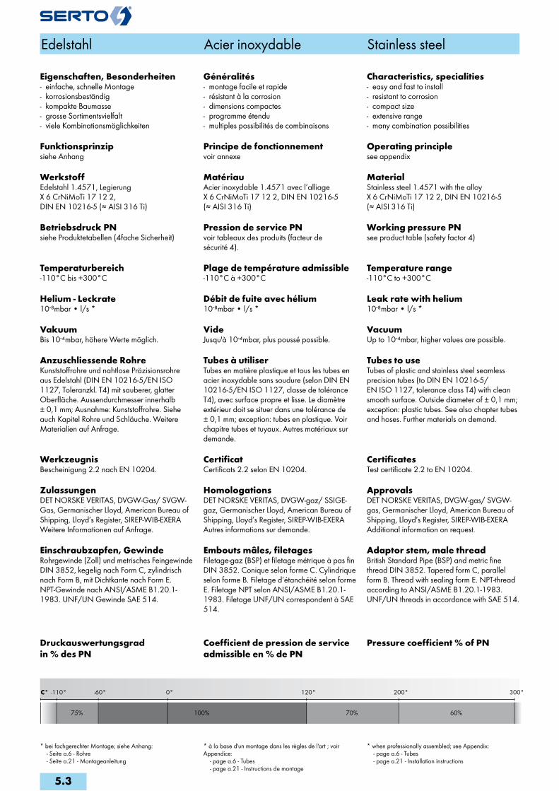
300°200°0° 120°-60°
100%75% 70% 60%
C° -110°
Edelstahl Acier inoxydable Stainless steel
Eigenschaften, Besonderheiten- einfache, schnelle Montage- korrosionsbeständig- kompakte Baumasse- grosse Sortimentsvielfalt- viele Kombinationsmöglichkeiten
Funktionsprinzipsiehe Anhang
WerkstoffEdelstahl 1.4571, Legierung X 6 CrNiMoTi 17 12 2, DIN EN 10216-5 (≈ AISI 316 Ti)
Betriebsdruck PNsiehe Produktetabellen (4fache Sicherheit)
Temperaturbereich-110°C bis +300°C
Helium - Leckrate10-8mbar • l/s *
VakuumBis 10-4mbar, höhere Werte möglich.
Anzuschliessende RohreKunststoffrohre und nahtlose Präzisionsrohre aus Edelstahl (DIN EN 10216-5/EN ISO 1127, Toleranzkl. T4) mit sauberer, glatter Oberfläche. Aussendurchmesser innerhalb ± 0,1 mm; Ausnahme: Kunststoffrohre. Siehe auch Kapitel Rohre und Schläuche. Weitere Materialien auf Anfrage.
WerkzeugnisBescheinigung 2.2 nach EN 10204.
ZulassungenDET NORSKE VERITAS, DVGW-Gas/ SVGW-Gas, Germanischer Lloyd, American Bureau of Shipping, Lloyd’s Register, SIREP-WIB-EXERAWeitere Informationen auf Anfrage.
Einschraubzapfen, GewindeRohrgewinde (Zoll) und metrisches Feingewinde DIN 3852, kegelig nach Form C, zylindrisch nach Form B, mit Dichtkante nach Form E. NPT-Gewinde nach ANSI/ASME B1.20.1-1983. UNF/UN Gewinde SAE 514.
Druckauswertungsgrad in % des PN
Généralités- montage facile et rapide- résistant à la corrosion- dimensions compactes- programme étendu- multiples possibilités de combinaisons
Principe de fonctionnementvoir annexe
MatériauAcier inoxydable 1.4571 avec l’alliage X 6 CrNiMoTi 17 12 2, DIN EN 10216-5 (≈ AISI 316 Ti)
Pression de service PNvoir tableaux des produits (facteur de sécurité 4).
Plage de température admissible-110°C à +300°C
Débit de fuite avec hélium10-8mbar • l/s *
VideJusqu'à 10-4mbar, plus poussé possible.
Tubes à utiliserTubes en matière plastique et tous les tubes en acier inoxydable sans soudure (selon DIN EN 10216-5/EN ISO 1127, classe de tolérance T4), avec surface propre et lisse. Le diamètre extérieur doit se situer dans une tolérance de ± 0,1 mm; exception: tubes en plastique. Voir chapitre tubes et tuyaux. Autres matériaux sur demande.
CertificatCertificats 2.2 selon EN 10204.
HomologationsDET NORSKE VERITAS, DVGW-gaz/ SSIGE-gaz, Germanischer Lloyd, American Bureau of Shipping, Lloyd’s Register, SIREP-WIB-EXERAAutres informations sur demande.
Embouts mâles, filetagesFiletage-gaz (BSP) et filetage métrique à pas fin DIN 3852. Conique selon forme C. Cylindrique selon forme B. Filetage d’étanchéité selon forme E. Filetage NPT selon ANSI/ASME B1.20.1-1983. Filetage UNF/UN correspondent à SAE 514.
Coefficient de pression de service admissible en % de PN
Characteristics, specialities- easy and fast to install- resistant to corrosion- compact size- extensive range- many combination possibilities
Operating principlesee appendix
MaterialStainless steel 1.4571 with the alloy X 6 CrNiMoTi 17 12 2, DIN EN 10216-5 (≈ AISI 316 Ti)
Working pressure PNsee product table (safety factor 4)
Temperature range-110°C to +300°C
Leak rate with helium10-8mbar • l/s *
VacuumUp to 10-4mbar, higher values are possible.
Tubes to useTubes of plastic and stainless steel seamless precision tubes (to DIN EN 10216-5/ EN ISO 1127, tolerance class T4) with clean smooth surface. Outside diameter of ± 0,1 mm; exception: plastic tubes. See also chapter tubes and hoses. Further materials on demand.
CertificatesTest certificate 2.2 to EN 10204.
ApprovalsDET NORSKE VERITAS, DVGW-gas/ SVGW-gas, Germanischer Lloyd, American Bureau of Shipping, Lloyd’s Register, SIREP-WIB-EXERAAdditional information on request.
Adaptor stem, male threadBritish Standard Pipe (BSP) and metric fine thread DIN 3852. Tapered form C, parallel form B. Thread with sealing form E. NPT-thread according to ANSI/ASME B1.20.1-1983. UNF/UN threads in accordance with SAE 514.
Pressure coefficient % of PN
* bei fachgerechter Montage; siehe Anhang: - Seite a.6 - Rohre - Seite a.21 - Montageanleitung
* à la base d'un montage dans les règles de l'art ; voir Appendice: - page a.6 - Tubes - page a.21 - Instructions de montage
* when professionally assembled; see Appendix: - page a.6 - Tubes - page a.21 - Installation instructions
5.3

KlemmringBague de serrageCompression ferrule
SO 50001Type -d Mat.-Nr. bar L D z e kg/100Für metrische Rohre Pour tubes métriques For metric tubes SO 50001-2 056.0010.020 250 3.5 5.0 0.7 1.5 0.010SO 50001-3 056.0010.030 250 4.5 5.0 0.9 2.5 0.030SO 50001-4 056.0010.040 250 5.0 6.0 1.0 3.5 0.050SO 50001-5 056.0010.050 250 5.5 6.8 1.1 4.0 0.060SO 50001-6 056.0010.060 200 6.5 8.5 1.2 4.5 0.120SO 50001-8 056.0010.080 200 7.0 10.5 1.2 6.5 0.160SO 50001-10 056.0010.100 160 7.8 12.7 1.2 8.5 0.240SO 50001-12 056.0010.120 160 8.8 14.7 1.2 10.0 0.310SO 50001-15 056.0010.150 100 10.0 18.0 1.4 13.0 0.400SO 50001-18 056.0010.180 100 11.7 22.0 1.4 16.0 0.840SO 50001-22 056.0010.220 64 13.5 26.0 1.4 20.0 1.220SO 50001-28 056.0010.280 40 15.4 32.5 2.0 24.0 2.150
Für Zollrohre Pour tubes pouces For inch tubes SO 50001-3,2 056.0010.032 250 4.5 5.0 0.9 2.5 0.030SO 50001-6,35 056.0010.063 200 6.5 8.5 1.2 4.5 0.110SO 50001-7,94 056.0010.079 200 7.0 10.5 1.2 6.5 0.160SO 50001-9,52 056.0010.095 160 7.8 12.7 1.2 8.0 0.250SO 50001-12,7 056.0010.127 160 10.5 18.0 1.5 11.0 0.620
Klemmringmit integrierter Stützhülse
Bague de serrageavec douille d‘appui
Compression ferrulewith stiffener sleeve
SO 50001 FIXType -d -d1 Mat.-Nr. L d2 s z e D3 SO 50001-6-4 FIX 056.0015.110 11.2 4.00 0.20 1.2 4.5 8.5SO 50001-8-6 FIX 056.0015.140 13.2 6.00 0.25 1.2 6.5 10.5SO 50001-10-8 FIX 056.0015.190 16.2 8.00 0.30 1.2 8.5 12.7SO 50001-12-10 FIX 056.0015.240 19.2 10.00 0.25 1.2 10.0 14.7
Edelstahl Acier inoxydable Stainless steel
d=Rohraussen-ø d=ø extérieur du tube d=tube outside diameter
5.4
i
s
3F
4M
4G
5
5L
6
7
8
9
10
11
12
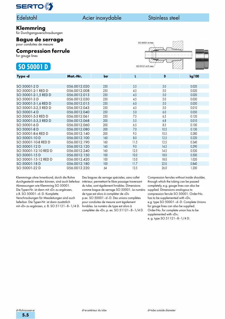
Klemmringfür Durchgangsverschraubungen
Bague de serragepour conduites de mesure
Compression ferrulefor gauge lines
SO 50001 DType -d Mat.-Nr. bar L D kg/100 SO 50001-2 D 056.0012.020 250 3.5 5.0 0.020SO 50001-2-1 RED D 056.0012.008 250 4.5 5.0 0.020SO 50001-2-1,5 RED D 056.0012.013 250 4.5 5.0 0.020SO 50001-3 D 056.0012.030 250 4.5 5.0 0.030SO 50001-3-1,6 RED D 056.0012.015 250 6.0 5.0 0.050SO 50001-3-2,5 RED D 056.0012.043 250 4.5 5.0 0.010SO 50001-4 D 056.0012.040 250 5.0 6.0 0.050SO 50001-5-3 RED D 056.0012.061 250 7.5 6.5 0.120SO 50001-5-3,5 RED D 056.0012.068 200 5.5 6.8 0.010SO 50001-6 D 056.0012.060 200 6.5 8.5 0.100SO 50001-8 D 056.0012.080 200 7.0 10.5 0.150SO 50001-8-6 RED D 056.0012.140 200 9.5 10.5 0.280SO 50001-10 D 056.0012.100 160 8.0 12.5 0.220SO 50001-10-8 RED D 056.0012.190 160 11.5 12.5 0.340SO 50001-12 D 056.0012.120 160 9.0 14.5 0.290SO 50001-12-10 RED D 056.0012.240 160 12.5 14.5 0.530SO 50001-15 D 056.0012.150 100 10.0 18.0 0.500SO 50001-15-12 RED D 056.0012.420 100 15.0 18.0 1.020SO 50001-18 D 056.0012.180 100 11.7 22.0 0.840SO 50001-22 D 056.0012.220 64 13.5 26.0 1.200
Klemmringe ohne Innenbund, durch die Rohredurchgesteckt werden können, sind auch lieferbar.Abmessungen wie Klemmring SO 50001.Die Typen-Nr. ist dann mit «D» zu ergänzen,z.B. SO 50001–d–D. KompletteVerschraubungen für Messleitungen sind auchlieferbar. Die Typen-Nr. ist dann zusätzlichmit «D» zu ergänzen, z. B. SO 51121–8–1/4 D.
Des bagues de serrage spéciales, sans colletintérieur, permettant le libre passage traversantdu tube, sont également livrables. Dimensionscomme bague de serrage SO 50001. Le numérode type est alors à compléter de «D»p.ex. SO 50001–d–D. Des unions complètespour conduites de mesure sont égalementlivrables. Le numéro de type est alors àcompléter de «D», p. ex. SO 51121–8–1/4 D.
Compression ferrules without inside shoulder,through which the tubing can be passedcompletely, e.g. gauge lines can also besupplied. Dimensions analogous tocompression ferrule SO 50001. Order-No.has to be supplemented with «D»,e.g. type SO 50001–d–D. Complete Unionsfor gauge lines can also be supplied.Order-No. for complete union has to besupplemented with «D»;e. g. type SO 51121–8–1/4 D.
Edelstahl Acier inoxydable Stainless steel
d=Rohraussen-ø d=ø extérieur du tube d=tube outside diameter
5.5
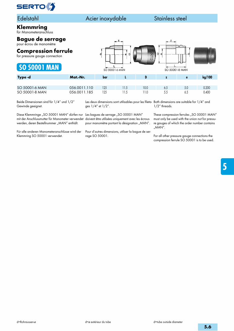
Klemmringfür Manometeranschluss
Bague de serragepour écrou de manomètre
Compression ferrulefor pressure gauge connection
SO 50001 MANType -d Mat.-Nr. bar L D z e kg/100 SO 50001-6 MAN 056.0011.110 125 11.5 10.0 6.5 5.0 0.200SO 50001-8 MAN 056.0011.185 125 11.5 11.0 5.5 6.5 0.400
Beide Dimensionen sind für 1/4“ und 1/2“ Gewinde geeignet.
Diese Klemmringe „SO 50001 MAN“ dürfen nur mit der Anschlussmutter für Manometer verwendet werden, deren Bestellnummer „MAN“ enthält.
Für alle anderen Manometeranschlüsse wird der Klemmring SO 50001 verwendet.
Les deux dimensions sont utilisables pour les fileta-ges 1/4“ et 1/2“.
Les bagues de serrage „SO 50001 MAN“ doivent être utilisées uniquement avec les écrous pour manomètre portant la désignation „MAN“.
Pour d’autres dimensions, utiliser la bague de ser-rage SO 50001.
Both dimensions are suitable for 1/4“ and 1/2“ threads.
These compression ferrules „SO 50001 MAN“ must only be used with the union nut for pressu-re gauges of which the order number contains „MAN“.
For all other pressure gauge connections the compression ferrule SO 50001 is to be used.
Edelstahl Acier inoxydable Stainless steel
d=Rohraussen-ø d=ø extérieur du tube d=tube outside diameter
5.6
i
s
3F
4M
4G
5
5L
6
7
8
9
10
11
12

Klemmring reduziertBague de serrage de réductionReduction compression ferrule
SO 50001 REDType -dr -d Mat.-Nr. bar L D dr z e kg/100Für metrische Rohre Pour tubes métriques For metric tubes SO 50001-4-2 RED 056.0014.030 250 7.0 6.0 4.00 0.9 1.5 0.080SO 50001-5-3 RED 056.0014.060 250 7.5 6.8 5.00 0.9 2.5 0.130SO 50001-6-4 RED 056.0014.110 200 8.5 8.5 6.00 1.1 3.5 0.190SO 50001-6-5 RED 056.0014.117 200 8.7 8.5 6.00 1.1 4.0 0.150SO 50001-8-6 RED 056.0014.140 200 9.5 10.5 8.00 1.3 4.5 0.320SO 50001-10-8 RED 056.0014.190 160 11.5 12.7 10.00 1.3 6.5 0.430SO 50001-12-10 RED 056.0014.240 160 12.5 14.7 12.00 1.2 8.5 0.510SO 50001-15-12 RED 056.0014.420 100 15.0 18.0 15.00 1.2 10.0 1.060SO 50001-15-14 RED 056.0014.440 100 15.0 18.0 15.00 1.4 12.0 0.710SO 50001-18-15 RED 056.0014.610 100 16.7 22.0 18.00 1.4 13.0 1.670SO 50001-18-16 RED 056.0014.620 100 16.7 22.0 18.00 1.4 14.0 1.470SO 50001-22-18 RED 056.0014.755 64 20.0 26.0 22.00 1.4 16.0 2.620
Für Zollrohre Pour tubes pouces For inch tubes SO 50001-3-1,6 RED 056.0014.015 250 6.2 5.0 3.00 0.8 1.0 0.090SO 50001-5-3,2 RED 056.0014.062 250 7.5 6.8 5.00 0.9 2.5 0.115SO 50001-8-6,35 RED 056.0014.143 200 9.5 10.5 8.00 1.3 4.5 0.300SO 50001-10-7,94 RED 056.0014.187 160 11.5 12.7 10.00 1.3 6.5 0.430SO 50001-15-12,7 RED 056.0014.427 100 15.0 18.0 15.00 1.4 11.0 0.940SO 50001-15-13,5 RED 056.0014.435 100 15.0 18.0 15.00 1.4 12.0 0.840SO 50001-18-15,88 RED 056.0014.618 100 16.7 22.0 18.00 1.4 14.0 1.470SO 50001-18-17,2 RED 056.0014.632 100 16.7 22.0 18.00 1.4 15.0 1.160SO 50001-22-19.05 RED 056.0014.760 64 20.0 26.0 22.00 1.4 16.0 2.480SO 50001-22-21,3 RED 056.0014.785 64 20.0 26.0 22.00 1.4 19.5 1.470
Anwendungsbeispiele: Exemples d‘utilisation: Sample combinations:
Einstufige Reduktionen von Rohranschlüssen sind auf einfachste Art durch Auswechseln der norma-len gegen die reduzierten Klemmringe möglich.Beispiel:Reduktion eines Rohranschlusses ø15 mm auf ø12 mm: Klemmring SO 50001–15 austauschen gegen Klemmring SO 50001–15–12 RED. Anschlussmutter SO 50020–15 bleibt.
Le raccordement de tubes réduits d’une dimen-sion peut s’effectuer très simplement en échan-geant la bague de serrage normale contre une bague de réduction.Exemple:Réduction d’un raccord ø15 mm à ø12 mm:Echanger la bague de serrage 50001-15 con-tre une bague de réduction SO 50001–15–12 RED. L’écrou SO 50020–15 reste le même.
Single stage tube reduction connections are easily made by replacing the standard com-pression ferrule with a reduction compression ferrule.Example:Tube reduction connection ø15 mm to ø12 mm:Replace compression ferrule SO 50001-15 by compression ferrule SO 50001–15–12 RED. Union nut SO 50020–15 remains.
Edelstahl Acier inoxydable Stainless steel
d=Rohraussen-ødr=Grösse Anschlussmutter bei Reduktion
d=ø extérieur du tubedr=Dimension de l´écrou lors de réductions
d=tube outside diameterdr=Size of union for reductions
5.7
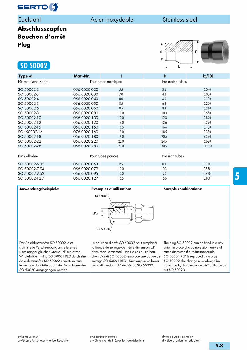
AbschlusszapfenBouchon d‘arrêtPlug
SO 50002Type -d Mat.-Nr. L D kg/100Für metrische Rohre Pour tubes métriques For metric tubes SO 50002-2 056.0020.020 5.5 3.6 0.040SO 50002-3 056.0020.030 7.0 4.8 0.080SO 50002-4 056.0020.040 8.0 6.0 0.130SO 50002-5 056.0020.050 8.5 6.4 0.200SO 50002-6 056.0020.060 9.5 8.3 0.310SO 50002-8 056.0020.080 10.0 10.3 0.550SO 50002-10 056.0020.100 13.0 12.3 0.890SO 50002-12 056.0020.120 14.0 13.6 1.390SO 50002-15 056.0020.150 16.5 16.6 3.100SOL 50002-16 076.0020.160 19.0 18.5 3.380SO 50002-18 056.0020.180 19.0 20.5 4.340SO 50002-22 056.0020.220 22.0 24.5 6.620SO 50002-28 056.0020.280 23.0 30.5 11.100
Für Zollrohre Pour tubes pouces For inch tubes SO 50002-6,35 056.0020.063 9.5 8.3 0.310SO 50002-7,94 056.0020.079 10.0 10.3 0.550SO 50002-9,52 056.0020.095 13.0 12.3 0.890SO 50002-12,7 056.0020.127 16.5 16.6 3.100
Anwendungsbeispiele: Exemples d‘utilisation: Sample combinations:
Der Abschlusszapfen SO 50002 lässt sich in jede Verschraubung anstelle eines Klemmringes gleicher Grösse „d“ einsetzen. Wird ein Klemmring SO 50001 RED durch einen Abschlusszapfen SO 50002 ersetzt, so muss immer von der Grösse „dr“ der Anschlussmutter SO 50020 ausgegangen werden.
Le bouchon d’arrêt SO 50002 peut remplacér la bague de serrage de même dimension „d“ dans chaque raccord. Dans le cas où un bou-chon d’arrêt SO 50002 remplace une bague de serrage SO 50001 RED il faut toujours se baser sur la dimension „dr“ de l’écrou SO 50020.
The plug SO 50002 can be fitted into anyunion in place of a compression ferrule of same diameter. If a reduction ferrule SO 50001 RED is replaced by a plug SO 50002, the change must always be governed by the dimension „dr“ of the union nut SO 50020.
Edelstahl Acier inoxydable Stainless steel
d=Rohraussen-ødr=Grösse Anschlussmutter bei Reduktion
d=ø extérieur du tubedr=Dimension de l´écrou lors de réductions
d=tube outside diameterdr=Size of union for reductions
5.8
i
s
3F
4M
4G
5
5L
6
7
8
9
10
11
12

Stützhülsezur Rohrverstärkung
Douille d‘appuipour renforcer les tubes
Stiffener sleeveto reinforce the tubes
SO 50003Type -d -d1 Mat.-Nr. L D d2 s kg/100Für metrische Rohre Pour tubes métriques For metric tubes SO 50003-3-2 056.0031.020 6.0 2.8 2.00 0.20 0.006SO 50003-4-2 056.0031.030 8.0 3.8 2.00 0.20 0.008SO 50003-4-2.5 056.0031.035 8.0 3.8 2.50 0.20 0.010SO 50003-4-3 056.0031.040 8.0 3.8 3.00 0.20 0.012SO 50003-5-3 056.0031.060 9.0 4.5 3.00 0.20 0.013SO 50003-5-4 056.0031.080 9.0 4.5 4.00 0.20 0.018SO 50003-6-3 056.0031.100 10.0 5.0 3.00 0.20 0.015SO 50003-6-4 056.0031.110 10.0 5.5 3.95 0.20 0.020SO 50003-6-4,5 056.0031.114 10.0 5.5 4.50 0.20 0.021SO 50003-6-5 056.0031.117 10.0 5.5 5.00 0.25 0.029SO 50003-8-5 056.0031.136 12.0 7.5 5.00 0.25 0.040SO 50003-8-6 056.0031.140 12.0 7.5 5.90 0.25 0.045SO 50003-8-7 056.0031.150 12.0 7.5 6.90 0.30 0.057SO 50003-10-7 056.0031.180 15.0 9.5 6.90 0.30 0.076SO 50003-10-8 056.0031.190 15.0 9.5 7.90 0.30 0.088SO 50003-10-9 056.0031.195 15.0 9.5 8.90 0.40 0.128SO 50003-12-9 056.0031.230 18.0 11.5 8.90 0.40 0.157SO 50003-12-10 056.0031.240 18.0 11.5 9.85 0.40 0.171SO 50003-12-10,4 056.0031.254 18.0 11.5 10.25 0.40 0.172SO 50003-14-12 056.0031.340 20.0 13.5 11.85 0.50 0.282SO 50003-15-12 056.0031.420 20.0 14.5 11.85 0.50 0.282SO 50003-15-13 056.0031.430 20.0 14.5 12.85 0.50 0.313SO 50003-16-14 056.0031.500 22.0 15.5 13.80 0.60 0.432SO 50003-18-14 056.0031.600 24.0 17.5 13.80 0.60 0.493SO 50003-18-15 056.0031.610 24.0 17.5 14.80 0.60 0.531SO 50003-18-16 056.0031.620 24.0 17.5 15.80 0.60 0.548SO 50003-22-19 056.0031.760 28.0 21.5 18.80 0.60 0.792SO 50003-22-20 056.0031.775 28.0 21.5 19.80 0.60 0.814SO 50003-28-25 056.0031.910 34.0 27.5 24.80 0.60 1.260
Für Zollrohre Pour tubes pouces For inch tubes SO 50003-9.52-6.22 056.0031.160 15.0 9.0 6.10 0.30 0.076
Verstärken:Rohre, die der radialen Einschnürung des Klemmringes ungenügenden Widerstand leisten, wie Kunststoffrohre, weiche Ne-Metallrohre, dünnwandige und weiche rostfreie Stahlrohre sind durch Stützhülsen zu verstärken.
Renforcement:Les tubes qui présentent une résistance insuffisan-te à la pression d’étranglement de la bague de serrage, tels les tubes en matière plastique ou en alliages légers, ou les tubes à parois minces en acier inoxydable mou doivent être renforcés par des douilles d’appui.
Reinforcement:Tubes which offer too little resistance to the nek-king of the compression ferrule, such as plastic, non-ferrous metals, thin-walled and soft stainless steel tubes are to be reinforced with stiffener sleeves.
Edelstahl Acier inoxydable Stainless steel
d=Rohraussen-ød1=Rohrinnen-ø
d=ø extérieur du tubed1=ø intérieur du tube
d=tube outside diameterd1=tube inside diameter
5.9

SechskantmutterEcrou à six pansHexagon nut
SO 50006 METRType -Mz Mat.-Nr. SW s kg/100 Mz=metrisches Gewinde (zylindrisch) Mz=Filetage métrique (cylindrique) Mz=Metric thread (straight)SO 50006-M6X0,75 056.0063.098 10 3.50 0.170SO 50006-M8X1 056.0063.120 12 3.50 0.220SO 50006-M10X1 056.0063.150 14 5.00 0.400SO 50006-M12X1 056.0063.190 17 6.00 0.700SO 50006-M14X1 056.0063.220 19 6.00 0.800SO 50006-M16X1 056.0063.260 22 6.00 1.100SO 50006-M20X1,5 056.0063.345 27 6.00 1.600SO 50006-M24X1,5 056.0063.405 30 7.00 2.000SO 50006-M28X1,5 056.0063.445 36 8.00 3.400SO 50006-M36X2 056.0063.560 41 10.00 4.000
Sechskantmutter für SO 51521 + SO 51524 Ecrou à six pans pour SO 51521 + SO 51524 Hexagon nut for SO 51521 + SO 51524
Edelstahl Acier inoxydable Stainless steel
s=Wandstärke s=épaisseur de la paroi s=wall thickness
5.10
i
s
3F
4M
4G
5
5L
6
7
8
9
10
11
12

AnschlussmutterEcrouUnion nut
SO 50020Type -d Mat.-Nr. bar M SW L kg/100Für metrische Rohre Pour tubes métriques For metric tubes SO 50020-2 056.0200.020 250 6x0.75 8 8.5 0.200SO 50020-3 056.0200.030 250 6x0.75 8 10.0 0.240SO 50020-4 056.0200.040 250 8x1 10 13.0 0.490SO 50020-5 056.0200.050 250 8x1 10 13.5 0.460SO 50020-6 056.0200.060 200 10x1 12 15.5 0.670SO 50020-8 056.0200.080 200 12x1 14 17.0 0.890SO 50020-10 056.0200.100 160 14x1 17 19.5 1.540SO 50020-12 056.0200.120 160 16x1 19 20.5 1.900SO 50020-15 056.0200.150 100 20x1.5 24 24.0 3.810SO 50020-18 056.0200.180 100 24x1.5 30 25.0 6.100SO 50020-22 056.0200.220 64 28x1.5 32 28.0 6.940SO 50020-28 056.0200.280 40 36x2 41 31.5 12.850
Für Zollrohre Pour tubes pouces For inch tubes SO 50020-3,2 056.0200.032 250 6x0.75 8 10.0 0.230SO 50020-6,35 056.0200.063 200 10x1 12 15.5 0.660SO 50020-7,94 056.0200.079 200 12x1 14 16.5 0.890SO 50020-9,52 056.0200.095 160 14x1 17 18.5 1.560SO 50020-12,7 056.0200.127 160 20x1.5 24 23.5 4.580
Anschlussmutter MANEcrou MANUnion nut MAN
SO 50020 MANType -d -G Mat.-Nr. bar SW L kg/100 G=Rohrgewinde (zylindrisch) G=Filetage-gaz BSP (cylindrique) G=BSP thread (straight)SO 50020-6-1/4 MAN 056.0201.110 200 17 20.0 2.550SO 50020-6-1/2 MAN 056.0201.125 200 24 28.0 4.820SO 50020-8-1/4 MAN 056.0201.170 200 17 24.0 2.550SO 50020-8-1/2 MAN 056.0201.185 200 24 29.0 5.110SO 50020-10-1/2 MAN 056.0201.285 160 24 25.5 4.400SO 50020-12-1/2 MAN 056.0201.400 160 24 28.0 4.480
Edelstahl Acier inoxydable Stainless steel
d=Rohraussen-ø d=ø extérieur du tube d=tube outside diameter
5.11
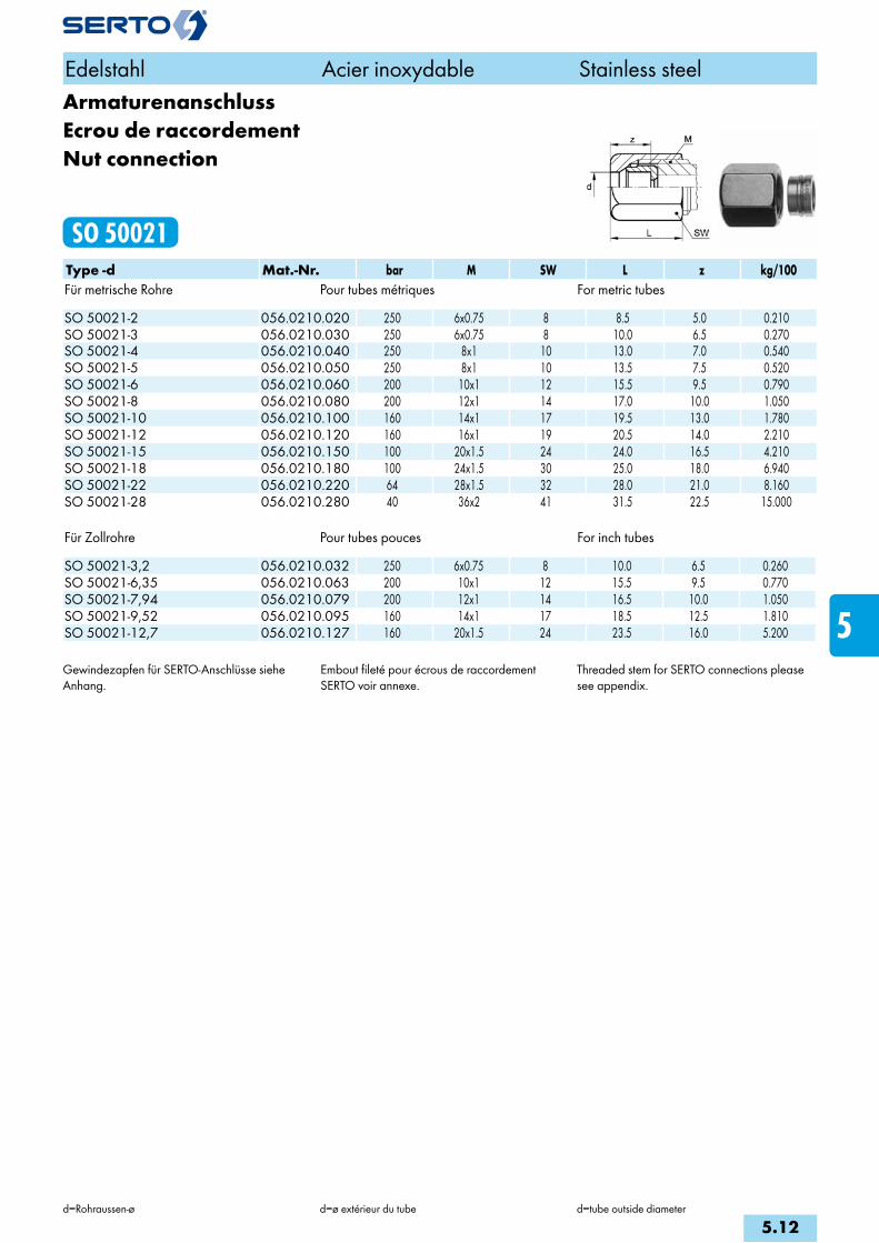
ArmaturenanschlussEcrou de raccordementNut connection
SO 50021Type -d Mat.-Nr. bar M SW L z kg/100Für metrische Rohre Pour tubes métriques For metric tubes SO 50021-2 056.0210.020 250 6x0.75 8 8.5 5.0 0.210SO 50021-3 056.0210.030 250 6x0.75 8 10.0 6.5 0.270SO 50021-4 056.0210.040 250 8x1 10 13.0 7.0 0.540SO 50021-5 056.0210.050 250 8x1 10 13.5 7.5 0.520SO 50021-6 056.0210.060 200 10x1 12 15.5 9.5 0.790SO 50021-8 056.0210.080 200 12x1 14 17.0 10.0 1.050SO 50021-10 056.0210.100 160 14x1 17 19.5 13.0 1.780SO 50021-12 056.0210.120 160 16x1 19 20.5 14.0 2.210SO 50021-15 056.0210.150 100 20x1.5 24 24.0 16.5 4.210SO 50021-18 056.0210.180 100 24x1.5 30 25.0 18.0 6.940SO 50021-22 056.0210.220 64 28x1.5 32 28.0 21.0 8.160SO 50021-28 056.0210.280 40 36x2 41 31.5 22.5 15.000
Für Zollrohre Pour tubes pouces For inch tubes SO 50021-3,2 056.0210.032 250 6x0.75 8 10.0 6.5 0.260SO 50021-6,35 056.0210.063 200 10x1 12 15.5 9.5 0.770SO 50021-7,94 056.0210.079 200 12x1 14 16.5 10.0 1.050SO 50021-9,52 056.0210.095 160 14x1 17 18.5 12.5 1.810SO 50021-12,7 056.0210.127 160 20x1.5 24 23.5 16.0 5.200
Gewindezapfen für SERTO-Anschlüsse siehe Anhang.
Embout fileté pour écrous de raccordement SERTO voir annexe.
Threaded stem for SERTO connections please see appendix.
Edelstahl Acier inoxydable Stainless steel
d=Rohraussen-ø d=ø extérieur du tube d=tube outside diameter
5.12
i
s
3F
4M
4G
5
5L
6
7
8
9
10
11
12

Armaturenanschluss reduziertEcrou de raccordement réduitReduction tube connection
SO 50021 REDType -dr -d Mat.-Nr. bar M SW L z kg/100Für metrische Rohre Pour tubes métriques For metric tubes SO 50021-5-3 RED 056.0214.060 250 8x1 10 13.5 7.5 0.590SO 50021-6-4 RED 056.0214.110 200 10x1 12 15.5 9.5 0.880SO 50021-6-5 RED 056.0214.117 200 10x1 12 15.5 9.5 0.840SO 50021-8-6 RED 056.0214.140 200 12x1 14 17.0 10.0 1.210SO 50021-10-8 RED 056.0214.190 160 14x1 17 19.5 13.0 1.970SO 50021-12-10 RED 056.0214.240 160 16x1 19 20.5 14.0 2.410SO 50021-15-12 RED 056.0214.420 100 20x1.5 24 24.0 16.5 4.770SO 50021-15-14 RED 056.0214.440 100 20x1.5 24 24.0 16.5 4.450SO 50021-18-15 RED 056.0214.610 100 24x1.5 30 25.0 18.0 7.690SO 50021-18-16 RED 056.0214.620 100 24x1.5 30 25.0 18.0 7.490SO 50021-22-18 RED 056.0214.755 64 28x1.5 32 28.0 21.0 10.760
Für Zollrohre Pour tubes pouces For inch tubes SO 50021-3-1,6 RED 056.0214.015 250 6x0.75 8 10.0 6.5 0.310SO 50021-5-3,2 RED 056.0214.062 250 8x1 10 13.5 7.5 0.575SO 50021-8-6,35 RED 056.0214.143 200 12x1 14 17.0 10.0 1.210SO 50021-10-7,94 RED 056.0214.187 160 14x1 17 19.5 13.0 1.970SO 50021-15-12,7 RED 056.0214.427 100 20x1.5 24 24.0 16.5 4.550SO 50021-15-13,5 RED 056.0214.435 100 20x1.5 24 24.0 16.5 4.550SO 50021-18-15,88 RED 056.0214.618 100 24x1.5 30 25.0 18.0 7.490SO 50021-18-17,2 RED 056.0214.632 100 24x1.5 30 25.0 18.0 7.190SO 50021-22-21,3 RED 056.0214.785 64 28x1.5 32 28.0 21.0 9.560
Anwendungsbeispiele: Exemples d‘utilisation: Sample combinations:
Mit diesem Armaturenanschluss SO 50021 RED können einstufige Reduktionen vorgenommen werden.Gewindezapfen für SERTO-Anschlüsse siehe Anhang.
Ces écrous de raccordement SO 50021 RED permettent d’effectuer des réductions d’une dimension.Embout fileté pour écrous de raccordement SERTO voir annexe.
This reduction tube connection SO 50021 RED permits single stage reductions to be made.Threaded stem for SERTO connections please see appendix.
Edelstahl Acier inoxydable Stainless steel
d=Rohraussen-ødr=Grösse der Anschlussmutter
d=ø extérieur du tubedr=Dimension de l'écrou de base
d=tube outside diameterdr=Size of the connection nut
5.13
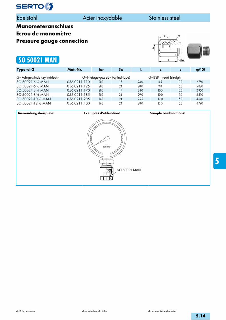
ManometeranschlussEcrou de manomètrePressure gauge connection
SO 50021 MANType -d -G Mat.-Nr. bar SW L z a kg/100 G=Rohrgewinde (zylindrisch) G=Filetage-gaz BSP (cylindrique) G=BSP thread (straight)SO 50021-6-1/4 MAN 056.0211.110 200 17 23.0 8.5 10.0 2.750SO 50021-6-1/2 MAN 056.0211.125 200 24 28.0 9.0 15.0 5.020SO 50021-8-1/4 MAN 056.0211.170 200 17 24.0 10.5 10.0 2.950SO 50021-8-1/2 MAN 056.0211.185 200 24 29.0 10.0 15.0 5.510SO 50021-10-1/2 MAN 056.0211.285 160 24 25.5 12.0 15.0 4.640SO 50021-12-1/2 MAN 056.0211.400 160 24 28.0 13.5 15.0 4.790
Anwendungsbeispiele: Exemples d‘utilisation: Sample combinations:
Edelstahl Acier inoxydable Stainless steel
d=Rohraussen-ø d=ø extérieur du tube d=tube outside diameter
5.14
i
s
3F
4M
4G
5
5L
6
7
8
9
10
11
12

ÜbergangsmuffeAdaptateur femelleFemale adaptor
SO 50030Type -d -G Mat.-Nr. bar M SW L b D f z e kg/100 G=Rohrgewinde (zylindrisch) G=Filetage-gaz BSP (cylindrique) G=BSP thread (straight)SO 50030-6-1/8 056.0301.100 200 10x1 14 20.0 14.0 13.8 10.0 4.0 5.0 1.480SO 50030-6-1/4 056.0301.110 200 10x1 17 21.0 15.0 16.8 11.0 4.0 5.0 2.350SO 50030-6-3/8 056.0301.120 200 10x1 22 22.0 16.0 21.8 10.0 4.0 5.0 4.500SO 50030-6-1/2 056.0301.125 200 10x1 27 24.0 18.0 26.8 11.0 4.0 5.0 7.440SO 50030-8-1/8 056.0301.160 200 12x1 17 21.0 14.0 16.8 10.0 4.0 6.5 2.560SO 50030-8-1/4 056.0301.170 200 12x1 17 23.0 16.0 16.8 12.0 5.0 6.5 2.150SO 50030-8-3/8 056.0301.180 200 12x1 22 23.0 16.0 21.8 11.0 4.0 6.5 4.500SO 50030-8-1/2 056.0301.185 200 12x1 27 25.0 18.0 26.8 13.0 4.0 6.5 7.140SO 50030-10-1/4 056.0301.270 160 14x1 17 22.0 15.0 16.8 12.0 4.0 8.5 1.870SO 50030-10-3/8 056.0301.280 160 14x1 22 23.0 16.0 21.8 12.0 4.0 8.5 4.050SO 50030-10-1/2 056.0301.285 160 14x1 27 25.0 18.0 26.8 13.0 4.0 8.5 7.400SO 50030-12-1/4 056.0301.380 160 16x1 19 22.0 15.0 18.8 11.0 4.0 8.5 3.460SO 50030-12-3/8 056.0301.390 160 16x1 22 23.0 16.0 21.8 12.0 4.0 10.0 3.720SO 50030-12-1/2 056.0301.400 160 16x1 27 25.0 18.0 26.8 12.0 4.0 10.0 7.030SO 50030-15-1/4 056.0301.528 100 20x1.5 24 20.0 12.0 20.0 8.0 4.0 11.5 4.900SO 50030-15-3/8 056.0301.532 100 20x1.5 24 25.0 17.0 23.8 12.0 5.0 13.0 5.350SO 50030-15-1/2 056.0301.534 100 20x1.5 27 27.0 19.0 26.8 12.0 5.0 13.0 6.600SO 50030-15-3/4 056.0301.536 100 20x1.5 32 30.0 22.0 31.8 15.0 5.0 13.0 10.400SO 50030-18-1/2 056.0301.646 100 24x1.5 30 28.0 20.0 29.8 12.0 6.0 15.0 8.810
Anwendungsbeispiele: Exemples d‘utilisation: Sample combinations:
Die Übergangsmuffe SO 50030 kann an jedes SERTO Formteil mit dem passenden zylindrischen Gewinde M aufgeschraubt werden.
Dichtungsprinzip:Bei der Montage drückt sich die Dichtkante des Übergangstückes in das SERTO-Formteil ein, dadurch entsteht eine einwandfreie metallische Dichtung. Wir empfehlen, das Gewinde mit einem geeigneten Flüssigklebstoff gegen unbe-absichtigtes Lösen zu sichern.
L’adaptateur femelle SO 50030 peut être monté sur toutes les pièces de forme SERTO avec le filetage cylindrique M correspondant.
Principe d’étanchéité: Lors du serrage, le bourrelet s’enfonce dans la pièce de forme SERTO et donne un joint métal-lique parfait. Nous recommandons de freiner le filetage avec une résine appropriée contre un desserrage intempestif.
The female adaptor SO 50030 can be scre-wed onto every SERTO union body with the appropriate straight thread M.
Sealing principle:On being installed, the lip of the adaptor presses into the SERTO union body, forming a sound metallic seal. We recommend to secu-re the thread with a suitable cement against unintended loosening.
Edelstahl Acier inoxydable Stainless steel
d=Rohraussen-øe=kleinste Bohrung
d=ø extérieur du tubee=ø-min. de passage
d=tube outside diametere=minimum bore
5.15

ÜbergangsnippelAdaptateur mâleMale adaptor
SO 50040Type -d -R Mat.-Nr. bar M SW L b c z e kg/100 R=Rohrgewinde (kegelig) R=Filetage-gaz BSP (conique) R=BSP thread (tapered)SO 50040-5-1/8 056.0401.082 250 8x1 10 17.0 11.0 9.0 7.0 3.5 0.700SO 50040-6-1/8 056.0401.100 200 10x1 12 17.0 11.0 9.0 7.0 4.5 0.740SO 50040-6-1/4 056.0401.110 200 10x1 14 21.0 15.0 9.0 9.0 4.5 1.710SO 50040-6-3/8 056.0401.120 200 10x1 17 20.0 14.0 8.0 7.6 4.5 2.850SO 50040-6-1/2 056.0401.125 200 10x1 22 23.0 17.0 7.0 8.8 4.5 3.800SO 50040-8-1/8 056.0401.160 200 12x1 14 18.0 11.0 10.0 7.0 6.0 0.980SO 50040-8-1/4 056.0401.170 200 12x1 14 22.0 15.0 10.0 9.0 6.5 1.450SO 50040-8-3/8 056.0401.180 200 12x1 17 22.0 15.0 10.0 8.6 6.5 2.800SO 50040-8-1/2 056.0401.185 200 12x1 22 26.0 19.0 10.0 10.8 6.5 3.700SO 50040-10-1/8 056.0401.265 160 14x1 17 18.5 11.5 10.5 7.5 6.0 1.200SO 50040-10-1/4 056.0401.270 160 14x1 17 22.0 15.0 10.0 9.0 8.5 1.570SO 50040-10-3/8 056.0401.280 160 14x1 17 22.0 15.0 10.0 8.6 8.5 2.280SO 50040-10-1/2 056.0401.285 160 14x1 22 23.0 16.0 7.0 7.8 8.5 4.610SO 50040-12-1/4 056.0401.380 160 16x1 19 23.0 16.0 11.0 10.0 8.5 1.970SO 50040-12-3/8 056.0401.390 160 16x1 19 22.0 15.0 10.0 8.6 10.5 2.220SO 50040-12-1/2 056.0401.400 160 16x1 22 26.0 19.0 10.0 10.8 10.5 4.830SO 50040-15-3/8 056.0401.532 100 20x1.5 24 24.0 16.0 12.0 9.6 10.5 3.530SO 50040-15-1/2 056.0401.534 100 20x1.5 24 27.0 19.0 11.0 10.8 13.0 4.170SO 50040-15-3/4 056.0401.536 100 20x1.5 27 27.5 19.5 11.0 10.0 13.0 5.520SO 50040-18-1/2 056.0401.646 100 24x1.5 30 29.0 21.0 13.0 12.8 13.5 6.020SO 50040-18-3/4 056.0401.648 100 24x1.5 30 29.5 21.5 13.0 12.0 15.0 8.400SO 50040-22-3/4 056.0401.768 100 28x1.5 36 29.5 21.5 13.0 12.0 19.0 10.000
Anwendungsbeispiele: Exemples d‘utilisation: Sample combinations:
Der Übergangsnippel SO 50040 kann an jedes SERTO-Formteil mit dem passenden zylindrischen Gewinde M aufgeschraubt werden.
Dichtungsprinzip: Bei der Montage drückt sich die Dichtkante des Übergangsstückes in das SERTO-Formteil ein, dadurch entsteht eine einwandfreie metallische Dichtung. Wir empfehlen, das Gewinde mit einem geeigneten Flüssigklebstoff gegen unbe-absichtigtes Lösen zu sichern.
L’adaptateur mâle SO 50040 peut être monté sur toutes les pièces de forme SERTO avec le filetage cylindrique M correspondant.
Principe d’étanchéité: Lors du serrage, l’arête d’étanchéité s’enfonce dans la pièce de forme SERTO et donne un joint métallique parfait. Nous recommandons de frei-ner le filetage avec une résine appropriée contre un desserrage intempestif.
The male adaptor SO 50040 can be scre-wed onto every SERTO union body with the appropriate straight thread M.
Sealing principle: On being installed, the lip of the adaptor presses into the SERTO union body, forming a sound metallic seal. We recommend to secu-re the thread with a suitable cement against unintended loosening.
Edelstahl Acier inoxydable Stainless steel
d=Rohraussen-øe=kleinste Bohrung
d=ø extérieur du tubee=ø-min. de passage
d=tube outside diametere=minimum bore
5.16
i
s
3F
4M
4G
5
5L
6
7
8
9
10
11
12

Übergangsnippel NPTAdaptateur mâle NPTMale adaptor NPT
SO 50040 NPTType -d -RNPT Mat.-Nr. bar M SW L b c z e kg/100 RNPT=NPT Gewinde RNPT=Filetage NPT RNPT=NPT threadSO 50040-5-1/8 NPT 056.0402.082 250 8x1 10 19.0 13.0 9.0 8.9 3.5 0.820SO 50040-6-1/8 NPT 056.0402.100 200 10x1 12 19.0 13.0 9.0 8.9 5.0 0.850SO 50040-6-1/4 NPT 056.0402.110 200 10x1 14 23.0 17.0 9.0 11.2 4.5 1.880SO 50040-8-1/4 NPT 056.0402.170 200 12x1 14 24.0 17.0 10.0 11.2 6.5 1.610SO 50040-10-1/4 NPT 056.0402.270 160 14x1 17 24.0 17.0 10.0 11.2 8.5 1.680SO 50040-10-3/8 NPT 056.0402.280 160 14x1 17 24.0 17.0 10.0 11.0 8.5 1.850SO 50040-12-1/4 NPT 056.0402.380 160 16x1 19 25.0 18.0 11.0 12.2 8.5 2.070SO 50040-12-3/8 NPT 056.0402.390 160 16x1 19 25.0 18.0 11.0 12.0 10.5 2.300SO 50040-12-1/2 NPT 056.0402.400 160 16x1 22 29.0 22.0 10.0 13.9 10.5 5.330SO 50040-15-1/2 NPT 056.0402.534 100 20x1.5 24 30.0 22.0 11.0 13.9 13.0 4.510
Der Übergangsnippel SO 50040 kann an jedes SERTO-Formteil mit dem passenden zylindrischen Gewinde M aufgeschraubt werden.
Dichtungsprinzip: Bei der Montage drückt sich die Dichtkante des Übergangsstückes in das SERTO-Formteil ein, dadurch entsteht eine einwandfreie metallische Dichtung. Wir empfehlen, das Gewinde mit einem geeigneten Flüssigklebstoff gegen unbeabsichtig-tes Lösen zu sichern.
L’adaptateur mâle SO 50040 peut être monté sur toutes les pièces de forme SERTO avec le filetage cylindrique M correspondant.
Principe d’étanchéité:Lors du serrage, l’arête d’étanchéité s’enfonce dans la pièce de forme SERTO et donne un joint métallique parfait. Nous recommandons de frei-ner le filetage avec une résine appropriée contre un desserrage intempestif.
The male adaptor SO 50040 can be screwed onto every SERTO union body with the appro-priate straight thread M.
Sealing principle: On being installed, the lip of the adaptor pres-ses into the SERTO union body, forming a sound metallic seal. We recommend to secure the thread with a suitable cement against uninten-ded loosening.
Übergangsnippel METRAdaptateur mâle METRMale adaptor METR
SO 50040 METRType -d -Mz bar M SW L b c z e kg/100 Mz=metrisches Gewinde (zylindrisch) Mz=Filetage métrique (cylindrique) Mz=Metric thread (straight)SO 50040-5-M6X0,75 056.0403.115 250 8x1 10 15.0 9.0 9.0 6.2 2.5 0.440SO 50040-5-M8X1 056.0403.125 250 8x1 10 17.0 11.0 9.0 7.5 3.5 0.550
Edelstahl Acier inoxydable Stainless steel
d=Rohraussen-øe=kleinste Bohrung
d=ø extérieur du tubee=ø-min. de passage
d=tube outside diametere=minimum bore
5.17
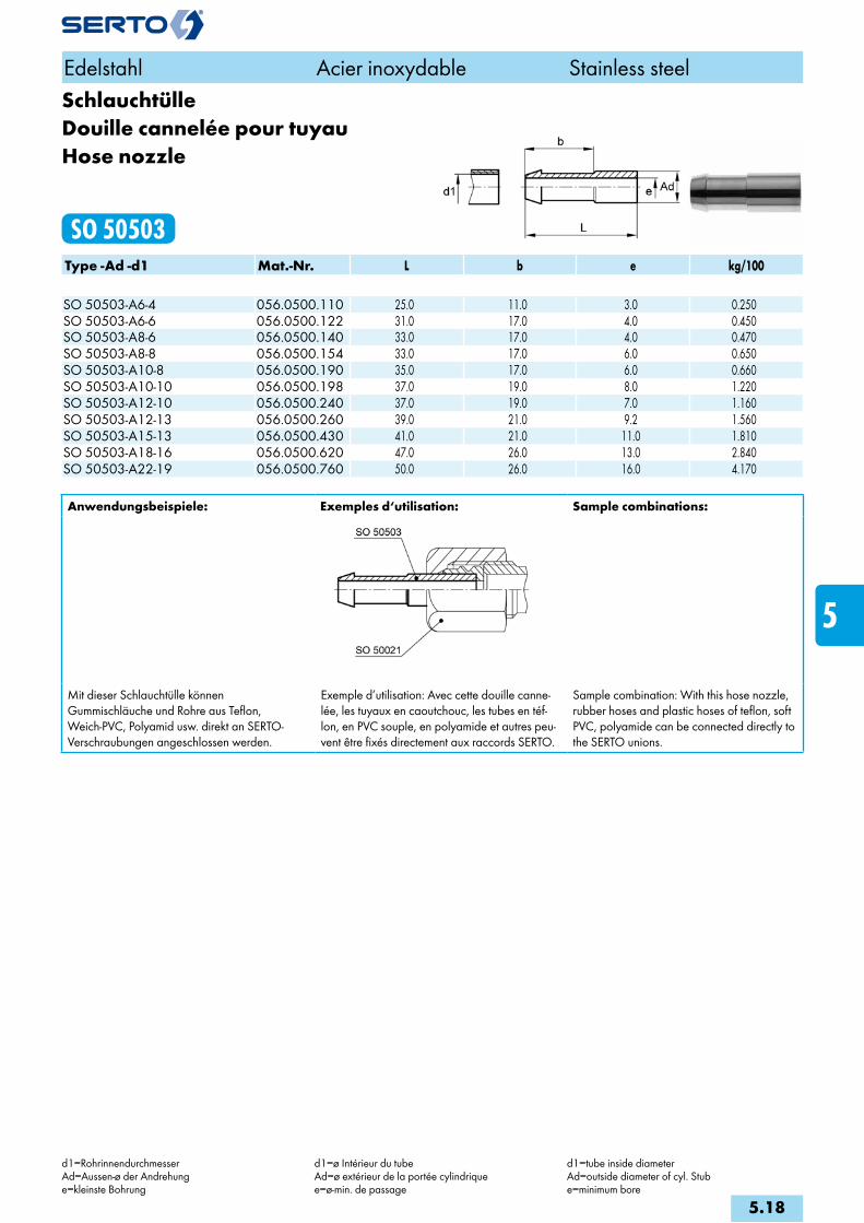
SchlauchtülleDouille cannelée pour tuyauHose nozzle
SO 50503Type -Ad -d1 Mat.-Nr. L b e kg/100 SO 50503-A6-4 056.0500.110 25.0 11.0 3.0 0.250SO 50503-A6-6 056.0500.122 31.0 17.0 4.0 0.450SO 50503-A8-6 056.0500.140 33.0 17.0 4.0 0.470SO 50503-A8-8 056.0500.154 33.0 17.0 6.0 0.650SO 50503-A10-8 056.0500.190 35.0 17.0 6.0 0.660SO 50503-A10-10 056.0500.198 37.0 19.0 8.0 1.220SO 50503-A12-10 056.0500.240 37.0 19.0 7.0 1.160SO 50503-A12-13 056.0500.260 39.0 21.0 9.2 1.560SO 50503-A15-13 056.0500.430 41.0 21.0 11.0 1.810SO 50503-A18-16 056.0500.620 47.0 26.0 13.0 2.840SO 50503-A22-19 056.0500.760 50.0 26.0 16.0 4.170
Anwendungsbeispiele: Exemples d‘utilisation: Sample combinations:
Mit dieser Schlauchtülle können Gummischläuche und Rohre aus Teflon, Weich-PVC, Polyamid usw. direkt an SERTO-Verschraubungen angeschlossen werden.
Exemple d’utilisation: Avec cette douille canne-lée, les tuyaux en caoutchouc, les tubes en téf-lon, en PVC souple, en polyamide et autres peu-vent être fixés directement aux raccords SERTO.
Sample combination: With this hose nozzle, rubber hoses and plastic hoses of teflon, soft PVC, polyamide can be connected directly to the SERTO unions.
Edelstahl Acier inoxydable Stainless steel
d1=RohrinnendurchmesserAd=Aussen-ø der Andrehunge=kleinste Bohrung
d1=ø Intérieur du tubeAd=ø extérieur de la portée cylindriquee=ø-min. de passage
d1=tube inside diameterAd=outside diameter of cyl. Stube=minimum bore
5.18
i
s
3F
4M
4G
5
5L
6
7
8
9
10
11
12

Schlauchtülle vormontiertDouille cannelée prémontéeHose nozzle assembly
SO 50526Type -Ad -d1 Mat.-Nr. M SW L b l e kg/100 SO 50526-A6-4 058.0520.110 10x1 12 30.0 8.0 23.0 3.0 1.060SO 50526-A6-6 058.0520.122 10x1 12 38.0 12.0 32.0 4.0 1.280SO 50526-A8-6 058.0520.140 12x1 14 37.0 12.0 30.0 4.0 1.750SO 50526-A8-8 058.0520.154 12x1 14 41.0 12.0 34.5 6.0 1.790SO 50526-A10-8 058.0520.190 14x1 17 40.0 12.0 32.0 6.0 2.950SO 50526-A10-10 058.0520.198 14x1 17 45.0 14.0 38.0 8.0 2.960SO 50526-A12-10 058.0520.240 16x1 19 43.0 14.0 35.0 7.0 4.090SO 50526-A12-13 058.0520.260 16x1 19 47.0 15.0 40.0 9.2 4.530SO 50526-A15-13 058.0520.430 20x1.5 24 49.0 15.0 40.0 10.0 7.290SO 50526-A18-16 058.0520.620 24x1.5 30 55.0 18.0 46.0 13.0 11.300SO 50526-A22-19 058.0520.760 28x1.5 32 57.0 18.0 49.0 16.0 14.500
AnschlussnippelEcrou de raccordement mâleNipple connection
SO 51001Type -d -G Mat.-Nr. bar SW L a c f kg/100 G=Rohrgewinde (zylindrisch) G=Filetage-gaz BSP (cylindrique) G=BSP thread (straight)SO 51001-6-1/4 058.0901.110 200 14 16.0 20.0 6.0 8.0 1.470SO 51001-8-1/4 058.0901.170 200 14 14.0 20.0 6.0 6.0 1.120SO 51001-10-3/8 058.0901.280 160 17 16.0 20.0 6.0 8.0 2.000SO 51001-12-1/2 058.0901.400 160 22 19.0 25.5 7.0 9.0 3.760
Anwendungsbeispiele: Exemples d‘utilisation: Sample combinations:
Edelstahl Acier inoxydable Stainless steel
d=Rohraussen-øAd=Aussen-ø der Andrehunge=kleinste BohrungL=Mass in montiertem Zustand*=mit reduziertem Klemmring
d=ø extérieur du tubeAd=ø extérieur de la portée cylindriquee=ø-min. de passageL=après montage*=avec bague de serrage de réduction
d=tube outside diameterAd=outside diameter of cyl. stube=minimum boreL=installed length*=with reduction compression ferrule
5.19
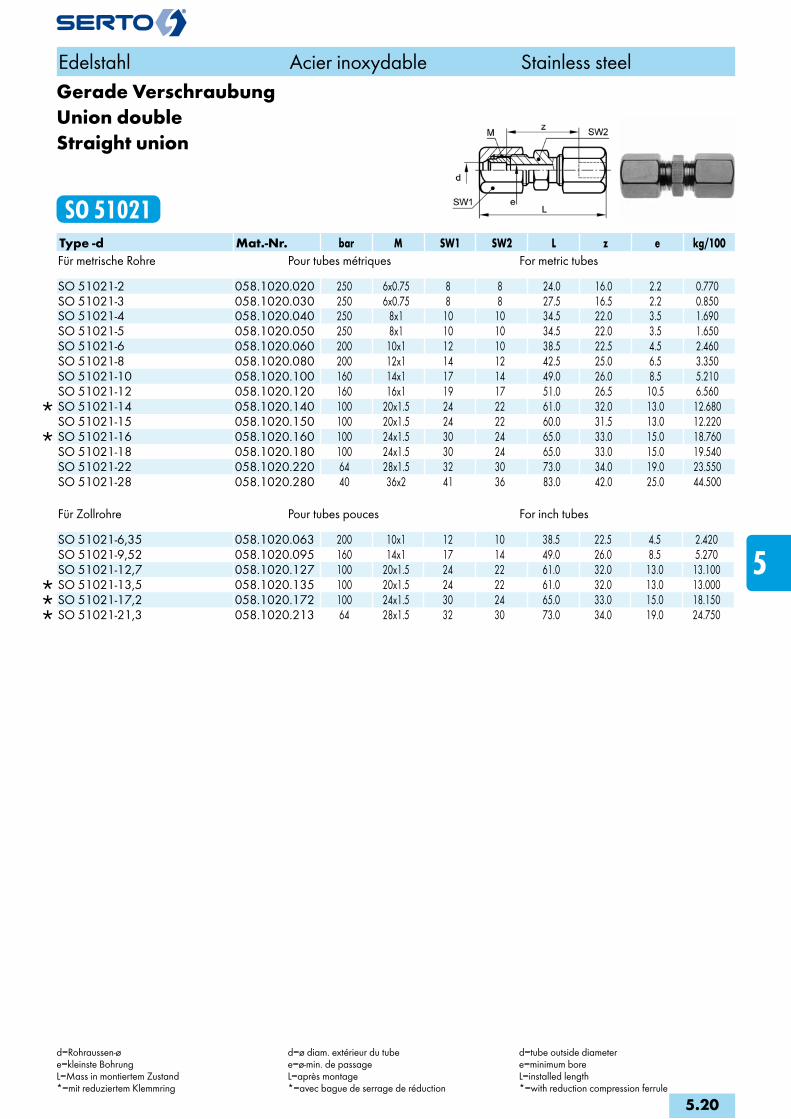
Gerade VerschraubungUnion doubleStraight union
SO 51021Type -d Mat.-Nr. bar M SW1 SW2 L z e kg/100Für metrische Rohre Pour tubes métriques For metric tubes
SO 51021-2 058.1020.020 250 6x0.75 8 8 24.0 16.0 2.2 0.770 SO 51021-3 058.1020.030 250 6x0.75 8 8 27.5 16.5 2.2 0.850 SO 51021-4 058.1020.040 250 8x1 10 10 34.5 22.0 3.5 1.690 SO 51021-5 058.1020.050 250 8x1 10 10 34.5 22.0 3.5 1.650 SO 51021-6 058.1020.060 200 10x1 12 10 38.5 22.5 4.5 2.460 SO 51021-8 058.1020.080 200 12x1 14 12 42.5 25.0 6.5 3.350 SO 51021-10 058.1020.100 160 14x1 17 14 49.0 26.0 8.5 5.210 SO 51021-12 058.1020.120 160 16x1 19 17 51.0 26.5 10.5 6.560
SO 51021-14 058.1020.140 100 20x1.5 24 22 61.0 32.0 13.0 12.680 SO 51021-15 058.1020.150 100 20x1.5 24 22 60.0 31.5 13.0 12.220
SO 51021-16 058.1020.160 100 24x1.5 30 24 65.0 33.0 15.0 18.760 SO 51021-18 058.1020.180 100 24x1.5 30 24 65.0 33.0 15.0 19.540 SO 51021-22 058.1020.220 64 28x1.5 32 30 73.0 34.0 19.0 23.550 SO 51021-28 058.1020.280 40 36x2 41 36 83.0 42.0 25.0 44.500
Für Zollrohre Pour tubes pouces For inch tubes
SO 51021-6,35 058.1020.063 200 10x1 12 10 38.5 22.5 4.5 2.420 SO 51021-9,52 058.1020.095 160 14x1 17 14 49.0 26.0 8.5 5.270 SO 51021-12,7 058.1020.127 100 20x1.5 24 22 61.0 32.0 13.0 13.100
SO 51021-13,5 058.1020.135 100 20x1.5 24 22 61.0 32.0 13.0 13.000 SO 51021-17,2 058.1020.172 100 24x1.5 30 24 65.0 33.0 15.0 18.150 SO 51021-21,3 058.1020.213 64 28x1.5 32 30 73.0 34.0 19.0 24.750
Edelstahl Acier inoxydable Stainless steel
d=Rohraussen-øe=kleinste BohrungL=Mass in montiertem Zustand*=mit reduziertem Klemmring
d=ø diam. extérieur du tubee=ø-min. de passageL=après montage*=avec bague de serrage de réduction
d=tube outside diametere=minimum boreL=installed length*=with reduction compression ferrule
5.20
i
s
3F
4M
4G
5
5L
6
7
8
9
10
11
12
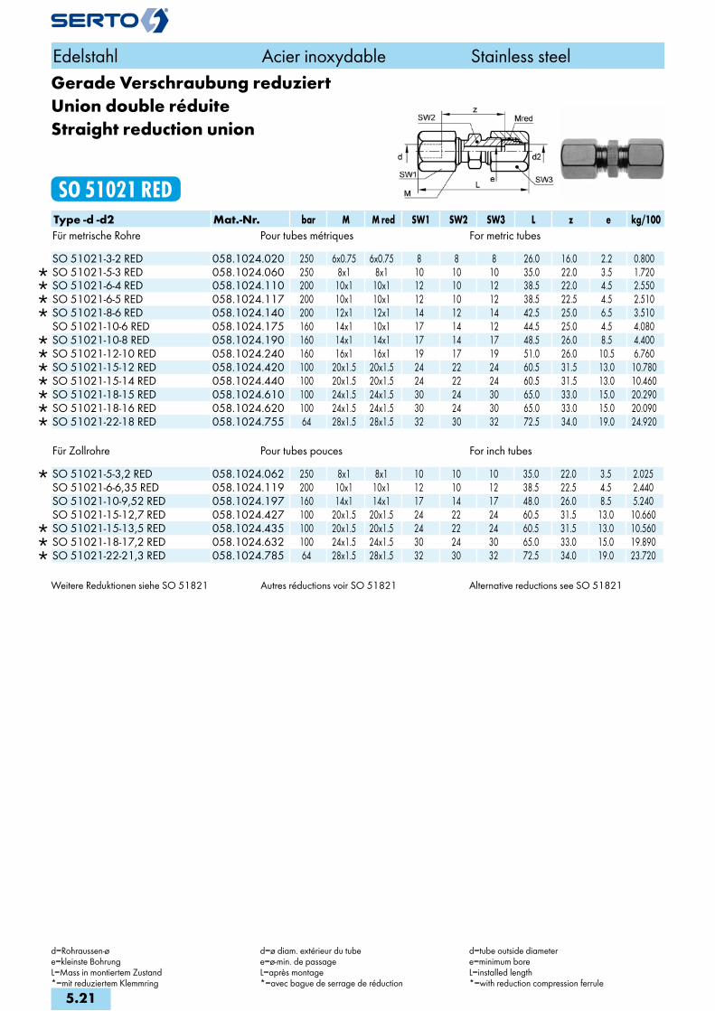
Gerade Verschraubung reduziertUnion double réduiteStraight reduction union
SO 51021 REDType -d -d2 Mat.-Nr. bar M M red SW1 SW2 SW3 L z e kg/100Für metrische Rohre Pour tubes métriques For metric tubes
SO 51021-3-2 RED 058.1024.020 250 6x0.75 6x0.75 8 8 8 26.0 16.0 2.2 0.800 SO 51021-5-3 RED 058.1024.060 250 8x1 8x1 10 10 10 35.0 22.0 3.5 1.720 SO 51021-6-4 RED 058.1024.110 200 10x1 10x1 12 10 12 38.5 22.0 4.5 2.550 SO 51021-6-5 RED 058.1024.117 200 10x1 10x1 12 10 12 38.5 22.5 4.5 2.510 SO 51021-8-6 RED 058.1024.140 200 12x1 12x1 14 12 14 42.5 25.0 6.5 3.510 SO 51021-10-6 RED 058.1024.175 160 14x1 10x1 17 14 12 44.5 25.0 4.5 4.080
SO 51021-10-8 RED 058.1024.190 160 14x1 14x1 17 14 17 48.5 26.0 8.5 4.400 SO 51021-12-10 RED 058.1024.240 160 16x1 16x1 19 17 19 51.0 26.0 10.5 6.760 SO 51021-15-12 RED 058.1024.420 100 20x1.5 20x1.5 24 22 24 60.5 31.5 13.0 10.780 SO 51021-15-14 RED 058.1024.440 100 20x1.5 20x1.5 24 22 24 60.5 31.5 13.0 10.460 SO 51021-18-15 RED 058.1024.610 100 24x1.5 24x1.5 30 24 30 65.0 33.0 15.0 20.290 SO 51021-18-16 RED 058.1024.620 100 24x1.5 24x1.5 30 24 30 65.0 33.0 15.0 20.090 SO 51021-22-18 RED 058.1024.755 64 28x1.5 28x1.5 32 30 32 72.5 34.0 19.0 24.920
Für Zollrohre Pour tubes pouces For inch tubes
SO 51021-5-3,2 RED 058.1024.062 250 8x1 8x1 10 10 10 35.0 22.0 3.5 2.025 SO 51021-6-6,35 RED 058.1024.119 200 10x1 10x1 12 10 12 38.5 22.5 4.5 2.440 SO 51021-10-9,52 RED 058.1024.197 160 14x1 14x1 17 14 17 48.0 26.0 8.5 5.240 SO 51021-15-12,7 RED 058.1024.427 100 20x1.5 20x1.5 24 22 24 60.5 31.5 13.0 10.660
SO 51021-15-13,5 RED 058.1024.435 100 20x1.5 20x1.5 24 22 24 60.5 31.5 13.0 10.560 SO 51021-18-17,2 RED 058.1024.632 100 24x1.5 24x1.5 30 24 30 65.0 33.0 15.0 19.890 SO 51021-22-21,3 RED 058.1024.785 64 28x1.5 28x1.5 32 30 32 72.5 34.0 19.0 23.720
Weitere Reduktionen siehe SO 51821 Autres réductions voir SO 51821 Alternative reductions see SO 51821
Edelstahl Acier inoxydable Stainless steel
d=Rohraussen-øe=kleinste BohrungL=Mass in montiertem Zustand*=mit reduziertem Klemmring
d=ø diam. extérieur du tubee=ø-min. de passageL=après montage*=avec bague de serrage de réduction
d=tube outside diametere=minimum boreL=installed length*=with reduction compression ferrule
5.21
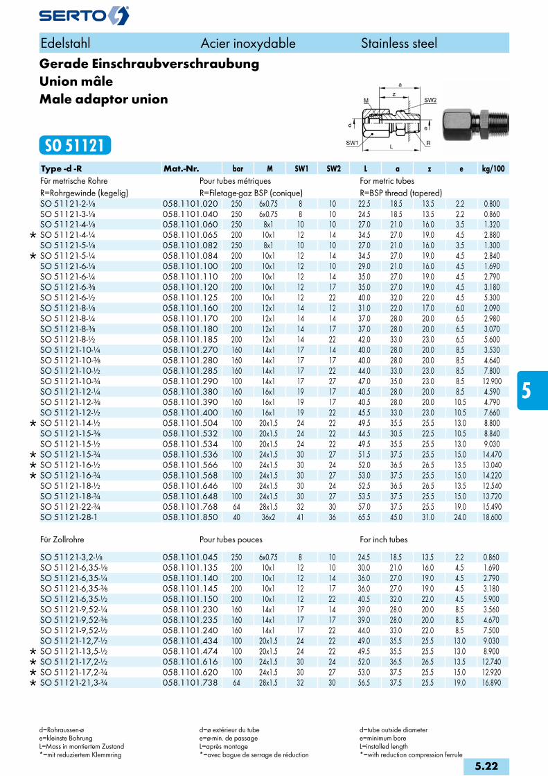
Gerade EinschraubverschraubungUnion mâleMale adaptor union
SO 51121Type -d -R Mat.-Nr. bar M SW1 SW2 L a z e kg/100Für metrische Rohre Pour tubes métriques For metric tubesR=Rohrgewinde (kegelig) R=Filetage-gaz BSP (conique) R=BSP thread (tapered)
SO 51121-2-1/8 058.1101.020 250 6x0.75 8 10 22.5 18.5 13.5 2.2 0.800 SO 51121-3-1/8 058.1101.040 250 6x0.75 8 10 24.5 18.5 13.5 2.2 0.860 SO 51121-4-1/8 058.1101.060 250 8x1 10 10 27.0 21.0 16.0 3.5 1.320
SO 51121-4-1/4 058.1101.065 200 10x1 12 14 34.5 27.0 19.0 4.5 2.880 SO 51121-5-1/8 058.1101.082 250 8x1 10 10 27.0 21.0 16.0 3.5 1.300
SO 51121-5-1/4 058.1101.084 200 10x1 12 14 34.5 27.0 19.0 4.5 2.840 SO 51121-6-1/8 058.1101.100 200 10x1 12 10 29.0 21.0 16.0 4.5 1.690 SO 51121-6-1/4 058.1101.110 200 10x1 12 14 35.0 27.0 19.0 4.5 2.790 SO 51121-6-3/8 058.1101.120 200 10x1 12 17 35.0 27.0 19.0 4.5 3.180 SO 51121-6-1/2 058.1101.125 200 10x1 12 22 40.0 32.0 22.0 4.5 5.300 SO 51121-8-1/8 058.1101.160 200 12x1 14 12 31.0 22.0 17.0 6.0 2.090 SO 51121-8-1/4 058.1101.170 200 12x1 14 14 37.0 28.0 20.0 6.5 2.980 SO 51121-8-3/8 058.1101.180 200 12x1 14 17 37.0 28.0 20.0 6.5 3.070 SO 51121-8-1/2 058.1101.185 200 12x1 14 22 42.0 33.0 23.0 6.5 5.600 SO 51121-10-1/4 058.1101.270 160 14x1 17 14 40.0 28.0 20.0 8.5 3.530 SO 51121-10-3/8 058.1101.280 160 14x1 17 17 40.0 28.0 20.0 8.5 4.640 SO 51121-10-1/2 058.1101.285 160 14x1 17 22 44.0 33.0 23.0 8.5 7.800 SO 51121-10-3/4 058.1101.290 100 14x1 17 27 47.0 35.0 23.0 8.5 12.900 SO 51121-12-1/4 058.1101.380 160 16x1 19 17 40.5 28.0 20.0 8.5 4.590 SO 51121-12-3/8 058.1101.390 160 16x1 19 17 40.5 28.0 20.0 10.5 4.790 SO 51121-12-1/2 058.1101.400 160 16x1 19 22 45.5 33.0 23.0 10.5 7.660
SO 51121-14-1/2 058.1101.504 100 20x1.5 24 22 49.5 35.5 25.5 13.0 8.800 SO 51121-15-3/8 058.1101.532 100 20x1.5 24 22 44.5 30.5 22.5 10.5 8.840 SO 51121-15-1/2 058.1101.534 100 20x1.5 24 22 49.5 35.5 25.5 13.0 9.030
SO 51121-15-3/4 058.1101.536 100 24x1.5 30 27 51.5 37.5 25.5 15.0 14.470 SO 51121-16-1/2 058.1101.566 100 24x1.5 30 24 52.0 36.5 26.5 13.5 13.040 SO 51121-16-3/4 058.1101.568 100 24x1.5 30 27 53.0 37.5 25.5 15.0 14.220 SO 51121-18-1/2 058.1101.646 100 24x1.5 30 24 52.5 36.5 26.5 13.5 12.540 SO 51121-18-3/4 058.1101.648 100 24x1.5 30 27 53.5 37.5 25.5 15.0 13.720 SO 51121-22-3/4 058.1101.768 64 28x1.5 32 30 57.0 37.5 25.5 19.0 15.490 SO 51121-28-1 058.1101.850 40 36x2 41 36 65.5 45.0 31.0 24.0 18.600
Für Zollrohre Pour tubes pouces For inch tubes
SO 51121-3,2-1/8 058.1101.045 250 6x0.75 8 10 24.5 18.5 13.5 2.2 0.860 SO 51121-6,35-1/8 058.1101.135 200 10x1 12 10 30.0 21.0 16.0 4.5 1.690 SO 51121-6,35-1/4 058.1101.140 200 10x1 12 14 36.0 27.0 19.0 4.5 2.790 SO 51121-6,35-3/8 058.1101.145 200 10x1 12 17 36.0 27.0 19.0 4.5 3.180 SO 51121-6,35-1/2 058.1101.150 200 10x1 12 22 40.5 32.0 22.0 4.5 5.900 SO 51121-9,52-1/4 058.1101.230 160 14x1 17 14 39.0 28.0 20.0 8.5 3.560 SO 51121-9,52-3/8 058.1101.235 160 14x1 17 17 39.0 28.0 20.0 8.5 4.670 SO 51121-9,52-1/2 058.1101.240 160 14x1 17 22 44.0 33.0 22.0 8.5 7.500 SO 51121-12,7-1/2 058.1101.434 100 20x1.5 24 22 49.0 35.5 25.5 13.0 9.030
SO 51121-13,5-1/2 058.1101.474 100 20x1.5 24 22 49.5 35.5 25.5 13.0 8.900 SO 51121-17,2-1/2 058.1101.616 100 24x1.5 30 24 52.0 36.5 26.5 13.5 12.740 SO 51121-17,2-3/4 058.1101.620 100 24x1.5 30 27 53.0 37.5 25.5 15.0 12.920 SO 51121-21,3-3/4 058.1101.738 64 28x1.5 32 30 56.5 37.5 25.5 19.0 16.890
Edelstahl Acier inoxydable Stainless steel
d=Rohraussen-øe=kleinste BohrungL=Mass in montiertem Zustand*=mit reduziertem Klemmring
d=ø extérieur du tubee=ø-min. de passageL=après montage*=avec bague de serrage de réduction
d=tube outside diametere=minimum boreL=installed length*=with reduction compression ferrule
5.22
i
s
3F
4M
4G
5
5L
6
7
8
9
10
11
12
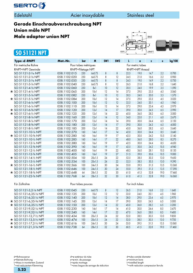
Gerade Einschraubverschraubung NPTUnion mâle NPTMale adaptor union NPT
SO 51121 NPTType -d -RNPT Mat.-Nr. bar M SW1 SW2 L a z e kg/100Für metrische Rohre Pour tubes métriques For metric tubesRNPT=NPT Gewinde RNPT=Filetage NPT RNPT=NPT thread
SO 51121-2-1/16 NPT 058.1102.015 250 6x0.75 8 8 22.5 19.0 14.7 2.2 0.700 SO 51121-2-1/8 NPT 058.1102.020 250 6x0.75 8 12 24.5 21.0 16.6 2.2 0.900 SO 51121-3-1/16 NPT 058.1102.035 250 6x0.75 8 8 24.5 19.0 14.9 2.2 0.750 SO 51121-3-1/8 NPT 058.1102.040 250 6x0.75 8 12 26.5 21.0 16.8 2.2 1.640 SO 51121-4-1/8 NPT 058.1102.060 250 8x1 10 12 30.5 24.0 19.9 3.5 1.590
SO 51121-4-1/4 NPT 058.1102.065 200 10x1 12 14 37.5 29.0 23.3 4.5 3.060 SO 51121-5-1/8 NPT 058.1102.082 250 8x1 10 12 30.5 24.0 20.0 3.5 1.570
SO 51121-5-1/4 NPT 058.1102.084 200 10x1 12 14 37.5 29.0 23.3 4.5 3.020 SO 51121-6-1/8 NPT 058.1102.100 200 10x1 12 12 32.5 24.0 20.1 4.5 1.960 SO 51121-6-1/4 NPT 058.1102.110 200 10x1 12 14 37.5 29.0 23.4 4.5 2.970
SO 51121-6-3/8 NPT 058.1102.120 200 12x1 14 17 39.0 30.0 24.3 6.5 2.990 SO 51121-6-1/2 NPT 058.1102.125 200 12x1 14 22 45.0 36.0 28.2 6.5 3.000 SO 51121-8-1/8 NPT 058.1102.160 200 12x1 14 12 34.0 25.0 21.1 6.0 2.670 SO 51121-8-1/4 NPT 058.1102.170 200 12x1 14 14 39.0 30.0 24.4 6.5 3.150 SO 51121-8-3/8 NPT 058.1102.180 200 12x1 14 17 39.0 30.0 24.3 6.5 4.000 SO 51121-8-1/2 NPT 058.1102.185 200 12x1 14 22 45.0 36.0 28.2 6.5 5.640 SO 51121-10-1/4 NPT 058.1102.270 160 14x1 17 14 42.0 30.0 24.4 8.5 3.640
SO 51121-10-3/8 NPT 058.1102.280 160 16x1 19 17 42.5 30.0 24.2 10.5 5.140 SO 51121-10-1/2 NPT 058.1102.285 160 14x1 17 22 48.0 36.0 28.0 8.5 8.270 SO 51121-12-1/4 NPT 058.1102.380 160 16x1 19 17 42.5 30.0 24.4 8.5 4.650 SO 51121-12-3/8 NPT 058.1102.390 160 16x1 19 17 42.5 30.0 24.2 10.5 4.940 SO 51121-12-1/2 NPT 058.1102.400 160 16x1 19 22 48.5 36.0 28.1 10.5 8.130 SO 51121-12-3/4 NPT 058.1102.405 160 16x1 19 27 51.5 39.0 30.6 10.5 9.000
SO 51121-14-1/2 NPT 058.1102.504 100 20x1.5 24 22 52.5 38.5 30.3 13.0 9.650 SO 51121-15-1/2 NPT 058.1102.534 100 20x1.5 24 22 52.5 38.5 30.3 13.0 9.390
SO 51121-16-1/2 NPT 058.1102.566 100 24x1.5 30 24 55.0 39.5 31.3 13.5 13.360 SO 51121-18-1/2 NPT 058.1102.646 100 24x1.5 30 24 55.0 39.5 31.3 13.5 17.390
SO 51121-18-3/4 NPT 058.1102.648 64 28x1.5 32 30 61.0 41.5 32.8 19.0 17.460 SO 51121-22-3/4 NPT 058.1102.768 64 28x1.5 32 30 61.0 41.5 32.8 19.0 16.060
Für Zollrohre Pour tubes pouces For inch tubes
SO 51121-3,2-1/8 NPT 058.1102.045 250 6x0.75 8 12 26.5 21.0 16.8 2.2 1.640 SO 51121-6,35-1/8 NPT 058.1102.135 200 10x1 12 12 33.0 24.0 20.1 4.5 1.960 SO 51121-6,35-1/4 NPT 058.1102.140 200 10x1 12 14 38.0 29.0 23.4 4.5 2.970
SO 51121-6,35-3/8 NPT 058.1102.145 200 12x1 14 17 39.0 30.0 24.3 6.5 3.000 SO 51121-6,35-1/2 NPT 058.1102.150 200 12x1 14 22 45.0 36.0 28.2 6.5 3.200 SO 51121-9,52-1/4 NPT 058.1102.230 160 14x1 17 14 41.0 30.0 24.4 8.5 3.670 SO 51121-9,52-1/2 NPT 058.1102.240 160 14x1 17 22 47.0 36.0 28.0 8.5 9.400 SO 51121-12,7-1/2 NPT 058.1102.434 100 20x1.5 24 22 52.0 38.5 30.3 13.0 9.850
SO 51121-13,5-1/2 NPT 058.1102.474 100 20x1.5 24 22 52.0 38.5 30.3 13.0 9.750 SO 51121-17,2-1/2 NPT 058.1102.616 100 24x1.5 30 24 55.0 39.5 31.3 13.5 13.060 SO 51121-21,3-3/4 NPT 058.1102.738 64 28x1.5 32 30 60.5 41.5 32.8 19.0 17.460
Edelstahl Acier inoxydable Stainless steel
d=Rohraussen-øe=kleinste BohrungL=Mass in montiertem Zustand*=mit reduziertem Klemmring
d=ø extérieur du tubee=ø-min. de passageL=après montage*=avec bague de serrage de réduction
d=tube outside diametere=minimum boreL=installed length*=with reduction compression ferrule
5.23
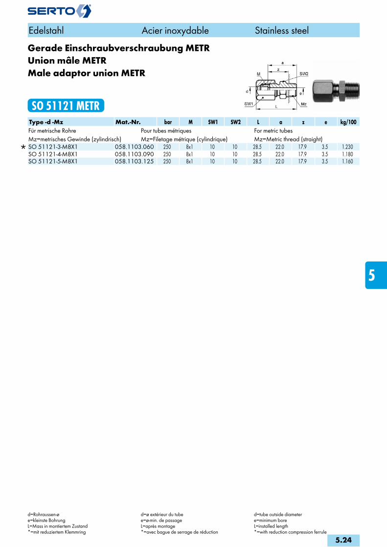
Gerade Einschraubverschraubung METRUnion mâle METRMale adaptor union METR
SO 51121 METRType -d -Mz Mat.-Nr. bar M SW1 SW2 L a z e kg/100Für metrische Rohre Pour tubes métriques For metric tubesMz=metrisches Gewinde (zylindrisch) Mz=Filetage métrique (cylindrique) Mz=Metric thread (straight)
SO 51121-3-M8X1 058.1103.060 250 8x1 10 10 28.5 22.0 17.9 3.5 1.230 SO 51121-4-M8X1 058.1103.090 250 8x1 10 10 28.5 22.0 17.9 3.5 1.180 SO 51121-5-M8X1 058.1103.125 250 8x1 10 10 28.5 22.0 17.9 3.5 1.160
Edelstahl Acier inoxydable Stainless steel
d=Rohraussen-øe=kleinste BohrungL=Mass in montiertem Zustand*=mit reduziertem Klemmring
d=ø extérieur du tubee=ø-min. de passageL=après montage*=avec bague de serrage de réduction
d=tube outside diametere=minimum boreL=installed length*=with reduction compression ferrule
5.24
i
s
3F
4M
4G
5
5L
6
7
8
9
10
11
12
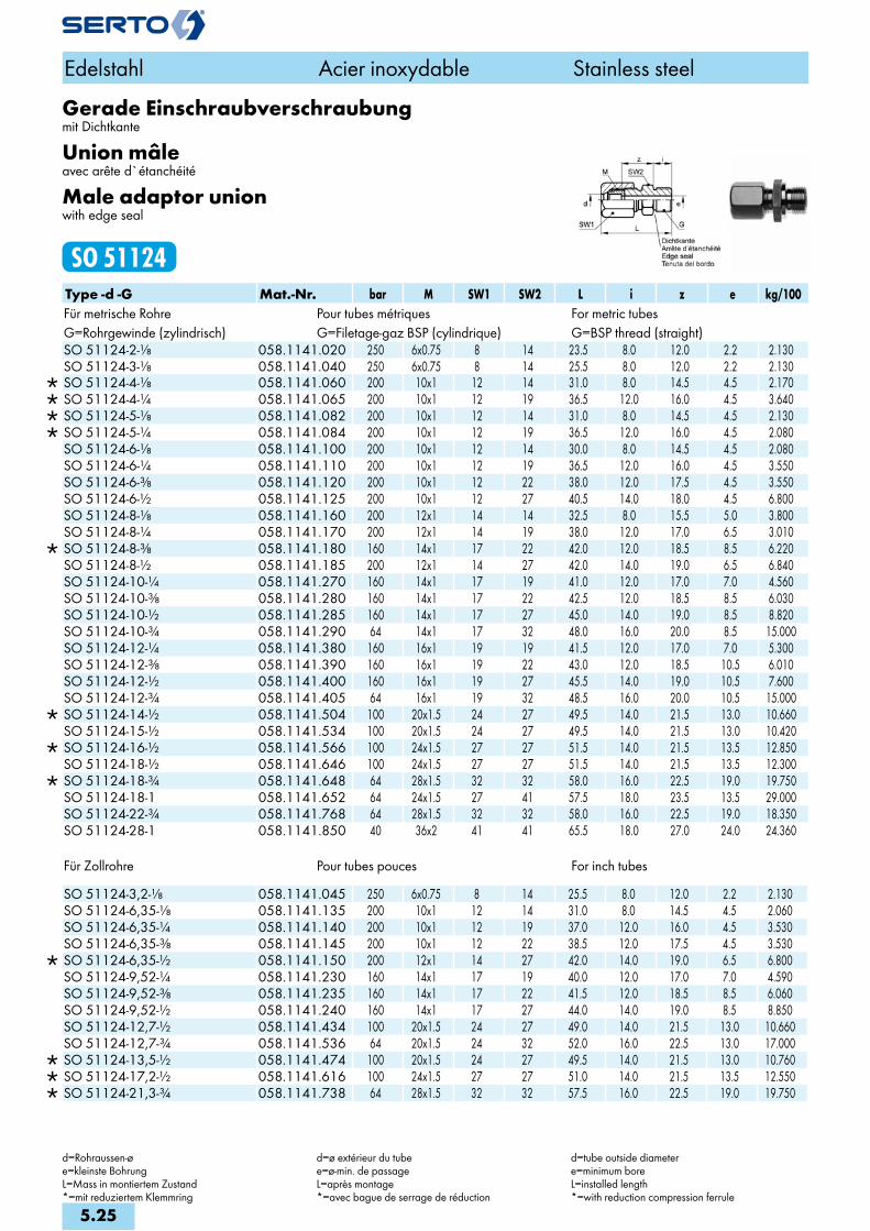
Für Zollrohre Pour tubes pouces For inch tubes
SO 51124-3,2-1/8 058.1141.045 250 6x0.75 8 14 25.5 8.0 12.0 2.2 2.130 SO 51124-6,35-1/8 058.1141.135 200 10x1 12 14 31.0 8.0 14.5 4.5 2.060 SO 51124-6,35-1/4 058.1141.140 200 10x1 12 19 37.0 12.0 16.0 4.5 3.530 SO 51124-6,35-3/8 058.1141.145 200 10x1 12 22 38.5 12.0 17.5 4.5 3.530
SO 51124-6,35-1/2 058.1141.150 200 12x1 14 27 42.0 14.0 19.0 6.5 6.800 SO 51124-9,52-1/4 058.1141.230 160 14x1 17 19 40.0 12.0 17.0 7.0 4.590 SO 51124-9,52-3/8 058.1141.235 160 14x1 17 22 41.5 12.0 18.5 8.5 6.060 SO 51124-9,52-1/2 058.1141.240 160 14x1 17 27 44.0 14.0 19.0 8.5 8.850 SO 51124-12,7-1/2 058.1141.434 100 20x1.5 24 27 49.0 14.0 21.5 13.0 10.660 SO 51124-12,7-3/4 058.1141.536 64 20x1.5 24 32 52.0 16.0 22.5 13.0 17.000
SO 51124-13,5-1/2 058.1141.474 100 20x1.5 24 27 49.5 14.0 21.5 13.0 10.760 SO 51124-17,2-1/2 058.1141.616 100 24x1.5 27 27 51.0 14.0 21.5 13.5 12.550 SO 51124-21,3-3/4 058.1141.738 64 28x1.5 32 32 57.5 16.0 22.5 19.0 19.750
Edelstahl Acier inoxydable Stainless steel
d=Rohraussen-øe=kleinste BohrungL=Mass in montiertem Zustand*=mit reduziertem Klemmring
d=ø extérieur du tubee=ø-min. de passageL=après montage*=avec bague de serrage de réduction
d=tube outside diametere=minimum boreL=installed length*=with reduction compression ferrule
Gerade Einschraubverschraubungmit Dichtkante
Union mâleavec arête d`étanchéité
Male adaptor unionwith edge seal
SO 51124Type -d -G Mat.-Nr. bar M SW1 SW2 L i z e kg/100Für metrische Rohre Pour tubes métriques For metric tubesG=Rohrgewinde (zylindrisch) G=Filetage-gaz BSP (cylindrique) G=BSP thread (straight)
SO 51124-2-1/8 058.1141.020 250 6x0.75 8 14 23.5 8.0 12.0 2.2 2.130 SO 51124-3-1/8 058.1141.040 250 6x0.75 8 14 25.5 8.0 12.0 2.2 2.130
SO 51124-4-1/8 058.1141.060 200 10x1 12 14 31.0 8.0 14.5 4.5 2.170 SO 51124-4-1/4 058.1141.065 200 10x1 12 19 36.5 12.0 16.0 4.5 3.640 SO 51124-5-1/8 058.1141.082 200 10x1 12 14 31.0 8.0 14.5 4.5 2.130 SO 51124-5-1/4 058.1141.084 200 10x1 12 19 36.5 12.0 16.0 4.5 2.080 SO 51124-6-1/8 058.1141.100 200 10x1 12 14 30.0 8.0 14.5 4.5 2.080 SO 51124-6-1/4 058.1141.110 200 10x1 12 19 36.5 12.0 16.0 4.5 3.550 SO 51124-6-3/8 058.1141.120 200 10x1 12 22 38.0 12.0 17.5 4.5 3.550 SO 51124-6-1/2 058.1141.125 200 10x1 12 27 40.5 14.0 18.0 4.5 6.800 SO 51124-8-1/8 058.1141.160 200 12x1 14 14 32.5 8.0 15.5 5.0 3.800 SO 51124-8-1/4 058.1141.170 200 12x1 14 19 38.0 12.0 17.0 6.5 3.010
SO 51124-8-3/8 058.1141.180 160 14x1 17 22 42.0 12.0 18.5 8.5 6.220 SO 51124-8-1/2 058.1141.185 200 12x1 14 27 42.0 14.0 19.0 6.5 6.840 SO 51124-10-1/4 058.1141.270 160 14x1 17 19 41.0 12.0 17.0 7.0 4.560 SO 51124-10-3/8 058.1141.280 160 14x1 17 22 42.5 12.0 18.5 8.5 6.030 SO 51124-10-1/2 058.1141.285 160 14x1 17 27 45.0 14.0 19.0 8.5 8.820 SO 51124-10-3/4 058.1141.290 64 14x1 17 32 48.0 16.0 20.0 8.5 15.000 SO 51124-12-1/4 058.1141.380 160 16x1 19 19 41.5 12.0 17.0 7.0 5.300 SO 51124-12-3/8 058.1141.390 160 16x1 19 22 43.0 12.0 18.5 10.5 6.010 SO 51124-12-1/2 058.1141.400 160 16x1 19 27 45.5 14.0 19.0 10.5 7.600 SO 51124-12-3/4 058.1141.405 64 16x1 19 32 48.5 16.0 20.0 10.5 15.000
SO 51124-14-1/2 058.1141.504 100 20x1.5 24 27 49.5 14.0 21.5 13.0 10.660 SO 51124-15-1/2 058.1141.534 100 20x1.5 24 27 49.5 14.0 21.5 13.0 10.420
SO 51124-16-1/2 058.1141.566 100 24x1.5 27 27 51.5 14.0 21.5 13.5 12.850 SO 51124-18-1/2 058.1141.646 100 24x1.5 27 27 51.5 14.0 21.5 13.5 12.300
SO 51124-18-3/4 058.1141.648 64 28x1.5 32 32 58.0 16.0 22.5 19.0 19.750 SO 51124-18-1 058.1141.652 64 24x1.5 27 41 57.5 18.0 23.5 13.5 29.000 SO 51124-22-3/4 058.1141.768 64 28x1.5 32 32 58.0 16.0 22.5 19.0 18.350 SO 51124-28-1 058.1141.850 40 36x2 41 41 65.5 18.0 27.0 24.0 24.360
5.25

Gerade Einschraubverschraubung METRmit Dichtkante
Union mâle METRavec arête d`étanchéité
Male adaptor union METRwith edge seal
SO 51124 METRType -d -Mz Mat.-Nr. bar M SW1 SW2 L i z e kg/100Für metrische Rohre Pour tubes métriques For metric tubesMz=metrisches Gewinde (zylindrisch) Mz=Filetage métrique (cylindrique) Mz=Metric thread (straight)
SO 51124-2-M5 058.1143.020 250 6x0.75 8 8 18.0 4.5 10.0 2.2 0.500 SO 51124-2-M6X0,75 058.1143.040 250 6x0.75 8 8 19.0 5.5 10.0 2.2 0.700 SO 51124-3-M5 058.1143.050 250 6x0.75 8 8 20.0 4.5 10.0 2.2 0.540 SO 51124-3-M6X0,75 058.1143.055 250 6x0.75 8 8 21.0 5.5 10.0 2.2 0.740
SO 51124-4-M5 058.1143.080 200 10x1 12 10 26.0 4.5 13.0 2.2 1.580 SO 51124-5-M5 058.1143.110 200 10x1 12 10 26.0 4.5 13.0 2.2 1.540 SO 51124-6-M5 058.1143.155 200 10x1 12 10 26.0 4.5 13.0 2.2 1.490
Für Zollrohre Pour tubes pouces For inch tubes SO 51124-3,2-M5 058.1143.067 250 6x0.75 8 8 19.0 4.5 10.0 2.2 0.600
SO 51124-6,35-M5 058.1143.205 200 10x1 12 10 26.0 4.5 13.0 2.2 1.470
Edelstahl Acier inoxydable Stainless steel
d=Rohraussen-øe=kleinste BohrungL=Mass in montiertem Zustand*=mit reduziertem Klemmring
d=ø extérieur du tubee=ø-min. de passageL=après montage*=avec bague de serrage de réduction
d=tube outside diametere=minimum boreL=installed length*=with reduction compression ferrule
5.26
i
s
3F
4M
4G
5
5L
6
7
8
9
10
11
12

Gerade Einschraubverschraubungmit O-Ringabdichtung (FPM)
Union mâleavec joint torique (FPM)
Male adaptor unionwith O-ring seal (FPM)
SO 51124 ORType -d -G Mat.-Nr. bar M SW1 SW2 L D i s z e kg/100Für metrische Rohre Pour tubes métriques For metric tubesG=Rohrgewinde (zylindrisch) G=Filetage-gaz BSP (cylindrique) G=BSP thread (straight)
SO 51124-4-1/8 OR 058.1171.060 200 10x1 12 14 31.0 15.0 8.0 1.00 14.5 4.5 2.200 SO 51124-4-1/4 OR 058.1171.065 200 10x1 12 19 34.5 19.0 10.0 1.50 16.0 4.5 3.500 SO 51124-5-1/8 OR 058.1171.082 200 10x1 12 14 31.0 15.0 8.0 1.00 14.5 4.5 2.100 SO 51124-5-1/4 OR 058.1171.084 200 10x1 12 19 31.5 19.0 10.0 1.50 16.0 4.5 3.400 SO 51124-6-1/8 OR 058.1171.100 200 10x1 12 14 31.0 15.0 8.0 1.00 14.5 4.5 2.100 SO 51124-6-1/4 OR 058.1171.110 200 10x1 12 19 31.5 19.0 10.0 1.50 16.0 4.5 3.400 SO 51124-8-1/8 OR 058.1171.160 200 12x1 14 14 32.5 15.0 8.0 1.00 15.5 4.5 2.800 SO 51124-8-1/4 OR 058.1171.170 200 12x1 14 19 36.0 19.0 10.0 1.50 17.0 6.5 3.700
SO 51124-8-3/8 OR 058.1171.180 160 14x1 17 22 40.5 23.0 10.0 2.00 18.5 8.5 6.100 SO 51124-10-1/4 OR 058.1171.270 160 14x1 17 19 39.0 19.0 10.0 1.50 17.0 7.0 4.400 SO 51124-10-3/8 OR 058.1171.280 160 14x1 17 22 40.5 23.0 10.0 2.00 18.5 8.5 5.900
SO 51124-10-1/2 OR 058.1171.285 160 16x1 19 27 43.5 27.0 12.0 2.50 19.0 10.5 7.500 SO 51124-12-3/8 OR 058.1171.390 160 16x1 19 22 41.0 23.0 10.0 2.00 18.5 10.5 6.000 SO 51124-12-1/2 OR 058.1171.400 160 16x1 19 27 43.5 27.0 12.0 2.50 19.0 10.5 7.400
SO 51124-14-1/2 OR 058.1171.504 100 20x1.5 24 27 47.5 27.0 12.0 2.50 21.5 13.0 10.400 SO 51124-15-1/2 OR 058.1171.534 100 20x1.5 24 27 47.5 27.0 12.0 2.50 21.5 13.0 10.200
SO 51124-16-1/2 OR 058.1171.566 100 24x1.5 27 27 49.0 27.0 12.0 2.50 21.5 13.0 12.500 SO 51124-18-1/2 OR 058.1171.646 100 24x1.5 27 27 49.0 27.0 12.0 2.50 21.5 13.0 12.000
SO 51124-18-3/4 OR 058.1171.648 64 28x1.5 32 32 54.0 33.0 12.0 2.50 22.5 19.0 19.400 SO 51124-22-3/4 OR 058.1171.768 64 28x1.5 32 32 54.0 33.0 12.0 2.50 22.5 19.0 18.000 SO 51124-28-1 OR 058.1171.850 64 36x2 41 41 63.0 42.0 13.0 2.50 30.0 24.0 38.300
Für Zollrohre Pour tubes pouces For inch tubes
SO 51124-6,35-1/8 OR 058.1171.135 200 10x1 12 14 31.5 15.0 8.0 1.00 14.5 4.5 2.000 SO 51124-6,35-1/4 OR 058.1171.140 200 10x1 12 19 35.0 19.0 10.0 1.50 16.0 4.5 3.300 SO 51124-9,52-1/4 OR 058.1171.230 160 14x1 17 19 38.0 19.0 10.0 1.50 17.0 7.0 4.500 SO 51124-9,52-3/8 OR 058.1171.235 160 14x1 17 22 39.5 23.0 10.0 2.00 18.5 8.5 5.800 SO 51124-12,7-1/2 OR 058.1171.434 100 20x1.5 24 27 47.0 27.0 12.0 2.50 21.5 13.0 10.800
SO 51124-13,5-1/2 OR 058.1171.474 100 20x1.5 24 27 48.0 27.0 12.0 2.50 21.5 13.0 10.500 SO 51124-17,2-1/2 OR 058.1171.616 100 24x1.5 27 27 49.0 27.0 12.0 2.50 21.5 13.0 12.200 SO 51124-21,3-3/4 OR 058.1171.738 64 28x1.5 32 32 53.5 33.0 12.0 2.50 22.5 19.0 19.000
Anwendungsbeispiele: Exemples d‘utilisation: Sample combinations:
Temperatur max. +200°C conovor® patentierte O-Ring Abdichtung
Température max. +200°C conovor® breveté joint torique étanchéité
Temperature max. +200°C conovor® patented O-ring sealing
Edelstahl Acier inoxydable Stainless steel
d=Rohraussen-øe=kleinste BohrungL=Mass in montiertem Zustand*=mit reduziertem Klemmring
d=ø extérieur du tubee=ø-min. de passageL=après montage*=avec bague de serrage de réduction
d=tube outside diametere=minimum boreL=installed length*=with reduction compression ferrule
5.27
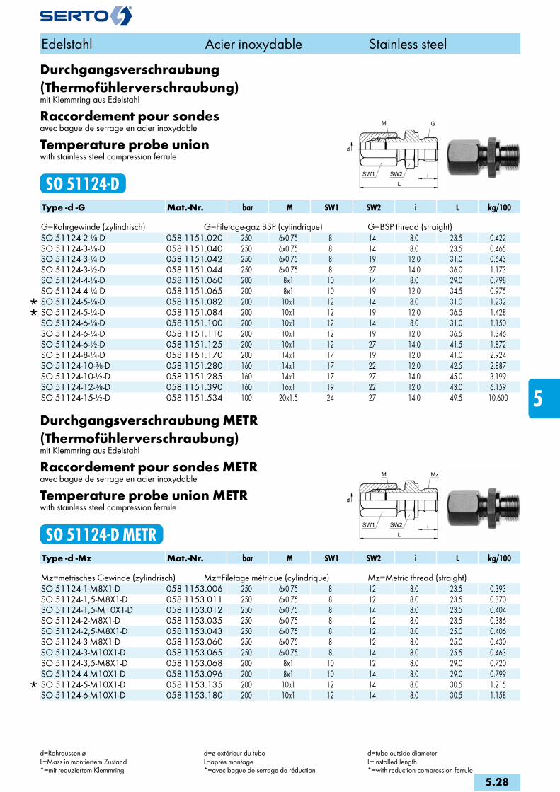
Durchgangsverschraubung (Thermofühlerverschraubung)mit Klemmring aus Edelstahl
Raccordement pour sondesavec bague de serrage en acier inoxydable
Temperature probe unionwith stainless steel compression ferrule
SO 51124-DType -d -G Mat.-Nr. bar M SW1 SW2 i L kg/100 G=Rohrgewinde (zylindrisch) G=Filetage-gaz BSP (cylindrique) G=BSP thread (straight)
SO 51124-2-1/8-D 058.1151.020 250 6x0.75 8 14 8.0 23.5 0.422 SO 51124-3-1/8-D 058.1151.040 250 6x0.75 8 14 8.0 23.5 0.465 SO 51124-3-1/4-D 058.1151.042 250 6x0.75 8 19 12.0 31.0 0.643 SO 51124-3-1/2-D 058.1151.044 250 6x0.75 8 27 14.0 36.0 1.173 SO 51124-4-1/8-D 058.1151.060 200 8x1 10 14 8.0 29.0 0.798 SO 51124-4-1/4-D 058.1151.065 200 8x1 10 19 12.0 34.5 0.975
SO 51124-5-1/8-D 058.1151.082 200 10x1 12 14 8.0 31.0 1.232 SO 51124-5-1/4-D 058.1151.084 200 10x1 12 19 12.0 36.5 1.428 SO 51124-6-1/8-D 058.1151.100 200 10x1 12 14 8.0 31.0 1.150 SO 51124-6-1/4-D 058.1151.110 200 10x1 12 19 12.0 36.5 1.346 SO 51124-6-1/2-D 058.1151.125 200 10x1 12 27 14.0 41.5 1.872 SO 51124-8-1/4-D 058.1151.170 200 14x1 17 19 12.0 41.0 2.924 SO 51124-10-3/8-D 058.1151.280 160 14x1 17 22 12.0 42.5 2.887 SO 51124-10-1/2-D 058.1151.285 160 14x1 17 27 14.0 45.0 3.199 SO 51124-12-3/8-D 058.1151.390 160 16x1 19 22 12.0 43.0 6.159 SO 51124-15-1/2-D 058.1151.534 100 20x1.5 24 27 14.0 49.5 10.600
Durchgangsverschraubung METR(Thermofühlerverschraubung)mit Klemmring aus Edelstahl
Raccordement pour sondes METRavec bague de serrage en acier inoxydable
Temperature probe union METRwith stainless steel compression ferrule
SO 51124-D METRType -d -Mz Mat.-Nr. bar M SW1 SW2 i L kg/100 Mz=metrisches Gewinde (zylindrisch) Mz=Filetage métrique (cylindrique) Mz=Metric thread (straight)
SO 51124-1-M8X1-D 058.1153.006 250 6x0.75 8 12 8.0 23.5 0.393 SO 51124-1,5-M8X1-D 058.1153.011 250 6x0.75 8 12 8.0 23.5 0.370 SO 51124-1,5-M10X1-D 058.1153.012 250 6x0.75 8 14 8.0 23.5 0.404 SO 51124-2-M8X1-D 058.1153.035 250 6x0.75 8 12 8.0 23.5 0.386 SO 51124-2,5-M8X1-D 058.1153.043 250 6x0.75 8 12 8.0 25.0 0.406 SO 51124-3-M8X1-D 058.1153.060 250 6x0.75 8 12 8.0 25.0 0.430 SO 51124-3-M10X1-D 058.1153.065 250 6x0.75 8 14 8.0 25.5 0.463 SO 51124-3,5-M8X1-D 058.1153.068 200 8x1 10 12 8.0 29.0 0.720 SO 51124-4-M10X1-D 058.1153.096 200 8x1 10 14 8.0 29.0 0.799
SO 51124-5-M10X1-D 058.1153.135 200 10x1 12 14 8.0 30.5 1.215 SO 51124-6-M10X1-D 058.1153.180 200 10x1 12 14 8.0 30.5 1.158
Edelstahl Acier inoxydable Stainless steel
d=Rohraussen-øL=Mass in montiertem Zustand*=mit reduziertem Klemmring
d=ø extérieur du tubeL=après montage*=avec bague de serrage de réduction
d=tube outside diameterL=installed length*=with reduction compression ferrule
5.28
i
s
3F
4M
4G
5
5L
6
7
8
9
10
11
12
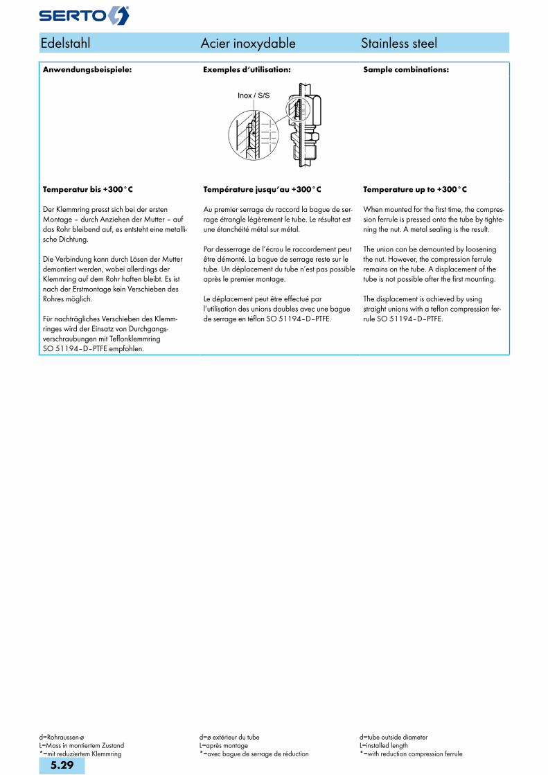
Anwendungsbeispiele: Exemplesd‘utilisation: Samplecombinations:
Temperaturbis+300°C
Der Klemmring presst sich bei der ersten Montage – durch Anziehen der Mutter – auf das Rohr bleibend auf, es entsteht eine metalli-sche Dichtung.
Die Verbindung kann durch Lösen der Mutter demontiert werden, wobei allerdings der Klemmring auf dem Rohr haften bleibt. Es ist nach der Erstmontage kein Verschieben des Rohres möglich.
Für nachträgliches Verschieben des Klemm- ringes wird der Einsatz von Durchgangs-verschraubungen mit Teflonklemmring SO 51194–D–PTFE empfohlen.
Températurejusqu’au+300°C
Au premier serrage du raccord la bague de ser-rage étrangle légèrement le tube. Le résultat est une étanchéité métal sur métal.
Par desserrage de l’écrou le raccordement peut être démonté. La bague de serrage reste sur le tube. Un déplacement du tube n’est pas possible après le premier montage.
Le déplacement peut être effectué par l’utilisation des unions doubles avec une bague de serrage en téflon SO 51194–D–PTFE.
Temperatureupto+300°C
When mounted for the first time, the compres-sion ferrule is pressed onto the tube by tighte-ning the nut. A metal sealing is the result.
The union can be demounted by loosening the nut. However, the compression ferrule remains on the tube. A displacement of the tube is not possible after the first mounting.
The displacement is achieved by using straight unions with a teflon compression fer-rule SO 51194–D–PTFE.
Edelstahl Acier inoxydable Stainless steel
d=Rohraussen-øL=Mass in montiertem Zustand*=mit reduziertem Klemmring
d=ø extérieur du tubeL=après montage*=avec bague de serrage de réduction
d=tube outside diameterL=installed length*=with reduction compression ferrule
5.29

Durchgangsverschraubung (Thermofühlerverschraubung)mit PTFE-Klemmring
Raccordement pour sondesavec bague de serrage en PTFE
Temperature probe unionwith PTFE compression ferrule
SO 51194-D-PTFEType -d -G Mat.-Nr. M SW1 SW2 L i kg/100 G=Rohrgewinde (zylindrisch) G=Filetage-gaz BSP (cylindrique) G=BSP thread (straight)SO 51194-1-1/4 058.1165.002 6x0.75 8 19 29.0 12.0 2.640SO 51194-1-1/2 058.1165.004 6x0.75 8 27 34.0 14.0 6.320SO 51194-1,5-1/4 058.1165.011 6x0.75 8 19 29.0 12.0 2.640SO 51194-1,5-1/2 058.1165.013 6x0.75 8 27 34.0 14.0 6.340SO 51194-2-1/8 058.1165.020 6x0.75 8 14 23.5 8.0 1.260SO 51194-2-1/4 058.1165.021 6x0.75 8 19 29.0 12.0 2.630SO 51194-2-1/2 058.1165.023 6x0.75 8 27 34.0 14.0 6.310SO 51194-2.5-1/8 058.1165.030 6x0.75 8 14 23.5 8.0 1.250SO 51194-2.5-1/4 058.1165.031 6x0.75 8 19 29.5 12.0 2.620SO 51194-2.5-1/2 058.1165.033 6x0.75 8 27 34.0 14.0 6.290SO 51194-3-1/8 058.1165.040 6x0.75 8 14 23.5 8.0 1.370SO 51194-3-1/4 058.1165.042 6x0.75 8 19 29.0 12.0 1.250SO 51194-3-1/2 058.1165.044 6x0.75 8 27 34.0 14.0 2.610SO 51194-3.5-1/8 058.1165.047 8x1 10 14 28.0 8.0 6.280SO 51194-3.5-1/4 058.1165.049 8x1 10 19 33.5 12.0 1.250SO 51194-4-1/8 058.1165.060 8x1 10 14 28.0 8.0 1.680SO 51194-4-1/4 058.1165.065 8x1 10 19 33.5 12.0 2.880SO 51194-4-1/2 058.1165.070 8x1 10 27 38.5 14.0 6.680SO 51194-4.5-1/8 058.1165.076 8x1 10 14 28.0 8.0 1.680SO 51194-4.5-1/4 058.1165.077 8x1 10 19 33.5 12.0 2.940SO 51194-5-1/8 058.1165.082 10x1 12 14 29.0 8.0 1.990SO 51194-5-1/4 058.1165.084 10x1 12 19 34.5 12.0 3.220SO 51194-5-1/2 058.1165.088 10x1 12 27 39.5 14.0 7.030SO 51194-5-3/4 058.1165.089 10x1 12 32 42.5 16.0 14.190SO 51194-6-1/4 058.1165.110 10x1 12 19 34.5 12.0 2.790SO 51194-6-1/2 058.1165.125 10x1 12 27 39.5 14.0 6.880SO 51194-6-3/4 058.1165.126 10x1 12 32 42.5 16.0 13.900SO 51194-8-1/4 058.1165.170 14x1 17 19 36.5 12.0 4.080SO 51194-8-3/8 058.1165.180 14x1 17 22 38.0 12.0 5.310SO 51194-8-1/2 058.1165.185 14x1 17 27 40.5 14.0 7.010SO 51194-8-3/4 058.1165.190 14x1 17 32 44.5 16.0 10.790SO 51194-9-1/2 058.1165.210 14x1 17 27 40.5 14.0 6.830SO 51194-9-3/4 058.1165.214 14x1 17 32 43.5 16.0 10.610SO 51194-10-3/8 058.1165.280 14x1 17 22 38.0 12.0 5.030SO 51194-10-1/2 058.1165.285 14x1 17 27 40.5 14.0 6.610SO 51194-10-3/4 058.1165.290 14x1 17 32 44.5 16.0 10.340
Werkstoff: 1.4571 Klemmring aus PTFETemperatur/Druck bis +200°C und 6 bar
Matériau: 1.4571 bague de serrage en PTFETempérature/Pression jusqu’au +200°C et 6 bar.
Material: 1.4571 compression ferrule of PTFETemperature/Pressure up to +200°C and 6 bar.
Edelstahl Acier inoxydable Stainless steel
d=Rohraussen-øL=Mass in montiertem Zustand
d=ø extérieur du tubeL=après montage
d=tube outside diameterL=installed length
5.30
i
s
3F
4M
4G
5
5L
6
7
8
9
10
11
12

Durchgangsverschraubung METR (Thermofühlerverschraubung)mit PTFE-Klemmring
Raccordement pour sondes METRavec bague de serrage en PTFE
Temperature probe union METRwith PTFE compression ferrule
SO 51194-D-PTFE METRType -d -Mz Mat.-Nr. M SW1 SW2 L i kg/100 Mz=metrisches Gewinde (zylindrisch) Mz=Filetage métrique (cylindrique) Mz=Metric thread (straight)SO 51194-0,5-M8x1 058.1167.003 6x0.75 8 12 24.5 8.0 1.400SO 51194-1-M8X1 058.1167.006 6x0.75 8 14 24.5 8.0 1.400SO 51194-1-M10x1 058.1167.004 6x0.75 8 12 24.5 8.0 1.280SO 51194-1,5-M8x1 058.1167.011 6x0.75 8 12 24.5 8.0 1.020SO 51194-1,5-M10x1 058.1167.012 6x0.75 8 14 24.5 8.0 1.270SO 51194-2-M8X1 058.1167.035 6x0.75 8 12 24.5 8.0 1.000SO 51194-2-M10x1 058.1167.036 6x0.75 8 14 24.5 8.0 1.260SO 51194-2.5-M8x1 058.1167.043 6x0.75 8 12 24.5 8.0 1.000SO 51194-2.5-M10x1 058.1167.044 6x0.75 8 14 24.5 8.0 1.240SO 51194-3-M8x1 058.1167.060 6x0.75 8 12 24.5 8.0 0.980SO 51194-3-M10x1 058.1167.065 6x0.75 8 14 24.5 8.0 1.250SO 51194-3.5-M8x1 058.1167.075 8x1 10 12 29.0 8.0 1.380SO 51194-4-M8x1 058.1167.090 8x1 10 12 29.0 8.0 1.330SO 51194-4-M10x1 058.1167.096 8x1 10 14 29.0 8.0 1.068SO 51194-5-M10x1 058.1167.135 10x1 12 14 29.0 8.0 1.980SO 51194-6-M10x1 058.1167.180 10x1 12 14 29.0 8.0 1.790
Werkstoff: 1.4571 Klemmring aus PTFETemperatur/Druck bis +200°C und 6 bar
Matériau: 1.4571 bague de serrage en PTFETempérature/Pression jusqu’au +200°C et 6 bar
Material: 1.4571 compression ferrule of PTFETemperature/Pressure up to +200°C and 6 bar
Edelstahl Acier inoxydable Stainless steel
d=Rohraussen-øL=Mass in montiertem Zustand
d=ø extérieur du tubeL=après montage
d=tube outside diameterL=installed length
5.31

PTFE Klemmring zu SO 51194/SO 61194Bague de serrage en PTFE pour SO 51194/SO 61194PTFE compression ferrule for SO 51194/SO 61194
SO 50009Type -d Mat.-Nr. D L SO 50009-0.5 056.0016.505 5.0 2.5SO 50009-1 056.0016.510 5.0 2.5SO 50009-1,5 056.0016.515 5.0 2.5SO 50009-2 056.0016.520 5.0 2.5SO 50009-2,5 056.0016.525 5.0 2.5SO 50009-3 056.0016.530 5.0 2.5SO 50009-4 056.0016.540 6.5 4.0SO 50009-4,5 056.0016.545 6.5 4.0SO 50009-5 056.0016.550 8.5 4.5SO 50009-6 056.0016.560 8.5 4.5SO 50009-8 056.0016.580 12.5 5.5SO 50009-9 056.0016.590 12.5 5.5SO 50009-10 056.0016.600 12.5 5.5
Edelstahl Acier inoxydable Stainless steel
d=Rohraussen-øL=Mass in montiertem Zustand
d=ø extérieur du tubeL=après montage
d=tube outside diameterL=installed length
5.32
i
s
3F
4M
4G
5
5L
6
7
8
9
10
11
12
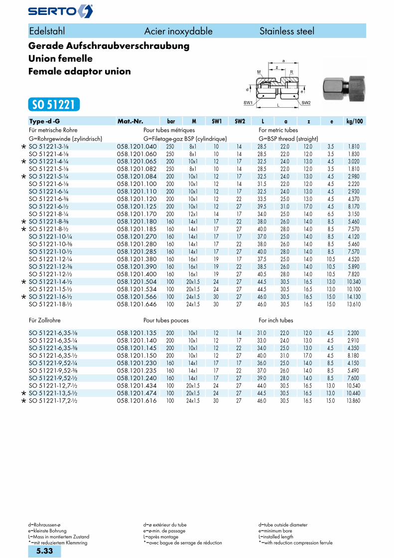
Gerade AufschraubverschraubungUnion femelleFemale adaptor union
SO 51221Type -d -G Mat.-Nr. bar M SW1 SW2 L a z e kg/100Für metrische Rohre Pour tubes métriques For metric tubesG=Rohrgewinde (zylindrisch) G=Filetage-gaz BSP (cylindrique) G=BSP thread (straight)
SO 51221-3-1/8 058.1201.040 250 8x1 10 14 28.5 22.0 12.0 3.5 1.810 SO 51221-4-1/8 058.1201.060 250 8x1 10 14 28.5 22.0 12.0 3.5 1.830
SO 51221-4-1/4 058.1201.065 200 10x1 12 17 32.5 24.0 13.0 4.5 3.020 SO 51221-5-1/8 058.1201.082 250 8x1 10 14 28.5 22.0 12.0 3.5 1.810
SO 51221-5-1/4 058.1201.084 200 10x1 12 17 32.5 24.0 13.0 4.5 2.980 SO 51221-6-1/8 058.1201.100 200 10x1 12 14 31.5 22.0 12.0 4.5 2.220 SO 51221-6-1/4 058.1201.110 200 10x1 12 17 32.5 24.0 13.0 4.5 2.930 SO 51221-6-3/8 058.1201.120 200 10x1 12 22 33.5 25.0 13.0 4.5 4.370 SO 51221-6-1/2 058.1201.125 200 10x1 12 27 39.5 31.0 17.0 4.5 8.170 SO 51221-8-1/4 058.1201.170 200 12x1 14 17 34.0 25.0 14.0 6.5 3.150
SO 51221-8-3/8 058.1201.180 160 14x1 17 22 38.0 26.0 14.0 8.5 5.460 SO 51221-8-1/2 058.1201.185 160 14x1 17 27 40.0 28.0 14.0 8.5 7.570 SO 51221-10-1/4 058.1201.270 160 14x1 17 17 37.0 25.0 14.0 8.5 4.120 SO 51221-10-3/8 058.1201.280 160 14x1 17 22 38.0 26.0 14.0 8.5 5.460 SO 51221-10-1/2 058.1201.285 160 14x1 17 27 40.0 28.0 14.0 8.5 7.570 SO 51221-12-1/4 058.1201.380 160 16x1 19 17 37.5 25.0 14.0 10.5 4.520 SO 51221-12-3/8 058.1201.390 160 16x1 19 22 38.5 26.0 14.0 10.5 5.890 SO 51221-12-1/2 058.1201.400 160 16x1 19 27 40.5 28.0 14.0 10.5 7.820
SO 51221-14-1/2 058.1201.504 100 20x1.5 24 27 44.5 30.5 16.5 13.0 10.340 SO 51221-15-1/2 058.1201.534 100 20x1.5 24 27 44.5 30.5 16.5 13.0 10.100
SO 51221-16-1/2 058.1201.566 100 24x1.5 30 27 46.0 30.5 16.5 15.0 14.130 SO 51221-18-1/2 058.1201.646 100 24x1.5 30 27 46.0 30.5 16.5 15.0 13.610
Für Zollrohre Pour tubes pouces For inch tubes
SO 51221-6,35-1/8 058.1201.135 200 10x1 12 14 31.0 22.0 12.0 4.5 2.200 SO 51221-6,35-1/4 058.1201.140 200 10x1 12 17 33.0 24.0 13.0 4.5 2.910 SO 51221-6,35-3/8 058.1201.145 200 10x1 12 22 34.0 25.0 13.0 4.5 4.350 SO 51221-6,35-1/2 058.1201.150 200 10x1 12 27 40.0 31.0 17.0 4.5 8.180 SO 51221-9,52-1/4 058.1201.230 160 14x1 17 17 36.0 25.0 14.0 8.5 4.150 SO 51221-9,52-3/8 058.1201.235 160 14x1 17 22 37.0 26.0 14.0 8.5 5.490 SO 51221-9,52-1/2 058.1201.240 160 14x1 17 27 39.0 28.0 14.0 8.5 7.600 SO 51221-12,7-1/2 058.1201.434 100 20x1.5 24 27 44.0 30.5 16.5 13.0 10.540
SO 51221-13,5-1/2 058.1201.474 100 20x1.5 24 27 44.5 30.5 16.5 13.0 10.440 SO 51221-17,2-1/2 058.1201.616 100 24x1.5 30 27 46.0 30.5 16.5 15.0 13.860
Edelstahl Acier inoxydable Stainless steel
d=Rohraussen-øe=kleinste BohrungL=Mass in montiertem Zustand*=mit reduziertem Klemmring
d=ø extérieur du tubee=ø-min. de passageL=après montage*=avec bague de serrage de réduction
d=tube outside diametere=minimum boreL=installed length*=with reduction compression ferrule
5.33
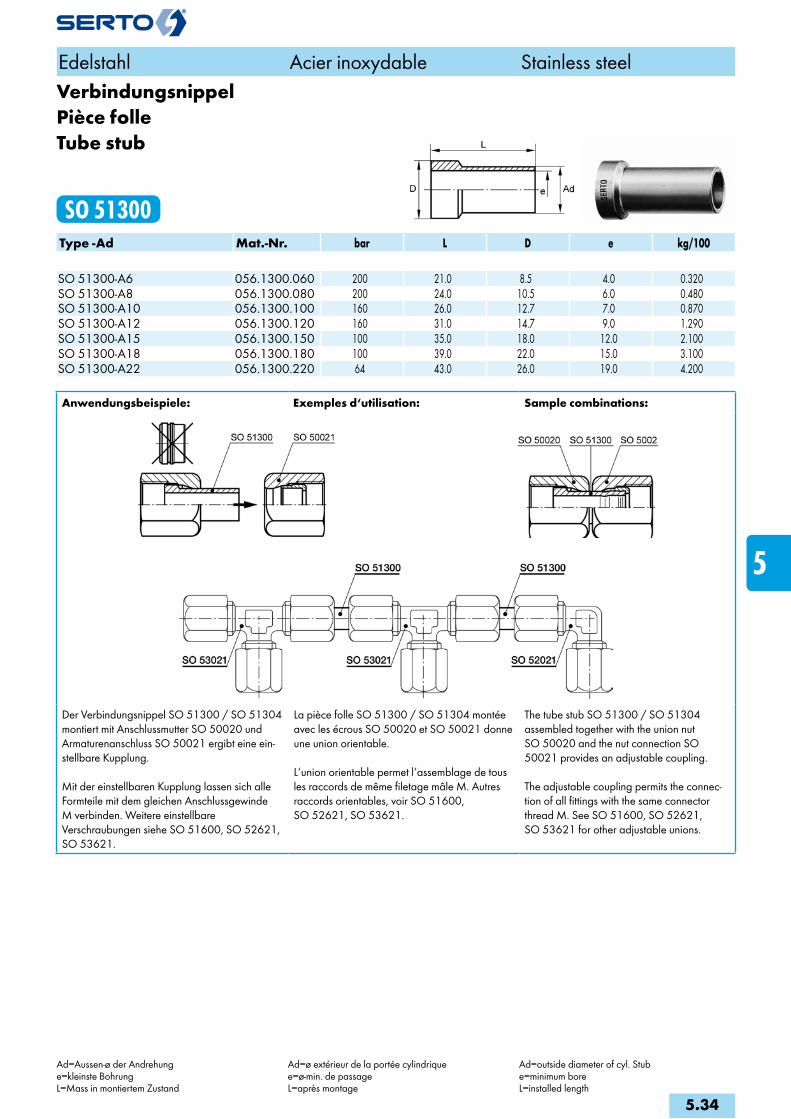
VerbindungsnippelPièce folleTube stub
SO 51300Type -Ad Mat.-Nr. bar L D e kg/100 SO 51300-A6 056.1300.060 200 21.0 8.5 4.0 0.320SO 51300-A8 056.1300.080 200 24.0 10.5 6.0 0.480SO 51300-A10 056.1300.100 160 26.0 12.7 7.0 0.870SO 51300-A12 056.1300.120 160 31.0 14.7 9.0 1.290SO 51300-A15 056.1300.150 100 35.0 18.0 12.0 2.100SO 51300-A18 056.1300.180 100 39.0 22.0 15.0 3.100SO 51300-A22 056.1300.220 64 43.0 26.0 19.0 4.200
Anwendungsbeispiele: Exemples d‘utilisation: Sample combinations:
Der Verbindungsnippel SO 51300 / SO 51304 montiert mit Anschlussmutter SO 50020 und Armaturenanschluss SO 50021 ergibt eine ein-stellbare Kupplung.
Mit der einstellbaren Kupplung lassen sich alle Formteile mit dem gleichen Anschlussgewinde M verbinden. Weitere einstellbare Verschraubungen siehe SO 51600, SO 52621, SO 53621.
La pièce folle SO 51300 / SO 51304 montée avec les écrous SO 50020 et SO 50021 donne une union orientable.
L‘union orientable permet l‘assemblage de tous les raccords de même filetage mâle M. Autres raccords orientables, voir SO 51600, SO 52621, SO 53621.
The tube stub SO 51300 / SO 51304 assembled together with the union nut SO 50020 and the nut connection SO 50021 provides an adjustable coupling.
The adjustable coupling permits the connec-tion of all fittings with the same connector thread M. See SO 51600, SO 52621, SO 53621 for other adjustable unions.
Edelstahl Acier inoxydable Stainless steel
Ad=Aussen-ø der Andrehunge=kleinste BohrungL=Mass in montiertem Zustand
Ad=ø extérieur de la portée cylindriquee=ø-min. de passageL=après montage
Ad=outside diameter of cyl. Stube=minimum boreL=installed length
5.34
i
s
3F
4M
4G
5
5L
6
7
8
9
10
11
12

Verbindungsnippel reduziertPièce folle réduiteReducing port connector
SO 51300 REDType -d -Ad Mat.-Nr. bar L L1 D e kg/100 SO 51300-8-A6 RED 056.1304.140 200 26.0 14.0 10.5 4.0 0.650SO 51300-10-A6 RED 056.1304.175 200 28.0 15.0 12.7 4.0 1.000SO 51300-10-A8 RED 056.1304.190 200 28.0 16.0 12.7 6.0 0.910SO 51300-12-A6 RED 056.1304.215 200 29.0 15.0 14.7 4.0 1.420SO 51300-12-A8 RED 056.1304.225 200 29.0 15.0 14.7 6.0 1.350SO 51300-12-A10 RED 056.1304.240 160 31.0 18.0 14.7 7.0 1.420SO 51300-15-A10 RED 056.1304.410 160 35.0 19.0 18.0 7.0 2.270SO 51300-15-A12 RED 056.1304.420 160 35.0 20.0 18.0 9.0 2.000SO 51300-18(16)-A12 RED 056.1304.480 160 35.0 20.0 22.4 9.0 3.040SO 51300-18(16)-A16 RED 056.1304.620 100 41.0 31.5 22.4 13.0 2.960SO 51300-22-A18 RED 056.1304.755 64 47.0 27.5 22.0 15.0 5.500SO 51300-28-A22 RED 056.1304.900 40 55.0 36.0 28.0 19.0 8.600
VerbindungsnippelPièce folleTube stub
SO 51304Type -Ad Mat.-Nr. bar L D e kg/100radial demontierbar démontable radialement radial dismantling SO 51304-A6 056.1310.060 200 29.0 8.5 4.0 0.440SO 51304-A8 056.1310.080 200 32.0 10.5 6.0 0.670SO 51304-A10 056.1310.100 160 37.0 12.7 7.0 1.170SO 51304-A12 056.1310.120 160 39.0 14.7 9.0 1.720SO 51304-A28 056.1310.280 40 62.0 32.7 25.0 7.700
Anwendungsbeispiele: Exemples d‘utilisation: Sample combinations:
Edelstahl Acier inoxydable Stainless steel
Ad=Aussen-ø der Andrehunge=kleinste BohrungL=Mass in montiertem Zustand
Ad=ø extérieur de la portée cylindriquee=ø-min. de passageL=après montage
Ad=outside diameter of cyl. Stube=minimum boreL=installed length
5.35

Einstellbare KupplungPièce folle montéeTube stub assembly
SO 51325Type -Ad Mat.-Nr. bar M SW l L D e kg/100 SO 51325-A6 058.1320.060 200 10x1 12 20.0 34.0 8.5 4.0 1.900SO 51325-A8 058.1320.080 200 12x1 14 23.0 38.5 10.5 6.0 2.580SO 51325-A10 058.1320.100 160 14x1 17 27.0 42.0 12.7 7.0 4.430SO 51325-A12 058.1320.120 160 16x1 19 30.0 45.5 14.7 9.0 5.710SO 51325-A15 058.1320.150 100 20x1.5 24 36.5 54.5 18.0 12.0 10.520SO 51325-A18 058.1320.180 100 24x1.5 30 40.5 57.0 22.0 15.0 16.980SO 51325-A22 058.1320.220 64 28x1.5 32 44.5 60.0 26.0 19.0 20.520
Einstellbare Kupplungradial demontierbar
Pièce folle montéedémontable radialement
Tube stub assemblyradial dismantling
SO 51326Type -Ad Mat.-Nr. bar M SW l L D e kg/100 radial demontierbar démontable radialement radial dismantlingSO 51326-A6 058.1330.060 200 10x1 12 30.0 44.0 8.5 4.0 2.020SO 51326-A8 058.1330.080 200 12x1 14 33.0 48.5 10.5 6.0 2.770SO 51326-A10 058.1330.100 160 14x1 17 38.0 53.0 12.7 7.0 4.730SO 51326-A12 058.1330.120 160 16x1 19 40.0 54.5 14.7 9.0 6.140
Edelstahl Acier inoxydable Stainless steel
Ad=Aussen-ø der Andrehunge=kleinste BohrungL=Mass in montiertem Zustand
Ad=ø extérieur de la portée cylindriquee=ø-min. de passageL=après montage
Ad=outside diameter of cyl. Stube=minimum boreL=installed length
5.36
i
s
3F
4M
4G
5
5L
6
7
8
9
10
11
12

AnschweissverschraubungUnion avec embout à souderWeld-on union
SO 51429Type -d Mat.-Nr. bar M SW1 SW2 L f x z e kg/100Für metrische Rohre Pour tubes métriques For metric tubes
SO 51429-3 058.1400.030 250 8x1 10 8 24.5 7.5 6.0 19.0 3.5 1.050 SO 51429-4 058.1400.040 250 8x1 10 8 25.5 7.5 6.0 19.0 3.5 1.020 SO 51429-5 058.1400.050 250 8x1 10 8 25.5 7.5 6.0 19.0 3.5 1.000 SO 51429-6 058.1400.060 200 10x1 12 10 29.5 9.8 8.0 21.0 4.5 1.690 SO 51429-8 058.1400.080 200 12x1 14 12 31.0 11.8 8.0 22.0 6.5 2.250 SO 51429-10 058.1400.100 160 14x1 17 14 35.0 13.8 8.0 23.0 8.5 3.380 SO 51429-12 058.1400.120 160 16x1 19 17 36.5 16.0 8.0 24.0 10.5 4.340
SO 51429-14 058.1400.140 100 20x1.5 24 22 43.5 19.0 10.0 29.5 13.0 8.240 SO 51429-15 058.1400.150 100 20x1.5 24 22 43.5 19.0 10.0 29.5 13.0 8.000
SO 51429-16 058.1400.160 100 24x1.5 27 24 47.0 22.0 11.0 31.5 15.0 11.760 SO 51429-18 058.1400.180 100 24x1.5 30 24 47.0 22.0 11.0 31.5 15.0 13.100 SO 51429-22 058.1400.220 64 28x1.5 32 30 52.0 27.0 11.0 32.5 19.0 17.000 SO 51429-28 058.1400.280 40 36x2 41 36 60.5 32.0 14.0 40.0 24.0 22.500
Für Zollrohre Pour tubes pouces For inch tubes
SO 51429-6,35 058.1400.063 200 10x1 12 10 30.0 9.8 8.0 21.0 4.5 1.670 SO 51429-9,52 058.1400.095 160 14x1 17 14 34.0 13.8 8.0 23.0 8.5 3.410 SO 51429-12,7 058.1400.127 100 20x1.5 24 22 43.0 19.0 10.0 29.5 13.0 8.440
SO 51429-13,5 058.1400.135 100 20x1.5 24 22 43.5 19.0 10.0 29.5 13.0 8.340 SO 51429-17,2 058.1400.172 100 24x1.5 27 24 47.0 22.0 11.0 31.5 15.0 13.350 SO 51429-21,3 058.1400.213 64 28x1.5 32 30 51.5 27.0 11.0 32.5 19.0 18.400
Edelstahl Acier inoxydable Stainless steel
d=Rohraussen-øe=kleinste BohrungL=Mass in montiertem Zustand*=mit reduziertem Klemmring
d=ø extérieur du tubee=ø-min. de passageL=après montage*=with reduction compresion ferrule
d=tube outside diametere=minimum boreL=finstalled length*=with reduction compression ferrule
5.37

Gerade SchottverschraubungDurchführungslänge max. 5 mm
Union double pour passage de cloisonpour cloison max. 5 mm
Panel mount unionmax. panel thickness 5 mm
SO 51521Type -d Mat.-Nr. bar M SW1 SW2 L1 L2 B z z1 e kg/100Für metrische Rohre Pour tubes métriques For metric tubes SO 51521-2 058.1500.020 250 6x0.75 8 10 14.0 19.0 6.5 10.5 15.5 2.2 1.190SO 51521-3 058.1500.030 250 6x0.75 8 10 16.0 21.0 6.5 10.5 15.5 2.2 1.270SO 51521-4 058.1500.040 250 8x1 10 12 20.0 24.0 8.5 13.5 17.5 3.5 2.240SO 51521-5 058.1500.050 250 8x1 10 12 20.0 24.0 8.5 13.5 17.5 3.5 2.200SO 51521-6 058.1500.060 200 10x1 12 14 22.0 27.5 10.5 13.5 19.0 4.5 3.610SO 51521-8 058.1500.080 200 12x1 14 17 24.0 30.0 12.5 15.0 21.0 6.5 5.210SO 51521-10 058.1500.100 160 14x1 17 19 27.5 33.0 14.5 15.5 21.0 8.5 7.330SO 51521-12 058.1500.120 160 16x1 19 22 28.5 33.5 16.5 16.0 21.0 10.5 9.400
Für Zollrohre Pour tubes pouces For inch tubes SO 51521-6,35 058.1500.063 200 10x1 12 14 22.5 28.0 10.5 13.5 19.0 4.5 3.570SO 51521-9,52 058.1500.095 160 14x1 17 19 26.5 32.0 14.5 15.5 21.0 8.5 7.390
Gerade SchottverschraubungreduziertDurchführungslänge max. 5 mm
Union double réduite pour passage de cloisonpour cloison max. 5 mm
Panel mount reduction unionmax. panel thickness 5 mm
SO 51521 REDType -d -d2 Mat.-Nr. bar M SW1 SW2 L1 L2 z z1 e kg/100Für metrische Rohre Pour tubes métriques For metric tubes
SO 51521-3-2 058.1504.020 250 6x0.75 8 10 16.0 19.0 10.5 15.5 2.2 1.190 SO 51521-5-3 058.1504.060 250 8x1 10 12 20.0 23.0 13.5 17.5 3.5 2.290 SO 51521-5-4 058.1504.080 200 10x1 12 14 22.0 25.5 13.5 19.0 4.5 2.300 SO 51521-6-4 058.1504.110 200 10x1 12 14 22.0 25.5 13.5 19.0 4.5 3.720 SO 51521-6-5 058.1504.117 200 10x1 12 14 22.0 25.5 13.5 19.0 4.5 3.700 SO 51521-8-6 058.1504.140 200 12x1 14 17 24.0 29.5 15.0 21.0 6.5 5.370 SO 51521-10-4 058.1504.167 160 14x1/10x1 17 14 26.0 25.5 14.5 19.0 4.5 5.800 SO 51521-10-5 058.1504.170 160 14x1/10x1 17 14 26.0 25.5 14.5 19.0 4.5 5.750 SO 51521-10-6 058.1504.175 160 14x1/10x1 17 14 26.0 27.5 14.5 19.0 4.5 5.700
SO 51521-10-8 058.1504.190 160 14x1 17 19 27.5 30.0 15.5 21.0 8.5 7.520 SO 51521-12-10 058.1504.240 160 16x1 19 22 28.5 33.0 16.0 21.0 10.5 9.600
Edelstahl Acier inoxydable Stainless steel
d=Rohraussen-øe=kleinste BohrungL=Mass in montiertem Zustand*=mit reduziertem Klemmring
d=ø extérieur du tubee=ø-min. de passageL=après montage*=avec bague de serrage de réduction
d=tube outside diametere=minimum boreL=installed length*=with reduciton compression ferrule
5.38
i
s
3F
4M
4G
5
5L
6
7
8
9
10
11
12

Gerade SchottverschraubungDurchführungslänge max. 16mm
Union double pour passage de cloisonpour cloison max. 16mm
Panel mount unionmax. panel thickness 16mm
SO 51524Type -d Mat.-Nr. bar M SW1 SW2 L1 L2 B z z1 e kg/100Für metrische Rohre Pour tubes métriques For metric tubes
SO 51524-14 058.1540.140 100 20x1.5 24 27 33.5 47.5 20.5 19.5 33.5 13.0 18.010 SO 51524-15 058.1540.150 100 20x1.5 24 27 33.5 47.5 20.5 19.5 33.5 13.0 17.680
SO 51524-16 058.1540.160 100 24x1.5 30 30 35.0 50.0 24.5 19.5 34.5 15.0 28.430 SO 51524-18 058.1540.180 100 24x1.5 30 30 35.0 50.0 24.5 19.5 34.5 15.0 29.080 SO 51524-22 058.1540.220 64 28x1.5 32 36 40.0 55.0 28.5 20.5 35.5 19.0 33.490 SO 51524-28 058.1540.280 40 36x2 41 41 42.5 58.5 36.5 26.0 42.0 25.0 72.000
Für Zollrohre Pour tubes pouces For inch tubes
SO 51524-12,7 058.1540.127 100 20x1.5 24 27 33.0 47.0 20.5 19.5 33.5 13.0 18.410 SO 51524-13,5 058.1540.135 100 20x1.5 24 27 33.5 47.5 20.5 19.5 33.5 13.0 18.210 SO 51524-17,2 058.1540.172 100 24x1.5 30 30 35.0 50.0 24.5 19.5 34.5 15.0 27.830 SO 51524-21,3 058.1540.213 64 28x1.5 32 36 39.5 54.5 28.5 20.5 35.5 19.0 36.290
Gerade SchottverschraubungreduziertDurchführungslänge max. 16mm
Union double réduite pour passage de cloisonpour cloison max. 16mm
Panel mount reduction unionmax. panel thickness 16mm
SO 51524 REDType -d -d2 Mat.-Nr. bar M SW1 SW2 L1 L2 B z z1 e kg/100Für metrische Rohre Pour tubes métriques For metric tubes
SO 51524-15-12 058.1544.420 100 20x1.5 24 27 33.5 47.5 20.5 19.5 33.5 13.0 18.090 SO 51524-15-14 058.1544.440 100 20x1.5 24 27 33.5 47.5 20.5 19.5 33.5 13.0 17.770 SO 51524-18-15 058.1544.610 100 24x1.5 30 30 35.0 50.0 24.5 19.5 34.5 15.0 28.080 SO 51524-18-16 058.1544.620 100 24x1.5 30 30 35.0 50.0 24.5 19.5 34.5 15.0 27.880
Für Zollrohre Pour tubes pouces For inch tubes
SO 51524-15-12,7 058.1544.427 100 20x1.5 24 27 33.5 47.5 20.5 19.5 33.5 13.0 17.970 SO 51524-15-13,5 058.1544.435 100 20x1.5 24 27 33.5 47.5 20.5 19.5 33.5 13.0 17.870 SO 51524-18-17,2 058.1544.632 100 24x1.5 30 30 35.0 50.0 24.5 19.5 34.5 15.0 27.580
Edelstahl Acier inoxydable Stainless steel
d=Rohraussen-øe=kleinste BohrungL=Mass in montiertem Zustand*=mit reduziertem Klemmring
d=ø extérieur du tubee=ø-min. de passageL=après montage*=with reduction compresion ferrule
d=tube outside diametere=minimum boreL=finstalled length*=with reduction compression ferrule
5.39
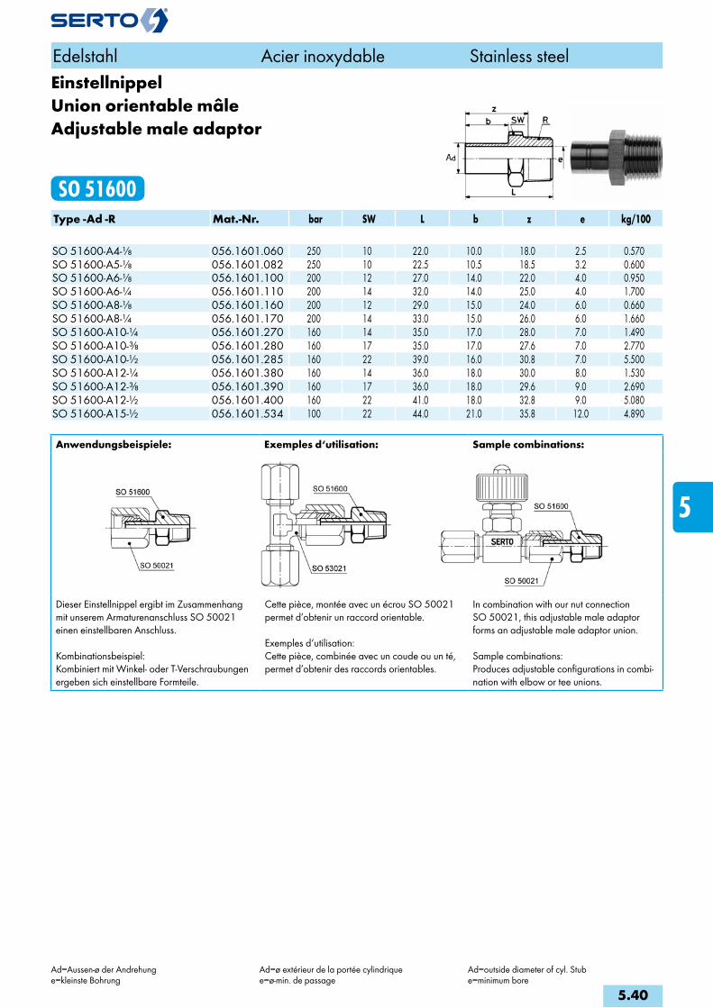
EinstellnippelUnion orientable mâleAdjustable male adaptor
SO 51600Type -Ad -R Mat.-Nr. bar SW L b z e kg/100 SO 51600-A4-1/8 056.1601.060 250 10 22.0 10.0 18.0 2.5 0.570SO 51600-A5-1/8 056.1601.082 250 10 22.5 10.5 18.5 3.2 0.600SO 51600-A6-1/8 056.1601.100 200 12 27.0 14.0 22.0 4.0 0.950SO 51600-A6-1/4 056.1601.110 200 14 32.0 14.0 25.0 4.0 1.700SO 51600-A8-1/8 056.1601.160 200 12 29.0 15.0 24.0 6.0 0.660SO 51600-A8-1/4 056.1601.170 200 14 33.0 15.0 26.0 6.0 1.660SO 51600-A10-1/4 056.1601.270 160 14 35.0 17.0 28.0 7.0 1.490SO 51600-A10-3/8 056.1601.280 160 17 35.0 17.0 27.6 7.0 2.770SO 51600-A10-1/2 056.1601.285 160 22 39.0 16.0 30.8 7.0 5.500SO 51600-A12-1/4 056.1601.380 160 14 36.0 18.0 30.0 8.0 1.530SO 51600-A12-3/8 056.1601.390 160 17 36.0 18.0 29.6 9.0 2.690SO 51600-A12-1/2 056.1601.400 160 22 41.0 18.0 32.8 9.0 5.080SO 51600-A15-1/2 056.1601.534 100 22 44.0 21.0 35.8 12.0 4.890
Anwendungsbeispiele: Exemples d‘utilisation: Sample combinations:
Dieser Einstellnippel ergibt im Zusammenhang mit unserem Armaturenanschluss SO 50021 einen einstellbaren Anschluss.
Kombinationsbeispiel:Kombiniert mit Winkel- oder T-Verschraubungen ergeben sich einstellbare Formteile.
Cette pièce, montée avec un écrou SO 50021 permet d’obtenir un raccord orientable.
Exemples d‘utilisation:Cette pièce, combinée avec un coude ou un té, permet d’obtenir des raccords orientables.
In combination with our nut connection SO 50021, this adjustable male adaptor forms an adjustable male adaptor union.
Sample combinations:Produces adjustable configurations in combi-nation with elbow or tee unions.
Edelstahl Acier inoxydable Stainless steel
Ad=Aussen-ø der Andrehunge=kleinste Bohrung
Ad=ø extérieur de la portée cylindriquee=ø-min. de passage
Ad=outside diameter of cyl. Stube=minimum bore
5.40
i
s
3F
4M
4G
5
5L
6
7
8
9
10
11
12
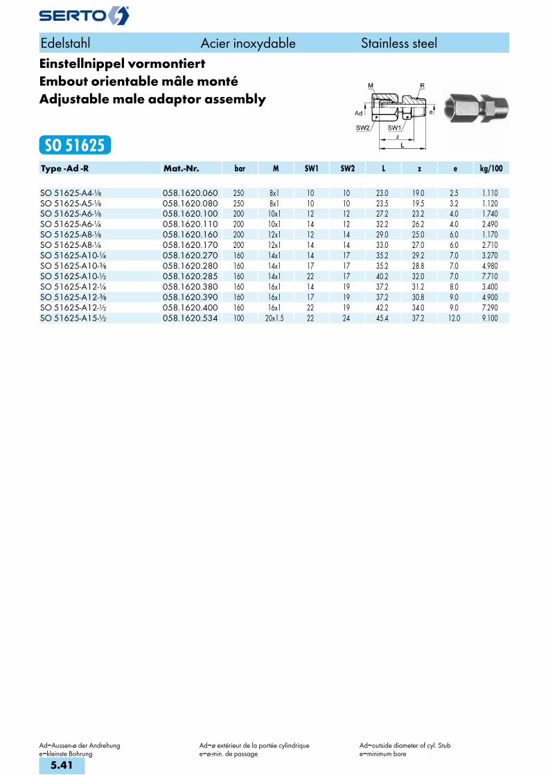
Edelstahl Acier inoxydable Stainless steel
Ad=Aussen-ø der Andrehunge=kleinste Bohrung
Ad=ø extérieur de la portée cylindriquee=ø-min. de passage
Ad=outside diameter of cyl. Stube=minimum bore
Einstellnippel vormontiertEmbout orientable mâle montéAdjustable male adaptor assembly
SO 51625Type -Ad -R Mat.-Nr. bar M SW1 SW2 L z e kg/100 SO 51625-A4-1/8 058.1620.060 250 8x1 10 10 23.0 19.0 2.5 1.110SO 51625-A5-1/8 058.1620.080 250 8x1 10 10 23.5 19.5 3.2 1.120SO 51625-A6-1/8 058.1620.100 200 10x1 12 12 27.2 23.2 4.0 1.740SO 51625-A6-1/4 058.1620.110 200 10x1 14 12 32.2 26.2 4.0 2.490SO 51625-A8-1/8 058.1620.160 200 12x1 12 14 29.0 25.0 6.0 1.170SO 51625-A8-1/4 058.1620.170 200 12x1 14 14 33.0 27.0 6.0 2.710SO 51625-A10-1/4 058.1620.270 160 14x1 14 17 35.2 29.2 7.0 3.270SO 51625-A10-3/8 058.1620.280 160 14x1 17 17 35.2 28.8 7.0 4.980SO 51625-A10-1/2 058.1620.285 160 14x1 22 17 40.2 32.0 7.0 7.710SO 51625-A12-1/4 058.1620.380 160 16x1 14 19 37.2 31.2 8.0 3.400SO 51625-A12-3/8 058.1620.390 160 16x1 17 19 37.2 30.8 9.0 4.900SO 51625-A12-1/2 058.1620.400 160 16x1 22 19 42.2 34.0 9.0 7.290SO 51625-A15-1/2 058.1620.534 100 20x1.5 22 24 45.4 37.2 12.0 9.100
5.41
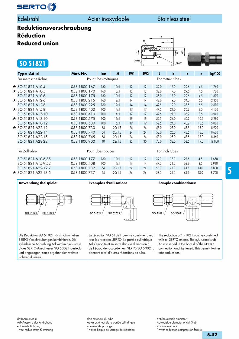
ReduktionsverschraubungRéductionReduced union
SO 51821Type -Ad -d Mat.-Nr. bar M SW1 SW2 L b z e kg/100Für metrische Rohre Pour tubes métriques For metric tubes
SO 51821-A10-4 058.1800.167 160 10x1 12 12 39.0 17.0 29.6 4.5 1.760 SO 51821-A10-5 058.1800.170 160 10x1 12 12 38.0 17.0 29.6 4.5 1.720 SO 51821-A10-6 058.1800.175 160 10x1 12 12 38.0 17.0 29.6 4.5 1.670
SO 51821-A12-6 058.1800.215 160 12x1 14 14 42.0 19.0 34.0 6.5 2.350 SO 51821-A12-8 058.1800.225 160 12x1 14 14 42.5 19.0 33.5 6.5 2.610
SO 51821-A15-8 058.1800.400 100 14x1 17 17 47.5 21.0 36.2 8.5 4.130 SO 51821-A15-10 058.1800.410 100 14x1 17 17 47.5 21.0 36.2 8.5 3.940
SO 51821-A18-10 058.1800.575 100 16x1 19 19 52.5 24.0 40.2 10.5 5.280 SO 51821-A18-12 058.1800.580 100 16x1 19 19 52.5 24.0 40.2 10.5 5.080
SO 51821-A22-12 058.1800.730 64 20x1.5 24 24 58.0 25.0 43.5 13.0 8.920 SO 51821-A22-14 058.1800.740 64 20x1.5 24 24 58.0 25.0 43.5 13.0 8.600 SO 51821-A22-15 058.1800.745 64 20x1.5 24 24 58.0 25.0 43.5 13.0 8.360 SO 51821-A28-22 058.1800.900 40 28x1.5 32 30 70.0 32.0 53.5 19.0 19.000
Für Zollrohre Pour tubes pouces For inch tubes
SO 51821-A10-6,35 058.1800.177 160 10x1 12 12 39.0 17.0 29.6 4.5 1.650 SO 51821-A15-9,52 058.1800.408 100 14x1 17 17 47.0 21.0 36.2 8.5 3.910 SO 51821-A22-12,7 058.1800.732 64 20x1.5 24 24 58.0 25.0 43.5 13.0 8.800
SO 51821-A22-13,5 058.1800.737 64 20x1.5 24 24 58.0 25.0 43.5 13.0 8.700
Anwendungsbeispiele: Exemples d‘utilisation: Sample combinations:
Die Reduktion SO 51821 lässt sich mit allen SERTO-Verschraubungen kombinieren. Die zylindrische Andrehung Ad wird in die Grösse d des SERTO-Anschlusses SO 50021 gesteckt und angezogen, somit ergeben sich weitere Rohrreduktionen.
La réduction SO 51821 peut se combiner avec tous les raccords SERTO. La portée cylindrique Ad s’emboîte et se serre dans la dimension d de l’écrou de raccordement SERTO SO 50021, donnant ainsi d’autres réductions de tube.
The reduction SO 51821 can be combined with all SERTO unions. The cyl. turned stub Ad is inserted in the bore d of the SERTO connection and tightened. This permits further tube reductions.
Edelstahl Acier inoxydable Stainless steel
d=Rohraussen-øAd=Aussen-ø der Andrehunge=kleinste Bohrung*=mit reduziertem Klemmring
d=ø extérieur du tubeAd=ø extérieur de la portée cylindriquee=ø-min. de passage*=avec bague de serrage de réduction
d=tube outside diameterAd=outside diameter of cyl. Stube=minimum bore*=with reduction compression ferrule
5.42
i
s
3F
4M
4G
5
5L
6
7
8
9
10
11
12
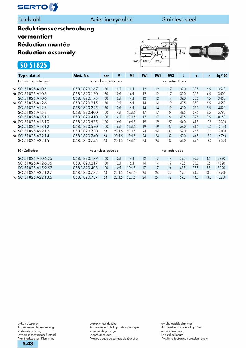
Reduktionsverschraubung vormontiertRéduction montéeReduction assembly
SO 51825Type -Ad -d Mat.-Nr. bar M M1 SW1 SW2 SW3 L z e kg/100Für metrische Rohre Pour tubes métriques For metric tubes
SO 51825-A10-4 058.1820.167 160 10x1 14x1 12 12 17 39.0 30.5 4.5 3.540 SO 51825-A10-5 058.1820.170 160 10x1 14x1 12 12 17 39.0 30.5 4.5 3.500 SO 51825-A10-6 058.1820.175 160 10x1 14x1 12 12 17 39.0 30.5 4.5 3.450
SO 51825-A12-6 058.1820.215 160 12x1 16x1 14 14 19 43.5 35.0 6.5 4.550 SO 51825-A12-8 058.1820.225 160 12x1 16x1 14 14 19 43.0 35.0 6.5 4.820 SO 51825-A15-8 058.1820.400 100 14x1 20x1.5 17 17 24 48.5 37.5 8.5 5.790 SO 51825-A15-10 058.1820.410 100 14x1 20x1.5 17 17 24 48.5 37.5 8.5 8.150
SO 51825-A18-10 058.1820.575 100 16x1 24x1.5 19 19 27 54.0 41.5 10.5 10.300 SO 51825-A18-12 058.1820.580 100 16x1 24x1.5 19 19 27 54.0 41.5 10.5 10.130
SO 51825-A22-12 058.1820.730 64 20x1.5 28x1.5 24 24 32 59.0 44.5 13.0 17.080 SO 51825-A22-14 058.1820.740 64 20x1.5 28x1.5 24 24 32 59.0 44.5 13.0 16.760 SO 51825-A22-15 058.1820.745 64 20x1.5 28x1.5 24 24 32 59.0 44.5 13.0 16.520
Für Zollrohre Pour tubes pouces For inch tubes
SO 51825-A10-6.35 058.1820.177 160 10x1 14x1 12 12 17 39.0 30.5 4.5 3.430 SO 51825-A12-6.35 058.1820.217 160 12x1 16x1 14 14 19 43.5 35.0 6.5 4.820 SO 51825-A15-9.52 058.1820.408 100 14x1 20x1.5 17 17 24 48.5 37.5 8.5 8.120 SO 51825-A22-12.7 058.1820.732 64 20x1.5 28x1.5 24 24 32 59.0 44.5 13.0 13.900
SO 51825-A22-13.5 058.1820.737 64 20x1.5 28x1.5 24 24 32 59.0 44.5 13.0 13.250
Edelstahl Acier inoxydable Stainless steel
d=Rohraussen-øAd=Aussen-ø der Andrehunge=kleinste BohrungL=Mass in montiertem Zustand*=mit reduziertem Klemmring
d=ø extérieur du tubeAd=ø extérieur de la portée cylindriquee=ø-min. de passageL=après montage*=avec bague de serrage de réduction
d=tube outside diameterAd=outside diameter of cyl. Stube=minimum boreL=installed length*=with reduction compression ferrule
5.43

WinkelverschraubungCoudeElbow union
SO 52021Type -d Mat.-Nr. bar M SW1 SW2 L z e kg/100Für metrische Rohre Pour tubes métriques For metric tubes
SO 52021-2 058.2000.020 250 8x1 9 10 23.0 16.0 3.5 1.980 SO 52021-3 058.2000.030 250 8x1 9 10 23.5 16.0 3.5 1.970 SO 52021-4 058.2000.040 250 8x1 9 10 21.5 16.0 3.5 1.950 SO 52021-5 058.2000.050 250 8x1 9 10 22.0 16.0 3.5 1.900 SO 52021-6 058.2000.060 200 10x1 9 12 23.5 16.0 4.5 2.730 SO 52021-8 058.2000.080 200 12x1 10 14 27.0 18.0 6.5 3.740 SO 52021-10 058.2000.100 160 14x1 12 17 31.5 20.5 8.5 5.900 SO 52021-12 058.2000.120 160 16x1 14 19 33.5 21.5 9.5 7.530
SO 52021-14 058.2000.140 100 20x1.5 17 24 38.0 24.5 13.0 13.150 SO 52021-15 058.2000.150 100 20x1.5 17 24 38.0 24.5 13.0 12.910
SO 52021-16 058.2000.160 100 24x1.5 22 30 42.0 26.5 15.0 21.980 SO 52021-18 058.2000.180 100 24x1.5 22 30 42.0 26.5 15.0 21.430 SO 52021-22 058.2000.220 64 28x1.5 27 32 49.5 30.5 19.0 27.180 SO 52021-28 058.2000.280 40 36x2 36 41 59.5 43.0 25.0 76.000
Für Zollrohre Pour tubes pouces For inch tubes
SO 52021-6,35 058.2000.063 200 10x1 9 12 23.5 16.0 4.5 2.690 SO 52021-9,52 058.2000.095 160 14x1 12 17 31.5 20.5 8.5 5.960 SO 52021-12,7 058.2000.127 100 20x1.5 17 24 38.0 24.5 13.0 13.790
SO 52021-13,5 058.2000.135 100 20x1.5 17 24 38.0 24.5 13.0 13.250 SO 52021-17,2 058.2000.172 100 24x1.5 22 30 42.0 26.5 15.0 21.680 SO 52021-21,3 058.2000.213 64 28x1.5 27 32 49.5 30.5 19.0 28.580
Edelstahl Acier inoxydable Stainless steel
d=Rohraussen-øe= kleinste BohrungL= Mass in montiertem Zustand*=mit reduziertem Klemmring
d=ø extérieur du tubee= ø-min. de passageL=après montage*=avec bague de serrage de réduction
d=tube outside diametere=minimum boreL=installed length*=with reduction compression ferrule
5.44
i
s
3F
4M
4G
5
5L
6
7
8
9
10
11
12

Winkelverschraubung reduziertCoude réduitElbow reduction union
SO 52021 REDType -d -d2 Mat.-Nr. bar M SW1 SW2 L z e kg/100Für metrische Rohre Pour tubes métriques For metric tubes
SO 52021-5-3 058.2004.060 250 8x1 9 10 22.5 16.0 3.5 1.830 SO 52021-6-4 058.2004.110 200 10x1 9 12 24.5 16.0 4.5 2.820 SO 52021-6-5 058.2004.117 200 10x1 9 12 24.5 16.0 4.5 2.780 SO 52021-8-6 058.2004.140 200 12x1 10 14 27.0 18.0 6.5 3.900 SO 52021-10-8 058.2004.190 160 14x1 12 17 32.5 20.5 8.5 6.090 SO 52021-12-10 058.2004.240 160 16x1 14 19 34.0 21.5 9.5 7.760 SO 52021-15-12 058.2004.420 100 20x1.5 17 24 38.5 24.5 13.0 13.470 SO 52021-15-14 058.2004.440 100 20x1.5 17 24 38.5 24.5 13.0 13.150 SO 52021-18-15 058.2004.610 100 24x1.5 22 30 42.5 26.5 15.0 22.180 SO 52021-18-16 058.2004.620 100 24x1.5 22 30 42.5 26.5 15.0 21.980 SO 52021-22-18 058.2004.755 64 28x1.5 27 32 50.0 30.5 19.0 29.780
Für Zollrohre Pour tubes pouces For inch tubes
SO 52021-6-6,35 058.2004.119 200 10x1 9 12 24.5 16.0 4.5 2.720 SO 52021-10-9,52 058.2004.197 160 14x1 12 17 32.5 20.5 8.5 5.930 SO 52021-15-12,7 058.2004.427 100 20x1.5 17 24 38.5 24.5 13.0 13.350
SO 52021-15-13,5 058.2004.435 100 20x1.5 17 24 38.5 24.5 13.0 13.250 SO 52021-18-17,2 058.2004.632 100 24x1.5 22 30 42.5 26.5 15.0 21.680 SO 52021-22-21,3 058.2004.785 64 28x1.5 27 32 50.0 30.5 19.0 28.580
Weitere Reduktionen siehe SO 51821 Autres réductions voir SO 51821 Alternative reductions see SO 51821
Edelstahl Acier inoxydable Stainless steel
d=Rohraussen-øe= kleinste BohrungL= Mass in montiertem Zustand*=mit reduziertem Klemmring
d=ø extérieur du tubee= ø-min. de passageL=après montage*=avec bague de serrage de réduction
d=tube outside diametere=minimum boreL=installed length*=with reduction compression ferrule
5.45
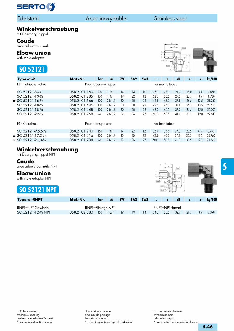
Winkelverschraubungmit Übergangsnippel
Coudeavec adaptateur mâle
Elbow unionwith male adaptor
SO 52121Type -d -R Mat.-Nr. bar M SW1 SW2 SW3 L b zR z e kg/100Für metrische Rohre Pour tubes métriques For metric tubes
SO 52121-8-1/8 058.2101.160 200 12x1 14 14 10 27.0 28.0 24.0 18.0 6.5 3.670 SO 52121-10-1/2 058.2101.285 160 14x1 17 22 12 32.5 35.5 27.3 20.5 8.5 8.730
SO 52121-16-1/2 058.2101.566 100 24x1.5 30 30 22 42.5 46.0 37.8 26.5 13.5 21.060 SO 52121-18-1/2 058.2101.646 100 24x1.5 30 30 22 42.5 46.0 37.8 26.5 13.5 20.510 SO 52121-18-3/4 058.2101.648 100 24x1.5 30 30 22 42.5 46.5 37.0 26.5 15.0 26.300 SO 52121-22-3/4 058.2101.768 64 28x1.5 32 36 27 50.0 50.5 41.0 30.5 19.0 29.640
Für Zollrohre Pour tubes pouces For inch tubes
SO 52121-9,52-1/2 058.2101.240 160 14x1 17 22 12 32.5 35.5 27.3 20.5 8.5 8.760 SO 52121-17,2-1/2 058.2101.616 100 24x1.5 30 30 22 42.5 46.0 37.8 26.5 13.5 20.760 SO 52121-21,3-3/4 058.2101.738 64 28x1.5 32 36 27 50.0 50.5 41.0 30.5 19.0 29.640
Winkelverschraubungmit Übergangsnippel NPT
Coudeavec adaptateur mâle NPT
Elbow unionwith male adaptor NPT
SO 52121 NPTType -d -RNPT Mat.-Nr. bar M SW1 SW2 SW3 L b zR z e kg/100 RNPT=NPT Gewinde RNPT=Filetage NPT RNPT=NPT threadSO 52121-12-1/4 NPT 058.2102.380 160 16x1 19 19 14 34.0 38.5 32.7 21.5 8.5 7.390
Edelstahl Acier inoxydable Stainless steel
d=Rohraussen-øe=kleinste BohrungL=Mass in montiertem Zustand*=mit reduziertem Klemmring
d=ø extérieur du tubee=ø-min. de passageL=après montage*=avec bague de serrage de réduction
d=tube outside diametere=minimum boreL=installed length*=with reduction compression ferrule
5.46
i
s
3F
4M
4G
5
5L
6
7
8
9
10
11
12

Winkelverschraubung METRmit Übergangsnippel
Coude METRavec adaptateur mâle
Elbow union METRwith male adaptor
SO 52121 METRType -d -Mz Mat.-Nr. bar M SW1 SW2 SW3 L b zR z e kg/100 Mz=metrisches Gewinde (zylindrisch) Mz=Filetage métrique (cylindrique) Mz=Metric thread (straight)
SO 52121-3-M6X0,75 058.2143.055 250 8x1 10 10 9 22.5 24.0 20.0 16.0 2.5 1.750 SO 52121-3-M8X1 058.2143.060 250 8x1 10 10 9 22.5 26.0 23.0 16.0 3.5 1.860 SO 52121-4-M6X0,75 058.2143.085 250 8x1 10 10 9 22.5 24.0 20.0 16.0 2.5 1.700 SO 52121-4-M8X1 058.2143.090 250 8x1 10 10 9 22.5 26.0 23.0 16.0 3.5 1.810 SO 52121-5-M6X0,75 058.2143.115 250 8x1 10 10 9 22.5 24.0 20.0 16.0 2.5 1.680 SO 52121-5-M8X1 058.2143.125 250 8x1 10 10 9 22.5 26.0 23.0 16.0 3.5 1.790
Der Übergangsnippel SO 50040 kann an jedes SERTO-Formteil anstelle des Armaturenanschlusses SO 50021 mit dem passenden Gewinde aufgeschraubt werden. In Verbindung mit den Formteilen ist der Übergangsnippel SO 50040 nur lose aufgeschraubt und muss bei der Montage angezogen werden. Dichtungsprinzip siehe SO 50040. Die Bestellnummer für eine Winkelverschraubung mit aufgeschraubtem Übergangsnippel SO 50040 lautet SO 52121.
L’adaptateur mâle SO 50040 peut être monté sur toutes les pièces de forme SERTO avec le filetage correspondant, au lieu et place de l’écrou SO 50021. En cas de livraison avec des pièces SERTO, l’adaptateur SO 50040 n’est que très légèrement vissé et doit être resserré lors du mon-tage. Principe de l’étanchéité et filetage voir SO 50040. No de commande pour un coude avec adaptateur SO 50040 = SO 52121. Exemples d’utilisation voir page Coude mâle SO 52421.
The male adaptor SO 50040 can be fitted to any SERTO forged body in place of the nut connection SO 50021 with the relevant straight thread. Combinations are supplied with the male adaptor SO 50040 screwed only loosely on the body. It must be tightened for installation. See SO 50040 for sealing principle. The order No. for an elbow union complete with male adaptor SO 50040 is SO 52121.
Edelstahl Acier inoxydable Stainless steel
d=Rohraussen-øe=kleinste BohrungL=Mass in montiertem Zustand*=mit reduziertem Klemmring
d=ø extérieur du tubee=ø-min. de passageL=après montage*=avec bague de serrage de réduction
d=tube outside diametere=minimum boreL=installed length*=with reduction compression ferrule
5.47

Winkelverschraubungmit Übergangsmuffe
Coudeavec adaptateur femelle
Elbow unionwith female adaptor
SO 52221Type -d -G Mat.-Nr. bar M SW1 SW2 SW3 L b zR z e kg/100Für metrische Rohre Pour tubes métriques For metric tubesG=Rohrgewinde (zylindrisch) G=Filetage-gaz BSP (cylindrique) G=BSP thread (straight)
SO 52221-4-1/8 058.2201.060 200 10x1 12 14 9 24.5 29.0 19.0 16.0 4.5 3.500 SO 52221-5-1/8 058.2201.082 200 10x1 12 14 9 24.5 29.0 19.0 16.0 4.5 3.470 SO 52221-6-1/8 058.2201.100 200 10x1 12 14 9 24.5 29.0 19.0 16.0 4.5 3.420 SO 52221-6-1/4 058.2201.110 200 10x1 12 17 9 24.5 30.0 19.0 16.0 4.5 4.680 SO 52221-8-1/8 058.2201.160 200 12x1 14 17 10 27.0 31.0 21.0 18.0 6.5 5.250 SO 52221-8-1/4 058.2201.170 200 12x1 14 17 10 27.0 33.0 22.0 18.0 6.5 4.840
SO 52221-8-3/8 058.2201.180 160 14x1 17 22 12 32.5 35.5 23.5 20.5 8.5 8.360 SO 52221-10-1/4 058.2201.270 160 14x1 17 17 12 32.5 34.5 23.5 20.5 8.5 5.990 SO 52221-10-3/8 058.2201.280 160 14x1 17 22 12 32.5 35.5 23.5 20.5 8.5 8.170 SO 52221-12-3/8 058.2201.390 160 16x1 19 22 14 34.0 36.5 24.5 21.5 9.5 9.040
SO 52221-12-1/2 058.2201.400 100 20x1.5 24 27 17 38.5 42.0 28.0 24.5 13.0 16.390 SO 52221-14-1/2 058.2201.504 100 20x1.5 24 27 17 38.5 42.0 28.0 24.5 13.0 15.540 SO 52221-15-1/2 058.2201.534 100 20x1.5 24 27 17 38.5 42.0 28.0 24.5 13.0 15.300
SO 52221-16-1/2 058.2201.566 100 24x1.5 30 30 22 42.5 45.0 31.0 26.5 15.0 23.850 SO 52221-18-1/2 058.2201.646 100 24x1.5 30 30 22 42.5 45.0 31.0 26.5 15.0 23.300
Für Zollrohre Pour tubes pouces For inch tubes
SO 52221-6,35-1/8 058.2201.135 200 10x1 12 14 9 24.5 29.0 19.0 16.0 4.5 3.400 SO 52221-9,52-1/4 058.2201.230 160 14x1 17 17 12 32.5 35.5 23.5 20.5 8.5 6.020 SO 52221-9,52-3/8 058.2201.235 160 14x1 17 22 12 32.5 35.5 23.5 20.5 8.5 8.200 SO 52221-12,7-1/2 058.2201.434 100 20x1.5 24 27 17 38.5 42.0 28.0 24.5 13.0 16.270
SO 52221-13,5-1/2 058.2201.474 100 20x1.5 24 27 17 38.5 42.0 28.0 24.5 13.0 15.640 SO 52221-17,2-1/2 058.2201.616 100 24x1.5 30 30 22 42.5 45.0 31.0 26.5 15.0 23.460
Die Übergangsmuffe SO 50030 kann an jedes SERTO-Formteil anstelle des Armaturenanschlusses SO 50021 mit dem passenden Gewinde aufgeschraubt werden. In Verbindung mit den Formteilen ist die Übergangsmuffe SO 50030 nur lose aufgeschraubt und muss bei der Montage angezogen werden. Dichtungsprinzip siehe SO 50030. Die Bestellnummer für die Winkelverschraubung mit aufgeschraubter Übergangsmuffe SO 50030 lautet SO 52221.
L’adaptateur femelle SO 50030 peut être monté sur toutes les pièces de forme SERTO avec le filetage correspondant, au lieu et place de l’écrou SO 50021. En cas de livraison avec des pièces SERTO, l’adaptateur SO 50030 n’est que très légèrement vissé et doit être resserré lors du mon-tage. Principe de l’étanchéité et filetage voir SO 50030. No de commande pour un coude avec adaptateur SO 50030 = SO 52221.
The female adaptor SO 50030 can be fitted to any SERTO forged body in place of the nut connection SO 50021 with the relevant straight thread. Combinations are supplied with the female adaptor SO 50030 screwed only loose-ly on the body. It must be tightened for installa-tion. See SO 50030 for sealing principle. The order No. for the elbow union complete with female adaptor SO 50030 is SO 52221.
Edelstahl Acier inoxydable Stainless steel
d=Rohraussen-øe=kleinste BohrungL=Mass in montiertem Zustand*=mit reduziertem Klemmring
d=ø extérieur du tubee=ø-min. de passageL=après montage*=avec bague de serrage de réduction
d=tube outside diametere=minimum boreL=installed length*=with reduction compression ferrule
5.48
i
s
3F
4M
4G
5
5L
6
7
8
9
10
11
12

Winkel-EinschraubverschraubungCoude mâleMale adaptor elbow union
SO 52421Type -d -R Mat.-Nr. bar M SW1 SW2 L b zR z e kg/100Für metrische Rohre Pour tubes métriques For metric tubesR=Rohrgewinde (kegelig) R=Filetage-gaz BSP (conique) R=BSP thread (tapered)
SO 52421-2-1/8 058.2401.020 250 8x1 9 10 20.0 17.0 13.0 16.0 1.5 1.740 SO 52421-3-1/8 058.2401.040 250 8x1 9 10 21.5 17.0 13.0 16.0 3.5 1.700 SO 52421-4-1/8 058.2401.060 250 8x1 9 10 22.5 17.0 13.0 16.0 3.5 1.620 SO 52421-5-1/8 058.2401.082 250 8x1 9 10 22.5 17.0 13.0 16.0 3.5 1.600 SO 52421-6-1/8 058.2401.100 200 10x1 9 12 24.5 17.0 13.0 16.0 4.5 2.090 SO 52421-6-1/4 058.2401.110 200 10x1 10 12 26.5 22.5 18.5 18.0 4.5 3.410 SO 52421-8-1/8 058.2401.160 200 12x1 10 14 27.0 18.0 13.5 18.0 6.0 2.670 SO 52421-8-1/4 058.2401.170 200 12x1 10 14 27.0 22.5 18.5 18.0 6.5 3.250 SO 52421-8-3/8 058.2401.180 200 12x1 14 14 32.0 26.0 19.6 22.0 6.5 5.510 SO 52421-10-1/4 058.2401.270 160 14x1 12 17 32.5 25.0 19.0 20.5 8.5 4.220
SO 52421-10-3/8 058.2401.280 160 16x1 14 19 34.0 26.0 19.6 21.5 10.5 6.110 SO 52421-12-1/4 058.2401.380 160 16x1 14 19 34.0 25.3 18.9 21.5 8.5 5.120 SO 52421-12-3/8 058.2401.390 160 16x1 14 19 34.0 26.0 19.6 21.5 10.5 5.910
SO 52421-12-1/2 058.2401.400 100 20x1.5 17 24 38.5 29.5 21.3 24.5 13.0 10.240 SO 52421-14-1/2 058.2401.504 100 20x1.5 17 24 38.5 29.5 21.3 24.5 13.0 9.920 SO 52421-15-1/2 058.2401.534 100 20x1.5 17 24 38.5 29.5 21.3 24.5 13.0 9.680 SO 52421-18-1/2 058.2401.646 100 24x1.5 24 30 49.5 35.0 26.8 33.5 15.0 19.990 SO 52421-22-3/4 058.2401.768 64 28x1.5 27 32 57.0 45.0 35.5 37.5 19.0 27.200 SO 52421-28-1 058.2401.850 40 36x2 36 41 54.5 45.0 29.0 38.0 24.0 51.000
Für Zollrohre Pour tubes pouces For inch tubes
SO 52421-6,35-1/8 058.2401.135 200 10x1 9 12 24.5 17.0 13.0 16.0 4.5 2.000 SO 52421-6,35-1/4 058.2401.140 200 12x1 10 14 27.0 22.5 18.5 18.0 6.5 3.400 SO 52421-9,52-1/4 058.2401.230 160 14x1 12 17 32.5 25.0 19.0 20.5 8.5 4.250 SO 52421-12,7-1/2 058.2401.434 100 20x1.5 17 24 38.5 29.5 21.3 24.5 13.0 10.120
SO 52421-13,5-1/2 058.2401.474 100 20x1.5 17 24 38.5 29.5 21.3 24.5 13.0 10.020
Weitere Einschraubwinkel siehe SO 52121. Autres coudes mâles voir SO 52121. Alternative elbow union see SO 52121.
Edelstahl Acier inoxydable Stainless steel
d=Rohraussen-øe=kleinste BohrungL=Mass in montiertem Zustand*=mit reduziertem Klemmring
d=ø extérieur du tubee=ø-min. de passageL=après montage*=avec bague de serrage de réduction
d=tube outside diameterL=installed lengthe=minimum bore*=with reduction compression ferrule
5.49
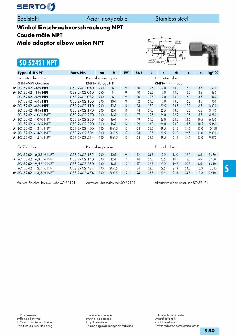
Winkel-Einschraubverschraubung NPTCoude mâle NPTMale adaptor elbow union NPT
SO 52421 NPTType -d -RNPT Mat.-Nr. bar M SW1 SW2 L b zR z e kg/100Für metrische Rohre Pour tubes métriques For metric tubesRNPT=NPT Gewinde RNPT=Filetage NPT RNPT=NPT thread
SO 52421-3-1/8 NPT 058.2402.040 250 8x1 9 10 22.5 17.0 13.0 16.0 3.5 1.530 SO 52421-4-1/8 NPT 058.2402.060 250 8x1 9 10 22.5 17.0 13.0 16.0 3.5 1.460 SO 52421-5-1/8 NPT 058.2402.082 250 8x1 9 10 22.5 17.0 13.0 16.0 3.5 1.440 SO 52421-6-1/8 NPT 058.2402.100 200 10x1 9 12 24.5 17.0 13.0 16.0 4.5 1.900
SO 52421-6-1/4 NPT 058.2402.110 200 12x1 10 14 27.0 22.5 18.5 18.0 6.5 3.330 SO 52421-8-1/4 NPT 058.2402.170 200 12x1 10 14 27.0 22.5 18.5 18.0 6.5 3.170 SO 52421-10-1/4 NPT 058.2402.270 160 14x1 12 17 32.5 25.0 19.2 20.5 8.5 4.280
SO 52421-10-3/8 NPT 058.2402.280 160 16x1 14 19 34.0 26.0 20.0 21.5 10.5 6.060 SO 52421-12-3/8 NPT 058.2402.390 160 16x1 14 19 34.0 26.0 20.0 21.5 10.5 5.860
SO 52421-12-1/2 NPT 058.2402.400 100 20x1.5 17 24 38.5 29.5 21.3 24.5 13.0 10.130 SO 52421-14-1/2 NPT 058.2402.504 100 20x1.5 17 24 38.5 29.5 21.3 24.5 13.0 9.810 SO 52421-15-1/2 NPT 058.2402.534 100 20x1.5 17 24 38.5 29.5 21.3 24.5 13.0 9.570
Für Zollrohre Pour tubes pouces For inch tubes
SO 52421-6,35-1/8 NPT 058.2402.135 200 10x1 9 12 24.5 17.0 13.0 16.0 4.5 1.880 SO 52421-6,35-1/4 NPT 058.2402.140 200 12x1 10 14 27.0 22.5 18.5 18.0 6.5 3.300 SO 52421-9,52-1/4 NPT 058.2402.230 160 14x1 12 17 32.5 25.0 19.2 20.5 8.5 4.310 SO 52421-12,7-1/2 NPT 058.2402.434 100 20x1.5 17 24 38.5 29.5 21.3 24.5 13.0 10.010
SO 52421-13,5-1/2 NPT 058.2402.474 100 20x1.5 17 24 38.5 29.5 21.3 24.5 13.0 9.910
Weitere Einschraubwinkel siehe SO 52121. Autres coudes mâles voir SO 52121. Alternative elbow union see SO 52121.
Edelstahl Acier inoxydable Stainless steel
d=Rohraussen-øe=kleinste BohrungL=Mass in montiertem Zustand*=mit reduziertem Klemmring
d=ø extérieur du tubee=ø-min. de passageL=après montage*=avec bague de serrage de réduction
d=tube outside diameterL=installed lengthe=minimum bore*=with reduction compression ferrule
5.50
i
s
3F
4M
4G
5
5L
6
7
8
9
10
11
12
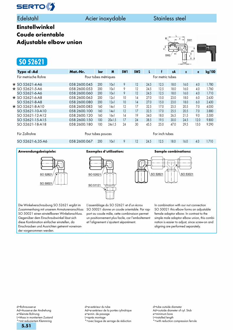
EinstellwinkelCoude orientableAdjustable elbow union
SO 52621Type -d -Ad Mat.-Nr. bar M SW1 SW2 L f zA z e kg/100Für metrische Rohre Pour tubes métriques For metric tubes
SO 52621-4-A6 058.2600.045 200 10x1 9 12 24.5 12.5 18.0 16.0 4.0 1.780 SO 52621-5-A6 058.2600.053 200 10x1 9 12 24.5 12.5 18.0 16.0 4.0 1.760 SO 52621-6-A6 058.2600.060 200 10x1 9 12 24.5 12.5 18.0 16.0 4.0 1.710
SO 52621-6-A8 058.2600.063 200 12x1 10 14 27.0 15.0 23.0 18.0 6.0 2.630 SO 52621-8-A8 058.2600.080 200 12x1 10 14 27.0 15.0 23.0 18.0 6.0 2.430
SO 52621-8-A10 058.2600.083 160 14x1 12 17 32.5 17.0 25.5 20.5 7.0 4.050 SO 52621-10-A10 058.2600.100 160 14x1 12 17 32.5 17.0 25.5 20.5 7.0 3.880 SO 52621-12-A12 058.2600.120 160 16x1 14 19 34.0 18.0 26.5 21.5 9.0 5.500 SO 52621-15-A15 058.2600.150 100 20x1.5 17 24 38.5 19.5 30.0 24.5 12.0 9.800 SO 52621-18-A18 058.2600.180 100 24x1.5 24 30 45.5 25.0 47.0 29.5 15.0 9.290
Für Zollrohre Pour tubes pouces For inch tubes SO 52621-6,35-A6 058.2600.067 200 10x1 9 12 24.5 12.5 18.0 16.0 4.0 1.710
Anwendungsbeispiele: Exemples d‘utilisation: Sample combinations:
Die Winkelverschraubung SO 52621 ergibt im Zusammenhang mit unserem Armaturenanschluss SO 50021 einen einstellbaren Winkelanschluss. Gegenüber dem Einschraubwinkel lässt sich diese Kombination einfacher einstellen, da Einschrauben und Ausrichten getrennt voneinan-der vorgenommen werden.
L’assemblage du SO 52621 et d’un écrou SO 50021 donne un coude orientable. Par rap-port au coude mâle, cette combinaison permet un positionnement plus facile, car l’emboîtement et l’alignement s’ajustent séparément.
In combination with our nut connection SO 50021 this elbow forms an adjustable female adaptor elbow. In contrast to the simple male adaptor elbow union, this combi-nation is easier to adjust, since screw-on and aligning are performed separately.
Edelstahl Acier inoxydable Stainless steel
d=Rohraussen-øAd=Aussen-ø der Andrehunge=kleinste BohrungL=Mass in montiertem Zustand*=mit reduziertem Klemmring
d=ø extérieur du tubeAd=ø extérieur de la portée cylindriquee=ø-min. de passageL=après montage*=avec bague de serrage de réduction
d=tube outside diameterAd=outside diameter of cyl. Stube=minimum boreL=installed length*=with reduction compression ferrule
5.51

Winkelverschraubungmit Einstellzapfen vormontiert
Coude orientable montéAdjustable elbow assembly
SO 52625Type -d -Ad Mat.-Nr. bar M SW1 SW2 L l z e kg/100Für metrische Rohre Pour tubes métriques For metric tubes
SO 52625-4-A6 058.2620.045 200 10x1 9 12 24.5 19.0 16.0 4.0 2.570 SO 52625-5-A6 058.2620.053 200 10x1 9 12 24.5 19.0 16.0 4.0 2.550 SO 52625-6-A6 058.2620.060 200 10x1 9 12 24.5 19.0 16.0 4.0 2.500
SO 52625-6-A8 058.2620.063 200 12x1 10 14 27.0 24.2 18.0 6.0 3.800 SO 52625-8-A8 058.2620.080 200 12x1 10 14 27.0 24.2 18.0 6.0 3.480
SO 52625-8-A10 058.2620.083 160 14x1 12 17 32.5 26.7 20.5 7.0 5.830 SO 52625-10-A10 058.2620.100 160 14x1 12 17 32.5 26.7 20.5 7.0 5.660 SO 52625-12-A12 058.2620.120 100 16x1 14 19 34.0 27.7 21.5 9.0 7.280 SO 52625-15-A15 058.2620.150 100 20x1.5 17 24 38.5 31.4 24.5 12.0 8.040 SO 52625-18-A18 058.2620.180 100 24x1.5 24 27 47.5 48.5 29.5 15.0 17.300
Für Zollrohre Pour tubes pouces For inch tubes
SO 52625-6.35-A6 058.2620.067 200 10x1 12 12 24.5 19.0 16.0 4.0 2.500
Winkel-SchottverschraubungDurchführungslänge max. 20 mm
Coude pour passage de cloisonpour cloison max. 20 mm
Panel mount elbow unionmax. panel thickness 20 mm
SO 52721Type -d Mat.-Nr. bar M SW1 SW2 SW3 L L1 W z1 z e kg/100 SO 52721-6 058.2700.060 200 10x1 12 12 14 27.5 57.5 13.0 36.0 19.0 4.5 6.980SO 52721-8 058.2700.080 200 12x1 12 14 17 28.0 58.0 13.0 36.0 19.0 5.5 9.450SO 52721-10 058.2700.100 160 14x1 12 17 19 35.0 65.0 17.0 36.0 23.0 7.5 12.350SO 52721-12 058.2700.120 160 16x1 14 19 22 36.5 66.5 17.0 37.0 24.0 8.5 17.060SO 52721-15 058.2700.150 100 20x1.5 19 24 27 43.5 77.5 23.0 40.5 29.5 13.0 28.600SO 52721-18 058.2700.180 100 24x1.5 24 30 30 49.5 80.5 22.0 42.5 33.5 15.0 34.380SO 52721-22 058.2700.220 64 28x1.5 27 32 36 57.0 94.0 29.0 46.5 37.5 19.0 31.800
Edelstahl Acier inoxydable Stainless steel
M=Anschlussgewindel=Einbaulängee=kleinste BohrungL=Mass in montiertem Zustand*=mit reduziertem Klemmring
M=filetagel=longueur encastréee=ø-min. de passageL=après montage*=avec bague de serrage de réduction
M=threadl=fitted lengthe=minimum boreL=installed length*=with reduction compression ferrule
5.52
i
s
3F
4M
4G
5
5L
6
7
8
9
10
11
12

SchwenkverschraubungCoude banjoSingle banjo
SO 52824Type -d -G Mat.-Nr. bar M SW1 SW2 L A b D zR z e kg/100Für metrische Rohre Pour tubes métriques For metric tubesG=Rohrgewinde (zylindrisch) G=Filetage-gaz BSP (cylindrique) G=BSP thread (straight)
SO 52824-4-1/8 058.2841.060 200 10x1 12 14 24.5 21.0 31.0 17.0 8.0 18.0 4.5 5.000 SO 52824-5-1/8 058.2841.082 200 10x1 12 14 24.5 21.0 31.0 17.0 8.0 18.0 4.5 4.950 SO 52824-6-1/8 058.2841.100 200 10x1 12 14 26.5 21.0 31.0 17.0 8.0 18.0 4.5 4.900
SO 52824-6-1/4 058.2841.110 200 12x1 14 19 29.5 27.0 36.0 20.5 11.0 20.5 7.0 10.100 SO 52824-8-1/8 058.2841.160 200 12x1 14 14 27.0 22.0 29.0 18.0 9.0 19.0 4.5 6.300 SO 52824-8-1/4 058.2841.170 200 12x1 14 19 29.5 27.0 36.0 20.5 11.0 20.5 7.0 9.950 SO 52824-10-1/4 058.2841.270 160 14x1 17 19 32.5 27.0 36.0 20.5 11.0 20.5 7.0 10.800
SO 52824-10-3/8 058.2841.280 160 16x1 19 24 36.5 35.0 47.0 26.0 14.0 24.0 9.0 17.200 SO 52824-12-3/8 058.2841.390 160 16x1 19 24 36.5 35.0 47.0 26.0 14.0 24.0 9.0 16.800
SO 52824-12-1/2 058.2841.400 160 20x1.5 24 27 42.5 41.5 55.0 31.5 12.0 28.5 12.0 32.200 SO 52824-14-1/2 058.2841.504 100 20x1.5 24 27 42.5 41.5 55.0 31.5 12.0 28.5 12.0 31.800 SO 52824-15-1/2 058.2841.534 100 20x1.5 24 27 42.5 41.5 55.0 31.5 12.0 28.5 12.0 31.600 SO 52824-18-1/2 058.2841.646 100 24x1.5 30 27 44.5 41.5 55.0 31.5 12.0 28.5 12.0 34.690
Für Zollrohre Pour tubes pouces For inch tubes SO 52824-6,35-1/8 058.2841.135 200 10x1 12 14 26.5 21.0 31.0 17.0 8.0 18.0 4.5 4.900SO 52824-9,52-1/4 058.2841.230 160 14x1 17 19 32.5 27.0 36.0 20.5 11.0 20.5 7.0 10.800SO 52824-12,7-1/2 058.2841.434 160 20x1.5 24 27 42.5 41.5 55.0 31.5 12.0 28.5 12.0 32.000
Schwenkverschraubung METRCoude banjo METRSingle banjo METR
SO 52824 METRType -d -Mz Mat.-Nr. bar M SW1 SW2 L A b D zR z e kg/100Für metrische Rohre Pour tubes métriques For metric tubesMz=metrisches Gewinde (zylindrisch) Mz=Filetage métrique (cylindrique) Mz=Metric thread (straight)SO 52824-10-M12X1.5 058.2843.275 160 14x1 17 19 32.5 27.5 36.0 20.5 11.0 20.5 7.0 11.600SO 52824-18-M22X1.5 058.2843.646 100 24x1.5 30 27 44.5 27.5 36.0 31.5 17.0 28.5 12.0 11.600
O-Ring: FPM Joint: FPM O-Ring: FPM
Edelstahl Acier inoxydable Stainless steel
d=Rohraussen-øe=kleinste BohrungL=Mass in montiertem Zustand*=mit reduziertem Klemmring
d=ø extérieur du tubee=ø-min. de passageL=après montage*=avec bague de serrage de réduction
d=tube outside diametere=minimum boreL=installed length*=with reduction compression ferrule
5.53

T-VerschraubungTéTee union
SO 53021Type -d Mat.-Nr. bar M SW1 SW2 L z e kg/100Für metrische Rohre Pour tubes métriques For metric tubes
SO 53021-2 058.3000.020 250 6x0.75 9 8 19.5 15.5 2.5 1.730 SO 53021-3 058.3000.030 250 6x0.75 9 8 21.0 16.0 2.5 1.850 SO 53021-4 058.3000.040 250 8x1 9 10 21.5 16.0 3.5 2.810 SO 53021-5 058.3000.050 250 8x1 9 10 22.0 16.0 3.5 2.750 SO 53021-6 058.3000.060 200 10x1 9 12 24.0 16.0 4.5 3.990 SO 53021-8 058.3000.080 200 12x1 10 14 26.5 18.0 6.5 5.340 SO 53021-10 058.3000.100 160 14x1 12 17 32.0 20.5 8.5 8.450 SO 53021-12 058.3000.120 160 16x1 14 19 34.0 21.5 9.5 10.700
SO 53021-14 058.3000.140 100 20x1.5 17 24 38.5 24.5 13.0 18.890 SO 53021-15 058.3000.150 100 20x1.5 17 24 38.5 24.5 13.0 18.650
SO 53021-16 058.3000.160 100 24x1.5 22 30 42.0 26.5 15.0 31.060 SO 53021-18 058.3000.180 100 24x1.5 22 30 42.0 26.5 15.0 30.510 SO 53021-22 058.3000.220 64 28x1.5 27 32 48.0 30.5 19.0 38.280 SO 53021-28 058.3000.280 64 36x2 36 41 62.0 43.0 25.0 93.700
Für Zollrohre Pour tubes pouces For inch tubes
SO 53021-3,2 058.3000.032 250 6x0.75 9 8 21.0 16.0 2.5 1.650 SO 53021-6,35 058.3000.063 200 10x1 9 12 24.0 16.0 4.5 3.930 SO 53021-9,52 058.3000.095 160 14x1 12 17 31.0 20.5 8.5 8.540 SO 53021-12,7 058.3000.127 100 20x1.5 17 24 38.0 24.5 13.0 19.970
SO 53021-13,5 058.3000.135 100 20x1.5 17 24 38.5 24.5 13.0 18.990 SO 53021-17,2 058.3000.172 100 24x1.5 22 30 42.0 26.5 15.0 30.660 SO 53021-21,3 058.3000.213 64 28x1.5 27 32 50.0 31.0 19.0 39.680
Edelstahl Acier inoxydable Stainless steel
d=Rohraussen-øe=kleinste BohrungL=Mass in montiertem Zustand*=mit reduziertem Klemmring
d=ø extérieur du tubee=ø-min. de passageL=après montage*=avec bague de serrage de réduction
d=tube outside diametere=minimum boreL=installed length*=with reduction compression ferrule
5.54
i
s
3F
4M
4G
5
5L
6
7
8
9
10
11
12
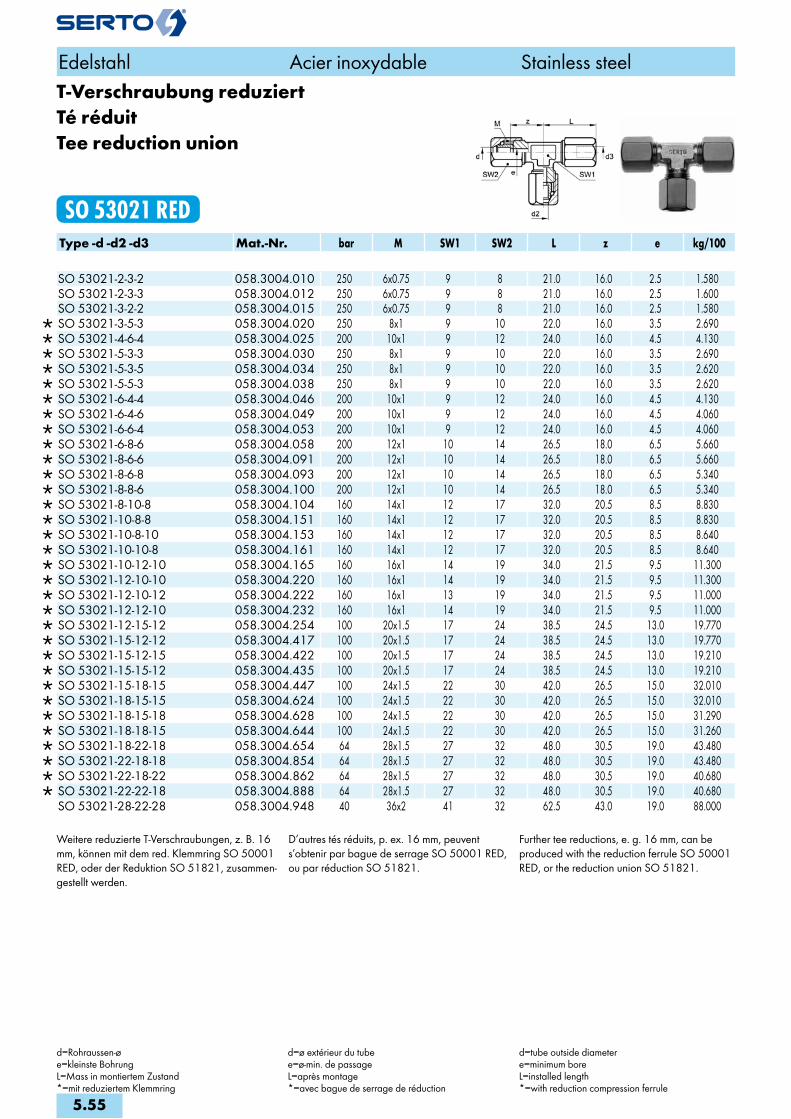
T-Verschraubung reduziertTé réduitTee reduction union
SO 53021 REDType -d -d2 -d3 Mat.-Nr. bar M SW1 SW2 L z e kg/100
SO 53021-2-3-2 058.3004.010 250 6x0.75 9 8 21.0 16.0 2.5 1.580 SO 53021-2-3-3 058.3004.012 250 6x0.75 9 8 21.0 16.0 2.5 1.600 SO 53021-3-2-2 058.3004.015 250 6x0.75 9 8 21.0 16.0 2.5 1.580
SO 53021-3-5-3 058.3004.020 250 8x1 9 10 22.0 16.0 3.5 2.690 SO 53021-4-6-4 058.3004.025 200 10x1 9 12 24.0 16.0 4.5 4.130 SO 53021-5-3-3 058.3004.030 250 8x1 9 10 22.0 16.0 3.5 2.690 SO 53021-5-3-5 058.3004.034 250 8x1 9 10 22.0 16.0 3.5 2.620 SO 53021-5-5-3 058.3004.038 250 8x1 9 10 22.0 16.0 3.5 2.620 SO 53021-6-4-4 058.3004.046 200 10x1 9 12 24.0 16.0 4.5 4.130 SO 53021-6-4-6 058.3004.049 200 10x1 9 12 24.0 16.0 4.5 4.060 SO 53021-6-6-4 058.3004.053 200 10x1 9 12 24.0 16.0 4.5 4.060 SO 53021-6-8-6 058.3004.058 200 12x1 10 14 26.5 18.0 6.5 5.660 SO 53021-8-6-6 058.3004.091 200 12x1 10 14 26.5 18.0 6.5 5.660 SO 53021-8-6-8 058.3004.093 200 12x1 10 14 26.5 18.0 6.5 5.340 SO 53021-8-8-6 058.3004.100 200 12x1 10 14 26.5 18.0 6.5 5.340 SO 53021-8-10-8 058.3004.104 160 14x1 12 17 32.0 20.5 8.5 8.830 SO 53021-10-8-8 058.3004.151 160 14x1 12 17 32.0 20.5 8.5 8.830 SO 53021-10-8-10 058.3004.153 160 14x1 12 17 32.0 20.5 8.5 8.640 SO 53021-10-10-8 058.3004.161 160 14x1 12 17 32.0 20.5 8.5 8.640 SO 53021-10-12-10 058.3004.165 160 16x1 14 19 34.0 21.5 9.5 11.300 SO 53021-12-10-10 058.3004.220 160 16x1 14 19 34.0 21.5 9.5 11.300 SO 53021-12-10-12 058.3004.222 160 16x1 13 19 34.0 21.5 9.5 11.000 SO 53021-12-12-10 058.3004.232 160 16x1 14 19 34.0 21.5 9.5 11.000 SO 53021-12-15-12 058.3004.254 100 20x1.5 17 24 38.5 24.5 13.0 19.770 SO 53021-15-12-12 058.3004.417 100 20x1.5 17 24 38.5 24.5 13.0 19.770 SO 53021-15-12-15 058.3004.422 100 20x1.5 17 24 38.5 24.5 13.0 19.210 SO 53021-15-15-12 058.3004.435 100 20x1.5 17 24 38.5 24.5 13.0 19.210 SO 53021-15-18-15 058.3004.447 100 24x1.5 22 30 42.0 26.5 15.0 32.010 SO 53021-18-15-15 058.3004.624 100 24x1.5 22 30 42.0 26.5 15.0 32.010 SO 53021-18-15-18 058.3004.628 100 24x1.5 22 30 42.0 26.5 15.0 31.290 SO 53021-18-18-15 058.3004.644 100 24x1.5 22 30 42.0 26.5 15.0 31.260 SO 53021-18-22-18 058.3004.654 64 28x1.5 27 32 48.0 30.5 19.0 43.480 SO 53021-22-18-18 058.3004.854 64 28x1.5 27 32 48.0 30.5 19.0 43.480 SO 53021-22-18-22 058.3004.862 64 28x1.5 27 32 48.0 30.5 19.0 40.680 SO 53021-22-22-18 058.3004.888 64 28x1.5 27 32 48.0 30.5 19.0 40.680 SO 53021-28-22-28 058.3004.948 40 36x2 41 32 62.5 43.0 19.0 88.000
Weitere reduzierte T-Verschraubungen, z. B. 16 mm, können mit dem red. Klemmring SO 50001 RED, oder der Reduktion SO 51821, zusammen-gestellt werden.
D’autres tés réduits, p. ex. 16 mm, peuvent s’obtenir par bague de serrage SO 50001 RED, ou par réduction SO 51821.
Further tee reductions, e. g. 16 mm, can be produced with the reduction ferrule SO 50001 RED, or the reduction union SO 51821.
Edelstahl Acier inoxydable Stainless steel
d=Rohraussen-øe=kleinste BohrungL=Mass in montiertem Zustand*=mit reduziertem Klemmring
d=ø extérieur du tubee=ø-min. de passageL=après montage*=avec bague de serrage de réduction
d=tube outside diametere=minimum boreL=installed length*=with reduction compression ferrule
5.55
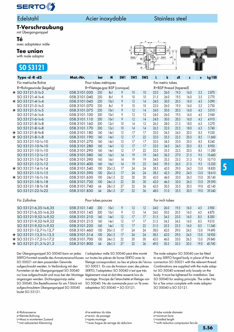
T-Verschraubungmit Übergangsnippel
Téavec adaptateur mâle
Tee unionwith male adaptor
SO 53121Type -d -R -d3 Mat.-Nr. bar M SW1 SW2 SW3 L b zR z e kg/100Für metrische Rohre Pour tubes métriques For metric tubesR=Rohrgewinde (kegelig) R=Filetage-gaz BSP (conique) R=BSP thread (tapered)
SO 53121-3-1/8-3 058.3101.030 250 8x1 9 10 10 22.0 26.0 19.5 16.0 3.5 2.870 SO 53121-4-1/8-4 058.3101.040 250 8x1 9 10 10 21.5 26.0 19.5 16.0 3.5 2.770
SO 53121-4-1/4-4 058.3101.045 250 10x1 9 12 14 24.0 30.0 20.5 16.0 4.5 5.090 SO 53121-5-1/8-5 058.3101.070 250 8x1 9 10 10 22.0 26.0 19.5 16.0 3.5 2.730
SO 53121-5-1/4-5 058.3101.075 250 10x1 9 12 14 24.0 30.0 20.5 16.0 4.5 5.010 SO 53121-6-1/8-6 058.3101.100 200 10x1 9 12 12 24.0 26.0 19.5 16.0 4.5 3.940 SO 53121-6-1/4-6 058.3101.110 200 10x1 9 12 14 24.0 30.0 20.5 16.0 4.5 4.910 SO 53121-8-1/8-8 058.3101.160 200 12x1 10 14 12 26.5 28.0 21.5 18.0 6.5 5.270 SO 53121-8-1/4-8 058.3101.170 200 12x1 10 14 14 26.5 32.0 22.5 18.0 6.5 5.740
SO 53121-8-3/8-8 058.3101.180 160 14x1 12 17 17 32.0 34.5 24.5 20.5 8.5 9.330 SO 53121-8-1/2-8 058.3101.190 160 14x1 12 17 22 32.0 35.5 22.5 20.5 8.5 11.660 SO 53121-10-1/4-10 058.3101.270 160 14x1 12 17 17 32.0 34.5 25.0 20.5 8.5 8.240 SO 53121-10-3/8-10 058.3101.280 160 14x1 12 17 17 32.0 34.5 24.5 20.5 8.5 8.950 SO 53121-10-1/2-10 058.3101.290 160 14x1 12 17 22 32.0 35.5 22.5 20.5 8.5 11.280 SO 53121-12-1/4-12 058.3101.380 160 16x1 14 19 19 34.0 36.5 27.0 21.5 9.5 10.460 SO 53121-12-3/8-12 058.3101.390 160 16x1 14 19 19 34.0 35.5 25.5 21.5 9.5 10.710 SO 53121-12-1/2-12 058.3101.400 160 16x1 14 19 22 34.0 39.5 26.5 21.5 9.5 13.320
SO 53121-14-1/2-14 058.3101.540 100 20x1.5 17 24 24 38.5 42.0 29.0 24.5 13.0 18.850 SO 53121-15-1/2-15 058.3101.590 100 20x1.5 17 24 24 38.5 42.5 29.0 24.5 13.0 18.610
SO 53121-16-1/2-16 058.3101.630 100 24x1.5 22 30 30 42.0 46.0 33.0 26.5 15.0 30.140 SO 53121-18-1/2-18 058.3101.730 100 24x1.5 22 30 30 42.0 46.5 33.0 26.5 15.0 29.590 SO 53121-18-3/4-18 058.3101.740 64 28x1.5 27 32 36 42.0 50.5 35.5 30.5 19.0 42.140 SO 53121-22-3/4-22 058.3101.830 64 28x1.5 27 32 36 48.0 51.0 35.5 30.5 19.0 39.340
Für Zollrohre Pour tubes pouces For inch tubes
SO 53121-6,35-1/8-6,35 058.3101.140 200 10x1 9 12 12 24.0 26.0 19.5 16.0 4.5 3.900 SO 53121-6,35-1/4-6,35 058.3101.145 200 10x1 9 12 14 24.0 30.0 20.5 16.0 4.5 4.870 SO 53121-9,52-1/4-9,52 058.3101.210 160 14x1 12 17 17 31.5 34.5 25.0 16.0 8.5 8.300 SO 53121-9,52-3/8-9,52 058.3101.215 160 14x1 12 17 17 31.5 34.5 24.5 16.0 8.5 9.010 SO 53121-9,52-1/2-9,52 058.3101.220 160 14x1 12 17 22 31.5 35.5 22.5 16.0 8.5 11.340 SO 53121-12,7-1/2-12,7 058.3101.460 100 20x1.5 17 24 24 38.0 42.0 29.0 24.5 13.0 19.490
SO 53121-13,5-1/2-13,5 058.3101.514 100 20x1.5 17 24 24 38.5 42.0 29.0 24.5 13.0 18.950 SO 53121-17,2-1/2-17,2 058.3101.700 100 24x1.5 22 30 30 42.0 46.0 33.0 26.5 15.0 29.840 SO 53121-21,3-3/4-21,3 058.3101.800 64 28x1.5 27 32 36 49.0 50.5 35.5 30.5 19.0 40.740
Der Übergangsnippel SO 50040 kann an jedes SERTO-Formteil anstelle des Armaturenanschlusses SO 50021 mit dem passenden Gewinde aufgeschraubt werden. In Verbindung mit den Formteilen ist der Übergangsnippel SO 50040 nur lose aufgeschraubt und muss bei der Montage angezogen werden. Dichtungsprinzip siehe SO 50040. Die Bestellnummer für ein T-Stück mit aufgeschraubtem Übergangsnippel SO 50040 lautet SO 53121.
L’adaptateur mâle SO 50040 peut être monté sur toutes les pièces de forme SERTO avec le filetage correspondant, au lieu et place de l’écrou SO 50021. En cas de livraison avec des pièces SERTO, l’adaptateur SO 50040 n’est que très légèrement vissé et doit être resserré lors du montage. Principe de l’étanchéité et filetage voir SO 50040. No de commande pour un Té avec adaptateur SO 50040 = SO 53121.
The male adaptor SO 50040 can be fitted to any SERTO forged body in place of the nut connection SO 50021 with the relevant thread. Combinations are supplied with the male adap-tor SO 50040 screwed only loosely on the body. It must be tightened for installation. See SO 50040 for sealing principle. The order No. for a Tee union complete with male adaptor SO 50040 is SO 53121.
Edelstahl Acier inoxydable Stainless steel
d=Rohraussen-øe=kleinste BohrungL=Mass in montiertem Zustand*=mit reduziertem Klemmring
d=ø extérieur du tubee=ø-min. de passageL=après montage*=avec bague de serrage de réduction
d=tube outside diametere=minimum boreL=installed length*=with reduction compression ferrule
5.56
i
s
3F
4M
4G
5
5L
6
7
8
9
10
11
12

T-Verschraubungmit Übergangsnippel NPT
Téavec adaptateur mâle NPT
Tee unionwith male adaptor NPT
SO 53121 NPTType -d -RNPT -d3 Mat.-Nr. bar M SW1 SW2 SW3 L b zR z e kg/100Für metrische Rohre Pour tubes métriques For metric tubesRNPT=NPT Gewinde RNPT=Filetage NPT RNPT=NPT thread
SO 53121-3-1/8 NPT-3 058.3102.030 250 8x1 9 10 10 22.0 28.0 21.5 16.0 3.5 2.990 SO 53121-4-1/8 NPT-4 058.3102.040 250 8x1 9 10 10 21.5 28.0 21.5 16.0 3.5 2.890
SO 53121-4-1/4 NPT-4 058.3102.045 200 10x1 9 12 14 24.0 32.0 22.0 16.0 4.5 5.260 SO 53121-5-1/8 NPT-5 058.3102.070 250 8x1 9 10 10 22.0 28.0 21.5 16.0 3.5 2.850
SO 53121-5-1/4 NPT-5 058.3102.075 200 10x1 9 12 14 24.0 32.0 22.0 16.0 4.5 5.180 SO 53121-6-1/8 NPT-6 058.3102.100 200 10x1 9 12 12 24.0 28.0 21.5 16.0 4.5 4.050 SO 53121-6-1/4 NPT-6 058.3102.110 200 10x1 9 12 14 24.0 32.0 22.0 16.0 4.5 5.080 SO 53121-8-1/4 NPT-8 058.3102.170 200 12x1 10 14 14 26.5 34.0 24.0 18.0 6.5 5.900 SO 53121-10-1/4 NPT-10 058.3102.270 160 14x1 12 17 17 32.0 36.5 26.5 20.5 8.5 8.350
SO 53121-10-1/2 NPT-10 058.3102.290 160 16x1 14 19 22 32.0 42.5 29.0 20.5 8.5 14.220 SO 53121-12-1/4 NPT-12 058.3102.380 160 16x1 14 19 19 34.0 38.5 27.0 21.5 9.5 10.540 SO 53121-12-3/8 NPT-12 058.3102.390 160 16x1 14 19 19 34.0 38.5 27.0 21.5 9.5 10.750 SO 53121-12-1/2 NPT-12 058.3102.400 160 16x1 14 19 22 34.0 42.5 29.0 21.5 9.5 13.820
SO 53121-14-1/2 NPT-14 058.3102.540 100 20x1.5 17 24 24 38.5 45.0 31.5 24.5 13.0 19.530 SO 53121-15-1/2 NPT-15 058.3102.590 100 20x1.5 17 24 24 38.5 45.0 31.5 24.5 13.0 18.950
Für Zollrohre Pour tubes pouces For inch tubes
SO 53121-6,35-1/8 NPT-6,35 058.3102.140 200 10x1 9 12 12 24.0 28.0 21.5 16.0 4.5 4.010 SO 53121-6,35-1/4 NPT-6,35 058.3102.145 200 10x1 9 12 14 24.0 32.0 22.0 16.0 4.5 5.040 SO 53121-9,52-1/4 NPT-9,52 058.3102.210 160 14x1 12 17 17 31.5 36.5 27.0 16.0 8.5 8.410 SO 53121-12,7-1/2 NPT-12,7 058.3102.460 100 20x1.5 17 24 24 38.0 45.0 31.5 24.5 13.0 19.830
SO 53121-13,5-1/2 NPT-13,5 058.3102.514 100 20x1.5 17 24 24 38.5 45.0 31.5 24.5 13.0 19.730
T-Verschraubungmit Übergangsnippel METR
Téavec adaptateur mâle METR
Tee unionwith male adaptor METR
SO 53121 METRType -d -Mz -d3 Mat.-Nr. bar M SW1 SW2 SW3 L b zR z e kg/100Für metrische Rohre Pour tubes métriques For metric tubesMz=metrisches Gewinde (zylindrisch) Mz=Filetage métrique (cylindrique) Mz=Metric thread (straight)
SO 53121-3-M6X0,75-3 058.3143.055 250 8x1 9 10 10 22.0 24.0 19.0 16.0 3.5 2.610 SO 53121-3-M8X1-3 058.3143.060 250 8x1 9 10 10 22.0 26.0 20.0 16.0 3.5 2.720 SO 53121-4-M6X0,75-4 058.3143.085 250 8x1 9 10 10 22.0 24.0 19.0 16.0 3.5 2.510 SO 53121-4-M8X1-4 058.3143.090 250 8x1 9 10 10 22.0 26.0 20.0 16.0 3.5 2.620 SO 53121-5-M6X0,75-5 058.3143.115 250 8x1 9 10 10 22.0 24.0 19.0 16.0 3.5 2.470 SO 53121-5-M8X1-5 058.3143.125 250 8x1 9 10 10 22.0 26.0 20.0 16.0 3.5 2.580
Edelstahl Acier inoxydable Stainless steel
d=Rohraussen-øe=kleinste BohrungL=Mass in montiertem Zustand*=mit reduziertem Klemmring
d=ø extérieur du tubee=ø-min. de passageL=après montage*=avec bague de serrage de réduction
d=tube outside diametere=minimum boreL=installed length*=with reduction compression ferrule
5.57
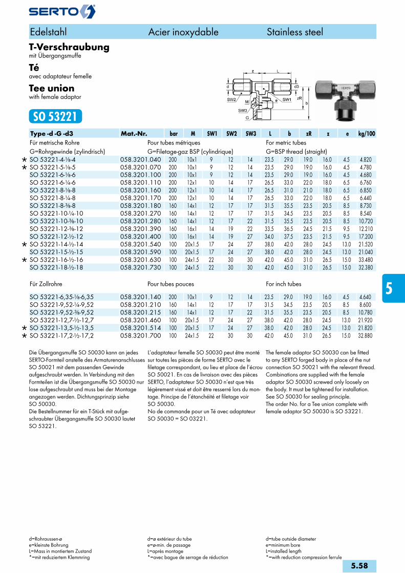
T-Verschraubungmit Übergangsmuffe
Téavec adaptateur femelle
Tee unionwith female adaptor
SO 53221Type -d -G -d3 Mat.-Nr. bar M SW1 SW2 SW3 L b zR z e kg/100Für metrische Rohre Pour tubes métriques For metric tubesG=Rohrgewinde (zylindrisch) G=Filetage-gaz BSP (cylindrique) G=BSP thread (straight)
SO 53221-4-1/8-4 058.3201.040 200 10x1 9 12 14 23.5 29.0 19.0 16.0 4.5 4.820 SO 53221-5-1/8-5 058.3201.070 200 10x1 9 12 14 23.5 29.0 19.0 16.0 4.5 4.780 SO 53221-6-1/8-6 058.3201.100 200 10x1 9 12 14 23.5 29.0 19.0 16.0 4.5 4.680 SO 53221-6-1/4-6 058.3201.110 200 12x1 10 14 17 26.5 33.0 22.0 18.0 6.5 6.760 SO 53221-8-1/8-8 058.3201.160 200 12x1 10 14 17 26.5 31.0 21.0 18.0 6.5 6.850 SO 53221-8-1/4-8 058.3201.170 200 12x1 10 14 17 26.5 33.0 22.0 18.0 6.5 6.440 SO 53221-8-3/8-8 058.3201.180 160 14x1 12 17 17 31.5 35.5 23.5 20.5 8.5 8.730 SO 53221-10-1/4-10 058.3201.270 160 14x1 12 17 17 31.5 34.5 23.5 20.5 8.5 8.540 SO 53221-10-3/8-10 058.3201.280 160 14x1 12 17 22 31.5 35.5 23.5 20.5 8.5 10.720 SO 53221-12-3/8-12 058.3201.390 160 16x1 14 19 22 33.5 36.5 24.5 21.5 9.5 12.210 SO 53221-12-1/2-12 058.3201.400 100 16x1 14 19 27 34.0 37.5 23.5 21.5 9.5 17.200
SO 53221-14-1/2-14 058.3201.540 100 20x1.5 17 24 27 38.0 42.0 28.0 24.5 13.0 21.520 SO 53221-15-1/2-15 058.3201.590 100 20x1.5 17 24 27 38.0 42.0 28.0 24.5 13.0 21.040
SO 53221-16-1/2-16 058.3201.630 100 24x1.5 22 30 30 42.0 45.0 31.0 26.5 15.0 33.480 SO 53221-18-1/2-18 058.3201.730 100 24x1.5 22 30 30 42.0 45.0 31.0 26.5 15.0 32.380
Für Zollrohre Pour tubes pouces For inch tubes
SO 53221-6,35-1/8-6,35 058.3201.140 200 10x1 9 12 14 23.5 29.0 19.0 16.0 4.5 4.640 SO 53221-9,52-1/4-9,52 058.3201.210 160 14x1 12 17 17 31.5 34.5 23.5 20.5 8.5 8.600 SO 53221-9,52-3/8-9,52 058.3201.215 160 14x1 12 17 22 31.5 35.5 23.5 20.5 8.5 10.780 SO 53221-12,7-1/2-12,7 058.3201.460 100 20x1.5 17 24 27 38.0 42.0 28.0 24.5 13.0 21.920
SO 53221-13,5-1/2-13,5 058.3201.514 100 20x1.5 17 24 27 38.0 42.0 28.0 24.5 13.0 21.820 SO 53221-17,2-1/2-17,2 058.3201.700 100 24x1.5 22 30 30 42.0 45.0 31.0 26.5 15.0 32.880
Die Übergangsmuffe SO 50030 kann an jedes SERTO-Formteil anstelle des Armaturenanschlusses SO 50021 mit dem passenden Gewinde aufgeschraubt werden. In Verbindung mit den Formteilen ist die Übergangsmuffe SO 50030 nur lose aufgeschraubt und muss bei der Montage angezogen werden. Dichtungsprinzip siehe SO 50030.Die Bestellnummer für ein T-Stück mit aufge-schraubter Übergangsmuffe SO 50030 lautet SO 53221.
L’adaptateur femelle SO 50030 peut être monté sur toutes les pièces de forme SERTO avec le filetage correspondant, au lieu et place de l’écrou SO 50021. En cas de livraison avec des pièces SERTO, l’adaptateur SO 50030 n’est que très légèrement vissé et doit être resserré lors du mon-tage. Principe de l’étanchéité et filetage voir SO 50030. No de commande pour un Té avec adaptateur SO 50030 = SO 03221.
The female adaptor SO 50030 can be fitted to any SERTO forged body in place of the nut connection SO 50021 with the relevant thread. Combinations are supplied with the female adaptor SO 50030 screwed only loosely on the body. It must be tightened for installation. See SO 50030 for sealing principle.The order No. for a Tee union complete with female adaptor SO 50030 is SO 53221.
Edelstahl Acier inoxydable Stainless steel
d=Rohraussen-øe=kleinste BohrungL=Mass in montiertem Zustand*=mit reduziertem Klemmring
d=ø extérieur du tubee=ø-min. de passageL=après montage*=avec bague de serrage de réduction
d=tube outside diametere=minimum boreL=installed length*=with reduction compression ferrule
5.58
i
s
3F
4M
4G
5
5L
6
7
8
9
10
11
12

Einstellbare T-VerschraubungTé orientableAdjustable tee union
SO 53621 TType -d -Ad -d3 Mat.-Nr. bar M SW1 SW2 L f z zA e kg/100Für metrische Rohre Pour tubes métriques For metric tubes
SO 53621-4-A6-4 058.3600.045 200 10x1 9 12 24.0 12.5 16.0 18.0 4.0 3.170 SO 53621-5-A6-5 058.3600.053 200 10x1 9 12 24.0 12.5 16.0 18.0 4.0 3.130 SO 53621-6-A6-6 058.3600.060 200 10x1 9 12 24.0 12.5 16.0 18.0 4.0 3.030
SO 53621-6-A8-6 058.3600.063 200 12x1 10 14 26.5 15.0 18.0 23.0 6.0 4.420 SO 53621-8-A8-8 058.3600.080 200 12x1 10 14 26.5 15.0 18.0 23.0 6.0 4.020
SO 53621-8-A10-8 058.3600.083 160 14x1 12 17 32.0 17.0 20.5 25.5 7.0 6.760 SO 53621-10-A10-10 058.3600.100 160 14x1 12 17 32.0 17.0 20.5 25.5 7.0 6.420
Für Zollrohre Pour tubes pouces For inch tubes
SO 53621-6,35-A6-6,35 058.3600.067 200 10x1 9 12 24.0 12.5 16.0 18.0 4.0 2.990 SO 53621-6,35-A8-6,35 058.3600.070 200 12x1 10 14 26.5 15.0 18.0 23.0 6.0 4.380
Anwendungsbeispiele: Exemples d‘utilisation: Sample combinations:
Das Einstell-T SO 53621 ergibt im Zusammenhang mit unserem Armaturenanschluss SO 50021 eine einstellbare T-Kombination. Gegenüber dem Einschraub-T lässt sich diese Kombination einfacher einstellen, da Einschrauben und Ausrichten getrennt voneinan-der vorgenommen werden.
L’assemblage du SO 53621 et d’un écrou SO 50021 donne un té orientable. Par rapport à un Té mâle, cette combinaison permet un positionnement plus facile. L’emboîtement et l’alignement se font séparément.
In combination with our nut connection SO 50021, the adjustable tee union SO 53621 forms an adjustable female adap-tor tee union. In contrast to the simple male adaptor Tee union, this combination is easier to adjust, since screw on and aligning are performed separately.
Edelstahl Acier inoxydable Stainless steel
d=Rohraussen-øAd=Aussen-ø der Andrehunge=kleinste BohrungL=Mass in montiertem Zustand*=mit reduziertem Klemmring
d=ø extérieur du tubeAd=ø extérieur de la portée cylindriquee=ø-min. de passageL=après montage*=avec bague de serrage de réduction
d=tube outside diameterAd=outside diameter of cyl. stube=minimum boreL=installed length*=with reduction compression ferrule
5.59
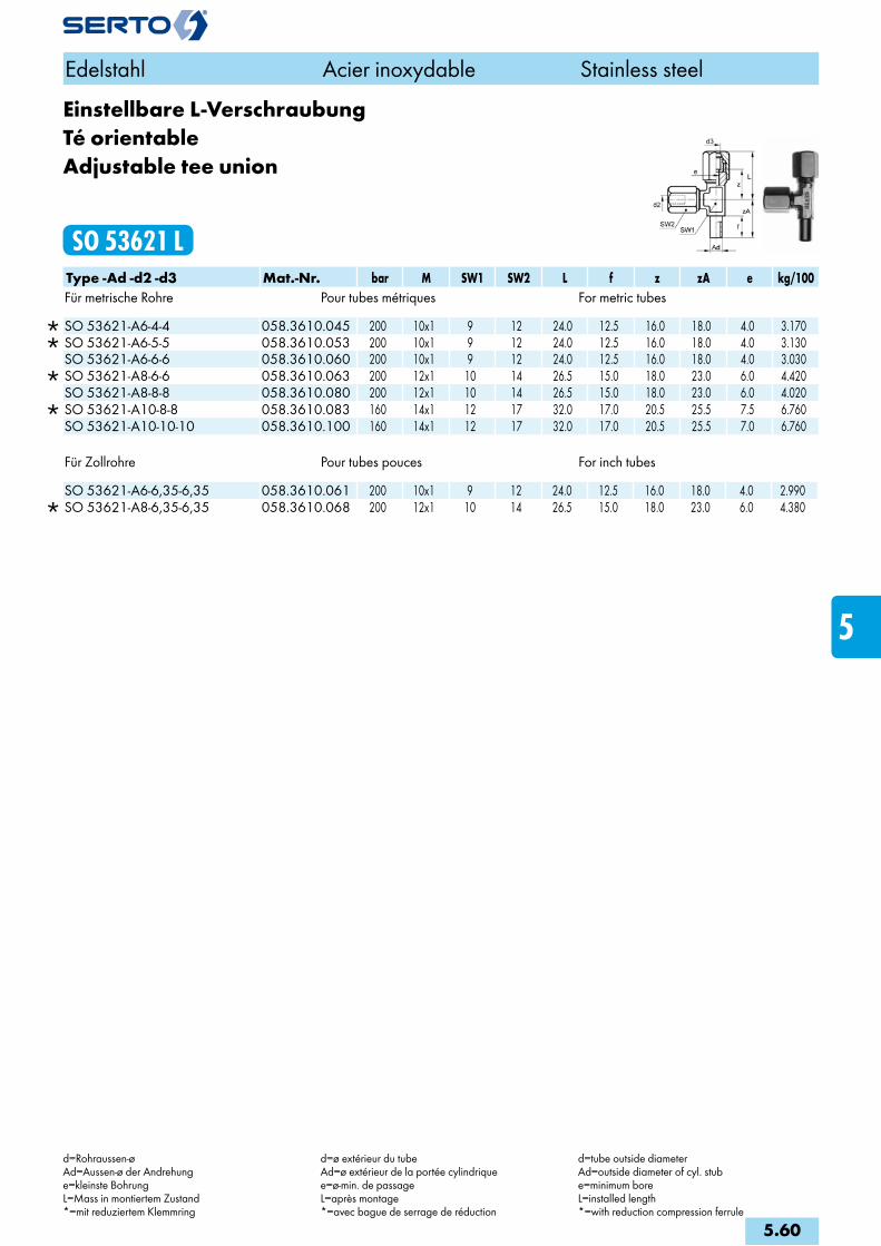
Einstellbare L-VerschraubungTé orientableAdjustable tee union
SO 53621 LType -Ad -d2 -d3 Mat.-Nr. bar M SW1 SW2 L f z zA e kg/100Für metrische Rohre Pour tubes métriques For metric tubes
SO 53621-A6-4-4 058.3610.045 200 10x1 9 12 24.0 12.5 16.0 18.0 4.0 3.170 SO 53621-A6-5-5 058.3610.053 200 10x1 9 12 24.0 12.5 16.0 18.0 4.0 3.130 SO 53621-A6-6-6 058.3610.060 200 10x1 9 12 24.0 12.5 16.0 18.0 4.0 3.030
SO 53621-A8-6-6 058.3610.063 200 12x1 10 14 26.5 15.0 18.0 23.0 6.0 4.420 SO 53621-A8-8-8 058.3610.080 200 12x1 10 14 26.5 15.0 18.0 23.0 6.0 4.020
SO 53621-A10-8-8 058.3610.083 160 14x1 12 17 32.0 17.0 20.5 25.5 7.5 6.760 SO 53621-A10-10-10 058.3610.100 160 14x1 12 17 32.0 17.0 20.5 25.5 7.0 6.760
Für Zollrohre Pour tubes pouces For inch tubes
SO 53621-A6-6,35-6,35 058.3610.061 200 10x1 9 12 24.0 12.5 16.0 18.0 4.0 2.990 SO 53621-A8-6,35-6,35 058.3610.068 200 12x1 10 14 26.5 15.0 18.0 23.0 6.0 4.380
Edelstahl Acier inoxydable Stainless steel
d=Rohraussen-øAd=Aussen-ø der Andrehunge=kleinste BohrungL=Mass in montiertem Zustand*=mit reduziertem Klemmring
d=ø extérieur du tubeAd=ø extérieur de la portée cylindriquee=ø-min. de passageL=après montage*=avec bague de serrage de réduction
d=tube outside diameterAd=outside diameter of cyl. stube=minimum boreL=installed length*=with reduction compression ferrule
5.60
i
s
3F
4M
4G
5
5L
6
7
8
9
10
11
12
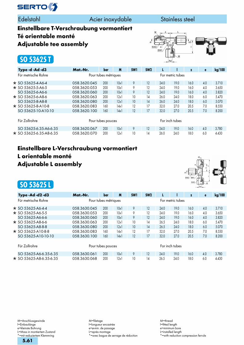
Einstellbare T-Verschraubung vormontiertTé orientable montéAdjustable tee assembly
SO 53625 TType -d -Ad -d3 Mat.-Nr. bar M SW1 SW2 L l z e kg/100Für metrische Rohre Pour tubes métriques For metric tubes
SO 53625-4-A6-4 058.3620.045 200 10x1 9 12 24.0 19.0 16.0 4.0 3.710 SO 53625-5-A6-5 058.3620.053 200 10x1 9 12 24.0 19.0 16.0 4.0 3.650 SO 53625-6-A6-6 058.3620.060 200 10x1 9 12 24.0 19.0 16.0 4.0 3.820
SO 53625-6-A8-6 058.3620.063 200 12x1 10 14 26.0 24.0 18.0 6.0 5.470 SO 53625-8-A8-8 058.3620.080 200 12x1 10 14 26.0 24.0 18.0 6.0 5.070
SO 53625-8-A10-8 058.3620.083 160 14x1 12 17 32.0 27.0 20.5 7.0 8.550 SO 53625-10-A10-10 058.3620.100 160 14x1 12 17 32.0 27.0 20.5 7.0 8.200
Für Zollrohre Pour tubes pouces For inch tubes
SO 53625-6.35-A6-6.35 058.3620.067 200 10x1 9 12 24.0 19.0 16.0 4.0 3.780 SO 53625-6.35-A8-6.35 058.3620.070 200 12x1 10 14 26.0 24.0 18.0 6.0 4.430
Einstellbare L-Verschraubung vormontiertL orientable montéAdjustable L assembly
SO 53625 LType -Ad -d2 -d3 Mat.-Nr. bar M SW1 SW2 L l z e kg/100Für metrische Rohre Pour tubes métriques For metric tubes
SO 53625-A6-4-4 058.3630.045 200 10x1 9 12 24.0 19.0 16.0 4.0 3.710 SO 53625-A6-5-5 058.3630.053 200 10x1 9 12 24.0 19.0 16.0 4.0 3.650 SO 53625-A6-6-6 058.3630.060 200 10x1 9 12 24.0 19.0 16.0 4.0 3.820
SO 53625-A8-6-6 058.3630.063 200 12x1 10 14 26.5 24.0 18.0 6.0 5.470 SO 53625-A8-8-8 058.3630.080 200 12x1 10 14 26.5 24.0 18.0 6.0 5.070
SO 53625-A10-8-8 058.3630.083 160 14x1 12 17 32.0 27.0 20.5 7.0 8.550 SO 53625-A10-10-10 058.3630.100 160 14x1 12 17 32.0 27.0 20.5 7.0 8.200
Für Zollrohre Pour tubes pouces For inch tubes
SO 53625-A6-6.35-6.35 058.3630.061 200 10x1 9 12 24.0 19.0 16.0 4.0 3.780 SO 53625-A8-6.35-6.35 058.3630.068 200 12x1 10 14 26.5 24.0 18.0 6.0 4.430
Edelstahl Acier inoxydable Stainless steel
M=Anschlussgewindel=Einbaulängee=kleinste BohrungL=Mass in montiertem Zustand*=mit reduziertem Klemmring
M=filetagel=longueur encastréee=ø-min. de passageL=après montage*=avec bague de serrage de réduction
M=threadl=fitted lengthe=minimum boreL=installed length*=with reduction compression ferrule
5.61

KreuzverschraubungCroixCross union
SO 54021Type -d Mat.-Nr. bar M SW1 SW2 L z e kg/100Für metrische Rohre Pour tubes métriques For metric tubes
SO 54021-4 058.4000.040 200 10x1 12 12 25.5 17.5 4.5 5.600 SO 54021-5 058.4000.050 200 10x1 12 12 25.5 17.5 4.5 5.550 SO 54021-6 058.4000.060 200 10x1 12 12 25.5 17.5 4.5 5.500 SO 54021-8 058.4000.080 200 12x1 12 14 27.5 19.0 6.5 7.400 SO 54021-10 058.4000.100 160 14x1 17 17 35.5 23.0 8.5 11.400 SO 54021-12 058.4000.120 160 16x1 17 19 37.5 25.0 9.5 13.900
SO 54021-14 058.4000.140 100 20x1.5 19 24 40.5 26.5 13.0 25.300 SO 54021-15 058.4000.150 100 20x1.5 19 24 40.5 26.5 13.0 24.500
Für Zollrohre Pour tubes pouces For inch tubes
SO 54021-6.35 058.4000.063 200 10x1 12 12 25.5 17.5 4.5 5.500 SO 54021-9.52 058.4000.095 160 14x1 17 17 35.5 23.0 8.5 11.600 SO 54021-12.7 058.4000.127 100 20x1.5 19 24 40.5 26.5 13.0 28.000
SO 54021-13.5 058.4000.135 100 20x1.5 19 24 40.5 26.5 13.0 25.800
Edelstahl Acier inoxydable Stainless steel
d=Rohraussen-øe=kleinste BohrungL=Mass in montiertem Zustand*=mit reduzierten Klemmring
d=ø extérieur du tubee=ø-min. de passageL=après montage*=avec bague de serrage de réduction
d=tube outside diametere=minimum boreL=installed length*=witch compression ferrule
5.62
i
s
3F
4M
4G
5
5L
6
7
8
9
10
11
12

MontagestutzenPièce de montagePre-assembly stud
SO 56000Type -d Mat.-Nr. M SW1 L SO 56000-6/-6,35 058.6000.060 10x1 11 36.0SO 56000-8 058.6000.080 12x1 11 37.0SO 56000-10/-9,52 058.6000.100 14x1 14 37.0SO 56000-12 058.6000.120 16x1 14 37.0SO 56000-15/-12,7/-13,5/-14 058.6000.150 20x1.5 17 40.0SO 56000-18/-16/-17,2 058.6000.180 24x1.5 19 40.0SO 56000-22/-21,3 058.6000.220 28x1.5 22 40.0SO 56000-28 058.6000.280 36x2 27 46.0
Anwendungsbeispiele: Exemples d‘utilisation: Sample combinations:
Der Montagestutzen wird zur Vormontage des Armaturenanschlusses verwendet.
Anwendung:Montagestutzen in Schraubstock einspannen.Armaturenanschluss aufschrauben.Rohr in Armaturenanschluss stecken.Mit Gabelschlüssel Anschlussmutter ca. 1 3/4 Umdrehungen anziehen.
Auf saubere Planfläche achten.
Zur Erleichterung der Montage sollte das Gewinde und die Planfläche ab und zu geölt werden.
Montageanleitung beachten.
Für automatisierte Vormontage siehe Apparate SERTOtool/SERTOmatic im Kapitel Werkzeuge und Zubehör.
d = Rohraussendurchmesser
La pièce de montage s’utilise pour le prémonta-ge standard de l’écrou de raccordement.
Procédé de montage:Serrer la pièce de montage dans l’étau.Visser par dessus l’écrou de raccordement.Enfiler le tube dans l’écrou de raccordement.Au moyen d’une clef à fourche serrer l’écrou d’env. 1 3/4 tours.
La surface d’étanchéité doit être propre.
La lubrification occasionnelle du filetage et de la surface d’étanchéité facilite le montage.
Se reporter aux instructions de montage.
Pour prémontage automatique voir les appareils SERTOtool/SERTOmatic au chapitre accessoires et outillage.
d = extérieur du tube
The pre-assembly stud is employed for the batch pre-fitting of the nut connection.
Directions:Clamp pre-assembly stud in vise.Screw on the nut connection.Push tube into nut connection.Tighten the union nut about 1 3/4 turns with open spanner.
Keep the flat metal surface clean.
Occasional lubrification of the thread and the flat metal surface facilitate pre-assembly.
Refer further to assembly instructions.
For automated pre-assembly see the machi-nes SERTOtool/SERTOmatic at chapter accessories, tools.
d = tube outside diameter
Edelstahl Acier inoxydable Stainless steel
5.63

M SW –G –d –G –d –G –d3 –d –G –d3 –d4M 10 x 1 14 – –4 – –4 – –4 –4 – –4 –4M 10 x 1 17 – –4 – –4 – –4 –4 – –4 –4M 10 x 1 22 – –4 – –4 – –4 –4 – –4 –4M 10 x 1 27 – –4 – –4 – –4 –4 – –4 –4M 10 x 1 14 – –5 – –5 – –5 –5 – –5 –5M 10 x 1 17 – –5 – –5 – –5 –5 – –5 –5M 10 x 1 22 – –5 – –5 – –5 –5 – –5 –5M 10 x 1 27 – –5 – –5 – –5 –5 – –5 –5M 10 x 1 14 – –6 – –6 – –6 –6 – –6 –6M 10 x 1 17 – –6 – –6 – –6 –6 – –6 –6M 10 x 1 22 – –6 – –6 – –6 –6 – –6 –6M 10 x 1 27 – –6 – –6 – –6 –6 – –6 –6M 12 x 1 17 – –8 – –8 – –8 –8 – –8 –8M 12 x 1 17 – –8 – –8 – –8 –8 – –8 –8M 12 x 1 22 – –8 – –8 – –8 –8 – –8 –8M 12 x 1 27 – –8 – –8 – –8 –8 – –8 –8M 14 x 1 17 – –10 – –10 – –10 –10 – –10 –10M 14 x 1 22 – –10 – –10 – –10 –10 – –10 –10M 14 x 1 27 – –10 – –10 – –10 –10 – –10 –10M 16 x 1 19 – –12 – –12 – –12 –12 – –12 –12M 16 x 1 22 – –12 – –12 – –12 –12 – –12 –12M 16 x 1 27 – –12 – –12 – –12 –12 – –12 –12M 20 x 1,5 24 – –14 – –14 – –14 –14 – –14 –14M 20 x 1,5 24 – –14 – –14 – –14 –14 – –14 –14M 20 x 1,5 27 – –14 – –14 – –14 –14 – –14 –14M 20 x 1,5 32 – –14 – –14 – –14M 20 x 1,5 24 – –15 – –15 – –15 –15 – –15 –15M 20 x 1,5 24 – –15 – –15 – –15 –15 – –15 –15M 20 x 1,5 27 – –15 – –15 – –15 –15 – –15 –15M 20 x 1,5 32 – –15 – –15 – –15 –15 – –15 –15
d
G
d
G
d3
G
M
SW
S0 54221S0 53221S0 52221S0 50030
d3
d4
d
G
Edelstahl Acier inoxydable Stainless steel
Anschlussvarianten mit ÜbergangsmuffeVariantes de raccordement avec adaptateur femelleConnections with female adaptor
5.64
i
s
3F
4M
4G
5
5L
6
7
8
9
10
11
12

M SW –G –d –G –d –G –d3 –d –G –d3 –d4M 24 x 1,5 30 – –16 – –16 – –16M 24 x 1,5 30 – –18 – –18 – –18M 10 x 1 14 – –6,35 – –6,35 – –6,35 –6,35 – –6,35 –6,35M 10 x 1 14 – –6,35 – –6,35 – –6,35 –6,35 – –6,35 –6,35M 10 x 1 14 – –6,35 – –6,35 – –6,35 –6,35 – –6,35 –6,35M 10 x 1 14 – –6,35 – –6,35 – –6,35 –6,35 – –6,35 –6,35M 14 x 1 17 – –9,52 – –9,52 – –9,52 –9,52 – –9,52 –9,52M 14 x 1 22 – –9,52 – –9,52 – –9,52 –9,52 – –9,52 –9,52M 14 x 1 27 – –9,52 – –9,52 – –9,52 –9,52 – –9,52 –9,52M 20 x 1,5 24 – –12,7 – –12,7 – –12,7 –12,7 – –12,7 –12,7M 20 x 1,5 24 – –12,7 – –12,7 – –12,7 –12,7 – –12,7 –12,7M 20 x 1,5 27 – –12,7 – –12,7 – –12,7 –12,7 – –12,7 –12,7M 20 x 1,5 24 – –13,5 – –13,5 – –13,5 –13,5M 20 x 1,5 24 – –13,5 – –13,5 – –13,5 –13,5M 20 x 1,5 27 – –13,5 – –13,5 – –13,5 –13,5 – –13,5 –13,5M 24 x 1,5 30 – –17,2 – –17,2 – –17,2
d
G
d
G
d3
G
M
SW
S0 54221S0 53221S0 52221S0 50030
d3
d4
d
G
Edelstahl Acier inoxydable Stainless steel
Anschlussvarianten mit ÜbergangsmuffeVariantes de raccordement avec adaptateur femelleConnections with female adaptor
5.65

M SW –R –d –R –d –R –d3 –d –R –d3 –d4M 8 x 1 10 – –3 – –3M 8 x 1 10 – –4 – –4M 8 x 1 10 – –5 – –5
M 10 x 1 12 – –4 – –4 –4M 10 x 1 14 – –4 –– –4 –4 – –4 –4M 10 x 1 17 – –4 – –4 –4M 10 x 1 22 – –4 – –4 –4
M 10 x 1 12 – –5 – –5 –5M 10 x 1 14 – –5 –– –5 –5 – –5 –5M 10 x 1 17 – –5 – –5 –5M 10 x 1 22 – –5 – –5 –5
M 10 x 1 12 – –6 – –6 –6 – –6 –6M 10 x 1 14 – –6 – –6 –6 – –6 –6M 10 x 1 17 – –6 – –6 –6 – –6 –6M 10 x 1 22 – –6 – –6 –6 – –6 –6 M 12 x 1 14 – –8 – –8 – –8 –8 – –8 –8M 12 x 1 14 – –8 – –8 –8 – –8 –8M 12 x 1 17 – –8 – –8 –8 – –8 –8M 12 x 1 22 – –8 – –8 –8 – –8 –8
M 14 x 1 17 – –10 – –10 –10M 14 x 1 17 – –10 – –10 –10 – –10 –10M 14 x 1 17 – –10 –– –10 –10 – –10 –10M 14 x 1 22 – –10 – –10 –– –10 –10 – –10 –10–M 16 x 1 19 – –12 – –12 –12 – –12 –12M 16 x 1 19 – –12 – –12 –12 – –12 –12M 16 x 1 22 – –12 – –12 –12 – –12 –12
M 20 x 1,5 24 – –14 – –14 –14M 20 x 1,5 24 – –14 – –14 –14 – –14 –14M 20 x 1,5 27 – –14 – –14 –14
M 20 x 1,5 24 – –15 – –15 –15M 20 x 1,5 24 – –15 – –15 –15 – –15 –15M 20 x 1,5 27 – –15 – –15 –15
M 24 x 1,5 30 – –16 – –16–16 – –18 – –18
M 24 x 1,5 30 – –18 ––18 –
M 28 x 1,5 36 – –18 – –18M 28 x 1,5 36 – –22 – –22 – –22
d
R
d
R
d3
R
M
SW
S0 54121S0 53121S0 52121S0 50040
d
R
d3
d4
Edelstahl Acier inoxydable Stainless steel
Anschlussvarianten mit ÜbergangsnippelVariantes de raccordement avec adaptateur mâleConnections with male adaptor
5.66
i
s
3F
4M
4G
5
5L
6
7
8
9
10
11
12

S0 53121S0 52121S0 50040 S0 54121
d
R / RNPT R / RNPT R / RNPT
d d3
d d3
d4R / RNPT
M
SW
Edelstahl Acier inoxydable Stainless steel
Anschlussvarianten mit ÜbergangsnippelVariantes de raccordement avec adaptateur mâleConnections with male adaptor
M SW –R –d –R –d –R –d3 –d –R –d3 –d4Für Zollrohre / Pour tubes en pouces / For inch tubesM10x1 12 – –6,35 – –6,35 –6,35 – –6,35 –6,35M10x1 14 – –6,35 – –6,35 –6,35 – –6,35 –6,35
M14x1 17 – –9,52 – –9,52 –9,52 – –9,52 –9,52M14x1 17 – –9,52 – –9,52 – –9,52 –9,52 – –9,52 –9,52M14x1 22 – –9,52 – –9,52 – –9,52
M20x1,5 24 – –12,7 – –12,7 –12,7 – –12,7 –12,7
M24x1,5 30 – –17,2 – –17,2 – –17,2
M28x1,5 36 – –21,3 – –21,3 – –21,3
M SW –RNPT –d –RNPT –d –RNPT –d3 –d –RNPT –d3 –d4Für Zollrohre - NPT-Gewinde / Pour tubes en pouces - Filetage NPT / For inch tubes - NPT threadM10x1 17 – –6,35 –NPT –6,35 –6,35 –NPT –6,35 –6,35M10x1 17 – –6,35 –NPT –6,35 –6,35 –NPT –6,35 –6,35
M14x1 19 – –9,52 –NPT –9,52 –9,52 –NPT –9,52 –9,52M14x1 19 –1 –9,52 –1NPT –9,52 –9,52
M20x1,5 24 – –12,7 –NPT –12,7 –12,7 –NPT –12,7 –12,7M20x1,5 24 – –13,5 –NPT –13,5 –12,7 –NPT –12,7 –12,7
5.67

S0 53121S0 52121S0 50040 S0 54121
d
Mz / RNPT Mz / RNPT Mz / RNPT
d d3
d d3
d4Mz / RNPT
M
SW
Edelstahl Acier inoxydable Stainless steel
Anschlussvarianten mit ÜbergangsnippelVariantes de raccordement avec adaptateur mâleConnections with male adaptor
M SW –Mz –d –Mz –d –Mz –d3 –d –Mz –d3 –d4Metrisches Feingewinde zylindrisch / Filetage métrique / Straight metric thread
M 8 x 1 10 M6 x 0,75 –3 M6 x 0,75 –3 M6 x 0,75M 8 x 1 10 M8 x 1 –3 M8 x 1 –3 M8 x 1M 8 x 1 10 M6 x 0,75 –4 M6 x 0,75 –4 M6 x 0,75 –4 M6 x 0,75 –4 –4M 8 x 1 10 M8 x 1 –4 M8 x 1 –4 M8 x 1 –4 M8 x 1 –4 –4M 8 x 1 10 M6 x 0,75 –5 M6 x 0,75 –5 M6 x 0,75 –5 M6 x 0,75 –5 –5M 8 x 1 10 M8 x 1 –5 M8 x 1 –5 M8 x 1 –5 M8 x 1 –5 –5
M SW –d –RNPT –d –RNPT –d3 –d –RNPT –d3 –d4NPT–Gewinde / Filetage NPT / NPT threadM 8 x 1 10 –3 –NPTM 8 x 1 10 –4 –NPTM 8 x 1 10 –5 –NPTM10x1 12 –4 –NPT –4 –4M10x1 14 –4 – NPT –4 –4 –NPT –4 –4M10x1 12 –5 –NPT –5 –5M10x1 14 –5 – NPT –5 –5 – NPT –5 –5M10x1 12 –6 – NPT –6 –6 –NPT –6 –6M10x1 14 –6 – NPT –6 –6 –NPT –6 –6M12x1M12x1 14 –8 – NPT –8 –8 – NPT –8 –8M14x1 17 –10 – NPT –10 –10 – NPT –10 –10M14x1 17 –10 – NPT –10 –10M16x1 22 –10 –NPT –10M16x1 19 –12 – NPT –12 – NPT –12 –12 – NPT –12 –12M16x1 19 –12 – NPT –12 –12 – NPT –12 –12M16x1 22 –12 – NPT –12 –12 – NPT –12 –12M20x1,5 24 –14 – NPT –14 –14 – NPT –14 –14M20x1,5 24 –15 – NPT –15 –15 – NPT –15 –15
5.68
i
s
3F
4M
4G
5
5L
6
7
8
9
10
11
12

DoppelnippelMamelon doubleHex nipple
AD HN 50Type -R Mat.-Nr. SW L e kg/100R=Rohrgewinde (kegelig) R=Filetage-gaz BSP (conique) R=BSP thread (tapered) AD HN 50-1/8-1/8 TAD.5110.042 12 25.0 6.0 1.005AD HN 50-1/4-1/4 TAD.5110.104 14 31.0 8.0 1.979AD HN 50-3/8-3/8 TAD.5110.166 17 33.0 10.5 3.180AD HN 50-1/2-1/2 TAD.5110.228 22 43.0 13.0 6.749AD HN 50-3/4-3/4 TAD.5110.292 27 48.0 21.0 7.285AD HN 50-1-1 TAD.5110.414 36 52.0 26.0 13.822
Doppelnippel R-NPTMamelon double R-NPTHex nipple R-NPT
AD HN 50 R-NPTType -R -RNPT2 Mat.-Nr. SW L e kg/100R=Rohrgewinde (kegelig) R=Filetage-gaz BSP (conique) R=BSP thread (tapered)RNPT2=NPT Gewinde RNPT2=Filetage NPT RNPT2=NPT threadAD HN 50-1/8-1/8 NPT TAD.5114.042 12 25.0 6.0 1.067AD HN 50-1/4-1/4 NPT TAD.5114.104 14 31.0 8.0 2.061AD HN 50-3/8-3/8 NPT TAD.5114.166 17 33.0 10.5 3.260AD HN 50-1/2-1/2 NPT TAD.5114.228 22 43.0 13.0 6.850AD HN 50-3/4-3/4 NPT TAD.5114.292 27 48.0 21.0 7.371AD HN 50-1-1 NPT TAD.5114.414 36 52.0 26.0 13.760
Doppelnippel NPT-NPTMamelon double NPT-NPTHex nipple NPT-NPT
AD HN 50 NPT-NPTType -RNPT Mat.-Nr. SW L e kg/100RNPT=NPT Gewinde RNPT=Filetage NPT RNPT=NPT thread AD HN 50-1/8 NPT-1/8 NPT TAD.5111.042 12 25.0 6.0 1.113AD HN 50-1/4 NPT-1/4 NPT TAD.5111.104 14 31.0 8.0 2.141AD HN 50-3/8 NPT-3/8 NPT TAD.5111.166 17 33.0 10.5 3.340AD HN 50-1/2 NPT-1/2 NPT TAD.5111.228 22 43.0 13.0 6.949AD HN 50-3/4 NPT-3/4 NPT TAD.5111.292 27 48.0 21.0 7.457AD HN 50-1 NPT-1 NPT TAD.5111.414 36 52.0 26.0 13.698
Edelstahl Acier inoxydable Stainless steel
5.69
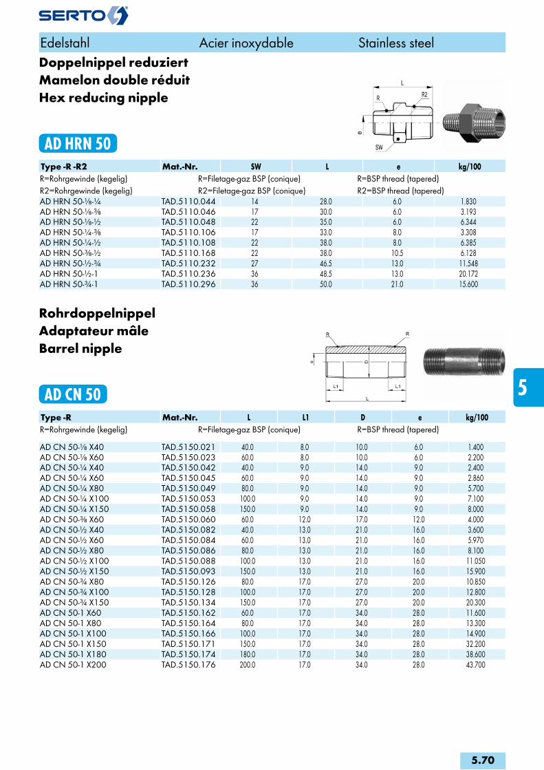
Doppelnippel reduziertMamelon double réduitHex reducing nipple
AD HRN 50Type -R -R2 Mat.-Nr. SW L e kg/100R=Rohrgewinde (kegelig) R=Filetage-gaz BSP (conique) R=BSP thread (tapered)R2=Rohrgewinde (kegelig) R2=Filetage-gaz BSP (conique) R2=BSP thread (tapered)AD HRN 50-1/8-1/4 TAD.5110.044 14 28.0 6.0 1.830AD HRN 50-1/8-3/8 TAD.5110.046 17 30.0 6.0 3.193AD HRN 50-1/8-1/2 TAD.5110.048 22 35.0 6.0 6.344AD HRN 50-1/4-3/8 TAD.5110.106 17 33.0 8.0 3.308AD HRN 50-1/4-1/2 TAD.5110.108 22 38.0 8.0 6.385AD HRN 50-3/8-1/2 TAD.5110.168 22 38.0 10.5 6.128AD HRN 50-1/2-3/4 TAD.5110.232 27 46.5 13.0 11.548AD HRN 50-1/2-1 TAD.5110.236 36 48.5 13.0 20.172AD HRN 50-3/4-1 TAD.5110.296 36 50.0 21.0 15.600
RohrdoppelnippelAdaptateur mâleBarrel nipple
AD CN 50Type -R Mat.-Nr. L L1 D e kg/100R=Rohrgewinde (kegelig) R=Filetage-gaz BSP (conique) R=BSP thread (tapered) AD CN 50-1/8 X40 TAD.5150.021 40.0 8.0 10.0 6.0 1.400AD CN 50-1/8 X60 TAD.5150.023 60.0 8.0 10.0 6.0 2.200AD CN 50-1/4 X40 TAD.5150.042 40.0 9.0 14.0 9.0 2.400AD CN 50-1/4 X60 TAD.5150.045 60.0 9.0 14.0 9.0 2.860AD CN 50-1/4 X80 TAD.5150.049 80.0 9.0 14.0 9.0 5.700AD CN 50-1/4 X100 TAD.5150.053 100.0 9.0 14.0 9.0 7.100AD CN 50-1/4 X150 TAD.5150.058 150.0 9.0 14.0 9.0 8.000AD CN 50-3/8 X60 TAD.5150.060 60.0 12.0 17.0 12.0 4.000AD CN 50-1/2 X40 TAD.5150.082 40.0 13.0 21.0 16.0 3.600AD CN 50-1/2 X60 TAD.5150.084 60.0 13.0 21.0 16.0 5.970AD CN 50-1/2 X80 TAD.5150.086 80.0 13.0 21.0 16.0 8.100AD CN 50-1/2 X100 TAD.5150.088 100.0 13.0 21.0 16.0 11.050AD CN 50-1/2 X150 TAD.5150.093 150.0 13.0 21.0 16.0 15.900AD CN 50-3/4 X80 TAD.5150.126 80.0 17.0 27.0 20.0 10.850AD CN 50-3/4 X100 TAD.5150.128 100.0 17.0 27.0 20.0 12.800AD CN 50-3/4 X150 TAD.5150.134 150.0 17.0 27.0 20.0 20.300AD CN 50-1 X60 TAD.5150.162 60.0 17.0 34.0 28.0 11.600AD CN 50-1 X80 TAD.5150.164 80.0 17.0 34.0 28.0 13.300AD CN 50-1 X100 TAD.5150.166 100.0 17.0 34.0 28.0 14.900AD CN 50-1 X150 TAD.5150.171 150.0 17.0 34.0 28.0 32.200AD CN 50-1 X180 TAD.5150.174 180.0 17.0 34.0 28.0 38.600AD CN 50-1 X200 TAD.5150.176 200.0 17.0 34.0 28.0 43.700
Edelstahl Acier inoxydable Stainless steel
5.70
i
s
3F
4M
4G
5
5L
6
7
8
9
10
11
12
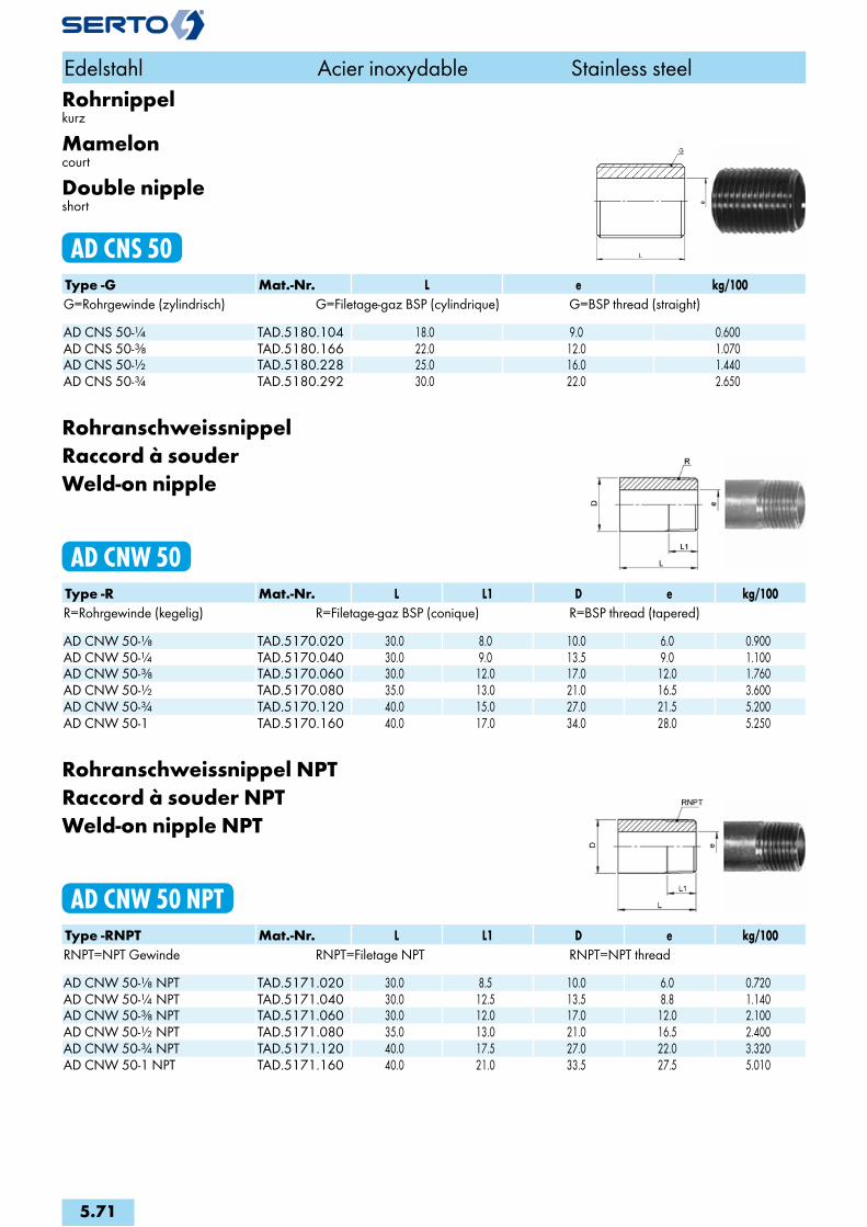
Rohrnippelkurz
Mameloncourt
Double nippleshort
AD CNS 50Type -G Mat.-Nr. L e kg/100G=Rohrgewinde (zylindrisch) G=Filetage-gaz BSP (cylindrique) G=BSP thread (straight) AD CNS 50-1/4 TAD.5180.104 18.0 9.0 0.600AD CNS 50-3/8 TAD.5180.166 22.0 12.0 1.070AD CNS 50-1/2 TAD.5180.228 25.0 16.0 1.440AD CNS 50-3/4 TAD.5180.292 30.0 22.0 2.650
RohranschweissnippelRaccord à souderWeld-on nipple
AD CNW 50Type -R Mat.-Nr. L L1 D e kg/100R=Rohrgewinde (kegelig) R=Filetage-gaz BSP (conique) R=BSP thread (tapered) AD CNW 50-1/8 TAD.5170.020 30.0 8.0 10.0 6.0 0.900AD CNW 50-1/4 TAD.5170.040 30.0 9.0 13.5 9.0 1.100AD CNW 50-3/8 TAD.5170.060 30.0 12.0 17.0 12.0 1.760AD CNW 50-1/2 TAD.5170.080 35.0 13.0 21.0 16.5 3.600AD CNW 50-3/4 TAD.5170.120 40.0 15.0 27.0 21.5 5.200AD CNW 50-1 TAD.5170.160 40.0 17.0 34.0 28.0 5.250
Rohranschweissnippel NPTRaccord à souder NPTWeld-on nipple NPT
AD CNW 50 NPTType -RNPT Mat.-Nr. L L1 D e kg/100RNPT=NPT Gewinde RNPT=Filetage NPT RNPT=NPT thread AD CNW 50-1/8 NPT TAD.5171.020 30.0 8.5 10.0 6.0 0.720AD CNW 50-1/4 NPT TAD.5171.040 30.0 12.5 13.5 8.8 1.140AD CNW 50-3/8 NPT TAD.5171.060 30.0 12.0 17.0 12.0 2.100AD CNW 50-1/2 NPT TAD.5171.080 35.0 13.0 21.0 16.5 2.400AD CNW 50-3/4 NPT TAD.5171.120 40.0 17.5 27.0 22.0 3.320AD CNW 50-1 NPT TAD.5171.160 40.0 21.0 33.5 27.5 5.010
Edelstahl Acier inoxydable Stainless steel
5.71

AdapterAdaptateurAdapter
AD A 50Type -G -R2 Mat.-Nr. SW L L1 L2 e kg/100G=Rohrgewinde (zylindrisch) G=Filetage-gaz BSP (cylindrique) G=BSP thread (straight)R2=Rohrgewinde (kegelig) R2=Filetage-gaz BSP (conique) R2=BSP thread (tapered)AD A 50-1/8-1/8 TAD.5120.042 14 21.0 9.5 8.0 6.0 1.226AD A 50-1/4-1/4 TAD.5120.104 17 26.0 12.5 9.0 8.0 2.192AD A 50-3/8-3/8 TAD.5120.166 22 27.0 12.5 9.5 10.5 3.698AD A 50-1/2-1/2 TAD.5120.228 27 35.0 17.5 11.5 13.0 7.183AD A 50-3/4-3/4 TAD.5120.292 32 40.0 19.0 14.0 21.0 9.166AD A 50-1-1 TAD.5120.414 41 45.0 21.0 17.0 26.0 17.524
Adapter reduziertAdaptateur réduitReducing adapter
AD RA 50 G-RType -G -R2 Mat.-Nr. SW L L1 L2 e kg/100G=Rohrgewinde (zylindrisch) G=Filetage-gaz BSP (cylindrique) G=BSP thread (straight)R2=Rohrgewinde (kegelig) R2=Filetage-gaz BSP (conique) R2=BSP thread (tapered)AD RA 50-1/4-1/8 TAD.5120.102 17 23.0 9.5 9.0 6.0 1.776AD RA 50-3/8-1/4 TAD.5120.164 22 28.0 12.5 9.5 8.0 3.586AD RA 50-1/2-1/4 TAD.5120.224 27 31.0 12.5 11.5 8.0 5.815AD RA 50-1/2-3/8 TAD.5120.226 27 30.0 12.5 11.5 10.5 5.780AD RA 50-3/4-1/2 TAD.5120.288 32 39.0 17.5 14.0 13.0 9.662AD RA 50-1-1/2 TAD.5120.408 41 45.0 17.5 17.0 13.0 18.781AD RA 50-1-3/4 TAD.5120.412 41 45.0 19.0 17.0 21.0 17.126
Edelstahl Acier inoxydable Stainless steel
5.72
i
s
3F
4M
4G
5
5L
6
7
8
9
10
11
12
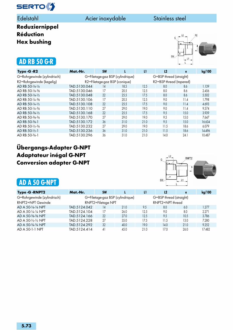
ReduziernippelRéductionHex bushing
AD RB 50 G-RType -G -R2 Mat.-Nr. SW L L1 L2 e kg/100G=Rohrgewinde (zylindrisch) G=Filetage-gaz BSP (cylindrique) G=BSP thread (straight)R2=Rohrgewinde (kegelig) R2=Filetage-gaz BSP (conique) R2=BSP thread (tapered)AD RB 50-1/8-1/4 TAD.5130.044 14 18.5 12.5 8.0 8.6 1.139AD RB 50-1/8-3/8 TAD.5130.046 17 20.5 12.5 8.0 8.6 2.456AD RB 50-1/8-1/2 TAD.5130.048 22 25.5 17.5 8.0 8.6 5.502AD RB 50-1/4-3/8 TAD.5130.106 17 20.5 12.5 9.0 11.4 1.798AD RB 50-1/4-1/2 TAD.5130.108 22 25.5 17.5 9.0 11.4 4.693AD RB 50-1/4-3/4 TAD.5130.110 27 29.0 19.0 9.0 11.4 9.574AD RB 50-3/8-1/2 TAD.5130.168 22 25.5 17.5 9.5 15.0 3.939AD RB 50-3/8-3/4 TAD.5130.170 27 29.0 19.0 9.5 15.0 7.647AD RB 50-3/8-1 TAD.5130.172 36 31.0 21.0 9.5 15.0 16.634AD RB 50-1/2-3/4 TAD.5130.232 27 29.0 19.0 11.5 18.6 6.079AD RB 50-1/2-1 TAD.5130.236 36 31.0 21.0 11.5 18.6 14.496AD RB 50-3/4-1 TAD.5130.296 36 31.0 21.0 14.0 24.1 10.487
Übergangs-Adapter G-NPTAdaptateur inégal G-NPTConversion adapter G-NPT
AD A 50 G-NPTType -G -RNPT2 Mat.-Nr. SW L L1 L2 e kg/100G=Rohrgewinde (zylindrisch) G=Filetage-gaz BSP (cylindrique) G=BSP thread (straight)RNPT2=NPT Gewinde RNPT2=Filetage NPT RNPT2=NPT threadAD A 50-1/8-1/8 NPT TAD.5124.042 14 21.0 9.5 8.0 6.0 1.277AD A 50-1/4-1/4 NPT TAD.5124.104 17 26.0 12.5 9.0 8.0 2.271AD A 50-3/8-3/8 NPT TAD.5124.166 22 27.0 12.5 9.5 10.5 3.786AD A 50-1/2-1/2 NPT TAD.5124.228 27 35.0 17.5 11.5 13.0 7.280AD A 50-3/4-3/4 NPT TAD.5124.292 32 40.0 19.0 14.0 21.0 9.252AD A 50-1-1 NPT TAD.5124.414 41 45.0 21.0 17.0 26.0 17.482
Edelstahl Acier inoxydable Stainless steel
5.73
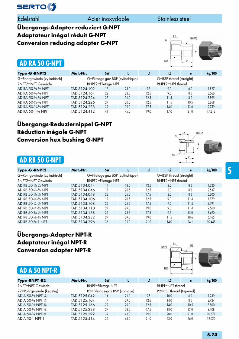
Übergangs-Adapter reduziert G-NPTAdaptateur inégal réduit G-NPTConversion reducing adapter G-NPT
AD RA 50 G-NPTType -G -RNPT2 Mat.-Nr. SW L L1 L2 e kg/100G=Rohrgewinde (zylindrisch) G=Filetage-gaz BSP (cylindrique) G=BSP thread (straight)RNPT2=NPT Gewinde RNPT2=Filetage NPT RNPT2=NPT threadAD RA 50-1/4-1/8 NPT TAD.5124.102 17 23.0 9.5 9.0 6.0 1.827AD RA 50-3/8-1/4 NPT TAD.5124.164 22 28.0 12.5 9.5 8.0 3.666AD RA 50-1/2-1/4 NPT TAD.5124.224 27 31.0 12.5 11.5 8.0 5.895AD RA 50-1/2-3/8 NPT TAD.5124.226 27 30.0 12.5 11.5 10.5 5.868AD RA 50-3/4-1/2 NPT TAD.5124.288 32 39.0 17.5 14.0 13.0 9.759AD RA 50-1-3/4 NPT TAD.5124.412 41 45.0 19.0 17.0 21.0 17.213
Übergangs-Reduziernippel G-NPTRéduction inégale G-NPTConversion hex bushing G-NPT
AD RB 50 G-NPTType -G -RNPT2 Mat.-Nr. SW L L1 L2 e kg/100G=Rohrgewinde (zylindrisch) G=Filetage-gaz BSP (cylindrique) G=BSP thread (straight)RNPT2=NPT Gewinde RNPT2=Filetage NPT RNPT2=NPT threadAD RB 50-1/8-1/4 NPT TAD.5134.044 14 18.5 12.5 8.0 8.6 1.220AD RB 50-1/8-3/8 NPT TAD.5134.046 17 20.5 12.5 8.0 8.6 2.537AD RB 50-1/8-1/2 NPT TAD.5134.048 22 25.5 17.5 8.0 8.6 5.600AD RB 50-1/4-3/8 NPT TAD.5134.106 17 20.5 12.5 9.0 11.4 1.879AD RB 50-1/4-1/2 NPT TAD.5134.108 22 25.5 17.5 9.0 11.4 4.791AD RB 50-1/4-3/4 NPT TAD.5134.110 27 29.0 19.0 9.0 11.4 9.660AD RB 50-3/8-1/2 NPT TAD.5134.168 22 25.5 17.5 9.5 15.0 3.490AD RB 50-1/2-3/4 NPT TAD.5134.232 27 29.0 19.0 11.5 18.6 6.165AD RB 50-3/4-1 NPT TAD.5134.296 36 31.0 21.0 14.0 24.1 10.445
Übergangs-Adapter NPT-RAdaptateur inégal NPT-RConversion adapter NPT-R
AD A 50 NPT-RType -RNPT -R2 Mat.-Nr. SW L L1 L2 e kg/100RNPT=NPT Gewinde RNPT=Filetage NPT RNPT=NPT threadR2=Rohrgewinde (kegelig) R2=Filetage-gaz BSP (conique) R2=BSP thread (tapered)AD A 50-1/8 NPT-1/8 TAD.5125.042 14 21.0 9.5 10.0 6.0 1.239AD A 50-1/4 NPT-1/4 TAD.5125.104 17 29.0 12.5 14.0 8.0 2.424AD A 50-3/8 NPT-3/8 TAD.5125.166 22 29.0 12.5 14.0 10.5 3.800AD A 50-1/2 NPT-1/2 TAD.5125.228 27 38.0 17.5 18.0 13.0 8.108AD A 50-3/4 NPT-3/4 TAD.5125.292 32 43.0 19.0 20.0 21.0 10.371AD A 50-1 NPT-1 TAD.5125.414 36 45.0 21.0 23.0 26.0 12.020
Edelstahl Acier inoxydable Stainless steel
5.74
i
s
3F
4M
4G
5
5L
6
7
8
9
10
11
12

Übergangs-Reduziernippel NPT-RRéduction inégale NPT-RConversion hex bushing NPT-R
AD RB 50 NPT-RType -RNPT -R2 Mat.-Nr. SW L L1 L2 e kg/100RNPT=NPT Gewinde RNPT=Filetage NPT RNPT=NPT threadR2=Rohrgewinde (kegelig) R2=Filetage-gaz BSP (conique) R2=BSP thread (tapered)AD RB 50-1/8 NPT-1/4 TAD.5135.044 14 18.5 12.5 6.7 8.4 1.142AD RB 50-1/4 NPT-3/8 TAD.5135.106 17 20.5 12.5 10.2 10.8 1.869AD RB 50-1/4 NPT-1/2 TAD.5135.108 22 25.5 17.5 10.2 10.8 4.802AD RB 50-1/2 NPT-3/4 TAD.5135.232 27 29.0 19.0 13.5 17.7 6.418
Adapter reduziert NPT-NPTAdaptateur réduit NPT-NPTReducing adapter NPT-NPT
AD RA 50 NPT-NPTType -RNPT -RNPT2 Mat.-Nr. SW L L1 L2 e kg/100RNPT=NPT Gewinde RNPT=Filetage NPT RNPT=NPT threadRNPT2=NPT Gewinde RNPT2=Filetage NPT RNPT2=NPT threadAD RA 50-1/4 NPT -1/8 NPT TAD.5121.102 17 26.0 9.5 10.2 6.0 2.150AD RA 50-3/8 NPT -1/4 NPT TAD.5121.164 22 30.0 12.5 10.3 8.0 3.920AD RA 50-1/2 NPT -1/4 NPT TAD.5121.224 27 35.0 12.5 13.5 8.0 7.505AD RA 50-1/2 NPT -3/8 NPT TAD.5121.226 27 35.0 12.5 13.5 10.5 7.866AD RA 50-3/4 NPT -1/2 NPT TAD.5121.288 32 43.0 17.5 13.8 13.0 12.030AD RA 50-1 NPT -1/2 NPT TAD.5121.408 36 48.0 17.5 17.4 13.0 14.540AD RA 50-1 NPT -3/4 NPT TAD.5121.412 36 48.0 19.0 17.4 21.0 13.110
Reduziernippel NPT-NPTRéduction NPT-NPTHex bushing NPT-NPT
AD RB 50 NPT-NPTType -RNPT -RNPT2 Mat.-Nr. SW L L1 L2 e kg/100RNPT=NPT Gewinde RNPT=Filetage NPT RNPT=NPT threadRNPT2=NPT Gewinde RNPT2=Filetage NPT RNPT2=NPT threadAD RB 50-1/8 NPT -1/4 NPT TAD.5131.044 14 18.5 12.5 6.7 8.4 1.280AD RB 50-1/8 NPT -3/8 NPT TAD.5131.046 17 20.5 12.5 6.7 8.4 2.660AD RB 50-1/4 NPT -3/8 NPT TAD.5131.106 17 20.5 12.5 10.2 10.8 2.070AD RB 50-1/4 NPT -1/2 NPT TAD.5131.108 22 25.5 17.5 10.2 10.8 5.150AD RB 50-3/8 NPT -1/2 NPT TAD.5131.168 22 25.5 17.5 10.3 13.9 3.980AD RB 50-1/2 NPT -3/4 NPT TAD.5131.232 27 29.0 19.0 13.5 17.7 6.820AD RB 50-1/2 NPT -1 NPT TAD.5131.236 36 31.0 21.0 13.5 17.7 15.510AD RB 50-3/4 NPT -1 NPT TAD.5131.296 36 31.0 21.0 13.8 22.5 11.920
Edelstahl Acier inoxydable Stainless steel
5.75

MuffeManchonAdaptor
AD C 50Type -G -G2 Mat.-Nr. L D D1 kg/100G=Rohrgewinde (zylindrisch) G=Filetage-gaz BSP (cylindrique) G=BSP thread (straight)G2=Rohrgewinde (zylindrisch) G2=Filetage-gaz BSP (cylindrique) G2=BSP thread (straight)AD C 50-1/8-1/8 TAD.5140.042 17.0 14.0 1.150AD C 50-1/8-1/4 TAD.5140.044 25.0 18.0 15.0 2.540AD C 50-1/4-1/4 TAD.5140.104 25.0 18.0 2.150AD C 50-1/4-3/8 TAD.5140.106 30.0 22.5 17.5 5.140AD C 50-1/4-1/2 TAD.5140.108 37.0 28.0 18.0 8.600AD C 50-3/8-3/8 TAD.5140.166 27.0 22.0 3.600AD C 50-3/8-1/2 TAD.5140.168 34.0 28.0 22.0 7.660AD C 50-1/2-1/2 TAD.5140.228 34.0 27.0 5.760AD C 50-1/2-3/4 TAD.5140.232 39.0 33.0 27.0 13.860AD C 50-3/4-3/4 TAD.5140.292 36.0 33.0 8.600AD C 50-3/4-1 TAD.5140.296 45.0 40.0 33.0 26.340AD C 50-3/4-1 1/4 TAD.5140.298 50.0 50.0 33.0 29.310AD C 50-1-1 TAD.5140.414 43.0 40.0 15.250AD C 50-1-1 1/4 TAD.5140.418 50.0 50.0 40.0 34.420
Halbe MuffeManchon courtCoupling short
AD CS 50Type -G Mat.-Nr. L D kg/100G=Rohrgewinde (zylindrisch) G=Filetage-gaz BSP (cylindrique) G=BSP thread (straight) AD CS 50-1/8 TAD.5200.042 8.0 14.0 0.500AD CS 50-1/4 TAD.5200.104 11.0 17.0 0.900AD CS 50-3/8 TAD.5200.166 12.0 22.0 1.550AD CS 50-1/2 TAD.5200.228 15.0 27.0 2.600AD CS 50-3/4 TAD.5200.292 17.0 32.0 3.670AD CS 50-1 TAD.5200.414 19.0 40.0 6.100
Edelstahl Acier inoxydable Stainless steel
5.76
i
s
3F
4M
4G
5
5L
6
7
8
9
10
11
12

HochdruckanschweissmuffeManchon haute pression à souderHigh-pressure weld-on adaptor
AD FCW 50Type -RNPT Mat.-Nr. L D kg/100RNPT=NPT Gewinde RNPT=Filetage NPT RNPT=NPT thread AD FCW 50-1/8 NPT TAD.5161.042 21.0 20.0 1.250AD FCW 50-1/4 NPT TAD.5161.104 25.0 25.0 2.160AD FCW 50-3/8 NPT TAD.5161.166 30.0 25.0 7.000AD FCW 50-1/2 NPT TAD.5161.228 30.0 32.0 7.240AD FCW 50-1 NPT TAD.5161.414 40.0 50.0 37.400
Sechskant-MuffeManchon doubleHex coupling
AD HC 50Type -G Mat.-Nr. SW L e kg/100G=Rohrgewinde (zylindrisch) G=Filetage-gaz BSP (cylindrique) G=BSP thread (straight) AD HC 50-1/8-1/8 TAD.5100.042 17 17.0 8.6 2.278AD HC 50-1/4-1/4 TAD.5100.104 22 25.0 11.4 5.500AD HC 50-3/8-3/8 TAD.5100.166 22 26.0 15.0 4.391AD HC 50-1/2-1/2 TAD.5100.228 27 34.0 18.6 8.425AD HC 50-3/4-3/4 TAD.5100.292 32 36.0 24.1 10.686AD HC 50-1-1 TAD.5100.414 46 43.0 30.3 33.192
Sechskant-Muffe reduziertManchon double réduitHex reducing coupling
AD HRC 50Type -G -G2 Mat.-Nr. SW L L1 L2 e kg/100G=Rohrgewinde (zylindrisch) G=Filetage-gaz BSP (cylindrique) G=BSP thread (straight)G2=Rohrgewinde (zylindrisch) G2=Filetage-gaz BSP (cylindrique) G2=BSP thread (straight)AD HRC 50-1/8-1/4 TAD.5100.044 22 25.0 8.0 9.0 8.6 5.938AD HRC 50-1/8-3/8 TAD.5100.046 22 30.0 8.0 9.5 8.6 6.500AD HRC 50-1/8-1/2 TAD.5100.048 27 41.0 8.0 11.5 8.6 14.097AD HRC 50-1/4-3/8 TAD.5100.106 22 29.0 9.0 9.5 11.4 5.746AD HRC 50-1/4-1/2 TAD.5100.108 27 40.0 9.0 11.5 11.4 12.941AD HRC 50-3/8-1/2 TAD.5100.168 27 38.0 9.5 11.5 15.0 10.055AD HRC 50-1/2-3/4 TAD.5100.232 32 41.0 11.5 14.0 18.6 15.200AD HRC 50-1/2-1 TAD.5100.236 46 51.0 11.5 17.0 18.6 48.706
Edelstahl Acier inoxydable Stainless steel
5.77
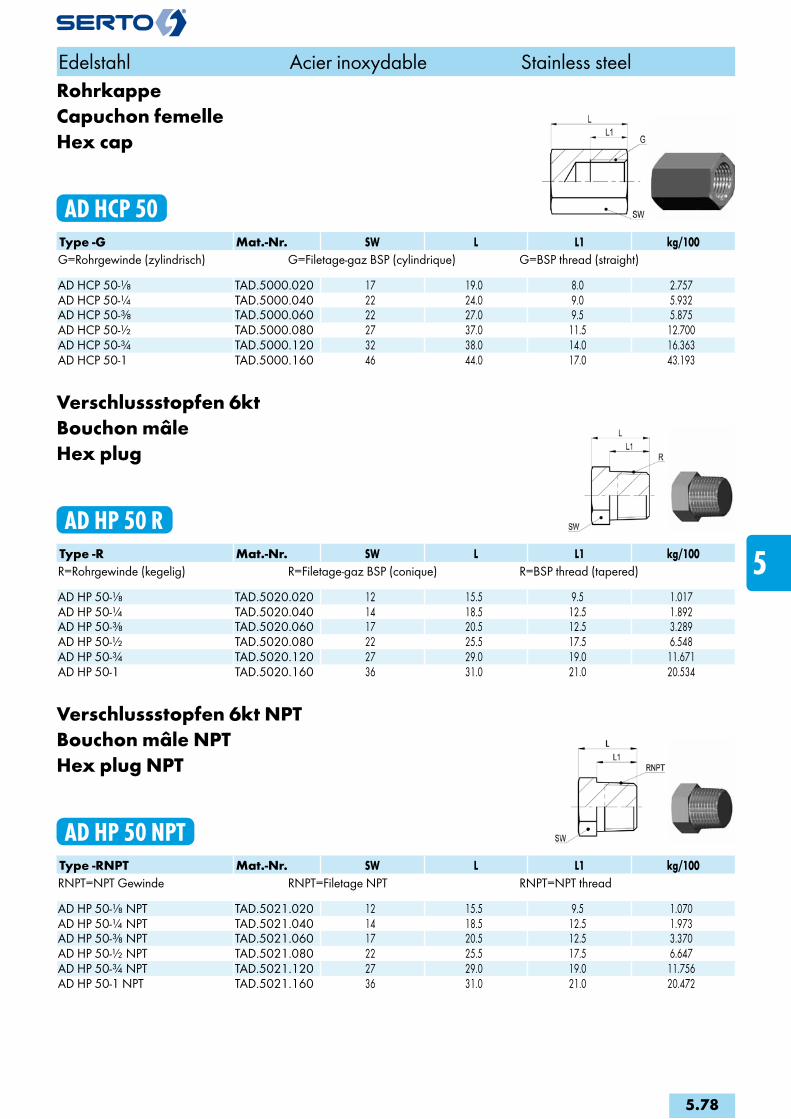
RohrkappeCapuchon femelleHex cap
AD HCP 50Type -G Mat.-Nr. SW L L1 kg/100G=Rohrgewinde (zylindrisch) G=Filetage-gaz BSP (cylindrique) G=BSP thread (straight) AD HCP 50-1/8 TAD.5000.020 17 19.0 8.0 2.757AD HCP 50-1/4 TAD.5000.040 22 24.0 9.0 5.932AD HCP 50-3/8 TAD.5000.060 22 27.0 9.5 5.875AD HCP 50-1/2 TAD.5000.080 27 37.0 11.5 12.700AD HCP 50-3/4 TAD.5000.120 32 38.0 14.0 16.363AD HCP 50-1 TAD.5000.160 46 44.0 17.0 43.193
Verschlussstopfen 6ktBouchon mâleHex plug
AD HP 50 RType -R Mat.-Nr. SW L L1 kg/100R=Rohrgewinde (kegelig) R=Filetage-gaz BSP (conique) R=BSP thread (tapered) AD HP 50-1/8 TAD.5020.020 12 15.5 9.5 1.017AD HP 50-1/4 TAD.5020.040 14 18.5 12.5 1.892AD HP 50-3/8 TAD.5020.060 17 20.5 12.5 3.289AD HP 50-1/2 TAD.5020.080 22 25.5 17.5 6.548AD HP 50-3/4 TAD.5020.120 27 29.0 19.0 11.671AD HP 50-1 TAD.5020.160 36 31.0 21.0 20.534
Verschlussstopfen 6kt NPTBouchon mâle NPTHex plug NPT
AD HP 50 NPTType -RNPT Mat.-Nr. SW L L1 kg/100RNPT=NPT Gewinde RNPT=Filetage NPT RNPT=NPT thread AD HP 50-1/8 NPT TAD.5021.020 12 15.5 9.5 1.070AD HP 50-1/4 NPT TAD.5021.040 14 18.5 12.5 1.973AD HP 50-3/8 NPT TAD.5021.060 17 20.5 12.5 3.370AD HP 50-1/2 NPT TAD.5021.080 22 25.5 17.5 6.647AD HP 50-3/4 NPT TAD.5021.120 27 29.0 19.0 11.756AD HP 50-1 NPT TAD.5021.160 36 31.0 21.0 20.472
Edelstahl Acier inoxydable Stainless steel
5.78
i
s
3F
4M
4G
5
5L
6
7
8
9
10
11
12

Verschlussschraube mit Innen 6ktBouchon d‘obturationScrew Plug
AD SP 50Type -R Mat.-Nr. SW B kg/100R=Rohrgewinde (kegelig) R=Filetage-gaz BSP (conique) R=BSP thread (tapered) AD SP 50-1/8 TAD.5010.020 5 8.0 0.338AD SP 50-1/4 TAD.5010.040 7 10.0 0.740AD SP 50-3/8 TAD.5010.060 8 10.0 1.250AD SP 50-1/2 TAD.5010.080 10 10.0 1.940AD SP 50-3/4 TAD.5010.110 12 12.0 3.800AD SP 50-1 TAD.5010.160 17 12.0 5.760
Verschlussschraubemit Aussen-6kt und Bund
Vis d‘extrémitésix pans extérieur
Screw plughexagon head
AD HPS 50Type -G Mat.-Nr. SW L L1 kg/100G=Rohrgewinde (zylindrisch) G=Filetage-gaz BSP (cylindrique) G=BSP thread (straight) AD HPS 50-1/8 TAD.5030.020 10 17.0 8.0 1.160AD HPS 50-1/4 TAD.5030.040 13 21.0 12.0 2.600AD HPS 50-3/8 TAD.5030.060 17 21.0 12.0 3.960AD HPS 50-1/2 TAD.5030.080 19 26.5 14.0 6.960AD HPS 50-3/4 TAD.5030.120 24 30.0 16.0 12.620AD HPS 50-1 TAD.5030.160 27 32.0 16.0 19.900
Verschlussschraube mit O-RingBouchon d‘obturation avec joint toriqueScrew plug with O-Ring
AD HPO 50Type -G Mat.-Nr. SW L L1 kg/100G=Rohrgewinde (zylindrisch) G=Filetage-gaz BSP (cylindrique) G=BSP thread (straight) AD HPO 50-1/8 TAD.5040.020 10 17.0 8.0 1.180AD HPO 50-1/4 TAD.5040.040 13 21.0 12.0 2.280AD HPO 50-3/8 TAD.5040.060 17 21.0 12.0 3.780AD HPO 50-1/2 TAD.5040.080 19 26.0 14.0 7.000
Edelstahl Acier inoxydable Stainless steel
5.79

Verschlussschraube mit O-Ring (FPM)Bouchon d‘obturation avec joint torique (FPM)Screw plug with O-Ring (FPM)
AD HSPO 50Type -G Mat.-Nr. SW L L1 D kg/100G=Rohrgewinde (zylindrisch) G=Filetage-gaz BSP (cylindrique) G=BSP thread (straight) AD HSPO 50-1/8-FPM TAD.5050.020 5 11.0 8.0 14.0 0.610AD HSPO 50-1/4-FPM TAD.5050.040 6 15.0 12.0 18.0 1.410AD HSPO 50-3/8-FPM TAD.5050.060 8 15.0 12.0 18.0 2.200AD HSPO 50-1/2-FPM TAD.5050.080 10 18.0 14.0 26.0 4.130AD HSPO 50-3/4-FPM TAD.5050.120 12 20.0 16.0 32.0 7.380
Verschlussschraube mit Innen-6ktVis d‘extrémité six pans creuxHexagon socket screw plug
AD HSP 50Type -G Mat.-Nr. SW L L1 D kg/100G=Rohrgewinde (zylindrisch) G=Filetage-gaz BSP (cylindrique) G=BSP thread (straight) AD HSP 50-1/8 TAD.5070.020 5 11.0 8.0 14.0 0.650AD HSP 50-1/4 TAD.5070.040 6 15.0 12.0 18.0 1.470AD HSP 50-3/8 TAD.5070.060 8 15.0 12.0 22.0 2.320AD HSP 50-1/2 TAD.5070.080 10 18.0 14.0 26.0 4.350AD HSP 50-3/4 TAD.5070.120 12 20.0 16.0 32.0 7.700AD HSP 50-1 TAD.5070.160 17 21.0 16.0 39.0 12.000
Sechskant-KontermutterEcrou à six pansHex counternut
AD HCN 50Type -G Mat.-Nr. SW s kg/100G=Rohrgewinde (zylindrisch) G=Filetage-gaz BSP (cylindrique) G=BSP thread (straight) AD HCN 50-1/8 TAD.5900.042 19 6.00 1.200AD HCN 50-1/4 TAD.5900.104 22 6.00 1.430AD HCN 50-3/8 TAD.5900.166 27 7.00 2.370AD HCN 50-1/2 TAD.5900.228 32 8.00 3.000AD HCN 50-3/4 TAD.5900.292 36 9.00 4.260
Edelstahl Acier inoxydable Stainless steel
5.80
i
s
3F
4M
4G
5
5L
6
7
8
9
10
11
12

Aufschraub-WinkelCoude double femelleFemale elbow
AD FE 51Type -G Mat.-Nr. H kg/100G=Rohrgewinde (zylindrisch) G=Filetage-gaz BSP (cylindrique) G=BSP thread (straight) AD FE 51-1/8-1/8 TAD.5300.042 14.0 3.700AD FE 51-1/4-1/4 TAD.5300.104 19.0 5.100AD FE 51-3/8-3/8 TAD.5300.166 23.0 6.600AD FE 51-1/2-1/2 TAD.5300.228 27.0 9.000AD FE 51-3/4-3/4 TAD.5300.292 30.5 19.100AD FE 51-1-1 TAD.5300.414 36.0 27.800
Einschraub-/Aufschraub-WinkelCoude femelle - mâleStreet elbow
AD SE 51Type -G -R2 Mat.-Nr. H h kg/100G=Rohrgewinde (zylindrisch) G=Filetage-gaz BSP (cylindrique) G=BSP thread (straight)R2=Rohrgewinde (kegelig) R2=Filetage-gaz BSP (conique) R2=BSP thread (tapered)AD SE 51-1/8-1/8 TAD.5320.042 17.0 26.0 2.800AD SE 51-1/4-1/4 TAD.5320.104 19.0 30.0 3.600AD SE 51-3/8-3/8 TAD.5320.166 23.0 35.0 6.500AD SE 51-1/2-1/2 TAD.5320.228 27.0 40.0 11.200AD SE 51-3/4-3/4 TAD.5320.292 32.0 40.0 16.100AD SE 51-1-1 TAD.5320.414 38.0 52.0 25.600
Aufschraub-TTé triple femelleFemale Tee
AD FT 51Type -G Mat.-Nr. L H kg/100G=Rohrgewinde (zylindrisch) G=Filetage-gaz BSP (cylindrique) G=BSP thread (straight) AD FT 51-1/8-1/8-1/8 TAD.5400.060 36.0 18.0 3.000AD FT 51-1/4-1/4-1/4 TAD.5400.160 38.0 19.0 7.300AD FT 51-3/8-3/8-3/8 TAD.5400.350 46.0 23.0 10.100AD FT 51-1/2-1/2-1/2 TAD.5400.450 54.0 27.0 16.400AD FT 51-3/4-3/4-3/4 TAD.5400.520 63.4 31.7 22.500AD FT 51-1-1-1 TAD.5400.650 72.0 36.0 37.000
Edelstahl Acier inoxydable Stainless steel
5.81

6kt-Nippelmit einseitigem 60°-Innenkonus, andere Seite Innengewinde
Raccord six pansà cône intérieur 60°, filetage femelle sur l'autre côté
Hexagon nipplewith 60° internal taper on 1 side, internal thread on other side
ADH A 50Type -G -G2 Mat.-Nr. SW L L1 L2 e kg/100G=Rohrgewinde (zylindrisch) G=Filetage-gaz BSP (cylindrique) G=BSP thread (straight)G2=Rohrgewinde (zylindrisch) G2=Filetage-gaz BSP (cylindrique) G2=BSP thread (straight)ADH A 50-3/8 -3/8 496.5320.166 22 26.0 11.0 10.0 9.0 3.870ADH A 50-1/2 -1/2 496.5320.228 27 29.0 12.0 13.0 12.0 6.110
6kt-Doppelnippelbeidseitig 60°-Innenkonus
Raccord six pansà cône intérieur 60° des deux côtés
Hexagon barrel nipple60° internal taper on both sides
ADH HNC 50Type -G Mat.-Nr. SW L L1 L2 e kg/100G=Rohrgewinde (zylindrisch) G=Filetage-gaz BSP (cylindrique) G=BSP thread (straight) ADH HNC 50-1/4 -1/4 496.5100.104 17 28.0 11.0 11.0 8.5 1.490ADH HNC 50-3/8 -3/8 496.5100.166 14 28.0 11.0 11.0 7.5 2.560
Doppelnippelmit einseitigem 60°-Innenkonus, andere Seite kegeliges Aussengewinde
Raccord doubleà cône intérieur 60°, filetage mâle sur l'autre côté
Barrel nipplewith 60° internal taper on 1 side, tapered external thread on other side
ADH HNIC 50Type -G -R2 Mat.-Nr. SW L L1 L2 e kg/100G=Rohrgewinde (zylindrisch) G=Filetage-gaz BSP (cylindrique) G=BSP thread (straight)R2=Rohrgewinde (kegelig) R2=Filetage-gaz BSP (conique) R2=BSP thread (tapered)ADH HNIC 50-1/8 -1/8 496.5210.042 10 22.0 10.0 8.0 4.0 0.760ADH HNIC 50-1/4 -1/4 496.5210.104 14 28.0 10.0 11.0 7.5 1.120ADH HNIC 50-3/8 -3/8 496.5210.166 17 30.0 11.0 12.0 10.0 3.280ADH HNIC 50-1/2 -1/2 496.5210.228 22 34.0 11.5 13.0 12.0 5.480ADH HNIC 50-3/4 -3/4 496.5210.292 27 38.0 13.0 15.0 17.0 9.000
Edelstahl Acier inoxydable Stainless steel
5.82
i
s
3F
4M
4G
5
5L
6
7
8
9
10
11
12
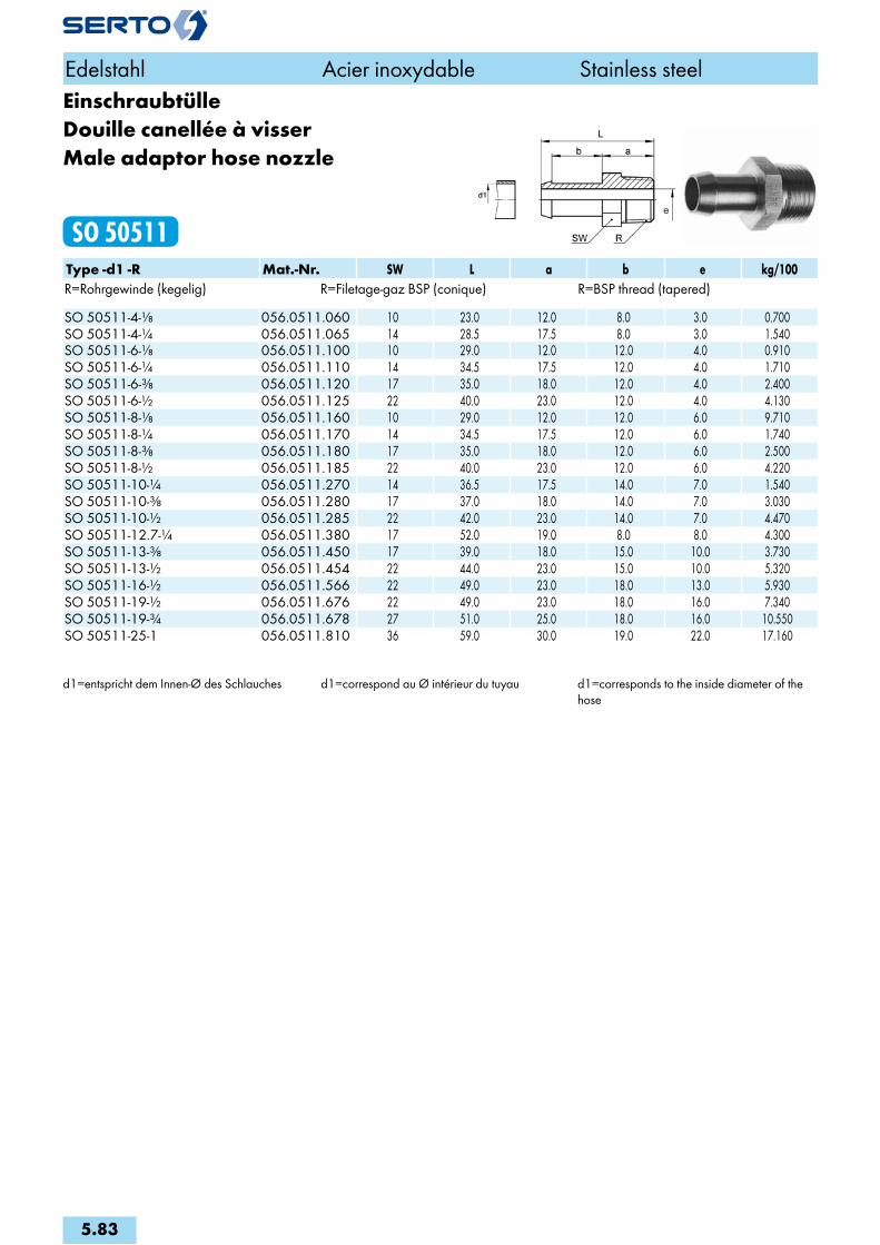
EinschraubtülleDouille canellée à visserMale adaptor hose nozzle
SO 50511Type -d1 -R Mat.-Nr. SW L a b e kg/100R=Rohrgewinde (kegelig) R=Filetage-gaz BSP (conique) R=BSP thread (tapered) SO 50511-4-1/8 056.0511.060 10 23.0 12.0 8.0 3.0 0.700SO 50511-4-1/4 056.0511.065 14 28.5 17.5 8.0 3.0 1.540SO 50511-6-1/8 056.0511.100 10 29.0 12.0 12.0 4.0 0.910SO 50511-6-1/4 056.0511.110 14 34.5 17.5 12.0 4.0 1.710SO 50511-6-3/8 056.0511.120 17 35.0 18.0 12.0 4.0 2.400SO 50511-6-1/2 056.0511.125 22 40.0 23.0 12.0 4.0 4.130SO 50511-8-1/8 056.0511.160 10 29.0 12.0 12.0 6.0 9.710SO 50511-8-1/4 056.0511.170 14 34.5 17.5 12.0 6.0 1.740SO 50511-8-3/8 056.0511.180 17 35.0 18.0 12.0 6.0 2.500SO 50511-8-1/2 056.0511.185 22 40.0 23.0 12.0 6.0 4.220SO 50511-10-1/4 056.0511.270 14 36.5 17.5 14.0 7.0 1.540SO 50511-10-3/8 056.0511.280 17 37.0 18.0 14.0 7.0 3.030SO 50511-10-1/2 056.0511.285 22 42.0 23.0 14.0 7.0 4.470SO 50511-12.7-1/4 056.0511.380 17 52.0 19.0 8.0 8.0 4.300SO 50511-13-3/8 056.0511.450 17 39.0 18.0 15.0 10.0 3.730SO 50511-13-1/2 056.0511.454 22 44.0 23.0 15.0 10.0 5.320SO 50511-16-1/2 056.0511.566 22 49.0 23.0 18.0 13.0 5.930SO 50511-19-1/2 056.0511.676 22 49.0 23.0 18.0 16.0 7.340SO 50511-19-3/4 056.0511.678 27 51.0 25.0 18.0 16.0 10.550SO 50511-25-1 056.0511.810 36 59.0 30.0 19.0 22.0 17.160
d1=entspricht dem Innen-Ø des Schlauches d1=correspond au Ø intérieur du tuyau d1=corresponds to the inside diameter of the hose
Edelstahl Acier inoxydable Stainless steel
5.83

Einschraubtülle NPTDouille canellée à visser NPTMale adaptor hose nozzle NPT
SO 50511 NPTType -d1 -RNPT Mat.-Nr. SW L a b e kg/100RNPT=NPT Gewinde RNPT=Filetage NPT RNPT=NPT thread SO 50511-4-1/8 NPT 056.0512.060 12 25.5 14.5 8.0 3.0 1.000SO 50511-4-1/4 NPT 056.0512.065 14 30.5 19.5 8.0 3.0 1.990SO 50511-6-1/8 NPT 056.0512.100 12 31.5 14.5 12.0 4.0 1.200SO 50511-6-1/4 NPT 056.0512.110 14 36.5 19.5 12.0 4.0 2.190SO 50511-8-1/8 NPT 056.0512.160 12 31.5 14.5 12.0 6.0 1.170SO 50511-8-1/4 NPT 056.0512.170 14 36.5 19.5 12.0 6.5 2.180SO 50511-10-1/4 NPT 056.0512.270 14 38.5 19.5 14.0 7.0 2.500SO 50511-10-3/8 NPT 056.0512.280 17 39.0 20.0 14.0 7.0 2.700SO 50511-10-1/2 NPT 056.0512.285 22 45.0 26.0 14.0 7.0 5.530SO 50511-13-3/8 NPT 056.0512.450 17 41.0 20.0 15.0 10.0 3.600SO 50511-13-1/2 NPT 056.0512.454 22 47.0 26.0 15.0 10.0 5.830SO 50511-16-1/2 NPT 056.0512.566 22 52.0 26.0 18.0 13.0 6.620SO 50511-19-1/2 NPT 056.0512.676 22 52.0 26.0 18.0 14.0 6.460SO 50511-19-3/4 NPT 056.0512.678 30 55.0 29.0 18.0 16.0 10.330SO 50511-25-3/4 NPT 056.0512.805 30 59.0 29.0 20.0 19.0 9.850SO 50511-25-1 NPT 056.0512.810 36 63.0 33.0 20.0 22.0 16.500
d1=entspricht dem Innen-Ø des Schlauches d1=correspond au Ø intérieur du tuyau d1=corresponds to the inside diameter of the hose
Edelstahl Acier inoxydable Stainless steel
5.84
i
s
3F
4M
4G
5
5L
6
7
8
9
10
11
12

5LEdelstahl L
Hochdruck-Verschraubungen
Acier inoxydable L
Raccords à haute pression
Stainless steel L
High pressure unions

5L.3ArmaturenanschlussEcrou de raccordementNut connection
SOL 50021
5L.3Gerade VerschraubungUnion doubleStraight union
SOL 51021
5L.4-5L.7Gerade EinschraubverschraubungUnion mâleMale adaptor union
SOL 51121
5L.8Gerade AufschraubverschraubungUnion femelleFemale adaptor union
SOL 51221
5L.9VerbindungsnippelPièce folleTube stub
SOL 51300
5L.10Einstellbare KupplungAccouplement orientableAdjustable coupling
SOL 51325
5L.11AnschweissverschraubungUnion avec embout à souderWeld-on union
SOL 51429
5L.12Gerade SchottverschraubungUnion double pour cloisonPanel mount union
SOL 51521
5L.13Einstellnippel vormontiertEmbout orientable mâle montéAdjustable male adaptor assembly
SOL 51625
5L.14ReduktionsverschraubungRéductionReduction
SOL 51821
5L.15WinkelverschraubungCoudeElbow union
SOL 52021
5L.16Winkel-EinschraubverschraubungCoude mâleMale adaptor elbow union
SOL 52421
5L.17EinstellwinkelCoude orientableAdjustable elbow union
SOL 52621
5L.18Winkel-SchottverschraubungUnion double pour passage de cloisonPanel mount union
SOL 52721
5L.18SchwenkverschraubungCoude banjoSingle banjo
SOL 52824
5L.19T-VerschraubungTéTee union
SOL 53021
5L.19-5L.20Einstellbare L-VerschraubungL orientableAdjustable L union
SOL 53621 L
5L.19-5L.20Einstellbare T-VerschraubungTé orientableAdjustable Tee union
SOL 53621 T
5L.21KreuzverschraubungCroixCross union
SOL 54021
Sonderausführungen:Exécution en option:Optional Services:
Spezialbehandlung für Einsatz mit SauerstoffTraitement spécial pour utilisation sous oxygèneSpecial treatment for use with oxygen
Spezialbehandlung - silikonfreiTraitement spécial - sans siliconeSpecial treatment - silicone free
Spezialreinigung - entfettetTraitement spécial - sans siliconeSpecial treatment - degreased
Vorbeschichtete Gewinde mit Loctite 5061Filetages pré enduits avec Loctite 5061Pre-coated threads with Loctite 5061
Trockengeschmierte AnschlussmutterEcrou enduit d‘un lubrifiant secDry lubricated nut
Seite/Page/Page Seite/Page/Page Seite/Page/Page
Übersicht Aperçu Overview
5L.1
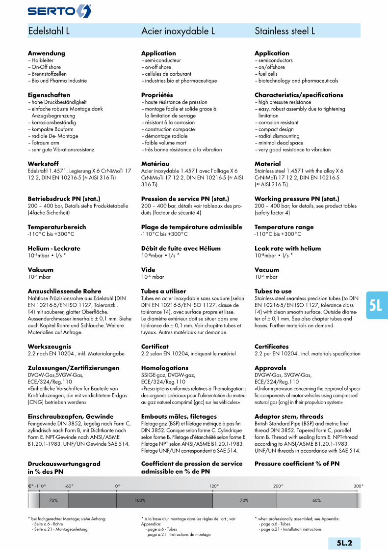
300°200°0° 120°-60°
100%75% 70% 60%
C° -110°
Edelstahl L Acier inoxydable L Stainless steel L
Anwendung– Halbleiter– On-Off shore– Brennstoffzellen– Bio und Pharma Industrie
Eigenschaften– hohe Druckbeständigkeit– einfache robuste Montage dank Anzugsbegrenzung– korrosionsbeständig – kompakte Bauform– radiale De- Montage– Totraum arm– sehr gute Vibrationsresistenz
WerkstoffEdelstahl 1.4571, Legierung X 6 CrNiMoTi 17 12 2, DIN EN 10216-5 (≈ AISI 316 Ti)
Betriebsdruck PN (stat.)200 – 400 bar, Details siehe Produktetabelle (4fache Sicherheit)
Temperaturbereich-110°C bis +300°C
Helium - Leckrate10-8mbar • l/s *
Vakuum10-6 mbar
Anzuschliessende RohreNahtlose Präzisionsrohre aus Edelstahl (DIN EN 10216-5/EN ISO 1127, Toleranzkl. T4) mit sauberer, glatter Oberfläche. Aussendurchmesser innerhalb ± 0,1 mm. Siehe auch Kapitel Rohre und Schläuche. Weitere Materialien auf Anfrage.
Werkszeugnis2.2 nach EN 10204 , inkl. Materialangabe
Zulassungen/ZertifizierungenDVGW-Gas,SVGW-Gas, ECE/324/Reg.110 «Einheitliche Vorschriften für Bauteile von Kraftfahrzeugen, die mit verdichtetem Erdgas (CNG) betrieben werden»
Einschraubzapfen, GewindeFeingewinde DIN 3852, kegelig nach Form C, zylindrisch nach Form B, mit Dichtkante nach Form E. NPT-Gewinde nach ANSI/ASME B1.20.1-1983. UNF/UN Gewinde SAE 514.
Application– semi-conducteur– on-off shore– cellules de carburant– industries bio et pharmaceutique
Propriétés– haute résistance de pression– montage facile et solide grace à la limitation de serrage– résistant à la corrosion– construction compacte– démontage radiale– faible volume mort– très bonne résistance à la vibration
MatériauAcier inoxydable 1.4571 avec l’alliage X 6 CrNiMoTi 17 12 2, DIN EN 10216-5 (≈ AISI 316 Ti).
Pression de service PN (stat.)200 – 400 bar, détails voir tableaux des pro-duits (facteur de sécurité 4)
Plage de température admissible-110°C bis +300°C
Débit de fuite avec Hélium10-8mbar • l/s *
Vide10-6 mbar
Tubes a utiliserTubes en acier inoxydable sans soudure (selon DIN EN 10216-5/EN ISO 1127, classe de tolérance T4), avec surface propre et lisse. Le diamètre extérieur doit se situer dans une tolérance de ± 0,1 mm. Voir chapitre tubes et tuyaux. Autres matériaux sur demande.
Certificat2.2 selon EN 10204, indiquant le matériel
HomologationsSSIGE-gaz, DVGW-gaz, ECE/324/Reg.110 «Prescriptions uniformes relatives à l‘homologation : des organes spéciaux pour l‘alimentation du moteur au gaz naturel comprimé (gnc) sur les véhicules»
Embouts mâles, filetagesFiletage-gaz (BSP) et filetage métrique à pas fin DIN 3852. Conique selon forme C. Cylindrique selon forme B. Filetage d’étanchéité selon forme E. Filetage NPT selon ANSI/ASME B1.20.1-1983. Filetage UNF/UN correspondent à SAE 514.
Application– semiconductors– on/offshore– fuel cells– biotechnology and pharmaceuticals
Characteristics/specifications– high pressure resistance– easy, robust assembly due to tightening limitation– corrosion resistant– compact design– radial dismounting– minimal dead space– very good resistance to vibration
MaterialStainless steel 1.4571 with the alloy X 6 CrNiMoTi 17 12 2, DIN EN 10216-5 (≈ AISI 316 Ti).
Working pressure PN (stat.)200 – 400 bar; for details, see product tables (safety factor 4)
Temperature range-110°C bis +300°C
Leak rate with helium10-8mbar • l/s *
Vacuum10-6 mbar
Tubes to useStainless steel seamless precision tubes (to DIN EN 10216-5/EN ISO 1127, tolerance class T4) with clean smooth surface. Outside diame-ter of ± 0,1 mm. See also chapter tubes and hoses. Further materials on demand.
Certificates2.2 per EN 10204 , incl. materials specification
ApprovalsDVGW-Gas, SVGW-Gas, ECE/324/Reg.110 «Uniform provision concerning the approval of speci-fic components of motor vehicles using compressed natural gas (cng) in their propulsion system»
Adaptor stem, threadsBritish Standard Pipe (BSP) and metric fine thread DIN 3852. Tapered form C, parallel form B. Thread with sealing form E. NPT-thread according to ANSI/ASME B1.20.1-1983. UNF/UN threads in accordance with SAE 514.
Druckauswertungsgrad in % des PN
Coefficient de pression de service admissible en % de PN
Pressure coefficient % of PN
* bei fachgerechter Montage; siehe Anhang: - Seite a.6 - Rohre - Seite a.21 - Montageanleitung
* à la base d'un montage dans les règles de l'art ; voir Appendice: - page a.6 - Tubes - page a.21 - Instructions de montage
* when professionally assembled; see Appendix: - page a.6 - Tubes - page a.21 - Installation instructions
5L.2
i
s
3F
4M
4G
5
5L
6
7
8
9
10
11
12

ArmaturenanschlussEcrou de raccordementNut connection
SOL 50021Type -d Mat.-Nr. bar M SW L z kg/100Für metrische Rohre Pour tubes métriques For metric tubes SOL 50021-6 076.0210.060 400 10x1 14 17.5 10.0 1.650SOL 50021-8 076.0210.080 330 12x1 17 18.5 10.5 2.500SOL 50021-10 076.0210.100 330 14x1 19 20.5 12.5 3.270SOL 50021-12 076.0210.120 330 16x1 22 21.5 13.5 4.600SOL 50021-15 076.0210.150 250 20x1.5 27 25.0 15.0 7.860SOL 50021-16 076.0210.160 250 24x1.5 30 26.5 18.5 10.400SOL 50021-18 076.0210.180 200 24x1.5 30 26.5 17.5 9.500
Für Zollrohre Pour tubes pouces For inch tubes SOL 50021-6,35 076.0210.063 400 10x1 14 17.5 10.5 1.700SOL 50021-9,52 076.0210.095 330 14x1 19 20.5 12.5 3.600SOL 50021-12,7 076.0210.127 330 20x1.5 27 25.0 15.0 8.700
Gerade VerschraubungUnion doubleStraight union
SOL 51021Type -d Mat.-Nr. bar M SW1 SW2 L z e kg/100Für metrische Rohre Pour tubes métriques For metric tubes SOL 51021-6 078.1020.060 400 10x1 14 10 42.0 22.5 4.5 4.180SOL 51021-8 078.1020.080 330 12x1 17 12 46.0 25.0 6.5 6.250SOL 51021-10 078.1020.100 330 14x1 19 14 51.0 26.0 8.5 8.190SOL 51021-12 078.1020.120 330 16x1 22 17 53.0 26.5 10.5 11.340SOL 51021-15 078.1020.150 250 20x1.5 27 22 62.0 31.5 13.0 19.520SOL 51021-16 078.1020.160 200 24x1.5 30 24 70.0 33.0 15.0 26.460SOL 51021-18 078.1020.180 200 24x1.5 30 24 67.0 33.0 15.0 24.660
Für Zollrohre Pour tubes pouces For inch tubes SOL 51021-6,35 078.1020.063 400 10x1 14 10 43.0 22.5 4.5 4.300SOL 51021-9,52 078.1020.095 330 14x1 19 14 51.0 26.0 8.5 8.900SOL 51021-12,7 078.1020.127 330 20x1.5 27 22 62.0 32.0 13.0 21.700
Edelstahl L Acier inoxydable L Stainless steel L
d=Rohraussen-øe=kleinste BohrungL=Mass in montiertem Zustand
d=ø extérieur du tubee=ø-min. de passageL=après montage
d=tube outside diametere=minimum boreL=installed length
5L.3

Gerade EinschraubverschraubungUnion mâleMale adaptor union
SOL 51121Type -d -R Mat.-Nr. bar M SW1 SW2 a L z e kg/100Für metrische Rohre Pour tubes métriques For metric tubesR=Rohrgewinde (kegelig) R=Filetage-gaz BSP (conique) R=BSP thread (tapered)SOL 51121-6-1/8 078.1101.100 400 10x1 14 10 21.0 31.0 17.0 4.5 2.550SOL 51121-6-1/4 078.1101.110 400 10x1 14 14 27.0 37.0 21.0 4.5 3.650SOL 51121-6-3/8 078.1101.120 400 10x1 14 17 27.0 37.0 20.6 4.5 4.040SOL 51121-6-1/2 078.1101.125 400 10x1 14 22 32.0 42.0 23.8 4.5 6.160SOL 51121-8-1/8 078.1101.160 330 12x1 17 12 22.0 32.5 18.0 6.0 3.540SOL 51121-8-1/4 078.1101.170 330 12x1 17 14 28.0 38.5 22.0 6.5 4.430SOL 51121-8-3/8 078.1101.180 330 12x1 17 17 28.0 38.5 21.6 6.5 4.520SOL 51121-8-1/2 078.1101.185 330 12x1 17 22 33.0 43.5 24.8 6.5 7.050SOL 51121-10-1/4 078.1101.270 330 14x1 19 14 28.0 40.5 22.0 8.5 5.020SOL 51121-10-3/8 078.1101.280 330 14x1 19 17 28.0 40.5 21.6 8.5 6.130SOL 51121-10-1/2 078.1101.285 330 14x1 19 22 33.0 45.5 24.8 8.5 9.290SOL 51121-12-1/4 078.1101.380 330 16x1 22 17 28.0 41.5 22.0 8.5 6.980SOL 51121-12-3/8 078.1101.390 330 16x1 22 17 28.0 41.5 21.6 10.5 7.180SOL 51121-12-1/2 078.1101.400 330 16x1 22 22 33.0 46.5 24.8 10.5 10.050SOL 51121-15-3/8 078.1101.532 250 20x1.5 27 22 30.5 45.5 24.1 10.5 12.490SOL 51121-15-1/2 078.1101.534 250 20x1.5 27 22 35.5 50.5 27.3 13.0 12.680SOL 51121-16-1/2 078.1101.566 200 24x1.5 30 24 36.5 55.0 28.3 13.5 16.500SOL 51121-16-3/4 078.1101.568 200 24x1.5 30 27 36.5 55.0 27.0 15.0 17.680SOL 51121-18-1/2 078.1101.646 200 24x1.5 30 24 36.5 53.0 28.3 13.5 15.100SOL 51121-18-3/4 078.1101.648 200 24x1.5 30 27 37.5 54.0 27.0 15.0 16.280
Für Zollrohre Pour tubes pouces For inch tubes SOL 51121-6,35-1/8 078.1101.135 400 10x1 14 10 21.0 31.0 25.0 4.5 2.600SOL 51121-6,35-1/4 078.1101.140 400 10x1 14 14 27.0 37.0 33.0 4.5 3.700SOL 51121-6,35-3/8 078.1101.145 400 10x1 14 17 27.0 37.0 21.0 4.5 4.100SOL 51121-6,35-1/2 078.1101.150 330 10x1 14 22 32.0 42.0 22.0 4.5 6.700SOL 51121-9,52-1/4 078.1101.230 330 14x1 19 14 28.0 40.0 22.0 8.5 5.500SOL 51121-9,52-3/8 078.1101.235 330 14x1 19 17 28.0 40.0 22.0 8.5 6.600SOL 51121-9,52-1/2 078.1101.240 330 14x1 19 22 33.0 45.0 23.0 8.5 8.700SOL 51121-12,7-1/2 078.1101.434 250 20x1.5 27 22 35.5 48.5 27.5 13.0 9.600
Edelstahl L Acier inoxydable L Stainless steel L
d=Rohraussen-øe=kleinste BohrungL=Mass in montiertem Zustand
d=ø extérieur du tubee=ø-min. de passageL=après montage
d=tube outside diametere=minimum boreL=installed length
5L.4
i
s
3F
4M
4G
5
5L
6
7
8
9
10
11
12

Gerade Einschraubverschraubung NPTUnion mâle NPTMale adaptor union NPT
SOL 51121 NPTType -d -RNPT Mat.-Nr. bar M SW1 SW2 a L z e kg/100Für metrische Rohre Pour tubes métriques For metric tubesRNPT=NPT Gewinde RNPT=Filetage NPT RNPT=NPT threadSOL 51121-6-1/8 NPT 078.1102.100 400 10x1 14 12 24.0 34.0 19.9 4.5 2.820SOL 51121-6-1/4 NPT 078.1102.110 400 10x1 14 14 29.0 39.0 23.2 4.5 3.830SOL 51121-8-1/8 NPT 078.1102.160 330 12x1 17 12 25.0 35.5 20.9 6.0 4.120SOL 51121-8-1/4 NPT 078.1102.170 330 12x1 17 14 30.0 40.5 24.2 6.5 4.600SOL 51121-8-3/8 NPT 078.1102.180 330 12x1 17 17 30.0 40.5 23.9 6.5 5.450SOL 51121-8-1/2 NPT 078.1102.185 330 12x1 17 22 36.0 46.5 27.9 6.5 7.090SOL 51121-10-1/4 NPT 078.1102.270 330 14x1 19 14 30.0 42.5 24.2 8.5 5.130SOL 51121-10-1/2 NPT 078.1102.285 330 14x1 19 22 36.0 48.5 27.9 8.5 9.760SOL 51121-12-1/4 NPT 078.1102.380 330 16x1 22 17 30.0 43.5 24.2 8.5 7.040SOL 51121-12-3/8 NPT 078.1102.390 330 16x1 22 17 30.0 43.5 23.9 10.5 7.330SOL 51121-12-1/2 NPT 078.1102.400 330 16x1 22 22 36.0 49.5 27.9 10.5 10.520SOL 51121-12-3/4 NPT 078.1102.405 330 16x1 22 27 39.0 52.5 30.4 10.5 11.390SOL 51121-15-1/2 NPT 078.1102.534 250 20x1.5 27 22 38.0 53.0 30.4 13.0 13.040SOL 51121-16-1/2 NPT 078.1102.566 200 24x1.5 30 24 39.0 57.5 31.4 13.5 20.850SOL 51121-18-1/2 NPT 078.1102.646 200 24x1.5 30 24 39.5 56.0 31.4 13.5 19.950
Für Zollrohre Pour tubes pouces For inch tubes SOL 51121-6,35-1/8 NPT 078.1102.135 400 10x1 14 12 24.0 33.0 20.0 4.5 3.000SOL 51121-6,35-1/4 NPT 078.1102.140 400 10x1 14 14 29.0 38.0 23.5 4.5 4.000SOL 51121-9,52-1/4 NPT 078.1102.230 330 14x1 19 14 30.0 47.0 24.5 8.5 5.700SOL 51121-9,52-1/2 NPT 078.1102.240 330 14x1 19 22 36.0 48.0 28.0 8.5 10.600SOL 51121-12,7-1/2 NPT 078.1102.434 250 20x1.5 27 22 38.0 50.0 30.5 13.0 14.900
Gerade Einschraubverschraubung zylindrisch METRmit Dichtkante
Union mâle filetage cylindrique METR avec arête d‘étanchéité
Male adaptor union with parallel thread METRwith edge seal
SOL 51124 METRType -d -Mz Mat.-Nr. bar M SW1 SW2 i L z e kg/100Für metrische Rohre Pour tubes métriques For metric tubesMz=metrisches Gewinde (zylindrisch) Mz=Filetage métrique (cylindrique) Mz=Metric thread (straight)SOL 51124-6-M5 Z 078.1143.155 400 10x1 14 10 4.5 27.5 13.0 2.2 2.300
Für Zollrohre Pour tubes pouces For inch tubes SOL 51124-6,35-M5 Z 078.1143.205 400 10x1 14 10 4.5 26.5 13.0 2.2 8.100
Edelstahl L Acier inoxydable L Stainless steel L
d=Rohraussen-øe=kleinste BohrungL=Mass in montiertem Zustand
d=ø extérieur du tubee=ø-min. de passageL=après montage
d=tube outside diametere=minimum boreL=installed length
5L.5
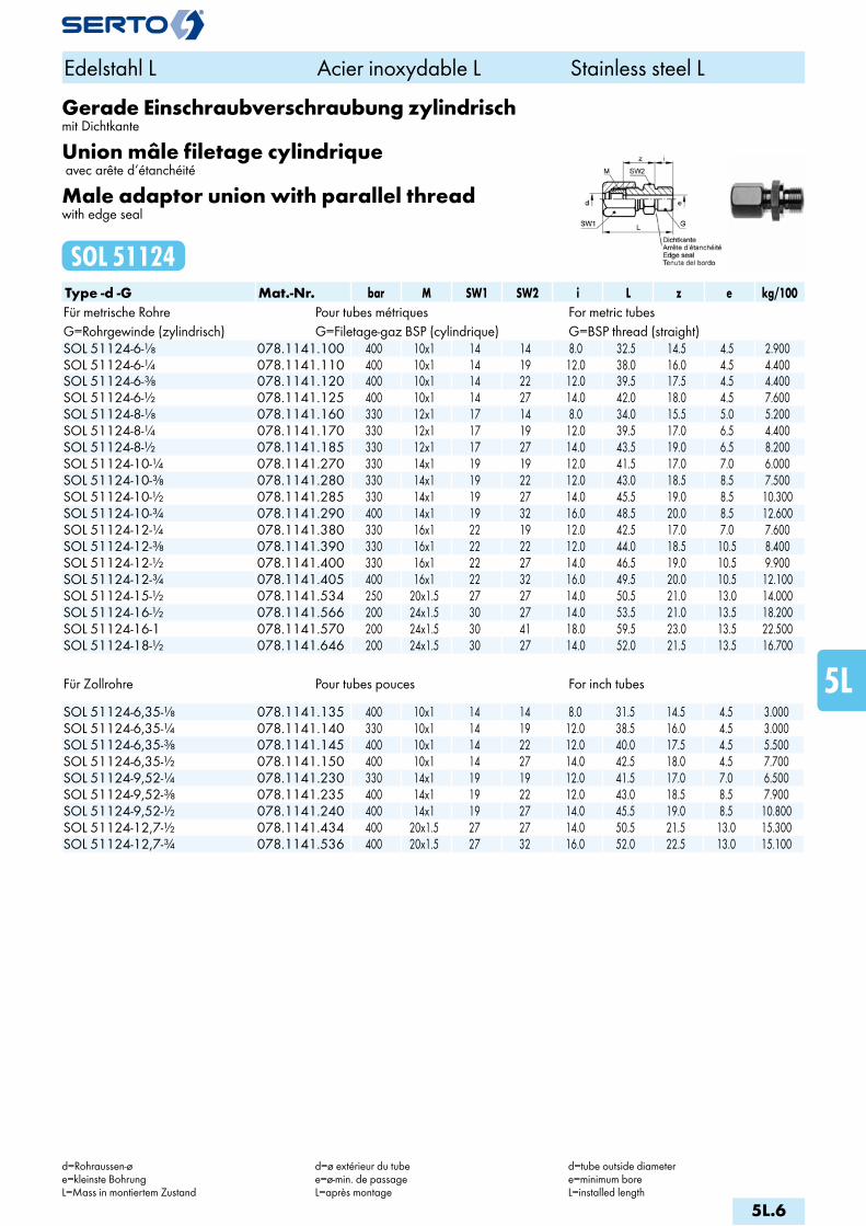
Gerade Einschraubverschraubung zylindrischmit Dichtkante
Union mâle filetage cylindrique avec arête d‘étanchéité
Male adaptor union with parallel threadwith edge seal
SOL 51124Type -d -G Mat.-Nr. bar M SW1 SW2 i L z e kg/100Für metrische Rohre Pour tubes métriques For metric tubesG=Rohrgewinde (zylindrisch) G=Filetage-gaz BSP (cylindrique) G=BSP thread (straight)SOL 51124-6-1/8 078.1141.100 400 10x1 14 14 8.0 32.5 14.5 4.5 2.900SOL 51124-6-1/4 078.1141.110 400 10x1 14 19 12.0 38.0 16.0 4.5 4.400SOL 51124-6-3/8 078.1141.120 400 10x1 14 22 12.0 39.5 17.5 4.5 4.400SOL 51124-6-1/2 078.1141.125 400 10x1 14 27 14.0 42.0 18.0 4.5 7.600SOL 51124-8-1/8 078.1141.160 330 12x1 17 14 8.0 34.0 15.5 5.0 5.200SOL 51124-8-1/4 078.1141.170 330 12x1 17 19 12.0 39.5 17.0 6.5 4.400SOL 51124-8-1/2 078.1141.185 330 12x1 17 27 14.0 43.5 19.0 6.5 8.200SOL 51124-10-1/4 078.1141.270 330 14x1 19 19 12.0 41.5 17.0 7.0 6.000SOL 51124-10-3/8 078.1141.280 330 14x1 19 22 12.0 43.0 18.5 8.5 7.500SOL 51124-10-1/2 078.1141.285 330 14x1 19 27 14.0 45.5 19.0 8.5 10.300SOL 51124-10-3/4 078.1141.290 400 14x1 19 32 16.0 48.5 20.0 8.5 12.600SOL 51124-12-1/4 078.1141.380 330 16x1 22 19 12.0 42.5 17.0 7.0 7.600SOL 51124-12-3/8 078.1141.390 330 16x1 22 22 12.0 44.0 18.5 10.5 8.400SOL 51124-12-1/2 078.1141.400 330 16x1 22 27 14.0 46.5 19.0 10.5 9.900SOL 51124-12-3/4 078.1141.405 400 16x1 22 32 16.0 49.5 20.0 10.5 12.100SOL 51124-15-1/2 078.1141.534 250 20x1.5 27 27 14.0 50.5 21.0 13.0 14.000SOL 51124-16-1/2 078.1141.566 200 24x1.5 30 27 14.0 53.5 21.0 13.5 18.200SOL 51124-16-1 078.1141.570 200 24x1.5 30 41 18.0 59.5 23.0 13.5 22.500SOL 51124-18-1/2 078.1141.646 200 24x1.5 30 27 14.0 52.0 21.5 13.5 16.700
Für Zollrohre Pour tubes pouces For inch tubes SOL 51124-6,35-1/8 078.1141.135 400 10x1 14 14 8.0 31.5 14.5 4.5 3.000SOL 51124-6,35-1/4 078.1141.140 330 10x1 14 19 12.0 38.5 16.0 4.5 3.000SOL 51124-6,35-3/8 078.1141.145 400 10x1 14 22 12.0 40.0 17.5 4.5 5.500SOL 51124-6,35-1/2 078.1141.150 400 10x1 14 27 14.0 42.5 18.0 4.5 7.700SOL 51124-9,52-1/4 078.1141.230 330 14x1 19 19 12.0 41.5 17.0 7.0 6.500SOL 51124-9,52-3/8 078.1141.235 400 14x1 19 22 12.0 43.0 18.5 8.5 7.900SOL 51124-9,52-1/2 078.1141.240 400 14x1 19 27 14.0 45.5 19.0 8.5 10.800SOL 51124-12,7-1/2 078.1141.434 400 20x1.5 27 27 14.0 50.5 21.5 13.0 15.300SOL 51124-12,7-3/4 078.1141.536 400 20x1.5 27 32 16.0 52.0 22.5 13.0 15.100
Edelstahl L Acier inoxydable L Stainless steel L
d=Rohraussen-øe=kleinste BohrungL=Mass in montiertem Zustand
d=ø extérieur du tubee=ø-min. de passageL=après montage
d=tube outside diametere=minimum boreL=installed length
5L.6
i
s
3F
4M
4G
5
5L
6
7
8
9
10
11
12

Gerade Einschraubverschraubungmit O-Ringabdichtung (FPM)
Union mâleavec joint torique (FPM)
Male adaptor unionwith O-ring seal (FPM)
SOL 51124 ORType -d -G Mat.-Nr. bar M SW1 SW2 i L z e D s kg/100Für metrische Rohre Pour tubes métriques For metric tubesG=Rohrgewinde (zylindrisch) G=Filetage-gaz BSP (cylindrique) G=BSP thread (straight)SOL 51124-6-1/8 OR 078.1171.100 400 10x1 14 14 8.0 32.5 14.5 4.5 15.0 1.00 2.960SOL 51124-6-1/4 OR 078.1171.110 400 10x1 14 19 10.0 36.0 16.0 4.5 19.0 1.50 4.260SOL 51124-8-1/4 OR 078.1171.170 330 12x1 17 19 10.0 37.5 17.0 6.5 19.0 1.50 5.150SOL 51124-10-1/4 OR 078.1171.270 330 14x1 19 19 10.0 39.5 17.0 7.0 19.0 1.50 5.890SOL 51124-10-3/8 OR 078.1171.280 330 14x1 19 22 10.0 41.0 18.5 8.5 23.0 2.00 7.390SOL 51124-12-3/8 OR 078.1171.390 330 16x1 22 22 10.0 42.0 18.5 10.5 23.0 2.00 8.390SOL 51124-12-1/2 OR 078.1171.400 330 16x1 22 27 12.0 44.5 19.0 10.5 27.0 2.50 9.790SOL 51124-15-1/2 OR 078.1171.534 250 20x1.5 27 27 12.0 48.5 21.5 13.0 27.0 2.50 13.850SOL 51124-16-1/2 OR 078.1171.566 200 24x1.5 30 27 12.0 52.0 21.5 13.0 27.0 2.50 17.850SOL 51124-18-1/2 OR 078.1171.646 200 24x1.5 30 27 12.0 50.0 21.5 13.0 27.0 2.50 16.450
Für Zollrohre Pour tubes pouces For inch tubes SOL 51124-6,35-1/8 OR 078.1171.135 400 10x1 14 14 8.0 31.5 14.5 4.5 15.0 1.00 3.000SOL 51124-6,35-1/4 OR 078.1171.140 400 10x1 14 19 10.0 35.0 16.0 4.5 19.0 1.50 4.300SOL 51124-9,52-1/4 OR 078.1171.230 330 14x1 19 19 10.0 40.0 17.0 7.0 19.0 1.50 6.300SOL 51124-9,52-3/8 OR 078.1171.235 330 14x1 19 22 10.0 41.0 18.5 8.5 23.0 2.00 7.600SOL 51124-12,7-1/2 OR 078.1171.434 330 20x1.5 27 27 12.0 49.0 22.0 13.0 27.0 2.50 14.700
Edelstahl L Acier inoxydable L Stainless steel L
d=Rohraussen-øe=kleinste BohrungL=Mass in montiertem Zustand
d=ø extérieur du tubee=ø-min. de passageL=après montage
d=tube outside diametere=minimum boreL=installed length
5L.7

Gerade AufschraubverschraubungUnion femelleFemale adaptor union
SOL 51221Type -d -G Mat.-Nr. bar M SW1 SW2 a L z e kg/100Für metrische Rohre Pour tubes métriques For metric tubesG=Rohrgewinde (zylindrisch) G=Filetage-gaz BSP (cylindrique) G=BSP thread (straight)SOL 51221-6-1/8 078.1201.100 400 10x1 14 14 22.0 32.0 12.0 4.5 3.000SOL 51221-6-1/4 078.1201.110 400 10x1 14 17 24.0 34.0 13.0 4.5 3.700SOL 51221-6-3/8 078.1201.120 400 10x1 14 22 25.0 35.0 13.0 4.5 5.200SOL 51221-6-1/2 078.1201.125 400 10x1 14 27 31.0 41.0 17.0 4.5 9.000SOL 51221-8-1/4 078.1201.170 330 12x1 17 17 25.0 35.5 14.0 6.5 4.500SOL 51221-10-1/4 078.1201.270 330 14x1 19 17 25.0 37.5 14.0 8.5 5.600SOL 51221-10-3/8 078.1201.280 330 14x1 19 22 26.0 38.5 14.0 8.5 6.900SOL 51221-10-1/2 078.1201.285 330 14x1 19 27 28.0 40.5 14.0 8.5 9.000SOL 51221-12-1/4 078.1201.380 330 16x1 22 17 25.0 38.5 14.0 10.5 6.900SOL 51221-12-3/8 078.1201.390 330 16x1 22 22 26.0 39.5 14.0 10.5 8.200SOL 51221-12-1/2 078.1201.400 330 16x1 22 27 28.0 41.5 14.0 10.5 10.200SOL 51221-15-1/2 078.1201.534 250 20x1.5 27 27 30.5 45.5 16.5 13.0 13.700SOL 51221-16-1/2 078.1201.566 200 24x1.5 30 27 30.5 49.0 16.5 15.0 17.500SOL 51221-18-1/2 078.1201.646 200 24x1.5 30 27 30.5 47.0 16.5 15.0 16.100
Für Zollrohre Pour tubes pouces For inch tubes SOL 51221-6,35-1/8 078.1201.135 400 10x1 14 14 22.0 32.0 12.0 4.5 3.200SOL 51221-6,35-1/4 078.1201.140 400 10x1 14 17 24.0 34.0 13.0 4.5 3.900SOL 51221-6,35-3/8 078.1201.145 400 10x1 14 22 25.0 35.0 13.0 4.5 5.400SOL 51221-6,35-1/2 078.1201.150 400 10x1 14 27 31.0 41.0 17.0 4.5 9.300SOL 51221-9,52-1/4 078.1201.230 330 14x1 19 17 25.0 38.0 14.0 8.5 6.000SOL 51221-9,52-3/8 078.1201.235 330 14x1 19 22 26.0 39.0 14.0 8.5 7.500SOL 51221-9,52-1/2 078.1201.240 330 14x1 19 27 28.0 40.0 14.0 8.5 9.600SOL 51221-12,7-1/2 078.1201.434 250 20x1.5 27 27 30.5 40.0 16.5 10.5 14.700
Edelstahl L Acier inoxydable L Stainless steel L
d=Rohraussen-øe=kleinste BohrungL=Mass in montiertem Zustand
d=ø extérieur du tubee=ø-min. de passageL=après montage
d=tube outside diametere=minimum boreL=installed length
5L.8
i
s
3F
4M
4G
5
5L
6
7
8
9
10
11
12

VerbindungsnippelPièce folleTube stub
SOL 51300Type -Ad Mat.-Nr. bar D L e kg/100Für metrische Rohre Pour tubes métriques For metric tubes SOL 51300-A6 076.1300.060 400 8.5 19.0 4.0 0.421SOL 51300-A8 076.1300.080 330 10.5 22.0 6.0 0.624SOL 51300-A10 076.1300.100 330 12.7 26.0 7.0 1.055SOL 51300-A12 076.1300.120 330 14.7 29.0 9.0 1.597SOL 51300-A15 076.1300.150 250 18.0 37.0 11.5 2.407SOL 51300-A16 076.1300.160 200 22.4 41.0 12.5 2.790SOL 51300-A18 076.1300.180 200 22.0 41.0 15.0 3.631
Die entsprechende Stützhülse SO 50003 ist immer separat zu bestellen.
Les douilles d‘appui SO 50003 correspondants sont à commander séparément.
The relevant stiffener sleeve SO 50003 must always be ordered separately.
VerbindungsnippelPièce folleTube stub
SOL 51304Type -Ad Mat.-Nr. bar D L e kg/100Für metrische Rohre Pour tubes métriques For metric tubes SOL 51304-A6 076.1310.060 400 8.5 34.0 4.0 0.548SOL 51304-A8 076.1310.080 330 10.5 36.0 6.0 0.801SOL 51304-A10 076.1310.100 330 12.7 40.0 7.0 1.359SOL 51304-A12 076.1310.120 330 14.7 42.0 9.0 1.993
Die entsprechende Stützhülse SO 50003 ist immer separat zu bestellen.
Les douilles d‘appui SO 50003 correspondants sont à commander séparément.
The relevant stiffener sleeve SO 50003 must always be ordered separately.
Edelstahl L Acier inoxydable L Stainless steel L
Ad=Aussen-ø der Andrehunge=kleinste BohrungL=Mass in montiertem Zustand
Ad=ø extérieur de la portée cylindriquee=ø-min. de passageL=après montage
Ad=outside diameter of cyl. Stube=minimum boreL=installed length
5L.9
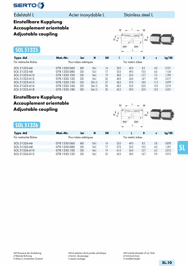
Einstellbare KupplungAccouplement orientableAdjustable coupling
SOL 51325Type -Ad Mat.-Nr. bar M SW l L D e kg/100Für metrische Rohre Pour tubes métriques For metric tubes SOL 51325-A6 078.1320.060 400 10x1 14 30.0 45.0 8.5 4.0 0.751SOL 51325-A8 078.1320.080 330 12x1 17 33.0 49.0 10.5 6.0 1.124SOL 51325-A10 078.1320.100 330 14x1 19 38.0 53.0 12.7 7.5 1.709SOL 51325-A12 078.1320.120 330 16x1 22 40.0 56.0 14.7 9.0 2.517SOL 51325-A15 078.1320.150 250 20x1.5 27 38.5 57.0 18.0 11.5 3.979SOL 51325-A16 078.1320.160 250 24x1.5 30 40.5 55.0 22.0 15.0 2.219SOL 51325-A18 078.1320.180 200 24x1.5 30 42.5 59.0 22.0 15.0 5.531
Einstellbare KupplungAccouplement orientableAdjustable coupling
SOL 51326Type -Ad Mat.-Nr. bar M SW l L D e kg/100Für metrische Rohre Pour tubes métriques For metric tubes SOL 51326-A6 078.1330.060 400 10x1 14 35.0 49.0 8.5 3.8 0.878SOL 51326-A8 078.1330.080 330 12x1 17 37.0 52.0 10.5 6.0 1.301SOL 51326-A10 078.1330.100 330 14x1 19 41.0 56.0 12.7 6.5 2.013SOL 51326-A12 078.1330.120 330 16x1 22 43.0 58.0 14.7 9.0 2.913
Edelstahl L Acier inoxydable L Stainless steel L
Ad=Aussen-ø der Andrehunge=kleinste BohrungL=Mass in montiertem Zustand
Ad=ø extérieur de la portée cylindriquee=ø-min. de passageL=après montage
Ad=outside diameter of cyl. Stube=minimum boreL=installed length
5L.10
i
s
3F
4M
4G
5
5L
6
7
8
9
10
11
12

AnschweissverschraubungUnion avec embout à souderWeld-on union
SOL 51429Type -d Mat.-Nr. bar M SW1 SW2 L f x z e kg/100Für metrische Rohre Pour tubes métriques For metric tubes SOL 51429-6 078.1400.060 400 10x1 14 10 31.0 9.8 8.0 21.0 4.5 2.500SOL 51429-8 078.1400.080 330 12x1 17 12 32.5 11.8 8.0 22.0 6.5 3.700SOL 51429-10 078.1400.100 330 14x1 19 14 35.5 13.8 8.0 23.0 8.5 4.800SOL 51429-12 078.1400.120 330 16x1 22 17 37.5 16.0 8.0 24.0 10.5 6.700SOL 51429-15 078.1400.150 250 20x1.5 27 22 44.5 19.0 10.0 29.5 13.0 11.600SOL 51429-16 078.1400.160 200 24x1.5 30 24 50.0 22.0 11.0 31.5 15.0 17.100SOL 51429-18 078.1400.180 200 24x1.5 30 24 48.0 22.0 11.0 31.5 15.0 15.600
Für Zollrohre Pour tubes pouces For inch tubes SOL 51429-6,35 078.1400.063 330 10x1 14 10 31.0 9.8 8.0 21.0 4.5 2.600SOL 51429-9,52 078.1400.095 330 14x1 19 14 35.5 13.8 8.0 23.0 8.5 5.100SOL 51429-12,7 078.1400.127 250 20x1.5 27 22 44.5 19.0 10.0 29.5 13.0 12.600
Edelstahl L Acier inoxydable L Stainless steel L
d=Rohraussen-øe=kleinste BohrungL=Mass in montiertem Zustand
d=ø extérieur du tubee=ø-min. de passageL=après montage
d=tube outside diametere=minimum boreL=installed length
5L.11

Gerade SchottverschraubungDurchführungslänge max. 5 mm
Union double pour passage de cloisonpour cloison max. 5 mm
Panel mount unionmax. panel thickness 5 mm
SOL 51521Type -d Mat.-Nr. bar M SW1 SW2 L L1 B z1 z e kg/100Für metrische Rohre Pour tubes métriques For metric tubes SOL 51521-6 078.1500.060 400 10x1 14 14 22.5 28.0 10.5 19.0 13.5 4.5 5.300SOL 51521-8 078.1500.080 330 12x1 17 17 24.5 30.5 12.5 21.0 15.0 6.5 8.100SOL 51521-10 078.1500.100 330 14x1 19 19 28.0 32.5 14.5 21.0 15.5 8.5 10.300SOL 51521-12 078.1500.120 330 16x1 22 22 28.5 34.5 16.5 21.0 16.0 10.5 14.100
Für Zollrohre Pour tubes pouces For inch tubes SOL 51521-6,35 078.1500.063 330 10x1 14 14 22.5 28.0 10.5 19.0 13.5 4.5 5.600SOL 51521-9,52 078.1500.095 330 14x1 19 19 28.0 32.5 14.5 21.0 15.5 8.5 11.200
Gerade SchottverschraubungDurchführungslänge max. 16mm
Union double pour passage de cloisonpour cloison max. 16mm
Panel mount unionmax. panel thickness 16mm
SOL 51524Type -d Mat.-Nr. bar M SW1 SW2 L L1 B z1 z e kg/100Für metrische Rohre Pour tubes métriques For metric tubes SOL 51524-16 078.1540.160 200 24x1.5 30 30 36.5 51.5 24.5 34.5 19.5 15.0 36.000SOL 51524-18 078.1540.180 200 24x1.5 30 30 34.5 49.0 24.5 34.5 19.5 15.0 34.200
Edelstahl L Acier inoxydable L Stainless steel L
d=Rohraussen-øe=kleinste BohrungL=Mass in montiertem Zustand
d=ø extérieur du tubee=ø-min. de passageL=après montage
d=tube outside diametere=minimum boreL=installed length
5L.12
i
s
3F
4M
4G
5
5L
6
7
8
9
10
11
12
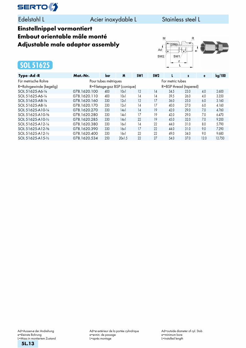
Einstellnippel vormontiertEmbout orientable mâle montéAdjustable male adaptor assembly
SOL 51625Type -Ad -R Mat.-Nr. bar M SW1 SW2 L z e kg/100Für metrische Rohre Pour tubes métriques For metric tubesR=Rohrgewinde (kegelig) R=Filetage-gaz BSP (conique) R=BSP thread (tapered)SOL 51625-A6-1/8 078.1620.100 400 10x1 12 14 34.5 23.0 4.0 2.600SOL 51625-A6-1/4 078.1620.110 400 10x1 14 14 39.5 26.0 4.0 3.350SOL 51625-A8-1/8 078.1620.160 330 12x1 12 17 36.0 25.0 6.0 3.160SOL 51625-A8-1/4 078.1620.170 330 12x1 14 17 40.0 27.0 6.0 4.160SOL 51625-A10-1/4 078.1620.270 330 14x1 14 19 42.0 29.0 7.0 4.760SOL 51625-A10-3/8 078.1620.280 330 14x1 17 19 42.0 29.0 7.0 6.470SOL 51625-A10-1/2 078.1620.285 330 14x1 22 19 45.0 32.0 7.0 9.200SOL 51625-A12-1/4 078.1620.380 330 16x1 14 22 44.0 31.0 8.0 5.790SOL 51625-A12-3/8 078.1620.390 330 16x1 17 22 44.0 31.0 9.0 7.290SOL 51625-A12-1/2 078.1620.400 330 16x1 22 22 49.0 34.0 9.0 9.680SOL 51625-A15-1/2 078.1620.534 250 20x1.5 22 27 54.0 37.0 12.0 12.750
Edelstahl L Acier inoxydable L Stainless steel L
Ad=Aussen-ø der Andrehunge=kleinste BohrungL=Mass in montiertem Zustand
Ad=ø extérieur de la portée cylindriquee=ø-min. de passageL=après montage
Ad=outside diameter of cyl. Stube=minimum boreL=installed length
5L.13

ReduktionsverschraubungRéductionReduction
SOL 51821Type -Ad -d Mat.-Nr. bar M SW1 SW2 L b z e kg/100Für metrische Rohre Pour tubes métriques For metric tubes SOL 51821-A10-6 078.1800.175 330 10x1 14 12 39.5 17.0 29.5 4.5 2.530SOL 51821-A12-8 078.1800.225 330 12x1 17 14 44.0 19.0 33.5 6.5 4.060SOL 51821-A15-10 078.1800.410 250 14x1 19 17 48.5 21.0 36.0 8.5 5.430SOL 51821-A18-12 078.1800.580 200 16x1 22 19 52.5 24.0 40.0 10.5 7.470SOL 51821-A22-15 078.1800.745 200 20x1.5 27 24 58.5 25.0 43.5 13.0 12.010
Die entsprechende Stützhülse SO 50003 ist immer separat zu bestellen.
Les douilles d‘appui SO 50003 correspondants sont à commander séparément.
The relevant stiffener sleeve SO 50003 must always be ordered separately.
Reduktionsverschraubung vormontiertRéduction montéeReduction assembly
SOL 51825Type -Ad -d Mat.-Nr. bar M M1 SW1 SW2 SW3 L z e kg/100Für metrische Rohre Pour tubes métriques For metric tubes SOL 51825-A10-6 078.1820.175 330 10x1 14x1 14 12 19 47.5 30.5 4.5 4.310SOL 51825-A12-8 078.1820.225 330 12x1 16x1 17 14 22 52.0 34.5 6.5 6.270SOL 51825-A15-10 078.1820.410 250 14x1 20x1.5 19 17 27 56.5 37.5 8.5 9.640SOL 51825-A18-12 078.1820.580 200 16x1 24x1.5 22 19 30 62.5 41.0 10.5 12.520
Edelstahl L Acier inoxydable L Stainless steel L
d=Rohraussen-øAd=Aussen-ø der Andrehunge=kleinste BohrungL=Mass in montiertem Zustand
d=ø extérieur du tubeAd=ø extérieur de la portée cylindriquee=ø-min. de passageL=après montage
d=tube outside diameterAd=outside diameter of cyl. Stube=minimum boreL=installed length
5L.14
i
s
3F
4M
4G
5
5L
6
7
8
9
10
11
12
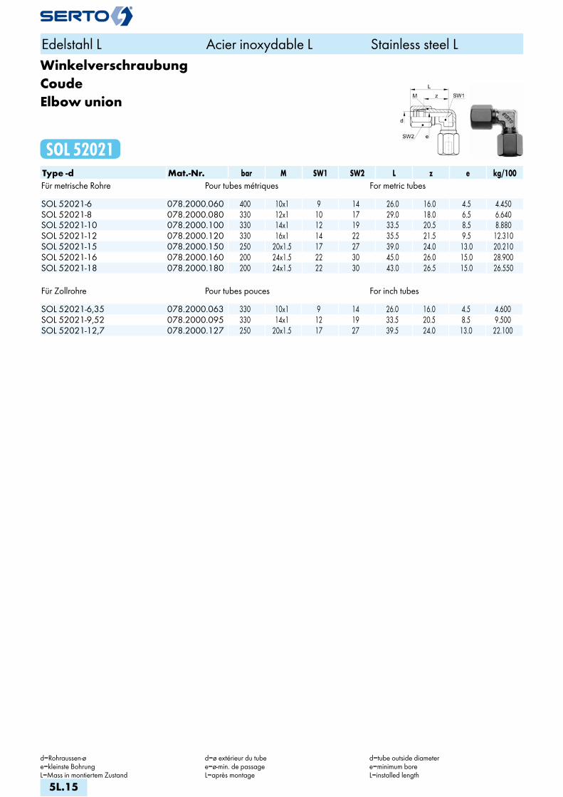
WinkelverschraubungCoudeElbow union
SOL 52021Type -d Mat.-Nr. bar M SW1 SW2 L z e kg/100Für metrische Rohre Pour tubes métriques For metric tubes SOL 52021-6 078.2000.060 400 10x1 9 14 26.0 16.0 4.5 4.450SOL 52021-8 078.2000.080 330 12x1 10 17 29.0 18.0 6.5 6.640SOL 52021-10 078.2000.100 330 14x1 12 19 33.5 20.5 8.5 8.880SOL 52021-12 078.2000.120 330 16x1 14 22 35.5 21.5 9.5 12.310SOL 52021-15 078.2000.150 250 20x1.5 17 27 39.0 24.0 13.0 20.210SOL 52021-16 078.2000.160 200 24x1.5 22 30 45.0 26.0 15.0 28.900SOL 52021-18 078.2000.180 200 24x1.5 22 30 43.0 26.5 15.0 26.550
Für Zollrohre Pour tubes pouces For inch tubes SOL 52021-6,35 078.2000.063 330 10x1 9 14 26.0 16.0 4.5 4.600SOL 52021-9,52 078.2000.095 330 14x1 12 19 33.5 20.5 8.5 9.500SOL 52021-12,7 078.2000.127 250 20x1.5 17 27 39.5 24.0 13.0 22.100
Edelstahl L Acier inoxydable L Stainless steel L
d=Rohraussen-øe=kleinste BohrungL=Mass in montiertem Zustand
d=ø extérieur du tubee=ø-min. de passageL=après montage
d=tube outside diametere=minimum boreL=installed length
5L.15
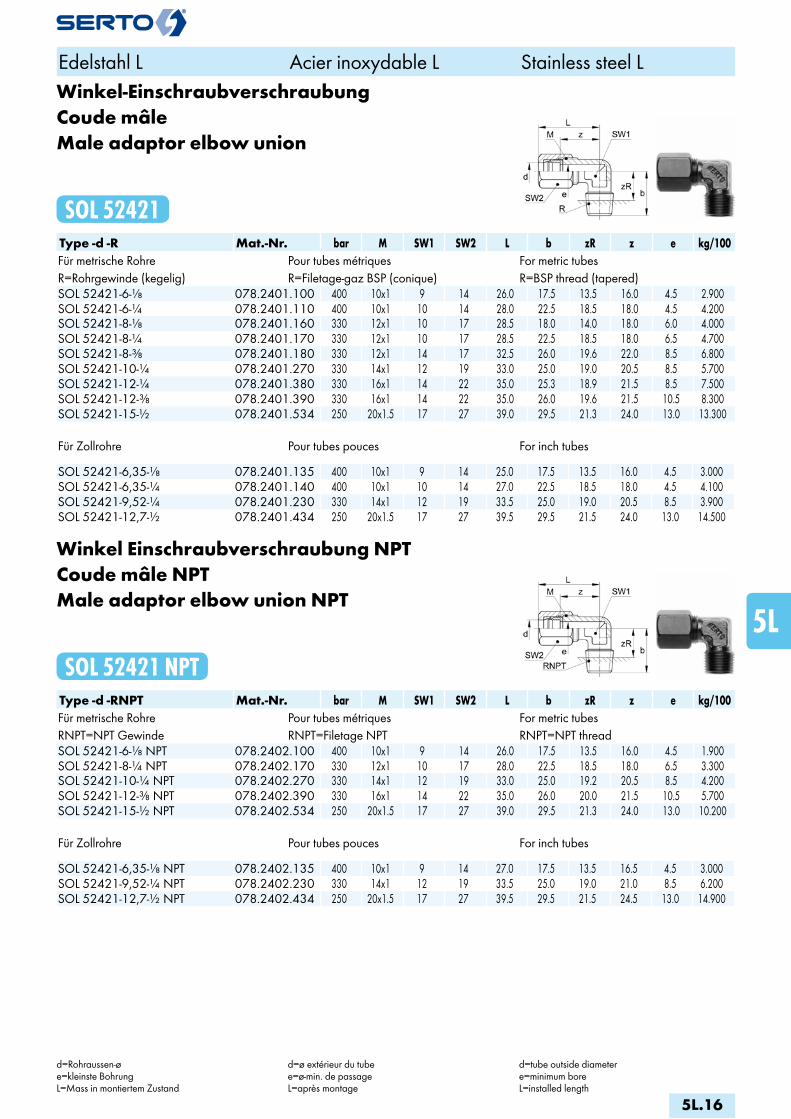
Winkel-EinschraubverschraubungCoude mâleMale adaptor elbow union
SOL 52421Type -d -R Mat.-Nr. bar M SW1 SW2 L b zR z e kg/100Für metrische Rohre Pour tubes métriques For metric tubesR=Rohrgewinde (kegelig) R=Filetage-gaz BSP (conique) R=BSP thread (tapered)SOL 52421-6-1/8 078.2401.100 400 10x1 9 14 26.0 17.5 13.5 16.0 4.5 2.900SOL 52421-6-1/4 078.2401.110 400 10x1 10 14 28.0 22.5 18.5 18.0 4.5 4.200SOL 52421-8-1/8 078.2401.160 330 12x1 10 17 28.5 18.0 14.0 18.0 6.0 4.000SOL 52421-8-1/4 078.2401.170 330 12x1 10 17 28.5 22.5 18.5 18.0 6.5 4.700SOL 52421-8-3/8 078.2401.180 330 12x1 14 17 32.5 26.0 19.6 22.0 8.5 6.800SOL 52421-10-1/4 078.2401.270 330 14x1 12 19 33.0 25.0 19.0 20.5 8.5 5.700SOL 52421-12-1/4 078.2401.380 330 16x1 14 22 35.0 25.3 18.9 21.5 8.5 7.500SOL 52421-12-3/8 078.2401.390 330 16x1 14 22 35.0 26.0 19.6 21.5 10.5 8.300SOL 52421-15-1/2 078.2401.534 250 20x1.5 17 27 39.0 29.5 21.3 24.0 13.0 13.300
Für Zollrohre Pour tubes pouces For inch tubes SOL 52421-6,35-1/8 078.2401.135 400 10x1 9 14 25.0 17.5 13.5 16.0 4.5 3.000SOL 52421-6,35-1/4 078.2401.140 400 10x1 10 14 27.0 22.5 18.5 18.0 4.5 4.100SOL 52421-9,52-1/4 078.2401.230 330 14x1 12 19 33.5 25.0 19.0 20.5 8.5 3.900SOL 52421-12,7-1/2 078.2401.434 250 20x1.5 17 27 39.5 29.5 21.5 24.0 13.0 14.500
Winkel Einschraubverschraubung NPTCoude mâle NPTMale adaptor elbow union NPT
SOL 52421 NPTType -d -RNPT Mat.-Nr. bar M SW1 SW2 L b zR z e kg/100Für metrische Rohre Pour tubes métriques For metric tubesRNPT=NPT Gewinde RNPT=Filetage NPT RNPT=NPT threadSOL 52421-6-1/8 NPT 078.2402.100 400 10x1 9 14 26.0 17.5 13.5 16.0 4.5 1.900SOL 52421-8-1/4 NPT 078.2402.170 330 12x1 10 17 28.0 22.5 18.5 18.0 6.5 3.300SOL 52421-10-1/4 NPT 078.2402.270 330 14x1 12 19 33.0 25.0 19.2 20.5 8.5 4.200SOL 52421-12-3/8 NPT 078.2402.390 330 16x1 14 22 35.0 26.0 20.0 21.5 10.5 5.700SOL 52421-15-1/2 NPT 078.2402.534 250 20x1.5 17 27 39.0 29.5 21.3 24.0 13.0 10.200
Für Zollrohre Pour tubes pouces For inch tubes SOL 52421-6,35-1/8 NPT 078.2402.135 400 10x1 9 14 27.0 17.5 13.5 16.5 4.5 3.000SOL 52421-9,52-1/4 NPT 078.2402.230 330 14x1 12 19 33.5 25.0 19.0 21.0 8.5 6.200SOL 52421-12,7-1/2 NPT 078.2402.434 250 20x1.5 17 27 39.5 29.5 21.5 24.5 13.0 14.900
Edelstahl L Acier inoxydable L Stainless steel L
d=Rohraussen-øe=kleinste BohrungL=Mass in montiertem Zustand
d=ø extérieur du tubee=ø-min. de passageL=après montage
d=tube outside diametere=minimum boreL=installed length
5L.16
i
s
3F
4M
4G
5
5L
6
7
8
9
10
11
12
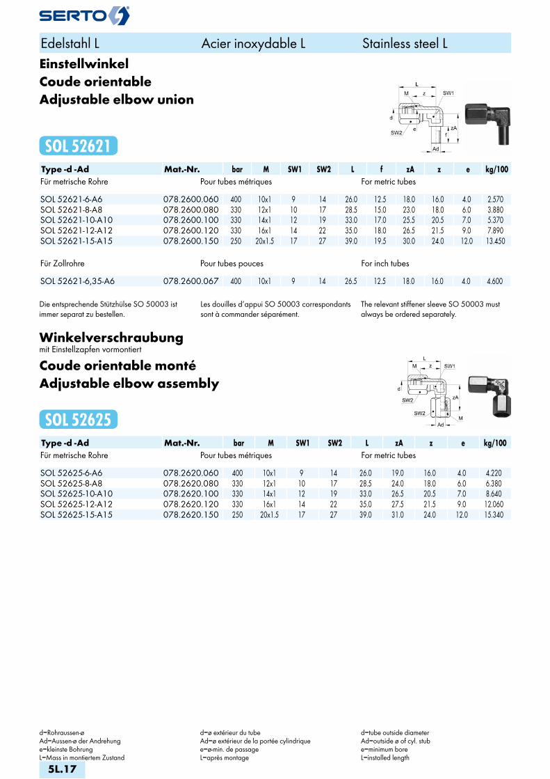
EinstellwinkelCoude orientableAdjustable elbow union
SOL 52621Type -d -Ad Mat.-Nr. bar M SW1 SW2 L f zA z e kg/100Für metrische Rohre Pour tubes métriques For metric tubes SOL 52621-6-A6 078.2600.060 400 10x1 9 14 26.0 12.5 18.0 16.0 4.0 2.570SOL 52621-8-A8 078.2600.080 330 12x1 10 17 28.5 15.0 23.0 18.0 6.0 3.880SOL 52621-10-A10 078.2600.100 330 14x1 12 19 33.0 17.0 25.5 20.5 7.0 5.370SOL 52621-12-A12 078.2600.120 330 16x1 14 22 35.0 18.0 26.5 21.5 9.0 7.890SOL 52621-15-A15 078.2600.150 250 20x1.5 17 27 39.0 19.5 30.0 24.0 12.0 13.450
Für Zollrohre Pour tubes pouces For inch tubes SOL 52621-6,35-A6 078.2600.067 400 10x1 9 14 26.5 12.5 18.0 16.0 4.0 4.600
Die entsprechende Stützhülse SO 50003 ist immer separat zu bestellen.
Les douilles d‘appui SO 50003 correspondants sont à commander séparément.
The relevant stiffener sleeve SO 50003 must always be ordered separately.
Winkelverschraubungmit Einstellzapfen vormontiert
Coude orientable montéAdjustable elbow assembly
SOL 52625Type -d -Ad Mat.-Nr. bar M SW1 SW2 L zA z e kg/100Für metrische Rohre Pour tubes métriques For metric tubes SOL 52625-6-A6 078.2620.060 400 10x1 9 14 26.0 19.0 16.0 4.0 4.220SOL 52625-8-A8 078.2620.080 330 12x1 10 17 28.5 24.0 18.0 6.0 6.380SOL 52625-10-A10 078.2620.100 330 14x1 12 19 33.0 26.5 20.5 7.0 8.640SOL 52625-12-A12 078.2620.120 330 16x1 14 22 35.0 27.5 21.5 9.0 12.060SOL 52625-15-A15 078.2620.150 250 20x1.5 17 27 39.0 31.0 24.0 12.0 15.340
Edelstahl L Acier inoxydable L Stainless steel L
d=Rohraussen-øAd=Aussen-ø der Andrehunge=kleinste BohrungL=Mass in montiertem Zustand
d=ø extérieur du tubeAd=ø extérieur de la portée cylindriquee=ø-min. de passageL=après montage
d=tube outside diameterAd=outside ø of cyl. stube=minimum boreL=installed length
5L.17

Winkel-SchottverschraubungDurchführungslänge max. 20 mm
Union double pour passage de cloisonpour cloison max 20 mm
Panel mount unionmax. panel thickness 20 mm
SOL 52721Type -d Mat.-Nr. bar M SW1 SW2 SW3 L L1 W z1 z e kg/100Für metrische Rohre Pour tubes métriques For metric tubes SOL 52721-6 078.2700.060 400 10x1 12 14 14 29.0 59.0 13.0 36.0 19.0 4.5 6.980SOL 52721-8 078.2700.080 330 12x1 12 17 17 29.5 59.5 13.0 36.0 19.0 5.5 9.450SOL 52721-10 078.2700.100 330 14x1 12 19 19 35.5 65.5 17.0 36.0 23.0 7.5 12.350SOL 52721-12 078.2700.120 330 16x1 14 22 22 37.0 67.0 17.0 37.0 24.0 8.5 17.060SOL 52721-15 078.2700.150 250 20x1.5 19 27 27 44.0 78.0 23.0 40.0 29.0 13.0 28.600SOL 52721-16 078.2700.160 250 24x1.5 24 30 30 52.0 83.0 22.0 42.5 33.0 15.0 30.600SOL 52721-18 078.2700.180 200 24x1.5 24 27 30 50.0 81.0 22.0 42.5 33.5 15.0 29.700
Für Zollrohre Pour tubes pouces For inch tubes SOL 52721-6,35 078.2700.063 400 10x1 12 14 14 30.0 60.0 13.0 36.0 19.0 4.5 7.300SOL 52721-9,52 078.2700.095 330 14x1 12 19 19 36.0 66.0 17.0 36.0 23.0 7.5 13.800SOL 52721-12,7 078.2700.127 250 20x1.5 19 27 27 44.5 78.5 23.0 40.5 29.5 13.0 31.800
SchwenkverschraubungCoude banjoSingle banjo
SOL 52824Type -d -G Mat.-Nr. bar M SW1 SW2 L A b D z e kg/100Für metrische Rohre Pour tubes métriques For metric tubesG=Rohrgewinde (zylindrisch) G=Filetage-gaz BSP (cylindrique) G=BSP thread (straight)SOL 52824-6-1/8 078.2841.100 400 10x1 14 14 28.0 21.0 28.5 16.0 18.0 4.5 6.280SOL 52824-8-1/8 078.2841.160 330 12x1 17 14 29.0 22.0 28.5 18.0 19.0 4.5 8.300SOL 52824-8-1/4 078.2841.170 330 12x1 17 19 31.0 27.0 38.0 20.5 20.5 7.0 12.000SOL 52824-10-1/4 078.2841.270 330 14x1 19 19 33.0 27.0 36.0 20.5 20.5 7.0 13.190SOL 52824-12-3/8 078.2841.390 330 16x1 22 24 36.5 35.0 47.0 26.0 24.0 9.0 24.600SOL 52824-15-1/2 078.2841.534 250 20x1.5 27 27 43.0 41.5 54.5 31.5 28.0 12.0 39.100SOL 52824-16-1/2 078.2841.566 200 24x1.5 30 27 46.0 43.5 54.5 31.5 28.5 12.0 42.400SOL 52824-18-1/2 078.2841.646 200 24x1.5 30 27 45.0 43.5 54.5 31.5 28.5 12.0 41.700
Für Zollrohre Pour tubes pouces For inch tubes SOL 52824-6,35-1/8 078.2841.135 400 10x1 14 14 29.0 21.0 31.0 17.0 18.0 4.5 2.200SOL 52824-9,52-1/4 078.2841.230 330 14x1 19 19 33.5 27.0 36.0 20.5 20.5 7.0 4.600SOL 52824-12,7-1/2 078.2841.434 330 20x1.5 27 27 43.5 41.5 55.0 31.5 28.5 12.0 25.600
Edelstahl L Acier inoxydable L Stainless steel L
d=Rohraussen-øe=kleinste BohrungL=Mass in montiertem Zustand
d=ø extérieur du tubee=ø-min. de passageL=après montage
d=tube outside diametere=minimum boreL=installed length
5L.18
i
s
3F
4M
4G
5
5L
6
7
8
9
10
11
12

T-VerschraubungTéTee union
SOL 53021Type -d Mat.-Nr. bar M SW1 SW2 L z e kg/100Für metrische Rohre Pour tubes métriques For metric tubes SOL 53021-6 078.3000.060 400 10x1 9 14 26.0 16.0 4.5 6.500SOL 53021-8 078.3000.080 330 12x1 10 17 28.5 18.0 6.5 9.600SOL 53021-10 078.3000.100 330 14x1 12 19 33.5 20.5 8.5 12.900SOL 53021-12 078.3000.120 330 16x1 14 22 35.0 21.5 9.5 17.800SOL 53021-15 078.3000.150 250 20x1.5 17 27 39.0 24.0 13.0 29.600SOL 53021-16 078.3000.160 200 24x1.5 22 30 45.0 26.0 15.0 40.800SOL 53021-18 078.3000.180 200 24x1.5 22 30 43.5 26.5 15.0 38.100
Für Zollrohre Pour tubes pouces For inch tubes SOL 53021-6,35 078.3000.063 400 10x1 9 14 25.5 16.5 4.5 6.800SOL 53021-9,52 078.3000.095 330 14x1 12 19 33.5 21.0 8.5 13.900SOL 53021-12,7 078.3000.127 250 20x1.5 17 27 39.5 24.5 13.0 32.400
Einstellbare L-VerschraubungL orientableAdjustable L union
SOL 53621 LType -Ad -d2 -d3 Mat.-Nr. bar M SW1 SW2 L f zA z e kg/100Für metrische Rohre Pour tubes métriques For metric tubes SOL 53621-A6-6-6 078.3610.060 400 10x1 9 14 26.0 12.5 18.0 16.0 4.0 4.750SOL 53621-A8-8-8 078.3610.080 330 12x1 10 17 28.5 15.0 23.0 18.0 6.0 6.920SOL 53621-A10-10-10 078.3610.100 330 14x1 12 19 33.0 17.0 25.5 20.5 7.0 9.400
Die entsprechende Stützhülse SO 50003 ist immer separat zu bestellen.
Les douilles d‘appui SO 50003 correspondants sont à commander séparément.
The relevant stiffener sleeve SO 50003 must always be ordered separately.
Edelstahl L Acier inoxydable L Stainless steel L
d=Rohraussen-øAd=Aussen-ø der Andrehunge=kleinste BohrungL=Mass in montiertem Zustand
d=ø extérieur du tubeAd=ø extérieur de la portée cylindriquee=ø-min. de passageL=après montage
d=tube outside diameterAd=outside ø of cyl. stube=minimum boreL=installed length
5L.19
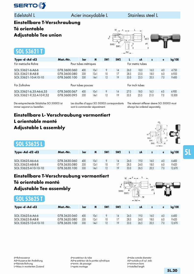
Einstellbare T-VerschraubungTé orientableAdjustable Tee union
SOL 53621 TType -d -Ad -d3 Mat.-Nr. bar M SW1 SW2 L zA z e kg/100Für metrische Rohre Pour tubes métriques For metric tubes SOL 53621-6-A6-6 078.3600.060 400 10x1 9 14 26.0 18.0 16.0 4.0 4.750SOL 53621-8-A8-8 078.3600.080 330 12x1 10 17 28.5 23.0 18.0 6.0 6.920SOL 53621-10-A10-10 078.3600.100 330 14x1 12 19 33.0 25.5 20.5 7.0 9.400
Für Zollrohre Pour tubes pouces For inch tubes SOL 53621-6,35-A6-6,35 078.3600.067 400 10x1 9 14 27.0 18.0 16.5 4.0 4.900SOL 53621-9,52-A10-9,52 078.3600.095 330 14x1 12 19 33.5 25.5 21.0 7.0 10.300
Die entsprechende Stützhülse SO 50003 ist immer separat zu bestellen.
Les douilles d‘appui SO 50003 correspondants sont à commander séparément.
The relevant stiffener sleeve SO 50003 must always be ordered separately.
Einstellbare L- Verschraubung vormontiertL orientable montéAdjustable L assembly
SOL 53625 LType -Ad -d2 -d3 Mat.-Nr. bar M SW1 SW2 L zA z e kg/100 SOL 53625-A6-6-6 078.3630.060 400 10x1 9 14 26.0 19.0 16.0 4.0 6.400SOL 53625-A8-8-8 078.3630.080 330 12x1 10 17 28.5 24.0 18.0 6.0 9.420SOL 53625-A10-10-10 078.3630.100 330 14x1 12 19 33.0 26.5 20.5 7.0 12.670
Einstellbare T-Verschraubung vormontiertTé orientable montéAdjustable Tee assembly
SOL 53625 TType -d -Ad -d3 Mat.-Nr. bar M SW1 SW2 L zA z e kg/100 SOL 53625-6-A6-6 078.3620.060 400 10x1 9 14 26.0 19.0 16.0 4.0 6.400SOL 53625-8-A8-8 078.3620.080 330 12x1 10 17 28.5 24.0 18.0 6.0 9.420SOL 53625-10-A10-10 078.3620.100 330 14x1 12 19 33.0 26.5 20.5 7.0 12.670
Edelstahl L Acier inoxydable L Stainless steel L
d=Rohraussen-øAd=Aussen-ø der Andrehunge=kleinste BohrungL=Mass in montiertem Zustand
d=ø extérieur du tubeAd=ø extérieur de la portée cylindriquee=ø-min. de passageL=après montage
d=tube outside diameterAd=outside ø of cyl. stube=minimum boreL=installed length
5L.20
i
s
3F
4M
4G
5
5L
6
7
8
9
10
11
12

KreuzverschraubungCroixCross union
SOL 54021Type -d Mat.-Nr. bar M SW1 SW2 L z e kg/100Für metrische Rohre Pour tubes métriques For metric tubes SOL 54021-6 078.4000.060 400 10x1 12 14 27.5 17.5 4.5 8.900SOL 54021-8 078.4000.080 330 12x1 12 17 29.5 19.0 6.5 13.200SOL 54021-10 078.4000.100 330 14x1 14 19 35.5 23.0 8.5 17.300SOL 54021-12 078.4000.120 330 16x1 14 22 38.5 25.0 9.5 23.400SOL 54021-15 078.4000.150 250 20x1.5 17 27 41.0 26.0 13.0 39.100
Für Zollrohre Pour tubes pouces For inch tubes SOL 54021-6,35 078.4000.063 400 10x1 12 14 27.0 17.5 4.5 9.700SOL 54021-9,52 078.4000.095 330 14x1 14 19 36.0 23.5 8.5 10.000SOL 54021-12,7 078.4000.127 250 20x1.5 17 27 41.5 26.5 13.0 19.200
Edelstahl L Acier inoxydable L Stainless steel L
d=Rohraussen-øe=kleinste BohrungL=Mass in montiertem Zustand
d=ø extérieur du tubee=ø-min. de passageL=après montage
d=tube outside diametere=minimum boreL=installed length
5L.21

6
Stahl Verschraubungen
Acier Raccords
Steel Unions
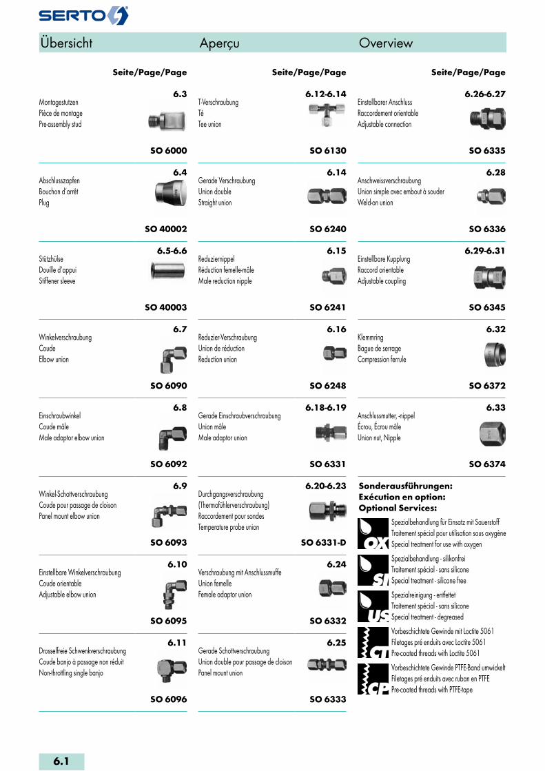
6.3MontagestutzenPièce de montagePre-assembly stud
SO 6000
6.4AbschlusszapfenBouchon d‘arrêtPlug
SO 40002
6.5-6.6StützhülseDouille d‘appuiStiffener sleeve
SO 40003
6.7WinkelverschraubungCoudeElbow union
SO 6090
6.8EinschraubwinkelCoude mâleMale adaptor elbow union
SO 6092
6.9Winkel-SchottverschraubungCoude pour passage de cloisonPanel mount elbow union
SO 6093
6.10Einstellbare WinkelverschraubungCoude orientableAdjustable elbow union
SO 6095
6.11Drosselfreie SchwenkverschraubungCoude banjo à passage non réduitNon-throttling single banjo
SO 6096
6.12-6.14T-VerschraubungTéTee union
SO 6130
6.14Gerade VerschraubungUnion doubleStraight union
SO 6240
6.15ReduziernippelRéduction femelle-mâleMale reduction nipple
SO 6241
6.16Reduzier-VerschraubungUnion de réductionReduction union
SO 6248
6.18-6.19Gerade EinschraubverschraubungUnion mâleMale adaptor union
SO 6331
6.20-6.23Durchgangsverschraubung(Thermofühlerverschraubung)Raccordement pour sondesTemperature probe union
SO 6331-D
6.25Gerade SchottverschraubungUnion double pour passage de cloisonPanel mount union
SO 6333
6.26-6.27Einstellbarer AnschlussRaccordement orientableAdjustable connection
SO 6335
6.28AnschweissverschraubungUnion simple avec embout à souderWeld-on union
SO 6336
6.29-6.31Einstellbare KupplungRaccord orientableAdjustable coupling
SO 6345
6.32KlemmringBague de serrageCompression ferrule
SO 6372
6.33Anschlussmutter, -nippelÉcrou, Écrou mâleUnion nut, Nipple
SO 6374
Sonderausführungen:Exécution en option:Optional Services:
Spezialbehandlung für Einsatz mit SauerstoffTraitement spécial pour utilisation sous oxygèneSpecial treatment for use with oxygen
Spezialbehandlung - silikonfreiTraitement spécial - sans siliconeSpecial treatment - silicone free
Spezialreinigung - entfettetTraitement spécial - sans siliconeSpecial treatment - degreased
Vorbeschichtete Gewinde mit Loctite 5061Filetages pré enduits avec Loctite 5061Pre-coated threads with Loctite 5061
Vorbeschichtete Gewinde PTFE-Band umwickeltFiletages pré enduits avec ruban en PTFEPre-coated threads with PTFE-tape
Seite/Page/Page Seite/Page/Page Seite/Page/Page
Übersicht Aperçu Overview
6.24Verschraubung mit AnschlussmuffeUnion femelleFemale adaptor union
SO 6332
6.1

300°200°0° 120°-40°
100% 60%
C° -100°
Stahl Acier Steel
Eigenschaften, Besonderheiten- einfache, schnelle Montage- kompakte Baumasse- grosse Sortimentsvielfalt- viele Kombinationsmöglichkeiten- hohe Betriebsdrücke
Funktionsprinzipsiehe Anhang
AnwendungZur Verbindung von Präzisionsrohren aus Stahl. Besonders für hohe Betriebsdrücke, z.B. in der Hydraulik.
WerkstoffStahl nach DIN 3859Blauverzinkt mit Dickschichtpassivierung 1)
Betriebsdruck PNsiehe Produktetabellen (4-fache Sicherheit). Dynamische Belastungen auf Anfrage.
Temperaturbereich-40°C bis +200°C
Helium - Leckrate10-8mbar • l/s *
Anzuschliessende RohreNahtlose Präzisionsrohre nach EN 10305-1 aus St 35.4, normalblankgeglüht (NBK), blank oder rostschutzgebondert und Kunststoffrohre. Aussendurchmesser innerhalb ± 0,1 mm; Ausnahme: Kunststoffrohre. Siehe auch Kapitel Rohre und Schläuche sowie Tabelle Mindestwandungen im Anhang.
1) entspricht Richtlinien 2002/95/EG und2000/53/EG
Characteristics, specialities- easy and fast to install- compact size- wide selection of compatible components- extensive range of combinations- high operating pressures
Operating principlesee appendix
ApplicationTo connect precision steel tubes, in particular for high operating pressures. For example in the hydraulic field.
MaterialSteel of DIN 3859Blue galvanization with thick film passivation 1)
Working pressure PNsee product table (safety factor 4). Dynamic loads on demand.
Temperature range-40°C to +200°C
Leak rate with helium10-8mbar • l/s *
Tubes to useSeamless precision steel tubing conforming to EN 10305-1 of St 35.4, normalized bright annealed (NBK) with bright or rust preventative bonded finish or plastic tubing. Diameters within ± 0,1 mm; exception: plastic tubes. See also chapter «tubes, hoses» and table «minimum wall for tube outside diameter» in the appendix.
1) according to directives 2002/95/EC and2000/53 EC
Généralités- Montage facile et rapide- compactes dimensions- programme étendu- multiples possibilités de combinaisons- pressions de service élevées
Principe de fonctionnementvoir annexe
ApplicationPour assembler des tubes en acier. Particulièrement pour des pressions de service élevées. P. ex. dans le domaine de l’hydraulique.
MatériauAcier selon DIN 3859Zinqué bleu avec passivation de chouche épaisse 1)
Pression de service PNvoir tableaux des produits (facteur de sécurité 4). Solicitations dynamique sur demande.
Plage de température admissible-40°C à +200°C
Débit de fuite avec hélium10-8mbar • l/s *
Tubes à utiliserUtiliser, avec les raccords à bague de serrage SERTO en acier, des tubes de précision sans soudure selon EN 10305-1 en Ac 35.4, recuit blanc, exécution polie ou bondérisée ou tubes en matières plastiques. Diamètre extérieur dans une tolérance de ± 0,1 mm; exception: tubes en plastique. Voir chapitre «tubes, tuyaux» et le tableau épaisseur de paroi minimale en annexe.
1) selon directive 2002/95/CE et2000/53/CE
Druckauswertungsgrad in % des PN
Coefficient de pression de service admissible en % de PN
Pressure coefficient % of PN
* bei fachgerechter Montage; siehe Anhang: - Seite a.6 - Rohre - Seite a.21 - Montageanleitung
* à la base d'un montage dans les règles de l'art ; voir Appendice: - page a.6 - Tubes - page a.21 - Instructions de montage
* when professionally assembled; see Appendix: - page a.6 - Tubes - page a.21 - Installation instructions
6.2
i
s
3F
4M
4G
5
5L
6
7
8
9
10
11
12
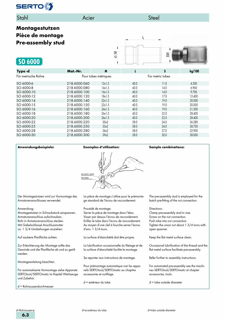
MontagestutzenPièce de montagePre-assembly stud
SO 6000Type -d Mat.-Nr. M L S kg/100Für metrische Rohre Pour tubes métriques For metric tubes SO 6000-6 218.6000.060 12x1.5 40.0 11.0 4.300SO 6000-8 218.6000.080 14x1.5 40.0 14.0 6.960SO 6000-10 218.6000.100 16x1.5 40.0 14.0 9.700SO 6000-12 218.6000.120 18x1.5 40.0 17.0 12.400SO 6000-14 218.6000.140 22x1.5 40.0 19.0 20.000SO 6000-15 218.6000.150 22x1.5 40.0 19.0 20.000SO 6000-16 218.6000.160 24x1.5 40.0 19.0 21.300SO 6000-18 218.6000.180 26x1.5 40.0 22.0 28.400SO 6000-20 218.6000.200 26x1.5 40.0 22.0 28.400SO 6000-22 218.6000.220 30x2 58.0 24.0 36.280SO 6000-25 218.6000.250 33x2 58.0 24.0 38.750SO 6000-28 218.6000.280 36x2 58.0 27.0 52.900SO 6000-30 218.6000.300 39x2 58.0 30.0 58.000
Stahl Acier Steel
d=Rohraussen-ø d=ø extérieur du tube d=tube outside diameter
Anwendungsbeispiele: Exemples d‘utilisation: Sample combinations:
Der Montagestutzen wird zur Vormontage des Armaturenanschlusses verwendet.
Anwendung:Montagestutzen in Schraubstock einspannen.Armaturenanschluss aufschrauben.Rohr in Armaturenanschluss stecken.Mit Gabelschlüssel Anschlussmutterca. 1 3/4 Umdrehungen anziehen.
Auf saubere Planfläche achten.
Zur Erleichterung der Montage sollte das Gewinde und die Planfläche ab und zu geölt werden.
Montageanleitung beachten.
Für automatisierte Vormontage siehe Apparate SERTOtool/SERTOmatic im Kapitel Werkzeuge und Zubehör.
d = Rohraussendurchmesser
La pièce de montage s’utilise pour le prémonta-ge standard de l’écrou de raccordement.
Procédé de montage:Serrer la pièce de montage dans l’étau.Visser par dessus l’écrou de raccordement.Enfiler le tube dans l’écrou de raccordement.Au moyen d’une clef à fourche serrer l’écrou d’env. 1 3/4 tours.
La surface d’étanchéité doit être propre.
La lubrification occasionnelle du filetage et de la surface d’étanchéité facilite le montage.
Se reporter aux instructions de montage.
Pour prémontage automatique voir les appa - reils SERTOtool/SERTOmatic au chapitre accessoires et outillage.
d = extérieur du tube
The pre-assembly stud is employed for the batch pre-fitting of the nut connection.
Directions:Clamp pre-assembly stud in vise.Screw on the nut connection.Push tube into nut connection.Tighten the union nut about 1 3/4 turns with open spanner.
Keep the flat metal surface clean.
Occasional lubrification of the thread and the flat metal surface facilitate pre-assembly.
Refer further to assembly instructions.
For automated pre-assembly see the machi-nes SERTOtool/SERTOmatic at chapter accessories, tools.
d = tube outside diameter
6.3

AbschlusszapfenBouchon d‘arrêtPlug
SO 40002Type -d Mat.-Nr. L D kg/100Für metrische Rohre Pour tubes métriques For metric tubes SO 40002-4 016.0020.040 8.0 6.8 0.150SO 40002-5 016.0020.050 8.5 6.8 0.190SO 40002-6 016.0020.060 10.0 8.4 0.310SO 40002-8 016.0020.080 10.5 10.5 0.570SO 40002-10 016.0020.100 13.0 12.7 0.960SO 40002-12 016.0020.120 14.0 14.8 1.470SO 40002-14 016.0020.140 15.0 17.5 2.230SO 40002-15 016.0020.150 15.0 18.0 2.370SO 40002-18 016.0020.180 16.8 22.0 4.000SO 40002-22 016.0020.220 19.0 26.0 6.300SO 40002-28 016.0020.280 22.5 32.5 11.900SO 40002-35 016.0020.350 25.2 39.5 20.000
Anwendungsbeispiele: Exemples d‘utilisation: Sample combinations:
Werkstoff: Messing
Der Abschlusszapfen lässt sich in jede Verschraubung anstelle eines Klemmringesgleicher Grösse d einsetzen.
Anschlussmutter mit 1/4 Drehung anziehen.
Matériau: Laiton
Le bouchon d’arrêt peut remplacer la bague de serrage de même dimension d dans chaque raccord.
Serrer l’écrou avec 1/4 tour.
Material: Brass
The plug can be fitted into any union in place of a compression ferrule of same diameter d.
Tighten the union nut with 1/4 turn.
Stahl Acier Steel
d=Rohraussen-ø d=ø extérieur du tube d=tube outside diameter
6.4
i
s
3F
4M
4G
5
5L
6
7
8
9
10
11
12

Stützhülsezur Rohrverstärkung
Douille d‘appuipour renforcer les tubes
Stiffener sleeveto reinforce the tubes
SO 40003Type -d -d1 Mat.-Nr. L D d2 s kg/100Für metrische Rohre Pour tubes métriques For metric tubes
SO 40003-3-2 016.0030.020 6.0 2.8 1.95 0.20 0.006SO 40003-3-2,4 016.0030.024 6.0 2.8 2.35 0.20 0.007SO 40003-4-2 016.0030.030 8.0 3.8 1.95 0.20 0.008SO 40003-4-2,5 016.0030.035 8.0 3.8 2.45 0.20 0.010SO 40003-4-3 016.0030.040 8.0 3.8 2.95 0.20 0.010SO 40003-5-3 016.0030.060 8.0 4.5 2.95 0.20 0.015SO 40003-5-3,5 016.0030.075 8.0 4.5 3.45 0.20 0.020SO 40003-6-3 016.0030.100 10.0 5.2 2.95 0.20 0.015SO 40003-6-4 016.0030.110 10.0 5.5 3.95 0.20 0.025SO 40003-6-4,4 016.0030.113 10.0 5.5 4.35 0.20 0.025SO 40003-6-4,65 016.0030.116 10.0 5.5 4.65 0.20 0.025SO 40003-6-4,7 D 016.0030.118 10.0 5.5 4.65 0.40 0.046SO 40003-8-5 016.0030.136 12.0 7.5 4.90 0.25 0.040SO 40003-8-5,5 016.0030.138 12.0 7.5 5.40 0.25 0.045SO 40003-8-6 016.0030.140 12.0 7.5 5.90 0.25 0.045SO 40003-8-6,4 016.0030.144 12.0 7.5 6.30 0.25 0.050SO 40003-10-7 016.0030.180 16.0 9.5 6.90 0.30 0.080SO 40003-10-7,5 016.0030.185 16.0 9.5 7.40 0.30 0.090SO 40003-10-8 016.0030.190 16.0 9.5 7.80 0.30 0.100SO 40003-10-8 D 016.0030.189 16.0 9.5 7.85 0.60 0.190SO 40003-10-8,4 016.0030.192 16.0 9.5 8.30 0.30 0.095SO 40003-10-8,6 016.0030.193 16.0 9.5 8.50 0.30 0.095SO 40003-12-9 016.0030.230 20.0 11.5 8.80 0.40 0.190SO 40003-12-9,5 016.0030.235 20.0 11.5 9.40 0.40 0.195SO 40003-12-10 016.0030.240 20.0 11.5 9.80 0.40 0.195SO 40003-12-10,4 016.0030.254 20.0 11.5 10.20 0.40 0.195SO 40003-12-11 D 016.0030.257 20.0 12.0 10.80 1.00 0.500SO 40003-13-11 016.0030.280 20.0 12.5 10.80 0.50 0.330SO 40003-13-11 D 016.0030.279 20.0 12.5 10.80 1.00 0.530SO 40003-14-11 016.0030.330 24.0 13.5 10.80 0.50 0.350SO 40003-14-11,5 016.0030.335 24.0 13.5 11.40 0.50 0.350SO 40003-14-12 016.0030.340 24.0 13.5 11.80 0.50 0.370SO 40003-15-12,5 016.0030.425 24.0 14.5 12.40 0.50 0.390SO 40003-15-13 016.0030.430 24.0 14.5 12.80 0.50 0.390
Fortsetzung nächste Seite Suite à la prochaine page Continued on next page
Stahl Acier Steel
d=Rohraussen-ød1=Rohrinnen-øs=Rohrwandstärke
d=ø extérieur du tubed1=ø intérieur de tubes=epaisseur de la paroi du tube
d=tube outside diameterd1=tube inside diameters=tube wall thickness
6.5

Stützhülsezur Rohrverstärkung
Douille d‘appuipour renforcer les tubes
Stiffener sleeveto reinforce the tubes
SO 40003Type -d -d1 Mat.-Nr. L D d2 s kg/100Für metrische Rohre Pour tubes métriques For metric tubes
SO 40003-16-13,5 016.0030.495 26.0 15.5 13.40 0.50 0.430SO 40003-16-14 016.0030.500 26.0 15.5 13.80 0.50 0.470SO 40003-16-14 D 016.0030.499 26.0 15.5 13.80 1.00 0.900SO 40003-17-15 016.0030.540 26.0 16.5 14.70 0.60 0.590SO 40003-18-15 016.0030.610 26.0 16.5 14.70 0.60 0.590SO 40003-18-15,6 016.0030.616 26.0 17.5 15.30 0.60 0.610SO 40003-18-16 016.0030.620 26.0 17.5 15.70 0.60 0.630SO 40003-19-17 016.0030.640 28.0 18.5 16.70 0.60 0.820SO 40003-19-17 D 016.0030.642 28.0 19.0 16.90 1.00 1.140SO 40003-20-17 016.0030.690 28.0 19.5 16.70 0.60 0.800SO 40003-20-18 016.0030.700 28.0 19.5 17.70 0.60 0.830SO 40003-22-19 016.0030.760 30.0 21.5 18.70 0.60 0.850SO 40003-22-19,6 016.0030.771 30.0 21.5 19.30 0.60 0.940SO 40003-22-20 016.0030.775 30.0 21.5 19.70 0.60 0.980SO 40003-28-25 016.0030.870 36.0 27.5 24.70 0.80 1.500SO 40003-28-25,6 016.0030.876 36.0 27.5 25.30 0.80 1.600SO 40003-35-32 016.0030.890 41.0 34.0 31.70 0.85 2.500
Werkstoff: Messing
Verstärken:Dünnwandige und weiche Rohre sowie alle Kunststoffrohre sind vor dem Einführen in die SERTO Verschraubung mit Stützhülsen zu verstär-ken. Genaue Angaben über das Verstärken sind den einzelnen Verschraubungsreihen zu entnehmen. Zum Entgraten und Kalibrieren der Rohre eignen sich besonders unsere Hilfswerkzeuge (siehe Kapitel 11).
Matériau: Laiton
Renforcement:Les tubes présentant une paroi mince, les tubes en matière souple ainsi que les tubes en matière pla-stique doivent être renforcés à l’aide de douilles d’appui avant d’être introduits dans les raccords SERTO. Des indications plus précises concernant le ren-forcement sont données pour chaque série de raccord. L’ébarbage et le calibrage du tube sont facilités par l’emploi de notre outil spécial (voir chap. 11).
Material: Brass
Reinforcement:Thin walled and soft tubes and all plastic tubes, are to be reinforced with stiffener sleeves before insert them into the SERTO union. Exact details concerning stiffening are to be found in the sections on the relevant model series. Our tools are especially useful for debur-ring and calibrating tubing (see chapter 11).
Stahl Acier Steel
d=Rohraussen-ød1=Rohrinnen-øs=Rohrwandstärke
d=ø extérieur du tubed1=ø intérieur de tubes=epaisseur de la paroi du tube
d=tube outside diameterd1=tube inside diameters=tube wall thickness
6.6
i
s
3F
4M
4G
5
5L
6
7
8
9
10
11
12

WinkelverschraubungCoudeElbow union
SO 6090Type -d Mat.-Nr. bar M L S1 S2 z kg/100Für metrische Rohre Pour tubes métriques For metric tubes SO 6090-6 218.2000.060 400 12x1.5 28.0 12 14 20.0 4.000SO 6090-8 218.2000.080 300 14x1.5 30.0 12 17 22.0 6.200SO 6090-10 218.2000.100 250 16x1.5 33.0 14 19 23.0 9.000SO 6090-12 218.2000.120 250 18x1.5 37.0 17 22 25.0 12.700SO 6090-14 218.2000.140 250 22x1.5 42.0 19 27 29.0 21.500SO 6090-15 218.2000.150 200 22x1.5 42.0 19 27 29.0 21.500SO 6090-16 218.2000.160 200 24x1.5 46.0 22 30 31.0 28.200SO 6090-18 218.2000.180 200 26x1.5 48.0 24 32 32.0 32.400SO 6090-20 218.2000.200 200 26x1.5 50.0 24 32 32.5 33.800SO 6090-22 218.2000.220 160 30x2 51.0 27 36 37.0 42.400SO 6090-25 218.2000.250 160 33x2 57.0 30 41 40.0 61.500SO 6090-28 218.2000.280 160 36x2 56.0 36 41 40.0 58.800
Stahl Acier Steel
d=Rohraussen-øL=Mass in montiertem Zustand
d=ø extérieur du tubeL=après montage
d=tube outside diameterL=installed length
6.7

EinschraubwinkelCoude mâleMale adaptor elbow union
SO 6092Type -d -R Mat.-Nr. bar M L1 L2 S1 S2 y z kg/100Für metrische Rohre Pour tubes métriques For metric tubesR=Rohrgewinde (kegelig) R=Filetage-gaz BSP (conique) R=BSP thread (tapered)SO 6092-6-1/8 218.2401.100 400 12x1.5 28.0 20.0 12 14 15.0 20.0 3.100SO 6092-6-1/4 218.2401.110 400 12x1.5 30.0 26.0 12 14 18.0 22.0 4.000SO 6092-8-1/8 218.2401.160 300 14x1.5 30.0 26.0 12 17 21.0 22.0 4.300SO 6092-8-1/4 218.2401.170 300 14x1.5 30.0 26.0 12 17 18.0 22.0 4.600SO 6092-10-1/4 218.2401.270 250 16x1.5 32.5 27.0 14 19 19.0 23.0 6.400SO 6092-10-3/8 218.2401.280 250 16x1.5 32.5 26.0 14 19 18.0 23.0 8.300SO 6092-12-3/8 218.2401.390 250 18x1.5 37.0 28.0 17 22 20.0 25.0 8.600SO 6092-14-3/8 218.2401.502 250 22x1.5 42.0 32.0 19 27 24.0 29.0 14.500SO 6092-14-1/2 218.2401.504 250 22x1.5 42.0 32.0 19 27 22.0 29.0 15.600SO 6092-15-3/8 218.2401.532 200 22x1.5 42.0 32.0 19 27 24.0 29.0 14.500SO 6092-15-1/2 218.2401.534 200 22x1.5 42.0 32.0 19 27 22.0 29.0 15.600SO 6092-16-1/2 218.2401.566 200 24x1.5 46.0 35.0 22 30 25.0 31.0 19.600SO 6092-18-1/2 218.2401.646 200 26x1.5 48.0 36.0 24 32 26.0 32.0 21.700SO 6092-18-3/4 218.2401.648 200 26x1.5 48.0 35.0 24 32 23.0 32.0 24.800SO 6092-20-1/2 218.2401.706 200 26x1.5 50.0 36.0 24 32 26.0 33.0 21.700SO 6092-20-3/4 218.2401.708 200 26x1.5 50.0 35.0 24 32 23.0 33.0 24.810SO 6092-22-3/4 218.2401.768 160 30x2 51.0 39.0 27 36 27.0 37.0 28.800SO 6092-25-1 218.2401.810 160 33x2 57.0 44.0 30 41 30.0 40.0 43.900SO 6092-28-1 218.2401.850 160 36x2 56.0 46.0 36 41 32.0 40.0 39.400
Stahl Acier Steel
d=Rohraussen-øL1=Mass in montiertem Zustand
d=ø extérieur du tubeL1=après montage
d=tube outside diameterL1=installed length
6.8
i
s
3F
4M
4G
5
5L
6
7
8
9
10
11
12
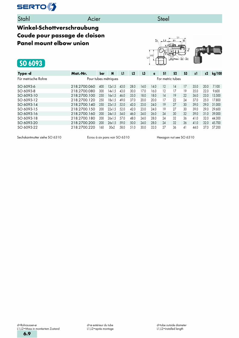
Winkel-SchottverschraubungCoude pour passage de cloisonPanel mount elbow union
SO 6093Type -d Mat.-Nr. bar M L1 L2 L3 a S1 S2 S3 z1 z2 kg/100Für metrische Rohre Pour tubes métriques For metric tubes SO 6093-6 218.2700.060 400 12x1.5 43.0 28.0 14.0 14.0 12 14 17 35.0 20.0 7.100SO 6093-8 218.2700.080 300 14x1.5 43.0 30.0 17.0 16.0 12 17 19 35.0 22.0 9.600SO 6093-10 218.2700.100 250 16x1.5 46.0 33.0 18.0 18.0 14 19 22 36.0 23.0 13.500SO 6093-12 218.2700.120 250 18x1.5 49.0 37.0 20.0 20.0 17 22 24 37.0 25.0 17.800SO 6093-14 218.2700.140 250 22x1.5 52.0 42.0 23.0 24.0 19 27 30 39.0 29.0 31.000SO 6093-15 218.2700.150 200 22x1.5 52.0 42.0 23.0 24.0 19 27 30 39.0 29.0 29.600SO 6093-16 218.2700.160 200 24x1.5 54.0 46.0 24.0 26.0 24 30 32 39.0 31.0 39.000SO 6093-18 218.2700.180 200 26x1.5 57.0 48.0 24.0 28.0 24 32 36 41.0 32.0 44.300SO 6093-20 218.2700.200 200 26x1.5 59.0 50.0 24.0 28.0 24 32 36 41.0 32.0 45.700SO 6093-22 218.2700.220 160 30x2 58.0 51.0 30.0 32.0 27 36 41 44.0 37.0 57.200
Sechskantmutter siehe SO 6310 Ecrou à six pans voir SO 6310 Hexagon nut see SO 6310
Stahl Acier Steel
d=Rohraussen-øL1,L2=Mass in montiertem Zustand
d=ø extérieur du tubeL1,L2=après montage
d=tube outside diameterL1,L2=installed length
6.9
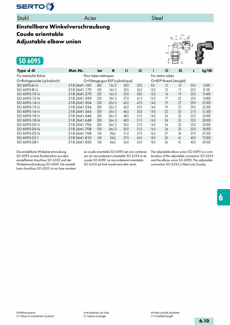
Einstellbare WinkelverschraubungCoude orientableAdjustable elbow union
SO 6095Type -d -G Mat.-Nr. bar M L1 L2 i S1 S2 z kg/100Für metrische Rohre Pour tubes métriques For metric tubesG=Rohrgewinde (zylindrisch) G=Filetage-gaz BSP (cylindrique) G=BSP thread (straight)SO 6095-6-1/8 218.2641.100 400 12x1.5 28.0 33.0 8.0 12 14 20.0 5.000SO 6095-8-1/4 218.2641.170 300 14x1.5 30.0 36.5 12.0 12 17 22.0 8.100SO 6095-10-1/4 218.2641.270 250 16x1.5 33.0 38.0 12.0 14 19 23.0 10.400SO 6095-12-3/8 218.2641.390 250 18x1.5 37.0 41.0 12.0 17 22 25.0 14.800SO 6095-14-1/2 218.2641.504 250 22x1.5 42.0 47.0 14.0 19 27 29.0 25.300SO 6095-15-1/2 218.2641.534 200 22x1.5 42.0 47.0 14.0 19 27 29.0 25.300SO 6095-16-1/2 218.2641.566 200 24x1.5 46.0 50.0 14.0 22 30 31.0 31.500SO 6095-18-1/2 218.2641.646 200 26x1.5 48.0 51.0 14.0 24 32 32.0 35.000SO 6095-18-3/4 218.2641.648 200 26x1.5 48.0 51.0 16.0 24 32 32.0 38.000SO 6095-20-1/2 218.2641.706 200 26x1.5 50.0 51.0 14.0 24 32 33.0 35.000SO 6095-20-3/4 218.2641.708 200 26x1.5 50.0 51.0 16.0 24 32 33.0 38.000SO 6095-22-3/4 218.2641.768 160 30x2 51.0 57.0 16.0 27 36 37.0 47.200SO 6095-25-1 218.2641.810 160 33x2 57.0 63.0 18.0 30 41 40.0 72.000SO 6095-28-1 218.2641.850 160 36x2 56.0 63.0 18.0 36 41 40.0 69.200
Die einstellbare Winkelverschraubung SO 6095 ist eine Kombination aus dem einstellbaren Anschluss SO 6335 und der Winkelverschraubung SO 6090. Der einstell- bare Anschluss SO 6335 ist nur lose montiert.
Le coude orientable SO 6095 est une combinai-son du raccordement orientable SO 6335 et du coude SO 6090. Le raccordement orientable SO 6335 est livré monté sans être serré.
The adjustable elbow union SO 6095 is a com-bination of the adjustable connection SO 6335 and the elbow union SO 6090. The adjustable connection SO 6335 is fitted only loosely.
d=Rohraussen-øL1=Mass in montiertem Zustand
d=ø extérieur du tubeL1=après montage
d=tube outside diameterL1=installed length
6.10
i
s
3F
4M
4G
5
5L
6
7
8
9
10
11
12
Stahl Acier Steel
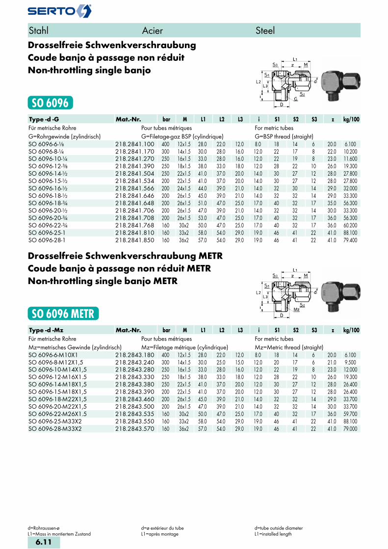
Drosselfreie SchwenkverschraubungCoude banjo à passage non réduitNon-throttling single banjo
SO 6096Type -d -G Mat.-Nr. bar M L1 L2 L3 i S1 S2 S3 z kg/100Für metrische Rohre Pour tubes métriques For metric tubesG=Rohrgewinde (zylindrisch) G=Filetage-gaz BSP (cylindrique) G=BSP thread (straight)SO 6096-6-1/8 218.2841.100 400 12x1.5 28.0 22.0 12.0 8.0 18 14 6 20.0 6.100SO 6096-8-1/4 218.2841.170 300 14x1.5 30.0 28.0 16.0 12.0 22 17 8 22.0 10.200SO 6096-10-1/4 218.2841.270 250 16x1.5 33.0 28.0 16.0 12.0 22 19 8 23.0 11.600SO 6096-12-3/8 218.2841.390 250 18x1.5 38.0 33.0 18.0 12.0 28 22 10 26.0 19.300SO 6096-14-1/2 218.2841.504 250 22x1.5 41.0 37.0 20.0 14.0 30 27 12 28.0 27.800SO 6096-15-1/2 218.2841.534 200 22x1.5 41.0 37.0 20.0 14.0 30 27 12 28.0 27.800SO 6096-16-1/2 218.2841.566 200 24x1.5 44.0 39.0 21.0 14.0 32 30 14 29.0 32.000SO 6096-18-1/2 218.2841.646 200 26x1.5 45.0 39.0 21.0 14.0 32 32 14 29.0 33.300SO 6096-18-3/4 218.2841.648 200 26x1.5 51.0 47.0 25.0 17.0 40 32 17 35.0 56.300SO 6096-20-1/2 218.2841.706 200 26x1.5 47.0 39.0 21.0 14.0 32 32 14 30.0 33.300SO 6096-20-3/4 218.2841.708 200 26x1.5 53.0 47.0 25.0 17.0 40 32 17 36.0 56.300SO 6096-22-3/4 218.2841.768 160 30x2 50.0 47.0 25.0 17.0 40 32 17 36.0 60.200SO 6096-25-1 218.2841.810 160 33x2 58.0 54.0 29.0 19.0 46 41 22 41.0 88.100SO 6096-28-1 218.2841.850 160 36x2 57.0 54.0 29.0 19.0 46 41 22 41.0 79.400
Drosselfreie Schwenkverschraubung METRCoude banjo à passage non réduit METRNon-throttling single banjo METR
SO 6096 METRType -d -Mz Mat.-Nr. bar M L1 L2 L3 i S1 S2 S3 z kg/100Für metrische Rohre Pour tubes métriques For metric tubesMz=metrisches Gewinde (zylindrisch) Mz=Filetage métrique (cylindrique) Mz=Metric thread (straight)SO 6096-6-M10X1 218.2843.180 400 12x1.5 28.0 22.0 12.0 8.0 18 14 6 20.0 6.100SO 6096-8-M12X1,5 218.2843.240 300 14x1.5 30.0 25.0 15.0 12.0 20 17 6 21.0 9.500SO 6096-10-M14X1,5 218.2843.280 250 16x1.5 33.0 28.0 16.0 12.0 22 19 8 23.0 12.000SO 6096-12-M16X1.5 218.2843.330 250 18x1.5 38.0 33.0 18.0 12.0 28 22 10 26.0 19.300SO 6096-14-M18X1,5 218.2843.380 250 22x1.5 41.0 37.0 20.0 12.0 30 27 12 28.0 26.400SO 6096-15-M18X1,5 218.2843.390 200 22x1.5 41.0 37.0 20.0 12.0 30 27 12 28.0 26.400SO 6096-18-M22X1,5 218.2843.460 200 26x1.5 45.0 39.0 21.0 14.0 32 32 14 29.0 33.700SO 6096-20-M22X1,5 218.2843.500 200 26x1.5 47.0 39.0 21.0 14.0 32 32 14 30.0 33.700SO 6096-22-M26X1.5 218.2843.535 160 30x2 50.0 47.0 25.0 17.0 40 32 17 36.0 59.700SO 6096-25-M33X2 218.2843.550 160 33x2 58.0 54.0 29.0 19.0 46 41 22 41.0 88.100SO 6096-28-M33X2 218.2843.570 160 36x2 57.0 54.0 29.0 19.0 46 41 22 41.0 79.000
Stahl Acier Steel
d=Rohraussen-øL1=Mass in montiertem Zustand
d=ø extérieur du tubeL1=après montage
d=tube outside diameterL1=installed length
6.11

T-VerschraubungTéTee union
SO 6130Type -d Mat.-Nr. bar M L S1 S2 z kg/100Für metrische Rohre Pour tubes métriques For metric tubes SO 6130-6 218.3000.060 400 12x1.5 28.0 12 14 20.0 6.600SO 6130-8 218.3000.080 300 14x1.5 30.0 12 17 22.0 8.900SO 6130-10 218.3000.100 250 16x1.5 33.0 14 19 23.0 13.700SO 6130-12 218.3000.120 250 18x1.5 37.0 17 22 25.0 18.400SO 6130-14 218.3000.140 250 22x1.5 42.0 19 27 29.0 32.800SO 6130-15 218.3000.150 200 22x1.5 42.0 19 27 29.0 32.800SO 6130-16 218.3000.160 200 24x1.5 46.0 22 30 31.0 42.700SO 6130-18 218.3000.180 200 26x1.5 48.0 24 32 32.0 49.800SO 6130-20 218.3000.200 200 26x1.5 49.5 24 32 32.5 51.300SO 6130-22 218.3000.220 160 30x2 51.0 27 36 37.0 63.700SO 6130-25 218.3000.250 160 33x2 57.0 30 41 40.0 93.400SO 6130-28 218.3000.280 160 36x2 56.0 36 41 40.0 86.600
Stahl Acier Steel
d=Rohraussen-øL=Mass in montiertem Zustand
d=ø extérieur du tubeL=après montage
d=tube outside diameterL=installed length
6.12
i
s
3F
4M
4G
5
5L
6
7
8
9
10
11
12

Einstellbare T-VerschraubungTé orientableAdjustable tee union
SO 6135Type -d -G Mat.-Nr. bar M L1 L2 i S1 S2 z kg/100Für metrische Rohre Pour tubes métriques For metric tubesG=Rohrgewinde (zylindrisch) G=Filetage-gaz BSP (cylindrique) G=BSP thread (straight)SO 6135-8-1/4 218.3651.170 300 14x1.5 31.0 37.0 12.0 12 17 22.0 11.000SO 6135-10-1/4 218.3651.270 250 16x1.5 33.0 38.0 12.0 14 19 23.0 15.100SO 6135-12-3/8 218.3651.390 250 18x1.5 37.0 41.0 12.0 17 22 25.0 20.500SO 6135-14-1/2 218.3651.504 250 22x1.5 42.0 47.0 14.0 19 27 29.0 36.500SO 6135-15-1/2 218.3651.534 200 22x1.5 42.0 47.0 14.0 19 27 29.0 36.500SO 6135-16-1/2 218.3651.566 200 24x1.5 46.0 50.0 14.0 22 30 31.0 46.000SO 6135-18-1/2 218.3651.646 200 26x1.5 48.0 51.0 14.0 24 32 32.0 52.300SO 6135-18-3/4 218.3651.648 200 26x1.5 48.0 51.0 16.0 24 32 32.0 55.500SO 6135-20-1/2 218.3651.706 200 26x1.5 49.5 51.0 14.0 24 32 32.5 52.300SO 6135-20-3/4 218.3651.708 200 26x1.5 49.5 51.0 16.0 24 32 32.5 55.500SO 6135-22-3/4 218.3651.768 160 30x2 51.0 57.0 16.0 27 36 37.0 68.500SO 6135-25-1 218.3651.810 160 33x2 57.0 63.0 18.0 30 41 40.0 104.000SO 6135-28-1 218.3651.850 160 36x2 56.0 63.0 18.0 36 41 40.0 97.000
Anwendungsbeispiele: Exemples d‘utilisation: Sample combinations:
Die einstellbare T-Verschraubung SO 6135 ist eine Kombination aus einstellbarem Anschluss SO 6335 und T-Verschraubung SO 6130.
Der einstellbare Anschluss SO 6335 ist nur lose montiert und kann gegen den SERTO-Anschluss SO 6372 und SO 6374 ausgewechselt werden.
Weitere Kombinationen sind mit der reduzierten T-Verschraubung SO 6130 möglich.
Le té orientable SO 6135 est une combinaison du raccordement orientable SO 6335 et du té SO 6130.
Le raccordement orientable SO 6335 est livré monté sans être serré. Il peut être remplacé par l‘écrou de raccordement SERTO SO 6372 et SO 6374.
D‘autres combinaisons sont possibles avec le té réduit SO 6130.
The adjustable tee union SO 6135 is a com-bination of the adjustable connection SO 6335 and the tee union SO 6130.
The adjustable connection SO 6335 is fitted only loosely and can be replaced by the SERTO connection SO 6372 and SO 6374.
Further combinations can be obtained with the tee reduction union SO 6130.
Stahl Acier Steel
d=Rohraussen-øL=Mass in montiertem Zustand
d=ø extérieur du tubeL=après montage
d=tube outside diameterL=installed length
6.13
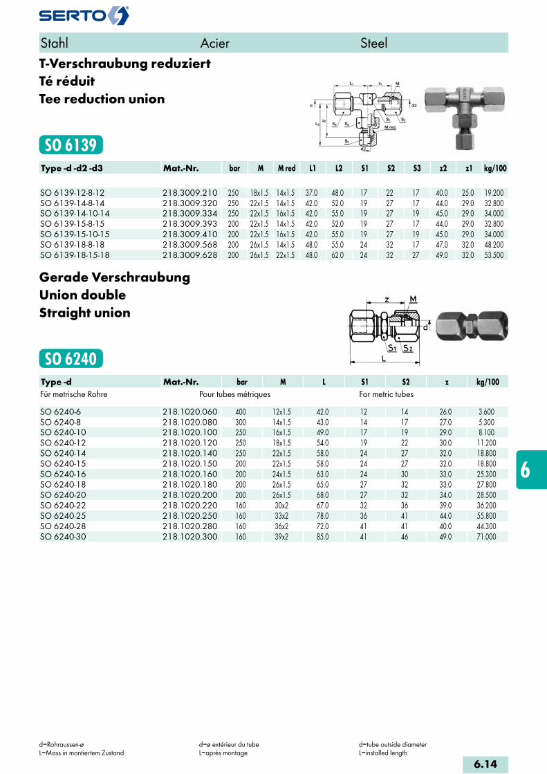
T-Verschraubung reduziertTé réduitTee reduction union
SO 6139Type -d -d2 -d3 Mat.-Nr. bar M M red L1 L2 S1 S2 S3 z2 z1 kg/100 SO 6139-12-8-12 218.3009.210 250 18x1.5 14x1.5 37.0 48.0 17 22 17 40.0 25.0 19.200SO 6139-14-8-14 218.3009.320 250 22x1.5 14x1.5 42.0 52.0 19 27 17 44.0 29.0 32.800SO 6139-14-10-14 218.3009.334 250 22x1.5 16x1.5 42.0 55.0 19 27 19 45.0 29.0 34.000SO 6139-15-8-15 218.3009.393 200 22x1.5 14x1.5 42.0 52.0 19 27 17 44.0 29.0 32.800SO 6139-15-10-15 218.3009.410 200 22x1.5 16x1.5 42.0 55.0 19 27 19 45.0 29.0 34.000SO 6139-18-8-18 218.3009.568 200 26x1.5 14x1.5 48.0 55.0 24 32 17 47.0 32.0 48.200SO 6139-18-15-18 218.3009.628 200 26x1.5 22x1.5 48.0 62.0 24 32 27 49.0 32.0 53.500
Gerade VerschraubungUnion doubleStraight union
SO 6240Type -d Mat.-Nr. bar M L S1 S2 z kg/100Für metrische Rohre Pour tubes métriques For metric tubes SO 6240-6 218.1020.060 400 12x1.5 42.0 12 14 26.0 3.600SO 6240-8 218.1020.080 300 14x1.5 43.0 14 17 27.0 5.300SO 6240-10 218.1020.100 250 16x1.5 49.0 17 19 29.0 8.100SO 6240-12 218.1020.120 250 18x1.5 54.0 19 22 30.0 11.200SO 6240-14 218.1020.140 250 22x1.5 58.0 24 27 32.0 18.800SO 6240-15 218.1020.150 200 22x1.5 58.0 24 27 32.0 18.800SO 6240-16 218.1020.160 200 24x1.5 63.0 24 30 33.0 25.300SO 6240-18 218.1020.180 200 26x1.5 65.0 27 32 33.0 27.800SO 6240-20 218.1020.200 200 26x1.5 68.0 27 32 34.0 28.500SO 6240-22 218.1020.220 160 30x2 67.0 32 36 39.0 36.200SO 6240-25 218.1020.250 160 33x2 78.0 36 41 44.0 55.800SO 6240-28 218.1020.280 160 36x2 72.0 41 41 40.0 44.300SO 6240-30 218.1020.300 160 39x2 85.0 41 46 49.0 71.000
Stahl Acier Steel
d=Rohraussen-øL=Mass in montiertem Zustand
d=ø extérieur du tubeL=après montage
d=tube outside diameterL=installed length
6.14
i
s
3F
4M
4G
5
5L
6
7
8
9
10
11
12
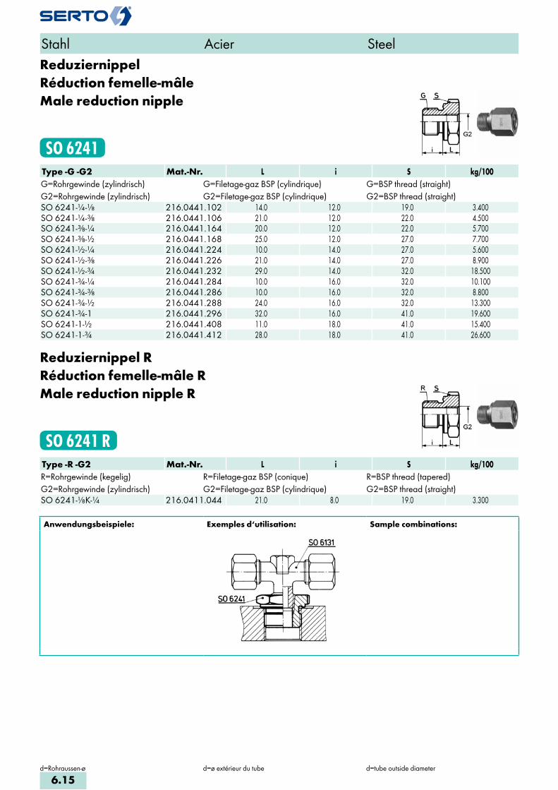
ReduziernippelRéduction femelle-mâleMale reduction nipple
SO 6241Type -G -G2 Mat.-Nr. L i S kg/100G=Rohrgewinde (zylindrisch) G=Filetage-gaz BSP (cylindrique) G=BSP thread (straight)G2=Rohrgewinde (zylindrisch) G2=Filetage-gaz BSP (cylindrique) G2=BSP thread (straight)SO 6241-1/4-1/8 216.0441.102 14.0 12.0 19.0 3.400SO 6241-1/4-3/8 216.0441.106 21.0 12.0 22.0 4.500SO 6241-3/8-1/4 216.0441.164 20.0 12.0 22.0 5.700SO 6241-3/8-1/2 216.0441.168 25.0 12.0 27.0 7.700SO 6241-1/2-1/4 216.0441.224 10.0 14.0 27.0 5.600SO 6241-1/2-3/8 216.0441.226 21.0 14.0 27.0 8.900SO 6241-1/2-3/4 216.0441.232 29.0 14.0 32.0 18.500SO 6241-3/4-1/4 216.0441.284 10.0 16.0 32.0 10.100SO 6241-3/4-3/8 216.0441.286 10.0 16.0 32.0 8.800SO 6241-3/4-1/2 216.0441.288 24.0 16.0 32.0 13.300SO 6241-3/4-1 216.0441.296 32.0 16.0 41.0 19.600SO 6241-1-1/2 216.0441.408 11.0 18.0 41.0 15.400SO 6241-1-3/4 216.0441.412 28.0 18.0 41.0 26.600
Reduziernippel RRéduction femelle-mâle RMale reduction nipple R
SO 6241 RType -R -G2 Mat.-Nr. L i S kg/100R=Rohrgewinde (kegelig) R=Filetage-gaz BSP (conique) R=BSP thread (tapered)G2=Rohrgewinde (zylindrisch) G2=Filetage-gaz BSP (cylindrique) G2=BSP thread (straight)SO 6241-1/8K-1/4 216.0411.044 21.0 8.0 19.0 3.300
Anwendungsbeispiele: Exemples d‘utilisation: Sample combinations:
Stahl Acier Steel
d=Rohraussen-ø d=ø extérieur du tube d=tube outside diameter
6.15

Reduzier-VerschraubungUnion de réductionReduction union
SO 6248Type -d -d2 Mat.-Nr. bar M M red L S1 S2 z kg/100Für metrische Rohre Pour tubes métriques For metric tubes SO 6248-8-6 218.1203.140 300 14x1.5 12x1.5 23.0 17 14 15.0 2.800SO 6248-10-6 218.1203.175 250 16x1.5 12x1.5 23.0 19 14 15.0 3.200SO 6248-10-8 218.1203.190 250 16x1.5 14x1.5 23.0 19 17 15.0 3.900SO 6248-12-5 218.1203.210 200 18x1.5 12x1.5 24.0 22 14 16.0 3.900SO 6248-12-6 218.1203.215 250 18x1.5 12x1.5 24.0 22 14 16.0 3.900SO 6248-12-8 218.1203.225 250 18x1.5 14x1.5 24.0 22 17 16.0 4.700SO 6248-12-10 218.1203.240 250 18x1.5 16x1.5 27.0 22 19 17.0 6.100SO 6248-15-8 218.1203.400 200 22x1.5 14x1.5 24.0 27 17 16.0 6.400SO 6248-15-10 218.1203.410 200 22x1.5 16x1.5 27.0 27 19 17.0 7.600SO 6248-15-12 218.1203.420 200 22x1.5 18x1.5 29.0 27 22 17.0 8.400SO 6248-16-10 218.1203.470 200 24x1.5 16x1.5 27.0 30 19 17.0 8.700SO 6248-16-12 218.1203.480 200 24x1.5 18x1.5 29.0 30 22 17.0 10.000SO 6248-16-14 218.1203.500 200 24x1.5 22x1.5 31.0 30 27 18.0 13.200SO 6248-18-8 218.1203.570 200 26x1.5 14x1.5 24.0 32 17 16.0 8.400SO 6248-18-10 218.1203.575 200 26x1.5 16x1.5 27.0 32 19 17.0 9.100SO 6248-18-12 218.1203.580 200 26x1.5 18x1.5 29.0 32 22 17.0 10.400SO 6248-18-14 218.1203.600 200 26x1.5 22x1.5 31.0 32 27 18.0 13.700SO 6248-18-15 218.1203.610 200 26x1.5 22x1.5 31.0 32 27 18.0 13.700SO 6248-22-12 218.1203.730 160 30x2 18x1.5 30.0 36 22 18.0 12.600SO 6248-22-14 218.1203.740 160 30x2 22x1.5 31.0 36 27 18.0 15.300SO 6248-22-15 218.1203.745 160 30x2 22x1.5 31.0 36 27 18.0 15.300SO 6248-22-18 218.1203.755 160 30x2 26x1.5 35.0 36 32 19.0 19.100
Stahl Acier Steel
d/d2=Rohraussen-øL=Mass im montierten Zustand
d/d2=ø extérieur du tubeL=après montage
d/d2=tube outside diameterL=installed length
Anwendungsbeispiele: Exemples d‘utilisation: Sample combinations:
Dichtungsprinzip:Bei der Montage drückt sich die Dichtkante des Übergangsstückes in das SERTO-Formteil ein, dadurch entsteht eine einwandfreie metallische Dichtung. Wir empfehlen, das Gewinde mit einem geeigneten Flüssigklebstoff gegen unbe-absichtigtes Lösen zu sichern.
d=Kenngrösse:entspricht dem Rohraussen-ø des SERTO-Anschlusses SO 6372 und SO 6374, der gegen die Reduzierverschraubung SO 6248 ausgetauscht werden kann.
Principe d‘étanchéité:Lors du serrage, le bourrelet s‘enfonde dans la pièce de forme SERTO et donne un joint métal-lique parfait. Nous recommandons de freiner le filetage avec une résine appropriée contre un desserrage intempestif.
d=dimension nominale: correspond au ø exté-rieur du tube de l‘écrou de raccordement SO 6372/ SO 6374, lequel peut être échangé contre l‘union de réduction SO 6248.
Sealing principle:On being installed, the lip of the adaptor presses into the SERTO union body, forming a sound metallic seal. We recommend to secu-re the thread with a suitable cement against unintended loosening.
d=Nominal size: corresponds to tube outside dia. of the SERTO connections SO 6372/ SO 6374 which could be replaced by the reduction union SO 6248.
6.16
i
s
3F
4M
4G
5
5L
6
7
8
9
10
11
12

SechskantmutterEcrou à six pansHexagon nut
SO 6310 METRType -Mz Mat.-Nr. SW s kg/100 Mz=metrisches Gewinde (zylindrisch) Mz=Filetage métrique (cylindrique) Mz=Metric thread (straight)SO 6310-M12X1,5 216.0063.195 17 6.00 0.700SO 6310-M14X1,5 216.0063.225 19 6.00 0.800SO 6310-M16X1,5 216.0063.265 22 6.00 1.100SO 6310-M18X1,5 216.0063.305 24 6.00 1.100SO 6310-M22X1,5 216.0063.375 30 7.00 2.200SO 6310-M24X1,5 216.0063.405 32 7.00 2.400SO 6310-M26X1,5 216.0063.435 36 8.00 3.500SO 6310-M30X2 216.0063.470 41 8.00 4.500
Sechskantmutter für SO 6093 und SO 6333 Ecrou à six pans pour SO 6093 et SO 6333 Hexagon nut for SO 6093 and SO 6333
Stahl Acier Steel
6.17

Gerade Einschraubverschraubungmit Dichtkante
Union mâleavec arête d‘étanchiéité
Male adaptor unionwith edge seal
SO 6331Type -d -G Mat.-Nr. bar M L i S1 S2 z kg/100Für metrische Rohre Pour tubes métriques For metric tubesG=Rohrgewinde (zylindrisch) G=Filetage-gaz BSP (cylindrique) G=BSP thread (straight)SO 6331-6-1/8 218.1141.100 400 12x1.5 24.5 8.0 14 14 16.5 2.500SO 6331-6-1/4 218.1141.110 400 12x1.5 26.0 12.0 19 14 18.0 3.900SO 6331-8-1/4 218.1141.170 300 14x1.5 26.0 12.0 19 17 18.0 4.500SO 6331-10-1/4 218.1141.270 250 16x1.5 29.0 12.0 19 19 19.0 5.800SO 6331-10-3/8 218.1141.280 250 16x1.5 30.5 12.0 22 19 20.5 7.500SO 6331-10-1/2 218.1141.285 250 16x1.5 31.0 14.0 27 19 21.0 8.900SO 6331-12-1/4 218.1141.380 250 18x1.5 31.0 12.0 19 22 19.0 7.250SO 6331-12-3/8 218.1141.390 250 18x1.5 32.5 12.0 22 22 20.5 8.500SO 6331-12-1/2 218.1141.400 250 18x1.5 33.0 14.0 27 22 21.0 11.200SO 6331-14-3/8 218.1141.502 250 22x1.5 34.5 12.0 22 27 21.5 11.800SO 6331-14-1/2 218.1141.504 250 22x1.5 35.0 14.0 27 27 22.0 13.700SO 6331-15-3/8 218.1141.532 200 22x1.5 34.5 12.0 22 27 21.5 11.800SO 6331-15-1/2 218.1141.534 200 22x1.5 35.0 14.0 27 27 22.0 14.200SO 6331-16-1/2 218.1141.566 200 24x1.5 38.0 14.0 27 30 23.0 17.000SO 6331-18-1/2 218.1141.646 200 26x1.5 39.0 14.0 27 32 23.0 17.900SO 6331-18-3/4 218.1141.648 200 26x1.5 40.0 16.0 32 32 24.0 21.300SO 6331-18-1 218.1141.652 200 26x1.5 40.0 18.0 41 32 24.0 29.660SO 6331-20-1/2 218.1141.706 200 26x1.5 40.5 14.0 27 32 23.5 17.900SO 6331-20-3/4 218.1141.708 200 26x1.5 41.5 16.0 32 32 24.5 21.600SO 6331-20-1 218.1141.712 200 26x1.5 41.5 18.0 41 32 24.5 29.880SO 6331-22-3/4 218.1141.768 160 30x2 40.0 16.0 32 36 26.0 24.200SO 6331-22-1 218.1141.770 160 30x2 41.0 18.0 41 36 27.0 33.500SO 6331-25-1 218.1141.810 160 33x2 46.0 18.0 41 41 29.0 40.600SO 6331-28-1 218.1141.850 160 36x2 43.0 18.0 41 41 27.0 33.200SO 6331-30-1 218.1141.900 160 39x2 50.0 18.0 41 46 32.0 44.600SO 6331-30-1 1/4 218.1141.902 160 39x2 52.0 20.0 50 46 34.0 58.500
Gerade Einschraubverschraubung Rmit Dichtkante
Union mâle Rave arête d‘étanchiéité
Male adaptor union Rwith edge seal
SO 6331 RType -d -R Mat.-Nr. bar M L i S1 S2 z kg/100Für metrische Rohre Pour tubes métriques For metric tubesR=Rohrgewinde (kegelig) R=Filetage-gaz BSP (conique) R=BSP thread (tapered)SO 6331-8-1/8K 218.1101.160 300 14x1.5 26.0 5.0 14 17 18.0 3.200
k=kegeliges Einschraubgewinded=Rohraussen-øL=Mass in montiertem Zustand
k=filetage mâle coniqued=ø extérieur du tubeL=après montage
k=tapered male adaptor threadd=tube outside diameterL=installed length
k=kegeliges Einschraubgewinded=Rohraussen-øL=Mass in montiertem Zustand
k=filetage mâle coniqued=ø extérieur du tubeL=après montage
k=tapered male adaptor threadd=tube outside diameterL=installed length
6.18
i
s
3F
4M
4G
5
5L
6
7
8
9
10
11
12
Stahl Acier Steel

Gerade Einschraubverschraubung METRmit Dichtkante
Union mâle METRavec arête d‘étanchéité
Male adaptor union METRwith edge seal
SO 6331 METRType -d -Mz Mat.-Nr. bar M L i S1 S2 z kg/100Für metrische Rohre Pour tubes métriques For metric tubesMz=metrisches Gewinde (zylindrisch) Mz=Filetage métrique (cylindrique) Mz=Metric thread (straight)SO 6331-6-M10X1 218.1143.180 400 12x1.5 24.5 8.0 14 14 16.5 2.600SO 6331-8-M12X1,5 218.1143.240 300 14x1.5 26.0 12.0 17 17 18.0 4.000SO 6331-10-M14X1,5 218.1143.280 250 16x1.5 29.0 12.0 19 19 19.0 5.900SO 6331-12-M16X1,5 218.1143.330 250 18x1.5 32.5 12.0 22 22 20.5 8.300SO 6331-14-M18X1,5 218.1143.380 250 22x1.5 34.5 12.0 24 27 21.5 12.200SO 6331-15-M18X1,5 218.1143.390 200 22x1.5 34.5 12.0 24 27 21.5 12.200SO 6331-16-M22X1,5 218.1143.410 200 24x1.5 38.0 14.0 27 30 23.0 17.500SO 6331-18-M22X1,5 218.1143.460 200 26x1.5 39.0 14.0 27 32 23.0 18.500SO 6331-18-M26X1,5 218.1143.465 200 26x1.5 40.0 16.0 32 32 24.0 21.400SO 6331-20-M22X1,5 218.1143.500 200 26x1.5 40.5 14.0 27 32 23.5 18.500SO 6331-20-M26X1,5 218.1143.505 200 26x1.5 41.5 16.0 32 32 24.5 21.400SO 6331-22-M26X1,5 218.1143.535 160 30x2 40.0 16.0 32 36 26.0 24.200SO 6331-25-M33X2 218.1143.550 160 33x2 46.0 18.0 41 41 29.0 40.200
Stahl Acier Steel
k=kegeliges Einschraubgewinded=Rohraussen-øL=Mass in montiertem Zustand
k=filetage mâle coniqued=ø extérieur du tubeL=après montage
k=tapered male adaptor threadd=tube outside diameterL=installed length
6.19

Durchgangsverschraubung (Thermofühlerverschraubung)mit Klemmring aus Edelstahl
Raccordement pour sondesavec bague de serrage en acier inoxydable
Temperature probe unionwith stainless steel compression ferrule
SO 6331-DType -d -G Mat.-Nr. bar M SW1 SW2 L i kg/100 G=Rohrgewinde (zylindrisch) G=Filetage-gaz BSP (cylindrique) G=BSP thread (straight)SO 6331-3-1/4 -D YDD.610.0501 400 6x0.75 8 19 31.0 12.0 2.430SO 6331-6-1/4 -D YDD.610.0600 200 10x1 12 19 37.0 12.0 3.240SO 6331-6-1/2 -D YDD.610.0603 200 10x1 12 27 41.0 14.0 7.285SO 6331-8-1/4 -D YDD.610.0620 160 12x1 14 19 38.5 12.0 3.600SO 6331-8-1/2 -D YDD.610.0621 160 12x1 14 27 42.5 14.0 7.000SO 6331-9-1/2 -D YDD.610.0640 160 16x1 19 27 42.5 14.0 9.130SO 6331-12-1/2 -D YDD.610.0701 100 16x1 19 27 44.5 14.0 8.800
Durchgangsverschraubung METR(Thermofühlerverschraubung)mit Klemmring aus Edelstahl
Raccordement pour sondes METRavec bague de serrage en acier inoxydable
Temperature probe union METRwith stainless steel compression ferrule
SO 6331-D METRType -d -Mz Mat.-Nr. bar M SW1 SW2 L i kg/100 Mz=metrisches Gewinde (zylindrisch) Mz=Filetage métrique (cylindrique) Mz=Metric thread (straight)SO 6331-1-M8X1-D YDD.610.0400 400 6x0.75 8 12 24.0 8.0 1.080SO 6331-1,5-M8X1-D YDD.610.0420 400 6x0.75 8 12 24.0 8.0 1.080SO 6331-2-M8X1-D YDD.610.0460 400 6x0.75 8 12 24.0 8.0 1.060SO 6331-3-M8X1-D YDD.610.0500 400 6x0.75 8 12 25.5 8.0 1.100
Stahl Acier Steel
d=Rohraussen-øL=Mass in montiertem Zustand
d=ø extérieur du tubeL=après montage
d=tube outside diameterL=installed length
6.20
i
s
3F
4M
4G
5
5L
6
7
8
9
10
11
12

Anwendungsbeispiele: Exemples d‘utilisation: Sample combinations:
Temperatur bis +200°C
Der Klemmring presst bei der ersten Montage – durch Anziehen der Mutter – auf das Rohr blei-bend auf, es entsteht eine metallische Dichtung.
Die Verbindung kann durch Lösen der Mutter demontiert werden, wobei allerdings der Klemmring auf dem Rohr haften bleibt. Es ist also nach der Erstmontage kein Verschieben des Rohres möglich.
Für nachträgliches Verschieben des Klemmringes wird der Einsatz von Durchgangsverschraubungen mit Teflonklemmring SO 61194–D–PTFE empfoh-len.
Température jusqu’au +200°C
Au premier serrage du raccord la bague de ser-rage étrangle légèrement le tube. Le résultat est une étanchéité métal sur métal.
Par desserrage de l’écrou le raccordement peut être démonté. La bague de serrage reste sur le tube. Un déplacement du tube n’est pas possible après le premier montage.
Le déplacement peut être effectué par l’utilisation des unions doubles avec une bague de serrage en téflon SO 61194–D–PTFE.
Temperature up to +200°C
When mounted for the first time, the compres-sion ferrule is pressed onto the tube by tighte-ning the nut. A metal sealing is the result.
The union can be demounted by loosening the nut. However, the compression ferrule remains on the tube. A displacement of the tube is not possible after the first mounting.
The displacement is achieved by using straight unions with a teflon compression fer-rule SO 61194–D–PTFE.
Stahl Acier Steel
d=Rohraussen-øL=Mass in montiertem Zustand
d=ø extérieur du tubeL=après montage
d=tube outside diameterL=installed length
6.21
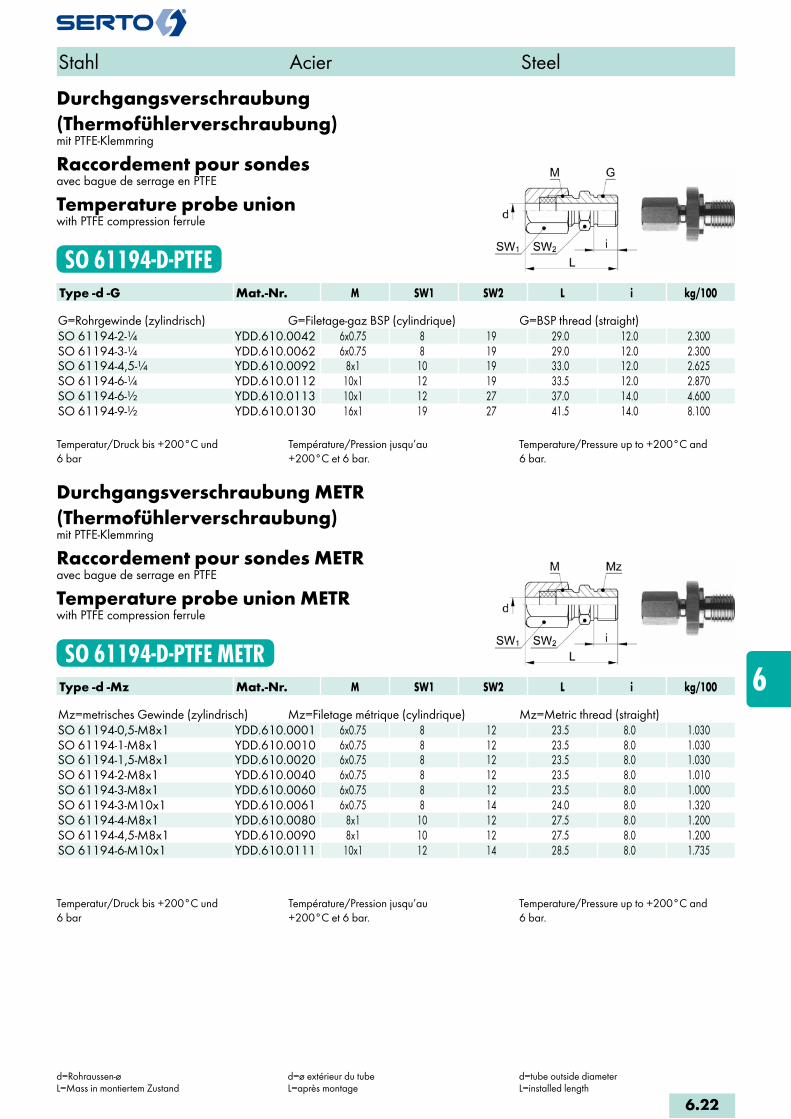
Durchgangsverschraubung (Thermofühlerverschraubung)mit PTFE-Klemmring
Raccordement pour sondesavec bague de serrage en PTFE
Temperature probe unionwith PTFE compression ferrule
SO 61194-D-PTFEType -d -G Mat.-Nr. M SW1 SW2 L i kg/100 G=Rohrgewinde (zylindrisch) G=Filetage-gaz BSP (cylindrique) G=BSP thread (straight)SO 61194-2-1/4 YDD.610.0042 6x0.75 8 19 29.0 12.0 2.300SO 61194-3-1/4 YDD.610.0062 6x0.75 8 19 29.0 12.0 2.300SO 61194-4,5-1/4 YDD.610.0092 8x1 10 19 33.0 12.0 2.625SO 61194-6-1/4 YDD.610.0112 10x1 12 19 33.5 12.0 2.870SO 61194-6-1/2 YDD.610.0113 10x1 12 27 37.0 14.0 4.600SO 61194-9-1/2 YDD.610.0130 16x1 19 27 41.5 14.0 8.100
Temperatur/Druck bis +200°C und6 bar
Température/Pression jusqu’au +200°C et 6 bar.
Temperature/Pressure up to +200°C and 6 bar.
Durchgangsverschraubung METR (Thermofühlerverschraubung)mit PTFE-Klemmring
Raccordement pour sondes METRavec bague de serrage en PTFE
Temperature probe union METRwith PTFE compression ferrule
SO 61194-D-PTFE METRType -d -Mz Mat.-Nr. M SW1 SW2 L i kg/100 Mz=metrisches Gewinde (zylindrisch) Mz=Filetage métrique (cylindrique) Mz=Metric thread (straight)SO 61194-0,5-M8x1 YDD.610.0001 6x0.75 8 12 23.5 8.0 1.030SO 61194-1-M8x1 YDD.610.0010 6x0.75 8 12 23.5 8.0 1.030SO 61194-1,5-M8x1 YDD.610.0020 6x0.75 8 12 23.5 8.0 1.030SO 61194-2-M8x1 YDD.610.0040 6x0.75 8 12 23.5 8.0 1.010SO 61194-3-M8x1 YDD.610.0060 6x0.75 8 12 23.5 8.0 1.000SO 61194-3-M10x1 YDD.610.0061 6x0.75 8 14 24.0 8.0 1.320SO 61194-4-M8x1 YDD.610.0080 8x1 10 12 27.5 8.0 1.200SO 61194-4,5-M8x1 YDD.610.0090 8x1 10 12 27.5 8.0 1.200SO 61194-6-M10x1 YDD.610.0111 10x1 12 14 28.5 8.0 1.735
Temperatur/Druck bis +200°C und 6 bar
Température/Pression jusqu’au +200°C et 6 bar.
Temperature/Pressure up to +200°C and 6 bar.
Stahl Acier Steel
d=Rohraussen-øL=Mass in montiertem Zustand
d=ø extérieur du tubeL=après montage
d=tube outside diameterL=installed length
6.22
i
s
3F
4M
4G
5
5L
6
7
8
9
10
11
12
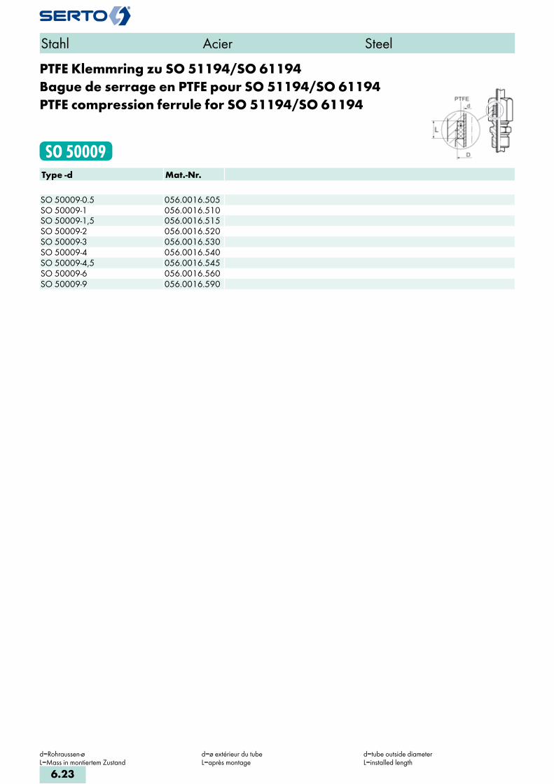
PTFE Klemmring zu SO 51194/SO 61194Bague de serrage en PTFE pour SO 51194/SO 61194PTFE compression ferrule for SO 51194/SO 61194
SO 50009Type -d Mat.-Nr. SO 50009-0.5 056.0016.505SO 50009-1 056.0016.510SO 50009-1,5 056.0016.515SO 50009-2 056.0016.520SO 50009-3 056.0016.530SO 50009-4 056.0016.540SO 50009-4,5 056.0016.545SO 50009-6 056.0016.560SO 50009-9 056.0016.590
Stahl Acier Steel
d=Rohraussen-øL=Mass in montiertem Zustand
d=ø extérieur du tubeL=après montage
d=tube outside diameterL=installed length
6.23

Verschraubung mit AnschlussmuffeUnion femelleFemale adaptor union
SO 6332Type -d -G Mat.-Nr. bar M L i S1 S2 z kg/100Für metrische Rohre Pour tubes métriques For metric tubesG=Rohrgewinde (zylindrisch) G=Filetage-gaz BSP (cylindrique) G=BSP thread (straight)SO 6332-6-1/8 218.1201.100 400 12x1.5 32.0 10.0 14 14 14.0 2.500SO 6332-6-1/4 218.1201.110 400 12x1.5 34.0 11.0 19 14 15.0 4.200SO 6332-6-3/8 218.1201.120 400 12x1.5 35.0 12.0 22 14 15.0 4.800SO 6332-6-1/2 218.1201.125 400 12x1.5 41.0 14.0 27 14 19.0 8.700SO 6332-8-1/4 218.1201.170 300 14x1.5 34.0 11.0 19 17 15.0 4.700SO 6332-8-1/2 218.1201.185 300 14x1.5 37.0 14.0 27 17 15.0 6.900SO 6332-10-1/4 218.1201.270 250 16x1.5 37.0 11.0 19 19 16.0 6.100SO 6332-10-3/8 218.1201.280 250 16x1.5 38.0 12.0 22 19 16.0 6.800SO 6332-10-1/2 218.1201.285 250 16x1.5 40.0 14.0 27 19 16.0 8.400SO 6332-12-1/4 218.1201.380 250 18x1.5 39.0 11.0 19 22 16.0 7.700SO 6332-12-3/8 218.1201.390 250 18x1.5 40.0 12.0 22 22 16.0 7.900SO 6332-12-1/2 218.1201.400 250 18x1.5 42.0 14.0 27 22 16.0 9.500SO 6332-14-1/2 218.1201.504 250 22x1.5 44.0 14.0 27 27 17.0 13.200SO 6332-15-1/2 218.1201.534 200 22x1.5 44.0 14.0 27 27 17.0 13.200SO 6332-16-1/2 218.1201.566 200 24x1.5 46.0 14.0 27 30 17.0 15.600SO 6332-18-1/2 218.1201.646 200 26x1.5 48.0 14.0 27 32 18.0 17.500SO 6332-18-3/4 218.1201.648 200 26x1.5 52.0 17.0 32 32 19.0 19.100SO 6332-20-1/2 218.1201.706 200 26x1.5 49.5 14.0 27 32 18.5 17.500SO 6332-20-3/4 218.1201.708 200 26x1.5 53.5 17.0 32 32 19.5 19.100SO 6332-22-3/4 218.1201.768 160 30x2 52.0 17.0 32 36 21.0 23.000SO 6332-25-1 218.1201.810 160 33x2 60.0 20.0 41 41 23.0 36.900SO 6332-28-1 218.1201.850 160 36x2 59.0 20.0 41 41 23.0 30.200SO 6332-30-1 218.1201.900 160 39x2 63.0 20.0 41 46 25.0 35.890
Anwendungsbeispiele: Exemples d‘utilisation: Sample combinations:
Stahl Acier Steel
d=Rohraussen-øL=Mass in montiertem Zustand
d=ø extérieur du tubeL=après montage
d=tube outside diameterL=installed length
6.24
i
s
3F
4M
4G
5
5L
6
7
8
9
10
11
12

Gerade SchottverschraubungDurchführungslänge max. 20 mm
Union double pour passage de cloisonpour cloison max. 20 mm
Panel mount unionmax. panel thickness 20 mm
SO 6333Type -d Mat.-Nr. bar M L1 L2 a S1 S2 S3 z2 z1 kg/100Für metrische Rohre Pour tubes métriques For metric tubes SO 6333-6 218.1500.060 400 12x1.5 23.0 43.0 14.0 17 14 17 35.0 15.0 6.200SO 6333-8 218.1500.080 300 14x1.5 24.0 43.0 16.0 19 17 19 35.0 16.0 8.500SO 6333-10 218.1500.100 250 16x1.5 28.0 46.0 18.0 22 19 22 36.0 18.0 12.500SO 6333-12 218.1500.120 250 18x1.5 30.0 49.0 20.0 24 22 24 37.0 18.0 16.100SO 6333-14 218.1500.140 250 22x1.5 33.0 52.0 24.0 27 27 30 39.0 20.0 27.300SO 6333-15 218.1500.150 200 22x1.5 33.0 52.0 24.0 27 27 30 39.0 20.0 26.700SO 6333-16 218.1500.160 200 24x1.5 36.0 54.0 26.0 30 30 32 39.0 21.0 35.000SO 6333-18 218.1500.180 200 26x1.5 39.0 58.0 28.0 32 32 36 42.0 23.0 41.000SO 6333-20 218.1500.200 200 26x1.5 40.5 59.5 28.0 32 32 36 42.5 23.5 41.000SO 6333-22 218.1500.220 160 30x2 40.0 58.0 32.0 36 36 41 44.0 26.0 52.200
Sechskantmutter siehe SO 6310 Ecrou à six pans voir SO 6310 Hexagon nut see SO 6310
Stahl Acier Steel
d=Rohraussen-øL1,L2=Mass in montiertem Zustand
d=ø extérieur du tubeL1,L2=après montage
d=tube outside diameterL1,L2=installed length
6.25

Einstellbarer AnschlussRaccordement orientableAdjustable connection
SO 6335Type -d -G Mat.-Nr. bar M L a i S1 S2 z kg/100Für metrische Rohre Pour tubes métriques For metric tubesG=Rohrgewinde (zylindrisch) G=Filetage-gaz BSP (cylindrique) G=BSP thread (straight)SO 6335-6-1/8 218.1651.100 250 12x1.5 20.0 4.0 8.0 14 14 14.0 2.000SO 6335-8-1/4 218.1651.170 250 14x1.5 22.0 6.0 12.0 17 17 16.0 3.500SO 6335-10-1/4 218.1651.270 200 16x1.5 23.5 7.0 12.0 19 19 16.0 4.100SO 6335-12-3/8 218.1651.390 200 18x1.5 24.0 9.0 12.0 22 22 17.0 6.000SO 6335-14-1/2 218.1651.504 160 22x1.5 28.0 11.0 14.0 27 27 19.0 10.200SO 6335-15-1/2 218.1651.534 160 22x1.5 28.0 11.0 14.0 27 27 19.0 10.200SO 6335-16-1/2 218.1651.566 160 24x1.5 29.0 12.0 14.0 30 27 20.0 12.100SO 6335-18-1/2 218.1651.646 160 26x1.5 29.0 14.0 14.0 32 27 20.0 12.500SO 6335-18-3/4 218.1651.648 160 26x1.5 29.0 16.0 16.0 32 32 20.0 14.500SO 6335-20-1/2 218.1651.706 160 26x1.5 29.0 14.0 14.0 32 27 20.0 12.500SO 6335-20-3/4 218.1651.708 160 26x1.5 29.0 16.0 16.0 32 32 20.0 14.500SO 6335-22-3/4 218.1651.768 160 30x2 32.0 18.0 16.0 36 36 22.0 17.700SO 6335-25-1 218.1651.810 160 33x2 36.5 20.0 18.0 41 41 24.5 30.000SO 6335-28-1 218.1651.850 160 36x2 34.5 23.0 18.0 41 41 24.5 24.800
Anwendungsbeispiele: Exemples d‘utilisation: Sample combinations:
Die angedrehte Dichtkante am Einstellnippel drückt sich bei der Montage in das Gegenstück ein und dichtet metallisch ab.
d=Kenngrösse: entspricht dem Rohraussen-ø des SERTO-Anschlusses SO 6372 und SO 6374, der gegen den einstellbaren Anschluss SO 6335 ausgetauscht werden kann.
L‘arête d‘étanchéité de l‘union orientable s‘enfonce au montage dans la contre-pièce et forme un joint métallique parfait.
d=dimension nominale: correspond au ø exté-rieur du tube de l‘écrou de raccordement SO 6372/ SO 6374, lequel peut être échangé con-tre le raccordement orientable SO 6335.
The integrally turned sealing edge on the adjusting nipple bites into the mating part on assembly, forming a metal/metal seal.
d=Nominal size: corresponds to tube outside dia. of the SERTO connection SO 6372/6374 which could be replaced by the adjustable connection SO 6335.
Stahl Acier Steel
6.26
i
s
3F
4M
4G
5
5L
6
7
8
9
10
11
12

Einstellbarer AnschlussRaccordement orientableAdjustable connection
SO 6335 GType -G -G1 Mat.-Nr. bar L a i S1 S2 z kg/100 G=Rohrgewinde (zylindrisch) G=Filetage-gaz BSP (cylindrique) G=BSP thread (straight)SO 6335-1/8-1/8 218.1655.042 250 20.0 4.0 8.0 14 14 14.0 2.000SO 6335-1/4-1/4 218.1655.104 250 22.0 6.0 12.0 17 17 15.5 3.500SO 6335-3/8-3/8 218.1655.166 200 24.5 9.0 12.0 22 22 15.5 6.000SO 6335-1/2-1/2 218.1655.228 160 29.0 11.0 14.0 27 27 19.0 10.200
Einstellbarer Anschluss METRRaccordement orientable METRAdjustable connection METR
SO 6335 METRType -G -Mz Mat.-Nr. bar L a i S1 S2 z kg/100 Mz=metrisches Gewinde (zylindrisch) Mz=Filetage métrique (cylindrique) Mz=Metric thread (straight)SO 6335-1/8-M10X1 218.1656.040 250 20.0 4.0 8.0 14 14 14.0 2.500SO 6335-1/4-M12X1,5 218.1656.085 250 22.0 6.0 12.0 17 17 15.5 3.500SO 6335-3/8-M16X1,5 218.1656.150 200 24.0 9.0 12.0 22 22 16.0 5.500SO 6335-1/2-M18X1,5 218.1656.180 160 28.5 11.0 12.0 24 27 18.5 9.500
Stahl Acier Steel
Anwendungsbeispiele: Exemples d‘utilisation: Sample combinations:
Direkte Verbindung von verschiedenen Aggregaten möglich ohne Verwendung von Rohren. Kompakte Bauweise, schnelle Montage, einfache Fixierung der Aggregate in der gewünschten Stellung.
Der Gewindezapfen für das Gewinde G muss zylindrisch sein und eine plane Auflagefläche haben.
Beachten Sie auch die Möglichkeiten mitSO 6345.
Die angedrehte Dichtkante am Einstellnippel drückt sich bei der Montage in das Gegenstück ein und dichtet metallisch ab.
Raccordement direct de différents éléments possible sans recours à des tuyaux. Construction compacte, montage rapide, fixation simple des éléments en position désirée.
L‘embout fileté pour filetage G doit être cylin-drique et présenter une face d‘appui plane.
Voir également les possibilités avec SO 6345.
L‘arête d‘étanchéité de l‘union orientable s‘enfonce au montage dans la contre-pièce et forme un joint métallique parfait.
Direct inter-connection of various appliances possible without the use of tubes. Compact construction, quick assembly, and easy fixing of the appliances in the desired position.
The threaded stem for the thread G must be straight, and have a plane seating surface.
See SO 6345 for additional possibilities.
The integrally turned sealing edge on the adjusting nipple bites into the mating part on assembly, forming a metal/metal seal.
6.27

AnschweissverschraubungUnion simple avec embout à souderWeld-on union
SO 6336Type -d Mat.-Nr. bar M L f S1 S2 z kg/100Für metrische Rohre Pour tubes métriques For metric tubes SO 6336-6 218.1400.060 400 12x1.5 30.0 10.0 12 14 22.0 2.300SO 6336-8 218.1400.080 300 14x1.5 32.0 12.0 14 17 24.0 3.400SO 6336-10 218.1400.100 250 16x1.5 36.0 14.0 17 19 26.0 5.100SO 6336-12 218.1400.120 250 18x1.5 38.0 16.0 19 22 26.0 6.700SO 6336-14 218.1400.140 250 22x1.5 43.0 19.0 22 27 30.0 11.300SO 6336-15 218.1400.150 200 22x1.5 43.0 19.0 22 27 30.0 11.300SO 6336-18 218.1400.180 200 26x1.5 48.0 22.0 27 32 32.0 17.300SO 6336-20 218.1400.200 200 26x1.5 49.5 22.0 27 32 32.5 17.300SO 6336-22 218.1400.220 160 30x2 52.0 27.0 32 36 38.0 24.200SO 6336-28 218.1400.280 160 36x2 56.0 32.0 41 41 40.0 32.200
Stahl Acier Steel
d=Rohraussen-øL=Mass in montiertem Zustand
d=ø extérieur du tubeL=après montage
d=tube outside diameterL=installed length
6.28
i
s
3F
4M
4G
5
5L
6
7
8
9
10
11
12
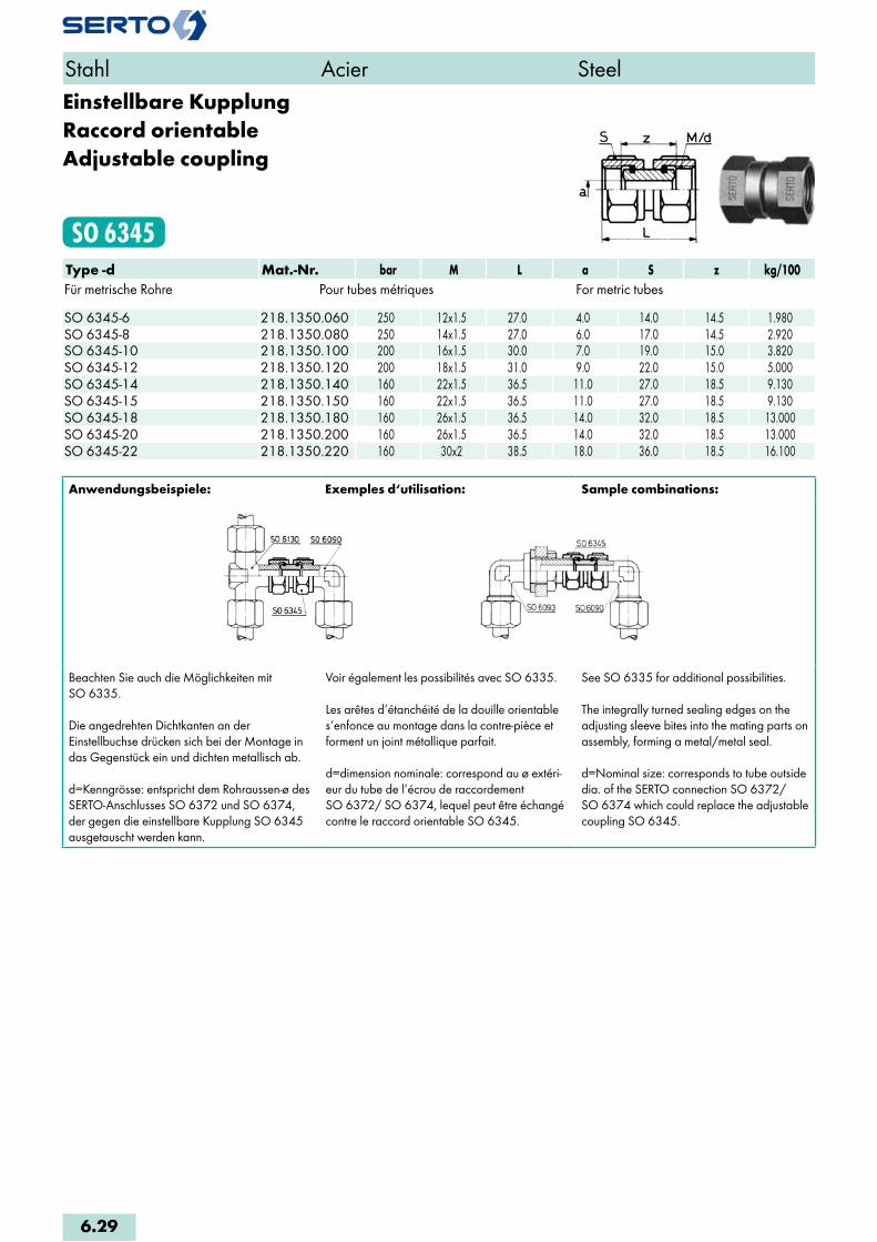
Einstellbare KupplungRaccord orientableAdjustable coupling
SO 6345Type -d Mat.-Nr. bar M L a S z kg/100Für metrische Rohre Pour tubes métriques For metric tubes SO 6345-6 218.1350.060 250 12x1.5 27.0 4.0 14.0 14.5 1.980SO 6345-8 218.1350.080 250 14x1.5 27.0 6.0 17.0 14.5 2.920SO 6345-10 218.1350.100 200 16x1.5 30.0 7.0 19.0 15.0 3.820SO 6345-12 218.1350.120 200 18x1.5 31.0 9.0 22.0 15.0 5.000SO 6345-14 218.1350.140 160 22x1.5 36.5 11.0 27.0 18.5 9.130SO 6345-15 218.1350.150 160 22x1.5 36.5 11.0 27.0 18.5 9.130SO 6345-18 218.1350.180 160 26x1.5 36.5 14.0 32.0 18.5 13.000SO 6345-20 218.1350.200 160 26x1.5 36.5 14.0 32.0 18.5 13.000SO 6345-22 218.1350.220 160 30x2 38.5 18.0 36.0 18.5 16.100
Anwendungsbeispiele: Exemples d‘utilisation: Sample combinations:
Beachten Sie auch die Möglichkeiten mitSO 6335.
Die angedrehten Dichtkanten an der Einstellbuchse drücken sich bei der Montage in das Gegenstück ein und dichten metallisch ab.
d=Kenngrösse: entspricht dem Rohraussen-ø des SERTO-Anschlusses SO 6372 und SO 6374, der gegen die einstellbare Kupplung SO 6345 ausgetauscht werden kann.
Voir également les possibilités avec SO 6335.
Les arêtes d‘étanchéité de la douille orientable s‘enfonce au montage dans la contre-pièce et forment un joint métallique parfait.
d=dimension nominale: correspond au ø extéri-eur du tube de l‘écrou de raccordement SO 6372/ SO 6374, lequel peut être échangé contre le raccord orientable SO 6345.
See SO 6335 for additional possibilities.
The integrally turned sealing edges on the adjusting sleeve bites into the mating parts on assembly, forming a metal/metal seal.
d=Nominal size: corresponds to tube outside dia. of the SERTO connection SO 6372/ SO 6374 which could replace the adjustable coupling SO 6345.
Stahl Acier Steel
6.29
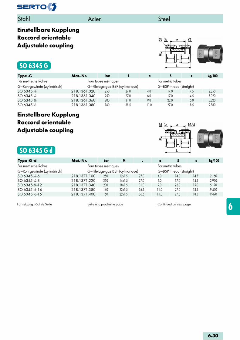
Einstellbare KupplungRaccord orientableAdjustable coupling
SO 6345 GType -G Mat.-Nr. bar L a S z kg/100Für metrische Rohre Pour tubes métriques For metric tubesG=Rohrgewinde (zylindrisch) G=Filetage-gaz BSP (cylindrique) G=BSP thread (straight)SO 6345-1/8 218.1361.020 250 27.0 4.0 14.0 14.5 2.350SO 6345-1/4 218.1361.040 250 27.0 6.0 17.0 14.5 3.020SO 6345-3/8 218.1361.060 200 31.0 9.0 22.0 15.0 5.320SO 6345-1/2 218.1361.080 160 38.5 11.0 27.0 18.5 9.880
Einstellbare KupplungRaccord orientableAdjustable coupling
SO 6345 G dType -G -d Mat.-Nr. bar M L a S z kg/100Für metrische Rohre Pour tubes métriques For metric tubesG=Rohrgewinde (zylindrisch) G=Filetage-gaz BSP (cylindrique) G=BSP thread (straight)SO 6345-1/8-6 218.1371.100 250 12x1.5 27.0 4.0 14.0 14.5 2.160SO 6345-1/4-8 218.1371.220 250 14x1.5 27.0 6.0 17.0 14.5 2.950SO 6345-3/8-12 218.1371.340 200 18x1.5 31.0 9.0 22.0 15.0 5.170SO 6345-1/2-14 218.1371.380 160 22x1.5 36.5 11.0 27.0 18.5 9.490SO 6345-1/2-15 218.1371.400 160 22x1.5 36.5 11.0 27.0 18.5 9.490
Fortsetzung nächste Seite Suite à la prochaine page Continued on next page
Stahl Acier Steel
6.30
i
s
3F
4M
4G
5
5L
6
7
8
9
10
11
12

Anwendungsbeispiele: Exemples d‘utilisation: Sample combinations:
Direkte Verbindung von verschiedenen Aggregaten möglich ohne Verwendung von Rohren. Kompakte Bauweise, schnelle Montage, einfache Fixierung der Aggregate in die gewünschte Stellung.
Beachten Sie auch die Möglichkeiten mit SO 6335.
Der Gewindezapfen für das Gewinde G muss zylindrisch sein und eine plane Auflagefläche haben.
Die angedrehten Dichtkanten an der Einstellbuchse drücken sich bei der Montage in das Gegenstück ein und dichten metallisch ab.
d=Kenngrösse: entspricht dem Rohraussen-ø des SERTO-Anschlusses SO 6372 und SO 6374, der gegen die einstellbare Kupplung SO 6345 ausgetauscht werden kann.
Raccordement direct de différents éléments possible sans recours à des tuyaux. Construction compacte, montage rapide, fixation simple des éléments en position désirée.
Voir également les possibilités avec SO 6335.
L‘embout fileté pour filetage G doit être cylin-drique et présenter une face d‘appui plane.
Les arêtes d‘étanchéité de l‘union orientable s‘enfoncent au montage dans la contre-pièce et forment un joint métallique parfait.
d=dimension nominale: correspond au ø extéri-eur du tube de l‘écrou de raccordement SO 6372/ SO 6374, lequel peut être échangé contre le raccord orientable SO 6345.
Direct inter-connection of various appliances possible without the use of tubes. Compact construction, quick assembly, and easy fixing of the appliances in the desired position.
See SO 6335 for additional possibilities.
The threaded stem for the thread G must be straigth, and have a plane sealing surface.
The integrally turned sealing edges on the adjusting sleeve bites into the mating parts on assembly, forming a metal/metal seal.
d=Nominal size: corresponds to tube outside dia. of the SERTO connection SO 6372/ SO 6374 which could replace the adjustable coupling SO 6345.
Stahl Acier Steel
6.31
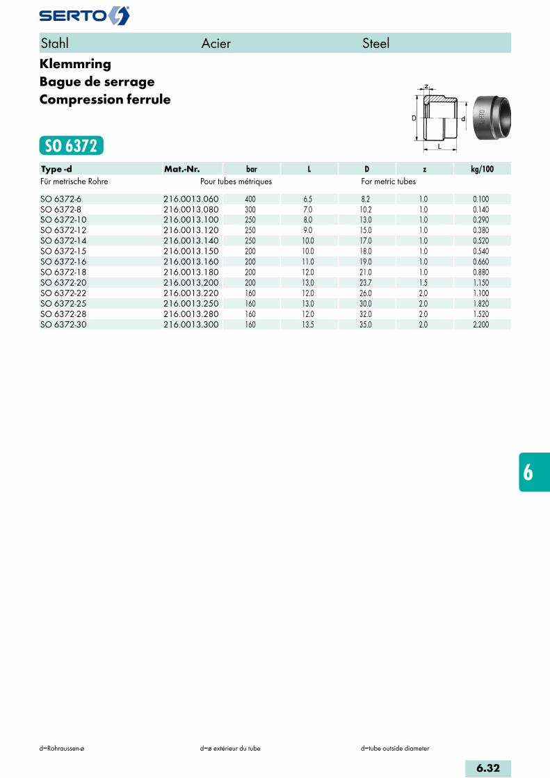
KlemmringBague de serrageCompression ferrule
SO 6372Type -d Mat.-Nr. bar L D z kg/100Für metrische Rohre Pour tubes métriques For metric tubes SO 6372-6 216.0013.060 400 6.5 8.2 1.0 0.100SO 6372-8 216.0013.080 300 7.0 10.2 1.0 0.140SO 6372-10 216.0013.100 250 8.0 13.0 1.0 0.290SO 6372-12 216.0013.120 250 9.0 15.0 1.0 0.380SO 6372-14 216.0013.140 250 10.0 17.0 1.0 0.520SO 6372-15 216.0013.150 200 10.0 18.0 1.0 0.540SO 6372-16 216.0013.160 200 11.0 19.0 1.0 0.660SO 6372-18 216.0013.180 200 12.0 21.0 1.0 0.880SO 6372-20 216.0013.200 200 13.0 23.7 1.5 1.150SO 6372-22 216.0013.220 160 12.0 26.0 2.0 1.100SO 6372-25 216.0013.250 160 13.0 30.0 2.0 1.820SO 6372-28 216.0013.280 160 12.0 32.0 2.0 1.520SO 6372-30 216.0013.300 160 13.5 35.0 2.0 2.200
Stahl Acier Steel
d=Rohraussen-ø d=ø extérieur du tube d=tube outside diameter
6.32
i
s
3F
4M
4G
5
5L
6
7
8
9
10
11
12

AnschlussmutterEcrouUnion nut
SO 6374Type -d Mat.-Nr. bar M L S kg/100Für metrische Rohre Pour tubes métriques For metric tubes SO 6374-6 216.0200.060 250 12x1.5 16.0 14.0 0.950SO 6374-8 216.0200.080 300 14x1.5 16.0 17.0 1.500SO 6374-10 216.0200.100 250 16x1.5 18.0 19.0 2.400SO 6374-12 216.0200.120 250 18x1.5 20.0 22.0 3.500SO 6374-14 216.0200.140 250 22x1.5 22.0 27.0 5.900SO 6374-15 216.0200.150 200 22x1.5 22.0 27.0 5.900SO 6374-16 216.0200.160 200 24x1.5 23.0 30.0 8.100SO 6374-18 216.0200.180 200 26x1.5 25.0 32.0 9.200SO 6374-20 216.0200.200 200 26x1.5 26.0 32.0 9.200SO 6374-22 216.0200.220 160 30x2 26.0 36.0 11.500SO 6374-25 216.0203.250 160 33x2 30.0 41.0 17.700SO 6374-28 216.0203.280 160 36x2 27.0 41.0 12.700SO 6374-30 216.0203.300 160 39x2 33.0 46.0 21.400
AnschlussnippelEcrou mâleNipple connection
SO 6377Type -d -G Mat.-Nr. bar b h S t kg/100 G=Rohrgewinde (zylindrisch) G=Filetage-gaz BSP (cylindrique) G=BSP thread (straight)SO 6377-6-1/4 216.0911.110 400 5.5 10.0 14.0 8.0 1.200SO 6377-6-1/4 216.0911.114 400 8.5 8.0 14.0 11.0 1.300SO 6377-8-1/4 216.0911.160 300 8.0 7.0 14.0 11.0 1.000SO 6377-8-3/8 216.0911.182 300 9.0 8.5 17.0 12.0 2.000
SO 6377-8-1/4 =nur für Rohre mit Wandstärke 1mm
Bitte beachten:Die jeweils dazugehörenden KlemmringeSO 6372 müssen separat bestellt werden.
SO 6377-8-1/4 =seulement pour tubes avec paroi de 1mm
Remarque:Les bagues de serrage correspondantes SO 6372 doivent être commandées séparément dans chaque cas
SO 6377-8-1/4 =for tubes with wall thickness of 1mm only
Please note:The relevant compression ferrules SO 6372 must be ordered separately
Stahl Acier Steel
d=Rohraussen-ø d=ø extérieur du tube d=tube outside diameter
6.33

8
Messing chemisch vernickelt
Verschraubungen
Laiton avec nickelage chimique
Raccords
Brass chemically nickel-plated Unions

8.4-8.5KlemmringBague de serrageCompression ferrule
SO 80001
8.6AbschlusszapfenBouchon d‘arrêtPlug
SO 80002
8.7StützhülseDouille d‘appuiStiffener sleeve
SO 80003
8.8AnschlussmutterEcrouUnion nut
SO 80020
8.8-8.9ArmaturenanschlussEcrou de raccordementNut connection
SO 80021
8.10ÜbergangsmuffeAdaptateur femelleFemale adaptor
SO 80030
8.11ÜbergangsnippelAdaptateur mâleMale adaptor
SO 80040
8.12SchlauchtülleDouille cannelée pour tuyauHose nozzle
SO 80503
8.13Gerade VerschraubungUnion doubleStraight union
SO 81021
8.14Gerade EinschraubverschraubungUnion mâleMale adaptor union
SO 81121
8.15-8.16Gerade EinschraubverschraubungUnion mâleMale adaptor union
SO 81124
8.17Gerade AufschraubverschraubungUnion simple femelleFemale adaptor union
SO 81221
8.18VerbindungsnippelPièce folleTube stub
SO 81300
8.19Gerade SchottverschraubungUnion doublePanel mount union
SO 81521
8.19-8.20EinstellnippelUnion orientable mâleAdjustable male adaptor
SO 81600
8.21ReduktionsverschraubungRéductionReduction union
SO 81821
8.22WinkelverschraubungCoudeElbow union
SO 82021
8.23Winkel-EinschraubverschraubungCoude mâleMale adaptor elbow union
SO 82421
8.24EinstellwinkelCoude orientableAdjustable elbow union
SO 82621
8.25Winkel-SchottverschraubungUnion double pour passage de cloisonPanel mount union
SO 82721
8.25T-VerschraubungTéTee union
SO 83021
8.26Einstellbare T-VerschraubungTé orientableAdjustable tee union
SO 83621 T
8.26Einstellbare L-VerschraubungL orientableAdjustable L union
SO 83621 L
8.27T-EinschraubverschraubungTé mâleMale adaptor Tee union
SO 83721 T
Seite/Page/Page Seite/Page/Page Seite/Page/Page
Übersicht Aperçu Overview
8.1

8.28ReduziermuffeRéduction femelle-femelleFemale reduction socket
SO 80031
8.28-8.29ReduziernippelRéduction femelle-mâleMale reduction nipple
SO 80041
8.29VerschlussschraubeBouchon d‘obturationScrew plug
SO 80371
8.29EinschraubtülleDouille cannelée à visserMale adaptor hose nozzle
SO 80511
Sonderausführungen:Exécution en option:Optional Services:
Spezialbehandlung für Einsatz mit SauerstoffTraitement spécial pour utilisation sous oxygèneSpecial treatment for use with oxygen
Spezialbehandlung - silikonfreiTraitement spécial - sans siliconeSpecial treatment - silicone free
Spezialreinigung - entfettetTraitement spécial - sans siliconeSpecial treatment - degreased
Vorbeschichtete Gewinde mit Loctite 5061Filetages pré enduits avec Loctite 5061Pre-coated threads with Loctite 5061
Vorbeschichtete Gewinde PTFE-Band umwickeltFiletages pré enduits avec ruban en PTFEPre-coated threads with PTFE-tape
Sonderausführung für Adaptersiehe Kapitel 9
Exécution en option pour adaptateurs voir chapitre 9
Option services for adaptors see chapter 9
Alle Produkte aus dem Kapitel 4 sind auf Wunsch mit Aufpreis in chem. vernickelter Ausführung erhältlich.
Tous les produits du chapitre 4 sont aussiréalisables en nickelé chimique avec unsupplément.
All products in chapter 4 are availablechemically nickel plated for anadditional charge.
Seite/Page/Page
Übersicht Aperçu Overview
8.2
i
s
3F
4M
4G
5
5L
6
7
8
9
10
11
12

Généralités- montage facile et rapide- compactes dimensions- programme étendu- multiples possibilités de combinaisons
Principe de fonctionnementvoir annexe
Matériau de baseLaiton CW617N (CuZn40Pb2)
Nickelage chimiqueNickel: 88 – 89,5 %Phosphore: 10,5 –12 %Point de fusion: ca. +880°CDureté: 450/500 Vickers
Epaisseur de la coucheGénéral: env. 7 - 8 µmException: tige du robinet env. 2 - 3 µm
Pression de service PNLa pression de service PN est indiquée en bar avec un coefficient de sécurité 4 à une charge statique et est présentée dans des tableaux tech-niques pour tous les diamètres individuels.
Plage de température admissible-40°C à +180°C
Débit de fuite avec hélium10-8mbar • l/s *
VideJusqu’à 10-4 mbar, plus poussé possible
Tubes en cuivre à utiliserTubes en cuivre sans soudure (selon EN 12449/1057) avec surface propre et lisse. Le diamètre extérieur doit être situé dans une tolé-rance de ± 0,1 mm. Tous les tubes en cuivre à paroi mince repérés sur le tableau dans l’annexe doivent être renforcés par des douilles d’appui.
Tubes en acier inox à utiliserTubes en acier inoxydable sans soudure (selon DIN EN 10216-5/EN ISO 1127, classe de tolérance T4), avec surface propre et lisse. Le diamètre extérieur doit se situer dans une tolé-rance de ± 0,1 mm. Qualité de la surface en minimum m, dureté ≤ HRB 80 ≈ HV 155.
Important!Dans certains cas d’application, les vissages nickelés peuvent représenter une variante plus éco-nomique que les alliages inoxydables. Le domaine d’utilisation n’est cependant pas universel. Chaque utilisation devra donc faire l’objet d’une considé-ration des conditions présentes (pression, fluide, température, environnement, etc.). Il est conseillé d’effectuer, si nécessaire, des tests préalables, ou le cas échéant, de prendre contact avec nous, en indiquant les conditions d’environnement de la manière la plus précise possible.
Eigenschaften, Besonderheiten- einfache, schnelle Montage- kompakte Baumasse- grosse Sortimentsvielfalt- sehr viele Kombinationsmöglichkeiten
Funktionsprinzipsiehe Anhang
Basis-WerkstoffMessing CW617N (CuZn40Pb2)
Chemische VernickelungNickel: 88 – 89,5 %Phosphor: 10,5 –12 %Schmelzpunkt: ca. +880°CHärtegrad: 450/500 Vickers
SchichtstärkeGenerell: ca. 7 - 8 µmAusnahme: Ventilspindeln ca. 2 - 3 µm
Betriebsdruck PNDer Betriebsdruck PN ist mit 4-facher Sicherheit in bar bei statischer Belastung und in den technischen Tabellen für jeden Rohrdurchmesser individuell aufgeführt.
Temperaturbereich-40°C bis +180°C
Helium - Leckrate10-8mbar • l/s *
VakuumBis 10-4 mbar, höhere Werte möglich
Anzuschliessende KupferrohreNahtlose, gezogene Kupferrohre (insbes. EN 12449/1057) mit sauberer, glatter Oberfläche. Aussendurchmesser innerhalb ± 0,1 mm. Alle dünnwandigen Kupferrohre, welche gemäss der Tabelle im Anhang mit einem versehen sind, müssen mit Stützhülsen verstärkt werden.
Anzuschliessende EdelstahlrohreNahtlose Präzisionsrohre aus Edelstahl (DIN EN 10216-5/EN ISO 1127, Toleranzkl. T4) mit sauberer, glatter Oberfläche. Aussendurchmesser innerhalb ± 0,1 mm. Oberflächenbeschaffenheit mindestens m, Härte ≤ HRB 80 ≈ HV 155.
Wichtig!Chemisch vernickelte Verschraubungen können im Einzelfall als günstigere Variante zu Edelstahl eingesetzt, jedoch keinesfalls als allgemeine Alternative betrachtet werden.Jede Anwendung ist unter Berücksichtigung der Einsatzbedingungen (Druck, Medium, Temperatur, Umgebung, etc.) individuell abzu-klären. Wir empfehlen bei Bedarf vorgängig eigene Tests durchzuführen oder sich unter Angabe der genauen Einsatzbedingungen an uns zu wenden.
Characteristics, specialities- easy and fast to install- compact dimensions- extensive range- many combination possibilities
Operating principlesee appendix
Basic-MaterialBrass CW617N (CuZn40Pb2)
Chemical nickel-platingNickel: 88 – 89,5 %Phosphorus: 10,5 –12 %Melting point: ca. +880°CDegree of hardness: 450/500 Vickers
Thickness of the layerGenerally: ca. 7 - 8 µmException: valve spindles ca. 2 - 3 µm
Working pressure PNThe working pressure PN is indicated in bar with a safety factor of 4 at static load and shown in the technical product tables for each individual diameters.
Temperature range-40°C to +180°C
Leak rate with helium10-8mbar • l/s *
VacuumUp to 10-4mbar, higher values are possible
Copper tubes to useSeamless copper tubes (esp. EN 12449/ 1057) with clean smooth surface. Outside dia-meter of ± 0,1 mm. All thin-walled copper tubes as marked on the table in the appendix must be reinforced with stiffener sleeves.
Stainless steel tubes to useSeamless stainless steel precision tubes (to DIN EN 10216-5/EN ISO 1127, tolerance class T4) with clean smooth surface. Outside diame-ter of ± 0,1 mm. Minimum quality of the surface: m, hardness ≤ HRB 80 ≈ HV 155.
Important!Chemical nickel-plated unions can be used as a less expensive alternative to stainless steel in individual cases, but under no circumstances as a general rule. The working conditions (pressure, medium, temperature, environment etc.) have to be established for each individual application. To the extent required we recommend that you carry out your own tests beforehand, or that you consult us with indication of the exact working conditions.
Messing CV Lation CV Brass CV
* bei fachgerechter Montage; siehe Anhang: - Seite a.6 - Rohre - Seite a.21 - Montageanleitung
* à la base d'un montage dans les règles de l'art ; voir Appendice: - page a.6 - Tubes - page a.21 - Instructions de montage
* when professionally assembled; see Appendix: - page a.6 - Tubes - page a.21 - Installation instructions
8.3

KlemmringBague de serrageCompression ferrule
SO 80001Type -d Mat.-Nr. bar L D z e kg/100 SO 80001-4 036.0010.040 125 5.0 6.0 1.0 3.5 0.060SO 80001-5 036.0010.050 125 5.5 6.8 1.0 4.0 0.060SO 80001-6 * 036.0010.060 200 6.5 8.4 1.2 4.0 0.120SO 80001-8 * 036.0010.080 125 7.0 10.5 1.2 6.5 0.170SO 80001-10 * 036.0010.100 80 7.8 12.7 1.2 8.5 0.250SO 80001-12 * 036.0010.120 80 8.8 14.7 1.2 10.0 0.330SO 80001-15 036.0010.150 25 10.0 18.0 1.4 13.0 0.510SO 80001-18 036.0010.180 25 11.7 22.0 1.4 16.0 0.910
Messing CV Laiton CV Brass CV
d=Rohraussen-ø d=ø extérieur du tube d=tube outside diameter
8.4
i
s
3F
4M
4G
5
5L
6
7
8
9
10
11
12
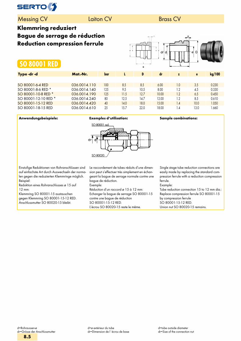
Klemmring reduziertBague de serrage de réductionReduction compression ferrule
SO 80001 REDType -dr -d Mat.-Nr. bar L D dr z e kg/100 SO 80001-6-4 RED 036.0014.110 100 8.5 8.5 6.00 1.0 3.5 0.230SO 80001-8-6 RED * 036.0014.140 125 9.5 10.5 8.00 1.2 4.5 0.330SO 80001-10-8 RED * 036.0014.190 125 11.5 12.7 10.00 1.2 6.5 0.450SO 80001-12-10 RED * 036.0014.240 80 12.5 14.7 12.00 1.2 8.5 0.610SO 80001-15-12 RED 036.0014.420 40 14.0 18.0 15.00 1.4 10.0 1.050SO 80001-18-15 RED 036.0014.610 25 15.7 22.0 18.00 1.4 13.0 1.660
Anwendungsbeispiele: Exemples d‘utilisation: Sample combinations:
Einstufige Reduktionen von Rohranschlüssen sind auf einfachste Art durch Auswechseln der norma-len gegen die reduzierten Klemmringe möglich.Beispiel:Reduktion eines Rohranschlusses ø 15 auf 12 mm:Klemmring SO 80001-15 austauschen gegen Klemmring SO 80001-15-12 RED. Anschlussmutter SO 80020-15 bleibt.
Le raccordement de tubes réduits d’une dimen-sion peut s’effectuer très simplement en échan-geant la bague de serrage normale contre une bague de réduction.Exemple:Réduction d’un raccord ø 15 à 12 mm: Echanger la bague de serrage SO 80001-15 contre une bague de réduction SO 80001-15-12 RED. L’écrou SO 80020-15 reste le même.
Single stage tube reduction connections are easily made by replacing the standard com-pression ferrule with a reduction compression ferrule.Example:Tube reduction connection 15 to 12 mm dia.:Replace compression ferrule SO 80001-15 by compression ferrule SO 80001-15-12 RED. Union nut SO 80020-15 remains.
Messing CV Laiton CV Brass CV
d=Rohraussen-ødr=Grösse der Anschlussmutter
d=ø extérieur du tubedr=Dimension de l´écrou de base
d=tube outside diameterdr=Size of the connection nut
8.5
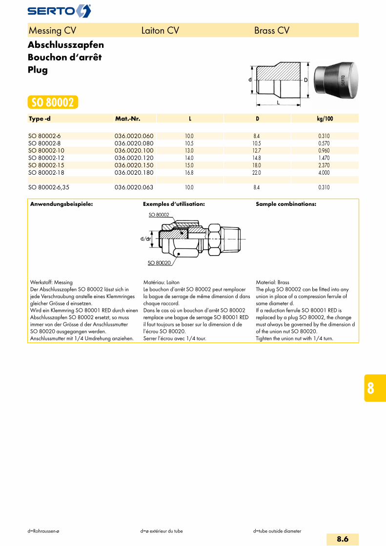
AbschlusszapfenBouchon d‘arrêtPlug
SO 80002Type -d Mat.-Nr. L D kg/100 SO 80002-6 036.0020.060 10.0 8.4 0.310SO 80002-8 036.0020.080 10.5 10.5 0.570SO 80002-10 036.0020.100 13.0 12.7 0.960SO 80002-12 036.0020.120 14.0 14.8 1.470SO 80002-15 036.0020.150 15.0 18.0 2.370SO 80002-18 036.0020.180 16.8 22.0 4.000 SO 80002-6,35 036.0020.063 10.0 8.4 0.310
Anwendungsbeispiele: Exemples d‘utilisation: Sample combinations:
Werkstoff: MessingDer Abschlusszapfen SO 80002 lässt sich in jede Verschraubung anstelle eines Klemmringes gleicher Grösse d einsetzen.Wird ein Klemmring SO 80001 RED durch einen Abschlusszapfen SO 80002 ersetzt, so muss immer von der Grösse d der Anschlussmutter SO 80020 ausgegangen werden.Anschlussmutter mit 1/4 Umdrehung anziehen.
Matériau: LaitonLe bouchon d’arrêt SO 80002 peut remplacer la bague de serrage de même dimension d dans chaque raccord.Dans le cas où un bouchon d’arrêt SO 80002 remplace une bague de serrage SO 80001 RED il faut toujours se baser sur la dimension d de l’écrou SO 80020.Serrer l’écrou avec 1/4 tour.
Material: BrassThe plug SO 80002 can be fitted into any union in place of a compression ferrule of same diameter d.If a reduction ferrule SO 80001 RED is replaced by a plug SO 80002, the change must always be governed by the dimension d of the union nut SO 80020.Tighten the union nut with 1/4 turn.
Messing CV Laiton CV Brass CV
d=Rohraussen-ø d=ø extérieur du tube d=tube outside diameter
8.6
i
s
3F
4M
4G
5
5L
6
7
8
9
10
11
12

StützhülseDouille d‘appuiStiffener sleeve
SO 80003Type -d -d1 Mat.-Nr. L D d2 s kg/100 SO 80003-6-4 036.0030.110 10.0 5.5 3.95 0.20 0.025SO 80003-8-6 036.0030.140 12.0 7.5 5.90 0.25 0.045SO 80003-10-8 D 036.0030.189 16.0 9.5 7.85 0.60 0.190SO 80003-10-8 036.0030.190 16.0 9.5 7.80 0.30 0.100SO 80003-12-10 036.0030.240 20.0 11.5 9.80 0.40 0.195SO 80003-15-13 036.0030.430 24.0 14.5 12.80 0.50 0.390SO 80003-17-15 036.0030.610 26.0 16.5 14.70 0.60 0.590SO 80003-18-15 036.0030.540 26.0 16.5 14.70 0.60 0.590
Werkstoff: Messing, chemisch vernickeltVerstärken:Dünnwandige und weiche Rohre sowie alleKunststoffrohre sind vor dem Einführen in dieSERTO-Verschraubung mit Stützhülsen zuverstärken.Genaue Angaben über das Verstärken sind deneinzelnen Verschraubungsreihen im Anhang zuentnehmen.Zum Entgraten und Kalibrieren der Rohre eignensich besonders unsere Hilfswerkzeuge.
Matériau: Laiton, nickelé chimiqueRenforcement:Les tubes présentant une paroi mince, les tubesen matière souple ainsi que les tubes en matièreplastique doivent être renforcés à l’aide dedouilles d’appui avant d’être introduits dans lesraccords SERTO.Des indications plus précises concernant lerenforcement sont données pour chaque sériede raccord dans l’annexe.L’ébarbage et le calibrage du tube sont facilitéspar l’emploi de notre outil spécial.
Material: Brass, chemically nickel-platedReinforcement:Thin walled and soft tubes, and all plastic tubes,are to be reinforced with stiffner sleeves beforeintroducing them into the SERTO union.Exact details concerning stiffening are to befound in the sections on the relevant modelseries in the appendix.Our tools are especially useful for deburringand calibrating tubing.
SechskantmutterEcrou à six pansHexagon nut
SO 80006 METRType -Mz Mat.-Nr. SW D h s kg/100Für metrische Rohre Pour tubes métriques For metric tubesMz=metrisches Gewinde (zylindrisch) Mz=Filetage métrique (cylindrique) Mz=Metric thread (straight)SO 80006-M10X1 036.0063.150 14 13.8 0.5 4.00 0.310SO 80006-M12X1 036.0063.190 17 16.8 0.5 4.00 0.460SO 80006-M14X1 036.0063.220 19 18.8 0.5 4.00 0.530SO 80006-M16X1 036.0063.260 19 18.8 0.5 4.00 0.380SO 80006-M20X1 036.0063.340 24 23.8 0.5 4.50 0.690SO 80006-M20X1,5 036.0063.345 27 26.8 0.5 6.00 1.640SO 80006-M24X1,5 036.0063.405 27 26.8 0.5 7.00 1.140
Sechskantmutter für SO 81521 und Ventile Ecrou à six pans pour SO 81521 et robinets Hexagon nut for SO 81521 and valves
Messing CV Laiton CV Brass CV
d=Rohraussen-ød1=Rohrinnendurchmessers=Wandstärke
d=ø extérieur du tubeø diam. Intérieur du tubes=épaisseur de la paroi
d=tube outside diameterd1=tube inside diameters=wall thickness
8.7

AnschlussmutterEcrouUnion nut
SO 80020Type -d Mat.-Nr. bar M SW L kg/100 SO 80020-6 036.0200.060 200 10x1 12 14.5 0.740SO 80020-8 036.0200.080 125 12x1 14 16.0 0.990SO 80020-10 036.0200.100 80 14x1 17 18.5 1.770SO 80020-12 036.0200.120 80 16x1 19 19.5 2.170SO 80020-15 036.0200.150 25 20x1.5 24 21.0 3.910SO 80020-18 036.0200.180 25 20x1.5 27 23.0 4.370
ArmaturenanschlussEcrou de raccordementNut connection
SO 80021Type -d Mat.-Nr. bar M SW L z kg/100 SO 80021-6 036.0210.060 200 10x1 12 14.5 7.5 0.840SO 80021-8 036.0210.080 125 12x1 14 16.0 8.0 1.120SO 80021-10 036.0210.100 80 14x1 17 18.5 10.0 1.890SO 80021-12 036.0210.120 80 16x1 19 19.5 11.0 2.340SO 80021-15 036.0210.150 25 20x1.5 24 21.0 12.5 4.240SO 80021-18 036.0210.180 25 24x1.5 27 23.0 14.0 5.260
Anschlussmutter SO 80020 mit Klemmring SO 80001
Ecrou SO 80020 avec bague de serrageSO 80001
Union nut SO 80020 with compression ferrule SO 80001
Messing CV Laiton CV Brass CV
d=Rohraussen-øz=Mass im montierten Zustand
d=ø extérieur du tubez=après montage
d=tube outside diameterz=installed length
8.8
i
s
3F
4M
4G
5
5L
6
7
8
9
10
11
12

Armaturenanschluss reduziertEcrou de raccordement réduitReduction tube connection
SO 80021 REDType -dr -d Mat.-Nr. bar M SW L dr z kg/100 SO 80021-6-4 RED 036.0214.110 100 10x1 12 14.5 6.00 7.5 0.950SO 80021-8-6 RED 036.0214.140 125 12x1 14 16.0 8.00 8.0 1.280SO 80021-10-8 RED 036.0214.190 125 14x1 17 18.5 10.00 10.0 2.090SO 80021-12-10 RED 036.0214.240 80 16x1 19 19.5 12.00 11.0 2.620SO 80021-15-12 RED 036.0214.420 40 20x1.5 24 21.0 15.00 12.5 4.780SO 80021-18-15 RED 036.0214.610 25 24x1.5 27 23.0 18.00 14.0 6.010
Anwendungsbeispiele: Exemples d‘utilisation: Sample combinations:
Anschlussmutter SO 80020 mit Klemmring redu-ziert SO 80001 RED.Mit diesem Armaturenanschluss können einstufi-ge Reduktionen vorgenommen werden.Gewindezapfen für SERTO-Anschlüssesiehe Anhang.
Ecrou SO 80020 avec bague de serrage de réduction SO 80001 RED.Ces écrous de raccordement permettent d’effectuer des réductions d’une dimension.Embout fileté pour écrous de raccordement SERTO voir annexe.
Union nut SO 80020 with reduction com-pression ferrule SO 80001 RED.This reduction tube connection permits single stage reductions to be made.Threaded stem for SERTO connections please see appendix.
Messing CV Laiton CV Brass CV
d=Rohraussen-ødr=Grösse der Anschlussmutterz=Mass in montiertem Zustand
d=ø extérieur du tubedr=Dimension de l'écrou de basez=après montage
d=tube outside diameterdr=Size of the connection nutz=installed length
8.9

ÜbergangsmuffeAdaptateur femelleFemale adaptor
SO 80030Type -d -G Mat.-Nr. bar M SW L b c D f z e kg/100 G=Rohrgewinde (zylindrisch) G=Filetage-gaz BSP (cylindrique) G=BSP thread (straight)SO 80030-6-1/8 036.0301.100 200 10x1 14 20.0 14.0 8.0 13.8 10.0 4.0 5.0 1.670SO 80030-6-1/4 036.0301.110 200 10x1 17 21.0 15.0 8.0 16.8 11.0 4.0 5.0 2.530SO 80030-8-1/8 036.0301.160 125 12x1 17 21.0 14.0 9.0 16.8 10.0 4.0 6.5 2.790SO 80030-8-1/4 036.0301.170 125 12x1 17 23.0 16.0 9.0 16.8 12.0 5.0 6.5 2.540SO 80030-10-1/4 036.0301.270 80 14x1 17 22.0 15.0 8.0 16.8 12.0 4.0 8.5 2.090SO 80030-10-3/8 036.0301.280 80 14x1 22 23.0 17.0 10.0 21.8 11.0 5.0 8.5 4.760SO 80030-12-3/8 036.0301.390 80 16x1 22 23.0 16.0 10.0 21.8 11.0 4.0 10.0 4.090SO 80030-12-1/2 036.0301.400 80 16x1 27 25.0 18.0 11.0 26.8 12.0 4.0 10.0 7.270SO 80030-15-1/2 036.0301.534 25 20x1.5 27 27.0 19.0 13.0 26.8 12.0 5.0 13.0 7.130SO 80030-18-1/2 036.0301.646 25 24x1.5 30 28.0 20.0 14.0 29.8 12.0 6.0 15.0 9.410SO 80030-18-3/4 036.0301.648 25 24x1.5 32 31.0 23.0 13.0 31.8 16.0 6.0 15.0 10.350
Anwendungsbeispiele: Exemples d‘utilisation: Sample combinations:
Die Übergangsmuffe SO 80030 kann an jedes SERTO-Formteil mit dem passenden zylindrischen Gewinde M aufgeschraubt werden.
Dichtungsprinzip:Bei der Montage drückt sich die Dichtkante des Übergangsstückes in das SERTO-Formteil ein, dadurch entsteht eine einwandfreie metallische Dichtung. Wir empfehlen, das Gewinde mit einem geeigneten Flüssigklebstoff gegen unbe-absichtigtes Lösen zu sichern.
L’adaptateur femelle SO 80030 peut être monté sur toutes les pièces de forme SERTO avec le filetage cylindrique M correspondant.
Principe d’étanchéité:Lors du serrage, le bourrelet s’enfonce dans la pièce de forme SERTO et donne un joint métal-lique parfait. Nous recommandons de freiner le filetage avec une résine appropriée contre un desserrage intempestif.
The female adaptor SO 80030 can be scre-wed onto every SERTO union body with the appropriate straight thread M.
Sealing principle:On being installed, the lip of the adaptor presses into the SERTO union body, forming a sound metallic seal. We recommend to secu-re the thread with a suitable cement against unintended loosening.
Messing CV Laiton CV Brass CV
d=Rohraussen-øe=kleinste Bohrung
d=ø extérieur du tubee=ø-min. de passage
d=tube outside diametere=minimum bore
8.10
i
s
3F
4M
4G
5
5L
6
7
8
9
10
11
12
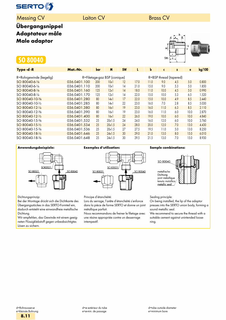
ÜbergangsnippelAdaptateur mâleMale adaptor
SO 80040Type -d -R Mat.-Nr. bar M SW L b c z e kg/100 R=Rohrgewinde (kegelig) R=Filetage-gaz BSP (conique) R=BSP thread (tapered)SO 80040-6-1/8 036.0401.100 200 10x1 12 17.0 11.0 9.0 4.5 5.0 0.800SO 80040-6-1/4 036.0401.110 200 10x1 14 21.0 15.0 9.0 5.3 5.0 1.850SO 80040-8-1/8 036.0401.160 125 12x1 14 18.0 11.0 10.0 4.5 5.0 0.990SO 80040-8-1/4 036.0401.170 125 12x1 14 22.0 15.0 10.0 5.3 6.5 1.520SO 80040-10-3/8 036.0401.280 80 14x1 17 22.0 15.0 10.0 4.9 8.5 2.440SO 80040-10-1/2 036.0401.285 80 14x1 22 23.0 16.0 7.0 2.8 8.5 5.030SO 80040-12-1/4 036.0401.380 80 16x1 19 23.0 16.0 11.0 6.3 8.5 2.110SO 80040-12-3/8 036.0401.390 80 16x1 19 23.0 16.0 11.0 6.0 10.0 2.870SO 80040-12-1/2 036.0401.400 80 16x1 22 26.0 19.0 10.0 6.0 10.0 4.840SO 80040-15-3/8 036.0401.532 25 20x1.5 24 24.0 16.0 12.0 6.0 10.0 3.760SO 80040-15-1/2 036.0401.534 25 20x1.5 24 28.0 20.0 12.0 7.0 13.0 4.430SO 80040-15-3/4 036.0401.536 25 20x1.5 27 27.5 19.5 11.0 5.0 13.0 8.250SO 80040-18-1/2 036.0401.646 25 24x1.5 30 29.0 21.0 13.0 8.0 15.0 6.010SO 80040-18-3/4 036.0401.648 25 24x1.5 30 29.5 21.5 13.0 7.0 15.0 8.930
Anwendungsbeispiele: Exemples d‘utilisation: Sample combinations:
Dichtungsprinzip:Bei der Montage drückt sich die Dichtkante des Übergangsstückes in das SERTO-Formteil ein, dadurch entsteht eine einwandfreie metallische Dichtung. Wir empfehlen, das Gewinde mit einem geeig-neten Flüssigklebstoff gegen unbeabsichtigtes Lösen zu sichern.
Principe d’étanchéité:Lors du serrage, l’arête d’étanchéité s’enfonce dans la pièce de forme SERTO et donne un joint métallique parfait. Nous recommandons de freiner le filetage avec une résine appropriée contre un desserrage intempestif.
Sealing principle:On being installed, the lip of the adaptor presses into the SERTO union body, forming a sound metallic seal. We recommend to secure the thread with a suitable cement against unintended loose-ning.
Messing CV Laiton CV Brass CV
d=Rohraussen-øe=kleinste Bohrung
d=ø extérieur du tubee=ø-min. de passage
d=tube outside diametere=minimum bore
8.11

SchlauchtülleDouille cannelée pour tuyauHose nozzle
SO 80503Type -Ad -d1 Mat.-Nr. L b e kg/100 SO 80503-A6-4 036.0500.110 25.0 11.0 3.0 0.270SO 80503-A6-6 036.0500.122 31.0 17.0 4.0 0.480SO 80503-A8-6 036.0500.140 32.5 17.0 5.0 0.520SO 80503-A8-8 036.0500.154 32.5 17.0 6.0 0.710SO 80503-A10-8 036.0500.190 35.0 17.0 7.0 0.720SO 80503-A12-10 036.0500.240 37.0 19.0 8.5 1.230SO 80503-A12-13 036.0500.260 39.0 21.0 9.0 2.889SO 80503-A15-13 036.0500.430 41.0 21.0 11.0 2.050SO 80503-A18-16 036.0500.620 47.0 26.0 14.0 3.240
Anwendungsbeispiele: Exemples d‘utilisation: Sample combinations:
Mit dieser Schlauchtülle können Gummischläuche und Rohre aus Teflon, Weich-PVC, Polyamid usw. direkt an SERTO-Verschraubungen angeschlossen werden. Für die Schlauchsicherung verwenden Sie bitte unsere Schlauchklemme SO 40512.
Avec cette douille cannelée, les tuyaux en caoutchouc, les tubes en téflon, en PVC souple, en polyamide et autres peuvent être fixés directe-ment aux raccords SERTO.Afin d’assurer la bonne tenue des tuyaux, utiliser nos colliers de serrage SO 40512.
With this hose nipple, rubber hoses and pla-stic hoses of teflon, soft PVC, polyamide can be connected directly to the SERTO unions.Please use our hose clip SO 40512 for secu-ring the hose.
Messing CV Laiton CV Brass CV
d1=RohrinnendurchmesserAd=Aussen-ø der Andrehunge=kleinste Bohrung
d1=ø Intérieur du tubeAd=ø extérieur de la portée cylindriquee=ø-min. de passage
d1=tube inside diameterAd=outside diameter of cyl. Stube=minimum bore
8.12
i
s
3F
4M
4G
5
5L
6
7
8
9
10
11
12
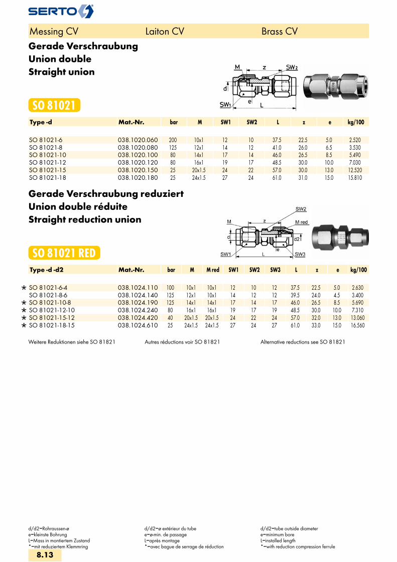
Gerade VerschraubungUnion doubleStraight union
SO 81021Type -d Mat.-Nr. bar M SW1 SW2 L z e kg/100 SO 81021-6 038.1020.060 200 10x1 12 10 37.5 22.5 5.0 2.520SO 81021-8 038.1020.080 125 12x1 14 12 41.0 26.0 6.5 3.530SO 81021-10 038.1020.100 80 14x1 17 14 46.0 26.5 8.5 5.490SO 81021-12 038.1020.120 80 16x1 19 17 48.5 30.0 10.0 7.030SO 81021-15 038.1020.150 25 20x1.5 24 22 57.0 30.0 13.0 12.520SO 81021-18 038.1020.180 25 24x1.5 27 24 61.0 31.0 15.0 15.810
Gerade Verschraubung reduziertUnion double réduiteStraight reduction union
SO 81021 REDType -d -d2 Mat.-Nr. bar M M red SW1 SW2 SW3 L z e kg/100
SO 81021-6-4 038.1024.110 100 10x1 10x1 12 10 12 37.5 22.5 5.0 2.630 SO 81021-8-6 038.1024.140 125 12x1 10x1 14 12 12 39.5 24.0 4.5 3.400
SO 81021-10-8 038.1024.190 125 14x1 14x1 17 14 17 46.0 26.5 8.5 5.690 SO 81021-12-10 038.1024.240 80 16x1 16x1 19 17 19 48.5 30.0 10.0 7.310 SO 81021-15-12 038.1024.420 40 20x1.5 20x1.5 24 22 24 57.0 32.0 13.0 13.060 SO 81021-18-15 038.1024.610 25 24x1.5 24x1.5 27 24 27 61.0 33.0 15.0 16.560
Weitere Reduktionen siehe SO 81821 Autres réductions voir SO 81821 Alternative reductions see SO 81821
Messing CV Laiton CV Brass CV
d/d2=Rohraussen-øe=kleinste BohrungL=Mass in montiertem Zustand*=mit reduziertem Klemmring
d/d2=ø extérieur du tubee=ø-min. de passageL=après montage*=avec bague de serrage de réduction
d/d2=tube outside diametere=minimum boreL=installed length*=with reduction compression ferrule
8.13

Gerade EinschraubverschraubungUnion mâleMale adaptor union
SO 81121Type -d -R Mat.-Nr. bar M SW1 SW2 L a z e kg/100Für metrische Rohre Pour tubes métriques For metric tubesR=Rohrgewinde (kegelig) R=Filetage-gaz BSP (conique) R=BSP thread (tapered)
SO 81121-4-1/8 038.1101.060 125 8x1 10 10 27.0 21.0 14.5 3.5 1.410 SO 81121-4-1/4 038.1101.065 100 10x1 12 14 34.0 26.5 16.5 4.5 2.930 SO 81121-6-1/8 038.1101.100 200 10x1 12 10 28.5 21.0 14.5 4.5 1.690 SO 81121-6-1/4 038.1101.110 200 10x1 12 14 34.0 26.5 16.5 4.5 2.820 SO 81121-6-3/8 038.1101.120 200 10x1 12 17 34.5 27.0 20.5 4.5 3.390 SO 81121-8-1/8 038.1101.160 125 12x1 14 12 30.5 22.5 16.0 6.0 2.260 SO 81121-8-1/4 038.1101.170 125 12x1 14 14 35.5 27.5 17.5 6.5 3.110 SO 81121-8-3/8 038.1101.180 125 12x1 14 17 36.0 28.0 18.0 6.5 3.730 SO 81121-8-1/2 038.1101.185 125 12x1 14 22 41.0 33.0 20.0 6.5 6.040 SO 81121-10-1/4 038.1101.270 80 14x1 17 14 37.5 27.5 17.5 8.5 3.630 SO 81121-10-3/8 038.1101.280 80 14x1 17 17 38.0 28.0 18.0 8.5 4.830
SO 81121-10-1/2 038.1101.285 80 16x1 19 22 44.0 33.0 20.0 10.0 8.040 SO 81121-12-1/4 038.1101.380 80 16x1 19 17 39.0 28.0 18.0 8.5 4.820 SO 81121-12-3/8 038.1101.390 80 16x1 19 17 39.0 28.0 18.0 10.5 5.110 SO 81121-12-1/2 038.1101.400 80 16x1 19 22 44.0 33.0 20.0 10.5 7.760 SO 81121-15-3/8 038.1101.532 40 20x1.5 24 22 43.0 30.5 20.0 10.5 8.820 SO 81121-15-1/2 038.1101.534 25 20x1.5 24 22 45.0 34.5 21.5 13.0 9.110 SO 81121-15-3/4 038.1101.536 25 20x1.5 24 27 49.5 37.0 22.5 13.0 10.650 SO 81121-18-1/2 038.1101.646 25 24x1.5 27 24 49.5 35.5 22.0 15.0 10.760
Für Zollrohre Pour tubes pouces For inch tubes
SO 81121-6,35-1/8 038.1101.135 100 10x1 12 10 28.5 21.0 14.5 4.5 1.680
Messing CV Laiton CV Brass CV
d=Rohraussen-øe=kleinste BohrungL=Mass in montiertem Zustand*=mit reduziertem Klemmring
d=ø extérieur du tubee=ø-min. de passageL=après montage*=avec bague de serrage de réduction
d=tube outside diametere=minimum boreL=installed length*=with reduction compression ferrule
8.14
i
s
3F
4M
4G
5
5L
6
7
8
9
10
11
12
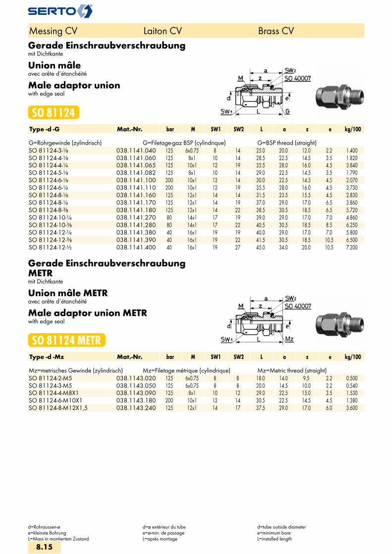
Gerade Einschraubverschraubungmit Dichtkante
Union mâleavec arête d‘étanchéité
Male adaptor unionwith edge seal
SO 81124Type -d -G Mat.-Nr. bar M SW1 SW2 L a z e kg/100 G=Rohrgewinde (zylindrisch) G=Filetage-gaz BSP (cylindrique) G=BSP thread (straight)SO 81124-3-1/8 038.1141.040 125 6x0.75 8 14 25.0 20.0 12.0 2.2 1.400SO 81124-4-1/8 038.1141.060 125 8x1 10 14 28.5 22.5 14.5 3.5 1.820SO 81124-4-1/4 038.1141.065 125 10x1 12 19 35.5 28.0 16.0 4.5 3.840SO 81124-5-1/8 038.1141.082 125 8x1 10 14 29.0 22.5 14.5 3.5 1.790SO 81124-6-1/8 038.1141.100 200 10x1 12 14 30.0 22.5 14.5 4.5 2.070SO 81124-6-1/4 038.1141.110 200 10x1 12 19 35.5 28.0 16.0 4.5 3.730SO 81124-8-1/8 038.1141.160 125 12x1 14 14 31.5 23.5 15.5 4.5 2.830SO 81124-8-1/4 038.1141.170 125 12x1 14 19 37.0 29.0 17.0 6.5 3.860SO 81124-8-3/8 038.1141.180 125 12x1 14 22 38.5 30.5 18.5 6.5 5.720SO 81124-10-1/4 038.1141.270 80 14x1 17 19 39.0 29.0 17.0 7.0 4.860SO 81124-10-3/8 038.1141.280 80 14x1 17 22 40.5 30.5 18.5 8.5 6.250SO 81124-12-1/4 038.1141.380 40 16x1 19 19 40.0 29.0 17.0 7.0 5.800SO 81124-12-3/8 038.1141.390 40 16x1 19 22 41.5 30.5 18.5 10.5 6.500SO 81124-12-1/2 038.1141.400 40 16x1 19 27 45.0 34.0 20.0 10.5 7.200
Gerade Einschraubverschraubung METRmit Dichtkante
Union mâle METRavec arête d‘étanchéité
Male adaptor union METRwith edge seal
SO 81124 METRType -d -Mz Mat.-Nr. bar M SW1 SW2 L a z e kg/100 Mz=metrisches Gewinde (zylindrisch) Mz=Filetage métrique (cylindrique) Mz=Metric thread (straight)SO 81124-2-M5 038.1143.020 125 6x0.75 8 8 18.0 14.0 9.5 2.2 0.500SO 81124-3-M5 038.1143.050 125 6x0.75 8 8 20.0 14.5 10.0 2.2 0.540SO 81124-4-M8X1 038.1143.090 125 8x1 10 12 29.0 22.5 15.0 3.5 1.530SO 81124-6-M10X1 038.1143.180 200 10x1 12 14 30.5 22.5 14.5 4.5 1.380SO 81124-8-M12X1,5 038.1143.240 125 12x1 14 17 37.5 29.0 17.0 6.0 3.600
Messing CV Laiton CV Brass CV
d=Rohraussen-øe=kleinste BohrungL=Mass in montiertem Zustand
d=ø extérieur du tubee=ø-min. de passageL=après montage
d=tube outside diametere=minimum boreL=installed length
8.15

Gerade Einschraubverschraubungmit O-Ringabdichtung (NBR)
Union mâleavec joint torique (NBR)
Male adaptor unionwith O-ring seal (NBR)
SO 81124 ORType -d -G Mat.-Nr. bar M SW L D i s z e kg/100Für metrische Rohre Pour tubes métriques For metric tubesG=Rohrgewinde (zylindrisch) G=Filetage-gaz BSP (cylindrique) G=BSP thread (straight)
SO 81124-4-1/8 OR 038.1171.060 100 10x1 14 30.0 15.0 8.0 1.00 14.5 4.0 2.300 SO 81124-4-1/4 OR 038.1171.065 100 10x1 19 33.5 19.0 10.0 1.50 16.0 4.0 3.900 SO 81124-5-1/8 OR 038.1171.082 100 10x1 14 30.0 15.0 8.0 1.00 14.5 4.5 2.200 SO 81124-6-1/8 OR 038.1171.100 200 10x1 14 30.0 15.0 8.0 1.00 14.5 4.0 2.000 SO 81124-6-1/4 OR 038.1171.110 200 10x1 19 33.5 19.0 10.0 1.50 16.0 4.0 3.900 SO 81124-8-1/4 OR 038.1171.170 125 12x1 19 33.5 19.0 10.0 1.50 17.0 6.0 4.000
SO 81124-8-3/8 OR 038.1171.180 125 14x1 22 38.5 23.0 10.0 2.00 18.5 8.0 6.400 SO 81124-10-1/4 OR 038.1171.270 80 14x1 19 37.0 19.0 10.0 1.50 17.0 6.5 4.700 SO 81124-10-3/8 OR 038.1171.280 80 14x1 22 38.5 23.0 10.0 2.00 18.5 8.0 6.200 SO 81124-12-3/8 OR 038.1171.390 80 16x1 22 39.5 23.0 10.0 2.00 18.5 10.0 6.300 SO 81124-12-1/2 OR 038.1171.400 80 16x1 27 42.0 27.0 12.0 2.50 19.0 10.0 7.700 SO 81124-15-1/2 OR 038.1171.534 25 20x1.5 27 46.0 27.0 12.0 2.50 21.5 13.0 13.500 SO 81124-18-1/2 OR 038.1171.646 25 24x1.5 27 47.5 27.0 12.0 2.50 21.5 13.0 15.300
Anwendungsbeispiele: Exemples d‘utilisation: Sample combinations:
Die Vorteile von conovor®:– keine Dichtmittelreste in Geräten– einwandfreie Abdichtung– keine Beschädigung von Geräten durchkonische Gewinde– schnelle Montage
Temperatur max. +100°C
Les avantages du conovor®:– pas de reste de produits d’étanchéité dans les appareils– étanchéité impeccable– pas d’endommagement des appareils par des filetages coniques– montages rapide
Température max. +100°C
The advantages of conovor®:– no sealing compound residue in instruments– flawless sealing– no damage to instruments due to tapered threads– quick installing
Temperature max. +100°C
Messing CV Laiton CV Brass CV
d=Rohraussen-øe=kleinste BohrungL=Mass in montiertem Zustand*=mit reduziertem Klemmring
d=ø extérieur du tubee=ø-min. de passageL=après montage*=avec bague de serrage de reduction
d=tube outside diameter e=minimum bore L=installed length*=with reduction compression ferrule
8.16
i
s
3F
4M
4G
5
5L
6
7
8
9
10
11
12
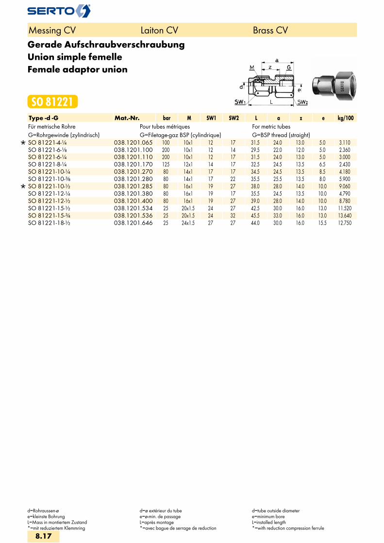
Gerade AufschraubverschraubungUnion simple femelleFemale adaptor union
SO 81221Type -d -G Mat.-Nr. bar M SW1 SW2 L a z e kg/100Für metrische Rohre Pour tubes métriques For metric tubesG=Rohrgewinde (zylindrisch) G=Filetage-gaz BSP (cylindrique) G=BSP thread (straight)
SO 81221-4-1/4 038.1201.065 100 10x1 12 17 31.5 24.0 13.0 5.0 3.110 SO 81221-6-1/8 038.1201.100 200 10x1 12 14 29.5 22.0 12.0 5.0 2.360 SO 81221-6-1/4 038.1201.110 200 10x1 12 17 31.5 24.0 13.0 5.0 3.000 SO 81221-8-1/4 038.1201.170 125 12x1 14 17 32.5 24.5 13.5 6.5 2.430 SO 81221-10-1/4 038.1201.270 80 14x1 17 17 34.5 24.5 13.5 8.5 4.180 SO 81221-10-3/8 038.1201.280 80 14x1 17 22 35.5 25.5 13.5 8.0 5.900
SO 81221-10-1/2 038.1201.285 80 16x1 19 27 38.0 28.0 14.0 10.0 9.060 SO 81221-12-1/4 038.1201.380 80 16x1 19 17 35.5 24.5 13.5 10.0 4.790 SO 81221-12-1/2 038.1201.400 80 16x1 19 27 39.0 28.0 14.0 10.0 8.780 SO 81221-15-1/2 038.1201.534 25 20x1.5 24 27 42.5 30.0 16.0 13.0 11.520 SO 81221-15-3/4 038.1201.536 25 20x1.5 24 32 45.5 33.0 16.0 13.0 13.640 SO 81221-18-1/2 038.1201.646 25 24x1.5 27 27 44.0 30.0 16.0 15.5 12.750
Messing CV Laiton CV Brass CV
d=Rohraussen-øe=kleinste BohrungL=Mass in montiertem Zustand*=mit reduziertem Klemmring
d=ø extérieur du tubee=ø-min. de passageL=après montage*=avec bague de serrage de reduction
d=tube outside diametere=minimum boreL=installed length*=with reduction compression ferrule
8.17
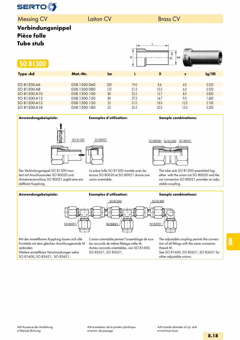
VerbindungsnippelPièce folleTube stub
SO 81300Type -Ad Mat.-Nr. bar L D e kg/100 SO 81300-A6 038.1300.060 200 19.0 8.4 4.0 0.350SO 81300-A8 038.1300.080 125 21.5 10.5 6.0 0.520SO 81300-A10 038.1300.100 80 25.5 12.7 8.0 0.850SO 81300-A12 038.1300.120 80 27.5 14.7 9.0 1.400SO 81300-A15 038.1300.150 25 31.0 18.0 12.0 2.100SO 81300-A18 038.1300.180 25 35.5 22.0 15.0 3.200
Anwendungsbeispiele: Exemples d‘utilisation: Sample combinations:
Der Verbindungsnippel SO 81300 mon-tiert mit Anschlussmutter SO 80020 und Armaturenanschluss SO 80021 ergibt eine ein-stellbare Kupplung.
La pièce folle SO 81300 montée avec les écrous SO 80020 et SO 80021 donne une union orientable.
The tube stub SO 81300 assembled tog-ether with the union nut SO 80020 and the nut connection SO 80021 provides an adju-stable coupling.
Anwendungsbeispiele: Exemples d‘utilisation: Sample combinations:
Mit der einstellbaren Kupplung lassen sich alle Formteile mit dem gleichen Anschlussgewinde M verbinden. Weitere einstellbare Verschraubungen siehe SO 81600, SO 82621, SO 83621.
L’union orientable permet l’assemblage de tous les raccords de même filetage mâle M. Autres raccords orientables, voir SO 81600, SO 82621, SO 83621.
The adjustable coupling permits the connec-tion of all fittings with the same connector thread M. See SO 81600, SO 82621, SO 83621 for other adjustable unions.
Messing CV Laiton CV Brass CV
Ad=Aussen-ø der Andrehunge=kleinste Bohrung
Ad=ø extérieur de la portée cylindriquee=ø-min. de passage
Ad=outside diameter of cyl. stube=minimum bore
8.18
i
s
3F
4M
4G
5
5L
6
7
8
9
10
11
12

Gerade SchottverschraubungDurchführungslänge max.5 mm
Union doublepour passage de cloison,Pour cloison max.5 mm
Panel mount unionmax. panel thickness 5 mm
SO 81521Type -d Mat.-Nr. bar M SW1 SW2 L L1 B z1 z e kg/100 SO 81521-6 038.1500.060 200 10x1 12 14 21.0 26.5 10.5 19.0 13.5 4.5 3.540SO 81521-8 038.1500.080 125 12x1 14 17 23.0 28.0 12.5 20.0 15.0 6.5 5.320SO 81521-10 038.1500.100 80 14x1 17 19 25.5 31.0 14.5 21.0 15.5 8.5 7.710SO 81521-12 038.1500.120 80 16x1 19 22 27.0 32.0 16.5 21.0 16.0 10.5 9.320SO 81521-15 038.1500.150 25 20x1.5 24 27 30.5 36.5 20.5 24.0 18.0 13.0 16.080SO 81521-18 038.1500.180 25 24x1.5 27 30 32.5 38.5 24.5 24.5 18.5 15.0 18.500
Weitere Reduktionen siehe SO 81821Sechskantmutter siehe SO 80006
Autres réductions voir SO 81821Ecrou à six pans voir SO 80006
Alternative reductions see SO 81821Hexagon nut see SO 80006
EinstellnippelUnion orientable mâleAdjustable male adaptor
SO 81604Type -Ad -R Mat.-Nr. bar SW L b z e kg/100 SO 81604-A15-1/2 038.1611.534 25 22 53.0 30.0 40.0 12.0 5.760
Anwendungsbeispiele: Exemples d‘utilisation: Sample combinations:
Dieser Einstellnippel ergibt im Zusammenhang mit unserem Armaturenanschluss SO 80021 einen einstellbaren Anschluss.Nur bei Typ SO 81604–d–R lässt sich die Anschlussmutter auf dem zyl. Schaft so weit zurückschieben, dass eine radiale Demontage möglich ist.
Cette union montée avec un écrou SO 80021 permet d’obtenir un raccord orientable mâle. La longueur libre plus importante des pièces SO 81604–d–R assure le recul de l’écrou afin de permettre le démontage radial.
In combination with our nut connection SO 80021 this adjustable male adaptor forms an adjustable male adaptor union.Radial dismantling is possible only with SO 81604–d–R as the nut can be fully withdrawn.
Messing CV Laiton CV Brass CV
d=Rohraussen-øe=kleinste BohrungL=Mass in montiertem Zustand
d=ø extérieur du tubee=ø-min. de passageL=après montage
d=tube outside diametere=minimum boreL=installed length
8.19

EinstellnippelUnion orientable mâleAdjustable male adaptor
SO 81600Type -Ad -R Mat.-Nr. bar SW L b z e kg/100 SO 81600-A6-1/8 038.1601.100 100 12 26.0 13.0 19.5 4.0 1.000SO 81600-A6-1/4 038.1601.110 100 14 31.0 13.0 21.0 4.0 1.950SO 81600-A8-1/8 038.1601.160 64 12 28.0 14.0 21.5 6.0 1.200SO 81600-A8-1/4 038.1601.170 64 14 32.0 14.0 22.0 6.0 1.800SO 81600-A10-1/4 038.1601.270 40 14 34.0 16.0 24.0 8.0 1.650SO 81600-A10-3/8 038.1601.280 40 17 34.0 16.0 15.0 8.0 2.900SO 81600-A10-1/2 038.1601.285 40 22 39.0 16.0 23.8 8.0 5.570SO 81600-A12-3/8 038.1601.390 40 17 36.0 18.0 27.0 9.0 3.000SO 81600-A12-1/2 038.1601.400 40 22 41.0 18.0 28.0 9.0 5.670
Anwendungsbeispiele: Exemples d‘utilisation: Sample combinations:
Kombiniert mit Winkel- oder T-Verschraubungen ergeben sich einstellbare Formteile.
Cette union, combinée avec un coude ou un té, permet d’obtenir des raccords orientables.
Produces adjustable configurations in combi-nation with elbow or tee unions.
Messing CV Laiton CV Brass CV
Ad=Aussen-ø der Andrehunge=kleinste BohrungL=Mass in montiertem Zustand
Ad=ø extérieur de la portée cylindriquee=ø-min. de passageL=après montage
Ad=outside diameter of cyl. Stube=minimum boreL=installed length
8.20
i
s
3F
4M
4G
5
5L
6
7
8
9
10
11
12

Reduktionsverschraubungfür Grundteile
Réductionpour pièces de base
Reduced unionfor basic components
SO 81821Type -d2 -d Mat.-Nr. bar M M1 SW1 SW2 L a z e kg/100
SO 81821-10-4 038.1800.167 80 10x1 14x1 12 17 27.5 20.0 13.0 4.0 2.580 SO 81821-10-6 038.1800.175 80 10x1 14x1 12 17 27.5 20.0 13.0 4.0 2.470
SO 81821-12-6 038.1800.215 80 12x1 16x1 14 19 29.5 21.5 13.5 6.0 3.500 SO 81821-12-8 038.1800.225 80 12x1 16x1 14 19 29.5 21.5 13.5 6.0 3.340
SO 81821-15-8 038.1800.400 40 14x1 20x1.5 17 24 33.5 23.5 15.5 8.0 5.920 SO 81821-15-10 038.1800.410 40 14x1 20x1.5 17 24 33.5 23.5 15.5 8.0 5.720
SO 81821-18-10 038.1800.575 40 16x1 24x1.5 19 30 35.5 24.5 16.5 10.0 9.100 SO 81821-18-12 038.1800.580 40 16x1 24x1.5 19 30 35.5 24.5 16.5 10.0 8.820
Anwendungsbeispiele: Exemples d‘utilisation: Sample combinations:
Die Reduktion SO 81821 kann an jedes SERTO-Formteil mit dem passenden Gewinde (d2) aufgeschraubt werden. Durch diese Kombination ergeben sich weitere Rohrreduktionen.
Dichtungsprinzip:Bei der Montage drückt sich die Dichtkante der Reduktion in das SERTO Formteil ein, dadurch entsteht eine einwandfreie metallische Dichtung. Wir empfehlen, das Gewinde mit einem geeig-neten Flüssigklebstoff gegen unbeabsichtigtes Lösen zu sichern.
La réduction SO 81821 peut être montée sur toutes les pièces de forme SERTO avec le fileta-ge (d2) correspondant. De cette combinaison résulte d’autres réductions de tubes.
Principe d’étanchéité:Lors du serrage, l’arête d’étanchéité de la réduc-tion s’enfonce dans la pièce de forme SERTO et donne un joint métallique parfait. Nous recom-mandons de freiner le filetage avec une résine appropriée contre un desserrage intempestif.
The reduction SO 81821 can be screwed onto every SERTO union body with the appropriate thread (d2). From this combinati-on result further tube reductions.
Sealing principle:On being installed, the lip of the reduction presses into the SERTO union body, forming a sound metallic seal. We recommend to secu-re the thread with a suitable cement against unintended loosening.
Messing CV Laiton CV Brass CV
d=Rohraussen-øe=kleinste BohrungL=Mass in montiertem Zustand*=mit reduziertem Klemmring
d=ø extérieur du tubee=ø-min. de passageL=après montage*=avec bague de serrage de réduction
d=tube outside diametere=minimum boreL=installed length*=with reduction compression ferrule
8.21

WinkelverschraubungCoudeElbow union
SO 82021Type -d Mat.-Nr. bar M SW1 SW2 L z e kg/100 SO 82021-6 038.2000.060 200 10x1 10 12 23.5 16.0 4.0 2.750SO 82021-8 038.2000.080 125 12x1 10 14 26.0 18.0 6.0 3.680SO 82021-10 038.2000.100 80 14x1 14 17 30.5 20.5 8.0 6.340SO 82021-12 038.2000.120 80 16x1 17 19 32.5 21.5 10.0 7.920SO 82021-15 038.2000.150 25 20x1.5 19 24 36.0 23.5 13.0 13.110SO 82021-18 038.2000.180 25 24x1.5 22 27 39.5 25.5 15.0 18.020
Winkelverschraubung reduziertCoude réduitElbow reduction union
SO 82021 REDType -d -d2 Mat.-Nr. bar M SW1 SW2 L z e kg/100
SO 82021-6-4 038.2004.110 100 10x1 10 12 23.5 16.0 4.5 2.860 SO 82021-8-6 038.2004.140 125 12x1 10 14 26.0 18.0 6.5 3.740 SO 82021-10-8 038.2004.190 125 14x1 14 17 30.5 20.0 8.5 6.540 SO 82021-12-10 038.2004.240 80 16x1 17 19 32.5 21.5 10.5 9.000 SO 82021-15-12 038.2004.420 40 20x1.5 19 24 36.0 23.5 13.0 13.650 SO 82021-18-15 038.2004.610 25 24x1.5 22 27 40.5 26.5 15.0 18.720
Weitere Reduktionen siehe SO 81821 Autres réductions voir SO 81821 Alternative reductions see SO 81821
Messing CV Laiton CV Brass CV
d/d2=Rohraussen-øe=kleinste BohrungL=Mass in montiertem Zustand*=mit reduziertem Klemmring
d/d2=ø extérieur du tubee=ø-min. de passageL=après montage*=avec bague de serrage de réduction
d/d2=tube outside diametere=minimum boreL=installed length*=with reduction compression ferrule
8.22
i
s
3F
4M
4G
5
5L
6
7
8
9
10
11
12
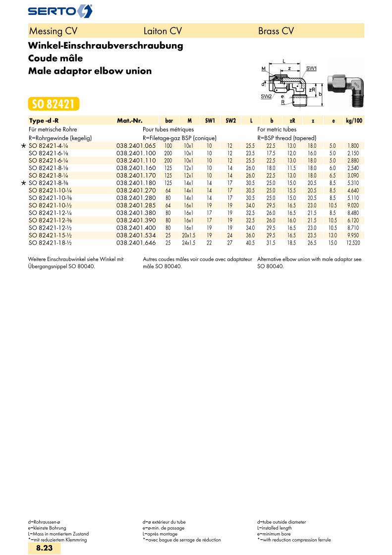
Winkel-EinschraubverschraubungCoude mâleMale adaptor elbow union
SO 82421Type -d -R Mat.-Nr. bar M SW1 SW2 L b zR z e kg/100Für metrische Rohre Pour tubes métriques For metric tubesR=Rohrgewinde (kegelig) R=Filetage-gaz BSP (conique) R=BSP thread (tapered)
SO 82421-4-1/4 038.2401.065 100 10x1 10 12 25.5 22.5 13.0 18.0 5.0 1.800 SO 82421-6-1/8 038.2401.100 200 10x1 10 12 23.5 17.5 12.0 16.0 5.0 2.150 SO 82421-6-1/4 038.2401.110 200 10x1 10 12 25.5 22.5 13.0 18.0 5.0 2.880 SO 82421-8-1/8 038.2401.160 125 12x1 10 14 26.0 18.0 11.5 18.0 6.0 2.540 SO 82421-8-1/4 038.2401.170 125 12x1 10 14 26.0 22.5 13.0 18.0 6.5 3.090
SO 82421-8-3/8 038.2401.180 125 14x1 14 17 30.5 25.0 15.0 20.5 8.5 5.310 SO 82421-10-1/4 038.2401.270 64 14x1 14 17 30.5 25.0 15.5 20.5 8.5 4.640 SO 82421-10-3/8 038.2401.280 80 14x1 14 17 30.5 25.0 15.0 20.5 8.5 5.110 SO 82421-10-1/2 038.2401.285 64 16x1 19 19 34.0 29.5 16.5 23.0 10.5 9.020 SO 82421-12-1/4 038.2401.380 80 16x1 17 19 32.5 26.0 16.5 21.5 8.5 8.480 SO 82421-12-3/8 038.2401.390 80 16x1 17 19 32.5 26.0 16.0 21.5 10.5 6.120 SO 82421-12-1/2 038.2401.400 80 16x1 19 19 34.0 29.5 16.5 23.0 10.5 8.710 SO 82421-15-1/2 038.2401.534 25 20x1.5 19 24 36.0 29.5 16.5 23.5 13.0 9.950 SO 82421-18-1/2 038.2401.646 25 24x1.5 22 27 40.5 31.5 18.5 26.5 15.0 12.520
Weitere Einschraubwinkel siehe Winkel mit Übergangsnippel SO 80040.
Autres coudes mâles voir coude avec adaptateur mâle SO 80040.
Alternative elbow union with male adaptor see SO 80040.
Messing CV Laiton CV Brass CV
d=Rohraussen-øe=kleinste BohrungL=Mass in montiertem Zustand*=mit reduziertem Klemmring
d=ø extérieur du tubee=ø-min. de passageL=après montage*=avec bague de serrage de réduction
d=tube outside diameterL=installed lengthe=minimum bore*=with reduction compression ferrule
8.23

EinstellwinkelCoude orientableAdjustable elbow union
SO 82621Type -d -Ad Mat.-Nr. bar M SW1 SW2 L f zA z e kg/100
SO 82621-4-A6 038.2600.045 100 10x1 10 12 23.5 11.0 17.5 16.0 4.0 1.980 SO 82621-6-A6 038.2600.060 200 10x1 10 12 23.5 11.0 17.5 16.0 4.0 1.870
SO 82621-6-A8 038.2600.063 200 12x1 10 14 26.0 13.0 21.0 18.0 6.0 2.600 SO 82621-8-A8 038.2600.080 125 12x1 10 14 26.0 13.0 21.0 18.0 6.0 2.460
SO 82621-8-A10 038.2600.083 125 14x1 14 17 30.5 16.0 25.0 20.5 8.0 4.180 SO 82621-10-A10 038.2600.100 80 14x1 14 17 30.5 16.0 25.0 20.5 8.0 3.990
SO 82621-10-A12 038.2600.103 80 16x1 17 19 32.5 17.0 26.5 21.5 9.0 5.780 SO 82621-12-A12 038.2600.120 80 16x1 17 19 32.5 17.0 26.5 21.5 9.0 5.500 SO 82621-15-A15 038.2600.150 25 20x1.5 19 24 36.0 18.0 29.0 23.5 12.0 8.550
SO 82621-15-A18 038.2600.156 25 24x1.5 22 27 40.5 18.0 33.5 26.5 15.0 13.280 SO 82621-18-A18 038.2600.180 25 24x1.5 22 27 40.5 18.0 33.5 26.5 15.0 12.530
Anwendungsbeispiele: Exemples d‘utilisation: Sample combinations:
Der Einstellwinkel SO 82621 ergibt im Zusammenhang mit unserem Armaturenanschluss SO 80021 einen einstellbaren Winkelanschluss.Gegenüber dem Einschraubwinkel lässt sich diese Kombination einfacher einstellen, da Einschrauben und Ausrichten getrennt voneinan-der vorgenommen werden.
L’assemblage du SO 82621 et d’un écrou SO 80021 donne un coude orientable. Par rapport au coude mâle, cette combinai-son permet un positionnement plus facile, car l’emboîtement et l’alignement s’ajustent séparé-ment.
In combination with our nut connection SO 80021 this elbow forms an adjustable female adaptor elbow. In contrast to the simple male adaptor elbow union, this combination is easier to adjust, since screw-on and aligning are performed separately.
Messing CV Laiton CV Brass CV
d=Rohraussen-øAd=Aussen-ø der Andrehunge=kleinste BohrungL=Mass in montiertem Zustand*=mit reduziertem Klemmring
d=ø extérieur du tubeAd=ø extérieur de la portée cylindriquee=ø-min. de passageL=après montage*=avec bague de serrage de reduction
d=tube outside diameterAd=outside diameter of cyl. Stube=minimum boreL=installed length*=with reduction compression ferrule
8.24
i
s
3F
4M
4G
5
5L
6
7
8
9
10
11
12

Winkel-SchottverschraubungDurchführungslänge max. 5mm
Union double pour passage de cloisonpour cloison max. 5 mm
Panel mount unionmax. panel thickness 5 mm
SO 82721Type -d Mat.-Nr. bar M SW1 SW2 SW3 L L1 w z1 z e kg/100
SO 82721-4 038.2700.040 100 10x1 10 12 14 25.5 40.5 14.0 19.0 18.0 4.0 4.270 SO 82721-6 038.2700.060 200 10x1 10 12 14 25.5 40.5 14.0 19.0 18.0 4.0 4.160 SO 82721-8 038.2700.080 125 12x1 11 14 17 28.5 45.0 17.0 20.0 20.5 6.0 6.480 SO 82721-10 038.2700.100 80 14x1 14 17 19 33.5 49.0 18.0 21.0 23.5 8.0 9.560 SO 82721-12 038.2700.120 80 16x1 14 19 19 34.5 50.0 18.0 21.0 23.5 9.0 10.640 SO 82721-15 038.2700.150 25 20x1.5 19 24 27 38.0 57.0 20.0 24.5 25.5 12.5 18.300
Weitere Reduktionen siehe SO 81821Sechskantmutter siehe SO 80006
Autres réductions voir SO 81821Ecrou à six pans voir SO 80006
Alternative reductions see SO 81821Hexagon nut see SO 80006
T-VerschraubungTéTee union
SO 83021Type -d Mat.-Nr. bar M SW1 SW2 L z e kg/100 SO 83021-6 038.3000.060 200 10x1 10 12 23.5 16.0 4.5 4.240SO 83021-8 038.3000.080 125 12x1 10 14 26.0 18.0 6.5 5.590SO 83021-10 038.3000.100 80 14x1 14 17 30.5 20.5 8.5 8.840SO 83021-12 038.3000.120 80 16x1 17 19 32.5 21.5 10.5 11.320SO 83021-15 038.3000.150 25 20x1.5 19 24 36.0 23.5 13.0 18.750SO 83021-18 038.3000.180 25 24x1.5 22 27 40.5 26.5 15.0 25.600
Messing CV Laiton CV Brass CV
d=Rohraussen-øe=kleinste BohrungL=Mass in montiertem Zustand*=mit reduziertem Klemmring
d=ø extérieur du tubee=ø-min. de passageL=après montage*=avec bague de serrage de reduction
d=tube outside diametere=minimum boreL=installed length*=with reduction compression ferrule
8.25

Einstellbare T-VerschraubungTé orientableAdjustable tee union
SO 83621 TType -d -Ad -d3 Mat.-Nr. bar M SW1 SW2 L f zA z e kg/100
SO 83621-4-A6-4 038.3600.045 200 10x1 10 12 23.5 12.0 17.5 16.0 4.0 3.540 SO 83621-6-A6-6 038.3600.060 200 10x1 10 12 23.5 12.0 17.5 16.0 4.0 3.160 SO 83621-8-A8-8 038.3600.080 125 12x1 10 14 26.0 14.0 23.0 18.0 6.0 4.230 SO 83621-10-A10-10 038.3600.100 80 14x1 14 17 30.5 16.0 25.5 20.5 7.5 6.970
Anwendungsbeispiele: Exemples d‘utilisation: Sample combinations:
Die T-Verschraubung mit Einstellzapfen SO 83621 ergibt im Zusammenhang mit unse-rem Armaturenanschluss SO 80021 eine einstell-bare T-Kombination.
Kombinationsbeispiele:Gegenüber dem Einschraub-T lässt sich diese Kombination einfacher einstellen, da Einschrauben und Ausschrauben getrennt voneinander vorgenommen werden.
L‘assemblage du SO 83621 et d‘un écrou SO 80021 donne un Té orientable.
Exemples d‘utilisation:Par rapport à un Té cette combinaison permet un positionnement plus facile. L‘emboîtement et l‘alignement se font séparément.
In combination with our nut connection SO 80021 the adjustable Tee union SO 83621 forms an adjustable female adap-tor Tee union.
Sample combinations:In contrast to the simple male adaptor Tee union, this combination is easier to adjust, since srew-on and aligning are performed separately.
Einstellbare L-VerschraubungL orientableAdjustable L union
SO 83621 LType -Ad -d2 -d3 Mat.-Nr. bar M SW1 SW2 L f zA z e kg/100
SO 83621-A6-4-4 038.3610.045 200 10x1 10 12 23.5 12.0 18.0 16.0 4.0 3.600 SO 83621-A6-6-6 038.3610.060 200 10x1 10 12 23.5 12.0 18.0 16.0 4.0 3.220 SO 83621-A8-8-8 038.3610.080 125 12x1 10 14 26.0 14.0 23.0 18.0 6.0 4.260 SO 83621-A10-10-10 038.3610.100 80 14x1 14 17 30.5 16.5 26.0 20.5 8.0 7.000
Messing CV Laiton CV Brass CV
d=Rohraussen-øAd=Aussen-ø der Andrehunge=kleinste BohrungL=Mass in montiertem Zustand*=mit reduziertem Klemmring
d=ø extérieur du tubeAd=ø extérieur de la portée cylindriquee=ø-min. de passageL=après montage*=avec bague de serrage de reduction
d=tube outside diameterAd=outside diameter of cyl. Stube=minimum boreL=installed length*=with reduction compression ferrule
8.26
i
s
3F
4M
4G
5
5L
6
7
8
9
10
11
12

T-EinschraubverschraubungTé mâleMale adaptor Tee union
SO 83721 TType -d -R -d3 Mat.-Nr. bar M SW1 SW2 L zR z e kg/100 R=Rohrgewinde (kegelig) R=Filetage-gaz BSP (conique) R=BSP thread (tapered)
SO 83721-4-1/8-4 038.3701.040 125 8x1 10 10 22.0 10.5 16.0 3.5 2.350 SO 83721-4-1/4-4 038.3701.045 125 10x1 10 12 25.5 13.0 18.0 4.5 4.110 SO 83721-5-1/8-5 038.3701.070 125 8x1 10 10 22.5 10.5 16.0 3.5 2.330
SO 83721-5-1/4-5 038.3701.075 125 10x1 10 12 25.5 13.0 18.0 4.5 4.060 SO 83721-6-1/8-6 038.3701.100 200 10x1 10 12 23.5 11.0 16.0 4.5 3.240 SO 83721-6-1/4-6 038.3701.110 200 10x1 10 12 25.5 13.0 18.0 4.5 4.000 SO 83721 8-1/4-8 038.3701.170 125 12x1 10 14 26.0 13.0 18.0 6.5 4.730 SO 83721-10-1/4-10 038.3701.270 80 14x1 14 17 30.5 15.5 20.5 8.5 7.900
Messing CV Laiton CV Brass CV
d=Rohraussen-øe=kleinste BohrungL=Mass in montiertem Zustand*=mit reduziertem Klemmring
d=ø extérieur du tubee=ø-min. de passageL=après montage*=avec bague de serrage de réduction
d=tube outside diametere=minimum boreL=installed length*=with reduction compression ferrule
8.27

ReduziermuffeRéduction femelle-femelleFemale reduction socket
SO 80031Type -G -G2 Mat.-Nr. SW L b c D f kg/100G=Rohrgewinde (zylindrisch) G=Filetage-gaz BSP (cylindrique) G=BSP thread (straight)G2=Rohrgewinde (zylindrisch) G2=Filetage-gaz BSP (cylindrique) G2=BSP thread (straight)SO 80031-1/8-1/8 036.0311.042 14 16.0 8.0 8.0 13.8 6.0 1.240SO 80031-1/8-1/4 036.0311.044 17 19.0 11.0 9.0 16.8 8.0 2.170SO 80031-1/4-1/4 036.0311.104 17 18.0 9.0 9.0 16.8 7.0 1.710SO 80031-1/4-3/8 036.0311.106 22 21.0 12.0 10.0 21.8 9.0 4.060SO 80031-1/4-1/2 036.0311.108 27 23.0 14.0 12.0 26.8 9.0 6.900SO 80031-3/8-3/8 036.0311.166 22 19.0 9.5 10.0 21.8 7.0 3.090SO 80031-3/8-1/2 036.0311.168 27 23.5 14.0 12.0 27.0 9.5 6.520SO 80031-1/2-1/2 036.0311.228 27 23.0 11.5 12.0 26.8 9.0 5.450SO 80031-3/4-1/2 036.0311.288 32 28.5 11.5 13.0 31.8 13.5 9.870
ReduziernippelEinschraubgewinde kegelig
Réduction femelle-mâleFiletage conique
Male reduction nippleTapered adaptor thread
SO 80041Type -G -R2 Mat.-Nr. SW L b c z kg/100G=Rohrgewinde (zylindrisch) G=Filetage-gaz BSP (cylindrique) G=BSP thread (straight)R2=Rohrgewinde (kegelig) R2=Filetage-gaz BSP (conique) R2=BSP thread (tapered)SO 80041-1/8-1/8 036.0411.042 14 21.0 8.0 13.0 14.5 2.100SO 80041-1/8-1/4 036.0411.044 14 17.5 8.0 5.5 8.0 1.060SO 80041-1/8-1/2 036.0411.048 22 23.0 8.0 7.0 10.0 3.970SO 80041-1/4-1/8 036.0411.102 17 22.0 9.0 8.5 15.5 1.630SO 80041-1/4-3/8 036.0411.106 17 20.0 9.0 7.5 10.0 1.690SO 80041-1/4-1/2 036.0411.108 22 23.0 9.0 7.0 10.0 3.590SO 80041-3/8-1/2 036.0411.168 22 23.0 9.5 7.0 10.0 2.740SO 80041-1/2-3/4 036.0411.232 27 27.5 11.5 11.0 13.0 5.133
Bei der Bestellung bitte G und R2 nicht verwech-seln.
Lors de la commande ne pas confondre G et R2. Please do not confuse G and R2 when orde-ring.
Messing CV Laiton CV Brass CV
8.28
i
s
3F
4M
4G
5
5L
6
7
8
9
10
11
12

Reduziernippel NPT-REinschraubgewinde kegelig
Réduction femelle-mâle NPT-RFiletage conique
Male reduction nipple NPT-RTapered adaptor thread
SO 80041 NPT RType -RNPT -R2 Mat.-Nr. SW L b c z kg/100RNPT=NPT Gewinde RNPT=Filetage NPT RNPT=NPT threadR2=Rohrgewinde (kegelig) R2=Filetage-gaz BSP (conique) R2=BSP thread (tapered)SO 80041-1/8 NPT-1/8 036.0414.042 14 21.0 6.5 13.0 14.5 1.470SO 80041-1/8 NPT-1/4 036.0414.044 14 18.0 6.6 6.0 8.0 1.130SO 80041-1/4 NPT-1/4 036.0414.104 17 29.5 9.5 17.5 20.0 2.740SO 80041-1/4 NPT-3/8 036.0414.106 17 19.0 9.5 7.0 9.0 1.650SO 80041-1/2 NPT-1/2 036.0414.228 27 38.0 12.5 22.0 25.0 8.310
VerschlussschraubeBouchon d‘obturationScrew plug
SO 80371Type -R Mat.-Nr. SW L b kg/100R=Rohrgewinde (kegelig) R=Filetage-gaz BSP (conique) R=BSP thread (tapered) SO 80371-1/8 036.0711.020 5 8.0 5.5 0.340SO 80371-1/4 036.0711.040 7 10.0 7.5 0.750SO 80371-3/8 036.0711.060 8 10.0 6.5 1.320SO 80371-1/2 036.0711.080 10 10.0 6.5 1.940
EinschraubtülleDouille cannelée à visserMale adaptor hose nozzle
SO 80511Type -d1 -R Mat.-Nr. SW L b e kg/100R=Rohrgewinde (kegelig) R=Filetage-gaz BSP (conique) R=BSP thread (tapered) SO 80511-6-1/8 036.0511.100 10 29.0 12.0 4.0 0.730SO 80511-6-1/4 036.0511.110 14 34.5 12.0 4.0 1.920SO 80511-8-1/4 036.0511.170 14 34.5 12.0 6.0 1.690SO 80511-10-1/4 036.0511.270 14 36.5 14.0 7.0 1.640SO 80511-13-3/8 036.0511.450 17 39.0 15.0 10.0 2.910
Messing CV Laiton CV Brass CV
8.29
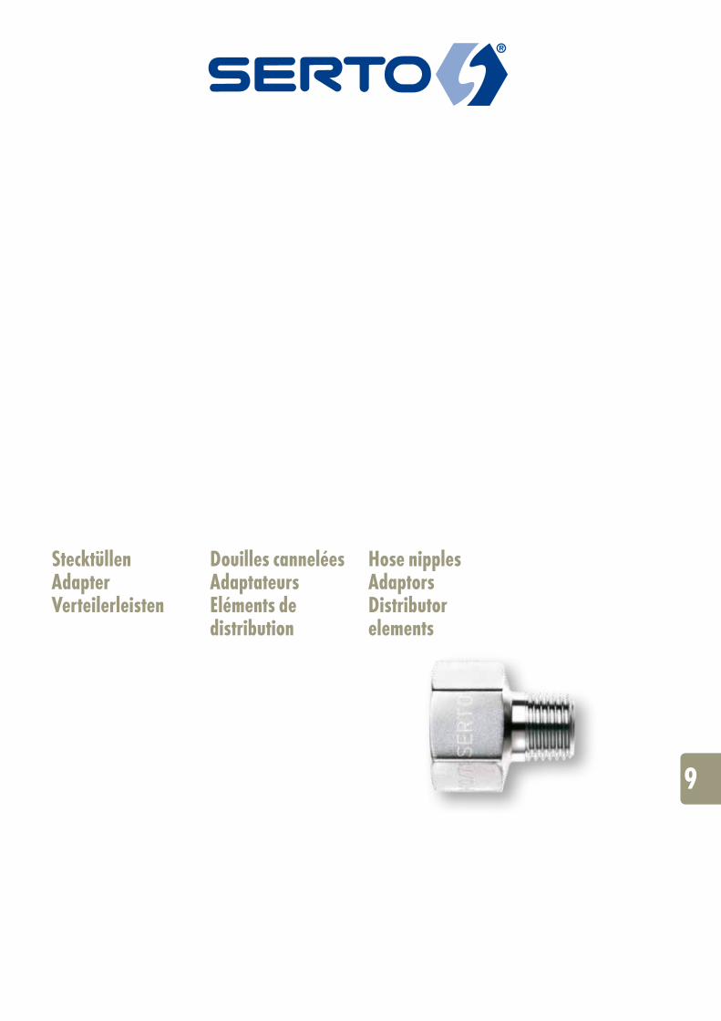
9
Stecktüllen Adapter Verteilerleisten
Douilles cannelées Adaptateurs Eléments de distribution
Hose nipples Adaptors Distributor elements
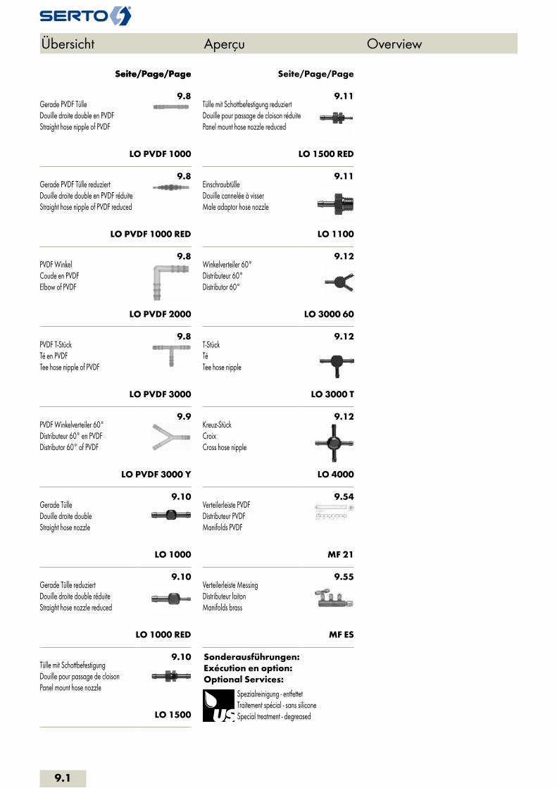
9.8Gerade PVDF TülleDouille droite double en PVDFStraight hose nipple of PVDF
LO PVDF 1000
9.8Gerade PVDF Tülle reduziertDouille droite double en PVDF réduiteStraight hose nipple of PVDF reduced
LO PVDF 1000 RED
9.8PVDF WinkelCoude en PVDFElbow of PVDF
LO PVDF 2000
9.8PVDF T-StückTé en PVDFTee hose nipple of PVDF
LO PVDF 3000
9.9PVDF Winkelverteiler 60°Distributeur 60° en PVDFDistributor 60° of PVDF
LO PVDF 3000 Y
9.10Gerade TülleDouille droite doubleStraight hose nozzle
LO 1000
9.10Gerade Tülle reduziertDouille droite double réduiteStraight hose nozzle reduced
LO 1000 RED
9.10Tülle mit SchottbefestigungDouille pour passage de cloisonPanel mount hose nozzle
LO 1500
9.11Tülle mit Schottbefestigung reduziertDouille pour passage de cloison réduitePanel mount hose nozzle reduced
LO 1500 RED
9.11EinschraubtülleDouille cannelée à visserMale adaptor hose nozzle
LO 1100
9.12Winkelverteiler 60°Distributeur 60°Distributor 60°
LO 3000 60
9.12T-StückTéTee hose nipple
LO 3000 T
9.12Kreuz-StückCroixCross hose nipple
LO 4000
9.54Verteilerleiste PVDFDistributeur PVDFManifolds PVDF
MF 21
9.55Verteilerleiste MessingDistributeur laitonManifolds brass
MF ES
Sonderausführungen:Exécution en option:Optional Services:
Spezialreinigung - entfettetTraitement spécial - sans siliconeSpecial treatment - degreased
Seite/Page/Page Seite/Page/PageSeite/Page/Page
Übersicht Aperçu Overview
9.1

Adapter PVDFAdaptateurs PVDFAdaptors PVDF
9.14ReduziermuffeRéduction femelle-femelleFemale reduction socket
SO 20031
9.14ReduziernippelRéduction femelle-mâleMale reduction nipple
SO 20041
9.15Sechskant-VerschlussschraubeBouchon mâle à 6 pansMale hexagon plug
SO 20371
9.15EinschraubtülleDouille cannelée à visserMale adaptor hose nozzle
SO 20511
9.16Doppelnippel konisch-konischMamelon mâle-mâle conique-coniqueMale adaptor tapered-tapered
SO 21109
Adapter Kunststoff PAAdaptateurs plastique PAAdaptors plastic PA
9.17EinschraubtülleDouille cannelée à visserMale adaptor hose nozzle
SO 30511
Sonderausführungen:Exécution en option:Optional Services:
Spezialreinigung - entfettetTraitement spécial - sans siliconeSpecial treatment - degreased
Vorbeschichtete Gewinde mit Loctite 5061Filetages pré enduits avec Loctite 5061Pre-coated threads with Loctite 5061
Vorbeschichtete Gewinde PTFE-Band umwickeltFiletages pré enduits avec ruban en PTFEPre-coated threads with PTFE-tape
Seite/Page/Page Seite/Page/Page
Übersicht Aperçu Overview
9.2
i
s
3F
4M
4G
5
5L
6
7
8
9
10
11
12
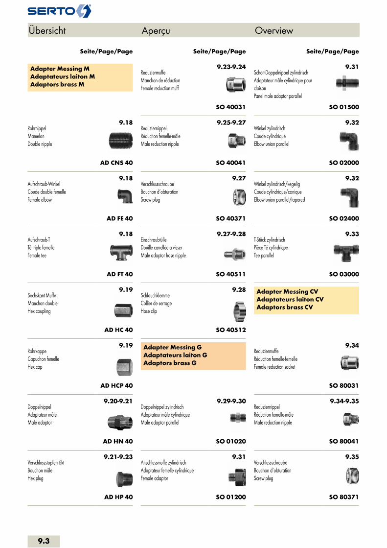
Adapter Messing MAdaptateurs laiton MAdaptors brass M
9.18RohrnippelMamelonDouble nipple
AD CNS 40
9.18Aufschraub-WinkelCoude double femelleFemale elbow
AD FE 40
9.18Aufschraub-TTé triple femelleFemale tee
AD FT 40
9.19Sechskant-MuffeManchon doubleHex coupling
AD HC 40
9.19RohrkappeCapuchon femelleHex cap
AD HCP 40
9.20-9.21DoppelnippelAdaptateur mâleMale adaptor
AD HN 40
9.21-9.23Verschlussstopfen 6ktBouchon mâleHex plug
AD HP 40
9.23-9.24ReduziermuffeManchon de réductionFemale reduction muff
SO 40031
9.25-9.27ReduziernippelRéduction femelle-mâleMale reduction nipple
SO 40041
9.27VerschlussschraubeBouchon d‘obturationScrew plug
SO 40371
9.27-9.28EinschraubtülleDouille canellèe a visserMale adaptor hose nipple
SO 40511
9.28SchlauchklemmeCollier de serrageHose clip
SO 40512
Adapter Messing GAdaptateurs laiton GAdaptors brass G
9.29-9.30Doppelnippel zylindrischAdaptateur mâle cylindriqueMale adaptor parallel
SO 01020
9.31Anschlussmuffe zylindrischAdaptateur femelle cylindriqueFemale adaptor
SO 01200
9.31Schott-Doppelnippel zylindrischAdaptateur mâle cylindrique pour cloisonPanel male adaptor parallel
SO 01500
9.32Winkel zylindrischCoude cylindriqueElbow union parallel
SO 02000
9.32Winkel zylindrisch/kegeligCoude cylindrique/coniqueElbow union parallel/tapered
SO 02400
9.33T-Stück zylindrischPièce Té cylindriqueTee parallel
SO 03000
Adapter Messing CVAdaptateurs laiton CVAdaptors brass CV
9.34ReduziermuffeRéduction femelle-femelleFemale reduction socket
SO 80031
9.34-9.35ReduziernippelRéduction femelle-mâleMale reduction nipple
SO 80041
9.35VerschlussschraubeBouchon d‘obturationScrew plug
SO 80371
Seite/Page/Page Seite/Page/Page Seite/Page/Page
Übersicht Aperçu Overview
9.3

9.35EinschraubtülleDouille cannelée à visserMale adaptor hose nozzle
SO 80511
Sonderausführungen:Exécution en option:Optional Services:
Spezialreinigung - entfettetTraitement spécial - sans siliconeSpecial treatment - degreased
Vorbeschichtete Gewinde mit Loctite 5061Filetages pré enduits avec Loctite 5061Pre-coated threads with Loctite 5061
Vorbeschichtete Gewinde PTFE-Band umwickeltFiletages pré enduits avec ruban en PTFEPre-coated threads with PTFE-tape
Chemisch vernickeltNickelage chimiqueChemical nickel-plated
Messing bleifreiLaiton sans plombUnleaded brass
Seite/Page/Page
Übersicht Aperçu Overview
9.4
i
s
3F
4M
4G
5
5L
6
7
8
9
10
11
12

Adapter EdelstahlAdaptateurs inoxAdaptors stainless steel
9.37DoppelnippelMamelon doubleHex nipple
AD HN 50
9.38Doppelnippel reduziertMamelon double réduitHex reducing nipple
AD HRN 50
9.38RohrdoppelnippelAdaptateur mâleBarrel nipple
AD CN 50
9.39RohrnippelMamelonDouble nipple
AD CNS 50
9.39RohranschweissnippelRaccord à souderWeld-on nipple
AD CNW 50
9.40AdapterAdaptateurAdapter
AD A 50
9.40Adapter reduziertAdaptateur réduitReducing adapter
AD RA 50 G-R
9.41-9.43ReduziernippelRéductionHex bushing
AD RB 50 G-R
9.44MuffeManchonAdaptor
AD C 50
9.44Halbe MuffeManchon courtCoupling short
AD CS 50
9.45HochdruckanschweissmuffeManchon haute pression à souderHigh-pressure weld-on adaptor
AD FCW 50
9.45Sechskant-MuffeManchon doubleHex coupling
AD HC 50
9.45Sechskant-Muffe reduziertManchon double réduitHex reducing coupling
AD HRC 50
9.46RohrkappeCapuchon femelleHex cap
AD HCP 50
9.46Verschlussstopfen 6ktBouchon mâleHex plug
AD HP 50
9.47Verschlussschraube mit Innen 6ktBouchon d‘obturationScrew Plug
AD SP 50
9.47VerschlussschraubeVis d‘extrémitéScrew plug
AD HPS 50
9.47Verschlussschraube mit O-RingBouchon d‘obturation avec joint toriqueScrew plug with O-Ring
AD HPO 50
9.48Verschlussschraube mit O-Ring (FPM)Bouchon d‘obturation avec joint torique (FPM)Screw plug with O-Ring (FPM)
AD HSPO 50
9.48Verschlussschraube mit Innen-6ktVis d‘extrémité six pans creuxHexagon socket screw plug
AD HSP 50
9.48Sechskant-KontermutterEcrou à six pansHex counternut
AD HCN 50
9.49Aufschraub-WinkelCoude double femelleFemale elbow
AD FE 51
9.49Einschraub-/Aufschraub-WinkelCoude femelle - mâleStreet elbow
AD SE 51
Seite/Page/Page Seite/Page/Page Seite/Page/Page
Übersicht Aperçu Overview
9.5
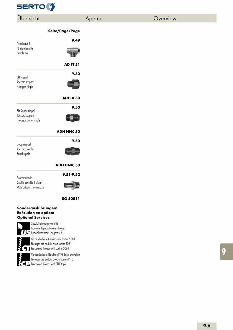
9.49Aufschraub-TTé triple femelleFemale Tee
AD FT 51
9.506kt-NippelRaccord six pansHexagon nipple
ADH A 50
9.506kt-DoppelnippelRaccord six pansHexagon barrel nipple
ADH HNC 50
9.50DoppelnippelRaccord doubleBarrel nipple
ADH HNIC 50
9.51-9.52EinschraubtülleDouille canellée à visserMale adaptor hose nozzle
SO 50511
Sonderausführungen:Exécution en option:Optional Services:
Spezialreinigung - entfettetTraitement spécial - sans siliconeSpecial treatment - degreased
Vorbeschichtete Gewinde mit Loctite 5061Filetages pré enduits avec Loctite 5061Pre-coated threads with Loctite 5061
Vorbeschichtete Gewinde PTFE-Band umwickeltFiletages pré enduits avec ruban en PTFEPre-coated threads with PTFE-tape
Seite/Page/Page
Übersicht Aperçu Overview
9.6
i
s
3F
4M
4G
5
5L
6
7
8
9
10
11
12

Eigenschaften, Besonderheiten- einfache und schnelle Montage- platzsparend- grosse Sortimentsvielfalt: - leichte Kunststoffausführung - durchflussoptimierte Messingausführung- preisgünstig
AnwendungZur Verbindung von Schläuchen z.B. in Mess- und Regeltechnik, Labor, Apparatebau, etc.
RohreGeeignet sind Rohre und Schläuche deren Werkstoffe genügend Elastizität aufweisen, um die Aufweitung auf Dauer schadlos zu vertra-gen, z.B. Polyurethan, Polyamid, PVC, Gummi.
WerkstoffKunststoff PVDF, Messing vernickelt
Betriebsdruck PNZulässiger Betriebsdruck bis PN 6 nach DIN EN 1333. Die anwendbaren Betriebsdrücke hängen von den verwendeten Schläuchen ab. Bei höheren Belastungen oder unge-nügender Spannkraft des Schlauches sind zusätzliche Befestigungen erforderlich (z.B. Schlauchschellen).
Généralités- connexions simples et vites- peu encombrants- grand assortiment: - exécution ténue en plastique - exécution en laiton avec coefficient de débit optimisé- avantageux
ApplicationPour connexion des tubes dans des systèmes de mesure et de réglage, dans des laboratoires et dans la construction d'appareils, etc.
TubesUtilisables sont des tuyaux à condition que le matériau présente une élasticité suffisante pour pouvoir supporter l’élargissement sans dommage, p.ex. des tubes en polyamide, poly-uréthane, PVC, caoutchouc.
MatériauxPlastique PVDF, Laiton nickelé
Pression de service PNPression de service admissible jusqu'à 6 bars. Les pressions de service dépendent du genre de tube utilisé. Lorsque les sollicitations sont élevées ou si le tuyau ne présente pas une force d’auto-serrage suffisante, il est nécessaire de prévoir un dispositif de fixation supplémentaire tel que des colliers de fixation par exemple.
Characteristics, specialities- simple and fast connections- space-saving- large product line: - lightweight plastics - brass, flow-optimized- inexpensive
ApplicationFor tube connection in gauging and regulating systems, laboratories, apparatus manufacturing, etc.
TubingSuitable are tubes where the material is suffici-ently elastic to stretch for an adequate length of time without suffering damage, i.e. polyurethan, polyamide, PVC, rubber.
MaterialPlastic PVDF, Nickel plated brass
Working pressure PNAdmissible working pressure up to PN 6 acc. to DIN EN 1333. The relevant operating pressure will depend on the tube used, however. Under high load conditions or where the natural tube tension is insufficient, additional fixures, e.g. hose clips, may be necessary.
Stecktüllen Douilles cannelées Hose nipples
9.7
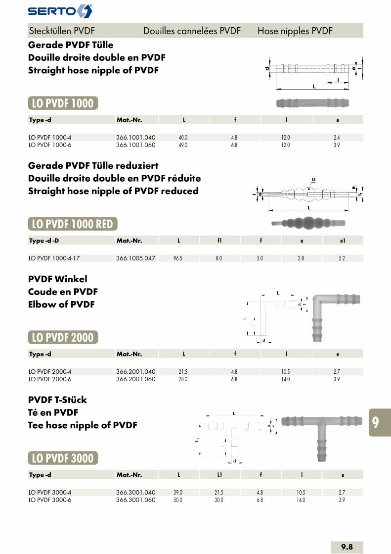
Gerade PVDF TülleDouille droite double en PVDFStraight hose nipple of PVDF
LO PVDF 1000Type -d Mat.-Nr. L f l e LO PVDF 1000-4 366.1001.040 40.0 4.8 12.0 2.4LO PVDF 1000-6 366.1001.060 49.0 6.8 12.0 3.9
Gerade PVDF Tülle reduziertDouille droite double en PVDF réduiteStraight hose nipple of PVDF reduced
LO PVDF 1000 REDType -d -D Mat.-Nr. L f1 f e e1 LO PVDF 1000-4-17 366.1005.047 96.5 8.0 5.0 2.8 5.2
PVDF WinkelCoude en PVDFElbow of PVDF
LO PVDF 2000Type -d Mat.-Nr. L f l e LO PVDF 2000-4 366.2001.040 21.5 4.8 10.5 2.7LO PVDF 2000-6 366.2001.060 28.0 6.8 14.0 3.9
PVDF T-StückTé en PVDFTee hose nipple of PVDF
LO PVDF 3000Type -d Mat.-Nr. L L1 f l e LO PVDF 3000-4 366.3001.040 39.0 21.5 4.8 10.5 2.7LO PVDF 3000-6 366.3001.060 50.0 30.0 6.8 14.0 3.9
Stecktüllen PVDF Douilles cannelées PVDF Hose nipples PVDF
9.8
i
s
3F
4M
4G
5
5L
6
7
8
9
10
11
12
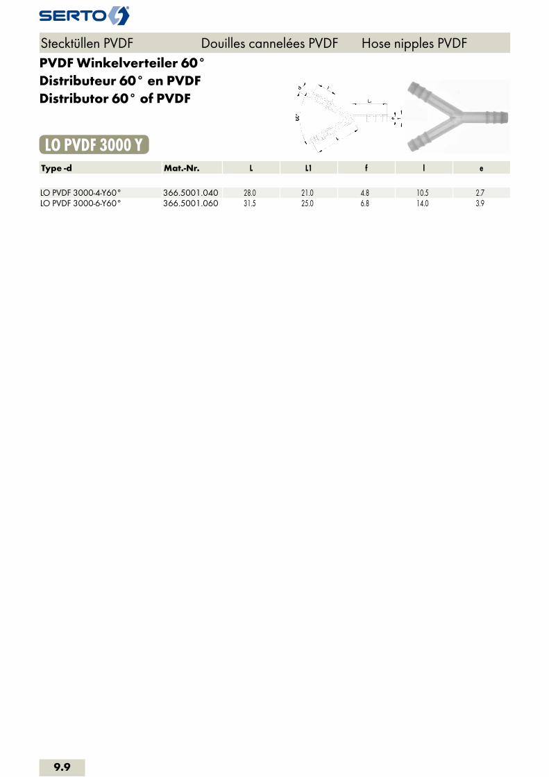
PVDF Winkelverteiler 60°Distributeur 60° en PVDFDistributor 60° of PVDF
LO PVDF 3000 YType -d Mat.-Nr. L L1 f l e LO PVDF 3000-4-Y60° 366.5001.040 28.0 21.0 4.8 10.5 2.7LO PVDF 3000-6-Y60° 366.5001.060 31.5 25.0 6.8 14.0 3.9
Stecktüllen PVDF Douilles cannelées PVDF Hose nipples PVDF
9.9
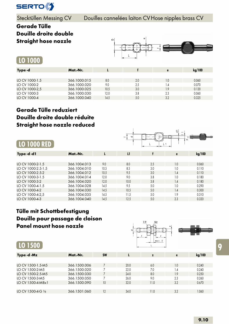
Gerade TülleDouille droite doubleStraight hose nozzle
LO 1000Type -d Mat.-Nr. L f e kg/100 LO CV 1000-1.5 366.1000.015 8.0 2.0 1.0 0.060LO CV 1000-2 366.1000.020 9.0 2.5 1.4 0.070LO CV 1000-2,5 366.1000.025 10.5 3.0 1.9 0.120LO CV 1000-3 366.1000.030 12.0 3.8 2.3 0.060LO CV 1000-4 366.1000.040 14.5 5.0 3.2 0.325
Gerade Tülle reduziertDouille droite double réduiteStraight hose nozzle reduced
LO 1000 REDType -d -d1 Mat.-Nr. L L1 f e kg/100 LO CV 1000-2-1.5 366.1004.013 9.0 8.0 2.5 1.0 0.060LO CV 1000-2.5-1.5 366.1004.010 10.5 8.5 3.0 1.0 0.110LO CV 1000-2.5-2 366.1004.012 10.5 9.5 3.0 1.4 0.110LO CV 1000-3-1.5 366.1004.014 12.0 9.0 3.8 1.0 0.180LO CV 1000-3-2 366.1004.020 12.0 10.0 3.8 1.4 0.180LO CV 1000-4-1.5 366.1004.028 14.5 9.5 5.0 1.0 0.290LO CV 1000-4-2 366.1004.030 14.5 10.5 5.0 1.4 0.300LO CV 1000-4-2,5 366.1004.035 14.5 11.5 5.0 1.9 0.310LO CV 1000-4-3 366.1004.040 14.5 12.5 5.0 2.3 0.320
Tülle mit SchottbefestigungDouille pour passage de cloisonPanel mount hose nozzle
LO 1500Type -d -Mz Mat.-Nr. SW L z e kg/100 LO CV 1500-1.5-M5 366.1500.006 7 20.0 6.0 1.0 0.240LO CV 1500-2-M5 366.1500.020 7 22.0 7.0 1.4 0.240LO CV 1500-2.5-M5 366.1500.030 7 24.0 8.0 1.9 0.250LO CV 1500-3-M5 366.1500.050 7 26.0 9.0 2.3 0.260LO CV 1500-4-M8x1 366.1500.090 10 32.0 11.0 3.2 0.670 LO CV 1500-4-G 1/8 366.1501.060 12 34.0 11.0 3.2 1.060
Stecktüllen Messing CV Douilles cannelées laiton CV Hose nipples brass CV
9.10
i
s
3F
4M
4G
5
5L
6
7
8
9
10
11
12
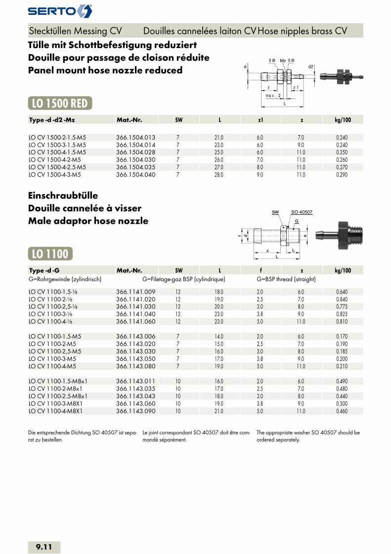
Tülle mit Schottbefestigung reduziertDouille pour passage de cloison réduitePanel mount hose nozzle reduced
LO 1500 REDType -d -d2 -Mz Mat.-Nr. SW L z1 z kg/100 LO CV 1500-2-1.5-M5 366.1504.013 7 21.0 6.0 7.0 0.240LO CV 1500-3-1.5-M5 366.1504.014 7 23.0 6.0 9.0 0.240LO CV 1500-4-1.5-M5 366.1504.028 7 25.0 6.0 11.0 0.250LO CV 1500-4-2-M5 366.1504.030 7 26.0 7.0 11.0 0.260LO CV 1500-4-2.5-M5 366.1504.035 7 27.0 8.0 11.0 0.270LO CV 1500-4-3-M5 366.1504.040 7 28.0 9.0 11.0 0.290
EinschraubtülleDouille cannelée à visserMale adaptor hose nozzle
SO 40507
LO 1100Type -d -G Mat.-Nr. SW L f z kg/100G=Rohrgewinde (zylindrisch) G=Filetage-gaz BSP (cylindrique) G=BSP thread (straight) LO CV 1100-1.5-1/8 366.1141.009 12 18.0 2.0 6.0 0.640LO CV 1100-2-1/8 366.1141.020 12 19.0 2.5 7.0 0.840LO CV 1100-2,5-1/8 366.1141.030 12 20.0 3.0 8.0 0.775LO CV 1100-3-1/8 366.1141.040 12 23.0 3.8 9.0 0.825LO CV 1100-4-1/8 366.1141.060 12 23.0 5.0 11.0 0.810 LO CV 1100-1.5-M5 366.1143.006 7 14.0 2.0 6.0 0.170LO CV 1100-2-M5 366.1143.020 7 15.0 2.5 7.0 0.190LO CV 1100-2,5-M5 366.1143.030 7 16.0 3.0 8.0 0.185LO CV 1100-3-M5 366.1143.050 7 17.0 3.8 9.0 0.200LO CV 1100-4-M5 366.1143.080 7 19.0 5.0 11.0 0.210 LO CV 1100-1.5-M8x1 366.1143.011 10 16.0 2.0 6.0 0.490LO CV 1100-2-M8x1 366.1143.035 10 17.0 2.5 7.0 0.480LO CV 1100-2.5-M8x1 366.1143.043 10 18.0 3.0 8.0 0.440LO CV 1100-3-M8X1 366.1143.060 10 19.0 3.8 9.0 0.500LO CV 1100-4-M8X1 366.1143.090 10 21.0 5.0 11.0 0.460
Die entsprechende Dichtung SO 40507 ist sepa-rat zu bestellen.
Le joint correspondant SO 40507 doit être com-mandé séparément.
The appropriate washer SO 40507 should be ordered separately.
Stecktüllen Messing CV Douilles cannelées laiton CV Hose nipples brass CV
9.11
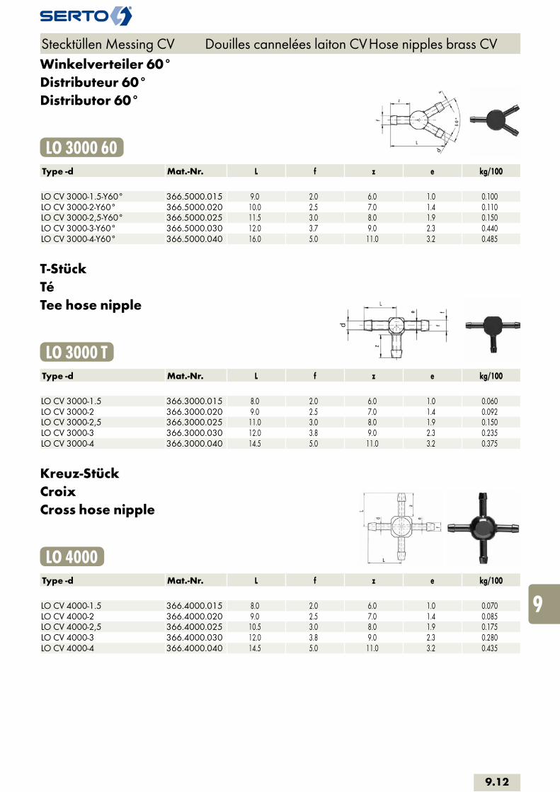
Winkelverteiler 60°Distributeur 60°Distributor 60°
LO 3000 60Type -d Mat.-Nr. L f z e kg/100 LO CV 3000-1.5-Y60° 366.5000.015 9.0 2.0 6.0 1.0 0.100LO CV 3000-2-Y60° 366.5000.020 10.0 2.5 7.0 1.4 0.110LO CV 3000-2,5-Y60° 366.5000.025 11.5 3.0 8.0 1.9 0.150LO CV 3000-3-Y60° 366.5000.030 12.0 3.7 9.0 2.3 0.440LO CV 3000-4-Y60° 366.5000.040 16.0 5.0 11.0 3.2 0.485
T-StückTéTee hose nipple
LO 3000 TType -d Mat.-Nr. L f z e kg/100 LO CV 3000-1.5 366.3000.015 8.0 2.0 6.0 1.0 0.060LO CV 3000-2 366.3000.020 9.0 2.5 7.0 1.4 0.092LO CV 3000-2,5 366.3000.025 11.0 3.0 8.0 1.9 0.150LO CV 3000-3 366.3000.030 12.0 3.8 9.0 2.3 0.235LO CV 3000-4 366.3000.040 14.5 5.0 11.0 3.2 0.375
Kreuz-StückCroixCross hose nipple
LO 4000Type -d Mat.-Nr. L f z e kg/100 LO CV 4000-1.5 366.4000.015 8.0 2.0 6.0 1.0 0.070LO CV 4000-2 366.4000.020 9.0 2.5 7.0 1.4 0.085LO CV 4000-2,5 366.4000.025 10.5 3.0 8.0 1.9 0.175LO CV 4000-3 366.4000.030 12.0 3.8 9.0 2.3 0.280LO CV 4000-4 366.4000.040 14.5 5.0 11.0 3.2 0.435
Stecktüllen Messing CV Douilles cannelées laiton CV Hose nipples brass CV
9.12
i
s
3F
4M
4G
5
5L
6
7
8
9
10
11
12

Eigenschaften, Besonderheiten- einfache Verbindungselemente mit Innen- und Aussengewinden, Anschlussstutzen und Tüllen- zahlreiche Bauformen- viele Kombinationsmöglichkeiten
AnwendungAnschluss an Gewinde sowie an Kunststoffschläuche niedrige bis mittlere Drücke.
Werkstoff PVDF, PA, Messing und Edelstahl
Généralités- éléments simples d‘assemblage avec des filetages intérieurs et extérieurs, avec des pièces de raccordement et des douilles- grand nombre de formes de construction- multiples possibilités de combinaisons de montages
ApplicationRaccordement aux filetages ainsi qu‘aux tuyaux en matière plastique pressions faibles à moyennes.
MatériauxPVDF, PA, laiton, acier inoxydable
Characteristics, specialities- simple connecting pieces with internal and external threads, nipples and hose nozzles- large number of construction versions- many possible combinations
ApplicationConnection to threads as well as to plastic hoses low to medium operating pressures.
MaterialPVDF, PA, brass, stainless steel
Adapter Adaptateur Adaptor
9.13
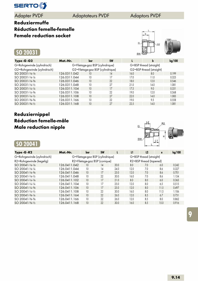
ReduziermuffeRéduction femelle-femelleFemale reduction socket
SO 20031Type -G -G2 Mat.-Nr. bar SW L b kg/100G=Rohrgewinde (zylindrisch) G=Filetage-gaz BSP (cylindrique) G=BSP thread (straight)G2=Rohrgewinde (zylindrisch) G2=Filetage-gaz BSP (cylindrique) G2=BSP thread (straight)SO 20031-1/8-1/8 126.0311.042 10 14 16.0 8.0 0.199SO 20031-1/8-1/4 126.0311.044 10 17 17.0 11.0 0.323SO 20031-1/8-3/8 126.0311.046 10 22 18.0 12.0 0.546SO 20031-1/8-1/2 126.0311.048 10 27 21.0 14.0 1.081SO 20031-1/4-1/4 126.0311.104 10 17 17.5 9.0 0.331SO 20031-1/4-3/8 126.0311.106 10 22 19.0 12.0 0.568SO 20031-1/4-1/2 126.0311.108 10 27 22.0 14.0 1.083SO 20031-3/8-3/8 126.0311.166 10 22 19.0 9.5 0.558SO 20031-3/8-1/2 126.0311.168 10 27 22.5 14.0 1.081
ReduziernippelRéduction femelle-mâleMale reduction nipple
SO 20041Type -G -R2 Mat.-Nr. bar SW L L1 L2 e kg/100G=Rohrgewinde (zylindrisch) G=Filetage-gaz BSP (cylindrique) G=BSP thread (straight)R2=Rohrgewinde (kegelig) R2=Filetage-gaz BSP (conique) R2=BSP thread (tapered)SO 20041-1/8-1/8 126.0411.042 10 14 20.0 8.0 7.0 6.0 0.242SO 20041-1/8-1/4 126.0411.044 10 14 24.0 12.0 7.0 8.6 0.327SO 20041-1/8-3/8 126.0411.046 10 17 25.0 12.0 7.0 8.6 0.701SO 20041-1/8-1/2 126.0411.048 10 22 30.0 16.0 7.0 8.6 1.154SO 20041-1/4-1/8 126.0411.102 10 17 21.0 8.0 8.0 6.0 0.363SO 20041-1/4-1/4 126.0411.104 10 17 25.0 12.0 8.0 6.5 0.515SO 20041-1/4-3/8 126.0411.106 10 17 25.0 12.0 8.0 11.5 0.497SO 20041-1/4-1/2 126.0411.108 10 22 30.0 16.0 8.0 11.5 1.106SO 20041-3/8-1/4 126.0411.164 10 22 26.0 12.0 8.5 6.7 0.731SO 20041-3/8-3/8 126.0411.166 10 22 26.0 12.0 8.5 8.0 0.862SO 20041-3/8-1/2 126.0411.168 10 22 30.0 16.0 8.5 15.0 0.916
Adapter PVDF Adaptateurs PVDF Adaptors PVDF
9.14
i
s
3F
4M
4G
5
5L
6
7
8
9
10
11
12

Sechskant-VerschlussschraubeBouchon mâle à 6 pansMale hexagon plug
SO 20371Type -R Mat.-Nr. SW L L1 kg/100R=Rohrgewinde (kegelig) R=Filetage-gaz BSP (conique) R=BSP thread (tapered) SO 20371-1/8 126.0721.020 10 13.0 8.0 0.141SO 20371-1/4 126.0721.040 14 18.5 12.0 0.379SO 20371-3/8 126.0721.060 17 19.0 12.0 0.356SO 20371-1/2 126.0721.080 22 24.0 16.0 1.810
EinschraubtülleDouille cannelée à visserMale adaptor hose nozzle
SO 20511Type -d1 -R Mat.-Nr. bar SW L a b e kg/100R=Rohrgewinde (kegelig) R=Filetage-gaz BSP (conique) R=BSP thread (tapered)
SO 20511-4-1/8 126.0511.060 10 10 24.0 13.0 8.0 3.0 0.157SO 20511-6-1/8 126.0511.100 10 10 30.0 13.0 12.0 4.0 0.201SO 20511-6-1/4 126.0511.110 10 14 35.5 18.5 12.0 4.0 0.438SO 20511-8-1/4 126.0511.170 10 14 35.5 18.5 12.0 6.0 0.456SO 20511-10-3/8 126.0511.280 10 17 38.0 19.0 14.0 7.0 0.764SO 20511-12-3/8 126.0511.390 10 17 38.0 19.0 14.0 10.0 0.649SO 20511-12-1/2 126.0511.400 10 22 43.0 24.0 14.0 10.0 1.262
Für die Schlauchsicherung verwenden Sie bitteunsere Schlauchklemme SO 40512(Stahl promatverzinkt).
d1 = Schlauchinnen-Øe = kleinste Bohrung
Afin d’assurer la bonne tenue des tuyaux, utilisernos colliers de serrage SO 40512(Acier zingué passivé).
d1 = Ø intérieur du tuyaue = Ø min. de passage
Please use our hose clip SO 40512(zinc promatised) for securing the hose.
d1 = hose inside diametere = minimum bore
Adapter PVDF Adaptateurs PVDF Adaptors PVDF
9.15

Doppelnippel konisch-konischMamelon mâle-mâle conique-coniqueMale adaptor tapered-tapered
SO 21109Type -R -R2 Mat.-Nr. SW L1 L2 L3 e kg/100R=Rohrgewinde (kegelig) R=Filetage-gaz BSP (conique) R=BSP thread (tapered)R2=Rohrgewinde (kegelig) R2=Filetage-gaz BSP (conique) R2=BSP thread (tapered)SO 21109-1/8k - 1/8k 126.0641.042 10 21.0 8.0 8.0 5.1 0.208SO 21109-1/8k - 1/4k 126.0641.044 14 26.5 8.0 12.0 5.1 0.449SO 21109-1/4k - 1/4k 126.0641.104 14 30.5 12.0 12.0 6.7 0.577SO 21109-1/4k - 3/8k 126.0641.106 17 31.0 12.0 12.0 6.7 0.817SO 21109-1/4k - 1/2k 126.0641.108 22 36.0 12.0 16.0 6.7 1.359SO 21109-3/8k - 3/8k 126.0641.166 17 30.0 12.0 12.0 8.0 0.935SO 21109-3/8k - 1/2k 126.0641.168 22 36.0 12.0 16.0 8.0 1.489SO 21109-1/2k - 1/2k 126.0641.228 22 40.0 16.0 16.0 12.0 1.727SO 21109-1/2k - 3/4k 126.0641.232 27 40.5 16.0 16.5 12.0 2.277
Adapter PVDF Adaptateurs PVDF Adaptors PVDF
9.16
i
s
3F
4M
4G
5
5L
6
7
8
9
10
11
12
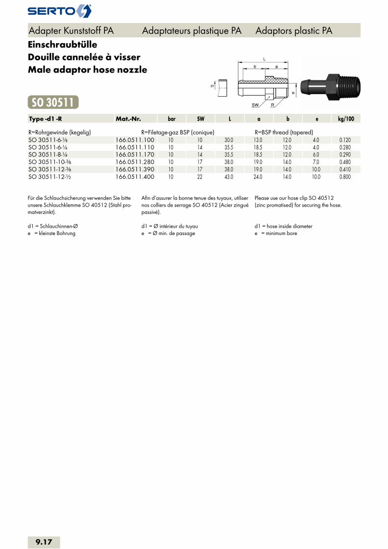
EinschraubtülleDouille cannelée à visserMale adaptor hose nozzle
SO 30511Type -d1 -R Mat.-Nr. bar SW L a b e kg/100 R=Rohrgewinde (kegelig) R=Filetage-gaz BSP (conique) R=BSP thread (tapered)SO 30511-6-1/8 166.0511.100 10 10 30.0 13.0 12.0 4.0 0.120SO 30511-6-1/4 166.0511.110 10 14 35.5 18.5 12.0 4.0 0.280SO 30511-8-1/4 166.0511.170 10 14 35.5 18.5 12.0 6.0 0.290SO 30511-10-3/8 166.0511.280 10 17 38.0 19.0 14.0 7.0 0.480SO 30511-12-3/8 166.0511.390 10 17 38.0 19.0 14.0 10.0 0.410SO 30511-12-1/2 166.0511.400 10 22 43.0 24.0 14.0 10.0 0.800
Für die Schlauchsicherung verwenden Sie bitte unsere Schlauchklemme SO 40512 (Stahl pro-matverzinkt).
d1 = Schlauchinnen-Øe = kleinste Bohrung
Afin d’assurer la bonne tenue des tuyaux, utiliser nos colliers de serrage SO 40512 (Acier zingué passivé).
d1 = Ø intérieur du tuyaue = Ø min. de passage
Please use our hose clip SO 40512(zinc promatised) for securing the hose.
d1 = hose inside diametere = minimum bore
Adapter Kunststoff PA Adaptateurs plastique PA Adaptors plastic PA
9.17

Rohrnippelkurz
Mameloncourt
Double nippleshort
AD CNS 40Type -G Mat.-Nr. L e SW kg/100G=Rohrgewinde (zylindrisch) G=Filetage-gaz BSP (cylindrique) G=BSP thread (straight) AD CNS 40-1/8 TAD.4180.042 20.0 6.5 0.480AD CNS 40-1/4 TAD.4180.104 20.0 8.5 0.940AD CNS 40-3/8 TAD.4180.166 20.0 10 1.490AD CNS 40-1/2 TAD.4180.228 25.0 12 3.200AD CNS 40-3/4 TAD.4180.292 26.0 17 4.670AD CNS 40-1 TAD.4180.414 33.0 25.0 8.420
Aufschraub-WinkelCoude double femelleFemale elbow
AD FE 40Type -G Mat.-Nr. L b D H kg/100G=Rohrgewinde (zylindrisch) G=Filetage-gaz BSP (cylindrique) G=BSP thread (straight) AD FE 40-1/8 TAD.4300.042 21.0 8.0 15.0 15.0 2.000AD FE 40-1/4 TAD.4300.104 30.0 10.0 22.0 19.0 4.380AD FE 40-3/8 TAD.4300.166 36.0 11.0 23.0 23.0 5.930AD FE 40-1/2 TAD.4300.228 39.0 12.0 27.0 25.0 7.430AD FE 40-3/4 TAD.4300.292 46.0 15.0 36.0 30.0 12.090AD FE 40-1 TAD.4300.414 57.0 16.0 42.0 35.0 21.100
Aufschraub-TTé triple femelleFemale tee
AD FT 40Type -G Mat.-Nr. L b D H kg/100G=Rohrgewinde (zylindrisch) G=Filetage-gaz BSP (cylindrique) G=BSP thread (straight) AD FT 40-1/8 TAD.4400.060 28.0 8.0 15.0 14.0 2.610AD FT 40-1/4 TAD.4400.160 35.0 10.0 21.0 17.5 5.680AD FT 40-3/8 TAD.4400.350 43.0 11.0 23.0 21.5 9.360AD FT 40-1/2 TAD.4400.450 48.0 12.0 27.0 24.0 9.700AD FT 40-3/4 TAD.4400.520 60.0 15.0 36.0 30.0 16.760AD FT 40-1 TAD.4400.650 68.0 16.0 42.0 34.0 25.850
Adapter Messing M Adaptateurs laiton M Adaptors brass M
9.18
i
s
3F
4M
4G
5
5L
6
7
8
9
10
11
12
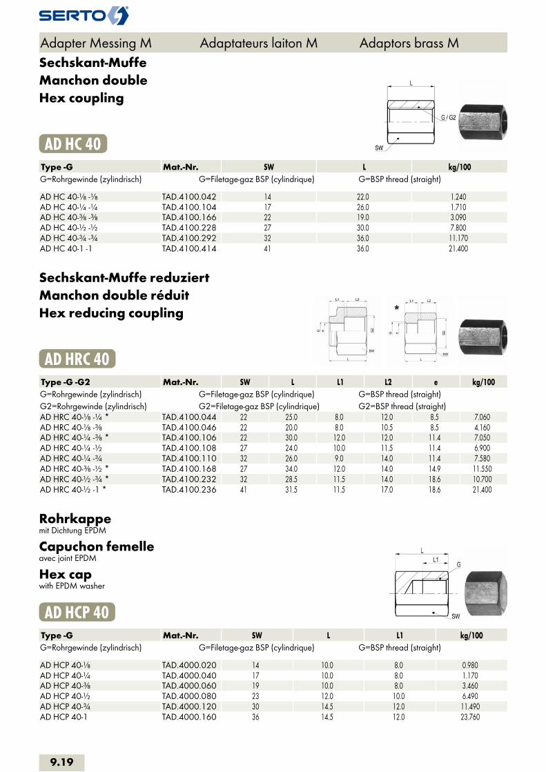
Sechskant-MuffeManchon doubleHex coupling
AD HC 40Type -G Mat.-Nr. SW L kg/100G=Rohrgewinde (zylindrisch) G=Filetage-gaz BSP (cylindrique) G=BSP thread (straight) AD HC 40-1/8 -1/8 TAD.4100.042 14 22.0 1.240AD HC 40-1/4 -1/4 TAD.4100.104 17 26.0 1.710AD HC 40-3/8 -3/8 TAD.4100.166 22 19.0 3.090AD HC 40-1/2 -1/2 TAD.4100.228 27 30.0 7.800AD HC 40-3/4 -3/4 TAD.4100.292 32 36.0 11.170AD HC 40-1 -1 TAD.4100.414 41 36.0 21.400
Sechskant-Muffe reduziertManchon double réduitHex reducing coupling
AD HRC 40Type -G -G2 Mat.-Nr. SW L L1 L2 e kg/100G=Rohrgewinde (zylindrisch) G=Filetage-gaz BSP (cylindrique) G=BSP thread (straight)G2=Rohrgewinde (zylindrisch) G2=Filetage-gaz BSP (cylindrique) G2=BSP thread (straight)AD HRC 40-1/8 -1/4 * TAD.4100.044 22 25.0 8.0 12.0 8.5 7.060AD HRC 40-1/8 -3/8 TAD.4100.046 22 20.0 8.0 10.5 8.5 4.160AD HRC 40-1/4 -3/8 * TAD.4100.106 22 30.0 12.0 12.0 11.4 7.050AD HRC 40-1/4 -1/2 TAD.4100.108 27 24.0 10.0 11.5 11.4 6.900AD HRC 40-1/4 -3/4 TAD.4100.110 32 26.0 9.0 14.0 11.4 7.580AD HRC 40-3/8 -1/2 * TAD.4100.168 27 34.0 12.0 14.0 14.9 11.550AD HRC 40-1/2 -3/4 * TAD.4100.232 32 28.5 11.5 14.0 18.6 10.700AD HRC 40-1/2 -1 * TAD.4100.236 41 31.5 11.5 17.0 18.6 21.400
Rohrkappemit Dichtung EPDM
Capuchon femelleavec joint EPDM
Hex capwith EPDM washer
AD HCP 40Type -G Mat.-Nr. SW L L1 kg/100G=Rohrgewinde (zylindrisch) G=Filetage-gaz BSP (cylindrique) G=BSP thread (straight) AD HCP 40-1/8 TAD.4000.020 14 10.0 8.0 0.980AD HCP 40-1/4 TAD.4000.040 17 10.0 8.0 1.170AD HCP 40-3/8 TAD.4000.060 19 10.0 8.0 3.460AD HCP 40-1/2 TAD.4000.080 23 12.0 10.0 6.490AD HCP 40-3/4 TAD.4000.120 30 14.5 12.0 11.490AD HCP 40-1 TAD.4000.160 36 14.5 12.0 23.760
Adapter Messing M Adaptateurs laiton M Adaptors brass M
9.19
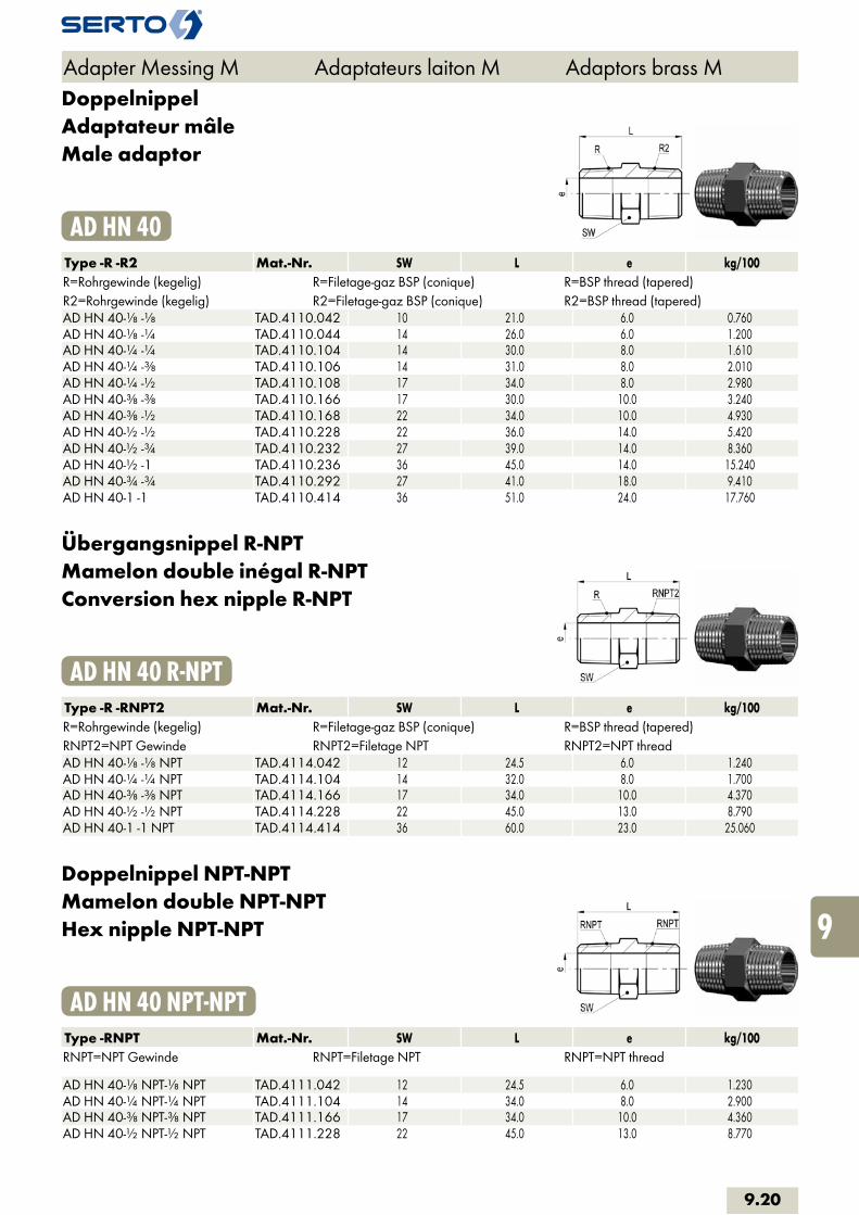
DoppelnippelAdaptateur mâleMale adaptor
AD HN 40Type -R -R2 Mat.-Nr. SW L e kg/100R=Rohrgewinde (kegelig) R=Filetage-gaz BSP (conique) R=BSP thread (tapered)R2=Rohrgewinde (kegelig) R2=Filetage-gaz BSP (conique) R2=BSP thread (tapered)AD HN 40-1/8 -1/8 TAD.4110.042 10 21.0 6.0 0.760AD HN 40-1/8 -1/4 TAD.4110.044 14 26.0 6.0 1.200AD HN 40-1/4 -1/4 TAD.4110.104 14 30.0 8.0 1.610AD HN 40-1/4 -3/8 TAD.4110.106 14 31.0 8.0 2.010AD HN 40-1/4 -1/2 TAD.4110.108 17 34.0 8.0 2.980AD HN 40-3/8 -3/8 TAD.4110.166 17 30.0 10.0 3.240AD HN 40-3/8 -1/2 TAD.4110.168 22 34.0 10.0 4.930AD HN 40-1/2 -1/2 TAD.4110.228 22 36.0 14.0 5.420AD HN 40-1/2 -3/4 TAD.4110.232 27 39.0 14.0 8.360AD HN 40-1/2 -1 TAD.4110.236 36 45.0 14.0 15.240AD HN 40-3/4 -3/4 TAD.4110.292 27 41.0 18.0 9.410AD HN 40-1 -1 TAD.4110.414 36 51.0 24.0 17.760
Übergangsnippel R-NPTMamelon double inégal R-NPTConversion hex nipple R-NPT
AD HN 40 R-NPTType -R -RNPT2 Mat.-Nr. SW L e kg/100R=Rohrgewinde (kegelig) R=Filetage-gaz BSP (conique) R=BSP thread (tapered)RNPT2=NPT Gewinde RNPT2=Filetage NPT RNPT2=NPT threadAD HN 40-1/8 -1/8 NPT TAD.4114.042 12 24.5 6.0 1.240AD HN 40-1/4 -1/4 NPT TAD.4114.104 14 32.0 8.0 1.700AD HN 40-3/8 -3/8 NPT TAD.4114.166 17 34.0 10.0 4.370AD HN 40-1/2 -1/2 NPT TAD.4114.228 22 45.0 13.0 8.790AD HN 40-1 -1 NPT TAD.4114.414 36 60.0 23.0 25.060
Doppelnippel NPT-NPTMamelon double NPT-NPTHex nipple NPT-NPT
AD HN 40 NPT-NPTType -RNPT Mat.-Nr. SW L e kg/100RNPT=NPT Gewinde RNPT=Filetage NPT RNPT=NPT thread AD HN 40-1/8 NPT-1/8 NPT TAD.4111.042 12 24.5 6.0 1.230AD HN 40-1/4 NPT-1/4 NPT TAD.4111.104 14 34.0 8.0 2.900AD HN 40-3/8 NPT-3/8 NPT TAD.4111.166 17 34.0 10.0 4.360AD HN 40-1/2 NPT-1/2 NPT TAD.4111.228 22 45.0 13.0 8.770
Adapter Messing M Adaptateurs laiton M Adaptors brass M
9.20
i
s
3F
4M
4G
5
5L
6
7
8
9
10
11
12

6kt-Doppelnippelbeidseitig 60°-Innenkonus
Raccord six pansà cône intérieur 60° des deux côtés
Hexagon barrel nipple60° internal taper on both sides
ADH HNC 40Type -G -G2 Mat.-Nr. SW L L1 L2 e kg/100G=Rohrgewinde (zylindrisch) G=Filetage-gaz BSP (cylindrique) G=BSP thread (straight)G2=Rohrgewinde (zylindrisch) G2=Filetage-gaz BSP (cylindrique) G2=BSP thread (straight)ADH HNC 40-1/4 496.4100.104 14 26.0 10.0 10.0 7.5 1.690ADH HNC 40-1/4 -3/8 496.4100.106 14 27.0 10.0 11.0 7.5 2.330ADH HNC 40-3/8 496.4100.166 17 28.0 11.0 11.0 8.5 3.160
Verschlussstopfen 6ktBouchon mâleHex plug
AD HP 40Type -R Mat.-Nr. SW L L1 kg/100R=Rohrgewinde (kegelig) R=Filetage-gaz BSP (conique) R=BSP thread (tapered) AD HP 40-1/8 TAD.4020.020 12 13.0 8.0 0.970AD HP 40-1/4 TAD.4020.040 14 18.0 12.0 2.060AD HP 40-3/8 TAD.4020.060 17 19.0 12.0 3.460AD HP 40-1/2 TAD.4020.080 22 22.0 14.0 6.490AD HP 40-3/4 TAD.4020.120 27 25.0 16.0 11.490AD HP 40-1 TAD.4020.160 36 31.0 20.0 23.760
Verschlussstopfen 6kt NPTBouchon mâle NPTHex plug NPT
AD HP 40 NPTType -RNPT Mat.-Nr. SW L L1 kg/100RNPT=NPT Gewinde RNPT=Filetage NPT RNPT=NPT thread AD HP 40-1/8 NPT TAD.4021.020 12 15.0 10.0 1.130AD HP 40-1/4 NPT TAD.4021.040 14 20.0 14.0 2.320AD HP 40-3/8 NPT TAD.4021.060 17 22.0 14.0 4.400AD HP 40-1/2 NPT TAD.4021.080 22 27.0 19.0 7.720AD HP 40-3/4 NPT TAD.4021.120 27 29.0 20.0 13.600
Adapter Messing M Adaptateurs laiton M Adaptors brass M
9.21

Verschlussschraubemit Aussen-6kt und Bund
Vis d‘extrémitésix pans extérieur
Screw plughexagon head
AD HPS 40Type -G Mat.-Nr. SW L L1 kg/100G=Rohrgewinde (zylindrisch) G=Filetage-gaz BSP (cylindrique) G=BSP thread (straight) AD HPS 40-1/8 TAD.4030.020 10 17.0 8.0 0.610AD HPS 40-1/4 TAD.4030.040 13 21.0 12.0 1.430AD HPS 40-3/8 TAD.4030.060 17 21.0 12.0 2.240AD HPS 40-1/2 TAD.4030.080 19 26.0 14.0 4.250AD HPS 40-3/4 TAD.4030.120 24 30.0 16.0 7.410
Verschlussschraube mit O-RingBouchon d‘obturation avec joint toriqueScrew plug with O-Ring
AD HPO 40Type -G Mat.-Nr. SW L L1 kg/100G=Rohrgewinde (zylindrisch) G=Filetage-gaz BSP (cylindrique) G=BSP thread (straight) AD HPO 40-1/8 TAD.4040.020 10 17.0 8.0 1.200AD HPO 40-1/4 TAD.4040.040 13 21.0 12.0 2.460AD HPO 40-3/8 TAD.4040.060 17 21.0 12.0 4.800AD HPO 40-1/2 TAD.4040.080 19 26.0 14.0 7.180AD HPO 40-3/4 TAD.4040.120 24 30.0 16.0 13.040
Verschlussschraube mit Innen-6ktBouchon d‘obturationScrew Plug
AD HSP 40Type -G Mat.-Nr. SW L L1 D kg/100G=Rohrgewinde (zylindrisch) G=Filetage-gaz BSP (cylindrique) G=BSP thread (straight) AD HSP 40-1/8 TAD.4070.020 5 11.0 8.0 14.0 0.610AD HSP 40-1/4 TAD.4070.040 6 15.0 12.0 18.0 1.430AD HSP 40-3/8 TAD.4070.060 8 15.0 12.0 22.0 2.240AD HSP 40-1/2 TAD.4070.080 10 18.0 14.0 26.0 4.250AD HSP 40-3/4 TAD.4070.120 12 20.0 16.0 32.0 7.410AD HSP 40-1 TAD.4070.160 17 21.0 16.0 39.0 11.000
Adapter Messing M Adaptateurs laiton M Adaptors brass M
9.22
i
s
3F
4M
4G
5
5L
6
7
8
9
10
11
12

Verschlussschraube mit O-RingBouchon d‘obturation avec joint toriqueScrew plug with O-Ring
AD HSPO 40Type -G Mat.-Nr. SW L L1 D kg/100G=Rohrgewinde (zylindrisch) G=Filetage-gaz BSP (cylindrique) G=BSP thread (straight) AD HSPO 40-1/8 TAD.4050.020 5 11.0 8.0 14.0 0.610AD HSPO 40-1/4 TAD.4050.040 6 15.0 12.0 18.0 1.430AD HSPO 40-3/8 TAD.4050.060 8 15.0 12.0 22.0 2.240AD HSPO 40-1/2 TAD.4050.080 10 18.0 14.0 26.0 4.250AD HSPO 40-3/4 TAD.4050.120 12 20.0 15.0 32.0 7.410
ReduziermuffeManchon de réductionFemale reduction muff
SO 40031Type -G -G2 Mat.-Nr. SW L b f D kg/100G=Rohrgewinde (zylindrisch) G=Filetage-gaz BSP (cylindrique) G=BSP thread (straight)G2=Rohrgewinde (zylindrisch) G2=Filetage-gaz BSP (cylindrique) G2=BSP thread (straight)SO 40031-1/8-1/8 016.0311.042 14 16.0 8.0 6.0 13.8 1.240SO 40031-1/8-1/4 016.0311.044 17 19.0 11.0 8.0 16.8 2.170SO 40031-1/8-3/8 016.0311.046 22 20.0 12.0 8.0 21.5 4.160SO 40031-1/8-1/2 016.0311.048 27 22.0 14.0 8.0 26.5 6.940SO 40031-1/4-1/4 016.0311.104 17 18.0 9.0 7.0 16.8 1.710SO 40031-1/4-3/8 016.0311.106 22 21.0 12.0 9.0 21.8 4.060SO 40031-1/4-1/2 016.0311.108 27 23.0 14.0 9.0 26.8 6.900SO 40031-3/8-3/8 016.0311.166 22 19.0 9.5 7.0 21.8 3.090SO 40031-3/8-1/2 016.0311.168 27 23.5 14.0 9.5 26.8 6.520SO 40031-1/2-1/2 016.0311.228 27 23.0 11.5 9.0 26.8 5.450SO 40031-3/4-3/8 016.0311.286 32 26.5 9.5 11.5 31.8 7.830SO 40031-3/4-1/2 016.0311.288 32 28.5 11.5 13.5 31.8 9.870SO 40031-3/4-3/4 016.0311.292 32 28.0 14.0 13.0 31.8 7.580
Adapter Messing M Adaptateurs laiton M Adaptors brass M
9.23

Reduziermuffe NPTRéduction femelle-femelle NPTFemale reduction muff NPT
SO 40031 NPTType -G -RNPT2 Mat.-Nr. SW L b D f kg/100G=Rohrgewinde (zylindrisch) G=Filetage-gaz BSP (cylindrique) G=BSP thread (straight)RNPT2=NPT Gewinde RNPT2=Filetage NPT RNPT2=NPT threadSO 40031-1/8-1/8 NPT 016.0312.042 14 20.0 10.0 13.8 10.0 1.340SO 40031-1/8-1/4 NPT 016.0312.044 19 22.0 14.0 18.8 11.0 3.970SO 40031-1/8-3/8 NPT 016.0312.046 22 22.0 14.0 21.8 11.0 4.260SO 40031-1/4-1/8 NPT 016.0312.102 17 18.5 7.5 16.8 7.5 2.710SO 40031-1/4-1/4 NPT 016.0312.104 19 25.0 14.0 18.8 14.0 4.300SO 40031-1/4-3/8 NPT 016.0312.106 22 23.0 14.0 21.8 12.0 4.060SO 40031-3/8-1/4 NPT 016.0312.164 22 21.0 9.0 21.8 9.0 3.670SO 40031-3/8-3/8 NPT 016.0312.166 22 26.0 14.0 21.8 14.0 4.270SO 40031-3/8-1/2 NPT 016.0312.168 27 28.0 18.0 26.8 14.0 6.870SO 40031-1/2-1/4 NPT 016.0312.224 27 23.0 9.0 19.8 6.0 6.030SO 40031-1/2-3/8 NPT 016.0312.226 27 24.0 10.0 26.8 10.0 6.520SO 40031-1/2-1/2 NPT 016.0312.228 27 32.0 18.0 26.8 18.0 6.850
Anwendungsbeispiele: Exemples d‘utilisation: Sample combinations:
Adapter Messing M Adaptateurs laiton M Adaptors brass M
9.24
i
s
3F
4M
4G
5
5L
6
7
8
9
10
11
12

ReduziernippelEinschraubgewinde kegelig
Réduction femelle-mâleFiletage conique
Male reduction nippleTapered adaptor thread
SO 40041 G RType -G -R2 Mat.-Nr. SW L b c z kg/100G=Rohrgewinde (zylindrisch) G=Filetage-gaz BSP (cylindrique) G=BSP thread (straight)R2=Rohrgewinde (kegelig) R2=Filetage-gaz BSP (conique) R2=BSP thread (tapered)SO 40041-1/8-1/8 016.0411.042 14 21.0 8.0 13.0 14.5 2.100SO 40041-1/8-1/4 016.0411.044 14 17.5 8.0 5.5 8.0 1.060SO 40041-1/8-3/8 016.0411.046 17 18.0 8.0 6.0 8.0 2.280SO 40041-1/8-1/2 016.0411.048 22 23.0 8.0 7.0 10.0 3.970SO 40041-1/4-1/8 016.0411.102 17 22.0 9.0 13.0 15.5 1.630SO 40041-1/4-1/4 016.0411.104 17 26.0 6.0 14.0 10.0 2.600SO 40041-1/4-3/8 016.0411.106 17 20.0 9.0 8.0 10.0 1.690SO 40041-1/4-1/2 016.0411.108 22 23.0 9.0 7.0 10.0 3.590SO 40041-1/4-3/4 016.0411.110 27 25.5 9.0 9.0 11.0 9.050SO 40041-3/8-1/8 016.0411.162 22 23.0 9.5 16.0 16.5 3.490SO 40041-3/8-1/4 016.0411.164 22 27.0 9.5 15.0 17.5 3.180SO 40041-3/8-3/8 016.0411.166 22 27.0 6.0 15.0 10.0 4.500SO 40041-3/8-1/2 016.0411.168 22 23.0 9.5 10.0 10.0 2.740SO 40041-3/8-3/4 016.0411.170 27 25.5 9.5 9.0 11.0 7.510SO 40041-1/2-1/4 016.0411.224 27 29.0 11.5 17.0 19.0 5.852SO 40041-1/2-3/8 016.0411.226 27 29.0 11.5 17.0 19.0 5.720SO 40041-1/2-1/2 016.0411.228 27 32.0 8.0 18.0 12.0 8.200SO 40041-1/2-3/4 016.0411.232 27 27.5 11.5 9.0 13.0 5.133SO 40041-1/2-1 016.0411.236 36 31.0 11.5 11.0 14.0 13.100SO 40041-3/4-3/8 016.0411.286 32 33.5 14.0 21.5 23.5 8.900SO 40041-3/4-1/2 016.0411.288 32 37.5 14.0 21.5 24.5 11.000SO 40041-3/4-3/4 016.0411.292 32 38.0 14.0 21.5 23.5 9.400SO 40041-3/4-1 016.0411.296 36 31.0 14.0 14.0 14.0 13.900 SO 40041-M5-1/8 016.0413.050 10 12.0 6.0 4.0 5.5 0.580
Anwendungsbeispiele: Exemples d‘utilisation: Sample combinations:
Adapter Messing M Adaptateurs laiton M Adaptors brass M
9.25

Reduziernippel G-NPTEinschraubgewinde kegelig
Réduction femelle-mâle G-NPTFiletage conique
Male reduction nipple G-NPTTapered adaptor thread
SO 40041 G NPTType -G -RNPT2 Mat.-Nr. SW L b c z kg/100G=Rohrgewinde (zylindrisch) G=Filetage-gaz BSP (cylindrique) G=BSP thread (straight)RNPT2=NPT Gewinde RNPT2=Filetage NPT RNPT2=NPT threadSO 40041-1/8-1/8 NPT 016.0412.042 14 23.0 8.0 13.0 17.5 2.300SO 40041-1/8-1/4 NPT 016.0412.044 14 20.0 8.0 6.0 10.0 1.200SO 40041-1/4-1/8 NPT 016.0412.102 17 24.5 9.0 14.5 18.0 3.000SO 40041-1/4-1/4 NPT 016.0412.104 17 26.5 9.0 14.5 16.5 3.900SO 40041-1/4-3/8 NPT 016.0412.106 17 21.0 9.0 7.0 11.0 2.800SO 40041-1/4-1/2 NPT 016.0412.108 22 27.0 9.0 8.0 13.5 7.700SO 40041-3/8-1/4 NPT 016.0412.164 22 29.5 9.5 15.5 19.5 5.900SO 40041-3/8-3/8 NPT 016.0412.166 22 29.5 9.5 15.5 19.5 6.800SO 40041-3/8-1/2 NPT 016.0412.168 22 27.0 9.5 8.0 13.5 5.400SO 40041-3/8-3/4 NPT 016.0412.170 27 29.0 9.5 9.0 15.0 12.800SO 40041-1/2-1/4 NPT 016.0412.224 27 32.0 8.0 18.0 12.0 6.900SO 40041-1/2-3/8 NPT 016.0412.226 27 32.0 8.0 18.0 12.0 7.100SO 40041-1/2-1/2 NPT 016.0412.228 27 37.5 11.5 18.5 24.0 11.100SO 40041-1/2-3/4 NPT 016.0412.232 27 31.0 11.5 11.0 17.0 8.900SO 40041-3/4-3/4 NPT 016.0412.292 32 41.5 14.0 21.5 28.0 17.200SO 40041-3/4-1 NPT 016.0412.296 36 33.0 14.0 11.0 16.0 16.500SO 40041-1-1 NPT 016.0412.414 41 45.0 15.0 20.0 21.0 21.600
Reduziernippel NPT-REinschraubgewinde kegelig
Réduction femelle-mâle NPT-RFiletage conique
Male reduction nipple NPT-RTapered adaptor thread
SO 40041 NPT RType -RNPT -R2 Mat.-Nr. SW L b c z kg/100RNPT=NPT Gewinde RNPT=Filetage NPT RNPT=NPT threadR2=Rohrgewinde (kegelig) R2=Filetage-gaz BSP (conique) R2=BSP thread (tapered)SO 40041-1/8 NPT-1/8 016.0414.042 14 21.0 6.5 13.0 14.5 1.470SO 40041-1/8 NPT-1/4 016.0414.044 14 18.0 6.6 6.0 8.0 1.130SO 40041-1/4 NPT-1/4 016.0414.104 17 29.5 9.5 17.5 20.0 2.740SO 40041-1/4 NPT-3/8 016.0414.106 17 19.0 9.5 7.0 9.0 1.650SO 40041-1/2 NPT-1/2 016.0414.228 27 38.0 12.5 22.0 25.0 8.310
Adapter Messing M Adaptateurs laiton M Adaptors brass M
9.26
i
s
3F
4M
4G
5
5L
6
7
8
9
10
11
12
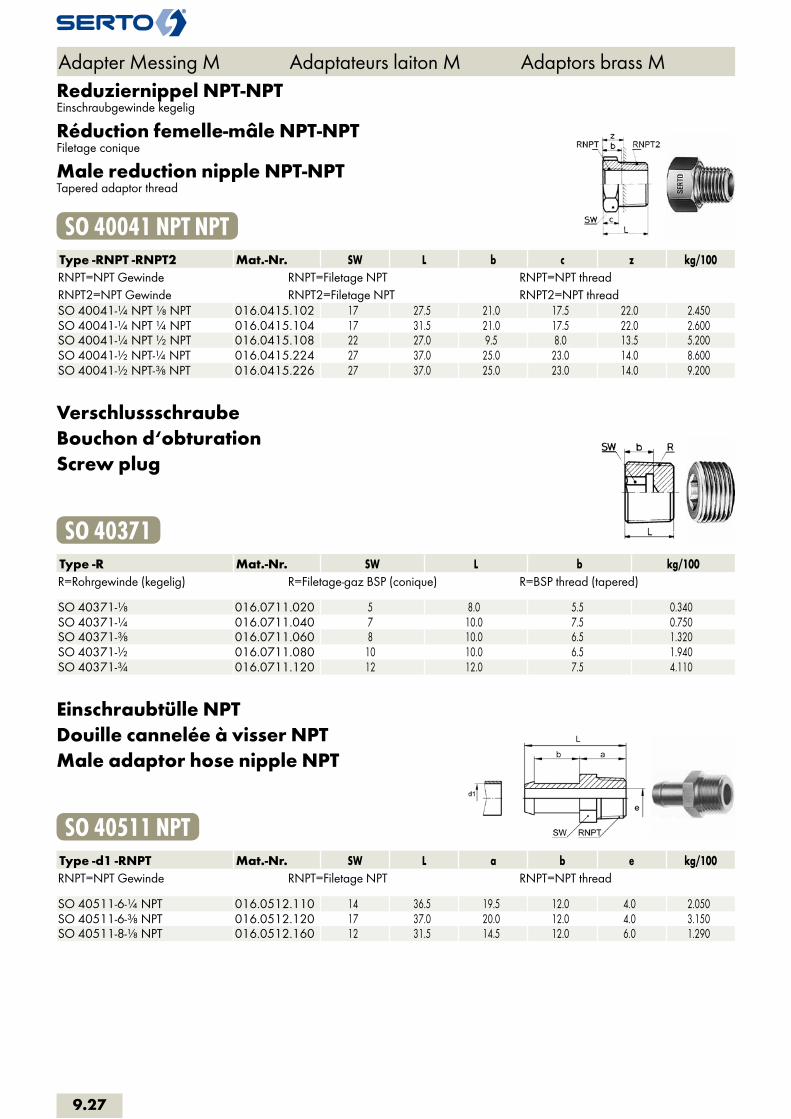
Reduziernippel NPT-NPTEinschraubgewinde kegelig
Réduction femelle-mâle NPT-NPTFiletage conique
Male reduction nipple NPT-NPTTapered adaptor thread
SO 40041 NPT NPTType -RNPT -RNPT2 Mat.-Nr. SW L b c z kg/100RNPT=NPT Gewinde RNPT=Filetage NPT RNPT=NPT threadRNPT2=NPT Gewinde RNPT2=Filetage NPT RNPT2=NPT threadSO 40041-1/4 NPT 1/8 NPT 016.0415.102 17 27.5 21.0 17.5 22.0 2.450SO 40041-1/4 NPT 1/4 NPT 016.0415.104 17 31.5 21.0 17.5 22.0 2.600SO 40041-1/4 NPT 1/2 NPT 016.0415.108 22 27.0 9.5 8.0 13.5 5.200SO 40041-1/2 NPT-1/4 NPT 016.0415.224 27 37.0 25.0 23.0 14.0 8.600SO 40041-1/2 NPT-3/8 NPT 016.0415.226 27 37.0 25.0 23.0 14.0 9.200
VerschlussschraubeBouchon d‘obturationScrew plug
SO 40371Type -R Mat.-Nr. SW L b kg/100R=Rohrgewinde (kegelig) R=Filetage-gaz BSP (conique) R=BSP thread (tapered) SO 40371-1/8 016.0711.020 5 8.0 5.5 0.340SO 40371-1/4 016.0711.040 7 10.0 7.5 0.750SO 40371-3/8 016.0711.060 8 10.0 6.5 1.320SO 40371-1/2 016.0711.080 10 10.0 6.5 1.940SO 40371-3/4 016.0711.120 12 12.0 7.5 4.110
Einschraubtülle NPTDouille cannelée à visser NPTMale adaptor hose nipple NPT
SO 40511 NPTType -d1 -RNPT Mat.-Nr. SW L a b e kg/100RNPT=NPT Gewinde RNPT=Filetage NPT RNPT=NPT thread SO 40511-6-1/4 NPT 016.0512.110 14 36.5 19.5 12.0 4.0 2.050SO 40511-6-3/8 NPT 016.0512.120 17 37.0 20.0 12.0 4.0 3.150SO 40511-8-1/8 NPT 016.0512.160 12 31.5 14.5 12.0 6.0 1.290
Adapter Messing M Adaptateurs laiton M Adaptors brass M
9.27

EinschraubtülleDouille canellèe a visserMale adaptor hose nipple
SO 40511Type -d1 -R Mat.-Nr. SW L a b e kg/100R=Rohrgewinde (kegelig) R=Filetage-gaz BSP (conique) R=BSP thread (tapered) SO 40511-4-1/8 016.0511.060 10 23.0 12.0 8.0 3.0 0.750SO 40511-6-1/8 016.0511.100 10 29.0 12.0 12.0 4.0 0.730SO 40511-6-1/4 016.0511.110 14 34.5 17.5 12.0 4.0 1.920SO 40511-8-1/8 016.0511.160 10 29.0 12.0 12.0 6.0 0.780SO 40511-8-1/4 016.0511.170 14 34.5 17.5 12.0 6.0 1.690SO 40511-8-3/8 016.0511.180 17 35.0 18.0 12.0 6.0 2.910SO 40511-8-1/2 016.0511.185 22 40.0 23.0 12.0 6.0 4.530SO 40511-10-1/8 016.0511.265 12 31.0 12.0 14.0 6.0 1.580SO 40511-10-1/4 016.0511.270 14 36.5 17.5 14.0 7.0 1.640SO 40511-10-3/8 016.0511.280 17 37.0 18.0 14.0 7.0 2.910SO 40511-10-1/2 016.0511.285 22 42.0 23.0 14.0 7.0 4.900SO 40511-13-3/8 016.0511.450 17 39.0 18.0 15.0 10.0 2.910SO 40511-13-1/2 016.0511.454 22 44.0 23.0 15.0 10.0 5.340SO 40511-16-1/2 016.0511.566 22 49.0 23.0 18.0 13.0 5.410SO 40511-19-1/2 016.0511.676 22 49.0 23.0 18.0 15.0 5.800SO 40511-19-3/4 016.0511.678 27 51.0 25.0 18.0 16.0 10.900
SchlauchklemmeStahl promatverzinkt
Collier de serrageAcier zingué passivé
Hose clipZinc promatised steel
SO 40512Type -d Mat.-Nr. B D kg/100 SO 40512-3-5 016.0610.030 5.0 5.0 0.065SO 40512-5-7 016.0610.050 3.0 7.0 0.100SO 40512-7-9 016.0610.070 7.0 9.0 0.220SO 40512-9-11 016.0610.090 7.0 11.0 0.245SO 40512-11-13 016.0610.110 7.0 13.0 0.280SO 40512-13-15 016.0610.130 7.5 15.0 0.385SO 40512-15-18 016.0610.150 8.0 18.0 0.510SO 40512-17-20 016.0610.170 8.5 20.0 0.585SO 40512-20-23 016.0610.200 9.0 23.0 0.920SO 40512-23-27 016.0610.230 10.0 27.0 1.200
Adapter Messing M Adaptateurs laiton M Adaptors brass M
9.28
i
s
3F
4M
4G
5
5L
6
7
8
9
10
11
12

Doppelnippel zylindrischAdaptateur mâle cylindriqueMale adaptor parallel
SO 01020Type -G Mat.-Nr. bar SW L z1 e kg/100G=Rohrgewinde (zylindrisch) G=Filetage-gaz BSP (cylindrique) G=BSP thread (straight) SO 01020-1/8-1/8 246.1020.060 125 12 26.0 10.0 4.5 1.420SO 01020-1/4-1/4 246.1020.080 125 14 28.0 11.0 6.5 2.150SO 01020-3/8-3/8 246.1020.100 100 17 30.0 11.5 8.5 3.800SO 01020-1/2-1/2 246.1020.140 64 22 36.0 14.0 12.0 6.450
Doppelnippel zylindrisch reduziertAdaptateur mâle cylindrique réduitMale adaptor parallel reduced
SO 01020 REDType -G -G2 Mat.-Nr. bar SW L z1 z e kg/100G=Rohrgewinde (zylindrisch) G=Filetage-gaz BSP (cylindrique) G=BSP thread (straight)G2=Rohrgewinde (zylindrisch) G2=Filetage-gaz BSP (cylindrique) G2=BSP thread (straight)SO 01020-1/4-1/8 246.1024.140 125 14 27.0 10.0 11.0 4.5 2.100SO 01020-3/8-1/4 246.1024.190 100 17 29.5 11.0 11.5 6.5 3.450SO 01020-1/2-3/8 246.1024.240 64 22 33.5 11.5 14.0 8.5 6.200
Adapter Messing G Adaptateurs laiton G Adaptors brass G
9.29

Doppelnippel zylindrisch/kegeligNipple mâle cylindrique/coniqueMale adaptor nipple parallel/tapered
SO 01100Type -G -R2 Mat.-Nr. bar SW L z e kg/100G=Rohrgewinde (zylindrisch) G=Filetage-gaz BSP (cylindrique) G=BSP thread (straight)R2=Rohrgewinde (kegelig) R2=Filetage-gaz BSP (conique) R2=BSP thread (tapered)SO 01100-1/8 Z-1/8 K 246.1101.100 125 10 22.0 18.0 4.0 1.310SO 01100-1/8 Z-1/4 K 246.1101.110 125 14 28.0 22.0 4.0 2.010SO 01100-1/8 Z-3/8 K 246.1101.120 125 17 28.0 21.6 4.0 2.810SO 01100-1/4 Z-1/8 K 246.1101.160 125 14 25.0 21.0 5.0 2.010SO 01100-1/4 Z-1/4 K 246.1101.170 125 14 29.0 23.0 6.5 2.410SO 01100-1/4 Z-3/8 K 246.1101.180 125 17 29.0 22.6 6.5 3.210SO 01100-1/4 Z-1/2 K 246.1101.185 125 22 34.0 25.8 6.5 4.910SO 01100-3/8 Z-1/4 K 246.1101.270 100 17 29.5 23.5 8.5 2.970SO 01100-3/8 Z-3/8 K 246.1101.280 100 17 29.5 23.1 8.5 3.570SO 01100-3/8 Z -1/2 K 246.1101.285 100 22 34.5 26.3 8.5 5.270SO 01100-1/2 Z-1/4 K 246.1101.380 64 22 33.0 27.0 8.0 5.970SO 01100-1/2 Z-3/8 K 246.1101.390 64 22 33.0 26.6 10.0 5.770SO 01100-1/2 Z-1/2 K 246.1101.504 64 22 37.0 28.8 12.0 6.260SO 01100-1/2 Z-3/4 K 246.1101.506 64 27 39.0 29.5 12.0 8.860SO 01100-3/4 Z-1/2 K 246.1101.596 64 27 40.0 31.8 14.0 9.190SO 01100-3/4 Z-3/4 K 246.1101.598 64 27 40.0 30.5 15.0 10.190
Doppelnippel zylindrischmit Dichtkante
Nipple mâle cylindriqueavec arête d‘étanchéité
Male adaptor nipple parallelwith sealing lip
SO 01104Type -G -G2 Mat.-Nr. bar SW L z e kg/100G=Rohrgewinde (zylindrisch) G=Filetage-gaz BSP (cylindrique) G=BSP thread (straight)G2=Rohrgewinde (zylindrisch) G2=Filetage-gaz BSP (cylindrique) G2=BSP thread (straight)SO 01104-1/8-1/8 246.1141.100 125 14 23.5 15.5 4.0 1.410SO 01104-1/8-1/4 246.1141.110 125 19 29.0 17.0 4.0 3.010SO 01104-1/4-1/8 246.1141.160 125 14 24.5 16.5 5.0 1.710SO 01104-1/4-1/4 246.1141.170 125 19 30.0 18.0 6.0 3.110SO 01104-1/4-3/8 246.1141.180 125 22 31.5 19.5 6.0 4.010SO 01104-3/8-1/4 246.1141.270 100 19 30.5 18.5 7.0 3.570SO 01104-3/8-3/8 246.1141.280 100 22 32.0 20.0 7.0 5.470SO 01104-1/2-1/4 246.1141.380 64 22 34.5 22.5 7.0 6.600SO 01104-1/2-3/8 246.1141.390 64 22 34.5 22.5 9.0 6.270SO 01104-1/2-1/2 246.1141.504 64 27 38.0 24.0 12.0 9.490
Adapter Messing G Adaptateurs laiton G Adaptors brass G
9.30
i
s
3F
4M
4G
5
5L
6
7
8
9
10
11
12
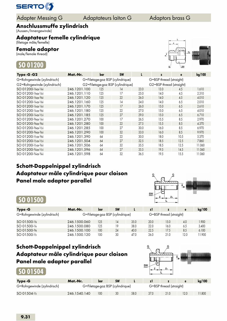
Anschlussmuffe zylindrisch(Aussen-/Innengewinde)
Adaptateur femelle cylindrique(filetage mâle/femelle)
Female adaptor(male/female thread)
SO 01200Type -G -G2 Mat.-Nr. bar SW L z e kg/100G=Rohrgewinde (zylindrisch) G=Filetage-gaz BSP (cylindrique) G=BSP thread (straight)G2=Rohrgewinde (zylindrisch) G2=Filetage-gaz BSP (cylindrique) G2=BSP thread (straight)SO 01200-1/8a-1/8i 246.1201.100 125 14 23.0 13.0 4.5 1.610SO 01200-1/8a-1/4i 246.1201.110 125 17 25.0 14.0 4.5 2.310SO 01200-1/8a-3/8i 246.1201.120 125 22 26.0 14.0 4.5 4.010SO 01200-1/4a-1/8i 246.1201.160 125 14 24.0 14.0 6.5 2.010SO 01200-1/4a-1/4i 246.1201.170 125 17 26.0 15.0 6.5 2.610SO 01200-1/4a-3/8i 246.1201.180 125 22 27.0 15.0 6.5 4.010SO 01200-1/4a-1/2i 246.1201.185 125 27 29.0 15.0 6.5 6.710SO 01200-3/8a-1/4i 246.1201.270 100 17 26.5 15.5 8.5 2.970SO 01200-3/8a-3/8i 246.1201.280 100 22 27.5 15.5 8.5 4.370SO 01200-3/8a-1/2i 246.1201.285 100 27 30.0 16.0 8.5 6.970SO 01200-3/8a-3/4i 246.1201.290 100 32 33.0 16.0 8.5 9.970SO 01200-1/2a-3/8i 246.1201.390 64 22 30.0 18.0 10.5 5.370SO 01200-1/2a-1/2i 246.1201.504 64 27 32.5 18.5 12.5 7.860SO 01200-1/2a-3/4i 246.1201.506 64 32 35.5 18.5 12.5 11.060SO 01200-3/4a-1/2i 246.1201.596 64 27 35.5 19.5 14.5 11.060SO 01200-3/4a-3/4i 246.1201.598 64 32 36.5 19.5 15.5 11.060
Schott-Doppelnippel zylindrischAdaptateur mâle cylindrique pour cloisonPanel male adaptor parallel
SO 01500Type -G Mat.-Nr. bar SW L z1 z e kg/100G=Rohrgewinde (zylindrisch) G=Filetage-gaz BSP (cylindrique) G=BSP thread (straight) SO 01500-1/8 246.1500.060 125 14 35.0 20.0 15.0 4.0 1.900SO 01500-1/4 246.1500.080 125 19 38.0 22.0 16.0 6.5 3.400SO 01500-3/8 246.1500.100 100 24 40.0 22.5 17.5 8.5 6.100SO 01500-1/2 246.1500.120 100 30 47.0 26.0 21.0 12.0 11.900
Schott-Doppelnippel zylindrischAdaptateur mâle cylindrique pour cloisonPanel male adaptor parallel
SO 01504Type -G Mat.-Nr. bar SW L z1 z e kg/100G=Rohrgewinde (zylindrisch) G=Filetage-gaz BSP (cylindrique) G=BSP thread (straight) SO 01504-1/2 246.1540.140 100 30 58.0 37.0 21.0 12.0 11.800
Adapter Messing G Adaptateurs laiton G Adaptors brass G
9.31
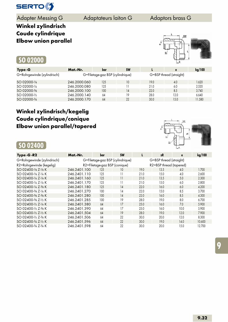
Winkel zylindrischCoude cylindriqueElbow union parallel
SO 02000Type -G Mat.-Nr. bar SW L e kg/100G=Rohrgewinde (zylindrisch) G=Filetage-gaz BSP (cylindrique) G=BSP thread (straight) SO 02000-1/8 246.2000.060 125 10 19.0 4.0 1.620SO 02000-1/4 246.2000.080 125 11 21.0 6.0 2.520SO 02000-3/8 246.2000.100 100 14 22.0 8.5 3.740SO 02000-1/2 246.2000.140 64 19 28.0 12.0 6.640SO 02000-3/4 246.2000.170 64 22 30.0 15.0 11.580
Winkel zylindrisch/kegeligCoude cylindrique/coniqueElbow union parallel/tapered
SO 02400Type -G -R2 Mat.-Nr. bar SW L zR e kg/100G=Rohrgewinde (zylindrisch) G=Filetage-gaz BSP (cylindrique) G=BSP thread (straight)R2=Rohrgewinde (kegelig) R2=Filetage-gaz BSP (conique) R2=BSP thread (tapered)SO 02400-1/8 Z-1/8 K 246.2401.100 125 10 19.0 13.5 4.0 1.700SO 02400-1/8 Z-1/4 K 246.2401.110 125 11 21.0 15.0 4.0 2.600SO 02400-1/4 Z-1/8 K 246.2401.160 125 11 21.0 13.5 5.0 2.300SO 02400-1/4 Z-1/4 K 246.2401.170 125 11 21.0 15.0 6.0 2.800SO 02400-1/4 Z-3/8 K 246.2401.180 125 14 22.0 16.0 6.0 4.200SO 02400-3/8 Z-1/4 K 246.2401.270 100 14 22.0 15.0 8.5 3.700SO 02400-3/8 Z-3/8 K 246.2401.280 100 14 22.0 16.0 8.5 4.300SO 02400-3/8 Z-1/2 K 246.2401.285 100 19 28.0 19.0 8.0 6.700SO 02400-1/2 Z-1/4 K 246.2401.380 64 17 25.0 16.0 7.0 5.900SO 02400-1/2 Z-3/8 K 246.2401.390 64 17 25.0 16.0 10.0 5.900SO 02400-1/2 Z-1/2 K 246.2401.504 64 19 28.0 19.0 12.0 7.900SO 02400-1/2 Z-3/4 K 246.2401.506 64 22 30.0 20.0 12.0 8.300SO 02400-3/4 Z-1/2 K 246.2401.596 64 22 30.0 19.0 14.0 10.600SO 02400-3/4 Z-3/4 K 246.2401.598 64 22 30.0 20.0 15.0 12.700
Adapter Messing G Adaptateurs laiton G Adaptors brass G
9.32
i
s
3F
4M
4G
5
5L
6
7
8
9
10
11
12

T-Stück zylindrischPièce Té cylindriqueTee parallel
SO 03000Type -G Mat.-Nr. bar SW L z e kg/100G=Rohrgewinde (zylindrisch) G=Filetage-gaz BSP (cylindrique) G=BSP thread (straight) SO 03000-1/8 246.3000.060 125 10 38.0 19.0 4.0 2.200SO 03000-1/4 246.3000.080 125 11 42.0 21.0 6.0 3.600SO 03000-3/8 246.3000.100 100 14 44.0 22.0 8.0 5.200SO 03000-1/2 246.3000.120 100 19 50.0 25.0 11.0 9.300SO 03000-3/4 246.3000.170 64 27 64.0 32.0 15.0 15.700
Adapter Messing G Adaptateurs laiton G Adaptors brass G
9.33
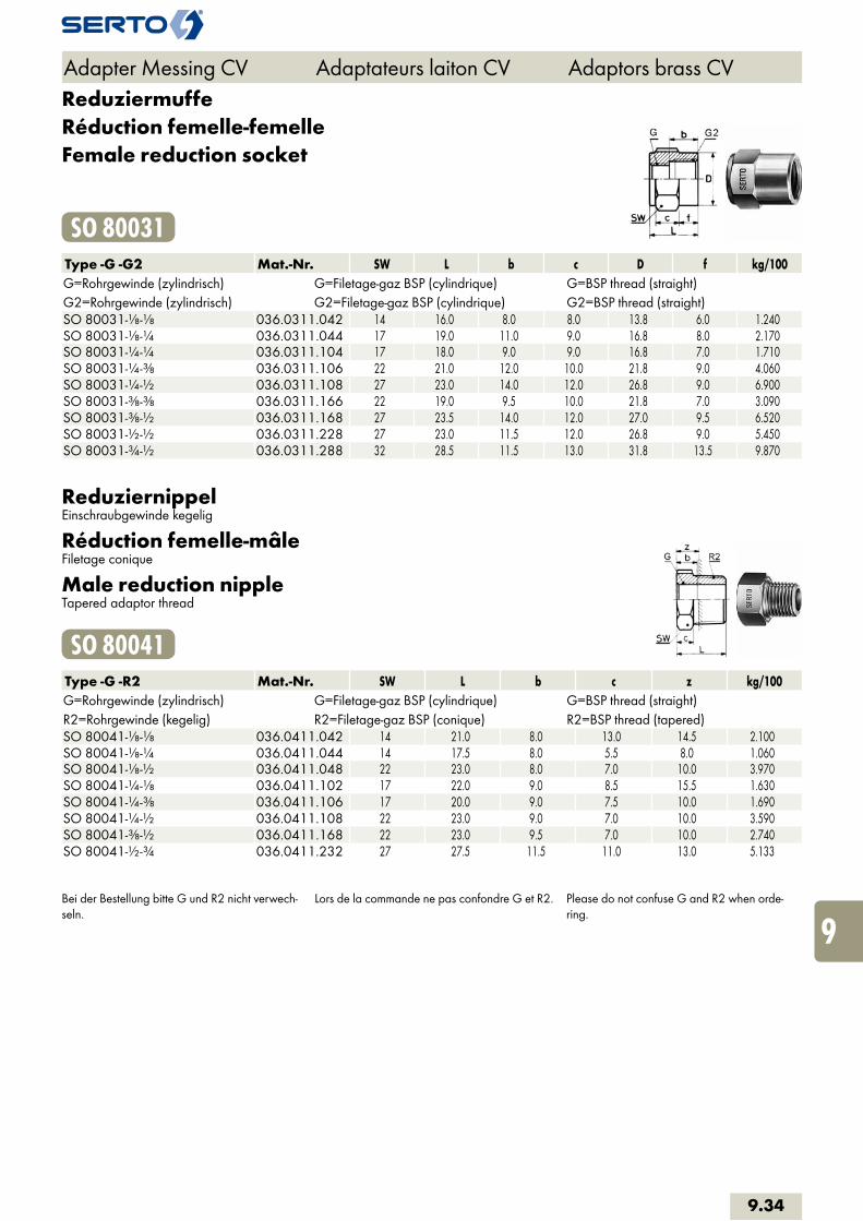
ReduziermuffeRéduction femelle-femelleFemale reduction socket
SO 80031Type -G -G2 Mat.-Nr. SW L b c D f kg/100G=Rohrgewinde (zylindrisch) G=Filetage-gaz BSP (cylindrique) G=BSP thread (straight)G2=Rohrgewinde (zylindrisch) G2=Filetage-gaz BSP (cylindrique) G2=BSP thread (straight)SO 80031-1/8-1/8 036.0311.042 14 16.0 8.0 8.0 13.8 6.0 1.240SO 80031-1/8-1/4 036.0311.044 17 19.0 11.0 9.0 16.8 8.0 2.170SO 80031-1/4-1/4 036.0311.104 17 18.0 9.0 9.0 16.8 7.0 1.710SO 80031-1/4-3/8 036.0311.106 22 21.0 12.0 10.0 21.8 9.0 4.060SO 80031-1/4-1/2 036.0311.108 27 23.0 14.0 12.0 26.8 9.0 6.900SO 80031-3/8-3/8 036.0311.166 22 19.0 9.5 10.0 21.8 7.0 3.090SO 80031-3/8-1/2 036.0311.168 27 23.5 14.0 12.0 27.0 9.5 6.520SO 80031-1/2-1/2 036.0311.228 27 23.0 11.5 12.0 26.8 9.0 5.450SO 80031-3/4-1/2 036.0311.288 32 28.5 11.5 13.0 31.8 13.5 9.870
ReduziernippelEinschraubgewinde kegelig
Réduction femelle-mâleFiletage conique
Male reduction nippleTapered adaptor thread
SO 80041Type -G -R2 Mat.-Nr. SW L b c z kg/100G=Rohrgewinde (zylindrisch) G=Filetage-gaz BSP (cylindrique) G=BSP thread (straight)R2=Rohrgewinde (kegelig) R2=Filetage-gaz BSP (conique) R2=BSP thread (tapered)SO 80041-1/8-1/8 036.0411.042 14 21.0 8.0 13.0 14.5 2.100SO 80041-1/8-1/4 036.0411.044 14 17.5 8.0 5.5 8.0 1.060SO 80041-1/8-1/2 036.0411.048 22 23.0 8.0 7.0 10.0 3.970SO 80041-1/4-1/8 036.0411.102 17 22.0 9.0 8.5 15.5 1.630SO 80041-1/4-3/8 036.0411.106 17 20.0 9.0 7.5 10.0 1.690SO 80041-1/4-1/2 036.0411.108 22 23.0 9.0 7.0 10.0 3.590SO 80041-3/8-1/2 036.0411.168 22 23.0 9.5 7.0 10.0 2.740SO 80041-1/2-3/4 036.0411.232 27 27.5 11.5 11.0 13.0 5.133
Bei der Bestellung bitte G und R2 nicht verwech-seln.
Lors de la commande ne pas confondre G et R2. Please do not confuse G and R2 when orde-ring.
Adapter Messing CV Adaptateurs laiton CV Adaptors brass CV
9.34
i
s
3F
4M
4G
5
5L
6
7
8
9
10
11
12
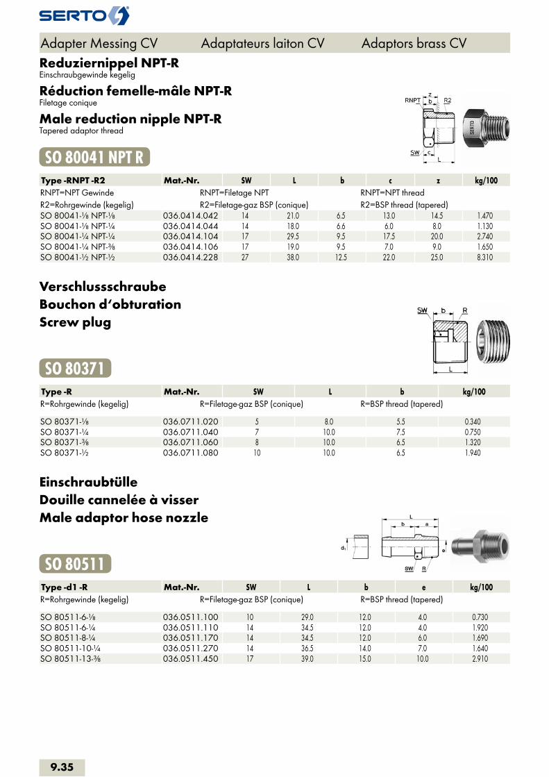
Reduziernippel NPT-REinschraubgewinde kegelig
Réduction femelle-mâle NPT-RFiletage conique
Male reduction nipple NPT-RTapered adaptor thread
SO 80041 NPT RType -RNPT -R2 Mat.-Nr. SW L b c z kg/100RNPT=NPT Gewinde RNPT=Filetage NPT RNPT=NPT threadR2=Rohrgewinde (kegelig) R2=Filetage-gaz BSP (conique) R2=BSP thread (tapered)SO 80041-1/8 NPT-1/8 036.0414.042 14 21.0 6.5 13.0 14.5 1.470SO 80041-1/8 NPT-1/4 036.0414.044 14 18.0 6.6 6.0 8.0 1.130SO 80041-1/4 NPT-1/4 036.0414.104 17 29.5 9.5 17.5 20.0 2.740SO 80041-1/4 NPT-3/8 036.0414.106 17 19.0 9.5 7.0 9.0 1.650SO 80041-1/2 NPT-1/2 036.0414.228 27 38.0 12.5 22.0 25.0 8.310
VerschlussschraubeBouchon d‘obturationScrew plug
SO 80371Type -R Mat.-Nr. SW L b kg/100R=Rohrgewinde (kegelig) R=Filetage-gaz BSP (conique) R=BSP thread (tapered) SO 80371-1/8 036.0711.020 5 8.0 5.5 0.340SO 80371-1/4 036.0711.040 7 10.0 7.5 0.750SO 80371-3/8 036.0711.060 8 10.0 6.5 1.320SO 80371-1/2 036.0711.080 10 10.0 6.5 1.940
EinschraubtülleDouille cannelée à visserMale adaptor hose nozzle
SO 80511Type -d1 -R Mat.-Nr. SW L b e kg/100R=Rohrgewinde (kegelig) R=Filetage-gaz BSP (conique) R=BSP thread (tapered) SO 80511-6-1/8 036.0511.100 10 29.0 12.0 4.0 0.730SO 80511-6-1/4 036.0511.110 14 34.5 12.0 4.0 1.920SO 80511-8-1/4 036.0511.170 14 34.5 12.0 6.0 1.690SO 80511-10-1/4 036.0511.270 14 36.5 14.0 7.0 1.640SO 80511-13-3/8 036.0511.450 17 39.0 15.0 10.0 2.910
Adapter Messing CV Adaptateurs laiton CV Adaptors brass CV
9.35
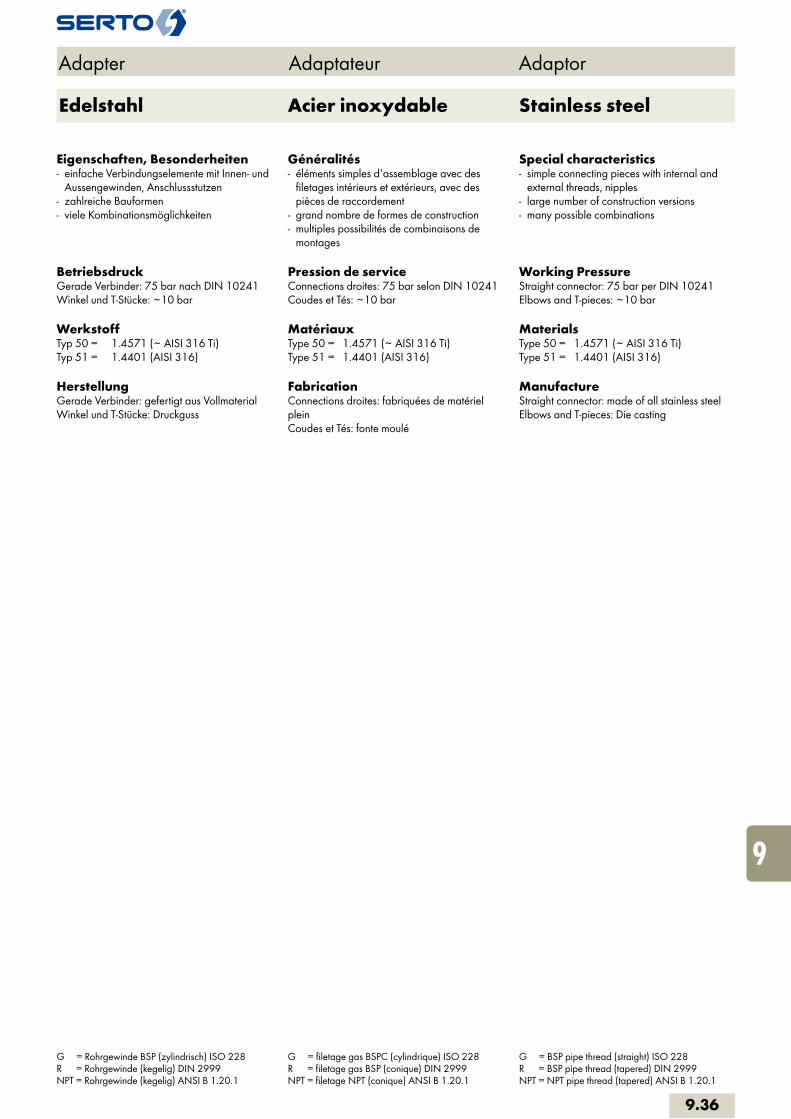
Adapter Adaptateur Adaptor
Eigenschaften, Besonderheiten- einfache Verbindungselemente mit Innen- und Aussengewinden, Anschlussstutzen - zahlreiche Bauformen- viele Kombinationsmöglichkeiten
BetriebsdruckGerade Verbinder: 75 bar nach DIN 10241 Winkel und T-Stücke: ~10 bar
Werkstoff Typ 50 = 1.4571 (~ AISI 316 Ti)Typ 51 = 1.4401 (AISI 316)
HerstellungGerade Verbinder: gefertigt aus Vollmaterial Winkel und T-Stücke: Druckguss
Généralités- éléments simples d‘assemblage avec des filetages intérieurs et extérieurs, avec des pièces de raccordement- grand nombre de formes de construction- multiples possibilités de combinaisons de montages
Pression de serviceConnections droites: 75 bar selon DIN 10241 Coudes et Tés: ~10 bar
MatériauxType 50 = 1.4571 (~ AISI 316 Ti)Type 51 = 1.4401 (AISI 316)
FabricationConnections droites: fabriquées de matériel plein Coudes et Tés: fonte moulé
Special characteristics- simple connecting pieces with internal and external threads, nipples- large number of construction versions- many possible combinations
Working PressureStraight connector: 75 bar per DIN 10241 Elbows and T-pieces: ~10 bar
MaterialsType 50 = 1.4571 (~ AISI 316 Ti)Type 51 = 1.4401 (AISI 316)
ManufactureStraight connector: made of all stainless steel Elbows and T-pieces: Die casting
G = Rohrgewinde BSP (zylindrisch) ISO 228 R = Rohrgewinde (kegelig) DIN 2999 NPT = Rohrgewinde (kegelig) ANSI B 1.20.1
G = filetage gas BSPC (cylindrique) ISO 228 R = filetage gas BSP (conique) DIN 2999 NPT = filetage NPT (conique) ANSI B 1.20.1
G = BSP pipe thread (straight) ISO 228 R = BSP pipe thread (tapered) DIN 2999 NPT = NPT pipe thread (tapered) ANSI B 1.20.1
9.36
i
s
3F
4M
4G
5
5L
6
7
8
9
10
11
12
Acier inoxydable Stainless steelEdelstahl

DoppelnippelMamelon doubleHex nipple
AD HN 50Type -R Mat.-Nr. SW L e kg/100R=Rohrgewinde (kegelig) R=Filetage-gaz BSP (conique) R=BSP thread (tapered) AD HN 50-1/8-1/8 TAD.5110.042 12 25.0 6.0 1.005AD HN 50-1/4-1/4 TAD.5110.104 14 31.0 8.0 1.979AD HN 50-3/8-3/8 TAD.5110.166 17 33.0 10.5 3.180AD HN 50-1/2-1/2 TAD.5110.228 22 43.0 13.0 6.749AD HN 50-3/4-3/4 TAD.5110.292 27 48.0 21.0 7.285AD HN 50-1-1 TAD.5110.414 36 52.0 26.0 13.822
Doppelnippel R-NPTMamelon double R-NPTHex nipple R-NPT
AD HN 50 R-NPTType -R -RNPT2 Mat.-Nr. SW L e kg/100R=Rohrgewinde (kegelig) R=Filetage-gaz BSP (conique) R=BSP thread (tapered)RNPT2=NPT Gewinde RNPT2=Filetage NPT RNPT2=NPT threadAD HN 50-1/8-1/8 NPT TAD.5114.042 12 25.0 6.0 1.067AD HN 50-1/4-1/4 NPT TAD.5114.104 14 31.0 8.0 2.061AD HN 50-3/8-3/8 NPT TAD.5114.166 17 33.0 10.5 3.260AD HN 50-1/2-1/2 NPT TAD.5114.228 22 43.0 13.0 6.850AD HN 50-3/4-3/4 NPT TAD.5114.292 27 48.0 21.0 7.371AD HN 50-1-1 NPT TAD.5114.414 36 52.0 26.0 13.760
Doppelnippel NPT-NPTMamelon double NPT-NPTHex nipple NPT-NPT
AD HN 50 NPT-NPTType -RNPT Mat.-Nr. SW L e kg/100RNPT=NPT Gewinde RNPT=Filetage NPT RNPT=NPT thread AD HN 50-1/8 NPT-1/8 NPT TAD.5111.042 12 25.0 6.0 1.113AD HN 50-1/4 NPT-1/4 NPT TAD.5111.104 14 31.0 8.0 2.141AD HN 50-3/8 NPT-3/8 NPT TAD.5111.166 17 33.0 10.5 3.340AD HN 50-1/2 NPT-1/2 NPT TAD.5111.228 22 43.0 13.0 6.949AD HN 50-3/4 NPT-3/4 NPT TAD.5111.292 27 48.0 21.0 7.457AD HN 50-1 NPT-1 NPT TAD.5111.414 36 52.0 26.0 13.698
Adapter Edelstahl Adaptateurs inox Adaptors stainless steel
9.37

Doppelnippel reduziertMamelon double réduitHex reducing nipple
AD HRN 50Type -R -R2 Mat.-Nr. SW L e kg/100R=Rohrgewinde (kegelig) R=Filetage-gaz BSP (conique) R=BSP thread (tapered)R2=Rohrgewinde (kegelig) R2=Filetage-gaz BSP (conique) R2=BSP thread (tapered)AD HRN 50-1/8-1/4 TAD.5110.044 14 28.0 6.0 1.830AD HRN 50-1/8-3/8 TAD.5110.046 17 30.0 6.0 3.193AD HRN 50-1/8-1/2 TAD.5110.048 22 35.0 6.0 6.344AD HRN 50-1/4-3/8 TAD.5110.106 17 33.0 8.0 3.308AD HRN 50-1/4-1/2 TAD.5110.108 22 38.0 8.0 6.385AD HRN 50-3/8-1/2 TAD.5110.168 22 38.0 10.5 6.128AD HRN 50-1/2-3/4 TAD.5110.232 27 46.5 13.0 11.548AD HRN 50-1/2-1 TAD.5110.236 36 48.5 13.0 20.172AD HRN 50-3/4-1 TAD.5110.296 36 50.0 21.0 15.600
RohrdoppelnippelAdaptateur mâleBarrel nipple
AD CN 50Type -R Mat.-Nr. L L1 D e kg/100R=Rohrgewinde (kegelig) R=Filetage-gaz BSP (conique) R=BSP thread (tapered) AD CN 50-1/8 X40 TAD.5150.021 40.0 8.0 10.0 6.0 1.400AD CN 50-1/8 X60 TAD.5150.023 60.0 8.0 10.0 6.0 2.200AD CN 50-1/4 X40 TAD.5150.042 40.0 9.0 14.0 9.0 2.400AD CN 50-1/4 X60 TAD.5150.045 60.0 9.0 14.0 9.0 2.860AD CN 50-1/4 X80 TAD.5150.049 80.0 9.0 14.0 9.0 5.700AD CN 50-1/4 X100 TAD.5150.053 100.0 9.0 14.0 9.0 7.100AD CN 50-1/4 X150 TAD.5150.058 150.0 9.0 14.0 9.0 8.000AD CN 50-3/8 X60 TAD.5150.060 60.0 12.0 17.0 12.0 4.000AD CN 50-1/2 X40 TAD.5150.082 40.0 13.0 21.0 16.0 3.600AD CN 50-1/2 X60 TAD.5150.084 60.0 13.0 21.0 16.0 5.970AD CN 50-1/2 X80 TAD.5150.086 80.0 13.0 21.0 16.0 8.100AD CN 50-1/2 X100 TAD.5150.088 100.0 13.0 21.0 16.0 11.050AD CN 50-1/2 X150 TAD.5150.093 150.0 13.0 21.0 16.0 15.900AD CN 50-3/4 X80 TAD.5150.126 80.0 17.0 27.0 20.0 10.850AD CN 50-3/4 X100 TAD.5150.128 100.0 17.0 27.0 20.0 12.800AD CN 50-3/4 X150 TAD.5150.134 150.0 17.0 27.0 20.0 20.300AD CN 50-1 X60 TAD.5150.162 60.0 17.0 34.0 28.0 11.600AD CN 50-1 X80 TAD.5150.164 80.0 17.0 34.0 28.0 13.300AD CN 50-1 X100 TAD.5150.166 100.0 17.0 34.0 28.0 14.900AD CN 50-1 X150 TAD.5150.171 150.0 17.0 34.0 28.0 32.200AD CN 50-1 X180 TAD.5150.174 180.0 17.0 34.0 28.0 38.600AD CN 50-1 X200 TAD.5150.176 200.0 17.0 34.0 28.0 43.700
Adapter Edelstahl Adaptateurs inox Adaptors stainless steel
9.38
i
s
3F
4M
4G
5
5L
6
7
8
9
10
11
12

Rohrnippelkurz
Mameloncourt
Double nippleshort
AD CNS 50Type -G Mat.-Nr. L e kg/100G=Rohrgewinde (zylindrisch) G=Filetage-gaz BSP (cylindrique) G=BSP thread (straight) AD CNS 50-1/4 TAD.5180.104 18.0 9.0 0.600AD CNS 50-3/8 TAD.5180.166 22.0 12.0 1.070AD CNS 50-1/2 TAD.5180.228 25.0 16.0 1.440AD CNS 50-3/4 TAD.5180.292 30.0 22.0 2.650
RohranschweissnippelRaccord à souderWeld-on nipple
AD CNW 50Type -R Mat.-Nr. L L1 D e kg/100R=Rohrgewinde (kegelig) R=Filetage-gaz BSP (conique) R=BSP thread (tapered) AD CNW 50-1/8 TAD.5170.020 30.0 8.0 10.0 6.0 0.900AD CNW 50-1/4 TAD.5170.040 30.0 9.0 13.5 9.0 1.100AD CNW 50-3/8 TAD.5170.060 30.0 12.0 17.0 12.0 1.760AD CNW 50-1/2 TAD.5170.080 35.0 13.0 21.0 16.5 3.600AD CNW 50-3/4 TAD.5170.120 40.0 15.0 27.0 21.5 5.200AD CNW 50-1 TAD.5170.160 40.0 17.0 34.0 28.0 5.250
Rohranschweissnippel NPTRaccord à souder NPTWeld-on nipple NPT
AD CNW 50 NPTType -RNPT Mat.-Nr. L L1 D e kg/100RNPT=NPT Gewinde RNPT=Filetage NPT RNPT=NPT thread AD CNW 50-1/8 NPT TAD.5171.020 30.0 8.5 10.0 6.0 0.720AD CNW 50-1/4 NPT TAD.5171.040 30.0 12.5 13.5 8.8 1.140AD CNW 50-3/8 NPT TAD.5171.060 30.0 12.0 17.0 12.0 2.100AD CNW 50-1/2 NPT TAD.5171.080 35.0 13.0 21.0 16.5 2.400AD CNW 50-3/4 NPT TAD.5171.120 40.0 17.5 27.0 22.0 3.320AD CNW 50-1 NPT TAD.5171.160 40.0 21.0 33.5 27.5 5.010
Adapter Edelstahl Adaptateurs inox Adaptors stainless steel
9.39

AdapterAdaptateurAdapter
AD A 50Type -G -R2 Mat.-Nr. SW L L1 L2 e kg/100G=Rohrgewinde (zylindrisch) G=Filetage-gaz BSP (cylindrique) G=BSP thread (straight)R2=Rohrgewinde (kegelig) R2=Filetage-gaz BSP (conique) R2=BSP thread (tapered)AD A 50-1/8-1/8 TAD.5120.042 14 21.0 9.5 8.0 6.0 1.226AD A 50-1/4-1/4 TAD.5120.104 17 26.0 12.5 9.0 8.0 2.192AD A 50-3/8-3/8 TAD.5120.166 22 27.0 12.5 9.5 10.5 3.698AD A 50-1/2-1/2 TAD.5120.228 27 35.0 17.5 11.5 13.0 7.183AD A 50-3/4-3/4 TAD.5120.292 32 40.0 19.0 14.0 21.0 9.166AD A 50-1-1 TAD.5120.414 41 45.0 21.0 17.0 26.0 17.524
Adapter reduziertAdaptateur réduitReducing adapter
AD RA 50 G-RType -G -R2 Mat.-Nr. SW L L1 L2 e kg/100G=Rohrgewinde (zylindrisch) G=Filetage-gaz BSP (cylindrique) G=BSP thread (straight)R2=Rohrgewinde (kegelig) R2=Filetage-gaz BSP (conique) R2=BSP thread (tapered)AD RA 50-1/4-1/8 TAD.5120.102 17 23.0 9.5 9.0 6.0 1.776AD RA 50-3/8-1/4 TAD.5120.164 22 28.0 12.5 9.5 8.0 3.586AD RA 50-1/2-1/4 TAD.5120.224 27 31.0 12.5 11.5 8.0 5.815AD RA 50-1/2-3/8 TAD.5120.226 27 30.0 12.5 11.5 10.5 5.780AD RA 50-3/4-1/2 TAD.5120.288 32 39.0 17.5 14.0 13.0 9.662AD RA 50-1-1/2 TAD.5120.408 41 45.0 17.5 17.0 13.0 18.781AD RA 50-1-3/4 TAD.5120.412 41 45.0 19.0 17.0 21.0 17.126
Adapter Edelstahl Adaptateurs inox Adaptors stainless steel
9.40
i
s
3F
4M
4G
5
5L
6
7
8
9
10
11
12

ReduziernippelRéductionHex bushing
AD RB 50 G-RType -G -R2 Mat.-Nr. SW L L1 L2 e kg/100G=Rohrgewinde (zylindrisch) G=Filetage-gaz BSP (cylindrique) G=BSP thread (straight)R2=Rohrgewinde (kegelig) R2=Filetage-gaz BSP (conique) R2=BSP thread (tapered)AD RB 50-1/8-1/4 TAD.5130.044 14 18.5 12.5 8.0 8.6 1.139AD RB 50-1/8-3/8 TAD.5130.046 17 20.5 12.5 8.0 8.6 2.456AD RB 50-1/8-1/2 TAD.5130.048 22 25.5 17.5 8.0 8.6 5.502AD RB 50-1/4-3/8 TAD.5130.106 17 20.5 12.5 9.0 11.4 1.798AD RB 50-1/4-1/2 TAD.5130.108 22 25.5 17.5 9.0 11.4 4.693AD RB 50-1/4-3/4 TAD.5130.110 27 29.0 19.0 9.0 11.4 9.574AD RB 50-3/8-1/2 TAD.5130.168 22 25.5 17.5 9.5 15.0 3.939AD RB 50-3/8-3/4 TAD.5130.170 27 29.0 19.0 9.5 15.0 7.647AD RB 50-3/8-1 TAD.5130.172 36 31.0 21.0 9.5 15.0 16.634AD RB 50-1/2-3/4 TAD.5130.232 27 29.0 19.0 11.5 18.6 6.079AD RB 50-1/2-1 TAD.5130.236 36 31.0 21.0 11.5 18.6 14.496AD RB 50-3/4-1 TAD.5130.296 36 31.0 21.0 14.0 24.1 10.487
Übergangs-Adapter G-NPTAdaptateur inégal G-NPTConversion adapter G-NPT
AD A 50 G-NPTType -G -RNPT2 Mat.-Nr. SW L L1 L2 e kg/100G=Rohrgewinde (zylindrisch) G=Filetage-gaz BSP (cylindrique) G=BSP thread (straight)RNPT2=NPT Gewinde RNPT2=Filetage NPT RNPT2=NPT threadAD A 50-1/8-1/8 NPT TAD.5124.042 14 21.0 9.5 8.0 6.0 1.277AD A 50-1/4-1/4 NPT TAD.5124.104 17 26.0 12.5 9.0 8.0 2.271AD A 50-3/8-3/8 NPT TAD.5124.166 22 27.0 12.5 9.5 10.5 3.786AD A 50-1/2-1/2 NPT TAD.5124.228 27 35.0 17.5 11.5 13.0 7.280AD A 50-3/4-3/4 NPT TAD.5124.292 32 40.0 19.0 14.0 21.0 9.252AD A 50-1-1 NPT TAD.5124.414 41 45.0 21.0 17.0 26.0 17.482
Adapter Edelstahl Adaptateurs inox Adaptors stainless steel
9.41

Übergangs-Adapter reduziert G-NPTAdaptateur inégal réduit G-NPTConversion reducing adapter G-NPT
AD RA 50 G-NPTType -G -RNPT2 Mat.-Nr. SW L L1 L2 e kg/100G=Rohrgewinde (zylindrisch) G=Filetage-gaz BSP (cylindrique) G=BSP thread (straight)RNPT2=NPT Gewinde RNPT2=Filetage NPT RNPT2=NPT threadAD RA 50-1/4-1/8 NPT TAD.5124.102 17 23.0 9.5 9.0 6.0 1.827AD RA 50-3/8-1/4 NPT TAD.5124.164 22 28.0 12.5 9.5 8.0 3.666AD RA 50-1/2-1/4 NPT TAD.5124.224 27 31.0 12.5 11.5 8.0 5.895AD RA 50-1/2-3/8 NPT TAD.5124.226 27 30.0 12.5 11.5 10.5 5.868AD RA 50-3/4-1/2 NPT TAD.5124.288 32 39.0 17.5 14.0 13.0 9.759AD RA 50-1-3/4 NPT TAD.5124.412 41 45.0 19.0 17.0 21.0 17.213
Übergangs-Reduziernippel G-NPTRéduction inégale G-NPTConversion hex bushing G-NPT
AD RB 50 G-NPTType -G -RNPT2 Mat.-Nr. SW L L1 L2 e kg/100G=Rohrgewinde (zylindrisch) G=Filetage-gaz BSP (cylindrique) G=BSP thread (straight)RNPT2=NPT Gewinde RNPT2=Filetage NPT RNPT2=NPT threadAD RB 50-1/8-1/4 NPT TAD.5134.044 14 18.5 12.5 8.0 8.6 1.220AD RB 50-1/8-3/8 NPT TAD.5134.046 17 20.5 12.5 8.0 8.6 2.537AD RB 50-1/8-1/2 NPT TAD.5134.048 22 25.5 17.5 8.0 8.6 5.600AD RB 50-1/4-3/8 NPT TAD.5134.106 17 20.5 12.5 9.0 11.4 1.879AD RB 50-1/4-1/2 NPT TAD.5134.108 22 25.5 17.5 9.0 11.4 4.791AD RB 50-1/4-3/4 NPT TAD.5134.110 27 29.0 19.0 9.0 11.4 9.660AD RB 50-3/8-1/2 NPT TAD.5134.168 22 25.5 17.5 9.5 15.0 3.490AD RB 50-1/2-3/4 NPT TAD.5134.232 27 29.0 19.0 11.5 18.6 6.165AD RB 50-3/4-1 NPT TAD.5134.296 36 31.0 21.0 14.0 24.1 10.445
Übergangs-Adapter NPT-RAdaptateur inégal NPT-RConversion adapter NPT-R
AD A 50 NPT-RType -RNPT -R2 Mat.-Nr. SW L L1 L2 e kg/100RNPT=NPT Gewinde RNPT=Filetage NPT RNPT=NPT threadR2=Rohrgewinde (kegelig) R2=Filetage-gaz BSP (conique) R2=BSP thread (tapered)AD A 50-1/8 NPT-1/8 TAD.5125.042 14 21.0 9.5 10.0 6.0 1.239AD A 50-1/4 NPT-1/4 TAD.5125.104 17 29.0 12.5 14.0 8.0 2.424AD A 50-3/8 NPT-3/8 TAD.5125.166 22 29.0 12.5 14.0 10.5 3.800AD A 50-1/2 NPT-1/2 TAD.5125.228 27 38.0 17.5 18.0 13.0 8.108AD A 50-3/4 NPT-3/4 TAD.5125.292 32 43.0 19.0 20.0 21.0 10.371AD A 50-1 NPT-1 TAD.5125.414 36 45.0 21.0 23.0 26.0 12.020
Adapter Edelstahl Adaptateurs inox Adaptors stainless steel
9.42
i
s
3F
4M
4G
5
5L
6
7
8
9
10
11
12
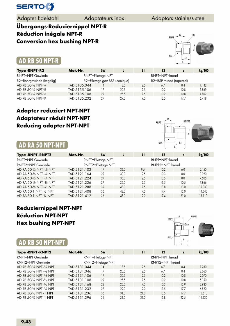
Übergangs-Reduziernippel NPT-RRéduction inégale NPT-RConversion hex bushing NPT-R
AD RB 50 NPT-RType -RNPT -R2 Mat.-Nr. SW L L1 L2 e kg/100RNPT=NPT Gewinde RNPT=Filetage NPT RNPT=NPT threadR2=Rohrgewinde (kegelig) R2=Filetage-gaz BSP (conique) R2=BSP thread (tapered)AD RB 50-1/8 NPT-1/4 TAD.5135.044 14 18.5 12.5 6.7 8.4 1.142AD RB 50-1/4 NPT-3/8 TAD.5135.106 17 20.5 12.5 10.2 10.8 1.869AD RB 50-1/4 NPT-1/2 TAD.5135.108 22 25.5 17.5 10.2 10.8 4.802AD RB 50-1/2 NPT-3/4 TAD.5135.232 27 29.0 19.0 13.5 17.7 6.418
Adapter reduziert NPT-NPTAdaptateur réduit NPT-NPTReducing adapter NPT-NPT
AD RA 50 NPT-NPTType -RNPT -RNPT2 Mat.-Nr. SW L L1 L2 e kg/100RNPT=NPT Gewinde RNPT=Filetage NPT RNPT=NPT threadRNPT2=NPT Gewinde RNPT2=Filetage NPT RNPT2=NPT threadAD RA 50-1/4 NPT -1/8 NPT TAD.5121.102 17 26.0 9.5 10.2 6.0 2.150AD RA 50-3/8 NPT -1/4 NPT TAD.5121.164 22 30.0 12.5 10.3 8.0 3.920AD RA 50-1/2 NPT -1/4 NPT TAD.5121.224 27 35.0 12.5 13.5 8.0 7.505AD RA 50-1/2 NPT -3/8 NPT TAD.5121.226 27 35.0 12.5 13.5 10.5 7.866AD RA 50-3/4 NPT -1/2 NPT TAD.5121.288 32 43.0 17.5 13.8 13.0 12.030AD RA 50-1 NPT -1/2 NPT TAD.5121.408 36 48.0 17.5 17.4 13.0 14.540AD RA 50-1 NPT -3/4 NPT TAD.5121.412 36 48.0 19.0 17.4 21.0 13.110
Reduziernippel NPT-NPTRéduction NPT-NPTHex bushing NPT-NPT
AD RB 50 NPT-NPTType -RNPT -RNPT2 Mat.-Nr. SW L L1 L2 e kg/100RNPT=NPT Gewinde RNPT=Filetage NPT RNPT=NPT threadRNPT2=NPT Gewinde RNPT2=Filetage NPT RNPT2=NPT threadAD RB 50-1/8 NPT -1/4 NPT TAD.5131.044 14 18.5 12.5 6.7 8.4 1.280AD RB 50-1/8 NPT -3/8 NPT TAD.5131.046 17 20.5 12.5 6.7 8.4 2.660AD RB 50-1/4 NPT -3/8 NPT TAD.5131.106 17 20.5 12.5 10.2 10.8 2.070AD RB 50-1/4 NPT -1/2 NPT TAD.5131.108 22 25.5 17.5 10.2 10.8 5.150AD RB 50-3/8 NPT -1/2 NPT TAD.5131.168 22 25.5 17.5 10.3 13.9 3.980AD RB 50-1/2 NPT -3/4 NPT TAD.5131.232 27 29.0 19.0 13.5 17.7 6.820AD RB 50-1/2 NPT -1 NPT TAD.5131.236 36 31.0 21.0 13.5 17.7 15.510AD RB 50-3/4 NPT -1 NPT TAD.5131.296 36 31.0 21.0 13.8 22.5 11.920
Adapter Edelstahl Adaptateurs inox Adaptors stainless steel
9.43

MuffeManchonAdaptor
AD C 50Type -G -G2 Mat.-Nr. L D D1 kg/100G=Rohrgewinde (zylindrisch) G=Filetage-gaz BSP (cylindrique) G=BSP thread (straight)G2=Rohrgewinde (zylindrisch) G2=Filetage-gaz BSP (cylindrique) G2=BSP thread (straight)AD C 50-1/8-1/8 TAD.5140.042 17.0 14.0 1.150AD C 50-1/8-1/4 TAD.5140.044 25.0 18.0 15.0 2.540AD C 50-1/4-1/4 TAD.5140.104 25.0 18.0 2.150AD C 50-1/4-3/8 TAD.5140.106 30.0 22.5 17.5 5.140AD C 50-1/4-1/2 TAD.5140.108 37.0 28.0 18.0 8.600AD C 50-3/8-3/8 TAD.5140.166 27.0 22.0 3.600AD C 50-3/8-1/2 TAD.5140.168 34.0 28.0 22.0 7.660AD C 50-1/2-1/2 TAD.5140.228 34.0 27.0 5.760AD C 50-1/2-3/4 TAD.5140.232 39.0 33.0 27.0 13.860AD C 50-3/4-3/4 TAD.5140.292 36.0 33.0 8.600AD C 50-3/4-1 TAD.5140.296 45.0 40.0 33.0 26.340AD C 50-3/4-1 1/4 TAD.5140.298 50.0 50.0 33.0 29.310AD C 50-1-1 TAD.5140.414 43.0 40.0 15.250AD C 50-1-1 1/4 TAD.5140.418 50.0 50.0 40.0 34.420
Halbe MuffeManchon courtCoupling short
AD CS 50Type -G Mat.-Nr. L D kg/100G=Rohrgewinde (zylindrisch) G=Filetage-gaz BSP (cylindrique) G=BSP thread (straight) AD CS 50-1/8 TAD.5200.042 8.0 14.0 0.500AD CS 50-1/4 TAD.5200.104 11.0 17.0 0.900AD CS 50-3/8 TAD.5200.166 12.0 22.0 1.550AD CS 50-1/2 TAD.5200.228 15.0 27.0 2.600AD CS 50-3/4 TAD.5200.292 17.0 32.0 3.670AD CS 50-1 TAD.5200.414 19.0 40.0 6.100
Adapter Edelstahl Adaptateurs inox Adaptors stainless steel
9.44
i
s
3F
4M
4G
5
5L
6
7
8
9
10
11
12

HochdruckanschweissmuffeManchon haute pression à souderHigh-pressure weld-on adaptor
AD FCW 50Type -RNPT Mat.-Nr. L D kg/100RNPT=NPT Gewinde RNPT=Filetage NPT RNPT=NPT thread AD FCW 50-1/8 NPT TAD.5161.042 21.0 20.0 1.250AD FCW 50-1/4 NPT TAD.5161.104 25.0 25.0 2.160AD FCW 50-3/8 NPT TAD.5161.166 30.0 25.0 7.000AD FCW 50-1/2 NPT TAD.5161.228 30.0 32.0 7.240AD FCW 50-1 NPT TAD.5161.414 40.0 50.0 37.400
Sechskant-MuffeManchon doubleHex coupling
AD HC 50Type -G Mat.-Nr. SW L e kg/100G=Rohrgewinde (zylindrisch) G=Filetage-gaz BSP (cylindrique) G=BSP thread (straight) AD HC 50-1/8-1/8 TAD.5100.042 17 17.0 8.6 2.278AD HC 50-1/4-1/4 TAD.5100.104 22 25.0 11.4 5.500AD HC 50-3/8-3/8 TAD.5100.166 22 26.0 15.0 4.391AD HC 50-1/2-1/2 TAD.5100.228 27 34.0 18.6 8.425AD HC 50-3/4-3/4 TAD.5100.292 32 36.0 24.1 10.686AD HC 50-1-1 TAD.5100.414 46 43.0 30.3 33.192
Sechskant-Muffe reduziertManchon double réduitHex reducing coupling
AD HRC 50Type -G -G2 Mat.-Nr. SW L L1 L2 e kg/100G=Rohrgewinde (zylindrisch) G=Filetage-gaz BSP (cylindrique) G=BSP thread (straight)G2=Rohrgewinde (zylindrisch) G2=Filetage-gaz BSP (cylindrique) G2=BSP thread (straight)AD HRC 50-1/8-1/4 TAD.5100.044 22 25.0 8.0 9.0 8.6 5.938AD HRC 50-1/8-3/8 TAD.5100.046 22 30.0 8.0 9.5 8.6 6.500AD HRC 50-1/8-1/2 TAD.5100.048 27 41.0 8.0 11.5 8.6 14.097AD HRC 50-1/4-3/8 TAD.5100.106 22 29.0 9.0 9.5 11.4 5.746AD HRC 50-1/4-1/2 TAD.5100.108 27 40.0 9.0 11.5 11.4 12.941AD HRC 50-3/8-1/2 TAD.5100.168 27 38.0 9.5 11.5 15.0 10.055AD HRC 50-1/2-3/4 TAD.5100.232 32 41.0 11.5 14.0 18.6 15.200AD HRC 50-1/2-1 TAD.5100.236 46 51.0 11.5 17.0 18.6 48.706
Adapter Edelstahl Adaptateurs inox Adaptors stainless steel
9.45

RohrkappeCapuchon femelleHex cap
AD HCP 50Type -G Mat.-Nr. SW L L1 kg/100G=Rohrgewinde (zylindrisch) G=Filetage-gaz BSP (cylindrique) G=BSP thread (straight) AD HCP 50-1/8 TAD.5000.020 17 19.0 8.0 2.757AD HCP 50-1/4 TAD.5000.040 22 24.0 9.0 5.932AD HCP 50-3/8 TAD.5000.060 22 27.0 9.5 5.875AD HCP 50-1/2 TAD.5000.080 27 37.0 11.5 12.700AD HCP 50-3/4 TAD.5000.120 32 38.0 14.0 16.363AD HCP 50-1 TAD.5000.160 46 44.0 17.0 43.193
Verschlussstopfen 6ktBouchon mâleHex plug
AD HP 50 RType -R Mat.-Nr. SW L L1 kg/100R=Rohrgewinde (kegelig) R=Filetage-gaz BSP (conique) R=BSP thread (tapered) AD HP 50-1/8 TAD.5020.020 12 15.5 9.5 1.017AD HP 50-1/4 TAD.5020.040 14 18.5 12.5 1.892AD HP 50-3/8 TAD.5020.060 17 20.5 12.5 3.289AD HP 50-1/2 TAD.5020.080 22 25.5 17.5 6.548AD HP 50-3/4 TAD.5020.120 27 29.0 19.0 11.671AD HP 50-1 TAD.5020.160 36 31.0 21.0 20.534
Verschlussstopfen 6kt NPTBouchon mâle NPTHex plug NPT
AD HP 50 NPTType -RNPT Mat.-Nr. SW L L1 kg/100RNPT=NPT Gewinde RNPT=Filetage NPT RNPT=NPT thread AD HP 50-1/8 NPT TAD.5021.020 12 15.5 9.5 1.070AD HP 50-1/4 NPT TAD.5021.040 14 18.5 12.5 1.973AD HP 50-3/8 NPT TAD.5021.060 17 20.5 12.5 3.370AD HP 50-1/2 NPT TAD.5021.080 22 25.5 17.5 6.647AD HP 50-3/4 NPT TAD.5021.120 27 29.0 19.0 11.756AD HP 50-1 NPT TAD.5021.160 36 31.0 21.0 20.472
Adapter Edelstahl Adaptateurs inox Adaptors stainless steel
9.46
i
s
3F
4M
4G
5
5L
6
7
8
9
10
11
12
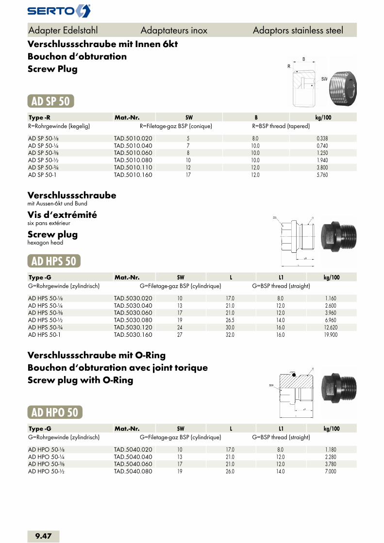
Verschlussschraube mit Innen 6ktBouchon d‘obturationScrew Plug
AD SP 50Type -R Mat.-Nr. SW B kg/100R=Rohrgewinde (kegelig) R=Filetage-gaz BSP (conique) R=BSP thread (tapered) AD SP 50-1/8 TAD.5010.020 5 8.0 0.338AD SP 50-1/4 TAD.5010.040 7 10.0 0.740AD SP 50-3/8 TAD.5010.060 8 10.0 1.250AD SP 50-1/2 TAD.5010.080 10 10.0 1.940AD SP 50-3/4 TAD.5010.110 12 12.0 3.800AD SP 50-1 TAD.5010.160 17 12.0 5.760
Verschlussschraubemit Aussen-6kt und Bund
Vis d‘extrémitésix pans extérieur
Screw plughexagon head
AD HPS 50Type -G Mat.-Nr. SW L L1 kg/100G=Rohrgewinde (zylindrisch) G=Filetage-gaz BSP (cylindrique) G=BSP thread (straight) AD HPS 50-1/8 TAD.5030.020 10 17.0 8.0 1.160AD HPS 50-1/4 TAD.5030.040 13 21.0 12.0 2.600AD HPS 50-3/8 TAD.5030.060 17 21.0 12.0 3.960AD HPS 50-1/2 TAD.5030.080 19 26.5 14.0 6.960AD HPS 50-3/4 TAD.5030.120 24 30.0 16.0 12.620AD HPS 50-1 TAD.5030.160 27 32.0 16.0 19.900
Verschlussschraube mit O-RingBouchon d‘obturation avec joint toriqueScrew plug with O-Ring
AD HPO 50Type -G Mat.-Nr. SW L L1 kg/100G=Rohrgewinde (zylindrisch) G=Filetage-gaz BSP (cylindrique) G=BSP thread (straight) AD HPO 50-1/8 TAD.5040.020 10 17.0 8.0 1.180AD HPO 50-1/4 TAD.5040.040 13 21.0 12.0 2.280AD HPO 50-3/8 TAD.5040.060 17 21.0 12.0 3.780AD HPO 50-1/2 TAD.5040.080 19 26.0 14.0 7.000
Adapter Edelstahl Adaptateurs inox Adaptors stainless steel
9.47

Verschlussschraube mit O-Ring (FPM)Bouchon d‘obturation avec joint torique (FPM)Screw plug with O-Ring (FPM)
AD HSPO 50Type -G Mat.-Nr. SW L L1 D kg/100G=Rohrgewinde (zylindrisch) G=Filetage-gaz BSP (cylindrique) G=BSP thread (straight) AD HSPO 50-1/8-FPM TAD.5050.020 5 11.0 8.0 14.0 0.610AD HSPO 50-1/4-FPM TAD.5050.040 6 15.0 12.0 18.0 1.410AD HSPO 50-3/8-FPM TAD.5050.060 8 15.0 12.0 18.0 2.200AD HSPO 50-1/2-FPM TAD.5050.080 10 18.0 14.0 26.0 4.130AD HSPO 50-3/4-FPM TAD.5050.120 12 20.0 16.0 32.0 7.380
Verschlussschraube mit Innen-6ktVis d‘extrémité six pans creuxHexagon socket screw plug
AD HSP 50Type -G Mat.-Nr. SW L L1 D kg/100G=Rohrgewinde (zylindrisch) G=Filetage-gaz BSP (cylindrique) G=BSP thread (straight) AD HSP 50-1/8 TAD.5070.020 5 11.0 8.0 14.0 0.650AD HSP 50-1/4 TAD.5070.040 6 15.0 12.0 18.0 1.470AD HSP 50-3/8 TAD.5070.060 8 15.0 12.0 22.0 2.320AD HSP 50-1/2 TAD.5070.080 10 18.0 14.0 26.0 4.350AD HSP 50-3/4 TAD.5070.120 12 20.0 16.0 32.0 7.700AD HSP 50-1 TAD.5070.160 17 21.0 16.0 39.0 12.000
Sechskant-KontermutterEcrou à six pansHex counternut
AD HCN 50Type -G Mat.-Nr. SW s kg/100G=Rohrgewinde (zylindrisch) G=Filetage-gaz BSP (cylindrique) G=BSP thread (straight) AD HCN 50-1/8 TAD.5900.042 19 6.00 1.200AD HCN 50-1/4 TAD.5900.104 22 6.00 1.430AD HCN 50-3/8 TAD.5900.166 27 7.00 2.370AD HCN 50-1/2 TAD.5900.228 32 8.00 3.000AD HCN 50-3/4 TAD.5900.292 36 9.00 4.260
Adapter Edelstahl Adaptateurs inox Adaptors stainless steel
9.48
i
s
3F
4M
4G
5
5L
6
7
8
9
10
11
12
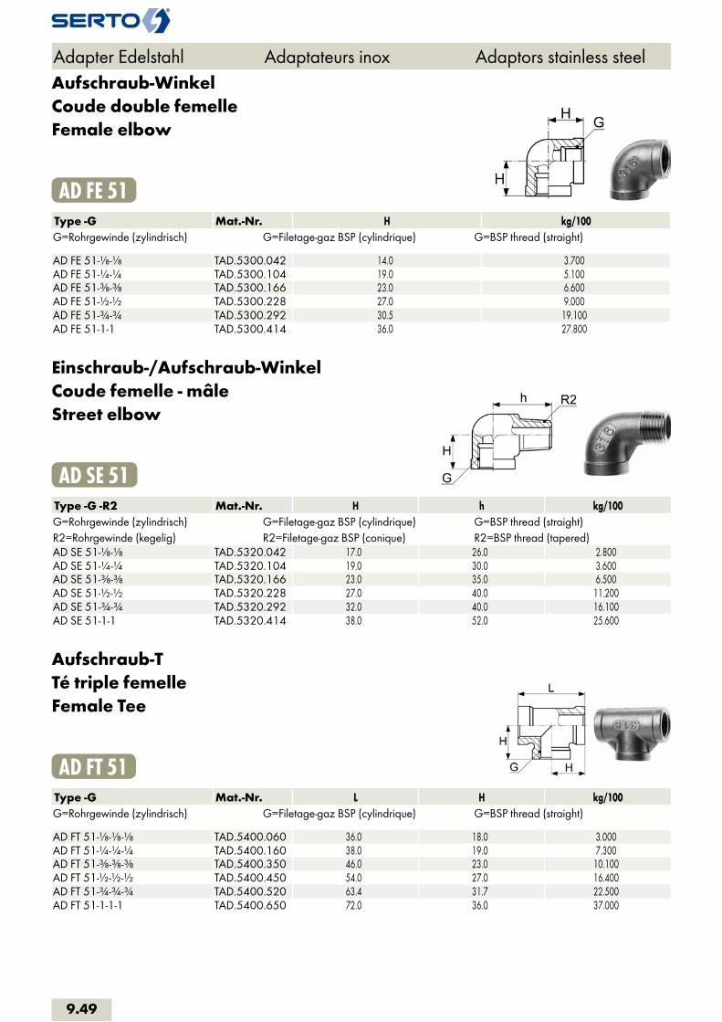
Aufschraub-WinkelCoude double femelleFemale elbow
AD FE 51Type -G Mat.-Nr. H kg/100G=Rohrgewinde (zylindrisch) G=Filetage-gaz BSP (cylindrique) G=BSP thread (straight) AD FE 51-1/8-1/8 TAD.5300.042 14.0 3.700AD FE 51-1/4-1/4 TAD.5300.104 19.0 5.100AD FE 51-3/8-3/8 TAD.5300.166 23.0 6.600AD FE 51-1/2-1/2 TAD.5300.228 27.0 9.000AD FE 51-3/4-3/4 TAD.5300.292 30.5 19.100AD FE 51-1-1 TAD.5300.414 36.0 27.800
Einschraub-/Aufschraub-WinkelCoude femelle - mâleStreet elbow
AD SE 51Type -G -R2 Mat.-Nr. H h kg/100G=Rohrgewinde (zylindrisch) G=Filetage-gaz BSP (cylindrique) G=BSP thread (straight)R2=Rohrgewinde (kegelig) R2=Filetage-gaz BSP (conique) R2=BSP thread (tapered)AD SE 51-1/8-1/8 TAD.5320.042 17.0 26.0 2.800AD SE 51-1/4-1/4 TAD.5320.104 19.0 30.0 3.600AD SE 51-3/8-3/8 TAD.5320.166 23.0 35.0 6.500AD SE 51-1/2-1/2 TAD.5320.228 27.0 40.0 11.200AD SE 51-3/4-3/4 TAD.5320.292 32.0 40.0 16.100AD SE 51-1-1 TAD.5320.414 38.0 52.0 25.600
Aufschraub-TTé triple femelleFemale Tee
AD FT 51Type -G Mat.-Nr. L H kg/100G=Rohrgewinde (zylindrisch) G=Filetage-gaz BSP (cylindrique) G=BSP thread (straight) AD FT 51-1/8-1/8-1/8 TAD.5400.060 36.0 18.0 3.000AD FT 51-1/4-1/4-1/4 TAD.5400.160 38.0 19.0 7.300AD FT 51-3/8-3/8-3/8 TAD.5400.350 46.0 23.0 10.100AD FT 51-1/2-1/2-1/2 TAD.5400.450 54.0 27.0 16.400AD FT 51-3/4-3/4-3/4 TAD.5400.520 63.4 31.7 22.500AD FT 51-1-1-1 TAD.5400.650 72.0 36.0 37.000
Adapter Edelstahl Adaptateurs inox Adaptors stainless steel
9.49
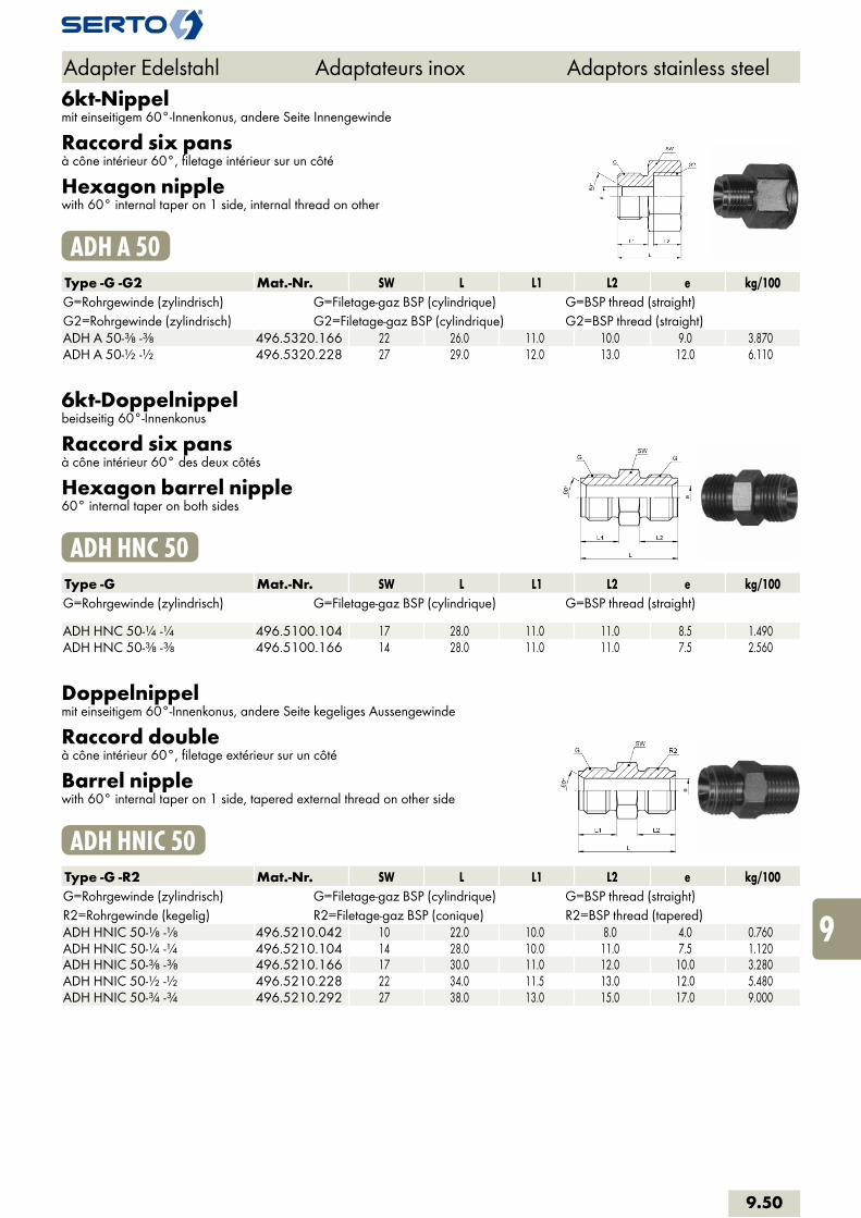
6kt-Nippelmit einseitigem 60°-Innenkonus, andere Seite Innengewinde
Raccord six pansà cône intérieur 60°, filetage intérieur sur un côté
Hexagon nipplewith 60° internal taper on 1 side, internal thread on other
ADH A 50Type -G -G2 Mat.-Nr. SW L L1 L2 e kg/100G=Rohrgewinde (zylindrisch) G=Filetage-gaz BSP (cylindrique) G=BSP thread (straight)G2=Rohrgewinde (zylindrisch) G2=Filetage-gaz BSP (cylindrique) G2=BSP thread (straight)ADH A 50-3/8 -3/8 496.5320.166 22 26.0 11.0 10.0 9.0 3.870ADH A 50-1/2 -1/2 496.5320.228 27 29.0 12.0 13.0 12.0 6.110
6kt-Doppelnippelbeidseitig 60°-Innenkonus
Raccord six pansà cône intérieur 60° des deux côtés
Hexagon barrel nipple60° internal taper on both sides
ADH HNC 50Type -G Mat.-Nr. SW L L1 L2 e kg/100G=Rohrgewinde (zylindrisch) G=Filetage-gaz BSP (cylindrique) G=BSP thread (straight) ADH HNC 50-1/4 -1/4 496.5100.104 17 28.0 11.0 11.0 8.5 1.490ADH HNC 50-3/8 -3/8 496.5100.166 14 28.0 11.0 11.0 7.5 2.560
Doppelnippelmit einseitigem 60°-Innenkonus, andere Seite kegeliges Aussengewinde
Raccord doubleà cône intérieur 60°, filetage extérieur sur un côté
Barrel nipplewith 60° internal taper on 1 side, tapered external thread on other side
ADH HNIC 50Type -G -R2 Mat.-Nr. SW L L1 L2 e kg/100G=Rohrgewinde (zylindrisch) G=Filetage-gaz BSP (cylindrique) G=BSP thread (straight)R2=Rohrgewinde (kegelig) R2=Filetage-gaz BSP (conique) R2=BSP thread (tapered)ADH HNIC 50-1/8 -1/8 496.5210.042 10 22.0 10.0 8.0 4.0 0.760ADH HNIC 50-1/4 -1/4 496.5210.104 14 28.0 10.0 11.0 7.5 1.120ADH HNIC 50-3/8 -3/8 496.5210.166 17 30.0 11.0 12.0 10.0 3.280ADH HNIC 50-1/2 -1/2 496.5210.228 22 34.0 11.5 13.0 12.0 5.480ADH HNIC 50-3/4 -3/4 496.5210.292 27 38.0 13.0 15.0 17.0 9.000
Adapter Edelstahl Adaptateurs inox Adaptors stainless steel
9.50
i
s
3F
4M
4G
5
5L
6
7
8
9
10
11
12

EinschraubtülleDouille canellée à visserMale adaptor hose nozzle
SO 50511Type -d1 -R Mat.-Nr. SW L a b e kg/100R=Rohrgewinde (kegelig) R=Filetage-gaz BSP (conique) R=BSP thread (tapered) SO 50511-4-1/8 056.0511.060 10 23.0 12.0 8.0 3.0 0.700SO 50511-4-1/4 056.0511.065 14 28.5 17.5 8.0 3.0 1.540SO 50511-6-1/8 056.0511.100 10 29.0 12.0 12.0 4.0 0.910SO 50511-6-1/4 056.0511.110 14 34.5 17.5 12.0 4.0 1.710SO 50511-6-3/8 056.0511.120 17 35.0 18.0 12.0 4.0 2.400SO 50511-6-1/2 056.0511.125 22 40.0 23.0 12.0 4.0 4.130SO 50511-8-1/8 056.0511.160 10 29.0 12.0 12.0 6.0 9.710SO 50511-8-1/4 056.0511.170 14 34.5 17.5 12.0 6.0 1.740SO 50511-8-3/8 056.0511.180 17 35.0 18.0 12.0 6.0 2.500SO 50511-8-1/2 056.0511.185 22 40.0 23.0 12.0 6.0 4.220SO 50511-10-1/4 056.0511.270 14 36.5 17.5 14.0 7.0 1.540SO 50511-10-3/8 056.0511.280 17 37.0 18.0 14.0 7.0 3.030SO 50511-10-1/2 056.0511.285 22 42.0 23.0 14.0 7.0 4.470SO 50511-12.7-1/4 056.0511.380 17 52.0 19.0 8.0 8.0 4.300SO 50511-13-3/8 056.0511.450 17 39.0 18.0 15.0 10.0 3.730SO 50511-13-1/2 056.0511.454 22 44.0 23.0 15.0 10.0 5.320SO 50511-16-1/2 056.0511.566 22 49.0 23.0 18.0 13.0 5.930SO 50511-19-1/2 056.0511.676 22 49.0 23.0 18.0 16.0 7.340SO 50511-19-3/4 056.0511.678 27 51.0 25.0 18.0 16.0 10.550SO 50511-25-1 056.0511.810 36 59.0 30.0 19.0 22.0 17.160
d1=entspricht dem Innen-Ø des Schlauches d1=correspond au Ø intérieur du tuyau d1=corresponds to the inside diameter of the hose
Adapter Edelstahl Adaptateurs inox Adaptors stainless steel
9.51
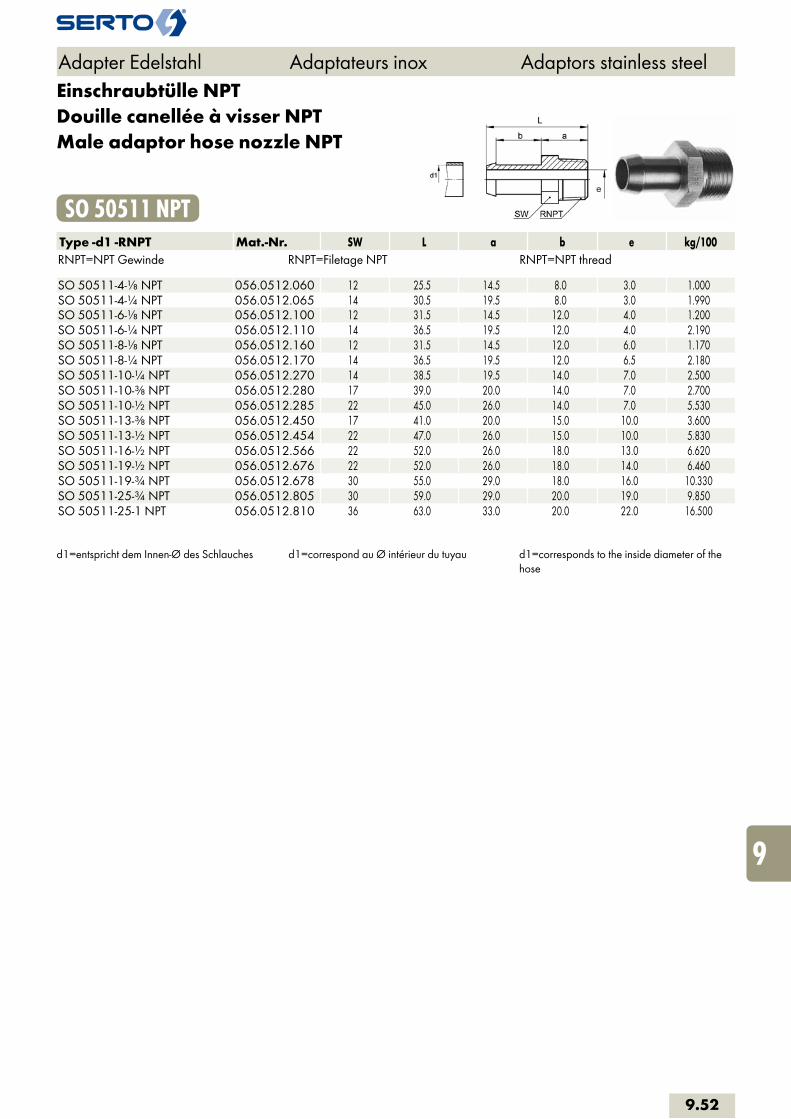
Einschraubtülle NPTDouille canellée à visser NPTMale adaptor hose nozzle NPT
SO 50511 NPTType -d1 -RNPT Mat.-Nr. SW L a b e kg/100RNPT=NPT Gewinde RNPT=Filetage NPT RNPT=NPT thread SO 50511-4-1/8 NPT 056.0512.060 12 25.5 14.5 8.0 3.0 1.000SO 50511-4-1/4 NPT 056.0512.065 14 30.5 19.5 8.0 3.0 1.990SO 50511-6-1/8 NPT 056.0512.100 12 31.5 14.5 12.0 4.0 1.200SO 50511-6-1/4 NPT 056.0512.110 14 36.5 19.5 12.0 4.0 2.190SO 50511-8-1/8 NPT 056.0512.160 12 31.5 14.5 12.0 6.0 1.170SO 50511-8-1/4 NPT 056.0512.170 14 36.5 19.5 12.0 6.5 2.180SO 50511-10-1/4 NPT 056.0512.270 14 38.5 19.5 14.0 7.0 2.500SO 50511-10-3/8 NPT 056.0512.280 17 39.0 20.0 14.0 7.0 2.700SO 50511-10-1/2 NPT 056.0512.285 22 45.0 26.0 14.0 7.0 5.530SO 50511-13-3/8 NPT 056.0512.450 17 41.0 20.0 15.0 10.0 3.600SO 50511-13-1/2 NPT 056.0512.454 22 47.0 26.0 15.0 10.0 5.830SO 50511-16-1/2 NPT 056.0512.566 22 52.0 26.0 18.0 13.0 6.620SO 50511-19-1/2 NPT 056.0512.676 22 52.0 26.0 18.0 14.0 6.460SO 50511-19-3/4 NPT 056.0512.678 30 55.0 29.0 18.0 16.0 10.330SO 50511-25-3/4 NPT 056.0512.805 30 59.0 29.0 20.0 19.0 9.850SO 50511-25-1 NPT 056.0512.810 36 63.0 33.0 20.0 22.0 16.500
d1=entspricht dem Innen-Ø des Schlauches d1=correspond au Ø intérieur du tuyau d1=corresponds to the inside diameter of the hose
Adapter Edelstahl Adaptateurs inox Adaptors stainless steel
9.52
i
s
3F
4M
4G
5
5L
6
7
8
9
10
11
12

Verteilerleisten Distributeurs Manifolds
Eléments de distribution Distributor elementsVerteilerleisten
Eigenschaften, Besonderheiten- viele Anschlussmöglichkeiten
AnwendungLuft- und Flüssigkeitsverteiler Einsatz sowohl im Bereich der pneumatischen Steuerungsanlagen als auch in der chemischen Industrie.
Werkstoff PVDF
Généralités- multiples possibillités de raccordements
Applicationair et fluidesApplication dans la domaine des installations de commande pneumatiques et aussi dans I’industrie chimique.
MatériauxPVDF
Characteristics, specialities- many possible combinations
Applicationair and liquidApplication in the field of pneumatic control system and in the chemical industry.
MaterialPVDF
9.53
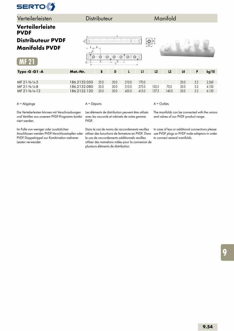
Verteilerleiste PVDFDistributeur PVDFManifolds PVDF
MF 21Type -G -G1 -A Mat.-Nr. B D L L1 L2 L3 L4 P kg/10 MF 21-3/8-1/4-5 186.2132.050 35.0 30.0 210.0 170.0 20.0 5.2 2.560MF 21-3/8-1/4-8 186.2132.080 35.0 30.0 315.0 275.0 102.5 70.0 20.0 5.2 4.100MF 21-3/8-1/4-12 186.2132.120 35.0 30.0 455.0 415.0 137.5 140.0 20.0 5.2 6.150
A = Abgänge
Die Verteilerleisten können mit Verschraubungen und Ventilen aus unserem PVDF-Programm kombi-niert werden.
Im Falle von weniger oder zusätzlichen Anschlüssen werden PVDF-Verschlussstopfen oder PVDF Doppelnippel zur Kombination mehrerer Leisten verwendet.
A = Départs
Les éléments de distribution peuvent être utilisés avec les raccords et robinets de notre gamme PVDF.
Dans le cas de moins de raccordements veuillez utiliser des bouchons de fermeture en PVDF. Dans le cas de raccordements additionnels veuillez utiliser des mamelons mâles pour la connexion de plusieurs éléments de distribution.
A = Outlets
The manifolds can be connected with the unions and valves of our PVDF product range.
In case of less or additional connections please use PVDF plugs or PVDF male adaptors in order to connect several manifolds.
Verteilerleisten Distributeur Manifold
9.54
i
s
3F
4M
4G
5
5L
6
7
8
9
10
11
12
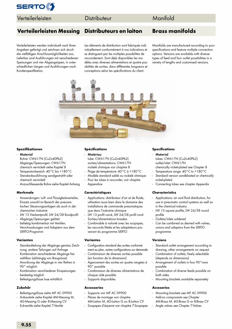
Spezifikationen
- MaterialRohre: CW617N (CuZn40Pb2) Abgänge/Speisungen: CW617N chemisch vernickelt siehe Kapitel 8
- Temperaturbereich -40°C bis +180°C- Standardausführung sandgestrahlt oder
chemisch vernickelt- Anzuschliessende Rohre siehe Kapitel Anhang
Merkmale
- Anwendungen: Luft- und Flüssigkeitsverteiler, Einsatz sowohl im Bereich der pneuma-tischen Steuerungsanlagen als auch in der chemischen Industrie
- LW 13 Vierkantprofil, LW 24/38 Rundprofil- Abgänge/Speisungen gelötet- beliebig kombinierbar mit Ventilen,
Verschraubungen und Adaptern aus dem SERTO-Programm
Varianten
- Standardteilung der Abgänge gemäss Zeich-nung, andere Teilungen auf Anfrage
- Kombination verschiedener Abgänge frei wählbar (abhängig von Baugrösse)
- Anordnung der Abgänge in vier Reihen à 90° möglich
- Kombination verschiedener Einspeisungen beidseitig möglich
- Befestigungsfüsse lose erhältlich
Zubehör
- Befestigungsfüsse siehe MF AC 09900- Anbauteile siehe Kapitel 4M-Messing M,
4G-Messing G oder 8-Messing CV- Eckventile siehe Kapitel 7-Ventile
Spécifications
- Matériautube: CW617N (CuZn40Pb2) sorties/alimentations: CW617N nickelé chimique voir chapitre 8
- Plage de température -40°C à +180°C- Modèle standard sablé ou nickelé chimique- Pour les tubes à raccorder, voir chapitre
Appendice
Caractéristiques
- Applications: distributeur d’air et de fluide, utilisation aussi bien dans le domaine des installations de commande pneumatiques que dans l’industrie chimique
- LW 13 profil carré, LW 24/38 profil rond- Sorties/alimentations brasées- Combinable à volonté avec les soupapes,
les raccords filetés et les adaptateurs pro-venant du programme SERTO
Variantes
- Configuration standard des sorties conformé-ment au plan, autres configurations sur demande
- Combinaison de diverses sorties possible (en fonction de la dimension)
- Agencement des sorties en quatre rangées à 90° possible
- Combinaison de diverses alimentations de chaque côté possible
- Supports disponibles
Accessories
- Supports voir MF AC 09900- Pièces de montage voir chapitre
4M-Laiton M, 4G-Laiton G ou 8-Laiton CV- Soupapes d’équerre voir chapitre 7-Soupapes
Specifications
- Materialtubes: CW617N (CuZn40Pb2) outlet/inlet: CW617N chemically nickel-plated see Chapter 8
- Temperature range -40°C to +180°C- Standard version sandblasted or chemically
nickel-plated- Connecting tubes see chapter Appendix
Characteristics
- Applications: air and fluid distribution, for use in pneumatic control systems as well as in the chemical industry
- LW 13 square profile, LW 24/38 round profile
- Outlets/inlets soldered- Can be combined as desired with valves,
unions and adaptors from the SERTO programme
Versions
- Standard outlet arrangement according to drawing, other arrangements on request
- Combination of outlets, freely selectable (depends on dimensions)
- Arrangement of outlets in four 90°rows possible
- Combination of diverse feeds possible on both sides
- Mounting brackets available separately
Accesories
- Mounting brackets see MF AC 09900- Add-on components see Chapter
4M-Brass M, 4G-Brass G or 8-Brass CV- Angle valves see Chapter 7-Valves
Verteilerleisten Distributeur Manifold
Verteilerleisten werden individuell nach Ihren Angaben gefertigt und zeichnen sich durch die vielfältigen Anschlussmöglichkeiten aus. Lieferbar sind Ausführungen mit verschiedenen Speisungen und vier Abgangstypen, in unter-schiedlichen Längen und Ausführungen nach Kundenspezfikation.
Distributeurs en laiton Brass manifoldsVerteilerleisten Messing
Les éléments de distribution sont fabriqués indi-viduellement conformément à vos indications et se distinguent par les multiples possibilités de raccordement. Sont déjà disponibles les mo-dèles avec diverses alimentations et quatre pos-sibilités de sorties, dans différentes longueurs et conceptions selon les spécifications du client.
Manifolds are manufactured according to your specifications and feature multiple connection options. Versions are available with diverse types of feed and four outlet possibilities in a variety of lengths and customised versions.
9.55

zR
D
L
zR
zR
zR
zR ½ x xx x x ½ x
h
LW
D
LW 24/38 LW13
LW
D
h
LW
D
h
LW
D
hh1
LW
D
Verteilerleisten Distributeur Manifold
EinspeisungenAlimentationsInlets
MF ES 01421Nippel geradeEmbout droitStraight nipple
MF ES 01401Nippel konischEmbout coniqueNipple tapered
MF ES 01403MuffeManchonAdaptor
MF ES 01404Muffe mit DichtkanteManchon avec arrête d‘étanchéitéAdaptor with edge seal
mögliche Abgängesorties possiblespossible outlets
Type Mat.-Nr. PN LW D
MF 42 185.4113.000 125 13 16
MF 43 185.4224.000 100 24 28
MF 44 185.4238.000 64 38 42
Type -G Mat.-Nr. x h h1LW 13 LW 24 LW 38 LW 13 LW 24 LW 38
SO 01421-6-6 248.1400.100 35 24 37 44 – – –SO 01421-8-9 248.1400.140 35 27 40 47 – – –SO 01421-10-12 248.1400.185 40 30.5 43.5 50.5 – – –SO 01421-12-14 248.1400.200 40 35 48 55 – – –
SO 01401-1/8 246.1401.020 35 24 29 36 14 19 26SO 01401-1/4 246.1401.040 35 26 31 38 15 20 27SO 01401-3/8 246.1401.060 40 27 32 39 15 20 27SO 01401-1/2 246.1401.080 45 29.5 34.5 41.5 15.5 20.5 27.5SO 01401-3/4 246.1401.120 50 32.5 37.5 44.5 15.5 20.5 27.5
SO 01402-6-A6 246.1402.060 35 37 42 49 – – –SO 01402-9-A8 246.1402.080 35 41 46 53 – – –SO 01402-12-A10 246.1402.100 40 43 48 55 – – –SO 01402-14-A12 246.1402.120 45 46 51 58 – – –SO 01402-14-A14 246.1402.140 50 49 54 61 – – –
SO 01403-1/8k 246.1403.100 35 23 28 35 – – –SO 01403-1/4k 246.1403.140 35 29 34 41 – – –SO 01403-3/8k 246.1403.185 40 29 34 41 – – –SO 01403-1/2k 246.1403.200 45 32 37 44 – – –
MF BO 00400BodenFondBase
SO 01403Nippel konischEmbout coniqueNipple tapered
SO 01421Nippel geradeEmbout droitStraight nipple
SO 01401MuffeManchonAdaptor
SO 01402EinlötstutzenEmbout à braserSoldering stud
9.56
i
s
3F
4M
4G
5
5L
6
7
8
9
10
11
12

Verschraubung gerademit Einlötnippel
Union droitavec embout à braser
Straight unionwith soldering nipple
MF ES 01421Type -LW -d Mat.-Nr. SW SW1 D z zR L e LW 13 LW 24 LW 38 MF ES 01421-13-6 248.1410.101 12 12 10.0 18.5 27.7 5.0 MF ES 01421-13-8 248.1410.102 14 14 17.0 11.0 19.5 30.0 7.0 MF ES 01421-13-10 248.1410.103 17 17 21.0 11.5 20.5 33.4 10.5 MF ES 01421-13-12 248.1410.104 22 19 26.0 14.0 24.0 38.5 10.0 MF ES 01421-24-6 248.1420.101 12 12 10.0 18.5 27.6 5.0 MF ES 01421-24-8 248.1420.102 14 14 17.0 11.0 20.5 31.0 7.0 MF ES 01421-24-10 248.1420.103 17 17 21.0 11.5 21.5 34.4 10.5 MF ES 01421-24-12 248.1420.104 22 19 26.0 14.0 24.0 38.5 13.0 MF ES 01421-38-8 248.1430.102 14 14 17.0 11.0 20.5 31.0 7.0 MF ES 01421-38-10 248.1430.103 17 17 21.0 11.5 21.5 34.4 10.5 MF ES 01421-38-12 248.1430.104 22 19 26.0 14.0 24.0 38.5 13.0
für Einspeisung links / rechts pour alimentation gauche / droite for inlet left / right
Einlötnippel konischEmbout à braser coniqueSoldering nipple tapered
MF ES 01401Type -LW -R Mat.-Nr. SW zR e LW 13 LW 24 LW 38 R=Rohrgewinde (kegelig) R=Filetage-gaz BSP (conique) R=BSP thread (tapered)MF ES 01401-13-1/8 245.1413.101 12 15.0 6.0 MF ES 01401-13-1/4 245.1413.102 14 21.0 8.5 MF ES 01401-13-3/8 245.1413.103 17 21.0 10.5 MF ES 01401-13-1/2 245.1413.104 22 24.0 10.0 MF ES 01401-24-1/8 245.1423.101 12 15.0 6.0 MF ES 01401-24-1/4 245.1423.102 14 21.0 8.5 MF ES 01401-24-3/8 245.1423.103 17 21.0 10.5 MF ES 01401-24-1/2 245.1423.104 22 24.0 13.0 MF ES 01401-38-1/4 245.1433.102 14 21.0 8.5 MF ES 01401-38-3/8 245.1433.103 17 21.0 10.5 MF ES 01401-38-1/2 245.1433.104 22 24.0 13.0
für Einspeisung links / rechts pour alimentation gauche / droite for inlet left / right
Verteilerleisten Distributeur Manifold
d=Rohraussen-øe=kleinste BohrungL=Mass in montiertem ZustandLW=Nennweite
d=ø extérieur du tubee=ø-min. de passageL=après montageLW=largeur nominale
d=tube outside diametere=minimum boreL=installed lengthLW=nominal bore
9.57
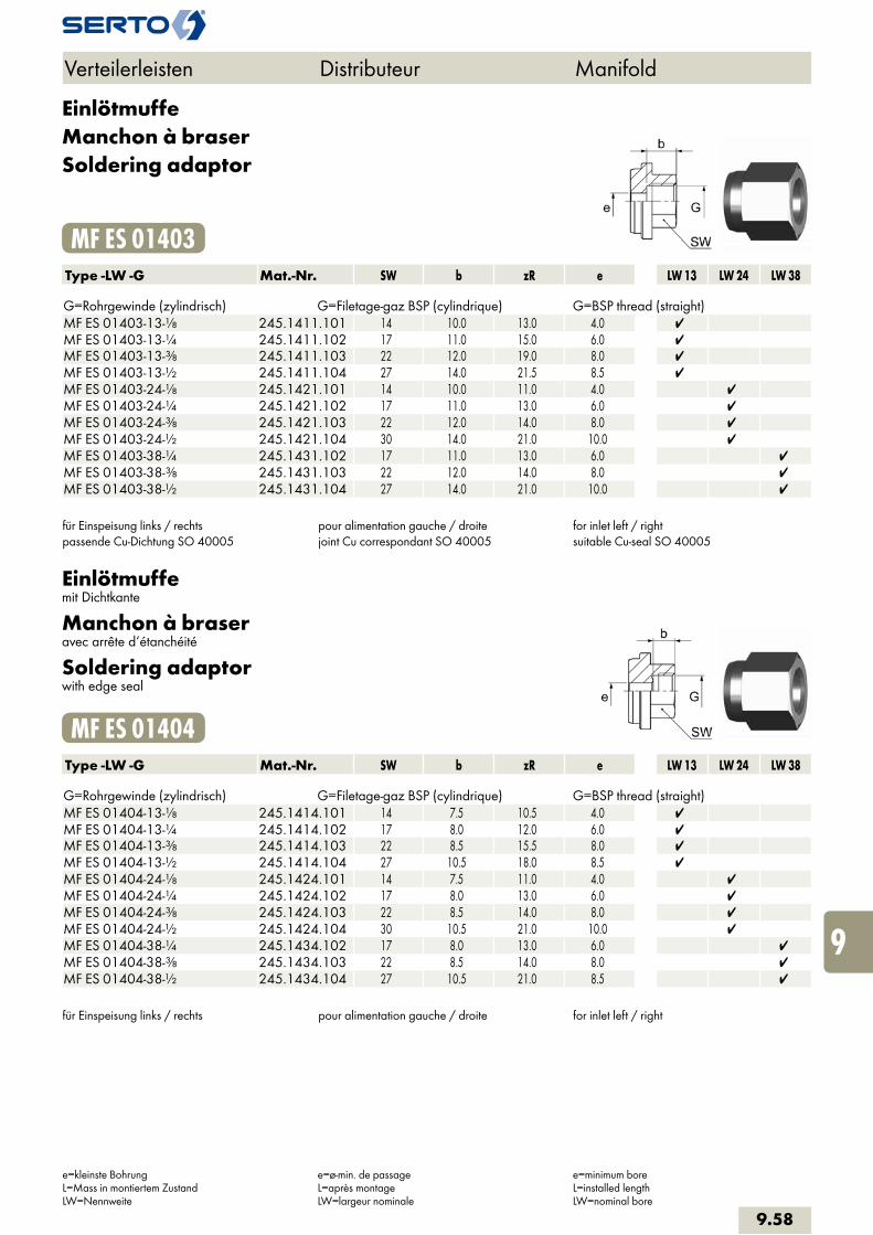
EinlötmuffeManchon à braserSoldering adaptor
MF ES 01403Type -LW -G Mat.-Nr. SW b zR e LW 13 LW 24 LW 38 G=Rohrgewinde (zylindrisch) G=Filetage-gaz BSP (cylindrique) G=BSP thread (straight)MF ES 01403-13-1/8 245.1411.101 14 10.0 13.0 4.0 MF ES 01403-13-1/4 245.1411.102 17 11.0 15.0 6.0 MF ES 01403-13-3/8 245.1411.103 22 12.0 19.0 8.0 MF ES 01403-13-1/2 245.1411.104 27 14.0 21.5 8.5 MF ES 01403-24-1/8 245.1421.101 14 10.0 11.0 4.0 MF ES 01403-24-1/4 245.1421.102 17 11.0 13.0 6.0 MF ES 01403-24-3/8 245.1421.103 22 12.0 14.0 8.0 MF ES 01403-24-1/2 245.1421.104 30 14.0 21.0 10.0 MF ES 01403-38-1/4 245.1431.102 17 11.0 13.0 6.0 MF ES 01403-38-3/8 245.1431.103 22 12.0 14.0 8.0 MF ES 01403-38-1/2 245.1431.104 27 14.0 21.0 10.0
für Einspeisung links / rechtspassende Cu-Dichtung SO 40005
pour alimentation gauche / droitejoint Cu correspondant SO 40005
for inlet left / rightsuitable Cu-seal SO 40005
Einlötmuffemit Dichtkante
Manchon à braseravec arrête d‘étanchéité
Soldering adaptorwith edge seal
MF ES 01404Type -LW -G Mat.-Nr. SW b zR e LW 13 LW 24 LW 38 G=Rohrgewinde (zylindrisch) G=Filetage-gaz BSP (cylindrique) G=BSP thread (straight)MF ES 01404-13-1/8 245.1414.101 14 7.5 10.5 4.0 MF ES 01404-13-1/4 245.1414.102 17 8.0 12.0 6.0 MF ES 01404-13-3/8 245.1414.103 22 8.5 15.5 8.0 MF ES 01404-13-1/2 245.1414.104 27 10.5 18.0 8.5 MF ES 01404-24-1/8 245.1424.101 14 7.5 11.0 4.0 MF ES 01404-24-1/4 245.1424.102 17 8.0 13.0 6.0 MF ES 01404-24-3/8 245.1424.103 22 8.5 14.0 8.0 MF ES 01404-24-1/2 245.1424.104 30 10.5 21.0 10.0 MF ES 01404-38-1/4 245.1434.102 17 8.0 13.0 6.0 MF ES 01404-38-3/8 245.1434.103 22 8.5 14.0 8.0 MF ES 01404-38-1/2 245.1434.104 27 10.5 21.0 8.5
für Einspeisung links / rechts pour alimentation gauche / droite for inlet left / right
Verteilerleisten Distributeur Manifold
e=kleinste BohrungL=Mass in montiertem ZustandLW=Nennweite
e=ø-min. de passageL=après montageLW=largeur nominale
e=minimum boreL=installed lengthLW=nominal bore
9.58
i
s
3F
4M
4G
5
5L
6
7
8
9
10
11
12
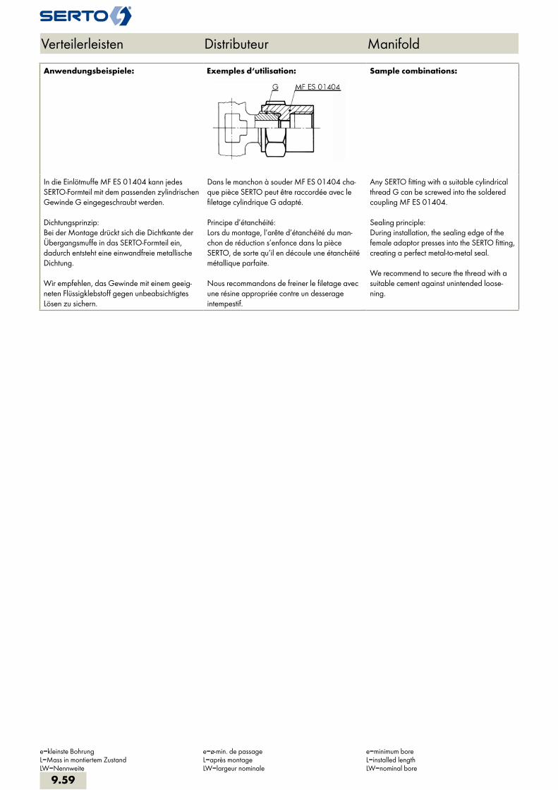
Anwendungsbeispiele: Exemples d‘utilisation: Sample combinations:
In die Einlötmuffe MF ES 01404 kann jedes SERTO-Formteil mit dem passenden zylindrischen Gewinde G eingegeschraubt werden.
Dichtungsprinzip: Bei der Montage drückt sich die Dichtkante der Übergangsmuffe in das SERTO-Formteil ein, dadurch entsteht eine einwandfreie metallische Dichtung.
Wir empfehlen, das Gewinde mit einem geeig-neten Flüssigklebstoff gegen unbeabsichtigtes Lösen zu sichern.
Dans le manchon à souder MF ES 01404 cha-que pièce SERTO peut être raccordée avec le filetage cylindrique G adapté.
Principe d’étanchéité: Lors du montage, l’arête d’étanchéité du man-chon de réduction s’enfonce dans la pièce SERTO, de sorte qu’il en découle une étanchéité métallique parfaite.
Nous recommandons de freiner le filetage avec une résine appropriée contre un desserage intempestif.
Any SERTO fitting with a suitable cylindrical thread G can be screwed into the soldered coupling MF ES 01404.
Sealing principle: During installation, the sealing edge of the female adaptor presses into the SERTO fitting, creating a perfect metal-to-metal seal.
We recommend to secure the thread with a suitable cement against unintended loose-ning.
Verteilerleisten Distributeur Manifold
e=kleinste BohrungL=Mass in montiertem ZustandLW=Nennweite
e=ø-min. de passageL=après montageLW=largeur nominale
e=minimum boreL=installed lengthLW=nominal bore
9.59
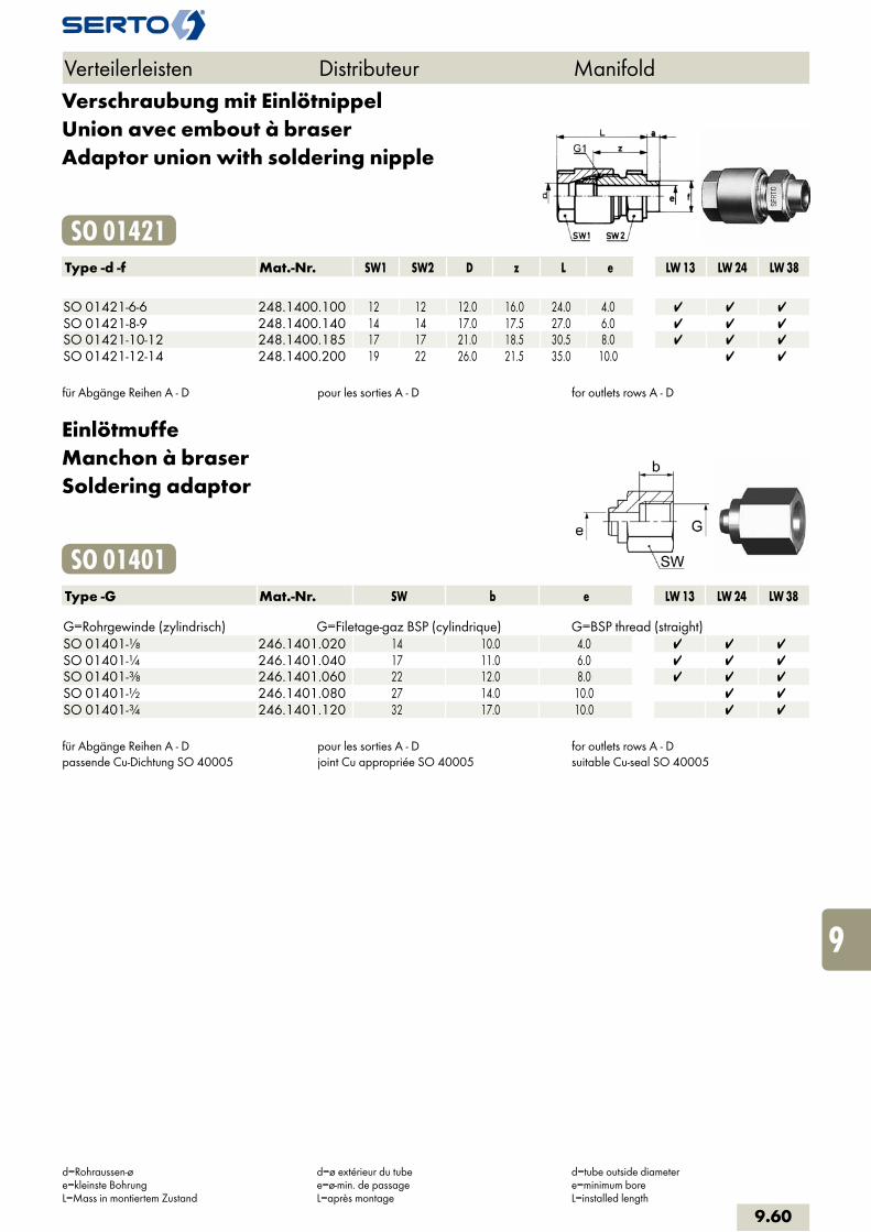
Verschraubung mit EinlötnippelUnion avec embout à braserAdaptor union with soldering nipple
SO 01421Type -d -f Mat.-Nr. SW1 SW2 D z L e LW 13 LW 24 LW 38 SO 01421-6-6 248.1400.100 12 12 12.0 16.0 24.0 4.0 SO 01421-8-9 248.1400.140 14 14 17.0 17.5 27.0 6.0 SO 01421-10-12 248.1400.185 17 17 21.0 18.5 30.5 8.0 SO 01421-12-14 248.1400.200 19 22 26.0 21.5 35.0 10.0
für Abgänge Reihen A - D pour les sorties A - D for outlets rows A - D
EinlötmuffeManchon à braserSoldering adaptor
SO 01401Type -G Mat.-Nr. SW b e LW 13 LW 24 LW 38 G=Rohrgewinde (zylindrisch) G=Filetage-gaz BSP (cylindrique) G=BSP thread (straight)SO 01401-1/8 246.1401.020 14 10.0 4.0 SO 01401-1/4 246.1401.040 17 11.0 6.0 SO 01401-3/8 246.1401.060 22 12.0 8.0 SO 01401-1/2 246.1401.080 27 14.0 10.0 SO 01401-3/4 246.1401.120 32 17.0 10.0
für Abgänge Reihen A - Dpassende Cu-Dichtung SO 40005
pour les sorties A - Djoint Cu appropriée SO 40005
for outlets rows A - Dsuitable Cu-seal SO 40005
Verteilerleisten Distributeur Manifold
d=Rohraussen-øe=kleinste BohrungL=Mass in montiertem Zustand
d=ø extérieur du tubee=ø-min. de passageL=après montage
d=tube outside diametere=minimum boreL=installed length
9.60
i
s
3F
4M
4G
5
5L
6
7
8
9
10
11
12

EinlötstutzenEmbout lisse à braserSoldering stud cylindrical
SO 01402Type -f -Ad Mat.-Nr. SW b e LW 13 LW 24 LW 38 SO 01402-6-A6 246.1402.060 12 22.0 4.0 SO 01402-9-A8 246.1402.080 14 24.0 6.0 SO 01402-12-A10 246.1402.100 17 26.0 8.0 SO 01402-14-A12 246.1402.120 22 28.0 9.0 SO 01402-14-A14 246.1402.140 27 30.0 11.0
für Abgänge Reihen A - D pour les sorties A - D for outlets rows A - D
Einlötnippel konischEmbout à braser coniqueSoldering nipple tapered
SO 01403Type -R Mat.-Nr. SW z e LW 13 LW 24 LW 38 R=Rohrgewinde (kegelig) R=Filetage-gaz BSP (conique) R=BSP thread (tapered)SO 01403-1/8k 246.1403.100 12 4.0 4.0 SO 01403-1/4k 246.1403.140 14 6.0 6.0 SO 01403-3/8k 246.1403.185 17 6.0 8.0 SO 01403-1/2k 246.1403.200 22 6.0 10.0
für Abgänge Reihen A - D pour les sorties A - D for outlets rows A - D
Verteilerleisten Distributeur Manifold
Ad=Aussen-ø der Andrehunge=kleinste BohrungL=Mass in montiertem Zustand
Ad=ø extérieur de la portée cylindriquee=ø-min. de passageL=après montage
Ad=outside diameter of cyl. stube=minimum boreL=installed length
9.61

BefestigungsfussSupport de fixationMounting bracket
MF AC 09900Type -LW Mat.-Nr. D D2 L s LW 13 LW 24 LW 38 MF AC 09900-13 185.0013.000 17.0 4.2 32.0 1.50 MF AC 09900-24 185.0024.000 28.0 5.5 44.0 1.50 MF AC 09900-38 185.0038.000 42.0 6.0 62.0 1.50
Verteilerleisten Distributeur Manifold
LW=Nennweite LW=largeur nominale LW=nominal bore
9.62
i
s
3F
4M
4G
5
5L
6
7
8
9
10
11
12