uk-2252-22 addendum # 1 04/27/2022
332
University of Kentucky Purchasing Division 322 Peterson Service Building Lexington, KY 40506-0005 An Equal Opportunity University INVITATION FOR BIDS UK-2252-22 ADDENDUM # 1 04/27/2022 ATTENTION: This is not an order. Read all instructions, terms and conditions carefully. IMPORTANT: BID AND ADDENDUM MUST BE RECEIVED BY: 05/10/2022 @ 3:00 P.M. LEXINGTON, KY TIME Bidder must acknowledge receipt of this and any addendum as stated in the Invitation for Bids. 1. Please see the attached Drawings and Specifications that were inadvertently omitted from the original posting of the RFP. 2. If you have any questions, please feel free to contact Ken Scott at the number below or at [email protected]. OFFICIAL APPROVAL SIGNATURE UNIVERSITY OF KENTUCKY ________________________________________ ______________________________________ ________________________________________ Contracting Officer / (859) 257-9102 Typed or Printed Name 04/27/2022
-
Upload
khangminh22 -
Category
Documents
-
view
1 -
download
0
Transcript of uk-2252-22 addendum # 1 04/27/2022

University of Kentucky Purchasing Division 322 Peterson Service Building Lexington, KY 40506-0005
A n E q u a l O p p o r t u n i t y U n i v e r s i t y
INVITATION FOR BIDS
UK-2252-22 ADDENDUM # 1
04/27/2022
ATTENTION: This is not an order. Read all instructions, terms and conditions carefully.
IMPORTANT: BID AND ADDENDUM MUST BE RECEIVED BY: 05/10/2022 @ 3:00 P.M. LEXINGTON, KY TIME Bidder must acknowledge receipt of this and any addendum as stated in the Invitation for Bids. 1. Please see the attached Drawings and Specifications that were inadvertently omitted from the original posting
of the RFP. 2. If you have any questions, please feel free to contact Ken Scott at the number below or at
OFFICIAL APPROVAL SIGNATURE UNIVERSITY OF KENTUCKY
________________________________________ ______________________________________
________________________________________ Contracting Officer / (859) 257-9102 Typed or Printed Name
04/27/2022

Phase 3 - Doors & Hardware Package University of Kentucky Pavilion A - 12th Floor UK Project Number 2402.16
GBBN Project No. 13703.01 TABLE OF CONTENTS - PAGE COUNT Issue Date: March 14, 2022 000110 - 1
SECTION 000110
TABLE OF CONTENTS
SECTIONS PAGES
DIVISION 00 — PROCUREMENT AND CONTRACTING REQUIREMENTS 004400 - SUBSTITUTIONS PRIOR TO BIDDING ................................................................................... 8 009000 - EXISTING CODE SUMMARY .................................................................................................. 0 009000.12 - CODE SUMMARY- 12TH FLOOR PATIENT ROOM FIT-OUT ........................................ 2
DIVISION 01 — GENERAL REQUIREMENTS 011100.01 - SUMMARY OF WORK ......................................................................................................... 3 012200 - UNIT PRICES .............................................................................................................................. 2 012300 - ALTERNATES ............................................................................................................................ 3 012500 - OWNER FURNISHED ITEMS ................................................................................................... 4 013100 - PROJECT MANAGEMENT AND COORDINATION .............................................................. 7 013300 - SUBMITTAL PROCEDURES .................................................................................................. 13 013500 - INTERIM LIFE SAFETY MEASURES (ILSM) ......................................................................... 3 013600 - INDOOR AIR QUALITY ............................................................................................................ 3 014000 - QUALITY REQUIREMENTS ..................................................................................................... 7 015000 - TEMPORARY FACILITIES AND CONTROLS ........................................................................ 8 016000 - PRODUCT REQUIREMENTS .................................................................................................... 7 017300 - EXECUTION ............................................................................................................................... 7 017329 - CUTTING AND PATCHING ...................................................................................................... 6 017700 - CLOSEOUT PROCEDURES ...................................................................................................... 6 019100 - COMMISSIONING w Appendix A ............................................................................................. 0
DIVISION 02 — EXISTING CONDITIONS 024110 - SELECTIVE DEMOLITION ....................................................................................................... 7
DIVISION 03 — CONCRETE NOT USED
DIVISION 04 — MASONRY NOT USED
DIVISION 05 — METALS 055000 - METAL FABRICATIONS ........................................................................................................ 11
DIVISION 06 — WOOD, PLASTICS, AND COMPOSITES 061050 - MISCELLANEOUS ROUGH CARPENTRY ............................................................................. 7 064000 - ARCHITECTURAL WOODWORK ......................................................................................... 28 066116 - SOLID SURFACING FABRICATIONS ..................................................................................... 8
DIVISION 07 — THERMAL AND MOISTURE PROTECTION 071800 - TRAFFIC COATINGS ................................................................................................................. 6 072100 - INSULATION .............................................................................................................................. 3 075400.1 - THERMOPLASTIC POLYOLEFIN (TPO) ROOFING_REPAIR ......................................... 11 076200 - SHEET METAL FLASHING AND TRIM .................................................................................. 0 078100 - APPLIED FIREPROOFING - PATCHING ................................................................................. 9 078400 - FIRESTOPPING .......................................................................................................................... 9 079200 - JOINT SEALANTS .................................................................................................................... 14

Phase 3 - Doors & Hardware Package University of Kentucky Pavilion A - 12th Floor UK Project Number 2402.16
GBBN Project No. 13703.01 TABLE OF CONTENTS - PAGE COUNT Issue Date: March 14, 2022 000110 - 2
DIVISION 08 — OPENINGS 081100 - HOLLOW METAL DOORS AND FRAMES ........................................................................... 13 081400 - WOOD DOORS ........................................................................................................................... 7 083100 - ACCESS DOORS and FRAMES ................................................................................................. 5 083400 - SPECIAL FUNCTION DOORS .................................................................................................. 5 084243 - ICU CCU ENTRANCES .............................................................................................................. 8 087100 - DOOR HARDWARE ................................................................................................................. 12 087100.1 - DOOR HARDWARE SCHEDULE ........................................................................................ 15 087113 - AUTOMATIC DOOR OPERATORS ........................................................................................ 12 088000 - GLAZING .................................................................................................................................. 14
DIVISION 09 — FINISHES 090160 - CONCRETE FLOORING REPAIR ............................................................................................. 4 090600.1 - SCHEDULE FOR FINISHES ................................................................................................... 1 090600.2 - MATERIAL AND COLOR SCHEDULE ................................................................................ 0 092216 - NON-STRUCTURAL METAL FRAMING .............................................................................. 12 092900 - GYPSUM BOARD ..................................................................................................................... 14 093000 - TILING ....................................................................................................................................... 15 095100 - ACOUSTICAL CEILINGS ........................................................................................................ 11 095426 - SUSPENDED WOOD CEILINGS ............................................................................................... 6 096100 - FLOORING TREATMENT ......................................................................................................... 4 096340 - STONE FLOORING .................................................................................................................... 0 096500 - RESILIENT FLOORING ........................................................................................................... 13 097200 - WALL COVERINGS ................................................................................................................... 5 097500 - STONE FACING ....................................................................................................................... 13 097700 - SPECIAL WALL SURFACES .................................................................................................... 7 097700.1 - SPECIAL WALL SURFACES SCHEDULE ............................................................................ 6 097700.2 - ELEVATOR LOBBY GRAPHIC SCHEDULE ....................................................................... 2 098400 - ACOUSTIC WALL AND CEILING SYSTEMS ........................................................................ 6 099100 - PAINTING ................................................................................................................................... 0
DIVISION 10 — SPECIALTIES 101100 - VISUAL DISPLAY SURFACES ................................................................................................. 2 101400 - SIGNAGE ..................................................................................................................................... 5 102113 - TOILET COMPARTMENTS ...................................................................................................... 0 102120 - CUBICLE CURTAIN TRACK SYSTEMS ................................................................................. 4 102600 - WALL PROTECTION ................................................................................................................. 8 102813 - TOILET ROOM ACCESSORIES ................................................................................................ 8 104400 - FIRE PROTECTION SPECIALTIES .......................................................................................... 8 105113 - METAL LOCKERS ..................................................................................................................... 8 105116 - WOOD LOCKERS ....................................................................................................................... 6
DIVISION 11 — EQUIPMENT 117000 - MEDICAL EQUIPMENT ............................................................................................................ 1
DIVISION 12 — FURNISHINGS 122400 - ROLLER WINDOW SHADES .................................................................................................... 9 123100 - MODULAR METAL CASEWORK ............................................................................................ 5 123113 - STAINLESS STEEL COUNTERS .............................................................................................. 5 123216 - MANUFACTURED PLASTIC-LAMINATE-CLAD CASEWORK .......................................... 8 125000 - HEALTHCARE CASEWORK AND FURNITURE ................................................................... 4

Phase 3 - Doors & Hardware Package University of Kentucky Pavilion A - 12th Floor UK Project Number 2402.16
GBBN Project No. 13703.01 TABLE OF CONTENTS - PAGE COUNT Issue Date: March 14, 2022 000110 - 3
DIVISION 13 — SPECIAL CONSTRUCTION 133400 - FABRICATED ENGINEERED STRUCTURES ........................................................................ 3 134275 - INTEGRATED INTERIOR ASSEMBLIES ................................................................................ 9 134900 - RADIATION PROTECTION ...................................................................................................... 8
DIVISION 14 — CONVEYING EQUIPMENT NOT USED
DIVISION 20 — MECHANICAL SUPPORT 200000 General Mechanical Requirements ................................................................................................. 0 200513 Motors ............................................................................................................................................. 0 200514 Variable Frequency Drive (VFD) System ....................................................................................... 0 200529 Piping and Equipment Supporting Devices .................................................................................... 0 200553 Mechanical Systems Identification ................................................................................................. 0 200573 Mechanical Systems Firestopping .................................................................................................. 0 200700 Mechanical Systems Insulation ....................................................................................................... 0
DIVISION 21 — FIRE SUPPRESSION 210000 General Fire Suppression Requirements ......................................................................................... 0 211314 Automatic Fire Sprinkler System .................................................................................................... 0
DIVISION 22 — PLUMBING 220000 General Plumbing Requirements .................................................................................................... 0 220594 Domestic Water Systems Balance .................................................................................................. 0 221118 Water Distribution System .............................................................................................................. 0 221314 Sanitary Waste and Storm Drainage Systems ................................................................................. 0 222114 Plumbing Specialties ....................................................................................................................... 0 224000 Plumbing Fixtures ........................................................................................................................... 0 224014 Equipment By Others ...................................................................................................................... 0 226316 Medical Gas Systems ...................................................................................................................... 0
DIVISION 23 — HEATING VENTILATING AND AIR CONDITIONING 230000 General HVAC Requirements ........................................................................................................ 0 230525 Owner Furnished Equipment .......................................................................................................... 0 230550 Vibration Isolation .......................................................................................................................... 0 230594 Water Systems Test Adjust Balance ............................................................................................... 0 230595 Air Systems Test Adjust Balance .................................................................................................... 0 230901 Control Systems Integration ............................................................................................................ 0 230902 Control Valves and Dampers .......................................................................................................... 0 230903 Control Instrumentation .................................................................................................................. 0 230923 Direct Digital Controllers and Networks ........................................................................................ 0 230993 Control Sequences .......................................................................................................................... 0 232116 Pipe and Pipe Fittings ..................................................................................................................... 0 232118 Valves ............................................................................................................................................. 0 232120 Piping Specialties ............................................................................................................................ 0 232123 Pumps .............................................................................................................................................. 0 232514 Water Systems Chemical Treating .................................................................................................. 0 233114 Ductwork ......................................................................................................................................... 0 233314 Ductwork Specialties ...................................................................................................................... 0 233400 Fans ................................................................................................................................................. 0 233600 Air Terminal Devices ...................................................................................................................... 0 233614 Pressure Relationship Temperature and Airflow Control Sy .......................................................... 0

Phase 3 - Doors & Hardware Package University of Kentucky Pavilion A - 12th Floor UK Project Number 2402.16
GBBN Project No. 13703.01 TABLE OF CONTENTS - PAGE COUNT Issue Date: March 14, 2022 000110 - 4
233713 Diffusers, Registers and Grilles ...................................................................................................... 0 234114 Filters .............................................................................................................................................. 0 237328 Factory Fabricated Custom Air Handling Units ............................................................................. 0 238214 Heating and Cooling Terminal Devices .......................................................................................... 0 238216 Coils ................................................................................................................................................ 0 238314 Radiant Ceiling Panels .................................................................................................................... 0 238413 Humidification Equipment .............................................................................................................. 0
DIVISION 25 — INTEGRATED AUTOMATION NOT USED
DIVISION 26 — ELECTRICAL 260000 General Electrical Requirements .................................................................................................... 0 260519 Low-Voltage Electrical Power Conductors and Cables .................................................................. 0 260526 Grounding and Bonding for Electrical Systems .............................................................................. 0 260529 Hangers and Supports for Electrical Systems ................................................................................. 0 260533 Raceway and Boxes for Electrical Systems .................................................................................... 0 260533.13 Surface Raceway System ........................................................................................................... 0 260536 Cable Trays for Electrical Systems ................................................................................................. 0 260553 Electrical Systems Identification .................................................................................................... 0 260573 Overcurrent Protective Device Coordination Study ....................................................................... 0 260593 Electrical System Firestopping ....................................................................................................... 0 260812 Power Distribution Acceptance Tests ............................................................................................. 0 260813 Power Distribution Acceptance Tests Tables 1-12 ......................................................................... 0 260923 Lighting Control Devices ................................................................................................................ 0 262416.13 Lighting and Appliance Panelboards ......................................................................................... 0 262416.16 Distribution Panelboards ............................................................................................................ 0 262726 Wiring Devices ............................................................................................................................... 0 262813 Fuses ............................................................................................................................................... 0 262816 Enclosed Switches and Circuit Breakers ........................................................................................ 0 262913 Enclosed Controllers ....................................................................................................................... 0 265100 Interior Lighting .............................................................................................................................. 0
DIVISION 27 — COMMUNICATIONS 270000 General Communications Requirements ......................................................................................... 0 270526 Grounding and Bonding for Communications Systems .................................................................. 0 270528.29 Hangers and Supports for Communications Systems ................................................................ 0 270528.33 Raceway and Boxes for Communications Systems ................................................................... 0 270528.36 Cable Trays for Communications Systems ................................................................................ 0 270537 Communications System Firestopping ........................................................................................... 0 270553 Communications Systems Identification ......................................................................................... 0 271100 Communications Equipment Room Fittings ................................................................................... 0 271500 Communications Horizontal Cabling .............................................................................................. 0 275223 Nurse Call ....................................................................................................................................... 0
DIVISION 28 — ELECTRONIC SAFETY AND SECURITY 280000 General Electronic Safety and Security Requirements ................................................................... 0 280526 Grounding and Bonding for Electronic Safety and Security Systems ............................................ 0 281300 Security Management System ......................................................................................................... 0 282300 Video Surveillance System ............................................................................................................. 0 283116 Multiplexed Fire Detection And Alarm Systems ............................................................................ 0

Phase 3 - Doors & Hardware Package University of Kentucky Pavilion A - 12th Floor UK Project Number 2402.16
GBBN Project No. 13703.01 TABLE OF CONTENTS - PAGE COUNT Issue Date: March 14, 2022 000110 - 5
DIVISION 31 — EARTHWORK NOT USED
DIVISION 32 — EXTERIOR IMPROVEMENTS NOT USED
DIVISION 33 — UTILITIES NOT USED
DIVISION 34 — TRANSPORTATION NOT USED
DIVISION 35 — WATERWAYS AND MARINE CONSTRUCTION NOT USED
DIVISION 40 — PROCESS INTERCONNECTIONS NOT USED
DIVISION 41 — MATERIAL PROCESSING AND HANDLING EQUIPMENT NOT USED
DIVISION 42 — PROCESS HEATING, COOLING, AND DRYING EQUIPMENT NOT USED
DIVISION 43 — PROCESS GAS AND LIQUID HANDLING, PURIFICATION AND STORAGE EQUIPMENT NOT USED
DIVISION 44 — POLLUTION CONTROL EQUIPMENT NOT USED
DIVISION 45 — INDUSTRY-SPECIFIC MANUFACTURING EQUIPMENT NOT USED
DIVISION 46 — WATER AND WASTEWATER EQUIPMENT NOT USED
DIVISION 48 — ELECTRICAL POWER GENERATION NOT USED

This page intentionally left blank.

PROJECT ARCHITECT
GBBN.COM
CONSULTANT
S
DRAWING ISSUE
DRAWING
TITLE
SEAL
JOB NUMBER
NO
.
DAT
EDESCRIPTIO
N
Renovate/UpgradeUK Healthcare Facilities
Pavilion A 12th Floor
Project Number: 2402.16
OWNER
University of Kentucky222 Peterson Service
BuildingLexington, Kentucky 40506
3/2
4/2
022 3
:55:3
4 P
MB
IM 3
60://U
K 5
th a
nd 1
2th
Flo
ors
/AR
CH
_U
K-P
CF
_In
t_12_
R20.r
vt
TITLE SHEET - INDEX
13703.01
PHASE 3 - CONTRACT
DOCUMENTS
PA
VIL
ION
A,
10
00
S.
LIM
ES
TO
NE
, L
EX
ING
TO
N,
KY
40
53
6P
av
ilio
n A
12
th F
loo
r
CONSTRUCTION MANAGER
Turner Construction Company
609 West Main Street
Louisville, KY 40202
502.583.0700
588 Leestown Road Suite 130-300Lexington, KY 40511
859.421.4913
MEP ENGINEER
AEI Affiliated Engineers, Inc.10 South LaSalle Street, Suite 2700
Chicago, IL 60603312.977.2800
MEDICAL EQUIPMENT
BSA Life Structures9365 Counselors Row #300
Indianapolis, IN 46240317.819.7878
TS
STRUCTURAL ENGINEERS
Brown + Kubican8900 Greeneway Commons Pl, S.201
Louisville, KY 40220502.749.2061
UNIVERSITY OF KENTUCKYRENOVATE/UPGRADE UK HEALTHCARE FACILITIES
1000 S. LIMESTONE, LEXINGTON, KENTUCKY 40536
PROJECT RELEASE: PHASE 3 - CONTRACT DOCUMENTS
PROJECT ARCHITECT
GBBN Architects, Inc.609 West Main StreetLouisville, Kentucky 40202Ph: 502.583-0700www.gbbn.com
MEP ENGINEER
AEI Affiliated Engineers, Inc.10 South LaSalle Street, Suite 2700Chicago, IL 60603Ph: 312.977.2800www.aeieng.com
OWNERUNIVERSITY OF KENTUCKY
222 Peterson Service BuildingLexington, Kentucky 40506Phone: 859-257-5911
CONSTRUCTION MANAGER
PROJECT TEAM
PAVILION A - 12TH FLOOR PATIENT ROOM FIT-OUT
TURNER CONSTRUCTION COMPANY1588 LEESTOWN ROAD SUITE 130-300LEXINGTON, KENTUCKY 40511Ph: 859.421.4913www.turnerconstruction.com/
DRAWING INDEX - VOLUME 1
DRAWING INDEX_VOLUME 1SHEET
NUMBER SHEET NAME
DRAWING INDEX_VOLUME 1SHEET
NUMBER SHEET NAME
A843 TYPICAL DETAILS
A844 WORKROOM DETAILS
A845 PUBLIC SPACES SECTIONS AND DETAILS
A851 CEILING DETAILS
A861 CASEWORK LEGEND, SECTIONS, AND DETAILS
A871 HEADWALL ELEVATIONS & DETAILS
AI912A LEVEL 12 FLOOR FINISH PLAN - AREA A
AI912B LEVEL 12 FLOOR FINISH PLAN - AREA B
AI912C LEVEL 12 FLOOR FINISH PLAN - AREA C
AI912D LEVEL 12 FLOOR FINISH PLAN - AREA D
AI922A LEVEL 12 WALL FINISH PLAN - AREA A
AI922B LEVEL 12 WALL FINISH PLAN - AREA B
AI922C LEVEL 12 WALL FINISH PLAN - AREA C
AI922D LEVEL 12 WALL FINISH PLAN - AREA D
AI932A LEVEL 12 WALL PROTECTION PLAN - AREA A
AI932B LEVEL 12 WALL PROTECTION PLAN - AREA B
AI932C LEVEL 12 WALL PROTECTION PLAN - AREA C
AI932D LEVEL 12 WALL PROTECTION PLAN - AREA D
AI941 FLOOR FINISH PROFILES AND DETAILS
AI942 WALL PROTECTION PROFILES AND DETAILS
EQUIPMENT
AF112A LEVEL 12 FFE PLAN - AREA A
AF112B LEVEL 12 FFE PLAN - AREA B
AF112C LEVEL 12 FFE PLAN - AREA C
AF112D LEVEL 12 FFE PLAN - AREA D
EQ112A MEDICAL EQUIPMENT FLOOR PLANS - LEVEL 12- AREA A
EQ112B MEDICAL EQUIPMENT FLOOR PLANS - LEVEL 12- AREA B
EQ112C MEDICAL EQUIPMENT FLOOR PLANS - LEVEL 12- AREA C
EQ112D MEDICAL EQUIPMENT FLOOR PLANS - LEVEL 12- AREA D
STRUCTURAL
S203B LEVEL 3 PLATFORM FRAMING PLANS AND SECTIONS - AREA B
S801 TYPICAL FRAMING DETAILS
DRAWING INDEX_VOLUME 1SHEET
NUMBER SHEET NAME
GENERAL
TS TITLE SHEET - INDEX
AS ARCHITECTURAL STANDARDS
CD-1 CONDOC NOTES
LS112 LEVEL 12 LIFE SAFETY PLAN
DEMOLITION
AD111 LEVEL 11 DEMOLITION REFLECTED CEILING PLAN
AD112 LEVEL 12 DEMOLITION PLAN
ARCHITECTURAL
A112 LEVEL 12 FLOOR PLAN
A112A.1 LEVEL 12 FLOOR PLAN - AREA A - DIMENSIONS
A112A.2 LEVEL 12 FLOOR PLAN - AREA A - NOTES
A112B.1 LEVEL 12 FLOOR PLAN - AREA B - DIMENSIONS
A112B.2 LEVEL 12 FLOOR PLAN - AREA B - NOTES
A112C.1 LEVEL 12 FLOOR PLAN - AREA C - DIMENSIONS
A112C.2 LEVEL 12 FLOOR PLAN - AREA C - NOTES
A112D.1 LEVEL 12 FLOOR PLAN - AREA D - DIMENSIONS
A112D.2 LEVEL 12 FLOOR PLAN - AREA D - NOTES
A212A LEVEL 12 REFLECTED CEILING PLAN - AREA A
A212B LEVEL 12 REFLECTED CEILING PLAN - AREA B
A212C LEVEL 12 REFLECTED CEILING PLAN - AREA C
A212D LEVEL 12 REFLECTED CEILING PLAN - AREA D
A401 CURTAIN WALL DETAILS
A601 PARTITION TYPES AND DETAILS
A602 PARTITION DETAILS
A603 PARTITION DETAILS
A611 DOOR SCHEDULE - LEVEL 12
A613 DOOR AND FRAME TYPES, DOOR DETAILS
A621 ROOM FINISH SCHEDULE - LEVEL 12
A801 ENLARGED PATIENT RM (ICU + ICU ISO. + ICU-PROT. ENV.)
A802 ENLARGED PATIENT R00M (ICU ISO. WITH ANTE R00M)
A803 ENLARGED PATIENT RM (ALL ICU END UNITS)
A804 ENLARGED PATIENT RM (HOT ZONE)
A805 ENLARGED PATIENT R00M (ACUTE ISO WITH ANTE R00M)
A806 ENLARGED NURSE CHARTING & PATIENT TOILET
A811A ENLARGED TYPICAL WORKROOM - AREA-A
A811B ENLARGED TYPICAL WORKROOM - AREA-B
A811C ENLARGED TYPICAL WORKROOM - AREA-C
A811D ENLARGED TYPICAL WORKROOM - AREA-D
A812 ENLARGED CORE PLANS AND ELEVATIONS
A813 ENLARGED CORE PLANS AND ELEVATIONS
A814 ENLARGED CORE ELEVATIONS
A815 ENLARGED CORE PLANS AND ELEVATIONS
A816 SCD LAB PLANS & ELEVATIONS
A817 ENLARGED PLANS AND ELEVATIONS
A818 PHARMACY ENLARGED PLANS AND ELEVATIONS
A819 ENLARGED CORE PLANS AND ELEVATIONS
A820 ENLARGED CORE PLANS AND ELEVATIONS
A821 ENLARGED WAITING AREA AND ELEVATIONS
A822 PUBLIC CORRIDOR ELEVATIONS
A831 RESTROOM ELEVATIONS
A841 PATIENT ROOM DETAILS
A842 PATIENT ROOM DETAILS
DRAWING INDEX - VOLUME 2
DRAWING INDEX_VOLUME 2SHEET
NUMBER SHEET NAME
E701 ELECTRICAL SINGLE LINE DIAGRAM
E702 ELECTRICAL SINGLE LINE DIAGRAM
E703 ELECTRICAL SINGLE LINE DIAGRAM
E720 FIRE ALARM RISER DIAGRAM
E800 ELECTRICAL DETAILS - POWER
E801 ELECTRICAL DETAILS - LIGHTING
E802 ELECTRICAL DETAILS - FIRE ALARM
E803 ELECTRICAL DETAILS - CLEAN ROOM
E900 ELECTRICAL PANEL SCHEDULES - TOWER 100 'C' NORMAL POWER
E901 ELECTRICAL PANEL SCHEDULES - TOWER 100 'C' EMERGENCYPOWER
E902 ELECTRICAL PANEL SCHEDULES - TOWER 200 'D' NORMAL POWER
E903 ELECTRICAL PANEL SCHEDULES - TOWER 200 'D' EMERGENCYPOWER
E904 ELECTRICAL PANEL SCHEDULES - THIRD FLOOR
E910 LUMINAIRE SCHEDULE
TECHNOLOGY
T000 TECHNOLOGY SYMBOLS AND ABBREVIATIONS
T212A LEVEL 12 TECHNOLOGY FLOOR PLAN - AREA A
T212B LEVEL 12 TECHNOLOGY FLOOR PLAN - AREA B
T212C LEVEL 12 TECHNOLOGY FLOOR PLAN - AREA C
T212D LEVEL 12 TECHNOLOGY FLOOR PLAN - AREA D
T580 TECHNOLOGY DETAILS
T581 TECHNOLOGY DETAILS
T582 TECHNOLOGY DETAILS
T602 FIBER CABLE RISER DIAGRAM
T609 NURSE CALL SCHEMATIC DIAGRAM
T610 INFOTAINMENT SCHEMATIC DIAGRAM
T611 PHYSIO- MONIT- & TELEMETRY SCHEMATIC DIAGRAM
T800 LEVEL 12 TECHNOLOGY EIDF DETAILS - AREA D
T801 LEVEL 12 TECHNOLOGY IDF DETAILS - AREA D
T802 LEVEL 12 TECHNOLOGY EIDF DETAILS - AREA C
T803 LEVEL 12 TECHNOLOGY IDF DETAILS - AREA C
SECURITY
SEC000 SECURITY SYMBOLS AND ABBREVIATIONS
SEC312A LEVEL 12 SECURITY FLOOR PLAN - AREA
SEC312B LEVEL 12 SECURITY FLOOR PLAN - AREA B
SEC312C LEVEL 12 SECURITY FLOOR PLAN - AREA C
SEC312D LEVEL 12 SECURITY FLOOR PLAN - AREA D
SEC501 SECURITY RISER
SEC502 SECURITY ACCESS CONTROL RISER
DRAWING INDEX_VOLUME 2SHEET
NUMBER SHEET NAME
P400 ENLARGED PLANS
P501 AREA A MED GAS
P502 AREA B MED GAS
P503 AREA C MED GAS
P504 AREA D MED GAS
P505 AREA A SANITARY WASTE AND VENT
P506 AREA B SANITARY WASTE AND VENT
P507 AREA C SANITARY WASTE AND VENT
P508 AREA D SANITARY WASTE AND VENT
P509 AREA A DOMESTIC WATER
P510 AREA B DOMESTIC WATER
P511 AREA C DOMESTIC WATER
P512- AREA D DOMESTIC WATER
P514 MEDICAL GAS RISER DIAGRAM
P801 PLUMBING DETAILS
P901 PLUMBING SCHEDULES
FIRE PROTECTION
FP000 FIRE PROTECTION SYMBOLS AND ABBREVIATIONS
FP112A LEVEL 12 FIRE PROTECTION DEMOLITION FLOOR PLAN - AREA A
FP112B LEVEL 12 FIRE PROTECTION DEMOLITION FLOOR PLAN - AREA B
FP112C LEVEL 12 FIRE PROTECTION DEMOLITION FLOOR PLAN - AREA C
FP112D LEVEL 12 FIRE PROTECTION DEMOLITION FLOOR PLAN - AREA D
FP203A LEVEL 03 FIRE PROTECTION FLOOR PLAN - AREA A
FP203B LEVEL 03 FIRE PROTECTION FLOOR PLAN - AREA B
FP203C LEVEL 03 FIRE PROTECTION FLOOR PLAN - AREA C
FP204A LEVEL 04 FIRE PROTECTION FLOOR PLAN - AREA A
FP204B LEVEL 04 FIRE PROTECTION FLOOR PLAN - AREA B
FP212A LEVEL 12 FIRE PROTECTION FLOOR PLAN - AREA A
FP212B LEVEL 12 FIRE PROTECTION FLOOR PLAN - AREA B
FP212C LEVEL 12 FIRE PROTECTION FLOOR PLAN - AREA C
FP212D LEVEL 12 FIRE PROTECTION FLOOR PLAN - AREA D
FP501 FIRE PROTECTION DETAILS
FP601 FIRE PROTECTION RISER DIAGRAM
ELECTRICAL
E000 ELECTRICAL SYMBOLS AND ABBREVIATIONS
E212A LEVEL 12 LIGHTING FLOOR PLAN - AREA A
E212B LEVEL 12 LIGHTING FLOOR PLAN - AREA B
E212C LEVEL 12 LIGHTING FLOOR PLAN - AREA C
E212D LEVEL 12 LIGHTING FLOOR PLAN - AREA D
E303A LEVEL 03 POWER FLOOR PLAN - AREA A
E303B LEVEL 03 POWER FLOOR PLAN - AREA B
E312A LEVEL 12 POWER FLOOR PLAN - AREA A
E312B LEVEL 12 POWER FLOOR PLAN - AREA B
E312C LEVEL 12 POWER FLOOR PLAN - AREA C
E312D LEVEL 12 POWER FLOOR PLAN - AREA D
E313A LEVEL 13 POWER FLOOR PLAN - AREA AD
E412A LEVEL 12 FIRE ALARM FLOOR PLAN - AREA A
E412B LEVEL 12 FIRE ALARM FLOOR PLAN - AREA B
E412C LEVEL 12 FIRE ALARM FLOOR PLAN - AREA C
E412D LEVEL 12 FIRE ALARM FLOOR PLAN - AREA D
DRAWING INDEX_VOLUME 2SHEET
NUMBER SHEET NAME
GENERAL
TS TITLE SHEET - INDEX
MECHANICAL
M000 MECHANICAL SYMBOLS AND ABBREVIATIONS
M203A LEVEL 03 MECHANICAL PLAN - AREA A
M203B LEVEL 03 MECHANICAL PLAN - AREA B
M203C LEVEL 03 MECHANICAL PLAN - AREA C
M204A LEVEL 04 MECHANICAL PLAN - AREA A
M204B LEVEL 04 MECHANICAL PLAN - AREA B
M212 LEVEL 12 MECHANICAL EXISTING DUCT FLOOR PLAN
M212A LEVEL 12 MECHANICAL DUCT FLOOR PLAN - AREA A
M212B LEVEL 12 MECHANICAL DUCT FLOOR PLAN - AREA B
M212C LEVEL 12 MECHANICAL DUCT FLOOR PLAN - AREA C
M212D LEVEL 12 MECHANICAL DUCT FLOOR PLAN - AREA D
M213A LEVEL 13 MECHANICAL PLAN - AREA A
M213D LEVEL 13 MECHANICAL PLAN - AREA D
M312A LEVEL 12 MECHANICAL PIPING FLOOR PLAN - AREA A
M312B LEVEL 12 MECHANICAL PIPING FLOOR PLAN - AREA B
M312C LEVEL 12 MECHANICAL PIPING FLOOR PLAN - AREA C
M312D LEVEL 12 MECHANICAL PIPING FLOOR PLAN - AREA D
M801 MECHANICAL DETAILS
M802 MECHANICAL DETAILS
M803 MECHANICAL DETAILS
M901 MECHANICAL SCHEDULES
M902 MECHANICAL SCHEDULES
M903 MECHANICAL SCHEDULES
M904 MECHANICAL SCHEDULES
INSTRUMENTATION
IC000 INSTRUMENTATION CONTROL SYMBOLS & ABBREVIATIONS
IC710 AIR HANDLING UNIT CONTROL DIAGRAM
IC711 AHU BT121AE CONTROL DIAGRAM
IC720 EXHAUST CONTROL DIAGRAMS
IC730 TERMINAL UNIT CONTROL DIAGRAMS
IC731 TERMINAL UNIT CONTROL DIAGRAMS
IC900 CONTROL SCHEDULES
PLUMBING
P000 PLUMBING SYMBOLS AND ABBREVIATIONS
P111A LEVEL 11 PLUMBING DEMOLITION FLOOR PLAN - AREA A
P111B LEVEL 11 PLUMBING DEMOLITION FLOOR PLAN - AREA B
P111C LEVEL 11 PLUMBING DEMOLITION FLOOR PLAN - AREA C
P111D LEVEL 11 PLUMBING DEMOLITION FLOOR PLAN - AREA D
P211A LEVEL 11 PLUMBING FLOOR PLAN - AREA A
P211B LEVEL 11 PLUMBING FLOOR PLAN - AREA B
P211C LEVEL 11 PLUMBING FLOOR PLAN - AREA C
P211D LEVEL 11 PLUMBING FLOOR PLAN - AREA D
P212A LEVEL 12 PLUMBING FLOOR PLAN - AREA A
P212B LEVEL 12 PLUMBING FLOOR PLAN - AREA B
P212C LEVEL 12 PLUMBING FLOOR PLAN - AREA C
P212D LEVEL 12 PLUMBING FLOOR PLAN - AREA D
P312A LEVEL 12 MEDICAL GAS FLOOR PLAN - AREA A
P312B LEVEL 12 MEDICAL GAS FLOOR PLAN - AREA B
P312C LEVEL 12 MEDICAL GAS FLOOR PLAN - AREA C
P312D LEVEL 12 MEDICAL GAS FLOOR PLAN - AREA D
STRUCTURAL ENGINEER
Brown + Kubican8900 Greeneway Commons PlaceSuite 201Louisville, KY 40220Ph: 502.749.2061www.brownkubican.com/
1 01.18.22 ENABLING PKG #2 - DEMO
2 03.14.22 DOORS & HARDWARE PKG
3 03.23.22 CONTRACT DOCUMENTS
DOORS & HARDWARE PACKAGE

9'-4"
6'-0"
CLE
AR
12'-4
"3'-
0"
5'-8"
3'-6"
6'-0"
CLE
AR
12'-4
"
15'-4
"18
'-0"
14'-0
"20
'-8"
15'-4
"15
'-4"
15'-4
"15
'-4"
15'-4
"
34'-8
"
83'-4
"
248'-
4"
15'-4
"15
'-4"
15'-4
"15
'-4"
15'-4
"15
'-4"
14'-1
0"13
'-11 / 2"
15'-1
1 / 4"13
'-2"
19'-5
1 / 2"14
'-101 / 2"
5'-4"
12'-0
"12
'-0"
12'-0
"12
'-0"
12'-0
"12
'-0"
21'-2
"
17'-4
"17
'-4"
15'-4
"15
'-4"
4'-2"
11'-2
"12
'-8"
12'-4
"
7"7"
7"7"
7"7"
7"7"
7"7"
20'-1
1"
7"
10'-7
"
12'-1
"
6'-11 / 4"
5'-31 / 4"
2'-41 / 2"
7'-33 / 4"
6'-6"
1'-31 / 4"
2"2"2'-
41 / 2"
15'-4
"15
'-4"
2'-1"
2'-1"
2'-1"
2'-1"
2'-1"
2'-1"
T/DAVIT BASE
1204'-8"
T/DAVIT BASE
1189'-10"
5" SLAB ON 20" PANS
5" SLAB ON 2" DECK
LEVEL G
978'-4"
LEVEL 1
993'-8"
LEVEL 2
1009'-0"
LEVEL 3
1024'-4"
LEVEL 4
1039'-8"
LEVEL 5
1055'-0"
LEVEL G
978'-8"
LEVEL 1
993'-6"
LEVEL 2
1006'-7 1/2"
LEVEL 3
1021'-8 3/4"
LEVEL 4
1034'-10 3/4"
LEVEL 6
1054'-4 1/4"
LEVEL 7
1069'-2 3/4"
BASEMENT LEVEL
963'-0"
GROUND LEVEL
978'-4"
1ST LEVEL
993'-8"
2ND LEVEL
1009'-0"
3RD LEVEL
1027'-0"
4TH LEVEL
1041'-0"
5TH LEVEL
1061'-8"
7TH LEVEL
1092'-4"
6TH LEVEL
1077'-0"
8TH LEVEL
1107'-8"
9TH LEVEL
1123'-0"
10TH LEVEL
1138'-4"
11TH LEVEL
1153'-8"
LEVEL L
963'-0"
LEVEL G
975'-0"
LEVEL 2
987'-0"
LEVEL 3
999'-0"
LEVEL 4
1011'-0"
LEVEL 5
1023'-0"
LEVEL 6
1035'-0"
LIMESTN RD.
969'-6"
B.O. BRIDGE
ELEV. VARIES
MIN. CLR.
12TH LEVEL
1169'-0"
13TH LEVEL
1186'-4"
14TH LEVEL (HELIPAD)
1190'-6"
15TH LEVEL
1201'-8"
16TH LEVEL
1214'-4"
17TH LEVEL
1226'-8" DECK BEARING
1070'-6"
ROOF
1081'-8"
T/ANTENNA
1243'-2 1/2"
CRITICAL CARE UK PATIENT CARE FACILITY
B
G
1
2
3
4
5
6
7
8
9
10
7
6
4
3
2
1
G
5
4
3
2
1
G
PARKING GARAGE #8
GILL HEARTINSTITUTE
11
12
14
15
16
17
13
EAST CONNECTOR
B
G
1
2
3
4
5
6
74"
MIN
.
40"
MA
X.
34"
MA
X.
42" MIN.
15" -
48" 33
" - 3
6"
URINALS
STANDARD AND ACCESSIBLE MOUNTING HEIGHTS
DIAPER CHANGING DECKTRASH
RECEPTACLE
WALL MOUNTED
CONTROLAREA
36" MIN.
16" - 18"
17" -
19"
27" MAX.
17" -
19" 33
" -
36"
38" M
IN.
48" M
AX
.
KN
EE
SP
AC
E
27" M
IN.
32"
- 34
"
CH
AN
GIN
GS
UR
FA
CE
TO S
EA
T
15" M
IN.
12".
30"
MA
X.
TO D
ISP
EN
SE
R
48"
MA
X.
MAX.
12"
24" 12"
39" - 41"
COUNTER TOP/FURNITURE SURFACE
CABINET BRACKET
48" M
AX
.
ELE
CT
RIC
AL
OU
TLE
TS
PE
CIA
L R
EC
EP
TA
CL
E
WA
LL J
AC
K
SW
ITC
H
TH
ER
MO
ST
AT
(IN
CO
RR
IDO
RS
)
FIR
E A
LA
RM
PU
LL
15" MIN.
33"
- 3
6"
36" MAX.
39"
- 41
"18
" MIN
.
35"
MA
X.
MIRRORS
NOT MOUNTED OVER SINK OR COUNTER
74"
MIN
.
15" MIN. 30" MIN.
TO L
ATC
H
48" M
AX
.
DISPENSERS
(UNOBSTRUCTED FORWARD REACH)
LIP
OF
TR
AS
HR
EC
EP
TA
CL
E
DISPENSER
(OVER COUNTER )
MAX.
10".
DISPENSER
(OVER COUNTER)
DRINKING FOUNTAIN
FRONT APPROACH
AD
A 36
" M
AX
.
STA
ND
ING
PE
RS
ON
S
38" -
43"
CO
NTR
OL S
48"
MA
X.
17"
MA
X.
24
" M
AX
.
4" MAX.
COMBINATION PAPER TOWEL
AND TRASH RECEPTACLE
RECESSED IN WALL
30
" M
AX
.
LIP
OF
TR
AS
HR
EC
EP
TA
CL
E
MOP RACK
72" M
AX
.
FRO
NT
AP
PR
OA
CH
48" M
AX
.
60" M
AX
.
ACCESSIBLESTANDARD
COAT RACKS
TO E
XTI
NQ
UIS
HE
R H
AN
DLE
48"
MA
X.
TO E
XTI
NQ
UIS
HE
R H
AN
DLE
48
" M
AX
.
FIRE EXTINGUISHERS
(EXTINGUISHERS LESS THEN 40 POUNDS WEIGHT)
SHOWER GRAB BARS
36"d x 60"wROLL IN WITH SEAT
33"
- 36
" MA
X.
SHOWER GRAB BARS
36"d x 60"wROLL-IN
WITHOUT SEAT
6" MAX. 6" MAX.
CONTROLAREA
CONTROLSIDE
BACK WALL NON-CONTROLSIDE WALL
4" MAX. 6" MAX.
NON -CONTROLWALL
BACK WALL
6" MAX.
15" - 16"
CONTROLAREA
17" -
19"38
" MIN
.
48" M
AX
.
SHOWER
36"d X 36"wTRANSFER WITH SEAT
4" MAX.
CONTROLWALL
BACK WALL
18"
15" - 16"
15"
33" -
36"
ADA CLEARANCES AND MOUNTING HEIGHTS
LAVATORY - GRAB BAR - MIRROR - WATER CLOSET
ADA CLEARANCES AND MOUNTING HEIGHTS
WATER CLOSET - GRAB BARS - TOILET PAPER DISPENSER
GENERAL WALL MOUNTED DEVICES
COORDINATE WITH MECHANICAL AND ELECTRICAL DRAWINGSIF DISCREPANCY EXISTS, COORDINATE WITH ARCHITECT
1101
60"
MA
X.
OFFICE
48"
MIN
.
FIR
E A
LA
RM
AU
DIO
/VIS
UA
L
ELE
CT
RIC
AL
OU
TLE
TS
PE
CIA
L R
EC
EP
TA
CLE
WA
LL J
AC
K
18".
ELE
CT
RIC
AL
OU
TLE
TS
PE
CIA
L R
EC
EP
TA
CLE
WA
LL J
AC
K
8" 80"
FOLDING CHILD PROTECTION SEAT SIGNAGE
TO
TO
P O
F S
EA
T
7" - 9"
DIS
PE
NS
ER
O
UT
LE
T
SID
E W
ALL
48" M
AX
.
4" MAX.
TO C
ON
TRO
LS /
DIS
PE
NS
ER
S
34" -
48"
MA
X.
TO C
ON
TRO
LS /
DIS
PE
NS
ER
34" -
44"
MA
X.
MAX.
> 20" - 25"
DISPENSER
(OVER COUNTER)
TO C
ON
TRO
LS /
DIS
PE
NS
ER
48"
MA
X.
20" MAX.
DISPENSER
(OVER COUNTER )
MAX.
> 10-" - 24"
TO C
ON
TRO
LS /
DIS
PE
NS
ER
34" -
46"
MA
X.
6" MAX. 4" MAX.6" MAX.4" MAX.
1 1/
2"
MIN
.
1'-0
"
18".
6" M
AX
.3"
MIN
.
18"
6" M
AX
.3"
MIN
.
4" MAX.
18"
6" M
AX
.3"
MIN
.
4" MAX.
DISPENSER MOUNTING HEIGHTS(UNLESS NOTED OTHERWISE)
4" MAX.
16" MIN.
EQ EQ
CA
LL B
UT
TO
N
CA
LL B
UT
TO
N
NU
RS
E C
ALL
UN
IT
ME
DIC
AL
GA
S
TYP
8"
INDIVIDUALOUTLETS
GANGEDOUTLETS
UN
LES
S N
OTE
D O
THE
RW
ISE
48" M
AX
.
ME
DIC
AL
GA
S
ME
DIC
AL
GA
S
ME
DIC
AL G
AS
ME
DIC
AL
GA
S
STANDARD MOUNTING HEIGHTS
2010 ADA STANDARDS FOR ACCESSIBLE DESIGN, DEPARTMENT OF JUSTICE , SEPTEMBER 15, 2010FOR CHILDREN TOILET FIXTURE MOUNTING HEIGHTS REFER TO SECTION 604.9
FOR CHILDREN REACH RANGES REFER TO SECTION 308.1
34"
MA
X.
27"
MIN
.
6" MIN.
8" MIN.
17" - 25"
9" M
IN.
11" MIN.
ADA KNEE AND TOE CLEARANCES
ACCESS
PANEL
12" M
IN.
MEDICAL GAS OUTLETS
COORDINATE WITH MECHANICAL DRAWINGSIF DISCREPANCY EXISTS,
COORDINATE WITH ARCHITECT
03/24/2013
V VOA A V S V N2 O N20
TYP
8"
SA
- S
TAFF
AS
SIS
T
NU
RS
E C
ALL
UN
IT
CB
- C
OD
E B
LUE
NCU
STAFF / CODE
CALL BUTTONS
60" U
NO
60".
4'-6
"
4'-0
"
12" M
IN.
ACCESS
PANEL
INDIVIDUAL
MEDICAL GASOUTLETS
GANGED
MEDICAL GASOUTLETS
TH
ER
MO
ST
AT
(IF A HC WC IS PROVIDED AND (1) URINAL IS PROVIDED, THAT SINGLE URINAL SHOULD BE AT THE STD MOUNTING HEIGHT. IF (2) OR MORE URINALS ARE PROVIDED, PROVIDE THE MIN NUMBER OF ADA URINAL MOUNTED HEIGHTS, AND ALL THE REST STD HEIGHTS)
DIALYSIS
BOX
MIN
.
12"
BED
HIN
GE
40" MAX.
27" MIN.
3"
TO T
OP
2'-6
"S
AN
ITA
RY
N
AP
KIN
DIS
PO
SA
L
A
ACP ACOUSTIC CEILING PANELAFF ABOVE FINISH FLOORALT ALTERNATEAP ACCESS PANEL
B
B/M BENCH MARKB.P. BID PACKAGEB/S BOTH SIDESB/W BOTH WAYS
C
CB CATCH BASINCG CORNER GUARDCJ CONTROL JOINTCL CENTER LINECLG CEILINGCMU CONCRETE MASONRY UNITCONC CONCRETECONT CONTINUOUS
D
DN DOWN
E
E EASTEA EACHEG END GUARDEJ EXPANSION JOINTEL ELEVATIONELEC ELECTRICELEV ELEVATOREQ EQUALE/W EACH WAYEWC ELECTRIC WATER COOLEREXP EXPOSEDEXST EXISTING
F
FD FLOOR DRAIN or FIRE DAMPERFE FIRE EXTINGUISHERFEB FIRE EXTINGUISHER AND WALL BRACKETFEC FIRE EXTINGUISHER CABINETFF&E FURNITURE, FIXTURES AND EQUIPMENTFVC FIRE VALVE CABINET
G
GA GAUGE or GAGEGFCI GROUND FAULT CIRCUIT INTERRUPTER
H
H HIGHHB HOSE BIBBH/P HIGH POINTHR HOURHT HEIGHTHVAC HEATING, VENTILATING & AIR CONDITIONING
I
ID INSIDE DIAMETER
L
L LONGLBS POUNDSLF LINEAR FEET / FOOTLLH LONG LEG HORIZONTALLLV LONG LEG VERTICALL/P LOW POINT
M
MAX MAXIMUMMIN MINIMUMMO MASONRY OPENING
N
N NORTHNIC NOT IN CONTRACTNO. NUMBER# NUMBERNOM NOMINALNRC NOISE REDUCTION COEFFICIENT
O
O.C. ON CENTEROD OUTSIDE DIAMETEROFCI OWNER FURNISHED
CONTRACTOR INSTALLEDOFOI OWNER FURNISHED OWNER INSTALLEDOPP OPPOSITE HAND
P
% PERCENTPLAM PLASTIC LAMINATE± or +/- PLUS OR MINUSPSI POUNDS PER SQUARE INCHPSF POUNDS PER SQUARE FOOT
Q
NONE
R
R RADIUS or RISERRD ROOF DRAINREQD REQUIREDRO ROUGH OPENING
S
S SOUTHSAN SANITARY SEWERSF SQUARE FEETSIM SIMILARSTC SOUND TRANSMISSION COEFFICIENTSTS STORM SEWER
T
T TREADT/ TOP OFT/M TOP OF MASONRYT/S TOP OF STEELT/W TOP OF WALLTYP TYPICAL
U
UC UNDERCOUNTERUNO UNLESS NOTED OTHERWISE
V
VIF VERIFY IN FIELD
W
W WEST or WIDEW/ WITHWB WOOD BASEWD WOODW/O WITHOUTW/P WORKING POINTWWF WELDED WIRE FABRIC
X
NONE
Y
YD YARD DRAIN
Z
NONE
OFFICE
1 2
1'-6"
11'-6" 4'-0" 11'-0"
1'-6"30'-0"
9'-0" 10'-0" 7'-6"
13'-0
"
9'-0
"4'
-0"
1. DIMENSIONS ARE TO EXTERIOR FACE OF WALL OR PARTITION ORTO GRID/COLUMN CENTERLINE
2. DIMENSIONS ARE TO ONE SIDE OF WALL ONLY, PARTITION TYPE WILL INDICATE WALL THICKNESS.
3. CONTRACTOR SHALL CHECK AND VERIFY DIMENSIONS AND IMMEDIATELY REPORT ANY DISCREPANCIES TO THE ARCHITECT.
4. DO NOT SCALE THE DRAWINGS.
A205
OFFICE
206
OFFICE
207
CORRIDOR
204
205
206
207
100'-4"SPOT
ELEVATION
A821
1
2
3
4
ELEVATION NUMBER
SHEET NUMBER OF ELEVATION
1
FIRE ASSEMBLY RATING NOTED (IN HOURS) OR (SP) SMOKE PARTITION REQUIREMENTS
2A
SP
b
"A" DESIGNATES THE PARTITION CONFIGURATION
"b" DESIGNATES THEPARTITION MODIFICATION
REFER TOSHEET A600 SERIES
DRAWINGS FOR ADDITIONAL
INFORMATION
2
ROOM NAME
ROOM NUMBER
110
1
DOOR NUMBER
ROOM
DESIGNATION
DOOR NUMBER
12'-10"
1
1234A
1
A101
SIM
1
A101
SIM
SCALE:
1 VIEW NAME1/8" = 1'-0"A101
TITLE MARK
SECTION
REFERENCE
REFERENCE NUMBER
SHEET NUMBER
REFERENCENUMBER
SHEET NUMBER
DETAIL
REFERENCE
REFERENCENUMBER
SHEETNUMBER
ELEVATION
REFERENCE
NORTH ARROW
ROOM
NAME1235788
ROOM NUMBER
CEILING HEIGHT
CEILING HEIGHT
DESIGNATION
1101
A
1 A
COLUMN
CENTERLINE
EXISTING COLUMN
CENTERLINE
DRAWING KEY
NOTES
A2
INTERIOR WALL
TAG
E1
"1" DESIGNATES THEWALL TYPEEXTERIOR WALL
TAG
"2" DESIGNATES THEPARTITION TYPE
"E" DESIGNATES THAT THIS IS AN EXTERIOR WALL TYPE
REVISION CLOUD
FLOOR OPENING
OR
SYMBOLS
REFER TOSHEET A600 SERIES
DRAWINGS FOR ADDITIONAL
INFORMATION
NEUROSCIENCES (KNI)
SURGICAL SERVICES
SURGICAL SERVICES
CARDIOLOGY
CARDIOLOGY
ICU OUTFLOW
ONCOLOGY
MEDICAL ICU /ICU OUTFLOW
PROJECT ARCHITECT
GBBN.COM
CONSULTANT
S
DRAWING ISSUE
DRAWING
TITLE
SEAL
JOB NUMBER
NO
.
DAT
EDESCRIPTIO
N
Renovate/UpgradeUK Healthcare Facilities
Pavilion A 12th Floor
Project Number: 2402.16
OWNER
University of Kentucky222 Peterson Service
BuildingLexington, Kentucky 40506
3/24
/202
2 3:
57:1
3 P
MB
IM 3
60://
UK
5th
and
12t
h F
loor
s/A
RC
H_U
K-P
CF
_Int
_12_
R20
.rvt
ARCHITECTURAL
STANDARDS
13703.01
PHASE 3 - CONTRACT
DOCUMENTS
PA
VIL
ION
A,
10
00
S.
LIM
ES
TO
NE
, L
EX
ING
TO
N,
KY
40
53
6P
av
ilio
n A
12
th F
loo
r
CONSTRUCTION MANAGER
Turner Construction Company
609 West Main Street
Louisville, KY 40202
502.583.0700
588 Leestown Road Suite 130-300Lexington, KY 40511
859.421.4913
MEP ENGINEER
AEI Affiliated Engineers, Inc.10 South LaSalle Street, Suite 2700
Chicago, IL 60603312.977.2800
MEDICAL EQUIPMENT
BSA Life Structures9365 Counselors Row #300
Indianapolis, IN 46240317.819.7878
AS
STRUCTURAL ENGINEERS
Brown + Kubican8900 Greeneway Commons Pl, S.201
Louisville, KY 40220502.749.2061
ABBREVIATIONSSYMBOLS
DIMENSIONING
BUILDING FLOOR REFERENCE
1 03.14.22 DOORS & HARDWARE PKG
2 03.23.22 CONTRACT DOCUMENTS
3 03.30.22 ENABLING PACKAGE #3

The nomenclature of a typical Condoc Keynote is as follows:
e.g.: 09-2200-A003 3-5/8" METAL STUD
The first 6 digits, refer to a Section of the Specifications. The following alpha character refers to the specific Bid Pack, i.e., in this example, Drawing Release "A". The suffix "003" is the specific indicator for a particular item, material, etc. Therefore, the suffix "003" would denote the same item in Section 09-2200, wherever indicated, regardless of referenced Bid Pack.
Various Condoc Keynotes occur on each sheet on which those specific notes are applicable. Where notes are missing from a specific drawing, refer to the Master List of Condoc Keynotes; All Condoc Keynotes applicable to the project are listed on the Master List.
PROJECT ARCHITECT
GBBN.COM
CONSULTANT
S
DRAWING ISSUE
DRAWING
TITLE
SEAL
JOB NUMBER
NO
.
DAT
EDESCRIPTIO
N
Renovate/UpgradeUK Healthcare Facilities
Pavilion A 12th Floor
Project Number: 2402.16
OWNER
University of Kentucky222 Peterson Service
BuildingLexington, Kentucky 40506
3/2
4/2
022 3
:55:4
3 P
MB
IM 3
60://U
K 5
th a
nd 1
2th
Flo
ors
/AR
CH
_U
K-P
CF
_In
t_12_
R20.r
vt
CONDOC NOTES
13703.01
PHASE 3 - CONTRACT
DOCUMENTS
PA
VIL
ION
A,
10
00
S.
LIM
ES
TO
NE
, L
EX
ING
TO
N,
KY
40
53
6P
av
ilio
n A
12
th F
loo
r
CONSTRUCTION MANAGER
Turner Construction Company
609 West Main Street
Louisville, KY 40202
502.583.0700
588 Leestown Road Suite 130-300Lexington, KY 40511
859.421.4913
MEP ENGINEER
AEI Affiliated Engineers, Inc.10 South LaSalle Street, Suite 2700
Chicago, IL 60603312.977.2800
MEDICAL EQUIPMENT
BSA Life Structures9365 Counselors Row #300
Indianapolis, IN 46240317.819.7878
CD-1
STRUCTURAL ENGINEERS
Brown + Kubican8900 Greeneway Commons Pl, S.201
Louisville, KY 40220502.749.2061
KEYNOTENUMBER DESCRIPTION
12-5000-A008 WORKSURFACE BY FURNITURE VENDOR / OWNER
12-5000-A009 OVERHEAD STORAGE BY FURNITURE VENDOR
12-5000-A010 STORAGE UNITS BY FURNITURE VENDOR
12-5000-A011 OPEN CUBBIES STORAGE BY FURNITURE VENDOR
12-5000-A012 SIT/STAND WORKSURFACE BY FURNITURE VENDOR
12-5000-A111 PATIENT ROOM RECLINER - OWNER FURNISHED
12-5000-A112 PATIENT ROOM DESK CHAIR - OWNER FURNISHED
12-5000-A113 BACKBOARD HANGING SYSTEM - OWNER FURNISHED
12-5000-A116 SYSTEM FURNITURE OFOI
12-5000-A120 MODULAR WALL SYSTEM BY FURNITURE VENDOR
12-5000-A121 TALL STORAGE CABINET WITH ADJ SHELVES BY OWNER / FURNITUREVENDOR
12-5000-A122 MOBILE PED FILE BY OWNER / FURNITURE VENDOR
12-5000-A123 SYSTEMS FURNITURE WORKSTATION WITH TRANSACTION TOP
13-3400-A101 PREFABRICATED STEEL CANOPY
13-3400-A102 ROOF SUPPORT RAFTERS
13-3400-A103 ROOF DECK
13-3400-A104 FACIA TRIM
13-3400-A105 GUTTER / INTEGRAL DOWNSPOUT
13-3400-A106 CANOPY SUPPORT STRUCTURE
14-2100-A101 HALL LANTERNS - EXISTING
14-2100-A103 HOISTWAY TRANSOM - EXISTING
14-2100-A104 ELEVATOR HOIST WAY DOOR - EXISTING
14-2100-A105 ELEVATOR HOISTWAY DOOR FRAME - EXISTING
14-9200-A001 PNEUMATIC TUBE STATION
21-0000-A101 SPRINKLER HEAD - SEE FIRE PROTECTION DRAWINGS
22-0000 DIVISION 22 PLUMBING
22-0000-A001 PLUMBING FIXTURE. REFER TO PLUMBING DRAWINGS
22-0000-A101 LAVATORY DRAIN PIPE
22-0000-A103 FAUCET (VARIES PER SINK TYPE)- SEE PLUMBING DRAWINGS
22-0000-A104 ADA COMPLIANT UNDER SINK ANTI-MICROBIAL PIPE COVER - SEEPLUMBING SPECIFICATIONS
22-0000-A105 LAVATORY SHROUD
22-0000-A106 CLINICAL SERVICE SINK
22-0000-A107 SCRUB SINK WITH KNEE AND MANUAL CONTROLS - SEE PLUMBINGDRAWINGS
22-0000-A109 MOP SINK - SEE PLUMBING DRAWINGS
22-0000-A110 DIALYSIS BOX - SEE PLUMBING DRAWINGS FOR ROOM LOCATIONS
22-0000-A111 GOOSE NECKED SPOUT SINK FAUCET - SEE PLUMBING DRAWINGS
22-0000-A112 FLOOR DRAIN - SEE PLUMBING DRAWINGS
22-0000-A113 ACCESS PANEL - COORDINATE LOCATION WITH PLUMBING DRAWINGS
22-0000-A115 ZONE VALVE BOX - SEE MED GAS DRAWINGS
22-0000-A116 MED GAS ALARM PANEL - SEE MED GAS DRAWINGS
23-0000-A101 RETURN AIR GRILLE - SEE MECHANICAL DRAWINGS
23-0000-A102 RADIANT CEILING PANEL - SEE MECHANICAL DRAWINGS
23-0000-A103 LINEAR DIFFUSER - SEE MECHANICAL DRAWINGS
23-0000-A104 SUPPLY AIR GRILLE - SEE MECHANICAL DRAWINGS
23-0000-A107 THERMOSTAT
23-0000-A108 AIR PRESSURE MONITOR FOR ISO ROOMS ONLY
26-0000-A101 SURFACE MOUNTED ELECTRICAL RACEWAY - SEE ELECTRICAL DRAWINGS
26-0000-A102 LIGHT FIXTURE - SEE ELECTRICAL DRAWINGS
26-0000-A103 FLUSH ELECTRIC PANEL BOARD
26-0000-A104 ELECTRICAL RECEPTACLE - REFER TO ELECTRICAL DRAWINGS
26-0000-A106 QUAD ELECTRICAL RECEPTACLE - SEE ELECTRICAL DRAWINGS
26-0000-A108 ELECTRICAL OUTLET FOR DAYBED. COORDINATE WITH FURNITUREVENDOR
26-0000-A112 ELECTRICAL PANELS - REFER TO ELECTRICAL DRAWINGS
27-0000-A101 NURSE CALL UNIT - OWNER PROVIDED (SEE TECHNOLOGY DRAWINGS)
27-0000-A102 PATIENT INFORMATION DEVICE - OWNER PROVIDED (SEE TECHNOLOGYDRAWINGS)
27-0000-A103 TIME CLOCK - OWNER PROVIDED (SEE TECHNOLOGY DRAWINGS)
27-0000-A104 AIPHONE - OWNER PROVIDED (SEE TECHNOLOGY DRAWINGS)
27-0000-A105 CARD READER - OWNER PROVIDED (SEE TECHNOLOGY DRAWINGS)
27-0000-A106 KEYSWITCH - OWNER PROVIDED (SEE TECHNOLOGY DRAWINGS)
27-0000-A108 CLG MTD MICROPHONE - OWNER PROVIDED (SEE TECHNOLOGYDRAWINGS)
27-0000-A109 CLG MTD CAMERA - OWNER PROVIDED (SEE TECHNOLOGY DRAWINGS)
27-0000-A110 INFRARED CAMERA - OWNER PROVIDED (SEE TECHNOLOGY DRAWINGS)
28-0000-A101 PATIENT ROOM CLINICAL CAMERA - OWNER FURNISHED
A-03-4500-A002
A-05-5000-A127
A-05-5000-A133
A-05-5000-A134
A-07-6200-A002
A-11-1300-A001
A-11-1300-A002
A-11-1300-A004
A-11-1300-A005
A-13-3400-A005
A-13-3400-A006
A-26-0000-A0XX
WP-14
KEYNOTENUMBER DESCRIPTION
09-7500-A102 32-MILLIMETER STONE BASE
09-7500-A103 20-MILLIMETER STONE PANEL
09-7500-A104 32-MILLIMETER STONE PANEL
09-7500-A105 MORTAR SETTING BED
09-7500-A106 STONE PANEL ANCHOR
09-7500-A107 GROUT
09-7500-A108 QUIRK MITER - FINISH EXPOSED EDGES
09-7500-A109 1/2-INCH CEMENTITIOUS BOARD
09-7700-A101 GRAPHIC DISPLAY SYSTEM. ARTWORK PANEL LOCATION.
09-7700-A102 XOREL ARTFORM PANEL. SEE MATERIAL SCHEDULE AND MANUFACTURERSHOP DRAWINGS
09-8400-A101 FABRIC WRAPPED ACOUSTICAL WALL PANEL SYSTEM
09-8400-A102 CONTINUOUS SHIM PRE-WRAPPED WITH SCHEDULED FABRIC AT EXPOSEDENDS
09-8400-A103 PRE-WRAPPED SPLINE END RETAINER
09-8400-A104 1-INCH SPLINE MOUNTED STRETCHED FABRIC ACOUSTICAL WALL
09-8400-A105 SHIM
09-8400-A106 PRE-WRAPPED SPLINE END RETAINER
09-8400-A107 OUTSIDE CORNER SPLINE RETAINER
09-8400-A108 1/2-INCH WOOD FRAME SURROUNDING RECESSED DOOR PULL
09-9100-A101 ACCENT PAINT
09-9100-A102 PAINT. SEE ROOM FINISH SCHEDULE
10-1100-A102 OFCI MARKER BOARD
10-1100-A104 OFCI MAGNETIC WHITEBOARDS
10-1400-A101 SIGNAGE - SEE SIGNAGE DRAWINGS
10-2113-A001 TOILET COMPARTMENT.
10-2113-A101 SOLID SURFACE PARTITION
10-2123-A101 CUBICLE CURTAIN TRACK SYSTEMS - TRACK AND CARRIER ISCONTRACTOR FURNISHED; CUBICLE CURTAIN IS OWNER FURNISHED
10-2123-A102 COMPRESSION SLEEVE AND SPACER AT 24-INCHES ON CENTER MAXIMUM
10-2600-A101 CORNER GUARD - SEE WALL PROTECTION PLANS FOR TYPE
10-2600-A102 FIBERGLASS REINFORCED WALL PANELING SYSTEM - FRP-1
10-2600-A103 TRIM CORNER GUARD
10-2600-A104 WALL PROTECTION - SEE WALL PROTECTION PLANS FOR SYSTEM TYPES
10-2600-A105 WALL PROTECTION SHEET GOOD AND TRIM
10-2600-A106 CORNER GUARD TO BOTTOM OF CASEGOOD.
10-2600-A107 WRAP WALL PROTECTION ON INSIDE OF ALCOVE
10-2600-A108 SOLID SURFACE AT SINK, SEE 800 SERIES ELEVATIONS
10-2813-A101 SOAP DISPENSER
10-2813-A102 ALCOHOL DISPENSER
10-2813-A103 PAPER TOWEL DISPENSER
10-2813-A104 TOWEL DISPENSER
10-2813-A108 HOOK-COAT; CH-1 ON SOILD MAPLE TRIM WD-1A UNO.
10-2813-A109 SHOWER CURTAIN ROD AND HOOKS; TBA-3
10-2813-A111 SOAP DISPENSER - OWNER FURNISHED
10-2813-A112 GRAB BAR (TOWEL BAR); GB-XX
10-2813-A115 MOP RACK; TBA-1
10-2813-A121 MIRROR
10-2813-A123 SHOWER CURTAIN
10-2813-A126 SANITARY NAPKIN DISPOSAL
10-2813-A127 PAPER TOWEL DISPENSER - RECESSED IN-WALL Z-FOLD
10-4400-A001 FLUSH MOUNTED FIRE EXTINGUISHER AND CABINET
10-4400-A002 FULLY RECESSED FIRE EXTINGUISHER AND CABINET
10-4400-A003 SEMI-RECESSED FIRE EXTINGUISHER AND CABINET
10-4400-A101 FULLY RECESSED STAINLESS STEEL FIRE EXTINGUISHER CABINET
10-5113-A104 COMPARTMENT BACKPACK STORAGE UNIT
10-5113-A105 3 TIER 12-INCH WIDE X 18-INCH DEEP X 24-INCH HIGH METAL LOCKERS
10-5113-A107 LOCKER BENCH
10-5116-A101 3 TIER 12-INCH WIDE X 18-INCH DEEP LOCKERS
11-1300-A001 DOCK LEVELER
11-1300-A002 DOCK SEAL
11-1300-A004 DOCK BUMPER
11-4000-A104 COFFEE MACHINE BY OWNER
11-4000-A105 ICE AND WATER, COUNTERTOP MODEL BY OWNER
11-4000-A106 UNDERCOUNTER FRIG, ADA HT 34" BY OWNER
11-7000 HEALTH CARE EQUIPMENT
11-7000-A101 PATIENT LIFT TRAVERSE RAIL (MOBILE) - OWNER FURNISHED
11-7000-A102 PATIENT LIFT RAIL TRANSFER SWITCH - OWNER FURNISHED
11-7000-A103 PATIENT LIFT PRIMARY RAIL (STATIONARY) - OWNER FURNISHED
11-7000-A104 WALL BINS - OWNER FURNISHED
11-7000-A107 FLAT SCREEN TELEVISION - OWNER FURNISHED
11-7000-A112 LINEN RECEPTACLE. SEE MEDICAL EQUIPMENT PLANS - OWNER
11-7000-A114 PATIENT BED - OWNER FURNISHED
11-7000-A115 PATIENT LIFT RAIL STOP - OWNER FURNISHED
11-7000-A117 OVERHEAD STRUCTURAL SUPPORT FOR MEDICAL EQUIPMENT - OWNERFURNISHED
11-7000-A119 EQUIPMENT MOUNTING BRACKET
11-7000-A120 PPE CABINET - O.F.C.I.
11-7000-A121 MEDICAL GAS OUTLET - O2
11-7000-A122 SOAPS DISPENSER (HOUSEKEEPING)
11-7000-A124 PRINTER/COPIER - OWNER FURNISHED
11-7000-A125 SHRED/CONFIDENTIAL BIN - OWNER FURNISHED
11-7000-A126 TRASH RECEPTACLE - OWNER FURNISHED
11-7000-A128 WALL MTD MONITORS AND BRACKET, SEE EQUIPMENT DWGS
11-7000-A129 MONITORS AND BRACKETS, SEE EQUIPMENT PLANS
11-7000-A130 WALL MTD COMPUTER MONITORS, BY OWNER
11-7000-A131 WALL MTD MONITORS AND WORKSTATIONS FOR HOSPITAL COMPUTERAND XL TEK REVIEW STATION. SEE EQUIPMENT AND TECHNOLOGY DWGS
11-7000-A132 WALL MTD CLASSROOM MONITORS FOR VIRTUAL MTG TECHNOLOGY, SEEEQUIPMENT AND TECHNOLOGY DWGS. OFCI
11-7000-A133 STACKABLE WASHER/DRYER BY OWNER
11-7000-A134 WALL HUNG WALKER STORAGE BY OWNER
11-7000-A135 CLOCK, ANALOG, SYNCHRONIZED, WIRELESS
11-7000-A136 CEILING SUSPENDED FLAT SCREEN TV/MONITOR WITH MONITOR BRACKET-BY OWNER
11-7000-A137 CEILING SUSPENDED PROJECTOR - OWNER FURNISHED
11-7000-A139 TOUCH PANEL OFOI
11-7000-A141 DIGITAL PATIENT BOARD
11-7000-A146 POINT OF CARE TESTING, POWER AND DATA REQ'D
11-7000-A148 PORTABLE CT SCANNER - OWNER FURNISHED
11-7000-A149 PORTABLE CT SCANNER CONSOLE - OWNER FURNISHED
11-7000-A150 MMF/EICU
12-1000-A001 WALL MOUNTED ARTWORK - OWNER FURNISHED
12-2400-A001 MANUALLY OPERATED BLACK-OUT SHADE
12-2400-A101 MANUAL SINGLE ROLLER SHADE WITH RECESSED POCKET AND CLOSUREPANEL; TYPE 2
12-2400-A102 MANUAL DOUBLE ROLLER SHADES WITH RECESSED POCKET ANDCLOSURE PANEL; TYPE 1
12-2400-A103 CLOSURE TRIM
12-3100-A001 MANUFACTURED METAL CASEWORK
12-3100-A002 SOLID SURFACE COUNTERTOP, BACKSPLASH, SIDESPLASH
12-3100-A003 MODULAR METAL CASEWORK - TALL STORAGE WITH ADJ SHELVING
12-3100-A102 REMOVABLE CLOSURE PANEL
12-3100-A104 SLOPED TOP
12-3100-A105 MODULAR BASE CABINET
12-3100-A107 MODULAR METAL FILLER PANEL
12-3100-A108 MICROWAVE CABINET, PROVIDE OUTLET IN BACK OF CABINET. SHELF FORMICROWAVE BY OWNER
12-3100-A109 STRAIGHT FASCIA PANEL TO MATCH CABINETS
12-3100-A110 MODULAR WALL CABINET, OPEN ADJ SHELVES
12-3100-A111 MODULAR TALL LINEN CABINET, HOLD FRONT IN LINE WITH FRONT OF W/D
12-3100-A112 MODULAR DRAWER BASE UNDER WALKER STORAGE
12-3100-A113 MODULAR TALL STORAGE CABINET WITH ADJ SHELVES AND POWERSTRIPS FOR CHARGING EQUIPMENT
12-3100-A114 MODULAR METAL CABINET - PULL OUT WASTE
12-3100-A115 MODULAR METAL CABINET - 4 DRAWER BASE CABINET
12-3100-A116 MODULAR METAL CABINET - 3 DRAWER BASE CABINET
12-3100-A117 METAL FOOTRAIL INTEGRATED INTO CASEWORK
12-3100-A118 MODULAR TALL STORAGE CABINET WITH ADJ SHELVES
12-3113-A101 STAINLESS STEEL LEG
12-3113-A102 STAINLESS STEEL COUNTERTOP
12-3113-A104 20-INCH WIDE X 24-INCH DEEP X 16-INCH HIGH STAINLESS STEEL SINK
12-5000-A001 HEALTHCARE CASEWORK, OWNER FURNISHED, BY FURNITURE VENDOR
12-5000-A002 HEALTHCARE CASEWORK STRAIGHT FASCIA PANEL, BY FURNITUREVENDOR
12-5000-A003 HEALTHCARE CASEWORK BY FURNITURE VENDOR, DESK UNIT
12-5000-A004 HEALTHCARE CASEWORK/DAYBED FURNITURE, BY FURNITURE VENDOR
12-5000-A005 CASEWORK 3H LOCKERS, OWNER FURNISHED BY FURNITURE VENDOR
12-5000-A006 HEALTHCARE CASEWORK PPE CABINET, BY FURNITURE VENDOR
12-5000-A007 SOLID SURFACE COUNTERTOP, BACKSPLASH, SIDESPLASH BY FURNITUREVENDOR
KEYNOTENUMBER DESCRIPTION
06-6116-A121 SOLID SURFACE COUNTERTOP, BACKSPLASH, SIDESPLASH
06-6116-A122 SOLID SURFACE BACKSPLASH
06-6116-A124
07-2100-A001 SOUND ATTENUATION BLANKETS.
07-2100-A102 1-INCH ACOUSTICAL INSULATION BOARD
07-6200-A101 MANUFACTURED ARCHITECTURAL CASTING IRON DOWNSPOUT BOOT.
07-8100-A101 SPRAY APPLIED FIREPROOFING
07-8400-A101 FIRESTOP FIRESAFING
07-8400-A102 FIRESTOP SEALANT
07-9200-A001 SEALANT.
07-9200-A002 BACKING ROD AND SEALANT.
07-9200-A003 ACOUSTIC SEALANT.
07-9200-A102 CLEAR SILICONE SEALANT
08-1100-A001 HOLLOW METAL FRAME.
08-1100-A003 HOLLOW METAL GLAZING STOP.
08-1100-A101 HOLLOW METAL WINDOW/SIDELIGHT FRAME
08-1100-A102 HOLLOW METAL DOUBLE EGRESS DOOR FRAME
08-1100-A103 FRAME ANCHOR
08-1100-A104 HOLLOW METAL WINDOW WITH BUTT GLAZED CORNER
08-4100-A003 AD SYSTEMS "EXAMSLIDE" BI-PARTING SLIDING DOOR WITH (2) SIDELITES.
08-4100-A004 AD SYSTEMS "EXAMSLIDE" SLIDING DOOR WITH SIDELITE.
08-4100-A005 AD SYSTEMS "EXAMSLIDE" DOOR
08-4100-A101 1/4" GLAZING
08-4100-A102 BACK TO BACK 1" LADDER PULLS
08-4100-A103 AD SYSTEMS CARRIAGE TRACK
08-4100-A104 AD SYSTEMS VALANCE
08-4100-A105 AD SYSTEMS BOTTOM TRACK
08-4100-A106 AD SYSTEMS SILL GUIDE AND ANCHOR
08-4100-A107 AD SYSTEMS FULL DEPTH MULLION
08-4100-A108 AD SYSTEMS EDGE GASKET
08-4100-A109 AD SYSTEMS SIDELITE JAMB
08-4100-A110 AD SYSTEMS CLOSER AND CARRIAGE TRACK
08-4100-A111 AD SYSTEMS HANGERS
08-4100-A113
08-4100-A114 Ad systems door frame header profile
08-4100-A115 Ad systems end cap
08-4100-A116 Ad systems stile support bracket and stile pocket
08-4100-A117 Ad systems standard mullion
08-4243-A002 GLAZED ALUMINUM SLIDING DOOR.
08-4243-A101 SCHEDULED ALUMINUM ICU/CCU TYPE DOOR
08-4243-A102 SCHEDULED ALUMINUM ICU/CCU TYPE DOOR FRAME/TRACK
08-4243-A103 INTEGRAL BLINDS, VISION CONTROL BY UNICEL
08-4243-A104 PRIVACY FILM
08-4413-A101 6-INCH CURTAIN WALL FRAMING
08-4413-A102 FORMED METAL PANEL
08-4413-A103 ACOUSTICAL SUB FRAME SYSTEM
08-4413-A104 SPANDREL GLASS INSULATION
08-4413-A105 INSULATION TAPE
08-4413-A106 FRAMELESS GLASS PARTITION. 3/8" REVEAL AT VERTICAL JOINTS
08-4413-A108
08-5113-A101 ALUMINUM FIXED WINDOW 2-0W X 4-0H OPENING. 2"X4" FRAME
08-5113-A102 ALUMINUM FIXED WINDOW 3-0W X 4-0H OPENING. 2"X4" FRAME
08-5113-A103 ALUMINUM FIXED WINDOW 4-0W X 4-0H OPENING. 2"X4" FRAME
08-5113-A104 EXISTING WINDOW TO REMAIN
08-5113-A105 ALUMINUM WINDOW FRAME
08-8000-A001 GLASS.
08-8000-A102 SHIM
08-8000-A103 1/2-INCH TEMPERED GLAZING
08-8000-A104 ALUMINUM GLAZING CHANNEL
08-8000-A105 SETTING BLOCK
08-8000-A106 POLISHED, ROUNDED EDGE
08-8000-A107 1/4-INCH TEMPERED GLAZING GL-10T
08-8000-A108 1/4-INCH BUTT JOINT
08-8000-A110 INSULATING GLASS WITH INTEGRAL BLINDS
08-8000-A113 3/8-INCH CLEAR LAMINATED GLAZING
09-2216-A001 CONTINUOUS STEEL FLOOR/CEILING TRACK.
09-2216-A002 1 5/8-INCH STEEL STUD FRAMING.
09-2216-A003 2 1/2-INCH STEEL STUD FRAMING.
09-2216-A004 3 5/8-INCH STEEL STUD FRAMING.
09-2216-A006 6-INCH STEEL STUD FRAMING.
09-2216-A010 4-INCH METAL C-H STUD SHAFT WALL FRAMING.
09-2216-A012 DOUBLE STUDS AT JAMBS - TYPICAL.
09-2216-A013 SUSPENDED CEILING STEEL SUPPORT FRAMING.
09-2216-A101 6-INCH DOUBLE METAL STUD HEADER
09-2216-A102 STEEL STUD BLOCKING
09-2216-A103 STEEL STUD BRACING
09-2216-A104 RUNNER
09-2216-A105 3 5/8-INCH METAL STUD SOFFIT FRAMING
09-2216-A106 FRAMING ANGLE
09-2216-A107 SHEET METAL WALL REINFORCING
09-2216-A108 SUSPENSION GRID END CHANNEL MOLDING
09-2216-A109 METAL STUD PARTITION - SEE FLOOR PLANS
09-2216-A111 CLIP ANGLE ATTACHMENT
09-2216-A113 BOX HEADER
09-2216-A116 MIN. 16 GA STUD AT JAMBS
09-2216-A117
09-2900-A001 5/8-INCH GYPSUM BOARD.
09-2900-A003 1-INCH GYPSUM SHAFTWALL LINER PANEL.
09-2900-A006 CONTROL JOINT.
09-2900-A101 'J' CASING BEAD.
09-2900-A102 'L" TRIM MOLDING.
09-2900-A103 1/4-INCH FLEXIBLE GYPSUM BOARD
09-2900-A104 SHEET METAL ANGLE
09-2900-A105 ABUSE RESISTANT GYPSUM BOARD - PROVIDE MINIMUM
09-2900-A106 GLASS FIBER REINFORCED GYPSUM COLUMN COVER
09-2900-A107 SHEET METAL END CLOSURE WITH TAPING FLANGES
09-2900-A108 GYPSUM BOARD
09-2900-A109 TILE BACKING PANEL
09-3000-A001 TRANSITION STRIP
09-3000-A003 WALL TILE
09-3000-A006 CEMENT BACKER BOARD
09-3000-A008 MORTAR BED
09-3000-A101 GROUT
09-3000-A102 SCHEDULE TILE. SEE ROOM FINISH SCHEDULE AND MATERIAL AND COLORSCHEDULE.
09-3000-A104 CEMENT BASED WATERPROOFING
09-3000-A105 METAL DIVIDER STRIP
09-3000-A106 MORTAR BOND COAT
09-3000-A107 REINFORCING AT MORTAR BED
09-3000-A109 FLOOR DRAIN ASSEMBLY AT PATIENT SHOWER
09-3000-A111 JOINT SEALANT
09-3000-A112 BOND BREAKER
09-3000-A113 STAINLESS STEEL BAR STOCK BEVELED FLOORING TRANSITION
09-3000-A114 BULL NOSE TILE
09-3000-A115 WATERPROOF MEMBRANE
09-5100-A001 SUSPENDED ACOUSTIC PANEL CEILING SYSTEM.
09-5100-A101 SUSPENDED CEILING "T" BAR
09-5100-A102 CEILING PERIMETER PROFILE
09-5100-A103 CONTINUOUS ANGLE WALL MOLDING
09-5100-A104 EXTRUDED ALUMINUM PERIMETER TRIM
09-5426-A101 LINEAR WOOD CEILING
09-5426-A102 3/4" HARDWOOD VENEER CEILING TILE WITH HARDWOOD EDGE
09-5426-A103 T-BAR SUSPENSION MEMBER
09-5426-A104 T -BAR STIFFENER
09-5426-A105 LIFT AND LOCK CLIP
09-5426-A106 CONTINUOUS WALL ANGLE
09-5426-A107 HANGER WIRE
09-6500-A102 RESILIENT BASE
09-6500-A103 4-INCH RESILIENT BASE AS SCHEDULED
09-6500-A104 6-INCH RESILIENT BASE AS SCHEDULED
09-6500-A105 RESILIENT TRANSITION STRIP
09-6500-A106 RESILIENT SHEET FLOORING AS SCHEDULED
09-6500-A108 CAPPING SEAL
09-6500-A109 RADIUS COVE FORMER
09-6500-A110 RESILIENT LEVELER STRIP
09-6500-A111 INSTALL 4-INCH RESILIENT BASE ON INSTALLED 12-5000 FURNITURECASEWORK ITEMS
09-6813-A101 SCHEDULED TILE CARPETING
09-6813-A103 CARPET TO RESILIENT FLOORING REDUCER STRIP
09-7500-A101 20-MILLIMETER STONE BASE
KEYNOTENUMBER DESCRIPTION
03-3000-A001 CONCRETE SLAB ON GRADE. REFER TO STRUCTURAL DRAWINGS.
03-3000-A102 CONCRETE SLAB - EXISTING
05-1200-A002 STEEL COLUMN. EXISTING
05-1200-A101 STEEL CHANNEL. EXISTING
05-3100-A101 METAL DECK - EXISTING
05-5000-A101 TS3X2 FRAMING
05-5000-A102 SKIM COAT OF GROUT
05-5000-A103 EMBEDDED 3/8-INCH X 8-INCH X 8-INCH STEEL BASE PLATE
05-5000-A104 (2) 3/8-INCH DIAMETER HILTI HIT HY 150 MINIMUM ANCHOR
05-5000-A105 4-INCH X 4-INCH X 3/8-INCH STEEL ANGLE
05-5000-A106 3-INCH X 3-INCH X 1/4-INCH STEEL ANGLE BRACING
05-5000-A107 THREADED COLLAR
05-5000-A108 1 1/2-INCH DIAMETER SCHEDULE 40 NPT THREADED PIPE HANGER
05-5000-A109 1/8-INCH CONTINUOUS BRAKE METAL BENT PLATE
05-5000-A111 SLOTTED CHANNEL FASTENED TO RUNNER, LENGTH AS REQUIRED TOATTACH TOILET PARTITION
05-5000-A112 1/8-INCH CONTINUOUS BRAKE METAL BENT PLATE
05-5000-A114 3/8-INCH X 5 1/2-INCH X 6-INCH STEEL BASE PLATE WITH (2)
05-5000-A115 HSS 6 X 4 X 3/16-INCH FRAME
05-5000-A116 NOMINAL 3-INCH STANDARD WEIGHT STEEL PIPE
05-5000-A117 3/8-INCH X 10-INCH X 10-INCH EMBED PLATE WITH (4) 1/2-INCH DIAMETER X4-INCH STUDS AT 7-INCHES ON CENTER EACH WAY
05-5000-A118 2 1/2-INCH X 2-INCH X 1/4-INCH STEEL ANGLE, LONG LEG
05-5000-A119 PAINTED FINISH, BLACK SATIN SHEEN
05-5000-A121 NOMINAL 3 1/2-INCH STANDARD WEIGHTSTEEL PIPE
05-5000-A122 3-INCH X 3-INCH X 1/4-INCH STEEL ANGLE KICKERS WITH 1/4-INCH TABPLATES
05-5000-A123 3/8-INCH PLATES WITH (4) 5/8-INCH DIAMETER BOLTS
05-5000-A124 5/8-INCH THROUGH-BOLT WITH VERTICAL SLOTTED HOLE IN 3-INCH STEELPIPE. DO NOT WELD PIPES TOGETHER
05-5000-A125 C5X6.7 CHANNEL SUPPORT FRAMING
05-5000-A126 HSS 2-INCH X 3-INCH X 1/4-INCH JAMB SUPPORT ASSEMBLE
05-5000-A127 1/4-INCH BENT PLATE TOP AND BOTTOM)
05-5000-A128 EXPANSION ANCHOR
05-5000-A129 STEEL SLAB EDGE REINFORCEMENT
05-5000-A130 GALVANIZED STEEL VEHICULAR GUARDRAIL
05-5000-A131 GALVANIZED POST
05-5000-A132 TERMINAL RAIL
05-5000-A133 6” X 6” X 3/8” THICK 90-DEGREE STEEL BENT PLATE
05-5000-A134 OFFSET BLOCK
06-1050-A001 FIRE RETARDANT TREATED WOOD BLOCKING/GROUND.
06-1050-A002 PRESERVATIVE TREATED WOOD BLOCKING/GROUND.
06-1050-A003 WOOD BLOCKING.
06-1050-A004 SHIM.
06-1050-A101 FIRE-RETARDANT TREATED 2X SOLID WOOD BLOCKING
06-1050-A102 FIRE-RETARDANT TREATED CONTINUOUS PLYWOOD BLOCKING
06-1050-A103 1/2-INCH DIAMETER EXPANSION BOLTS AT 48-INCHES ON CENTER
06-1050-A104 2X CONTINUOUS SOLID WOOD BLOCKING
06-1050-A105 3/4-INCH FIRE RETARDANT TREATED PLYWOOD
06-1050-A106 FASTENERS AT 6-INCH ON CENTER, MINIMUM (2)
06-1050-A107 SPECIFIED FIRE RETARDANT TREATED WOOD BLOCKING
06-1050-A108 SHOP FABRICATED NOTCH AT STUD FLANGE
06-1050-A109 TRIM FACE BEHIND FLANGE TO BRING FLUSH
06-1050-A112 CONTINUOUS FIRE RETARDANT TREATED WOOD BLOCKING 18-INCHESABOVE FINISHED FLOOR TO 18-INCHES BELOW SOFFIT
06-4000-A101 VENEER CLAD SOLID HARDWOOD REVEAL
06-4000-A102 1/2-INCH THICK PLASTIC GLAZING MATERIAL
06-4000-A103 WOOD VENEER
06-4000-A104 4-INCH DIAMETER BRUSH STAINLESS STEEL POST WRAP
06-4000-A105 3/4-INCH HARDWOOD VENEER PANEL
06-4000-A108 3/4-INCH PLASTIC LAMINATE CLAD PLYWOOD PANEL
06-4000-A109 PLASTIC LAMINATE CLAD FIRE-RETARDANT-TREATED 1 X 4 SOLID WOODBOX CLEAT
06-4000-A110 12-INCH DEEP ADJUSTABLE PLASTIC LAMINATE CLAD SHELF
06-4000-A111 STANDARD AND BRACKET SUPPORT
06-4000-A112 14-INCH DEEP ADJUSTABLE PLASTIC LAMINATE CLAD SHELF
06-4000-A115 4" SOLID WOOD CHAIR RAIL
06-4000-A117 WORK SURFACE SUPPORT BRACKET: WALL MOUNTED STEEL
06-4000-A118 1/2-INCH PLYWOOD
06-4000-A119 STAINLESS STEEL EDGE BANDING
06-4000-A120 1/2-INCH CONTINUOUS WOOD BLOCKING
06-4000-A121 CONTINUOUS HARDWOOD TRIM
06-4000-A122 3/4-INCH PLASTIC LAMINATE WALL PANEL
06-4000-A123 2 X WOOD FRAMING
06-4000-A124 1/4-INCH DEEP PANEL MOUNTING BRACKET
06-4000-A125 SHIM
06-4000-A126 GROMMET - TYPE 1
06-4000-A127 CORK TACK SURFACE
06-4000-A128 2 X FIRE RETARDANT TREATED BLOCKING
06-4000-A129 1/2-INCH THICK PLASTIC GLAZING MATERIAL
06-4000-A130 SOLID HARDWOOD HANDRAIL ASSEMBLY
06-4000-A131 SOLID HARDWOOD CRASH-RAIL ASSEMBLY
06-4000-A132 SOLID HARDWOOD BUMPER-GUARD ASSEMBLY
06-4000-A133 VENEER CLAD SOLID HARDWOOD EDGE
06-4000-A134 MEDIUM DENSITY FIBER-BOARD
06-4000-A135 ALUMINUM HANDRAIL BRACKET
06-4000-A136 12-INCH LONG SOLID WOOD CLEAT AT 32-INCHES ON CENTER
06-4000-A137 WOOD SCREW - COUNTER-SINK FLUSH
06-4000-A138 PANEL MASTIC
06-4000-A140 3/4-INCH PLYWOOD
06-4000-A141 CONTINUOUS HARDWOOD EDGE
06-4000-A142 OUTSIDE CORNER STAINLESS STEEL EDGE PROTECTION TRIM
06-4000-A143 CURVED HARDWOOD VENEER PLYWOOD - 3/4-INCH TOTAL THICKNESS
06-4000-A144 7/8" CEILING GRID SYSTEM HEMMED ANGLE MOLDING. CONTINUOUSLENGTH WITH NO SPLICES.
06-4000-A145 1/2-INCH CONTINUOUS WOOD BLOCKING
06-4000-A146 FABRICATED METAL RADIANT PANEL AND DIFFUSER SUPPORT FRAME
06-4000-A147 SOLID HARDWOOD WALL PHONE PROTECTION ASSEMBLY
06-4000-A151 3/4" PLASTIC LAMINATE TRIM WITH PVC EDGING (PL-20)
06-4000-A153 3/4-INCH PLASTIC LAMINATE CLAD PANEL
06-4000-A154 PLASTIC LAMINATE CLAD 1-INCH X RUNNING TRIM
06-4000-A155 (2) FINISHING TRIM HEAD SCREWS EVERY 32-INCHES ON CENTER. PUTTYHOLES TO MATCH.
06-4000-A156 3/4 INCH PARTICLE BOARD
06-4000-A158 PLASTIC LAMINATE CLAD FILLER PANEL
06-4000-A159 PLASTIC LAMINATE CLAD 1-INCH X 4-INCH CHAIR RAIL
06-4000-A160 3/4-INCH PLASTIC LAMINATE CLAD PANEL
06-4000-A161 LOCK - MAGNETIC LATCH
06-4000-A162 CONTINUOUS PIANO HINGE
06-4000-A166 METAL REVEAL STRIP
06-4000-A167 3MM PVC EDGE
06-4000-A168 BRUSHED SS FACEPLATE
06-4000-A169 COAT HOOK
06-4000-A170 MAGNETIC CATCH TOP AND BOTTOM
06-4000-A171 FABRICATED METAL "T" RADIANT PANEL AND DIFFUSER SUPPORT FRAME.PAINT TO MATCH ADJACENT COLOR
06-4000-A174 PROVIDE 2" RADIUS ROUNDED CORNER AT EXPOSED EDGE OF COUNTER.
06-4000-A175 SEATED FIXED HEIGHT WORKSURFACE
06-4000-A176 2" FIRM FOAM CUSHION, UPHOLSTERED IN CARNEGIE XOREL
06-6116 SOLID SURFACING FABRICATIONS
06-6116-A009
06-6116-A010
06-6116-A101 SOLID SURFACE COUNTERTOP WITH INTEGRAL BACKSPLASH
06-6116-A102 SOLID SURFACE WALL MOUNTED SPLASH PANEL. AT SINK LOCATIONSWRAP ADJACENT WALL DEPTH OF THE COUNTERTOP OR 24 INCH IF NOCOUNTERTOP
06-6116-A103 SOLID SURFACE LAVATORY BOWL
06-6116-A104 1/2-INCH SOLID SURFACE APRON
06-6116-A105 1/4-INCH SOLID SURFACE
06-6116-A106 EASED EDGE
06-6116-A107 HARD SEAM
06-6116-A108 45 DEGREE CHAMFER EDGE
06-6116-A109 FIRE-RETARDANT-TREATED 1 X 4 SOLID WOOD BOX CLEAT
06-6116-A110 8-INCH DIAMETER TRASH GROMMET WITH 1/2-INCH RADIUSED
06-6116-A112 SOLID SURFACE TRANSACTION TOP
06-6116-A113 3/4-INCH VENEER PLYWOOD CORE
06-6116-A114 SOLID SURFACE COUNTERTOP
06-6116-A115 SHIM
06-6116-A116 SOLID SURFACE SILL
06-6116-A117 1/2-INCH SOLID SURFACE
06-6116-A118 SOLID SURFACE PANEL
06-6116-A119 Z CLIPS FOR PANEL INSTALLATION
1 03.14.22 DOORS & HARDWARE PKG
2 03.23.22 CONTRACT DOCUMENTS

FLOOR PLAN GENERAL NOTES
A. REFER TO ARCHITECTURAL STANDARDS "AS" SHEET FOR MISCELLANEOUS ITEMS INSTALLATION HEIGHTS AND GENERAL PROJECT NOTES.
B. PARTITIONS TO BE TYPE 3A UNLESS NOTED OTHERWISE. PARTITIONS AT SHELL SPACES TO BE TYPE 23A UNLESS NOTED OTHERWISE. FURRING AT CONCRETE COLUMNS TO BE TYPE 31 HEIGHT TO MATCH CONTIGUOUS PARTITION. WHERE FURRING IS NOT AN EXTENSION OF A PARTITION, PROVIDE TYPE 31D.
C. REFER TO EQUIPMENT PLANS, EQUIPMENT PROJECT MANUAL INFORMATION AND SITE SPECIFIC VENDOR DRAWINGS FOR EQUIPMENT DETAILS AND MISCELLANEOUS INSTALLATION INFORMATION.
D. ALL COUNTERTOPS ARE 2'-1" DEEP UNLESS NOTED OTHERWISE.E. EXCEPT WHERE DIMENSIONED OTHERWISE, LOCATE OUTER
EDGES OF DOOR FRAMES 4-INCHES FROM PERPENDICULAR WALLS AND PARTITIONS.
F. REFER TO MEP DRAWINGS AND ARCHITECTURAL ELEVATIONS FOR LOCATIONS OF MEDICAL GASES, CODE BLUE AND NURSE CALL OUTLETS.
G. FURNITURE AND EQUIPMENT SHOWN DASHED ON THE FLOOR PLANS IS TO BE OWNER FURNISHED AND OWNER INSTALLED, UNLESS INDICATED OTHERWISE. SEE GRAPHIC LEGEND FOR DIVISION OF SCOPE.
H. ENLARGED PLAN DRAWINGS ARE PROVIDED TO DEPICT GENERAL LAYOUT OF WORK WITHIN BOUNDARY OF THE ENLARGED PLAN AND ARE INTENDED TO REPRESENT SIMILAR ROOM AND SPACE CONFIGURATIONS WHERE INDICATED OR WHERE TYPICAL. WHERE 1/8" SCALE PLAN AND ENLARGED PLAN OF A CORRESPONDING SIMILAR AREA SHOW DIFFERING LAYOUTS OR SCOPE, REFER TO THE 1/8" SCALE PLAN.
I. FOR WALL MOUNTED FIRE EXTINGUISHERS (10-4400) SEE LIFE SAFETY DRAWINGS.
J. AT FIT-UP OF SHELL SPACES IN PREVIOUSLY CONSTRUCTED BID PACKAGES REMOVE EXISTING WALL MOUNTED FIRE EXTINGUISHERS, SALVAGE FOR REUSE.
K. CONTROL JOINTS IN FLOOR FINISH AND NEW TOPPING SLAB SUBSTRATE ARE TO ALIGN WITH THE ACTUAL STRUCTURAL SLAB JOINTS.
L. ALL NEGATIVE AND POSITIVE PRESSURE PATIENT ROOMS ARE TO BE PRESSURE TESTED AND APPROVED BY OWNER/ARCHITECT/ENGINEER AFTER PARTITION AND DOOR ENCLOSURE IS COMPLETE, AND PRIOR TO INSTALLATION OF INTERIOR FINISHES.
M. PROVIDE BLOCKING IN WALLS, CEILINGS, AND WHERE ELSE REQUIRED FOR ALL OWNER AND CONTRACTOR INSTALLED EQUIPMENT. VERIFY WITH CONSTRUCTION MANAGER PRIOR TO INSTALLATION OF GYP. BD
N. PROVIDE 16-1050 PAINTED PLYWOOD EQUIPMENT BACKING PANELS FOR NEW EQUIPMENT IN IDF, EIDF, ELECTRICAL AND MECHANICAL ROOMS AND WHERE NEW EQUIPMENT IS INDICATED ON MEPT DOCUMENTS.
O. ALL EXISTING WALLS ARE TO BE FINISHED TO LEVEL 4 PRIOR TO PAINTING.
P. REFERENCE VENDOR DRAWINGS FOR INFORMATION AND DETAILS REGARDING OWNER PROVIDED ITEMS.
Q. EXISTING WALLS: AT LOCATIONS WHERE EXISTING DUCT WORK IS REMOVED LEAVING AN OPENING IN THE PARTITION; INFILL HOLE WITH SIMILAR WALL ASSEMBLY AS THE EXISTING MAINTAINING ANY AND ALL FIRE AND/OR SMOKE RESISTANCE RATINGS OF THE EXISTING PARTITION.
R. SEE SHEET A831 FOR ELEVATIONS OF STAFF AND PUBLIC RESTROOMS.
7 8 9 10 11 12 12.2
6.7
12.1
D
E
F
G
F.7
D.3
3 ASP
90 ASB
90 ASB
90 A 90 A
5 A
90 A 90 A
6 A
90 A 90 A
5 A
23 A
25 Cb
90 A90 A
23 Cb
23 Cb
90 A90 A
90 A90 A
23 Cb
90 A90 A
22 Cb
22 Cb
90 A90 A
90 A90 A
5 A
99 A
3 Af
SP
23 ASP
21 Ab,f
21 Ab,f
21 Ab,f
3 Af
23 Db
23 Db
23 D23 D23 A23 A
25 Db 23 D
b
23 Db
23 Db
23 Cb
23 Cb
5 Ag
SB
3 ASB
3 ASB
3 Cg
SB
3 Cb,g
3 A1
5 A1
3 ASB
90 Ab
90 Ab
90 Ab
23 D23 D
23 D
23 D
A12L005
A12035
A12281
A12260
A12273
A12270
A12268
A12253B
A12256
A12254 A12253A
A12231A A12230A
A12229A A12228A
A12227A A12226A
A12225A A12224A
A12223A
A12211B
A12212A A12213A
A12214A A12215A
A12216A A12217A
A12218A
A12222B
A12221A
A12220A
A12219B
A12223
A12222A
A12211
A12211A
/1
A112C
.1
3'-4 1/2" 20'-4" 5'-4 1/2"
7'-5
"1
5'-1
1/2
"3
'-4 1
/2"
4'-0
1/2
"
1'-2
"
29'-0
"1'
-0"
1'-2
"
8'-4" 4'-4 3/4" 1'-2" 13'-7 3/4" 11'-9" 14'-5"
30'-0
" +/-
VIF
1'-2
"
7'-1
0 3/
4"7'
-7 1
/2"
6'-9
3/4
"7'
-8"
1'-2
"
5'-7" 14'-0 1/4" 6'-8"
1'-3 3/4"
6'-4"
3'-0
"
1'-2"
MIN.
8'-0"
A12211a
A12E008
A12222a
A12219a
/1 A112D.1
22 Df
5 A5 A
5 A
9'-5"
EQ
EQ
299 SF
PATIENT
RM. ICU-ISO.
A12222A
46 SF
TOILET
A12221A47 SF
TOILET
A12222B
265 SF
PATIENT
RM. ICU
A12223
274 SF
PATIENT
RM. ICU-ISO.
A12221
268 SF
PATIENT
RM. ICU
A12224
266 SF
PATIENT
RM. ICU
A12225
267 SF
PATIENT
RM. ICU -
ISO.
A12226
265 SF
PATIENT
RM. ICU -
ISO.
A12227
266 SF
PATIENT
RM. ICU
A12228
267 SF
PATIENT
RM. ICU
A12229267 SF
PATIENT
RM. ICU
A12230
47 SF
TOILET
A12223A
47 SF
TOILET
A12224A47 SF
TOILET
A12225A
47 SF
TOILET
A12226A
47 SF
TOILET
A12228A
47 SF
TOILET
A12227A
47 SF
TOILET
A12229A
47 SF
TOILET
A12230A
266 SF
PATIENT
RM. ICU
A12212
266 SF
PATIENT
RM. ICU
A12213
268 SF
PATIENT
RM. ICU
A12214
266 SF
PATIENT
RM. ICU
A12215
268 SF
PATIENT
RM. ICU
A12216
266 SF
PATIENT
RM. ICU
A12217
266 SF
PATIENT
RM. ICU
A12218
301 SF
PATIENT
RM. ICU-ISO.
A12219A
276 SF
PATIENT
RM. ICU-ISO.
A12220
47 SF
TOILET
A12212A
47 SF
TOILET
A12213A
47 SF
TOILET
A12214A
47 SF
TOILET
A12215A
47 SF
TOILET
A12216A
47 SF
TOILET
A12217A
47 SF
TOILET
A12218A
47 SF
TOILET
A12219B46 SF
TOILET
A12220A28 SF
CHARTING
A12258C
29 SF
CHARTING
A12258D
51 SF
EQUIP
ALCOVE
A12250A
85 SF
SCD
ANTE/DON
A12250
187 SF
SCD LAB
A12251
221 SF
STAIR
A12S04
15 SF
EQUIP
A12260A
14 SF
EQUIP
A12278B
91 SF
NOUR.
A12258
254 SF
CLEAN
UTILITY
A12257
260 SF
EQUIP.
A12253
116 SF
MEDS
A12255
57 SF
HSKP.
A12256
115 SF
ANTE RM.
A12222
144 SF
SOILED
A12254
237 SF
COMMUNAL
BREAK
A12275
278 SF
CONF RM
A12276
98 SF
OFFICE PCM
A12270
37 SF
RECHARGE
A12277
71 SF
LACTATION
A12274
55 SF
STAFF TOIL.
A12272
82 SF
ANTE ROOM
A12211
267 SF
PATIENT
RM. -
PROTECTIVE
ISO.
A12211A
47 SF
TOILET
A12211B
562 SF
CORR.
A12258
1596 SF
CORR.
A12260
1614 SF
CORR.
A12278
266 SF
PATIENT
RM. ICU
A12231
273 SF
CORRIDOR
A12041
60 SF
LINEN
CHUTE
A12L005
178 SF
CORRIDOR
A12035
83 SF
SCD
ANTE/DOFF
A12252
44 SF
XRAY
A12035A
23 A
23 A23 A
114 SF
ANTE
A12219
10'-1 3/4"
10'-1 3/4" 11'-4 5/8"
A12276
A12275
23 Cb
23 Cb
A12277
23 D23 D
23 D23 D
EQ
EQ
42 SF
FOCUS
A12263
315 SF
RN
RECHARGE
A12262
147 SF
HALL
A12259
40 SF
ATTENDING
A12261
253 SF
OT/PT/SPPEACH
WORKROOM
A12266
253 SF
PROVIDER
WORKROOM
A12265
248 SF
PTS HALL
A12267
113 SF
MED ROOM
A12271
87 SF
OFFICE
APCM
A12269
81 SF
OFFICE CNS
A12268
238 SF
CLEAN
UTILITY
A12273
12'-7
"
1'-2 1/2"
1'-2
"
A12269
A12271
A12272
16'-8
"15
'-8"
4'-3
"4'
-2 3
/4"5'-9" 2'-9"
A12257
A12258
13'-0 1/2" 9'-5" 1'-2"1'-2"
5'-9"
5'-6
3/4
"
8'-0
"
5'-6
"
8'-1
0"
13'-0 3/8" 9'-5 1/8"
1'-2" 1'-2"
6'-1 7/8" 3'-4"
1'-2
"
3 Af
SP
21 Ab,f
3 ASP
3 ASP
19'-9
1/8
"3'
-9"
3 Asp
3 ASP
A12222
A12231A12231B A12224 A12223BA12224BA12225A12226 A12225BA12226BA12227A12227BA12228 A12228BA12229A12229BA12230 A12230B
A12212A12212B A12213 A12213B A12214A12214B A12215 A12215B A12216A12216B A12217 A12217B A12218A12218B
A12221
A12221B
A12220
A12220B
A12252
A12251B
A12250
A12219A12219A
A12274
A12031
3 ASP
A12211C
A1
22
66
A1
22
65
A12262
A12251A
3'-0
"5'
-3"
23 Cb
3 ASB
3 ASB
3
3 A
3 A
3 A3 A
2323 A
b
3 ASP
3 ASB
3 ASP
3 Ag
1
3 A1
23 Af
23 Af
5 A
3 Af
SP
23 Ab
23 Ab
23 Ab
3 Af
3 A 3 ASP
3 A
3 A1
3 A1 3 A
g
1
25 D3 C
g
3 A1
5 Af
3 C
5 Af,g
3 Ah
87 Ah
3 Ah
3 Ah
3 Ag
1
3 Af
1
3 A1
3 Ab,f
3 ASP
23 ASP
5 ASP
3 Af
SP
23 Ag
5 Af
5 Af
3 Af
1'-2
"
5 ASP
3 Ag
SB
3 Ag
SB
3 ASB
5 ASB
5 Af
1
3 Ag
1
3 Ag
1
3 Ag
1
10"
3 Ag
1
A12263
A12261
8'-0"
CLE
AR
MAINTAIN
5'-2
1/2
"
9'-10 1/8"
1'-2
3/8
"
6'-10"
3'-8
3/4
"
8'-0" CLEAR
MAINTAIN
9'-5"12'-0 7/8"
3'-9" 4'-0"
4'-4
3/4
"
9'-2 1/2"4'-4"
6'-8
1/2
"3'
-5 1
/2"
90 A
HOLD
4'-6" 3'-7" 17'-1 1/2"
CLEAR
4'-0" 6'-2 3/4" 3'-10 3/4"1'-2
"1'
-2"
14'-9
1/2
"1
5'-2
1/2
"
CLEAR
4'-2"
1'-8"
1'-2"3'-3 7/8" 3'-9 11/16"
HOLD
4'-1"
HOLD
4'-6" 4'-0"
1'-2
"5'
-0"
20'-2
"4'
-10"
1'-2
"
8'-2
1/2
"7
'-9 1
/2"
3'-8 7/8"
3 Fb
3 Fb
3 Fb
3 Fb
3 Fb
3 Fb
3 A
3 Fb
23 A23 A
3 A
2'-0
"3'
-10"
1'-2
"
3 Af
SP
3 Fb
3 Cb
3 Fb
1'-5"
4'-7"
90 A90 A90 A90 A90 A90 A90 A90 A
8'-2
"
3 ASB
3 ASB
3 C
A12S04
A12S02
MIN.
8'-0" CLR
8'-6 3/8" 135.00°
7'-11 1/2"
3 Ab,f
3 Af
1
3 Af
13'-5"6'-0"
9 1/4"
10 1/4"
135.00°
5 Cb
3 Fb
3 Cb
3 Cb
135.00°
3 Fb
MIN
18" CLR
MIN
18" CLR
1'-2
"
ALIG
N
23 Cb
3 A1
5 A1
PROJECT ARCHITECT
GBBN.COM
CONSULTANT
S
DRAWING ISSUE
DRAWING
TITLE
SEAL
JOB NUMBER
NO
.
DAT
E
DESCRIPTIO
N
Renovate/UpgradeUK Healthcare Facilities
Pavilion A 12th Floor
Project Number: 2402.16
OWNER
University of Kentucky222 Peterson Service
BuildingLexington, Kentucky 40506
3/2
4/2
022 3
:52:2
3 P
MB
IM 3
60://U
K 5
th a
nd 1
2th
Flo
ors
/AR
CH
_U
K-P
CF
_In
t_12_
R20.r
vt
LEVEL 12 FLOOR PLAN -
AREA A - DIMENSIONS
13703.01
PHASE 3 - CONTRACT
DOCUMENTS
PA
VIL
ION
A,
10
00
S.
LIM
ES
TO
NE
, L
EX
ING
TO
N,
KY
40
53
6P
av
ilio
n A
12
th F
loo
r
CONSTRUCTION MANAGER
Turner Construction Company
609 West Main Street
Louisville, KY 40202
502.583.0700
588 Leestown Road Suite 130-300Lexington, KY 40511
859.421.4913
MEP ENGINEER
AEI Affiliated Engineers, Inc.10 South LaSalle Street, Suite 2700
Chicago, IL 60603312.977.2800
MEDICAL EQUIPMENT
BSA Life Structures9365 Counselors Row #300
Indianapolis, IN 46240317.819.7878
A112A.1
STRUCTURAL ENGINEERS
Brown + Kubican8900 Greeneway Commons Pl, S.201
Louisville, KY 40220502.749.2061
SCALE: 1/8" = 1'-0"A112A.1
1 LEVEL 12 FLOOR PLAN - AREA A.N
KEYNOTE LEGEND
KEYNOTE DESCRIPTION
B
A
D
C
NKEY PLAN
1 03.14.22 DOORS & HARDWARE PKG
2 03.23.22 CONTRACT DOCUMENTS

8 9 10 11 12 12.212.1
K
L
M
N
M.7
K.3
8'-3
1/2
"7'
-7 3
/4"
6'-9
3/4
"7'
-3"
/1
A112D
.1/
1A
112D
.1
90 Ab
90 Ab
5 A
90 Ab
90 Ab
6 A
90 Ab
90 Ab
5 A
25 ASP
23 Cb
90 Ab
90 Ab
22 Cb
22 Cb
90 Ab
90 Ab
90 Ab
90 Ab
23 Cb
90 Ab
90 Ab
23 Cb
23 Cb
23 ASP
23 Ag
SP
44Ab
1
97 Af
23 Db
23 Db
23 Db
23 ASP
23 ASP
3 Cb,g
3 Cg,f
A12128 A12127 A12126 A12122
A12122BA12122A
A12123A
A12124AA12125A
A12126AA12127A
A12128A
A12121
A12121A
A12120
A12120A
A12119AA12119B
A12118
A12118A
A12117A
A12117A12116A12115
A12115A
A12116A
A12114A12113
A12113A
A12114A
A12154A
5 A5 A
5 A
27'-1
0"
1'-0
"
2'-3" 2'-10"
3'-10 1/2" 11'-0 3/8" 5'-9" 6'-11" 1'-2"
2'-1"
3'-9 7/8" 3'-9 1/2" 9'-6 1/8"
10'-0 5/16"
1'-2
"1'
-2"
8'-0
"15
'-6 1
/4"
7'-7
3/4
"
268 SF
PATIENT
RM. ICU
A12113
266 SF
PATIENT
RM. ICU
A12114
268 SF
PATIENT
RM. ICU
A12115
266 SF
PATIENT
RM. ICU
A12116
268 SF
PATIENT
RM. ICU
A12117
266 SF
PATIENT
RM. ICU
A12118
306 SF
PATIENT
RM. ICU
A12119
275 SF
PATIENT
RM. ICU
A12120
276 SF
PATIENT
RM. ICU
A12121
301 SF
PATIENT
RM. ICU
A12122
266 SF
PATIENT
RM. ICU
A12123
266 SF
PATIENT
RM. ICU
A12124
266 SF
PATIENT
RM. ICU
A12125
265 SF
PATIENT
RM. ICU
-ISO.
A12126
266 SF
PATIENT
RM. ICU -
ISO
A12127
266 SF
PATIENT
RM. ICU
A12128
47 SF
TOILET
A12114A
47 SF
TOILET
A12113A
47 SF
TOILET
A12115A
47 SF
TOILET
A12116A47 SF
TOILET
A12117A
47 SF
TOILET
A12118A
47 SF
TOILET
A12119A
46 SF
TOILET
A12120A
47 SF
TOILET
A12122A46 SF
TOILET
A12121A
47 SF
TOILET
A12123A
47 SF
TOILET
A12124A47 SF
TOILET
A12125A
47 SF
TOILET
A12126A
46 SF
TOILET
A12127A
47 SF
TOILET
A12128A
98 SF
CORRIDOR
A12158B
673 SF
CORRIDOR
A12158
1594 SF
CORRIDOR
A12160
42 SF
EQUIP.
A12178A
14 SF
EQUIP.
A12178B
265 SF
CLEAN UTIL.
A12157
58 SF
HSKP.
A12156
113 SF
MEDS
A12155
130 SF
SOILED
A12154
115 SF
CASE
MNGMT
A12161C
260 SF
EQUIP
A12153
95 SF
NOUR
A12158
253 SF
PROVIDER
WRKRM
A12163
109 SF
CONSULT
SERVICES
A12166
1'-7
"
90 Ab
90 A
90 A90 A90 A90 A
90 Ab
90 A
90 A90 A90 Ab
90 Ab
90 A90 A
81 SF
OFFICE -
CNS
A12168
99 SF
OFFICE -
MICU APP
A12170
137 SF
HALL
A12162
1577 SF
CORRIDOR
A12178
275 SF
SHAFT
AM10
221 SF
STAIR
A012ST05
212 SF
RN
RECHARGE
A12151
61 SF
STAFF
TOILET
A12150
72 SF
RECHARGE
A12152
98 SF
CORRIDOR
A12158A
3 Ah
23 A
23 A23 Ab
23 Ab
23 Ab
23 A23 Ab
3 A1
3 F
6'-9 5/8" 12'-3" 7'-10 3/4" 3'-9 7/8" 3'-4"
5 Af,g
13 A
f
1
3 Ag
1
A12154B
87 Ah
5'-6
3/4
"
9'-2 3/8"
12'-10 7/8"
17'-4
1/4
"
9'-4
1/2
"
A12153
5'-4
1/4
"
8'-0
"
1'-2
"
5 Ag
1
3 A1
117Ag
3 Ag
3 Ag
5 Af,g
5 Af
23 A
3 Ag
1
8'-4 5/8"
A12157
A12156
A12155
A12170
A12168
A12171
A12169
A12119A12118BA12117BA12116BA12115BA12114BA12113B
A12126BA12127BA12128B
A12121B
A12120B
A12150
9'-5"
A12125B A12125 A12124 A12124B
A1
21
64
A1
21
63
A12165A12166
85 SF
CLINICAL
NUTRITION
A12164
49 SF
MED
DIRECTOR
A12165
66 SF
OFFICE
A12161B
5'-8 1/2"
2'-9"
4'-0 1/2" 4'-0"
A12151a
A12151
8'-0"
CLE
AR
8'-0" CLEAR
5 A
ATTENDING
A12161A
FOCUS
A12161D
HALL
A12159
A12161A
A12161D
7'-7 7/8"
2'-0
"
3'-5 1/16" 1'-3 1/4"9'-2
3/8
"
1'-8 13/16"
8'-3 1/2"
12'-5 5/8"
A12
16
1B
A1
21
61
C
A12123A12123B
3 A1
1'-2
"
5 A1
23 Ab
3 Fb
5'-2" 8'-0 5/8" 7'-9 1/2"
8'-9 1/2"
4'-7 11/16" 9'-9"
3 Fb3 A
SP
3 A
23 Ab
4'-4 1/2"
23 Cb
23 Cb
23 Cb
23 Cb
4'-2
11/
16"
4'-9
7/1
6"
11'-1
"
1'-2
"1'
-2"
1'-2"
1'-9 3/4"
1'-2
"4
'-9 1
/2"
10'-0
"1
6'-0
1/2
"
6'-2 1/2"
135.00°
5'-8 9
/16"
7'-5
"12
'-7 1
3/16
"4'
-9 1
/2"
1'-2
"
1'-2
"
1'-2
"
1'-2"
3 Fb
3 Fb
3 Fb
3 Cb
3 Cb 3 C
b
3 Cb
3 Fb
3 Cb
3 Cb
3 Fb
3 Fb
3 Fb
3 Ab
3 Fb
3 Ab
1'-2"
6'-8"
23 Cg
23 A
23 Ag
3 Ag
1
3 Fb
3 Cb
5'-2"
3'-8"
3 A
1'-0
"
3 Cb,g,f
9 1/4" 10 1/4"
2'-1
"
5'-9
"
45.00°
5'-3"
8'-8 5/8"
3 Af
SP
25 ASP
5 ASP
5 ASP
3'-0 3/4" 4'-0" 2'-10"
45.0
0°
4'-4 1/2" 5'-8"
23 Ab,f
1'-8
3/4
"
30" CLR 11 1/2"
11 1/2"
8'-3 1/2"
25 ASP
3 Ab
3 Ab
23 ASP
3 ASP
11'-4 3/4"
11'-4 3/4"
3
3 Ab
5 Ag,f
1
3 Ag
1
5 Af
5 Af
23 A
23 A
A12S05
?
?
?
3 Af
1 3 Af
SP
23 Af
90 Ab
90 A 90 A90 A
90 Ab
9090 Ab
90 Ab
90 90 A90 A 90 A90 A
2323 Db
23 Db
90 Ab
90 Ab
90 A90 A
90 Ab
90
90 Ab
90
9090 Ab
90 Ab
90 Ab
90 Ab
90 A90 A90 A90 A90 A90 A90 A90 A
MIN
30" CLR
3'-8 1/16"
FLOOR PLAN GENERAL NOTES
A. REFER TO ARCHITECTURAL STANDARDS "AS" SHEET FOR MISCELLANEOUS ITEMS INSTALLATION HEIGHTS AND GENERAL PROJECT NOTES.
B. PARTITIONS TO BE TYPE 3A UNLESS NOTED OTHERWISE. PARTITIONS AT SHELL SPACES TO BE TYPE 23A UNLESS NOTED OTHERWISE. FURRING AT CONCRETE COLUMNS TO BE TYPE 31 HEIGHT TO MATCH CONTIGUOUS PARTITION. WHERE FURRING IS NOT AN EXTENSION OF A PARTITION, PROVIDE TYPE 31D.
C. REFER TO EQUIPMENT PLANS, EQUIPMENT PROJECT MANUAL INFORMATION AND SITE SPECIFIC VENDOR DRAWINGS FOR EQUIPMENT DETAILS AND MISCELLANEOUS INSTALLATION INFORMATION.
D. ALL COUNTERTOPS ARE 2'-1" DEEP UNLESS NOTED OTHERWISE.E. EXCEPT WHERE DIMENSIONED OTHERWISE, LOCATE OUTER
EDGES OF DOOR FRAMES 4-INCHES FROM PERPENDICULAR WALLS AND PARTITIONS.
F. REFER TO MEP DRAWINGS AND ARCHITECTURAL ELEVATIONS FOR LOCATIONS OF MEDICAL GASES, CODE BLUE AND NURSE CALL OUTLETS.
G. FURNITURE AND EQUIPMENT SHOWN DASHED ON THE FLOOR PLANS IS TO BE OWNER FURNISHED AND OWNER INSTALLED, UNLESS INDICATED OTHERWISE. SEE GRAPHIC LEGEND FOR DIVISION OF SCOPE.
H. ENLARGED PLAN DRAWINGS ARE PROVIDED TO DEPICT GENERAL LAYOUT OF WORK WITHIN BOUNDARY OF THE ENLARGED PLAN AND ARE INTENDED TO REPRESENT SIMILAR ROOM AND SPACE CONFIGURATIONS WHERE INDICATED OR WHERE TYPICAL. WHERE 1/8" SCALE PLAN AND ENLARGED PLAN OF A CORRESPONDING SIMILAR AREA SHOW DIFFERING LAYOUTS OR SCOPE, REFER TO THE 1/8" SCALE PLAN.
I. FOR WALL MOUNTED FIRE EXTINGUISHERS (10-4400) SEE LIFE SAFETY DRAWINGS.
J. AT FIT-UP OF SHELL SPACES IN PREVIOUSLY CONSTRUCTED BID PACKAGES REMOVE EXISTING WALL MOUNTED FIRE EXTINGUISHERS, SALVAGE FOR REUSE.
K. CONTROL JOINTS IN FLOOR FINISH AND NEW TOPPING SLAB SUBSTRATE ARE TO ALIGN WITH THE ACTUAL STRUCTURAL SLAB JOINTS.
L. ALL NEGATIVE AND POSITIVE PRESSURE PATIENT ROOMS ARE TO BE PRESSURE TESTED AND APPROVED BY OWNER/ARCHITECT/ENGINEER AFTER PARTITION AND DOOR ENCLOSURE IS COMPLETE, AND PRIOR TO INSTALLATION OF INTERIOR FINISHES.
M. PROVIDE BLOCKING IN WALLS, CEILINGS, AND WHERE ELSE REQUIRED FOR ALL OWNER AND CONTRACTOR INSTALLED EQUIPMENT. VERIFY WITH CONSTRUCTION MANAGER PRIOR TO INSTALLATION OF GYP. BD
N. PROVIDE 16-1050 PAINTED PLYWOOD EQUIPMENT BACKING PANELS FOR NEW EQUIPMENT IN IDF, EIDF, ELECTRICAL AND MECHANICAL ROOMS AND WHERE NEW EQUIPMENT IS INDICATED ON MEPT DOCUMENTS.
O. ALL EXISTING WALLS ARE TO BE FINISHED TO LEVEL 4 PRIOR TO PAINTING.
P. REFERENCE VENDOR DRAWINGS FOR INFORMATION AND DETAILS REGARDING OWNER PROVIDED ITEMS.
Q. EXISTING WALLS: AT LOCATIONS WHERE EXISTING DUCT WORK IS REMOVED LEAVING AN OPENING IN THE PARTITION; INFILL HOLE WITH SIMILAR WALL ASSEMBLY AS THE EXISTING MAINTAINING ANY AND ALL FIRE AND/OR SMOKE RESISTANCE RATINGS OF THE EXISTING PARTITION.
R. SEE SHEET A831 FOR ELEVATIONS OF STAFF AND PUBLIC RESTROOMS.
PROJECT ARCHITECT
GBBN.COM
CONSULTANT
S
DRAWING ISSUE
DRAWING
TITLE
SEAL
JOB NUMBER
NO
.
DAT
E
DESCRIPTIO
N
Renovate/UpgradeUK Healthcare Facilities
Pavilion A 12th Floor
Project Number: 2402.16
OWNER
University of Kentucky222 Peterson Service
BuildingLexington, Kentucky 40506
3/2
4/2
022 3
:59:2
6 P
MB
IM 3
60://U
K 5
th a
nd 1
2th
Flo
ors
/AR
CH
_U
K-P
CF
_In
t_12_
R20.r
vt
LEVEL 12 FLOOR PLAN -
AREA B - DIMENSIONS
13703.01
PHASE 3 - CONTRACT
DOCUMENTS
PA
VIL
ION
A,
10
00
S.
LIM
ES
TO
NE
, L
EX
ING
TO
N,
KY
40
53
6P
av
ilio
n A
12
th F
loo
r
CONSTRUCTION MANAGER
Turner Construction Company
609 West Main Street
Louisville, KY 40202
502.583.0700
588 Leestown Road Suite 130-300Lexington, KY 40511
859.421.4913
MEP ENGINEER
AEI Affiliated Engineers, Inc.10 South LaSalle Street, Suite 2700
Chicago, IL 60603312.977.2800
MEDICAL EQUIPMENT
BSA Life Structures9365 Counselors Row #300
Indianapolis, IN 46240317.819.7878
A112B.1
STRUCTURAL ENGINEERS
Brown + Kubican8900 Greeneway Commons Pl, S.201
Louisville, KY 40220502.749.2061
SCALE: 1/8" = 1'-0"A112B.1
1 LEVEL 12 FLOOR PLAN - AREA B.N
B
A
D
C
NKEY PLAN
KEYNOTE LEGEND
KEYNOTE DESCRIPTION
1 03.14.22 DOORS & HARDWARE PKG
2 03.23.22 CONTRACT DOCUMENTS

3 4 5 6
5.9 6.7
D
E
F
G
F.7
D.3
3.52.8
3 A
129Af
3 ASP
5 ASP
3 ASP
5 Af
23 Ab
SP3 A
f
SP
3 ASP
23 Ab,f
23 Af
3 Af
3 Af
SP
23 Ab,f
23 Ab,f
23 Ab,f
23 Ab
90 A90 A23 C23 C
23 A
23 Ab
23 Ab
45 Af
45 Af
45 ASP
45 ASP
45 ASP
90 A90 A
90 A
90 A6 A
b
83 A 22 A22 A
23 Cb
23 Cb
5 ASP
90 A 90 A
5 A
90 A 90 A
5 A
90 Ab
90 Ab
90 Ab
90 Ab
23 Db
23 Db
3 A1
5 A1
3 ASB
23 Ab
23 Ab
23 Ab
23 Ab23 D
b23 D
b
5 B
3 Af
22 A
90 Ab
90 Ab
90 Ab
90 Ab
23 Af
23 Ab
SP23 A
b
SP
23 Db
23 Db23 D
b23 D
b
25 Ab
A12242C
A12242B
A12201
A12L005
A12035
A12287
A12288
A12286 A12284
A12285
A12282A12283
A12281
A12203
A12236
A12236A
A12235A A12234A
A12233A A12232A
A12231A
A12241A
A12242A
A12240B
A12239A
A12238A
A12237A
/1 A112D.1
9'-9 1/2" 8'-4"
6'-3 3/4" 6'-3 3/4"
CLR
2'-7"
1'-1
0 3/
4"8'
-1"
1'-2
"
10'-8
"2'
-1"
3'-8
1/2
"12
'-4 1
/2"
1'-2
"
1'-7"
10'-3 1/2"
10'-6"
5'-8 13/16" 7'-7 1/16" 8'-5 1/2" 8'-2"
10'-1
"
1'-2"
A12E008
A12C007A12Q006
A12237B
A12240a
7'-7 1/2" 2'-7"
104 SF
SERVICE
ELEV. #35
AE02-A
104 SF
SERVICE
ELEV. #36
AE02-B
104 SF
SERVICE
ELEV. #37
AE02-C
37 SF
RECHARGE
A12277
266 SF
PATIENT
RM. ICU
A12231
268 SF
PATIENT
RM. ICU
A12232
47 SF
TOILET
A12231A
47 SF
TOILET
A12232A
266 SF
PATIENT
RM. ICU
A12233
268 SF
PATIENT
RM. ICU
A12234
266 SF
PATIENT
RM. ICU
A12235
47 SF
TOILET
A12234A
47 SF
TOILET
A12233A
47 SF
TOILET
A12235A
47 SF
TOILET
A12236A
266 SF
PATIENT
RM. ICU
A12236
305 SF
PATIENT
RM. ICU
A12237
47 SF
TOILET
A12237A
46 SF
TOILET
A12238A
274 SF
PATIENT
RM. ICU -
ISO.
A12238
273 SF
PATIENT
RM. ICU -
ISO.
A12239
46 SF
TOILET
A12239A
47 SF
TOILET
A12240B
303 SF
PATIENT
RM. -
PROTECTIVE
ISO.
A12240A
267 SF
PATIENT
RM. ICU
A12241
266 SF
PATIENT
RM. ICU -
ISO.
A12242
47 SF
TOILET
A12241A
47 SF
TOILET
A12242A
248 SF
PROVIDER
WKRM
A12292
118 SF
ANTE ROOM
A12240
127 SF
CORRIDOR
A12298A
251 SF
RESPIRATORY
THERAPY
WKRM
A12291 135 SF
MEDS
A12286
150 SF
SOILED
UTILITY
A12287
164 SF
EQUIP
A12288
49 SF
NOUR
A12289
57 SF
STAFF
TOILET
A1228357 SF
STAFF
TOILET
A12282
59 SF
HSKP.
A1228183 SF
NOUR
A12284
216 SF
ELEC.
A12E008
140 SF
IDF
A12C007
72 SF
EIDF
A12Q006
273 SF
CORRIDOR
A12041
44 SF
EQUIP.
ALCOVE
A12299A
48 SF
ANTE ROOM
A12242B
65 SF
RECHARGE
CONSULT
A12203
190 SF
PUBLIC
MEN'S
RESTROOM
A12201A
36 SF
VEST.
A12201
60 SF
LINEN
CHUTE
A12L005
592 SF
CORRIDOR
A12298
1215 SF
CORRIDOR
A12299
1073 SF
CORRIDOR
A12297
189 SF
STAIR
A12S02 178 SF
CORRIDOR
A12035
371 SF
CORRIDOR
A12047
104 SF
SERVICE
ELEV. #35
AE02-A
104 SF
SERVICE
ELEV. #36
AE02-B
104 SF
SERVICE
ELEV. #37
AE02-C
A12276
A12277
111
253 SF
CLEAN
UTILITY
A12285
291 SF
SHAFT
AM08
263 SF
PTS HALL
A12290
133 SF
HALL
A12293
39 SF
FOCUS
A12296
185 SF
RN
RECHARGE
A12295
41 SF
ATTENDING
A12294
11'-4 1/4" 8'-9 1/2" 8'-7 1/4" 8'-10 3/4"
4'-0
3/4
"
3 Asp
23 Ab
3 A
23 A
23 A23 Ab
23 Ab
23 A23 A
23 A23 A
16'-2
3/4
"
A12236B A12235 A12234 A12233 A12232 A12231A12235B A12234B A12233B A12232B A12231B
A12237
A12238
A12238B
A12239
A12239B
A12240AA12241 A12241B A12242A12242a
A12202A12240
A12297
3 ASP
3 ASP
3 A
71 SF
UNIT CLERK
A12202
A2
CLR
2'-7"
A1
22
95
A1
22
91
A1
22
92
3
3 ASP
10"
A12296
A12294
14'-9 5/8" 6'-4 1/8" 14'-6 5/8" 15'-1 1/4" 6'-4 3/4" 14'-6" 15'-1 1/4"
90 A90 A
3 Af
3 Af
3 Af
3 Af
3 Af
3 Af
3 ASP
3 ASP
3 ASP
3 ASP
90 A90 A 90 A90 A
7'-3"
1'-0"
1'-10 1/2"
4'-1 7/8" 16'-8 1/4" 4'-1 11/16" 4'-0"
1'-2
"4'
-9"
20'-6
1/8
"5'
-11"
9'-3 13/16"
1'-2
1/1
6"15
'-0"
15'-0
"1'
-2"
12'-1 1/2"
13'-8
3/4
"6'
-2 1
/4"
15'-4
3/8
"15
'-8 3
/4"
5'-1
1"15
'-7 1
/4"
3 A
3 A
3 Ab
3 A
3 A
3 Ab
3 Ab
3 A
3 Ab
3 Af
23 A
97 Ag
1
97 Ag
1
97 Ag
1
97 Ag
23 Cb,g
3 Ag
121 Af,g
1
5 Af,g
5 Ag
3 A
3 Af
3 Af,g
1
5 Af,g
1
5 Af,g
1
97 A
30'-3 5/8" 14'-6" 6'-4 3/4" 14'-5"
18'-11 7/8"
3 ASP
3 ASP
3 ASP
3 ASP
3 ASP
3 ASP
3 ASP
7'-4
1/8
"
5 Af,h
8'-0" CLEAR
MAINTAIN
3 A
3'-8
3/4
"
2'-0
"
8'-0"
CLE
AR
MAINTAIN
23 A23 A
3 A
2'-0
"3'
-10"
1'-2
"
4'-0"
ALIG
N W
ITH
EX
IST
ING
WA
LL
3 A
A12S02
MIN.
8'-0" CLR
90 A90 A
20'-9 15/16"
90 A90 A 90 A90 A
3'-2"
5'-0
3/4
"
A44
3 ASP
129Af
SP
1'-2
"
90 A90 A
90 A90 A
3'-7 1/2"1'-0 3/4"
3'-8 1/8"
FLOOR PLAN GENERAL NOTES
A. REFER TO ARCHITECTURAL STANDARDS "AS" SHEET FOR MISCELLANEOUS ITEMS INSTALLATION HEIGHTS AND GENERAL PROJECT NOTES.
B. PARTITIONS TO BE TYPE 3A UNLESS NOTED OTHERWISE. PARTITIONS AT SHELL SPACES TO BE TYPE 23A UNLESS NOTED OTHERWISE. FURRING AT CONCRETE COLUMNS TO BE TYPE 31 HEIGHT TO MATCH CONTIGUOUS PARTITION. WHERE FURRING IS NOT AN EXTENSION OF A PARTITION, PROVIDE TYPE 31D.
C. REFER TO EQUIPMENT PLANS, EQUIPMENT PROJECT MANUAL INFORMATION AND SITE SPECIFIC VENDOR DRAWINGS FOR EQUIPMENT DETAILS AND MISCELLANEOUS INSTALLATION INFORMATION.
D. ALL COUNTERTOPS ARE 2'-1" DEEP UNLESS NOTED OTHERWISE.E. EXCEPT WHERE DIMENSIONED OTHERWISE, LOCATE OUTER
EDGES OF DOOR FRAMES 4-INCHES FROM PERPENDICULAR WALLS AND PARTITIONS.
F. REFER TO MEP DRAWINGS AND ARCHITECTURAL ELEVATIONS FOR LOCATIONS OF MEDICAL GASES, CODE BLUE AND NURSE CALL OUTLETS.
G. FURNITURE AND EQUIPMENT SHOWN DASHED ON THE FLOOR PLANS IS TO BE OWNER FURNISHED AND OWNER INSTALLED, UNLESS INDICATED OTHERWISE. SEE GRAPHIC LEGEND FOR DIVISION OF SCOPE.
H. ENLARGED PLAN DRAWINGS ARE PROVIDED TO DEPICT GENERAL LAYOUT OF WORK WITHIN BOUNDARY OF THE ENLARGED PLAN AND ARE INTENDED TO REPRESENT SIMILAR ROOM AND SPACE CONFIGURATIONS WHERE INDICATED OR WHERE TYPICAL. WHERE 1/8" SCALE PLAN AND ENLARGED PLAN OF A CORRESPONDING SIMILAR AREA SHOW DIFFERING LAYOUTS OR SCOPE, REFER TO THE 1/8" SCALE PLAN.
I. FOR WALL MOUNTED FIRE EXTINGUISHERS (10-4400) SEE LIFE SAFETY DRAWINGS.
J. AT FIT-UP OF SHELL SPACES IN PREVIOUSLY CONSTRUCTED BID PACKAGES REMOVE EXISTING WALL MOUNTED FIRE EXTINGUISHERS, SALVAGE FOR REUSE.
K. CONTROL JOINTS IN FLOOR FINISH AND NEW TOPPING SLAB SUBSTRATE ARE TO ALIGN WITH THE ACTUAL STRUCTURAL SLAB JOINTS.
L. ALL NEGATIVE AND POSITIVE PRESSURE PATIENT ROOMS ARE TO BE PRESSURE TESTED AND APPROVED BY OWNER/ARCHITECT/ENGINEER AFTER PARTITION AND DOOR ENCLOSURE IS COMPLETE, AND PRIOR TO INSTALLATION OF INTERIOR FINISHES.
M. PROVIDE BLOCKING IN WALLS, CEILINGS, AND WHERE ELSE REQUIRED FOR ALL OWNER AND CONTRACTOR INSTALLED EQUIPMENT. VERIFY WITH CONSTRUCTION MANAGER PRIOR TO INSTALLATION OF GYP. BD
N. PROVIDE 16-1050 PAINTED PLYWOOD EQUIPMENT BACKING PANELS FOR NEW EQUIPMENT IN IDF, EIDF, ELECTRICAL AND MECHANICAL ROOMS AND WHERE NEW EQUIPMENT IS INDICATED ON MEPT DOCUMENTS.
O. ALL EXISTING WALLS ARE TO BE FINISHED TO LEVEL 4 PRIOR TO PAINTING.
P. REFERENCE VENDOR DRAWINGS FOR INFORMATION AND DETAILS REGARDING OWNER PROVIDED ITEMS.
Q. EXISTING WALLS: AT LOCATIONS WHERE EXISTING DUCT WORK IS REMOVED LEAVING AN OPENING IN THE PARTITION; INFILL HOLE WITH SIMILAR WALL ASSEMBLY AS THE EXISTING MAINTAINING ANY AND ALL FIRE AND/OR SMOKE RESISTANCE RATINGS OF THE EXISTING PARTITION.
R. SEE SHEET A831 FOR ELEVATIONS OF STAFF AND PUBLIC RESTROOMS.
PROJECT ARCHITECT
GBBN.COM
CONSULTANT
S
DRAWING ISSUE
DRAWING
TITLE
SEAL
JOB NUMBER
NO
.
DAT
E
DESCRIPTIO
N
Renovate/UpgradeUK Healthcare Facilities
Pavilion A 12th Floor
Project Number: 2402.16
OWNER
University of Kentucky222 Peterson Service
BuildingLexington, Kentucky 40506
3/2
4/2
022 4
:00:2
1 P
MB
IM 3
60://U
K 5
th a
nd 1
2th
Flo
ors
/AR
CH
_U
K-P
CF
_In
t_12_
R20.r
vt
LEVEL 12 FLOOR PLAN -
AREA C - DIMENSIONS
13703.01
PHASE 3 - CONTRACT
DOCUMENTS
PA
VIL
ION
A,
10
00
S.
LIM
ES
TO
NE
, L
EX
ING
TO
N,
KY
40
53
6P
av
ilio
n A
12
th F
loo
r
CONSTRUCTION MANAGER
Turner Construction Company
609 West Main Street
Louisville, KY 40202
502.583.0700
588 Leestown Road Suite 130-300Lexington, KY 40511
859.421.4913
MEP ENGINEER
AEI Affiliated Engineers, Inc.10 South LaSalle Street, Suite 2700
Chicago, IL 60603312.977.2800
MEDICAL EQUIPMENT
BSA Life Structures9365 Counselors Row #300
Indianapolis, IN 46240317.819.7878
A112C.1
STRUCTURAL ENGINEERS
Brown + Kubican8900 Greeneway Commons Pl, S.201
Louisville, KY 40220502.749.2061
SCALE: 1/8" = 1'-0"A112C.1
1 LEVEL 12 FLOOR PLAN - AREA C.N
KEYNOTE LEGEND
KEYNOTE DESCRIPTION
A2 ADD MOISTURE AND MOLD RESISTANT GYP BOARD UP TO 8'-0".
A44 WALLS THIS ROOM ARE EXISTING AND LOCATIONS SHOULD BEFIELD VERIFIED AGAINST THE PLAN.
B
A
D
C
NKEY PLAN
Hex Floor Plan Notes
Key Value Keynote Text
A2 ADD MOISTURE AND MOLD RESISTANT GYP BOARD UP TO8'-0".
A44 WALLS THIS ROOM ARE EXISTING AND LOCATIONS SHOULDBE FIELD VERIFIED AGAINST THE PLAN.
1 03.14.22 DOORS & HARDWARE PKG
2 03.23.22 CONTRACT DOCUMENTS

3 4 5 6 7 84.9 5.7 5.9 6.3 6.7
G
H
J
K
L
M
N
M.7
K.3
2.8
184 SF
RN
RECHARGE
A12195
23 C23 C23 A
b23 A
b
45 ASP
45 ASP
45 ASP
3 ASB
3 Af
SP
3 ASB
5 B
5 Fb
5 Fb
3 Cb
3 Cb
23 Cb
23 Cb
90 Ab
90 Ab
25 Bb
23 Cb
3 A1
3 A1
3 A1
3 A1
23 Db
5 Fb
5 Fb
5 Fb
3 Cb
3 Cb
23 Cb
3 ASB
5 A1
23 Ab
SP
3 ASP
23 Af
123 A
b,f
3 Af
3 Ab,f
SP
23 Ab,f
23 Ab,f 23 A
b,f
23 Ab,f
90 Ab
90 Ab
90 Ab
90 Ab
90 Ab
90 Ab
6 A
90 Ab
90 Ab
90 Ab
90 Ab
23 Db
23 Db
23 Db
23 Db
5 A129A
f
3 Ag
SP
23 ASP
3 ASP
3 ASP
3 Af
SP
23 Ab
90 Ab
90 Ab
23 Cb
23 Cb
23 A
3 Af
23 C23 C
45 ASP
90 A
23 Ab
23 Ab
90 Ab
90 Ab
90 Ab
90 Ab
23 Db
23 Db
23 Db
23 Db
23 Ab
SP23 A
b
SP
3 Ag
SP
23 Db
90 Ab
90 Ab 23 C
b23 C
b
5 A1
3 A1
3 A
3 A
25 Ab
23 A
23 Ab
3 ASB
23 Cb
23 Cb
23 Cb
45 ASP
23 Cb
23 Ab
23 Ab
23 Db
23 Db
23 Db
3 A
23 Ab
23 Db
3 Af
SP
A12201
A12035
A12180
A12182A12183
A12142C
A12142B
A12101A12101A
A12019
A12L004
A12021A
A12047
A12137
A12136A
A12135A
A12134A
A12133A A12132A
A12131A
A12141A
A12142A
A12140B
A12139A
A12138A
A12137A
5 ASP
/1 A112C.1
/1
A112B
.1
/1 A112A.1
46Ag
1
23 Ab,f
3'-0" 4'-8" 2'-1" 8"
2'-7"
1'-6"
R 19' - 1 1/2"
3'-0" 4'-7 3/8" 2'-9"
1'-4 1/16"
5'-5
1/8
"
22'-1
1/8
"
7'-5"
1'-4
"5'
-4"
5'-5
"
5'-0" 14'-1 1/4"
1'-0 1/8"
1'-6"
5'-8 7/8" 7'-2 1/4" 8'-3" 8'-9 1/4" 32'-4"
7'-1
0 5/
16"
5'-7"
10'-6"
1'-2
"8'
-1"
1'-1
0 3/
4"
CLEAR
2'-6"
1'-8 1/2"
6'-3 3/4" 6'-3 3/4"
1'-4"
8'-3
1/2
"7'
-7 3
/4"
6'-9
3/4
"7'
-3"
A12C002 A12Q003
A12E001
A12137B
A12140a
/1
A112B
.1
46Ak
1
1'-0"
3'-1
"
20'-0 3/4"
90 ASB
90 ASB
5 ASB
90 Ab
90 Ab
5 A
5 ASB
23 Cb
23 Cb
3 ASB
3 C
3 ASB
90 Ab
90 Ab
90 Ab
81 SF
PUBLIC
ELEV. #39
AE01-A
82 SF
PUBLIC
ELEV. #40
AE01-B
82 SF
PUBLIC
ELEV. #41
AE01-C
239 SF
PUBLIC
ELEV. #42
AE01-D
104 SF
SERVICE
ELEV. #35
AE02-A
104 SF
SERVICE
ELEV. #36
AE02-B
104 SF
SERVICE
ELEV. #37
AE02-C
108 SF
SERVICE
ELEV. #38
AE02-D
114 SF
PATIENT
ELEV. #45
AE04-A
115 SF
PATIENT
ELEV.#46
AE04-B
176 SF
PATIENT
ELEV. #47
AE03-A
188 SF
PATIENT
ELEV. #48
AE03-B
79 SF
STAFF
ELEV. #50
AE05-B
79 SF
STAFF
ELEV. #51
AE05-C
76 SF
STAFF
ELEV. #52
AE05-D
80 SF
STAFF
ELEV. #53
AE05-E76 SF
STAFF
ELEV. #54
AE05-F
6 ASB
3 A1
6 A1
A12128
A12129A
A12130A
A12113
A12111B
A12112A
A12111C
A12111a
A12178
A12160
A12111A
3 ASP
3 ASB
5 A
267 SF
PATIENT
RM. -
PROTECTIVE
ISO.
A12211A
74 SF
ATTENDING
SLEEP
A12030B
564 SF
WAIT.
A12200
568 SF
WAIT.
A12100
47 SF
VENDING
A12100A
48 SF
VENDING
A12200A
36 SF
VEST.
A12201
371 SF
CORRIDOR
A12047
326 SF
SERVICE
ELEVATORS
A12028
387 SF
PATIENT
ELEVATORS
A12023
325 SF
STAFF
ELEVATORS
A12020
369 SF
ELEVATORS
A12000
344 SF
CLEAN
EQUIPMENT
A1202171 SF
EQUIPMENT
A12022
193 SF
STAIR
A12S01
62 SF
LINEN
CHUTE
A12L004
262 SF
PATIENT
RM. -
PROTECTIVE
ISO.
A12111A
47 SF
TOILET
A12111B
82 SF
ANTE ROOM
A12111 47 SF
TOILET
A12112A
260 SF
PATIENT
RM. ICU
A12112
268 SF
PATIENT
RM. ICU
A12129
47 SF
TOILET
A12129A
47 SF
TOILET
A12130A
291 SF
COMMUNAL
BREAK
A12175
113 SF
MED ROOM
A12171
235 SF
CLEAN
UTILITY
A12173
71 SF
LACTATION
A12174
54 SF
STAFF
TOILET
A12172
264 SF
CORRIDOR
A12013
43 SF
EQUIP
ALCOVE
A12199A
58 SF
HSKP.
A12181
57 SF
STAFF
TOILET
A12182
57 SF
STAFF
TOILET
A12183
216 SF
ELEC.
A12E001
140 SF
IDF
A12C002
73 SF
EIDF
A12Q003
7 SF
SINK
A12184
261 SF
CLEAN
UTILITY
A12185
164 SF
EQUIP
A12188
248 SF
PHARMACY
TEAM WKRM
A12191
148 SF
SOILED
UTILITY
A12187
44 SF
XRAY
ALCOVE
A12019A
187 SF
STAFF
CORRIDOR
A12019
708 SF
STAFF
CORRIDOR
A12029
630 SF
PUBLIC
CORRIDOR
A12001
271 SF
PATIENT
RM. ICU
A12130
268 SF
PATIENT
RM. ICU
A12131
267 SF
PATIENT
RM. ICU
A12132
268 SF
PATIENT
RM. ICU
A12133
265 SF
PATIENT
RM. ICU
A12134
268 SF
PATIENT
RM. ICU
A12135
267 SF
PATIENT
RM. ICU
A12136
302 SF
PATIENT
RM. ICU
A12137
273 SF
PATIENT
RM. ICU-ISO
A12138
302 SF
PATIENT
RM. -
PROTECTIVE
ISO.
A12140A
265 SF
PATIENT
RM. ICU
A12141
265 SF
PATIENT
RM. ICU -
ISO.
A12142
48 SF
ANTE RM.
A12142B
65 SF
RECHARGE
CONSULT
A12103
190 SF
PUBLIC
WOMEN'S
RESTROOM
A12101A
35 SF
VEST.
A12101
47 SF
TOILET
A12142A
47 SF
TOILET
A12141A
46 SF
TOILET
A12139A47 SF
TOILET
A12140B
46 SF
TOILET
A12138A
47 SF
TOILET
A12137A
47 SF
TOILET
A12136A
47 SF
TOILET
A12135A
47 SF
TOILET
A12133A
47 SF
TOILET
A12134A
47 SF
TOILET
A12132A
47 SF
TOILET
A12131A
102 SF
CORRIDOR
A12198A
120 SF
ANTE ROOM
A12140
81 SF
PUBLIC
ELEV. #39
AE01-A
82 SF
PUBLIC
ELEV. #40
AE01-B
82 SF
PUBLIC
ELEV. #41
AE01-C
239 SF
PUBLIC
ELEV. #42
AE01-D
104 SF
SERVICE
ELEV. #35
AE02-A
104 SF
SERVICE
ELEV. #36
AE02-B
104 SF
SERVICE
ELEV. #37
AE02-C
108 SF
SERVICE
ELEV. #38
AE02-D
114 SF
PATIENT
ELEV. #45
AE04-A
115 SF
PATIENT
ELEV.#46
AE04-B
176 SF
PATIENT
ELEV. #47
AE03-A
188 SF
PATIENT
ELEV. #48
AE03-B
78 SF
STAFF
ELEV. #49
AE05-A
79 SF
STAFF
ELEV. #50
AE05-B
79 SF
STAFF
ELEV. #51
AE05-C
76 SF
STAFF
ELEV. #52
AE05-D
80 SF
STAFF
ELEV. #53
AE05-E76 SF
STAFF
ELEV. #54
AE05-F
CLE
AR
8'-0
"
NOUR.
A12189
MEDS
A12186
23 Cb
23 Cb
23 Af
105 SF
CORRIDOR
A12024
525 SF
PHARMACY
WORKROOM
A12025
CORRIDOR
A12017
CONF/CLASSROOM
A12176
111
41 SF
ATTENDING
A12194
248 SF
PROVIDER
WKRM
A12192
258 SF
PTS HALL
A12190
295 SF
SHAFT
AM07
629 SF
CORRIDOR
A12198
?
?
?
41 SF
FOCUS
A12196
84 SF
NOUR
A12184
81 SF
OFFICE -
CNS
A12168
87 SF
OFFICE-
APCM
A12169
99 SF
OFFICE -
MICU APP
A12170
5 Ag
1
5 ASP
3'-1
0"
A12188
A12187 A12186
4'-0
"
A12184
5 Af,g
1
5 C
5 Cg
3 Cf
A12185
11'-4" 8'-9 3/4" 8'-6"9'-4 1/2"
1'-2
"
5 Ch
23 A
12'-0
"16
'-10"
8'-2"
3 Af
3 Af
5 Af
A12030BA12030A
A12102
A12103
A12172
A12170
A12168
A12173
A12175
A12176
A12174
A12171
A12169
A12140 A12112A12112B
A12129A12129BA12130 A12130BA12131A12131BA12132 A12132BA12133A12133BA12134 A12134BA12135A12135BA12136 A12136B
A12138B
A12139B
A12025B
A12025
A12142A12141A12140A
A12139
A12138
A12111
A12017
A12021B
A12141B A12142a
A12024A
A12024B
73 SF
FELLOW
SLEEP
A12030A
233 SF
BUFFER
ROOM
A12025B
158 SF
ACTIVE
INVENTORY
A12025C
77 SF
SHOWER
A12024B
56 SF
DRESSING
A12024A
78 SF
CORRIDOR
A12030
5 ASP
3 ASP
5 Bb
23 Cb
3 ASP
74 SF
UNIT CLERK
A12102
15'-0
"
16'-1
1/2
"
1'-1
0 1/
2"
CLEAR
5'-0"
2'-7
"
4'-1 3/4" 14'-9 1/2"
9'-1
1 3/
4"21
'-2 1
/4"
6'-1"
6'-5 7/8" 4'-10 1/2"
6 3/
4"18
'-6"
3'-1
0 1/
4"
5 ASP
3 ASP
274 SF
PATIENT
RM. ICU-ISO
A12139
23 Ab
23 Ab
3 ASP
A2
3 Af
3 Af
SP
3 ASB
A12025C
A1
21
95
A1
21
92
A1
21
91
5 A1
3 A15 A
1
3 A1
3 A1
A12194
A12196
3 A1
1'-2
"
7'-3 3/4"
1'-0 1/2"
1'-9 1/4"
4'-1 1/4" 16'-10" 4'-1 3/4" 4'-0" 3'-6 3/4"
8'-0" CLEAR
MAINTAIN
8'-0"
CLE
AR
MAINTAIN
5'-1
1"
9'-3 3/4"
3'-8 7/8"
7'-11 1/4" 1'-4 1/2"
4'-1 1/4" 4'-0"
1'-2
"15
'-0"
10'-7 1/4" 14'-9 5/8" 6'-4 3/4"
6'-7
1/8
"15
'-8 3
/4"
14'-1
1 1/
2"6'
-7 1
/8"
13'-8
3/4
"1'
-2 3
/8"
23 A23 A
23 A23 A
3 F3 F
3 C3 F
23 A
23 A23 A
23 A3 C
3 F
97 Ag
1
3 A
16'-9
1/2
"
8'-1 3/4"
AL
IGN
WIT
HE
XIS
TIN
G
WA
LL
5 A1
97 Ag
1
23 Cb,g
14'-10 1/4" 6'-4 1/8" 14'-6" 15'-1 1/4" 6'-4 3/4" 14'-6" 15'-1 1/4" 6'-4 3/4" 14'-6" 15'-1 1/4" 6'-4 3/4" 14'-6"
19'-4 3/4"
3 A 3 ASP
3 ASP
3 ASP
3 ASP
3 ASP
4'-7
1/2
"
9'-4 3/4"
12'-5 3/4"
3 ASP
108Af
SP
108ASP
3 ASP
8'-2"
9'-0
"
6'-1
1"15
'-10"
10'-4 3/8"
1'-2" 8'-0"
4'-3 3/4"
3'-1
1 3/
8"6'
-2 1
/2"
3'-4 1/2"
11'-5 1/4" 6'-4 1/2" 14'-6 1/4"
6'-6
"13
'-6 1
/4"
5 A1
23 Ab
23 Ab
5'-2"
3 ASP
3 A
23 Ab
23 Ab
11'-1
"
3 F
3 C
3 F
3 F
3 F
3 F
3 C
3 F
3 F
13'-7 1/2"
11'-9 1/4" 8'-10 7/16" 5'-2"
A12
02
5A
128 SF
ANTE ROOM
A12025A
?
?
?
90 Ab
1'-2
"
2'-5"
3 A3 A
SP
3'-6
"
3 ASP
CLEAR
8'-0"
11'-3
7/1
6"
23 A
23 Dd
23 Dd
1'-3
3/1
6"
23 Cb
1'-6
"
3'-2" 10'-5 5/8"
1'-4" 9'-0 5/8"
7'-6
9/1
6"
5 Bb
3 ASP
1'-5
"5'
-9"
10"
6'-1
3/4
"
23 Af
4'-5 3/4"1'-3"3 A
SP
3 ASP
1'-3
1/4
"
23 Af
23 Af
8'-4
3/4
" 23 Af
5'-5 3/4"1'-2"
2'-7
"
1'-0
15/
16"
44A123 A
b,f
7'-5 1/4"
2'-10 1/2"
23 Af
90 A90 A
5'-5
"
23 Cb
23 Af
3 Af
23 A
5 A1
3 A1
90 A90 A90 A90 A90 A90 A90 A90 A90 A
90 A90 A90 A90 A90 A90 A90 A
2'-0
"
1'-1 5/8"
90 A90 A
135.00°
135.00°
1'-2
"4'
-8 3
/4"
23 A
2'-3 1/2"
1'-2
"
3'-5
1/2
"
3'-7 1/2"
3'-8
"
6 3/4"3'-1 1/4"
5 Ag
1
5 C
2'-4"
5'-8"
3'-6"3'-6"
CLEAR
2'-6"
3 Cg
23 Ab
23 Ab
3 A
3 Asp
23 ASP
3 ASB
3 ASB
23 Ab
3 ASB
5 A
3 A
CLE
AR
2'-6
"
23 Af
3 Af
MIN
30" CLR
3 A1
3 A1
3 A
1'-2
"
90 A90 A 90 A90 A
90 Ab
90 Ab
129SP
5 A
3 AA
SP
23 Ab
A44
1'-5
"
5 A
22'-0"
1'-5
1/4
"
3'-9 1/8"1'-7"
9'-7
1/2
"
23 D
23 Da
FLOOR PLAN GENERAL NOTES
A. REFER TO ARCHITECTURAL STANDARDS "AS" SHEET FOR MISCELLANEOUS ITEMS INSTALLATION HEIGHTS AND GENERAL PROJECT NOTES.
B. PARTITIONS TO BE TYPE 3A UNLESS NOTED OTHERWISE. PARTITIONS AT SHELL SPACES TO BE TYPE 23A UNLESS NOTED OTHERWISE. FURRING AT CONCRETE COLUMNS TO BE TYPE 31 HEIGHT TO MATCH CONTIGUOUS PARTITION. WHERE FURRING IS NOT AN EXTENSION OF A PARTITION, PROVIDE TYPE 31D.
C. REFER TO EQUIPMENT PLANS, EQUIPMENT PROJECT MANUAL INFORMATION AND SITE SPECIFIC VENDOR DRAWINGS FOR EQUIPMENT DETAILS AND MISCELLANEOUS INSTALLATION INFORMATION.
D. ALL COUNTERTOPS ARE 2'-1" DEEP UNLESS NOTED OTHERWISE.E. EXCEPT WHERE DIMENSIONED OTHERWISE, LOCATE OUTER
EDGES OF DOOR FRAMES 4-INCHES FROM PERPENDICULAR WALLS AND PARTITIONS.
F. REFER TO MEP DRAWINGS AND ARCHITECTURAL ELEVATIONS FOR LOCATIONS OF MEDICAL GASES, CODE BLUE AND NURSE CALL OUTLETS.
G. FURNITURE AND EQUIPMENT SHOWN DASHED ON THE FLOOR PLANS IS TO BE OWNER FURNISHED AND OWNER INSTALLED, UNLESS INDICATED OTHERWISE. SEE GRAPHIC LEGEND FOR DIVISION OF SCOPE.
H. ENLARGED PLAN DRAWINGS ARE PROVIDED TO DEPICT GENERAL LAYOUT OF WORK WITHIN BOUNDARY OF THE ENLARGED PLAN AND ARE INTENDED TO REPRESENT SIMILAR ROOM AND SPACE CONFIGURATIONS WHERE INDICATED OR WHERE TYPICAL. WHERE 1/8" SCALE PLAN AND ENLARGED PLAN OF A CORRESPONDING SIMILAR AREA SHOW DIFFERING LAYOUTS OR SCOPE, REFER TO THE 1/8" SCALE PLAN.
I. FOR WALL MOUNTED FIRE EXTINGUISHERS (10-4400) SEE LIFE SAFETY DRAWINGS.
J. AT FIT-UP OF SHELL SPACES IN PREVIOUSLY CONSTRUCTED BID PACKAGES REMOVE EXISTING WALL MOUNTED FIRE EXTINGUISHERS, SALVAGE FOR REUSE.
K. CONTROL JOINTS IN FLOOR FINISH AND NEW TOPPING SLAB SUBSTRATE ARE TO ALIGN WITH THE ACTUAL STRUCTURAL SLAB JOINTS.
L. ALL NEGATIVE AND POSITIVE PRESSURE PATIENT ROOMS ARE TO BE PRESSURE TESTED AND APPROVED BY OWNER/ARCHITECT/ENGINEER AFTER PARTITION AND DOOR ENCLOSURE IS COMPLETE, AND PRIOR TO INSTALLATION OF INTERIOR FINISHES.
M. PROVIDE BLOCKING IN WALLS, CEILINGS, AND WHERE ELSE REQUIRED FOR ALL OWNER AND CONTRACTOR INSTALLED EQUIPMENT. VERIFY WITH CONSTRUCTION MANAGER PRIOR TO INSTALLATION OF GYP. BD
N. PROVIDE 16-1050 PAINTED PLYWOOD EQUIPMENT BACKING PANELS FOR NEW EQUIPMENT IN IDF, EIDF, ELECTRICAL AND MECHANICAL ROOMS AND WHERE NEW EQUIPMENT IS INDICATED ON MEPT DOCUMENTS.
O. ALL EXISTING WALLS ARE TO BE FINISHED TO LEVEL 4 PRIOR TO PAINTING.
P. REFERENCE VENDOR DRAWINGS FOR INFORMATION AND DETAILS REGARDING OWNER PROVIDED ITEMS.
Q. EXISTING WALLS: AT LOCATIONS WHERE EXISTING DUCT WORK IS REMOVED LEAVING AN OPENING IN THE PARTITION; INFILL HOLE WITH SIMILAR WALL ASSEMBLY AS THE EXISTING MAINTAINING ANY AND ALL FIRE AND/OR SMOKE RESISTANCE RATINGS OF THE EXISTING PARTITION.
R. SEE SHEET A831 FOR ELEVATIONS OF STAFF AND PUBLIC RESTROOMS.
PROJECT ARCHITECT
GBBN.COM
CONSULTANT
S
DRAWING ISSUE
DRAWING
TITLE
SEAL
JOB NUMBER
NO
.
DAT
E
DESCRIPTIO
N
Renovate/UpgradeUK Healthcare Facilities
Pavilion A 12th Floor
Project Number: 2402.16
OWNER
University of Kentucky222 Peterson Service
BuildingLexington, Kentucky 40506
3/2
4/2
022 4
:01:2
3 P
MB
IM 3
60://U
K 5
th a
nd 1
2th
Flo
ors
/AR
CH
_U
K-P
CF
_In
t_12_
R20.r
vt
LEVEL 12 FLOOR PLAN -
AREA D - DIMENSIONS
13703.01
PHASE 3 - CONTRACT
DOCUMENTS
PA
VIL
ION
A,
10
00
S.
LIM
ES
TO
NE
, L
EX
ING
TO
N,
KY
40
53
6P
av
ilio
n A
12
th F
loo
r
CONSTRUCTION MANAGER
Turner Construction Company
609 West Main Street
Louisville, KY 40202
502.583.0700
588 Leestown Road Suite 130-300Lexington, KY 40511
859.421.4913
MEP ENGINEER
AEI Affiliated Engineers, Inc.10 South LaSalle Street, Suite 2700
Chicago, IL 60603312.977.2800
MEDICAL EQUIPMENT
BSA Life Structures9365 Counselors Row #300
Indianapolis, IN 46240317.819.7878
A112D.1
STRUCTURAL ENGINEERS
Brown + Kubican8900 Greeneway Commons Pl, S.201
Louisville, KY 40220502.749.2061
SCALE: 1/8" = 1'-0"A112D.1
1 LEVEL 12 FLOOR PLAN - AREA D.N
B
A
D
C
NKEY PLAN
KEYNOTE LEGEND
KEYNOTE DESCRIPTION
A2 ADD MOISTURE AND MOLD RESISTANT GYP BOARD UP TO 8'-0".
A44 WALLS THIS ROOM ARE EXISTING AND LOCATIONS SHOULD BE FIELDVERIFIED AGAINST THE PLAN.
1 03.14.22 DOORS & HARDWARE PKG
2 03.23.22 CONTRACT DOCUMENTS

PROJECT ARCHITECT
GBBN.COM
CONSULTANT
S
DRAWING ISSUE
DRAWING
TITLE
SEAL
JOB NUMBER
NO
.
DAT
EDESCRIPTIO
N
Renovate/UpgradeUK Healthcare Facilities
Pavilion A 12th Floor
Project Number: 2402.16
OWNER
University of Kentucky222 Peterson Service
BuildingLexington, Kentucky 40506
3/2
9/2
022 1
1:5
7:0
5 A
MB
IM 3
60://U
K 5
th a
nd 1
2th
Flo
ors
/AR
CH
_U
K-P
CF
_In
t_12_
R20.r
vt
DOOR SCHEDULE -LEVEL 12
13703.01
PHASE 3 - CONTRACTDOCUMENTS
PA
VIL
ION
A, 1
00
0 S
. L
IME
ST
ON
E, L
EX
ING
TO
N, K
Y 4
053
6P
avilio
n A
12
th F
loo
r
CONSTRUCTION MANAGER
Turner Construction Company
609 West Main StreetLouisville, KY 40202
502.583.0700
588 Leestown Road Suite 130-300Lexington, KY 40511
859.421.4913
MEP ENGINEER
AEI Affiliated Engineers, Inc.10 South LaSalle Street, Suite 2700
Chicago, IL 60603312.977.2800
MEDICAL EQUIPMENT
BSA Life Structures9365 Counselors Row #300
Indianapolis, IN 46240317.819.7878
A611
STRUCTURAL ENGINEERS
Brown + Kubican8900 Greeneway Commons Pl, S.201
Louisville, KY 40220502.749.2061
DOOR SCHEDULE (TWELFTH FLOOR)
DOOR MARK DOOR LOCATION
DOOR INFORMATION FRAME INFORMATION
HARDWARE SET
FIRERATING
GLASSTYPE COMMENTS REV. NO.WIDTH HEIGHT
MATERIAL STYLE
MATERIAL TYPE
DETAILS
HEAD JAMB OTHER
A12216A TOILET 1'-6"(3'-0") 7'-0" WD F HM 1 32 32 - 02 - HS
A12216B PATIENT RM. ICU 2'-9" 3'-8" 5 30 30 31 (none) INTEGRAL BLINDS
A12217 PATIENT RM. ICU 8'-0" 7'-4" AL ICU AL 1 46 47 (none) SMOKE INTEGRAL BLINDS
A12217A TOILET 1'-6"(3'-0") 7'-0" WD F HM 1 32 32 - 02 - HS
A12217B PATIENT RM. ICU 2'-9" 3'-8" 5 30 30 31 (none) INTEGRAL BLINDS
A12218 PATIENT RM. ICU 8'-0" 7'-4" AL ICU AL 1 46 47 (none) SMOKE INTEGRAL BLINDS
A12218A TOILET 1'-6"(3'-0") 7'-0" WD F HM 1 32 32 - 02 - HS
A12218B PATIENT RM. ICU 2'-9" 3'-8" 5 30 30 31 (none) INTEGRAL BLINDS
A12219 ANTE 8'-0" 7'-4" AL ICU AL 1 46 47 (none) SMOKE INTEGRAL BLINDS
A12219A PATIENT RM. ICU-ISO. 8'-0" 7'-4" AL ICU AL 1 46 47 (none) INTEGRAL BLINDS
A12219a PATIENT RM. ICU-ISO. 1'-8" 3'-2" - HM 5 30 30 31 - GL36 INTEGRAL BLINDS
A12219B TOILET 1'-6"(3'-0") 7'-0" WD F HM 1 32 32 - 02 - HS
A12220 PATIENT RM. ICU-ISO. 8'-0" 7'-4" AL ICU AL 1 46 47 (none) SMOKE INTEGRAL BLINDS
A12220A TOILET 1'-6"(3'-0") 7'-0" WD F HM 1 32 32 - 02 - HS
A12220B PATIENT RM. ICU-ISO. 2'-9" 3'-8" 5 30 30 31 (none) INTEGRAL BLINDS
A12221 PATIENT RM. ICU-ISO. 8'-0" 7'-4" AL ICU AL 1 46 47 (none) SMOKE INTEGRAL BLINDS
A12221A TOILET 1'-6"(3'-0") 7'-0" WD F HM 1 32 32 - 02 - HS
A12221B CHARTING 2'-9" 3'-8" 5 30 30 31 (none) INTEGRAL BLINDS
A12222 ANTE RM. 8'-0" 7'-4" AL ICU AL 1 46 47 (none) SMOKE INTEGRAL BLINDS
A12222A PATIENT RM. ICU-ISO. 8'-0" 7'-4" AL ICU AL 1 46 47 - (none) - INTEGRAL BLINDS
A12222a CHARTING 1'-8" 3'-2" - HM 5 30 30 31 - GL36 INTEGRAL BLINDS
A12222B TOILET 1'-6"(3'-0") 7'-0" WD F HM 1 32 32 - 02 - HS
A12223 PATIENT RM. ICU 8'-0" 7'-4" AL ICU AL 1 46 47 (none) SMOKE - INTEGRAL BLINDS
A12223A TOILET 1'-6"(3'-0") 7'-0" WD F HM 1 32 32 - 02 - HS
A12223B PATIENT RM. ICU 2'-9" 3'-8" 5 30 30 31 (none) INTEGRAL BLINDS
A12224 PATIENT RM. ICU 8'-0" 7'-4" AL ICU AL 1 46 47 (none) SMOKE - INTEGRAL BLINDS
A12224A TOILET 1'-6"(3'-0") 7'-0" WD F HM 1 32 32 - 02 - HS
A12224B PATIENT RM. ICU 2'-9" 3'-8" 5 30 30 31 (none) INTEGRAL BLINDS
A12225 PATIENT RM. ICU 8'-0" 7'-4" AL ICU AL 1 46 47 (none) SMOKE - INTEGRAL BLINDS
A12225A TOILET 1'-6"(3'-0") 7'-0" WD F HM 1 32 32 - 02 - HS
A12225B PATIENT RM. ICU 2'-9" 3'-8" 5 30 30 31 (none) INTEGRAL BLINDS
A12226 PATIENT RM. ICU - ISO. 8'-0" 7'-4" AL ICU AL 1 46 47 (none) SMOKE - INTEGRAL BLINDS
A12226A TOILET 1'-6"(3'-0") 7'-0" WD F HM 1 32 32 - 02 - HS
A12226B PATIENT RM. ICU - ISO. 2'-9" 3'-8" 5 30 30 31 (none) INTEGRAL BLINDS
A12227 PATIENT RM. ICU - ISO. 8'-0" 7'-4" AL ICU AL 1 46 47 (none) SMOKE - INTEGRAL BLINDS
A12227A TOILET 1'-6"(3'-0") 8'-10" WD F1 HM 1 32 32 - 02.1 - HS, NOTCH TOP OF DOOR. REFER TO DETAIL 25/A389
A12227B PATIENT RM. ICU - ISO. 2'-9" 3'-8" 5 30 30 31 (none) INTEGRAL BLINDS
A12228 PATIENT RM. ICU 8'-0" 7'-4" AL ICU AL 1 46 47 (none) SMOKE - INTEGRAL BLINDS
A12228A TOILET 1'-6"(3'-0") 7'-0" WD F HM 1 32 32 - 02 - HS
A12228B PATIENT RM. ICU 2'-9" 3'-8" 5 30 30 31 (none) INTEGRAL BLINDS
A12229 PATIENT RM. ICU 8'-0" 7'-4" AL ICU AL 1 46 47 (none) SMOKE - INTEGRAL BLINDS
A12229A TOILET 1'-6"(3'-0") 7'-0" WD F HM 1 32 32 - 02 - HS
A12229B PATIENT RM. ICU 2'-9" 3'-8" 5 30 30 31 (none) INTEGRAL BLINDS
A12230 PATIENT RM. ICU 8'-0" 7'-4" AL ICU AL 1 46 47 (none) SMOKE - INTEGRAL BLINDS
A12230A TOILET 1'-6"(3'-0") 7'-0" WD F HM 1 32 32 - 02 - HS
A12230B PATIENT RM. ICU 2'-9" 3'-8" 5 30 30 31 (none) INTEGRAL BLINDS
A12231 PATIENT RM. ICU 8'-0" 7'-4" AL ICU AL 1 46 47 - (none) SMOKE GL10T INTEGRAL BLINDS
A12231A TOILET 1'-6"(3'-0") 7'-0" WD F HM 1 32 32 - 02 - HS
A12231B PATIENT RM. ICU 2'-9" 3'-8" 5 30 30 31 (none) INTEGRAL BLINDS
A12232 PATIENT RM. ICU 8'-0" 7'-4" AL ICU AL 1 46 47 - (none) SMOKE GL10T INTEGRAL BLINDS
A12232A TOILET 1'-6"(3'-0") 7'-0" WD F HM 1 32 32 - 02 - HS
A12232B PATIENT RM. ICU 2'-9" 3'-8" 5 30 30 31 (none) INTEGRAL BLINDS
A12233 PATIENT RM. ICU 8'-0" 7'-4" AL ICU AL 1 46 47 - (none) SMOKE GL10T INTEGRAL BLINDS
A12233A TOILET 1'-6"(3'-0") 7'-0" WD F HM 1 32 32 - 02 - HS
A12233B PATIENT RM. ICU 2'-9" 3'-8" 5 30 30 31 (none) INTEGRAL BLINDS
A12234 PATIENT RM. ICU 8'-0" 7'-4" AL ICU AL 1 46 47 - (none) SMOKE GL10T INTEGRAL BLINDS
A12234A TOILET 1'-6"(3'-0") 7'-0" WD F HM 1 32 32 - 02 - HS
A12234B PATIENT RM. ICU 2'-9" 3'-8" 5 30 30 31 (none) INTEGRAL BLINDS
A12235 PATIENT RM. ICU 8'-0" 7'-4" AL ICU AL 1 46 47 - (none) SMOKE GL10T INTEGRAL BLINDS
A12235A TOILET 1'-6"(3'-0") 7'-0" WD F HM 1 32 32 - 02 - HS
A12235B PATIENT RM. ICU 2'-9" 3'-8" 5 30 30 31 (none) INTEGRAL BLINDS
A12236 PATIENT RM. ICU 8'-0" 7'-4" AL ICU AL 1 46 47 - (none) SMOKE GL10T INTEGRAL BLINDS
A12236A TOILET 1'-6"(3'-0") 7'-0" WD F HM 1 32 32 - 02 - HS
A12236B PATIENT RM. ICU 2'-9" 3'-8" 5 30 30 31 (none) INTEGRAL BLINDS
A12237 PATIENT RM. ICU 8'-0" 7'-4" AL ICU AL 1 46 47 (none) SMOKE INTEGRAL BLINDS
A12237A TOILET 1'-6"(3'-0") 7'-0" WD F HM 1 32 32 - 02 - HS
A12237B PATIENT RM. ICU 1'-8" 3'-2" - HM 5 30 30 31 - GL10T INTEGRAL BLINDS
A12238 PATIENT RM. ICU - ISO. 8'-0" 7'-4" AL ICU AL 1 46 47 (none) SMOKE INTEGRAL BLINDS
A12238A TOILET 1'-6"(3'-0") 7'-0" WD F HM 1 32 32 - 02 - HS
A12238B PATIENT RM. ICU - ISO. 2'-9" 3'-8" 5 30 30 31 (none) INTEGRAL BLINDS
A12239 PATIENT RM. ICU - ISO. 8'-0" 7'-4" AL ICU AL 1 46 47 (none) SMOKE INTEGRAL BLINDS
A12239A TOILET 1'-6"(3'-0") 7'-0" WD F HM 1 32 32 - 02 - HS
A12239B PATIENT RM. ICU - ISO. 2'-9" 3'-8" 5 30 30 31 (none) INTEGRAL BLINDS
A12240 ANTE ROOM 8'-0" 7'-4" AL ICU AL 1 46 47 (none) SMOKE INTEGRAL BLINDS
A12240A PATIENT RM. - PROTECTIVE ISO. 8'-0" 7'-4" AL ICU AL 1 46 47 (none) SMOKE INTEGRAL BLINDS
A12240a PATIENT RM. - PROTECTIVE ISO. 1'-8" 3'-2" - HM 5 30 30 31 - GL10T INTEGRAL BLINDS
A12240B TOILET 1'-6"(3'-0") 7'-0" WD F HM 1 32 32 - 02 - HS
A12241 PATIENT RM. ICU 8'-0" 7'-4" AL ICU AL 1 46 47 (none) SMOKE INTEGRAL BLINDS
A12241A TOILET 1'-6"(3'-0") 7'-0" WD F HM 1 32 32 - 02 - HS
A12241B PATIENT RM. ICU 2'-9" 3'-8" 5 30 30 31 (none) INTEGRAL BLINDS
A12242 PATIENT RM. ICU - ISO. 8'-0" 7'-4" AL ICU AL 1 46 47 (none) SMOKE INTEGRAL BLINDS
A12242A TOILET 1'-6"(3'-0") 7'-0" WD F HM 1 32 32 - 02 - HS
A12242a PATIENT RM. ICU - ISO. 2'-9" 3'-8" 5 30 30 31 (none) INTEGRAL BLINDS
A12242B ANTE ROOM 3'-0" 7'-0" WD G HM 1 21 21 - 129 GL10T HS
A12242C PATIENT RM. ICU - ISO. 3'-0" 7'-0" WD G HM 1 21 21 - 135 GL10T HS, INTEGRAL BLINDS
A12250 SCD ANTE/DON 7'-0" 7'-4" AL ICU AL 1 46 47 (none) SMOKE
A12251A SCD LAB 7'-0" 7'-4" AL ICU AL 1 46 47 (none)
A12251B SCD LAB 7'-0" 7'-4" AL ICU AL 1 46 47 (none)
A12252 SCD ANTE/DOFF 7'-0" 7'-4" AL ICU AL 1 46 47 (none) SMOKE
A12253A EQUIP. 3'-6" 7'-0" WD N HM 1 21 21 - 69B 45 GL20T CR, HS
A12253B EQUIP. 3'-6" 7'-0" WD N HM 1 21 21 - 69B 45 GL20T CR, HS
A12254 SOILED 3'-6" 7'-0" WD N HM 1 21 35 - 69 45 GL20T CR, HS
A12256 HSKP. 3'-6" 7'-0" WD F HM 1 21 21 - 13 45 - CLOSER, PIN PAD, HS
A12257 CLEAN UTILITY 3'-6" 7'-0" WD N HM 1 21 21 69 45 GL20T CR, HS
A12258 NOUR. 3'-6" 7'-0" WD N HM 1 21 21 69B 45 GL20T CR, HS
A12260 CORRIDOR 2 @ 3'-8" 7'-0" WD F HM 3 25 26 126 20 GL20T CR, AO, HS, RR, RATED CONSTRUCTION, TUG
A12261 ATTENDING 3'-4" 7'-0" WD FGW HM 61 21/30 21 36/31 (none)
A12262 RN RECHARGE 8'-2"(3'-6") 7'-8" AL DS AL 40/42 37/43 36/31 304 AD SYSTEMS
A12263 FOCUS 3'-4" 7'-0" WD FGW HM 61 21/30 21 36/31 (none)
A12265 PROVIDER WORKROOM 8'-2"(3'-6") 7'-8" AL DS AL 40/42 37/43 38/39/41 302 AD SYSTEMS, CR
A12266 OT/PT/SPPEACH WORKROOM 8'-2"(3'-6") 7'-8" AL DS AL 40/42 37/43 38/39/41 302 AD SYSTEMS, CR
A12268 OFFICE CNS 3'-0" 7'-0" WD N HM 1 21 21 - 05 SMOKE GL10T HS
A12269 OFFICE APCM 3'-0" 7'-0" WD N HM 1 21 21 05 SMOKE GL10T HS
A12270 OFFICE PCM 3'-0" 7'-0" WD N HM 1 21 21 - 08 SMOKE GL10T CR, HS
A12271 MED ROOM 3'-6" 7'-0" WD N HM 1 21 21 69 45 GL10T CR, HS
A12272 STAFF TOIL. 3'-0" 7'-0" WD F HM 1 21 21 - 54 SMOKE - HS, PL
A12273 CLEAN UTILITY 3'-6" 7'-0" WD N HM 1 21 21 - 82 45 GL20T CR, HS
A12274 LACTATION 3'-0" 7'-0" WD F HM 1 21 21 82.1 SMOKE CR, HS, OCCUPANCY INDICATOR
A12275 COMMUNAL BREAK 3'-0" 7'-0" WD N HM 1 21 21 - 69 20 GL20T CR, HS
A12276 CONF RM 3'-0" 7'-0" WD N HM 1 21 21 - 69 SMOKE GL10T CR, HS
A12277 RECHARGE 3'-0" 7' 0" AL SS AL 61 40/42 43/44 3/39/41 303 SMOKE GL10T AD SYSTEMS
A12281 HSKP. 3'-6" 7'-0" WD F HM 1 21 21 - 13 SMOKE - CLOSER, PIN PAD, HS
A12282 STAFF TOILET 3'-0" 7'-0" WD F HM 1 21 21 - 54 SMOKE - HS
A12283 STAFF TOILET 3'-0" 7'-0" WD F HM 1 21 21 - 54 SMOKE - HS
A12284 NOUR 3'-6" 7'-0" WD N HM 1 21 21 - 69 45 GL20T CR, HS
A12285 CLEAN UTILITY 3'-6" 7'-0" WD N HM 1 21 21 - 69 45 GL20T CR, HS
A12286 MEDS 3'-6" 7'-0" WD N HM 1 21 21 - 69 45 GL20T CR, HS
A12287 SOILED UTILITY 3'-6" 7'-0" WD N HM 1 21 35 - 69 45 GL20T CR, HS
A12288 EQUIP 3'-6" 7'-0" WD N HM 1 21 21 - 69B 45 GL20T CR, HS
A12291 HALL 8'-2"(3'-6") 7'-8" AL DS AL 40/42 37/43 38/39/41 302 AD SYSTEMS, CR
A12292 PROVIDER WKRM 8'-2"(3'-6") 7'-8" AL DS AL 40/42 37/43 38/39/41 302 AD SYSTEMS, CR
A12294 ATTENDING 3'-4" 7'-0" WD FGW HM 61 21/30 21 36/31 (none)
A12295 HALL 8'-2"(3'-6") 7'-8" AL DS AL 40/42 37/43 38/39/41 304 AD SYSTEMS
A12296 FOCUS 3'-4" 7'-0" WD FGW HM 61 21 36/31 (none)
A12297 CORRIDOR 2 @ 3'-8" 7'-0" WD N HM 3 25 26 127 GL10T CR, AO, HS, TUG, RO
DOOR SCHEDULE (TWELFTH FLOOR)
DOOR MARK DOOR LOCATION
DOOR INFORMATION FRAME INFORMATION
HARDWARE SET
FIRERATING
GLASSTYPE COMMENTS REV. NO.WIDTH HEIGHT
MATERIAL STYLE
MATERIAL TYPE
DETAILS
HEAD JAMB OTHER
A12L004 LINEN CHUTE 3'-6" 7'-0" WD F HM 1 21 21 - 15 - CR, HS
A12L005 LINEN CHUTE 3'-6" 7'-0" WD F HM 1 21 21 - 15 45 - CR, HS
A12017 PUBLIC CORRIDOR 2 @ 3'-8" 7'-0" WD N HM 3 25 26 127 CR, AO, HS, TUG, RO
A12019 STAFF CORRIDOR 2 @ 3'-8" 7'-0" WD F HM 3 25 26 - 126 GL10T CR, AO, HS, TUG
A12021A CLEAN EQUIPMENT 3'-6" 7'-0" WD F HM 1 21 35 - 69.2 45 GL20T HS, CR
A12021B CLEAN EQUIPMENT 3'-6" 7'-0" WD F HM 1 21 35 69.2 45 HS, CR
A12024A DRESSING 3'-0" 7' 0" WD SS AL - 42 - - 300 SMOKE - AD SYSTEMS, PRIVACY LOCK
A12024B DRESSING 3'-0" 7' 0" WD SS AL - 42 - - 300 - AD SYSTEMS, PRIVACY LOCK
A12025 PHARMACY WORKROOM 4'-0" 7'-0" WD N HM 1 21 21 82.1 SMOKE CR
A12025A PHARMACY WORKROOM 7'-0" 7'-4" AL ICU AL 1 46 47 (none)
A12025B BUFFER ROOM 7'-0" 7'-4" AL ICU AL 1 46 47 (none)
A12025C PHARMACY WORKROOM 5'-0" 4'-2" - - HM 6 (none) GL10T TRANSACTION WINDOW
A12025D BUFFER ROOM 2'-9" 3'-8" (none)
A12030A FELLOW SLEEP 3'-0" 7'-0" WD SS AL - 42 300 SMOKE AD SYSTEMS, PRIVACY LOCK
A12030B ATTENDING SLEEP 3'-0" 7'-0" WD SS AL - 42 300 SMOKE AD SYSTEMS, PRIVACY LOCK
A12031 CORRIDOR 2 @ 3'-8" 7'-0" WD N HM 3 25 26 127 20 GL20T CR, AO, HS, RATED CONSTRUCTION, TUG, RO
A12035 STAFF CORRIDOR 2 @ 3'-8" 7'-0" WD N HM 3 25 26 - 126 20 GL20T CR, AO, HS, RATED CONSTRUCTION, TUG
A12047 PUBLIC CORRIDOR 2 @ 3'-8" 7'-0" WD N HM 3 25 26 - 11 20 GL20T HO, HS, RATED CONSTRUCTION
A12101 VEST. 3'-0" 7'-0" WD F HM 1 21 21 - 60 SMOKE - HS, EXISTING DOOR / NEW FRAME (RELOCATED 12101A)
A12101A VEST. 3'-0" 7'-0" WD F HM 1 21 21 - 60 - HS
A12102 UNIT CLERK 3'-0" 7'-0" WD N HM 1 21 21 - 10 GL10T HS, CR
A12103 RECHARGE CONSULT 3'-0" 7' 0" AL SS AL - 42 - - 301 SMOKE GL10T AD SYSTEMS
A12111 ANTE ROOM 2'-0"(4'-0") 7'-0" WD FG HM 1 21 21 14 SMOKE - HS
A12111A PATIENT RM. - PROTECTIVE ISO. 2'-0"(4'-0") 7'-0" WD FG HM 1 21 21 - 14 - HS
A12111a ANTE ROOM 1'-2 1/4" 3'-2" - HM 5 30 30 31 (none) GL36 -
A12111B TOILET 1'-6"(3'-0") 7'-0" WD F HM 1 32 32 - 02 - HS
A12111C ANTE ROOM 2'-7 3/4" 3'-2" - HM 5 30 30 31 (none) GL36 INTEGRAL BLINDS
A12112 PATIENT RM. ICU 8'-0" 7'-4" AL ICU AL 1 46 47 - (none) SMOKE - INTEGRAL BLINDS
A12112A TOILET 1'-6"(3'-0") 7'-0" WD F HM 1 32 32 - 02 - HS
A12112B PATIENT RM. ICU 2'-9" 3'-8" 5 30 30 31 (none) INTEGRAL BLINDS
A12113 PATIENT RM. ICU 8'-0" 7'-4" AL ICU AL 1 46 47 - (none) SMOKE - INTEGRAL BLINDS
A12113A TOILET 1'-6"(3'-0") 7'-0" WD F HM 1 32 32 - 02 - HS
A12113B PATIENT RM. ICU 2'-9" 3'-8" 5 30 30 31 (none) INTEGRAL BLINDS
A12114 PATIENT RM. ICU 8'-0" 7'-4" AL ICU AL 1 46 47 - (none) SMOKE - INTEGRAL BLINDS
A12114A TOILET 1'-6"(3'-0") 8'-10" WD F1 HM 1 32 32 - 02.1 - HS, LD, NOTCH TOP OF DOOR. REFER TO DETAIL 25/A389
A12114B PATIENT RM. ICU 2'-9" 3'-8" 5 30 30 31 (none) INTEGRAL BLINDS
A12115 PATIENT RM. ICU 8'-0" 7'-4" AL ICU AL 1 46 47 - (none) SMOKE - INTEGRAL BLINDS
A12115A TOILET 1'-6"(3'-0") 7'-0" WD F HM 1 32 32 - 02 - HS, LD
A12115B PATIENT RM. ICU 2'-9" 3'-8" 5 30 30 31 (none) INTEGRAL BLINDS
A12116 PATIENT RM. ICU 8'-0" 7'-4" AL ICU AL 1 46 47 - (none) SMOKE - INTEGRAL BLINDS
A12116A TOILET 1'-6"(3'-0") 7'-0" WD F HM 1 32 32 - 02 - HS
A12116B PATIENT RM. ICU 2'-9" 3'-8" 5 30 30 31 (none) INTEGRAL BLINDS
A12117 PATIENT RM. ICU 8'-0" 7'-4" AL ICU AL 1 46 47 - (none) SMOKE - INTEGRAL BLINDS
A12117A TOILET 1'-6"(3'-0") 7'-0" WD F HM 1 32 32 - 02 - HS
A12117B PATIENT RM. ICU 2'-9" 3'-8" 5 30 30 31 (none) INTEGRAL BLINDS
A12118 PATIENT RM. ICU 8'-0" 7'-4" AL ICU AL 1 46 47 - (none) SMOKE - INTEGRAL BLINDS
A12118A TOILET 1'-6"(3'-0") 7'-0" WD F HM 1 32 32 - 02 - HS
A12118B PATIENT RM. ICU 2'-9" 3'-8" 5 30 30 31 (none) INTEGRAL BLINDS
A12119 PATIENT RM. ICU 8'-0" 7'-4" AL ICU AL 1 46 47 (none) SMOKE INTEGRAL BLINDS
A12119A TOILET 1'-6"(3'-0") 7'-0" WD F HM 1 32 32 - 02 - HS
A12119B PATIENT RM. ICU 1'-8" 3'-2" - 5 30 30 31 (none) GL36 INTEGRAL BLINDS
A12120 PATIENT RM. ICU 8'-0" 7'-4" AL ICU AL 1 46 47 - (none) SMOKE - INTEGRAL BLINDS
A12120A TOILET 1'-6"(3'-0") 7'-0" WD F HM 1 32 32 - 02 - HS
A12120B PATIENT RM. ICU 2'-9" 3'-8" 5 30 30 31 (none) INTEGRAL BLINDS
A12121 PATIENT RM. ICU 8'-0" 7'-4" AL ICU AL 1 46 47 - (none) SMOKE - INTEGRAL BLINDS
A12121A TOILET 1'-6"(3'-0") 7'-0" WD F HM 1 32 32 - 02 - HS
A12121B PATIENT RM. ICU 2'-0" 3'-6" 5 30 30 31 (none) INTEGRAL BLINDS
A12122 PATIENT RM. ICU 8'-0" 7'-4" AL ICU AL 1 46 47 - (none) SMOKE - INTEGRAL BLINDS
A12122A TOILET 1'-6"(3'-0") 7'-0" WD F HM 1 32 32 - 02 - HS
A12122B PATIENT RM. ICU 1'-8" 3'-2" - 5 30 30 31 (none) GL36 INTEGRAL BLINDS
A12123 PATIENT RM. ICU 8'-0" 7'-4" AL ICU AL 1 46 47 (none) SMOKE INTEGRAL BLINDS
A12123A TOILET 1'-6"(3'-0") 7'-0" WD F HM 1 32 32 - 02 - HS
A12123B CORRIDOR 2'-9" 3'-8" 5 30 30 31 (none) INTEGRAL BLINDS
A12124 PATIENT RM. ICU 8'-0" 7'-4" AL ICU AL 1 46 47 (none) SMOKE INTEGRAL BLINDS
A12124A TOILET 1'-6"(3'-0") 7'-0" WD F HM 1 32 32 - 02 - HS, LD
A12124B PATIENT RM. ICU 2'-9" 3'-8" 5 30 30 31 (none) INTEGRAL BLINDS
A12125 PATIENT RM. ICU 8'-0" 7'-4" AL ICU AL 1 46 47 (none) SMOKE INTEGRAL BLINDS
A12125A TOILET 1'-6"(3'-0") 7'-0" WD F HM 1 32 32 - 02 - HS, LD
A12125B PATIENT RM. ICU 2'-9" 3'-8" 5 30 30 31 (none) INTEGRAL BLINDS
A12126 PATIENT RM. ICU -ISO. 8'-0" 7'-4" AL ICU AL 1 46 47 - (none) SMOKE - INTEGRAL BLINDS
A12126A TOILET 1'-6"(3'-0") 7'-0" WD F HM 1 32 32 - 02 - HS
A12126B PATIENT RM. ICU -ISO. 2'-9" 3'-8" 5 30 30 31 (none) INTEGRAL BLINDS
A12127 PATIENT RM. ICU - ISO 8'-0" 7'-4" AL ICU AL 1 46 47 - (none) SMOKE - INTEGRAL BLINDS
A12127A TOILET 1'-6"(3'-0") 8'-10" WD F1 HM 1 32 32 - 02.1 - HS, NOTCH TOP OF DOOR. REFER TO DETAIL 25/A389
A12127B PATIENT RM. ICU - ISO 2'-9" 3'-8" 5 30 30 31 (none) INTEGRAL BLINDS
A12128 PATIENT RM. ICU 8'-0" 7'-4" AL ICU AL 1 46 47 - (none) SMOKE - INTEGRAL BLINDS
A12128A TOILET 1'-6"(3'-0") 7'-0" WD F HM 1 32 32 - 02 - HS
A12128B PATIENT RM. ICU 2'-9" 3'-8" 5 30 30 31 (none) INTEGRAL BLINDS
A12129 PATIENT RM. ICU 8'-0" 7'-4" AL ICU AL 1 46 47 - (none) SMOKE - INTEGRAL BLINDS
A12129A TOILET 1'-6"(3'-0") 7'-0" WD F HM 1 32 32 - 02 - HS
A12129B PATIENT RM. ICU 2'-9" 3'-8" 5 30 30 31 (none) INTEGRAL BLINDS
A12130 PATIENT RM. ICU 8'-0" 7'-4" AL ICU AL 1 46 47 - (none) SMOKE - INTEGRAL BLINDS
A12130A TOILET 1'-6"(3'-0") 7'-0" WD F HM 1 32 32 - 02 - HS
A12130B PATIENT RM. ICU 2'-9" 3'-8" 5 30 30 31 (none) INTEGRAL BLINDS
A12131 PATIENT RM. ICU 8'-0" 7'-4" AL ICU AL 1 46 47 - (none) SMOKE - INTEGRAL BLINDS
A12131A TOILET 1'-6"(3'-0") 7'-0" WD F HM 1 32 32 - 02 - HS
A12131B PATIENT RM. ICU 2'-9" 3'-8" 5 30 30 31 (none) INTEGRAL BLINDS
A12132 PATIENT RM. ICU 8'-0" 7'-4" AL ICU AL 1 46 47 - (none) SMOKE - INTEGRAL BLINDS
A12132A TOILET 1'-6"(3'-0") 7'-0" WD F HM 1 32 32 - 02 - HS
A12132B PATIENT RM. ICU 2'-9" 3'-8" 5 30 30 31 (none) INTEGRAL BLINDS
A12133 PATIENT RM. ICU 8'-0" 7'-4" AL ICU AL 1 46 47 - (none) SMOKE - INTEGRAL BLINDS
A12133A TOILET 1'-6"(3'-0") 7'-0" WD F HM 1 32 32 - 02 - HS
A12133B PATIENT RM. ICU 2'-9" 3'-8" 5 30 30 31 (none) INTEGRAL BLINDS
A12134 PATIENT RM. ICU 8'-0" 7'-4" AL ICU AL 1 46 47 - (none) SMOKE - INTEGRAL BLINDS
A12134A TOILET 1'-6"(3'-0") 7'-0" WD F HM 1 32 32 - 02 - HS
A12134B PATIENT RM. ICU 2'-9" 3'-8" 5 30 30 31 (none) INTEGRAL BLINDS
A12135 PATIENT RM. ICU 8'-0" 7'-4" AL ICU AL 1 46 47 - (none) SMOKE - INTEGRAL BLINDS
A12135A TOILET 1'-6"(3'-0") 7'-0" WD F HM 1 32 32 - 02 - HS
A12135B PATIENT RM. ICU 2'-9" 3'-8" 5 30 30 31 (none) INTEGRAL BLINDS
A12136 PATIENT RM. ICU 8'-0" 7'-4" AL ICU AL 1 46 47 - (none) SMOKE - INTEGRAL BLINDS
A12136A TOILET 1'-6"(3'-0") 7'-0" WD F HM 1 32 32 - 02 - HS
A12136B PATIENT RM. ICU 2'-9" 3'-8" 5 30 30 31 (none) INTEGRAL BLINDS
A12137 PATIENT RM. ICU 8'-0" 7'-4" AL ICU AL 1 46 47 - (none) SMOKE GL10T INTEGRAL BLINDS
A12137A TOILET 1'-6"(3'-0") 7'-0" WD F HM 1 32 32 - 02 - HS
A12137B PATIENT RM. ICU 1'-8" 3'-2" - 5 30 30 31 - GL10T INTEGRAL BLINDS
A12138 PATIENT RM. ICU-ISO 8'-0" 7'-4" AL ICU AL 1 46 47 (none) SMOKE INTEGRAL BLINDS
A12138A TOILET 1'-6"(3'-0") 7'-0" WD F HM 1 32 32 - 02 - HS
A12138B PATIENT RM. ICU-ISO 2'-9" 3'-8" 5 30 30 31 (none) INTEGRAL BLINDS
A12139 PATIENT RM. ICU-ISO 8'-0" 7'-4" AL ICU AL 1 46 47 (none) SMOKE INTEGRAL BLINDS
A12139A TOILET 1'-6"(3'-0") 7'-0" WD F HM 1 32 32 - 02 - HS
A12139B PATIENT RM. ICU-ISO 2'-9" 3'-8" 5 30 30 31 (none) INTEGRAL BLINDS
A12140 ANTE ROOM 8'-0" 7'-4" AL ICU AL 1 46 47 (none) SMOKE INTEGRAL BLINDS
A12140A PATIENT RM. - PROTECTIVE ISO. 8'-0" 7'-4" AL ICU AL 1 46 47 (none) INTEGRAL BLINDS
A12140a PATIENT RM. - PROTECTIVE ISO. 1'-8" 3'-2" - 5 30 30 31 - GL10T INTEGRAL BLINDS
A12140B TOILET 1'-6"(3'-0") 7'-0" WD F HM 1 32 32 - 02 - HS
A12141 PATIENT RM. ICU 8'-0" 7'-4" AL ICU AL 1 46 47 (none) SMOKE INTEGRAL BLINDS
A12141A TOILET 1'-6"(3'-0") 7'-0" WD F HM 1 32 32 - 02 - HS
A12141B PATIENT RM. ICU 2'-9" 3'-8" 5 30 30 31 (none) INTEGRAL BLINDS
A12142 PATIENT RM. ICU - ISO. 8'-0" 7'-4" AL ICU AL 1 46 47 (none) SMOKE INTEGRAL BLINDS
A12142A TOILET 1'-6"(3'-0") 7'-0" WD F HM 1 32 32 - 02 - HS
A12142a PATIENT RM. ICU - ISO. 2'-9" 3'-8" 5 30 30 31 (none) INTEGRAL BLINDS
A12142B ANTE RM. 3'-0" 7'-0" WD G HM 1 21 21 - 129 SMOKE GL10T HS
A12142C PATIENT RM. ICU - ISO. 3'-0" 7'-0" WD G HM 1 21 21 - 135 GL10T HS, INTEGRAL BLINDS
A12150 STAFF TOILET 3'-0" 7'-0" WD F HM 1 21 21 54 SMOKE HS
A12151 RN RECHARGE 8'-2"(3'-6") 7'-8" AL DS AL 1 40/42 37/43 38/39/41 304 AD SYSTEMS
A12151a RECHARGE 7'-8" AL SS AL 1 40/42 43/44 39/41/45 303 AD SYSTEMS
A12153 SOILED 3'-6" 7'-0" WD N HM 1 21 21 - 69B 45 GL20T CR, HS
A12154A EQUIP 3'-6" 7'-0" WD N HM 1 21 21 - 69B 45 GL20T CR, HS
A12154B EQUIP 3'-6" 7'-0" WD N HM 1 21 21 - 69B 45 GL20T CR, HS
A12155 HSKP. 3'-6" 7'-0" WD F HM 1 21 21 - 13 45 - CLOSER, PIN PAD, HS
A12156 NOUR 3'-6" 7'-0" WD N HM 1 21 21 69B 45 GL20T CR, HS
A12157 CLEAN UTIL. 3'-6" 7'-0" WD N HM 1 21 21 69 45 GL20T CR, HS
A12160 CORRIDOR 2 @ 3'-8" 7'-0" WD N HM 3 25 26 - 126 20 GL20T CR, AO, HS, RR, RATED CONSTRUCTION, TUG
A12161A ATTENDING 3'-4" 7'-0" WD FGW HM 61 21/30 21 36/31 (none)
A12161B OFFICE 3'-9"(3'-3") 7'-8" AL SS AL 40/42 43/44 39/41/45 301 AD SYSTEMS, KEYED
A12161C CASE MNGMT 3'-9"(3'-3") 7'-8" AL SS AL 40/42 43/44 39/41/45 301 AD SYSTEMS, KEYED
A12161D FOCUS 3'-4" 7'-0" WD FGW HM 61 21/30 21 36/31 (none)
A12163 PROVIDER WRKRM 8'-2"(3'-6") 7'-8" AL DS AL 40/42 37/43 38/39/41 302 AD SYSTEMS, CR
A12164 CLINICAL NUTRITION 3'-9"(3'-3") 7'-8" AL SS AL 40/42 43/44 39/41/45 301 AD SYSTEM, KEYED
A12165 MED DIRECTOR 3'-9"(3'-3") 7'-8" AL SS AL 40/42 43/44 39/41/45 301 AD SYSTEM, KEYED
A12166 CONSULT SERVICES 3'-9"(3'-3") 7'-8" AL SS AL 40/42 43/44 39/41/45 304 AD SYSTEMS, CR
A12168 OFFICE - CNS 3'-0" 7'-0" WD N HM 1 21 21 - 05 SMOKE GL10T HS
A12169 OFFICE- APCM 3'-0" 7'-0" WD N HM 1 21 21 05 SMOKE GL10T HS
A12170 OFFICE - MICU APP 3'-0" 7'-0" WD N HM 1 21 21 - 05 SMOKE GL10T HS
A12171 MED ROOM 3'-6" 7'-0" WD N HM 1 21 21 69 45 GL10T CR, HS
A12172 STAFF TOILET 3'-0" 7'-0" WD F HM 1 21 21 - 54 SMOKE - HS
A12173 CLEAN UTILITY 3'-6" 7'-0" WD N HM 1 21 21 - 82 45 GL20T CR, HS
A12174 LACTATION 3'-0" 7'-0" WD F HM 1 21 21 82.1 SMOKE CR, HS, OCCUPANCY INDICATOR
A12175 COMMUNAL BREAK 3'-0" 7'-0" WD N HM 1 21 21 - 69 20 GL20T CR, HS
A12176 CONF/CLASSROOM 3'-0" 7'-0" WD N HM 1 21 21 - 69 SMOKE GL10T CR, HS
A12178 CORRIDOR 2 @ 3'-8" 7'-0" WD N HM 3 25 26 - 127 20 GL20T CR, AO, HS, RATED CONSTRUCTION, TUG, RO
A12180 HSKP. 3'-0" 7'-0" WD F HM 1 21 21 - 13 SMOKE - PIN PAD, HS
A12182 STAFF TOILET 3'-0" 7'-0" WD F HM 1 21 21 - 54 SMOKE - HS, PL
A12183 STAFF TOILET 3'-0" 7'-0" WD F HM 1 21 21 - 54 SMOKE - HS, PL
A12184 NOUR 3'-6" 7'-0" WD N HM 1 21 21 69 45 GL20T CR, HS
A12185 CLEAN UTILITY 3'-6" 7'-0" WD N HM 1 21 21 - 69 45 GL20T CR, HS
A12186 MEDS 3'-6" 7'-0" WD N HM 1 21 21 - 69 45 GL20T CR, HS
A12187 SOILED UTILITY 3'-6" 7'-0" WD N HM 1 21 35 - 69 45 GL20T CR, HS
A12188 EQUIP 3'-6" 7'-0" WD N HM 1 21 21 - 69B 45 GL20T CR, HS
A12191 PHARMACY TEAM WKRM 8'-2"(3'-6") 7'-8" AL DS AL 40/42 37/43 38/39/41 302 AD SYSTEMS
A12192 PROVIDER WKRM 8'-2"(3'-6") 7'-8" AL DS AL 40/42 37/43 38/39/41 302 AD SYSTEMS, CR
A12194 ATTENDING 3'-4" 7'-0" WD FGW HM 61 21/30 21 36/31 (none)
A12195 RN RECHARGE 8'-2"(3'-6") 7'-8" AL DS AL 40/42 37/43 38/39/41 304 AD SYSTEMS, CR
A12196 FOCUS 3'-4" 7'-0" WD FGW HM 61 21/30 21 36/31 (none)
A12201 VEST. 3'-0" 7'-0" WD F HM 1 21 21 - 60 - HS
A12202 UNIT CLERK 3'-0" 7'-0" WD N HM 1 21 21 - 10 SMOKE GL10T HS, CR, CR
A12203 RECHARGE CONSULT 3'-0" 7'-0" WD F HM 1 21 21 - 69 - CR, HS
A12211 ANTE ROOM 2'-0"(4'-0") 7'-0" WD FG HM 1 21 21 - 14 - HS
A12211A PATIENT RM. - PROTECTIVE ISO. 2'-0"(4'-0") 7'-0" WD FG HM 1 21 21 - 14 - HS
A12211a ANTE ROOM 1'-2 1/4" 3'-2" - HM 5 30 30 31 - GL10T -
A12211B TOILET 1'-6"(3'-0") 7'-0" WD F HM 1 32 32 - 02 - HS
A12211C ANTE ROOM 2'-9" 3'-8" HM 5 30 30 31 (none) INTEGRAL BLINDS
A12212 PATIENT RM. ICU 8'-0" 7'-4" AL ICU AL 1 46 47 (none) SMOKE INTEGRAL BLINDS
A12212A TOILET 1'-6"(3'-0") 7'-0" WD F HM 1 32 32 - 02 - HS
A12212B PATIENT RM. ICU 2'-9" 3'-8" 5 30 30 31 (none) INTEGRAL BLINDS
A12213 PATIENT RM. ICU 8'-0" 7'-4" AL ICU AL 1 46 47 (none) SMOKE INTEGRAL BLINDS
A12213A TOILET 1'-6"(3'-0") 7'-0" WD F HM 1 32 32 - 02 - HS
A12213B PATIENT RM. ICU 2'-9" 3'-8" 5 30 30 31 (none) INTEGRAL BLINDS
A12214 PATIENT RM. ICU 8'-0" 7'-4" AL ICU AL 1 46 47 (none) SMOKE INTEGRAL BLINDS
A12214A TOILET 1'-6"(3'-0") 8'-10" WD F1 HM 1 32 32 - 02.1 - HS, NOTCH TOP OF DOOR. REFER TO DETAIL 25/A389
A12214B PATIENT RM. ICU 2'-9" 3'-8" 5 30 30 31 (none) INTEGRAL BLINDS
A12215 PATIENT RM. ICU 8'-0" 7'-4" AL ICU AL 1 46 47 (none) SMOKE INTEGRAL BLINDS
A12215A TOILET 1'-6"(3'-0") 7'-0" WD F HM 1 32 32 - 02 - HS
A12215B PATIENT RM. ICU 2'-9" 3'-8" 5 30 30 31 (none) INTEGRAL BLINDS
A12216 PATIENT RM. ICU 8'-0" 7'-4" AL ICU AL 1 46 47 (none) SMOKE INTEGRAL BLINDS REFER TO SHEET A613 FOR HARDWARE, GENERAL NOTES, AND ABBREVIATIONS
DOOR SCHEDULE_EXISTING (TWELFTH FLOOR)
DOOR MARK DOOR LOCATION
DOOR INFORMATION FRAME INFORMATION
HARDWARESET FIRE RATING
GlassType COMMENTS REV. NO.WIDTH HEIGHT MATERIAL STYLE MATERIAL TYPE
DETAILS
HEAD JAMB OTHER
A12C002 IDF - - - EXISTING DOOR
A12C007 IDF - - - EXISTING DOOR
A12E001 ELEC. - - 255 EXISTING DOOR - ADD CARD READER
A12E008 ELEC. - - 255 EXISTING DOOR - ADD CARD READER
A12Q003 EIDF - - 255 EXISTING DOOR
A12Q006 EIDF - - 255 EXISTING DOOR
A12S01 STAIR - - 241 EXISTING DOOR - MODIFY HARDWARE
A12S02 STAIR - - 241 EXISTING DOOR - MODIFY HARDWARE
A12S04 STAIR - - 241 EXISTING DOOR - MODIFY HARDWARE
A12S05 STAIR - - 241 EXISTING DOOR - MODIFY HARDWARE
1 03.14.22 DOORS & HARDWARE PKG
2 03.23.22 CONTRACT DOCUMENTS

PB
01A
IT487A
ET-01
S-21B
S-21F
PB
01A
IT487A
ET-01
S-21B
S-21F
5051
5051
69-177
69-177
4V
R-0
1
IT487A
S-21F
S-21B
IT487APB01A
S-2
1BS
-21F
ET
-01
5051
5051
69-1
77
69-1
77
4TBR-01
ET
-01
IT487APB01A
TR-SL120
VA04A
TR-SL120
S-2
1F
S-2
1B
5051
5051
69-1
77
69-1
77
4TBR-01
5051
5051
5051
5051
5051
5051
7" 7"
2'-9
"3'
-6"
7" 2'-1
"3'
-6"
4" 7"
SCHED WIDTH
SC
HE
D H
EIG
HT
F G
HALF GLASS NARROW VERTICAL LIGHT
NICU
ICU_SLIDING W/ BREAKAWAY
F1
9"
6"
WIDTH
SCHED
SC
HE
D H
EIG
HT
WIDTH
SCHED
SC
HE
D H
EIG
HT
WIDTH
SCHED
SC
HE
D H
EIG
HT
WIDTH
SCHED
SC
HE
D H
EIG
HT
7" 7"
2'-9
"3'
-6"
FG
FLUSH/HALF GLASS
WIDTH
SCHED
WIDTH
SCHED
SC
HE
D H
EIG
HT
08-8000-A110
7" 7"
FGW
FULL GLASS
WIDTH
SCHED
SC
HE
D H
EIG
HT
8"1'
-0"
FLUSH FLUSH
08-8000-A110
A841
22 WIDTH
SCHED
DOUBLE SLIDING WITH HALF SIDELIGHT
DS
SINGLE SLIDING WITH HALF SIDELIGHT
SS
SCHED WIDTH
4'-0
"
7'-7"
SC
HE
D H
EIG
HT
SC
HE
D H
EIG
HT
4'-0
"
4'-0
"
4'-0 1/2"
43
A613
37
A613
38
A613
39
A613
40
A613
41
A613
40
A613
43
A613
42
A613
42
A613
41
A613
39
A613
44
A613
45
A613
08-4243-A103
08-4243-A104
WIDTH
SCHED
WIDTH
SCHED
47A613
46A613
HARDWARE ABBREVIATIONS
AO = AUTOMATIC OPERATORSMOKE AO = SMOKE EVACUATION AUTOMATIC OPERATORRMP = REMOTELY MANAGED PORTALMAGLOCK = ELECTROMAGNETIC LOCKDC = DOOR CONTACTDM = DOOR MONITORCR = CARD READERRR = REMOTE RELEASEHO = HOLD OPENEL = ELECTRIC LOCKDA = DOOR ALARMHS = HOSPITAL STOPRO = REMOTE ACTIVATION / OPENINGTUG = FUTURE AUTOMATED DELIVERY VEHICLEHALO = INFANT PROTECTION SYSTEMLD = LEAD LINED DOOR AND FRAME LEAD THICKNESS TO MATCH WALL LEAD THICKNESSLG = LEAD LINED GLAZING AD FRAME LEAD THICKNESS TO MATCH WALL LEAD THICKNESS
1/2" 1/2"
2"
HEADSCALE: 3" = 1'-0"
TYPE + 1/8 - INCH
SEE PLAN FOR PARTITION
09-2216-A012
09-2900-A001
08-1100-A001
07-9200-A001(BOTH SIDES)
1/2"
1/2"
2"
JAMBSCALE: 3" = 1'-0"
TYP
E +
1/8
- IN
CH
SE
E P
LAN
FO
R P
AR
TITI
ON
09-2216-A012
09-2900-A001
08-1100-A001
07-9200-A001(BOTH SIDES)
1/2"
4"
1"
1/2"
TYP
E +
1/8
- IN
CH
SE
E P
LAN
FO
R P
AR
TITI
ON
09-2900-A001
09-2216-A012
08-1100-A102
JAMB / HEAD SIM.SCALE: 3" = 1'-0"
1/2"
TY
P.
TYP
E +
1/8
- IN
CH
SE
E P
LAN
FO
R P
AR
TITI
ON
09-2900-A001
(BOTH SIDES)
09-2900-A001
09-2216-A001
08-8000-A001
07-9200-A001
06-1050-A001
08-1100-A101
08-1100-A003
2"
07-9200-A001(BOTH SIDES)
23
A613
24
A613
HEADSCALE: 3" = 1'-0"
JAMBSCALE: 3" = 1'-0"
25
A613
26
A613
30
A613
SILLSCALE: 3" = 1'-0"
1/2" TYP.
TYPE + 1/8 - INCH
SEE PLAN FOR PARTITION
09-2900-A001
(BOTH SIDES)
09-2900-A001 09-2216-A001
08-8000-A001
07-9200-A001
06-1050-A001
08-1100-A101
08-1100-A003
2"
31
A613
1/2" TYP.
4"
2 3/
8"1"
1/2"
EQ1 15/16"EQ
TYPE + 1/8 - INCH
SEE PLAN FOR PARTITION
09-2900-A001
09-2216-A012
08-1100-A102
(BOTH SIDES)07-9200-A001
1/2"
TY
P.
1/2"
TY
P.
2"
TYP
E +
1/8
- IN
CH
SE
E P
LAN
FO
R P
AR
TITI
ON
JAMB / HEAD SIM.SCALE: 3" = 1'-0"
21
A613
08-1100-A001
07-9200-A001(BOTH SIDES)
09-2216-A012
09-2900-A001
3/4"
TY
P.
TYP
E +
1/8
- IN
CH
SE
E P
LAN
FO
R P
AR
TITI
ON
JAMB / HEAD SIM.SCALE: 3" = 1'-0"
32
A613
(BOTH SIDES)
09-2216-A012
09-2900-A109
07-9200-A001
08-1100-A001
2"
1/2"
TY
P.
09-3000-A101
09-3000-A003
HEAD JAMB @ PATIENT TOILET RM.
PATIENT TOILET
SIDE
PATIENT ROOM SIDE
1/2" TYP.
1/2"
TY
P.
2"
(FLOOR TO 4'-0")
JAMBSCALE: 3" = 1'-0"
35
A613
08-1100-A001
05-5000-A128
05-5000-A127
07-9200-A001(BOTH SIDES)
05-5000-A126
TYP
E +
1/8
- IN
CH
SE
E P
LAN
FO
R P
AR
TITI
ON
09-2900-A001
1/2"
TY
P.
1/2"
TY
P.
.
ROOM SIDE
2"
RE
FE
R T
O
PA
RT
ITIO
N
TY
PE
S
2"
JAMBSCALE: 3" = 1'-0"
36
A613
08-1100-A103
07-9200-A001
BOTH SIDES
09-2216-A012
08-1100-A001
08-1100-A003
08-8000-A001
08-8000-A001
08-4243-A101
08-4243-A102
09-2900-A101
07-9200-A002(BOTH SIDES)
06-1050-A004
06-1050-A001
09-2216-A101
09-2900-A001
CORRIDORROOM
SEE PLAN FOR PARTITION TYPE
1/4"
1/4"
08-8000-A001
08-4243-A101
08-4243-A102CORRIDOR
ROOM09-2900-A101
09-2900-A001
09-2216-A012
07-9200-A002
06-1050-A004
06-1050-A001
05-5000-A126
FLOOR TO DECK ABOVE
06-1050-A001
06-1050-A001
05-5000-A109BOTH SIDES
09-2900-A101
09-2900-A001
09-2216-A012
07-9200-A002
06-1050-A004
06-1050-A001
08-5113-A105
2"
2"
WIDTH
SCHED.
HE
IGH
T
SC
HE
D.
WIDTH
SCHED.
HE
IGH
T
SC
HE
D.
2"
2"
WIDTH
SCHED.
HE
IGH
T
SC
HE
D.
2"
2"
7'-2
"
1 3 5
2" DOUBLEEGRESS
2"
2"
WIDTH
SCHED.
HE
IGH
T
SC
HE
D.
61
2" 2"VARIES
2"
36A613
21A613
30A613
31
A613
21A613
2"
2"
WIDTH
SCHED.
HE
IGH
T
SC
HE
D.
2"
2"
7'-2
"
6
AS
SC
HE
DU
LED
WA
LL
09-2216-A116
3/4" 1" 1"
13/1
6"9/
16"
08-3400-A106
08-3400-A107ABOVE
ABOVE
DAYLIGHT OPENING
08-3400-A112
05-5000-A128
05-5000-A127
05-5000-A126FLOOR TO WINDOW FRAME
1/2"
3 1/2"
2" 3/4"
08-3400-A110
08-3400-A111
08-3400-A109
08-3400-A107ABOVE
1 3/
4"
LINE OF FRAME ABOVE
08-3400-A116
1/2"
3 1/2"
5 1/8"
08-3400-A104
08-3400-A105
1 3/
4"
08-3400-A104
2"
5/8" 1 3/4" 3 7/8"
AS SCHEDULED
WALL
ROOM SIDEOUTSIDE
09-2900-A001
06-4000-A140
08-3400-A117
2 7/8"
CONTRACTOR TO VERIFY
4 7/8" 13/16"
3 5/8"
1"1"
2"3/
4"
5/8"
1 3/4" 3 7/8"
08-3400-A104
08-3400-A107
08-3400-A106
06-4000-A123
ROOM SIDEOUTSIDE
FLUSH WITH ADJACENT FRAMING
09-2900-A001
08-3400-A113
08-3400-A114
09-2216-A116
1/2"
3 1/
2"
3/8"
LINE OF DOOR FRAME
08-3400-A109
08-3400-A108
DA
YLIG
HT
OP
EN
ING
ROOM SIDEOUTSIDE
6 1/4"
WALL BEYOND
09-2900-A001
06-4000-A123
FLUSH WITH ADJACENT FRAMING
08-3400-A107
08-3400-A106
08-3400-A113
08-3400-A114
09-2216-A116
ROOM SIDEOUTSIDE
08-3400-A116
08-3400-A117
1"1"
3 5/8"
2 7/8"
CONTRACTOR TO VERIFY
4 7/8" 13/16"
09-2216-A116
09-2900-A001
CO
NTR
AC
TOR
TO
VE
RIF
Y
4 7/
8"
08-3400-A118
08-3400-A119
11/16"
2 5/
8"
1/2" 3 1/2"
1 1/2"
1" 1"
13/1
6"
08-3400-A105
LINE OF FRAME ABOVE
08-3400-A104
ROOM SIDE
OUTSIDE
1 3/
4"
3/4" 2"
3 1/
2"
2 1/4"
3 1/2" 1/2"
08-3400-A104
LINE OF FRAME BELOW
08-3400-A111
08-3400-A109
08-3400-A120
08-3400-A104
08-3400-A116
PROJECT ARCHITECT
GBBN.COM
CONSULTANT
S
DRAWING ISSUE
DRAWING
TITLE
SEAL
JOB NUMBER
NO
.
DAT
E
DESCRIPTIO
N
Renovate/UpgradeUK Healthcare Facilities
Pavilion A 12th Floor
Project Number: 2402.16
OWNER
University of Kentucky222 Peterson Service
BuildingLexington, Kentucky 40506
3/2
9/2
022 3
:00:2
9 P
MB
IM 3
60://U
K 5
th a
nd 1
2th
Flo
ors
/AR
CH
_U
K-P
CF
_In
t_12_
R20.r
vt
DOOR AND FRAME
TYPES, DOOR DETAILS
13703.01
PHASE 3 - CONTRACT
DOCUMENTS
PA
VIL
ION
A, 1
00
0 S
. L
IME
ST
ON
E, L
EX
ING
TO
N, K
Y 4
053
6P
avilio
n A
12
th F
loo
r
CONSTRUCTION MANAGER
Turner Construction Company
609 West Main StreetLouisville, KY 40202
502.583.0700
588 Leestown Road Suite 130-300Lexington, KY 40511
859.421.4913
MEP ENGINEER
AEI Affiliated Engineers, Inc.10 South LaSalle Street, Suite 2700
Chicago, IL 60603312.977.2800
MEDICAL EQUIPMENT
BSA Life Structures9365 Counselors Row #300
Indianapolis, IN 46240317.819.7878
A613
STRUCTURAL ENGINEERS
Brown + Kubican8900 Greeneway Commons Pl, S.201
Louisville, KY 40220502.749.2061
SCALE: 1/4" = 1'-0"A613
2 DOOR STYLES
SCALE: 3" = 1'-0"A613
46 DETAILSCALE: 3" = 1'-0"A613
47 DETAIL
SCALE: 1/4" = 1'-0"A613
1 FRAME TYPES
KEYNOTE LEGEND
KEYNOTE DESCRIPTION
05-5000-A109 1/8-INCH CONTINUOUS BRAKE METAL BENT PLATE
05-5000-A126 HSS 2-INCH X 3-INCH X 1/4-INCH JAMB SUPPORT ASSEMBLE
05-5000-A127 1/4-INCH BENT PLATE TOP AND BOTTOM)
05-5000-A128 EXPANSION ANCHOR
06-1050-A001 FIRE RETARDANT TREATED WOOD BLOCKING/GROUND.
06-1050-A004 SHIM.
06-4000-A123 2 X WOOD FRAMING
06-4000-A140 3/4-INCH PLYWOOD
07-9200-A001 SEALANT.
07-9200-A002 BACKING ROD AND SEALANT.
08-1100-A001 HOLLOW METAL FRAME.
08-1100-A003 HOLLOW METAL GLAZING STOP.
08-1100-A101 HOLLOW METAL WINDOW/SIDELIGHT FRAME
08-1100-A102 HOLLOW METAL DOUBLE EGRESS DOOR FRAME
08-1100-A103 FRAME ANCHOR
08-3400-A104 1/4" GLAZING
08-3400-A105 BACK TO BACK 1" LADDER PULLS
08-3400-A106 AD SYSTEMS CARRIAGE TRACK
08-3400-A107 AD SYSTEMS VALANCE
08-3400-A108 AD SYSTEMS BOTTOM TRACK
08-3400-A109 AD SYSTEMS SILL GUIDE AND ANCHOR
08-3400-A110 AD SYSTEMS FULL DEPTH MULLION
08-3400-A111 AD SYSTEMS EDGE GASKET
08-3400-A112 AD SYSTEMS SIDELITE JAMB
08-3400-A113 AD SYSTEMS CLOSER AND CARRIAGE TRACK
08-3400-A114 AD SYSTEMS HANGERS
08-3400-A116 AD SYSTEMS DOOR LEAF
08-3400-A117 AD SYSTEMS DOOR FRAME HEADER PROFILE
08-3400-A118 AD SYSTEMS END CAP
08-3400-A119 AD SYSTEMS STILE SUPPORT BRACKET AND STILE POCKET
08-3400-A120 AD SYSTEMS STANDARD MULLION
08-4243-A101 SCHEDULED ALUMINUM ICU/CCU TYPE DOOR
08-4243-A102 SCHEDULED ALUMINUM ICU/CCU TYPE DOOR FRAME/TRACK
08-4243-A103 INTEGRAL BLINDS, VISION CONTROL BY UNICEL
08-4243-A104 PRIVACY FILM
08-5113-A105 ALUMINUM WINDOW FRAME
08-8000-A001 GLASS.
08-8000-A110 INSULATING GLASS WITH INTEGRAL BLINDS
09-2216-A001 CONTINUOUS STEEL FLOOR/CEILING TRACK.
09-2216-A012 DOUBLE STUDS AT JAMBS - TYPICAL.
09-2216-A101 6-INCH DOUBLE METAL STUD HEADER
09-2216-A116 MIN. 16 GA STUD AT JAMBS
09-2900-A001 5/8-INCH GYPSUM BOARD.
09-2900-A101 'J' CASING BEAD.
09-2900-A109 TILE BACKING PANEL
09-3000-A003 WALL TILE
09-3000-A101 GROUT
SCALE: 3" = 1'-0"A613
43 DETAIL
JAMB ABOVE PONY WALL
SCALE: 3" = 1'-0"A613
37 DETAIL
INTERMEDIATE MULLION
SCALE: 3" = 1'-0"A613
38 DETAIL
MEETING RAILS
SCALE: 3" = 1'-0"A613
39 DETAIL
SILL AT PONY WALL
SCALE: 3" = 1'-0"A613
40 DETAIL
HEAD SECTION DETAIL
SCALE: 3" = 1'-0"A613
41 DETAIL
BOTTOM RAIL
SCALE: 3" = 1'-0"A613
42 DETAIL
HEAD SECTION DETAIL
SCALE: 3" = 1'-0"A613
44 DETAIL
JAMB
SCALE: 3" = 1'-0"A613
45 DETAIL
INTERMEDIATE MULLION
1 03.14.22 DOORS & HARDWARE PKG
2 03.23.22 CONTRACT DOCUMENTS

PROJECT MANUAL VOLUME 2
University of Kentucky
Renovate/Upgrade UK Healthcare Facilities
Pavilion A - 12th Floor
Phase 3 - Doors & Hardware Package
UK Project Number 2402.16
March 14, 2022
Prepared for: University of Kentucky 222 Peterson Service Building Lexington, KY 40506

PROJECT TEAM
ARCHITECT OF RECORD GBBN ARCHITECTS, INC. 609 WEST MAIN STREET LOUISVILLE, KY 40202 V502.583.0700 www.gbbn.com
MEP ENGINEERS AFFILIATED ENGINEERS, INC. 10 SOUTH LASALLE ST, SUITE 2700 CHICAGO, IL 60603 v 312.977.2800 www.aeieng.com
MEDICAL EQUIPMENT BSA LIFESTRUCTURES, INC. 9365 COUNSELORS ROW INDIANAPOLIS, IN 46240 v 317.819.7878 www.bsalifestructures.com
STRUCTURAL ENGINEERS BROWN + KUBICAN 8900 GREENEWAY COMMONS PLACE SUITE 201 LOUISVILLE, KY 40220 Ph: 502.749.2061 www.brownkubican.com/
SECURITY AFFILIATED ENGINEERS, INC. 10 SOUTH LASALLE ST, SUITE 2700 CHICAGO, IL 60603 v 312.977.2800 www.aeieng.com
OWNER UNIVERSITY OF KENTUCKY 222 PETERSON SERVICE BUILDING LEXINGTON, KY 40506 v 859.257.5911
PROJECT LOCATION UK ALBERT B. CHANDLER HOSPITAL PAVILION A 1000 SOUTH LIMESTONE LEXINGTON, KY 40536 v 859.323.5000

Phase 3 - Doors & Hardware Package University of Kentucky Pavilion A - 12th Floor UK Project Number 2402.16
GBBN Project No. 13703.01 TITLE SHEET Issue Date: March 14, 2022 000002 - 1
SECTION 00 0002
TITLE SHEET
PART 1 - PROJECT NAME AND LOCATION Project: Pavilion A - 12th Floor Phase 3 - Doors & Hardware Package March 14, 2022 Address: 1000 S. Limestone Lexington, KY 40536
PART 2 - PROFESSIONAL SEALS Architects:
Professional Engineers/Surveyors:

Phase 3 - Doors & Hardware Package University of Kentucky Pavilion A - 12th Floor UK Project Number 2402.16
GBBN Project No. 13703.01 TITLE SHEET Issue Date: March 14, 2022 000002 - 2
Other Professional Registrations:
END OF TITLE PAGE

Phase 3 - Doors & Hardware Package University of Kentucky
Pavilion A - 12th Floor
UK Project Number 2402.16
GBBN Project No. 13703.01 TABLE OF CONTENTS - PAGE COUNT
Issue Date: March 14, 2022 000110 - 1
SECTION 000110
TABLE OF CONTENTS
SECTIONS PAGES
DIVISION 00 — PROCUREMENT AND CONTRACTING REQUIREMENTS
004400 - SUBSTITUTIONS PRIOR TO BIDDING ................................................................................... 8
009000 - EXISTING CODE SUMMARY ................................................................................................ 16
009000.12 - CODE SUMMARY- 12TH FLOOR PATIENT ROOM FIT-OUT ........................................ 2
DIVISION 01 — GENERAL REQUIREMENTS
011100 - SUMMARY OF WORK .............................................................................................................. 3
011100.01 - SUMMARY OF WORK ......................................................................................................... 3
012200 - UNIT PRICES .............................................................................................................................. 2
013100 - PROJECT MANAGEMENT AND COORDINATION .............................................................. 7
013300 - SUBMITTAL PROCEDURES .................................................................................................. 13
013500 - INTERIM LIFE SAFETY MEASURES (ILSM) ......................................................................... 3
013600 - INDOOR AIR QUALITY ............................................................................................................ 3
014000 - QUALITY REQUIREMENTS ..................................................................................................... 7
015000 - TEMPORARY FACILITIES AND CONTROLS ........................................................................ 8
016000 - PRODUCT REQUIREMENTS .................................................................................................... 7
017300 - EXECUTION ............................................................................................................................... 7
017329 - CUTTING AND PATCHING ...................................................................................................... 6
017700 - CLOSEOUT PROCEDURES ...................................................................................................... 6
DIVISION 02 — EXISTING CONDITIONS
NOT USED
DIVISION 03 — CONCRETE
NOT USED
DIVISION 04 — MASONRY
NOT USED
DIVISION 05 — METALS
055000 - METAL FABRICATIONS ........................................................................................................ 11
DIVISION 06 — WOOD, PLASTICS, AND COMPOSITES
061050 - MISCELLANEOUS ROUGH CARPENTRY ............................................................................. 7
DIVISION 07 — THERMAL AND MOISTURE PROTECTION
076200 - SHEET METAL FLASHING AND TRIM .................................................................................. 5
079200 - JOINT SEALANTS .................................................................................................................... 14
DIVISION 08 — OPENINGS
081100 - HOLLOW METAL DOORS AND FRAMES ........................................................................... 13
081400 - WOOD DOORS ........................................................................................................................... 7
083100 - ACCESS DOORS and FRAMES ................................................................................................. 5
083400 - SPECIAL FUNCTION DOORS .................................................................................................. 5
084243 - ICU CCU ENTRANCES .............................................................................................................. 8
087100 - DOOR HARDWARE ................................................................................................................. 12
087100.1 - DOOR HARDWARE SCHEDULE ........................................................................................ 15
087100.2 - ELECTRIFIED HARDWARE DEVICE OPERATIONS SCHEDULE ................................... 4

Phase 3 - Doors & Hardware Package University of Kentucky
Pavilion A - 12th Floor
UK Project Number 2402.16
GBBN Project No. 13703.01 TABLE OF CONTENTS - PAGE COUNT
Issue Date: March 14, 2022 000110 - 2
087100.3 - SAMPLE WIRE DIAGRAMS .................................................................................................. 8
087113 - AUTOMATIC DOOR OPERATORS ........................................................................................ 12
088000 - GLAZING .................................................................................................................................. 14
DIVISION 09 — FINISHES
090600.1 - SCHEDULE FOR FINISHES ................................................................................................... 1
090600.2 - MATERIAL AND COLOR SCHEDULE .............................................................................. 24
092216 - NON-STRUCTURAL METAL FRAMING .............................................................................. 12
099100 - PAINTING ................................................................................................................................. 12
DIVISION 10 — SPECIALTIES
NOT USED
DIVISION 11 — EQUIPMENT
NOT USED
DIVISION 12 — FURNISHINGS
NOT USED
DIVISION 13 — SPECIAL CONSTRUCTION
NOT USED
DIVISION 14 — CONVEYING EQUIPMENT
NOT USED
DIVISION 20 — MECHANICAL SUPPORT
NOT USED
DIVISION 21 — FIRE SUPPRESSION
NOT USED
DIVISION 22 — PLUMBING
NOT USED
DIVISION 23 — HEATING VENTILATING AND AIR CONDITIONING
NOT USED
DIVISION 25 — INTEGRATED AUTOMATION
NOT USED
DIVISION 26 — ELECTRICAL
NOT USED
DIVISION 27 — COMMUNICATIONS
NOT USED
DIVISION 28 — ELECTRONIC SAFETY AND SECURITY
NOT USED
DIVISION 31 — EARTHWORK
NOT USED
DIVISION 32 — EXTERIOR IMPROVEMENTS
NOT USED
DIVISION 33 — UTILITIES
NOT USED
DIVISION 34 — TRANSPORTATION

Phase 3 - Doors & Hardware Package University of Kentucky
Pavilion A - 12th Floor
UK Project Number 2402.16
GBBN Project No. 13703.01 TABLE OF CONTENTS - PAGE COUNT
Issue Date: March 14, 2022 000110 - 3
NOT USED
DIVISION 35 — WATERWAYS AND MARINE CONSTRUCTION
NOT USED
DIVISION 40 — PROCESS INTERCONNECTIONS
NOT USED
DIVISION 41 — MATERIAL PROCESSING AND HANDLING EQUIPMENT
NOT USED
DIVISION 42 — PROCESS HEATING, COOLING, AND DRYING EQUIPMENT
NOT USED
DIVISION 43 — PROCESS GAS AND LIQUID HANDLING, PURIFICATION AND STORAGE
EQUIPMENT
NOT USED
DIVISION 44 — POLLUTION CONTROL EQUIPMENT
NOT USED
DIVISION 45 — INDUSTRY-SPECIFIC MANUFACTURING EQUIPMENT
NOT USED
DIVISION 46 — WATER AND WASTEWATER EQUIPMENT
NOT USED
DIVISION 48 — ELECTRICAL POWER GENERATION
NOT USED

This page intentionally left blank.

Phase 3 - Doors & Hardware Package University of Kentucky Pavilion A - 12th Floor UK Project Number 2402.16
GBBN Project No. 13703.01 SUBSTITUTIONS PRIOR TO BIDDING Issue Date: March 14, 2022 004400 - 1
SECTION 00 4400
SUBSTITUTIONS PRIOR TO BIDDING
PART 1 - GENERAL
1.1 SUMMARY
A. Allowable substitution requests for all products and procedures for entire project:
Administrative and procedural requirements for handling requests for substitutions: Must be
made prior to bidding except where exceptions provided for in General Conditions and Special
Conditions.
B. Related Sections:
1. General Conditions: Provisions provided therein for basis of substitutions and
substitution request made after bidding.
2. Special Conditions: Provisions provided therein for basis of substitutions and substitution
request made after bidding.
1.2 DEFINITIONS
A. Any product proposed by Contractor, which does not meet requirements of the Contract
Documents, whether in product characteristics, performance, quality, or manufacturer or brand
names, is considered a substitution.
1.3 PRODUCT SELECTION – GENERAL
A. Certain types of products are described in Project Manual by means of trade names, catalog
numbers and/or manufacture’s names. This is not intended to exclude from consideration other
products, which may be capable of accomplishing purpose indicated.
B. Other types of products may be considered acceptable to Owner and Architect in place of those
specified.
C. Listing of a manufacturer implies acceptance of them only as supplier of a product, which
complies with specified.
D. No substitution permitted after execution of contract, except as allowed in Section 01 6000.
E. Conditional bids and voluntary alternates will not be considered.
1.4 REQUESTS FOR SUBSTITUTION
A. Only written request with complete data for evaluation will be considered.
1. Request must be received at least 10 calendar days prior to bid date.
2. Requests received late will not be considered

Phase 3 - Doors & Hardware Package University of Kentucky Pavilion A - 12th Floor UK Project Number 2402.16
GBBN Project No. 13703.01 SUBSTITUTIONS PRIOR TO BIDDING Issue Date: March 14, 2022 004400 - 2
3. Submit evaluation data with attached form to Architect.
B. In making request for substitution, supplier and Contractor represent:
1. Has personally investigated proposed product or method and have determined that it is
equal to, or superior in all respects.
2. Will provide same warranty for substitute item as for product or method specified.
3. Will coordinate installation of accepted substitution in Work, to include building
modifications if necessary, making such changes as may be required for Work to be
complete in all respects.
4. Certify cost data presented is complete and includes all related cost except any redesign
cost of Architect.
5. Waive all claims for additional costs or time related to substitution, which subsequently
become apparent or caused by substitution.
6. Will pay all Architect redesign cost and other costs caused by substitution.
7. Proposed substitution is in full compliance with applicable code requirements.
8. Acknowledge acceptance of these provisions in request.
C. For bidding purposes; base all bids on materials, equipment and procedures specified or
approved by Addenda
D. Addenda listing approved substitutions will be published.
E. No verbal or written approvals other that by Addenda will be valid.
F. Contractor sign request in space provided
1.5 SUBSTITUTION PRIOR TO BIDDING REQUEST
A. Comprehensive submission: Contractor shall submit complete data and information
substantiating compliance of proposed substitution with Contract Documents.
B. For products:
1. Product identification, including manufacturer’s name.
2. Manufacturer’s literature, marked to indicate specific model, type, size, and options to be
considered.
a. Product description.
b. Performance and test data.
c. Reference standards
d. Difference in power demand, air quantities, etc.
e. Dimensional differences front specified unit.
3. Full size samples if requested.
4. Architect reserves right to retain samples until physical units are installed on project for
comparison purposes.
5. Requester pay all costs of furnishing and return of samples.
6. Architect is not responsible for loss of, or damage to, samples.

Phase 3 - Doors & Hardware Package University of Kentucky Pavilion A - 12th Floor UK Project Number 2402.16
GBBN Project No. 13703.01 SUBSTITUTIONS PRIOR TO BIDDING Issue Date: March 14, 2022 004400 - 3
7. Name and address of at least 5 similar projects and name of Owner’s representative
Architect can contact; to discuss product, installation, and field performance data.
C. For construction methods:
1. Detailed description of proposed method.
2. Illustrate with drawings and other pertinent data.
D. Itemized comparison of proposed substitute to specific item; indicate variations.
E. Effect and charges required on separate or other contracts.
F. Cost of proposed substitution in comparison with product, system or method specified.
G. Availability of maintenance and repair services, and sources of repair or replacement items.
1.6 REJECTION OF SUBSTITUTIONS AND SUBSTITUTION REQUESTS
A. All substitutions requests for all scopes of work for Project: Substitutions and/or requests for
substitutions will not be considered except for exceptions indicated in General Conditions and
Special Conditions. Basis of rejections:
1. Requests for substitutions are not submitted in accord with this document.
2. Acceptance will require substantial revision of Contract Documents, or building spaces.
3. Request for substitution does not indicate specific item for which request is submitted.
4. Request forms are not properly executed:
a. Substitution Request Form
b. Product Substitution History Form
c. Effect of Substitution Form
5. Acceptance of manufacturer only will not be made.
6. Insufficient information submitted.
PART 2 - NOT USED
PART 3 - ATTACHMENTS
3.1 SUBSTITUTION REQUEST FORM
3.2 PRODUCT SUBSTITUTION HISTORY FORM
3.3 EFFECT OF SUBSTITUTION FORM
END OF SECTION

Phase 3 - Doors & Hardware Package University of Kentucky Pavilion A - 12th Floor UK Project Number 2402.16
GBBN Project No. 13703.01 SUBSTITUTIONS PRIOR TO BIDDING Issue Date: March 14, 2022 004400 - 4
SUBSTITUTION REQUEST FORM
PROJECT: University of Kentucky
Pavilion A - 12th Floor
PROJECT NUMBER: UK Project Number 2402.16
TO: Construction Manager: Turner Construction Company
1000 South Limestone Street
Lexington, KY 40503
FROM:
ABOVE FIRM HEREBY REQUESTS CONSIDERATION OF FOLLOWING PRODUCT OR
SYSTEMS AS SUBSTITUTION IN ACCORD WITH PROVISIONS OF CONTRACT
DOCUMENTS.
SPECIFIED PRODUCT OR SYSTEM:
Substitution request for:
Specification Section Number:
Article(s)/paragraph(s):
SUPPORTING DATA:
Attach product description, specifications, drawings, photographs, performance data, test data, and any
additional data or information for evaluation of the proposed substitution in accord with requirements of
Document 00 4400.
Sample is attached: Yes: No:
Sample will be sent if requested: Yes: No:
COMPARISON:
Name, brand:
Catalog No:
Manufacturer:
Variations:

Phase 3 - Doors & Hardware Package University of Kentucky Pavilion A - 12th Floor UK Project Number 2402.16
GBBN Project No. 13703.01 SUBSTITUTIONS PRIOR TO BIDDING Issue Date: March 14, 2022 004400 - 5
Maintenance Service Available: Yes: No:
If yes, location:
Spare Parts Source:
product substitution history form
List minimum of 5 previous installations giving data regarding projects on which proposed substitution
was used:
Project:
Address:
Architect:
Owner:
General Contractor:
Date Installed:
Dollar Value this Work: $
Project:
Address:
Architect:
Owner:
General Contractor:
Date Installed:
Dollar Value this Work: $
Project:
Address:
Architect:
Owner:
General Contractor:
Date Installed:

Phase 3 - Doors & Hardware Package University of Kentucky Pavilion A - 12th Floor UK Project Number 2402.16
GBBN Project No. 13703.01 SUBSTITUTIONS PRIOR TO BIDDING Issue Date: March 14, 2022 004400 - 6
Dollar Value this Work: $
Project:
Address:
Architect:
Owner:
General Contractor:
Date Installed:
Dollar Value this Work: $
Project:
Address:
Architect:
Owner:
General Contractor:
Date Installed:
Dollar Value this Work: $

Phase 3 - Doors & Hardware Package University of Kentucky Pavilion A - 12th Floor UK Project Number 2402.16
GBBN Project No. 13703.01 SUBSTITUTIONS PRIOR TO BIDDING Issue Date: March 14, 2022 004400 - 7
effect of substitution form
REASON FOR NOT GIVING PRIORITY TO SPECIFIED ITEMS:
EFFECT OF SUBSTITUTION:
Proposed substitution affects other parts of Work: Yes: No
(If yes, explain)
STATEMENT OF CONFORMANCE OF PROPOSED SUBSTITUTION TO CONTRACT
REQUIREMENTS:
I/we have personally investigated the proposed substitution and determined that it is equal or superior in
all respects to specified product or system and will perform intended function, except as stated above:
will provide same warranty as specified;
is in full compliance with applicable code requirements
have included complete cost data and implications of substitution;
will pay redesign, special inspection and other costs caused by use of this substitution;
will pay additional costs to other contracts caused by substitution;
will coordinate incorporation of proposed substitution in Work;
will modify other parts of Work as may be needed, to make all parts of Work complete and functioning;
waive future claims for added cost or time to Contract caused by substitution.
Comments:
Acknowledgement:
Firm:
Address:

Phase 3 - Doors & Hardware Package University of Kentucky Pavilion A - 12th Floor UK Project Number 2402.16
GBBN Project No. 13703.01 SUBSTITUTIONS PRIOR TO BIDDING Issue Date: March 14, 2022 004400 - 8
Date:
by:
Position with Firm:

Phase 3 - Doors & Hardware Package University of Kentucky Pavilion A - 12th Floor UK Project Number 2402.16
GBBN Project No. 13703.01 EXISTING CODE SUMMARY Issue Date: March 14, 2022 009000 - 1
SECTION 00 9000.E
CODE SUMMARY-EXISTING BUILDING
PART 1 - GENERAL
1.1 CODE SUMMARY – EXISTING BUILDING
A. The following code summary is for the existing building submitted for permit in March of 2006. It is included to provide reference of the codes used and insight to the code analysis at the time the building was constructed.
UK PCF - CONSTRUCTION DOCUMENTS CODE SUMMARY
PROJECT LOCATION: 1000 S. Limestone Avenue, Lexington, Kentucky 40507, Fayette County
PROJECT DESCRIPTION: Core and shell for new hospital building located on UK Medical Campus
BUILDING DEPARTMENT Kentucky Housing Buildings & Inspections, 101 Sea Hero Road, Suite 1, Frankfort, Kentucky 40601-5405
APPLICABLE CODES 2007 Kentucky Building Code [2006 IBC], 2006 International Mechanical Code, 2007 Kentucky Plumbing Code, 2011 NFPA 70 National Electric Code, 2006 International Fire Code, 2002 NFPA 13-Sprinkler Systems, NFPA 14-Standpipe-Hose Systems, NFPA 72-Fire Alarm.
200 GENERAL ASSUMPTIONS Non-separated mixed use: group classifications I-2, A-2, A-3, B, and S-1; IA Type of construction; 17 stories including Basement and Ground levels; penthouses are levels 15 and 16; fully sprinklered throughout; new hospital building is attached to existing buildings; existing buildings are IA construction. Seismic Design Category A BUILDING AREA: Designed Allowable per Table 503 Largest floor area: 140,080 SF [Level G] includes 34,400 SF Lobby Unlimited Total area all floors: 1,366,924 S.F. Unlimited Number of stories: 17 [including B & G levels] and two penthouse levels] Total Height: 252’-8” Unlimited Grade Plan Elevation: 971’-0” lowest point Top of Roof Elevation: 1223’—8”
109.3.1 Footing and foundation inspection: Footing and foundation inspections shall be made after excavations for footings are complete and any required reinforcing steel is in place. For concrete foundations, any required forms shall be in place prior to inspection. Materials for the foundation shall be on the job, except where concrete is ready mixed in accordance with ASTM C 94; the concrete need not be on the job.
109.3.2 Concrete slab and under-floor inspection: Concrete slab and under-floor inspections shall be made after in-slab or under-floor reinforcing steel and building service equipment, conduit, piping accessories and other ancillary equipment items are in place, but before any concrete is placed or floor sheathing installed, including the subfloor.

Phase 3 - Doors & Hardware Package University of Kentucky Pavilion A - 12th Floor UK Project Number 2402.16
GBBN Project No. 13703.01 EXISTING CODE SUMMARY Issue Date: March 14, 2022 009000 - 2
109.3.8 Other inspections: In addition to the inspections specified above, the building official is authorized to make or require other inspections of any construction work to ascertain compliance with the provisions of this code and other laws that are enforced by the department of building safety.
SECTION 403 - HIGH-RISE BUILDINGS [F] 403.2 Automatic sprinkler system: Buildings and structures shall be equipped throughout with an automatic sprinkler system in accordance with Section 903.3.1.1. Secondary water supply is not required by Section 903.3.5.2 since Seismic Design Category is A. Exception: An automatic sprinkler system shall not be required in spaces or areas of: 1. Open parking garages in accordance with Section 406.3. 2. Telecommunications equipment buildings used exclusively for telecommunications equipment, associated
electrical power distribution equipment, batteries and standby engines, provided that those spaces or areas are equipped throughout with an automatic fire detection system in accordance with Section 907.2 and are separated from the remainder of the building by fire barriers consisting of not less than 1-hour fire-resistance-rated walls and 2-hour fire-resistance-rated floor/ceiling assemblies.
[F] 403.5 Automatic fire detection: Smoke detection shall be provided in accordance with Section 907.2.12.1.
[F] 403.6 Emergency voice/alarm communication systems: An emergency voice/alarm communication system shall be provided in accordance with Section 907.2.12.2.
[F] 403.7 Fire department communications system: A two-way fire department communications system shall be provided for fire department use in accordance with Section 907.2.12.3.
[F] 403.8 Fire command: A fire command center complying with Section 911 shall be provided in a location approved by the fire department.
403.9 Elevators. Elevator operation and installation shall be in accordance with Chapter 30.
[F] 403.10 Standby power: A standby power system complying with Section 2702 shall be provided for standby power loads specified in Section 403.10.2.
403.10.1 Special requirements for standby power systems: If the standby system is a generator set inside a building, the system shall be located in a separate room enclosed with 2-hour fire barriers constructed in accordance with Section 706 or horizontal assemblies constructed in accordance with Section 711, or both. System supervision with manual start and transfer features shall be provided at the fire command center.
[F] 403.10.2 Standby power loads: The following are classified as standby power loads: 1. Power and lighting for the fire command center required by Section 403.8; 2. Electrically powered fire pumps; 3. Ventilation and automatic fire detection equipment for smokeproof enclosures. 4. Standby power shall be provided for elevators in accordance with Sections 1007.4 and 3003.
[F] 403.11 Emergency power systems: An emergency power system complying with Section 2702 shall be provided for emergency power loads specified in Section 403.11.1.
[F] 403.11.1 Emergency power loads.
The following are classified as emergency power loads: 1. Exit signs and means of egress illumination required by Chapter 10; 2. Elevator car lighting; 3. Emergency voice/alarm communications systems; 4. Automatic fire detection systems; and 5. Fire alarm systems.

Phase 3 - Doors & Hardware Package University of Kentucky Pavilion A - 12th Floor UK Project Number 2402.16
GBBN Project No. 13703.01 EXISTING CODE SUMMARY Issue Date: March 14, 2022 009000 - 3
403.12.1 Stairway communications system: A telephone or other two-way communications system connected to an approved constantly attended station shall be provided at not less than every fifth floor in each required stairway where the doors to the stairway are locked.
403.12.1 Stairway communications system: A telephone or other two-way communications system connected to an approved constantly attended station shall be provided at not less than every fifth floor in each required stairway where the doors to the stairway are locked.
403.13 Smokeproof exit enclosures: Every required stairway serving floors more than 75 feet (22 860 mm) above the lowest level of fire department vehicle access shall comply with Sections 909.20 and 1020.1.7.
403.14 Seismic design requirements: For seismic considerations: See Record Structrual Drawings Sheet S001.
SECTION 404 – ATRIUM: An opening connecting two or more stories other than enclosed stairways, elevators, hoistways, escalators, plumbing, electrical, air-conditioning or other equipment, which is closed at the top and not defined as a mall. Stories, as used in this definition, do not include balconies within assembly groups or mezzanines that comply with Section 505.
[F] 404.3 Automatic sprinkler protection: An approved automatic sprinkler system shall be installed throughout the entire building.
404.4 Smoke control. A smoke control system shall be installed in accordance with Section 909.
404.5 Enclosure of atriums. Atrium spaces shall be separated from adjacent spaces by a 1-hour fire barrier constructed in accordance with Section 706 or a horizontal assembly constructed in accordance with Section 711, or both. Exceptions: 1. A glass wall forming a smoke partition where automatic sprinklers are spaced 6 feet (1829 mm) or less along both
sides of the separation wall, or on the room side only if there is not a walkway on the atrium side, and between 4 inches and 12 inches (102 mm and 305 mm) away from the glass and designed so that the entire surface of the glass is wet upon activation of the sprinkler system without obstruction. The glass shall be installed in a gasketed frame so that the framing system deflects without breaking (loading) the glass before the sprinkler system operates.
2. A glass-block wall assembly in accordance with Section 2110 and having a ¾-hour fire protection rating. 3. The adjacent spaces of any three floors of the atrium shall not be required to be separated from the atrium where
such spaces are included in the design of the smoke control system.
[F] 404.6 Standby power: Equipment required to provide smoke control shall be connected to a standby power system in accordance with Section 909.11.
404.7 Interior finish: The interior finish of walls and ceilings of the atrium shall not be less than Class B with no reduction in class for sprinkler protection.
404.8 Travel distance: In other than the lowest level of the atrium, where the required means of egress is through the atrium space, the portion of exit access travel distance within the atrium space shall not exceed 200 feet (60 960 mm).
SECTION 407 - GROUP I-2 Kentucky amends Section 407 to read as follows: [State of Kentucky deletes Section 407 and refers the designer to the current Life Safety Code - NFPA 101; current Life Safety Code is NFPA 101 - 2000] Reason: To coordinate the IBC requirements with the policies and procedures used by State Fire Marshal’s Office. 407.1 General: All occupancies in Group I-2 shall comply with the provisions of NFPA 101. In addition, the following sections of this code shall apply: Table 503 (Area Limitations Only), Sections 106.1.1.1, 410, 412.5, 506, 507, Chapter 6, 704, 705,

Phase 3 - Doors & Hardware Package University of Kentucky Pavilion A - 12th Floor UK Project Number 2402.16
GBBN Project No. 13703.01 EXISTING CODE SUMMARY Issue Date: March 14, 2022 009000 - 4
707.11, 707.12, 710, 711, 712, 715, 717, 718, 805, 806, 1009.11, 1017.4, 1024.3, Chapter 11, 1209.2, Chapter 13, Chapter 14, 2406.3, and Chapters 16 through 34.
SECTION 412.5 – HELISTOP: The same as a “Heliport,” except that no fueling, defueling, maintenance, repairs or storage of helicopters is permitted.
412.5.3 Design. Helicopter landing areas and the supports thereof on the roof of a building shall be noncombustible construction. Landing areas shall be designed to confine any flammable liquid spillage to the landing area itself and provisions shall be made to drain such spillage away from any exit or stairway serving the helicopter landing area or from a structure housing such exit or stairway. For structural design requirements, see KBC Section 1605.5.
412.5.4 Means of egress: The means of egress from heliports and helistops shall comply with the provisions of KBC Chapter 10. Landing areas located on buildings or structures shall have two or more means of egress. For landing areas less than 60 feet (18 288 mm) in length, or less than 2,000 square feet (186 m2) in area, the second means of egress may be a fire escape or ladder leading to the floor below.
412.5.5 Rooftop heliports and helistops: Rooftop heliports and helistops shall comply with NFPA 418. Heliports and helistops maybe erected on buildings or other locations if they are approved by the Federal Aviation Administration and are constructed in accordance with this chapter.
SECTION 505 - MEZZANINES 505.5 Equipment platforms: Equipment platforms in buildings shall not be considered as a portion of the floor below. Such equipment platforms shall not contribute to either the building area or the number of stories as regulated by Section 503.1. The area of the equipment platform shall not be included in determining the fire area. Equipment platforms shall not be a part of any mezzanine and such platforms and the walkways, stairs and ladders providing access to an equipment platform shall not serve as a part of the means of egress from the building.
505.5.1 Area limitations: The aggregate area of all equipment platforms within a room shall not exceed two-thirds of the area of the room in which they are located. Where an equipment platform is located in the same room as a mezzanine, the area of the mezzanine shall be determined by Section 505.2 and the combined aggregate area of the equipment platforms and mezzanines shall not exceed two-thirds of the room in which they are located.
[F] 505.5.2 Fire suppression: Where located in a building that is required to be protected by an automatic sprinkler system, equipment platforms shall be fully protected by sprinklers above and below the platform, where required by the standards referenced in KBC Section 903.3.
SECTION 506 - AREA MODIFICATIONS 506.2.2 Open space limits: Such open space shall be either on the same lot or dedicated for public use and shall be accessed from a street or approved fire lane constructed in accordance with the Specifications of the International Fire Code.
SECTION 508 - MIXED USE AND OCCUPANCY 508.2.2.1 Construction. Where Table 508.2 permits an automatic fire-extinguishing system without a fire barrier, the incidental use area shall be separated from the remainder of the building by construction capable of resisting the passage of smoke. The partitions shall extend from the floor to the underside of the fire-resistance-rated floor/ceiling assembly or fire-resistance-rated roof/ceiling assembly above or to the underside of the floor or roof sheathing, or sub deck above. Doors shall be self- or automatic closing upon detection of smoke. Doors shall not have air transfer openings and shall not be undercut in excess of the clearance permitted in accordance with NFPA 80.
TABLE 508.2 - INCIDENTAL USE AREAS Room or Area Separation Paint shops located in occupancies other than F 1-hour and automatic fire-extinguishing system Laboratories located in I-2 Automatic fire-extinguishing system with smoke partitions

Phase 3 - Doors & Hardware Package University of Kentucky Pavilion A - 12th Floor UK Project Number 2402.16
GBBN Project No. 13703.01 EXISTING CODE SUMMARY Issue Date: March 14, 2022 009000 - 5
Laundry rooms over 100 SF Automatic fire-extinguishing system with smoke partitions Storage rooms over 100 SF Automatic fire-extinguishing system with smoke partitions I-2 waste and linen collection room over 100 SF 1-hour and automatic fire-extinguishing system Stationary lead-acid battery systems of > 100 gallons 2-hour fire barriers & floor ceiling assemblies in A & I for uninterrupted power supplies occupancies
508.3.1 Accessory occupancies: Accessory occupancies are those occupancies subsidiary to the main occupancy of the building or portion thereof. Aggregate accessory occupancies shall not occupy more than 10 percent of the area of the story in which they are located and shall not exceed the tabular values in Table 503, without height and area increases in accordance with Sections 504 and 506 for such accessory occupancies. Exceptions: 1. Accessory assembly areas having a floor area less than 750 square feet are not considered separate occupancies.
508.3.1.3 Separation. No separation is required between accessory occupancies or the main occupancy.
508.3.2 Non-separated occupancies: Buildings or portions of buildings that comply with the provisions of this section shall qualify as non-separated occupancies.
508.3.2.1 Occupancy classification: Non-separated occupancies shall be individually classified in accordance with Section 302.1. Code requirements shall apply to each portion of the building based on the occupancy classification of that space except that the most restrictive applicable provisions of Section 403 and Chapter 9 shall apply to the entire building or portion thereof.
508.3.2.2 Allowable area and height: The allowable area and height of the building or portion thereof shall be based on the most restrictive allowances for the occupancy groups under consideration for the type of construction of the building in accordance with Section 503.1.
601.0 TYPE OF CONSTRUCTION [Table 601] Fire-resistance rating requirements for building elements Building element IA Structural frame: Columns, girders, trusses - 3 (b) Bearing walls: (Not less than floor rating supported) Exterior (f) - 3 Interior - 3 (b) Nonbearing walls and partitions: Exterior - See Table 602 Interior - See Section 602 Floor construction: Including supporting beams and joists - 2 Roof construction: Including supporting beams and joists - 1 ½ (c) Note a: The structural frame shall be considered to be the columns and the girders, beams, trusses and spandrels
having direct connections to the columns and bracing members designed to carry gravity loads. The members of floor or roof panels, which have no connection to the columns, shall be considered secondary members and not a part of the structural frame.
Note b: For roof supports the fire-resistance ratings of structural frame and bearing walls is permitted to be reduced
by 1 hour where supporting a roof only. Note c: 1. Fire protection of structural members is not required, including protection of roof framing and decking
where every part of the roof construction is 20 feet or more above any floor immediately below. 2. In all occupancies, heavy timber is allowed where a 1-hour or less fire-resistance rating is required.

Phase 3 - Doors & Hardware Package University of Kentucky Pavilion A - 12th Floor UK Project Number 2402.16
GBBN Project No. 13703.01 EXISTING CODE SUMMARY Issue Date: March 14, 2022 009000 - 6
603.1 Allowable materials. Combustible materials shall be permitted in buildings of Type I or Type II construction in the following applications and in accordance with Sections 603.1.1 through 603.1.3: 1. Fire-retardant-treated wood shall be permitted in:
1.1. Nonbearing partitions where the required fire-resistance rating is 2 hours or less, 1.2. Nonbearing exterior walls where no fire rating is required, 1.3. Roof construction, including girders, trusses, framing and decking. Exception: In buildings of Type I construction exceeding two stories in height, fire-retardant-treated wood is not permitted in roof construction when the vertical distance from the upper floor to the roof is less than 20 feet (6096 mm).
2. Thermal and acoustical insulation, other than foam plastics, having a flame spread index of not more than 25. Exceptions: 1. Insulation placed between two layers of noncombustible materials without an intervening airspace shall be
allowed to have a flame spread index of not more than 100. 2. Insulation installed between a finished floor and solid decking without intervening airspace shall be allowed to
have a flame spread index of not more than 200. 3. Foam plastics in accordance with Chapter 26. 4. Roof coverings that have an A, B or C classification. 5. Interior floor finish and interior finish, trim and millwork such as doors, door frames, window sashes and frames. 6. Where not installed over 15 feet (4572 mm) above grade, show windows, nailing or furring strips and wooden
bulkheads below show windows, including their frames, aprons and show cases. 7. Finished flooring applied directly to the floor slab or to wood sleepers that are fire blocked in accordance with
Section 717.2.7. 8. Partitions dividing portions of stores, offices or similar places occupied by one tenant only and that do not
establish a corridor serving an occupant load of 30 or more shall be permitted to be constructed of fire-retardant-treated wood, 1-hour fire-resistance-rated construction or of wood panels or similar light construction up to 6 feet (1829 mm) in height.
9. Stages and platforms constructed in accordance with Sections 410.3 and 410.4, respectively. 10. Combustible exterior wall coverings, balconies and similar projections and bay or oriel windows in accordance
with Chapter 14. 11. Blocking such as for handrails, millwork, cabinets and window and door frames. 12. Light-transmitting plastics as permitted by Chapter 26. 13. Mastics and caulking materials applied to provide flexible seals between components of exterior wall
construction. 14. Exterior plastic veneer installed in accordance with Section 2605.2. 15. Nailing or furring strips as permitted by Section 803.4. 16. Heavy timber as permitted by Note d to Table 601 and Sections 602.4.7 and 1406.3. 17. Aggregates, component materials and admixtures as permitted by Section 703.2.2. 18. Sprayed fire-resistant materials and intumescent and mastic fire-resistant coatings, determined on the basis of
fire-resistance tests in accordance with Section 703.2 and installed in accordance with Section 1704.10 and 1704.11, respectively.
19. Materials used to protect penetrations in fire-resistance-rated assemblies in accordance with Section 712. 20. Materials used to protect joints in fire-resistance-rated assemblies in accordance with Section 713. 21 Materials allowed in the concealed spaces of buildings of Type I and II construction in accordance with Section
717.5. 22. Materials exposed within plenums complying with Section 602 of the International Mechanical Code.
704.3 Buildings on the same property and buildings containing courts: For required wall and opening protection and roof-covering requirements, buildings on the same property and court walls of buildings over one story in height are assumed to have a property line between them. . . Exception: Two or more buildings on the same property are either regulated as separate buildings or considered as portions of one building if the aggregate area of such buildings is within the limits specified in Chapter 5 for a single building. Where buildings contain different occupancy groups or of different types of construction, area allowed is that for the most restrictive occupancy or construction.
704.7 Unexposed surface temperature. Where protected openings are not limited by Section 704.8, the limitation on the rise of temperature on the unexposed surface of exterior walls as required by ASTM E 119 shall not apply.
TABLE 704.8 - Maximum Area of Exterior Wall Openings Unprotected openings with greater than 25 feet fire separation distance = unlimited openings

Phase 3 - Doors & Hardware Package University of Kentucky Pavilion A - 12th Floor UK Project Number 2402.16
GBBN Project No. 13703.01 EXISTING CODE SUMMARY Issue Date: March 14, 2022 009000 - 7
704.8.1 Automatic sprinkler system In buildings equipped throughout with an automatic sprinkler system in accordance with Section 903.3.1.1, the maximum allowable area of unprotected openings in occupancies other than Groups H-1, H-2, and H-3 shall be the same as the tabulated limitations for protected openings.
704.8.2 First story. In occupancies other than Group H, unlimited unprotected openings are permitted in the exterior walls of the first story above grade facing a street that have a fire separation distance of greater than 15 feet or facing an unoccupied space. The unoccupied space shall be on the same lot or dedicated for public use, shall not be less than 30 feet in width and shall have access from a street by a posted fire lane in accordance with the International Fire Code.
704.10 Vertical Exposure: For buildings on the same lot, opening protectives are required in every opening that is less than 15 feet vertically above the roof of an adjoining building, or adjacent structure that is within a horizontal fire separation distance of 15 feet of the wall in which the opening is located. Exception: Opening protectives are not required where the roof construction has a fire-resistance rating of not less than 1 hour for a minimum distance of 10 feet from the adjoining building. And the entire length and span of the supporting elements for the fire-resistance-rated roof assembly has a fire-resistance rating of not less than 1 hour.
704.11 Parapets. Parapets shall be provided on exterior walls of buildings. Exceptions: A parapet need not be provided on an exterior wall where any of the following conditions exist: 1. The wall is not required to be fire-resistance rated in accordance with Table 602 because of fire separation
distance.
704.13.1 Voids. The void created at the intersection of a floor/ceiling assembly and an exterior curtain wall assembly shall be protected in accordance with Section 713.4.
706.0 Fire Barriers 706.1 General: Fire barriers used for separation of vertical exit enclosures, exit passageways, horizontal exits, incidental use areas, to separate different occupancies or to separate a single occupancy into different fire areas, must comply with this section.
706.6 Openings in a Fire Barrier Wall These openings shall be protected per Section 714. Openings are limited to a maximum aggregate width of 25 percent of the length of the wall, and the maximum area of any single opening is not to exceed 120 square feet. Openings in exit enclosures must also comply with Section 1005.3.4. Exceptions: 1. Openings are not limited to 120 SF where adjoining fire areas are equipped throughout with sprinkler system per
section 903.3.1.1. 2. Fire doors serving an exit enclosure. Openings are not limited to 120 square feet or an aggregate width of 25
percent of the length of the wall where the opening protective assembly has been tested per ASTM E 119 and has a minimum fire rating not less than wall fire-resistance rating.
711.6 Joints. Joints made in or between fire-resistance-rated horizontal assemblies shall comply with Section 713. The void created at the intersection of a floor/ceiling assembly and an exterior curtain wall assembly shall be protected in accordance with Section 713.4.
SECTION 713 - FIRE-RESISTANT JOINT SYSTEMS 713.1 General. Joints installed in or between fire-resistance-rated walls, floor or floor/ceiling assemblies and roofs or roof/ceiling assemblies shall be protected by an approved fire-resistant joint system designed to resist the passage of fire for a time period not less than the required fire-resistance rating of the wall, floor or roof in or between which it is installed. Fire-resistant joint systems shall be tested in accordance with Section 713.3. The void created at the intersection of a floor/ceiling assembly and an exterior curtain wall assembly shall be protected in accordance with Section 713.4. Exception: Fire-resistant joint systems shall not be required for joints in all of the following locations: 1. Floors within a single dwelling unit. 2. Floors where the joint is protected by a shaft enclosure in accordance with Section 707.

Phase 3 - Doors & Hardware Package University of Kentucky Pavilion A - 12th Floor UK Project Number 2402.16
GBBN Project No. 13703.01 EXISTING CODE SUMMARY Issue Date: March 14, 2022 009000 - 8
3. Floors within atriums where the space adjacent to the atrium is included in the volume of the atrium for smoke control purposes.
4. Floors within malls. 5. Floors within open parking structures. 6. Mezzanine floors. 7. Walls that are permitted to have unprotected openings. 8. Roofs where openings are permitted. 9. Control joints not exceeding a maximum width of 0.625 inch and tested in accordance with ASTM E 119.
713.4 Exterior curtain wall/floor intersection. Where fire resistance-rated floor or floor/ceiling assemblies are required, voids created at the intersection of the exterior curtain wall assemblies and such floor assemblies shall be sealed with an approved material or system to prevent the interior spread of fire. Such material or systems shall be securely installed and capable of preventing the passage of flame and hot gases sufficient to ignite cotton waste where subjected either to ASTM E 119 time-temperature fire conditions under a minimum positive pressure differential of 0.01 inch of water column or installed as tested in accordance with ASTM E 2307 for the time period at least equal to the fire-resistance rating of the floor assembly. Height and fire-resistance requirements for curtain wall spandrels shall comply with Section 704.9.
713.5 Spandrel wall. Height and fire-resistance requirements for curtain wall spandrels shall comply with Section 704.9. Where Section 704.9 does not require a fire-resistance-rated spandrel wall, the requirements of Section 713.4 shall still apply to the intersection between the spandrel wall and the floor.
INTERIOR FINISHES - SECTION 801 - GENERAL 801.1 Scope. Provisions of this chapter shall govern the use of materials used as interior finishes, trim and decorative materials. 801.1.1 Interior finishes. These provisions shall limit the allowable flame spread and smoke development based on location and occupancy classification. Exceptions: 1. Materials having a thickness less than 0.036 inch (0.9 mm) applied directly to the surface of walls or ceilings. 2. Exposed portions of structural members complying with the requirements for buildings of Type IV construction in
Section 602.4 shall not be subject to interior finish requirements.
801.1.2 Decorative materials and trim. Decorative materials and trim shall be restricted by combustibility and the flame propagation performance criteria of NFPA 701, in accordance with Section 806.
801.2.2 Foam plastics. Foam plastics shall not be used as interior finish or trim except as provided in Section 2603.9 or 2604. This section shall apply both to exposed foam plastics and to foam plastics used in conjunction with a textile or vinyl facing or cover.
SECTION 803 - WALL AND CEILING FINISHES 803.1 General. Interior wall and ceiling finishes shall be classified in accordance with ASTM E 84. Such interior finish materials shall be grouped in the following classes in accordance with their flame spread and smoke-developed indexes. Class A: Flame spread 0-25; smoke-developed 0-450. Class B: Flame spread 26-75; smoke-developed 0-450. Class C: Flame spread 76-200; smoke-developed 0-450. Exception: Materials, other than textiles, tested in accordance with Section 803.2.
TABLE 803.5 - INTERIOR WALL AND CEILING FINISH REQUIREMENTS BY OCCUPANCY k Sprinklered Occupancy l Exit enclosures and exit passageways a, b Class A or B Corridors Class A or B Rooms and enclosed spaces c Class A or B
a. Class C interior finish materials shall be permitted for wainscoting or paneling of not more than 1,000 square feet of applied surface area in the grade lobby where applied directly to a noncombustible base or over furring strips applied to a noncombustible base and fire blocked as required by Section 803.4.1.

Phase 3 - Doors & Hardware Package University of Kentucky Pavilion A - 12th Floor UK Project Number 2402.16
GBBN Project No. 13703.01 EXISTING CODE SUMMARY Issue Date: March 14, 2022 009000 - 9
b. In exit enclosures of buildings less than three stories in height of other than Group I-3, Class B interior finish for non-sprinklered buildings and Class C interior finish for sprinklered buildings shall be permitted.
c. Requirements for rooms and enclosed spaces shall be based upon spaces enclosed by partitions. Where a fire-resistance rating is required for structural elements, the enclosing partitions shall extend from the floor to the ceiling. Partitions that do not comply with this shall be considered enclosing spaces and the rooms or spaces on both sides shall be considered one. In determining the applicable requirements for rooms and enclosed spaces, the specific occupancy thereof shall be the governing factor regardless of the group classification of the building or structure.
h. Class C interior finish materials shall be permitted in administrative spaces. i. Class C interior finish materials shall be permitted in rooms with a capacity of four persons or less.
SECTION 906 - PORTABLE FIRE EXTINGUISHERS [F] 906.1 General: Portable fire extinguishers shall be provided in occupancies & locations as required by International Fire Code. Extinguishers shall be within 75 feet of any point within building and construction area. [Also see 3309.1]
[F] 907.2.12 High-rise buildings: Buildings having floors used for human occupancy located more than 75 feet (22 860 mm) above the lowest level of fire department vehicle access shall be provided with an automatic fire alarm system and an emergency voice/alarm communication system in accordance with Section 907.2.12.2.
[F] 907.2.12.3 Fire department communication system: An approved two-way, fire department communication system designed and installed in accordance with NFPA 72 shall be provided for fire department use. It shall operate between a fire command center complying with Section 911 and elevators, elevator lobbies, emergency and standby power rooms, fire pump rooms, areas of refuge and inside enclosed exit stairways. The fire department communication device shall be provided at each floor level within the enclosed stairway. Exception: Fire department radio systems where approved by the fire department.
[F] 912.2 Location: With respect to hydrants, driveways, buildings and landscaping, fire department connections shall be so located that fire apparatus and hose connected to supply the system will not obstruct access to the buildings for other fire apparatus. The location of fire department connections shall be approved.
[F] 912.2.1 Visible location: Fire department connections shall be located on the street side of buildings, fully visible and recognizable from the street or nearest point of fire department vehicle access or as otherwise approved by the fire code official.
MEANS OF EGRESS 1003.2.10.3 Stairway exit signs: A tactile sign stating EXIT and complying with Chapter 11 shall be provided adjacent to each door to an egress stairway.
1005.3.2.3 Discharge identification: A stairway in an exit enclosure shall not continue below the level of exit discharge unless an approved barrier is provided at the level of exit discharge to prevent persons from unintentionally continuing into levels below. Directional exit signs shall be provided as specified in Section 1003.2.10.
1005.3.4 Openings and penetrations: Exit passageway and vertical exit enclosure opening protectives shall be in accordance with the requirements of Section 714. Except as permitted in Section 402.4.6, openings in exit enclosures and exit passageways other than unexposed exterior openings shall be limited to those necessary for exit access to the enclosure from normally occupied spaces and for egress from enclosure.
1405.12 Exterior windows and doors. Windows and doors installed in exterior walls shall conform to the testing and performance requirements of Section 1714.5.
1405.12.1 Installation.

Phase 3 - Doors & Hardware Package University of Kentucky Pavilion A - 12th Floor UK Project Number 2402.16
GBBN Project No. 13703.01 EXISTING CODE SUMMARY Issue Date: March 14, 2022 009000 - 10
Windows and doors shall be installed in accordance with approved manufacturer’s instructions. Fastener size and spacing shall be provided in such instructions and shall be calculated based on maximum loads and spacing used in the tests.
1408 [Window Clean Safety Guards] General: All buildings and structures over 50 feet or four stories in height, in which the windows are cleaned from the outside, shall be provided with anchors, belt terminals or other approved safety devices for all window openings. Such devices shall be of an approved design, and shall be constructed of corrosion-resistant materials securely attached to the window frames or anchored in the enclosure walls of the building. Cast-iron or cast-bronze anchors shall be prohibited.
1600 STRUCTURAL For Structural Requirements - see record structural drawing S001, Structural General Notes and Steel Framing Notes.
1714.5.1 Exterior windows and doors: Exterior windows and sliding doors shall be tested and labeled as conforming to AAMA/WDMA/CSA101/I.S.2/A440. The label shall state the name of the manufacturer, the approved labeling agency and the product designation as specified in AAMA/ WDMA/CSA101/I.S.2/A440. Exterior side-hinged doors shall be tested and labeled as conforming to AAMA/WDMA/CSA101/I.S.2/A440 or comply with Section 1714.5.2. Products tested and labeled as conforming to AAMA/WDMA/CSA 101/I.S.2/A440 shall not be subject to the requirements of Sections 2403.2 and 2403.3.
1714.5.2 Exterior windows and door assemblies not provided for in Section 1714.5.1. Exterior window and door assemblies shall be tested in accordance with ASTM E 330. Exterior window and door assemblies containing glass shall comply with Section 2403. The design pressure for testing shall be calculated in accordance with Chapter 16. Each assembly shall be tested for 10 seconds at a load equal to 1.5 times the design pressure.
2406.2 Identification of safety glazing. Except as indicated in Section 2406.2.1, each pane of safety glazing installed in hazardous locations shall be identified by a manufacturer’s designation specifying who applied the designation, the manufacturer or installer and the safety glazing standard with which it complies, as well as the information specified in Section 2403.1. The designation shall be acid etched, sand blasted, ceramic fired, laser etched, embossed or of a type that once applied, cannot be removed without being destroyed. A label as defined in Section 1702.1 and meeting the requirements of this section shall be permitted in lieu of the manufacturer’s designation. Exceptions: 1. For other than tempered glass, manufacturer’s designations are not required, provided the building official
approves the use of a certificate, affidavit or other evidence confirming compliance with this code. 2. Tempered spandrel glass is permitted to be identified by the manufacturer with a removable paper designation
[F] 2702.1 Installation: Emergency and standby power systems required by this code or the International Fire Code shall be installed in accordance with the National Electric Code [NFPA 70], NFPA 110 and 111.
SECTION 2901.1 KENTUCKY STATE PLUMBING CODE: The provisions of the Kentucky State Plumbing Code shall govern the erection, installation, alteration, repairs, relocation, replacement, addition to, use or maintenance of plumbing equipment and systems.
SECTION 3104 - PEDESTRIAN WALKWAYS AND TUNNELS 3104.1 General. This section shall apply to connections between buildings such as pedestrian walkways or tunnels, located at, above or below grade level, that are used as a means of travel by persons. The pedestrian walkway shall not contribute to the building area or the number of stories or height of connected buildings.
3104.2 Separate structures. Connected buildings shall be considered to be separate structures. Exceptions: 1. Buildings on the same lot in accordance with Section 503.1.2. 2. For purposes of calculating the number of Type B units required by Chapter 11, structurally connected buildings
and buildings with multiple wings shall be considered one structure.

Phase 3 - Doors & Hardware Package University of Kentucky Pavilion A - 12th Floor UK Project Number 2402.16
GBBN Project No. 13703.01 EXISTING CODE SUMMARY Issue Date: March 14, 2022 009000 - 11
3104.3 Construction. The pedestrian walkway shall be of noncombustible construction. Exceptions: 1. Combustible construction shall be permitted where connected buildings are of combustible construction. 2. Fire-retardant-treated wood, in accordance with Table 601, Note c, shall be permitted for the roof construction of
the pedestrian walkway where connected buildings are a minimum of Type I or II construction.
3104.4 Contents. Only materials and decorations approved by the building official shall be located in the pedestrian walkway.
3104.5 Fire barriers between pedestrian walkways and buildings. Walkways shall be separated from the interior of the building by fire-barrier walls with a fire-resistance rating of not less than 2 hours. This protection shall extend vertically from a point 10 feet above the walkway roof surface or the connected building roof line, whichever is lower, down to a point 10 feet below the walkway and horizontally 10 feet from each side of the pedestrian walkway. Openings within the l0-foot horizontal extension of the protected walls beyond the walkway shall be equipped with devices providing a ¾-hour fire protection rating per Section 715. Exception: The walls separating the pedestrian walkway from a connected building are not required to have a fire-resistance rating by this section where any of the following conditions exist: 1. The distance between the connected buildings is more than 10 feet, the pedestrian walkway and connected
buildings, except for open parking garages, are equipped throughout with an automatic sprinkler system in accordance with NFPA 13 and the wall is constructed of a tempered, wired or laminated glass wall and doors subject to the following: 1.1. The glass shall be protected by an automatic sprinkler system in accordance with NFPA 13 and the
sprinkler system shall completely wet the entire surface of interior sides of the glass wall when actuated. 1.2. The glass shall be in a gasketed frame and installed in such a manner that the framing system will deflect
without breaking (loading) the glass before the sprinkler operates. 1.3. Obstructions shall not be installed between the sprinkler heads and the glass.
2. The distance between the connected buildings is more than 10 feet and both sidewalls of the pedestrian walkway are at least 50 percent open with the open area uniformly distributed to prevent the accumulation of smoke and toxic gases.
3. Buildings are on the same lot in accordance with Section 503.1.2. 4. Where exterior walls of connected buildings are required by Section 704 to have a fire-resistance rating greater
than 2 hours, the walkway shall be equipped throughout with an automatic sprinkler system installed in accordance with NFPA 13.
3104.6 Public way. Pedestrian walkways over a public way shall also comply with Chapter 32.
3104.7 Egress. Access shall be provided at all times to a pedestrian walkway that serves as a required exit.
3104.8 Width. The unobstructed width of pedestrian walkways shall not be less than 36 inches (914 mm). The total width shall not exceed 30 feet (9144 mm).
3104.9 Exit access travel. The length of exit access travel shall not exceed 200 feet (60 960 mm). Exceptions: 1. Exit access travel distance on a pedestrian walkway equipped throughout with an automatic sprinkler system in
accordance with NFPA 13 shall not exceed 250 feet (76 200 mm).
SECTION 3202 - ENCROACHMENTS 3202.3.4 Pedestrian walkways: The installation of a pedestrian walkway over a public right-of-way shall be subject to the approval of local authority having jurisdiction. The vertical clearance from the public right-of-way to the lowest part of a pedestrian walkway shall be 15 feet (4572 mm) minimum.
SECTION 3301 - GENERAL 3301.1 Scope. The provisions of this chapter shall govern safety during construction and the protection of adjacent public and private properties.

Phase 3 - Doors & Hardware Package University of Kentucky Pavilion A - 12th Floor UK Project Number 2402.16
GBBN Project No. 13703.01 EXISTING CODE SUMMARY Issue Date: March 14, 2022 009000 - 12
3301.2 Storage and placement. Construction equipment and materials shall be stored and placed so as not to endanger the public, the workers or adjoining property for the duration of the construction project.
SECTION 3302 - CONSTRUCTION SAFEGUARDS 3302.1 Remodeling and additions. Required exits, existing structural elements, fire protection devices and sanitary safeguards shall be maintained at all times during remodeling, alterations, repairs or additions to any building or structure. Exceptions: 1. When such required elements or devices are being remodeled, altered or repaired, adequate substitute
provisions shall be made. 2. When the existing building is not occupied.
3302.2 Manner of removal. Waste materials shall be removed in a manner, which prevents injury or damage to persons, adjoining properties and public rights-of-way.
SECTION 3303 - DEMOLITION 3303.1 Construction documents. Construction documents and a schedule for demolition must be submitted when required by the building official. Where such information is required, no work shall be done until such construction documents or schedule, or both, are approved.
3303.2 Pedestrian protection.
The work of demolishing any building shall not be commenced until pedestrian protection is in place as required by this chapter.
3303.3 Means of egress. A party wall balcony or horizontal exit shall not be destroyed unless and until a substitute means of egress has been provided and approved.
3303.4 Vacant lot. Where a structure has been demolished or removed, the vacant lot shall be filled and maintained to the existing grade or in accordance with the ordinances of the jurisdiction having authority.
3303.5 Water accumulation. Provision shall be made to prevent the accumulation of water or damage to any foundations on the premises or the adjoining property.
3303.6 Utility connections. Service utility connections shall be discontinued and capped in accordance with the approved rules and the requirements of the authority having jurisdiction.
SECTION 3304 - SITE WORK 3304.1 Excavation and fill. Excavation and fill for buildings and structures shall be constructed or protected so as not to endanger life or property. Stumps and roots shall be removed from the soil to a depth of at least 12 inches (305 mm) below the surface of the ground in the area to be occupied by the building. Wood forms which have been used in placing concrete, if within the ground or between foundation sills and the ground, shall be removed before a building is occupied or used for any purpose. Before completion, loose or casual wood shall be removed from direct contact with the ground under the building.
3304.1.1 Slope limits. Slopes for permanent fill shall not be steeper than one unit vertical in two units horizontal (50-percent slope). Cut slopes for permanent excavations shall not be steeper than one unit vertical in two units horizontal (50-percent slope). Deviation from the foregoing limitations for cut slopes shall be permitted only upon the presentation of a soil investigation report acceptable to the building official.

Phase 3 - Doors & Hardware Package University of Kentucky Pavilion A - 12th Floor UK Project Number 2402.16
GBBN Project No. 13703.01 EXISTING CODE SUMMARY Issue Date: March 14, 2022 009000 - 13
3304.1.2 Surcharge. No fill or other surcharge loads shall be placed adjacent to any building or structure unless such building or structure is capable of withstanding the additional loads caused by the fill or surcharge. Existing footings or foundations which can be affected by any excavation shall be underpinned adequately or otherwise protected against settlement and shall be protected against later movement.
3304.1.3 Footings on adjacent slopes: For footings on adjacent slopes, see KBC Chapter 18. 3304.1.4 Fill supporting foundations. Fill to be used to support the foundations of any building or structure shall comply with Section 1803.5. Special inspections of compacted fill shall be in accordance with Section 1704.7.
SECTION 3305 - SANITARY 3305.1 Facilities required. Sanitary facilities shall be provided during construction, remodeling or demolition activities in accordance with the International Plumbing Code.
SECTION 3306 - PROTECTION OF PEDESTRIANS 3306.1 Protection required [during construction]. Pedestrians shall be protected during construction, remodeling and demolition activities as required by this Chapter and Table 3306.1. Signs shall be provided to direct pedestrian traffic.
TABLE 3306.1 - PROTECTION OF PEDESTRIANS HEIGHT OF
CONSTRUCTION DISTANCE FROM CONSTRUCTION TO
LOT LINE TYPE OF PROTECTION
REQUIRED 8 feet or less Less than 5 feet Construction railings
5 feet or more None
More than 8 feet
Less than 5 feet Barrier and covered walkway
5 feet or more, but not more than one-fourth the height of construction
Barrier and covered walkway
5 feet or more, but between one-fourth and one-half the height of construction
Barrier
5 feet or more, but exceeding one-half the height of construction
None
3306.2 Walkways [during construction]. A walkway shall be provided for pedestrian travel in front of every construction and demolition site unless the authority having jurisdiction authorizes the sidewalk to be fenced or closed. Walkways shall be of sufficient width to accommodate the pedestrian traffic, but in no case shall they be less than 4 feet (1219 mm) in width. Walkways shall be provided with a durable walking surface. Walkways shall be accessible in accordance with Chapter 11 and shall be designed to support all imposed loads and in no case shall the design live load be less than 150 psf (7.2 kN/m2).
3306.3 Directional barricades. Pedestrian traffic shall be protected by a directional barricade where the walkway extends into the street. The directional barricade shall be of sufficient size and construction to direct vehicular traffic away from the pedestrian path.
3306.4 Construction railings. Construction railings shall be at least 42 inches (1067 mm) in height and shall be sufficient to direct pedestrians around construction areas.
3306.5 Barriers. Barriers shall be a minimum of 8 feet (2438 mm) in height and shall be placed on the side of the walkway nearest the construction. Barriers shall extend the entire length of the construction site. Openings in such barriers shall be protected by doors, which are normally kept closed.
3306.6 Barrier design. Barriers shall be designed to resist loads required in Chapter 16 unless constructed as follows: 1. Barriers shall be provided with 2-inch by 4-inch (51 mm by 102 mm) top and bottom plates. 2. The barrier material shall be a minimum of ¾-inch boards or ¼-inch wood structural use panels. 3. Wood structural use panels shall be bonded with an adhesive identical to that for exterior wood structural use
panels.

Phase 3 - Doors & Hardware Package University of Kentucky Pavilion A - 12th Floor UK Project Number 2402.16
GBBN Project No. 13703.01 EXISTING CODE SUMMARY Issue Date: March 14, 2022 009000 - 14
4. Wood structural use panels ¼ inch (6.4 mm) or 5/16 inch (23.8 mm) in thickness shall have studs spaced not more than 2 feet (610 mm) on center (o.c.).
5. Wood structural use panels 3/8 inch (9.5 mm) or ½ inch (12.7 mm) in thickness shall have studs spaced not more than 4 feet (1219 mm) o.c., provided a 2-inch by 4-inch (51 mm by 102 mm) stiffener is placed horizontally at mid height where the stud spacing exceeds 2 feet (610 mm) o.c.
6. Wood structural use panels 5/8 inch (15.9 mm) or thicker shall not span over 8 feet (2438 mm).
3306.7 Covered walkways. Covered walkways shall have a minimum clear height of 8 feet (2438 mm) as measured from the floor surface to the canopy overhead. Adequate lighting shall be provided at all times. Covered walkways shall be designed to support all imposed loads. In no case shall the design live load be less than 150 psf (7.2 kN/m2) for the entire structure. Exception: Roofs and supporting structures of covered walkways for new, light-frame construction not exceeding two stories in height are permitted to be designed for a live load of 75 psf (3.6kN/m2) or the loads imposed on them, whichever is greater. In lieu of such designs, the roof and supporting structure of a covered walkway are permitted to be constructed as follows: 1. Footings shall be continuous 2-inch by 6-inch (51 mm by 152 mm) members. 2. Posts not less than 4 inches by 6 inches (102 mm by 152 mm) shall be provided on both sides of the roof and
spaced not more than 12 feet (3658 mm) o.c. 3. Stringers not less than 4 inches by 12 inches (102 mm by 305 mm) shall be placed on edge upon the posts. 4. Joists resting on the stringers shall be at least 2 inches by 8 inches (51 mm by 203 mm) and shall be spaced not
more than 2 feet (610 mm) o.c. 5. The deck shall be planks at least 2 inches (51 mm) thick or wood structural panels with an exterior exposure
durability classification at least 23/32 inch (18.3 mm) thick nailed to the joists. 6. Each post shall be knee braced to joists and stringers by 2-inch by 4-inch minimum members 4 feet long. 7. A 2-inch by 4-inch (51 mm by 102 mm) minimum curb shall be set on edge along the outside edge of the deck.
3306.8 Repair, maintenance and removal. Pedestrian protection required by this chapter shall be maintained in place and kept in good order for the entire length of time pedestrians may be endangered. The owner or the owner’s agent, upon the completion of the construction activity, shall immediately remove walkways, debris and other obstructions and leave such public property in as good a condition as it was before such work was commenced.
3306.9 Adjacent to excavations. Every excavation on a site located 5 feet (1524 mm) or less from the street lot line shall be enclosed with a barrier not less than 6 feet (1829 mm) high. Where located more than 5 feet (1524 mm) from the street lot line, a barrier shall be erected when required by the building official. Barriers shall be of adequate strength to resist wind pressure as specified in Chapter 16.
SECTION 3307 - PROTECTION OF ADJOINING PROPERTY 3307.1 Protection required. Adjoining public and private property shall be protected from damage during construction, remodeling and demolition work. Protection must be provided for footings, foundations, party walls, chimneys, skylights and roofs. Provisions shall be made to control water runoff and erosion during construction or demolition activities. The person making or causing an excavation to be made shall provide written notice to the owners of adjoining buildings advising them that the excavation is to be made and that the adjoining buildings should be protected. Said notification shall be delivered not less than 10 days prior to the scheduled starting date of the excavation.
SECTION 3308 TEMPORARY USE OF STREETS, ALLEYS AND PUBLIC PROPERTY 3308.1 Storage and handling of materials. Temporary use of streets or public property for the storage or handling of materials or of equipment required for construction or demolition, and protection provided to the public shall comply with provisions of the authority having jurisdiction and this chapter.
3308.1.1 Obstructions. Construction materials and equipment shall not be placed or stored so as to obstruct access to fire hydrants, standpipes, fire or police alarm boxes, catch basins or manholes, nor shall such material or equipment be located within 20 feet (6096 mm) of a street intersection, or placed so as to obstruct normal observations of traffic signals or to hinder the use of public transit loading platforms.

Phase 3 - Doors & Hardware Package University of Kentucky Pavilion A - 12th Floor UK Project Number 2402.16
GBBN Project No. 13703.01 EXISTING CODE SUMMARY Issue Date: March 14, 2022 009000 - 15
3308.2 Utility fixtures. Building materials, fences, sheds or any obstruction of any kind shall not be placed so as to obstruct free approach to any fire hydrant, fire department connection, utility pole, manhole, fire alarm box or catch basin, or so as to interfere with the passage of water in the gutter. Protection against damage shall be provided to such utility fixtures during the progress of the work, but sight of them shall not be obstructed.
SECTION 3309 - FIRE EXTINGUISHERS [F] 3309.1 Where required. All structures under construction, alteration or demolition shall be provided with not less than one approved portable fire extinguisher in accordance with Section 906 and sized for not less than ordinary hazard as follows: 1. At each stairway on all floor levels where combustible materials have accumulated. 2. In every storage and construction shed. 3. Additional portable fire extinguishers shall be provided where special hazards exist, such as the storage and use
of flammable and combustible liquids.
3309.2 Fire hazards. The provisions of this code and the International Fire Code shall be strictly observed to safeguard against all fire hazards attendant upon construction operations.
SECTION 3310 - EXITS 3310.1 Stairways required. Where a building has been constructed to a height greater than 50 feet (15 240 mm) or four stories, or where an existing building exceeding 50 feet (15 240 mm) in height is altered, at least one temporary lighted stairway shall be provided unless one or more of the permanent stairways are erected as the construction progresses.
3310.2 Maintenance of exits. Required means of egress shall be maintained at all times during construction, demolition, remodeling or alterations and additions to any building. Exception: Approved temporary means of egress systems and facilities.
3310.3 Stairway floor number signs. Temporary stairway floor number signs shall be provided in accordance with the requirements of Section 1020.1.6. [F] SECTION 3311
STANDPIPES 3311.1 Where required. Buildings four stories or more in height shall be provided with not less than one standpipe for use during construction. Such standpipes shall be installed where the progress of construction is not more than 40 feet (12 192 mm) in height above the lowest level of fire department access. Such standpipe shall be provided with fire department hose connections at accessible locations adjacent to usable stairs. Such standpipes shall be extended as construction progresses to within one floor of the highest point of construction having secured decking or flooring.
3311.2 Buildings being demolished.
Where a building is being demolished and a standpipe exists within such a building, such standpipe shall be maintained in an operable condition so as to be available for use by the fire department. Such standpipe shall be demolished with the building but shall not be demolished more than one floor below the floor being demolished.
3311.3 Detailed requirements. Standpipes shall be installed in accordance with the provisions of Chapter 9. Exception: Standpipes shall be either temporary or permanent in nature, and with or without a water supply, provided that such standpipes conform to the requirements of Section 905 as to capacity, outlets and materials.
3311.4 Water supply. Water supply for fire protection, either temporary or permanent, shall be made available as soon as combustible material accumulates.
F101.5.1 Rodent-accessible openings: Windows and other openings for the purpose of light and ventilation in the exterior walls not covered in this chapter, accessible to rodents by way of exposed pipes, wires, conduits and other appurtenances, shall be covered with wire cloth of at least 0.035 inch (0.89 mm) wire. In lieu of wire cloth covering, said pipes, wires, conduits and other appurtenances shall be blocked from rodent usage by installing solid sheet metal guards 0.024 inch (0.61 mm) thick or heavier. Guards shall be fitted around pipes, wires, conduits or other appurtenances. In addition, they shall be

Phase 3 - Doors & Hardware Package University of Kentucky Pavilion A - 12th Floor UK Project Number 2402.16
GBBN Project No. 13703.01 EXISTING CODE SUMMARY Issue Date: March 14, 2022 009000 - 16
fastened securely to and shall extend perpendicularly from the exterior wall for a minimum distance of 12 inches (305 mm) beyond and on either side of pipes, wires, conduits or appurtenances.
END OF SECTION
M:\13211.01 UK PCF 8TH FLOOR\7. SPECS-PRODUCT INFO\7.00 CURRENT SPECS\00 9000 CODE SUMMARY.UKPCF.CD.070717.DOC

Phase 3 - Doors & Hardware Package University of Kentucky Pavilion A - 12th Floor UK Project Number 2402.16
GBBN Project No. 13703.01 CODE SUMMARY- 12TH FLOOR PATIENT ROOM FIT-OUT Issue Date: March 14, 2022 009000.12 - 1
SECTION 00 9000.5
CODE SUMMARY- 12TH FLOORS PATIENT ROOM FIT-OUT
PART 1 - GENERAL
1.1 CODE SUMMARY
A. The following code summary is for the proposed 12th floor patient room fit-out:
Project Location 1000 S. Limestone Avenue, Lexington, Kentucky 40536,
Fayette County Authority Having Jurisdiction Kentucky Housing Buildings & Inspections, 101 Sea Hero
Road, Suite 1, Frankfort, Kentucky 40601-5405 Zoning Indicated applicable Zoning
Building Codes & Standards • 2018 Kentucky Building Code [2015 IBC]
• 2015 International Mechanical Code
• 2017 Kentucky State Plumbing Code
• International Energy Conservation Code (IECC) 2015 Edition
• NFPA 72, National Fire Alarm and Signaling Code, 2013 Edition
• NFPA 13, Installation of Sprinkler Code, 2013 Edition
• NFPA 70, National Electrical Code, 2017 Edition
Health Care Codes • NFPA 101 Life Safety Code 2000 Edition adopted by KBC
• NFPA 101 Life Safety Code 2012 Edition as enforced by the centers for Medicaid/Medicare
• 2006 FGI Guidelines
• NFPA 99, Healthcare Facilities Code, 2012 Edition
Applicable Federal Regulations • 2010 Americans with Disability Act
Type of work Renovation: 12th Floor Patient Room Fit-Out
Existing building occupancy classifications
Groups: I-2, A-2, A-3, B, and S-1
Occupancy Classification in area of work
I-2
Mixed occupancy separations Non-separated mixed use: group classifications I-2, A-2, A-3, B, and S-1
Type of Construction 1A
Seismic Design Category A
Fire Resistance Rating Requirements
Primary structural Frame 3 hours
Bearing walls
Exterior 3 hours
Interior 3 hours
Nonbearing walls and partitions
Table 602 Exterior 0 hours
Interior 0 hours

Phase 3 - Doors & Hardware Package University of Kentucky Pavilion A - 12th Floor UK Project Number 2402.16
GBBN Project No. 13703.01 CODE SUMMARY- 12TH FLOOR PATIENT ROOM FIT-OUT Issue Date: March 14, 2022 009000.12 - 2
Floor construction 2 hours
Roof construction 1.5 hours
Shaft Enclosures (708.4) 2 hours
Building height and areas
Building Height Existing
Building Stories Existing 17 Stories
Building Area Existing 1,229,110 SF
Gross Area of Renovation
Level 11 66,910 SF
Fire suppression Yes → NFPA 13 automatic sprinkler system Standpipes Yes
Fire Alarm 907.2.6 Yes Occupant load:
1004.1.1 See occupancy tables on LS Series Sheets 603 Occupants on 12th floor
Minimum egress width 1005.1 Total clear width of stairway doors=158 inches 158”/.2=790 occupant capacity. (790>603 therefore OK)
Accessible means of egress 1007.1 Required
Stairway width 1009.1 (Stairs = 0.3”/person) Stairway width and capacity indicated on Life Safety Sheets
Maximum common path of travel
1014.3 Shall not exceed 75 feet
Maximum distance to smoke compartment or exit
1016.1 200-feet
Number exits required per story Table 1019.1
3
Stair enclosure Existing 2-hour
Maximum smoke compartment area
407.4 Shall not exceed 22,500 SF
Smoke-proof enclosure 1020.1.7 Existing pressurized stairways
Corridors fire resistance rating 407.3 Corridor walls shall be constructed as smoke partitions in accordance with Section 711
Corridor Doors 407.3.1 Corridor doors, other than those in a wall required to be rated by Section 508.2.5 or for the enclosure of a vertical opening or an exit, shall not have a required fire protection rating and shall not be required to be equipped with self-closing or automatic-closing devices, but shall provide an effective barrier to limit the transfer of smoke and shall be equipped with positive latching.
Minimum corridor width 1017.2 96-inches (Group I-2 areas where required for bed movement) otherwise 44-inches
Exit and exit access door locations
1015.2.1.2 Separation distance, not less than 1/3 the overall diagonal of the area served,
Energy Efficiency Existing Building
Zoning: Existing Building
END OF SECTION
J:\13593\7. SPECS-PRODUCT INFO\7.00 CURRENT SPECS\00 9000.90 CODE SUMMARY.DOC

Phase 3 - Doors & Hardware Package University of Kentucky Pavilion A - 12th Floor UK Project Number 2402.16
GBBN Project No. 13703.01 SUMMARY OF WORK Issue Date: March 14, 2022 011100 - 1
SECTION 01 1100
SUMMARY OF WORK
PART 1 - GENERAL
1.1 SUMMARY
A. Application and Conflict:
1. This section applies to all portions of the Work. In the event of conflict between provisions herein and those otherwise required by the Owner for the Contractor, consult with Owner for resolution.
2. References herein to, or repetition of, any portions of Project Manual preceding Division 01 shall not nullify any un-referenced or un-repeated portions thereof.
3. Drawings and general provisions of the Contract, including General and Supplementary Conditions and Division 01 Specification Sections, apply to all succeeding Sections.
B. Section includes:
1. Definitions.
2. Specification language.
3. Responsibility for means of construction and safety on Site.
4. Contract method.
5. Work sequence.
6. Owner's occupancy.
7. Contractor Use of Site.
C. Work covered by Contract Documents: Material, equipment and tools and services as specified in Project Manager’s Scope of Work Description for:
University of Kentucky Medical Center Pavilion A - 12th Floor UK Project Number 2402.16
1.2 DEFINITIONS
A. Trade Contractor: Contractor designated by Construction Manager for the Work defined below.
B. Architect: GBBN Architects, Inc.
C. Work: As described under Work Covered by Contract Documents above.
D. Site: Site, whether or not capitalized, shall be defined as the area, or a portion thereof, within the Owner's property lines for the Project, and properties adjacent to Owner's Property Lines, affected by construction of the Project.
E. Project Manual: The volume(s) which includes Bidding Requirements, Conditions of the Contract, and Specification Divisions 1 through 50.
F. The term "provide" includes both furnishing and installation.
G. The pronouns "he", "his" and "him" are used for brevity and shall apply to both the males and females.

Phase 3 - Doors & Hardware Package University of Kentucky Pavilion A - 12th Floor UK Project Number 2402.16
GBBN Project No. 13703.01 SUMMARY OF WORK Issue Date: March 14, 2022 011100 - 2
H. The terms "warranty" and "guaranty", or "guarantee", shall be interpreted interchangeably to describe the responsibility of a manufacturer, contractor, subcontractor or sub-subcontractor relative to the manufacture, furnishing or installation of a product or combination of products as described in each applicable section of the Specifications.
I. Substantial Completion: As defined in General Conditions.
1. Unless noted otherwise, Substantial Completion shall occur at same time for all Contractors
J. Final Completion: Completion of the Work, including all corrections made subsequent to Substantial Completion.
K. Owner's Representative: Person designated by Owner to act on Owner's behalf.
1.3 SPECIFICATION LANGUAGE
A. The imperative and streamlined language used in the Contract Documents is directed to the Contractor, unless specifically noted otherwise. The words "shall be" shall be included by inference where a colon (:) is used within sentences or phrases.
1.4 RESPONSIBILITY FOR MEANS OF CONSTRUCTION AND SAFETY ON SITE
A. Architect and Engineer shall not be responsible for Trade Contractors’ means, methods, techniques, sequences or procedures of construction.
B. Each Trade Contractor shall be solely and completely responsible for conditions of Site including safety of all persons and property during performance of the Work. This requirement shall apply continuously and not be limited to normal working hours. When on Site, Architect and Engineer are not responsible for safety of personnel or safety conditions at Site.
1.5 CONTRACT METHOD
A. In accordance with Construction Manager's Trade Contract documentation
B. Each Trade Contractor shall be responsible for all work referenced to them, all necessary coordinative work and all work normally associated with their trade(s) regardless of the location of such work within the Contract Documents.
1.6 WORK SEQUENCE
A. Existing occupied area within the area of the Work will be vacated by Owner to permit the Work to be performed in that area. Construct Work in coordination with Owner's requirements as directed by Owner.
1.7 OWNER'S OCCUPANCY
A. Owner will occupy premises during entire period of construction for the conduct of his normal operations. Cooperate with Owner to minimize conflict and to facilitate Owner's operations.
B. Do not reduce or diminish fire alarm, fire exiting, fire-fighting access, or fire protection for building occupants, at any stage of construction, to less than that existing at the start of construction.
C. Perform the Work with a minimum of disruption by noise, odors, dust or other disruptive causes to Owner's normal operations. Notify Owner 24 hours in advance, of any operations causing noise, odor or dust. Coordinate with Owner and provide barriers and separations as necessary to protect adjacent occupied areas from noise, dust or other disruptive activities.
D. Do not interrupt existing plumbing, fire protection, HVAC or electrical systems in existing adjacent buildings at any time unless authorized by Construction Manager or Owner. Refer to Section

Phase 3 - Doors & Hardware Package University of Kentucky Pavilion A - 12th Floor UK Project Number 2402.16
GBBN Project No. 13703.01 SUMMARY OF WORK Issue Date: March 14, 2022 011100 - 3
015000 for temporary plumbing, fire protection, HVAC and electric in areas of new construction. Do not interrupt electrical systems that power computers or other sensitive equipment unless authorized by Construction Manager or Owner. Each Trade Contractor shall be responsible for costs incurred by Owner for losses caused by that Trade Contractor's unauthorized interruptions to elevator and utilities.
E. Each Trade Contractor shall control the whereabouts on Owner's premises of all personnel involved in the Work for security and safety purposes. Cooperate with Owner's personnel and Owner's security personnel.
1.8 CONTRACTOR USE OF SITE
A. Perform Work at Site in areas permitted by law, permits, and Contract Documents.
B. Do not unreasonably encumber Site with materials or equipment, and do not load structure with weight that will endanger structure.
C. Assume full responsibility for protection and safekeeping of products stored on Site. Obtain and pay for use of additional storage or work areas needed for operations.
D. Limit use of Site for Work and storage:
1. Do not block or interfere with vehicular or pedestrian access to any buildings or other portions of Site required for conducting Owner's normal operations.
2. Perform the Work with a minimum of disruption by noise, odors, dust or other disruptive causes to Owner's normal operations.
3. Provide access for utility work or, if notified by Owner, work of Owner's other Contractors.
4. Coordinate with Owner and Architect prior to storing materials and equipment within building, except at areas designated on Drawings.
PART 2 - PRODUCTS
Not Applicable.
PART 3 - EXECUTION
Not Applicable.
END OF SECTION - 011100

This page intentionally left blank.

Phase 3 - Doors & Hardware Package University of Kentucky Pavilion A - 12th Floor UK Project Number 2402.16
GBBN Project No. 13703.01 SUMMARY OF WORK ENABLING PACKAGE #3 Issue Date: March 14, 2022 011100.01 - 1
SECTION 01 1100
SUMMARY OF WORK
PART 1 - GENERAL
1.1 SUMMARY
A. Application and Conflict:
1. This section applies to all portions of the Work. In the event of conflict between provisions herein and those otherwise required by the Owner for the Contractor, consult with Owner for resolution.
2. References herein to, or repetition of, any portions of Project Manual preceding Division 01 shall not nullify any un-referenced or un-repeated portions thereof.
3. Drawings and general provisions of the Contract, including General and Supplementary Conditions and Division 01 Specification Sections, apply to all succeeding Sections.
B. Section includes:
1. Definitions.
2. Specification language.
3. Responsibility for means of construction and safety on Site.
4. Contract method.
5. Work sequence.
6. Owner's occupancy.
7. Contractor Use of Site.
C. Work covered by Contract Documents: Material, equipment and tools and services as specified in Project Manager’s Scope of Work Description for:
University of Kentucky Medical Center Pavilion A – Enabling Package #3 UK Project Number 2402.16
1.2 DEFINITIONS
A. Trade Contractor: Contractor designated by Construction Manager for the Work defined below.
B. Architect: GBBN Architects, Inc.
C. Work: As described under Work Covered by Contract Documents above.
D. Site: Site, whether or not capitalized, shall be defined as the area, or a portion thereof, within the Owner's property lines for the Project, and properties adjacent to Owner's Property Lines, affected by construction of the Project.
E. Project Manual: The volume(s) which includes Bidding Requirements, Conditions of the Contract, and Specification Divisions 1 through 50.
F. The term "provide" includes both furnishing and installation.
G. The pronouns "he", "his" and "him" are used for brevity and shall apply to both the males and females.

Phase 3 - Doors & Hardware Package University of Kentucky Pavilion A - 12th Floor UK Project Number 2402.16
GBBN Project No. 13703.01 SUMMARY OF WORK ENABLING PACKAGE #3 Issue Date: March 14, 2022 011100.01 - 2
H. The terms "warranty" and "guaranty", or "guarantee", shall be interpreted interchangeably to describe the responsibility of a manufacturer, contractor, subcontractor or sub-subcontractor relative to the manufacture, furnishing or installation of a product or combination of products as described in each applicable section of the Specifications.
I. Substantial Completion: As defined in General Conditions.
1. Unless noted otherwise, Substantial Completion shall occur at same time for all Contractors
J. Final Completion: Completion of the Work, including all corrections made subsequent to Substantial Completion.
K. Owner's Representative: Person designated by Owner to act on Owner's behalf.
1.3 SPECIFICATION LANGUAGE
A. The imperative and streamlined language used in the Contract Documents is directed to the Contractor, unless specifically noted otherwise. The words "shall be" shall be included by inference where a colon (:) is used within sentences or phrases.
1.4 RESPONSIBILITY FOR MEANS OF CONSTRUCTION AND SAFETY ON SITE
A. Architect and Engineer shall not be responsible for Trade Contractors’ means, methods, techniques, sequences or procedures of construction.
B. Each Trade Contractor shall be solely and completely responsible for conditions of Site including safety of all persons and property during performance of the Work. This requirement shall apply continuously and not be limited to normal working hours. When on Site, Architect and Engineer are not responsible for safety of personnel or safety conditions at Site.
1.5 CONTRACT METHOD
A. In accordance with Construction Manager's Trade Contract documentation
B. Each Trade Contractor shall be responsible for all work referenced to them, all necessary coordinative work and all work normally associated with their trade(s) regardless of the location of such work within the Contract Documents.
1.6 WORK SEQUENCE
A. Existing occupied area within the area of the Work will be vacated by Owner to permit the Work to be performed in that area. Construct Work in coordination with Owner's requirements as directed by Owner.
1.7 OWNER'S OCCUPANCY
A. Owner will occupy premises during entire period of construction for the conduct of his normal operations. Cooperate with Owner to minimize conflict and to facilitate Owner's operations.
B. Do not reduce or diminish fire alarm, fire exiting, fire-fighting access, or fire protection for building occupants, at any stage of construction, to less than that existing at the start of construction.
C. Perform the Work with a minimum of disruption by noise, odors, dust or other disruptive causes to Owner's normal operations. Notify Owner 24 hours in advance, of any operations causing noise, odor or dust. Coordinate with Owner and provide barriers and separations as necessary to protect adjacent occupied areas from noise, dust or other disruptive activities.
D. Do not interrupt existing plumbing, fire protection, HVAC or electrical systems in existing adjacent buildings at any time unless authorized by Construction Manager or Owner. Refer to Section

Phase 3 - Doors & Hardware Package University of Kentucky Pavilion A - 12th Floor UK Project Number 2402.16
GBBN Project No. 13703.01 SUMMARY OF WORK ENABLING PACKAGE #3 Issue Date: March 14, 2022 011100.01 - 3
015000 for temporary plumbing, fire protection, HVAC and electric in areas of new construction. Do not interrupt electrical systems that power computers or other sensitive equipment unless authorized by Construction Manager or Owner. Each Trade Contractor shall be responsible for costs incurred by Owner for losses caused by that Trade Contractor's unauthorized interruptions to elevator and utilities.
E. Each Trade Contractor shall control the whereabouts on Owner's premises of all personnel involved in the Work for security and safety purposes. Cooperate with Owner's personnel and Owner's security personnel.
1.8 CONTRACTOR USE OF SITE
A. Perform Work at Site in areas permitted by law, permits, and Contract Documents.
B. Do not unreasonably encumber Site with materials or equipment, and do not load structure with weight that will endanger structure.
C. Assume full responsibility for protection and safekeeping of products stored on Site. Obtain and pay for use of additional storage or work areas needed for operations.
D. Limit use of Site for Work and storage:
1. Do not block or interfere with vehicular or pedestrian access to any buildings or other portions of Site required for conducting Owner's normal operations.
2. Perform the Work with a minimum of disruption by noise, odors, dust or other disruptive causes to Owner's normal operations.
3. Provide access for utility work or, if notified by Owner, work of Owner's other Contractors.
4. Coordinate with Owner and Architect prior to storing materials and equipment within building, except at areas designated on Drawings.
PART 2 - PRODUCTS
Not Applicable.
PART 3 - EXECUTION
Not Applicable.
END OF SECTION - 011100.01

This page intentionally left blank.

Phase 3 - Doors & Hardware Package University of Kentucky Pavilion A - 12th Floor UK Project Number 2402.16
GBBN Project No. 13703.01 UNIT PRICES Issue Date: March 14, 2022 012200 - 1
SECTION 01 2200
UNIT PRICES
PART 1 - GENERAL
1.1 SUMMARY
A. Application and Conflict:
1. This section applies to all portions of the Work. In the event of conflict between provisions herein and those otherwise required by the Owner for the Contractor, consult with Owner for resolution.
2. References herein to, or repetition of, any portions of Project Manual preceding Division 01 shall not nullify any un-referenced or un-repeated portions thereof.
B. Section Includes:
1. Administrative and procedural requirements for unit prices.
C. Related Sections: The following Sections contain requirements that relate to this Section:
1. Provided by Construction Manager.
1.2 DEFINITIONS
A. Unit price is an amount proposed by bidders, stated on the Bid Form, as a price per unit of measurement for materials or services added to or deducted from the Contract Sum by appropriate modification, if the estimated quantities of Work required by the Contract Documents are increased or decreased.
1.3 PROCEDURES
A. Unit prices include all necessary material, plus cost for delivery, installation, insurance, overhead, profit, and applicable taxes.
B. Measurement and Payment: Refer to individual Specification Sections for work that requires establishment of unit prices. Methods of measurement and payment for unit prices are specified in those Sections.
C. The Owner reserves the right to reject the Contractor's measurement of work-in-place that involves use of established unit prices, and to have this work measured, at the Owner's expense, by an independent surveyor acceptable to the Contractor.
D. Schedule: A "Unit Price Schedule" is included at the end of this Section. Specification Sections referenced in the Schedule contain requirements for materials described under each unit price.
PART 2 - PRODUCTS
Not Applicable

Phase 3 - Doors & Hardware Package University of Kentucky Pavilion A - 12th Floor UK Project Number 2402.16
GBBN Project No. 13703.01 UNIT PRICES Issue Date: March 14, 2022 012200 - 2
PART 3 - EXECUTION
3.1 UNIT PRICES
A. The following unit prices are to be submitted as a proposed basis for additive or deductive adjustment in the event contract changes in the Work are required involving items described. It is understood and agreed that unit prices are separately subject to acceptance by Owner and that such prices are not a part of the Contract except as accepted and entered in the Agreement. Unit prices shall include labor, materials, equipment, overhead, profit, taxes, fees and insurance.
B. Unit Prices
1. Provide any Unit Prices requested by the Construction Manager.
END OF SECTION - 012200

Phase 3 - Doors & Hardware Package University of Kentucky Pavilion A - 12th Floor UK Project Number 2402.16
GBBN Project No. 13703.01 PROJECT MANAGEMENT AND COORDINATION Issue Date: March 14, 2022 013100 - 1
SECTION 01 3100
PROJECT MANAGEMENT AND COORDINATION
PART 1 - GENERAL
1.1 SUMMARY
A. Application and Conflict:
1. This section applies to all portions of the Work. In the event of conflict between provisions herein and those otherwise required by the Owner for the Contractor, consult with Construction Manager for resolution.
2. References herein to, or repetition of, any portions of Project Manual preceding Division 01 shall not nullify any un-referenced or un-repeated portions thereof.
B. Section Includes: Administrative provisions for coordinating construction operations on Project including, but not limited to, the following:
1. Coordination Drawings.
2. RFIs.
3. Administrative and supervisory personnel.
4. Project meetings.
C. Related Sections:
1. Division 01 3300 - Submittal Procedures: Preparing and submitting Contractor's Construction Schedule.
2. Division 01 7300 - Execution: Procedures for coordinating general installation and field-engineering services, including establishment of benchmarks and control points.
3. Division 01 7700 - Closeout Procedure: Coordinating closeout of the Contract.
1.2 COORDINATION
A. The Construction Manager shall schedule and coordinate work of all trades. He shall direct arrangements for storage of materials. He shall coordinate and expedite the work of all trades so that progress of the project shall be kept on schedule.
B. All Trade Contractors shall coordinate their work with adjacent work, cooperate with one another and with other trades to ensure efficient and orderly installation of each part of the Work, and shall afford each other every reasonable opportunity for installation of their work and storage of their materials. Coordinate construction operations, included in different Sections that depend on each other for proper installation, connection, and operation.
1. Schedule construction operations in sequence required to obtain the best results where installation of one part of the Work depends on installation of other components, before or after its own installation.
2. Coordinate installation of different components with other contractors to ensure maximum accessibility for required maintenance, service, and repair.

Phase 3 - Doors & Hardware Package University of Kentucky Pavilion A - 12th Floor UK Project Number 2402.16
GBBN Project No. 13703.01 PROJECT MANAGEMENT AND COORDINATION Issue Date: March 14, 2022 013100 - 2
3. Make adequate provisions to accommodate items scheduled for later installation.
4. Where availability of space is limited, coordinate installation of different components to ensure maximum performance and accessibility for required maintenance, service, and repair of all components, including mechanical and electrical.
C. Prepare memoranda for distribution to each party involved, outlining special procedures required for coordination. Include such items as required notices, reports, and list of attendees at meetings.
1. Prepare similar memoranda for Owner and separate contractors if coordination of their Work is required.
D. Administrative Procedures: Coordinate scheduling and timing of required administrative procedures with other construction activities and activities of other contractors to avoid conflicts and to ensure orderly progress of the Work. Such administrative activities include, but are not limited to, the following:
1. Preparation of Contractor's Construction Schedule.
2. Preparation of the Schedule of Values.
3. Installation and removal of temporary facilities and controls.
4. Delivery and processing of submittals.
5. Progress meetings.
6. Pre-installation conferences.
7. Project closeout activities.
8. Startup and adjustment of systems.
9. Project closeout activities.
1.3 SUBMITTALS
A. Coordination Drawings: Prepare Coordination Drawings if limited space availability necessitates maximum utilization of space for efficient installation of different components or if coordination is required for installation of products and materials fabricated by separate entities.
1. Content: Project-specific information, drawn accurately to scale. Do not base Coordination Drawings on reproductions of the Contract Documents or standard printed data. Include the following information, as applicable:
a. Indicate functional and spatial relationships of components of architectural, structural, civil, mechanical, and electrical systems.
b. Indicate required installation sequences.
c. Indicate dimensions shown on the Contract Drawings and make specific note of dimensions that appear to be in conflict with submitted equipment and minimum clearance requirements. Provide alternate sketches to Architect for resolution of such conflicts. Minor dimension changes and difficult installations will not be considered changes to the Contract.
2. Sheet Size: At least 8-1/2 by 11 inchesbut no larger than 30 by 40 inches.

Phase 3 - Doors & Hardware Package University of Kentucky Pavilion A - 12th Floor UK Project Number 2402.16
GBBN Project No. 13703.01 PROJECT MANAGEMENT AND COORDINATION Issue Date: March 14, 2022 013100 - 3
3. Number of Copies: Submit (4) four opaque copies of each submittal. Architect will return one copy.
a. Submit (2) two additional copies of approved Drawings as required for operation and maintenance manuals, and Project Record Documents.
4. Refer to individual Sections for Coordination Drawing requirements for Work in those Sections.
B. Key Personnel Names: Within 15 days of starting construction operations, submit a list of key personnel assignments, including superintendent and other personnel in attendance at Project site. Identify individuals and their duties and responsibilities; list addresses and telephone numbers, including home and office telephone numbers. Provide names, addresses, and telephone numbers of individuals assigned as standbys in the absence of individuals assigned to Project.
1. Post copies of list in Project meeting room, in temporary field office, and by each temporary telephone. Keep list current at all times.
1.4 COORDINATION DRAWINGS
A. Coordination Drawings, General: Prepare coordination drawings according to requirements in individual Sections, and additionally where installation is not completely indicated on Shop Drawings, where limited space availability necessitates coordination, or if coordination is required to facilitate integration of products and materials fabricated or installed by more than one entity.
1. Content: Project-specific information, drawn accurately to a scale large enough to indicate and resolve conflicts. Do not base coordination drawings on standard printed data. Include the following information, as applicable:
a. Use applicable Drawings as a basis for preparation of coordination drawings. Prepare sections, elevations, and details as needed to describe relationship of various systems and components.
b. Coordinate the addition of trade-specific information to coordination drawings by multiple contractors in a sequence that best provides for coordination of the information and resolution of conflicts between installed components before submitting for review.
c. Indicate functional and spatial relationships of components of architectural, structural, civil, mechanical, and electrical systems.
d. Indicate space requirements for routine maintenance and for anticipated replacement of components during the life of the installation.
e. Show location and size of access doors required for access to concealed dampers, valves, and other controls.
f. Indicate required installation sequences.
g. Indicate dimensions shown on Drawings. Specifically note dimensions that appear to be in conflict with submitted equipment and minimum clearance requirements. Provide alternative sketches to Architect indicating proposed resolution of such conflicts. Minor dimension changes and difficult installations will not be considered changes to the Contract.

Phase 3 - Doors & Hardware Package University of Kentucky Pavilion A - 12th Floor UK Project Number 2402.16
GBBN Project No. 13703.01 PROJECT MANAGEMENT AND COORDINATION Issue Date: March 14, 2022 013100 - 4
B. Coordination Digital Data Files: Prepare coordination digital data files according to the following requirements:
1. BIM File Incorporation: Develop and incorporate coordination drawing files into BIM established for Project.
a. Perform three-dimensional component conflict analysis as part of preparation of coordination drawings. Resolve component conflicts prior to submittal. Indicate where conflict resolution requires modification of design requirements by Architect.
2. Architect will furnish Contractor one set of digital data files of Drawings for use in preparing coordination digital data files.
a. Refer to Section 01 3300 - Submittal Procedures.
1.5 REQUEST FOR INFORMATION (RFI)
A. General: Immediately on discovery of the need for additional information, clarification, or interpretation of the Contract Documents, Contractor shall prepare and submit an RFI in the form specified.
1. Architect will return without response those RFIs submitted to Architect by other entities controlled by Contractor.
2. Coordinate and submit RFIs in a prompt manner so as to avoid delays in Contractor's work or work of subcontractors.
B. Content of the RFI: Include a detailed, legible description of item needing information or interpretation and the following:
1. Project name.
2. Project number.
3. Date.
4. Name of Contractor.
5. Name of Architect and Construction Manager.
6. RFI number, numbered sequentially.
7. RFI subject.
8. Specification Section number and title and related paragraphs, as appropriate.
9. Drawing number and detail references, as appropriate.
10. Field dimensions and conditions, as appropriate.
11. Contractor's suggested resolution. If Contractor's suggested resolution impacts the Contract Time or the Contract Sum, Contractor shall state impact in the RFI.
12. Contractor's signature.
13. Attachments: Include sketches, descriptions, measurements, photos, Product Data, Shop Drawings, coordination drawings, and other information necessary to fully describe items needing interpretation.
a. Include dimensions, thicknesses, structural grid references, and details of affected materials, assemblies, and attachments on attached sketches.

Phase 3 - Doors & Hardware Package University of Kentucky Pavilion A - 12th Floor UK Project Number 2402.16
GBBN Project No. 13703.01 PROJECT MANAGEMENT AND COORDINATION Issue Date: March 14, 2022 013100 - 5
C. RFI Forms: AIA Document G716.
1. Attachments shall be electronic files in PDF format.
D. Architect's and Construction Manager's Action: Architect and Construction Manager will review each RFI, determine action required, and respond. Allow seven working days for Architect's response for each RFI. RFIs received by Architect or Construction Manager after 1:00 p.m. will be considered as received the following working day.
1. The following Contractor-generated RFIs will be returned without action:
a. Requests for approval of submittals.
b. Requests for approval of substitutions.
c. Requests for approval of Contractor's means and methods.
d. Requests for coordination information already indicated in the Contract Documents.
e. Requests for adjustments in the Contract Time or the Contract Sum.
f. Requests for interpretation of Architect's actions on submittals.
g. Incomplete RFIs or inaccurately prepared RFIs.
2. Architect's action may include a request for additional information, in which case Architect's time for response will date from time of receipt by Architect or Construction Manager of additional information.
3. Architect's action on RFIs that may result in a change to the Contract Time or the Contract Sum may be eligible for Contractor to submit Change Proposal.
a. If Contractor believes the RFI response warrants change in the Contract Time or the Contract Sum, notify Architect and Construction Manager in writing within 10 days of receipt of the RFI response.
E. RFI Log: Prepare, maintain, and submit a tabular log of RFIs organized by the RFI number. Submit log weekly. Include the following:
1. Project name.
2. Name and address of Contractor.
3. Name and address of Architect and Construction Manager.
4. RFI number including RFIs that were returned without action or withdrawn.
5. RFI description.
6. Date the RFI was submitted.
7. Date Architect's and Construction Manager's response was received.
8. Identification of related Minor Change in the Work, Construction Change Directive, and Proposal Request, as appropriate.
F. On receipt of Architect's and Construction Manager's action, update the RFI log and immediately distribute the RFI response to affected parties. Review response and notify Architect and Construction Manager within seven days if Contractor disagrees with response.

Phase 3 - Doors & Hardware Package University of Kentucky Pavilion A - 12th Floor UK Project Number 2402.16
GBBN Project No. 13703.01 PROJECT MANAGEMENT AND COORDINATION Issue Date: March 14, 2022 013100 - 6
1.6 PROJECT MEETINGS
A. General:
1. Construction Manager shall conduct meetings and take complete meeting notes at preconstruction and progress meetings, type and distribute to all attendees and those absent who normally would be in attendance.
2. Attendees: Construction Manager, Authorized representatives of Owner, Architect, and their consultants; Trade Contractors and their designated project superintendent; major subcontractors and their respective project superintendents; suppliers; and other concerned parties shall attend the conference. All participants at the conference shall be familiar with Project and authorized to conclude matters relating to the Work.
B. Preconstruction Meeting: Prior to commencement of the Work at place and time designated by the Construction Manager, a preconstruction meeting shall be held with the Construction Manager, Owner or his designated representative, the Architect, all Trade Contractors identified in Summary of Work and their designated project superintendents.
C. All parties present at the preconstruction meeting shall state their authority and identify the parties with the authority to schedule and administer their branch of the Work throughout the construction period.
D. Job Progress Meetings: Construction Manager and all Trade Contractors and selected Subcontractors shall meet at the site at least weekly, as agreed-on in the preconstruction meeting, during construction, to review the various phases and schedule of completion of the Work.
E. Pre-installation Conferences: Trade Contractor coordinates with Construction Manager to schedule and conduct a pre-installation conference at Project site before each construction activity that requires coordination with other construction.
1. Attendees: Installer and representatives of manufacturers and fabricators involved in or affected by the installation and its coordination or integration with other materials and installations that have preceded or will follow, shall attend the meeting. Advise Construction Manager, Architect and Owner’s project representative of scheduled meeting dates.
2. Agenda: Review progress of other construction activities and preparations for the particular activity under consideration
3. Record significant conference discussions, agreements, and disagreements, including required corrective measures and actions.
4. Reporting: Distribute minutes of the meeting to each party present and to parties who should have been present.
5. Do not proceed with installation if the conference cannot be successfully concluded. Initiate whatever actions are necessary to resolve impediments to performance of the Work and reconvene the conference at earliest feasible date.
6. All submittals to be approved and returned to Contractor prior to pre-installation conference.
PART 2 - PRODUCTS
Not Used
PART 3 - EXECUTION
Not Used

Phase 3 - Doors & Hardware Package University of Kentucky Pavilion A - 12th Floor UK Project Number 2402.16
GBBN Project No. 13703.01 PROJECT MANAGEMENT AND COORDINATION Issue Date: March 14, 2022 013100 - 7
END OF SECTION – 013100

This page intentionally left blank.

Phase 3 - Doors & Hardware Package University of Kentucky Pavilion A - 12th Floor UK Project Number 2402.16
GBBN Project No. 13703.01 SUBMITTAL PROCEDURES Issue Date: March 14, 2022 013300 - 1
SECTION 01 3300
SUBMITTAL PROCEDURES
PART 1 - GENERAL
1.1 SUMMARY
A. Application and Conflict:
1. This section applies to all portions of the Work. In the event of conflict between provisions herein and those otherwise required by the Owner for the Contractor, consult with Owner for resolution.
2. References herein to, or repetition of, any portions of Project Manual preceding Division 01 shall not nullify any un-referenced or un-repeated portions thereof.
B. Section Includes:
1. Action Submittals:
a. Product data.
b. Shop drawings.
c. Samples.
d. Delegated-Design Submittal
e. Contractor's Construction Schedule.
f. Schedule of values.
g. Progress Schedule.
h. Application for Payment.
i. Project record drawings and specifications.
j. Operation and maintenance data.
k. Warranties
l. Subcontract List.
2. Information Submittals:
a. Qualification Data.
b. Product Certificates.
c. Welding Certificates.
d. Installer Certificates
e. Manufacturer’s Certificates.
f. Material Certificates.
g. Material Test Reports.
h. Preconstruction Test Reports.
i. Compatibility Test Reports.
j. Field Test Reports.
k. Product Test Reports.
l. Research/Evaluation Reports.
m. Maintenance Data.
n. Design Data.
o. Manufacturer’s Instructions.

Phase 3 - Doors & Hardware Package University of Kentucky Pavilion A - 12th Floor UK Project Number 2402.16
GBBN Project No. 13703.01 SUBMITTAL PROCEDURES Issue Date: March 14, 2022 013300 - 2
p. Manufacturer’s Field Reports.
q. Insurance Certificates and Bonds.
3. Release of Architect’s electronic files for use by contractors and subcontractors.
C. Related Sections:
1. Drawings and general provisions of the contract, including General and Special Conditions.
2. Division 01 Section "Quality Requirements" for submitting test and inspection reports and Delegated-Design Submittals and for erecting mockups.
3. Division 01 Section "Closeout Procedures" for submitting warranties Project Record Documents and operation and maintenance manuals.
4. Trade Sections for submittal requirements pertaining to individual sections.
5. Mechanical and Electrical Sections for additional requirements specified therein for work specified therein.
1.2 DEFINITIONS
A. Action Submittals: Written and graphic information that requires Architect's and Construction Manager's responsive action.
B. Informational Submittals: Written information that does not require Architect's and Construction Manager's approval. Submittals may be rejected for not complying with requirements.
1.3 SUBMITTAL PROCEEDURES
A. General: Architect will provide Electronic “CAD” Drawings to the Contractor thru construction manager for use in preparing submittals. Contractor will be required to sign Architect's waiver form (at end of section).
1. Electronic drawings are not construction drawings.
2. Submittals that are merely reproductions of Architect's and/or Engineer's electronic drawings will be rejected.
B. Coordination: Coordinate preparation and processing of submittals with performance of construction activities.
1. Coordinate each submittal with fabrication, purchasing, testing, delivery, other submittals, and related activities requiring sequential activity.
2. Coordinate transmittal of different types of submittals for related parts of the Work so processing will not be delayed because of need to review submittals concurrently for coordination.
a. Architect and Construction Manager reserve the right to withhold action on a submittal requiring coordination with other submittals until related submittals are received.
C. Submittals Schedule: Comply with requirements in General and Special Conditions for list of submittals and time requirements for scheduled performance of related construction activities.
D. Processing Time: Allow enough time for submittal review, including time for resubmittals, as follows. Time for review shall commence on Architect's receipt of submittal.
1. Initial Review: Allow 15 days for initial review of each submittal. Allow additional time if processing must be delayed to permit coordination with subsequent submittals. Architect will advise Contractor when a submittal being processed must be delayed for coordination.

Phase 3 - Doors & Hardware Package University of Kentucky Pavilion A - 12th Floor UK Project Number 2402.16
GBBN Project No. 13703.01 SUBMITTAL PROCEDURES Issue Date: March 14, 2022 013300 - 3
2. Concurrent Review: Where concurrent review of submittals by Architect's consultants, University, or other parties is required, allow 21days for initial review of each submittal.
3. If intermediate submittal is necessary, process it in same manner as initial submittal.
4. Allow 15 days for processing each resubmittal.
5. No extension of the Contract Time will be authorized because of failure to transmit submittals enough in advance of the Work to permit processing.
E. Identification: Place a permanent label or title block on each submittal for identification.
1. Indicate name of firm or entity that prepared each submittal on label or title block.
2. Provide a space approximately 4 by 5 inches (100 by 125 mm) on label or beside title block to record Contractor's review and approval markings and action taken by Architect and Construction Manager.
3. Include the following information on label for processing and recording action taken:
a. Project name.
b. Date of transmittance.
c. Name and address of Architect.
d. Name and address of Contractor.
e. Name and address of subcontractor.
f. Name and address of supplier.
g. Name of entity that prepared the submittal.
h. Submittal number or other unique identifier, including revision identifier.
i. Number and title of appropriate Specification Section.
j. Drawing number and detail references, as appropriate.
k. Other necessary identification.
F. Deviations: Highlight, encircle, or otherwise identify deviations from the Contract Documents on submittals.
1. All markings on a submittal by the Trade Contractor or CM should be in a color other than Red. Architect and/or Consultants commenting on the submittal will make annotations in Red
G. Additional Copies: Unless additional copies are required for final submittal, and unless Architect or Construction Manager observes noncompliance with provisions of the Contract Documents, initial submittal may serve as final submittal.
1. Additional copies submitted for maintenance manuals will not be marked with action taken and will be returned.
2. Closeout Submittals for all Architectural Specification Sections 03-XXXX – 14-XXXX: For all products specified, provide manufacturers’ recommended maintenance, cleaning, and if specific to a product, operation manuals: (1) hard/paper format and (1) PDF electronic format and as further described in Section 01-7700 Closeout Procedures.
H. Transmittal: Package each submittal individually and appropriately for transmittal and handling. Transmit each submittal using a transmittal form. Architect will discard submittals received from sources other than Contractor.
1. Transmittal Form: Use form provided by Owner, or create a form that will be used on all submittals for the duration of the project.

Phase 3 - Doors & Hardware Package University of Kentucky Pavilion A - 12th Floor UK Project Number 2402.16
GBBN Project No. 13703.01 SUBMITTAL PROCEDURES Issue Date: March 14, 2022 013300 - 4
2. On the transmittal form, record relevant information, requests for data, revisions other than those requested by Architect and Construction Manager on previous submittals, and deviations from requirements of the Contract Documents, including minor variations and limitations. Include the same label information as the related submittal.
3. Include Contractor's certification stating that information submitted complies with requirements of the Contract Documents.
4. Transmit submittals to Architect through Construction Manager.
I. Submittal Numbering: All submittals should be numbered by the spec section, followed by number, then revision number:
a. Example: 07_9200-01, 02, 03 etc.
J. Resubmittals: Make resubmittals in same form and number of copies as initial submittal.
1. Note date and content of previous submittal.
2. Note date and content of revision in label or title block and clearly indicate extent of revision.
3. Resubmit submittals until they are marked “No Exception Taken” or “Furnish as Corrected.”
4. All resubmittals should be numbered by the spec section, followed by number, then revision number:
a. Example: 07_9200-01R1, R2, R3 etc.
K. Distribution: Furnish copies of final submittals to manufacturers, subcontractors, suppliers, fabricators, installers, authorities having jurisdiction, and others as necessary for performance of construction activities. Show distribution on transmittal forms.
L. Use for Construction: Use only final submittals with mark indicating action taken by Architect in connection with construction.
1. No portion of the Work requiring the submittal of shop drawings, product data, or samples, shall begin until each such submittal has been reviewed by Architect, and any action required on returned submittal is complete, or no action was required for resubmittal. Each installer must have possession of final reviewed submittal prior to commencing its portion of the Work.
PART 2 - PRODUCTS
2.1 ACTION SUBMITTALS
A. General: Prepare and submit Action Submittals required by individual Specification Sections.
B. Product Data: Collect information into a single submittal for each element of construction and type of product or equipment.
1. If information must be specially prepared for submittal because standard printed data are not suitable for use, submit as Shop Drawings, not as Product Data.
2. Mark each copy of each submittal to show which products and options are applicable.
3. Include the following information, as applicable:
a. Manufacturer's written recommendations.
b. Manufacturer's product specifications.
c. Manufacturer's installation instructions.
d. Standard color charts.
e. Manufacturer's catalog cuts.

Phase 3 - Doors & Hardware Package University of Kentucky Pavilion A - 12th Floor UK Project Number 2402.16
GBBN Project No. 13703.01 SUBMITTAL PROCEDURES Issue Date: March 14, 2022 013300 - 5
f. Wiring diagrams showing factory-installed wiring.
g. Printed performance curves.
h. Operational range diagrams.
i. Mill reports.
j. Standard product operating and maintenance manuals.
k. Compliance with recognized trade association standards.
l. Compliance with recognized testing agency standards.
m. Application of testing agency labels and seals.
n. Notation of coordination requirements.
4. Submit Product Data before or concurrent with Samples
5. Number of Copies: Submit four copies of Product Data, unless otherwise indicated. Architect will return two copies.
C. Shop Drawings:
1. Do not submit traced or reproduced Architect's drawings, with or without Architect's name, for shop drawings. Do not submit "standard information" that contains information not pertinent to the Work, or information not clearly indicated as pertinent to the Work.
2. Clearly indicate project name on each sheet.
3. Review for compliance with Construction Documents and stamp with approval each drawing prior to submittal to Architect. Drawings not marked as reviewed for compliance with Contract Documents and bearing Contractor's stamp of approval will be returned without review.
a. By approving and submitting Shop Drawings, Product Data, Samples, and similar submittals, Contractor represents he has determined and verified materials, field measurements and field construction criteria related hereto, and has checked and coordinated the information contained within such submittals with the requirements of the Work and of the Contract Documents.
4. Number of Copies: Submit to Architect through Construction Manager (3) opaque (bond) copies of each submittal and (1) electronic copy (PDF format). Provide copies of approved submittals as required in Special Conditions.
5. Submit pdf shop drawings with black line work so that review comments by Construction Manager (BLUE) can be differentiated by Architects’/Engineers’ (RED) line work.
D. Samples: Prepare physical units of materials or products, including the following:
1. Comply with requirements in Division 1 Section "Quality Requirements" for mockups.
2. Samples for Verification: Submit full-size units or Samples of size indicated, prepared from the same material to be used for the Work, cured and finished in manner specified, and physically identical with the product proposed for use, and that show full range of color and texture variations expected. Samples include, but are not limited to, the following: partial sections of manufactured or fabricated components; small cuts or containers of materials; complete units of repetitively used materials; swatches showing color, texture, and pattern; color range sets; and components used for independent testing and inspection.
3. Preparation: Mount, display, or package Samples in manner specified to facilitate review of qualities indicated. Prepare Samples to match Architect's sample where so indicated. Attach label on unexposed side that includes the following:
a. Generic description of Sample.
b. Product name or name of manufacturer.

Phase 3 - Doors & Hardware Package University of Kentucky Pavilion A - 12th Floor UK Project Number 2402.16
GBBN Project No. 13703.01 SUBMITTAL PROCEDURES Issue Date: March 14, 2022 013300 - 6
c. Sample source.
d. Number and title of appropriate Specification Section.
4. Submit Samples for review of kind, color, pattern, and texture for a final check of these characteristics with other elements and for a comparison of these characteristics between final submittal and actual component as delivered and installed.
a. If variation in color, pattern, texture, or other characteristic is inherent in the product represented by a Sample, submit at least three sets of paired units that show approximate limits of the variations.
b. Refer to individual Specification Sections for requirements for Samples that illustrate workmanship, fabrication techniques, details of assembly, connections, operation, and similar construction characteristics.
5. Number of Samples for Initial Selection: Submit one full set of available choices where color, pattern, texture, or similar characteristics are required to be selected from manufacturer's product line. Architect, through Construction Manager, will return submittal with options selected.
6. Number of Samples for Verification: As indicated below except comply with more stringent requirements indicated in specific specification sections:
a. Submit three sets of Samples. (1) retained by the University, (1) retained by the Architect, and (1) returned to the Construction Manager.
b. Submit a single Sample where assembly details, workmanship, fabrication techniques, connections, operation, and other similar characteristics are to be demonstrated.
7. Disposition: Maintain sets of approved Samples at Project site, available for quality-control comparisons throughout the course of construction activity. Sample sets may be used to determine final acceptance of construction associated with each set.
E. Delegated-Design Submittal: Comply with requirements in Division 1 Section "Quality Requirements."
F. Contractor's Construction Schedule: Comply with requirements specified in General and Special Conditions.
G. Schedule of Values: Comply with requirements specified in General and Special Conditions.
H. Progress Schedule:
1. Comply with requirements specified in General and Special Conditions.
2. Information required in Progress Schedule:
a. All on-site operations in proper sequence.
b. All lead time for shop fabrication drawings.
c. Lead time for manufactured items.
d. Normal days to be lost due to weather.
e. Date of Substantial Completion.
f. Date of Final Completion of the Project.
3. When requested by Architect, or as otherwise required, revise and resubmit progress schedule based on the current state of the Work
4. Should an extension of time due to an excusable delay be granted, revise and resubmit schedule showing all revised dates and information due to this extension.

Phase 3 - Doors & Hardware Package University of Kentucky Pavilion A - 12th Floor UK Project Number 2402.16
GBBN Project No. 13703.01 SUBMITTAL PROCEDURES Issue Date: March 14, 2022 013300 - 7
I. Application for Payment:
1. Comply with requirements specified in Project Manual, Accounting Section.
J. Project Record Drawings, Specifications and Approved Shop Drawings: Comply with requirements specified in General and Special Conditions.
K. Operation and Maintenance Manuals: Comply with requirements specified in General and Special Conditions.
L. Warranties: Comply with requirements specified in General and Special Conditions.
1. Provide duplicate notarized copies.
2. Execute and assemble documents from subcontractors, suppliers, and manufacturers.
3. Provide Table of Contents and assemble in three-ring binder with durable plastic cover.
4. Submit prior to final Application for Payment.
5. For items of Work delayed beyond date of Substantial Completion, provide updated submittal within ten days after acceptance, listing date of acceptance as start of warranty period.
M. Subcontract List: Prepare a written summary identifying individuals or firms proposed for each portion of the Work, including those who are to furnish products or equipment fabricated to a special design. Include the following information in tabular form:
1. Name, address, and telephone number of entity performing subcontract or supplying products.
2. Number and title of related Specification Section(s) covered by subcontract.
3. Drawing number and detail references, as appropriate, covered by subcontract.
2.2 INFORMATIONAL SUBMITTALS
A. General: Prepare and submit Informational Submittals required by other Specification Sections.
1. Number of Copies: Submit one (3) copies of each submittal and (1) electronic copy (PDF format), unless otherwise indicated. Architect will not return copies.
a. Contractor to stamp each submittal.
2. Certificates and Certifications: Provide a notarized statement that includes signature of entity responsible for preparing certification. Certificates and certifications shall be signed by an officer or other individual authorized to sign documents on behalf of that entity.
3. Test and Inspection Reports: Comply with requirements in Division 1 Section "Quality Requirements."
B. Coordination Drawings: Comply with requirements specified in General and Special Conditions.
C. Contractor’s Construction Schedule: Comply with requirements specified in General and Special Conditions.
D. Qualification Data: Prepare written information that demonstrates capabilities and experience of firm or person. Include lists of completed projects with project names and addresses, names and addresses of Architects and owners, and other information specified.
E. Welding Certificates: Prepare written certification that welding procedures and personnel comply with requirements. Submit record of Welding Procedure Specification (WPS) and Procedure Qualification Record (PQR) on AWS forms. Include names of firms and personnel certified.

Phase 3 - Doors & Hardware Package University of Kentucky Pavilion A - 12th Floor UK Project Number 2402.16
GBBN Project No. 13703.01 SUBMITTAL PROCEDURES Issue Date: March 14, 2022 013300 - 8
F. Installer Certificates: Prepare written statements on manufacturer's letterhead certifying that Installer complies with requirements and, where required, is authorized for this specific Project.
G. Manufacturer Certificates: Prepare written statements on manufacturer's letterhead certifying that manufacturer complies with requirements. Include evidence of manufacturing experience where required.
H. Product Certificates: Prepare written statements on manufacturer's letterhead certifying that product complies with requirements.
I. Material Certificates: Prepare written statements on manufacturer's letterhead certifying that material complies with requirements.
J. Material Test Reports: Prepare reports written by a qualified testing agency, on testing agency's standard form, indicating and interpreting test results of material for compliance with requirements.
K. Product Test Reports: Prepare written reports indicating current product produced by manufacturer complies with requirements. Base reports on evaluation of tests performed by manufacturer and witnessed by a qualified testing agency, or on comprehensive tests performed by a qualified testing agency.
L. Research/Evaluation Reports: Prepare written evidence, from a model code organization acceptable to authorities having jurisdiction, that product complies with building code in effect for Project. Include the following information:
1. Name of evaluation organization.
2. Date of evaluation.
3. Time period when report is in effect.
4. Product and manufacturers' names.
5. Description of product.
6. Test procedures and results.
7. Limitations of use.
M. Preconstruction Test Reports: Prepare reports written by a qualified testing agency, on testing agency's standard form, indicating and interpreting results of tests performed before installation of product, for compliance with performance requirements.
N. Compatibility Test Reports: Prepare reports written by a qualified testing agency, on testing agency's standard form, indicating and interpreting results of compatibility tests performed before installation of product. Include written recommendations for primers and substrate preparation needed for adhesion.
O. Field Test Reports: Prepare reports written by a qualified testing agency, on testing agency's standard form, indicating and interpreting results of field tests performed either during installation of product or after product is installed in its final location, for compliance with requirements.
P. Maintenance Data: Prepare written and graphic instructions and procedures for operation and normal maintenance of products and equipment. Comply with requirements in Division 1 Section "Closeout Procedures."
Q. Design Data: Prepare written and graphic information, including, but not limited to, performance and design criteria, list of applicable codes and regulations, and calculations. Include list of assumptions and other performance and design criteria and a summary of loads. Include load diagrams if applicable. Provide name and version of software, if any, used for calculations. Include page numbers.

Phase 3 - Doors & Hardware Package University of Kentucky Pavilion A - 12th Floor UK Project Number 2402.16
GBBN Project No. 13703.01 SUBMITTAL PROCEDURES Issue Date: March 14, 2022 013300 - 9
R. Manufacturer's Instructions: Prepare written or published information that documents manufacturer's recommendations, guidelines, and procedures for installing or operating a product or equipment. Include name of product and name, address, and telephone number of manufacturer. Include the following, as applicable:
1. Preparation of substrates.
2. Required substrate tolerances.
3. Sequence of installation or erection.
4. Required installation tolerances.
5. Required adjustments.
6. Recommendations for cleaning and protection.
S. Manufacturer's Field Reports: Prepare written information documenting factory-authorized service representative's tests and inspections. Include the following, as applicable:
1. Name, address, and telephone number of factory-authorized service representative making report.
2. Statement on condition of substrates and their acceptability for installation of product.
3. Statement that products at Project site comply with requirements.
4. Summary of installation procedures being followed, whether they comply with requirements and, if not, what corrective action was taken.
5. Results of operational and other tests and a statement of whether observed performance complies with requirements.
6. Statement whether conditions, products, and installation will affect warranty.
7. Other required items indicated in individual Specification Sections.
T. Insurance Certificates and Bonds: Prepare written information indicating current status of insurance or bonding coverage. Include name of entity covered by insurance or bond, limits of coverage, amounts of deductibles, if any, and term of the coverage.
2.3 PROJECT RECORD DRAWINGS, SPECIFICATIONS AND APPROVED SHOP DRAWINGS
A. Comply with requirements specified in General and Special Conditions.
2.4 OPERATION AND MAINTENANCE MANUALS
A. Comply with requirements specified in General and Special Conditions.
PART 3 - EXECUTION
3.1 CONTRACTOR'S REVIEW
A. Review each submittal and check for compliance with the Contract Documents. Note corrections and field dimensions. Mark with approval stamp before submitting to Architect and Construction Manager.
B. Approval Stamp: Stamp each submittal with a uniform, approval stamp. Include Project name and location, submittal number, Specification Section title and number, name of reviewer, date of Contractor's approval, and statement certifying that submittal has been reviewed, checked, and approved for compliance with the Contract Documents.

Phase 3 - Doors & Hardware Package University of Kentucky Pavilion A - 12th Floor UK Project Number 2402.16
GBBN Project No. 13703.01 SUBMITTAL PROCEDURES Issue Date: March 14, 2022 013300 - 10
3.2 ARCHITECT'S ACTIONS
A. Except for submittals for the record or information, where action and return is required, the Architect will review each submittal, mark to indicate action taken, and return promptly.
B. Review of submittals is for the limited purpose of checking for conformance with information given and the design concept expressed in the Contract Documents. Review of submittals is not conducted for the purpose of determining the accuracy or completeness of other details such as dimensions and quantities, or for substantiating instructions for installation or performance of products or systems, all of which remain the responsibility of the Contractor.
C. The Architect shall not be responsible for checking deviations from Contract Document requirements or changes from earlier submittals not specifically and conspicuously noted.
D. If not in compliance as noted beyond “FURNISH AS CORRECTED”, make corrections and resubmit.
E. When in compliance and not required to be resubmitted, Architect will return submittal “NO EXCEPTIONS TAKEN” or “FURNISH AS CORRECTED”.
F. Do not submit further submittals beyond "FURNISH AS CORRECTED" unless specifically directed to by Architect. Such further submittals, when not directed by Architect, will be returned to Contractor without review.
G. Unsolicited Submittals: Architect will return unsolicited submittals to the sender without action.
3.3 RELEASE OF ARCHITECT’S AND ENGINEERS ELECTRONIC FILES
A. The attached Electronic Data Transfer Agreements as provided by the respective parties originating the drawings shall set forth the Terms and Conditions for the transfer of the party’s Electronic Data to the Construction Manager, or Contractor, exclusively for its use in connection with the construction of this Project and this Project alone. All other rights fully reserved by Architect or Architect’s Consultant.
B. Applications for Files:
1. By Construction Manager: Made directly to Architect.
2. By Contractor (Subcontractor): Made indirectly to Architect through Construction manager.
C. Requests:
1. In triplicate.
2. Fully executed prior to submittal to Architect.
PART 4 - ATTACHMENTS
4.1 ELECTRONIC DATA TRANSFER WAIVER
A. Agreement Between Architect and Construction Manager and/or Contractor for Transfer of Electronic Data:
END OF SECTION - 013300

Phase 3 - Doors & Hardware Package University of Kentucky Pavilion A - 12th Floor UK Project Number 2402.16
GBBN Project No. 13703.01 SUBMITTAL PROCEDURES Issue Date: March 14, 2022 013300 - 11

Phase 3 - Doors & Hardware Package University of Kentucky Pavilion A - 12th Floor UK Project Number 2402.16
GBBN Project No. 13703.01 SUBMITTAL PROCEDURES Issue Date: March 14, 2022 013300 - 12
-------------------------------------------------------------------------------------------------------------------------------
Agreement Between Architect and Construction Manager and/or Contractor – subcontractor - vendor for Transfer of Electronic Data
The Project: The Owner
Pavilion A - 12th Floor The University of Kentucky
UK Project Number 2402.16 Lexington, Kentucky
The Architect: The Construction Manager:
GBBN Architects, Inc.
609 West Main Street
Louisville, KY 40202
This Electronic Data Transfer Agreement shall set forth the Terms and Conditions for the transfer of the Architect’s Electronic Data to the Construction Manager, Contractor or Vendor for it’s use in connection with the construction of this Project only.
References to the Architect, Owner, Construction Manager, Contractor and Vendor apply equally to their agents, contractors,
sub-contractors and consultants for the project noted above and transfer thereto of Electronic Data is hereby authorized.
Electronic Data includes but is not limited to, computer-aided design (CAD) files including native file formats (DWG) and draw-
ing exchange formats (DXF), files produced by word processing, spread sheet, scheduling, data base and other software pro-
grams. The Electronic Data may be provided in an original format produced by GBBN ARCHITECTS or an alternate, “translat-
ed” format as requested by other parties to this Agreement. Regardless of the method of transfer used, Architect shall transfer
data to Owner and Construction Manager only. Further distribution and management of Electronic Data is responsibility of the
recipient.
The means by which the Electronic Data is transferred may include, but are not limited to, electronic mail, File Transfer Protocol
sites, project websites, and disc copies transmitted between the parties in this Agreement. Owner and Construction Manager
acknowledge that Electronic Data transferred in any manner or translated from the system and format used by GBBN
ARCHITECTS to an alternate system or format is subject to errors that may affect the accuracy and reliability of the data and that
the data may be altered, whether inadvertently or otherwise. Owner and Construction Manager further acknowledge that changes
to the Electronic Data by anyone other than GBBN ARCHITECTS may result in adverse consequences which GBBN
ARCHITECTS can neither predict nor control. Accordingly, GBBN ARCHITECTS makes no warranty, express or implied, as to
the accuracy, completeness, or permanence of Electronic Data nor for their merchantability or fitness for a particular purpose.
Addenda information or revisions made after the date indicated on the Electronic Data may not have been incorporated. The
Electronic Data are not the Construction Documents and differences may exist between these electronic files and corresponding
hard-copy Construction Documents. GBBN ARCHITECTS will retain hard copies in addition to electronic copies of the Elec-
tronic Data transferred, which originals shall be referred to and shall govern.
As one form of Electronic Data, the Owner has requested that the Architect furnish the Construction Manager machine-readable
information in the form of “DWG” format files (hereinafter referred to as CAD files), of the plans, elevations, sections and/or
other drawings of the above referenced building. CAD files were prepared using AutoCAD software. The Architect makes no
representation as to the compatibility of CAD files with any hardware or software. (The responsibility for compatibility with
prior version of AutoCAD software rests solely with firm or individual requesting electronic files from the Architect. The Archi-
tect will only provide compatible files with fair remuneration to the architect from the requesting entity.)
The Architect will transfer CAD files by one of the methods above, without charge to the Construction Manager, on a limited basis as follows. The provision of such CAD files, without regard to number, at times other than the following shall be at costs agreed between the Construction Manager and the Architect. Content of CAD files transferred at dates below shall be as agreed between Construction Manager and Architect.
Owner, Construction Manager, Contractor and Vendor acknowledge that the Architect does not provide support services in con-
nection with the use of the referenced Electronic Data.

Phase 3 - Doors & Hardware Package University of Kentucky Pavilion A - 12th Floor UK Project Number 2402.16
GBBN Project No. 13703.01 SUBMITTAL PROCEDURES Issue Date: March 14, 2022 013300 - 13
The use of Electronic Data prepared by the Architect shall not alter the Construction Manager’s nor the Contractor‘s or Vendor’s
responsibility for the preparation, checking and coordination of required submittals.
Construction Manager, Contractor and Vendor acknowledge that the data contained in Electronic Data are the instruments of
service of the Architect. The use of the referenced Electronic Data for completion of this project by others, for additions to this
project, for solicitation of other projects, or for use on other projects is strictly prohibited, excepting only such use as may be
authorized, in writing, by GBBN ARCHITECTS.
This agreement shall be governed by the laws of the Commonwealth of Kentucky.
Therefore, in consideration of the Architect’s agreement to deliver the Electronic Data as its instruments of professional service,
Owner, Construction Manager, Contractors and Vendors agree to the fullest extent permitted by law to waive and release and to
hold harmless and indemnify the Architect from and against any and all claims, demands, liabilities, losses, damages, and costs
including, but not limited to, attorney's fees arising out of, or in any way connected with, the transfer, use, modification, misin-
terpretation, misuse or reuse of the machine-readable information and data provided by the Architect under this agreement.
The transfer to any party not authorized by this agreement or use of this data by any person not a party hereto is prohibited. The
undersigned understand and agree that equitable and injunctive relief is appropriate in the event of any such transfer or unauthor-
ized use since monetary damages alone are inadequate.
IN WITNESS WHEREOF, the parties hereto have executed this agreement as of the dates stated below. Witness of signing re-
quired for each party participating in this agreement.
ARCHITECT: CONSTRUCTION MANAGER: GBBN Architects, Inc.
By: By:
Title: Title:
WITNESS: WITNESS:
Title Title
Date of Execution: Date of Execution:
CONTRACTOR (SUBCONTRACTOR): VENDOR:
By: By:
Title: Title:
WITNESS: WITNESS:
Title Title
Date of Execution: Date of Execution:
----------------------------------------------------------------------------------------------------------------------------------------------

This page intentionally left blank.

Phase 3 - Doors & Hardware Package University of Kentucky Pavilion A - 12th Floor UK Project Number 2402.16
GBBN Project No. 13703.01 INTERIM LIFE SAFETY MEASURES (ILSM) Issue Date: March 14, 2022 013500 - 1
SECTION 01 3500
INTERIM LIFE SAFETY MEASURES (ILSM)
PART 1 - GENERAL
1.1 DESCRIPTION OF POLICY
A. To ensure a safe environment during any period of construction, implementation of Interim Life Safety Measures, hereafter referred to as ILSM, may be required in and adjacent to all construction areas. ILSM applies to all personnel, including construction workers, and shall be implemented based on deficiencies in Life Safety Code (LSC) or other specific hazards.
1.2 PROCEDURE
A. Before construction begins, the Owner will orient the Contractor to the Owner’s Interim Life Safety program. Because ILSM are based on specific deficiencies and/or hazards, the specific measures required may change during the life of the project.
1. During all preconstruction, coordination, and progress meetings, the contractor will outline all upcoming work activities that will/could result in LSC deficiencies or other significant construction hazards and the Owner’s representatives and the contractor will review and agree upon required ILSM and responsibility for implementation. ILSM required during the interim between such meetings will be documented on an ILSM matrix, which will be dated, signed by the Owner’s representative and contractor and posted outside the construction site.
B. All employees of the Owner affected by the construction will be informed of specific ILSM by the Owner’s designated Safety Officer.
C. Monitoring of the construction site will be a shared responsibility of the Owner’s designated Safety Officer, the project manager, and the contractor. The Contractor’s Project Coordinator shall be responsible for completing all daily and monthly inspections logs.
D. Interim Life Safety Measures, as outlined in the University of Kentucky Hospital, shall include the following:
1. Suggested Criteria for Interim Life Safety Measures (ILSM) and Other Precautions Used Within Hospital Buildings.

Phase 3 - Doors & Hardware Package University of Kentucky Pavilion A - 12th Floor UK Project Number 2402.16
GBBN Project No. 13703.01 INTERIM LIFE SAFETY MEASURES (ILSM) Issue Date: March 14, 2022 013500 - 2
Construction Hazard or LCS Deficiency Interim Measures ❑ Alter or compromise integrity of exit
access, exit, or discharge.
❑ Ensure free and unobstructed exit.
❑ Ensure escape route for construction workers. In-
spect daily.
❑ Provide additional training for staff and signage
when alternative exits are designated.
❑ Increase debris removal schedule to reduce build-
ing’s flammable and combustible load to lowest
feasible level.
❑ Conduct at least two fire drills per shift per quarter.
❑ Significantly compromise integrity of
building’s defend in place compart-
ments/features:
❑ Fire barriers
❑ Smoke barriers
❑ Floor slabs
❑ Corridor walls
❑ Ensure that construction partitions are smoke tight
and built of noncombustible or limited combustible
materials.
❑ Impair building’s fire alarm, detection,
or suppression systems.
❑ Implement temporary, but equivalent, fire alarm,
detection, or suppression systems.
❑ Inspect and test temporary systems monthly.
❑ Ensure that construction partitions are smoke tight
and built of noncombustible or limited combustible
materials.
❑ Provide additional fire-fighting equipment and
train staff to use.
❑ Involve temporary sources of ignition:
❑ Cutting
❑ Welding
❑ Plumber’s torch
❑ Obtain hot work permit and follow guidelines.
❑ Ensure free and unobstructed walkways.
❑ Ensure fire alarm, detection, and suppression sys-
tems in working order.
❑ Provide additional fire-fighting equipment (A fire
extinguisher every 50 feet) and train staff to use.
❑ Decrease combustible load to lowest feasible level.
Involve presence of large quantities
of combustibles or debris.
❑ Increase debris removal schedule.
❑ Provide additional fire-fighting equipment (A fire
extinguisher every 50 feet) and train staff to use.
❑ Ensure that construction partitions are smoke tight
and built of noncombustible or limited combustible
materials.
Excessive Noise or Vibrations
a. Note: If the assessment team elects not to implement any of the measures suggested by the criteria, a justification must be provided.
PART 2 - PRODUCTS
Not Applicable

Phase 3 - Doors & Hardware Package University of Kentucky Pavilion A - 12th Floor UK Project Number 2402.16
GBBN Project No. 13703.01 INTERIM LIFE SAFETY MEASURES (ILSM) Issue Date: March 14, 2022 013500 - 3
PART 3 - EXECUTION
Not Applicable
END OF SECTION - 013500

This page intentionally left blank.

Phase 3 - Doors & Hardware Package University of Kentucky Pavilion A - 12th Floor UK Project Number 2402.16
GBBN Project No. 13703.01 INDOOR AIR QUALITY Issue Date: March 14, 2022 013600 - 1
SECTION 01 3600
INDOOR AIR QUALITY
PART 1 - GENERAL
1.1 INTRODUCTION
A. The Owner is committed to providing a safe environment for all patients, visitors, and staff. This specification/policy is intended to ensure that the air quality of the Owner’s healthcare facilities are not compromised in any manner during renovation or construction projects. All Contractors, Vendors, or Others involved in the installation of fixed materials within the Owner’s healthcare facilities shall review and adhere to this Specification/Policy. Refer to the Infection Control Risk Assessment for Construction, Renovation, Maintenance matrix below.
B. Infection Control Risk Assessment for Construction, Renovation, Maintenance matrix.
University of Kentucky
Infection Control Risk Assessment (ICRA) for Construction, Renovation, or Maintenance within Hos-
pital Buildings
Construction/Maintenance Activity
Type Activities
Type A Non-invasive activities, include but are not limited to:
❑ Removal of ceiling tiles for visual inspection, limited to 1 or 2 tiles.
❑ Painting, no sanding
❑ Wall papering
❑ Installation of outlet covers and other electrical trim.
❑ Other activities that do not generate dust or require cutting of walls or access to ceilings
Type B Work that creates minimal dust, includes but is not limited to:
❑ Cutting of walls or ceiling where dust migration can be controlled.
Type C Work that creates a moderate-to-high level of dust or requires demolition of fixed compo-
nents, includes but is not limited to:
❑ Sanding walls for painting or wall papering
❑ Removal of floor coverings, ceiling tiles, and casework
❑ Work above ceiling that requires removal of sections of ceiling tile.
Type D Major demolition and construction activities, include but are not limited to:
❑ Activities that require heavy demolition
❑ Major new construction

Phase 3 - Doors & Hardware Package University of Kentucky Pavilion A - 12th Floor UK Project Number 2402.16
GBBN Project No. 13703.01 INDOOR AIR QUALITY Issue Date: March 14, 2022 013600 - 2
Risk Groups/Areas
Level of Risk Usage
Low Risk Office areas Other
Medium Risk ❑ Endoscopy
❑ Nuclear Medicine
❑ Physical Therapy
❑ Radiology/MRI
❑ Respiratory Therapy
❑ Emergency Department
❑ Birthing Center
❑ Children’s Hospital, excluding 4
West and NICU
❑ Clinical Laboratory
❑ Pharmacy
❑ PACU
❑ Nursing Units not listed as high risk
❑ Other
High Risk ❑ Burn unit
❑ Cardiac Cath Lab
❑ Center Sterile
❑ ICUs
❑ Negative pressure isolation rooms
❑ Markey 2 and 3 and other oncology
areas
❑ OR
❑ BMT
❑ Solid organ transplant areas
❑ Radiation Medicine
❑ 4 West
❑ NICU
❑ Other
Precautions Matrix—Use to identify the appropriate level of precaution
Patient Risk Group
Type A Type B Type C Type D
Low Risk I II II III/IV
Medium Risk I II III IV
High Risk I IV IV IV

Phase 3 - Doors & Hardware Package University of Kentucky Pavilion A - 12th Floor UK Project Number 2402.16
GBBN Project No. 13703.01 INDOOR AIR QUALITY Issue Date: March 14, 2022 013600 - 3
Precautions Chart
Classes PRECAUTIONS DURING DEMOLITION Precautions Upon Completion of
Demolition
I ❑ Use methods designed to minimize dust
❑ Immediately replace a ceiling tile displaced for visu-
al inspection
None
II ❑ Provide active means to prevent dust from dispersing
❑ Mist work surfaces to control dust
❑ Seal unused doors with duct tape
❑ Block off and seal vents
❑ Wipe work surfaces.
❑ Contain construction waste before
transport
❑ Wet mop before leaving work area
III ❑ Seal air vents
❑ Construct dust-tight barriers to seal area from non-
work area. Do not remove barriers from work area
until demolition is complete.
❑ Seal holes, pipes, conduits, and punctures in con-
struction area walls.
❑ Maintain negative air pressure within work area uti-
lizing HEPA-equipped air filtration system
❑ Cover construction waste before transport. Wipe
down waste carts.
❑ Install and maintain sticky mats immediately outside
construction area.
❑ Remove barriers carefully to mini-
mize spreading of dirt and debris
❑ Vacuum work area
❑ Wet-mop area
IV ❑ Seal air vents
❑ Construct dust-tight barriers with ante-rooms. Do not
remove until demolition is complete.
❑ Maintain negative pressure within work site utilizing
HEPA-equipped air filtration systems
❑ Seal holes, pipes, conduits, and punctures in con-
struction area walls.
❑ Require all construction personnel to wear coveralls
and to remove in ante-room prior to leaving area.
❑ All personnel entering work area must wear shoe
covers. Shoe covers are removed each time the
worker leaves the area
❑ Install and maintain sticky mats immediately outside
construction area.
❑ Remove barriers carefully to mini-
mize spreading of dirt and debris
❑ Vacuum work areas
❑ Wet-mop area with disinfectant
Note: If the assessment team elects not to implement any of the measures suggested by the criteria, a justification must be provided.
PART 2 - PRODUCTS
Not Applicable
PART 3 - EXECUTION
Not Applicable
END OF SECTION - 013600

This page intentionally left blank.

Phase 3 - Doors & Hardware Package University of Kentucky Pavilion A - 12th Floor UK Project Number 2402.16
GBBN Project No. 13703.01 QUALITY REQUIREMENTS Issue Date: March 14, 2022 014000 - 1
SECTION 01 4000
QUALITY REQUIREMENTS
PART 1 - GENERAL
1.1 SUMMARY
A. Application and Conflict:
1. This section applies to all portions of the Work. In the event of conflict between provisions herein and those otherwise required by the Owner for the Contractor, consult with Owner for resolution.
2. References herein to, or repetition of, any portions of Project Manual preceding Division 01 shall not nullify any un-referenced or un-repeated portions thereof.
B. Section Includes:
1. Administrative and procedural requirements for quality assurance and quality control.
2. Requirements for interdisciplinary mockups:
a. Schedule listing of required interdisciplinary.
1.2 RESPONSIBILITIES
A. Trade Contractor Responsibilities: Unless otherwise indicated as the responsibility of another identified entity, Trade Contractor shall provide quality-control services required for his work as specified elsewhere in the Contract Documents and as required by authorities having jurisdiction. Costs for these services are included in the Contract Sum.
B. Where individual Sections specifically indicate that certain inspections, tests, and other quality-control services are the Owner's responsibility, the Consultant will employ and pay a qualified independent testing agency to perform those services.
1.3 DELEGATED DESIGN
A. Performance and Design Criteria: Where professional design services or certifications by a design professional are specifically required of Contractor by the Contract Documents, provide products and systems complying with specific performance and design criteria indicated.
1. If criteria indicated are not sufficient to perform services or certification required, submit a written request for additional information to Architect
2. Specific quality control requirements for individual construction activities are specified in the Sections that specify those activities. Requirements in those Sections may also cover production of standard products
3. Specified inspections, tests, and related actions do not limit Contractor’s quality control procedures that facilitate compliance with Construction Documents
4. Requirements for Contractor to provide quality control services required by the Owner, Architect, or authorities having jurisdiction are not limited by provisions of this Section
1.4 SUBMITTALS
A. Copies of Regulations: Obtain copies of applicable regulations and retain at Project site to be available for reference by parties who have a reasonable need to examine them
B. Comply with requirements of Section 01 3300 - Submittal Procedures.

Phase 3 - Doors & Hardware Package University of Kentucky Pavilion A - 12th Floor UK Project Number 2402.16
GBBN Project No. 13703.01 QUALITY REQUIREMENTS Issue Date: March 14, 2022 014000 - 2
C. All submittals required under provisions of this Section are informational
D. Submit certified written reports in duplicate for each inspection or test required by the Contract Documents
1. Submit additional copies directly to authorities having jurisdiction
E. Testing Agency Reports:
1. Date of issue
2. Project title and address
3. Name, address, and telephone number of testing agency
4. Dates and locations of samples and tests or inspections
5. Ambient conditions at time of sample taking and testing
6. Names of persons responsible for inspections, sampling, and tests
7. Designation of the Work and test method
8. Identification of products and Specification sections
9. Complete inspection or test data
10. Test results and interpretations of results
11. Comments or professional opinion on whether inspected or tested Work conforms to Contract requirements
12. Recommendations regarding re-testing
13. Name and signature of laboratory inspector
F. Delegated-Design Submittal: In addition to Shop Drawings, Product Data, and other required submittals, submit a statement, signed and sealed by the responsible design professional, for each product and system specifically assigned to Contractor to be designed or certified by a design professional, indicating that the products and systems are in compliance with performance and design criteria indicated. Include list of codes, loads, and other factors used in performing these services.
G. Permits, Licenses, and Certificates: For Owner's records, submit copies of permits, licenses, certifications, inspection reports, releases, jurisdictional settlements, notices, receipts for fee payments, judgments, correspondence, records, and similar documents, established for compliance with standards and regulations bearing on performance of the Work.
1.5 QUALITY ASSURANCE
A. General: Qualifications paragraphs in this Article establish the minimum qualification levels required; individual Specification Sections specify additional requirements.
B. Fabricator Qualifications: A firm experienced in producing products similar to those indicated for this Project and with a record of successful in-service performance, as well as sufficient production capacity to produce required units.
C. Factory-Authorized Service Representative Qualifications: An authorized representative of manufacturer who is trained and approved by manufacturer to inspect installation of manufacturer's products that are similar in material, design, and extent to those indicated for this Project.
D. Installer Qualifications: A firm or individual experienced in installing, erecting, or assembling work similar in material, design, and extent to that indicated for this Project, whose work has resulted in construction with a record of successful in-service performance.
E. Manufacturer Qualifications: A firm experienced in manufacturing products or systems similar to those indicated for this Project and with a record of successful in-service performance.

Phase 3 - Doors & Hardware Package University of Kentucky Pavilion A - 12th Floor UK Project Number 2402.16
GBBN Project No. 13703.01 QUALITY REQUIREMENTS Issue Date: March 14, 2022 014000 - 3
F. Professional Engineer Qualifications: A professional engineer who is legally qualified to practice in jurisdiction where Project is located and who is experienced in providing engineering services of the kind indicated. Engineering services are defined as those performed for installations of the system, assembly, or product that are similar to those indicated for this Project in material, design, and extent.
G. Specialists: Certain sections of the Specifications require that specific construction activities shall be performed by entities recognized as experts in those operations. Specialists shall satisfy qualification requirements indicated and shall be engaged for the activities indicated.
1. Requirement for specialists shall not supersede building codes and similar regulations governing the Work, nor interfere with local trade-union jurisdictional settlements and similar conventions.
H. Testing Agency Qualifications: Engage agencies that comply with the American Council of Independent Laboratories’ “Recommended Requirements for Independent Laboratory Qualification” and that specialize in the types of inspections or tests required.
1. Where testing or inspection is required to demonstrate compliance with codes, statutes, or other public regulations, employ agencies acceptable to authorities having jurisdiction for enforcing those regulations.
I. Quality‐Control Plan: Submit quality‐control plan within 10 days of Notice to Proceed, and not less than five days prior to preconstruction conference. Submit in format acceptable to Architect. Identify personnel, procedures, controls, instructions, tests, records, and forms to be used to carry out Contractor's quality‐assurance and quality‐control responsibilities. Coordinate with Construction Managers construction schedule.
J. Quality‐Control Personnel Qualifications: Engage qualified full‐time personnel trained and experienced in managing and executing quality‐assurance and quality‐control procedures similar in nature and extent to those required for this Project.
1. Project quality‐control manager/superintendent shall not have any other Project responsibilities.
K. Continuous Inspection of Workmanship: Describe process for continuous inspection during construction to identify and correct deficiencies in workmanship in addition to testing and inspection specified. Indicate types of corrective actions to be required to bring work into compliance with standards of workmanship established by Contract requirements and approved mockups.
L. Monitoring and Documentation: Maintain testing and inspection reports including log of approved and rejected results. Include work Architect has indicated as nonconforming or defective. Indicate corrective actions taken to bring nonconforming work into compliance with requirements.
1.6 REGULATORY REQUIREMENTS
A. Applicable Codes and Regulatory Agencies
1. The "Kentucky Building Code" (latest edition) including all amendments as administered shall govern in addition to any other code authority indicated in the Specifications.
2. Specified requirements in excess of requirements of codes referenced herein shall take precedence over codes referenced herein.
3. The repetition of or reference to any portion of codes referenced herein shall not negate any unrepeated or unreferenced portions of codes referenced herein.
4. Requirements of The Occupational Safety and Health Administration (OSHA) and The Environmental Protection Agency (EPA) that apply to work places and to building construction shall govern the Work in addition to any other code authority referenced herein.

Phase 3 - Doors & Hardware Package University of Kentucky Pavilion A - 12th Floor UK Project Number 2402.16
GBBN Project No. 13703.01 QUALITY REQUIREMENTS Issue Date: March 14, 2022 014000 - 4
5. Requirements for persons with disabilities: Comply with building code referenced above and with The Americans with Disabilities Act Accessibility Guideline (ADAAG).
B. Permits:
1. Refer to General Conditions.
2. Contractor shall apply for, obtain and pay all costs for plan examinations, permits, fees and inspections which may be required by state laws, ordinances, rules and regulations for various portions of the Work.
3. Expedite obtaining of permits for fire protection, fire detection and all other permits so as not to delay installation of or coordination with the Work.
4. File copies of permits and inspection certifications with Architect.
5. Comply with requirements of governing building authorities for procedures to be followed in preparation for obtaining occupancy permit.
1.7 REFERENCES
A. Applicable Standards:
1. Code Listing: Any reference to standards of any society, institute, association, or governmental agency which is part of the referenced Building Code shall comply with the edition date published in the referenced Building Code.
2. Non-Code Listings: Any reference to standards of any society, institute, association, or governmental agency which is not a part of the referenced Building Code shall be the edition in effect at the time of opening of Bids, except as otherwise specifically stated in this Project Manual.
3. In case of conflict between the published standard and the Contract Documents, the latter shall govern. The repetition of or reference to any portion of a standard shall not negate unrepeated or unreferenced portions thereof.
4. No claim for additional compensation will be permitted due to failure to be fully informed of requirements of referenced standards, or other published standards referenced in the Contract Documents.
B. Conflicting Requirements
1. General: If compliance with two or more standards is specified and the standards establish different or conflicting requirements for minimum quantities or quality levels, comply with the most stringent requirement. Refer uncertainties and requirements that are different, but apparently equal, to Architect for a decision before proceeding.
2. Minimum Quantity or Quality Levels: The quantity or quality level shown or specified shall be the minimum provided or performed. The actual installation may comply exactly with the minimum quantity or quality specified, or it may exceed the minimum within reasonable limits. To comply with these requirements, indicated numeric values are minimum or maximum, as appropriate, for the context of requirements. Refer uncertainties to Architect for a decision before proceeding.
1.8 PROJECT CONDITIONS
A. Testing agencies are not authorized to release, revoke, alter, or enlarge requirements of the Contract Documents, nor to approve or accept any portion of the Work.
B. Coordination: Coordinate sequence of activities to accommodate required services with minimum delay. Coordinate activities to avoid necessity of removing and replacing construction to accommodate inspections and tests.
1. Contractor is responsible for scheduling times for inspections, tests, taking of samples, and similar activities.

Phase 3 - Doors & Hardware Package University of Kentucky Pavilion A - 12th Floor UK Project Number 2402.16
GBBN Project No. 13703.01 QUALITY REQUIREMENTS Issue Date: March 14, 2022 014000 - 5
C. Inspection of Conditions: Require the Installer of each major component to inspect both the substrate and conditions under which Work is to be performed. Do not proceed until unsatisfactory conditions have been corrected in an acceptable manner.
D. Manufacturer's Instructions: Comply with manufacturer's installation instructions and recommendations, to the extent that those instructions and recommendations are more explicit or stringent than requirements contained in Contract Documents.
E. Inspect materials or equipment immediately upon delivery and again prior to installation. Reject damaged and defective items.
F. Provide attachment and connection devices and methods necessary for securing work. Secure work true to line and level.
G. Visual Effects: Provide uniform joint widths in exposed work. Arrange joints in exposed work to obtain the best visual effect. Refer questionable choices to the Architect for final decision.
H. Recheck measurements, layout locations and dimensions, before starting each installation. If there is a conflict refer questions to Architect for clarification.
I. Install each component in proper sequence, order of work and project status that will ensure the best possible results. Isolate each part of the completed construction from incomplete as necessary to prevent damage.
J. Mounting Heights: Contractors to verify mounting heights and locations are coordinated on all drawings. Where mounting heights or locations are not indicated, or there are conflicting heights or locations on different drawings refer the questionable mounting height, location decisions to the Architect for final decision.
1.9 MANUFACTURER'S FIELD SERVICES
A. Where required by specifications or needed for execution of warranty, arrange for manufacturers to provide authorized technical representatives to attend pre-installation conferences, and to observe field conditions, quality of workmanship, testing, and start-up of equipment, as applicable, and to make recommendations for quality control.
B. Submit copies of written reports by technical representatives to Architect as informational submittals
1.10 MOCKUPS
A. Mockups: Full-size, physical example assemblies to illustrate finishes and materials. Mockups are used to verify selections made under Sample submittals, to demonstrate aesthetic effects and, where indicated, qualities of materials and execution, and to review construction, coordination, testing, or operation; they are not Samples. Mockups establish the standard by which the Work will be judged.
1. Obtain architect's written acceptance of mockups before start of actual unit of work.
2. Approval of mockups does not constitute approval of deviations from the Contract Documents contained in mockups unless Architect specifically approves such deviations in writing.
B. Where required by specifications, erect complete full-scale mockups of assemblies at project site in conformance with requirements for final Work, unless otherwise specified. Use same products and execution intended for final Work.
C. Place mockups where directed by Architect.

Phase 3 - Doors & Hardware Package University of Kentucky Pavilion A - 12th Floor UK Project Number 2402.16
GBBN Project No. 13703.01 QUALITY REQUIREMENTS Issue Date: March 14, 2022 014000 - 6
D. Provide foundations, bracing, and supports needed for strength and stability.
E. Alter or remove and reconstruct mockups that do not conform to requirements for the Work as necessary to demonstrate conformance.
F. Mockups are subject to same testing as final Work.
G. Accepted mockups shall serve as comparison standards for final Work. Maintain mockups in clean, undamaged condition until removed.
H. Remove mockups, including temporary foundations, bracing, and supports, from site when acceptable to Architect.
1.11 TEST AND INSPECTION LOG
A. Prepare a record of tests and inspections. Include the following:
1. Date test or inspection was conducted.
2. Description of the Work tested or inspected.
3. Date test or inspection results were transmitted to Architect.
4. Identification of testing agency or special inspector conducting test or inspection.
B. Maintain log at Project site. Post changes and modifications as they occur. Provide access to test and inspection log for Construction Manager’s and Architect’s reference during normal working hours.
C. Special Tests and Inspections: Conducted by a qualified testing agency as required by authorities having jurisdiction, as indicated in individual Specification Sections, and as follows:
1. Verifying that manufacturer maintains detailed fabrication and quality-control procedures and reviewing the completeness and adequacy of those procedures to perform the Work.
2. Notifying Architect, and Contractor promptly of irregularities and deficiencies observed in the Work during performance of its services.
3. Submitting a certified written report of each test, inspection, and similar quality-control service to Architect, with copy to Contractor and to authorities having jurisdiction.
4. Submitting a final report of special tests and inspections at Substantial Completion, which includes a list of unresolved deficiencies.
5. Interpreting tests and inspections and stating in each report whether tested and inspected work complies with or deviates from the Contract Documents.
6. Retesting and re-inspecting corrected work.
1.12 REPAIR AND PROTECTION
A. Upon completion of testing, inspection, sample taking, and similar activities, repair damaged construction and restore substrates and finishes to eliminate deficiencies, including deficiencies in visual qualities of exposed finishes.
B. Protect construction exposed by or for quality control service activities, and protect repaired construction.
C. Repair and protection is the Contractor's responsibility, regardless of assignment of responsibility for testing, inspection, or similar services.
D. Within 24 hours after rejection of work pursuant to the General Conditions, remove all materials and equipment so rejected and immediately replace work, at the Contractor's cost, to the satisfaction of the Architect and Construction Manager. Should the work of the Owner or other

Phase 3 - Doors & Hardware Package University of Kentucky Pavilion A - 12th Floor UK Project Number 2402.16
GBBN Project No. 13703.01 QUALITY REQUIREMENTS Issue Date: March 14, 2022 014000 - 7
Contractors be damaged by such removal or replacement, the Contractor shall reimburse the Owner or other Contractors for all costs incurred for correcting damage.
PART 2 - PRODUCTS
Not Applicable
PART 3 - EXECUTION
Not Applicable
END OF SECTION - 014000

This page intentionally left blank.

Phase 3 - Doors & Hardware Package University of Kentucky Pavilion A - 12th Floor UK Project Number 2402.16
GBBN Project No. 13703.01 TEMPORARY FACILITIES AND CONTROLS Issue Date: March 14, 2022 015000 - 1
SECTION 01 5000
TEMPORARY FACILITIES AND CONTROLS
PART 1 - GENERAL
1.1 SUMMARY
A. Application and Conflict:
1. This section applies to all portions of the Work. In the event of conflict between provisions herein and those otherwise required by the Owner for the Contractor, consult with Owner for resolution.
2. References herein to, or repetition of, any portions of Project Manual preceding Division 01 shall not nullify any un-referenced or un-repeated portions thereof.
B. Section Includes:
1. Temporary utilities
2. Construction facilities
3. Vehicular access and parking
4. Construction aids.
5. Temporary barriers and enclosures
6. Temporary controls
1.2 QUALITY ASSURANCE
A. Regulations: Comply with industry standards and applicable laws and regulations of authorities having jurisdiction.
B. Inspections: Arrange for authorities having jurisdiction to inspect and test each temporary utility before use. Obtain required certifications and permits.
1.3 TEMPORARY UTILITIES
A. Utility, Fuel and Water Costs:
1. Provide as specified in General and Special Conditions.
2. Provide meters to monitor utility consumption.
3. Do not waste utilities, fuel and water by unnecessary running of equipment, unnecessary opening of windows and doors and other unnecessary or wasteful actions.
B. Temporary Electric:
1. Install temporary wiring throughout project and provide electrical outlets for single phase tools or extension lines. Provide lamp receptacles complete with 100 watt minimum lamps in unlighted or dark areas, rooms and corridors to provide sufficient artificial illumination to permit passage of workmen with safety. Furnish and maintain lamps sufficient to provide lighting levels at working surfaces in compliance with OSHA requirements or 40 foot candles whichever is greater
2. Provide 3 phase current or other electric facilities required in excess of those herein specified.

Phase 3 - Doors & Hardware Package University of Kentucky Pavilion A - 12th Floor UK Project Number 2402.16
GBBN Project No. 13703.01 TEMPORARY FACILITIES AND CONTROLS Issue Date: March 14, 2022 015000 - 2
3. Provide ground fault circuit interrupters (G.F.C.I.) on all panels and receptacles.
4. If Owner's existing utilities are inadequate, provide generators as required to provide adequate electrical service in addition to that available from Owner's facilities. Electrical Trade Contractor shall bear costs for generators, operation and maintenance of generators and fuel for the same.
5. Connect to existing electrical service and provide temporary electrical distribution as specified herein and in Division 26, all in compliance with The National Electrical Code and other codes referenced in the Construction Documents.
C. Temporary Heating, Ventilating and Air Conditioning:
1. General:
a. Provide temporary heating, ventilating and air conditioning and provide all necessary maintenance and operating personnel to maintain specified requirements for temperatures, humidity and ventilation for 24 hours a day, seven days a week.
b. After approval for temporary use, protect existing heating, ventilating and air conditioning (HVAC) system from abnormal usage, damage or abuse during construction.
c. Do not waste heat, ventilation or air conditioning through exterior openings being left open, or by heating or cooling interior spaces above or below specified temperatures.
d. For odor control within building, provide sufficient ventilation to outdoor air prior to, during and after installation of materials specified in other divisions of Specifications. Comply with EPA and other applicable standards for indoor air quality.
e. Provide high efficiency throw-away type air filters in all units. Maintain and replace filters at intervals to ensure that adjacent occupied areas receive air quantities being received at the start of construction and to prevent spread of dust to these areas.
f. Protect hydronic systems from freezing; provide sufficient glycol in the system's water.
2. Portable temporary units:
a. Provide portable temporary HVAC units of the number and size necessary to provide adequate heating, ventilating or air conditioning of interior space as required to permit work of all trades to proceed according to the Progress Schedule once building is en-closed.
b. Remove portable HVAC units at end of heating or cooling season or at the time permanent system is ready and approved for use for temporary HVAC.
3. Use of permanent HVAC system for temporary heating, ventilating and air conditioning to maintain specified requirements for temperatures, humidity and ventilation prior to Substantial Completion:
a. Work specified in the following subparagraphs shall be provided by Heating, Ventilating and Air Conditioning Trade Contractor.
b. After Architect’s and Construction Manager's approval, make transition from temporary units to the permanent system.
c. Make necessary final connections for use of permanent heating system.
d. Provide high efficiency throw-away type air filters in all units and maintain and replace them as required.
e. Protect hydronic systems from freezing; provide sufficient glycol in the system's water.
f. Provide temporary heating, ventilating and air conditioning and provide all necessary maintenance and operating personnel to maintain specified requirements for temperatures, humidity and ventilation for 24 hours a day, seven days a week.

Phase 3 - Doors & Hardware Package University of Kentucky Pavilion A - 12th Floor UK Project Number 2402.16
GBBN Project No. 13703.01 TEMPORARY FACILITIES AND CONTROLS Issue Date: March 14, 2022 015000 - 3
g. Immediately prior to transition from temporary use to permanent use, remove filters and replace with specified filters; drain hydronic systems, flush and refill, and thoroughly clean equipment.
h. Correction of work associated with use of permanent system, although started prior to Substantial Completion, shall extend for the full one year period following Substantial Completion described in General and Special Conditions.
D. Temporary Water
1. Plumbing Trade Contractor shall obtain water from existing building or exterior hose bib, or connection to domestic water line.
2. Plumbing Trade Contractor shall provide service sink or other facilities to allow use for construction purposes and prevent damage to any areas of building.
1.4 CONSTRUCTION FACILITIES
A. Temporary Sanitation Facilities: Provide as specified in General and Special Conditions.
B. Temporary Portable Fire Protection Equipment
1. Provide temporary portable fire protection equipment throughout Contract Time to meet the requirements of codes referenced in Division 01; keep equipment accessible at all times in compliance with said codes.
2. Do not reduce or diminish fire alarm or fire protection for building occupants, at any stage of construction, to less than that existing at the start of construction.
C. Debris Control
1. Maintain all areas under the Construction Manager’s control free of extraneous debris 2. Containers for Waste Materials:
a. Provide on-site containers for collection of waste materials, debris and rubbish; empty at regular intervals.
b. Prohibit truck overloading to prevent spillage on access roads and haul routes. Provide periodic traffic areas inspection to enforce requirements.
D. Tobacco: The University of Kentucky is a tobacco free campus. Smoking, and the use ofsmokless tobacco is prohibited on jobsite, and anywhere on Campus.
1.5 VEHICULAR ACCESS AND PARKING
A. Provide as specified in General and Special Conditions.
1. Existing paved areas on site may be used as specified herein for construction operations. Damages to said paved areas for construction operations shall be repaired by Contractor.
a. Coordinate with Owner to determine portions of existing paved areas that may be used for access during construction. Also coordinate time of use for any purpose so as not to interfere with Owner's use of paved areas.
b. Prior to permitted use of existing paved areas request Construction Manager to accompany Contractor in examining the paved areas for defects present. If defects are found, make note of same to avoid disputes that may arise after Contractor's use of paved areas commences. Contractor shall examine paved areas weekly during construction and notify Construction Manager of damages.
c. Coordinate with Construction Manager to determine when repairs to damage shall be made in order to maintain safe, continuous use by Owner.

Phase 3 - Doors & Hardware Package University of Kentucky Pavilion A - 12th Floor UK Project Number 2402.16
GBBN Project No. 13703.01 TEMPORARY FACILITIES AND CONTROLS Issue Date: March 14, 2022 015000 - 4
d. Quality of repair to sub-grade and paving shall be equal to quality of existing.
B. Keep existing driveways and entrances serving the premises clear and available to the Owner and his employees at all times. Do not use these areas for parking or storage of materials.
C. Keep fire lanes and access for emergency vehicles free and clear at all times.
1.6 CONSTRUCTION AIDS
A. Use stairwells and elevators only as permitted by Construction Manager and Owner.
1. Daily clean all surfaces of soil, debris and dust caused by the Work to maintain first class equipment and facilities acceptable to Owner.
2. Elevators:
a. If pad hooks are available, provide pads and ensure that pads are in place at all times during which elevator is used for the Work.
b. Whether or not elevator has pad hooks, provide protection sufficient to ensure that interior of elevator, and car and hoistway doors and jambs are protected from soil or damage. If so soiled or damaged from use for the Work, restore to original condition as acceptable to Architect.
c. Do not exceed elevator weight-carrying capacity as stated on elevator. If not stated, coordinate with Architect and Owner.
B. Scaffolding: Contractor shall provide and install all materials required for staging, platforms, temporary flooring, railings, and ladders as required by Local and State Laws for the protection of employees on the work. The Contractor shall be held responsible for installation, maintenance and removal of all scaffolding and equipment required for the construction.
1. At no time should Contractor borrow any equipment, ladders, scaffolds, containers, tools, etc., from Owner or its personnel.
C. Temporary Signs: Prepare signs to provide directional information to construction and Owner’s personnel, and visitors.
1.7 TEMPORARY BARRIERS AND ENCLOSURES
A. Protection of Persons:
1. Contractors shall each provide temporary construction, such as protection of openings in floors and roof, barricades at open excavations, and protection of other hazardous conditions, for each of their respective portions of the Work, to ensure compliance with requirements of General and Special Conditions, and Applicable Codes and Regulatory Agencies specified in Division 01, for protection of persons throughout Contract Time. Coordinate protection through Construction Manager.
2. Refer to other sections of Specifications for further requirements for protection of persons.
B. Protection of Surfaces:
1. The following requirements apply to areas of new work and areas of existing facilities required for access to Work of this project.
2. Provide adequate protection from damage of all finished surfaces.
a. Provide minimum 4-foot width of plywood protection at perimeter of all finished surfaces at all construction entrances.
b. Provide plywood protection of exterior stone at grade a minimum of 4-feet in height.

Phase 3 - Doors & Hardware Package University of Kentucky Pavilion A - 12th Floor UK Project Number 2402.16
GBBN Project No. 13703.01 TEMPORARY FACILITIES AND CONTROLS Issue Date: March 14, 2022 015000 - 5
3. Protect items, exposed unfinished surfaces and finish surfaces as specified below. If items, exposed unfinished surfaces or finish surfaces are stained, discolored, damaged, or otherwise rendered in unacceptable or unusable condition, as determined by Architect, restore to new condition or replace with new, to satisfaction of Architect, with materials approved by Architect and manufacturer of items, exposed unfinished surfaces and finish surfaces being restored.
4. Cover jambs of doorframes in finished masonry openings to 72-inch height above floor.
5. Provide box protection for non-ferrous metal work wherever exposed to possible damage.
6. Protect unfinished surfaces that are to be left exposed in the finished work from oil or any other substances, which could cause staining, discoloration or other damage to appearance of surface.
7. Protect surfaces that are to be finished with transparent materials from oil or any other substances, which could cause staining, discoloration or other damage to appearance of surface after application of transparent materials.
8. Protect surfaces that are to be finished with other materials from oil or any other substances, which could inhibit adherence of finish materials.
9. Protect finished flooring surfaces with heavy Kraft paper walkways and hardboard overlay or other suitable means approved by Construction Manager for the use of workmen. Limit construction traffic over such surfaces to that necessary to complete the Work.
a. Tape seams and edges of overlay to prevent debris from becoming trapped underneath and damaging floors. Do not tape to finished surfaces.
b. Protection shall be maintained regularly and damages to temporary covering in a timely fashion to prevent damage to flooring.
C. Removal, storage and replacement of existing building components
1. Remove, store, protect and replace windows and other building components required for access for construction as coordinated and approved by Owner.
2. Clean, repair and restore to condition when removed, or replace with new to match existing, any items soiled or damaged by removal, storage or replacement as approved by Owner.
D. Temporary Partition:
1. Provide as specified in General and Special Conditions:
a. Partition shall be of non-combustible construction.
b. Maintain access to exits; fire extinguishing apparatus, and freight and passenger elevators.
1) Provide signage as needed.
2. Coordinate with trade contractor for Heating, Ventilating and Air Conditioning for movement of air and for smoke evacuation through temporary partitions where required to ensure that adjacent occupied areas are supplied with air for heating, ventilating and air conditioning, and provided with smoke evacuation in full compliance with building code referenced in Section 014000.
3. If loading dock is utilized for delivery and removal of materials, coordinate with Construction Manager and Owner’s requirements to provide separation between construction and Owner’s use.
4. Temporary Partition and Ceiling Enclosures including framing, sheet materials and door openings which comply with structural and fire rating requirements of applicable codes and standards.
a. Close joints between sheet materials, and seal edges and intersections with existing surfaces, to prevent penetration of dust or moisture. Paint “occupied” side of partition with two (2) coats of latex paint.

Phase 3 - Doors & Hardware Package University of Kentucky Pavilion A - 12th Floor UK Project Number 2402.16
GBBN Project No. 13703.01 TEMPORARY FACILITIES AND CONTROLS Issue Date: March 14, 2022 015000 - 6
b. In locations where fire protection is required, paint both sides of partitions and ceilings with fire-retardant paint to provide maximum flame spread of twenty-five (25) in conformance with ASTM E84 and as required by local fire officials.
c. Provide mechanical ventilation systems to maintain uninterrupted ventilation of Work areas adjacent to occupied space and ensure air flow from occupied space to Work areas. The Construction Manager shall be responsible to prevent airborne materials from contaminating adjoining areas.
5. Provide walk-off mats at all entrances to Owner-occupied areas from the Project Area, including stairways and elevators.
6. Two mats are required, a carpet mat inside the entrance door and a sticky mat outside the entrance door.
a. Mats shall be of the type to ensure that dust and dirt will be removed from shoes, and ensure that workmen do not track dust, dirt, grease or other floor soiling material onto occupied floors.
b. At elevators, provide sticky mat outside elevator and carpet inside.
c. If so soiled, immediately, and not less often than daily, restore floors to condition acceptable to Architect
7. Coordinate with trade contractor for Heating, Ventilating and Air Conditioning for movement of air and for smoke evacuation through temporary partitions where required to ensure that adjacent occupied areas are supplied with air for heating, ventilating and air conditioning, and provided with smoke evacuation in full compliance with building code referenced in Section 014000.
E. Repair of Temporary Barriers and Enclosures:
1. Other Contractors removing or damaging protection shall reinstall same in a timely fashion.
2. The Contractor shall provide all necessary labor, material and equipment to repair or reconstruct Barricades and fencing damaged as a result of his work.
F. Removal of Temporary Facilities:
1. When temporary facilities are no longer required, remove same from site. Unless otherwise specified herein, all such facilities shall be removed before Substantial Completion. Removal shall be performed by the Trade Contractor who provided the temporary facilities, unless otherwise directed by the Construction Manager.
G. Restoration of Existing Conditions:
1. In the event that temporary facilities require removal of existing construction in order to facilitate the work, The Contractor shall provide all labor and materials necessary to restore the removed construction to the condition before installation of temporary facilities. The Contractor shall document the condition of existing construction prior to installation of temporary facilities.
1.8 TEMPORARY CONTROLS
A. Cleaning During Construction: Refer to Section 017300 – Execution.
B. Noise Control: Construction Manager shall coordinate noisy operations with the Owner providing a minimum forty-eight (48) hour advance notice.
C. Dust Control: Provide positive methods and apply Dust Control materials to minimize construction operation dust, and provide positive means to prevent airborne dust from dispersing into the atmosphere.

Phase 3 - Doors & Hardware Package University of Kentucky Pavilion A - 12th Floor UK Project Number 2402.16
GBBN Project No. 13703.01 TEMPORARY FACILITIES AND CONTROLS Issue Date: March 14, 2022 015000 - 7
D. All materials transported through building shall be covered with an approved material to prevent spread of dust and dirt.
PART 2 - PRODUCTS
2.1 MATERIALS
A. General: Provide new materials; if acceptable to the Architect, undamaged previously used materials in serviceable condition may be used. Provide materials suitable for the use intended.
B. Lumber and Plywood: Comply with requirements in Section 061050 – Miscellaneous Rough Carpentry.
1. For job-built temporary offices, shops and sheds within construction area, provide UL labeled, fire treated lumber and plywood for framing, sheathing, and siding.
a. Standard Grade Southern Pine or Douglas Fir
b. Plywood: APA C-D Plugged Plywood, Exposure 1, square edge.
2. For signs and directory boards, provide exterior type, Grade B-B High Density Concrete Form Overlay Plywood conforming to PS-1, of sizes and thickness indicated. (3/4-inch minimum)
C. Paint: Comply with requirements of Division 09 Section, Painting.
1. For sign panels and applied graphics, provide exterior grade alkyd gloss enamel over exterior primer.
D. Tarpaulins: Provide waterproof, fire-resistant,UL labeled tarpaulin with flame spread rating of 15 or less. For temporary enclosures, provide translucent, nylon reinforced, laminated polyethylene of polyvinyl chloride fire retardant tarpaulins.
E. Water: Provide potable water approved by local health authorities.
2.2 TEMPORARY PARTITIONS
A. Provide as specified in General and Special Conditions.
B. Provide temporary partitions of construction indicated below as a minimum basis of design unless otherwise indicated on drawings. Provide lockable openings in barriers as required to access adjoining work areas.
C. Interior Dust Partitions – Minor Renovation (10 day duration or less).
1. Non-Bearing Metal Stud. Size, gage, spacing and style as recommended by manufacturer for allowable height requirement, wind load of 5 psf, and maximum deflection of L/360.
2. 60 mil, fire retardant polyethylene one side of partition.
a. Full height of partition, taped and seal joints, perimeter edges and penetrations.
D. Interior Dust Partitions.
1. Non-Bearing Metal Stud. Size, gage, spacing and style as recommended by manufacturer for allowable height requirement, wind load of 5 psf, and maximum deflection of L/360.
2. 1/2-inch gypsum board or fire retardant plywood one side of partition.
a. Full height of partition, taped and seal joints, perimeter edges and penetrations to prohibit dirt and air borne dust from entering occupied spaces.

Phase 3 - Doors & Hardware Package University of Kentucky Pavilion A - 12th Floor UK Project Number 2402.16
GBBN Project No. 13703.01 TEMPORARY FACILITIES AND CONTROLS Issue Date: March 14, 2022 015000 - 8
E. Interior Temporary Barrier.
1. Non-Bearing Metal Stud. Size, gage, spacing and style as recommended by manufacturer for allowable height requirement, wind load of 5 psf, and maximum deflection of L/360.
2. 1/2-inch fire retardant plywood one side of partition full height of partition.
a. Taped and seal joints, perimeter edges and penetrations to prohibit dirt and air borne dust from entering occupied spaces.
3. Painted finish at interior occupied areas.
F. Exterior Protection Barricade.
1. Wood studs. Size, spacing, and bracing as required.
2. Fire retardant plywood one side of partition to height required to provide protection of item or area indicated on documents. Thickness of plywood as required – 1/2-inch minimum.
PART 3 - EXECUTION
Not Applicable.
END OF SECTION - 015000
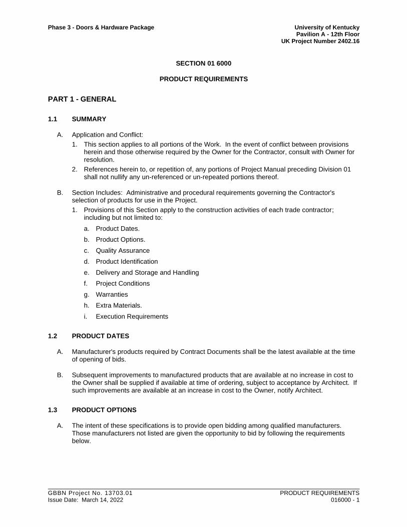
Phase 3 - Doors & Hardware Package University of Kentucky Pavilion A - 12th Floor UK Project Number 2402.16
GBBN Project No. 13703.01 PRODUCT REQUIREMENTS Issue Date: March 14, 2022 016000 - 1
SECTION 01 6000
PRODUCT REQUIREMENTS
PART 1 - GENERAL
1.1 SUMMARY
A. Application and Conflict:
1. This section applies to all portions of the Work. In the event of conflict between provisions herein and those otherwise required by the Owner for the Contractor, consult with Owner for resolution.
2. References herein to, or repetition of, any portions of Project Manual preceding Division 01 shall not nullify any un-referenced or un-repeated portions thereof.
B. Section Includes: Administrative and procedural requirements governing the Contractor's selection of products for use in the Project.
1. Provisions of this Section apply to the construction activities of each trade contractor; including but not limited to:
a. Product Dates.
b. Product Options.
c. Quality Assurance
d. Product Identification
e. Delivery and Storage and Handling
f. Project Conditions
g. Warranties
h. Extra Materials.
i. Execution Requirements
1.2 PRODUCT DATES
A. Manufacturer's products required by Contract Documents shall be the latest available at the time of opening of bids.
B. Subsequent improvements to manufactured products that are available at no increase in cost to the Owner shall be supplied if available at time of ordering, subject to acceptance by Architect. If such improvements are available at an increase in cost to the Owner, notify Architect.
1.3 PRODUCT OPTIONS
A. The intent of these specifications is to provide open bidding among qualified manufacturers. Those manufacturers not listed are given the opportunity to bid by following the requirements below.

Phase 3 - Doors & Hardware Package University of Kentucky Pavilion A - 12th Floor UK Project Number 2402.16
GBBN Project No. 13703.01 PRODUCT REQUIREMENTS Issue Date: March 14, 2022 016000 - 2
B. Methods of specifying products, and options permitted up to bid date:
1. Reference or performance standards: Select product meeting standards by any manufacturer and approved by Architect prior to Contract signing.
2. One manufacturer as standard and other manufacturers specified: Provide product of manufacturer as standard, or select product of same design, quality and performance characteristics by one of the other manufacturers listed. Any substitute product shall have been approved by Architect prior to Contract signing.
3. One or more manufacturers with term "Acceptable Manufacturers" or similar wording, or followed by the term "or equal", "or approved equal", or similar term: Provide product by manufacturer or one of manufacturers specified. Any substitute product for approval of "or equal", "or approved equal", or similar term shall have been approved by Architect prior to Contract signing.
4. One manufacturer only: Provide product by manufacturer specified. Any substitute product shall have been approved by addendum or listed on Substitution Sheet of Bid Form and approved by Architect prior to Contract signing.
C. Substitutions:
1. The materials, products and equipment described in the Bidding Documents establish a standard of required function, dimension, appearance and quality to be met by any proposed substitution.
2. If the Architect approves a proposed substitution prior to receipt of Bids, such approval will be set forth in an Addendum.
a. Architect must receive final Substitutions through Construction Manager 10 days before receipt of Bids.
3. Substitutions after opening of bids will not be considered except for the following reasons:
a. Unavailability of the materials or equipment due to conditions beyond the control of the supplier.
b. Inability of the supplier to meet the Contract Schedule.
c. Technical noncompliance to specifications.
1.4 QUALITY ASSURANCE
A. Source Limitations: To the fullest extent possible, provide products of the same kind from a single source.
B. Compatibility of Options: When the Contractor is given the option of selecting between 2 or more products for use on the Project, the product selected shall be compatible with products previously selected, even if previously selected products were also options.
1. Each trade contractor is responsible for providing products and construction methods that are compatible with products and construction methods of other prime or separate contractors.
2. If a dispute arises between prime contractors over concurrently selectable, but incompatible products, the Architect will determine which products shall be retained and which are incompatible and must be replaced.
C. Except as otherwise specifically noted, products shall be new and first (merchandisable) quality
D. Do not use a product for purposes other than those for which it is intended
E. Do not use damaged products in the Work

Phase 3 - Doors & Hardware Package University of Kentucky Pavilion A - 12th Floor UK Project Number 2402.16
GBBN Project No. 13703.01 PRODUCT REQUIREMENTS Issue Date: March 14, 2022 016000 - 3
F. Comply with manufacturers' delivery, storage, handling, installation, adjusting, cleaning, protection, maintenance, and other use recommendations except where more stringent requirements are specified.
1. Maintain copies of use recommendations at Project site
2. Note and comply with field instructions of manufacturer's technical representatives
3. Remove products with expired shelf life from site
G. Measurements and Dimensions: Take measurements of constructed conditions before ordering products or doing work requiring same. Notify Architect of discrepancies between Contract Documents and constructed conditions before any affected work is started.
1.5 PRODUCT IDENTIFICATION
A. Product Identification: Manufacturer's permanent product identification marks, labels and logos shall be located as inconspicuously as practicable and as approved by Architect.
1. Locate required product labels and stamps on concealed surfaces or, where required for observation after installation, on accessible surfaces that are not conspicuous. Provide layout and type of label and indicate location on shop drawings.
1.6 DELIVERY, STORAGE AND HANDLING
A. Deliver, store and handle products in compliance with manufacturer's requirements, using means and methods that will prevent damage, deterioration, and loss, including theft.
1. Schedule delivery to minimize long-term storage at the site and to prevent overcrowding of construction spaces.
a. Coordinate delivery with installation time to assure minimum holding time for items that are flammable, hazardous, easily damaged, or sensitive to deterioration, theft, and other losses.
b. Deliver products to the site in an undamaged condition in the manufacturer's original sealed container or other packaging system, complete with labels and instructions for handling, storing, unpacking, protecting, and installing. No other containers or packaging will be permitted on the Site.
c. Immediately inspect products upon delivery to ensure that products are undamaged and properly protected, that they comply with the Contract Documents, and that quantities are correct.
d. Store products at the site in a manner that will facilitate inspection and measurement of quantity or counting of units.
e. Store products subject to damage by the elements above ground, under cover in a weather tight enclosure, with ventilation adequate to prevent condensation. Maintain temperature and humidity within range required by manufacturer's instructions.
f. Store heavy materials away from the Project structure in a manner that will not endanger the supporting construction.
g. Do not install material that has become damaged by moisture.
B. Do not store within building without prior approval by Construction Manager. If storage within building is approved by Construction Manager, store to prevent overloading of structure or creating any other dangerous condition.

Phase 3 - Doors & Hardware Package University of Kentucky Pavilion A - 12th Floor UK Project Number 2402.16
GBBN Project No. 13703.01 PRODUCT REQUIREMENTS Issue Date: March 14, 2022 016000 - 4
1.7 PROJECT CONDITIONS
A. Environmental Requirements: Comply with manufacturer recommendations.
B. Field Measurements: Measure existing and in-place new construction as needed for fabrication and execution. Notify Architect of discrepancies between Contract Documents and constructed conditions before any affected work is started. No changes to Contract Sum or Contract Time will be allowed for differences between Drawing dimensions and field measurements.
C. Notification of Substandard Work: Unless otherwise agreed, the Owner's sole responsibility for notification shall be to notify the contractor in writing of defects and failures. However, the Owner reserves the right to contact installer, supplier, or manufacturer directly at its discretion.
1. Upon receipt of notification, Contractor shall immediately investigate the situation, and in the case of defect or failure in fact, shall promptly perform or arrange for performance of remedies
2. Contractor shall be responsible for securing remedies from any other party on behalf of the Owner
1.8 WARRANTIES
A. Specified warranties, including requirements for Contractor to provide manufacturer warranties, are in addition to other Contract and statutory warranties and shall not deprive the Owner of other rights and remedies under Contract Documents or applicable laws. Such specified warranties shall run concurrent with other warranties by the Contractor.
B. General Limitations: Warranties are intended to protect the Owner against failure of the Work to perform as intended, and against deficient, defective, and faulty materials or workmanship, regardless of sources. Except as otherwise indicated, specific warranties do not cover failures in the Work which result from:
1. Unusual and abnormal weather phenomena that exceed performance or design requirements.
2. Misuse, abuse, or improper maintenance.
3. Vandalism after date of Substantial Completion.
4. Insurrection or acts of aggression, including war.
C. Related Damages and Losses: In connection with Contractor's correction of warranted Work which has failed, remove and replace other Work of Project which has been damaged as result of such failure, or which must be removed and replaced to provide access for correction of warranted Work.
D. Warranty Periods: Except as otherwise stipulated, all required warranty periods shall begin on the date of Substantial Completion, regardless of whether The Owner has benefited from use before that date.
1. Reinstatement: Except as otherwise stipulated, when Work covered by Special Project Warranty or Specified Product Warranty has failed and has been corrected by replacement or restoration, reinstate the warranty by written endorsement for a period of time ending upon date original warranty would have expired if there had been no failure and starting on date of acceptance of replaced or restored Work.

Phase 3 - Doors & Hardware Package University of Kentucky Pavilion A - 12th Floor UK Project Number 2402.16
GBBN Project No. 13703.01 PRODUCT REQUIREMENTS Issue Date: March 14, 2022 016000 - 5
E. Replacement Cost, Obligations: Except as otherwise indicated, costs of replacing or restoring failed warranted products is Contractor's obligation, regardless of whether the Owner has benefited from use. Except as otherwise specifically stipulated, no warranty remedy shall be limited to original purchase price.
F. Manufacturer Warranties: Where required by the Specifications, provide warranties by manufacturer that are transferable or assignable to the Owner.
G. Contractor's Procurement Obligations: Do not purchase, subcontract for products where special product warranty, specified product warranty, certification, or similar commitment is required, until Contractor determines that entities required to sign such commitments are willing to do so.
1. Contractor shall require subcontractors and suppliers to provide for assignment of warranties to the Owner so that requirements for coverage, remedies, and time periods are unimpaired.
H. Rejection of Warranties: The Owner reserves the right, at time of Substantial Completion or thereafter, to reject coincidental product warranties submitted by the Contractor which, in the Owner's judgment, tend to detract from or confuse interpretation of requirements of Contract Documents. Coincidental warranties that do not conform to requirements of this Section shall not apply to Work of Contract.
I. Owner's Rights:
1. The Owner may take immediate action in the event of an emergency. Such actions shall not void warranties or relieve warrantors of financial responsibility for remedies, including corrections performed by the Owner
2. The Owner may correct defects and failures in the event that Contractor, when notified, does not respond as required within a reasonable time period. Contractor shall pay for such corrections, whether performed by the Owner's own personnel or others.
3. The Owner shall not be limited to employing the original installer for corrections unless otherwise stipulated in the individual specification sections
4. Specified warranties and warranty periods, and other Contract stipulations shall not diminish the Owner's rights under implied warranties
1.9 EXTRA MATERIALS
A. Furnish extra materials from same manufacturing lots as installed products.
B. Store extra materials in original packaging with intact labels. Mark packages with locations of installed products.
C. Store extra materials in building where directed by the Construction Manager.
PART 2 - PRODUCTS
Not Applicable.

Phase 3 - Doors & Hardware Package University of Kentucky Pavilion A - 12th Floor UK Project Number 2402.16
GBBN Project No. 13703.01 PRODUCT REQUIREMENTS Issue Date: March 14, 2022 016000 - 6
PART 3 - EXECUTION
3.1 EXAMINATION
A. Notify Architect of conditions that would hinder proper or timely execution, or adversely affect performance of finished Work.
B. Verify that conditions permit proper or timely execution, and will not adversely affect performance of finished Work before starting installation. Do not proceed with execution until unsatisfactory conditions have been corrected.
C. Inspect each product immediately before installation. Do not install defective products.
3.2 INSTALLATION
A. Project structures have been designed for strength, stability, and safety in completed form. Until completed, provide temporary bracing and supports needed for strength, stability, and safety of construction in progress and for protection of persons and property.
B. Comply with manufacturer recommendations and instructions in full detail and correct sequence. Use installation methods, tools, equipment, and fasteners recommended by manufacturer for Project applications.
1. Where manufacturer recommendations conflict with Contract Documents, request clarification from Architect before proceeding.
C. Provide attachment and connection devices and methods for permanently securing Work. Secure Work true to line and level, and within specified tolerances or, where not specified, within industry standard tolerances
D. Allow for expansion and movements
E. Provide uniform joint widths in exposed Work. Arrange joints in exposed surfaces for best visual effect, with straight lines and accurate alignment.
F. Isolate each unit of Work from incompatible Work as necessary to prevent deterioration
G. Coordinate enclosure of the Work with required inspections and tests so as to minimize need for uncovering Work for those purposes
H. Apply liquid-applied adhesives and coatings at manufacturer's recommended rates with recommended equipment
I. Where specific tolerances are not stipulated, conform to manufacturer's recommendations or applicable industry standards. Tolerances are non-cumulative unless otherwise noted.
3.3 ADJUSTING AND CLEANING
A. Adjust and lubricate operating components for smooth, accurate operation.
B. Clean exposed surfaces and protect as necessary to ensure freedom from damage and deterioration at time of Substantial Completion.
1. Comply with manufacturer recommendations for cleaning.

Phase 3 - Doors & Hardware Package University of Kentucky Pavilion A - 12th Floor UK Project Number 2402.16
GBBN Project No. 13703.01 PRODUCT REQUIREMENTS Issue Date: March 14, 2022 016000 - 7
2. Clean spills, misapplications, and other accidents immediately as they occur.
3. Do not remove or obscure UL labels or other required labeling.
3.4 DEMONSTRATION
A. Demonstrate operation of each item of equipment and each system to the Owner.
B. Provide training by original installer or manufacturer's representative for the Owner's personnel in operation, adjustment, lubrication, and maintenance of equipment and systems.
3.5 PROTECTION
A. Comply with manufacturer recommendations for protection of completed installations.
B. Provide protective coverings as needed to prevent damage or deterioration, including permanent staining or discoloration, until date of Contract Completion.
C. Limit exposure of installed products to dangerous, harmful, damaging, or otherwise deleterious conditions during subsequent construction period.
END OF SECTION - 016000

This page intentionally left blank.

Phase 3 - Doors & Hardware Package University of Kentucky Pavilion A - 12th Floor UK Project Number 2402.16
GBBN Project No. 13703.01 EXECUTION Issue Date: March 14, 2022 017300 - 1
SECTION 01 7300
EXECUTION
PART 1 - GENERAL
1.1 SUMMARY
A. Application and Conflict:
1. This section applies to all portions of the Work. In the event of conflict between provisions herein and those otherwise required by the Owner for the Contractor, consult with Owner for resolution.
2. References herein to, or repetition of, any portions of Project Manual preceding Division 01 shall not nullify any un-referenced or un-repeated portions thereof.
B. Section Includes; general procedural requirements governing execution of the Work including, but not limited to, the following:
1. Construction layout.
2. Field verification of constructed conditions.
3. Field engineering and surveying.
4. General installation of products.
5. Coordination of Owner-installed products.
6. Progress cleaning.
7. Starting and adjusting.
8. Protection of installed construction.
9. Correction of the Work.
1.2 SUBMITTALS
A. Landfill Receipts: Submit copy of receipts issued by a landfill facility, licensed to accept hazardous materials, for hazardous waste disposal.
PART 2 - PRODUCTS
2.1 MATERIALS
A. Cleaning Agents: Use cleaning materials and agents recommended by manufacturer or fabricator of the surface to be cleaned. Do not use cleaning agents that are potentially hazardous to health or property or that might damage finished surfaces.
PART 3 - EXECUTION
3.1 EXAMINATION
A. Existing Conditions: The existence and location of site improvements, utilities, and other construction indicated as existing are not guaranteed. Before beginning work, investigate and verify the existence and location of mechanical and electrical systems and other construction affecting the Work.

Phase 3 - Doors & Hardware Package University of Kentucky Pavilion A - 12th Floor UK Project Number 2402.16
GBBN Project No. 13703.01 EXECUTION Issue Date: March 14, 2022 017300 - 2
1. Before construction verify:
a. Location and points of connection of utility services.
b. Actual dimensions of existing conditions.
c. Document and report discrepancies to Architect through the Construction Manager.
B. Existing Utilities: The existence and location of underground and other utilities and construction indicated as existing are not guaranteed. Before beginning site work, investigate and verify the existence and location of underground utilities and other construction affecting the Work.
1. Before construction, verify the location and invert elevation at points of connection of sanitary sewer, storm sewer, and water-service piping; and underground electrical services.
2. Furnish location data for work related to Project that must be performed by public utilities serving Project site.
C. Verification of Constructed and Existing Conditions:
1. Examine substrates, areas, dimensions and, conditions where work is to be installed.
2. Examine areas of work with Installer or Applicator present where indicated.
3. Examine for compliance with requirements for installation tolerances and other conditions affecting performance and installation.
4. Record observations of these examinations where required by other sections.
5. Written Report: Where a written report listing conditions detrimental to performance of the Work is required by other Sections, include the following:
a. Description of the Work.
b. List of detrimental conditions, including substrates.
c. List of unacceptable installation tolerances.
d. Recommended corrections.
6. Verify compatibility with and suitability of substrates, including compatibility with existing finishes or primers.
7. Examine roughing-in for mechanical and electrical systems to verify actual locations of connections before equipment and fixture installation.
8. Examine walls, floors, and roofs for suitable conditions where products and systems are to be installed.
D. Acceptance of Conditions:
1. Proceed with installation only after unsatisfactory conditions have been corrected.
2. Proceeding with the Work indicates acceptance of surfaces and conditions.
3.2 PREPARATION
A. Existing Utility Information: Furnish information to Owner that is necessary to adjust, move, or relocate existing utility structures, utility poles, lines, services, or other utility appurtenances located in or affected by construction. Coordinate with authorities having jurisdiction.
B. Field Measurements: Take field measurements as required to fit the Work properly. Recheck measurements before installing each product. Where portions of the Work are indicated to fit to other construction, verify dimensions of other construction by field measurements before fabrication. Coordinate fabrication schedule with construction progress to avoid delaying the Work.
C. Space Requirements: Verify space requirements and dimensions of items shown diagrammatically on Drawings.

Phase 3 - Doors & Hardware Package University of Kentucky Pavilion A - 12th Floor UK Project Number 2402.16
GBBN Project No. 13703.01 EXECUTION Issue Date: March 14, 2022 017300 - 3
D. Review of Contract Documents and Field Conditions: Immediately on discovery of the need for clarification of the Contract Documents, submit a request for information to Architect through Construction Manager. Include a detailed description of problem encountered, together with recommendations for changing the Contract Documents.
3.3 CONSTRUCTION LAYOUT
A. Verification: Before proceeding to lay out the Work, verify layout information shown on Drawings, in relation to the property survey and existing benchmarks. If discrepancies are discovered, notify Architect and Construction Manager promptly.
B. General: Engage a professional engineer to lay out the Work using accepted surveying practices.
1. Establish benchmarks and control points to set lines and levels as needed to locate each element of Project.
2. Establish dimensions within tolerances indicated. Do not scale Drawings to obtain required dimensions.
3. Inform installers of lines and levels to which they must comply.
4. Check the location, level and plumb, of every major element as the Work progresses.
5. Notify Architect and Construction Manager when deviations from required lines and levels exceed allowable tolerances.
3.4 INSTALLATION
A. General: Locate the Work and components of the Work accurately, in correct alignment and elevation, as indicated.
1. Make vertical work plumb and make horizontal work level.
2. Where space is limited, install components to maximize space available for maintenance and ease of removal for replacement.
3. Conceal pipes, ducts, and wiring in finished areas, unless otherwise indicated.
4. Maintain minimum headroom clearance of 8 feet in spaces without a suspended ceiling.
B. Comply with manufacturer's written instructions and recommendations for installing products in applications indicated.
C. Install products at the time and under conditions that will ensure the best possible results. Maintain conditions required for product performance until Substantial Completion.
D. Conduct construction operations so no part of the Work is subjected to damaging operations or loading in excess of that expected during normal conditions of occupancy.
E. Tools and Equipment: Do not use tools or equipment that produce harmful noise levels.
F. Templates: Obtain and distribute to the parties involved templates for work specified to be factory prepared and field installed. Check Shop Drawings of other work to confirm that adequate provisions are made for locating and installing products to comply with indicated requirements.
G. Anchors and Fasteners: Provide anchors and fasteners as required to anchor each component securely in place, accurately located and aligned with other portions of the Work.
1. Mounting Heights: Where mounting heights are not indicated, mount components at heights directed by Architect.
2. Allow for building movement, including thermal expansion and contraction.

Phase 3 - Doors & Hardware Package University of Kentucky Pavilion A - 12th Floor UK Project Number 2402.16
GBBN Project No. 13703.01 EXECUTION Issue Date: March 14, 2022 017300 - 4
3. Coordinate installation of anchorages. Furnish setting drawings, templates, and directions for installing anchorages, including sleeves, concrete inserts, anchor bolts, and items with integral anchors, that are to be embedded in concrete or masonry. Deliver such items to Project site in time for installation.
H. Joints: Make joints of uniform width. Where joint locations in exposed work are not indicated, arrange joints for the best visual effect. Fit exposed connections together to form hairline joints.
I. Hazardous Materials: Use products, cleaners, and installation materials that are not considered hazardous.
3.5 OWNER-INSTALLED PRODUCTS
A. Site Access: Provide access to Project site for Owner's construction forces.
B. Coordination: Coordinate construction and operations of the Work with work performed by Owner's construction forces.
1. Construction Schedule: Inform Owner of Contractor's preferred construction schedule for Owner's portion of the Work. Adjust construction schedule based on a mutually agreeable timetable. Notify Owner if changes to schedule are required due to differences in actual construction progress.
2. Preinstallation Conferences: Include Owner's construction forces at preinstallation conferences covering portions of the Work that are to receive Owner's work. Attend preinstallation conferences conducted by Owner's construction forces if portions of the Work depend on Owner's construction.
3.6 PROGRESS CLEANING
A. General: Clean Project site and work areas daily, including common areas and areas of existing building accessed for Work of this Project. Coordinate progress cleaning for joint-use areas where more than one installer has worked. Enforce requirements strictly. Dispose of materials lawfully.
1. Requirements specified herein for cleaning during construction apply to the new building, and to portions of existing building included in, or access for the Work indicated in Contract Documents.
2. Requirements specified herein for cleaning during construction, plus those listed in Items a. through c. immediately below, also apply to portions of existing building that are not included in the Work, but are affected by prosecution of the Work.
a. Cooperate with Construction Manager to clean to condition satisfactory to Construction Manager when directed by Construction Manager or Architect.
b. Remove grease, dust, dirt, stains, fingerprints, and other foreign materials, from sight-exposed interior and exterior finish surfaces; polish surfaces to match adjacent where applicable.
c. Repair, patch or touch up marred surfaces to match adjacent surfaces.
1) Methods must be approved by Architect.
B. Cleaning During Construction:
1. Keep entire Project area clean, orderly and in conformance with the requirements below, and in conformance with construction requirements of Applicable Codes and Regulatory Agencies specified in Division 01 Section, Quality Requirements. Coordinate progress cleaning for joint-use areas where more than one installer has worked.
2. Except within building, wet down dry materials and rubbish to lay dust and prevent blowing dust.

Phase 3 - Doors & Hardware Package University of Kentucky Pavilion A - 12th Floor UK Project Number 2402.16
GBBN Project No. 13703.01 EXECUTION Issue Date: March 14, 2022 017300 - 5
3. Handle materials in a controlled manner; do not drop or throw materials from heights.
a. If trash chutes are required, locate only at windows designated by Construction Manager.
4. Schedule cleaning operations so that dust and other contaminants resulting from cleaning process will not fall on wet, newly painted surfaces.
5. Conduct cleaning and disposal operations to comply with ordinances and laws which apply to the place of the Work, plus the following:
a. Store volatile wastes in covered metal containers, and remove from site daily.
b. Prevent accumulation of wastes that create hazardous conditions.
c. Containerize hazardous and unsanitary waste materials separately from other waste. Mark containers appropriately and dispose of legally, according to regulations.
6. Cleaning materials and methods shall be as recommended by manufacturer of material being cleaned, and in compliance with EPA and applicable regulations for maintaining indoor air quality.
7. Refer to Division 01 Section, Contract Closeout for final cleaning.
C. Site: Maintain Project site in order and free of waste materials and debris.
1. If any vehicle for a Contractor or any of his sub-contractors or suppliers carries mud/dirt on any roadways/pavements, it shall be cleaned off immediately.
D. Work Areas: Clean areas where work is in progress to the level of cleanliness necessary for proper execution of the Work.
1. Remove liquid spills promptly.
2. Where dust would impair proper execution of the Work, broom-clean or vacuum the entire work area, as appropriate.
3. Provide walk-off mats at entrances to Owner-occupied areas. Mats shall be of the type to ensure that dust and dirt will be removed from shoes, and ensure that workmen do not track dust, dirt, grease or other floor soiling material onto occupied floors. If so soiled, immediately, and not less often than daily, restore floors to condition acceptable to Architect
E. Installed Work: Keep installed work clean. Clean installed surfaces according to written instructions of manufacturer or fabricator of product installed, using only cleaning materials specifically recommended. If specific cleaning materials are not recommended, use cleaning materials that are not hazardous to health or property and that will not damage exposed surfaces.
1. Remove grease, dust, dirt, stains, fingerprints, and other foreign materials, from sight-exposed interior and exterior finish surfaces; polish surfaces to match adjacent where applicable.
2. Repair, patch or touch up marred surfaces to match adjacent surfaces.
F. Concealed Spaces: Remove debris from concealed spaces before enclosing the space.
G. Waste Disposal:
1. Remove rubbish and waste from concealed spaces prior to enclosing.
2. Do not dispose of volatile wastes such as mineral spirits, oil, or paint thinner in storm or sanitary drains, or plumbing fixtures.
3. Clean with cleaning materials and methods recommended by manufacturer of material being cleaned, and in compliance with EPA and other applicable regulations for maintaining indoor air quality.
4. Do not hold materials more than 7 days during normal weather or 3 days if the temperature is expected to rise above 80 deg F.

Phase 3 - Doors & Hardware Package University of Kentucky Pavilion A - 12th Floor UK Project Number 2402.16
GBBN Project No. 13703.01 EXECUTION Issue Date: March 14, 2022 017300 - 6
H. During handling and installation, clean and protect construction in progress and adjoining materials already in place. Apply protective covering where required to ensure protection from damage or deterioration at Substantial Completion.
I. Clean and provide maintenance on completed construction as frequently as necessary through the remainder of the construction period.
1. Adjust and lubricate operable components to ensure operability without damaging effects.
J. Limiting Exposures: Supervise construction operations to assure that no part of the construction, completed or in progress, is subject to harmful, dangerous, damaging, or otherwise deleterious exposure during the construction period.
3.7 STARTING AND ADJUSTING
A. Start equipment and operating components to confirm proper operation. Remove malfunctioning units, replace with new units, and retest.
B. Adjust operating components for proper operation without binding. Adjust equipment for proper operation.
C. Test each piece of equipment to verify proper operation. Test and adjust controls and safeties. Replace damaged and malfunctioning controls and equipment.
D. Manufacturer's Field Service: If a factory-authorized service representative is required to inspect field-assembled components and equipment installation, comply with qualification requirements in Section 014000 – Quality Requirements."
3.8 PROTECTION OF INSTALLED CONSTRUCTION
A. Provide protection and maintain conditions that ensure installed Work is without damage or deterioration at all times during construction and at time of Substantial Completion.
B. Comply with manufacturer's written instructions for temperature and relative humidity.
C. Protect finished flooring surfaces with heavy Kraft paper walkways and hardboard overlay or other suitable means approved by Construction Manager for the use of workmen. Limit construction traffic over such surfaces to that necessary to complete the Work.
1. Tape seams and edges of overlay to prevent debris from becoming trapped underneath and damaging floors. Do not tape to finished surfaces.
2. Protection shall be maintained regularly and damages to temporary covering in a timely fashion to prevent damage to flooring.
3.9 CORRECTION OF THE WORK
A. Repair or remove and replace defective construction. Restore damaged substrates and finishes. Comply with requirements in Division 01 Section "Cutting and Patching."
1. Repairing includes replacing defective parts, refinishing damaged surfaces, touching up with matching materials, and properly adjusting operating equipment.
B. Restore permanent facilities used during construction to their specified condition.
C. Remove and replace damaged surfaces that are exposed to view if surfaces cannot be repaired without visible evidence of repair.

Phase 3 - Doors & Hardware Package University of Kentucky Pavilion A - 12th Floor UK Project Number 2402.16
GBBN Project No. 13703.01 EXECUTION Issue Date: March 14, 2022 017300 - 7
D. Repair components that do not operate properly. Remove and replace operating components that cannot be repaired.
E. Remove and replace chipped, scratched, and broken glass or reflective surfaces.
END OF SECTION - 017300

This page intentionally left blank.

Phase 3 - Doors & Hardware Package University of Kentucky Pavilion A - 12th Floor UK Project Number 2402.16
GBBN Project No. 13703.01 CUTTING AND PATCHING Issue Date: March 14, 2022 017329 - 1
SECTION 01 7329
CUTTING AND PATCHING
PART 1 - GENERAL
1.1 SUMMARY
A. Application and Conflict:
1. This section applies to all portions of the Work. In the event of conflict between provisions herein and those otherwise required by the Owner for the Contractor, consult with Owner for resolution.
2. References herein to, or repetition of, any portions of Project Manual preceding Division 01 shall not nullify any un-referenced or un-repeated portions thereof.
B. Section Includes:
1. Administrative requirements for cutting and patching.
2. Procedural requirements for cutting and patching.
3. Performance requirements for cutting and patching where identified.
4. Concrete Floor Slabs:
a. Special attention and field investigation and procedures for restoration of concrete slabs provided by trade contractors requiring specific tolerances for floor flatness and levelness.
1) Coordinate requirements with Contractor and owner's representative.
2) Where finish trades require more stringent requirements than that provided (current field conditions), provide floor repair to achieve requirements.
b. Identify and repair damaged or irregular, existing and new concrete floor surfaces that are not suitable substrates for installation of resilient flooring, carpet tile, carpet, stone flooring and tile floor, and existing and new concrete floor surfaces not suitable to be left exposed.
1) Decision of Architect will be final regarding suitability for intended use of new and existing floor surfaces.
c. Saw cutting and removal of concrete to form depressions for floor materials where indicated. Areas included, but are not limited to the following:
1) Adjustments to depression for recessed patient toilet rooms.
2) Areas around floor drains where ceramic tile or resilient flooring is specified.
3) Areas at stone flooring where existing blockouts are not sufficient to achieve smooth transitions.
4) Areas of carpet where surface applied underlayment is not appropriate to achieve smooth transitions.
5) Around floor boxes, as required to achieve smooth, flush transitions.
C. Related Sections: Refer to all other Sections of the project manual for specific requirements and limitations applicable to cutting and patching individual parts of the Work.
1. Requirements of this Section apply to:
a. Architectural,
b. Fire Protection,
c. Plumbing,
d. HVAC,
e. Electrical,

Phase 3 - Doors & Hardware Package University of Kentucky Pavilion A - 12th Floor UK Project Number 2402.16
GBBN Project No. 13703.01 CUTTING AND PATCHING Issue Date: March 14, 2022 017329 - 2
f. Communications
g. Electronic Safety and Security installations.
2. Includes cutting and patching related to the installation of all equipment installed as part of the scope of The Project.
3. Refer to Mechanical and Electrical Divisions for other requirements and limitations applicable to cutting and patching mechanical, and electrical installations.
1.2 DEFINITIONS
A. Cutting: Removal of in-place or existing construction necessary to permit installation or performance of other Work.
B. Patching: Fitting and repair work required to restore surfaces to original conditions after installation of other Work.
1.3 SUBMITTALS
A. Cutting and Patching Proposal: Submit a proposal describing procedures at least 10 days before the time cutting and patching wll be performed. Request approval to proceed. Include the following information, as applicable, in the proposal:
1. Describe the extent of cutting and patching required. Show how it will be performed and indicate why it cannot be avoided.
2. Describe anticipated results in terms of changes to existing and in-place construction. Include changes to structural elements and operating components as well as changes in the building's appearance and other significant visual elements.
3. List products to be used and firms or entities that will perform Work.
4. Indicate dates when cutting and patching will be performed.
5. Utilities: List utilities that cutting and patching procedures will disturb or affect. List utilities that will be relocated and those that will be temporarily out-of-service. Indicate how long service will be disrupted.
6. Where cutting and patching involves adding reinforcement to structural elements, submit details and engineering calculations showing integration of reinforcement with the original structure.
7. Construction Manager's Approval: Obtain approval of cutting and patching proposal before cutting and patching. Approval does not waive right to later require removal and replacement of unsatisfactory work.
1.4 QUALITY ASSURANCE
A. Cutting and patching of structural members and work affecting structural members or the structural integrity of any portion of the building: Notify Architect of necessity for cutting structural members and work affecting structural members or the structural integrity of any portion of the building; do not proceed until approved by Architect.
B. Operational Limitations: Do not cut and patch operating elements or related components in a manner that would result in reducing their capacity to perform as intended. Do not cut and patch operating elements or related components in a manner that would result in increased maintenance or decreased operational life or safety.
1. Obtain approval of the cutting and patching proposal before cutting and patching the following operating elements or safety related systems:
a. Primary operational systems and equipment.
b. Air or smoke barriers.
c. Water, moisture, or vapor barriers.

Phase 3 - Doors & Hardware Package University of Kentucky Pavilion A - 12th Floor UK Project Number 2402.16
GBBN Project No. 13703.01 CUTTING AND PATCHING Issue Date: March 14, 2022 017329 - 3
d. Membranes and flashings.
e. Fire protection systems.
f. Noise and vibration control elements and systems.
g. Control systems.
h. Communication systems.
i. Conveying systems.
j. Electrical wiring systems.
k. Piping, ductwork, vessels, and equipment.
l. Exterior curtain-wall construction.
C. Miscellaneous Elements: Do not cut and patch miscellaneous elements or related components in a manner that could change their load-carrying capacity, that results in reducing their capacity to perform as intended, or that results in increased maintenance or decreased operational life or safety
D. Visual Requirements: Do not cut and patch construction exposed on the exterior or in occupied spaces in a manner that would, in the Architect's opinion, reduce the building's aesthetic qualities. Do not cut and patch construction in a manner that would result in visual evidence of cutting and patching. Remove and replace construction cut and patched in a visually unsatisfactory manner.
1. If possible retain the original Installer or fabricator to cut and patch the exposed Work listed below. If it is impossible to engage the original Installer or fabricator, engage another recognized experienced and specialized firm.
E. Cutting and Patching Conference: Before proceeding, meet at Project site with parties involved in cutting and patching, including mechanical and electrical trades. Review areas of potential interference and conflict. Coordinate procedures and resolve potential conflicts before proceeding.
1.5 WARRANTY
A. Existing and In-Place Warranties: Remove, replace, patch, and repair material and surfaces cut or damaged by methods and with materials in such a manner as not to void any warranties required or existing.
PART 2 - PRODUCTS
2.1 MATERIALS
A. General: Comply with requirements specified in other Sections
B. Use materials identical to existing or in-place materials. For exposed surfaces, use materials that visually match adjacent surfaces to the fullest extent possible.
1. If identical materials are unavailable or cannot be used, use materials that, when installed, will match the visual and functional performance of in-place materials.
C. Thick Section Concrete floor Topping: For floor repairs 1 inch or more in thickness, use either proprietary dry factory mix or Project site mixed concrete.
1. Proprietary dry factory mixed grout: Containing manufacturer's bonding agent and requiring only adding water at point of use.
a. Acceptable manufacturers and product.
1) Ardex, Inc.: Ardex K-55.
2) Master Builders: Embeco 411-A.

Phase 3 - Doors & Hardware Package University of Kentucky Pavilion A - 12th Floor UK Project Number 2402.16
GBBN Project No. 13703.01 CUTTING AND PATCHING Issue Date: March 14, 2022 017329 - 4
3) Thoro System Products: Thoro Underlayment, Trowel Grade.
4) Maxxon Corp: Level-Right Self Leveling Floor Underlayment.
2. Project site mixed: Sand, cement, and water mixture with proprietary liquid bonding agent added to produce normal weight concrete having a 3500 pounds per square inch compressive strength. Submit mix design.
a. Acceptable manufacturers and product for liquid bonding agent:
1) W. R. Meadows, Inc.: Interlock Bonding Agent.
2) Comparable product by other manufacturers.
D. Thin Section Topping: For floor repair less than 1 inch thick, use self leveling proprietary mixture, including primer recommended by mixture manufacturer, designed to be installed to a featheredge, requiring only adding of water at point of use.
1. Acceptable manufacturers and products:
a. Ardex, Inc.: Ardex V-800.
b. Thoro Systems Products: Thoro Underlayment.
c. Maxxon Corp: Level-Right Self Leveling Floor Underlayment.
E. Concrete topping accessories:
1. Latex Additive: Acrylic-based emulsion designed for use as as additive to improve adhesion, flexural and tensile strength in portland cement plaster mixes.
a. Thoro System Products: Acryl 60.
b. Comparable products of other manufacturers.
2. Bonding Agent: High-strength liquid bonding agent for bonding portland cement underlayment to substrates.
a. Thoro System Products: Thorobond.
b. Comparable products of other manufacturers.
3. Water: Clean, potable, free from deleterious amounts of acids, alkalies, or organic materials.
PART 3 - EXECUTION
3.1 INSPECTION
A. Examine surfaces to be cut and patched and conditions under which cutting and patching is to be performed before cutting.
1. Compatibility: Before patching, verify compatibility with and suitability of substrates, including compatibility with in-place finishes or primers.
2. Proceed with installation only after unsafe or unsatisfactory conditions have been corrected.
3.2 PREPARATION
A. Temporary Support: Provide temporary support of work to be cut.
B. Protection: Protect existing construction during cutting and patching to prevent damage. Provide protection from adverse weather conditions for portions of the Project that might be exposed during cutting and patching operations.
C. Avoid interference with use of adjoining areas or interruption of free passage to adjoining areas.
D. Avoid cutting existing pipe, conduit, or ductwork serving the building but scheduled to be removed or relocated until provisions have been made to bypass them.
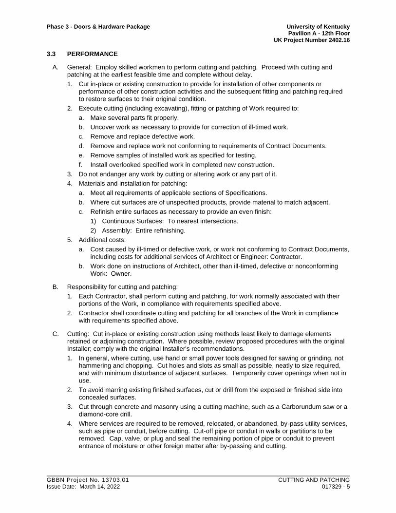
Phase 3 - Doors & Hardware Package University of Kentucky Pavilion A - 12th Floor UK Project Number 2402.16
GBBN Project No. 13703.01 CUTTING AND PATCHING Issue Date: March 14, 2022 017329 - 5
3.3 PERFORMANCE
A. General: Employ skilled workmen to perform cutting and patching. Proceed with cutting and patching at the earliest feasible time and complete without delay.
1. Cut in-place or existing construction to provide for installation of other components or performance of other construction activities and the subsequent fitting and patching required to restore surfaces to their original condition.
2. Execute cutting (including excavating), fitting or patching of Work required to:
a. Make several parts fit properly.
b. Uncover work as necessary to provide for correction of ill-timed work.
c. Remove and replace defective work.
d. Remove and replace work not conforming to requirements of Contract Documents.
e. Remove samples of installed work as specified for testing.
f. Install overlooked specified work in completed new construction.
3. Do not endanger any work by cutting or altering work or any part of it.
4. Materials and installation for patching:
a. Meet all requirements of applicable sections of Specifications.
b. Where cut surfaces are of unspecified products, provide material to match adjacent.
c. Refinish entire surfaces as necessary to provide an even finish:
1) Continuous Surfaces: To nearest intersections.
2) Assembly: Entire refinishing.
5. Additional costs:
a. Cost caused by ill-timed or defective work, or work not conforming to Contract Documents, including costs for additional services of Architect or Engineer: Contractor.
b. Work done on instructions of Architect, other than ill-timed, defective or nonconforming Work: Owner.
B. Responsibility for cutting and patching:
1. Each Contractor, shall perform cutting and patching, for work normally associated with their portions of the Work, in compliance with requirements specified above.
2. Contractor shall coordinate cutting and patching for all branches of the Work in compliance with requirements specified above.
C. Cutting: Cut in-place or existing construction using methods least likely to damage elements retained or adjoining construction. Where possible, review proposed procedures with the original Installer; comply with the original Installer's recommendations.
1. In general, where cutting, use hand or small power tools designed for sawing or grinding, not hammering and chopping. Cut holes and slots as small as possible, neatly to size required, and with minimum disturbance of adjacent surfaces. Temporarily cover openings when not in use.
2. To avoid marring existing finished surfaces, cut or drill from the exposed or finished side into concealed surfaces.
3. Cut through concrete and masonry using a cutting machine, such as a Carborundum saw or a diamond-core drill.
4. Where services are required to be removed, relocated, or abandoned, by-pass utility services, such as pipe or conduit, before cutting. Cut-off pipe or conduit in walls or partitions to be removed. Cap, valve, or plug and seal the remaining portion of pipe or conduit to prevent entrance of moisture or other foreign matter after by-passing and cutting.

Phase 3 - Doors & Hardware Package University of Kentucky Pavilion A - 12th Floor UK Project Number 2402.16
GBBN Project No. 13703.01 CUTTING AND PATCHING Issue Date: March 14, 2022 017329 - 6
D. Patching: Patch with durable seams that are as invisible as possible. Comply with specified tolerances.
1. Where feasible, inspect and test patched areas to demonstrate integrity of the installation.
2. Restore exposed finishes of patched areas and extend finish restoration into retained adjoining construction in a manner that will eliminate evidence of patching and refinishing.
3. Where removing walls or partitions extends one finished area into another, patch and repair floor and wall surfaces in the new space. Provide an even surface of uniform color and appearance. Remove existing floor and wall coverings and replace with new materials, if necessary, to achieve uniform color and appearance.
a. Where patching occurs in a smooth painted surface, extend final paint coat over entire unbroken surface containing the patch after the area has received primer and second coat.
E. Patching of voids in existing construction left after removal of existing work
1. Each Contractor shall be responsible for and pay all costs for patching voids in existing construction left after removal of existing work of their respective portions of the Work, whether or not specifically indicated in Contract Documents, and not otherwise required by Contract Documents to be patched or finished.
2. Patching shall be done by trades appropriate for and normally experienced in patching materials and procedures required. Provide materials and installation procedures for patching equal in appearance and quality to existing adjacent materials, or other materials and installation procedures if otherwise indicated in Contract Documents.
3. Where structural support is required, provide as required, whether or not indicated in Contract Documents. Consult with Architect to determine structural requirements if not indicated in Contract Documents, but pay all costs for providing such structural supports.
F. Patching of voids in existing construction left after removal of existing hazardous materials under separate contract or contracts by Owner.
1. Contractor shall be responsible for and pay all costs for patching voids in existing construction left after removal of hazardous materials.
2. Patching shall be done by trades appropriate for and normally experienced in patching materials and procedures required. Provide materials and installation procedures for patching equal in appearance and quality to existing adjacent materials, or other materials and installation procedures if otherwise indicated in Contract Documents.
3. Where structural support is required, provide as required, whether or not indicated in Contract Documents. Consult with Architect to determine structural requirements if not indicated in Contract Documents, but pay all costs for providing such structural supports.
3.4 CLEANING
A. Clean areas and spaces where cutting and patching are performed. Completely remove paint, mortar, oils, putty, and similar items. Thoroughly clean piping, conduit, and similar features before applying paint or other finishing materials. Restore damaged pipe covering to its original condition.
END OF SECTION - 017329

Phase 3 - Doors & Hardware Package University of Kentucky Pavilion A - 12th Floor UK Project Number 2402.16
GBBN Project No. 13703.01 CLOSEOUT PROCEDURES Issue Date: March 14, 2022 017700 - 1
SECTION 01 7700
CLOSEOUT PROCEDURES
PART 1 - GENERAL
1.1 SUMMARY
A. Application and Conflict:
1. This section applies to all portions of the Work. In the event of conflict between provisions herein and those otherwise required by the Owner for the Contractor, consult with Owner for resolution.
2. References herein to, or repetition of, any portions of Project Manual preceding Division 01 shall not nullify any un-referenced or un-repeated portions thereof.
B. Section includes:
1. Final cleaning.
2. Substantial completion procedures.
3. Final completion procedures.
4. Project closeout submittals.
5. Instructions to Owner.
6. Warranties.
7. Final Cleaning.
8. Repair of Work.
C. Related Sections:
1. Division 01 Section, Summary of Work: Requirements for occupancy permit.
2. Division 01 Section, Submittal Requirements: Requirements for closeout submittals listed herein.
3. Division 01 Section, Temporary Facilities and Controls: Cleaning during Construction and Removal of Temporary Facilities.
4. Divisions 2 through 33: Requirements for maintenance materials and spare parts.
5. Facility Services Subgroup; Mechanical, Plumbing, and Electrical: Additional requirements specified therein.
1.2 SUBSTANTIAL COMPLETION MILESTONE PROCEDURES
A. Contractor's List of Incomplete Items: Prepare and submit a list of items to be completed and corrected (Contractor's punch list), indicating the value of each item on the list and reasons why the Work is incomplete.
1. Each Contractor shall submit to Architect a list of items to be completed or corrected.
2. Include name and identification of each space and area affected by construction operations for incomplete items and items needing correction including, if necessary, areas disturbed by Contractor that are outside the limits of construction.
3. Organize list of spaces in sequential order.
4. Organize items applying to each space by major element, including categories for ceiling, individual walls, floors, equipment, and building systems.

Phase 3 - Doors & Hardware Package University of Kentucky Pavilion A - 12th Floor UK Project Number 2402.16
GBBN Project No. 13703.01 CLOSEOUT PROCEDURES Issue Date: March 14, 2022 017700 - 2
5. Include the following information at the top of each page:
a. Project name.
b. Date.
c. Name of Architect and Construction Manager.
d. Name of Contractor.
e. Page number.
B. Submittals Prior to Substantial Completion: Complete the following a minimum of 7 days prior to requesting inspection for determining date of Substantial Completion. List items below that are incomplete at time of request.
1. Certificates of Release: Obtain and submit releases from authorities having jurisdiction permitting Owner unrestricted use of the Work and access to services and utilities. Include occupancy permits, operating certificates, and similar releases.
2. Submit closeout submittals specified in other Division 01 Sections, including project record documents, operation and maintenance manuals, damage or settlement surveys, property surveys, and similar final record information.
3. Submit closeout submittals specified in individual Sections, including specific warranties, workmanship bonds, maintenance service agreements, final certifications, and similar documents.
4. Submit maintenance material submittals specified in individual Sections, including tools, spare parts, extra materials, and similar items, and deliver to location designated by Construction Manager. Label with manufacturer's name and model number.
a. Schedule of Maintenance Material Items: Prepare and submit schedule of maintenance material submittal items, including name and quantity of each item and name and number of related Specification Section. Obtain Construction Manager's signature for receipt of submittals.
5. Submit testing, adjusting, and balancing records.
6. Submit changeover information related to Owner's occupancy, use, operation, and maintenance.
C. Procedures Prior to Substantial Completion: Complete the following a minimum of 7 days prior to requesting inspection for determining date of Substantial Completion. List items below that are incomplete at time of request.
1. Advise Owner of pending insurance changeover requirements.
2. Make final changeover of permanent locks and deliver keys to Owner. Advise Owner's personnel of changeover in security provisions.
3. Complete startup and testing of systems and equipment.
4. Perform preventive maintenance on equipment used prior to Substantial Completion.
5. Instruct Owner's personnel in operation, adjustment, and maintenance of products, equipment, and systems.
6. Advise Owner of changeover in utility services.
7. Participate with Owner in conducting inspection and walkthrough with local emergency responders.
8. Terminate and remove temporary facilities from Project site, along with mockups, construction tools, and similar elements.
9. Complete final cleaning requirements.
10. Touch up paint and otherwise repair and restore marred exposed finishes to eliminate visual defects.

Phase 3 - Doors & Hardware Package University of Kentucky Pavilion A - 12th Floor UK Project Number 2402.16
GBBN Project No. 13703.01 CLOSEOUT PROCEDURES Issue Date: March 14, 2022 017700 - 3
D. Inspection: Submit a written request for inspection to determine Substantial Completion a minimum of 7 days prior to date the Work will be completed and ready for final inspection and tests. On receipt of request, Architect and Construction Manager will either proceed with inspection or notify Contractor of unfulfilled requirements. Architect will prepare the Certificate of Substantial Completion after inspection or will notify Contractor of items, either on Contractor's list or additional items identified by Architect, that must be completed or corrected before certificate will be issued.
1. Request reinspection when the Work identified in previous inspections as incomplete is completed or corrected.
2. Results of completed inspection will form the basis of requirements for final completion.
1.3 FINAL COMPLETION PROCEDURES
A. Submittals Prior to Final Completion: Before requesting final inspection for determining final completion, complete the following:
1. Submit a final Application for Payment.
2. Certified List of Incomplete Items: Submit certified copy of Architect's Substantial Completion inspection list of items to be completed or corrected (punch list), endorsed and dated by Architect. Certified copy of the list shall state that each item has been completed or otherwise resolved for acceptance.
3. Certificate of Insurance: Submit evidence of final, continuing insurance coverage complying with insurance requirements.
4. Submit pest-control final inspection report.
5. Submit final completion photographic documentation.
B. Inspection: Submit a written request for final inspection to determine acceptance a minimum of 7 days prior to date the work will be completed and ready for final inspection and tests. On receipt of request, Architect and Construction Manager will either proceed with inspection or notify Contractor of unfulfilled requirements. Architect will prepare a final Certificate for Payment after inspection or will notify Contractor of construction that must be completed or corrected before certificate will be issued.
1. Request reinspection when the Work identified in previous inspections as incomplete is completed or corrected.
1.4 PROJECT CLOSEOUT SUBMITTALS
A. Contractor shall submit the following in accordance with all requirements of the Contract Documents:
1. Project record documents.
2. Operation and maintenance manuals and materials where specified for mechanical and electrical equipment.
3. Operation and maintenance data and materials for operating items other than mechanical and electrical equipment where specified.
4. Maintenance materials and spare parts required.
5. Maintenance data and materials for finish materials where specified.
6. Replacement materials.
7. Special maintenance tools if required by manufacturer for proper maintenance, or if specified.
8. Photographic documentation of spaces at Substantial Completion.
9. Keys and keying schedule.

Phase 3 - Doors & Hardware Package University of Kentucky Pavilion A - 12th Floor UK Project Number 2402.16
GBBN Project No. 13703.01 CLOSEOUT PROCEDURES Issue Date: March 14, 2022 017700 - 4
10. Guarantees, warranties and bonds required.
11. Affidavits.
12. Evidence of compliance with requirements of governing authorities as applicable.
13. Release of liens and other related project closeout data, if required by Owner, as indicated in General Conditions and Special Conditions.
14. Electronic submittals:
a. All test and/or certification reports.
b. Operation and maintenance manuals and materials where specified for mechanical and electrical equipment.
1) Provide separate pdfs for each Specification Section.
c. Operation and maintenance data and materials for operating items other than mechanical and electrical equipment where specified.
d. Complete equipment list in electronic spreadsheet format including the following: Identify the following:
1) All materials that require preventative maintenance. The list is to include the description and specific unit number, manufacturer, model number, room number where located.
2) Required maintenance procedure.
3) Required frequency of maintenance.
4) Listing of maintenance parts and items: i.e. filters, lubricants, etc.
1.5 INSTRUCTIONS TO OWNER
A. Prior to final completion coordinate with Construction Manager to provide verbal instructions to Owner or Owner's designated personnel for all items specified to require same.
1. Provide authorized factory representatives or factory-authorized personnel for instructions.
2. Schedule training with Owner, through Construction Manager, with at least 7 days’ notice.
3. Refer to Divisions 02 through 33 for additional requirements.
B. Engage manufacturers’ trained technical service representatives to train Owner’s maintenance/ environmental services personnel on site on each manufacturers’ recommended cleaning, maintenance, and operation procedures.
1. Coordinate training with the Physical Plant Division UK Medical Center (PPDMC) 30 days prior to training date with training syllabus being provided.
1.6 SUBMITTAL OF PROJECT WARRANTIES
A. Time of Submittal: Submit written warranties on request of Architect for designated portions of the Work where warranties are indicated to commence on dates other than date of Substantial Completion, or when delay in submittal of warranties might limit Owner's rights under warranty.
B. Partial Occupancy: Submit properly executed warranties within 15 days of completion of designated portions of the Work that are completed and occupied or used by Owner during construction period by separate agreement with Contractor.
C. Organize warranty documents into an orderly sequence based on the table of contents of Project Manual.

Phase 3 - Doors & Hardware Package University of Kentucky Pavilion A - 12th Floor UK Project Number 2402.16
GBBN Project No. 13703.01 CLOSEOUT PROCEDURES Issue Date: March 14, 2022 017700 - 5
D. Warranty Electronic File:
1. Provide warranties and bonds in PDF format.
2. Assemble complete warranty and bond submittal package into a single electronic PDF file with bookmarks enabling navigation to each item.
3. Provide bookmarked table of contents at beginning of document.
4. Submit on digital media acceptable to Architect.
E. Provide additional copies of each warranty to include in operation and maintenance manuals.
PART 2 - PRODUCTS
2.1 MATERIALS
A. Cleaning Agents: Use cleaning materials and agents recommended by manufacturer or fabricator of the surface to be cleaned. Do not use cleaning agents that are potentially hazardous to health or property or that might damage finished surfaces.
PART 3 - EXECUTION
3.1 FINAL CLEANING
A. Multiple Prime Contracts: Responsibility for direction of cleaning throughout the construction shall be that of the Lead Contractor as designated by the Construction Manager. Each Contractor shall be responsible for complying with the requirements below for cleaning of his areas of Work; all Contractors shall cooperate with the Lead Contractor's directives.
B. General: Perform final cleaning. Conduct cleaning and waste-removal operations to comply with local laws and ordinances and Federal and local environmental and antipollution regulations.
C. Cleaning: Employ experienced workers or professional cleaners for final cleaning. Clean each surface or unit to condition expected in an average commercial building cleaning and maintenance program. Comply with manufacturer's written instructions.
1. Complete the following cleaning operations before requesting inspection for certification of Substantial Completion for entire Project or for a designated portion of Project:
a. Clean Project site, yard, and grounds, in areas disturbed by construction activities, including landscape development areas, of rubbish, waste material, litter, and other foreign substances.
b. Sweep paved areas broom clean. Remove petrochemical spills, stains, and other foreign deposits.
c. Rake grounds that are not planted, mulched, or paved to a smooth, even-textured surface.
d. Remove tools, construction equipment, machinery, and surplus material from Project site.
e. Remove snow and ice to provide safe access to building.
f. Clean exposed exterior and interior hard-surfaced finishes to a dirt-free condition, free of stains, films, and similar foreign substances. Avoid disturbing natural weathering of exterior surfaces. Restore reflective surfaces to their original condition.

Phase 3 - Doors & Hardware Package University of Kentucky Pavilion A - 12th Floor UK Project Number 2402.16
GBBN Project No. 13703.01 CLOSEOUT PROCEDURES Issue Date: March 14, 2022 017700 - 6
g. Remove debris and surface dust from limited access spaces, including roofs, plenums, shafts, trenches, equipment vaults, manholes, attics, and similar spaces.
h. Sweep concrete floors broom clean in unoccupied spaces.
i. Vacuum carpet and similar soft surfaces, removing debris and excess nap; clean according to manufacturer's recommendations if visible soil or stains remain.
j. Clean transparent materials, including mirrors and glass in doors and windows. Remove glazing compounds and other noticeable, vision-obscuring materials. Polish mirrors and glass, taking care not to scratch surfaces.
k. Remove labels that are not permanent.
l. Wipe surfaces of mechanical and electrical equipment, elevator equipment, and similar equipment. Remove excess lubrication, paint and mortar droppings, and other foreign substances.
m. Clean plumbing fixtures to a sanitary condition, free of stains, including stains resulting from water exposure.
n. Replace disposable air filters and clean permanent air filters. Clean exposed surfaces of diffusers, registers, and grills.
o. Clean ducts, blowers, and coils if units were operated without filters during construction or that display contamination with particulate matter on inspection.
p. Clean light fixtures, lamps, globes, and reflectors to function with full efficiency.
q. Leave Project clean and ready for occupancy.
D. Construction Waste Disposal: Comply with waste disposal requirements in Section 01 5000 "Temporary Facilities and Controls."
3.2 REPAIR OF THE WORK
A. Complete repair and restoration operations before requesting inspection for determination of Substantial Completion.
B. Repair, or remove and replace, defective construction. Repairing includes replacing defective parts, refinishing damaged surfaces, touching up with matching materials, and properly adjusting operating equipment. Where damaged or worn items cannot be repaired or restored, provide replacements. Remove and replace operating components that cannot be repaired. Restore damaged construction and permanent facilities used during construction to specified condition.
1. Remove and replace chipped, scratched, and broken glass, reflective surfaces, and other damaged transparent materials.
2. Touch up and otherwise repair and restore marred or exposed finishes and surfaces. Replace finishes and surfaces that that already show evidence of repair or restoration.
a. Do not paint over "UL" and other required labels and identification, including mechanical and electrical nameplates. Remove paint applied to required labels and identification.
3. Replace parts subject to operating conditions during construction that may impede operation or reduce longevity.
4. Replace burned-out bulbs, bulbs noticeably dimmed by hours of use, and defective and noisy starters in fluorescent and mercury vapor fixtures to comply with requirements for new fixtures
END OF SECTION - 017700

Phase 3 - Doors & Hardware Package University of Kentucky Pavilion A - 12th Floor UK Project Number 2402.16
GBBN Project No. 13703.01 METAL FABRICATIONS Issue Date: March 14, 2022 055000 - 1
SECTION 05 5000
METAL FABRICATIONS
PART 1 - GENERAL
1.1 SUMMARY
A. Section Includes:
1. Steel framing and supports for mechanical and electrical equipment.
2. Steel framing and supports for applications where framing and supports are not specified in other Sections.
3. Steel framing and supports for medical equipment and apparatus identified in the Drawings and project manual.
4. Loose bearing and leveling plates.
5. Supports that attach ceiling-hung toilet compartments, specified in Section 10 2113, to overhead structural system.
6. Steel Beam Guardrail, Terminal Sections No.1 and No. 2, and associated steel post and base plate supports and mounting posts.
7. Other items indicated in the Drawings.
B. Items specified herein but provided and installed elsewhere:
1. Division 11 Sections for Medical Equipment: Supports for medical equipment specified in Division 11 Sections for Medical Equipment.
1.2 PERFORMANCE REQUIREMENTS
A. Structural Performance of Ladders: Provide ladders capable of withstanding the effects of loads and stresses within limits and under conditions specified in ANSI A14.3.
B. Thermal Movements: Provide exterior metal fabrications that allow for thermal movements resulting from the following maximum change (range) in ambient and surface temperatures by preventing buckling, opening of joints, overstressing of components, failure of connections, and other detrimental effects. Base engineering calculation on surface temperatures of materials due to both solar heat gain and nighttime-sky heat loss.
1. Temperature Change (Range): 120 deg F, ambient; 180 deg F, material surfaces.
1.3 SUBMITTALS
A. Product Data:
1. Paint products.
2. Grout.
B. Shop Drawings: Show fabrication and installation details for metal fabrications.
1. Submit shop drawings of metal fabrications indicating fabrication assembly and erection details, sizes of members, fastenings, supports and anchors, patterns, clearances, and necessary connections to work of other trades. Submit manufacturer's shop drawings where a specific manufacturer is specified.
2. Submit setting drawings, templates, and directions for installation of anchorage items.
3. Submit manufacturer's product data for proprietary products specified herein.

Phase 3 - Doors & Hardware Package University of Kentucky Pavilion A - 12th Floor UK Project Number 2402.16
GBBN Project No. 13703.01 METAL FABRICATIONS Issue Date: March 14, 2022 055000 - 2
4. For expansion bolts submit manufacturer's certificate of performance of expansion bolts.
5. Include plans, elevations, sections, and details of metal fabrications and their connections. Show anchorage and accessory items.
6. Provide templates for anchors and bolts specified for installation under other Sections.
7. For installed products indicated to comply with design loads, include structural analysis data signed and sealed by the qualified professional engineer responsible for their preparation.
C. Welding certificates.
D. Qualification Data: For professional engineer.
1.4 QUALITY ASSURANCE
A. Welding: Qualify procedures and personnel according to the following:
1. AWS D1.1, "Structural Welding Code--Steel."
2. AWS D1.2, "Structural Welding Code--Aluminum."
3. AWS D1.3, "Structural Welding Code--Sheet Steel."
4. AWS D1.6, "Structural Welding Code--Stainless Steel."
1.5 REFERENCES
A. Referenced Standards:
1. AISC "Code of Standard Practice for Steel Buildings".
2. AWS D1.1 "Structural Welding Code - Steel".
3. Steel Structures Painting Council (SSPC) for shop painting.
4. AHDGA "Design of Products To Be Hot Dip Galvanized After Fabrication".
5. AISC "Code of Standard Practice For Steel Buildings and Bridges".
6. ASTM A6 "General Requirements For Delivery of Rolled Steel Plates, Shapes, Sheet Piling and Bars For Structural Use."
7. NOMMA "Voluntary Guideline for Joint Finishes".
8. AASHTO M-180- Railing or Terminal Section -CLASS A, TYPE II; Terminal Sections - CLASS B, TYPE 2.
B. Steel Fabricator Qualifications: Not less than 10 years experience in fabrication of structural steel.
C. Steel Erector Qualifications:
1. Erector shall have not less than 5 years experience in erection of structural steel.
2. Submit a written description of structural steel erection ability including equipment, personnel and a list of similar completed projects.
D. Erector shall have not less than 5 years experience in erection of structural steel.
E. Submit a written description of structural steel erection ability including equipment, personnel and a list of similar completed projects.
F. Welders Qualifications: Welding procedures, welders, welding and tackers shall be qualified in accordance with AWS B2.1 "Standard for Welding Procedures and Performance Qualifications", except that thickness of metal for test samples shall be equivalent to those encountered on this project.

Phase 3 - Doors & Hardware Package University of Kentucky Pavilion A - 12th Floor UK Project Number 2402.16
GBBN Project No. 13703.01 METAL FABRICATIONS Issue Date: March 14, 2022 055000 - 3
1.6 DESIGN REQURIMENTS
A. Design elements in accordance with requirements of the Kentucky Building Code.
B. Design steel beam guardrail elements in accordance with requirements of the Kentucky Building Code and the Kentucky Department of Highways.
1.7 PROJECT CONDITIONS
A. Field Measurements: Verify actual locations of walls and other construction contiguous with metal fabrications by field measurements before fabrication and indicate measurements on Shop Drawings.
1. Provide allowance for trimming and fitting at site.
1.8 DELIVERY, STORAGE AND HANDLING
A. Protect metal from injury at shops, in transit to job, until erected in place, completed, inspected and accepted.
B. Deliver anchorage items and templates for anchorage items embedded in cast-in-place concrete or masonry construction to site for timely installation in concrete and masonry construction.
C. Steel receiving fireproofing: After steel installation, wire brush scarred areas, welds and rust spots on surfaces to receive spray-applied fireproofing under Section “Spray Applied Fireproofing”. Ensure that all surfaces of steel are in a condition to ensure adherence of spray-applied fireproofing.
1.9 COORDINATION
A. Coordinate installation of anchorages for metal fabrications. Furnish setting drawings, templates, and directions for installing anchorages, including sleeves, concrete inserts, anchor bolts, and items with integral anchors, that are to be embedded in concrete or masonry. Deliver such items to Project site in time for installation.
B. Coordinate installation of steel weld plates and angles for casting into concrete that are specified in this Section but required for work of another Section. Deliver such items to Project site in time for installation.
PART 2 - PRODUCTS
2.1 METALS, GENERAL
A. Metal Surfaces, General: Provide materials with smooth, flat surfaces, unless otherwise indicated. For metal fabrications exposed to view in the completed Work, provide materials without seam marks, roller marks, rolled trade names, or blemishes.
B. Ferrous Metals
1. Steel Plates, Shapes, and Bars: ASTM A 36/A 36M.
a. 3/32 inch plate over opening for future pneumatic tube station cover.
2. Stainless-Steel Sheet, Strip, Plate, and Flat Bars: ASTM A 666, Type 304.
3. Stainless-Steel Bars and Shapes: ASTM A 276, Type 304.
4. Rolled-Stainless-Steel Floor Plate: ASTM A 793.
5. Steel Tubing: ASTM A 500, cold-formed steel tubing.

Phase 3 - Doors & Hardware Package University of Kentucky Pavilion A - 12th Floor UK Project Number 2402.16
GBBN Project No. 13703.01 METAL FABRICATIONS Issue Date: March 14, 2022 055000 - 4
6. Steel Pipe: ASTM A 53/A 53M, standard weight (Schedule 40), unless another weight is indicated or required by structural loads.
7. Stainless Steel Welded Pipe: ASTM A 312, type 304, standard weight (Schedule 40), unless another weight is indicated or required by structural loads.
8. Slotted Channel Framing: Cold-formed metal channels with continuous slot complying with MFMA-3.
a. Size of Channels: As indicated but minimum 1-5/8 by 1-5/8 inches.
b. Material: Steel complying with ASTM A 1008, structural steel, Grade 33; 0.0966-inch minimum thickness; hot-dip galvanized after fabrication.
9. Cast Iron: ASTM A 48/A 48M, Class 30, unless another class is indicated or required by structural loads.
10. Forged metal framing systems: Basis of Design Manufacturer: Unistrut Inc., A division of Tyco International:
a. Size and Loading: Provide sizes engineered for dead and live loading. Provide engineering calculations at request of Architect for any application employed within the Project.
b. Finish:
1) Interior locations. Factory applied corrosion resistant coatings.
2) Damp locations: Factory applied Galvanized, G-90 coating.
c. Traceability: Each framing member to be stamped with numeric code that allows traceability to the origin of the steel.
11. Vehicular Guardrail: Sheet Steel Beam (Rail Corrugated- 12’-6” Lengths) and associated Terminal Sections No. 1 and No. 2
a. Provide and Install Standard Kentucky Department of Highways Galvanized Steel Vehicular Guardrail at 12’-6” Lengths, Galvanized “W” Beam Single-Face with Posts and baseplate, Pressure treated wood offset block, No. 1 Terminal Section and No. 2 Terminal Sections.
1) Guard Rail Element shall comply with AASHTO M-180- Class A, Type II
2) Terminal Section No. 1 shall comply with AASHTO M-180- Class A or B, Type 2
3) Terminal Section No. 2 shall comply with AASHTO M-180- Class B, Type 2.
b. 5/8” Button Head Bolt and Recessed Nut with round Washers and Rectangular Plate Washers, as approved by AASHTO, for mounting of Guardrail and Terminal Sections.
C. Nonferrous Metals
1. Aluminum Plate and Sheet: ASTM B 209, Alloy 6061-T6.
2. Aluminum Extrusions: ASTM B 221, Alloy 6063-T6.
3. Aluminum-Alloy Rolled Tread Plate: ASTM B 632/B 632M, Alloy 6061-T6.
4. Aluminum Castings: ASTM B 26/B 26M, Alloy 443.0-F.
5. Bronze Plate, Sheet, Strip, and Bars: ASTM B 36/B 36M, Alloy UNS No. C28000 (muntz metal, 60 percent copper).
6. Bronze Extrusions: ASTM B 455, Alloy UNS No. C38500 (extruded architectural bronze).
7. Bronze Castings: ASTM B 584, Alloy UNS No. C83600 (leaded red brass) or No. C84400 (leaded semired brass).
8. Nickel Silver Extrusions: ASTM B 151/B 151M, Alloy UNS No. C74500.

Phase 3 - Doors & Hardware Package University of Kentucky Pavilion A - 12th Floor UK Project Number 2402.16
GBBN Project No. 13703.01 METAL FABRICATIONS Issue Date: March 14, 2022 055000 - 5
9. Nickel Silver Castings: ASTM B 584, Alloy UNS No. C97600 (20 percent leaded nickel bronze).
2.2 FASTENERS
A. General: Unless otherwise indicated, provide Type 304 stainless-steel fasteners for exterior use and zinc-plated fasteners with coating complying with ASTM B 633, Class Fe/Zn 5, at exterior walls. Provide stainless-steel fasteners for fastening aluminum. Select fasteners for type, grade, and class required.
B. Stainless-Steel Bolts and Nuts: Regular hexagon-head annealed stainless-steel bolts, nuts and, where indicated, flat washers; ASTM F 593 for bolts and ASTM F 594 for nuts, Alloy Group 2 (A4).
C. Anchor Bolts: ASTM F 1554, Grade 36.
1. Provide hot-dip or mechanically deposited, zinc-coated anchor bolts where item being fastened is indicated to be galvanized.
D. Eyebolts: ASTM A 489.
E. Machine Screws: ASME B18.6.3.
F. Lag Bolts: ASME B18.2.1.
G. Wood Screws: Flat head, ASME B18.6.1.
H. Plain Washers: Round, ASME B18.22.1.
I. Lock Washers: Helical, spring type, ASME B18.21.1.
J. Cast-in-Place Anchors in Concrete: Anchors capable of sustaining, without failure, a load equal to four times the load imposed, as determined by testing according to ASTM E 488, conducted by a qualified independent testing agency.
1. Threaded type; galvanized ferrous castings, either ASTM A 47/A 47M malleable iron or ASTM A 27/A 27M cast steel. Provide bolts, washers, and shims as needed, hot-dip galvanized per ASTM A 153/A 153M.
2. Halfen type: galvanized ferrous forgings.
K. Expansion Anchors: Anchor bolt and sleeve assembly with capability to sustain, without failure, a load equal to six times the load imposed when installed in unit masonry and four times the load imposed when installed in concrete, as determined by testing according to ASTM E 488, conducted by a qualified independent testing agency.
1. Material for Anchors in Interior Locations: Carbon-steel components zinc-plated to comply with ASTM B 633, Class Fe/Zn 5.
2. Material for Anchors in wet/damp Locations: Alloy Group 2 stainless-steel bolts complying with ASTM F 593 and nuts complying with ASTM F 594.
2.3 MISCELLANEOUS MATERIALS
A. Welding Rods and Bare Electrodes: Select according to AWS specifications for metal alloy welded.
B. Universal Shop Primer: Fast-curing, lead- and chromate-free, universal modified-alkyd primer complying with MPI#79.
1. Zinc-Rich Primer: Complying with SSPC-Paint 20 or SSPC-Paint 29 and compatible with topcoat.
C. Bituminous Paint: Cold-applied asphalt emulsion complying with ASTM D 1187.

Phase 3 - Doors & Hardware Package University of Kentucky Pavilion A - 12th Floor UK Project Number 2402.16
GBBN Project No. 13703.01 METAL FABRICATIONS Issue Date: March 14, 2022 055000 - 6
D. Nonshrink, Nonmetallic Grout: Factory-packaged, nonstaining, noncorrosive, nongaseous grout complying with ASTM C 1107. Provide grout specifically recommended by manufacturer for interior and exterior applications.
2.4 FABRICATION, GENERAL
A. Shop Assembly: Preassemble items in the shop to greatest extent possible. Disassemble units only as necessary for shipping and handling limitations. Use connections that maintain structural value of joined pieces. Clearly mark units for reassembly and coordinated installation.
B. Cut, drill, and punch metals cleanly and accurately. Remove burrs and ease edges to a radius of approximately 1/32 inch, unless otherwise indicated. Remove sharp or rough areas on exposed surfaces.
C. Form bent-metal corners to smallest radius possible without causing grain separation or otherwise impairing work.
D. Form exposed work true to line and level with accurate angles and surfaces and straight edges.
E. Weld corners and seams continuously to comply with the following:
1. Use materials and methods that minimize distortion and develop strength and corrosion resistance of base metals.
2. Obtain fusion without undercut or overlap.
3. Remove welding flux immediately.
4. At exposed connections, finish exposed welds and surfaces smooth and blended so no roughness shows after finishing and contour of welded surface matches that of adjacent surface.
F. Form exposed connections with hairline joints, flush and smooth, using concealed fasteners where possible. Where exposed fasteners are required, use Phillips flat-head (countersunk) screws or bolts, unless otherwise indicated. Locate joints where least conspicuous.
G. Fabricate seams and other connections that will be exposed to weather in a manner to exclude water. Provide weep holes where water may accumulate.
H. Cut, reinforce, drill, and tap metal fabrications as indicated to receive finish hardware, screws, and similar items.
I. Provide for anchorage of type indicated; coordinate with supporting structure. Space anchoring devices to secure metal fabrications rigidly in place and to support indicated loads.
1. Where units are indicated to be cast into concrete or built into masonry, equip with integrally welded steel strap anchors, 1/8 by 1-1/2 inches, with a minimum 6-inch embedment and 2-inch hook, not less than 8 inches from ends and corners of units and 24 inches o.c., unless otherwise indicated.
2.5 MISCELLANEOUS FRAMING AND SUPPORTS
A. General: Provide steel framing and supports not specified in other Sections as needed to complete the Work.
B. Fabricate units from steel shapes, plates, and bars of welded construction, unless otherwise indicated. Fabricate to sizes, shapes, and profiles indicated and as necessary to receive adjacent construction retained by framing and supports. Cut, drill, and tap units to receive hardware, hangers, and similar items.
C. Slotted Channel Framing: Fabricate units from slotted channel framing where indicated.
1. Basis of Design: Unistrut framing and support system.
2. Furnish inserts if units are installed after concrete is placed.

Phase 3 - Doors & Hardware Package University of Kentucky Pavilion A - 12th Floor UK Project Number 2402.16
GBBN Project No. 13703.01 METAL FABRICATIONS Issue Date: March 14, 2022 055000 - 7
3. Where exposed at finished ceiling applications provide clip in cosmetic cover at all open slot areas.
a. Configuration: Snap in type with full face width coverage.
b. Material: Noryl plastic or approved equal; Grey color.
D. Fabricate supports for ceiling hung partitions; doors and; other assemblies from continuous steel beams of sizes indicated with attached bearing plates, anchors, and braces as indicated. Drill bottom flanges of beams to receive partition track hanger rods; locate holes where indicated on operable partition Shop Drawings.
E. Galvanize miscellaneous framing and supports at exterior locations, at wet locations and where indicated.
F. Prime miscellaneous framing and supports with zinc-rich primer where not indicated to be galvanized
2.6 JAMB SUPPORT FRAMING SYSTEM
A. Provide at each side of door jambs where indicated on documents.
a. HSS 2x3x1/4-inch from floor to ceiling.
b. ¼-inch bent plate welded to bottom of HSS tube for anchoring to floor.
c. ¼-inch bent plate slot bolted to top of HSS tube for anchoring to underside of structure above. Allow for ½” movement.
d. Provide expansion anchors into concrete floor structure.
2.7 LOOSE BEARING AND LEVELING PLATES
A. Provide loose bearing and leveling plates for steel items bearing on masonry or concrete construction. Drill plates to receive anchor bolts and for grouting.
B. Galvanize plates after fabrication.
2.8 STEEL WELD PLATES AND ANGLES
A. Provide steel weld plates and angles not specified in other Sections, for items supported from concrete construction as needed to complete the Work. Provide each unit with not less than two integrally welded steel strap anchors for embedding in concrete.
2.9 STEEL SLAB EDGE REINFORCEMENT
A. Curb Angles: Where indicated and at dock edge angles at dock levelers:
1. Galvanized steel angle.
2. Size: 3-by-3-by-3/16-inch Rear Angle, 2-by-2-by-3/16-inch Side Angle, or as approved by the Dock Leveler Manufacturer.
2.10 MISCELLANEOUS STEEL TRIM
A. Unless otherwise indicated, fabricate units from steel shapes, plates, and bars of profiles shown with continuously welded joints and smooth exposed edges. Miter corners and use concealed field splices where possible.
B. Provide cutouts, fittings, and anchorages as needed to coordinate assembly and installation with other work.

Phase 3 - Doors & Hardware Package University of Kentucky Pavilion A - 12th Floor UK Project Number 2402.16
GBBN Project No. 13703.01 METAL FABRICATIONS Issue Date: March 14, 2022 055000 - 8
1. Provide with integrally welded steel strap anchors for embedding in concrete or masonry construction.
C. Galvanize miscellaneous steel trim in wet/damp locations.
D. Prime interior miscellaneous steel trim with zinc-rich primer.
2.11 FINISHES, GENERAL
A. Comply with NAAMM's "Metal Finishes Manual for Architectural and Metal Products" for recommendations for applying and designating finishes.
B. Finish metal fabrications after assembly.
C. Weld Finish:
1. Where exposed to view: NOMMA #2 finish except where noted otherwise.
2. Where hidden: NOMMA #3 finish.
D. Prep unfinished metal for applied painted finish where applicable.
2.12 STEEL AND IRON FINISHES
A. Galvanizing: Hot-dip galvanize items as indicated to comply with applicable standard listed below:
1. ASTM A123 for hot-dipped galvanizing rolled, pressed and forged steel shapes, plates, bars and strip 1/8 inch thick and heavier.
2. ASTM A153 for hot-dipped, centrifugal galvanizing of iron and steel hardware.
3. ASTM A385 and A386 for galvanizing assembled steel products.
4. Surface preparation: Prepare ferrous metal surfaces prior to galvanizing to comply with minimum requirements of SSPC. Ensure that metal is thoroughly clean.
5. To the maximum practicable extent, galvanize assemblies after fabrication.
6. Fabricate to permit venting and drainage during galvanizing, per referenced AHDGA standard.
7. Remove slag and weld spatters; grind, wire brush and clean welds before galvanizing.
8. After galvanizing touch up portions up to a maximum of one inch wide with zinc-rich touch-up primer meeting all requirements of ASTM A780 to ensure continuity of galvanized surfaces.
9. Where welding is required after galvanizing, provide adequate ventilation and protection of personnel. Comply with OSHA and other regulations of other regulatory agencies, and recommendations of AHDGA.
10. For galvanized items that will be painted under other section of Specifications, comply with requirements of AHDGA standard referenced in Part 1 herein so as not to inhibit bond of primer applied therein.
11. For galvanized steel to be finish coat field painted, prepare steel surface and apply steel fabricator's recommended and Architect's approved "paint-grip" primer. Ensure that prime painted surfaces are free from substances that will inhibit adherence of field paint. Comply with referenced AHDGA "Painting Galvanized Structural Steel" and coordinate with Section 09 9100 – Painting.
12. Galvanize the following:
a. Items exposed to exterior temperatures.
b. Items exposed to interior wet conditions.
c. Items specified herein to be galvanized.

Phase 3 - Doors & Hardware Package University of Kentucky Pavilion A - 12th Floor UK Project Number 2402.16
GBBN Project No. 13703.01 METAL FABRICATIONS Issue Date: March 14, 2022 055000 - 9
d. Items indicated on Drawings to be galvanized.
13. For items to receive spray-applied fireproofing, ensure that galvanized surfaces are free from substances that will inhibit adherence of fireproofing. Coordinate with Section 07810.
B. Preparation for Shop Priming: Prepare uncoated ferrous-metal surfaces to comply with minimum requirements indicated below for SSPC surface preparation specifications and environmental exposure conditions of installed metal fabrications:
1. Exteriors (SSPC Zone 1B) and Items Indicated to Receive Zinc-Rich Primer: SSPC-SP 6/NACE No. 3, "Commercial Blast Cleaning."
2. Interiors (SSPC Zone 1A): SSPC-SP 3, "Power Tool Cleaning."
C. Shop Priming: Apply shop primer to uncoated surfaces of metal fabrications, except those with galvanized finishes and those to be embedded in concrete, sprayed-on fireproofing, or masonry, unless otherwise indicated. Comply with SSPC-PA 1, "Paint Application Specification No. 1: Shop, Field, and Maintenance Painting of Steel," for shop painting.
1. Stripe paint corners, crevices, bolts, welds, and sharp edges.
D. Shop Applied Powder Coat finish: Siliconized polyester.
1. Color: As selected by Architect from manufacturers full range or as specified herein.
2. Provide pretreatment of galvanized surfaces to insure bonding of primer and finish coats.
3. Primer: Type recommended by paint manufacturer for optimum bonding to treated galvanized surfaces and for bonding of finish coat.
2.13 STAINLESS STEEL FINISHES
A. Remove tool and die marks and stretch lines or blend into finish.
B. Grind and polish surfaces to produce uniform, directionally textured, polished finish indicated, free of cross scratches. Run grain with long dimension of each piece.
C. Dull Satin Finish: No. 6.
D. When polishing is completed, passivate and rinse surfaces. Remove embedded foreign matter and leave surfaces chemically clean.
2.14 ALUMINUM FINISHES
A. Class I, Clear Anodic Finish: Anodic Coating: Architectural Class I, clear coating 0.018 mm or thicker complying with AAMA 611.
PART 3 - EXECUTION
3.1 INSTALLATION, GENERAL
A. Cutting, Fitting, and Placement: Perform cutting, drilling, and fitting required for installing metal fabrications. Set metal fabrications accurately in location, alignment, and elevation; with edges and surfaces level, plumb, true, and free of rack; and measured from established lines and levels.
B. Fit exposed connections accurately together to form hairline joints. Weld connections that are not to be left as exposed joints but cannot be shop welded because of shipping size limitations. Do not weld, cut, or abrade surfaces of exterior units that have been hot-dip galvanized after fabrication and are for bolted or screwed field connections.
C. Field Welding: Comply with the following requirements:

Phase 3 - Doors & Hardware Package University of Kentucky Pavilion A - 12th Floor UK Project Number 2402.16
GBBN Project No. 13703.01 METAL FABRICATIONS Issue Date: March 14, 2022 055000 - 10
1. Use materials and methods that minimize distortion and develop strength and corrosion resistance of base metals.
2. Obtain fusion without undercut or overlap.
3. Remove welding flux immediately.
4. At exposed connections, finish exposed welds and surfaces smooth and blended so no roughness shows after finishing and contour of welded surface matches that of adjacent surface.
D. Fastening to In-Place Construction: Provide anchorage devices and fasteners where metal fabrications are required to be fastened to in-place construction. Provide threaded fasteners for use with concrete and masonry inserts, toggle bolts, through bolts, lag bolts, wood screws, and other connectors.
E. Provide temporary bracing or anchors in formwork for items that are to be built into concrete, masonry, or similar construction.
F. Corrosion Protection: Coat concealed surfaces of aluminum that will come into contact with grout, concrete, masonry, wood, or dissimilar metals with a heavy coat of bituminous paint.
3.2 INSTALLING MISCELLANEOUS FRAMING AND SUPPORTS
A. General: Install framing and supports to comply with requirements of items being supported, including manufacturers' written instructions and requirements indicated on Shop Drawings.
B. Anchor supports for operable partitions and miscellaneous equipment including medical equipment securely to and rigidly brace from building structure.
C. Support steel girders on solid grouted masonry, concrete, or steel pipe columns. Secure girders with anchor bolts embedded in grouted masonry or concrete or with bolts through top plates of pipe columns.
1. Where grout space under bearing plates is indicated for girders supported on concrete or masonry, install as specified in "Installing Bearing and Leveling Plates" Article.
D. Install pipe columns on concrete footings with grouted baseplates. Position and grout column baseplates as specified in "Installing Bearing and Leveling Plates" Article.
1. Grout baseplates of columns supporting steel girders after girders are installed and leveled.
E. Installing Slotted Channel Framing:
1. Install in strict accordance with manufacturer’s design and loading recommendations with a complete complement of recommended attachment accessories.
2. Where installed to be exposed adjacent to finished ceilings install flush with adjacent finished ceiling. Install to be level, straight and square.
a. Install clip in covers at all exposed channel after suspended equipment is installed. Install in a manner to fully and completely close off all exposed slots
3.3 INSTALLING BEARING AND LEVELING PLATES
A. Clean concrete and masonry bearing surfaces of bond-reducing materials and roughen to improve bond to surfaces. Clean bottom surface of plates.
B. Set bearing and leveling plates on wedges, shims, or leveling nuts. After bearing members have been positioned and plumbed, tighten anchor bolts. Do not remove wedges or shims but, if protruding, cut off flush with edge of bearing plate before packing with grout.
1. Pack grout solidly between bearing surfaces and plates to ensure that no voids remain.

Phase 3 - Doors & Hardware Package University of Kentucky Pavilion A - 12th Floor UK Project Number 2402.16
GBBN Project No. 13703.01 METAL FABRICATIONS Issue Date: March 14, 2022 055000 - 11
3.4 ADJUSTING AND CLEANING
A. Touchup Painting: Immediately after erection, clean field welds, bolted connections, and abraded areas. Paint uncoated and abraded areas with the same material as used for shop painting to comply with SSPC-PA 1 for touching up shop-painted surfaces.
1. Apply by brush or spray to provide a minimum 2.0-mil dry film thickness.
B. Touchup Painting: Cleaning and touchup painting of field welds, bolted connections, and abraded areas of shop paint are specified in Division 09 painting Sections.
C. Galvanized Surfaces: Clean field welds, bolted connections, and abraded areas and repair galvanizing to comply with ASTM A 780.
END OF SECTION

This page intentionally left blank.

Phase 3 - Doors & Hardware Package University of Kentucky Pavilion A - 12th Floor UK Project Number 2402.16
GBBN Project No. 13703.01 MISCELLANEOUS ROUGH CARPENTRY Issue Date: March 14, 2022 061050 - 1
SECTION 06 1050
MISCELLANEOUS ROUGH CARPENTRY
PART 1 - GENERAL
1.1 SUMMARY
A. This Section includes the following:
1. Solid wood and plywood blocking, cants, and nailers for the following products and installations including but not limited to:
a. Casework: Wall and floor mounted.
b. Shelving
c. Surface mounted fire extinguisher cabinets
d. At metal fabrications.
e. Handrail and guardrail attachment.
f. All architectural woodwork items requiring same.
g. Wall mounted door stops.
h. Solid surfacing fabrications.
i. Expansion control installations.
j. Medical equipment.
k. Specialty doors and grilles and movable partitions.
l. Blocking within metal framing assemblies and suspended ceilings.
m. For attachment of specialties:
1) Visual display surfaces:
a) At vertical trim members at panel ends.
2) Project signage;
3) Lockers;
4) Toilet compartments;
5) Wall mounted flat screen monitors and televisions.
6) Projection screens;
7) Audio visual projecting equipment;
8) Other visual display equipment;
9) Other specialties indicated within the project manuals.
n. Roller window shade assemblies.
o. Wall mounted plumbing equipment not provided with carriers.
p. Where identified or indicated in the Drawings.
2. Plywood equipment backing panels.
3. Fire-retardant treatment.
4. Connection hardware and accessories.

Phase 3 - Doors & Hardware Package University of Kentucky Pavilion A - 12th Floor UK Project Number 2402.16
GBBN Project No. 13703.01 MISCELLANEOUS ROUGH CARPENTRY Issue Date: March 14, 2022 061050 - 2
B. Related Sections include the following:
1. Division 01 Section – Owner Furnished Items: Equipment and items indicated therein to be installed in the Project: Wood blocking specified and provided herein for attachment of items identified therein.
2. Division 09 Section “Non-Structural Metal Framing”: Metal strap blocking for wall mounted casework and other items identified.
1.2 SUBMITTALS
A. Product Data: For each type of process and factory-fabricated product. Indicate component materials and dimensions and include construction and application details.
1. Include data for fire-retardant treatment from chemical treatment manufacturer and certification by treating plant that treated materials comply with requirements. Include physical properties of treated materials based on testing by a qualified independent testing agency.
2. For products receiving a waterborne treatment, include statement that moisture content of treated materials was reduced to levels specified before shipment to Project site.
3. Include copies of warranties from chemical treatment manufacturers for each type of treatment.
B. Research/Evaluation Reports: For the following, showing compliance with building code in effect for Project:
1. Fire-retardant-treated wood.
2. Power-driven fasteners.
3. Powder-actuated fasteners.
4. Expansion anchors.
5. Metal framing anchors.
1.3 DELIVERY, STORAGE, AND HANDLING
A. Stack lumber flat with spacers between each bundle to provide air circulation. Provide for air circulation around stacks and under coverings.
B. Deliver interior wood materials that are to be exposed to view only after building wet work other than painting is dry, and HVAC system is operating and maintaining temperature and humidity at occupancy levels.
PART 2 - PRODUCTS
2.1 WOOD PRODUCTS, GENERAL
A. Lumber: DOC PS 20 and applicable rules of grading agencies indicated. If no grading agency is indicated, provide lumber that complies with the applicable rules of any rules-writing agency certified by the ALSC Board of Review. Provide lumber graded by an agency certified by the ALSC Board of Review to inspect and grade lumber under the rules indicated.
1. Factory mark each piece of lumber with grade stamp of grading agency.
2. For exposed lumber indicated to receive a stained or natural finish, mark grade stamp on end or back of each piece.

Phase 3 - Doors & Hardware Package University of Kentucky Pavilion A - 12th Floor UK Project Number 2402.16
GBBN Project No. 13703.01 MISCELLANEOUS ROUGH CARPENTRY Issue Date: March 14, 2022 061050 - 3
3. Where nominal sizes are indicated, provide actual sizes required by DOC PS 20 for moisture content specified. Where actual sizes are indicated, they are minimum dressed sizes for dry lumber.
4. Provide dressed lumber, S4S, unless otherwise indicated.
2.2 FIRE-RETARDANT-TREATED MATERIALS
A. General: Comply with performance requirements in AWPA C20 (lumber) and AWPA C27 (plywood).
1. Use treatment that does not promote corrosion of metal fasteners.
2. Use Exterior type where indicated.
3. Use Interior Type A, unless otherwise indicated.
B. Identify fire-retardant-treated wood with appropriate classification marking of testing and inspecting agency acceptable to authorities having jurisdiction.
C. Application: Treat items indicated on Drawings, and the following:
1. Concealed blocking.
2.3 LUMBER SPECIES FOR TREATING
A. General: Provide miscellaneous lumber indicated and lumber for support or attachment of other construction, including but not limited to the following:
1. Blocking, nailers, furring, and grounds.
B. For items of dimension lumber size, provide Construction or No. 2 grade lumber with maximum 15 percent maximum moisture content of any species.
C. For exposed boards, provide lumber with maximum 15 percent maximum moisture content and any of the following species and grades:
1. Eastern white pine, Idaho white, lodgepole, ponderosa, or sugar pine; Premium or 2 Common (Sterling) grade; NeLMA, NLGA, WCLIB, or WWPA.
2. Mixed southern pine, No. 1 grade; SPIB.
3. Hem-fir or hem-fir (north), Select Merchantable or No. 1 Common grade; NLGA, WCLIB, or WWPA.
4. Spruce-pine-fir (south) or spruce-pine-fir, Select Merchantable or No. 1 Common grade; NeLMA, NLGA, WCLIB, or WWPA.
D. For concealed boards, provide lumber with 15 percent maximum moisture content and any of the following species and grades:
1. Mixed southern pine, No. 2 grade; SPIB.
2. Hem-fir or hem-fir (north), Construction or 2 Common grade; NLGA, WCLIB, or WWPA.
3. Spruce-pine-fir (south) or spruce-pine-fir, Construction or 2 Common grade; NeLMA, NLGA, WCLIB, or WWPA.
E. For blocking not used for attachment of other construction Utility, Stud, or No. 2 grade lumber of any species may be used provided that it is cut and selected to eliminate defects that will interfere with its attachment and purpose.
F. For blocking and nailers used for attachment of other construction, select and cut lumber to eliminate knots and other defects that will interfere with attachment of other work.

Phase 3 - Doors & Hardware Package University of Kentucky Pavilion A - 12th Floor UK Project Number 2402.16
GBBN Project No. 13703.01 MISCELLANEOUS ROUGH CARPENTRY Issue Date: March 14, 2022 061050 - 4
G. For furring strips for installing plywood or hardboard paneling, select boards with no knots capable of producing bent-over nails and damage to paneling.
2.4 PLYWOOD EQUIPMENT BACKING PANELS
A. Telephone, Electrical, and Misc. Equipment Backing Panels: DOC PS 1, Exposure 1, C-D Plugged, fire-retardant treated, in thickness indicated but not less than 3/4-inch nominal thickness.
1. All equipment backing panels to be painted grey to match existing.
2.5 FLEXIBLE WOOD BACKING PLATE
A. Contractor’s option to provide prefabricated heavy duty flexible wood backing plate system made from fire-retardant treated wood for concealed wood blocking locations.
1. 6 inch minimum Strap Width
2.6 FLAT METAL STRAPPING
A. Flat metal strapping is not an acceptable blocking except at locations where plywood backing panels or wood blocking cannot be installed due to physical obstructions within the stud cavity.
1. Minimum Strap Width: 6 inches
2. Thickness: .0451 inch (18 Gauge)
2.7 FASTENERS
A. General: Provide fasteners of size and type indicated that comply with requirements specified in this Article for material and manufacture.
B. Nails, Brads, and Staples: ASTM F 1667.
C. Power-Driven Fasteners: NES NER-272.
D. Wood Screws: ASME B18.6.1.
E. Screws for Fastening to Cold-Formed Metal Framing: ASTM C 954, except with wafer heads and reamer wings, length as recommended by screw manufacturer for material being fastened.
F. Lag Bolts: ASME B18.2.1.
G. Bolts: Steel bolts complying with ASTM A 307, Grade A; with ASTM A 563 hex nuts and, where indicated, flat washers.
H. Expansion Anchors: Anchor bolt and sleeve assembly of material indicated below with capability to sustain, without failure, a load equal to 6 times the load imposed when installed in unit masonry assemblies and equal to 4 times the load imposed when installed in concrete as determined by testing per ASTM E 488 conducted by a qualified independent testing and inspecting agency.
1. Material: Carbon-steel components, zinc plated to comply with ASTM B 633, Class Fe/Zn 5.
2. Material: Stainless steel with bolts and nuts complying with ASTM F 593 and ASTM F 594, Alloy Group 1 or 2.

Phase 3 - Doors & Hardware Package University of Kentucky Pavilion A - 12th Floor UK Project Number 2402.16
GBBN Project No. 13703.01 MISCELLANEOUS ROUGH CARPENTRY Issue Date: March 14, 2022 061050 - 5
2.8 METAL FRAMING ANCHORS
A. Available Manufacturers: Subject to compliance with requirements, manufacturers offering products that may be incorporated into the Work include, but are not limited to, the following:
1. Cleveland Steel Specialty Co.
2. Harlen Metal Products, Inc.
3. Simpson Strong-Tie Co., Inc.
4. USP Structural Connectors.
B. Galvanized Steel Sheet: Hot-dip, zinc-coated steel sheet complying with ASTM A 653, G60 coating designation.
1. Use for interior locations where stainless steel is not indicated.
C. Stainless-Steel Sheet: ASTM A 666, Type 304.
1. Where indicated.
2.9 (ADDM-4)MISCELLANEOUS MATERIALS
A. Adhesives for Gluing Furring and Sleepers to Concrete or Masonry: Formulation complying with ASTM D 3498 that is approved for use indicated by adhesive manufacturer.
2.10 FABRICATION
A. Fire Retardant Treatment
1. General: Where fire-retardant-treated materials are indicated, use materials complying with requirements in this article, that are acceptable to authorities having jurisdiction, and with firetest-response characteristics specified as determined by testing identical products per testmethod indicated by a qualified testing agency.
2. Fire-Retardant-Treated Lumber and Plywood by Pressure Process: Products with a flame spread index of 25 or less when tested according to ASTM E 84, and with no evidence of significant progressive combustion when the test is extended an additional 20 minutes, and with the flame front not extending more than 10.5 feet beyond the centerline of the burners at any time during the test.
a. Use treatment that does not promote corrosion of metal fasteners.
3. Kiln-dry lumber after treatment to a maximum moisture content of 19 percent. Kiln-dry plywood after treatment to a maximum moisture content of 15 percent.
4. Identify fire-retardant-treated wood with appropriate classification marking of testing and inspecting agency acceptable to authorities having jurisdiction indicating the following:
a. Grade mark of an independent agency approved by the manufacturer and the Kentucky Building Code.
b. Name of manufacturer of fire retardant treatment.
c. Name of treatment plant.
d. U.L. flame spread mark.
e. Flame spread rating or FR-S designation.
f. The notation "Monitored by TP, Standard 2200P".
g. Structural properties that occur following fire-retardant treatment process
5. Location: Interior blocking, and other locations indicated on Drawings.

Phase 3 - Doors & Hardware Package University of Kentucky Pavilion A - 12th Floor UK Project Number 2402.16
GBBN Project No. 13703.01 MISCELLANEOUS ROUGH CARPENTRY Issue Date: March 14, 2022 061050 - 6
PART 3 - EXECUTION
3.1 INSTALLATION, GENERAL
A. General:
1. Consult Drawings for requirements and location of blocking and other miscellaneous carpentry work necessary for support and/or attachment of work specified in other sections.
2. Set carpentry to required levels and lines, with members plumb, true to line, cut, and fitted. Fit carpentry to other construction; scribe and cope as needed for accurate fit. Locate furring, nailers, blocking, grounds, ]and similar supports to comply with requirements for attaching other construction.
3. Interior wood blocking and backing panels for Owner-furnished items: Coordinate with Architect and Owner to determine necessary blocking for Owner-furnished items. Install blocking and backing panels as required to support Owner-furnished items.
a. Coordinate with Division 09 Section, Painting, to prime backside of backing panels prior to installation.
4. Carefully select members: Select individual pieces so that knots and obvious defects will not interfere with placing bolts or proper nailing or making proper connections.
5. If fire retardant treated lumber or plywood is exposed to moisture during delivery, storage or handling, and prior to installation, dry as recommended by manufacturer and treater of FRT material, and keep dry until permanently protected by building enclosure.
B. Blocking and Grounds:
1. Consult Drawings for requirements and location of blocking and other miscellaneous carpentry work necessary for support and/or attachment of work specified in other sections.
2. Provide blocking in stud partitions where indicated and for wall mounted items not specified or indicated as metal blocking specified in Division 09 Section – Nonstructural Metal Framing.
3. Anchor blocking firmly in place with anchors appropriate for installation, spaced not more than 32 inches o.c.; stagger bolts where placed in two rows.
4. Set grounds rigidly; use toggle bolts, expansion shield in masonry. Set in perfect alignment; true up with long straight edge.
5. Provide metal clips for fastening gypsum board or lath at corners and intersections where framing or blocking does not provide a surface for fastening edges of panels. Space clips not more than 16 inches o.c.
C. Anchors: Furnish to other trades anchors, bolts, plates required for wood anchorage built into work provided by those trades.
D. Securely attach carpentry work to substrate by anchoring and fastening as indicated, complying with the following:
1. NES NER-272 for power-driven fasteners.
2. Table 2304.9.1, "Fastening Schedule," in ICC's International Building Code.
E. Use common wire nails, unless otherwise indicated. Select fasteners of size that will not fully penetrate members where opposite side will be exposed to view or will receive finish materials. Make tight connections between members. Install fasteners without splitting wood; do not countersink nail heads, unless otherwise indicated.
3.2 ADJUSTMENT
A. In the event of damage, repair or replace with new as acceptable to Architect.

Phase 3 - Doors & Hardware Package University of Kentucky Pavilion A - 12th Floor UK Project Number 2402.16
GBBN Project No. 13703.01 MISCELLANEOUS ROUGH CARPENTRY Issue Date: March 14, 2022 061050 - 7
B. Keep premises in a neat, safe, and orderly condition at all times during execution of this portion of the Work, free from accumulation of sawdust, cut-ends, and debris
END OF SECTION

This page intentionally left blank.

Phase 3 - Doors & Hardware Package University of Kentucky Pavilion A - 12th Floor UK Project Number 2402.16
GBBN Project No. 13703.01 SHEET METAL FLASHING AND TRIM Issue Date: March 14, 2022 076200 - 1
SECTION 07 6200
SHEET METAL FLASHING AND TRIM
PART 1 - GENERAL
1.1 SUMMARY
A. Section Includes:
1. Manufactured Products:
a. Manufactured Architectural Casting iron downspout boot.
B. Related Sections:
1. Division 13 Section "Fabricated Engineered Structures", for Eyebrow Canopy, 4-inch by 4-inch downspout, included with canopy assembly.
1.2 PERFORMANCE REQUIREMENTS
A. General: Stormwater drainage assemblies as indicated shall withstand wind loads, structural movement, thermally induced movement, and exposure to weather without failure due to defective manufacture, fabrication, installation, or other defects in construction. Completed sheet metal flashing and trim shall not rattle, leak, or loosen, and shall remain watertight.
B. Thermal Movements: Provide for in-plane thermal movements resulting from annual: Ambient temperature changes of 120 deg F; and 180 deg F, material surfaces.
C. SPRI Wind Design Standard: Manufacture and install copings and roof-edge flashings tested according to SPRI ES-1 and capable of resisting wind loads and design pressures indicated on Drawings and required by the Kentucky Building Code.
D. ASTM A-48 Class 30 Gray Iron for Architectural Casting Iron Downspout Boot.
1.3 SUBMITTALS
A. Product Data: For each type of product indicated. Include construction details, material descriptions, dimensions of individual components and profiles, and finishes for each manufactured product and accessory.
B. Shop Drawings: Show fabrication and installation layouts of sheet metal flashing and trim, including plans, elevations, expansion-joint locations, and keyed details. Distinguish between shop- and field-assembled work. Include the following:
1. Identification of material, thickness, weight, and finish for each item and location in Project.
2. Details for forming sheet metal flashing and trim, including profiles, shapes, seams, and dimensions.
3. Details for joining, supporting, and securing sheet metal flashing and trim, including layout of fasteners, cleats, clips, and other attachments. Include pattern of seams.
4. Details of termination points and assemblies, including fixed points.
5. Details of special conditions.
6. Details of connections to adjoining work.

Phase 3 - Doors & Hardware Package University of Kentucky Pavilion A - 12th Floor UK Project Number 2402.16
GBBN Project No. 13703.01 SHEET METAL FLASHING AND TRIM Issue Date: March 14, 2022 076200 - 2
C. Qualification Data: For qualified fabricator.
D. Maintenance Data: For sheet metal flashing, trim, and accessories to include in maintenance manuals.
E. Warranty: Sample of special warranty.
1.4 QUALITY ASSURANCE
A. Fabricator Qualifications: Shop that employs skilled workers who custom fabricate sheet metal flashing and trim similar to that required for this Project and whose products have a record of successful in-service performance.
B. Sheet Metal Flashing and Trim Standard: Comply with SMACNA's "Architectural Sheet Metal Manual" unless more stringent requirements are specified or shown on Drawings.
C. Downspout design:
1. Per Eyebrow Canopy Manufacturer’s recommendations and provisions.
D. Architectural Casting Iron Downspout Boot design:
1. ASTM A-48 Class 30 Gray Iron.
2. Provide manufacturers Rubber Adapter Connection to match size of outflow at bottom of boot.
3. Provide 4-inch inside diameter pvc pipe to connect to rubber Adapter Connection for daylighting of stormwater from downspout connecting to downspout boot.
1.5 DELIVERY, STORAGE, AND HANDLING
A. Do not store sheet metal flashing and trim materials in contact with other materials that might cause staining, denting, or other surface damage. Store sheet metal flashing and trim materials away from uncured concrete and masonry.
B. Protect strippable protective covering on sheet metal flashing and trim from exposure to sunlight and high humidity, except to the extent necessary for the period of sheet metal flashing and trim installation.
1.6 WARRANTY
A. Special Warranty on Powder Coated Painted Finishes: Manufacturer's standard form in which manufacturer agrees to repair finish or replace roof specialties that show evidence of deterioration of factory-applied finishes within specified warranty period. 1. Fluoropolymer Finish: Deterioration includes, but is not limited to, the following:
a. Color fading more than 5 Hunter units when tested according to ASTM D 2244. b. Chalking in excess of a No. 8 rating when tested according to ASTM D 4214. c. Cracking, checking, peeling, or failure of paint to adhere to bare metal.
2. Finish Warranty Period: 20 years from date of Substantial Completion.

Phase 3 - Doors & Hardware Package University of Kentucky Pavilion A - 12th Floor UK Project Number 2402.16
GBBN Project No. 13703.01 SHEET METAL FLASHING AND TRIM Issue Date: March 14, 2022 076200 - 3
PART 2 - PRODUCTS
2.1 ARCHITECTURAL CASTING IRON DOWNSPOUT BOOTS
A. General: Protect mechanical and other finishes on exposed surfaces from damage by applying a strippable, temporary protective film before shipping.
B. Architectural Casting Iron Downspout Boot
1. ASTM A-48 Class 30 Gray Iron, factory applied powder coat finish to be selected from manufacturers standard color range.
2. Configuration- Ninety but without mounting ears.
3. Size- 4-inch by 4-inch by 24-inch long.
4. Surface: Smooth, flat.
5. Basis-of-Design:
a. J.R. Hoe, Inc., 4006 Collins Lane, Louisville, KY 40245, (800) 245-5521
1) Product Number N-4424AX, without mounting ears on either side.
2) Weight- 36.95.
3) Top Bell: 4-inch by 4-inch
b. Length: 24-inch.
c. Outlet Style: Ninety
6. Outlet: 4.25-inch diameter
7. Accessories: Provide Rubber Adapter Connection to match outlet size. Connect 4-inch inside diameter pvc pipe, to Rubber Adapter Connection, to daylight stormwater to outside of existing loading dock concrete foundation wall, per drawing details.
2.2 MISCELLANEOUS MATERIALS
A. General: Provide materials and types of fasteners, protective coatings, separators, sealants, and other miscellaneous items as required for complete stormwater downspout boot installation and recommended by manufacturer of downspout boot or manufactured item unless otherwise indicated.
B. Fasteners: Wood screws, annular threaded nails, self-tapping screws, self-locking rivets and bolts, and other suitable fasteners designed to withstand design loads and recommended by manufacturer of primary sheet metal or manufactured item.
1. General: Blind fasteners or self-drilling screws, gasketed, with hex-washer head.
a. Exposed Fasteners: Heads matching color of sheet metal using plastic caps or factory-applied coating.
b. Blind Fasteners: High-strength aluminum or stainless-steel rivets suitable for metal being fastened.
c. Spikes and Ferrules: Same material as gutter; with spike with ferrule matching internal gutter width.
C. Sealant Tape: Pressure-sensitive, 100 percent solids, gray polyisobutylene compound sealant tape with release-paper backing. Provide permanently elastic, non-sag, nontoxic, non-staining tape ½-inch wide and 1/8-inch thick.

Phase 3 - Doors & Hardware Package University of Kentucky Pavilion A - 12th Floor UK Project Number 2402.16
GBBN Project No. 13703.01 SHEET METAL FLASHING AND TRIM Issue Date: March 14, 2022 076200 - 4
D. Elastomeric Sealant: ASTM C 920, elastomeric polyurethane polymer sealant; low modulus; of type, grade, class, and use classifications required to seal joints in adjacent materials and trim and remain watertight.
E. Butyl Sealant: ASTM C 1311, single-component, solvent-release butyl rubber sealant; polyisobutylene plasticized; heavy bodied for hooked-type expansion joints with limited movement.
2.3 FABRICATION, GENERAL
A. General: Custom fabricate sheet metal flashing and trim to comply with recommendations in SMACNA's "Architectural Sheet Metal Manual" that apply to design, dimensions, geometry, metal thickness, and other characteristics of item indicated. Fabricate items at the shop to greatest extent possible.
1. Fabricate all items to meet performance criteria for exposure and seismic design as indicated in Part 1 herein.
B. Sealed Joints: Form non-expansion but movable joints in metal to accommodate elastomeric sealant.
C. Do not use graphite pencils to mark metal surfaces.
PART 3 - EXECUTION
3.1 EXAMINATION
A. Examine substrates, areas, and conditions, with Installer present, to verify actual locations, dimensions and other conditions affecting performance of the Work.
1. Verify compliance with requirements for installation tolerances of substrates.
2. Verify that substrate is sound, dry, smooth, clean, sloped for drainage, and securely anchored.
B. For the record, prepare written report, endorsed by Installer, listing conditions detrimental to performance of the Work.
C. Proceed with installation only after unsatisfactory conditions have been corrected.
3.2 INSTALLATION, GENERAL
A. General: Anchor architectural casting iron downspout boot and other components of the Work securely in place, with provisions for thermal and structural movement. Use fasteners, protective coatings, separators, sealants, and other miscellaneous items as required to complete downspout boot installation as intended to divert Eyebrow Canopy Stormwater runoff to the existing loading dock trench drain, via the existing side wall of the concrete loading dock foundation wall.
1. Install downspout boot, offset away from existing concrete precast wall panels to accept Eyebrow Canopy 4-inch by 4-inch downspout with bottom offset. Rotate downspout boot to point stormwater outflow, from downspout boot, toward the lower adjacent existing concrete foundation wall, of existing Small Box Truck Loading Dock. Once downspout boot, rubber adapter and pvc pipe are installed into existing sawcut concrete loading dock slab and foundation wall, install new concrete to seal into place, for a flush loading dock slab surface, for a solid and permanent installation.
2. Install sealant tape where indicated or as required by manufacturer.

Phase 3 - Doors & Hardware Package University of Kentucky Pavilion A - 12th Floor UK Project Number 2402.16
GBBN Project No. 13703.01 SHEET METAL FLASHING AND TRIM Issue Date: March 14, 2022 076200 - 5
3. Torch cutting of sheet metal flashing and trim is not permitted.
4. Do not use graphite pencils to mark metal surfaces.
B. Metal Protection: Where dissimilar metals will contact each other or corrosive substrates, protect against galvanic action by painting contact surfaces with bituminous coating or by other permanent separation as recommended by SMACNA.
C. Expansion Provisions: Provide for thermal expansion of exposed flashing and trim. Space movement joints at a maximum of 10-feet with no joints allowed within 24 inches of corner or intersection. Where lapped expansion provisions cannot be used or would not be sufficiently watertight, form expansion joints of intermeshing hooked flanges, not less than 1 inch deep, filled with sealant concealed within joints.
D. Fastener Sizes: Use fasteners of sizes that will penetrate substrate of length not less than recommended by fastener manufacturer to achieve required minimum pull-out resistance. Provide in length to insure fastener will not penetrate or damage adjacent sub surface materials or assemblies.
E. Seal joints as shown and as required for watertight construction.
1. Where sealant-filled joints are used, embed hooked flanges of joint members not less than 1 inch into sealant. Form joints to completely conceal sealant. When ambient temperature at time of installation is moderate, between 40 and 70 deg F, set joint members for 50 percent movement each way. Adjust setting proportionately for installation at higher ambient temperatures. Do not install sealant-type joints at temperatures below 40 deg F.
2. Prepare joints and apply sealants to comply with requirements in Division 07 Section "Joint Sealants."
3. Fully embed metal transitions such as flashings and counter flashings in mastic or butyl sealant to prevent air leakage
F. Rivets: Rivet joints in stainless steel where indicated and where necessary for strength.
3.3 ERECTION TOLERANCES
A. Installation Tolerances: Shim and align sheet metal flashing and trim within installed tolerance of 1/4 inch in 20 feet on slope and location lines as indicated and within 1/8-inch offset of adjoining faces and of alignment of matching profiles.
3.4 CLEANING AND PROTECTION
A. Clean exposed metal surfaces of substances that interfere with uniform oxidation and weathering.
B. Clean off excess sealants.
C. Remove temporary protective coverings and strippable films as sheet metal flashing and trim are installed unless otherwise indicated in manufacturer's written installation instructions. On completion of installation, remove unused materials and clean finished surfaces. Maintain in a clean condition during construction.
END OF SECTION

This page intentionally left blank.

Phase 3 - Doors & Hardware Package University of Kentucky Pavilion A - 12th Floor UK Project Number 2402.16
GBBN Project No. 13703.01 JOINT SEALANTS Issue Date: March 14, 2022 079200 - 1
SECTION 07 9200
JOINT SEALANTS
PART 1 - GENERAL
1.1 SUMMARY
A. Section Includes:
1. Joint preparation, backing, and sealant:
a. Silicone joint sealants.
b. Urethane joint sealants.
c. Polysulfide joint sealants.
d. Solvent-release-curing joint sealants.
e. Preformed joint sealants.
f. Acoustical joint sealants.
2. Bond testing and bond certification of all sealant systems: By manufacturer or testing agency for each installing contract.
3. Field sealant joint testing.
B. Related Sections: Sealants specified herein for work specified therein:
1. The following sections in Division 01:
a. Cutting and Patching.
2. The following sections in Division 04:
a. Maintenance of Masonry.
b. Unit Masonry.
3. The following sections in Division 05:
a. Metal Fabrications
4. The following sections in Division 06:
a. Architectural Woodwork
b. Solid Surfacing Fabrications
5. The following Sections from Division 07:
a. Roofing
6. The following Sections from Division 08:
a. Hollow Metal Doors and Frames
b. Wood Doors
c. Access Doors and Frames.
d. ICU/CCU Entrances
e. Door Hardware
f. Glazing
7. The following Sections from Division 9:
a. Non-Structural Metal Framing
b. Gypsum Board
c. Tiling

Phase 3 - Doors & Hardware Package University of Kentucky Pavilion A - 12th Floor UK Project Number 2402.16
GBBN Project No. 13703.01 JOINT SEALANTS Issue Date: March 14, 2022 079200 - 2
d. Acoustical Ceilings
e. Suspended Wood Ceilings
f. Flooring Treatment
g. Resilient Flooring
h. Wall Coverings
i. Stone Facing
j. Special Wall Surfaces
k. Acoustic Wall and Ceiling Systems
l. Painting
8. The following sections from Division 10:
a. Visual Display Surfaces
b. Signage
c. Toilet Compartments
d. Cubicle Curtain Track
e. Wall Protection
f. Toilet Room Accessories
g. Fire Protection Specialties
h. Metal Lockers
i. Wood Lockers
9. The following sections from Division 11.
a. Projection Screens.
10. The following sections from Division 12.
a. Stainless Steel Counters
b. Manufactured Plastic Laminate Casework
c. Roller Window Shades
C. Related Sections:
1. Division 07 Section “Firestopping”:
a. Firestopping sealant used as acoustical sealant at acoustically rated partitions.
b. Firestopping sealant at rated partitions including smoke partitions
1.2 PRECONSTRUCTION TESTING
A. Preconstruction Compatibility and Adhesion Testing: Submit to joint-sealant manufacturers, for testing indicated below, samples of materials that will contact or affect joint sealants.
1. Use ASTM C 1087 or manufacturer's standard test method to determine whether priming and other specific joint preparation techniques are required to obtain rapid, optimum adhesion of joint sealants to joint substrates.
2. Submit not fewer than eight pieces of each kind of material, including joint substrates, shims, joint-sealant backings, secondary seals, and miscellaneous materials.
3. Schedule sufficient time for testing and analyzing results to prevent delaying the Work.
4. For materials failing tests, obtain joint-sealant manufacturer's written instructions for corrective measures including use of specially formulated primers.
5. Testing will not be required if joint-sealant manufacturers submit joint preparation data that are based on previous testing, not older than 24 months, of sealant products for adhesion to, and compatibility with, joint substrates and other materials matching those submitted.

Phase 3 - Doors & Hardware Package University of Kentucky Pavilion A - 12th Floor UK Project Number 2402.16
GBBN Project No. 13703.01 JOINT SEALANTS Issue Date: March 14, 2022 079200 - 3
1.3 SUBMITTALS
A. Product Data: For each joint-sealant product indicated.
B. Samples for Initial Selection: Manufacturer's color charts consisting of strips of cured sealants showing the full range of colors available for each product exposed to view.
C. Samples for Verification: For each kind and color of joint sealant required, provide Samples with joint sealants in 1/2-inch wide joints formed between two 6-inch long strips of material matching the appearance of exposed surfaces adjacent to joint sealants.
D. Joint-Sealant Schedule: By each installing contract: Include the following information:
1. Joint-sealant application, joint location, and designation.
2. Joint-sealant manufacturer and product name.
3. Joint-sealant formulation.
4. Joint-sealant color.
E. Color: To match architect’s samples: Acceptance by final approval of submitted samples by Architect.
F. Qualification Data: For qualified Installer.
G. Product Certificates: For each kind of joint sealant and accessory:
1. From manufacturer.
2. From Sealant, Waterproofing, and Restoration Institute (SWRI) Validation Certificate: For each sealant specified to be validated by SWRI's Sealant Validation Program.
H. Product Test Reports: Based on evaluation of comprehensive tests performed by a qualified testing agency, indicating that sealants comply with requirements.
I. Preconstruction Compatibility and Adhesion Test Reports:
1. Compatibility Criteria: Compatibility Criteria indicating optimum sealant type selection for each type and application of sealant required: Based on compatibility criteria indicated herein and by test data provided by manufacturers and independent testing agencies.
2. From sealant manufacturer, indicating the following:
a. Materials forming joint substrates and joint-sealant backings have been tested for compatibility and adhesion with joint sealants.
b. Interpretation of test results and written recommendations for primers and substrate preparation needed for adhesion.
c. Joint movement range and requirements;
d. Optimum adherence to substrate;
e. Weathering exposure;
f. Compatibility with adjacent materials;
g. Optimum performance with provided joint size for selected materials;
h. Performance under the stated conditions of use over entire warranty period;
i. Documented history of application success for selected sealant;
j. Sealant manufacturer capable of providing the necessary in-house resources to support testing and application of selected product for all eventualities including product failure.

Phase 3 - Doors & Hardware Package University of Kentucky Pavilion A - 12th Floor UK Project Number 2402.16
GBBN Project No. 13703.01 JOINT SEALANTS Issue Date: March 14, 2022 079200 - 4
J. Preconstruction Field-Adhesion Test Reports: Indicate which sealants and joint preparation methods resulted in optimum adhesion to joint substrates based on testing specified in "Preconstruction Testing" Article.
K. Field-Adhesion Test Reports: For each sealant application tested.
L. Warranties: Sample of special warranties.
1.4 QUALITY ASSURANCE
A. Installer Qualifications: Manufacturer's authorized representative who is trained and approved for installation of units required for this Project.
B. Source Limitations: Obtain each kind of joint sealant from single source from single manufacturer.
C. Product Testing: Test joint sealants using a qualified testing agency or reputable manufacturer with established testing laboratory.
1. Testing Agency Qualifications: An independent testing agency qualified according to ASTM C 1021 to conduct the testing indicated.
2. Test according to SWRI's Sealant Validation Program for compliance with requirements specified by reference to ASTM C 920 for adhesion and cohesion under cyclic movement, adhesion-in-peel, and indentation hardness.
D. Rooms, with the descriptors “Isolation” and “Protective Environment” as part of their Room Name, shall have “perimeter walls, ceiling and floors, including penetrations, sealed tightly so that air does not infiltrate the environment from the outside or from other spaces” as defined in the most current addition of AIA Guidelines for Design and Construction of Healthcare Facilities.
1.5 REFERENCE STANDARDS
A. Reference Standards: Comply with the following where applicable:
1. C1193-00 Standard Guide for Use of Joint Sealants: The use of single and multi-component, cold-applied joint sealants for parallel joint sealing applications in buildings and related adjacent areas, such as plazas, decks, and pavements for vehicular or pedestrian use, and types of construction other than highways and airfield pavements and bridges
2. C920-02 Standard Specification for Elastomeric Joint Sealants: Properties of a cured single or multi-component cold-applied elastomeric joint sealant for sealing, caulking, or glazing operations on buildings, plazas, and decks for vehicular or pedestrian use, and types of construction other than highway and airfield pavements and bridges
3. C834-00e1 Standard Specification for Latex Sealants: One component latex sealants used for sealing joints in building construction.
4. C1184-00ae1 Standard Specification for Structural Silicone Sealants: Properties of cold liquid applied, single-component or multi-component, chemically curing elastomeric structural silicone sealants herein referred to as the sealant. Sealants intended to structurally adhere components of structural sealant glazing systems.
5. C1247-98 Standard Test Method for Durability of Sealants Exposed to Continuous Immersion in Liquids: Laboratory procedure that assists in determining the durability of a sealant and its adhesion to a substrate while continuously immersed in a liquid. This test method tests the influence of a liquid on the sealant and its adhesion to a substrate. It does not test the added influence of constant stress from hydrostatic pressure that is often present with sealants used in submerged and below-grade applications, nor does it test the added influence of stress from joint movement while immersed. This test method also does not (in its standard form)

Phase 3 - Doors & Hardware Package University of Kentucky Pavilion A - 12th Floor UK Project Number 2402.16
GBBN Project No. 13703.01 JOINT SEALANTS Issue Date: March 14, 2022 079200 - 5
test the added influence of acids or caustics or other materials that may be in the liquid, in many applications.
6. C1249-93 (2000) Standards for secondary seal for Sealed Insulating Glass Units for Structural Sealant Glazing Applications - This guide covers design and fabrication considerations for the edge seal of conventionally sealed insulating glass units, herein referred to as IG units. The IG units described are used in structural silicone sealant glazing systems, herein referred to as SSG systems, SSG systems typically are either two or four sided, glazed with a structural sealant. Other conditions such as one, three, five, six sided may be used.
7. C1299-99 Standard Guide for Use in Selection of Liquid-Applied Sealants. Background information for the comparative evaluation and selection of liquid-applied sealants for use in building construction.
8. C1401-02 Standard Guide for Structural Sealant Glazing: Structural sealant glazing, hereinafter referred to as SSG, is an application where a sealant not only can function as a barrier against the passage of air and water through a building envelope, but also primarily provides structural support and attachment of glazing or other components to a window, curtain wall, or other framing system.
9. D5893-96 Standard Specification for Cold Applied, Single Component, Chemically Curing Silicone Joint Sealant for Portland Cement Concrete Pavements - This specification covers cold applied, single component, chemically curing silicone sealants that are based on polymers of polysiloxane structures and are intended for use in sealing joints and cracks in portland cement concrete highway and airfield pavements. The specification includes both non-sag and self-leveling types of sealants.
1.6 PROJECT CONDITIONS
A. Do not proceed with installation of joint sealants under the following conditions:
1. When ambient and substrate temperature conditions are outside limits permitted by joint-sealant manufacturer.
2. When joint substrates are wet.
3. Where joint widths are less than those allowed by joint-sealant manufacturer for applications indicated.
4. Where contaminants capable of interfering with adhesion have not yet been removed from joint substrates.
1.7 WARRANTY
A. Special Installer's Warranty: Manufacturer's standard form in which Installer agrees to repair or replace joint sealants that do not comply with performance and other requirements specified in this Section within specified warranty period.
1. Warranty Period: Two years from date of Substantial Completion.
B. Special Manufacturer's Warranty: Manufacturer's standard form in which joint-sealant manufacturer agrees to furnish joint sealants to repair or replace those that do not comply with performance and other requirements specified in this Section within specified warranty period.
1. Warranty Period: 20 years from date of Substantial Completion.
C. Special warranties specified in this article exclude deterioration or failure of joint sealants from the following:
1. Movement of the structure caused by structural settlement or errors attributable to design or construction resulting in stresses on the sealant exceeding sealant manufacturer's written specifications for sealant elongation and compression.

Phase 3 - Doors & Hardware Package University of Kentucky Pavilion A - 12th Floor UK Project Number 2402.16
GBBN Project No. 13703.01 JOINT SEALANTS Issue Date: March 14, 2022 079200 - 6
2. Disintegration of joint substrates from natural causes exceeding design specifications.
3. Mechanical damage caused by individuals, tools, or other outside agents.
4. Changes in sealant appearance caused by accumulation of dirt or other atmospheric contaminants.
PART 2 - PRODUCTS
2.1 MATERIALS, GENERAL
A. Compatibility: Provide joint sealants, backings, and other related materials that are compatible with one another and with joint substrates under conditions of service and application, as demonstrated by joint-sealant manufacturer, based on testing and field experience.
1. Compatibility criteria:
a. Joint movement requirements;
b. Optimum adherence to substrate;
c. Weathering exposure;
d. Compatibility with adjacent materials;
e. Optimum performance with provided joint size for selected materials;
f. Performance under the stated conditions of use over entire warranty period;
g. Documented history of application success for selected sealant;
h. Sealant manufacturer capable of providing the necessary in-house resources to support testing and application of selected product for all eventualities including product failure.
B. Liquid-Applied Joint Sealants: Comply with ASTM C 920 and other requirements indicated for each liquid-applied joint sealant specified, including those referencing ASTM C 920 classifications for type, grade, class, and uses related to exposure and joint substrates.
C. Suitability for Immersion in Liquids. Where sealants are indicated for Use I for joints that will be continuously immersed in liquids, provide products that have undergone testing according to ASTM C 1247. Liquid used for testing sealants is deionized water, unless otherwise indicated.
D. Stain-Test-Response Characteristics: Where sealants are specified to be nonstaining to porous substrates, provide products that have undergone testing according to ASTM C 1248 and have not stained porous joint substrates indicated for Project.
E. Colors of Exposed Joint Sealants: Match Architect's samples.
2.2 SILICONE JOINT SEALANTS
A. Manufacturers: Subject to compliance with requirements, provide products by one of the following manufacturers:
1. Dow Corning Corporation.
2. GE Advanced Materials.
3. Pecora Corporation.
4. Polymeric Systems, Inc.
5. Tremco, Inc.
B. Types: Provide types optimally selected and tested for all applications indicated pending approval by Architect:

Phase 3 - Doors & Hardware Package University of Kentucky Pavilion A - 12th Floor UK Project Number 2402.16
GBBN Project No. 13703.01 JOINT SEALANTS Issue Date: March 14, 2022 079200 - 7
1. Metal to Metal at curtain wall framing and panels: Dow Corning, “756 SMS” Building Sealant or equivalent by manufacturers of silicone sealant specified herein with reduced residue runoff characteristics.
a. Single Component, Nonsag, Neutral-Curing Silicone Joint Sealant” ASTM C 920, Type S, Grade NS, Class 50, Use NT,M, G, A, O. ASTM C 1248 Staining/Migration, white marble; none.
2. Stone, and adjoining surfaces: Dow Coring. “795 SMS” Building Sealant or equivalent by manufacturers of silicone sealant specified herein.
a. Single Component, Nonsag, Neutral-Curing Silicone Joint Sealant” ASTM C 920 Type S, Grade NS, Class 50, Use NT, M, G, A, O. ASTM C 1248 Staining, granite, marle, limestone, brick and concrete; none.
3. Single-Component, Nonsag, Neutral-Curing Silicone Joint Sealant: ASTM C 920, Type S, Grade NS, Class 25, for Use NT.
4. Single-Component, Nonsag, Traffic-Grade, Neutral-Curing Silicone Joint Sealant: ASTM C 920, Type S, Grade NS, Class 100/50, for Use T.
5. Single-Component, Pourable, Traffic-Grade, Neutral-Curing Silicone Joint Sealant: ASTM C 920, Type S, Grade P, Class 100/50, for Use T.
6. Mildew-Resistant, Single-Component, Nonsag, Neutral-Curing Silicone Joint Sealant: ASTM C 920, Type S, Grade NS, Class 25, for Use NT.
2.3 URETHANE JOINT SEALANTS
A. Manufacturers: Subject to compliance with requirements, provide products by one of the following manufacturers:
1. BASF Building Systems.
2. Bostik, Inc.
3. Polymeric Systems, Inc.
4. Sika Corporation, Construction Products Div.
5. Tremco Incorporated.
B. Types: Provide types optimally selected and tested for all applications indicated pending approval by Architect:
1. Single-Component, Nonsag, Urethane Joint Sealant: ASTM C 920, Type S, Grade NS, Class 25, for Use NT.
2. Single-Component, Nonsag, Traffic-Grade, Urethane Joint Sealant: ASTM C 920. Type S, Grade NS, Class 25, for Use T.
3. Single-Component, Pourable, Traffic-Grade, Urethane Joint Sealant: ASTM C 920, Type S, Grade P, Class 25, for Use T.
2.4 PREFORMED JOINT SEALANTS
A. Manufacturers: Subject to compliance with requirements, provide products by one of the following manufacturers:
1. Dayton Superior Specialty Chemicals.
2. Dow Corning Corporation.
3. EMSEAL Joint Systems, Ltd.
4. GE Advanced Materials.
5. Pecora Corporation.
6. Willseal USA, LLC.

Phase 3 - Doors & Hardware Package University of Kentucky Pavilion A - 12th Floor UK Project Number 2402.16
GBBN Project No. 13703.01 JOINT SEALANTS Issue Date: March 14, 2022 079200 - 8
B. Preformed Silicone Joint Sealants: Manufacturer's standard sealant consisting of precured low-modulus silicone extrusion, in sizes to fit joint widths indicated, combined with a neutral-curing silicone sealant for bonding extrusions to substrates.
C. Preformed Foam Joint Sealant: Manufacturer's standard preformed, precompressed, open-cell foam sealant manufactured from urethane foam with minimum density of 10 lb/cu. ft. and impregnated with a nondrying, water-repellent agent. Factory produce in precompressed sizes in roll or stick form to fit joint widths indicated; coated on one side with a pressure-sensitive adhesive and covered with protective wrapping.
2.5 LATEX JOINT SEALANTS
A. Latex Joint Sealant: Siliconized acrylic latex, ASTM C 834, Type OP, Grade NF: Interior tempered locations only:
1. Products: Subject to compliance with requirements, provide one of the following:
a. BASF Building Systems; Sonolac.
b. Bostik, Inc.; Chem-Calk 600.
c. Pecora Corporation; AC-20+.
d. Schnee-Morehead, Inc.; SM 8200.
e. Tremco Incorporated; Tremflex 834.
2.6 ACOUSTICAL JOINT SEALANTS
A. Acoustical Joint Sealant: Manufacturer's standard nonsag, paintable, nonstaining latex sealant complying with ASTM C 834. Product effectively reduces airborne sound transmission through perimeter joints and openings in building construction as demonstrated by testing representative assemblies according to ASTM E 90.
1. Products: Subject to compliance with requirements, provide one of the following:
a. Pecora Corporation; AC-20 FTR or AIS-919.
b. USG Corporation; SHEETROCK Acoustical Sealant.
c. Tremco; Acoustical Sealant.
2. Locations: All non-fire rated and non-smoke partitions only (both sides of partition):
a. Permitted substitutions: Section 07 8400 – Firestopping: Firestopping sealant used as acoustical sealant:
2.7 JOINT SEALANT BACKING
A. General: Provide sealant backings of material that are nonstaining; are compatible with joint substrates, sealants, primers, and other joint fillers; and are approved for applications indicated by sealant manufacturer based on field experience and laboratory testing.
B. Cylindrical Sealant Backings: ASTM C 1330, Type C (closed-cell material with a surface skin) of size and density to control sealant depth and otherwise contribute to producing optimum sealant performance.
C. Bond-Breaker Tape: Polyethylene tape or other plastic tape recommended by sealant manufacturer for preventing sealant from adhering to rigid, inflexible joint-filler materials or joint surfaces at back of joint. Provide self-adhesive tape where applicable.

Phase 3 - Doors & Hardware Package University of Kentucky Pavilion A - 12th Floor UK Project Number 2402.16
GBBN Project No. 13703.01 JOINT SEALANTS Issue Date: March 14, 2022 079200 - 9
2.8 MISCELLANEOUS MATERIALS
A. Primer: Material recommended by joint-sealant manufacturer where required for adhesion of sealant to joint substrates indicated, as determined from preconstruction joint-sealant-substrate tests and field tests.
B. Cleaners for Nonporous Surfaces: Chemical cleaners acceptable to manufacturers of sealants and sealant backing materials, free of oily residues or other substances capable of staining or harming joint substrates and adjacent nonporous surfaces in any way, and formulated to promote optimum adhesion of sealants to joint substrates.
C. Masking Tape: Nonstaining, nonabsorbent material compatible with joint sealants and surfaces adjacent to joints.
PART 3 - EXECUTION
3.1 EXAMINATION
A. Examine joints indicated to receive joint sealants, with Installer present, for compliance with requirements for joint configuration, installation tolerances, and other conditions affecting joint-sealant performance.
B. Proceed with installation only after unsatisfactory conditions have been corrected.
3.2 PREPARATION
A. Surface Cleaning of Joints: Clean out joints immediately before installing joint sealants to comply with joint-sealant manufacturer's written instructions and the following requirements:
1. Remove all foreign material from joint substrates that could interfere with adhesion of joint sealant, including dust, paints (except for permanent, protective coatings tested and approved for sealant adhesion and compatibility by sealant manufacturer), old joint sealants, oil, grease, waterproofing, water repellents, water, surface dirt, and frost.
2. Clean porous joint substrate surfaces by brushing, grinding, mechanical abrading, or a combination of these methods to produce a clean, sound substrate capable of developing optimum bond with joint sealants. Remove loose particles remaining after cleaning operations above by vacuuming or blowing out joints with oil-free compressed air. Porous joint substrates include the following:
a. Concrete.
b. Masonry.
c. Stone.
d. Other porous joint substrates encountered at project.
3. Remove laitance and form-release agents from concrete.
4. Clean nonporous joint substrate surfaces with chemical cleaners or other means that do not stain, harm substrates, or leave residues capable of interfering with adhesion of joint sealants. Nonporous joint substrates include the following:
a. Metal.
b. Glass.
c. Non-porous stone.
B. Joint Priming: Prime joint substrates where recommended by joint-sealant manufacturer or as indicated by preconstruction joint-sealant-substrate tests or prior experience:

Phase 3 - Doors & Hardware Package University of Kentucky Pavilion A - 12th Floor UK Project Number 2402.16
GBBN Project No. 13703.01 JOINT SEALANTS Issue Date: March 14, 2022 079200 - 10
1. Apply primer to comply with joint-sealant manufacturer's written instructions.
2. Confine primers to areas of joint-sealant bond; do not allow spillage or migration onto adjoining surfaces.
3. Do not apply primer in thicknesses greater than recommended by sealant or primer manufacturer.
C. Masking Tape: Use masking tape where required to prevent contact of sealant or primer with adjoining surfaces that otherwise would be permanently stained or damaged by such contact or by cleaning methods required to remove sealant smears. Remove tape immediately after tooling without disturbing joint seal.
3.3 INSTALLATION OF JOINT SEALANTS
A. General: Comply with joint-sealant manufacturer's written installation instructions for products and applications indicated, unless more stringent requirements apply.
B. Sealant Installation Standard: Comply with recommendations in ASTM C 1193 for use of joint sealants as applicable to materials, applications, and conditions indicated.
C. Install sealant backings of kind indicated to support sealants during application and at position required to produce cross-sectional shapes and depths of installed sealants relative to joint widths that allow optimum sealant movement capability.
1. Use installation tool with minimum 100 degree "wing span".
2. Select size of backing to allow a minimum of 30 percent compression.
3. For closed cell type, do not use sharp tools that will puncture and do not force backing so as to cause puncture; if punctured, replace same to prevent outgassing.
4. Do not "pack" joints with backing.
5. Joint depth:
a. Joints 1/4 inch to 1/2 inch wide: Backing rod 1/4 inch from surface.
b. Joints wider than 1/2 inch: Set backing to provide sealant joint size of 2:1 (width to depth) ratio to a maximum depth of 1/2 inch.
c. Maintain uniform depth and profile to ensure sealant manufacturer's recommended shape of sealed joint for full length of joint.
6. Do not leave gaps between ends of sealant backings.
7. Do not stretch, twist, puncture, or tear sealant backings.
8. Remove absorbent sealant backings that have become wet before sealant application and replace them with dry materials.
D. Install bond-breaker tape behind sealants where sealant backings are not used between sealants and backs of joints.
E. Install sealants using proven techniques that comply with the following and at the same time backings are installed:
1. Place sealants so they directly contact and fully wet joint substrates.
2. Completely fill recesses in each joint configuration.
3. Produce uniform, cross-sectional shapes and depths relative to joint widths that allow optimum sealant movement capability.
4. Pour self-leveling sealants per manufacturer's recommendations; on sloping horizontal surfaces follow manufacturer's recommendations for pre-curing, damming, etc.

Phase 3 - Doors & Hardware Package University of Kentucky Pavilion A - 12th Floor UK Project Number 2402.16
GBBN Project No. 13703.01 JOINT SEALANTS Issue Date: March 14, 2022 079200 - 11
5. Gun apply non-sag sealants through a nozzle opening of a diameter so that full bead of sealant is gunned into joint; fill joint completely.
6. Tool concave immediately after installation to ensure firm full contact with inner faces of joint. Strike off excess material with tooling stick or knife.
7. Neatly point beads, free of wrinkles, uniformly smooth.
8. Do not use tooling agents unless recommended by sealant manufacturer.
9. Do not install sealant flashing weeps or other openings designed to drain water.
F. Tooling of Nonsag Sealants: Immediately after sealant application and before skinning or curing begins, tool sealants according to requirements specified in subparagraphs below to form smooth, uniform beads of configuration indicated; to eliminate air pockets; and to ensure contact and adhesion of sealant with sides of joint.
1. Remove excess sealant from surfaces adjacent to joints.
2. Use tooling agents that are approved in writing by sealant manufacturer and that do not discolor sealants or adjacent surfaces.
3. Provide concave joint profile per Figure 8A in ASTM C 1193, unless otherwise indicated.
4. Provide flush joint profile where indicated per Figure 8B in ASTM C 1193.
5. Provide recessed joint configuration of recess depth and at locations indicated per Figure 8C in ASTM C 1193.
a. Use masking tape to protect surfaces adjacent to recessed tooled joints.
G. Acoustic sealant installation:
1. Apply sealant at floor and top of sound walls as indicated on partition manufacturer's standard acoustical partition details and partition typical details found within the Drawings. Seal openings around wall outlets and butter back of electrical boxes in these walls with sealant.
a. Provide acoustic sealant at all partitions where acoustic blanket insulation is indicated on documents.
2. Apply in strict accordance with manufacturer's directions.
H. Installation of Preformed Silicone-Sealant System: Comply with the following requirements:
1. Apply masking tape to each side of joint, outside of area to be covered by sealant system.
2. Apply silicone sealant to each side of joint to produce a bead of size complying with preformed silicone-sealant system manufacturer's written instructions and covering a bonding area of not less than 3/8 inch. Hold edge of sealant bead 1/4 inch inside masking tape.
3. Within 10 minutes of sealant application, press silicone extrusion into sealant to wet extrusion and substrate. Use a roller to apply consistent pressure and ensure uniform contact between sealant and both extrusion and substrate.
4. Complete installation of sealant system in horizontal joints before installing in vertical joints. Lap vertical joints over horizontal joints. At ends of joints, cut silicone extrusion with a razor knife.
I. Installation of Preformed Foam Sealants: Install each length of sealant immediately after removing protective wrapping. Do not pull or stretch material. Produce seal continuity at ends, turns, and intersections of joints. For applications at low ambient temperatures, apply heat to sealant in compliance with sealant manufacturer's written instructions.
3.4 FIELD QUALITY CONTROL
A. Field-Adhesion Testing: Field test joint-sealant adhesion to joint substrates as follows:

Phase 3 - Doors & Hardware Package University of Kentucky Pavilion A - 12th Floor UK Project Number 2402.16
GBBN Project No. 13703.01 JOINT SEALANTS Issue Date: March 14, 2022 079200 - 12
1. Extent of Testing: Test completed and cured sealant joints as follows:
a. Perform 10 tests for the first 1000 feet of joint length for each kind of sealant and joint substrate.
b. Perform 1 test for each 1000 feet of joint length thereafter or 1 test per each floor per elevation.
2. Test Method: Test joint sealants according to Method A, Field-Applied Sealant Joint Hand Pull Tab, in Appendix X1 in ASTM C 1193 or Method A, Tail Procedure, in ASTM C 1521.
a. For joints with dissimilar substrates, verify adhesion to each substrate separately; extend cut along one side, verifying adhesion to opposite side. Repeat procedure for opposite side.
3. Inspect tested joints and report on the following:
a. Whether sealants filled joint cavities and are free of voids.
b. Whether sealant dimensions and configurations comply with specified requirements.
c. Whether sealants in joints connected to pulled-out portion failed to adhere to joint substrates or tore cohesively. Include data on pull distance used to test each kind of product and joint substrate. Compare these results to determine if adhesion passes sealant manufacturer's field-adhesion hand-pull test criteria.
4. Record test results in a field-adhesion-test log. Include dates when sealants were installed, names of persons who installed sealants, test dates, test locations, whether joints were primed, adhesion results and percent elongations, sealant fill, sealant configuration, and sealant dimensions.
5. Repair sealants pulled from test area by applying new sealants following same procedures used originally to seal joints. Ensure that original sealant surfaces are clean and that new sealant contacts original sealant.
B. Evaluation of Field-Adhesion Test Results: Sealants not evidencing adhesive failure from testing or noncompliance with other indicated requirements will be considered satisfactory. Remove sealants that fail to adhere to joint substrates during testing or to comply with other requirements. Retest failed applications until test results prove sealants comply with indicated requirements.
3.5 ADJUSTMENT AND CLEANING
A. Repair, replace work that exhibits leakage, alligatoring, hardening, cracking, crumbling, shrinking, sagging, or staining of adjacent work. Ensure that sealant is removed from weeps and other openings designed to drain water.
B. If joint sealant requires adjustment or re-installation as directed by Architect, do not apply sealant over material already in place. Remove in-place material, thoroughly clean and prepare surfaces, and reinstall sealant using procedures specified herein.
C. Cleaning: Immediately following installation remove excess sealant and smears adjacent to joint with xylol or toluol as work progresses. Use only clean white lint free cloths.
D. Remove excess sealants with commercial solvents of type recommended by sealant manufacturer. Exercise care not to damage sealant in joints.
3.6 PROTECTION
A. Protect joint sealants during and after curing period from contact with contaminating substances and from damage resulting from construction operations or other causes so sealants are without deterioration or damage at time of Substantial Completion. If, despite such protection, damage or

Phase 3 - Doors & Hardware Package University of Kentucky Pavilion A - 12th Floor UK Project Number 2402.16
GBBN Project No. 13703.01 JOINT SEALANTS Issue Date: March 14, 2022 079200 - 13
deterioration occurs, cut out and remove damaged or deteriorated joint sealants immediately so installations with repaired areas are indistinguishable from original work.
3.7 JOINT-SEALANT SCHEDULE
A. Joint-Sealant Application: General:
1. Apply and install only submitted and approved types in full conformance with performance criteria as indicated herein.
2. Joint-Sealant Color: Color and finish at all exposed joints: Match Architect's sample unless noted otherwise.
B. Joint-Sealant Application: Exterior joints in horizontal traffic surfaces:
1. Joint Locations:
a. Isolation and contraction joints in cast-in-place concrete slabs.
b. Tile control and expansion joints.
c. Pipe railing posts recessed into concrete.
d. Joints between different materials listed above.
e. Other joints as indicated.
C. Joint-Sealant Application: Exterior joints in horizontal traffic surfaces subject to water immersion.
1. Joint Locations:
a. Joints in pedestrian plazas.
b. Other joints as indicated.
D. Joint-Sealant Application: Interior joints in horizontal traffic surfaces.
1. Joint Locations:
a. Isolation joints in cast-in-place concrete slabs.
b. Control and expansion joints in stone flooring.
c. Control and expansion joints in tile flooring.
d. Pipe railing posts recessed into concrete.
e. Other joints as indicated.
2. Joint Sealant:
a. Silicone Joint Sealant: Single component, nonsag, traffic grade, neutral curing, or Single component, pourable, traffic grade, neutral curing, or Multicomponent, pourable, traffic grade, neutral curing.
b. Urethane Joint Sealant: Multicomponent, nonsag, traffic grade, Class 50 or Class 25.
E. Joint-Sealant Application: Interior joints in vertical surfaces and horizontal nontraffic surfaces.
1. Joint Locations:
a. Control and expansion joints on exposed interior surfaces of exterior walls.
b. Perimeter joints of exterior openings where indicated.
c. Tile control and expansion joints.
d. Perimeter of items built into finish masonry walls.
e. Between metal surface and casing trim on edge of gypsum board and at insulating tape where gypsum board abuts exterior metal door or window frame.
f. Window stools at window jambs and at windows, and under window stools unless otherwise detailed.
g. Vertical joints on exposed surfaces of interior unit masonry, concrete, and partitions.

Phase 3 - Doors & Hardware Package University of Kentucky Pavilion A - 12th Floor UK Project Number 2402.16
GBBN Project No. 13703.01 JOINT SEALANTS Issue Date: March 14, 2022 079200 - 14
h. Perimeter joints between interior wall surfaces and frames of interior doors, aluminum framed openings and elevator entrances.
i. Countertop and countertop backsplash to wall joints.
j. Casework to wall joints.
k. Mirrors at intersecting walls.
l. Intersections of unlike wall materials.
m. Where door or window frames are 1/2 inch or less from intersecting wall.
n. Other joints as indicated.
2. Joint Sealant: Siliconized acrylic latex or silicone sealant. Select for optimum performance.
3. Joint-Sealant Color: Match Architect's sample.
F. Joint Sealants at interior glass and glazing: Section 08 8000 – Glazing: Silicone as selected by this contract conforming to the requirement indicated herein.
1. Color: Clear unless noted otherwise.
G. Joint-Sealant Application: Mildew-resistant interior joints in vertical surfaces and horizontal nontraffic surfaces.
1. Joint Sealant Location:
a. Joints between plumbing fixtures and adjoining walls, floors, and counters.
b. Tile control and expansion joints where indicated.
c. Other joints as indicated.
2. Joint Sealant: Mildew resistant, single component, nonsag, neutral curing, Silicone.
3. Joint-Sealant Color: As selected by Architect from manufacturer's full range of colors.
H. Joint-Sealant Application: Interior acoustical joints in vertical surfaces and horizontal nontraffic surfaces.
1. Joint Location:
a. Acoustical joints at all partitions where acoustic insulation indicated and where otherwise indicated.
b. Other joints as indicated.
2. Joint Sealant: Acoustical.
3. Joint-Sealant Color: As selected by Architect from manufacturer's full range.
END OF SECTION

Phase 3 - Doors & Hardware Package University of Kentucky Pavilion A - 12th Floor UK Project Number 2402.16
GBBN Project No. 13703.01 HOLLOW METAL DOORS AND FRAMES Issue Date: March 14, 2022 081100 - 1
SECTION 081100
HOLLOW METAL DOORS AND FRAMES
PART 1 - GENERAL
1.1 SUMMARY
A. Section Includes:
1. Standard, pressed steel hollow metal doors and frames.
a. Hollow metal frames for:
1) Hollow metal doors.
2) Flush wood doors.
3) Coiling counter doors.
4) Hollow metal sidelights and glazed openings.
B. Products Installed but Not Supplied Under This Section: Section 08 7100 - Door Hardware;
hardware for metal doors.
1.2 REFERENCES
A. Work specified herein shall conform to applicable portions of the following referenced standards:
1. ANSI/A250.10 “Test procedure and Acceptance Criteria for Prime Painted Steel Surfaces
for Steel Doors and Frames”
2. ANSI/S.D.I.-A250.8 "Recommended Specifications for Standard Steel Doors and
Frames".
3. Hardware Locations: Unless in conflict with Regulatory Requirements specified herein,
locate hardware in accordance with DHI "Recommended Locations for Architectural Hard-
ware for Standard Steel Doors and Frames", and approved by Architect during shop
drawing submittal.
1.3 SUBMITTALS
A. Submit the following items for review by Architect:
1. Product Data: Submit manufacturer’s technical products data substantiating that products
comply with requirements.
a. Product Test Reports: Based on evaluation of comprehensive fire tests performed
by a qualified testing agency, for each type of standard steel door and frame.
b. Thermal rating data: Submit thermal rating of thermally insulated doors.
c. Oversize Construction Certification: For assemblies required to be fire-rated and
exceeding limitations of labeled assemblies.
2. Shop Drawings:
a. Elevations of each door design.

Phase 3 - Doors & Hardware Package University of Kentucky Pavilion A - 12th Floor UK Project Number 2402.16
GBBN Project No. 13703.01 HOLLOW METAL DOORS AND FRAMES Issue Date: March 14, 2022 081100 - 2
b. Details of doors, including vertical and horizontal edge details and metal thickness.
c. Frame details for each frame type, including dimensioned profiles and metal
thickness.
d. Locations of reinforcement and preparations for hardware.
e. Details of each different wall opening condition.
f. Details of anchorages, joints, field splices, and connections.
g. Details of accessories.
h. Details of conduit and preparations for power, signal, and control systems.
i. Dimensions of materials, and hardware requirements.
3. Coordination Drawings: Drawings of each opening, including door and frame, drawn to
scale and coordinating door hardware. Show elevations of each door design type, showing
dimensions, locations of door hardware, and preparations for power, signal, and electrified
control systems.
4. Schedule: Provide a schedule of hollow metal work prepared by or under the supervision
of supplier, using same reference numbers for details and openings as those on Drawings.
Coordinate with door hardware schedule.
B. Product Test Reports: Based on evaluation of comprehensive tests performed by a qualified
testing agency, for each type of hollow metal door and frame assembly.
C. Closeout Documents:
1. Field quality control reports.
2. For fire-rated doors, list of door numbers and applicable room name and number to which
door accesses.
1.4 QUALITY ASSURANCE
A. S.D.I. standards shall apply unless more stringent requirements are specified herein.
B. Source Limitations: Obtain hollow metal work from single source from single manufacturer,
unless certain fire-rated assemblies of sizes indicated are only available from other manufacturers
having label of a testing agency specified under Regulatory Requirements. In such case other
manufacturers shall be used to supply labeled openings.
C. Products specified herein shall be supplied by one manufacturer unless certain fire-rated
assemblies of sizes indicated are only available from other manufacturers having label of a testing
agency specified under Regulatory Requirements herein. In such case other manufacturers shall
be used to supply labeled openings.
D. Qualifications of Installer: Use only personnel thoroughly trained and experienced in installation
of hollow metal doors, frames and finish hardware.
E. Fire-Rated Door Inspector Qualifications: Inspector for field quality control inspections of fire-
rated door assemblies shall meet the qualifications set forth in NFPA 80, Section 5.2.3.1 and the
following:
1. Door and Hardware Institute Fire and Egress Door Assembly Inspector (FDAI)
certification.

Phase 3 - Doors & Hardware Package University of Kentucky Pavilion A - 12th Floor UK Project Number 2402.16
GBBN Project No. 13703.01 HOLLOW METAL DOORS AND FRAMES Issue Date: March 14, 2022 081100 - 3
F. Egress Door Inspector Qualifications: Inspector for field quality control inspections of egress
door assemblies shall meet the qualifications set forth in NFPA 101, section 7.2.1.15.4 and the
following:
1. Door and Hardware Institute Fire and Egress Door Assembly Inspector (FDAI)
certification.
1.5 DELIVERY, STORAGE AND HANDLING
A. Store doors and frames to prevent rust; store upright, in a protected, dry area, at least one inch off
ground and with at least 1/4-inch air space between individual pieces; protect prefinished and
hardware surfaces as required. Do not install rusted doors or frames.
B. Inspect hollow metal work upon delivery for damage. Minor damages may be repaired provided
refinished items are equal in all respects to new work and acceptable to Architect; otherwise,
remove and replace damaged items as directed.
1.6 COORDINATION
A. Coordinate requirements for installation of door hardware, electrified door hardware, and access
control and security systems.
1.7 REGULATORY REQUIREMENTS
A. Fire-rated openings: Comply with specifications and procedures of testing agency meeting South
Carolina Building Code requirements; label with name of testing agency and manufacturer's name
and file number.
1. Test Pressure: Test according to NFPA 252 or UL 10C. After 5 minutes into the test, the
neutral pressure level in furnace shall be established at 40 inchesor less above the sill.
B. Requirements for Persons with Disabilities: Comply with requirements of the South Carolina
Building Code and International Code Council (ICC) A117.1 – Accessible and Usable Buildings
and Facilities.
PART 2 - PRODUCTS
2.1 ACCEPTABLE MANUFACTURERS
A. Manufacturers: Subject to compliance with requirements, provide products by one of the
following:
1. Ceco Door Products.
2. Curries Company.
3. Steelcraft.
4. Metal Products Inc.

Phase 3 - Doors & Hardware Package University of Kentucky Pavilion A - 12th Floor UK Project Number 2402.16
GBBN Project No. 13703.01 HOLLOW METAL DOORS AND FRAMES Issue Date: March 14, 2022 081100 - 4
2.2 PERFORMANCE REQUIREMENTS
A. Fire-Rated Assemblies: Complying with NFPA 80 and listed and labeled by a qualified testing
agency acceptable to authorities having jurisdiction for fire-protection ratings and temperature-
rise limits indicated, based on testing at positive pressure according to NFPA 252 or UL 10C.
1. Temperature-Rise Limit: At vertical exit enclosures and exit passageways, provide doors
that have a maximum transmitted temperature end point of not more than 450 deg Fabove
ambient after 30 minutes of standard fire-test exposure.
2. Smoke- and Draft-Control Assemblies: Provide assemblies with gaskets listed and labeled
for smoke and draft control by a qualified testing agency acceptable to authorities having
jurisdiction, based on testing according to UL 1784 and installed in compliance with
NFPA 105.
3. Oversize Fire-Rated Door Assemblies: For units exceeding sizes of tested assemblies,
provide certification by a qualified testing agency that doors comply with standard
construction requirements for tested and labeled fire-rated door assemblies except for size.
B. Thermally Rated Door Assemblies: Provide door assemblies with U-factor of not more than 0.50
deg Btu/F x h x sq. ft. when tested according to ASTM C 518.
2.3 MATERIALS
A. Cold-Rolled Steel Sheet: ASTM A 1008, Commercial Steel (CS), Type B; suitable for exposed
applications.
B. Metallic-Coated Steel Sheet: ASTM A 653, Commercial Steel (CS), Type B; with minimum G60
or A60 metallic coating.
C. Frame Anchors: ASTM A 591, Commercial Steel (CS), 40Z coating designation; mill
phosphatized.
1. For anchors built into exterior walls, steel sheet complying with ASTM A 1008/A 1008M
or ASTM A 1011, hot-dip galvanized according to ASTM A 153/A 153M, Class B.
D. Inserts, Bolts, and Fasteners: Hot-dip galvanized according to ASTM A 153/A 153M.
E. Powder-Actuated Fasteners in Concrete: Fastener system of type suitable for application
indicated, fabricated from corrosion-resistant materials, with clips or other accessory devices for
attaching hollow metal frames of type indicated.
F. Shop Primer: Manufacturer's standard rust-inhibitive primer suitable as base, without further
field preparation, for either acrylic-based or alkyd-based field-applied paint.
G. Silencers: Frame manufacturer's standard; 3 per single door; 2 per pair of doors.
H. Mineral-Fiber Insulation: Acoustical insulation type as specified in Section 07 2100.

Phase 3 - Doors & Hardware Package University of Kentucky Pavilion A - 12th Floor UK Project Number 2402.16
GBBN Project No. 13703.01 HOLLOW METAL DOORS AND FRAMES Issue Date: March 14, 2022 081100 - 5
2.4 STANDARD STEEL DOORS AND FRAMES
A. Construct hollow-metal doors and frames to comply with standards indicated for materials,
fabrication, hardware locations, hardware reinforcement, tolerances, and clearances, and as
specified.
B. Extra-Heavy-Duty Doors and Frames: SDI A250.8, Level 3; SDI A250.4, Level A.
1. Doors:
a. Type: As indicated in the Door and Frame Schedule.
b. Thickness: 1-3/4 inches.
c. Face: Minimum thickness of 0.053 inch
1) Exterior: Metallic-coated steel sheet.
2) Interior: Uncoated steel sheet.
d. Edge Construction: Model 2, Seamless.
e. Edge Bevel: Bevel lock and hinge edges 1/8 inch in 2 inches.
f. Exterior Top Edge Closures: Close top edges of doors with flush closures of same
material as face sheets. Seal joints against water penetration.
g. Bottom Edges: Close bottom edges of doors with end closures or channels of same
material as face sheets. Provide weep-hole openings in bottoms of exterior doors to
permit moisture to escape.
h. Core:
1) Interior: Manufacturer's standard polystyrene, polyurethane, mineral-board,
or vertical steel-stiffener core that produces doors complying with
ANSI A250.8.
2) Fire-Rated Core: As required to provide fire-protection and temperature-rise
ratings indicated.
3) Exterior: Unless indicated as a fire rated door, provide doors fabricated with
thermal U-value as specified herein Section 08 1100.
2. Frames:
a. Materials:
1) Exterior: Metallic coated steel sheet, minimum thickness of 0.067-inch.
2) Interior: Uncoated steel sheet, minimum thickness of 0.053- inch.
b. Construction: Fabricate frames with mitered or coped and welded face corners and
seamless face joints, unless otherwise indicated.
3. Hardware Reinforcement: Fabricate according to ANSI/SDI A250.6 with reinforcing
plates from same material as door face sheets.
4. Exposed Finish: Prime.
2.5 BORROWED LITES
A. Fabricate of uncoated steel sheet, minimum thickness of 0.053-inch.
B. Construction: Full profile welded.

Phase 3 - Doors & Hardware Package University of Kentucky Pavilion A - 12th Floor UK Project Number 2402.16
GBBN Project No. 13703.01 HOLLOW METAL DOORS AND FRAMES Issue Date: March 14, 2022 081100 - 6
C. Fabricate in one piece except where handling and shipping limitations require multiple sections.
Where frames are fabricated in sections due to shipping or handling limitations, provide
alignment plates or angles at each joint, fabricated of metal of same or greater thickness as metal
as frames.
D. Provide countersunk, flat- or oval-head exposed screws and bolts for exposed fasteners unless
otherwise indicated.
2.6 FRAME ANCHORS
A. Jamb Anchors:
1. Type: Anchors of minimum size and type required by applicable door and frame standard,
and suitable for performance level indicated.
a. Stud-Wall Type; designed to engage stud, welded to back of frames; not less than
0.042-inchthick.
B. Floor Anchors: Provide floor anchors for each jamb and mullion that extends to floor.
C. Material: ASTM A 879, Commercial Steel (CS), 04Zcoating designation; mill phosphatized.
1. For anchors built into exterior walls, steel sheet complying with ASTM A 1008 or
ASTM A 1011; hot-dip galvanized according to ASTM A 153, Class B.
2.7 STOPS AND MOLDINGS
A. Fixed frame moldings: Formed integral with hollow metal frames, a minimum of 5/8 inch high
unless otherwise indicated .
B. Loose Stops for Glazed Lites in Frames: Minimum 0,032 inch thick, fabricated from same
material as frames in which they are installed.
C. Terminated Stops, (Hospital Stops): Interior door frames: Terminate stops 6 inches above finished
floor with a 45 degree angle cut, and close open end of stop with steel sheet closure. Cover
opening in extension of frame with welded-steel filler plate with welds ground smooth and flush
with frame.
1. Do not use for exterior openings or other openings where this stop configuration is
restricted by applicable building or other codes.
2. Provide terminated stops unless otherwise indicated.
2.8 FABRICATION, GENERAL
A. General:
1. Provide metal frames for doors, of types and styles as shown on drawings and schedules.
Conceal fastenings, unless otherwise indicated.
2. Workmanship: Fabricate units rigid, neat, and free from defects, warp, or
buckle. Accurately form metal to required sizes and profiles, with minimum radius for

Phase 3 - Doors & Hardware Package University of Kentucky Pavilion A - 12th Floor UK Project Number 2402.16
GBBN Project No. 13703.01 HOLLOW METAL DOORS AND FRAMES Issue Date: March 14, 2022 081100 - 7
thickness of metal. Dress welds on sight-exposed surfaces flush and smooth, invisible
when prime painted. Fabricate in largest sizes practicable.
3. Clearly identify work that cannot be permanently factory-assembled before shipment, to
assure proper assembly at project site.
B. Tolerances: Fabricate hollow metal work to tolerances indicated in SDI 117
1. Clearances at fire-rated doors: Meet requirements of NFPA 80.
a. Coordinate clearances, especially at bottom, with hardware and finish flooring
suppliers.
2. Clearances at non-fire-rated doors, with tolerance of + 1/32-inch:
a. Jambs and heads: 1/8-inch. Bevel lock/latch edge 1/8-inch in 2-inches; optional
beveling of hinge edge 1/8-inch in 2-inches if approved by and coordinated with
hardware supplier.
b. Face of door to door stop: 1/16-inch.
c. Meeting edges, pairs of doors: 1/4-inch.
d. Bottom where neither threshold, nor carpet on either side of door opening: 3/4-inch.
e. Bottom at carpet on either side of door opening: 1/2-inch above carpet. Confirm
total thickness of installed carpet and pad with carpet manufacturer.
f. Bottom at threshold: 1/8-inch above threshold.
g. If undercut is required for air movement provide as indicated, or minimum 3/4-inch,
above higher finish floor on either side of door.
3. Coordinate clearances, especially at bottom, with hardware and finish flooring suppliers.
C. Door Astragals: Provide overlapping astragal on one leaf of pairs of doors where required by
NFPA 80 for fire-performance rating or where indicated. Extend minimum 3/4-inch beyond edge
of door on which astragal is mounted or as required to comply with published listing of qualified
testing agency.
D. Exterior doors shall be constructed with solid top, no depressions allowed at top of door. Door
tops shall have no holes or openings.
1. Provide weep-hole openings in bottom of exterior doors to permit moisture to escape.
2. Seal joints in top edges of doors against water penetration.
E. Hollow-Metal Frames: Fabricate in one piece except where handling and shipping limitations
require multiple sections. Where frames are fabricated in sections, provide alignment plates or
angles at each joint, fabricated of metal of same or greater thickness as frames.
1. Provide countersunk, flat- or oval-head exposed screws and bolts for exposed fasteners
unless otherwise indicated.
2. Door Silencers: Except on weather-stripped frames, drill stops to receive door silencers as
follows. Keep holes clear during construction.
a. Single-Door Frames: Drill stop in strike jamb to receive three door silencers.
b. Double-Door Frames: Drill stop in head jamb to receive two door silencers.
3. Jamb Anchors: Provide number and spacing of anchors as follows:
a. Stud-Wall Type: Locate anchors not more than 18-inches from top and bottom of
frame. Space anchors not more than 32-incheso.c. and as follows:
1) Four anchors per jamb from 60 to 90-inchesin height.
2) Five anchors per jamb from 90 to 96-inches in height.

Phase 3 - Doors & Hardware Package University of Kentucky Pavilion A - 12th Floor UK Project Number 2402.16
GBBN Project No. 13703.01 HOLLOW METAL DOORS AND FRAMES Issue Date: March 14, 2022 081100 - 8
3) Two anchors per head for frames more than 42-incheswide and mounted in
metal-stud partitions.
4. Floor anchors: Weld anchors to bottom of jambs and mullions with at least four spot welds
per anchor.
5. Spreader bars: Provide one removable spreader bar at frames under 6-inches deep, two at
frames 6 inches or deeper, tack welded to bottom of jambs and mullions.
6. Head stiffener for frames 44-inches wide or greater: Provide continuous steel channel
stiffener of not less than 0.109-inch thickness welded to inside of frame head. Reinforcing
is not intended to act as a lintel to bear a wall load above.
7. Sidelite Frames: Provide closed tubular members with no visible face seams or joints,
fabricated from same material as door frame. Fasten members at crossings and to jambs by
welding.

Phase 3 - Doors & Hardware Package University of Kentucky Pavilion A - 12th Floor UK Project Number 2402.16
GBBN Project No. 13703.01 HOLLOW METAL DOORS AND FRAMES Issue Date: March 14, 2022 081100 - 9
F. Hardware Reinforcement in Doors and Frames: Fabricate reinforcement plates from same
material as door face sheets to comply with the following minimum sizes:
1. Hinges: Minimum 0.123-inch thick by 1-1/2 inches wide by 6-inches longer than hinge,
secured by not less than 6 spot welds.
2. Pivots: Minimum 0.167-inch thick by 1-1/2 inches wide by 6-incheslonger than hinge,
secured by not less than 6 spot welds.
3. Lock Face, Closers, and Concealed Holders: Minimum 0.067-inchthick.
4. All Other Surface-Mounted Hardware: Minimum 0.067-inch thick.
G. Hardware Preparation: Factory prepare hollow-metal doors and frames to receive templated
mortised hardware, and electrical wiring; include cutouts, reinforcement, mortising, drilling, and
tapping according to SDI A250.6, the Door Hardware Schedule, and templates.
1. Locate finish hardware as indicated on final shop drawings or, if not indicated, in
accordance with “Recommended Locations for Builder’s Hardware”, published by Door
and Hardware Institute.
2. Reinforce doors and frames to receive non-templated mortised and surface-mounted door
hardware.
3. Comply with applicable requirements in ANSI A250.6 and ANSI/DHI A115 Series
specifications for door and frame preparation for hardware. Locate hardware as indicated
on Shop Drawings or, if not indicated, according to ANSI A250.8.
4. Factory prep and coordinate locations of conduit and wiring boxes for electrical
connections with Division 26 Sections and security subcontractor.
5. Drill and tap doors and frames to receive non-templated, mortised, and surface-mounted
door hardware.
6. Factory install all hardware mounted to manufactured items provided herein:
a. Install to fit and function properly with optimum alignment and functioning.
b. Test installed hardware for proper and optimum operation.
c. Replace door, frame or hardware found to be less than optimum in function and
interface with installed hardware.
d. Repackage doors with installed hardware for shipment to the job site.
1) Package to protect all elements of doors, frames and hardware.
e. Label repackaged doors with installed hardware to clearly identify scheduled
opening.
H. Glazed Lites: Provide stops and moldings around glazed lites where indicated. Form corners of
stops and moldings with butted or mitered hairline joints.
1. Provide stops and moldings flush with face of door, and with square stops unless otherwise
indicated.
a. Exterior door to receive 1-inch insulating glazing.
b. Moldings for Glazed Lites in Doors: Minimum 0.032-inchthick, fabricated from
same material as door face sheet in which they are installed.
2. Multiple Glazed Lites: Provide fixed and removable stops and moldings so that each glazed
lite is capable of being removed independently.

Phase 3 - Doors & Hardware Package University of Kentucky Pavilion A - 12th Floor UK Project Number 2402.16
GBBN Project No. 13703.01 HOLLOW METAL DOORS AND FRAMES Issue Date: March 14, 2022 081100 - 10
3. Provide fixed frame moldings on outside of exterior and on secure side of interior doors
and frames. Provide loose stops and moldings on inside of hollow-metal doors and frames.
a. Fixed Frame Moldings: Formed integral with hollow metal frames, a minimum of
5/8-inchhigh unless otherwise indicated.
b. Loose Stops for Glazed Lites in Frames: Minimum 0.032-inchthick, fabricated from
same material as frames in which they are installed.
4. Coordinate rabbet width between fixed and removable stops with glazing and installation
types indicated.
5. Provide stops for installation with countersunk flat- or oval-head machine screws spaced
uniformly not more than 9-inches o.c. and not more than 2-inches o.c. from each corner.
2.9 STEEL FINISHES
A. Prime Finish: Clean, pretreat, and apply manufacturer's standard primer.
1. Preparation: Remove rust and mill scale per SSPC-CP-2 and solvent clean per SSPC-CP-1.
2. Pretreatment: Apply cold phosphate (SSPC-PT-2) or hot phosphate (SSPC-PT-4) solution.
3. Shop Primer: Manufacturer's standard, fast-curing, lead- and chromate-free primer
complying with SDI A250.10; recommended by primer manufacturer for substrate;
compatible with substrate and field-applied coatings despite prolonged exposure.
PART 3 - EXECUTION
3.1 EXAMINATION
A. Examine substrates, areas, and conditions for compliance with requirements for installation
tolerances and other conditions affecting performance of the Work
1. Examine roughing-in for embedded and built-in anchors to verify actual locations before
frame installation
2. Proceed with installation only after unsatisfactory conditions have been corrected
3. Start of work indicates an acceptance of conditions as found
3.2 PREPARATION
A. Remove welded-in shipping spreaders installed at factory. Restore exposed finish by grinding,
filling, and dressing, as required to make repaired area smooth, flush, and invisible on exposed
faces.
B. Prior to installation, adjust and securely brace welded hollow metal frames for squareness,
alignment, twist, and plumbness to the following tolerances:
1. Squareness: Plus or minus 1/16-inch, measured at door rabbet on a line 90 degrees from
jamb perpendicular to frame head.
2. Alignment: Plus or minus 1/16-inch, measured at jambs on a horizontal line parallel to
plane of wall.
3. Twist: Plus or minus 1/16-inch, measured at opposite face corners of jambs on parallel
lines, and perpendicular to plane of wall.

Phase 3 - Doors & Hardware Package University of Kentucky Pavilion A - 12th Floor UK Project Number 2402.16
GBBN Project No. 13703.01 HOLLOW METAL DOORS AND FRAMES Issue Date: March 14, 2022 081100 - 11
4. Plumbness: Plus or minus 1/16-inch, measured at jambs on a perpendicular line from head
to floor.
C. Drill and tap doors and frames to receive nontemplated, mortised, and surface-mounted door
hardware.
D. Allow door bottoms to be painted under Section 09 9100 prior to hanging.
3.3 INSTALLATION
A. General: Install hollow metal work plumb, rigid, properly aligned, and securely fastened in place
in accordance with ANSI A250.11.
1. Comply with Drawings, shop drawings, and manufacturer's written instructions.
2. Do not install rusted doors or frames.
3. Install fire rated doors and frames in accordance with NFPA 80.
B. Frames:
1. Welded Frames: Place frames prior to construction of walls and ceilings, except for frames
located at in-place construction.
a. At fire-protection-rated openings, install frames according to NFPA 80.
2. Set frames accurately in position, plumbed, aligned, and braced securely until permanent
anchors are set.
a. Weld anchors to studs.
b. Install door silencers in frames before grouting.
c. Remove temporary braces necessary for installation only after frames have been
properly set and secured.
d. Check plumbness, squareness, and twist of frames as walls are constructed. Shim
as necessary to comply with installation tolerances.
e. After wall construction is complete, remove temporary braces, leaving surfaces
smooth and undamaged.
3. Floor Anchors: Provide floor anchors for each jamb and mullion that extends to floor, and
secure with postinstalled expansion anchors.
a. Floor anchors may be set with powder-actuated fasteners instead of postinstalled
expansion anchors if so indicated and approved on Shop Drawings.
4. Metal Stud and In-Place Partitions:
a. Interior: Solidly pack voids of frames with sound insulation batt installed in walls
and specified in Section 07 2100.
b. Exterior: Solidly pack voids of frames with mineral thermal insulation batt specified
in Section 07 2100.
5. Install hardware in frames per hardware manufacturer's instructions and recommendations.
6. Door silencers: Install silencers after painting of frames is completed. Coordinate with
Section 09 9100.
C. Hollow-Metal Doors: Hang doors plumb, true and to accurate fit within clearances specified
below. Shim as necessary.

Phase 3 - Doors & Hardware Package University of Kentucky Pavilion A - 12th Floor UK Project Number 2402.16
GBBN Project No. 13703.01 HOLLOW METAL DOORS AND FRAMES Issue Date: March 14, 2022 081100 - 12
1. Non-Fire-Rated Steel Doors:
a. Between Door and Frame Jambs and Head: 1/8-inchplus or minus 1/32-inch.
b. Between Edges of Pairs of Doors: 1/8-inch to 1/4-inch plus or minus 1/32-inch.
c. At Bottom of Door: 5/8-inchplus or minus 1/32-inch.
d. Between Door Face and Stop: 1/16-inch to 1/8-inch plus or minus 1/32-inch.
2. Fire-Rated Doors: Install doors with clearances according to NFPA 80.
3. Smoke-Control Doors: Install doors and gaskets according to NFPA 105.
4. Install hardware in doors in accordance with hardware manufacturer's instructions and
recommendations.
D. Glazing: Comply with installation requirements in Division 08 Section "Interior Glazing" and
with hollow metal manufacturer's written instructions.
1. Secure stops with countersunk flat- or oval-head machine screws spaced uniformly not
more than 9-incheso.c. and not more than 2-incheso.c. from each corner.
3.4 FIELD QUALITY CONTROL
A. Inspection Agency: Engage a qualified inspector to perform inspections and to furnish reports to
Architect.
B. Inspections:
1. Fire-Rated Door Inspections: Inspect each fire-rated door according to NFPA 80, Section
5.2
2. Egress Door Inspections: Inspect each door equipped with panic hardware, each door
equipped with fire exit hardware, each door located in an exit enclosure, each electrically
controlled egress door, and each door equipped with special locking arrangements
according to NFPA 101, Section 7.2.1.15.
C. Repair or remove and replace installations where inspections indicate that they do not comply
with specified requirements.
D. Reinspect repaired or replaced installations to determine if replaced or repaired door assembly
installations comply with specified requirements.
E. Prepare and submit separate inspection report for each fire-rated door assembly indicating
compliance with each item listed in NFPA 80.
3.5 ADJUSTMENT AND CLEANING
A. Final Adjustments: Check and readjust operating hardware items immediately before final
inspection. Leave work in complete and proper operating condition. Remove and replace
defective work, including hollow metal work that is warped, bowed, or otherwise unacceptable.
1. Adjust or replace frames as necessary, and as approved by Architect, if not suitable for
proper fit of doors.
2. Adjust doors to proper fit and swing; leave in proper, noise-free operating condition
acceptable to Architect.

Phase 3 - Doors & Hardware Package University of Kentucky Pavilion A - 12th Floor UK Project Number 2402.16
GBBN Project No. 13703.01 HOLLOW METAL DOORS AND FRAMES Issue Date: March 14, 2022 081100 - 13
3. Adjust hardware for doors for proper, noise-free operation and function; leave in proper,
noise-free operating condition acceptable to Architect.
B. Cleaning:
1. Remove grout and other bonding material from hollow metal work immediately after
installation.
2. Clean exposed door and frame surfaces to paintable condition acceptable to Architect.
a. Sand smooth rusted or damaged areas of prime coat and apply touchup of compatible
air-drying, rust-inhibitive primer
3. Clean hardware surfaces to new condition.
C. Prime-Coat Touchup: Immediately after erection, sand smooth rusted or damaged areas of prime
coat and apply touchup of compatible air-drying, rust-inhibitive primer.
D. Metallic-Coated Surfaces: Clean abraded areas and repair with galvanizing repair paint according
to manufacturer's written instructions.
END OF SECTION - 081100

This page intentionally left blank.

Phase 3 - Doors & Hardware Package University of Kentucky Pavilion A - 12th Floor UK Project Number 2402.16
GBBN Project No. 13703.01 WOOD DOORS Issue Date: March 14, 2022 081400 - 1
SECTION 08 1400
WOOD DOORS
PART 1 - GENERAL
1.1 SUMMARY
A. Section Includes:
1. Solid-core doors with wood-veneer faces.
2. Factory finishing flush wood doors.
3. Factory fitting flush wood doors to frames and factory machining for hardware.
B. Items installed herein but furnished elsewhere:
1. Division 08 Section “Door Hardware” for hardware for wood doors.
2. Division 08 Section - Glazing: Glass and glazing in wood doors.
C. Items furnished and installed herein but specified and sourced elsewhere:
1. Division 06 Section – Architectural Woodwork:
a. Wood veneer panels specified and sourced therein and provided and factory applied to custom wood doors herein.
b. For requirements and AWI standards for all veneers for all doors.
D. Related Sections:
1. Division 06 Section "Architectural Woodwork":
a. For wood door frames where indicated.
2. Division 08 Section “Hollow Metal Doors and Frames”: Frames for wood doors specified herein.
3. Division 13 Section “Radiation Protection”
a. For Lead Lined Doors.
1.2 SUBMITTALS
A. Product Data: For each type of door indicated. Include details of core and edge construction, and trim for openings. Include factory-finishing specifications.
B. Shop Drawings: Indicate location, size, and hand of each door; elevation of each kind of door; construction details not covered in Product Data; location and extent of hardware blocking; and other pertinent data.
1. Indicate dimensions and locations of mortises and holes for hardware.
2. Indicate dimensions and locations of cutouts.
3. Indicate requirements for veneer matching.
4. Indicate doors to be factory finished and finish requirements.
5. Indicate fire-protection ratings for fire-rated doors.
C. Samples for Initial Selection: For factory-finished doors.
D. Samples for Verification:

Phase 3 - Doors & Hardware Package University of Kentucky Pavilion A - 12th Floor UK Project Number 2402.16
GBBN Project No. 13703.01 WOOD DOORS Issue Date: March 14, 2022 081400 - 2
1. Factory finishes applied to actual door face materials, approximately 8 by 10 inches, for each material and finish. For each wood species and transparent finish, provide set of three samples showing typical range of color and grain to be expected in the finished work.
2. Corner sections of doors, approximately 8 by 10 inches, with door faces and edges representing actual materials to be used.
a. Provide samples for each species of veneer and solid lumber required.
b. Provide samples for each color, texture, and pattern of plastic laminate required.
c. Finish veneer-faced door samples with same materials proposed for factory-finished doors.
E. Warranty: Sample of special warranty.
1.3 REFERENCED STANDARDS
A. AWI, Architectural Woodwork Institute: “Architectural Woodwork Standards”.
B. WDMA, Window and Door Manufacturers Association: Industry Standard for Architectural Wood Flush Doors: I.S.1A-04.
1.4 QUALITY ASSURANCE
A. Manufacturer Qualifications: A qualified manufacturer that is certified for chain of custody by an FSC-accredited certification body.
B. Source Limitations:
1. Obtain flush wood doors from single manufacturer.
2. Obtain wood veneer from single manufacturer.
C. Quality Standard: In addition to requirements specified, comply with AWI's "Architectural Woodwork Quality Standards Illustrated."
1. Provide AWI Quality Certification Labels or an AWI letter of licensing for Project indicating that doors comply with requirements of grades specified.
D. Fire-Rated Wood Doors: Doors complying with NFPA 80 that are listed and labeled by a qualified testing agency, for fire-protection ratings indicated, based on testing in accordance with NFPA252 or UL 10C. After 5 minutes into the NFPA 252 test, the neutral pressure level in the furnace shall be established at 40 inches (1016mm) or less above the sill.
1. Oversize Fire-Rated Door Assemblies: For units exceeding sizes of tested assemblies, provide certification by a qualified testing agency that doors comply with standard construction requirements for tested and labeled fire-rated door assemblies except for size.
E. Preinstallation Conference: Conduct conference at Project site.
1.5 DELIVERY, STORAGE, AND HANDLING
A. Comply with requirements of referenced standard and manufacturer's written instructions.
B. Package doors individually in cardboard cartons and wrap bundles of doors in plastic sheeting.
C. Mark each door on top and bottom rail with opening number used on Shop Drawings.

Phase 3 - Doors & Hardware Package University of Kentucky Pavilion A - 12th Floor UK Project Number 2402.16
GBBN Project No. 13703.01 WOOD DOORS Issue Date: March 14, 2022 081400 - 3
1.6 PROJECT CONDITIONS
A. Environmental Limitations: Do not deliver or install doors until spaces are enclosed and weather tight, wet work in spaces is complete and dry, and HVAC system is operating and maintaining ambient temperature and humidity conditions at occupancy levels during the remainder of the construction period.
1. Conditioned spaces to provide for a relative humidity between 43 and 70 percent during the remainder of the construction period.
1.7 WARRANTY
A. Special Warranty: Manufacturer's standard form in which manufacturer agrees to repair or replace doors that fail in materials or workmanship within specified warranty period.
1. Failures include, but are not limited to, the following:
a. Warping (bow, cup, or twist) more than 1/4 inch in a 42-by-84-inch section.
b. Telegraphing of core construction in face veneers exceeding 0.01 inch in a 3-inch span.
2. Warranty shall also include installation and finishing that may be required due to repair or replacement of defective doors.
3. Warranty Period for Solid-Core Interior Doors: Life of installation.
PART 2 - PRODUCTS
2.1 MANUFACTURERS
A. Manufacturers: Subject to compliance with requirements, provide products by one of the following:
1. Algoma Hardwoods, Inc.
2. Eggers Industries.
3. Marshfield Door Systems, Inc.
4. Graham Doors (Premium Bonded Doors)
5. VT Industries.
2.2 REINFORCING
A. Reinforcing: Provide high frequency hardware reinforcing at all installation points for all hardware specified.
2.3 DOOR CONSTRUCTION, GENERAL
A. WDMA I.S.1-A Performance Grade:
1. Extra Heavy Duty.
B. Cross Banding: 5 or more plies: Sound wood veneer.
C. Core:
1. Structural Composite Lumber: WDMA I.S.10.
a. Screw Withdrawal, Face: 700 lbf.
b. Screw Withdrawal, Edge: 400 lbf.

Phase 3 - Doors & Hardware Package University of Kentucky Pavilion A - 12th Floor UK Project Number 2402.16
GBBN Project No. 13703.01 WOOD DOORS Issue Date: March 14, 2022 081400 - 4
D. Fire-Protection-Rated Doors: Provide core specified above except provide mineral core as needed to provide fire-protection rating indicated.
1. Edge Construction: 45 minute and higher rated doors: Provide edge construction with intumescent seals concealed by outer stile. Comply with specified requirements for exposed edges.
2. Pairs: 45 minute and higher rated doors: Provide fire-retardant stiles that are listed and labeled for applications indicated without formed-steel edges and astragals. Provide stiles with concealed intumescent seals. Comply with specified requirements for exposed edges.
E. Mineral-Core Doors:
1. Core: Noncombustible mineral product complying with requirements of referenced quality standard and testing and inspecting agency for fire-protection rating indicated.
2. Blocking: Provide composite blocking with improved screw-holding capability approved for use in doors of fire-protection ratings indicated as follows:
a. 5-inch top-rail blocking.
b. 5-inch bottom-rail blocking.
c. 5-inch midrail blocking.
d. 5-inch lock blocks.
3. Edge Construction: At hinge stiles, provide laminated-edge construction with improved screw-holding capability and split resistance. Comply with specified requirements for exposed edges.
a. Double doors: Meeting stiles: WDMA I.S. - Option E2
F. Glazing configuration: As indicated in the Drawings.
1. Edge molding requirements:
a. Non rated and 20 minute rated doors: Equal to Algoma W-9 flush bead wood moulding without lip: Same species as door veneer.
b. Other rated doors: Equal to Algoma V-9 Labeled Wood Veneered Lite Beading: Veneer same species as door veneer.
2.4 VENEER FACING
A. Veneer General:
1. Room Match: Match door faces within each separate room or area of building. Corridor-door faces do not need to match where they are separated by 12 feet or more.
2. Blueprint Match: Where indicated, provide doors with faces produced from same flitches as adjacent wood paneling and arranged to provide blueprint match with wood paneling. Comply with requirements in Division 06 Section "Architectural Woodwork."
3. Exposed Vertical and Top Edges where exposed at atrium areas and viewable from above: Same species as faces or a compatible species, (stained to match if so scheduled).
B. Veneer Type 1 (WD-1A): All wood doors unless noted otherwise: Match species as specified in 06 4000 – Architectural Woodwork for WD-1A.
1. Hardwood Veneer: Grade: Premium, with Grade AA faces.
2. Veneer assembly: Center Balanced Book Match.
3. Pairs of doors: Pair matched, unless otherwise indicated.
4. Adjacent Pairs: If adjacent pairs of doors are within 3 feet of each other, than Set Match veneers.

Phase 3 - Doors & Hardware Package University of Kentucky Pavilion A - 12th Floor UK Project Number 2402.16
GBBN Project No. 13703.01 WOOD DOORS Issue Date: March 14, 2022 081400 - 5
C. Veneer Type 2 (WD-2): Where indicated: Match species and finish as specified in 06 4000 – Architectural Woodwork for WD-2.
1. Hardwood Veneer: Grade: Premium, with Grade AA faces.
2. Veneer assembly: Center Balanced Book Match.
3. Pairs of doors: Pair matched, unless otherwise indicated.
4. Adjacent Pairs: If adjacent pairs of doors are within 3 feet of each other, than Set Match veneers.
2.5 SPECIAL DOORS AND TREATMENTS (NOT APPLICABLE TO TYPICAL PATIENT FLOORS)
A. Doors identified to have special surfaces applied:
1. Factory Applied Surfaces: Species: WD-2 unless noted otherwise.
a. Factory apply to slab with glue attachment as recommended by manufacturer.
b. Wood panel cladding: Division 06 Section 4000 – Architectural Woodwork: Wood veneer panels sourced therein and herein provided and factory applied to wood doors.
c. Wood veneer panels to be sourced from sole supplier for wall paneling for Project.
2. Field applied surfaces:
a. Solid wood edge trim: Section 06 4000 – Architectural Woodwork: Where indicated: Provide in profile indicated.
1) WD-2 unless noted otherwise.
b. Acoustical Wall treatment: Section 09 8400 – Acoustical Wall Treatment: Acoustical wall treatment where indicated at door faces.
2.6 FABRICATION
A. Factory fit doors to suit frame-opening sizes indicated. Comply with clearance requirements of referenced quality standard for fitting unless otherwise indicated.
1. Comply with requirements in NFPA 80 for fire-rated doors.
B. Factory install all hardware mounted to manufactured items provided herein:
1. Factory machine doors for hardware that is not surface applied.
2. Locate hardware to comply with DHI-WDHS-3.
3. Comply with final hardware schedules, door frame Shop Drawings, DHI A115-W series standards, and hardware templates.
4. Coordinate with hardware mortises in metal frames to verify dimensions and alignment before factory machining.
5. Install hardware to fit and function properly with optimum alignment and functioning.
6. Test installed hardware for proper and optimum operation.
7. Replace door, frame or hardware found to be less than optimum in function and interface with installed hardware.
8. Repackage doors with installed hardware for shipment to the job site.
a. Package to protect all elements of doors, frames and hardware.
9. Label repackaged doors with installed hardware to clearly identify scheduled opening.
C. Openings: Cut and trim openings through doors in factory.
1. Light Openings: Trim openings with moldings of material and profile indicated.
2. Glazing: Factory install glazing in doors indicated to be factory finished. Comply with applicable requirements in Division 08 Section "Glazing."

Phase 3 - Doors & Hardware Package University of Kentucky Pavilion A - 12th Floor UK Project Number 2402.16
GBBN Project No. 13703.01 WOOD DOORS Issue Date: March 14, 2022 081400 - 6
2.7 FACTORY FINISHING
A. General: Comply with referenced quality standard for factory finishing. Complete fabrication, including fitting doors for openings and machining for hardware that is not surface applied, before finishing.
1. Finish faces, all four edges, edges of cutouts, and mortises. Stains and fillers may be omitted on bottom edges, edges of cutouts, and mortises.
B. Finish doors at factory; transparent Finish:
1. Grade: Premium.
2. Finish: AWI catalyzed polyurethane: Transparent:
a. Sanding before coating.
b. Sanding between all coats
c. Washcoat: Reduced vinyl sealer.
d. Vinyl sealer
e. Intermediate coat
f. Top coat
3. Sheen: Satin, 20-35 gloss units measured on 60-degree gloss meter per ASTM D 523.
PART 3 - EXECUTION
3.1 EXAMINATION
A. Examine doors and installed door frames before hanging doors.
1. Verify that frames comply with indicated requirements for type, size, location, and swing characteristics and have been installed with level heads and plumb jambs.
2. Reject doors with defects.
B. Proceed with installation only after unsatisfactory conditions have been corrected.
3.2 INSTALLATION
A. Hardware: For installation, see Division 08 Section "Door Hardware."
B. Installation Instructions: Install doors to comply with manufacturer's written instructions and the referenced quality standard, and as indicated.
1. Install fire-rated doors in corresponding fire-rated frames according to NFPA 80.
C. Doors: Hang plumb, square, and true to accurate fit with clearances specified herein. Maintain clearances required by labeling agency for labeled doors.
1. Do not trim stiles and rails in excess of limits set by manufacturer or permitted for fire-rated doors.
2. Re-seal edges of doors and cutouts, after fitting and machining.
D. Job-Fitted Doors: Note allowed
E. Factory-Fitted Doors: Align in frames for uniform clearance at each edge.
F. Install hardware in accordance with hardware manufacturer's instructions and recommendations.

Phase 3 - Doors & Hardware Package University of Kentucky Pavilion A - 12th Floor UK Project Number 2402.16
GBBN Project No. 13703.01 WOOD DOORS Issue Date: March 14, 2022 081400 - 7
G. Factory-Finished Doors: Restore finish before installation if fitting or machining is required at Project site.
3.3 ADJUSTING
A. Replace with new, doors that are damaged or that do not comply with requirements.
1. Doors may be repaired or refinished if work complies with requirements and shows no evidence of repair or refinishing.
B. Doors: Adjust doors to proper swing. Leave in proper, noise-free operating condition acceptable to Architect.
C. Hardware: Adjust for proper operation and function. Leave in proper operating condition.
D. Clean exposed door and frame surfaces, and hardware surfaces, to finished condition as acceptable to Architect.
E. Perform adjustment and cleaning of glass as specified in Division 08 Section, Glazing.
END OF SECTION

This page intentionally left blank.

Phase 3 - Doors & Hardware Package University of Kentucky Pavilion A - 12th Floor UK Project Number 2402.16
GBBN Project No. 13703.01 ACCESS DOORS AND FRAMES Issue Date: March 14, 2022 083100 - 1
SECTION 08 3100
ACCESS DOORS and FRAMES
PART 1 - GENERAL
1.1 SUMMARY
A. Section Includes:
1. Access doors and frames for walls and ceilings.
2. Coordination of placement of access doors and frames specified in Divisions 21, 22, 23, 26, 27 and 28 including Fire Suppression; Plumbing; HVAC; Electrical; Communications; and Electronic Safety and Security.
B. Related Sections:
1. Division 09 Section "Non-Structural Metal Framing”: Framing for attachment of access panels specified herein.
2. Division 09 Section “Gypsum Board”: Gypsum board installed adjacent to access doors and frame specified herein.
3. Divisions 21, 22, 23, 26, 27 and 28 including Fire Suppression; Plumbing; HVAC; Electrical; Communications; and Electronic Safety and Security: For access doors and frames specified therein.
1.2 SUBMITTALS
A. Submit items indicated below to Construction Manager for review by Architect:
B. Product Data: For each type of access door and frame indicated. Include construction details, fire ratings, materials, individual components and profiles, and finishes.
C. Shop Drawings: Show fabrication and installation details of access doors and frames for each type of substrate. Include plans, elevations, sections, details, and attachments to other work.
D. Samples: For each door face material, at least 3 by 5 inches in size, in specified finish.
E. Access Door and Frame Schedule: Provide complete access door and frame schedule, including types, locations, sizes, latching or locking provisions, and other data pertinent to installation.
F. Ceiling Coordination Drawings: Reflected ceiling plans, drawn to scale, on which ceiling-mounted items including access doors and frames, lighting fixtures, diffusers, grilles, speakers, sprinklers, and special trim are shown and coordinated with each other.
1.3 QUALITY ASSURANCE
A. Source Limitations: Obtain each type of access doors and frames through one source from a single manufacturer.
B. Size Variations: Obtain Architect's acceptance of manufacturer's standard-size units, which may vary slightly from sizes indicated.

Phase 3 - Doors & Hardware Package University of Kentucky Pavilion A - 12th Floor UK Project Number 2402.16
GBBN Project No. 13703.01 ACCESS DOORS AND FRAMES Issue Date: March 14, 2022 083100 - 2
C. Fire-Rated Access Doors and Frames: Units complying with NFPA 80 that are identical to access door and frame assemblies tested for fire-test-response characteristics per the following test method and that are listed and labeled by UL or another testing and inspecting agency acceptable to authorities having jurisdiction:
1. NFPA 252 for vertical access doors and frames.
2. ASTM E 119 for horizontal access doors and frames.
1.4 COORDINATION
A. Verification: Determine specific locations and sizes for access doors needed to gain access to concealed plumbing, mechanical, or other concealed work, and indicate in the schedule specified in "Submittals" Article.
B. Coordinate placement of all access doors and frames including access doors and frames specified in Divisions 21, 22, 23, 26, 27 and 28 including Fire Suppression; Plumbing; HVAC; Electrical; Communications; and Electronic Safety and Security.
PART 2 - PRODUCTS
2.1 STEEL MATERIALS
A. Steel Plates, Shapes, and Bars: ASTM A 36.
1. ASTM A 123, for galvanizing steel and iron products.
2. ASTM A 153, for galvanizing steel and iron hardware.
B. Steel Sheet: Electrolytic zinc-coated, ASTM A 591 with cold-rolled steel sheet substrate complying with ASTM A 1008, Commercial Steel (CS), exposed.
C. Metallic-Coated Steel Sheet: ASTM A 653, Commercial Steel (CS) with A60 zinc-iron-alloy (galvannealed) coating or G60 mill-phosphatized zinc coating; stretcher-leveled standard of flatness; with minimum thickness indicated representing specified thickness according to ASTM A 924/A 924M.
D. Steel Finishes: Comply with NAAMM's "Metal Finishes Manual for Architectural and Metal Products" for recommendations for applying and designating finishes.
1. Surface Preparation for Steel Sheet: Clean surfaces to comply with SSPC-SP 1, "Solvent Cleaning," to remove dirt, oil, grease, or other contaminants that could impair paint bond. Remove mill scale and rust, if present, from uncoated steel, complying with SSPC-SP 5/NACE No. 1, "White Metal Blast Cleaning," or SSPC-SP 8, "Pickling."
2. Surface Preparation for Metallic-Coated Steel Sheet: Clean surfaces with nonpetroleum solvent so surfaces are free of oil and other contaminants. After cleaning, apply a conversion coating suited to the organic coating to be applied over it. Clean welds, mechanical connections, and abraded areas, and apply galvanizing repair paint specified below to comply with ASTM A 780.
a. Galvanizing Repair Paint: High-zinc-dust-content paint for regalvanizing welds in steel, complying with SSPC-Paint 20.
3. Factory-Primed Finish (non-white ceilings): Apply shop primer immediately after cleaning and pretreating.
a. Provide primer compatible for specified finish paint coatings identified in Section 09 9100 – Interior Painting: 1) Institutional Low Oder, Low VOC semi-gloss finish: Galvanized metal surfaces
including access doors: MPI INT # 5.3N.

Phase 3 - Doors & Hardware Package University of Kentucky Pavilion A - 12th Floor UK Project Number 2402.16
GBBN Project No. 13703.01 ACCESS DOORS AND FRAMES Issue Date: March 14, 2022 083100 - 3
4. Factory Finish (white ceilings)
a. Provide prefinished powder coated white access panels in white ceilings.
E. Stainless-Steel Materials:
1. Rolled-Stainless-Steel Floor Plate: ASTM A 793, manufacturer's standard finish.
2. Stainless-Steel Sheet, Strip, Plate, and Flat Bars: ASTM A 666, Type 304. Remove tool and die marks and stretch lines or blend into finish.
a. Finish: Where exposed: Directional Satin Finish, No. 4.
F. Aluminum Materials:
1. Aluminum Extrusions: ASTM B 221, Alloy 6063-T6.
a. Mill finish, AA-M10 (Mechanical Finish: as fabricated, unspecified).
2. Aluminum-Alloy Rolled Tread Plate: ASTM B 632/B 632M, Alloy 6061-T6.
a. Mill finish, AA-M10 (Mechanical Finish: as fabricated, unspecified).
3. Aluminum Sheet: ASTM B 209, alloy and temper recommended by aluminum producer and finisher for type of use and finish indicated, and with not less than strength and durability properties of Alloy 5005-H15; with minimum sheet thickness indicated representing specified thickness according to ANSI H35.2.
a. Mill Finish: Where hidden: AA-M10 (Mechanical Finish: as fabricated, unspecified).
b. Baked-Enamel Finish: Where exposed: AA-C12C42R1x (Chemical Finish: cleaned with inhibited chemicals; Chemical Finish: acid-chromate-fluoride-phosphate conversion coating; Organic Coating: as specified below). Apply baked enamel complying with paint manufacturer's written specifications for cleaning, conversion coating, and painting.
2.2 ACCESS DOORS AND FRAMES FOR WALLS AND CEILINGS
A. Manufacturers: Subject to compliance with requirements, provide products by one of the following:
1. Acudor Products, Inc.
2. Babcock-Davis.
3. J. L. Industries, Inc.
4. Larsen's Manufacturing Company.
5. Milcor, Inc.
6. Nystrom, Inc.
B. General requirements:
1. Locations: At ceilings and walls where indicated in the Drawings or where required for access.
2. Types: Where indicated in the Drawings provide types indicated herein.
3. Fire Rating: Where located in fire rated assemblies, provide rated type access door to meet requirements for doors located within the described rating but not less than the following:
a. U.L. Laboratories: 1-1/2 hours rated for two hour wall systems, class B, heat transmission less than 250 degrees after 30 minutes, U.L. File No. R6402.
4. Size: 24 inch by 24 inch unless noted otherwise.
5. Hinges: Continuous piano of same metal material as door expect stainless steel at aluminum access doors.
a. Spring loaded type at fire rated doors.
6. Latch: Cam latch with recessed hex socket operated by hex head wrench with interior release unless noted otherwise.

Phase 3 - Doors & Hardware Package University of Kentucky Pavilion A - 12th Floor UK Project Number 2402.16
GBBN Project No. 13703.01 ACCESS DOORS AND FRAMES Issue Date: March 14, 2022 083100 - 4
7. Frame: 1 inch frame at entire perimeter unless noted otherwise.
8. If occurring in acoustically insulated partitions, provide panel manufacturer's recommended closed cell neoprene gaskets on all sides of frame at back surfaces of panel.
C. Flush Steel Access Doors and Frames with Exposed Trim or Mud-in Trim: Fabricated from metallic-coated steel sheet:
1. Locations: At all locations unless noted otherwise herein or in Drawings:
2. Door: Minimum 0.060-inch thick sheet metal, set flush with exposed face flange of frame.
3. Frame: Minimum 0.060-inch thick sheet metal with 1-inch wide, surface-mounted trim.
a. Provide mud-in trim at patient rooms or where highly visible in public areas.
D. Flush Stainless Steel Access Doors and Frames with Gaskets and Exposed Trim: Fabricated from stainless-steel sheet:
1. Locations:
a. Isolation Rooms.
b. Wet areas including but not limited to: Patient bathrooms; Other showers.
c. Where otherwise indicated:
2. Door: Minimum 0.060-inch thick sheet metal, set flush with exposed face flange of frame.
3. Frame: Minimum 0.060-inch thick sheet metal with 1-inch wide, surface-mounted trim.
4. Gasket: Manufacturer’s highest quality type: Hidden; Continuous at perimeter of door and frame joint.
E. Fire-Rated, Insulated, Acoustic, Flush Access Doors and Frames with Exposed Trim: Fabricated from metallic-coated steel sheet.
1. Fire-Resistance Rating: As indicated the Drawings for partition type.
2. At non-fire rated installations: Remove frame flanges for aesthetic effects: Projection booth at auditorium and where indicated.
3. Door: Flush panel with a core of mineral-fiber insulation enclosed in sheet metal with a minimum thickness of 0.036 inch.
4. Frame: Minimum 0.060-inch thick sheet metal with 1-inch wide, surface-mounted trim.
5. Automatic Closer: Spring type.
6. Latch: Self-latching device operated by flush mechanism with interior release.
2.3 FABRICATION
A. General: Provide access door and frame assemblies manufactured as integral units ready for installation.
B. Metal Surfaces: For metal surfaces exposed to view in the completed Work, provide materials with smooth, flat surfaces without blemishes. Do not use materials with exposed pitting, seam marks, roller marks, rolled trade names, or roughness.
C. Doors and Frames: Grind exposed welds smooth and flush with adjacent surfaces. Furnish attachment devices and fasteners of type required to secure access panels to types of supports indicated.
1. Exposed Flanges: Nominal 1 inches wide around perimeter of frame.
2. Provide hidden mounting holes in frames for attachment of units to metal framing.
D. Latching Mechanisms: Furnish number required to hold doors in flush, smooth plane when closed.

Phase 3 - Doors & Hardware Package University of Kentucky Pavilion A - 12th Floor UK Project Number 2402.16
GBBN Project No. 13703.01 ACCESS DOORS AND FRAMES Issue Date: March 14, 2022 083100 - 5
1. For cylinder lock, furnish two keys per lock and key all locks alike.
2. For recessed panel doors, provide access sleeves for each locking device. Furnish plastic grommets and install in holes cut through finish.
E. Extruded Aluminum: After fabrication, apply manufacturer's standard protective coating on aluminum that will come in contact with concrete.
PART 3 - EXECUTION
3.1 EXAMINATION
A. Verification of Conditions:
1. Openings are correctly prepared to receive doors and frames.
2. Openings are correct size and depth in accordance with shop drawings.
3.2 INSTALLATION
A. Locate access panels, which may or may not be shown on the drawings, in walls and ceilings for items requiring access, maintenance, or adjustments, including, but not limited to dampers, valves, controls, etc. Coordinate location with Architect and show on coordination drawings.
B. Install items complete with necessary hardware and accessories in accordance with final shop drawings and manufacturer’s written instructions, as specified herein.
1. Set frames accurately in position and attach securely to supports.
2. Install all assemblies plumb, level, and properly aligned; flush with adjacent finish surfaces or recessed to receive finish material.
3. At panels in acoustically insulated partitions ensure that gaskets provide air-tight installation.
4. Install lock cylinders furnished in Section 08 7100.
3.3 ADJUSTMENT AND CLEANING
A. Prior to final acceptance of project adjust items for proper operation.
1. Lubricate, test, and adjust doors and hardware to operate free from warp, twist, or distortion.
2. Touch-up mars, defects.
3. Remove and replace with new, doors and frames that are warped, bowed, or otherwise damaged.
B. Patch, refinish adjacent work damaged or marred during installation.
END OF SECTION

This page intentionally left blank.

Phase 3 - Doors & Hardware Package University of Kentucky Pavilion A - 12th Floor UK Project Number 2402.16
GBBN Project No. 13703.01 SPECIAL FUNCTION DOORS Issue Date: March 14, 2022 083400 - 1
SECTION 08 34 00
SPECIAL FUNCTION DOORS
GENERAL
1.01 RELATED DOCUMENTS
A. Drawings and general provisions of the Contract, including General and Supplementary Conditions and Division 01 Specification Sections, apply to this Section.
1.02 SUMMARY
A. Section includes:
1. Interior Aluminum-Framed Top-Hung Sliding Doors
B. Related Sections:
1. Section 08 14 16 – Flush Wood Doors 2. Section 08 13 16 – Aluminum Doors
1.03 REFERENCES
A. ANSI – American National Standards Institute
1. ANSI 156.18 Materials and Finishes 2. ANSI A117.1 Specifications for making buildings and facilities usable by physically
handicapped people.
B. BHMA – Builders Hardware Manufacturers Association
C. DHI – Door and Hardware Institute
D. NFPA – National Fire Protection Association
1. NFPA 80 – Fire Doors and Windows 2. NFPA 101 – Life Safety code 3. NFPA 105 – Smoke and Draft Control Door Assemblies 4. NFPA 252 – Fire Tests of Doors Assemblies
E. AWS – Architectural Woodwork Standards
1.04 SUBMITTALS
A. Comply with Section 01 33 00 – Submittal Procedures

Phase 3 - Doors & Hardware Package University of Kentucky Pavilion A - 12th Floor UK Project Number 2402.16
GBBN Project No. 13703.01 SPECIAL FUNCTION DOORS Issue Date: March 14, 2022 083400 - 2
B. Product Data: Submit manufacturer’s product data, including installation instructions.
C. Shop Drawings: Submit manufacturer’s shop drawings, including plans, elevations, sections, and details, indicating dimensions, tolerances, materials, components, hardware, finish, options, and accessories. Shop Drawings to show required blocking by others.
D. Samples: Submit manufacturer’s samples of the following sliding door components:
1. Door veneer or laminate sample. 2. Aluminum Frame finish sample.
E. Manufacturer’s Certification: Submit manufacturer’s certification that materials comply with specified requirements and are suitable for intended application.
F. Warranty Documentation: Submit manufacturer’s standard warranty.
G. Test Reports: Submit acoustical reports or UL1784 as applicable.
1.05 QUALITY ASSURANCE
A. Product Options: Drawings indicate size, profiles, and dimensional requirements of interior aluminum frames and doors.
B. Source: Obtain sliding aluminum framed doors and hardware from single source.
C. Manufacturer's Qualifications: Manufacturer regularly engaged for past 5 years in manufacture of sliding doors similar to that specified.
1.06 PERFORMANCE
A. Aluminum perimeter frames with integral acoustic seals.
B. Soft self-closing mechanism integrated with top track.
C. Concealed door guide.
1.07 DELIVERY, STORAGE, AND HANDLING
A. Delivery and Acceptance Requirements: Deliver materials to site in manufacturer’s original, unopened containers and packaging, with labels clearly identifying product name and manufacturer.
B. Notify manufacturer immediately of any shipping damage.
C. Storage and Handling Requirements:
1. Store and handle materials in accordance with manufacturer’s instructions. 2. Keep materials in manufacturer’s original, unopened containers and packaging until
installation. 3. Store materials in clean, dry area indoors. 4. Protect materials and finish during storage, handling, and installation to prevent damage.

Phase 3 - Doors & Hardware Package University of Kentucky Pavilion A - 12th Floor UK Project Number 2402.16
GBBN Project No. 13703.01 SPECIAL FUNCTION DOORS Issue Date: March 14, 2022 083400 - 3
PRODUCTS
2.01 MANUFACTURERS
A. AD SYSTEMS 2201 100th St. SW, Everett, WA 98204 | Website: http://specADsystems.com | Phone: 425-374-1360 | Attn: Estimating: [email protected]
2.02 INTERIOR SLIDING ALUMINUM-FRAMED DOORS AND PARTITIONS
A. Manufacturer:
1. Scheduled Manufacturer: OfficeSlide™ High Performance Barn (Sliding) Door System by AD Systems.
2. Acceptable Substitute: No Substitution.
B. Specified Wall Thickness: See plans.
C. Frame Profiles: Extruded aluminum frame “wrap” frame with integral vertical jamb (stile pocket).
D. Finish:
1. Standard: Painted Hardcoat (Kynar) Finish. Meets AAMA 2604 Standard Colors: Light
Sequin 789G048
E. Door Leafs. All Doors to be factory machined for hardware including pilot and function holes.
a. See specification section 081400 “Wood Doors”
F. Door Components:
1. Single Top Track: AD Systems extruded aluminum track by AD Systems 2. Valances: Extruded aluminum with integral end caps
a. Standard square valance.
3. Top Rollers: tandem nylon roller sized to match door weight 4. Concealed Floor Guide: Integral Jamb floor guide by AD Systems 5. Soft-Closer: Soft and self-closing damper mechanism at [one] or [both] sides of door leaf 6. Handles:
a. AD Systems Standard Ladder Pull: 16” long x 1” diameter. Finish: US32D Satin Stainless Steel.
G. Specifier Notes: Specify required accessories. Delete accessories not required, all accessories listed below are optional.
H. Door Locks: See specification section 087100 for “Door Hardware”
I. Self-Closing Spring Mechanism

Phase 3 - Doors & Hardware Package University of Kentucky Pavilion A - 12th Floor UK Project Number 2402.16
GBBN Project No. 13703.01 SPECIAL FUNCTION DOORS Issue Date: March 14, 2022 083400 - 4
J. Synchronal Door Drive Coordinator for door pairs
EXECUTION
3.01 EXAMINATION
A. Examine wall openings to receive sliding doors for plumb, level, and square. Note: Finish door operation will be affected by out of tolerance framing.
B. Verify dimensions of wall openings.
C. Examine surfaces to receive top and bottom guide.
D. Notify Architect of conditions that would adversely affect installation or subsequent use of sliding doors.
E. Do not begin installation until unacceptable conditions are corrected.
F. Base of door side to be flush or minimal. Rubber Base acceptable.
3.02 INSTALLATION
A. Install sliding doors in accordance with manufacturer’s instructions at locations indicated on the Drawings.
B. Install sliding doors plumb, level, square, and in proper alignment.
C. Install sliding doors to close against walls without gaps
D. Install sliding doors to open and close smoothly.
E. Anchor sliding doors securely in place to supports. Required: Fire treated 2 x 6 blocking required full length of track.
3.03 ADJUSTING
A. Adjust sliding doors for proper operation in accordance with manufacturer’s instructions.
B. Adjust sliding doors to operate smoothly without binding.
C. Repair minor damages to finish in accordance with manufacturer’s instructions and as approved by Architect.
3.04 CLEANING
A. Clean sliding doors promptly after installation in accordance with manufacturer’s instructions.
B. Do not use harsh cleaning materials or methods that could damage materials or finish.
Phase 3 - Doors & Hardware Package University of Kentucky Pavilion A - 12th Floor UK Project Number 2402.16
GBBN Project No. 13703.01 SPECIAL FUNCTION DOORS Issue Date: March 14, 2022 083400 - 5
3.05 PROTECTION
A. Protect installed sliding doors from damage during construction. END OF SECTION

This page intentionally left blank.

Phase 3 - Doors & Hardware Package University of Kentucky Pavilion A - 12th Floor UK Project Number 2402.16
GBBN Project No. 13703.01 ICU CCU ENTRANCES Issue Date: March 14, 2022 084243 - 1
SECTION 08 4243 ICU CCU ENTRANCES
PART 1 - GENERAL 1.1 RELATED DOCUMENTS
A. Drawings and general provisions of the Contract, including General and Supplementary
Conditions and Division 1 Specification Sections, apply to this Section.
1.2 SUMMARY
A. This Section includes the following types of intensive care unit/critical care unit (ICU/CCU) entrances: 1. Interior, manual swinging ICU/CCU entrances. 2. Entrances shall be rated as an effective barrier limiting the passage of smoke. 3. Manual swinging ICU/CCU entrances shall be configured as follows:
a. Simultaneous pairs. b. Simultaneous pairs, uneven. c. Single doors.
B. Related Sections:
1. Division 7 Sections for caulking to the extent not specified in this section. 2. Division 8 Section "Door Hardware" for hardware to the extent not specified in this
Section. 3. Division 8 Section Glazing for materials and installation requirements of glazing for
ICU/CCU entrances. 4. Division 26 Sections for electrical connections including conduit and wiring for grounding
of ICU/CCU entrances.
1.3 REFERENCES
A. General: Standards listed by reference, including revisions by issuing authority, form a part of this specification section to extent indicated. Standards listed are identified by issuing authority, authority abbreviation, designation number, title or other designation established by issuing authority. Standards subsequently referenced herein are referred to by issuing authority abbreviation and standard designation.
B. American Society for Testing and Materials (ASTM): 1. ASTM B221 - Standard Specification for Aluminum and Aluminum-Alloy Extruded Bars,
Rods, Wire, Profiles, and Tubes. 2. ASTM B209 - Standard Specification for Aluminum and Aluminum-Alloy Sheet and Plate
C. International Organization for Standardization (ISO):
1. ISO 9001 - Quality Management Systems
D. National Fire Protection Association (NFPA): 1. NFPA 105 – Standard for the Installation of Smoke Door Assemblies
E. Underwriters Laboratories (UL): 1. UL 1784 – Air Leakage Tests for Door Assemblies
F. International Building Code (IBC) Current Edition.
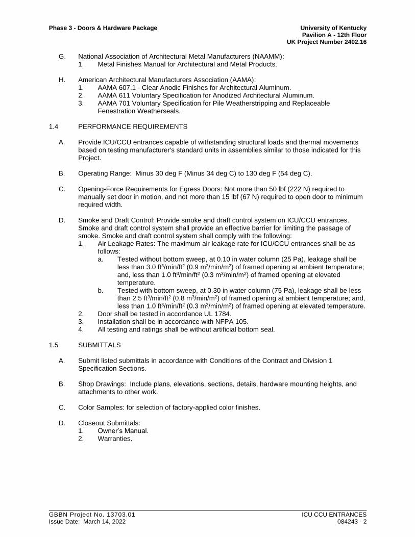
Phase 3 - Doors & Hardware Package University of Kentucky Pavilion A - 12th Floor UK Project Number 2402.16
GBBN Project No. 13703.01 ICU CCU ENTRANCES Issue Date: March 14, 2022 084243 - 2
G. National Association of Architectural Metal Manufacturers (NAAMM): 1. Metal Finishes Manual for Architectural and Metal Products.
H. American Architectural Manufacturers Association (AAMA):
1. AAMA 607.1 - Clear Anodic Finishes for Architectural Aluminum. 2. AAMA 611 Voluntary Specification for Anodized Architectural Aluminum. 3. AAMA 701 Voluntary Specification for Pile Weatherstripping and Replaceable
Fenestration Weatherseals.
1.4 PERFORMANCE REQUIREMENTS
A. Provide ICU/CCU entrances capable of withstanding structural loads and thermal movements based on testing manufacturer's standard units in assemblies similar to those indicated for this Project.
B. Operating Range: Minus 30 deg F (Minus 34 deg C) to 130 deg F (54 deg C).
C. Opening-Force Requirements for Egress Doors: Not more than 50 lbf (222 N) required to manually set door in motion, and not more than 15 lbf (67 N) required to open door to minimum required width.
D. Smoke and Draft Control: Provide smoke and draft control system on ICU/CCU entrances. Smoke and draft control system shall provide an effective barrier for limiting the passage of smoke. Smoke and draft control system shall comply with the following: 1. Air Leakage Rates: The maximum air leakage rate for ICU/CCU entrances shall be as
follows: a. Tested without bottom sweep, at 0.10 in water column (25 Pa), leakage shall be
less than 3.0 ft3/min/ft2 (0.9 m3/min/m2) of framed opening at ambient temperature; and, less than 1.0 ft3/min/ft2 (0.3 m3/min/m2) of framed opening at elevated temperature.
b. Tested with bottom sweep, at 0.30 in water column (75 Pa), leakage shall be less than 2.5 ft3/min/ft2 (0.8 m3/min/m2) of framed opening at ambient temperature; and, less than 1.0 ft3/min/ft2 (0.3 m3/min/m2) of framed opening at elevated temperature.
2. Door shall be tested in accordance UL 1784. 3. Installation shall be in accordance with NFPA 105. 4. All testing and ratings shall be without artificial bottom seal.
1.5 SUBMITTALS
A. Submit listed submittals in accordance with Conditions of the Contract and Division 1
Specification Sections.
B. Shop Drawings: Include plans, elevations, sections, details, hardware mounting heights, and attachments to other work.
C. Color Samples: for selection of factory-applied color finishes.
D. Closeout Submittals:
1. Owner’s Manual. 2. Warranties.
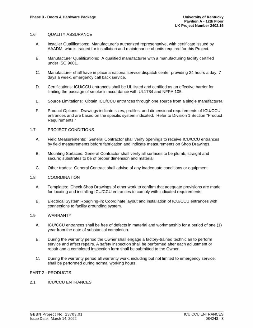
Phase 3 - Doors & Hardware Package University of Kentucky Pavilion A - 12th Floor UK Project Number 2402.16
GBBN Project No. 13703.01 ICU CCU ENTRANCES Issue Date: March 14, 2022 084243 - 3
1.6 QUALITY ASSURANCE
A. Installer Qualifications: Manufacturer's authorized representative, with certificate issued by AAADM, who is trained for installation and maintenance of units required for this Project.
B. Manufacturer Qualifications: A qualified manufacturer with a manufacturing facility certified under ISO 9001.
C. Manufacturer shall have in place a national service dispatch center providing 24 hours a day, 7 days a week, emergency call back service.
D. Certifications: ICU/CCU entrances shall be UL listed and certified as an effective barrier for limiting the passage of smoke in accordance with UL1784 and NFPA 105.
E. Source Limitations: Obtain ICU/CCU entrances through one source from a single manufacturer.
F. Product Options: Drawings indicate sizes, profiles, and dimensional requirements of ICU/CCU entrances and are based on the specific system indicated. Refer to Division 1 Section "Product Requirements."
1.7 PROJECT CONDITIONS
A. Field Measurements: General Contractor shall verify openings to receive ICU/CCU entrances by field measurements before fabrication and indicate measurements on Shop Drawings.
B. Mounting Surfaces: General Contractor shall verify all surfaces to be plumb, straight and secure; substrates to be of proper dimension and material.
C. Other trades: General Contract shall advise of any inadequate conditions or equipment. 1.8 COORDINATION
A. Templates: Check Shop Drawings of other work to confirm that adequate provisions are made
for locating and installing ICU/CCU entrances to comply with indicated requirements.
B. Electrical System Roughing-in: Coordinate layout and installation of ICU/CCU entrances with connections to facility grounding system.
1.9 WARRANTY
A. ICU/CCU entrances shall be free of defects in material and workmanship for a period of one (1) year from the date of substantial completion.
B. During the warranty period the Owner shall engage a factory-trained technician to perform service and affect repairs. A safety inspection shall be performed after each adjustment or repair and a completed inspection form shall be submitted to the Owner.
C. During the warranty period all warranty work, including but not limited to emergency service, shall be performed during normal working hours.
PART 2 - PRODUCTS
2.1 ICU/CCU ENTRANCES

Phase 3 - Doors & Hardware Package University of Kentucky Pavilion A - 12th Floor UK Project Number 2402.16
GBBN Project No. 13703.01 ICU CCU ENTRANCES Issue Date: March 14, 2022 084243 - 4
A. Manufacturer: Stanley Access Technologies; ProCare™ Series 8300 manual swinging ICU/CCU entrances.
2.2 MATERIALS
A. Aluminum: Alloy and temper recommended by manufacturer for type of use and finish indicated. 1. Headers, stiles, rails, and frames 6063-T6 2. Extruded Bars, Rods, Profiles, and Tubes: ASTM B 221. 3. Sheet and Plate: ASTM B 209.
B. Sealants and Joint Fillers: Performed under Division 7 Section "Joint Sealants".
2.3 ICU/CCU ENTRANCE ASSEMBLIES
A. Provide manufacturer's standard ICU/CCU entrance assemblies including doors, framing,
headers, pivots, and accessories required for a complete installation.
B. ICU/CCU Entrances: 1. Configuration:
a. Simultaneous pairs. b. Simultaneous pairs, uneven. c. Single door.
2. Traffic Pattern: Two-way. 3. Breakaway Capability: All active swinging panels. 4. Mounting: Between jambs
2.4 COMPONENTS
A. Framing Members: Manufacturer's standard extruded aluminum reinforced as required to
support imposed loads. 1. Nominal Size: 1 ¾ inch by 4 ½ inch. 2. Concealed Fastening: Framing shall incorporate a concealed fastening pocket, and
continuous flush insert cover, extending full length of each framing member.
B. Stile and Rail Doors and Sidelights: Manufacturer's standard 1 ¾ inch (45 mm) thick glazed doors with extruded-aluminum tubular stile and rail members. Incorporate concealed tie-rods that span full length of top and bottom rails. 1. Glazing Stops and Gaskets: Snap-on, extruded-security aluminum stops and preformed
gaskets. 2. Stile Design: Medium stile; 4-inch (51 mm) minimum nominal width.
a. Provide minimum width capable of accommodating specified hardware. 3. Bottom Rail Design: Minimum 6 inch (102 mm) nominal height. 4. Muntin Bars: Horizontal tubular rail member for each door; 2 inch (51 mm) nominal
height.
C. Glazing: Furnished under Division 8 Section Glazing. All Glazing furnished under separate section shall be 1/4 inch (6 mm) tempered.
D. Fasteners and Accessories: Manufacturer's standard corrosion-resistant, non-staining, non-bleeding fasteners and accessories compatible with adjacent materials.
E. Base Termination: Provide at each framing member where framing member meets floor and wall base.

Phase 3 - Doors & Hardware Package University of Kentucky Pavilion A - 12th Floor UK Project Number 2402.16
GBBN Project No. 13703.01 ICU CCU ENTRANCES Issue Date: March 14, 2022 084243 - 5
1. Aluminum Plate: 4-inch x 6-inch x ¼-inch thick. 2. Finish: Match entrance finish.
2.5 HARDWARE
A. Provide units in sizes and types recommended by ICU/CCU entrance and hardware
manufacturers for entrances and uses indicated.
B. Breakaway: Provide release hardware that allows panel(s) to swing out in direction of egress to full 90 degrees. Maximum force to open panel shall be 50 lbf (222 N) with panel retaining latches released. Limit arms shall be provided to control swing of panels on break-out; swing shall not exceed 90 degrees.
C. Continuous Hinge: Provide geared continuous hinges for swinging panels. Hinge shall be tested and approved by BHMA for ANSI A156.26-1996 Grade 1 and shall be non-handed.
D. Concealed In-Door Closer: Manufacturer’s standard units tested and certified to ANSI/BHMA A156.4, Grade 1. Size closers in accordance with manufacturer’s recommendation for door size and conditions. Closers shall incorporate the following: 1. Separate adjusting valves for closing and latching speed, and back-check. 2. Adjustable hold-open position.
E. Positive Latch: Manufacturer's standard non-keyed, spring loaded, latch and strike that can secure swinging door panels to head, adjacent panels, or jambs. Latch shall engage by closing action of door. On single doors strike shall mount flush to surface of framing. 1. Active panels: Positive latch shall be vertical rod type, top only. 2. In-Active Panels: Semi-automatic; self-latching.
F. Integral Blinds: Provide “Vision Control” by Unicel.
G. Sliding Weather Stripping: Manufacturer's standard replaceable smoke rated components
complying with AAMA 701.
H. Weather Sweeps: Manufacture’s standard dual row nylon brush sweep mounted to underside of door bottom
2.6 FABRICATION
A. Factory fabricate ICU/CCU entrance components to designs, sizes, and thickness indicated and to comply with indicated standards. 1. Form aluminum shapes before finishing. 2. Use concealed fasteners to greatest extent possible.
a. Where fasteners are subject to loosening or turning out from thermal and structural movements, wind loads, or vibration, use self-locking devices.
b. Reinforce members as required to receive fastener threads.
B. Framing: Provide ICU/CCU entrances as prefabricated assemblies. 1. Fabricate tubular and channel frame assemblies with manufacturer's standard
mechanical or welded joints. Provide sub-frames and reinforcement as required for a complete system to support required loads.
2. Perform fabrication operations in manner that prevents damage to exposed finish surfaces.
3. Form profiles that are sharp, straight, and free of defects or deformations. 4. Prepare components to receive concealed fasteners and anchor and connection devices.

Phase 3 - Doors & Hardware Package University of Kentucky Pavilion A - 12th Floor UK Project Number 2402.16
GBBN Project No. 13703.01 ICU CCU ENTRANCES Issue Date: March 14, 2022 084243 - 6
5. Fabricate components with accurately fitted joints with ends coped or mitered to produce hairline joints free of burrs and distortion.
C. Doors: Factory fabricated and assembled in profiles indicated. Reinforce as required to support
imposed loads and for installing hardware.
D. Glazing: Fabricate framing with minimum glazing edge clearances for thickness and type of glazing indicated.
E. Hardware: Factory install hardware to the greatest extent possible; remove only as required for final finishing operation and for delivery to and installation at Project site.
2.7 ALUMINUM FINISHES
A. Comply with NAAMM Metal Finishes Manual for Architectural and Metal Products for recommendations for applying and designing finishes. Finish designations prefixed by AA comply with system established by Aluminum Association for designing finishes.
B. Class II, Clear Anodic Finish: AA-M10C22A31 Mechanical Finish: as fabricated; Chemical
Finish: etched, medium matte; Anodic Coating: Architectural Class II, clear coating 0.40 mils minimum complying with AAMA 611-98, and the following: 1. AAMA 607.1 2. Applicator must be fully compliant with all applicable environmental regulations and
permits, including wastewater and heavy metal discharge.
PART 3 - EXECUTION
3.1 INSPECTION
A. Examine conditions for compliance with requirements for installation tolerances, header support, and other conditions affecting performance of ICU/CCU entrances. Proceed with installation only after unsatisfactory conditions have been corrected.
3.2 INSTALLATION
A. Do not install damaged components. Fit frame joints to produce joints free of burrs and
distortion. Rigidly secure non-movement joints.
B. Entrances: Install ICU/CCU entrances plumb and true in alignment with established lines and grades without warp or rack of framing members and doors. Anchor securely in place. 1. Install surface-mounted hardware using concealed fasteners to greatest extent possible. 2. Set headers, carrier assemblies, tracks, operating brackets, and guides level and true to
location with anchorage for permanent support.
C. Grounding: Connect ICU/CCU entrances to building grounding system as specified in Division 26 Sections.
D. Glazing: Performed under Division 8 Section "Glazing" in accordance with ICU/CCU entrance manufacture’s instructions.
E. Sealants: Comply with requirements specified in Division7 Section "Joint Sealants".
3.3 FIELD QUALITY CONTROL

Phase 3 - Doors & Hardware Package University of Kentucky Pavilion A - 12th Floor UK Project Number 2402.16
GBBN Project No. 13703.01 ICU CCU ENTRANCES Issue Date: March 14, 2022 084243 - 7
A. Testing Services: Factory Trained Installer shall test and inspect each ICU/CCU entrance to determine compliance of installed systems with applicable standards.
3.4 ADJUSTING
A. Adjust ICU/CCU entrances, and hardware for smooth and safe operation.
3.5 CLEANING AND PROTECTION
A. Clean glass and aluminum surfaces promptly after installation. Remove excess glazing and sealant compounds, dirt, and other substances. Repair damaged finish to match original finish. Comply with requirements in Division 8 Section “Glazing”, for cleaning and maintaining glass.
END OF SECTION 08 4243

Phase 3 - Doors & Hardware Package University of Kentucky Pavilion A - 12th Floor UK Project Number 2402.16
GBBN Project No. 13703.01 ICU CCU ENTRANCES Issue Date: March 14, 2022 084243 - 8
Available options not specified in this document are summarized as follows: 1. Configuration Options: (All Specified)
a. Simultaneous Pair b. Simultaneous Pair, Uneven c. Single Door
2. Header options: a. 1 3/4 inch (44 mm) height (Specified) b. 4 inch (102 mm) height.
3. Finish (Class 2, Clear Anodized specified) options include: a. Standard color anodizing options. b. Multi-coat Fluoropolymer painted finishes. c. Cladding.
4. Stile options; a. Narrow stile 2 inch (51 mm) (Specified) b. Medium stile 3 ½ inch (89 mm) available
5. Bottom rail options; up to 18 inch (457 mm). 6. Glazing options to 1 inch (25 mm) thick; supporting installation of “mini-blinds”. 7. Smoke & Draft control system (Specified) 8. Anti-Microbial coating of “Touch Points” or full package.
These specifications represent a “sample” door configuration and depict design features that are commonly used. These
specifications do not reflect “standard” features and are provided for informational purposes only. Please note that there is
no standard “off the shelf” product. Stanley custom manufactures each product to its customers’ specifications. It is the
customer’s responsibility to validate that a particular configuration of Stanley’s products is suitable for a specific
application. All specifications and designs contained herein are subject to change without notice or obligation.
Contact SpecCentre services or your local Stanley Access Technologies representative for more information on specifying the right sliding automatic entrance for your project.

Phase 3 - Doors & Hardware Package University of Kentucky Pavilion A - 12th Floor UK Project Number 2402.16
GBBN Project No. 13703.01 DOOR HARDWARE Issue Date: March 14, 2022 087100 - 1
SECTION 08 7100
DOOR HARDWARE
PART 1 - GENERAL
1.1 SUMMARY
A. Section Includes:
1. Commercial door hardware for the following:
a. Swinging doors.
b. Non-fire-rated sliding doors.
c. Non-fire-rated folding doors.
d. Other doors to the extent indicated.
2. Cylinders for doors specified in other Sections.
3. Electrified door hardware:
a. Doors with electrified operation and operational components.
b. Conformance with operational descriptions for electrified hardware.
4. Final connections of electrified automatic door operators and control modules to provided
adjacent power junctions.
5. Scope and material described for all hardware sets and operational descriptions for door
hardware provided as attachments within this division of the project manual.
B. Related Sections: Include cylinders and other items identified therein as provided herein: Other
hardware items provided therein are as follows:
1. Division 08 Section "Hollow Metal Doors and Frames" for door silencers provided as part
of hollow-metal frames.
2. Division 08 Section " Wood Doors" for integral intumescent seals provided as part of fire-
rated labeled assemblies provided therein.
3. Division 08 Section "Access Doors and Frames" for access door hardware.
4. Division 26 Electrical Sections: Work provided therein:
a. Providing electrical power to adjacent junction boxes at door installations with
electrical requirements.
b. Providing junction boxes at terminations of electrical power runs to a specific door.
c. Conduit and back box installations for routing electrical wiring at and around
electrified door hardware installations from junction boxes.
5. Division 27 Section "Communication" for intercom systems installed at door openings and
provided as part of a building wide communication system.
6. Division 28 Section "Electronic Safety and Security"
a. Access control devices installed at door openings and provided as part of a security
access system.

Phase 3 - Doors & Hardware Package University of Kentucky Pavilion A - 12th Floor UK Project Number 2402.16
GBBN Project No. 13703.01 DOOR HARDWARE Issue Date: March 14, 2022 087100 - 2
b. Detection devices installed at door openings and provided as part of an intrusion
detection system.
7. Division 28 Section "Fire Detection and Alarm" for connections to building fire alarm
system.
C. Products furnished, but not installed, under this Section include the following. Coordinating,
purchasing, delivering, and scheduling remain requirements of this Section.
1. Permanent cores for cylinders for locks.
2. Permanent cores to be installed by Owner.
1.2 SUBMITTALS
A. General: Submit items indicated below to Construction Manager for review by Architect.
B. Product Data: Include construction and installation details, material descriptions, dimensions of
individual components and profiles, and finishes.
C. Shop Drawings: Details of electrified door hardware, indicating the following:
D. Functional Description: Provide written description of the function of each hardware set.
Example as follows:
E. Wiring Diagrams: Complete wiring diagram for each electrified door. Including but not limited
to the following:
a. System schematic.
b. Point-to-point wiring diagram for coordination/integration of work by other trades.
c. Riser diagram.
d. Elevation of each door.
e. Detail interface between electrified door hardware, fire alarm, access control,
security and building control systems.
f. Operation Narrative: Describe the operation of doors controlled by electrified door
hardware.
F. Samples for Verification: Submit minimum 2-by-4-inch plate Samples of each type of finish
required, except primed finish.

Phase 3 - Doors & Hardware Package University of Kentucky Pavilion A - 12th Floor UK Project Number 2402.16
GBBN Project No. 13703.01 DOOR HARDWARE Issue Date: March 14, 2022 087100 - 3
G. Samples for Verification: For exposed door hardware of each type, in specified finish, full size.
Tag with full description for coordination with the door hardware sets. Submit Samples before,
or concurrent with, submission of the final door hardware sets.
1. Samples will be returned to Contractor. Units that are acceptable and remain undamaged
through submittal, review, and field comparison process may, after final check of
operation, be incorporated into the Work, within limitations of keying requirements.
H. Product Certificates: For electrified door hardware, signed by product manufacturer.
1. Certify that door hardware approved for use on types and sizes of labeled fire doors
complies with listed fire door assemblies.
I. Qualification Data: For Installer.
J. Maintenance Data: For each type of door hardware to include in maintenance manuals. Include
final hardware and keying schedule.
K. Warranty: Special warranty specified in this Section.
L. Keying Schedule: Prepared by or under the supervision of Architectural Hardware Consultant,
detailing Owner's final keying instructions for locks. Include schematic keying diagram and
index each key set to unique door designations.
1.3 REGULATORY REQUIREMENTS
A. Fire-rated openings: Comply with specifications and procedures of testing agency meeting the
Kentucky Building Code; label with name of testing agency and manufacturer's name and file
number.
B. Requirements for persons with disabilities: Comply with the Kentucky Building Code and with
ADA standards.
1.4 QUALITY ASSURANCE
A. Supplier's qualifications: Supplier shall have an established organization with experience and
competence required to interpret correctly Contract Documents and to furnish appropriate and
complete finish hardware. Supplier shall be manufacturer-franchised to supply material which it
proposes to furnish. Work shall be assigned to a specialist, a full-time employee of supplier's
firm, who shall also be a DHI-certified Architectural Hardware Consultant (not an "Apprentice
Hardware Consultant") or specialist with minimum 10 years experience in selecting and
scheduling hardware of the type and quantity specified herein. Supplier and specialist shall be
available upon short notice to Contractor and Architect throughout construction and one-year
correction period.
1. Scheduling Responsibility: Preparation of door hardware and keying schedules.
2. Engineering Responsibility: Preparation of data for electrified door hardware, including
Shop Drawings, based on testing and engineering analysis of manufacturer's standard units
in assemblies similar to those indicated for this Project.

Phase 3 - Doors & Hardware Package University of Kentucky Pavilion A - 12th Floor UK Project Number 2402.16
GBBN Project No. 13703.01 DOOR HARDWARE Issue Date: March 14, 2022 087100 - 4
3. Electrified Door Hardware Consultant Qualifications: A qualified Architectural Hardware
Consultant who is experienced in providing consulting services for electrified door
hardware installations.
B. Installer Qualifications: An employer of workers trained and approved by lock manufacturer.
1. Installer's responsibilities include supplying and installing door hardware and providing a
qualified Architectural Hardware Consultant available during the course of the Work to
consult with Contractor, Architect, and Owner about door hardware and keying.
2. Installer shall have warehousing facilities in Project's vicinity.
C. Source Limitations: Obtain each type and variety of door hardware from a single manufacturer,
unless otherwise indicated.
1. Provide electrified door hardware from same manufacturer as mechanical door hardware,
unless otherwise indicated. Manufacturers that perform electrical modifications and that
are listed by a testing and inspecting agency acceptable to authorities having jurisdiction
are acceptable.
D. Fire-Rated Door Assemblies: Assemblies complying with NFPA 80 that are listed and labeled
by a testing and inspecting agency acceptable to authorities having jurisdiction, for fire ratings
indicated, based on testing according to NFPA 252.
1. Test Pressure: Test at atmospheric pressure. After 5 minutes into the test, neutral pressure
level in furnace shall be established at 40 inches or less above the sill.
E. Electrified Door Hardware: Listed and labeled as defined in NFPA 70, Article 100, by a testing
agency acceptable to authorities having jurisdiction, and marked for intended use.
F. Keying Conference: Conduct conference at Project site to comply with requirements in Division
01 Section "Project Management and Coordination." In addition to Owner, Construction
Manager, Contractor, and Architect, conference participants shall also include Installer's
Architectural Hardware Consultant. Incorporate keying conference decisions into final keying
schedule after reviewing door hardware keying system including, but not limited to, the
following:
1. Function of building, flow of traffic, purpose of each area, degree of security required, and
plans for future expansion.
2. Preliminary key system schematic diagram.
3. Requirements for key control system.
4. Address for delivery of keys.
G. Preinstallation Conference: Conduct conference at Project site to comply with requirements in
Division 01 Section "Summary of Work." Review methods and procedures related to electrified
door hardware including, but not limited to, the following:
1. Inspect and discuss electrical roughing-in and other preparatory work performed by other
trades.
2. Review sequence of operation for each type of electrified door hardware.
3. Review and finalize construction schedule and verify availability of materials, Installer's
personnel, equipment, and facilities needed to make progress and avoid delays.
4. Review required testing, inspecting, and certifying procedures.

Phase 3 - Doors & Hardware Package University of Kentucky Pavilion A - 12th Floor UK Project Number 2402.16
GBBN Project No. 13703.01 DOOR HARDWARE Issue Date: March 14, 2022 087100 - 5
1.5 DOOR AND FRAME WIRING
A. All wiring internal to doors and frames must be color coded, and must be same color system in
all doors.
B. All connections inside doors and at frame must use Molex connectors. No other means of
connectors to be allowed.
C. All color coding and use of Molex connectors to be shown on wiring diagram supplied by 087100.
1.6 DELIVERY, STORAGE, AND HANDLING
A. Inventory door hardware on receipt and provide secure lock-up for door hardware delivered to
Project site.
B. Tag each item or package separately with identification related to the final door hardware sets,
and include basic installation instructions, templates, and necessary fasteners with each item or
package.
C. Deliver keys to manufacturer of key control system for subsequent delivery to Owner. D.
Deliver keys and permanent cores to Owner by registered courier service.
1. Deliver to location directed by Owner.
a. Permanent cylinders to be delivered directly to the owner in sealed unopened
containers originating directly from the manufacturer.
b. Ship with controlled courier service to validate the seal and closure of all packaging
as originated from the manufacturer directly to the Owners agent.
1.7 COORDINATION
A. Coordinate layout and installation of recessed pivots and closers with floor construction. Cast
anchoring inserts into concrete. Concrete, reinforcement, and formwork requirements are
specified in Division 03.
B. Templates: Distribute door hardware templates for doors, frames, and other work specified to be
factory prepared for installing door hardware. Check Shop Drawings of other work to confirm
that adequate provisions are made for locating and installing door hardware to comply with
indicated requirements.
C. Electrical System Roughing-in: Coordinate layout and installation of electrified door hardware
with connections to power supplies, fire alarm system and detection devices, access control
system, security system and building control system.
D. Existing Openings: Where new hardware components are scheduled for application to existing
construction or where modifications to existing door hardware are required, field verify existing
conditions and coordinate installation of door hardware to suit opening conditions and to provide
for proper operation.

Phase 3 - Doors & Hardware Package University of Kentucky Pavilion A - 12th Floor UK Project Number 2402.16
GBBN Project No. 13703.01 DOOR HARDWARE Issue Date: March 14, 2022 087100 - 6
1.8 WARRANTY
A. Special Warranty: Manufacturer's standard form in which manufacturer agrees to repair or
replace components of door hardware that fail in materials or workmanship within specified
warranty period.
1. Failures include, but are not limited to, the following:
a. Structural failures including excessive deflection, cracking, or breakage.
b. Faulty operation of operators and door hardware.
c. Deterioration of metals, metal finishes, and other materials beyond normal
weathering and use.
2. Warranty Period: Three years from date of Substantial Completion, except as follows:
a. Electromagnetic Delayed-Egress Locks: Five years from date of Substantial
Completion.
b. Exit Devices: Two years from date of Substantial Completion.
c. Manual Closers: 10 years from date of Substantial Completion.
d. Concealed Floor Closers: 10years from date of Substantial Completion.
1.9 MAINTENANCE SERVICE
A. Maintenance Tools and Instructions: Furnish a complete set of specialized tools and maintenance
instructions as needed for Owner's continued adjustment, maintenance, and removal and
replacement of door hardware.
B. Maintenance Service: Beginning at Substantial Completion, provide six months' full maintenance
by skilled employees of door hardware Installer. Include quarterly preventive maintenance, repair
or replacement of worn or defective components, lubrication, cleaning, and adjusting as required
for proper door hardware operation. Provide parts and supplies same as those used in the
manufacture and installation of original products.
PART 2 - PRODUCTS
2.1 GENERAL PRODUCT REQUIREMENTS
A. Hardware schedule is intended as a guide for description and quantity of material required.
Hardware supplier is responsible for supplying correct quantity of materials under this section
and for supplying hardware of quality, function and appearance suitable for job conditions as
shown in Contract Documents.
1. Architect shall be sole judge of whether products meet any and/or all of the criteria for
quality, finish, performance, design, weight, thickness and suitability of application as
compared to listed products in the hardware schedule.
B. Coordinate hardware fastening devices with materials to which it is applied.
C. Hinges and door closers shall conform to manufacturer’s published recommendations relating to
door size, weight, thickness, and anticipated frequency of operation and draft conditions.

Phase 3 - Doors & Hardware Package University of Kentucky Pavilion A - 12th Floor UK Project Number 2402.16
GBBN Project No. 13703.01 DOOR HARDWARE Issue Date: March 14, 2022 087100 - 7
D. Conform to all Regulatory Requirements indicated for The Project.
E. Hardware Requirements:
1. All hardware and fasteners provided shall meet and conform with all industry requirements
for high frequency use applications.
2.2 MANUFACTURERS
A. Manufacturers listed as acceptable may be used provided they match listed products in design,
weight, finish, and suitability for application. Architect shall be sole judge of whether products
meet any and all of these criteria.
1. Unless otherwise specified herein, do not mix manufacturers for any hardware item
category for different doors.
B. ITEM LISTED MANUFACTURER ACCEPTABLE ALT’S Hinges Mckinney Hager, Stanley
Continuous Hinges Markar (MA) Bommer, Hager
Key System BEST-CORMAX
BE
User standard –no sub
Locksets
Yale
(YA)
Sargent, BEST
NOTE: BEST
ELEC
LOCKS MUST HAVE MOLEX PLUGS
Closers Norton (NO) LCN 4040 EDA
Sargent 351P-10
Exit Devices Yale (YA) Von Duprin 99series X 32D
Sargent 80Series X 32D
1. Provide custom endcap identical in intent and function as endcap designed and man-ufactured by Yale Manufacturing. (Endcap specifically designed for the University of Kentucky Patient Care Facility Project.)
Overhead Stops Rixson (RF) ABH, GJ, Sargent
Floor / Wall Stops Rockwood (RO) Trimco, Hager
Power Supplies Securitron (SU) Von Duprin, Sargent
Yale (YA)
Protection Plates Rockwood (RO) Trimco, Hager
Thresholds National Guard (NG) Reese, Pemko
Seals & Bottoms National Guard (NG) Reese, Pemko
Sliding Door Hardware AD Door Syst (AD) Stanley
Pivots Rixson (RF) Dorma, Hager
Electromagnetic Securitron Locknetics

Phase 3 - Doors & Hardware Package University of Kentucky Pavilion A - 12th Floor UK Project Number 2402.16
GBBN Project No. 13703.01 DOOR HARDWARE Issue Date: March 14, 2022 087100 - 8
Door position Switches Securitron (SE) Locknetics, Sentrol
Key Switches Locknetics Securitron, Sargent
Hospital Latches Sargent (SA) GJ
Flush Bolts Rockwood (RO) Trimco, (TR)
Fire Latches Trimco (TR)
Electro Magnetic Re-
lease Rixson (RF) Dorma, LCN
2.3 FABRICATION
A. Manufacturer's Nameplate: Do not provide products that have manufacturer's name or trade name
displayed in a visible location except in conjunction with required fire-rated labels and as
otherwise approved by Architect.
B. Base Metals: Produce door hardware units of base metal, fabricated by forming method indicated,
using manufacturer's standard metal alloy, composition, temper, and hardness. Furnish metals of
a quality equal to or greater than that of specified door hardware units and BHMA A156.18.
1. Do not furnish manufacturer's standard materials or forming methods if different from
specified standard.
C. Reinforcing: Provide high frequency hardware reinforcing at all installations for all hardware.
D. Fasteners: Provide door hardware manufactured to comply with published templates generally
prepared for machine, wood, and sheet metal screws. Provide screws according to commercially
recognized industry standards for application intended, except aluminum fasteners are not
permitted. Provide Phillips flat-head screws with finished heads to match surface of door
hardware, unless otherwise indicated.
1. Concealed Fasteners: For door hardware units that are exposed when door is closed, except
for units already specified with concealed fasteners. Do not use through bolts for
installation where bolt head or nut on opposite face is exposed unless it is the only means
of securely attaching the door hardware. Where through bolts are used on hollow door and
frame construction, provide sleeves for each through bolt.
2. Steel Machine or Wood Screws: For the following fire-rated applications:
a. Mortise hinges to doors.
b. Strike plates to frames.
c. Closers to doors and frames.
3. Steel Through Bolts: For the following fire-rated applications unless door blocking is
provided:
a. Surface hinges to doors.
b. Closers to doors and frames.
c. Surface-mounted exit devices.
4. Spacers or Sex Bolts: For through bolting of hollow-metal doors.
5. Fasteners for Wood Doors: Comply with requirements in DHI WDHS.2, "Recommended Fasteners for Wood Doors."

Phase 3 - Doors & Hardware Package University of Kentucky Pavilion A - 12th Floor UK Project Number 2402.16
GBBN Project No. 13703.01 DOOR HARDWARE Issue Date: March 14, 2022 087100 - 9
E. Kick plates: Size kick plates to butt into edge of edge guards. Do not overlap edge guards.
2.4 KEYING SYSTEM
A. Provide exclusive University of Kentucky Great Grand Master Keying System by Best
Manufacturing.
1. Core/Keying System: Best High Security factory restricted Series Cormax key system:
Seven pin removable cores with custom keyway exclusive to the University of Kentucky
Hospital Complex at Lexington Campus as manufactured by Best.
2. Keying shall be an extension of the University of Kentucky Great Grand Master Key
System.
a. Supplier shall coordinate with Construction Manager in obtaining information about
existing system, and keying required for new locks and cores supplied herein.
B. Keys for Great Grand Master Keyed, Grand Master Keyed and Master Keyed in sets:
1. Number of Great Grand Master Keys provided: Thirty, (30).
2. Number of Grand Master Keys for each set provided: Thirty, (30)
3. Number of Master Keys for each set provided: Thirty, (30)
C. Provide additional permanent combined cores under each Master Key Set for Owner's reserve.
1. Provide 10 additional cores for each Master Key set.
2. Provide 10 additional cores for each Grand Master Key set.
3. Provide 10 additional cores for the Great Grand Master Key set.
D. Keying schedule: To be developed by supplier per Owner's requirements as directed by Owner
in conformance allowing ample time to meet Contractor’s construction schedule. Locks shall be
keyed alike and different per Owner's requirements.
1. Provide minimum of Five, (5), change keys per lock.
2. Include cost of developing schedule with cost of hardware.
E. Furnish temporary construction cores for locks for Contractor's use during period of construction.
1. Hardware supplier to provide 200 temporary cores for use during construction and prior to
placement of permanent cores. Deliver to hardware installing contract personnel.
2. Return all temporary cores to Hardware supplier after use and placement of permanent
cores.
F. Delivery of final cores and keys: Deliver final cores and keys directly to the Owner’s
representative via bonded courier service:
1. Pickup of final cores and keys by courier at Manufacturer’s facility.
2. Deliver directly to Owner’s representative from Manufacturer’s facility.
3. Deliver to designated site and individual as identified by the Owner.
a. Delivery shall be on the Lexington campus of the University of Kentucky.
4. Provide signed manifest to Owner indicating and validating reception and delivery of cores
and keys.

Phase 3 - Doors & Hardware Package University of Kentucky Pavilion A - 12th Floor UK Project Number 2402.16
GBBN Project No. 13703.01 DOOR HARDWARE Issue Date: March 14, 2022 087100 - 10
5. No permanent cores are to be delivered to contracted companies performing this or any
other aspect of the work for The Project.
2.5 FINISHES
A. Standard: BHMA A156.18, as indicated in door hardware sets.
B. Protect mechanical finishes on exposed surfaces from damage by applying a strippable, temporary
protective covering before shipping.
C. Appearance of Finished Work: Variations in appearance of abutting or adjacent pieces are
acceptable if they are within one-half of the range of approved Samples. Noticeable variations in
the same piece are not acceptable. Variations in appearance of other components areacceptable
if they are within the range of approved Samples and are assembled or installed to minimize
contrast.
PART 3 - EXECUTION
3.1 EXAMINATION
A. Examine doors and frames, with Installer present, for compliance with requirements for
installation tolerances, labeled fire door assembly construction, wall and floor construction, and
other conditions affecting performance.
B. Examine roughing-in for electrical power systems to verify actual locations of wiring connections
before electrified door hardware installation.
C. Proceed with installation only after unsatisfactory conditions have been corrected.
3.2 PREPARATION
A. Coordinate with door suppliers to preinstall, repackage and label per door opening at door
supplier’s factory prior to shipment to site.
B. Steel Doors and Frames: Comply with DHI A115 Series.
1. Surface-Applied Door Hardware: Drill and tap doors and frames according to ANSI
A250.6.
C. Wood Doors: Comply with DHI A115-W Series.
3.3 INSTALLATION
A. Mounting Heights: Mount door hardware units at heights indicated on Drawings and as follows
unless otherwise indicated or required to comply with governing regulations.
1. Standard Steel Doors and Frames: DHI's "Recommended Locations for Architectural
Hardware for Standard Steel Doors and Frames."

Phase 3 - Doors & Hardware Package University of Kentucky Pavilion A - 12th Floor UK Project Number 2402.16
GBBN Project No. 13703.01 DOOR HARDWARE Issue Date: March 14, 2022 087100 - 11
2. Custom Steel Doors and Frames: DHI's "Recommended Locations for Builders' Hardware
for Custom Steel Doors and Frames."
3. Wood Doors: DHI WDHS.3, "Recommended Locations for Architectural Hardware for
Wood Flush Doors."
B. Install each door hardware item to comply with manufacturer's written instructions. Where
cutting and fitting are required to install door hardware onto or into surfaces that are later to be
painted or finished in another way, coordinate removal, storage, and reinstallation of surface
protective trim units with finishing work specified in Division 09 Sections. Do not install surface-
mounted items until finishes have been completed on substrates involved.
1. Set units level, plumb, and true to line and location. Adjust and reinforce attachment
substrates as necessary for proper installation and operation.
2. Drill and countersink units that are not factory prepared for anchorage fasteners. Space
fasteners and anchors according to industry standards.
C. Key Control System: Cores installed by Owner. Final keys remain in control of Owner.
D. Boxed Power Supplies: Locate power supplies as indicated or, if not indicated, above accessible
ceilings or in equipment room or other location as directed by the Architect.
1. Configuration: Provide power supplies as scheduled.
E. Thresholds: Where indicated: Set thresholds for exterior and acoustical doors in full bed of
sealant complying with requirements specified in Division 07 Section "Joint Sealants."
3.4 FIELD QUALITY CONTROL
A. Independent Architectural Hardware Consultant: Architect will engage a qualified independent
B. Architectural Hardware Consultant to perform inspections and to prepare inspection reports.
1. Independent Architectural Hardware Consultant will inspect door hardware and state in
each report whether installed work complies with or deviates from requirements, including
whether door hardware is properly installed and adjusted.
3.5 ADJUSTING
A. Initial Adjustment: Adjust and check each operating item of door hardware and each door to
ensure proper operation or function of every unit. Replace units that cannot be adjusted to operate
as intended. Adjust door control devices to compensate for final operation of heating and
ventilating equipment and to comply with referenced accessibility requirements.
1. Spring Hinges: Adjust to achieve positive latching when door is allowed to close freely
from an open position of 30 degrees.
2. Electric Strikes: Adjust horizontal and vertical alignment of keeper to properly engage
lock bolt.
3. Door Closers: Unless otherwise required by authorities having jurisdiction, adjust sweep
period so that, from an open position of 70 degrees, the door will take at least 3 seconds to
move to a point 3 inches from the latch, measured to the leading edge of the door.

Phase 3 - Doors & Hardware Package University of Kentucky Pavilion A - 12th Floor UK Project Number 2402.16
GBBN Project No. 13703.01 DOOR HARDWARE Issue Date: March 14, 2022 087100 - 12
B. Occupancy Adjustment: Approximately six months after date of Substantial Completion,
Installer's Architectural Hardware Consultant shall examine and readjust, including adjusting
operating forces, each item of door hardware as necessary to ensure function of doors, door
hardware, and electrified door hardware.
3.6 CLEANING AND PROTECTION
A. Clean adjacent surfaces soiled by door hardware installation.
B. Clean operating items as necessary to restore proper function and finish.
C. Provide final protection and maintain conditions that ensure that door hardware is without damage
or deterioration at time of Substantial Completion.
3.7 DEMONSTRATION
A. Engage a factory-authorized service representative to train Owner's maintenance personnel to
adjust, operate, and maintain door hardware and door hardware finishes. Refer to Division 01 Section "Demonstration and Training."
3.8 DOOR HARDWARE SETS AND DESCRIPTIONS
A. Each door designation to receive complete hardware set as indicated in the attached set
descriptions. Reference Door Schedules in The Drawings for set assignments.
B. Reference the following attachments for hardware set descriptions and door operation
descriptions:
1. Section 08 7100.2 Electrified Hardware Device Operation Schedule.
a. Door operation descriptions for all electrified doors.
END OF SECTION

Phase 3 - Doors & Hardware Package University of Kentucky Pavilion A - 12th Floor UK Project Number 2402.16
GBBN Project No. 13703.01 DOOR HARDWARE SCHEDULE Issue Date: March 14, 2022 087100.1 - 1
SECTION 08 7100.1
DOOR HARDWARE SETS – 12th FLOOR
HARDWARE SETS FOR 12TH FLOOR PATIENT ROOM FIT-OUT
Hardware Set 01
2 CONT SW CL HING HG329 x 83-1/8" 32D MA
4 SHIMS CHS-2 7’0” MA 1 SELF LATCH BOLT 2805 18” TOP ONLY x WD 26D RO 1 HOSP LATCH 28-114P (ENG) 5"Backset 26D SA 1 CONC OH STOP 1-536 630 RF 1 CONC OH STOP 1-136 630 RF 1 SURF DOOR EDGE 306 x 83" 32D RO 1 SURF DOOR EDGE 306B x 83" 32D RO
2 KICKPLATE 6 x .050" x 3BE x LGTH TO FIT 32D RO
2 MOP PLATE 6 x .050” x 3BE X LGTH TO FIT 32D RO
Hardware Set 02
2 CONT SW CL HING HG329 x 83-1/8” 32D MA
4 SHIMS CHS-2 7’0” MA 1 SELF LATCH BOLT 2805 18” TOP ONLY x WD 26D RO 1 HOSP LATCH 28-114P (ENG) 5” Backset 26D SA 1 SURF OH STOP 55-136 630 1 CONC OH STOP 5-336 630 RF 2 MOP PLATE 6 x .050" x 3BE x LGTH TO FIT 32D RO 2 KICKPLATE 6 x .050” x 3BE x LGTH TO FIT 32D RO
1 MORT. ASTRAGAL 300CP x 84’ (ONE PC) (ACTIVE LEAF) PE
HARDWARE SET 02.2
2 CONT SW CL HING HG329 x 83-1/8” 32D MA
4 SHIMS CHS-2 7’0” MA 1 SELF LATCH BOLT 2805 18” TOP ONLY x WD 26D RO 1 PRIV LATCH JNR8802 FL 26D YA 1 SURF OH STOP 55-136 630 1 CONC OH STOP 5-336 630 RF 2 MOP PLATE 6 x .050" x 3BE x LGTH TO FIT 32D RO 2 KICKPLATE 6 x .050” x 3BE x LGTH TO FIT 32D RO
1 MORT. ASTRAGAL 300CP x 84’ (ONE PC) PE
Hardware Set 02.1 (MONO RAIL DOOR)
2 CONT SW CL HING HG329 x 83-1/4” 32D MA
4 SHIMS CHS-2 7’0” MA 2 SETS PULLS BF110 X 71 RCG 4 X 20 B TO B 32D SA 1 SURF OH STOP 55-236 630 RF 1 SURF OH STOP 55-336 630 RF 2 MOP PLATE 6 x .050" x 3BE x LGTH TO FIT 32D RO 2 KICKPLATE 6 x .050” x 3BE x LGTH TO FIT 32D RO
1 MORT. ASTRAGAL 300CP (ONE PC) PE
2 ROLLER LATCH 592 26D
NOTE: HINGE AND ASTRAGAL HEIGHT PER DOOR HEIGHT

Phase 3 - Doors & Hardware Package University of Kentucky Pavilion A - 12th Floor UK Project Number 2402.16
GBBN Project No. 13703.01 DOOR HARDWARE SCHEDULE Issue Date: March 14, 2022 087100.1 - 2
Hardware Set 05
3 HINGE TA2714 4.5 X 4.5 26D MK 1 CLASSROOM LOCK JNR8808FL 626 YA 1 HS MORTISE CYL 1E74 CORMAX W/RING 26D BE 1 KICKPLATE 6 x 34 x .050" x 3BE 32D RO
1 WALL STOPS 400 26D RO
1 SEAL 5050B
HARDWARE SET 05.1
3 HINGE TA2714 4.5 X 4.5 26D MK 1 CLASSROOM LOCK JNR8808FL 626 YA 1 HS MORTISE CYL 1E74 CORMAX W/RING 26D BE 1 KICKPLATE 6 x 34 x .050" x 3BE 32D RO
1 WALL STOPS 400 26D RO
1 CLOSER 7500 689 NO
Hardware Set 08
3 HINGE TA2714 4.5 X 4.5 26D MK 1 ELEC MORT LOCK JNR8891FL x LBM x REX (secure) 626 YA
CARD READER BY SECTION 28000 1 HS MORTISE CYL 1E74 CORMAX W/RING 26D BE 1 CLOSER 7500 689 NO 1 KICKPLATE 6 x 34 x .050" x 3BE 32D RO
1 WALL STOPS 400 26D RO
1 POWER TRANSFER EL-EPT/SC SU
1 CONC DOOR POS SWITCH MSS-1C 628 SU
1 POWER SUPPLY CENTRALIZED
NEEDS RACEWAY THRU DOOR
1 DOOR CABLE QC-C300P
1 FRAME CABLE QC-C1500P
1 WIRE DIAGRAM BY 087100/PER EXAMPLE
1 SMART PACK 2005M3 HES
1 JUNCTION BOX JB7 VD
Hardware Set 09
3 HINGE TA2714 4.5 X 4.5 26D MK 1 HS MORTISE CYL 1E74 CORMAX W/RING 26D BE 1 KEYPAD LOCK KP-8278 LNB 26D SA 1 CLOSER 7500 689 NO
PR7500 @ SWING OUT DOORS 1 KICKPLATE 6 x 34 x .050" x 3BE 32D RO 1 MOP PLATE 6 x .050" x 3BE x LGTH TO FIT 32D RO 1 WALL STOP 400 26D RO

Phase 3 - Doors & Hardware Package University of Kentucky Pavilion A - 12th Floor UK Project Number 2402.16
GBBN Project No. 13703.01 DOOR HARDWARE SCHEDULE Issue Date: March 14, 2022 087100.1 - 3
HARDWARE SET 10
3 HINGE TA2714 4.5 X 4.5 26D MK 1 ELEC MORT LOCK JNR8894-2 FL (SAFE) 626 YA 2 CARD READERS BY SECTION 28000 2 HS MORTISE CYL 1E74 CORMAX W/RING 26D BE 1 CLOSER 7500 689 NO 1 KICKPLATE 6 x 34 x .050" x 3BE 32D RO
1 WALL STOPS 400 26D RO
1 POWER TRANSFER EL-EPT/SC SU
1 CONC DOOR POS SWITCH MSS-1C 628 SU
1 POWER SUPPLY CENTRALIZED
NEEDS RACEWAY THRU DOOR
1 DOOR CABLE QC-C300P
1 FRAME CABLE QC-C1500P
1 WIRE DIAGRAM BY 087100/PER EXAMPLE
1 SMART PACK 2005M3 HES
1 JUNCTION BOX JB7 VD
NOTE: CARD READER IN & OUT, FAIL SAFE LOCK
Hardware Set 11
2 CONT SW CL HING HG329 x 83-1/8" 32D MK
4 SHIMS CHS-2 7’0” MA 2 PUSH PLATES 71 RCG 4 x 20 32D RO 2 PULLS BF110 X 71 REG 4 X 20 32D RO 2 CLOSER PR7500 689 NO 2 SURF DOOR EDGE 306B x 83" 32D RO 4 KICKPLATE 6 x .050" x 3BE x LGTH TO FIT 32D RO 2 ELEC MAG RELEAS 998 x 24VDC 689 RF WIRE TO FIRE ALARM SYSTEM 1 WIRE DIAGRAM BY 087100/PER EXAMPLE
Hardware Set 13
3 HINGE T4A3786 4.5 X 4.5 26D MK 1 HS MORTISE CYL 1E74 CORMAX W/RING 26D BE 1 KEYPAD LOCK KP8278 LNB 26D SA 1 CLOSER PR7500 689 NO
7500 @ DOORS SWINGING IN 1 KICKPLATE 6 x .050" x 3BE x LGTH TO FIT 32D RO 1 MOP PLATE 6 x .050" x 3BE x LGTH TO FIT 32D RO
1 WALL STOP 400 26D RO

Phase 3 - Doors & Hardware Package University of Kentucky Pavilion A - 12th Floor UK Project Number 2402.16
GBBN Project No. 13703.01 DOOR HARDWARE SCHEDULE Issue Date: March 14, 2022 087100.1 - 4
Hardware Set 14
2 CONT SW CL HING HG329 x 83-1/8" 32D MA
4 SHIMS CHS-2 7’0” MA 1 SELF LATCH BOLT 2805 18” TOP ONLY x WD 26D RO 1 HOSP LATCH 28-114P (ENG) 5"Backset 26D SA 1 CONC OH STOP 1-536 630 RF 1 CONC OH STOP 1-136 630 RF 1 SURF DOOR EDGE 306 x 83" 32D RO 1 SURF DOOR EDGE 306B x 83" 32D RO 2 KICKPLATE 6 x .050" x 3BE x LGTH TO FIT 32D RO
2 MOP PLATE 6 x .050" x 3BE x LGTH TO FIT 32D RO
1 SEAL 5050B-22 NG
1 SPLIT ASTRAGAL 9115A(SET) x 84" NG
Hardware Set 15
1 CONT SW CL HING HG329 x 83-1/8" x EPT 32D MA
2 SHIMS CHS-2 7’0” MA 1 ELEC MORT LOCK JNR8891FL x LBM x REX (secure) 626 YA 1 HS MORTISE CYL 1E74 CORMAX W/RING 26D BE 1 CLOSER 7500 689 NO 1 ARMOR PLATE 36 x .050" x 3BE x LGTH TO FIT 32D RO
1 MOP PLATE 6 x .050” x 3BE x LGTH TO FIT 32D RO
1 WALL STOPS 400 26D RO
1 POWER TRANSFER EL-EPTL / SC SU
1 CONC.DOOR POS SWITCH MCC-1C 628 SU
1 POWER SUPPLY CENTRALIZED CARD READER BY SECTION 280000 NEEDS RACEWAY THRU DOOR 1 SMART PACK 2005M3 HES 1 DOOR CABLE QC-C400P 1 FRAMING CABLE QC-C1500P 1 WIRE DIAGRAM BY 087100/PER EXAMPLE 1 JUNCTION BOX JB7 VD 1 CARD READER SECTION 028000 1 SEAL 5050B NG
Hardware Set 19
3 HINGE T4A3786 4.5 X 4.5 26D MK 1 STORAGE LOCK JNR8805FL 626 YA 1 HS MORTISE CYL 1E74 CORMAX W/RING 26D BE 1 CLOSER 7500 689 NO 1 KICKPLATE 6 x .050" x 3BE x LGTH TO FIT 32D RO
1 WALL STOPS 400 26D RO
Hardware Set 54
3 HINGE TA2714 4.5 X 4.5 26D MK 1 DORM LOCK JNR8822FL-V21 626 YA 1 HS MORTISE CYL 1E74 CORMAX W/RING 26D BE 1 CLOSER PR7500 689 NO 7500 @ INSWINGING DOORS 1 KICKPLATE 6 x 34 x .050" x 3BE 32D RO 1 MOP PLATE 6 x 35 x .050" x 3BE 32D RO 1 WALL STOPS 400 26D RO

Phase 3 - Doors & Hardware Package University of Kentucky Pavilion A - 12th Floor UK Project Number 2402.16
GBBN Project No. 13703.01 DOOR HARDWARE SCHEDULE Issue Date: March 14, 2022 087100.1 - 5
Hardware Set 59
6 HINGE T4A3786 5.0 X 4.5 26D MK 1 SELF LATCH FLUSH BOLT 2805 18” TOP ONLY 26D RO 1 CLASSROOM LOCK JNR8808FL 626 YA 1 HS MORTISE CYL 1E74 CORMAX W/RING 26D BE 2 MOP PLATE 6 x .050" x 3BE x LGTH TO FIT 32D RO 2 KICKPLATES 6 x .050” x 3BE x LGTH TO FIT 32D RO 2 WALL STOPS 400 26D RO
2 CLOSER 7500 7500 689 NO 1 CORD 1673 RO
Hardware Set 60
3 HINGE T4A3786 4.5 X 4.5 26D MK 1 PUSH PLATE 71 RCG 4 x 20 32D RO 1 PULL RM4412 x 24” x TYPE 12 MTG 32D RO 1 CLOSER 7500 689 NO 1 KICKPLATE 6 x 34 x .050" x 3BE 32D RO 1 MOP PLATE 6 x 35 x .050" x 3BE 32D RO 1 WALL STOPS 400 26D RO
Hardware Set 63
3 HINGE TA2714 4.5 X 4.5 26D MK 1 DORM LOCK JNR8822FL IND 626 YA 1 HS MORTISE CYL 1E74 CORMAX W/RING 26D BE 1 KICKPLATE 6 x 34 x .050" x 3BE 32D RO 1 MOP PLATE 6 x 35 x .050” x 3BE 32D RO 1 WALL STOPS 400 26D RO
Hardware Set 69
3 HINGE T4A3786 4.5 X 4.5 26D MK
T4A3786 5 x 4.5 @ 4'-0" DOORS 1 ELEC MORT LOCK JNR8891FL x LBM x REX (secure) 626 YA CARD READER BY SECTION 280000 1 HS MORTISE CYL 1E74 CORMAX W/RING 26D BE 1 CLOSER 7500 689 NO 1 KICK PLATE 6 x .050" x 3BE x LGTH TO FIT 32D RO
1 WALL STOPS 400 26D RO
OMIT WHEN OH STOP IS USED
1 POWER TRANSFER EL-EPTL / SC SU
1 CONC.DOOR POS SWITCH MSS-1C 628 SU
1 POWER SUPPLY CENTRALIZED NEEDS RACEWAY THRU DOOR 1 SMART PACK 2005M3 1 DOOR CABLE QC-C400P 1 FRAMING CABLE QC-C1500P 1 WIRE DIAGRAM BY 087100/PER EXAMPLE
1 JUNCTION BOX JB7 VD
1 SEAL 5050B NG

Phase 3 - Doors & Hardware Package University of Kentucky Pavilion A - 12th Floor UK Project Number 2402.16
GBBN Project No. 13703.01 DOOR HARDWARE SCHEDULE Issue Date: March 14, 2022 087100.1 - 6
Hardware Set 69B
3 HINGE T4A3786 4.5 X 4.5 26D MK
T4A3786 5 x 4.5 @ 4'-0" DOORS 1 ELEC MORT LOCK JNR8891FL x LBM x REX (secure) 626 YA 2 HS MORTISE CYL 5194 X 1765 RING 7P 26D YA 1 CLOSER 7500 689 NO 1 CONC OH STOP 5-436 or 5-536 630 RF 1 KICK PLATE 6 x .050" x 3BE x LGTH TO FIT 32D RO
1 POWER TRANSFER EL-EPTL / SC SU
1 CONC.DOOR POS SWITCH MSS-1C 628 SU
1 POWER SUPPLY CENTRALIZED NEEDS RACEWAY THRU DOOR 1 DOOR CABLE QC-C400P 1 FRAMING CABLE QC-C1500P 1 WIRE DIAGRAM BY 087100/PER EXAMPLE
1 SMART PACK 2005M3 HES
1 JUNCTION BOX JB7 VD
1 SEAL 5050B NG HARDWARE SET 69.2 1 CONTINUOUS HINGE HG329 83-1/8” EPT 630 MA 2 SHIMS CHS-2 7’0” MA 1 FAIL SECURE LOCK JNR 8891FL X LBM X REX 626 YA 1 I/C CORE 626 YA 1 SMART PAC III 2005M3 HES 1 SURFACE CLOSER 7500 (REGULAR ARM) DA 689 NO 1 ARMOR PLATE 36” X .050 3BE SIZE TO FIT 32D RO 1 WALL STOP 400 26D RO 1 EDGE GUARD 306B 83-3/8” 32D RO 1 ELECTRIC POWER TRANSFER EL-EPT-SC SU 1 ELECTROLYNX HARNESS QC-C400P MK 1 ELECTROLYNX HARNESS QC-C1500P MK 1 JUNCTION BOX JB7 VD 1 DOOR POSITION SWITCH MSS-1C SU 1 CARD READER READER BY SECURITY 1 POWER SUPPLY CENTRALIZED BY SECURITY 1 WIRING DIAGRAM BY 087100 1 HS MORTISE CYL 1E74 CORMAX W/RING 26D BE
Hardware Set 75.1
1 CONT SW CL HINGE HG329 X 83-1/8 32D MA
2 SHIMS CHS-2 7’0” MA 1 CLASSROOM LOCK JNR8808FL 626 YA 1 HS MORTISE CYL 1E74 CORMAX W/RING 26D BE 1 CLOSER 7500 DA 689 NO 1 SURFACE DOOR EDGE 306B X 8’3” 32D RO 1 ARMOR PLATE 36” X .050” X 3BE X LGTH TO FIT 32D RO 1 KICKPLATE 6 x .050” x 3BE x LGTH TO FIT 32D RO 1 WALL STOP 400 26D RO
Hardware Set 75.2

Phase 3 - Doors & Hardware Package University of Kentucky Pavilion A - 12th Floor UK Project Number 2402.16
GBBN Project No. 13703.01 DOOR HARDWARE SCHEDULE Issue Date: March 14, 2022 087100.1 - 7
1 CONT SW CL HINGE HG329 X 83-1/2 32D MA 32D MA 1 CONT SW CL HINGE HG329 X 83-1/2 X EPT 32D MA
4 SHIMS CHS-2 7’0” MA 1 ELECT. LOCK JNR8891 FL X LBM X REX (SECURE) 626 YA 1 HS MORTISE CYL 1E74 CORMAX W/RING 626 BE 1 SURFACE DOOR EDGES 306B X 83” (W/PREPS) 32D RO 1 SURFACE DOOR EDGE 306X 83” (W/PREPS) 32D RO 2 ARMOR PLATES 36” X .050” X 3BE X LGTH TO FIT 32D RO 2 WALL STOP 400 26D RO 1 SELF LATCH BOLT 2805 X 18” TOP ONLY 26D RO 1 POWER TRANSFER EL-EPT/SL SU 2 CONC DOOR POS SWITCH MCC-1C SU 1 POWER SUPPLY CENTRALIZED 1 CARD READER SECTION 28000 1 SMART PACK 2005M3 1 DOOR CABLE QC-C400P 1 FRAME CABLE QC-C1500P 1 WIRING DIAGRAM BY 087100 1 JUNCTION BOX JB7 VD
HARDWARE SET 75.3 3 HINGE T4A3786 4.5 X 4.5 26D MK 1 ELEC MORT LOCK JNR8891FL X LBM X REX (SECURE) 626 YA CARD READER BY SECTION 280000 1 CLASSROOM LOCK JNR8808FL 626 YA 1 HS MORTISE CYLINDER 1E74 CORMAX W/RING 626 BE 1 SURFACE DOOR EDGES 306B X 83” (W/PREPS) 32D RO 1 SURFACE DOOR EDGE 306 X 83” (W/PREPS) 32D RO 2 ARMOR PLATES 36” X .050” X 3BE X LGTH TO FIT 32D RO 2 WALL STOPS 400 26D RO 1 SELF LATCH BOLT 1945 TOP ONLY 26D RO 1 POWER TRANSFER EL-EPTL/SC SU 1 CONC. DOOR POS SWITCH MSS-1C 628 SU 1 POWER SUPPLY CENTRALIZED NEEDS RACEWAY THRU DOOR 1 JUNCTION BOX JB7 VD 1 SMART PACK 2005M3 HES 1 DOOR CABLE QC-C300P 1 FRAMING CABLE QC-C1500P 1 WIRE DIAGRAM BY 087100/PER EXAMPLE
Hardware Set 82
3 HINGE T4A3786 4.5 X 4.5 26D MK 1 ELEC MORT LOCK JNR8891FL x LBM x REX (secure) 626 YA CARD READER BY SECTION 280000 1 HS MORTISE CYL 1E74 CORMAX W/RING 26D BE 1 CLOSER 7500 689 YA 1 KICK PLATE 6 x 34 x .050" x 3BE 32D RO
1 WALL STOPS 400 26D RO
1 POWER TRANSFER EL-EPTL / SC SU
1 CONC.DOOR POS SWITCH MSS-1C 628 SU
1 POWER SUPPLY CENTRALIZED NEEDS RACEWAY THRU DOOR 1 SMART PACK 2005M3 HES 1 DOOR CABLE QC-C300P 1 FRAMING CABLE QC-C1500P 1 WIRE DIAGRAM BY 087100/PER EXAMPLE
1 JUNCTION BOX JB7 VD
1 SEAL 5050B NG

Phase 3 - Doors & Hardware Package University of Kentucky Pavilion A - 12th Floor UK Project Number 2402.16
GBBN Project No. 13703.01 DOOR HARDWARE SCHEDULE Issue Date: March 14, 2022 087100.1 - 8
Hardware Set 82.1
3 HINGE T4A3786 4.5 X 4.5 26D MK 1 ELEC MORT LOCK V21 PHR NAC 82281 LNB 626 SA 1 HS MORTISE CYL 1E74 CORMAX W/RING 26D BE 1 CLOSER 7500 689 YA 1 KICK PLATE 6 x 34 x .050" x 3BE 32D RO
1 WALL STOPS 400 26D RO
1 POWER TRANSFER EL-EPT / SC SU
1 CONC.DOOR POS SWITCH MSS-1C 628 SU
1 POWER SUPPLY CENTRALIZED
CARD READER BY SECTION 280000 NEEDS RACEWAY THRU DOOR 1 SMART PACK 2005M3 HES 1 DOOR CABLE QC-C300P 1 FRAMING CABLE QC-C1500P 1 WIRE DIAGRAM BY 087100/PER EXAMPLE
1 JUNCTION BOX JB7 VD
NOTE: LOCK WITH CARD READER SHUNT WHEN DEADBOLT ACTIVATED LOCK WITH OUTSIDE INDICATOR
Hardware Set 82.2
1 CONT SW CL HINGE HG329 X 83-1/8 X EPT 32D MK
2 SHIMS CHS-2 7’0” MA 1 ELEC MORT LOCK JN8891FL X LBM X REX (SECURE) (SECURE) 626 YA 1 HS MORTISE CYL 1E74 CORMAX W/RING 26D BE 1 SURFACE DOOR EDGE 306B X 83” 32D RO 1 ARMOR PLATE 36” X .050 X 3BE LGTH TO FIT 32D RO 1 MOP PLATE 6” X .050” X 3BE LGTH TO FIT 32D RO 1 CLOSER 7500 DA 689 NO
1 WALL STOP 400 26D RO
1 POWER TRANSFER EL-EPTL / SC SU
1 CONC.DOOR POS SWITCH MSS-1C 628 SU
1 POWER SUPPLY CENTRALIZED
CARD READER BY SECTION 280000 NEEDS RACEWAY THRU DOOR 1 SMART PACK 2005M3 HES 1 DOOR CABLE QC-C400P 1 FRAMING CABLE QC-C1500P 1 WIRE DIAGRAM BY 087100/PER EXAMPLE 1 JUNCTION BOX JB7 VD
Hardware Set 98
3 HINGE TA2714 4.5 X 4.5 26D MK 1 STORAGE LOCK JNR8805FL (SECURE) 626 YA 1 HS MORTISE CYL 1E74 CORMAX W/RING 26D BE 1 CLOSER 7500 689 NO PR75OO @ OUTSWIND DOORS
1 KICK PLATE 6 x .050” x 3BE x LGTH TO FIT 32D RO
1 WALL STOP 400 26D RO

Phase 3 - Doors & Hardware Package University of Kentucky Pavilion A - 12th Floor UK Project Number 2402.16
GBBN Project No. 13703.01 DOOR HARDWARE SCHEDULE Issue Date: March 14, 2022 087100.1 - 9
Hardware Set 113
2 CONT SW CL HING HG329 x 83-1/8” x EPT 32D MA
4 SHIMS CHS-2 7’0” MA
2 ELEC VR EXIT 7160 LBR x S x B x JN 627F (NITEL) 630 YA
2 ELEC. MODIFICATION 1550K-MDC ACSI 2 HS RIM CYLINDER 12E72 CORMAX W/RING 26D BE 2 SURF DOOR EDGE 306B x 83" 32D RO 2 MOP PLATE 6 x .050" x 3BE x LGTH TO FIT 32D RO 2 KICK PLATE 6 x .050" x 3BE x LGTH TO FIT 32D RO 2 WALL STOPS 400 26D RO 2 POWER TRANSFER EL-EPTL / SC SU 2 EDGE GUARD 5” METAL CHANNEL BY WD MFGR 2 CONC.DOOR POS SWITCH MSS-1C 628 SE 1 POWER SUPPLY CENTRALIZED 2 DOOR CABLE QC-C200P 2 FRAMING CABLE QC-C1500P 1 WIRE DIAGRAM BY 087100/PER EXAMPLE 2 AUTO OPERATORS BY OTHERS 2 ADA ACTUATORS BY OTHERS 1 JUNCTION BOX JB7 VD 1 CARD READER BY SECURITY HARDWARE SET 113A 2 CONTINUOUS HINGE HG329 83-1/8” CTP 630 MA 2 SHIM KITS CHS-2 7’0” MA 4 CONC VERT ROD EXIT 7160F LBR EO 630 YA 4 ELEC MODIFICATIONS 1550K-MDC ACSI 2 AUTO OPERATOR OPERATOR BY SECT 087113 2 ACTUATOR ACTUATOR BY SECT 087113 2 KICK PLATE 6” X .050 X 3BE LGTH TO FIT 32D ROCK 2 KICK PLATE 6” X .050 X 3BE LGTH TO FIT 32D ROCK 2 MAG H.O. 998 26D
1 GASKETING 5050B-22 NG 1 ASTRAGAL 600A NG 1 EDGE GUARD 5” METAL EDGE CHANNEL BY DR MFGR 2 ELECTROLYNX HARNESS QC-C1500P MCK 2 ELECTROLYNX HARBESS QC-C200P MCK 2 ELECTRIC POWER TRANSFER EL-EPT-SC SEC 2 TERMINATION BOX JB7 VD 2 POWER SUPPLY 2 WIRING DIAGRAM 1 POWER SUPPLY AL400 UL AUM AL NOTE: MAG H.O. TO RELEASE ON FIRE ALARM

Phase 3 - Doors & Hardware Package University of Kentucky Pavilion A - 12th Floor UK Project Number 2402.16
GBBN Project No. 13703.01 DOOR HARDWARE SCHEDULE Issue Date: March 14, 2022 087100.1 - 10
Hardware Set 126
2 CONT SW CL HING HG329 x 83-1/8" 32D MA
4 SHIMS CHS-2 7’0” MA 2 PUSH PLATES 71 RCG 4 x 20 32D RO 2 SHEAR MAG LOCK SAMSC: SHEAR MAG W/ SENSTAT SU WIRE TO FIRE ALARM SYSTEM 2 SAM WD DR BRKT SWB 26D SU 1 MORT CYLINDER 1E74 CORMAX W/RING 26D BE FOR KEY SWITCHES 2 SURF DOOR EDGE 306B x 83" 32D RO 4 KICKPLATE 6 x .050" x 3BE x LGTH TO FIT 32D RO 2 WALL STOPS 400 26D RO 2 CONC.DOOR POS SWITCH MSS-1C 628 SU 2 AUTO OPERATORS BY OTHERS 2 ADA ACTUATORS BY OTHERS 1 POWER SUPPLY CENTRALIZED 1 KEY SWITCH 4370L SA 1 EMERGENCY RELEASE EEB2 SU 1 WIRING DIAGRAM BY 087100/PER EXAMPLE 1 JUNCTION BOX JB7 VD 1 MOTION SENSOR XMS SU
CARD READER BY 280000 /AUTO OPER BY SECT 087113
Hardware Set 127
2 CONT SW CL HING HG329 x 83-1/8" 32D MA
4 SHIMS CHS-2 7’0” MA 2 PUSH PLATES 71 RCG 4 x 20 32D RO 2 SHEAR MAG LOCK SAMSC: SHEAR MAG W/ SENSTAT SU WIRE TO FIRE ALARM SYSTEM 2 SAM WD DR BRKT SWB 26D SU 1 MOTION SENSOR XMS SU 2 SURF DOOR EDGE 306B x 83" 32D RO 4 KICKPLATE 6 x .050" x 3BE x LGTH TO FIT 32D RO 2 CONC.DOOR POS SWITCH MSS-1C 628 SU 1 KEY SWITCH 4372L SA 1 HS MORT CYLINDER 1E74 CORMAX W/RING BE FOR KEY SWITCHES 1 POWER SUPPLY CENTRALIZED 1 EMER RELEASE EEB2 SU 1 KEY SWITCH 437OL SA 1 WIRING DIAGRAM BY 087100/PER EXAMPLE 1 JUNCTION BOX JB7 VD 2 AUTO OPERATORS BY OTHERS 2 ADA ACTUATORS BY OTHERS
CARD READER BY SECT 280000 /AUTO OPER BY SECT 087113 / REMOTE RELEASE BY SECT 280000

Phase 3 - Doors & Hardware Package University of Kentucky Pavilion A - 12th Floor UK Project Number 2402.16
GBBN Project No. 13703.01 DOOR HARDWARE SCHEDULE Issue Date: March 14, 2022 087100.1 - 11
Hardware Set 129
3 HINGE TA2714 4.5 X 4.5 26D MK 1 HOSP LATCH 28-114P (ENG) 2-3/4"Backset 26D SA 1 KICKPLATE 6 x .050" x 3BE x LGTH TO FIT 32D RO 1 MOP PLATE 6 x .050” x 3BE x LGTH TO FIT 32D RO 1 CONC OH STOP 5-336 32D RF 1 SEAL 5050B-22 NG
Hardware Set 130
2 CONT SW CL HING HG329 x 83-1/8" x EPT 32D MA
4 SHIMS CHS-2 7’0” MA 2 PUSH PLATES 71RCG 4 x 20 32D RO 2 SHEAR MAG LOCK SAMSC: SHEAR MAG W/ SENSTAT SU WIRE TO FIRE ALARM SYSTEM 2 SAM WD DR BRKT SWB 26D SU 1 MOTION SENSOR XMS SU 2 SURF DOOR EDGE 306B x 83” 32D RO 4 KICKPLATE 6 x .050” x 3BE x LGTH TO FIT 32D RO 2 AUTO OPERATOR BY OTHERS 2 ADA ACTUATORS BY OTHERS 2 WALL STOPS 400 26D RO 2 DOOR POS SWITCH MSS-1C 628 SU 1 HS MORTISE CYLINDER 1E74 CORMAX W/RING BE FOR KEY SWITCH 1 POWER SUPPLY CENTRALIZED 1 KEY SWITCH 4370L SA CONTROLS SHEAR LOCK 1 EMERGENCY RELEASE EEB2 1 WIRING DIAGRAM BY 087100/PER EXAMPLE 2 AUTO OPERATORS BY OTHERS 2 ADA ACTUATORS BY OTHERS 1 JUNCTION BOX JB7 VD
CARD READER BY SECT 280000 / AUTO OPERATOR BY SECT 087113 REMOTE RELEASE BY SECT 280000
Hardware Set 133
2 CONT SW CL HING HG329 x 83-1/8" x EPT 32D MA
4 SHIMS CHS-2 7’0” MA 2 PUSH PLATES 71RCG 4 x 20 32D RO 2 SHEAR MAG LOCK SAMSC: SHEAR MAG W/ SENSTAT SU WIRE TO FIRE ALARM SYSTEM 2 SAM WD DR BRKT SWB 26D SU 2 SURF DOOR EDGE 306B x 83” 32D RO 4 KICKPLATE 6 x .050” x 3BE x LGTH TO FIT 32D RO 2 WALL STOPS 400 26D RO 2 DOOR POS SWITCH MSS-1C 628 SU 1 HS MORTISE CYLINDER 1E74 CORMAX W/RING BE FOR KEY SWITCH 1 KEY SWITCH 4370L SA 1 EMERGENCY RELEASE EEB2 SU 1 WIRING DIAGRAM BY 087100/PER EXAMPLE 2 AUTO OPERATORS BY OTHERS 2 ADA ACTUATORS BY OTHERS 1 JUNCTION BOX JB7 VD
CARD READER BY SECT 280000 / AUTO OPERATOR BY SECT 087113

Phase 3 - Doors & Hardware Package University of Kentucky Pavilion A - 12th Floor UK Project Number 2402.16
GBBN Project No. 13703.01 DOOR HARDWARE SCHEDULE Issue Date: March 14, 2022 087100.1 - 12
REMOTE RELEASE BY SECT 280000
Hardware Set 135
3 HINGE TA2714 4.5 X 4.5 26D MK 1 HOSP LATCH 28-114P (ENG) 2-3/4"Backset 26D SA 1 CONC OH STOP 5-336 689 RF 1 KICKPLATE 6 x .050" x 3BE x LGTH TO FIT 32D RO 1 MOP PLATE 6 x .050 x 3BE x LGTH TO FIT 32D RO 1 SEAL 5050B-22 NG
Hardware Set 136
1 PIVOTS EP-5J DOUBLE ACTING PIVOTS 26D MK 1 STOP/STRIKE CSS-9 CENTER HUNG-STOP/STR 26D MK 1 CLASS / PRIVACY LOCK JNR8862FLIND (NO DEADBOLT) 626 YA 2 KICKPLATE 6 x .050" x 3BE x LGTH TO FIT 32D RO 1 CONC OH STOP 5-336 32D RF 2 MORT. ASTRAGAL 144SA x 84" (ONE PC) NG
Hardware Set 211
ALL HARDWARE BY DOOR MANUFACTURER EXCEPT:
1 HOSPITAL LATCH 24-28-114P (ENGRAVED) 2 3/4 BACKSET 26D SA
Hardware Set 216
2 CONT SW CL HING HG329 x 83-1/8" x EPT 26D MA
4 SHIMS CHS-2 7’0” MA 2 PUSH PLATES 71RCG 4 x 20 32D RO
1 HS MORTISE CYLINDER 1E74 CORMAX W/RING 26D BE FOR KEY SWITCH 1 SHEAR MAG LOCK SAMSC: SHEAR MAG W/ SENSTAT SU WIRE TO FIRE ALARM SYSTEM 1 SAM WD DR BRKT SWB SU 1 KEY SWITCH 4370L (W-2 LEDS) SA 2 KICKPLATE 6 x .050" x 3BE x LGTH TO FIT 32D RO 2 SURF DOOR EDGES 306B x 83” 32D RO 2 WALL STOPS 400 26D RO 1 SEAL 5050B-22 NG 2 CONC.DOOR POS SWITCH MSS-1C 628 SE 1 POWER SUPPLY CENTRALIZED CARD READER BY SECT 280000 2 AUTO OPERATORS BY OTHERS 2 ADA ACTUATORS BY OTHERS 1 JUNCTION BOX JB7 VD 1 WIRING DIAGRAM BY 087100/PER EXAMPLE
AUTO OPERATOR BY SECT 087113 REMOTE RELEASE IN NURSE STATION BY SECT 280000 FOR OPERATOR

Phase 3 - Doors & Hardware Package University of Kentucky Pavilion A - 12th Floor UK Project Number 2402.16
GBBN Project No. 13703.01 DOOR HARDWARE SCHEDULE Issue Date: March 14, 2022 087100.1 - 13
Hardware Set 226
6 HINGE T4A3786 5.0 X 4.5 26D MK 1 SELF LATCH FLUSH BOLT 2805 18” TOP ONLY 26D RO
1 ELEC MORT LOCK JNR8891FL x LBM x REX (secure) 626 YA 1 HS MORTISE CYL 1E74 CORMAX W/RING 26D BE
1 CLOSER 7500H (ACTIVE LEAF) 689 NO 2 MOP PLATE 6 x .050" x 3BE x LGTH TO FIT 32D RO 2 KICKPLATE 6 x .050” x 3BE x LGTH TO FIT 32D RO 2 WALL STOP 400 26D RO 1 POWER TRANSFER EL-EPT / SC SU 2 CONC.DOOR POS SWITCH MSS-1C 628 SU 1 POWER SUPPL CENTRALIZED
1 DOOR CABLE QC-C400P
1 FRAME CABLE QC-C1500P 1 WIRING DIAGRAM BY 087100/PER EXAMPLE
NEEDS RACEWAY THRU ACTIVE LEAF
CARD READER BY SECT 280000
1 SMART PACK 2005M3 HES
1 JUNCTION BOX JB7 VD
HARDWARE SET 251
3 HINGE T4A3786 4.5 X 4.5 26D MK 1 PASSAGE SET JNR8809FL 626 YA 1 CLOSER 7500 689 NO 1 KICKPLATE 6 X 34 X .050” X 3BE 32D RO 1 MOP PLATE 6 X 35 X .050” X 3BE 32D RO 1 WALL STOPS 400 26D RO
HARDWARE SET 251.1
3 HINGE T4A3786 4.5 X 4.5 26D MK 1 PASSAGE SET JNR8809 FL 626 YA 1 CLOSER 7500 689 NO 1 MOP PLATE 6 X 35 X .050” X 3BE 32D RO 1 WALL STOPS 400 26D RO HARDWARE SET 251.2
3 HINGE T4A3786 4.5 X 4.5 26D MK 1 PASSAGE SET JNR8801FL 626 YA 1 CLOSER 7500 689 NO 1 MOP PLATE 6 X 35 X .050” X 3BE 32D RO 1 CONC.OH STOP 5-336 32D RF HARDWARE SET 252
3 HINGE T4A3786 4.5 X 4.5 26D MK 1 PRIVACY LOCK JNR8802FL 626 YA 1 MOP PLATE 6 X 35 X .050” X 3BE 32D RO 1 CONC.OH STOP 5-336 32D RF
HARDWARE SET 253 2 CONT SW CL HINGE HG329 X 83-1/8” 32D MA 2 SHIMS CHS-2-83-1/8 1 SELF LATCH BOLT 2805 18” TOP ONLY X WD 26D RO 1 PRIVACY LOCK JNR8822 FL 626 YA 1 CONC OH STOP 1-536 630 RF 1 CONC OH STOP 1-136 630 RF 1 SURF DOOR EDGE 306 X 83” 32D RO 1 SURF DOOR EDGE 306B X 83” 32D RO 2 KICK PLATE 6 X .050” X 3BE X LGTH TO FIT 32D RO 2 MOP PLATES 6 X .050” X 3BE X LGTH TO FIT 32D RO 1 HS MORTISE CYLINDER 5194 X 1765 RING 7P

Phase 3 - Doors & Hardware Package University of Kentucky Pavilion A - 12th Floor UK Project Number 2402.16
GBBN Project No. 13703.01 DOOR HARDWARE SCHEDULE Issue Date: March 14, 2022 087100.1 - 14
HARDWARE SET 254 3 HINGE T4A3786 4.5 X 4.5 26D MK 1 ELEC MORT LOCK JNR8891FL X LBM X REX (SECURE) 626 YA CARD READER BY SECTION 280000 1 HS MORTISE CYL 1E74 CORMAX W/RING 26D BE 1 KICK PLATE 6 X 34 X .050” X 3BE 32D RO 1 MOP PLATE 6 X .050” X 3BE 32D RO 1 WALL STOP 400 26D RO 1 POWER TRANSFER EL-EPTL/SC SU 1 CONC DOOR POS SWITCH MSS-1C 628 SE 1 POWER SUPPLY CENTRALIZED NEEDS RACEWAY THRU DOOR 1 SMART PACK 2005M3 HES 1 DOOR CABLE QC-C300P 1 FRAMING CABLE QC-C1500P 1 WIRING DIAGRAM BY 087100/PER EXAMPLE 1 JUNCTION BOX JB7 HARDWARE SET 255 3 HINGE T4A3786 4.5 X 4.5 26D MK 1 ELEC MORT LOCK JNR8891FL X LBM X REX (SECURE) 626 YA CARD READER BY SECTION 280000 1 HS MORTISE CYL 1E74 CORMAX W/RING 26D BE 1 KICK PLATE 6 X .050” X 3BE X LGTH TO FIT 32D RO 1 POWER TRANSFER EL-EPTL/SC SU 1 POWER SUPPLY CENTRALIZED 1 CONC DOOR POS SWITCH MSS-1C 628 SE 1 POWER SUPPLY CENTRALIZED NEEDS RACEWAY THRU DOOR 1 SMART PACK 2005M3 HES 1 DOOR CABLE QC-C400P 1 FRAMING CABLE QC-C1500P 1 WIRING DIAGRAM BY 087100/PER EXAMPLE 1 JUNCTION BOX JB7 HARDWARE SET 300 1 EA TRACK BY DOOR MANUFACTURER 1 EA SOFT CLOSE BY DOOR MANUFACTURER 1 EA AUTO DOOR BOTTOM BY DOOR MANUFACTURER 1 EA PRIVACY SET AD644051 W/IND. BY DOOR MANUFACTURER HARDWARE SET 301 1 EA TRACK BY DOOR MANUFACTURER 1 EA SOFT CLOSE BY DOOR MANUFACTURER 1 EA AUTO DOOR BOTTOM BY DOOR MANUFACTURER 1 EA LOCKSET AD6450P X SFIC BY DOOR MANUFACTURER 1 EA CORE CORMAX BEST HARDWARE SET 302 2 EA TRACK BY DOOR MANUFACTURER 2 AUTO DOOR BOTTOM BY DOOR MANUFACTURER 2 SETS PULLS LADDER PULL BY DOOR MANUFACTURER 1 MAG LOCK SHEAR LOCK BY DOOR MANUFACTURER 1 SLIDING POWER TRANSFER BY DOOR MANUFACTURER 2 SOFT CLOSE BY DOOR MANUFACTURER 2 SELF CLOSE BY DOOR MANUFACTURER 1 POWER SUPPLY BY SECURITY 1 CARD READER BY SECURITY 1 MOTION REX XMS 1 AUX SWITCH EEB2

Phase 3 - Doors & Hardware Package University of Kentucky Pavilion A - 12th Floor UK Project Number 2402.16
GBBN Project No. 13703.01 DOOR HARDWARE SCHEDULE Issue Date: March 14, 2022 087100.1 - 15
HARDWARE SET 303 1 TRACK BY DOOR MANUFACTURER 1 SOFT CLOSE BY DOOR MANUFACTURER 1 AUTO DOOR BOTTOM BY DOOR MANUFACTURER 1 SET PULLS LADDER PULLS BY DOOR MANUFACTURER HARDWARE SET 304 2 TRACK BY DOOR MANUFACTURER 2 SOFT CLOSE BY DOOR MANUFACTURER 2 AUTO DOOR BOTTOM BY DOOR MANUFACTURER 2 SETS PULLS LADDER PULLS BY DOOR MANUFACTURER HARDWARE SET 305 1 TRACK BY DOOR MANUFACTURER 1 SOFT CLOSE BY DOOR MANUFACTURER 1 AUTO DOOR BOTTOM BY DOOR MANUFACTURER 1 SELF CLOSE BY DOOR MANUFACTURER 1 MAG LOCK SHEAR MAG BY DOOR MANUFACTURER 1 SET PULLS LADDER PULLS BY DOOR MANUFACTURER 1 CARD READER BY SECURITY 1 POWER SUPPLY BY SECURITY 1 MOTION REX XMS 1 AUX SWITCH EEB2

This page intentionally left blank.

Phase 3 - Doors & Hardware Package University of Kentucky Pavilion A - 12th Floor UK Project Number 2402.16
GBBN Project No. 13703.01 ELECTRIFIED HARDWARE DEVICE OPERATIONS SCHEDULE Issue Date: March 14, 2022 087100.2 - 1
SECTION 08 7100.2
ELECTRIFIED HARDWARE DEVICE OPERATIONS SCHEDULE
PART 1 NOT USED
PART 2 DESCRIPTIONS
2.1 ELECTRIFIED HARDWARE DEVICE OPERATION SETS
A. General: Descriptions provided herein apply to all hardware sets.
1. REX switches where used indicates door is being opened from egress side
2. Latch Bolt Monitors where used indicates position of latch bolt (extended or retracted) to remote location.
3. Refer to index at end for listing of hardware sets in numerical order.
4. Also see Security Riser Diagrams for remote locations.
B. HARDWARE SET NO. 08, 15, 69, 82, 69B, 69.2, 75.2, 75.3, 254
1. Door normally locked from ingress side. Always free for Egress.
2. Card Reader activates lock and releases outside lever for ingress. Closing door re-locks.
3. Latch bolt monitor indicates position of latch bolt (extended or retracted) to remote location.
4. REX switch indicates door is being opened from egress side.
5. Door Position switch indicates position of door (open or closed) to remote location.
C. HARDWARE SET NO. 10
1. Door normally locked in both directions.
2. Card Reader activates lock and releases both levers. Closing door re-locks.
3. Door Positions switch indicates position of door (open or closed) to remote location.
4. Lockset fail safe – no power will unlock.
D. HARDWARE SET NO. 11
1. Double egress doors.
2. Always free for ingress and egress.
3. Doors held open by electric wall magnets. Released by fire alarm system or manually pulled closed.
E. HARDWARE SET NO. 82.1
1. Door normally locked from ingress side. Always free for Egress.
2. Card Reader activates lock and releases outside lever for Ingress. Closing door re-locks.
3. Latch bolt monitor indicates position of latch bolt (extended or retracted) to remote location.
4. REX switch indicates door is being opened from egress side.
5. Door Position switch indicates position of door (open or closed) to remote location.
6. When deadbolt projected from inside of door “Occupancy Indicator” activated and outside card reader function shunted.
7. When deadbolt is retracted or when turning inside lever to exit room, lock put into “Unoccupied” mode and outside card reader will be active.

Phase 3 - Doors & Hardware Package University of Kentucky Pavilion A - 12th Floor UK Project Number 2402.16
GBBN Project No. 13703.01 ELECTRIFIED HARDWARE DEVICE OPERATIONS SCHEDULE Issue Date: March 14, 2022 087100.2 - 2
8. Key override on outside will always allow emergency entry.
F. HARDWARE SET NO. 113
1. Doors normally locked.
2. Exterior card reader will retract exit device bolts and activate auto operators for ingress.
3. Key switch will turn auto operators ON or OFF.
4. Push Plate on interior will retract exit device bolts and activate auto operators for egress.
5. At door A00380 only. PIR on interior will also retract exit device bolts and activate auto operators.
6. Using key on exit device exterior will permit ingress without activating auto operators.
7. Door position switches indicate position of door (open or closed) to remote location.
8. TUG system on either side will retract exit device bolts and activate auto operators for egress and ingress.
G. HARDWARE SET 113A
1. Double egress doors.
2. Both doors always activate with automatic operators.
3. Doors can be put into hold open mode with wall mags.
4. If doors are hold open, fire alarm to release.
5. Separate power supply to power up electric exit devices.
H. HARDWARE SET NO. 126
1. Double egress doors
2. Doors normally locked with shear locks in both directions.
3. Exterior card reader releases shear locks and activates auto operators.
4. Key switch turns off auto operators.
5. PIR and/or push button on interior releases shear locks and activates auto operators.
6. Fire alarm system releases shear locks allowing free traffic flow in both directions.
7. TUG system on both sides releases shear locks and activates auto operators.
8. Door position switches indicate position of door (open or closed) to remote location.
I. HARDWARE SET NO. 127
1. Double egress doors
2. Doors normally locked at night with shear locks in both directions.
3. Exterior card reader releases shear locks and activates auto operators.
4. Key switch turns auto operators ON or OFF.
5. PIR on interior releases shear locks. Push button releases shear locks and activates auto operators.
J. HARDWARE SET NO. 130
1. Double egress doors
2. Doors normally locked for travel in each direction.
3. Shear locks; lock both doors for ingress and egress.
4. Key switch turns shear locks ON or OFF.
5. Fire alarm system releases shear locks, allowing ingress and egress.
6. Exterior card reader releases shear locks, and activates auto operators for ingress.
7. PIR on inside releases shear locks.

Phase 3 - Doors & Hardware Package University of Kentucky Pavilion A - 12th Floor UK Project Number 2402.16
GBBN Project No. 13703.01 ELECTRIFIED HARDWARE DEVICE OPERATIONS SCHEDULE Issue Date: March 14, 2022 087100.2 - 3
8. Door position switches indicate position of door (open or closed) to remote location.
9. Remote release button and/or security system program function releases shear locks, and activates auto operators for egress and ingress.
10. Interior push button releases shear locks and activates auto operator.
11. TUG system on both sides releases shear locks and activates auto operators.
K. HARDWARE SET NO. 133
1. Double egress doors.
2. Doors normally locked by shear locks. Bond sensor indicates to remote location that magnet is in contact with door plate.
3. Key switch activates/de-activates shear locks.
4. For ingress, exterior card reader releases shear locks and in sequence activates door operators.
5. From inside PIR and/or push button releases shear locks for egress and activates auto operators.
6. Door position switch indicates position of doors to remote location
7. Tug system from either side releases shear locks and activates auto operators for both ingress and egress.
8. Fire alarm system releases shear locks allowing free traffic flow in both directions.
L. HARDWARE SET 216
1. Double egress doors. One leaf always free for manual egress from ICU.
2. Door to security ICU side normally locked by shear lock. Bond sensor indicates to remote location that magnet is in contact with door plate.
3. Key switch turns shear lock ON or OFF.
4. For ingress, exterior card reader releases shear lock and in sequence activates auto operators.
5. Push Plate on inside releases shear lock and activates auto operators.
6. Tug system from either side releases shear lock and activates auto operators for both ingress and egress
7. Door position switches indicates position of doors to remote location
8. Remote release button also releases shear lock.
M. HARDWARE SET NO. 226
1. Doors normally locked from ingress side. Active leaf always free for egress.
2. Card Reader releases outside lever permitting ingress. Closing door re-locks.
3. Latch bolt monitor indicates position of latch bolt (extended or retracted) to remote location.
4. Door position switches indicate position of door (open or closed) to remote location.
5. REX switch indicates door is being opened from inside/
END OF SECTION

Phase 3 - Doors & Hardware Package University of Kentucky Pavilion A - 12th Floor UK Project Number 2402.16
GBBN Project No. 13703.01 ELECTRIFIED HARDWARE DEVICE OPERATIONS SCHEDULE Issue Date: March 14, 2022 087100.2 - 1
THIS PAGE INTENTIONALLY BLANK

Norwood Hardware & Supply
WIRING DIAGRAM
AUTO OPERATORBY OTHERS
KEYSWITCH
(AUTO OP)BY OTHERS
EEB2EMERGENCY
RELEASEBUTTON
INTERIOR
N.O
.
N.C
.
N.O
.
N.C
.
N.O
.
N.C
.
N.O
.
N.C
.
INPUTS
OUTPUTRELAYS
PRO
XIN
PUT
PRO
XIN
PUT
C C C C
CARDBY SECURITY
REMOTE TECH CLOSET
(EACH TECH CLOSET HAS A SEPERATE DRAWING SHOWING POWER SUPPLY CONNECTIONS)
SEE CHART AT LEFT FOR TECHCLOSET # USED AT EACH DOOR
POWERSUPPLY
FIREALARM
TO 120 VAC
RED - NC
RED
+VD
CBL
K-V
DC
WH
I+VD
CG
RN
TO+L
OC
K
MOTION DETECTORSECURE SIDEBY OTHERS
SAMBMAG SHEARLOCK + DPS
653-04KEY
SWITCH(MAGS)
WHI - NOBLK - C
GN
D
WE
T
WE
T
IN-1
IN-2
GN
D
IN-3
GN
D
IN-4
GN
D
NO
NC
CO
M
NO
NC
CO
M
NO
NC
CO
M
12-2
4V
AC/D
CWET 1 2 3 4 1 2 3INPUTS RELAYS
BEA Br3
12VA
C
PUSH
PLAT
E
CO
MM
ON
12VA
C
1 2 3 4 5 6 7 8 9 101 2 3 4 5 6 7 8 9 10
HO
LDO
PEN
CO
MM
ON
AUTO
POS
TB2 TB4
+ - C NC NO
RE
D
BLK
+ - C NC NO
RE
D
BLK
WH
IG
RN
OR
G
WH
IG
RN
OR
G
C1 NC1NO1
DC+ -
IN OUT+ +
DC MOTIONDETECTOR
BOARD
65
32
47
89
1211
1314
1517
1819
2010
1621
2422
231
1400-26083950 JUNCTION BOX
(-)(+)
998MAG
HOLDER
998MAG
HOLDERWAVE
TOOPEN
INFRARED"HANDS FREE"
ACTUATORINTERIOR
Drawing #07
RED - NC
653-04KEY
SWITCH(WALL HOLD
OPENS)
WHI - NOBLK - C
AIPHONEINTERCOMBY OTHERSEXTERIOR
CARD READEREXTERIOR
BY OTHERS
- One keyswitch is used to enable/disable the shear locks.- One keyswitch is used to enable/disable the auto operator.- One keyswitch is used to enable/disable the wall mounted mag holders.- DAY MODE: - Wall mags are enabled & doors are held open - Free entry & egress.- NIGHT MODE: - Wall mags are disabled and doors close & lock. - Entry is by a valid card read which signals the auto operator to trigger the shear locks to release before opening the doors. - The interior ADA actuator is always active. - Pressing the interior actuator, a signal from the TUG system, or a signal from the intercom system signals the auto operator to trigger the shear locks to release before opening the doors. - Motion detector (PIR) releases the shear locks and sends a rex signal on approach from the secure side - Emergency exit button is a code required back-up which releases the shear locks for a timed period.- On fire alarm activation or power loss, shear locks and wall mags release.
OPERATION DESCRIPTION
TUGSYSTEM
BY OTHERS
AIPHONECENTRALCONTROL
USE N.O.CONTACTS
USE N.O.CONTACTS
120VAC24VAC/DC
12VDC
COM
120VAC24VAC/DC
12VDC
COM
(+)
(-)
LOCKPWR
HWSET # 127 127
DOOR #A011017A011031
TECHCLOSETA11Q003A11Q006
UK - PCF 11th Floor Drawn12/01/16SAMPLE WIRE DIAGRAM

Norwood Hardware & Supply
WIRING DIAGRAM
AUTO OPERATORBY OTHERS
Drawing #06
KEYSWITCH
(AUTO OP)BY OTHERS CARD READER
EXTERIORBY OTHERS
EEB2EMERGENCY
RELEASEBUTTON
INTERIOR
N.O
.
N.C
.
N.O
.
N.C
.
N.O
.
N.C
.
N.O
.
N.C
.
INPUTS
OUTPUTRELAYS
PRO
XIN
PUT
PRO
XIN
PUT
C C C C
CARDBY SECURITY
REMOTE TECH CLOSET
(EACH TECH CLOSET HAS A SEPERATE DRAWING SHOWING POWER SUPPLY CONNECTIONS)
SEE CHART AT LEFT FOR TECHCLOSET # USED AT EACH DOOR
POWERSUPPLY
FIREALARM
TUGSYSTEM
BY OTHERS
TO 120 VAC
RED - NC
RED
+VD
CBL
K-V
DC
WH
I+VD
CG
RN
TO+L
OC
K
MOTION DETECTORSECURE SIDEBY OTHERS
OPERATION DESCRIPTION- Doors are normally closed and secured by magnetic shear locks.- One keyswitch is used to enable/disable the shear locks.- One keyswitch is used to enable/disable the auto operator.- Entry is by a valid card read which signals the auto operator to trigger the shear locks to release before opening the doors.- The interior ADA actuator is always active.- Pressing the interior actuator, or a signal from the TUG system, signals the auto operator to trigger the shear locks to release before opening the doors.- Motion detector (PIR) releases the shear locks and sends a rex signal on approach from the secure side.- Emergency exit button is a code required back-up which releases the shear locks for a timed period.- On fire alarm activation or loss of power, shear locks release.
SAMBMAG SHEARLOCK + DPS
653-04KEY
SWITCH(MAGS)
WHI - NOBLK - C WAVE
TOOPEN
INFRARED"HANDS FREE"
ACTUATORINTERIOR
USE N.O.CONTACTS
GN
D
WE
T
WE
T
IN-1
IN-2
GN
D
IN-3
GN
D
IN-4
GN
D
NO
NC
CO
M
NO
NC
CO
M
NO
NC
CO
M
12-2
4V
AC/D
CWET 1 2 3 4 1 2 3INPUTS RELAYS
BEA Br3
12V
AC
PUSH
PLAT
E
CO
MM
ON
12V
AC
1 2 3 4 5 6 7 8 9 101 2 3 4 5 6 7 8 9 10
HO
LDO
PEN
CO
MM
ON
AUTO
POS
TB2 TB4
+ - C NC NO
RE
D
BLK
+ - C NC NO
RE
D
BLK
WH
I
GR
N
OR
G
WH
I
GR
N
OR
G
C1 NC1NO1
DC+ -
IN OUT+ +
DC MOTIONDETECTOR
BOARD
65
32
47
89
1211
1314
1517
1819
2010
1621
2422
231
1400-26083950 JUNCTION BOX
LOCKPWR
(-)(+)
UK - PCF 11th Floor Drawn12/01/16
DOOR #A11019A11035A11160A11260
HWSET #133126126216
TECHCLOSETA11Q003A11Q006A11Q003A11Q006
SAMPLE WIRE DIAGRAM

Norwood Hardware & Supply
WIRING DIAGRAM
AUTO OPERATOR
229DOOR
POSITIONSWITCHESUSE N.C.
CONTACTSEL-EPT-SC
ELEC POWERTRANSFER
EL-EPT-SCELEC POWER
TRANSFER
KEYSWITCH
(AUTO OP)BY OTHERS
GN
D
WE
T
WE
T
IN-1
IN-2
GN
D
IN-3
GN
D
IN-4
GN
D
NO
NC
CO
M
NO
NC
CO
M
NO
NC
CO
M
12-2
4V
AC/D
CWET 1 2 3 4 1 2 3INPUTS RELAYS
BEA Br3
1 2 3 4 5 6 7 8 9 101 2 3 4 5 6 7 8 9 10
HO
LDO
PE
NC
OM
MO
NAU
TOPO
S
TB2 TB4
CO
MM
ON
PUSH
PLAT
E
12V
AC
12V
AC
CARD READEREXTERIOR
BY OTHERS
TO 120 VAC
OPERATIONDESCRIPTION
- Doors are normally closed and latched by exit devices.- Keyswitch is used to enable/disable the operator.- Entry is by a valid card read which signals the auto operator to trigger the exit devices to release before opening the doors.- Entry also by key override.- The interior ADA actuator is always enabled.- Pressing the interior actuator, or a signal from the TUG system, signals the auto operator to trigger the exit devices to release before opening the doors.- On fire alarm activation, the signals from the card reader, ADA actuator, & TUG system are disabled. The doors close & latch.- Free egress at all times by depressing either exit device bar.
Drawing #05
POW
ERTR
ANSF
ER
BLACK (-) 24 VDCRED (+) 24 VDC
DEVICE SIDE OF EL-EPT
(1)(2)
(4)(3)
(5)
(6)(7)(8)
(1)(2)
(4)(3)
WIRING COLOR DESCRIPTION
BLUE - RX (COM)BROWN - RX (N.O.)YELLOW - RX (N.C.)
N.O
.
N.C
.
N.O
.
N.C
.
N.O
.
N.C
.
N.O
.
N.C
.
INPUTS
OUTPUTRELAYS
PRO
XIN
PU
TPR
OX
INPU
T
C C C C
CARDBY SECURITY
REMOTE TECH CLOSET
(EACH TECH CLOSET HAS A SEPERATE DRAWING SHOWING POWER SUPPLY CONNECTIONS)
SEE CHART AT LEFT FOR TECHCLOSET # USED AT EACH DOOR
POWERSUPPLY
FIREALARM
TUGSYSTEM
BY OTHERS
7160F90 JN628F PBEXIT DEVICE WITHELEC LATCH RETRACTIONAND REQUEST TO EXIT
7160F90 JN628F PSBEXIT DEVICE WITHELEC LATCH RETRACTIONAND REQUEST TO EXIT
VIOLET - UNUSEDGREY - UNUSEDPINK - UNUSEDTAN - UNUSED
INFRARED"HANDS FREE"
ACTUATORINTERIOR
WAVETO
OPEN
65
32
47
89
1211
1314
1517
1819
2010
1621
2422
231
1400-26083950 JUNCTION BOX
BRNBLUREDBLK
USE N.C.CONTACTS
USE N.O.CONTACTS
BLKREDBLUBRN
WHITE - UNUSEDGREEN - UNUSEDORANGE - UNUSED
DOOR #A11013A11041
HWSET #113113
TECHCLOSETA11Q003A11Q006
UK - PCF 11th Floor Drawn12/01/16SAMPLE WIRE DIAGRAM

Norwood Hardware & Supply
WIRING DIAGRAM
EL-EPTELEC POWER
TRANSFER
N.O
.
N.C
.
N.O
.
N.C
.
N.O
.
N.C
.
N.O
.
N.C
.
INPUTS
OUTPUTRELAYS
PRO
XIN
PU
TPR
OX
INPU
T
C C C C
REMOTE TECH CLOSET
(EACH TECH CLOSET HAS A SEPERATE DRAWING SHOWING POWER SUPPLY CONNECTIONS)
SEE CHART AT LEFT FOR TECHCLOSET # USED AT EACH DOOR
POWERSUPPLY
CARDBY SECURITY
POW
ERTR
ANSF
ER
BLACK (-) 24 VDCRED (+) 24 VDC
DEVICE SIDE OF EL-EPT
(1)(2)
(4)(3)
(5)
(6)(7)(8)
(1)(2)
(4)(3)
JUNCTION BOXBY OTHERS
MCKINNEY QC-C1500P15' - 12 WIRE HARNESS
229DOOR
POSITIONSWITCHUSE N.C.
CONTACTS
WIRING COLOR DESCRIPTION
OPERATION DESCRIPTION:
Drawing #04
CARD READEREXTERIOR
BY OTHERS
CARD READERINTERIOR
BY OTHERS
WHITEGREENORANGE
BLUEBROWNYELLOW
8895-2FLFAIL SECURE
ELEC MORTISE LOCK
BLKRED
VIOLET - UNUSEDGREY - UNUSEDPINK - UNUSEDTAN - UNUSED
- Door is normally closed & secured by a fail secure mortise lock in both directions.- Door position switch indicates door open/closed.- Entry is by a valid card read, from ether side, which releases the outside trim (lever) on both sides.- Entry also by key override on either side.
DOOR #A11102BA11202B
HWSET #69B69B
UK - PCF 11th Floors
TECHCLOSETA11Q003A11Q006
SAMPLE WIRE DIAGRAM

Norwood Hardware & Supply
WIRING DIAGRAM
Drawing #03
998MAG
HOLDER
998MAG
HOLDER
COM
120VAC24VAC/DC
12VDC
COM
120VAC24VAC/DC
12VDC
RED
-NC
JUNCTION BOXBY OTHERS
REMOTE TECH CLOSET
(EACH TECH CLOSET HAS A SEPERATE DRAWING SHOWING POWER SUPPLY CONNECTIONS)
SEE CHART AT LEFT FOR TECHCLOSET # USED AT EACH DOOR
POWERSUPPLY(-)
(+)
OPERATION DESCRIPTION:
FIREALARM
- Doors are normally held open by wall magnets.- Keyswitch is used ot enable/disable wall magnets.- On fire alarm activation or loss of power, wall magnets release & doors close.- Free egress at all times.
653-04KEY SWITCH
WH
I-N
OBL
K-C
OM
DOOR #A11047
UK - PCF 11th Floor
HWSET #11
TECHCLOSETA11Q006
SAMPLE WIRE DIAGRAM

Norwood Hardware & Supply
WIRING DIAGRAM
N.O
.
N.C
.
N.O
.
N.C
.
N.O
.
N.C
.
N.O
.
N.C
.
INPUTS
OUTPUTRELAYS
PRO
XIN
PU
TPR
OX
INPU
T
C C C C
REMOTE TECH CLOSET
(EACH TECH CLOSET HAS A SEPERATE DRAWING SHOWING POWER SUPPLY CONNECTIONS)
SEE CHART AT LEFT FOR TECHCLOSET # USED AT EACH DOOR
POWERSUPPLY
CARDBY SECURITY
POW
ERTR
ANSF
ER
BLACK (-) 24 VDCRED (+) 24 VDC
DEVICE SIDE OF EL-EPT
WHITE - RX (COM)GREEN - RX (N.O.)ORANGE - RX (N.C.)
(1)(2)
(4)(3)
(5)
(6)(7)(8)
(1)(2)
(4)(3)
BLKRED
JUNCTION BOXBY OTHERS
WHIGRN
WIRING COLOR DESCRIPTION
Drawing #01
DETAIL C
2005M3SMART-PAC
NOTE: 1- Set the slide switch to 24V.
TOHINGE
FROMLOCK
OPERATION DESCRIPTION:
229DOOR
POSITIONSWITCHUSE N.C.
CONTACTS
CARD READEREXTERIOR
BY OTHERS
2005M3SMART PAC
SEE DETAIL C
EL-EPTELEC POWER
TRANSFER
8891FL x REXFAIL SECURE
ELEC MORTISE LOCK
MCKINNEY QC-C1500P15' - 12 WIRE HARNESS
- Door is normally closed & secured by a fail secure mortise lock.- Door position switch indicates door open/closed.- REX indicates interior trim (lever) being used for egress.- Entry is by a valid card read which releases the outside trim (lever).- Emergency entry by key override.- Free egress at all times.
VIOLET - UNUSEDGREY - UNUSEDPINK - UNUSEDTAN - UNUSED
BLUE - UNUSEDBROWN - UNUSEDYELLOW - UNUSED
UK - PCF 11th Floor
DOOR #A11024BA11024CA11024DA11027A11152A11153A11154A11157A11162AA11162BA11163A11164A11165A11172A11173A11185A11186A11187A11189A11190A11252A11253A11254A11257A11262AA11262BA11263A11264A11265A11272A11273A11285A11286A11287A11289A11290A11L004A11L005
HWSET #254828282.282A696969696969696908080869.169696982A69696969696969690882A08696969691515
TECHCLOSETA11Q003A11Q003A11Q003A11Q006A11Q003A11Q003A11Q003A11Q003A11Q003A11Q003A11Q003A11Q003A11Q003A11Q003A11Q003A11Q003A11Q003A11Q003A11Q003A11Q003A11Q006A11Q006A11Q006A11Q006A11Q006A11Q006A11Q006A11Q006A11Q006A11Q006A11Q006A11Q006A11Q006A11Q006A11Q006A11Q006A11Q003A11Q006
SAMPLE WIRE DIAGRAM

Norwood Hardware & Supply
WIRING DIAGRAM
AUTO OPERATORBY OTHERS
KEYSWITCH
(AUTO OP)BY OTHERS
EEB2EMERGENCY
RELEASEBUTTON
INTERIOR
N.O
.
N.C
.
N.O
.
N.C
.
N.O
.
N.C
.
N.O
.
N.C
.
INPUTS
OUTPUTRELAYS
PRO
XIN
PUT
PRO
XIN
PUT
C C C C
CARDBY SECURITY
REMOTE TECH CLOSET
(EACH TECH CLOSET HAS A SEPERATE DRAWING SHOWING POWER SUPPLY CONNECTIONS)
SEE CHART AT LEFT FOR TECHCLOSET # USED AT EACH DOOR
POWERSUPPLY
FIREALARM
TO 120 VAC
RED - NC
RED
+VD
CBL
K-V
DC
WH
I+VD
CG
RN
TO+L
OC
K
MOTION DETECTORSECURE SIDEBY OTHERS
SAMBMAG SHEARLOCK + DPS
653-04KEY
SWITCH(MAGS)
WHI - NOBLK - C
GN
D
WE
T
WE
T
IN-1
IN-2
GN
D
IN-3
GN
D
IN-4
GN
D
NO
NC
CO
M
NO
NC
CO
M
NO
NC
CO
M
12-2
4V
AC/D
CWET 1 2 3 4 1 2 3INPUTS RELAYS
BEA Br3
12V
AC
PUSH
PLAT
E
CO
MM
ON
12V
AC
1 2 3 4 5 6 7 8 9 101 2 3 4 5 6 7 8 9 10
HO
LDO
PEN
CO
MM
ON
AUTO
POS
TB2 TB4
+ - C NC NO
RE
D
BLK
+ - C NC NO
RE
D
BLK
WH
I
GR
N
OR
G
WH
I
GR
N
OR
G
C1 NC1NO1
DC+ -
IN OUT+ +
DC MOTIONDETECTOR
BOARD
65
32
47
89
1211
1314
1517
1819
2010
1621
2422
231
1400-26083950 JUNCTION BOX
(-)(+)
WAVETO
OPEN
INFRARED"HANDS FREE"
ACTUATORINTERIOR
AIPHONEINTERCOMBY OTHERSEXTERIOR
CARD READEREXTERIOR
BY OTHERS
TUGSYSTEM
BY OTHERS
AIPHONECENTRALCONTROL
USE N.O.CONTACTS
USE N.O.CONTACTS
LOCKPWR
OPERATION DESCRIPTION- Doors are normally closed and secured by magnetic shear locks.- One keyswitch is used to enable/disable the shear locks.- One keyswitch is used to enable/disable the auto operator.- Entry is by a valid card read which signals the auto operator to trigger the shear locks to release before opening the doors.- The interior ADA actuator is always active.- Pressing the interior actuator, a signal from the TUG system, or a signal from the intercom system signals the auto operator to trigger the shear locks to release before opening the doors.- Motion detector (PIR) releases the shear locks and sends a rex signal on approach from the secure side- Emergency exit button is a code required back-up which releases the shear locks for a timed period.- On fire alarm activation or loss of power, shear locks release.
Drawing #08
DOOR #A11195A11295
HWSET # 130 130
TECHCLOSETA11Q003A11Q006
UK - PCF 11TH Floor Drawn12/01/16SAMPLE WIRE DIAGRAM


Phase 3 - Doors & Hardware Package University of Kentucky Pavilion A - 12th Floor UK Project Number 2402.16
GBBN Project No. 13703.01 AUTOMATIC DOOR OPERATORS Issue Date: March 14, 2022 087113 - 1
SECTION 08 7113
AUTOMATIC DOOR OPERATORS
PART 1 - GENERAL
1.1 SUMMARY
A. Section Includes:
1. Low energy automatic door operators at swinging interior doors.
2. Final connections of electrified automatic door operators and control modules to provided adjacent power junctions.
3. Testing: Installed automatic operators specified herein.
4. Integration of automatic operators with building smoke evacuation operation, fire alarm cycle: Automatic door opening; full requirements for alarm cycle.
5. Integration of automatic operators with building communications and security systems.
B. Related Sections:
1. Section 06 1050 – Miscellaneous Rough Carpentry: FRT solid 2X wood blocking for secure attachment of items specified herein to built elements.
2. Section 08 1100 – Hollow Metal Doors and Frames: Frames provided therein for the mounting of automatic door operators provided herein.
3. Section 08 1400 – Wood Doors: Mounting and operation of doors provided therein of automatic door operators provided herein.
4. Section 08 7100 - Door Hardware: As scheduled: Coordination and integration with door hardware specified therein.
a. Specific application and special functions required by each hardware group applicable to automatic operators specified herein.
5. Division 23 – HVAC: Smoke evacuation system:
a. Interface and interlock functioning of doors with automatic operators with smoke evacuation system.
6. Division 26 Electrical Sections: Work provided therein:
a. Providing electrical power to adjacent junction boxes at door installations with electrical requirements.
b. Providing junction boxes at terminations of electrical power runs to a specific door.
c. Conduit and back box installations for routing electrical wiring at and around electrified door hardware installations from junction boxes.
7. Divisions 27; and 28: Sections for communications and security connections including:
a. Wiring for automatic entrance operators and access-control devices.
b. Proximity detectors at controlled access doorways including building entries. Power supplies for same.
1.2 DEFINITIONS
A. AAADM: American Association of Automatic Door Manufacturers.
B. Activation Device: Device that, when actuated, sends an electrical signal to the door operator to open the door.

Phase 3 - Doors & Hardware Package University of Kentucky Pavilion A - 12th Floor UK Project Number 2402.16
GBBN Project No. 13703.01 AUTOMATIC DOOR OPERATORS Issue Date: March 14, 2022 087113 - 2
C. IBC: International Building Code.
D. Safety Device: Device that, to avoid injury, prevents a door from opening or closing.
E. For automatic door terminology, refer to BHMA A156.10 and BHMA A156.19 for definitions of terms.
1.3 PERFORMANCE REQUIREMENTS
A. Delegated Design: Design automatic operators, including comprehensive engineering analysis by a qualified professional engineer, using performance requirements and design criteria indicated.
B. Structural Performance: Automatic operators shall withstand the effects of gravity loads and the following loads and stresses within limits and under conditions indicated according to SEI/ASCE 7 and as indicated below:
1. Design units to accommodate live and dead loads imposed by secondary components attached to precast concrete units.
2. Refer to structural sheet S001 for most current structural design data. Verify data below in conformance with data on sheet S001. Bring any discrepancies to the attention of the Architect for resolution.
3. Earthquake Design Data:
a. Occupancy Category: 4
b. Seismic importance factor: IE = 1.5
c. Spectral Response Coefficient: Sds = 0.152
d. Spectral Response Coefficient: Sd1 = 0.059
e. Site Class: B
f. Seismic Design Category: A
g. Basic seismic force resisting systems: Ordinary reinforced concrete moment frame and shear walls, ordinary steel moment frames, and ordinary steel concentrically braced frames.
h. Response Modification Factor: r = 3
i. Seismic Response Coefficient (per ASCE 7, 11.7): Fx = 0.01 Wx
j. Design Base Shear:
1) Tower: 1995 KIPS
k. Analysis Procedure: Equivalent Lateral Force per ASCE 7, 11.7.
C. Thermal Movements: Allow for thermal movements from ambient and surface temperature changes. Base calculations on surface temperatures of materials due to both solar heat gain and nighttime-sky heat loss.
1. Temperature Change (Range): 120 deg F, ambient; 180 deg F, material surfaces.
D. Opening-Force Requirements:
1. Low Energy / Power Assisted Swinging Doors: Force required to manually open door if power fails: Per ANSI/ BHMA A156.19, most current standard.
2. Accessible Interior Doors: Not more than 5 lbf to fully open door.

Phase 3 - Doors & Hardware Package University of Kentucky Pavilion A - 12th Floor UK Project Number 2402.16
GBBN Project No. 13703.01 AUTOMATIC DOOR OPERATORS Issue Date: March 14, 2022 087113 - 3
E. Entrapment Force Requirements:
1. Power Operated Automatic Swinging Doors: Force required to prevent stopped door from closing or opening: Per ANSI/ BHMA A156.10, most current standard.
2. Low-Energy Doors: Force required to prevent stopped door from closing or opening: Per ANSI/ BHMA A156.19, most current standard.
1.4 SUBMITTALS
A. Product Data: For each type of product indicated. Include construction details, material descriptions, dimensions of individual components and profiles, and finishes for automatic operators. Include rated capacities, operating characteristics, electrical characteristics, and furnished specialties and accessories.
B. Shop Drawings: For automatic operators. Include plans, elevations, sections, details, hardware mounting heights, and attachments to other work.
1. For installed products indicated to comply with design loads, include structural analysis data signed and sealed by the qualified professional engineer responsible for their preparation.
2. Wiring Diagrams: For power, signal, and control wiring.
3. Activation and safety devices.
4. Include hardware schedule and indicate hardware types, functions, quantities, and locations.
C. Samples for Initial Selection: For units with factory-applied color and metal-cladding finishes.
D. Samples for Verification: For each type of exposed finish required, in manufacturer's standard sizes.
E. Delegated-Design Submittal: For automatic operators indicated to comply with performance requirements and design criteria, including analysis data signed and sealed by the qualified professional engineer responsible for their preparation.
1. Design Calculations: Calculate requirements for seismic restraints.
F. Qualification Data: For Installer, manufacturer and, certified inspector.
G. Product Certificates: For each type of emergency-exit automatic operator, from manufacturer.
H. Product Test Reports: Based on evaluation of comprehensive tests performed by a qualified testing agency, for automatic operators.
I. Field quality-control reports.
J. Maintenance Data: For automatic operators, safety devices, and control systems to include in maintenance manuals.
K. Electrical wiring diagrams: Point to point wiring diagrams for coordination/integration of work by other trades.
L. Warranties: Sample of special warranties.
1.5 QUALITY ASSURANCE
A. Manufacturer Qualifications:
1. A qualified manufacturer with a manufacturing facility certified under ISO 9001.
2. Work specified herein shall be performed by one subcontractor, with minimum 6 years’ experience in work of size and quality specified herein, and approved by manufacturer.

Phase 3 - Doors & Hardware Package University of Kentucky Pavilion A - 12th Floor UK Project Number 2402.16
GBBN Project No. 13703.01 AUTOMATIC DOOR OPERATORS Issue Date: March 14, 2022 087113 - 4
B. Installer Qualifications: Manufacturer's authorized representative, with certificate issued by AAADM, who is trained and approved for installation and maintenance of units required for this Project and who employs a certified inspector.
1. Maintenance Proximity: Not more than two hours' normal travel time from Installer's place of business to Project site.
C. Certified Inspector Qualifications: Certified by AAADM.
D. Source Limitations for Automatic Operators: Obtain automatic operators from one source from a single manufacturer.
E. Electrical Components, Devices, and Accessories: Listed and labeled as defined in NFPA 70, by a qualified testing agency, and marked for intended location and application.
F. Power-Operated Door Standard: BHMA A156.10 (most current edition).
G. Power-Assist and Low-Energy Door Standard: BHMA A156.19. (most current edition).
H. Emergency-Exit Door Requirements: Comply with requirements of authorities having jurisdiction for automatic operators serving as a required means of egress.
I. Pre-installation Conference: Conduct conference at Project site.
1. Review methods and procedures related to automatic operators including, but not limited to, the following:
a. Structural load limitations.
b. Construction schedule. Verify availability of materials, Installer's personnel, equipment, and facilities needed to make progress and avoid delays.
c. Coordination with electrical, glazing, and other trades.
d. Required testing, inspecting, and certifying procedures.
1.6 REFERENCED STANDARDS
A. Work specified herein shall conform to applicable portions of the following referenced standards:
1. ANSI/ BHMA A156.10, most current standard: American National Standard for Power Operated Pedestrian Doors.
2. ANSI/ BHMA A156.19, most current standard American National Standard for Power Assist and Low Energy Power Operated Doors.
1.7 COORDINATION
A. Templates: Obtain templates for doors, frames, and other work specified to be factory prepared for installing automatic operators, and distribute to parties involved. Check Shop Drawings of other work to confirm that adequate provisions are made for locating and installing automatic operators to comply with indicated requirements.
B. Coordinate hardware provided herein with other hardware, doors, frames, and related work to ensure proper size, thickness, hand, function, and finish. Coordinate hardware for automatic operators with hardware required for rest of Project.
C. Electrical System Roughing-in: Coordinate layout and installation of automatic operators with connections to power supplies, remote activation devices, electrical door latching hardware, and access-control system.
D. Coordinate with fabrication and construction schedule to eliminate construction delays by this contract.

Phase 3 - Doors & Hardware Package University of Kentucky Pavilion A - 12th Floor UK Project Number 2402.16
GBBN Project No. 13703.01 AUTOMATIC DOOR OPERATORS Issue Date: March 14, 2022 087113 - 5
1.8 WARRANTY
A. Special Warranty: Manufacturer's standard form in which manufacturer agrees to repair or replace components of automatic operators that fail in materials or workmanship within specified warranty period.
1. Failures include, but are not limited to, the following:
a. Faulty operation of operators, controls, and hardware.
b. Deterioration of metals, metal finishes, and other materials beyond normal weathering and use.
2. Warranty Period: Two years from date of Substantial Completion.
1.9 DELIVERY, STORAGE AND HANDLING
A. Ordering and Delivery: Comply with factory's ordering instructions and lead time requirements. Delivery shall be in factory's original, unopened, undamaged containers with identification labels intact.
B. Storage and Protection: Provide protection from exposure to harmful weather conditions and vandalism.
1.10 MAINTENANCE SERVICE
A. Initial Maintenance Service: Beginning at Substantial Completion, provide nine months' full maintenance by skilled employees of automatic door operator installer. Include monthly preventive maintenance, repair or replacement of worn or defective components, lubrication, cleaning, and adjusting as required for proper functioning of automatic operators at rated speed and capacity. Provide parts and supplies the same as those used in the manufacture and installation of original equipment.
1. Engage a certified inspector to perform safety inspection after each adjustment or repair and at end of maintenance period. Furnish completed inspection reports to Owner.
2. Perform maintenance, including emergency callback service, during normal working hours.
3. Include 24-hour-per-day, 7-day-per-week, emergency callback service.
PART 2 - PRODUCTS
2.1 AUTOMATIC DOOR OPERATORS
A. Manufacturer: Stanley Access Technologies; Magic-Force Series automatic door operator.
2.2 MATERIALS
A. Aluminum: Alloy and temper recommended by manufacturer for type of use and finish indicated.
1. Extruded Bars, Rods, Profiles, and Tubes: ASTM B 221.
2. Sheet and Plate: ASTM B 209.
B. Steel Reinforcement: With manufacturer's standard corrosion-resistant primer complying with SSPC-PS Guide No. 12.00 applied immediately after surface preparation and pretreatment. Select surface preparation methods according to recommendations in SSPC-SP COM and prepare surfaces according to applicable SSPC standard.
1. Structural Shapes, Plates, and Bars: ASTM A 36/A 36M.
2. Cold-Rolled Sheet and Strip: ASTM A 1008/A 1008M.
3. Hot-Rolled Sheet and Strip: ASTM A 1011/A 1011M.

Phase 3 - Doors & Hardware Package University of Kentucky Pavilion A - 12th Floor UK Project Number 2402.16
GBBN Project No. 13703.01 AUTOMATIC DOOR OPERATORS Issue Date: March 14, 2022 087113 - 6
C. Stainless-Steel Bars: ASTM A 276 or ASTM A 666, Type 304.
D. Stainless-Steel Tubing: ASTM A 554, Grade MT 304.
E. Stainless-Steel Sheet: ASTM A 240/A 240M or ASTM A 666, Type 304, stretcher-leveled standard of flatness, in operators’ manufacturer's standard thickness.
F. Glazing: As specified in Division 08 Section "Glazing".
G. Sealants and Joint Fillers: As specified in Division 07 Section "Joint Sealants."
H. Fasteners and Accessories: Stainless steel fasteners and accessories compatible with adjacent materials: Type 316.
2.3 GENERAL
A. Electrical requirements: Electrical requirement shall be 115 VAC, single-phase, 15 amp fused circuit, two 24 VAC class II wires between door headers and remote activation devices. Provide 3/4 inch EMT for activation wiring.
1. Conduit for control wiring below grade and at exterior to be CPVC type.
2. Electrical Interlocks: Unless units are equipped with self-protecting devices or circuits, provide electrical interlocks to prevent activation of operator when door is locked, latched, or bolted.
2.4 ACTIVATION AND SAFETY DEVICES
A. Combination Motion/Presence Sensors: Self-contained units; consisting of both motion and presence sensors in a single metal or plastic housing; adjustable to provide detection field sizes and functions required by BHMA A156.10.
1. Safety Device: Motion/presence sensor.
a. Mounted on door header
b. Safety Sensor: Photoelectric Beams: Pulsed infrared, sender-receiver assembly for recessed mounting. Beams shall not be active when doors are fully closed.
c. Detects pedestrians in presence zone: Prevents door from closing.
2. Presence Sensor: Infrared-scanner units; with relay hold time of not less than 2 to 10 seconds. Sensors shall remain active at all times.
B. Activation Switches: Activation switches shall be touchless microwave motion sensor type mounted on a wall, pedestal/bollard, or railing. The switch shall be marked with handicapped symbol, color as indicated. All wiring shall be concealed.
1. All activation switches shall meet all ADA requirements for mounting location, mounting height, identification, etc.
a. Coordinate locations with Architect.
2. Push-Plate Switch: Touchless microwave motion sensor switch with black flat face plate.
a. Configuration: Square push plate.
1) 4 inch X 4 inch face plate: Where mounted at opaque surfaces.
2) Narrow profile where mounted at aluminum framing members.
b. Push-Plate Material: As selected by Architect from manufacturer's full range.
c. Message: International symbol of accessibility and "Push to Open”: White lettering and symbol color.
d. Mounting: Flush.

Phase 3 - Doors & Hardware Package University of Kentucky Pavilion A - 12th Floor UK Project Number 2402.16
GBBN Project No. 13703.01 AUTOMATIC DOOR OPERATORS Issue Date: March 14, 2022 087113 - 7
3. Push-Button Switch: Where indicated and where required by regulatory agencies: Momentary-contact door control switch: Where indicated near interior door at interior:
a. Configuration: Button mounted at heavy duty stainless steel cover plate.
1) Red button for emergency egress operation: Verify.
2) Blue button for controlled access/non-egress installations: Verify.
b. Mounting: Recessed flush mounted.
4. Access Control Interface: Interface with Access Control Systems: Division 28 – Security: Remote door monitoring, activation, unlocking, opening and closing: Software switching and control interface.
a. Provide interface of automatic door controls as part of this specification section scope of work with Access Control systems, Division 28 – Security.
5. Keyed switch: At every automatic door including doors interfaced with smoke evacuation system:
a. General: Provide mechanisms compatible with Owner’s “University Standard” Great Grand Master cylinder keying system where interfacing with same: Section 08 7100 – Door Hardware: Yale 7-pin removable core cylinder compatible with the Medical Center Yale system. System includes a Yale #2213 cylinder shell and #1765 cylinder ring. The cylinder shell shall be compatible with a Yale #1220 removable core. The removable cores will be provided and installed by the owner.
b. Key operated switch. Face-Plate Material: As selected by Architect from manufacturer's full range.
c. Functions: Two-way automatic, hold open, one-way exit, off, full open, and partial open unless indicated otherwise.
6. Card reader: Section 08 7100 – Door Hardware and Division 28 – Security: Where indicated.
7. Electrical Interlocks: Unless units are equipped with self-protecting devices or circuits, provide electrical interlocks to prevent activation of operator when door is locked, latched, or bolted.
C. Safety and Security Interface:
1. Smoke Evacuation: Division 23 – HVAC: Smoke evacuation system: Coordinate integration and hard wire connection for auto smoke evacuation operation: Where indicated.
2. Security: Division 28 – Security Systems: Security and monitoring system: Coordinate integration and hard wire connection for remote monitoring and security.
2.5 OPERATORS AND OPERATION FOR INTERIOR SWINGING AUTOMATIC DOORS
A. General: Provide manufacturer's heavy duty rated automatic door operators, activation and safety devices, and accessories required for a complete installation.
1. Door Operators: Provide door operators of size recommended by manufacturer for door size, weight, and movement; for condition of exposure; and for long-term, maintenance-free operation under high traffic loads for pubic hospital occupancy indicated.
a. Door Operator Performance: Provide door operators that will open and close doors and maintain them in fully closed or open position when subjected to Project's design wind and ventilation loads.
b. Electromechanical Operators: Concealed, self-contained, overhead unit powered by fractional-horsepower, permanent-magnet dc motor; with closing speed controlled mechanically by gear train and dynamically by braking action of electric motor; with solid-state microprocessor controller; UL 325; and with manual operation with power off.
2. Hidden Features: Manual Opening:

Phase 3 - Doors & Hardware Package University of Kentucky Pavilion A - 12th Floor UK Project Number 2402.16
GBBN Project No. 13703.01 AUTOMATIC DOOR OPERATORS Issue Date: March 14, 2022 087113 - 8
a. Manual Opening for High-Power, Power Operated Swinging Doors: Provide hardware that in a power failure allows door to open with a manual force not to exceed 30 lbf according to BHMA A156.10.
b. Manual Opening for Power-Assist, Low-Energy Doors: Provide hardware that in a power failure allows door to open with a manual force not to exceed 15 lbf to release a latch, if equipped with a latch; 30 lbf to set the door in motion; and 15 lbf to fully open the door, according to BHMA A156.19.
B. Low Energy Operator: Swinging, Low-Energy, Low speed, Power-Assist Semi-automatic door operator: Surface applied electro-mechanical door operators, power open/spring close, enclosed in aluminum case, control box and solenoids and switches to synchronize for complete operation with hardware.
1. Basis-of-Design Product: Subject to compliance with requirements indicated herein: Magic Force by Stanley Access Technologies:
a. Overhead surface mount operator for swinging doors, both dual and single leaf applications. Operator electronically adjusted for low-energy operation.
1) Provide with activation and safety devices indicated herein.
2. Configurations:
a. Single-swinging door.
1) Traffic Pattern: Two-way, as indicated in the Drawings.
2) Mounting: At header at door frame.
b. Pair of swinging doors: Single egress configuration:
1) Operators mounted at same side of frame and housed in same enclosure.
2) Traffic Pattern: Two-way, as indicated in the Drawings.
3) Mounting: At header at door frame.
c. Pair of swinging doors: Dual egress configuration:
1) Operators mounted at opposite sides of frame.
2) Traffic Pattern: Two-way, as indicated in the Drawings.
3) Mounting: At header at door frame.
3. Capacities:
a. Door leaf size: Up to 48 inches wide.
b. Door leaf weight: Up to 350 pounds.
4. Operator Features:
a. Power opening and power assist opening.
b. Power closing.
c. Power operator:
1) Power modulation: Power operator to be able to be electronically modulated and adjusted to convert operator to High Power fully automatic operation per BMHA standards.
2) Minimum 1/8 horsepower motor.
d. Operational Modes:
1) Off.
2) Automatic.
3) Permanent open.
4) Exit only.

Phase 3 - Doors & Hardware Package University of Kentucky Pavilion A - 12th Floor UK Project Number 2402.16
GBBN Project No. 13703.01 AUTOMATIC DOOR OPERATORS Issue Date: March 14, 2022 087113 - 9
5) Partial open.
6) Timed airlock function.
7) Push and Go mode with disable function.
8) Low energy mode.
9) Door closer function in de-energized condition.
e. Adjustable opening and closing speeds.
f. Adjustable hold-open time between 0 and 30 seconds.
g. Adjustable back check and latching.
h. Obstruction recycle.
i. Automatic door re-open if stopped while closing.
j. On-off/hold-open switch to control electric power to operator,
k. Remote operation: Open/close operator integration with building smoke evacuation/fire alarm system. Remote override in alarm mode.
2.6 HARDWARE
A. General:
1. Where provided herein: Provide units in sizes and types recommended by automatic operator manufacturer for door and frame types and uses indicated. Finish exposed parts to match door finish.
2. Coordination and installation: Coordinate with specified hardware from other sections: Fabricate and shop install hardware components as identified therein.
a. Section 08 7100 – Door Hardware: Coordinate and fabricate for optimum fit, position and performance in doors and frames: Reference hardware sets for each door:
b. Division 28 – Security: Interface with Security Access Control systems and other items identified therein.
B. Hardware provided in other sections:
1. Section 08 7100 - Door Hardware: As scheduled: Coordination and integration with door hardware specified therein.
a. Specific application and special functions required by each hardware group applicable to automatic operators specified herein.
b. Electrified lock: As scheduled.
2. Division 23 – HVAC: Smoke evacuation system:
a. Interface and interlock functioning of automatically operating doors with smoke evacuation system.
3. Divisions 26; 27; and 28: Sections for electrical, communications and security connections including:
a. Wiring for automatic operators and access-control devices.
b. Proximity detectors at controlled access doorways. Power supplies for same.
c. Interface with Access Interface Control systems.
2.7 FABRICATION
A. General: Factory fabricate automatic operator components to designs, sizes, and thicknesses indicated and to comply with indicated standards.
1. Form aluminum shapes before finishing.

Phase 3 - Doors & Hardware Package University of Kentucky Pavilion A - 12th Floor UK Project Number 2402.16
GBBN Project No. 13703.01 AUTOMATIC DOOR OPERATORS Issue Date: March 14, 2022 087113 - 10
2. Weld in concealed locations to greatest extent possible to minimize distortion or discoloration of finish. Remove weld spatter and welding oxides from exposed surfaces by descaling or grinding.
3. Use concealed fasteners to greatest extent possible. Where exposed fasteners are required, use countersunk Phillips flat-head machine screws, finished to match framing, fabricated from stainless steel.
a. Where fasteners are subject to loosening or turning out from thermal and structural movements, wind loads, or vibration, use self-locking devices.
b. Reinforce members as required to receive fastener threads.
4. Where aluminum will contact dissimilar metals, protect against galvanic action by painting contact surfaces with primer or by applying sealant or tape recommended by manufacturer for this purpose.
B. Framing: Provide automatic operators as prefabricated assemblies. Complete fabrication, assembly, finishing, hardware application, and other work before shipment to Project site.
1. Fabricate tubular and channel frame assemblies with manufacturer's standard welded or mechanical joints. Provide subframes and reinforcement as required for a complete system to support required loads.
2. Perform fabrication operations in manner that prevents damage to exposed finish surfaces.
3. Form profiles that are sharp, straight, and free of defects or deformations.
4. Provide components with concealed fasteners and anchor and connection devices.
5. Fabricate components with accurately fitted joints with ends coped or mitered to produce hairline joints free of burrs and distortion.
6. Fabricate exterior components to drain water passing joints and condensation and moisture occurring or migrating within system to the exterior.
7. Provide anchorage and alignment brackets for concealed support of assembly from building structure.
a. Coordinate placement of concealed blocking: Section 06 1050 – Miscellaneous Rough Carpentry: FRT solid 2X wood blocking: Where required.
8. Allow for thermal expansion of exterior units.
9. Fabricate assembly to provide optimum clearance between bottom of door and attached weather-stripping from meeting surface. Note: Surfaces vary. Verify for given application.
C. Door Operators: Factory fabricated and installed in headers, including adjusting and testing.
D. Glazing: Fabricate framing with minimum glazing edge clearances for thickness and type of glazing indicated, according to GANA's "Glazing Manual."
E. Hardware: Factory install hardware to greatest extent possible; remove only as required for final finishing operation and for delivery to and installation at Project site. Cut, drill, and tap for factory-installed hardware before applying finishes.
F. Activation and Safety Devices:
1. General: Factory install devices in doors and headers as required by BHMA A156.19 for type of door and direction of travel.
2.8 FINISHES
A. Referenced Standards:
1. Comply with NAAMM's "Metal Finishes Manual for Architectural and Metal Products" for recommendations for applying and designating finishes.
B. Clear Anodic Finish: AAMA 611, AA-M12C22A41, Class I, 0.018 mm or thicker.

Phase 3 - Doors & Hardware Package University of Kentucky Pavilion A - 12th Floor UK Project Number 2402.16
GBBN Project No. 13703.01 AUTOMATIC DOOR OPERATORS Issue Date: March 14, 2022 087113 - 11
C. Protect mechanical and painted finishes on exposed surfaces from damage by applying a strippable, temporary protective covering before shipping.
D. Appearance of Finished Work: Noticeable variations in same piece are not acceptable. Variations in appearance of adjoining components are acceptable if they are within the range of approved Samples and are assembled or installed to minimize contrast.
PART 3 - EXECUTION
3.1 EXAMINATION
A. Examine conditions, with Installer present, for compliance with requirements for installation tolerances, header support, and other conditions affecting performance of automatic operators.
1. Proceed with installation only after unsatisfactory conditions have been corrected.
3.2 INSTALLATION
A. General: Do not install damaged components. Fit frame joints to produce hairline joints free of burrs and distortion. Rigidly secure nonmovement joints. Seal joints watertight.
1. Where aluminum will contact dissimilar metals, protect against galvanic action by painting contact surfaces with primer or by applying sealant or tape recommended by manufacturer for this purpose.
2. Where aluminum will contact concrete or masonry, protect against corrosion by painting contact surfaces with bituminous paint.
B. Operators: Install automatic operators plumb and true in alignment with established lines and grades without warp or rack of framing members and doors. Anchor securely in place.
1. Install surface-mounted hardware using concealed fasteners to greatest extent possible.
2. Set headers, carrier assemblies, tracks, operating brackets, and guides level and true to location with anchorage for permanent support.
3. Install components to drain water passing joints, condensation occurring within framing members, and moisture migrating within system to exterior.
C. Door Operators: Connect door operators to electrical power distribution system as specified in Division 26 Sections.
D. Access-Control Devices: Connect access-control devices to access-control system as specified in Division 28 Sections.
E. Activation and Safety Devices: Install and adjust devices to provide detection field and functions indicated.
F. Sealants: Comply with requirements specified in Division 07 Section "Joint Sealants" to provide weather tight installation.
1. Seal perimeter of framing members with sealant.
G. Signage: Apply signage on both sides of each door and fixed sidelights as required by referenced door standards and applicable codes requirements.
H. Wiring within Automatic Operator Enclosures: Bundle, lace, and train conductors to terminal points with no excess and without exceeding manufacturer's written limitations on bending radii. Provide and use lacing bars and distribution spools.

Phase 3 - Doors & Hardware Package University of Kentucky Pavilion A - 12th Floor UK Project Number 2402.16
GBBN Project No. 13703.01 AUTOMATIC DOOR OPERATORS Issue Date: March 14, 2022 087113 - 12
3.3 FIELD QUALITY CONTROL
A. Inspection: Engage Installer's certified inspector to test and inspect automatic operators and prepare test and inspection reports.
1. Certified inspector shall test and inspect each automatic operator to determine compliance of installed systems with applicable BHMA standards.
2. Inspection Report: Certified inspector shall submit report in writing to Architect and Contractor within 24 hours after inspection.
B. Work will be considered defective if it does not pass tests and inspections.
3.4 ADJUSTING
A. Adjust door operators, controls, and hardware for smooth and safe operation and for weather tight closure; comply with requirements in BHMA A156.10 and BHMA A156.19.
B. Lubricate operating hardware and other moving parts as recommended by manufacturer.
C. Readjust door operators and controls after repeated operation of completed installation equivalent to 3 days' use by normal traffic (100 to 300 cycles). Lubricate hardware, operating equipment, and other moving parts.
D. Occupancy Adjustments: When requested within 12 months of date of Substantial Completion, provide on-site assistance in adjusting system to suit actual occupied conditions. Provide up to two visits to Project during other-than-normal occupancy hours for this purpose.
3.5 CLEANING AND PROTECTION
A. Clean glass and metal surfaces promptly after installation. Remove excess glazing and sealant compounds, dirt, and other substances. Repair damaged finish to match original finish.
1. Comply with requirements in Division 08 Section "Glazing " for cleaning and maintaining glass.
3.6 DEMONSTRATION
A. Engage a certified inspector to train Owner's maintenance personnel to adjust, operate, and maintain automatic operators.
END OF SECTION

Phase 3 - Doors & Hardware Package University of Kentucky Pavilion A - 12th Floor UK Project Number 2402.16
GBBN Project No. 13703.01 GLAZING Issue Date: March 14, 2022 088000 - 1
SECTION 08 8000
GLAZING
PART 1 GENERAL
1.1 SUMMARY
A. Section Includes:
1. Specifications for glass and glazing:
a. Glass at doors at ICU / CCU entrances.
b. Fire Resistive glazing.
c. Doors.
d. Architectural Window Film
e. Aluminum Glazing Channel
f. Glass Mirrors
g. Insulating glass with integral blinds
2. Provide and install:
a. Fixed glazing assemblies mounted in partitions.
1) With and without special sill, jamb and head treatments, (by other contract).
b. Glass units with integral blinds.
c. Decorative etched and textured glass.
d. Fixed interior glazing not provided elsewhere
e. Other glazing indicated as installed herein.
B. Products specified herein but provided and installed Under listed sections below:
1. Division 06 Section – Architectural Woodwork: Glass and glazing materials.
2. Division 08 Section - Metal Doors and Frames: Glass and glazing materials: Glass within doors and fixed glass panels in hollow metal frames.
3. Division 08 Section - Wood Doors: Glass and glazing materials.
4. Division 08 Section – ICU / CCU entrances: Glass and glazing accessories.
C. Products specified elsewhere but provided and installed herein:
1. Division 07 Section – Joint Sealants: Joint Sealants for glazed assemblies.
D. Related Sections:
1. Division 13 Section “Radiation Protection”
a. For Lead equivalency glass.
1.2 REFERENCES
A. Glass quality: ASTM C1036.
B. Loading of glass panels: ASTM E 1300: Standard Practice for Determining the Load Resistance of Glass In Buildings.
C. Laminated glass: ASTM C1172: Standard Specification for Laminated Architectural Flat Glass.

Phase 3 - Doors & Hardware Package University of Kentucky Pavilion A - 12th Floor UK Project Number 2402.16
GBBN Project No. 13703.01 GLAZING Issue Date: March 14, 2022 088000 - 2
D. Heat-Treated glass: ASTM C1048.
E. ANSI Z97.1: Standard for Glazing Materials Used in Buildings – Safety Performance Specifica-tions and Methods of Test.
F. Safety Glazing Requirements: Consumer Product Safety Commission: CPSC 16 CFR 1201.
G. Fabrication, preparation and installation, except as otherwise specified herein, shall conform to above-referenced standards and to recommendations and requirements of the following docu-ments (latest edition) by Glass Association of North America (GANA) formerly The Flat Glass Marketing Association (FGMA).
1. Glazing Manual (GANA).
2. Sealant Manual (FGMA).
3. Laminated Glass Design Guide (GANA)
4. Except where noted otherwise on Drawings, the following shall govern location of glass and sealants specified:
5. Sealants:
a. Interior glazing: Type as specified.
1.3 DESIGN REQUIREMENTS
A. Design all glazing units in accordance with requirements of the Kentucky Building code. Design all components of glazing system.
B. Fire Resistance Rating: Select material and minimum thicknesses to provide two hour fire rating.
1.4 REGULATORY REQUIREMENTS:
1. Safety glass shall meet safety glazing requirements in:
a. Kentucky Building Code: Applicable version.
b. CPSC 16 CFR, Part 1201.
2. Fire-rated glass shall meet fire-rated glazing requirements in Kentucky Building Code.
1.5 SUBMITTALS
A. Submit items indicated below to Construction Manager for review by Architect:
B. Samples: Submit 1'-0" by 1'-0" samples in duplicate of each of the types of glass scheduled herein. Resubmit as required by Architect for final approval.
C. Replacement data for Owner's use for each type of each size: Submit list; indicate description and name of manufacturer; and show locations on elevation drawings.
D. Submit manufacturer's literature indicating compliance with requirements specified herein for each type of product specified herein.
E. Maintenance procedures: Submit to Owner, with copy to Architect, manufacturer's recommended cleaning procedures for glass requiring special cleaning procedures.
F. For items requiring color selections as specified herein, submit samples of manufacturer's full range of standard and custom colors.
G. Samples of Architectural window film matching existing spandrel.
H. Shop drawings showing locations and operable side of Insulating glass with integral blinds.

Phase 3 - Doors & Hardware Package University of Kentucky Pavilion A - 12th Floor UK Project Number 2402.16
GBBN Project No. 13703.01 GLAZING Issue Date: March 14, 2022 088000 - 3
I. Test results from quality testing specified below
1.6 QUALITY ASSURANCE
A. Source Limitations for Glass: Obtain the following through one source from a single manufacturer for each glass type.
B. Source Limitations for Glass Sputter-Coated with Solar-Control Low-E Coatings: Where solar-control low-e coatings of a primary glass manufacturer that has established a certified fabricator program is specified, obtain sputter-coated solar-control low-e-coated glass in fabricated units from a manufacturer that is certified by coated-glass manufacturer.
C. Source Limitations for Glazing Accessories: Obtain glazing accessories through one source from a single manufacturer for each product and installation method indicated.
D. Glass Product Testing: Obtain glass test results for product test reports in "Submittals" Article from a qualified testing agency based on testing glass products.
1. Glass Testing Agency Qualifications: An independent testing agency with the experience and capability to conduct the testing indicated, as documented according to ASTM E 548.
2. Glass Testing Agency Qualifications: An independent testing agency accredited according to the NFRC CAP 1 Certification Agency Program.
E. Tempered Glass Heat Soak Testing: Conduct a heat soak test on tempered glass products. Test shall be applied to all tempered glass.
1. Test by raising the temperature of glasses placed inside a chamber to 550 degrees F. + 50 F. (290 degrees C. + 10 degrees C.) with a dwell time of 2 hours.
F. Elastomeric Glazing Sealant Product Testing: Obtain sealant test results for product test reports in "Submittals" Article from a qualified testing agency based on testing current sealant formula-tions within a 36-month period.
1. Sealant Testing Agency Qualifications: An independent testing agency qualified according to ASTM C 1021 to conduct the testing indicated, as documented according to ASTM E 548.
2. Test elastomeric glazing sealants for compliance with requirements specified by reference to ASTM C 920, and where applicable, to other standard test methods.
G. Thermostress analysis testing: Construction Manager will select an independent engineering consultant to provide the following testing
1. Window units with tinted glass
H. Preconstruction Adhesion and Compatibility Testing: Submit to elastomeric glazing sealant man-ufacturers, for testing indicated below, samples of each glazing material type, tape sealant, gas-ket, glazing accessory, and glass-framing member that will contact or affect elastomeric glazing sealants:
1. Use ASTM C 1087 to determine whether priming and other specific joint preparation techniques are required to obtain rapid, optimum adhesion of glazing sealants to glass, tape sealants, gaskets, and glazing channel substrates.
2. Submit not fewer than eight pieces of each type of material, including joint substrates, shims, joint-sealant backings, secondary seals, and miscellaneous materials.
3. Schedule sufficient time for testing and analyzing results to prevent delaying the Work.
4. For materials failing tests, obtain sealant manufacturer's written instructions for corrective measures, including the use of specially formulated primers.
5. Testing will not be required if elastomeric glazing sealant manufacturers submit data based on previous testing of current sealant products for adhesion to, and compatibility with, glazing materials matching those submitted.

Phase 3 - Doors & Hardware Package University of Kentucky Pavilion A - 12th Floor UK Project Number 2402.16
GBBN Project No. 13703.01 GLAZING Issue Date: March 14, 2022 088000 - 4
I. Safety Glazing: Comply with requirements of CPSC Chapter 16 CFR, Part 1201.
J. Subject to compliance with requirements, obtain safety glazing products permanently marked with certification label of the Safety Glazing Certification Council or another certification agency or manufacturer acceptable to authorities having jurisdiction.
1. Where glazing units, including Kind FT glass and laminated glass, are specified in Part 2 articles for glazing lites more than 9 sq. ft. (0.84 sq. m) in exposed surface area of one side, provide glazing products that comply with Category II materials; for lites 9 sq. ft. (0.84 sq. m) or less in exposed surface area of one side, provide glazing products that comply with Category I or II materials, except for hazardous locations where Category II materials are required by 16 CFR 1201 and regulations of authorities having jurisdiction.
1.7 DELIVERY STORAGE AND HANDLING
A. Protect glazing materials according to manufacturer's written instructions and as needed to pre-vent damage to glass and glazing materials from condensation, temperature changes, direct ex-posure to sun, or other causes.
B. Package glass in proper containers for handling.
C. Package and store glass products as recommended by glass manufacturer and so as not to ex-ceed allowable load limits of building floors.
D. Unpack immediately after delivery and store in a vertical position away from high heat and mois-ture. Protect from damage.
E. Protect glazing materials according to manufacturer's written instructions and as needed to pre-vent damage to glass and glazing materials from condensation, temperature changes, direct ex-posure to sun, or other causes.
1.8 ENVIRONMENTAL REQUIREMENTS
A. Do not install glass when environmental conditions exceed limitations set forth in referenced standards.
B. Do no glazing at temperatures below minimum temperatures recommended by glazing manufac-turer, but in no case below 40 degrees F.
PART 2 PRODUCTS
2.1 GLASS PRODUCTS GENERAL
A. Thickness: Where glass thickness is indicated, it is a minimum. Provide glass lites in thickness-es as needed to comply with requirements indicated including all strength and structural loading conditions.
1. Minimum Glass Thickness:
a. For Lites at doors: Not less than 6.0 mm, (1/4 inch).
B. Strength:
1. Where float glass is indicated, provide annealed float glass, Kind HS heat-treated float glass, or Kind FT heat-treated float glass as needed to comply with "Performance Requirements" Article.
2. Where fully tempered glass is indicated, provide Kind FT heat-treated float glass.

Phase 3 - Doors & Hardware Package University of Kentucky Pavilion A - 12th Floor UK Project Number 2402.16
GBBN Project No. 13703.01 GLAZING Issue Date: March 14, 2022 088000 - 5
C. Provide glass products in the thicknesses and strengths (annealed or heat-treated) required to meet or exceed the following criteria based on project loads and in-service conditions per ASTM E1300.
1. Minimum thickness of annealed or heat-treated glass products is selected, so the worst-case probability of failure does not exceed the following:
a. 8 breaks per 1000 for glass installed vertically or not over 15 degrees from the vertical plane and under wind action.
b. 1 break per 1000 for glass installed 15 degrees or more from the vertical plane and under action of wind and/or snow.
2.2 MANUFACTURERS
A. Flat Glass Manufacturers
1. Provide float glass, flat, from one of the following:
a. AGC Glass Company: www.agc.com
b. Guardian Industries Corp.: www.guardian.com
c. Pilkington North America, Inc.: www.pilkington.com
d. PPG Industries, Inc.: www.ppg.com
e. Visteon – Float Glass Operations: www.visteon.com
2.3 PROPERTIES
A. Glass: General: ASTM C1036 Type I, Class I, Quality Q3 (glazing select):
1. Minimum thickness: 4mm (1/4 inch): Increase thickness as indicated herein, in the Drawings or as required for application per regulatory and/or structural and performance requirements.
2. Edge Treatment: Where exposed: Polished edge with 3/32” chamfered edges. Polishing and edge treatment per referenced standards.
B. Monolithic Float Glass
1. Uncoated Clear Float Glass: ASTM C 1036, Type I (transparent flat glass), Class 1 (clear)
2. Coated Clear Float Glass: ASTM C 1036, Type I (transparent flat glass), Class 1 (clear) glass lites with coating on second surface complying with the following:
C. Clear tempered safety glass: ASTM C1048, Kind FT; heat-strengthened by manufacturer's standard process to achieve a flexural strength not less than 4 times normal glass:
1. Glass shall be free of visible mosaic or pattern optical distortion (as opposed to slight waviness noticeable when viewpoint is moving), and from defects caused by roller pick.
2. Fabrication Process: By horizontal (roller-hearth) process with roll-wave distortion parallel to bottom edge of glass as installed unless otherwise indicated.
3. For uncoated glass, comply with requirements for Condition A.
4. For coated vision glass, comply with requirements for Condition C (other coated glass).
D. Clear heat-strengthened glass: ASTM C1048, Kind HS; heat-strengthened by manufacturer's standard process to achieve a flexural strength of 2 times normal glass:
1. Glass shall be free of visible mosaic or pattern optical distortion (as opposed to slight waviness noticeable when viewpoint is moving), and from defects caused by roller pick.
2. Fabrication Process: By horizontal (roller-hearth) process with roll-wave distortion parallel to bottom edge of glass as installed unless otherwise indicated.
3. For uncoated glass, comply with requirements for Condition A.
4. For coated vision glass, comply with requirements for Condition C (other coated glass).

Phase 3 - Doors & Hardware Package University of Kentucky Pavilion A - 12th Floor UK Project Number 2402.16
GBBN Project No. 13703.01 GLAZING Issue Date: March 14, 2022 088000 - 6
E. Laminated Glass:
1. General: ASTM C 1172 for kinds of laminated glass indicated and other requirements specified:
a. Edges:
1) All Edges: Eased.
2) Where exposed: Polished edges.
b. Polyvinyl Butyral interlayer, (PVB interlayer): Material with a proven record of absolutely no tendency to bubble, discolor, or lose physical and mechanical properties after laminating glass lites.
1) Thickness: 0.060 inch thickness:
c. Color: Clear unless noted otherwise.
1) Select from manufacturer’s standard range of colors where colors indicated.
2. Laminated clear vision glass at interior doors and fixed glass installations: At all locations where clear laminated glass indicated unless noted otherwise:
a. Total Thickness: 5/16 inch
b. Inner Lite: Clear float glass, heat strengthened, Kind HS.
1) Thickness 1/8 inch (3 mm) thick.
c. PVB Interlayer: Clear.
d. Outer Lite: Clear float glass, heat strengthened, Kind HS.
1) Thickness: 1/8 inch (3 mm) thick.
e. Edge treatment: All edges: Polished edges (including chamfers), with 3/32 inch chamfered outside corner edges.
3. Laminated clear vision glass at exterior windows for sound:
a. Total Thickness: 3/8 inch
b. Inner Lite: Clear float glass, heat strengthened, Kind HS.
1) Thickness 5/32inch thick.
c. PVB Interlayer: Clear.
d. Outer Lite: Clear float glass, heat strengthened, Kind HS.
1) Thickness: 5/32 inch (3 mm) thick.
e. Edge treatment: All edges: Polished edges (including chamfers), with 3/32 inch chamfered outside corner edges.
4. Laminated clear vision glass at insulating glass with integral blinds:
a. Total Thickness: 5/16 inch
b. Inner Lite: Clear float glass, heat strengthened, Kind HS.
1) Thickness 1/8 inch (2 mm) thick.
c. PVB Interlayer: Clear.
d. Outer Lite: Clear float glass, heat strengthened, Kind HS.
1) Thickness: 1/8 inch (2 mm) thick.
e. Edge treatment: Chamfered outside corner edges.
5. Laminated patterned vision glass at acute care patient rooms:
a. Basis of Design: Custom digitally designed pattern with screen printing on specialty film by Imaging Sciences LLC:

Phase 3 - Doors & Hardware Package University of Kentucky Pavilion A - 12th Floor UK Project Number 2402.16
GBBN Project No. 13703.01 GLAZING Issue Date: March 14, 2022 088000 - 7
1) Imaging Sciences LLC 38174 Willoughby Parkway Willoughby, OH 44094
2) P 440.975.9640 F 440.975.9657 E [email protected]
3) http://www.imaging-sciences.com/.
b. Total Overall Thickness: 7/16 inch
c. Inner Lite: Ultra Clear float glass, heat strengthened, Kind HS.
1) Thickness 3/16 thick.
d. PVB Interlayer: Sandwich lamination process:
1) PVB interlayer: Clear: Thickness: 0.030 inch
2) Custom printed custom digital design horizontal line pattern:
i. Screen printing process.
ii. Specialty film for printing.
iii. Film bonded between two layers of clear PVB interlayer.
3) PVB interlayer: Clear: Thickness: 0.030 inch
e. Outer Lite: Ultra Clear float glass, heat strengthened, Kind HS.
1) Thickness: 3/16 thick.
f. Edge treatment: Chamfered outside corner edges.
F. Fire Resistive Glazing:
1. Properties: Provide assembly and glazing with rating required for location per governing code requirements.
a. Thickness: Thickness required to meet requirements indicated herein but minimum ¼ inch.
b. Surface finish: High grade transparent.
c. Safety glass: Where required by governing code requirements.
2. Basis of Design:
a. Non-Safety glass: Firelite High Grade surface by Nippon Electric Glass Co., Ltd.
b. Safety glass: Firelite Plus High Grade Surface by Nippon Electric Glass Co., Ltd.
3. Acceptable manufacturers
a. Nippon Electric Glass Co., Ltd. (Distributor: Technical Glass Products)
b. Pilkington Building Products North America (Distributor: Technical Glass Products)
c. SAFTI A Division of O'Keeffe's Inc. San Francisco, CA (415) 822-4234 www.safti.com
d. Technical Glass Products Kirkland, WA (800) 426-0279; (206) 822-4514 www.fireglass.com
G. Insulated Interior Glazing with Louver Blinds in Air Cavity
1. Acceptable manufacturer:
a. Unicel Vision Control provided by Unicel Architectural Corporation. www.unicelarchitectural.com
1) Inboard and outboard light: ¼-inch thick clear tempered glass

Phase 3 - Doors & Hardware Package University of Kentucky Pavilion A - 12th Floor UK Project Number 2402.16
GBBN Project No. 13703.01 GLAZING Issue Date: March 14, 2022 088000 - 8
2) Air Space: 1-inch
3) Louvers: Regular Interlock 3/16” thick – Color white
4) Control: Manual thumbwheel operated; accessible on both sides. Black PVC
5) Frame when installed in doors: Provide manufacturers standard frame, throat size to match the door thickness; Factory finish to match Sherwin Williams SW-75-7 – Stone Lion.
b. Acceptable manufactures: Pilkington Insulight, IE; Blinds
1) Acceptable manufacturer must provide a vertical thumbwheel control option
H. Exterior Tinted Float Glass: (match existing)
1. Class 2, complying with other requirements specified.
2. Basis of Design: Solarban 60 solar control Low E glass: Gray: PPG Industries, Inc., Pittsburgh, PA (800) 377-5267; (412) 434-2858 www.ppgglass.com.
3. Properties: Minimum performance: Based on insulating vision unit: 1 inch unit with; ½ inch air space; outer ¼ inch light, tinted low E coated as described herein; Inner light, clear float glass.
a. Transmittance: Ultraviolet spectrum, 8%; Visible spectrum, 35%; Total Solar Energy, 17%.
b. Reflectance: Visible light spectrum, 6%; Total Solar Energy, 12%.
c. U-Value: Summer, 0.29 BTU/sq. ft./hour/degree F; Winter, 0.27 BTU/sq. ft./hour/degree F.
d. Shading Coefficient: 0.28
e. Solar Heat Gain Coefficient: 0.24
f. Light to Solar Gain: 1.47
g. Tint Color: Gray
h. Safety Glass: Fully tempered where required otherwise heat strengthened.
4. Coatings: Where indicated: Low E on #2 surface.
I. Exterior Ceramic Coated Spandrel Glass (match existing)
1. ASTM C 1048, Condition B, Type I, Quality-Q3, and complying with other requirements specified.
2. Basis of design: PPG Viraspan Spandrel
3. Standards Requirements: Other requirements specified herein and below:
a. Kind HS or Kind FT glass with ceramic coating complying with ASTM C1048, Condition B (spandrel glass, one surface ceramic-coated), Type I (transparent glass, flat), Quality Q3 (glazing select).
b. GANA/GTA 66-9-20, Specification for Heat-Strengthened or Fully Tempered Ceramic Enameled Spandrel Glass for Use in Building Window/Curtain Walls and Other Architectural Applications.
4. Glass:
a. Clear float; Kind HS.
b. Pattern: 100% opaque
c. Frit Color: As selected by architect from manufacturer’s complete standard color range.
d. Coatings: (2) pass application where exposed at interior side.
2.4 GLAZING ACCESSORIES

Phase 3 - Doors & Hardware Package University of Kentucky Pavilion A - 12th Floor UK Project Number 2402.16
GBBN Project No. 13703.01 GLAZING Issue Date: March 14, 2022 088000 - 9
A. Glazing Sealants
1. Bostik Findley, Warminster, PA, (800) 523-2678 ext. 3048, www.bostik.com
2. Dow Corning Corporation, Midland, MI, (800) 248-2481, www.dowcorning.com
3. GE Silicones, (877) 943-7325, www.gesilicones.com
4. Pecora Corporation, Harleysville, PA, (800) 523-6688; (215) 723-6051, www.pecora.com
5. Polymeric Systems Inc., Phoenixville, PA, (800) 228-5548; (610) 935-1170, www.polymericsystems.com
6. Schnee-Morehead, Inc., Irving, TX, (800) 878-7876; (972) 438-9111, www.schneemorehead.com
7. Sonneborn, Div. of ChemRex, Inc., Shakopee, MN, (800) 243-6739; (952) 496-6000, www.chemrex.com
8. Tremco, Beachwood, OH, (800) 852-8173; (216) 292-5000, www.tremcosealants.com.
B. Fixed Glazing Channel: Aluminum glazing channel with interlocked gasketing:
1. Basis of Design: CRL Wide “U” channel with narrow header by Laurence, C. R. Co., Inc.
2. “C” shaped aluminum extrusion:
a. Widths: Provide for the following glass widths:
1) 1/4 inch
2) 3/8 inch
3) 1/2 inch
b. Finish: Clear anodized to emulate brushed stainless steel finish.
C. Glazing accessories: Setting blocks, spacers, butt-glazing spacer blocks, compressible filler rods, compression wedges and other materials required for complete installation.
1. Meet requirements of referenced standards.
2. Materials shall have proven capability with sealants used.
3. Butt-glazing spacer blocks shall have 50 to 75 durometer.
4. Glazing Cement and Accessories for Structural Glazing: Provide glazing cement, setting blocks, shims, and related accessories as recommended or supplied by railing manufacturer for installing structural glazing in metal subrailsglass types.
5. Glazing Cement: Provide nonshrinking organic cement designed for curing by passing an electric current through metal subrail holding glass panel, as standard with manufacturer.
6. Cantilevered glass panel mounting shoe: “U” profile: Extruded aluminum or stainless steel: Through bolted attachment option at base and side:
a. Sized for design load: 42” high with 200 pound load at any point.
b. Metal painted trim system mounting accommodation: Recess at shoe channel for trim attachment.
D. Architectural Window Film:
a. Provide film on interior of window to match adjacent spandrel windows.
E. Aluminum Glazing Channel:
1. Provide at recessed all-glass installations.
2. C.R. Laurence SCBS3812SL or equal.
a. Color: Brushed Stainless
b. Length: 120-inches. Cut to length.
c. Size: 1-3/4" x 13/16"

Phase 3 - Doors & Hardware Package University of Kentucky Pavilion A - 12th Floor UK Project Number 2402.16
GBBN Project No. 13703.01 GLAZING Issue Date: March 14, 2022 088000 - 10
d. Gasket: Black roll-in gasket for size of glass indicated.
2.5 COMPOSITE GLASS ASSEMBLIES: GLAZING SCHEDULE
A. General: Tempered versions of glass types may not be indicated in the Drawings. Provide tem-pered types where required per cited regulatory codes and agencies as indicated herein.
B. (GL-1): Exterior glazing: Overall Thickness: 1 inch
1. Outboard Lite: Tinted float glass, Kind HS, Low-E coated on # 2 surface.
2. Air Space: ½ inch.
3. Interspace Content: Air.
4. Inboard lite: Clear float glass, Kind HS.
C. (GL-2): Spandrel Panel: Overall Thickness: 1 inch
1. Outboard Lite: Tinted float glass, Kind HS, Low-E coated on # 2 surface.
2. Air Space: ½ inch.
3. Interspace Content: Air.
4. Inboard lite: Clear float glass, Kind HS, Ceramic Coated Spandrel Glass: Coating on #4 surface.
D. (GL-10): Clear Glass: Glass lights at fixed glass frame installations where safety glazing not re-quired.
1. Thickness: ¼ inch.
2. Type: Clear annealed float glass.
E. (GL-10-T): Clear Glass fully tempered: Glass lights at interior non insulated doors; fixed glass frame installations and, where indicated.
1. Thickness: ¼ inch.
2. Type: Clear float glass, Kind FT.
F. (GL-13-T): Laminated translucent glass at interior doors and fixed glass installations:
1. Locations:
a. Doors and sidelights at ICU/CCU entrances as indicated:
b. Where otherwise indicated.
2. Configuration: Vision panel at sliding unit; No vision panel at fixed sidelight.
3. Overall Thickness: 5/16 inch.
G. (GL-14T): Clear Glass fully tempered:
1. Locations: Nurse Team Work Stations 193, 293.
2. Thickness: 1/2 inch.
3. Type: Clear float glass, Kind FT
H. (GL-16-T): Clear Glass fully tempered:
1. Locations: Where indicated.
2. Thickness: 5/16 inch.
3. Type: Clear float glass, Kind FT.
2.6 FIRE RESISTIVE GLAZING
A. (GL-20): Non-safety glass: Where safety glass is not required or not otherwise indicated.

Phase 3 - Doors & Hardware Package University of Kentucky Pavilion A - 12th Floor UK Project Number 2402.16
GBBN Project No. 13703.01 GLAZING Issue Date: March 14, 2022 088000 - 11
B. (GL-20-T): Safety Glass: Where safety glass is required, at all rated doors and where indicated.
C. (GL-21-T): Insulating glass unit constructed of fire rated safety glass: Manufacturer’s proprietary assembly:
1. Basis of Design: FireLite IGU by Technical Glass Products or approved equal: Premium vision grade.
2. Fire Rating: To match partition rating where installed.
3. Overall thickness: 1 inch.
4. Outboard Lite: Clear Fire Resistive Glazing, Kind FT.
a. Thickness: Thickness required by manufacturer for rating indicated but not less than 3/16 inch.
5. Air Space: 9/16 inch: Manufacturer’s stainless steel spacer tested for rating required:
a. Interspace Content: Air.
6. Inboard lite: Clear tempered safety glass, Kind FT.
a. Thickness: 1/4 inch.
D. (GL-36): Laminated patterned vision glass at acute care patient rooms:
1. Match “Imaging Sciences Imagine Glass, Product: Negative Dots, Spec: 8E23A01405.”As indicated herein.
2.7 INSULATING GLASS WITH INTEGRAL BLINDS
A. Insulating glass with integral blinds:
B. Acceptable manufacturers: Unicel Vision Control.
C. Glass Assemblies:
1. (GL-50): Insulating glass assembly using GL-36 & GL-10T:
a. Overall thickness: 1.5 inches.
b. Inboard (room side light): GL-10T
1) Thickness: 1/4 inch
c. Air space: 13/16 inch with integral blinds.
d. Outboard (corridor side light): GL-36
1) Thickness: 7/16 inch. (5/16 inch is acceptable if more air space is needed for the integral blind assembly)
2. (GL-51): Insulating glass assembly using GL-10T for both lites:
a. Overall thickness: 1.5 inches.
b. Inboard (room side light): GL-10T
1) Thickness: 1/4 inch
c. Air space: 1-inch.
d. Outboard (corridor side light): GL-10T
1) Thickness: 1/4 inch
D. Louvers: 5/8 inch extruded aluminum; white baked enamel finish.
E. Control: Manual operation: Large thumbwheel operator: Operable from corridor side or both sides (indicate option for operation of shop drawing). Coordinate clearances where mounting at fire rated hollow metal frame.

Phase 3 - Doors & Hardware Package University of Kentucky Pavilion A - 12th Floor UK Project Number 2402.16
GBBN Project No. 13703.01 GLAZING Issue Date: March 14, 2022 088000 - 12
F. Frame: Within wood doors: Extruded aluminum frame, moldings and trim.
1) Finish: Factory finish to match Sherwin Williams SW-75-7 – Stone Lion.
G. Mounting at Fire rated corridors: Install into rated painted hollow metal frames where indicated. Coordinate frame depth with frame profile.
2.8 GLASS MIRRORS
A. Location: All Patient Toilet Rooms and any other locations indicated
B. Size: Custom – Verify in Field prior to fabrication.
C. Thickness: 1/4-inch
D. Edges: Polished
E. Mounting: Manufacturer’s standard clips, subject to review and approval by Architect.
2.9 FABRICATION
A. Size glass to adhere to recommendations of referenced standards for "bite", clearance, etc.
B. Cut to size before delivery to site from field measurements or guaranteed dimensions of fabricator of frames.
C. Fabricate and cut glass to maintain consistent orientation of manufactured roller distortion at glass panels at all locations.
1. Vertical panels: Distortion to run vertically.
2. Sloping panels: Distortion to run parallel to slope.
D. Fabrication of tempered glass:
1. Grind edges smooth prior to tempering.
2. Bevel exposed edges prior to tempering.
3. Temper after edges are ground smooth and beveled.
E. Fabricate fire-rated glass per requirements of the building code referenced in Section 01 1100.
F. Glass identification:
1. Provide removable label identifying manufacturer, type, thickness and quality of glass on each glass. Remove only after glass has been set and inspected.
2. If any miscellaneous glass is not cut to size but furnished "cut from stock," supply written certification stating quality, thickness, type and manufacturer for glass furnished.
3. Mark tempered and laminated safety glass with a permanent identification etched or ceramic fired in one corner, so as to be visible after installation, stating the following:
a. Manufacturer's name.
b. Type of product (tempered or laminated).
c. 16 CFR 1201-Cat.II.
d. ANSI Z97.1.
4. Mark heat-strengthened glass with a permanent identification etched or ceramic fired in one corner, so as to be visible after installation, stating the following:
a. Manufacturer's name.
b. Type of product (heat-strengthened).

Phase 3 - Doors & Hardware Package University of Kentucky Pavilion A - 12th Floor UK Project Number 2402.16
GBBN Project No. 13703.01 GLAZING Issue Date: March 14, 2022 088000 - 13
5. Fabricate reflective glass with roll marks all vertical
6. Mark fire-rated glass in fire-rated openings with a permanent identification etched or ceramic fired so as to be visible after installation, as required by NFPA 80.
PART 3 EXECUTION
3.1 INSTALLATION IN OTHER SECTIONS
A. Refer to Part 1 herein for installation performed under other sections.
3.2 EXAMINATION
A. Examine sash, frames and surrounds for defects that will adversely affect execution and quality of work including but not limited to:
1. Manufacturing and installation tolerances, including those for size, squareness, and offsets at corners.
2. Presence and functioning of weep system.
3. Minimum required face or edge clearances.
4. Effective sealing between joints of glass-framing members.
B. Do not start work until unsatisfactory conditions have been corrected.
3.3 PREPARATION
A. Clean sealing surfaces at perimeter of glass and sealing surfaces of rabbets and stop beads be-fore applying glazing compound, tape, sealant or gaskets. Use only approved solvents and cleaning agents recommended by compound manufacturer.
1. Including existing curtain wall system and glazing.
B. Prior to installation of glass in metal frames specified in Section 08 1100 or wood frames speci-fied in Section 06 4000, allow frames and glass stops to be finished with primer and finish coats specified in Section 09 9100.
3.4 INSTALLATION - GENERAL.
A. Except where indicated in Part 1 herein to be installed under other sections, install all glass speci-fied herein.
B. Unless otherwise recommended by manufacturer of item being glazed, or standards referenced therein or in this section, descriptions herein shall govern.
C. Positioning glass: Center in glazing rabbet to maintain specified clearances at perimeter on all four sides. Maintain centered position of glass in rabbet and provide required sealer thickness (1/8 inch minimum) on both sides of glass. Whenever glass dimensions are larger than 50 united inches, provide setting blocks at sill and spacer shims on all four sides; locate setting blocks one quarter way in from each end of glass. Omit shims where pre-shimmed tape is required.
D. Apply sealant and stops as recommended by manufacturer of glass, doors, frames, and windows, per referenced standards, and in conformance with Regulatory Requirements specified in Part 1 herein.
E. Ensure that weeps are open after installation.
F. Install tempered safety glass with roll ripple (surface waves) in either vertical or horizontal direc-tion, as directed by fabricator of glass. Do not mix vertical and horizontal directions.

Phase 3 - Doors & Hardware Package University of Kentucky Pavilion A - 12th Floor UK Project Number 2402.16
GBBN Project No. 13703.01 GLAZING Issue Date: March 14, 2022 088000 - 14
G. Install heat-strengthened glass with roll ripple (surface waves) in either vertical or horizontal direc-tion, as directed by fabricator of glass. Do not mix vertical and horizontal directions.
H. Butt-glazing:
1. Install glass panels to mullions with structural sealant and spacer blocks using methods recommended by glass and sealant manufacturers and referenced standards. Hold spacer blocks back minimum 1/8 inch from edge of glass.
2. Install weather sealant as follows:
a. Gun apply sealant through a nozzle opening of a diameter so that full bead of sealant is gunned into joint; fill joint completely.
b. Tool concave immediately after application to ensure firm full contact with inner faces of joint. Strike off excess material with tooling stick or knife.
c. Neatly point beads, free of wrinkles, uniformly smooth.
I. Install glass and glazing beads in doors per door manufacturer's recommendations.
J. Install fire-rated glass in fire-rated openings as required by manufacturers to meet Regulatory Requirements specified in Part 1 herein.
3.5 ADJUSTMENT, PROTECTION, AND CLEANING
A. Adjustment:
1. After glazing doors and operating sash, keep fixed until compounds have set.
2. At completion of work, glass shall be free from cracks, fogging and other defects. Remove and replace with new, at no cost to Owner, any defective glass that may appear before acceptance or within specified warranty period.
B. Protection:
1. Protect glass from contact with contaminating substances resulting from construction operations, including weld splatter. If, despite such protection, contaminating substances do come into contact with glass, remove substances immediately as recommended by glass manufacturer.
C. Cleaning:
1. Remove compounds, sealants from glass and frames within working time of material.
2. Examine glass surfaces adjacent to or below exterior concrete and other masonry surfaces at frequent intervals during construction, but not less than once a month, for buildup of dirt, scum, alkaline deposits, or stains; remove as recommended in writing by glass manufacturer.
3. Wash glass on both exposed surfaces in each area of Project not more than four days before date scheduled for inspections that establish date of Substantial Completion.
a. Wash glass as recommended in writing by glass manufacturer removing all traces of residue from packaging, marking, installing, and other soil or stain.
b. Leave adjacent frames dust free.
END OF SECTION

Phase 3 - Doors & Hardware Package University of Kentucky Pavilion A - 12th Floor UK Project Number 2402.16
GBBN Project No. 13703.01 SCHEDULE FOR FINISHES Issue Date: March 14, 2022 090600.1 - 1
SECTION 09 0600.1
SCHEDULE FOR FINISHES
PART 1 - GENERAL
1.1 SUMMARY
A. Identification and referencing
1. Identification of finishes and locations of same per room and position within room.
2. Identification of materials and abbreviation codes for same.
B. Related sections: Specification sections defining scope of work and product performance for
identified products herein:
1. Section 06 4000: Architectural Woodwork.
2. Section 06 6116 Solid Surfacing Fabrications.
3. Section 09 3000 Tiling: Tiling.
4. Section 09 5100 Acoustical Ceilings.
5. Section 09 5426 Suspended Wood Ceilings.
6. Section 09 6100 Flooring Treatment.
7. Section 09 6340 Stone Flooring.
8. Section 09 6500 Resilient Flooring.
9. Section 09 6813 Tile Carpeting.
10. Section 09 7200 Wall Coverings.
11. Section 09 7500 Stone Facing.
12. Section 09 8400 Acoustic Wall and Ceiling Systems
13. Section 09 9100 Painting.
14. Section 10 2200 Demountable Partitions
1.2 ATTACHMENTS
A. MATERIAL AND COLOR SCHEDULE: See individual specification section for all
categories and groups.
1. Copies of the information are appended to this Section as Material and Color Schedule.
END OF SECTION

This page intentionally left blank.

GBBN Project No. 13703.01Issue Date: December 10, 2021
DESIGN DOCUMENTS
MATERIAL SCHEDULE09 600 - 1
University of Kentucky12th Floor ICU fitout
UK Project Number 2402.9
PLASTIC GLAZING MATERIALItem Code:Manufacturer:Pattern | Style:Color:Finish:Size:Thickness:Install Method:Remarks:
PGL-7B3-FormStarfire Tempered Glass | Fossil LeafGreen Color Leaf--1/2”refer to drawings for locations-
Location and/orSpecial Use:
Waiting Areawood divider -Odd Floors
PLASTIC GLAZING MATERIALItem Code:Manufacturer:Pattern | Style:Color:Finish:Size:Thickness:Install Method:Remarks:
PGL-7D3-FormStarfire Tempered Glass | Fossil LeafToffee Color Leaf--1/2”refer to drawings for locations-
Location and/orSpecial Use:
Waiting Areawood divider -Even Floors
PLASTIC GLAZING MATERIALItem Code:Manufacturer:Pattern | Style:Color:Finish:Size:Thickness:Install Method:Remarks:
PGL-7A3FormVaria EcoresinVeil in CoastlineSandstone-1/2”refer to drawings for locations-
Location and/orSpecial Use:
Waiting AreaDivider Panelsat InpatientFloors
06 4000 - ARCHITECTURAL WOODWORK
NOTUSE
D

GBBN Project No. 13703.01Issue Date: December 10, 2021
DESIGN DOCUMENTS
MATERIAL SCHEDULE09 600 - 2
University of Kentucky12th Floor ICU fitout
UK Project Number 2402.9
PLASTIC LAMINATEItem Code:Manufacturer:Pattern | Style:Color:Finish:Size:Thickness:Install Method:Remarks:
PL-1Formica920-58920 Almondstandard finish - 58 Matte-refer to drawings for locations
Location and/orSpecial Use:
-
PLASTIC LAMINATEItem Code:Manufacturer:Pattern | Style:Color:Finish:Size:Thickness:Install Method:Remarks:
PL-32NevamarS6052 TStringARP T - Low gloss, textured finish with ARP--refer to drawings for locations-
Location and/orSpecial Use:
Shelving
TACK SURFACEItem Code:Manufacturer:Pattern | Style:Color:Finish:Size:Thickness:Install Method:Remarks:
TS-1Neal SlateNatural Cork#77 Tan--1/4”refer to drawings for locations-
Location and/orSpecial Use:
tack surface
PLASTIC LAMINATEItem Code:Manufacturer:Pattern | Style:Color:Finish:Size:Thickness:Install Method:Remarks:
PL-20Wilsonart7919Amber Cherry60 Matte (patient rooms); and 78 Satin Finish-refer to drawings for locations--
Location and/orSpecial Use:
Patient RoomCabinets
06 4000 - ARCHITECTURAL WOODWORK

GBBN Project No. 13703.01Issue Date: December 10, 2021
DESIGN DOCUMENTS
MATERIAL SCHEDULE09 600 - 3
University of Kentucky12th Floor ICU fitout
UK Project Number 2402.9
WOODItem Code:Manufacturer:Pattern | Style:Color:Finish:Size:Thickness:Install Method:Remarks:
WD-1-Maple Hardwood | Veneer - Clear Vertical Grain No. 1 | Plainstained to match Architect’s sample----
Location and/orSpecial Use:
Public ElevatorLobby
WOODItem Code:Manufacturer:Pattern | Style:Color:Finish:Size:Thickness:Install Method:Remarks:
WD-1A-Maple Hardwood | Veneer - Clear Vertical Grain No. 1 | Plain-Clear Transparent Finish----
Location and/orSpecial Use:
Wood Doorsand Wood WallProtection
WOODItem Code:Manufacturer:Pattern | Style:Color:Finish:Size:Thickness:Install Method:Remarks:
WD-2-Figured Anigre | Quarter-Sawn (fiddle-back)Stained to match Architects Sample-----
Location and/orSpecial Use:
Public Lobbyand adjacentspacesArchitecturalPaneling andDoors
WOODItem Code:Manufacturer:Pattern | Style:Color:Finish:Size:Thickness:Install Method:Remarks:
WD-3-American Cherry | Quarter-SawnStained to match Architects Sample-----
Location and/orSpecial Use:
PublicArchitectualWoodwork Desks,Back-drop wallsand as indicatedon drawings
WOODItem Code:Manufacturer:Pattern | Style:Color:Finish:Size:Thickness:Install Method:Remarks:
WD-3A-American Cherry | Quarter-SawnStained to match Architects Sample-----
Location and/orSpecial Use:
Patient RoomTrim to match ad-jacent PlasticLaminateCabinets
06 4000 - ARCHITECTURAL WOODWORK

GBBN Project No. 13703.01Issue Date: December 10, 2021
DESIGN DOCUMENTS
MATERIAL SCHEDULE09 600 - 4
University of Kentucky12th Floor ICU fitout
UK Project Number 2402.9
SOLID SURFACE MATERIALItem Code:Manufacturer:Pattern | Style:Color:Finish:Size:Thickness:Install Method:Remarks:
SS-2DuPontCorianSavannahMatte Sheen-1/2”-
Location and/orSpecial Use:Window Stools, Pa-tient Floor NurseSinks, ChartingCounters, Wall Pan-els in Front of Win-dows, Toilet RoomLavs and partitions
SOLID SURFACE MATERIALItem Code:Manufacturer:Pattern | Style:Color:Finish:Size:Thickness:Install Method:Remarks:
LAV-1DuPontCorian Model #C75400 SavannahSS-2 SavannahMatte Sheen11-5/8 x 16-3/8”--
Location and/orSpecial Use:Small Oval PatientToilet Lavatory Sink
SOLID SURFACE MATERIALItem Code:Manufacturer:Pattern | Style:Color:Finish:Size:Thickness:Install Method:Remarks:
LAV-2DuPontCorian Model #C75760 RedondoSS-2 SavannahMatte Sheen15” Diameter--
Location and/orSpecial Use:Patient and ICUNurse LavatorySink.
SOLID SURFACE MATERIALItem Code:Manufacturer:Pattern | Style:Color:Finish:Size:Thickness:Install Method:Remarks:
SS-15InPro CorporationBioPrism Solid Surface SheetNatural Linen, P9079Matte Sheen-1/4” thick as noted on details-
Location and/orSpecial Use:Wall Protection
SOLID SURFACE MATERIALItem Code:Manufacturer:Pattern | Style:Color:Finish:Size:Thickness:Install Method:Remarks:
SS-15AInPro CorporationBioPrism Solid Surface SheetNatural Linen, P9079Matte Sheen-½” thick as noted on details-
Location and/orSpecial Use:Wall Protection
06-6116 SOLID SURFACING FABRICATIONS

GBBN Project No. 13703.01Issue Date: December 10, 2021
DESIGN DOCUMENTS
MATERIAL SCHEDULE09 600 - 5
University of Kentucky12th Floor ICU fitout
UK Project Number 2402.9
GroutItem Code:Manufacturer:Pattern | Style:Color:Finish:Size:Thickness:Install Method:Remarks:
GROUTLaticrete-24 Natural GreyFloors - Natural Grey; Walls - Medium---Neutral Color to be selected from manufacturers standard colors.
Location and/orSpecial Use:
Patient/PublicToilet RoomFloors,
Wall TileItem Code:Manufacturer:Pattern | Style:Color:Finish:Size:Thickness:Install Method:Remarks:
CT-1ADal-tileMatte SeriesX735 AlmondMatte4-1/4” x 4-1/4”---
Location and/orSpecial Use:
Staff ToiletRooms
Wall TileItem Code:Manufacturer:Pattern | Style:Color:Finish:Size:Thickness:Install Method:Remarks:
CT-1BDal-tileMatte Series0761 Urban PuttyMatte4-1/4” x 4-1/4”---
Location and/orSpecial Use:
Staff ToiletRooms - AccentWalls
Porcelain TileItem Code:Manufacturer:Pattern | Style:Color:Finish:Size:Thickness:Install Method:Remarks:
CT-20ADal-tileVolume 1.0 | Glazed PorcelainACOUSTIC TAN VL76Matte12” x 12”5/16” Thick1/16” Grout joint.-
Location and/orSpecial Use:
Public and Pa-tient ToiletRoom
Porcelain TileItem Code:Manufacturer:Pattern | Style:Color:Finish:Size:Thickness:Install Method:Remarks:
CT-20BDal-tileVolume 1.0 | Glazed PorcelainSTEREO GREY VL73Matte12” x 12”5/16” Thick1/16” Grout joint.-
Location and/orSpecial Use:
Public and Pa-tient ToiletRoom
09 3000: TILING

GBBN Project No. 13703.01Issue Date: December 10, 2021
DESIGN DOCUMENTS
MATERIAL SCHEDULE09 600 - 6
University of Kentucky12th Floor ICU fitout
UK Project Number 2402.9
Porcelain TileItem Code:Manufacturer:Pattern | Style:Color:Finish:Size:Thickness:Install Method:Remarks:
CT-20B1Dal-tileVolume 1.0 | Glazed PorcelainMatch wall tile color-12” x 4”-1/16” Grout joint.-
Location and/orSpecial Use:
Public/PatientToilet RoomWalls. BullnoseTrim at top of walltile and outsidewall corners
Porcelain TileItem Code:Manufacturer:Pattern | Style:Color:Finish:Size:Thickness:Install Method:Remarks:
CT-21Dal-tileVolume 1.0 | Glazed PorcelainACOUSTIC TAN VL76Matte12” x 24”-medium setting bed , 1/16” Grout joint.-
Location and/orSpecial Use:
Public CorridorFloors
Porcelain TileItem Code:Manufacturer:Pattern | Style:Color:Finish:Size:Thickness:Install Method:Remarks:
CT-22Dal-tileVolume 1.0 | Glazed PorcelainSTEREO GREY VL73Matte12” x 24”-medium setting bed , 1/16” Grout joint.-
Location and/orSpecial Use:
Public CorridorFloors
Porcelain TileItem Code:Manufacturer:Pattern | Style:Color:Finish:Size:Thickness:Install Method:Remarks:
CT-23Dal-tileVolume 1.0 | Glazed PorcelainSonic White VL75Matte12” x 24”-medium setting bed , 1/16” Grout joint.-
Location and/orSpecial Use:
Staff showerroom walls,staff dressingroom floor
Mosaic TileItem Code:Manufacturer:Pattern | Style:Color:Finish:Size:Thickness:Install Method:Remarks:
CT-24Dal-tileKeystone MosaicsD109 Architectural Gray-2” x 4” rectified-1/16” Epoxy Grout joint-
Location and/orSpecial Use:
09 3000: TILING

GBBN Project No. 13703.01Issue Date: December 10, 2021
DESIGN DOCUMENTS
MATERIAL SCHEDULE09 600 - 7
University of Kentucky12th Floor ICU fitout
UK Project Number 2402.9
Ceramic TileItem Code:Manufacturer:Pattern | Style:Color:Finish:Size:Thickness:Install Method:Remarks:
CT-25Dal-tileResilienceVitality WhiteMatte1.5” hexagon mosaic-1/16” Grout joint.-
Location and/orSpecial Use:
Staff showerroom floor
Ceramic TileItem Code:Manufacturer:Pattern | Style:Color:Finish:Size:Thickness:Install Method:Remarks:
CT-26Wow!FezAquaMatte and gloss mix2.5”x5”-1/16” Grout joint.-
Location and/orSpecial Use:
Staff showerroom wall accent
09 3000: TILING
Porcelain TileItem Code:Manufacturer:Pattern | Style:Color:Finish:Size:Thickness:Install Method:Remarks:
CT-27Dal-tileRemedyRD22 Hydro-3” x 9”-1/16” Epoxy Grout joint, horizontal brick, 1/3 offset-
Location and/orSpecial Use:
Respite/break

GBBN Project No. 13703.01Issue Date: December 10, 2021
DESIGN DOCUMENTS
MATERIAL SCHEDULE09 600 - 8
University of Kentucky12th Floor ICU fitout
UK Project Number 2402.9
09 5100: ACOUSTICAL CEILINGS
Acoustical Ceiling PanelsItem Code:Manufacturer:Pattern | Style:Color:Finish:Size:Thickness:Install Method:Remarks:
ACP-1Armstrong World Industries, Inc.Ultima Health Zone High NRC, 1445WhiteSquare Lay-In24” x 24”1”with grid - Armstrong Prelude XL - 15/16” grid faceClass A Fire/Flame Spread
Location and/orSpecial Use:
Public Spaces,Non-IsolationPatient andTreatmentRooms
Acoustical Ceiling PanelsItem Code:Manufacturer:Pattern | Style:Color:Finish:Size:Thickness:Install Method:Remarks:
ACP-2Armstrong World Industries, Inc.Fine Fissured 1728 Humiguard PlusWhiteSquare Lay-In24” x 24”5/8”with grid - Armstrong Prelude XL - 15/16” grid faceClass A Fire/Flame Spread
Location and/orSpecial Use:
Back of House/Support Spaces,corridors
Acoustical Ceiling PanelsItem Code:Manufacturer:Pattern | Style:Color:Finish:Size:Thickness:Install Method:Remarks:
ACP-3Armstrong World Industries, Inc.Clean Room VL 868, Square Lay-InWhiteWhite Vinyl Faced Membrane24” x 24”5/8”with grid - Armstrong Prelude XL - 15/16” grid faceClass A Fire/Flame Spread
Location and/orSpecial Use:
IsolationPatient andIsolationTreatmentRooms, Dietary
Acoustical Ceiling PanelsItem Code:Manufacturer:Pattern | Style:Color:Finish:Size:Thickness:Install Method:Remarks:
ACP-3GArmstrong World Industries, Inc.Clean Room VL 868, Square Lay-In 15/16”WhiteWhite Vinyl Faced Membrane24” x 24”5/8”with grid - Armstrong AL Prelude PLUS with hold down clipsClass A Fire/Flame Spread
Location and/orSpecial Use:
IsolationPatient andIsolationTreatmentRooms, Phar-macy
Acoustical Ceiling PanelsItem Code:Manufacturer:Pattern | Style:Color:Finish:Size:Thickness:Install Method:Remarks:
ACP-4Armstrong World Industries, Inc.Cirrus Second Look III No. 514, Beveled TegularWhite-48” x 24”3/4”with grid - Armstrong Prelude XL - 15/16” grid faceShape: Plank (resembles 6” x 48” planks); Class A
Location and/orSpecial Use:
Waiting Areas

GBBN Project No. 13703.01Issue Date: December 10, 2021
DESIGN DOCUMENTS
MATERIAL SCHEDULE09 600 - 9
University of Kentucky12th Floor ICU fitout
UK Project Number 2402.9
Wood Ceiling PanelsItem Code:Manufacturer:Pattern | Style:Color:Finish:Size:Thickness:Install Method:Remarks:
WPC-19 Wood4000S Wood TilesWD-1A-48” x 48”3/4” standard thickness-Solid Wood Edges
Location and/orSpecial Use:
Elevator LobbyCeiling Panels
09 5426: SUSPENDED WOOD CEILINGS

GBBN Project No. 13703.01Issue Date: December 10, 2021
DESIGN DOCUMENTS
MATERIAL SCHEDULE09 600 - 10
University of Kentucky12th Floor ICU fitout
UK Project Number 2402.9
FLOORING TREATMENTItem Code:Manufacturer:Pattern | Style:Color:Finish:Size:Thickness:Install Method:Remarks:
SL-2See specification section 09 6100-Non-YellowingClear----
Location and/orSpecial Use:
IDF/EIDF, Elec-tric RM, Shell
STONEItem Code:Manufacturer:Pattern | Style:Color:Finish:Size:Thickness:Install Method:Remarks:
ST-11.AStone SelectionLimestoneHautevilleHoned18” x 18” nominal3/8” thick1/16” grout joint; grout color to match stone color.Quarried from Hauteville Plateau in the Departement of the Ain, France
Location and/orSpecial Use:
Stone Tile Floor-ing (Field Color);Public CorridorFloors, Public El-evator Cab Floors
STONEItem Code:Manufacturer:Pattern | Style:Color:Finish:Size:Thickness:Install Method:Remarks:
ST-12.AStone SelectionLimestoneRuomsHoned18” x 18” nominal3/8” thick1/16” grout joint; grout color to match stone color.Quarried from LaBeaume 07, Rhone Alpes, France
Location and/orSpecial Use:
Stone Tile Floor-ing (AccentColor); PublicCorridor Floors,Public ElevatorCab Floors
STONEItem Code:Manufacturer:Pattern | Style:Color:Finish:Size:Thickness:Install Method:Remarks:
ST-15.AStone SelectionMarbleRosso Verona (Verona Red)Honed18” x 18” nominal3/8” thick1/16” grout joint; grout color to match stone color.Country of Origin: Italy
Location and/orSpecial Use:
Stone Tile Floor-ing (AccentColor); PublicCorridor Floors,Public ElevatorCab Floors
09 6340 STONE FLOORING
09 6100 - FLOORING TREATMENT

GBBN Project No. 13703.01Issue Date: December 10, 2021
DESIGN DOCUMENTS
MATERIAL SCHEDULE09 600 - 11
University of Kentucky12th Floor ICU fitout
UK Project Number 2402.9
09 6500: RESILIENT FLOORING
VINYL ENHANCED TILEItem Code:Manufacturer:Pattern | Style:Color:Finish:Size:Thickness:Install Method:Remarks:
RF-8AVPI FlooringPRT Earthtones015 African Granitematte sheen12” x 12”-quarter turn-
Location and/orSpecial Use:
Patient Care Ar-eas
VINYL ENHANCED TILEItem Code:Manufacturer:Pattern | Style:Color:Finish:Size:Thickness:Install Method:Remarks:
RF-8BVPI FlooringPRT EarthtonesP025A12 Inca Stonematte sheen12” x 12”-quarter turn-
Location and/orSpecial Use:
Patient Care Ar-eas
VINYL ENHANCED TILEItem Code:Manufacturer:Pattern | Style:Color:Finish:Size:Thickness:Install Method:Remarks:
RF-8CVPI FlooringPRT Earthtones125 Onyx Fossil (Purple Accent)matte sheen12” x 12”-quarter turnNEW PURPLE ACCENT - FLOORS 8, 9, 10, 11, 5, 12
Location and/orSpecial Use:
Patient Care Ar-eas
VINYL ENHANCED TILEItem Code:Manufacturer:Pattern | Style:Color:Finish:Size:Thickness:Install Method:Remarks:
RF-8DVPI FlooringPRT Earthtones105 Copper Topaz (Orange Accent)matte sheen12” x 12”-quarter turn
Location and/orSpecial Use:
Patient Care Ar-eas
ORIGIN
ALFLO
ORMA
TERIAL
- UND
ER
CONS
IDERAT
IONTO
CHAN
GE

GBBN Project No. 13703.01Issue Date: December 10, 2021
DESIGN DOCUMENTS
MATERIAL SCHEDULE09 600 - 12
University of Kentucky12th Floor ICU fitout
UK Project Number 2402.9
09 6500: RESILIENT FLOORING
SOLID VINYL TILEItem Code:Manufacturer:Pattern | Style:Color:Finish:Size:Thickness:Install Method:Remarks:
RF-9BAmerican BiltriteTexas GraniteHonest Beige VTG-119
36”x36”-quarter turn, flash cove at walls where noted in finishschedule
Location and/orSpecial Use:
ICU Corridor,typical floor
SOLID VINYL TILEItem Code:Manufacturer:Pattern | Style:Color:Finish:Size:Thickness:Install Method:Remarks:
RF-9DAmerican BiltriteTexas GraniteAmber VTG-177
36”x36”-quarter turn, flash cove at walls where noted in finishschedule
Location and/orSpecial Use:
ICU corridoraccent
SOLID VINYL TILEItem Code:Manufacturer:Pattern | Style:Color:Finish:Size:Thickness:Install Method:Remarks:
RF-9AAmerican BiltriteTexas GraniteAlmond Shell VTG-146
36”x36”-quarter turn, flash cove at walls where noted in finishschedule
Location and/orSpecial Use:
Patient room
SOLID VINYL TILEItem Code:Manufacturer:Pattern | Style:Color:Finish:Size:Thickness:Install Method:Remarks:
RF-9CAmerican BiltriteTexas GraniteBowling Green VTG-134
36”x36”-quarter turn, flash cove at walls where noted in finishschedule
Location and/orSpecial Use:
Patient roomaccent
SHEET VINYL FLOORINGItem Code:Manufacturer:Pattern | Style:Color:Finish:Size:Thickness:Install Method:Remarks:
RF-16AltroMaxis UnityWR305 MonumentEasyclean Maxis PUR Technology66’ | 20m L x 6’7” | 2m W0.10” | 2.5mm--
Location and/orSpecial Use:
Clean Equip-ment areas
NEW FLO
ORMA
TERIAL
- UND
ER
CONS
IDERAT
IONTO
REPLAC
E ORIG
INAL

GBBN Project No. 13703.01Issue Date: December 10, 2021
DESIGN DOCUMENTS
MATERIAL SCHEDULE09 600 - 13
University of Kentucky12th Floor ICU fitout
UK Project Number 2402.9
09 6500 - RESILIENT FLOORING
RUBBER FLOOR TILEItem Code:Manufacturer:Pattern | Style:Color:Finish:Size:Thickness:Install Method:Remarks:
RF-31JohnsoniteArtisan or Matera HRTSP713 Saharahammered textureNominal Size: 24” x 24”1/8” thick--
Location and/orSpecial Use:
Exit Stairs -mid-level land-ings
SHEET VINYL FLOORINGItem Code:Manufacturer:Pattern | Style:Color:Finish:Size:Thickness:Install Method:Remarks:
RF-60ATEKNOFLORNaturescapes89508 Flint-6.594’ wide x 65.617’ long2.5mm-
Location and/orSpecial Use:
Patient FloorWaiting Areaand Consult Rm
SHEET VINYL FLOORINGItem Code:Manufacturer:Pattern | Style:Color:Finish:Size:Thickness:Install Method:Remarks:
RF-60BTEKNOFLORNaturescapes89512 Silt-6.594’ wide x 65.617’ long2.5mm-
Location and/orSpecial Use:
Patient FloorWaiting Area
RESILIENT STAIR TREAD SYSTEMItem Code:Manufacturer:Pattern | Style:Color:Finish:Size:Thickness:Remarks:
RST-2JohnsoniteHTRSP | F-31713 SaharaArtisan or Matera-1/8” thickTo match existing: one piece stair tread and riser, ham-mered texture, speckled fleck appearance, no safety strip.
Location and/orSpecial Use:Provide rubber tileat mid-level landingas specified inRoom FinishSchedules and asSpecific Notes

GBBN Project No. 13703.01Issue Date: December 10, 2021
DESIGN DOCUMENTS
MATERIAL SCHEDULE09 600 - 14
University of Kentucky12th Floor ICU fitout
UK Project Number 2402.9
09 6500 - RESILIENT FLOORING
RESILIENT BASEItem Code:Manufacturer:Pattern | Style:Color:Finish:Size:Thickness:Install Method:Remarks:
RB-3JohnsoniteCoved Resilient Base150 WetlandsCoved6” high---
Location and/orSpecial Use:
For use withwood look sheetvinyl, PatientFloor WaitingArea
RESILIENT BASEItem Code:Manufacturer:Pattern | Style:Color:Finish:Size:Thickness:Install Method:Remarks:
RB-4JohnsoniteTightlock Resilient Base, Coved with Toe80 FawnCoved6” high--4” high coved resilient base at base cabinets
Location and/orSpecial Use:
General base

GBBN Project No. 13703.01Issue Date: December 10, 2021
DESIGN DOCUMENTS
MATERIAL SCHEDULE09 600 - 15
University of Kentucky12th Floor ICU fitout
UK Project Number 2402.9
09 6813 - TILE CARPETING
CARPET TILEItem Code:Manufacturer:Pattern | Style:Color:Fiber:Size:Backing:Install Method:Remarks:
CPT-2EF ContractSpreeLark100% Solution Dyed Polyester24” x 24”Polyester Felt Cushionquarter turn
Location and/orSpecial Use:
Staff Office Ar-eas; basementmock-up
CARPET TILEItem Code:Manufacturer:Pattern | Style:Color:Fiber:Size:Backing:Install Method:Remarks:
CPT-3ForboFlotex - SeagrassAlmondNylonPlank - 39.37”x9.48”
Location and/orSpecial Use:
Basementmockup
NOTUSE
D

GBBN Project No. 13703.01Issue Date: December 10, 2021
DESIGN DOCUMENTS
MATERIAL SCHEDULE09 600 - 16
University of Kentucky12th Floor ICU fitout
UK Project Number 2402.9
WALLCOVERINGItem Code:Manufacturer:Pattern | Style:Color:Content:Size:Backing|Finish:Install Method:Remarks:
WC-10CarnegieXorel | Prism 6621165100% Xorel | Type I | Class A52”Width | No repeatXprotect wall | Microventingstraight match, non-reverseAlternate product would be Xorel Prism 6621 F165 if Xorel 154 is ever discontinued.
Location and/orSpecial Use:
Elevator Lobbyand Corridor onPatient Floors
WALLCOVERINGItem Code:Manufacturer:Pattern | Style:Color:Content:Size:Backing|Finish:Install Method:Remarks:
WC-11CarnegieXorel Artform | Peak
Quiet-Core substrateVarious, tbdTo be wrapped in Bio-based Xorel; patterns/colors tbdAdhered to wall with manufacturer-provided adhesive
Location and/orSpecial Use:
Respite/recharge
WALLCOVERINGItem Code:Manufacturer:Pattern | Style:Color:Content:Size:Backing|Finish:Install Method:Remarks:
WC-12InproAspexTbd - custom digital image
Inpro Bond adhesive
Location and/orSpecial Use:
Behind allchartingstations, seeelevations
09 7200 - WALL COVERINGS

GBBN Project No. 13703.01Issue Date: December 10, 2021
DESIGN DOCUMENTS
MATERIAL SCHEDULE09 600 - 17
University of Kentucky12th Floor ICU fitout
UK Project Number 2402.9
STONE WALL FACING AND BASEItem Code:Manufacturer:Pattern | Style:Color:Finish:Size:Thickness:Install Method:Remarks:
ST-02.BStone SelectionLimestoneRuomsPolished18” x 18” nominal1 1/4” thick (32mm)1/16” grout joint; grout color to match stone color.Quarried from LaBeaume 07, Rhone Alpes, France
Location and/orSpecial Use:
Patient floorlobby waitingareas
STONE WALL FACING AND BASEItem Code:Manufacturer:Pattern | Style:Color:Finish:Size:Thickness:Install Method:Remarks:
ST-22.B.6Stone SelectionLimestoneRuomsPolished18” x 18” nominal7/8” thick (20mm)1/16” grout joint; grout color to match stone color.Quarried from LaBeaume 07, Rhone Alpes, France
Location and/orSpecial Use:
Patient floorlobby waitingareas
STONE WALL FACING AND BASEItem Code:Manufacturer:Pattern | Style:Color:Finish:Size:Thickness:Install Method:Remarks:
ST-05.AStone SelectionMarbleRosso Verona (Verona Red)Polished18” x 18” nominal1 1/4” thick (32mm)1/16” grout joint; grout color to match stone color.Country of Origin: Italy
Location and/orSpecial Use:
Public ElevatorCab Wainscot(Contractor’s Op-tion)
STONE WALL FACING AND BASEItem Code:Manufacturer:Pattern | Style:Color:Finish:Size:Thickness:Install Method:Remarks:
ST-25.AStone SelectionMarbleRosso Verona (Verona Red)Polished18” x 18” nominal7/8” thick (20mm)1/16” grout joint; grout color to match stone color.Country of Origin: Italy
Location and/orSpecial Use:
Public ElevatorCab Wainscot
09 7500 - STONE FACING

GBBN Project No. 13703.01Issue Date: December 10, 2021
DESIGN DOCUMENTS
MATERIAL SCHEDULE09 600 - 18
University of Kentucky12th Floor ICU fitout
UK Project Number 2402.9
WALLCOVERINGItem Code:Manufacturer:Pattern | Style:Color:Content:Size:Install Method:
Remarks:
AWT-10Novawall1/2” and 1” square edge systemsWC-10 with light acrylic backing--Shim 1” system 1/4” to align with adjacent Stone WallFacing (wainscot and base) and Wood Panels.-
Location and/orSpecial Use:
See wallcovering forgenerallocations
09 8400 - ACOUSTIC WALL AND CEILING SYSTEMS

GBBN Project No. 13703.01Issue Date: December 10, 2021
DESIGN DOCUMENTS
MATERIAL SCHEDULE09 600 - 19
University of Kentucky12th Floor ICU fitout
UK Project Number 2402.9
09 9100 - PAINTING
PAINTItem Code:Manufacturer:Pattern | Style:Color:Finish:Size:Thickness:Install Method:Remarks:
PT-ASherwin WilliamsSW Harmony or ProMarSW7012 CreamyEgg-shell Finish----
Location and/orSpecial Use:
Typical Walls;Patient Rooms
PAINTItem Code:Manufacturer:Pattern | Style:Color:Finish:Size:Thickness:Install Method:Remarks:
PT-BSherwin WilliamsSW Harmony or ProMarSW7507 Stone LionEgg-shell Finish----
Location and/orSpecial Use:
Interior DoorFrames
PAINTItem Code:Manufacturer:Pattern | Style:Color:Finish:Size:Thickness:Install Method:Remarks:
PT-CSherwin WilliamsHarmonySW7007 Ceiling Bright WhiteFlat Finish for all ceiings----
Location and/orSpecial Use:
Ceiling paint
PAINTItem Code:Manufacturer:Pattern | Style:Color:Finish:Size:Thickness:Install Method:Remarks:
PT-D.1Benjamin MooreAF-555MontpelierEgg-shell Finish----
Location and/orSpecial Use:
Color Accent
PAINTItem Code:Manufacturer:Pattern | Style:Color:Finish:Size:Thickness:Install Method:Remarks:
PT-D.2Benjamin Moore2144-30Rosemary SprigEg-shell Finish----
Location and/orSpecial Use:
Color Accent

GBBN Project No. 13703.01Issue Date: December 10, 2021
DESIGN DOCUMENTS
MATERIAL SCHEDULE09 600 - 20
University of Kentucky12th Floor ICU fitout
UK Project Number 2402.9
09 9100 - PAINTING
PAINTItem Code:Manufacturer:Pattern | Style:Color:Finish:Size:Thickness:Install Method:Remarks:
PT-D.3Benjamin MooreAF-495AzoresEg-shell Finish----
Location and/orSpecial Use:
Color Accent
PAINTItem Code:Manufacturer:Pattern | Style:Color:Finish:Size:Thickness:Install Method:Remarks:
PT-D.4Sherwin WilliamsSW7701Cavern ClayEg-shell Finish----
Location and/orSpecial Use:
Color Accent
PAINTItem Code:Manufacturer:Pattern | Style:Color:Finish:Size:Thickness:Install Method:Remarks:
PT-D.6Sherwin WilliamsSW0009Eastlake GoldEg-shell Finish----
Location and/orSpecial Use:
Color Accent
PAINTItem Code:Manufacturer:Pattern | Style:Color:Finish:Size:Thickness:Install Method:Remarks:
PT-D.7PPG531-5PewterEg-shell Finish----
Location and/orSpecial Use:
Color Accent
PAINTItem Code:Manufacturer:Pattern | Style:Color:Finish:Size:Thickness:Install Method:Remarks:
PT-EBenjamin MooreHC-80Bleeker BeigeEg-shell Finish----
Location and/orSpecial Use:
Neutral Accent

GBBN Project No. 13703.01Issue Date: December 10, 2021
DESIGN DOCUMENTS
MATERIAL SCHEDULE09 600 - 21
University of Kentucky12th Floor ICU fitout
UK Project Number 2402.9
PRIVACY CURTAINItem Code:Manufacturer:Pattern | Style:Color:Finish:Size:Thickness:Install Method:Remarks:
---------
Location and/orSpecial Use:
Patient rooms
10 2123 - CUBICLE CURTAINS AND TRACKS

GBBN Project No. 13703.01Issue Date: December 10, 2021
DESIGN DOCUMENTS
MATERIAL SCHEDULE09 600 - 22
University of Kentucky12th Floor ICU fitout
UK Project Number 2402.9
CORNER GUARD COLORItem Code:Manufacturer:Pattern | Style:Color:Finish:Size:Thickness:Install Method:Remarks:
CG-Type 430 Stainless SteelStainless Steel#4 satin finish2-1/2” leg16 gaugemechanically fastenedSee drawing for wall protection details
Location and/orSpecial Use:
Corner Guards
10 2600 WALL PROTECTION

GBBN Project No. 13703.01Issue Date: December 10, 2021
DESIGN DOCUMENTS
MATERIAL SCHEDULE09 600 - 23
University of Kentucky12th Floor ICU fitout
UK Project Number 2402.9
10 2600 WALL PROTECTION
WALL PROTECTION SHEET GOODSItem Code:Manufacturer:Pattern | Style:Color:Backing:Size:Thickness:Install Method:Remarks:
WC-1AltroWhiterockCream/Linen 41--3 mmColor-matched caulk for joints and transitions-
Location and/orSpecial Use:
Wall protectionprofile anddetails sheetplus wallprotection plans

GBBN Project No. 13703.01Issue Date: December 10, 2021
DESIGN DOCUMENTS
MATERIAL SCHEDULE09 600 - 24
University of Kentucky12th Floor ICU fitout
UK Project Number 2402.9
12 2400 ROLLER WINDOW SHADES
MANUAL SHADESItem Code:Manufacturer:Pattern | Style:Color:Color:Size:Thickness:Install Method:Remarks:
WT-1MechoShade - 5400 Series (5% open)Manual Operating interior “double” Sunscreen and BlackoutSunscreen Fabric - #5407 Caramel Creme0250 Chelsea Series - Blackout Fabric - #0285 Pearlmanual shades - recessed mount with clg bracket#10 SS chain rated to 90 lbsRecessed mounted into MechoShade 5113 pocketCoordinated custom color trim to match adjacent wood grain finish
Location and/orSpecial Use:
Roller Shade,Shade type 1
MANUAL SHADESItem Code:Manufacturer:Pattern | Style:Color:Color:Size:Thickness:Install Method:Remarks:
WT-2MechoShade - Soho 1900 Series (5% open)Manual Operating Room DarkeningSunscreen Fabric - #1904 Sand-manual shades - recessed mount with clg bracket#10 SS chain rated to 90 lbsRecessed mounted into MechoShade 4123 pocketTrim Color White
Location and/orSpecial Use:
Roller Shade,Shade type 2

Phase 3 - Doors & Hardware Package University of Kentucky Pavilion A - 12th Floor UK Project Number 2402.16
GBBN Project No. 13703.01 NON-STRUCTURAL METAL FRAMING Issue Date: March 14, 2022 092216 - 1
SECTION 09 2216
NON-STRUCTURAL METAL FRAMING
PART 1 - GENERAL
1.1 SUMMARY
A. Section Includes; non-load-bearing steel framing members for the following applications:
1. Interior framing systems (e.g., supports for partition walls, framed soffits, furring, etc.).
2. Interior shaft wall framing systems.
3. Interior suspension systems (e.g., supports for ceilings, suspended soffits, etc.).
4. Sheet metal wall reinforcing and blocking.
5. Coordination with installation and testing of waterproofing membrane assemblies extending up wall framing where indicated.
B. Products installed but not supplied under this Section
1. Division 06 Section - Miscellaneous Rough Carpentry: Wood blocking in stud partitions for wall bumpers, toilet accessories, railings, water coolers and other wall mounted items.
2. Division 09 Section - Gypsum Board: Shaft wall cavity wall liner board.
C. Related Sections:
1. Division 01 Section – Owner Furnished Items: Equipment and items indicated therein to be installed in the project: Metal strap blocking specified and provided herein for attachment of items identified therein.
2. Division 06 Section – Architectural Woodwork: Casework, cleats, shelving and other specialty items specified and provided therein attached to metal strap blocking specified and provided herein.
3. Division 07 Section " Insulation: Acoustic insulation.
4. Division 07 Section - Firestopping: head-of-wall joint systems installed with non-load-bearing steel framing; fire safing sealant.
5. Division 07 Section – Sealants: Acoustic sealant.
6. Division 13 Section “Radiation Protection”
a. For lead Lined gypsum and plywood.
1.2 REFERENCES
A. Work specified herein shall conform to applicable portions of the following referenced standards:
1. ASTM C645 “Standard Specification for Nonstructural Steel Framing Members”.
2. ASTM C754 “Standard Specification for Installation of Steel Framing Members to Receive Screw-Attached Gypsum Panel Products”.
3. Other standards as referenced herein.
1.3 SUBMITTALS
A. Product Data: For each type of product indicated.

Phase 3 - Doors & Hardware Package University of Kentucky Pavilion A - 12th Floor UK Project Number 2402.16
GBBN Project No. 13703.01 NON-STRUCTURAL METAL FRAMING Issue Date: March 14, 2022 092216 - 2
1.4 QUALITY ASSURANCE
A. Fire-Test-Response Characteristics: For fire-resistance-rated assemblies that incorporate non-load-bearing steel framing, provide materials and construction identical to those tested in assembly indicated according to ASTM E 119 by an independent testing agency.
B. STC-Rated Assemblies: For STC-rated assemblies, provide materials and construction identical to those tested in assembly indicated according to ASTM E 90 and classified according to ASTM E 413 by an independent testing agency.
C. Preinstallation Conference: Conduct conference at Project site to comply with requirements in Division 01 Section "Summary of Work." Review methods and procedures for installing gypsum board shaft-wall assemblies including, but not limited to, the following:
1. Fasteners proposed for anchoring nonstructural steel framing to building structure.
2. Sprayed fire-resistive materials applied to structural steel framing.
3. Wiring devices in shaft-wall assemblies.
4. Doors and other items penetrating shaft-wall assemblies.
5. Items supported by shaft-wall-assembly framing.
1.5 REGULATORY REQUIREMENTS
A. Fire rated assembly: Where specific fire tested assembly is called for in Contract Documents, materials, installation procedures and other requirements of specific test supersede any conflicting requirements specified herein.
B. Fire rated assemblies: Listed by testing agency approved by the Kentucky Building Code.
1.6 DELIVERY, STORAGE AND HANDLING
A. Deliver materials in original packaging bearing name of manufacturer and brand.
B. Protect metal from rusting; do not install rusted metal.
C. Stack panels flat on leveled supports off floor or slab to prevent sagging.
1.7 PROJECT CONDITIONS
A. Environmental Limitations: Comply with ASTM C 840 requirements or with gypsum board manufacturer's written recommendations, whichever are more stringent.
B. Do not install interior products until installation areas are enclosed and conditioned.
C. Do not install panels that are wet, moisture damaged, or mold damaged.
1. Indications that panels are wet or moisture damaged include, but are not limited to, discoloration, sagging, and irregular shape.
2. Indications that panels are mold damaged include, but are not limited to, fuzzy or splotchy surface contamination and discoloration.

Phase 3 - Doors & Hardware Package University of Kentucky Pavilion A - 12th Floor UK Project Number 2402.16
GBBN Project No. 13703.01 NON-STRUCTURAL METAL FRAMING Issue Date: March 14, 2022 092216 - 3
PART 2 - PRODUCTS
2.1 PRODUCT REQUIREMENTS
A. Acceptable manufacturers of studs and other related wall and ceiling framing components:
1. Clark Dietrich Building Systems.
2. Marino/Ware Div., Ware Industries, Inc.
3. Telling Industries
4. The Steel Network
2.2 NON-LOAD-BEARING STEEL FRAMING, GENERAL
A. Framing Members, General: Comply with ASTM C 754 for conditions indicated.
1. Steel Sheet Components: Comply with ASTM C 645 requirements for metal, unless otherwise indicated.
2. Protective Coating: ASTM A 653, G60 or Coating with equivalent corrosion resistance of ASTM A 653, G60.
B. Provide materials and components complying with requirements of fire-resistance-rated assemblies indicated.
1. Provide panels in maximum lengths available to eliminate or minimize end-to-end butt joints.
2. Provide auxiliary materials complying with gypsum board shaft-wall assembly manufacturer's written recommendations.
2.3 SUSPENSION SYSTEM COMPONENTS
A. Tie Wire: ASTM A 641, Class 1 zinc coating, soft temper, 0.0625-inch diameter wire, or double strand of 0.0475-inch diameter wire.
B. Hanger Attachments to Concrete:
1. Anchors: Fabricated from corrosion-resistant materials with holes or loops for attaching wire hangers and capable of sustaining, without failure, a load equal to (5) times that imposed by construction as determined by testing according to ASTM E 488 by an independent testing agency.
a. Type: Postinstalled, chemical anchor or Postinstalled, expansion anchor.
2. Powder-Actuated Fasteners: Suitable for application indicated, fabricated from corrosion-resistant materials with clips or other devices for attaching hangers of type indicated, and capable of sustaining, without failure, a load equal to (10) times that imposed by construction as determined by testing according to ASTM E 1190 by an independent testing agency.
C. Wire Hangers: ASTM A 641, Class 1 zinc coating, soft temper, 0.162-inch diameter.
D. Flat Hangers: Steel sheet, 1 by 3/16 inch by length required.
E. Channel Suspension System for Ceilings: Composed of cold rolled main runners with cross furring suspended from main runners:
1. Carrying Channels: Cold-rolled, commercial-steel sheet with a base-metal thickness of 0.0538 inch and minimum 1/2-inch wide flanges.
a. Depth: 1-1/2 inches or as indicated in the Drawings
2. Furring Channels (Furring Members):

Phase 3 - Doors & Hardware Package University of Kentucky Pavilion A - 12th Floor UK Project Number 2402.16
GBBN Project No. 13703.01 NON-STRUCTURAL METAL FRAMING Issue Date: March 14, 2022 092216 - 4
a. Cold-Rolled Channels: 0.0598 inch bare-steel thickness, with minimum ½ inch wide flanges, 3/4 inch deep.
b. Steel Studs: ASTM C 645.
1) Minimum Base-Metal Thickness: 0.0312 inch.
2) Depth: As indicated on Drawings.
c. Hat-Shaped, Rigid Furring Channels: ASTM C 645, 7/8 inch (22.2 mm) deep.
1) Minimum Base Metal Thickness: 0.0312 inch.
d. Resilient Furring Channels: 1/2-inch deep members designed to reduce sound transmission.
1) Configuration: Asymmetrical or hat shaped.
3. Provide galvanized finished channels at showers, kitchens, and similar wet locations
F. Grid Suspension System for Ceilings: ASTM C 645, direct-hung system composed of main beams and cross-furring members that interlock. Provide fire rated systems where required.
1. Products: Subject to compliance with requirements, provide one of the following:
a. Armstrong World Industries, Inc.; Drywall Grid Systems.
b. Chicago Metallic Corporation: Drywall Grid Suspension System: 640-C; Fire Front 650-C; 660-C; or Fire Front 670-C.
c. USG Corporation; Drywall Suspension System.
2. Description: Manufacturer’s standard corrosion resistant coated metal “Tee” grid section.
a. Accessories: Full range of manufacturer’s accessories: Provide type required to efficiently frame configurations indicated in the Drawings.
2.4 STEEL FRAMING FOR FRAMED ASSEMBLIES
A. Steel Studs and Runners and Steel studs for shaft wall system including "C-H" or "E", or similar configuration: ASTM C 645.
1. Minimum Base-Metal Thickness: 0.0312 inch, 20 gauge.
2. Depth: As indicated on Drawings.
3. Maximum Deflection: l/360.
4. Wind design load: 5 pounds per square foot except 15 pounds per square foot at elevator hoist ways exceeding three floor levels with cab speeds greater than 350 feet per minute.
5. Maximum stud spacing: 16 inches on centers except 12 inches on centers at walls with stone or tile facing, unless noted otherwise.
6. Framing sizes and configuration at spans at floor to underside of deck heights indicated as follows (for five pound per square foot wind loading. Modify as required for 15 pound per square foot wind loading:

Phase 3 - Doors & Hardware Package University of Kentucky Pavilion A - 12th Floor UK Project Number 2402.16
GBBN Project No. 13703.01 NON-STRUCTURAL METAL FRAMING Issue Date: March 14, 2022 092216 - 5
SHAFTWALL STUD SIZES FOR VERTICAL SHAFTWALL ENCLOSURES
Shaft wall Stud Type Rating Gauge and Center spacing. Allowable floor to deck height.
a. 2 ½” - “CH” Stud 2 Hours 20 gauge @ 24” o.c. 12’-5”
b. 4” - “CH” Stud 2 Hours 20 gauge @ 24” o.c. 16’-7”
c. 6” - “CH” Stud 2 Hours 20 gauge @ 24” o.c. 21’-11”
d. 2 ½” - “I” Stud By SCAFCO
2 Hours 20 gauge @ 24” o.c. 15’-0”
CONVENTIONAL STEEL STUD HEIGHT TABLE FOR 5 LBS. PER SQ. FT. WIND LOAD
Standard Stud Size Gauge and Center spacing. Allowable floor to deck height.
e. 1 5/8” 20 gauge @ 16” o.c. 7’-6”
f. 1 5/8” 20 gauge @ 12” o.c 8’-4”
g. 2 ½” 20 gauge @ 16” o.c. 10’-9”
h. 2 ½” 20 gauge @ 12” o.c 11’-10”
i. 2 1/2” CSJ Designation (1 5/8” wide flange)
18 Gauge @ 12” o.c. 13’-10”
j. 2 1/2” CSJ Designation (1 5/8” wide flange)
16 Gauge @ 12” o.c. 14’-9
k. 3 5/8” 20 gauge @ 16” o.c. 14’-5”
l. 3 5/8” 20 gauge @ 12” o.c 15’-9”
m. 3 5/8” CSJ Designation (1 5/8” wide flange)
18 Gauge @ 12” o.c. 18’-4”
n. 3 5/8” CSJ Designation (1 5/8” wide flange)
16 Gauge @ 12” o.c. 19’-8”
o. 4” 20 gauge @ 16” o.c. 15’-6”
p. 4” 20 gauge @ 12” o.c 17’-1”
q. 4” CSW Designation (2” wide flange)
18 gauge @ 12” o.c. 20’-11”
r. 6” 20 gauge @ 16” o.c. 21’-6”
s. 6” 20 gauge @ 12” o.c 23’-7”
t. 6” CSJ Designation (1 5/8” wide flange)
18 Gauge @ 16” o.c. 24’-9”

Phase 3 - Doors & Hardware Package University of Kentucky Pavilion A - 12th Floor UK Project Number 2402.16
GBBN Project No. 13703.01 NON-STRUCTURAL METAL FRAMING Issue Date: March 14, 2022 092216 - 6
“ULTRASTEEL” STUD HEIGHT TABLE FOR 5 LBS. PER SQ. FT. WIND LOAD
“UltraSteel” Stud Size
Gauge “Equivalent” and Center spacing.
Allowable floor to deck height.
u. 1 5/8” 20 gauge @ 16” o.c. 9’-5”
v. 1 5/8” 20 gauge @ 12” o.c 12’-7”
w. 2 ½” 20 gauge @ 16” o.c. 11’-11”
x. 2 ½” 20 gauge @ 12” o.c 14’-5”
y. 3 5/8” 20 gauge @ 16” o.c. 13’-8”
z. 3 5/8” 20 gauge @ 12” o.c 15’-5”
aa. 4” 20 gauge @ 16” o.c. 15’-5”
bb. 4” 20 gauge @ 12” o.c 17’-3”
cc. 6” 20 gauge @ 16” o.c. 19’-8”
dd. 6” 20 gauge @ 12” o.c 24’-7”
B. Minimum shaft wall stud sizes for horizontal spans for shaft wall enclosures: Minimum 20 gauge:
1. 4 inch deep “CH” studs: Up to 9 foot span.
2. 6 inch deep “CH” studs: Up to 13 foot span.
3. Greater than 13 feet: Engineer designed system by this contract: Submit calculations signed and sealed by a structural engineer licensed to practice in the Commonwealth of Kentucky.
C. Steel Studs and Runners for Lead Lined Assemblies
1. Stud to be engineered and submitted to architect for review
a. Stud size: as called out on the drawings.
1) Minimum size 2 ½ inch
b. Minimum gauge: as required but not less than 18 gauge
c. Spacing: 16 inches on center minimum.
D. Slip-Type Head Joints: Where indicated, provide one of the following:
1. Single Long-Leg Runner System: ASTM C 645 top runner with 2-inch deep flanges in thickness not less than indicated for studs, installed with studs friction fit into top runner and with continuous bridging located within 12 inches (305 mm) of the top of studs to provide lateral bracing.
2. Double-Runner System: ASTM C 645 top runners, inside runner with 2-inch deep flanges in thickness not less than indicated for studs and fastened to studs, and outer runner sized to friction fit inside runner.
3. Deflection Track: Steel sheet top runner manufactured to prevent cracking of finishes applied to interior partition framing resulting from deflection of structure above; in thickness not less than indicated for studs and in width to accommodate depth of studs.
a. Available Products: Subject to compliance with requirements, products that may be incorporated into the Work include, but are not limited to, the following:
1) Steel Network Inc. (The); VertiClip SLD Series.
2) Superior Metal Trim; Superior Flex Track System (SFT).
E. Firestop Tracks: Top runner manufactured to allow partition heads to expand and contract with movement of the structure while maintaining continuity of fire-resistance-rated assembly

Phase 3 - Doors & Hardware Package University of Kentucky Pavilion A - 12th Floor UK Project Number 2402.16
GBBN Project No. 13703.01 NON-STRUCTURAL METAL FRAMING Issue Date: March 14, 2022 092216 - 7
indicated; in thickness not less than indicated for studs and in width to accommodate depth of studs.
1. Available Products: Subject to compliance with requirements, products that may be incorporated into the Work include, but are not limited to, the following:
a. Fire Trak Corp.; Fire Trak attached to studs with Fire Trak Slip Clip.
b. Metal-Lite, Inc.; The System.
F. Flat Strap and Backing Plate: Steel sheet for blocking and bracing:
1. Minimum Base-Metal Thickness: 0.0312 inch.
2. Wall mounted casework, cleats, shelving and other wall mounted items.
G. Cold-Rolled Channel Bridging: 0.0538-inch bare-steel thickness, with minimum 1/2-inch wide flanges.
1. Depth: 1-1/2 inches (38.1 mm) unless noted otherwise.
2. Clip Angle: Not less than 1-1/2 by 1-1/2 inches, 0.068-inch thick, galvanized steel.
H. Hat-Shaped, Rigid Furring Channels: ASTM C 645.
1. Minimum Base Metal Thickness: 0.0312 inch (0.79 mm).
2. Depth: 7/8 inch or 1-1/2 inches as indicated in the drawings.
I. Resilient Furring Channels: 1/2-inch deep, steel sheet members designed to reduce sound transmission.
1. Configuration: Asymmetrical or hat shaped.
J. Cold-Rolled Furring Channels: 0.0538-inch bare-steel thickness, with minimum 1/2-inch wide flanges.
1. Depth: 3/4 inch.
2. Furring Brackets: Adjustable, corrugated-edge type of steel sheet with minimum bare-steel thickness of 0.0312 inch.
3. Tie Wire: ASTM A 641/A 641M, Class 1 zinc coating, soft temper, 0.0625-inch diameter wire, or double strand of 0.0475-inch diameter wire.
K. Jamb Studs: Provide at all door openings.
1. Jamb Depth: Match wall stud depth
2. Jamb Flange: 3” or 3 ½”
3. Jamb Lip/Return: 1”
4. Jamb Thickness: As required for floor to floor height, Min 20ga.
5. Material: G60
2.5 WALL REINFORCING
A. Sheet Metal Wall Reinforcing: All corridor walls and where otherwise indicated:
1. Cold rolled sheet steel: Electro-galvanized bonderized without surface phosphate treatment: Conforms to ASTM A-591.
2. Thickness: 0.0747 inch, (14 gauge).
3. Width: 48 inch and other widths where indicated.

Phase 3 - Doors & Hardware Package University of Kentucky Pavilion A - 12th Floor UK Project Number 2402.16
GBBN Project No. 13703.01 NON-STRUCTURAL METAL FRAMING Issue Date: March 14, 2022 092216 - 8
2.6 AUXILIARY MATERIALS
A. General: Provide auxiliary materials that comply with referenced installation standards.
1. Fasteners for Metal Framing: Of type, material, size, corrosion resistance, holding power, and other properties required to fasten steel members to substrates.
B. Isolation Strip at Exterior Walls: Adhesive-backed, closed-cell neoprene foam strips that allow fastener penetration without foam displacement, 1/8 inch thick, in width to suit steel stud size.
C. Steel angles for anchoring studs to floor at 1/2 height walls and at door jambs of lead-lined doors: Rolled steel shapes as indicated on drawings; where not indicated, provide 4 inches by 4 inches by 1/4 inch by 3 inches.
D. Supports for glass fiber reinforced preformed gypsum shapes: Type recommended by manufacturer of shapes. Framing integral with shapes is provided by manufacturer of shapes, as specified in section 09 2900.
E. Other materials, not specifically described but required for a complete installation of items furnished under this section: Furnish in strict accordance with recommendations of manufacturer of items used, and subject to approval of Architect.
PART 3 - EXECUTION
3.1 EXAMINATION
A. Examine areas and substrates, with Installer present, and including welded hollow-metal frames, cast-in anchors, and structural framing, for compliance with requirements and other conditions affecting performance.
1. Proceed with installation only after unsatisfactory conditions have been corrected.
3.2 PREPARATION
A. Coordination with Sprayed Fire-Resistive Materials:
1. Before sprayed fire-resistive materials are applied, attach offset anchor plates or ceiling runners (tracks) to surfaces indicated to receive sprayed fire-resistive materials. Where offset anchor plates are required, provide continuous plates fastened to building structure not more than 24 inches o.c.
2. After sprayed fire-resistive materials are applied, remove them only to extent necessary for installation of non-load-bearing steel framing. Do not reduce thickness of fire-resistive materials below that required for fire-resistance ratings indicated. Protect adjacent fire-resistive materials from damage.
B. Accurately layout work herein from dimensions given on Contract Drawings.
1. Coordinate with Division 06 Section, Miscellaneous Rough Carpentry, and Division 01 Section, Owner Furnished Items, for wood blocking in steel stud partitions.
2. Frame for access panels and any other wall openings. Coordinate with other sections as required.
a. Coordinate with Divisions 20 – 28 for access panels provided therein.
C. Unless otherwise indicated on Drawings, locate control joints at maximum intervals of 30'-0" o.c.; verify exact location with Architect in field. Construct as specified herein.

Phase 3 - Doors & Hardware Package University of Kentucky Pavilion A - 12th Floor UK Project Number 2402.16
GBBN Project No. 13703.01 NON-STRUCTURAL METAL FRAMING Issue Date: March 14, 2022 092216 - 9
3.3 INSTALLATION, GENERAL
A. Installation Standard: ASTM C 754, except comply with framing sizes and spacing indicated.
1. Gypsum Board Assemblies: Also comply with requirements in ASTM C 840 that apply to framing installation.
2. Installation Tolerance: Install each framing member so fastening surfaces vary not more than 1/8 inch from the plane formed by faces of adjacent framing.
B. Install supplementary framing, and blocking to support fixtures, equipment services, heavy trim, grab bars, toilet accessories, furnishings, or similar construction.
C. Install bracing at terminations in assemblies.
D. Do not bridge building control and expansion joints with non-load-bearing steel framing members. Frame both sides of joints independently.
E. Fire-rated construction:
1. Do not penetrate fire-rated construction with abutting non-fire-rated construction; continue total fire-rated assembly past non-fire-rated construction.
2. Attach supports for abutting non-fire-rated construction through finish surface and into supports of fire-rated construction.
3. At control joints:
a. Coordinate with Section 07 8400 for installation of fire safing installation between studs prior to installation of gypsum board.
b. At 1-hour rated partitions, install studs back-to-back, 7/8 inches apart, centered on joint.
c. At 2-hour rated partitions, install studs face-to-face, 3 inches apart, centered on joint.
F. Unless otherwise indicated on Drawings or specified herein, extend partitions to structure above. Where items such as ductwork prevent studs from extending to structure above, frame around such items, or stop studs below the items and brace the studs securely to structure above.
G. Construction at welded door frames occurring in steel stud walls with sound insulation:
1. Interior sound-deadening: Prior to installing wall framing at steel door frames, pack voids of frame with sound insulation batt as specified in Division 07, Section – Insulation.
H. Refer to Section 07 8400 for fire safing sealant and Section 07 9200 for acoustical sealant in partitions requiring same.
3.4 INSTALLING SUSPENSION SYSTEMS
A. Install suspension system components in sizes and spacing indicated on Drawings, but not less than those required by referenced installation standards for assembly types and other assembly components indicated.
B. Isolate suspension systems from building structure where they abut or are penetrated by building structure to prevent transfer of loading imposed by structural movement.
C. Suspend hangers from building structure as follows:
1. Install hangers plumb and free from contact with insulation or other objects within ceiling plenum that are not part of supporting structural or suspension system.

Phase 3 - Doors & Hardware Package University of Kentucky Pavilion A - 12th Floor UK Project Number 2402.16
GBBN Project No. 13703.01 NON-STRUCTURAL METAL FRAMING Issue Date: March 14, 2022 092216 - 10
a. Splay hangers only where required to miss obstructions and offset resulting horizontal forces by bracing, counters playing, or other equally effective means.
2. Where width of ducts and other construction within ceiling plenum produces hanger spacing that interfere with locations of hangers required to support standard suspension system members, install supplemental suspension members and hangers in the form of trapezes or equivalent devices.
a. Size supplemental suspension members and hangers to support ceiling loads within performance limits established by referenced installation standards.
3. Wire Hangers: Secure by looping and wire tying, either directly to structures or to inserts, eye screws, or other devices and fasteners that are secure and appropriate for substrate, and in a manner that will not cause hangers to deteriorate or otherwise fail.
4. Flat Hangers: Secure to structure, including intermediate framing members, by attaching to inserts, eye screws, or other devices and fasteners that are secure and appropriate for structure and hanger, and in a manner that will not cause hangers to deteriorate or otherwise fail.
5. Do not attach hangers to steel roof decks. Provide cold rolled channel, (or other structural member), bridging between beams and joists for ceiling hanger support. Provide clamp type hangers for attachment of bridging to beam flanges.
6. Do not attach hangers to permanent metal forms. Furnish cast-in-place hanger inserts that extend through forms.
7. Do not attach hangers to rolled-in hanger tabs of composite steel floor deck.
8. Do not connect or suspend steel framing from ducts, pipes, or conduit.
D. Fire-Resistance-Rated Assemblies: Wire tie furring channels to supports.
E. Seismic Bracing: Sway-brace suspension systems with hangers used for support.
F. Grid Suspension Systems: Conform with requirements indicated herein: Attach perimeter wall track or angle where grid suspension systems meet vertical surfaces. Mechanically join main beam and cross-furring members to each other and butt-cut to fit into wall track.
G. Installation Tolerances: Install suspension systems that are level to within 1/8 inch in 12 feet measured lengthwise on each member that will receive finishes and transversely between parallel members that will receive finishes.
3.5 INSTALLING FRAMED ASSEMBLIES
A. Where studs are installed directly against exterior masonry walls or dissimilar metals at exterior walls, install isolation strip between studs and exterior wall.
B. Install studs so flanges within framing system point in same direction. Space studs as follows:
1. Single-Layer Application: 16 inches o.c., unless otherwise indicated.
2. Multilayer Application: 16 inches o.c., unless otherwise indicated.
3. Tile backing panels: 12 inches o.c.
4. Directly adjacent to corners, intersecting partitions and partition terminals; and on either side of control joints.
5. Partition at abutting masonry surface: Attach stud full height to masonry and set adjacent stud maximum 6 inches from masonry. Install separator material as specified herein.
C. Studs at door and window frames and other openings with or without frames: Install jamb studs at door, window and framed opening. Attach door frame anchor clips to studs with screws per

Phase 3 - Doors & Hardware Package University of Kentucky Pavilion A - 12th Floor UK Project Number 2402.16
GBBN Project No. 13703.01 NON-STRUCTURAL METAL FRAMING Issue Date: March 14, 2022 092216 - 11
manufacturer’s recommendations but not less than 2’-0” o.c with (4) screws into each stud. Attach stud securely to track with stud manufacturer's recommended attachment. At door header and opening tops and bottoms, install runner track; screw runner tracks to strut studs above and below openings.
D. Chase walls: Install two rows of studs of size and spacing to span full height. Brace between stud rows with minimum 1/2 inch thick by 12 inches high gypsum board, maximum 4'-0" vertical spacing between braces.
E. Single side cladding at framing: Attach 1 5/8 inch deep framing to structure at 48 inches on centers.
F. Corner reinforcement at walls with stone or tile facing:
1. Inside corners: Continuous “L” metal angle from floor to ceiling with mechanical attachment of adjacent wall studs at intersecting walls.
G. Install tracks (runners) at floors and overhead supports. Extend framing to heights indicated in the drawings. Continue framing around ducts penetrating partitions above ceiling.
1. Slip-Type Head Joints: Where framing extends to overhead structural supports, install to produce joints at tops of framing systems that prevent axial loading of finished assemblies.
2. Door Openings: Screw vertical studs at jambs to jamb anchor clips on door frames; install runner track section (for cripple studs) at head and secure to jamb studs.
a. Install two studs at each jamb, unless otherwise indicated.
b. Extend jamb studs through suspended ceilings and attach to underside of overhead structure.
3. Other Framed Openings: Frame openings other than door openings the same as required for door openings, unless otherwise indicated. Install framing below sills of openings to match framing required above door heads.
4. Fire-Resistance-Rated Partitions: Install framing to comply with fire-resistance-rated assembly indicated and support closures and to make partitions continuous from floor to underside of solid structure.
a. Firestop Track: Where indicated, install to maintain continuity of fire-resistance-rated assembly indicated.
5. Sound-Rated Partitions: Install framing to comply with sound-rated assembly indicated.
6. Curved Partitions:
a. Bend track to uniform curve and locate straight lengths so they are tangent to arcs.
b. Begin and end each arc with a stud, and space intermediate studs equally along arcs. On straight lengths of not less than 2 studs at ends of arcs, place studs 6 inches o.c.
H. Direct Furring:
1. Attach to concrete or masonry with stub nails, screws designed for masonry attachment, or powder-driven fasteners spaced maximum 24 inches o.c.
I. Additional requirements for shaft-wall assemblies:
1. Cut liner board panels 1 inch less than floor-to-ceiling height and erect vertically between J-Runners. Where shaft walls exceed max. available panel height, position liner panel end joints within upper and lower third points of wall. Stagger top and bottom in adjacent panels and reinforce joints with horizontal C-H stud.
2. Use steel C-H-studs 3/8 inch to not more than 1/2 inch less than floor-to-ceiling height, and install between liner panels with liner inserted in groove. Install full-length steel E-Studs or

Phase 3 - Doors & Hardware Package University of Kentucky Pavilion A - 12th Floor UK Project Number 2402.16
GBBN Project No. 13703.01 NON-STRUCTURAL METAL FRAMING Issue Date: March 14, 2022 092216 - 12
J-Runners vertically at T-intersections, corners, door jambs, and columns. Install full-length E-Studs over shaft wall liner both sides of closure panels. Frame openings cut within a liner panel with J-Runner around perimeter. For openings, frame with vertical E-Stud or J-Runner at edges, horizontal J-Runner at head and sill, and reinforcing as shown on Drawings. Suitably frame openings to maintain structural support for wall.
J. Framing for support of glass fiber reinforced preformed gypsum shapes: Install and brace as recommended by manufacturer of shapes and indicated on Drawings.
END OF SECTION

Phase 3 - Doors & Hardware Package University of Kentucky Pavilion A - 12th Floor UK Project Number 2402.16
GBBN Project No. 13703.01 PAINTING Issue Date: March 14, 2022 099100 - 1
SECTION 09 9100
PAINTING
PART 1 - GENERAL
SUMMARY
Section includes surface preparation and the application of paint and transparent finish systems on the following interior substrates:
1. Concrete.
2. Concrete masonry units (CMU).
3. Steel.
4. Galvanized metal.
5. Shop applied primed metal.
6. Aluminum (not anodized or otherwise coated).
7. Wood.
a. Opaque finishes.
b. Stained Transparent finishes
8. Gypsum board.
Paint exposed surfaces, except where the paint schedules indicate that a surface or material is not to be painted or is to remain natural. If the paint schedules do not specifically mention an item or a surface, paint the item or surface the same as similar adjacent materials or surfaces whether or not schedules indicate colors. If the schedules do not indicate color or finish, the Architect will select from standard colors and finishes available.
1. Painting includes field painting of exposed bare and covered pipes and ducts (including color coding), hangers, exposed steel and iron work, and primed metal surfaces of mechanical and electrical equipment occurring within finished areas.
a. Finish Areas are herein defined as spaces with finished ceilings (lay-in or gypsum board ceilings).
b. Clarification - scope of painting in electrical and communication rooms: It is not required to paint conduits, boxes, hangers and supports, and other mechanical and electrical components with these rooms.
Work not included: Unless otherwise indicated, do not finish following surfaces:
1. Concrete floors, (floor coatings for concrete floors specified elsewhere).
2. Surfaces of copper, bronze, nickel, stainless steel, coated aluminum and bright metal.
3. Items with factory applied finishes, except as otherwise specified herein. (Note: Factory primed surfaces shall be painted herein as specified herein.)
4. Ceilings.
5. Factory finished wood door faces, side edges, tops and bottoms.
6. Factory finished interior surfaces of cabinets such as fire extinguisher cabinets.
7. Factory finished items having color and finish required by Kentucky Building Code, NFPA, OSHA and other regulatory agencies.
8. Do not paint prefinished items, concealed surfaces, finished metal surfaces, operating parts, and labels, unless otherwise indicated.

Phase 3 - Doors & Hardware Package University of Kentucky Pavilion A - 12th Floor UK Project Number 2402.16
GBBN Project No. 13703.01 PAINTING Issue Date: March 14, 2022 099100 - 2
a. Labels: Do not paint over Underwriters Laboratories (UL), Factory Mutual (FM), or other code-required labels or equipment name, identification, performance rating, or nomenclature plates.
Related Sections include the following:
1. Division 06 Sections for shop priming carpentry with primers specified in this Section.
SUBMITTALS
Product Data: For each type of product indicated.
Samples for Initial Selection: For each type of topcoat product indicated.
Samples for Verification: For each type of paint system and in each color and gloss of topcoat indicated.
1. Submit Samples on rigid backing, 8 inches square.
2. Step coats on Samples to show each coat required for system.
3. Label each coat of each Sample.
4. Label each Sample for location and application area.
Product List: For each product indicated, include the following:
1. Cross-reference to paint system and locations of application areas. Use same designations indicated on Drawings and in schedules.
2. Printout of current "MPI Approved Products List" for each product category specified in Part 2, with the proposed product highlighted.
REFERENCED STANDARDS
MPI: Master Painters Institute, (MPI): "MPI Architectural Painting Specification Manual" for standards, procedures and material systems
DEFINITIONS
Paint: Paint systems materials, including: Primers; emulsions; enamels; transparent coatings; stains; sealers; fillers; and other applied materials: Whether used as prime, intermediate or finish coats, and of various degrees of opacity and sheen.
“Top of the Line” Paint: The premium offering of a particular paint product line or paint system type from approved manufacturers where multiple products from the manufacturer meets or exceed the requirements of the standards indicated herein.
Minimum Dry Film Thickness (MDFT or DFT): Specified by minimum dry film thickness in mils, per coat. Where manufacturer's recommendations require greater dry film thicknesses, or if no MDFT is specified, follow manufacturer's recommendations.
Paint System (09 9100-xx or PT-xx): Two or more coats of paint, generally consisting of a prime coat and one or more coats of finish paint.
1. When “09 9100-A, 09 9100-B, or 09 9100-C, etc.” is indicated, provide paint system based on substrate as described under Part 2, including surface preparation, primers, and finish coats.
2. The letters “A, B, C, etc.” refer to paint colors. Refer to list below (1.2 F).
3. Paint system includes surface preparation and required pretreatment.

Phase 3 - Doors & Hardware Package University of Kentucky Pavilion A - 12th Floor UK Project Number 2402.16
GBBN Project No. 13703.01 PAINTING Issue Date: March 14, 2022 099100 - 3
4. Refer to paint schedule for paint system descriptions based on material to be painted and sheen indicated.
a. Select primer from specified products for substrate involved. Field-applied primer coat is required for each material scheduled for paint unless the primer was shop-applied.
b. Touch-up of damaged shop-applied primers is a requirement of this Section.
c. Two topcoats are required for each paint system unless otherwise indicated.
Sheen: Specular gloss or sheen of paint finish as determined in accordance with ASTM D523.
1. Sheen or gloss values:
Sheen or
Gloss
Level
Description
Units
@ 60 degrees
Units
@ 85 degrees
1 Matte or Flat finish 0 to 5 10 max.
2 Velvet finish
0 to 10
10 to 35
3
Eggshell finish
10 to 25
10 to 35
4
Satin finish
20 to 35
35 min.
5
Semi-Gloss finish
35 to 70
6
Gloss finish
70 to 85
7
High-Gloss finish
> 85
2. Unless otherwise indicated, use the following sheens at these locations:
a. Concrete and concrete block walls: Semi gloss (sheen 5).
b. Ceilings at offices and non clinical spaces: (gypsum, metal, concrete): Satin (sheen 2).
c. Ceilings at patient rooms, laboratories and clinical spaces, (with exceptions noted below): Satin (sheen 3).
d. Gypsum walls at offices and non-clinical spaces: Satin (sheen 3).
e. Gypsum walls at patient rooms; patient corridors; clinical spaces; and laboratories, (with exceptions noted below): Semi-gloss (sheen 5)
f. Hollow metal doors and frames: Semi-gloss (sheen 4).
QUALITY ASSURANCE
MPI Standards:
1. Products: Complying with MPI standards indicated and listed in "MPI Approved Products List."
2. Preparation and Workmanship: Comply with requirements in "MPI Architectural Painting Specification Manual" for products and paint systems indicated.
3. All materials, preparation and workmanship shall conform to requirements of the latest edition of the Architectural Painting Specification Manual by the Master Painters Institute (MPI) (hereafter referred to as the MPI Painting Manual) as issued by the local MPI Accredited Quality Assurance Association having jurisdiction.
Prepainting conference: Prior to commencement of work of this section a meeting at site shall be held with Construction Manager, Painting Contractor, a representative of each coating manufacturer and Architect to review Specifications, scope of work, surfaces to be coated, colors and other requirements.
Mockups: Apply benchmark samples of each paint system indicated and each color and finish selected to verify preliminary selections made under sample submittals and to demonstrate aesthetic effects and set quality standards for materials and execution.

Phase 3 - Doors & Hardware Package University of Kentucky Pavilion A - 12th Floor UK Project Number 2402.16
GBBN Project No. 13703.01 PAINTING Issue Date: March 14, 2022 099100 - 4
1. Architect will select one surface to represent surfaces and conditions for application of each paint system specified in Part 3.
a. Wall and Ceiling Surfaces: Provide samples of at least 100 sq. ft. (9 sq. m).
b. Other Items: Architect will designate items or areas required.
2. Apply benchmark samples after permanent lighting and other environmental services have been activated.
3. Final approval of color selections will be based on benchmark samples.
a. If preliminary color selections are not approved, apply additional benchmark samples of additional colors selected by Architect at no added cost to Owner.
DELIVERY, STORAGE, AND HANDLING
Deliver materials in original containers with seals unbroken and label intact.
Store materials used in job in place or places designated by Construction Manager. Do not store more materials than permitted by codes or Underwriters Laboratories.
Store materials not in use in tightly covered containers in well-ventilated areas with ambient temperatures continuously maintained at not less than 45 deg F.
1. Maintain containers in clean condition, free of foreign materials and residue.
2. Remove rags and waste from storage areas daily.
Protect materials from excessive heat or freezing temperatures.
Apply paints only when temperature of surfaces to be painted and ambient air temperatures are between 50 and 95 deg F.
Do not apply paints when relative humidity exceeds 85 percent; at temperatures less than 5 deg F above the dew point; or to damp or wet surfaces.
Prime un-primed wood and metal as soon as delivered to site, as specified herein. Thoroughly prime exposed edges of plywood trim.
Inspect materials immediately prior to use. Do not use, and replace with new, any materials that show any of the following signs of possible deterioration:
1. Skimmed-over top.
2. Unusual odor.
3. Excessive separation.
4. Excessive thickness
PROJECT CONDITIONS
Environmental requirements:
1. Do no painting in dusty areas.
2. Do not apply coatings when surface temperature is below 50 degrees F. unless otherwise specified.
3. Do not paint exterior during frosty or rainy weather.
4. Unless otherwise permitted by manufacturer, do no painting on surfaces exposed to direct sun or in temperatures above 90 deg. F.
5. Maintain minimum temperature of 60 degrees F. (75F. for stains), until newly coated items have dried for a period of time recommended by manufacturer of coating.

Phase 3 - Doors & Hardware Package University of Kentucky Pavilion A - 12th Floor UK Project Number 2402.16
GBBN Project No. 13703.01 PAINTING Issue Date: March 14, 2022 099100 - 5
6. Provide lighting levels of 80 foot candles measured mid-height at substrate surface.
7. Provide ventilation required by manufacturer of product requiring ventilation.
For odor control within building, provide sufficient ventilation to outdoor air prior to, during and after installation of materials specified herein. Comply with EPA and other applicable standards for indoor air quality.
Protection:
1. Protect persons, motor vehicles, existing surfaces, work of other trades against damage, injury, or soiling from materials, tools, or utensils used. Immediately remove spatters from surfaces not to be finished.
2. Move furniture and other movable objects, equipment, fittings, and accessories; protect and replace upon completion of a space.
3. Cover surfaces to be protected with drop cloths, free of holes and of adequate size.
4. Use special precaution for spray painting; ensure protection of all surrounding surfaces. Do not spray exterior paint in windy weather.
5. Remove oily rags and waste from building each night; take every precaution to avoid damage of fire. Do not dispose of paint or any materials of this section into plumbing fixtures or any piping.
MAINTENANCE STOCK
Furnish extra materials described below that are from same production run (batch mix) as materials applied and that are packaged for storage and identified with labels describing contents.
1. Quantity: Furnish an additional 5 percent, but not less than 1 gallon, nor more than 10 gallons of each material and color applied.
Provide chart to indicate colors and manufacturers for each color of each type of finish for Owner's use for maintenance.
Identify colors on the containers.
Do not leave opened containers for maintenance stock unless directed otherwise by Owner.
PART 2 - PRODUCTS
MATERIALS
Only materials (primers, paints, coatings, varnishes, stains, lacquers, urethanes, fillers, etc.) provided by the manufacturers listed below are acceptable for use on this project. All such material shall be from a single manufacturer for each system used.
MANUFACTURERS
Manufacturers: Subject to compliance with requirements herein: Provide only “top of the line” products by one of the following: Where multiple products meet the requirements of
1. For opaque finishes:
a. Benjamin Moore & Co.
b. Devoe Paints.
c. Glidden Professional.
d. Porter Paints.

Phase 3 - Doors & Hardware Package University of Kentucky Pavilion A - 12th Floor UK Project Number 2402.16
GBBN Project No. 13703.01 PAINTING Issue Date: March 14, 2022 099100 - 6
e. PPG Architectural Finishes, Inc.
f. Pratt and Lambert Company.
g. The Sherwin Williams Co.
h. Valspar Paint and Coatings.
2. For Wood Stain:
a. Benjamin Moore & Co.
b. Cabot Stains
c. Porter Paints
3. For Transparent Wood Finishes:
a. Benjamin Moore & Co.
b. Porter Paints.
c. Valspar.
PAINT, GENERAL
Material Compatibility:
1. Provide materials for use within each paint system that are compatible with one another and substrates indicated, under conditions of service and application as demonstrated by manufacturer, based on testing and field experience.
2. For each coat in a paint system, provide products recommended in writing by manufacturers of topcoat for use in paint system and on substrate indicated.
Colors: Match Architect's sample, color designation or color descriptor where provided.
1. Where the above is not provided, color shall be selected by Architect from manufacturer's full range.
PAINT - TYPES
BLOCK FILLERS
1. Interior/Exterior Latex Block Filler: MPI #4.
PRIMERS/SEALERS
1. Interior Latex Primer/Sealer: At latex topcoats: MPI #50.
2. Interior Alkyd Primer/Sealer: At alkyd topcoats: MPI #45.
3. Wood-Knot Sealer: Sealer recommended in writing by topcoat manufacturer for use in paint systems indicated.
METAL PRIMERS
1. Alkyd Anticorrosive Metal Primer: MPI #79.
2. Quick-Drying Alkyd Metal Primer: MPI #76.
3. Rust-Inhibitive Primer (Water Based): MPI #107.
4. Institutional Low Oder, Low VOC semi-gloss finish: Galvanized metal surfaces including access doors: MPI INT # 5.3N.
WOOD PRIMERS
1. Interior Alkyd-Based Wood Primer: MPI #45.
LATEX PAINTS
1. Interior Latex (Flat): MPI #53 (Gloss Level 1).

Phase 3 - Doors & Hardware Package University of Kentucky Pavilion A - 12th Floor UK Project Number 2402.16
GBBN Project No. 13703.01 PAINTING Issue Date: March 14, 2022 099100 - 7
2. Interior Latex (Low Sheen): MPI #44 (Gloss Level 2).
3. Interior Latex (Satin): MPI #43 (Gloss Level 4).
4. Interior Latex (Semigloss): MPI #54 (Gloss Level 5).
5. Interior Latex (Gloss): MPI #114 (Gloss Level 6, except minimum gloss of 65 units at 60 deg).
6. Interior High Performance Architectural Latex (Semigloss): INT.9.2B, (Gloss Level 5).
7. Interior Fire Retardant Latex Paint, (Semi-Gloss): (Gloss Level 5).
a. Fire Hazard Rating: Class A.
b. Basis of Design: Flame Control Coatings, LLC., http://www.flamecontrol.com/index.htm
8. Interior latex Non-bridging: (
a. Coverage: 350 t 400 sf per gallon.
b. Thickness: 1.8 mils dry
c. Color / Sheen: see room finish schedule
d. Volatile Organic content (VOC): 44 g/L (0.37 lb/gal)
e. Product: ProMar 200 Zero VOC Interior Latex by Sherwin Williams
1) Primer: ProMar 200 Zero VOC Interior Latex Primer by Sherwin Williams
ALKYD PAINTS
1. Interior Alkyd (Flat): MPI #49 (Gloss Level 1).
2. Interior Alkyd (Eggshell): MPI #51 (Gloss Level 3).
3. Interior Alkyd (Semigloss): MPI #47 (Gloss Level 5).
4. Interior Alkyd (Gloss): MPI #48 (Gloss Level 6).
Urethane finishes at wood surfaces.
1. Wood Stain:
2. Wood Sealer:
ALUMINUM PAINT
1. Aluminum Paint: MPI #1.
PART 3 - EXECUTION
EXAMINATION
Examine substrates and conditions, with Applicator present, for compliance with requirements for maximum moisture content and other conditions affecting performance of work.
Maximum Moisture Content of Substrates: When measured with an electronic moisture meter as follows:
1. Concrete: 12 percent.
2. Masonry (Clay and CMU): 12 percent.
3. Wood: 15 percent.
4. Gypsum Board: 12 percent.
Verify suitability of substrates, including surface conditions and compatibility with existing finishes and primers.

Phase 3 - Doors & Hardware Package University of Kentucky Pavilion A - 12th Floor UK Project Number 2402.16
GBBN Project No. 13703.01 PAINTING Issue Date: March 14, 2022 099100 - 8
Begin coating application only after unsatisfactory conditions have been corrected and surfaces are dry.
1. Beginning coating application constitutes Contractor's acceptance of substrates and conditions.
PREPARATION
Comply with manufacturer's written instructions and recommendations in "MPI Architectural Painting Specification Manual" applicable to substrates indicated.
Remove plates, machined surfaces, and similar items already in place that are not to be painted. If removal is impractical or impossible because of size or weight of item, provide surface-applied protection before surface preparation and painting.
1. After completing painting operations, use workers skilled in the trades involved to reinstall items that were removed. Remove surface-applied protection if any.
2. Do not paint over labels of independent testing agencies or equipment name, identification, performance rating, or nomenclature plates.
3. Mask off fire rating labels on fire-rated doors and frames.
Clean substrates of substances that could impair bond of paints, including dirt, oil, grease, and incompatible paints and encapsulates.
1. Remove incompatible primers and reprime substrate with compatible primers as required to produce paint systems indicated.
Concrete Substrates: Remove release agents, curing compounds, efflorescence, and chalk. Do not paint surfaces if moisture content or alkalinity of surfaces to be painted exceeds that permitted in manufacturer's written instructions.
1. Ensure that surfaces are dry, and free from dust, dirt, oil and efflorescence.
2. When recommended by manufacturer, etch concrete that is dense and smooth or that has hardener applied.
3. Spot-prime any exposed metal with an oil-base masonry rust-stopping primer, recommended by paint manufacturer.
Concrete Masonry Substrates: Remove efflorescence and chalk. Do not paint surfaces if moisture content or alkalinity of surfaces to be painted exceeds that permitted in manufacturer's written instructions.
1. Ensure that surfaces are dry, and free from dust, dirt, oil and efflorescence.
2. Spot-prime any exposed metal with an oil-base masonry rust-stopping primer, recommended by paint manufacturer.
Steel Substrates: Where not shop primed: Remove rust and loose mill scale. Clean using methods recommended in writing by paint manufacturer.
1. Wash entire surface with mineral spirits, or otherwise prepare surface as required by paint manufacturer; ensure that preparation materials and procedures do not damage adjacent surfaces. Remove rust or scale with 3M Company "Scotch-Brite Clean Strip" wheels; clean to bare metal.
Steel Substrates: Where shop primed: Where factory primed surfaces are smooth, sand to ensure bond of coats specified herein.
1. Prime as specified herein if desired finish color is not attainable over factory priming.

Phase 3 - Doors & Hardware Package University of Kentucky Pavilion A - 12th Floor UK Project Number 2402.16
GBBN Project No. 13703.01 PAINTING Issue Date: March 14, 2022 099100 - 9
Galvanized-Metal Substrates: Remove grease and oil residue from galvanized sheet metal fabricated from coil stock by mechanical methods to produce clean, lightly etched surfaces that promote adhesion of subsequently applied paints.
1. Comply with EPA, OSHA and other applicable regulations referenced in General Requirements of Project Manual.
2. Remove soil, cement spatter and other surface dirt with a stiff brush, scraper or other suitable means. Take care not to damage galvanizing.
3. Remove oil or grease by wiping or scrubbing surface with suitable rags or brushes wetted with a suitable solvent such as mineral spirits, turpentine and high-flash naphtha. (Do not use gasoline, benzene, low-flash naphtha or other volatile or explosive substance.) Provide adequate ventilation. Clean with clean solvent and clean rags or brushes.
4. If alkaline detergents such as trisodium phosphate are used, rinse with hot water under pressure to ensure total removal of alkaline residue.
5. Do not use vinegar or other acids for cleaning under any circumstances.
6. If stronger solvents than specified above are needed to remove foreign materials, provide adequate ventilation. Use these solvents only if above-specified solvents are inadequate.
7. Touch up damaged galvanized surfaces with zinc-rich paint to ensure continuity of galvanized surfaces.
Aluminum Substrates: Remove surface oxidation.
Wood Substrates:
1. Scrape and clean knots, and apply coat of knot sealer before applying primer.
2. Sand surfaces that will be exposed to view, and dust off.
3. Prime edges, ends, faces, undersides, and backsides of wood.
a. Prime at time of delivery to site.
4. After priming, fill holes and imperfections in the finish surfaces with putty or plastic wood filler. Sand smooth when dried.
Gypsum Board Substrates: Do not begin paint application until finishing compound is dry and sanded smooth.
1. Allow for reapplication of finish compound as a corrective to deficient finishes after initial application of prime coat.
2. Reapply spot priming after complete correction of gypsum board finishes.
APPLICATION
Apply paints according to manufacturer's written instructions.
1. Use applicators and techniques suited for paint and substrate indicated.
2. Paint surfaces behind movable equipment and furniture same as similar exposed surfaces. Before final installation, paint surfaces behind permanently fixed equipment or furniture with prime coat only.
3. Paint front and backsides of access panels, removable or hinged covers, and similar hinged items to match exposed surfaces.
4. In spaces specified to be painted, prime coat entire gypsum board wall faces, including area above acoustical ceiling grids and areas where wall extends up into architectural wall slot/coves and light slot/coves. Finish coats entire gypsum board wall: a minimum of 6” above specified finished acoustical ceiling grid, areas where wall extends up into architectural wall slot/coves, areas where wall extends up into light slot/coves and a minimum of 4” below finished top of wall base.

Phase 3 - Doors & Hardware Package University of Kentucky Pavilion A - 12th Floor UK Project Number 2402.16
GBBN Project No. 13703.01 PAINTING Issue Date: March 14, 2022 099100 - 10
Tint each undercoat a lighter shade to facilitate identification of each coat if multiple coats of same material are to be applied. Tint undercoats to match color of topcoat, but provide sufficient difference in shade of undercoats to distinguish each separate coat.
If undercoats or other conditions show through topcoat, apply additional coats until cured film has a uniform paint finish, color, and appearance.
Apply paints to produce surface films without cloudiness, spotting, holidays, laps, brush marks, roller tracking, runs, sags, ropiness, or other surface imperfections. Cut in sharp lines and color breaks.
CLEANING AND PROTECTION
At end of each workday, remove rubbish, empty cans, rags, and other discarded materials from Project site.
After completing paint application, clean spattered surfaces. Remove spattered paints by washing, scraping, or other methods. Do not scratch or damage adjacent finished surfaces.
Protect work of other trades against damage from paint application. Correct damage to work of other trades by cleaning, repairing, replacing, and refinishing, as approved by Architect, and leave in an undamaged condition.
At completion of construction activities of other trades, touch up and restore damaged or defaced painted surfaces.
INTERIOR PAINTING SCHEDULE
Concrete Substrates, Nontraffic Surfaces:
1. High-Performance Architectural Latex System: MPI INT 3.1C.
a. Prime Coat: Interior latex primer/sealer.
b. Intermediate Coat: High-performance architectural latex matching topcoat.
c. Topcoat: High-performance architectural latex satin).
Concrete Substrates, Traffic Surfaces:
1. Latex Floor Enamel System: MPI INT 3.2A.
a. Prime Coat: Interior/exterior latex floor and porch paint (low gloss).
b. Intermediate Coat: Interior/exterior latex floor and porch paint (low gloss).
c. Topcoat: Interior/exterior latex floor and porch paint (low gloss).
CMU Substrates:
1. High-Performance Architectural Latex System: MPI INT 4.2D.
a. Prime Coat: Interior/exterior latex block filler.
b. Intermediate Coat: High-performance architectural latex matching topcoat.
c. Topcoat: High-performance architectural latex (satin).
Steel Substrates:
1. Alkyd System: MPI INT 5.1E.
a. Prime Coat: Alkyd anticorrosive metal primer.
b. Intermediate Coat: Interior alkyd matching topcoat.
c. Topcoat: Interior alkyd (semigloss).

Phase 3 - Doors & Hardware Package University of Kentucky Pavilion A - 12th Floor UK Project Number 2402.16
GBBN Project No. 13703.01 PAINTING Issue Date: March 14, 2022 099100 - 11
Steel Substrates subject to wetting:
1. Alkyd System: MPI EXT 5.1D.
a. Prime Coat: Alkyd anticorrosive metal primer.
b. Intermediate Coat: Exterior alkyd enamel matching topcoat.
c. Topcoat: Exterior alkyd enamel (semigloss).
Galvanized-Metal Substrates:
1. Alkyd System: MPI INT 5.3N.
a. Prime Coat: Waterborne galvanized-metal primer.
b. Intermediate Coat: Institutional low-odor/VOC interior latex matching topcoat.
c. Topcoat: Institutional low-odor/VOC interior latex (semigloss).
Aluminum (Not Anodized or Otherwise Coated) Substrates:
1. Alkyd Over Vinyl Wash Primer System: MPI INT 5.4A.
a. Prime Coat: Vinyl wash primer.
b. Intermediate Coat: Interior alkyd matching topcoat.
c. Topcoat: Interior alkyd (semigloss).
d. Topcoat: Interior alkyd (semigloss).
Dressed Lumber Substrates: Including architectural woodwork.
1. Alkyd System: MPI INT 6.3B.
a. Prime Coat: Interior alkyd primer/sealer.
b. Intermediate Coat: Interior alkyd matching topcoat.
c. Topcoat: Interior alkyd (semigloss).
Exposed Fire Retardant Treated Plywood: Interior Fire Retardant Latex Paint, (Semi-Gloss):
1. Locations: All exposed plywood surfaces: IDF and EIDF closets and at other equipment mounting locations with exposed plywood.
2. Prime Coat: Latex primer compatible with topcoat and as recommended by topcoat manufacturer.
a. Basis of Design: Flame Control No. 3003 Acrylic Primer
3. Topcoat: Interior latex semigloss fire retardant coating (semigloss):
a. Basis of Design: FC No. 40-40 Class A Semi-Gloss Latex Paint; Flame Control No. 40-40A except semi-gloss.
4. Color: Off white as selected by Architect.
Gypsum Board Substrates:
1. All surfaces unless noted otherwise: High-Performance Architectural Latex System: MPI INT 9.2B.
a. Prime Coat: Interior latex primer/sealer.
b. Intermediate Coat: High-performance architectural latex matching topcoat.
c. Topcoat: High-performance architectural latex (satin).
2. All hidden surfaces scheduled to receive adhesive applied wall covering specified in section 09 9100 – Wall Covering: Architectural Latex System: MPI INT 9.2A.
a. Prime Coat: Interior latex primer/sealer.
b. Topcoat: Architectural latex (high gloss).

Phase 3 - Doors & Hardware Package University of Kentucky Pavilion A - 12th Floor UK Project Number 2402.16
GBBN Project No. 13703.01 PAINTING Issue Date: March 14, 2022 099100 - 12
3. All hidden surfaces scheduled to receive wall protection panels specified in sections Section 06 6116 – Solid Surfacing Fabrications and Section 10 2600 – Wall Protection: Architectural Latex System: MPI INT 9.2A.
a. Prime Coat: Interior latex primer/sealer.
b. Topcoat: Architectural latex (satin).
Cotton or Canvas Insulation-Covering Substrates: Where indicated: Including pipe and duct coverings.
1. Latex System: MPI INT 10.1A.
a. Prime Coat: Interior latex primer/sealer.
b. Topcoat: Interior latex (satin).
END OF SECTION