9/27/04, Browns Ferry Nuclear Plant - Issuance of Amendments Re ...
49
September 27, 2004 Mr. Karl W. Singer Chief Nuclear Officer and Executive Vice President Tennessee Valley Authority 6A Lookout Place 1101 Market Street Chattanooga, TN 37402-2801 SUBJECT: BROWNS FERRY NUCLEAR PLANT, UNITS 1, 2, AND 3 — ISSUANCE OF AMENDMENTS REGARDING FULL-SCOPE IMPLEMENTATION OF ALTERNATIVE SOURCE TERM (TAC NOS. MB5733, MB5734, MB5735, MC0156, MC0157 AND MC0158) (TS-405) Dear Mr. Singer: The U.S. Nuclear Regulatory Commission (NRC) has issued the enclosed Amendment Nos. 251, 290, and 249 to Facility Operating License Nos. DPR-33, DPR-52, and DPR-68 for the Browns Ferry Nuclear Plant (BFN), Units 1, 2, and 3, respectively. These amendments are in response to your application dated July 31, 2002, as supplemented by letters dated December 9, 2002, February 12, March 26, July 11, and July 17, 2003, and May 17, July 2, August 24, and September 17, 2004. These amendments adopt the alternative source term (AST) methodology by revising the current accident source term and replacing it with an accident source term as prescribed in Title 10 to the Code of Federal Regulations (10 CFR) Section 50.67. The submittals also propose to revise the Technical Specification (TS) sections associated with control room emergency ventilation (CREV), standby gas treatment (SGT), standby liquid control (SLC), and secondary containment systems. Specifically, the amendments modify the licensing and design basis to reflect the application of the AST methodology, the safety-related function of the SLC system, and deletion of a license condition for Units 2 and 3, for which all the actions have been completed. This licensing action is considered a full implementation of the AST. With this approval, the previous accident source term in the BFN Units 1, 2, and 3 design bases is superseded by the AST proposed by Tennessee Valley Authority (TVA). The previous offsite and control room accident dose criteria expressed in terms of whole body, thyroid, and skin doses are superseded by the total effective dose equivalent (TEDE) criteria of 10 CFR 50.67 or small fractions thereof, as defined in Regulatory Guide 1.183. All future radiological analyses performed to demonstrate compliance with regulatory requirements shall address all characteristics of the AST and the TEDE criteria as described in the now-updated BFN Units 1, 2, and 3 design bases.
-
Upload
khangminh22 -
Category
Documents
-
view
1 -
download
0
Transcript of 9/27/04, Browns Ferry Nuclear Plant - Issuance of Amendments Re ...
September 27, 2004
Mr. Karl W. SingerChief Nuclear Officer and Executive Vice President Tennessee Valley Authority6A Lookout Place1101 Market StreetChattanooga, TN 37402-2801
SUBJECT: BROWNS FERRY NUCLEAR PLANT, UNITS 1, 2, AND 3 — ISSUANCEOF AMENDMENTS REGARDING FULL-SCOPE IMPLEMENTATION OFALTERNATIVE SOURCE TERM (TAC NOS. MB5733, MB5734, MB5735, MC0156, MC0157 AND MC0158) (TS-405)
Dear Mr. Singer:
The U.S. Nuclear Regulatory Commission (NRC) has issued the enclosed AmendmentNos. 251, 290, and 249 to Facility Operating License Nos. DPR-33, DPR-52, and DPR-68 forthe Browns Ferry Nuclear Plant (BFN), Units 1, 2, and 3, respectively. These amendments arein response to your application dated July 31, 2002, as supplemented by letters datedDecember 9, 2002, February 12, March 26, July 11, and July 17, 2003, and May 17, July 2,August 24, and September 17, 2004.
These amendments adopt the alternative source term (AST) methodology by revising thecurrent accident source term and replacing it with an accident source term as prescribed in Title10 to the Code of Federal Regulations (10 CFR) Section 50.67. The submittals also propose torevise the Technical Specification (TS) sections associated with control room emergencyventilation (CREV), standby gas treatment (SGT), standby liquid control (SLC), and secondarycontainment systems. Specifically, the amendments modify the licensing and design basis toreflect the application of the AST methodology, the safety-related function of the SLC system,and deletion of a license condition for Units 2 and 3, for which all the actions have beencompleted. This licensing action is considered a full implementation of the AST. With thisapproval, the previous accident source term in the BFN Units 1, 2, and 3 design bases issuperseded by the AST proposed by Tennessee Valley Authority (TVA). The previous offsiteand control room accident dose criteria expressed in terms of whole body, thyroid, and skindoses are superseded by the total effective dose equivalent (TEDE) criteria of 10 CFR 50.67 orsmall fractions thereof, as defined in Regulatory Guide 1.183. All future radiological analysesperformed to demonstrate compliance with regulatory requirements shall address allcharacteristics of the AST and the TEDE criteria as described in the now-updated BFN Units 1,2, and 3 design bases.

K. Singer September 27, 2004-2-
The February 12, 2003, supplement added TS Section 3.9.9 to require verification that theminimum fuel decay period has passed prior to moving fuel after the reactor is shut down. TheJuly 17, 2003, supplement included the withdrawal of the request to delete one of the TSSections associated with the absorption of elemental iodine by the SGT and CREV systemscharcoal filters.
In a letter dated July 11, 2003, TVA requested an exemption from the requirements of10 CFR Part 50, Appendix A, General Design Criterion 41, Containment atmosphere cleanup. The NRC staff has determined that the exemption request is not required for the approval forfull implementation of AST on the BFN units. However, the information provided in theexemption request was used by the NRC staff to support the enclosed safety evaluation (SE). TVA’s implementation of AST methodology requires the addition of a safety-related function tothe SLC system. As a result of the new safety-related function for SLC the following licensecondition will be added:
The licensee shall maintain the Augmented Quality Program for theStandby Liquid Control system to provide quality control elements toensure component reliability for the required alternative source termfunction defined in the Updated Final Safety Analyses Report.
Since these analyses were performed at a power level of 4031 MWt (102 percent of3952 MWt), the NRC staff finds that the radiological consequences of these design basisaccidents would remain bounding up to a rated thermal power of 3952 MWt. However, theapproval of this amendment does not constitute authority to operate above the current licensedrated thermal power.
Additionally, the NRC staff reviewed the seismic ruggedness of the structures and componentsassociated with the main steam isolation valve (MSIV) alternative drain path for Unit 1. As aresult of this review, the following license condition will be added on Unit 1 only:
The licensee is required to confirm that the conclusions made in TVA'sletter dated September 17, 2004, for the turbine building remain acceptableusing seismic demand accelerations based on dynamic seismic analysisprior to the restart of Unit 1.
The approval of this amendment does not constitute a change in the licensing basis of thealternative drain path for Unit 1, it does represent the NRC staff’s acceptance of the alternativedrain path methodology proposed for use to implement AST. As noted above, TVA mustreceive approval of the change in licensing and design bases, as well as complete actionsnecessary to establish a seismically-rugged MSIV leakage alternative drain path, for Unit 1 priorto restart before the BFN Unit 1 loss-of-coolant accident analysis can become effective.
K. Singer September 27, 2004-3-
A copy of the related SE is also enclosed. The Notice of Issuance will be included in theCommission’s biweekly Federal Register notice.
Sincerely,
/RA/
Eva A. Brown, Project Manager, Section 2Project Directorate IIDivision of Licensing Project ManagementOffice of Nuclear Reactor Regulation
Docket Nos. 50-259, 50-260 and 50-296
Enclosures: 1. Amendment No. 251 to License No. DPR-33
2. Amendment No. 290 to License No. DPR-52
3. Amendment No. 249 to License No. DPR-68
4. Safety Evaluation
cc w/enclosures: See next page

K. Singer September 27, 2004-4-
A copy of the related SE is also enclosed. The Notice of Issuance will be included in theCommission’s biweekly Federal Register notice.
Sincerely,
/RA/
Eva A. Brown, Project Manager, Section 2Project Directorate IIDivision of Licensing Project ManagementOffice of Nuclear Reactor Regulation
Docket Nos. 50-259, 50-260 and 50-296
Enclosures: 1. Amendment No. 251 to License No. DPR-33
2. Amendment No. 290 to License No. DPR-52
3. Amendment No. 249 to License No. DPR-68
4. Safety Evaluation
cc w/enclosures: See next page
Distribution:PUBLIC PDII R/F EBrown KJabbour MMarshall EHackettACRS OGC UShoop RDennig FAkstulewicz BClayton (Hard Copy)EForrest SLavie DTrimble JBongarra KManoly JMaLLund RJenkins NPatel TKoshy TBoyce JDixon-HerrityCHarbuck KParczewski CLi DReddy SCahill, RII GHill (2 Copies)RSubbaratnam YDiaz-Sanabria
Tech Specs: ML ML ML
Package No.: ML042730052ADAMS Accession No.: ML042730028 NRR-058OFFICE PDII-2/PM PDII-2/PM PDII-2/LA EMEB/SC IEHB/SC EMCB/SCNAME EBrown KJabbour BClayton KManoly by letter dtd DTrimble by letter dtd LLund by letter dtdDATE 9/22/04 9/22/04 9/21/04 9/22/04 6/2/2003 7/20/04
OFFICE EEIB/SC SPLB/SC(A) SRXB/SC SPSB\SC IROB\SC OGC PDII-2/SC(A)
NAMERJenkins by letter dtd
JDixon-Herrity by letter dtd
FAkstulewicz by letter dtd
RDennig TBoyceMcGurren“Commentsas discussed”
MMarshall
DATE 9/3/04 9/17/04 9/ 24/03 9/21/04 09/ 04 9/24/04 9/27/04
OFFICIAL RECORD COPY

Mr. Karl W. Singer BROWNS FERRY NUCLEAR PLANTTennessee Valley Authority
cc:Mr. Ashok S. Bhatnagar, Senior Vice PresidentNuclear OperationsTennessee Valley Authority6A Lookout Place1101 Market StreetChattanooga, TN 37402-2801
Mr. James E. Maddox, Vice PresidentEngineering & Technical ServicesTennessee Valley Authority6A Lookout Place1101 Market StreetChattanooga, TN 37402-2801
Mr. Michael D. SkaggsSite Vice PresidentBrowns Ferry Nuclear PlantTennessee Valley AuthorityP.O. Box 2000Decatur, AL 35609
General CounselTennessee Valley AuthorityET 11A400 West Summit Hill DriveKnoxville, TN 37902
Mr. John C. Fornicola, ManagerNuclear Assurance and LicensingTennessee Valley Authority6A Lookout Place1101 Market StreetChattanooga, TN 37402-2801
Mr. Kurt L. Krueger, Plant ManagerBrowns Ferry Nuclear PlantTennessee Valley AuthorityP.O. Box 2000Decatur, AL 35609
Mr. Jon R. Rupert, Vice PresidentBrowns Ferry Unit 1 RestartBrowns Ferry Nuclear PlantTennessee Valley AuthorityP.O. Box 2000Decatur, AL 35609
Mr. Robert G. JonesBrowns Ferry Unit 1 Plant Restart ManagerBrowns Ferry Nuclear PlantTennessee Valley AuthorityP.O. Box 2000Decatur, AL 35609
Mr. Mark J. Burzynski, ManagerNuclear LicensingTennessee Valley Authority4X Blue Ridge1101 Market StreetChattanooga, TN 37402-2801
Mr. Timothy E. Abney, ManagerLicensing and Industry AffairsBrowns Ferry Nuclear PlantTennessee Valley AuthorityP.O. Box 2000Decatur, AL 35609
Senior Resident InspectorU.S. Nuclear Regulatory CommissionBrowns Ferry Nuclear Plant10833 Shaw RoadAthens, AL 35611-6970
State Health OfficerAlabama Dept. of Public HealthRSA Tower - Administration Suite 1552P.O. Box 303017Montgomery, AL 36130-3017
ChairmanLimestone County Commission310 West Washington StreetAthens, AL 35611
TENNESSEE VALLEY AUTHORITY
DOCKET NO. 50-259
BROWNS FERRY NUCLEAR PLANT, UNIT 1
AMENDMENT TO FACILITY OPERATING LICENSE
Amendment No. 251License No. DPR-33
1. The Nuclear Regulatory Commission (the Commission) has found that:
A. The application for amendment by Tennessee Valley Authority (the licensee) datedJuly 31, 2002, as supplemented by letters dated December 9, 2002, February 12,March 26, July 11, and July 17, 2003, and May 17, July 2, August 24, andSeptember 17, 2004, complies with the standards and requirements of the AtomicEnergy Act of 1954, as amended (the Act), and the Commission’s rules andregulations set forth in 10 CFR Chapter I;
B. The facility will operate in conformity with the application, the provisions of the Act,and the rules and regulations of the Commission;
C. There is reasonable assurance (i) that the activities authorized by this amendmentcan be conducted without endangering the health and safety of the public, and(ii) that such activities will be conducted in compliance with the Commission’sregulations;
D. The issuance of this amendment will not be inimical to the common defense andsecurity or to the health and safety of the public; and
E. The issuance of this amendment is in accordance with 10 CFR Part 51 of theCommission’s regulations and all applicable requirements have been satisfied.

- 2 -
2. Accordingly, the license is amended by changes to the Operating License and TechnicalSpecifications as indicated in the attachment to this license amendment and paragraph2.C.(2) of Facility Operating License No. DPR-33 is hereby amended to read as follows:
(2) Technical Specifications
The Technical Specifications contained in Appendix A, as revised through AmendmentNo. 251, are hereby incorporated in the license. The licensee shall operate the facility inaccordance with the Technical Specifications.
3. Accordingly, the Operating License is amended as indicated in the attachment to thislicense amendment and subject to the following License Conditions:
The licensee shall maintain the Augmented Quality Program for theStandby Liquid Control system to provide quality control elements to ensurecomponent reliability for the required alternative source term functiondefined in the Updated Final Safety Analyses Report.
The licensee is required to confirm that the conclusions made in TVA’sletter dated September 17, 2004, for the turbine building remain acceptableusing seismic demand accelerations based on dynamic seismic analysisprior to the restart of Unit 1.
4. This license amendment is effective as of its date of issuance and shall be implementedprior to the restart of Unit 1.
FOR THE NUCLEAR REGULATORY COMMISSION
/RA/
Michael L. Marshall, Jr., Acting Chief, Section 2Project Directorate IIDivision of Licensing Project ManagementOffice of Nuclear Reactor Regulation
Attachments: 1. Page of License DPR-33 2. Changes to the Technical Specifications
Date of Issuance: September 27, 2004

ATTACHMENT TO LICENSE AMENDMENT NO. 251
FACILITY OPERATING LICENSE NO. DPR-33
DOCKET NO. 50-259
Replace pages 4 and 5 of the Operating License No. DPR-33 with the attached page.
Replace the following pages of Appendix A Technical Specifications with the attached revisedpages. The revised pages are identified by amendment number and contain marginal linesindicating the areas of change.
Remove Insert
3.1-23 3.1-233.1-24 3.1-243.1-25 3.1-253.1-26 3.1-263.1-64 3.1-643.3-69 3.3-693.6-44 3.6-443.6-45 3.6-453.6-47 3.6-473.6-49 3.6-493.6-51 3.6-513.6-52 3.6-523.6-53 3.6-533.7-8 3.7-83.7-9 3.7-93.7-10 3.7-10 - - - 3.9-22 - - - 3.9-23 - - - B3.9-36 - - - B3.9-37 - - - B3.9-38

TENNESSEE VALLEY AUTHORITY
DOCKET NO. 50-260
BROWNS FERRY NUCLEAR PLANT, UNIT 2
AMENDMENT TO FACILITY OPERATING LICENSE
Amendment No. 290License No. DPR-52
1. The Nuclear Regulatory Commission (the Commission) has found that:
A. The application for amendment by Tennessee Valley Authority (the licensee) datedJuly 31, 2002, as supplemented by letters dated December 9, 2002, February 12,March 26, July 11, and July 17, 2003, and May 17, July 2, August 24, andSeptember 17, 2004, complies with the standards and requirements of the AtomicEnergy Act of 1954, as amended (the Act), and the Commission’s rules andregulations set forth in 10 CFR Chapter I;
B. The facility will operate in conformity with the application, the provisions of the Act,and the rules and regulations of the Commission;
C. There is reasonable assurance (i) that the activities authorized by this amendmentcan be conducted without endangering the health and safety of the public, and(ii) that such activities will be conducted in compliance with the Commission’sregulations;
D. The issuance of this amendment will not be inimical to the common defense andsecurity or to the health and safety of the public; and
E. The issuance of this amendment is in accordance with 10 CFR Part 51 of theCommission’s regulations and all applicable requirements have been satisfied.
- 2 -
2. Accordingly, the license is amended by changes to the Operating License and TechnicalSpecifications as indicated in the attachment to this license amendment and paragraph2.C.(2) of Facility Operating License No. DPR-52 is hereby amended to read as follows:
(2) Technical Specifications
The Technical Specifications contained in Appendix A, as revised throughAmendment No. 290, are hereby incorporated in the license. The licensee shalloperate the facility in accordance with the Technical Specifications.
3. Accordingly, the Operating License is amended as indicated in the attachment to thislicense amendment and subject to the following License Condition:
The licensee shall maintain the Augmented Quality Program for theStandby Liquid Control system to provide quality control elements to ensurecomponent reliability for the required alternative source term functiondefined in the Updated Final Safety Analyses Report.
4. This license amendment is effective as of its date of issuance and shall be implementedwithin 120 days.
FOR THE NUCLEAR REGULATORY COMMISSION
/RA/
Michael L. Marshall, Jr., Acting Chief, Section 2Project Directorate IIDivision of Licensing Project ManagementOffice of Nuclear Reactor Regulation
Attachments: 1. Page of License DPR-52 2. Changes to the Technical Specifications
Date of Issuance: September 27, 2004
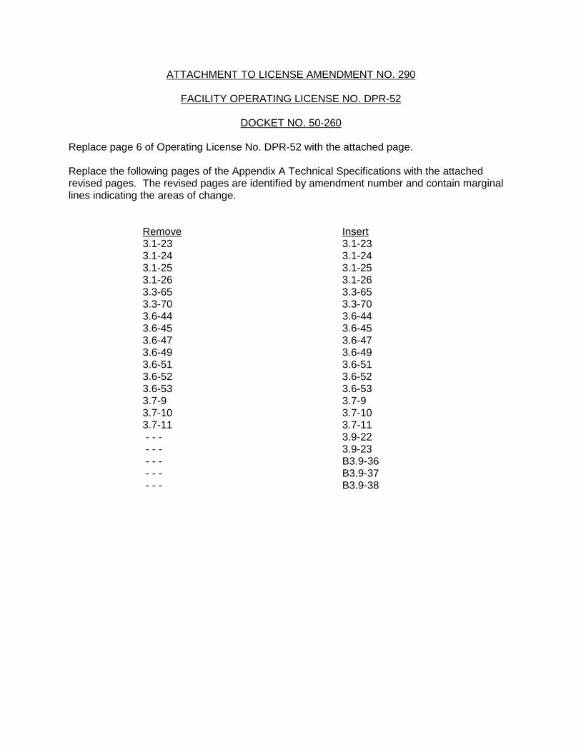
ATTACHMENT TO LICENSE AMENDMENT NO. 290
FACILITY OPERATING LICENSE NO. DPR-52
DOCKET NO. 50-260
Replace page 6 of Operating License No. DPR-52 with the attached page.
Replace the following pages of the Appendix A Technical Specifications with the attachedrevised pages. The revised pages are identified by amendment number and contain marginallines indicating the areas of change.
Remove Insert3.1-23 3.1-233.1-24 3.1-243.1-25 3.1-253.1-26 3.1-263.3-65 3.3-653.3-70 3.3-703.6-44 3.6-443.6-45 3.6-453.6-47 3.6-473.6-49 3.6-493.6-51 3.6-513.6-52 3.6-523.6-53 3.6-533.7-9 3.7-93.7-10 3.7-103.7-11 3.7-11 - - - 3.9-22 - - - 3.9-23 - - - B3.9-36 - - - B3.9-37 - - - B3.9-38
TENNESSEE VALLEY AUTHORITY
DOCKET NO. 50-296
BROWNS FERRY NUCLEAR PLANT, UNIT 3
AMENDMENT TO FACILITY OPERATING LICENSE
Amendment No. 249License No. DPR-68
1. The Nuclear Regulatory Commission (the Commission) has found that:
A. The application for amendment by Tennessee Valley Authority (the licensee) datedJuly 31, 2002, as supplemented by letters dated December 9, 2002, February 12,March 26, July 11, and July 17, 2003, and May 17, July 2, August 24, andSeptember 17, 2004, complies with the standards and requirements of the AtomicEnergy Act of 1954, as amended (the Act), and the Commission’s rules andregulations set forth in 10 CFR Chapter I;
B. The facility will operate in conformity with the application, the provisions of the Act,and the rules and regulations of the Commission;
C. There is reasonable assurance (i) that the activities authorized by this amendmentcan be conducted without endangering the health and safety of the public, and(ii) that such activities will be conducted in compliance with the Commission’sregulations;
D. The issuance of this amendment will not be inimical to the common defense andsecurity or to the health and safety of the public; and
E. The issuance of this amendment is in accordance with 10 CFR Part 51 of theCommission’s regulations and all applicable requirements have been satisfied.

- 2 -
2. Accordingly, the license is amended by changes to the Operating License and Technical Specifications as indicated in the attachment to this license amendment and paragraph2.C.(2) of Facility Operating License No. DPR-68 is hereby amended to read as follows:
(2) Technical Specifications
The Technical Specifications contained in Appendix A, as revised throughAmendment No. 249, are hereby incorporated in the license. The licensee shalloperate the facility in accordance with the Technical Specifications.
3. Accordingly, the Operating License is amended as indicated in the attachment to thislicense amendment and subject to the following License Conditions:
The licensee shall maintain the Augmented Quality Program for theStandby Liquid Control system to provide quality control elements to ensurecomponent reliability for the required alternative source term functiondefined in the Updated Final Safety Analyses Report.
4. This license amendment is effective as of its date of issuance and shall be implementedwithin 120 days.
FOR THE NUCLEAR REGULATORY COMMISSION
/RA/
Michael L. Marshall, Jr., Acting Chief, Section 2Project Directorate IIDivision of Licensing Project ManagementOffice of Nuclear Reactor Regulation
Attachments: 1. Page of License DPR-68 2. Changes to the Technical Specifications
Date of Issuance: September 27, 2004
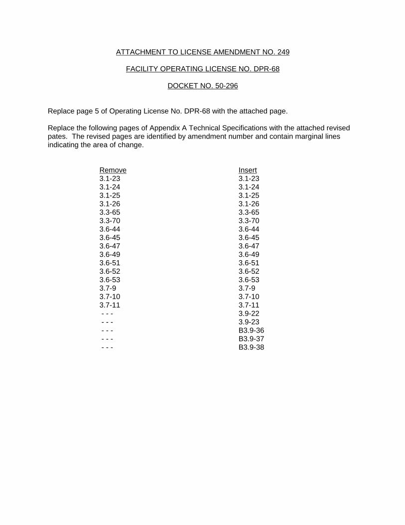
ATTACHMENT TO LICENSE AMENDMENT NO. 249
FACILITY OPERATING LICENSE NO. DPR-68
DOCKET NO. 50-296
Replace page 5 of Operating License No. DPR-68 with the attached page.
Replace the following pages of Appendix A Technical Specifications with the attached revisedpates. The revised pages are identified by amendment number and contain marginal linesindicating the area of change.
Remove Insert3.1-23 3.1-233.1-24 3.1-243.1-25 3.1-253.1-26 3.1-263.3-65 3.3-653.3-70 3.3-703.6-44 3.6-443.6-45 3.6-453.6-47 3.6-473.6-49 3.6-493.6-51 3.6-513.6-52 3.6-523.6-53 3.6-533.7-9 3.7-93.7-10 3.7-103.7-11 3.7-11 - - - 3.9-22 - - - 3.9-23 - - - B3.9-36 - - - B3.9-37 - - - B3.9-38
SAFETY EVALUATION BY THE OFFICE OF NUCLEAR REACTOR REGULATION
RELATED TO AMENDMENT NO. 251 TO FACILITY OPERATING LICENSE NO. DPR-33,
AMENDMENT NO. 290 TO FACILITY OPERATING LICENSE NUMBER DPR-52,
AND AMENDMENT NO. 249 TO FACILITY OPERATING LICENSE NUMBER DPR-68
TENNESSEE VALLEY AUTHORITY
BROWNS FERRY NUCLEAR PLANT, UNITS 1, 2, AND 3
DOCKET NOS 50-259, 50-260, AND 50-296
1.0 INTRODUCTION
By letter to the U. S. Nuclear Regulatory Commission (NRC), dated July 31, 2002, assupplemented by letters dated December 9, 2002, February 12, March 26, July 11, and July 17,2003, and May 17, July 2, August 24, and September 17, 2004, the Tennessee Valley Authority(TVA, the licensee) submitted a request for an amendment to licenses DPR-33, DPR-52 andDPR-68. These amendments adopt the alternative source term (AST) methodology forBrowns Ferry Nuclear (BFN), Units 1, 2, and 3, by revising the current accident source term andreplacing it with an accident source term pursuant to Title 10 to the Code of FederalRegulations (10 CFR) Section 50.67. The submittals also propose to revise/delete theTechnical Specification (TS) sections associated with control room emergency ventilation(CREV), standby gas treatment (SGT), standby liquid control (SLC), and secondarycontainment systems. Specifically, the amendments modify the licensing and design basis toreflect the application of the AST methodology and the function of the SLC system, and deletionof a license condition for Units 2 and 3, for which all the actions have been completed.
The supplements to the original application include the withdrawal of the request to delete oneof the TS sections associated with the absorption of elemental iodine by the SGT and CREVsystems charcoal filters. Also, the supplements add a new TS Section to require verificationthat the minimum fuel decay period has passed prior to moving fuel after the reactor is shutdown. TVA had requested deletion of requirements related to the testing of charcoal absorbersin the SGT system (SGTS) and CREV system (CREVS). Although the mitigation capability ofthe charcoal absorbers in the SGTS and CREVS was not credited in the design basis accident(DBA) radiological consequence analyses, TVA retracted this particular request in a letter datedJuly 17, 2003. In that letter, TVA stated that the analyses would continue to not take credit forthe removal of iodine by the charcoal filters.
In its original submittal, TVA had requested that this request be approved for all three BFNunits, but had not submitted complete supporting analyses for Unit 1. TVA had re-analyzed theapplicable DBA analyses for Units 2 and 3 and described these in the submittal. The fuel

- 2 -
handling accident (FHA) analysis had been performed for all three BFN units. At that time, TVAstated that since the three units were essentially identical, comparable results would beexpected for all three units. TVA stated that the existing License Condition 2.C.(4) provided astanding obligation for TVA to submit the remaining analyses for review prior to Unit 1 enteringMode 3 or above. This was affirmed by TVA in its letter of December 9, 2002. By letter datedMay 17, 2004, TVA submitted descriptions of the Unit 1 analysis methods, assumptions, inputs,and results, thereby satisfying this obligation.
In a letter dated July 11, 2003, TVA requested an exemption from the requirements of10 CFR 50, Appendix A, General Design Criterion (GDC) 41, Containment atmospherecleanup. The NRC staff has determined that the exemption request is not required for theapproval for full implementation of AST on the BFN units. However, the information provided inthe exemption request was used by the NRC staff to support the technical evaluation discussedbelow.
The NRC staff reviewed all the supplements. The supplements augmented/withdrew portionsof the submittal. The NRC staff determined that although the scope had been modified theoriginally published no significant hazards consideration determination (67 FR 63697) did notchange. However a new Federal Register Notice (69 FR 22883) was issued to address themodifications to the submittal not originally noticed.
2.0 REGULATORY EVALUATION
In the past, power reactor licensees have typically used U.S. Atomic Energy CommissionTechnical Information Document (TID)-14844, Calculation of Distance Factors for Power andTest Reactor Sites, dated March 23, 1962, as the basis for DBA analysis source terms. Thepower reactor siting regulation, which contains offsite dose limits in terms of whole body andthyroid dose, 10 CFR 100.11, Determination of Exclusion Area, Low Population Zone, andPopulation Center Distance, makes reference to TID-14844.
In December 1999, the NRC issued a new regulation, 10 CFR 50.67, Accident Source Term,which provided a mechanism for licensed power reactors to replace the traditional accidentsource term used in their DBA analyses with an alternative source term. Section 50.67 of10 CFR requires a licensee seeking to use an AST to apply for a license amendment andrequires that the application contain an evaluation of the consequences of affected DBAs. Regulatory guidance for the implementation of these ASTs is provided in Regulatory Guide(RG) 1.183, Alternative Radiological Source Terms for Evaluating Design Basis Accidents atNuclear Power Reactors. TVA ’s application of July 2002, as supplemented, addresses theserequirements in proposing to use the AST described in RG 1.183 as the DBA source term usedto evaluate the radiological consequences of DBAs for BFN Units 1, 2 and 3. As part of theimplementation of the AST, the total effective dose equivalent (TEDE) acceptance criterion of10 CFR 50.67(b)(2) replaces the previous whole body and thyroid dose guidelines of10 CFR 100.11 and 10 CFR Part 50, Appendix A, GDC 19, for the loss-of-coolant accident(LOCA), the main steam line break (MSLB) accident, and the control rod drop accident (CRDA).
Part 50 of 10 CFR, Appendix A, GDC 26, requires that each reactor have two independentreactivity control systems of a different design, while GDC 29 requires that the reactivity controlsystem be capable of accomplishing its safety function in the event of anticipated operationaloccurrences.

- 3 -
Section 50.49 of 10 CFR, Environmental Qualification of Equipment, requires that thesafety-related electrical equipment which are relied upon to remain functional during andfollowing the design basis events be qualified for accident (harsh) environment. This providesassurance that the equipment needed in the event of an accident will perform its intendedfunction. Regulatory Position 1.3.5, 6, and Appendix I of RG 1.189 addresses the requirementsfor assessing the impact of the difference in source term characteristics on environmentalqualification (EQ) doses. NUREG-1465, Accident Source Terms for Light-Water Nuclear PowerPlants, provides estimates of AST that were more physically based and that could be applied toa BWR [boiling water reactor]. NUREG-0933 Issue 187, The Potential Impact of PostulatedCesium Concentration on Equipment Qualification1, indicated that for equipment exposed tothe containment atmosphere, the TID-14844 source term and the gap and in-vessel releases inthe AST produced similar integrated doses, and for equipment exposed to suppression poolwater, the integrated doses calculated with the AST remain enveloped by those calculated withTID-14844 for the first 145 days post accident for a BWR, including the 30 percent vs.1-percent release of cesium. It was concluded that there was no clear basis for back fitting therequirement to modify the design basis for equipment qualification to adopt the AST. Therewould be no discernible risk reduction associated with such a requirement.
NUREG-800, Standard Review Plan (SRP), Section 6.5.2, Containment Spray as a FissionProduct Cleanup System, provides the acceptance criteria regarding the systems used tominimize iodine re-evolution as presented in the licensee’s re-analysis of the radiologicalconsequences for the LOCA. The BFN units were not licensed to many of the GDC containedin 10 CFR Part 50, Appendix A, but Section 1.5.1.6 of the Updated Final Safety Analysis Report(UFSAR) contains criteria that are essentially equivalent to GDC’s. Maintaining compliancewith the intent of these criteria was evaluated as part of the evaluation process.
On March 14, 2003, the NRC staff issued an amendment for Units 2 and 3 to increase theallowable main steam isolation valve (MSIV) leakage rate. This amendment permitted Units 2and 3 to use the main steam drain lines to direct any MSIV leakage to the main condenser. This drain path takes advantage of the large volume of the main steam lines (MSLs) andcondenser to provide holdup and plate-out of fission products that may leak through the closedMSIVs. The licensee performed evaluations and seismic verification walkdowns to demonstratethat the main steam system piping and components which comprise the alternate leakagetreatment (ALT) system were seismically rugged and are able to perform the safety function ofan MSIV leakage treatment system. By letter dated July 9, 2004, the licensee requested anamendment similar to that granted on Units 2 and 3. The licensee also submitted, in lettersdated July 2, August 24, and September 17, 2004, the evaluations, seismic verificationwalkdowns, and seismic ruggedness evaluations to support the AST use of the ALT MSIV leakpath for Unit 1. The seismic ruggedness evaluation was performed to demonstrate the seismicadequacy of the turbine building which houses the ALT system. The structural integrity of theturbine building is an important consideration to the adequacy of the alternate MSIV leakagepath because a non-seismically designed turbine building should be capable of withstanding theearthquake without degrading the capability of the ALT system.
The licensee referenced the General Electric Company (GE) Report, NEDC-31858P-A, BoilingWater Reactor Owners Group (BWROG) Report for Increasing MSIV Leakage Rate Limits andElimination of Leakage Control Systems, Revision (Rev.) 2 (BWROG Report orNEDC-31858P), as a basis for the acceptability of its proposed license amendment. TheBWROG report summarizes data on the seismic performance of main steam piping and
- 4 -
condensers in past strong-motion earthquakes at various facilities, and compares designattributes of the piping and condensers with those in typical GE Mark I, II, and III nuclear plants. The NRC staff, in its safety evaluation (SE) of the BWROG report dated March 3, 1999,determined that the BWROG approach of utilizing the earthquake experience-basedmethodology, supplemented by plant-specific seismic adequacy evaluations was not anacceptable basis in and of itself to demonstrate the seismic ruggedness of non-seismicallyanalyzed main steam system piping and condensers. Therefore, the NRC staff identifiedcertain limitations that required individual licensees to provide plant-specific design informationand evaluation when BWROG approach was elected for resolving the MSIV leakage issue.
The licensee cited Duane Arnold, Brunswick, Grand Gulf, Hope Creek, Clinton, and Perry asprecedents. The NRC staff considers the implementation of an AST to be a significant changeto the design basis of the facility that is voluntarily initiated by the licensee. In order to issue alicense amendment authorizing the use of an AST and the TEDE dose criteria, the NRC staffmust make a current finding of compliance with regulations applicable to the amendment.During this review, the NRC staff found that the BFN units were not at the samelicensing/design bases for these precedents to be of any substantial value. For example, thelicensee requested that this amendment be approved for all three BFN units, however, Unit 1has been shut down since the early 80’s resulting in the need for additional NRC review toresolve issues surrounding design bases verification and required precedent licensing actions. 3.0 TECHNICAL EVALUATION
3.1 Accident Dose Calculations
The NRC staff reviewed the technical analyses related to the radiological consequences ofDBAs that were performed by TVA in support of this proposed license amendment. Informationregarding these analyses was provided in the July 21, 2002, submittal and in the supplementalletters dated December 9, 2002, May 17, and July 2, 2004. The NRC staff reviewed theassumptions, inputs, and methods used by TVA to assess these impacts. Independentcalculations were performed to confirm the conservatism of the TVA analyses. TVA performedan evaluation of all significant LOCA and non-LOCA events currently analyzed in the BFNUFSAR. These events:
• LOCA
• MSLB
• CRDA
• FHA
For these re-analyses, TVA determined the TEDE at the exclusion area boundary (EAB) for theworst 2-hour period and the 0-30 day low population zone (LPZ) TEDE. TVA also evaluated thepotential TEDE to control room personnel from these DBAs. The accident-specific sections thatfollow describe the accident, the TVA assessment of the impact of the proposed changes, andthe NRC staff’s evaluation.
- 5 -
With regard to Unit 1, the inputs used in the MSLB, FHA, and CRDA analyses are bounding forUnits 1, 2, and 3. As such, the results determined for these events are applicable for all threeunits. The inputs used in the LOCA analysis are different for Unit 1 and Units 2 and 3; aseparate analysis was performed and the bounding results for Units 1, 2, and 3 were provided. Significant analysis changes are:
• For Units 2 and 3, the turbine building roof ventilator χ/Q values are more conservativethan the turbine building exhaust χ/Q values. For Unit 1, the reverse is true. Thelimiting value for each case was used in the analysis.
• For Units 2 and 3, the reactor building effective mixing free volume is 1,931,502 ft3. ForUnit 1, the corresponding volume is taken as 1,311,209 ft3.
• With the exception of the two items above, the remaining LOCA analysis assumptionsand inputs are identical, or bounding, for all three units.
3.1.1 Loss-of-Coolant Accident
The objective of analyzing the radiological consequences of a LOCA is to evaluate theperformance of various plant safety systems intended to mitigate the postulated release ofradioactive materials from the plant to the environment. TVA assumes an abrupt failure of alarge reactor coolant pipe and that substantial core damage occurs as a result of this event. The assumption of core damage is conservative in that DBA thermo-hydraulic analyses in theBFN UFSAR conclude the fuel damage thresholds are not exceeded.
3.1.1.1 Source Term
Fission products from the damaged fuel are released into reactor coolant system (RCS) andthen into the primary containment (i.e., drywell and wetwell). For a LOCA, it is anticipated thatthe initial release to the primary containment will last 30 seconds and will release all of theradioactive materials dissolved or suspended in the RCS liquid. The gap inventory releasephase begins 2 minutes after the event starts and is assumed to continue for 30 minutes. Asthe core continues to degrade, the gap inventory release phase ends and the in-vessel releasephase begins. This phase continues for 1.5 hours. Tables 1, 4, and 5 of RG 1.183 define thesource term used for these two phases. These data are summarized in the attached Table 1. The inventory in each release phase is released at a constant ramp starting at the onset of thephase and continuing over the duration of the phase. Once dispersed in the primarycontainment, the release to the environment is assumed to occur through five pathways:
� Leakage of primary containment atmosphere (i.e., design leakage).
� Leakage of primary containment atmosphere via design leakage through MSIVs.
� Leakage from emergency core cooling systems (ECCS) that recirculate suppressionpool water outside of the primary containment (i.e., design leakage).
� Releases via the containment atmosphere dilution (CAD) system
� Leakage via the hardened wetwell vent (HWWV)

- 6 -
The LOCA considered in this evaluation is a complete and instantaneous severance of one ofthe recirculation loops. The pipe break results in a blowdown of the reactor pressure vessel(RPV) liquid and steam to the drywell via the severed recirculation pipe. The resulting pressurebuildup drives the mixture of steam, water, and other gases down through vents to thedowncomers and into the suppression pool water thereby condensing the steam and reducingthe pressure. Due to the postulated loss of core cooling, the fuel heats up, resulting in therelease of fission products. Under the TID-14844 assumption of instantaneous core damage,this initial blowdown would also include fission products, a fraction of which would be retainedby the suppression pool water. Under the AST, the fission product release occurs in phasesover a 2-hour period. TVA has conservatively assumed that the fission product release fromthe RPV is homogeneously dispersed within the drywell free volume only for the first 2 hours. TVA assumes that core quenching occurs at about 2 hours resulting in substantial steamproduction in the RPV and drywell that will purge a large fraction of the drywell atmospherethrough the torus downcomer vents, through the suppression pool, and into the torus airspace. TVA did not credit any reduction in fission products transferred to the torus air space bysuppression pool scrubbing. Instead, TVA assumes a well-mixed torus air space and drywell.
TVA assumes that a portion of the fission products released from the RPV will plate-out due tonatural deposition processes. TVA models this deposition using the 10-percentile modeldescribed in the NRC staff-accepted NUREG/CR-6189, A Simplified Model of Aerosol Removalby Natural Processes in Reactor Containments (i.e., the “Powers Model”).
The AST assumes that the iodine released to the containment includes 95 percent CsI,4.85 percent elemental iodine, and 0.15 percent organic forms. The assumption of this iodinespeciation is predicated on maintaining the containment sump water at pH 7.0 or higher. TVAproposes to use the SLC to inject sodium pentaborate (SPB) to the RPV, where it will mix withECCS flow and spill over to the drywell and then to the suppression pool. SPB, a base, willneutralize acids generated in the post-accident primary containment environment.
3.1.1.2 Containment Leakage Pathway
The drywell and wetwell are projected to leak at their design leakage of 2.0 percent of itscontents by weight per day for the 30-day accident duration. Leakage from the drywell andwetwell will collect in the free volume of the secondary containment and be released to theenvironment via ventilation system exhaust or leakage. Following a LOCA, the SGTS fans startand draw down the secondary containment to create a negative pressure with reference to theenvironment. This pressure differential ensures that leakage from the drywell and wetwell iscollected and processed by the SGTS. SGTS exhaust is processed through HEPA andcharcoal filter media prior to release to the environment via the site’s elevated stack. Note thatthe analyses conservatively did not credit iodine removal by the charcoal filters in the SGTS. TVA assumes that all three SGTS trains are running at the start of the event. TVA states that ifonly two of the SGTS trains are running, there will be a short period at the start of the event inwhich the secondary containment may not be at a negative pressure. However, the two SGTStrains can draw the pressure down prior to the onset of the gap release phase at 2 minutespost-accident. The three SGTS train case is conservative as it maximizes the release rate fromthe secondary containment. A portion of the stack flow is assumed to leak through thebackdraft dampers and be released as a ground level release.
- 7 -
3.1.1.3 Main Steam Isolation Valve Leakage
The four MSLs that penetrate the primary containment are automatically isolated by the MSIVsin the event of a LOCA. There are two MSIVs on each steam line, one inside containment (i.e.,inboard) and one outside containment (i.e., outboard). The MSIVs are functionally part of theprimary containment boundary and design leakage through these valves provides a leakagepath for fission products to bypass the secondary containment and enter the environment as aground level release. TVA conservatively assumes that the fission products released from thecore are dispersed equally throughout the drywell via the severed recirculation line. Followingthe initial blowdown of the RPV, the fuel heats up and fuel melt begins, the steaming in the RPVcarries fission products to the drywell. When core cooling is restored, steam is rapidlygenerated in the core. This steam and the ECCS flow carry fission products from the core tothe primary containment via the severed recirculation line, resulting in well-mixed RPV domeand primary containment fission product concentrations. Once the rapid steaming stops, thecontainment contents can flow back into the RPV through the severed line and would beavailable for release via the MSIVs.
TVA assumes that one of the four inboard MSIVs fails to close. Therefore, three of the steamlines have a closed space between the inboard and outboard MSIVs; all have the piping volumebetween the outboard MSIVs and the point at which the drain line path to the condenserconnects to the steam line. TVA assumes a maximum MSIV leakage of 100 scfh in the linewith the failed inboard MSIV. One of the other lines is assumed to leak at 50 scfh, and theother two lines are assumed not to leak. This modeling is conservative as it minimizesdeposition credit. The TVA modeling assumes well-mixed control volumes. Only the pipingvolumes associated with horizontal runs of MSL piping are included. The amount of fissionproduct aerosol deposition is derived from the methodology in Appendix A to NRC staff reportAEB-98-03, Assessment of the Radiological Consequences for the Perry Pilot Plant ApplicationUsing the Revised (NUREG-1465) Source Term. Particulate deposition in the main condenserwas treated using the same approach as that for the steam lines. The deposition of elementaliodine in the MSLs is determined using the NRC staff-accepted RADTRAD Bixler model. Sincethe particulate deposition velocity in the condenser is less than the elemental iodine depositionvelocity from SRP 6.5.2, TVA used the particulate deposition velocity.
3.1.1.4 Alternate Leakage Treatment
3.1.1.4.1 Functional Design and Reliability of the Alternate Leakage Treatment Boundary for Unit 1
The BFN alternate leakage treatment (ALT) system for Units 2 and 3 was addressed previouslyin a license amendment for Units 2 and 3 dated March 14, 2000. TVA submitted anamendment request for Unit 1 on July 9, 2004 (TS-436), the review of which has not beencompleted. The review in this section addresses the use of the ALT path as it relates to ASTfor Unit 1.
The ALT utilizes the MSL drains to direct the MSIV leakage to the main condenser. This ALTpath takes advantage of the capability of the large volume of the MSLs and condenser to hold-up and plate-out fission products in the MSIV leakage effluent. To mitigate a DBA, this pathmust be available under DBA conditions with loss-of-offsite-power (LOOP). The ALT path isfrom the downstream side of the MSIVs through four 3-inch lines which join a 4-inch drainheader to the main condenser. In addition to the MSL drains, the drain header also receives
- 8 -
drains from high-pressure coolant injection, reactor core isolation coolant steam lines, and the auxiliary boiler. All valves in the flow path are normally open, with the exception of two,FCV-1-58 and FCV-1-59, which are normally closed. FCV-1-59 has a 4-inch bypass line that also routes to the condenser. The bypass around FCV-1-59 is free of valves and orifices;therefore, operation of FCV-1-59 is not essential to align the ALT path.
In the event of an accident, operator actions will establish the primary ALT path to the maincondenser. Normally-closed valves FCV-1-58 and FCV-1-59 will be opened using handswitches in the main control room. Both FCV-1-58 and FCV-1-59 will be powered fromessential power buses with emergency diesel generator backup. Therefore, these valves aredesigned to be available during and after a LOCA event concurrent with a LOOP. To furtherensure valve reliability, these two valves are in the Inservice Testing Program and will beperiodically stroke-tested. The licensee considered the action of including FCV-1-58 in themotor operated valve test programs such as discussed in Generic Letter (GL) 89-10, Safety-Related Motor-Operated Valve Testing and Surveillance, and GL 96-05, Periodic Verification ofDesign-Basis Capability of Safety-Related Power-Operated Valves. However, the licensee hasdetermined that the American Society of Mechanical Engineers (ASME) Code testingrequirements are adequate due to the fact that this valve is not subject to high dynamic loadsunder the assumed accident conditions.
Additionally, to ensure ALT boundary integrity, the pressure control valve PCV-1-147 on sealingsteam supply line will be modified, so that it fails closed instead of open on loss of power, air, orcontrol signal. Also, check valves CKV-1-742 and CKV-1-744 will be added to the steam supplylines to the offgas preheaters to serve as the pressure boundary valves. Subsequently, all ofthe valves in the ALT boundary will be either: (a) normally closed manual valves, (b) normallyclosed motor-operated valves, (c) fail-close air-operated valves, or (d) check valves withspring-assisted closure. The licensee has determined that the failure of PCV-1-147 to either anopen or closed position results in an operational problem depending on the power level of thereactor, therefore, either state requires operator action. The NRC staff reviewed theoperational problems identified by the licensee. As TVA is currently defueled and preparingUnit 1 for restart after almost 19 years, the NRC staff was concerned with the necessaryimplementation of training and procedures for these modifications. In a letter datedSeptember 17, 2004, the licensee committed to provide training and procedures commensuratewith that for Units 2 and 3 for the establishment of the Unit 1 alternate pathway. The NRC staff concludes that based on the modifications to the various valves and the commitment ensuringassociated operator actions and training will be performed, the ALT boundary is satisfactoryand should not adversely affect normal rector operation.
Section 5.2 of the March 3, 1999, SE states that a secondary path to the condenser, having anorifice, should exist. NEDC-31858P-A does not require that this secondary path have the sameflow capability as the primary path. The licensee’s application states that a secondary passiveflow path also exists from the MSIVs to the condenser. This secondary path is considered acontingency alignment in the event of the unlikely failure of FCV-1-58. The licensee hasdetermined in the event FCV-1-58 were to fail open, the leakage flow would split, with part ofthe flow going to the condenser via a 0.1875-inch diameter orifice in a normally open bypassaround FCV-1-58, and the remainder going to the condenser via normal leakage paths throughthe main steam stop/control valves and through the high-pressure turbine. The functionaldesign of the secondary path meets the intent of NEDC-31858P-A, and, therefore, isacceptable.

- 9 -
The NRC staff has reviewed the proposed primary ALT path. Based on the completion ofmodifications to the Unit 1 valves discussed in this section, revision of procedures andperformance of training to address these modifications, the NRC staff concludes that the Unit 1ALT boundary meets NEDC-31858P-A functional design and reliability criteria, and would beavailable under post-accident conditions including a LOOP.
3.1.1.4.2 Seismic Walkdown on ALT Pathway
The licensee contracted Facility Risk Consultants (FRC), Inc. to conduct an MSIV seismicruggedness verification for BFN Unit 1. A report entitled “MSIV Seismic RuggednessVerification at Browns Ferry Nuclear Plant Unit 1," dated May 2004, was attached to thelicensee’s July 2, 2004 letter. The report stated that the BFN Unit-1 MSIV seismic ruggednessverification program was performed in accordance with the recommendations of the GEBWROG Report for increasing MSIV Leakage Rate Limits and Elimination of Leakage ControlSystems, NEDC-31858P, Revision 2, September 1993.
FRC performed a walkdown of the main steam lines, various drain paths, associatedcomponents and appendages within the seismic verification boundary for BFN Unit 1 MSIVseismic ruggedness verification program. The walkdown team consisted of four people, allhavecollege degrees in engineering, and each person possesses ten to twenty years of experiencein structural or mechanical engineering and/or earthquake engineering application to nuclearpower plants. The team identified 54 potential outliers, which were documented in theWalkdown Data Package. These potential outliers were further evaluated to the acceptancecriteria of TVA Design Criteria BFN-50-C-7306, “Qualification Criteria for Seismic Class IIPiping, Pipe Supports, and Components.” Further evaluation utilized hand calculations forsimple piping configurations and rigorous piping analysis (TPIPE computer program) forcomplex piping configurations. A total of 15 outliers were found to have not met theacceptance criteria. Plant modifications were designed and several Design Change Noticeswere issued to implement changes determined necessary to resolve identified outliers. Furthermore, 15 maintenance and/or housekeeping items were also identified for correctiveactions. Maintenance work order requests were issued to address these items. The walkdownperformed by FRC, in accordance with the procedures of the BWROG NEDC-31858P,Revision 2, September 1993, is acceptable to the staff.
The pipe support acceptance criteria in the FRC report accept support material to go beyondyield for non-ductile behavior supports. The staff in a letter, dated September 14, 2004,requested the licensee to provide justification for such a criterion. In the September 17, 2004,submittal, the licensee stated that, after a review, it had not used supports constructed fromnon-ductile materials. The staff also requested the licensee to provide justification for acceptingloads on test data with mean less one standard deviation capacity. The licensee respondedthat it had not used such a criterion for Unit 1. The staff further requested the licensee toprovide justification for considering those pipe supports that failed the stress criteria to beacceptable if their adjacent supports and the resulting pipe span can resist dead loads with afactor of safety of 2.0. The licensee responded that, after a review, Unit 1 does not have sucha condition. The staff considers the licensee’s responses satisfactory to resolve the requestsfor additional information (RAIs).

- 10 -
3.1.1.4.3 Condenser
The FRC report stated that the main condenser anchorage was reviewed during the walkdown. Each of the three condensers is mounted on concrete pedestals. The concrete pedestals wereobserved to be in good condition. The report further stated that confirmation of the condenserseismic capacity and anchorage adequacy is required to ensure its structural integrity during adesign-basis earthquake (DBE) seismic event. The licensee submitted additional informationon the condenser in an August 24, 2004 letter. The licensee stated that the condensers wereanalyzed for structural integrity to seismic DBE load. Results of the analysis indicate that thecondenser shell stresses are relatively small for both combined axial and bending, and shear.
The condenser support anchorage consists of a center key and six support feet. The centersupport is a fixed anchor and consists of a built-up wide flange H section embedded 4 feet intothe concrete pedestal, which is connected to the turbine building base mat and welded to thebottom plate of the condenser. The support plates consist of two to three anchors of 2- to2-1/2-inch diameter bolts. Each anchor bolt has greater than 5-feet nominal length withapproximately 48-inches of embedment into the concrete pedestal, which is connected to theturbine building base mat. These supports were designed to resist vertical operating loads andare slotted radially from the center key to allow for thermal growth. Shear forces aretransferred to the H-shaped anchor in the center, to the anchor bolts and shear keys to thesupport feet, and carried through the concrete pedestal to the turbine building base mat. Theanchorage for the BFN condenser is comparable with the performance of the anchorages forsimilar condensers in the earthquake experience database. The shear areas of the condenseranchorage, in the directions parallel and transverse to the turbine generator axis, divided by theseismic demand, were used to compare with those presented in the NEDC-31858P-A report. The BFN condenser anchorage shear area to seismic demand is greater than those in theselected database sites. The condenser support anchorage was also evaluated and the resultsindicate that the combined seismic DBE and operational demand are less than the anchoragecapacity based on the American Institute of Steel Construction (AISC) allowables. Maximumstress ratios are 0.57 for bolt tension in the perimeter support feet and 0.95 for shear in thecenter support built-up section.
The staff finds the licensee use of seismic analysis for the condenser, and the NEDC-31858P-Adata for evaluating the condenser anchorage capacity acceptable.
3.1.1.4.4 Turbine Building
The licensee’s August 24, 2004, submittal on the turbine building concluded that the turbinebuilding would remain intact based on earthquake experience data. The referenced experiencedata was summarized in a statement that, “. . . there are no known cases of structural collapseof either turbine buildings at power plant stations or structures of a similar construction.” In anRAI, dated September 14, 2004, the staff informed the licensee that the staff had not endorsedthe use of seismic experience data for qualifying structures subjected to earthquakes, andrequested additional technical justification that supports the contention that the BFN Unit 1turbine building will remain structurally intact following a DBE.
The licensee’s September 17, 2004, letter stated that it had performed an evaluation of the turbine building seismic capacity against seismic demand generated by a DBE. The evaluation
- 11 -
includes the lower reinforced concrete frame and shear wall structure, turbine pedestal, and thesteel superstructure. The staff evaluation results are stated below.
Lower Reinforced Concrete Frame and Shear Wall Structure: The licensee calculated thecapacity of concrete wall and column at a cross section believed to have the least seismiccapacity coupled with a great seismic demand. The calculated seismic capacity of the shearwalls and columns is 25,500 kips in the north-south direction and 20,300 kips in the east-westdirection. The shear capacity was calculated based on nominal cross sectional properties ofthe walls and columns and concrete shear strength as specified in the American ConcreteInstitute 318-89 Code. The licensee also estimated the seismic demand at the same section. The licensee used an amplification factor of 1.6 for soil-founded Class I structures, as stated inthe UFSAR, and calculated the seismic demand spectral acceleration using 1.6 times the0.30g peak of the 5 percent damped DBE ground response spectrum curve. The seismicdemand shear load is calculated by the total dead load plus the design live load above thecross section times the seismic demand spectral acceleration, which equals 15,200 kips forboth the north-south and east-west directions of earthquake motion. The calculated seismiccapacity over demand (C/D) ratios for the lower concrete structure is 1.68 for the north-southdirection and 1.34 for the east-west direction. Since the seismic capacities are greater than theseismic demand, the lower reinforced concrete frame and shear wall structure will remain intactfollowing a DBE.
Turbine Pedestal: The turbine pedestal is a separate reinforced concrete structure housedwithin the turbine building. The turbine pedestal was previously evaluated for lateral loadsequivalent to 25 percent of the weight of the turbine generator machinery, applied in both lateraldirections. The evaluation was described in the UFSAR. The evaluation used working(allowable) stress method. Therefore, the seismic capacity of the turbine pedestal wascalculated to be equal to 0.425g (1.7 x 0.25g). Since the turbine pedestal is a rigid structure, itsseismic demand equals the peak ground acceleration of the ground motion DBE (0.20g),increased by 1.6 to account for soil amplification effects, as described in the UFSAR. Thisyields a seismic demand acceleration of 0.32g (1.6 x 0.2g). The seismic C/D ratio for theturbine pedestal is 1.33. Since the seismic capacity of the turbine pedestal is greater than thedemand generated by the DBE, the turbine pedestal will remain intact following a DBE.
Steel Superstructure: The Turbine Building consists of eight (8) two-span high-bay momentresisting frames in the east-west direction, and braced frames in the north-south direction. Theoriginal design of the steel superstructure was based on dead and live loads, plus loading dueto 100 mph wind (30 psf lateral load on the entire structure) and lift loads for the turbine buildingcrane. As a seismic II/I verification, a typical moment frame in the east-west direction, a bracedframe in the north-south direction, and a simple roof girder in the vertical direction are used. The analysis assumes that the frames in the east-west and north-south directions behave as asingle-degree-of-freedom oscillator and that the mass on the roof girder is uniformly distributed. Standard structural mechanics analysis methodology was used to determine the stiffness andstrength of the east-west and north-south load resisting frames for lateral loads applied at theroof line of the superstructure. Mass was lumped at the roof line. The mass was determinedbased on the weight of the roof framing of the structural frame, the tributary weight of theroofing, and ½ of the weight of the columns, longitudinal framing (including the crane rail), andthe siding of the building.
- 12 -
The capacity of structural members and connections were calculated based on Part 2 of theAISC specification. The limiting condition that governs the capacity of the steel superstructurein the east-west direction was determined to be the bending capacity at the top of the mainsupport columns, and the calculated capacity is 73,000 in-kips. The limiting condition thatgoverns the capacity in the north-south direction was determined to be the capacity of theconnections for the brace members, and the calculated capacity is 311 kips. The limitingcondition that governs the capacity in the vertical direction of the roof girder was determined tobe the bending strength at the center of the roof girder, and the calculated capacity is38,200 in-kips.
Seismic demand loads were determined by dead load plus seismic spectral acceleration timesthe mass. The seismic load cases investigated include a DBE in the east-west direction plusvertical direction, and in the north-south direction plus vertical direction. The spectralaccelerations used for the evaluation are taken from an approximation of the floor responsespectra at the El. 617 ft operating deck. The floor response spectra were approximated basedon scaling from the DBE ground motion response spectrum. The scale factor for horizontaldirection motion is taken as 1.6 x 1.5 x 1.5 = 3.6. As described above, the 1.6 coefficient wasused to represent the soil amplification. The first 1.5 factor is to account for buildingamplification up to an elevation of 40 ft above grade, based on the Seismic Qualification Utility Group General Implementation Procedure, up to El. 605 ft. The second 1.5 amplification factorwas used to account for additional building amplification from El. 605 ft to the operating decklevel of El. 617 ft. In the vertical direction, the scale factor was taken as 2/3 x 1.1 = 0.733. The2/3 factor is the ratio between vertical and horizontal ground motion as defined in the UFSAR. The 1.1 coefficient is for soil amplification in the vertical direction, as described in the UFSARfor soil-founded Class I structures. The spectral acceleration values applied for the seismicload analysis were taken from the 5 percent damped floor response spectra at the naturalfrequency of the structure. Frequency was calculated using the respective stiffness and massfor the east-west and north-south mathematical models. The calculated natural frequency is1.13 Hz for the frame in the east-west direction, and 2.74 Hz for the frame in the north-southdirection. The natural frequency of the roof girder in the vertical direction was determined usingthe 1g deflection approximation methodology. The calculated natural frequency is 2.34 Hz forthe roof girder in the vertical direction. The calculated seismic demand for the frame in theeast-west direction is 48,500 in-kips at the top of the column and 15,500 in-kips at the center ofthe roof girder. The calculate seismic demand for the frame in the North-South direction is299 kips shear force.
The C/D ratios for the steel superstructure are 1.51 for the frame in the east-west direction,1.11 for the frame in the north-south direction, and 2.47 for the roof girder in the verticaldirection. Since the resulting C/D ratios are greater than 1.0, the steel superstructure wasdetermined to remain intact following a DBE.
The staff did not review seismic experience-based seismic II/I verification of the turbine building,because it has not endorsed such a method for structures. The staff concurs with thelicensee’s methods and assumptions for calculating seismic capacity of the turbine building. The staff finds that the licensee’s methods and assumptions for calculating seismic demandsfor the turbine building subject to a DBE are approximate and reasonable. Therefore, the staffconcludes that the licensee has demonstrated, with some confidence, that the turbine buildingwill remain intact following a DBE event. Since the capacity/demand ratio is as low as 1.11 forthe frame in the north-south direction, and several approximations were used both in the
- 13 -
assumptions and hand-calculation methods, the NRC staff requires the addition of the followinglicense condition:
The licensee is required to confirm that the conclusions made in TVA’s letterdated September 17, 2004, for the turbine building remain acceptable usingseismic demand accelerations based on dynamic seismic analysis prior to therestart of Unit 1.
Based on the above evaluation, the NRC staff concludes there is reasonable assurance that theBFN Unit 1 MSIV ALT system is seismically adequate for the intended purpose. The staffapproval of this amendment is contingent on licensee’s confirmation of satisfying the licensecondition to perform a dynamic analysis for the turbine building as discussed above. The staff’sconclusion is based on the fact that (1) the ALT pathway has been walkdown in accordancewith the procedures in the NEDC-31858P-A report, which was approved by the NRC staff,(2) all the outliers have been either analytically resolved or physically modified, (3) thecondenser was seismically analyzed subject to a DBE for its adequacy and its anchorages wereevaluated to be adequate in accordance with information contained in the NEDC-31858P-Areport, and (4) the turbine building is deemed, through the use of approximate calculations tobe followed by performance of dynamic seismic analysis prior to the plant restart, to remainintact following a DBE.
It should be noted that the staff’s acceptance of the experience-based methodology aspresented by the BWROG and BFN Unit 1, is restricted to its application for ensuring thepressure boundary integrity and functionality of the alternate drain pathway associated with theMSIV leakage treatment system. The staff’s acceptance of the methodology for this applicationis not an endorsement for the use of the experience-based methodology for other applicationsat BFN Unit 1.
3.1.1.5 Leakage from Emergency Core Cooling Systems
During the progression of a LOCA, some fission products released from the fuel will be carriedto the suppression pool via spillage from the RCS and by natural processes such as depositionand plate-out. Post-LOCA, the suppression pool is a source of water for ECCS. Since portionsof these systems are located outside of the primary containment, leakage from these systemsis evaluated as a potential radiation exposure pathway. For the purposes of assessing theconsequences of leakage from the ECCS, TVA assumes that all of the radioiodines releasedfrom the fuel are instantaneously moved to the suppression pool. Noble gases are assumed toremain in the drywell atmosphere. Since aerosols and particulate radionuclides will not becomeairborne on release from the ECCS, they are not included in the ECCS source term. Thissource term assumption is conservative, in that all of the radioiodine released from the fuel iscredited in both the primary containment atmosphere leakage and the ECCS leakage. In amechanistic treatment, the radioiodines in the primary containment atmosphere would relocateto the suppression pool over time.
The analysis considers the equivalent of 5 gallons per minute (gpm) unfiltered ECCS leakagestarting at the onset of the LOCA. TVA assumes the 10 percent of the iodine in the ECCSleakage becomes airborne and is available for release as 97 percent elemental and 3 percentorganic iodine. No credit was assumed for hold-up and dilution in the secondary containment.
- 14 -
As assumed for the primary containment leakage pathway, the leakage enters the environmentvia the SGTS as a filtered elevated release. The release continues for 30 days.
3.1.1.6 Other Release Paths
TVA models two additional release paths that vent the torus air space to the stack. The first isthe CAD system. This system is operated for 24 hours at 10, 20, and 29 days post-accident. The flow rate from this system, which is directed through the SGTS filters, is 139 cfm. Thesecond path is the HWWV which is postulated to leak at a rate of 10 cfm starting at 8 hours andcontinuing for 30 days. This latter release does not pass through the SGTS filters.
3.1.1.7 Offsite Doses
TVA evaluated the maximum 2-hour TEDE to an individual located at the EAB and the 30-dayTEDE to an individual at the outer boundary of the LPZ. The resulting doses are less than the10 CFR 50.67 criteria.
3.1.1.8 Control Room Doses
TVA evaluated the dose to the operators in the control room. The CREVS is automaticallyactuated by a primary containment isolation signal (PCIS), by high radiation at the control bayair intakes, or by manual actuation by the control room operators. Since the PCIS actuation istriggered by plant process sensors, such as RPV low water level and high drywell pressure,isolation of the control room is assumed to be immediate (i.e., completed before substantialfission products are released) for the DBA LOCA. Although TVA stated in Table 2-10 of itssubmittal that CREVS would enter the pressurization mode for the MSLB and the CRDA, nocredit is taken for filtration by HEPA filters or charcoal media for these events. Initially, thecontrol room ventilation system intake is 3000 cfm plus 3717 cfm of unfiltered inleakage. Onceisolation occurs, the 3000 cfm intake is filtered and the 3717 cfm of unfiltered inleakagecontinues.
Although the control room is designed to be pressurized during an accident event, TVAassumes that unfiltered inleakage into the control building habitability zone (CBHZ) occurs. InMay 1992, TVA performed testing and determined the unfiltered inleakage rate was 3717 cfm. Additional testing, performed using special test fans to maintain a positive pressure of 0.50-inchwater gauge, determined an inleakage rate of 3815 cfm. The results obtained using theCREVS fans showed an inleakage rate of 3189 cfm. This additional testing was described in aTVA letter dated May 18, 1993. For this amendment request, the NRC staff requestedadditional information with regard to actions taken by TVA to establish the continued validity ofthe assumed unfiltered inleakage value. In its response dated December 9, 2002, TVA statedthat the assumed unfiltered inleakage value is validated by surveillance testing every 24months. TVA also stated that it has administrative programs in place to control penetrationsinto the CBHZ and to maintain door seals.
The NRC staff is currently working toward resolution of generic issues related to control roomhabitability, in particular, the validity of control room inleakage rates assumed by licensees inanalyses of control room habitability. The NRC staff issued GL 2003-01, Control RoomHabitability. TVA responded to this GL by letter dated December 8, 2003. In this response,TVA reported that inleakage testing using the American Society for Testing Materials tracer gas
- 15 -
methodology yielded a control room unfiltered inleakage rate of only 600 cfm. This value isapproximately 84 percent less than the 3717 cfm assumed in the BFN design and licensingbasis, a conservative situation. Although the TVA response to the generic letter is still underreview, the NRC staff has determined that there is reasonable assurance that the BFN controlroom will be habitable during DBAs and that this amendment may be approved before the finalresolution of the generic issue. The NRC staff bases this determination on (1) the results of thetracer gas testing, (2) the relative magnitude of the infiltration currently assumed in the BFNanalyses, and (3) favorable site χ/Q values. The NRC staff’s acceptance of TVA’s unfilteredinleakage assumption for the purpose of this amendment request does not establish that theNRC staff has found the December 8, 2003 response adequate. The NRC staff will respond toTVA’s generic letter response under separate cover once its review is complete.
The assumptions found acceptable to the NRC staff are presented in Tables 1 and 2. TheEAB, LPZ, and control room doses estimated by TVA for the LOCA were found to beacceptable. The NRC staff performed independent calculations and confirmed the TVAconclusions.
3.1.1.9 Suppression Pool Post-LOCA pH
One of the modifications specified in the submittal is a requirement for maintaining basic pH inthe suppression pool in order to minimize release of the radioactive iodine. The licenseedeveloped a method for controlling pH by using the buffering action of SPB released to thesuppression pool from the SLC system (SLCS). The amount of the SPB needed to maintainbasic pH in the suppression pool was calculated using a computer program. The NRC staffreviewed this calculation and concurs with the licensee that buffering action of SPB will ensurethat the suppression pool’s pH will stay above 7 for the period of 30 days after beginning of theaccident.
Section 5.1.2, Credit for Engineered Safety Features, of RG 1.183 provides the criteria forsafety-related features that provide accident mitigation. These criteria include TS operability,powered by emergency power sources, and are actuated automatically or are actuated inaccordance with emergency operating procedures. Additionally, the single active componentfailure that results in the most limiting radiological consequences should be assumed. Asdiscussed previously, the licensee elected to use the SLCS to minimize the release ofradioactive iodine. The NRC staff reviewed the licensee’s evaluation regarding the use of theSLCS for the safety-related function. The NRC staff found that the SLCS failed to meet all therequirements of a safety-related system in that SLCS is not designed for the single activecomponent failure, nor has the system been procured consistent with the requirements forsafety-related systems. To provide reasonable assurance regarding the reliability andredundancy of the system the licensee designated the following design, inspection andprograms:
a. The system has seismic Class 1 design of components required for reactivitycontrol and new suppression pool pH control functions.
b. The system is provided with standby AC power supplemented by theemergency diesel generators.
c. The system is subject ASME Section XI, Inservice Inspection requirements.

- 16 -
d. The system is within the scope of the BFN 10 CFR 50.65 Maintenance RuleProgram.
e. Most components (pumps, squib valves, etc.) are redundant in parallel trainspowered from different electrical busses. The exceptions are the containmentisolation check valves and the selector switch in the main control room.
f. Procedures will be updated to activate the SLC system in two hourspost-LOCA. The activation will be based on fuel failure as determined byhigh radiation in the primary containment.
g. Training will be provided on the new SLC injection function during operatorrequalification training.
Although not completely meeting the single failure criteria, the NRC staff reviewed the components that could be subject to single failure. Two components were identified, thecontainment isolation check valves and the main control room selector switch. Thecontainment isolation valves are 1 ½ inch Velan stainless steel piston check valves procuredunder ASME, Section 3, Class 2 design requirements as safety related due to the containmentisolation function. In the periodic inspections and testing of these valves, BFN has notexperienced any failures of these valves or similar valves on pump discharge. Industrydatabases (EPIX and NPRDS) confirm that no failures to open or close have been reported onvalves of this manufacture and type. Although acknowledging that a single failure to open ofone of the two check valves could prevent SLC injection, the NRC staff has determined that thepotential for failure is very low based on the quality as established by its procurement as anASME, Section 3, Class 2 safety-related valve, periodic testing and inspection, and historicalperformance of the component.
The NRC staff also acknowledged that the selector switch in the main control room could failand prevent either train or both trains of injection from functioning. The NRC staff determinedthat the switch was a high reliable component at an accessible location. The switch couldeasily be replaced or bypassed to start one of the SLC trains if the switch were to fail.
The NRC staff considered the transport of the SPB from the reactor vessel to the suppressionpool. The SLC system injects the SPB to the reactor vessel. The transport of reactor vesselcontents including the SPB to the suppression pool is by flow through the break (assumed to bea large recirculation pipe break) to the drains that feed the suppression pool. The licenseestated that the Core Spray (CS) injection would provide water directly to the core. One train offlow would be 5600 gallons with a maximum of 600 gallons being lost to steaming. The waterwould flow downward in the core to the bottom of jet pumps and then flow upward in the jetpumps and out the break. This flow would sweep the SPB from the vessel to the suppressionpool. The licensee provided a cross section of the reactor vessel showing the SLC injectionlocation and the flow path for the CS injection that mixes with the SPB and transports it from thevessel. The large CS flow combined with the relatively small SLC injection flow provides goodmixing and a significant level of transport from the vessel.
The licensee also stated that the residual heat removal (RHR) system operating in the coolingmode would provide mixing of the suppression pool. The NRC staff concluded that there would
- 17 -
be mixing and transport at some rate and that it was reasonable to assume the concentration ofSPB in the core would equalize with the concentration in the suppression pool within anacceptable time after SLC injection. As a consequence, there would be sufficient pH control todeter and prevent iodine re-evolution.
The specific changes being made to TS 3.1.7 are (1) the extension of applicability to Mode 3,(2) an additional Required Action and Completion Time for Action C, (3) a change inSurveillance Requirement (SR) 3.1.7.1 increasing the volume of the SPB solution from3007 gallons to 4000 gallons, and (4) an additional surveillance requirement, SR 3.1.7.3, whichverifies the SPB concentration and specifies the frequency testing.
Most of the calculations of the suppression pool pH, presented in the submittal, were performedusing a proprietary computer code not accessible to the NRC staff. However, the licenseeprovided enough information to permit the NRC staff to perform its independent verification. After a LOCA, several acidic species are introduced into the suppression pool. The mainsources of acidic species are hydrochloric and nitric acids. Hydrochloric acid is generated bydecomposition of the Hypalon and PVC cable insulation. Only the insulation on the cablesexposed directly to radiation field is decomposed. Significant portion of cables remainsshielded from radiation by metal conduits and they are not significantly affected by radiation. Nitric acid is produced by irradiation of water and air in the radiation environment existing in thecontainment after a LOCA. The only significant source of basic species is cesium hydroxidereleased from the damage fuel. With these chemical species and without buffering action ofSPB, the pH in the suppression pool water will drop below 7 in about 1 day. However, with asufficient amount of buffer, the pH in the suppression pool could be maintained above 7 for 30days.
The amount of SPB required for maintaining sufficient buffering capacity was calculated by acontractor using the STARpH computer code. This code has been used previously by otherlicensees for determining the required amount of SPB buffers. For the BFN, 4000 gallons of8-weight percent of SPB solution was required to provide sufficient amount of buffer. Thissolution was provided from the plant’s SLCS. Although the primary function of the SLCS is tointroduce negative reactivity to the core, in the event of a control rod mechanism failure, it wasextended to include injecting SPB solution into the suppression pool for pH control. Thequalification of the SLCS to perform this function in a post-LOCA environment was verified bythe NRC staff. The AST analysis specifies manual initiation of SLCS 2 hours after thebeginning of the accident and its completion when adequate volume of SPB solution isintroduced into the suppression pool. The current plant TSs will be revised to increase theminimum required volume of SPB solution from 3007 to 4000 gallons, and to verify that theconcentration of SPB in the SLCS is equal or higher than 8-weight percent. Subsequently, thelicensee found that the amount of the cable which was a source of hydrochloric acid wasunderestimated in the calculation of pH. The calculation based on a corrected value of thecable was submitted in a letter dated May 7, 2004. These calculations were done for Units 2and 3, and separately for Unit 1 because the amount of acid-generating cable in Unit 1 isdifferent. The results of the modified calculations did not change the final conclusion of theSLCS control of sump pH.
In the submittal, the licensee described its methodology for controlling the post-LOCA pH in thesuppression pool water above 7. The methodology relies on using buffering action of SPB,introduced into the suppression pool from the SLCS. The licensee provided analyses justifying
- 18 -
that 4000 gallons of 8-weight percent solution of SPB will ensure that pH in the suppressionpool will stay above 7 for 30 days after a LOCA. The NRC staff has reviewed the analysis andjustifications provided by the licensee and concludes that the analysis presented in thelicensee’s submittal indicates that the suppression pool pH will stay basic (above 7) for theperiod of 30 days after a LOCA.
The licensee indicated that the existing Augmented Quality Program contains stringent controlsto provide adequate quality control elements such as procurement of replacement parts andcontrol of maintenance activities to ensure the reliability of the SLCS. From the licenseestatements, the NRC staff has concluded that although not designated safety related, the SLCSas installed at BFN is a system of sufficient quality that provides reasonable assurance that theSPB will be injected into the core upon activation. However to ensure the reliability,redundancy, and quality of the system is maintained the following condition is being added tothe license:
The licensee shall maintain the Augmented Quality Program for theStandby Liquid Control system to provide quality control elements toensure component reliability for the required alternative source termfunction defined in the Updated Final Safety Analyses Report.
Based on the SLCS having suitable redundancy, in components and features, suitableinterconnections, leak detection, isolation, and containment capabilities, adequate emergencypower available to ensure it’s safety function can be accomplished, the NRC staff finds the useof SLCS to minimize the re-evolution of iodine into the containment atmosphere is acceptable. The assumptions regarding the dose consequences for a LOCA found acceptable by the NRCstaff are presented in Tables 1 and 2. The NRC staff performed independent calculations andconfirmed the TVA conclusions.
3.1.2 Main Steam Line Break
The accident considered is the complete severance of an MSL outside the primarycontainment. The radiological consequences of a break outside containment will bound theresults from a break inside containment. No fuel damage is projected to occur. The MSIVs areassumed to isolate the leak within 5.5 seconds. No other release mitigation is assumed. Theanalysis is performed for two activity release cases, based on the maximum equilibrium andpre-accident iodine spike concentrations of 3.2 uCi/gm and 32.0 uCi/gm dose equivalent I-131,respectively. TVA assumes that the iodine specie in the release is entirely elemental. Thisassumption differs from that in RG 1.183. However, the difference is inconsequential since nocredit was taken for filtration or other iodine removal mechanisms. The control room wasmodeled as described above for the LOCA, with the exception that no credit is taken forCREVS filters or charcoal beds.
The assumptions found acceptable to the NRC staff are presented in Tables 1 and 2. TheEAB, LPZ, and control room doses estimated by TVA for the MSLB were found to beacceptable. The NRC staff performed independent calculations and confirmed the TVAconclusions.
- 19 -
3.1.3 Control Rod Drop Accident
This accident analysis postulates a sequence of mechanical failures that result in the rapidremoval (i.e., drop) of a control rod. A reactor trip will occur. Localized damage to fuel claddingand a limited amount of fuel melt are projected. The MSIVs are assumed to remain open forthe duration of the event. TVA has projected 850 fuel rods would be breached by the eventand, of these damaged rods, 0.77 percent would exceed the threshold for melting. Theanalysis assumes that the fission products released from the damaged fuel are instantaneouslytransported to the main condenser. It is assumed that 100 percent of the noble gases and10 percent of the iodines released reach the main condenser due to plate-out in the RPV andmain steam lines. Of the iodine that enters the main condenser, 90 percent plates out. Theseassumptions are consistent with the guidance of RG 1.183. There is no reduction in noblegases. It is further assumed that the main condenser is evacuated for 30 days after the eventby either the steam jet air ejectors or the mechanical vacuum pumps. The mechanical vacuumpump release path is used for this analysis as this results in the most limiting fission productrelease. The mechanical vacuum pump discharges via the stack and enters the environmentas an elevated release. A portion of the stack flow is assumed to leak through the backdraftdampers and be released as a ground level release. This transport path differs from theguidance in RG 1.183, which states that the release from the condenser should be modeled as1.0 percent per day for 24 hours as a ground level release. The NRC staff considers this to bean acceptable alternative in that the mechanical vacuum pump flow yields an effective releaserate of 1425 percent per day for 30 days, which is more limiting. The current licensing basisanalysis assumed two additional release paths. In response to an NRC staff request foradditional information, TVA stated that these pathways had been considered, but themechanical vacuum pump case was more limiting under the original source term and theproposed AST. The control room was modeled as described above for the LOCA, with theexception that no credit is taken for CREVS filters or charcoal beds.
The assumptions found acceptable to the NRC staff are presented in Tables 1 and 2. TheEAB, LPZ, and control room doses estimated by TVA for the CRDA were found to beacceptable. The NRC staff performed independent calculations and confirmed the TVAconclusions.
3.1.4 Fuel Handling Accident
This accident analysis postulates that a spent fuel assembly is dropped during refueling. Thekinetic energy developed in this drop is conservatively assumed to be dissipated in the damageto the cladding on 111 fuel rods. The fission product inventory in the core is largely containedin the fuel pellets that are enclosed in the fuel rod clad. However, the volatile constituents ofthis inventory will migrate from the pellets to the gap between the pellets and the fuel rod clad. The fission product inventory in the fuel rod gap of the damaged fuel rods is assumed to beinstantaneously released because of the accident. Fission products released from thedamaged fuel are decontaminated by passage through the pool water, depending on theirphysical and chemical form. TVA assumed no decontamination for noble gases, a factor of 200decontamination of radioiodines, and retention of all aerosol and particulate fission products. The fission products released from the pool are assumed to be released to the environmentwithout credit for reactor building holdup or dilution, via the refueling building ventilation system. The control room was modeled as described above for the LOCA, with the exception that nocredit is taken for CREVS filters or charcoal beds.

- 20 -
The assumptions found acceptable to the NRC staff are presented in Tables 1 and 2. TheEAB, LPZ, and control room doses estimated by TVA for the FHA were found to be acceptable. The NRC staff performed independent calculations and confirmed the TVA conclusions.
3.2 Atmospheric Dispersion
The χ/Q values used in this assessment were developed prior to the current amendment andwere previously accepted by the NRC staff for Amendment Nos. 263 and 223 for BFN Units 2and 3. The exhaust ventilation systems at BFN are common to all three units. As such, thesame release points are generally involved with the accident sequences regardless of whichunit is experiencing the event. There are a common Unit 1 and 2 control room and a separateUnit 3 control room. Both control rooms are served by a common ventilation system that hastwo separated outside air intakes. These intakes, although designated as “Unit 1” or “Unit 3,”serve both control rooms concurrently. The ductwork and damper configuration does notprovide the capability to isolate either intake from either control room, but does provide formixing of the two air streams. In previous analyses for Units 2 and 3, TVA utilized the morelimiting χ/Q value for the control room intakes divided by two to account for dilution from airdrawn into the other intake as provided for in regulatory guidance. There are two release pointsfor the turbine building–the turbine building roof ventilators and the turbine building exhaust. For Unit 2 and 3, the roof ventilator values were more conservative and were used in analysesof the post-LOCA MSIV leakage consequences. However, for Unit 1, the turbine buildingexhaust is more limiting. As such, the Unit 1 LOCA utilized the turbine building exhaust χ/Qvalues in assessing MSIV leakage.
TVA proposed a new instantaneous puff release χ/Q value for the control room based on anew, unreviewed dispersion methodology. TVA proposed to use this value as a replacementfor values in the current BFN licensing basis. In Draft Guide DG-1111, Atmospheric RelativeConcentrations for Control Room Habitability Assessments at Nuclear Power Plants, the NRCstaff proposed an acceptable model for puff release χ/Q values. That model was derived fromempirically-based meteorological dispersion methods. This guide was issued for publiccomment in December 2001 (subsequently issued as RG 1.194 in June 2003). The puffdispersion model proposed by TVA is not derived from standard meteorological dispersionformulations but rather is based largely on thermodynamic phenomena. TVA provided noempirical confirmation that its proposed methodology was appropriate. In response, TVAelected to continue to use the current BFN licensing basis value and retract the proposed newmethodology. Since the proposed new χ/Q value was slightly greater than the currentlicensing basis value, the docketed dose results of the MSLB analysis performed by TVA areacceptable for the present amendment request.
3.3 Proposed Technical Specification Changes
The licensee has proposed the following changes to the BFN TSs for Units 1, 2, and 3. Thechanges evaluated below are considered to be design changes to the facility. The TSrequirements that are being deleted have not been identified as being relocated to otherdocuments, such that the control provided by the requirements will be completely removed fromthe facility.
- 21 -
3.3.1 TS 3.1.7, Standby Liquid Control (SLC) System
TS 3.1.7 is being changed to revise the required amount of SPB from ~3007 gallons to~4000 gallons. Additionally, a new surveillance requirement to verify that the SPBconcentration is ~8.0 percent by weight is being added. SLC system operability will also berequired in Mode 3. These changes implement AST methodology regarding the use of SLC tobuffer the suppression pool following a LOCA involving fuel damage.
TVA requested three changes to TS 3.1.7. The first change is to Limiting Condition forOperation (LCO) 3.1.7, which will add the requirement that the reactor be in Mode 4 within36 hours if the required action and associated completion time are not met. The secondchange is to increase the required volume of SPB from greater than 3007 gallons to greaterthan 4000 gallons in SR 3.1.7.1. The third change is to add SR 3.1.7.3, which requires thatverification of the SPB concentration above 8.0 percent by weight be performed every 31 daysand once within 24 hours after water or boron is added to solution.
The requirement in LCO 3.1.7 for the reactor to be in Mode 4 in 36 hours if the required actionand associated Completion Time is not needed because after implementation of AST, the SLCsystem operability will be required in Mode 3. This addition does not affect the previousrequirements for reactor shutdown based on SLC system availability and increases theshutdown requirements. Therefore, the NRC staff finds this additional shutdown requirement to LCO 3.1.7 acceptable.
The modification to SR 3.1.7.1 will increase the volume of SPB solution to greater than 4000 gallons. Since the proposed SR 3.1.7.3 and SR 3.1.7.4 maintain the concentration of theSPB within a range between 8.0 percent and 9.2 percent by weight and SR 3.1.7.6 maintainsthe SLC parameters for meeting Anticipated Transient Without Scram (ATWS) concerns,changing the volume of the solution within the tank will not impact the concentration of solutionentering the reactor in the event of an accident. Similarly, SR 3.1.7.7 specifies that the pumpflow rate must be greater than 39 gpm and no change is proposed to this SR; therefore, therate that the solution enters the reactor will not change. Therefore, the reactivity controlfunction of the SLC system will not be impacted by the proposed change and the SLC systemwill continue to meet GDC 26 and 29, so changing the volume of the SPB solution in the tank isacceptable.
The addition of SR 3.1.7.3 requires verification of the SPB concentration above 8.0 percent byweight be performed every 31 days and once within 24 hours after water or boron is added tosolution is needed to maintain the pH of the sump above 7.0 so that iodine re-evolution doesnot occur. This minimum requirement will not impact the reactivity control function of the SLCsystem because previously the minimum concentrations were controlled by SR 3.1.7.5, whichspecifies a minimum quantity of Boron-10 in the SLC solution tank and SR 3.1.7.6, whichmaintains the SLC conditions for meeting ATWS concerns. Neither of these SRs are beingmodified so the addition of a minimum SPB concentration to the TSs will not impact thereactivity control function of the SLC system and the SLC system will still meet GDC 26 and 29. Therefore, the addition of this new SR is acceptable.
These changes reflect the use of SLC for maintaining suppression pool pH following a LOCAinvolving fuel damage. As such, this change is already reflected in the analyses foundacceptable above and is, therefore, acceptable with regard to DBA radiological consequences.
- 22 -
3.3.2 TS 3.6.4.1, Secondary Containment
TS 3.6.4.1, Secondary Containment, is being revised to delete the requirement for operabilityduring core alterations and movement of irradiated fuel assemblies in the secondarycontainment. The effect of this change would be that the secondary containment could beinoperable during core alterations and movement of irradiated fuel assemblies.
The licensee states that the secondary containment is shared between all three units. Eachunits TSs require the secondary containment to be operable when any unit is in Mode 1 through3. Thus, the only time that the secondary containment would be permitted to be inoperable iswhen all three units are in Modes 4 or higher.
In a letter dated July 2, 2004, the licensee stated as a defense-in-depth measure, TVA plans torevise the following procedures:
The BFN General Operating Instruction for fuel movements during refueling will berevised to verify that prior to moving irradiated fuel, if secondary containment is notrequired to be operable, that it can be reestablished.
The BFN Technical Instruction for secondary containment penetrationbreach analysis currently contains actions to be taken in the event secondarycontainment cannot be maintained due to a breach exceeding the available margin.These steps include stationing an Auxiliary Unit Operator at the breach location that isresponsible for closing the breach if instructed by the control room. This instruction willbe revised to require calculating the size of the breaches in secondary containment evenwhen the TSs does not require secondary containment.
The BFN Abnormal Operating Instruction for fuel damage during refueling provides thesymptoms, automatic actions and operator actions for a fuel damage accident, includinga dropped fuel bundle. Steps will be added to this instruction to ensure that secondarycontainment is intact or promptly restored following a postulated fuel handling accident.
The NRC staff concludes that these procedural revisions enhance the defense in depth byproviding a defined set of procedures and actions to re-establish closure of the secondarycontainment in the event of a refueling accident. As such, the actions provide an increasedmeasure of protection for public health and safety.
The NRC staff has reviewed the licensee’s analysis which indicates that the dose guidelines ofRG 1.183 would not be exceeded during a refueling accident. In addition, the licensee hasindicated that administrative controls will be put into place to ensure closure of the secondarycontainment and terminate venting to support the design function of the secondary containmentto serve as a barrier to the release of radioactive materials. Based on administrative controlsbeing available to isolate the secondary containment in the event of a refueling DBA, thesecondary containment being required operability while either of the other units are in Modes 1through 3, the NRC staff finds the proposed change acceptable.
3.3.3 TS 3.6.4.2, Secondary Containment Isolation Valves
TS 3.6.4.2, Secondary Containment Isolation Valves (SCIVs) is being revised to delete therequirement for operability during core alterations and movement of irradiated fuel assemblies
- 23 -
in the secondary containment. The affect of this change would be that the secondarycontainment isolation valves could be inoperable during core alterations and movement ofirradiated fuel assemblies.
The licensee states that the secondary containment is shared between all three units. Eachunits TSs require the secondary containment isolation valves to be operable when any unit is inMode 1 through 3. Thus, the only time that the secondary containment would be permitted tobe inoperable is when all three units are in Modes 4 or higher.
The NRC staff has reviewed the licensee’s analysis which indicates that the dose guidelines ofRegulatory Guide 1.183 would not be exceeded during a refueling accident. In addition, thelicensee has indicated that administrative controls will be put into place to assure closure of thesecondary containment, including the secondary isolation valves and terminate venting tosupport the design function of the secondary containment to serve as a barrier to the release ofradioactive materials.
Based on the secondary containment isolation valves remaining operable if any of the threeunits are in Modes 1 through 3 and that administrative controls will be available to isolate thesecondary containment including the secondary containment isolation valves in the event of arefueling DBA, the NRC staff finds the proposed change acceptable.
3.3.4 TS 3.6.4.3, Standby Gas Treatment System
TS 3.6.4.3, Standby Gas Treatment System is being revised to delete the requirement foroperability during core alterations and movement of irradiated fuel assemblies in the secondarycontainment. The SGTS draws a negative pressure on the secondary containment andexhaust through filters to the plant stack. The licensee states that the secondary containmentis shared between all three units. Each unit has the requirement in the TSs that threesubsystems of the SGTS will be operable when the respective unit is in Mode 1 through 3. Thus, the only time that the SGTS would be permitted to be inoperable is the condition in whichall three units are in Modes 4 or higher.
The NRC staff has reviewed the licensee’s analysis which indicates, that even if no credit istaken for the SGTS, the dose guidelines of RG 1.183 would not be exceeded during a refuelingaccident. In addition, the licensee has indicated that administrative controls will be put intoplace to assure closure of the secondary containment and terminate venting to support thedesign function of the secondary containment to serve as a barrier to the release of radioactivematerials.
Based on the SGTS remaining operable if any of the three units are in Modes 1 through 3 andthat administrative controls are available to isolate the secondary containment in the event of arefueling DBA, the NRC staff finds that the proposed change is acceptable.
3.3.5 TS 3.7.3, Control Room Emergency Ventilation System
TS 3.7.3 is being revised to delete the requirement for operability of CREVS during corealterations and movement of irradiated fuel assemblies in the secondary containment. Thelicensee states in his submittal that the three control rooms for the three units share the samecontrol envelope. Each unit has the requirement in the TSs that the control room emergencyventilation system will be operable when the respective unit is in Mode 1 through 3. Thus, the
- 24 -
only time that the control room emergency ventilation system would be permitted to beinoperable is the condition in which all three units are in Modes 4 or higher.
The NRC staff has reviewed the licensee’s analysis which indicates that the dose guidelines ofRegulatory Guide 1.183 would not be exceeded during a refueling accident. In addition, thelicensee has indicated that administrative controls will be put into place to assure closure of thesecondary containment and terminate venting to support the design function of the secondarycontainment to serve as a barrier to the release of radioactive materials and would reduce thepotential source term to the common control room envelope.
Based on the CREVS instrumentation remaining operable if any of the three units are inModes 1 through 3 and that administrative controls are available to isolate the secondarycontainment in the event of a refueling DBA. The use of administrative controls will ensure thatadequate protection is afforded to the operators in the control rooms of all three units.
3.3.6 TS Table 3.3.6.2-1, Secondary Containment Isolation Instrumentation
TS Table 3.3.6.2-1, Secondary Containment Isolation Instrumentation, is being revised to deletefootnote (b) which specifies the applicable modes or other specified conditions for operablesecondary containment instrumentation during core alterations and movement of irradiated fuelassemblies in the secondary containment. The licensee states that the “SecondaryContainment Isolation Instrumentation is being revised to delete the requirement for operablesecondary containment instrumentation during core alterations and movement of irradiated fuelassemblies in the secondary containment. The AST analyses does not take credit for thesecondary containment function.”
The effect of this change is that the secondary containment would not be automatically isolatedon a high-radiation signal from the Reactor Zone Exhaust or Refueling Floor Exhaust. TheReactor zone exhaust is specific to each unit. Since the only DBA that could result in ahigh-radiation signal in a reactor zone during refueling is the FHA and since the isolation of thesecondary containment is not required to be operable in the mitigation of a refueling DBA, aLCO based on 10 CFR 50.36 is not required and the NRC staff finds this change acceptable.
The Refueling Floor Exhaust high-radiation signal is common to all three units. If any of thethree units is operating in Modes 1, 2, or 3, the technical specification for that unit will requiresecondary containment isolation instrumentation for that unit including the Refueling FloorExhaust high-radiation signal to be operable. Thus, the proposed change which would allowthe refueling Floor Exhaust high radiation instrumentation to be non-operable during refuelingwould only be valid when all three units are in Mode 4 or higher. With all three units in Mode 4or higher, the only DBA that could result in a high-radiation signal is the FHA. The licensee hasshown that the secondary containment is not required to be operable in the mitigation of arefueling DBA. Thus, a LCO based on 10 CFR 50.36 is not required and the NRC staff findsthis change acceptable.
The NRC staff has reviewed the licensee’s analysis which indicates that the dose guidelines ofRG 1.183 would not be exceeded during a refueling accident. In addition, the licensee hasindicated that administrative controls will be put into place to assure closure of the secondarycontainment and terminate venting to support the design function of the secondary containmentstated in UFSAR Section 1.5.1.6 to serve as a barrier to the release of radioactive materials.
- 25 -
3.3.7 TS Table 3.3.7.1-1, Control Room Emergency Ventilation (CREV) System Instrumentation
Delete the requirement for operability during core alterations and movement of irradiated fuel inthe secondary containment. The operability of these secondary containment and CREVSfunctions will no longer be assumed as an initial condition in the DBA FHA radiologicalconsequence analyses. As such, Criterion 2 of 10 CFR 50.36 is no longer met. The NRCstaff’s review above of the DBA FHA analyses determined that the EAB, LPZ, and control roomdoses were acceptable without credit being taken for the above systems and functions
TS Table 3.3.7.1-1, Control Room Emergency Ventilation (CREV) System Instrumentation, isbeing revised to delete footnote (b) which specifies the applicable modes or other specifiedconditions for operable CREV instrumentation during core alterations and movement ofirradiated fuel assemblies in the secondary containment.
The effect of deleting this footnote is that high-radiation signals from the Reactor Zone Exhaust,the Refueling Floor Exhaust, and the Control Room Air Supply Duct for the unit in refueling willnot actuate the CREV system during core alterations and movement of irradiated fuelassemblies in the secondary containment. The Reactor zone exhaust is specific to each unit. Since the only DBA that could result in a high-radiation signal in a reactor zone during refuelingis the FHA and since the CREV system is not required to be operable in the mitigation of arefueling DBA, an LCO based on 10 CFR 50.36 is not required and the NRC staff finds thischange acceptable.
The Refueling Floor Exhaust high-radiation signal and the Control Room Air Supply Ducthigh-radiation signals are common to all three units. If any of the three units is operating inModes 1, 2, or 3, the TS for that unit will require the CREVs instrumentation for that unitincluding the Refueling Floor Exhaust high-radiation signal and the Control Room Air SupplyDuct Radiation signal to be operable. Thus, the proposed change which would allow theRefueling Floor Exhaust high-radiation instrumentation and the Control Room Air Supply DuctRadiation signal to be non-operable during refueling would only be valid when all three units arein Mode 4 or higher. With all three units in Mode 4 or higher, the only DBA that could result in ahigh-radiation signal is the FHA. The licensee has shown that the CREV system is not requiredto be operable in the mitigation of a refueling DBA. Thus, an LCO based on 10 CFR 50.36 isnot required and the NRC staff finds this change acceptable.
The NRC staff has reviewed the licensee’s analysis which indicates that the dose guidelines ofRG 1.183 would not be exceeded during a refueling accident. In addition, the licensee hasindicated that administrative controls will be put into place to assure closure of the secondarycontainment and terminate venting to support the design function of the secondary containment to serve as a barrier to the release of radioactive materials and would reduce thepotential source term to the common control room envelope.
3.3.8 Addition of TS Section 3.9.9, Decay Time
The NRC staff has reviewed the inclusion of a decay-time specification as Section 3.9.9 in theTS. Section 10.5.5 of the UFSAR indicated that administrative controls are used to ensure thatfuel pool heat load does not exceed available cooling capacity. The licensee has sized thecapacity of the fuel pool cooling (FPC) and auxiliary decay heat removal Systems, consideringseasonal cooling water temperatures and current heat exchanger conditions. These systemsare utilized to maintain the fuel pool temperature at or below 125°F during normal refueling
- 26 -
outages (average spent fuel batch discharged from the equilibrium fuel cycle). In addition, theRHR system can be operated in parallel with the FPC system (supplemental fuel pool cooling)to maintain the fuel pool temperature less than 150°F if a full core off load is performed.
The licensee has indicated that the decay time assumed in the fuel handling DBA is 24 hours. Inclusion of the decay time specification ensures that fuel will not be moved prior to the timeassumed for the FHA to occur in the refueling DBA. This is consistent with the requirement ofan LCO that in accordance with 10 CFR 50.36 Criterion 2, since the 24 hours is an inputparameter used in the FHA. Based on the specification being consistent with the time and theformat of the TS Section, have been determined to be acceptable.
3.3.9 Facility Operating License Condition 2.C.(4) for Units 2 and 3
The licensee proposed the deletion of Facility Operating License Condition 2.C.(4) for Units 2and 3. This license condition required TVA to perform an analysis of the DBA LOCA to confirmcompliance with GDC 19 and offsite limits considering MSIV and ECCS leakage. As requiredthe licensee submitted the LOCA analysis in this amendment application. As discussed above,the NRC staff has determined that the licensee’s radiological analyses for BFN Units 2 and 3 tobe acceptable, and that TVA has met the action required by this license condition for Units 2and 3. Therefore, the NRC staff finds the deletion of Facility Operating License Condition2.C.(4) for Units 2 and 3 acceptable.
3.4 Environmental Qualification
While in development of RG 1.183, the NRC staff recognized that current environmentalanalysis may be impacted by modifications associated with AST implementation and decidedthat while the generic issue concerning the effect of increased cesium releases on equipmentwas being resolved, licensees are permitted to use either the AST or the TID-14833assumptions for performing the required EQ analyses. The licensee stated the following:
. . . TVA has elected to retain the TID-14844 assumptions for performing therequired environmental qualification (EQ) analyses. The radiation doses usedfor the EQ analyses at both current licensed thermal power and Extended PowerUprate (EPU) conditions are adjusted upward from the original values based onthe determined source terms of the ORIGEN computer code for the respectivepower level. The BFN AST analysis considers the source term from the FissionProduct Inventory shown on Table 2-2 of the Safety Assessment. A reactorthermal power of 4031 MWt (102 percent of 3952 MWt) is also used . . . . Thereare no instruments in the suppression pool that are within the EQ program . . . . The BFN EQ program is based on qualification for 100 days post accident. Based on the above, the continued use of the TID-14844 source term providesintegrated doses for equipment which envelope [sic] those that would becalculated using AST. Therefore, following implementation of AST, BFN willcontinue to meet their commitment to 10 CFR 50.49 by using a radiationenvironment associated with the most severe design basis accident.
NUREG-1465, Accident Source Terms for Light-Water Nuclear Power Plants, discusses thefindings that equipment dose calculations performed with this NUREG source term were lowerthan doses calculated with the TID-14844 source term during the gap release and earlyin-vessel release phases of core degradation. NUREG-0933 Issue 187, The Potential Impact
- 27 -
of Postulated Cesium Concentration on Equipment Qualification, discussed the fact thatanalyses showed that for equipment exposed to the containment atmosphere, the TID-14844source term, and the gap and in-vessel releases in the AST produced similar integrated doses. The NUREG also indicated that for equipment exposed to suppression pool water, theintegrated doses calculated with the AST remain enveloped by those calculated with TID-14844for the first 145 days post accident for a BWR, including the 30 percent vs. one percent releaseof cesium. It was concluded in this NUREG that there was no clear basis for backfitting therequirement to modify the design basis for equipment qualification to adopt the AST. Therewould be no discernible risk reduction associated with such a requirement.
The NRC staff reviewed the licensee’s submittal regarding EQ at the proposed reactor thermalpower of 4031 MWt against the assumptions in RG 1.183, NUREG-1465, and NUREG-0933. For the equipment exposed to sump (suppression pool) water, the integrated doses calculatedwith the AST exceeded those calculated with TID-14844 after 145 days for a BWR, because ofthe 30 percent vs. 1 percent release of cesium according to NUREG-1465. However, as thereis no EQ equipment in the sump and the licensee has opted for continued use of TID-14844source term which provides integrated doses for equipment enveloping those that would becalculated using AST as the current licensing basis for a post accident period of 100 days, theNRC staff finds the dose impacts at a reactor thermal power of 4031 MWt (102 percent of3952 MWt) acceptable.
3.5 Summary
This licensing action is considered a full implementation of the AST. With this approval, theprevious accident source term in the BFN Unit 1, 2, and 3 design bases is superseded by theAST proposed by TVA. The previous offsite and control room accident dose criteria expressedin terms of whole body, thyroid, and skin doses are superseded by the TEDE criteria of10 CFR 50.67 or small fractions thereof, as defined in RG 1.183. All future radiologicalanalyses performed to demonstrate compliance with regulatory requirements shall address allcharacteristics of the AST and the TEDE criteria as described in the now-updated BFN Unit 1,2, and 3 design bases.
Based on the above information, the NRC staff considered the applicability of the revisedsource terms to operating reactors and determined that the current analytical approach basedon the TID-14844 source term would continue to be adequate to protect public health andsafety, and that operating reactors licensed under this approach would not be required toreanalyze accidents using the revised source term. The NRC staff compared the dosesestimated by TVA to the applicable regulatory criteria and finds, with reasonable assurance,that the licensee’s estimates of the EAB, LPZ, and control room doses will continue to complywith these criteria.
As discussed above, to support the implementation, the NRC staff has concluded that althoughnot designated safety related, the SLCS as installed at BFN is a system of sufficient quality thatprovides reasonable assurance that the SPB will be injected into the core upon activation. However to ensure the reliability, redundancy, and quality of the system is maintained thefollowing condition is being added to the license:

- 28 -
The licensee shall maintain the Augmented Quality Program for theStandby Liquid Control system to provide quality control elements toensure component reliability for the required alternative source termfunction defined in the Updated Final Safety Analyses Report.
Since these analyses were performed at a power level of 4031 MWt (102 percent of 3952MWt), the NRC staff finds that the radiological consequences of these DBAs would remainbounding up to a rated thermal power of 3952 MWt. However, the approval of this amendmentdoes not constitute authority to operate above the current licensed rated thermal power.
Additionally, the NRC staff reviewed the seismic ruggedness of the structures and componentsassociated with the MSIV alternative drain path for Unit 1. The approval of this amendmentdoes not constitute a change in the licensing basis of the alternative drain path for Unit 1, itdoes represent the NRC staff’s acceptance of the alternative drain path methodology proposedfor use to implement AST. As described above, TVA must receive approval of the change inlicensing and design bases as well as complete actions necessary to confirm, by means of aseismic analysis, the conclusions obtained via the use of approximate calculations for theBrowns Ferry Unit 1 turbine building prior to the restart of the Unit 1. This requirementconcerning the Unit 1 turbine is contained in the following license condition:
The licensee is required to confirm that the conclusions made in TVA'sletter dated September 17, 2004, for the turbine building remainacceptable using seismic demand accelerations based on dynamicseismic analysis prior to the restart of Unit 1.
4.0 STATE CONSULTATION
In accordance with the Commission's regulations, the Alabama State official was notified of theproposed issuance of the amendment. The State official had no comments.
5.0 ENVIRONMENTAL CONSIDERATION
These amendments involve a change in the installation or use of a facility component locatedwithin the restricted area as defined in 10 CFR Part 20 and changes surveillance requirements. The NRC staff has determined that the amendments involve no significant increase in theamounts, and no significant change in the types, of any effluents that may be released offsite,and that there is no significant increase in individual or cumulative occupational radiationexposure. The Commission has previously issued a proposed finding that the amendmentsinvolve no significant hazards consideration, and there has been no public comment on suchfinding (67 FR 636977 and 69 FR 22883). Accordingly, these amendments meet the eligibilitycriteria for categorical exclusion set forth in 10 CFR 51.22(c)(9). Pursuant to 10 CFR 51.22(b)no environmental impact statement or environmental assessment need be prepared inconnection with the issuance of the amendments.
6.0 CONCLUSION
The Commission has concluded, based on the considerations discussed above, that: (1) thereis reasonable assurance that the health and safety of the public will not be endangered byoperation in the proposed manner, (2) such activities will be conducted in compliance with the
- 29 -
Commission’s regulations, and (3) the issuance of the amendment will not be inimical to thecommon defense and security or to the health and safety of the public.
Principal Contributors: Steven LaVie Edwin Forrest Undine Shoop Thomas Koshy Nitin Patel John Ma James Bongarra C. Craig Harbuck Krzysztof Parczewski Devender Reddy Kahtan Jabbour
Attachments: 1. Table 1 2. Table 2
Date: September 27, 2004
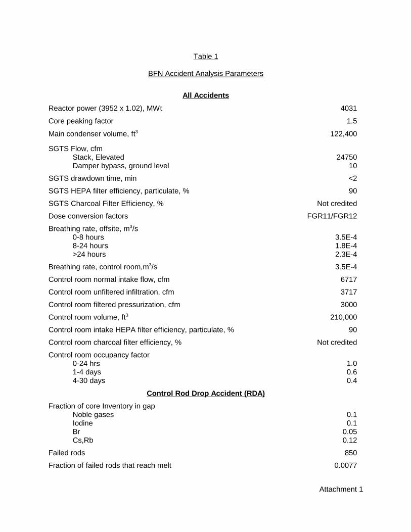
Attachment 1
Table 1
BFN Accident Analysis Parameters
All Accidents
Reactor power (3952 x 1.02), MWt 4031
Core peaking factor 1.5
Main condenser volume, ft3 122,400
SGTS Flow, cfmStack, Elevated 24750Damper bypass, ground level 10
SGTS drawdown time, min <2
SGTS HEPA filter efficiency, particulate, % 90
SGTS Charcoal Filter Efficiency, % Not credited
Dose conversion factors FGR11/FGR12
Breathing rate, offsite, m3/s0-8 hours 3.5E-48-24 hours 1.8E-4>24 hours 2.3E-4
Breathing rate, control room,m3/s 3.5E-4
Control room normal intake flow, cfm 6717
Control room unfiltered infiltration, cfm 3717
Control room filtered pressurization, cfm 3000
Control room volume, ft3 210,000
Control room intake HEPA filter efficiency, particulate, % 90
Control room charcoal filter efficiency, % Not credited
Control room occupancy factor0-24 hrs 1.01-4 days 0.64-30 days 0.4
Control Rod Drop Accident (RDA)
Fraction of core Inventory in gapNoble gases 0.1Iodine 0.1Br 0.05Cs,Rb 0.12
Failed rods 850
Fraction of failed rods that reach melt 0.0077
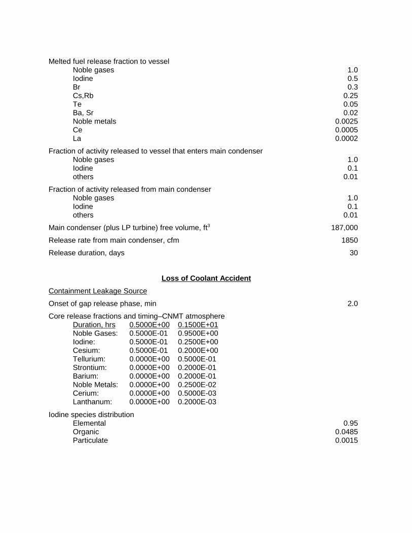
Melted fuel release fraction to vesselNoble gases 1.0Iodine 0.5Br 0.3Cs,Rb 0.25Te 0.05Ba, Sr 0.02Noble metals 0.0025Ce 0.0005La 0.0002
Fraction of activity released to vessel that enters main condenserNoble gases 1.0Iodine 0.1others 0.01
Fraction of activity released from main condenserNoble gases 1.0Iodine 0.1others 0.01
Main condenser (plus LP turbine) free volume, ft3 187,000
Release rate from main condenser, cfm 1850
Release duration, days 30
Loss of Coolant Accident
Containment Leakage Source
Onset of gap release phase, min 2.0
Core release fractions and timing–CNMT atmosphereDuration, hrs 0.5000E+00 0.1500E+01Noble Gases: 0.5000E-01 0.9500E+00Iodine: 0.5000E-01 0.2500E+00Cesium: 0.5000E-01 0.2000E+00Tellurium: 0.0000E+00 0.5000E-01Strontium: 0.0000E+00 0.2000E-01Barium: 0.0000E+00 0.2000E-01Noble Metals: 0.0000E+00 0.2500E-02Cerium: 0.0000E+00 0.5000E-03Lanthanum: 0.0000E+00 0.2000E-03
Iodine species distributionElemental 0.95Organic 0.0485Particulate 0.0015
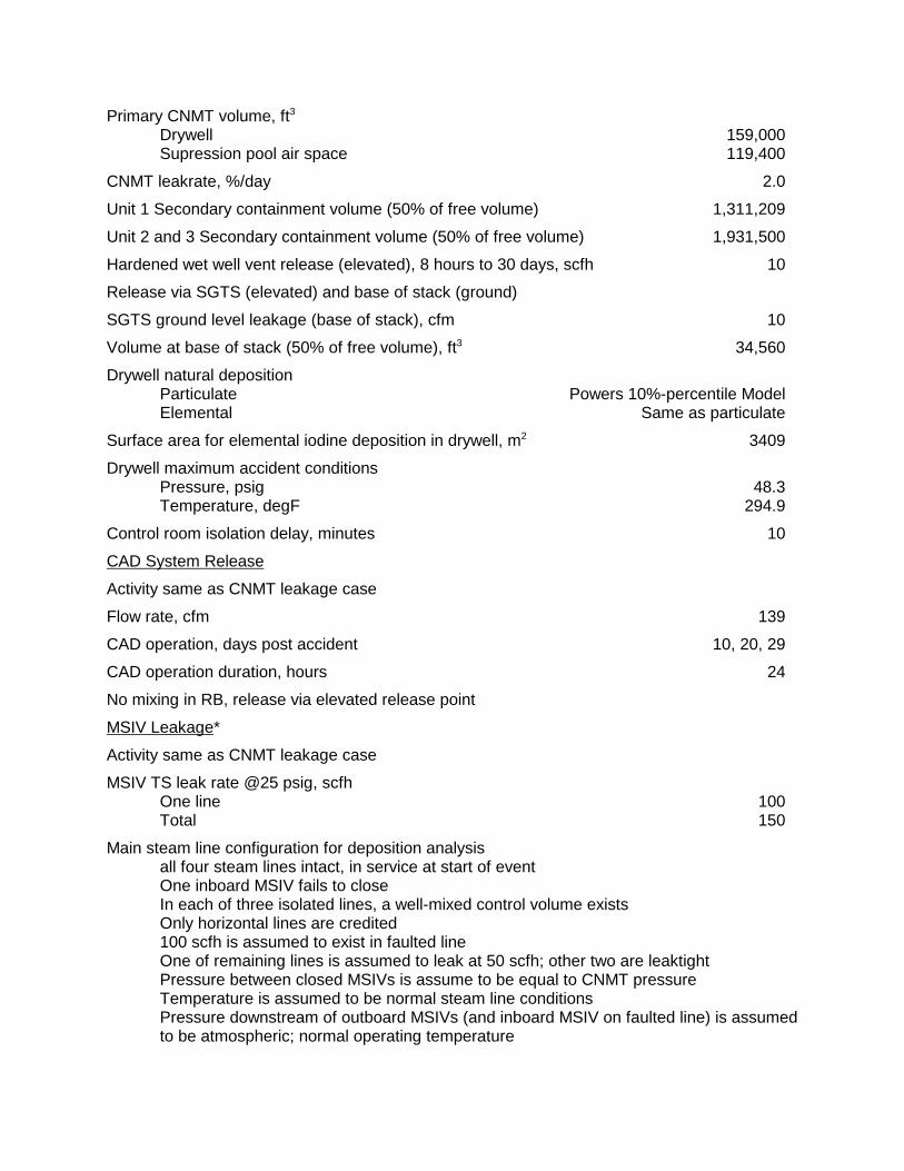
Primary CNMT volume, ft3
Drywell 159,000Supression pool air space 119,400
CNMT leakrate, %/day 2.0
Unit 1 Secondary containment volume (50% of free volume) 1,311,209
Unit 2 and 3 Secondary containment volume (50% of free volume) 1,931,500
Hardened wet well vent release (elevated), 8 hours to 30 days, scfh 10
Release via SGTS (elevated) and base of stack (ground)
SGTS ground level leakage (base of stack), cfm 10
Volume at base of stack (50% of free volume), ft3 34,560
Drywell natural depositionParticulate Powers 10%-percentile ModelElemental Same as particulate
Surface area for elemental iodine deposition in drywell, m2 3409
Drywell maximum accident conditionsPressure, psig 48.3Temperature, degF 294.9
Control room isolation delay, minutes 10
CAD System Release
Activity same as CNMT leakage case
Flow rate, cfm 139
CAD operation, days post accident 10, 20, 29
CAD operation duration, hours 24
No mixing in RB, release via elevated release point
MSIV Leakage*
Activity same as CNMT leakage case
MSIV TS leak rate @25 psig, scfhOne line 100Total 150
Main steam line configuration for deposition analysisall four steam lines intact, in service at start of eventOne inboard MSIV fails to closeIn each of three isolated lines, a well-mixed control volume existsOnly horizontal lines are credited100 scfh is assumed to exist in faulted lineOne of remaining lines is assumed to leak at 50 scfh; other two are leaktightPressure between closed MSIVs is assume to be equal to CNMT pressureTemperature is assumed to be normal steam line conditionsPressure downstream of outboard MSIVs (and inboard MSIV on faulted line) is assumedto be atmospheric; normal operating temperature

MSIV leakage at test pressure is converted to volumetric flow based on post-LOCAdrywell temperature and pressureRADTRAD Bixler model used for elemental iodineMSIV leakage from condenser is released without dilution or holdup in turbine building
MSIV Leakage that bypasses main condenser,% of total 0.5
Steam line deposition Aerosol ElementalSteam line 99.87 99.01MC bypass 89.33 16.37
ECCS Leakage
Iodine species fraction SumpParticulate/aerosol 0Elemental 97Organic 3
Suppression pool liquid volume, ft3 121,500
Estimated leakage, gpm 5
Iodine Flash Fraction 0.1
SGTS charcoal filtration Not credited
Release via SGTS (elevated) and base of stack (ground)
Fuel Handling Accident
Fuel rods damaged 111(conservatively based on 7 x 7 fuel)
Decay period, hrs 24
Fraction of core in gapI-131 0.08Kr-85 0.1Other iodines 0.05Other noble gases 0.05
Pool decontamination factor 200
Release period Instantaneously
Hold-up and mitigation No credit
Release via: RB refueling zone vent

Main Steam Line Break
Reactor coolant activity, uCi/gm dose equivalent I-131Normal 3.2Spike 32
Mass release, lbmSteam 11,975Liquid (saturated at 898 psia) 42,215
Release flash fraction (pressure=1020 psia) 0.38
Release duration, sec 5.5
Iodine species 100% Elemental

Attachment 2
Table 2
BFN METEOROLOGY
Control Room Site BoundaryTime Period Unit 1 Unit 3 EAB LPZ
Top of Stack Releases (LOCA and CRDA)
0-0.5 hrs 3.40E-5 * 2.35E-5 1.26E-50.5-2 hrs ** 1.41E-7 1.19E-6 1.13E-62-8 hrs ** 4.50E-8 5.75E-78-24 hrs ** 2.54E-8 4.10E-71-4 days ** 7.36E-9 1.97E-74-30 days ** 1.24E-9 6.88E-8
Base of Stack Releases (LOCA and CRDA)
0-2 hrs 2.00E-4 * 2.62E-4 1.31E-42-8 hrs 1.28E-4 * 6.61E-58-24 hrs 5.72E-5 * 4.69E-51-4 days 4.05E-5 * 2.23E-54-30 days 3.09E-5 * 7.96E-6
Turbine Building Exhaust Releases (MSLB Only, Unit 1 Post LOCA MSIV Leakage)
0-2 hrs 3.22E-4 * 2.62E-4 1.31E-42-8 hrs 2.77E-4 * 6.61E-58-24 hrs 1.31E-4 * 4.69E-51-4 days 7.91E-5 * 2.23E-54-30 days 6.10E-5 * 7.96E-6
Refuel Floor Releases
0-2 hrs 4.60E-4 * 2.62E-4 1.31E-4
Turbine Building Roof Ventilators (Units 2 and 3 Post-LOCA MSIV Leakage)
0-2 hrs ** 2.17E-4 2.62E-4 1.31E-42-8 hrs ** 1.64E-4 6.61E-58-24 hrs ** 7.89E-5 4.69E-51-4 days ** 4.33E-5 2.23E-54-30 days ** 3.35E-5 7.96E-6
* Unit 1 intake limiting** Unit 3 intake limiting
Due to dual intake configuration, limiting χ/Q needs to be divided by two.