Effect of Surface Modification on Magnetization of Iron Oxide Nanoparticle Colloids

Optical manipulation of nematic colloids: wires, superstructures and 2D crystals
Igor Muševič*a,b , Miha Škarabota, Miha Ravnikb, Uroš Tkaleca, Andriy Nychc, Ulyana Ognystac,
Vassili Nazarenkoc and Slobodan Žumera,b
aJ. Stefan Institute, Jamova 39, 1000 Ljubljana, Slovenia bFaculty of Mathematics and Physics, University of Ljubljana, Jadranska 19, 1000 Ljubljana,
Slovenia c Institute of Physics, Prospect Nauki 46, Kyiv-22, 252022, Ukraine
ABSTRACT
We describe and analyze experiments, where optical manipulation of small colloidal particles in the nematic liquid crystal (NLC) was used to create artificial colloidal structures, such as 1D chains and 2D colloidal crystals, and superstructures of different types of colloids. In all cases, the colloidal particles are strongly bound to each other, with a typical pair interaction energy of several 1000 kBT per 1µm size particle. There are two distinct mechanisms of colloidal binding in a spatially homogeneous NLC: (i) binding via spatially localized topological (point) defects, and (ii) binding via entangled topological defects, where the defect line winds around and wraps several colloidal particles. Keywords: laser manipulation, colloidal particles, nematic liquid crystal, colloidal structures
1. INTRODUCTION The broken symmetry of the isotropic phase of a nematic liquid crystal is responsible for fascinating optic, electro-optic and mechanical properties of these materials. In recent years, there has been a renewed interest in nematic liquid crystal emulsions [1,2,3] and nematic colloidal dispersions [4-6]. It has been shown in a number of publications, that liquid crystals exhibit a new class of forces between objects, which are the consequence of the distortions of the long-range orientational order around inclusions [1]. These forces are named "structural forces", as they are caused by the intrinsic "structure" of an ordered fluid [2] around each inclusion. The structural forces [7] between inclusions in nematic liquid crystals give rise to interesting self-assembly processes and induce growth of unique self-assembled structures such as linear chains [3], 2D hexagonal arrangements of particles at interfaces [4,5], regular arrays of defects [8], particle-stabilized defect gels [9], cellular structures [10], and even long-range ordered 2D structures in thin nematic layers [11]. These experimental studies, combined with theoretical analyses [12-23] have shown, that a rich variety of structural forces in the nematic liquid crystals could be used to design novel materials and devices, such as, for example, photonic crystals [24] and metamaterials [25]. Nematic liquid crystals are orientationally ordered complex fluids, in which rod-like molecules are spontaneously aligned into a certain direction, called the director. In the absence of external forces, the director field is uniform in space and any deviation of local orientation of molecules costs energy. When a small colloidal particle, such as a silica microsphere, shown in Figure 1, is immersed in the nematic liquid crystal, the surface of the particle interacts with liquid crystalline molecules and forces them to align into a preferred direction relative to the surface. The type of liquid crystal alignment depends on the surface preparation of the particle, and can be either planar, where the
Optical Trapping and Optical Micromanipulation V, edited by Kishan Dholakia, Gabriel C. Spalding,Proc. of SPIE Vol. 7038, 70381A, (2008) · 0277-786X/08/$18 · doi: 10.1117/12.796066
Proc. of SPIE Vol. 7038 70381A-12008 SPIE Digital Library -- Subscriber Archive Copy

(a) / \?i\ /
(c)77____________ (e)—______-—-—
LC molecules are parallel to the surface, or homeotropic, where they align in a direction perpendicular to the surface. The process of including a colloidal particle into the nematic and its interaction with the NLC inevitably results in the creation of topological defects, such as small singular points or loops [20]. As a consequence of the appearance of these topological singularities, the order of the nematic liquid crystal is elastically deformed arond the inclusion. This elastic distortion, which surrounds the particle, is further responsible for the interaction forces between neighbouring particles. Figure 1 shows what happens, if a microsphere with preferential surface boundary conditions for LC alignment is inserted into a nematic liquid crystal (NLC), the orientation of which is illustrated by straight horizontal lines, showing uniform alignment of NLC molecules. In case, when the surface of the colloidal particle favours planar (i.e. parallel) surface alignment (shown in Figure 1a), two point defects, called "boojums", are created at each end of the sphere, after it is inserted into the NLC (see Figure 1b). These defects are characterized by strong distortion of the nematic liquid crystal around them, as well as highly reduced degree of the ordering inside the defect. This is the reason why these defect points are also referred as to the singular points of the nematic order. For homeotropic surface anchoring of NLC molecules at the colloidal surface, shown schematically in Figure 1c, there are two possible topological scenarios, as depicted in Figures 1d and 1e. Figure 1d shows the "dipolar" nematic collloidal particle, where a microsphere is accompanied by a small singular ponit, forming together a topological dipole. Figure 1e shows the "quadrupolar" nematic colloid, where the sphere is spontaneously encircled by a small loop. Hence, the quadrupolar structure is also referred as to the Saturn ring collloid. One should stress, that the appearance of points and loops is inevitable process, which is due to the conservation of the topological charge. The appearance of either dipolar or quadrupolar configuration depends on the strength of surface anchoring of NLC molecules, as well as the size of the particles. As a general rule, smaller particles adopt quadrupolar configuration, whereas larger particles adopt dipolar one [19,20,26].
Fig.1. Nematic colloids and topological defects. (a) A colloidal particle with surface boundary conditions that favor planar
(parallel) alignment generates two defects ("boojums"), after it is inserted into the nematic liquid crystal (b). (c) When a colloidal particle with surface boundary conditions that favor perpendicular alignment of NLC molecules is inserted into the NLC, the resulting object has either dipolar symmetry (d), where a point defect accompanies the particle, or quadrupolar symmetry (e), where it is encircled by a small defect loop-the Saturn ring.
Proc. of SPIE Vol. 7038 70381A-2

Fig.2. Dipolar and quadrupolar nematic colloids. (a) Nematic colloidal particle of dipolar symmetry (i.e. the topological dipole)
is accompanied by a point defect, which is clearly visible due to the strong scattering of light. (b) Polarization image of (a) shows that the region of deformation of the birefringent NLC extends far around the particle, which appears much larger than its actual size. The image is taken between crossed polarizers. (c) Quadrupolar nematic colloidal particle is surrounded by a small, singular defect ring, which is visible via two dark points, which represent two cross-sections of the ring. (d) The ring is better observed between crossed polarizers, it is slightly bent and positioned vertically.
Figures 2a-d show nonpolarized images of dipolar nematic colloidal particle (2a) and quadrupolar colloidal particle (2b), together with their images between crossed polarizers (2b and 2d). It is clearly visible, that the particles are accompanied by a dark spot-point defect (Figure 2a-b) or encircled by a small loop (Figure 2d), which makes the distortion of the liquid crystal anisotropic, even though the particle is spherical. The defects and the colloidal particle form a "topological" dipole or topological quadrupole, which are reminiscent of the electrostatic dipole and quadrupole and their lines of the electric field. The mathematical description of the interactions between colloidal particles in the nematic crystals is in fact very similar, [15] although not exactly equivalent [27] to the electrostatic interaction between the electric multipoles. For example, the experiments have shown, that two topological dipolar nematic colloids will attract or repel each other according to the schematic presentation in Figure 3a,b. Two dipoles, placed collinearly with the nematic director, will attract when their dipoles point into the same direction, and will repel, when their dipoles are opposite. On the contrary, two topological dipoles, placed side by side with respect to the nematic director, will attract when anti-parallel, and will repel, when their dipoles are parallel to each other (lower Figure 3b). We have recently reported [11,28,29,30] several interesting colloidal structures and superstructures using directed self-assembly of different types of nematic colloids, using properly surface-functionalized micrometer sized silica spheres in a thin layer of nematic liquid crystal. Here we describe in more details some aspects of our recent work on directed self-assembly of different types of 2D nematic colloidal crystals, colloidal wires and superstructures of large and small colloidal particles.
Proc. of SPIE Vol. 7038 70381A-3
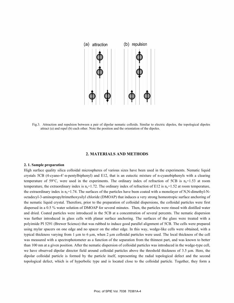
(a) attraction (b) repulsion
Fig.3. Attraction and repulsion between a pair of dipolar nematic colloids. Similar to electric dipoles, the topological dipoles
attract (a) and repel (b) each other. Note the position and the orientation of the dipoles.
2. MATERIALS AND METHODS
2. 1. Sample preparation High surface quality silica colloidal microspheres of various sizes have been used in the experiments. Nematic liquid crystals 5CB (4-cyano-4’-n-pentylbiphenyl) and E12, that is an eutectic mixture of n-cyanobiphenyls with a clearing temperature of 59°C, were used in the experiments. The ordinary index of refraction of 5CB is no=1.53 at room temperature, the extraordinary index is ne=1.72. The ordinary index of refraction of E12 is no=1.52 at room temperature, the extraordinary index is ne=1.74. The surfaces of the particles have been coated with a monolayer of N,N-dimethyl-N-octadecyl-3-aminopropyltrimethoxysilyl chloride (DMOAP) that induces a very strong homeotropic surface anchoring of the nematic liquid crystal. Therefore, prior to the preparation of colloidal dispersions, the colloidal particles were first dispersed in a 0.5 % water solution of DMOAP for several minutes. Then, the particles were rinsed with distilled water and dried. Coated particles were introduced in the 5CB at a concentration of several percents. The nematic dispersion was further introduced in glass cells with planar surface anchoring. The surfaces of the glass were treated with a polyimide PI 5291 (Brewer Science) that was rubbed to induce good parallel alignment of 5CB. The cells were prepared using mylar spacers on one edge and no spacer on the other edge. In this way, wedge-like cells were obtained, with a typical thickness varying from 1 µm to 6 µm, when 2 µm colloidal particles were used. The local thickness of the cell was measured with a spectrophotometer as a function of the separation from the thinnest part, and was known to better than 100 nm at a given position. After the nematic dispersion of colloidal particles was introduced in the wedge-type cell, we have observed dipolar director field around colloidal particles above the threshold thickness of 3.5 µm. Here, the dipolar colloidal particle is formed by the particle itself, representing the radial topological defect and the second topological defect, which is of hyperbolic type and is located close to the colloidal particle. Together, they form a
Proc. of SPIE Vol. 7038 70381A-4

+ -4-
4
topological dipole. For smaller cell thickness, the dipolar field around the colloidal particles was transformed into the quadrupolar, Saturn-like arrangement. 2. 2. Experimental set-up and procedures Laser tweezers have been used to position colloidal particles [11,31-33] and assist their assembly into stable 2D structures and superstructures. We have used a multi-trap laser tweezers setup built around an inverted microscope and a 1 W Ar+ laser at 514.5 nm as a laser source. An acousto-optic deflector (AOD), driven by custom made electronics controlled by a PC was used for trap moving. A beam expander was used to match the laser beam to the AOD aperture and some additional optics was used to image the pivotal point of the AOD onto the entrance pupil of the water immersion microscope objective (Nikon 60x, water immersion). The maximum laser power of a diffraction limited beam in the sample plane was up to 60 mW. The temporal position of the colloidal particles was video-monitored using an optical microscope and image capture. In an off-line analysis the colloidal trajectories were further analyzed [18]. The position of the particle center of gravity was determined by video-analysis of the captured frames with an accuracy of ~5 nm. Having the recorded time-dependence of the separation between the particle and the laser focus, it was possible to restore the effective elastic pair potential acting on the particle. Following the Stokes law, dtrdRF eff
vηπ6= , we can calculate the force between the light focus and the silica particle. Finally, by integrating the force over the separation the interaction energy can be calculated .
Fig.4. The direction of the nematic topological dipole could be reversed from "up" (first image) to "down" (the last image) by simply "drawing" an isotropic melt of the NLC (dark circle) across the colloidal particle. The defect remains on that side of the colloidal particle, where the melt was in last contact with the particle. The cross indicates the position of the laser tweezers.
At low laser power (up to 30 mW), the tweezers set-up was used to manipulate the colloidal particles. However, at larger laser power (above 60 mW), the light was used also to change their topological properties, and to promote the entanglement between several colloidal particles by local thermal quench. Figure 4 illustrates the method, which has been used to change the direction of the topological dipole from "up" (the first frame, Figure 4) to "down" (the last frame in Figure 4). For this purpose, the power of the Ar+ laser was increased so that we had approximatelly 60 mW at the tweezers focus. Due to absorption of light in the ITO layers on the inner surfaces of the cells, the liquid crystal is heated locally into the isotropic phase, as shown in the first frame, Figure 4. Note the initial direction of the dipole, which points
Proc. of SPIE Vol. 7038 70381A-5

0t
"up". Then, the tweezers is positioned so that the colloid is encircled by the isotropic phase of the liquid crystal, which is followed by "sweeping" slowly the tweezers focus in the downward direction in Figure 4. This results in the change of the direction of the topological dipole, as shown in the last frame of Figure 4. High-laser power and locally induced isotropic phase was also used to induce "entanglement" of colloidal particles, where two or many colloidal particles are bound together with a single (or two) disclination lines, wrapping around the particles. In order to be able to produce the entanglement, one has to be able to generate a large number of disclination
Fig.5. Defect loops could be created in the NLC by heating it into the isotropic phase (see the first video frame) and by
quenching it into the nematic phase. Heating is provided by absorption of light of the laser tweezers in the ITO (indium-tin-oxide) layer on the inner side of the measuring cell, which is in contact with NLC. After switching-off the light, the NLC is rapidly cooled (several K per second) into the nematic phase. Note that only one loop, encircling the colloidal particle, remains, whereas all other annihilate.
lines in the vicinity of colloidal particles. This can be done during rapidly quenching the isotropic melt into the nematic phase. Figure 5 shows a series of consecutive video frames during the quench. One can see initially a large number of entangled disclination lines, which "clear-up" via annihilation, so that at the end there is only a single disclination ring (i.e. Saturn ring), encircling the colloidal particle. In case there are several colloids, entangled colloidal states are created, as will be explained in the following text.
3. RESULTS AND DISCUSSION 3.1. 2D "binary nematic colloidal crystals" assembled from dipolar and quadrupolar colloidal particles 2D nematic colloidal crystals of dipolar and quadrupolar colloidal particles were first reported in 2006 [11]. Since then, a lot is known about their structure, stability and methods, which have to be used for their assembly. Recently, we have shown [30], that also "mixed" types of nematic colloidal crystals could be assembled, where we have two different building blocks instead of a single (either dipolar or quadrupolar). The first type of the basic "binary" building block is shown in Figure 6. Here, a dipole and a quadrupole attract each other collinearly, as shown schematically. It turns out, that one could assemble from these two basic building blocks a wide variety of stable, 2D "binary" nematic colloidal crystals, and two examples out of many that were recently discovered [unpublished], are shown in Figure 8. It remains to be systematically analyzed and classified, what classes of "crystal" structures could be assembled into stable 2D binary structures.
Proc. of SPIE Vol. 7038 70381A-6

Fig.6. A "binary" building block, composed of a collinear mixed pair of dipolar and quadrupolar colloidal particle. The
schematics of the ordering of the NLC is shown on the right drawing.
Fig.7. The second "binary" building block, composed of a mixed pair of dipolar and quadrupolar colloidal particles, which are positioned side-by-side. The schematics of the ordering of the NLC are shown on the right drawing.
Fig.8. Two examples of 2D binary nematic colloidal crystals (structures) formed of dipolar and quadrupolar nematic colloids.
Proc. of SPIE Vol. 7038 70381A-7

160 nm
3.2. Entangled colloidal wires Whereas localized point defects and small loops are responsible for a wide variety of 2D nematic colloidal structures, it is interesting to analyze, what kind of colloidal objects could be "synthesized" by entanglement of a pair or several colloidal particles in a homogeneous nematic matrix (NLC). Figure 9 summarizes what happens, when a pair of colloidal particles is quenched from the isotropic melt into the nematic phase using local heating by an intense laser light. First, a pair of separated quadrupolar colloidal particles are positioned close to each other, and then their
Fig.9. (a) A pair of isolated quadrupolar nematic colloidal particles is positioned into a close vicinity. (b) Intense field of the
laser tweezers is used to heat the colloidal surrounding into the isotropic phase, which is followed by a rapid quench. A dense tangle of defect lines is observed during cooling of the NLC. Three different entangled states are observed after a longer time [28]: (c) " figure of 8" entangled pair, where a single defect line twists around the pair and binds it firmly. (d) "figure of Ω" entangled pair, where a single defect line twists in between both colloidal particles and creates a smaller loop, orthogonal to the larger loop. (e) "entangled point defect" pair, which usually develops from (d), and the small loop in between the particles separates from the larger defect line and forms a small and isolated defect loop or point. It is visible due to its "white hallo" in between the particles.
liquid crystalline surrounding is molten into the isotropic phase by intense laser light. Immediately after switching-off the light, a dense tangle of defect loops is created (Figure 9b), which in the course of time annihilate and "dilute". What remains after a longer time (several seconds), are three possible and different colloidal pairs, entangled by a single or a pair of defect lines, shown Figures 9c-e.
Fig.10. An ensemble of 8 colloidal particles, entangled by "figure-of-8" defect line. The surface-to-surface separation between the colloidal particles is around 160 nm.
Proc. of SPIE Vol. 7038 70381A-8

iT 6OOO
-800010 I
-10000JI-1 2000
0 2 4 6 8 10 12 14
Path distance (tm)
Using the same technique, it is possible to form not only entangled pairs, but also an arbitrary number of entangled colloidal particles, such as the ensemble, shown in Figure 10. Here, an ensemble of 8 micro-spheres has been formed by figure-of-8 entanglement. We call these chains of colloidal particles "colloidal wires" for the important reason, illustrated on the right image in Figure 10. Namely, the measurements indicate that the inter-colloidal surface-surface separation is of the order of 160 nm for 2.2 µm particles, and can also be below 100 nm. This means, that such an object could act as a coupled chain of optical micro-resonators in close proximity. This proximity could enable coupling of the optical fields of each resonator and induce flow of light by tunneling through the inter-colloidal gap. Hence, one could in principle create self-assembled "optical wires" for light transport along the colloidal chain. 3.3. Hierarchical assemblies in a mixture of large and small nematic colloids Topological defects in the NLC, such as points and small loops, are characterized by reduced degree of the nematic order in the core of the defects, as well as high distortion of the nematic director in the vicinity of the defect. If we consider an additional, smaller colloidal particle in the vicinity of the defect (such as, for example a Saturn ring) one could expect that it is more favorable for the smaller particle to migrate into the core of the Saturn ring. This will reduce the volume with director distortion and consequently also reduce the total free energy of the system. We have recently shown that indeed in a mixture of large and small colloidal particles, the smaller ones tend to segregate in the cores of the defects [29]. Figure 11 illustrates attraction of a smaller (dipolar) nematic colloidal particle into the Saturn defect loop around a larger colloidal particle. The range of attraction is very large and is of the order of the diameter of the larger colloidal particle. The long range of the attraction is also responsible for very large binding energy of smaller colloidal particles into the defect core. This energy is of the order of 10.000 kBT for a 4.7 µm particle, trapped in the Saturn ring around a 19 µm diameter colloidal particle, as presented in the right panel of Figure 11.
Fig.11. Small colloidal particle of 4.7 µm diameter is attracted into the Saturn ring of a 19 µm colloidal particle. The right panel shows the binding potential of the small colloidal particle along the trapping path, which is in this case curved and not radial.
The colloidal superstructures made of smaller and larger colloidal particles could be extremely interesting for application in metamaterials. Figures 12 shows the Saturn ring around the colloidal particle, which is filled with smaller colloidal particles. If one could provide that the small particles are made of conductive material, such a ring-like superstructure could function as a distributed split ring resonator (SRR), which is an essential element for negative µ response. Here, the capacitor C is formed of the two conductive surfaces of the neighboring smaller colloidal spheres in close proximity, filled with the NLC, whereas the inductance L comes from the smaller conductive colloidal particles. A series of
Proc. of SPIE Vol. 7038 70381A-9

conductive particles, trapped into the ring therefore represents a distributed LC circuit. An estimate shows that for a 5 µm diameter of the colloidal ring and 50 nm diameter smaller particles, the resonant frequency of distributed resonant circuit is at the order of 15 THz , corresponding to the wavelength of 12 µm. The hierarchical mechanism of assembly in a mixture of large and small colloidal particle could in principle provide true self-assembly of negative µ materials.
Fig.12. Smaller colloidal particles are trapped into the topological defect loop (Saturn ring), encircling a larger colloidal particle. This structure mimics the distributed split ring resonator superstructure, where small and conductive colloidal particles are arranged into a necklace around large particle. An estimate shows that the resonant frequency is around 15 THz, if 50 nm conductive particles are trapped in a ring, encircling 5µm colloidal particle.
4. CONCLUSION In this paper, we have presented some of our recent results on directed self-assembly in nematic colloids. We have shown that there is a rich variety of colloidal structures and superstructures of nematic colloids, which are potential candidates for photonic applications. We have shown that there are two distinct mechanisms of colloidal self-assembly in nematic colloids, and both are based on structural forces between particles in the NLC. Unlike forces that are responsible for the organization of colloidal particles in the isotropic solvents, the structural forces in the NLC colloids are anisotropic and can act on hierarchically chosen length scales originating from the intrinsic particle scales and anchoring strengths. A very fine balance between the local disorder and the elastic distortion controls the self-assembly. Although only simple examples of colloidal superstructures have been shown, it is clear that complex, robust and material-independent colloidal superstructures could be built in nematic colloids.
REFERENCES
1. P. Poulin, H. Stark, T.C. Lubensky, and D.A. Weitz,, Science 275, 1770 (1997). 2. P. Poulin and D. A. Weitz, Phys. Rev. E 57, 626 (1998). 3. Y. Ch. Loudet, P. Barois, and P. Poulin, Nature 407, 611(2000). 4. V. G. Nazarenko, A. B. Nych, and B. I. Lev, Phys. Rev. Lett. 87, 075504, (2001).
Proc. of SPIE Vol. 7038 70381A-10

5. A. B. Nych, U. M. Ognysta, V. M. Pergamenshchik, B. I. Lev, V. G. Nazarenko, I.Muševič, M. Škarabot and O. D. Lavrentovich, Phys. Rev. Lett. 98, 057801(2007).
6. I. I. Smalyukh, S. Chernyshuk, B. I. Lev, A. B. Nych, U. Ognysta, V.G. Nazarenko, and O. D. Lavrentovich, Phys. Rev. Lett. 93, 117801, (2004).
7. K. Kočevar, I.Muševič, ChemPhysChem 4, 1049(2003). 8. M. Yada, J. Yamamoto, H. Yokoyama, Langmuir 18, 7436(2002). 9. M. Zapotocky, L. Ramos, P. Poulin, T. C. Lubensky, D. A. Weitz, Science 283, 209(1999) 10. S. P. Meeker, W. C. K. Poon, J. Crain, E. M. Terentjev, Phys. Rev. E 61, R6083(2000); J. Anderson, E. M.
Terentjev, S. P. Meeker, J. Crain, W. C. K. Poon, Eur. Phys. J. E 4, 11-20(2001). 11. I. Muševič, M. Škarabot, U. Tkalec, M. Ravnik, S. Žumer, Science 313, 954/958 (2006). 12. S.L.Lopatnikov and V.A.Namiot, Zh. Eksp. Teor. Fiz. 75, 361 (1978) [Sov. Phys. JETP 48, 180 (1978)] 13. S. Ramaswamy, R. Nityananda, V. A. Raghunathan, J. Prost, Mol. Cryst. Liq. Cryst. 288,175 (1996). 14. O. V. Kuksenok, R. W. Ruhwandl, S. Shiyanovskii, and E.M.Terentjev, Phys. Rev. E 54, 5198 (1996). 15. T. C. Lubensky, D. Pettey, N. Currier, and H. Stark, Phys. Rev. E 57, 610 (1998). 16. B. I. Lev and P. M. Tomchuk, Phys. Rev. E 59, 591 (1999). 17. S. B. Chernyshuk, B. I. Lev, and H. Yokoyama, Zh. Eksp. Teor. Fiz. 120, 871 (2001) [Sov. Phys. JETP 93, 760
(2001). 18. B. I. Lev, S. B. Chernyshuk, P. M. Tomchuk, and H. Yokoyama, Phys. Rev. E 65, 021709 (2002). 19. H. Stark, Eur. Phys. J. B 10, 311 (1999). 20. H. Stark, Physics Report 351, 387 (2001). 21. D. Andrienko, G. Germano, and M. P. Allen, Phys. Rev. E 63, 04170 (2001). 22. D. Andrienko, M. P. Allen, G. Skačej, and S. Žumer, Phys. Rev. E 65, 041702 (2002). 23. O. Guzman, E. B. Kim, S. Grollau, N. L. Abbott, J. J. de Pablo, Phys. Rev. Lett. 91, 235507(2003). 24. J. D. Joannopoulos, P. R. Villeneuve, S. Fan, Nature, 1997, 386, 143; Y. A. Vlasov, Xiang-Zheng Bo, J. C.
Sturm, D. J. Norris, Nature, 2001, 414, 289. 25. V. G. Veselago, Sov. Phys. Usp., 1968, 10, 509; J. B. Pendry, Phys. Rev. Lett., 2000, 85, 3966. 26. M. Kleman, O. D. Lavrentovich, Phil. Mag. , 2006, 86, 4117. 27. D. Pires, J.-B. Fleury, Y. Galerne, Phys. Rev. Lett. 98, 247801(2007). 28. M. Ravnik et al., Phys. Rev. Lett. 99, 247801(2007) 29. M. Škarabot et al., Phys. Rev. E 77, 061706(2008). 30. U. Ognysta, A. Nych, V. Nazarenko, I. Muševič, M. Škarabot, M. Ravnik, S. Žumer, I. Poberaj, D. Babič, Phys.
Rev. Lett. 100, 217803(2008). 31. Jun-ichi Hotta, H. Masuhara, Appl. Phys. Lett. 71, 2085(1997). 32. I. Muševič, M.Škarabot, D. Babič, N. Osterman, I. Poberaj, V. Nazarenko, and A. Nych, Phys. Rev. Lett. 93,
187801(2004). 33. M. Škarabot, M. Ravnik, D. Babič, N. Osterman, I.Poberaj, S.Žumer, I. Muševič, A. Nych, U. Ognysta and V.
Nazarenko, Phys. Rev. E 73, 021705(2006).
Proc. of SPIE Vol. 7038 70381A-11
Copyright © 2022 FDOKUMEN