
Assessing Fire Safety in Maritime Composite Superstructures
121
Assessing Fire Safety in Maritime Composite Superstructures – A Risk-Based Approach Franz Evegren Department of Fire Safety Engineering and Systems Safety Faculty of Engineering Lund University, Sweden Avdelning för Brandteknik och Riskhantering Lunds Tekniska Högskola Lunds Universitet Report 5327, Lund 2010
-
Upload
khangminh22 -
Category
Documents
-
view
1 -
download
0
Transcript of Assessing Fire Safety in Maritime Composite Superstructures
Assessing Fire Safety in Maritime Composite Superstructures – A Risk-Based Approach
Franz Evegren
Department of Fire Safety Engineering and Systems Safety
Faculty of Engineering
Lund University, Sweden
Avdelning för Brandteknik och Riskhantering
Lunds Tekniska Högskola
Lunds Universitet
Report 5327, Lund 2010

2
3
Assessing Fire Safety in Maritime
Composite Superstructures
– A Risk-Based Approach
Franz Evegren
Lund 2010

4
Title / Titel Assessing Fire Safety in Maritime Composite Superstructures – A Risk-Based Approach / Bedömning av Brandsäkerheten i Marina Kompositöverbyggnader – En Riskbaserad Approach
Author / Författare Franz Evegren
Report / Rapport 5327 Number of pages: 117 Illustrations: If not specified, by author ISSN: 1402-3504 ISRN: LUTVDG/TVBB—5327—SE © Copyright: Brandteknik och Riskhantering, Lunds Tekniska Högskola, Lunds universitet, Lund 2010
Abstract Reduced weight and maintenance make it advantageous to replace steel with Fibre Reinforced Polymer (FRP) composites in maritime applications, but being combustible makes fire safety a burning issue. A new methodology in regulations has opened up for innovative design solutions if they can be regarded as safe as a design complying with all prescriptive requirements. However, an uneven safety level in regulations and unclear connections with objectives and functional requirements make it problematic to distinguish the level of fire safety in prescriptive requirements. This report provides an approach to clarify effects to the implicit fire safety when implementing an FRP composite superstructure to a passenger ship. FRP composites were considered with thermal insulation as a basic requirement for all interior surfaces, which keeps it thermally insulated for 60 minutes in case of fire. In order to establish how this conceptual design affects the prescribed level of fire safety, five qualitative analyses were performed, investigating (1) the fire safety regulations, (2) the fire safety objectives and functional require-ments, (3) the fire safety structure, (4) the fire safety properties and (5) the fire development. The analyses showed on possible improved containment of fire and enhanced evacuation conditions within the first 60 minutes of a fire in the novel structure. After 60 minutes there may, however, be negative effects necessary to consider, such as an increased production of toxic smoke. Furthermore, if exterior surfaces are considered in the design, these will need special attention since they are combustible and outside the scope of current regulations. With the verification needs established, the report presents a risk-based approach to assess the fire safety in FRP composite designs. It consists of a risk analysis process in line with the methodology required when deviating from prescriptive fire safety requirements. It considers the previously revealed effects to fire safety and is adaptable to the intended scope of the novel design.
Keywords Composite, fire safety, ship, risk-based, risk analysis, maritime, risk assessment.
Sökord Komposit, brand, fartyg, riskbaserad, riskanalys, säkerhet, riskbedömning, marin.
Department of Fire Safety
Engineering and Systems Safety Lund University
P.O. Box 118 SE-221 00 Lund, Sweden
http://www.brand.lth.se
Telephone: +46 (46) 222 73 60 Telefax: +46 (46) 222 46 12
Brandteknik och Riskhantering
Lunds Tekniska Högskola Lunds Universitet
Box 118 221 00 Lund
http://www.brand.lth.se
Telefon: 046-222 73 60 Telefax: 046-222 46 12
5
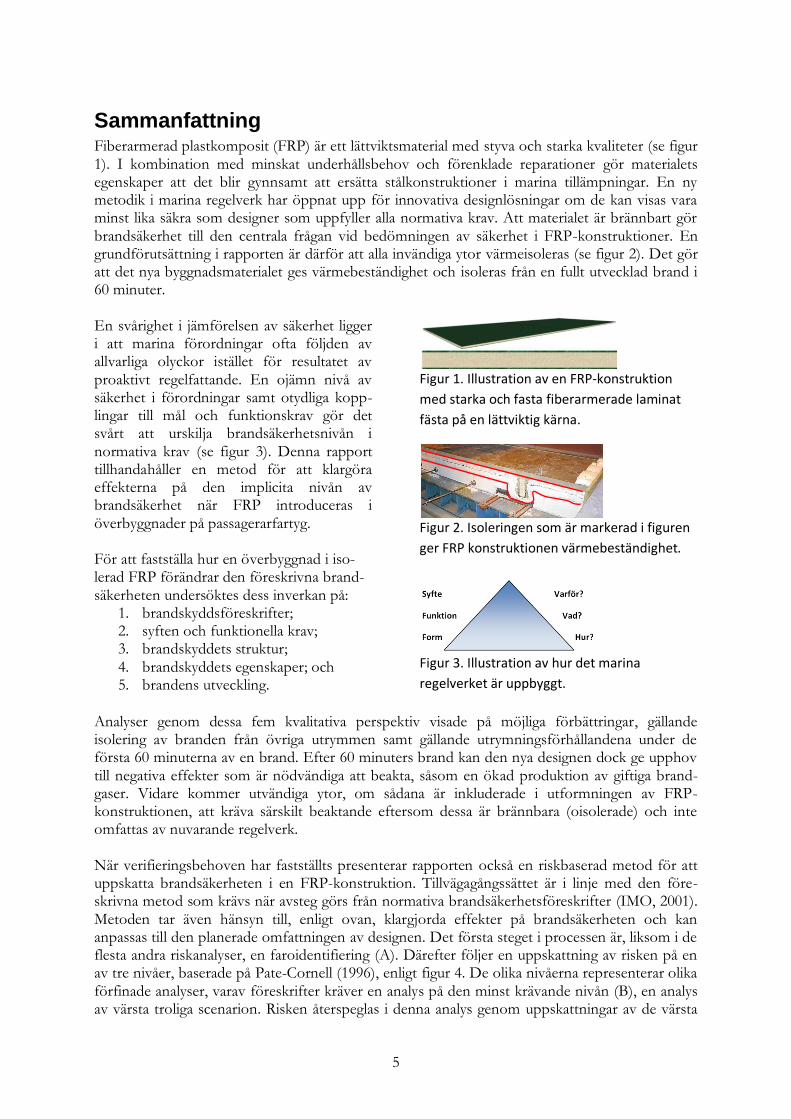
Sammanfattning Fiberarmerad plastkomposit (FRP) är ett lättviktsmaterial med styva och starka kvaliteter (se figur 1). I kombination med minskat underhållsbehov och förenklade reparationer gör materialets egenskaper att det blir gynnsamt att ersätta stålkonstruktioner i marina tillämpningar. En ny metodik i marina regelverk har öppnat upp för innovativa designlösningar om de kan visas vara minst lika säkra som designer som uppfyller alla normativa krav. Att materialet är brännbart gör brandsäkerhet till den centrala frågan vid bedömningen av säkerhet i FRP-konstruktioner. En grundförutsättning i rapporten är därför att alla invändiga ytor värmeisoleras (se figur 2). Det gör att det nya byggnadsmaterialet ges värmebeständighet och isoleras från en fullt utvecklad brand i 60 minuter. En svårighet i jämförelsen av säkerhet ligger i att marina förordningar ofta följden av allvarliga olyckor istället för resultatet av proaktivt regelfattande. En ojämn nivå av säkerhet i förordningar samt otydliga kopp-lingar till mål och funktionskrav gör det svårt att urskilja brandsäkerhetsnivån i normativa krav (se figur 3). Denna rapport tillhandahåller en metod för att klargöra effekterna på den implicita nivån av brandsäkerhet när FRP introduceras i överbyggnader på passagerarfartyg. För att fastställa hur en överbyggnad i iso-lerad FRP förändrar den föreskrivna brand-säkerheten undersöktes dess inverkan på:
1. brandskyddsföreskrifter; 2. syften och funktionella krav; 3. brandskyddets struktur; 4. brandskyddets egenskaper; och 5. brandens utveckling.
Figur 1. Illustration av en FRP-konstruktion
med starka och fasta fiberarmerade laminat
fästa på en lättviktig kärna.
Figur 2. Isoleringen som är markerad i figuren
ger FRP konstruktionen värmebeständighet.
Figur 3. Illustration av hur det marina
regelverket är uppbyggt.
Analyser genom dessa fem kvalitativa perspektiv visade på möjliga förbättringar, gällande isolering av branden från övriga utrymmen samt gällande utrymningsförhållandena under de första 60 minuterna av en brand. Efter 60 minuters brand kan den nya designen dock ge upphov till negativa effekter som är nödvändiga att beakta, såsom en ökad produktion av giftiga brand-gaser. Vidare kommer utvändiga ytor, om sådana är inkluderade i utformningen av FRP-konstruktionen, att kräva särskilt beaktande eftersom dessa är brännbara (oisolerade) och inte omfattas av nuvarande regelverk. När verifieringsbehoven har fastställts presenterar rapporten också en riskbaserad metod för att uppskatta brandsäkerheten i en FRP-konstruktion. Tillvägagångssättet är i linje med den före-skrivna metod som krävs när avsteg görs från normativa brandsäkerhetsföreskrifter (IMO, 2001). Metoden tar även hänsyn till, enligt ovan, klargjorda effekter på brandsäkerheten och kan anpassas till den planerade omfattningen av designen. Det första steget i processen är, liksom i de flesta andra riskanalyser, en faroidentifiering (A). Därefter följer en uppskattning av risken på en av tre nivåer, baserade på Pate-Cornell (1996), enligt figur 4. De olika nivåerna representerar olika förfinade analyser, varav föreskrifter kräver en analys på den minst krävande nivån (B), en analys av värsta troliga scenarion. Risken återspeglas i denna analys genom uppskattningar av de värsta

6
rimliga brandscenarierna som kan inträffa, vilka även anger den erfordrade funktions-nivån hos konstruktionen. Även om säker-hetsnivån hos designen antas klara det värsta troliga scenariot finns dock en okänd sannolikhet för att så inte blir fallet. Den faktiska säkerhetsnivån i konstruktionen är därmed inte uppenbarad. Trots det kan en analys på denna nivå vara tillräcklig; om omfattningen av den avsedda FRP-överbyg-gnaden är begränsad och inte innefattar några utvändiga (oisolerade) ytor. I annat fall kommer effekterna på brandsäkerheten att vara mer komplicerade och behovet av verifiering är större.
Figur 4. Beroende på hur brandsäkerheten
påverkas av en föreslagen FRP-konstruktion
rekommenderas att uppskatta effekterna
genom en riskanalys på en viss nivå.
Nästkommande nivå (Γ) innebär att en pro-babilistisk riskanalys utförs för att illustrera riskerna. I motsats till föregående angrepps-sätt tar en analys på denna nivå inte bara hänsyn till konsekvenser utan även till sannolikheter. Analysen är avsedd att beskriva en fullständig fördelning av poten-tiella förluster, vilket vanligtvis framställs genom en risk kurva. En begränsning i uppskattningen av risker på denna nivå är att effekterna av olika osäkerhetsfaktorer inte kan särskiljas. En djupare analys av osäker-heter kan beskriva sekundära sannolikheter eller osäkerhet rörande sannolikhet, vilket definierar den mest avancerade nivån av dem som beaktas i rapporten. På denna nivå (Δ) är det möjligt att t.ex. särskilja spridning orsakad av bristande kunskap från den på grund av naturlig variation. Detta görs genom att presentera risken som en familj av riskkurvor. En analys på denna nivå är dock mycket krävande och bör endast eftersträvas vid exceptionellt höga verifieringsbehov, t.ex. om säkerheten optimeras genom att minska den termiska isoleringen.
Figur 5. Beskrivning av den rekommenderade
riskanalysprocessen som inkluderar en utred-
ning av effekterna på brandsäkerheten och är i
linje med IMO (2001).
Ett steg till nästkommande nivå i figur 4 bör endast tas i den mån som krävs för att få tillräckligt med information för att kunna ta ett beslut (Bridges, 2000). En djupare analys tar itu med speci-fika brister i de tidigare nivåerna, men att gå vidare till nästa nivå gör också informationen mer komplex och ökar kostnaderna för insamling och bearbetning av ytterligare data. Detta symboli-seras av den växande arean för nivåerna nedåt i triangeln. Den ökade arbetsbelastningen gör att det är aktuellt att söka en balans vad gäller utvärderingen av osäkerheter. Det föregående beskrivna angreppssättet för att klargöra verifieringsbehov kan inkluderas i den beskrivna riskanalysen och bildar då en process som exemplifieras översiktligt i rapporten och sammanfattas i figur 5.
7
Preface This project has indeed been an interesting journey. I hope this report will be of some help and bring as much knowledge and ideas to someone else out there as it has brought me. I am very glad for the opportunity to study within this field, provided by Tommy Hertzberg, PhD, Department of Fire, Risk and Safety, SP Technical Research Institute of Sweden. I am also thankful for all the advice and hospitable treatment when visiting Borås. As the apprentice, I would also like to give many thanks to my all-knowing master, Håkan Frantzich, PhD, Department of Fire Safety Engineering and Systems Safety, Lund University, Lund, Sweden, for the patience and the many long discussions. Finally, I would like extend my most loving gratitude to Kristie; for all the self-sacrificing love you heave over me,
Franz
May 2010
”Everything is in fact combustible – the question is only at what temperature.”

8
Abbreviations ALARP As Low As Reasonably Practicable CCF Common Cause Failures Circ. Circular COSO Committee of Sponsoring Organizations of the Treadway Commission DNV Det Norske Veritas ETA Event Tree Analysis ETSC European Transport Safety Council Fe Steel FMEA Failure Modes and Effects Analysis FN Frequency of accidents versus Number of fatalities FRD Fire Resisting Division FRP Fibre Reinforced Polymer FSA Formal Safety Assessment FTA Fault Tree Analysis GBS Goal Based Design HAZOP Hazard and Operability Study HRA Human Reliability Analysis HSC High Speed Craft HSE Health & Safety Commission (UK) IACS International Association of Classification Societies IEC International Electrotechnical Commission IMO International Maritime Organization ISM International Safety Management ISO International Organization of Standards LÄSS Light Weight Construction Applications at Sea (Lättviktskonstruktioner till sjöss) LSA Life-Saving Appliances LTH Faculty of Engineering, Lund University MSC Marine Safety Committee (commission within the IMO) NFPA National Fire Protection Association PHA Process Hazards Analysis PLL Potential lives lost PRA Probabilistic Risk Assessment PVC Polyvinyl Chloride QRA Quantitative Risk Assessment RCM Risk Control Measure RCO Risk Control Option RFR Regulation Functional Requirement RO Regulation Objective SLA Safety Level Approach SOLAS International Convention for the Safety of Life at Sea SOU Swedish Government Official Reports (Statens Offentliga Utredningar) THERP Technique for Human Error Rate Prediction UK United Kingdom SOLAS chapter II-2 is also sometimes written SOLAS II-2 and refers to the second subchapter of SOLAS chapter II. SOLAS II-2/9.2.2.3 means SOLAS chapter II-2 Regulation 9 paragraph 2.2.3. If not specified, the chapter regarding fire safety, SOLAS II-2, is implied. Further explanations of some of the abbreviations are found in Appendix A. Definitions.

9
Table of Contents
1. INTRODUCTION 13
1.1 PROBLEM PRESENTATION 13
1.2 PROSPECT AND OBJECTIVES 13
1.3 METHOD 14
1.4 DISPOSITION 15
1.5 LIMITATIONS 15
1.6 DEFINITIONS 16
2. FIRE SAFETY REQUIREMENTS AND THE DEVELOPMENT IN SOLAS 17
2.1 IMO AND SOLAS 17
2.2 ESTABLISHMENT OF SOLAS CHAPTER II-2 17
2.3 CURRENT PERFORMANCE-BASED SOLAS-REGULATIONS 19
2.3.1 Damage Stability 19
2.3.2 Regulation 17 19
2.3.3 Circular 1212 20
2.4 DEVELOPMENT IN IMO RULE-MAKING 20
2.4.1 Formal Safety Assessment 21
2.4.2 Moving from compliance to safety 21
2.4.3 Explicit criteria 22
2.4.4 An opening for risk-based design 22
3. INTRODUCTION TO THE CONCEPT OF RISK 25
3.1 RISK IS INEVITABLE 25
3.2 ON THE DEFINITION OF RISK 26
3.3 RISK MANAGEMENT AND RISK ASSESSMENT 27
3.4 RISK ANALYSIS 28
3.5 RISK EVALUATION AND THE CURRENT APPROACH 30
3.6 UNCERTAINTY 31
3.7 SAFETY CULTURE AND HUMAN ERROR 32
3.7.1 Organization and management 33
3.7.2 Human error in a safety culture 33
3.7.3 Safety culture affects the risk 34
3.7.4 Management systems 35
3.7.5 Risk management systems as an input to risk analysis 35
3.8 RISK PERCEPTION 36
4. STRUCTURAL REQUIREMENTS AND THE FRP COMPOSITE 39
4.1 SHIP FIRES 39
4.2 EVACUATION 40
4.3 SPECIFIC REQUIREMENTS FOR STRUCTURES 41
4.3.1 “A” class 42
4.3.2 “B” class divisions 42
4.3.3 “C” class divisions 43
4.3.4 A note on combustibility 43
4.4 THE COMPOSITE BASE DESIGN 43
4.4.1 Structure of an FRP composite panel 44
4.4.2 The necessary insulating qualities 45
4.4.3 Foundational arrangements in an FRD design 46
10
4.5 PROPERTIES REVEALED FROM TESTS 47
4.6 TESTS AS A METHOD FOR COMPARISON 48
5. ANALYZING THE NEEDS FOR VERIFICATION 51
5.1 THE FIRE SAFETY REGULATIONS 52
5.1.1 Regulation 4 54
5.1.2 Regulation 5 54
5.1.3 Regulation 6 54
5.1.4 Regulation 9 55
5.1.5 Regulation 11 55
5.1.6 Regulation 13 56
5.2 THE FIRE SAFETY OBJECTIVES AND FUNCTIONAL REQUIREMENTS 56
5.2.1 Fire safety objectives 57
5.2.2 Functional requirements 58
5.3 THE FIRE SAFETY STRUCTURE 59
5.3.1 Different types of fire protection 59
5.3.2 Multi-purpose complexities 60
5.3.3 Matrix describing the universal effects 62
5.3.4 Marking changes in the matrix 63
5.3.5 Using the matrix to analyze a change to FRD 64
5.4 THE FIRE SAFETY PROPERTIES 64
5.4.1 Human intervention 65
5.4.2 Complexity in the fire protection strategy 66
5.4.3 Fire protection complexity 66
5.4.4 Flexibility 67
5.4.5 Sensitivity 67
5.4.6 Reliability 68
5.4.7 Vulnerability 68
5.5 THE FIRE DEVELOPMENT 69
5.5.1 Ignition and the first stages of an enclosure fire 69
5.5.2 Structural divisions within the first 60 minutes 70
5.5.3 Structural divisions after propagation or deterioration (> 60 min) 71
5.5.4 Exterior surfaces 72
5.6 SUMMARY OF THE PRECEDING ANALYSES 72
6. RISK ANALYSIS FOR VERIFICATION 75
6.1 UNCERTAINTIES IN A SHIP DESIGN 75
6.2 UNCERTAINTIES FROM THE DESIGN PROCESS 77
6.3 MANAGING UNCERTAINTIES ON DIFFERENT LEVELS IN RISK ANALYSIS 78
6.3.1 Level 0: identification of hazards and failure modes 78
6.3.2 Level 1: the worst-case approach 79
6.3.3 Level 2: plausible worst-case 79
6.3.4 Level 3: best estimates and central values 80
6.3.5 Level 4: probabilistic risk assessment and single risk curve 80
6.3.6 Level 5: display of risk uncertainties 80
6.3.7 Discussion on the levels of verification 81
6.3.8 Choosing a simple or sophisticated approach 82
6.4 THE METHODOLOGY OUTLINED IN CIRCULAR 1002 83
6.4.1 Preliminary analysis in qualitative terms 83
6.4.2 Quantitative analysis 84

11
6.4.3 Discussion on the approach outlined in Circular 1002 85
6.5 RECOMMENDED APPROACH FOR THE FIRE SAFETY ANALYSIS 87
6.5.1 Level A: identification of hazards and preliminary analysis 88
6.5.2 Level B: plausible worst-case analysis 88
6.5.3 Level Γ: probabilistic risk analysis 89
6.5.4 Level Δ: evaluation of risk uncertainties 89
7. SYNOPTIC APPLICATION OF THE APPROACH 91
7.1 NORWEGIAN GEM AND THE PROPOSED FRD DESIGN 91
7.2 THE PRELIMINARY ANALYSIS 91
7.2.1 Identification and enumeration of hazards 92
7.2.2 Analysis of the effects to fire safety 93
7.2.3 Selection of fire hazards and specification of fire scenarios 96
7.3 RISK ESTIMATION 98
7.3.1 Fire scenario development 98
7.3.2 Quantification of fire scenarios 100
7.3.3 Presentation of the risk 100
7.3.4 The illustrated process 102
8. CONCLUSIONS 103
8.1 FULFILMENT OF OBJECTIVES 103
8.2 FUTURE WORK 104
9. REFERENCES 105
APPENDIX A. DEFINITIONS 113
APPENDIX B. THE PURPOSES OF SOLAS II-2 115
APPENDIX C. THE NORWEGIAN GEM 119

12
13
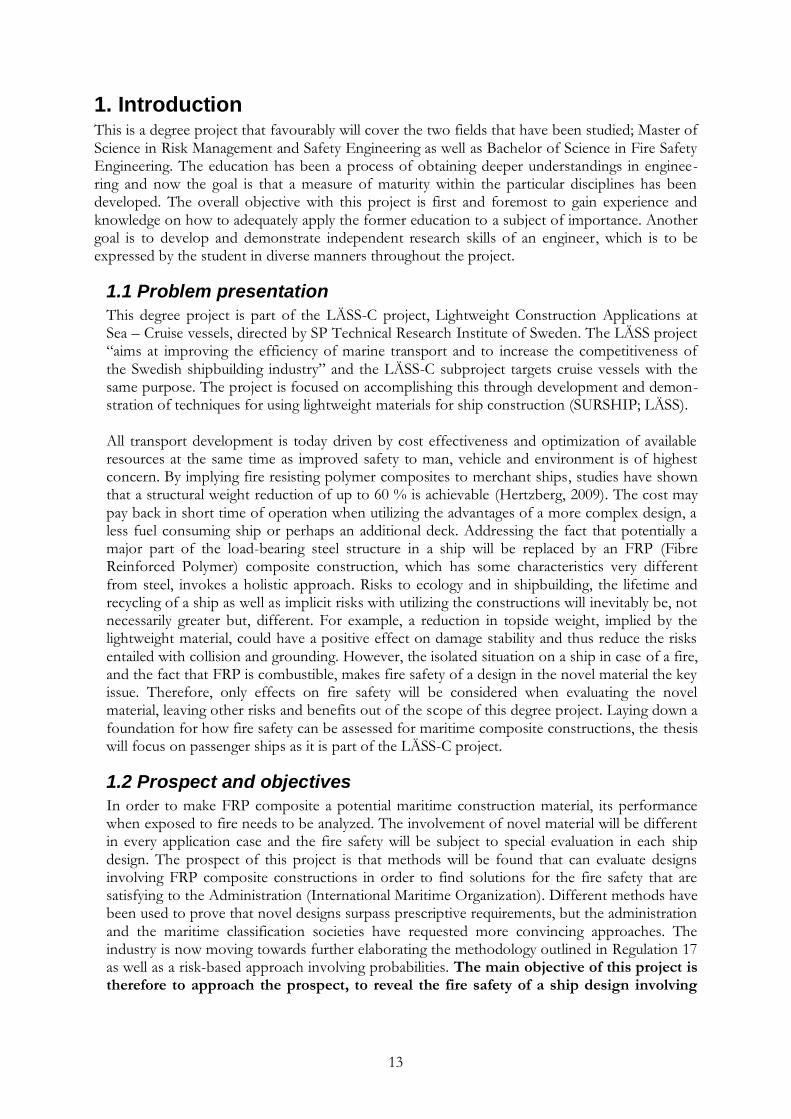
1. Introduction This is a degree project that favourably will cover the two fields that have been studied; Master of Science in Risk Management and Safety Engineering as well as Bachelor of Science in Fire Safety Engineering. The education has been a process of obtaining deeper understandings in enginee-ring and now the goal is that a measure of maturity within the particular disciplines has been developed. The overall objective with this project is first and foremost to gain experience and knowledge on how to adequately apply the former education to a subject of importance. Another goal is to develop and demonstrate independent research skills of an engineer, which is to be expressed by the student in diverse manners throughout the project.
1.1 Problem presentation
This degree project is part of the LÄSS-C project, Lightweight Construction Applications at Sea – Cruise vessels, directed by SP Technical Research Institute of Sweden. The LÄSS project “aims at improving the efficiency of marine transport and to increase the competitiveness of the Swedish shipbuilding industry” and the LÄSS-C subproject targets cruise vessels with the same purpose. The project is focused on accomplishing this through development and demon-stration of techniques for using lightweight materials for ship construction (SURSHIP; LÄSS).
All transport development is today driven by cost effectiveness and optimization of available resources at the same time as improved safety to man, vehicle and environment is of highest concern. By implying fire resisting polymer composites to merchant ships, studies have shown that a structural weight reduction of up to 60 % is achievable (Hertzberg, 2009). The cost may pay back in short time of operation when utilizing the advantages of a more complex design, a less fuel consuming ship or perhaps an additional deck. Addressing the fact that potentially a major part of the load-bearing steel structure in a ship will be replaced by an FRP (Fibre Reinforced Polymer) composite construction, which has some characteristics very different from steel, invokes a holistic approach. Risks to ecology and in shipbuilding, the lifetime and recycling of a ship as well as implicit risks with utilizing the constructions will inevitably be, not necessarily greater but, different. For example, a reduction in topside weight, implied by the lightweight material, could have a positive effect on damage stability and thus reduce the risks entailed with collision and grounding. However, the isolated situation on a ship in case of a fire, and the fact that FRP is combustible, makes fire safety of a design in the novel material the key issue. Therefore, only effects on fire safety will be considered when evaluating the novel material, leaving other risks and benefits out of the scope of this degree project. Laying down a foundation for how fire safety can be assessed for maritime composite constructions, the thesis will focus on passenger ships as it is part of the LÄSS-C project.
1.2 Prospect and objectives
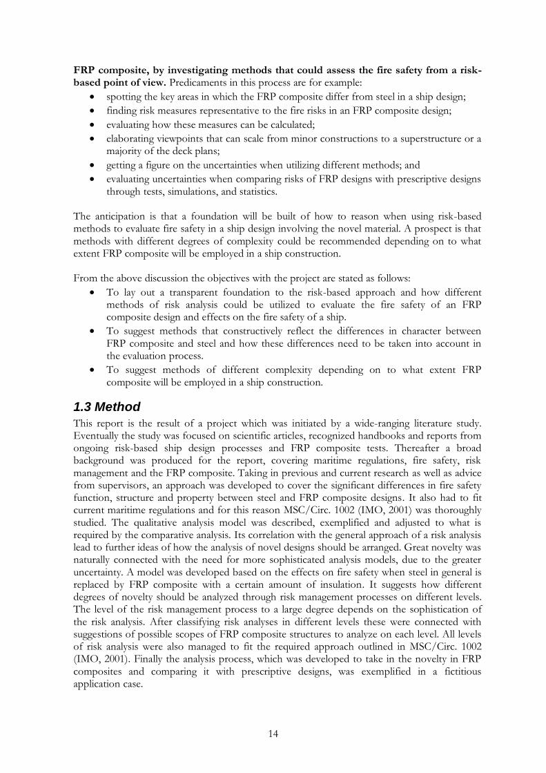
In order to make FRP composite a potential maritime construction material, its performance when exposed to fire needs to be analyzed. The involvement of novel material will be different in every application case and the fire safety will be subject to special evaluation in each ship design. The prospect of this project is that methods will be found that can evaluate designs involving FRP composite constructions in order to find solutions for the fire safety that are satisfying to the Administration (International Maritime Organization). Different methods have been used to prove that novel designs surpass prescriptive requirements, but the administration and the maritime classification societies have requested more convincing approaches. The industry is now moving towards further elaborating the methodology outlined in Regulation 17 as well as a risk-based approach involving probabilities. The main objective of this project is therefore to approach the prospect, to reveal the fire safety of a ship design involving
14
FRP composite, by investigating methods that could assess the fire safety from a risk-based point of view. Predicaments in this process are for example:
spotting the key areas in which the FRP composite differ from steel in a ship design;
finding risk measures representative to the fire risks in an FRP composite design;
evaluating how these measures can be calculated;
elaborating viewpoints that can scale from minor constructions to a superstructure or a majority of the deck plans;
getting a figure on the uncertainties when utilizing different methods; and
evaluating uncertainties when comparing risks of FRP designs with prescriptive designs through tests, simulations, and statistics.
The anticipation is that a foundation will be built of how to reason when using risk-based methods to evaluate fire safety in a ship design involving the novel material. A prospect is that methods with different degrees of complexity could be recommended depending on to what extent FRP composite will be employed in a ship construction. From the above discussion the objectives with the project are stated as follows:
To lay out a transparent foundation to the risk-based approach and how different methods of risk analysis could be utilized to evaluate the fire safety of an FRP composite design and effects on the fire safety of a ship.
To suggest methods that constructively reflect the differences in character between FRP composite and steel and how these differences need to be taken into account in the evaluation process.
To suggest methods of different complexity depending on to what extent FRP composite will be employed in a ship construction.
1.3 Method
This report is the result of a project which was initiated by a wide-ranging literature study. Eventually the study was focused on scientific articles, recognized handbooks and reports from ongoing risk-based ship design processes and FRP composite tests. Thereafter a broad background was produced for the report, covering maritime regulations, fire safety, risk management and the FRP composite. Taking in previous and current research as well as advice from supervisors, an approach was developed to cover the significant differences in fire safety function, structure and property between steel and FRP composite designs. It also had to fit current maritime regulations and for this reason MSC/Circ. 1002 (IMO, 2001) was thoroughly studied. The qualitative analysis model was described, exemplified and adjusted to what is required by the comparative analysis. Its correlation with the general approach of a risk analysis lead to further ideas of how the analysis of novel designs should be arranged. Great novelty was naturally connected with the need for more sophisticated analysis models, due to the greater uncertainty. A model was developed based on the effects on fire safety when steel in general is replaced by FRP composite with a certain amount of insulation. It suggests how different degrees of novelty should be analyzed through risk management processes on different levels. The level of the risk management process to a large degree depends on the sophistication of the risk analysis. After classifying risk analyses in different levels these were connected with suggestions of possible scopes of FRP composite structures to analyze on each level. All levels of risk analysis were also managed to fit the required approach outlined in MSC/Circ. 1002 (IMO, 2001). Finally the analysis process, which was developed to take in the novelty in FRP composites and comparing it with prescriptive designs, was exemplified in a fictitious application case.
15
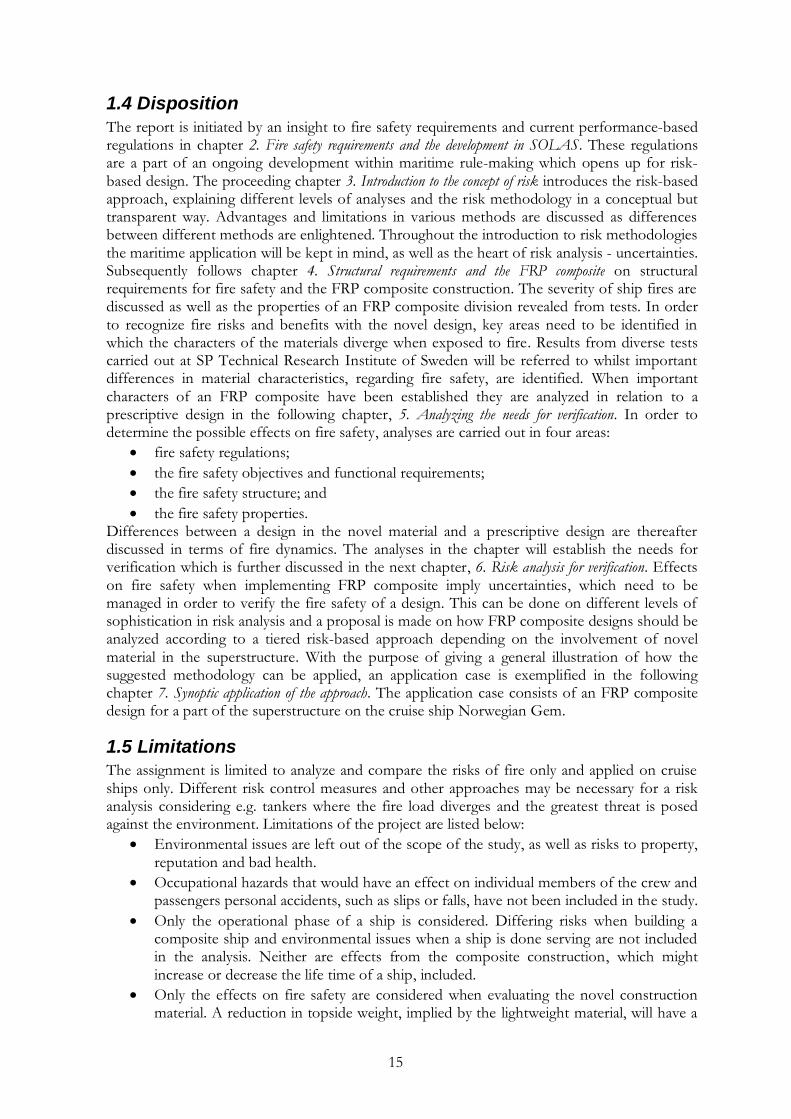
1.4 Disposition
The report is initiated by an insight to fire safety requirements and current performance-based regulations in chapter 2. Fire safety requirements and the development in SOLAS. These regulations are a part of an ongoing development within maritime rule-making which opens up for risk-based design. The proceeding chapter 3. Introduction to the concept of risk introduces the risk-based approach, explaining different levels of analyses and the risk methodology in a conceptual but transparent way. Advantages and limitations in various methods are discussed as differences between different methods are enlightened. Throughout the introduction to risk methodologies the maritime application will be kept in mind, as well as the heart of risk analysis - uncertainties. Subsequently follows chapter 4. Structural requirements and the FRP composite on structural requirements for fire safety and the FRP composite construction. The severity of ship fires are discussed as well as the properties of an FRP composite division revealed from tests. In order to recognize fire risks and benefits with the novel design, key areas need to be identified in which the characters of the materials diverge when exposed to fire. Results from diverse tests carried out at SP Technical Research Institute of Sweden will be referred to whilst important differences in material characteristics, regarding fire safety, are identified. When important characters of an FRP composite have been established they are analyzed in relation to a prescriptive design in the following chapter, 5. Analyzing the needs for verification. In order to determine the possible effects on fire safety, analyses are carried out in four areas:
fire safety regulations;
the fire safety objectives and functional requirements;
the fire safety structure; and
the fire safety properties. Differences between a design in the novel material and a prescriptive design are thereafter discussed in terms of fire dynamics. The analyses in the chapter will establish the needs for verification which is further discussed in the next chapter, 6. Risk analysis for verification. Effects on fire safety when implementing FRP composite imply uncertainties, which need to be managed in order to verify the fire safety of a design. This can be done on different levels of sophistication in risk analysis and a proposal is made on how FRP composite designs should be analyzed according to a tiered risk-based approach depending on the involvement of novel material in the superstructure. With the purpose of giving a general illustration of how the suggested methodology can be applied, an application case is exemplified in the following chapter 7. Synoptic application of the approach. The application case consists of an FRP composite design for a part of the superstructure on the cruise ship Norwegian Gem.
1.5 Limitations
The assignment is limited to analyze and compare the risks of fire only and applied on cruise ships only. Different risk control measures and other approaches may be necessary for a risk analysis considering e.g. tankers where the fire load diverges and the greatest threat is posed against the environment. Limitations of the project are listed below:
Environmental issues are left out of the scope of the study, as well as risks to property, reputation and bad health.
Occupational hazards that would have an effect on individual members of the crew and passengers personal accidents, such as slips or falls, have not been included in the study.
Only the operational phase of a ship is considered. Differing risks when building a composite ship and environmental issues when a ship is done serving are not included in the analysis. Neither are effects from the composite construction, which might increase or decrease the life time of a ship, included.
Only the effects on fire safety are considered when evaluating the novel construction material. A reduction in topside weight, implied by the lightweight material, will have a

16
positive effect on damage stability and thus reduce the risks entailed with collision and grounding. The risks from collision and grounding are of a much greater magnitude than risks caused by fire. The improved damage stability could therefore lead to a total risk reduction for the ship that is greater than the total risks due to fire. This is although not considered.
Fires with origin outside of the composite superstructure will not be considered in the analysis. Engine room fires, the most likely fire to occur, could spread through the funnel and cause a fire in the composite superstructure but are, hence, not included.
The study is limited to analyse how fire safety in FRP composite superstructures can be evaluated through risk analysis. Other parts of risk management are not adequately considered.
Risks associated with intending FRP composite as a part of the hull girder are not taken into account.
Collapse due to fire is kept in mind when it comes to the safety of fire fighting crew working in and around a fire enclosure. Issues with progressive collapses are, however, not taken into consideration in the project.
1.6 Definitions
This field of maritime fire safety favourably uses a certain terminology set out by IMO (International Maritime Organization) and IACS (International Association of Classification Societies Ltd.). In general it is very similar to the normal vocabulary of a fire safety or risk management engineer but one particularly uses quite a few abbreviations. Definitions of most of the used extraordinary expressions can be found in Appendix A. Definitions. Abbreviations are also explained preceding the table of contents.
17
2. Fire safety requirements and the development in SOLAS Below follows a brief orientation of the legal regulations applicable to merchant ships today, SOLAS (International Convention for the Safety of Life at Sea), and especially the layout of fire safety regulations and structural requirements. Different performance-based regulations in SOLAS are then investigated, in particular the reasonably new-founded fire safety regulation for alternative designs and arrangements. Thereafter follows a general overview of the development in the maritime rule-making process. Together with performance-based regulations the new and pro-active approach to constitute regulations introduces an opening for risk-based design.
2.1 IMO and SOLAS
The International Maritime Organization is a specialized agency of the United Nations that regulates safety, environmental concerns, legal matters, technical co-operation, maritime security and the efficiency of shipping through international conventions. IMO is foremost an organization working for inter-governmental congregation amongst the world‟s maritime countries. Accordingly its 300 employees work to coordinate and make the most of the member countries‟ development in maritime safety and environmental protection. The Marine Safety Committee (MSC) with its nine subcommittees is a commission within the IMO in which all member countries are represented and where most of the tangible work is conducted. One of the most important directives for merchant ships on international waters is SOLAS, which was also the first maritime safety convention, adopted in 1929. The convention has thereafter been revised in 1948, 1960, and ultimately in the version SOLAS 1974, which with its updates and amendments still is the regulation of practice. SOLAS consists of twelve chapters comprising issues such as construction, life-saving appliances, safety of navigation, carriage of cargoes and other measures for maritime safety, see IMO (2004a). Fire safety has always been of great concern on merchant ships and for these matters chapter II-2 of the SOLAS conven-tion is essential. It includes fire safety requirements for all ships including specific measures for passenger ships and other classes of ship (IMO 1; Jense, 1999; IMO 2; SOU, 1996; IMO, 2004a).
2.2 Establishment of SOLAS chapter II-2
As a result of several fires on passenger ships in the early sixties, new amendments to improve fire safety on ships were implemented in 1966 and 1967. The principles of the augmented requirements became the foundation of today‟s fire safety regulations in SOLAS and consist of the following general principles (SOU 1996; IMO 2; IMO, 2004a):
division of ships in vertical and horizontal fire zones by thermal and structural boundaries;
spaces where passengers or crew are occupied more than temporarily (mainly accommodation spaces) are separated from other compartments by thermal and structural divisions;
restricted use of combustible materials;
a fire is to be detected in the zone of origin;
contained and extinction of any fire in the space of origin;
evacuation routes are protected, as well as access for fire fighting;
alleviated access to fire-extinguishing equipment;
minimized possibility of ignition of flammable vapour from ship cargo. In consequence of the catastrophe on the Scandinavian Star in 1990 some new amendments, mainly for passenger ships, came into practice in 1994. The challenge of managing hot and toxic smoke was given attention through requirements on means of escape, smoke detection

18
and smoke ventilation. Applicable to all ships were requirements on fire-fighting plans and ready availability of fire-extinguishing appliances. Worth mentioning is also the obligation for all ships to be equipped with automatic sprinkler systems became operational as of 2005. Furthermore all passenger ships are according to SOLAS bound to perform fire and evacuation drills every week (SOU, 1996; IMO, 2004a). The fire safety regulations in SOLAS II-2 consist of 20 regulations divided in parts A-G. The different parts cover regulations of similar character, as specified below:
Part A – General 1 Application 2 Fire safety objectives and functional requirements 3 Definitions
Part B – Prevention of fire and explosion 4 Probability of ignition 5 Fire growth potential 6 Smoke generation potential and toxicity
Part C – Suppression of fire 7 Detection and alarm 8 Control of smoke spread 9 Containment of fire 10 Fire fighting 11 Structural integrity
Part D – Escape 12 Notification of crew and passengers 13 Means of escape
Part E – Operational requirements 14 Operational readiness and maintenance 15 Instructions, on-board training and drills 16 Operations
Part F – Alternative design and arrangements 17 Alternative design and arrangements
Part G – Special requirements 18 Helicopter facilities 19 Carriage of dangerous goods 20 Protection of vehicle, special category and ro–ro spaces
The first part (A) in SOLAS II-2 is of general character for the chapter. One of the first regulations sets out the objectives for the whole chapter and presents functional requirements which are to embody all of the following regulations. Each of those regulations begins with a purpose statement which includes its own objective and functional requirements. Thereafter follow detailed (prescriptive) requirements which settle how to accomplish the previously established safety targets (see figure 2.1). The question is if the fire safety objectives and functional requirements can be achieved in other ways than by complying with prescriptive

19
requirements? With an FRP design for example. The regulations are further outlined when analyzing this issue in chapter 5. Analyzing the needs for verification.
Figure 2.1. Illustration of how the maritime (and many other) regulations are founded1.
2.3 Current performance-based SOLAS-regulations
For decades pro-active and holistic approaches have been employed in other innovative transportation industries, which are also to a large extent driven by safety, but the process in the maritime industry has been slow. Performance-based regulations were pioneered when probabilistic methods were introduced to evaluate ship‟s damage stability in the 1960‟s. Now they have also come to take a place amongst prescriptive requirements for structures, LSA (life-saving appliances) as well as fire protection (Papanikolaou, 2009).
2.3.1 Damage Stability
The fundamental approach of new probabilistic rules on damage stability is to assume that the vessel has been dented, e.g. in a collision. The probability that the incident causes certain
damage, i.e. that the compartments under consideration are flooded, is denoted . This
connects with the probability of the loading conditions, , and the calculated probability that
the vessel will survive in that damaged condition, . The resulting probability that the vessel will sustain a certain damage scenario and survive is calculated and subsequently the average survivability of a range of damage scenarios can be obtained. This value is called the Attained
Index of Subdivision, , and in order for the damage stability to prove sufficiently safe the
value of is required not to be lesser than the Required Index of Subdivision, . The
formulation of is determined by the IMO and is assumed to reflect some measure of safety.
Index is supposed to reflect the average probability of a vessel to survive collision damage
and flooding in seaway, but recent research results indicate that the formulation of seriously underestimates i.e. the survivability of cruise ships. Moreover, the uncertainties from
the formulation of make it very hard to distinguish the actual safety level of the regulations (Papanikolaou, 2009; Marine, 2009; Vassalos & Jasionowski, 2007; Papanikolaou & Eliopoulou, 2008; Vassalos et al., 2005).
2.3.2 Regulation 17
Even though there has been an alternative to prescriptive fire safety design through SOLAS Chapter I/5 for some time it was not until 2002 that a convenient regulation entered into force. The provisions in Regulation 5 are rarely employed since the approval is based on the
1 Markus Abrahamsson, Lund University. Lecture 18 February 2010 in the class “Risk Management Process” (VBR171) at Lund University.
Objective
Function
Form
Why?
What?
How?
20
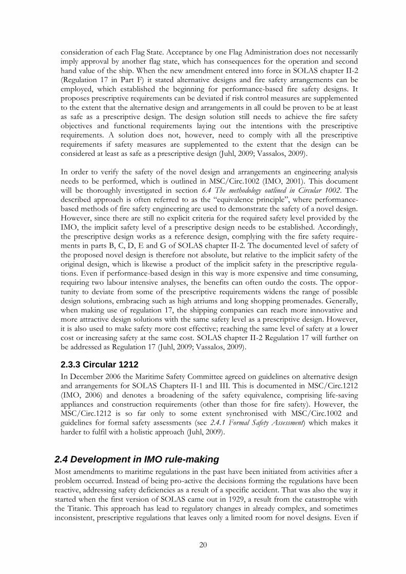
consideration of each Flag State. Acceptance by one Flag Administration does not necessarily imply approval by another flag state, which has consequences for the operation and second hand value of the ship. When the new amendment entered into force in SOLAS chapter II-2 (Regulation 17 in Part F) it stated alternative designs and fire safety arrangements can be employed, which established the beginning for performance-based fire safety designs. It proposes prescriptive requirements can be deviated if risk control measures are supplemented to the extent that the alternative design and arrangements in all could be proven to be at least as safe as a prescriptive design. The design solution still needs to achieve the fire safety objectives and functional requirements laying out the intentions with the prescriptive requirements. A solution does not, however, need to comply with all the prescriptive requirements if safety measures are supplemented to the extent that the design can be considered at least as safe as a prescriptive design (Juhl, 2009; Vassalos, 2009). In order to verify the safety of the novel design and arrangements an engineering analysis needs to be performed, which is outlined in MSC/Circ.1002 (IMO, 2001). This document will be thoroughly investigated in section 6.4 The methodology outlined in Circular 1002. The described approach is often referred to as the “equivalence principle”, where performance-based methods of fire safety engineering are used to demonstrate the safety of a novel design. However, since there are still no explicit criteria for the required safety level provided by the IMO, the implicit safety level of a prescriptive design needs to be established. Accordingly, the prescriptive design works as a reference design, complying with the fire safety require-ments in parts B, C, D, E and G of SOLAS chapter II-2. The documented level of safety of the proposed novel design is therefore not absolute, but relative to the implicit safety of the original design, which is likewise a product of the implicit safety in the prescriptive regula-tions. Even if performance-based design in this way is more expensive and time consuming, requiring two labour intensive analyses, the benefits can often outdo the costs. The oppor-tunity to deviate from some of the prescriptive requirements widens the range of possible design solutions, embracing such as high atriums and long shopping promenades. Generally, when making use of regulation 17, the shipping companies can reach more innovative and more attractive design solutions with the same safety level as a prescriptive design. However, it is also used to make safety more cost effective; reaching the same level of safety at a lower cost or increasing safety at the same cost. SOLAS chapter II-2 Regulation 17 will further on be addressed as Regulation 17 (Juhl, 2009; Vassalos, 2009).
2.3.3 Circular 1212
In December 2006 the Maritime Safety Committee agreed on guidelines on alternative design and arrangements for SOLAS Chapters II-1 and III. This is documented in MSC/Circ.1212 (IMO, 2006) and denotes a broadening of the safety equivalence, comprising life-saving appliances and construction requirements (other than those for fire safety). However, the MSC/Circ.1212 is so far only to some extent synchronised with MSC/Circ.1002 and guidelines for formal safety assessments (see 2.4.1 Formal Safety Assessment) which makes it harder to fulfil with a holistic approach (Juhl, 2009).
2.4 Development in IMO rule-making
Most amendments to maritime regulations in the past have been initiated from activities after a problem occurred. Instead of being pro-active the decisions forming the regulations have been reactive, addressing safety deficiencies as a result of a specific accident. That was also the way it started when the first version of SOLAS came out in 1929, a result from the catastrophe with the Titanic. This approach has lead to regulatory changes in already complex, and sometimes inconsistent, prescriptive regulations that leaves only a limited room for novel designs. Even if

21
technical solutions to a problem exist, equivalent to those prescribed, the development in regulations has been unable to cope with the rapid technological development and left novel designs out of range. In that sense it would be more useful if there were specific safety objectives and functional requirements to be met, covering both technical and operational aspects. This methodology, often referred to as Goal-Based Standards (GBS), has been on the IMO agenda for some years and there is a clear tendency that this is the impending approach (Skjong, 2009; Juhl, 2009; Papanikolaou, 2009).
2.4.1 Formal Safety Assessment
Formal Safety Assessment (FSA) is a methodology adopted by the IMO as interim guidelines in the rule-making process. The guidelines for FSA were first adopted in 2002 (IMO, 2002b) and have also been updated in 2007 (IMO, 2007). It is a systematic approach to assess risks and benefits associated with shipping activities and for evaluating measures to prevent or reduce such risks (Pålsson & Torstensson, 1998). FSA builds on the basis for many other methods of risk assessment and comprises the following five steps (IMO, 2007):
1. identification of hazards – recognition of typically dangerous events in the interdependent systems;
2. risk analysis – identification and evaluation of events or scenarios that could lead to the hazards;
3. risk control options – proposition of different measures to deal with the identified risks;
4. cost benefit assessment – evaluation of pros and cons with the identified risk control options and their effect on risks; and
5. recommendations for decision-making – transparent documentation of the above systematic approach and the summarized conclusions.
IMO makes use of this tool to verify the effectiveness of proposed rules and regulations in order to find out what might go wrong, as opposed to what went wrong. In that respect the FSA-methodology reveals itself to focus on pro-active accident prevention, unlike the previous reactive rule-making process that focused on avoiding accident recurrence (Skjong, 2009; Juhl, 2009).
2.4.2 Moving from compliance to safety
The FSA guidelines are a great innovation in maritime safety requirements, working against the earlier principles of detailed and describing norms. Instead the FSA-methodology moves towards a development of rules guided by frameworks and holistic objectives. Such a regula-tion also puts a clear safety responsibility on the operators and shipping companies. They are also the ones that ultimately have the practical abilities to ensure the safety of the ships. Today‟s safety culture only implies the ship companies to, without further considerations on safety, make sure they meet present requirements (compliance culture). The new approach to rule-making can eventually contribute to a better safety culture, forcing shipping companies to be able to explain why and how a chosen solution is adequate from a safety point of view (SOU, 1996). Instead of dealing with safety as a simplistic add-on in the design process the methodology invokes shipping companies to involve safety as a key aspect with serious economic implications (Sames, 2009). In 1992 a committee established by the British House of Lords suggested a “Safety Case” methodology as the ideal reform in maritime safety. A Safety Case consists of a documen-tation of all reviews, analyses and evaluations that have taken place for a particular project. In lack of the necessary foundation for quantitative evaluations of risks and tools for describing the effects in relation to costs the approach was explained unrealistic (SOU, 1996). The IMO
22
guidelines for FSA, however, describe a number of tools to eventually achieve a concise evaluation of inherent risks. The safety level in any given project, design, operation or regula-tion can then be estimated. Therefore the FSA in many cases ends up as a Safety Case for the rules and regulations (Juhl, 2009). This development towards utilizing risk analyses for ships was insisted by the Swedish Committee of Maritime Safety many years ago, with the intention to win general accession for the Safety Case methodology within the shipping industry (SOU, 1996). The principles in the FSA-methodology awoke a development within the IMO to establish GBS, a regulatory framework based on risk-assessments. Drawing on the so-called Safety Level Approach, introduced at MSC 81/6/2, the concept makes use of the IMO approach to risk acceptance to define a level of acceptable reliability at any level (ship, ship function, system, subsystem or component) (Sames, 2009).
2.4.3 Explicit criteria
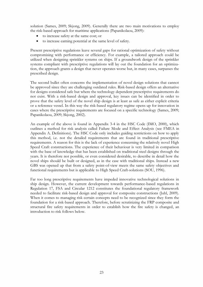
The FSA-approach, moving towards a safety culture instead of a compliance culture, implies that quantitative tools are utilized to make the safety of designs explicit. When many assessments have been submitted to the IMO it will also tend to result in making the safety objectives of regulations explicit. The emerging tendency at the IMO implies an indirect goal-based approach where high level goals (objectives and functional requirements) will be used to verify prescriptive requirements in codes, rules and regulations. A ship will then be verified to comply with prescriptive requirements but could also be verified against the rules for these requirements; the high level goals. In order for that to be possible the high level rules for the prescriptive rules need to be explicit (Skjong, 2009). As an example Circular 1002 describes a performance-based methodology with the goal to prove the fire safety in an alternative design and arrangements to be as safe as or safer than what is required by the prescriptive requirements. Quantifying the safety level of an inno-vative solution is of little value without acceptance criteria. Except from risk acceptance criteria at ship level there are currently no risk measures provided by the IMO to represent prescriptive requirements at any level. Acceptance criteria for risks associated with fire safety therefore need to be established originating from the prescriptive design solution. The implicit safety in current prescriptive requirements will however be disclosed each time such a design analysis is performed and imply a step forward for GBS (Skjong, 2009). It should yet be recognized that the existing prescriptive requirements are not necessarily as objective and safe as one would hope (Juhl, 2009). Because of the way existing figures, numbers and measures are chosen, as a reaction to incidents, the safety of prescriptive requirements is heterogeneous. The unknown rule-making process is a weakness in current prescriptive rules and implies that the priority of the risk controlling measures may be far from optimum (Skjong, 2002). The uncertainties in prescriptive requirements make it hard to distinguish the explicit level of safety in rules and regulations but it is evident that IMO will restructure the resgulations in this way (Sames, 2009). When explicit criteria are settled upon they will set goals (risk acceptance criteria) for the design solutions while prescriptive require-ments will be seen as means to achieve those goals. Technically the new approach opens up for any design solution that can be documented to achieve the goals which heralds oppor-tunities for risk-based designs (Skjong, 2009).
2.4.4 An opening for risk-based design
“The future is risk-based” was proclaimed recently at the IMO (Vassalos, 2009). Risk-based design is principally associated with introducing the rules, which are used to justify the prescriptive codes, rules and regulations, directly in the design process for each innovative
23
solution (Sames, 2009; Skjong, 2009). Generally there are two main motivations to employ the risk-based approach for maritime applications (Papanikolaou, 2009):
to increase safety at the same cost; or
to increase earning potential at the same level of safety. Present prescriptive regulations leave several gaps for rational optimization of safety without compromising with performance or efficiency. For example, a tailored approach could be utilized when designing sprinkler systems on ships. If a groundwork design of the sprinkler systems compliant with prescriptive regulations will lay out the foundation for an optimiza-tion, the approach grants a design that never operates worse but, in many cases, surpasses the prescribed design. The second bullet often concerns the implementation of novel design solutions that cannot be approved since they are challenging outdated rules. Risk-based design offers an alternative for designs considered safe but where the technology dependent prescriptive requirements do not exist. With a risk-based design and approval, key issues can be identified in order to prove that the safety level of the novel ship design is at least as safe as either explicit criteria or a reference vessel. In this way the risk-based regulatory regime opens up for innovation in cases where the prescriptive requirements are focused on a specific technology (Sames, 2009; Papanikolaou, 2009; Skjong, 2002). An example of the above is found in Appendix 3-4 in the HSC Code (IMO, 2000), which outlines a method for risk analysis called Failure Mode and Effect Analysis (see FMEA in Appendix A. Definitions). The HSC Code only includes guiding restrictions on how to apply this method, i.e. not the detailed requirements that are found in traditional prescriptive requirements. A reason for this is the lack of experience concerning the relatively novel High Speed Craft constructions. The experience of their behaviour is very limited in comparison with the base of knowledge that has been established on traditional steel designs through the years. It is therefore not possible, or even considered desirable, to describe in detail how the novel ships should be built or designed, as in the case with traditional ships. Instead a new GBS was opened up that from a safety point-of-view meets the same safety objectives and functional requirements but is applicable to High Speed Craft-solutions (SOU, 1996). Far too long prescriptive requirements have impeded innovative technological solutions in ship design. However, the current development towards performance-based regulations in Regulation 17, FSA and Circular 1212 constitutes the foundational regulatory framework needed to facilitate risk-based design and approval for composite constructions (Juhl, 2009). When it comes to managing risk certain concepts need to be recognized since they form the foundation for a risk-based approach. Therefore, before scrutinizing the FRP composite and structural fire safety requirements in order to establish how the fire safety is changed, an introduction to risk follows below.

24

25
3. Introduction to the concept of risk A way of comparing designs that have been implemented for some years is to compare statistics. Statistics give an image of something that could be called the result or the effect of a design or a new amendment. An interesting comparison is for example to investigate the results from implementing the sprinkler amendment to SOLAS and how this affected the number of fatalities. However, the current comparison needs to be carried out before the innovative design is put into practice. If there would be a way of estimating the effects of the novel design, this could be used to compare with statistics from similar vessels, representing the prescriptive regulations. This is what the risk-based approach aims to accomplish. By means of a risk-based methodology it is possible to estimate the risks due to fire through extrapolation from the construction and knowing the characteristics of the materials and their behaviour in case of fire. The approach is obviously bound with uncertainties, which need to be examined thoroughly. However, uncertainties are also contributed from the statistical representation of prescriptive designs. Even if statistical information is often considered to be “the truth” it should be handled with care since the figures are always changing and bound with great uncertainties. These and other uncertainties are the mere reason to the existence of risk. Usage of the term risk and how it is used in risk management is presented below, followed by an orientation to the elements of risk management. Thereafter follows a review of methods for risk analysis and an insight to how these manage different kinds of uncertainties. An actualized uncertainty is the diversity regarding safety cultures and management systems. This is overviewed in relation to risk management before the ending section of this chapter briefly investigates what actually is “the true” risk.
3.1 Risk is inevitable
Risk is a term, utilized with the intention to make decisions in an organization without compromising security, health and environment. Depending on how you view the world around you, management of risks might be of varying importance. However, applying the mindset in the quote below evidentially makes risk management significant. ”--- we are not able in life to avoid risk but only to choose between risks.” (Kaplan & Garrick, 1981, p. 11) It is impossible to remove risk completely but we are able to choose between risks, and naturally prefer the less “risky” options – but to what cost? As an example, risk often stands in contrast to economical cost, which is also the case in traffic. Say there are 10,000 statistical fatalities in traffic accidents in a country. Avoiding the first 10 will be relatively inexpensive in comparison with preventing the last 10 when 9990 are already saved. To what limit should society be willing to pay for saving another life? Speaking of lives and fatalities with a risk-based approach it is crucial to understand that lives are used in a statistical sense. Life is priceless and it is inevitably controversial to put a price on it. Although, in order to get a figure on the risks associated with a certain activity and to optimize the allocation of resources it is sensible to make use of this very valuable constituent. Since risk cannot be excluded, the cost for saving the last life will be unreasonably and unaccep-tably high, if possible to save at any cost. So how far should society be willing to go in order to save another life; £ 105, 106 or 107? The question does not have to be answered to understand that risk management is necessary in order to minimize risks to life, environment and property. On the other hand, the question is in a way already answered by the manner resources are allocated in the social order. The goal with risk management is to do it better by minimizing the number of unforeseen and uncontrollable events.

26
3.2 On the definition of risk
The need to evaluate and compare risks applies to many different fields. Risks are discussed in terms of business risk, social risk, economic risk, safety risk, investment risk, military risk, political risk, etc. As a consequence of the many different scenes the terminology is differential. Particularly that applies to the foundational term “risk”. Many people use the term as equal to “likelihood” and some understand something “risky” if the consequences are substantial if an accident occurs, e.g. an airplane crash. It is, however, essential to agree on a uniform and consistent usage of words if the subject is to be intelligible (Kaplan & Garrick 1981). The COSO (Committee of Sponsoring Organizations of the Treadway Commission) guidelines for Enterprise Risk Management define risk as “the possibility that an event will occur and adversely affect the achievement of objectives” (COSO, 2004). This definition focuses on the events and their probability rather than the consequences of the events (Fox, 2010). The ISO (International Organization of Standards) recently came out with a new standard to provide comprehensive principles and generic guidelines on risk management applicable to any type of risk, organization or potential level of an enterprise (ISO, 2009). The new guidelines go under the name ISO 31000 and define risk as the “effect of uncertainty on objectives”. This definition allows a wider understanding of risk than COSO and has more focus on uncertainty. This focus on the effects of uncertainty facilitates a framework to consider the interdependent consequen-ces of an event occurring in a system (Fox, 2010). Both the COSO and the ISO definitions of “risk” are founded on the existence of objectives or a policy describing best practice and undesired events. Because if there is no policy or law declaring what should be achieved there is nothing that could prevent goals to be realized and nothing defining misbehaviour, i.e. there is no risk. This is indeed a fundamental principle not getting any younger.
“And where there is no law there is no transgression.” (Romans 4:15)
Managing risk is really all about managing uncertainties. Both the COSO and the ISO defini-tion seem to contribute to this perspective of risk. Together the definitions state that there are probabilities, known and unknown, of the occurrence of events causing set objectives not to be achieved. In a way risk can be said to be equal to uncertainty and some sort of loss or damage that might be received (Kaplan & Garrick, 1981). A technical definition of risk in agreement with the descriptions above is something that Kaplan & Garrick (1981) suggest to name “triplets”. A triplet answers the following three questions:
What can happen? (i.e., what can go wrong?)
How likely is it that it will happen?
If it does happen, what are the consequences? In other words, the triplet describes a scenario, the probability of the scenario and the outcome related to the scenario quantitatively. In mathematical terms the risk contribution from a
specific scenario would then be written as:
where
is a scenario identification or description;
is the probability of that scenario; and
is the consequence or the measure of damage from that scenario.

27
Adding up all scenarios we can think of accumulates the total risk, which becomes a set of triplets:
. (Kaplan & Garrick, 1981) The risk is, hence, not only the sum of all risk contributions in one figure, but the whole table of scenarios with associated likelihoods and consequences. This perspective of risk has proven to be comprehensive and logical to the industry, especially when handling risks quantitatively for technical applications. The process of appraising and managing risk is further outlined subsequently.
3.3 Risk management and risk assessment
Risk management is a collecting name for systematically accounting for, analyzing and preven-ting risks within a project or organization. The goal with risk management is to take greater control over the identified risks and to minimize the number of unforeseen and uncontrollable events (Kolluru et al., 1996). Sound risk management weighs the many different attributes of a decision and develops risk control options in order to advocate the most appropriate course of action. In this process the risk assessment is but one source of information since decision makers may also consider e.g. politics, economics, ethics, law, competing risks or equity (Kolluru et al., 1996). This is called a risk-informed approach (see 3.5 Risk evaluation). Risk management principles are used daily in most companies, agencies and organizations and are nothing out of the ordinary. The question is to what extent they are documented and made formal in the considered business. Since most applications of risk management in maritime decisions have been informal and unsystematic they cannot be replicated and will not provide a body to build on in the future (Transportation Research Board, 2000). A systematic base for risk management was developed by the International Electrotechnical Commission (IEC) which has become acknowledged in many areas. The approaches outlined for Formal Safety Assessment (see 2.4.1 Formal Safety Assessment) and performance-based regulations (see 2.3 Current performance-based regulations) can also be considered to be in line with this metho-dology. It consists of a process comprising risk assessment and risk reduction/control (see figure 3.1). The present study is focused on the risk assessment and in particular the risk analysis.
Figure 3.1. The elements of risk management (adapted from IEC, 1995).
Risk analysis Scope definition
Hazard identification
Risk estimation
Risk reduction/control Decision making
Implementation
Monitoring
Risk evaluation
Risk tolerability decisions
Analysis of options
Risk assessment
Risk management
28
As a scientific support to risk management and policy decisions, the risk assessment should be based on systematic management and evaluation of technologies (Elmer, 2000). The goal for the assessment is to estimate specific risks and benefits before the basic phenomena are fully understood and to rank risk reduction options on a cost-effectiveness basis (Paté-Cornell, 1996). The risk assessment acknowledges the ever-present existence of uncertainty in decision-making and an important feature is therefore to evaluate uncertainties and establish whether the knowledge base is sufficient to support decision-making (see 3.6 Uncertainty) (Bridges, 2000). Below follows more detailed insight to the elements of risk assessment, in particular the risk analysis.
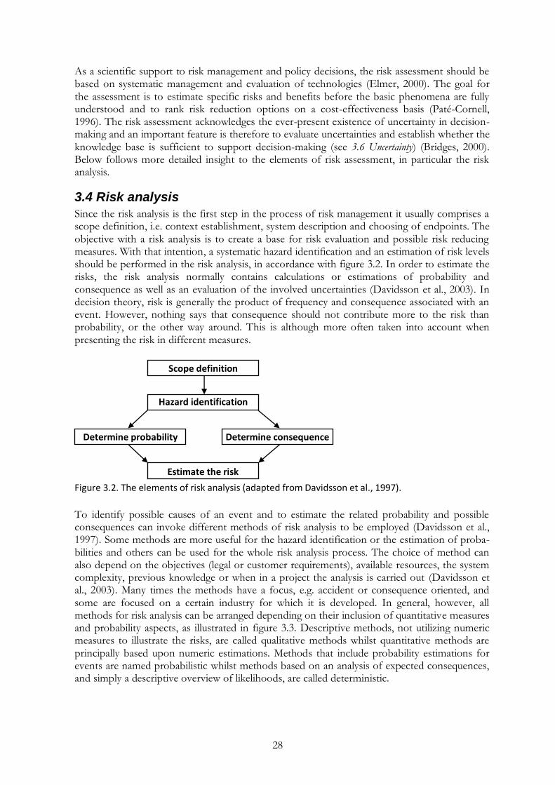
3.4 Risk analysis
Since the risk analysis is the first step in the process of risk management it usually comprises a scope definition, i.e. context establishment, system description and choosing of endpoints. The objective with a risk analysis is to create a base for risk evaluation and possible risk reducing measures. With that intention, a systematic hazard identification and an estimation of risk levels should be performed in the risk analysis, in accordance with figure 3.2. In order to estimate the risks, the risk analysis normally contains calculations or estimations of probability and consequence as well as an evaluation of the involved uncertainties (Davidsson et al., 2003). In decision theory, risk is generally the product of frequency and consequence associated with an event. However, nothing says that consequence should not contribute more to the risk than probability, or the other way around. This is although more often taken into account when presenting the risk in different measures.
Figure 3.2. The elements of risk analysis (adapted from Davidsson et al., 1997).
To identify possible causes of an event and to estimate the related probability and possible consequences can invoke different methods of risk analysis to be employed (Davidsson et al., 1997). Some methods are more useful for the hazard identification or the estimation of proba-bilities and others can be used for the whole risk analysis process. The choice of method can also depend on the objectives (legal or customer requirements), available resources, the system complexity, previous knowledge or when in a project the analysis is carried out (Davidsson et al., 2003). Many times the methods have a focus, e.g. accident or consequence oriented, and some are focused on a certain industry for which it is developed. In general, however, all methods for risk analysis can be arranged depending on their inclusion of quantitative measures and probability aspects, as illustrated in figure 3.3. Descriptive methods, not utilizing numeric measures to illustrate the risks, are called qualitative methods whilst quantitative methods are principally based upon numeric estimations. Methods that include probability estimations for events are named probabilistic whilst methods based on an analysis of expected consequences, and simply a descriptive overview of likelihoods, are called deterministic.
Scope definition
Determine probability
Hazard identification
Determine consequence
Estimate the risk

29
Figure 3.3. A presentation of how some of the most common risk analysis methods differ on a two-
dimensional scale.
Qualitative methods are often adapted to certain industries, such as the chemical process industry, and result in descriptions of events under different circumstances (Nilsson, 2003). The main use for qualitative methods is in the hazard identification. Qualitative elements are, however, included in all methods for risk analysis. Except the hazard identification, the system delimitation and the way risks are modelled are typical qualitative processes of a risk analysis (Davidsson et al., 2003). If the purpose with the risk analysis is limited to identify hazards or to compare risk on an ordinal scale, then qualitative methods can be sufficient for the whole analysis (Nystedt, 2000; Davidsson et al., 2003). Hybrid methods are similar to qualitative methods but more detailed in structure and contain some sort of rating of probabilities and consequences (Nilsson, 2003; Nystedt, 2000). Common hybrid methods for risk analysis are so called index methods, e.g. Gretener or NFPA 101M, that include some quantitative measures when calculating risk. An advantage with utilizing simpler methods for risk analysis is that the results can be easily presented. Methods without inclusion of probabilities, but where consequences are quantified, are called deterministic. The outcomes from possible events are analyzed and e.g. the 80 % or 95 % of the worst case, or the worst credible case, is chosen as the dimensioning scenario (Nilsson, 2003). The advantage with an analysis only of consequences is the limited complexity, both when carrying out the analysis and when it is communicated (Davidsson et al., 2003). However, basing a design on worst case scenarios can lead to a waste of resources trying to design for very improbable events. Moreover, because of the uncertainties when deciding on design scena-rios the actual safety level will be implicit and unknown for further comparison (Davidsson et al., 2003). A numeric estimation of risks invokes quantification of both probabilities and consequences, i.e. a probabilistic method. A QRA (Quantitative Risk Assessment) attempts to quantify risks to human life in and around a facility. PRA‟s (Probabilistic Risk Assessments) reminds of a QRA but are more detailed and focused on the triggering events (Nilsson, 2003). Uncertainties are included in all methods for risk analysis but when performing a probabilistic risk analysis they become more transparent. Especially when estimating the probability of an event or evaluating the limits of calculation models (Nystedt, 2000).
30
3.5 Risk evaluation and the current approach
Say a risk analysis established the risk of a considered ship or system design is RD and the acceptable risk, represented by a prescriptive ship design or explicit criteria, is denoted RA. A design that needs to be as safe as or safer than a prescriptive design in order to be accepted by the approval authority must then accomplish the following relation:
.
This approach to evaluate fire safety is said to be risk-based. From a regulatory approach, risk-
based decision-making should solely be based on the numerical result of a risk assessment, . (Callan, 1998). However, there is not a coherent usage of the term “risk-based” and even though many use the term risk-based when it comes to ship design, the IMO does not endorse a true risk-based approach. Being fastidious, the utilized approach is rather risk-informed, where insights from risk assessments are heeded in conjunction with important design and operational factors (Callan, 1998). Furthermore, decision-makers may also consider e.g. politics, economics, ethics, law, competing risks or equity (Kolluru et al., 1996). The IMO demonstrates the risk-informed approach by having established risk evaluation criteria instead of risk accep-tance criteria. Even if the calculated risk is below the generally accepted criteria, decisions may still be open for evaluation. Hence, when using the term “risk-based” in this field, and also in this report, what is really meant is risk-informed. When it comes to acceptability of risks and reaching an optimal decision, value judgements are evidently involved (Elmer, 2000). The risk assessment should, however, be objective and show a clear separation between facts and value judgements. Even legitimate risk aversion (see 3.8 Risk perception) that may eventually form a decision should be kept out of the assessment since it runs counter to manage meaningful risk ranking (diverse degrees of conservatism in different situations will lead to incomparable results) (Paté-Cornell, 1996). A systematic process that ensures objectivity when deciding on risk levels is therefore necessary to guarantee that standards for evidence are objective and scientific (Elmer, 2000).
The established risk in a risk analysis, , is supposed to represent the total risk from all kinds of contributing hazards but many times risk presentations are delineated to consider a certain category of risk, e.g. human safety, environment or property (Sames, 2009). Acceptable risks regarding property and business are seldom regulated by authorities, but by the operator or shipping company, and are outside the scope of this study. Damage to the environment and threats to human safety are usually separated into different risk measures because of the complex matter of combining them. To facilitate a joint assessment there is need for a common ground when it comes to evaluation. In this sense monetary terms are deemed insufficient. In this study the safety of passengers and crew has been chosen as endpoint for evaluating conse-quences. When doing so a decision has to be made of what should be considered an adverse consequence. Since different levels of injury and health effects are complex to discern, the most common endpoint when evaluating the consequences of a scenario is the number of expected fatalities. Choosing human life as the measure of consequences is relatively well delineated and will be the basis in this study. The number of fatalities can also be considered to be in propor-tion with the number of injured and will thus be representing for the occurring event even if injuries are not taken into account explicitly. No matter whether environmental or health issues are distinguished, the inherent risk of a ship design is generally the sum of risk contributions from three categories of accidents: collisions, groundings and fires (Sames, 2009). The hazardous result of a collision or grounding is mainly flooding, which invokes a study of the ships‟ damage stability (2.3.1 Damage Stability). This study
31
is, however, delineated to consider the partial risk contribution from fire. The approach to do so is risk-based (or risk-informed). The main innovation when applying this approach is that the focus will be on uncertainties. Risk analysis is really all about evaluating uncertainties (Lundin, Delin & Johansson, 2005). If technologies and circumstances were fully understood there would be no need for risk analysis; the outcome would be certain and there would be no risk. However, no matter if a decision is made upon prescriptive requirements or as a result of a complex probabilistic risk analysis uncertainties will be included to some extent (see 6.1 Uncertainties in a ship design). The overall difference between methods for risk analysis can be described in how thoroughly they investigate uncertainties. Methods of different sophistication take uncertainties into account on different levels of the analysis. This will be further investi-gated in section 6.3 Managing uncertainties on different levels in risk analysis but an introduction to uncertainties follows subsequently.
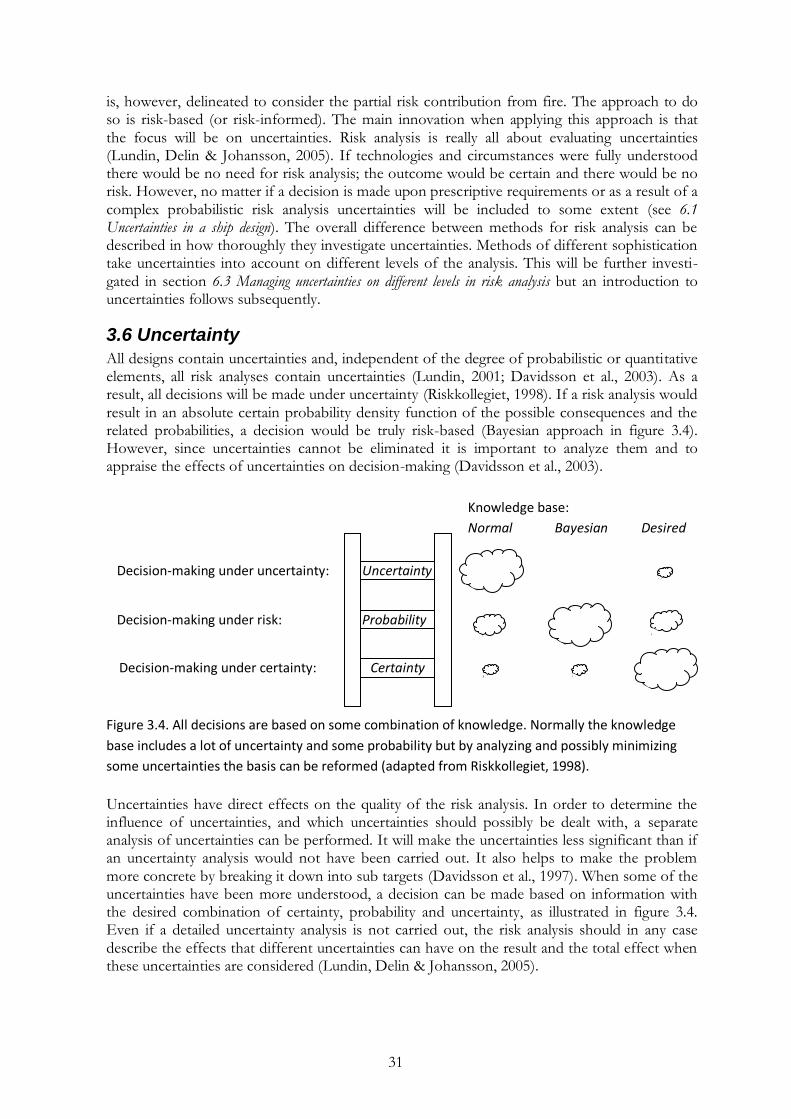
3.6 Uncertainty
All designs contain uncertainties and, independent of the degree of probabilistic or quantitative elements, all risk analyses contain uncertainties (Lundin, 2001; Davidsson et al., 2003). As a result, all decisions will be made under uncertainty (Riskkollegiet, 1998). If a risk analysis would result in an absolute certain probability density function of the possible consequences and the related probabilities, a decision would be truly risk-based (Bayesian approach in figure 3.4). However, since uncertainties cannot be eliminated it is important to analyze them and to appraise the effects of uncertainties on decision-making (Davidsson et al., 2003).
Figure 3.4. All decisions are based on some combination of knowledge. Normally the knowledge
base includes a lot of uncertainty and some probability but by analyzing and possibly minimizing
some uncertainties the basis can be reformed (adapted from Riskkollegiet, 1998).
Uncertainties have direct effects on the quality of the risk analysis. In order to determine the influence of uncertainties, and which uncertainties should possibly be dealt with, a separate analysis of uncertainties can be performed. It will make the uncertainties less significant than if an uncertainty analysis would not have been carried out. It also helps to make the problem more concrete by breaking it down into sub targets (Davidsson et al., 1997). When some of the uncertainties have been more understood, a decision can be made based on information with the desired combination of certainty, probability and uncertainty, as illustrated in figure 3.4. Even if a detailed uncertainty analysis is not carried out, the risk analysis should in any case describe the effects that different uncertainties can have on the result and the total effect when these uncertainties are considered (Lundin, Delin & Johansson, 2005).
Decision-making under uncertainty: Uncertainty
Decision-making under certainty: Certainty
Decision-making under risk: Probability
Knowledge base:
Normal Bayesian Desired

32
There are several general approaches to classify uncertainties (Paté-Conell, 1996; Lundin, Delin & Johansson, 2005; Kammen & Hassenzahl, 1999; Riskkollegiet, 1998). Most commonly uncertainties are although divided into the following two classes (Paté-Conell, 1996):
random error; and
lack of knowledge. Random error, or stochastic uncertainty, is not possible to reduce. It derives from natural variation, e.g. in temperature or wind speed, and can be described by rolling an honest dice. You know that the probability of getting any number is 1/6 and that the most likely sum of two random faces is 7. Because of the natural variation you are although unaware of the number that will come up (Kammen & Hassenzahl, 1999). Knowledge uncertainties spring from lack of information concerning a system, which leads to not understanding its complexity. It can have to do with shortcomings when modelling an event or with insufficient data. Using a dice to exemplify this uncertainty it can have to do with not knowing if the dice is honest or not. Before rolling the dice the probability 1/6 is given every number, not knowing if the dice is weighed, dented or if a number is painted on more than one face. After rolling it 10,000 times the probability of getting any number is still 1/6, i.e. the dice is honest and the probability is unchanged, but the knowledge uncertainty has decreased (Riskkollegiet, 1998). This uncertainty can in other words be reduced by more and better observations. Even the most detailed risk analysis contains limitations, and uncertainties are involved throughout the whole risk analysis process (see figure 3.2). The uncertainties entering when determining the probabilities of events are often perceived as the dominating source of error. Generally data is insufficient and not fully relevant for the particular events. One reason can be that the aging data does not comprise updates in legislation and novel technology. The statis-tical base can be supplemented with expert judgements, but to the “cost” of involving subjective values and simplifications (Davidsson et al., 2003). When determining consequences of events, uncertainties depend on how systematic and detailed the approach is. Models used when estimating the consequences and experience in the expert group are also sources of uncertainties (Davidsson et al., 2003). In the hazard identification uncertainties are also many times linked with the used method, how detailed it is performed and the competence of the expert group examining the systems. Lack of routines, knowledge and experience is a drawback which needs to be considered when designing a ship in a novel material. The uncertainties can result in missing or wrong scenarios when identifying hazardous events, which can have great effects on the proceeding analysis (Davidsson et al., 2003). In common for all steps of the risk analysis is that many simplifications are made in order to model complicated systems. Much because of the complex matter of assessing the impact of human behaviour when modelling, they tend to be focused on machines and technical components. Leaving the effects of organi-zational aspects, safety management systems and operator actions out of the scope of the risk assessment will, on the other hand, not reduce uncertainties. This highly topical subject is not in the centre of the scope of the present study but has been reviewed because of its current interest. Below follows a brief introduction to how organizational safety culture and human error can have an effect on maritime risks.
3.7 Safety culture and human error
The fact that human error is a major contributory factor in maritime accidents has been known for a long time and has inevitably resulted in making ship management invoke a “find the victim ideology”. Even though the scientific world put down the concept of “accident prone-ness” quite some time ago (see Shaw & Sichel, 1971) the principles still remain in many indus-tries. Reason (1990) chooses to leave, not the fact that the errors are caused by humans, but the focus on giving operator actions the whole blame for an error, as he writes:
33
“Rather than being the main instigators of an accident, operators tend to be the inheritors of
system defects created by poor design, incorrect installation, faulty maintenance, and bad
management decisions. Their part is usually that of adding the final garnish to the lethal brew
whose ingredients have already been long in cooking.” (Reason, 1990, p. 173)
This perspective gives a different approach to human error and claims that what the operators frequently inherit and are blamed for are the consequences of what is called latent failures (Wahlström et al., 1987; Jense, 2005; Turner & Pidgeon, 1997).
3.7.1 Organization and management
Latent failures often stem from organization and management inadequacies. For shipping companies to get involved in and take responsible for organizational and management safety matters IMO added The International Safety Management Code (ISM Code) as a chapter to SOLAS in 1994. The progress with the code was initiated already after the catastrophe with Herald of Free Enterprise in 1987 and impelled further after the catastrophe with the Scandinavian Star in 1990, both accidents to a large extent caused by organizational safety ineptitude. The code, with the overall objective; to attain maritime safety and protection for people, environ-ment, and property, concerns all types of ships. It elucidates the responsibility situation between ship commanders and company management along with great emphasis on an engaged land-based organization and management. In a way the ISM Code works as an administrative tool for shipping companies on how to organize safety, obligating implement-tation, certification and control of the safety systems covered (Turner & Pidgeon, 1997; SOU, 1996; IMO 4; Jense, 2005). Even though the ISM Code has been effective some ten years back there are still some struggles with creating a safety culture within organization management and amongst crew. The returning conception that a safety mindset amongst crew, or a safety culture, can be actively created by management should be recognized with some criticism. Each form of culture affecting safety and risk is to a large extent socially constructed, with subjective elements and relativism. Another point of criticism touches the fact that safety culture is a dynamic phenomenon that continually is reformed and shaped by people‟s interactions and group specific processes. Even though safety culture is a complex social phenomenon that hardly can be moulded by formal policies, the degree of management commitment and engagement is yet important. What is more important, however, is an environment that encourages active engagement amongst crew and an atmosphere that is open for their viewpoints (Akselsson, 2008; Jense, 2005; Reason, 1990).
3.7.2 Human error in a safety culture
One side of the desired safety culture that becomes topical when looking into another common latent failure, technical design flaws, is the management attitude against human error. In order to facilitate a deep defence against imperfections, reports of own mistakes and “near misses” must be rewarding. If reprimands await the crew that reports mistakes or misconceptions, the most valuable source of information, when it comes to finding weak-nesses and illogicalities in the design, will be lost. As mentioned above, human errors are common, about 80 % of all incidents are said to be caused by human error. That has in many cases caused the reversed effect and created a resilient “find the guilty ideology” which gives rise to the complete opposite response amongst crew (Akselsson, 2008; Jense, 2005; Reason, 1990).
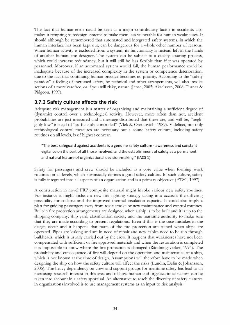
34
The fact that human error could be seen as a major contributory factor in accidents also makes it tempting to redesign systems to make them less vulnerable for human weaknesses. It should although be remembered that automated and integrated safety systems, in which the human interface has been kept out, can be dangerous for a whole other number of reasons. When human activity is excluded from a system, its functionality is instead left in the hands of another human; the designer. The system can be subject to a quality assuring process, which could increase redundancy, but it will still be less flexible than if it was operated by personnel. Moreover, if an automated system would fail, the human performance could be inadequate because of the increased complexity in the system or competence deterioration, due to the fact that continuing human practice becomes no priority. According to the “safety paradox” a feeling of increased safety, by technical and other arrangements, will also invoke actions of a more carefree, or if you will risky, nature (Jense, 2005; Akselsson, 2008; Turner & Pidgeon, 1997).
3.7.3 Safety culture affects the risk
Adequate risk management is a matter of organizing and maintaining a sufficient degree of (dynamic) control over a technological activity. However, more often than not, accident probabilities are just measured and a message distributed that these are, and will be, “negli-gibly low” instead of “sufficiently controlled” (Vlek & Cvetkovich, 1989). Videlicet, not only technological control measures are necessary but a sound safety culture, including safety routines on all levels, is of highest concern.
“The best safeguard against accidents is a genuine safety culture - awareness and constant
vigilance on the part of all those involved, and the establishment of safety as a permanent
and natural feature of organizational decision-making.” (IACS 1)
Safety for passengers and crew should be included as a core value when forming work routines on all levels, which intrinsically defines a good safety culture. In such culture, safety is fully integrated into all aspects of an organization and is a primary objective (ETSC, 1997). A construction in novel FRP composite material might invoke various new safety routines. For instance it might include a new fire fighting strategy taking into account the differing possibility for collapse and the improved thermal insulation capacity. It could also imply a plan for guiding passengers away from toxic smoke or new maintenance and control routines. Built-in fire protection arrangements are designed when a ship is to be built and it is up to the shipping company, ship yard, classification society and the maritime authority to make sure that they are made according to present regulations. Even if this is the case mistakes in the design occur and it happens that parts of the fire protection are ruined when ships are operated. Pipes are leaking and are in need of repair and new cables need to be run through bulkheads, which is usually carried out by the crew. It happens that weaknesses have not been compensated with sufficient or fire approved materials and when the restoration is completed it is impossible to know where the fire protection is damaged (Räddningsverket, 1994). The probability and consequence of fire will depend on the operation and maintenance of a ship, which is not known at the time of design. Assumptions will therefore have to be made when designing the ship on how the safety culture will affect the risks (Lundin, Delin & Johansson, 2005). The heavy dependency on crew and support groups for maritime safety has lead to an increasing research interest in this area and of how human and organizational factors can be taken into account in a safety appraisal. An alternative to reach the diversity of safety cultures in organizations involved is to use management systems as an input to risk analysis.

35
3.7.4 Management systems
All organisations have management systems, even if they are more or less extensive or documented depending on the considered business. A management system can be described as a formalized system to establish policy and objectives and to achieve these objectives by introducing improvements in the organization.2, 3 Depending on the objectives with the management system it is aligned for a certain area, e.g. environment, quality, risk, economy, etc. A management system has the task of compiling information from different parts of an organization to provide decision-makers with an overall and accurate picture of the present situation. A management system, e.g. for quality, is in other words a system where all activi-ties affecting the product (i.e. the value-making of the business) are described. By collecting facts from the organization the functional activities can be safeguarded and relevant problems identified, understood and minimized. Using the information from a management system, decisions can be made on how the present situation should be shaped in the future. In practise, a management system may imply a transparent responsibility distribution, clear routines, follow-up (to see if routines are functional) and focus in work to achieve set targets in a well drafted business policy. If the management system permeates the whole organization it will be a structured way for the management to elucidate the activities the organization should perform.4 By encouraging analysis, cooperation and learning, a management system could contribute to make the business more effective in achieving set objectives.4 Other motives to introduce management systems are increased profitability, improved orderliness, increased engagement and comfort for workers and improved trust from clients.3 The definition of risk states that there are probabilities, known and unknown, of the occur-rence of events causing set objectives not to be achieved. If this is the definition of the risks that should be evaluated and controlled through risk management it is evident that it is con-nected to management systems. In the same way as the definition of risk presupposes the existence of objectives, management systems are based on the same policy and goals. Management systems are about setting objectives and making the organization reach these efficiently whilst risk management treats the governance towards the same goals with respect to risks. Thus, risk management systems can be defined as a structured way for the management to clarify the desired activities with regard to the organizations‟ risks.4
3.7.5 Risk management systems as an input to risk analysis
The effectiveness of a risk management system is seldom taken into account when risks are estimated (Acikalin, 2009). Since most accidents are caused by problems on management level it could be considered desirable to take the local risk management system into account in the risk analysis. By integrating technological, organizational and management aspects, a risk analysis could result in considerably more reliable information on hazards and correspon-ding risks (Acikalin, 2009). Since risk management systems are typically formulated without quantitative risk assessments as support it is hard to even define the objective of the risk management system itself (Demichela et al., 2004). There are several suggestions on how to integrate risk management systems into a QRA but there is still no accepted method for the
2 Per Lundmark, iFACTS. Lecture 26 January 2010 in the class “Risk Management Process” (VBR171) at Lund University. 3 Liane Haeffler, Scandpower. Lecture 17 February 2010 in the class “Risk Management Process” (VBR171) at Lund University. 4 Tobias Jansson, P&B Brandkonsult. Lecture 11 February 2010 in the class “Risk Management Process” (VBR171) at Lund University.

36
evaluation of management systems. Suggestions on how to verify the effectiveness of management systems exist also in other areas than risk management (Boehmer, 2008) but an investigation was performed delimited to this particular area. A review of some relevant articles (Acikalin, 2009; Demichela & Piccinini, 2006; Walker & Tait, 2004; Teo & Ling, 2006; Guldenmund, 2006; Jovašević-Stojanović & Stojanović, 2009; Rosenthal et al., 2006; Austin & Samadzadeh, 2008) concludes that the current suggestions on how to evaluate risk manage-ment systems are all different forms of index methods. Furthermore, they are all in some way shaped by the industry they are developed for, which makes it hard to draw general conclu-sions from them and to compare different kinds of industries. More general index methods would, however, entail uncertainties when local conditions are to be reflected (Davidsson et al., 2003). The challenges in soundly including risk management systems in a risk assessment are not increasing incentives to do so, even if it would be desirable.
3.8 Risk perception
Even though no human activity can be separated from risk there is no generally accepted level of safety (Fischhoff et al., 1978). This is connected with risk being subjective and relative to the observer:
“...qualitatively, risk depends on what you do and what you know and what you do not know.”
(Kaplan & Garrick, 1981, p. 12)
The acceptability of risks in a population is differential and depends on the benefits of the risk-producing activities (Fischhoff et al., 1978). However, because of subjectivity it will never be possible to optimize safety in society through a cost-benefit analysis. Risks and benefits depend on people‟s experience, knowledge and evaluation of different risks, i.e. how the risks are perceived. The expression “risk perception” may suggest there is some kind of truth regarding risk, but since risk is subjective there is no absolute risk. What is safe for one person can be something totally different to the neighbour. With this perspective, what is sometime described as the absolute risk is therefore rather the perceived risk of someone else. There is no absolute risk; risk is subjective and will depend on the knowledge and incentives of the observer (Kaplan & Garrick, 1981). Risk perception in society generally diverges from the quantitative definition of risk, which is based on consequences and probability of events (see 3.2 On the definition of risk). Not only have probability and consequences in human fatalities significance for the perception of risks, also the character of the risk will affect the judgement. It can have to do with if the risk is voluntary, ordinary, natural, considered controllable or if the effects are delayed. Depending on what factors people consider in their evaluations, the perception of risk will vary significantly (Riskkollegiet, 1993). Experimental psychologists made an effort to distinguish the most essential factors influencing society‟s ranking of risk, which resulted in the following four aspects (Slovic, 1987):
is the risk understood – dying from heart disease is more acceptable than dying from some unknown problem caused by bioengineering;
is the risk controllable – people generally accept a much higher level of risk when driving their own car than when they put their life in the hands of someone else (e.g. airplane pilot or ship master);
is the risk potentially catastrophic – most people have more fear of death involving large numbers of fatalities (e.g. large ferry sinking) than of a fatality related to a small accident (e.g., pleasure boat sinking); and

37
is the risk dreaded – death from radioactive fallout, fires, explosions, and drowning is feared much more than death from natural causes (e.g. stroke).
Even if accidents on passenger ships are rare, the consequences can be potentially serious when accidents occur (ETSC, 1997). The risk contribution from high consequence and low proba-bility accidents are often hard for people to comprehend. Neither is a quantitative expression of the expected value a fair representation of the risk, since the expected outcome will never occur if the probability is diminutive. The only possible outcome is major, if yet very rare, as for example in damage stability (see 2.3.1 Damage stability), where the only considered consequences are survival or a sinking ship (Riskkollegiet, 1993). This is why many people tend to be more influenced by the possible consequences than the minute probability. It is often referred to as risk aversion. For example, (1) 1,000 fatalities in a catastrophe occurring every 100 years may be considered worse than (2) 1 fatality 10 times every year in a certain type of accident (see figure 3.5). The expected outcome is identical in the two scenarios (10 fatalities per year) but in the former scenario the probability is lower whilst the consequences are greater (Lundin, Delin & Johansson, 2005). If the latter scenario is considered less severe, then the comprehension of risk is risk avert, which is common in society.
Figure 3.5. What situation is worse; (1) accidents with high probability and low consequences or (2)
accidents with low probability and high consequences? Even if the expected outcomes of the
scenarios (the areas of the rectangles) are identical, it is common to believe that scenario 1 (e.g.
car accident) is less severe than scenario 2 (e.g. ship accident). This perception of risk is called risk
aversion (figure adapted from Lundin, Delin & Johansson, 2005).
Another reason for this mindset is that the general public believes some accidents occur more frequently than they actually do (Fischhoff et al., 1993). For example, the occurrence of air-plane crashes, tanker spills, botulism, violent crime and ferry accidents are many times believed to be more common than strokes or car accidents (Bushell, 2000). The reason for this is that the public reacts more to bloated headlines than scientific analyses (Garrick, 1998). The former accidents are always published in the press, whilst the latter are rarely mentioned, depending on the familiarity of the injured person (Bushell, 2000). This focus in media makes society tend only to certain risks (Garrick, 1998). Instead of allocating resources in the most life-saving manner, a disproportionate amount will be prioritized to industries believed to be dangerous, despite if scientific analyses suggest the opposite (Slovic, 2001). An increase in risk-reducing resources in one area will always imply an increased risk in another area (Fischhoff et al., 1978). It would be desirable to optimize the allocation of resources in order to save the most lives. It is, however, an ongoing debate of what is democratic, to follow what society thinks or to go with science? Can stigmatism and skewness in media be used as an argument to disagree with the public perception of risk? The definition of risk, being subjective and relative to the observer, suggests risk can never be optimized in a cost-benefit analysis unless the public is informed with the truth about risks and the perception of risk can be taken
Consequence
Pro
bab
ility
1 2
Consequence
Pro
bab
ility

38
into account. The public has, however, never demanded the same level of safety for all activities (Fischhoff et al., 1978). Instead of avoiding the greatest hazards, society rather opposes those that feel imposed or in contrast with their values (Renn, 1998). Fatalities may be possible to minimize, but risk is therefore difficult to minimize with this subjective definition. There are, however, some suggestions on how to work on this issue. Since the message to the public is skewed through technological stigmatism and disproportionate media coverage the information to society needs to change. The “truth” about technological risks, revealed by risk analysts and experts in the area, needs to be brought to the public in order for society to establish the actual perception of risk (Garrick, 1998). Thereafter attempts should be made to include both community and researcher perspectives in a more nuanced analysis of risks (see e.g. Renn, 1998). Then the distribution of risk-reducing resources becomes more democratic, even if not economically optimized.

39
4. Structural requirements and the FRP composite Fire is often perceived as a frightening and untameable phenomenon. The instant heat from flames which consumes everything in its way is, however, not what is most dangerous to human life in a fire. Some of the extraordinary conditions in case of a ship fire are discussed below, followed by an insight to the prescriptive fire safety requirements which need to be achieved by ship structures. The proceeding section describes the structure of an FRP composite and how it needs to be insulated in order to perform sufficiently in fire tests. Structural fire safety require-ments in SOLAS are based on fire tests and the compatibility of these tests when testing insu-lated FRP composites divisions is discussed subsequently. The chapter is closed with a précis of the most important properties of insulated composite divisions, revealed from tests carried out at SP Technical Research Institute of Sweden.
4.1 Ship fires
Fires have always been feared, especially on ships. There is no safe place to escape an uncon-trolled fire and the isolated situation on the waters makes you feel very small. In combination with the presence of large amounts of combustible materials it can make fires aboard ships very severe. The extraordinary conditions on a ship means fires can cause problems in many ways. Except damaging cargo and injuring people it can damage manoeuvrability and cause collision and grounding or bring about a severe list if extinguishing a fire with excessive water, which will affect mustering and evacuation (Vanem & Skjong, 2004b). Typically, however, the fire itself is not the primary danger to passengers and crew. When a fire develops, chemical energy is released and heat is produced along with a production of smoke. Even if the radiation from uncontrolled flames seems frightening it is typically the produced smoke that poses the greatest threat to human life in a fire (Räddningsverket, 1994). Depending on the materials involved in the fire, as well as the supply of oxygen, a few breaths of toxic smoke can be fatal. A well functioning ventilation system can therefore achieve great difference when it comes to miti-gating smoke spread. Smoke management is therefore one of the most important fire safety issues aboard, but also one of the most challenging to master (SOU, 1996). Both the consequences and the probability of fire are generally greater on passenger ships than on carriers. Some of the reasons are (SOU, 1996):
the amount of furnishings and linings are greater, which are easily accessible fuels that can increase the probability of a developing fire and increase smoke production;
in a crowd of people there are always individuals that, with or without motives, will handle fire without care;
greater interiors increases the evacuation distances;
some of the passengers will have trouble moving or are disabled and will need assistance;
some of the passengers will act irrationally in an emergency situation and will have to be taken care of properly;
the amount of people that needs to be managed in case of emergency can be substantial;
fire sources cannot be reduced when everyone can bring anything everywhere onboard. The task of increasing fire safety on a passenger ship is complex and therefore the demands on knowledge, experience and resources are higher than what generally is expected on a carrier. Preventing fire and mitigating its consequences is primarily done by the integrated fire protec-tion in the construction. The usage of combustible materials is limited and the construction is intended to prevent combustible materials from being exposed to high temperatures. Secondary safeguards are reducing fire sources, implementing precautionary routines, fire detection and
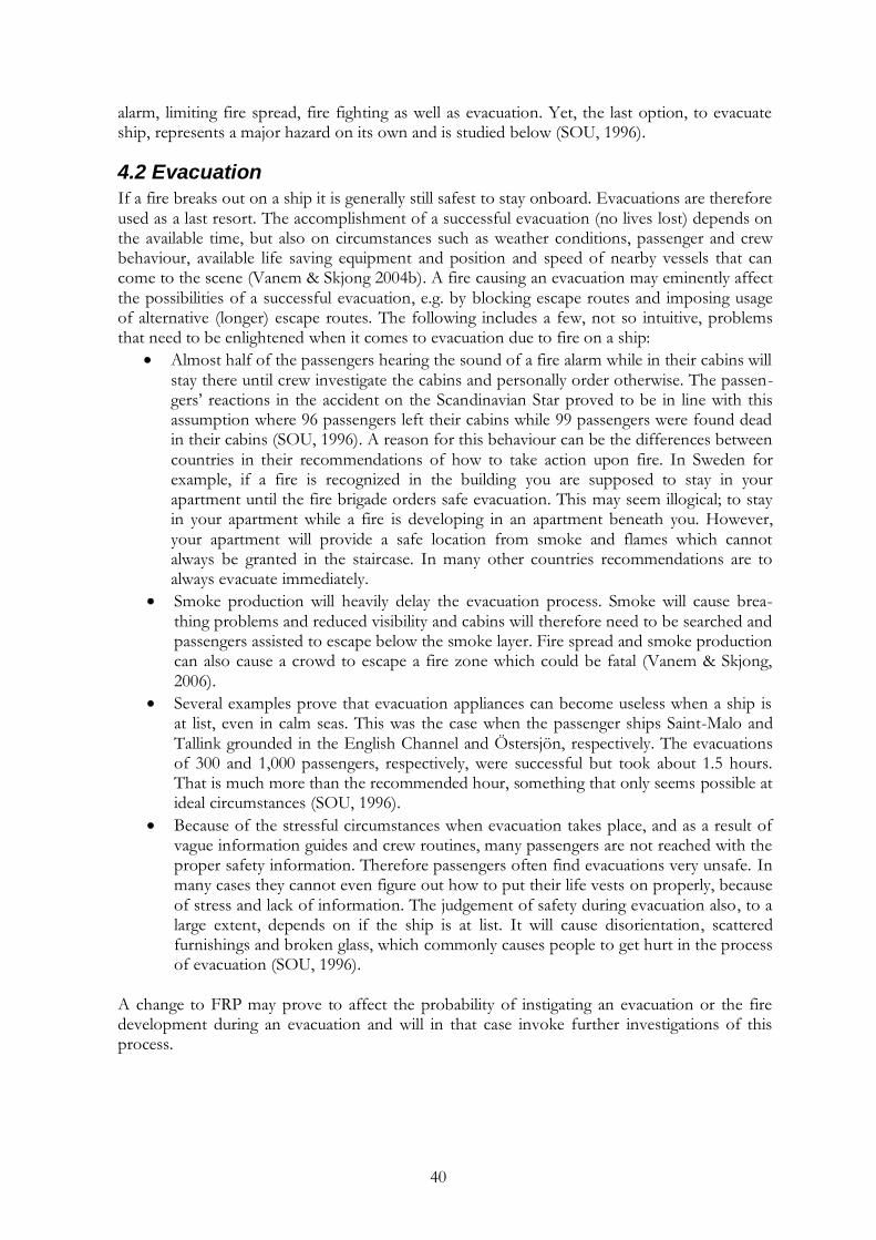
40
alarm, limiting fire spread, fire fighting as well as evacuation. Yet, the last option, to evacuate ship, represents a major hazard on its own and is studied below (SOU, 1996).
4.2 Evacuation
If a fire breaks out on a ship it is generally still safest to stay onboard. Evacuations are therefore used as a last resort. The accomplishment of a successful evacuation (no lives lost) depends on the available time, but also on circumstances such as weather conditions, passenger and crew behaviour, available life saving equipment and position and speed of nearby vessels that can come to the scene (Vanem & Skjong 2004b). A fire causing an evacuation may eminently affect the possibilities of a successful evacuation, e.g. by blocking escape routes and imposing usage of alternative (longer) escape routes. The following includes a few, not so intuitive, problems that need to be enlightened when it comes to evacuation due to fire on a ship:
Almost half of the passengers hearing the sound of a fire alarm while in their cabins will stay there until crew investigate the cabins and personally order otherwise. The passen-gers‟ reactions in the accident on the Scandinavian Star proved to be in line with this assumption where 96 passengers left their cabins while 99 passengers were found dead in their cabins (SOU, 1996). A reason for this behaviour can be the differences between countries in their recommendations of how to take action upon fire. In Sweden for example, if a fire is recognized in the building you are supposed to stay in your apartment until the fire brigade orders safe evacuation. This may seem illogical; to stay in your apartment while a fire is developing in an apartment beneath you. However, your apartment will provide a safe location from smoke and flames which cannot always be granted in the staircase. In many other countries recommendations are to always evacuate immediately.
Smoke production will heavily delay the evacuation process. Smoke will cause brea-thing problems and reduced visibility and cabins will therefore need to be searched and passengers assisted to escape below the smoke layer. Fire spread and smoke production can also cause a crowd to escape a fire zone which could be fatal (Vanem & Skjong, 2006).
Several examples prove that evacuation appliances can become useless when a ship is at list, even in calm seas. This was the case when the passenger ships Saint-Malo and Tallink grounded in the English Channel and Östersjön, respectively. The evacuations of 300 and 1,000 passengers, respectively, were successful but took about 1.5 hours. That is much more than the recommended hour, something that only seems possible at ideal circumstances (SOU, 1996).
Because of the stressful circumstances when evacuation takes place, and as a result of vague information guides and crew routines, many passengers are not reached with the proper safety information. Therefore passengers often find evacuations very unsafe. In many cases they cannot even figure out how to put their life vests on properly, because of stress and lack of information. The judgement of safety during evacuation also, to a large extent, depends on if the ship is at list. It will cause disorientation, scattered furnishings and broken glass, which commonly causes people to get hurt in the process of evacuation (SOU, 1996).
A change to FRP may prove to affect the probability of instigating an evacuation or the fire development during an evacuation and will in that case invoke further investigations of this process.
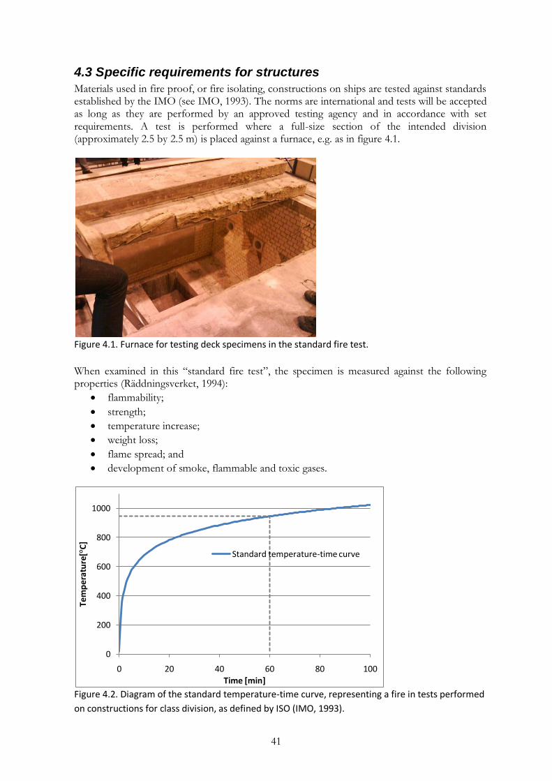
41
4.3 Specific requirements for structures
Materials used in fire proof, or fire isolating, constructions on ships are tested against standards established by the IMO (see IMO, 1993). The norms are international and tests will be accepted as long as they are performed by an approved testing agency and in accordance with set requirements. A test is performed where a full-size section of the intended division (approximately 2.5 by 2.5 m) is placed against a furnace, e.g. as in figure 4.1.
Figure 4.1. Furnace for testing deck specimens in the standard fire test.
When examined in this “standard fire test”, the specimen is measured against the following properties (Räddningsverket, 1994):
flammability;
strength;
temperature increase;
weight loss;
flame spread; and
development of smoke, flammable and toxic gases.
Figure 4.2. Diagram of the standard temperature-time curve, representing a fire in tests performed
on constructions for class division, as defined by ISO (IMO, 1993).
0
200
400
600
800
1000
0 20 40 60 80 100
Tem
per
atu
re[°
C]
Time [min]
Standard temperature-time curve
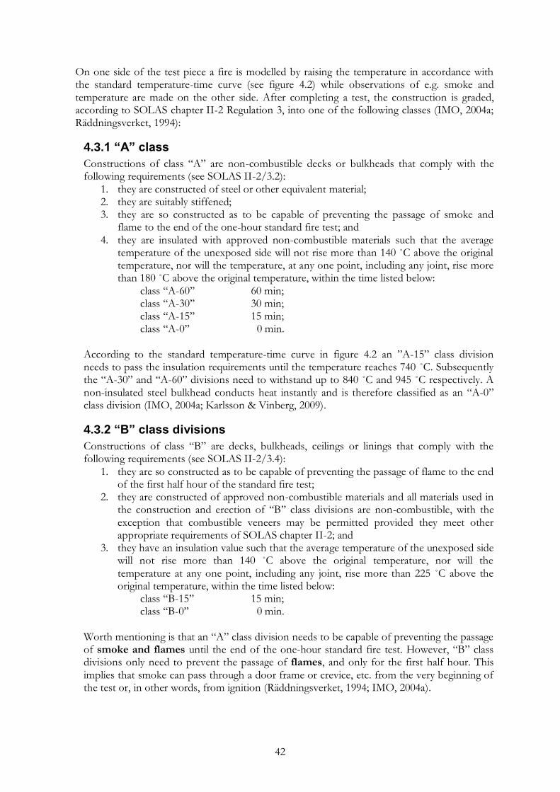
42
On one side of the test piece a fire is modelled by raising the temperature in accordance with the standard temperature-time curve (see figure 4.2) while observations of e.g. smoke and temperature are made on the other side. After completing a test, the construction is graded, according to SOLAS chapter II-2 Regulation 3, into one of the following classes (IMO, 2004a; Räddningsverket, 1994):
4.3.1 “A” class
Constructions of class “A” are non-combustible decks or bulkheads that comply with the following requirements (see SOLAS II-2/3.2):
1. they are constructed of steel or other equivalent material; 2. they are suitably stiffened; 3. they are so constructed as to be capable of preventing the passage of smoke and
flame to the end of the one-hour standard fire test; and 4. they are insulated with approved non-combustible materials such that the average
temperature of the unexposed side will not rise more than 140 ˚C above the original temperature, nor will the temperature, at any one point, including any joint, rise more than 180 ˚C above the original temperature, within the time listed below:
class „„A-60‟‟ 60 min; class „„A-30‟‟ 30 min; class „„A-15‟‟ 15 min; class „„A-0‟‟ 0 min.
According to the standard temperature-time curve in figure 4.2 an ”A-15” class division needs to pass the insulation requirements until the temperature reaches 740 ˚C. Subsequently the “A-30” and “A-60” divisions need to withstand up to 840 ˚C and 945 ˚C respectively. A non-insulated steel bulkhead conducts heat instantly and is therefore classified as an “A-0” class division (IMO, 2004a; Karlsson & Vinberg, 2009).
4.3.2 “B” class divisions
Constructions of class “B” are decks, bulkheads, ceilings or linings that comply with the following requirements (see SOLAS II-2/3.4):
1. they are so constructed as to be capable of preventing the passage of flame to the end of the first half hour of the standard fire test;
2. they are constructed of approved non-combustible materials and all materials used in the construction and erection of „„B‟‟ class divisions are non-combustible, with the exception that combustible veneers may be permitted provided they meet other appropriate requirements of SOLAS chapter II-2; and
3. they have an insulation value such that the average temperature of the unexposed side will not rise more than 140 ˚C above the original temperature, nor will the temperature at any one point, including any joint, rise more than 225 ˚C above the original temperature, within the time listed below:
class „„B-15‟‟ 15 min; class „„B-0‟‟ 0 min.
Worth mentioning is that an “A” class division needs to be capable of preventing the passage of smoke and flames until the end of the one-hour standard fire test. However, “B” class divisions only need to prevent the passage of flames, and only for the first half hour. This implies that smoke can pass through a door frame or crevice, etc. from the very beginning of the test or, in other words, from ignition (Räddningsverket, 1994; IMO, 2004a).
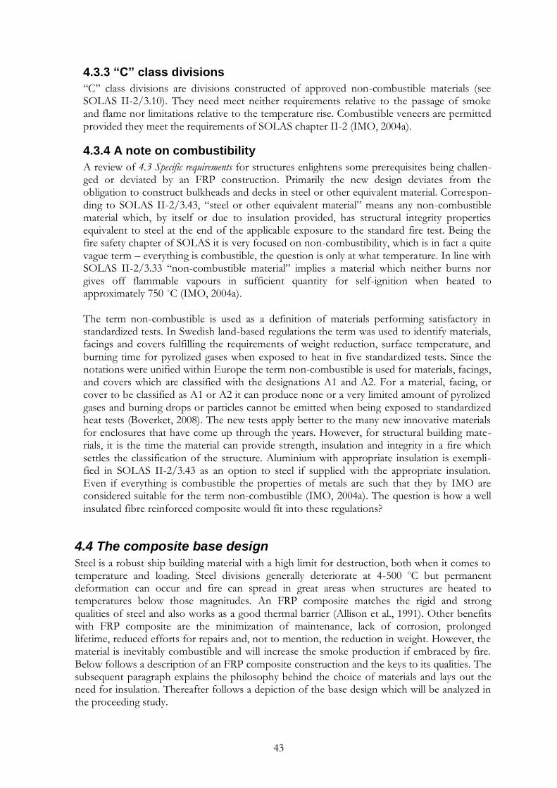
43
4.3.3 “C” class divisions
„„C‟‟ class divisions are divisions constructed of approved non-combustible materials (see SOLAS II-2/3.10). They need meet neither requirements relative to the passage of smoke and flame nor limitations relative to the temperature rise. Combustible veneers are permitted provided they meet the requirements of SOLAS chapter II-2 (IMO, 2004a).
4.3.4 A note on combustibility
A review of 4.3 Specific requirements for structures enlightens some prerequisites being challen-ged or deviated by an FRP construction. Primarily the new design deviates from the obligation to construct bulkheads and decks in steel or other equivalent material. Correspon-ding to SOLAS II-2/3.43, “steel or other equivalent material” means any non-combustible material which, by itself or due to insulation provided, has structural integrity properties equivalent to steel at the end of the applicable exposure to the standard fire test. Being the fire safety chapter of SOLAS it is very focused on non-combustibility, which is in fact a quite vague term – everything is combustible, the question is only at what temperature. In line with SOLAS II-2/3.33 “non-combustible material” implies a material which neither burns nor gives off flammable vapours in sufficient quantity for self-ignition when heated to approximately 750 ˚C (IMO, 2004a). The term non-combustible is used as a definition of materials performing satisfactory in standardized tests. In Swedish land-based regulations the term was used to identify materials, facings and covers fulfilling the requirements of weight reduction, surface temperature, and burning time for pyrolized gases when exposed to heat in five standardized tests. Since the notations were unified within Europe the term non-combustible is used for materials, facings, and covers which are classified with the designations A1 and A2. For a material, facing, or cover to be classified as A1 or A2 it can produce none or a very limited amount of pyrolized gases and burning drops or particles cannot be emitted when being exposed to standardized heat tests (Boverket, 2008). The new tests apply better to the many new innovative materials for enclosures that have come up through the years. However, for structural building mate-rials, it is the time the material can provide strength, insulation and integrity in a fire which settles the classification of the structure. Aluminium with appropriate insulation is exempli-fied in SOLAS II-2/3.43 as an option to steel if supplied with the appropriate insulation. Even if everything is combustible the properties of metals are such that they by IMO are considered suitable for the term non-combustible (IMO, 2004a). The question is how a well insulated fibre reinforced composite would fit into these regulations?
4.4 The composite base design
Steel is a robust ship building material with a high limit for destruction, both when it comes to temperature and loading. Steel divisions generally deteriorate at 4-500 oC but permanent deformation can occur and fire can spread in great areas when structures are heated to temperatures below those magnitudes. An FRP composite matches the rigid and strong qualities of steel and also works as a good thermal barrier (Allison et al., 1991). Other benefits with FRP composite are the minimization of maintenance, lack of corrosion, prolonged lifetime, reduced efforts for repairs and, not to mention, the reduction in weight. However, the material is inevitably combustible and will increase the smoke production if embraced by fire. Below follows a description of an FRP composite construction and the keys to its qualities. The subsequent paragraph explains the philosophy behind the choice of materials and lays out the need for insulation. Thereafter follows a depiction of the base design which will be analyzed in the proceeding study.
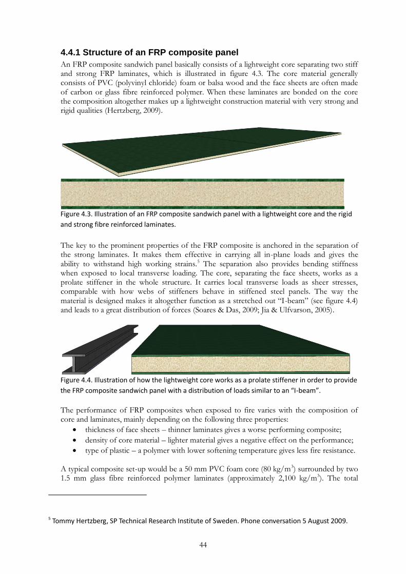
44
4.4.1 Structure of an FRP composite panel
An FRP composite sandwich panel basically consists of a lightweight core separating two stiff and strong FRP laminates, which is illustrated in figure 4.3. The core material generally consists of PVC (polyvinyl chloride) foam or balsa wood and the face sheets are often made of carbon or glass fibre reinforced polymer. When these laminates are bonded on the core the composition altogether makes up a lightweight construction material with very strong and rigid qualities (Hertzberg, 2009).
Figure 4.3. Illustration of an FRP composite sandwich panel with a lightweight core and the rigid
and strong fibre reinforced laminates.
The key to the prominent properties of the FRP composite is anchored in the separation of the strong laminates. It makes them effective in carrying all in-plane loads and gives the ability to withstand high working strains.5 The separation also provides bending stiffness when exposed to local transverse loading. The core, separating the face sheets, works as a prolate stiffener in the whole structure. It carries local transverse loads as sheer stresses, comparable with how webs of stiffeners behave in stiffened steel panels. The way the material is designed makes it altogether function as a stretched out “I-beam” (see figure 4.4) and leads to a great distribution of forces (Soares & Das, 2009; Jia & Ulfvarson, 2005).
Figure 4.4. Illustration of how the lightweight core works as a prolate stiffener in order to provide
the FRP composite sandwich panel with a distribution of loads similar to an “I-beam”.
The performance of FRP composites when exposed to fire varies with the composition of core and laminates, mainly depending on the following three properties:
thickness of face sheets – thinner laminates gives a worse performing composite;
density of core material – lighter material gives a negative effect on the performance;
type of plastic – a polymer with lower softening temperature gives less fire resistance. A typical composite set-up would be a 50 mm PVC foam core (80 kg/m3) surrounded by two 1.5 mm glass fibre reinforced polymer laminates (approximately 2,100 kg/m3). The total
5 Tommy Hertzberg, SP Technical Research Institute of Sweden. Phone conversation 5 August 2009.
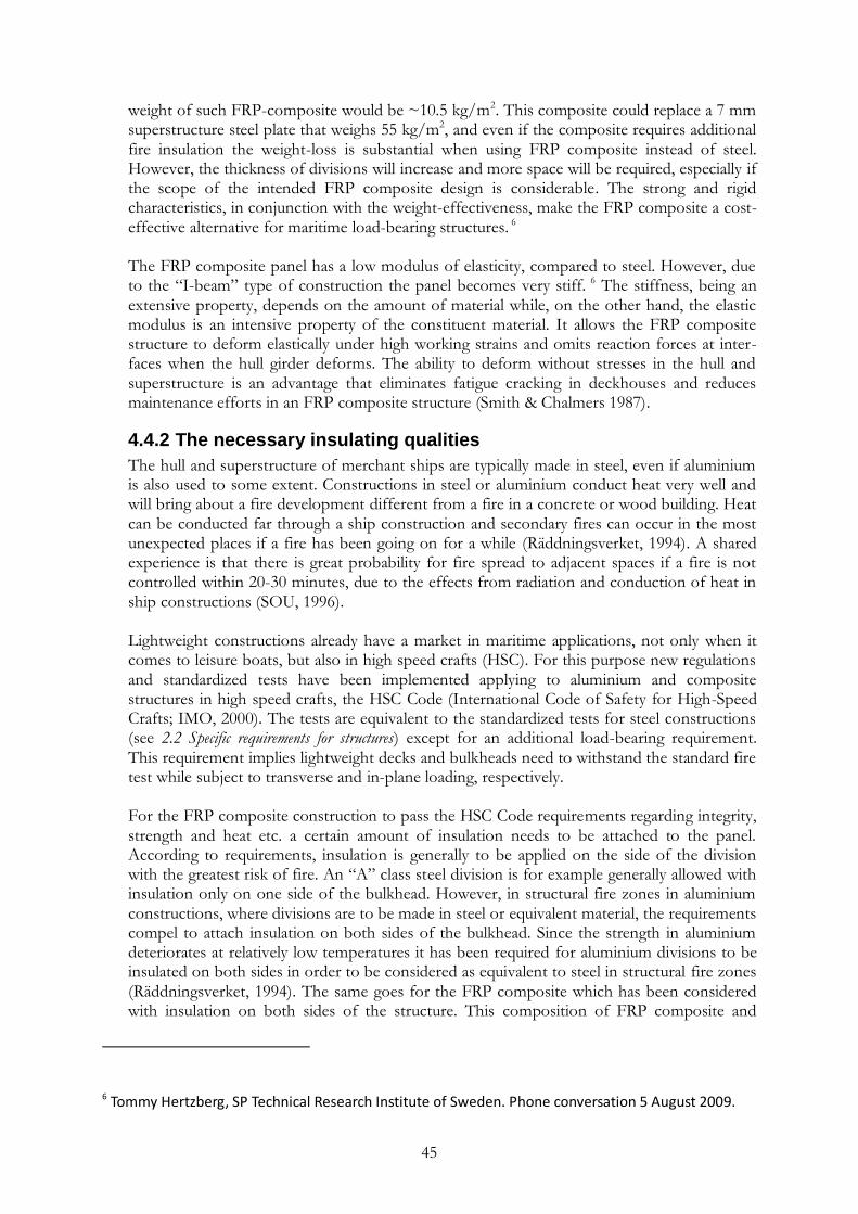
45
weight of such FRP-composite would be ~10.5 kg/m2. This composite could replace a 7 mm superstructure steel plate that weighs 55 kg/m2, and even if the composite requires additional fire insulation the weight-loss is substantial when using FRP composite instead of steel. However, the thickness of divisions will increase and more space will be required, especially if the scope of the intended FRP composite design is considerable. The strong and rigid characteristics, in conjunction with the weight-effectiveness, make the FRP composite a cost-effective alternative for maritime load-bearing structures. 6
The FRP composite panel has a low modulus of elasticity, compared to steel. However, due to the “I-beam” type of construction the panel becomes very stiff. 6 The stiffness, being an extensive property, depends on the amount of material while, on the other hand, the elastic modulus is an intensive property of the constituent material. It allows the FRP composite structure to deform elastically under high working strains and omits reaction forces at inter-faces when the hull girder deforms. The ability to deform without stresses in the hull and superstructure is an advantage that eliminates fatigue cracking in deckhouses and reduces maintenance efforts in an FRP composite structure (Smith & Chalmers 1987).
4.4.2 The necessary insulating qualities
The hull and superstructure of merchant ships are typically made in steel, even if aluminium is also used to some extent. Constructions in steel or aluminium conduct heat very well and will bring about a fire development different from a fire in a concrete or wood building. Heat can be conducted far through a ship construction and secondary fires can occur in the most unexpected places if a fire has been going on for a while (Räddningsverket, 1994). A shared experience is that there is great probability for fire spread to adjacent spaces if a fire is not controlled within 20-30 minutes, due to the effects from radiation and conduction of heat in ship constructions (SOU, 1996). Lightweight constructions already have a market in maritime applications, not only when it comes to leisure boats, but also in high speed crafts (HSC). For this purpose new regulations and standardized tests have been implemented applying to aluminium and composite structures in high speed crafts, the HSC Code (International Code of Safety for High-Speed Crafts; IMO, 2000). The tests are equivalent to the standardized tests for steel constructions (see 2.2 Specific requirements for structures) except for an additional load-bearing requirement. This requirement implies lightweight decks and bulkheads need to withstand the standard fire test while subject to transverse and in-plane loading, respectively. For the FRP composite construction to pass the HSC Code requirements regarding integrity, strength and heat etc. a certain amount of insulation needs to be attached to the panel. According to requirements, insulation is generally to be applied on the side of the division with the greatest risk of fire. An “A” class steel division is for example generally allowed with insulation only on one side of the bulkhead. However, in structural fire zones in aluminium constructions, where divisions are to be made in steel or equivalent material, the requirements compel to attach insulation on both sides of the bulkhead. Since the strength in aluminium deteriorates at relatively low temperatures it has been required for aluminium divisions to be insulated on both sides in order to be considered as equivalent to steel in structural fire zones (Räddningsverket, 1994). The same goes for the FRP composite which has been considered with insulation on both sides of the structure. This composition of FRP composite and
6 Tommy Hertzberg, SP Technical Research Institute of Sweden. Phone conversation 5 August 2009.

46
insulation makes up a Fire Resisting Division (FRD), which has been subject to tests at SP Technical Research Institute of Sweden (see figure 4.5 and figure 4.6).
Figure 4.5. The insulation marked in the picture provides heat integrity to the FRP composite, a
composition that makes up a fire resisting division (FRD).The FRD deck construction is here
tested on top of a large furnace in accordance with MSC.45(65) in the IMO Fire Test Procedures
code (IMO, 1995).
An FRD deck or bulkhead structure must sustain the specified fire load in a large scale furnace for 30 or 60 minutes in order to be certified as an “FRD-30” or “FRD-60” division, respectively. This kind of division is not to be confused with the currently used light-weight panels which have no requirements on structural integrity in SOLAS.
4.4.3 Foundational arrangements in an FRD design
FRP composites are good thermal barriers and have demonstrated ability to contain fire on its own (Allison et al., 1991). However, because of the evident predominant benefits in risk reduction compared to the costs, some further mitigating efforts will be assumed to be implemented in an FRP composite design for a SOLAS-vessel. It means even the initial design will be stricter than the requirements for HSC. The tests for deck and bulkhead constructions applying to HSC are in general the same as those prescribed for SOLAS-vessels except from the additional load bearing requirements. As a precautionary measure FRD-60 structures will be used ubiquitously and not only in fire hazard areas as required in the HSC Code. It implies no composite surfaces are exposed (except for the outside), all interior decks and bulkheads of the ship will be protected with insulation representing at least 60 minutes of survival in the standard fire test. It also means all load bearing structures, regardless of the nature of adjacent spaces, will be protected so that at least 60 minutes of protection is reached. That includes low risk spaces and when the adjacent space is an open deck, i.e. sun decks, roof of balconies and underneath other external decks. In some cases this exceeds the SOLAS requirement, as for an A-07 steel construction where the backside (unexposed to fire) of the construction will become hot very quickly and thereby increases the probability of fire spread to the adjacent space. The
7 ”A” means “non-combustible” and “60 minutes fire resistant”. “A-X” (X = 0, 15, 30 or 60) means a temperature requirement must be met after X minutes on the side of the construction that is unexposed to fire.

47
composite construction will have 60 minutes insulation which will keep the temperature on the exposed side of the FRP composite low enough for the construction to keep its integrity (typically <140 ˚C for a PVC foam). It means that the temperature on the unexposed side of the division will be low (35-40 ˚C with a PVC-foam) for the full 60 minute period. Therefore the probability for fire spread to the other side is lower than for a steel construction. The fact that an interior surface will not be allowed without a protective insulation is a fundamental condition for the composite base design. For a steel division insulation might or might not be necessary, depending on the nature of the separated spaces. When applying the above safety measures to the FRP composite decks and bulkheads it is thus important to note that the time of thermal insulation is increased to at least 60 minutes, instead of sometimes no such protection time (i.e. for an A-0 division). Preventing propagation of fire to the deck above for this time proposes that each deck becomes a so called fire division. The deck areas between bulkheads would then become structural fire zones if no other than fire resistance requirements would apply. This can compare to an A-0 division that has no restrictions of thermal insulation. The minimum fire integrity of bulkheads and decks depends on the adjoining spaces and is prescribed in SOLAS II-2/9.2.2.3. Except achieving the fire protection requirements, all divisions in an FRP composite construction will be load-bearing structures and will therefore meet applicable requirements. The fire safety organization and fire fighting routines on the ship will be assumed to follow the requirements in SOLAS II-2. Also the fire protection systems and equipment will be presumed to be in agreement with those requirements. Together with the fire safety measures in the prescriptive requirements of the HCS Code and the extended measures described in the preceding passages this makes up the studied design of the FRP composite superstructure and will be referred to as an FRD design. Below follows a summary of some important properties revealed from tests, which are important for the subsequent analyses of the fire safety on an FRD design.
4.5 Properties revealed from tests
Throughout the numerous and detailed tests carried out at SP Technical Research Institute of Sweden on FRP composite the weak link for structural stability of the construction has appeared to be the core material and its bonding to the face sheets. As long as the core is intact and well adhered to both laminates the structural strength of the material is not affected by heat. Therefore the temperature between the core and the face sheet on the side exposed to fire becomes a critical feature. For a low performing FRP composite with relatively thin glass fibre reinforced polyester laminate and a PVC foam core, the joint between the first laminate and the core begins to soften at about 100 ˚C. When the temperature reaches about 130-140 ˚C the structural performance can be considered deteriorated as the construction becomes deform-able. However, if just a part of the material would be exposed to heat, only that limited area would be subject to deformation since FRD unlike steel does not conduct heat very well. Before the temperature of the interface between the exposed laminate and the core reaches 130-140 ˚C the strength of the structure will not be affected. However, when the temperature exceeds that level the load-bearing capacity of the structure will deteriorate quite fast. Therefore it is not necessary to test FRD with case specific loading, since its performance in fire tests will not depend on the magnitude of the loading. As explained above, the FRD structure is there-fore tested with a nominal load, analogous to what is prescribed by the IMO for high speed crafts. Its performance in fire will rather depend on the fire development, i.e. the heat produc-
48
tion (temperature) and the time of exposure. When exposing a specimen to fire specified by the standard temperature-time curve it will imply the strength of a structure will mainly depend on the time of exposure (Hertzberg, 2009). In the 60 minute fire test it is critical that the temperature of the FRP laminate-core interface of the fire exposed side stays below 130-140 ˚C in order for the structural performance to be satisfying throughout the test. The temperature on the unexposed side will, down to the high insulation capacity of the FRD, therefore be virtually at room temperature even after 60 minutes of fire. Tests confirmed a temperature on the unexposed side of the division of about 45 ˚C, which can compare to the average 140 ˚C or peak 180 ˚C allowed according to the strictest division requirement in SOLAS, see 4.3 Specific requirements for structures. Constructions with FRP composite have been tested and certified in accordance with the IMO regulations, also when involving windows, doors, ducts, and other penetrations (see figure 4.6) (Hertzberg, 2009).
Figure 4.6. FRD bulkhead specimen after successful bulkhead penetration tests.
Tests in a cone calorimeter have shown that the critical temperature of when the FRP begins to soften could very well be reached within one minute if directly exposed to fire. This is when the material ignites if exposed to a radiation of 50 kW/m2. Such short period of exposure until ignition and deterioration might thus be critical if an unprotected FRP composite is exposed to fire, both from a structural strength perspective and from a fire spread perspective. This is why it is fundamental to nowhere allow an interior composite surface without protective insulation of at least 60 minutes, as described above (Hertzberg, 2009). An FRP composite module has also been tested in full-scale at SP Technical Research. The tests showed an FRD design will withstand a fully developed fire for more than 60 minutes without critical damage. A range tests also investigated different mitigating measures and different fire scenarios (Arvidsson et al., 2008).
4.6 Tests as a method for comparison
Full-scale testing is the method that typically will give the most accurate results of how a design will perform, even if natural variations always will be present. Since it would be very costly to perform all possible scenarios in full scale tests some chosen scenarios are often tested from which the safety of the rest of the design is evaluated through knowledge of fire dynamics and an engineering approach. This is basically what the prescriptive requirements of SOLAS are founded upon, tests of steel or equivalent materials make out if the construction is valid as a certain division. Numerous performance tests have been carried out on FRD to discern whether the novel concept would be valid for different classes of division. Apart from the fact
49
that the material is not equivalent to steel in the sense of being combustible, the tests proved for the materials‟ advantages. A comparison through tests can although be considered as a quite obtuse way of evaluating the performance of two such diverse materials. When comparing designs through tests there is always a lowest level for passing the test, an acceptance criterion. Obviously the assurance of identical set-ups and measurements is of greatest significance when tests are carried out by different people and stations in several countries throughout the world. However, even without those uncertainties, a test says nothing concerning the performance not represented in the test, e.g. the function if the load, temperature or time in the test increases by 10, 20 or 50 percent. In general the prescriptive fire tests of the Fire Test Procedures Code only give pass or no pass. Therefore no information is given on how the construction performed during the test or how long it could have performed with satisfaction. Testing is a good tool for construction comparisons when the main characteristics of the tested materials are similar and a lowest acceptable level of performance is well defined. However it would be very hard to construct a test that would engage the many different characteristics of steel and FRD in a way that all fire risks are represented. Today‟s fire tests are constructed to measure some key properties reflecting different disadvantages with steel designs and, ideally, representing the performance of steel when exposed to fire. Some characteristics are left out in the tests because of the implicit benefits with the traditional steel solutions. Implicit advantages with steel structures that are not represented in tests are neither possible to evaluate through the tests. Such a property is its ability to withstand high temperatures before deteriorated. It is because of the implicit advantages with steel, not visible in tests, that there is an additional requirement for many divisions to be made in non-combustible material. When aluminium was introduced to merchant ship building, another advantage of steel needed to be highlighted, its high performing load bearing qualities. Therefore aluminium structures need to pass a load bearing requirement in order to pass structural tests (see 4.3 Specific requirements for structures and IMO, 2000). Even if FRD passes the structural tests, there is reason to believe that the tests do not fully reflect the risks from an FRD construction in case of fire. Implicit properties beyond the tests need to be identified and evaluated. The fact that FRD contains combustible FRP composite is one of the differences that need to be evaluated with a different approach.

50

51
5. Analyzing the needs for verification The change from steel to FRD is considered to be a deviation from the prescriptive requirements and the changes need to be assessed. Evaluating the equivalence criterion in Regulation 17 makes it topical to reveal the safety levels in the alternative design and arrangements as well as in the prescriptive requirements. Generally the industry has seen two options in this issue; to compare the fire safety of a novel design with that of a reference design which complies with the prescrip-tive requirements also in the areas where the novel design deviates, or to compare the novel design with explicit criteria representing the safety level in prescriptive regulations. The former evaluation includes tests, modelling and simulations of fire scenarios in various spaces of both the novel and the reference designs. Since IMO has not reached consensus on explicit criteria this is currently the only alternative. However, based on the IMO rule-making process (see 2.4.1 Formal Safety Assessment), the SAFEDOR project presented suggestions on explicit and holistic safety targets (Skjong et al., 2005), which open up for explicit risk-based approval. However, present prescriptive regulations are steel-based and there will be great uncertainties when introducing novel technology, such as FRP composite. The developed holistic safety targets can be useful as general safety guidelines but uncertainties invoke more detailed evaluations. In lack of measurable objectives and functional requirements a need is elevated to further analyze the implicit level of fire safety in prescriptive requirements. The needs of verification can then be determined by how the fire safety in a ship will be affected, depending on the scope of the intended FRD design. The choice of method to verify the fire safety should be based on the needs for verification and the uncertainties with introducing novel technology. This chapter attempts to clarify effects to the implicit level of fire safety represented in prescriptive requirements in order to establish the needs for verification. The approach is partially based on a methodology adapted from Lundin (2001). The report by Lundin is a similar investigation on how to determine verification needs when using performance-based methods to deviate from prescriptive building requirements in Sweden. The different viewpoints on fire safety used in the report will settle the foundation for an analysis of the implicit fire safety level in maritime regulations, which are considered to repre-sent implicit acceptance criteria for the required level of fire safety. Effects from introducing FRP as a maritime construction material instead of steel will be assessed in relation to this level. The considered viewpoints used to determine how an FRD construction will affect prescriptive requirements in this study are:
The fire safety regulations Each regulation in SOLAS II-2 has a purpose statement and prescriptive requirements. Even if these can be deviated, they are important since they represent the implicit safety level in prescriptive designs, which invokes a study of challenged regulations.
The fire safety objectives and functional requirements When deviating from prescriptive requirements, the fire safety objectives and functional requirements still need to be achieved and they will therefore be investigated.
The fire safety structure A layout study of the prescribed fire safety is carried out in order to identify the parts of the protection strategy that can be affected. The goals with different fire safety functions are studied whilst concurrently considering the structure of the fire protection as a whole.
The fire safety properties It is essential to evaluate the implicit fire safety properties in a prescriptive design and how a change can affect the fire safety.
The fire development Differences between the structures revealed in the previous analyses and conclusions from diverse tests are discussed in the context of fire dynamics.

52
In order to verify the safety level of an FRD design it is necessary to study the affected parts of the fire safety. By investigating how the fire safety is affected through these perspectives, the goal is that the needs for verification of an FRD design will be made clear. The objective with the analyses below is not to be case specific but to evaluate how fire safety can be affected by an implementation of FRD in general. The approach can, however, be of assistance when the verification needs for a certain scope of FRD superstructure are to be established. Differences revealed from the analyses are also discussed in terms of fire dynamics in the closing section of this chapter.
5.1 The fire safety regulations
When utilizing Regulation 17 it is possible to deviate from prescriptive requirements, but the fire safety objectives and functional requirements still need to be achieved. MSC/Circ. 1002 outlines the required engineering analysis when laying claim to Regulation 17. It specifies that the fire safety objectives and the purpose statements, listed at the beginning of each individual regulation in SOLAS II-2, should be used to provide the basis when comparing safety levels (4.4 in IMO, 2001). The general functional requirements in the beginning of SOLAS II-2 and the prescriptive requirements of each regulation are although also important when establishing the implicit safety level represented in prescriptive designs as they set out the safety targets for the whole chapter. The subsequent analysis has been delineated to evaluate the FRD construction with a starting point in the purpose statements and the following prescriptive requirements of the regulations in SOLAS II-2. Each regulation purpose statement consists of an individual regulation objective (RO) and regulation functional requirements (RFR) and they have been divided accordingly for this analysis. The possibly challenged regulations and the specific deviations introduced by an FRD design are summarized in table 5.1. A comment on how the novel technology challenges regulation objectives, regulation functional requirements and the following prescriptive requirements of each regulation are given in the table. Further discussions on compliance with the challenged fire safety regulations follow in the subsequent sections. All fire safety objectives and functional requirements in SOLAS II-2 as well as the regulation purposes with their functional requirements are summarized in Appendix D. Purposes of SOLAS II-2. For the following prescriptive requirements of each regulation see SOLAS (IMO 2004a).
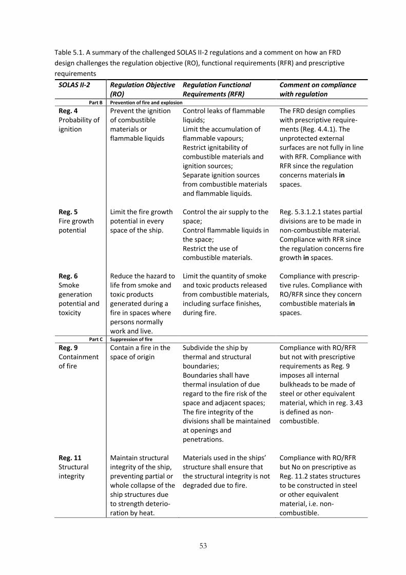
53
Table 5.1. A summary of the challenged SOLAS II-2 regulations and a comment on how an FRD
design challenges the regulation objective (RO), functional requirements (RFR) and prescriptive
requirements
SOLAS II-2 Regulation Objective (RO)
Regulation Functional Requirements (RFR)
Comment on compliance with regulation
Part B Prevention of fire and explosion
Reg. 4 Probability of ignition
Prevent the ignition of combustible materials or flammable liquids
Control leaks of flammable liquids; Limit the accumulation of flammable vapours; Restrict ignitability of combustible materials and ignition sources; Separate ignition sources from combustible materials and flammable liquids.
The FRD design complies with prescriptive require-ments (Reg. 4.4.1). The unprotected external surfaces are not fully in line with RFR. Compliance with RFR since the regulation concerns materials in spaces.
Reg. 5 Fire growth potential
Limit the fire growth potential in every space of the ship.
Control the air supply to the space; Control flammable liquids in the space; Restrict the use of combustible materials.
Reg. 5.3.1.2.1 states partial divisions are to be made in non-combustible material. Compliance with RFR since the regulation concerns fire growth in spaces.
Reg. 6 Smoke generation potential and toxicity
Reduce the hazard to life from smoke and toxic products generated during a fire in spaces where persons normally work and live.
Limit the quantity of smoke and toxic products released from combustible materials, including surface finishes, during fire.
Compliance with prescrip-tive rules. Compliance with RO/RFR since they concern combustible materials in spaces.
Part C Suppression of fire
Reg. 9 Containment of fire
Contain a fire in the space of origin
Subdivide the ship by thermal and structural boundaries; Boundaries shall have thermal insulation of due regard to the fire risk of the space and adjacent spaces; The fire integrity of the divisions shall be maintained at openings and penetrations.
Compliance with RO/RFR but not with prescriptive requirements as Reg. 9 imposes all internal bulkheads to be made of steel or other equivalent material, which in reg. 3.43 is defined as non-combustible.
Reg. 11 Structural integrity
Maintain structural integrity of the ship, preventing partial or whole collapse of the ship structures due to strength deterio-ration by heat.
Materials used in the ships’ structure shall ensure that the structural integrity is not degraded due to fire.
Compliance with RO/RFR but No on prescriptive as Reg. 11.2 states structures to be constructed in steel or other equivalent material, i.e. non-combustible.
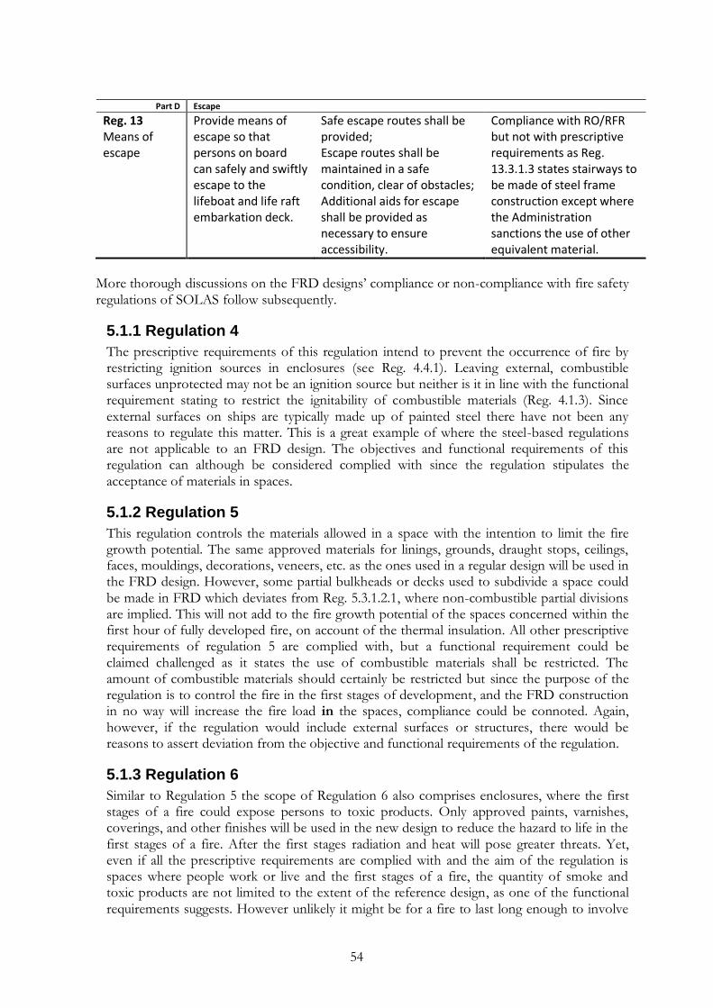
54
Part D Escape
Reg. 13 Means of escape
Provide means of escape so that persons on board can safely and swiftly escape to the lifeboat and life raft embarkation deck.
Safe escape routes shall be provided; Escape routes shall be maintained in a safe condition, clear of obstacles; Additional aids for escape shall be provided as necessary to ensure accessibility.
Compliance with RO/RFR but not with prescriptive requirements as Reg. 13.3.1.3 states stairways to be made of steel frame construction except where the Administration sanctions the use of other equivalent material.
More thorough discussions on the FRD designs‟ compliance or non-compliance with fire safety regulations of SOLAS follow subsequently.
5.1.1 Regulation 4
The prescriptive requirements of this regulation intend to prevent the occurrence of fire by restricting ignition sources in enclosures (see Reg. 4.4.1). Leaving external, combustible surfaces unprotected may not be an ignition source but neither is it in line with the functional requirement stating to restrict the ignitability of combustible materials (Reg. 4.1.3). Since external surfaces on ships are typically made up of painted steel there have not been any reasons to regulate this matter. This is a great example of where the steel-based regulations are not applicable to an FRD design. The objectives and functional requirements of this regulation can although be considered complied with since the regulation stipulates the acceptance of materials in spaces.
5.1.2 Regulation 5
This regulation controls the materials allowed in a space with the intention to limit the fire growth potential. The same approved materials for linings, grounds, draught stops, ceilings, faces, mouldings, decorations, veneers, etc. as the ones used in a regular design will be used in the FRD design. However, some partial bulkheads or decks used to subdivide a space could be made in FRD which deviates from Reg. 5.3.1.2.1, where non-combustible partial divisions are implied. This will not add to the fire growth potential of the spaces concerned within the first hour of fully developed fire, on account of the thermal insulation. All other prescriptive requirements of regulation 5 are complied with, but a functional requirement could be claimed challenged as it states the use of combustible materials shall be restricted. The amount of combustible materials should certainly be restricted but since the purpose of the regulation is to control the fire in the first stages of development, and the FRD construction in no way will increase the fire load in the spaces, compliance could be connoted. Again, however, if the regulation would include external surfaces or structures, there would be reasons to assert deviation from the objective and functional requirements of the regulation.
5.1.3 Regulation 6
Similar to Regulation 5 the scope of Regulation 6 also comprises enclosures, where the first stages of a fire could expose persons to toxic products. Only approved paints, varnishes, coverings, and other finishes will be used in the new design to reduce the hazard to life in the first stages of a fire. After the first stages radiation and heat will pose greater threats. Yet, even if all the prescriptive requirements are complied with and the aim of the regulation is spaces where people work or live and the first stages of a fire, the quantity of smoke and toxic products are not limited to the extent of the reference design, as one of the functional requirements suggests. However unlikely it might be for a fire to last long enough to involve

55
the FRP in the fire, the scenario would imply an increased production of smoke and toxic products in comparison with a reference design. Even if no one would be present in the already uninhabitable spaces at this stage, a contribution of combustible structural material would increase the fire load and production of smoke. It could be hazardous to persons on the embarkation deck in case of unfortunate wind and should therefore be accounted for in an analysis, even if the regulation can be considered complied with. Since present regulations are formed around steel constructions, which do not produce smoke, there are reasons to investigate the production of smoke further. This also includes the production of smoke in case of outside fires, where smoke production although could be less significant to human life.
5.1.4 Regulation 9
The objectives and functional requirements of this regulation are complied with since the thermal insulation in the FRD by all means exceed the requirements of integrity and expec-tedly will contain a fire in its origin better than the reference design. However, since steel or equivalent material is obliged throughout the prescriptive requirements, which according to Reg. 3.43 is interpreted as non-combustible material, this regulation is widely challenged (see 4.3.4 A note on combustibility). In general all divisions and penetrations for ducts, doors, pipes, windows etc. are required to be made of non-combustible material due to this interpretation. If FRD and the fire resistant solutions for penetrations would be considered to be equivalent to steel, this regulation would also be complied with. This equivalence will although have to be evaluated further as FRP is in fact combustible.
5.1.5 Regulation 11
The prescriptive requirement in SOLAS II-2/11.2 states:
“The hull, superstructures, structural bulkheads, decks and deckhouses shall be constructed
of steel or other equivalent material. For the purpose of applying the definition of steel or
other equivalent material as given in regulation 3.43, the ‘applicable fire exposure’ shall be
according to the integrity and insulation standards given in tables 9.1 to 9.4. For example,
where divisions such as decks or sides and ends of deckhouses are permitted to have ‘B-0’
fire integrity, the ‘applicable fire exposure’ shall be half an hour.”
Again the requirement of structures in steel or other equivalent material cannot be complied with as it interprets as non-combustible, which in other words implies a metal construction. The objectives and functional requirements of Regulation 11 insist on maintaining structural integrity in order to prevent partial or whole collapse as a result of strength deterioration by heat. This could be considered complied with as the FRD design by all means accomplish the prescriptive fire integrity and insulation standards of SOLAS II-2/9.2.2.3 and typically exceed them considerably with regard to thermal insulation capacity. A severe fire could although cause the structure to deform when the thermal insulation no longer is enough protection to isolate the heat. In the worst case scenario it could bring about a local collapse. The reference steel construction, however, also suffers from strength deterioration and, in particular, deformation problems when heated enough. In this case it is mainly dependable on the heat transfer properties of steel which on the contrary causes more heat to be lead away. The differences in character of the structural materials do not make it easy to distinguish whether one of them is better performing, or in other terms, if the FRD design is at least as safe as the steel design.

56
5.1.6 Regulation 13
The prescriptive requirements in Reg. 13.3.1.3 states most stairways are to be made of steel frame construction except where sanctions can be made by the IMO. Again, the steel condition cannot be complied with. The question is what additional means need to be provided in order for the safety of an FRD stairway construction to be satisfying to the IMO? Being fastidious, also the objectives and functional requirements of this regulation can only be considered complied with if the escape routes in the new design can be regarded “safe”. Made up by the well insulated FRP composite, which is irrefutably combustible, the new construction would again exceed the reference design with regard to thermal capacity. In case of fire that ability would give the advantage of an increased time for escape as the tempera-ture in the stairways and escape routes would be significantly lower. The fact that the stairways will not be made in non-combustible material will be kept in mind as the qualitative analysis proceeds. The novel material is, however, not intended for any other steel prescribed structures, such as ladders or doors, of this regulation. The investigation above was performed in order to sift out the key areas in which the constructions differ, by studying the requirements in detail. Below follows a study observing the characteristics of the novel design through the fire safety objectives and functional requirements meant to originate the above regulations. This is done in order to convey the differences between a prescriptive steel design and an FRD design with more perspective.
5.2 The fire safety objectives and functional requirements
The fire safety objectives and functional requirements in SOLAS II-2/2 highlight the purpose of the whole fire safety chapter in SOLAS. They are the framework for the following regula-tions, each with its own purpose statement which includes functional requirements. It can be confusing that both the requirements setting the functional purpose for the whole chapter are called “functional requirements” in the same way as the performance requisites for each regulation. The functional requirements investigated below are thus the ones stated in SOLAS II-2/2 to embody the following regulations, which were investigated in the preceding section. From Regulation 2 and Regulation 17 it can be assumed that only the fire safety objectives and functional requirements in Regulation 2 need to be complied with by a novel design and arrangements. However, when studying MSC/Circ. 1002, the fire safety objectives in SOLAS II-2/2 and the purpose statements in the beginning of each regulation are prescribed to be used as reference in safety comparisons. The rest of the information, i.e. functional requirements in SOLAS II-2/2 and detailed regulation requirements, is although also important as all it sets out the implicit safety level in the prescriptive regulations. Some of these prescriptive requirements are results of rule-making as a reaction to accidents and may therefore not be fully reflected in objectives and functional requirements. Many of the fire safety objectives are clearly represented in functional requirements and prescriptive requirements but others are not as visible. For example, the regulations are meant to protect the life of passengers and crew, but how about the safety for fire-fighting crew? And how is the environment protected from risk of damage in the prescriptive requirements? Some unclear connections between fire safety objectives, functional requirements and regulations make it hard to discern whether the objectives are achieved when only investigating prescriptive requirements. The individual regulations were analyzed above but in order to attain also the objectives and functional requirements, not fully embodied in the prescriptive requirements, the change from steel to FRD is evaluated also through Regulation 2, which is meant to originate the following regulations. The effects on fire safety will be evaluated through a consideration of

57
how the fire safety objectives and functional requirements could be challenged by an FRD design. It also needs to be clear if a change affects one or several matters, since it will influence the needs for verification.
5.2.1 Fire safety objectives
Using FRD instead of steel in all load-bearing structures will inevitably affect some of the fire safety objectives. Comments concerning each fire safety objective are summarized in table 5.2 and discussed below.
Table 5.2. A summary of the fire safety objectives of SOLAS II-2/2.1 and comments on how they
are affected by the FRD design
The fire safety objectives in SOLAS II-2/2 Comment
.1 prevent the occurrence of fire and explosion;
Complied with in the same way as a prescriptive design.
.2 reduce the risk to life caused by fire;
This objective will be affected, the question is how?
.3 reduce the risk of damage caused by fire to the ship, its cargo and the environment;
This objective will be affected but will be inferior to the risk to life on a passenger ship.
.4 contain, control and suppress fire and explosion in the compartment of origin; and
New approved structure and penetrations will imply improved containment of fire and new equipment and routines for fire fighting. Other means are the same as prescribed.
.5 provide adequate and readily accessible means of escape for passengers and crew.
The FRD design will imply improved conditions for escape within the first 60 minutes.
The use of spaces and its related activities and interiors will be governed by prescriptive requirements. As a result there will be no differences affecting the first objective. The same goes for the last objective, except that the novel design might improve the conditions in adjacent spaces during an escape (defined as the escape from a fire to the lifeboat and liferaft embarkation deck, i.e. not to confuse with the evacuation which also includes embarking and launching life safety appliances, or transferring passengers to shore or another ship). Solutions for load-bearing structures and penetrations have been documented for the novel technology. The fourth objective insists on containing, controlling and suppressing a fire in the space of origin. Also this objective will most likely be achieved at least as safe in the novel design. The improvements, however, also imply changes which could be beneficial to verify in the novel design. The greatest needs for verification tend to appear in the second and third fire safety objectives (see table 5.2). These objectives insist on reducing the risk to life, property and environment. Whilst acceptance criteria for risk to property are typically set by shipping companies, criteria for the environment should be set by authorities. A prescribed reduction in risk of damage to the environment is although not clearly presented in the fire safety regulations of SOLAS. Even though the risks to environment and property will defini-tely be affected by the novel design to some extent, it is outside the scope of this study. The value of several thousand lives will always be much greater than a billion dollar ship or the environmental effects from a ship catastrophe. The greatest risk caused by fire on a passenger ship is therefore the risk of life.
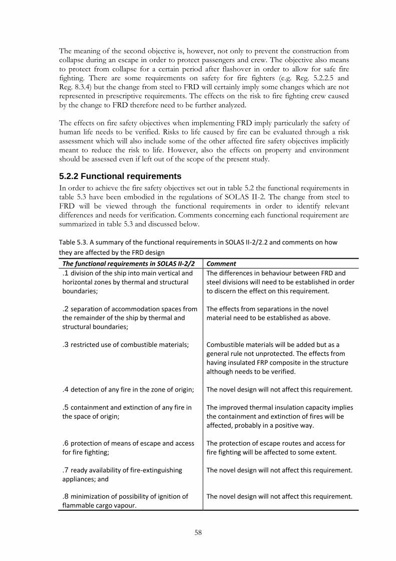
58
The meaning of the second objective is, however, not only to prevent the construction from collapse during an escape in order to protect passengers and crew. The objective also means to protect from collapse for a certain period after flashover in order to allow for safe fire fighting. There are some requirements on safety for fire fighters (e.g. Reg. 5.2.2.5 and Reg. 8.3.4) but the change from steel to FRD will certainly imply some changes which are not represented in prescriptive requirements. The effects on the risk to fire fighting crew caused by the change to FRD therefore need to be further analyzed. The effects on fire safety objectives when implementing FRD imply particularly the safety of human life needs to be verified. Risks to life caused by fire can be evaluated through a risk assessment which will also include some of the other affected fire safety objectives implicitly meant to reduce the risk to life. However, also the effects on property and environment should be assessed even if left out of the scope of the present study.
5.2.2 Functional requirements
In order to achieve the fire safety objectives set out in table 5.2 the functional requirements in table 5.3 have been embodied in the regulations of SOLAS II-2. The change from steel to FRD will be viewed through the functional requirements in order to identify relevant differences and needs for verification. Comments concerning each functional requirement are summarized in table 5.3 and discussed below.
Table 5.3. A summary of the functional requirements in SOLAS II-2/2.2 and comments on how
they are affected by the FRD design
The functional requirements in SOLAS II-2/2 Comment
.1 division of the ship into main vertical and horizontal zones by thermal and structural boundaries;
The differences in behaviour between FRD and steel divisions will need to be established in order to discern the effect on this requirement.
.2 separation of accommodation spaces from the remainder of the ship by thermal and structural boundaries;
The effects from separations in the novel material need to be established as above.
.3 restricted use of combustible materials;
Combustible materials will be added but as a general rule not unprotected. The effects from having insulated FRP composite in the structure although needs to be verified.
.4 detection of any fire in the zone of origin;
The novel design will not affect this requirement.
.5 containment and extinction of any fire in the space of origin;
The improved thermal insulation capacity implies the containment and extinction of fires will be affected, probably in a positive way.
.6 protection of means of escape and access for fire fighting;
The protection of escape routes and access for fire fighting will be affected to some extent.
.7 ready availability of fire-extinguishing appliances; and
The novel design will not affect this requirement.
.8 minimization of possibility of ignition of flammable cargo vapour.
The novel design will not affect this requirement.

59
The review of SOLAS II-2/2.2 enlightened some areas that will be affected by a change from steel to FRD. The first and the second functional requirements concern the division of a ship and the separation of spaces. Differences in behaviour between steel and FRD boundaries will affect these regulations and are therefore necessary to identify. The third functional requirement makes the usage of combustible materials topical. It invokes an evaluation of the effects from using combustible materials beyond what is permitted in prescriptive require-ments. As a general rule there should not be any unprotected combustible materials added. However, the effects from having external FRP composite surfaces protected by e.g. drencher need to be verified. The same goes for the effects from having insulated FRP composite in the structure. Functional requirements five and six will be affected in similar ways as the first and second requirements. Depending on the properties of the novel material there will be effects when it comes to containment and extinction of the fire as well as the protection from and access to the fire. These and the above effects on functional require-ments indicate some important needs for verification that ought to be targeted when evaluating the novel design.
5.3 The fire safety structure
The analysis in this section utilizes a methodology presented by Lundin (2001), endorsing an investigation of the goals of different fire safety functions in consideration with the structure of fire protection as a whole. The goal is to identify the effects on fire safety and the scope of changes in fire protection when implementing a novel design or arrangements. This investigation is a process which begins with a division of the SOLAS II-2 regulations into different fire protection categories. Thereafter follows some relevant theory and an estimation of how a change from steel to FRD will affect the fire protection strategy. An interpretation of the changes in the fire protection strategy based on the theory follows subsequently. The result from the investigation is, however, not only the interpretation of the analysis but the whole process giving perspective to the changes.
5.3.1 Different types of fire protection
Depending on the deviations from prescriptive requirements different parts of the fire protection strategy will be affected. Prescriptive requirements impose a certain design or properties and lead to physical fire protection in the shape of detectors, alarms and sprinkler systems etc. They can also imply restrictions in size, number of people and usage allowed in a compartment (Lundin, 2001). The question is what kind of fire risks a particular requirement was meant to minimize and how? What were the intentions with implementing one or a number of risk controlling measures? A synoptic classification of different forms of fire protection was carried out by Merkhofer (1987) and implies the following three categories:
source, i.e. preventing fire;
exposure, i.e. limiting the development and spread of fire and smoke;
effect, i.e. preventing and limiting the damage on endpoints. With this perspective, risk control measures are meant to prevent or limit the occurrence of fire, the spread of fire and smoke or the damage on endpoints (load bearing structures, people on the ship, cargo, environment, adjoining ships etc.). Each risk control measure can reach one or more of these functions or will give an effect only in collaboration with other measures. A sprinkler system is an example of a system that provides fire protection in more
60
than one way. Except extinguishing the fire and limiting its abilities to spread it can decrease the temperature in the smoke layer, which reduces the thermal effect on load bearing struc-tures (Lundin, 2001). The three categories of fire protection almost represent how SOLAS II-2 is divided into Part B – Prevention of fire and explosion, Part C – Suppression of fire and Part D – Escape. There are, however, some differences. In order to get a better overview of the fire protection strategy in SOLAS II-2 the three categories of fire protection are the basis for slightly different division of the regulations:
Source Regulation 4 - Probability of ignition Regulation 16 - Operations Exposure Regulation 5 - Fire growth potential Regulation 6 - Smoke generation potential and toxicity Regulation 7 - Detection and alarm Regulation 8 - Control of smoke spread Regulation 9 - Containment of fire Regulation 10 - Fire fighting Regulation 14 - Operational readiness and maintenance Effect Regulation 11 - Structural integrity Regulation 12 - Notification of crew and passengers Regulation 13 - Means of escape Regulation 15 - Instructions, on-board training and drills
Every fire starts small and if it is detected at an early stage, not given the fuel to develop, or contained in the space of origin there is a great probability it will stay that way. To get early control over a fire and limit its potential to grow are crucial factors to limit the possible consequences of a fire. It is also mainly during this time people can be present since the risk of inhaling toxic products or getting lost in the smoke while escaping could be hazardous. That is probably the reason to the focus in SOLAS chapter II-2 on the first stages of a fire. The division is, however, not carried out without objections and omits the last four regulations (consisting of Regulation 17 and special requirements). All purposes of the regulations in SOLAS II-2 are found in Appendix B. Purposes of SOLAS.
5.3.2 Multi-purpose complexities
The level of fire safety composed in the prescriptive requirements is based on a network of protection chains made up of numerous risk control measures. A protection chain consists of a number of functions provided by risk control measures (RCM) targeting the source, exposure and effect for a certain endpoint in order to reduce or prevent its risks (see figure 5.1).

61
FIgure 5.1. A simplified illustration of how risk control measures (RCM) make up protection
chains for a certain endpoint.
The ellipse shaped objects in figure 5.1 represent risk control measures (e.g. sprinkler system, fire detector or structural division) and the lower boxes symbolize endpoints and different categories of how they can be affected by a fire. RCM 3 could for example be structural divisions, preventing fire spread between compartments. Endpoints 2 and 3 could then represent fire fighting crew and property, respectively, since structural divisions limit the exposure and effect on fire fighting crew and the ship itself. All the RCM‟s connecting with the protection categories of a certain endpoint make up a protection chain. RCM‟s can have many targets and the connections with endpoints make up a network of protection chains representing the fire protection strategy. The strategy can be hard to grasp since many of the risk control measures are integrated, i.e. target more than one endpoint. RCM 2, for example, prevents a certain fire source that implies risks to Endpoint 1, Endpoint 2 and Endpoint i (see figure 5.1). If it was to be exchanged with RCM i it would mean effects would be mitigated for Endpoint 1 and Endpoint i, but not for Endpoint 2. It is therefore important to identify all intended endpoints, and the aspired protection strategy, when a change is on the table. It is seldom possible to obtain the intended safety level by implementing risk control measures only targeting one of the three fire protection categories. If it was possible to eliminate all fire sources this would definitely be the best way to minimize fire risks. Fire safety on ships is therefore also to a large extent about how to avoid accidents (Grimvall, Jacobsson & Thedéen, 2003). However, since it is not possible to fully prevent fire, the exposure category needs to be addressed, e.g. by implementing a sprinkler system as an RCM. A sprinkler system will although not put out a fire with 100 % reliability and it is therefore necessary to also target the possible effects from a fire, e.g. by providing means of escape. In the same way as it is unfavourable to focus only on one fire protection category, it is not beneficial to reduce the number of connections targeting a certain fire protection category. It could be tempting to increase the capacity of one risk control measure, e.g. an RCM targeting the effect from fire, in order to eliminate another RCM. That would, however, reduce the redundancy of the system and it is also often more expensive to reach the same level of safety with one measure than with several (Lundin, 2001). Implementing risk control measures targeting several endpoints or fire protection strategies will help increase redundancy and will decrease the sensitivity of a system. Building protection chains with integrated risk control measures will also imply a more efficient use of resources. However, the complexity grows with the increasing number of connections, which makes it hard for a designer to discern the intrinsic safety level of a system. It is although necessary to comprehend the network of
RCM 1 RCM i RCM 3 RCM 2
Source Exposure Effect
Endpoint 1
Source Exposure Effect
Endpoint 2
Source Exposure Effect
Endpoint 3
Source Exposure Effect
Endpoint i
Protection
chain
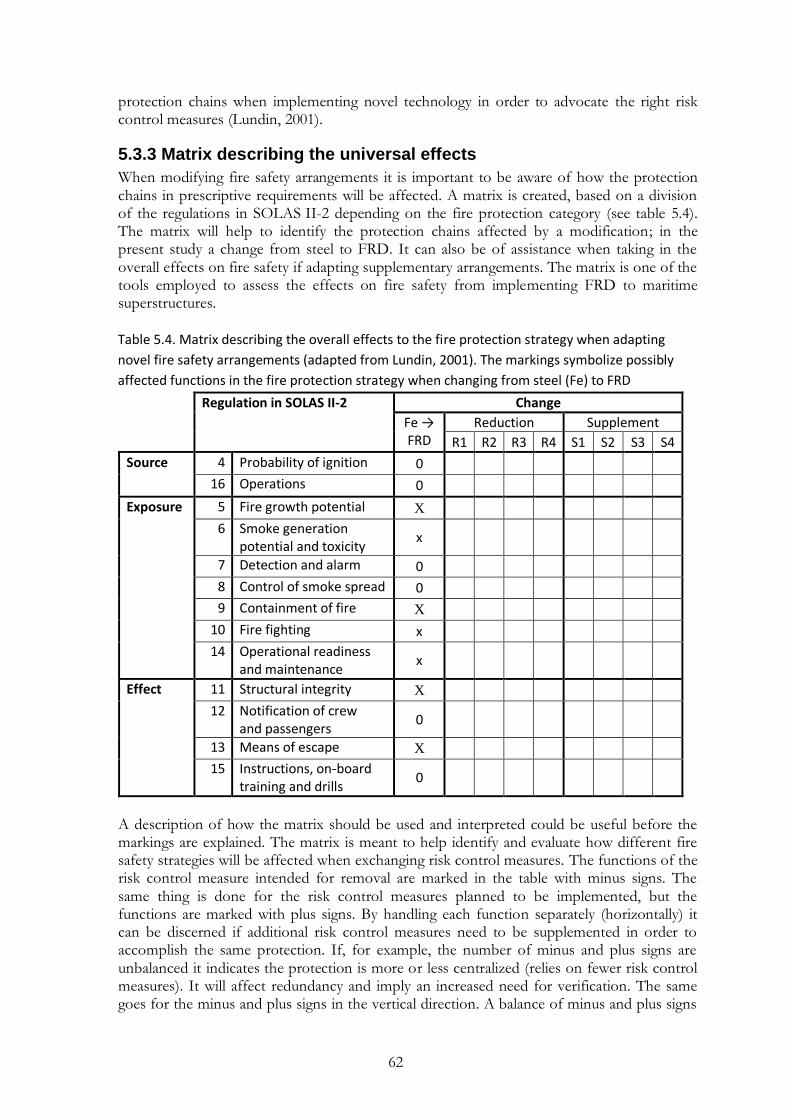
62
protection chains when implementing novel technology in order to advocate the right risk control measures (Lundin, 2001).
5.3.3 Matrix describing the universal effects
When modifying fire safety arrangements it is important to be aware of how the protection chains in prescriptive requirements will be affected. A matrix is created, based on a division of the regulations in SOLAS II-2 depending on the fire protection category (see table 5.4). The matrix will help to identify the protection chains affected by a modification; in the present study a change from steel to FRD. It can also be of assistance when taking in the overall effects on fire safety if adapting supplementary arrangements. The matrix is one of the tools employed to assess the effects on fire safety from implementing FRD to maritime superstructures.
Table 5.4. Matrix describing the overall effects to the fire protection strategy when adapting
novel fire safety arrangements (adapted from Lundin, 2001). The markings symbolize possibly
affected functions in the fire protection strategy when changing from steel (Fe) to FRD
Regulation in SOLAS II-2 Change
Fe → FRD
Reduction Supplement
R1 R2 R3 R4 S1 S2 S3 S4
Source 4 Probability of ignition 0
16 Operations 0
Exposure 5 Fire growth potential X
6 Smoke generation potential and toxicity
x
7 Detection and alarm 0
8 Control of smoke spread 0
9 Containment of fire X
10 Fire fighting x
14 Operational readiness and maintenance
x
Effect 11 Structural integrity X
12 Notification of crew and passengers
0
13 Means of escape X
15 Instructions, on-board training and drills
0
A description of how the matrix should be used and interpreted could be useful before the markings are explained. The matrix is meant to help identify and evaluate how different fire safety strategies will be affected when exchanging risk control measures. The functions of the risk control measure intended for removal are marked in the table with minus signs. The same thing is done for the risk control measures planned to be implemented, but the functions are marked with plus signs. By handling each function separately (horizontally) it can be discerned if additional risk control measures need to be supplemented in order to accomplish the same protection. If, for example, the number of minus and plus signs are unbalanced it indicates the protection is more or less centralized (relies on fewer risk control measures). It will affect redundancy and imply an increased need for verification. The same goes for the minus and plus signs in the vertical direction. A balance of minus and plus signs
63
will, however, not imply the same level of safety has been achieved. If the markings are spread vertically it indicates a fire protection function has been replaced by protection of a different category. It means some of the protection chains have been modified which also increases the requirements on verification. If, however, a change implies reduction and supplement only within one fire protection category there could be a possibility that the needs for verification are minor. An evaluation of safety functions is although always necessary (Lundin, 2001).
5.3.4 Marking changes in the matrix
In this study the change from steel to FRD is to be evaluated in terms of fire safety. It is not the same thing as exchanging risk control measures but the matrix can reveal some interesting information. For the purpose of evaluating an FRD design in relation to steel, an additional column has been added to the matrix, table 5.4. Markings in this column show how functions (regulations) in the fire protection strategy may be affected by a change from steel (Fe) to FRD. Below follows explanations to the markings in the added column. Section 5.1 Fire safety regulations made a number of fire safety functions topical. Some of them were Regulations 9, 11 and 13 which are marked with a capital “X” in the matrix, implying the functions will definitely be affected. Regulation 9, placed under “exposure” in the fire protection strategy, is one of the functions with certain positive effects. The increased thermal insulating capacity implies less heat will be conducted in FRD than in a steel struc-ture. This would delay propagation of fire and better isolate the fire in the space of origin, which is what the regulation is about. Regulation 11 and Regulation 13 represent functions placed under “effect” in the fire protection strategy. Local collapse will be more likely to occur in the novel design but the insulating capacity will improve conditions in adjacent spaces. Whether the total effect will be better or worse does not need to be distinguished in order to establish that there will be certain differences in the fire protection strategy. Regulation 5 is also marked with a capital “X” in table 5.4. The regulation is placed under “exposure” in the fire protection strategy and, considering the unprotected external surfaces, this function will clearly be affected. The external surfaces will probably be subject to supplementary mitigation efforts, which could be marked in the matrix when established. An outdoor fire would, however, make smoke production less significant (Regulation 6). Leaving out external surfaces there is reason to believe a fire development would be more limited in an FRD design, which implies a positive change. This function is, however, represented in Regulation 9. There are no reasons to believe smoke spread would behave differently and the smoke production would not be different except in the exceptional case of a delayed evacuation. Then, however, there could be a minor difference, hence the lower-case “x” by Regulation 6, representing functions with possibly minor effects due to a change to FRD. Functions in the fire protection strategy without any relevant effects are marked with “0”. Regulation 10 and Regulation 14, under exposure in the fire protection strategy, have also been denoted with lower-case “x” in the matrix. The reason for this is the need for special training for fire fighting and maintenance in the novel structure. When carrying out work onboard, personnel need to know how to renovate with sufficient fire protection afterwards. Strict routines for maintenance and control need to be established in order to avoid exposure of combustible FRP material. This issue, on the other hand, needs to be brought up in management systems also for steel designs (see 3.7.3 Safety culture affects the risk). When it comes to fire fighting there will be no need for boundary cooling when fire occurs in FRD compartments. The effect from sound insulating properties could relieve some of the crew to assist with the evacuation instead. Another difference when fighting fires in composite
64
compartments is that it can be carried out without actually entering the fire enclosure. The gear for such operations is considered standard equipment for fire fighting in composite structures. It is obviously more effective for fires in small spaces, such as cabins, whilst regular routines are more practicable in larger spaces. Moreover, if a fire proceeds for more than an hour in a compartment, fire fighters need to further consider the risk of local collapse.
5.3.5 Using the matrix to analyze a change to FRD
The markings in the matrix are now to be interpreted. Since the indications are only made to recognize changes, there is obviously nothing to be made out of the horizontal balance of signs. Whether the effects on the marked functions in the fire protection strategy are positive or negative needs to be further analyzed which, however, also is a result. When the effects on functions have been made clear, supplementary risk control measures can be implemented to mitigate risks to the relevant functions. Looking at the markings from a vertical point of view there are no indications on effects on ignition sources. The markings are, however, widely spread in the “exposure” and “effect” categories of the fire protection strategy. It indicates many different parts of the strategy will be affected by a change to FRD, which increases the needs for verification. Seven out of eleven functions will possibly be affected by the change, meaning many of the protection chains will be modified. This raises the needs for verification in order to establish the effects for fire safety. When the effects have been recognized and estimated the matrix can help find suitable supplementary actions. Using the matrix helps identify and evaluate how different fire safety strategies are affected but it is also important to evaluate the intrinsic effects on fire safety. Can for example an increase in capacity for a risk control measure targeting the effects to an endpoint replace a measure targeting the exposure, or are there other perspectives to consider. This will be evaluated by investigating fire safety properties and how different functions interrelate.
5.4 The fire safety properties
When evaluating changes in safety systems it is typically done by comparing the affected functions, e.g. how changes will have an effect on conditions for evacuation. Safety systems can, however, also be described by different properties revealing their overall performance (Meister, 1991). For example, the distance in escape routes, quality of linings and insulation for load-bearing structures cannot be reduced and complemented only by installing a sprinkler system intended to extinguish a possible fire. The achieved safety will not be the same, e.g. since it is not enough only comparing systems when they are working. Active systems generally have lower reliability than passive systems, which needs to be accounted for when comparing safety (Lundin, 2001). Even if the reliability of a sprinkler system is fairly high and the expected outcome from a system is acceptable, it does not imply the distribution of outcomes is acceptable. The consequences in case a system does not reach the expected function may be catastrophic and might not be accepted by society, which will imply great effects on the market and development of technology. This section will evaluate how the implicit fire safety in a prescriptive design will be affected by a change to FRD in order to establish the needs for verification. It will be done by investigating characteristic properties of a system for fire safety, suggested by Lundin (2001), and how these will be affected. The effects when changing from steel (Fe) to FRD are marked in table 5.5 and explained subsequently.
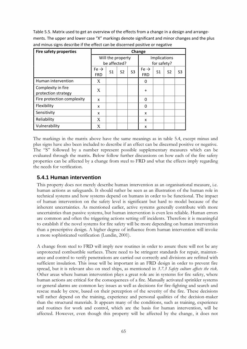
65
Table 5.5. Matrix used to get an overview of the effects from a change in a design and arrange-
ments. The upper and lower case “X” markings denote significant and minor changes and the plus
and minus signs describe if the effect can be discerned positive or negative
Fire safety properties Change
Will the property be affected?
Implications for safety?
Fe → FRD
S1 S2 S3 Fe → FRD
S1 S2 S3
Human intervention X 0
Complexity in fire protection strategy
X
+
Fire protection complexity x 0
Flexibility x 0
Sensitivity x x
Reliability X x
Vulnerability X x
The markings in the matrix above have the same meanings as in table 5.4, except minus and plus signs have also been included to describe if an effect can be discerned positive or negative. The “S” followed by a number represent possible supplementary measures which can be evaluated through the matrix. Below follow further discussions on how each of the fire safety properties can be affected by a change from steel to FRD and what the effects imply regarding the needs for verification.
5.4.1 Human intervention
This property does not merely describe human intervention as an organisational measure, i.e. human actions as safeguards. It should rather be seen as an illustration of the human role in technical systems and how systems depend on humans in order to be functional. The impact of human intervention on the safety level is significant but hard to model because of the inherent uncertainties. As mentioned earlier, active systems generally contribute with more uncertainties than passive systems, but human intervention is even less reliable. Human errors are common and often the triggering actions setting off incidents. Therefore it is meaningful to establish if the novel systems for fire safety will be more depending on human intervention than a prescriptive design. A higher degree of influence from human intervention will invoke a more sophisticated verification (Lundin, 2001). A change from steel to FRD will imply new routines in order to assure there will not be any unprotected combustible surfaces. There need to be stringent standards for repair, mainten-ance and control to verify penetrations are carried out correctly and divisions are refitted with sufficient insulation. This issue will be important in an FRD design in order to prevent fire spread, but it is relevant also on steel ships, as mentioned in 3.7.3 Safety culture affects the risk. Other areas where human intervention plays a great role are in systems for fire safety, where human actions are critical for the consequences of a fire. Manually activated sprinkler systems or general alarms are common key issues as well as decisions for fire-fighting and search and rescue made by crew, based on their perception of the severity of the fire. These decisions will rather depend on the training, experience and personal qualities of the decision-maker than the structural materials. It appears many of the conditions, such as training, experience and routines for work and control, which are the basis for human intervention, will be affected. However, even though this property will be affected by the change, it does not
66
mean the safety of the design will be lower. Human intervention will affect the novel design similar to how it will affect the fire safety of a prescriptive design. New routines and training might even be a stimulating change to the crew. The decreased experience of FRD designs and a possibility of different routines for different parts of the ship might although have a negative influence on human intervention. As a general conclusion, the changes in human intervention are although not considered to have any significant effects on fire safety.
5.4.2 Complexity in the fire protection strategy
If it was possible it would be safe and uncomplicated if every single hazard was targeted with its own specific protection. There are, however, great benefits with coordinating risk control measures to target several parts of the fire protection strategy and more than one endpoint (see 5.3.2 Multi-purpose complexities). Building interdependent protection chains will, however, not only result in a complex network, which can be hard to comprehend, it will also provide conditions for common cause failures (CCF). When several risk control measures are replaced by one measure, or by many dependant measures, it will cause some protection barriers to fall. An example can be a failure in detection of a fire which will cause late responses in escape, fire fighting and sprinkler activation (if activated manually or as a result of detection). The relationships between systems can also cover dependencies, which can bring about hazardous and incontrollable “snow ball” (exponential) effects when several systems fail at the same time. Increased complexities in the fire protection strategy can get huge consequences if the designer is not aware of the relationships between protection chains. A fire protection strategy with high complexity therefore implies higher demands on verification (Lundin, 2001). A relevant example of how common cause failures can be mitigated is by dividing a construc-tion into fire zones. This is accomplished in SOLAS by prescribing structural main vertical and horizontal zones, see e.g. Regulations 2 and 9. The division into structural fire zones will limit the consequences in case e.g. the sprinkler system fails to work as intended or if the fire fighting crew needs to fall back. Improved thermal insulation in the novel structure would make all spaces separated by FRD-60 divisions into structural fire zones in case no other than fire resistance requirements were of interest. No main divisions with extreme capacity will exist but all divisions will be adapted into the higher standard, which will reduce complexity. A reduction in complexity will also be the result when heat can no longer be conducted far through the structure and bring about fires where there are weaknesses in integrity. A change from steel to FRD could also imply an increase in complexity since some mitigating efforts need to be implemented in order to protect external surfaces. The combustible surfaces represent an additional target for risk control measures which inevitably will add to the already complex fire protection strategy. The total effect on complexity in the fire protection system is estimated positive but needs to be further verified.
5.4.3 Fire protection complexity
The function of a technical system for fire protection many times depends on the perfor-mance of several components or subsystems. For example, in order to get smoke ventilation to function the smoke needs to be detected, detectors need to be functioning, control systems needs to work as intended, the ventilation openings must open and the supply of air needs to function. The same thing goes for sprinkler systems where detectors, sprinkler heads, pipes, control systems, pumps and, not the least, drainage needs to be functioning in order to assure the expected function. Building technical systems depending on the function of many components will increase the complexity and inevitably the probability of failure since more sources and combinations for error exist. It is also common for technical systems for fire protection to be integrated with everyday functions, e.g. ventilation and control of

67
doors. The cooperation with other systems will further enlarge the network of systems. It will increase the complexities and increase the needs for verification (Lundin, 2001). The least complex fire protection is that of passive structures. They are generally quite inde-pendent from other influences even if those occur, e.g. doors, windows and penetrations. The overall change to FRD is on this level and will not imply any great increases in complexity. The exterior surfaces will, however, require an additional passive or active system which will somewhat increase the complexity of the whole fire protection system. A drencher system would although not require any drainage and the risk of list would not be increased. Other than that, there are no apparent increases in complexity in the fire protection system that will affect safety. The above changes should be taken into account and the effects verified even if changes in complexity are not considered to have any great effects on safety.
5.4.4 Flexibility
The possibility for a system to accomplish the expected function in different ways is called flexibility. Systems for fire safety can often achieve objectives by targeting different parts of the fire protection strategy (see figure 5.1). If the prevention of fire sources fails there will be measures to prevent and limit exposure of fire, and if that fails there are measures to prevent and limit the effects from fire. Combining different independent risk control measures targe-ting different parts of the fire protection strategy will give the system several possibilities to e.g. control fire. It will make the system flexible, which also characterizes a measure of redundancy. If a change in the fire protection strategy will make a system less flexible it can somewhat be compensated by increasing the reliability, i.e. the probability for a system to obtain the expected function. A lower flexibility will although also increase the needs for verification (Lundin, 2001). Building an FRD superstructure on a ship will imply differences in the approach for fire fighting crew. The novel material will allow for fire fighting without entering the fire enclosure, which is an additional measure for fire protection. The flexibility can also be affected if a fire is not under control within 60 minutes. If the probability for collapse is greater in the novel construction it can hinder fire fighting crew from accomplishing their task which will reduce flexibility. The overall effect on flexibility is although considered minor and will not have any significant effect on safety.
5.4.5 Sensitivity
The sensitivity of a system describes the importance of conditions and assumptions for a system to function as intended. In a system for fire safety there might be conditions and assumptions necessary to make the design for fire protection sufficient. Will achievement depend on the number of people in the compartment, weather conditions, occurrence of fire sources, the activities in the space, if a fire was set off by arson, if a penetration is not properly insulated, on the furnishings or on a certain risk control measure such as the sprinkler system? Factors such as the activity in the compartment, how things are carried out or necessary restrictions will often increase the sensitivity of a system. Restrictions to activi-ties and human behaviour are often hard to control and seldom given enough resources. An increase in sensitivity needs to be taken into account when verifying system safety (Lundin, 2001). When evaluating fire safety in the novel design there are some functions of great importance for the design to perform satisfactory. The sprinkler system is one of the most important systems onboard and will determine the consequences of a fire. This will, however, be the same in both steel and FRD designs. A difference if the sprinkler system fails to control the
68
fire is that the fire safety in the novel design and arrangements is based on the improved insulation of decks and bulkheads. The sensitivity to defects in fire protection of the structure should therefore be evaluated. Most likely, a fire contained in the space of origin in the novel structure will be more isolated and less dependent on circumstances, such as the performance of fire fighting and sprinkler system. The load-bearing capacity of the structure is not particularly sensitive to the magnitude of loading, but rather to the time it is exposed to fire. Before the temperature in the interface between the exposed laminate and the core reaches a certain temperature the strength will not be affected. Since the structure will persist 60 minutes of fully developed fire it can be said to be independent of the fire development within this period. The capacity after that will, however, depend on the previous development and the effect of mitigating efforts. A fire on external surfaces will also be sensitive to the function of its protection, which will imply a difference between the designs. The effects on sensitivity by a change to FRD need to be further analyzed in order to establish how the safety will be affected.
5.4.6 Reliability
The reliability of a system can be defined as the probability of achieving the intended function of a system. The reliability of a system is generally connected with the probability of errors in the system but can also have to do with its ability to manage working strains. For example the reliability of a sprinkler system will not only depend on the probability of technical failure but also on how likely it is that the specific fire is manageable. Low reliability naturally implies greater needs for verification and especially requires an evaluation of the consequences if the system fails (Lundin, 2001). The increased probability of a fire on exterior surfaces will inevitably imply a decreased reliability, regardless of the mitigating efforts. Drencher systems generally have high reliability and fire fighting crew can also assist to make the fire protection strategy more flexible and reliable. However, since the surfaces go from being non-combustible to combustible the reliability will be lessened as long as the surfaces are not made non-combustible again. This decrease in reliability can have minor effects on safety but the possible consequences of an uncontrolled external fire need to be analyzed in order to verify the safety of the FRD design. The improved thermal insulation for interior divisions will increase reliability when it comes to containing the fire in the compartment of origin. The question is how the consequences will be affected if a fire is not under control after 60 minutes in the novel design. The reliability will definitely be affected by a change to FRD structure, but in order to establish the effects on safety the consequences need to be analyzed in association with the changes in reliability. These effects can be further analyzed in a risk analysis.
5.4.7 Vulnerability
Vulnerability is an undesired property which describes the ability of a system to survive internal and external strains. Internal vulnerability refers to the same characteristics as reliability whilst external vulnerability is determined by the probability that a system will function as designed when exposed to external stresses, such as arson, power outs, explosion, weather conditions etc. Some of the qualities characterizing low vulnerability are stability, perseverance and an ability to resist interference (Lundin, 2001). Common sources of vulnerability are activities and circumstances, which e.g. can lead to keeping doors open in some way and for some time. In case of fire it will provide with additional oxygen to the fire and obliterate the limitation of smoke and fire spread. The general rule in prescriptive requirements is to provide two escape routes from all spaces in order to increase the reliability of successful escape. In the same way as doors are often kept

69
open, they are also vulnerable to blockage, which will reduce the ability to escape fire. These vulnerabilities can be reduced by a better understanding of the different functions in the system for fire protection, i.e. through education, training and experience. The above vulnerabilities are although the same in both FRD and prescriptive designs. Except what is mentioned in section 5.4.6 Reliability there may be differences in vulnerability when it comes to maintenance and sabotage. Since the structure is based on improved insulation qualities to protect the combustible FRP composite, the insulation may also becomes a source of vulnerability. The sensitivity against defects in the fire protection was also identified as a prospect for further investigation in 5.4.5 Sensitivity. Another point mentioned above is the external surfaces and how e.g. a drencher system will be a vulnerable component when it comes to extinguishing an external fire. The fact that the FRD design in this case implies a change from steel to FRD-60 in the whole superstructure will reduce the vulnerability of the fire protection. It will be less vulnerable to hazardous circumstances and activity changes since the whole FRD design already meets the highest requirements for structural integrity. The vulnerability of the system in case a fire lasts for more than 60 minutes, however, needs to be further investigated. Some of the properties represented in the sections above are closely related to the vulnera-bility of a system, which makes it hard to delimit the changes in this property. From the discussions, the general conclusion is although drawn that the vulnerability of the fire protect-tion will be affected and that the effects on safety may be positive. However, this needs to be further investigated through e.g. a risk analysis.
5.5 The fire development
In the previous analyses, characteristics of an FRD design have been investigated in detailed and holistic manners in order to ascertain the impact of the novel structure on fire safety. Differences revealed above are discussed below with respect to fire dynamics and draws on conclusions from diverse tests carried out at SP Technical Research Institute of Sweden (Hertzberg, 2009; Arvidsson et al., 2008). This suggests how differences between the structures may affect the fire development with a holistic approach. The analysis aims at identifying differences to consider in the proceeding analysis of fire safety. The first sections consider the internal spaces in different stages of a fire whilst exterior surfaces are discussed separately in the following. The ending section summarizes all five analyses of this chapter.
5.5.1 Ignition and the first stages of an enclosure fire
Differences in routines for e.g. maintenance and repair will imply dissimilarities when it comes to fire sources. It can, however, be justified to assume neither the probability of ignition nor the first development of enclosure fires will be considerably affected by the new design of load-bearing structures. Ignition sources will for the most part be alike and hard to restrict on passenger ships, especially when including arson as a possible source of fire. The first stages of a fire do not depend on the load-bearing structures but are rather dependable on conditions such as ignition sources, the availability of flammable materials, fire load, ventilation openings, fire control installations, etc. which are all assumed to be identical in the two designs. At this stage the fire will be detected, sprinkler system and other active measures will be set off and general alarms will be activated and evacuation initiated. It implies most fires will be controlled and extinguished in this early stage of fire development which reveals no major differences between the prescriptive design and the alternative design and arrangements at this stage. There might, however, be extended possibilities for fire fighting crew to extinguish a fire from adjacent spaces. If a fire, for whatever reason, is given the

70
possibility to develop dissimilarities will eventually appear as the fire proceeds (Arvidsson et al., 2008). The above implies, if a fire breaks out in an FRD construction the conditions will not be worse than in a prescriptive design the first 60 minutes. The outbreak and the first stage of a fire will be formed by settings within the space, such as possible ignition sources, fire load, ventilation openings, fire suppressing installations, etc. These circumstances will not be affected by the material in divisions and will be assumed identical to the conditions in a prescriptive design. Most likely a fire will be extinguished at an early stage but in case of e.g. a sprinkler failure it might progress into a fully developed fire. If the fire restricting installations fail, the differences with an alternative design can cause a somewhat higher temperature in the fire enclosure because of the increased thermal insulation in the composite construction. On the other hand, for the same reason, conduction of heat and propagation of fire to adjacent spaces would be delayed which improves fire safety. The big question is however what will happen after 60 minutes of fire that the prescriptive fire tests embrace.
5.5.2 Structural divisions within the first 60 minutes
Can FRD be considered equivalent to steel? It deteriorates at 130-140 ˚C which is equal to about one minute of fire exposure to the FRP composite. However, if only a part of the material would be exposed to heat, just that limited area would be subject to deformation since FRD, unlike steel, does not conduct heat very well. Steel starts to deteriorate at a much higher temperature (400-500 ˚C) but the improved thermal insulation of an FRD construc-tion implies adjacent spaces will be at normal temperature while a steel design allows 140 (180) ˚C on the other side of a division (Hertzberg, 2009). All divisions will have at least 60 minutes of thermal insulation which will be a great increase in some places (compared with e.g. A-0 divisions). In terms of fire safety requirements it implies all spaces become fire zones. It will also reduce complexity, sensitivity and vulnera-bility when all divisions are the same and adapted to the highest standard. When assessing fire safety in a novel FRD design it will therefore be noteworthy how many decks and bulkheads are intended for the improved insulation. Complexity will also be reduced for fire fighters who will not need to focus on boundary cooling and will be able to extinguish a fire without actually entering the fire enclosure. The prerequisite of not allowing any interior composite surfaces without at least 60 minutes of fire protective insulation results in less heat conducted through the construction to adja-cent compartments. It will diminish the risk for fire spread due to heat transfer through the enclosure boundary and delay propagation of fire to adjacent spaces. Down to the improved thermal insulation, the decks, bulkheads and ambience in adjacent spaces will be of ambient temperature which could be advantageous in an escape situation and increase the probability of a successful escape. More crew could help with the evacuation since there is no need for boundary cooling and the time available for escape and evacuation could be increased down to the improved thermal insulation. Evacuation should be designed to be completed within these first 60 minutes of improved conditions. A non-extinguished fire will be confined within the FRD space for the first 60 minutes and it will be better contained than a prescriptive steel design. The structure will not be deformed even if a fire is uncontrolled and reaches flash-over, and heat will not be conducted to other places of the ship as in a steel design. The sensitivity to defects in fire protection should also be evaluated to ensure robustness of the novel design. Since the properties of an FRD structure are heavily based on the improved insulation capacity it needs to be established how

71
sensitive the performance is to damage. Routines for maintenance and control need to be established in order to avoid exposure of combustible FRP material. The consequences if the structure would although be damaged, e.g. from maintenance, penetrations or sabotage, may, however, still need to be investigated. The heat from a fire will to a larger extent stay in the space of origin and not easily be transmitted to adjacent spaces, which could be beneficial from a fire safety point of view. A backside to the improved insulation could be an increased temperature in the fire compart-ment, which also would imply a somewhat increased heat release rate. However, the possible increase in temperature due to the decreased transmission of heat through boundaries will reasonably be minute.8,9 Furthermore, if a fire is not isolated in one space, e.g. if a door is left open, air from adjacent spaces will mix in which will make the effect even less significant. If a fire is isolated in one space it will lead to lack of oxygen and diminish the fire before any such effects would occur. The heat release rate is rather depending on the contents in the space which, however, would not affect the FRD since it is tested against 60 minutes of fully developed fire. An increase in temperature in the space of origin will probably be insignificant but there could still be reasons to confirm this in simulations or tests. If the hypothesis is proved, the increased insulation will only lead to improved conditions for fire safety within the first 60 minutes.
5.5.3 Structural divisions after propagation or deterioration (> 60 min)
If a fire is not under control after 60 minutes the FRP composite will be considered to take part in the propagating fire. Provided with enough energy to reach the composite in spite of the used insulation it would in fact worsen the already hazardous conditions. Not only by adding more fuel to the fire but also by increasing the smoke production. Down to the improved thermal insulation capacity this stage of a fire is less likely to occur, and if it happens it is likely to be delayed in an FRD design. This stage would only be reached after 60 minutes of uncontrolled fire and a ship should already have been evacuated by then. Even if the consequences, when it comes to evaluating hazards to life in the new design, seem to be of minor importance it should still be brought to attention in an analysis. More combustible materials will exist onboard, even if unavailable for a fire within the first 60 minutes. When contributing with combustible materials it will increase the fire load and the production of smoke and toxic products to the uncontrolled fire. At this stage conditions must already have become uninhabitable in many more ways, especially in the space of origin. Even if no one is present in the already uninhabitable spaces after 60 minutes it could be hazardous to persons on the embarkation deck in case of an unfortunate wind. The questions are if a fire is more likely to be under control in an FRD design and what the consequences will be? How will the consequences be affected by the FRD design after 60 minutes of fire? In the exceptional case of a time-consuming fire, collapse will be more likely to occur in the FRD construction, due to the properties of the FRP composite material. Although, if only a part of the FRP composite is exposed to extraordinary heat or flames, the deterioration and collapse would be local. Furthermore, the load-bearing capacity of FRD is
8 Tommy Hertzberg, SP Technical Research Institute of Sweden. Phone conversation 5 August 2009.
9 Håkan Frantzich, Department of Fire Safety Engineering and Systems Safety, Lund University. Conversation 19 August 2009.

72
not very dependable on the loading but rather on the fire development and the time of exposure. The reference steel construction also suffers from deformation problems and strength deterioration when heated enough. In this case it is mainly dependable on the heat transfer properties of steel. Fire fighting will therefore be very difficult at this stage, both in an FRD design and a prescriptive design (Arvidsson et al., 2008). A fire might be more likely to be controlled in the novel design and thanks to the improved conditions within the first 60 minutes the expected outcome might be acceptable. However, the consequences in case of failure still need to be considered. The result after more than 60 minutes may be catastrophic because of the increased amount of combustible materials. Any magnitude of consequences will not be acceptable if e.g. the sprinkler system fails and an evacuation is protracted, which is not unusual (Vanem & Skjong, 2004b). Even if not directly affected by the fire, an increased smoke production could e.g. imply an additional risk to people embarking life safety appliances. Differences in ability to resist collapse could also affect the initiation of an evacuation itself. The evacuation process could be hazardous and affected by the novel design which invokes to also account for risks in the evacuation process.
5.5.4 Exterior surfaces
A direct change from steel to FRP would not imply increased risks when it comes to ignition sources but unprotected external surfaces would definitely be a source of fire risk. Exchan-ging the external steel surfaces with combustible FRP composite will give an uncontrolled fire the ability to propagate vertically if a window breaks or if a balcony door is left open. Except including external surfaces in the fire it could imply fire spread between decks and fire zones. This issue has been given much attention and full scale tests have been carried out on the matter in order to find suitable mitigating measures. To produce FRP face sheets with low flame-spread characteristics or to install a drencher system for all external surfaces are the leading alternatives at the moment. If a drencher will be used to extinguish an external fire the achievement will be sensitive to the function of the system, making the drencher a vulne-rable measure. New routines could, however, also include fire fighting crew to prevent and limit fire propagation on external surfaces. The change from “non-combustible” to “combus-tible but protected” implies a possibility for smoke production and fire spread in case the chosen risk control measure malfunctions and will therefore reduce reliability. The fact that external surfaces on ships are typically made of painted steel makes it hard to distinguish from prescriptive requirements what level of fire safety should be required. However, the unprotected external surfaces of the FRD base design need to be managed and the effects evaluated in an analysis (Arvidsson et al., 2008). As a general conclusion one could regard the novel design to be advantageous in comparison with a prescriptive design within the first 60 minutes, which is the time the performance of decks and bulkheads are tested and an evacuation should be carried out. Depending on the proceeding scenario, differences between the designs might come in to play which could affect the fire safety of a ship in a negative way.
5.6 Summary of the preceding analyses
The five performed analyses above revealed several important effects on the implicit level of fire safety that need to be verified. The first analysis of the fire safety regulations disclosed some regulation purpose statements and prescriptive requirements which may be challenged by an FRD design. In particular the requirements on non-combustible and steel or equivalent materials cannot be achieved by the novel material, even if the accomplished safety may be
73
sufficient. It was also found that the current steel-based regulations are not fully applicable for FRD designs as they do not consider combustible exterior surfaces. When it comes to the fire safety objectives of SOLAS II-2, an FRD design may fulfil some of the objectives superior to a traditional design down to its improved thermal insulation. The focus on safety of human life in the fire safety objectives makes it topical to address, not only the safety of passengers, but also the safety of fire fighters and crew. Investigating the func-tional requirements for the whole fire safety chapter in SOLAS especially indicated that the risks when adding combustible materials need to be accounted for. Effects on the fire safety structure mainly concerned the exposure and effect parts of the fire protection strategy and invoke thorough verification since the changes will affect many protec-tion chains. The following analysis of fire safety properties showed that particularly human intervention, complexity in fire protection strategy, reliability and vulnerability will be affected. The implications for safety may, however, not be very significant for all of these properties. When the revealed differences were put in the context of fire dynamics it was established that the ignition and first stages of a fire will be unaffected by a change to FRD. In case the circumstances allow a fire to progress, it will reasonably be better contained in an FRD structure within the first 60 minutes. The conditions in an FRD design if a fire develops past 60 minutes may although be worse, in comparison with a traditional design. Fire safety will also be negatively affected in case a fire includes external surfaces, which will go from being non-combustible in a steel design to combustible but protected in an FRD design. Safety may be affected differently depending on the considered spaces (e.g. cabin, restaurant or bridge) and on the degree of novelty in the alternative design and arrangements. The most important effects on fire safety when introducing FRD to maritime superstructures have been recognized in the analyses above. Both positive and negative effects on the analyzed aspects of fire safety need to be verified when evaluating an FRD design in comparison with a prescriptive design. There are several approaches to verify these differences. If an FRD construction is intended to involve minor parts of a superstructure a fire safety engineering analysis could be carried out for each space, comparing every element in detail. Alternatively a deterministic risk-based approach could provide the sufficient validation when evaluating the alternative design and arrangements. When a major part of a ship, such as a large superstructure, is addressed, the complexity in fire risks increases rapidly. All fire safety arrangements have to be placed in the design itself and the fire safety will depend fully on the novel design and arrangements. For example, if a fire progresses for more than 60 minutes, no other means for escape will be available than those provided in the novel superstructure, as opposed to if only a minor part of the superstructure was intended in FRD. It implies redundancy is even more significant in a major FRD design, and a more sophisticated method for verification is necessary. The above analyses revealed differences which will be the foundation for a recommendation of analysis methods, depending on the uncertainties and the scope of the intended FRD design, in the following chapter.

74

75
6. Risk analysis for verification In this report a risk-based approach will be endorsed to assess the effects to fire safety when introducing FRD as a construction material. The reasons for performing a risk analysis can be many, e.g. to introduce a novel technology or to utilize a grand design, but many times it is also required by the authorities. From a government point-of-view there are different approaches when it comes to regulating risk analyses. Within the offshore industry in Norway risk analyses have been requisite since 1986 (Skjong, 1999). Legislation entitles authorities to have insight into the decision-making process in the individual enterprise, including policies and target levels, and gives them access to all relevant documentation. The approach is called “self-regulatory” since the authority does not approve the documentation or safety targets; that is the responsibility of the owner. Another option for the authority is to set the safety targets and make it up to the ship constructors to design a ship according to a, by the authority prescribed, safety level. A more controlling approach can be to, except perusing the analyses, prescribe the models or scenarios to be used when evaluating the risks, as in land-based regulation in the Netherlands. In any case, both designers and approval authorities must be conversant with the usage of risk analysis tools to assess safety levels as well as the associated uncertainties when introducing novel technology. The key to determine the needs for verification is to identify the uncertainties bound with a design (Lundin, Delin & Johansson, 2005). The analyses in the preceding chapter can all be said to study uncertainties of the FRD design. There are uncertainties in all ship designs, but when introducing technology particularly knowledge uncertainty is significant (see 3.6 Uncertainty). As a consequence of differences in material properties, there is a need to analyze and manage these uncertainties in order to make a decision based on more evaluated (certain) information. The verification needs for the FRD design have been analyzed and the approach to assess fire safety in such design is suggested to be risk-based. Uncertainties are the heart of risk analysis and this chapter aims at describing how uncertainties when introducing FRD should be managed on different levels in risk analysis. The choice of method for verification will depend on the uncer-tainties involved when making changes in the fire protection and on the uncertainties introduced when verifying safety. However, the uncertainties from utilizing a risk analysis in the design process also need to be taken into account when assessing the level of fire safety in a design. Below follows an investigation of uncertainties from different perspectives and how these can be managed on different levels of sophistication. Depending on the uncertainties involved when verifying fire safety and on the uncertainties introduced by the novel design, different methods and approaches to manage uncertainties will be appropriate (Lundin, 2001). Thereafter the prescribed engineering analysis to be carried out when laying claim to Regulation 17 is studied. Finally a proposal is made of an approach to manage changes in fire safety depending on the scope of the intended novelty.
6.1 Uncertainties in a ship design
Not only performance-based designs are bound with uncertainties. Regardless if the basis for a design is prescriptive requirements or a comprehensive risk analysis there will be uncertainties in the achieved safety level. This is illustrated in the idealized figure 6.1.
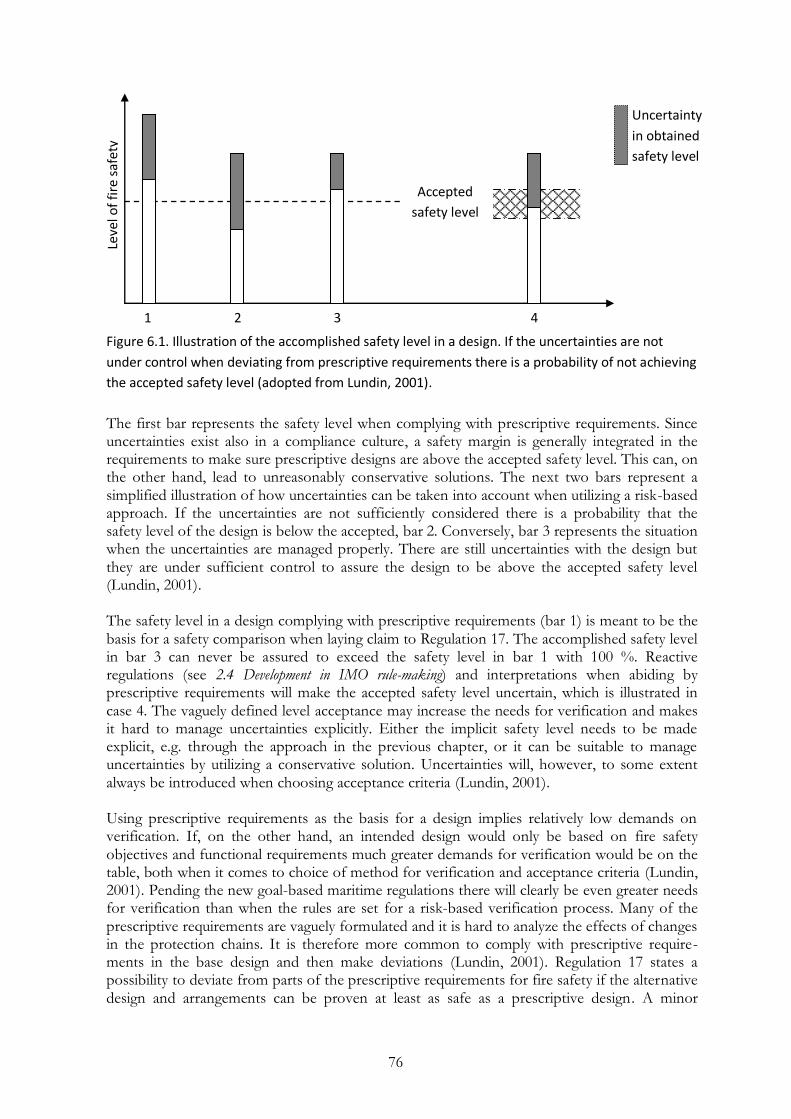
76
Figure 6.1. Illustration of the accomplished safety level in a design. If the uncertainties are not
under control when deviating from prescriptive requirements there is a probability of not achieving
the accepted safety level (adopted from Lundin, 2001).
The first bar represents the safety level when complying with prescriptive requirements. Since uncertainties exist also in a compliance culture, a safety margin is generally integrated in the requirements to make sure prescriptive designs are above the accepted safety level. This can, on the other hand, lead to unreasonably conservative solutions. The next two bars represent a simplified illustration of how uncertainties can be taken into account when utilizing a risk-based approach. If the uncertainties are not sufficiently considered there is a probability that the safety level of the design is below the accepted, bar 2. Conversely, bar 3 represents the situation when the uncertainties are managed properly. There are still uncertainties with the design but they are under sufficient control to assure the design to be above the accepted safety level (Lundin, 2001). The safety level in a design complying with prescriptive requirements (bar 1) is meant to be the basis for a safety comparison when laying claim to Regulation 17. The accomplished safety level in bar 3 can never be assured to exceed the safety level in bar 1 with 100 %. Reactive regulations (see 2.4 Development in IMO rule-making) and interpretations when abiding by prescriptive requirements will make the accepted safety level uncertain, which is illustrated in case 4. The vaguely defined level acceptance may increase the needs for verification and makes it hard to manage uncertainties explicitly. Either the implicit safety level needs to be made explicit, e.g. through the approach in the previous chapter, or it can be suitable to manage uncertainties by utilizing a conservative solution. Uncertainties will, however, to some extent always be introduced when choosing acceptance criteria (Lundin, 2001). Using prescriptive requirements as the basis for a design implies relatively low demands on verification. If, on the other hand, an intended design would only be based on fire safety objectives and functional requirements much greater demands for verification would be on the table, both when it comes to choice of method for verification and acceptance criteria (Lundin, 2001). Pending the new goal-based maritime regulations there will clearly be even greater needs for verification than when the rules are set for a risk-based verification process. Many of the prescriptive requirements are vaguely formulated and it is hard to analyze the effects of changes in the protection chains. It is therefore more common to comply with prescriptive require-ments in the base design and then make deviations (Lundin, 2001). Regulation 17 states a possibility to deviate from parts of the prescriptive requirements for fire safety if the alternative design and arrangements can be proven at least as safe as a prescriptive design. A minor
Leve
l of
fire
saf
ety
Accepted
safety level
Uncertainty
in obtained
safety level
1 2 3 4
safety level

77
deviation (and corresponding implemented risk control measures) will naturally invoke a less comprehensive analysis than several or major deviations. A small deviation from prescriptive requirements can have a rather large effect on fire safety but generally the greater changes, the greater are the intrinsic uncertainties of a new design. These uncertainties can be decreased by greater demands on control when designing, building and operating a ship (Lundin, 2001). It will lead to an increasing demand of documentation in order to describe functionality and a more sophisticated analysis to verify fire safety. A more complex analysis can decrease the influence of design uncertainties but it will inevitably be based on a greater measure of subjec-tivity and other uncertainties associated with establishing the safety level of the design. The uncertainties of the estimated fire safety in a design will therefore depend on the uncertainties involved when making a change to the fire protection and on how these are managed. Uncer-tainties when using risk analysis to assess fire safety in a design are further discussed below.
6.2 Uncertainties from the design process
Complexities in reality require simplifications, assumptions and other uncertainties to be mana-ged; coarsely or in detail. It is understandable that a synoptic description of the fire protection implies greater uncertainties and requires a more conservative solution than if a detailed analysis is performed (Lundin, Delin & Johansson, 2005). When verifying fire safety, uncertainties will nevertheless be involved regardless of the used method. A suitable way to categorize different uncertainties when designing structures can help identify how these can lead to adverse events. There are several ways to classify uncertainties in risk analysis (Lundin, Delin & Johansson, 2005; Blockley, 1980; Bolsover et al., 1998; Rowe, 1994) but classifications generally include uncertainties associated with:
data and parameters;
models (and programs);
the analysis group. Uncertainties associated with data and parameters are the most specific kind of uncertainties. The uncertainties are caused by insufficient data (knowledge based uncertainty) and natural variation (stochastic uncertainty). The uncertainties can be managed through quantitative analyses, e.g. sensitivity analysis or Monte-Carlo simulations. Another option is to investigate historical data or expert judgements, e.g. through a Bayesian analysis (Lundin, 2001). When a model is chosen there has to be a balance between the resolution represented by the model and the application. However, even if a problem lies within the limitations of a model there will be uncertainties in how the model gives an image of reality. To manage these uncertainties it is vital to increase knowledge on the simplifications and assumptions which the employed models are based upon. Experience and expert judgements as well as using different models and approaches are also valuable when dealing with these uncertainties (Davidsson et al., 2003). The uncertainties associated with models and programs are generally small in comparison with the more vague effects from the analysis group. Involving people in the assumptions and decisions implies that competence, experience and human error will have an effect on the uncertainties (see 3.7 Safety culture and human error). People will be involved when defining, delimiting and structuring problems and in all the proceeding stages of the analysis. The choice of models for calculation and evaluation must be suitable and functions properly communi-cated with decision-makers, or else errors will cultivate. A significant subcategory in this class of uncertainty is systematic uncertainty, stemming from uncalibrated instruments, bias by observers or the method of observation. It can be compared with observing information through a dirty window and leads to systematic error for whole data series. This uncertainty is

78
often underestimated and hard to correct since the truth is unknown (Kammen & Hassenzahl, 1999). Policies, appropriate routines and internal or external reviews are essential means to manage these uncertainties. In practice it can be to involve personnel (crew) familiar with the workplace in analyses, exchange experiences between analysts, quality planning, manage known uncertainties and an active search for unknown uncertainties (Morgan & Henrion, 1990). Also resources not associated with the engineer himself can be incorporated in this class of uncertainties. It includes the quality of available programs, models and scientific data, but also limitations in time and funds. Management systems, quality control and good planning are some tools to manage these kinds of uncertainties in the analysis group (Lundin, 2001; Davidsson et al., 2003). Limiting conditions, lack of competence and other uncertainties in the analysis group are generally hard to estimate or to manage quantitatively. Even if it would be desirable to include all uncertainties in one quantitative analysis (see e.g. 3.7.5 Risk management systems as an input to risk analysis) these uncertainties are generally not managed in the risk analysis but rather as a tool for quality assurance in the risk management process. Uncertainties from the analysis group need to be managed, if not in the risk analysis in the risk management process, but will not be further taken into account in the present study.
6.3 Managing uncertainties on different levels in risk analysis
The main innovation when applying a risk-based approach is that the focus will be on uncer-tainties. Risk analysis is really all about evaluating uncertainties. It should describe the effects different uncertainties can have on the result and the possible effect when all these uncertain-ties are considered. Estimations and discussions on uncertainties will contribute with know-ledge and understanding amongst analysts and decision-makers. It can also help structuring the information on complex problems and will lead to a design with a more certain safety level (see figure 6.1 vis-à-vis figure 3.4) (Lundin, Delin & Johansson, 2005; Davidsson et al., 2003). Many different methods, of varying sophistication, can be used to analyze uncertainties in a design, as described in 3.4 Risk analysis. In 1996 Paté-Cornell presented a categorization of how uncertainties can be treated in risk analysis on six different levels of sophistication. The categorization of methods to evaluate uncertainties is a different way to arrange methods for risk analysis than the ones presented in 3.4 Risk analysis. The previous classifications were based on the inclusion of quantitative measures (qualitative-quantitative) and the consideration of likelihood for outcomes (deterministic-probabilistic). Paté-Cornell‟s categorization of methods depending on sophistication includes the previous features and describes how uncertainties are investigated with varying thoroughness. This systematic approach will be the basis for a recommendation of how to choose risk analysis methods for verification of FRD designs. Below follows a simplified outline of the different levels of treatment of uncertainties in risk analysis according to Paté-Cornell (1996).
6.3.1 Level 0: identification of hazards and failure modes
This level comprises a process of detecting potential hazards or modes in which a system can fail. What If?, HAZOP, and FMEA are examples of methods on this level (see Appendix A. Definitions), all with varying systematic approaches. Methods on this level are mainly deter-ministic. It implies the magnitude of risks cannot be fully compared and the cost-effective-ness of risk control measures cannot be ranked. Methods on this level may, however, be satisfying in cases when no risk is accepted and the mere identification of a potential hazard will lead to mitigation efforts. True zero-risk acceptance policies are although rare since very small risks bottom line will be subject to a judgment call, interpreting them as existing hazards or not. Some uncertainties will be integrated when certain potential hazards are
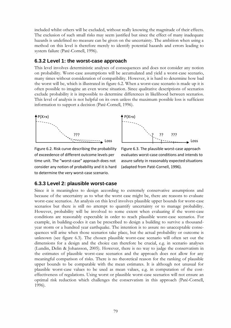
79
included whilst others will be excluded, without really knowing the magnitude of their effects. The exclusion of such small risks may seem justified but since the effect of many inadequate hazards is undefined no measure can be given on the uncertainty. The ambition when using a method on this level is therefore merely to identify potential hazards and errors leading to system failure (Paté-Cornell, 1996).
6.3.2 Level 1: the worst-case approach
This level involves deterministic analyses of consequences and does not consider any notion on probability. Worst-case assumptions will be accumulated and yield a worst-case scenario, many times without consideration of compatibility. However, it is hard to determine how bad the worst will be, which is illustrated in figure 6.2. When a worst-case scenario is made up it is often possible to imagine an even worse situation. Since qualitative descriptions of scenarios exclude probability it is impossible to determine differences in likelihood between scenarios. This level of analysis is not helpful on its own unless the maximum possible loss is sufficient information to support a decision (Paté-Cornell, 1996).
Figure 6.2. Risk curve describing the probability Figure 6.3. The plausible worst-case approach
of exceedence of different outcome levels per evaluates worst-case conditions and intends to
time unit. The “worst-case” approach does not assure safety in reasonably expected situations
consider any notion of probability and it is hard (adapted from Paté-Cornell, 1996).
to determine the very worst-case scenario.
6.3.3 Level 2: plausible worst-case
Since it is meaningless to design according to extremely conservative assumptions and because of the uncertainty as to what the worst case might be, there are reasons to evaluate worst-case scenarios. An analysis on this level involves plausible upper bounds for worst-case scenarios but there is still no attempt to quantify uncertainty or to manage probability. However, probability will be involved to some extent when evaluating if the worst-case conditions are reasonably expectable in order to reach plausible worst-case scenarios. For example, in building-codes it can be prescribed to design a building to survive a thousand-year storm or a hundred year earthquake. The intention is to assure no unacceptable conse-quences will arise when those scenarios take place, but the actual probability or outcome is unknown (see figure 6.3). The chosen plausible worst-case scenario will often set out the dimensions for a design and the choice can therefore be crucial, e.g. in scenario analyses (Lundin, Delin & Johansson, 2005). However, there is no way to judge the conservatism in the estimates of plausible worst-case scenarios and the approach does not allow for any meaningful comparison of risks. There is no theoretical reason for the ranking of plausible upper bounds to be comparable with the mean estimates. It is although not unusual for plausible worst-case values to be used as mean values, e.g. in computation of the cost-effectiveness of regulations. Using worst or plausible worst-case scenarios will not ensure an optimal risk reduction which challenges the conservatism in this approach (Paté-Cornell, 1996).
P(X>x) P(X>x)
??? ? ?? ???
Loss Loss

80
6.3.4 Level 3: best estimates and central values
The approach on this level is to provide balance to the plausible upper bounds by providing best estimates. The risk is still described by point estimates but central values (the mean, the median or the mode) will impart more information on the loss distribution, i.e. lessen uncer-tainties. Even if the approach sometimes will give zero as the best estimate, the possibility that something might happen cannot be ignored. The mean is the most common central value to use since it has the most economic relevance. It is, however, strongly influenced by the tails of the distribution which, on the other hand, the median is more independent from. The mode describes the maximum probability density for a continuous variable which will provide some more information on the probability density function (see figure 6.4). Even if the calculation of these central values will not reveal anything more than point estimates of the probability density function they are a good contribution to the plausible upper bounds (Paté-Cornell, 1996).
Figure 6.4 Central values will provide Figure 6.5. The probabilistic risk assessment approach
useful information on the probability can describe a complete distribution of potential losses
density function (adapted from Paté- which can be presented as a risk curve, e.g. an FN-
Cornell, 1996). curve (adapted from Paté-Cornell, 1996).
6.3.5 Level 4: probabilistic risk assessment and single risk curve
A probabilistic risk assessment (PRA) allows, not only single point estimates, but can describe a full distribution of potential losses. This can be done by evaluating scenarios representing the whole distribution of scenarios with consequences and probabilities. The resulting proba-bility density function will include both knowledge uncertainty and stochastic uncertainty and can be presented as some kind of risk curve (generally an FN-curve), describing the proba-bility of exceedence of the different outcome levels per time unit (see figure 6.5). However, the dispersion due to knowledge uncertainties or randomness in samples is impossible to distinguish since the effects from all uncertainties are aggregated into one risk curve (Paté-Cornell, 1996).
6.3.6 Level 5: display of risk uncertainties
This level aims at describing secondary probabilities or uncertainty about probability. This can be done by statistical treatment (Bayesian inference) or by separating the individual evaluations of risk in an expert group. Displaying the fundamental hypotheses in a family of risk curves will allow a description of e.g. the disagreement between experts, as illustrated in figure 6.6. The set of risk curves may eventually need to be aggregated in order to support a decision which can be a problem. Politics, research funding and associations between experts and models may favour certain hypotheses and it is therefore important to put weights on the different hypotheses and models, focusing on scientific evidence and not on the experts (Paté-Cornell, 1996).
f(X) f(X) P(X>x)
Loss Loss
Mean
Med
ian
Mo
de
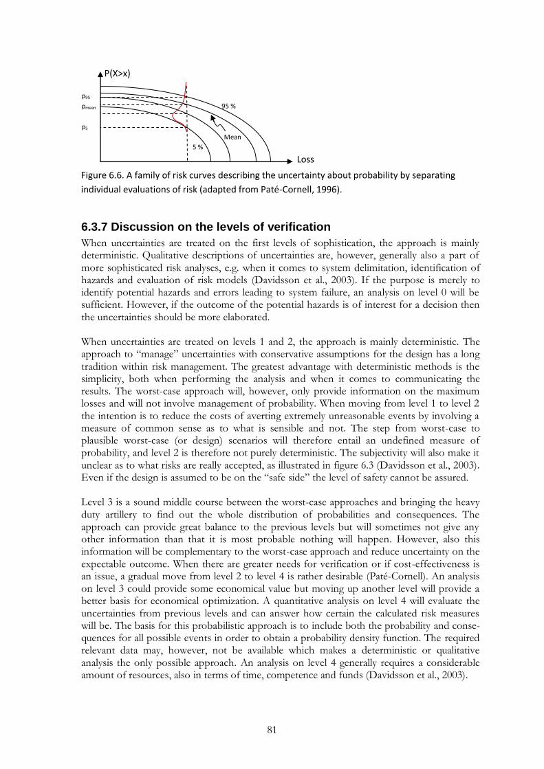
81
Figure 6.6. A family of risk curves describing the uncertainty about probability by separating
individual evaluations of risk (adapted from Paté-Cornell, 1996).
6.3.7 Discussion on the levels of verification
When uncertainties are treated on the first levels of sophistication, the approach is mainly deterministic. Qualitative descriptions of uncertainties are, however, generally also a part of more sophisticated risk analyses, e.g. when it comes to system delimitation, identification of hazards and evaluation of risk models (Davidsson et al., 2003). If the purpose is merely to identify potential hazards and errors leading to system failure, an analysis on level 0 will be sufficient. However, if the outcome of the potential hazards is of interest for a decision then the uncertainties should be more elaborated. When uncertainties are treated on levels 1 and 2, the approach is mainly deterministic. The approach to “manage” uncertainties with conservative assumptions for the design has a long tradition within risk management. The greatest advantage with deterministic methods is the simplicity, both when performing the analysis and when it comes to communicating the results. The worst-case approach will, however, only provide information on the maximum losses and will not involve management of probability. When moving from level 1 to level 2 the intention is to reduce the costs of averting extremely unreasonable events by involving a measure of common sense as to what is sensible and not. The step from worst-case to plausible worst-case (or design) scenarios will therefore entail an undefined measure of probability, and level 2 is therefore not purely deterministic. The subjectivity will also make it unclear as to what risks are really accepted, as illustrated in figure 6.3 (Davidsson et al., 2003). Even if the design is assumed to be on the “safe side” the level of safety cannot be assured. Level 3 is a sound middle course between the worst-case approaches and bringing the heavy duty artillery to find out the whole distribution of probabilities and consequences. The approach can provide great balance to the previous levels but will sometimes not give any other information than that it is most probable nothing will happen. However, also this information will be complementary to the worst-case approach and reduce uncertainty on the expectable outcome. When there are greater needs for verification or if cost-effectiveness is an issue, a gradual move from level 2 to level 4 is rather desirable (Paté-Cornell). An analysis on level 3 could provide some economical value but moving up another level will provide a better basis for economical optimization. A quantitative analysis on level 4 will evaluate the uncertainties from previous levels and can answer how certain the calculated risk measures will be. The basis for this probabilistic approach is to include both the probability and conse-quences for all possible events in order to obtain a probability density function. The required relevant data may, however, not be available which makes a deterministic or qualitative analysis the only possible approach. An analysis on level 4 generally requires a considerable amount of resources, also in terms of time, competence and funds (Davidsson et al., 2003).
P(X>x)
p95
pmean 95 %
p5
Mean
5 %
Loss
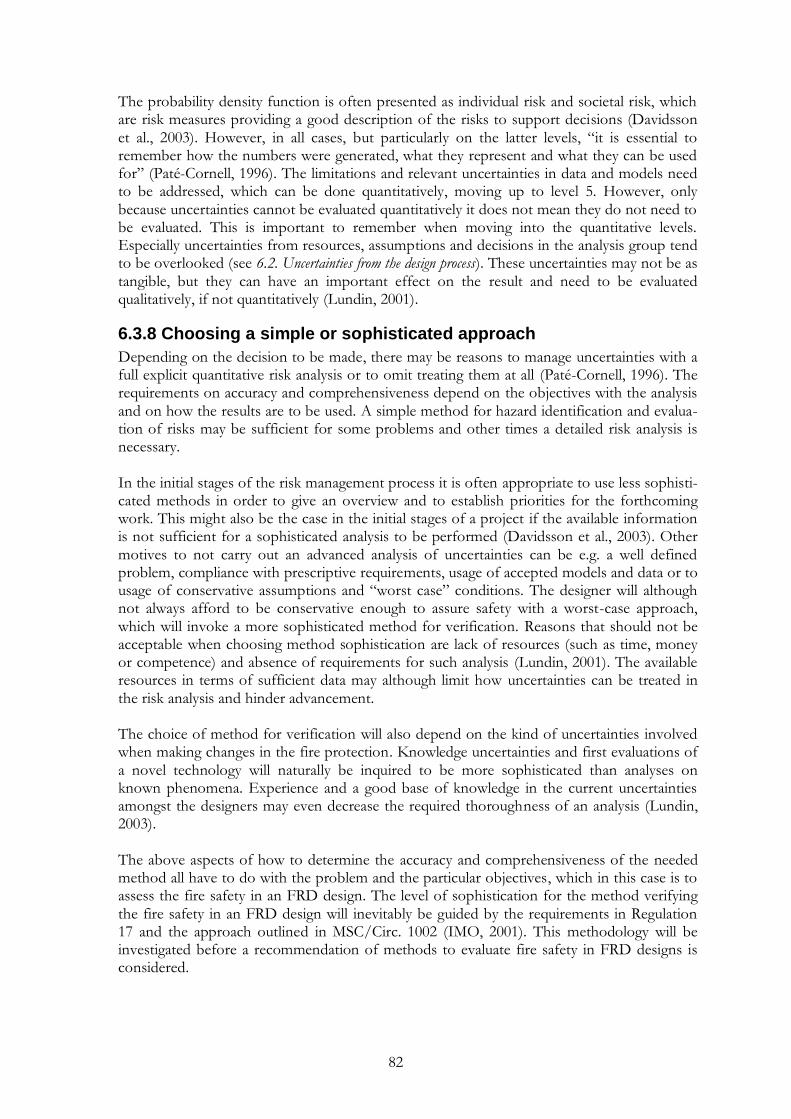
82
The probability density function is often presented as individual risk and societal risk, which are risk measures providing a good description of the risks to support decisions (Davidsson et al., 2003). However, in all cases, but particularly on the latter levels, “it is essential to remember how the numbers were generated, what they represent and what they can be used for” (Paté-Cornell, 1996). The limitations and relevant uncertainties in data and models need to be addressed, which can be done quantitatively, moving up to level 5. However, only because uncertainties cannot be evaluated quantitatively it does not mean they do not need to be evaluated. This is important to remember when moving into the quantitative levels. Especially uncertainties from resources, assumptions and decisions in the analysis group tend to be overlooked (see 6.2. Uncertainties from the design process). These uncertainties may not be as tangible, but they can have an important effect on the result and need to be evaluated qualitatively, if not quantitatively (Lundin, 2001).
6.3.8 Choosing a simple or sophisticated approach
Depending on the decision to be made, there may be reasons to manage uncertainties with a full explicit quantitative risk analysis or to omit treating them at all (Paté-Cornell, 1996). The requirements on accuracy and comprehensiveness depend on the objectives with the analysis and on how the results are to be used. A simple method for hazard identification and evalua-tion of risks may be sufficient for some problems and other times a detailed risk analysis is necessary. In the initial stages of the risk management process it is often appropriate to use less sophisti-cated methods in order to give an overview and to establish priorities for the forthcoming work. This might also be the case in the initial stages of a project if the available information is not sufficient for a sophisticated analysis to be performed (Davidsson et al., 2003). Other motives to not carry out an advanced analysis of uncertainties can be e.g. a well defined problem, compliance with prescriptive requirements, usage of accepted models and data or to usage of conservative assumptions and “worst case” conditions. The designer will although not always afford to be conservative enough to assure safety with a worst-case approach, which will invoke a more sophisticated method for verification. Reasons that should not be acceptable when choosing method sophistication are lack of resources (such as time, money or competence) and absence of requirements for such analysis (Lundin, 2001). The available resources in terms of sufficient data may although limit how uncertainties can be treated in the risk analysis and hinder advancement. The choice of method for verification will also depend on the kind of uncertainties involved when making changes in the fire protection. Knowledge uncertainties and first evaluations of a novel technology will naturally be inquired to be more sophisticated than analyses on known phenomena. Experience and a good base of knowledge in the current uncertainties amongst the designers may even decrease the required thoroughness of an analysis (Lundin, 2003). The above aspects of how to determine the accuracy and comprehensiveness of the needed method all have to do with the problem and the particular objectives, which in this case is to assess the fire safety in an FRD design. The level of sophistication for the method verifying the fire safety in an FRD design will inevitably be guided by the requirements in Regulation 17 and the approach outlined in MSC/Circ. 1002 (IMO, 2001). This methodology will be investigated before a recommendation of methods to evaluate fire safety in FRD designs is considered.

83
6.4 The methodology outlined in Circular 1002
The methodology for the engineering analysis required when laying claim to Regulation 17 is briefly outlined in SOLAS (IMO, 2004a) whilst detailed descriptions are found in Circular 1002 (IMO, 2001). This document illustrates a two-step risk assessment in line with IEC‟s systematic base for risk management (see figure 3.1). In the first step an assembled design team is to define the scope of the analysis, identify hazards and develop design fire scenarios, which altogether needs to have a preliminary approval (Sames, 2009). This documents the requirements for the next step of the analysis, where the design fire scenarios are to be quantified and the outcomes compared with explicit criteria from SOLAS II-2 or criteria derived from a prescriptive reference design. The design team should consist of the owner, builder and designer as well as experts with the necessary knowledge and experience in fire safety, design and operation. For example operators, marine surveyors, and equipment manufacturers may also be included depending on the alternative design and arrangements. A slightly more elaborated review of the two analyses follows below, with comments on the methodology as a risk-based approach to assess fire safety. Some of the administrative and logistic details have deliberately been left out of the review. A concluding discussion on the approach outlined in IMO (2001) follows in the ending section. The requirements in IMO (2001) will be referred to as Circular 1002 in the following.
6.4.1 Preliminary analysis in qualitative terms
The first part of the engineering analysis to be performed by the design team is called a “preliminary analysis in qualitative terms”. It is to be initiated with a definition of the scope of the proposed alternative design and arrangements, which is a natural introduction of any risk analysis (see 3.7 Risk analysis). If the attempt with the whole analysis is to compare an alternative design and arrangements with a prescriptive design, then also the prescriptive design and its systems subject to the analysis need to be defined. The scope definition will also include recognition of the regulations affecting the proposed alternative design and arrangements, along with their functional requirements (IMO, 2001). The evaluation of fire safety in the alternative design and arrangements is based on fire scenarios. One or a number of selected trial alternative designs are to be compared with a prescriptive design through a range of design fire scenarios. It is therefore essential to develop proper fire scenarios, which will depend on the deviation from the prescribed design. The process of developing design fire scenarios begins with a hazard identification to enlighten important conditions and characteristics which pose fire hazards in the designs. HAZOP, PHA, FMEA and “What if?” are exemplified as recommended procedures for this step and also a list of minimum considerations is specified (IMO, 2001). The fire hazards should be grouped into one of the three incident classes localized, major or catastrophic, i.e. a fire in a confined area, ship or spreading outside of the boundaries of a ship (IMO, 2001). The instruction to tabulate fire hazards into these incident classes can, however, seem quite illogical with the standard definitions of hazards and incidents in risk management (Kaplan & Garrick, 1981). A hazard is merely a source of danger whilst the incident classes represent degrees of consequences, which will depend on the existence and function of safeguards. With this perspective, the hazards do not have to be related with the possible outcomes. To shed some light on the issue, the ocean can be said to be a hazard and attempting to cross is we undergo risk. If the means of transportation is a row boat the risk will be significantly greater than if Queen Elisabeth is used as a safeguard. In the example the possible consequences are rather clear; when crossing the ocean you will either die or live. The change in risk depends on how the safeguards affect the probability of a hazard con-verging into actual damage or loss (Kaplan & Garrick, 1981). The probability of functioning
84
safeguards and the possible consequences together constitute what is generally defined as the liberally used term risk. However, when applying a deterministic approach the probability of functioning safeguards are ignored and the hazards can then be understood to stand in relation with the possible outcomes. Hazards can obviously pose more or less significant threats and can represent a great deal of the possible consequences, as they would in the example above if the probability of a functioning means of transportation is ignored. The connection between hazards and consequences is although not always as clear, which generally leads to a worst-case approach. The interpretation is therefore to group hazards according to their (possibly worst) expected outcomes. Depending on the complexity of the trial designs, fire hazards should now be selected to compose a representative number of incidents. The largest and most probable range of previously enumerated fire hazards are to be included in incidents of, favourably, major significance. It is endorsed to select major fires since the engineering evaluation relies on a deterministic comparison between designs where minor incidents are considered to be included in major incidents. Equivalent performance during a major incident is thereby an adequate demonstration of safety also for the lesser incidents. The process will be simplified if major incidents can be found which cover as many of the minor incidents and significant hazards as possible, hence the deterministic approach. When the most appropriate incidents are carefully selected, the conditions for each incident are to be specified. Descriptions of the development and spread of fire within and through ship spaces as well as descriptions of measures which can have an effect on the fire develop-ment and its exposure and effect are defined in what are called design fire scenarios. The performance during these design fire scenarios will be compared between the trial designs and prescriptive design in the forthcoming quantitative analysis. The qualitative analysis ends with a specification of the trial alternative designs. Worth mentioning is that not only technical solutions, but also human factors, operations and management are encouraged to be taken into consideration in the design specifications. Well-defined operations and management procedures are recognized to play a big part in increasing the overall level of safety, but the inclusion is also bound with great uncertainties (IMO, 2001).
6.4.2 Quantitative analysis
The preliminary analysis in qualitative terms mainly consists of a scope definition and a preparation for the quantitative analysis. The design fire scenarios are now to be quantified, performance criteria developed and the performance of the trial alternative designs evaluated. The quantification of design fire scenarios will include estimations of how the fire develop-ment will be affected by different measures, e.g. detection, alarm, suppression etc. Calcula-tions will also be carried out on the effect and possible exposure of a fire, in terms of e.g. heat release rate, heat flux and smoke production. The estimations on fire development and its effects are typically made in conjunction with evacuation analyses in order to establish if anyone, or how many, will be exposed to inhabitable conditions during the design fire scenarios (IMO, 2001). Performance criteria for life safety need to be developed in order to define what should be considered tenability limits, e.g. in the form of smoke yields, smoke obscuration, height of smoke layer, temperature or evacuation time. Criteria should, however, also be developed for damage to the ship structure and related systems as well as for damage to the environment. The performance criteria should be quantitative expressions of the fire safety objectives, purpose statements and functional requirements of the regulations. Since very few explicit

85
criteria exist in SOLAS II-2 it is, however, often more convenient to compare the trial designs with the performance of a prescriptive reference design (IMO, 2001). In order to compensate for uncertainties in the methods and assumptions of the approach, a safety margin needs to be applied when determining performance criteria or when assessing the consequences of fire. The safety margin is to be determined by the design team in the outset of the design process, but may be adjusted as necessary during the analysis. Uncertain-ties should also be evaluated by conducting a sensitivity analysis of input data for the calculations, regardless if the employed procedures are acknowledged (IMO, 2001). A sensitivity analysis will enlighten effects on the calculated results from different variables. If the sensitivity analysis shows certain variables will be unclear in case of an incident, then these variables need to be further elaborated. Examples of variables which commonly need to be further analyzed and described regarding uncertainties are (Lundin, Delin & Johansson, 2005):
the heat release rate of the fire;
probabilities of different events (such as the reliability of technical systems);
walking speed;
the number of people in the spaces.
6.4.3 Discussion on the approach outlined in Circular 1002
The engineering analysis outlined in Circular 1002 (IMO, 2001) is a typical consequence analysis of plausible worst-case scenarios, or design scenarios (see 6.3.3 Level 2: plausible worst case). As any risk analysis it is introduced by a scope definition and a qualitative identification of hazards and errors leading to system failure (see figure 3.2). However, the hazard identifi-cation is also part of the development of fire scenarios which makes it blend in with an identification of possible consequences. This is not unusual in a deterministic approach where probabilities of failing safeguards are overlooked. The hazard identification is a crucial step in the entire alternative design methodology since only the hazards and outcomes which have been identified will be considered in the proceeding analysis (IMO, 2001). If an important fire hazard or incident is omitted then the final design may be inadequate, which gives rise to some of the uncertainties in the approach. Since the backbone of the alternative design process are design fire scenarios, the develop-ment of these scenarios is essential. Thereby, section 5.2.3.1 Selection of fire hazards contains some of the most central information in Circular 1002 (IMO, 2001). This is where some of the previously identified hazards are selected to compose a representative range of incidents. The instruction to choose the largest but also the most probable range of enumerated fire hazards makes the approach embrace the necessary amount of probability to take the step to level 2 (see 6.3.3 Level 2: plausible worst case). The inclusion of an estimation as to what is reasonably expectable includes a measure of probability, but the approach is still to a large degree deterministic. The philosophy of the approach can be illustrated by a symbolic definition of risk, expressed with the following equation (Kaplan & Garrick, 1981):
.
In the plausible worst-case approach uncertainties are primarily managed with conservative assumptions for the design. It means the uncertainties are not explored but rather ignored, i.e.
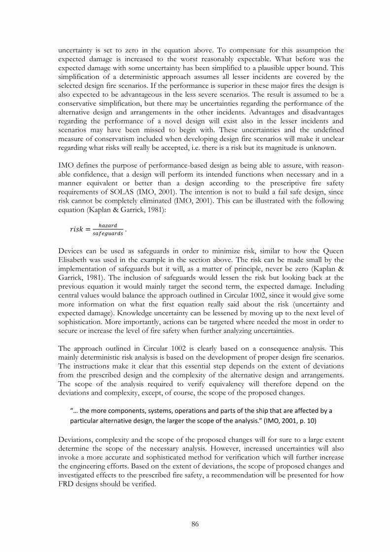
86
uncertainty is set to zero in the equation above. To compensate for this assumption the expected damage is increased to the worst reasonably expectable. What before was the expected damage with some uncertainty has been simplified to a plausible upper bound. This simplification of a deterministic approach assumes all lesser incidents are covered by the selected design fire scenarios. If the performance is superior in these major fires the design is also expected to be advantageous in the less severe scenarios. The result is assumed to be a conservative simplification, but there may be uncertainties regarding the performance of the alternative design and arrangements in the other incidents. Advantages and disadvantages regarding the performance of a novel design will exist also in the lesser incidents and scenarios may have been missed to begin with. These uncertainties and the undefined measure of conservatism included when developing design fire scenarios will make it unclear regarding what risks will really be accepted, i.e. there is a risk but its magnitude is unknown. IMO defines the purpose of performance-based design as being able to assure, with reason-able confidence, that a design will perform its intended functions when necessary and in a manner equivalent or better than a design according to the prescriptive fire safety requirements of SOLAS (IMO, 2001). The intention is not to build a fail safe design, since risk cannot be completely eliminated (IMO, 2001). This can be illustrated with the following equation (Kaplan & Garrick, 1981):
.
Devices can be used as safeguards in order to minimize risk, similar to how the Queen Elisabeth was used in the example in the section above. The risk can be made small by the implementation of safeguards but it will, as a matter of principle, never be zero (Kaplan & Garrick, 1981). The inclusion of safeguards would lessen the risk but looking back at the previous equation it would mainly target the second term, the expected damage. Including central values would balance the approach outlined in Circular 1002, since it would give some more information on what the first equation really said about the risk (uncertainty and expected damage). Knowledge uncertainty can be lessened by moving up to the next level of sophistication. More importantly, actions can be targeted where needed the most in order to secure or increase the level of fire safety when further analyzing uncertainties. The approach outlined in Circular 1002 is clearly based on a consequence analysis. This mainly deterministic risk analysis is based on the development of proper design fire scenarios. The instructions make it clear that this essential step depends on the extent of deviations from the prescribed design and the complexity of the alternative design and arrangements. The scope of the analysis required to verify equivalency will therefore depend on the deviations and complexity, except, of course, the scope of the proposed changes.
“… the more components, systems, operations and parts of the ship that are affected by a
particular alternative design, the larger the scope of the analysis.” (IMO, 2001, p. 10)
Deviations, complexity and the scope of the proposed changes will for sure to a large extent determine the scope of the necessary analysis. However, increased uncertainties will also invoke a more accurate and sophisticated method for verification which will further increase the engineering efforts. Based on the extent of deviations, the scope of proposed changes and investigated effects to the prescribed fire safety, a recommendation will be presented for how FRD designs should be verified.

87
6.5 Recommended approach for the fire safety analysis
The methodology adopted in Regulation 17, and further outlined in MSC/Circ. 1002 (IMO, 2001), is consistent with the risk-based approach established by the IEC. In that sense Regu-lation 17, FSA and Circular 1212 together constitute the foundational regulatory framework needed to facilitate risk-based design and approval for composite constructions (Juhl, 2009). An objective of the present study is to find appropriate methods to evaluate the differences between traditional designs and those involving FRP composite with a risk-based approach. The level of sophistication necessary for the analysis should be determined by the effects on fire safety. Some decisions do not need full explicit quantitative treatment of uncertainties whilst other problems are complex and decisions will be extremely supported by a sophisticated analysis. In this application to verify fire safety, a tiered approach is recommended, proposing uncertainties in an FRD design could be managed on four levels in risk analysis, as illustrated in figure 6.7. The utilized risk-based approach implies a focus on human survival alone and will therefore be suitable for passenger ships.
Figure 6.7. Depending on how the fire safety will be affected by a proposed FRD design it is
recommended to evaluate uncertainties through risk analysis down to a certain level of
sophistication.
The first level, Alpha, represents the identification of hazards and preliminary analysis as pre-scribed in the first step of Circular 1002 and partly defined in 6.3.1 Level 0: identification of hazards and failure modes. Level Beta represents a quantitative plausible worst-case approach as defined in 6.3.3 Level 2: plausible worst-case and is the simplest interpretation of the quantitative analysis described in Circular 1002. In this coarse evaluation the most relevant uncertainties need to be documented and their possible effects on fire safety accounted for. This will settle if a more sophisticated analysis of uncertainties is necessary or if the results can be considered sufficiently safe. Moving to the next level, Gamma, implies a probabilistic analysis of uncertainties will be carried out, as defined in 6.3.5 Level 4: probabilistic risk assessment and single risk curve. This quantitative analysis will aim at describing a full distribution of potential losses and allows for meaningful comparison of risks and optimization of risk control measures. It should describe how effects from uncertainties appear, the specific effects from relevant uncertainties and the effect when all uncertainties are taken into account (Lundin, 2001). The bottom level, Delta, denotes a full display of risk uncertainties, i.e. secondary probabilities, as described in 6.3.6 Level 5: display of risk uncertainties. However, the levels of analyzing uncertainties may potentially continue further down in the future (Paté-Cornell, 1996).
88
Level A can be seen as the tip of an iceberg of information and does not provide sufficient information on the problem. When digging deeper, specific deficiencies in the previous levels will be resolved. However, moving to the next tier will make information more complex and increase the costs associated with collecting and managing additional data. This is symbolized by the growing area of the levels in the triangle. The increased labour makes it topical to seek a balance regarding the examination of uncertainties. Progress through the tiers in figure 6.7 should only be made as far as necessary in order to gain sufficient information to make a decision (Bridges, 2000). Recommendations on intended scopes of FRD designs to be analyzed on the different levels are discussed below, based on the possible effects on fire safety investi-gated in chapter 5. Analyzing the needs for verification (Bridges, 2000; Paté-Cornell, 1996).
6.5.1 Level A: identification of hazards and preliminary analysis
When making use of Regulation 17, the methodology outlined in Circular 1002 (IMO, 2001) will naturally settle the minimum requirements for an analysis of fire safety in an FRD design. The first part of an analysis will therefore need to consist of a qualitative scope definition, hazard identification and development of fire scenarios, level Alpha. Concerning the hazard identification there are some procedures recommended in Circular 1002 which, depending on the thoroughness in which they are carried out, can settle a good starting point for risk analysis methods of any sophistication.
6.5.2 Level B: plausible worst-case analysis
Neither the probability of ignition nor the first development of an enclosure fire will be negatively affected by a change to FRD. Significant differences in behaviour, which could have a negative effect on fire safety, will not show until after 60 minutes of fire. For a fire to induce negative characteristics of an FRD structure, conditions therefore need to be provided for it to develop into a major fire during this time. If no negative differences will show until a major fire has developed it suggests a deterministic approach can be a reasonable description of the changes in fire safety. Only performance in major fires is evaluated and minor fires are disregarded. The plausible worst-case approach can be said to assume the effects within the first 60 minutes will be positive (or insignificant) and negative effects will appear only if a major fire has developed after 60 minutes. This may be a reasonable assumption when it comes to the structural behaviour of FRD. However, no effects to the fire safety properties, the structure of the fire protection or positive effects within the first 60 minutes are taken into account. There may also be uncertainties regarding the chosen design fire scenarios used to represent the effects on fire safety after the 60 minutes of fire. When carrying out an analysis on level Beta, plausible upper bounds are estimated to account for uncertainties, see figure 6.3. The conservative estimations are assumed to cover most of the possible incidents but the actual probability that an incident will exceed the level of fire safety in the design is unknown. A plausible worst-case analysis can, however, be sufficient to determine if uncertainties need to be managed further in order to assure safety with a certain margin. It will resolve if a more sophisticated analysis of uncertainties is necessary or if the results can be considered sufficiently safe, e.g. by implementing supplementary risk control measures or restrictions for the spaces concerned. An analysis on this level may be sufficient if the scope of the intended FRD design only comprises one category of spaces on one deck. It could also be adequate if limited categories of spaces are considered but the number of spaces is restricted and the spaces are confined to one deck. Particularly small FRD spaces, such as cabins and sanitary spaces, where doors are automatically closed and the conditions for fire propagation are limited, may be suitable to evaluate on this level. These spaces may be considered not to need a sophisticated analysis
89
since the probability of a fire to sustain for more than 60 minutes is very low. Spaces where divisions have been substantially improved (e.g. from C or A-0 to FRD-60) could also be sufficiently evaluated on this level. However, if exterior surfaces, large spaces or several decks are considered, the effects on fire safety will be more intricate and the needs for verification are greater.
6.5.3 Level Γ: probabilistic risk analysis
A risk analysis on level Gamma will require an increased number of consequence estimations and information on occurrence frequencies. All relevant positive and negative effects on fire safety should be taken into account in the analysis and the total effect evaluated. Some uncertainties need to be evaluated qualitatively but as many as possible should be quantified in order to include them in quantitative risk measures. Inclusion of FRD material in load-bearing structures will imply an increased fire load and smoke production if a fire reaches the composite. The consequences if a fire is provided with enough energy to survive for more than 60 minutes may be catastrophic due to the increased amount of combustible materials. More severe consequences cannot be allowed unless the fire safety is improved in other ways. An uncontrolled fire after 60 minutes may lead to more severe consequences but if, for example, the probabilities of negative outcomes are reduced, the fire safety may be compensated and regarded at least as safe (see figure 7.7). This may be the case in an FRD design since the thermal insulation capacity is improved which could delay propagation of fire and reduce the probability of a fire to survive for more than 60 minutes. Other relevant, positive and negative, effects within and after the first 60 minutes should also be taken into account in the evaluation, as well as qualitatively investigated uncertainties. Exterior composite surfaces is one of the issues which definitely needs to be included in an evaluation on this level of sophistication. Combustible exterior surfaces are not regulated in prescriptive regulations and signify a considerable source of uncertainties. Except increasing the probability of including external surfaces in a fire it could imply fire spread between decks and fire zones. It would also lead to an increased probability of inhabitable consequences if people can be exposed to smoke production and fire spread from exterior surfaces.
6.5.4 Level Δ: evaluation of risk uncertainties
If all divisions in an FRD superstructure are adapted to the highest standard (FRD-60) it will reduce complexity, sensitivity and vulnerability. When this conservative approach has been accepted by the Administration it may, however, be desirable to reduce thermal insulation for divisions where the fire risk is minimal, e.g. where “C” or “B” class divisions are required. Then particularly the fire safety properties will need to be further evaluated since some of the properties identified to be enhanced by a universal change to FRD-60 divisions instead might be negatively affected. When optimizing fire safety in different ways, uncertainties will appear more significant and it can be appropriate to move to level Delta. Uncertainties in expert opinions, different models, and statistical information can then be displayed and further evaluated before making decisions. An analysis on this level of sophistication is, however, extremely demanding and should not be attempted unless necessary. Previous chapters have deliberately not gone into details regarding certain methods for risk analysis. The focus has instead been to develop a suggestion on how changes in the implicit fire safety can be uncovered and to present different methodologies for the risk analysis,

90
connected to the scope of the proposed changes. However, below it is exemplified how an evaluation of the effects on the implicit level of fire safety and how an estimation of risks can be carried out in line with the suggested approach.
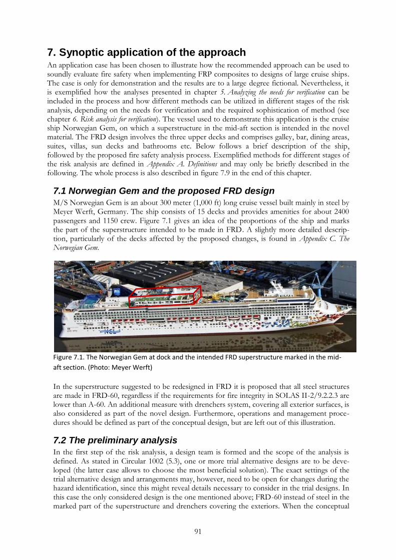
91
7. Synoptic application of the approach An application case has been chosen to illustrate how the recommended approach can be used to soundly evaluate fire safety when implementing FRP composites to designs of large cruise ships. The case is only for demonstration and the results are to a large degree fictional. Nevertheless, it is exemplified how the analyses presented in chapter 5. Analyzing the needs for verification can be included in the process and how different methods can be utilized in different stages of the risk analysis, depending on the needs for verification and the required sophistication of method (see chapter 6. Risk analysis for verification). The vessel used to demonstrate this application is the cruise ship Norwegian Gem, on which a superstructure in the mid-aft section is intended in the novel material. The FRD design involves the three upper decks and comprises galley, bar, dining areas, suites, villas, sun decks and bathrooms etc. Below follows a brief description of the ship, followed by the proposed fire safety analysis process. Exemplified methods for different stages of the risk analysis are defined in Appendix A. Definitions and may only be briefly described in the following. The whole process is also described in figure 7.9 in the end of this chapter.
7.1 Norwegian Gem and the proposed FRD design
M/S Norwegian Gem is an about 300 meter (1,000 ft) long cruise vessel built mainly in steel by Meyer Werft, Germany. The ship consists of 15 decks and provides amenities for about 2400 passengers and 1150 crew. Figure 7.1 gives an idea of the proportions of the ship and marks the part of the superstructure intended to be made in FRD. A slightly more detailed descrip-tion, particularly of the decks affected by the proposed changes, is found in Appendix C. The Norwegian Gem.
Figure 7.1. The Norwegian Gem at dock and the intended FRD superstructure marked in the mid-
aft section. (Photo: Meyer Werft)
In the superstructure suggested to be redesigned in FRD it is proposed that all steel structures are made in FRD-60, regardless if the requirements for fire integrity in SOLAS II-2/9.2.2.3 are lower than A-60. An additional measure with drenchers system, covering all exterior surfaces, is also considered as part of the novel design. Furthermore, operations and management proce-dures should be defined as part of the conceptual design, but are left out of this illustration.
7.2 The preliminary analysis
In the first step of the risk analysis, a design team is formed and the scope of the analysis is defined. As stated in Circular 1002 (5.3), one or more trial alternative designs are to be deve-loped (the latter case allows to choose the most beneficial solution). The exact settings of the trial alternative design and arrangements may, however, need to be open for changes during the hazard identification, since this might reveal details necessary to consider in the trial designs. In this case the only considered design is the one mentioned above; FRD-60 instead of steel in the marked part of the superstructure and drenchers covering the exteriors. When the conceptual
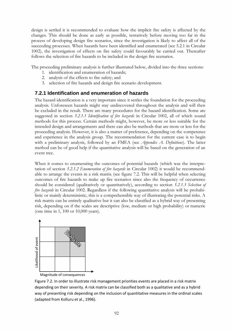
92
design is settled it is recommended to evaluate how the implicit fire safety is affected by the changes. This should be done as early as possible, tentatively before moving too far in the process of developing design fire scenarios, since the investigation is likely to affect all of the succeeding processes. When hazards have been identified and enumerated (see 5.2.1 in Circular 1002), the investigation of effects on fire safety could favourably be carried out. Thereafter follows the selection of fire hazards to be included in the design fire scenarios. The proceeding preliminary analysis is further illustrated below, divided into the three sections:
1. identification and enumeration of hazards; 2. analysis of the effects to fire safety; and 3. selection of fire hazards and design fire scenario development.
7.2.1 Identification and enumeration of hazards
The hazard identification is a very important since it settles the foundation for the proceeding analysis. Unforeseen hazards might stay undiscovered throughout the analysis and will then be excluded in the result. There are many procedures for the hazard identification. Some are suggested in section 5.2.1.1 Identification of fire hazards in Circular 1002, all of which sound methods for this process. Certain methods might, however, be more or less suitable for the intended design and arrangements and there can also be methods that are more or less for the proceeding analysis. However, it is also a matter of preference, depending on the competence and experience in the analysis group. The recommendation for the current case is to begin with a preliminary analysis, followed by an FMEA (see Appendix A. Definitions). The latter method can be of good help if the quantitative analysis will be based on the generation of an event tree. When it comes to enumerating the outcomes of potential hazards (which was the interpre-tation of section 5.2.1.2 Enumeration of fire hazards in Circular 1002) it would be recommend-able to arrange the events in a risk matrix (see figure 7.2. This will be helpful when selecting outcomes of fire hazards to make up fire scenarios since also the frequency of occurrence should be considered (qualitatively or quantitatively), according to section 5.2.1.3 Selection of fire hazards in Circular 1002. Regardless if the following quantitative analysis will be probabi-listic or mainly deterministic, this is a comprehensible way of illustrating the potential risks. A risk matrix can be entirely qualitative but it can also be classified as a hybrid way of presenting risk, depending on if the scales are descriptive (low, medium or high probability) or numeric (one time in 1, 100 or 10,000 years).
Figure 7.2. In order to illustrate risk management priorities events are placed in a risk matrix
depending on their severity. A risk matrix can be classified both as a qualitative and as a hybrid
way of presenting risk depending on the inclusion of quantitative measures in the ordinal scales
(adapted from Kolluru et al., 1996).
Like
liho
od
of
even
t
Magnitude of consequences
93
Evaluating events in a risk matrix can help prioritizing when selecting outcomes of fire hazards to make up fire scenarios. It is crucial to find comprehensible measures to present risk, but this becomes challenging as reality often invokes more complex models for evaluation.
7.2.2 Analysis of the effects to fire safety
Paragraphs 4.3.4 and 5.1.2 in Circular 1002 instruct to clearly define the regulations which affect the design and to document a clear understanding of the objectives and functional requirements of the regulations. This should form the basis for the forthcoming comparative analysis with a reference design. As mentioned in chapter 5. Analyzing the needs for verification, Circular 1002 (paragraph 4.4) states that the fire safety objectives in SOLAS II-2/2 and the purpose statements listed at the beginning of each individual regulation in SOLAS II-2 should be used to provide basis in this comparison. However, it has been show that an extended analysis can be necessary in order to determine all the effects on the implicit level of fire safety when introducing FRD. The approach presented in chapter 5. Analyzing the needs for verification investigates the effects on fire safety when changing from steel to FRD structures from five perspectives.
7.2.2.1 The fire safety regulations The regulations in SOLAS II-2 represent the implicit level of fire safety in prescriptive requirements. The conceptual design will challenge Regulations 5, 6, 9, 11 and 13. Specific challenged prescriptive requirements are for example Regulations 5.3.1.2.1, 9.2.2.2.2, 11.2 and 13.3.1.3, except the general Regulation 3.43, defining what is considered as a steel or equivalent material. The general investigation of challenged regulations in section 5.1 The fire safety regulations includes more thorough discussions on the compliance or non-compliance with fire safety regulations of SOLAS, applicable also in the current case. It may although be appropriate to point out that external surfaces are considered in the design, for which there are no specific regulations.
7.2.2.2 The fire safety objectives and functional requirements The fire safety objectives and functional requirements still need to be achieved by the novel FRD superstructure. The effects on the implicit safety represented by the fire safety objectives cannot be determined right away. A fire may be more likely to be contained in the novel structure and the conditions for escape could be improved down to the superior thermal insulation capacity of FRD (see 5.2.1 Fire safety objectives). However, the specific effects and the risk to life need to be further evaluated in the succeeding analysis. The functional requirements in SOLAS II-2/2 make it topical to analyze the differences in behaviour between FRD and steel divisions (see 5.2.2 Functional requirements). The outcome from adding combustible materials to the ship also needs to be evaluated, as well as possible positive effects to the containment of a fire and conditions in escape routes, as identified above. 7.2.2.3 The fire safety structure The layout of the prescribed fire safety is studied in order to identify changes in the fire protection and how this can affect safety when implementing the novel superstructure. Markings have been made in a matrix (see table 7.1), based on the descriptions in 5.3 The fire safety structure. The markings are explained below.

94
Table 7.1. Example of a matrix describing the overall effects to the fire protection strategy
when implementing an FRD superstructure for a specific case
Effects on different parts of the fire protection when implementing FRD to the specific superstructure have been marked in the column “Fe → FRD”. The installed drencher system is seen as a supplementary arrangement and the effects from this measure are therefore marked in column S1. All markings represent examples and should not be considered as well-founded facts without further investigations. However, in short terms, Regulation 9 and Regulation 13 are marked with plus signs, down to the improved thermal insulation in an FRD design. Also the means for fire fighting are considered to be positively affected, thanks to the new means for fire suppression. Collapse is more likely to occur in the novel structure, even is the effect may be local, and Regulation 11 is therefore marked with a minus. So is Regulation 5, considering the unprotected external surfaces. The external surfaces are also targeted by the drencher system and the regulation is therefore also marked in the supplementary columns. Finally Regulation 6 is marked with a minus because of the possible increased smoke production if a fire is uncontrolled after 60 minutes. The rest of the fire protection strategy are considered unaffected. None of the markings are, however, unambiguous since there are often both positive and negative effects to consider for each regulation. The markings, hence, represent examples of combined considerations and more thorough descriptions are necessary in a real case investigation. The matrix helps identify and evaluate how different fire safety strategies will be affected when exchanging risk control measures. By viewing each regulation separately (horizon-tally) it can be established that there is an unbalance in some parts of the fire protection strategy. Regulation 5 is supplemented with the drencher system, but Regulations 6 and 11 are negatively affected and not complemented in order to accomplish the same protec-tion. Instead, positive effects in the vertical direction need to be taken into account. The positive and negative markings are spread vertically in two of the three fire protection categories and indicate that the fire protection may have been reformed in the two categories. It means some of the protection chains have been modified and increases the requirements on verification. The vertical balance of minus and plus signs does not imply the same level of safety has been achieved but it is good that there is a balance in both the
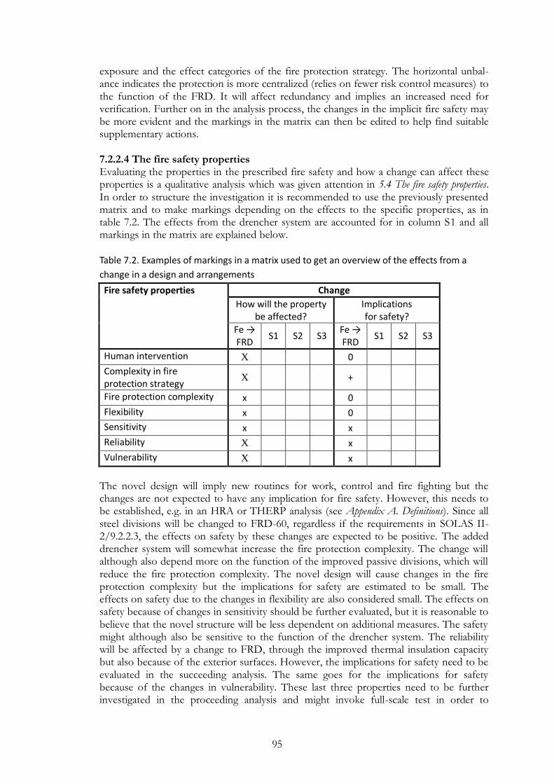
95
exposure and the effect categories of the fire protection strategy. The horizontal unbal-ance indicates the protection is more centralized (relies on fewer risk control measures) to the function of the FRD. It will affect redundancy and implies an increased need for verification. Further on in the analysis process, the changes in the implicit fire safety may be more evident and the markings in the matrix can then be edited to help find suitable supplementary actions. 7.2.2.4 The fire safety properties Evaluating the properties in the prescribed fire safety and how a change can affect these properties is a qualitative analysis which was given attention in 5.4 The fire safety properties. In order to structure the investigation it is recommended to use the previously presented matrix and to make markings depending on the effects to the specific properties, as in table 7.2. The effects from the drencher system are accounted for in column S1 and all markings in the matrix are explained below. Table 7.2. Examples of markings in a matrix used to get an overview of the effects from a
change in a design and arrangements
Fire safety properties Change
How will the property be affected?
Implications for safety?
Fe → FRD
S1 S2 S3 Fe → FRD
S1 S2 S3
Human intervention X 0
Complexity in fire protection strategy
X
+
Fire protection complexity x 0
Flexibility x 0
Sensitivity x x
Reliability X x
Vulnerability X x
The novel design will imply new routines for work, control and fire fighting but the changes are not expected to have any implication for fire safety. However, this needs to be established, e.g. in an HRA or THERP analysis (see Appendix A. Definitions). Since all steel divisions will be changed to FRD-60, regardless if the requirements in SOLAS II-2/9.2.2.3, the effects on safety by these changes are expected to be positive. The added drencher system will somewhat increase the fire protection complexity. The change will although also depend more on the function of the improved passive divisions, which will reduce the fire protection complexity. The novel design will cause changes in the fire protection complexity but the implications for safety are estimated to be small. The effects on safety due to the changes in flexibility are also considered small. The effects on safety because of changes in sensitivity should be further evaluated, but it is reasonable to believe that the novel structure will be less dependent on additional measures. The safety might although also be sensitive to the function of the drencher system. The reliability will be affected by a change to FRD, through the improved thermal insulation capacity but also because of the exterior surfaces. However, the implications for safety need to be evaluated in the succeeding analysis. The same goes for the implications for safety because of the changes in vulnerability. These last three properties need to be further investigated in the proceeding analysis and might invoke full-scale test in order to
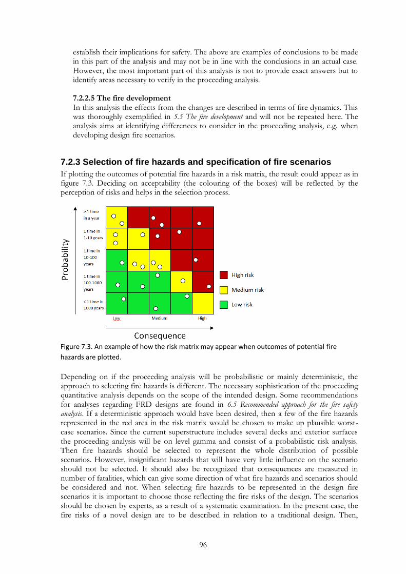
96
establish their implications for safety. The above are examples of conclusions to be made in this part of the analysis and may not be in line with the conclusions in an actual case. However, the most important part of this analysis is not to provide exact answers but to identify areas necessary to verify in the proceeding analysis. 7.2.2.5 The fire development In this analysis the effects from the changes are described in terms of fire dynamics. This was thoroughly exemplified in 5.5 The fire development and will not be repeated here. The analysis aims at identifying differences to consider in the proceeding analysis, e.g. when developing design fire scenarios.
7.2.3 Selection of fire hazards and specification of fire scenarios
If plotting the outcomes of potential fire hazards in a risk matrix, the result could appear as in figure 7.3. Deciding on acceptability (the colouring of the boxes) will be reflected by the perception of risks and helps in the selection process.
Figure 7.3. An example of how the risk matrix may appear when outcomes of potential fire
hazards are plotted.
Depending on if the proceeding analysis will be probabilistic or mainly deterministic, the approach to selecting fire hazards is different. The necessary sophistication of the proceeding quantitative analysis depends on the scope of the intended design. Some recommendations for analyses regarding FRD designs are found in 6.5 Recommended approach for the fire safety analysis. If a deterministic approach would have been desired, then a few of the fire hazards represented in the red area in the risk matrix would be chosen to make up plausible worst-case scenarios. Since the current superstructure includes several decks and exterior surfaces the proceeding analysis will be on level gamma and consist of a probabilistic risk analysis. Then fire hazards should be selected to represent the whole distribution of possible scenarios. However, insignificant hazards that will have very little influence on the scenario should not be selected. It should also be recognized that consequences are measured in number of fatalities, which can give some direction of what fire hazards and scenarios should be considered and not. When selecting fire hazards to be represented in the design fire scenarios it is important to choose those reflecting the fire risks of the design. The scenarios should be chosen by experts, as a result of a systematic examination. In the present case, the fire risks of a novel design are to be described in relation to a traditional design. Then,
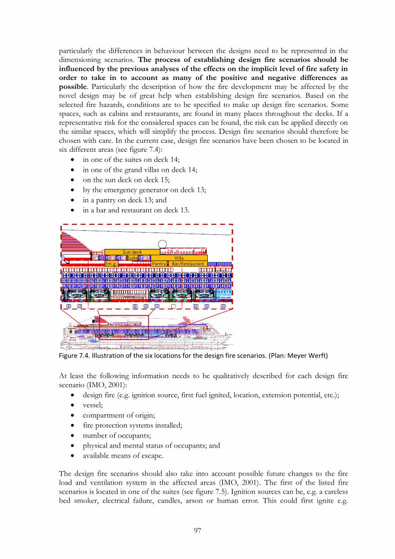
97
particularly the differences in behaviour between the designs need to be represented in the dimensioning scenarios. The process of establishing design fire scenarios should be influenced by the previous analyses of the effects on the implicit level of fire safety in order to take in to account as many of the positive and negative differences as possible. Particularly the description of how the fire development may be affected by the novel design may be of great help when establishing design fire scenarios. Based on the selected fire hazards, conditions are to be specified to make up design fire scenarios. Some spaces, such as cabins and restaurants, are found in many places throughout the decks. If a representative risk for the considered spaces can be found, the risk can be applied directly on the similar spaces, which will simplify the process. Design fire scenarios should therefore be chosen with care. In the current case, design fire scenarios have been chosen to be located in six different areas (see figure 7.4):
in one of the suites on deck 14;
in one of the grand villas on deck 14;
on the sun deck on deck 15;
by the emergency generator on deck 13;
in a pantry on deck 13; and
in a bar and restaurant on deck 13.
Figure 7.4. Illustration of the six locations for the design fire scenarios. (Plan: Meyer Werft)
At least the following information needs to be qualitatively described for each design fire scenario (IMO, 2001):
design fire (e.g. ignition source, first fuel ignited, location, extension potential, etc.);
vessel;
compartment of origin;
fire protection systems installed;
number of occupants;
physical and mental status of occupants; and
available means of escape. The design fire scenarios should also take into account possible future changes to the fire load and ventilation system in the affected areas (IMO, 2001). The first of the listed fire scenarios is located in one of the suites (see figure 7.5). Ignition sources can be, e.g. a careless bed smoker, electrical failure, candles, arson or human error. This could first ignite e.g.

98
flammable liquids (alcohol), cushions or clothes, which could spread to e.g. flooring, furni-ture, electronics, etc. The extension potentials depend on conditions, such as if doors to the corridor or to the balcony are left open, the fire load and the ventilation, as well as on the function of technical systems, such as detection and the sprinkler system. These factors will affect the fire development, which will affect the consequences of the fire. Other factors that will also affect the consequences are the number of occupants and their physical and mental status. The particular suites sleep two people but the floor plan is spacious and fits at least six people. Regarding the occupants mental and physical status, it is neither unlikely that some-one is under the influence of alcohol, nor that someone is physically impaired. The available means for escape are favourably described in the evacuation plan, which in the particular case is identical in both the novel and prescriptive designs. The above gives an idea of the information that needs to be described for each design fire scenario.
Figure 7.5. Illustration of the Fire onsets on deck 14 (Plan: Meyer Werft).
Some of the scenarios may prove to be excessive; for example, the fire scenario in the suite may be applicable also for the villas, and the risk contribution from pantries may be possible to estimate with statistics. It may, however, also be necessary to consider additional scenarios. The enumerated design fire scenarios are only examples. The elaboration of fire scenarios in the selected locations will also diverge depending on the number of fire hazards possible to affect the fire development. The chosen design fire scenarios will not be further specified here since they will be developed in the next step of the analysis. It is, however, up to the approving authority how well the design fire scenarios need to be elaborated. It may be favourable to carry out some of the illustrated processes in the preliminary analysis in collaboration with affected authorities. All of the above is namely to be documented in a preliminary analysis report which needs an approval. It is recommendable to await the approval before commencing the quantitative analysis, which begins with the estimation of risk.
7.3 Risk estimation
The level of sophistication for the risk analysis has affected the preceding selection of fire scenarios and specification of fire scenarios. This part of the analysis will even more be influenced by the attempted level of sophistication. The analysis may be divided in three main areas, each described subsequently.
7.3.1 Fire scenario development
As mentioned above, when a probabilistic risk analysis is on the cards, not only the worst case scenarios are to be developed, but scenarios are to be chosen to represent the whole distribution of scenarios. A method called Event Tree Analysis (ETA) is often utilized when establishing the scenarios and it also helps to structure the problem. IACS defines ETA as:
Fire onset Suites Grand villas Pantry / storage Corridor Balconies / deck
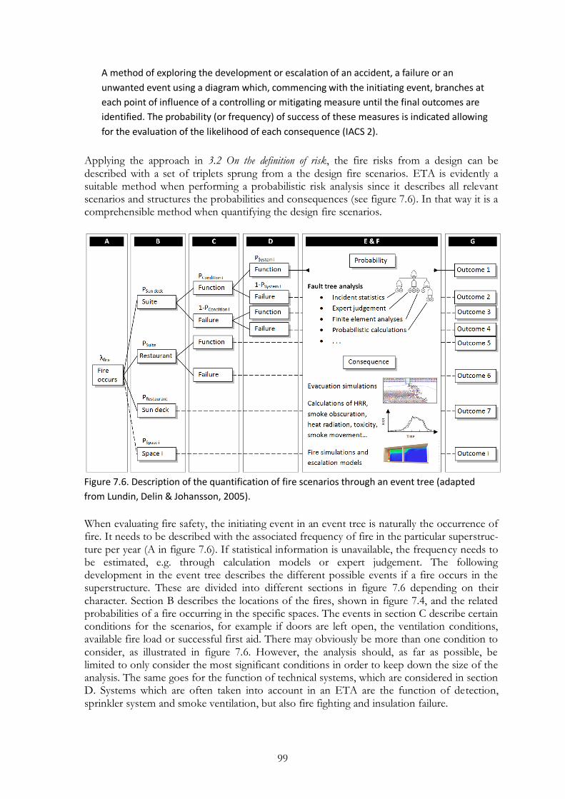
99
A method of exploring the development or escalation of an accident, a failure or an
unwanted event using a diagram which, commencing with the initiating event, branches at
each point of influence of a controlling or mitigating measure until the final outcomes are
identified. The probability (or frequency) of success of these measures is indicated allowing
for the evaluation of the likelihood of each consequence (IACS 2).
Applying the approach in 3.2 On the definition of risk, the fire risks from a design can be described with a set of triplets sprung from a the design fire scenarios. ETA is evidently a suitable method when performing a probabilistic risk analysis since it describes all relevant scenarios and structures the probabilities and consequences (see figure 7.6). In that way it is a comprehensible method when quantifying the design fire scenarios.
Figure 7.6. Description of the quantification of fire scenarios through an event tree (adapted
from Lundin, Delin & Johansson, 2005).
When evaluating fire safety, the initiating event in an event tree is naturally the occurrence of fire. It needs to be described with the associated frequency of fire in the particular superstruc-ture per year (A in figure 7.6). If statistical information is unavailable, the frequency needs to be estimated, e.g. through calculation models or expert judgement. The following development in the event tree describes the different possible events if a fire occurs in the superstructure. These are divided into different sections in figure 7.6 depending on their character. Section B describes the locations of the fires, shown in figure 7.4, and the related probabilities of a fire occurring in the specific spaces. The events in section C describe certain conditions for the scenarios, for example if doors are left open, the ventilation conditions, available fire load or successful first aid. There may obviously be more than one condition to consider, as illustrated in figure 7.6. However, the analysis should, as far as possible, be limited to only consider the most significant conditions in order to keep down the size of the analysis. The same goes for the function of technical systems, which are considered in section D. Systems which are often taken into account in an ETA are the function of detection, sprinkler system and smoke ventilation, but also fire fighting and insulation failure.
100
7.3.2 Quantification of fire scenarios
When the selected spaces, conditions and systems have been taken into account to make up specific scenarios, the probability and consequence of each scenario are to be calculated (see figure 3.2). Since specific statistical data seldom exists, failure models are often necessary to estimate the probabilities. Fault tree analysis (FTA) is a popular method used to models failure possibilities for scenario events and to quantify failure probabilities. Some examples of inputs to an FTA are enumerated in section E in figure 7.6. These may, however, also provide sufficient information regarding the probabilities, and an FTA is in those cases unnecessary. The quantification of consequences takes many calculations into account. A starting point is to establish probable diagrams describing the heat release rate per time unit, depending on the available initial fuels, the fire load, ventilation conditions etc. In certain cases, live fire testing and experiments may be necessary to properly predict the fire characteristics (IMO, 2001). The approach thereafter is commonly to compare estimations of the conditions in the affected compartments with evacuation simulations. Parameters describing the conditions in compartments affected by smoke or fire are e.g. heat radiation, toxicity, smoke obscuration and the temperature and height of the smoke layer. Transient calculations of these parameters will settle when the conditions will be inhabitable. This time will be compared with the calculated time for escape (there are also some other factors necessary to take into account, such as the reaction time and the fact that many passengers tend to stay in their cabins when the alarm sounds, as mentioned in 4.2 Evacuation). Comparing the analyses will settle a number of expected casualties, i.e. the consequences of the specific scenario. The calculated results from sections E and F are summarized as the outcome of the scenario in section G. Regardless of the calculation procedures utilized to estimate the results, a sensitivity analysis should be conducted to determine the effects from uncertainties and limitations in input parameters (IMO, 2001). Since several extensive evaluations are necessary for each considered scenario it is essential to select the events with care. Some will affect the result more than others and the labour of the analysis will to a large degree depend on the number of events in the event tree.
7.3.3 Presentation of the risk
The quantified outcomes from the ETA are now to be merged into risk measures. Estimations from probabilistic risk analyses are commonly presented in the risk measures “individual risk” and “societal risk”. In risk management “individual risk” is normally defined as the probability for an individual, situated in a specific area for a year, to be exposed to inhabitable conditions from possible accidents scenarios. Being in a space for one year where the individual risk is 10-4 implies the probability to die is one in ten thousand. The individual risk is independent from the possible number of exposed people and reveals nothing on the extent of damage to society. “Societal risk” on the other hand, concerns the total risk to human life in the areas affected by the possible fire scenarios. If one million people are situated in an area for a year where the individual risk is 10-4, then the societal risk is 100. It is important to present risk in a combination of risk measures since all features of a risk cannot be displayed in one measure. Say the probability of fire is the same in two spaces with 10 and 100 people respectively. If calculations will show that a fire will result in 5 fatalities in both areas then the societal risk will be identical. The individual risk, however, will be 0.5 and 0.05 in the different spaces, which shows the probability of inhabitable exposure is less if situated in the latter space. Hence there is a need to present risk in different risk measures and to establish several acceptance criteria (Lundin, 2004). Societal risk is typically expressed as the expected number of fatalities in a year of operation or illustrated in an FN diagram, as in figure 7.7. However, the information in the former risk measure also exists in the latter. What is also notable concerning the expected number of

101
fatalities is that is needs a fairly delimited context to make sense, which although is the case when comparing two designs of similar superstructures. An advantage with the FN-diagram is that it also provides a visual illustration of the potential risk. FN comes from for “Frequency of accidents versus Number of fatalities” and the diagram displays the estimated cumulative frequency for a certain number of fatalities expected from incidents. Since the number of fatalities from different scenarios is plotted in order of magnitude against the cumulative frequency, the expected frequency of e.g. 10 or more fatalities can be deduced from the diagram. The lines in the diagram represent examples of acceptance criteria. The upper line indicates the limit above which risks are intolerable whilst risks below the lower line should be accepted. The area in between the lines is commonly referred to as the ALARP area (As Low As Reasonably Practicable). Risks in this area should be minimized as long as the costs are not disproportionate to the risk reduction, which is commonly established through a cost-effectiveness assessment. Note that an event with catastrophic consequences can be acceptable if the probability is sufficiently small.
Figure 7.7. FN-diagram displaying societal risk. If the risk curve crosses the upper line the risk
should not be tolerated but if it is below the lower line it can be accepted. The area in between
the dashed lines is commonly referred to as the ALARP area, where risks should be reduced as
long as the costs are not out of proportion.
Even if the societal risk is acceptable the individual risk can be unacceptable. When individual risk is presented for land-based applications it is typically done with iso-risk contours over a map. These contours include all hazards in the area and the individual risk contributions they result in. The individual risk contours are marked in this way to illustrate how the risks of a facility or component are distributed and which areas are more exposed than others. For maritime applications it would be preferable to illustrate the individual risk in the different spaces of the ship. Combining fire scenarios from all spaces will show if the probability of inhabitable conditions is unacceptably high in any of the spaces, e.g. as in figure 7.8. Also the individual risk is many times presented with an ALARP zone, where a cost-benefit analysis will settle the supplementary efforts (e.g. 10-5 - 10-7 as in figure 7.8).
1E-09
1E-08
1E-07
1E-06
1E-05
1E-04
1E-03
1 10 100
Freq
uen
cy fo
r N
or
mo
re f
atal
itie
s p
er
year
Number of fatalities (N)

102
Figure 7.8. An illustration of how individual risk can be presented when evaluated for a ship
design. Depending on the acceptance criteria the colours show if the individual risk is acceptable
or if mitigating efforts need to be considered.
7.3.4 The illustrated process
The synoptic illustration of how the needs for verification can be discovered and how the fire safety can be assessed for an FRD design ends here. The process is in line with Circular 1002 but only covers the parts of the prescribed two step methodology that are included in a risk analysis, as illustrated in figure 7.9 (compare with figure 3.1 and 3.2). Performance criteria should still be established; either based on a reference design, or derived in conjunction with statistical information from holistic explicit criteria acknowledged by the IMO. However, despite its necessity, development of performance criteria and the proceeding comparative analysis are outside the scope of this report.
Figure 7.9. Description of the recommended risk analysis process in relation to the two step
analysis process prescribed in IMO (2001) and elements of risk management.

103
8. Conclusions The findings in this report have been formed from qualitative analyses, discussions with experts and scientific literature. It has been a foundational intention to keep the report as objective as possible. This chapter summarizes the findings from the project, based on its prospect and objectives. It also suggests future areas of research.
8.1 Fulfilment of objectives
The main objective of this project was to approach the prospect, to reveal the fire safety of a ship design involving FRP composite, by investigating methods that could assess the fire safety from a risk-based point of view. This extensive objective was concretized in the following three objectives:
1. To lay out a transparent foundation to the risk-based approach and how different methods of risk analysis could be utilized to evaluate the fire safety of an FRP composite design and effects on the fire safety of a ship.
2. To suggest methods that constructively reflect the differences in character between FRP composite and steel and how these differences need to be taken into account in the evaluation process.
3. To suggest methods of different complexity depending on to what extent FRP composite will be employed in a ship construction.
The anticipation was that, by achieving these objectives, a foundation would be built of how to reason when using risk-based methods to evaluate fire safety in ship designs involving FRP composite. The report is introduced by an overview of the current SOLAS regulations. Some have introduced a measure of risk- or performance-based methodology even if the main part is still prescriptive and reactive, as opposed to proactive, regulations. Furthermore, the report provides an introduction to risk which, despite its extent, is merely a conspectus of the most relevant perspectives of risk. Methods of risk analysis are also exemplified and the general approach in a risk analysis is outlined in relation to the risk management process. By connecting these parts with fire safety and the risks when introducing FRP composites the report achieves the first objective. Chapter 5. Analyzing the needs for verification uses an approach that includes not only functional parameters, but also the properties and the structure of fire safety to describe effects when introducing FRP composites. By including these parameters, effects to fire safety can be identified beyond what is described as necessary functions in the regulations. This is necessary since the novelty in FRP composite designs sometimes goes beyond prescriptive regulations as well as their functional requirements. A way of including this approach as part of the required engineering analysis (see IMO, 2001) is exemplified in chapter 7. Synoptic application of the approach, which favourably accomplishes the second objective. A prospect was that methods with different degrees of complexity could be recommended depending on to what extent FRP composite will be employed in a ship construction. With background in chapter 5. Analyzing the needs for verification this matter was investigated in chapter 6. Risk analysis for verification. The former chapter shows how the novelty of an FRP composite design should be described beyond what is required. It also identifies a number of changes in fire safety when steel in general is replaced by FRP composite with a certain amount of insulation (FRD60). Based on these effects to fire safety the following chapter suggests how different degrees of novelty should be analyzed through risk management processes on
104
different levels. The sophistication of a risk management process to a large extent depends on the choice of risk analysis method. Therefore the sophistication of different risk analysis methods was investigated in chapter 6. Risk analysis for verification. The result was a recommendation of how risk analyses on different levels should be utilized when analyzing different scopes of FRP composite designs. All levels of risk analysis are in line with the required approach outlined in MSC/Circ. 1002 (IMO, 2001) and different scopes of FRP composite structures are exemplified for each level. This settles the final of the three objectives for this report.
8.2 Future work
This report has in many ways illustrated the approach necessary to analyze the effects on fire safety when introducing FRP composites. However, the approach needs to be described in further detail in order to be a tool of common practice. These thorough descriptions can only be settled by using the approach in an actual design case. The conditions in such process will raise many questions, but hopefully just as many answers and new ideas of how to develop the recommended process further. A real design case would also set an example for the rest of the shipping industry. Building ships with superstructures in FRP composite is not impossible and could in fact be beneficial, not only from a financial, but also from a risk point of view. It also needs to be mentioned that the required engineering analysis to describe fire safety outlined in MSC/Circ. 1002 (IMO, 2001) is in great need of modification. First of all the approach is very vague and sometimes contradictive, e.g. when it comes to what the comparative analysis should be based upon. The required process of how to describe effects to fire safety when analyzing alternative designs and arrangements needs to be described in more detail, especially the development of design fire scenarios, in order to increase reproducibility and decrease uncertainty. A recommendation would be to take in good practice from e.g. Madden et al. (2005). Secondly, the process should, similar to the approach recommended in this report, favourably be possible to scale depending on the proposed scope of novelty. Furthermore, IMO (2001) has a comparative starting point which implies excessive uncertainties. On a general plane, there are uncertainties when establishing the level of fire safety in the novel design and when comparing it with the level of safety in a prescriptive design. However, corresponding to today‟s practice in IMO (2001) there will also be uncertainties involved when establishing the safety level of the prescriptive design. If explicit evaluation criteria would be established that could represent the fire safety level in the SOLAS regulations, then this uncertainty could be minimized. For sure there would still be uncertainties involved and a need for safety margins, but if the IMO would settle on acceptable safety criteria and corresponding safety margins, expediently depending on the analysis sophistication, the uncertainties would decrease as well as the labour of the analysis. This would, in the best of worlds, lead to an efficient use of both analysis methods and ship designs.
105
9. References Acikalin, A. (2009). Integration of Safety Management Effectiveness into QRA Calculations. Process Safety Progress, Vol. 28, No. 4, pp. 331-337 Akselsson, R. (2008). Människa, teknik, organisation och riskhantering. Lund: KFS i Lund AB Allison, D. M.; Marchand, A. J.; Morchat, R. M. (1991). Fire Performance of Composite Materials in Ships and Offshore Structures. Marine Structures, Vol. 4, No. 2, pp. 129-140 Arvidsson, M.; Axelsson, J.; Hertzberg, T. (2008). Large-scale fire tests in a passenger cabin (SP Report 2008:33). Borås: SP Technical Research Institute of Sweden Austin, M. & Samadzadeh, M. (2008). An Objective Method to Measure the Effectiveness of a Risk Management System. In proceedings from 19th International Conference on Systems Engineering, pp. 508-511 Bolsover, A.; Skramstad, E.; Lyon, A. (1998). Uncertainty in QRA. Presentation at the 7th Annual Conference on Offshore Installations by DNV Norway. Boehmer, W. (2008). Appraisal of the effectiveness and efficiency of an Information Security Management System based on ISO 27001. In proceedings from Second International Conference on Emerging Security Information, Systems and Technologies, pp. 224-231 Boverket (2008). Regelsamling för byggande, BBR. Karlskrona: Boverket Blockley, D. (1980). The Nature of Structural Design and Safety. Ellis Horwood Ltd. Bridges, T. (2000). Application of Risk Assessment. In Conference proceedings 22 - Risk Management in the Marine Transportation System. Irvine, CA. Bushell, G., E. (2000). Oceans Risk and Criteria Analysis. In Conference proceedings 22 - Risk Management in the Marine Transportation System. Irvine, CA Callan, L.J. (1998). White Paper on Risk-Informed and Performance-Based Regulation. (Electronic) Available: <http://www.nrc.gov/reading-rm/doc-collections/commission/secys/1998/ secy1998-144/1998-144scy.html> (2010-04-27) COSO. Committee of Sponsoring Organizations of the Treadway Commission. (2004). Enterprise Risk Management - Integrated Framework Executive Summary. (Elektronic) Available: <http://www.coso.org/documents/COSO_ERM_ExecutiveSummary.pdf> [2010-02-09] Davidsson, G.; Lindgren, M.; Mett, L. (1997). Värdering av risk. (Electronic) Available: <http://www2.msb.se/shopping/srv_ShowItem____26432.aspx> (2009-08-10) Davidsson, G.; Haeffler, L.; Ljundman, B.; Frantzich, H. (2003). Handbok för riskanalys. (Electronic) Available: <http://www2.msbmyndigheten.se/shopping/srv_ShowItem____26987.aspx> (2010-01-30)

106
Demichela, M. & Piccinini, N. (2006). How the management aspects can affect the results of the QRA. Journal of Loss Prevention in the Process Industries, Vol. 19, No. 1, pp. 70-77 Demichela, M.; Piccinini, N.; Romano, A. (2004). Risk analysis as a basis for safety management system. Journal of Loss Prevention in the Process Industries, Vol. 17, No. 3, pp. 179-185 Elmer, A. (2000). Application of Risk Management in the Marine Transportation System. In Conference proceedings 22 - Risk Management in the Marine Transportation System. Irvine, CA. ETSC. European Transport Safety Council (1997). Priority measures for maritime accident reduction. Brussels: ETSC Fischhoff, B.; Bostrom, A. & Quadrel, M., J. (1993). Risk Perception and Communication. Annual Review of public health, Vol. 14, pp. 183-203 Fischhoff, B. et al. (1978). How Safe Is Safe Enough? A Psychometric Study of Attitudes Toward Technological Risk and Benefits. Policy Sciences, Vol. 8 Fox, C. (2010). What You Need to Know About ISO 31000. (Electronic) Available: < http://community.ca.com/blogs/iam/archive/2010/01/07/what-you-need-to-know-about-iso-31000.aspx> (2010-02-16) Grimvall, G.; Jacobsson, P.; Thedéen, T. (2003). Risker i tekniska system. Lund: Studentlitteratur Guldenmund, F. et al. (2006). The development of an audit technique to assess the quality of safety barrier management. Journal of Hazardous Materials, Vol. 130, No. 3, pp. 234-241 Hertzberg, T. et al. (2009). LASS, Lightweight Construction Applications at Sea. (Electronic) Available: <http://www.lass.nu/Reports/LASS-SP_Report_2009_13.pdf > (2009-06-07) IACS 1. International Association of Classification Societies Ltd. (2004).. A guide to risk assessment in ship operations. (Electronic) Available: <http://www.iacs.org.uk/document/public/Publications/Other_technical/PDF/ Guide_to_Risk_Assessment_in_Ship_Ops_pdf421.pdf> (2009-08-03) IACS 2. International Association of Classification Societies Ltd. Formal safety assessment - Basic glossary of terms. (Electronic) Available: <http://www.iacs.org.uk/document/public/Publications/Other_technical/PDF/ FSA_Glossary_pdf437.pdf> (2009-08-04) IEC. International Electrotechnical Commission (1995). Dependability management – Part 3: Application Guide – Section 9: Risk analysis of technological systems (International Standard IEC 300-3-9). Genève: Bureau Central de la Commission Electrotechnique Internationale IMO. International Maritime Organization (1993). Recommendation on Fire Resistance Tests for “A”, “B” and “F” Class Divisions. IMO Resolution A.754(18). IMO (1995). Test Procedures for Fire-resisting Divisions of High Speed Craft. IMO Resolution MSC.45(65) IMO (2000). International Code of Safety for High-Speed Craft. IMO Resolution MSC.97(73).

107
IMO (2001). Guidelines on Alternative Design and Arrangements for Fire Safety. MSC/Circ.1002. IMO (2002a). Interim Guidelines for evacuation analysis for new and existing passenger ships. MSC/Circ.1033 IMO (2002b). Guidelines for Formal Safety Assessment (FSA) for use in the IMO Rule-Making Process. MSC/Circ.1023 IMO (2004a). SOLAS – Consolidated edition, 2004. London: The Bath Press IMO (2004b). International Safety Management Code. IMO Resolution MSC.179(79). IMO (2006). Guidelines on alternative design and arrangements for SOLAS Chapters II-1 and III. MSC/Circ.1212. IMO (2007). Consolidated text of the Guidelines for Formal Safety Assessment (FSA) for Use in the IMO Rule-Making Process (MSC/Circ.1023–MEPC/Circ.392). MSC83/INF.2. IMO (2008a). Formal Safety Assessment – FSA - Cruise Ships. MSC 85/17/1 IMO (2008b). Formal Safety Assessment – FSA - Cruise Ships – Details of the Formal Safety Assessment. MSC 85/INF.2 IMO (2009a). Goal-Based New Ship Construction Standards – Guidelines on approval of risk-based ship design. MSC 86/5/3 IMO (2009b). Goal-Based New Ship Construction Standards – The safety level approach - introducing the safety knob to control maritime safety. MSC 86/6/8 IMO (2009c). Goal-Based New Ship Construction Standards – Safety level approach - Safety level criteria. MSC 86/6/10 IMO 1. Introduction to IMO. (Electronic) Available: <http://www.imo.org/> (2009-07-09) IMO 2. International Convention for the Safety of Life at Sea (SOLAS), 1974. (Electronic) Available: <http://www.imo.org/> (2009-07-09) ISO. International Organization for Standards. (2009). ISO 31000:2009. (Electronic) Available: <http://www.iso.org/iso/catalogue_detail.htm?csnumber=43170> [2010-02-11] Jense, G. (1999). Om sjöfart och sjösäkerhet – en bakgrund (Rapport 2). Växjö: Växjö University Jense, G. (2005). Den relativa säkerheten – Om risk, säkerhet och sjöfart (Rapport 25). Växjö: Växjö University Jia, J. & Ulfvarson, A (2005). A systematic approach towards the structural behaviour of a lightweight deck–side shell system. Thin-Walled Structures, Vol. 43, No. 1, pp. 83–105
108
Jovašević-Stojanović, M. & Stojanović, B. (2009). Performance indicators for monitoring safety management systems in chemical industry. Chemical Industry & Chemical Engineering Quarterly, Vol. 15, No. 1, pp. 5-8 Kammen, D. & Hassenzahl, D. (1999). Should We Risk It? Exploring Environmental, Health, and Technological Problem Solving. Ch. 4. Princeton: Princeton University Press Kaplan, S. & Garrick, J. (1981). On The Quantitative Definition of Risk. Risk Analysis, Vol. 1, No. 1, pp. 11-27 Karlsson, E. & Vinberg, D. (2009). Strukturellt brandskydd på marina farkoster – Analytisk dimensionering av brandsektioneringar samt utvärdering av flexibla brandtätningar genom viktat urval (Report 5311). Lund: Lund University, Department of Fire Safety Engineering and Systems Safety Kolluru, R. et al. (1996). Risk Assessment and Management Handbook – For Environmental, Health, and Safety Professionals. New York: McGraw-Hill LÄSS. (LÄttviktskonstruktioner till sjöSS). Lightweight construction applications at sea. (Electronic) Available: <http://www.lass.nu/> (2010-01-30) Lua, J. et al. (2006). A temperature and mass dependent thermal model for fire response prediction of marine composites. Composites Part A: Applied Science and Manufacturing, Part A, Vol. 37, No. 7, pp. 1024–1039 Lundin, J. (2001). Verifiering, kontroll och dokumentation vid brandteknisk projektering (Report 3129). Lund: Lund University, Department of Fire Safety Engineering and Systems Safety Lundin, J. (2004). Acceptabel risk vid dimensionering av utrymningssäkerhet (Report 3129). Lund: Lund University, Department of Fire Safety Engineering and Systems Safety Lundin, J.; Delin, M. & Johansson, H. (2005). Chapter 13 - Analytisk dimensionering. In Jönsson, R. (Ed.); Bengtsson, S. (Ed.) & Frantzich, H. (Ed.) (2005). Brandskyddshandboken (Report 3134). Lund: Lund University, Department of Fire Safety Engineering and Systems Safety Madden, M. J. et al. (2005). SFPE Engineering Guide to Application of Risk Assessment in Fire Protection Design. Bethesda: Society of Fire Protection Engineers Marine (2009). Maxsurf – Dec ’09. (Electronic) Available: < http://www.formsys.com/maxsurf/newsletters/maxsurf---december-2009> (2010-01-15) Meister, D. (1991). Psychology of System Design. New York: Elsevier (secondary source) Merkhofer, M. (1987). Decision science and social risk management. Netherlands: D. Reidel Publishing Company Morgan, M. G. & Henrion, M. (1990). Uncertainty - A guide to dealing with Uncertainty in Quantitative Risk and Policy Analysis. New York: Cambridge University Press

109
NCL. Norwegian Gem: Overview. (Electronic) Available: <http://www.ncl.com/nclweb/fleet/shipInformation.html?shipCode=GEM> (2009-07-14) Nilsson, J. (2003). Introduktion till riskanalysmetoder (Report 3124). Lund: Lund University, Department of Fire Safety Engineering and Systems Safety Nystedt, F. (2000). Riskanalysmetoder (Report 7011). Lund: Lund University, Department of Fire Safety Engineering and Systems Safety Pålsson, I. & Torstensson, H. (1998). Sealoc - Safer Maritime Transport of Dangerous Goods – Safety Analysis and Assessment (SSPA Research Report No. 107). Göteborg: SSPA Maritime Consulting AB Papanikolaou, A. & Eliopoulou, E. (2008). On the development of the new harmonised damage stability regulations for dry cargo and passenger ships. Reliability Engineering and System Safety, Vol. 93, No. 9, pp. 1305–1316 Papanikolaou, A. (Ed.) (2009). Risk-Based Ship Design. Berlin: Springer Paté-Cornell, E. (1996). Uncertainties in Risk Analysis: Six levels of treatment. Reliability Engineering and System Safety. Vol. 54, No. 54, pp. 95-111 Räddningsverket (1994). Fartygs brandsläckning. Karlstad: Räddningsverket (Swedish Rescue Services Agency) Reason, J. (1990). Human error. Cambridge: Cambridge University Press Riskkollegiet (1993). Upplevd risk. (Electronic) Available: < http://www.riskkollegiet.nu/Skrift3.pdf> (2009-03-29) Riskkollegiet (1998). Beslut under osäkerhet. (Electronic) Available: < http://www.riskkollegiet.nu/Skrift11.pdf> (2009-03-29) Rosenthal, I.; Kleindorfer, P.; Elliott, M. (2006). Predicting and Confirming the Effectiveness of Systems for Managing Low-Probability Chemical Process Risks. Process Safety Progress, Vol. 25, No. 2, pp. 135-155 Rowe, W. (1994). Understanding Uncertainty. Risk Analysis, Vol. 14, No. 5, pp. 743-750 SAFEDOR. about SAFEDOR. (Electronic) Available: <http://www.safedor.org/> (2009-07-14) Sames, P. (2009). Chapter 1 - Introduction to Risk-Based Approaches in the Maritime Industry. In Papanikolaou, A. (Ed.) (2009). Risk-Based Ship Design. Berlin: Springer Shaw, L. & Sichel, H (1971). Accident proneness. Oxford: Pergamon SIS Forum (2004). Tankar om möjligheter. Integrerade ledningssystem – artikelsamling. Nytt om 9000 & 1400, No. 127. (Electronic) Available: <http://www.sis.se/upload/632436460434681250.pdf> (2010-02-09)

110
Skjong, R. (1999). 5.2.2 Offshore Regulations and Risk Assessment. In Final Report for Publication – Concerted Action on FSEA. (Electronic) Available: <http://www.emsa.europa.eu/Docs/marine_casualties/fsea_final_report.pdf> (2010-01-13) Skjong, R. (2002). Risk Acceptance Criteria: current proposals and IMO position. (Electronic) Available: < http://research.dnv.com/skj/Papers/SkjValencia.pdf> (2009-07-25) Skjong, R. (2009). Chapter 3 - Regulatory Framework. Risk-Based Ship Design. In Papanikolaou, A. (Ed.) (2009). Risk-Based Ship Design. Berlin: Springer Skjong, R.; Vanem, E.; Endresen, Ö. (2005). Risk Evaluation Criteria (SAFEDOR Report D.4.5.2.). (Electronic) Available: <http://www.safedor.org/resources/SAFEDOR-D-04.05.02-2005-10-21-DNV-RiskEvaluationCriteria-rev-3.pdf> (2009-11-04) Slovic, P. (1987). Perception of Risk. Science. Vol. 236, No. 4799, pp. 280-285 Smith, C. S. & Chalmers, D. W. (1987). Design of ship superstructures in fibre reinforced plastic. Trans. RINA, Vol. 129, pp. 45-62. Soares, C. G. & Das, P. K. (2009). Analysis and Design of Marine Structures. Leiden: CRC Press SOU (1996). (Statens Offentliga Utredningar) Handlingsprogram för ökad sjösäkerhet – Betänkande av Sjösäkerhetskommittén – SOU 1996:182. Malmö: Norstedts Juridik SURSHIP. (SURvivability for SHIPs). LASS-c: Lightweight construction of a cruise vessel. (Electronic) Available: < http://www.surship.eu/project/lass-c/overview> (2010-02-01) Teo, E. & Ling, F. (2006). Developing a model to measure the effectiveness of safety management systems of construction sites. Building and Environment, Vol. 41, No. 11, pp. 1584-1592 Transportation Research Board. (2000). Conference proceedings 22 - Risk Management in the Marine Transportation System. Irvine: Transportation Research Board Turner, B. & Pidgeon, N. (1997). Man-Made Disasters. Oxford: Butterworth Heinemann Vanem, E. & Skjong, R. (2004a). Collision and Grounding of Passenger Ships – Risk Assessment and Emergency Evacuations. In Proceedings of the 3rd International Conference on Collision and Grounding of Ships (ICCGS). Izu, Japan. Vanem, E. & Skjong, R. (2004b). Fire and Evacuation Risk Assessment for Passenger Ships. In Proceedings of the 10th International Fire Science and Engineering Conference (Interflam). Edinburgh, Scotland. Vanem, E. & Skjong, R. (2006). Designing for safety in passenger ships utilizing advanced evacuation analyses – A risk based approach. Safety Science, Vol. 44, No. 111-135, pp 111-135. Vassalos, D. & Jasionowski, A. (2007). SOLAS 2009 – Raising the Alarm. In Conference proceedings of the 10th International Ship Stability Workshop. Hamburg, Germany.

111
Vassalos, D. (2009). Chapter 2 - Risk-Based Ship Design. Risk-Based Ship Design. In Papanikolaou, A. (Ed.) (2009) Risk-Based Ship Design. Berlin: Springer Vlek, C. & Cvetkovich, G. (1989). Social Decision Methodology for Technological Projects. Dordrecht: Kluwer Wahlström, H.; Nyberg, D.; Valbärj, K. (1987). Hamnarna, sjöfarten och trafikpolitiken. Borås: Svenska Transportarbetareförbundet Walker, D. & Tait, R. (2004). Health and safety management in small enterprises: an effective low cost approach. Safety Science, Vol. 42, No. 1, pp. 69-83

112
113
Appendix A. Definitions Below follows definitions and explanations to some of the used terminology in the report. Short explanations to abbreviations are found preceding the table of contents. Alternative design and arrangements means fire safety measures which deviate from prescriptive requirements in SOLAS chapter II-2, but are suitable to satisfy the fire safety objectives and the functional requirements of that chapter. CCF means Common Cause Failure and means that one error will cause several failures, which can result in fateful consequences (e.g. electric power loss). Core implies the lightweight stiff plate material, often PVC foam or balsa wood, used to separate the face sheets of a sandwich panel. ETA means Event Tree Analysis and is a method exploring the development of an accident, or in this case a fire. A diagram branches out at each events influencing the development, such as conditions and the function of systems, until the final outcomes are identified. Face sheets are rigid and strong laminates of e.g. plastic or carbon fibre, bonded on each side of the core to make up a sandwich panel. FMEA means Failure Mode and Effect Analysis and is a method for hazard identification comprising an operator analysis and is based on a fault tree analysis. FRD means fire resistant division, a composite structure designed with insulation in order to provide fire resistance. FTA means Fault Tree Analysis which structures information on sources to a certain error in a logical diagram and seeks out the root causes, called base events. A general rule is that if a base event is caused by a human error it is more likely to happen than if the base event is an active component (pump, instrument, etc.). Active components are, on the other hand, more likely to generate an error than passive components, such as pipes and tanks etc. If identical base events are found, it means that one single event affects many of the branches, which is called a common cause failure (CCF). Functional requirements explain, in general terms, what function the ship should provide to meet the objectives. HAZOP means HAZard and OPerability study and is a method for hazard identification where magnitudes of e.g. temperature, pressure, and flow are varied in order to evaluate possible causes and consequences up- and downstream from a position in the system. HRA means Human Reliability Analysis and is a process where a set of activities and a number of techniques are used to derive human error probabilities, e.g. for an ETA or FTA. LSA means Life-Saving Appliances and refers to any device or arrangement intended for people in distress in case of an emergency. Performance criteria are measurable quantities stated in engineering terms to be used to judge the adequacy of trial designs.

114
PHA means Process Hazard Analysis which is a used to identify and analyze the importance and potential hazard from processing and handling chemicals. PLL means potential lost lives, a measure for comparing risks. Preliminary analysis is, except the first step in the engineering analysis described in Circular 1002 (IMO, 2001), a coarse method for hazard identification which is often is a good starting point in order to get a picture of the problem. Prescriptive based design or prescriptive design means a design of fire safety measures which comply with the prescriptive regulatory requirements set out in parts B, C, D, E or G of RCM means Risk Control Measure and is a means to minimizing an element of a risk, usually targeting either the probability or consequence. RCO means Risk Control Options and is used for the alternative design and arrangements to enhance safety and consists of a number of RCM. SAFEDOR is a European project founded to increase maritime safety by treating it as a design objective. This is done by establishing risk-based regulations and involving risk assessments in the design process (SAFEDOR). Sensitivity analysis is an analysis determining the effects on a result when making changes in individual input parameters. SOLAS chapter II-2. SOLAS is the International Convention for the Safety of Life at Sea, 1974, as amended. THERP means Technique for Human Error Rate Prediction and is a comprehensive methodology which identifies, models and quantifies human error. What If? is a procedure for hazard identification where the system is methodically examined whilst the function of components and human interactions are questioned with; “What if X happens?”.
115
Appendix B. The purposes of SOLAS II-2 The fire safety objectives and functional requirements that set out the purpose of the following regulations in SOLAS chapter II-2 are reproduced subsequently. 1 Fire safety objectives 1.1 The fire safety objectives of this chapter are to: .1 prevent the occurrence of fire and explosion; .2 reduce the risk to life caused by fire; .3 reduce the risk of damage caused by fire to the ship, its cargo and the environment; .4 contain, control and suppress fire and explosion in the compartment of origin; and .5 provide adequate and readily accessible means of escape for passengers and crew. 2 Functional requirements 2.1 In order to achieve the fire safety objectives set out in paragraph 1, the following functional requirements are embodied in the regulations of this chapter as appropriate: .1 division of the ship into main vertical and horizontal zones by thermal and structural boundaries; .2 separation of accommodation spaces from the remainder of the ship by thermal and structural boundaries; .3 restricted use of combustible materials; .4 detection of any fire in the zone of origin; .5 containment and extinction of any fire in the space of origin; .6 protection of means of escape and access for fire fighting; .7 ready availability of fire-extinguishing appliances; and .8 minimization of possibility of ignition of flammable cargo vapour. In the following paragraphs the purposes of every regulation in SOLAS II-2 are summarized, hence each consisting of its own objectives and functional requirements.
B.1 Regulation 4 - Probability of ignition
The purpose of this regulation is to prevent the ignition of combustible materials or flammable liquids. For this purpose, the following functional requirements shall be met: .1 means shall be provided to control leaks of flammable liquids; .2 means shall be provided to limit the accumulation of flammable vapours; .3 the ignitability of combustible materials shall be restricted; .4 ignition sources shall be restricted; .5 ignition sources shall be separated from combustible materials and flammable liquids; and .6 the atmosphere in cargo tanks shall be maintained out of the explosive range.
B.2 Regulation 5 - Fire growth potential
The purpose of this regulation is to limit the fire growth potential in every space of the ship. For this purpose, the following functional requirements shall be met: .1 means of control for the air supply to the space shall be provided; .2 means of control for flammable liquids in the space shall be provided; and .3 the use of combustible materials shall be restricted.
B.3 Regulation 6 - Smoke generation potential and toxicity
The purpose of this regulation is to reduce the hazard to life from smoke and toxic products generated during a fire in spaces where persons normally work or live. For this purpose, the

116
quantity of smoke and toxic products released from combustible materials, including surface finishes, during fire shall be limited.
B.4 Regulation 7 - Detection and alarm
The purpose of this regulation is to detect a fire in the space of origin and to provide for alarm for safe escape and fire-fighting activity. For this purpose, the following functional requirements shall be met: .1 fixed fire detection and fire alarm system installations shall be suitable for the nature of the space, fire growth potential and potential generation of smoke and gases; .2 manually operated call points shall be placed effectively to ensure a readily accessible means of notification; and .3 fire patrols shall provide an effective means of detecting and locating fires and alerting the navigation bridge and fire teams.
B.5 Regulation 8 - Control of smoke spread
The purpose of this regulation is to control the spread of smoke in order to minimize the hazards from smoke. For this purpose, means for controlling smoke in atriums, control stations, machinery spaces and concealed spaces shall be provided.
B.6 Regulation 9 - Containment of fire
The purpose of this regulation is to contain a fire in the space of origin. For this purpose, the following functional requirements shall be met: .1 the ship shall be subdivided by thermal and structural boundaries; .2 thermal insulation of boundaries shall have due regard to the fire risk of the space and adjacent spaces; and .3 the fire integrity of the divisions shall be maintained at openings and penetrations.
B.7 Regulation 10 - Fire fighting
The purpose of this regulation is to suppress and swiftly extinguish a fire in the space of origin. For this purpose, the following functional requirements shall be met: .1 fixed fire-extinguishing systems shall be installed, having due regard to the fire growth potential of the protected spaces; and .2 fire-extinguishing appliances shall be readily available.
B.8 Regulation 11 - Structural integrity
The purpose of this regulation is to maintain structural integrity of the ship, preventing partial or whole collapse of the ship structures due to strength deterioration by heat. For this purpose, materials used in the ships‟ structure shall ensure that the structural integrity is not degraded due to fire.
B.9 Regulation 12 – Notification of crew and passengers
The purpose of this regulation is to notify crew and passengers of a fire for safe evacuation. For this purpose, a general emergency alarm system and a public address system shall be provided.
B.10 Regulation 13 - Means of escape
The purpose of this regulation is to provide means of escape so that persons on board can safely and swiftly escape to the lifeboat and life raft embarkation deck. For this purpose, the following functional requirements shall be met:
117
.1 safe escape routes shall be provided;
.2 escape routes shall be maintained in a safe condition, clear of obstacles; and
.3 additional aids for escape shall be provided as necessary to ensure accessibility, clear marking, and adequate design for emergency situations.
B.11 Regulation 14 - Operational readiness and maintenance
The purpose of this regulation is to maintain and monitor the effectiveness of the fire safety measures the ship is provided with. For this purpose, the following functional requirements shall be met: .1 fire protection systems and fire-fighting systems and appliances shall be maintained ready for use; and .2 fire protection systems and fire-fighting systems and appliances shall be properly tested and inspected.
B.12 Regulation 15 - Instructions, on-board training and drills
The purpose of this regulation is to mitigate the consequences of fire by means of proper instructions for training and drills of persons on board in correct procedures under emergency conditions. For this purpose, the crew shall have the necessary knowledge and skills to handle fire emergency cases, including passenger care.
B.13 Regulation 16 - Operations
The purpose of this regulation is to provide information and instructions for proper ship and cargo handling operations in relation to fire safety. For this purpose, the following functional requirements shall be met: .1 fire safety operational booklets shall be provided on board; and .2 flammable vapour releases from cargo tank venting shall be controlled.
D.14 Regulation 17 - Alternative design and arrangements
The purpose of this regulation is to provide a methodology for alternative design and arrangements for fire safety.
B.14 Regulation 18 - Helicopter facilities
The purpose of this regulation is to provide additional measures in order to address the fire safety objectives of this chapter for ships fitted with special facilities for helicopters. For this purpose, the following functional requirements shall be met: .1 helideck structure shall be adequate to protect the ship from the fire hazards associated with helicopter operations; .2 fire-fighting appliances shall be provided to adequately protect the ship from the fire hazards associated with helicopter operations; .3 refuelling and hangar facilities and operations shall provide the necessary measures to protect the ship from the fire hazards associated with helicopter operations; and .4 operation manuals and training shall be provided.
B.15 Regulation 19 - Carriage of dangerous goods
The purpose of this regulation is to provide additional safety measures in order to address the fire safety objectives of this chapter for ships carrying dangerous goods. For this purpose, the following functional requirements shall be met: .1 fire protection systems shall be provided to protect the ship from the added fire hazards associated with carriage of dangerous goods; .2 dangerous goods shall be adequately separated from ignition sources; and
118
.3 appropriate personnel protective equipment shall be provided for the hazards associated with the carriage of dangerous goods.
B.16 Regulation 20 - Protection of vehicle, special category and ro–ro spaces
The purpose of this regulation is to provide additional safety measures in order to address the fire safety objectives of this chapter for ships fitted with vehicle, special category and ro–ro spaces. For this purpose, the following functional requirements shall be met: .1 fire protection systems shall be provided to adequately protect the ship from the fire hazards associated with vehicle, special category and ro–ro spaces; .2 ignition sources shall be separated from vehicle, special category and ro–ro spaces; and .3 vehicle, special category and ro–ro spaces shall be adequately ventilated.

119
Appendix C. The Norwegian Gem M/S Norwegian Gem has been operating since late 2007 and is a $US 700 million cruise vessel. She was built by Meyer Werft in Papenburg, Germany, in steel except for some parts of the upper superstructure (mainly sun decks) that were made in aluminium. The ship is owned by Norwegian Cruise Line which has had her spend most of the time sailing from her home port in Manhattan to destinations like Florida, Bahamas and South Caribbean (NCL). To get a general picture of the Norwegian Gem ship see figure C1 and table C1.
Figure C1. The Norwegian Gem and the intended FRD superstructure marked in the mid-aft section.
The Norwegian Gem offers about 2400 passengers a variety of amenities, consisting of e.g. 11 bars and lounges, 12 restaurants, 4-lane bowling alley, courtyard and garden villas, 3 pools, 5 jacuzzis, spa & beauty salon, fitness centre, running track, basketball, volleyball and tennis courts, boutiques, theatre, casino, chapel and much more on 15 decks (NCL). Table C1. General statistics of the cruise ship Norwegian Gem (Meyer Werft).
Tonnage 93,500 gross tons Length 965 ft (294 m) Beam 106 ft (32 m) Draft 27 ft (8.2 m) Decks 15 Average speed 25 Knots Capacity 2400 passengers Personnel 1150 crew
It is proposed that a part of the superstructure of deck 13-15 in the mid-aft section will be designed in FRD instead of steel. Therefore, a slightly more thorough review regarding the decks that may be affected by the novel design (decks 12-15) follows in the succeeding subsections.
C.3 Deck 12
Deck 12 is a pure leisure deck as can be seen in figure C2. Beginning from the aft there is an outdoor buffet and dining on the stern deck followed by a small restaurant on port side and a dining hall on starboard side (101 seats, 190 m2). A large pantry interconnecting the three dining halls is found in the middle, by some bathrooms and elevators. On starboard side the dining area continues through two main bulkheads. The latter is underneath the composite superstructure and comprises 192 seats (655 m2) and a buffet area. On port side the main galley is situated along with some storage rooms at cold and normal temperature. Parts of the galley are located below the intended superstructure, as well as two children‟s arcade lounges; one with games, dance floor, bar, cinema and video arcade and the other with areas for art and play.

120
Midships follows more elevators, a stairway, a galley and a bar, all of which are situated below the proposed FRD superstructure.
Figure C2. The general deck plan for deck 12 with dining halls and galleys in the aft, the main pool
area in the mid section and spa and beauty salons in the fore (Plan: Meyer Werft).
The galley and bar under the superstructure are placed to serve the pool area and main sun deck. These are found in the mid section of this deck, with pools, sun chairs, seats and tables. On port side follows a gym with various machines and on starboard side a couple of spaces for games and a library. In the fore of the ship there is a considerable area for spa, beauty salons, hair salon, relaxation, saunas, and numerous treatment rooms.
C.4 Deck 13
This deck is mainly an outdoor deck, where a combination of sport courts, also working as a helicopter platform, is found on the aft deck. Large rooms for ventilation and other machine-ries take up a lot of the space in the aft followed by two restaurants and a bar, all situated in the superstructure (Steak House, 106 seats, 274 m2; Cagney´s Steakhouse, 62 seats, 100 m2; Star Bar, 48 seats, 116 m2). Around the above arrangements is also a running track, followed by a large open space in the middle of the ship. Sun chairs are placed around the opening to the pool area on the deck below (see figure C3).
Figure C3. The part of deck 13 to be designed in FRD, comprising two restaurants, a bar surrounded
by a jogging track (Plan: Meyer Werft).
C.5 Deck 14
This deck mainly consists of sun decks and exclusive suites (see figure C4). Seats (48) over-looking the sports court are found in the aft and also some sun chairs (48) around the funnel.

121
Ten large suites and two 5000 sq ft (465 m2) grand villas occupy the space in front of the funnel and will all be part of the FRD superstructure.
Figure C4. Layout of the part of deck 14 which is to be redesigned in FRD. The intended FRD
superstructure consists of exclusive suites, an inner yard and two grand villas (Plan: Meyer Werft).
C.6 Deck 15
Deck 15 begins in front of the funnel with another two sun decks; one private for the suites below and one public with 95 sun chairs (335 m2). There are also another two suites towards the fore, with private sundecks overlooking the main pool area (see figure C5).
Figure C5. General plan for the part of deck 15 intended for FRD, mainly consisting of sun decks
(Plan: Meyer Werft).


![[Composite Cultures] - CORE](https://static.fdokumen.com/doc/165x107/6325e67de491bcb36c0a86c0/composite-cultures-core.jpg)


