
U s e r M anual - AMCI
76
MICRO CONTROLS INC. ADVANCED U s e r M a n u a l Manual #: 940-0N090 E2 Technology
-
Upload
khangminh22 -
Category
Documents
-
view
0 -
download
0
Transcript of U s e r M anual - AMCI
MICRO CONTROLS INC.ADVANCED
User
M
anual
Manual #: 940-0N090
E2 Technology
GENERAL INFORMATION
Important User InformationThe products and application data described in this manual are useful in a wide variety of different applica-tions. Therefore, the user and others responsible for applying these products described herein are responsible for determining the acceptability for each application. While efforts have been made to provide accurate infor-mation within this manual, AMCI assumes no responsibility for the application or the completeness of the information contained herein.UNDER NO CIRCUMSTANCES WILL ADVANCED MICRO CONTROLS, INC. BE RESPONSIBLE OR LIABLE FOR ANY DAMAGES OR LOSSES, INCLUDING INDIRECT OR CONSEQUENTIAL DAM-AGES OR LOSSES, ARISING FROM THE USE OF ANY INFORMATION CONTAINED WITHIN THIS MANUAL, OR THE USE OF ANY PRODUCTS OR SERVICES REFERENCED HEREIN.No patent liability is assumed by AMCI, with respect to use of information, circuits, equipment, or software described in this manual.The information contained within this manual is subject to change without notice.This manual is copyright 2020 by Advanced Micro Controls Inc. You may reproduce this manual, in whole or in part, for your personal use, provided that this copyright notice is included. You may distribute copies of this complete manual in electronic format provided that they are unaltered from the version posted by Advanced Micro Controls Inc. on our official website: www.amci.com. You may incorporate portions of this documents in other literature for your own personal use provided that you include the notice “Portions of this document copyright 2020 by Advanced Micro Controls Inc.” You may not alter the contents of this document or charge a fee for reproducing or distributing it.
Standard WarrantyADVANCED MICRO CONTROLS, INC. warrants that all equipment manufactured by it will be free from defects, under normal use, in materials and workmanship for a period of [18] months. Within this warranty period, AMCI shall, at its option, repair or replace, free of charge, any equipment covered by this warranty which is returned, shipping charges prepaid, within eighteen months from date of invoice, and which upon examination proves to be defective in material or workmanship and not caused by accident, misuse, neglect, alteration, improper installation or improper testing.The provisions of the "STANDARD WARRANTY" are the sole obligations of AMCI and excludes all other warranties expressed or implied. In no event shall AMCI be liable for incidental or consequential damages or for delay in performance of this warranty.
Returns PolicyAll equipment being returned to AMCI for repair or replacement, regardless of warranty status, must have a Return Merchandise Authorization number issued by AMCI. Call (860) 585-1254 with the model number and serial number (if applicable) along with a description of the problem during regular business hours, Monday through Friday, 8AM - 5PM Eastern. An "RMA" number will be issued. Equipment must be shipped to AMCI with transportation charges prepaid. Title and risk of loss or damage remains with the customer until shipment is received by AMCI.
24 Hour Technical Support Number24 Hour technical support is available on this product. If you have internet access, start at www.amci.com. Product documentation and FAQ’s are available on the site that answer most common questions.If you require additional technical support, call (860) 583-1254. Your call will be answered by the factory dur-ing regular business hours, Monday through Friday, 8AM - 5PM Eastern. During non-business hours an auto-mated system will ask you to enter the telephone number you can be reached at. Please remember to include your area code. The system will page an engineer on call. Please have your product model number and a description of the problem ready before you call.
Waste Electrical and Electronic Equipment (WEEE)At the end of life, this equipment should be collected separately from any unsorted municipal waste.
ADVANCED MICRO CONTROLS INC.
TABLE OF CONTENTS
General InformationImportant User Information ..................... 2Standard Warranty ................................... 2Returns Policy .......................................... 224 Hour Technical Support Number ........ 2Waste Electrical and Electronic Equipment
(WEEE) .................................................. 2
About this ManualAudience .................................................. 5Trademark Notices ................................... 5Revision Record ....................................... 5
Revision History ............................ 5Navigating this Manual ............................ 5Manual Conventions ................................ 5Where To Go From Here ......................... 6
Reference: NX2A4E2 IntroductionThe NX2A4E2 ......................................... 7Stop Time Monitoring ............................. 9NX2A4E2 Programmable Parameters ..... 10
Common Parameters ..................... 10Single Turn Parameters ................. 10Multi-turn parameters .................... 11
Front Panel Description ........................... 12Connector Pinout ........................... 12
Status LEDs ............................................. 13Resolver Status LEDs .................... 13Ethernet Status LEDs .................... 13Input Status LEDs .......................... 14
Specifications ........................................... 15
Reference: Data FormatsMixed Data Formats ................................ 17Output Data Formats ................................ 17
Single Resolver Data Format ......... 17Dual Resolver Data Format ........... 20
Input Data Formats .................................. 24Data Blocks ................................... 24Multi-word Data Format ................ 24Single Resolver Data Format ......... 25Dual Resolver Data Format ........... 26
Reference: Configuring Network Interfaces
Firewall Settings ....................................... 29Disable All Unused Network Interfaces .. 29Configure Your Network Interface .......... 29Test Your Network Interface ................... 30
Task: Installing the NX2A4E2Safe Handling Guidelines ........................ 31
Prevent Electrostatic Damage ....... 31Prevent Debris From
Entering the Unit ........................ 31Remove Power Before Servicing .. 31
General Wiring Guidelines ...................... 31Wiring ........................................... 31Grounding ..................................... 32Surge Suppression ......................... 32Mounting ....................................... 32
DIN Rail Mounting .................................. 32DIN Rail Installation ..................... 32Attach the DIN Brackets ............... 32Dimensions ................................... 33
Panel Mounting ........................................ 34Attach the Panel Mount
Brackets ...................................... 34Dimensions ................................... 34
Power Wiring ........................................... 35Network Connections ............................... 35
EtherNet/IP DLR Applications ..... 35PROFINET MRP Applications .... 35
AMCI Transducers ................................... 36Transducer Outline Drawings ....... 36Mounting ....................................... 36
Foreign Transducers ................................. 37Transducer Connector Pinout ................... 37Transducer Wiring ................................... 38
Single Resolver Transducers ........ 38Size 11 and Size 15 Resolvers ...... 39AMCI Dual Resolver
Multi-turn Transducers ............... 40Foreign Dual Resolver
Transducers ................................. 40Avoiding Ground Loops and
Ground Shifts .............................. 41DC Input Wiring ...................................... 42
Cable Shields ................................ 42
20 Gear Drive, Plymouth Ind. Park, Terryville, CT 06786Tel: (860) 585-1254 Fax: (860) 584-1973 http://www.amci.com
3
TABLE OF CONTENTS NX2A4E2 User Manual
Task: Set the IP Address and Protocol
Determine the Best Method for Setting the IP Address ............................ 43
Use Factory Default Settings .................... 43Use DIP Switches ..................................... 44Use the Embedded Web Server ................ 45Use the AMCI NET
Configurator Utility ................................ 47
Task: Installing an EDS FileObtain the EDS file .................................. 53Install the EDS file ................................... 53
Start the EDS Hardware Installation Tool .......................... 53
Install the EDS File ....................... 54
Task: EtherNet/IP Implicit Communications
Host System Configuration ...................... 57Add the NX2A4E2 ................................... 57Check I/O Data Formats ........................... 60Buffer the Input Data ................................ 60Configure the NX2A4E2 .......................... 60
Task: EtherNet/IP Explicit Messaging
Required Message Instructions ................ 61Create Four New Data Files ..................... 61Add the Message Instructions
to your Ladder Logic .............................. 62Troubleshooting ....................................... 65
Task: Modbus TCP ConfigurationEnable Modbus TCP Protocol .................. 67Modbus Addressing .................................. 67
Modbus Table Mapping ................ 67Host Addressing ............................ 67
AMCI Modbus TCP Memory Layout ...... 68Supported Number of Connections .......... 68Supported Modbus Functions ................... 69Supported Modbus Exceptions ................. 69
Task: PROFINET Network Configuration
Basic Steps ................................................ 71Download the GSDML files ..................... 71GSDML File Installation .......................... 71Configure the PROFINET Network ......... 71Add the NX2A4E2 to the
PROFINET Network .............................. 72Set the I/O Configuration ......................... 74Verify and Download the
New Configuration ................................. 74MRP Installations ..................................... 75Configure the NX2A4E2 as an MRC ....... 75
ADVANCED MICRO CONTROLS INC.4

ABOUT THIS MANUAL
Audience This manual explains the set-up, installation, and operation of AMCI’s NX2A4E2 Resolver Interface Module. It is written for the engineer responsible for incorporating these modules into a design, as well as the engineer or technician responsible for their actual installation.
Trademark NoticesThe AMCI logo is a trademark of Advanced Micro Controls Inc. “CIP” is a trademark of Open DeviceNet Vendor Association, Inc. “EtherNet/IP” is a trademark of ControlNet International, Ltd. under license by Open DeviceNet Vendor Association, Inc. “PROFINET” is a registered trademark of PROFIBUS & PROFI-NET International (PI). “Adobe” and “Acrobat” are registered trademarks of Adobe Systems Incorporated.
All other trademarks contained herein are the property of their respective holders.
Revision RecordThis manual, 940-0N090, is the first release of this manual. It was released April 23rd, 2020.
Revision History
940-0N090 Initial Release.
Navigating this ManualThis manual is designed to be used in both printed and on-line formats. Its on-line form is a PDF document, which requires Adobe Acrobat Reader version 7.0+ to open it. The manual is laid out with an even number of pages in each chapter. This makes it easier to print a chapter to a duplex (double sided) printer.
The PDF file is password protected to prevent changes to the document. You are allowed to select and copy sections for use in other documents and, if you own Adobe Acrobat version 7.0 or later, you are allowed to add notes and annotations.
Manual ConventionsThree icons are used to highlight important information in the manual:
NOTES highlight important concepts, decisions you must make, or the implications of those decisions.
CAUTIONS tell you when equipment may be damaged if the procedure is not followed properly.
WARNINGS tell you when people may be hurt or equipment may be damaged if the pro-cedure is not followed properly.
Read this chapter to learn how to navigate through this manual and familiarize yourself with the conventions used in it. The last section of this chapter highlights the manual’s remaining chapters and their target audiences.
20 Gear Drive, Plymouth Ind. Park, Terryville, CT 06786Tel: (860) 585-1254 Fax: (860) 584-1973 http://www.amci.com
5
ABOUT THIS MANUAL NX2A4E2 User Manual
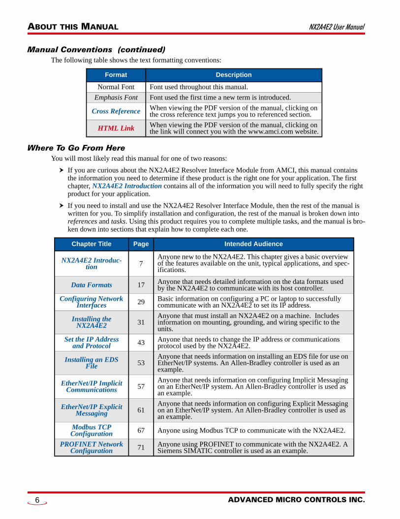
Manual Conventions (continued)The following table shows the text formatting conventions:
Where To Go From HereYou will most likely read this manual for one of two reasons:
If you are curious about the NX2A4E2 Resolver Interface Module from AMCI, this manual contains the information you need to determine if these product is the right one for your application. The first chapter, NX2A4E2 Introduction contains all of the information you will need to fully specify the right product for your application.
If you need to install and use the NX2A4E2 Resolver Interface Module, then the rest of the manual is written for you. To simplify installation and configuration, the rest of the manual is broken down into references and tasks. Using this product requires you to complete multiple tasks, and the manual is bro-ken down into sections that explain how to complete each one.
Format Description
Normal Font Font used throughout this manual.
Emphasis Font Font used the first time a new term is introduced.
Cross Reference When viewing the PDF version of the manual, clicking on the cross reference text jumps you to referenced section.
HTML Link When viewing the PDF version of the manual, clicking on the link will connect you with the www.amci.com website.
Chapter Title Page Intended Audience
NX2A4E2 Introduc-tion 7
Anyone new to the NX2A4E2. This chapter gives a basic overview of the features available on the unit, typical applications, and spec-ifications.
Data Formats 17 Anyone that needs detailed information on the data formats used by the NX2A4E2 to communicate with its host controller.
Configuring Network Interfaces 29 Basic information on configuring a PC or laptop to successfully
communicate with an NX2A4E2 to set its IP address.
Installing the NX2A4E2 31
Anyone that must install an NX2A4E2 on a machine. Includes information on mounting, grounding, and wiring specific to the units.
Set the IP Address and Protocol 43 Anyone that needs to change the IP address or communications
protocol used by the NX2A4E2.
Installing an EDS File 53
Anyone that needs information on installing an EDS file for use on EtherNet/IP systems. An Allen-Bradley controller is used as an example.
EtherNet/IP Implicit Communications 57
Anyone that needs information on configuring Implicit Messaging on an EtherNet/IP system. An Allen-Bradley controller is used as an example.
EtherNet/IP Explicit Messaging 61
Anyone that needs information on configuring Explicit Messaging on an EtherNet/IP system. An Allen-Bradley controller is used as an example.
Modbus TCP Configuration 67 Anyone using Modbus TCP to communicate with the NX2A4E2.
PROFINET Network Configuration 71 Anyone using PROFINET to communicate with the NX2A4E2. A
Siemens SIMATIC controller is used as an example.
ADVANCED MICRO CONTROLS INC.6

20 Gear Drive, PTel: (860) 585-12
REFERENCE 1
NX2A4E2 INTRODUCTIONThe NX2A4E2The NX2A4E2 is a member of the growing line of products from AMCI that incorporate our E2 Technology. E2 Technology by AMCI is an innovative new multi-protocol approach to Ethernet distributed I/O.
E2 Technology products are simple and intuitive, allowing easy transition between Ethernet/IP, PROFINET, or Modbus/TCP protocols without the need to physically switch parts. An advanced web server integrated into all AMCI E2 Technology devices facilitates simple network configuration and troubleshooting via a web-browser. Furthermore, an impressive array of advanced features for each supported protocol has been incorporated into the devices to meet many unique application requirements.
The NX2A4E2 is a four channel resolver interface module that allows you to lower transducer wiring cost by placing the NX2A4E2 close to the transducers and running a single network cable back to the host controller. The NX2A4E2 also future-proofs your resolver feedback design. The host controller can be updated to any future platform that supports EtherNet/IP, PROFINET, or Modbus TCP and the NX2A4E2 will operate with the new system.
The NX2A4E2 can be programmed to accept up to four single resolver transducers, or two dual-resolver transducers. Single resolver transducers are typically single turn devices, but can have a gear train between the input shaft and the internal resolver. Dual-resolver transducers are designed for high resolution, multi-turn applications. The NX2A4E2 can also be programmed to accept two single resolver transducers and one dual-resolver transducer. This setup is advantageous in several industries, such a press automation. This unit gives press builders crankshaft angle indication on a single-turn channel and shut height indication on the multi-turn channel, combining the functions of two separate boxes or modules into one. To further aid press integra-tors, the NX2A4E2 also includes a brake input that can be used to measure crankshaft stopping time.
Each unit has two Ethernet ports which are internally connected through an onboard, two port, 10/100 Mbps ethernet switch. These ports allow you to wire your network in a “daisy-chain” fashion, which may lower net-work wiring costs and complexities.
The two ports also allow the units to function as members of a redundant Device Level Ring (DLR) network when using the EtherNet/IP protocol or as clients in a Media Redundancy Protocol (MRP) network when using PROFINET.
In DLR environments, the units act as Beacon-Based Ring Nodes. All units can process beacon packets at the default rate of every 400 microseconds. Beacon-based nodes can respond faster to network changes than nodes that only process Announce packets.
This reference section contains the information you need to decide if the NX2A4E2 Resolver Interface Module is the right product for your application.
lymouth Ind. Park, Terryville, CT 0678654 Fax: (860) 584-1973 http://www.amci.com
7

NX2A4E2 INTRODUCTION NX2A4E2 User Manual
The NX2A4E2 (continued)As briefly described above, NX2A4E2 can be programmed to accept multiple types of resolver based trans-ducers:
Single Resolver Transducers - This type of transducer has a single resolver in the transducer package. This type includes transducers that yield an absolute position over a single turn, such as our HT-20, HT-400, H25, and R11 product lines, and transducers that include an integral gear train between the input shaft and the resolver so they can yield an absolute position value over multiple turns. An example of this type of transducer is any member of the HT-20-(x) line from AMCI.
Redundant Resolver Transducers - This type of transducer has two resolvers that are geared 1:1 with the input shaft. Examples of a redun-dant resolver transducer are the HTT-20-1 and HTT-400-1A-J/J from AMCI. These transducers are typically used in systems that require redundant controls for safety or high availability. To the NX2A4E2, these transducers appear as two single resolver, single turn, transducers.
Dual Resolver Transducers - This type of transducer has two resolvers in the transducer package that are geared in such a way that the trans-ducer yields a high resolution absolute position over multiple turns. As shown in figure R1.1 to the right, there are two types of dual resolver multi-turn transducers. One type uses a vernier gearing, where the two gears differ by one tooth. Examples of this type of transducer are the HTT-20-100, HTT-20-180, HTT-20-1000 and HTT-20-1800 transducers from AMCI. The second type uses a gear reduction between the fine and coarse gear so that the coarse gear completes one rotation for multiple turns of the fine resolver.
The NX2A4E2 accepts programming information and reports position, veloc-ity, and error information over the network connection. This connection means that you do not have to be physically near the NX2A4E2 while configuring it. All configuration and setup data is sent from your host system over the net-work connection. This allows you to:
Configure the NX2A4E2 from anywhere Store multiple setups on your machine Copy setup data from one machine to another Design custom HMI interfaces for configuration and setup that can sim-
plify machine training, startup, and repair.
Figure R1.1 Resolver Transducer Types
ADVANCED MICRO CONTROLS INC.8
NX2A4E2 User Manual NX2A4E2 INTRODUCTION
Stop Time MonitoringIf you are using the NX2A4E2 in a press control application, you can use the stop time monitoring feature to measure the stopping time of the crankshaft. The stop time monitor on the unit measures the time between the on-to-off transition of the Brake Input and the stopping of the transducer attached to channel one. Note that channel one must be configured as a single-turn channel to use the stop time monitor. The Stop Time Timer measures a stopping time of 34 milliseconds to 9.999 seconds with a resolution of 1 millisecond.
The NX2A4E2 also captures the position at which the brake is applied and reports this information, along with the stopping time, when a brake cycle is completed. This information is reported over the network until the next brake cycle finishes.
If you are not using the unit in a press control application, you can leave the Brake Input un-wired and the Stop Time monitor will never be triggered.
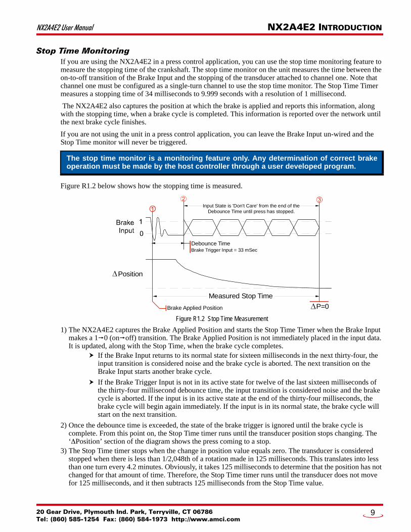
Figure R1.2 below shows how the stopping time is measured.
Figure R1.2 Stop Time Measurement
1) The NX2A4E2 captures the Brake Applied Position and starts the Stop Time Timer when the Brake Input makes a 10 (onoff) transition. The Brake Applied Position is not immediately placed in the input data. It is updated, along with the Stop Time, when the brake cycle completes.
If the Brake Input returns to its normal state for sixteen milliseconds in the next thirty-four, the input transition is considered noise and the brake cycle is aborted. The next transition on the Brake Input starts another brake cycle.
If the Brake Trigger Input is not in its active state for twelve of the last sixteen milliseconds of the thirty-four millisecond debounce time, the input transition is considered noise and the brake cycle is aborted. If the input is in its active state at the end of the thirty-four milliseconds, the brake cycle will begin again immediately. If the input is in its normal state, the brake cycle will start on the next transition.
2) Once the debounce time is exceeded, the state of the brake trigger is ignored until the brake cycle is complete. From this point on, the Stop Time timer runs until the transducer position stops changing. The ‘Position’ section of the diagram shows the press coming to a stop.
3) The Stop Time timer stops when the change in position value equals zero. The transducer is considered stopped when there is less than 1/2,048th of a rotation made in 125 milliseconds. This translates into less than one turn every 4.2 minutes. Obviously, it takes 125 milliseconds to determine that the position has not changed for that amount of time. Therefore, the Stop Time timer runs until the transducer does not move for 125 milliseconds, and it then subtracts 125 milliseconds from the Stop Time value.
The stop time monitor is a monitoring feature only. Any determination of correct brake operation must be made by the host controller through a user developed program.
Debounce TimeBrake Trigger Input = 33 mSec
Measured Stop Time
Brake Applied Position
Position
P=0
Input State is 'Don't Care' from the end of theDebounce Time until press has stopped.
20 Gear Drive, Plymouth Ind. Park, Terryville, CT 06786Tel: (860) 585-1254 Fax: (860) 584-1973 http://www.amci.com
9

NX2A4E2 INTRODUCTION NX2A4E2 User Manual
NX2A4E2 Programmable Parameters
Common Parameters
These parameters are available on the NX2A4E2 regardless of the type of transducer used.
Resolver Type
This global parameter configures the NX2A4E2 for AMCI transducers, or transducers from AVG/Autotech or Gemco. This parameter alters the reference voltage to the resolvers so that the return signals are compatible with the NX2A4E2 resolver inputs. Therefore, you cannot mix resolver types when using this parameter. If you need to interface both resolver types to the NX2A4E2, you will have to purchase a separate item from AMCI with the part number RM-3. The RM-3 Reference Module is a single ended transformer that wires into the transducer cable and alters the reference voltage for the foreign transducers.
AMCI also offers the RM-1 Reference Module to interface Namco/C&A transducers with the NX2A4E2, and the RM-5 to interface Reliance or Tamagawa resolvers.
Enable Channel Status LED
These four parameters allow you to selectively disable the status LED’s on channels you are not using in your application.
Transducer Fault Latch
This parameter is available on each transducer input channel and gives you programmable control over whether or not transducer faults are self clearing or latched. Self clearing faults clear themselves as soon as the resolver signals return to valid values. Latched faults must be cleared by the host. The factory default set-ting is for self clearing faults.
Count Direction
This parameter is available on each transducer input channel and gives you programmable control over the direction of rotation needed to produce increasing counts. When you use AMCI transducers that are wired as shown in this manual, the factory default setting is for clockwise increasing counts when looking at the trans-ducer shaft.
Tachometer Response
This parameter is available on each transducer input channel and gives you programmable control over the update time of the tachometer value. The Tachometer Response can be programmed to 120 milliseconds or 24 milliseconds, and is 120 milliseconds by default. Note that this parameter only affects the update time of the tachometer value. It does on affect the position update time, which is always 200 microseconds.
Single Turn Parameters
These parameter are available when the module is used with single resolver or redundant resolver transduc-ers.
Full Scale Count
This parameter allows you to set the number of counts reported by the NX2A4E2 for a full rotation of the resolver. This parameter has a range of 2 to 8,192, with a factory default of 1,024.
ADVANCED MICRO CONTROLS INC.10

NX2A4E2 User Manual NX2A4E2 INTRODUCTION
NX2A4E2 Programmable Parameters (continued)Single Turn Parameters (continued)
Linear Offset
The Linear Offset parameter changes the range of count values output by the unit and is used when the trans-ducer position directly correlates to a linear measurement that does not start at zero. One such example is an overhead crane. Another example is a press shut height measurement.
As an example of how the Linear offset works, when the Full Scale Count is set to 1,500 and the Linear Offset is set to zero, the NX2A4E2 will output position values from 0 to 1,499. If the Linear Offset is changed to 100, then the unit will then output values from 100 to 1,599.
The default Linear Offset is zero. For single-resolver channels, the Linear Offset range is 0 to (32,767 – Full Scale Count).
Preset Value
The transducer position can be set to any value within the range of Linear Offset to (Linear Offset +(Full Scale Count – 1)). This parameter sets the value the transducer position is set to when the host controller issues the Apply Preset command. This parameter has a factory default value of zero.
Multi-turn parameters
These parameters are available when the module is used with dual resolver, multi-turn transducers.
Transducer Type
This parameter defines the type of dual resolver transducer attached to the NX2A4E2. This parameter has five values: 100, 180, 1,000, 1,800, and 128. The 100, 180, 1,000, and 1,800 values program the module to inter-face with AMCI vernier style transducers. The 128 value programs the module to use reduction style trans-ducer such as those available from AVG/Autotech. The Resolver Type parameter determines the type of resolver used with the NX2A4E2 and affects the values that can be programmed into this parameter.
Number of Turns
This parameter defines the number of turns the transducer shaft must complete before the position value returns to zero. The acceptable values are dependant on the value of the Transducer Type parameter.
Table R1.1 Number of Turns Parameter Settings
Full Scale Count
This parameter allows you to set the number of counts reported by the NX2A4E2 over the programmed Num-ber of Turns. This parameter has a range of 2 to (4,096 * Number of Turns) for 100, and 180 turn transducers and 2 to (409.6 * Number of Turns) for 1,000 and 1,800 turn transducers. For 128 turn transducers, the range is 2 to (1,024 * Number of Turns). As an example, assume an HTT-20-180 transducer and the programmed Number of Turns is 36. The range of the Full Scale Count Parameter is 2 to 147,456. (4,096*36)
Transducer Type Parameter Setting
Number of TurnsAcceptable Values
100 1, 2, 4, 5, 10, 20, 25, 50, 100
180 1, 2, 3, 4, 5, 6, 9, 10, 12, 15,18, 20, 30, 36, 45, 60, 90, 180
1000 10, 20, 40, 50, 100, 200, 250, 500, 1,000
1800 10, 20, 30, 40, 50, 60, 90, 100, 120, 150, 180, 200, 300, 360, 450, 600, 900, 1,800
128 1, 2, 4, 8, 16, 32, 64, 128
20 Gear Drive, Plymouth Ind. Park, Terryville, CT 06786Tel: (860) 585-1254 Fax: (860) 584-1973 http://www.amci.com
11

NX2A4E2 INTRODUCTION NX2A4E2 User Manual
NX2A4E2 Programmable Parameters (continued)Multi-turn Parameters (continued)
Linear Offset
The Linear Offset parameter changes the range of count values output by the unit and is used when the trans-ducer position directly correlates to a linear measurement that does not start at zero. One such example is an overhead crane. Another example is a press shut height measurement.
As an example of how the Linear offset works, when the Full Scale Count is set to 15,000 and the Linear Off-set is set to zero, the NX2A4E2 will output position values from 0 to 14,999. If the Linear Offset is changed to 10,000, then the unit will then output values from 10,000 to 24,999.
The default Linear Offset is zero. For dual-resolver channels, the Linear Offset range is 0 to 999,999.
Preset Value
The transducer position can be set to any value within the range of Linear Offset to (Linear Offset + (Full Scale Count – 1)). This parameter sets the value the transducer position is set to when the host controller issues the Apply Preset command. This parameter has a factory default value of zero.
Front Panel DescriptionFigure R1.3 shows the front panel layout of the NX2A4E2 Resolver Interface. Note that the unit ships with four Phoenix Contact connectors that are not shown for clarity. The RS485 channel, which is not imple-mented at this time, does not ship with a connector
Figure R1.3 Front Panel Layout
Connector Pinout
Connector pinout and wiring is given in the appropriate section of the Installing the NX2A4E2 chapter, start-ing on page 31.
Section 1.4, Power Wiring, is on page 35. Section 1.5, Network Connections, starts on page 35. Section 1.8, Transducer Connector Pinout, which starts on page 37, begins the sections on transducer
wiring. Section 1.10, DC Input Wiring, starts on page 42.
Additional sections of the installation chapter, such as Safe Handling Guidelines, and General Wiring Guidelines, must be reviewed and adhered to when actually installing the unit.
1 2
NEXUSRESOLVER
POWER INPUT ANDCHASSIS GROUND
RESOLVER STATUS LED's
DC INPUTS AND STATUS LED'sBrake Input Tied To Resolver 1.Preset Input Not Presently Implemented.
RS485 COMM CHANNELFor Future Expansion
Not Presently Implemented
MODULESTATUS LED's
TRANSDUCER INPUT CONNECTORSEach Connector Accepts (2) Single-Turn or (1) Multi-turn Transducer.
ETHERNET RJ45 CONNECTORPort 1
ETHERNET RJ45 CONNECTORPort 2
DIP SWITCH BANKOptionally sets IP Address
LINK2 PORT 2 PORT 1MS
NS LINK1
12345678
ADVANCED MICRO CONTROLS INC.12

NX2A4E2 User Manual NX2A4E2 INTRODUCTION
Status LEDs
Resolver Status LEDs
Each resolver channel has a status LED on the front panel.
Table R1.2 Transducer Status LED Patterns
Ethernet Status LEDs
Module Status (MS) LED
The Module Status LED is a bi-color red/green LED. The unit will blink the Module Status LED green during initialization. After initialization, the state of the LED depends on the state of the network adapter module.
Table R1.3 Module Status LED States
LED State Description
Off The LED has been disabled.
All ON Red Module Fault. This state cannot be disabled.
Blinking Red Non-clearable transducer fault on the channel. This state can be disabled if the channel is not used.
Blinking Green Latched, clearable transducer fault on the channel. This state can be disabled if the channel is not used.
Solid GreenThe channel is not in fault and is reporting position data. This state can be disabled if the channel is not used.
LED State EtherNet/IP Definition Modbus TCP Definition PROFINET Definition
Off No Power No Power No power
Alternating Red/Green
Initializing: Power up Self-Test
Communications failure. There is a communications error between the main processor and the ethernet co-processor within the unit. You must cycle power to the NX2A4E2 to attempt to clear this fault.
Flashing Green
Initializing: Waiting for valid physical connection to the network.
Steady Green Module and Network are operational. Device Name or IP Address are set.
Flashing Red
Initializing: IP Address conflict Initializing: Device Name or IP Address are not set.
If the Network Status LED is also flashing, the IP Address or Network Protocol has been changed. Cycle power to the unit to continue. If the Network Status LED is in any other state, a write to flash memory has failed. Cycle power to the unit to clear this fault.
20 Gear Drive, Plymouth Ind. Park, Terryville, CT 06786Tel: (860) 585-1254 Fax: (860) 584-1973 http://www.amci.com
13
NX2A4E2 INTRODUCTION NX2A4E2 User Manual
Status LED’s (continued)Ethernet Status LEDs (continued)
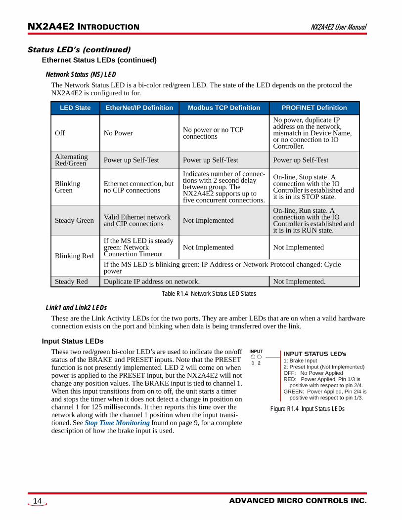
Network Status (NS) LED
The Network Status LED is a bi-color red/green LED. The state of the LED depends on the protocol the NX2A4E2 is configured to for.
Table R1.4 Network Status LED States
Link1 and Link2 LEDs
These are the Link Activity LEDs for the two ports. They are amber LEDs that are on when a valid hardware connection exists on the port and blinking when data is being transferred over the link.
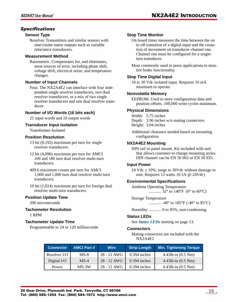
Input Status LEDs
These two red/green bi-color LED’s are used to indicate the on/off status of the BRAKE and PRESET inputs. Note that the PRESET function is not presently implemented. LED 2 will come on when power is applied to the PRESET input, but the NX2A4E2 will not change any position values. The BRAKE input is tied to channel 1. When this input transitions from on to off, the unit starts a timer and stops the timer when it does not detect a change in position on channel 1 for 125 milliseconds. It then reports this time over the network along with the channel 1 position when the input transi-tioned. See Stop Time Monitoring found on page 9, for a complete description of how the brake input is used.
LED State EtherNet/IP Definition Modbus TCP Definition PROFINET Definition
Off No Power No power or no TCP connections
No power, duplicate IP address on the network, mismatch in Device Name, or no connection to IO Controller.
Alternating Red/Green Power up Self-Test Power up Self-Test Power up Self-Test
Blinking Green
Ethernet connection, but no CIP connections
Indicates number of connec-tions with 2 second delay between group. The NX2A4E2 supports up to five concurrent connections.
On-line, Stop state. A connection with the IO Controller is established and it is in its STOP state.
Steady Green Valid Ethernet network and CIP connections Not Implemented
On-line, Run state. A connection with the IO Controller is established and it is in its RUN state.
Blinking Red
If the MS LED is steady green: Network Connection Timeout
Not Implemented Not Implemented
If the MS LED is blinking green: IP Address or Network Protocol changed: Cycle power
Steady Red Duplicate IP address on network. Not Implemented.
INPUT STATUS LED's1: Brake Input2: Preset Input (Not Implemented)OFF: No Power AppliedRED: Power Applied, Pin 1/3 is positive with respect to pin 2/4.GREEN: Power Applied, Pin 2/4 is positive with respect to pin 1/3.
1 2
Figure R1.4 Input Status LEDs
ADVANCED MICRO CONTROLS INC.14
NX2A4E2 User Manual NX2A4E2 INTRODUCTION
SpecificationsSensor Type
Resolver Transmitters and similar sensors with sine/cosine stator outputs such as variable reluctance transducers.
Measurement MethodRatiometric. Compensates for, and eliminates,
most sources of error, including phase shift, voltage drift, electrical noise, and temperature changes.
Number of Input ChannelsFour. The NX2A4E2 can interface with four inde-
pendent single resolver transducers, two dual resolver transducers, or a mix of two single resolver transducers and one dual resolver trans-ducer
Number of I/O Words (16 bits each)21 input words and 10 output words
Transducer Input IsolationTransformer Isolated
Position Resolution13 bit (8,192) maximum per turn for single
resolver transducers.
12 bit (4,096) maximum per turn for AMCI 100 and 180 turn dual resolver multi-turntransducers.
409.6 maximum counts per turn for AMCI 1,000 and 1,800 turn dual resolver multi-turn transducers.
10 bit (1,024) maximum per turn for foreign dual resolver multi-turn transducers.
Position Update Time200 microseconds
Tachometer Resolution1 RPM
Tachometer Update TimeProgrammable to 24 or 120 milliseconds
Stop Time MonitorOn board timer measures the time between the on
to off transition of a digital input and the cessa-tion of movement on transducer channel one. Channel one must be configured for a single-turn transducer.
Most commonly used in press applications to mon-itor brake functionality.
Stop Time Digital Input10 to 30 Vdc isolated input. Requires 10 mA
minimum to operate
Nonvolatile MemoryEEPROM. Used to store configuration data and
position offsets. 100,000 write cycles minimum.
Physical DimensionsWidth: 5.75 inchesDepth: 3.96 inches w/o mating connectorsHeight: 3.04 inches
Additional clearance needed based on mounting configuration
NX2A4E2 MountingDIN rail or panel mount. Kit included with unit
that allows customer to change mounting styles. DIN channel can be EN 50 002 or EN 50 035.
Input Power24 Vdc ± 10%, surge to 30Vdc without damage to
unit. Requires 12 watts. (0.5A @ 24Vdc)
Environmental SpecificationsAmbient Operating Temperature
............ 32° to 140°F (0° to 60°C)
Storage Temperature............ -40° to 185°F (-40° to 85°C)
Humidity ............ 0 to 95%, non-condensing
Status LEDsSee Status LEDs starting on page 13.
ConnectorsMating connectors are included with the
NX2A4E2
Connector AMCI Part # Wire Strip Length Min. Tightening Torque
Resolver I/O MS-8 28 - 12 AWG 0.394 inches 4.43lb-in (0.5 Nm)
Digital I/O MS-4 28 - 12 AWG 0.394 inches 4.43lb-in (0.5 Nm)
Power MS-3W 28 - 12 AWG 0.394 inches 4.43lb-in (0.5 Nm)
20 Gear Drive, Plymouth Ind. Park, Terryville, CT 06786Tel: (860) 585-1254 Fax: (860) 584-1973 http://www.amci.com
15

NX2A4E2 INTRODUCTION NX2A4E2 User Manual
Notes
ADVANCED MICRO CONTROLS INC.16

20 Gear Drive, PTel: (860) 585-12
REFERENCE 2
DATA FORMATSMixed Data FormatsThe NX2A4E2 allows you to work with up to four single resolver transducers, up to two dual resolver trans-ducers, or one dual resolver transducer along with up to two single resolver transducers.
Output data is used to program the channels and preset the transducer position values. Only one channel can be programmed at a time, so the description of the two formats is straight forward.
If the NX2A4E2 is programmed for a dual resolver multi-turn transducer, and either of the two input channels is later programmed as a single resolver channel, then both of the channels of the dual resolver multi-turn transducer input will be re-programmed with the single resolver data. For example, if channels 3 and 4 are programmed as a dual resolver multi-turn channel, and channel 4 is later programmed as a single resolver channel, then channels 3 and 4 both become single resolver channels and the programming for channel 4 is also applied to channel 3.
Input data is broken down into four word blocks for single resolver channels and eight word blocks for dual resolver channels. When channel 1 is programmed as a single resolver channel, then the stop time on that channel can be monitored. In this case, two additional words, the Stopping Tine, and Brake Applied Position, are available after the channel data blocks.
Output Data Formats
Single Resolver Data Format
Figure R2.1 below shows the format of the output data when programming the module to operate with single resolver transducers. Only one programming bit in the Command Word can be set at a time. Therefore, when programming the NX2A4E2 to interface with four single resolver transducers, four programming blocks are needed.
Figure R2.1 Single Resolver Output Data Format
This reference chapter details the input and output data formats used to commu-nicate with the NX2A4E2 in single turn and dual resolver, multi-turn applications.
Word (2)
Word (1)
Word (0)
Word (3)
Word (4)
Word (5)
Word (6)
Word (7)
Word (8)
Word (9)
lymouth Ind. Park, Terryville, CT 0678654 Fax: (860) 584-1973 http://www.amci.com
17

DATA FORMATS NX2A4E2 User Manual
Output Data Formats (continued)Single Resolver Data Format (continued)
Command Word 0
Figure R2.2 Single Turn Command Word Format
Bit 15: Transmit Bit – Used to control the flow of programming data to the NX2A4E2. The NX2A4E2 will not accept new programming data until this bit makes a 01 transition. Once this bit is set, it should remain set until the module responds by setting the Acknowledge bit in the Network Input Data. Pro-gramming error bits in the input data are valid as long as the Acknowledge bit is set. Resetting the Transmit bit to “0” will resets the Acknowledge bit.
Bit 14: Reset_Errors – When set to “1”, the module will reset all programming error bits and clear any latched transducer faults that can be cleared.
Bit 07: Setup_CH4 – When set to “1”, the module uses words 1 through 9 to program channel 4. Note that only one channel can be programmed at a time. If this bit is a “1”, then bits 6, 5, and 4 of this word must be “0”.
Bit 06: Setup_CH3 – When set to “1”, the module uses words 1 through 9 to program channel 3. Note that only one channel can be programmed at a time. If this bit is a “1”, then bits 7, 5, and 4 of this word must be “0”.
Bit 05: Setup_CH2 – When set to “1”, the module uses words 1 through 9 to program channel 2. Note that only one channel can be programmed at a time. If this bit is a “1”, then bits 7, 6, and 4 of this word must be “0”.
Bit 04: Setup_CH1 – When set to “1”, the module uses words 1 through 9 to program channel 1. Note that only one channel can be programmed at a time. If this bit is a “1”, then bits 7, 6, and 5 of this word must be “0”.
Bit 03: Apply_Preset4 – When set to “1”, the module sets the CH4 position to the value of the CH4 Preset Value parameter. The CH4 Preset Value has a factory default value of zero. The CH4 Preset Value can be programmed by setting the Setup_CH4 bit (bit 07 of this word) and putting the desired CH4 Preset Value in Word 7. Please note that applying the preset value, and programming the CH4 Preset Value parameter, are two independent processes. They can be accomplished in the same transmit cycle, but do not have to be. Also note that the ApplyPreset bits are not exclusive. All four channels can be pre-set together in one programming cycle.
Bit 02: Apply_Preset3 – When set to “1”, the module sets the CH3 position to the value of the CH3 Preset Value parameter. The CH3 Preset Value has a factory default value of zero. The CH3 Preset Value can be programmed by setting the Setup_CH3 bit (bit 06 of this word) and putting the desired CH3 Preset Value in Word 7. Please note that applying the preset value, and programming the CH3 Preset Value parameter, are two independent processes. They can be accomplished in the same transmit cycle, but do not have to be. Also note that the ApplyPreset bits are not exclusive. All four channels can be pre-set together in one programming cycle.
RESERVED: Bit must equal zero.
Command Word (0)
15 14 13 12 11 10 09 08 07 06 05 04 03 02 01 00
Tra
nsm
it
Re
set_
Err
ors
Se
tup
_C
H2
Se
tup
_C
H3
Se
tup
_C
H4
Set
up_
CH
1
Ap
ply
_Pre
set2
Ap
ply
_Pre
set3
Ap
ply
_Pre
set4
Ap
ply
_Pre
set1
ADVANCED MICRO CONTROLS INC.18
NX2A4E2 User Manual DATA FORMATS
Output Data Formats (continued)Single Resolver Data Format (continued)
Command Word 0 (continued)
Bit 01: Apply_Preset2 – When set to “1”, the module sets the CH2 position to the value of the CH2 Preset Value parameter. The CH2 Preset Value has a factory default value of zero. The CH2 Preset Value can be programmed by setting the Setup_CH2 bit (bit 05 of this word) and putting the desired CH2 Preset Value in Word 7. Please note that applying the preset value, and programming the CH2 Preset Value parameter, are two independent processes. They can be accomplished in the same transmit cycle, but do not have to be. Also note that the ApplyPreset bits are not exclusive. All four channels can be pre-set together in one programming cycle.
Bit 00: Apply_Preset1 – When set to “1”, the module sets the CH1 position to the value of the CH1 Preset Value parameter. The CH1 Preset Value has a factory default value of zero. The CH1 Preset Value can be programmed by setting the Setup_CH1 bit (bit 04 of this word) and putting the desired CH1 Preset Value in Word 7. Please note that applying the preset value, and programming the CH1 Preset Value parameter, are two independent processes. They can be accomplished in the same transmit cycle, but do not have to be. Also note that the ApplyPreset bits are not exclusive. All four channels can be pre-set together in one programming cycle.
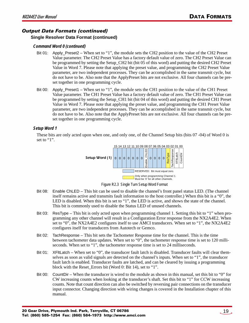
Setup Word 1
These bits are only acted upon when one, and only one, of the Channel Setup bits (bits 07 -04) of Word 0 is set to “1”.
Figure R2.3 Single Turn Setup Word Format
Bit 08: Enable ChLED – This bit can be used to disable the channel’s front panel status LED. (The channel itself remains active and transmits fault information to the host controller.) When this bit is a “0”, the LED is disabled. When this bit is set to “1”, the LED is active, and shows the state of the channel. This bit is commonly used to disable the Status LED of unused channels.
Bit 03: ResType – This bit is only acted upon when programming channel 1. Setting this bit to “1” when pro-gramming any other channel will result in a Configuration Error response from the NX2A4E2. When set to “0”, the NX2A4E2 configures itself to use AMCI transducers. When set to “1”, the NX2A4E2 configures itself for transducers from Autotech or Gemco.
Bit 02: TachResponse – This bit sets the Tachometer Response time for the channel. This is the time between tachometer data updates. When set to “0”, the tachometer response time is set to 120 milli-seconds. When set to “1”, the tachometer response time is set to 24 milliseconds.
Bit 01: XFltLatch – When set to “0”, the transducer fault latch is disabled. Transducer faults will clear them-selves as soon as valid signals are detected on the channel’s inputs. When set to “1”, the transducer fault latch is enabled. Transducer faults are latched, and can be cleared by issuing a programming block with the Reset_Errors bit (Word 0: Bit 14), set to “1”.
Bit 00: CountDir – When the transducer is wired to the module as shown in this manual, set this bit to “0” for CW increasing counts when looking at the transducer’s shaft. Set this bit to “1” for CCW increasing counts. Note that count direction can also be switched by reversing pair connections on the transducer input connector. Changing direction with wiring changes is covered in the Installation chapter of this manual.
RESERVED: Bit must equal zero.
Setup Word (1)
15 14 13 12 11 10 09 08 07 06 05 04 03 02 01 00
XF
ltLa
tch
Tach
Re
spo
nse
Re
sTyp
e
Co
untD
ir
En
ab
le_
Ch
LE
D
Only when programming Channel 1.Must be ‘0' for all other channels.
20 Gear Drive, Plymouth Ind. Park, Terryville, CT 06786Tel: (860) 585-1254 Fax: (860) 584-1973 http://www.amci.com
19
DATA FORMATS NX2A4E2 User Manual
Output Data Formats (continued)
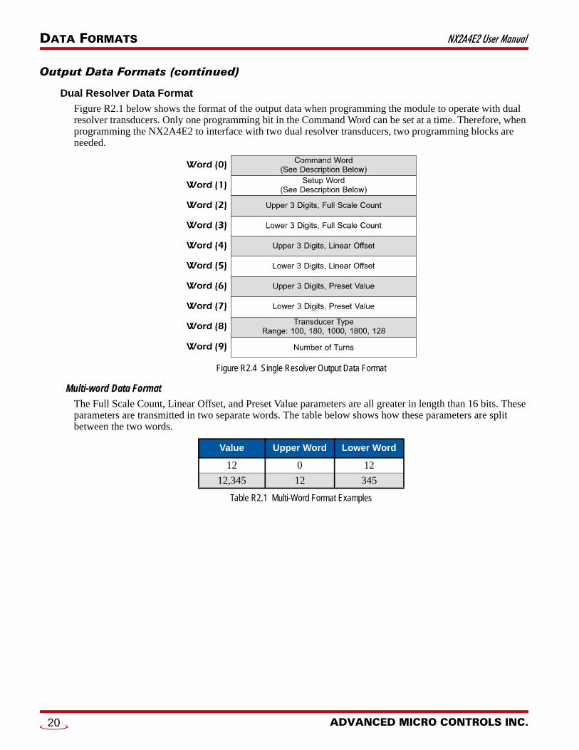
Dual Resolver Data Format
Figure R2.1 below shows the format of the output data when programming the module to operate with dual resolver transducers. Only one programming bit in the Command Word can be set at a time. Therefore, when programming the NX2A4E2 to interface with two dual resolver transducers, two programming blocks are needed.
Figure R2.4 Single Resolver Output Data Format
Multi-word Data Format
The Full Scale Count, Linear Offset, and Preset Value parameters are all greater in length than 16 bits. These parameters are transmitted in two separate words. The table below shows how these parameters are split between the two words.
Table R2.1 Multi-Word Format Examples
Value Upper Word Lower Word
12 0 12
12,345 12 345
Word (1)
Word (0)
Word (2)
Word (3)
Word (4)
Word (5)
Word (6)
Word (7)
Word (8)
Word (9)
ADVANCED MICRO CONTROLS INC.20

NX2A4E2 User Manual DATA FORMATS
Output Data Formats (continued)Dual Resolver Data Format (continued)
Command Word 0
Figure R2.5 Single Turn Command Word Format
Bit 15: Transmit Bit – Used to control the flow of programming data to the NX2A4E2. The NX2A4E2 will not accept new programming data until this bit makes a 01 transition. Once this bit is set, it should remain set until the module responds by setting the Acknowledge bit in the Network Input Data. Pro-gramming error bits in the input data are valid as long as the Acknowledge bit is set. Resetting the Transmit bit to “0” will reset the Acknowledge bit.
Bit 14: Reset_Errors – When set to “1”, the module will reset all programming error bits and clear any latched transducer faults that can be cleared.
Bit 09: Setup_MCH2 – When set to “1”, the module uses words 1 through 9 to program input channels 3 and 4 as a dual-resolver transducer channel. Note that only one channel can be programmed at a time. If this bit is a “1”, then bit 8 of this word must be “0”.
Bit 08: Setup_MCH1 – When set to “1”, the module uses words 1 through 9 to program input channels 1 and 2 as a dual-resolver transducer channel. Note that only one channel can be programmed at a time. If this bit is a “1”, then bit 9 of this word must be “0”.
Bit 02: Apply_Preset2 – When set to “1”, the module sets the multi-turn position for the second dual resolver channel to the value of the MCH2 Preset Value parameter. The MCH2 Preset Value has a factory default value of zero. The MCH2 Preset Value can be programmed by setting the Setup_MCH2 bit (bit 09 of this word) and putting the desired MCH2 Preset Value in Words 6 and 7. Please note that applying the preset value, and programming the MCH2 Preset Value parameter, are two independent processes. They can be accomplished in the same transmit cycle, but do not have to be. Also note that the ApplyPreset bits are not exclusive. Any number of channels can be preset together in one pro-gramming cycle.
Bit 00: Apply_Preset1 – When set to “1”, the module sets the multi-turn position for the first dual resolver channel to the value of the MCH1 Preset Value parameter. The MCH1 Preset Value has a factory default value of zero. The MCH1 Preset Value can be programmed by setting the Setup_MCH1 bit (bit 08 of this word) and putting the desired MCH1 Preset Value in Words 6 and 7. Please note that applying the preset value, and programming the MCH1 Preset Value parameter, are two independent processes. They can be accomplished in the same transmit cycle, but do not have to be. Also note that the ApplyPreset bits are not exclusive. Any number of channels can be preset together in one pro-gramming cycle.
RESERVED: Bit must equal zero.
Command Word (0)
15 14 13 12 11 10 09 08 07 06 05 04 03 02 01 00
Tra
nsm
it
Re
set_
Err
ors
Se
tup
_M
CH
1
Se
tup
_M
CH
2
Ap
ply
_Pre
set2
Ap
ply
_Pre
set1
20 Gear Drive, Plymouth Ind. Park, Terryville, CT 06786Tel: (860) 585-1254 Fax: (860) 584-1973 http://www.amci.com
21
DATA FORMATS NX2A4E2 User Manual
Output Data Formats (continued)Dual Resolver Data Format (continued)
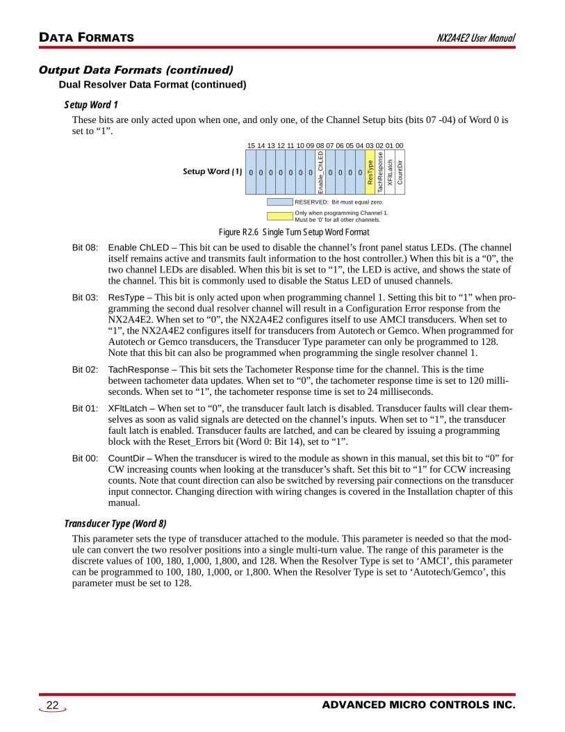
Setup Word 1
These bits are only acted upon when one, and only one, of the Channel Setup bits (bits 07 -04) of Word 0 is set to “1”.
Figure R2.6 Single Turn Setup Word Format
Bit 08: Enable ChLED – This bit can be used to disable the channel’s front panel status LEDs. (The channel itself remains active and transmits fault information to the host controller.) When this bit is a “0”, the two channel LEDs are disabled. When this bit is set to “1”, the LED is active, and shows the state of the channel. This bit is commonly used to disable the Status LED of unused channels.
Bit 03: ResType – This bit is only acted upon when programming channel 1. Setting this bit to “1” when pro-gramming the second dual resolver channel will result in a Configuration Error response from the NX2A4E2. When set to “0”, the NX2A4E2 configures itself to use AMCI transducers. When set to “1”, the NX2A4E2 configures itself for transducers from Autotech or Gemco. When programmed for Autotech or Gemco transducers, the Transducer Type parameter can only be programmed to 128. Note that this bit can also be programmed when programming the single resolver channel 1.
Bit 02: TachResponse – This bit sets the Tachometer Response time for the channel. This is the time between tachometer data updates. When set to “0”, the tachometer response time is set to 120 milli-seconds. When set to “1”, the tachometer response time is set to 24 milliseconds.
Bit 01: XFltLatch – When set to “0”, the transducer fault latch is disabled. Transducer faults will clear them-selves as soon as valid signals are detected on the channel’s inputs. When set to “1”, the transducer fault latch is enabled. Transducer faults are latched, and can be cleared by issuing a programming block with the Reset_Errors bit (Word 0: Bit 14), set to “1”.
Bit 00: CountDir – When the transducer is wired to the module as shown in this manual, set this bit to “0” for CW increasing counts when looking at the transducer’s shaft. Set this bit to “1” for CCW increasing counts. Note that count direction can also be switched by reversing pair connections on the transducer input connector. Changing direction with wiring changes is covered in the Installation chapter of this manual.
Transducer Type (Word 8)
This parameter sets the type of transducer attached to the module. This parameter is needed so that the mod-ule can convert the two resolver positions into a single multi-turn value. The range of this parameter is the discrete values of 100, 180, 1,000, 1,800, and 128. When the Resolver Type is set to ‘AMCI’, this parameter can be programmed to 100, 180, 1,000, or 1,800. When the Resolver Type is set to ‘Autotech/Gemco’, this parameter must be set to 128.
RESERVED: Bit must equal zero.
Setup Word (1)
15 14 13 12 11 10 09 08 07 06 05 04 03 02 01 00
XF
ltLa
tch
Tach
Re
spo
nse
Re
sTyp
e
Co
untD
ir
En
ab
le_
Ch
LE
D
Only when programming Channel 1.Must be ‘0' for all other channels.
ADVANCED MICRO CONTROLS INC.22

NX2A4E2 User Manual DATA FORMATS
Output Data Formats (continued)Dual Resolver Data Format (continued)
Number of Turns (Word 9)
This parameter sets the number of turns that the transducer must complete before the position value returns to zero. The range of values for this parameter depends on the setting of the Transducer Type parameter.
Table R2.2 Available Number of Turns Parameter Values
Full Scale Count (Words 2&3)
This parameter sets the number of counts over the programmed number of turns. The range of values for this parameter depends on the setting of the Transducer Type parameter.
Table R2.3 Available Full Scale Count Parameter Values
This value is programmed with two 16 bit words. The ‘thousands’ digits go into the upper word and the remaining digits are entered into the lower word. For example, a value of 123,456 would have a value of 123 in word 2, and a value of 456 in word 3. A value of 36,000 would have a value of 36 in word 2, and a value of 0 in word 3.
Linear Offset (Words 4 & 5)
This parameter changes the range of counts available over the programmed number of turns. The reported position value equals the value of the Linear Offset plus the calculated position value. The range of values for the Linear Offset is 0 to 999,999.
This value is programmed with two 16 bit words. The ‘thousands’ digits go into the upper word and the remaining digits are entered into the lower word. For example, a value of 123,456 would have a value of 123 in word 4, and a value of 456 in word 5. A value of 36,000 would have a value of 36 in word 4, and a value of 0 in word 5.
Transducer Type Available Number of Turns
100 1, 2, 4, 5, 10, 20, 25, 50, 100
180 1, 2, 3, 4, 5, 6, 9, 10, 12, 15, 18, 20, 30, 36, 45, 60, 90, 180
1,000 10, 20, 40, 50, 100, 200, 250, 500, 1,000
1,800 10, 20, 30, 40, 50, 60, 90, 100, 120, 150, 180, 200, 300, 360, 450, 600, 900, 1,800
128 1, 2, 4, 8, 16, 32, 64, 128
Transducer Type Full Scale Count
100 2 to (Number of Turns * 4,096)Maximum value of 409,600
180 2 to (Number of Turns * 4,096)Maximum value of 737,280
1,000 2 to (Number of Turns * 409.6)Maximum value of 409,600
1,800 2 to (Number of Turns * 409.6)Maximum value of 737,280
128 2 to (Number of Turns * 1,024)Maximum value of 131,072
20 Gear Drive, Plymouth Ind. Park, Terryville, CT 06786Tel: (860) 585-1254 Fax: (860) 584-1973 http://www.amci.com
23

DATA FORMATS NX2A4E2 User Manual
Output Data Formats (continued)Dual Resolver Data Format (continued)
Preset Value (Words 6 & 7)
This parameter allows you to set the reported position to any value within its programmable range. The range of values for the Preset Value is Linear Offset to (Linear Offset + (Full Scale Count – 1)). When the Linear Offset equals zero, this becomes 0 to (Full Scale Count – 1).
This value is programmed with two 16 bit words. The ‘thousands’ digits go into the upper word and the remaining digits are entered into the lower word. For example, a value of 123,456 would have a value of 123 in word 6, and a value of 456 in word 7. A value of 36,000 would have a value of 36 in word 6, and a value of 0 in word 7.
Input Data Formats
Data Blocks
The input data is broken down into two data blocks. Words 0 - 7 are Data Block A, while words 8 - 15 are Data Block B. Each Data Block contains the data for two single resolver transducers, or one dual-resolver transducer. Table R2.4 shows the formats of the blocks. The left column is for when the Data Block is for single resolver transducer, and the right block is for when the Data Block is for one dual-resolver transducer. Words 16 and 17 will only contain data if the NX2A4E2 has a single resolver transducer on channel 1.
Multi-word Data Format
The Full Scale Count, Linear Offset, and Preset Value parameters are all greater in length than 16 bits. This parameters are transmitted in two separate words. The table below shows how these parameters are split between the two words.
Table R2.5 Multi-Word Format Examples
Value Upper Word Lower Word
12 0 12
12,345 12 345
Table R2.4 Input Data Format
0 CH1 Status MCH1 Status1 16#0000 MCH1 Upper 4 Position Digits2 CH 1 Position MCH1 Lower 3 Position Digits3 CH1 Tachometer MCH1 Tachometer4 CH2 Status 16#00005 16#0000 16#00006 CH2 Position 16#00007 CH2 Tachometer 16#00008 CH3 Status MCH2 Status9 16#0000 MCH2 Upper 4 Position Digits10 CH3 Position MCH2 Lower 3 Position Digits11 CH3 Tachometer MCH2 Tachometer12 CH4 Status 16#000013 16#0000 16#000014 CH4 Position 16#000015 CH4 Tachometer 16#000016 CH1 Stop Time 16#000017 Brake Applied Position 16#000018 16#0000 16#000019 16#0000 16#000020 16#0000 16#0000
Word # Single Resolver Data Dual-Resolver Data
DA
TA B
LO
CK
AD
ATA
BLO
CK
B
ADVANCED MICRO CONTROLS INC.24

NX2A4E2 User Manual DATA FORMATS
Input Data Formats (continued)
Single Resolver Data Format
Each Data Block contains the data for two single resolver transducer channels. Note that if the first two chan-nels are programmed as a dual-resolver interface, the input data in words 0 through 7 will follow the Dual Resolver Data Format that is found on page 26. The same is true for words eight through fifteen if the last two channels are programmed as a dual-resolver interface.
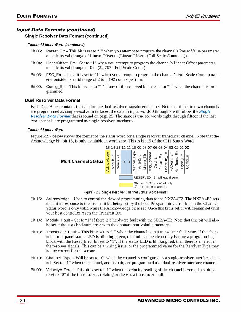
Channel Status Word
Figure R2.7 below shows the format of the status word for a single resolver transducer channel. Note that the Acknowledge bit, bit 15, is only available in word zero. This is bit 15 of the CH1 Status Word.
Figure R2.7 Single Resolver Channel Status Word Format
Bit 15: Acknowledge – Used to control the flow of programming data to the NX2A4E2. The NX2A4E2 sets this bit in response to the Transmit bit being set by the host. Programming error bits in the Channel Status word is only valid while the Acknowledge bit is set. Once this bit is set, it will remain set until your host controller resets the Transmit Bit.
Bit 14: Module_Fault – Set to “1” if there is a hardware fault with the NX2A4E2. Note that this bit will also be set if the is a checksum error with the onboard non-volatile memory.
Bit 13: Transducer_Fault – This bit is set to “1” when the channel is in a transducer fault state. If the chan-nel’s front panel status LED is blinking green, the fault can be cleared by issuing a programming block with the Reset_Error bit set to “1”. If the status LED is blinking red, then there is an error in the resolver signals. This can be a wiring issue, or the programmed value for the Resolver Type may not be correct for the sensor.
Bit 10: Channel_Type – Will be set to “0” when the channel is configured as a single-resolver interface chan-nel. Set to “1” when the channel, and its pair, are programmed as a dual-resolver interface channel.
Bit 09: VelocityAtZero – This bit is set to “1” when the velocity reading of the channel is zero. This bit is reset to “0” if the transducer is rotating or there is a transducer fault.
Bit 08: Motion_Direction – Reset to “0” when the counts are increasing. Set to “1” when the counts are decreasing. This bit remains in its last state when no motion is occurring.
Bit 07: Message_Ignored – Set to “1” when you attempt to program a parameter or channel if a parameter error has already been flagged for a different parameter. This bit is also set to “1” if you attempt to preset the position on a channel that is in transducer fault.
Bit 06: Command_Err – Set to “1” under the following conditions: Any of the reserved bits in the command words are set to “1” You attempt to program more than one channel at a time You attempt to preset channels 2 or 4 when they are part of a dual-resolver channel.
RESERVED: Bit will equal zero.
Channel 1 Status Word only.‘0' on all other channels.
Channel ‘n’ Status
15 14 13 12 11 10 09 08 07 06 05 04 03 02 01 00
Cm
d_
Err
Msg
_Ig
no
red
Co
nfig
Err
Ve
l@Z
ero
Ch
an
nel_
Typ
e
FS
Cou
nt_
Err
Lin
ear
Off_
Err
Pre
set_
Err
Xd
uce
rFlt
Mo
dul
eFlt
Ack
no
wle
dge
Mot
ion
_Dir
20 Gear Drive, Plymouth Ind. Park, Terryville, CT 06786Tel: (860) 585-1254 Fax: (860) 584-1973 http://www.amci.com
25
DATA FORMATS NX2A4E2 User Manual
Input Data Formats (continued)Single Resolver Data Format (continued)
Channel Status Word (continued)
Bit 05: Preset_Err – This bit is set to “1” when you attempt to program the channel’s Preset Value parameter outside its valid range of Linear Offset to (Linear Offset - (Full Scale Count – 1)).
Bit 04: LinearOffset_Err – Set to “1” when you attempt to program the channel’s Linear Offset parameter outside its valid range of 0 to (32,767 - Full Scale Count).
Bit 03: FSC_Err – This bit is set to “1” when you attempt to program the channel’s Full Scale Count param-eter outside its valid range of 2 to 8,192 counts per turn.
Bit 00: Config_Err – This bit is set to “1” if any of the reserved bits are set to “1” when the channel is pro-grammed.
Dual Resolver Data Format
Each Data Block contains the data for one dual-resolver transducer channel. Note that if the first two channels are programmed as single-resolver interfaces, the data in input words 0 through 7 will follow the Single Resolver Data Format that is found on page 25. The same is true for words eight through fifteen if the last two channels are programmed as single-resolver interfaces.
Channel Status Word
Figure R2.7 below shows the format of the status word for a single resolver transducer channel. Note that the Acknowledge bit, bit 15, is only available in word zero. This is bit 15 of the CH1 Status Word.
Figure R2.8 Single Resolver Channel Status Word Format
Bit 15: Acknowledge – Used to control the flow of programming data to the NX2A4E2. The NX2A4E2 sets this bit in response to the Transmit bit being set by the host. Programming error bits in the Channel Status word is only valid while the Acknowledge bit is set. Once this bit is set, it will remain set until your host controller resets the Transmit Bit.
Bit 14: Module_Fault – Set to “1” if there is a hardware fault with the NX2A4E2. Note that this bit will also be set if the is a checksum error with the onboard non-volatile memory.
Bit 13: Transducer_Fault – This bit is set to “1” when the channel is in a transducer fault state. If the chan-nel’s front panel status LED is blinking green, the fault can be cleared by issuing a programming block with the Reset_Error bit set to “1”. If the status LED is blinking red, then there is an error in the resolver signals. This can be a wiring issue, or the programmed value for the Resolver Type may not be correct for the sensor.
Bit 10: Channel_Type – Will be set to “0” when the channel is configured as a single-resolver interface chan-nel. Set to “1” when the channel, and its pair, are programmed as a dual-resolver interface channel.
Bit 09: VelocityAtZero – This bit is set to “1” when the velocity reading of the channel is zero. This bit is reset to “0” if the transducer is rotating or there is a transducer fault.
RESERVED: Bit will equal zero.
Channel 1 Status Word only.‘0' on all other channels.
MultiChannel Status
15 14 13 12 11 10 09 08 07 06 05 04 03 02 01 00
Cm
d_
Err
Msg
_Ig
no
red
Co
nfig
Err
Ve
l@Z
ero
Ch
an
nel
_Ty
pe
FS
Cou
nt_
Err
Nu
mT
urn
s_E
rr
TTy
pe
_Err
Lin
ea
rOff_
Err
Pre
set_
Err
Xd
uce
rFlt
Mo
dul
eF
lt
Ack
no
wle
dge
Mo
tion
_D
ir
ADVANCED MICRO CONTROLS INC.26

NX2A4E2 User Manual DATA FORMATS
Input Data Formats (continued)Dual Resolver Data Format (continued)
Channel Status Word (continued)
Bit 08: Motion_Direction – Reset to “0” when the counts are increasing. Set to “1” when the counts are decreasing. This bit remains in its last state when no motion is occurring.
Bit 07: Message_Ignored – Set to “1” when you attempt to program a parameter or channel if a parameter error has already been flagged for a different parameter. This bit is also set to “1” if you attempt to preset the position on a channel that is in transducer fault.
Bit 06: Command_Err – Set to “1” under the following conditions: Any of the reserved bits in the command words are set to “1” You attempt to program more than one channel at a time You attempt to preset channels 2 or 4 when they are part of a dual-resolver channel.
Bit 05: Preset_Err – This bit is set to “1” when you attempt to program the channel’s Preset Value parameter outside its valid range of Linear Offset to (Linear Offset - (Full Scale Count – 1)).
Bit 04: LinearOffset_Err – Set to “1” when you attempt to program the channel’s Linear Offset parameter outside its valid range of 0 to 999,999.
Bit 03: FSC_Err – This bit is set to “1” when you attempt to program the channel’s Full Scale Count param-eter outside its valid range. Valid ranges are:
2 to (4,096 * Number of Turns) for 100 or 180 turn transducers 2 to (409.6 * Number of Turns) for 1,000 or 1,800 turn transducers 2 to (1,024 * Number of Turns) for 128 turn transducers
Bit 02: NumTurns_Err – This bit is set to “1” when you attempt to program the channel’s Number of Turns parameter outside its valid range. Valid ranges are:
Bit 01: TType_Err – This bit is set to “1” when you attempt to program the channel’s Transducer Type parameter outside its valid range of 100, 180, 1,000, 1,800 or 128.
Bit 00: Config_Err – This bit is set to “1” if any of the reserved bits are set to “1” when the channel is pro-grammed.
Transducer Type Available Number of Turns
100 1, 2, 4, 5, 10, 20, 25, 50, 100
180 1, 2, 3, 4, 5, 6, 9, 10, 12, 15, 18, 20, 30, 36, 45, 60, 90, 180
1,000 10, 20, 40, 50, 100, 200, 250, 500, 1,000
1,800 10, 20, 30, 40, 50, 60, 90, 100, 120, 150, 180, 200, 300, 360, 450, 600, 900, 1,800
128 1, 2, 4, 8, 16, 32, 64, 128
20 Gear Drive, Plymouth Ind. Park, Terryville, CT 06786Tel: (860) 585-1254 Fax: (860) 584-1973 http://www.amci.com
27

DATA FORMATS NX2A4E2 User Manual
Notes
ADVANCED MICRO CONTROLS INC.28

20 Gear Drive, PTel: (860) 585-12
REFERENCE 3
CONFIGURING NETWORK INTERFACESFirewall SettingsFirewalls are hardware devices or software that prevent unwanted network connections from occurring. Fire-wall software has been present on Windows based computers since XP, and it may prevent your computer from communicating with the NX2A4E2. The internal webserver uses port 80, which is the default http port, and should work without changing any firewall settings. Configuring your firewall to allow communication with the NX2A4E2 is beyond the scope of this manual.
Disable All Unused Network InterfacesRouting and default gateway setting on your computer might prevent connection to the NX2A4E2. When using the Net Configurator utility, broadcast packets that are used to find the NX2A4E2 often go out the wrong port. The easiest way to avoid this problem is to temporarily disable all network interfaces that are not attached to the NX2A4E2.
This includes all wireless interfaces as well as all Bluetooth interfaces.
Configure Your Network InterfaceBefore you can communicate with the NX2A4E2, your network interface must be on the same subnet as the encoder.
The rest of this procedure assumes you are using the 192.168.0.xxx subnet. If you are not, you will have to adjust the given network addresses accordingly.
The easiest way to check the current settings for your NIC is with the ‘ipconfig’ command.
For Windows 7, click on the [Start] button, and type “cmd” in the “Search programs and files” text box. Press [Enter] on the keyboard.
For Windows 8 and 10, press the [Win+X] keys and select “Command Prompt” from the resulting popup. There is no need to run the command prompt as the administrator, so do not select “Command Prompt (Admin)”.
This section lists suggestions for configuring the network interfaces on your com-puter or laptop before attaching to the NX2A4E2.
lymouth Ind. Park, Terryville, CT 0678654 Fax: (860) 584-1973 http://www.amci.com
29
CONFIGURING NETWORK INTERFACES NX2A4E2 User Manual
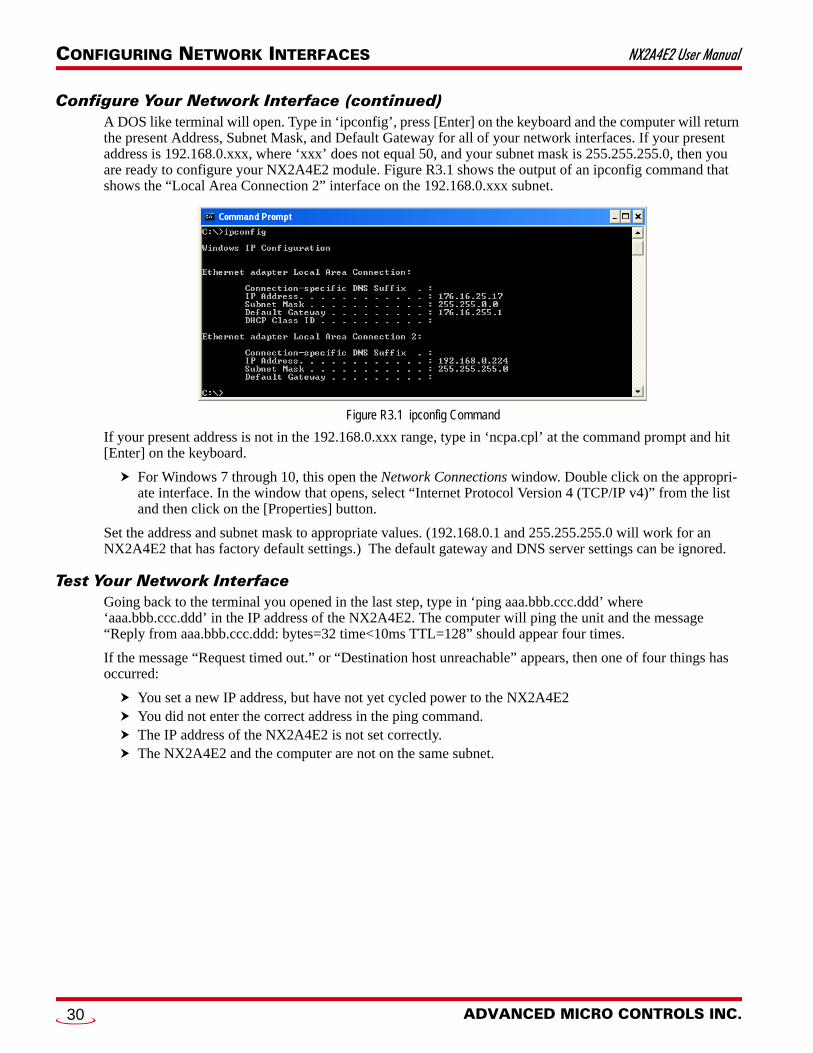
Configure Your Network Interface (continued)A DOS like terminal will open. Type in ‘ipconfig’, press [Enter] on the keyboard and the computer will return the present Address, Subnet Mask, and Default Gateway for all of your network interfaces. If your present address is 192.168.0.xxx, where ‘xxx’ does not equal 50, and your subnet mask is 255.255.255.0, then you are ready to configure your NX2A4E2 module. Figure R3.1 shows the output of an ipconfig command that shows the “Local Area Connection 2” interface on the 192.168.0.xxx subnet.
Figure R3.1 ipconfig Command
If your present address is not in the 192.168.0.xxx range, type in ‘ncpa.cpl’ at the command prompt and hit [Enter] on the keyboard.
For Windows 7 through 10, this open the Network Connections window. Double click on the appropri-ate interface. In the window that opens, select “Internet Protocol Version 4 (TCP/IP v4)” from the list and then click on the [Properties] button.
Set the address and subnet mask to appropriate values. (192.168.0.1 and 255.255.255.0 will work for an NX2A4E2 that has factory default settings.) The default gateway and DNS server settings can be ignored.
Test Your Network InterfaceGoing back to the terminal you opened in the last step, type in ‘ping aaa.bbb.ccc.ddd’ where ‘aaa.bbb.ccc.ddd’ in the IP address of the NX2A4E2. The computer will ping the unit and the message “Reply from aaa.bbb.ccc.ddd: bytes=32 time<10ms TTL=128” should appear four times.
If the message “Request timed out.” or “Destination host unreachable” appears, then one of four things has occurred:
You set a new IP address, but have not yet cycled power to the NX2A4E2 You did not enter the correct address in the ping command. The IP address of the NX2A4E2 is not set correctly. The NX2A4E2 and the computer are not on the same subnet.
ADVANCED MICRO CONTROLS INC.30

20 Gear Drive, PTel: (860) 585-12
TASK 1
INSTALLING THE NX2A4E21.1 Safe Handling Guidelines
1.1.1 Prevent Electrostatic Damage
Electrostatic discharge can damage the NX2A4E2 if you touch connector pins. Follow these guidelines when handling the module.
1) Touch a grounded object to discharge static potential before handling the module.2) Work in a static-safe environment whenever possible.3) Wear an approved wrist-strap grounding device.4) Do not touch the pins of the I/O or Ethernet connectors.5) Do not disassemble the module6) Store the module in its anti-static bag and shipping box when it is not in use.
1.1.2 Prevent Debris From Entering the Unit
While mounting a unit, make sure that all debris (metal chips, wire strands, tapping liq-uids, etc.) is prevented from falling into the module. Debris may cause damage to the unit or unintended machine operation with possible personal injury. When using DIN rail to mount the unit, the rail should be securely installed and grounded before the unit is mounted on it.
1.1.3 Remove Power Before Servicing
Remove power before removing or installing the NX2A4E2 module.
1.2 General Wiring GuidelinesWhen wiring any control system, these guidelines must be followed to help prevent electromagnetic interfer-ence and ground loops:
1.2.1 Wiring
Transducer signals are generally low voltage, low power signals. If you are using A-B guidelines for cabling installation, treat the transducer cable as a Category 2 cable. It can be installed in conduit along with other low power cabling such as communication cables and low power ac/dc I/O lines. It cannot be installed in con-duit with ac power lines or high power ac/dc I/O lines.
Like all signal and communication cable, the transducer cable should be shielded. The shield must be grounded at one end only, typically at the input to the NX2A4E2.
If a junction must be made in the signal cable, treat the shield as a signal-carrying conductor. Do not connect the shield to ground at any junction box or the transducer.
If the signal cable must cross power feed lines, it should do so at right angles.
Route at least five feet from high voltage enclosures, or sources of “rf” radiation.
This chapter covers the physical installation of the NX2A4E2.
lymouth Ind. Park, Terryville, CT 0678654 Fax: (860) 584-1973 http://www.amci.com
31
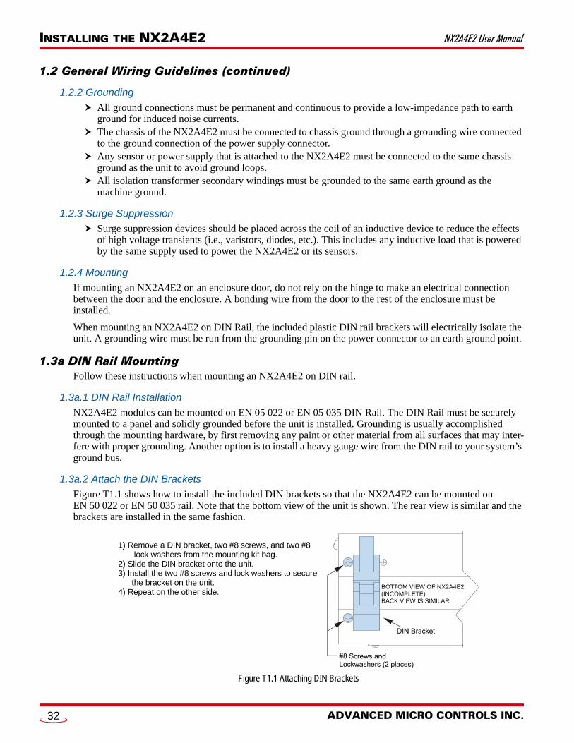
INSTALLING THE NX2A4E2 NX2A4E2 User Manual
1.2 General Wiring Guidelines (continued)
1.2.2 Grounding
All ground connections must be permanent and continuous to provide a low-impedance path to earth ground for induced noise currents.
The chassis of the NX2A4E2 must be connected to chassis ground through a grounding wire connected to the ground connection of the power supply connector.
Any sensor or power supply that is attached to the NX2A4E2 must be connected to the same chassis ground as the unit to avoid ground loops.
All isolation transformer secondary windings must be grounded to the same earth ground as the machine ground.
1.2.3 Surge Suppression
Surge suppression devices should be placed across the coil of an inductive device to reduce the effects of high voltage transients (i.e., varistors, diodes, etc.). This includes any inductive load that is powered by the same supply used to power the NX2A4E2 or its sensors.
1.2.4 Mounting
If mounting an NX2A4E2 on an enclosure door, do not rely on the hinge to make an electrical connection between the door and the enclosure. A bonding wire from the door to the rest of the enclosure must be installed.
When mounting an NX2A4E2 on DIN Rail, the included plastic DIN rail brackets will electrically isolate the unit. A grounding wire must be run from the grounding pin on the power connector to an earth ground point.
1.3a DIN Rail MountingFollow these instructions when mounting an NX2A4E2 on DIN rail.
1.3a.1 DIN Rail Installation
NX2A4E2 modules can be mounted on EN 05 022 or EN 05 035 DIN Rail. The DIN Rail must be securely mounted to a panel and solidly grounded before the unit is installed. Grounding is usually accomplished through the mounting hardware, by first removing any paint or other material from all surfaces that may inter-fere with proper grounding. Another option is to install a heavy gauge wire from the DIN rail to your system’s ground bus.
1.3a.2 Attach the DIN Brackets
Figure T1.1 shows how to install the included DIN brackets so that the NX2A4E2 can be mounted on EN 50 022 or EN 50 035 rail. Note that the bottom view of the unit is shown. The rear view is similar and the brackets are installed in the same fashion.
Figure T1.1 Attaching DIN Brackets
1) Remove a DIN bracket, two #8 screws, and two #8 lock washers from the mounting kit bag.2) Slide the DIN bracket onto the unit.3) Install the two #8 screws and lock washers to secure the bracket on the unit.4) Repeat on the other side.
BOTTOM VIEW OF NX2A4E2(INCOMPLETE)BACK VIEW IS SIMILAR
ADVANCED MICRO CONTROLS INC.32
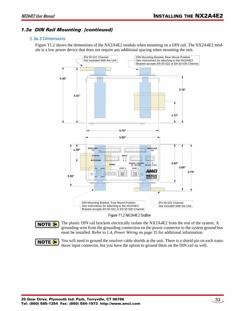
NX2A4E2 User Manual INSTALLING THE NX2A4E2
1.3a DIN Rail Mounting (continued)
1.3a.3 Dimensions
Figure T1.2 shows the dimensions of the NX2A4E2 module when mounting on a DIN rail. The NX2A4E2 mod-ule is a low power device that does not require any additional spacing when mounting the unit.
Figure T1.2 NX2A4E2 Outline
The plastic DIN rail brackets electrically isolate the NX2A4E2 from the rest of the system. A grounding wire from the grounding connection on the power connector to the system ground bus must be installed. Refer to 1.4, Power Wiring on page 35 for additional information.
You will need to ground the resolver cable shields at the unit. There is a shield pin on each trans-ducer input connector, but you have the option to ground them on the DIN rail as well.
3.04"
3.69"
3.74"
1.39"
3.35"
1.72"
3.76"
4.41"
4.46"
5.75"
5.95"
EN 50 022 Channel.Not Included With the Unit.
DIN Mounting Bracket, Foot Mount PositionSee Instructions for attaching to the NX2A4E2.Bracket accepts EN 50 022 or EN 50 035 Channel.
DIN Mounting Bracket, Rear Mount PositionSee Instructions for attaching to the NX2A4E2.Bracket accepts EN 50 022 or EN 50 035 Channel.
EN 50 022 Channel.Not Included With the Unit.
1 2
NEXUSRESOLVER
LINK2 PORT 2 PORT 1MS
NS LINK1
12345678
20 Gear Drive, Plymouth Ind. Park, Terryville, CT 06786Tel: (860) 585-1254 Fax: (860) 584-1973 http://www.amci.com
33

INSTALLING THE NX2A4E2 NX2A4E2 User Manual
1.3b Panel MountingFollow these instructions when mounting an NX2A4E2 on a panel.
1.3b.1 Attach the Panel Mount Brackets
Figure T1.3 shows how to install the included brackets so that the NX2A4E2 can be mounted to a panel. Note that the bottom view of the unit is shown. The rear view is similar and the brackets are installed in the same way.
Figure T1.3 Attaching Panel Mount Brackets
1.3b.2 Dimensions
Figure T1.4 shows the dimensions of the NX2A4E2 module when panel mounting.
Figure T1.4 NX2A4E2 Outline
You will need to ground the resolver cable shields at the unit. There is a shield pin on each trans-ducer input connector, but you have the option to ground them on the DIN rail as well.
1) Remove a panel bracket, two #8 screws, and two #8 lock washers from the mounting kit bag.2) Position the panel bracket onto the unit.3) Install the two #8 screws and lock washers to secure the bracket to the unit.4) Repeat on the other side. BOTTOM VIEW OF NX2A4E2
(INCOMPLETE)BACK VIEW IS SIMILAR
SIDE VIEW OF PANELBRACKET INSTALLATION
1.13"
1.90"
5.75"
3.04"
0.41 "7.15"
6.58"
3.25"1.900"
3.88"
4.09"
Panel Mounting Brackets, Rear Mount Position. See Instructions forattaching to the NX2A4E2.
Panel Mounting Brackets, Foot Mount Position. See Instructions forattaching to the NX2A4E2.
0.180 "typical
1 2
NEXUSRESOLVER
LINK2 PORT 2 PORT 1MS
NS LINK1
12345678
ADVANCED MICRO CONTROLS INC.34

NX2A4E2 User Manual INSTALLING THE NX2A4E2
1.4 Power WiringThe NX2A4E2 accepts 24 Vdc as its input power. The input range is 18 to 30Vdc. Maximum power draw is 12 watts, or 0.50 A @ 24Vdc. Minimum wire gauge for the connector is 24 AWG, but a heavier wire gauge is suggested. The mating connector is included with the NX2A4E2.
The power connector is located on the right side of the unit. Power connections should be tight, as loose con-nections may lead to arcing which will heat the connector. Phoenix Contact specifies a tightening torque of 4.4 to 5.4 lb-in (0.5 to 0.6 Nm).
The power supply is connected to the pins marked “+” and “–”. The ground pin is used to attach the NX2A4E2 to earth ground. The use of a 12 AWG, stranded wire for the earth ground connection is strongly recommended.
Figure T1.5 Power Supply and Grounding Connections
1.5 Network ConnectionsAs shown in the figure below, the NX2A4E2 modules have two Ethernet ports. An internal two port Ethernet switch connects the two. In non-redundant applications, either port can be used to attach the module to the network. The remaining port can be used to extend the network to another device if this would reduce wiring costs.
Figure T1.6 Network Port Locations
1.5.1 EtherNet/IP DLR Applications
In Device Level Ring applications, the NX2A4E2 modules function as Beacon-Based Ring Nodes. In these applications, both ports are used when wiring the ring, daisy chaining from one unit in the ring to the next.
1.5.2 PROFINET MRP Applications
In Media Redundancy Protocol applications, the NX2A4E2 modules function as a Media Redundancy Client (MRC). In these applications, both ports are used when wiring the ring, daisy chaining from one unit in the ring to the next.
NEXUSRESOLVER
GROUND BUS
+18Vdc to +30VdcIsolated Power
Supply
Grounding Strap maybe required by local safety codes.Strap can be attached without the concern of forming a ground loop between the supply and NX2A4E2 because the negative side (–) of the units' power input is isolated from the chassis ground connection.
Required Functional Grounding Connection.A 12 AWG, stranded wire must be used to connect
the NX2A4E2 to the system’s ground bus.
NEXUSRESOLVER
LINK2 PORT 2 PORT 1MS
NS LINK1
12345678
20 Gear Drive, Plymouth Ind. Park, Terryville, CT 06786Tel: (860) 585-1254 Fax: (860) 584-1973 http://www.amci.com
35

INSTALLING THE NX2A4E2 NX2A4E2 User Manual
1.6 AMCI Transducers
1.6.1 Transducer Outline Drawings
The NX2A4E2 is compatible with every standard single and dual resolver transducer manufactured by AMCI as well as our R11 and R15 resolver transmitters. Outline drawings and specification sheets are available on our website at: www.amci.com/resolvers.asp.
1.6.2 Mounting
All AMCI resolver transducers are designed for industrial environments and therefore require little attention. The resolver is electrically isolated from the body of the transducer to eliminate the potential for ground loops and ground shifts in the system. The main guideline to follow when mounting the transducers is to limit bear-ing loads when coupling the transducer to your machine. This includes using flexible couplers when directly coupling shafts to eliminate shaft misalignments.
The following bearing load ratings are known as “L10 ratings” in the bearing trade associations. L10 is a stati-cal rating meaning that 90% of the bearings will survive the specified number of revolutions. AMCI specifies our rated number of revolutions as 2X10⁹, or 2 billion, which is a number commonly used in the industry. By specifying the maximum load and statical life, AMCI gives you data you need to choose the right transducer for your application.
Note that these load ratings are maximums, and you should always strive to keep shaft loading to a minimum. The inverse relationship between shaft loading and bearing life is not linear, it's exponential.
This means that decreasing the shaft loading by half will, statically, increase the bearing life by a factor of eight. For example, decreasing a shaft load from 100 lbs. to 50 lbs. yields: [100/50]3 = 8 times increase in sta-tistical bearing life.
At the loads specified below, bearing life is a minimum of 2x10⁹ revolutions. Note that the R11 series and HT-6 transducers always require a flexible coupler to your machine because of their shaft size.
Table T1.1 Shaft Load Specifications
Shaft Dia. Maximum Radial Load
Maximum Axial Load
R11 Series0.120" 2.0 lbs. (8.9N) 1.0 lb. (4.4N)0.188" 6.0 lbs. (26.7N) 3.0 lbs. (13.3N)
HT-60.188" 6.0 lbs. (26.7N) 3.0 lbs. (13.3N)
H25 Series0.250" 40 lbs. (178N) 20 lbs. (89N)10 mm 40 lbs. (178N) 20 lbs. (89N)0.375" 40 lbs. (178N) 20 lbs. (89N)0.625" 100 lbs. (445N) 50 lbs. (222N)
HT Series0.375" 100 lbs. (445N) 50 lbs. (222N)0.625" 100 lbs. (445N) 50 lbs. (222N)
HTT Series0.375" 100 lbs. (445N) 50 lbs. (222N)0.625" 100 lbs. (445N) 50 lbs. (222N)
1x---
3where x
new shaft loadold shaft load----------------------------------- old shaft load
new shaft load-----------------------------------
3=
ADVANCED MICRO CONTROLS INC.36

NX2A4E2 User Manual INSTALLING THE NX2A4E2
1.7 Foreign TransducersThe NX2A4E2 is programmatically compatible with resolver transducers from Autotech and Gemco. Resolver transducers from several other manufacturers can be made compatible with an AMCI Reference Module. Each Reference Module is a single ended transformer that is wired into the transducer cable. The Reference Module alters the reference voltage such that the return signals appear to come from an AMCI transducer. Several different Reference Modules are available. Contact AMCI for additional information.
Regardless of the type of cable suggested by the transducer manufacturer, AMCI strongly rec-ommends Belden 9730 or 9731, or exact equivalents, as cables for your transducer. With tens of thousands of installations worldwide, AMCI is confident in the quality of these cables. If you wish to use a different cable, contact AMCI to verify your cable type.
1.8 Transducer Connector PinoutThe transducer input connectors, labeled “RESOLVER 1/2” and “RESOLVER 3/4” have eight contacts. The mating connectors are supplied with the NX2A4E2. The AMCI part number for the mating connector is MS-8, while the Phoenix Contact part number is MSTB2.5/8-ST-5.08, order number 1757077. Figure T1.7 shows the connector pinout to industry standard wire designations. The single-turn pin out is shown on the left and multi-turn pin out on the right.
Figure T1.7 Transducer Input Connector Pinout
Pin 3 is connected to the earth ground pin on the power connector. As covered in section 1.4, Power Wiring on page 35, the earth ground pin on the power connector must be attached to the system ground bus for proper operation.
87654321
BS3BS4AS3AS4
AS1, AS2, BS1, BS2All ShieldsAR2, BR2AR1, BR1
A – First Resolver Transducer B – Second Resolver Transducer R1/R2 – Reference Winding S1/S3 – COS Winding S2/S4 – SIN Winding
FS4FS1CS4CS3CS1, CS2, FS2, FS3All ShieldsCR2, FR2CR1, FR1
F – Fine Resolver C – Coarse Resolver R1/R2 - Reference Winding
S2/S4 – SIN WindingS1/S3 – COS Winding
20 Gear Drive, Plymouth Ind. Park, Terryville, CT 06786Tel: (860) 585-1254 Fax: (860) 584-1973 http://www.amci.com
37
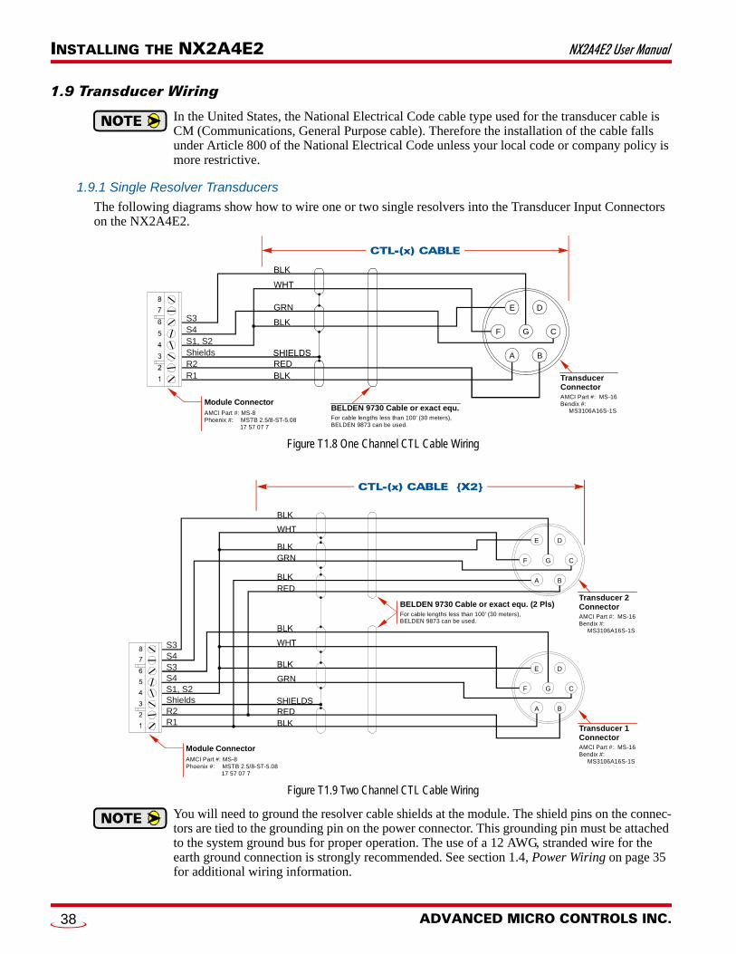
INSTALLING THE NX2A4E2 NX2A4E2 User Manual
1.9 Transducer Wiring
In the United States, the National Electrical Code cable type used for the transducer cable is CM (Communications, General Purpose cable). Therefore the installation of the cable falls under Article 800 of the National Electrical Code unless your local code or company policy is more restrictive.
1.9.1 Single Resolver Transducers
The following diagrams show how to wire one or two single resolvers into the Transducer Input Connectors on the NX2A4E2.
Figure T1.8 One Channel CTL Cable Wiring
Figure T1.9 Two Channel CTL Cable Wiring
You will need to ground the resolver cable shields at the module. The shield pins on the connec-tors are tied to the grounding pin on the power connector. This grounding pin must be attached to the system ground bus for proper operation. The use of a 12 AWG, stranded wire for the earth ground connection is strongly recommended. See section 1.4, Power Wiring on page 35 for additional wiring information.
BELDEN 9730 Cable or exact equ.For cable lengths less than 100' (30 meters),BELDEN 9873 can be used.
TransducerConnectorAMCI Part #: MS-16Bendix #: MS3106A16S-1S
S3S4S1, S2ShieldsR2R1
A B
C
DE
F G
BLK
GRN
BLK
REDBLK
Module ConnectorAMCI Part #: MS-8Phoenix #: MSTB 2.5/8-ST-5.08 17 57 07 7
BELDEN 9730 Cable or exact equ. (2 Pls)For cable lengths less than 100' (30 meters),BELDEN 9873 can be used.
Transducer 1ConnectorAMCI Part #: MS-16Bendix #: MS3106A16S-1S
Transducer 2ConnectorAMCI Part #: MS-16Bendix #: MS3106A16S-1S
S3S4S3
S4S1, S2ShieldsR2R1
Module ConnectorAMCI Part #: MS-8Phoenix #: MSTB 2.5/8-ST-5.08 17 57 07 7
A B
C
DE
F G
A B
C
DE
F G
GRN
SHIELDSREDBLK
BLK
WHT
GRNBLK
REDBLK
ADVANCED MICRO CONTROLS INC.38

NX2A4E2 User Manual INSTALLING THE NX2A4E2
1.9 Transducer Wiring (continued)
1.9.1 Single Resolver Transducers (continued)
Figures T1.8 and T1.9 show connections to AMCI transducers that use our standard MS-16 connector. For units that do not use the MS-16 connector, refer to the transducer’s specification sheet for connection infor-mation. Specifications sheets can be found on our website at:
https://www.amci.com/industrial-automation-support/user-manuals/
When connecting a transducer from another manufacturer, use the R1-R2 and S1-S4 designations to deter-mine how to correctly attach the transducer to the NX2A4E2.
1) There are two ways to reverse the count direction when using single resolver transducers. One method is to set the Count Direction parameter when programming the NX2A4E2. The other method is to reverse the connections on one of the stator pairs. AMCI standard method is to reverse the S2-S4 pair, which is the green/black pair of the CTL cables.
2) When using a foreign single resolver transducer, note how the signals are paired in the AMCI CTL cable and use this pairing when generating your wiring diagrams.
3) The cable shields must be isolated from earth ground at the transducer to prevent ground loops and ground shifts. If using a junction box, treat the cable shields as a signal carrying conductor at the junction. Do not tie the shields to earth ground at the junction box.
4) The cable shields must be isolated from earth ground at the transducer to prevent ground loops and ground shifts. When using a foreign transducer, do not attach the shields to a transducer pin, even if this follows the standard of your transducer’s manufacturer.
1.9.2 Size 11 and Size 15 Resolvers
Figure T1.10 shows the connections required to attach a resolver with industry standard wire colors to a Belden 9730 cable. If these connections are followed, you can refer to Figures T1.8 and T1.9 on page 38 for connections from the Belden cable to the NX2A4E2.
Figure T1.10 Resolver to Cable Connections
20 Gear Drive, Plymouth Ind. Park, Terryville, CT 06786Tel: (860) 585-1254 Fax: (860) 584-1973 http://www.amci.com
39
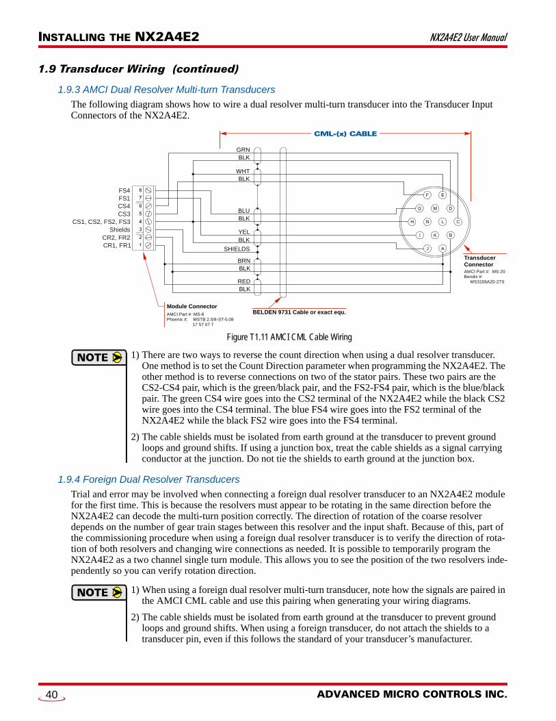
INSTALLING THE NX2A4E2 NX2A4E2 User Manual
1.9 Transducer Wiring (continued)
1.9.3 AMCI Dual Resolver Multi-turn Transducers
The following diagram shows how to wire a dual resolver multi-turn transducer into the Transducer Input Connectors of the NX2A4E2.
Figure T1.11 AMCI CML Cable Wiring
1) There are two ways to reverse the count direction when using a dual resolver transducer. One method is to set the Count Direction parameter when programming the NX2A4E2. The other method is to reverse connections on two of the stator pairs. These two pairs are the CS2-CS4 pair, which is the green/black pair, and the FS2-FS4 pair, which is the blue/black pair. The green CS4 wire goes into the CS2 terminal of the NX2A4E2 while the black CS2 wire goes into the CS4 terminal. The blue FS4 wire goes into the FS2 terminal of the NX2A4E2 while the black FS2 wire goes into the FS4 terminal.
2) The cable shields must be isolated from earth ground at the transducer to prevent ground loops and ground shifts. If using a junction box, treat the cable shields as a signal carrying conductor at the junction. Do not tie the shields to earth ground at the junction box.
1.9.4 Foreign Dual Resolver Transducers
Trial and error may be involved when connecting a foreign dual resolver transducer to an NX2A4E2 module for the first time. This is because the resolvers must appear to be rotating in the same direction before the NX2A4E2 can decode the multi-turn position correctly. The direction of rotation of the coarse resolver depends on the number of gear train stages between this resolver and the input shaft. Because of this, part of the commissioning procedure when using a foreign dual resolver transducer is to verify the direction of rota-tion of both resolvers and changing wire connections as needed. It is possible to temporarily program the NX2A4E2 as a two channel single turn module. This allows you to see the position of the two resolvers inde-pendently so you can verify rotation direction.
1) When using a foreign dual resolver multi-turn transducer, note how the signals are paired in the AMCI CML cable and use this pairing when generating your wiring diagrams.
2) The cable shields must be isolated from earth ground at the transducer to prevent ground loops and ground shifts. When using a foreign transducer, do not attach the shields to a transducer pin, even if this follows the standard of your transducer’s manufacturer.
CML-(x) CABLE
BELDEN 9731 Cable or exact equ.
Transducer ConnectorAMCI Part #: MS-20Bendix #: MS3106A20-27S
CS4FS1FS4
CS3CS1, CS2, FS2, FS3
ShieldsCR2, FR2CR1, FR1
Module ConnectorAMCI Part #: MS-8Phoenix #: MSTB 2.5/8-ST-5.08 17 57 07 7
F
L
J
REDBLK
BRNBLK
SHIELDS
YELBLK
BLUBLK
WHTBLK
GRNBLK
ADVANCED MICRO CONTROLS INC.40
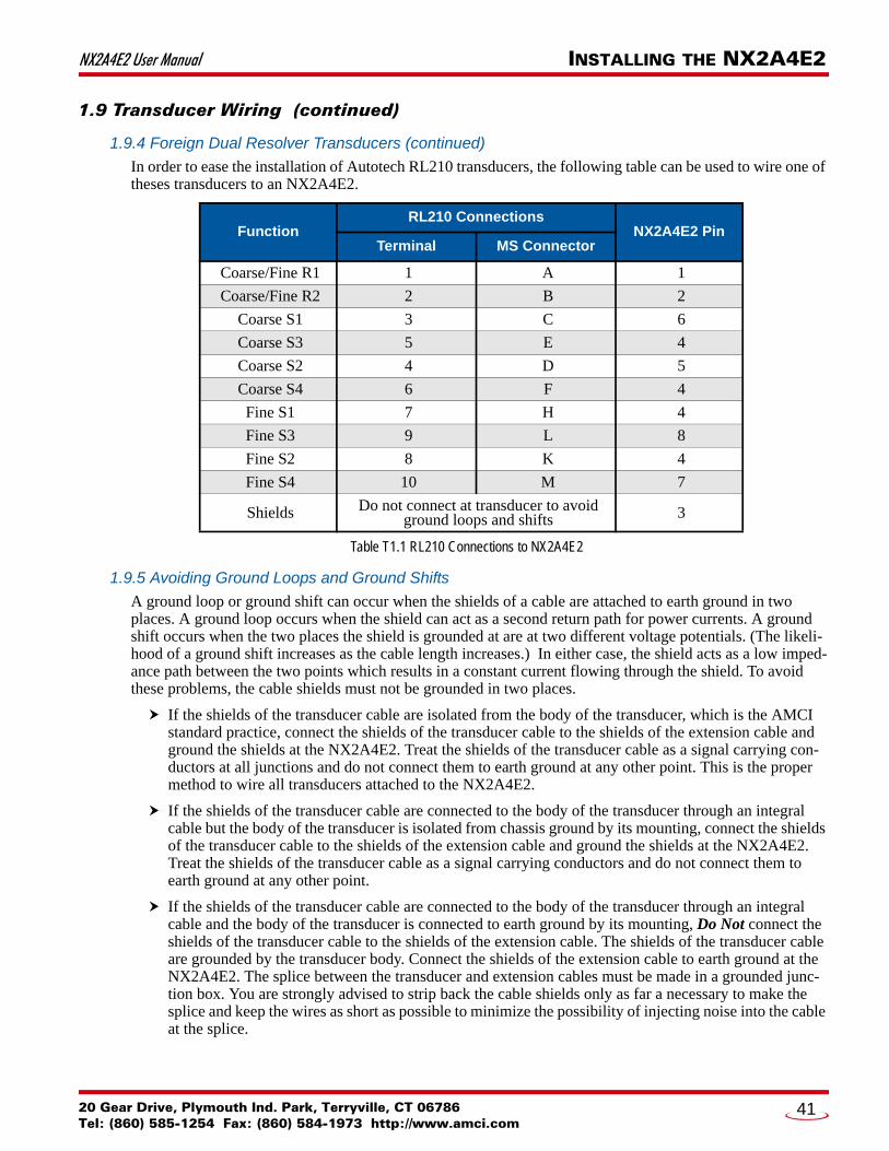
NX2A4E2 User Manual INSTALLING THE NX2A4E2
1.9 Transducer Wiring (continued)
1.9.4 Foreign Dual Resolver Transducers (continued)
In order to ease the installation of Autotech RL210 transducers, the following table can be used to wire one of theses transducers to an NX2A4E2.
Table T1.1 RL210 Connections to NX2A4E2
1.9.5 Avoiding Ground Loops and Ground Shifts
A ground loop or ground shift can occur when the shields of a cable are attached to earth ground in two places. A ground loop occurs when the shield can act as a second return path for power currents. A ground shift occurs when the two places the shield is grounded at are at two different voltage potentials. (The likeli-hood of a ground shift increases as the cable length increases.) In either case, the shield acts as a low imped-ance path between the two points which results in a constant current flowing through the shield. To avoid these problems, the cable shields must not be grounded in two places.
If the shields of the transducer cable are isolated from the body of the transducer, which is the AMCI standard practice, connect the shields of the transducer cable to the shields of the extension cable and ground the shields at the NX2A4E2. Treat the shields of the transducer cable as a signal carrying con-ductors at all junctions and do not connect them to earth ground at any other point. This is the proper method to wire all transducers attached to the NX2A4E2.
If the shields of the transducer cable are connected to the body of the transducer through an integral cable but the body of the transducer is isolated from chassis ground by its mounting, connect the shields of the transducer cable to the shields of the extension cable and ground the shields at the NX2A4E2. Treat the shields of the transducer cable as a signal carrying conductors and do not connect them to earth ground at any other point.
If the shields of the transducer cable are connected to the body of the transducer through an integral cable and the body of the transducer is connected to earth ground by its mounting, Do Not connect the shields of the transducer cable to the shields of the extension cable. The shields of the transducer cable are grounded by the transducer body. Connect the shields of the extension cable to earth ground at the NX2A4E2. The splice between the transducer and extension cables must be made in a grounded junc-tion box. You are strongly advised to strip back the cable shields only as far a necessary to make the splice and keep the wires as short as possible to minimize the possibility of injecting noise into the cable at the splice.
FunctionRL210 Connections
NX2A4E2 PinTerminal MS Connector
Coarse/Fine R1 1 A 1
Coarse/Fine R2 2 B 2
Coarse S1 3 C 6
Coarse S3 5 E 4
Coarse S2 4 D 5
Coarse S4 6 F 4
Fine S1 7 H 4
Fine S3 9 L 8
Fine S2 8 K 4
Fine S4 10 M 7
Shields Do not connect at transducer to avoid ground loops and shifts 3
20 Gear Drive, Plymouth Ind. Park, Terryville, CT 06786Tel: (860) 585-1254 Fax: (860) 584-1973 http://www.amci.com
41
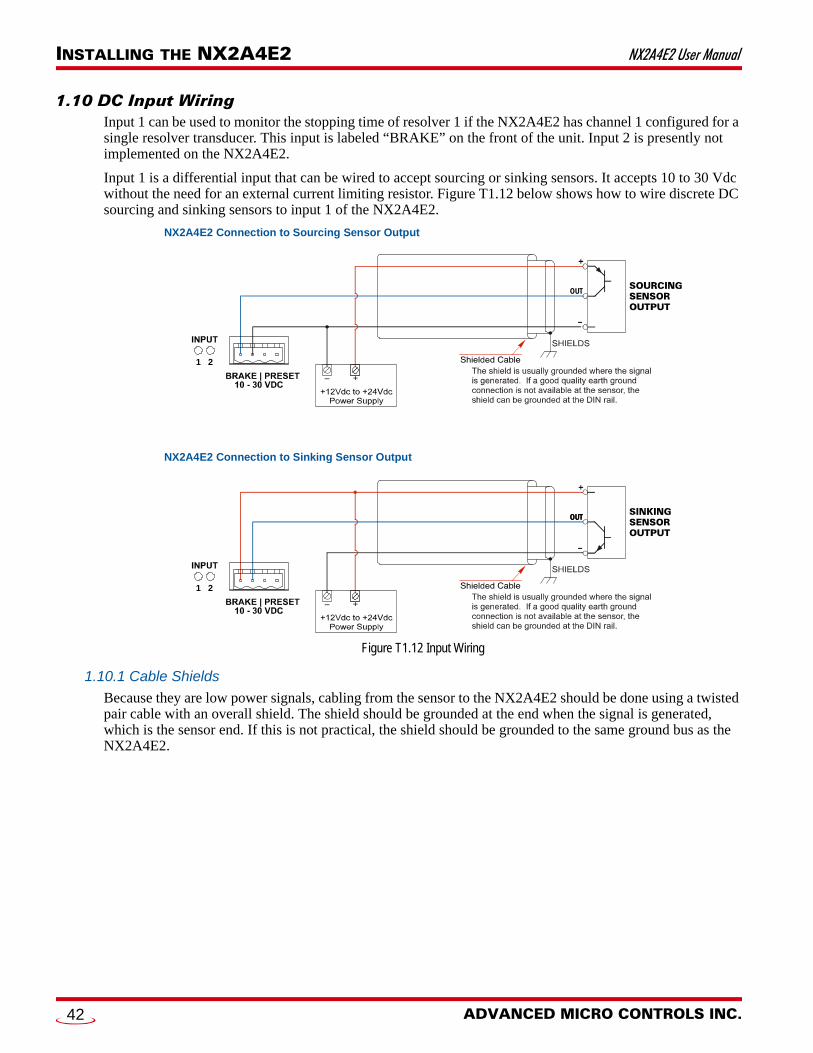
INSTALLING THE NX2A4E2 NX2A4E2 User Manual
1.10 DC Input WiringInput 1 can be used to monitor the stopping time of resolver 1 if the NX2A4E2 has channel 1 configured for a single resolver transducer. This input is labeled “BRAKE” on the front of the unit. Input 2 is presently not implemented on the NX2A4E2.
Input 1 is a differential input that can be wired to accept sourcing or sinking sensors. It accepts 10 to 30 Vdc without the need for an external current limiting resistor. Figure T1.12 below shows how to wire discrete DC sourcing and sinking sensors to input 1 of the NX2A4E2.
Figure T1.12 Input Wiring
1.10.1 Cable Shields
Because they are low power signals, cabling from the sensor to the NX2A4E2 should be done using a twisted pair cable with an overall shield. The shield should be grounded at the end when the signal is generated, which is the sensor end. If this is not practical, the shield should be grounded to the same ground bus as the NX2A4E2.
NX2A4E2 Connection to Sourcing Sensor Output
NX2A4E2 Connection to Sinking Sensor Output
OUT
OUTOUT
–
–
1 2
1 2
ADVANCED MICRO CONTROLS INC.42
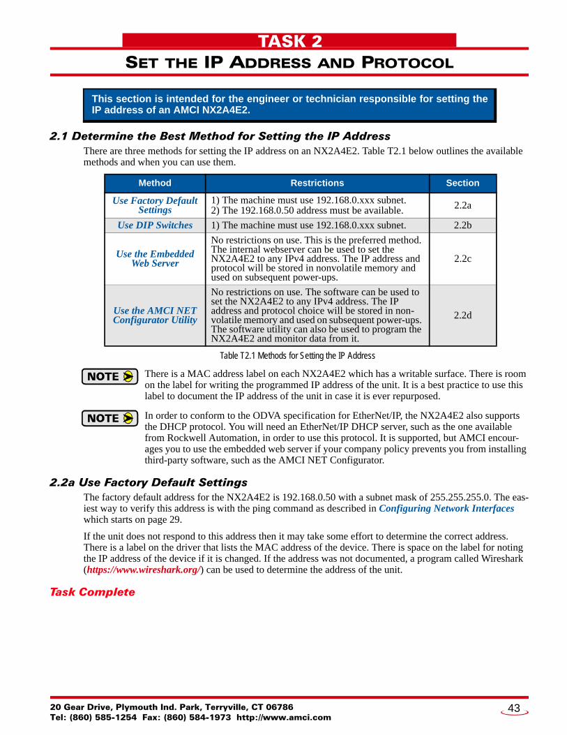
20 Gear Drive, PTel: (860) 585-12
TASK 2
SET THE IP ADDRESS AND PROTOCOL2.1 Determine the Best Method for Setting the IP AddressThere are three methods for setting the IP address on an NX2A4E2. Table T2.1 below outlines the available methods and when you can use them.
Table T2.1 Methods for Setting the IP Address
There is a MAC address label on each NX2A4E2 which has a writable surface. There is room on the label for writing the programmed IP address of the unit. It is a best practice to use this label to document the IP address of the unit in case it is ever repurposed.
In order to conform to the ODVA specification for EtherNet/IP, the NX2A4E2 also supports the DHCP protocol. You will need an EtherNet/IP DHCP server, such as the one available from Rockwell Automation, in order to use this protocol. It is supported, but AMCI encour-ages you to use the embedded web server if your company policy prevents you from installing third-party software, such as the AMCI NET Configurator.
2.2a Use Factory Default SettingsThe factory default address for the NX2A4E2 is 192.168.0.50 with a subnet mask of 255.255.255.0. The eas-iest way to verify this address is with the ping command as described in Configuring Network Interfaces which starts on page 29.
If the unit does not respond to this address then it may take some effort to determine the correct address. There is a label on the driver that lists the MAC address of the device. There is space on the label for noting the IP address of the device if it is changed. If the address was not documented, a program called Wireshark (https://www.wireshark.org/) can be used to determine the address of the unit.
Task Complete
This section is intended for the engineer or technician responsible for setting the IP address of an AMCI NX2A4E2.
Method Restrictions Section
Use Factory Default Settings
1) The machine must use 192.168.0.xxx subnet.2) The 192.168.0.50 address must be available. 2.2a
Use DIP Switches 1) The machine must use 192.168.0.xxx subnet. 2.2b
Use the Embedded Web Server
No restrictions on use. This is the preferred method. The internal webserver can be used to set the NX2A4E2 to any IPv4 address. The IP address and protocol will be stored in nonvolatile memory and used on subsequent power-ups.
2.2c
Use the AMCI NET Configurator Utility
No restrictions on use. The software can be used to set the NX2A4E2 to any IPv4 address. The IP address and protocol choice will be stored in non-volatile memory and used on subsequent power-ups. The software utility can also be used to program the NX2A4E2 and monitor data from it.
2.2d
lymouth Ind. Park, Terryville, CT 0678654 Fax: (860) 584-1973 http://www.amci.com
43

SET THE IP ADDRESS AND PROTOCOL NX2A4E2 User Manual
2.2b Use DIP SwitchesWhen using the DIP switches, a switch in its ON position represents a logic ‘1’. Physically, the switch is pushed “up” towards the transducer connectors. A logic ‘0’ is when the switch is in its OFF position, (pushed down).
When all of the DIP switches are in their logic ‘1’ position, (ON), the NX2A4E2 will use the IP address it has stored in flash memory. When all of the switches are in their logic ‘0’ position, (OFF), the NX2A4E2 will start searching for a DHCP server on power up.
The DHCP client is included to meet the ODVA requirements for EtherNet/IP. It is not a suggested method for setting the IP address on a NX2A4E2. If your system requires you to use DHCP, contact AMCI Tech Support for assistance.
When the eight DP switches are set to any other ON/OFF combination, these switches set the lowest octant of the IP address.
When using this method the upper three octets of the address are locked to ‘192.168.0’.
Because of its mounting, switch 1, which is the closest to Port 2, is the Most Significant Bit. Switch 8, which is closest to the Status LED’s, is the Least Significant Bit.
As an example, ‘50’ equals ‘0011 0010’ in binary. To program this value into the NX2A4E2, set switches 3, 4, 7 to their ON position, and all other switches to their OFF position.
Figure T2.1 DIP Switch IP Address Example
Task Complete12
1
0
3
0
1
4
0
1
5
1
0
6
1
0
7
0
1
8
0
0IP Address: 50 =
ADVANCED MICRO CONTROLS INC.44

NX2A4E2 User Manual SET THE IP ADDRESS AND PROTOCOL
2.2c Use the Embedded Web ServerPREREQUISITE: You must know the present IP address of the NX2A4E2. The factory default address is 192.168.0.50.
PREREQUISITE: Task 1.4: Power Wiring found on page 35. You must be able to power the NX2A4E2.
PREREQUISITE: Task 1.5 Network Connections found on page 35. You must attach your NX2A4E2 to your computer.
PREREQUISITE: The network interfaces on your computer must be on the same subnet before you can communicate with an NX2A4E2. Refer to Configuring Network Interfaces, which starts on page 29 if needed.
2.2c.1 Disconnect the NX2A4E2 from the host controller and cycle power to the NX2A4E2.
This ensures that the unit does not have any open connections to the host controller.
2.2c.2 Start your web browser and connect to the NX2A4E2
The internal HTML pages should work with any browser. Once your web browser is running, enter the pres-ent IP address of the NX2A4E2 into the address bar. The default address is 192.168.0.50. The unit will respond with the following page. Note that the Firmware Version number may be different.
Figure T2.2 NX2A4E2 Information Webpage
20 Gear Drive, Plymouth Ind. Park, Terryville, CT 06786Tel: (860) 585-1254 Fax: (860) 584-1973 http://www.amci.com
45
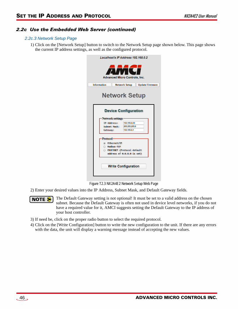
SET THE IP ADDRESS AND PROTOCOL NX2A4E2 User Manual
2.2c Use the Embedded Web Server (continued)
2.2c.3 Network Setup Page
1) Click on the [Network Setup] button to switch to the Network Setup page shown below. This page shows the current IP address settings, as well as the configured protocol.
Figure T2.3 NX2A4E2 Network Setup Web Page
2) Enter your desired values into the IP Address, Subnet Mask, and Default Gateway fields.
The Default Gateway setting is not optional! It must be set to a valid address on the chosen subnet. Because the Default Gateway is often not used in device level networks, if you do not have a required value for it, AMCI suggests setting the Default Gateway to the IP address of your host controller.
3) If need be, click on the proper radio button to select the required protocol.4) Click on the [Write Configuration] button to write the new configuration to the unit. If there are any errors
with the data, the unit will display a warning message instead of accepting the new values.
ADVANCED MICRO CONTROLS INC.46
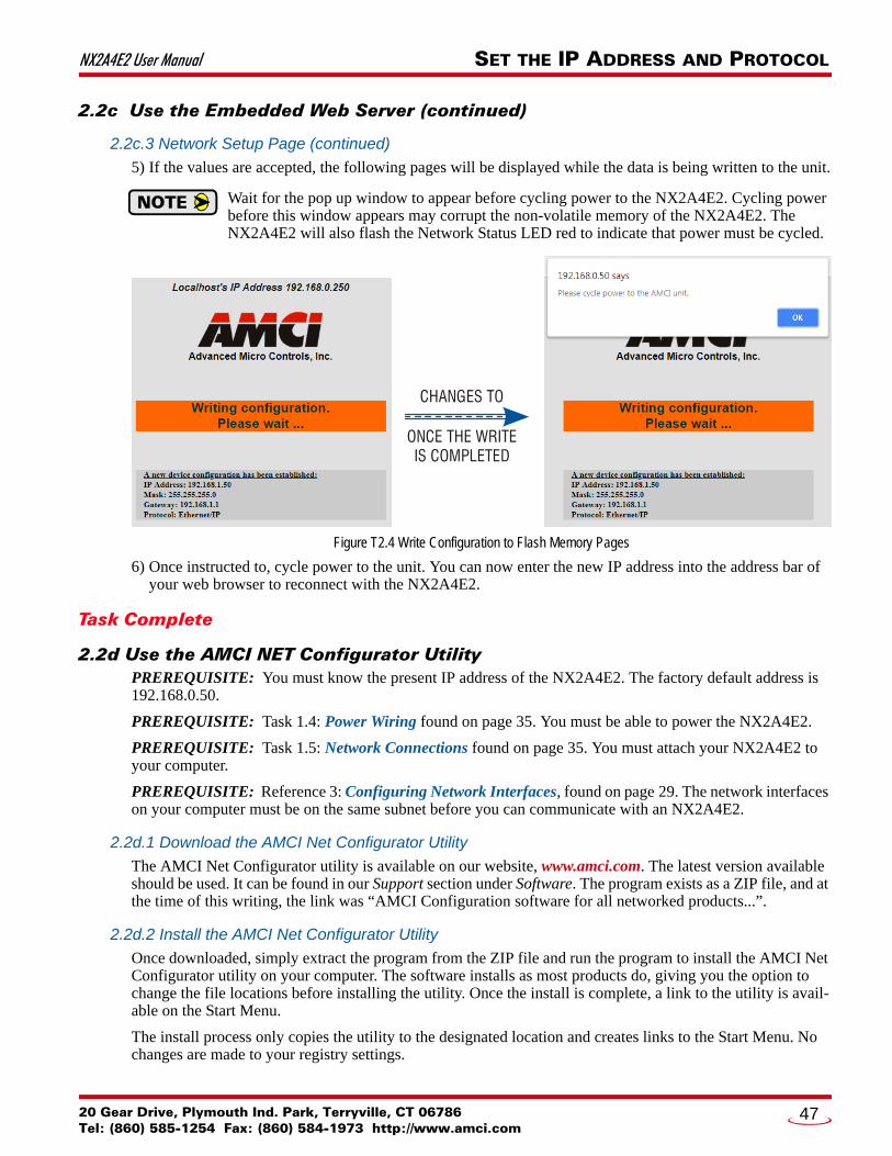
NX2A4E2 User Manual SET THE IP ADDRESS AND PROTOCOL
2.2c Use the Embedded Web Server (continued)
2.2c.3 Network Setup Page (continued)
5) If the values are accepted, the following pages will be displayed while the data is being written to the unit.
Wait for the pop up window to appear before cycling power to the NX2A4E2. Cycling power before this window appears may corrupt the non-volatile memory of the NX2A4E2. The NX2A4E2 will also flash the Network Status LED red to indicate that power must be cycled.
Figure T2.4 Write Configuration to Flash Memory Pages
6) Once instructed to, cycle power to the unit. You can now enter the new IP address into the address bar of your web browser to reconnect with the NX2A4E2.
Task Complete
2.2d Use the AMCI NET Configurator UtilityPREREQUISITE: You must know the present IP address of the NX2A4E2. The factory default address is 192.168.0.50.
PREREQUISITE: Task 1.4: Power Wiring found on page 35. You must be able to power the NX2A4E2.
PREREQUISITE: Task 1.5: Network Connections found on page 35. You must attach your NX2A4E2 to your computer.
PREREQUISITE: Reference 3: Configuring Network Interfaces, found on page 29. The network interfaces on your computer must be on the same subnet before you can communicate with an NX2A4E2.
2.2d.1 Download the AMCI Net Configurator Utility
The AMCI Net Configurator utility is available on our website, www.amci.com. The latest version available should be used. It can be found in our Support section under Software. The program exists as a ZIP file, and at the time of this writing, the link was “AMCI Configuration software for all networked products...”.
2.2d.2 Install the AMCI Net Configurator Utility
Once downloaded, simply extract the program from the ZIP file and run the program to install the AMCI Net Configurator utility on your computer. The software installs as most products do, giving you the option to change the file locations before installing the utility. Once the install is complete, a link to the utility is avail-able on the Start Menu.
The install process only copies the utility to the designated location and creates links to the Start Menu. No changes are made to your registry settings.
CHANGES TO
ONCE THE WRITEIS COMPLETED
20 Gear Drive, Plymouth Ind. Park, Terryville, CT 06786Tel: (860) 585-1254 Fax: (860) 584-1973 http://www.amci.com
47

SET THE IP ADDRESS AND PROTOCOL NX2A4E2 User Manual
2.2d Use the AMCI Net Configurator Utility (continued)
2.2d.3 Verify that Your Host Controller is Disconnected from the NX2A4E2
EtherNet/IP is not a multi-master protocol. There can be only one bus master on the network at a time. In order to program the NX2A4E2, the AMCI Net Configurator utility must act as a bus master. Therefore, physically disconnect your host controller from the NX2A4E2 before starting the Net Configurator utility.
2.2d.4 Apply or Cycle Power to the NX2A4E2
Cycling power to the NX2A4E2 will reset any connections it may have with the host controller.
2.2d.5 Start the AMCI Net Configurator Utility
Double click on the utility’s icon. A welcome screen similar to the one in figure T2.5 below will appear.
Figure T2.5 Net Configurator Welcome Screen
ADVANCED MICRO CONTROLS INC.48
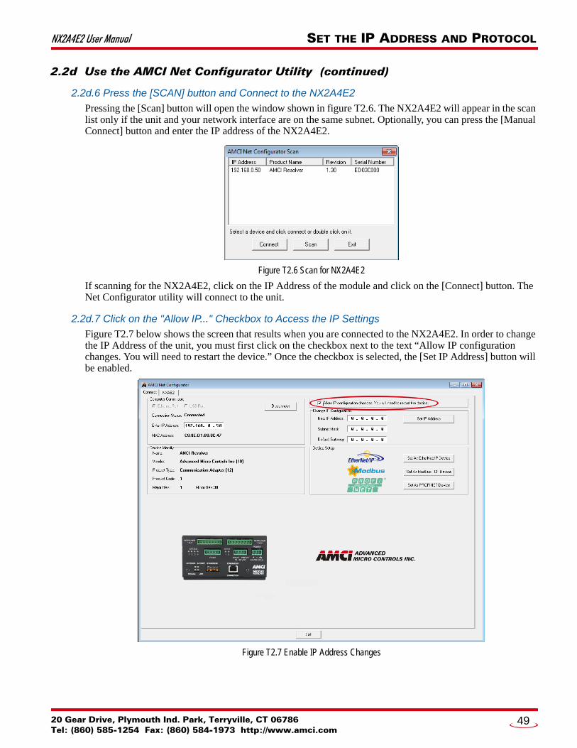
NX2A4E2 User Manual SET THE IP ADDRESS AND PROTOCOL
2.2d Use the AMCI Net Configurator Utility (continued)
2.2d.6 Press the [SCAN] button and Connect to the NX2A4E2
Pressing the [Scan] button will open the window shown in figure T2.6. The NX2A4E2 will appear in the scan list only if the unit and your network interface are on the same subnet. Optionally, you can press the [Manual Connect] button and enter the IP address of the NX2A4E2.
Figure T2.6 Scan for NX2A4E2
If scanning for the NX2A4E2, click on the IP Address of the module and click on the [Connect] button. The Net Configurator utility will connect to the unit.
2.2d.7 Click on the "Allow IP..." Checkbox to Access the IP Settings
Figure T2.7 below shows the screen that results when you are connected to the NX2A4E2. In order to change the IP Address of the unit, you must first click on the checkbox next to the text “Allow IP configuration changes. You will need to restart the device.” Once the checkbox is selected, the [Set IP Address] button will be enabled.
Figure T2.7 Enable IP Address Changes
20 Gear Drive, Plymouth Ind. Park, Terryville, CT 06786Tel: (860) 585-1254 Fax: (860) 584-1973 http://www.amci.com
49

SET THE IP ADDRESS AND PROTOCOL NX2A4E2 User Manual
2.2d Use the AMCI Net Configurator Utility (continued)
2.2d.8 Set the IP Address, Subnet Mask, and Default Gateway
Enter your desired values into the IP Address, Subnet Mask, and Default Gateway fields.
The Default Gateway setting is not optional! In order to comply with the ODVA specification, it must be set to a valid address on the chosen subnet. Because the Default Gateway is often not used in device level networks, if you do not have a required value for it, AMCI suggests setting the Default Gateway to the IP address of your host controller.
2.2d.9 Set the Communications Protocol
The factory default protocol for the NX2A4E2 is EtherNet/IP. In order to use the Modbus TCP or PROFINET protocols, simply click on the appropriate button.
2.2d.10 Write the New IP Address to the NX2A4E2
Click on the [Set IP Address] button. If there is an error in the settings, the utility will tell you what is wrong. Once they are all correct, the utility will write the new IP address settings to the unit. These settings are auto-matically saved to nonvolatile memory.
2.2d.11 Remove Power from the NX2A4E2
The new IP address will not be used until power to the NX2A4E2 has been cycled.
Task Complete
ADVANCED MICRO CONTROLS INC.50

20 Gear Drive, PTel: (860) 585-12
PROTOCOL SPECIFIC INFORMATION
Manual SectionsThe remainder of this manual is divided into three sections, one for each supported protocol. Each section has the protocol name in the page header.
Starting Pages
EtherNet/IP protocol: Page 53
Modbus TCP protocol: Page 67
PROFINET protocol: Page 71
lymouth Ind. Park, Terryville, CT 0678654 Fax: (860) 584-1973 http://www.amci.com
51

PROTOCOL SPECIFIC INFORMATION NX2A4E2 User Manual
Notes
ADVANCED MICRO CONTROLS INC.52
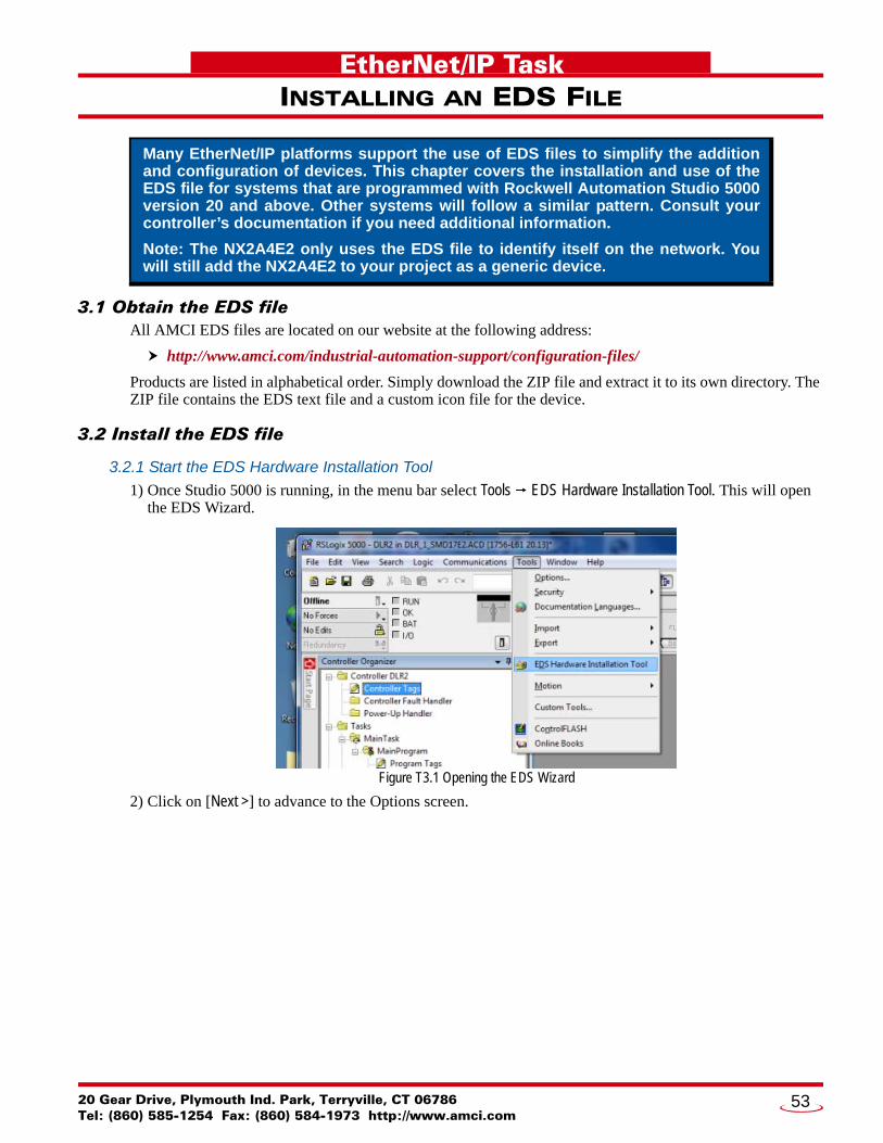
20 Gear Drive, PTel: (860) 585-12
EtherNet/IP Task
INSTALLING AN EDS FILE3.1 Obtain the EDS fileAll AMCI EDS files are located on our website at the following address:
http://www.amci.com/industrial-automation-support/configuration-files/
Products are listed in alphabetical order. Simply download the ZIP file and extract it to its own directory. The ZIP file contains the EDS text file and a custom icon file for the device.
3.2 Install the EDS file
3.2.1 Start the EDS Hardware Installation Tool
1) Once Studio 5000 is running, in the menu bar select Tools EDS Hardware Installation Tool. This will open the EDS Wizard.
Figure T3.1 Opening the EDS Wizard
2) Click on [Next >] to advance to the Options screen.
Many EtherNet/IP platforms support the use of EDS files to simplify the addition and configuration of devices. This chapter covers the installation and use of the EDS file for systems that are programmed with Rockwell Automation Studio 5000 version 20 and above. Other systems will follow a similar pattern. Consult your controller’s documentation if you need additional information.
Note: The NX2A4E2 only uses the EDS file to identify itself on the network. You will still add the NX2A4E2 to your project as a generic device.
lymouth Ind. Park, Terryville, CT 0678654 Fax: (860) 584-1973 http://www.amci.com
53
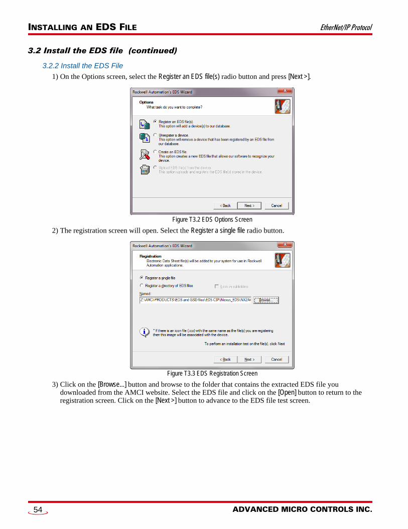
INSTALLING AN EDS FILE EtherNet/IP Protocol
3.2 Install the EDS file (continued)
3.2.2 Install the EDS File
1) On the Options screen, select the Register an EDS file(s) radio button and press [Next >].
Figure T3.2 EDS Options Screen
2) The registration screen will open. Select the Register a single file radio button.
Figure T3.3 EDS Registration Screen
3) Click on the [Browse...] button and browse to the folder that contains the extracted EDS file you downloaded from the AMCI website. Select the EDS file and click on the [Open] button to return to the registration screen. Click on the [Next >] button to advance to the EDS file test screen.
ADVANCED MICRO CONTROLS INC.54
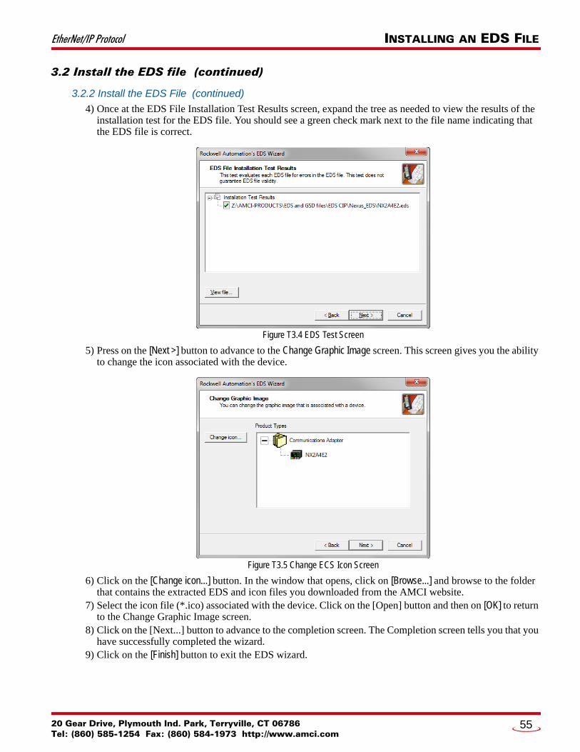
EtherNet/IP Protocol INSTALLING AN EDS FILE
3.2 Install the EDS file (continued)
3.2.2 Install the EDS File (continued)
4) Once at the EDS File Installation Test Results screen, expand the tree as needed to view the results of the installation test for the EDS file. You should see a green check mark next to the file name indicating that the EDS file is correct.
Figure T3.4 EDS Test Screen
5) Press on the [Next >] button to advance to the Change Graphic Image screen. This screen gives you the ability to change the icon associated with the device.
Figure T3.5 Change ECS Icon Screen
6) Click on the [Change icon...] button. In the window that opens, click on [Browse...] and browse to the folder that contains the extracted EDS and icon files you downloaded from the AMCI website.
7) Select the icon file (*.ico) associated with the device. Click on the [Open] button and then on [OK] to return to the Change Graphic Image screen.
8) Click on the [Next...] button to advance to the completion screen. The Completion screen tells you that you have successfully completed the wizard.
9) Click on the [Finish] button to exit the EDS wizard.
20 Gear Drive, Plymouth Ind. Park, Terryville, CT 06786Tel: (860) 585-1254 Fax: (860) 584-1973 http://www.amci.com
55

INSTALLING AN EDS FILE EtherNet/IP Protocol
Notes
ADVANCED MICRO CONTROLS INC.56
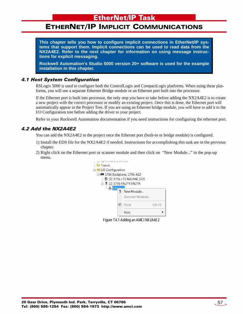
20 Gear Drive, PTel: (860) 585-12
EtherNet/IP Task
ETHERNET/IP IMPLICIT COMMUNICATIONS4.1 Host System ConfigurationRSLogix 5000 is used to configure both the ControlLogix and CompactLogix platforms. When using these plat-forms, you will use a separate Ethernet Bridge module or an Ethernet port built into the processor.
If the Ethernet port is built into processor, the only step you have to take before adding the NX2A4E2 is to create a new project with the correct processor or modify an existing project. Once this is done, the Ethernet port will automatically appear in the Project Tree. If you are using an Ethernet bridge module, you will have to add it to the I/O Configuration tree before adding the driver to your project.
Refer to your Rockwell Automation documentation if you need instructions for configuring the ethernet port.
4.2 Add the NX2A4E2You can add the NX2A4E2 to the project once the Ethernet port (built-in or bridge module) is configured.
1) Install the EDS file for the NX2A4E2 if needed. Instructions for accomplishing this task are in the previous chapter.
2) Right click on the Ethernet port or scanner module and then click on “New Module...” in the pop-up menu.
Figure T4.1 Adding an AMCI NX2A4E2
This chapter tells you how to configure implicit connections in EtherNet/IP sys-tems that support them. Implicit connections can be used to read data from the NX2A4E2. Refer to the next chapter for information on using message instruc-tions for explicit messaging.
Rockwell Automation’s Studio 5000 version 20+ software is used for the example installation in this chapter.
lymouth Ind. Park, Terryville, CT 0678654 Fax: (860) 584-1973 http://www.amci.com
57
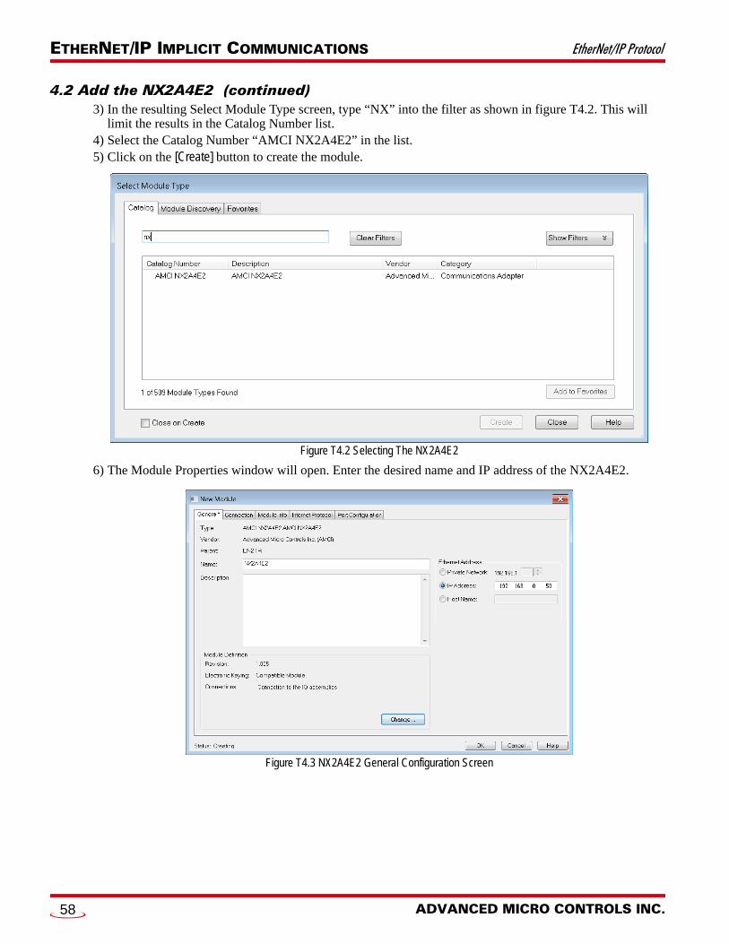
ETHERNET/IP IMPLICIT COMMUNICATIONS EtherNet/IP Protocol
4.2 Add the NX2A4E2 (continued)3) In the resulting Select Module Type screen, type “NX” into the filter as shown in figure T4.2. This will
limit the results in the Catalog Number list. 4) Select the Catalog Number “AMCI NX2A4E2” in the list. 5) Click on the [Create] button to create the module.
Figure T4.2 Selecting The NX2A4E2
6) The Module Properties window will open. Enter the desired name and IP address of the NX2A4E2.
Figure T4.3 NX2A4E2 General Configuration Screen
ADVANCED MICRO CONTROLS INC.58
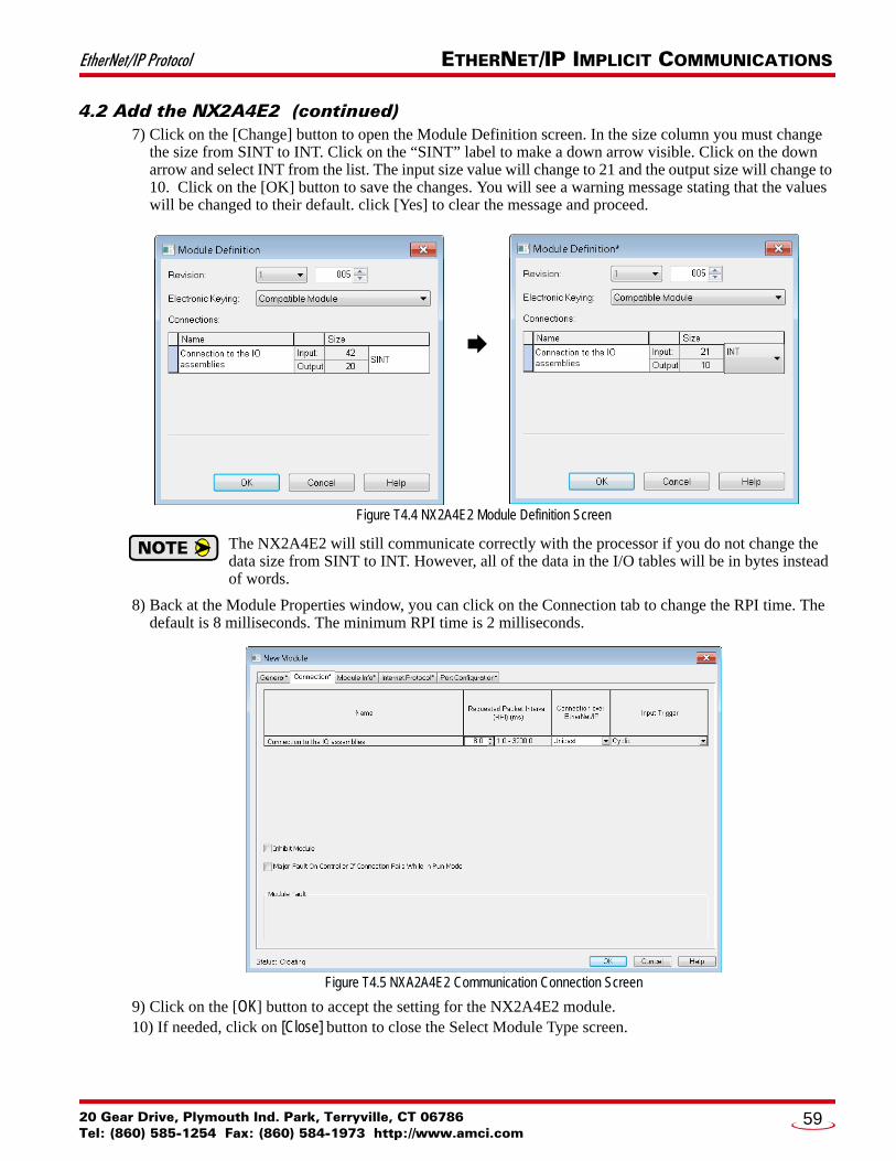
EtherNet/IP Protocol ETHERNET/IP IMPLICIT COMMUNICATIONS
4.2 Add the NX2A4E2 (continued)7) Click on the [Change] button to open the Module Definition screen. In the size column you must change
the size from SINT to INT. Click on the “SINT” label to make a down arrow visible. Click on the down arrow and select INT from the list. The input size value will change to 21 and the output size will change to 10. Click on the [OK] button to save the changes. You will see a warning message stating that the values will be changed to their default. click [Yes] to clear the message and proceed.
Figure T4.4 NX2A4E2 Module Definition Screen
The NX2A4E2 will still communicate correctly with the processor if you do not change the data size from SINT to INT. However, all of the data in the I/O tables will be in bytes instead of words.
8) Back at the Module Properties window, you can click on the Connection tab to change the RPI time. The default is 8 milliseconds. The minimum RPI time is 2 milliseconds.
Figure T4.5 NXA2A4E2 Communication Connection Screen
9) Click on the [OK] button to accept the setting for the NX2A4E2 module.10) If needed, click on [Close] button to close the Select Module Type screen.
20 Gear Drive, Plymouth Ind. Park, Terryville, CT 06786Tel: (860) 585-1254 Fax: (860) 584-1973 http://www.amci.com
59

ETHERNET/IP IMPLICIT COMMUNICATIONS EtherNet/IP Protocol
4.3 Check I/O Data FormatsVerify the format and number of input and output words. The output data will appear as a 10 word integer array. The input data will appear an a 21 word integer array. In addition to the twenty-one word array, the input data contains a “ConnectionFaulted” status bit. This bit is a logic “1” when there is a communication fault between the host controller and the NX2A4E2.
The NX2A4E2 will still communicate correctly with the processor if you did not change the data size from SINT to INT. However, the data sizes above will be 20 and 42, and all of the data in the I/O tables will be in bytes instead of words. If you wish to go back and change the data size, right click on the NX2A4E2 in the I/O tree and select “Properties” in the pop up menu. Then follow the instructions in section 4.2 above, starting with step 6 on page 58.
4.4 Buffer the Input DataData from the NX2A4E2 should be buffered once per scan using Synchronous Copy instructions. This is to insure stable input data during the program scan. Twenty-one word integer arrays can be used for this pur-pose.
Figure T4.6 Buffer Input Data
4.5 Configure the NX2A4E2The device will join the EtherNet/IP network as soon as the request is made to it. The NX2A4E2 will use the configuration data stored in its EEPROM memory to configure itself on power up. You can change this con-figuration at anytime and store this new configuration to nonvolatile memory. Configuration is accomplished by writing a block of data to the device that is formatted according to the specifications in the Data Formats reference, starting on page 17.
ADVANCED MICRO CONTROLS INC.60
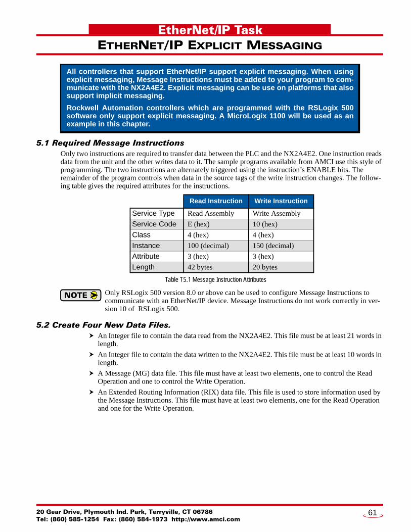
20 Gear Drive, PTel: (860) 585-12
EtherNet/IP Task
ETHERNET/IP EXPLICIT MESSAGING5.1 Required Message InstructionsOnly two instructions are required to transfer data between the PLC and the NX2A4E2. One instruction reads data from the unit and the other writes data to it. The sample programs available from AMCI use this style of programming. The two instructions are alternately triggered using the instruction’s ENABLE bits. The remainder of the program controls when data in the source tags of the write instruction changes. The follow-ing table gives the required attributes for the instructions.
Table T5.1 Message Instruction Attributes
Only RSLogix 500 version 8.0 or above can be used to configure Message Instructions to communicate with an EtherNet/IP device. Message Instructions do not work correctly in ver-sion 10 of RSLogix 500.
5.2 Create Four New Data Files. An Integer file to contain the data read from the NX2A4E2. This file must be at least 21 words in
length.
An Integer file to contain the data written to the NX2A4E2. This file must be at least 10 words in length.
A Message (MG) data file. This file must have at least two elements, one to control the Read Operation and one to control the Write Operation.
An Extended Routing Information (RIX) data file. This file is used to store information used by the Message Instructions. This file must have at least two elements, one for the Read Operation and one for the Write Operation.
All controllers that support EtherNet/IP support explicit messaging. When using explicit messaging, Message Instructions must be added to your program to com-municate with the NX2A4E2. Explicit messaging can be use on platforms that also support implicit messaging.
Rockwell Automation controllers which are programmed with the RSLogix 500 software only support explicit messaging. A MicroLogix 1100 will be used as an example in this chapter.
Read Instruction Write Instruction
Service Type Read Assembly Write Assembly
Service Code E (hex) 10 (hex)
Class 4 (hex) 4 (hex)
Instance 100 (decimal) 150 (decimal)
Attribute 3 (hex) 3 (hex)
Length 42 bytes 20 bytes
lymouth Ind. Park, Terryville, CT 0678654 Fax: (860) 584-1973 http://www.amci.com
61
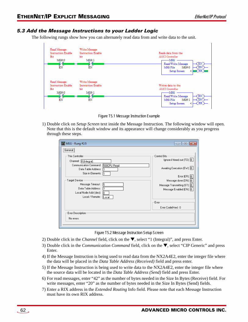
ETHERNET/IP EXPLICIT MESSAGING EtherNet/IP Protocol
5.3 Add the Message Instructions to your Ladder Logic The following rungs show how you can alternately read data from and write data to the unit.
Figure T5.1 Message Instruction Example
1) Double click on Setup Screen text inside the Message Instruction. The following window will open. Note that this is the default window and its appearance will change considerably as you progress through these steps.
Figure T5.2 Message Instruction Setup Screen
2) Double click in the Channel field, click on the , select “1 (Integral)”, and press Enter. 3) Double click in the Communication Command field, click on the , select “CIP Generic” and press
Enter. 4) If the Message Instruction is being used to read data from the NX2A4E2, enter the integer file where
the data will be placed in the Data Table Address (Received) field and press enter. 5) If the Message Instruction is being used to write data to the NX2A4E2, enter the integer file where
the source data will be located in the Data Table Address (Send) field and press Enter. 6) For read messages, enter “42” as the number of bytes needed in the Size In Bytes (Receive) field. For
write messages, enter “20” as the number of bytes needed in the Size In Bytes (Send) fields. 7) Enter a RIX address in the Extended Routing Info field. Please note that each Message Instruction
must have its own RIX address.
ADVANCED MICRO CONTROLS INC.62
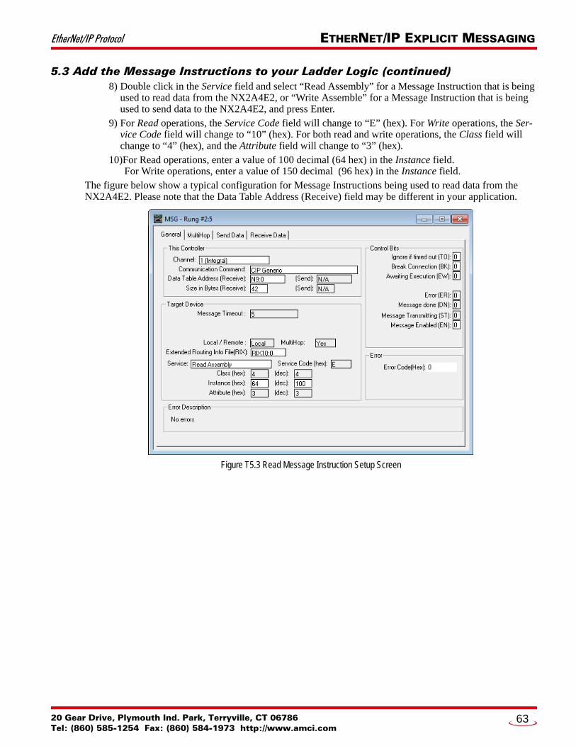
EtherNet/IP Protocol ETHERNET/IP EXPLICIT MESSAGING
5.3 Add the Message Instructions to your Ladder Logic (continued) 8) Double click in the Service field and select “Read Assembly” for a Message Instruction that is being
used to read data from the NX2A4E2, or “Write Assemble” for a Message Instruction that is being used to send data to the NX2A4E2, and press Enter.
9) For Read operations, the Service Code field will change to “E” (hex). For Write operations, the Ser-vice Code field will change to “10” (hex). For both read and write operations, the Class field will change to “4” (hex), and the Attribute field will change to “3” (hex).
10)For Read operations, enter a value of 100 decimal (64 hex) in the Instance field. For Write operations, enter a value of 150 decimal (96 hex) in the Instance field.
The figure below show a typical configuration for Message Instructions being used to read data from the NX2A4E2. Please note that the Data Table Address (Receive) field may be different in your application.
Figure T5.3 Read Message Instruction Setup Screen
20 Gear Drive, Plymouth Ind. Park, Terryville, CT 06786Tel: (860) 585-1254 Fax: (860) 584-1973 http://www.amci.com
63
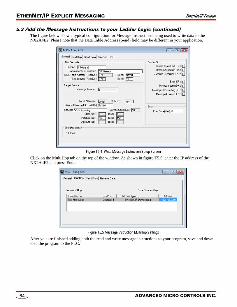
ETHERNET/IP EXPLICIT MESSAGING EtherNet/IP Protocol
5.3 Add the Message Instructions to your Ladder Logic (continued) The figure below show a typical configuration for Message Instructions being used to write data to the NX2A4E2. Please note that the Data Table Address (Send) field may be different in your application.
Figure T5.4 Write Message Instruction Setup Screen
Click on the MultiHop tab on the top of the window. As shown in figure T5.5, enter the IP address of the NX2A4E2 and press Enter.
Figure T5.5 Message Instruction MultiHop Settings
After you are finished adding both the read and write message instructions to your program, save and down-load the program to the PLC.
ADVANCED MICRO CONTROLS INC.64
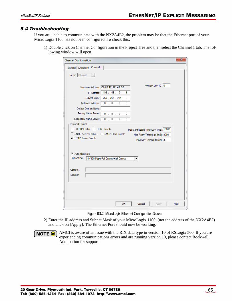
EtherNet/IP Protocol ETHERNET/IP EXPLICIT MESSAGING
5.4 TroubleshootingIf you are unable to communicate with the NX2A4E2, the problem may be that the Ethernet port of your MicroLogix 1100 has not been configured. To check this:
1) Double click on Channel Configuration in the Project Tree and then select the Channel 1 tab. The fol-lowing window will open.
Figure R3.2 MicroLogix Ethernet Configuration Screen
2) Enter the IP address and Subnet Mask of your MicroLogix 1100, (not the address of the NX2A4E2) and click on [Apply]. The Ethernet Port should now be working.
AMCI is aware of an issue with the RIX data type in version 10 of RSLogix 500. If you are experiencing communications errors and are running version 10, please contact Rockwell Automation for support.
20 Gear Drive, Plymouth Ind. Park, Terryville, CT 06786Tel: (860) 585-1254 Fax: (860) 584-1973 http://www.amci.com
65

ETHERNET/IP EXPLICIT MESSAGING EtherNet/IP Protocol
Notes
ADVANCED MICRO CONTROLS INC.66

20 Gear Drive, PTel: (860) 585-12
Modbus TCP Reference
MODBUS TCP CONFIGURATIONEnable Modbus TCP ProtocolThe internal web page utility can be used to change the communications protocol used by the NX2A4E2. This is typically done while setting the IP address. Specifically, follow the steps in section 2.2c, Use the Embed-ded Web Server which starts on page 45.
Modbus AddressingThe register addresses used in this manual are the Modbus logical reference numbers†, which are unsigned integers starting at zero. This is often called zero based addressing. In this scheme, the first register is given an address of zero. This is the actual addressing scheme used in the Modbus packets.
Another common addressing scheme is one based or data model addressing. In this scheme, the register’s number is used as its address, so the first register, Register 1 in the data model, has an address of 1.
Modbus Table Mapping
The Discrete Input and Input Register tables in the Modbus data model map to the same physical memory locations in the NX2A4E2 units.
These registers hold data that is reported from the NX2A4E2 to the host controller. Addresses for these registers and inputs start at 0 in zero based addressing.
As examples:
Discrete Input 0 is the same memory location as bit 0 of the first Input Register. Register address 3, the fourth register, contains Discrete Inputs 48 through 63.
The Coil and Holding Register tables in the Modbus data model map to the same physical memory locations in the NX2A4E2 units.
These registers hold data that is from the host controller to the unit. This data is typically commands. Addresses for these registers start at 1024 in zero based addressing. Coil addresses start at 16,384 in
zero based addressing (1024*16).
As examples:
Coil 16384 is the same memory location as bit 0 of the first Holding Register. Register address 1025, the address of the second Holding Register, contains Discrete Inputs 16,400
through 16,415 in zero based addressing.
Host Addressing
Your host controller may not use these basic addressing schemes for communicating over a Modbus connec-tion. For example, Modicon controllers use addresses starting at 30000 for Input Registers and addresses starting at 40000 for Holding Registers. GE hosts internally use their %R memory for Holding Registers and %AI memory for Input Registers.
If this is the case, you will define a mapping between your host controller’s addressing scheme and the zero based Modbus TCP addresses when you add the NX2A4E2 to your host controller. Refer to your host control-ler’s documentation for information on how to accomplish this.
An AMCI NX2A4E2 that has been configured for the Modbus TCP protocol requires a host controller to issue configuration data and read data from the unit. This chapter tell you how the I/O words used by an AMCI NX2A4E2 are mapped to the Modbus I/O registers.
† MODBUS Application Protocol Specification V1.1b3, section 4.3: MODBUS Data model. www.modbus.org
lymouth Ind. Park, Terryville, CT 0678654 Fax: (860) 584-1973 http://www.amci.com
67
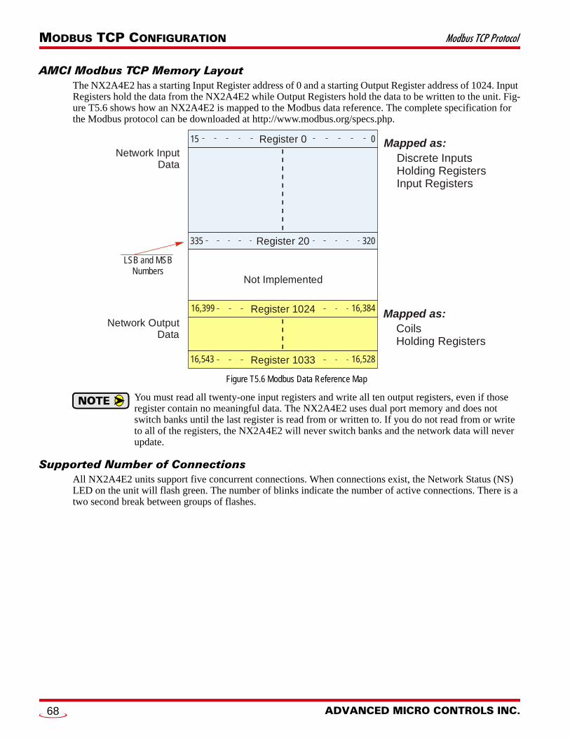
MODBUS TCP CONFIGURATION Modbus TCP Protocol
AMCI Modbus TCP Memory LayoutThe NX2A4E2 has a starting Input Register address of 0 and a starting Output Register address of 1024. Input Registers hold the data from the NX2A4E2 while Output Registers hold the data to be written to the unit. Fig-ure T5.6 shows how an NX2A4E2 is mapped to the Modbus data reference. The complete specification for the Modbus protocol can be downloaded at http://www.modbus.org/specs.php.
Figure T5.6 Modbus Data Reference Map
You must read all twenty-one input registers and write all ten output registers, even if those register contain no meaningful data. The NX2A4E2 uses dual port memory and does not switch banks until the last register is read from or written to. If you do not read from or write to all of the registers, the NX2A4E2 will never switch banks and the network data will never update.
Supported Number of ConnectionsAll NX2A4E2 units support five concurrent connections. When connections exist, the Network Status (NS) LED on the unit will flash green. The number of blinks indicate the number of active connections. There is a two second break between groups of flashes.
Network InputData
Not Implemented
Network OutputData
LSB and MSBNumbers
Mapped as:Discrete InputsHolding RegistersInput Registers
Mapped as:CoilsHolding Registers
Register 1024
Register 1033
16,38416,399
16,52816,543
Register 20 320335
015 Register 0
ADVANCED MICRO CONTROLS INC.68
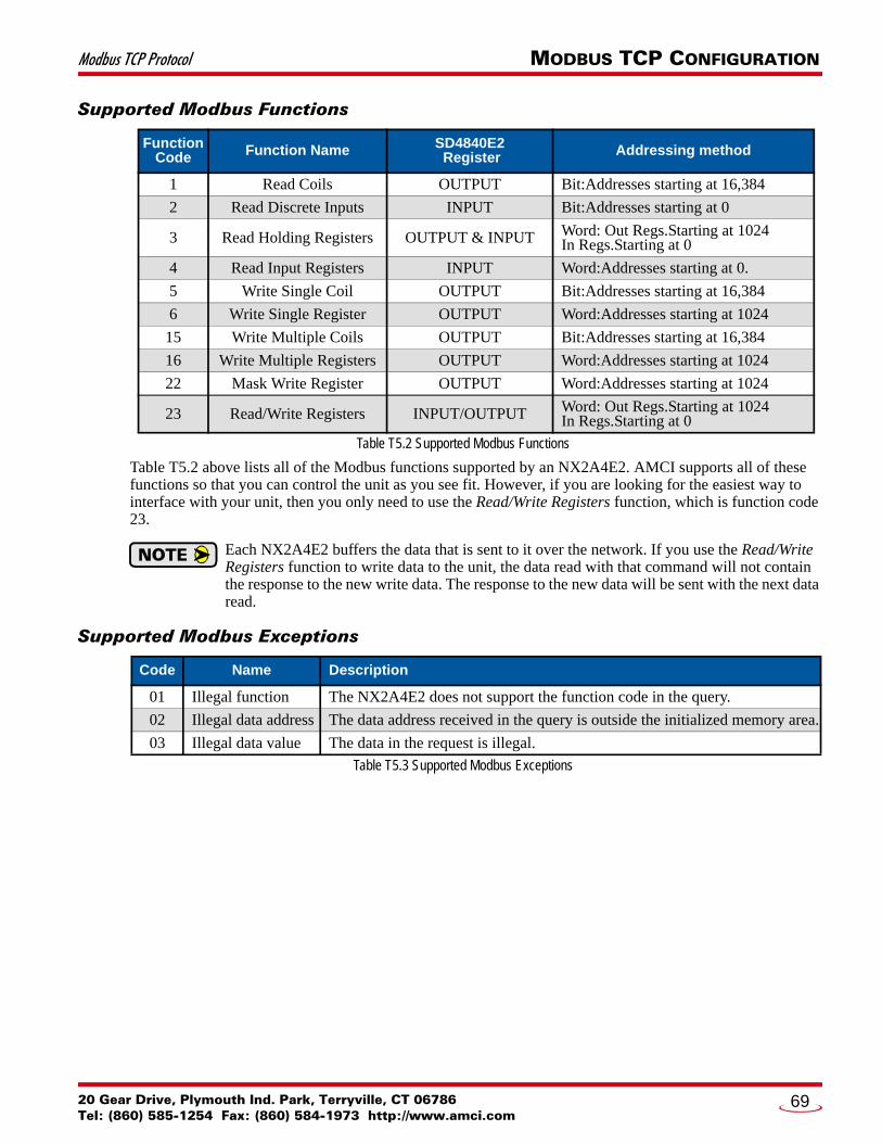
Modbus TCP Protocol MODBUS TCP CONFIGURATION
Supported Modbus Functions
Table T5.2 Supported Modbus Functions
Table T5.2 above lists all of the Modbus functions supported by an NX2A4E2. AMCI supports all of these functions so that you can control the unit as you see fit. However, if you are looking for the easiest way to interface with your unit, then you only need to use the Read/Write Registers function, which is function code 23.
Each NX2A4E2 buffers the data that is sent to it over the network. If you use the Read/Write Registers function to write data to the unit, the data read with that command will not contain the response to the new write data. The response to the new data will be sent with the next data read.
Supported Modbus Exceptions
Table T5.3 Supported Modbus Exceptions
Function Code Function Name SD4840E2
Register Addressing method
1 Read Coils OUTPUT Bit:Addresses starting at 16,384
2 Read Discrete Inputs INPUT Bit:Addresses starting at 0
3 Read Holding Registers OUTPUT & INPUT Word: Out Regs.Starting at 1024In Regs.Starting at 0
4 Read Input Registers INPUT Word:Addresses starting at 0.
5 Write Single Coil OUTPUT Bit:Addresses starting at 16,384
6 Write Single Register OUTPUT Word:Addresses starting at 1024
15 Write Multiple Coils OUTPUT Bit:Addresses starting at 16,384
16 Write Multiple Registers OUTPUT Word:Addresses starting at 1024
22 Mask Write Register OUTPUT Word:Addresses starting at 1024
23 Read/Write Registers INPUT/OUTPUT Word: Out Regs.Starting at 1024In Regs.Starting at 0
Code Name Description
01 Illegal function The NX2A4E2 does not support the function code in the query.
02 Illegal data address The data address received in the query is outside the initialized memory area.
03 Illegal data value The data in the request is illegal.
20 Gear Drive, Plymouth Ind. Park, Terryville, CT 06786Tel: (860) 585-1254 Fax: (860) 584-1973 http://www.amci.com
69

MODBUS TCP CONFIGURATION Modbus TCP Protocol
Notes
ADVANCED MICRO CONTROLS INC.70
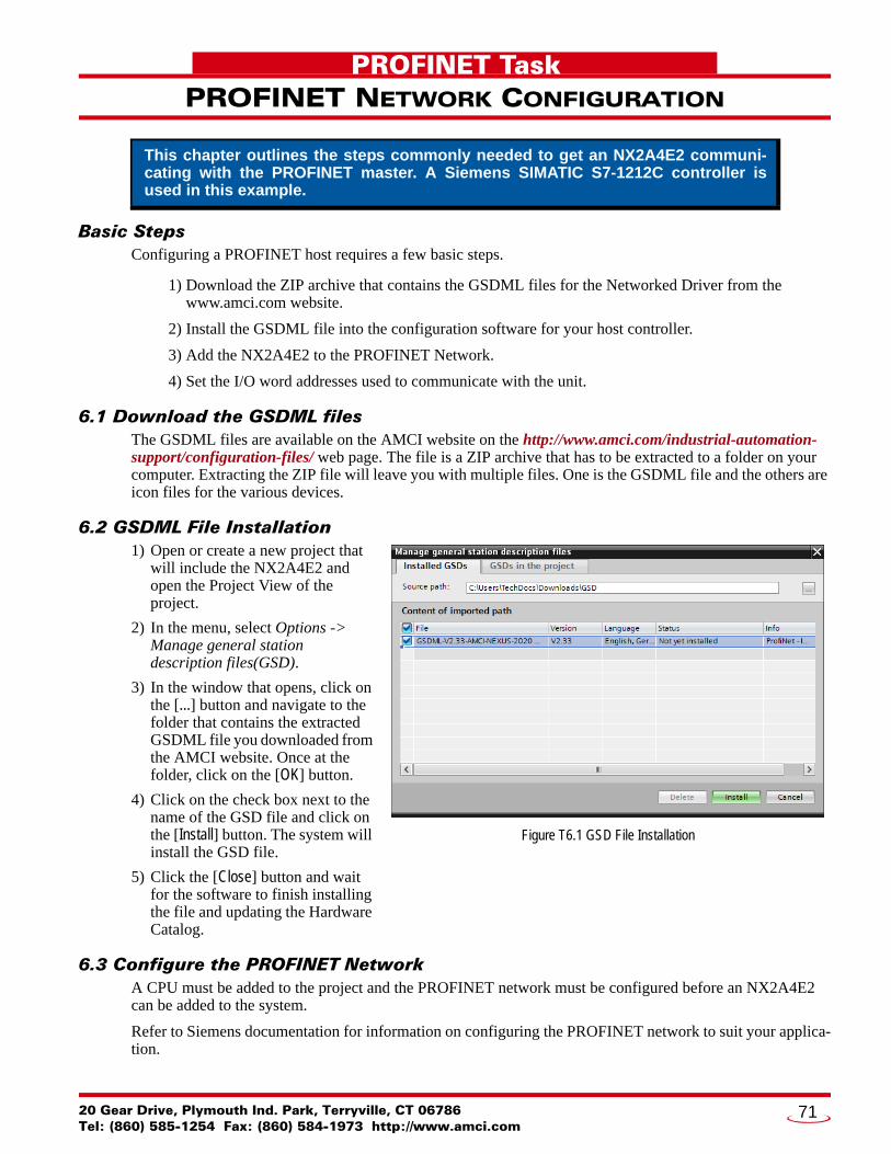
20 Gear Drive, PTel: (860) 585-12
PROFINET Task
PROFINET NETWORK CONFIGURATIONBasic StepsConfiguring a PROFINET host requires a few basic steps.
1) Download the ZIP archive that contains the GSDML files for the Networked Driver from the www.amci.com website.
2) Install the GSDML file into the configuration software for your host controller.
3) Add the NX2A4E2 to the PROFINET Network.
4) Set the I/O word addresses used to communicate with the unit.
6.1 Download the GSDML filesThe GSDML files are available on the AMCI website on the http://www.amci.com/industrial-automation-support/configuration-files/ web page. The file is a ZIP archive that has to be extracted to a folder on your computer. Extracting the ZIP file will leave you with multiple files. One is the GSDML file and the others are icon files for the various devices.
6.2 GSDML File Installation1) Open or create a new project that
will include the NX2A4E2 and open the Project View of the project.
2) In the menu, select Options -> Manage general station description files(GSD).
3) In the window that opens, click on the [...] button and navigate to the folder that contains the extracted GSDML file you downloaded from the AMCI website. Once at the folder, click on the [OK] button.
4) Click on the check box next to the name of the GSD file and click on the [Install] button. The system will install the GSD file.
5) Click the [Close] button and wait for the software to finish installing the file and updating the Hardware Catalog.
6.3 Configure the PROFINET NetworkA CPU must be added to the project and the PROFINET network must be configured before an NX2A4E2 can be added to the system.
Refer to Siemens documentation for information on configuring the PROFINET network to suit your applica-tion.
This chapter outlines the steps commonly needed to get an NX2A4E2 communi-cating with the PROFINET master. A Siemens SIMATIC S7-1212C controller is used in this example.
Figure T6.1 GSD File Installation
lymouth Ind. Park, Terryville, CT 0678654 Fax: (860) 584-1973 http://www.amci.com
71
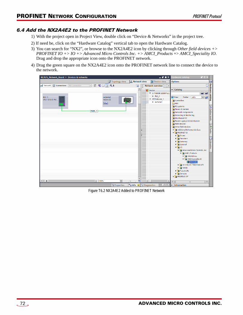
PROFINET NETWORK CONFIGURATION PROFINET Protocol
6.4 Add the NX2A4E2 to the PROFINET Network1) With the project open in Project View, double click on “Device & Networks” in the project tree.
2) If need be, click on the “Hardware Catalog” vertical tab to open the Hardware Catalog.3) You can search for “NX2”, or browse to the NX2A4E2 icon by clicking through Other field devices +>
PROFINET IO +> IO +> Advanced Micro Controls Inc. +> AMCI_Products +> AMCI_Speciality IO. Drag and drop the appropriate icon onto the PROFINET network.
4) Drag the green square on the NX2A4E2 icon onto the PROFINET network line to connect the device to the network.
Figure T6.2 NX2A4E2 Added to PROFINET Network
ADVANCED MICRO CONTROLS INC.72
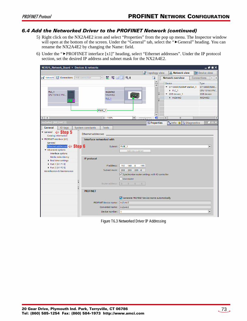
PROFINET Protocol PROFINET NETWORK CONFIGURATION
6.4 Add the Networked Driver to the PROFINET Network (continued)5) Right click on the NX2A4E2 icon and select “Properties” from the pop up menu. The Inspector window
will open at the bottom of the screen. Under the “General” tab, select the “General” heading. You can rename the NX2A4E2 by changing the Name: field.
6) Under the “PROFINET interface [x1]” heading, select “Ethernet addresses”. Under the IP protocol section, set the desired IP address and subnet mask for the NX2A4E2.
Figure T6.3 Networked Driver IP Addressing
20 Gear Drive, Plymouth Ind. Park, Terryville, CT 06786Tel: (860) 585-1254 Fax: (860) 584-1973 http://www.amci.com
73
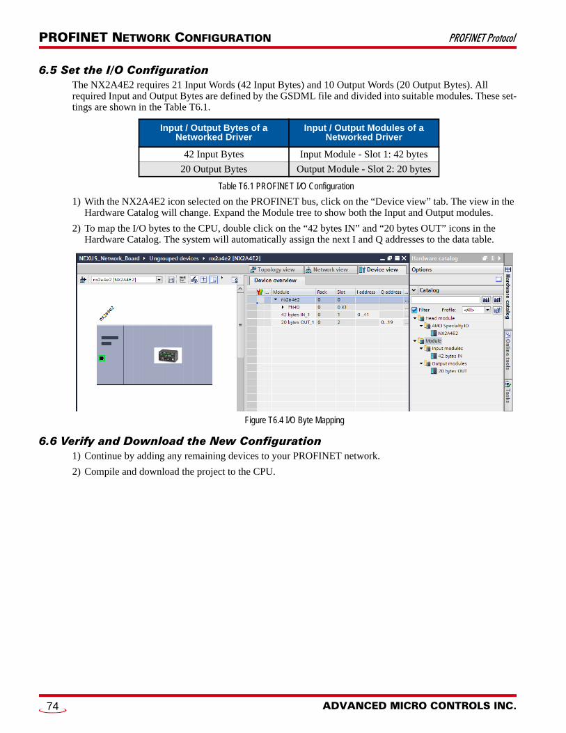
PROFINET NETWORK CONFIGURATION PROFINET Protocol
6.5 Set the I/O ConfigurationThe NX2A4E2 requires 21 Input Words (42 Input Bytes) and 10 Output Words (20 Output Bytes). All required Input and Output Bytes are defined by the GSDML file and divided into suitable modules. These set-tings are shown in the Table T6.1.
Table T6.1 PROFINET I/O Configuration
1) With the NX2A4E2 icon selected on the PROFINET bus, click on the “Device view” tab. The view in the Hardware Catalog will change. Expand the Module tree to show both the Input and Output modules.
2) To map the I/O bytes to the CPU, double click on the “42 bytes IN” and “20 bytes OUT” icons in the Hardware Catalog. The system will automatically assign the next I and Q addresses to the data table.
Figure T6.4 I/O Byte Mapping
6.6 Verify and Download the New Configuration1) Continue by adding any remaining devices to your PROFINET network.
2) Compile and download the project to the CPU.
Input / Output Bytes of a Networked Driver
Input / Output Modules of a Networked Driver
42 Input Bytes Input Module - Slot 1: 42 bytes
20 Output Bytes Output Module - Slot 2: 20 bytes
ADVANCED MICRO CONTROLS INC.74

PROFINET Protocol PROFINET NETWORK CONFIGURATION
MRP InstallationsAt this point, the NX2A4E2 is configured and ready to use. If you are using the unit in a redundant, ring based, network that uses the Media Redundancy Protocol (MRP), continue with the following instructions.
6.7 Configure the NX2A4E2 as an MRCThe NX2A4E2 functions as a Media Redundancy Client (MRC) in an MRP network.
1) Switch to Topology view and drag the additional connections between the appropriate ports.
2) Click on the NX2A4E2 icon to select it. In the Inspector window, select Advanced options +> Media redundancy. Use the “MRP domain:” drop down menu to select the appropriate domain. Use the “Media redundancy role:” drop down menu to select “Client”.
3) Continuing in the Inspector window, select Advanced options +> Port 1 +> Port interconnection. Under “Partner port:”, the partner port you assigned to the port when you drew the topology is shown. If you do not know which port will be the partner port in the actual installation, you can use the drop down menu to select “Any partner”.
4) If need be, repeat step 3 for Port 2 of the NX2A4E2.
Figure T6.5 MRP Topology and Client settings
5) Continue configuring the rest of the devices on the network before compiling the project and downloading it to the CPU.
Media Redundancy Protocol (MRP) installations require that the NX2A4E2 be installed in a ring topology. In these applications, both Ethernet ports are used when wiring the ring, daisy chaining from one unit in the ring to the next. The steps below covers typical software configuration that must also be completed.
20 Gear Drive, Plymouth Ind. Park, Terryville, CT 06786Tel: (860) 585-1254 Fax: (860) 584-1973 http://www.amci.com
75

ADVANCED MICRO CONTROLS INC.
LEADERS IN ADVANCED CONTROL PRODUCTS