
U s e r M anual - AMCI
55
MICRO CONTROLS INC. ADVANCED U s e r M a n u a l RBE2-8 Networked Relay Board with Integral 2-Port Ethernet Switch Device Level Ring functionality for EtherNet/IP Media Redundancy Protocol for PROFINET Manual #: 940-0R011 E2 Technology
-
Upload
khangminh22 -
Category
Documents
-
view
0 -
download
0
Transcript of U s e r M anual - AMCI

MICRO CONTROLS INC.ADVANCED
User
M
anual
RBE2-8 Networked Relay Board with Integral 2-Port Ethernet Switch Device Level Ring functionality for EtherNet/IP Media Redundancy Protocol for PROFINET
Manual #: 940-0R011
E2 Technology

GENERAL INFORMATION
Important User InformationThe products and application data described in this manual are useful in a wide variety of different applica-tions. Therefore, the user and others responsible for applying these products described herein are responsible for determining the acceptability for each application. While efforts have been made to provide accurate infor-mation within this manual, AMCI assumes no responsibility for the application or the completeness of the information contained herein.UNDER NO CIRCUMSTANCES WILL ADVANCED MICRO CONTROLS, INC. BE RESPONSIBLE OR LIABLE FOR ANY DAMAGES OR LOSSES, INCLUDING INDIRECT OR CONSEQUENTIAL DAM-AGES OR LOSSES, ARISING FROM THE USE OF ANY INFORMATION CONTAINED WITHIN THIS MANUAL, OR THE USE OF ANY PRODUCTS OR SERVICES REFERENCED HEREIN.No patent liability is assumed by AMCI, with respect to use of information, circuits, equipment, or software described in this manual.The information contained within this manual is subject to change without notice.This manual is copyright 2022 by Advanced Micro Controls Inc. You may reproduce this manual, in whole or in part, for your personal use, provided that this copyright notice is included. You may distribute copies of this complete manual in electronic format provided that they are unaltered from the version posted by Advanced Micro Controls Inc. on our official website: www.amci.com. You may incorporate portions of this documents in other literature for your own personal use provided that you include the notice “Portions of this document copyright 2022 by Advanced Micro Controls Inc.” You may not alter the contents of this document or charge a fee for reproducing or distributing it.
Standard WarrantyADVANCED MICRO CONTROLS, INC. warrants that all equipment manufactured by it will be free from defects, under normal use, in materials and workmanship for a period of [18] months. Within this warranty period, AMCI shall, at its option, repair or replace, free of charge, any equipment covered by this warranty which is returned, shipping charges prepaid, within eighteen months from date of invoice, and which upon examination proves to be defective in material or workmanship and not caused by accident, misuse, neglect, alteration, improper installation or improper testing.The provisions of the "STANDARD WARRANTY" are the sole obligations of AMCI and excludes all other warranties expressed or implied. In no event shall AMCI be liable for incidental or consequential damages or for delay in performance of this warranty.
Returns PolicyAll equipment being returned to AMCI for repair or replacement, regardless of warranty status, must have a Return Merchandise Authorization number issued by AMCI. Call (860) 585-1254 with the model number and serial number (if applicable) along with a description of the problem during regular business hours, Monday through Friday, 8AM - 5PM Eastern. An "RMA" number will be issued. Equipment must be shipped to AMCI with transportation charges prepaid. Title and risk of loss or damage remains with the customer until shipment is received by AMCI.
24 Hour Technical Support Number24 Hour technical support is available on this product. If you have internet access, start at www.amci.com. Product documentation and FAQ’s are available on the site that answer most common questions.If you require additional technical support, call (860) 583-1254. Your call will be answered by the factory dur-ing regular business hours, Monday through Friday, 8AM - 5PM Eastern. During non-business hours an auto-mated system will ask you to enter the telephone number you can be reached at. Please remember to include your area code. The system will page an engineer on call. Please have your product model number and a description of the problem ready before you call.
Waste Electrical and Electronic Equipment (WEEE)At the end of life, this equipment should be collected separately from any unsorted municipal waste.
ADVANCED MICRO CONTROLS INC.

TABLE OF CONTENTS
GENERAL INFORMATIONImportant User Information ..................... 2Standard Warranty ................................... 2Returns Policy .......................................... 224 Hour Technical Support Number ........ 2WEEE Statement ..................................... 2
About this ManualAudience .................................................. 5Trademark Notices ................................... 5Revision Record ....................................... 5
Revision History ............................ 5Navigating this Manual ............................ 5Manual Conventions ................................ 5Where To Go From Here ......................... 6
Reference: RBE2-8 IntroductionThe RBE2-8 ............................................. 7Unit Description ....................................... 8Status LEDs ............................................. 9
Output Mode LED ......................... 9Channel Status LEDs ..................... 9Link Activity LEDs ....................... 9Module Status (MS) LED .............. 10Network Status (NS) LED ............. 10
Compatible Relays ................................... 11AC Relay Specifications................. 11DC Relay Specifications ................ 11Relay Dimensions .......................... 12Relay Environmental Curves ......... 12
Specifications ........................................... 13Notes ........................................................ 14
Reference: Data FormatsData Addressing ....................................... 15Output Data Format ................................. 15Input Data Format .................................... 16
Word 1 Input Bits .......................... 16Word 0 Input Bits .......................... 16
Reference: Configuring NetworkInterfaces
Firewall Settings ...................................... 17Disable All Unused Network Interfaces .. 17Configure Your Network Interface .......... 17Test Your Network Interface ................... 18
Task: Installing the RBE2-8Safe Handling Guidelines ........................ 19
Prevent Electrostatic Damage ....... 19Prevent Debris From
Entering the Unit ........................ 19Remove Power Before Servicing .. 19
General Wiring Guidelines ...................... 19Wiring ........................................... 19Grounding ..................................... 20Surge Suppression ......................... 20Mounting ....................................... 20
DIN Rail Mounting .................................. 20Reattach the DIN Brackets
(if needed) ................................... 20DIN Rail Installation ..................... 21Dimensions ................................... 21
Panel Mounting ........................................ 22Attach the Panel Mount Brackets ........................................ 22Dimensions ................................... 22
Power Wiring ........................................... 23Network Connections ............................... 24
EtherNet/IP DLR Applications ..... 24PROFINET MRP Applications .... 24
Installing Relays ....................................... 24Relay Output Wiring ................................ 24
Task: Set the IP Address and Protocol
Determine the Best Method ..................... 25Use Factory Default Settings ................... 25Use the Embedded Web Server ................ 26
Task: Implicit Communications with an EDS
Obtain the EDS file ..................................31Install the EDS file ................................... 31
Start the EDS Hardware Installation Tool .......................... 31
Install the EDS File ....................... 32Host System Configuration ...................... 34Add the RBE2-8 to Your Project ............. 34Configure the RBE2-8 .............................. 35
General Tab ................................... 35Connection Tab ............................. 35
Buffering the I/O Data ............................. 35
20 Gear Drive, Plymouth Ind. Park, Terryville, CT 06786Tel: (860) 585-1254 Fax: (860) 584-1973 http://www.amci.com
3

TABLE OF CONTENTS RBE2-8 User Manual
Task: Implicit Communications Without an EDS
Host System Configuration ...................... 36Add the RBE2-8 ....................................... 36Buffer I/O Data ......................................... 39
Task: EtherNet/IP Explicit Messaging
Required Message Instructions ................ 40Create Four New Data Files ..................... 40Add the Message Instructions to your
Ladder Logic .......................................... 41Troubleshooting ....................................... 44
Task: Modbus TCP ConfigurationEnable Modbus TCP Protocol .................. 45Modbus Addressing .................................. 45
Modbus Table Mapping ................ 45Host Addressing ............................ 45
AMCI Modbus TCP Memory Layout ...... 46Supported Number of Connections .......... 46Supported Modbus Functions ................... 46Supported Modbus Exceptions ................. 47
Task: PROFINET Network Configuration
Basic Steps ............................................... 49Download the GSDML files .................... 49GSDML File Installation .......................... 49Configure the PROFINET Network ......... 49Add the RBE2-8 to the
PROFINET Network .............................. 50Set the I/O Configuration ......................... 52Verify and Download the
New Configuration ................................. 52MRP Installations ..................................... 53Configure the RBE2-8 as an MRC ........... 53
ADVANCED MICRO CONTROLS INC.4

ABOUT THIS MANUAL
Audience This manual explains the set-up, installation, and operation of AMCI’s RBE2-8 Networked Relay Board. It is written for the engineer responsible for incorporating these units into a design, as well as the engineer or tech-nician responsible for their actual installation.
Trademark NoticesThe AMCI logo is a trademark of Advanced Micro Controls Inc. “CIP” is a trademark of Open DeviceNet Vendor Association, Inc. “EtherNet/IP” is a trademark of ControlNet International, Ltd. under license by Open DeviceNet Vendor Association, Inc. “PROFINET” is a registered trademark of PROFIBUS & PROFINET International (PI). “Adobe” and “Acrobat” are registered trademarks of Adobe Systems Incorpo-rated.
All other trademarks contained herein are the property of their respective holders.
Revision RecordThis manual, 940-0R011, is the second release of this manual. It was released May 10th, 2022. It adds addi-tional relays to the compatible relay list.
Revision History
940-0R010 February 28th, 2022. Initial Release.
Navigating this ManualThis manual is designed to be used in both printed and on-line formats. Its on-line form is a PDF document, which requires Adobe Acrobat Reader version 7.0+ to open it. The manual is laid out with an even number of pages in each chapter. This makes it easier to print a chapter to a duplex (double sided) printer.
The PDF file is password protected to prevent changes to the document. You are allowed to select and copy sections for use in other documents and, if you own Adobe Acrobat version 7.0 or later, you are allowed to add notes and annotations.
Manual ConventionsThree icons are used to highlight important information in the manual:
NOTES highlight important concepts, decisions you must make, or the implications of those decisions.
CAUTIONS tell you when equipment may be damaged if the procedure is not followed properly.
WARNINGS tell you when people may be hurt or equipment may be damaged if the pro-cedure is not followed properly.
Read this chapter to learn how to navigate through this manual and familiarize yourself with the conventions used in it. The last section of this chapter highlights the manual’s remaining chapters and their target audiences.
20 Gear Drive, Plymouth Ind. Park, Terryville, CT 06786Tel: (860) 585-1254 Fax: (860) 584-1973 http://www.amci.com
5

ABOUT THIS MANUAL RBE2-8 User Manual
Manual Conventions (continued)The following table shows the text formatting conventions:
Where To Go From HereYou will most likely read this manual for one of two reasons:
If you are curious about the RBE2-8 Networked Relay Board from AMCI, this manual contains the information you need to determine if these product is the right one for your application. The first chap-ter, RBE2-8 Introduction contains all of the information you will need to fully specify the right product for your application.
If you need to install and use the RBE2-8 Networked Relay Board, then the rest of the manual is written for you. To simplify installation and configuration, the rest of the manual is broken down into refer-ences and tasks. Using this product requires you to complete multiple tasks, and the manual is broken down into sections that explain how to complete each one.
Format Description
Normal Font Font used throughout this manual.
Emphasis Font Font used the first time a new term is introduced.
Cross Reference When viewing the PDF version of the manual, clicking on the cross reference text jumps you to referenced section.
HTML Link When viewing the PDF version of the manual, clicking on the link will connect you with the www.amci.com website.
Chapter Title Page Intended Audience
RBE2-8 Introduction 7 Anyone new to the RBE2-8. This chapter gives a basic overview of the features available on the unit and specifications.
Data Formats 15 Anyone that needs detailed information on the data formats used by the RBE2-8 to communicate with its host controller.
Configuring Network Interfaces 17 Basic information on configuring a PC or laptop to successfully
communicate with an RBE2-8 to set its IP address.
Installing the RBE2-8 19 Anyone that must install an RBE2-8 on a machine. Includes infor-
mation on mounting, grounding, and wiring specific to the units.
Set the IP Address and Protocol 25 Anyone that needs to change the IP address or communications
protocol used by the RBE2-8.
Implicit Communications with
an EDS31
Anyone that needs information on installing an EDS file for use on EtherNet/IP systems. An Allen-Bradley controller is used as an example.
Implicit Communications Without an EDS
36Anyone that needs information on configuring Implicit Messaging on an EtherNet/IP system that does not use EDS files. An Allen-Bradley controller is used as an example.
EtherNet/IP Explicit Messaging 40
Anyone that needs information on configuring Explicit Messaging on an EtherNet/IP system. An Allen-Bradley controller is used as an example.
Modbus TCP Configuration 45 Anyone using Modbus TCP to communicate with the RBE2-8.
PROFINET Network Configuration 49 Anyone using PROFINET to communicate with the RBE2-8. A
Siemens SIMATIC controller is used as an example.
ADVANCED MICRO CONTROLS INC.6

20 Gear Drive, PTel: (860) 585-12
REFERENCE 1
RBE2-8 INTRODUCTIONThe RBE2-8The RBE2-8 is a member of the growing line of products from AMCI that incorporate our E2 Technology. E2 Technology by AMCI is an innovative new multi-protocol approach to Ethernet distributed I/O.
E2 Technology products are simple and intuitive, allowing easy transition between Ethernet/IP, PROFINET, or Modbus/TCP protocols without the need to physically switch parts. An advanced web server integrated into all AMCI E2 Technology devices facilitates simple network configuration and troubleshooting via a web-browser. Furthermore, an impressive array of advanced features for each supported protocol has been incorporated into the devices to meet many unique application requirements.
The RBE2-8 is an eight output relay board that accepts AC and DC solid state relays. The RBE2-8 can drive high power loads while allowing you to lower wiring cost by placing the RBE2-8 close to those loads and running a single network cable back to the host controller. The RBE2-8 also future-proofs your high power output design. The host controller can be updated to any future platform that supports EtherNet/IP, PROFINET, or Modbus TCP and the RBE2-8 will operate with the new system.
Features of the RBE2-8 include:
Compatible with a variety of AC and DC solid state relays 24 Vdc operation A push button on the relay board that disables / enables the outputs A DIP switch on the relay board sets the state of outputs if there is a network communications loss A Reset Module push button to reboot the relay board without the need to cycle power All relay control lines are monitored for open, short to ground, and short to power supply
Each unit has two Ethernet ports which are internally connected through an onboard, two port, 10/100 Mbps ethernet switch. These ports allow you to wire your network in a “daisy-chain” fashion, which may lower net-work wiring costs and complexities.
The two ports also allow the units to function as members of a redundant Device Level Ring (DLR) network when using the EtherNet/IP protocol or as clients in a Media Redundancy Protocol (MRP) network when using PROFINET.
In DLR environments, the units act as Beacon-Based Ring Nodes. All units can process beacon packets at the default rate of every 400 microseconds. Beacon-based nodes can respond faster to network changes than nodes that only process Announce packets.
This reference section contains the information you need to decide if the RBE2-8 Networked Relay Board is the right product for your application.
lymouth Ind. Park, Terryville, CT 0678654 Fax: (860) 584-1973 http://www.amci.com
7

RBE2-8 INTRODUCTION RBE2-8 User Manual
Unit DescriptionFigure R1.1 shows the layout of the RBE2-8 Networked Relay Board.
Figure R1.1 RBE2-8 Layout
1) The RBE2-8 can be mounted on a DIN rail or directly on a panel. The four outer screws on the unit, and the included two brackets, allow you to change how the unit is mounted. Instructions, and dimensional drawings of the two configurations, can be found in the Installing the RBE2-8 section of the manual, starting on page 19.
2) Two RJ45 Ethernet jacks. The two ports are connected through an embedded two port switch. Both ports feature auto-switch and auto-MDIX functionality. They will automatically adjust to the speed of your network, and crossover cables are never needed. In non-redundant networks, either port can be used to connect to your host controller and the other port can be used to extend the network if this would reduce wiring costs. In redundant networks, both ports are used. There is a Link Activity LED on each connector. See the Status LEDs section starting on page 9 for a description of these LED’s.
3) Status LED’s. The Module Status and Network Status LED’s indicate the state of the unit and the network connection. The state of the LED’s is determined by the protocol the RBE2-8 is configured for. See the Status LEDs section starting on page 9 for a complete description.
4) Output Mode momentary pushbutton and LED. Allows you to disable the outputs from the relay board regardless of the state of the network data. Press the button to toggle between its Active and Disabled states. The LED is red when the outputs are disabled by the switch and green when the outputs are controlled by the network data.
5) Communication Error Mode switch. This slide switch is used to specify what state the output take if the network connection is lost. When the switch is off, the outputs retain their last state. When the switch is on, all of the outputs turn off if the network connection is lost. The state of this switch is only read when power is applied to the relay board or when the relay board is reset with the “Reset Module” button.
6) Reset Module momentary pushbutton. This pushbutton can be used to force the RBE2-8 to re-read the state of the Communication Error Mode switch and/or disconnect and reconnect to the network. If you disconnect the RBE2-8 from your host controller and attach it to your PC to troubleshoot or reconfigure the relay board, press the Reset Module switch to force the RBE2 to drop all connections to the host controller and create new ones with your PC.
7) Relay hold down bar and thumb screws. This bar and thumb screws are used to keep the relays in place in applications that are subject to shock and vibration.
8) Eight Output Relays. The relays are field replaceable. A variety of AC and DC relays are compatible with the RBE2-8. See Compatible Relays, starting on page 11, for information on compatible relays. Please note that relays are not included with the RBE2-8.
MODULESTATUS
OUTPUT MODE:
GND +24V
ONCOMM.ERRORMODE
GRN / NORMALRED / ALL OFF
OUTPUTMODE
TOGGLE
RESETMODULE
K1 K2 K3 K4 K5 K6 K7 K8
NETWORKSTATUS
11
ADVANCED MICRO CONTROLS INC.8

RBE2-8 User Manual RBE2-8 INTRODUCTION
Unit Description (continued)9) Channel Status LED’s. These eight LED’s show the on/off status of the control signals to the relays. (One
LED for each relay.) Note that this is the control side of the relay. The RBE2-8 cannot monitor the state of the relay output due to the required isolation.
10)Power Connector. The RBE2-8 requires 24 Vdc to operate. The maximum current draw is 300 mA. An earth ground pin is also available on this connector.
11) Relay Output Connector. Each relay output has a two pin connector. These connectors offer a high voltage and current connection to your load device.
Status LEDs
Output Mode LED
The Output Mode LED is a bi-color red/green LED. For its location on the relay board, see item in figure R1.1 on page 8.
Table R1.1 Output Mode LED
Channel Status LEDs
Each output channel has a yellow status LED that shows the state of the relay control signal. For their loca-tions on the relay board, see item in figure R1.1 on page 8.
Table R1.2 Channel Status LEDs
Link Activity LEDs
There is a Link Activity LED on each of the two RJ45 connectors. For their locations on the relay board, see item in figure R1.1 on page 8. They are amber LEDs.
Table R1.3 Link Activity LEDs
LED State Description
Red The relays are disabled. Press the Output Mode push button once to enable the relays.
GreenThe state of the relays is controlled by the host control-ler. Press the Output Mode push button once to disable the relays.
LED State Description
Off The relay is off and should not be conducting current.
On The relay is on and should be conducting current.
LED State Description
OffA valid Ethernet hardware connection does not exist between the RBE2-8 and the network equipment it is connected to.
On The RBE2-8 has a valid hardware connection to the network equipment it is attached to.
Blinking The RBE2-8 is transmitting data across the Ethernet link.
20 Gear Drive, Plymouth Ind. Park, Terryville, CT 06786Tel: (860) 585-1254 Fax: (860) 584-1973 http://www.amci.com
9

RBE2-8 INTRODUCTION RBE2-8 User Manual
Status LED’s (continued)
Module Status (MS) LED
The Module Status LED is a bi-color red/green LED. For its location on the relay board, see item in figure R1.1 on page 8. The unit will blink the Module Status LED green during initialization. After initialization, the state of the LED depends on the state of the network adapter and the configured protocol.
Table R1.4 Module Status LED States
Network Status (NS) LED
The Network Status LED is a bi-color red/green LED. For its location on the relay board, see item in figure R1.1 on page 8. The state of the LED depends on the state of the network adapter on the protocol the RBE2-8 is configured to for.
Table R1.5 Network Status LED States
LED State EtherNet/IP Definition Modbus TCP Definition PROFINET Definition
Off No Power No Power No power
Alternating Red/Green
Initializing: Power up Self-Test
Communications failure. There is a communications error between the main processor and the ethernet co-processor within the unit. You must cycle power to the RBE2-8 to attempt to clear this fault, or press the “Reset Module” push button to reset the relay board.
Flashing Green
Initializing: Waiting for valid physical connection to the network.
Steady Green Module and Network are operational. Device Name or IP Address are set.
Flashing RedInitializing: IP Address conflict Initializing: Device Name or
IP Address are not set.
If the Network Status LED is also flashing, the IP Address or Network Protocol has been changed. Cycle power to the unit or press the “Reset Module” push button to continue.
LED State EtherNet/IP Definition Modbus TCP Definition PROFINET Definition
Off No Power No power or no TCP connections
No power, duplicate IP address on the network, mismatch in Device Name, or no connection to IO Controller.
Alternating Red/Green Power up Self-Test Power up Self-Test Power up Self-Test
Blinking Green
Ethernet connection, but no CIP connections
Indicates number of connec-tions with 2 second delay between group. The RBE2-8 supports up to four concurrent connections.
On-line, Stop state. A connection with the IO Controller is established and it is in its STOP state.
Steady Green Valid Ethernet network and CIP connections Not Implemented
On-line, Run state. A connection with the IO Controller is established and it is in its RUN state.
Blinking Red
If the MS LED is steady green: Network Connection Timeout
Not Implemented Not Implemented
If the MS LED is blinking green: IP Address or Network Protocol changed: Cycle power
Steady Red Duplicate IP address on network. Not Implemented.
ADVANCED MICRO CONTROLS INC.10

RBE2-8 User Manual RBE2-8 INTRODUCTION
Compatible RelaysThe RBE2-8 was designed for compatibility with the following AC and DC Relays: Sensata-Crydom MCXE240D5, MP120D3, MP240D3, and MP240D4 AC relays Opto22 MP120D4, and MP240D4 AC relays Sensata-Crydom MPDCD3 and MPDCD3-B DC Relays Opto22 DC60MP and DC200MP DC Relays
Relays from other manufacturers that have identical physical dimensions and use 24Vdc as the control volt-age, should also be compatible with the RBE2-8. Contact AMCI for assistance if required.
AC Relay Specifications
Table R1.6 AC Relay Specifications
DC Relay Specifications
Table R1.7 DC Relay Specifications
Crydom Crydom Crydom Crydom
MP120D3 MP240D3 MP240D4 MCXE240D5
Control Voltage (Vdc) 3 - 32 3 - 32 3 - 32 15 - 32Typical Control Current (mA) 23 23 23 15
Load Voltage (Vrms) 47-63 Hz 12 - 140 24 - 280 24 - 280 12 - 280Transient Overvoltage (Vpk) 400 600 600 600
Maximum Off-State Leakage Current (mA) 5 5 5 0.1Minimum Off-State dv/dt (v/µs) 200 200 200 500Maximum Load Current (Arms) 3 3 4 5Minimum Load Current (Arms) 0.02 0.02 0.02 0.06
Maximum Surge Current (Apk for 16.67 mS) 90 90 130 250Maximum On-State Voltage Drop 1.6 1.6 1.6 1.4
Minimum Power Factor @ Max. Load 0.5 0.5 0.5 0.5
Opto22 Opto22
MP120D4 MP240D4
Control Voltage (Vdc) 3 - 24 3 - 24Typical Control Current (mA) 24 24
Load Voltage (Vrms) 47-63 Hz 12 - 140 24 - 280Transient Overvoltage (Vpk) 600 600
Maximum Off-State Leakage Current (mA) 5 5Maximum Load Current (Arms) 4 4Minimum Load Current (Arms)
Maximum Surge Current (Apk for 16.67 mS) 47 47Maximum On-State Voltage Drop 1.6 1.6
Crydom Opto22 Opto22
MPDCD3(-B) DC60MP DC200MP
Control Voltage (Vdc) 3 - 32 3 - 24 3 - 24Typical Control Current (mA) 23 24 24
Load Voltage (Vdc) 3 - 60 3 - 60 12 - 250Maximum Load Current (Adc) 3 3 1Minimum Load Current (Adc) 0.02
Maximum Surge Current (Adc for 1 Second) 5 5 2Maximum On-State Voltage Drop (Vdc) 1.5 1.5 1.5
Maximum Off-State Leakage Current (mA) 1.0 1.0 1.0
20 Gear Drive, Plymouth Ind. Park, Terryville, CT 06786Tel: (860) 585-1254 Fax: (860) 584-1973 http://www.amci.com
11

RBE2-8 INTRODUCTION RBE2-8 User Manual
Compatible Relays (continued)
Relay Dimensions
The following figure are the dimensions of the listed compatible relays. Other relays must be of the same dimensions to be compatible.
Figure R1.2 Dimensions of Compatible Relays
Relay Environmental Curves
The following figure show the maximum allowable load current per relay vs. the ambient temperature. Note that the RBE2-8 itself is rated to 50°C.
Figure R1.3 Relay Maximum Allowable Current
0.30" [7.6]
LOAD CTRL 0.0
25"
[0
.64
]
0.16" [4.1]
0.50" [12.7] 0.40" [10.2]
1.00" [25.4]
1.00
" [25
.4]
1.40" [35.6]
1.70" [43.2]
6.0
Load
Cur
rent
(Am
ps)
Ambient Temperature (°C)
Crydom MCXE240D5
Crydom MP240D4
Opto22 MP120D4 MP240D4
Opto22 DC60MP
Opto22 DC200MP
Crydom MP120D3 MP240D3 MPDCD3 MPDCD3-B
5.0
4.0
3.0
2.0
1.0
0.0
20 40 60 80
Maximum operatingtemperature of RBE2-8
ADVANCED MICRO CONTROLS INC.12

RBE2-8 User Manual RBE2-8 INTRODUCTION
SpecificationsNetwork Interface
10/100baseT. Two switched ports. Supports EtherNet/IP, PROFINET, and Modbus TCP. EtherNet/IP-DLR and PROFINET-MRP extensions also supported.
Number of I/O Words (16 bits each)Two input words and two output words.
MountingDIN rail or panel mount. The RBE2-8 ships in its
DIN rail mount configuration. Mounting style can be changed in the field. DIN channel can be EN 05 022 or EN 05 035.
Physical DimensionsSee page 21 for the DIN rail mount configurationSee page 22 for the panel mount configuration
Weight1.50 lb (0.68 kg) maximum
Input Power24 Vdc ± 10%. Requires a maximum of 7.3 watts
when all relays are on. (0.3A @ 24Vdc)
Maximum Relay Output Voltage300 Vac. The RBE2-8 is designed for operation
with 240Vac relays. 380Vac and 480Vac relays are not compatible.
Compatible RelaysSensata-Crydom MCXE240D5, MP120D3,
MP240D3, and MP240D4 AC relays.
Opto22 MP120D4 and MP240D4 AC relays.
Sensata-Crydom MPDCD3 and MPDCD3-B DC Relays
Opto22 DC60MP and DC200MP AC relays.
Relays from other manufacturers that have an iden-tical height and pin configuration, and use 24Vdc as the control voltage, should also be compatible with the RBE2-8. Contact AMCI for assistance if required.
Status LEDsSee Status LEDs starting on page 9.
Environmental SpecificationsAmbient Operating Temperature†
............ -4° to 122°F (-20° to 50°C)
Storage Temperature............ -40° to 185°F (-40° to 85°C)
Humidity ............ 0 to 95%, non-condensing
† This specification is for the RBE2-8 Networked Relay Board itself. The actual operating temper-ature may be limited by the relays.
The following Opto22 relays are available from AMCI using the given AMCI part numbers.
AC Relays AMCI Part # DC Relays AMCI Part #
MP120D4 KA-1 DC60MP KD-1
MP240D4 KA-2 DC200MP KD-2
20 Gear Drive, Plymouth Ind. Park, Terryville, CT 06786Tel: (860) 585-1254 Fax: (860) 584-1973 http://www.amci.com
13

RBE2-8 INTRODUCTION RBE2-8 User Manual
Notes
ADVANCED MICRO CONTROLS INC.14

20 Gear Drive, PTel: (860) 585-12
REFERENCE 2
DATA FORMATSData AddressingWhen using the PROFINET protocol or the EtherNet/IP protocol with an EDS file, the input and output reg-isters are named in the GSDML or EDS file. When using the EtherNet/IP protocol without an EDS file, both the input and output registers start with address 0.
Addresses for the Modbus TCP protocol are given in zero based addressing in this manual. In this scheme, the first register is given an address of zero. This is the actual addressing scheme used in the Modbus packets. Input registers start at address 0. Output registers start at address 1024.
Output Data FormatFigure R2.1 below shows the format of the output data. The bottom eight bits of the first output word are used to control the state of the eight relay outputs. A “0” in the bit location turns the output off. A “1” in the bit locations turns the output on. Note that the state of these bits is ignored and the outputs are forced off if the Output Mode momentary pushbutton is toggled to its Disabled state.
See bullet of figure R1.1 on page 8 for location of the Output Mode momentary pushbutton and its LED. Note that the Output Mode state is reported in the network input data.
Figure R2.1 Output Data Format
This reference chapter details the input and output data formats used to commu-nicate with the RBE2-8.
EtherNet/IPPROFINET
Word
Modbus TCP Register
Bit Number
15 14 13 12 11 10 9 8 7 6 5 4 3 2 1 0
0 1024 0 0 0 0 0 0 0 0O
utpu
t_K
8
Out
put_
K7
Out
put_
K6
Out
put_
K5
Out
put_
K4
Out
put_
K3
Out
put_
K2
Out
put_
K1
1 1025 0 0 0 0 0 0 0 0 0 0 0 0 0 0 0 0
IGNORED: Bit should equal zero for compatibility with future versions.
lymouth Ind. Park, Terryville, CT 0678654 Fax: (860) 584-1973 http://www.amci.com
15

DATA FORMATS RBE2-8 User Manual
Input Data FormatFigure R2.2 below shows the format of the network input data.
Figure R2.2 Input Data Format
Word 1 Input Bits
Bit 14: Heartbeat Bit – This bit will change state approximately every 500 milliseconds. Monitor this bit to verify that the unit and network connection are operating correctly.
Bit 13: Output Mode State Bit – This bit reports the present state of the Output Mode toggle. If this bit equals “1”, the outputs are forced off, regardless of the state of their control bits in Output Word 0. If this bit equals “0”, then the outputs are controlled by the state of their control bits in Output Word 0.The state of this bit is controlled by the Output Mode momentary pushbutton. See bullet of figure R1.1 on page 8 for location of this pushbutton and its LED. Note that this bit is reset on power up or when the RBE2-8 board is reset by the Reset Module momentary pushbutton.
Word 0 Input Bits
Bits 07- 00:Relay Fault Bits – The low power input circuit of each relay is monitored for fault conditions. Each relay has a fault bit associated with it. The associated bit equals “0” when the corresponding relay is functioning normally. The associated bit equals “1” when the corresponding relay has a fault. Table R2.1 below lists the fault states based on the state of the Output_K’n’ bit and the Fault_’n’ bit. (‘n’ = 1 to 8.) This table assumes that the Output Mode State bit (Input Word 1, bit 13) equals “0”.
Table R2.1 Multi-Word Format Examples
1) The monitoring circuit only monitors the state of the circuit that drives the low power input circuit of the relay. Due to the required opto-isolation of the relay, the high power drive cir-cuit of the relay cannot be monitored.
2) Open circuit faults are always detected. Shorts to ground or the 24Vdc supply can only be detected when the relay is driven low or high with the Output_K’n’ control bit. In the case of a short to ground, the fault bit will be off when you command the relay to turn on. The fault bit will turn on when you command the relay to turn off.
EtherNet/IPPROFINET
Word
Modbus TCP Register
Bit Number
15 14 13 12 11 10 9 8 7 6 5 4 3 2 1 0
0 0 0 0 0 0 0 0 0 0
Fa
ult_
8
Fa
ult_
7
Fa
ult_
6
Fa
ult_
5
Fa
ult_
4
Fa
ult_
3
Fa
ult_
2
Fa
ult_
1
1 1 0
He
artb
eat
Out
putM
ode
0 0 0 0 0 0 0 0 0 0 0 0 0
Fault_’n’ State
Output_K’n’ State Description
0 0 No fault detected, the relay is off.
0 1 No fault detected, the relay is on.
1 0 A fault is detected. The fault is an open circuit, or a short to ground. Replace the relay to try to fix the problem.
1 1 A fault is detected. The fault is an open circuit, or a short to the 24Vdc supply. Replace the relay to try to fix the problem.
ADVANCED MICRO CONTROLS INC.16

20 Gear Drive, PTel: (860) 585-12
REFERENCE 3
CONFIGURING NETWORK INTERFACESFirewall SettingsFirewalls are hardware devices or software that prevent unwanted network connections from occurring. Fire-wall software has been present on Windows based computers since XP, and it may prevent your computer from communicating with the RBE2-8. The internal webserver uses port 80, which is the default http port, and should work without changing any firewall settings. Configuring your firewall to allow communication with the RBE2-8 is beyond the scope of this manual.
Disable All Unused Network InterfacesRouting and default gateway setting on your computer might prevent connection to the RBE2-8. When using the Net Configurator utility, broadcast packets that are used to find the RBE2-8 often go out the wrong port. The easiest way to avoid this problem is to temporarily disable all network interfaces that are not attached to the RBE2-8.
This includes all wireless interfaces as well as all Bluetooth interfaces.
Configure Your Network InterfaceBefore you can communicate with the RBE2-8, your network interface must be on the same subnet as the relay board.
The rest of this procedure assumes you are using the 192.168.0.xxx subnet. If you are not, you will have to adjust the given network addresses accordingly.
The easiest way to check the current settings for your NIC is with the ‘ipconfig’ command.
For Windows 7, click on the [Start] button, and type “cmd” in the “Search programs and files” text box. Press [Enter] on the keyboard.
For Windows 8 and 10, press the [Win+X] keys and select “Command Prompt” from the resulting popup. There is no need to run the command prompt as the administrator, so do not select “Command Prompt (Admin)”.
This section lists suggestions for configuring the network interfaces on your com-puter or laptop before attaching to the RBE2-8.
lymouth Ind. Park, Terryville, CT 0678654 Fax: (860) 584-1973 http://www.amci.com
17

CONFIGURING NETWORK INTERFACES RBE2-8 User Manual
Configure Your Network Interface (continued)A DOS like terminal will open. Type in ‘ipconfig’, press [Enter] on the keyboard and the computer will return the present Address, Subnet Mask, and Default Gateway for all of your network interfaces. If your present address is 192.168.0.xxx, where ‘xxx’ does not equal 50, and your subnet mask is 255.255.255.0, then you are ready to configure your RBE2-8 board. Figure R3.1 shows the output of an ipconfig command that shows the “Local Area Connection 2” interface on the 192.168.0.xxx subnet.
Figure R3.1 ipconfig Command
If your present address is not in the 192.168.0.xxx range, type in ‘ncpa.cpl’ at the command prompt and hit [Enter] on the keyboard.
For Windows 7 through 10, this open the Network Connections window. Double click on the appropri-ate interface. In the window that opens, select “Internet Protocol Version 4 (TCP/IP v4)” from the list and then click on the [Properties] button.
Set the address and subnet mask to appropriate values. (192.168.0.1 and 255.255.255.0 will work for an RBE2-8 that has factory default settings.) The default gateway and DNS server settings can be ignored.
Test Your Network InterfaceGoing back to the terminal you opened in the last step, type in ‘ping aaa.bbb.ccc.ddd’ where ‘aaa.bbb.ccc.ddd’ in the IP address of the RBE2-8. The computer will ping the unit and the message “Reply from aaa.bbb.ccc.ddd: bytes=32 time<10ms TTL=128” should appear four times.
If the message “Request timed out.” or “Destination host unreachable” appears, then one of four things has occurred:
You set a new IP address, but have not yet cycled power to the RBE2-8 You did not enter the correct address in the ping command. The IP address of the RBE2-8 is not set correctly. The RBE2-8 and the computer are not on the same subnet.
ADVANCED MICRO CONTROLS INC.18

20 Gear Drive, PTel: (860) 585-12
TASK 1
INSTALLING THE RBE2-81.1 Safe Handling Guidelines
1.1.1 Prevent Electrostatic Damage
Electrostatic discharge can damage the RBE2-8. Follow these guidelines when handling the relay board.
1) Touch a grounded object to discharge static potential before handling the unit.2) Work in a static-safe environment whenever possible.3) Wear an approved wrist-strap grounding device.4) Do not touch the pins of the Ethernet connectors.5) Do not disassemble the relay board except to change the mounting style as
described in this chapter.6) Store the module in its anti-static bag and shipping box when it is not in use.
1.1.2 Prevent Debris From Entering the Unit
While mounting a unit, make sure that all debris (metal chips, wire strands, tapping liq-uids, etc.) is prevented from falling into the board. Debris may cause damage to the unit or unintended machine operation with possible personal injury. When using DIN rail to mount the unit, the rail should be securely installed and grounded before the unit is mounted on it.
1.1.3 Remove Power Before Servicing
Remove power before removing or installing the RBE2-8 module.
1.2 General Wiring GuidelinesWhen wiring any control system, these guidelines must be followed to help prevent electromagnetic interfer-ence and ground loops:
1.2.1 Wiring
Networking signals are generally low voltage, low power signals. If you are using A-B guidelines for cabling installation, treat the transducer cable as a Category 2 cable. Ethernet cables can be installed in conduit along with other low power communication cables and low power ac/dc I/O lines. It cannot be installed in conduit with ac power lines or high power ac/dc I/O lines including cabling from the relay outputs of the RBE2-8.
If the Ethernet cables must cross power feed lines, they should do so at right angles.
Route at least five feet from high voltage enclosures, or sources of “rf” radiation.
This chapter covers the physical installation of the RBE2-8.
lymouth Ind. Park, Terryville, CT 0678654 Fax: (860) 584-1973 http://www.amci.com
19

INSTALLING THE RBE2-8 RBE2-8 User Manual
1.2 General Wiring Guidelines (continued)
1.2.2 Grounding
All ground connections must be permanent and continuous to provide a low-impedance path to earth ground for induced noise currents.
The chassis of the RBE2-8 must be connected to chassis ground through a grounding wire connected to the ground connection of the power supply connector.
The power supply that is attached to the RBE2-8 must be connected to the same chassis ground as the unit to avoid ground loops.
All isolation transformer secondary windings must be grounded to the same earth ground as the machine ground.
1.2.3 Surge Suppression
Surge suppression devices should be placed across the coil of an inductive device to reduce the effects of high voltage transients (i.e., varistors, diodes, etc.). This includes any inductive load that is powered by the same supply used to power the RBE2-8 and any of the loads attached to its relay outputs.
1.2.4 Mounting
If mounting an RBE2-8 on an enclosure door, do not rely on the hinge to make an electrical connection between the door and the enclosure. A bonding wire from the door to the rest of the enclosure must be installed.
When mounting an RBE2-8 on DIN Rail, the included plastic DIN rail brackets will electrically isolate the unit. A grounding wire must be run from the grounding pin on the power connector to an earth ground point.
1.3a DIN Rail MountingFollow these instructions when mounting an RBE2-8 on a DIN rail.
1.3a.1 Reattach the DIN Brackets (if needed)
The RBE2-8 ships with the DIN brackets installed. Figure T1.1 shows how to install the DIN brackets if con-verting an RBE2-8 from its panel mount configuration.
Figure T1.1 Attaching DIN Brackets
1) Remove the two screws that hold the bracket in place.
2) Remove the bracket.
3) Slide the plastic DIN adapter into the channel to install it.
4) Reverse the bracket and reattach it to the relay board with the two screws.
REPEAT THESE STEPS TO CONVERT THE OTHER SIDE.
ADVANCED MICRO CONTROLS INC.20

RBE2-8 User Manual INSTALLING THE RBE2-8
1.3a DIN Rail Mounting (continued)
1.3a.2 DIN Rail Installation
RBE2-8 Networked Relay Boards can be mounted on EN 05 022 or EN 05 035 DIN Rail. The DIN Rail must be securely mounted to a panel and solidly grounded before the unit is installed. Grounding is usually accom-plished through the mounting hardware, by first removing any paint or other material from all surfaces that may interfere with proper grounding. Another option is to install a heavy gauge wire from the DIN rail to the system’s ground bus.
1.3a.3 Dimensions
Figure T1.2 shows the dimensions of the RBE2-8 Networked Relay Board when mounting on a DIN rail. The RBE2-8 does not require any additional spacing when mounting the unit.
Figure T1.2 RBE2-8 DIN Rail Mount Outline
The plastic DIN rail brackets electrically isolate the RBE2-8 from the rest of the system. A grounding wire from the grounding connection on the power connector to the system ground bus must be installed. Refer to 1.4, Power Wiring on page 23 for additional information.
MODULESTATUS
OUTPUT MODE:
GND +24V
ONCOMM.ERRORMODE
GRN / NORMALRED / ALL OFF
OUTPUTMODE
TOGGLE
NETWORKSTATUS
2.44" [62.0]
8.98" [228.1]
4.00" [101.6] 0.75" [19.1]
0.91" [23.0] 0.52" [13.2]
10.00" [254.0]
10.40" [264.2] 0.20" max.[5.1]
2.0
7" [5
2.6
]
1.9
2"
[48
.8]
2.9
4"
[74.
7]
3.8
0" [9
6.5
]
2.9
0"
Max
. [7
3.3
] DIN rail not included.
shown.EN 05 022 35 x 7.5
DIN rail CL
RESETMODULE
20 Gear Drive, Plymouth Ind. Park, Terryville, CT 06786Tel: (860) 585-1254 Fax: (860) 584-1973 http://www.amci.com
21

INSTALLING THE RBE2-8 RBE2-8 User Manual
1.3b Panel MountingFollow these instructions when mounting an RBE2-8 on a panel.
1.3b.1 Attach the Panel Mount Brackets
Figure T1.3 shows how to remove the DIN rail mounts so the RBE2-8 can be mounted to a panel.
Figure T1.3 Panel Mount Bracket Conversion
1.3b.2 Dimensions
Figure T1.4 shows the dimensions of the RBE2-8 Networked Relay Board when panel mounting.
Figure T1.4 RBE2-8 Panel Mount Outline
When panel mounted, the RBE2-8 is typically grounded through its mounting hardware. If needed, a wire from the grounding connection on the power connector to the system ground bus can be installed. Refer to 1.4, Power Wiring on page 23 for additional information.
1) Remove the two screws that hold the bracket in place.
2) Remove the bracket.
3) Slide the plastic DIN adapter off of the channel to remove it.
4) Reverse the bracket and reattach it to the relay board with the two screws.
REPEAT THESE STEPS TO CONVERT THE OTHER SIDE.
MODULESTATUS
OUTPUT MODE:
GND +24V
ONCOMM.ERRORMODE
GRN / NORMALRED / ALL OFF
OUTPUTMODE
TOGGLE
RESETMODULE
NETWORKSTATUS
2.44" [62.0]
0.21" [5.3]
4.00" [101.6] 0.75" per output[19.1]
10.00" [254.0]
10.00" [254.0]
10.40" [264.2]
10.80" [274.3]
11.25" [285.8]
2.5
0" [6
3.5
]
2.7
5"
ma
x.
[69
.9]
0.65" [16.5]
2.0
7" [5
2.6
]
2.9
4"
[74.
7]
3.8
0" [9
6.5
]
ADVANCED MICRO CONTROLS INC.22

RBE2-8 User Manual INSTALLING THE RBE2-8
1.4 Power WiringThe RBE2-8 accepts 24 Vdc ±10% as its input power. Minimum current draw occurs when all of the outputs are off. The minimum current draw is 0.125 A @ 24 Vdc, which is 3 watts. The maximum current draw occurs when all of the relays are on. If you installation uses one of the suggested relays shown on page 11, then the maximum current draw is 0.30 A @ 24Vdc, which is 7.3 watts.
The connector accepts 30 to 10 AWG wire. Choose your wire size based on current draw and local safety codes.
The power connector is located on the left side of the unit. Power connections should be tight, as loose con-nections may lead to arcing which will heat the connector. Phoenix Contact specifies a tightening torque of 4.4 to 5.4 lb-in (0.5 to 0.6 Nm).
The power supply is connected to the pins marked “+24V” and “GND”. The “CHASSIS GND” pin is used to attach the aluminum frame of the RBE2-8 to earth ground. The use of a 12 AWG, stranded wire for the earth ground connection is strongly recommended.
A strip length of up to 0.4 inches (10 mm) is acceptable for the power connector. Neat wiring is important to prevent the wires from shorting against each other or the grounded aluminum frame of the RBE2-8.
Figure T1.5 Power Supply and Grounding Connections
OUTPUT MODE:
GND +24V
ONCOMM.ERRORMODE
GRN / NORMALRED / ALL OFF
OUTPUTMODE
TOGGLE
GROUND BUS
+24 VdcPower
Supply
Grounding Strap maybe required by local safety codes.Strap can be attached without the concern of forming a ground loop between the supply and RBE2-8 because the negative side (–) of the units' power input is isolated from the chassis ground connection.
Required FunctionalGrounding Connection.A 12 AWG, stranded wire must be used to connect the RBE2-8 to the system’s ground bus.
20 Gear Drive, Plymouth Ind. Park, Terryville, CT 06786Tel: (860) 585-1254 Fax: (860) 584-1973 http://www.amci.com
23

INSTALLING THE RBE2-8 RBE2-8 User Manual
1.5 Network ConnectionsFigure R1.1 on page 8 shows the location of the two Ethernet ports on the RBE2-8. An internal two port Ethernet switch connects the two ports. In non-redundant applications, either port can be used to attach the board to the network. The remaining port can be used to extend the network to another device if this would reduce wiring costs.
1.5.1 EtherNet/IP DLR Applications
In Device Level Ring applications, the RBE2-8 functions as a Beacon-Based Ring Node. In these applica-tions, both ports are used when wiring the ring, daisy chaining from one unit in the ring to the next.
1.5.2 PROFINET MRP Applications
In Media Redundancy Protocol applications, the RBE2-8 functions as a Media Redundancy Client (MRC). In these applications, both ports are used when wiring the ring, daisy chaining from one unit in the ring to the next.
1.6 Installing Relays1) Remove the two thumb screws and remove the aluminum anti-vibration bar.2) Install your choice of compatible relays. If using an equivalent to the crydom relays, verify that the relays
are one inch (25.4 mm) in height. The relays will only install in one direction.3) Install the aluminum anti-vibration bar and the two thumb screws to complete the installation.
1.7 Relay Output WiringA simple wiring diagram is shown below. For AC relays, the polarity of the connections is not important. For example, the Neutral connection of a 120V circuit can be connected to either pin. For DC relays, the high side of the power supply voltage must be attached to the right pin of the connector. (A “+” symbol is on the silk-screen to denote the high side connection.) For both AC and DC relays, the load can be wired to either side of the relay.
Inductive DC loads, such as mechanical relays solenoids, and DC motors, must have surge suppression placed across their coils. This limits the electrical noise spikes when the load is switched off. As shown in the figure below, the surge suppressor should be installed on the terminals of the load, not the terminals of the RBE2-8.
Figure T1.6 Output Wiring
++ ++
+DCAC
SurgeSupressor
SurgeSupressor
–DCAC
LO
AD
LO
AD
LO
AD
LO
AD
ADVANCED MICRO CONTROLS INC.24

20 Gear Drive, PTel: (860) 585-12
TASK 2
SET THE IP ADDRESS AND PROTOCOL2.1 Determine the Best Method for Setting the IP AddressThere are two methods for setting the IP address on an RBE2-8. Table T2.1 below outlines the available methods and when you can use them.
Table T2.1 Methods for Setting the IP Address
There is a MAC address label on each RBE2-8. It is located on the side of the painted alumi-num frame near the RJ-45 connectors. There is an additional label next to the MAC address label that has a writable surface. There is room on the label for writing the programmed IP address of the unit. It is a best practice to use this label to document the IP address of the unit in case it is ever repurposed.
The AMCI NET Configurator utility can also be used to configure the IP Address of the RBE2-8. However, it is a more complicated method, that requires a software download and installation. If you are already familiar and comfortable with the NET Configurator software, feel free to use it.
In order to conform to the ODVA specification for EtherNet/IP, the RBE2-8 also supports the DHCP protocol. You can use an EtherNet/IP DHCP server, such as the one available from Rockwell Automation, to save the IP address to flash memory. It is supported, but AMCI encourages you to use the embedded web server.
2.2a Use Factory Default SettingsThe factory default address for the RBE2-8 is 192.168.0.50 with a subnet mask of 255.255.255.0. The easiest way to verify this address is with the ping command as described in Configuring Network Interfaces which starts on page 17.
If the unit does not respond to this address then it may take some effort to determine the correct address. There is a label on the driver that lists the MAC address of the device. There is space on the label for noting the IP address of the device if it is changed. If the address was not documented, a program called Wireshark (https://www.wireshark.org/) can be used to determine the address of the unit.
Task Complete
This section is intended for the engineer or technician responsible for setting the IP address of an AMCI RBE2-8. The factory default IP address is 192.168.0.50. This address is stored in flash memory and can be changed as described below.
Method Restrictions Section
Use Factory Default Settings
1) The machine must use 192.168.0.xxx subnet.2) The 192.168.0.50 address must be available. 2.2a
Use the Embedded Web Server
No restrictions on use. This is the preferred method. The internal webserver can be used to set the RBE2-8 to any IPv4 address. The IP address and protocol will be stored in nonvolatile memory and used on subsequent power-ups.
2.2b
lymouth Ind. Park, Terryville, CT 0678654 Fax: (860) 584-1973 http://www.amci.com
25

SET THE IP ADDRESS AND PROTOCOL RBE2-8 User Manual
2.2b Use the Embedded Web ServerPREREQUISITE: You must know the present IP address of the RBE2-8. The factory default address is 192.168.0.50.
PREREQUISITE: Task 1.4: Power Wiring, found on page 23. You must be able to power the RBE2-8.
PREREQUISITE: Task 1.5 Network Connections, found on page 24. You must attach your RBE2-8 to your computer.
PREREQUISITE: The network interfaces on your computer must be on the same subnet before you can communicate with an RBE2-8. Refer to Configuring Network Interfaces, which starts on page 17 if needed.
2.2b.1 Disconnect the RBE2-8 from the host controller and cycle power to the RBE2-8.
This ensures that the unit does not have any open connections to the host controller.
2.2b.2 Start your web browser and connect to the RBE2-8
The internal HTML pages should work with any browser. Once your web browser is running, enter the pres-ent IP address of the RBE2-8 into the address bar. The default address is 192.168.0.50. The unit will respond with the following page. Note that the Firmware Version number may be different.
Figure T2.1 RBE2-8 Information Webpage
ADVANCED MICRO CONTROLS INC.26

RBE2-8 User Manual SET THE IP ADDRESS AND PROTOCOL
2.2b Use the Embedded Web Server (continued)
2.2b.3 Network Setup Page
1) Click on the [Network Setup] button to switch to the Network Setup page shown below. This page shows the current IP address settings, as well as the configured protocol.
Figure T2.2 RBE2-8 Network Setup Web Page
2) Enter your desired values into the IP Address, Subnet Mask, and Default Gateway fields.
The Default Gateway setting is not optional! It must be set to a valid address on the chosen subnet. Because the Default Gateway is often not used in device level networks, if you do not have a required value for it, AMCI suggests setting the Default Gateway to the IP address of your host controller.
3) If needed, click on the proper radio button to select the required protocol.4) Click on the [Write Configuration] button to write the new configuration to the unit. If there are any errors
with the data, the unit will display a warning message instead of accepting the new values.
20 Gear Drive, Plymouth Ind. Park, Terryville, CT 06786Tel: (860) 585-1254 Fax: (860) 584-1973 http://www.amci.com
27

SET THE IP ADDRESS AND PROTOCOL RBE2-8 User Manual
2.2b Use the Embedded Web Server (continued)
2.2b.3 Network Setup Page (continued)
5) If the values are accepted, the following pages will be displayed while the data is being written to the unit.
Wait for the pop up window to appear before cycling power to the RBE2-8. Cycling power before this window appears may corrupt the non-volatile memory of the RBE2-8. The RBE2-8 will also flash the Network Status LED red to indicate that power must be cycled.
Figure T2.3 Write Configuration to Flash Memory Pages
6) Once instructed to, cycle power to the unit. You can now enter the new IP address into the address bar of your web browser to reconnect with the RBE2-8.
Task Complete
CHANGES TO
ONCE THE WRITEIS COMPLETED
ADVANCED MICRO CONTROLS INC.28

20 Gear Drive, PTel: (860) 585-12
PROTOCOL SPECIFIC INFORMATION
Manual SectionsThe remainder of this manual is divided into three sections, one for each supported protocol. Each section has the protocol name in the page header.
Starting Pages
EtherNet/IP protocol: Page 31
Modbus TCP protocol: Page 45
PROFINET protocol: Page 49
lymouth Ind. Park, Terryville, CT 0678654 Fax: (860) 584-1973 http://www.amci.com
29

PROTOCOL SPECIFIC INFORMATION RBE2-8 User Manual
Notes
ADVANCED MICRO CONTROLS INC.30

20 Gear Drive, PTel: (860) 585-12
TASK 3 (EtherNet/IP Option)
IMPLICIT COMMUNICATIONS WITH AN EDS3.1 Obtain the EDS fileAll AMCI EDS files are located on our website at the following address:
http://www.amci.com/industrial-automation-support/configuration-files/
Simply download the ZIP file and extract it to its own directory. The ZIP file contains the EDS text file and a custom icon file for the device.
3.2 Install the EDS file
3.2.1 Start the EDS Hardware Installation Tool
1) Once Studio 5000 is running, in the menu bar select Tools EDS Hardware Installation Tool. This will open the EDS Wizard.
Figure T3.1 Opening the EDS Wizard
2) Click on [Next >] to advance to the Options screen.
Many EtherNet/IP platforms support the use of EDS files to simplify the addition and configuration of devices. This chapter covers the installation and use of the EDS file for systems that are programmed with Rockwell Automation Studio 5000 version 20 and above. Other systems will follow a similar pattern. Consult your controller’s documentation if you need additional information.
Note: Use of an EDS file is completely optional. The RBE2-8 can always be added to a system as a generic module. If you are using RSLogix 5000 version 19 and below, or RSLogix 500, adding the unit as a generic module is the only option available.
Using the EDS file simplifies configuration and adds named tags for all input and output data.
lymouth Ind. Park, Terryville, CT 0678654 Fax: (860) 584-1973 http://www.amci.com
31

IMPLICIT COMMUNICATIONS WITH AN EDS RBE2-8 User Manual
3.2 Install the EDS file (continued)
3.2.2 Install the EDS File
1) On the Options screen, select the Register an EDS file(s) radio button and press [Next >].
Figure T3.2 EDS Options Screen
2) The registration screen will open. Select the Register a single file radio button.
Figure T3.3 EDS Registration Screen
3) Click on the [Browse...] button and browse to the folder that contains the extracted EDS file you downloaded from the AMCI website. Select the EDS file and click on the [Open] button to return to the registration screen. Click on the [Next >] button to advance to the EDS file test screen.
ADVANCED MICRO CONTROLS INC.32

RBE2-8 User Manual IMPLICIT COMMUNICATIONS WITH AN EDS
3.2 Install the EDS file (continued)
3.2.2 Install the EDS File (continued)
4) Once at the EDS File Installation Test Results screen, expand the tree as needed to view the results of the installation test for the EDS file. You should see a green check mark next to the file name indicating that the EDS file is correct.
Figure T3.4 EDS Test Screen
5) Press on the [Next >] button to advance to the Change Graphic Image screen. This screen gives you the ability to change the icon associated with the device.
Figure T3.5 Change ECS Icon Screen
6) Click on the [Change icon...] button. In the window that opens, click on [Browse...] and browse to the folder that contains the extracted EDS and icon files you downloaded from the AMCI website.
7) Select the icon file (*.ico) associated with the device. Click on the [Open] button and then on [OK] to return to the Change Graphic Image screen.
8) Click on the [Next...] button to advance to the completion screen. The Completion screen tells you that you have successfully completed the wizard.
9) Click on the [Finish] button to exit the EDS wizard.
20 Gear Drive, Plymouth Ind. Park, Terryville, CT 06786Tel: (860) 585-1254 Fax: (860) 584-1973 http://www.amci.com
33

IMPLICIT COMMUNICATIONS WITH AN EDS RBE2-8 User Manual
3.3 Host System ConfigurationStudio 5000 is used to configure both the ControlLogix and CompactLogix platforms. When using these plat-forms, you have the option of using a separate Ethernet Bridge module or an Ethernet port built into the pro-cessor.
If the Ethernet port is built into processor, the only step you have to take before adding an AMCI RBE2-8 is to cre-ate a new project with the correct processor or modify an existing project. Once this is done, the Ethernet port will automatically appear in the Project Tree. If you are using an Ethernet bridge module, you will have to add it to the I/O Configuration tree before adding the unit to your project.
Refer to your Rockwell Automation documentation if you need instructions for configuring the ethernet port.
3.4 Add the RBE2-8 to Your Project You can add an RBE2-8 to the project once the Ethernet port (built-in or bridge module) is configured. As shown in figure T3.6 below, the Ethernet port will be listed under the I/O Configuration tree.
1) Right click on the Ethernet port and then click on “New Module...” in the pop-up menu.
Figure T3.6 Adding an AMCI Ethernet Driver
2) In the resulting Select Module Type screen, select “Advanced Micro Controls Inc. (AMCI)” in the Vendor Filters. This will limit the results to catalog numbers from AMCI.
3) Select “RBE2-8” in the resulting list. 4) Click on the [Create] button to create the module. 5) Click on [Close] if necessary to close the Select Module Type screen.
Figure T3.7 Selecting the Networked Driver
ADVANCED MICRO CONTROLS INC.34

RBE2-8 User Manual IMPLICIT COMMUNICATIONS WITH AN EDS
3.5 Configure the RBE2-8If you are continuing from step 3.4, the resulting New Module screen is used to configure the network con-nection between the RBE2-8 and your controller. If you need to open the screen to perform this task at a later time, right click on the unit in the project tree and then select “Properties” from the drop-down menu
Tabs that are not listed in the steps below are filled with reasonable defaults by the EDS file.
3.5.1 General Tab
The Name, Description, and IP address of the device must be specified here. The [Change...] button allows you to change the Module Definition if needed.
3.5.2 Connection Tab
The default RPI time is eight milliseconds. This value can be changed in this tab. The minimum acceptable value is one millisecond. The maximum value is 3200 milliseconds.
3.6 Buffering the I/O DataInput and output data is transferred asynchronously to the program scan. The input data tags should be buff-ered with Synchronous Copy File instructions to guarantee stable data during the program scan.
Figure T3.8 Buffer I/O Data
20 Gear Drive, Plymouth Ind. Park, Terryville, CT 06786Tel: (860) 585-1254 Fax: (860) 584-1973 http://www.amci.com
35

20 Gear Drive, PTel: (860) 585-12
TASK 4 (EtherNet/IP Option)
IMPLICIT COMMUNICATIONS WITHOUT AN EDS4.1 Host System ConfigurationRSLogix 5000 is used to configure both the ControlLogix and CompactLogix platforms. When using these plat-forms, you have the option of using a separate Ethernet Bridge module or an Ethernet port built into the processor.
If the Ethernet port is built into processor, the only step you have to take before adding the RBE2-8 is to create a new project with the correct processor or modify an existing project. Once this is done, the Ethernet port will auto-matically appear in the Project Tree. If you are using an Ethernet bridge module, you will have to add it to the I/O Configuration tree before adding the driver to your project.
Refer to your Rockwell Automation documentation if you need instructions for configuring the ethernet port.
4.2 Add the RBE2-8You can add the RBE2-8 to the project once the Ethernet port (built-in or bridge module) is configured.
1) Right click on the Ethernet port and then click on “New Module...” in the pop-up menu.
Figure T4.1 Adding an AMCI RBE2-8
An AMCI RBE2-8 requires a host controller to issue output updates to it. This chapter tells you how to configure implicit connections in EtherNet/IP systems that do not use EDS files. If you instead wish to use explicit messaging, refer to the next chapter for information on using message instructions.
Rockwell Automation’s RSLogix 5000 version 20 software is used for the example installation in this chapter.
lymouth Ind. Park, Terryville, CT 0678654 Fax: (860) 584-1973 http://www.amci.com
36
RBE2-8 User Manual IMPLICIT COMMUNICATIONS WITHOUT EDS
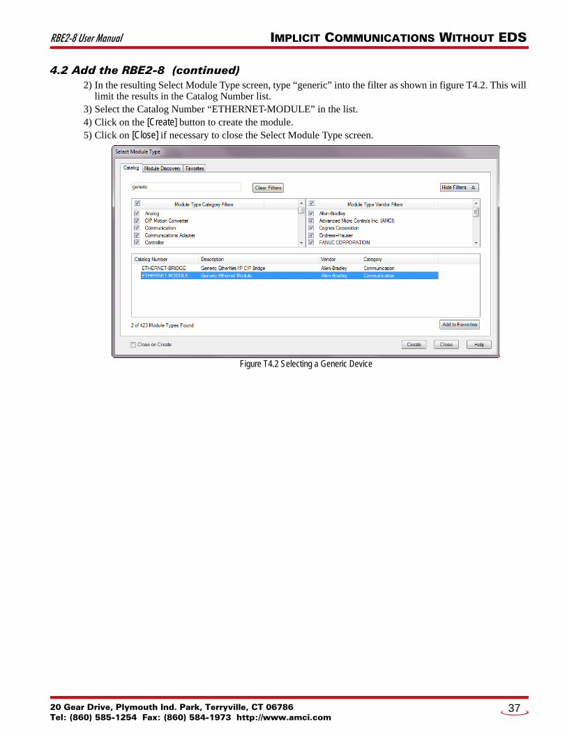
4.2 Add the RBE2-8 (continued)2) In the resulting Select Module Type screen, type “generic” into the filter as shown in figure T4.2. This will
limit the results in the Catalog Number list. 3) Select the Catalog Number “ETHERNET-MODULE” in the list. 4) Click on the [Create] button to create the module. 5) Click on [Close] if necessary to close the Select Module Type screen.
Figure T4.2 Selecting a Generic Device
20 Gear Drive, Plymouth Ind. Park, Terryville, CT 06786Tel: (860) 585-1254 Fax: (860) 584-1973 http://www.amci.com
37

IMPLICIT COMMUNICATIONS WITHOUT EDS RBE2-8 User Manual
4.2 Add the RBE2-8 (continued)6) Set the following parameters in the Module Properties window. All parameters not listed here are optional.
Figure T4.3 shows a completed screen.
Figure T4.3 Configuration Screen - Generic Device
Name: A descriptive name for the RBE2-8 Comm Format: Data - INT
The Comm Format defaults to Data - DINT. The RBE2-8 will not be able to communi-cate with the host controller if this format is not changed when the device is added to the system. Once added, the Comm Format cannot be changed. The device must be deleted and again added to the project if the Comm Format is incorrect.
IP Address: Must be the address you set for the RBE2-8. Refer to the Set the IP Address and Protocol task chapter starting on page 25 for information on setting the IP Address of the unit.
Input: Assembly Instance = 100, Size = 2 words. Output: Assembly Instance = 150, Size = 2 words. Configuration: Assembly Instance = 110, Size = 0
7) Verify that the “Open Module Properties” check box is selected and click on [OK]. The Module Properties window will open. You can set the RPI time as required for your system in this window. The minimum RPI time for an RBE2-8 is one millisecond. When done, click on [OK] to complete the setup.
Error Code 16#0109The PLC will generate an Error Code 16#0109 when the Comm Format parameter is not changed from its default of “Data-DINT” to “Data-INT”. This is the most common cause of communication failures with the RBE2-8.
ADVANCED MICRO CONTROLS INC.38

RBE2-8 User Manual IMPLICIT COMMUNICATIONS WITHOUT EDS
4.3 Buffer I/O DataData to and from the RBE2-8 should be buffered once per scan using Synchronous Copy instructions. This is to insure stable input data during the program scan and guarantee that complete command data is delivered to the device. Ten word integer arrays can be used for this purpose.
These data tags should be buffered with Synchronous Copy File instructions to guarantee stable input data during the program scan and guarantee that complete command data is delivered to the device.
Figure T4.4 Buffer I/O Data
20 Gear Drive, Plymouth Ind. Park, Terryville, CT 06786Tel: (860) 585-1254 Fax: (860) 584-1973 http://www.amci.com
39

20 Gear Drive, PTel: (860) 585-12
TASK 5 (EtherNet/IP Option)
ETHERNET/IP EXPLICIT MESSAGING5.1 Required Message InstructionsOnly two instructions are required to transfer data between the PLC and the RBE2-8. One instruction reads data from the unit and the other writes data to it. The sample programs available from AMCI use this style of programming. The two instructions are alternately triggered using the instruction’s ENABLE bits. The remainder of the program controls when data in the source tags of the write instruction changes. The follow-ing table gives the required attributes for the instructions.
Table T5.1 Message Instruction Attributes
Only RSLogix 500 version 8.0 or above can be used to configure Message Instructions to communicate with an EtherNet/IP device. Message Instructions do not work correctly in ver-sion 10 of RSLogix 500.
5.2 Create Four New Data Files. An Integer file to contain the data read from the RBE2-8. This file must be at least 2 words in
length.
An Integer file to contain the data written to the RBE2-8. This file must be at least 2 words in length.
A Message (MG) data file. This file must have at least two elements, one to control the Read Operation and one to control the Write Operation.
An Extended Routing Information (RIX) data file. This file is used to store information used by the Message Instructions. This file must have at least two elements, one for the Read Operation and one for the Write Operation.
All controllers that support EtherNet/IP support explicit messaging. When using explicit messaging, Message Instructions must be added to your program to com-municate with the RBE2-8. Explicit messaging can be use on platforms that also support implicit messaging.
Rockwell Automation controllers which are programmed with the RSLogix 500 software only support explicit messaging. A MicroLogix 1100 will be used as an example in this chapter.
Read Instruction Write Instruction
Service Type Read Assembly Write Assembly
Service Code E (hex) 10 (hex)
Class 4 (hex) 4 (hex)
Instance 100 (decimal) 150 (decimal)
Attribute 3 (hex) 3 (hex)
Length 4 bytes 4 bytes
lymouth Ind. Park, Terryville, CT 0678654 Fax: (860) 584-1973 http://www.amci.com
40

RBE2-8 User Manual ETHERNET/IP EXPLICIT MESSAGING
5.3 Add the Message Instructions to your Ladder Logic The following rungs show how you can alternately read data from and write data to the unit.
Figure T5.1 Message Instruction Example
1) Double click on Setup Screen text inside the Message Instruction. The following window will open. Note that this is the default window and its appearance will change considerably as you progress through these steps.
Figure T5.2 Message Instruction Setup Screen
2) Double click in the Channel field, click on the , select “1 (Integral)”, and press Enter. 3) Double click in the Communication Command field, click on the , select “CIP Generic” and press
Enter. 4) If the Message Instruction is being used to read data from the RBE2-8, enter the integer file where
the data will be placed in the Data Table Address (Received) field and press enter. 5) If the Message Instruction is being used to write data to the RBE2-8, enter the integer file where the
source data will be located in the Data Table Address (Send) field and press Enter. 6) Enter “4” as the number of bytes needed in either the Size In Bytes (Receive) or Size In Bytes (Send)
fields. The RBE2-8 requires 4 bytes for both Receive and Send.7) Enter a RIX address in the Extended Routing Info field. Please note that each Message Instruction
must have its own RIX address.
20 Gear Drive, Plymouth Ind. Park, Terryville, CT 06786Tel: (860) 585-1254 Fax: (860) 584-1973 http://www.amci.com
41

ETHERNET/IP EXPLICIT MESSAGING RBE2-8 User Manual
5.3 Add the Message Instructions to your Ladder Logic (continued) 8) Double click in the Service field and select “Read Assembly” for a Message Instruction that is being
used to read data from the RBE2-8, or “Write Assemble” for a Message Instruction that is being used to send data to the RBE2-8, and press Enter.
9) For Read operations, the Service Code field will change to “E” (hex). For Write operations, the Ser-vice Code field will change to “10” (hex). For both read and write operations, the Class field will change to “4” (hex), and the Attribute field will change to “3” (hex).
10) For Read operations, enter a value of 100 decimal (64 hex) in the Instance field. For Write operations, enter a value of 150 decimal (96 hex) in the Instance field.
The figure below show a typical configuration for Message Instructions being used to read data from the RBE2-8. Please note that the Data Table Address (Receive) field may be different in your application.
Figure T5.3 Read Message Instruction Setup Screen
ADVANCED MICRO CONTROLS INC.42

RBE2-8 User Manual ETHERNET/IP EXPLICIT MESSAGING
5.3 Add the Message Instructions to your Ladder Logic (continued) The figure below show a typical configuration for Message Instructions being used to write data to the RBE2-8. Please note that the Data Table Address (Send) field may be different in your application.
Figure T5.4 Write Message Instruction Setup Screen
Click on the MultiHop tab on the top of the window. As shown in figure T5.5, enter the IP address of the RBE2-8 and press Enter.
Figure T5.5 Message Instruction MultiHop Settings
After you are finished adding both the read and write message instructions to your program, save and down-load the program to the PLC.
20 Gear Drive, Plymouth Ind. Park, Terryville, CT 06786Tel: (860) 585-1254 Fax: (860) 584-1973 http://www.amci.com
43

ETHERNET/IP EXPLICIT MESSAGING RBE2-8 User Manual
5.4 TroubleshootingIf you are unable to communicate with the RBE2-8, the problem may be that the Ethernet port of your MicroLogix 1100 has not been configured. To check this:
1) Double click on Channel Configuration in the Project Tree and then select the Channel 1 tab. The fol-lowing window will open.
Figure T5.6 MicroLogix Ethernet Configuration Screen
2) Enter the IP address and Subnet Mask of your MicroLogix 1100, (not the address of the RBE2-8) and click on [Apply]. The Ethernet Port should now be working.
AMCI is aware of an issue with the RIX data type in version 10 of RSLogix 500. If you are experiencing communications errors and are running version 10, please contact Rockwell Automation for support.
ADVANCED MICRO CONTROLS INC.44

20 Gear Drive, PTel: (860) 585-12
TASK 6 (Modbus TCP Option)
MODBUS TCP CONFIGURATIONEnable Modbus TCP ProtocolThe internal web page utility can be used to change the communications protocol used by the RBE2-8. This is typically done while setting the IP address. Specifically, follow the steps in section 2.2b, Use the Embedded Web Server which starts on page 26.
Modbus AddressingThe register addresses used in this manual are the Modbus logical reference numbers†, which are unsigned integers starting at zero. This is often called zero based addressing. In this scheme, the first register is given an address of zero. This is the actual addressing scheme used in the Modbus packets.
Another common addressing scheme is one based or data model addressing. In this scheme, the register’s number is used as its address, so the first register, Register 1 in the data model, has an address of 1.
Modbus Table Mapping
The Discrete Input and Input Register tables in the Modbus data model map to the same physical memory locations in the RBE2-8 units.
These registers hold data that is reported from the RBE2-8 to the host controller. Addresses for these registers and inputs start at 0 in zero based addressing.
As examples:
Discrete Input 0 is the same memory location as bit 0 of the first Input Register. Register address 1, the second register, contains Discrete Inputs 16 through 31.
The Coil and Holding Register tables in the Modbus data model map to the same physical memory locations in the RBE2-8 relay boards.
These registers hold data that is from the host controller to the unit. Addresses for these registers start at 1024 in zero based addressing. Coil addresses start at 16,384 in
zero based addressing (1024*16).
As examples:
Coil 16384 is the same memory location as bit 0 of the first Holding Register. Register address 1025, the address of the second Holding Register, contains Discrete Outputs 16,400
through 16,415 in zero based addressing.
Host Addressing
Your host controller may not use these basic addressing schemes for communicating over a Modbus connec-tion. For example, Modicon controllers use addresses starting at 30000 for Input Registers and addresses starting at 40000 for Holding Registers. GE hosts internally use their %R memory for Holding Registers and %AI memory for Input Registers.
If this is the case, you will define a mapping between your host controller’s addressing scheme and the zero based Modbus TCP addresses when you add the RBE2-8 to your host controller. Refer to your host control-ler’s documentation for information on how to accomplish this.
This chapter tell you how the I/O words used by an AMCI RBE2-8 are mapped to the Modbus I/O registers.
† MODBUS Application Protocol Specification V1.1b3, section 4.3: MODBUS Data model. www.modbus.org
lymouth Ind. Park, Terryville, CT 0678654 Fax: (860) 584-1973 http://www.amci.com
45

MODBUS TCP CONFIGURATION RBE2-8 User Manual
AMCI Modbus TCP Memory LayoutThe RBE2-8 has a starting Input Register address of 0 and a starting Output Register address of 1024. Input Registers hold the data from the RBE2-8 while Output Registers hold the data to be written to the unit. Figure T6.1 shows how an RBE2-8 is mapped to the Modbus data reference. The complete specification for the Modbus protocol can be downloaded at http://www.modbus.org/specs.php.
Figure T6.1 Modbus Data Reference Map
Supported Number of ConnectionsAll RBE2-8 units support four concurrent connections. When connections exist, the Network Status (NS) LED on the unit will flash green. The number of blinks indicate the number of active connections. There is a two second break between groups of flashes.
Supported Modbus Functions
Table T6.1 Supported Modbus Functions
Table T6.1 above lists all of the Modbus functions supported by an RBE2-8. AMCI supports all of these func-tions so that you can control the unit as you see fit. However, if you are looking for the easiest way to inter-face with your unit, then you only need to use the Read/Write Registers function, which is function code 23.
Each RBE2-8 buffers the data that is sent to it over the network. If you use the Read/Write Registers function to write data to the unit, the data read with that command will not contain the response to the new write data. The response to the new data will be sent with the next data read.
Function Code Function Name RBE2-8
Register Addressing method
1 Read Coils OUTPUT Bit: Addresses starting at 16,384
2 Read Discrete Inputs INPUT Bit: Addresses starting at 0
3 Read Holding Registers OUTPUT & INPUT Word: Out Regs.Starting at 1024In Regs.Starting at 0
4 Read Input Registers INPUT Word: Addresses starting at 0.
5 Write Single Coil OUTPUT Bit: Addresses starting at 16,384
6 Write Single Register OUTPUT Word: Addresses starting at 1024
15 Write Multiple Coils OUTPUT Bit: Addresses starting at 16,384
16 Write Multiple Registers OUTPUT Word: Addresses starting at 1024
22 Mask Write Register OUTPUT Word: Addresses starting at 1024
23 Read/Write Registers INPUT/OUTPUT Word: Out Regs.Starting at 1024In Regs.Starting at 0
Network InputData
Not Implemented
Network OutputData
LSB and MSBNumbers
Mapped as:Discrete InputsHolding RegistersInput Registers
Mapped as:CoilsHolding Registers
Register 1024
Register 1025
16,38416,399
16,40016,415
0
16
15
31
Register 0
Register 1
ADVANCED MICRO CONTROLS INC.46

RBE2-8 User Manual MODBUS TCP CONFIGURATION
Supported Modbus Exceptions
Table T6.2 Supported Modbus Exceptions
Code Name Description
01 Illegal function The RBE2-8 does not support the function code in the query.
02 Illegal data address The data address received in the query is outside the initialized memory area.
03 Illegal data value The data in the request is illegal.
20 Gear Drive, Plymouth Ind. Park, Terryville, CT 06786Tel: (860) 585-1254 Fax: (860) 584-1973 http://www.amci.com
47

MODBUS TCP CONFIGURATION RBE2-8 User Manual
Notes
ADVANCED MICRO CONTROLS INC.48
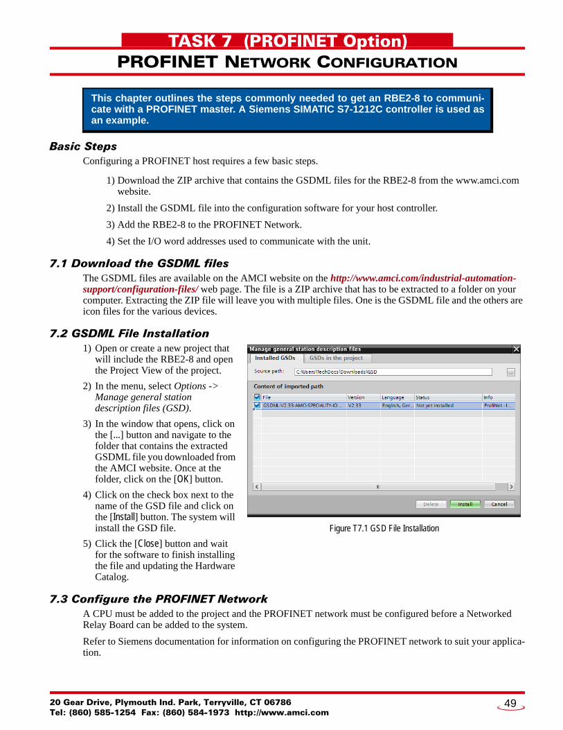
20 Gear Drive, PTel: (860) 585-12
TASK 7 (PROFINET Option)
PROFINET NETWORK CONFIGURATIONBasic StepsConfiguring a PROFINET host requires a few basic steps.
1) Download the ZIP archive that contains the GSDML files for the RBE2-8 from the www.amci.com website.
2) Install the GSDML file into the configuration software for your host controller.
3) Add the RBE2-8 to the PROFINET Network.
4) Set the I/O word addresses used to communicate with the unit.
7.1 Download the GSDML filesThe GSDML files are available on the AMCI website on the http://www.amci.com/industrial-automation-support/configuration-files/ web page. The file is a ZIP archive that has to be extracted to a folder on your computer. Extracting the ZIP file will leave you with multiple files. One is the GSDML file and the others are icon files for the various devices.
7.2 GSDML File Installation1) Open or create a new project that
will include the RBE2-8 and open the Project View of the project.
2) In the menu, select Options -> Manage general station description files (GSD).
3) In the window that opens, click on the [...] button and navigate to the folder that contains the extracted GSDML file you downloaded from the AMCI website. Once at the folder, click on the [OK] button.
4) Click on the check box next to the name of the GSD file and click on the [Install] button. The system will install the GSD file.
5) Click the [Close] button and wait for the software to finish installing the file and updating the Hardware Catalog.
7.3 Configure the PROFINET NetworkA CPU must be added to the project and the PROFINET network must be configured before a Networked Relay Board can be added to the system.
Refer to Siemens documentation for information on configuring the PROFINET network to suit your applica-tion.
This chapter outlines the steps commonly needed to get an RBE2-8 to communi-cate with a PROFINET master. A Siemens SIMATIC S7-1212C controller is used as an example.
Figure T7.1 GSD File Installation
lymouth Ind. Park, Terryville, CT 0678654 Fax: (860) 584-1973 http://www.amci.com
49

PROFINET NETWORK CONFIGURATION RBE2-8 User Manual
7.4 Add the RBE2-8 to the PROFINET Network1) With the project open in Project View, double click on “Device & Networks” in the project tree.
2) If need be, click on the “Hardware Catalog” vertical tab to open the Hardware Catalog.3) You can search for “RBE”, or browse to the RBE2-8 icon by clicking through Other field devices +>
PROFINET IO +> IO +> Advanced Micro Controls Inc. +> AMCI_Products +> AMCI_Speciality IO. Drag and drop the appropriate icon onto the PROFINET network.
4) Drag the green square on the RBE2-8 icon onto the PROFINET network line to connect the device to the network.
Figure T7.2 RBE2-8 Added to PROFINET Network
ADVANCED MICRO CONTROLS INC.50

RBE2-8 User Manual PROFINET NETWORK CONFIGURATION
7.4 Add the Networked Driver to the PROFINET Network (continued)5) Right click on the RBE2-8 icon and select “Properties” from the pop up menu. The Inspector window will
open at the bottom of the screen. Under the “General” tab, select the “General” heading. You can rename the RBE2-8 by changing the Name: field.
6) Under the “PROFINET interface [x1]” heading, select “Ethernet addresses”. Under the IP protocol section, set the desired IP address and subnet mask for the RBE2-8.
Figure T7.3 RBE2-8 IP Addressing
20 Gear Drive, Plymouth Ind. Park, Terryville, CT 06786Tel: (860) 585-1254 Fax: (860) 584-1973 http://www.amci.com
51

PROFINET NETWORK CONFIGURATION RBE2-8 User Manual
7.5 Set the I/O ConfigurationThe RBE2-8 units require 2 Input Words (4 Input Bytes) and 2 Output Words (4 Output Bytes). All required Input and Output Bytes are defined by the GSDML file and divided into suitable modules. These settings are shown in the Table T7.1.
Table T7.1 PROFINET I/O Configuration
1) With the RBx2-8 icon selected on the PROFINET bus, click on the “Device view” tab. The view in the Hardware Catalog will change. Expand the Module tree to show both the Input and Output modules.
2) To map the I/O bytes to the CPU, double click on the “4 bytes IN” and “4 bytes OUT” icons in the Hardware Catalog. The system will automatically assign the next I and Q addresses to the data table.
Figure T7.4 I/O Byte Mapping
7.6 Verify and Download the New Configuration1) Continue by adding any remaining devices to your PROFINET network.
2) Compile and download the project to the CPU.
Input / Output Bytes of an RBE2-8
Input / Output Modules of an RBE2-8
4 Input Bytes Input Module - Slot 1: 4 bytes
4 Output Bytes Output Module - Slot 2: 4 bytes
ADVANCED MICRO CONTROLS INC.52

RBE2-8 User Manual PROFINET NETWORK CONFIGURATION
MRP InstallationsAt this point, the RBE2-8 is configured and ready to use. If you are using the unit in a redundant, ring based, network that uses the Media Redundancy Protocol (MRP), continue with the following instructions.
7.7 Configure the RBE2-8 as an MRCThe RBE2-8 functions as a Media Redundancy Client (MRC) in an MRP network.
1) Switch to Topology view and drag the additional connections between the appropriate ports.
2) Click on the RBx2-8 icon to select it. In the Inspector window, select Advanced options +> Media redundancy. Use the “MRP domain:” drop down menu to select the appropriate domain. Use the “Media redundancy role:” drop down menu to select “Client”.
3) Continuing in the Inspector window, select Advanced options +> Port 1 +> Port interconnection. Under “Partner port:”, the partner port you assigned to the port when you drew the topology is shown. If you do not know which port will be the partner port in the actual installation, you can use the drop down menu to select “Any partner”.
4) If need be, repeat step 3 for Port 2 of the RBE2-8.
Figure T7.5 MRP Topology and Client settings
5) Continue configuring the rest of the devices on the network before compiling the project and downloading it to the CPU.
Media Redundancy Protocol (MRP) installations require that the RBE2-8 be installed in a ring topology. In these applications, both Ethernet ports are used when wiring the ring, daisy chaining from one unit in the ring to the next. The steps below covers typical software configuration that must also be completed.
20 Gear Drive, Plymouth Ind. Park, Terryville, CT 06786Tel: (860) 585-1254 Fax: (860) 584-1973 http://www.amci.com
53

ADVANCED MICRO CONTROLS INC.
LEADERS IN ADVANCED CONTROL PRODUCTS

RBE2-8 User Manual PROFINET NETWORK CONFIGURATION
20 Gear Drive, Plymouth Ind. Park, Terryville, CT 06786Tel: (860) 585-1254 Fax: (860) 584-1973 http://www.amci.com
55