
Two-stage air-source heat pump for residential heating and cooling applications in northern U.S....
11
Two-stage air-source heat pump for residential heating and cooling applications in northern U.S. climates Stefan S. Bertsch*, Eckhard A. Groll Purdue University, School of Mechanical Engineering, Ray W. Herrick Laboratories, 140 S. Intramural Drive, West Lafayette, IN 47907, USA article info Article history: Received 11 June 2007 Received in revised form 9 January 2008 Accepted 16 January 2008 Published online 31 January 2008 Keywords: Heat pump Air-source Compression system Two-stage system R410A Design Experiment abstract Air-source heat pumps for residential heating are more widely used than geothermal heat pumps mainly due to their lower installation costs. Major disadvantages of air-source heat pumps are the decrease of heat output and coefficient of performance (COP), and increase in discharge temperature, towards low outdoor temperatures. In this paper an air-source two-stage heat pump using R410A as the refrigerant was simulated, designed, constructed, and tested at ambient temperatures as low as 30 C and supply temperatures of up to 50 C in air and water heating mode. In addition, the system is able to provide sufficient air conditioning in cooling mode (approximately 50–60% of the design heat transfer rate in heating mode). A short summary of an extended literature review is shown as well as a theoretical screening study of the three most promising cycles. Furthermore, the design and test results of a breadboard system and a comparison with commercially available heat pumps are presented. Second law efficiencies of up to 45% could be achieved, result- ing in a coefficient of performance (COP) of 2.1 at 30 C ambient temperature. ª 2008 Elsevier Ltd and IIR. All rights reserved. Pompe a ` chaleur bie ´tage ´ e air-eau dans les applications re ´ sidentielles de chauffage et de refroidissement dans les climats septentrionaux aux Etats-Unis Mots cle ´s : Pompe a ` chaleur ; Air-eau ; Syste `me a ` compression ; Syste `me bie ´ tage ´ ; R410A ; Conception ; Expe ´ rimentation 1. Introduction Heating requirements in northern climates of the United States, such as in Minnesota, and South and North Dakota, can represent a challenge for air-source heat pumps, since the ambient air temperatures in this region can reach values as low as 30 C during the heating season. Nevertheless, most heat pumps for space heating in this area are still * Corresponding author. Tel.: þ1 765 496 2668; fax: þ1 765 494 0787. E-mail addresses: [email protected] (S.S. Bertsch), [email protected] (E.A. Groll). www.iifiir.org available at www.sciencedirect.com journal homepage: www.elsevier.com/locate/ijrefrig 0140-7007/$ – see front matter ª 2008 Elsevier Ltd and IIR. All rights reserved. doi:10.1016/j.ijrefrig.2008.01.006 international journal of refrigeration 31 (2008) 1282–1292
Transcript of Two-stage air-source heat pump for residential heating and cooling applications in northern U.S....
i n t e r n a t i o n a l j o u r n a l o f r e f r i g e r a t i o n 3 1 ( 2 0 0 8 ) 1 2 8 2 – 1 2 9 2
www. i ifi i r .org
ava i lab le at www.sc iencedi rec t .com
journa l homepage : www. e lsev ier . com/ loca te / i j re f r ig
Two-stage air-source heat pump for residential heatingand cooling applications in northern U.S. climates
Stefan S. Bertsch*, Eckhard A. Groll
Purdue University, School of Mechanical Engineering, Ray W. Herrick Laboratories, 140 S. Intramural Drive,
West Lafayette, IN 47907, USA
a r t i c l e i n f o
Article history:
Received 11 June 2007
Received in revised form
9 January 2008
Accepted 16 January 2008
Published online 31 January 2008
Keywords:
Heat pump
Air-source
Compression system
Two-stage system
R410A
Design
Experiment
* Corresponding author. Tel.: þ1 765 496 266E-mail addresses: [email protected] (
0140-7007/$ – see front matter ª 2008 Elsevidoi:10.1016/j.ijrefrig.2008.01.006
a b s t r a c t
Air-source heat pumps for residential heating are more widely used than geothermal heat
pumps mainly due to their lower installation costs. Major disadvantages of air-source heat
pumps are the decrease of heat output and coefficient of performance (COP), and increase
in discharge temperature, towards low outdoor temperatures. In this paper an air-source
two-stage heat pump using R410A as the refrigerant was simulated, designed, constructed,
and tested at ambient temperatures as low as �30 �C and supply temperatures of up to
50 �C in air and water heating mode. In addition, the system is able to provide sufficient
air conditioning in cooling mode (approximately 50–60% of the design heat transfer rate
in heating mode). A short summary of an extended literature review is shown as well as
a theoretical screening study of the three most promising cycles. Furthermore, the design
and test results of a breadboard system and a comparison with commercially available
heat pumps are presented. Second law efficiencies of up to 45% could be achieved, result-
ing in a coefficient of performance (COP) of 2.1 at �30 �C ambient temperature.
ª 2008 Elsevier Ltd and IIR. All rights reserved.
Pompe a chaleur bietagee air-eau dans les applicationsresidentielles de chauffage et de refroidissement dans lesclimats septentrionaux aux Etats-Unis
Mots cles : Pompe a chaleur ; Air-eau ; Systeme a compression ; Systeme bietage ; R410A ; Conception ; Experimentation
1. Introduction
Heating requirements in northern climates of the United
States, such as in Minnesota, and South and North Dakota,
8; fax: þ1 765 494 0787.S.S. Bertsch), groll@purduer Ltd and IIR. All rights
can represent a challenge for air-source heat pumps, since
the ambient air temperatures in this region can reach values
as low as �30 �C during the heating season. Nevertheless,
most heat pumps for space heating in this area are still
e.edu (E.A. Groll).reserved.
Nomenclature
A area (m2)
COP coefficient of performance (–)
cp specific heat at constant pressure
(J kg�1 K�1)
DB dry bulb temperature (�C)
h enthalpy (kJ kg�1)_m mass flow rate (kg s�1)
NTU number of transfer units (–)
T temperature (�C)_Q heat rate (kW)
W work (kJ)
WB wet bulb temperature (�C)
Greek symbols
3 efficiency (–)
r density (kg m�3)
hcarnot second law efficiency (–)
Subscripts
a air
aux auxiliary
comp compressor
cond condenser
cool cooling
corr corrected
el electric
evap evaporator
H heating
in inlet
isent isentropic
map according to compressor map
out outlet
r refrigerant
sh superheat
tot total
W water
i n t e r n a t i o n a l j o u r n a l o f r e f r i g e r a t i o n 3 1 ( 2 0 0 8 ) 1 2 8 2 – 1 2 9 2 1283
air-source heat pumps due to their ease of installation and
their low installation costs compared to ground source heat
pumps. It has to be noted though that once the ambient tem-
perature drops below approximately 0 �C most of these sys-
tem turn off and switch to fossil fuel or electric backup
heating. One of the advantages of using a reversible heat
pump/air conditioning system is the possibility of achieving
heating and cooling with the same appliance, which results
in cost savings during installation.
A survey of the installed heating and cooling capacities of
residential homes in northern U.S. regions showed that the
cooling demand is about 50–60% of the installed heating ca-
pacity. However, in currently installed heat pumps in this re-
gion, the cooling and heating capacities are not necessarily
matched to the application, which reduces efficiency and
comfort due to the need of cycling. In addition, many residen-
tial dwellings in Minnesota and its border states are equipped
with hydronic floor heating systems on the ground level and
air heating on the second floor. Therefore, a system capable
of delivering water heating, air heating or the combination
of both is desirable.
The four main problems for air-source heat pumps at very
low ambient temperatures are
(a) Insufficient heat output as the required heat increases
whereas the heat pump capacity decreases mainly due to
lower refrigerant mass flow rates delivered by the com-
pressor at high pressure ratios.
(b) High compressor discharge temperature caused by the low
suction pressure and high pressure ratio across the com-
pressor. This leads to bivalent heat pump systems which
use the heat pump at medium ambient temperatures
only. At very low ambient temperatures (mostly below
0 �C) the compressor is turned off to protect it from over-
heating and electric resistance heating is used instead.
The combined efficiency of such systems is quite low.
(c) The coefficient of performance (COP) decreases rapidly for
high pressure ratios which occur at low ambient tempera-
ture conditions.
(d) Heat pumps designed for low ambient temperature condi-
tions usually have too large capacities at medium ambient
temperatures. Therefore, the need of cycling the heat
pump on and off arises at higher ambient temperatures
in order to reduce the heating capacity. Due to the transient
effects associated with cycling, this leads to a lower effi-
ciency of the system compared to steady-state perfor-
mance and also to a lower comfort level for the inhabitants.
Several concepts have been proposed in the literature to
address these problems and to design heat pumps for low
temperature climates. A summary and comparison of the ad-
vantages and disadvantages of eight concepts using different
refrigerants can be found in Bertsch and Groll (2005). These
concepts include two-stage compression systems with either
intercooling, economizing (Zhao et al., 2005), or in a cascade
arrangement. Furthermore, systems which inject two-phase
refrigerant into the compressor to decrease the compressor
discharge temperature (Zogg, 2002; Zehnder and Favrat,
2000; Shuangquan et al., 2002), systems which use high oil
flow rates to cool the compressor, and systems with active
subcooling as proposed by Zubair et al. (1996) are shown in
(Bertsch and Groll, 2005).
Table 1 lists the relative performance of seven concepts for
a comparison using the single-stage cycle as a reference cycle
at 100% relative heating capacity and 100% relative efficiency.
Values for efficiency and capacity were compared over a broad
ambient and supply temperature range. Besides listing the rel-
ative efficiency and capacity, the table also lists the discharge
temperature and the number of achievable variations in the
heating capacity, i.e., by turning off one of two compressors.
For more detailed explanations and schematics of the cycles
refer to Bertsch and Groll (2005).
2. Modeling
Based on the comparison of the seven concepts listed in Table 1,
it was concluded that the cascade cycle, the two-stage cycle

Table 1 – Comparison of different heat pump cycles to a one stage cycle (from Bertsch and Groll, 2005)
Concept Preferredcompressora
Number heatoutput steps
Relativeefficiency (%)
Relative heatcapacity (%)
Dischargetemperature
Single-stage cycle Recip 1 100 100 Too high
Two-stage cycle
with intercooler
Two-stage 1 130 100 Acceptable
Sc, Recip, Rot 3 130 140 Acceptable
Two-stage cycle
with economizer
Two-stage 1 130 100 Low
Sc, Recip, Rot 3 130 150 Low
Cascade cycle Sc, Recip, Rot 1 140 140 Low
Refrigerant injection Sc, Screw 2 100 115 High
Oil cooling Recip, Rot 1 100 100 Acceptable
Mechanical subcooling Recip, Sc 2 110 120 Too high
a Sc – scroll, Recip – reciprocating, Rot – rotary, Two-stage – two-stage compression in one shell.
i n t e r n a t i o n a l j o u r n a l o f r e f r i g e r a t i o n 3 1 ( 2 0 0 8 ) 1 2 8 2 – 1 2 9 21284
with intercooling and the two-stage cycle with economizing
are the most feasible concepts for the given application of
a low outdoor temperature air-source heat pump. In order to
select one of three cycles, more detailed simulations of the
three cycles were conducted as part of a screening study.
The three cycles were modeled as heat pumps with water-
cooled condensers and air-heated evaporators. The intercooler
cycle was modeled by assuming that the hydronic water first
flows through the intercooler and then through the con-
denser. A short description of the cycle models can be found
in this section. A more detailed description of the cycle models
and component models can be found in Bertsch (2005) and
LeRoy et al. (1997)), respectively.
The design conditions for sizing the heat exchangers and
compressors are an ambient temperature of �20 �C and
a hot water supply temperature of 50 �C. The desired heating
capacity at the design point is 17 kW (5 tons). The water flow
rate through the condenser was set at 1500 l/h (0.42 l/s), which
leads to a temperature difference between the supply and
return water of approximately 16 �C. This temperature differ-
ence provides a good compromise among the electrical power
consumption of the water pump, the heat pump efficiency,
and the comfort of the inhabitants. Smaller water flow rates
lead to a larger temperature differences and uneven floor
heating. The water flow rate was therefore not determined
by an optimization for the heat pump, but by the demand of
the end user.
In a first step, each cycle model was exercised to determine
the optimum size of the components at the design point with
respect to heating capacity and system efficiency. Once the
components were sized, the model was applied to a range of
operating conditions in order to determine the performance
of the system.
2.1. Two-stage heat pump with intercooler
The two-stage heat pump with intercooling as shown in
Fig. 1(a) consists of two compressors that are arranged in se-
ries with a heat exchanger in between the discharge line of
the first compressor and the suction line of the second com-
pressor. The return water flows from the intercooler to the
condenser and leaves the heat pump at the desired supply
temperature. This configuration allows the largest operating
range of the intercooler system. Considering the given water
flow rate, the return water temperature from the residential
building can be determined. The cycle matches the given op-
erating conditions well and can be used with two single-stage
compressors or with one two-stage compressor. The inter-
cooler decreases the refrigerant inlet temperature of the
high-pressure stage compressor, which also decreases the
discharge temperature of the same compressor. This measure
extends the operation of the heat pump to far lower outdoor
temperatures. Studies by several authors (Zogg, 2002; Zehnder
and Favrat, 2000) have shown that the oil migration in such
systems is a critical issue, especially if only one compressor
is running. Therefore, the usage of an oil separator or other
measures to ensure even oil distribution between both com-
pressors is recommended.
2.2. Two-stage heat pump with economizer
Instead of using an intercooler, a two-stage cycle may be oper-
ated with a closed economizer as shown in Fig. 1(b). The econ-
omizer delivers a certain amount of two-phase refrigerant to
a mixing chamber in the suction line of the high-pressure
stage compressor where it is mixed with the hot discharge
gas of the low-pressure stage compressor. This measure al-
lows very accurate and easy control of the inlet state of the
high-pressure stage compressor. Therefore, the compressor
discharge temperature of the high-pressure stage compressor
can be reduced. In addition, the economized refrigerant sub-
cools the remaining condensed refrigerant before it enters
the expansion valve, which improves the system COP. Instead
of using a closed economizer, an open economizer could be
used resulting in a similar efficiency.
For design purposes, the intermediate pressure was calcu-
lated as the square root of the suction pressure times the dis-
charge pressure. This value was then used to determine the
size ratio of both compressors at the design point. Once the
compressor sizes were determined, the simulated intermedi-
ate pressure was calculated by the system simulations by
adjusting the refrigerant injection from the economizer to
achieve a specified superheat value at the inlet of the high-
pressure stage compressor.
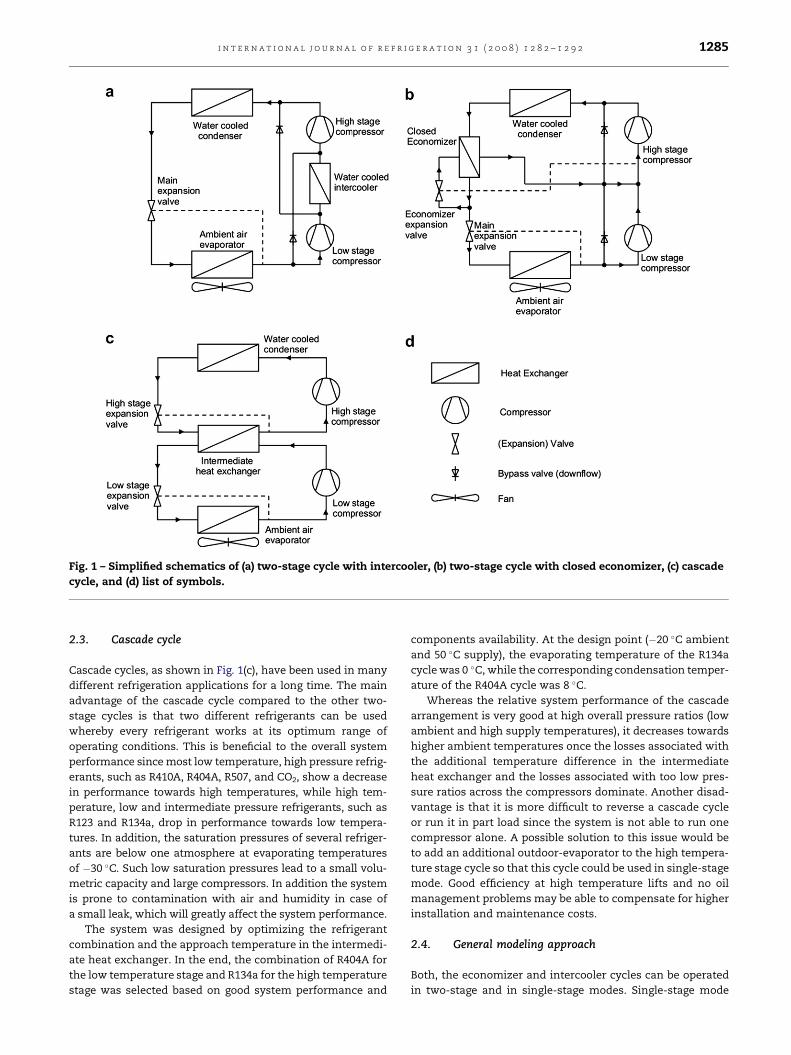
Fig. 1 – Simplified schematics of (a) two-stage cycle with intercooler, (b) two-stage cycle with closed economizer, (c) cascade
cycle, and (d) list of symbols.
i n t e r n a t i o n a l j o u r n a l o f r e f r i g e r a t i o n 3 1 ( 2 0 0 8 ) 1 2 8 2 – 1 2 9 2 1285
2.3. Cascade cycle
Cascade cycles, as shown in Fig. 1(c), have been used in many
different refrigeration applications for a long time. The main
advantage of the cascade cycle compared to the other two-
stage cycles is that two different refrigerants can be used
whereby every refrigerant works at its optimum range of
operating conditions. This is beneficial to the overall system
performance since most low temperature, high pressure refrig-
erants, such as R410A, R404A, R507, and CO2, show a decrease
in performance towards high temperatures, while high tem-
perature, low and intermediate pressure refrigerants, such as
R123 and R134a, drop in performance towards low tempera-
tures. In addition, the saturation pressures of several refriger-
ants are below one atmosphere at evaporating temperatures
of �30 �C. Such low saturation pressures lead to a small volu-
metric capacity and large compressors. In addition the system
is prone to contamination with air and humidity in case of
a small leak, which will greatly affect the system performance.
The system was designed by optimizing the refrigerant
combination and the approach temperature in the intermedi-
ate heat exchanger. In the end, the combination of R404A for
the low temperature stage and R134a for the high temperature
stage was selected based on good system performance and
components availability. At the design point (�20 �C ambient
and 50 �C supply), the evaporating temperature of the R134a
cycle was 0 �C, while the corresponding condensation temper-
ature of the R404A cycle was 8 �C.
Whereas the relative system performance of the cascade
arrangement is very good at high overall pressure ratios (low
ambient and high supply temperatures), it decreases towards
higher ambient temperatures once the losses associated with
the additional temperature difference in the intermediate
heat exchanger and the losses associated with too low pres-
sure ratios across the compressors dominate. Another disad-
vantage is that it is more difficult to reverse a cascade cycle
or run it in part load since the system is not able to run one
compressor alone. A possible solution to this issue would be
to add an additional outdoor-evaporator to the high tempera-
ture stage cycle so that this cycle could be used in single-stage
mode. Good efficiency at high temperature lifts and no oil
management problems may be able to compensate for higher
installation and maintenance costs.
2.4. General modeling approach
Both, the economizer and intercooler cycles can be operated
in two-stage and in single-stage modes. Single-stage mode
i n t e r n a t i o n a l j o u r n a l o f r e f r i g e r a t i o n 3 1 ( 2 0 0 8 ) 1 2 8 2 – 1 2 9 21286
can be achieved by operating either the low-pressure stage or
the high-pressure stage compressor. The single-stage model-
ing results shown in this paper are only for the high-pressure
stage compressor, since the capacity better matches the de-
mand and the system efficiency was higher.
The simulation was approached using a steady-state simu-
lation model consisting of sub-models for each component of
the cycle. These component models could then be arranged
and used for all three heat pump cycles. In this way, the re-
sults were directly comparable. A general assumption for all
simulations was the usage of dry air as the ambient air. This
means that frost buildup and therefore, defrosting, was not
considered in the simulations. Since the heating capacity
and the configuration of the outdoor coil of the three simu-
lated cycles are quite similar, the ice buildup on the outdoor
coil would be comparable. Neglecting the frost formation
and required defrosting results in an over-prediction of the
heating capacity and system efficiency. However, the relative
over-prediction is similar for each cycle and thus, the relative
differences between the cycle performances hold true with
and without considering the frost formation and required
defrosting. Furthermore, all pressure drops and heat losses
in the refrigerant lines were neglected. It is assumed that
these model assumptions will affect all three cycles in a simi-
lar way and therefore, they have little or no influence on the
results of the comparison.
Simulations were carried out within the operating
conditions of the system in heating mode from ambient
temperatures of �30 �C to 10 �C and heat supply temperatures
of 40–60 �C.
2.5. Compressor model
Since the data of commercial compressors for the given oper-
ating range of the low-pressure stage compressor were not
available, a simplified physical model from Mackensen et al.
(2002) was used to extend the performance data of standard
compressors. In the usual operating range, the standard 3rd
order polynomial approach with cross-terms according to
ANSI/ARI Standard 540-1999 (1999) was used due to its higher
accuracy. In order to account for variations of the superheat
the following approach by Dabiri and Rice (1981) was used to
correct the refrigerant mass flow rate:
_mR;act ¼ _mR;map
"1þ F1
rsh;corr
rmap
� 1
!#(1)
with rsh,corr¼ f(Pevap,Tsh,act), rmap¼ f(Pevap,Tsh,map), and
F1¼ 0.75 (recommended by authors, Dabiri and Rice, 1981,
for hermetic compressors).
With the updated refrigerant mass flow rate, the electrical
input power was corrected to account for the difference in su-
perheat between compressor map and simulation.
_Wel ¼ _Wel;map
_mR;act
_mR;map
�hout;isent;act � hin;act
hout;isent;map � hin;map
�(2)
The heat loss of the compressor was calculated using a fixed
heat loss factor and the compressor exit state was determined
by using an energy balance across the compressor.
2.6. Heat exchanger models
Generally, there are three main methods of modeling a heat
exchanger with phase change. Finite difference models divide
the heat exchanger into small segments, whereas moving
boundary models keep track of the boundaries between sin-
gle- and two-phase flow. Both modeling approaches require
a detailed knowledge of the geometry and configuration of
the heat exchanger. The third method is a lumped method,
which was chosen in this study in form of an effectiveness-
NTU model. Several books and papers in the literature (ASH-
RAE Handbook, 2000; Incropera and DeWitt, 2002; Kumar
and Venkatarathnam, 2000) indicate that sufficient accuracy
can be achieved for screening purposes when using an
effectiveness-NTU model since the inherent errors of over
predicting the conductance in the effectiveness calculations
and under predicting the temperature difference in the heat
exchanger calculations tend to compensate each other. The
modeling approach is shown on the example of the water-
cooled condenser, but can be transferred to all other heat
exchangers (intercooler, economizer, and evaporator) in a sim-
ilar way, using their configurations and the properties of the
respective working fluids (air, refrigerant, and water).
Assuming a fixed amount of subcooling, the heat transfer
rate of the condenser can be equated as follows:
_Qcond ¼ _mR;act
�hcond;out � hcond;in
�(3)
where hcond,out is evaluated at the condensing pressure and
a temperature calculated with the fixed subcooling and hcond,in
is set equal to the enthalpy at the compressor outlet.
Then, the effectiveness, 3cond of the condenser is calculated
knowing the heat transfer characteristics of the heat ex-
changer and the water specific heat:
3cond ¼ 1� e�NTUcond (4)
with
NTUcond ¼UAcond
cW _mW(5)
where U is the overall heat transfer coefficient of the heat ex-
changer, A is the area of the heat exchanger, cW is the specific
heat of water, and _mW is the water flow rate.
Using the now known condenser effectiveness, 3cond, the
condensing temperature, Tcond, and the water outlet tempera-
ture, TW,out can be updated as follows:
Tcond ¼ TW;in þ_Qcond
3condcW _mW(6)
TW;out ¼ TW;in þ_Qcond
cW _mW(7)
2.7. Closing of the cycles
With the component models shown above and the assump-
tion of an adiabatic expansion valve all cycles could be simu-
lated by guessing start values for the suction temperature and
pressure and the discharge pressure. The solutions were then
i n t e r n a t i o n a l j o u r n a l o f r e f r i g e r a t i o n 3 1 ( 2 0 0 8 ) 1 2 8 2 – 1 2 9 2 1287
obtained iteratively by updating the pressures and tempera-
tures in the heat exchanger models, which were then used
as new inputs to the compressor model. Convergences of
the system models were quite fast and stable. Further details
can be found in Bertsch (2005).
3. Simulation results
Once all components of the cycles had been selected and di-
mensioned, the simulations were run by varying the outdoor
temperature from �30 �C to 10 �C in 5 �C increments at water
supply temperatures of 40, 50 and 60 �C. At the design point
(�20 �C ambient air and 50 �C water supply temperature), the
simulation model of the economizer cycle predicted a conden-
sation temperature of 54.6 �C, an evaporation temperature of
�28.8 �C, and a saturation temperature at the injection port
of 0.4 �C. In comparison, the intercooler cycle simulation
model predicted an evaporating temperature of�26.2 �C, a sat-
uration temperature at the intercooler of �0.5 �C and a con-
densation temperature of 53.5 �C. The cascade cycle
simulation model predicted a low-pressure stage evaporation
and condensing temperature of �27.9 �C and 8.7 �C, respec-
tively, and high-pressure stage evaporation and condensing
temperatures of 0.2 �C and 54.1 �C, respectively.
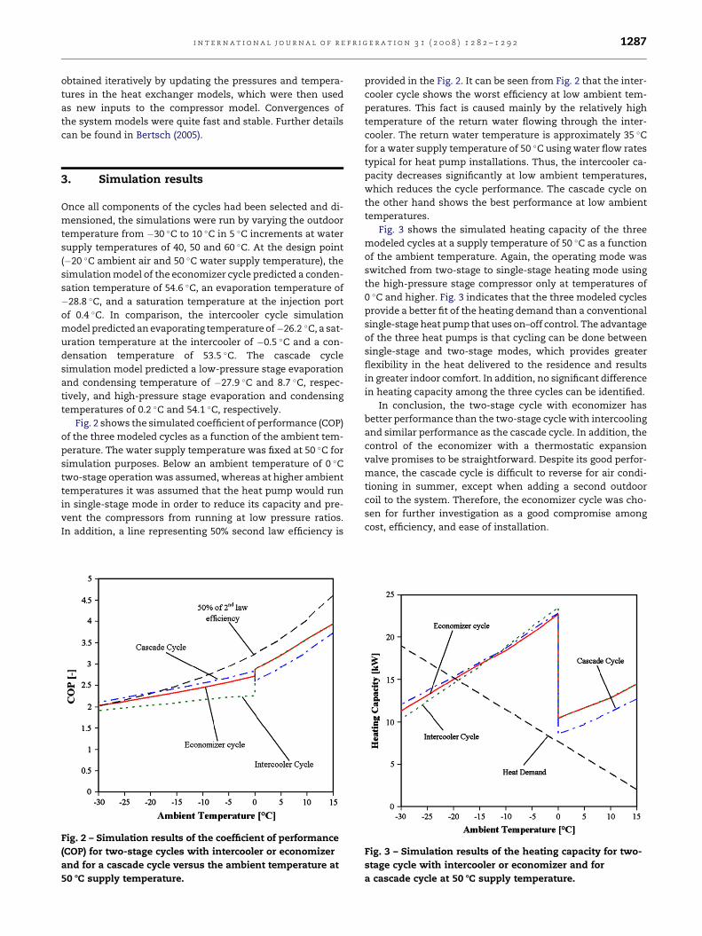
Fig. 2 shows the simulated coefficient of performance (COP)
of the three modeled cycles as a function of the ambient tem-
perature. The water supply temperature was fixed at 50 �C for
simulation purposes. Below an ambient temperature of 0 �C
two-stage operation was assumed, whereas at higher ambient
temperatures it was assumed that the heat pump would run
in single-stage mode in order to reduce its capacity and pre-
vent the compressors from running at low pressure ratios.
In addition, a line representing 50% second law efficiency is
Fig. 2 – Simulation results of the coefficient of performance
(COP) for two-stage cycles with intercooler or economizer
and for a cascade cycle versus the ambient temperature at
50 8C supply temperature.
provided in the Fig. 2. It can be seen from Fig. 2 that the inter-
cooler cycle shows the worst efficiency at low ambient tem-
peratures. This fact is caused mainly by the relatively high
temperature of the return water flowing through the inter-
cooler. The return water temperature is approximately 35 �C
for a water supply temperature of 50 �C using water flow rates
typical for heat pump installations. Thus, the intercooler ca-
pacity decreases significantly at low ambient temperatures,
which reduces the cycle performance. The cascade cycle on
the other hand shows the best performance at low ambient
temperatures.
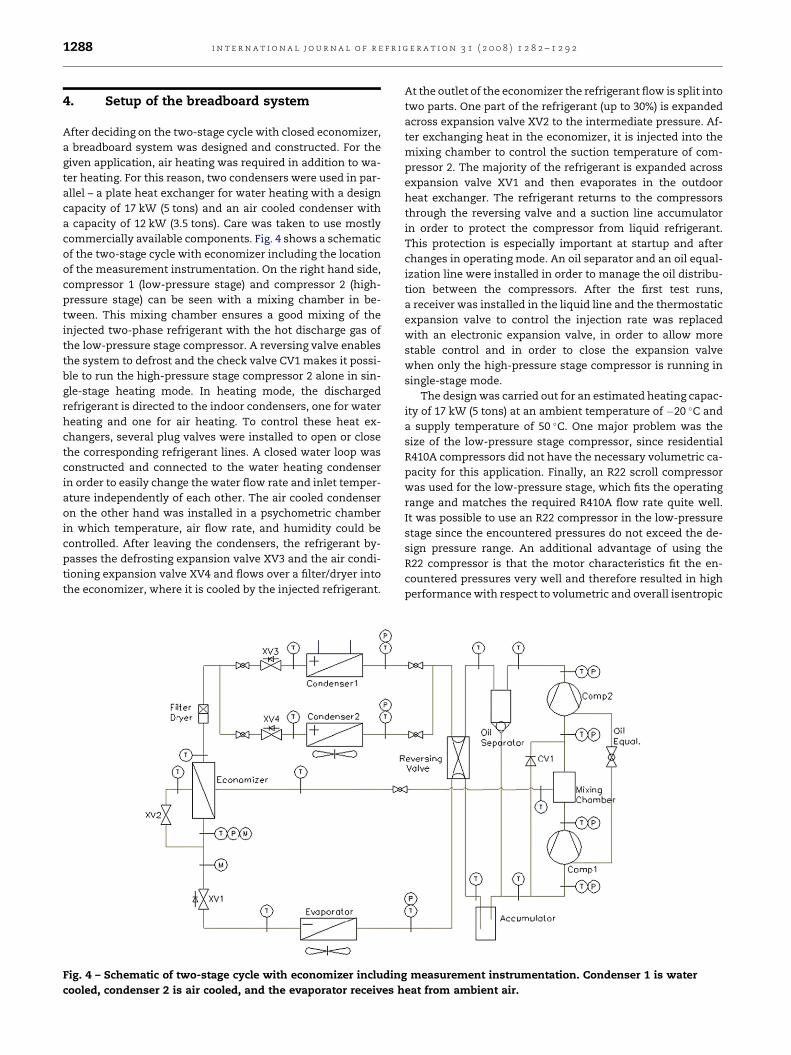
Fig. 3 shows the simulated heating capacity of the three
modeled cycles at a supply temperature of 50 �C as a function
of the ambient temperature. Again, the operating mode was
switched from two-stage to single-stage heating mode using
the high-pressure stage compressor only at temperatures of
0 �C and higher. Fig. 3 indicates that the three modeled cycles
provide a better fit of the heating demand than a conventional
single-stage heat pump that uses on–off control. The advantage
of the three heat pumps is that cycling can be done between
single-stage and two-stage modes, which provides greater
flexibility in the heat delivered to the residence and results
in greater indoor comfort. In addition, no significant difference
in heating capacity among the three cycles can be identified.
In conclusion, the two-stage cycle with economizer has
better performance than the two-stage cycle with intercooling
and similar performance as the cascade cycle. In addition, the
control of the economizer with a thermostatic expansion
valve promises to be straightforward. Despite its good perfor-
mance, the cascade cycle is difficult to reverse for air condi-
tioning in summer, except when adding a second outdoor
coil to the system. Therefore, the economizer cycle was cho-
sen for further investigation as a good compromise among
cost, efficiency, and ease of installation.
Fig. 3 – Simulation results of the heating capacity for two-
stage cycle with intercooler or economizer and for
a cascade cycle at 50 8C supply temperature.
i n t e r n a t i o n a l j o u r n a l o f r e f r i g e r a t i o n 3 1 ( 2 0 0 8 ) 1 2 8 2 – 1 2 9 21288
4. Setup of the breadboard system
After deciding on the two-stage cycle with closed economizer,
a breadboard system was designed and constructed. For the
given application, air heating was required in addition to wa-
ter heating. For this reason, two condensers were used in par-
allel – a plate heat exchanger for water heating with a design
capacity of 17 kW (5 tons) and an air cooled condenser with
a capacity of 12 kW (3.5 tons). Care was taken to use mostly
commercially available components. Fig. 4 shows a schematic
of the two-stage cycle with economizer including the location
of the measurement instrumentation. On the right hand side,
compressor 1 (low-pressure stage) and compressor 2 (high-
pressure stage) can be seen with a mixing chamber in be-
tween. This mixing chamber ensures a good mixing of the
injected two-phase refrigerant with the hot discharge gas of
the low-pressure stage compressor. A reversing valve enables
the system to defrost and the check valve CV1 makes it possi-
ble to run the high-pressure stage compressor 2 alone in sin-
gle-stage heating mode. In heating mode, the discharged
refrigerant is directed to the indoor condensers, one for water
heating and one for air heating. To control these heat ex-
changers, several plug valves were installed to open or close
the corresponding refrigerant lines. A closed water loop was
constructed and connected to the water heating condenser
in order to easily change the water flow rate and inlet temper-
ature independently of each other. The air cooled condenser
on the other hand was installed in a psychometric chamber
in which temperature, air flow rate, and humidity could be
controlled. After leaving the condensers, the refrigerant by-
passes the defrosting expansion valve XV3 and the air condi-
tioning expansion valve XV4 and flows over a filter/dryer into
the economizer, where it is cooled by the injected refrigerant.
Fig. 4 – Schematic of two-stage cycle with economizer includin
cooled, condenser 2 is air cooled, and the evaporator receives h
At the outlet of the economizer the refrigerant flow is split into
two parts. One part of the refrigerant (up to 30%) is expanded
across expansion valve XV2 to the intermediate pressure. Af-
ter exchanging heat in the economizer, it is injected into the
mixing chamber to control the suction temperature of com-
pressor 2. The majority of the refrigerant is expanded across
expansion valve XV1 and then evaporates in the outdoor
heat exchanger. The refrigerant returns to the compressors
through the reversing valve and a suction line accumulator
in order to protect the compressor from liquid refrigerant.
This protection is especially important at startup and after
changes in operating mode. An oil separator and an oil equal-
ization line were installed in order to manage the oil distribu-
tion between the compressors. After the first test runs,
a receiver was installed in the liquid line and the thermostatic
expansion valve to control the injection rate was replaced
with an electronic expansion valve, in order to allow more
stable control and in order to close the expansion valve
when only the high-pressure stage compressor is running in
single-stage mode.
The design was carried out for an estimated heating capac-
ity of 17 kW (5 tons) at an ambient temperature of �20 �C and
a supply temperature of 50 �C. One major problem was the
size of the low-pressure stage compressor, since residential
R410A compressors did not have the necessary volumetric ca-
pacity for this application. Finally, an R22 scroll compressor
was used for the low-pressure stage, which fits the operating
range and matches the required R410A flow rate quite well.
It was possible to use an R22 compressor in the low-pressure
stage since the encountered pressures do not exceed the de-
sign pressure range. An additional advantage of using the
R22 compressor is that the motor characteristics fit the en-
countered pressures very well and therefore resulted in high
performance with respect to volumetric and overall isentropic
g measurement instrumentation. Condenser 1 is water
eat from ambient air.
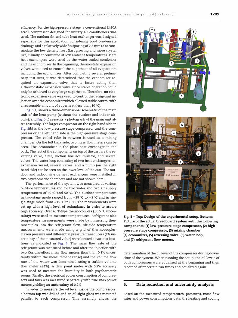
Fig. 5 – Top: Design of the experimental setup. Bottom:
Picture of the actual breadboard system with the following
components: (1) low-pressure stage compressor, (2) high-
pressure stage compressor, (3) mixing chamber,
(4) economizer, (5) reversing valve, (6) water loop,
and (7) refrigerant flow meters.
i n t e r n a t i o n a l j o u r n a l o f r e f r i g e r a t i o n 3 1 ( 2 0 0 8 ) 1 2 8 2 – 1 2 9 2 1289
efficiency. For the high-pressure stage, a conventional R410A
scroll compressor designed for unitary air conditioners was
used. The outdoor fin and tube heat exchanger was designed
especially for this application considering good condensate
drainage and a relatively wide fin spacing of 2.5 mm to accom-
modate the low density frost (fast growing and more crystal
like) usually encountered at low ambient temperatures. Plate
heat exchangers were used as the water-cooled condenser
and the economizer. In the beginning, thermostatic expansion
valves were used to control the superheat of all evaporators
including the economizer. After completing several prelimi-
nary test runs, it was determined that the economizer re-
quired an expansion valve that is faster acting than
a thermostatic expansion valve since stable operation could
only be achieved at very large superheats. Therefore, an elec-
tronic expansion valve was used to control the refrigerant in-
jection over the economizer which allowed stable control with
a reasonable amount of superheat (less than 10 �C).
Fig. 5(a) shows a three-dimensional schematic of the main
unit of the heat pump (without the outdoor and indoor air-
coils), and Fig. 5(b) presents a photograph of the main unit af-
ter assembly. The larger compressor on the right hand side in
Fig. 5(b) is the low-pressure stage compressor and the com-
pressor on the left hand side is the high-pressure stage com-
pressor. The coiled tube in between is used as a mixing
chamber. On the left back side, two mass flow meters can be
seen. The economizer is the plate heat exchanger in the
back. The rest of the components on top of the cart are the re-
versing valve, filter, suction line accumulator, and several
valves. The water loop consisting of two heat exchangers, an
expansion vessel, several valves, and a pump (on the right
hand side) can be seen on the lower level of the cart. The out-
door and indoor air-side heat exchangers were installed in
two psychometric chambers and are not shown here.
The performance of the system was measured at various
outdoor temperatures and for two water and two air supply
temperatures of 40 �C and 50 �C. The outdoor temperatures
in two-stage mode ranged from �28 �C to �2 �C and in sin-
gle-stage mode from �15 �C to 8 �C. The measurements were
set up with a high level of redundancy in order to assure
high accuracy. Over 40 T-type thermocouples (�0.5 �C uncer-
tainty) were used to measure temperatures. Refrigerant-side
temperature measurements were made by immersing ther-
mocouples into the refrigerant flow. Air-side temperature
measurements were made using a grid of thermocouples.
Eleven pressure and differential pressure transducers (1% un-
certainty of the measured value) were located at various loca-
tions as indicated in Fig. 4. The mass flow rate of the
refrigerant was measured before and after the injection with
two Coriolis-effect mass flow meters (less than 0.5% uncer-
tainty within the measurement range) and the volume flow
rate of the water was determined using a turbine volume
flow meter (�1%). A dew point meter with 0.2% accuracy
was used to measure the humidity in both psychometric
rooms. Finally, the electrical power consumption of compres-
sors and fans was measured separately with true RMS power
meters yielding an uncertainty of 0.2%
In order to measure the oil level inside the compressors,
a bottom tap was drilled and an oil sight glass was mounted
parallel to each compressor. This assembly allows the
determination of the oil level of the compressor during down-
time of the system. When running the setup, the oil levels of
both compressors were equalized at the beginning and then
recorded after certain run times and equalized again.
5. Data reduction and uncertainty analysis
Based on the measured temperatures, pressures, mass flow
rates and power consumptions data, the heating and cooling
i n t e r n a t i o n a l j o u r n a l o f r e f r i g e r a t i o n 3 1 ( 2 0 0 8 ) 1 2 8 2 – 1 2 9 21290
capacities, heating and cooling COPs, and second law efficien-
cies were calculated using the following equations.
Heating capacity for water and air heating (including pump
and fan power) was calculated as
_Qh;W ¼ _mWcp
�TW;o � TW;i
�(8)
_Qh;a ¼ _ma
�ha;o � ha;i
�(9)
and the cooling capacity (also including fan power) as
_Qcool ¼ _ma
�ha;o � ha;i
�(10)
where the inlet and outlet enthalpies were calculated using
temperature and humidity measurements. The coefficients
of performance (COP) for heating and cooling considering
the electrical power consumption of compressors, fans, and
pump, can be calculated as
COPcool ¼_Qcool
_Qel
(11)
COPh ¼_Qh;a þ _Qh;W
_Qel
(12)
The second law efficiency is defined as
hcarnot ¼COPmeasured
COPcarnot100% (13)
using the Carnot COP for heating and cooling
COPcarnot;H ¼Tsupply
Tsupply � Toutdoor(14)
COPcarnot;cool ¼Tsupply
Toutdoor � Tsupply(15)
The uncertainty of the results was calculated using a stan-
dard error analysis (Taylor, 1997). The calculated errors of
the heating and cooling COPs were between 3% and 9%,
whereas the errors of the heating and cooling capacity calcu-
lations were between 3% and 6%. The uncertainties in dis-
charge temperature were �0.5 �C and the errors in second
law efficiencies were 5–10%.
Fig. 6 – Compressor discharge temperature at a supply
temperature of 50 8C in single-stage and two-stage
operation modes versus ambient temperature.
6. Experimental results and comparisons
The system operated very well from the beginning using only
minor changes and adjustments. In air conditioning mode,
the indoor conditions were fixed at a dry bulb temperature
of 26.7 �C and a wet bulb temperature of 19.4 �C. At an outdoor
temperature of 35 �C DB and 23.9 �C WB (ARI Standard test
point ‘‘A’’, ARI Standard 210/240-2003, 2003), the cooling COP
including auxiliary power consumptions of fans, controls,
etc. was 3.3 and the cooling capacity was 13.0 kW. At an out-
door temperature of 28 �C (ARI Standard test point ‘‘B’’, ARI
Standard 210/240-2003, 2003), the cooling COP was 4.2 and
the cooling capacity was 13.5 kW.
In heating mode, the system was operated in single-stage
and in two-stage mode. Results were achieved during
a quasi-steady-state mode by starting the test with a dry coil
and running the system for 1 or 2 h for the purpose of data ac-
quisition. During the tests with evaporation temperatures be-
low 0 �C, frost formed on the outdoor coil and the operating
conditions changed slightly. However, frosting was not con-
sidered a concern for the validity of the test run because the
frost formation was very small for all test runs. At moderate
temperatures, the heat pump was operated in single-stage
mode and the oversized outdoor air-coil and air flow rate
resulted in small temperature difference between inlet and
outlet air and thus, little frost formation. At low temperatures,
the water content of the air is extremely small, which also
resulted in little frost formation. Notable frost accumulation
was only experienced in two-stage mode at ambient temper-
atures around the freezing point. However, the effect of this
frost formation on COP and heating capacity within the mea-
surement duration of 2 h was relatively small, due to the fact
that the frost first slightly enhances the heat transfer on the
coil due to more turbulence, before the heat transfer de-
creases according to the lower air flow rate and higher ther-
mal resistance of the ice layer on the fin surface. The
reported COP values and heating capacities are averaged
values for dry coil and coils with some ice buildup but before
the ice buildup significantly decreases the performance.
The evaporating, intermediate, and condensing tempera-
tures were�25.8 �C, 6.7 �C, and 54.9 �C, respectively, at an out-
door temperature of�20.5 �C and water supply temperature of
49.9 �C. These values agree very well with the prediction of the
system simulation model presented in Section 3.
The discharge temperatures of the compressors are shown
in Fig. 6 as a function of the outdoor temperature. It can be
seen that the temperature at the compressor discharge in-
creases rapidly with decreasing ambient temperature in sin-
gle-stage mode, which leads to a limitation of the operating
range (comparable to conventional systems). In two-stage
mode, the discharge temperatures of both compressors can
be kept below 105 �C over the whole operating range.

i n t e r n a t i o n a l j o u r n a l o f r e f r i g e r a t i o n 3 1 ( 2 0 0 8 ) 1 2 8 2 – 1 2 9 2 1291
Currently available conventional heat pumps reach discharge
temperatures of up to 120 �C at low ambient temperatures
before they are shut down. Compared to this value, the two-
stage heat pump investigated in this study is performing ex-
tremely well. Boiling of the supply water was not encountered,
due to heat losses in the discharge line, oil separator and re-
versing valve and the high water flow rates in the condenser.
The second law efficiency of the system was calculated
considering the auxiliary power usage of fans and pumps.
During two-stage operation, it was in the range of 39–46%
and in single-stage mode almost constant at a value of 43%,
which is high compared to current commercial air-source
heat pumps. In comparison, the current minimum required
Heating Seasonal Performance Factor (HSPF¼ 7.7) at the ASH-
RAE standard conditions of 21.1 �C indoor temperature and
8.3 �C outdoor temperature translates into a second law effi-
ciency of less than 15%.
The experimental results for heating COP and heating ca-
pacity obtained with the breadboard system were compared
to the simulation results as well as to the performance of an
average commercial air-source heat pump. Fig. 7 presents
the heating COP as a function of outdoor temperature. It can
be seen in Fig. 7 that the measured heating COP in single-stage
mode matches the simulation results very well. In two-stage
mode, the simulation results are approximately 20% higher
than the achieved measurements, which is a reasonable
agreement considering the relatively simplistic system simu-
lation model and the lack of compressor performance maps
for the given operating range. The compressor model of the
low-pressure stage compressor is the main contributor to
this deviation. The performance of the low-pressure stage
compressor had to be extrapolated from the manufacturer
data. Firstly, the compressor performance map had to be con-
verted from the working fluid R22 to R410A. Secondly, the
compressor performance map had to be extended to evaporat-
ing temperatures below �20 �C. An extrapolation at this point
Fig. 7 – COP versus ambient temperature for a supply
temperature of 50 8C and considering auxiliary power
according to (ARI Standard 210/240-2003, 2003).
is very critical, since the oil becomes more viscous towards
lower temperatures and therefore, the power consumption
of the compressor increases. An additional error in the perfor-
mance predictions was made by assuming a smaller econo-
mizer superheat at the inlet to the high-pressure stage
compressor than the ones achieved during the experiments
which reduces the system efficiency. In addition to the uncer-
tainty of the compressor simulation the modeling neglected
pressure losses in the oil separator and the suction line accu-
mulator, which are noticeable during two-stage operation. In
single-stage mode the performance of the breadboard system
compares well to the simulation and is as expected approxi-
mately 10% higher than the performance of a conventional
high efficiency system mainly due to the larger heat ex-
changers. In two-stage mode, the operation envelope can be
extended to ambient temperatures as low as �30 �C.
Fig. 8 shows the heating capacities obtained from the mea-
surements, predicted by the simulation model and of a typical
commercial product with the same size high-pressure stage
compressor. The experimental results closely match the sim-
ulation results for single-stage and two-stage operations. Sin-
gle-stage operation leads basically to the same heating
capacity as the commercial heat pump. Switching from sin-
gle-stage to two-stage mode more than doubles the capacity
of the system, which is a big advantage in meeting the re-
quired heating demand during low ambient temperatures. A
similar heating capacity could be obtained by a heat pump
with two parallel compressors. However, such a heat pump
would not be able to operate at the low end of the ambient
temperatures due to overheating of the compressors. Addi-
tionally, the performance of a heat pump with two parallel
compressors is expected to be lower than a heat pump with
two-stage compression due to the wide range of operating
conditions that need to be covered by each compressor,
which makes an optimization for several operating points
difficult.
Fig. 8 – Heating capacity at a supply temperature of 50 8C
versus ambient temperature.

i n t e r n a t i o n a l j o u r n a l o f r e f r i g e r a t i o n 3 1 ( 2 0 0 8 ) 1 2 8 2 – 1 2 9 21292
The oil management of the compressors worked quite well
in single-stage and in two-stage operating mode. The time in-
terval in which oil equalization between the compressors is
necessary was found to be in the range of 1–2 h. Frost accumu-
lation on the outdoor coil was very low. This was mainly
caused by the fact that the absolute humidity of the ambient
air is very low at ambient temperatures below �10 �C. In the
temperature interval from 0 �C to approximately 5 �C, where
usually most frost accumulation occurs, the frosting behavior
was also very good, due to the fact that the heat pump oper-
ates in single-stage mode, which reduces the load on the out-
door coil.
7. Conclusions
A two-stage air-source heat pump for water and air heating
was simulated, designed, constructed, and tested. The func-
tionality and concept of the system could be verified by show-
ing that the heat pump is able to operate at ambient
temperatures between �30 �C and 10 �C with supply water
temperatures of up to 50 �C. Air and water heating can be pro-
vided in single-stage and in two-stage operating mode. At the
same ambient temperature, two-stage mode operation ap-
proximately doubles the heating capacity compared to sin-
gle-stage mode operation. The discharge temperatures of the
compressors in two-stage mode stayed below 105 �C at all
times. Very high second law efficiencies of 39–46% were mea-
sured over the whole operating range, which outperforms
most currently available commercial single-stage air-source
heat pumps.
All four major problems associated with heat pumps oper-
ating at low ambient temperatures, namely, (1) high compres-
sor discharge temperatures, (2) low COP, (3) reduced heating
capacity, and (4) increased on/off cycling when a heat pump
designed for low ambient temperatures then operates at
higher ambient temperatures, could be addressed with the
new concept. It could also be shown that the system can be
made from commercial available components with only little
modifications.
The cost of the two-stage system with economizer is con-
siderably higher than the one of a current single-stage air-
source heat pump due to the need of a second compressor,
an additional heat exchanger, and a more complex control
system. On the other hand, the cost is less than the one of
a ground source heat pump considering the cost for drilling
the boreholes.
The main challenges in the implementation of the system
are the appropriate logic to control the system and to find
commercially available compressors for the given specifica-
tion. Especially the low-pressure stage compressor with an
oil tap on the bottom or on the side of the compressor and
a suction volume of approximately 90 cm3/rev are not com-
mercially available for a single-phase R410A compressor at
the moment. On the other hand, the substitution with an
R22 compressor worked very well.
Acknowledgments
This project was funded by Electro Industries, Inc. from Mon-
ticello, MN. The authors would like to acknowledge the sup-
port and initiative of Electro Industries, Inc. and William J.
Seefeldt in particular.
r e f e r e n c e s
ANSI/ARI Standard 540-1999, 1999. Positive displacementrefrigerant compressors and compressor units.
ARI Standard 210/240-2003, 2003. Unitary air-conditioning andair-source heat pump equipment.
ASHRAE Handbook, 2000. HVAC Systems and Equipment(Chapter 21 and 35).
Bertsch, S.S., 2005. Theoretical and Experimental Investigation ofa Two Stage Heat Pump Cycle for Nordic Climates. Master’sthesis, Mechanical Engineering, Herrick Labs 2005-13P, ReportNo. 7031-1, Purdue University, West Lafayette, Indiana, 2005.
Bertsch, S.S., Groll, E.A., 2005. Air to water heat pump for lowtemperature climates. In: 8th International Energy AgencyHeat Pump Conference, Las Vegas, NV, CD-ROM.
Dabiri, A.E., Rice, C.K., 1981. A compressor simulation model withcorrections for the level of suction gas superheat. ASHRAETransactions 87 (2), 771–780.
Incropera, F.P., DeWitt, D.P., 2002. Fundamentals of Heat andMass Transfer, fifth ed. John Wiley & Sons (Chapter 11).
Kumar, K.P., Venkatarathnam, G., 2000. Optimization of matrixheat exchanger geometry. Journal of Heat Transfer 122 (3),579–586.
LeRoy, J.T., Groll, E.A., Braun, J.E., 1997. Computer modelpredictions of dehumidification performance of unitary airconditioners and heat pumps under extreme operatingconditions. Final Report ASHRAE RP-859, Herrick Labs 97-26,Report No. 3220-3, Purdue University, West Lafayette,Indiana.
Mackensen, A., Klein, S.A., Reindl, D.T., 2002. Characterization ofrefrigerant system compressor performance. In: Proceedingsof the International Refrigeration and Air ConditioningConference at Purdue, Purdue University, CD-ROM.
Shuangquan, S., Ma, G., Yan, Q., 2002. Study on heat pump cyclefor cold regions with two-stage compression in one scrollcompressor. In: 7th International Energy Agency Heat pumpConference, CD-ROM, China.
Taylor, J.R., 1997. An Introduction to Error Analysis, second ed.University Science Books, p. 327.
Zehnder, M., Favrat, D., 2000. Oil Migration on Single and TwoStage Heat Pump Systems. Swiss Department of Energy.
Zhao, H., Liu, S., Ma, G., 2005. Experimental study on heat pumpcycle of flash-tank economizer with scroll compressor. In: 8thInternational Energy Agency Heat Pump Conference, LasVegas, NV, CD-ROM.
Zogg, M., 2002. The Swiss retrofit heat pump programme. In: 7thInternational Energy Agency Heat pump Conference, CD-Rom-Proceedings, China.
Zubair, S.M., Yagub, M., Khan, S.H., 1996. Second-law-basedthermodynamic analysis of two-stage and mechanical-subcooling refrigeration cycles. International Journal ofRefrigeration 19, 506–516.