Testing the MODIS satellite retrieval of aerosol fine-mode fraction

The HIGH-COMBI project: High solar fraction heating and coolingsystems with combination of innovative components and methods
Vassiliki N. Drosou a,n, Panagiotis D. Tsekouras b, Th.I. Oikonomou a, Panos I. Kosmopoulos c,Constantine S. Karytsas d
a Centre for Renewable Energy Sources and Saving, Solar Thermal Systems Department, 19th km Marathon Avenue, Pikermi, 19009 Athens, Greeceb National Technical University of Athens, School of Mechanical Engineering, Laboratory of Solar Energy, Heroon Polytechniou 9, Zografou Campus,15780 Athens, Greecec Laboratory of Environmental and Energy Design of Buildings and Settlements, Democritus University of Thrace, Department of Environmental Engineering,Vas Sofias 12, Xanthi, Greeced Centre for Renewable Energy Sources and Saving, Geothermal Energy Department, 19th km Marathon Avenue, Pikermi, 19009 Athens, Greece
a r t i c l e i n f o
Article history:Received 17 October 2012Received in revised form2 August 2013Accepted 11 August 2013Available online 23 September 2013
Keywords:Solar thermal systemsSolar coolingHigh solar fractionSeasonal storageSolar heat pumpAbsorption cooling
a b s t r a c t
The scope of the HIGH-COMBI project is the development of high solar fraction systems by innovativecombination of optimized solar heating, cooling and storage technologies as well as control strategies, inorder to contribute and assist the further deployment of the solar energy market. Within this project, sixdemonstration plants were installed in four European countries (Greece, Italy, Spain and Austria). Thepurpose of this article is to assess the result achieved in the technical field of the project and to presentthe technical aspects of the six innovative demonstration systems realised during the project period.
& 2013 Elsevier Ltd. All rights reserved.
Contents
1. Introduction . . . . . . . . . . . . . . . . . . . . . . . . . . . . . . . . . . . . . . . . . . . . . . . . . . . . . . . . . . . . . . . . . . . . . . . . . . . . . . . . . . . . . . . . . . . . . . . . . . . . . . . . 4642. Energy related topics of the solar cooling sector . . . . . . . . . . . . . . . . . . . . . . . . . . . . . . . . . . . . . . . . . . . . . . . . . . . . . . . . . . . . . . . . . . . . . . . . . . . 4643. Overview of HIGH-COMBI project. . . . . . . . . . . . . . . . . . . . . . . . . . . . . . . . . . . . . . . . . . . . . . . . . . . . . . . . . . . . . . . . . . . . . . . . . . . . . . . . . . . . . . . 4654. HIGH-COMBI demonstration systems . . . . . . . . . . . . . . . . . . . . . . . . . . . . . . . . . . . . . . . . . . . . . . . . . . . . . . . . . . . . . . . . . . . . . . . . . . . . . . . . . . . . 465
4.1. The Greek demonstration plant . . . . . . . . . . . . . . . . . . . . . . . . . . . . . . . . . . . . . . . . . . . . . . . . . . . . . . . . . . . . . . . . . . . . . . . . . . . . . . . . . . 4654.2. The Italian demonstration plant . . . . . . . . . . . . . . . . . . . . . . . . . . . . . . . . . . . . . . . . . . . . . . . . . . . . . . . . . . . . . . . . . . . . . . . . . . . . . . . . . . 4674.3. The Spanish demonstration plant . . . . . . . . . . . . . . . . . . . . . . . . . . . . . . . . . . . . . . . . . . . . . . . . . . . . . . . . . . . . . . . . . . . . . . . . . . . . . . . . . 4684.4. The 1st Austrian demonstration plant . . . . . . . . . . . . . . . . . . . . . . . . . . . . . . . . . . . . . . . . . . . . . . . . . . . . . . . . . . . . . . . . . . . . . . . . . . . . . 4694.5. The 2nd Austrian demonstration plant. . . . . . . . . . . . . . . . . . . . . . . . . . . . . . . . . . . . . . . . . . . . . . . . . . . . . . . . . . . . . . . . . . . . . . . . . . . . . 4694.6. The 3rd Austrian demonstration plant . . . . . . . . . . . . . . . . . . . . . . . . . . . . . . . . . . . . . . . . . . . . . . . . . . . . . . . . . . . . . . . . . . . . . . . . . . . . . 470
5. HIGH-COMBI software tool: “TRNSED” . . . . . . . . . . . . . . . . . . . . . . . . . . . . . . . . . . . . . . . . . . . . . . . . . . . . . . . . . . . . . . . . . . . . . . . . . . . . . . . . . . . 4716. Conclusions . . . . . . . . . . . . . . . . . . . . . . . . . . . . . . . . . . . . . . . . . . . . . . . . . . . . . . . . . . . . . . . . . . . . . . . . . . . . . . . . . . . . . . . . . . . . . . . . . . . . . . . . 471
Contents lists available at ScienceDirect
journal homepage: www.elsevier.com/locate/rser
Renewable and Sustainable Energy Reviews
1364-0321/$ - see front matter & 2013 Elsevier Ltd. All rights reserved.http://dx.doi.org/10.1016/j.rser.2013.08.019
Abbreviations: ACM, absorption cooling machine; AHU, air handling unit; BTES, borehole thermal energy storage; CHP, combined heat and power plant; COP, coefficient ofperformance; CRES, Centre for Renewable Energy Sources and Saving; CSHPSS, central solar heating plants with seasonal storage; DEC, desiccant evaporative cooling device;DHW, domestic hot water; ESTIF, European Solar Thermal Industry Federation; GHE, ground heat exchangers; HP, heat pump; HVAC, heating–ventilation–air conditioning;IEA, International Energy Agency; RES, renewable energy sources; SAC, solar air conditioning (systems); SF, solar fraction; SPFel, seasonal performance factor (electrical);STES, seasonal thermal energy storage; UNEP, United Nations Environment Program; UTES, underground thermal energy storage
n Corresponding author. Tel.: þ30 2106603381; fax: þ30 2106603300.E-mail addresses: [email protected] (V.N. Drosou), [email protected] (P.D. Tsekouras), [email protected] (Th.I. Oikonomou),
[email protected] (P.I. Kosmopoulos), [email protected] (C.S. Karytsas).
Renewable and Sustainable Energy Reviews 29 (2014) 463–472
Acknowledgments . . . . . . . . . . . . . . . . . . . . . . . . . . . . . . . . . . . . . . . . . . . . . . . . . . . . . . . . . . . . . . . . . . . . . . . . . . . . . . . . . . . . . . . . . . . . . . . . . . . . . . . 471References . . . . . . . . . . . . . . . . . . . . . . . . . . . . . . . . . . . . . . . . . . . . . . . . . . . . . . . . . . . . . . . . . . . . . . . . . . . . . . . . . . . . . . . . . . . . . . . . . . . . . . . . . . . . . 472
1. Introduction
In 2010, the European Commission adopted the communication“Energy 2020” that defines a new strategy toward 2020 for acompetitive, sustainable and secure energy [1]. Priority is given tobuildings and transport sectors. Through directives to improvebuilding energy efficiency (energy performance of buildings direc-tive, or EPBD), the European Union has recognized the highpotential for energy savings from buildings and promote theinstallation of solar thermal systems in the building sector.
Solar thermal systems for hot water production are alreadymandatory in new buildings according to solar ordinances in Spain[2], Portugal [3], Italy [4], Greece [5] and other European Countries [6].The most common solar energy thermal application is for sanitary hotwater (SHW) production [7].
Small systems for SHW production using natural flow systems,known as thermosyphons, are common practice in southern Europeand in general in frost-free climates [8]. Systems combining produc-tion of SHW and space heating, known as “solar combi” systems, arewell suited to middle and high latitudes, due to significantly highersolar radiation in the transitional periods around winter (September–October and March–May) and the significant heating demand inthese latitudes at that time [8]. For this reason, they are popular incentral and northern Europe [9]. Installations with large solarcollector areas and small size heat storage capacity can cover around50% of the total heat demand. The percentage can be higher in somecases of large storage capacities and primary energy savings up to80% can be realised [10,11]. Simulations of central solar heatingplants with seasonal storage (CSHPSS) has shown that the solarfraction of such systems varies between 50% and 100% [12]. The heatproduced by the collectors may be stored in thermal energy storagesin order to provide domestic hot water and space heating whenrequired [13].
The addition of a solar cooling facility makes the systemcomplete, covering all building thermal and cooling demands[11]. These systems are known as “solar combi plus” systems.“Solar combi plus” systems, seem to be proved advantageous sincehigh cooling loads coincide with high solar radiation, and conse-quently the readily available solar energy from the existing solarcollectors can be exploited by a heat driven machine [14]. The useof the solar collectors is thus extended to a whole year, making thesystem financially attractive, when the number of annual full-loadhours is high [15]. Furthermore, since the cooling machine is heatdriven, the building electrical loads are reduced and the problemsassociated with peak power demand during summer are mini-mized [11]. Depending on the size of solar collector field, hot waterstorage, local climatic conditions and building loads, a “solar combiplus” system may cover 10–60% of the combined space heating/cooling and SHW demand at southern, central and northernEuropean countries [16].
The HIGH-COMBI project focused on developing innovativehigh solar fraction systems by optimized combination of solarheating and cooling technologies with adapted seasonal storagedevice that can reach a solar fraction approaching 100% [17].
This paper presents the six demonstration installations thatwere constructed in the framework of HIGH-COMBI project. Foreach installation is given the technical characteristics, the opera-tional principles of summer and winter operation for coolingand heating respectively, as well as available solar fraction indi-cators [17].
2. Energy related topics of the solar cooling sector
Europe has a well-structured market, serving various solarthermal applications. With almost 2.6 GWth installed in 2011, thetotal installed capacity in Europe is now 26.3 GWth, generating18.8 TWh of solar thermal energy while contributing to savings of13 MMt CO2 [18].
In an effort to improve the energy performance of buildingsand the integration of renewables, the primary goal should alwaysbe to first reduce heating and cooling loads [19]. Simply shiftingprimary energy from fossil fuels and electricity to solar energymay be environmentally sound, but on the other hand it will provefinancially prohibitive; energy waste of solar energy is as unac-ceptable as any other energy source [20]. Implementing properbuilding and plant design, construction and operation followingwell established principles, reducing heat losses in winter and heatgains in summer through the building envelope, using energyefficient equipment and technologies, is a practical and mandatoryprocess for any high performance building project [21].
Solar collector efficiency, simply estimated as the delivered heatto incident solar radiation, mainly depends on the solar thermaltechnology used, the design and the quality of the collector, thetechnical characteristics of hot water storage and back-up systems,averaging on an annual basis 40–55% for SHW [22]. In similar way,annual average solar utilization (accounting for storage heat lossesand waste heat) of 20–25% have been obtained in “combi systems” inCentral Europe and 30–35% in Mediterranean countries. Dependingon the size of the solar collector field, hot water storage, local climaticconditions and building loads, “solar combi” systems may cover 10–60% of the combined SHW and space heating demand at central andnorthern European locations. According to Aidonis et al. [23], thesimulations for Greece showed that the “solar combi” systems can becombined with the conventional heating systems, giving highenergetic results and solar coverage of the total heating load thatcan reach 40–50%. Similar results have been presented fromArgiriou et al. [24] in a simulation of three systems in NorthernGreece.
In parallel, solar thermal systems for cooling is an emergingmarket with a huge growth potential. Specific guidelines and anoverview of various applications are reported in Balaras et al. 2006[25]. Each solar cooling technology has specific characteristics thatmatch the building's HVAC design, loads, and local climaticconditions. A good design must first exploit all available solarradiation and then cover the remaining loads from conventionalsources [26].
According to the handbook for planners for solar assisted airconditioning of building, written by Henning [14] and to thedesign guidelines presented in Balaras et al. [25], proper calcula-tions for collector and storage size depend on the employed solarcooling technology. The use of solar collectors should be max-imized by also supplying heat to cover space heating or SHWloads. Hot-water storage may be integrated between the solarcollectors and the heat-driven chiller to dampen the fluctuationsin the return temperature of the hot water from the chiller. Thestorage size depends on the application: if cooling loads mainlyoccur during the day, then a smaller storage will be necessary thanwhen the loads peak in the evening. Heating the hot-water storageby the backup heat source should be strictly avoided. The storage'sonly function is to store excess heat of the solar system and tomake it available when sufficient solar heat is not available.
V.N. Drosou et al. / Renewable and Sustainable Energy Reviews 29 (2014) 463–472464

In Europe, there has been various projects, scoping the furtherdevelopment of solar cooling, including: CLIMASOL “promotingsolar air conditioning” [27]; SACE “solar air conditioning inEurope” [28]; SOLAIR “increasing the market implementation ofsolar air-conditioning systems for small and medium applicationsin residential and commercial buildings” [29]; SOLCO “removal ofnon-technological barriers to solar cooling technology acrosssouthern European islands” [30] and at international level throughthe IEA solar heating & cooling (SHC) program, including: Task 25“solar assisted air-conditioning of buildings” [31] and Task 38“solar air-conditioning and refrigeration” [32].
Regarding “solar combi plus” even though some installationshave been realized in Europe [33], there are still main obstaclesahead. Among others, “drawbacks” for the massive application ofsuch systems are the high initial cost and the lack of knowledgeand practical experience in design, control, operation, installationand maintenance. Although the installed systems worldwide areabout 200, there are not yet adequate official reviews andtestimonials of these systems [34]. Besides the trained technicalpersonnel for such systems is limited, as there has been nospecified training program currently established. As a result, theexisting engineers and installers are not thoroughly aware of thevarying design parameters and there are no significant provisionsof technical support in a local level [33]. Research and develop-ment in Europe, including the described at this paper Europeanproject HIGH-COMBI, are being brought forward with the view toovercome these barriers. The present study contributes to thesolution of the above mentioned issues.
3. Overview of HIGH-COMBI project
The HIGH-COMBI project aimed on developing high—even upto 100%, solar fraction systems by combing the two technologies of“solar combi” and “solar cooling” system with innovative seasonalstorage device.
The development of these combined systems has many advan-tages due to the fact that allows the use of solar energy throughoutthe whole year, endeavoring to increase the primary energysavings in buildings and consequently to contribute and assistthe further deployment of the solar energy market. One of themost signature parameters for examining the economic viability ofa technology is the operating cost. Solar Combi plus systems havethe advantage of minimizing the operating cost in relation to theconventional energy (fuel or electricity) cost [33]. A secondadvantage is the positive environmental profile of solar combisystems by the mitigation of CO2 emissions, through the saving ofprimary energy and electricity [33]. A significant market-orientedadvantage of solar combi systems is that they cover three energyfunctions—(i.e., heating, cooling and domestic hot water—into onesingle product [33].
The main objectives of the project were
� Identification of configurations of solar plants for heating andcooling applications.
� Computational analysis of the solar plants and optimizationprocedures using different combination of technologies.
� Realization of the demonstration plants.� Development of a simple software tool for dimensioning solar
systems under the same configurations.� Monitoring and technology evaluation.� Dissemination of the activities on national level and Europe-
wide.
In the research phase, different configurations were examinedand optimized by detailed simulations. Demonstration plants were
constructed, using different combination of technologies, compo-nents and control strategies. All demo plants achieved high solarfractions values with a sound economy; for some of the plantsmore than 70% of coverage for the space heating, domestic hotwater and cooling loads was reached. Innovative techniques,components and configurations were examined (e.g., newstorages, use of rejected heat during cooling, combined heatingand cooling control etc.). Demonstration plants' monitoring datawas analyzed, the simulation and design tools validated and theplants' performance evaluated. Market analyses were carried outin order to estimate the potential penetration of these systems inthe European heating and cooling market. A user friendly simula-tion software tool was developed for dimensioning and economicanalysis for planners.
The most valuable outcome of the project was the design anddevelopment of six innovative High Solar Fraction DemonstrationSystems in four European countries (Greece, Italy, Spain andAustria). The sectors of implementation are all medium and largebuilding end-users having heating and cooling loads alongthe year.
All project information is readily accessible and can be viewedon and/or downloaded from the HIGH-COMBI website at www.highcombi.eu
4. HIGH-COMBI demonstration systems
In the framework of HIGH-COMBI project six demonstrationplants have been constructed, using different combination oftechnologies, components and control strategies, as shown inTable 1.
In Table 2, an overview of the technical characteristics of solarthermal collectors and solar cooling application for each HIGH-COMBI installation is given
The demonstration plants were monitored and analyzed. Solarfraction factors for each HIGH-COMBI demonstration plant arepresented in Table 3. Based on these monitoring data the simula-tion and design tools were validated and the performance of theplants evaluated. In order to derive common energy figures for allthe installations, the monitoring procedure developed in IEA SHCTask 38 Subtask A and B has been used as assessment tool [35].
In the present section of the paper a technical description foreach plant is given, together with representative energy perfor-mance figures derived from the application of the monitoringprocedure—where available.
4.1. The Greek demonstration plant
The Greek plant is installed in an existing office building, at thesite of the Centre for Renewable Energy Sources and Saving - CRESin Athens (latitude 38100′N & longitude 23155′ E), Greece. Thebuilding covers a total of 427 m2 with a volume of 1296 m3, whichis typical of medium sized offices and multifamily buildings. Thebuilding was constructed in 2000 and was initially designated aslaboratory. In 2008, the building was renovated and it is currentlyused as office.
The Greek plant operates since December 2011. The mainsystem components of the plant include: selective flat plate solarthermal collectors, a seasonal underground thermal energy sto-rage, an absorption chiller, a wet cooling tower and an energyefficient heat pump (HP).
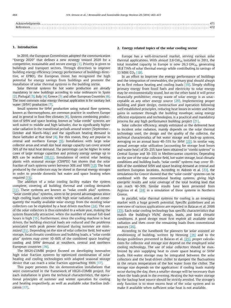
In heating operation mode as shown in Fig. 1, the solar systemis designed to supply the building with a hot water temperature of45 1C. Priority is given to the heat coming directly from the solarfield or/and the UTES. The HP is connected in series and operatesas a backup, using the UTES as a heat source, increasing the supply
V.N. Drosou et al. / Renewable and Sustainable Energy Reviews 29 (2014) 463–472 465

temperature to the building, if necessary. Depending on thebuilding's heating demand, the availability of solar radiation andthe water temperature inside the UTES, a control system selectsthe optimum heat source or a combination there after.
The possible operating modes for winter period are: (1) Solarcollectors; (2) Underground seasonal thermal energy water sto-rage (UTES); (3) Solar collectors—heat pump; (4) UTES—heatpump.
Table 1General characteristics of each HIGH-COMBI demonstration plant.
Country Greece Italy Spain Austria I Austria II Austria IIILocation Athens Milano Barcelona Gleisdorf Gleisdorf Graz
Operation December2011
July 2011 December 2011 July 2008 July 2010 July 2008
End user Office Sport facilities Health care and socialhousingfor elderly people
Town hall offices Offices Offices
Conditioned area 427 m2 700 m2 3700 m2 2533 m2 1000 m2 430 m2
Heat/cold distributionsystem
Fan coils Fan coils, air handlingunit
Radiant floor Radiators, floorheating,ceiling elements, fancoils
Ceiling elements,radiators
Radiators, ceilingelements
Heating requirements 12.3 MWh/a 59 MWh/a 12 MWh/a 142 MWh/a 14.7 MWh/a 38 MWh/aCooling requirements 19.4 MWh/a 23 MWh/a 60 MWh/a 71 MWh/a 14.8 MWh/a 11 MWh/a
Table 2Solar thermal collectors and solar cooling technical characteristics of each HIGH-COMBI demonstration plant.
Country Greece Italy Spain Austria I Austria II Austria III
Solar thermal collectorsTECHNOLOGY Selective
flat plateSelectiveflat plate
Evacuated heat pipe tubes Flat plate collectors HT Flat plate collectors HT Flat platecollectors HT
Area (gross) 149.5 m2 146 m2 200 m2 302 m2 64 m2 59 m2
Heat storage 58 m3 22 m3 9 m3 4.6 m3 10 m3 2 m3
Solar coolingTechnology Absorption
chillerAbsorptionchiller
Absorption chiller Absorption chiller & solarACM (Silica gel)
Absorption chiller Absorptionchiller
Nominalcapacity
35 kW 35 kW 70 kW 35 kW 19 kW 17.5 kW
Cold storage Notapplicable
4 m3 1 m3 1 m3 Not Applicable 0.2 m3
Auxiliarysystem
Heat pumps Heat pumps Condensing gas boilers/compression chillers
District heating (naturalgas)
Vegetable oil driven CHP, natural gas boiler,ground source heat pump
Districtheating
Table 3Solar fraction of each HIGH-COMBI demonstration plant.
Country Greece Italy Spain Austria I Austria II Austria III
Solar fraction (SF)Designed SF 85% 54% 54% (overall),
68% (onlysocialhousing)
36% 66% 100% solar coolingfraction
Measured SF 70% Not available(no real loadas the buildingis not yet inuse)
Not available 25% 13% 43%
Reason ofdiscrepanciesbetweendesigned andmeasured SF
The operationperiod of the plant(December 2011–February 2012)was not indicativefor the expectedannual SF
– – Although the measuredsolar gain was higher thanthe simulated one, themeasured SF was less thanthe designed because:(a) The measured HeatDemand for heating andcooling was 37% higherthan the simulated one and(b) the lower than expectedmeasured coefficient ofperformance (COP) of thedesiccant evaporativecooling (DEC) system
The much highermonitored heatdemand than thesimulated one (11times more), becauseother heat demandsof the building, via adistrict heatingnetwork, are coveredin reality
The design of theplant was focusedon 100 % solarcooling, so it wasnot designed for aspecific solarheating fraction
V.N. Drosou et al. / Renewable and Sustainable Energy Reviews 29 (2014) 463–472466
In cooling operation, as illustrated in Fig. 2, the solar system isdesigned to supply the building with a chilled water temperatureof 7 1C. Priority is given to the absorption chiller due to its lowelectrical energy consumption. The HP is connected in series andoperates as a backup energy source, reducing the supply tempera-ture to the building, if necessary. The absorption chiller is drivenby either the heat output from the solar collectors at a “high”temperature usually in the range of 70–85 1C or the UTES andprovides useful cooling by extracting heat from the building.During summer, whenever there is excess solar energy (i.e., lowcooling load or SHW demand), it is delivered directly to the UTES.The water in the tank may be heated up to about 90 1C in summer.Depending on the building's cooling demand, the availability ofsolar radiation and the water temperature inside the UTES, acontrol system selects the optimum heat source or a combinationthere after.
The possible operating modes for summer are: (1) Solarcollectors—absorption chiller; (2) UTES—absorption chiller;(3) Solar collectors—absorption chiller & heat pump; (4) UTES—absorption chiller & heat pump.
During the intermediate seasons (autumn and spring opera-tion), when heating and cooling loads are relatively low, the excesssolar energy will be stored in the UTES, reaching a watertemperature of about 95 οC.
The estimated solar fraction is around 85% of the total thermalenergy requirement.
4.2. The Italian demonstration plant
The Italian plant is installed at the “Idroscalo”—HydroPark. TheHydroplane Port is located on the east side of Milan and is todaysurrounded by a park dedicated to recreational activities withapproximately 2 million visitors per year. So far the building hasnot been in use for several years. After refurbishment it willserve activities of public interest, such as sport and other activities.The demonstration solar plant is covering heating, cooling andSHW loads.
The Italian plant is in operation since July, 2011. The systemcombines solar cooling with heat pumps, which is a very promis-ing trend of research and commercial applications. It is a complete
Fig. 1. Energy flow scheme of heating operations of the Greek plant.
Fig. 2. Energy flow scheme of cooling operations of the Greek plant.
V.N. Drosou et al. / Renewable and Sustainable Energy Reviews 29 (2014) 463–472 467

combination, since the water–water heat pump uses in winter hotwater from the solar tank as cold source, adding energy from theelectricity network in order to reach the desired temperatures.A second heat pump (air–water) is used to cover the peak loads inwinter, as well as in summer.
A water–water heat-pump is connected “in series” with thesolar tank and is in charge of covering heat demand in case solarenergy is not available. This increases both the solar plantefficiency and the heat pump's COP.
There are two operation modes available: the winter andsummer operation. Figs. 3 and 4 show the energy flow schemeof the system in summer and winter respectively. In winteroperation, the solar thermal system heats up the SHW storageand the two storages tanks: tank A and tank B. Priority is given tothe SHW tank. Hot water from tank A can charge the buffer storagetank C. Tank C can be also charged by the water to water heatpump that is extracting heat either from tank B or from both tanksA and B. Tank C is maintained at about 40–45 1C, in order toactivate fan-coils (40 1C) and air handling unit (AHU). If necessary,an air to water heat pump charges tank C. The auxiliary heat forthe SHW (when the solar heat is not enough) is provided bytank C.
In summer operation, the solar thermal system heats up theSHW storage and the two tanks A and B. Priority is given to theSHW tank. Then tank A is heated up till the maximum acceptedtemperature is reached (90 1C). Tank A delivers heat to theabsorption chiller, which produces cold water to be stored in thetank C; therefore it is used in summer as a cold storage. Heat fromabsorption chiller is rejected toward the environment by means ofan incorporated cooling tower. The water–water HP (WW_HP) isshut down in summer. Cold backup is therefore provided by theair–water HP (AW_HP), which directly cools down tank C. Fan-coils and AHU work at a delivery temperature of 8 1C. The auxiliaryheat for the SHW (in the very rare cases when the solar heat is notenough) is provided by an electric resistance. Estimated solarfraction is around 55% of total load.
4.3. The Spanish demonstration plant
The Spanish plant is installed at a newly designed building, inthe center of Barcelona. The building, owned by the PatronatMunicipal de l'Habitage de Barcelona, comprehends a healthcarecenter in the three lower floors, and 32 social housing flats forelderly people in the upper floors. The building has been designed
Fig. 3. Energy flow scheme in winter mode of the Italian plant.
Fig. 4. Energy flow scheme in summer mode of the Italian plant.
V.N. Drosou et al. / Renewable and Sustainable Energy Reviews 29 (2014) 463–472468

and built according various energy optimization criteria, throughthe detailed simulation and the proposal of different measures(including the optimal size of insulation, the glasses to be used andthe size of the balconies).
The installed system consists of 200 m2 heat pipe evacuatedtube collectors, a stratified storage tank, an absorption chiller, acompression chiller and a condensation boiler. The option toinstall geothermal heat exchangers was disregarded, due to sub-stantially higher investment costs that could not be justified whenenergy price is taken in account. Additionally, the heat demand inwinter is low and could be easily covered by the solar collectors.
The optimization process led to an optimal driving temperaturefor the absorption chiller (75–80 1C), for the optimal solar collectorsinclination (251) and for the specific heat storage ratio (35 l/m2).
The main components of the Spanish demonstration plant arethe evacuated heat pipe tubes, the absorption chiller of nominalcapacity 70 kWc, and wet cooling tower. The building has imple-mented with radiant floor for heating and cooling and a dehumi-dification has also been installed.
In Fig. 5 the energy flow scheme of the plan is given.
4.4. The 1st Austrian demonstration plant
Within the framework of the renovation of the old Town Hall(1321 m2) and the construction of a new Service Centre (officebuilding with 1212 m2), a solar combi plus installation wasrealised in 2008. The system provides both buildings with heatingand cooling energy as well as domestic hot water.
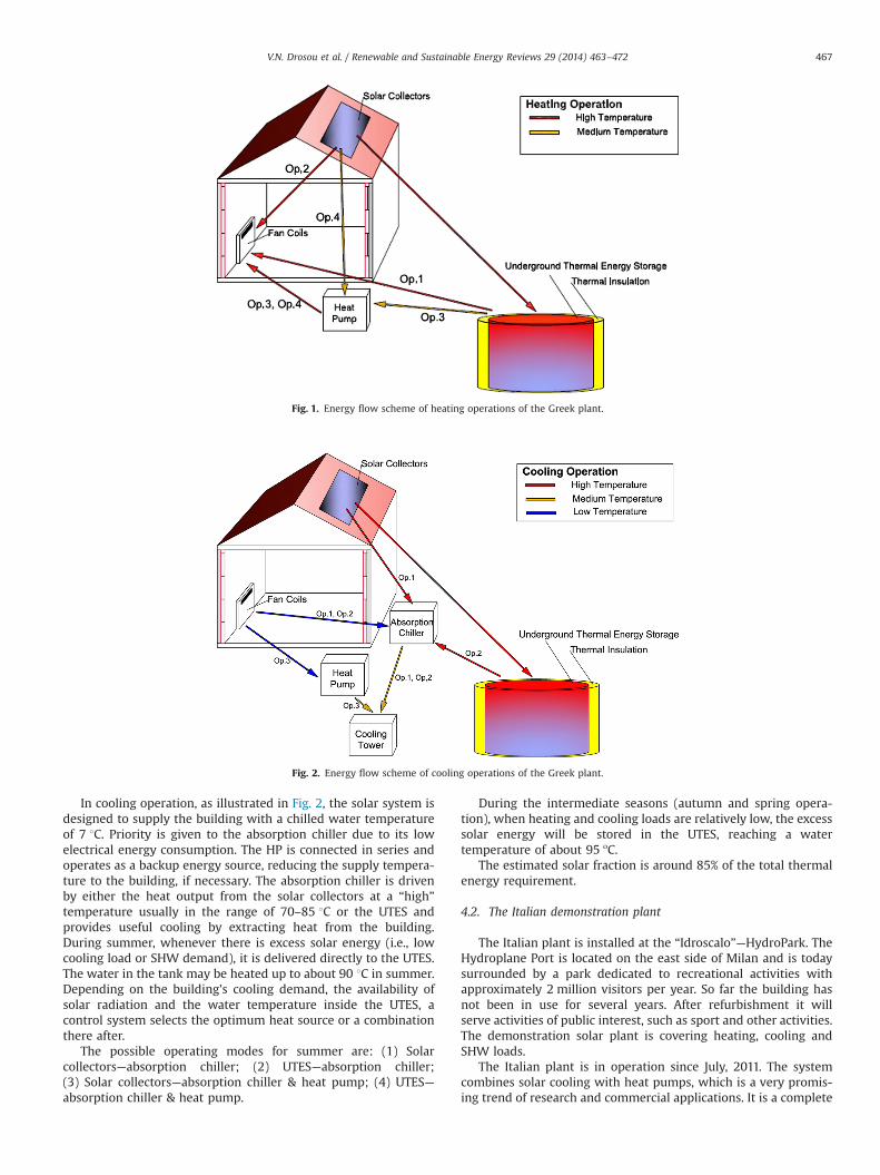
In Fig. 6 the energy flow scheme of the system is shown. Spaceheating energy is taken out of the central heat storage and isdistributed via radiators and floor heating in the Town Hall and viaceiling elements and the heated supply air of the air handling unit
in the Service Center. Domestic hot water is prepared with a “freshwater station” by the means of an external plate heat exchanger.
Space cooling energy is generated by the means of twodifferent solar thermal cooling technologies—at the one side byan absorption cooling machine (ACM) and on the other side by adesiccant evaporative cooling device (DEC). The DEC is condition-ing the hygienic air flow within the Service Center and the ACMcovers the cooling load of both buildings. Cooling energy distribu-tion occurs with fan coils in the Town Hall and with chilledceilings in the Service Center.
Two different oriented collector fields are integrated in thesystem. One field is situated at the roof of the Service Center andthe other one is situated on four so called “solar trees”. Thegenerated heat is stored in one heat storage via an external plateheat exchanger and a stratifier unit. A district heating access servesas heat-backup.
4.5. The 2nd Austrian demonstration plant
The 1000 m2 office building of the Feistritzwerke STEWEAGGmbH (a regional energy and municipal water supplier) is locatedin Gleisdorf and was equipped with a solar thermal heating andcooling system in June 2010. Air ventilation is provided via manualwindow openings. Solar thermal energy is produced by a 64 m2
collector field and is stored in five 2 m3 heat storage tanks. One ofthese tanks is equipped with a stratifier unit and is switched inseries to the other four tanks. That high temperature tank can beoperated independently of the other four tanks.
Space heating occurs with the ceiling elements and with theexisting radiators. In Fig. 7 the energy flow scheme of the system isshown. During the heating season two vegetable oil and onenatural gas driven combined heat and power plant (CHP), a
Fig. 5. Energy flow scheme of the Spanish plant.
V.N. Drosou et al. / Renewable and Sustainable Energy Reviews 29 (2014) 463–472 469
condensing natural gas boiler and a ground source heat pumpserve as backup. During the cooling period cold water is mainlygenerated with solar thermal energy and waste heat from thevegetable oil driven CHPs. An absorption chiller is driven with heatfrom the storage. The produced cold water is transported directlyto the cold distribution system without any cold water storage inbetween in order to avoid an extra circulating pump. The officerooms are cooled and heated via suspended ceiling elements madeof plaster boards with integrated cold water pipes.
The system concept is based on a dynamic control strategy ofthe absorption chiller. The cooling capacity of the chiller iscontrolled at the level of the actual required cooling load of thebuilding. This is realised by controlling the flow rates and thetemperatures of the chiller's periphery cycles as well as the speedof the cooling tower fan. Heat rejection is realised with a wet, opencooling tower combined with an electrolytic water preparationdevice with the advantage of reduced electricity consumption.
With that strategy a cold water storage and a second cold waterpump got unnecessary, with the advantage of less energy con-sumption for the cold water production.
4.6. The 3rd Austrian demonstration plant
The office building of SOLID was renovated in 2004 and thesolar heating and cooling system was installed in 2008. The officefacade has a south and west orientation. To reduce the solar gainsexternal shading devices are installed at each glazing. Because ofinternal gains and ventilation via windows, active cooling isindispensable. The solar cooling equipment is installed in a so-called “Cooling Cabin” placed under a pergola which is situated infront of the office building as a nice main entrance. The solarcollectors are installed on the roof of this pergola. The hybridcooling tower is placed on the flat roof of the office building.
Fig. 7. Energy flow scheme of the 2nd Austrian Plant.
Fig. 6. Energy flow scheme of the solar heating and cooling system of the 1st Austrian Plant.
V.N. Drosou et al. / Renewable and Sustainable Energy Reviews 29 (2014) 463–472470

The cooling load of the office rooms is taken out via ceiling coolingelements.
In Fig. 8, the energy flow scheme of the system is shown.A closed absorption cycle for generating cooling energy isemployed. Autonomously solar thermal generated heat by hightemperature flat plate collectors is used to regenerate the process.Within the absorption cooling machine water is used as refrigerantand lithium bromide is used as solvent. The cold water generatedby the absorption cooling machine is used to cover internal andexternal heat gains and also the heat income caused by window-ventilation in the office rooms. In winter the solar collectors are inassistance to the space heating. In summer and winter the solargenerated heat is stored in one buffer storage and all energydemand is taken out of it. The additional heat from the districtheating is not stored in the tank but directly carried to the spaceheating system. A special application is the usage of the hybridcooling tower for direct cooling via the ceiling cooling elements.
5. HIGH-COMBI software tool: “TRNSED”
A user friendly software tool was developed in the frameworkof HIGH-COMBI project, showing the potential of solar thermalenergy to cover a high fraction of the heating, cooling and SHWconsumption of buildings. The objective of the software program isto contribute in the optimum system's operation and to allowbasic dimensioning and economic analysis for planners.
Three main system concepts had been used as availablescenarios in TRNSED:
� a “solar combi plus” system,� a high “solar combi plus” systemwith seasonal storage through
borehole thermal energy storage, and� a high “solar combi plus” system with seasonal underground
water thermal energy storage.
The software includes an overall energy analysis of eachcomponent, input and output of the system in a visualized userfriendly way, cost analysis, comparison of the solar plant with areference one (gas boiler and electric chiller). The results of thesimulation present the economic, energy and environmentalanalysis. In the economic analysis of the software tool, it ispossible to estimate the necessary subsidy needed to make theinvestment sustainable.
The software menu consists of five display sheets with differentinformation included, according to particular configuration foreach country's plant. The software tool is available on-line at theproject website.
6. Conclusions
“High solar combi plus” systems that combine solar heatingand cooling technology in collaboration with thermal storageusage, seems to be an ideal solution, extending the use of thesolar system throughout the year. Although a limited number ofapplications have been realized, on-going research and demon-stration efforts are striving to achieve high solar fractions, thusenabling future market growth. “High solar combi plus” systemsmay play an integral role in the near future and support Europeanand national efforts to meet the ambitious energy saving targets.
As the high initial cost deter the application of “solar combiplus” systems, in almost all EU countries are considering specialsupport programmes and stimulation schemes for a larger marketdeployment of solar thermal technologies. Such installations whensupported by substantial investment funds can overcome theexisting cost barriers and prove high quality performance and ahigh level of reliability. On the other hand, in some other countriesthe support programmes are frequently changing because ofshort-term political decisions.
The following aspects have been identified in order to furtherinvestigate the concept presented in the current work:
– Use of ground heat exchangers around the STES.– Use of low cost thermal insulation materials.– Use of an adsorption heat pump as the auxiliary heating and
cooling source. This combination may lead to a 100% renewableenergy coverage of the heating/cooling demands with a smallerand cheaper plant.
– Examination of similar systems in other countries.– Optimization procedure with even more variables such as the
control system, the solar collectors and STES combinedwith GHE.
Acknowledgments
The HIGH-COMBI project was conducted as part of the EU SixthFramework Programme (Contract no: TREN/07/FP6EN/S07.68923/038659) and was partly financed by European Commission underthe co-ordination of Centre for Renewable Energy Sources andSaving (CRES).
The project had duration of 4.5 years from June 2007 toDecember 2011. The consortium of the project consisted of 12partners from 6 countries (Greece, Austria, Italy, Germany, Spainand Romania).
Fig. 8. Energy flow scheme of the 3rd Austrian Plant.
V.N. Drosou et al. / Renewable and Sustainable Energy Reviews 29 (2014) 463–472 471

CRES would like to thank the project partners: AEE INTEC(Institute for Sustainable Technologies, Austria), AIGUASOL (Sis-temes Avançats d'energia solar termica, Spain), FRAUNHOFER-ISE(Fraunhofer-Institut Solare Energiesysteme, Germany), NOA(National Observatory of Athens, Greece), PMHB (Patronat Muni-cipal de l'Habitatge, Ajuntament de Barcelona, Spain), POLIMI(Politecnico di Milano, Italy), Provincia di Milano, Italy, S.O.L.I.D.(Solarinstallation und design GmbH, Austria), SOLE SA, Greece,SOLITES, (Steinbeis Innovation GmbH, Germany), UOR (Universityof Oradea, Romania).
HIGH-COMBI website is available at ⟨www.highcombi.eu⟩.This project is dedicated to the memory of Dr. Tomas Núñez
(1965–2011) from Fraunhofer ISE, member of the HIGH-COMBIteam and a leading expert on solar cooling.
References
[1] Communication energy 2020—A strategy for competitive sustainable andsecure energy. European Commission, Brussels; 2010.
[2] European Solar Thermal Industry Federation (ESTIF). The Spanish TechnicalBuilding Code (Royal Decree 314/2006 of 17 March 2006)—Partial Translationof the Spanish Technical Building Code, Brussels. Available from: ⟨http://www.estif.org/fileadmin/estif/content/policies/downloads/CTE_solar_thermal_sec-tions_ENGLISH.pdf⟩; 2006 [accessed 19.06.13].
[3] ESTIF. Policies—solar ordinances, Brussels. Available from: ⟨http://www.estif.org/policies/solar_ordinances/⟩; 2013 [accessed 19.06.13].
[4] ESTIF. Solar Thermal Action Plan for Europe—Annex 4: Solar obligations inItaly. Deliverable prepared as part of the IEE Project “Key issues for RenewableHeat in Europe” (K4RES-H), Brussels; August 2007. Available from: ⟨http://www.estif.org/fileadmin/estif/content/policies/STAP/STAP_2007_comprehen-sive_version.pdf⟩; 2007 [accessed 19.06.13].
[5] Giakoumi A, Bürger V, Beurskens L, Kroon P. Policy recommendations forrenewable heating and cooling in Greece. Deliverable D15 prepared as part ofthe IEE Project “Policy Development for Improving RES-H/C Penetration inEuropean Member States (RES-HPolicy)”, Athens; 2011. Available from: ⟨http://www.res-h-policy.eu⟩.
[6] ESTIF. Best practice regulations for solar thermal, Deliverable prepared as partof the IEE Project “Key issues for Renewable Heat in Europe” (K4RES-H),Brussels; August 2007. Available from: ⟨http://www.estif.org/fileadmin/estif/content/policies/STAP/Best_practice_solar_regulations.pdf⟩; 2007 [accessed19.06.13].
[7] ESTIF, United Nations Environment Program (UNEP). Guide on Standardisationand Quality Assurance for Solar Thermal. Part of the “Global Solar WaterHeating Market Transformation and Strengthening Initiative” (Global SolarWater Heating: GSWH project), Brussels; 2012. Available from: ⟨http://solarthermalworld.org/sites/gstec/files/standardisation.pdf⟩; 2012 [accessed19.06.13].
[8] International Energy Agency (IEA). Technology Roadmap—Solar Heating andCooling, OECD/IEA, Paris; 2012. Available from: ⟨http://www.iea.org/publica-tions/freepublications/publication/2012_SolarHeatingCooling_Roadmap_FI-NAL_WEB.pdf⟩; 2012 [accessed 19.06.13].
[9] Tsekouras P, Drosou V, Antonopoulos K, Karytsas C. An innovative high solarfraction heating and cooling plant in Athens—control strategy and initialmeasurements. In: Proceedings of the ASME 2012 heat transfer, fluidsengineering, and nanochannels, microchannels and minichannels conference,Puerto Rico, USA, July 8–12, 2012.
[10] Ampatzi E, Knight I, Wiltshire R. The potential contribution of solar thermalcollection and storage systems to meeting the energy requirements of NorthEuropean Housing. Solar Energy 2013;91:402–21.
[11] Henning H-M, Doll J. Solar systems for heating and cooling of buildings.Energy Procedia 2012;30:633–53.
[12] Argiriou A. CSHPSS systems in Greece: test of simulation software and analysisof typical systems. Solar Energy 1997;60:159–70.
[13] Pinel P, Cruickshank C, Beausoleil-Morrison I, Wills A. A review of availablemethods for seasonal storage of solar thermal energy in residential applica-tions. Renewable and Sustainable Energy Reviews 2011;15:3341–59.
[14] Henning H-M. Solar assisted air conditioning of buildings—A handbook forplanners an overview. New York: Springer Wien; 2004.
[15] Henning H-M. Primary energy and economic analysis of combined heating,cooling and power systems. Energy 2011;36(1):575–85.
[16] CRES. “Market Study”, Deliverable D22 prepared as part of the European FP6project 'High solar fraction heating and cooling systems with Combination ofinnovative components and methods', Athens; 2011. Available from: ⟨http://www.highcombi.eu/deliverables/⟩; 2011 [accessed 19.06.13].
[17] European FP6 project 'High solar fraction heating and cooling systems withCombination of innovative components and methods'. Available from: ⟨http://www.highcombi.eu/⟩ [accessed 30.05.13].
[18] ESTIF, Solar Thermal Markets in Europe—Trends and Market Statistics, Brus-sels; 2011.
[19] IEA Renewable for Heating and Cooling, Renewable Energy TechnologyDeployment—RETD, Organisation for Economic Co-operation and Develop-ment—OECD, France; 2007.
[20] Balaras C, Tsekouras P, Daskalaki E, Chasapis D, Aidonis A. Solar combi &cooling systems in Europe. In: Proceedings of the international symposium onsustainability and green buildings design, ASHRAE Region-at-Large ChaptersRegional Conference, Kuwait; 2009.
[21] Swift JM, Lawrence T, Enck HJ, Lewis M, editors. The design, construction, andoperation of sustainable buildings. 2nd ed. American Society of Heating,Refrigerating and Air-Conditioning Engineers, Inc., ASHRAE Press, USA; 2006.
[22] Philibert C. Barriers to technology diffusion: the case of solar thermaltechnologies. Organisation for Economic Co-operation and Development andEnvironment Directorate, International Energy Agency, Paris, FRANCE; 2006.
[23] Aidonis A, Drosou V, Karagiorgas M. Combi solar thermal systems forcombined space and domestic water heating. In: Proceedings of the 3rdnational conference for the application of renewable energy sources, NTU,RENES, Athens; 23–25 February.
[24] Argiriou A, Klitsikas N, Balaras C, Asimakopoulos D. Active solar space heatingof residential buildings in northern Hellas—a case study. Energy and Buildings1997;26(2):215–21.
[25] Balaras CA, Henning HM, Grossman G, Podesser E, Ferreira CA. An overview ofEuropean applications & design guidelines. ASHRAE Journal 2006;48:14–21.
[26] Henning H-M. Solar assisted air conditioning of buildings – an overview.Applied Thermal Engineering 2007;27(10):1734–49.
[27] European project: CLIMASOL “Promoting solar air conditioning”. Availablefrom: ⟨http://www.raee.org/climasol⟩ [accessed 10.06.13].
[28] European project SACE—“Solar Air Conditioning in Europe”. Available from:⟨http://www.energycon.org/sace/sace.htm⟩ [accessed 10.06.13].
[29] European project: SOLAIR. “Increasing the market implementation of solar air-conditioning systems for small and medium applications in residential andcommercial buildings”. Available from: ⟨http://www.solair-project.eu/⟩[accessed 10.06.13].
[30] European project: SOLCO. “Removal of non-technological barriers to SolarCooling technology across southern European islands”. Available from: ⟨http://www.solcoproject.net⟩ [accessed 10.06.13].
[31] International Energy Agency (IEA). “Solar Heating & Cooling” (SHC) program.Task 25 “Solar assisted air-conditioning of buildings”. Available from: ⟨http://iea-shc-task38.org/task-25⟩ [accessed 10.06.13].
[32] International Energy Agency (IEA). “Solar Heating & Cooling” (SHC) program.Task 38 “Solar Air-Conditioning and Refrigeration”. Available from: ⟨http://iea-shc-task38.org/⟩ [accessed 10.06.13].
[33] Fedrizzi R. Identification of most promising markets and promotion ofstandardised system configurations for the market entry of small scalecombined solar heating & cooling applications. Final Publishable Report forthe IEE project: SolarCombiPlus.; Brussels. Available from: ⟨http://www.solarcombiplus.eu⟩; 2010 [accessed 10.06.13].
[34] Drosou V, Lamaris P, Vokas G, Skittides Ph. Maintenance experience from solarassisted air conditioning installations in Greece. In: Proceedings of the 2ndinternational conference on solar air conditioning, Tarragona, Spain, October18–19, 2007, OTTI (editor.); 2007: p. 129–39.
[35] International Energy Agency (IEA). “Solar Heating & Cooling” (SHC) program.Task 38 “Solar Air-Conditioning and Refrigeration”, Subtask A and B report D-A3a or D-B3b “Monitoring Procedure for Solar Cooling Systems—A jointtechnical report of subtask A and B”. Available from: ⟨http://www.iea-shc-task38.org⟩ [accessed 10.06.13].
V.N. Drosou et al. / Renewable and Sustainable Energy Reviews 29 (2014) 463–472472
Copyright © 2022 FDOKUMEN