TS RANGE - Ecoflam
20
TS RANGE GAS, LIGHT OIL, HEAVY OIL AND DUAL FUEL DUOBLOCK BURNERS FROM 230 TO 34000 kW www.ecoflam-burners.com
-
Upload
khangminh22 -
Category
Documents
-
view
6 -
download
0
Transcript of TS RANGE - Ecoflam

TS RANGEGAS, LIGHT OIL, HEAVY OIL
AND DUAL FUEL
DUOBLOCK BURNERS FROM 230 TO 34000 kW
www.ecoflam-burners.com

2
Ecoflam offers a full range of blown air pressure jet burners granting high efficiency and reliable operation with significant energy savings. All models feature extreme ease of installation maintenance and flexible boiler–burner matching.All products are conform to CE standards and are manufactured in accordance with ISO 9001(quality management system), ISO 14001 (environmental management) and OHSAS 18001 (occupational health and safety management).
Our proposal
Our expertise
Our worldwide network
For more than 40 years, Ecoflam has been working continuously on new developments and the optimisation of existing products.The Ecoflam philosophy of continuous development, implemented in our laboratories, allows us to go forward and produce better results, such as the reduced NOx level emissions.
Thanks to its strong attitude in customization, besides its wide range of standard burners for all fuels, Ecoflam boasts many dif-ferent solutions for different applications.
TEXTILEDRYING
HEATING INCINERATORS& WASTE
FOODPRODUCTION
PLANTMODERNIZATION
ASPHALT& BUILDING
AGRICULTURE CHEMICALPLANTS
ENGINEERINGWOODBOILERS
Manufacturing is carried out in the factory of Resana (Treviso - Italy) and products are distributed worldwide thanks to a wide network of partners. In fourty years, Ecoflam has been capable to build loyal partnerships and today can count on reliable Partners in more than 60 Countries. You can fully trust in our partners, they distribute Ecoflam products in their Countries of competence, they have good knowledge of the products, they are well trained under the technical point of view and they carry out commissioning and service by keeping constantly in touch with the headquarter.
COMPANYTS RANGE

3
Range overview 4
Main characteristics of the range 6
Configurations, variants and accessories 7
Electronic version with BMS 8
Ventilator 9
Pressure drops 10
Overall dimensions 12
Gas trains matching 17
Flame dimension 18
MULTICALOR TS 1200.1 LN PR TC HT LPG 380-60
NOx EMISSIONS- = class 1 or class 2LN = class 3 (EN676/EN267)
ELECTRICAL POWER SUPPLY- = Standard configurations: 1 phase: 230V - 50Hz 3 phase: 400V-50Hz230V 50-60 = 230V - 50-60Hz380-60 = 380V - 60Hz460-60 = 460V - 60Hz
HEAD LENGHTTC = shortTL = long
RANGEBLU: gasMAIOR: light oilOILFLAM: heavy oilMULTICALOR: dual fuel (gas/light oil)MULTIFLAM: dual fuel (gas/heavy oil)
SIZE (rough output)Gas: in kWOil and dual fuel: in kg/h
MANUFACTURERD = DungsK = KromschröderS = Siemens
VALVE NOMINAL DIAMETER (Examples)Threaded connection:RP40 = Rp 1”1/2RP50 = Rp 2” Flanged connection:DN65 = DN65DN125 = DN125
OTHER DEVICES (empty if not applicable)F = Filter included (either as a component or included in the regulator)G = GovernorA = Anti-vibration jointM = Manual valve
OPERATION TYPEAB = 2 stagesPR = 2 stage progressive mechanicalPRE = 2 stage progressive electronicMD = modulating with PID
FUEL TYPEBF = BiofuelHV = High viscosity oil up to 50°E at 50°CLPG = LPGK = Kerosene
OUT OF STANDARD CONFIGURATIONSO = Version for OEMS4 = 4-head configurationSW = Blast tube with swirlHT = High temperature versionCV = Continuous ventilationFGR = Flue gas recirculationS = Out of standard burner
Burner designation
Gas train designation
Index
INDEXTS RANGE
GT - S2 - VGD40 - DN80 PS2
VALVE FEATURES1 = Valve with built in pressure governor2 = Two-stage valve with built in pressure governor3 = Valve without built in pressure governor
GAS PRESSURE SWITCH ARRANGEMENTPS1 = Single gas pressure switch upstream of the first shutterPS2 = Single pressure switch between the two shuttersPS3 = Two minimum gas pressure switches, before and between the valves
VALVE MODEL (Examples)MBDLE415 = MultiBloc model MB-DLE 415VGD20503 = Siemens model VGD 20.503VCS240 = Kromschröder model VCS240

4
Oil pump on board
OILFLAM TS 200.1 710 ... 2372 kW
OILFLAM TS 300.1 1000 ... 3000 kW
OILFLAM TS 400.1 1300 ... 3900 kW
OILFLAM TS 600.1 1795 ... 5800 kW
Separated oil pumping unit
OILFLAM TS 800.1 2750 ... 8500 kW
OILFLAM TS 1000.1 3300 ... 10500 kW
OILFLAM TS 1200.1 4367 ... 12500 kW
OILFLAM TS 1800.1 5700 ... 17000 kW
OILFLAM TS 2300.1 6500 ... 22000 kW
OILFLAM TS 3400.1 7000 ... 34000 kW
BLUNatural gas
OILFLAMHeavy oil
Standard version Tair = 20°C
Standard version Tair = 20°C
Hot air version Tair = 200°C
Hot air version Tair = 200°C
RANGE OVERVIEWTS RANGE
5000 10000 15000 20000 35000 kW0
BLU TS 500.1 230 ... 500 kW
BLU TS 1000.1 280 ... 875 kW
BLU TS 1500.1 300 ... 1550 kW
BLU TS 2000.1 414 ... 2150 kW
BLU TS 3000.1 630 ... 3000 kW
BLU TS 4000.1 875 ... 3900 kW
BLU TS 6000.1 1500 ... 5800 kW
BLU TS 8000.1 2000 ... 8500 kW
BLU TS 10000.1 2500 ... 10500 kW
BLU TS 12000.1 2700 ... 13000 kW
BLU TS 18000.1 4000 ... 17000 kW
BLU TS 23000.1 5500 ... 22000 kW
BLU TS 34000.1 6000 ... 34000 kW
5000 10000 15000 20000 35000 kW0
MAIORLight oil
Standard version Tair = 20°C Hot air version Tair = 200°C
Oil pump on board
MAIOR TS 200.1 710 ... 2372 kW
MAIOR TS 300.1 1000 ... 3000 kW
MAIOR TS 400.1 1300 ... 3900 kW
MAIOR TS 600.1 1795 ... 5800 kW
Separated oil pumping unit
MAIOR TS 800.1 2750 ... 8500 kW
MAIOR TS 1000.1 3300 ... 10500 kW
MAIOR TS 1200.1 4367 ... 12500 kW
MAIOR TS 1800.1 5700 ... 17000 kW
MAIOR TS 2300.1 6500 ... 22000 kW
MAIOR TS 3400.1 7000 ... 34000 kW
5000 10000 15000 20000 35000 kW0

5
Oil pump on board
MULTIFLAM TS 300.1 630 ... 3000 kW
MULTIFLAM TS 400.1 875 ... 3900 kW
MULTIFLAM TS 600.1 1500 ... 5800 kW
Separated oil pumping unit
MULTIFLAM TS 800.1 2000 ... 8500 kW
MULTIFLAM TS 1000.1 2500 ... 10500 kW
MULTIFLAM TS 1200.1 2700 ... 13000 kW
MULTIFLAM TS 1800.1 4000 ... 17000 kW
MULTIFLAM TS 2300.1 5500 ... 22000 kW
MULTIFLAM TS 3400.1 6000 ... 34000 kW
Oil pump on board
MULTICALOR TS 100 300 ... 1000 kW
MULTICALOR TS 140 400 ... 1300 kW
MULTICALOR TS 200.1 414 ... 2150 kW
MULTICALOR TS 300.1 630 ... 3000 kW
MULTICALOR TS 400.1 875 ... 3900 kW
MULTICALOR TS 600.1 1500 ... 5800 kW
Separated oil pumping unit
MULTICALOR TS 800.1 2000 ... 8500 kW
MULTICALOR TS 1000.1 2500 ... 10500 kW
MULTICALOR TS 1200.1 2700 ... 13000 kW
MULTICALOR TS 1800.1 4000 ... 17000 kW
MULTICALOR TS 2300.1 5500 ... 22000 kW
MULTICALOR TS 3400.1 6000 ... 34000 kW
MULTICALORNatural gas/light oil
MULTIFLAMNatural gas/heavy oil
Standard version Tair = 20°C
Standard version Tair = 20°C
Hot air version Tair = 200°C
Hot air version Tair = 200°C
RANGE OVERVIEWTS RANGE
5000 10000 15000 20000 35000 kW0
5000 10000 15000 20000 35000 kW0
6
MAIN CHARACTERISTICSTS RANGE
Installation scheme with smoke exchanger and heat recuperator
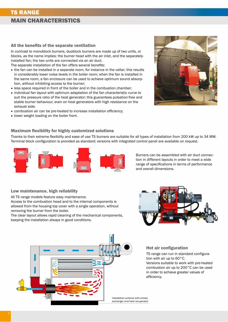
Hot air configurationTS range can run in standard configura-tion with air up to 60°C.Versions suitable to work with pre-heated combustion air up to 200°C can be used in order to achieve greater values of efficiency.
All the benefits of the separate ventilationIn contrast to monoblock burners, duoblock burners are made up of two units, or blocks, as the name implies: the burner head with the air inlet, and the separately-installed fan; the two units are connected via an air duct.The separate installation of the fan offers several benefits:• the fan can be installed in a separate room, for instance in the cellar; this results
in considerably lower noise levels in the boiler room; when the fan is installed in the same room, a fan enclosure can be used to achieve optimum sound absorp-tion, without inhibiting access to the burner;
• less space required in front of the boiler and in the combustion chamber;• individual fan layout with optimum adaptation of the fan characteristic curve to
suit the pressure ratio of the heat generator; this guarantees pulsation-free and stable burner behaviour, even on heat generators with high resistance on the exhaust side;
•combustion air can be pre-heated to increase installation efficiency;• lower weight loading on the boiler front.
Low maintenance, high reliabilityAll TS range models feature easy maintenance. Access to the combustion head and to the internal components is allowed from the housing top cover with a single operation, without removing the burner from the boiler.The clear layout allows rapid cleaning of the mechanical components, keeping the installation always in good conditions.
Maximum flexibility for highly customized solutionsThanks to their extreme flexibility and ease of use TS burners are suitable for all types of installation from 200 kW up to 34 MW.Terminal block configuration is provided as standard; versions with integrated control panel are available on request.
Burners can be assembled with air duct connec-tion in different layouts in order to meet a wide range of specifications in terms of performance and overall dimensions.

7
CONFIGURATIONS, VARIANTS AND ACCESSORIESTS RANGE
Gas train unit
Standard configuration:loose version withderivative panel
Pre-heating pump station
Separate ventilator
IP55 Switch cabinet configuration:version with assembled or remote switch cabinet
Gas governor/filterCompulsory EN676
Max pressure switch
LPG/Natural gasTightness controlCompulsory EN676 (over 1200 kW)
Modulation Kit
8
CAN-Bus
PGASmin PGAS
LT
PAIR
TPPOILmax
POILmin
M
BUSmu l t i
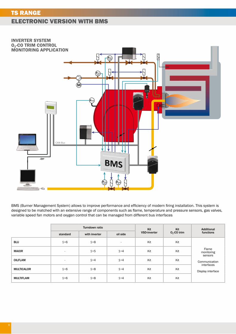
INVERTER SYSTEMO2-CO TRIM CONTROLMONITORING APPLICATION
Turndown ratio KitVSD-inverter
KitO2-CO trim
Additionalfunctionsstandard with inverter oil side
BLU 1÷6 1÷8 - Kit Kit
Flamemonitoring
sensors
Communicationinterfaces
Display interface
MAIOR - 1÷5 1÷4 Kit Kit
OILFLAM - 1÷4 1÷4 Kit Kit
MULTICALOR 1÷6 1÷8 1÷4 Kit Kit
MULTIFLAM 1÷6 1÷8 1÷4 Kit Kit
BMS (Burner Management System) allows to improve performance and efficiency of modern firing installation. This system is designed to be matched with an extensive range of components such as flame, temperature and pressure sensors, gas valves, variable speed fan motors and oxygen control that can be managed from different bus interfaces
ELECTRONIC VERSION WITH BMSTS RANGE

9
How to choose the correct ventilatorAccording to the application output or the fuel flow rate we need to calculate the air needed considering the following data:- Output / Fuel air flow;- Temperature of combustion air;- Backpressure in the combustion chamber;- Sea level altitude.
In order to dimension the correct ventilator the following calculation has to be made:1. Air flow needed2. Pressure needed
First of all we need to calculate the air flow needed in function of Nm3/h for gas or kg/h for oil and multiply it for the following suggested coefficients:Natural gas: K=12Light oil: K=15,7Heavy oil: K=15
This value must be adjusted according to the following:1. temperature of combustion air (standard 20° C; see table for different temperature);2. sea level (refer to the table for correction factors);3. air loss of the connecting pipes between burner head and ventilator (estimated to 5%).
Total air pressure:to finalize the calculation we shall consider the following factors:- head loss of the burner* (see following pages);- backpressure in the combustion chamber;- additional loss given from accessories like heat exchanger, filters, …
*: pressure losses calculated at sea level at 20°C; the value must be adjusted according to the correction factor
1000 Nm3/h gas for BLU 10000.110000 kW (L.C.V. 8570 kcal/Nm3)- head loss = 35/0,855 = 42 mbar- backpressure installation = 15 mbar- additional exchanger = 15 mbarTotal: 42+15+15 = 72 mbar
Final data achieved for selecting the ventilator:1. Air needed = 14737 m3/h2. Pressure = 72 mbar
Temp.(°C)
Air density(kg/m)
Sea level altitude (m)
0 250 500 750 1000 1250 1500 1750 2000 2250 2500 2750 3000
0 1,293 1,073 1,042 1,012 0,982 0,954 0,926 0,899 0,873 0,847 0,823 0,799 0,775 0,753
5 1,270 1,054 1,023 0,993 0,965 0,936 0,909 0,883 0,857 0,832 0,808 0,784 0,761 0,739
10 1,247 1,035 1,005 0,976 0,947 0,920 0,893 0,867 0,842 0,817 0,793 0,770 0,748 0,726
15 1,226 1,017 0,988 0,959 0,931 0,904 0,878 0,852 0,827 0,803 0,780 0,757 0,735 0,714
20 1,205 1,000 0,971 0,943 0,915 0,888 0,863 0,837 0,813 0,789 0,766 0,744 0,722 0,701
25 1,185 0,983 0,955 0,927 0,900 0,874 0,848 0,823 0,799 0,776 0,754 0,732 0,710 0,690
30 1,165 0,967 0,939 0,911 0,885 0,859 0,834 0,810 0,786 0,763 0,741 0,720 0,699 0,678
40 1,128 0,936 0,909 0,882 0,857 0,832 0,807 0,784 0,761 0,739 0,717 0,697 0,676 0,657
50 1,093 0,907 0,881 0,855 0,830 0,806 0,782 0,760 0,738 0,716 0,695 0,675 0,655 0,636
60 1,060 0,880 0,854 0,829 0,805 0,782 0,759 0,737 0,715 0,695 0,674 0,655 0,636 0,617
80 1,000 0,830 0,806 0,782 0,760 0,737 0,716 0,695 0,675 0,655 0,636 0,618 0,600 0,582
100 0,946 0,786 0,763 0,740 0,719 0,698 0,678 0,658 0,639 0,620 0,602 0,585 0,567 0,551
150 0,834 0,693 0,672 0,653 0,634 0,615 0,598 0,580 0,563 0,547 0,531 0,515 0,500 0,486
200 0,746 0,619 0,601 0,584 0,567 0,550 0,534 0,519 0,504 0,489 0,475 0,461 0,448 0,434
250 0,675 0,560 0,544 0,528 0,513 0,498 0,483 0,469 0,456 0,442 0,429 0,417 0,405 0,393
300 0,616 0,511 0,496 0,482 0,468 0,454 0,441 0,428 0,416 0,404 0,392 0,380 0,369 0,359
Example:1000 Nm3/h of gasThe quantity of air will be: 1000 [Nm3/h] x 12 = 12000 m3/h of air
Results will be the following for an installation at 500 m from the sea level and with air at 50°C:12000 [m3/h] x 1,05 / 0,855 = 14737 m3/h
Correction factors
VENTILATORTS RANGE

10
Burner head AIR pressure drop Burner head GAS pressure drop
30
25
20
15
10
5
00 1000 2000 3000 4000 5000 kW
mbar
4000.1400.1
3000.1300.1
30
25
20
15
10
5
00 1000 2000 3000 4000 5000 kW
mbar
4000.1400.1
3000.1300.1
Pressure drop on AIR side Pressure drop on GAS side
30
35
40mbar
25
20
15
10
5
02000 3000 4000 5000 6000
6000.1600.1
7000 kW
30
35
40mbar
25
20
15
10
5
02000 3000 4000 5000 6000 7000 kW
6000.1600.1
Pressure drop on AIR side Pressure drop on GAS side
30
40
50mbar
20
10
00 2000 4000 6000 8000 10000 12000 14000 kW
12000.11200.1
10000.11000.1
8000.1800.1 40
140
120
100
mbar
20
80
60
00 2000 4000 6000 8000 10000 12000 14000 kW
12000.11200.1
10000.11000.1
8000.1800.1
PRESSURE DROPSTS RANGE

11
Pressure drop on AIR side Pressure drop on GAS side
50
40
30
20
10
00 4000 8000 12000 16000
18000.11800.1
20000 kW
mbar200
160
120
80
40
00 4000 8000 12000 16000 20000 kW
mbar
18000.11800.1
Pressure drop on AIR side
Pressure drop on AIR side
Pressure drop on GAS side
Pressure drop on GAS side
60
50
40
30
20
10
00 5000 10000 15000 20000 25000
23000.12300.1
30000 kW
mbar
60
50
40
30
20
10
00 5000 10000 15000 20000 3000025000
34000.13400.1
35000 kW
mbar
120
100
80
60
40
20
00 5000 10000 15000 20000 25000 30000 kW
mbar
23000.12300.1
120
100
80
60
40
20
00 5000 10000 15000 20000 3000025000
34000.13400.1
35000 kW
mbar
PRESSURE DROPSTS RANGE

12
1 2 3 4 5 6 7 8 9 10 11 12
A
B
C
D
E
F
G
H
1 2 3 4 5 6 7 8 9 10
A
B
C
D
E
F
G
H
(c) ±4±8
>2000 <=4000-
±2
±6±3
>400 <=1000
±1.2±0.5
±4
>1000 <=2000
±2±0.8±0.5±0.3
±0.2
±1.5
±0.3
±2.5
>120 <=400
±1.2
±0.15>30 <=120
±1
±0.2±0.8
±0.1>6 <=30<=6
±0.5±0.1
±0.5±0.3
±0.05MediumCoarse
(f)(m)
(v)Very CoarseISO
2768
Tolerance ClassFine
BY TERM LAWS WE RESERVE THE PROPERTY OF THIS DRAWING WITH PROHIBITION OF USE AND REPRODUCTION
A
C B
P
E D - D1
G O
N
F I
L
M
J
J
S
R
Q
U
T
J
L
I
J
M
S
R
T
U
Q AIR INTAKE FLANGE 710-800
S
T
R
U
Q
AIR INTAKE FLANGE 260 - 380
BOILER FLANGE 260-630
AIR INTAKE FLANGE 630
BOILER FLANGE 710-800
1:10
CODE REV.
SCALE
DESCRIPTION
MATERIAL
TREATMENT
Burners Business Unit
FORMAT
A2DOCUMENT CODE - REV
-
RUGOSITY Ra µm
CRITICITYWEIGHT KgRADIUS / BEVELS WITHOUT INDICATIONS
MODIFICATION DESCRIPTION
ECN FIRST CREATION
ECN MODIFICATION
DESIGNED BY
DATE
DATE
DESIGNED BY
APPROVED BY DATE
SHEET / OF
1 / 1
DIMENSIONS WITHOUT TOLERANCE INDICATIONS
THERMO GROUPPROTOTYPENOT VALID FOR
MASS PRODUCTION
Le quote con indicazione di tolleranza devono considerarsi critiche e soggette a controlloDimensions with tolerances must be considered as Critical and subject to inspection
*: gas train connection on the right side of the burnerD: short head - D1: long headDimensions (in mm) make reference to the electronic versions; data may vary according to the configuration and options installed
Gas: TS 500.1 ... 12000.1Oil and dual: TS 100 ... 1200.1
Gas: TS 1800.1 ... 34000.1Oil and dual: TS 1800.1 ... 3400.1
Connecting flange
Burner body
OVERALL DIMENSIONSTS RANGE
A B C D D1 E F G I L M Ø J J N O P
TS 500.1 523 216 307 174 394 556 160 290 190 190 4xM10 - - 139 175* 405
TS 1000.1 / TS 100 523 216 307 174 394 556 190 290 190 190 4xM10 - - 139 175* 405
TS 1500.1 / TS 140 523 216 307 342 492 556 200 290 190 190 4xM10 - - 139 175* 405
TS 2000.1 / TS 200.1 543 234 309 348 548 620 270 375 270 270 4xM16 - - 125 250 448
TS 3000.1 / TS 300.1 605 265 340 330 530 728 290 392 315 315 4xM16 - - 188 250 528
TS 4000.1 / TS 400.1 605 265 340 365 565 728 320 392 315 315 4xM16 - - 188 250 528
TS 6000.1 / TS 600.1 617 271 346 373 573 810 320 404 330 330 4xM16 - - 195 250 575
TS 8000.1 / TS 800.1 723 324 399 470 - 1030 420 550 460 460 4xM20 550 4xM16 195 299 752
TS 10000.1 / TS 1000.1 723 324 399 470 - 1030 420 550 460 460 4xM20 550 4xM16 195 299 752
TS 12000.1 / TS 1200.1 723 324 399 470 - 1030 450 550 460 460 4xM20 550 4xM16 195 299 752
TS 18000.1 / TS 1800.1 899 412 487 590 - 1480 551 670 619 619 4xM20 700 4xM20 200 390 1115
TS 23000.1 / TS 2300.1 1080 501 579 530 - 1549 626 760 800 800 4xM20 1130 4xM20 210 412 1084
TS 34000.1 / TS 3400.1 1080 501 579 530 - 1549 626 760 800 800 4xM20 1130 4xM20 210 412 1084
1 2 3 4 5 6 7 8 9 10 11 12
A
B
C
D
E
F
G
H
1 2 3 4 5 6 7 8 9 10
A
B
C
D
E
F
G
H
(c) ±4±8
>2000 <=4000-
±2
±6±3
>400 <=1000
±1.2±0.5
±4
>1000 <=2000
±2±0.8±0.5±0.3
±0.2
±1.5
±0.3
±2.5
>120 <=400
±1.2
±0.15>30 <=120
±1
±0.2±0.8
±0.1>6 <=30<=6
±0.5±0.1
±0.5±0.3
±0.05MediumCoarse
(f)(m)
(v)Very CoarseISO
2768
Tolerance ClassFine
BY TERM LAWS WE RESERVE THE PROPERTY OF THIS DRAWING WITH PROHIBITION OF USE AND REPRODUCTION
A
C B
P
E D - D1
G O
N
F I
L
M
J
J
S
R
Q
U
T
J
L
I
J
M
S
R
T
U
Q AIR INTAKE FLANGE 710-800
S
T
R
U
Q
AIR INTAKE FLANGE 260 - 380
BOILER FLANGE 260-630
AIR INTAKE FLANGE 630
BOILER FLANGE 710-800
1:10
CODE REV.
SCALE
DESCRIPTION
MATERIAL
TREATMENT
Burners Business Unit
FORMAT
A2DOCUMENT CODE - REV
-
RUGOSITY Ra µm
CRITICITYWEIGHT KgRADIUS / BEVELS WITHOUT INDICATIONS
MODIFICATION DESCRIPTION
ECN FIRST CREATION
ECN MODIFICATION
DESIGNED BY
DATE
DATE
DESIGNED BY
APPROVED BY DATE
SHEET / OF
1 / 1
DIMENSIONS WITHOUT TOLERANCE INDICATIONS
THERMO GROUPPROTOTYPENOT VALID FOR
MASS PRODUCTION
Le quote con indicazione di tolleranza devono considerarsi critiche e soggette a controlloDimensions with tolerances must be considered as Critical and subject to inspection

13
Dimensions in mm
ab b
c df
f
f fØg Øg Øg Øg
hc
ee
ff
ab bf f
h
ce
ee
e
ef
f
af b b b b b bf
h
cf
f
af f
h
Øg
ee
ee
b b b b
cf
f
af f
h
ab b
c df
f
f fØg Øg Øg Øg
h
ce
ef
f
ab bf f
h
ce
ee
e
ef
f
af b b b b b bf
h
cf
f
af f
h
Øg
ee
ee
b b b b
cf
f
af f
h
Gas: TS 23000.1 ... 34000.1Oil and dual: TS 2300.1 ... 3400.1
Gas: TS 3000.1 ... 6000.1Oil and dual: TS 300 ... 600.1
Gas: TS 18000.1Oil and dual: TS 1800.1
Gas: TS 500.1 ... 2000.1Oil and dual: TS 100 ... 200.1
Gas: TS 8000.1 ... 12000.1Oil and dual: TS 800.1 ... 1200.1
Air duct
OVERALL DIMENSIONSTS RANGE
a b c d e f Øg h
TS 500.1 303 136,5 252 222 - 15 6x R12 40
TS 1000.1 / TS 100 303 136,5 252 222 - 15 6x R12 40
TS 1500.1 / TS 140 303 136,5 252 222 - 15 6x R12 40
TS 2000.1 / TS 200.1 345 157,5 287 257 - 15 6x R12 40
TS 3000.1 / TS 300.1 400 185 349 - 159,5 15 8x R12 40
TS 4000.1 / TS 400.1 400 185 349 - 159,5 15 8x R12 40
TS 6000.1 / TS 600.1 470 220 361 - 165,5 15 8x R12 40
TS 8000.1 / TS 800.1 557 173 474 - 218 19 10x R14 43
TS 10000.1 / TS 1000.1 557 173 474 - 218 19 10x R14 43
TS 12000.1 / TS 1200.1 557 173 474 - 218 19 10x R14 43
TS 18000.1 / TS 1800.1 730 230,7 650 - 204 19 12x R14 43
TS 23000.1 / TS 2300.1 930 223 828 - 197,5 19 16x R14 40
TS 34000.1 / TS 3400.1 930 223 828 - 197,5 19 16x R14 40

14
sag.ttA
Ø
rØ
Rr
Sr
PA B
A1=
=
Qr
sag.ttA
Ø
r Ø
Sr
PrA B
A1=
=
Qr
160R
r
3218
5
6 7
4
VCS Kromschröder
Et =
A +
B +
Pr +
N
Et =
A +
B +
Pr +
N
N
O
N
O
Ct = O + Rr + Qr + 160* Ct = O + Rr + Qr + 160*
Et =
A +
B +
Pr +
N
Et =
A +
B +
Pr +
N
N
O
N
O
Ct = O + Rr + Qr + 160* Ct = O + Rr + Qr + 160*
Et =
A +
B +
Pr +
N
Et =
A +
B +
Pr +
N
N
O
N
O
Ct = O + Rr + Qr + 160* Ct = O + Rr + Qr + 160*
Et =
A +
B +
Pr +
N
Et =
A +
B +
Pr +
N
N
O
N
O
Ct = O + Rr + Qr + 160* Ct = O + Rr + Qr + 160*
Et =
A +
B +
Pr +
N
Et =
A +
B +
Pr +
N
N
O
N
O
Ct = O + Rr + Qr + 160* Ct = O + Rr + Qr + 160*
*: kit VPS
1 Main gas pipe2 Ball valve3 Antivibration coupling4 Gas governor5 Gas pressure switch6 Safety gas valve7 Working gas valve8 Leakage control
Gas train
VCS...
NoteIn order to calculate the overall dimension of the burner complete with gas train (Et and Ct) you need to consider the dimensions of the gas train, choosen according to the inlet gas pressure, and the dimension of the connection pipe (if needed): see page 17.If the value Et is lower than E, consider Et = E.
OVERALL DIMENSIONSTS RANGE
Gas: TS 500.1, TS 1000.1Oil and dual: TS 100
Gas: TS 1500.1 ... 34000.1Oil and dual: TS 140 ... 3400.1

15
67
9 8
5
11 10
321
VGD Siemens
Et =
A +
B +
Pr +
N
Et =
A +
B +
Pr +
N
N
O
N
O
Ct = O + Rr + Qr + 160* Ct = O + Rr + Qr + 160*
Et =
A +
B +
Pr +
N
Et =
A +
B +
Pr +
N
N
O
N
O
Ct = O + Rr + Qr + 160* Ct = O + Rr + Qr + 160*
Et =
A +
B +
Pr +
N
Et =
A +
B +
Pr +
N
N
O
N
O
Ct = O + Rr + Qr + 160* Ct = O + Rr + Qr + 160*
Et = E
Ct = U
+ Pr + A
Et =
A +
B +
Pr +
N
Ct = O + Rr
N
O
N
O
Et = E
Ct = U
+ Pr + AEt
= A
+ B
+ P
r + N
Ct = O + Rr
N
O
N
O
VGD40...VGD20...
PrA B
Qr R
r
A1
==
Pr85
Rr
Qr
A
A1
==
1 Main gas pipe2 Ball valve3 Antivibration coupling4 Gas governor5 Gas pressure switch6 Safety gas valve7 Working gas valve8 Leakage control9 Gas filter10 Actuator11 Actuator
Gas train
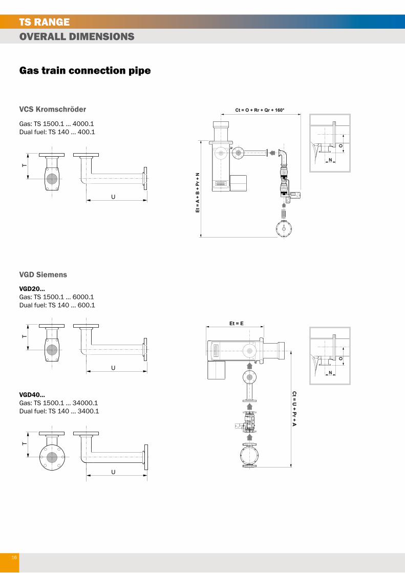
NoteIn order to calculate the overall dimension of the burner complete with gas train (Et and Ct) you need to consider the dimensions of the gas train, choosen according to the inlet gas pressure, and the dimension of the connection pipe (if needed): see page 17.
OVERALL DIMENSIONSTS RANGE
Gas: TS 500.1, TS 1000.1Oil and dual: TS 100
Gas: TS 1500.1 ... 34000.1Oil and dual: TS 140 ... 3400.1
16
Gas: TS 1500.1 ... 4000.1Dual fuel: TS 140 ... 400.1
VGD20...Gas: TS 1500.1 ... 6000.1Dual fuel: TS 140 ... 600.1
T
U
T
U V
T
U
T
U
T
U V
T
U
T
U
T
U V
T
U
Gas train connection pipe
Et =
A +
B +
Pr +
N
Et =
A +
B +
Pr +
N
N
O
N
O
Ct = O + Rr + Qr + 160* Ct = O + Rr + Qr + 160*
Et =
A +
B +
Pr +
N
Et =
A +
B +
Pr +
N
N
O
N
O
Ct = O + Rr + Qr + 160* Ct = O + Rr + Qr + 160*
Et =
A +
B +
Pr +
N
Et =
A +
B +
Pr +
N
N
O
N
O
Ct = O + Rr + Qr + 160* Ct = O + Rr + Qr + 160*
Et =
A +
B +
Pr +
N
Et =
A +
B +
Pr +
N
N
O
N
O
Ct = O + Rr + Qr + 160* Ct = O + Rr + Qr + 160*
Et =
A +
B +
Pr +
N
Et =
A +
B +
Pr +
N
N
O
N
O
Ct = O + Rr + Qr + 160* Ct = O + Rr + Qr + 160*
Et = E
Ct = U
+ Pr + A
Et =
A +
B +
Pr +
N
Ct = O + Rr
N
O
N
O
VGD40...Gas: TS 1500.1 ... 34000.1Dual fuel: TS 140 ... 3400.1
VCS Kromschröder
VGD Siemens
OVERALL DIMENSIONSTS RANGE

17
Gas train model
GTCP Dimension GT DimensionGas governor &
filter / Filter
FGDR - Filter
T U V Pr Qr Rr Sr Ør A A1 B
Gas: TS 500.1, 1000.1
Dual fuel:TS 100
VCS-125
- - -
310 65 155 215 1” FGDR-RP25 146 131 >100
VCS-240 310 82 155 240 1”1/2 FGDR-RP40 194 178 >100
VCS-350 372 95 155 250 2" FGDR-RP50 260 225 >100
Gas: TS 1500.1, 2000.1
Dual fuel:TS 140, 200.1
VCS-240 85 400
-
310 82 155 240 1”1/2 FGDR-RP40 194 178 >100
VCS-240 85 400 310 82 155 240 1”1/2 FGDR-RP50 260 225 >100
VCS-350 85 400 372 95 155 250 2" FGDR-RP50 260 225 >100
VGD20.503 85 400 - 450 185 315 - 2" Filter 2" 186 186 >100
VGD40.065 104 560 104 290 97 211 - DN65 Filter DN65 290 212 -
VGD40.080 125 560 125 310 102 218 - DN80 Filter DN80 320 240 -
Gas: TS 3000.1, 4000.1
Dual fuel:TS 300.1, 400.1
VCS-350 85 588 - 372 95 155 250 2" FGDR-RP50 260 225 >100
VGD20.503 85 588 - 450 185 315 - 2" Filter 2" 186 186 >100
VGD40.065 104 560 104 290 97 211 - DN65 Filter DN65 290 212 -
VGD40.080 125 560 125 310 102 218 - DN80 Filter DN80 320 240 -
VGD40.100 125 560 255 350 113,5 229 - DN100 Filter DN100 380 280 -
Gas: TS 6000.1
Dual fuel:TS 600.1
VGD20.503 85 588 - 450 185 315 - 2" Filter 2" 186 186 >100
VGD40.065 125 668 125 290 97 211 - DN65 Filter DN65 290 212 -
VGD40.080 125 668 125 310 102 218 - DN80 Filter DN80 320 240 -
VGD40.100 125 560 255 350 113,5 229 - DN100 Filter DN100 380 280 -
VGD40.125 125 718 164 400 127,5 243 - DN125 Filter DN125 380 280 -
Gas: TS 8000.1, 10000.1
Dual fuel:TS 800.1, 1000.1
VGD40.065 202 820 108 290 97 211 - DN65 Filter DN65 290 212 -
VGD40.080 221 820 129 310 102 218 - DN80 Filter DN80 320 240 -
VGD40.100 165 820 165 350 113,5 229 - DN100 Filter DN100 380 280 -
VGD40.125 165 820 441 400 127,5 243 - DN125 Filter DN125 380 280 -
Gas: TS 12000.1
Dual fuel:TS 1200.1
VGD40.080 221 820 129 310 102 218 - DN80 Filter DN80 320 240 -
VGD40.100 165 820 165 350 113,5 229 - DN100 Filter DN100 380 280 -
VGD40.125 165 820 441 400 127,5 243 - DN125 Filter DN125 380 280 -
Gas: TS 18000.1
Dual fuel:TS 1800.1
VGD40.080 221 820 129 310 102 218 - DN80 Filter DN80 320 240 -
VGD40.100 165 820 165 350 113,5 229 - DN100 Filter DN100 380 280 -
VGD40.125 165 820 441 400 127,5 243 - DN125 Filter DN125 380 280 -
Gas: TS 23000.1
Dual fuel: TS 2300.1
VGD40.100 165 820 165 350 113,5 229 - DN100 Filter DN100 380 280-
VGD40.125 165 820 441 400 127,5 243 - DN125 Filter DN125 380 280
Gas: TS 34000.1
Dual fuel: TS 3400.1
VGD40.100 165 820 165 350 113,5 229 - DN100 Filter DN100 380 280-
VGD40.125 165 820 441 400 127,5 243 - DN125 Filter DN125 380 280
Matching
GAS TRAINSTS RANGE

18
Data may vary depending on the configuration of the burner, the pressure of the combustion chamber and the draught.The values in the graphs refer to tests carried out with flame tubes.
Example:Burner output: 8000 kWL flame (m) = 5 (medium value)D flame (m) = 1 (medium value)
Modifications to the flame can be made in our Flexshop in order to shape the flame and meet specific requirements for special boilers or applications
L (m)
2000 3000 4000 5000 6000 7000 8000 9000 10000
4
5
1000
2000 30001000
6
11000
2
3
7
8
12000 kW13000
9
10
11
Nm3/h100 200 300 400 500
kcal/hx1000
kW
Nm3/h
kcal/hx1000
4000 5000 6000 7000 8000 9000 10000 11000 12000 13000 14000 15000
14000 15000 16000 17000
Ø (m)
2000 3000 4000 5000 6000 7000 8000 9000 10000
0,6
0,8
1000
2000 30001000
1
11000
0
0,2
0,4
1,2
1,4
12000 13000
1,6
1,8
2
4000 5000 6000 7000 8000 9000 10000 11000 12000 13000 14000 15000
14000 15000 16000 17000
FLAME LENGHT - GAS BURNERS
FLAME DIAMETER - GAS BURNERS
600 700 800 900 1000 1100 1200 1300 1400 1500 1600 1700
100 200 300 400 500 600 700 800 900 1000 1100 1200 1300 1400 1500 1600 1700
Flame lenght (gas burners)
Flame diameter (gas burners)
FLAME DIMENSIONTS RANGE

19
NOTES
Version 2.3 - 20/04/2017ECOFLAM Bruciatori S.p.A. reserves the right to make any adjustments, without prior notice, which is considered necessary or useful to its products, without affecting their main features.
HEAD OFFICE:Via Roma, 6431023 Resana (TV)
Tel.: +39 0423 719500Fax: +39 0423 719580Web: www.ecoflam-burners.comEmail: [email protected]
REGISTERED OFFICE:Viale A. Merloni, 4560044 Fabriano (AN)
Company subject to the direction and coordination of Ariston Thermo SpA.Via A. Merloni, 45 - 60044 Fabriano (AN) - CF 01026940427