Truly-Tender-Tailed Tag-Playing Robot Interface through Friendly Amusing Mobile Function
7
Truly-Tender-Tailed Tag-Playing Robot Interface Paper: Truly-Tender-Tailed Tag-Playing Robot Interface Through Friendly Amusing Mobile Function Takafumi Matsumaru, Yasutada Horiuchi, Kosuke Akai, and Yuichi Ito Bio-Robotics & Human-Mechatronics Laboratory, Shizuoka University 3-5-1 Johoku, Naka, Hamamatsu 432-8561, Japan E-mail: {ttmatum, f0510128, f0730001, f0830006}@ipc.shizuoka.ac.jp [Received October 14, 2009; accepted February 15, 2010] To expand use of the mobile robot Step-On Inter- face (SOI), originally targeting maintenance, training, and recovery of human physical and cognitive func- tions, we introduce a “Truly-Tender-Tailed” (T 3 , pro- nounced tee-cube) tag-playing robot as a “Friendly Amusing Mobile” (FAM) function. Displaying a pre- viously prepared bitmap (BMP) image and speeding up display make it easy to design button placement and other screen parameters using a painting software package. The BMP-image scope matrix simplifies step detection and recognition and the motion trajectory design editor facilitates robot behavior design. Keywords: step-on interface, human-robot interaction, friendly amusing mobile, projection, truly-tender-tailed tag-playing robot (T-cube tag player) 1. Introduction To expand mobile robot Step-On Interface (SOI) use, we have developed a Truly-Tender-Tailed tag-playing robot – called the T 3 (tee-cube) tag player for short – as a Friendly Amusing Mobile (FAM) function. The tag player targets maintenance, training, and recovery of hu- man physical and cognitive functions in the elderly, phys- ically challenged, injured, etc. This paper is organized as follows: Section 2 discusses the SOI as a conventional robot interface using a projec- tor and explains our R&D. Section 3 introduces the FAM function in SOI use. Sections 4–6 detail the tag player’s screen configuration, T 3 recognition, and motion trajec- tory design, Section 7 describes the T 3 tag player’s com- prehensive operation, and Section 8 summarizes conclu- sions. 2. Step-On Interface 2.1. Background User-equipment interfacing projectors are used on robots in teaching a manipulator when the user clicks on a projected virtual pendant [1], displaying recognition re- sults for fingertip instructions on real objects [2], project- ing references and content supporting instructions [3, 4], projecting a specified trajectory on objects while teach- ing a welding operation [5, 6], directing target locations or paths using a hand-held projector [7, 8], indicating differ- ent information projected around a robot [9, 10], etc. The SOI’s special feature is using projected screens as bidirec- tional interfaces enabling users to interact with working robots. 2.2. SOI Features The SOI presents information from equipment to users by way of a bidirectional screen presenting user instruc- tions to equipment [11]. The projector displays a screen on a floor or other surface and the user specifies a but- ton selecting movement by stepping or pointing. The SOI features: (i) Hands-free use, without buttons, joysticks, key- boards, mice, or touch panels, enabling everyone from the hands-full industrious to the incapacitated but active to use it. (ii) Nondisruptive voice-input-free use in disturbed en- vironments without misrecognition, e.g., as “noise.” (iii) No need for special devices – users can use their foot or a cane, for example, although eye control requires special eye-movement detectors and constraints such as user location or orientation. (iv) Minimally precise hand and finger movement, en- abling foot or cane use. (v) Screen direction projection requiring little prelimi- nary preparation or special setup. (vi) Language-independent operation using letters, fig- ures, and pictures, enabling beginners and nonnative speakers to use it. (vii) Screen functions easy to set up and change because they are included in software. (viii) Needed distance for those unfamiliar with robots or not wanting to interact with them, since they can use the SOI without directly contacting it. Journal of Robotics and Mechatronics Vol.22 No.3, 2010 301
Transcript of Truly-Tender-Tailed Tag-Playing Robot Interface through Friendly Amusing Mobile Function
Truly-Tender-Tailed Tag-Playing Robot Interface
Paper:
Truly-Tender-Tailed Tag-Playing Robot InterfaceThrough Friendly Amusing Mobile Function
Takafumi Matsumaru, Yasutada Horiuchi, Kosuke Akai, and Yuichi ItoBio-Robotics & Human-Mechatronics Laboratory, Shizuoka University
3-5-1 Johoku, Naka, Hamamatsu 432-8561, JapanE-mail: {ttmatum, f0510128, f0730001, f0830006}@ipc.shizuoka.ac.jp
[Received October 14, 2009; accepted February 15, 2010]
To expand use of the mobile robot Step-On Inter-face (SOI), originally targeting maintenance, training,and recovery of human physical and cognitive func-tions, we introduce a “Truly-Tender-Tailed” (T3, pro-nounced tee-cube) tag-playing robot as a “FriendlyAmusing Mobile” (FAM) function. Displaying a pre-viously prepared bitmap (BMP) image and speedingup display make it easy to design button placementand other screen parameters using a painting softwarepackage. The BMP-image scope matrix simplifies stepdetection and recognition and the motion trajectorydesign editor facilitates robot behavior design.
Keywords: step-on interface, human-robot interaction,friendly amusing mobile, projection, truly-tender-tailedtag-playing robot (T-cube tag player)
1. Introduction
To expand mobile robot Step-On Interface (SOI) use,we have developed a Truly-Tender-Tailed tag-playingrobot – called the T3 (tee-cube) tag player for short –as a Friendly Amusing Mobile (FAM) function. The tagplayer targets maintenance, training, and recovery of hu-man physical and cognitive functions in the elderly, phys-ically challenged, injured, etc.
This paper is organized as follows: Section 2 discussesthe SOI as a conventional robot interface using a projec-tor and explains our R&D. Section 3 introduces the FAMfunction in SOI use. Sections 4–6 detail the tag player’sscreen configuration, T3 recognition, and motion trajec-tory design, Section 7 describes the T3 tag player’s com-prehensive operation, and Section 8 summarizes conclu-sions.
2. Step-On Interface
2.1. Background
User-equipment interfacing projectors are used onrobots in teaching a manipulator when the user clicks ona projected virtual pendant [1], displaying recognition re-
sults for fingertip instructions on real objects [2], project-ing references and content supporting instructions [3, 4],projecting a specified trajectory on objects while teach-ing a welding operation [5, 6], directing target locations orpaths using a hand-held projector [7, 8], indicating differ-ent information projected around a robot [9, 10], etc. TheSOI’s special feature is using projected screens as bidirec-tional interfaces enabling users to interact with workingrobots.
2.2. SOI FeaturesThe SOI presents information from equipment to users
by way of a bidirectional screen presenting user instruc-tions to equipment [11]. The projector displays a screenon a floor or other surface and the user specifies a but-ton selecting movement by stepping or pointing. The SOIfeatures:
(i) Hands-free use, without buttons, joysticks, key-boards, mice, or touch panels, enabling everyonefrom the hands-full industrious to the incapacitatedbut active to use it.
(ii) Nondisruptive voice-input-free use in disturbed en-vironments without misrecognition, e.g., as “noise.”
(iii) No need for special devices – users can use their footor a cane, for example, although eye control requiresspecial eye-movement detectors and constraints suchas user location or orientation.
(iv) Minimally precise hand and finger movement, en-abling foot or cane use.
(v) Screen direction projection requiring little prelimi-nary preparation or special setup.
(vi) Language-independent operation using letters, fig-ures, and pictures, enabling beginners and nonnativespeakers to use it.
(vii) Screen functions easy to set up and change becausethey are included in software.
(viii) Needed distance for those unfamiliar with robots ornot wanting to interact with them, since they can usethe SOI without directly contacting it.
Journal of Robotics and Mechatronics Vol.22 No.3, 2010 301
Matsumaru, T. et al.
2.3. Research and Development2.3.1. Range Scanner Measurement
A commercially available two-dimensional (2D) rangescanner (URG-04LX, Hokuyo Automation Co., Ltd.)widely implemented as an external mobile robot sensorwas used to detect a user’s foot [12]. The range scan-ner scans 682 steps across 240◦ at a step angle of 0.35◦,determining a distance from 20 to 4095 mm to obstaclesacquired each 50 ms via a Universal Serial Bus (USB).This measurement involves the following:
(i) The error rate – the frequency the scanner judgesas not measurable, outputting an error code – for aglossy or black object rises when the object’s obliqueangle is too large or the distance to the object too far.
(ii) The error rate is zero but the error margin for awhite or rough-surfaced object becomes dozens ofmillimeters and variation is small if the oblique an-gle is less than 60◦ or the distance less than 1 meter.
(iii) Lateral error is negligible if the distance for detectingobstacles is less than 1 meter.
The range scanner thus detects and measures steps (wear-ing shoes) except those that are back or highly-glazed.
2.3.2. HFAMRO-1 Mobile Robot Functional ModelDevelopment
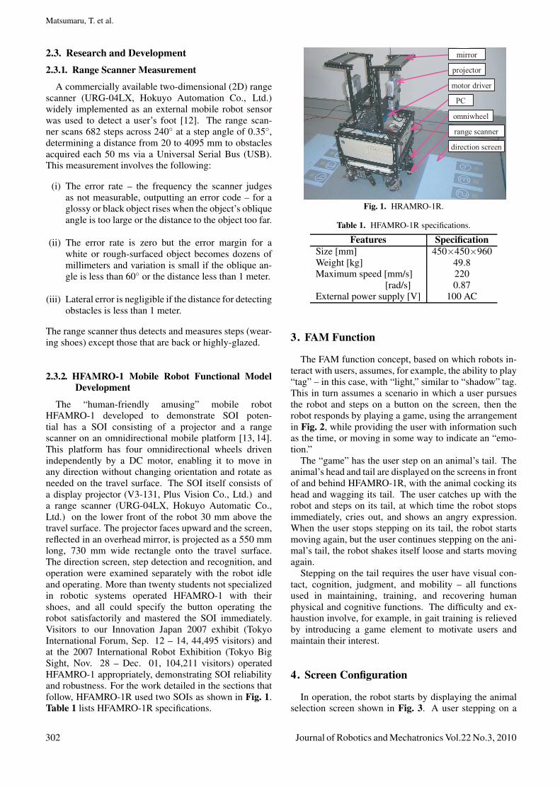
The “human-friendly amusing” mobile robotHFAMRO-1 developed to demonstrate SOI poten-tial has a SOI consisting of a projector and a rangescanner on an omnidirectional mobile platform [13, 14].This platform has four omnidirectional wheels drivenindependently by a DC motor, enabling it to move inany direction without changing orientation and rotate asneeded on the travel surface. The SOI itself consists ofa display projector (V3-131, Plus Vision Co., Ltd.) anda range scanner (URG-04LX, Hokuyo Automatic Co.,Ltd.) on the lower front of the robot 30 mm above thetravel surface. The projector faces upward and the screen,reflected in an overhead mirror, is projected as a 550 mmlong, 730 mm wide rectangle onto the travel surface.The direction screen, step detection and recognition, andoperation were examined separately with the robot idleand operating. More than twenty students not specializedin robotic systems operated HFAMRO-1 with theirshoes, and all could specify the button operating therobot satisfactorily and mastered the SOI immediately.Visitors to our Innovation Japan 2007 exhibit (TokyoInternational Forum, Sep. 12 – 14, 44,495 visitors) andat the 2007 International Robot Exhibition (Tokyo BigSight, Nov. 28 – Dec. 01, 104,211 visitors) operatedHFAMRO-1 appropriately, demonstrating SOI reliabilityand robustness. For the work detailed in the sections thatfollow, HFAMRO-1R used two SOIs as shown in Fig. 1.Table 1 lists HFAMRO-1R specifications.
projector
range scanner
omniwheel
motor driver
mirror
PC
direction screen
Fig. 1. HRAMRO-1R.
Table 1. HFAMRO-1R specifications.
Features SpecificationSize [mm] 450×450×960Weight [kg] 49.8Maximum speed [mm/s] 220
[rad/s] 0.87External power supply [V] 100 AC
3. FAM Function
The FAM function concept, based on which robots in-teract with users, assumes, for example, the ability to play“tag” – in this case, with “light,” similar to “shadow” tag.This in turn assumes a scenario in which a user pursuesthe robot and steps on a button on the screen, then therobot responds by playing a game, using the arrangementin Fig. 2, while providing the user with information suchas the time, or moving in some way to indicate an “emo-tion.”
The “game” has the user step on an animal’s tail. Theanimal’s head and tail are displayed on the screens in frontof and behind HFAMRO-1R, with the animal cocking itshead and wagging its tail. The user catches up with therobot and steps on its tail, at which time the robot stopsimmediately, cries out, and shows an angry expression.When the user stops stepping on its tail, the robot startsmoving again, but the user continues stepping on the ani-mal’s tail, the robot shakes itself loose and starts movingagain.
Stepping on the tail requires the user have visual con-tact, cognition, judgment, and mobility – all functionsused in maintaining, training, and recovering humanphysical and cognitive functions. The difficulty and ex-haustion involve, for example, in gait training is relievedby introducing a game element to motivate users andmaintain their interest.
4. Screen Configuration
In operation, the robot starts by displaying the animalselection screen shown in Fig. 3. A user stepping on a
302 Journal of Robotics and Mechatronics Vol.22 No.3, 2010
Truly-Tender-Tailed Tag-Playing Robot Interface
(a) Arrangement.
(b) Head. (c) Tail.
Fig. 2. T3: playing tag with light.
Fig. 3. Animal selection screen.
Fig. 4. Timer-controlled tail movement in cutoff animation.
numbered screen button displays the head and tail of thechosen animal, which cocks its head inquiringly and wagsits tail as shown in Fig. 4. Stepping on the “stop” buttonredisplays the animal selection screen.
5. T3 Tail Recognition
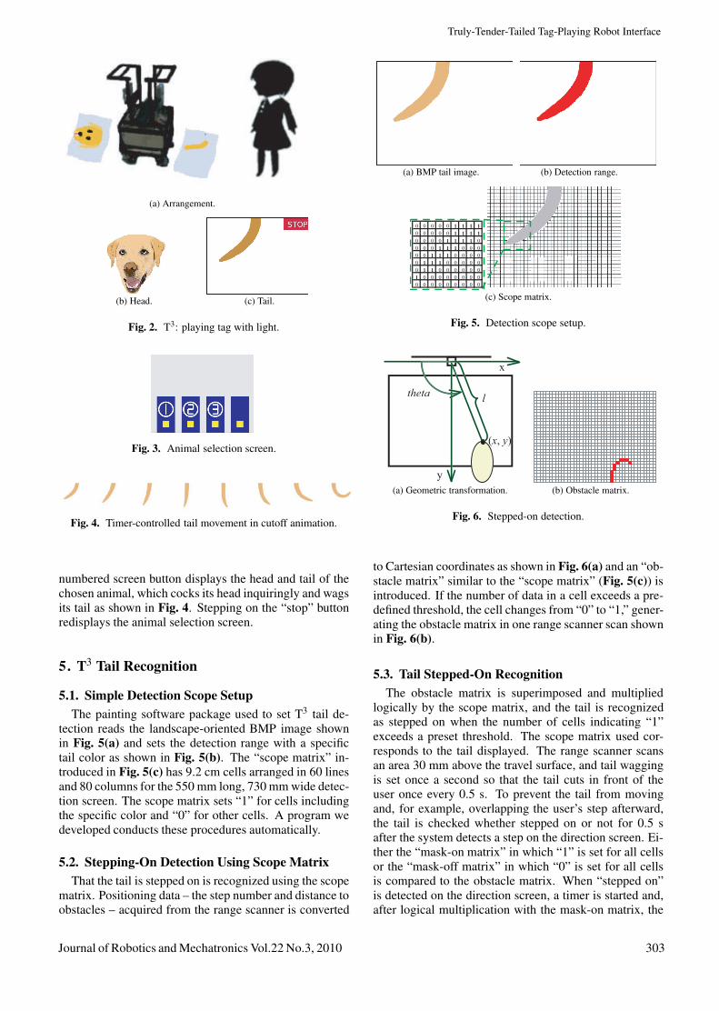
5.1. Simple Detection Scope SetupThe painting software package used to set T3 tail de-
tection reads the landscape-oriented BMP image shownin Fig. 5(a) and sets the detection range with a specifictail color as shown in Fig. 5(b). The “scope matrix” in-troduced in Fig. 5(c) has 9.2 cm cells arranged in 60 linesand 80 columns for the 550 mm long, 730 mm wide detec-tion screen. The scope matrix sets “1” for cells includingthe specific color and “0” for other cells. A program wedeveloped conducts these procedures automatically.
5.2. Stepping-On Detection Using Scope MatrixThat the tail is stepped on is recognized using the scope
matrix. Positioning data – the step number and distance toobstacles – acquired from the range scanner is converted
(a) BMP tail image. (b) Detection range.
0 0 0 0 0 1 1 1 1 0 0 0 0 0 1 1 1 1 0 0 0 0 1 1 1 1 0 0 0 0 1 1 1 0 0 0 0 0 1 1 1 0 0 0 0 0 1 1 1 0 0 0 0 0 0 1 1 0 0 0 0 0 0 1 0 0 0 0 0 0 0 0 0 0 0 0 0 0 0 0 0
(c) Scope matrix.
Fig. 5. Detection scope setup.
thetal
(x, y)
y
x
(a) Geometric transformation. (b) Obstacle matrix.
Fig. 6. Stepped-on detection.
to Cartesian coordinates as shown in Fig. 6(a) and an “ob-stacle matrix” similar to the “scope matrix” (Fig. 5(c)) isintroduced. If the number of data in a cell exceeds a pre-defined threshold, the cell changes from “0” to “1,” gener-ating the obstacle matrix in one range scanner scan shownin Fig. 6(b).
5.3. Tail Stepped-On RecognitionThe obstacle matrix is superimposed and multiplied
logically by the scope matrix, and the tail is recognizedas stepped on when the number of cells indicating “1”exceeds a preset threshold. The scope matrix used cor-responds to the tail displayed. The range scanner scansan area 30 mm above the travel surface, and tail waggingis set once a second so that the tail cuts in front of theuser once every 0.5 s. To prevent the tail from movingand, for example, overlapping the user’s step afterward,the tail is checked whether stepped on or not for 0.5 safter the system detects a step on the direction screen. Ei-ther the “mask-on matrix” in which “1” is set for all cellsor the “mask-off matrix” in which “0” is set for all cellsis compared to the obstacle matrix. When “stepped on”is detected on the direction screen, a timer is started and,after logical multiplication with the mask-on matrix, the
Journal of Robotics and Mechatronics Vol.22 No.3, 2010 303

Matsumaru, T. et al.
(a) Success. (b) Failure.
Fig. 7. Stepping recognition within 0.5 seconds.
(a) Ordinary. (b) Angry.
Fig. 8. Canine facial expressions.
(a) Ordinary. (b) Angry.
Fig. 9. Feline facial expressions.
(a) Ordinary. (b) Angry.
Fig. 10. Porcine facial expressions.
scope matrix is compared to the obstacle matrix up to 0.5 slater as shown in Fig. 7. After logical multiplication withthe mask-off matrix, the scope matrix is compared to theobstacle matrix after 0.5 s. If the user’s foot has been re-moved after 0.5 s, the timer is reset and the stepped-onaction can be recognized again.
5.4. Reaction to Stepped-On Tail
Once its tail is stepped on, the selected animal – a dog,cat, or pig – stops moving with a loud cry and its ex-pression becomes angry as shown in Figs. 8–10. ThePlaySound function reproduces WAV files containing an-imal calls. The system starts another timer when it recog-nizes that the tail has been stepped and, after a fixed time,instructs the mobile platform to repeatedly turn right andleft to “shaking” the tail loose.
A pr
qr
theta
1L
2LA
(a) Determining turn direction. (b) Stop condition.
Fig. 11. Trajectory design.
6. Motion Trajectory Design
6.1. Trajectory Design Editor
In developing a trajectory design editor, we set sev-eral points with the mouse on a PC screen to move therobot to points specified. Robot operation is limited togoing forward and turning to maintain the safety of theuser pursuing the robot and because animals rarely walkbackward. Turning during forward movement is used toimitate legged animal. Trajectory design proceeds as fol-lows:
(i) Determining Turn DirectionTarget point A clicked on using the mouse is con-verted to world coordinates. The turn direction isdecided as shown in Fig. 11(a). Turn angle θ is cal-culated from the inter product of the robot directionand the target direction.
(ii) Speed Command SetupThe magnitude of speed commands is constant ingoing forward and turning, except that when a turn-ing command is being output, a “go forward” com-mand is multiplied by coefficient (≤ 1), varied basedon turn angle θ calculated in (i), to control forwardmovement. It makes the robot turn in a small radiusand reach the target point smoothly even thought turnangle θ is large and the distance to the target is short.
(iii) Movement StartWhen a user clicks on a target, speed commandsboth forward and turning are calculated and the robotmoves executing these commands. Distance L1 be-tween the target and the robot direction and distanceL2 between the target and the present robot loca-tion are calculated during movement as shown inFig. 11(b).
(iv) Movement EndWhen distance L1 is shorter than a predeterminedthreshold, the turn command is made “0” and onlythe forward command is output. When distance L2 isshorter than the threshold, the forward command isagain made “0” and the robot stops.
304 Journal of Robotics and Mechatronics Vol.22 No.3, 2010

Truly-Tender-Tailed Tag-Playing Robot Interface
Fig. 12. Trajectory editor.
-1000
-750
-500
-250
0
250
500
750
1000
-1000 -750 -500 -250 0 250 500 750 1000
mm
mm
Edited trajectory
Locus based on
speed command
Fig. 13. Comparison result.
6.2. Trajectory DesignSpeed command setup values in designing the robot tra-
jectory are stored and reproduced to move the robot. Dif-ferences between the editor trajectory design and the actu-ally moved trajectory using stored commands is checkedas follows:
(a) The robot on the editor screen (Fig. 12) is moved bymouse-clicking on targets points. Speed commandsin going forward and turning and robot positioningcoordinates are written to a file every 50 ms. Thegrid spacing in Fig. 12 is set to 50 cm, but can beadjusted arbitrarily with zooming.
(b) The robot is moved based on speed commands read-ing the file written in (a) and positioning coordinateswritten to the other file every 50 ms.
(c) Data in the two files is compared.
An example of resulting trajectories is shown inFig. 13. Note that almost no difference exists between thetrajectory designed on the editor and the trajectory actu-ally moved using stored speed commands, indicating thatthe robot could operate along the trajectory designed bygiving the robot speed commands generated by the trajec-tory editor.
Individual animal trajectories are designed using thetrajectory editor based on animal behavior as follows:
(a) (b) (c)
Fig. 14. Designed dog trajectories.
(a) (b) (c)
Fig. 15. Designed cat trajectories.
(a) (b) (c)
Fig. 16. Designed pig trajectories.
Dog: A dog runs a long way for a long time, so speedcommands for going forward and turning are set to moveon a comparatively large scale as shown in Fig. 14.
Cat: A cat cannot run quickly a long time but canmove quickly in short spurts, so its trajectory is designedfor swift changes in speed including many small turns asshown in Fig. 15.
Pig: The pig’s trajectory is designed to move sloweroverall compared than the dog or cat as shown in Fig. 16.
The point of movement is its speed, not whether themovement resembles that of the actual animal, becausethis is used in determining a user’s exercise, such as inwalking training, based on the degree of recovery andmaintaining the user’s interest and achievement.
7. Comprehensive Operation
In comprehensive operation for the dog, the robot dis-plays the animal selection screen, shown in Fig. 17(a),then reproduces speed commands stored, shown inFig. 17(b), when the user steps on button-1, showing thecocking head, wagging tail, and panting, as in Fig. 17(c).When the user catches up with the robot and steps onits tail, the robot stops immediately with a loud cry andshows an anger expression, as in Fig. 17(d). The opera-tion is the same regardless of the animal.
Journal of Robotics and Mechatronics Vol.22 No.3, 2010 305

Matsumaru, T. et al.
(a) Animal selection screen.
(b) Movement start.
(c) Cocking head, wagging tail, and panting.
(d) Tail stepped on, anger, and barking.
Fig. 17. Comprehensive operation.
8. Conclusions
We have introduced a “Truly-Tender-Tailed” (T3, pro-nounced tee-cube) tag-playing robot as a “Friendly Amus-ing Mobile” (FAM) function to expand use of the mobilerobot Step-On Interface (SOI), targeting aims to be ap-plied to the maintenance, training, and recovery of phys-ical and cognitive functions in everyone from hands-freeindustrious to incapacitated but active users. Displayinga BMP image prepared beforehand and speeding up dis-play have made it easy to design button placement andother display parameters using a painting software pack-age. The BMP-image scope matrix simplifies step detec-tion and recognition, and the motion trajectory design ed-itor makes it easy to design robot behavior.
Such training teaches users three functions syntheti-cally – sensory function for detecting projected imagemovement, cognition and judgment function for predict-ing robot movement and deciding where to step, and mo-bility function for moving a foot as intended. The traininglevel is easily adjusted to user capability by changing partof software. User motivation and interest are maintainedby including illustration or animation tone or color on thescreen and chimes or melodies from a speaker in the soft-ware. The robot behavior design editor includes multi-media functions in addition to motion trajectory enablingnonexperts to easily modify or create robot behavior onsite is to be developed in projected work. We are alsodeveloping other content such as explosion prevention bystamping out a lighted bomb fuse and displaying footstepsas a training target for those finding it repugnant to stepon an animal’s tail or otherwise knowingly cause pain toan animal or other sentient being. We plan experiments atnursing homes and other care facilities to evaluate the effi-ciency of such training supporting an individual’s physicalindependence and warding off dementia in the elderly.
AcknowledgementsThis study was supported in part by the Hayao Nakayama Foun-dations for Science & Technology and Culture (fiscal 2007), towhich we are most grateful.
References:[1] M. Terashima and S. Sakane, “A Human-Robot Interface Using an
Extended Digital Desk,” Proc. IEEE Int. Conf. on Robotics and Au-tomation 1999 (ICRA ’99), Vol.4, pp. 2874-2880, 1999.
[2] S. Sato and S. Sakane, “A human-robot interface using an inter-active hand pointer that projects a mark in the real work space,”Proc. IEEE Int. Conf. on Robotics and Automation 2000 (ICRA’00), Vol.1, pp. 589-595, 2000.
[3] T. Machino et al., “Remote-collaboration system using mobile robotwith camera and projector,” Proc. IEEE Int. Conf. on Robotics andAutomation, 2006 (ICRA 2006), pp. 4063-4068, 2006.
[4] Y. Nakamura et al., “Framework and service allocation for networkrobot platform and execution of interdependent services,” Roboticsand Autonomous Systems, Vol.56, Issue 10, pp. 793-797, 2008.
[5] G. Reinhart, W. Vogl, and I. Kresse, “Projection-based User In-terface for Industrial Robots,” IEEE Symp. on Virtual Environ-ments, Human-Computer Interfaces and Measurement Systems2007 (VECIMS 2007), pp. 67-71, 2007.
[6] G. Reinhart, U. Munzert, and W. Vogl, “A programming system forrobot-based remote-laser-welding with conventional optics,” CIRPAnnals – Manufacturing Technology, Vol.57, Issue 1, pp. 37-40,2008.
306 Journal of Robotics and Mechatronics Vol.22 No.3, 2010
Truly-Tender-Tailed Tag-Playing Robot Interface
[7] K. Hosoi, V. N. Dao, A. Mori, and M. Sugimoto, “VisiCon: a robotcontrol interface for visualizing manipulation using a handheld pro-jector,” Proc. of Int. Conf. on Advances in Computer EntertainmentTechnology (ACE 2007), pp. 99-106, 2007.
[8] K. Hosoi, V. N. Dao, A. Mori, and M. Sugimoto, “CoGAME: Ma-nipulation using a Handheld Projector,” 34th Int. Conf. and Ex-hibition on Computer Graphics and Interactive Techniques (SIG-GRAPH 2007) Emerging Technologies, No.2, 2007.
[9] T. Matsumaru, “Mobile Robot with Preliminary-announcement andDisplay Function of Forthcoming Motion using Projection Equip-ment,” 15th IEEE Int. Symp. on Robot and Human Interactive Com-munication (RO-MAN 06), pp. 443-450, 2006.
[10] J. Park and G. J. Kim, “Robots with projectors: an alternative to an-thropomorphic HRI,” Proc. of 4th ACM/IEEE Int. Conf. on Humanrobot interaction (HRI 2009), pp. 221-222, 2009.
[11] T. Matsumaru, “Operating Device,” Patent Abstracts ofJapan, JP 2008-006551 A, Jan. 17, 2008. [On-Line] Availablewww.ipdl.inpit.go.jp/homepg e.ipdl [Accessed Nov. 12, 2009].
[12] T. Matsumaru, “A Characteristics Measurement of Two-Dimensional Range Scanner and its Application,” The OpenAutomation and Control Systems J., Vol.2, pp. 21-30, 2009.
[13] T. Matsuamru and K. Akai, “Step-On Interface on Mobile Robot toOperate by Stepping on Projected Button,” The Open Automationand Control Systems J., Vol.2, pp. 85-95, 2009.
[14] T. Matsuamru and K. Akai, “Functions of Step-On InterfaceEquipped on Mobile Robot,” J. of Robotics and Mechatronics,Vol.21, No.2, pp. 267-276, 2009.
Name:Takafumi Matsumaru
Affiliation:Associate Professor, Bio-Robotics & Human-Mechatronics Laboratory, Shizuoka University
Address:3-5-1 Johoku, Naka, Hamamatsu 432-8561, JapanBrief Biographical History:1987-1999 Toshiba Corporation, R&D Center1999- Shizuoka University2003 Invited Professor, LSC-CNRS, FranceMain Works:• “Development of four kinds of mobile robot with preliminary-announcement and display function of its forthcoming operation,” J. ofRobotics and Mechatronics, Vol.19, No.2, pp. 148-159, 2007.• “A Characteristics Measurement of Two-Dimensional Range Scannerand its Application,” The Open Automation and Control Systems J., Vol.2,pp. 21-30, 2009.• “Functions of Mobile Robot Step-On Interface,” J. of Robotics andMechatronics, Vol.21, No.2, pp. 267-276, 2009.• “Dynamic Remodeling of Environmental Map using Range Data forRemote Operation of Mobile Robot,” J. of Robotics and Mechatronics,Vol.21, No.3, pp. 332-341, 2009.• “Discrimination of Emotion from Movement and Addition of Emotion inMovement to Improve Personal Affinity of Human-Coexistence Robot,”SICE J. of Control, Measurement, and System Integration, Vol.2, No.6,pp. 365-372, 2009.• “Study on Handover Movement Informing Receiver of Weight Load asInformative Motion of Human-friendly Robot,” Int. J. of FactoryAutomation, Robotics and Soft Computing, Vol.2009, Issue 3, pp. 11-19,2009.Membership in Academic Societies:• Society of Biomechanisms Japan (SOBIM)• The Robotic Society of Japan (RSJ)• The Society of Instrument and Control Engineers (SICE)• The Japan Society of Mechanical Engineers (JSME)• Human Interface Society (HIS)• The Virtual Reality Society of Japan (VRSJ)• Society of Automotive Engineers of Japan, Inc. (JSAE)• The Institute of Electrical and Electronics Engineers, Inc. (IEEE)• International Association of Engineers (IAEMG)
Name:Yasutada Horiuchi
Affiliation:Under Graduate Student, Bio-Robotics &Human-Mechatronics Laboratory, ShizuokaUniversity (now, at Honda Motor Co., Ltd.)
Address:3-5-1 Johoku, Naka, Hamamatsu 432-8561, JapanBrief Biographical History:2005-2009 Faculty of Engineering, Shizuoka University2009- Honda Motor Co., Ltd.Main Works:• Study on mobile robot step-on interface.
Name:Kosuke Akai
Affiliation:Master’s Course Student, Bio-Robotics &Human-Mechatronics Laboratory, ShizuokaUniversity (now, at Caterpillar Japan Ltd.)
Address:3-5-1 Johoku, Naka, Hamamatsu 432-8561, JapanBrief Biographical History:2003-2007 Faculty of Engineering, Shizuoka University2007-2009 Graduate School of Engineering, Shizuoka University2009- Caterpillar Japan Ltd.Main Works:• Study on mobile robot step-on interface.
Name:Yuichi Ito
Affiliation:Master’s Course Student, Bio-Robotics &Human-Mechatronics Laboratory, ShizuokaUniversity (now, at Hitachi Construction Ma-chinery Co., Ltd.)
Address:3-5-1 Johoku, Naka, Hamamatsu 432-8561, JapanBrief Biographical History:2004-2008 Faculty of Engineering, Shizuoka University2008-2010 Graduate School of Engineering, Shizuoka University2010- Hitachi Construction Machinery Co., Ltd.Main Works:• Study on mobile robot step-on interface.
Journal of Robotics and Mechatronics Vol.22 No.3, 2010 307