Trial Application of API RP 2A - WSD Draft Section 17 Volume I
126
TriaLr Joa Industry Project Trial Application of API RP 2A - WSD Draft Section 17 Volume I - Summary Report by PMB Engtreering IK San Francisco, CA December 1994
-
Upload
khangminh22 -
Category
Documents
-
view
0 -
download
0
Transcript of Trial Application of API RP 2A - WSD Draft Section 17 Volume I
TriaLr J o a Industry Project
Trial Application of API RP 2A - WSD Draft Section 17
Volume I - Summary Report
by PMB Engtreering IK
San Francisco, CA
December 1994

Trials M n t Industry meet
Trial AppYcation of the API RP 2A-WSD DraR Section 77
Prepared for
Minerals Management Service and Trials JIP Participants
Prepared by
PIHB B*uBBIw.IC
PMB Engineering lnc.
December 7994

Contents
Section Page
1 Introduction .......................................... 1-1
1.1 Background . . . . . . . . . . . . . . . . . . . . . . . . . . . . . . . . . . 1-1 1.2 Objectives . . . . . . . . . . . . . . . . . . . . . . . . . . . . . . . . . . . 1-2 1.3 Project Participants . . . . . . . . . . . . . . . . . . . . . . . . . . . . 1-2 1.4 Platforms Assessed . . . . . . . . . . . . . . . . . . . . . . . . . . . . . 1-3
Information to Participants ............................. 2-1
2.1 Trial Basis Document . . . . . . . . . . . . . . . . . . . . . . . . . . . 2-1 2.2 Other Information . . . . . . . . . . . . . . . . . . . . . . . . . . . . . 2-2
...................... Summary of Participants' Submittals 3-1
3.1 Platform Selection . . . . . . . . . . . . . . . . . . . . . . . . . . . . 3-1 3.2 Categorization . . . . . . . . . . . . . . . . . . . . . . . . . . . . . . . 3-2 3.3 Condition Assessment . . . . . . . . . . . . . . . . . . . . . . . . . . 3-3
. . . . . . . . . . . . . . . . . . . . . . . . . . . . 3.4 Design Basis Check 3-4 3.5 Analysis Checks . . . . . . . . . . . . . . . . . . . . . . . . . . . . . . . 3-4 3.6 Mitigation Alternatives . . . . . . . . . . . . . . . . . . . . . . . . . . 3-11 3.7 Summary . . . . . . . . . . . . . . . . . . . . . . . . . . . . . . . . . . . . 3-12
Participants' Inquiries. Review and Feedback to the 92-5 ....... 4-1
4.1 Inquiries . . . . . . . . . . . . . . . . . . . . . . . . . . . . . . . . . . . . 4-1 4.2 Review and Feedback of Draft Section 17 (Part B) . . . . . 4-2 4.3 Other Comments and Observations from Participants . . . 4-18
. . . . . . . . . 4.4 Miscellaneous Information from Participants 4-19
5 Summary and Observations ............................. 5-1
Appendix
A API TG 92-5 Response to Participants's Comments ........... A-1
B Participants' Inquiries up to the Progress Meeting ............ B-1
Trials JIP . Trial Applications Final Report December 1994 . . 11
Contents
ILLUSTRATIONS
Figures
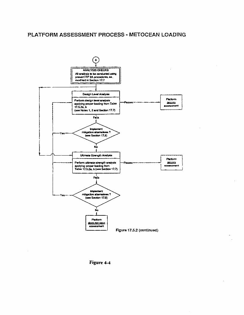
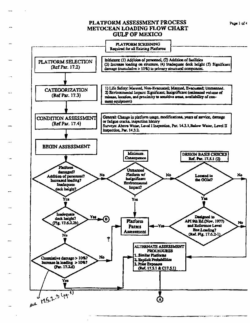
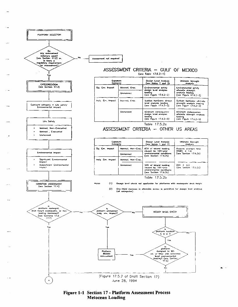
1-1 Section 17 - Platform Assessment Process Metocean Loading
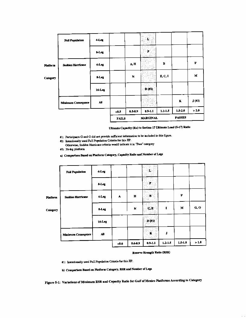
5-1 Variations of Minimum RSR and Capacity Ratio for Gulf of Mexico Platforms According to Category
Trials JIP - Trial Applications Final Report ... December 1994 111
Contents
Tables
2-1 Summary of Basic Platform Information - Physical Characteristics 2-2 Summary of Basic Platform Information - Physical Characteristics
Summary of Assessment Initiator Triggers Summary of Platform Categorization Summary of Condition Assessment Summary of Design Basis Check - Gulf of Mexico Platforms Summary of Metocean Criteria Summary of Design Level Analysis Results Summary of Ultimate Strength Analysis Results - Gulf of Mexico Four-Leg Platforms Summary of Ultimate Strength Analysis Results - Gulf of Mexico Eight-Leg Platforms Summary of Ultimate Strength Analysis Results - Other Gulf of Mexico Platforms Summary of Ultimate Strength Analysis Results - Offshore Southern California Platform Summary of Ultimate Strength Analysis Results - Cook Inlet Platform Summary of Ultimate Strength Analysiss Results - Other Platforms Summary of Trial Assessments
Trials JIP - Trial Applications Final Report December 1994 iv

Section 1 Introduction
BACKGROUND
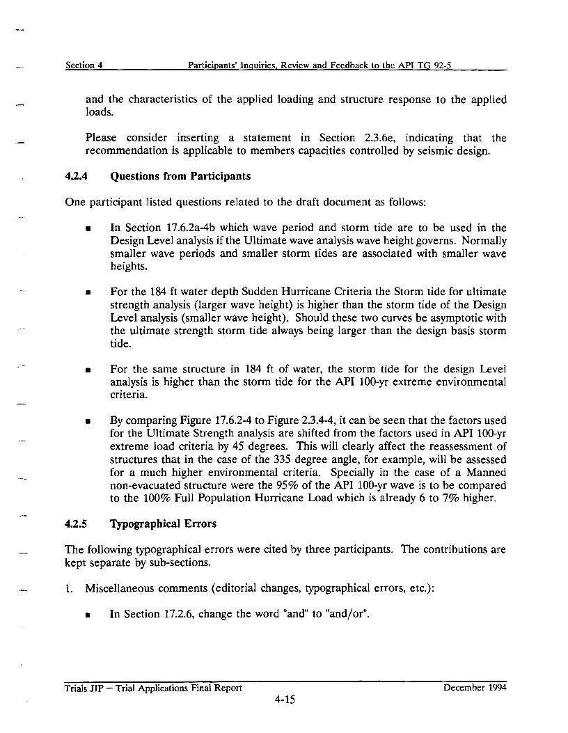
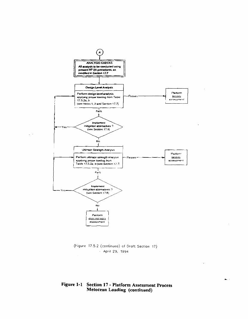
API Task Group (TG) 92-5 developed a draft guideline called I'API RP 2A-WSD 20th Edition, Draft Section 17.0, Assessment of Existing Platforms." The latest version of this document is dated April 29, 1994 with some particular revisions dated June 24, 1994. This document defines an assessment process as shown in Figure 1-1, which varies from that followed for a new design. It is based on a multi-level consequence-based acceptance criteria and follows a three-tiered assessment process consisting of screening checks, design level analysis or ultimate strength analysis.
This draft guideline has not been yet officially endorsed by the API, and has been distributed to interested parties for comments by the TG.
The Minerals Management Service (MMS) and a number of interested participants (21 total) contracted PMB Engineering Inc. (PMB) to manage and coordinate a Joint Industry Project (JIP), called the TRIALS JIP, consisting of two parts as follows:
Part I: Trial application of the draft guideline in its entirety by the participants to their selected platforms.
Part 11: Trial application of the ultimate strength analysis procedure of the draft guideline to a common platform by participants or any other interested organization not participating in Part I, in order to determine the variability in the ultimate strength analysis results.
At the kickoff meeting held for the Part I participants of the Trials JIP project on January 19, 1994 at PMB/Bechtel, Houston offices, a Technical Advisory Committee (TAC) was formed to govern both Part I and Part I1 of the JIP. All companies participating in Part I of the project nominated one member to the TAC. Each TAC member was given one vote on all project matters.
PMB developed the requirements of Trial Applications and produced a Trial Basis Document in agreement with the TAC. The Trial Basis Document provided the necessary background information for performing the trial applications and specific instructions on the types of analysis and results required of each participant. The Trial Basis Document was provided to the various companies interested in performing the Trial Applications.
This report provides details of Part I of the project. The information contained in the Trial Documents received from 21 participants is summarized in the same order as one would apply the Draft Section 17. The primary focus of review of Participants' submittals was to identify problems experienced by them in complete application of the Section 17 document
Trials JIP - Trial Applications Final Report December 1994 1- 1
Section 1 Introduction
and also to provide information (results obtained) to the MI TG for re-examining (if required) the criteria and the basis used in its development.
1.2 OBJECTIVES
The objectives of this portion of the TRIALS JIP were as follows:
Complete assessment of a platform by each participating company.
m To provide comments and feedback to the API TG on the draft document.
To provide assessment information for a larger sample of platforms assessed in this project to the T G to review the acceptance criteria, if found necessary
m To provide training (learning the process) to the participating companies
1.3 PROJECT PARTICIPANTS
At the kick-off meeting on January 19, 1994, 22 companies (16 operating companies and 6 engineering contractors) showed interest in performing Trial Applications. Nineteen companies (15 operating companies and 4 engineering companies) submitted their assessment to the project by September 15, 1994 (the revised original deadline), and four of these provided or revised their ultimate strength analysis results by November 15, 1994. Two companies submitted their documents by November 1,1994 (extended deadline for late submittals and new participants). In addition, one company provided an additional document on voluntary basis for a platform located West Africa to demonstrate applicability of the Section 17 process to other regions.
The 21 companies (hereafter called 'Trial Participants" or 'Participants") submitting documents are identified as follows:
AKER OMEGA AMERADA HESS AMOCO BARNE'IT & CASBARIAN CHEVRON CONOCO ELF EXPLORATION EXXON IDEAS IMP/PEMEX LINDER AND ASSOCIATES
Trials JIP - Trial Applications Final Report December 1994 1-2
Section 1 Introduction
MOBIL MURPHY OIL NEWFIELD PENNZOIL PHILLIPS SHELL TEXACO UNOCAL WALTER OIL & GAS ZENTECH
1.4 PLATFORMS ASSESSED
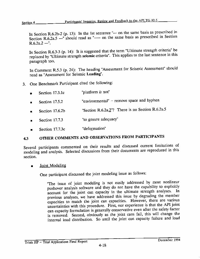
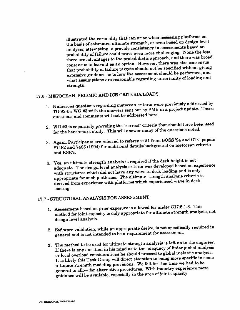
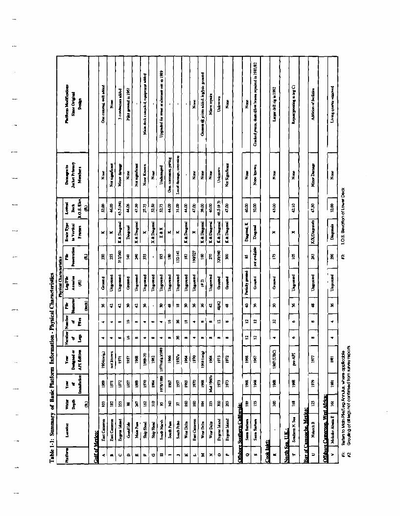
A summary of the physical and operational characteristics of the 22 platforms assessed in this JIP is presented in Table 1-1 and Table 1-2. All of these platforms were approved for inclusion in this JIP by the TAC members at the kick-off meeting of January 19, 1994 and through later PMB correspondence with the TAC. The participating companies are identified in this report as A, B, C, etc. to keep their identities confidential. The information presented in these tables is discussed below.
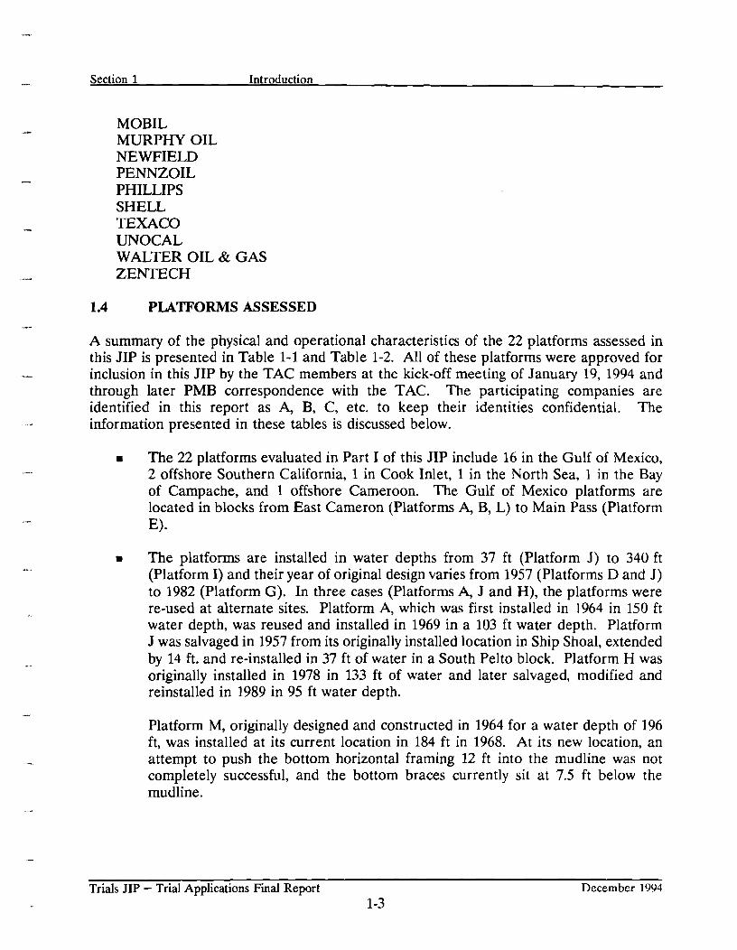
The 22 platforms evaluated in Part I of this JIP include 16 in the Gulf of Mexico, 2 offshore Southern California, 1 in Cook Inlet, 1 in the North Sea, 1 in the Bay of Campache, and 1 offshore Cameroon. The Gulf of Mexico platforms are located in blocks from East Cameron (Platforms A, B, L) to Main Pass (Platform E).
The platforms are installed in water depths from 37 ft (Platform J ) to 340 ft (Platform I) and their year of original design varies from 1957 (Platforms D and J ) to 1982 (Platform G). In three cases (Platforms A, J and H), the platforms were re-used at alternate sites. Platform A, which was first installed in 1964 in 150 ft water depth, was reused and installed in 1969 in a 103 ft water depth. Platform J was salvaged in 1957 from its originally installed location in Ship Shoal, extended by 14 ft. and re-installed in 37 ft of water in a South Pelto block. Platform H was originally installed in 1978 in 133 ft of water and later salvaged, modified and reinstalled in 1989 in 95 ft water depth.
Platform M, originally designed and constructed in 1964 for a water depth of 196 ft, was installed at its current location in 184 ft in 1968. At its new location, an attempt to push the bottom horizontal framing 12 ft into the mudline was not completely successful, and the bottom braces currently sit at 7.5 ft below the mudline.
Trials JIP - Trial Applications Final Report December 1994 1-3
Section 1 Introduction
m Most of the platforms have either four or eight legs. One platform (D) has 16 legs, consisting of two 8-legged jackets installed and connected together. Platform J has 36 legs, consisting of three 12-leg jackets installed and connected together. Platform T has 6 legs and platforms S and Q have 12 legs.
The bracing scheme in the vertical frames of platforms primarily included K-braces and diagonals. In five cases (Platforms H, L, R, T, and U), X-braces are provided.
The damage reported is minimal for most of these platforms. For a majority of platforms, modifications were made from the original design stage or future modifications are under consideration.
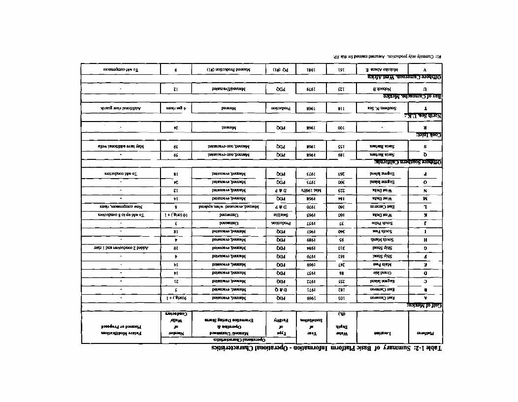
m A majority of platforms have Production, Drilling, and Quarters (PDQ) facilities.
All the "manned" platforms in the Gulf of Mexico are reported to be "evacuated" during storm. Whereas, the three platforms (Q, R, S) located Offshore California and Cook Inlet are "manned" but "not evacuated" during storm.
The number of wells in these platforms vary from a minimum of three (Platform J) to a maximum of 59 (Platform Q). Platform T has no wells.
The above information indicates that these platforms provide cases with a wide variation of physical and operational characteristics. The assessment information for these platforms provides a useful database for the MMS and the API TG.
Trials JIP - Trial Applications Final Report December 1994 1-4
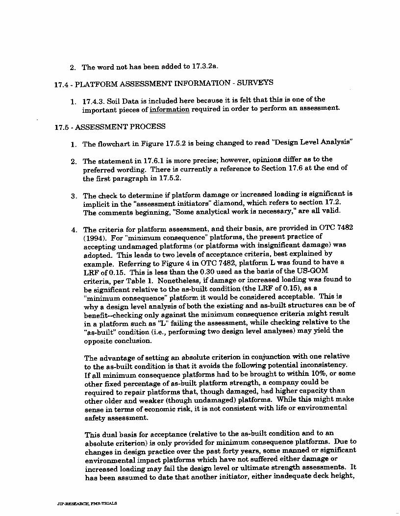
ASSESSMENT CRllEFM - GULF OF MEXICO (see Table 17.6.2-1)
D.4- Lrrd And,+ ut*rrolc s- 7 (m Nd" 1 ad 2) -1
sa. Em. hoocl -. E=. Cmkw-&j . O ( ~ Y d e b l"d om+ ,&-ndc 'bmtqu, W E ? w e 17.62-23 -4-i= (scr Fpr t w l i . 6 . i - l j
h s k h. +d Uon-. C . ~ C Sudden hvrricaoc d-$n Sudda hrvrinorr unmmde
I Lrrr( om^ om+& h06.w
I (see F g y c 17.6.2-Jj _ _ _ _ (Y.C Fqu- 17.62-J)
L , I Table 1 7.5.20
ASSESSMEM CRlTE3lA - OTHER US AREAS
+. Cm. h+od Uorncd. Yon-C~OL
Uonmnca MX d Maol bod+ K34 2 0.6 - b 7 1 ~ - (,r. Secim 17 .6 2b) cmMnmontd cod- (- %dc.-, 17.6.2a)
Table 17.5.2b
Hot-: (I) D&qn M - net a&-& fa. pbtforrm 6 m b q d c M k W h C
(Figure 17.5.2 o f Drof t Section 17) June 28, 1994
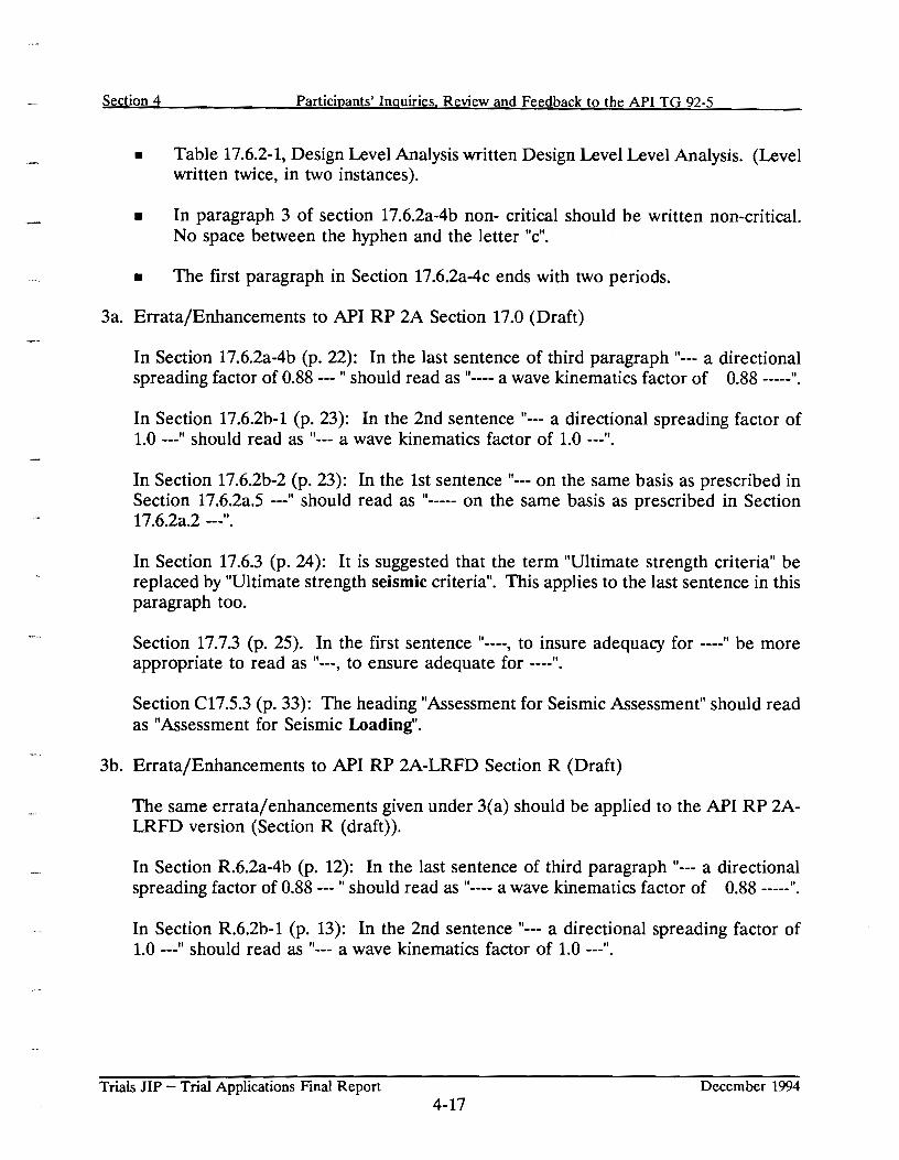
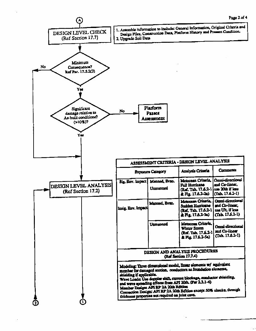
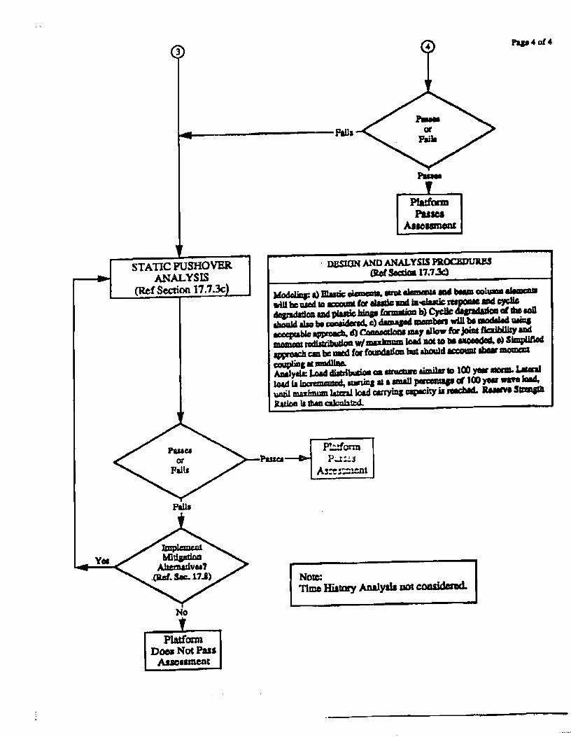
Figure 1-1 Section 17 - Platform Assessment Process Metocean Loading
w w p a p a badw trwn Table
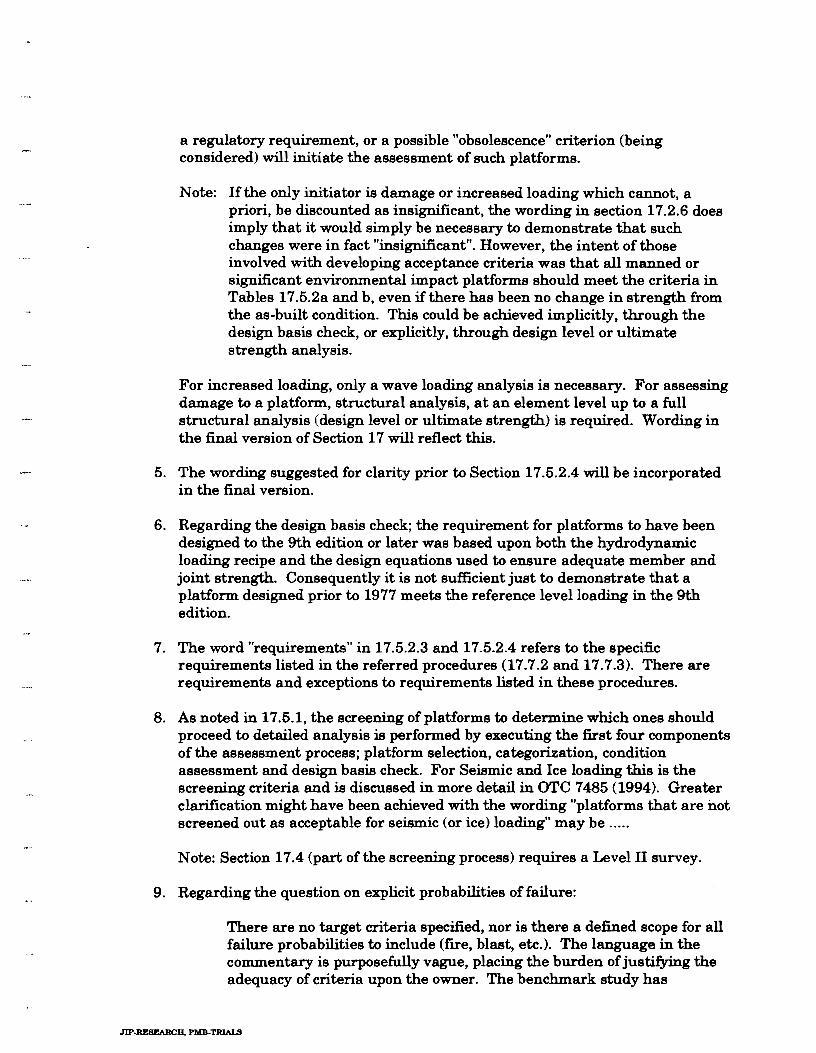
( s e e Notes 1.2 end S e c M n 17.7) I
Uirnale Strength h l y u s e -1 Pdorrn ultimale strength anatys6
apply in^ proper bad~ng tmm Table 17.5.2~. b (see S e c w n r 7 T;
I Plsrtwm I - 1 assessment 1
(Figure 17.5.2 (continued) of Draf t Section 17)
April 29. 1994
Figure 1-1 Section 17 - Platform Assessment Process Metocean Loading (continued)
I,! i! i
't PI b # ~ C)
4 t i $ g S .
Q i E * k P s
B
P
I 5 :I a - " 1 E l i E -2
i i . 4 - ii Z
, t i d h i r n E
P 3 2 3 % . .Y 9
* 3 , a r 1 % 2
P m .. 4
r CI z
I 02 P-n bad 8%1 001 I I) x
wfi I-PW. -q Ic.n
~lqjnpm WOL
spqr‘-=du=m~
~ 0 1 9 1 1 ~ 1 ~ ~ 8 0 1 d n ~ o ~
I 1 + ( . 8 ~ ) 6 ( FJl-.='l'=w I bad I 696 1 €01 I t0atq)W.d
6s
6s
I h I -n
8 I
PZ
Z I
PI
8
1 + VF") 01
m-*-mn m-*-pannn
m w w
m - m n m-pannn
W - H P ~ M ~ W-HT-Wi4
m p d n u r l f i w ~ m n
auuuun
8 1
bad
bad
L Z ~ I
W-l'=w I bad I L%1 1 OPE 1 eDPd WnoS I
bad
bad
d u a
bad
d u a
a!nw LE I qPd lll*S I r
8961
8961
E L ~ I
E C ~ I
M X ) ~ ~ I P ! I Y
8961
0 ~ 6 1
s961
SSI
68 I
rnqaa 4ms s urq- 4"'s b
€92
OOE
m P8 1
091
091
msl =a- prqq
9=a ~B)M
8Xl P A
urwr;)m a=aa=m
d
o N
HI
1
H
Section 2 Information to Participants
2.1 TRIAL BASIS DOCUMENT
The participants were provided with the Trial Basis Document dated February 24, 1994. The document included details of project organization, analysis and documentation requirements for participation in the project. Two tasks were identified for the participants as follows:
Task A: A complete application of the API assessment process up to and including ultimate strength analysis. The screening analysis is optional.
Task B: A critical review of the draft guideline, as applicable to the ultimate strength analysis, with emphasis on completeness, clarity, complexity, and suggestions where possible. Any typos or other errors should be identified. This task was voluntary. Participants may suggest alternative approaches for "assessment of existing platforms."
The Trial Basis Document mentioned the following:
The API assessment process shall be applied in a stepwise manner in its entirety to meet the requirements of this project. In case a platform passes at an early stage, the participant shall identify that stage in their trial document and continue with further application of the assessment process.
The participant shall provide sufficient documentation to understand how each part of the process was performed and significant results. All the steps leading to the selected assessment criteria shall be clearly given. For items such as Platform Selection and Condition Assessment, a brief written statement of the approach used and results shall be provided.
m For platforms located in other regions (such as the North Sea), for which criteria are not given in Draft Section 17, participants shall define their own criteria which shall be in accordance with those suggested by the draft guideline.
m Analysis results, where possible, shall be presented on platform sketches. No computer outputs should be submitted. Participants are encouraged to provide results in tabular or graphical form, where possible.
m If the optional screening analysis is used in Task A, then the participant shall provide a summary of the approach plus documentation indicating that the approach is more conservative than the design or ultimate strength checks.
Trials JIP - Trial Applications Final Report December 1994 6 1
Section 2 Information to Participants
H For design level analysis, the relevant information required by the MMS for new platforms should be used as a guideline for the type of data required [Federal Register Rules and Regulations, OCS Report MMS 91-0082, 30 CFR 250, Latest Edition]. Per the MMS, the data should include a summary of pertinent derived factors of safety against failure for major structural members.
H For ultimate strength analysis, the lateral load corresponding to the 100-year environmental condition, the ultimate lateral capacity, and RSR for the platform shall be clearly identified on suggested format for load-displacement plots.
The lateral load level at which the first component reaches a unity check of 1.0 or the first pile reaches the axial pile capacity (design level) per R P 2A-WSD, 20th Edition, with all safety factors included, shall be determined.
The participants were provided with formats of figures and tables for presentation of their analysis results. Also, they were provided details of the voluntary information, which would be useful to the project.
2 2 OTHER INFORMATION
Other information was provided to the participants, including versions and modifications to the Draft Section 17, handouts and minutes of kick-off, progress, and final meetings.
Trials JIP - Trial Applications Final Report December 1994 2-2
Section 3 Summary of Participant Submittals
This section summarizes the platform assessment information obtained from the Participants' submittals.
Nineteen participants provided their documents by September 15, 1994 and were included in the Draft Report of September 1994 and were discussed at the Final Meeting held on October 18, 1994.
Following the Final Meeting several participants provided missing information in the Draft Report, participants G and 0 provided results for the ultimate strength analysis, and participants D and N submitted updated documents.
Participants T and U submitted their documents by November 1, 1994 (extended deadline for late submittals and new participants). The information from these documents have been included in this report as summarized by these participants in the format of the tables of this report.
The information for the platform V located offshore West Africa, a voluntary submittal, which demonstrates applicability of the Section 17 process to other regions has also been summarized in this section.
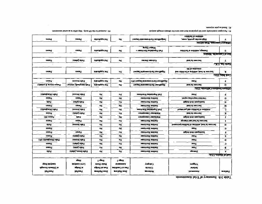
The information is summarized in tabular form in Tables 3-1 to 3-8, in the sequence of application of the Draft Section 17 document, and is discussed in the following subsections.
Where the information was not provided by the participants, it is noted by the symbol "-" in the tables. Also, in some cases the participants' computed values (such as RSR or platform pass/fail assessment) differed from that defined per Section 17. Where it was clear that the values were computed incorrectly, corrected values are provided.
3.1 PLATFORM SELECTION (SECTION 17.2)
Section 17.2 and Figure 17.5.2 provide six assessment initiators as follows:
Addition of Personnel
Addition of Facilities
Increased Loading on Structure
Inadequate Deck Height
Damage Found During Inspections
Trials JIP - Trial Applications Final Report December 1994 3- 1
Section 3 Summary of Participant Submittals
w Is there a Regulatory Requirement?
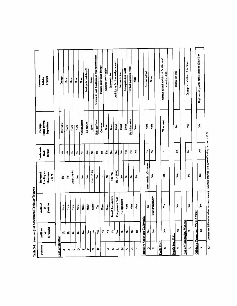
The participants' assessments for the initiators (excluding Regulatory Requirement) are summarized in Table 3-1. The information presented indicated the following:
For Platform L, the manning status will change from "unmanned" to "manned"
m For Platform L, additional facilities (compressors, risers) are planned.
For five platforms (H, K, M, R, and T), participants estimate that the load level is likely to increase by more than 10%. The reasons for such increase included heavy marine growth, additional conductors, and revised criteria.
Three platforms (F, J, N) had inadequate deck height.
In two cases (A, I) corrosion damage was noted with all others noting minor or no damage. Platform U has several dented, bent members and joints with cracks in the splash zone.
Based upon these initiators, fifteen platforms were triggered for assessment and seven were not.
Platform I had mixed initiators: marine growth and corrosion damage. Several participants cited choosing the platforms due to various other reasons, such as installed at an alternate site (M), on life extension (E, R), to evaluate for feasibility of future additions (P, S).
32 CATEGORIZATION (SECTION 17.3)
The platforms were categorized according to life safety and environmental impact. Based on this, the applicable metocean criteria were selected, including one of the following:
Full Population Hurricane
Sudden Hurricane
Minimum Consequence
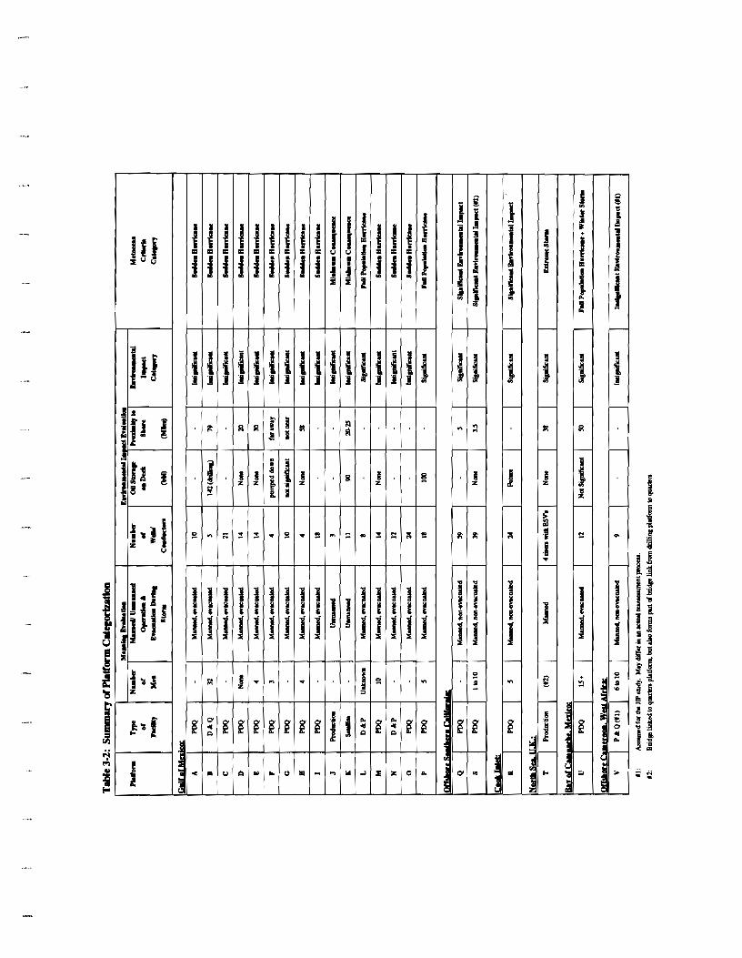
Table 3-2 summarizes the information for all platforms. A majority (15) of platforms have Production, Drilling and Quarters (PDQ) facilities. Only one platform was defined as a "satellite" drilling platform.
Trials JIP - Trial Applications Final Report December 1994 3 -2
Section 3 Summary of Participant Submittals
Two platforms are "unmanned." The manning level of platforms was not available for all cases. For those situations in which it was available, it varied from 3 people (Platform F) to 32 people (Platform B). All the "manned" platform cases in the Gulf of Mexico were defined as "evacuated" during storm events. The three platforms located offshore Southern California and in Cook Inlet were considered "non-evacuated" during extreme loading states.
Platform T is bridge connected to the quarters platform and is categorized manned. Platform U is categorized as manned, evacuated and platform V as manned, non-evacuated for this study.
The number of wells varied from a minimum of three (Platform J) to a maximum of 59 (Platform Q). Production platform T has no wells/conductors but has risers, which have been considered in environmental impact evaluation. The information on oil storage on the deck was not available for all cases, and where it was available, it was noted as being very low and having minimal environmental impact. Information on a platform's proximity to shore was not available for all cases. Participants identified 14 Gulf of Mexico platforms as having "Insignificant Environmental Impact" and two with "Significant Environmental Impact."
Based upon the Life Safety and Environmental Impact classifications, metocean criteria were selected as follows for the Gulf of Mexico platforms:
Full Population Hurricane - 2 platforms
Sudden Hurricane - 12 platforms
Minimum Consequence - 2 platforms
Five platforms located in other regions were identified to have "Significant Environmental Impact" and one to have "Insignificant Environmental Impact" for selection of applicable metocean, seismic and/or ice criteria.
CONDITION ASSESSMENT (SECTION 17.4)
Condition Assessment of platforms per Figure 17.5.2 includes gathering platform information per Section 17.4 and assessing the state of the platform to "screen" the "minimum consequence" platforms without damage, those with adequate deck height, and those without significant (> 10 %) increase in loading under "PASSES ASSESSMENT' category. The platforms which do not pass at this stage require either "Design Basis Check or "Analysis Checks."
Trials JIP - Trial Applications Final Report December 1994 3-3
Section 3 Summarv of Participant Submittals
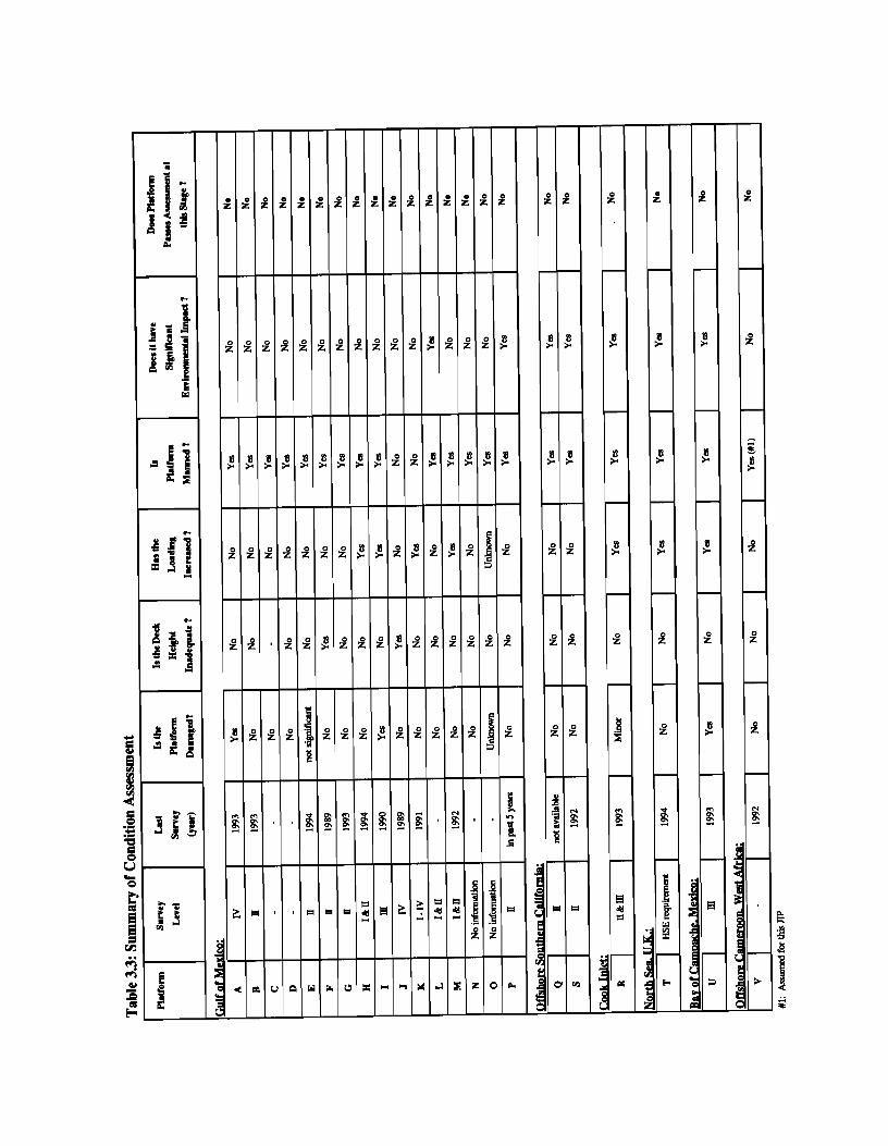
Table 3-3 provides a summary of this assessment. The survey level for platforms varied from an above-water Level I to an underwater Level IV (Platforms A, J, and K). Damage was reported on three platforms (Platforms A, I and U). Two platforms E and R had minor damages whereas damage to platform 0 was unknown. Inadequate deck height was noted for only two cases (platforms F, J), and increase in loading was cited for seven cases (platforms H, I, K, M, R, T, U) and for platform 0 was unknown.
Based upon these three "screening" criteria, 11 platforms will not meet the criteria and will require "Analysis Checks." These platforms are identified as A, F, H, I, J, K, M, 0, R, T, and U. The remaining eleven platforms will need to be screened further based on consequence level.
These remaining platforms do not pass at this stage either due to being "manned" or having "significant environmental impact."
Therefore in an actual assessment, none of these platforms would clearly pass at the "Condition Assessment" stage due to not meeting "screening criteria" or due to inadequate information. They would need to undergo either a "Design Basis Check (for the Gulf of Mexico platforms only)" or an "Analysis Check."
3.4 DESIGN BASIS CHECK
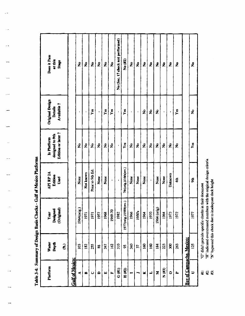
The Design Basis Check is applicable only to the Gulf of Mexico platforms. These platforms were further screened based on the API RP 2A Edition used in their design. Table 3-4 provides the information retrieved from the participants' submittals. The information presented indicates that only platforms G and H were designed or re-designed to an API Edition later than the 9th Edition. Participant H indicated overstressed members with the original design criteria. In some cases, participants did not provide an answer to this screening criteria question, but based on their year of design/installation, the project put YES/NO in the table.
Participant G did not provide specific checks in their document. Participant N noted that they omitted this check due to the platform having inadequate deck height.
3.5 ANALYSIS CHECKS (SECTION 17.6 AND 17.7)
3.5.1 Metocean, Seismic, and Ice Criteria
Metocean Criteria
The metocean criteria selected by the participants for Section 17 Design Level and Ultimate Strength, and Section 2 of the RP 2A, 20th Edition is summarized in Table 3-5 according
Trials JIP - Trial Applications Final Report December 1994 3-4
Section 3 Summary of Particioant Submittals
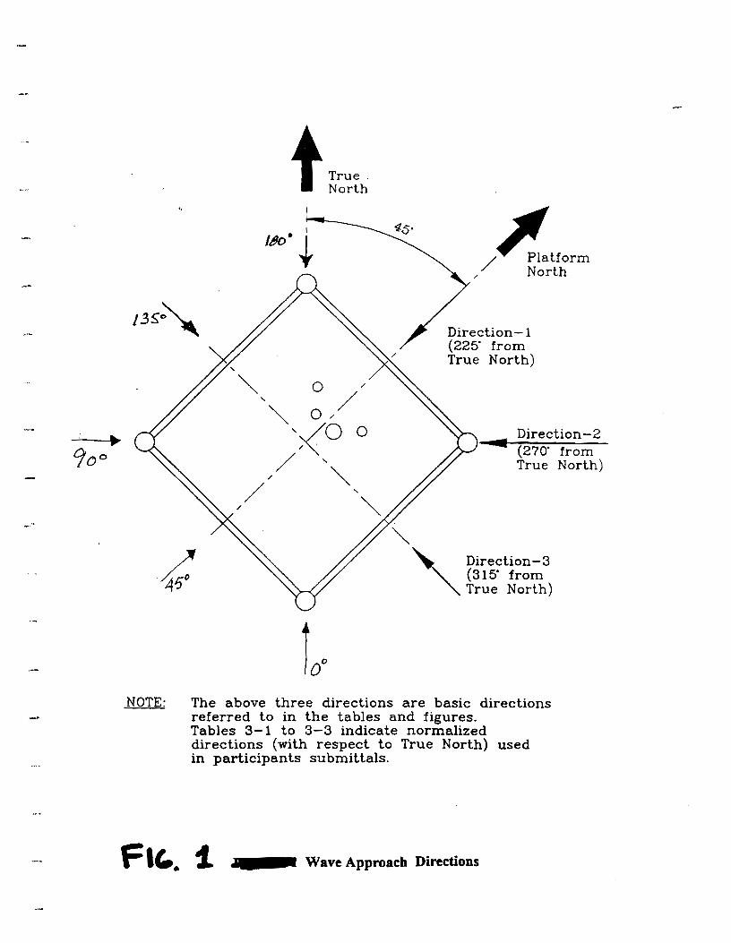
to the metocean criteria category. The orientation of Platform North varies from N45E to NSSW. For some cases, information for one or more criteria were not provided by the participants or were not easlly extracted from the submittals.
A comparison of the selected wave heights indicate that for .the "Sudden Hurricane" category, the Section 17 design level wave height varies from 41 ft to 47.5 ft for water depths from 88 ft to 340 ft, respectively. The variation of the wave height for the Section 17 ultimate strength criteria is from 50 f t to 61.5 ft for this category. Some inconsistencies are noted among platform cases A, H and D in the lower water depth range. Participant D clarified using intentionally greater wave height and current based on full population hurricane criteria to test procedure for wave acting on deck.
Section 17 provides the 100-year return period metocean criteria for the platforms offshore Southern California and does not require analysis for metocean loads for Cook Inlet structures as ice forces govern.
Participants T, U, and V developed metocean criteria for the design level and ultimate strength analysis for the applicable environmental impact category, following the procedure used in the development of Section 17 parameters for the Gulf of Mexico which is discussed in OTC 7484, 1994.
Seismic Criteria
All three platforms Q, R, S under the "Significant Environmental Impact" category require ultimate capacity assessment using loads associated with the median 1,000-year return period earthquake appropriate at the site. Participants used site-specific spectrum in their analysis.
Participants used 200-year return period spectra to perform design level analysis. However, note that Section 17 does not strictly require design level seismic assessment.
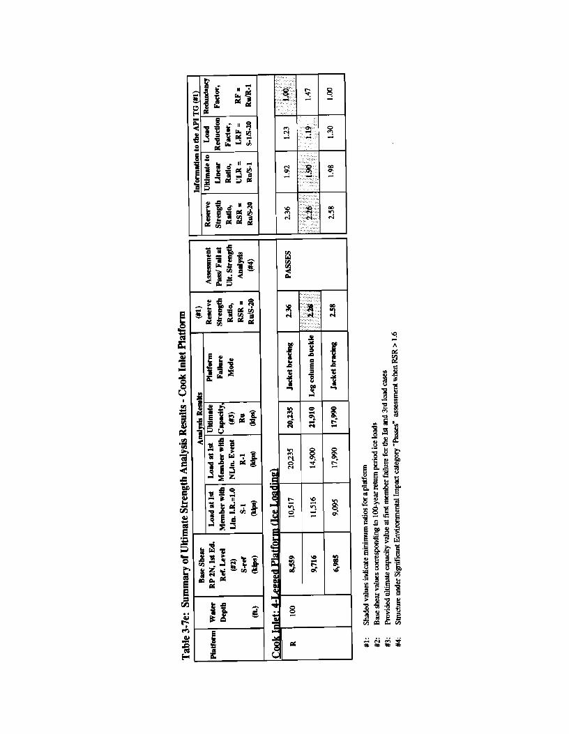
Ice Criteria
The ice loads, applicable to the Platform R, were estimated. by the participant per API RP 2N, 1st Edition (100-year return period) as 166 kips/ft leg diameter. The ice loads used in the original design were 120 kips/ft.
3.5.2 Screening
None of the participants performed screening analysis before moving on to the "Design Level" or "Ultimate Strength" analysis.
Trials JIP - Trial Applications Final Report December 1994 3-5
ection 3
3.5.3 Design Level Analysis
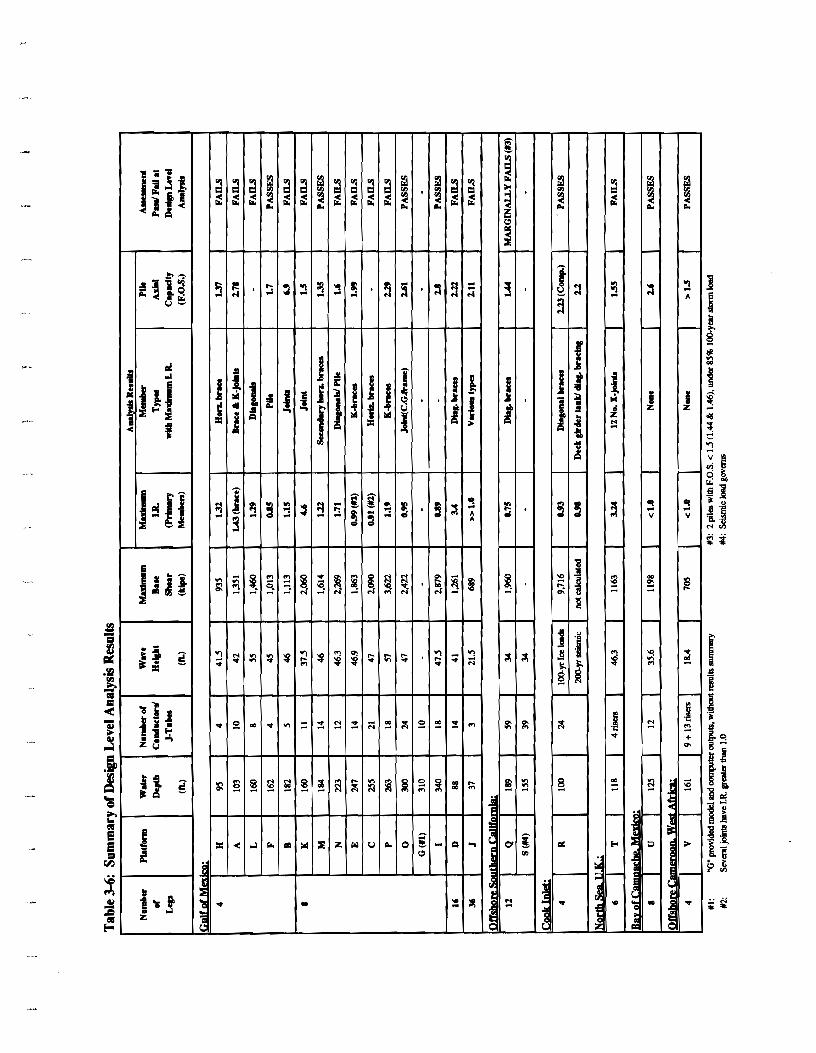
Table 3-6 summarizes the design level analysis results for the critical direction for each of the platforms. The information for the Gulf of Mexico is further classified according to the number of platform legs. The number of conductors/J-tubes infor,mation is also given in this table to provide reasons for variation in base shear.
The five 4-leg platforms located in the Gulf of Mexico in water depths ranging from 95 ft to 182 ft, have wave heights varying from 41.5 ft to 55 ft. These platforms have 4 to 10 conductors and their base shears vary from 935 to 1,460 kips. Of these, only platform F "PASSES'at this stage and the other 4 platforms (A, B, H, L) fail design level analysis check due to I.R.'s exceeding 1.0 for jacket braces or joints. In the case of platform H, the factor of safety against axial capacity (1.37) was also found to be inadequate.
The nine 8-leg platforms located in the Gulf of Mexico in water depths ranging from 160 to 340 ft have base shears varying from 1,614 to 3,622 kips. Participant G did not provide information in the required format. Of these, only three platforms (I, M, 0 ) pass at this stage. Platform D, a 16-leg platform, and platform J, a 36-leg platform do not pass at this stage.
Per Section 17, design level analysis is not applicable for seismic assessment of platforms. However, both participants with platforms in this region performed this analysis for design level metocean and seismic loading criteria. Platform Q marginally fails its metocean design level assessment, as two piles had factors of safety less than 1.5 (1.44 and 1.46). Under design level seismic loading, 9 of 12 piles had factors of safety less than 1.50. Platform S fails this assessment due to overstressing of four members.
The Cook Inlet structure was analyzed for ice loading. Per participant R, the platform passes its assessment (I.R. = 0.93). The participant also provided results for 200-year return period seismic criteria and found maximum I.R. of 0.98. The participant noted that, per Figure 17.5.2b (Section 17), 85% of the 100-year loading is to be applied for the design level analysis.
The North Sea structures (T) fails, whereas the Bay of Campache (U) and Offshore Cameroon (V) structures pass assessment at the design level analysis stage.
Participants used ASAD, CAP, DAMS, KARMA, MicroSAS, SACS, SESAS, and StruCAD, STRWDL software packages in their analyses.
Trials JIP - Trial Applications Final Report December 1994 3-6
" + Section 3 Summary of Partici~ant Submittals
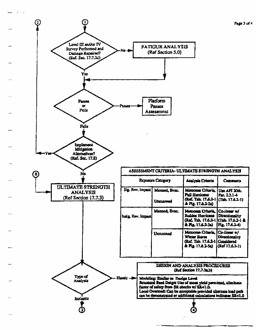
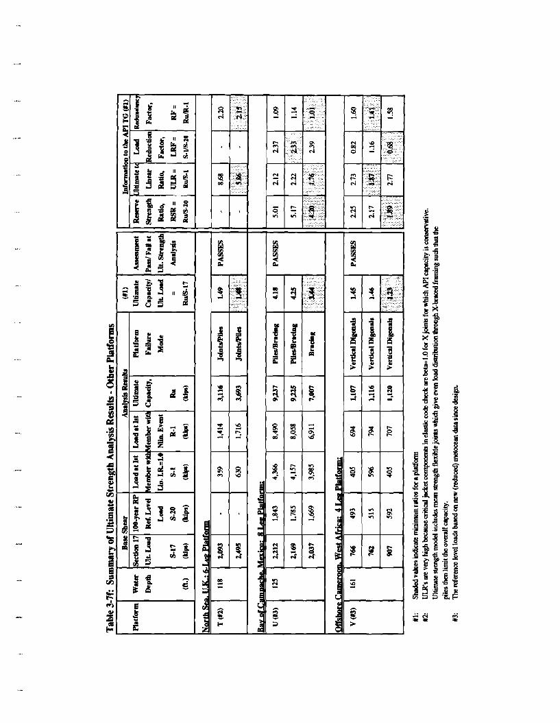
3.5.4 Ultimate Strength Analysis Results (Required)
Tables 3-7a to 3-7f present ultimate capacity analysis results. Participants used various - software programs and analysis procedures for this analysis. Participants used ASADS,
CAP, KARMA, MicroSAS, SAFJAC, and USFOS software packages for nonlinear analysis. The first three tables provide results for the Gulf of Mexico platforms, and the other three tables address platforms Q to V in other regions.
These tables include base shear values, ultimate capacity analysis results, and various ratios computed for use by the API TG 92-5. The results provided for various storm approach directions (maximum of three) are included, and the discussion of results in this section is limited to the most critical direction for a given platform.
*,-
G u l f o f e d Platforms
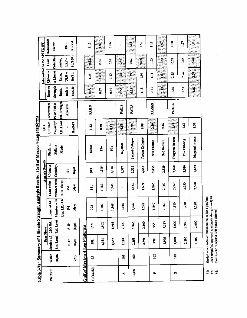
."., Table 3-7a presents results for 4-legged platform cases in the Gulf of Mexico.
The base shear corresponding to the Section 17 criteria varies from 970 kips (Platform F) to 2,600 kips (Platform L). When the base shear is compared to the 20th Edition criteria, the variation ranges from 955 kips (Platform F) to 2,600 kips (Platform A).
A " The ultimate capacity of the platforms varied from 990 kips (Platform H) to 3,500 kips (Platform B). The platform failure modes were composed of nonlinear events in jacket framing, pile sections, or inadequate axial capacity of soil. The capacity beyond first
-.- member failure (RF) varied from 1.0 to 1.5 for these platforms.
, ,.
The ratio of ultimate capacity of a platform to the base shear per applicable Section 17 criteria varied from 0.59 (Platform A) to 2.10 (Platform F). Based upon this ratio, platforms A, H, and L fail the ultimate strength analyses, whereas platforms B and F pass.
The ratio of RSR varies from 0.55 (Platform A) to 1.75 (Platform F). Without platform F, the RSR range would become 0.55 to 1.18.
ULR ratio for these platforms varies from 1.03 to 2.07 and the LRF ratio varies from 0.44 to 1.63.
Gulf of Mexico: 8-Legged Platforms
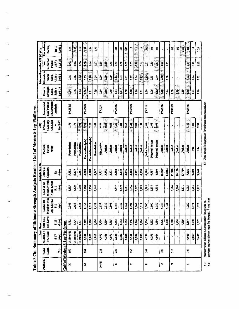
. Table 3-7b presents results for &legged platform cases in the Gulf of Mexico. The base shear corresponding to the Section 17 criteria varies from 1,840 kips (Platform E) to 6,291 kips (Platform P). Comparing the base shear per 20th Edition criteria, the variation is from
..,". 2,176 kips (Platform M) to 5,932 kips (Platform K).
Trials JIP - Trial Applications Final Report December 1994 -". 3-7
Section 3 Summarv of Partici~ant Submittals
The ultimate capacity of the platforms varies from 3,471 kips (Platform N in 223 ft) to 15,029 kips (Platform 0 in 300 ft). The platform failure modes were composed of nonlinear events in jacket framing, pile sections, or inadequate axial capacity of soil. The capacity beyond first member failure (RF) varied from 1.0 (Platforms E and P) to 1.55 (Platforms K and G).
The ratio of ultimate capacity of a platform to the base shear per applicable Section 17 criteria varied from 0.85 (Platform N) to 2.16 (Platform M). Based upon this ratio, platform N "Fails" and platform P "Marginally Fails" their ultimate strength analysis, whereas other platforms "Pass." The required Section 17 base shear values were not available for platforms G and 0 . Hence, it is not clear whether they meet the Section 17 ultimate strength criteria or not. However, based on their RSR values, they will surely "Pass" the Section 17 requirement.
The ratio of RSR varies from 0.60 (Platform N) to 1.56 (Platform M) for most platforms. For platforms G and 0 higher RSR values, 2.30 to 3.2, have been reported. The ULR ratio varies from 1.2 (Platform N) to 2.84 (Platform M). The LRF ratio varies from 0.43 (Platform K) to 1.22 (Platform 0) .
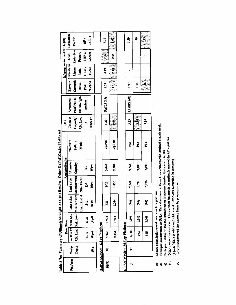
Table 3-7c presents results for platforms D and J with more than 8-legs located in the Gulf of Mexico.
Participant D presented results based on the full population metocean criteria for this analysis, whereas the platform was categorized under the "Sudden Hurricane" category. The minimum ultimate capacity of the platform is 2,300 kips and the RSR is estimated as 1.18. The platform fails due to nonlinear events in its jacket framing and pile sections. The ratio of ultimate capacity load to the base shear is 0.94. This would place the platform in the "Fails" category.
The minimum RSR for platform J is 1.46. This platform is classified under the "Minimum Consequence" metocean criteria category, resulting in an ultimate load base shear significantly lower than that per 20th Edition. This platform "Passes" Section 17 ultimate strength requirements.
Participant for platform D provided the following discussion for using different criteria:
"This platform passes the ultimate strength check when it passes the platform assessment initiator check (i.e., when the deck height is adequate).
Trials JIP - Trial Applications Final Report December 1994 3-8
Section 3 Summarv of Particivant Submittals
Participant used the full-population hurricane (significant environmental impact) to test the procedure for wave loading on the deck. Under this scenario, this structure would NOT PASS the platform assessment initiator check due to inadequate wave height. This is consistent with the tabulated 0.94 ratio for ultimate strength assessment.
For an actual assessment, the sudden hurricane (insignificant environmental impact) would apply, and the platform would PASS the platform assessment initiator check (i.e., deck height is adequate). For the ultimate strength analysis, the Section 17 Ultimate Load becomes 1620 and 1955 kips (was 2340 and 2451) for the two analyzed directions. This results in ultimate capacity/ultimate load ratios of 1.88 and 1.18 (was 1.30 and 0.94) based on the previous capacities; the ratios would increase since the deck is not loaded under this scenario."
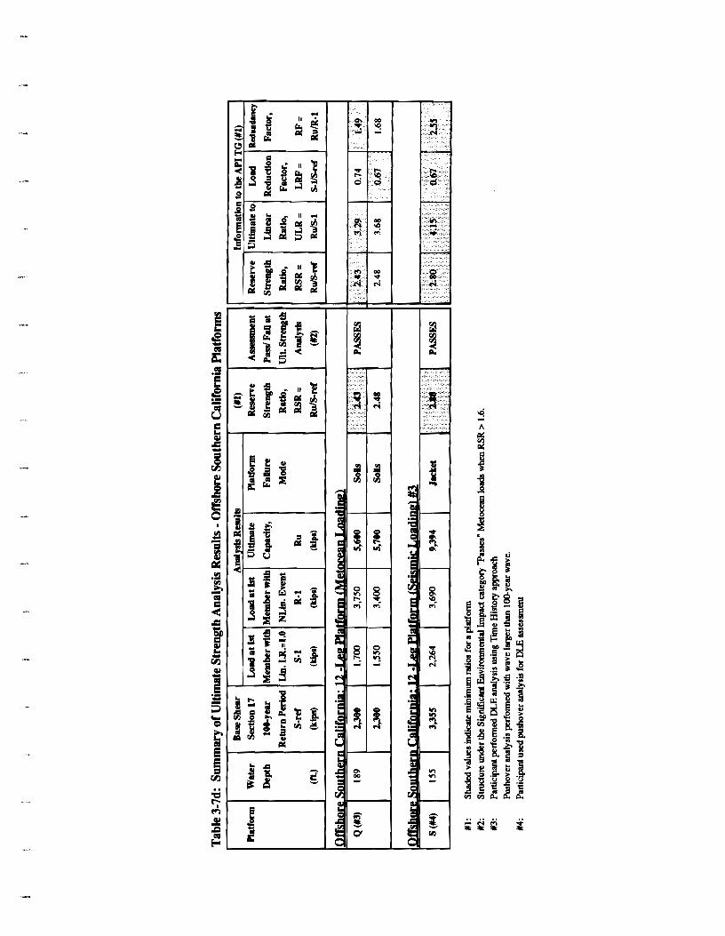
Offshore Southern California Platforms
Both of these platforms are classified as "Manned Non-evacuated" and have "Significant Environmental Impact." Per Section 17, the ultimate strength criteria would be set at a median 1000-year return period seismic event.
Participant Q performed a pushover analysis for ultimate wave loading and seismic time history analyses for seismic loading. The pushover analysis results indicate an ultimate capacity of 5,600 kips, with a failure mode due to inadequate soil (axial) capacity. The RSR is computed as 2.43, which is higher than the 1.6 minimum required per Section 17. The seismic criteria (spectra from 1971 San Fernando Earthquake) produced lateral load level of 5,600 kips, which leads to buckling or yielding of several vertical diagonals and horizontal braces. None of the legs and pile sections exhibited hinging for the 1000-year seismic spectra. Eleven out of the 12 piles experienced loading beyond static axial capacity, causing soil degradation in the range of 15 to 35 percent. The participant classified the platform as surviving the 1000-year seismic event due to no collapse mechanism being formed.
Participant S performed a pushover analysis for a load level of 3,355 kips (diagonal direction) corresponding to the Ductility Level Earthquake (DLE) criteria. The ultimate capacity estimate is 9,394 kips with failure of several jacket components. The participant provided an RSR value of 2.8 with a load level corresponding to the Serviceability Level Earthquake (SLE) criteria as the denominator. The Section 17 minimum acceptable RSR criteria of 1.6 is applicable to the metocean and ice criteria and not to the seismic event. Per Section 17, a platform would "pass" when the best estimate of resistance can be shown to withstand loads associated with a median 1000-year return period earthquake event without system collapse.
Trials JIP - Trial Applications Final Report December 1994 3-9