Treadmill User Centering - DigitalCommons@CalPoly
115
Treadmill User Centering California Polytechnic State University, San Luis Obispo Sponsor: Quality of Life Plus Advisor: Dr. Lily Laiho Number: 88a1 CP Cecilia Yuen, [email protected] Adam Patrella, [email protected] Donavan Feliz, [email protected] Ariel Crisostomo, [email protected] 1
-
Upload
khangminh22 -
Category
Documents
-
view
1 -
download
0
Transcript of Treadmill User Centering - DigitalCommons@CalPoly

Treadmill User Centering California Polytechnic State University,
San Luis Obispo Sponsor: Quality of Life Plus
Advisor: Dr. Lily Laiho Number: 88a1 CP
Cecilia Yuen, [email protected] Adam Patrella, [email protected] Donavan Feliz, [email protected]
Ariel Crisostomo, [email protected]
1

DISCLAIMER
Statement of Disclaimer Since this project is a result of a class assignment, it has been graded and accepted as fulfillment of the course requirements. Acceptance does not imply technical accuracy or reliability. Any use of information in this report is done at the risk of the user. These risks may include catastrophic failure of the device or infringement of patent or copyright laws. California Polytechnic State University at San Luis Obispo and its staff cannot be held liable for any use or misuse of the project.
2

Table of Contents Executive Summary 9
1. Introduction 10
2. Background 11
2.1. Retinitis Pigmentosa 11
2.2. Challenger’s Problem and Current Solution 12
2.3. Existing Solutions 14
2.3.1. Solutions for Visually Impaired Runners 14
2.3.2 Other Solutions for the Visually Impaired 15
3. Objectives 16
3.1. Quality Function Deployment 19
3.2. Engineering Specifications 19
4. Design Development 23
4.1. Concept Generation 23
4.1.1. Conceptual Prototypes 23
Position Detection: 23
Providing User Feedback: 24
4.2. Concept Selection 24
4.3. Concept Iteration 25
4.3.1 User Feedback Positioning 25
4.3.2. Conceptual Design Review Concept 26
Mechanical Safety 26
Dual Optical Mount 27
Haptic Harness 31
Device Calibration and Displacement Tracking 34
Preliminary Concept Justification 37
Hazards and Costs 37
4.3.3. Conceptual Design Review Feedback 38
4.3.4. Critical Design Review Selection 38
Overall Description 38
Sensor Housing and Orientation 40
Vibro-Belt 42
Electrical and Software Design 45
Projected Prototype Cost 47
Material, geometry, component selection 47
Safety Considerations 50
3

Maintenance and Repair Considerations 50
5. Functional Analysis and Testing 51
5.1. Treadmill Scaling Analysis 52
Treadmill Photo Scaling 52
Larry’s Treadmill Dimensions 52
5.2. Motor Testing 53
5.3. Battery Analysis 54
5.4. Sensor Configuration Testing 55
5.5. Safe Zone Boundary Analysis 56
5.6. Safety Distance Analysis 57
6. Final Design 58
6.1. First Full System Prototype and Testing 58
6.1.1. Prototype Description 58
First Prototype-Sensor Box 58
First Prototype- Vibrational Belt 59
6.1.2. Full System Testing 61
6.2. Design Iterations 62
6.2.1. Sensor housing- include all prototypes 62
6.2.2. Vibro-belt 64
6.2.3. Code 66
6.2.4. Mounting 67
6.3. Description of Final Design 68
6.3.1. Cost breakdown 70
6.3.2. Safety Considerations 72
6.3.3. Maintenance and Repair Considerations 72
7. Product Realization 73
7.1. Manufacturing 73
7.1.1. Sensor Housing 73
7.1.2. Vibro-belt 74
7.1.3. Mechanical Safety 74
7.2. Recommendations for Future Manufacturing 74
7.3. Cost Estimation for Future Production 74
8. Design Verification 75
8.1. Initial Verification and Testing Plan 75
8.2. Actual Verification and Testing 77
Functional/Safe 77
Independent Setup 77
4

Portable 78
Adjustable 78
Long-lasting 78
Drop Test 78
8.3. Design Expo Feedback 78
9. Conclusions and Recommendations 79
9.1. Recommended Device Modifications 79
9.2. Recommended Testing 80
References 81
A. Project Documents 85
A.1. Quality Function Diagram (QFD) 85
A.2. Gantt Chart 86
A.3. Pugh Decision Matrix 88
A.4. Hazard Identification Checklist 89
A.5. Project Costs 90
A.6. Management Plan 94
B. Prototype Documents 95
B.1. Prototype Drawings & Analysis 95
B.2. Prototype Datasheets & Code 103
C. Final Design Documents 106
C.1. Final Design Drawings 106
C.2. Final Design Code 108
C.3. User Product Guide 114
C.3.1. Starting the Device 114
C.3.2. Calibration 115
C.3.3. Turning Off and Disassembly 115
C.3.4. Charging the Devices 116
5

List of Tables Table 1. Customer Requirements 16 Table 2. Technical Engineering Specifications and Targets 17 Table 3. Design Concept Meets Customer Requirements 37 Table 4. Cost Breakdown of Prototype 47 Table 5. Final Project Budget 70 Table 6. Initial Verification and Testing Plans 75 Table 7. Verification and Testing Results 77
6

List of Figures Figure 2.1.1 Image of the eye and how images are focused in the eye 10 Figure 2.1.2 Comparison of 2 retinas 11 Figure 2.2.1 A common example of a treadmill found in a local gym 12 Figure 2.3.1 A standard 400 meter track. 13 Figure 4.1.1. Displacement-sensing concepts 22 Figure 4.1.2. Feedback-providing concepts 23 Figure 4.3.1. Experiment for most stable point on the body while running 25 Figure 4.3.2.1. SolidWorks rendering of the uncollapsed dual optical mount 28 Figure 4.3.2.2. The lidar lite 3 calculates the distance. 29 Figure 4.3.2.3. LiDAR lite 3 is can communicate with an Arduino Uno 29 Figure 4.3.2.4. A pair of XBee wireless module shields 31 Figure 4.3.2.5. A rough sketch of the haptic harness and desired final result 31 Figure 4.3.2.6. The three types of actuator devices under investigation 31 Figure 4.3.2.7. A Linear resonant actuator is seen here 33 Figure 4.3.2.9. A piezoelectric actuator is shown here 34 Figure 4.3.2.10. A virtual space is mapped out by the optical sensors 35 Figure 4.3.2.11. System Communication block diagram 36 Figure 4.3.4.1. Top-down views of the ultrasonic sensor ranges 39 Figure 4.3.4.2 Revised system communication block diagram 40 Figure 4.3.4.3. 3D isometric model of the housing with full assembly 41 Figure 4.3.4.4. Internal stitching of the outer face of the Vibro-Belt 43 Figure 4.3.4.5 A final rendition of the Vibro-Belt 45 Figure 4.3.4.6 The software flowchart of the final design 46 Figure 4.3.4.7. An example of a typical snap button fastening device 48 Figure 4.3.4.8. This push button switch 50 Figure 4.3.4.9 This is an example of a micro-USB charging jack 51 Figure 5.1.1. Larry’s treadmill at his local YMCA 53 Figure 5.2.1 A GoPro harness with 4 coin motors and an Arduino Uno 53 Figure 5.3.1 The power bank used for the final system 54 Figure 5.4.1. Front view of example wood housing 55 Figure 5.5.1. Measuring the safe zone on a treadmill 56 Figure 5.6.1 Testing the appropriate distance of the stop cord 57 Figure 6.1.1.1. Solidworks model of one half of sensor housing prototype 59 Figure 6.1.2.1 First full system testing of the first full prototype 61 Figure 6.2.1.1. New location of the front sensor housing 63 Figure 6.2.1.2. Solidworks model of the side sensor housing 63 Figure 6.2.1.3. Solidworks model of front sensor housing for final prototype 64 Figure 6.2.3.1. The software flowchart of the final design 66 Figure 6.2.4.1. Velcro straps with hooks and loops on both sides 68 Figure 6.3.1. Final system communication block diagram 68
7

Figure 6.3.2. An image of the final prototype of the vibro-belt 69 Figure 7.1.1.1 The side sensor housing being 3D printed in the Ultimaker 2+ 73 Figure 7.1.1.2 The front sensor & side sensor housing and side sensor housing 74
8

Executive Summary The goal of team CENTREAD was to design a device to allow a person with a visual disability to run efficiently and effectively on a treadmill without fear of falling off or injuring themselves. The customer wished for the device to be small, lightweight, and have an easy, autonomous setup, while providing feedback to the user wirelessly for them to correct their own movement. The ultimate goal of the device is to allow the user to be comfortable, safe, and free while using it in order to ensure they have the best running experience. The device utilizes ultrasonic sensors in housings to detect distances of objects using sound wave pulses. These sensors send signals out and detect the amount of time it takes for the signal to return to the same place, taking that time and converting it into a distance. These distances are sent directly into a microcontroller, where the microcontroller collects and analyzes the data. While analyzing the data, the microcontroller looks for data points that are within the boundaries set as not safe zones. These data points are then assigned a value and are sent over to a wireless transmitter to communicate with its sister receiver. The receiver detects a signal sent from the relative transmitter and sends the signal to another microcontroller to be processed. This process takes the value sent from the transmitter and assigns that value to a pin to activate a voltage to. This pin contains a small eccentric weighted motor that vibrates when a voltage is applied. This vibration is then interpreted by the user to move in the opposite direction of the vibration, correcting their location. This device utilizes two housings, one along the length axis of the treadmill belt and one along the width axis of the treadmill belt. These boxes interpret backwards distance from the front edge of the belt and left and right distance from the inside face of the right treadmill arm, respectively. These housings each contain their own microcontroller and transmitter that communicate with the receiver. The receiver is contained with a belt that the user wears, and collects signals from both housings. The microcontroller interprets these signals and applies a voltage to the respective motor. These motors are located on the left, right, and back of the belt and are there to correct the user to the right, left, and forwards respectively. This feedback system ultimately serves the purpose for solving the users problem and is an effective way of helping them get back to running confidently and safely again.
9

1. Introduction Assistive technologies for the visually or balance impaired are important in improving their users’ quality of life. Whether it is for exercise, daily activities, or niche specialties, this technology is essential in helping the user feel connected and comfortable with their surroundings. The industry is quickly emerging as demand for devices constantly increases and expands into new mediums. However, the market still remains small with very niche specialties. Because of this, many devices designed to help people who are visually or balanced impaired are yet to be discovered. This project is designed to improve the quality of life of a blind Air Force veteran challenger, who needs a device that will enable him to run in the center of a treadmill without worrying about swaying to the sides, front, or back of the treadmill, resulting in potential injury. The goal is to design a device/system that assists in keeping a visually or balanced impaired user located in the center of any treadmill belt, without any other assistive device (e.g. guide railing) being used. By June 2018, the Air Force challenger will have a fully functional device/system that will help guide him to the correct position of the treadmill, instilling a stress-free and comfortable running experience. The sponsor of this project is Quality of Life Plus (QL+), a 501(c)(3) not-for-profit organization whose mission is to foster and generate innovations to aid and improve the quality of life of those injured in the line of duty. The challenger’s name is Larry Gunter, an Air Force veteran who suffers from retinitis pigmentosa, a degenerative disorder that slowly disintegrates the vision of the person. From this point forward, Larry will be referred to as simply the customer or the challenger. The team is excited and honored to work with the challenger as he inspires the team with his service and sacrifice, in conjunction with QL+ and Jon N. Monett, the Director and Chairman of the QL+ Board of Directors. The team hopes to provide the challenger with an effective and functional device in gratitude for his sacrifice and service to the United States of America.
10

2. Background The following section includes literature reviews, a study of applicable codes and standards, a look at existing products that solve similar problems, and any pre existing experiments that have been done in application to the challenger’s disorder and solutions to similar problems.
2.1. Retinitis Pigmentosa The challenger is a U.S. Air Force veteran with a hereditary eye disease known as Retinitis Pigmentosa (RP), which causes a gradual degeneration of cells in the retina [1]. In a healthy individual, the eye focuses light through the lens to the retina, as shown in Figure 2.1.1 [1]. RP has multiple common mutations that affect the retina in different ways, however in all cases the result is damage to the photoreceptors [1].
Figure 2.1.1 Image of the eye and how images are focused in the eye [1].
Photoreceptors are cells in the retina that absorb and convert light into electrical signals that are sent through the optic nerve and into the brain where the signals are processed into images [1]. The two different photoreceptors located in the retina are known as rods and cones [1]. The rods are located around the outer regions of the retina and allow humans to see in dim or dark lighting. The cones are located mostly in the central portion of the retina and allow humans to perceive fine visual detail and color [1].
11

Retinitis Pigmentosa takes place in multiple stages [1]. In the early stages, the rods in the retina are more severely affected making it difficult to see in dark lighting, thus reducing the person's field of vision [1]. As the disease continues to degenerate the rods, it enters into the later stage and begins to attack the cones, as shown in Figure 2.1.2, resulting in a greater loss of the person's visual field. Tunnel vision, from here on, is formed [1]. Tunnel vision is the loss of a person’s peripheral vision, creating a sort of “tunnel” in their direct field of vision that they can see [1].
Figure 2.1.2 Comparison of 2 retinas- one not affected by any disorder
(left) and one affected by RP (right). Retina on the right severely damaged [1].
2.2. Challenger’s Problem and Current Solution Because of this degenerative disorder, the challenger’s current struggle is being able to run on a treadmill without requiring assistance from the support railing. A video of the challenger portrayed the current solution as holding onto the front guide rail on the treadmill with one hand at a time, allowing the other to move freely and in a correct running form. After a period of time, he switches hands, allowing the arm previously holding on to rest and move in a comfortable form, while the arm previously resting holds onto the railing. He does this to ensure that he stays central, balanced, and safe on the treadmill, preventing stepping on the belt guard or slipping off the back of the treadmill. An example of the railing used in supporting the challenger can be seen on the treadmill shown in Figure 2.2.1.
12
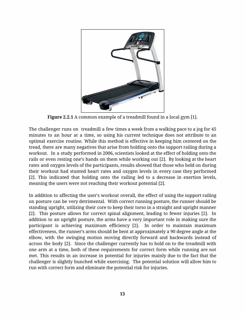
Figure 2.2.1 A common example of a treadmill found in a local gym [1].
The challenger runs on treadmill a few times a week from a walking pace to a jog for 45 minutes to an hour at a time, so using his current technique does not attribute to an optimal exercise routine. While this method is effective in keeping him centered on the tread, there are many negatives that arise from holding onto the support railing during a workout. In a study performed in 2006, scientists looked at the effect of holding onto the rails or even resting one’s hands on them while working out [2]. By looking at the heart rates and oxygen levels of the participants, results showed that those who held on during their workout had stunted heart rates and oxygen levels in every case they performed [2]. This indicated that holding onto the railing led to a decrease in exertion levels, meaning the users were not reaching their workout potential [2]. In addition to affecting the user's workout overall, the effect of using the support railing on posture can be very detrimental. With correct running posture, the runner should be standing upright, utilizing their core to keep their torso in a straight and upright manner [2]. This posture allows for correct spinal alignment, leading to fewer injuries [2]. In addition to an upright posture, the arms have a very important role in making sure the participant is achieving maximum efficiency [2]. In order to maintain maximum effectiveness, the runner’s arms should be bent at approximately a 90 degree angle at the elbow, with the swinging motion moving directly forward and backwards instead of across the body [2]. Since the challenger currently has to hold on to the treadmill with one arm at a time, both of these requirements for correct form while running are not met. This results in an increase in potential for injuries mainly due to the fact that the challenger is slightly hunched while exercising. The potential solution will allow him to run with correct form and eliminate the potential risk for injuries.
13

2.3. Existing Solutions
2.3.1. Solutions for Visually Impaired Runners Existing solutions have similar issues regarding the current task. A recent study in February of 2017 looked at the current methods for solving the problem of how long distance runners (e.g. marathon and ultramarathon distances) with visual disabilities ran their races [3]. The study found that oftentimes the primary method of solving this problem included the visually impaired being tied using a non-stretchable elbow tether to a sighted guide, in order to provide safety for the runner. This method ultimately led to a reduction in performance and autonomy. The proposed solution of this article was to create an “invisible hallway,” wearing a light sensor unit guided by electromagnets along a 400 meter track. As the athlete approached either limit of the “hallway,” the sensor would emit a vibro-tactile signal to the athlete, prompting them to move in the desired direction. From Figure 2.3.1, a vague outline of the hallway that the study was attempting to create can be seen.
Figure 2.3.1 A standard 400 meter track with outline barriers for the
“invisible hallway.” The red line indicates the outside barrier while the blue line indicates the inside. Taken from Electromagnetic Sensor article.
[3] The athlete would run between the red and blue lines without a sighted guide, receiving small signals that would increase the closer the athlete got to the respective line. The lines were marked on the track by wires on the ground that would generate 2 magnetic fields that would emit a signal of 0 volts at the center [3].
14

The results of this experiment found that athletes with vision impairments could run along the provided path without the need of a sighted guide, allowing the user to run free of any potential harm. The experiment also used standard commercial components that are cheap and easy to install, and the magnetic fields that are generated from the wires are completely safe for the runners. The largest shortcomings of the experiment appeared from obtaining and maintaining the wires used to create the hallway, as well as the vehicle designed to drive in front of the runner to ensure accurate warnings were sent to the sensors.
2.3.2 Other Solutions for the Visually Impaired Since the visually impaired typically encounter the same problem with most activities, there are often similar solutions to these problems. The most common solution to most problems found with the visually impaired is to get assistance through a sighted guide. Whether that sighted guide be another person or oftentimes a seeing eye animal, these guides are essential in assisting the person in completing the tasks. In most recreational activities these sighted guides assist the person through a tether or leash, where the guide, whether human or non-human, is physically tied to the person using a non-stretching cable. This physical connection allows the visually impaired person to exercise with their own freedom, but allowing for corrections to be made if they are moving down the wrong path. This method of assistance can be found in long distance running, swimming, walking, etc. While this solution is not necessarily the most advanced in regards to technology, it has proven effective and useful in being able to keep the visually impaired person safe. In addition, it typically involves a companion or guide, therefore creating a connection between the person and the aide.
15
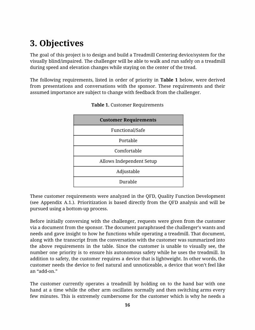
3. Objectives The goal of this project is to design and build a Treadmill Centering device/system for the visually blind/impaired. The challenger will be able to walk and run safely on a treadmill during speed and elevation changes while staying on the center of the tread. The following requirements, listed in order of priority in Table 1 below, were derived from presentations and conversations with the sponsor. These requirements and their assumed importance are subject to change with feedback from the challenger.
Table 1. Customer Requirements
Customer Requirements
Functional/Safe
Portable
Comfortable
Allows Independent Setup
Adjustable
Durable
These customer requirements were analyzed in the QFD, Quality Function Development (see Appendix A.1.). Prioritization is based directly from the QFD analysis and will be pursued using a bottom-up process. Before initially conversing with the challenger, requests were given from the customer via a document from the sponsor. The document paraphrased the challenger’s wants and needs and gave insight to how he functions while operating a treadmill. That document, along with the transcript from the conversation with the customer was summarized into the above requirements in the table. Since the customer is unable to visually see, the number one priority is to ensure his autonomous safety while he uses the treadmill. In addition to safety, the customer requires a device that is lightweight. In other words, the customer needs the device to feel natural and unnoticeable, a device that won’t feel like an “add-on.” The customer currently operates a treadmill by holding on to the hand bar with one hand at a time while the other arm oscillates normally and then switching arms every few minutes. This is extremely cumbersome for the customer which is why he needs a
16

device that allows him to run without holding on. Specifically, the customer would like a device that fits securely on his body, one not made of rigid materials and small enough to fit into his gym bag, which is a triathlete backpack. Finally, the customer sets a timer on his iPhone 6 for 45 minutes to an hour, so he needs a device that operates throughout that time frame. Similar to a swimming tether, the device needs to encapsulate flexibility and non-rigidity but needs to be more durable than a cycling strap.
Table 2. Technical Engineering Specifications and Targets
Customer Requirement
Spec. #
Parameter/Description Targets Tolerance
Risk Complian
ce
Functional/Safe 1 Distance from center: How much the device will allow the user to move away from the treadmill centerpoint
10 in from sides, 1.5 ft from front
Max H A, T, S
2 Distance From Shoulder to Running Surface edge: A safety measurement to help with autonomous usability measurements
<1.875 in Max H A, T, S
3 Distance from planted heel to back edge of treadmill belt radius: A safety measurement to help with autonomous usability measurements
<30 in Max H A, T, S
4 Output Response Time: Device must correctly and quickly alert the user on which direction to correct their position
32 ms ±10ms H A, T
Portable
5 Device Volume: How much space the device occupies when not in use
18” x 13” x 9” Max L I, A
6 Device Weight: How much the device/system weighs
1.23 oz. Max M A, T, S
Comfortable 7 User Comfort Rating: 5/5 Max H A
17

Subjective score to used for comfort modification
8 Elastic Modulus: the ratio of the force exerted upon a substance or body to the resultant deformation
2-4 GPa Max L A, I
9 Modulus of Rigidity: ratio of shear stress to shear strain
79.4 GPa Max M A, I
Allows independent
setup
10 Ease of Use Scale: Use of the device must be relatively easy to learn to use and understand on a scale of 1 to 5
4/5 N/A H T, S
11 Set up Time: Time between unpacking device and start of run
1 min Max M T
Adjustable 12 Adjustability Range: Must be able to adjust to different users and sizes
3 size options Min L I, S
Durable 13 Usage Duration: Amount of time the device can be used before replacing power
120 min Min L-M T
14 Fracture Toughness: Energy per unit volume that a material can absorb before rupture
0.69MPa m^1/2
Min L T
15 Drop Impact Test: The device will be dropped from a determined height repeatedly to test durability
6 ft. N/A M T
16 Water Resistance Rating: Used to determine device usability when exposed to various bodies of water
IPX7 Min H A, I
18

3.1. Quality Function Deployment To fully comprehend the scope of the customer’s needs specific to future design, the QFD method (Appendix A.1.) was performed which allowed the for the discovery of the customer requirements. From those, the engineering specifications were derived that will create the best product possible. Initially, a list of possible requirements were developed based on the project synopsis and its understanding of the project. Then, a paraphrased transcript from QL+ was received further detailing the customer’s personal requests. After comparing that transcript to the initial list, which was hence adjusted, an introductory phone call with the challenger was initiated where the challenger was effectively interviewed in order to finalize the customer requirements. The above engineering specifications and targets in Table 2 were created from the QFD analysis of the conversations with the customer, sponsor, and other background research performed. In the Risk column, “L” represents low risk, “M” represents medium risk, and “H” represents high risk to the customer. In the Compliance column, “T” represents Test, “A” represents Analysis, “I” represents Inspection, and “S” represents Similarity to Existing Designs.
3.2. Engineering Specifications The following specification breakdown provides the rationale for the listed engineering specifications: Distance from center: The treadmill that the customer uses, a Landice L7 Executive Treadmill, has a belt width of 20” [19]. Half of the width of the belt is used to reference the center of the treadmill. To maximize running strides, the most ideal running position from the front edge of the treadmill belt is 1.5’ [20]. These measurements are used together to find the center of the treadmill. Distance From Shoulder to Railings: Since the average person runs with their feet shoulder width apart for balance purposes, this distance measurement will be made from the shoulder to the edge of the running belt assuming the runner is standing in the center of the belt. Standard male shoulder width measurements were used, divided that width in half, and subtracted it from half the width of the running belt [4]. This calculation is used as a lower bound as this number shall be as small as possible. The calculated aim is <1.875 in to achieve the safety for the customer, which will help the customer avoid contact with non-moving parts of the treadmill during operation. Distance from Back Edge of Treadmill Belt: The length of a standard size treadmill’s running belt is used to estimate an upper bound for the distance from the customer’s heel to the back edge of the treadmill running belt [4]. By dividing the length in half and
19

assuming the user is running in the center of the belt, the upper bound for this parameter is derived. The aim is <30 in to achieve safety for the customer. Output Response Time: An article titled “An Electromagnetic Sensor for the Autonomous Running of Visually Impaired and Blind Athletes (Part I: The Fixed Infrastructure)” was read and analyzed. An upper bound of 32 ms was found appropriate to emulate. In the article, the signal generated was characterized by a pulse repetition time of 32 ms and a duration of 5 ms [3]. Device Volume: This specification seeks to satisfy the spatial importance of the device. The customer needs a device that is simple; one that occupies a reasonably small amount of space when not in use. Specifically, the customer uses a triathlete backpack therefore requiring the device to fit inside the backpack with ease for travel purposes. To achieve an upper boundary for the device volume, the interior spatial dimensions of a standard triathlete backpack are compared against the dimensions of a fitness tracker (a wearable device on the smaller side). An upper bound similar to the volume of average triathlete backpacks of 18” x 13” x 9” is used [6]. Device Weight: From the introductory phone call with the customer, it was learned that he prefers a device that fits securely to his body. Further, the customer needs the device to be light enough to be effectively unnoticeable to him when traveling with and when using it. To determine the maximum allowable weight parameter, research was done to determine the sizes of different wearable devices, including fitness trackers, smart watches, and belts, and used the weight of a Fitbit Charge 2 [4]. Additionally, a study on the effect of clothing weight on body weight was analyzed [5]. From research, the maximum weight of the device should not exceed 1.23 oz. User Comfort Rating: This parameter was developed on a 5-point scale and is designed to have a high level of subjectivity. The customer will rate his comfort based on if he noticed the device at all while running, material irritability, and general satisfaction while having the device touching his body. Elastic Modulus: The elastic modulus is a measurement of a material’s ability to resist being deformed elastically (non-permanently) when under stress. A stiffer material will have a high elastic modulus. Nylon 6, being a stiff material, has a high elasticity and is used in many textile and wearable applications [13]. It has a modulus of 2-4 GPa and will be used as an upper bound. Other calculations for consider in the future that may give a more enhanced vision of flexibility will be stiffness, flexural modulus, and Poisson's ratio. Modulus of Rigidity: A further investigation into the flexibility of the device is its rigidity. Since the customer requires the device to not be made of rigid materials, a rigidity calculation will be carried out to ensure that the device will efficiently suit the
20
customer’s needs. Silicon was looked at as a lower bound in terms of shear modulus, an indicator of rigidity. It has a modulus of 79.4 GPa and will be used as an upper bound when designing and testing the device [14]. Ease of Use Scale: Since the customer is visually incapacitated, he and other potential users will require a straightforward and intuitive operation of the device. This scale will be out of five, five being the easiest to operate and 1 being the hardest to operate. Adjustability Range: Adjustability is not straightforward to measure and will therefore be controlled to a certain range. For now, measurements will seek to accommodate sizes within a standard clothing size chart ranging from medium (M) to extra large (XL) and will include an upper bound of 7 adjustability notches and a lower bound of 3 adjustability notches [12]. Usage Duration: As the customer uses the treadmill currently, he sets a timer on his phone for 45 minutes to an hour and then begins his exercise. As a requirement, the device thereby needs to be able to operate for one hour at the bare minimum. Wireless wearable devices such as the Apple AirPods last for a continuous 5 hours before recharge and will therefore be used as an lower bound for this parameter [15]. Fracture Toughness: In order to survive an impact successfully, materials that the device is made from need to be tough. Toughness is the ability of a material to absorb energy and plastically deform without fracturing. In other words, toughness measures the energy required to crack a material. Gorilla glass, which is used in many smartphone, laptop and wearable device applications, is a composite material engineered to withstand drops up to four times better than other competitors [7]. It has a fracture toughness of .69 MPa m^½ which was compared to silicon, a common material used in wearable mobile device cases and bands [8]. It has a toughness of .83-.94 MPa m^½ depending on the plane direction of interest, therefore setting an upper target bound for future toughness calculations [9]. Drop Impact Test: A drop impact test is a further indication of device durability. In addition to fracture toughness calculations, drop impact test acts as a major complement to the testing phase of the project. The test can be adjusted based on different strength, toughness, and resilience calculations that will later on be performed. The Gorilla Glass 5 shield was able to withstand a drop height of 1.6m and will therefore be used as a lower bound for this operation [7]. Water Resistance Rating: Since the challenger will use the device while exercising, the device needs to be able to withstand and resist water damage from perspiration. This rating is to ensure user safety, device capability, and device durability. An IP test will be used to develop a water resistance rating. An IP rating, or International Protection rating, is a standardized tests for water resistance for smartphones and wearables that are set
21

by the International Electrotechnical Commission (IEC). They are denoted as IPxx, whereby each x represents a digit. The first x refers to dust protection (6 is the highest to date in smartphones) and the second x represents water protection [10]. A digit 7 is assigned to water protection, which is the same rating given to the apple watch series 1 [11].
22

4. Design Development After defining the requirements that the device has to meet, designs were developed to fulfill the requirements. The following section includes a description of the process used to select the top concept.
4.1. Concept Generation In order to be able to select ideas, our team first had to develop ideas for each function of the treadmill centering system. Functions include detecting user’s position/displacement and providing feedback to the user to self-adjust. We also considered the effect of component placement on tracking and feedback effectiveness.
4.1.1. Conceptual Prototypes After brainstorming, several conceptual prototypes were made to satisfy each function.
Position Detection:
Concepts regarding position detection included both mechanical and electrical-based components, as shown in Figure 4.1.1. These components would be placed on the front or side of the treadmill or on the user.
Figure 4.1.1. Displacement-sensing concepts. a) Bungee cords would sense displacement from the center, attached to the user and treadmill. b) Sensor
mat would lay on treadmill belt and sense force on edges. c) Laser proximity sensors would track position.
23
Providing User Feedback:
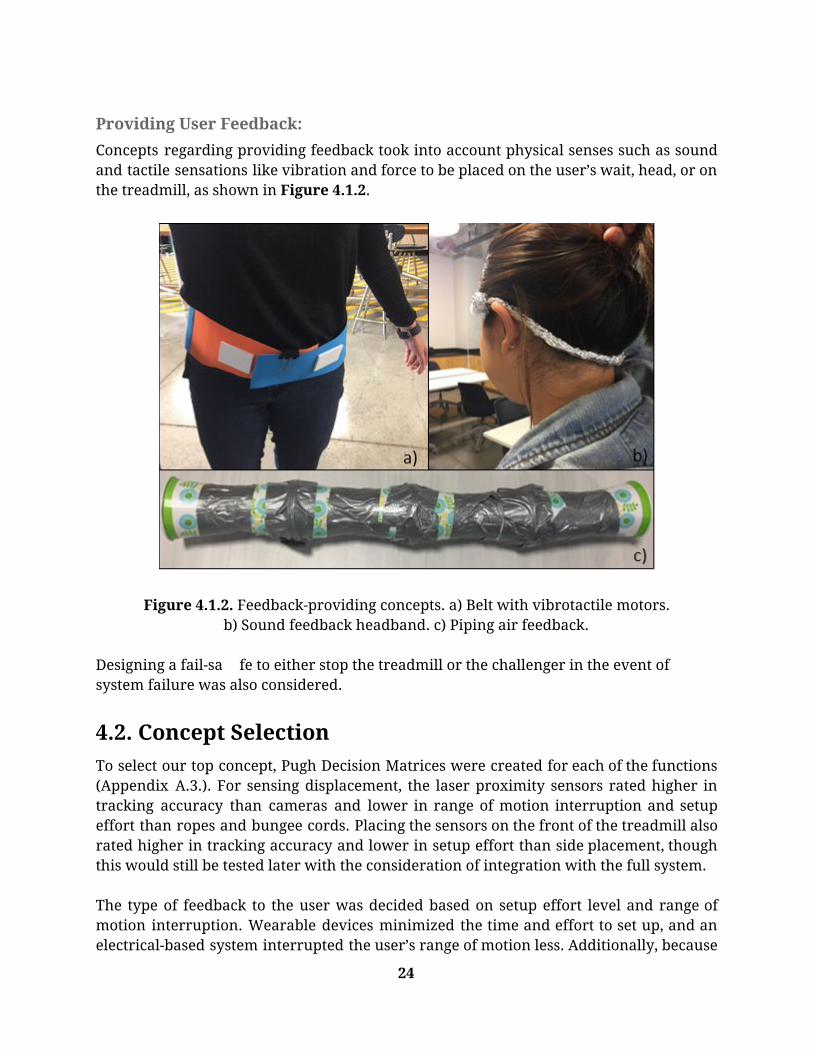
Concepts regarding providing feedback took into account physical senses such as sound and tactile sensations like vibration and force to be placed on the user’s wait, head, or on the treadmill, as shown in Figure 4.1.2.
Figure 4.1.2. Feedback-providing concepts. a) Belt with vibrotactile motors. b) Sound feedback headband. c) Piping air feedback.
Designing a fail-sa fe to either stop the treadmill or the challenger in the event of system failure was also considered.
4.2. Concept Selection To select our top concept, Pugh Decision Matrices were created for each of the functions (Appendix A.3.). For sensing displacement, the laser proximity sensors rated higher in tracking accuracy than cameras and lower in range of motion interruption and setup effort than ropes and bungee cords. Placing the sensors on the front of the treadmill also rated higher in tracking accuracy and lower in setup effort than side placement, though this would still be tested later with the consideration of integration with the full system. The type of feedback to the user was decided based on setup effort level and range of motion interruption. Wearable devices minimized the time and effort to set up, and an electrical-based system interrupted the user’s range of motion less. Additionally, because
24

the user is blind and uses hearing to gain awareness of their surroundings, vibration feedback was preferred over sound. After assessing existing top concepts, questions about initial calibration and displacement tracking were raised. Thus, concepts addressing these functions included the user taking one step forward, backward, and to each side to calibrate boundaries that the use could not cross without receiving feedback. Another concept included pre-setting a boundary, which would allow faster setup. System communication was considered, and the entirety of these factors would need to be explored.
4.3. Concept Iteration Proof-of-concept testing was performed in order to determine parameters and features for more detailed aspects of the design. Preliminary analysis and factor realization are summarized below.
4.3.1 User Feedback Positioning Since the displacement-sensing device requires a consistent point from which to measure the user’s position, the device would be placed at the most stable and accessible point on the user’s body while running. To find this position, an experiment was performed where a test subject ran on a treadmill with his eyes closed, as shown in Figure 4.3.1. A video was taken of the test subject and analyzed to find the most relatively stable point on the body. The chest was found to move the least while running. Along with providing consistent displacement measurements, the device would need to be secure on the runner’s body. A wearable on the torso/chest around both shoulders and waist would ensure security and comfortability.
25

Figure 4.3.1. Experiment for most stable point on the body while running
on a treadmill.
4.3.2. Conceptual Design Review Concept After evaluating the similarities and differences of the prototypes, a proposed concept was presented to the sponsor during the Conceptual Design Review. Though details of this design would change before manufacturing of the final design, details of the proposed design are described below.
Mechanical Safety
Before an electronic system could be considered, the mechanical system was established to help the user get familiar to the electronic system, to provide a fail safe should the electronic system fail mid run, and to allow use of the device should the electronics be out of commision. The mechanical system will feature 3 detachable devices which attach to the harness, treadmill, and user. First, an elastic cord will attach to the front of the harness and stretch to the front handrail of the treadmill, establishing a datum for the user in the forwards and backwards plane. This cord will be the exact distance from the optimal location on the treadmill belt to the railing, and be taut at this location. This tautness allows the user to feel a small pressure on their back/front and get a feeling for how close they are the the front of the treadmill, as well as if they are getting too close to the front by slacking and
26

no longer applying this pressure. Since the cord is elastic, however, it will allow for minimal movement in the backwards plane and provide steady increasing pressure to the users back, alerting them to move forward. This movement is allowed in order to provide the user with feedback, rather than holding them in place with an inelastic cord. The other two mechanical devices provide security in the left and right directions, attaching to the side railings as well as the user. These devices, while similar to the one above, are different in that they will attach to the users wrists rather than the harness. These cords also will not be elastic, as the movement to the left and right are very limited. These cords will feature wrist loops that the user can place on their forearms and held together using velcro. The velcro will ensure the user can establish their own tightness and security to their wrists, while also providing a fail safe should anything serious happen, like the user tripping or falling while running. While in the optimal location, the cords will be slacked and allow for free range of motion, not interfering with the user at all. However, should the user drift too far to the side, the inelastic cords will provide feedback by preventing the wrists from moving out of it’s range. This is important as the arms have some of the most freedom while running and are the safest parts of the body to be able to stop the motion of without creating a possibility for the user to fall in result. All devices for the mechanical system, as stated above, will attach to all locations via velcro or a similar function. This is because velcro, will being sturdy and able to hold firm under decent constant loads, is not able to withstand large sudden loads and will detach itself when experiencing that force. This force would be similar to the user falling on a treadmill and being pulled back along with the belt. When this happens, the velcro will let go and the user will no longer be attached to the treadmill in any way. As well, it will hold onto everything unless this sudden load is experienced, meaning that none of the devices will randomly detach itself.
Dual Optical Mount
The centering apparatus under consideration begins with the external reference system, dubbed the Dual Optical Mount. As its name suggests, the Dual Optical Mount consists of two similar optical sensors which mount to the treadmill to ensure stability. The mounting system in which the sensors are attached to consists of a collapsible/extendable rod, much like the legs of an EZ-Up with pins that slide into holes and hold steady, which rest in the cup holders of the treadmill. The advantage of using the cup holders for stability is that with a flat bottom surface and limited diameter, they provide a designable surface area in which the friction between the surfaces would hold the system steady. These “water bottle”-esque supports seen in the bottom corners of Figure 4.3.2.1 are attached to a rod which holds the sensors, supports, and everything else together. This rod ensures the sensors are constantly pointing in the same direction by locking them in place. This is important to make sure the user doesn’t need to set up
27

the orientation during the calibration, they only need to place it in the cup holders and turn it on.
Figure 4.3.2.1. SolidWorks rendering of the uncollapsed dual optical
mount. To ensure exceptional functionality and accuracy, three different types of reference sensors are considered. The first, being the Lidar-lite 3 laser rangefinder, as shown in Figure 4.3.2.2, is a powerful, scalable laser based measurement solution that supports a wide range of applications [27]. It is capable to measuring distances up to 40 meters of cooperative and non-cooperative targets with a tolerance of five centimeters [27]. Two distinct advantages of the Lidar-lite 3 are its spatial size and its measurement speed. At an impressive 500 readings a second, this millimeter-sized device brings with it the capability to accurately measure the desired markers on the haptic harness.
28

Figure 4.3.2.2. The lidar lite 3 emits a thin light beam and calculates the
distance by referencing the speed of light and the time it takes to reach the targeted marker.
LiDAR in general, which stands for Light Detection and Ranging, is a remote sensing method and uses light in the form of pulsed lasers to measure ranges to the Earth. Combined with other instruments, this technology is capable of generating 3D information about the shape of the Earth and its surface geometry. LiDAR instruments are typically comprised of a laser, a scanner, and a wireless receiver shown in Figure 4.3.2.3. In this particular application, two external LiDAR-lite 3 devices would be used to measure multiple trackers on the haptic harness.
Figure 4.3.2.3. LiDAR lite 3 is capable of working and communicating with
an Arduino Uno microcontroller.
The second type of tracking sensor under consideration is an Infrared proximity sensor. A proximity sensor is able to detect the presence of physical objects by emitting an electromagnetic field and looks for changes in that displayed field. The interest in proximity sensors stems from the fact that they have a long functional life because there
29

are no mechanical parts and no physical contact between the sensor and the target object. A downside to infrared proximity sensors is their proneness to ambient noise and external sunlight, however, this particular application will be consistently carried out indoors. In indoor environments, the IR proximity sensor thrives [29]. These sensors are known for their precision in low-light areas and are very cost effective. Typically, if the proximity sensor’s target is still for an extended period of time, the sensor will ignore it, and the device will eventually revert into sleep mode. This function is of special interest to the user of this device. Where the user may not always know if the device is on or off, the standby feature compensates by sensing its motion after a period of time, which is programmable. The third type of sensor under investigation- in this case a unit composed of a multitude of sensors- is the inertial measurement unit, or IMU. An IMU is a very special device because it does not inherently require an external reference system for positioning. An IMU houses multi-axis combinations of precision measuring devices, such as gyroscopes, accelerometers, magnetometers, and pressure sensors. Together these individual components work together to provide reliable position and motion displacement for stabilization purposes. The accelerometer on the IMU is responsible for calculating position by measuring the acceleration of the tracked object and integrating twice. This device, which required constancy for positional tracking, experiences drift since double integration is time consuming. To compensate, the gyroscope and magnetometer work simultaneously by measuring the orientation and direction of the target. Drift, however, will still need to be accounted for with this method and a GPS receiver will be considered to help mitigate this issue. A benefit to an IMU is that it can store small amounts of data, which is ideal for storing calibration parameters [30]. The microcontroller on the dual optical mount is used to process data received from the two optical sensors. There is another microcontroller on the harness to actuate the actuators that signals the user to move accordingly. The type of microcontrollers researched are under the Arduino products due to their ease of access to open source code and compatibility with sensors. Since a desired output response time of 32ms is desired, the Arduino Uno’s CPU speed of 16MHz is ideal [16]. For prototyping purposes, the Arduino Uno is to be used, but investigation for a smaller microcontroller to be placed in the harness is underway. A possible candidate is the LilyPad Arduino because it can be easily integrated on clothes with wearable devices such as the harness concept. A wireless transmitter in the brick housing is needed because data taken from the sensors needs to be processed through the microcontroller to activate the coin motors in the vibro-belt to signal the user to move. Since a long data cable from the sensors to the microcontroller in the belt is not safe, wireless communication is necessary for safety and to minimize setup time and difficulty. Figure 4.3.2.4 shows the wireless modules sending data via radio frequency, or RF [17].
30

Figure 4.3.2.4. A pair of XBee wireless module shields connected to an Arduino .
The XBee wireless module uses RF to transmit and receive data processed through a microcontroller. A pair of Xbee modules and a pair of microcontrollers are needed for the device to function because the transmitter and receiver units are different. XBees are controlled through a serial interface, so they can be used as a wireless serial cable [17].
Haptic Harness
Since the customer will be running and walking, the harness’ material is to be made with moisture wicking fabrics and elastic materials, as shown in Figure 4.3.2.5. Fabrics, such as polyester and spandex, are ideal because they are durable, lightweight, breathable, and non-absorbent [18]. The fabrics are machine washable, so after the a few uses, the electronics can be removed if necessary. A common goal is to design appropriate housing for the electronic components within the harness so they can endure light hand washing. If this method does not prove to be effective, however, the harness will be designed with pockets. A rear pocket, along with two side pockets will secure the microcontroller and the actuators to the user’s body. These pockets will features and upper, internal velcro stitching so as to safely house the electronic components. In addition, the straps on the shoulder and around the waist will have an adjustable strap for the customer to adjust to his liking.
31

Figure 4.3.2.5. A rough sketch of the haptic harness (left). Representation of a desired final result (right).
The type of device that will be used to deliver vibrational feedback to the user will be an actuator. Actuators are responsible for the physical vibrations a person feels when using haptic devices. The actuator will vibrate the device in a specific pattern which, depending on the type, will determine the resolution and quality of the haptic, or touch-centered, effects. Three different types of actuator strips, as shown in Figure 4.3.2.6, are compared to determine which type of the three will be the most relevant for displaying vibro-tactile responses to the user based on his position within the virtual treadmill bounds.
Figure 4.3.2.6. The three types of actuator devices under investigation.
ERM features a counterweighted mass, LRA uses a spring-magnet combination, and PZ stacked layers of voltage-receiving strips.
The first of the three, an eccentric rotating mass (ERM) actuator, is an inertial, motor-based haptic actuator with an off-center weight that rotates, therefore sending multi-directional waves throughout the device. ERM actuators wield very mature technology, such that they are able to propagate strong vibrations, however they lack the precision to be able to deliver high definition responses. While ranking the slowest in terms of response times, at 40-80 ms delay time, ERM actuators are cost effective and still are reputable for producing noteworthy vibrations. The next type- linear resonant actuators (LRA)- are used in some smartphones for haptics and vibration alerts, as shown in Figure 4.3.2.7. This type of technology is different from an ERM actuator in that it consists of a simple magnet attached to a spring-mounted mass. The spring modulates up and down, creating vibrations, and vibrates in a linear motion, requiring that it be driven at a narrow resonant frequency. Linear resonant actuators rely on AC voltage, compared to DC voltage for ERM actuators [22]. The AC voltage drives a voice coil pressed against a moving mass connected to a spring. When the voice coil is driven at the resonant frequency of the spring, the entire actuator vibrates with a perceptible force. Two upsides to LRA actuators is that they are about
32

twice as quick, delivering 20-30 ms response times, and use much lower power than ERM actuators [21].
Figure 4.3.2.7. A Linear resonant actuator is seen here in a cross section
view with all of its internal components displayed.
The third, and arguably the most appealing actuator, is the piezoelectric actuator. This type of actuator, as shown in Figure 4.3.2.8, is used to implement HD haptics and offers very noticeable differences from ERM and LRA actuators [22]. To vibrate, a piezoelectric strip, or disk, shaped piezoelectric material bends when a differential voltage is applied [24]. In order to deform, piezoelectric actuators require a high voltage. Depending on the manufacturer, voltage can vary from 50 to 150 VPP [24]. Higher voltages requires fewer actuator strips to be stacked together, and currently the 150 VPP actuator has 4 layers, while a 50 VPP actuator can have as many as 16 layers [24]. The voltage required for the piezoelectric actuator to vibrate is significantly higher than that of an ERM actuator, but only by a factor of two to three. This perceived issue is not much of an issue, however, since higher voltages are required for the human skin anyways. The form factor of a piezoelectric actuator is of value since they can bend and can have extremely thin strips, ideal for packing into wearable devices. There are many advantages to piezoelectric actuators. These include faster start-up time, higher bandwidth, and lower audible noise, and stronger vibrations [24]. At a start up time of around 15 ms, these actuators seek to work to display vibrations even faster than LRA actuators. Since Piezoelectric actuators require significantly more voltage to perform, they also produce stronger output vibrations [24]. From research, it can be seen that piezoelectric modules are great candidates for larger scale devices since they produces the strongest vibrations and requires smaller current consumption when compared to ERM actuators.
33

Figure 4.3.2.9. A piezoelectric actuator is shown here. These actuators are
of high value because they can be stacked and can be flexible, ideal for tucking into clothing.
Device Calibration and Displacement Tracking
After the user has set up the potential reference system and has securely fastened the harness to his body, either buttons or switches will be used to power the devices. As a side note- since the user is visually impaired, the devices will be programmed to output an auditory alert if left on for a certain amount of time without use. To calibrate the device, the user will step onto the treadmill and will adjust his position
until his position matches an intersection point between the light beams emitted by the two sensors and the harness. Where exactly the lasers need to interact with the harness is still being considered. The user’s position on the treadmill during successful calibration will be on the center of the treadmill belt. Since most treadmills use the same, standard belt size, dimensions from that size will be used to define the center of the treadmill belt in relation to the external trackers, or sensors. Once the user has successfully calibrated his initial position on the treadmill, the sensors will work to create a pre-defined virtual space around the user, as shown in Figure 4.3.2.10, based on the treadmill dimensions- in which the user will be able to run or walk in, free from vibration. The goal here is to create a safe zone space for the user, so he can run on the treadmill in a range of locations near the center of the treadmill. As long as the user’s haptic harness remains inside the virtual space while the system is in use and calibrated, he will be safe from potential injury as this space will be designed as a rectangular area parallel to the treadmill belt, and spanning equidistant longitudinally along the treadmill belt and equidistant axially across the belt. These virtual areas will be cascaded up the z-axis to create the space around the user. In other words, planar 2D regions, bounded by their set parameters, will be bounded together to create domain shapes where distances near the region boundaries will be more strictly preserved (strong vibro-tactile response) as the user approaches the “virtual wall” nearby [25]. If the user makes contact with, or steps outside of the virtual space that has been
34
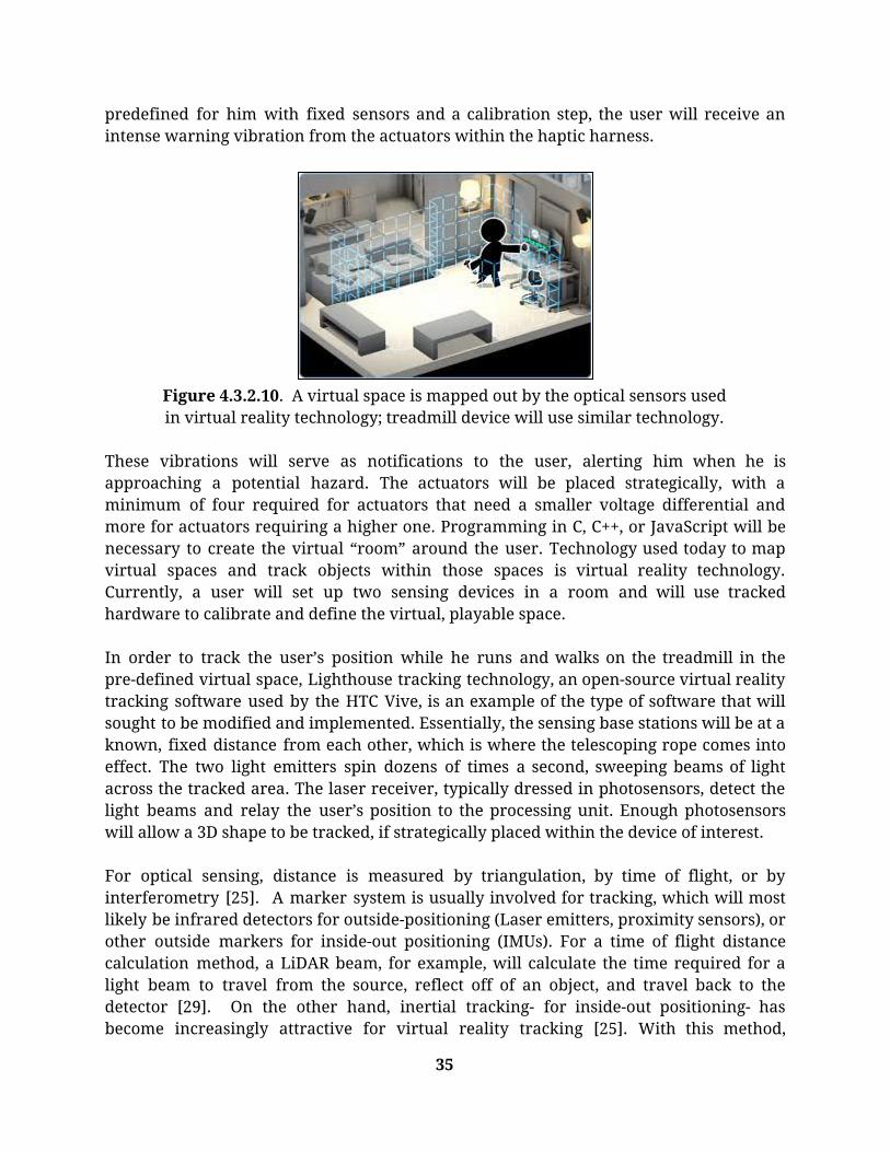
predefined for him with fixed sensors and a calibration step, the user will receive an intense warning vibration from the actuators within the haptic harness.
Figure 4.3.2.10. A virtual space is mapped out by the optical sensors used in virtual reality technology; treadmill device will use similar technology.
These vibrations will serve as notifications to the user, alerting him when he is approaching a potential hazard. The actuators will be placed strategically, with a minimum of four required for actuators that need a smaller voltage differential and more for actuators requiring a higher one. Programming in C, C++, or JavaScript will be necessary to create the virtual “room” around the user. Technology used today to map virtual spaces and track objects within those spaces is virtual reality technology. Currently, a user will set up two sensing devices in a room and will use tracked hardware to calibrate and define the virtual, playable space. In order to track the user’s position while he runs and walks on the treadmill in the pre-defined virtual space, Lighthouse tracking technology, an open-source virtual reality tracking software used by the HTC Vive, is an example of the type of software that will sought to be modified and implemented. Essentially, the sensing base stations will be at a known, fixed distance from each other, which is where the telescoping rope comes into effect. The two light emitters spin dozens of times a second, sweeping beams of light across the tracked area. The laser receiver, typically dressed in photosensors, detect the light beams and relay the user’s position to the processing unit. Enough photosensors will allow a 3D shape to be tracked, if strategically placed within the device of interest. For optical sensing, distance is measured by triangulation, by time of flight, or by interferometry [25]. A marker system is usually involved for tracking, which will most likely be infrared detectors for outside-positioning (Laser emitters, proximity sensors), or other outside markers for inside-out positioning (IMUs). For a time of flight distance calculation method, a LiDAR beam, for example, will calculate the time required for a light beam to travel from the source, reflect off of an object, and travel back to the detector [29]. On the other hand, inertial tracking- for inside-out positioning- has become increasingly attractive for virtual reality tracking [25]. With this method,
35

however, some drift is inevitable, and either an inertial package must periodically be returned to some home location for offset correction, or it must be used in conjunction with some other position sensor and appropriate method of data fusion [25]. For the scope of this project, an IMU sensor will be initially tested for inside-out position tracking and if this method proves to be too latent, outside-in position tracking with the dual optical mount will be employed. The microcontroller and the wireless receiver in the harness were previously mentioned in the dual optical mount section. The microcontroller may change depending if the comfort rating when the user wears the harness is low. The XBee wireless transmitter and receiver are purchased as a pair to ensure compatibility. Figure 4.3.2.11 shows the system communication between the dual optical mount on the treadmill to the harness worn by the user. The optical sensor maps the predetermined “safe” area on the treadmill, and once the user steps out of the area, the optical sensors will detect the user not in the area. The microcontroller will process the information, send the information to the transmitter, the receiver on the harness then passes the information to the other microcontroller, and the actuators activate accordingly.
Figure 4.3.2.11. System Communication block diagram showing the flow of
data input to mechanical output
36

Preliminary Concept Justification
As discussed in earlier sections, each feature of the concept design met a customer requirement. A summary is shown in Table 3.
Table 3. Design Concept Meets Customer Requirements
Customer Requirement Design Concept
Functional/Safe Optical sensors Haptic feedback-actuator strips
Portable Telescoping rod
Comfortable Harness Material- dry-fit
Allows Independent Setup Dual optical mount’s “water bottle” design
Wireless Pre-mapping
Durable Dual optical mount material -Aluminum/ABS plastic
Harness material - spandex, polyester
Adjustable Harness’ adjustable shoulder and waist straps
Secure Dual optical mount’s “water bottle” design
Harness’ adjustable shoulder and waist straps
Electronics sown into harness
Hazards and Costs
Appendix A.4. lists the hazard identification checklist that the concept complies to. The only main concern is the batteries that powers the device. Proper encasement of batteries and appropriate choice of batteries are needed to ensure there is no leakage nor any potential shorts to the battery. The batteries will be still accessible, but they will be in an enclosure in the dual optical mount’s rod. The batteries in the harness will also have a sealed compartment that will be accessible to replace the batteries. The cost estimate to prototype is about $300 without sales tax. This cost includes the dual optical mount and its sensors, the harness materials, the microcontrollers, the
37

transmitter and receiver units, and the feedback actuators on the harness. The device will not be mass produced as it is intended to be used solely by the QL+ challenger. Preliminary plans for construction and testing are to order individual sensors and to create test plans during shipment process of the sensors. Manufacturing for the rod of the dual optical sensor mount will be created through machining and the manufacturing of the harness is still under research. The individual sensors will be tested before integration to ensure they meet the criteria listed in their respective datasheets. The open source code for the optical sensors and wireless transmitter/receiver are to be obtained and edited to its usage.
4.3.3. Conceptual Design Review Feedback After receiving feedback from the project advisor, sponsor, and Dr. Crockett (Virtual Reality specialist) regarding the feasibility of this design concept, a new concept was chosen to better suit the availability of materials, time frame of the project, and skill set of the team. The following designs would still include positional tracking, but with sensors placed on the arms of the treadmill that will measure the distance between the sides and the user. The “safe zone” in which the user will run in and not receive feedback would be pre-determined and programmed based on the dimensions of the treadmill. The vibrational feedback would be received from motors installed in a belt around the user’s waist, so as to increase the user’s ability to move. The designs that would be made into functional prototypes and presented at the Critical Design Review are described below.
4.3.4. Critical Design Review Selection
Overall Description
Initially, the design of the treadmill centering device included an array of sensors placed on the arms of the treadmill. Ultrasonic sensors would measure distances between the sides and the user, and infrared break beam sensors would alert the user when breaking the beam too far in front of or behind the user. However, to simplify the design, the infrared break beam sensors will be replaced by two ultrasonic sensors programmed with different conditions. The ultrasonic sensors will actively record distances throughout the user’s running time, as displayed in Figure 4.3.4.1.
38

Figure 4.3.4.1. Top-down views of the ultrasonic sensor ranges from
treadmill sides to center
The sensors on the outside of the array will provide boundaries for the front and back of the user by comparing the distance recorded from the side to the center with the distance recorded from the side when the user is within range. Once the distance measurements show that the user is within range of the sensors furthest to the front and back, a signal will be sent to vibrational motors on the front or back of the user’s belt to vibrate. The sensors on the inside of the array will provide boundaries for the user’s side-to-side motion by recording distance from the side to the user. Once a distance threshold that indicates the user being too close to the sensor is reached, a signal will be sent to vibrational motors on the left or right side of the user’s belt to vibrate. Figure 4.3.4.2 shows the revised system communication block diagram with the flow of data. The system block diagram is similar to the previous concept except it has more specific sensors and actuators. The actuators are now the coin motors, and the optical sensors are the ultrasonic and the IR break beam sensors. However, as previously discussed, the IR break beam sensors will not be used and instead will be replaced with more ultrasonic sensors that function in the same manner.
39

Figure 4.3.4.2 Revised system communication block diagram showing the
flow of data input to mechanical output.
Sensor Housing and Orientation
In order for the sensors to be properly facing the correct direction in the correct orientation and configuration every time the device is used, a housing was determined necessary for repeatability. This housing will house all of the main electronic systems for our device, ensuring that the challenger will be able to run effectively and efficiently. For better visual representation of what the electronics look like in the housing, please reference Figure 4.3.4.3. In order to house all of the electronics, however, dimensions must be established in order to meet the key aspects of the housing design; these key aspects being maximum volume and maximum treadmill surface coverage. The device must be able to cover a maximum safe surface area on the treadmill running surface so that the user can make small adjustments from the center and not receive constant feedback, while also being small enough in volume to fit easily within the users backpack as they travel to and from the gym.
40

Figure 4.3.4.3. 3D isometric model of the housing with full assembly
including attachments and sensors.
Meeting both of these criteria is essential in the design of the housing units. After collaboration, the team determined that the sizing constraint of the backpack was the more central aspect to focus the dimensions around, then through iterative processes ultimately adapt the device through adding angles to portions of the device in order to maximize the safe surface. Because of that these were the dimensions determined. As can be seen in the detailed drawing in Appendix B.1., each housing will be approximately 15 inches in length, 4 inches in height, and 3 inches in width. The produces a volume of 180 cubic inches per unit, which a standard military backpack can easily hold [34]. Many smaller military backpacks can hold anywhere between 1500 and 4500 cubic inches [34]. The main source of this internal volume, however, is depth which with consideration to the housing is insignificant [34]. Since our maximum dimension is length and many of the backpacks seen have a maximum length dimension of between 17 and 20 inches, the maximum has been approached and set in order to ensure the backpack is still able to close effectively [34]. Designed into the housing dimensions as well are wall thicknesses, screw hole locations and sensor hole locations. Wall thicknesses were determined at ¼ inch to ensure the walls are stable enough to not risk structural integrity when under pressure from items in the backpack or should the device fall on and edge, corner, or surface. They were also established so that the internal volume of each device was sufficient enough to hold the multiple electronics systems that will be sitting inside. Screw holes were integrated also so that the multiple attachments to the device, being the back lid and two C clamps along
41

the bottom, can hold securely to the housing and be easily removed to provide maintenance. Finally, the sensor array quantity, locations, and orientations were established in order to maximize the surface area of the housing and accuracy of the array. For drawings showing with dimensioning as well as an exploded view showing all of the components involved, please see Appendix B.1. The locations of the clamps along the bottom of the housing are asymmetrical, meaning one clamp is located flush with the back edge of the housing, and one is flush with the center of the housing at 7.5 inches. These locations were established to create a hangoff of the device, ultimately covering a more accurate representation of where the safe zone is located. If the clamps were to be designed at each end of the housing, it would sit completely on the arm, which wouldn’t seem like a bad thing at first, until the realization that that length of the housing is approximately the same length as the arm. This calculation was done using a scaling method in Appendix B.1. Because of the scaling, the device would be flush with the front and back edge of the arm, meaning the only safe zone would be if he was close to hitting the treadmill interface which was determined as a constraint for being too far forward. To counteract this, we offset the device by 7.5 inches to allow for more room for movement and a more accurate safe zone. In regards to dimensions of the attachments discussed above, they have yet to be determined for a few reasons. Currently the team is discussing modes of power, power indicators/switches, and material selections meaning that many dimensions related to those features remain arbitrary until fully developed. This means the hole locations along the lid for the battery pack and power switch are arbitrary and are currently there solely to provide a representation of what it could look like. This is similar to the clamp dimensions and hole locations as the design of the clamp depends on which model treadmill the user is operating and what material the clamps will be made of. All screw hole dimensions are also arbitrary and dependent on material selection which will be discussed more in the manufacturing plan below.
Vibro-Belt
In order for the user to run freely with no physical assistance, the device will be fixed on the torso in order to provide feedback to the user for them to correct their movement. The body region chosen is the torso area because there is more surface area for the coin motors to make contact with, the sensitivity of the area to vibration, and the ease of placing the microcontroller that receives data to activate the motors. During the initial fortification of the team’s critical design, the idea of a tactile vest (haptic harness) was considered that would cover the entirely of the torso and strap securely over the shoulder. Due to the removal of the positional sensors from the wearable, however, the surface area covered by the tactile vest was no longer needed. Since the only electronics being strategically positioned within the wearable are the coin motors, a microcontroller, a signal receiver and a battery pack, a more-simplified wearable device becomes
42
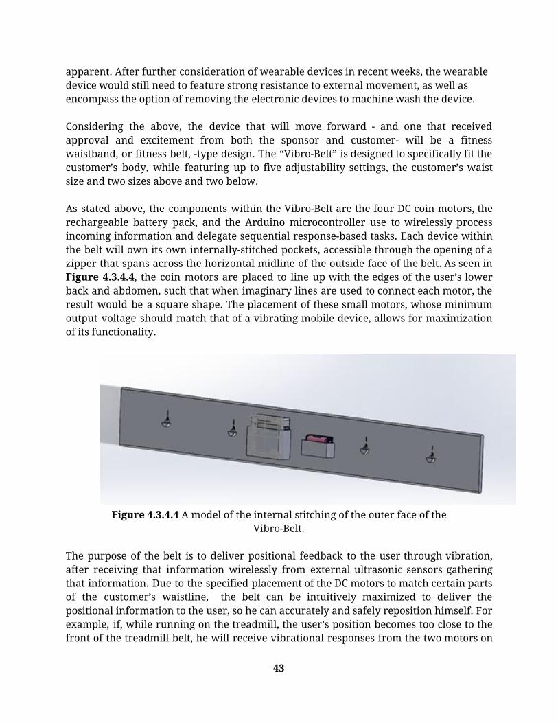
apparent. After further consideration of wearable devices in recent weeks, the wearable device would still need to feature strong resistance to external movement, as well as encompass the option of removing the electronic devices to machine wash the device. Considering the above, the device that will move forward - and one that received approval and excitement from both the sponsor and customer- will be a fitness waistband, or fitness belt, -type design. The “Vibro-Belt” is designed to specifically fit the customer’s body, while featuring up to five adjustability settings, the customer’s waist size and two sizes above and two below. As stated above, the components within the Vibro-Belt are the four DC coin motors, the rechargeable battery pack, and the Arduino microcontroller use to wirelessly process incoming information and delegate sequential response-based tasks. Each device within the belt will own its own internally-stitched pockets, accessible through the opening of a zipper that spans across the horizontal midline of the outside face of the belt. As seen in Figure 4.3.4.4, the coin motors are placed to line up with the edges of the user’s lower back and abdomen, such that when imaginary lines are used to connect each motor, the result would be a square shape. The placement of these small motors, whose minimum output voltage should match that of a vibrating mobile device, allows for maximization of its functionality.
Figure 4.3.4.4 A model of the internal stitching of the outer face of the
Vibro-Belt. The purpose of the belt is to deliver positional feedback to the user through vibration, after receiving that information wirelessly from external ultrasonic sensors gathering that information. Due to the specified placement of the DC motors to match certain parts of the customer’s waistline, the belt can be intuitively maximized to deliver the positional information to the user, so he can accurately and safely reposition himself. For example, if, while running on the treadmill, the user’s position becomes too close to the front of the treadmill belt, he will receive vibrational responses from the two motors on
43

the frontside of his body. If the user is too close to the right-side sensor box, i.e. too far to the right side of the treadmill belt, he will receive vibrational responses from the two rightmost motors on his body, the front-right motor, and the back-right motor, and so on. On the other hand, if the user is both too far forward and too far to the right of the treadmill belt, the system will utilize three of the four coin-motors to deliver positional information through vibration, the two front motors, and the back-right motor. On the issue of power, the belt will feature a rechargeable lithium-ion battery, designed to work with an Arduino, that will be rechargeable via an external power supply and micro-USB connection cable. During the testing of this device, the average amount of time it will take to charge the device will be determined using a 12-volt power supply, so that the belt can run for a maximum of two hours. The user can simply set a timer on his phone while the battery is charging. To notify the user of when the battery of the belt gets under a certain threshold value and needs to be recharged, different methods of audio, or sound-based, delivery will be experimented on. For example, if the battery level gets below 10%, the user will be able to hear a series of repeated “beep” noises, notifying him that it is time to recharge the device. Ultimately, the final design of the Vibro-Belt will be an all-encompassing, flexible design that will not only satisfy the user’s needs but will go so far as to excite the user while he wears the device. Adjustability is just one example of the belt’s flexibility. Due to the internal pouches, the components can be safely and easily removed from the belt. This is especially useful to the customer because after a few uses, he will want to wash and clean the belt without damaging any of the internal components. A functional prototype of the belt, as modeled in Figure 4.3.4.5, will be created to begin testing the full-system. During this stage of the project, adjustments regarding the exact placement of the vibration motor pouches will be made, and the local textile manufacturers will be subsequently contacted to aid in the improvement and creation of the belt. Currently, the height of the belt rests at four inches, and will be adjusted as the exact dimensions of the battery pack are determined.
44

Figure 4.3.4.5 A final rendition of the Vibro-Belt, as seen from the outside surface. A zipper allows access to the internal components of the device.
Electrical and Software Design
In Appendix B.1, Figure B.1.1 shows the black box and the wiring diagram for the connections in the brick housing on the treadmill. A 9V battery charges the Arduino Uno, and the inputs into the Arduino are the ultrasonic sensors and the infrared break beam sensors. As previously mentioned, the IR break beam sensors will be replaced with more ultrasonic sensors. The output of the Arduino connects to the XBee’s transmitting module that sends the data collected by the different sensors to the receiving module in the belt. In Appendix B.1, Figure B.1.2 shows the black box and the wiring diagram for the electrical connections in the Vibro-Belt. A 9V battery powers the Arduino Uno in the belt. The input to the Arduino is the XBee receiving module that will intake the data sent from the brick housing’s sensors to process the data to output to the coin motors accordingly. Figure 4.3.4.6 shows the software flowchart of the entire system. After turning on the sensors and initializing them, the ultrasonic sensors and the IR break beam sensors begin to collect data. If the ultrasonic sensors record a distance greater than or equal to 19 inches that was determined to be the border of the safe region, then there will be no action. If not, the the code checks if the distance measured is between 12 inches and 19 inches. If it is, then the data is saved to be compared to the next data intake. If not and the distance is less than 12 inches for more than 1 second, then a signal will be sent to turn on the left or right coin motor in the Vibro-Belt. The left and right motors are determined by the previously saved distance measurement. As previously mentioned,
45

the IR break beam sensors will be replaced with more ultrasonic sensors. However, the ultrasonic sensors that will replace them will have a similar function. These extra ultrasonic sensors will measure the distance and follow similar logic to the other ultrasonic sensors and activate the coin motors on the front and back if the user is too far back or too far front of the treadmill.
Figure 4.3.4.6 The software flowchart of the final design and its sensors.
46

Projected Prototype Cost
The following Table 4 shows the cost breakdown of the prospective prototype:
Table 4. Cost Breakdown of Prototype
Component Cost per Unit ($) Number of Units Total Cost ($)
HC-SR04 Ultrasonic Sensor
2.00 10 20.00
Coin Motors 1.00 8 8.00
Arduino Uno 20.00 2 40.00
Spandex 10.00 per yard 2 20.00
Zipper 4.00 2 8.00
XBee 25.00 2 50.00
3.7V 2500mAh Rechargeable Lithium Ion
Batteries
15.00 4 60.00
Battery Charger Interface with
Micro USB
7.00 2 14.00
Total 32 220.00
Material, geometry, component selection
HC-SR04 Ultrasonic Sensor: The HC-SR04 ultrasonic sensors were chosen based on various tests and comparisons with other ultrasonic sensors. The testing included the functional range that the sensor can detect and the output response time. Since large distances are not as relevant for the type of usage for the device, a minimum distance is imperative. From Appendix B.1., the HC-SR04 had the best functional range of detecting objects as close as 2 cm compared to other ultrasonic sensors whose minimum detection was around 5-6 cm. The output response time was shown on the serial plotter on a computer. The x-axis showed the time in ms while the y-axis showed the distance measured by the sensor. Using controlled testing, the HC-SR04 was chosen with the fastest output response time of 25ms compared to the other sensors’ output response time.
47

Infrared Break Beam Sensor: For the previous concept, the IR break beam sensors were chosen because their code is simple and intuitive. They also integrated well with the previous conceptual function and fit into the housing design. However, HC-SR04 ultrasonic sensors will replace the function of the break beam sensors for simplicity and reduction of overall dimensional sizing of the device. Snap Buttons: Figure 4.3.4.7, showing an example of a snap button, is the type of fastening device that is used to secure the Vibro-Belt to the user. Indeed, the Vibro-Belt is designed with an array of snap buttons, specifically an array consisting of five columns and two rows of snap buttons. The two ends Vibro-Belt will join around the front side of the user’s body. This is so battery pack and the microcontroller within the belt are on the backside of the user, therefore avoiding any potential irritability to the user’s stomach. It features four DC coin motors, responsible for supplying the vibrational response to the user, a rechargeable battery, and a microcontroller to process the information.
Figure 4.3.4.7. An example of a typical snap button fastening device
commonly used in textile design.
The addition of snap buttons as a fastening device will allow for the wearable to be adjustable, and also involves the use of multiple columns of snap buttons, therefore providing a secure and unyielding fit. A snap-type fastener is desirable over a velcro fastener because of its durability, or its ability to withstand wear and tear over time. Velcro is more susceptible to wear and tear due to machine washing and lint collecting, however a snap button does well at maintaining its strength over time and does not yield until a certain amount of force is applied to it; this is customizable, so the team can accurately choose snap buttons strong enough to withstand the force of the user’s body as he runs on the treadmill. Microcontroller: The Arduino Uno is used for the sensor boxes because of its compact size (2.96in x 2.1in x 0.59in), low power requirements (operating voltage of 5V), and the availability of source code [16]. A rechargeable lithium ion battery will charge the
48

microcontroller, and the battery can be charged via a micro-USB connection cable. The Arduino Uno has 14 digital pins which is more than enough to be used for all of the sensors in the brick housing on the treadmill. Battery: When considering battery configurations, voltages, and recharging capabilities, multiple selections were considered. Firstly deciding between the device being non rechargeable, with the user having to replace the batteries once they die, and being rechargeable, with the user being responsible for plugging in the device periodically to ensure its success, the latter option was chosen. This rechargeable capability means that the device is less costly and more easily maintained. With rechargeability now as a selection for the batteries, multiple rechargeable options were considered. Popular options for rechargeable batteries include NiMH, Nickel Metal Hydride, and Lithium Ion batteries. The differences between these two include the following: NiMH batteries are available off the shelf easily at local retailers and are relatively inexpensive, but have a pronation to lose capacity if not fully discharged after each use and must be in a parallel configuration meaning the user will need multiple to use it. Lithium Ion batteries are available in multiple sizes, voltages, and currents meaning the correct one can be purchased and there would be no need for a configuration as well as the battery does not need to be fully discharged and there's no worry about losing capacity. However, these batteries are slightly more difficult to possess and are slightly more expensive. With all things considered, the battery selection for this device is Lithium Ion due to its longer capacity life, meaning more usage per battery, and configuration ability. Ultimately this decision makes the users life easier when dealing with the device so that is why it was chosen. Push-Style Power Button: The customer has a specific interest in push-style buttons. This information is useful because it explores the addition of a push button switch, one that the user will use to power the device. This addition of such a device is still underway and will be noted and covered in subsequent iterations of the design. The initial ideas surrounding the addition of a push button switch are that it should feature a slight resistance when pushing the button- so that the device does not unintentionally turn on in the user’s backpack- and that it is placed on the belt near the snap buttons, so that when the user is wearing the device, the button is easily accessible. Figure 4.3.4.8 shows a push button that is currently under investigation: a flat, round momentary push button.
49

Figure 4.3.4.8. This push button switch features a button whose surface is
coplanar with the top surface of the overall device, therefore avoiding accidental pushes.
Belt Materials: Finally, and arguably one of the most important relevant features of the Vibro-Belt is the material that it is constructed with. In a recent conversation with the customer, the customer wants the option of running with either the belt under or over his shirt, which means that the solution will provide the user with the ultimate comfortability—this is part of the reason for eliminating the potential of working with Velcro, since it tends sometimes rub uncomfortably against peoples’ skin. The materials of interest fall under athletic-type materials since the purpose of the belt is to aid the user while he exercises. Of particular interest is the combination of micropoly and lycra spandex. Micropoly involves tight weaving of thousands of ultra-fine fibers, which is of interest to this design because through this, micropoly maintains its initial shape over long periods of time, avoids stretching and offers breathable characteristics [33]. With the addition of a small amount of lycra spandex, a fabric known for its exceptional elasticity, the belt can be made to be structurally sound, with resistance to wear and tear and overstretching [33]. This will create a tight, comfortable fit around the customer while he safely operates the treadmill for long periods of time.
Safety Considerations
Refer to Appendix A.4. for the Hazard Identification Checklist. There is no immediate hazards identified for the concept.
Maintenance and Repair Considerations
Off the Shelf Products: A specification determined due to the nature of the design is being able to purchase the same product off the shelf and reprogram/manufacture to ensure ease of replacement. This consideration is only required should an item fracture, malfunction, or become otherwise unusable to allow for quick and efficient remanufacturing of the product and return to the user. Machine Wash: A requirement of the vibro-belt is that it be machine washable. This is due to the fact that the customer will be exercising while using the belt, so after many uses the belt will accumulate dried perspiration and from that a disturbing odor. Since
50

the user is blind, this process can become a daunting task if it has to be performed often because washing the vibro-belt is not as simple as washing normal clothing. Therefore, the goal is to have the user wash the vibro-belt as little as possible, with a target of once every two to three weeks. From this, it will need a material with hydrophobic capabilities, or one that does an excellent job at wicking away sweat. Electronics Removal: The above requirement necessitates the availability to remove the electric components, i.e. the battery pack, microcontroller and motors, from the belt. In addition, the user will then need to be able to put the components back in the belt in their correct pouches after washing. Ways of connecting the components to the microcontroller in a straightforward way is being looked into, and it is noted that the fact that the soldering of the components to the microcontroller will need to be secure and resistant to accidental pulling. The housing and belt easy to take apart and remove components to replace if damaged. Battery charging: The addition of a micro-USB charging port, located within the belt and housings, that would be accessible to charge the devices for later use is being considered. This addition would involve the user removing the battery from the microcontroller (it wouldn’t be soldered to the microcontroller), and inserting it into the micro-USB jack for charging. Ways of simplifying this process are being explored. Refer to Figure 4.3.4.9, which shows an image of the micro-USB jack under consideration.
Figure 4.3.4.9 This is an example of a micro-USB charging jack. It is
compatible with Arduino, and involves the use of a lithium-ion battery.
5. Functional Analysis and Testing After the Critical Design Review, the design was broken down into different functional aspects. Before manufacturing, detailed design characteristics were explored through iterative testing and optimization. Some of these optimizations include determining exact values for non-safe zones, scaling to Larry’s treadmill model, maximizing motor strength to ensure they’re felt while
51

running, maximizing battery capacity for extended usage, etc. A synopsis of these crucial factors can be found in the following sections.
5.1. Treadmill Scaling Analysis
Treadmill Photo Scaling
In order to determine appropriate safe zone boundaries, treadmill model specifications and given photos of Larry’s treadmill were explored. Refer to Appendix B.1. for analysis and calculations for scaling the treadmill previously used. From the figure you can see the dimensions found using a ruler and pen as well as scaling. The reason this was done was because the model treadmill that was being used for the calculations was extremely old and outdated, meaning it was difficult/impossible to find a manual online which included proper dimensions. So based on the only dimensions that were found, the belt size being 20” x 60”, scaling was done to approximate the appropriate dimensions of the rest of the treadmill. Without the scaling, all dimensions would have been arbitrary instead of an approximation. However, due to recent information of a different treadmill that the user uses being presented, research will be conducted to determine whether or not the model has predetermined sizing or if scaling approximations must be redone to establish base numbers.
Larry’s Treadmill Dimensions
Because treadmill model specifications found in relevant datasheets only included belt measurements, Larry was asked to take measurements of his own treadmill that he uses at his YMCA, as shown in Figure 5.1.1. He reported that the side rails and front rails have circumferences of 13in and 6.25in, respectively. From the photos provided, it was noted that the side rails on Larry’s treadmill were longer than the treadmill being used for this project’s testing, allowing a greater length to be used for mounting of the sensor boxes.
52

Figure 5.1.1. Larry’s treadmill at his local YMCA. The greater arm lengths
on this treadmill would allow for larger sensor mounting area.
5.2. Motor Testing In order to alert the user to move to the defined safe zone on the treadmill, the placement of the motors, the amount of motors, and the intensity of the vibrations had to be determined. An initial idea was to place 4 coin motors around the waist: one motor each in the front left and right of the body and one motor each in the back left and right of the body. Using a GoPro harness as a belt, the 4 coin motors were taped so that the motors were against the wearer. An Arduino Uno to process the code was placed in the back of the GoPro harness as shown in Figure 5.2.1.
Figure 5.2.1 A GoPro harness with 4 coin motors and an Arduino Uno
attached (left). A blindfolded motor code testing with a member of the team (right).
53

To determine the amount of motors needed and the intensity of the motors, a blindfolded simulation was created. In Appendix B.2, a motor testing code was created to simulate different motors turning on and off at differing times and differing durations. A member of the team was blindfolded and would say out loud which motor turned on and off and for how long it was on as he walked forward down a hallway. The member did not know what order the motors would turn on nor in what combination of vibrating motors. The results of the test showed that the motors’ vibration was strong enough for walking but not for a faster pace. The locations of the motors allowed for the user to feel the motors, but it was not necessarily the most intuitive meaning as to what the user should do on an actual treadmill. For future iterations, the four locations tested were implemented into future iterations before the final design of replacing the two back motors to a single coin motor in the center of the back on the waist. Doubled coin motors in each location was also tested, however, the intensity decreased as more motors were added. Therefore, only one motor in each location was used for the final design. The delays in the code of turning on the motors were tested and adjusted to 110ms because it was the max vibration intensity that a user could feel without discomfort.
5.3. Battery Analysis The battery to power the system was required to be rechargeable, large enough capacity to power the system for at least an hour, and have a 5V output to power the microcontrollers. After purchasing and testing different models of batteries in varying voltages and capacities, a 5V 3350mAh rechargeable power bank, pictured in Figure 5.3.1, was chosen to power the system. A total of three separate power banks were used in the system to power the two sensor housings and the vibro-belt.
Figure 5.3.1 The power bank used for the final system that includes a
micro-USB port to recharge the power bank.
54

Based on power analysis and measurement using a multimeter, the system that uses the most power is the vibro-belt with a power consumption of 1.5W. The components in the belt runs at the maximum of 300mA, so with a power bank with 3350mAh, the full system can run at a maximum of 11.17 hours. The tradeoff for having a larger capacity would be that the weight of the system would be much greater, so future iterations must find the balance between the two constraints.
5.4. Sensor Configuration Testing In order to determine the number of sensors and distance between sensors that would provide the most effective displacement tracking, sensors were coded in various arrays and displacement accuracy assessed. In Figure 5.4.1, example housing made of wood with three sensors is shown. From this test, it was found that three sensors are sufficient to track side-to-side motion. Additionally, since sensors range of 2 degrees was verified, the distance of 6.5” between sensors was also sufficient.
Figure 5.4.1. Front view of example wood housing with ultrasonic sensors (top). Back view of example wood housing with all the connected electrical
components (bottom).
For the first full-system prototype, the sensor box would have the three sensors to detect side-to-side motion with an additional sensor on each end to detect backward motion. Since this functional model was constructed to initiate phase one of testing, it was the case that only a proto-model representing one axis of movement was constructed. At
55

first, exaggerated distances were used in order to obtain confidence in the ability of the sensors to measure and record the type of position desired. To test this, the XBee wireless transmitter communicated the position data to a receiver which displayed the results through coin motors in a rudimentary construction of the vibro-belt. After the functionality of the sensors was determined to be a success, tighter, closer-range distances were were accounted for based on the dimensions of the treadmill belt and the user’s position on the belt, and the safe zone was constructed from that.
5.5. Safe Zone Boundary Analysis To obtain boundary values to outline the “safe zone” in the code, running motion was analyzed on a treadmill. By placing measurement markings on the back of the treadmill, and shown in Figure 5.5.1, running was recorded and natural boundaries when running with and without a blindfold on were derived. The effect of arms swinging and feet placement were also added factors to consider if the sensors would be placed with the intention of only detecting the torso distance. The safe zone does not incorporate a front boundary of the treadmill belt because the measurements from testing showed that the front hood cover in on the bottom of the treadmill acts as a physical boundary for the runner’s feet placement. The runner’s feet would touch the front hood cover when they approached the measured front boundary, so front motion was not incorporated in the code for the system. Additionally, the user’s torso would make contact with the frontside railing, which would allow the user to recognize that they should shift their position backwards.
Figure 5.5.1. Measuring the safe zone on a treadmill (left) and modeling
with tape for testing (right). The safe zone is defined as the area on the treadmill belt in which the user operating the treadmill is on a spot of the treadmill belt that is effectively the center of the belt - a position where either side of the user’s torso is equidistant from the inner face of each
56

treadmill arm in terms of lateral movement, and within a certain range longitudinally from the front interface of the treadmill. The inner face of the right-side treadmill arm and the front surface of the sensor box when it is hung from the front railing serve as datums for the safe-zone. Since the right-side sensor box records positional data in one lateral range that determines if a user is too far to the left side and a different lateral range to determine if the user is too fat to the left side of the treadmill belt, the space where positional data is not being recorded - the space in the middle of these two ranges - carved out the lateral parameters of the safe-zone, which ended up being the space between 8” and 14” from the face of the right-side sensor box. After conducting a treadmill running test, it was seen from the videos that an effective safe-zone longitudinally was 25” from the front face of the front-side sensor box, and the space beyond this distance up to 48” was deemed as the zone where the user had moved too far backwards.
5.6. Safety Distance Analysis To provide an effective fail-safe mechanism using a magnetic treadmill stop, one end of the string would be attached to the belt as seen in Figure 5.6.1, while the magnet would remain on the treadmill until Larry reached an “unsafe” backwards distance. The length of the string was determined by trying different lengths and walking on the treadmill and safely falling off of the back. The delay between when the magnet stop is pulled off the treadmill and when the treadmill actually did stop was considered. The derived length of the string was tested at 32 in.
Figure 5.6.1 Testing the appropriate distance of the magnetic emergency
stop cord.
57

6. Final Design With critical function testing completed and established, final prototyping began. This prototyping still included multiple iterations, these iterations establishing new design considerations, small adjustments, and optimized functionality. A synopsis of the final design process can be found below.
6.1. First Full System Prototype and Testing The first round of final prototyping included components for a full system. Once all parts were manufactured and assembled, a full system test was performed on an actual treadmill. These events are described in the sections below.
6.1.1. Prototype Description The first system prototype was composed of a single sensor box to be placed on the right arm of the treadmill; the sensors detected side-to-side movement as well as backwards movement. The signals from the sensors were transmitted to motors on the belt- two on either side in the front, and two on either side in the back. Individual components and manufacturing information is described below.
First Prototype-Sensor Box
The first full system prototype included two sensor housings, located on the topside of each treadmill arm, as well as a vibro-belt to be worn by the user. The housings consisted of an array of three ultrasonic sensors located approximately 6.5” away from each other, an Arduino Uno microprocessor, an XBee wireless transmitter, and a power bank. These housings each had external dimensioning of 15”x3”x3” (LxWxH) as can be seen in Figure 6.1.1.1, having an external volume of 135 cubic inches or .078 cubic feet, taking up less than 6.4%, 12.8% combined, of the volume spec.
58

Figure 6.1.1.1. Solidworks model of one half of the first sensor housing prototype.
Manufacturing of the boxes was done utilizing 3D printers provided by QL+ and the Innovation Sandbox. Both boxes were printed in two symmetric 7.5” long pieces and assembled after printing due to the maximum dimension of the build plate of the printer being ~7.8”. To account for this a rounded joint was designed into the walls of the housing halves to allow more surface area for adhesion to occur while also preventing the case of having to deal with gluing 2 sheer surfaces together. The process of printing utilized fused deposition modeling (FDM) in which Polylactic Acid (PLA) filament was fed through the machine in layers to print the components. PLA was chosen after a comparative analysis with Acrylonitrile Butadiene Styrene (ABS) filament as these two materials are the most common choices when 3D printing. This comparative analysis included ease of access to the material, the ability for local printers to be able to print the material, as well as material properties. While most sources show that ABS is overall a more structurally strong material that has tendencies to be better than PLA given external forces and impacts [35], ABS requires specific enclosed and ventilated printers that can heat the material to its extremely high melting point and keep it at that temperature. The printers that were available for printing included the Ultimaker 2+, 3, and 3 Extended which are primarily low temperature, open printers requiring no ventilation, making them perfect for utilizing PLA.
First Prototype- Vibrational Belt
The belt operates in a straightforward and intuitive manner. There are motors placed inside the belt, and each motor vibrates to represent a specific location on the treadmill. If the user moves too far right of center, the motor on the right side of the body will vibrate, alerting the user to move back to the center. Likewise, if the user moves too far left of center, as determined by the software, the user will receive notifications from the motor on the left side of his body. And similarly, if the user drifts backward far enough, a
59

signal will be sent to the motor on the user’s backside. Essentially, to be successful while using this device when running on a treadmill, the user will need to run away from the vibration. Additionally, the longitudinal movement is determined to be the more important type of movement when using a treadmill. This is because there is no indicator when the user approaches the back end of the treadmill running belt – which could be hazardous – whereas a potential hazard based on excessive lateral movement can be avoided by the treadmill arms. To account for these revelations, the software was designed in such a way that provided a priority to the longitudinal movement. Once the user has corrected this type of movement but is still moving excessively in the lateral direction, the focus will be on correcting the corresponding position on the treadmill. The following materials were used in design of the vibro-belt: Carbon stretch polyester jersey: The fabric is 90% polyester, 10% lycra, and is ideal for activewear applications. It is an opaque, lightweight, knit fabric – an excellent choice for sports clothing. It features a four-way stretch, which allows for comfort and wicking capabilities. Soft and smooth to the touch, this material was used to wrap the foam material, keeping it from absorbing sweat due to its wicking capabilities. Solid Black Stretch Mesh with Wicking Capabilities: This material, which is a textured material that lines the outside of the pockets, will allow the user to easily distinguish from the other fabrics in the belt. This material is 91% nylon and 9% spandex, features a peek-a-boo, mesh pattern and has a four way stretch, which increases is performance during intense activities. Heavy Compression Double Knit w/ Max-Dri Wicking and Micro Air Technology: The fabric is a thicker compression material. While providing enhanced structural support to the belt, this sturdy material has Max-Dri wicking technology, meaning that it draws moisture away from the body and onto the fabric, allowing it to dry more quickly than on the skin alone. This type of wicking uses capillary action – tiny conduits, like the body’s capillaries draw sweat away from the body and onto the moisture itself, which allows the moisture to spread out and evaporate more rapidly. It absorbs 0.4% of its weight in water compared to 7% by cotton. It effectively reduces the amount absorbed at one time, allowing faster vaporization by the outside world whereas cotton absorbs perspiration much to quickly to dry in a reasonable time. Because this material wicks moisture away quickly, it keeps one’s skin dry to increase endurance in active environments. This material is composed of 86% polyester and 14% spandex. Zipper: A 3-inch zipper was used, and it defined the length across the pack part of the belt. The zipper allows for the components to be siphoned off from the outside world to avoid sweat and unintentional tampering by the user. It features a double-slide zipping mechanism, is made of 100% nylon, and is strong and durable. A length of zipper that would be less that the size of the user’s waist size would be needed so that the user could adjust the slide release buckles and make the belt tighter.
60
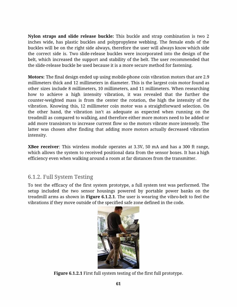
Nylon straps and slide release buckle: This buckle and strap combination is two 2 inches wide, has plastic buckles and polypropylene webbing. The female ends of the buckles will be on the right side always, therefore the user will always know which side the correct side is. Two slide-release buckles were incorporated into the design of the belt, which increased the support and stability of the belt. The user recommended that the slide-release buckle be used because it is a more secure method for fastening. Motors: The final design ended up using mobile-phone coin vibration motors that are 2.9 millimeters thick and 12 millimeters in diameter. This is the largest coin motor found as other sizes include 8 millimeters, 10 millimeters, and 11 millimeters. When researching how to achieve a high intensity vibration, it was revealed that the further the counter-weighted mass is from the center the rotation, the high the intensity of the vibration. Knowing this, 12 millimeter coin motor was a straightforward selection. On the other hand, the vibration isn’t as adequate as expected when running on the treadmill as compared to walking, and therefore either more motors need to be added or add more transistors to increase current flow so the motors vibrate more intensely. The latter was chosen after finding that adding more motors actually decreased vibration intensity. XBee receiver: This wireless module operates at 3.3V, 50 mA and has a 300 ft range, which allows the system to received positional data from the sensor boxes. It has a high efficiency even when walking around a room at far distances from the transmitter.
6.1.2. Full System Testing To test the efficacy of the first system prototype, a full system test was performed. The setup included the two sensor housings powered by portable power banks on the treadmill arms as shown in Figure 6.1.2.1. The user is wearing the vibro-belt to feel the vibrations if they move outside of the specified safe zone defined in the code.
Figure 6.1.2.1 First full system testing of the first full prototype.
61

From the first full system test, it was determined that the coin motors’ vibration intensity was not strong enough when the user was walking on the treadmill. In addition, the user felt a constant vibration even when no one was outside of the safe zone. The cause of the constant vibration came from the two sensor housings’ ultrasonic sensors interacting with each other. Since the sensors send eight 40 kHz pulses, as mentioned in the datasheet in Appendix B.2, and detect the echo back if it hits an object, the sensors in the left box was sending a direct signal to the right box whenever the user moved out from between the boxes. This caused a constant signal to be detected, thus causing the vibro-belt to constantly vibrate. This design flaw was unexpected and led to complications in developing solutions, as the sensors could no longer be pointed anywhere near each other, else that same problem would occur. Ultimately, further critical design iterations were necessary to fix the problem.
6.2. Design Iterations
6.2.1. Sensor housing- include all prototypes After the first full system testing, there was a reevaluation of the locations to place the sensor housings, the number of sensors, and how to arrange the sensors within the sensor box. A decision was made to move the left side sensor housing to the front of the treadmill hanging under the handlebar while the right side sensor housing stayed in its original position as seen in Figure 6.2.1.1. This change was determined in order to ensure the sensors could not communicate with each other. With this change, however, it was determined that this was the optimal configuration as each housing now only processed data in one dimension as opposed to two from before, making it easier for the microcontroller to process the information. Measurements were made and recorded to determine the most optimal positions to cover the entirety of the determined safe zone for the user. From the front of the treadmill belt to the end of the sensor box hanging from the treadmill arm was measured to be about 28”. The front sensor housing would be hung on the front handlebar with the center of the box lined up to the middle of the treadmill belt.
62

Figure 6.2.1.1. Measuring the placement of the right side sensor housing to cover the safe zone (left). New location of the front sensor housing after the first full system test
(right).
Since there was a change to the locations of where the sensor housings should be, the number of sensors and their arrangement had to be adjusted. Three sensors were used in the first full system test, and they were found to be able to cover the entire safe zone. Therefore, three sensors for the side housing were used in the final prototype, as can be seen in Figure 6.2.1.2. As for the front sensor housing, the size of the enclosure was scaled down to 6.5” in length (Figure 6.2.1.3.) to house only two ultrasonic sensors because two sensors were enough to cover the width of the treadmill belt, while providing accurate results and feedback. This scaling was also done to allow for easier identification on which housing went on which treadmill arm.
Figure 6.2.1.2. Solidworks model of the side sensor housing halves for the final
prototype.
63

Figure 6.2.1.3. Solidworks model of the front sensor housing for the final prototype.
Appendix C.1 shows the wiring diagram for the connections in the front sensor box housing on the treadmill. A 5V rechargeable battery powers the Arduino Uno. The inputs into the Arduino are the ultrasonic sensors. The output of the Arduino connects to the XBee’s transmitting module that sends the data collected by the different sensors to the receiving module in the belt. The front sensor housing checks if the user is too far back on the treadmill belt. It would send a signal with data to the receiving end, the belt, if the user is within the unsafe zone. Appendix C.1 shows the wiring diagram of the right side sensor housing. A 5V rechargeable battery powers an Arduino Uno. The microcontroller has three ultrasonic sensors and a XBee transmitting module connected to it. The right side sensor housing has a similar function to the front sensor housing, but it checks if the user is too far right or left of the treadmill belt. It would send a signal with data to the receiving end, the belt, if the user is within the unsafe zones.
6.2.2. Vibro-belt Fabric Materials After determining that the strength of the motors was not being felt to their full capacity, it was necessary to add a feature to the belt that would enhance the vibration of each motor by localizing its effect. To do this, a piece of open-cell foam was sewn into the vibro-belt, which allowed the motors to be pressed against the body of the user when the
64

belt was tightened around the waist. The inflating agent used in open-cell foam gives off gas so as to expand foam during vulcanization. This type of foam contains pores that are interconnected, which form a network that is relatively soft. Serving as a good insulator, the cells are open, allowing the air to fill the open space inside the material. Open-cell foam operates more like a spring, easily returning to its original state after compression thanks to the unrestricted air movement, which is ideal for breathability. This type of foam is more flexible, yet less durable than closed-cell foam, but still maintains sturdiness while providing superior cushioning as it conforms to the body shape. Components within Vibro-belt The original design used an Arduino Uno, however, an Arduino Nano was subsequently chosen due to its size. It operates at the same voltage input of the Arduino Uno - the microcontroller going into the sensor boxes - and supports the number of pin outputs that were required to operate all the motors, however choosing an Arduino Nano allowed for a smaller pocket to be designed, which allowed more room inside the belt. The belt was therefore relieved of a slight amount of bulkiness, which ended up being beneficial to the final design since a protoboard and transistors were incorporated into the final design. A portable power pack was also incorporated into the final design of the vibro-belt. The previous iteration of the belt employed a lower capacity lithium polymer battery that featured an Arduino power jack, but would needed to be removed from the microcontroller to be able to charge the belt. Additionally, the previous battery was incompatible with the newly-incorporated Arduino Nano. This power pack has a capacity of 3350mAh and features a compact and pocket-sized design. It is constructed out of aluminum, therefore reducing its weight to an ideal size for wearability. It has a micro-USB port, so it can be charged without being removed from the system. A flip-switch was also incorporated into the belt. This is so the user can flip on and off the power coming from the battery at their discretion. The previous iteration of the vibro-belt did not include a switch - the battery was plugged in and unplugged before each use of the belt. This component is a 20-amp rocker toggle LED switch. The LED is raised so that Larry can feel if the switch is on or off. The rocker toggle is a good concept for Larry because the switch flips to indicate the setting that it is currently on: on or off. He can feel the position of the switch using the raised LED, and the particular mode it is in cannot be easily or accidentally flipped without intentional effort put into flipping the switch. The switch is also always on the right side to make committing the component placements to memory simpler. Once the user has the vibro-belt securely fastened at the waist, the switch can be easily flipped to power the device. Appendix C.1 shows the connections of the motors inside the belt. The setup includes 3V coin motors, S8050 NPN transistors to increase the current delivered to the motors,
65

1N4001 flyback diodes, and 1kΩ resistors. 5V provided by the Arduino Nano powers the system. The digital pins toggles the NPN on and off, which in turn, toggles the motors on and off. The flyback diodes are used to prevent the motor from being damaged from initial current spikes when the system is turned on. These type of motors were included in the first prototype of the belt, but subsequent iterations removed one motor from the belt and assigned the other three motors to correspond to one specific location on the treadmill.
6.2.3. Code Figure 6.2.3.1. shows the software flowchart of the entire system. After turning the switches on to power the 2 boxes and the belt, the sensors and the motors will initialize. The ultrasonic sensors will start collecting data. For the side boxes, if the user is within 14’’ to 18’’ of any of the ultrasonic sensors in the box, then the left motor in the belt will turn on to alert the user to move towards the right of the treadmill belt. If the user is within 8” of any of the ultrasonic sensors, then the right motor in the belt will turn on to alert the user to move towards the left of the treadmill belt. Running in parallel, the sensor box in front of the treadmill will check if the user is within 25” to 48” of the ultrasonic sensors. If so, then the back motor in the belt will turn on to alert the user to move forward.
Figure 6.2.3.1. The software flowchart of the final design with the sensors
and motors.
66

For the software code portion of the system, please refer to Appendix C.2 for the microcontroller code of the front sensor housing, the right side sensor housing, and the vibro-belt. The front sensor box code includes pin assignments to the sensors and the XBee transmitting module, initialization code for the ultrasonic sensors, and the main logic that sends a signal when the user is too far back. There is an additional code that prints to the serial monitor for debugging purposes. The right side sensor housing is similar to that of the front sensor housing. However, there is one extra ultrasonic sensor incorporated into the code and conditional cases for when the user moves too far right and too far left. The conditional cases are based on distances away from the sensors in inches. The vibro-belt code includes the pin assignments to the motors and the XBee receiver module as well as the logic of what the motors do when the XBee receives a character data from the transmitting modules in the sensor boxes. The motors turn off once the user is out of the specified unsafe ranges determined in the code of the front and right side sensor boxes.
6.2.4. Mounting The current solution for the mounting of both boxes includes built in velcro slots at the top of the housings as seen in Appendix C.1, where long velcro straps will feed through and wrap around their respective arms, allowing the housings to hang underneath the arms of the treadmill. This design choice was taken into consideration due in part to allowing Larry to still fully utilize the treadmill arm functions (i.e. holding on, taking his heart rate, supporting himself, etc.) while still taking consistent, accurate data. An example of the velcro used can be seen in Figure 6.2.4.1.
Figure 6.2.4.1. Velcro straps with hooks and loops on both sides, allowing
the user to wrap them around and stick them to themselves.
67
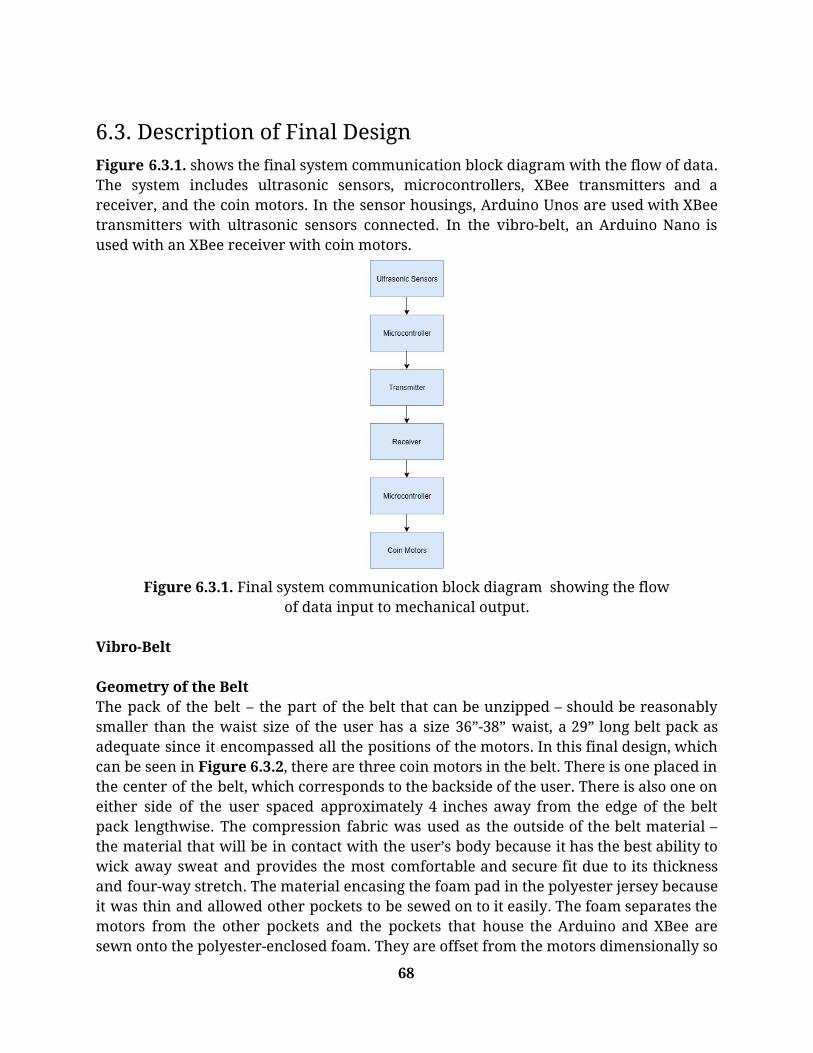
6.3. Description of Final Design Figure 6.3.1. shows the final system communication block diagram with the flow of data. The system includes ultrasonic sensors, microcontrollers, XBee transmitters and a receiver, and the coin motors. In the sensor housings, Arduino Unos are used with XBee transmitters with ultrasonic sensors connected. In the vibro-belt, an Arduino Nano is used with an XBee receiver with coin motors.
Figure 6.3.1. Final system communication block diagram showing the flow
of data input to mechanical output. Vibro-Belt Geometry of the Belt The pack of the belt – the part of the belt that can be unzipped – should be reasonably smaller than the waist size of the user has a size 36”-38” waist, a 29” long belt pack as adequate since it encompassed all the positions of the motors. In this final design, which can be seen in Figure 6.3.2, there are three coin motors in the belt. There is one placed in the center of the belt, which corresponds to the backside of the user. There is also one on either side of the user spaced approximately 4 inches away from the edge of the belt pack lengthwise. The compression fabric was used as the outside of the belt material – the material that will be in contact with the user’s body because it has the best ability to wick away sweat and provides the most comfortable and secure fit due to its thickness and four-way stretch. The material encasing the foam pad in the polyester jersey because it was thin and allowed other pockets to be sewed on to it easily. The foam separates the motors from the other pockets and the pockets that house the Arduino and XBee are sewn onto the polyester-enclosed foam. They are offset from the motors dimensionally so
68

that component stacking is avoided. The height of the belt is four and a half inches, and its thickness varies due to the components that are in the belt. Without the components in the belt, its thickness reduces to less than 1 inch.
Figure 6.3.2. An image of the final prototype of the vibro-belt.
Features and functionality Since the pack of the belt spans only 29 inches in length, the nylon straps have an adjustability feature on both the male and female ends of the buckles. Due to this feature, the belt can fit tightly and securely on a 29-inch waist all the way up to a 44-inch waist. Additionally, the female end of the buckles will always end up on the right side of the body if the user is wearing the belt correctly. This is so that the user can easily determine the correct orientation of the belt since the zipper will always be on the outside and the male end of the buckle on the left side of the body. If the user puts the belt on upside down, the belt will not function properly and could potentially cause issues when operating the device, so it is very important that it is always kept in mind that the female end of the buckles is on the right side of the body. Removal of components from the vibro-belt is a straightforward endeavor. The motors are secured in similarly-sized pockets behind the foam padding. These pockets were stitched to the compression fabric, which is the fabric that will be pressed up against the user’s body. Each motor pocket has a flap which is used to secure the motor in the pocket using small velcro patches. This is so the motors do not ever fall out of the pockets and end up loosely vibrating in the belt. To access the motors, the foam padding can be easily pulled back since it was only stitched to the bottom on the internal lining of the vibro-belt and is therefore not removable. Once the motors have been removed from their respective pockets, the battery, switch, and microcontroller can be removed. The microcontroller, like the motors, has its respective pocket. It is straightforward to differentiate between pockets due to size and the way the pocket operates. Since the microcontroller has unused pins sticking out of it, it can be quite difficult to insert and remove this device from the belt. To compensate, a pouch with an elastic opening was constructed for the microcontroller to make inserting the device into its respective pocket a simple task. Like the motor
69

pockets, however, the microcontroller pocket does have a velcro flap, which will allow it to be securely place into its respective pocket. As for the power bank pocket, it has no flap, but instead is open on one end while the opposite end is closed and has a velcro patch at the end. Additionally, the power bank used in the belt also has a velcro patch at its end and when the two velcro ends meet, which allows the user to distinguish it from the other two batteries. When the velcro end of the battery meets the velcro end of its pocket in the belt, the battery will be securely placed into its pocket. To remove the battery, simply detach the velcro couple.
6.3.1. Cost breakdown A full cost breakdown of the entirety of the project can be found in Appendix A.5, and a simplified version of the costs for the final design can be seen in Table 5 below.
Table 5. Final Project Budget.
Item, Specific to Device Quantity Cost per unit Total
Belt Materials
Jackery Mini 3350mAh Portable Charger 1 $12.99 $12.99
Carbon Stretch Polyester Jersey 1 $15.99 $15.99
Solid Black Stretch Mesh w/ Wicking Capabilities 1 $15.99 $15.99
Black Heavy Compression Double Knit w/ Max-Dri Wicking and Micro Air Tech 1 $15.99 $15.99
Blazer CWL624 Illuminated On/Off switch 1 $5.58 $5.58
34pcs Double Sided PCB Board Protoboard 1 $8.99 $8.99
Gikfun USB Female Type A Port 4-Pin Connector for Arduino 1 $5.26 $5.26
560PCS Heat Shrink 1 $8.99 $8.99
USB 3.0 Ultra High Speed Cable 1 $6.99 $6.99
Xbee Add-On for Arduino Nano 1 $31.75 $31.75
Flexible Silicone Wire, 24 gauge 1 $15.99 $15.99
Right Angle Male Headers 1 $6.42 $6.42
Mini Nano Board for Arduino 1 $8.29 $8.29
Magnetic Safety Treadmill Key 1 $8.95 $8.95
XBee Explorer Regulated 1 $11.95 $11.95
XBee 1mW Wire Antenna - Series 1 1 $26.95 $26.95
BestTong 3V DC 12127 Coin Mobile Phone Vibration Motor, 10Pcs 1 $11.99 $11.99
70

Aukru 20cm Male to Female Breadboard Dupont Wires Jumper Cables for Arduino, 40 pcs 1 $5.99 $5.99
McIgIcM Transistor Kit 200pcs 1 $9.77 $9.77
velcro strip 1 $5.68 5.68
velcro wrap 1 $4.29 $4.29
½” x 2.1” x 36” foam 1 $14.49 $14.49
Sensor Boxes
Jackery Mini 3350mAh Portable Charger 2 $12.99 $25.98
Blazer CWL624 Illuminated On/Off switch 2 $5.58 $11.16
USB 3.0 ultra high speed cable 2 $6.99 $13.98
XBee Explorer Regulated 2 $11.95 $23.90
XBee 1mW Wire Antenna- Series 1 2 $26.95 $53.90
Krazy Glue 1 $2.14 $2.14
Arduino Uno 2 14.99 29.98
Total Cost $420.32 The cost to build the final design is small because of its overall simplicity, and because materials used in the early stages of the prototype were reused. Materials that were repurchased included ultrasonic sensors and jumper cables. Additionally, the fabric materials used in the belt were changed, and full-sized pieces of fabric were purchased for the manufacturing of final prototype. The total amount spent during the final design period was $420.32. The total cost spent on the entirety of the project was $1263.74.
6.3.2. Safety Considerations Since the current iteration of the device does not physically secure the user to the treadmill, but rather allows them to build up to the point where they are self-sustaining on the treadmill, a learning curve will be undertaken by the user. Initial testing with the device showed that a user who is not tethered to the treadmill can lose track of their spatial orientation quickly, therefore creating the possibility of a hazard. To compensate for this a magnetic emergency stop cord was attached to the belt. If the user became unaware of their position on the treadmill belt and shifted into the hazardous zone towards the back of the treadmill belt, the emergency stop cord would be pulled taught and be taken off the treadmill interface, therefore causing the treadmill to stop. It is strongly recommended that during the initial phase of using this device another person be used to help guide and advise the user of their positions on the treadmill until the user felt comfortable using the device on their own. This will mitigate the potential for injury.
71

6.3.3. Maintenance and Repair Considerations If a sensor box begins to malfunction, if its readings are inaccurate, or it is not reading anything at all, the lids of the boxes can be removed, along with individual components within the boxes. If it is determined that one of the sensors is not functioning properly, acetone can be applied to the sensor box in order to weaken the glue bond to remove the sensor from the box in order to replace it. If the boundaries for the safe zone in the code are skewed, the user should open the sliding lids of the sensor housings to push the red reset button on the Arduino Uno, and push the reset button on the Arduino Nano in the vibro-belt while the full system is on. If the reset button does not work, then recalibration and readjustment is needed. The boundaries must be readjusted in the Arduino code through the Arduino IDE. In the case that the hardware fails, then replacements of the electronics must be conducted and the code must be reuploaded. After every use of the system, it is suggested to recharge the the two sensor housing and the vibro-belt overnight via a USB to USB cable. A wall adapter for a phone connected to one end of the USB to USB works to recharge the system. This is to ensure that there is no failure during the user’s exercise routine.
7. Product Realization
7.1. Manufacturing
7.1.1. Sensor Housing For information regarding the printing and materials of the housings, see Section 6.1.1. The process of 3D printing the housings can be seen in Figure 7.1.1.1. This figure shows the side housing halves mid-print on the same worktable. This process required multiple tries, as often times the print job, printer, or filament malfunctioned resulting in a failed print. These print jobs lasted approximately 32 hours.
72

Figure 7.1.1.1 The side sensor housing being 3D printed in the Ultimaker 2+.
After the housings finished printing, further assembly of the entire system was completed to ensure the stability and security of the components. First, the housing halves for the side housing were adhered using an incredibly quick reacting super glue. After the housing pieces were assembled, the attachment of the components inside the housings began, as can be seen in Figure 7.1.1.2. This attachment system was done using pieces of velcro for temporary placement of the components, since component placement optimization was not done yet. This analysis still needs to be done, however, in order to locate the center of mass of the system in the optimal spot.
Figure 7.1.1.2 The front sensor housing (left) side sensor housing and side sensor
housing (right) with full assembly of electronics.
7.1.2. Vibro-belt Since the belt was made from fabric materials and could not be machined or 3D printed, it was necessary to outsource the manufacturing of the vibro-belt to an experienced seamstress. Beverly’s, a fabrics and crafts store in San Luis Obispo was the first store searched to find a professional seamstress. While no seamstress was found at Beverly’s, a costume designer and freelancer names Randy Pool was referred. Randy, who has over 30 years of experience designing costumes for theatrical productions, graciously took on the task of sewing together the belts based on the design provided. A relationship was established with Randy, and at no cost, she was able to precisely sew together the pieces of the belt and provided creative insight for the design of the component pockets. All
73

materials were supplied to Mrs. Pool, and subsequently needed items were recommended by her. See Sections 6.1.1 and 6.2.2 for design details; the final belt is shown in Figure 6.3.2 above.
7.1.3. Mechanical Safety The magnetic treadmill stop was ordered off-the shelf and knots were tied to determine the appropriate length to ensure safety during testing. The magnetic treadmill stop is clipped onto the vibro-belt, and the magnetic end is coupled to the magnetic stop on the treadmill.
7.2. Recommendations for Future Manufacturing For future manufacturing of the sensor box, see Section 6.1.1. For manufacturing of the belt, ensure that the pockets are right-side-up when sewing. In regards to the safety mechanism, rather than tying the string, cut it to length and reattach the magnet.
7.3. Cost Estimation for Future Production It was stated above that the cost for the final prototype of the belt was $420.32. This cost, however, does not take into consideration the cost of outsourcing, the cost of filament for the 3D printer, or the cost that it would take to test this device with the user, which would include the cost of flying. The cost of outsourcing was not taken into account because the seamstress that was used to sew together the pieces of the belt did not charge a fee for labor. In addition, the cost of using 3D printed materials was also left out because the filaments were provided by the university. Further, the 3D printers themselves were provided by the university, and a fee could be implemented for future use of a 3D printer. Taking this into consideration, the cost for future production can be estimated to be around $800-$900.
8. Design Verification
8.1. Initial Verification and Testing Plan Types of tests planned to verify the specifications to be met by this design are listed in Table 6 below, including necessary equipment.
Table 6. Initial Verification and Testing Plans
Specification Test Description Equipment
Distance from center
Video test A video will be taken from a
Treadmill Camera
74

Distance from shoulder to running surface edge
top-down view of the treadmill while a user runs with the functional device. The video will be analyzed by measuring and scaling distances and determining response time.
Media player
Distance from planted heel to back edge of treadmill belt radius
Output response time
Device volume Inspection Dimensions of the compressed device will be measured and recorded.
Tape measure
Device weight Inspection Device will be weighed on a scale.
Scale
User comfort rating Inspection User comfort will be ranked by team members
Belt User
Elastic modulus and modulus of rigidity
Inspection Dependent on material of belt
Ease of use scale Blindfolded set up test
Participants will be blindfolded, timed while setting up the device, and surveyed after
Treadmill Blindfold Stopwatch Set up time
Adjustability Range Inspection Dependent on fastening mechanism of belt
Tape Measure
Usage duration Battery life test The device will be left powered on and timed by a program until the battery runs out. The battery will be recharged and the test repeated twice
Stop watch Timing program
Fracture toughness Inspection Dependent on the material of the
75

sensor housing
Drop Impact Drop Test The device will be dropped repeatedly from the height of the treadmill arm at 4 ft until fracture.
Ladder Device Tape Measure
Water Resistance Rating
Inspection Dependent on the material of the belt
Maximum Torque Tightness test Will torque the tightener to its maximum that ensures no damage to walls of clamps and surface of attachment. Will then relate that to number of turns and general feel to set a limit.
Treadmill Clamp Pressure Gauge Angle Reader
Throughout the manufacturing/testing process, other tests more relevant to the progressing design iterations were performed on the final product.
8.2. Actual Verification and Testing Table 7 displays a summary of testing for design verification performed on the final system.
Table 7. Verification and Testing Results
Customer Requirement
Engineering Specification
Test Method Result
Functional/Safe Foot doesn’t touch side or back edges
of treadmill
Self-evident Needs improvement
Independent Set-up Component placement accuracy
100%
Blindfolded setup Pass: 100%
Portable Volume < 1.219 ft^3 Weight < 21 lbs
Analysis Scale
Pass: Volume: .118 ft^3 Weight: 3.33 lbs
76
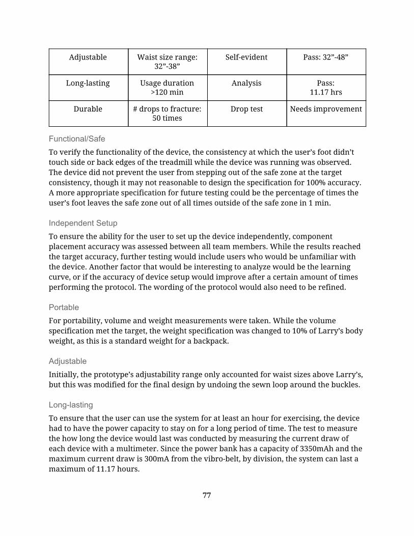
Adjustable Waist size range: 32”-38”
Self-evident Pass: 32”-48”
Long-lasting Usage duration >120 min
Analysis Pass: 11.17 hrs
Durable # drops to fracture: 50 times
Drop test Needs improvement
Functional/Safe To verify the functionality of the device, the consistency at which the user’s foot didn’t touch side or back edges of the treadmill while the device was running was observed. The device did not prevent the user from stepping out of the safe zone at the target consistency, though it may not reasonable to design the specification for 100% accuracy. A more appropriate specification for future testing could be the percentage of times the user’s foot leaves the safe zone out of all times outside of the safe zone in 1 min.
Independent Setup To ensure the ability for the user to set up the device independently, component placement accuracy was assessed between all team members. While the results reached the target accuracy, further testing would include users who would be unfamiliar with the device. Another factor that would be interesting to analyze would be the learning curve, or if the accuracy of device setup would improve after a certain amount of times performing the protocol. The wording of the protocol would also need to be refined.
Portable For portability, volume and weight measurements were taken. While the volume specification met the target, the weight specification was changed to 10% of Larry’s body weight, as this is a standard weight for a backpack.
Adjustable Initially, the prototype’s adjustability range only accounted for waist sizes above Larry’s, but this was modified for the final design by undoing the sewn loop around the buckles.
Long-lasting
To ensure that the user can use the system for at least an hour for exercising, the device had to have the power capacity to stay on for a long period of time. The test to measure the how long the device would last was conducted by measuring the current draw of each device with a multimeter. Since the power bank has a capacity of 3350mAh and the maximum current draw is 300mA from the vibro-belt, by division, the system can last a maximum of 11.17 hours.
77

Drop Test A preliminary drop test was performed on a PLA prototype of the sensor box. The PLA fractured easily on concrete, but not enough to break electronics inside. The specification for future testing can be changed to dropping 50+ times before fracture. A more appropriate test method to mimic Larry’s environment would be to test on carpet and drop the device from the treadmill arm height.
8.3. Design Expo Feedback During the final demonstration of the project at Senior Project Expo, key factors were also determined that are important to the calibration and function of the device. Through trial and error, these factors that were determined to be important were clothing type, calibration steps, and vibro-belt z-axis differential. One of the biggest causes of error during the Expo demonstration was the clothing type that each person wore. Due to the inconsistencies of looser and more flowy fabrics, the ultrasonic sensors had some troubles picking up correct values, assuming that the sound waves would bounce off the fabric in random directions as opposed to directly back towards the sensor. This determination was based on the inspection of users holding the vibro-belt in their hands as they were in front of the housings. The participants would get random signals from the motors telling them to correct both right and left movement at the same time. This was worrisome as inconsistencies like that could cause the user to receive incorrect signals while using the device, potentially resulting in hazardous corrections. Another problem resulted from directing the sensor housings at walls and not having the user stand in front of the housings to be detected. It was found that inconsistent motor vibrations were felt when the system was turned on and the housings were pointed at walls. From this an assumption was made that potentially two different outcomes resulted from that inspection, either the housings were communicating with each other when there was no object to detect in front of them much like the design flaw from the first iteration in Section 6.1.2, or the echoing off of walls caused incorrect data readings. The best results that were found were when the user followed the calibration steps found in Appendix C.3. With the vibro-belt pulled tight to their waist, with the belt approximately at the same height as the housings, the most accurate results with little to no inconsistencies were experienced.
78

9. Conclusions and Recommendations In conclusion, this senior project produced a substantial concept and preliminary product to help Larry Gunter stay centered while running on a treadmill. Background research and customer requirements were used to create a set of objectives. From these objectives, ideation and prototyping led to a final design. The components were manufactured, assembled, and tested as a full system. Valuable feedback was obtained and this feedback can be combined with the final design to finalize a device that is ready to be used by Larry.
9.1. Recommended Device Modifications For future iterations, a larger power bank can be used so the devices can be powered for longer. A drawback is that the total weight of the system would be much greater as battery capacity increases, which may go over the weight constraint. For the belt, the single motor placed in the back should be replaced with two motors placed on either side of the spine in order to increase the user’s ability to sense the vibration. The electronics pack should also be smaller in relation to the full length of the belt to allow a wider adjustability range. Functionality troubleshooting should be performed to address the issues presented during Design Expo.
9.2. Recommended Testing Functionality factors that should be explored include clothing worn and calibration steps taken. Combining the belt into a shirt so that Larry would be able to feel the vibration directly against his skin can be considered. More testing regarding setting up the device with a blindfold should be performed with those unfamiliar with the device. A finer calibration of the safe zone in the code should be done and tested for consistency. A test with Larry Gunter should performed to receive the challenger’s feedback. A setup test and full system test should be done to test the efficacy.
79

References [1] “Facts About Retinitis Pigmentosa.” National Eye Institute, NEI. May 2014. 6 Oct. 2017.
<https://nei.nih.gov/health/pigmentosa/pigmentosa_facts> [2] “The Effect of Handrail Support on Oxygen Uptake During Steady-State Treadmill
Exercise.” US National Library of Medicine, National Institutes of Health. Nov.-Dec. 2006. 6 Oct. 2017. <https://www.ncbi.nlm.nih.gov/pubmed/17135860>
[3] “An Electromagnetic Sensor for the Autonomous Running of Visually Impaired and
Blind Athletes.” US National Library of Medicine, National Institutes of Health. 14 Feb. 2017. 6 Oct. 2017. <https://www.ncbi.nlm.nih.gov/pmc/articles/PMC5336106/>
[4] “Treadmill 885.” Precor: Fitness Made Personal.
<http://www.precor.com/en-us/commercial/cardio/treadmill/trm-885ng-treadmill>
[5] “Effect of Clothing Weight on Body Weight.” International Journal of Obesity, vol. 37, no.1, 2012, pp.160–161., <www.researchgate.net/publication/221867032_Effect_of_clothing_weight_on_body_weight.>
[5] Lambert, Ellen. "What Are the Measurements of Most Treadmills?"
LIVESTRONG.COM. Leaf Group, 11 Sept. 2017. Web. [6] “TYR Alliance 30L Backpack.” Swim Outlet.
<https://www.swimoutlet.com/p/tyr-alliance-30l-backpack-8146312/?utm_source=google&utm_medium=cpc&utm_campaign=google-shopping&color=9606&gclid=CjwKCAjwpfzOBRA5EiwAU0ccNxgmY7spXgr01AXyHjTRm9RH2nUaPlEgddCxT5Mvbaj-1P5fYPljmxoCFvMQAvD_BwE>
[7] “Corning Gorilla Glass 5.” Corning.
<https://www.corning.com/gorillaglass/worldwide/en/glass-types/gorilla-glass-5.html>
[8] “Corning Gorilla Glass 5 Product Information.” Corning.
<http://www.corning.com/microsites/csm/gorillaglass/PI_Sheets/Corning_Gorilla_Glass_5_PI_Sheet_RevB.pdf>
[9] ‘Properties of Silicon.” Jarlath McEntee’s MEMs Links.
<http://www.design.caltech.edu/Resea/MEMS/siliconproprch.hmtl> [10] “What Makes a Device Waterproof or Water Resistant?” Make Use Of.
80

<httAp://www.makeuseof.com/tag/makes-device-waterproof-water-resistant/> [11] “About Apple Watch Water Resistance.” Apple.
<https://support.apple.com/en-us/HT205000> [12] “Men’s Size Guide -- US Sizes.” SizeGuide.
<http://www.sizeguide.net/size-guide-men-size-chart.html> [13] “Typical properties of engineering materials like steel, plastics, ceramics and
composites.” The Engineering Toolbox. <http://www.engineeringtoolbox.com/engineering-materials-properties-d_1225.html>
[14] “Why is (111) Silicon a Better Mechanical Material for MEMS?” School of Electrical
Engineering and Computer Engineering, Seoul National University. <http://www-mtl.mit.edu/researchgroups/mems-salon/sriram_Si-111-better.pdf>
[15] “Charge your AirPods with charging case and learn about battery life.” Apple.
<https://support.apple.com/en-us/HT207012> [16] “Compare board specs.” Arduino.
<https://www.arduino.cc/en/Products/Compare> [17] “XBee Shield Hookup Guide.” SparkFun.
<https://learn.sparkfun.com/tutorials/xbee-shield-hookup-guide> [18] “10 Fitness Fabrics, Explained.” Shape.
<https://www.shape.com/fitness/clothes/10-fitness-fabrics-explained>
[19] “Landice L-Series Home and Commercial Treadmill Diagnostic and Service Manual 2003.” Landice.
<http://www.landice.com/sites/default/files/L-50%20Series%20Service%20Manual. pdf>
[20] “Treadmill Length.” LIVESTRONG.COM. Leaf Group, 11 Sept. 2017. Web.
<https://www.livestrong.com/article/338155-length-of-a-treadmill/>
[21] “Haptics, Solutions for ERM and LRA Actuators.” TI.COM. Almaden Press, 2013. Web. <http://www.ti.com/lit/ml/sszb151/sszb151.pdf.>
[22] “Actuator Drivers- Actuators.” TI.COM. Almaden Press, 2013. Web.
<http://www.ti.com/motor-drivers/actuator-drivers/actuators.html>
81

[23] “Haptics, Touch Feedback that Really Moves You.” TI.COM. Almaden Press, 2013.Web.
<http://www.ti.com/lit/ml/slyt418a/slyt418a.pdf> [24] “High-Definition Haptics: Feel the Difference!” TI.COM. Texas Instruments Incorporated, 2012. Web.
<http://www.ti.com/lit/an/slyt483/slyt483.pdf> [25] “Virtual Reality: Scientific and Technological Challenges.” NAP.EDU. National Academic Press, 1995.
<https://www.nap.edu/read/4761/chapter/9> [26] “A Survey of Electromagnetic Position Tracker Techniques.” CITESEERX.IST.PSU.EDU. Virtual Reality: Research, Development, and Applications, 2000, vol. 5, no. 3, pp. 169-182.
<http://citeseerx.ist.psu.edu/viewdoc/download?doi=10.1.1.91.1544&rep=rep1&type=pdf>
[27] “Lidar-Lite 3 Laser Rangefinder.” ROBOTSHOP.COM. Robotshop, Inc. 2017. Web.
<http://www.robotshop.com/en/lidar-lite-3-laser-rangefinder.html#Specifications> [28] “What is LIDAR?” OCEANSERIVCE.NOAA.GOV. NOAA. Historical Maps and Charts audio podcast. National Ocean Service website, October 10, 2017. Web.
<https://oceanservice.noaa.gov/facts/lidar.html> [29] Types of Sensors for Target Detection and Tracking,” INTOROBOTICS.COM. November 20, 2013. Web.
<https://www.intorobotics.com/types-sensors-target-detection-tracking/> [30] “Inertial Measurement Units (IMU) Information.” GLOBALSPEC.COM. Web.
<http://www.globalspec.com/learnmore/sensors_transducers_detectors/orientation_position_sensing/inertial_measurement_units_imu>
[31] “The Ultimate Showdown - Snaps Vs Velcro: Is One Better Than the Other?” Julie. April 19, 2010. Knickernappiesblog.com. Web. <http://www.knickernappiesblog.com/2010/04/ultimate-showdown-snaps-vs-velcro-is.ht
ml> [33] “Polyester Microfabric is Misunderstood. Ninjaturtlebedding.com. Web.
<http://ninjaturtlebedding.com/polyester-microfiber-fabric-facts/> [34] “The Ultimate Guide to Military Backpacks”. The Military Backpack Guide. Web.
<http://militarybackpackguide.com/>
82

[35] Armando. “PLA vs ABS Filament: Plastic Strength, Flexibility Compared! Which Is
Better For 3D Printing?” All That 3D, 27 Jan. 2018, www.allthat3d.com/pla-vs-abs/.
83

A. Project Documents
A.1. Quality Function Diagram (QFD) 9.1 Appendix A - Quality Function Diagram (QFD)
In the Customer Requirements section of this QFD, all items were derived from conversations with the customer and sponsor. Each item in that list received an importance rating-- a number from one to five-- from Team CENTREAD based on its understanding of the problem. In the Measurables, or Engineering Specifications, section items were derived directly from the Customer Requirements and a rating of either one, three, or nine was assigned each specification based on the strength of its relationship to a specific customer requirement. From that each specification was assigned a weighted importance number and further a percentage of importance for the overall project. This analysis allows the team to gauge which issues will be of highest order.
84

A.2. Gantt Chart
85

86

A.3. Pugh Decision Matrix
87

A.4. Hazard Identification Checklist
88

A.5. Project Costs Phase (Conceptual Prototyping, Functional Prototype, Final Product) Item Name
Source (Personal, Amazon, Store) Quantity Price Total
Functional Prototype/Final XBee Explorer Regulated Amazon 3 $11.95 $35.85
Functional Prototype/Final Right Angle Male Headers Amazon 1 $6.42 $6.42
Functional Prototype/Final XBee Explorer USB Amazon 1 $24.95 $24.95
Functional Prototype/Final
XBee 1mW Wire Antenna- Series 1 Amazon 3 $26.95 $80.85
Functional Prototype Ultrasonic Range Finder-LV-MaxSonar-EZ1
Sparkfun Electronics 1 $25.95 $25.95
Functional Prototype
Infrared Proximity Sensor Long Range- Sharp GP2Y0A02YKOF
Sparkfun Electronics 1 $14.95 $14.95
Functional Prototype Shipping & Handling Sparkfun Electronics 1 $19.76 $19.76
Functional Prototype
BestTong 3V DC 12127 Coin Mobile Phone Vibration Motor 10Pcs Amazon 1 $11.99 $11.99
Functional Prototype
HUELE 5pcs DC3V 10x2.7mm Vibration Micro-motor for Cell Phone Amazon 1 $6.49 $6.49
Functional Prototype/Final
Power Supply- Lithium Battery Amazon 1 $10.99 $10.99
Functional Prototype/Final
Adafruit Micro Lupo w/MicroUSB Jack Amazon 1 $9.51 $9.51
Functional Prototype/Final
3ple Decker Case for Arduino Amazon 1 $9.95 $9.95
Functional Prototype/Final
Adafruit Pro Trinket Lilon/LiPoly Backpack Add-On Amazon 1 $8.12 $8.12
Functional Prototype/Final BNO055 Breakout Sensor Amazon 1 $33.89 $33.89
89

Functional Prototype Lidar Range Finder Sensor Amazon 1 $40.99 $40.99
Functional Prototype
TCRT5000 Photoelectric Sensors Reflective Optical Sensor with Transistor Output Infrared 50 PCS Amazon 1 $12.99 $12.99
Functional Prototype
AIRSUNNY Infrared Diode LED IR Emission and Receiver 5 PCS Amazon 1 $5.98 $5.98
Functional Prototype Photoelectric Sensor Reflective Tape Amazon 1 $13.99 $13.99
Functional Prototype/Final
HC-SR04 Ultrasonic Sensor Distance Module 5 PCS Amazon 3 $9.79 $29.37
Conceptual/Functional Prototype Go Pro Harness Target 1 $39.99 $39.99
Conceptual Prototype Aluminum Foil Target 1 $2.09 $2.09
Conceptual Prototype Bike mirror Target 2 $8.89 $17.78
Conceptual Prototype Swim noodle Target 1 $2.99 $2.99
Conceptual Prototype bungee cord Target 1 $7.29 $7.29
Conceptual Prototype duct tape Target 1 $2.74 $2.74
Conceptual Prototype rope Target 1 $8.54 $8.54
Conceptual Prototype hooks Target 1 $3.79 $3.79
Conceptual Prototype fastener sets Target 1 $3.75 $3.75
Conceptual Prototype Accessories Target 1 $13.13 $13.13
Functional Prototype Plywood Home Depot 1 $8.93 $8.93
Functional Prototype Nails Home Depot 1 $1.67 $1.67
Functional Prototype Screws Home Depot 1 $4.76 $4.76
Functional Prototype Bracket Home Depot 2 $1.20 $2.40
Functional Prototype solder QL+ Lab 1 $0.00 $0.00
Functional Prototype Arduino Uno Personal/Advisor 2 $0.00 $0.00
90

Functional Prototype Plastic filament QL+ Lab 1 $0.00 $0.00
Functional Prototype 40 pcs Nylon Invisible Zippers Amazon 1 $13.99 $13.99
Functional Prototype Solid Power Mesh Fabric, Nylon Spandex Amazon 1 $34.99 $34.99
Final Product Magnetic Safety Treadmill Key Amazon 1 $8.95 $8.95
Final Product VELCRO 24" x 3/4" Tape Amazon 1 $5.97 $5.97
Final Product ? Double Slide Zipper 30" Amazon 1 $6.03 $6.03
Final Product ? 4-Way Stretch Nylon Spandex Amazon 1 $9.95 $9.95
Final Product ? 4 Piece 2 in Plastic Buckles Amazon 1 $9.99 $9.99
Final Product ? VELCRO 15' x 2" Black Tape Amazon 1 $22.24 $22.24
Final Product ?
Selric UV Resistant High Strength Polyester Thread #69 Amazon 1 $6.19 $6.19
Functional Prototype Belt material swatches Mood Fabrics 1 $26.49 $26.49
Final Product Flexible Silicone Wire 24gauge Amazon 1 $15.99 $15.99
Final Product Mini Nano Board for Arduino Amazon 1 $8.29 $8.29
Final Product Krazy Glue CP Bookstore 1 $2.14 $2.14
Final Product Rubber Cement Pick Up CP Bookstore 1 $3.01 $3.01
Functional Prototype Foam cube Michaels 1 $3.99 $3.99
Functional Prototype Foam block Michaels 1 $6.59 $6.59
Functional Prototype/Final velcro strip Michaels 1 $5.68 $5.68
Functional Prototype velcro wrap Michaels 1 $4.29 $4.29
Functional Prototype bumper stickers Michaels 1 $2.99 $2.99
Functional Prototype lithium ion batteries + chargers All Battery 3 $62.98 $188.94
Final Product Xbee Add-On for Arduino Nano Gravitech 1 $31.75 $31.75
Functional Prototype 7.2V LiPo Battery Epic Tinker 1 $33.57 $33.57
Final Product USB 3.0 ultra high speed cable Amazon 3 $6.99 $20.97
91

Final Product Exuun USB Male to Female Cable Amazon 3 $7.99 $23.97
Final Product 34pcs Double Sided PCB Board Protoboard Amazon 1 $8.99 $8.99
Final Product Blazer CWL624 Illuminated On/Off switch Amazon 3 $5.58 $16.74
Final Product 560PCS Heat Shrink Amazon 1 $8.99 $8.99
Final Product
Gikfun USB Female Type A Port 4-Pin Connector for Arduino Amazon 1 $5.26 $5.26
Final Product AutoEC 3pc Rocker Toggle LED Switch Amazon 1 $7.49 $7.49
Final Product Jackery Mini 3350mAh Portable Charger Amazon 3 $12.99 $38.97
Final Product Carbon Stretch Polyester Jersey Mood fabrics 1 $15.99 $15.99
Final Product Solid Black Stretch Mesh w/Wicking Capabilities Mood fabrics 1 $15.99 $15.99
Final Product
Black Heavy Compression Double Kniw w/Max-Dri Wicking and Micro Air Tech Mood fabrics 1 $15.99 $15.99
Final Product shipping Mood fabrics 1 $11.99 $11.99
Functional Prototype 1/4 pink foam Quality Fabrics of SLO 1 $6.48 $6.48
Final Product 1/2x2.1x36 foam Quality Fabrics of SLO 1 $12.30 $12.30
Project Expo Easel Art Central 1 $22.95 $22.95
Project Expo Foam Board Art Central 1 $16.95 $16.95
Project Expo Spray Super Glue Art Central 1 $16.24 $16.24
Final Product
Aukru 40 pcs 20cm Male to Female Breadboard Dupont Wires Jumper Cables for Arduino Amazon 1 $5.99 $5.99
Final Product McIgIcM Transistor Kit 200pcs Amazon 1 $9.77 $9.77
Final Product ByAnnie Double Slide Zipper 30" Black Amazon 1 $6.86 $6.86
92

A.6. Management Plan Project Management and Organization The following roles listed below have been assigned to the members of Team CENTREAD, and are subject to changes as the completion of the project progresses. Over time, specific engineering and design-related roles have emerged and have subsequently been established. The role that each member holds will ensure that the team has a fair division of labor, leadership, effective use of time and resources, and an overall successful senior project experience. Specific roles have been assigned to the members of the team, however each member will continue to contribute his or her insight and ideas to all areas of the project as needed. In addition, each team member will seek approval from his or her teammates regarding design decisions. The roles are as follows: Lead Mechanical Engineer, Sensor Housing: Donavan Feliz · Responsible for design and construction of Sensor Housing blocks · Conducts strength and structure analysis of Sensor Housing treadmill mounting · Finds and collects materials and components for Sensor Housing construction Project Engineer and Logistics Manager: Ariel Crisostomo · Generates process plans and implements process improvement techniques · Designs and facilitates all testing procedures for system components · Responsible for keeping members of the team on task and writing team action items . Creates and finalizes all presentation material for sponsor and advisor presentations Lead Product Designer, Vibro-Belt: Adam Patrella · Analyzes belt materials and creates method for safe efficient removal of components · Responsible for the design and fabrication of belt · Communicates design information to customer, and creates protocol for operation Lead Electrical Engineer, Hardware and Software: Cecilia Yuen · Responsible for wiring electrical components to microcontroller · Designs algorithms and accompanying code · Creates software diagrams and software communication diagrams Team members have agreed to meet at least twice a week as a team, reach a consensus regarding all project decisions, commit to utilizing individual strengths and learning as a whole, compile project and design reports as needed and as required, and submit deliverables on or before deadlines. Team members have committed to working on the project for a minimum of 10 hours a week per person including class time and will notify other team members of any exceptions.
93

B. Prototype Documents
B.1. Prototype Drawings & Analysis
Figure B.1.1 Detailed drawing of right sensor housing with respective dimensioning.
For left sensor housing, dimensions remain the same.
94

Figure B.1.2 Exploded view of right housing assembly with attachments and electronics.
Breadboard currently missing.
95

Figure B.1.3 Scaling example used for finding approximate dimensions of old treadmill
model the user operated, the Landice L6 Pro Trainer.
96

Figure B.1.4 Black box diagram and wiring diagram of the transmitting
unit from the brick sensors on the arm of the treadmill.
97
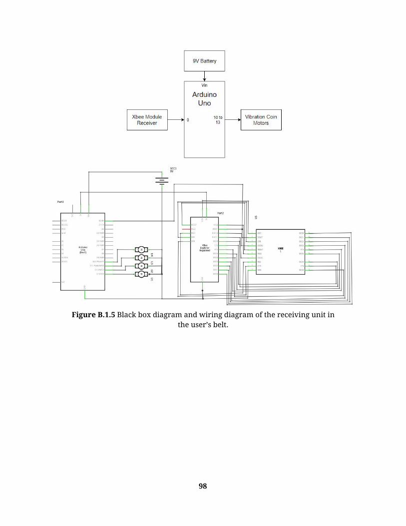
Figure B.1.5 Black box diagram and wiring diagram of the receiving unit in
the user’s belt.
98

Figure B.1.6 Detailed drawings of one half of the first sensor housing prototype.
99

Figure B.1.7 Detailed drawings of half of the side sensor housing for the final prototype.
Figure B.1.8 Detailed drawings of half of the side sensor housing for the final prototype.
100

Figure B.1.9 Detailed drawings of the front sensor housing for the final prototype.
101

B.2. Prototype Datasheets & Code Link to HC-SR04 Ultrasonic Sensor’s Datasheet: https://cdn.sparkfun.com/datasheets/Sensors/Proximity/HCSR04.pdf
Figure B.2.1. Electrical Characteristics of the HC-SR04 Ultrasonic Sensor for
its datasheet.
Motor Testing Code: const int motorPin1 = 3; //digital pin 3,other end goes to ground; front right
const int motorPin2 = 4; // back right
const int motorPin3 = 5; // back left
const int motorPin4 = 6; // front left
void setup()
{
pinMode(motorPin1,OUTPUT);
pinMode(motorPin2,OUTPUT);
pinMode(motorPin3,OUTPUT);
102

pinMode(motorPin4,OUTPUT);
}
void loop()
{
delay(6000);
digitalWrite(motorPin1, HIGH); //1
delay(800);
digitalWrite(motorPin1,LOW); //1 off
delay(3000);
digitalWrite(motorPin2, HIGH); //2
delay(5000);
digitalWrite(motorPin2,LOW); //2 off
delay(1000);
digitalWrite(motorPin2, HIGH); //2
digitalWrite(motorPin1, HIGH); //1
delay(5000);
digitalWrite(motorPin1,LOW); //1 off
delay(100);
digitalWrite(motorPin2,LOW); //2 off
delay(1000);
digitalWrite(motorPin4, HIGH); //4
digitalWrite(motorPin1, HIGH); //1
delay(4500);
digitalWrite(motorPin4,LOW); //4 off
digitalWrite(motorPin1,LOW); //1 off
delay(100);
digitalWrite(motorPin3, HIGH); //3
delay(100);
digitalWrite(motorPin2, HIGH); //2
delay(6000);
digitalWrite(motorPin2, LOW); //2 off
delay(3500);
digitalWrite(motorPin3, LOW); //3 off
delay(4500);
digitalWrite(motorPin3, HIGH); //3
digitalWrite(motorPin4, HIGH); //4
103

delay(3500);
digitalWrite(motorPin4,LOW); //4 off
delay(1000);
digitalWrite(motorPin3,LOW); //3 off
delay(5000);
digitalWrite(motorPin3, HIGH); //3
delay(1500);
digitalWrite(motorPin2, HIGH); //2
delay(3000);
digitalWrite(motorPin3,LOW); //3 off
delay(1000);
digitalWrite(motorPin2,LOW); //2 off
delay(8000);
}
104

C. Final Design Documents
C.1. Final Design Drawings
Figure C.1.1 The wiring diagram of the front sensor box with ultrasonic
sensors and XBee module.
105

Figure C.1.2 The wiring diagram of the right side sensor box with
ultrasonic sensors and XBee module.
Figure C.1.3 The wiring diagram of the motors in the vibro-belt with NPNs,
resistors, and diodes.
106
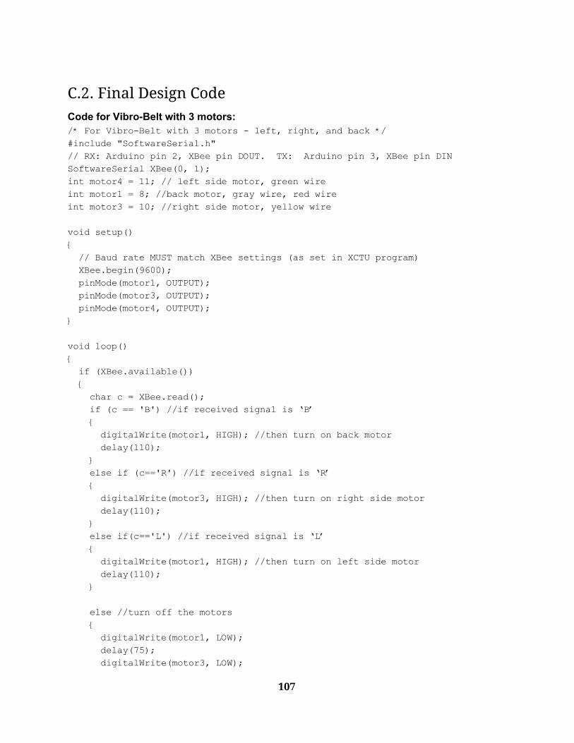
C.2. Final Design Code Code for Vibro-Belt with 3 motors: /* For Vibro-Belt with 3 motors - left, right, and back */
#include "SoftwareSerial.h"
// RX: Arduino pin 2, XBee pin DOUT. TX: Arduino pin 3, XBee pin DIN
SoftwareSerial XBee(0, 1);
int motor4 = 11; // left side motor, green wire
int motor1 = 8; //back motor, gray wire, red wire
int motor3 = 10; //right side motor, yellow wire
void setup()
{
// Baud rate MUST match XBee settings (as set in XCTU program)
XBee.begin(9600);
pinMode(motor1, OUTPUT);
pinMode(motor3, OUTPUT);
pinMode(motor4, OUTPUT);
}
void loop()
{
if (XBee.available())
{
char c = XBee.read();
if (c == 'B') //if received signal is ‘B’
{
digitalWrite(motor1, HIGH); //then turn on back motor
delay(110);
}
else if (c=='R') //if received signal is ‘R’
{
digitalWrite(motor3, HIGH); //then turn on right side motor
delay(110);
}
else if(c=='L') //if received signal is ‘L’
{
digitalWrite(motor1, HIGH); //then turn on left side motor
delay(110);
}
else //turn off the motors
{
digitalWrite(motor1, LOW);
delay(75);
digitalWrite(motor3, LOW);
107
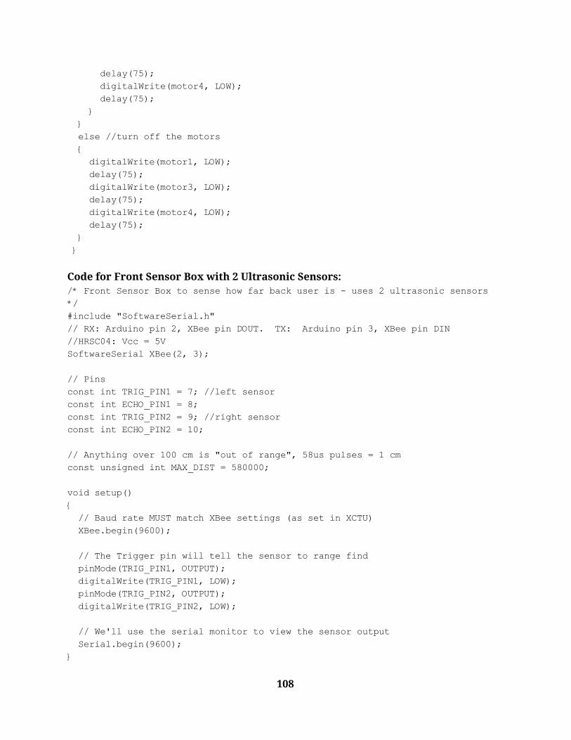
delay(75);
digitalWrite(motor4, LOW);
delay(75);
}
}
else //turn off the motors
{
digitalWrite(motor1, LOW);
delay(75);
digitalWrite(motor3, LOW);
delay(75);
digitalWrite(motor4, LOW);
delay(75);
}
}
Code for Front Sensor Box with 2 Ultrasonic Sensors: /* Front Sensor Box to sense how far back user is - uses 2 ultrasonic sensors
*/
#include "SoftwareSerial.h"
// RX: Arduino pin 2, XBee pin DOUT. TX: Arduino pin 3, XBee pin DIN
//HRSC04: Vcc = 5V
SoftwareSerial XBee(2, 3);
// Pins
const int TRIG_PIN1 = 7; //left sensor
const int ECHO_PIN1 = 8;
const int TRIG_PIN2 = 9; //right sensor
const int ECHO_PIN2 = 10;
// Anything over 100 cm is "out of range", 58us pulses = 1 cm
const unsigned int MAX_DIST = 580000;
void setup()
{
// Baud rate MUST match XBee settings (as set in XCTU)
XBee.begin(9600);
// The Trigger pin will tell the sensor to range find
pinMode(TRIG_PIN1, OUTPUT);
digitalWrite(TRIG_PIN1, LOW);
pinMode(TRIG_PIN2, OUTPUT);
digitalWrite(TRIG_PIN2, LOW);
// We'll use the serial monitor to view the sensor output
Serial.begin(9600);
}
108

void loop()
{
unsigned long t1, t2, t3, t4;
unsigned long pulse_width1, pulse_width2;
float cm1, cm2;
float inches1, inches2;
// Hold the trigger pin high for at least 10 us
digitalWrite(TRIG_PIN1, HIGH);
delayMicroseconds(10);
digitalWrite(TRIG_PIN1, LOW);
// Wait for pulse on echo pin
while ( digitalRead(ECHO_PIN1) == 0);
// Measure how long the echo pin was held high (pulse width)
// Note: the micros() counter will overflow after ~70 min
t1 = micros();
while ( digitalRead(ECHO_PIN1) == 1);
t2 = micros();
pulse_width1 = t2 - t1;
/* Calculate distance in centimeters and inches. The constants
are found in the datasheet, and calculated from the assumed speed
of sound in air at sea level (~340 m/s). */
cm1 = pulse_width1 / 58.0;
inches1 = pulse_width1 / 148.0;
delayMicroseconds(10); //Added for the 2nd sensor
digitalWrite(TRIG_PIN2, HIGH);
delayMicroseconds(10);
digitalWrite(TRIG_PIN2, LOW);
while ( digitalRead(ECHO_PIN2) == 0);
t3 = micros();
while( digitalRead(ECHO_PIN2) == 1);
t4 = micros();
pulse_width2 = t4 - t3;
cm2 = pulse_width2 / 58.0;
inches2 = pulse_width2 / 148.0;
//MAIN LOGIC RIGHT HERE TO CHANGE THE DISTANCES AROUND
//if the user is within less than 48in and past 25in of the sensors, the motor
goes off
if ((inches2 > 25 && inches2 < 48)||(inches1 > 25 && inches1 <48)){ //checks
if too far back
109

XBee.write('B'); //sends a signal to XBee receiver in belt to turn on back
motor
delay(50);
}
// Print out results
if ( (pulse_width1 > MAX_DIST) & (pulse_width2 > MAX_DIST)) {
Serial.println("Out of range");
}
else if ((inches1 < 60) & (inches2 < 60) ) {
Serial.print(inches1);
Serial.print(" in1 \t");
Serial.print(inches2);
Serial.println(" in2 \t");
}
else{
exit;
}
// Wait at least 100ms before next measurement
delay(60);
}
Code for Right Side Sensor Box with 3 Ultrasonic Sensors: /* Right Side Sensor Box to sense how far right and left user is - uses 3
ultrasonic sensors */
#include "SoftwareSerial.h"
// RX: Arduino pin 2, XBee pin DOUT. TX: Arduino pin 3, XBee pin DIN
//HRSC04: Vcc = 5V
SoftwareSerial XBee(2, 3);
// Pins
const int TRIG_PIN1 = 9; //middle sensor
const int ECHO_PIN1 = 10;
const int TRIG_PIN2 = 11; //back sensor
const int ECHO_PIN2 = 12;
const int TRIG_PIN3 = 7; //front sensor
const int ECHO_PIN3 = 8;
// Anything over 400 cm (23200 us pulse) is "out of range", 58us pulses = 1 cm
const unsigned int MAX_DIST = 580000;
void setup()
{
// Baud rate MUST match XBee settings (as set in XCTU program)
XBee.begin(9600);
// The Trigger pin will tell the sensor to range find
110

pinMode(TRIG_PIN1, OUTPUT);
digitalWrite(TRIG_PIN1, LOW);
pinMode(TRIG_PIN2, OUTPUT);
digitalWrite(TRIG_PIN2, LOW);
pinMode(TRIG_PIN3, OUTPUT);
digitalWrite(TRIG_PIN3, LOW);
// We'll use the serial monitor to view the sensor output
Serial.begin(9600);
}
void loop()
{
unsigned long t1, t2, t3, t4, t5, t6;
unsigned long pulse_width1, pulse_width2, pulse_width3;
float cm1, cm2, cm3;
float inches1, inches2, inches3;
// Hold the trigger pin high for at least 10 us
digitalWrite(TRIG_PIN1, HIGH);
delayMicroseconds(10);
digitalWrite(TRIG_PIN1, LOW);
// Wait for pulse on echo pin
while ( digitalRead(ECHO_PIN1) == 0);
// Measure how long the echo pin was held high (pulse width)
// Note: the micros() counter will overflow after ~70 min
t1 = micros();
while ( digitalRead(ECHO_PIN1) == 1);
t2 = micros();
pulse_width1 = t2 - t1;
/* Calculate distance in centimeters and inches. The constants
are found in the datasheet, and calculated from the assumed speed
of sound in air at sea level (~340 m/s). */
cm1 = pulse_width1 / 58.0;
inches1 = pulse_width1 / 148.0;
delayMicroseconds(10); //Added for 2nd sensor
digitalWrite(TRIG_PIN2, HIGH);
delayMicroseconds(10);
digitalWrite(TRIG_PIN2, LOW);
while ( digitalRead(ECHO_PIN2) == 0);
t3 = micros();
while( digitalRead(ECHO_PIN2) == 1);
t4 = micros();
pulse_width2 = t4 - t3;
111

cm2 = pulse_width2 / 58.0;
inches2 = pulse_width2 / 148.0;
delayMicroseconds(10); //Added for 3rd sensor
digitalWrite(TRIG_PIN3, HIGH);
delayMicroseconds(10);
digitalWrite(TRIG_PIN3, LOW);
while ( digitalRead(ECHO_PIN3) == 0);
t5 = micros();
while( digitalRead(ECHO_PIN3) == 1);
t6 = micros();
pulse_width3 = t6 - t5;
cm3 = pulse_width3 / 58.0;
inches3 = pulse_width3 / 148.0;
//if the user is within less than 8in of the any of the sensors, the right
motor goes off
if(inches1 <8 || inches2 <8 || inches3 <8){
XBee.write('R'); //Sends an ‘R’ to the XBee receiver
delay(20);
}
//If the user is within 14’’ to 18’’ of any of the sensors, then the left motor
goes off
else if ((inches1 > 14 && inches1 <18) || (inches2 > 14 && inches2 <18) ||
(inches3 > 14 && inches3 < 18)){
XBee.write('L'); //Sends an ‘L’ to the XBee receiver
delay(20);
}
// Print out results
if ( (pulse_width1 > MAX_DIST) & (pulse_width2 > MAX_DIST)) {
Serial.println("Out of range");
}
else if ((inches1 < 40) & (inches2 < 40) & (inches3 < 40) ) {
Serial.print(inches1);
Serial.print(" in1 \t");
Serial.print(inches2);
Serial.println(" in2 \t");
Serial.print(inches3);
Serial.println(" in3 \t");
}
else{
exit;
}
// Wait at least 100ms before next measurement
delay(40);
}
112

C.3. User Product Guide
C.3.1. Starting the Device 1. Arrive at the local gym, approach the respective treadmill and remove all three
components from the backpack. 2. Begin by grabbing the smaller of the two housings and approach the front railing
of the treadmill. a. Ensure that the velcro straps sticking out the front and back of the housing
are approximately the same length. i. If not, pull the strap towards the shorter length until both ends are
approximately even. b. Undo the velcro straps from each other if stuck together. c. With one hand, hold the box securely against the underside of the treadmill
quick start interface and using your free hand attach one of the velcro straps around the railing to itself.
i. Make sure that the box is secure against the bottom of the interface and is not hanging freely underneath, in order to ensure correct orientation.
d. Swap whichever hand was previously holding the housing secure and now use your new free hand to attach the other velcro strap around the railing to itself.
e. Ensure that the device is now underneath and secure to the bottom of the quick start interface.
i. A small amount of free hanging is fine, as long as the device is pointed parallel to the treadmill belt.
f. MAKE SURE YOU DO NOT TURN THE DEVICE ON YET!! 3. Next, grab the larger of the two housings and approach the right side railing of the
treadmill. a. Ensure that there are 4 velcro pieces equally spaced apart along the top
surface of the housing. b. Ensure that the velcro straps sticking out the front and back of the housing
are approximately the same length. i. If not, pull the strap towards the shorter length until both ends are
approximately even. c. Undo the velcro straps from each other if stuck together. d. Locate the 4 velcro pieces located on the underside of the treadmill arm. e. Match the velcro pieces along the top of the housing to the pieces along the
underside of the treadmill arm and press together.
113

f. Using one hand to hold the housing secure to the underside of the arm, grab one of the velcro straps with your free hand and secure the strap to itself over the top of the arm.
g. Swap whichever hand was previously holding the housing secure and now use your new free hand to attach the other velcro strap to itself over the top of the arm.
h. MAKE SURE YOU DO NOT TURN THE DEVICE ON YET!! 4. Lastly, grab the vibro-belt and approach the treadmill.
a. Ensure that the female buckles are on the right side and the zipper is pointed away from the body.
b. With female buckles in right hand and male buckles in left hand, push them together until a click is heard to ensure security.
c. With the belt now around the users waist, adjust the 4 adjustability sliders until proper tightness is achieved.
d. MAKE SURE YOU DO NOT TURN THE DEVICE ON YET!!
C.3.2. Calibration 1. With all components now setup and attached, and the user standing inside the
ranges of both housings on the treadmill facing the interface, devices can be turned on.
2. Begin by turning on the sensor housings. a. Find the toggle power switch on the front face of the front housing and
push the top half in to activate power. i. The top half can be identified with a bump on it.
b. Find the toggle power switch on the left side of the front face of the side housing and push the top half in to activate power.
i. The top half can be identified with a bump on it. 3. With power activated to both housing systems, find the power switch on the right
side of the belt through the material and push the top half in to activate power. 4. Before continuing with the workout, move to the right side, left side, and back of
the treadmill to ensure signals are being sent to each motor. If a motor isn’t felt when you move in that direction, try powering the respective device as well as the belt down and back on to reset.
5. With all devices calibrated, proceed with workout.
C.3.3. Turning Off and Disassembly 1. Once the workout is complete, make sure you do not leave the treadmill as doing
so could result in random signals and vibrations. 2. Begin by turning off all of the power switches on each of the 3 devices. 3. Remove the buckles of the belt and secure the device somewhere where it can’t be
damaged.
114
4. Remove the velcro straps of both housings and remove them from the treadmill arms.
5. Place all components back into the backpack.
C.3.4. Charging the Devices 1. Ensure that you are recharging the device after every use to create maximum
system reliability and functionality. 2. Begin by bringing the devices to charging station at users residence. 3. Find the power bank along the backside of the sensor housings.
a. Plug the micro usb ends into the IN ports located directly next to the OUT ports on the same face of the power banks.
4. Open up the zipper of the vibro-belt and locate the power bank on the right side of the device.
a. Plug the micro usb end into the IN port located directly next to the OUT port on the same face of the power bank.
5. With all devices charging, allow at least 2 hours of charging before following use.
115