Transport and Main Roads Specifications MRTS252 Next ...
52
Technical Specification Transport and Main Roads Specifications MRTS252 Next Generation Traffic Signal Controllers November 2019
-
Upload
khangminh22 -
Category
Documents
-
view
4 -
download
0
Transcript of Transport and Main Roads Specifications MRTS252 Next ...

Technical Specification Transport and Main Roads Specifications MRTS252 Next Generation Traffic Signal Controllers November 2019

Transport and Main Roads Specifications, November 2019
Copyright
© The State of Queensland (Department of Transport and Main Roads) 2019. Licence
This work is licensed by the State of Queensland (Department of Transport and Main Roads) under a Creative Commons Attribution (CC BY) 4.0 International licence. CC BY licence summary statement In essence, you are free to copy, communicate and adapt this work, as long as you attribute the work to the State of Queensland (Department of Transport and Main Roads). To view a copy of this licence, visit: https://creativecommons.org/licenses/by/4.0/ Translating and interpreting assistance
The Queensland Government is committed to providing accessible services to Queenslanders from all cultural and linguistic backgrounds. If you have difficulty understanding this publication and need a translator, please call the Translating and Interpreting Service (TIS National) on 13 14 50 and ask them to telephone the Queensland Department of Transport and Main Roads on 13 74 68.
Disclaimer While every care has been taken in preparing this publication, the State of Queensland accepts no responsibility for decisions or actions taken as a result of any data, information, statement or advice, expressed or implied, contained within. To the best of our knowledge, the content was correct at the time of publishing. Feedback Please send your feedback regarding this document to: [email protected]

Transport and Main Roads Specifications, November 2019 i
Contents
1 Introduction ....................................................................................................................................1
2 Definition of terms .........................................................................................................................1
3 Referenced documents .................................................................................................................3
4 Quality system requirements .......................................................................................................5
5 General requirements ....................................................................................................................5
5.1 Primary requirements ..................................................................................................................... 5
5.2 Operating conditions ....................................................................................................................... 5
5.3 Storage conditions .......................................................................................................................... 6
6 Controller housing .........................................................................................................................6
6.1 Introduction ..................................................................................................................................... 6
6.2 Physical requirements and equipment layout ................................................................................. 6 6.2.1 TSC main cabinet ...........................................................................................................6 6.2.2 TSC cabinet extension ...................................................................................................7
6.3 CyberLocks ..................................................................................................................................... 9 6.3.1 Installation of CyberLocks ..............................................................................................9 6.3.2 Programming CyberLocks ..............................................................................................9 6.3.3 Cyberkeys .......................................................................................................................9
6.4 Housing construction ...................................................................................................................... 9
6.5 Cable clamping bars ..................................................................................................................... 10
6.6 Switchboard .................................................................................................................................. 10
6.7 Field terminal blocks ..................................................................................................................... 10
6.8 GPS sensor ................................................................................................................................... 11
6.9 Flashing yellow override for emergency services ......................................................................... 11
6.10 Master relay and auxiliary relay .................................................................................................... 11
6.11 Flash change-over relays ............................................................................................................. 11
6.12 Flasher unit ................................................................................................................................... 12
6.13 Miscellaneous relays and contactors ............................................................................................ 12
6.14 Audio-Tactile supply circuit ........................................................................................................... 12
6.15 Site identification encoder ............................................................................................................. 12
6.16 Telecommunications interface ...................................................................................................... 12
6.17 Light sensor .................................................................................................................................. 13
6.18 Housing door switch ..................................................................................................................... 13
6.19 Extra low voltage output ............................................................................................................... 13
6.20 Service light .................................................................................................................................. 13
6.21 Wiring and connectors .................................................................................................................. 13
6.22 Information to be provided in the housing .................................................................................... 14
6.23 Stand-by generator connection ..................................................................................................... 14
7 Controller logic module ............................................................................................................. 14
7.1 Introduction ................................................................................................................................... 14

Transport and Main Roads Specifications, November 2019 ii
7.2 System overview ........................................................................................................................... 15
7.3 CPU module .................................................................................................................................. 15
7.4 Human machine interfaces ........................................................................................................... 16
7.5 Interface to controller hardware .................................................................................................... 16
7.6 Physical conflict monitoring system .............................................................................................. 16
7.7 Fault / error monitoring and response .......................................................................................... 17
7.8 Selecting groups for signal flashing .............................................................................................. 17
7.9 Lamp monitoring ........................................................................................................................... 17
7.10 Safety and integrity functions ........................................................................................................ 17
7.11 Power supplies.............................................................................................................................. 18
7.12 Log collection ................................................................................................................................ 18
7.13 Controller remote monitoring ........................................................................................................ 18
7.14 Network time protocol ................................................................................................................... 18
7.15 Digital I/O ...................................................................................................................................... 19
8 Networking and security requirements .................................................................................... 19
8.1 Security requirements ................................................................................................................... 19 8.1.1 Overarching requirements ........................................................................................... 19 8.1.2 Controller management requirements ......................................................................... 20 8.1.3 Authentication and credential management ................................................................ 20
8.2 Networking requirements .............................................................................................................. 21
9 Electrical and functional equipment requirements ................................................................. 22
9.1 ERAC safety ................................................................................................................................. 22
9.2 Nominal supply ............................................................................................................................. 22
9.3 Operating range ............................................................................................................................ 22
9.4 Voltage dip .................................................................................................................................... 22
9.5 Electrical safety ............................................................................................................................. 22
9.6 Earthing requirements .................................................................................................................. 23
9.7 Electrical Circuits .......................................................................................................................... 23
9.8 Electromagnetic compatibility ....................................................................................................... 23
9.9 Components.................................................................................................................................. 24 9.9.1 General requirements .................................................................................................. 24 9.9.2 Lamp outputs ............................................................................................................... 24 9.9.3 Pedestrian countdown timer ........................................................................................ 24 9.9.4 Loop detectors ............................................................................................................. 25 9.9.5 Transformers ............................................................................................................... 25 9.9.6 Fuses ........................................................................................................................... 25 9.9.7 Switches and contactors ............................................................................................. 25 9.9.8 Printed circuit boards ................................................................................................... 25 9.9.9 Master relay and auxiliary relay ................................................................................... 26 9.9.10 Facility switch function ................................................................................................. 26 9.9.11 Independent flashing unit and flash change-over relay............................................... 27 9.9.12 Miscellaneous relays and contactors .......................................................................... 27 9.9.13 Audio-Tactile supply circuit .......................................................................................... 27 9.9.14 Communications interface ports .................................................................................. 27 9.9.15 Labels .......................................................................................................................... 28

Transport and Main Roads Specifications, November 2019 iii
9.10 Office testing unit .......................................................................................................................... 28
9.11 On-site testing facility .................................................................................................................... 28
9.12 Site identifier ................................................................................................................................. 28
10 STREAMS interface .................................................................................................................... 28
10.1 Introduction ................................................................................................................................... 28
10.2 Request messages – Controller status information ...................................................................... 29 10.2.1 Signal group colour...................................................................................................... 29 10.2.2 Report detector volume ............................................................................................... 29 10.2.3 Report detector occupancy ......................................................................................... 29 10.2.4 Vehicle and pedestrian demands ................................................................................ 29 10.2.5 Phase demands ........................................................................................................... 29 10.2.6 Current phase sequence timer .................................................................................... 29 10.2.7 Current sequence timer for pedestrian signal groups ................................................. 30 10.2.8 Read special facility flags ............................................................................................ 30 10.2.9 Controller hardware and firmware status .................................................................... 30 10.2.10 Lamp faults .................................................................................................................. 30 10.2.11 Lamp watts .................................................................................................................. 30 10.2.12 Dimmer state report ..................................................................................................... 30 10.2.13 Read fault and/or error log .......................................................................................... 30 10.2.14 Notify of a fault ............................................................................................................. 30 10.2.15 Detector faults ............................................................................................................. 31 10.2.16 ‘Police Panel’ status .................................................................................................... 31 10.2.17 Site ID and revision ..................................................................................................... 31 10.2.18 Heartbeat ..................................................................................................................... 31 10.2.19 Read clock ................................................................................................................... 31 10.2.20 Read time setting data ................................................................................................ 31
10.3 Command messages – Controller state change .......................................................................... 31 10.3.1 Phase control ............................................................................................................... 31 10.3.2 Terminate walk ............................................................................................................ 31 10.3.3 Pedestrian automatic demand ..................................................................................... 31 10.3.4 Release for termination by Vehicle Actuation (V/A) control ........................................ 31 10.3.5 Next phase .................................................................................................................. 32 10.3.6 Set special facility switches ......................................................................................... 32 10.3.7 Set controller mode ..................................................................................................... 32 10.3.8 Reset fault log .............................................................................................................. 32 10.3.9 Set / override detector fault ......................................................................................... 32 10.3.10 Establish communications ........................................................................................... 32 10.3.11 Set clock ...................................................................................................................... 32 10.3.12 Set time setting data (RAM) ........................................................................................ 32
11 Software and functional traffic requirements .......................................................................... 33
11.1 Introduction ................................................................................................................................... 33
11.2 Start-up requirements ................................................................................................................... 33
11.3 Traffic control operation ................................................................................................................ 33 11.3.1 Vehicle detection ......................................................................................................... 34 11.3.2 Pedestrian detection .................................................................................................... 34 11.3.3 Time settings ............................................................................................................... 35 11.3.4 Start-up sequence ....................................................................................................... 35 11.3.5 Sequence of signal displays in signal face .................................................................. 35 11.3.6 Basic Vehicle Actuated Operation ............................................................................... 35 11.3.7 Isolated fixed time operation ....................................................................................... 36 11.3.8 Local coordinated operation ........................................................................................ 36 11.3.9 Fall back plans ............................................................................................................. 36 11.3.10 Area traffic control mode ............................................................................................. 36 11.3.11 Vehicle movements ..................................................................................................... 37

Transport and Main Roads Specifications, November 2019 iv
11.3.12 Pedestrian movements ................................................................................................ 37 11.3.13 Pedestrian clearance period ........................................................................................ 37 11.3.14 Filter movements ......................................................................................................... 37 11.3.15 Pedestrian protection .................................................................................................. 37 11.3.16 Smart pedestrian crossing ........................................................................................... 38 11.3.17 Right turn trap .............................................................................................................. 38 11.3.18 Detector fault monitoring ............................................................................................. 38 11.3.19 Red light runner extension .......................................................................................... 38 11.3.20 Train phase operation ................................................................................................. 38 11.3.21 Train phase conflict management ............................................................................... 38 11.3.22 Signal group green in multiple phases ........................................................................ 38 11.3.23 C-ITS readiness ........................................................................................................... 38
11.4 Interface to a coordination master ................................................................................................ 38
11.5 Software conflict monitoring system ............................................................................................. 39
11.6 Configuration software and data ................................................................................................... 39
11.7 Configuration software updates .................................................................................................... 40
11.8 System integrity protection ........................................................................................................... 40
12 Cooperative Intelligent Transport Systems (C-ITS) interface ................................................ 40
12.1 Introduction ................................................................................................................................... 40
12.2 Requirements................................................................................................................................ 40
13 Testing ......................................................................................................................................... 41
14 Quality assurance ....................................................................................................................... 41
15 Warranty provisions ................................................................................................................... 41
16 Training requirements ................................................................................................................ 41
16.1 Post-commissioning ...................................................................................................................... 42
16.2 Maintenance training .................................................................................................................... 42
17 Maintenance requirements ........................................................................................................ 42
18 Handover requirements ............................................................................................................. 42
Appendix A –Transport and Main Roads Product Preferences...................................................... 43
Appendix B – Facility switch operational plate ................................................................................ 44
Appendix C – Example of Switchboard Wiring ................................................................................ 45

Technical Specification, MRTS252 Next Generation Traffic Signal Controllers
Transport and Main Roads Specifications, November 2019 1
1 Introduction
This Technical Specification specifies the minimum / mandatory and desirable requirements for permanently installed Traffic Signal Controllers (TSC) for the state of Queensland.
The term ‘shall’ has been used throughout this document to denote a mandatory or binding requirement.
The term ‘should’ has been used to denote a desirable requirement. These requirements are not mandatory but will be viewed favourably by Transport and Main Roads.
Where the wording or parameters are deemed insufficient, offerors may contact Transport and Main Roads for clarification via [email protected].
This Technical Specification shall be read in conjunction with MRTS01 Introduction to Technical Specifications, MRTS50 Specific Quality System Requirements and other Technical Specifications as appropriate. This Technical Specification forms part of the Transport and Main Roads Specifications Manual.
2 Definition of terms
Table 2 defines relevant acronyms and technical terms used throughout this document. Refer to Australian Standard AS 2578 Traffic Signal Controllers for controller related terms. Refer also to the Austroads Glossary of Terms (2015 Edition) for Traffic Engineering terms that may be specific to Australia. Other terms, not related to traffic, are as defined in the relevant Australian Standards listed in Clause 3 of this Technical Specification.
Table 2 - Definitions
Term Definition
Australian Communications and Media Authority (ACMA)
The body responsible for ensuring communications and media meets regulations.
AS/NZS Australian and New Zealand Standards
C-ITS Cooperative Intelligent Transport Systems
Controller All references to “controller” are an abbreviation for Traffic Signal Controller.
CyberLock A proprietary key-centric access control system which Transport and Main Roads has implemented for cabinet access across the network. The system is comprised of electronic lock cylinders and programmable smart keys, known as CyberLock Cylinders and CyberKeys respectively.
Design Life The expected time that a piece of hardware, software or a system should remain operational commencing from the date it was commissioned.
Electrical Legislation Electrical Safety Act 2002, Electricity Act 1994, and all associated Regulations and Codes of Practice.
ERAC Electrical Regulatory Authorities Council
EMC Electromagnetic Compatibility
Extra Low Voltage (ELV) Extra Low Voltage as defined in AS/NZS 3000 Electrical installations.

Technical Specification, MRTS252 Next Generation Traffic Signal Controllers
Transport and Main Roads Specifications, November 2019 2
Term Definition
Error An abnormal condition or failure detected which does not compromise the safety of the intersection.
Emergency Vehicle Priority (EVP)
Is technology that enables emergency vehicles to automatically trigger traffic light sequences to change along the most direct route when responding to an emergency call.
Facility Switch A 2-position momentary switch on the outside of the cabinet used to manually set the physical signal output to normal operation or flashing yellow.
Fault A condition or failure detected which compromises the safety of the intersection.
Field Processor An industrial computer that complies with the requirements of MRTS232 Provision of Field Processors.
Gap Out Where a phase terminates as a result of a lack of vehicle demands within a specific period of time.
HMI Human Machine Interface
I/O Input(s)/Output(s)
ICT Information and Communications Technology
IPxx International Protection (IP) rating to degree “xx” as defined by AS 60529 Degrees of protection provided by enclosures.
ITS Intelligent Transport System
Low Voltage (LV) Low Voltage as defined in AS/NZS 3000 Electrical installations.
MEN Multiple Earthed Neutral
MRTS Transport and Main Roads Technical Specifications
MTBF Mean Time Between Failure
NATA National Association of Testing Authorities, Australia
NGTSC Next Generation Traffic Signal Controller
PCB Printed Circuit Board
Phase As per AS 2578 Traffic Signal Controllers, a phase is a set of compatible traffic movements controlled by signal groups. Note that this definition varies internationally.
Residual Current Device (RCD)
An electrical safety device which disconnects a circuit upon detection of an imbalance between the active and neutral conductors.
Recall A detection mode where a signal group or phase will not be skipped every cycle but is only called for the minimum green period specified by the user.
RPEQ Registered Professional Engineer of Queensland
SAT STREAMS Acceptance Test
Signal Face A set of signal aspects in a common assembly, generally in one or two columns, placed together with a target board to improve signal visibility, and facing traffic from one direction.
Safety Integrated Level (SIL) As defined in AS 61508 / IEC 61508 Functional Safety of Electrical/Electronic/Programmable Electronic Safety-related System.

Technical Specification, MRTS252 Next Generation Traffic Signal Controllers
Transport and Main Roads Specifications, November 2019 3
Term Definition
Signal Phase and Timing (SPaT)
A recognised C-ITS function.
STREAMS STREAMS Integrated Intelligent Transport System. The Principal’s traffic management system primary user interface to ITS field devices.
Telecommunications Field Cabinet
An enclosure that complies with MRTS226 Telecommunications Field Cabinets.
TMR Queensland Department of Transport and Main Roads
TRAFF The latest release of the standard NSW Roads and Maritime Services traffic control software.
Traffic Signal Controller (TSC)
Also referred to as ‘controller’.
Traffic Signal Controller (TSC) Cabinet Extension
An electrical enclosure used for ancillary equipment that is placed on the top of a traffic signal cabinet. Also known as a “top-hat”.
3 Referenced documents
Table 3 lists documents referenced in this Technical Specification.
Table 3 – Referenced documents
Reference Title
ANSI/IPC-A-600H Acceptability of Printed Boards
ANSI/IPC-A-610E Acceptability of Electronic Assemblies
AS 2578 Traffic Signal Controllers
AS 2703 Vehicle loop detector sensors
AS 31000 Risk Management
AS 60068.2 Environmental Testing
AS 60529 Degrees of protection provided by enclosures (IP Code)
AS 61508 Functional Safety of Electrical/Electronic/Programmable Electronic Safety-related Systems
AS IEC 61000.4.5 Electromagnetic compatibility (EMC) - Testing and measurement techniques - Surge immunity test, Level 3
AS IEC 6100.4.6 Electromagnetic compatibility (EMC) - Testing and measurement techniques - Immunity to conducted disturbances, induced by radio-frequency fields
AS/NZS 2276 Cables for traffic signal installations
AS/NZS 2276.2 Cables for traffic signal installations - Feeder cable for vehicle detectors
AS/NZS 3000 Electrical installations (known as the Australian/New Zealand Wiring Rules)
AS/NZS 5000.1 Electric cables - Polymeric insulated Part 1: For working voltages up to and including 0.6/1 (1.2) kV
AS/NZS 60076 Power Transformers
AS/NZS 60335.1 Household and similar electrical appliances - Safety - General requirements

Technical Specification, MRTS252 Next Generation Traffic Signal Controllers
Transport and Main Roads Specifications, November 2019 4
Reference Title
AS/NZS 61000 Electromagnet Compatibility
AS/NZS 61000.4.11 Electromagnetic compatibility (EMC) - Testing and measurement techniques - Voltage dips, short interruptions and voltage variations immunity tests, Level 3
AS/NZS IEC 61000.4.2 Electromagnetic compatibility (EMC) - Testing and measurement techniques - Electrostatic discharge immunity test, Level 3
AS/NZS IEC 61000.4.3 Electromagnetic compatibility (EMC) - Testing and measurement techniques - Radiated, radio-frequency, electromagnetic field immunity test
AS/NZS IEC 61000.4.4 Electromagnetic compatibility (EMC) - Testing and measurement techniques - Electrical fast transient/burst immunity test, Level 3
AS/NZS or IEC 61000.4.8 Electromagnetic compatibility (EMC) - Testing and measurement techniques - Power frequency magnetic field immunity test (mains at 50Hz)
AS/NZS or IEC 61000.6.4 Electromagnetic compatibility (EMC) - Generic standards - Emission standard for industrial environments, (CISPR22:2009-Class A)
AS/NZS ISO 9000 Quality management systems - Fundamentals and vocabulary
ETSI EN 302 665 V1.1.1 Intelligent Transport Systems (ITS); Communications Architecture
IEC 60068.2 Environmental Testing
IEC 60194 Printed board design, manufacture and assembly
IEC 61000 Electromagnet Compatibility
IEC 61508 Functional Safety of Electrical/Electronic/Programmable Electronic Safety-related Systems
IPC 6010 Printed Board Performance Specifications
IPC-SM-840D Qualification and Performance Specification of Permanent Solder Mask
ISO 780 Packaging - Pictorial marking for the handling of packages
ISO/TS 19091 Intelligent transport systems - Cooperative ITS Using V2I and I2V communications for applications related to signalized intersections
J2735 Dedicated Short Range Communications (DSRC) Message Set Dictionary, (March 2016)
MRTS01 Introduction to Technical Specifications
MRTS50 Specific Quality System Requirements
MRTS201 General Equipment Requirements
MRTS226 Telecommunications Field Cabinets
MRTS232 Provision of Field Processors
MRTS253 Traffic Signal Lanterns
Standard Drawing 1423 Traffic signals - Traffic Signal Controller base installation details
- Austroads Glossary of Terms (2015 Edition)
- Austroads Guide to Traffic Management: Part 9 - Traffic Operations
- Austroads Guide to Traffic Management: Part 10 - Traffic Control and Communication Devices

Technical Specification, MRTS252 Next Generation Traffic Signal Controllers
Transport and Main Roads Specifications, November 2019 5
4 Quality system requirements
The offeror shall submit information regarding the life and quality of the products offered. All claims in relation to lifespan, reliability, maintainability etc. shall be in accordance with the terms and definitions of AS/NZS ISO 9000.
Each controller supplied shall include a manufacturing schedule so approved by Queensland Transport and Main Roads. This manufacturing schedule shall detail all elements of the complete build as supplied including each item of the physical assembly, wiring interconnection and appropriate notes relevant to any departure from the approved schedule. This schedule of items includes provision for acknowledgement adjacent to the item and provision for a signatory acknowledgement.
5 General requirements
5.1 Primary requirements
The offeror shall meet the following overarching requirements:
a) procedures and systems shall be in place to ensure compliance with a minimum of a SIL2 rating, as per IEC 61508
b) the TSC and all configuration tools shall be compatible with left-hand drive operation (that is, vehicles drive on the left side of the road)
c) all measurements shall be metric (metres, grams, etc.), except for those known internationally in other units (for instance, a 19” rack)
d) all documentation and software interfaces shall be in English
e) sales support and ongoing customer support shall be available in English
f) all compliance standards as stated in Table 3, and
g) ERAC compliance as required to facilitate application of the RCM logo. (This is a legal requirement in Australia).
5.2 Operating conditions
The TSC and associated equipment shall operate correctly and accurately with lanterns as described in MRTS253 Traffic Signal Lanterns and with an ingress protection of IP45 for the TSC cabinet and IP4X for the logic module, as per AS 60529 / IEC 60529 Degrees of protection provided by enclosures. AS 60068.2 / IEC 60068.2 Environmental Testing shall be referenced. Documentation shall be provided showing compliance with the operating conditions outlined in AS 2578:2009 Clause 1.4.1 and the following:
a) tolerance to load variation
b) tolerance to continuous exposure to high levels of vehicle exhaust gases
c) tolerance to the recorded temperature range of Queensland and as stated in the relevant Australian Standard AS 2578, and
d) tolerance to continuous exposure to salt spray, as found in coastal environments.

Technical Specification, MRTS252 Next Generation Traffic Signal Controllers
Transport and Main Roads Specifications, November 2019 6
5.3 Storage conditions
The TSC and associated equipment shall not be adversely affected by storage in:
a) temperatures ranging between -20°C and +70°C, and
b) relative humidity of up to 90% between the temperature range of 0°C to +50°C.
6 Controller housing
6.1 Introduction
The controller housing is a secure cabinet or enclosure which contains the controller electronics, ancillary circuits and other electronic equipment deemed necessary to provide enhanced traffic management functions. It shall be of a rugged and weatherproof design and provide mechanical protection of contained equipment from external influence from any direction.
6.2 Physical requirements and equipment layout
6.2.1 TSC main cabinet
The controller cabinet is typically located on a public footpath area and therefore should be designed to complement this environment. The design shall eliminate known hazards, where possible, and demonstrate that every effort has been made to minimise hazards to the public utilising this space.
The cabinet is located typically with its back to the property alignment with an access from the front of the cabinet. Access shall be provided by means of a secure Cyberlock-compatible door (see Clause 6.3 Cyberlocks) which provides suitable access to all components for field technicians and allows them to carry out any necessary maintenance.
The cabinet shall be designed to bolt directly onto the existing plinth or utilise an adapter such that no modification to the existing infrastructure is required. Refer to Transport and Main Roads Standard Drawing, SD 1423 for guidance. The cabinet must be IP45 compliant and Certified by an accredited Test Laboratory. The outer enclosure panels must not be compromised by screws or any other fixing.
There are two preferred NGTC physical cabinet shapes/styles required by the department. Cabinet shape/style selection will be based on the site requirement; principally differentiation based on the application i.e., Pedestrian site or an Intersection site and or available space.
The first style is a rectangular cabinet, outside dimensions being W900 mm x D420 mm x H1345 mm not including the “Top Hat” ITS section. The second being a smaller cabinet W760 mm x D420 mm x H1345 mm not including the “Top Hat” ITS section. Transport and Main Roads will consider minor variations to these measurements where the manufacturer can present advantages related to the variation. The “Top Hat” ITS section details are referred to in Clause 6.2.2 herein. Transport and Main Roads have a preference for a combined TSC cabinet and ITS “Top Hat” section with a combined height of typically 1860 mm. Cabinets shall conform to existing plinth measurements.
The cabinet shall also include appropriate ventilation which does not sacrifice the ingress protection and keeps out insects and vermin which can cause circuit board failures and 240 VAC flash overs.
An example is the Asian House Gecko which is of particular concern in Australia as it is attracted to the warm internal cabinet environment.

Technical Specification, MRTS252 Next Generation Traffic Signal Controllers
Transport and Main Roads Specifications, November 2019 7
The equipment layout shall be in a manner that is logical and provides easy access for maintenance. The rear of the cabinet should facilitate external cable connections for lamps including lamp active wires, neutrals and earths. The left side of the cabinet should facilitate field connections for vehicle detectors, pedestrian detectors and digital I/O functions. The right side of the cabinet should facilitate internal function controls for electrical distribution (switchboard and generator power), dimming, light sensing, door monitoring, cabinet light and optional facility switch. The telecommunication external access point and terminal facility should also be located on the right side.
The equipment layout shall be in a manner that:
a) has a logical spatial layout which simplifies interconnections
b) provides appropriate segregation between LV and ELV with appropriate labels as per ERAC Certification requirements
c) locates the switchboard in the bottom right hand corner
d) incorporate earthing straps between doors, mounting panels and internal chassis as per ERAC Certification requirements
e) minimises maintenance requirements
f) simplifies access for field staff
g) facilitates internal distribution of cables via ducts of minimal size 55 mm width x 75 mm height
h) ensures any round conduit within the cabinet will have a minimum diameter of 25 mm
i) provides a suitable hole for locating a generator 'eye bolt'. This will be covered by a secure flap of material comparable to cabinet housing, and
j) includes internal partitioning or racks with appropriate labelling to easily identify all modules.
6.2.2 TSC cabinet extension
The cabinet design shall incorporate a segregated area for ITS devices through either of the following options:
a) A TSC Cabinet Extension, known as a “top-hat”, which is located on top of the standard cabinet shall have:
i. Equipment mounting plates on the three fixed sides with a minimum stand-off from the adjacent side of 10 mm.
ii. A distribution board with one circuit to be supplied off the controller auxiliary relay provision for a service light.
iii. The ability to fit a frame for 19" rack mount equipment.
iv. Suitable access to all components for a field technician to carry out any necessary maintenance.
v. The ability to fit a socket outlet with an integrated RCD, if required.

Technical Specification, MRTS252 Next Generation Traffic Signal Controllers
Transport and Main Roads Specifications, November 2019 8
As with the main cabinet, access shall be provided by means of a secure Cyberlock-compatible door (see Clause 6.3 CyberLocks). Cabinet ‘Top Hat’ Enclosure ‘Fit-Out’ shall include:
i. A ‘sub’ switchboard with a 10 amp Type C to be used as an isolator and three 6 amp RCBO circuits protected by a 16 amp circuit breaker in the main switchboard.
ii. Additionally, a hole 32 mm x 65 mm for cable feeds between the ITS Enclosure and the TSC cabinet is to be located on the enclosure floor/cabinet top separation left hand side rear. Another hole 32 mm x 65 mm located front right side is to be installed. No other holes are required.
iii. The equipment securing panel should maximise user accessible space and should incorporate one section of DIN Rail approximately 400 mm in length laterally located in the centre of the securing panel.
iv. The back plane should incorporate rectangular ducting 40 mm x 50 mm composed of two horizonal sections located towards top and bottom of the panel and a vertical section on the right-hand side, interconnecting the two horizontal sections.
v. Provision of two L shaped brackets to provide a 19inch rack securing capability should be located in the top section of the enclosure.
b) As an alternative to the 'top hat' extension in a) above, a physically segregated space reserved within the main controller housing for ITS devices. This extension or ITS cavity shall provide appropriate earthing, as per AS 3000 and electromagnetic segregation from the main cabinet. It shall have:
i. a 0.125 m³ capacity with minimum dimensions of 500 mm width, 350 mm depth and 500 mm height for ITS technologies and other future hardware additions
ii. segregation from the LV component of the cabinet with a path provided for necessary communications and power cables
iii. equipment mounting plates on the three fixed sides with a minimum stand off from the adjacent side of 10 mm
iv. a distribution board with one circuit to be supplied off the controller auxiliary relay provision for a service light
v. the ability to fit a frame for 19” rack mount equipment
vi. suitable access to all components for a field technician to carry out any necessary maintenance
vii. the ability to fit a socket outlet with an integrated RCD, if required, and
viii. the ability to provide a path for communication cables to pass from the base of the cabinet to the extension with appropriate segregation.

Technical Specification, MRTS252 Next Generation Traffic Signal Controllers
Transport and Main Roads Specifications, November 2019 9
6.3 CyberLocks
Locking and unlocking of each door shall be affected by single lock operation. The lock shall operate a three-point latching mechanism with pins extending from the top, centre, and bottom of the non-hinged side of the door. The door shall house a flush mounting 316 stainless steel handle capable of accepting a half Euro Profile locking cylinder (DIN 18252 / EN1303) with CyberLock compatibility. The handle shall incorporate a retractable dust cover. If applicable, one key shall be provided for the telecommunications access door as detailed in AS 2578.
Stainless steel swing handles shall be incorporated to enhance the longevity and robustness of the locking system.
6.3.1 Installation of CyberLocks
Electronic Half Euro Profile CyberLocks are to be installed on cabinet doors where required by the department. Once installed, each CyberLock is required to be labelled with the manufacture’s designated barcode / serial numbers. These labels are to be located inside the cabinet door adjacent to the CyberLock, with easy accessibility for barcode scanners. Serial identification numbers for both CyberLocks and cabinets shall be documented and supplied upon delivery.
CyberLocks shall be configured to be opened anticlockwise.
Cyberkeys are not to be supplied with the cabinet.
6.3.2 Programming CyberLocks
CyberLocks are to be programmed by Transport and Main Roads districts. If another entity, separate to the department, has possession of the site during construction, the department has the option to enable third-party access to the site for the duration of the project. Upon project completion and handover, the locks will then be reprogramed to remove third-party access to the cabinets.
6.3.3 Cyberkeys
Cyberkeys can only be programmed by Transport and Main Roads. All keys will be assigned to individuals, not corporations or organisations.
All keys used or acquired by any third party will be registered and configured by Transport and Main Roads before use.
The objective of the CyberLock locking system is to provide significantly improved traceability of and enhanced access control over the department’s assets, as well as strengthening ITS network security against intrusion.
6.4 Housing construction
A controller housing constructed from durable materials with a minimum design life of 15 years in Australian conditions as specified in AS 2578 may be considered. The housing shall be expanded to include an equipment shelf that folds down from the door and is suitable to support a laptop computer allowing staff to access the Logic Module. The finish and protection shall be vandal proof and are not limited to the existing specification and colour detailed in AS 2578 and may be enhanced to cover a different type of housing material and finish i.e vinyl wrap. The finish / paint colour code should be verified prior to submitting a tender. The cabinet design shall be IP45 compliant.

Technical Specification, MRTS252 Next Generation Traffic Signal Controllers
Transport and Main Roads Specifications, November 2019 10
6.5 Cable clamping bars
Cable clamping bars shall be provided for all except communications cables which enter the TSC cabinet. This includes the clamping bars for the following cables:
a) mains supply conductor size ranging from 6 mm² to 25 mm²
b) 6 mm main earth cable
c) up to 8 traffic signal field cable 'core bundles' 40 mm in diameter with typical securing screw length – 50 mm
d) detector loop cables for a minimum of 48 AS/NZS 2276 type specified cables. If a 'double layer' configuration is used this should be offset to facilitate ease of access, and
e) linking cables may be clamped together with the traffic signal cables or separately.
6.6 Switchboard
It is recommended that the switchboard complies with the requirements of AS 2578, however, alternative arrangements will be considered where no compromise of AS 3000 or other relevant Electrical Rules and Regulations.
• The switchboard shall be capable of providing two rows of 12 circuit breakers.
• Single pole circuit breakers are used for all sub circuits.
• There is a preference for a switchboard utilising non-metallic screws used to secure the front panel to the housing paper.
• No ELV circuits to be located in switchboard.
There is a preference for all switchboards to be located on the right side (Main switchboard on back of cabinet RHS and the 'tophat' sub switchboard RHS).
6.7 Field terminal blocks
Terminal blocks shall be provided for cable/wire connection and general details are specified herein, however it should be noted that Transport and Main Roads has product type and brand preferences based on 50+ years of field experience. These products and brands are detailed in Appendix A.
ELV Terminals
Terminals to accept up to 2.5 mm² diameter wire.
The terminal assembly shall be 4 pole – 1 pole from internal equipment or designated origin and three poles for ‘field connection’ to overcome crowding in the terminal. A terminal facilitating ferrule insertion using a screw driver or button is preferred. Refer to Appendix A for further preferred product information.
Additional terminals shall be added for DC Power Supply connection i.e., 24V and 0V DC distribution, facilitating each wire with an individual connection.

Technical Specification, MRTS252 Next Generation Traffic Signal Controllers
Transport and Main Roads Specifications, November 2019 11
LV Terminals
Intersection Cable Termination - Lamp Active, Earth & Neutral Termination.
Refer to Appendix A for examples of preferred Terminal Types and Assemblies.
• Intersection Lamp Terminals shall be Grey in colour, 4 pole (3 field connections) and accept up to 4 mm² diameter copper wire / ferrules.
• Earth Terminals shall be Green in colour, 3 pole (2 field connections), accept a minimum of 6 mm² diameter copper wires / ferrules and be composed of 8 terminal assemblies. Terminal assemblies shall be located adjacent to the lower Traffic Signal Lamp terminal block.
• Neutral Terminals shall be Blue in colour, 3 pole (2 field connections), accept a minimum of 6 mm² diameter wires / ferrules and be composed of 4 terminal assemblies. Terminal assemblies shall be located adjacent to each Traffic Signal Lamp terminal block.
Terminals Shorting Bars
Where shorting Bars are used, they shall be the correct length for the number of terminals linked, i.e. if three terminals are linked, the shorting bar shall be three ‘links’ long.
Queensland Transport and Main Roads will consider offerors layout design proposals and alternative quality products, however terminal sizes and numbers are stated as a minimum requirement.
6.8 GPS sensor
The controller shall facilitate time sourcing from a selectable source. These sources include the Logic Module, NTP (via STREAMS), a GNSS module or an integrated function within the C-ITS module. Provision shall be made for an antenna which shall be mounted on top of the controller cabinet for future use including the Cooperative and Automotive Vehicle application and have sub-meter accuracy. See also Clause 7.14 and Clause 12.
6.9 Flashing yellow override for emergency services
The Safety flash yellow function may be operated remotely from the TMC or locally via an optional facility switch located in the side of the cabinet facilitating local external manual operation.
6.10 Master relay and auxiliary relay
The physical facility switch function is an option. It is preferable for the TMC to activate safety flash yellow remotely. The Digital I/O terminal block Facility Switch input allocation is to be ‘linked’ disabling any physical action to initiate safety flash yellow when the controller is delivered. An optional facility switch and wire loom is to be purchased when required and will replace the wire link. The facility switch Operational Plate is located on the outside of the cabinet and covers a hole in the cabinet side comparable to the requirements of the facility switch mechanism (refer to Appendix B for pictorial representation). The facility switch is a momentary action for a sustained period of 4 seconds. The mechanism must be rugged and the interconnection between the facility switch shaft and the switch mechanism must be a comparable shaped metal interface i.e., square to square or triangle to triangle mating. Refer to Clause 9.9.10 Facility switch function for further operational information. Also refer to Clause 9.9.9 Master relay and auxiliary relay.
6.11 Flash change-over relays
Stand-alone relay or function incorporated in activation of master and auxiliary relays. Refer to Clause 9.9.11 Independent flashing unit and flash change-over relay.

Technical Specification, MRTS252 Next Generation Traffic Signal Controllers
Transport and Main Roads Specifications, November 2019 12
6.12 Flasher unit
Refer to Clause 9.9.10 Facility switch function.
6.13 Miscellaneous relays and contactors
Refer to Clause 9.9.12 Miscellaneous relays and contactors.
6.14 Audio-Tactile supply circuit
Refer to Clause 9.9.13 Audio-Tactile supply circuit
6.15 Site identification encoder
Refer to Clause 9.12 Site identifier.
6.16 Telecommunications interface
As per Australian requirements, equipment used to connect the TSC to a telecommunications network shall comply with the Australian Communications and Media Authority (ACMA) Telecommunications Labelling Notice 2001. The manufacturer shall provide an integrated solution for protecting the control equipment against transients and surges present on the telecommunications line by limiting these to a safe value. The device shall be installed in accordance with the manufacturer’s requirements.
Interconnection between line termination and communications specific equipment (modem or other media devices) shall be stipulated by the manufacturer.
Provision shall be made to allow all necessary communications to pass through the cabinet with appropriate segregation to the ‘top-hat’ (or internal ITS cavity).
The controller cabinet shall include a telecommunications line terminal box / cavity or externally accessible compartment that will allow a telecommunications technician safe access, comprising:
a) an access door
b) instruction label
c) connector pin designation, and
d) ACMA compliant insulation displacement connector (IDC) terminals.
Additionally, the top-hat (or ITS cavity) shall include:
a) allocated space, typically in the area where the access conduit terminates
b) separate instruction label
c) separate connector pin designation, and
d) ACMA compliant insulation displacement connector (IDC) terminals.
Where a telecommunications line terminal box is provided, it shall comply with the requirements of Clause 2.13 in AS 2578:2009.
An instruction label shall be affixed, and telecommunications conduit shall be provided in the housing, both as per AS 2578:2009 Clause 2.13.5 and 2.13.6.

Technical Specification, MRTS252 Next Generation Traffic Signal Controllers
Transport and Main Roads Specifications, November 2019 13
6.17 Light sensor
A light sensor should be installed on the outside of the controller to measure ambient light levels. Where provided, these light levels shall be used by the controller to determine when to dim the signal displays. The PE cell should be mounted in a position to minimise the effects of short duration bursts of light, for example from passing vehicles.
6.18 Housing door switch
A door switch should be installed on the main controller door and the top-hat door to monitor their states (open / closed). Where provided, the switch shall be connected to the controller and capable of raising an alarm in the area traffic management system if the door remains open in excess of a user-configurable period of time.
6.19 Extra low voltage output
An ELV output shall be supplied in the controller for pedestrian push buttons.
6.20 Service light
A robust and electrically safe service light with a manual on / off switch should be provided in the controller to allow maintenance to be carried out at night. Where provided, this shall be suitably bright and capable of illuminating all parts of the controller.
6.21 Wiring and connectors
The controller shall conform with the following requirements regarding wiring and connectors:
a) all wiring in the cabinet shall comply with AS/NZS 3000
b) all LV wiring shall conform to AS/NZS 5000.1
c) all ELV wiring shall have an insulation rated to withstand 200 VDC.
d) adequate segregation shall be maintained between LV and ELV cabling, as per AS/NZS 3000
e) wiring for the transformer, if applicable, shall conform to AS/NZS 60076
f) connectors are preferred to be polarised-type insulated material. LV and ELV shall not be taken through common connectors unless LV standards apply
g) lamp output and critical safety connectors incorporate coding pins to insure correct orientation. Connectors should also incorporate a means for secure retention
h) compliant segregation is mandatory with mixed ELV and LV cables in connectors (refer to AS/NZS 3000 for guidance), and
i) wire type and colours legend:
i. LV wires: P = brown, N = blue, PE = yellow/green
ii. LV cable: P = brown, N = blue, PE = yellow/green, sheath = orange
iii. ELV cables (DC): +V = red, -V /GND = black
iv. ELV cables (AC): Single colour Figure 8 Type flex - White
v. ELV cables: DigI/O +v level red, Common = black, Sheath grey.

Technical Specification, MRTS252 Next Generation Traffic Signal Controllers
Transport and Main Roads Specifications, November 2019 14
6.22 Information to be provided in the housing
The following information which shall be provided within the controller housing by means of durable and permanent printing:
a) A ‘MAINS VOLTAGE’ label danger sign with minimum letter height of 15 mm.
b) Housing layout schematic with all components and connections clearly identified.
c) Wiring diagram with sufficient details on all connections, colours, pins etc. clearly shown.
d) Serial number of a minimum of 8 digits in the format "YYMMXXXX..." where YYMM is the year and month of manufacture and the four or more following numbers shall be determined by the manufacturer to identify the controller type.
e) Regulatory Compliance Mark (RCM).
f) Transport and Main Roads Type-Approval number.
g) 240V AC Warning symbol where appropriate relative to all access points within the cabinet and in accordance with Australia Design rules. Minimum requirement front panel of Logic Module and lower protective cover of Logic Module.
6.23 Stand-by generator connection
Provision shall be provided for the connection of a generator to power the controller and the entire intersection in the case where mains power is not available. This shall include a generator change-over switch, an inlet for the power cable from the generator, a means of securing a generator to the cabinet housing, and an indicator to show that an alternative source of power is being used. The Local Generator circuit IN incorporates a 16AMP Circuit breaker. The change-over switch facilitating Mains connection OR Generator connection must ensure the generator connector pins are never in a ‘live’ state from the 240V AC line supply. The Generator current rating is 15Amp.
The Australian Standard AS 2578 provides a base-line specification for the controller housing and the items of equipment within in the housing. While Transport and Main Roads specific requirements and variations are detailed herein, the department encourages offerors to present alternative considerations for evaluation which do not compromise safety or functionality.
7 Controller logic module
7.1 Introduction
The controller logic module is a microprocessor-controlled system that shall process information from external detectors, pedestrian push-buttons and other equipment to manage the sequence and duration of signal displays for the control of road traffic at intersections and provide all safety functions.
The controller logic module should also:
a) provide the HMI
b) host the interface to the control systems
c) send/receive data
d) enable remote monitoring, and
e) allow configuration management.

Technical Specification, MRTS252 Next Generation Traffic Signal Controllers
Transport and Main Roads Specifications, November 2019 15
The logic module shall display the true states of operation through an easily interpreted interface on the front panel or alternative HMI.
7.2 System overview
The TSC shall support:
a) eight or more discrete and independent phases
b) 24 or more vehicle groups
c) 16 or more pedestrian groups
d) 16 pedestrian wait indicator outputs
e) 48 or more vehicle detectors
f) the main housing door switch, if applicable
g) the top-hat door switch, if applicable
h) a facility switch
i) a flasher unit or equivalent functionality achieved via software
j) a master relay
k) an auxiliary relay
l) ports for communication with a master equipment
m) intelligent transport devices via a physical port(s), and
n) wired or wireless HMI devices.
7.3 CPU module
The CPU module shall incorporate components, including but not limited to:
a) a multi-tasking microprocessor
b) RAM, and
c) non-volatile memory.
The CPU module shall:
a) store the configuration data in non-volatile memory and run the configuration data to control the signal displays safely, accurately and efficiently
b) be capable of reporting current CPU / RAM / memory usage
c) have sufficient capacity / memory for future demand throughout the service life of the controller, or shall support capacity / memory expansion with minimal modification or labour required
d) be able to interact with STREAMS and execute instructions from STREAMS, and
e) be compatible with the other emerging technology such as C-ITS.
Technical Specification, MRTS252 Next Generation Traffic Signal Controllers
Transport and Main Roads Specifications, November 2019 16
7.4 Human machine interfaces
The TSC shall provide a means of on-site / local interface. This may be through a front panel, on a laptop, a tablet or proprietary device via a cable or wirelessly. Preference will be given to an interface via wireless communication which allows field technicians to seek shelter in a vehicle or move around the intersection as required.
The interface shall provide sufficient information to allow a field technician to extract any information which may be necessary for troubleshooting faults, make any non-safety-critical changes to the configuration or view the current state of the controller and associated equipment, including but not limited to detectors, lamp outputs, the current phase and various timers.
With adequate access privilege, the controller shall provide information regarding hardware and firmware versions through queries via an external interface.
The controller should provide the user with an LCD or similar interface for control function display, output and input displays and all function switches shall be activated through a touch sensitive interface.
7.5 Interface to controller hardware
The controller shall provide software interface for all hardware components and peripherals as specified in Clause 9.9 Components. Where required synchronisation to the zero-crossing reference shall be provided, however timing functions are relevant to the NTP time source.
7.6 Physical conflict monitoring system
Conflict monitoring shall prevent a fault or the consequence of a fault from creating unsafe traffic displays. The conflict monitoring system is comprised of two independent levels of intervention.
• Primary conflict monitoring shall be carried out at the logical output (software) level to pre-emptively detect conflicts.
• Secondary conflict monitoring shall be carried out at the physical output (hardware) to detect induced currents from external lamp circuit malfunctions.
This clause details the secondary conflict monitoring. See Clause 11.5 Software Conflict Monitoring System for details on the primary conflict monitoring system.
The physical conflict monitoring system shall monitor the signal output for any event which may compromise the safety of the intersection including but limited to:
a) the absence of measurements from signal outputs
b) a lack of consistency of measurements from signal outputs
c) a number of lamps out exceeding the critical number specified in the configuration
d) drive-feedback faults
e) unwanted signals
f) invalid signal display
g) absent signals
h) non-compliance between logical commands and physical output, and
i) faults of external inputs.

Technical Specification, MRTS252 Next Generation Traffic Signal Controllers
Transport and Main Roads Specifications, November 2019 17
Upon the occurrence of a fault or error, the controller shall detect and respond as below in Clause 7.7 Fault / Error Monitoring and Response.
7.7 Fault / error monitoring and response
The controller shall continually monitor for faults and errors at intervals no greater than 50 ms.
The controller shall reliably detect and respond to all faults and errors within 200 ms of their occurrence.
The fault / error log shall be capable of storing a minimum of 100 entries to be viewed and downloaded both locally and remotely. Navigating through the fault log locally shall be a simple, straightforward process and provide adequate detail to enable a technician to take appropriate action.
The controller shall respond to a fault condition detected by the conflict monitoring system by changing the operating mode to Fault mode and making the intersection as safe as possible.
In the event of an error, the controller shall respond by creating an error entry in the fault / error log with details including the error code, time, controller action, signal status and a description with appropriate detail.
The controller shall include a priority schedule defining fault levels and corresponding responses. Upon entering fault mode, under pre-programmed conditions the controller shall attempt to restart. However, the management of restarts is strictly controlled such that all attempts shall cease after a pre-defined number of attempts in a pre-defined number of minutes.
7.8 Selecting groups for signal flashing
There must be a user configurable parameter to facilitate selected signal group safety flashing yellow displays at varying traffic intersections. That is, uniquely configurable for different intersections.
7.9 Lamp monitoring
With regards to lamp monitoring, the controller shall:
a) be capable of measuring the lamp supply r.m.s voltage and the average real power for the connected load of each aspect for each signal group
b) be capable of monitoring the lamp loads connected to the signal outputs and shall report any faults as they occur, and
c) incorporate an algorithm for learning the connected lamp loads and display these values in an easy-to-read format, accessible through the front-panel.
7.10 Safety and integrity functions
The controller shall perform routine safety and integrity checks of both hardware and software to confirm correct operation. This includes, but is not limited to:
a) memory checks, signal display faults, configuration data
b) connections not being properly made
c) integrity of the manufacturer firmware being executed on the controller
d) integrity of the underlying hardware, firmware and user configuration against a previously known good and approved state, and
e) automated validation of Site ID and configuration file in start-up sequence prior to operation.
Technical Specification, MRTS252 Next Generation Traffic Signal Controllers
Transport and Main Roads Specifications, November 2019 18
Invalid data entries shall be rejected without causing a controller malfunction or alternative action. Local keyboard entry of times or data that is out of range of a pre-set safety value shall be rejected.
Note: Only non-safety critical data shall be able to be modified remotely.
7.11 Power supplies
The power supply shall provide an interrupt to the microprocessor upon imminent failure if any supply voltage drops below the threshold values and within specified time intervals, both of which are nominated by the customer.
The controller shall be cooled by free air convection with an operating temperature up to 70°C with a nominal 80% load delivery sustained by a product derating graph.
The power supply shall have sufficient capacity for future expansion and ensure it will not operate above 80% load to prevent excessive heat generation. The controller logic module shall withstand 300V A.C surge for five seconds.
7.12 Log collection
The following activity shall be logged locally within the controller logic module for review:
a) data received on the channel
b) data transmitted on the channel
c) system status, and
d) other events such as those that affect the system configuration or normal in-field operation.
The types of events that are logged shall be able to be defined by the user.
A supervisory or log management system (such as Syslog) shall be able to retrieve and store long term the log entries collected by the controller for future review and aggregation. The controller should support the above mentioned supervisory or log management system service for security auditing, general informational, analysis and debugging purposes.
To support device forensic or audit capability, the controller logic module shall be synchronised with an authorised time source.
7.13 Controller remote monitoring
The controller should support availability and performance monitoring via the use of Simple Network Management Protocol (SNMP). Where SNMP is offered, the following monitoring standards shall apply:
a) as a minimum, SNMPv2c shall be used
b) where supported, SNMPv3 shall be used as it provides enhanced security
c) SNMP communities with write access shall not be used, and
d) SNMP access shall be restricted to authorised parties / systems.
7.14 Network time protocol
The controller equipment may synchronise time via Network Time Protocol (NTP) service that is enabled on respective network core infrastructure or any other means as described in Clause 6.8. If
Technical Specification, MRTS252 Next Generation Traffic Signal Controllers
Transport and Main Roads Specifications, November 2019 19
NTP is selected then the infrastructure shall synchronise its time from several GNSS based Stratum 1 NTP services.
Where NTP is offered, the following NTP standards shall apply in the controller network environment:
a) the controller equipment shall not use designated Stratum 1 NTP services
b) all controller equipment supporting NTP based time synchronisation shall be configured with authorised ITS time sources.
7.15 Digital I/O
The controller equipment shall provide Digital Input / Output facilities in addition to nominal lamp, vehicle detectors and pedestrian detectors, These Input / Output channels shall be capable of being mapped into the controller algorithm through the configuration program. The input / output interface shall incorporate effective isolation which protects the Logic Controller Module from over-voltage, spikes and surges.
8 Networking and security requirements
This clause details the networking and security requirements of Transport and Main Roads. The department will consider alternatives where safety and functional performance are not compromised.
Transport and Main Roads implements a Wide Area Network (WAN) for an extensive range of traffic management devices and infrastructure. As such, segregation of the control function channel from the service / maintenance channel is highly desirable.
Where multiple Ethernet ports are present, the following should be adhered to for improving the ability to secure the controller and wider ITS network as the fleet of ITS devices expands and network complexity increases:
a) Allocate one port solely to system-to-system commands that result in on-street changes (control function channel), such as:
i. to the Area Traffic Control system
ii. to signals display characteristics, and
iii. data broadcast to C-ITS infrastructure.
b) Allocate other Ethernet port(s) to other supporting functions (service/maintenance function channel).
8.1 Security requirements
8.1.1 Overarching requirements
The controller shall conform to the following overarching security requirements:
a) the use of any interface shall not allow for an actor to compromise the wider traffic control network
b) executable application code shall not be able to be executed from any removable storage device connected on the controller logic module, and
c) it shall not be possible to boot any TSC system (supervisory / main control / other) from a storage device connected to the controller without authorisation.

Technical Specification, MRTS252 Next Generation Traffic Signal Controllers
Transport and Main Roads Specifications, November 2019 20
8.1.2 Controller management requirements
As management of the controller equipment is to be performed in-band, regardless of specific vendor type deployment, the following configuration details shall be considered at each field site:
a) access to controller management interfaces shall be limited to authorised parties tasked with an ongoing management/maintenance role
b) controllers should support remote management through a centralised configuration system.
The controller equipment shall be managed through either / both of the following protocols:
a) Secure Shell (SSH) version two or higher, and/or
b) HyperText Transfer Protocol Secure (HTTPS) as per the following:
i. Where management via text-based shell session access is not supported, the use of a web browser is required. All new products shall support encryption of the web management traffic through the use of HTTPS.
ii. HTTPS shall utilise either Transport Layer Security (TLS) version one or higher or Secure Sockets Layer (SSL) version three.
iii. The secure transport protocol TLS shall be used in preference to SSL protocol.
iv. The controller equipment shall support the use of an external certificate that is derived through a trusted Certificate Authority (CA).
In general, use of secure web interface is supported on edge network devices. However, it is discouraged from use due to increasing underlying security attack vectors e.g. buffer overflows, SQL injections, etc. For this reason, use of SSH management protocol, if supported, is preferred over HTTPS. Additionally, the following shall apply:
a) Devices that support the use of secure management protocol but do not have the right software image (firmware) shall be upgraded to support this function.
b) The use of insecure management protocols e.g. Telnet, HTTP, etc. shall not be permitted. If this cannot be achieved, formal approval request for use of those is required to be provided to respective ITS Districts and/or Transport and Main Roads ITS Technical Reference Group (TRG).
c) Where supported, all unused, non-critical and insecure management protocols shall be disabled.
d) Remote access to the controller equipment shall be restricted to authorised IP segments / hosts / ports that are permitted for controller management.
e) Where supported, changes to the controller equipment configuration shall be centrally logged.
f) Any communications port that is unused shall be able to be disabled.
8.1.3 Authentication and credential management
The controller shall conform to the following requirements regarding authentication and credential management:
a) Functionality shall exist to verify that all system to system connections are between trusted hosts and clients (such as through the use and validation of certificates).

Technical Specification, MRTS252 Next Generation Traffic Signal Controllers
Transport and Main Roads Specifications, November 2019 21
b) Any activity that alters the traffic signal operations or configurations shall require appropriate authentication or will otherwise be denied. This includes, but is not limited to:
i. modifying firmware
ii. modifying or exporting configuration data, and
iii. modifying or exporting non-configuration data export.
c) Any current access level status shall be removed within a nominal time of inactivity (configurable with a default of 10 minutes).
d) Passwords stored in controller equipment shall be encrypted. Systems should enforce the use of a strong password through the application of a definable password policy.
e) Password encryption shall be implemented on the controller equipment. This shall protect any SSH, console, and local database passwords configured locally on the devices from being visible within the configuration.
f) Data used to remotely authenticate users shall be encrypted.
g) Controller management software should support centralised Authentication, Authorisation and Accounting (AAA) service to simplify management of user accounts, privileges, and controller hardware, and
h) Where a user is able to directly access a UI (User Interface) or CLI (Command Line Interface) to configure, manage or monitor a controller, a mechanism to implement two factor authentication (such as a certificate) should be present.
8.2 Networking requirements
Networking functionality on provided Ethernet ports:
a) MAC address shall not user definable
b) should support VLAN (802.1 Q)
c) should support MAC Address filtering, and
d) should support Quality of Service (QoS) support.
IP Support:
a) shall support DHCP and Static IP addressing
b) should support IPv6
c) should support DNS Client
d) should support Dynamic DNS
e) should support DNSSEC where DNS functionality available, and
f) should support IP Filtering restrict communications on this channel to a specific IP address.

Technical Specification, MRTS252 Next Generation Traffic Signal Controllers
Transport and Main Roads Specifications, November 2019 22
9 Electrical and functional equipment requirements
9.1 ERAC safety
As with all level 1, 2 or 3 electrical equipment sold in Australia, the offeror shall ensure their product is marked with a Regulatory Compliance Mark (RCM). Details on this can be found on the Electrical Regulatory Authorities Council (ERAC) website.
9.2 Nominal supply
The TSC shall operate accurately without adverse effects on a supply with nominal voltage of 230 V r.m.s at 50 Hz. The lamp output level for dimmed operation is 185V AC and governed by a suitably rated “Ferro-Resonant” transformer.
9.3 Operating range
The TSC shall operate accurately and without adverse effects between 180 – 260 V r.m.s, at frequencies ranging between 45 and 55 Hz, as per the table below. The controller shall shut down to prevent damage where the mains voltage drops below this limit.
Table 9.3 - Operating range requirements
Mains Supply Lower Limit Upper Limit
Voltage 180 V r.m.s 260 V r.m.s
Frequency 45 Hz 55 Hz
9.4 Voltage dip
Under voltage breaks or brownout conditions where the supply voltage drops below a definable lower voltage limit (default value as defined in Table 9.3), the controller shall behave as follows.
Table 9.4 – Voltage dip behaviour
Break/brownout duration (t) Behaviour
T < 100 ms Maintain normal operation
100 ms < t < 250 ms At the manufacturer's discretion. Shall be disclosed in manual
T > 250 ms Switch off physical signal output until mains supply is restored
9.5 Electrical safety
Refer to AS 2578:2009, Clause 1.4.10.
The TSC shall be provided with an Electrical Equipment Safety System (ESSS) declaration as per requirements under the legislation including but not restricted to; Class Specification, Risk Engine / Calculator Schedule and an overall ‘Certificate of Conformity’ from recognised Certifier.
The manufacturer shall ensure the controller conforms to the Electrical Regulatory Authorities Council (ERAC) requirements, is marked with Regulatory Compliance Mark (RCM) and conforms with AS 31000 Amendments 1, 2 & 3 Clause 3 (excluding 3.8.5, 3.11 & 3.12), 4, 5.1-5.6, 7, 8.3.1 and 8.13.
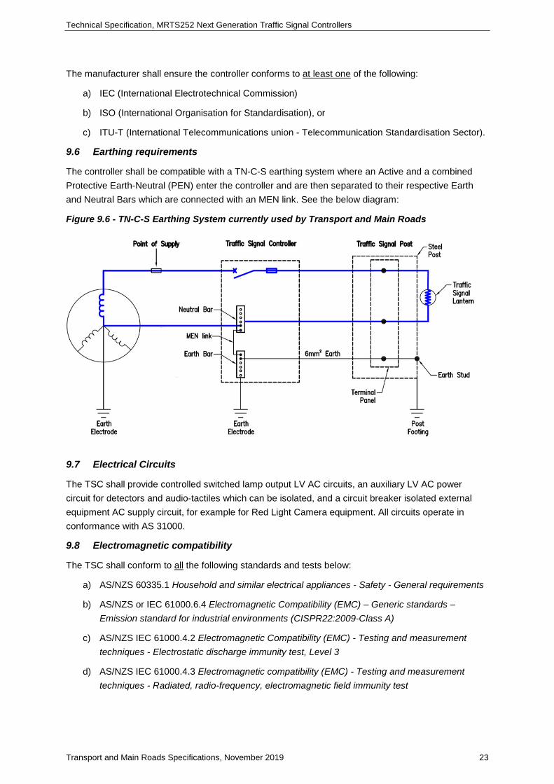
Technical Specification, MRTS252 Next Generation Traffic Signal Controllers
Transport and Main Roads Specifications, November 2019 23
The manufacturer shall ensure the controller conforms to at least one of the following:
a) IEC (International Electrotechnical Commission)
b) ISO (International Organisation for Standardisation), or
c) ITU-T (International Telecommunications union - Telecommunication Standardisation Sector).
9.6 Earthing requirements
The controller shall be compatible with a TN-C-S earthing system where an Active and a combined Protective Earth-Neutral (PEN) enter the controller and are then separated to their respective Earth and Neutral Bars which are connected with an MEN link. See the below diagram:
Figure 9.6 - TN-C-S Earthing System currently used by Transport and Main Roads
9.7 Electrical Circuits
The TSC shall provide controlled switched lamp output LV AC circuits, an auxiliary LV AC power circuit for detectors and audio-tactiles which can be isolated, and a circuit breaker isolated external equipment AC supply circuit, for example for Red Light Camera equipment. All circuits operate in conformance with AS 31000.
9.8 Electromagnetic compatibility
The TSC shall conform to all the following standards and tests below:
a) AS/NZS 60335.1 Household and similar electrical appliances - Safety - General requirements
b) AS/NZS or IEC 61000.6.4 Electromagnetic Compatibility (EMC) – Generic standards – Emission standard for industrial environments (CISPR22:2009-Class A)
c) AS/NZS IEC 61000.4.2 Electromagnetic Compatibility (EMC) - Testing and measurement techniques - Electrostatic discharge immunity test, Level 3
d) AS/NZS IEC 61000.4.3 Electromagnetic compatibility (EMC) - Testing and measurement techniques - Radiated, radio-frequency, electromagnetic field immunity test

Technical Specification, MRTS252 Next Generation Traffic Signal Controllers
Transport and Main Roads Specifications, November 2019 24
e) AS/NZS IEC 61000.4.4 Electromagnetic compatibility (EMC) - Testing and measurement techniques - Electrical fast transient/burst immunity test, Level 3
f) AS IEC 61000.4.5 Electromagnetic compatibility (EMC) - Testing and measurement techniques - Surge immunity test, Level 3
g) AS IEC 61000.4.6 Electromagnetic compatibility (EMC) - Testing and measurement techniques - Immunity to conducted disturbances, induced by radio-frequency fields
h) AS/NZS or IEC 61000.4.8 Electromagnetic compatibility (EMC) - Testing and measurement techniques - Power frequency magnetic field immunity test (mains at 50Hz), and
i) AS/NZS 61000.4.11 Electromagnetic compatibility (EMC) - Testing and measurement techniques - Voltage dips, short interruptions and voltage variations immunity tests, Level 3.
9.9 Components
9.9.1 General requirements
All components shall be of the highest quality and performance standard and be clearly marked with its description.
Plug in cards shall be secured in the chassis. Preference will be given to DIN style connectors.
All components and the controller layout shall be designed and labelled so as to allow a technician to easily identify a faulty component and its location and to minimise the labour involved in replacing a faulty component. Components shall incorporate industry standard markings in respect to identification and rating.
9.9.2 Lamp outputs
Each signal aspect shall have at least three terminals for field terminal connections. There shall be at least eight neutral field termination connections for use with lamps, detectors, etc. Lamp outputs shall support step dimming, outputting at the voltage levels described in AS 2144.
The controller shall be capable of supplying both LV and ELV lamp outputs. Suitable isolation shall be provided for LV & ELV circuits as per AS 3000, AS/NZS 5000.1 and AS 2578.
While there is a preference for connectors as detailed in Appendix A, other connector types deemed suitable will be considered. Preference will be given to spring-loaded terminals.
The field active output in the controller that is fed to the field shall be able to be deactivated independently of other signal outputs.
All lamp outputs shall be suitably fused with a mechanism that is readily accessible and easily replaced.
All lamp outputs should be protected in respect to ½ wave monitoring, detection and response.
The lamp output dimming transformer shall be a “Ferro-Resonant” transformer with an output voltage of 185V AC.
9.9.3 Pedestrian countdown timer
The controller shall be capable of interfacing with a Pedestrian Countdown Timer, as per MRTS253 Traffic Signal Lanterns.

Technical Specification, MRTS252 Next Generation Traffic Signal Controllers
Transport and Main Roads Specifications, November 2019 25
9.9.4 Loop detectors
This clause pertains only to loop detectors, however, the controller shall support other vehicle detection technologies, as discussed in Clause 11.3.1 Vehicle Detection.
The TSC shall support Integrated Vehicle Loop Detectors which:
a) are compliant with AS 2703
b) are up to 200 m in length
c) have an inductance range of 50 – 700 µH
d) have a Q factor 5-50 for frequencies < 60 kHz, and
e) have a Q factor 3-50 for frequencies > 60 kHz.
Detection by loop detectors shall support:
a) a minimum actuation 0.02% inductance variation within 0.5 sec
b) maximum actuation – any reduction in inductance up to 10% of initial inductance occurring within a period not less than 60 ms
c) a response time > 100 ms
d) a turn-off time ± 25 ms
e) a recovery time < 100 ms
f) a passage detection output 100 – 150 ms
g) a presence time shall not exceed 10 mins, and
h) a paralysis time 0.5 - 2.0 secs.
9.9.5 Transformers
Transformers, if applicable, shall manage up to 50% overload. At full load, the transformer’s temperature shall not increase above 30°C. The electrical specification of the transformer such as VA rating and the manufacturer details shall be provided. All transformer wiring shall conform to AS 60076. The lamp output dimming transformer shall be a “Ferro-Resonant” transformer with an output voltage of 185V AC.
9.9.6 Fuses
All fuses used in the controller shall comply with IEC 60269 and be BS88 or similar for physical format where relevant. All circuit breakers shall comply with AS/NZS 3000.
9.9.7 Switches and contactors
Switches and contactors shall be of high quality with a stated operational margin and typical operating life expectancy. It is preferable for front panel switches are touch-screen based.
9.9.8 Printed circuit boards
PCB Layout shall be in a logical and coherent format. Mounting of components and spacing between tracks shall adhere to the requirements of at least one of the following:
a) IEC 60194 Printed board design, manufacture and assembly
b) IPC 6010 Printed Board Performance Specifications, or

Technical Specification, MRTS252 Next Generation Traffic Signal Controllers
Transport and Main Roads Specifications, November 2019 26
c) other equivalent PCB standards.
A silk screen layer shall be included to clearly identify components.
PCBs shall feature an epoxy laminate of at least 1.6 mm and a recommended copper thickness of 35 µm.
Manufacturers shall nominate where PCBs are manufactured and submit associated bare board tests and card testing procedures.
All circuit board manufacturing and assembly shall conform to practices as per:
a) ANSI/IPC-A-600 Acceptability of Printed Boards (or equivalent)
b) ANSI/IPC-A-610 Acceptability of Electronic Assemblies (or equivalent), and
c) IPC-SM-840 Qualification and Performance Specification of Permanent Solder Mask (or equivalent).
Coatings, component placement, etc. shall facilitate and simplify maintenance. PCBs shall be clearly labelled with their part number, revision number and serial number.
9.9.9 Master relay and auxiliary relay
The controller shall provide the means for the logic control module to control the voltage supply to the designated signal group terminals and separate means to control the voltage supply to other equipment external to the controller housing. This control operation and function is subject to SIL rating of the traffic controller offered and shall conform to Clause 2.8 in AS 2578:2009.
This functionality may be achieved using separate relays, that is a master relay for signal outputs and auxiliary relay for other external equipment, however, Transport and Main Roads will consider variants, provided safety and functional performance are not compromised.
9.9.10 Facility switch function
The safety flash yellow function shall be incorporated in the traffic controller firmware. It is preferable for the TMC to activate safety flash yellow remotely. An optional hardware facility switch kit can be installed.
The physical facility switch function is an option. The Digital I/O terminal block facility switch input allocation is to be linked when the controller is delivered. An optional facility switch and wire loom is to be purchased when required and will replace the wire link. The facility switch operational plate is located on the outside of the cabinet and covers a hole in the cabinet side comparable to the requirements of the facility switch mechanism. The facility switch is a momentary action for a sustained period of 4 seconds. The mechanism must be rugged and the interconnection between the facility switch shaft and the switch mechanism must be a comparable shaped metal interface i.e., square to square or tri-angle to triangle mating. Refer to Clause 9.9.11 Independent flashing unit and flash change-over relay for further operational information.
The optional facility switch function is described herein:
a) The facility shall be a 2-position momentary switch.
b) The facility shall only allow change between the following two states: 1: normal operation, and 2: flashing yellow.

Technical Specification, MRTS252 Next Generation Traffic Signal Controllers
Transport and Main Roads Specifications, November 2019 27
c) A minimum of four seconds actuation shall be required to set signals to flashing yellow, followed by another minimum of four seconds actuation to return to normal operation.
d) The signals shall change to flashing yellow mode in a safe manner.
e) The facility switch function shall be accessible by STREAMS for remote control.
f) The label on the cabinet shall only consist of an arrow indicating the direction of momentary rotation. Refer to Appendix B.
g) Connection to a site identifier is not required.
h) Following an interruption to supply of power to the controller whilst in flashing yellow, the controller shall resume normal operation upon return of power.
9.9.11 Independent flashing unit and flash change-over relay
An independent flash unit is a self-contained unit that supplies the active voltage to support flashing yellow mode. The independent flashing unit’s requirements, operation and function is subject to the SIL rating of the traffic controller offered and shall conform to Clause 2.9 in AS 2578:2009 with a flashing duty cycle of 50:50 or 60:40.
The flash change-over relay provides the means for switching the Flasher Unit output to the yellow aspect of designated signal groups, and for disconnecting the normal signal drives from those aspects. A flash change-over relay’s requirements, operation and function is subject to the SIL rating of the traffic controller offered and where offered shall conform to Clause 2.9 in AS 2578:2009.
However, Transport and Main Roads will consider a variant without an independent flash unit and change-over relay provided safety and functional performance are not compromised.
9.9.12 Miscellaneous relays and contactors
Miscellaneous relays and connectors provide active low voltage to support Special Facility circuits. The requirements, operation and function is subject to the SIL rating of the traffic controller offered and where offered shall conform to Clause 2.10 in AS 2578:2009.
However, Transport and Main Roads will consider a variant design without miscellaneous relays and contactors as long as it provides satisfactory safety and functionality performance.
9.9.13 Audio-Tactile supply circuit
To maintain parity with existing Audio Tactile operation a dedicated sub-circuit is required. A 240V AC feed from the signal lamp circuit rreaker connects via a 2AMP Ceramic T2 Time Delay fuse, Contactor and Terminal Assembly. Refer Appendix C – Switchboard Circuit Diagram.
9.9.14 Communications interface ports
The communication interface shall include at least two Ethernet ports, one is used for control function and the other one is used for service / maintenance function, as described in Clause 8 Networking and Security Requirements. Additionally:
a) Ethernet Ports shall be compliant with IEEE 802.3 for copper twisted pair networks, and
b) the ports shall be able to communicate with a supervisory system (see Clause 10 STREAMS Interface).
The controller should have at least one Point to Pont Serial Port, such as RS-232, RS-485, SDLC or others for control function.

Technical Specification, MRTS252 Next Generation Traffic Signal Controllers
Transport and Main Roads Specifications, November 2019 28
The controller should include USB and Secure Digital (SD) ports for the purpose of firmware update, configuration modification and extract, and non-configuration data export.
Refer to Clause 8 Networking and Security Requirements for the communication interface ports.
Also refer to Clause 12.2 Requirements for C-ITS requirements.
9.9.15 Labels
All field-replaceable components, excluding consumables, shall be clearly marked with a unique identifier, such as text with a barcode or QR code, for human and machine identification.
Switch position shall denote ON & OFF where applicable and shall be clearly marked.
All labels shall be durable with permanent printing. ISO 780 is recommended for guidance.
9.10 Office testing unit
A stand-alone controller head shall be made available for office-based testing. The test unit shall be of a reasonable size with no exposed terminals making it suitable and safe for use in an office environment. This may be a smaller or cut-down version but shall run the same version of the controller software as will be deployed in the field with full functionality. It would be desirable for the office test unit to interface with simulated detector inputs, such as:
a) software or hardware switch to simulate a detector actuation
b) software that simulates a series of actuations at a given frequency, or
c) an interface to a microscopic traffic model to deliver realistic actuations from a simulated traffic stream, including a vehicle stopping on the loop when the signals are red.
9.11 On-site testing facility
The Supplier shall offer a method of checking wiring through flashing out each signal group while in maintenance or fault mode with appropriate level access. This may be achieved through the use of a separate testing unit or through functionality embedded in the controller. The method by which this is done shall be decided by the manufacturer and shall not compromise the safety of motorists or cause confusion.
9.12 Site identifier
Refer to AS 2578 for a functional description. The offeror may specify a different methodology with similar functionality which will be subject to the department’s acceptance.
10 STREAMS interface
10.1 Introduction
For the initial interfacing of STREAMS to a NGTSC, the manufacturer should use a set of messages that provide the functional outcomes as outlined in the following clauses.
It would be preferred if these messages (or combination of messages) were available from an existing manufacturer’s protocol. However, it is acceptable to develop a new protocol and associated messages to achieve the required outcome.

Technical Specification, MRTS252 Next Generation Traffic Signal Controllers
Transport and Main Roads Specifications, November 2019 29
The NGTSC shall be capable of utilising protocol messages that support alternatives to the phase control methodology such as Signal Group control. This is only a highly desirable requirement (not mandatory) as new messaging can be developed within STREAMS to work with the manufacturer’s protocols.
The protocol provided should be capable of being transported over any suitable media, however, the preference for the STREAMS / Controller interface is for a serial protocol supporting direct point to point operation as STREAMS will have a processor located at the NGTSC cabinet (RS232 full duplex with a Baud rate of at least 38,400).
The interface shall be a master / slave protocol with event reporting if required (unsolicited messages). The master (STREAMS) will send the NGTSC commands to be actioned or requests for data / status.
10.2 Request messages – Controller status information
All requested messages shall be updated at least once every second.
10.2.1 Signal group colour
STREAMS can request the controller to report on the current state of all signal groups.
The controller shall report the actual signal group ‘colour’ including but not limited to green, yellow, red, flashing yellow, flashing red (don't walk) and off.
10.2.2 Report detector volume
STREAMS can request the controller to report the vehicle count for all activated detectors since the last request.
The controller shall report the vehicle counts for all activated detectors since the last request for this information.
10.2.3 Report detector occupancy
STREAMS can request the controller to report the occupied time for all activated detectors since the last request.
The controller shall report the occupied time for all activated detectors since the last request for this information.
10.2.4 Vehicle and pedestrian demands
STREAMS can request the controller to report the current status (requested or not requested) of all pedestrian push button / vehicle detector demands.
The controller shall respond with an appropriate reply.
10.2.5 Phase demands
STREAMS can request the controller to report the current demands on each phase.
The controller shall respond with an appropriate reply.
10.2.6 Current phase sequence timer
STREAMS can request the controller to report the active phase and which basic sequence timer step is currently active.
The controller shall respond with an appropriate reply message.

Technical Specification, MRTS252 Next Generation Traffic Signal Controllers
Transport and Main Roads Specifications, November 2019 30
10.2.7 Current sequence timer for pedestrian signal groups
STREAMS can request the controller to reply with a message (or the controller will send a repeating message) of the current sequence timer step.
The controller shall respond with an appropriate reply.
10.2.8 Read special facility flags
STREAMS can request the controller to send the status of all special facilities (for example, inputs from a rail crossing).
The controller shall respond with an appropriate reply.
10.2.9 Controller hardware and firmware status
STREAMS can request the controller to report the hardware and firmware status of the controller, which may include but is not limited to lamp status (On / Off), controller start-up / normal running / watchdog state. Controller mode (for example, VA / Local Coordinated / Master control from STREAMS / Flashing Yellow / Off).
The controller shall reply with an appropriate reply message.
10.2.10 Lamp faults
STREAMS can request the controller to report the number of lamps on each signal group suspected as being faulty.
The controller shall respond with an appropriate reply(s).
10.2.11 Lamp watts
STREAMS can request the controller to report the lamp watts currently being drawn by each signal group and the ‘normal’ lamp wattage for that signal group.
The controller shall respond with an appropriate reply(s).
10.2.12 Dimmer state report
STREAMS can request the controller to report the current dimming level.
The controller shall respond with an appropriate reply(s).
10.2.13 Read fault and/or error log
STREAMS can request the controller to report the current contents of the fault and/or error log.
The controller shall reply with all entries in the log.
Note. It would be desirable if STREAMS was able to request recent and/or selected entries (by date range) from the fault and/or error log.
10.2.14 Notify of a fault
The controller shall notify STREAMS when there is an unread or unacknowledged entry in the fault log.
The notification should be an explicit message or implied from an entry in another message such as a ‘heartbeat’ message.

Technical Specification, MRTS252 Next Generation Traffic Signal Controllers
Transport and Main Roads Specifications, November 2019 31
10.2.15 Detector faults
STREAMS can request the controller to advise STREAMS of faulty detectors.
The controller shall respond with an appropriate reply.
10.2.16 ‘Police Panel’ status
Optionally, STREAMS can request the controller to report the current status of the ‘Police Panel’.
The controller shall respond with an appropriate reply.
10.2.17 Site ID and revision
STREAMS can request the controller to report the controller ID and configuration check sums.
The controller shall reply with the site number, the hardware model (and version if applicable), the firmware version / revision, the configuration CRC / checksum and version / revision (if applicable).
10.2.18 Heartbeat
The controller shall provide a ‘heartbeat’ message to STREAMS every two seconds.
10.2.19 Read clock
STREAMS can request the controller to report the current clock time (separate requests for date and time of day are acceptable).
The controller shall respond with an appropriate reply message or messages.
10.2.20 Read time setting data
STREAMS can request the controller to report configuration time settings stored in controller memory.
The controller shall respond with an appropriate reply message.
10.3 Command messages – Controller state change
10.3.1 Phase control
STREAMS can command the controller to terminate the running phase and move directly to a specified phase if possible (respecting all safety settings).
The controller shall reply with a message indicating if the request can be met.
10.3.2 Terminate walk
STREAMS can request the controller to terminate the pedestrian walk once the minimum safety times have run.
The controller shall respond with an appropriate reply.
10.3.3 Pedestrian automatic demand
STREAMS can advise the controller to place a permanent demand for a pedestrian crossing.
The controller shall respond with an appropriate reply.
10.3.4 Release for termination by Vehicle Actuation (V/A) control
STREAMS can request the controller to ‘Release’ a current phase for immediate termination based on vehicle actuation and the expiry of running approach timers. The controller will then move to the “Next Phase” previously specified by STREAMS.

Technical Specification, MRTS252 Next Generation Traffic Signal Controllers
Transport and Main Roads Specifications, November 2019 32
STREAMS can set a Release time to let the controller know when it should terminate a phase during rest or extension if the approach timers expire and all safety minimum times have been run. The controller shall then move to the “Next Phase” previously set by STREAMS. Refer to AS 2578:2009, Clause 4.2.5 Extending a phase.
10.3.5 Next phase
STREAMS can continually advise the controller of the next phase required to be run if the current phase has been released for termination by V/A.
The controller shall respond with an appropriate reply.
STREAMS can continually advise the controller of the ‘Next Phase’ to be run based on the phase demands supplied to STREAMS by the controller. It is expected that the controller will move to the ‘Next Phase’ requested by STREAMS as soon as the logic within the controller allows e.g. the phase approach timers expire (gap-out) and all safety minimum times have been run.
10.3.6 Set special facility switches
STREAMS can request the controller to set appropriate special facilities by setting the state of a bit / flag. This could be used to activate an output on the controller.
The controller shall respond with an appropriate reply.
10.3.7 Set controller mode
STREAMS can request the controller to change to a specified Controller mode (for example, VA / Local Coordinated / Master Control from STREAMS / flash / off).
The controller shall respond with an appropriate reply.
10.3.8 Reset fault log
STREAMS can request the controller to reset the fault log.
The controller shall respond with an appropriate reply confirming that the fault log has been reset.
10.3.9 Set / override detector fault
STREAMS can clear a detector alarm, disable a failed detector and force the detector state.
The controller shall respond with an appropriate reply.
10.3.10 Establish communications
STREAMS can request the controller to establish a synchronised data communications channel.
The controller shall respond with an appropriate reply.
10.3.11 Set clock
STREAMS can request the controller to set the clock to a specified time to sync the clock to STREAMS.
The controller shall respond with an appropriate reply.
10.3.12 Set time setting data (RAM)
STREAMS can request the controller to set RAM time settings to values supplied by STREAMS.
The controller shall respond with an appropriate reply.

Technical Specification, MRTS252 Next Generation Traffic Signal Controllers
Transport and Main Roads Specifications, November 2019 33
11 Software and functional traffic requirements
11.1 Introduction
The traffic signal control software shall provide facilities to safely and efficiently control traffic based on inputs from detectors and other sources. The operation of the signals will be primarily based on control parameters and timers associated with signal groups. It shall be possible to allocate signal groups to phases and control the timing and order of the phases.
STREAMS will be interfaced to the controller to allow for control of phase changes and signal group operation, as described in Clause 10 STREAMS Interface. The controller hardware and software systems will ensure safe operation at all times. A minimum of eight discrete and independent phases shall be available for use by STREAMS.
11.2 Start-up requirements
The controller shall perform a full safety check before switching on the physical outputs which should include, but are not limited to:
a) the facility switch is ‘ON’ (if applicable)
b) all correct cards are installed
c) no fault conditions are present
d) watchdog is active
e) lamps are present
f) connectors are all mated
g) CRC memory checks are complete
h) software revision is verified
i) site ID (or similar method of linking configuration to the site-specific controller) can be verified against the configuration, and
j) a preferred option to read electronic card IDs and record accordingly is desired.
11.3 Traffic control operation
The overarching principle of the traffic control functionality is to ensure the safe management of traffic while minimising delay to drivers within the safety and policy constraints. The latter are applied through settings such as cycle time, minimum green time, maximum green time and so on.
It shall be possible for a single controller to operate signals at multiple separate intersections and do so in such a way that the signalling at any one intersection does not influence or constrain the signalling at any of the other intersections. Each operated intersection shall have eight or more discrete and independent phases available for control. The vehicle groups, pedestrian groups, pedestrian wait indicator outputs and vehicle detectors shall be assignable to any of the intersections controlled by the controller.
It shall be possible to apply different control strategies by time of day and day of the week or as required, in response to measured or estimated performance.
Intergreen times shall be defined as the time from the end of a green to the start of the next green and considered part of the incoming green.

Technical Specification, MRTS252 Next Generation Traffic Signal Controllers
Transport and Main Roads Specifications, November 2019 34
The controller shall provide facilities to control traffic using the Australian conventions and procedures as described in Austroads Guide to Traffic Management Part 9, 2016 (AGTM-9). Timing intervals for vehicle and pedestrian signal groups, as currently used in Australia, are described in AGTM-9:2016 Clause 6.4.2 Phase Intervals. The detailed requirements should not imply that these specific timings are mandatory, alternative arrangements will be considered.
Specific requirements are detailed below. Note however, that in all cases, alternative functionality that provides equivalent or improved safety and efficiency will be considered.
11.3.1 Vehicle detection
All vehicle detection options shall include forced on, forced off, simulated manual input and recall. A desired function is a pulse interval actuation.
The controller shall operate with Transport and Main Roads loop detectors which are usually located:
i. 35 m upstream of the stop line on main road through approaches in a 50 or 60 Km/k zone
ii. 45 m upstream of the stop line on main road through approaches in a 70 or 80 Km/k zone
iii. 5 m from the stop line in other cases, or
iv. for turning movements, at or near the stop line and shall be of an appropriate size to detect vehicles waiting to turn.
Detector activations can call phases or signal groups after the detector has been de-activated. A call for a phase or signal group can be cancelled if a detector is de-activated for a defined time.
In addition to loop detectors, as outlined in Clause 9.9.4 Loop Detectors, the controller shall be compatible with alternative detection technologies including but not limited to video analytics, radar, thermal detection and other emerging vehicle detection technologies.
Provision should be made for the use of information from other data sources such as:
i. information from upstream intersections
ii. depart side detectors at upstream intersections
iii. probe vehicles, and
iv. broadcasting information from vehicles equipped with a C-ITS SPaT vehicle station.
Vehicle detector control function shall include call, extend, increment initial green time, and facilitate gap timers, presence function and conditional detection (or similar) for each phase
Vehicle detectors shall be capable of detecting and reporting operational issues and shall fall-back to a preconfigured state. Such issues include detector chattering or a locked-on detector.
11.3.2 Pedestrian detection
The controller shall conform to the following with regards to pedestrian detection:
a) pedestrian input options shall include forced on, forced off, simulated manual input and recall
b) it shall be possible to activate a signal at the pedestrian push button to indicate that the pedestrian movement has been called
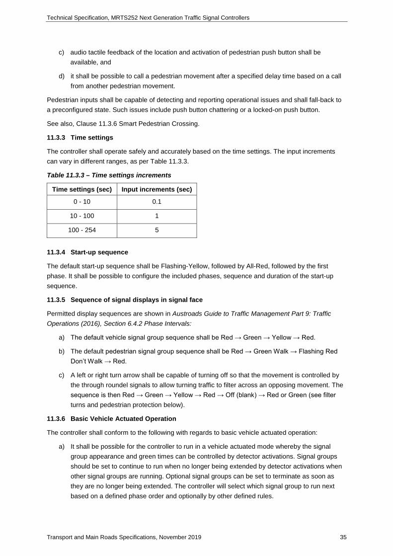
Technical Specification, MRTS252 Next Generation Traffic Signal Controllers
Transport and Main Roads Specifications, November 2019 35
c) audio tactile feedback of the location and activation of pedestrian push button shall be available, and
d) it shall be possible to call a pedestrian movement after a specified delay time based on a call from another pedestrian movement.
Pedestrian inputs shall be capable of detecting and reporting operational issues and shall fall-back to a preconfigured state. Such issues include push button chattering or a locked-on push button.
See also, Clause 11.3.6 Smart Pedestrian Crossing.
11.3.3 Time settings
The controller shall operate safely and accurately based on the time settings. The input increments can vary in different ranges, as per Table 11.3.3.
Table 11.3.3 – Time settings increments
Time settings (sec) Input increments (sec)
0 - 10 0.1
10 - 100 1
100 - 254 5
11.3.4 Start-up sequence
The default start-up sequence shall be Flashing-Yellow, followed by All-Red, followed by the first phase. It shall be possible to configure the included phases, sequence and duration of the start-up sequence.
11.3.5 Sequence of signal displays in signal face
Permitted display sequences are shown in Austroads Guide to Traffic Management Part 9: Traffic Operations (2016), Section 6.4.2 Phase Intervals:
a) The default vehicle signal group sequence shall be Red → Green → Yellow → Red.
b) The default pedestrian signal group sequence shall be Red → Green Walk → Flashing Red Don’t Walk → Red.
c) A left or right turn arrow shall be capable of turning off so that the movement is controlled by the through roundel signals to allow turning traffic to filter across an opposing movement. The sequence is then Red → Green → Yellow → Red → Off (blank) → Red or Green (see filter turns and pedestrian protection below).
11.3.6 Basic Vehicle Actuated Operation
The controller shall conform to the following with regards to basic vehicle actuated operation:
a) It shall be possible for the controller to run in a vehicle actuated mode whereby the signal group appearance and green times can be controlled by detector activations. Signal groups should be set to continue to run when no longer being extended by detector activations when other signal groups are running. Optional signal groups can be set to terminate as soon as they are no longer being extended. The controller will select which signal group to run next based on a defined phase order and optionally by other defined rules.

Technical Specification, MRTS252 Next Generation Traffic Signal Controllers
Transport and Main Roads Specifications, November 2019 36
b) It shall be possible to configure the controller to rest in a defined phase or with a defined set of signal groups green, and
c) It shall be possible to define signal group operations such as optionally turning the red arrow off in the configuration data for vehicle actuated operation.
11.3.7 Isolated fixed time operation
The controller can run in fixed time mode whereby all signal groups will run the defined maximum green time regardless of detector activations, unless safety minimums result in longer green times.
11.3.8 Local coordinated operation
The controller shall conform to the following with regards to local coordinated operation:
a) The controller shall be able to run with a defined cycle time whereby a nominated signal group or signal groups (possibly as defined by a phase) shall be green at the beginning of the cycle time and all other signal groups can run between minimum and maximum green times as controlled by detector activations (given that the sum of the green and intergreen times is less than the cycle time).
b) The controller shall be able to be configured to rest in a defined phase or with a defined set of signal groups green.
c) Facilities shall be provided to minimise delay to waiting traffic while efficiently serving flowing traffic. This may include concepts such as look-ahead, release, time stealing etc., and
d) It shall be possible to define the phase sequence used in a local coordination plan.
11.3.9 Fall back plans
The controller shall conform to the following with regards to fall back plans:
a) The controller shall be able to store all parameters required to run at least 12 local coordinated plans that can be selected by Time of Day (TOD) and day of week. Separate TOD schedules should be available for public holidays.
b) The plan shall include data to define the order in which phases will appear.
c) The controller shall rest in the predefined rest phase if no demands are active.
d) At least eight discrete, independent phases shall be available for use in these plans.
e) The controller shall be able to be configured to skip a phase even if it is demanded. For example, in a Sydney Diamond, a double diamond with additional right turn phases, trailing right turn movements are always skipped at certain times of day.
f) An alarm shall be raised if a demand is not serviced within a predefined time, and
g) It shall be possible to define the phase sequence used in a fall-back plan.
11.3.10 Area traffic control mode
The controller shall conform to the following with regards to area traffic control mode:
a) The controller shall be able to be configured to allow STREAMS to control signal groups and time settings. See elsewhere for interface and other requirements for this mode of operation.

Technical Specification, MRTS252 Next Generation Traffic Signal Controllers
Transport and Main Roads Specifications, November 2019 37
b) STREAMS shall control the operation of the controller by requesting phase changes. STREAMS will also send messages to control signal group operation in a phase (refer Clause 10 STREAMS Interface requirements for details). This includes the ability to supress the pedestrian demand (not service a pedestrian demand) when an EVP intervention is being serviced.
c) The controller shall make at least eight discrete and independent phases available for STREAMS control. Refer STREAMS protocol requirements for more information on how STREAMS will control phase changes, and
d) STREAMS can intervene in the running cycle and request the controller to service a specified movement or phase as quickly as possible respecting all minimum green and clearance times.
11.3.11 Vehicle movements
It shall be possible to optionally set turning vehicle red and green lanterns off as discussed above (in signal group aspect sequence). See more details and a reference in the clauses below.
11.3.12 Pedestrian movements
The controller shall conform to the following with regards to pedestrian movements:
a) Pedestrian signal groups shall be configured to only display green after the start of a phase when there are no demands for conflicting signal groups.
b) A demand for a signal group in the current phase can cause the controller to move away from that phase if there are no demands for other phases, and
c) Facilities shall be available to safely control pedestrians crossing the road. This follows Transport and Main Roads / Australian conventions and procedures as described in Austroads Guide to Traffic Management.
11.3.13 Pedestrian clearance period
The 'flashing don’t walk' period in a pedestrian signal group is known as the clearance period. The clearance period shall consist of two parts, Clearance 1 and Clearance 2. Clearance 1 shall conflict with green, yellow and off displays as defined in the conflict matrix. Optionally some vehicles signal groups can go yellow in the Clearance 1 period.
11.3.14 Filter movements
A signal group for a right-turn movement can be configured to be red at the start of a phase but drop off (dark) at a defined time during the phase to allow turning vehicles to filter through the oncoming traffic. Not turning the red signal off shall be the default action. The option of turning the signal group off shall be controlled by time of day in vehicle actuated mode or by configured data in a coordinated plan.
11.3.15 Pedestrian protection
A signal group for a left-turn movement shall be able to be configured to be red at the start of a phase but drop off (go dark) at a defined time during the phase to provide pedestrian protection. Holding the turning vehicles up allows the pedestrians to begin their movement and be in clear sight of the conflicting turning motorists. Not turning the red signal off shall be the default action. The option of turning the signal group off shall be controlled by time of day in vehicle actuated mode or by configured data in a coordinated plan.

Technical Specification, MRTS252 Next Generation Traffic Signal Controllers
Transport and Main Roads Specifications, November 2019 38
11.3.16 Smart pedestrian crossing
Based on input from detectors, it shall be possible to cancel a pedestrian demand if the pedestrian leaves the designated wait area. Based on input from detectors monitoring pedestrians crossing the road, it shall be possible to extend or truncate walk (optional) and clearance times.
11.3.17 Right turn trap
The controller shall manage signal group changes that could result in a right turn trap by closing opposing signal groups down for a ‘special’ all red period. This should include the ability to identify signal group changes that would result in a right turn trap in the configuration data.
11.3.18 Detector fault monitoring
The controller shall monitor detector operation and flag detectors as faulty if:
a) they are not activated for more than a configured period
b) the activation count is less than a configured value in a defined period, or
c) the detector board diagnostic if fitted, recognises an open circuit or short circuit loop or other fault.
The controller shall be able to be configured to run either minimum, maximum or specified green time when a loop is flagged as faulty. This setting can be disabled if an area traffic control system is controlling signal group operation.
11.3.19 Red light runner extension
Based on input from appropriate detectors, it shall be possible to extend the associated All-Red time.
11.3.20 Train phase operation
When a train phase demand is received from an external system, the controller shall terminate all signal groups not in the train phase and go to the train phase as soon as possible while respecting minimum green values and pedestrian clearance times.
11.3.21 Train phase conflict management
The controller shall be configurable to either switch to flash or turn signals off when a train conflict signal is received from an external system.
11.3.22 Signal group green in multiple phases
It shall be possible to define a cycle whereby a signal group is green more than once in the cycle.
11.3.23 C-ITS readiness
The TSC shall publish SPaT data in accordance with the requirements of ISO/TS 19091 and SAE J2735.
11.4 Interface to a coordination master
The controller shall be capable of communicating with STREAMS, as specified in Clause 10 STREAMS Interface.

Technical Specification, MRTS252 Next Generation Traffic Signal Controllers
Transport and Main Roads Specifications, November 2019 39
11.5 Software conflict monitoring system
This clause details the pre-emptive software conflict monitoring. The conflict monitoring system shall monitor for any events which may compromise the safety of the intersection including but limited to:
a) unwanted signals
b) InterGreen violations
c) invalid signal displays
d) non-compliance between logical commands and physical outputs, or
e) fault of external inputs.
Upon the occurrence of a fault or error, the controller shall detect and respond as per Clause 7.7 Fault / Error Monitoring and Response. The conflict monitor shall undertake a self-verification function to confirm normal operation at a pre-agreed period.
The controller shall measure and store lamp output references loads within a 2.5% accuracy. These measured loads are continually compared with changing lamp activity on the intersection.
11.6 Configuration software and data
The controller operation shall be configured using software provided by the manufacturer. This shall be used to define all parameters necessary to control the signals as identified in Clause 11.3 Traffic Control Operation. The configuration generated by the software shall comply with Australian Road Rules (TORUM Act), in particular, driving on the left-hand side of the road.
The configuration shall incorporate details specific to the intersection design (AKA “Personality”). This configuration includes all traffic movements, detection linkage tables and operational parameters specific to the intersection design. This shall be easily and safely configurable through a software package provided by the manufacturer. It is highly desirable that this configuration incorporate details and an intersection plan which meets C-ITS requirements.
The software package shall contain an emulator or equivalent function for test purpose along with a test unit as specified in Clause 9.10 Office Testing Unit. This software shall be able to run with a ‘variable’ second period to facilitate faster than real-time mode for testing.
It is highly desirable that the software be compatible with microsimulation software for the purpose of traffic analysis and simulation. The software and hardware emulation packages are expected to be capable of connecting to a higher-level area traffic management system to allow remote monitoring and control. Transport and Main Roads would give preference to suppliers who offer software that is packaged without licencing fees or licenced dongle requirements.
Once loaded into the controller, the configuration data shall be stored in the non-volatile memory of the controller with the ability to roll back to previous state where a configuration change has negatively impacted the controller operation. This shall be made possible in a simple and safe manner which minimises the time the signals are dark or in flashing yellow.
The configuration data shall include all necessary data to support conflict and lamp fault monitoring.

Technical Specification, MRTS252 Next Generation Traffic Signal Controllers
Transport and Main Roads Specifications, November 2019 40
11.7 Configuration software updates
The software shall be supported and maintained by the manufacturer and it shall be simply and efficiently configurable to provide all controller functionality required by Transport and Main Roads.
As required, software updates for improved security, functionality and usability shall be provided as they become available. As above, preference will be given to suppliers who provide ongoing updates without additional fees and to suppliers who demonstrate a willingness to accept feedback and input from customers for on-going software development.
11.8 System integrity protection
The controller shall perform automatic integrity checks at a regular interval to provide assurance that critical system files and directories have not been modified since the last self-check.
If an integrity check fails or produces non-standard results the controller shall raise an alarm containing actionable information for the system operator to review.
12 Cooperative Intelligent Transport Systems (C-ITS) interface
12.1 Introduction
As the department moves towards the future of C-ITS, it is essential that our next generation of TSC is compatible with our intended direction and emerging traffic management technologies. Below are the minimum requirements.
12.2 Requirements
See also Clause 9.9.14 Communications interface ports.
Hardware requirements
Minimum of one Communications Port for connection of R-ITS-S Road Side Station to the TSC.
Interface
TIA/EIA-568 8P8C modular connectors
Layer 1
As a minimum, supports 100BASE-TX
Layer 2
IEEE 802.3 Ethernet
Layer 3
IPv4 and IPv6
Standards requirement
The TSC shall support the following C-ITS Standards:
a) J2735:2016, Dedicated Short Range Communications (DSRC) Message Set Dictionary (March 2016), SAE International.
b) ISO/TS 19091:2017, Intelligent transport systems - Cooperative ITS - Using V2I and I2V communications for applications related to signalized intersections
Technical Specification, MRTS252 Next Generation Traffic Signal Controllers
Transport and Main Roads Specifications, November 2019 41
c) ETSI TS 103 301-2016, Facilities layer protocols and communication requirements for infrastructure services.
d) The TSC shall support the C-ITS standards as they develop and mature.
e) The TSC manufacturer shall indicate the proposed methodologies to be implemented to ensure the TSC continues to support the C-ITS standards.
f) The TSC shall support simultaneous maintenance and application access or have dedicated functional ports.
g) The C-ITS requirements assume that the Road Side Unit is a separate hardware device and not integrated within the TSC hardware platform.
h) The TSC shall connect to the Road Side ITS Station via the station's gateway service as described in ETSI EN 302 665 Intelligent Transport Systems (ITS), Communications Architecture.
13 Testing
Documentation shall be submitted to the department to demonstrate compliance to this Technical Specification.
A test schedule will be supplied by the department upon request. The tests shall be undertaken and appropriately documented by the offeror and made available to Transport and Main Roads upon request to assist in determining compliance with the specification. It should be noted that testing may not cover all clauses in this Technical Specification and thus completing all tests successfully does not guarantee compliance with the specification.
14 Quality assurance
Manufacturers shall provide a Quality Assurance (QA) manufacturing plan for TSC production. All plans shall demonstrate compliance with AS/NZS ISO 9000.
15 Warranty provisions
The warranty requirements defined in MRTS201 apply to this Technical Specification with a warranty period of three years, or as specified in a Standing Offer Arrangement.
16 Training requirements
The supplier shall develop and submit a formal training plan to the department for the traffic signal controller being supplied. The supplier shall then liaise with the department to arrange a suitable time for training sessions. The supplier shall deliver comprehensive training for each Transport and Main Roads region in which the traffic signal controllers are to be installed.
This training shall include two separate training programs, as follows:
a) general controller overview, installation, commissioning, maintenance and operation training, and
b) Queensland specific configuration/programming training.

Technical Specification, MRTS252 Next Generation Traffic Signal Controllers
Transport and Main Roads Specifications, November 2019 42
The supplier shall only use trainers who are qualified in Vocational and Workplace training under the Australian Qualification Training Framework (AQTF), or equivalent, and who have a competent understanding of the controller, related systems and components.
The trainers shall provide evidence consistent with AQTF, or equivalent, to the trainees and to the department to demonstrate that the training was completed, and trainees are assessed as competent by the supplier to safely undertake that work. Records of those assessments and the evidence should be kept by both the trainer and the supplier.
16.1 Post-commissioning
The training shall provide attendees with instructions on:
a) operational capabilities and where appropriate safety limits of each item of equipment and related systems
b) failure mechanisms and consequences for each item of equipment and related systems (for example, Points of Failure, Causes of Failure)
c) structure and relevant contents of the Operations, Repair and Maintenance manuals, and
d) reliability and maintainability refer to MRTS201 General Equipment Requirements.
The relevant contents of the Operations, Repair and Maintenance manuals shall be provided to the trainees at least seven days prior to the proposed training session.
16.2 Maintenance training
The supplier shall provide comprehensive hands-on training / knowledge transfer during such activities. Involvement of the department in this manner will not in any way relieve the supplier of the defects liability and/or maintenance responsibilities under this contract.
In addition to the hands-on field training above, the Supplier shall develop a formal training plan to train additional personnel for each site location, item of equipment and system prior to hand-over.
Training shall be sufficient to enable the department’s attendees to:
a) diagnose faults and failures and undertake all necessary repair work
b) replace faulty modules / equipment, and
c) perform routine maintenance on the equipment and related systems.
17 Maintenance requirements
The maintenance requirements defined in MRTS201 General Equipment Requirements apply to this Technical Specification.
18 Handover requirements
The handover requirements defined in MRTS201 General Equipment Requirements apply to this Technical Specification.

Technical Specification, MRTS252 Next Generation Traffic Signal Controllers
Transport and Main Roads Specifications, November 2019 43
Appendix A –Transport and Main Roads Product Preferences
Terminal Block Preference
Terminal blocks are required, however it should be noted that Transport and Main Roads has a preference for Weidmuller WDU 240 VAC terminal assemblies, WK’X’ SL/U or WACO Topjob S 22xx series.
The following information provides examples of Cabinet Terminal configurations and sizes:
• WAGO 2204-1401 (4 mm, 4 way gray) for numbered cores
• WAGO 2204-1404 (4 mm, 4 way blue) for neutral cores (this also aligns with SWARCO general use)
• WAGO 2206-1307 (10 mm, 3 way green/yellow) for earth cores
• WAGO Rail Mount Terminal Blocks – TOPJOB-S-603690731
• Weidmuller offer an alternative series WKxx Sl/U
Note: Screw alternative may be considered, i.e., Weidmuller A4C 1.5PE
https://catalog.weidmueller.com/procat/Product.jsp?page=Product&productId=([1521690000])
Audio Tactile Module Modification
The Audio Tactile field active fuse is 2A Littelfuse 215 Series 5 x20 mm T2 Time-delay, which is the same as the fuse in the group card.
https://m.littelfuse.com/products/fuses/cartridge-fuses/5x20mm-fuses/215.aspx
Proposed new fuse holder terminal for the 2A fuse above:
https://www.wago.com/au/rail-mount-terminal-blocks/3-conductor-fuse-terminal-block/p/2002-1711
Also for the terminal block, it could also be:
https://in.element14.com/wago/2202-1401/terminal-block-dinrail-4ways-12awg/dp/2931998
Switchboard Preference
IPD PVCLC24S Insulated load centre – 24-pole surface mount.
Preference for non-metallic screws for affixing panels, covers and inserts.
Cabinet Paint Colour
TBD

Technical Specification, MRTS252 Next Generation Traffic Signal Controllers
Transport and Main Roads Specifications, November 2019 44
Appendix B – Facility switch operational plate
Figure B – Facility switch operational plate
The plate is mounted on the cabinet and positioned in such a manner that a hole in the cabinet side is covered until required.

Technical Specification, MRTS252 Next Generation Traffic Signal Controllers
Transport and Main Roads Specifications, November 2019 45
Appendix C – Example of Switchboard Wiring