Training and Support system in the Cloud for improving the situational awareness in Search and...
6
Training and Support system in the Cloud for improving the situational awareness in Search and Rescue (SAR) operations Michal Pelka and Karol Majek and Janusz Bedkowski and Pawel Musialik and Andrzej Maslowski Institute of Mathematical Machines ul. Krzywickego 34, 02-078 Warsaw, Poland Email: [email protected] Geert de Cubber and Haris Balta Royal Military Academy of Belgium Department of Mechanics, Unmanned Vehicle Centre Avenue de la Renaissance 30, 1000 Brussels, Belgium Email: [email protected] [email protected] Antonio Coelho and Ricardo Goncalves and Ricardo Baptista DEI, Faculdade de Engenharia, Universidade do Porto / INESC TEC Rua Dr. Roberto Frias, s/n, Porto, Portugal E-mail: [email protected] Jose Manuel Sanchez IntegraSys S.A. Esquilo 1, 28232 Las Rozas, Spain Email: [email protected] Shashank Govindaraj Space Applications Services NV/SA Leuvensesteenweg 325, 1932 Zaventem, Belgium Email: [email protected] Abstract—In this paper, a Training and Support system for Search and Rescue operations is described. The system is a component of the ICARUS project (http://www.fp7-icarus.eu) which has a goal to develop sensor, robotic and communication technologies for Human Search And Rescue teams. The support system for planning and managing complex SAR operations is implemented as a command and control component that integrates different sources of spatial information, such as maps of the affected area, satellite images and sensor data coming from the unmanned robots, in order to provide a situation snapshot to the rescue team who will make the necessary decisions. Support issues will include planning of frequency resources needed for given areas, prediction of coverage conditions, location of fixed communication relays, etc. The training system is developed for the ICARUS operators controlling UGVs (Unmanned Ground Ve- hicles), UAVs (Unmanned Aerial Vehicles) and USVs (Unmanned Surface Vehicles) from a unified Remote Control Station (RC2). The Training and Support system is implemented in SaaS model (Software as a Service). Therefore, its functionality is available over the Ethernet. SAR ICARUS teams from different countries can be trained simultaneously on a shared virtual stage. In this paper we will show the multi-robot 3D mapping component (aerial vehicle and ground vehicles). We will demonstrate that these 3D maps can be used for Training purpose. Finally we demonstrate current approach for ICARUS Urban SAR (USAR) and Marine SAR (MSAR) operation training. I. I NTRODUCTION The main and most important task of rescue services during a major crisis is to search for human survivors on the incident site. As such endeavour is complex and dangerous, it often leads to loss of lives among the rescuers themselves. Introducing unmanned Search And Rescue (SAR) devices can decrease the scale and frequency of such events, while speeding up the SAR process. Many research efforts towards the development of un- manned SAR tools have been made(see here for an overview: (Kruijff et al., 2012)). One of these efforts is Neptus, a C3I (Command, Control, Communication and Information) framework, which aims to support coordinated operation of heterogeneous teams, including several types of UVs and human beings (Dias, 2006). Another example, is the German project I-LOV, which establishes a framework for integration of mobile platforms into a victim search mission (Hamp, 2013). Numerous attempts to use robotic systems in crisis situations were made: the 2001 World Trade Center attack (Murphy, 2004), the 2004 earthquake in Mid Niigata, the 2005 USA hurricanes (Murphy, 2008), or the 2011 Japan tsunami. Paper (Liu and Nejat, 2013) and (Hamp, 2013) give a broad overview of the effort done in this area. This research effort stands in contrast to the practical reality in the field, where unmanned SAR tools have great difficulty finding their way to the end- users, due to a number of remaining bottlenecks in the practical applicability of unmanned tools (Doroftei et al., 2012). This paper focuses on the training and support component of the ICARUS system (Govindaraj et al., 2013). The main goal of ICARUS is to combine robotic components into a common technology platform, capable of increasing the situational awareness of the action in a SAR mission. The system consists of collaborative Unmanned Ground Vehicles (UGVs) and Unmanned Aerial Vehicles (UAVs), operated using novel command and control tools. The data gathered by these unmanned systems is processed, in real-time, by a mobile data centre to provide a high-quality geo-referenced 3D model
Transcript of Training and Support system in the Cloud for improving the situational awareness in Search and...
Training and Support system in the Cloud forimproving the situational awareness in Search and
Rescue (SAR) operations
Michal Pelka and Karol Majekand Janusz Bedkowski and Pawel Musialik
and Andrzej MaslowskiInstitute of Mathematical Machines
ul. Krzywickego 34, 02-078 Warsaw, PolandEmail: [email protected]
Geert de Cubber and Haris BaltaRoyal Military Academy of Belgium
Department of Mechanics, Unmanned Vehicle CentreAvenue de la Renaissance 30, 1000 Brussels, Belgium
Email: [email protected]@rma.ac.be
Antonio Coelho and Ricardo Goncalves and Ricardo BaptistaDEI, Faculdade de Engenharia, Universidade do Porto / INESC TEC
Rua Dr. Roberto Frias, s/n, Porto, PortugalE-mail: [email protected]
Jose Manuel SanchezIntegraSys S.A.
Esquilo 1, 28232 Las Rozas, SpainEmail: [email protected]
Shashank GovindarajSpace Applications Services NV/SA
Leuvensesteenweg 325, 1932 Zaventem, BelgiumEmail: [email protected]
Abstract—In this paper, a Training and Support system forSearch and Rescue operations is described. The system is acomponent of the ICARUS project (http://www.fp7-icarus.eu)which has a goal to develop sensor, robotic and communicationtechnologies for Human Search And Rescue teams. The supportsystem for planning and managing complex SAR operationsis implemented as a command and control component thatintegrates different sources of spatial information, such as mapsof the affected area, satellite images and sensor data coming fromthe unmanned robots, in order to provide a situation snapshot tothe rescue team who will make the necessary decisions. Supportissues will include planning of frequency resources needed forgiven areas, prediction of coverage conditions, location of fixedcommunication relays, etc. The training system is developed forthe ICARUS operators controlling UGVs (Unmanned Ground Ve-hicles), UAVs (Unmanned Aerial Vehicles) and USVs (UnmannedSurface Vehicles) from a unified Remote Control Station (RC2).The Training and Support system is implemented in SaaS model(Software as a Service). Therefore, its functionality is availableover the Ethernet. SAR ICARUS teams from different countriescan be trained simultaneously on a shared virtual stage. In thispaper we will show the multi-robot 3D mapping component(aerial vehicle and ground vehicles). We will demonstrate thatthese 3D maps can be used for Training purpose. Finally wedemonstrate current approach for ICARUS Urban SAR (USAR)and Marine SAR (MSAR) operation training.
I. INTRODUCTION
The main and most important task of rescue servicesduring a major crisis is to search for human survivors on theincident site. As such endeavour is complex and dangerous, itoften leads to loss of lives among the rescuers themselves.Introducing unmanned Search And Rescue (SAR) devices
can decrease the scale and frequency of such events, whilespeeding up the SAR process.
Many research efforts towards the development of un-manned SAR tools have been made(see here for an overview:(Kruijff et al., 2012)). One of these efforts is Neptus, aC3I (Command, Control, Communication and Information)framework, which aims to support coordinated operation ofheterogeneous teams, including several types of UVs andhuman beings (Dias, 2006). Another example, is the Germanproject I-LOV, which establishes a framework for integration ofmobile platforms into a victim search mission (Hamp, 2013).Numerous attempts to use robotic systems in crisis situationswere made: the 2001 World Trade Center attack (Murphy,2004), the 2004 earthquake in Mid Niigata, the 2005 USAhurricanes (Murphy, 2008), or the 2011 Japan tsunami. Paper(Liu and Nejat, 2013) and (Hamp, 2013) give a broad overviewof the effort done in this area. This research effort stands incontrast to the practical reality in the field, where unmannedSAR tools have great difficulty finding their way to the end-users, due to a number of remaining bottlenecks in the practicalapplicability of unmanned tools (Doroftei et al., 2012).
This paper focuses on the training and support componentof the ICARUS system (Govindaraj et al., 2013). The maingoal of ICARUS is to combine robotic components intoa common technology platform, capable of increasing thesituational awareness of the action in a SAR mission. Thesystem consists of collaborative Unmanned Ground Vehicles(UGVs) and Unmanned Aerial Vehicles (UAVs), operatedusing novel command and control tools. The data gathered bythese unmanned systems is processed, in real-time, by a mobiledata centre to provide a high-quality geo-referenced 3D model
of the environment. Such a model increases the awareness ofhuman crisis managers, can be used in mission planning orcan be used for virtual training purpose.
The paper is organized as follows: after an introduction,the architecture of the system is described, followed by briefdescription of the hardware. Section 4 concentrates on themethodology of data fusion. Section 5 discusses the the resultsof experiments done with the system. The training tools arepresented in section 6. The paper finalizes with conclusions.
II. ARCHITECTURE OF THE TRAINING AND SUPPORTSYSTEM
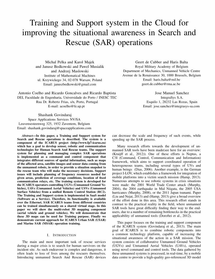
The Training and Support system is implemented using aSaaS (Software as a Service) model with the capability to per-form High Performance Computing in the Cloud (HPC). TheHPC approach is a relatively new topic, especially in mobilerobotics. We are using it for the task of 3D mapping, whichwill be described in more details in next sections. HPC isconnected with GPU virtualisation technology, allowing manyusers to have access to computational demanding applications(NVIDIA CUDA parallel computing, virtual training, visual-ization of 3D cloud of points) in the Cloud. In our opinion,these applications could be used to improve the situationalawareness of Search and Rescue operations. We decided toprovide needed computation power through a mobile datacentre based on NVIDIA GRID server (Supermicro RZ-1240i-NVK2 with two VGXK2 cards - in total 4 GPUs with 4GBRAM each) capable of GPU virtualization. For virtualization,we have used the Citrix framework VDI (desktop virtualiza-tion) and XenApp (application virtualization - allows GPUsharing between users) infrastructures (figure 1). Publishedapplications can be accessed as SaaS from web browser afterinstalling Citrix Receiver - thin client compatible with allpopular operating system for mobile devices (Mac OS X,Linux, Windows, iOS, Android etc.). Current GRID drivershave some limitations in programming framework (CUDA5.5) and GPU class (CUDA 3.0 CC). Nevertheless, the pro-vided functionalities are sufficient for our applications. BesidesCUDA, GRID technology supports building applications withsophisticated rendering (OpenGL 4.4). Thus, in our system it isused for registering, rendering and processing 3D point cloudsand for building training tools.
The data-centre can be used in two ways: as a classicaldata and computation power distribution point, connected tothe Ethernet in a safe location, or as a mobile data-center forthe robotic teams. In the later scenario the server is placedin a robust carrying case for safety (figure 2. The server isthen connected to a router that creates a local network for useby the rescuers. All software on the server can be run on astandard laptop, provided it is with CUDA-compatible GPU.
III. 3D MAPPING HARWARE
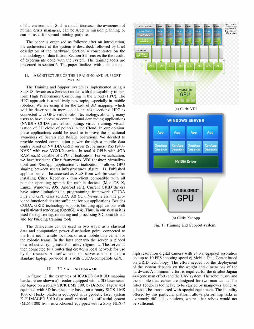
In figure 2, the examples of ICARUS SAR 3D mappinghardware are shown a) Teodor equipped with a 3D laser scan-ner based on a rotary SICK LMS 100, b) DrRobot Jaguar 4x4equipped with 3D laser scanner based on a rotary SICK LMS100, c) Husky platform equipped with geodetic laser systemZ+F IMAGER 5010 d) a small vertical take-off aerial system(MD4-1000 from microdrones) equipped with a Sony NEX-7
(a) Citrix VDI
(b) Citrix XenApp
Fig. 1: Training and Support system.
high resolution digital camera with 24.3 megapixel resolutionand up to 10 FPS shooting speed e) Mobile Data Center basedon GRID technology. The effort needed for the deploymentof the system depends on the weight and dimensions of thehardware. A minimum effort is required for the drrobot Jaguar4x4 (one man effort) and the UAV system. The robot husky andthe mobile data center are designed for two-man teams. Therobot Teodor is too heavy to be carried by manpower alone, soit has to be transported with special equipment. The mobilityoffered by this particular platform allows performing tasks inextremely difficult conditions, where other robots would notbe sufficient.
(a) Teodor (b) Drrobot Jaguar 4x4 (c) Husky
(d) Aerial system md4-1000(e) Mobile Data Centre
Fig. 2: ICARUS SAR 3D mapping Hardware.
IV. DATA FUSION METHODOLOGY
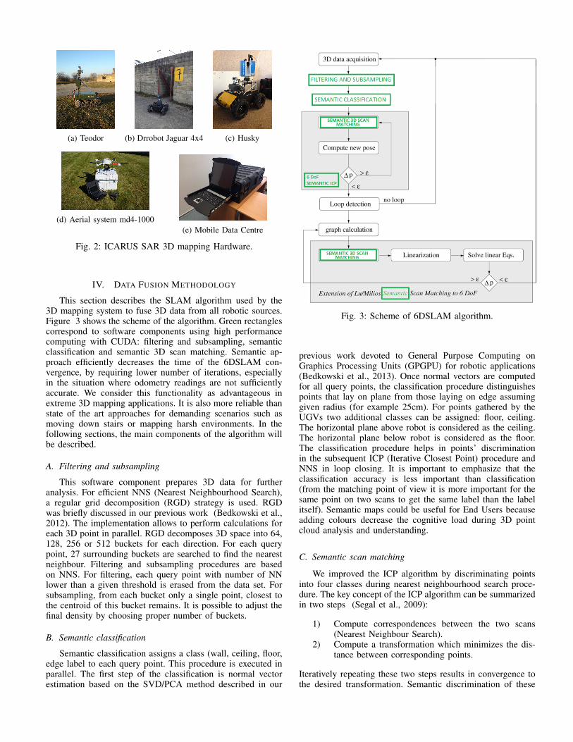
This section describes the SLAM algorithm used by the3D mapping system to fuse 3D data from all robotic sources.Figure 3 shows the scheme of the algorithm. Green rectanglescorrespond to software components using high performancecomputing with CUDA: filtering and subsampling, semanticclassification and semantic 3D scan matching. Semantic ap-proach efficiently decreases the time of the 6DSLAM con-vergence, by requiring lower number of iterations, especiallyin the situation where odometry readings are not sufficientlyaccurate. We consider this functionality as advantageous inextreme 3D mapping applications. It is also more reliable thanstate of the art approaches for demanding scenarios such asmoving down stairs or mapping harsh environments. In thefollowing sections, the main components of the algorithm willbe described.
A. Filtering and subsampling
This software component prepares 3D data for furtheranalysis. For efficient NNS (Nearest Neighbourhood Search),a regular grid decomposition (RGD) strategy is used. RGDwas briefly discussed in our previous work (Bedkowski et al.,2012). The implementation allows to perform calculations foreach 3D point in parallel. RGD decomposes 3D space into 64,128, 256 or 512 buckets for each direction. For each querypoint, 27 surrounding buckets are searched to find the nearestneighbour. Filtering and subsampling procedures are basedon NNS. For filtering, each query point with number of NNlower than a given threshold is erased from the data set. Forsubsampling, from each bucket only a single point, closest tothe centroid of this bucket remains. It is possible to adjust thefinal density by choosing proper number of buckets.
B. Semantic classification
Semantic classification assigns a class (wall, ceiling, floor,edge label to each query point. This procedure is executed inparallel. The first step of the classification is normal vectorestimation based on the SVD/PCA method described in our
Fig. 3: Scheme of 6DSLAM algorithm.
previous work devoted to General Purpose Computing onGraphics Processing Units (GPGPU) for robotic applications(Bedkowski et al., 2013). Once normal vectors are computedfor all query points, the classification procedure distinguishespoints that lay on plane from those laying on edge assuminggiven radius (for example 25cm). For points gathered by theUGVs two additional classes can be assigned: floor, ceiling.The horizontal plane above robot is considered as the ceiling.The horizontal plane below robot is considered as the floor.The classification procedure helps in points’ discriminationin the subsequent ICP (Iterative Closest Point) procedure andNNS in loop closing. It is important to emphasize that theclassification accuracy is less important than classification(from the matching point of view it is more important for thesame point on two scans to get the same label than the labelitself). Semantic maps could be useful for End Users becauseadding colours decrease the cognitive load during 3D pointcloud analysis and understanding.
C. Semantic scan matching
We improved the ICP algorithm by discriminating pointsinto four classes during nearest neighbourhood search proce-dure. The key concept of the ICP algorithm can be summarizedin two steps (Segal et al., 2009):
1) Compute correspondences between the two scans(Nearest Neighbour Search).
2) Compute a transformation which minimizes the dis-tance between corresponding points.
Iteratively repeating these two steps results in convergence tothe desired transformation. Semantic discrimination of these
correspondences improves the convergence. Range images(scans) are defined as model set M where
|M | = Nm (1)
and data set D where
|D| = Nd (2)
The goal of semantic ICP is to minimize the following costfunction:
E (R, t) =
Nm∑i=1
Nd∑j=1
wij
∥∥mci −
(Rdc
j + t)∥∥2 (3)
where wij is assigned 1 if the ith point of M corresponds tothe jth point in D in the sense of minimum distance and thesame class c. Otherwise wij = 0. Class c discriminates pointsinto wall, ceiling, floor or edge. R is the rotation matrix, t isthe translation matrix, mc
i corresponds to point i of class cfrom the model set M , dc
j corresponds to point j of class cfrom the data set D.
D. 6DSLAM
The core of our 6DSLAM contribution was inspired bywork (Borrmann et al., 2008). To improve the accuracyand reliability of the scan matching, we added semanticdiscrimination of points, what was also done in (Nuchter,2005) and (Pfaff et al., 2007). The main difference of ourapproach is the new semantic classification and usage of theparallel programming model for improving the performance ofthe computation. Another advantage of the approach is that allthe needed computation can be performed in the cloud, capableof virtualizing GPU (NVIDIA GRID technology). The cloudsystem allows performing 3D mapping based on many sources(mobile robots equipped with 3D lasers) in parallel and thento merge all maps into a common coordinate system. In thispaper we will demonstrate the 3D map building done by ourcloud system, based on data from two independent UGVs andone UAV. The 3D map can be distributed in the cloud in a SaaS(Software as a Service) model, therefore many end users canhave immediate access to the results of the robots’ surveying.
E. Discussion on the proposed approach and advantages ofthe semantic approach in 6DSLAM
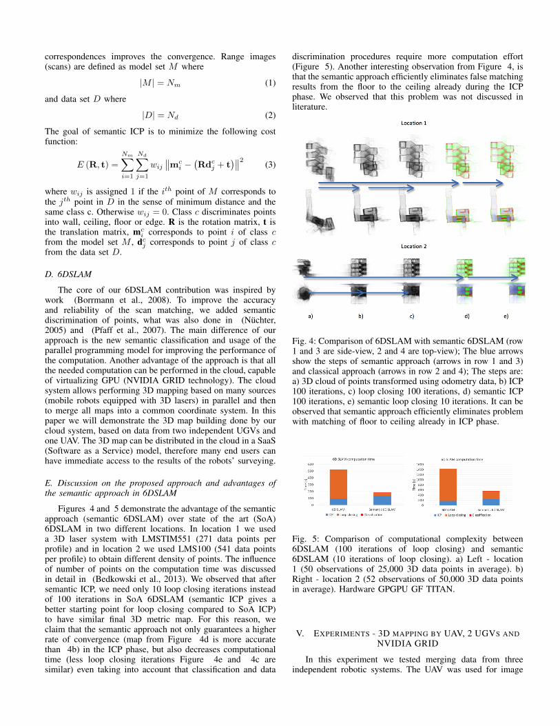
Figures 4 and 5 demonstrate the advantage of the semanticapproach (semantic 6DSLAM) over state of the art (SoA)6DSLAM in two different locations. In location 1 we useda 3D laser system with LMSTIM551 (271 data points perprofile) and in location 2 we used LMS100 (541 data pointsper profile) to obtain different density of points. The influenceof number of points on the computation time was discussedin detail in (Bedkowski et al., 2013). We observed that aftersemantic ICP, we need only 10 loop closing iterations insteadof 100 iterations in SoA 6DSLAM (semantic ICP gives abetter starting point for loop closing compared to SoA ICP)to have similar final 3D metric map. For this reason, weclaim that the semantic approach not only guarantees a higherrate of convergence (map from Figure 4d is more accuratethan 4b) in the ICP phase, but also decreases computationaltime (less loop closing iterations Figure 4e and 4c aresimilar) even taking into account that classification and data
discrimination procedures require more computation effort(Figure 5). Another interesting observation from Figure 4, isthat the semantic approach efficiently eliminates false matchingresults from the floor to the ceiling already during the ICPphase. We observed that this problem was not discussed inliterature.
Fig. 4: Comparison of 6DSLAM with semantic 6DSLAM (row1 and 3 are side-view, 2 and 4 are top-view); The blue arrowsshow the steps of semantic approach (arrows in row 1 and 3)and classical approach (arrows in row 2 and 4); The steps are:a) 3D cloud of points transformed using odometry data, b) ICP100 iterations, c) loop closing 100 iterations, d) semantic ICP100 iterations, e) semantic loop closing 10 iterations. It can beobserved that semantic approach efficiently eliminates problemwith matching of floor to ceiling already in ICP phase.
Fig. 5: Comparison of computational complexity between6DSLAM (100 iterations of loop closing) and semantic6DSLAM (10 iterations of loop closing). a) Left - location1 (50 observations of 25,000 3D data points in average). b)Right - location 2 (52 observations of 50,000 3D data pointsin average). Hardware GPGPU GF TITAN.
V. EXPERIMENTS - 3D MAPPING BY UAV, 2 UGVS ANDNVIDIA GRID
In this experiment we tested merging data from threeindependent robotic systems. The UAV was used for image
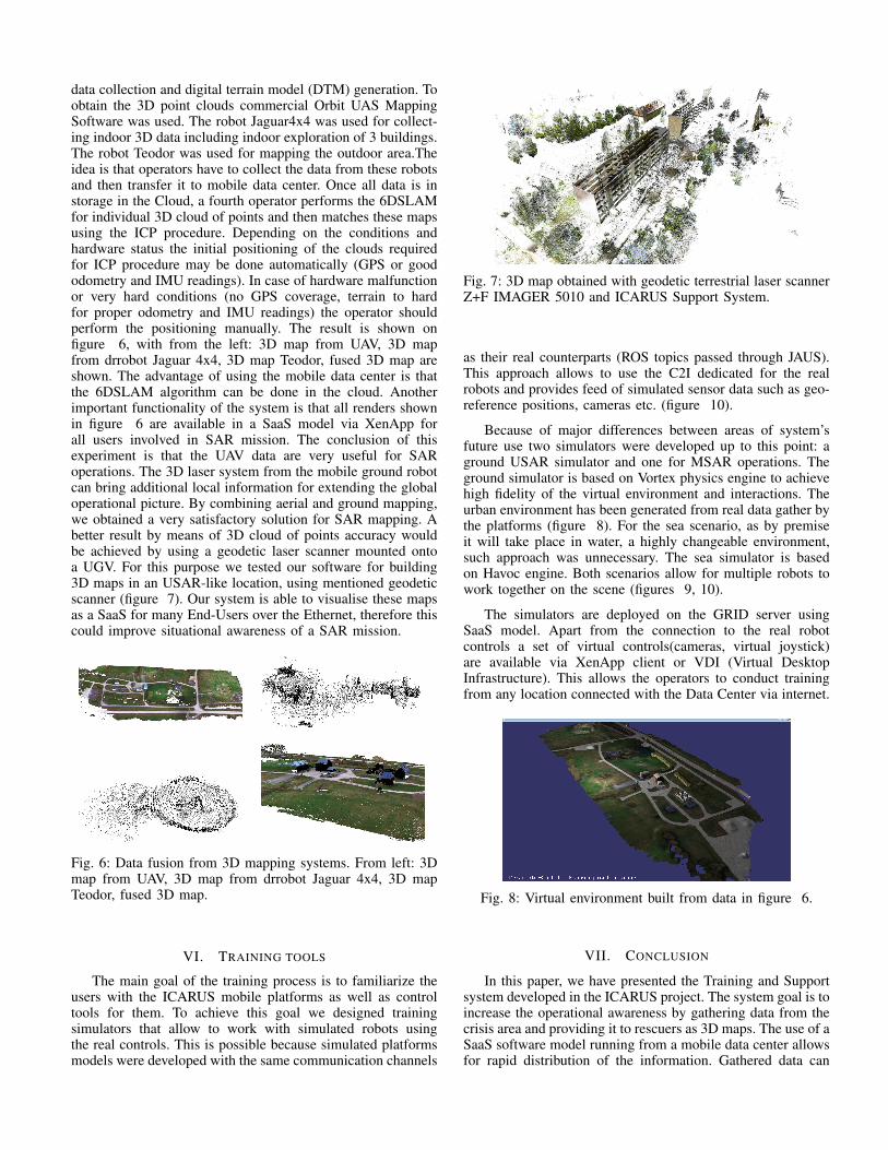
data collection and digital terrain model (DTM) generation. Toobtain the 3D point clouds commercial Orbit UAS MappingSoftware was used. The robot Jaguar4x4 was used for collect-ing indoor 3D data including indoor exploration of 3 buildings.The robot Teodor was used for mapping the outdoor area.Theidea is that operators have to collect the data from these robotsand then transfer it to mobile data center. Once all data is instorage in the Cloud, a fourth operator performs the 6DSLAMfor individual 3D cloud of points and then matches these mapsusing the ICP procedure. Depending on the conditions andhardware status the initial positioning of the clouds requiredfor ICP procedure may be done automatically (GPS or goododometry and IMU readings). In case of hardware malfunctionor very hard conditions (no GPS coverage, terrain to hardfor proper odometry and IMU readings) the operator shouldperform the positioning manually. The result is shown onfigure 6, with from the left: 3D map from UAV, 3D mapfrom drrobot Jaguar 4x4, 3D map Teodor, fused 3D map areshown. The advantage of using the mobile data center is thatthe 6DSLAM algorithm can be done in the cloud. Anotherimportant functionality of the system is that all renders shownin figure 6 are available in a SaaS model via XenApp forall users involved in SAR mission. The conclusion of thisexperiment is that the UAV data are very useful for SARoperations. The 3D laser system from the mobile ground robotcan bring additional local information for extending the globaloperational picture. By combining aerial and ground mapping,we obtained a very satisfactory solution for SAR mapping. Abetter result by means of 3D cloud of points accuracy wouldbe achieved by using a geodetic laser scanner mounted ontoa UGV. For this purpose we tested our software for building3D maps in an USAR-like location, using mentioned geodeticscanner (figure 7). Our system is able to visualise these mapsas a SaaS for many End-Users over the Ethernet, therefore thiscould improve situational awareness of a SAR mission.
Fig. 6: Data fusion from 3D mapping systems. From left: 3Dmap from UAV, 3D map from drrobot Jaguar 4x4, 3D mapTeodor, fused 3D map.
VI. TRAINING TOOLS
The main goal of the training process is to familiarize theusers with the ICARUS mobile platforms as well as controltools for them. To achieve this goal we designed trainingsimulators that allow to work with simulated robots usingthe real controls. This is possible because simulated platformsmodels were developed with the same communication channels
Fig. 7: 3D map obtained with geodetic terrestrial laser scannerZ+F IMAGER 5010 and ICARUS Support System.
as their real counterparts (ROS topics passed through JAUS).This approach allows to use the C2I dedicated for the realrobots and provides feed of simulated sensor data such as geo-reference positions, cameras etc. (figure 10).
Because of major differences between areas of system’sfuture use two simulators were developed up to this point: aground USAR simulator and one for MSAR operations. Theground simulator is based on Vortex physics engine to achievehigh fidelity of the virtual environment and interactions. Theurban environment has been generated from real data gather bythe platforms (figure 8). For the sea scenario, as by premiseit will take place in water, a highly changeable environment,such approach was unnecessary. The sea simulator is basedon Havoc engine. Both scenarios allow for multiple robots towork together on the scene (figures 9, 10).
The simulators are deployed on the GRID server usingSaaS model. Apart from the connection to the real robotcontrols a set of virtual controls(cameras, virtual joystick)are available via XenApp client or VDI (Virtual DesktopInfrastructure). This allows the operators to conduct trainingfrom any location connected with the Data Center via internet.
Fig. 8: Virtual environment built from data in figure 6.
VII. CONCLUSION
In this paper, we have presented the Training and Supportsystem developed in the ICARUS project. The system goal is toincrease the operational awareness by gathering data from thecrisis area and providing it to rescuers as 3D maps. The use of aSaaS software model running from a mobile data center allowsfor rapid distribution of the information. Gathered data can
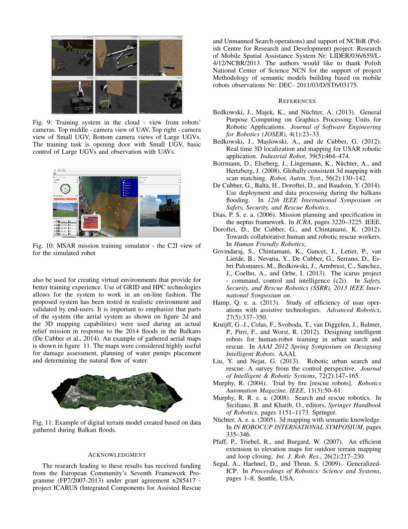
Fig. 9: Training system in the cloud - view from robots’cameras. Top middle - camera view of UAV, Top right - cameraview of Small UGV, Bottom camera views of Large UGVs.The training task is opening door with Small UGV, basiccontrol of Large UGVs and observation with UAVs.
Fig. 10: MSAR mission training simulator - the C2I view offor the simulated robot
also be used for creating virtual environments that provide forbetter training experience. Use of GRID and HPC technologiesallows for the system to work in an on-line fashion. Theproposed system has been tested in realistic environment andvalidated by end-users. It is important to emphasize that partsof the system (the aerial system as shown on figure 2d andthe 3D mapping capabilities) were used during an actualrelief mission in response to the 2014 floods in the Balkans(De Cubber et al., 2014). An example of gathered aerial mapsis shown in figure 11. The maps were considered highly usefulfor damage assessment, planning of water pumps placementand determining the natural flow of water.
Fig. 11: Example of digital terrain model created based on datagathered during Balkan floods.
ACKNOWLEDGMENT
The research leading to these results has received fundingfrom the European Community’s Seventh Framework Pro-gramme (FP7/2007-2013) under grant agreement n285417 -project ICARUS (Integrated Components for Assisted Rescue
and Unmanned Search operations) and support of NCBiR (Pol-ish Centre for Research and Development) project: Researchof Mobile Spatial Assistance System Nr: LIDER/036/659/L-4/12/NCBR/2013. The authors would like to thank PolishNational Center of Science NCN for the support of projectMethodology of semantic models building based on mobilerobots observations Nr: DEC- 2011/03/D/ST6/03175.
REFERENCES
Bedkowski, J., Majek, K., and Nuchter, A. (2013). GeneralPurpose Computing on Graphics Processing Units forRobotic Applications. Journal of Software Engineeringfor Robotics (JOSER), 4(1):23–33.
Bedkowski, J., Maslowski, A., and de Cubber, G. (2012).Real time 3D localization and mapping for USAR roboticapplication. Industrial Robot, 39(5):464–474.
Borrmann, D., Elseberg, J., Lingemann, K., Nuchter, A., andHertzberg, J. (2008). Globally consistent 3d mapping withscan matching. Robot. Auton. Syst., 56(2):130–142.
De Cubber, G., Balta, H., Doroftei, D., and Baudoin, Y. (2014).Uas deployment and data processing during the balkansflooding. In 12th IEEE International Symposium onSafety, Security, and Rescue Robotics.
Dias, P. S. e. a. (2006). Mission planning and specification inthe neptus framework. In ICRA, pages 3220–3225. IEEE.
Doroftei, D., De Cubber, G., and Chintanami, K. (2012).Towards collaborative human and robotic rescue workers.In Human Friendly Robotics,.
Govindaraj, S., Chintamani, K., Gancet, J., Letier, P., vanLierde, B., Nevatia, Y., De Cubber, G., Serrano, D., Es-bri Palomares, M., Bedkowski, J., Armbrust, C., Sanchez,J., Coelho, A., and Orbe, I. (2013). The icarus project- command, control and intelligence (c2i). In Safety,Security, and Rescue Robotics (SSRR), 2013 IEEE Inter-national Symposium on.
Hamp, Q. e. a. (2013). Study of efficiency of usar oper-ations with assistive technologies. Advanced Robotics,27(5):337–350.
Kruijff, G.-J., Colas, F., Svoboda, T., van Diggelen, J., Balmer,P., Pirri, F., and Worst, R. (2012). Designing intelligentrobots for human-robot teaming in urban search andrescue. In AAAI 2012 Spring Symposium on DesigningIntelligent Robots. AAAI.
Liu, Y. and Nejat, G. (2013). Robotic urban search andrescue: A survey from the control perspective. Journalof Intelligent & Robotic Systems, 72(2):147–165.
Murphy, R. (2004). Trial by fire [rescue robots]. RoboticsAutomation Magazine, IEEE, 11(3):50–61.
Murphy, R. R. e. a. (2008). Search and rescue robotics. InSiciliano, B. and Khatib, O., editors, Springer Handbookof Robotics, pages 1151–1173. Springer.
Nuchter, A. e. a. (2005). 3d mapping with semantic knowledge.In IN ROBOCUP INTERNATIONAL SYMPOSIUM, pages335–346.
Pfaff, P., Triebel, R., and Burgard, W. (2007). An efficientextension to elevation maps for outdoor terrain mappingand loop closing. Int. J. Rob. Res., 26(2):217–230.
Segal, A., Haehnel, D., and Thrun, S. (2009). Generalized-ICP. In Proceedings of Robotics: Science and Systems,pages 1–8, Seattle, USA.