
ffi {$} w c c w s g€AJge Hffi s& xs q}&n$fa' cx xewc ffi##M T''ru ...
Upload
khangminh22Category
view
1download
0
CSPTCL TR-21/05 132/33 KV S/S Betar
1
CHHATTISGARH STATE POWER TRANSMISSION CO. LTD. (A Govt. of Chhattisgarh undertaking) (A successor company of CSEB)
CIN- U40108CT2003SGC015820 GSTIN-22AADCC5773E1ZX
OFFICE OF EXECUTIVE DIRECTOR (PLANNING & PROJECT)
Third Floor, SLDC Building, CSEB Campus
Dangania, Raipur (C.G.)-492013
Phone: 0771-2574209/14/41 Fax: 0771-2574246
Website: - www.cspc.co.in/csptcl, email:- [email protected]
TR-21/05 (VOLUME – II OF III)
CONSTRUCTION OF
132/33 KV SUB-STATION AT BETAR
(DISTT.-BEMETARA)
ON TURNKEY BASIS
(Through E-Bidding)
RFx No. 8100022484
CSPTCL TR-21/05 132/33 KV S/S Betar
2
INDEX
SECTION - I
TECHNICAL SPECIFICATIONS FOR CONSTRUCTION OF 132/33 KV SUB-STATION
S.No. PARTICULARS PAGE No.
(A) Technical specification for Civil works for construction of 132/33 KV S/S 5-22
(B) Technical Specifications for Switchyard & Control Room Equipments &
other material etc.
1 Principal Parameters of sub-station, Yard & control room equipments,
erection of structures and equipment, climatic conditions, cable schedule,
quality assurance & work schedule.
23-27
2 Technical specification for 40 MVA 132/33 KV power transformer 28-107
3 Technical Specifications for 145 KV Circuit Breakers 108-129
4 Technical Specifications For 33 KV Vacuum Circuit Breakers. 130-138
5 Technical Specification For Instrument Transformers.
- Basic design features & acceptance criterion for CT & PTs
- Principal technical parameters of Current Transformers.
- Principal technical parameters of Potential Transformers
139-147
6 Technical Specification for 10 MVAR, 33 KV Capacitor Bank. 148-149
7 Technical Specification for 132KV & 33 KV Air Break Dis-
connector(Isolators)
150-161
8 Technical Specification For Lightning Arrestor (Surge Arrestors) 162-163
9 Technical Specifications for Indoor Control & Relay Panels. 164-191
10 Technical Specifications for (110 Volt And 48 Volt) Battery set. 192-194
11 Technical Specifications for (110 Volts And 48 Volts) Battery Charger. 195-201
12 Communication System: (RTU) 202-208
13 Technical Specifications for Unarmoured copper control & armoured power
cables
209-211
14 Technical Specifications for Automatic Data Logging System. 212-217
15 Technical Specifications for Clamps, Connectors and Hard-wares. 218-223
16 Technical Specifications of Station Transformer and D.O Fuse set 224-230
17 Technical Specifications for Lighting Luminaries for Switch Yard & Control
Room Lighting and High mast.
231-235
18 Specification for Supply of Galvanised Steel Structures and Earthing Steel,
ACDB, DCDB Panel and Marshalling/Junction Box, Erection, Testing and
Commissioning of 132 KV / 33 KV Sub Station.
236-246
CSPTCL TR-21/05 132/33 KV S/S Betar
3
19 Technical Specification for ACSR ‘Zebra’ Conductor 247-251
20 Technical Specification for 7/3.66mm Ground Wire 252
21 Technical Specification for 70KN & 90KN Disc Insulator (Anti-fog Type)
and Solid core post Insulators.
253-254
22 Technical Specification For Fire Detection System 255
(C) Details of Steel Structures 256-257
SECTION - III
PRICE VARIATION FORMULE FOR SUB-STATION EQUIPMENTS Page No.
PV-1 Price variation formula for Power Transformers with all accessories 259-260
PV-2 Price variation formula for Instrument Transformers 261-266
PV-3 Price variation formula for Isolators and switchgears 267-270
PV-4 Price variation formula for Lightning Arrestor 271-272
PV-5 Price variation formula for GI Structures 273-274
CSPTCL TR-21/05 132/33 KV S/S Betar
4
SECTION – I
TECHNICAL SPECIFICATION
FOR SUB-STATION
CSPTCL TR-21/05 132/33 KV S/S Betar
5 Technical Parameters
S E C T I O N – I
SECTION - I – A
TECHNICAL SPECIFICATION FOR CIVIL WORKS FOR 132/33 KV SUBSTATION
BETAR
1. SCOPE:-
This specification covers civil works like construction of Control Room Building.
Peripheral chain link mesh fencing with iron main gate of the switchyard, construction of
earth pits, concrete road, cable trenches, sanitation & water supply arrangement,
excavations, back filling, yard levelling/ metalling, foundations of all equipments/structures
etc., including materials viz., steel, cement, metal, sand etc. Water has to be arranged by the
contractor at his own cost. Also, storage space for equipments and site office will be
arranged by the contractor at his own cost. The labour hutments & model sanitary
arrangement have to be provided by the contractor at his own cost.
2. CIVIL WORKS: - The technical specifications for civil works, shall be as follows:-
2.1 Construction of Control Room Building and all civil works at 132/33 KV switch yard viz;
x-mer/equipment foundations cable trenches, yard fencing, yard levelling, metalling,
earth pits, gate, burnt oil tank, approach roads rain water harvesting tank, sign boards,
arrangement of slope protection works, drainage arrangement of yard, complete water
supply arrangement etc. is covered in the scope of contract. All materials shall be of best
quality conforming to relevant Indian Standards and Codes. In case of any conflict
between Standards/ Code and Technical Specification the provisions of Standards/
Code shall prevail.
The Contractor shall furnish all labour, tools, equipment, materials, temporary works,
constructional plant and machinery, fuel supply, transportation and all other incidental items
not shown or specified but as may be required for completion of the works in accordance
with approved drawings, specifications and direction of Engineer-in-charge.
All materials including cement, reinforcement steel and structural steel etc. shall be arranged
by the contractor. All testing of constructional material required as per relevant BIS codes
shall be arranged by the contractor at his own cost at site.
All the construction material shall have to be got approved prior to use, from
Engineer-in-charge of CSPTCL. The bidder shall fully appraise himself of the prevailing geographical, topographical &
climatic conditions at the proposed site, including monsoon patterns, local conditions and
site specific parameters, availability of all construction materials as per specifications and
shall include for all such conditions and contingent measures in the bid, including those
which may not have been specifically brought out in the specifications/ Bill of Quantity.
The data related to soil investigation in the tender document is intended to give the bidder
an idea about soil characteristics of site. However, the bidders are advised to visit the site
before submitting their offer, to assess the actual working condition prevailing. In case,
expansive / compressible / highly compressible soil strata is encountered while actual
execution of work, specifications / drawings suitable to the expansive / compressible /
highly compressible soil will have to be adopted, even though the bearing capacity
mentioned in the tender specification indicates otherwise, for which no extra payment will
be made.
Bidders are advised to visit the substation site prior to submission of offer & take into
account all factors like required levelling, retaining wall, approach road, if required,
slope protection etc., before quoting the rates.
2.2 DRAWINGS
The Contractor shall execute the work at site as per drawings provided by CSPTCL.
Photocopies shall not be used at site. Civil drawings of the equipment foundations, control
CSPTCL TR-21/05 132/33 KV S/S Betar
6 Technical Parameters
room, rain water harvesting tank & pit, burnt oil tank, road, retaining wall, chain link mesh
fencing etc. shall be provided by CSPTCL. However drawings for some equipments
which are make dependant viz. Circuit breaker, lighting mast, capacitor bank, Bay
marshalling room (Kiosk), etc. shall be provided by CSPTCL only after foundation
layout drawings and load details for such equipments are made available to CSPTCL
by successful bidder.
2.3 DESCRIPTION OF OIL RECOVERY SYSTEM:-
The oil recovery system shall be provided below all Transformers in order to avoid spread
of fire by the oil in case of any major failure of transformer. The oil collecting pit and burnt
oil tank shall be connected with GI class ‘C’ pipes of minimum 300 dia. for which no extra
payment shall be made. Burnt oil tank / pit shall be provided with 3.0 HP Submersible
pump of KSB/Kirloskar make.
3.0 SITE PREPARATION :-
3.1 Clearing, levelling
1) Material unsuitable for laying of foundations shall be removed and replaced by
suitable fill material as per approval of CSPTCL.
2) Backfill material around foundations or other works shall be suitable for the purpose for
which it is used and compacted to the density described under Compaction.
Excavated material not suitable or not required for backfill shall be disposed off in
areas as directed by CSPTCL.
3) Site clearing, levelling: - Before the work is commenced, the area described and shown
on plan shall be cleared by the contractor at his own cost, of all obstructions, including
abandoned brick masonry/ concrete/ steel structures, loose stones, materials, vegetation
such as grass, shrubs, bushes and stumps of trees, roots etc. as directed. The product of
the clearing shall be stacked in such places and in such manner as instructed by the
Engineer-in-charge of CSPTCL and the ground left in a perfectly clean condition. The
useless materials obtained by the clearing should be removed from the area and
disposed off as directed by the Engineer-in-charge of CSPTCL for which no payment
will be made by CSPTCL. All holes or hollows whether originally existing or produced
by digging and up roots shall be carefully filled up with earth well rammed and
levelled off as directed. On completion of the works, the site around the building
structures shall be cleared by the contractor at his own expense to the satisfaction of the
Engineer-in-charge of CSPTCL.
The excavated material shall be the property of CSPTCL & its storage, use or disposal,
shall be done as directed by the Engineer in charge of CSPTCL
4) The contractor shall level the entire area up to desired level through cutting/ filling.
The excavated material if found suitable may be used by the contractor for levelling.
However royalty/taxes as decided by concerned Govt. / CSPTCL authority on such use
shall be borne by the contractor. In case hard rock is obtained in excavation then such
material shall be taken in MAS of CSPTCL for proper record.
3.2 Excavation and backfill:
1. Excavation and backfill for foundations shall be in accordance with the relevant code.
2. If excavated soil in foundations is non-expansive, then same shall be used for
backfilling. If, excavated soil is expansive, then the foundation shall be backfilled by
non-expansive soil. In either case no separate payment shall be made.
3. No separate payment shall be made for any type of soil / rock encountered during
excavation of foundation as per approved LUP/Drawings.
4. Whenever water table is met during the excavation, it shall be dewatered and water
table shall be maintained below the bottom of the excavation level during excavation,
concreting and backfilling for which no extra payment shall be made by CSPTCL.
5. When embankments are to be constructed on slopes of 15° or greater, horizontal
benches or steps with horizontal and vertical faces shall be cut in the original slope prior
to placement of embankment material. Vertical faces shall measure not more than 1 m in
CSPTCL TR-21/05 132/33 KV S/S Betar
7 Technical Parameters
height.
6. Embankments adjacent to abutments, culverts, retaining walls & similar structures
shall be constructed by compacting the material in successive uniform horizontal
layers not exceeding 15 cm in thickness (of loose material before compaction). Each
layer shall be compacted at OMC as required by means of mechanical tampers
plate vibrator/rollers approved by the Engineer-in-charge of CSPTCL following
procedure outlined under compaction. Rocks larger than 10 cm in any direction
shall not be placed in embankment adjacent to structures.
7. Earth embankments of roadways and site areas adjacent to buildings shall
be placed in successive uniform horizontal layers not exceeding 20 cm in thickness in
loose stage measurement and compacted at OMC to the full width specified. The
upper surface of the embankment shall be shaped so as to provide complete drainage
of surface water at all times.
8. The soil from excavation of foundation, cable trenches etc. if used for yard levelling
(with proper compaction at OMC using vibratory plate compactor) as per direction of
Engineer-in-Charge, no extra payment shall be admissible. The soil so used shall be
adjusted in the quantity for levelling. If the excavated material is not usable, then same
shall be disposed off as per direction of Engineer-in-charge for which no extra payment
shall be made.
3.3 Compaction:
1. The density to which fill materials shall be compacted shall be as per relevant IS and
as per direction of engineer-in-charge. All compacted sand filling shall be confined as
far as practicable. Backfilled earth shall be compacted to minimum 90% of Maximum
Dry Density. The sub grade for the roads and embankment filling shall be compacted to
minimum 90% of Maximum Dry Density.
2. At all times unfinished construction shall have adequate drainage. Upon completion of
the road’s surface course, adjacent shoulders shall be given a final shaping, true
alignment and grade.
3. Each layer of earth embankment when compacted shall be a s close to optimum
moisture content as practicable. Embankment material which does not contain
sufficient moisture to obtain proper compaction shall be wetted. If the material contains
any excess moisture, then it shall be allowed to dry before rolling. The rolling shall
begin at the edges overlapping half the width of the roller each time and progress to
the centre of the road or towards the building as applicable. Rolling will also be
required on rock fills. No compaction shall be carried out during rain.
4. Drainage arrangement like Katcha drain should be made around periphery of
substation yard so that storm water does not enter/foul construction area /substation
yard.
3.4 Requirement for fill material under foundation:
The thickness of fill material under the foundations shall be such that the maximum
pressure from the footing, transferred through the fill material and distributed onto the
original undisturbed soil will not exceed the allowable soil bearing pressure of the
original undisturbed soil. For expansive soils the fill materials and other protections etc.
to be used under the foundation is to be got approved by CSPTCL.
4.0 ANTI WEED TREATMENT & METAL SPREADING:
4.1 Scope of work:
The Contractor shall furnish all labour, equipment and materials required for complete
performance of the work in accordance with the approved drawings, specification and
direction of CSPTCL. Metal spreading over coarse sand/stone dust layer shall be done
in the areas of the switchyard under present scope of work. However the metal
spreading over underlying layer in future areas within fenced area shall also be
provided in case step potential without metal layer is not well within safe limits.
CSPTCL TR-21/05 132/33 KV S/S Betar
8 Technical Parameters
4.2 General requirement:
The material required for site surfacing/ metal filling shall be free from all types of organic
materials and shall be of standard quality and as approved by CSPTCL.
4.2.1 The material to be used for metal filling/ site surfacing shall be crusher broken hard metal
of 40mm nominal size (ungraded single size) conforming to Table 2 of IS:383 – 1970.
(a) Sieve Analysis limits (Gradation) (IS : 383 – Table – 2)
Sieve Size % passing by weight
63mm 100
40mm 85-100
20mm 0-20
10mm 0-5
“One Test” shall be conducted for every 500 cum.
Hardness, flakiness as required for surfacing courses are given below:
(b) Hardness
Abrasion value (IS: 2386 Part-IV) – not more than 40%
Impact value (IS: 2386 Part-IV) – not more than 30% and frequency shall be
one test per 500 cum. with a minimum of one test per source.
(c) Flakiness Index
One test shall be conducted per 500 cum. of aggregate as per IS: 2386 Part – I
and maximum value is 25%.
4.2.2 After all the structures/equipments are erected, anti weed treatment shall be applied in
the switchyard where ever metal spreading over underlying layers is to be done and
the area shall be thoroughly de-weeded including removal of roots. The
recommendation of local agriculture or horticulture department may be sought where
ever feasible while choosing the type of chemical to be used. The anti weed chemical shall be
procured from reputed manufacturers. The doses and application of chemical shall be
strictly done as per manufacturer’s recommendation. Nevertheless the effectiveness of
the chemical shall be demonstrated by the contractor in a test area of 10m x 10m
(approximately) and shall be sprinkled with water at least once in the afternoon every day
after 48 hours of application of chemical. The treated area shall be monitored over a
period of two to three weeks for any growth of weeds by the Engineer – in- charge. The final
approval shall be given by Engineer – in –charge based on the results.
4.2.3 Engineer-in-charge shall decide final formation level so as to ensure that the site appears
uniform, devoid of undulations. The final formation level shall however be very close to
the formation level indicated in the approved drawing.
4.2.4 After anti weed treatment is complete, the surface of the switchyard area shall be maintained,
rolled/compacted to the lines and grades as decided by Engineer-in charge. The sub grade
shall be consolidated by using half ton roller with suitable water sprinkling arrangement to
form a smooth and compact surface. The roller shall run over the sub grade till the soil is
evenly and densely consolidated and behaves as an elastic mass.
4.2.5 In areas that are considered by the Engineer-in-Charge to be too congested with foundations
and structures for proper rolling of the site surfacing material by normal rolling
equipments, the material shall be compacted by plate compactor. Due care shall be
exercised so as not to damage any foundation structures or equipment during rolling &
compaction.
4.2.6 Over the prepared sub grade, first 100 mm thick layer of coarse sand shall be laid as
per direction of engineer-in-charge of CSPTCL in the area excluding roads, drains, cable
trenches as per detailed drawing. However in case of BC soil in top strata the thickness of
this layer shall be 200 mm. For easy drainage of water, minimum slope of 1:1000 is to be
provided from the ridge to the nearest drain. The ridge shall be suitably located at the
centre of the area between the nearest drains. The above slope shall be provided at FGL
only.
4.2.7 A final layer of 100mm thickness of crusher broken hard metal of 40mm nominal single
size (ungraded) shall be spread uniformly over underlying layer of stone dust.
CSPTCL TR-21/05 132/33 KV S/S Betar
9 Technical Parameters
4.2.8 The quantity of filling shall be measured in cubic metres through stack measurements and
voids shall be deducted as follows from stack measurements:-
S. No. Particulars % age voids to be deducted
1. Metal 8 %
2. Moorum/Sand 16 %
3. Stone dust 25%
5.0 STORM WATER DRAINAGE & RAINWATER HARVESTING:
5.1 It shall be total responsibility of contractor to provide drainage system of entire yard as per
direction of Engineer in charge of CSPTCL. No extra payment shall be made on this
account.
5.2 In addition to drainage of rainwater, the contractor shall make arrangement for rainwater
harvesting also.
5.3 Rainwater harvesting shall be done by providing one number recharge structure with rain
water harvesting and soak pit arrangement. The recharge structure shall be suitably located
within the substation. Branch drains from the main drain and cable trenches carrying
rainwater from entire switchyard shall be connected to the recharge structure by RCC drain
/ hume pipes. For RCC drains suitable RCC cable trench section without MS angles shall be
used. No extra payment shall be made for these RCC drain / hume pipes. Overflow
arrangement from recharge structure shall be provided and the overflow shall be taken
through trench / closed conduit (NP3 pipe) of approved size / dia. up to nearest available
natural drainage at such a level to completely ensure effective drainage in all seasons. No
extra payment shall be made on this account.
6.0 ROADS AND CULVERTS:
6.1 All the roads in the scope of contract shall be reinforced concrete road as per drawing
provided by CSPTCL.
6.2 Layout of the roads shall be as per approved LUP drawing for the substation. Adequate
turning space for vehicles shall be provided and bend radii shall be set accordingly. Road to
the Transformer shall be as short and straight as possible.
6.3 Road construction shall be as per IRC standards.
6.4 Adequate provisions shall be made for road drainage.
6.5 Adequate turning radius, tracking off / extra widening / swept path shall be provided for
trailer at all turnings of roads. No extra payment shall be made on this account.
7.0 FOUNDATION / RCC CONSTRUCTION:-
7.1 General:-
(a) Work covered under this Clause of the Specification comprises the construction of
foundations and other RCC constructions for switchyard structures, equipment
supports, trenches, drains, jacking pad, pulling block, control cubicles, bus supports,
Transformer/Reactors, marshalling kiosks, auxiliary equipment & systems buildings, tanks or
for any other equipment or service and any other foundation required to complete the work.
This clause is as well applicable to the other RCC constructions.
(b) Concrete shall conform to the requirements mentioned in latest IS: 456 and all the tests
shall be conducted as per relevant Indian Standard Codes. A minimum grade M20 –
nominal mix 1:1½:3 concrete shall be used for all construction works unless specified
otherwise.
It may please be noted that the metal to be used for P.C.C. / R.C.C. works shall be
hard stone metal only.
(c) If the site is sloping, the foundation height will be adjusted to maintain the exact level of the
top of structures to compensate such slopes.
(d) The switchyard foundation’s top shall be minimum 200 mm above finished yard level.
CSPTCL TR-21/05 132/33 KV S/S Betar
10 Technical Parameters
(e) Minimum 100 mm thick lean concrete (1:4:8) shall be provided below all underground
structures, foundations, trenches etc. to provide a base for construction.
(f) OPC / PPC of approved and reputed brand shall be used in construction works and test
certificate from manufacturer shall have to be submitted to engineer in charge of CSPTCL for
kind of cement being used.
(g) CABLE TRENCHES.-
All cable trenches shall be constructed as per drawing provided by CSPTCL.
External cable trenches.-
Y-1 Buried Type Cable Trench. –
The buried cable trench shall be constructed in following manner:-
Layer- I : 100 mm thick layer of bricks.
Layer-II : 200 mm layer of sand with cable embedded in between.
Layer-III: 100 mm thick layer of bricks.
Layer-IV: 100 mm backfilling with soil upto FGL.
Note:- The cables shall be kept at the centre of sand layer.
RCC cable trenches shall be constructed for branch cable trench (Y-2 type and Y-3 type & Y-4
type).
Y-2 Type Branch Cable Trench –
Cable trench having dimension of 325 mm (W) x 305 mm (D) with cable tray of 300 mm placed
on hot dip galvanised supporting angles at a height of 150 mm above the bottom surface of the
trench. The top cover of this cable trench shall be useful for path way & shall be provided with
doubly reinforced RCC Covers having stiffener & proper lifting arrangements as per approved
drawings, specifications, direction and approval of Engineer-In-Charge of CSPTCL.
Y-3 Type Branch Cable Trench –
This type of RCC Cable trench having dimension of 850 mm (W) x 650 mm (D) with two tiers
of cable tray of 450 mm width placed on hot dip galvanised supporting angles at a height of 150
mm and 450mm above the bottom surface of the CSPTCL TR-21/03 132/33 KV S/S Arang &
Assoc.Line 13
trench for placing AC supply cables and control cables separately. Cable trench covers shall be
doubly reinforced R.C.C. covers as per approved drawings, specifications, direction and
approval of Engineer-In-Charge of CSPTCL.
Y-4 Type Main Cable Trench –
This type of RCC cable trench having dimension of 1200 mm (W) x 1000 mm (D) with three
tiers of cable tray of 600 mm width placed on hot dip galvanised supporting angles at a height of
200 mm, 450 mm and 700 mm above the bottom surface of the trench. The top cover of these
cable trenches shall be useful for path way for operating and maintenance staff. The Cable
trench shall be covered with RCC cast in situ slab (fixed slab). At every 2.0 meter distance,
700mm wide openings shall be provided and the openings shall be covered with 6.0 mm thick
steel chequered plate. The chequered plate covers shall be duly stiffened and fixed to the frame
grouted in cable trench wall and RCC top slab, as per approved drawings, specifications,
direction and approval of Engineer-In-Charge of CSPTCL.
RCC cable trenches suitably designed to take super imposed load, with adequate inside
dimensions, weep hole arrangements with 50 dia weep holes @ 1.5m c/c spacing
horizontally and 1.0m c/c vertically with inverted filter at back, chases support hot dip
galvanised MS angle for cable tray, RCC covers (min. 90 mm thick) with reinforcement
on both faces etc. complete with proper bed slope for efficient drainage up to recharge
structure.
The cable trenches and precast removable RCC cover (with groove & lifting
arrangement) shall be constructed using RCC of M20 grade.
The cable trench walls shall be designed for the following loads.
Dead load of 155 kg/m length of cable support +75 kg on one tier at the end.
Triangular earth pressure + uniform surcharge pressure of 2T/m2.
CSPTCL TR-21/05 132/33 KV S/S Betar
11 Technical Parameters
Cable trench covers shall be designed for self weight of top slab +UDL of 2000 kg/m2 +
concentrated load of 200 kg at centre of span on each panel.
Cable trench crossing the road / rails shall be designed for class A loading of IRC/
relevant IS code.
Trenches shall be drained. Necessary sumps be constructed and sump pumps if necessary
shall be provided. Cable trenches shall not be used as storm water drains but, it should be
capable to drain water from yard area.
All metal parts inside the trench shall be connected to the earthing system.
Cables from trench to equipments shall run in hard conduit pipes.
Trench wall shall not foul with the foundation. Suitable clear gap shall be provided.
The trench bed shall have a slope of 1/ 1000 along the run & 1/250 Perpendicular to the
run.
All the construction joints of cable trenches i.e. between base slab to base slab and the
junction of vertical wall to base slab as well as from vertical wall to wall and all the
expansion joints shall be provided with approved quality PVC water stops of approx. 230
x 5 mm size for those sections where the ground water table is expected to rise above the
junction of base slab and vertical wall of cable trenches.
Cable trenches shall be provided at the ends with grating of 16mm plain bar. However
inside control room the end of Cable trenches should be provided with retaining wall.
Cement mortar for cable trenches shall be 1:6 for masonry and 1:6 for 12mm thick
plaster
7.2 Admixture & additives:
7.2.1 Only laboratory tested & established approved admixtures shall be used in the
concrete. When more than one admixture is to be used, each admixture shall be
batched in its own batch and added to the mixing water separately before
discharging into the mixer. Admixtures shall be delivered in suitably labelled
containers to enable identification.
7.2.2 Admixtures in concrete shall conform to IS: 9103. The water proofing cement
additives shall conform to IS: 2645. Concrete Admixtures/ Additives shall be approved by
Owner.
7.2.3 The Contractor may propose and CSPTCL may approve the use of a water-
reducing set-retarding admixture in some of the concrete. The use of such an admixture
will not be approved to overcome problems associated with inadequate concrete plant
capacity or improperly planned placing operations and shall only be approved as an aid to
overcoming unusual circumstances and placing conditions.
7.2.4 The water-reducing set-retarding admixture shall be an approved brand of
Lignosulphonate type admixture.
7.2.5 The water proofing cement additives shall be used as required/ advised by CSPTCL.
8.0 CHAIN LINK FENCING AND GATE:
Fencing and gate shall be provided as per drawing provided by CSPTCL.
8.1 Product materials:
The minimum requirements are as follows:
a) Chain link mesh (with galvanization) in accordance to IS: 2721.
1. 1. Size of opening in mesh : 75mm x 75mm
2. Nominal wire size : 8 gauge diameter
3. Height of chain link mesh : 2400 mm
b) Posts
(i) The posts shall be hot dip galvanized iron angle posts of size 65x65x6 at 2.5m c/c
spacing with 45x45x5 angle galvanized iron bracings at top and bottom of mesh.
The vertical posts shall have further V shaped extension of 450 mm (vertical height)
over the chain link mesh top. Six rows of barbed wires with weight not less than
CSPTCL TR-21/05 132/33 KV S/S Betar
12 Technical Parameters
9.38 kg per 100 m shall be provided in the V shaped portion. Two Nos. GI wire of
min 8 gauge shall be provided between top & bottom bracing angles along the
entire length of mesh which shall be tightened to provide stiffness to mesh.
Strainer posts shall be provided at every corner and at every 10th post.
Strainer posts shall be provided on either side of vertical post and from inner
side as well.
(ii) Fencing top shall be provided with galvanized barbed wire. Barbed wire shall
conform to IS: 278. The barbed wire may consist of not more than two splices per
reel. The barbed wire shall be formed by twisting two line wires, one containing the
barbs. The barbed wire shall be designed as Type A of IS: 278 and shall be
galvanized.
(iii) Barbed wire arms shall be same as intermediate and straining post.
(iv) Fittings and hardware: cast aluminum alloy or galvanized steel, malleable or ductile
cast iron turnbuckles to be drop forged.
(v) For every 50 reels or part there of samples of the barbed wire and the individual
line wires shall be put to tensile test and in case of failure to conform to the tensile
properties given below, two additional tests of each kind shall be made on the
samples cut from other reels.
(vi) GI chain link mesh shall be as per IS: 2721. Mesh size 75 mm and nominal wire
size shall be 8 gauge diameter.
TENSILE PROPERTIES
Tensile strength of line wire : 39 to 59 kg/sq. mm
Minimum breaking load of
Complete barbed wire : 370 kg
On the results of these additional tests, the whole or portion of the barbed wire shall
be accepted or discarded by the CSPTCL authorities as the case may be.
(vii) The whole assembly of angles shall be hot dip galvanized. The zinc
coating shall be minimum 610 gram per sq. meter. The purity of zinc shall be
99.95% as per IS: 209.
c) Brick Wall below mesh
Brick masonry wall of Min. 200 mm thickness shall be provided at bottom of
mesh with plastering, 75 mm thick coping of PCC 1:2:4 grade, painting with
exterior paint of reputed and approved brand etc. complete in all respects. The wall
shall be min. 200 mm below natural ground level, and, 200 mm above FYL. PCC
(1:3:6) of 100 mm thickness and 300 mm width shall be provided below wall in
hard soil for depth of wall upto 400 mm. However if the overall depth of wall
exceeds 400 mm, the thickness of wall and width of PCC shall be designed to
bear the superimposed loads. In case of black cotton soil in foundation 200mm
thick brick wall shall be provided over RCC bracing beam of min size 200x
200 mm. The height of wall shall be such that the top of wall shall be 200
mm above FYL.
8.2 Installation:
(i) Mesh:-
a) Mesh shall be installed leaving at least 6 m clearance from equipment/ structures
along the switchyard line as per approved General Arrangement drawing.
b) Post of hole/pit shall be excavated by approved method.
c) All posts shall be 2.50m apart measured parallel to ground surface. Posts shall be
set in 1:3:6 Plain Cement Concrete block of minimum 0.40x0.40x0.6m depth (in
side natural ground level) in hard soil in cutting zone and the top of fondation shall
be extended upto FYL. In case of fencing in filling zone the depth of foundat ion
shall be increased so that min. 0.60m foundation depth falls in side natural
ground level and top of foundation shall be extended upto FYL The fencing angle
CSPTCL TR-21/05 132/33 KV S/S Betar
13 Technical Parameters
shall be grouted upto 100 mm from bottom of foundation in eachcase.In case of
black cotton soil in foundation 200 mm dia single under reamed 3500 mm deep
inside NGL. Pile foundation shall be provided with 200 X 300 mm bracing
beam. The beam top shall be 100 mm above FYL.
d) Posts shall be braced and held in plumb position and true alignment and elevation
until concrete has set.
e) Mesh shall not be installed until concrete has cured a minimum of 7 days.
f) Mesh shall be fixed to the posts and bracing angles at 4 locations in each angle
using MS flat each of 30x3 mm, 100 mm long through 2 nos. of bolts (12 mm
diameter) on each flat.
g) The painting pattern of brick masonry wall shall be decided by Engineer-in- charge.
It shall be preferable to paint the alternate wall in different colour pattern such
that it gives better aesthetic look. The paint shall be Ultima/Weather coat brand.
(ii) Gate:-
i. The gate shall be made as per approved drawing.
ii. The gates shall be fabricated with welded joints to achieve rigid connections. The
gate frames shall be painted with one coat of approved steel primer and two coats of
synthetic enamel paint.
iii. The gates shall be provided with suitable locking arrangement.
iv. Steel rollers shall be provided below gates with grouted guide.
v. Gate shall be installed as per approved General arrangement drawing.
vi. The gate shall be made of medium duty M.S. pipe conforming to relevant IS Codes
with welded joints. The main frame (outer frame) of the gate shall be made of
50mm dia pipe medium quality & vertical pipes of 25mm dia medium quality pipes
@ 100mm c/c spacing. Other details shall be as per approved drawing.
9.0 WATER SUPPLY FOR BUILDINGS & EARTH PITS
Two number 150 mm dia tube wells at different locations, each with minimum 5000 litre
per hour yield, 2 Nos. overhead (interconnected) HDPE water tanks of 1000 litre capacity
each above control room building at corner location above toilet of control room building
roof for supplying water to all the earth pit through gravity, complete water supply
arrangements from both the bores to all the water tanks, from over head water tanks to
building and from both the bores as well as from both 1000 litre tank to all the earth pits,
with submersible pumps, panels, cables, water tanks, GI pipe lines, all fittings, fixtures etc.
of approved make as per specifications, in standard manner, as per direction of engineer in
charge of CSPTCL. The supply network to all the earth pits shall be closed loop type
ensuring supply from both the ends with designed sizes of pipes to ensure effective
supply of water to all the earth pits. Schematic drawing shall be prepared by the
contractor indicating the layout and details of each water supply scheme which shall
be got approved before actual start of work including all other incidental items not
shown or specified but as may be required for complete performance of the works.
Each Bore well shall be provided with 3-phase water cooled submersible pumps of
KSB/Kirlosker make of minimum 2 H.P. or more as per requirement /directions of
CSPTCL’s site engineer with Crompton Greaves /Havells make control panels and
Finolex/ Havells make cables.
The rain water from control room building shall be collected at one or more outlet points
through rain water pipe of suitable size or as per drawing. At each outlet points rainwater
harvesting filter such as ‘Rainy Filter FL-200’ suitable for roof area of control room
building to be provided at outlet point and these outlet shall be connected to rainwater
harvesting pit. Rain water harvesting pit are to be constructed as per drawing provided by
CSPTCL TR-21/05 132/33 KV S/S Betar
14 Technical Parameters
CSPTCL around bore well for direct recharge of bore wells. No extra payment shall be
made on this account.
9.1 Sewerage System
Sewerage system shall be provided for control room building by contractor.
The Contractor shall construct septic tank and soak pit suitable for 50 users.
10. OTHER TECHNICAL DETAILS
10.1 15mm cement plaster of mix 1:6 (1cement: 6 sand) shall be provided on the smooth side of
walls.
10.2 6 mm cement plaster of mix 1:3 (1 cement: 3 sand) to all ceiling.
10.3 20mm cement plaster of mix 1:6 (1 cement: 6 sand) on rough side of wall.
10.4 CONTROL ROOM: The Control room drawing as per Company’s standard practice has
been furnished with the tender specification. Mineral fibre false ceiling shall be provided in
C/R hall, A.E. and Carrier room .The clear height between floor top and Ceiling bottom
shall be not less than 3.6 metre The false ceiling shall comprise 600 x 600 x 15 mm
(minimum) mineral fibre tiles of type RH 90 of Armstrong or equivalent make of minimum
3.0 Kg/Sq.m. weight and 85% sound absorption capacity as per direction and approval of
Engineer-in-charge of CSPTCL. The tiles shall be laid over Armstrong Prelude XI exposed
grid system with main runner spacing as 1200 mm c/c securely fastened to structural ceiling
at 1200 mm c/c. Perimeter trim shall be Armstrong wall angle secured to wall at 450 mm
c/c as per direction of Engineer-in-charge of CSPTCL.
10.5 All internal wall surfaces / ceiling of Control Room Building shall be applied Birla/J.K
cement based water proof putty. Painting on all internal walls and ceilings with plastic
emulsion paint of Asian/ICI/Nerolac/Berger brand to give an even shade (two or more
coats). Over plaster first apply cement primer then, putty over it paint primer & then
painting is to be done.
10.6 Painting on all external walls two or more coats of Ultima or Weather Coat or Weather
Shield brand paint over two under coats of Plasto proof make primer over new cement
plaster surfaces of the C/R building inclusive of required tools, scaffolding, materials
and other painting accessories etc. as per recommendations of manufacturer.
10.7 Enamel Painting with synthetic enamel paint of approved brand and manufacture of required
colour to give an even shade shall be provided on the steel glazed doors, windows,
ventilators and rolling shutters in various buildings as per approved drawings. Two or more
coats over an under coat of suitable shade with primer paint of approved brand and
manufacture
10.8 Two or more coats of Touch wood brand polish with a coat of wood filler shall be
provided on the wooden doors. Final coating shall be of poly urethrin (pu) spray.
10.9 Filter room in Control Room building shall be provided 52 mm thick cement concrete
flooring with metallic concrete hardener topping over 40 mm thick layer of cement concrete
1:2:4 (1 cement : 2 coarse sand : 4 graded metal aggregate 20 mm nominal size) and top layer
12 mm thick concrete consisting of mix 1: 2 ( 1 cement hardener mix : 2 metal aggregate 6
mm nominal size) by volume with which "metallic" hardening compound shall be mixed
as per manufacturer’s instructions. Cement plaster skirting (up to 15 cm height) with
cement mortar 1:3 (1 cement: 3 coarse sand) mixed with metallic concrete hardener in same
ratio as for floor finished with a floating coat of neat cement 21 mm thick in Filter room.
10.10 1st Quality double charge ceramic glazed floor Group V tiles (anti-skid) of size and
thickness as directed by CSPTCL Engineer conforming to IS: 13755 of NITCO
/KAJARIA/BELL/JOHNSON/REGENCY, make shall be provided in toilet floor area
in all colour shades as approved by Engineer-in-charge of CSPTCL laid on 20mm thick
cement mortar 1:4 (1 cement : 4 coarse sand ) including pointing the joints with white
cement and matching pigment etc complete. Each tile should be tested with wooden
hammer after three days of fixing.
CSPTCL TR-21/05 132/33 KV S/S Betar
15 Technical Parameters
10.11 1st quality double charge ceramic glazed tiles conforming to IS : 13753 of minimum thickness
5mm of approved make like NITCO/BELL/JOHNNSON/REGENCY/ KAJARIA make
shall be provided in toilet wall in all colours shade of any size as approved by Engineer-
in-charge of CSPTCL in dados (height upto 2.4 m) over 12mm thick bed of cement mortar
1:3 ( 1 cement : 3 coarse sand ) and jointing with grey cement slurry @3.3kg per sq m
including pointing in white cement mixed with pigment of matching shade complete.
10.12 All Brick Works shall be with cement mortar 1:6 (1cement:6 coarse sand). Half brick
work masonry shall be with cement mortar 1:4 (1 cement: 4 coarse sand). Bricks to be
used shall be fly ash bricks having compressive strength of 35 kg/Sq.cm as per
approval of engineer in charge of CSPTCL.
10.13 The toilet frames and shutters will be PVC as per following specifications.
(a) PVC door frame made from rigid PVC hollow sections fixed to wall using 10 x 100 mm
wood screws screwed to wooden plug prefixed in wall at a distance of not more than 500
mm centre to centre with door frame made from rigid PVC hollow section of size 55 x 40
mm having an average outer seam thickness of 3 mm horizontal and vertical section jointed
together using aluminium angles of size 25 x 25 x 2 mm.
(b) PVC glazed shutters made up of rigid PVC hollow sections used for shutters frame with
panelling of rigid PVC multi-chamber hollow sections having tongue and groove joints
fixed with aluminium cleats brackets self tapping screws brass butt hinges complete fixed in
position wooden pieces of required sizes to be inserted in PVC hollow section for screws
and hardware. The PVC hollow frame section shall be of size 75 x 37 mm with an outer
seam average thickness of 2.0 mm for horizontal and vertical styles of shutter frame and
lock rail of 105 x 37 mm with an average seam thickness of 2 mm long with panelling
made from rigid PVC hollow multi-chamber sections of 100 x 12 mm size with an average
seam thickness of 1.00mm to be fixed to the frame work using rigid PVC self locking snap
beading of size 15 x 13 mm complete as per the direction of Engineer-in-charge of
CSPTCL.
10.14 Anti termite treatment shall be carried out for all buildings and also wherever required and
as per direction of engineer in charge of CSPTCL. Only preconstruction anti-termite
treatment should be done with approved chemical of required concentration.
10.15 M.S. Rolling shutters as per approved drawing shall be provided and fixed interlocked together
through their entire length and jointed together at the end by end locks mounted on
specially designed pipe shaft with brackets along with ball bearing for rolling shutter,
side guides and arrangements for inside and outside locking with push & pull operation
including the cost of providing and fixing necessary 27.5 cm long wire springs grade
No. 2 & G. I. top cover of MIN. 1.25 mm thickness for rolling shutters 80 x 1.25 mm M. S
laths with 1.25 mm thick top cover.
10.16 Flooring of Control Room Building is to be provided with “double shot” Vitrified tiles
(Size 600 x 600 mm) having thickness of 10 mm confirming to IS 15622:2006 (except in
Battery Room, toilet and filter room) with proper sub base and base concrete. After
preparing proper base a bed of cement & sand (1:4) of thickness 30 mm shall be made on
which the tiles shall be fixed with cement paste. Only Asian/ Jhonson / Kajaria/ BELL /
NITCO/REGENCY make Vitrified tiles shall be used. The flushing skirting shall be done
up to 150 mm from FFL.
10.17 Anodised aluminium work for doors, windows, ventilators and partitions shall be
provided and fixed in buildings with extruded built up standard tubular and other sections of
approved make conforming to IS:733 and IS : 1285, anodised transparent or dyed to
required shade according to IS : 1868. (Minimum anodic coating of grade AC 15) fixed
with rawl plugs and screws or with fixing clips, or with expansion hold fasteners
including necessary filling up of gaps at junctions at top, bottom and sides with required
PVC/neoprene felt etc and joined mechanically wherever required including cleat angle,
Aluminium snap beading for glazing / paneling, stainless steel screws including glazing and
CSPTCL TR-21/05 132/33 KV S/S Betar
16 Technical Parameters
fittings as specified.
Shutters of doors, windows and ventilators shall be provided and fixed with
hinges/pivots fittings wherever required including PVC/neoprene gasket.
10.18 SECTION FOR ALUMINIUM WINDOWS, DOOR & VENTILATOR:
a. Aluminium anodised doors/Ventilators made out of extruded aluminium section conforming
to IS : 733 IS : 1285 & IS : 1868 with outer frame size 101.6 x 44.45 x 1.90 mm weighing
1.54 kg/m and shutter frame made from aluminium section 47.62 x 44.45x1.9 mm weighing
0.97 kg/m for vertical style and top rail, bottom and lock rail are made from aluminium
section 101.6 x 44.45 x 1.9 mm weighing 1.64 kg/m including jointing with extruded
aluminium cleats neoprene rubber gasket bevelled edge beading screws and 5.0 mm thick
glass for door and reflective glass for ventilator of good quality (weight 13.50 kg/sq.m) and
make including all fittings of superior quality (decorative type) such as door handle tower
bolts hinges etc. Complete including applying a coat of lacquer, duly fixed in walls with
16x3.15 lugs 10 cm long embedded in CC blocks 15x10x10 cm size in cc 1:3:6 or with
wooden plug and screws or with rawl plugs and screws or with fixing clips or with bolts and
nuts as required as per direction of Engineer-In-Charge.
b. Aluminium anodized two track sliding window made out of extruded aluminium section
conforming to IS : 733 IS : 1285 & IS : 1868 with outer frame size 63.50 x 38.10 x 1.80
mm weighing 1.148 kg/m and track top section of size 62x31.50x1.50 mm weighing 0.77
kg/m, track bottom section of size 62 x 31.50 x 1.50 mm weighing 0.81 kg/m, shutter
handle section 39.40 x 17.70 x 1.50 mm weighing 0.58 kg/m, interlock section 39.40 x
17.70 x 1.50 mm weighing 0.60 kg/m, top & bottom section 39.40 x 17.70 x 1.50 mm
weighing 0.55 kg/m, superior quality guide locks, neoprene whether strips and 5mm thick
reflective glass of good quality and make (weight 13.50 kg/sq.m), complete including
applying a coat of lacquer duly fixed in walls with 16 x 3.15 mm lugs 10 cm long embedded
in CC blocks 15 x 10 x10 cm size in CC 1:3:6 or with bolts and nuts as required as per
direction of Engineer-In-Charge.
c. Aluminium anodized three track sliding window made out of extruded aluminium section
conforming to IS : 733 IS : 1285 & IS : 1868 with outer frame size 101.6 x 44.45 x 1.99
mm weighing 1.66 kg/m and track top section of size 91.8x31.7x1.50 mm weighing 0.983
kg/m , track bottom section of size 91.8x31.7x1.50 mm weighing 1.125 kg/m, shutter frame
handle section 39.40 x 17.70 x 1.50 mm weighing 0.58 kg/m, interlock section 39.40 x
17.70 x 1.50 mm weighing 0.60 kg/m, top & bottom section 39.40 x 17.70 x 1.50 mm
weighing 0.55 kg/m, including superior quality guide locks, neoprene whether strips and
5mm thick reflective glass of good quality and make (weight 13.50 kg/sq.m), complete
including applying a coat of lacquer duly fixed in walls with 16 x 3.15 mm lugs 10 cm long
embedded in CC blocks 15 x 10 x10 cm size in CC 1:3:6 or with bolts and nuts as required
as per direction of Engineer-In-Charge.
d. Aluminium anodized fixed partition and like made out of extruded aluminium section
conforming to IS : 733 IS : 1285 & IS : 1868 with outer frame of size 63.5 x 38.1 x 1.80
mm weighing 1.148 kg/m including jointing with extruded aluminium cleats neoprene
weather stripping gasket bevelled edge beading screws and 5 mm thick reflective glass
(weight 13.50 kg/sq. m) including all fittings of superior quality (decorative type) such as
door handle tower bolts hinges etc. Complete including applying a coat of lacquer as per
Direction of Engineer-In-Charge duly fixed in walls with 16 x 3.15 mm lugs 10 cm long
embedded in CC blocks 15 x 10 x 10 cm size in CC 1:3:6 or with wooden plugs and screws
or with rawal plugs and screws or with fixing clips or bolts as required.
10.19 Unplasticized rigid PVC rain water pipes 110mm dia shall be provided and fixed on the
wall face conforming to IS: 13592 type A as per approved drawing including jointing
with seal ring conforming to IS: 5382 leaving 10mm gap for thermal expansion single
socketed pipes.
10.20 Unplasticized PVC Moulded fittings/accessories including 110mm bend and 110mm
CSPTCL TR-21/05 132/33 KV S/S Betar
17 Technical Parameters
shoes shall be provided and fixed for un plasticized rigid PVC rain water pipes
conforming to IS:13592 type A including jointing with seal ring conforming to IS:
5382 leaving 10mm gap for thermal expansion.
10.21 Unplasticized PVC pipe clips of approved design shall be provided and fixed to
unplasticized 110mm PVC rain water pipes by means of 50x50x50mm hard wood
plugs, screwed with MS screws of required length including cutting brick work and
fixing in cement mortar 1 :4 (1 cement : 4 coarse sand) and making good the wall etc.
10.22 Double action hydraulic floor spring of approved brand and manufacture IS: 6315
marked "Hardwyn" make (Model 3000) or equivalent for doors shall be provided and
fixed at the following doors including cost of cutting floors as required, embedding in
floors and stainless steel cover plates with brass pivot and single piece MS sheet outer box
with slide plate etc. as per the direction of Engineer-in-charge of CSPTCL with stainless
steel:
10.23 Coloured vitreous china pedestal type water closet (European type)/Orisa pan (Indian type) of
Parryware/Hindware/Jal make with seat and lid, 40mm flush bend, 10 litre low
level flushing arrangement (cistern) with specials of standard make and mosquito proof
coupling of approved municipal design including painting of fittings and brackets, cutting
and making good the walls and floors shall be provided for all toilets.
10.24 Coloured vitreous china wash basin of Parryware/Hindware/Jal make size 630 x
450mm with C.I/M.S brackets along with single 15 mm C.P brass pi l lar tap,
JAL/Jaquar/Plumber make, 32mm C.P brass waste of standard pattern, shall be
provided and fixed wherever required including painting of fittings and brackets, cutting
and making good the walls wherever required along with C. P brass trap and C.P brass
union.
10.25 Urinals shall be coloured vitreous china flat back half stall urinal of 580x380x350mm
with 10 litre PVC automatic flushing cistern, Parryware/Hindware/Seabird/Orient
(Coral) with fittings, standard size C.P. brass flush pipe, spreaders with unions and clamps
(all in C.P. brass) with waste fitting as per IS: 2556 C.I. trap with outlet grating and
other couplings in C.P. brass including painting of fittings and cutting and making good the
walls and floors wherever required.
10.26 Following fittings shall be provided in the toilets:
i) CP brass bib cock 15mm nominal bore of approved quality conforming to IS:
8931.
ii) CP brass angle valve of 15mm nominal bore provided and fixed in position for basin and
cistern points of approved quality conforming IS :8931.
iii) Best quality granite partition slab provided and fixed in position for urinals, of size
610x1150mm, 20mm thick, polished on both sides &machine cut, exposed corners
rounded etc. wherever required.
iv) 6 mm thick bevelled edge mirror 1000x600mm shall be provided and fixed
mounted on 12mm thick water proof plywood backing and hardwood beading all-
round and mirror fixed to the backing with 4 Nos. of CP cap screws & washers,
including fixing the mirror to the wall with necessary screws, plugs & washers etc, with
each wash basin.
10.27 GI Pipe work for Internal and External works: All G.I. pipes shall be medium class of
Jindal/TATA make only. PVC pipe of approval make & quality may also be used.
i) All concealed GI pipes and fittings shall be ISI marked and shall be painted with
anticorrosive bitumastic paint including cutting of chases and making good the wall.
ii) All exposed GI pipes and fittings shall be painted with synthetic enamel paint of
desired shade over a ready mixed priming coat, both of approved quality for new
work.
CSPTCL TR-21/05 132/33 KV S/S Betar
18 Technical Parameters
iii) Wherever GI pipes are buried the same shall be provided and laid in position
including trenching sand cushion and refilling, painted with anticorrosive
bitumastic paint etc.
iv) Gun metal ball valve with operating levers, non-return valves conforming to
IS specification shall be provided and fixed in position as per approved drawing or
direction of Engineer-in-charge of CSPTCL.
10.28 Masonry chamber for sluice valve shall be 600x600mm size in plan and depth 750mm, or
matching with the site condition inside with 2ndclass designation brick work in cement mortar
1:4 (1 cement : 4 sand) with CI surface box 100 mm. Top diameter, 160 mm bottom dia
and 180 mm deep (inside) with chained lid and RCC top slab 1:2:4 mix (1cement : 2
coarse sand: 4 graded metal aggregate 20 mm nominal size) necessary excavation
foundation concrete 1:5:10 (1 cement : 5 fine sand : 10 graded metal aggregate 40 mm
nominal size) and inside plastering with cement mortar 1:3 (1 cement : 3 coarse sand) 12
mm thick finished with a floating coat of neat cement complete as per standard design
with 2nd class bricks.
10.29 HDPE water storage tanks (1000 litres capacity) provided and placed on roof of control
room building shall be of ISI mark with cover and suitable locking arrangement, float
valve and making necessary holes for inlet, outlet and overflow pipes.
10.30 PVC floor traps of self cleansing design shall be provided & fixed in position with outlet
size of 75mm diameter of approved make, including making connection with PVC
soil/waste pipes using rubber gaskets, embedding the trap in 150 mm thick PCC 1:2:4, providing
&fixing of top tile & strainer of CP or PVC on top of the trap etc.
10.31 Square-mouth SW gully trap grade 'A' 100x100mm size P type with 2nd class shall be
provided and fixed complete with CI grating brick masonry chamber with water tight C.I.
cover with frame of 300X300mm size (inside) the weight of cover to be not less than 4.5
Kg and frame to be not less than 2.70 Kg as per standard design.
10.32 PVC pipe 110 mm diameter shall be provided, laid and jointed with solvent including
testing of joints etc. complete.
10.33 Cement concrete 1:3:6 (1 cement: 3 coarse sand: 6 graded metal aggregate 40 mm nominal
size) shall be provided and laid around PVC pipe.
10.34 Brick masonry manhole shall be constructed in cement mortar 1:4 (1 cement : 4 coarse
sand ) RCC top slab with 1:2:4 mix ( 1 cement : 2 coarse sand : 4 graded metal aggregate 20
mm nominal size ) foundation concrete 1:4:8 mix (1 cement : 4 coarse sand :8 graded metal
aggregate 40 mm nominal size ) inside plastering 12 mm thick with cement mortar 1:3 (1
cement : 3 coarse sand) finished with floating coat of neat cement and making channels
in cement concrete 1:2:4 ( 1 cement: 2 coarse sand :4 graded metal aggregate 20 mm
nominal size ) finished with a floating coat of neat cement complete as per standard design.
a) Inside size shall be 90 x 80 cm and 60 cm deep including CI cover with frame (light
duty) 455 x 610 mm internal dimensions total weight of cover and frame shall not be
less than 38 kg (weight of cover 23 kg and weight of frame 15 kg).
b) Inside size shall be 120 x 90 cm and 90 cm or deeper including CI cover with frame
(medium duty) 500mm internal diameter total weight of cover and frame to be not less
than 116 kg (weight of cover 58 kg and weight of frame 58 kg).
10.35 MS foot of 20 x 20mm square rests shall be provided and fixed in manholes with 20 x 20 x 10
cm cement concrete blocks 1:3:6 ( 1 cement :3 coarse sand :6 graded metal aggregate 20
mm nominal size ) as per standard design.
10.36 Steel glazed doors, windows and ventilators of standard rolled steel sections shall be provided
and fixed wherever required, joints mitred and welded with 15 x 3 mm lugs, 10cm long,
embedded in cement concrete blocks 15 x 10 x10 cm of 1:3:6 (1 cement 3 coarse sand : 6
graded metal aggregate 20mm nominal size) or with wooden plugs and screws or rawl plugs
and screws or with fixing clips or with bolts and nuts as required, including providing and
CSPTCL TR-21/05 132/33 KV S/S Betar
19 Technical Parameters
fixing of glass panes with glazing clips and special metal sash putty of approved make
complete including applying a priming coat of approved steel primer, necessary hinges or
pivots as required.
10.37 All the internal walls of buildings ( except for cladded portion) shall be rendered smooth
using water proof putty of Birla/JK brand/Wall plast as per direction of Engineer in
charge.
10.38 The battery room shall have acid resistant ceramic tiles of Group V in approved colour and
shade of reputed and standard make with acid resistant joint filler on floor and wall up to
2100 mm height. Above 2100 height acid proof paint shall be painted up to roof level.
10.39 Anti skid tiles of reputed and approved make, quality class, pattern, color and shade
shall be provided below porch in area one metre wider than porch area on all sides as per
approved drawing and direction of engineer in charge of CSPTCL.
10.40 Electrical wirings including fittings: MS conduit concealed system with 7/20 PVC
copper wire shall be used for power circuit and 3/20 PVC copper wire for L&F circuits.
T-5 tube lights, CFLs, fans exhaust fans, fixtures are to be provided .Luminaries are to be
provided in excess so as to meet out minimum LUX level prescribed by CBIP even with
40% outages of light. Similarly 1200 mm sweep size ceiling fans in adequate nos. are to
be provided in Control room (15 Nos.), Back & front lobby (1 No. each), AC/DC room (4
Nos.), carrier room (2 Nos.), store room (1 No.) and AE room (2 Nos.) (Ceiling fans are
not required in filter & battery room). Exhaust fans of standard and approved make are to
be provided in Battery room, toilet, store, record room etc. and wherever required as per
approved drawings. In addition to the AC Wiring as above, 2 nos. 100-Watt bulbs shall be
connected in the control room from the DC Supply output through automatic change over
contactor. Also concealed wiring and connection outlets for telephone & LAN points shall
be provided as per direction of Engineer-in-charge of CSPTCL.
10.41 In Control Room building doors shall be of Aluminium Sections/flush door with teak /
PVC doors etc. The windows, ventilators shall be of Aluminium Sections. The
doors/windows/ ventilators/ fixed opening shall be semi glazed/fully glazed/ panelled/
louvered with reflective glasses minimum 5.0 mm thick in case of doors and 4 mm thick in
case of windows. All the windows, ventilators, fixed openings, exhaust fan openings etc.
shall be provided with Steel grills. In store room, 40 mm thick fully panelled grade-I “bija”
wood door with grade-I “sal /sarai” wood frame (Choukhat) shall be provided. No plywood
shall be used in door panels. All the doors, windows, ventilators, openings shall have
reflective glasses. Reflective glasses shall be provided on entire front and back entrance
openings upto roof height along with grill. Reflective glasses shall be provided over lintel
of shutter in filter room also. All the opening shall be covered with fixed & open able
reflective glasses & grill. The front and back entrance doors and entrance doors in control
room shall be 2400 mm high. The front and back entrance doors shall also be provided with
collapsible shutter grill gate.
10.42 All the materials such as TMT bars, MS rounds, MS angles, cement, G.I. barbed wire, G.I.
wire mesh, chequered plates, bricks, etc. shall conform to relevant IS specifications. The
water supply fittings, fixtures, PVC pipes, fittings, fixtures, G.I. pipes (medium class),
fittings, fixtures, water tank, exhaust fans, wires, cables, electrical fixtures etc. will be ISI
marked and approved by the EIC of CSPTCL. Approved quality of brick 2nd class with
minimum compressive strength of 35Kg per square centimetre or Fly ash bricks having
minimum compressive strength of 35 kg/Sq.cm shall be used in construction as per
approval of engineer in charge of CSPTCL. The metal for construction work shall be
crusher broken Hard stone variety only and sand shall be clean river sand free from silt,
clay organic matter etc.
10.43 It shall be responsibility of contractor to ensure effective and efficient drainage of all
rain water accumulating in substation area through drainage system up to nearest
available natural outlet as per approved drawing and directions of Engineer in charge
CSPTCL TR-21/05 132/33 KV S/S Betar
20 Technical Parameters
of CSPTCL. No extra payment shall be made on this account.
10.44 Main gate shall be supported on RCC posts and decorative lamps shall be provided on
each post.
10.45 Sub-station Glow Sign Board 1800 x 1200 mm size on top of 132 KV control room front
side with GI structure supports with internal T-5 tube light arrangements for illumination
with name of S/S .
10.46 132 KV substation Sign Board (1800 x 1200 mm size) in front of substation with hot dip GI
steel structure support with adequate illumination arrangement shall be provided.
10.47 SINGLE LINE DIAGRAM: 1800 x 1200 mm board showing the single line diagram of
the substation shall be provided by the contractor in the control room.
10.48 All roof parapet wall junctions, chajja-wall junctions shall be provided with haullers of
adequate dimensions as per direction of Engineer-in-charge of CSPTCL. Minimum 40 mm
thick coping in 1:1.5:3 mix concrete shall be provided over parapet.
10.49 Backfilling shall be done as per direction of engineer in charge of CSPTCL using approved
backfill material which shall be well compacted at maximum dry density in layers not
exceeding 200 mm loose thickness using proper compactor as per direction of engineer in
charge of CSPTCL.
10.50 Standard construction practices as per relevant IS codes and as per direction of
Engineer-in-charge of CSPTCL shall be followed wherever not specifically mentioned in
the tender documents.
10.51 All the construction materials, fixtures, fittings etc. shall be of reputed make and shall be
got approved from Engineer-in-charge of CSPTCL prior to use.
10.52 The septic tank and soak pit arrangement for C/R shall be provided for 50 users with two
year cleaning period.
10.53 All the FLUSH doors shall be of NIKI/NUCOR/DURIAN/KUTTY/SUITALL make and
will have teak veneer on both sides.
10.54 All the sanitary fittings shall be of Parryware/Hindware/Euro make.
10.55 All the switches shall be Modular switches of Havells/Crabtree/Salzer/Anchor make.
10.56 All the G.I. pipes and fittings shall be of TATA/Jindal/ make.
10.57 All the ceiling fans shall be of Havell’s/Polar/Bajaj make and shall not be less than 1200
mm sweep size.
10.58 All the electric wires/cables shall be of Havell’s/Finolex make.
10.59 All the exhaust fans shall be of Khaitan/Havells’s/Polar/Bajaj/Crompton make and shall
not be less than 300 mm sweep size.
10.60 The T-5 tube lights shall be of Phillips/Havells’/Bajaj make and CFL bulbs shall be of
Bajaj/Wipro/Havells’ make.
10.61 All the PVC pipes & fittings shall be of Kissan/Maharaja/Prince/Hasti make.
10.62 All the PVC doors shall be of Sintex/ANADOORS/Duroplast make.
10.63 The outdoor tiles below porch of control room shall be Ultima / Scorpio / Roopam make.
10.64 The plastic paints, enamel paints and acrylic distempers shall be of Asian/ Burger / ICl
/Nerolac make.
10.65 The filling below plinth and ramp shall be well compacted hard moorum /boulder filling.
The filling shall be done in compacted layers of max. 200 mm thickness. The compaction
shall be done mechanically using portable plate vibrator upto 95% proctor density.
10.66 All the toilet fittings shall be MARC/Jaquar/Plumber make. The HDPE water tanks shall
be of Syntex/Sarita gold make.
10.67 Only TMT bars having ISI specification shall be used as reinforcement. However, in
specific areas, mild steel (Grade I) conforming to IS: 432 can also be used. Test
CSPTCL TR-21/05 132/33 KV S/S Betar
21 Technical Parameters
certificate from manufacturer shall have to be submitted to engineer in charge of CSPTCL for
kind of steel being used.
10.68 In case of B.C. soil, the portion above NGL shall be filled with hard moorum well
compacted 90% of MDD. If there is unavailability of moorum then hard soil may be used
for filling. In case of control room building the filling shall be done with hard moorum only.
10.69 Chequered plates of min. 6 mm thickness with designed supports / Stiffeners shall be
provided over trenches inside control room building. The chequered plate shall be stiffened
with 45x45x6 mm. MS angle provided at 300 mm C/c across the trench. The length of
cover shall be max. 1200 mm.
11.0 MISCELLANEOUS TECHINAL/GENERAL REQUIREMENTS:-
11.1 Dense concrete with controlled water cement ratio as per IS-code shall be used
for all concrete structures such as, water retaining structures, cable and pipe trenches
etc. for achieving water-tightness.
11.2 All joints including construction and expansion joints for the water retaining
structures shall be made water tight by using PVC ribbed water stopper with central
bulb. However, kicker type (externally placed) PVC water stopper shall be used for
the base slab and in other areas where it is required to facilitate concreting. The
minimum thickness of PVC water stopper shall be 5 mm and minimum width shall
be 230 mm.
11.3 All mild steel parts used in the water retaining structures shall be hot-
double dip galvanized. The minimum coating of the zinc shall be 750 gm/sq. m. for
galvanized structures and shall comply with IS:2629 and IS:2633. Galvanizing shall be
checked and tested in accordance with IS:2633. The galvanizing shall be followed by the
application of an etching primer and dipping in black bitumen in accordance with BS:
3416.
11.4 Angles 50x50x5 mm (minimum) with lugs shall be provided for edge
protection all round cut outs/openings in floor slab, edges of drains supporting, grating
covers, edges of RCC cable / pipe trenches supporting covers, edges of manholes
supporting covers, supporting edges of manhole precast cover and any other place where
breakage of corners of concrete is expected.
11.5 Preconstruction Anti termite chemical treatment shall be given to column
pits, wall trenches, foundations of buildings, filling below the floors etc. as per IS: 6313
and other relevant Indian Standards.
11.6 ‘Kutcha Drain’ of size 0.3 m wide at bottom, 1.10 m wide at top and 0.4 m deep is to
be constructed around periphery of substation yard after completion of yard
construction to facilitate to drain storm water to the nearest natural drain.
11.7 Turfing on slopes should be provided using approved seeds or sod including laying
15cm of good soil on the top in 7.5 cm layers, surface watering and light ramming etc.
complete as per direction of Engineer-in-charge of CSPTCL including maintenance for
one year with sprinkler irrigation system for growth of grass.
11.8 VARIATION IN QUANTITIES: -The quantities of equipments/foundations/items of
works indicated in the schedules/Annexure are provisional and there may be
variation. The contractor shall have to complete all the construction/ supply/ erection/
commissioning works in all respects as per site and field conditions and as desired by
CSPTCL.
Bidders are advised to visit the yard site prior to submission of offer.
12.0 STATUTORY RULES
CSPTCL TR-21/05 132/33 KV S/S Betar
22 Technical Parameters
12.1 Contractor shall comply with all the applicable statutory rules pertaining to
factories act (as applicable for the State), Fire Safety Rules, Indian Electricity Act,
Pollution control act etc.
12.2 The contractor shall deploy at least one degree holder in civil engineering to supervise
civil works at site all the time.
12.3 Requirement of sulphate resistant cement (SRC) for sub structural works shall be
decided in accordance with the Indian Standards based on the findings of the detailed
soil investigation.
12.4 All building/ construction materials shall conform to the best quality specifications if
not mentioned in this specification.
12.5 All the tests required as per applicable relevant Indian standards/codes to ascertain quality of
construction material being used /works being carried out as per specifications, shall have
to be carried out at specified frequency and proper record of all these tests shall be
maintained.
12.6 Quality control lab shall be provided at site for testing of constructional material. In
the lab equipments tools and plants shall be provided for compressive strength testing
of bricks, concrete, fineness modulus of sand, equipments for measuring optimum
density after compaction, proctor density apparatus etc. and any other equipment
required for measuring parameters mentioned in approved drawings, specifications
and as per direction of engineer in charge of CSPTCL.
12.7 The civil works shall conform to following standards.
a) IS 269 Specifications for Portland Cement
b) IS 383 Specifications for coarse and fine aggregate for concrete
c) IS 4091 Specification for tower and equipment’s foundations
d) IS 432 (Part-iii) Specifications for mild steel and medium tensile steel bar concrete
reinforcement
e) IS 456 Code of practice for plain & reinforced concrete
***
CSPTCL TR-21/05 132/33 KV S/S Betar
23 Technical Parameters
SECTION - I - B
TECHNICAL SPECIFICATION FOR SWITCH YARD & CONTROL
ROOM EQUIPMENTS, OTHER MATERIAL, ERECTION AND
COMMISSIONING
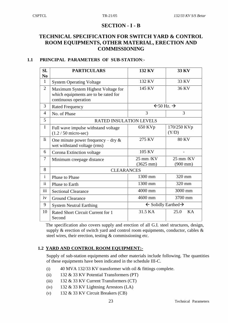
1.1 PRINCIPAL PARAMETERS OF SUB-STATION:-
Sl.
No
PARTICULARS 132 KV 33 KV
1 System Operating Voltage 132 KV 33 KV
2 Maximum System Highest Voltage for
which equipments are to be rated for
continuous operation
145 KV 36 KV
3 Rated Frequency 50 Hz.
4 No. of Phase 3 3
5 RATED INSULATION LEVELS
I Full wave impulse withstand voltage
(1.2 / 50 micro-sec)
650 KVp 170/250 KVp
(Y/D)
Ii One minute power frequency – dry &
wet withstand voltage (rms)
275 KV 80 KV
6 Corona Extinction voltage 105 KV -
7 Minimum creepage distance 25 mm /KV
(3625 mm)
25 mm /KV
(900 mm)
8 CLEARANCES
i Phase to Phase 1300 mm 320 mm
ii Phase to Earth 1300 mm 320 mm
iii Sectional Clearance 4000 mm 3000 mm
iv Ground Clearance 4600 mm 3700 mm
9 System Neutral Earthing Solidly Earthed
10 Rated Short Circuit Current for 1
Second
31.5 KA 25.0 KA
The specification also covers supply and erection of all G.I. steel structures, design,
supply & erection of switch yard and control room equipments, conductor, cables &
steel wires, their erection, testing & commissioning etc.
1.2 YARD AND CONTROL ROOM EQUIPMENT:-
Supply of sub-station equipments and other materials include following. The quantities
of these equipments have been indicated in the schedule III-C.
(i) 40 MVA 132/33 KV transformer with oil & fittings complete.
(ii) 132 & 33 KV Potential Transformers (PT)
(iii) 132 & 33 KV Current Transformers (CT)
(iv) 132 & 33 KV Lightning Arrestors (LA)
(v) 132 & 33 KV Circuit Breakers (CB)
CSPTCL TR-21/05 132/33 KV S/S Betar
24 Technical Parameters
(vi) 132 & 33 KV Isolators with & without Earth Switches.
(vii) 132 & 33 KV Solid core Post insulators.
(viii) 200 KVA, 33/0.4 KV Station transformer.
(ix) GPS base time synchronising equipment with accessories which is suitable for
synchronization of internal clocks of meters, relays and computer.
(x) 10 MVAR, 33 KV Shunt capacitor bank with series reactors and associated all
equipments.
(xi) Control & Relay panels with Relays like DPR, back up O/C, E/F Differential
relays, tripping relays, panel indication instruments (MW, A, V, F, Electronic
Energy meters,MFT etc.) Breakers Control switch, trips supervision,
annunciation, windows relays, mimic diagrams, semaphores, cartridge fuses,
internal wiring with ‘A’ grade multi stranded copper insulated wires, foundation
bolts etc.
(xii) 300AH 110V & 48V Battery set with electrolyte & teak wood stands & Battery
charger & its commissioning.
(xiii) AC/DC Boards, Junction /marshalling box with standard connectors & channel
etc.
(xiv) Supply, preparation of cable schedules & laying etc.
(xv) Supply of 2.5 mm sq un-armoured copper control cables with numbered core
including power cables laying & termination of control cables after construction
of cable trenches as required.
(xvi) Supply of Zebra ACSR conductors, earth wires, hard wares & their stringing &
jumpering works including supply of suitable clamps & connectors.
(xvii) Sub-station earthing materials, ensuing an Earth Resistance of 0.5 Ohm or
less.
(xviii) Luminaries of Switchyard & Control Room illumination.
(xix) T&P, safety appliances, office & control room furniture, fire fighting
equipments. Testing kits & measuring instrument etc., are also to be supplied by
the contractor as per enclosed Annexures.
1.3 ERECTION OF STRUCTURE & EQUIPMENTS:-
1.3.1 The structures are to be fabricated according to the CSPTCL design & drawing.
1.3.2 After the columns / supporting structures are erected respective equipment (132/33 KV)
are to be erected carefully with suitable crane. But breaker and isolators are to be
erected as 3 phase-unit basis, and other item like 132/33 KV CT, PT, CC, LA & PI etc.
are to be erected on I-phase unit basis and rigidly mounted on the supporting structures
to be supplied by the developer. Simplex/Duplex control relay panels are to be mounted
inside the control room in the same order as in the switchyard.
1.3.3 After the earth mat design is finalised, the earth mats with 65 x 8 mm GI Flat are to be
put with each equipment. Then flats are to be inter connected with each other as per
latest amended ISS.
1.3.4. 132 & 33 KV Bus Bars are to be strung after all the columns and beams are fitted. Both
the buses should have suitable tension insulators. On approval of cable schedules
various sizes of PVC Unarmoured control cable and Armoured power cable as required
are to be laid and connected with suitable supporting devices after the various
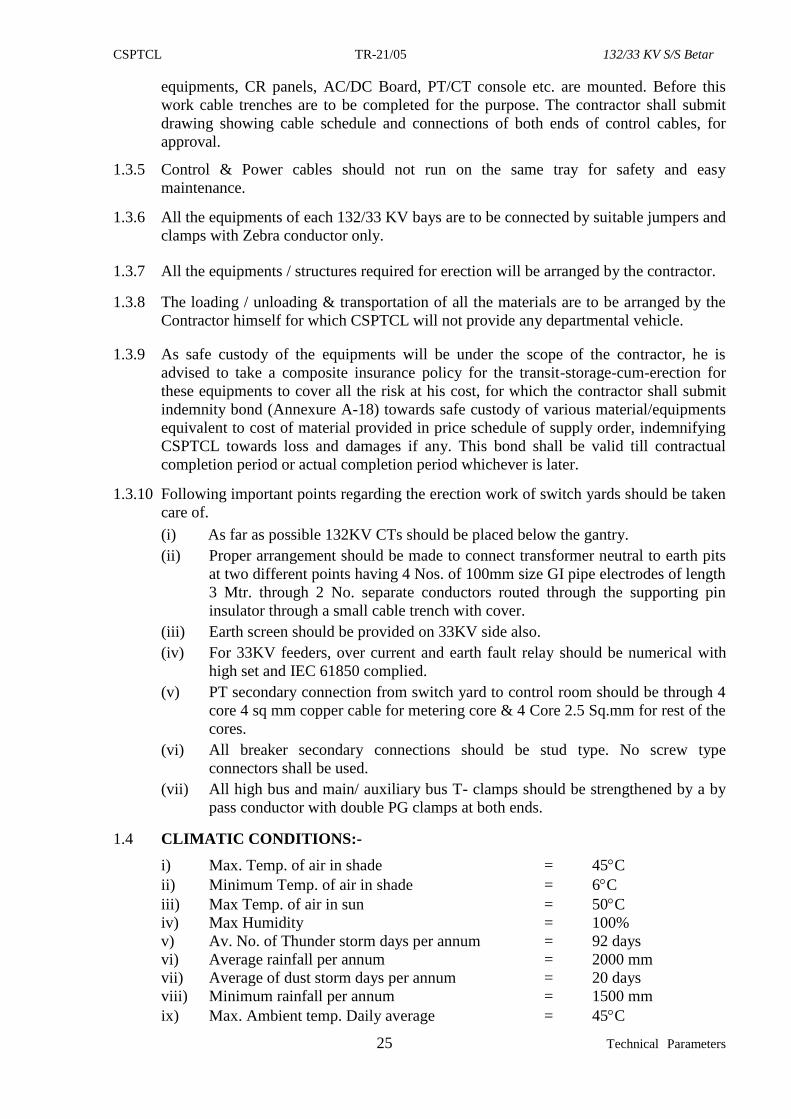
CSPTCL TR-21/05 132/33 KV S/S Betar
25 Technical Parameters
equipments, CR panels, AC/DC Board, PT/CT console etc. are mounted. Before this
work cable trenches are to be completed for the purpose. The contractor shall submit
drawing showing cable schedule and connections of both ends of control cables, for
approval.
1.3.5 Control & Power cables should not run on the same tray for safety and easy
maintenance.
1.3.6 All the equipments of each 132/33 KV bays are to be connected by suitable jumpers and
clamps with Zebra conductor only.
1.3.7 All the equipments / structures required for erection will be arranged by the contractor.
1.3.8 The loading / unloading & transportation of all the materials are to be arranged by the
Contractor himself for which CSPTCL will not provide any departmental vehicle.
1.3.9 As safe custody of the equipments will be under the scope of the contractor, he is
advised to take a composite insurance policy for the transit-storage-cum-erection for
these equipments to cover all the risk at his cost, for which the contractor shall submit
indemnity bond (Annexure A-18) towards safe custody of various material/equipments
equivalent to cost of material provided in price schedule of supply order, indemnifying
CSPTCL towards loss and damages if any. This bond shall be valid till contractual
completion period or actual completion period whichever is later.
1.3.10 Following important points regarding the erection work of switch yards should be taken
care of.
(i) As far as possible 132KV CTs should be placed below the gantry.
(ii) Proper arrangement should be made to connect transformer neutral to earth pits
at two different points having 4 Nos. of 100mm size GI pipe electrodes of length
3 Mtr. through 2 No. separate conductors routed through the supporting pin
insulator through a small cable trench with cover.
(iii) Earth screen should be provided on 33KV side also.
(iv) For 33KV feeders, over current and earth fault relay should be numerical with
high set and IEC 61850 complied.
(v) PT secondary connection from switch yard to control room should be through 4
core 4 sq mm copper cable for metering core & 4 Core 2.5 Sq.mm for rest of the
cores.
(vi) All breaker secondary connections should be stud type. No screw type
connectors shall be used.
(vii) All high bus and main/ auxiliary bus T- clamps should be strengthened by a by
pass conductor with double PG clamps at both ends.
1.4 CLIMATIC CONDITIONS:-
i) Max. Temp. of air in shade = 45C
ii) Minimum Temp. of air in shade = 6C
iii) Max Temp. of air in sun = 50C
iv) Max Humidity = 100%
v) Av. No. of Thunder storm days per annum = 92 days
vi) Average rainfall per annum = 2000 mm
vii) Average of dust storm days per annum = 20 days
viii) Minimum rainfall per annum = 1500 mm
ix) Max. Ambient temp. Daily average = 45C
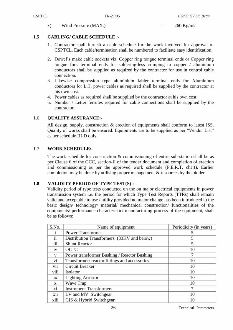
CSPTCL TR-21/05 132/33 KV S/S Betar
26 Technical Parameters
x) Wind Pressure (MAX.) = 260 Kg/m2
1.5 CABLING/ CABLE SCHEDULE :-
1. Contractor shall furnish a cable schedule for the work involved for approval of
CSPTCL. Each cable/termination shall be numbered to facilitate easy identification.
2. Dowel’s make cable sockets viz. Copper ring tongue terminal ends or Copper ring
tongue fork terminal ends for soldering-less crimping to copper / aluminium
conductors shall be supplied as required by the contractor for use in control cable
connection.
3. Likewise compression type aluminium fabler terminal ends for Aluminium
conductors for L.T. power cables as required shall be supplied by the contractor at
his own cost.
4. Power cables as required shall be supplied by the contractor at his own cost.
5. Number / Letter ferrules required for cable connections shall be supplied by the
contractor.
1.6 QUALITY ASSURANCE:-
All design, supply, construction & erection of equipments shall conform to latest ISS.
Quality of works shall be ensured. Equipments are to be supplied as per “Vendor List”
as per schedule III-D only.
1.7 WORK SCHEDULE:-
The work schedule for construction & commissioning of entire sub-station shall be as
per Clause 6 of the GCC, section-II of the tender document and completion of erection
and commissioning as per the approved work schedule (P.E.R.T. chart). Earlier
completion may be done by utilising proper management & resources by the bidder
1.8 VALIDITY PERIOD OF TYPE TEST(S) :
Validity period of type tests conducted on the on major electrical equipments in power
transmission system i.e. the period for which Type Test Reports (TTRs) shall remain
valid and acceptable to use / utility provided no major change has been introduced in the
basic design/ technology/ material/ mechanical construction/ functionalities of the
equipments/ performance characteristic/ manufacturing process of the equipment, shall
be as follows:
S.No. Name of equipment Periodicity (in years)
i Power Transformer 5
ii Distribution Transformers (33KV and below) 5
iii Shunt Reactor 5
iv OLTC 10
v Power transformer Bushing / Reactor Bushing 7
vi Transformer/ reactor fittings and accessories 10
vii Circuit Breaker 10
viii Isolator 10
ix Lighting Arrestor 10
x Wave Trap 10
xi Instrument Transformers 7
xii LV and MV Switchgear 10
xiii GIS & Hybrid Switchgear 10
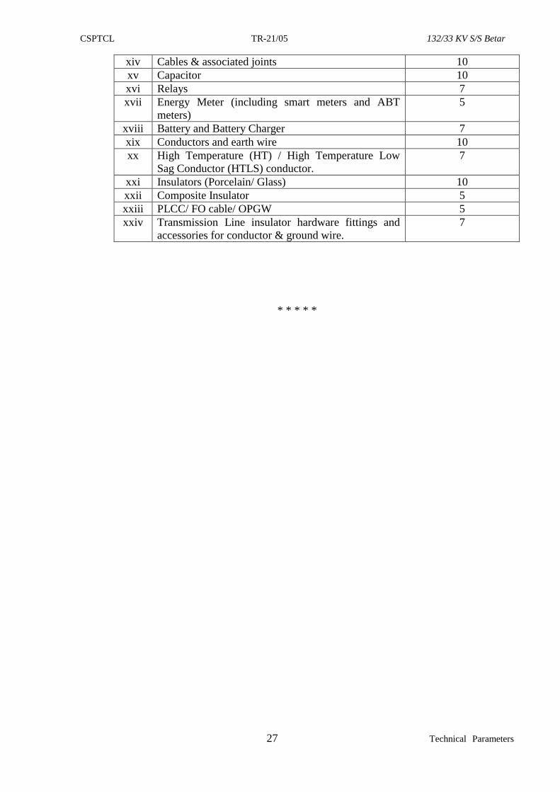
CSPTCL TR-21/05 132/33 KV S/S Betar
27 Technical Parameters
xiv Cables & associated joints 10
xv Capacitor 10
xvi Relays 7
xvii Energy Meter (including smart meters and ABT
meters)
5
xviii Battery and Battery Charger 7
xix Conductors and earth wire 10
xx High Temperature (HT) / High Temperature Low
Sag Conductor (HTLS) conductor.
7
xxi Insulators (Porcelain/ Glass) 10
xxii Composite Insulator 5
xxiii PLCC/ FO cable/ OPGW 5
xxiv Transmission Line insulator hardware fittings and
accessories for conductor & ground wire.
7
* * * * *
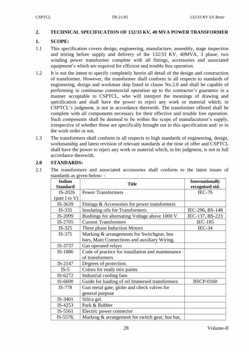
CSPTCL TR-21/05 132/33 KV S/S Betar
28 Volume-II
2. TECHNICAL SPECIFICATION OF 132/33 KV, 40 MVA POWER TRANSFORMER
1. SCOPE:
1.1 This specification covers design, engineering, manufacture, assembly, stage inspection
and testing before supply and delivery of the 132/33 KV, 40MVA, 3 phase, two
winding power transformer complete with all fittings, accessories and associated
equipment’s which are required for efficient and trouble free operation.
1.2 It is not the intent to specify completely herein all detail of the design and construction
of transformer. However, the transformer shall conform in all respects to standards of
engineering, design and workman ship listed in clause No.2.0 and shall be capable of
performing in continuous commercial operation up to the contractor’s guarantee in a
manner acceptable to CSPTCL, who will interpret the meanings of drawing and
specification and shall have the power to reject any work or material which, in
CSPTCL’s judgment, is not in accordance therewith. The transformer offered shall be
complete with all components necessary for their effective and trouble free operation.
Such components shall be deemed to be within the scope of manufacuturer’s supply,
irrespective of whether those are specifically brought out in this specification and/ or in
the work order or not.
1.3 The transformers shall conform in all respects to high standards of engineering, design,
workmanship and latest revision of relevant standards at the time of offer and CSPTCL
shall have the power to reject any work or material which, in his judgment, is not in full
accordance therewith.
2.0 STANDARDS:
2.1 The transformers and associated accessories shall conform to the latest issues of
standards as given below: - Indian
Standard Title
Internationally
recognised std.
IS-2026
(part I to V)
Power Transformers IEC-76
IS-3639 Fittings & Accessories for power transformers
IS-335 Insulating oils for Transformers. IEC-296, BS-148
IS-2099 Bushings for alternating Voltage above 1000 V IEC-137, BS-223
IS-2705 Current Transformers IEC-185
IS-325 Three phase Induction Motors IEC-34
IS-375 Marking & arrangements for Switchgear, bus
bars, Main Connections and auxiliary Wiring.
IS-3737 Gas operated relays
IS-1886 Code of practice for installation and maintenance
of transformers
IS-2147 Degrees of protection.
IS-5 Colors for ready mix paints
IS-6272 Industrial cooling fans
IS-6600 Guide for loading of oil Immersed transformers BSCP-0160
IS-778 Gun metal gate, globe and check valves for
general purpose
IS-3401 Silica gel.
IS-4253 Park & Rubber
IS-5561 Electric power connector
IS-5578, Marking & arrangement for switch gear, bus bar,
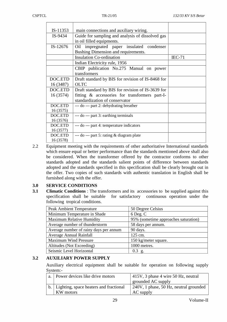
CSPTCL TR-21/05 132/33 KV S/S Betar
29 Volume-II
IS-11353
main connections and auxiliary wiring.
IS-9434 Guide for sampling and analysis of dissolved gas
in oil filled equipments.
IS-12676 Oil impregnated paper insulated condenser
Bushing Dimension and requirements.
Insulation Co-ordination IEC-71
Indian Electricity rule, 1956
CBIP publication No.275 Manual on power
transformers
DOC.ETD
16 (3487)
Draft standard by BIS for revision of IS-8468 for
OLTC
DOC.ETD
16 (3574)
Draft standard by BIS for revision of IS-3639 for
fitting & accessories for transformers part-I-
standardization of conservator
DOC.ETD
16 (3575)
--- do --- part 2: dehydrating breather
DOC.ETD
16 (3576)
--- do --- part 3: earthing terminals
DOC.ETD
16 (3577)
--- do --- part 4: temperature indicators
DOC.ETD
16 (3578)
--- do --- part 5: rating & diagram plate
2.2 Equipment meeting with the requirements of other authoritative International standards
which ensure equal or better performance than the standards mentioned above shall also
be considered. When the transformer offered by the contractor conforms to other
standards adopted and the standards salient points of difference between standards
adopted and the standards specified in this specification shall be clearly brought out in
the offer. Two copies of such standards with authentic translation in English shall be
furnished along with the offer.
3.0 SERVICE CONDITIONS
3.1 Climatic Conditions : The transformers and its accessories to be supplied against this
specification shall be suitable for satisfactory continuous operation under the
following tropical conditions.
Peak Ambient Temperature 50 Degree Celsius
Minimum Temperature in Shade 6 Deg. C
Maximum Relative Humidity 95% (sometime approaches saturation)
Average number of thunderstorm 58 days per annum.
Average number of rainy days per annum 90 days.
Average Annual Rainfall 125 cm.
Maximum Wind Pressure 150 kg/meter square.
Altitudes (Not Exceeding) 1000 metres.
Seismic Level Horizontal 0.3 g.
3.2 AUXILIARY POWER SUPPLY
Auxiliary electrical equipment shall be suitable for operation on following supply
System:-
a. Power devices like drive motors 415V, 3 phase 4 wire 50 Hz, neutral
grounded AC supply
b. Lighting, space heaters and fractional
KW motors
240V, 1 phase, 50 Hz, neutral grounded
AC supply
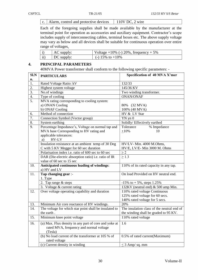
CSPTCL TR-21/05 132/33 KV S/S Betar
30 Volume-II
c. Alarm, control and protective devices 110V DC, 2 wire
Each of the foregoing supplies shall be made available by the manufacturer at the
terminal point for operation as accessories and auxiliary equipment. Contractor’s scope
includes supply of interconnecting cables, terminal boxes etc. The above supply voltage
may vary as below and all devices shall be suitable for continuous operation over entire
range of voltages.
i) AC supply: Voltage +10% (-) 20%, frequency + 5%
ii) DC supply: (-) 15% to +10%
4. PRINCIPAL PARAMETERS
40MVA Power transformer shall conform to the following specific parameters: -
Sl.N
o. PARTICULARS Specification of 40 MVA X’mer
1. Rated Voltage Ratio: kV 132/33
2. Highest system voltage 145/36 KV
3. No.of windings Two winding transformer.
4. Type of cooling ONAN/ONAF
5. MVA rating corresponding to cooling system:
a) ONAN Cooling
b) ONAF Cooling
80% (32 MVA)
100% (40 MVA)
6. Method of connection HV & LV Star LV delta
7. Connection Symbol (Vector group) YN yn 0
8. System earthing Solidly/ Effectively earthed
9. Percentage Impedance’s, Voltage on normal tap and
MVA base Corresponding to HV rating and
applicable tolerances:
a) HV-LV
Tolerance % Impedance
+10% 10
Insulation resistance at an ambient temp of 30 Deg
C with 5 KV Megger for 60 sec duration
HV/LV- Min. 4000 M.Ohms,
HV/E, LV/E- Min 3000 M. Ohms
Polarisation index i.e. ratio of 600 sec to 60 sec ≥ 2
DAR (Die-electric absorption ratio) i.e. ratio of IR
value of 60 sec to 15 sec
≥ 1.3
10. Anticipated continuous loading of windings:
a) HV and LV
110% of its rated capacity in any tap.
11. Tap changing gear :-
1. Type
On load Provided on HV neutral end.
2. Tap range & steps -15% to + 5%, steps 1.25%
3. Voltage & current rating 132KV (neutral end) & 500 amp Min.
12. Over voltage operating capability and duration 110% rated voltage Continuous
125% rated voltage for 60 secs.
140% rated voltage for 5 secs.
13. Minimum Air core reactance of HV windings. 20%
14. The voltage for which star point shall be insulated to
the earth .
The insulation class of the neutral end of
the winding shall be graded to 95 KV.
15. Minimum knee point voltage 110% rated voltage
16. (a) Max. Flux density in any part of core and yoke at
rated MVA, frequency and normal voltage
(Tesla)
1.6
(b) No load current of the transformer at 105 % of
rated voltage
0.5% of rated current(Maximum)
(c) Current density in winding < 3 Amp/ sq. mm
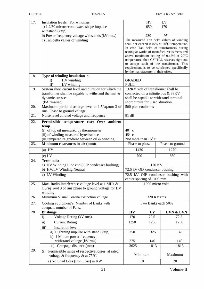
CSPTCL TR-21/05 132/33 KV S/S Betar
31 Volume-II
17. Insulation levels : For windings
a) 1.2/50 microsecond wave shape impulse
withstand (kVp)
HV LV
650 170
b) Power frequency voltage withstands (kV rms.) 230 95
c) Tan delta values of winding The measured Tan delta values of winding
shall not exceed 0.45% at 200C temperature.
In case Tan delta of transformers during
testing at works of manufacturer is measured
above maximum ceiling of 0.45% at 200C
temperature, then CSPTCL reserves right not
to accept such of the transformer. This
requirement is to be confirmed specifically
by the manufacturer in their offer.
18. Type of winding insulation :-
I) HV winding
II) LV winding
GRADED
FULL
19. System short circuit level and duration for which the
transformer shall be capable to withstand thermal &
dynamic stresses
(kA rms/sec)
132KV side of transformer shall be
connected on a infinite bus & 33KV
shall be capable to withstand terminal
short circuit for 3 sec. duration.
20. Maximum partial discharge level at 1.5/sq.root 3 of
rms. Phase to ground voltage.
500 pico coulombs
21. Noise level at rated voltage and frequency 81 dB
22. Permissible temperature rise: Over ambient
temp.
(i) of top oil measured by thermometer
(ii) of winding measured byresistance
(iii)temperature gradient between oil & winding
400 c
450 c
Not more than 160 c
23. Minimum clearances in air (mm): Phase to phase Phase to ground
(a) HV 1430 1270
(c) LV 700 660
24. Terminals:-
a) HV Winding Line end (OIP condenser bushing)
170 KV
b) HV/LV Winding Neutral 72.5 kV OIP condenser bushing
c) LV Winding 72.5 kV OIP condenser bushing with
center spacing of 1000 mm.
25. Max. Radio Interference voltage level at 1 MHz &
1.5/sq root 3 of rms phase to ground voltage for HV
winding
1000 micro volts
26. Minimum Visual Corona extinction voltage 320 KV rms
27. Cooling equipment’s: Number of Banks with
adequate number of Fans.
Two Banks each 50%
28. Bushings : HV LV HVN & LVN
i) Voltage Rating (kV rms) 170 72.5 72.5
ii) Current Rating 1250 1250 1250
iii) Insulation level :
a) Lightning impulse with stand (kVp) 750 325 325
b) 1 Minute power frequency
withstand voltage (kV rms)
275
140
140
c) Creepage distance (mm) 3625 1813 1813
29. (i) Permissible range of respective losses at rated
voltage & frequency & at 75°C
Minimum
Maximum
a) No Load Loss (Iron Loss) in KW 18 20
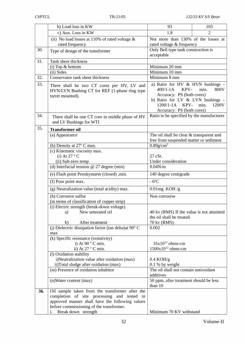
CSPTCL TR-21/05 132/33 KV S/S Betar
32 Volume-II
b) Load loss in KW 93 103
c) Aux. Loss in KW 1.8 2
(ii) No load losses at 110% of rated voltage &
rated frequency
Not more than 130% of the losses at
rated voltage & frequency
30. Type of design of the transformer Only Bell type tank construction is
acceptable
31. Tank sheet thickness
(i) Top & bottom Minimum 20 mm
(ii) Sides Minimum 10 mm
32. Conservator tank sheet thickness Minimum 8 mm
33. There shall be two CT cores per HV, LV and
HVN/LVN Bushing CT for REF (1-phase ring type
turret mounted).
a) Ratio for HV & HVN bushings -
400/1-1A KPV- min. 800V
Accuracy: PS (both cores)
b) Ratio for LV & LVN bushings -
1200/1-1A KPV- min. 1200V
Accuracy: PS (both cores)
34. There shall be one CT core in middle phase of HV
and LV Bushings for WTI
Ratio to be specified by the manufacturer
35. Transformer oil
(a) Appearance
The oil shall be clear & transparent and
free from suspended matter or sediment
(b) Density at 27o C max. 0.89g/cm3
(c) Kinematic viscosity max.
(i) At 27 o C
(ii) Sub-zero temp
27 cSt.
Under consideration
(d) Interfacial tension @ 27 degree (min) 0.04N/m
(e) Flash point Penskymartn (closed) ,min. 140 degree centigrade
(f) Pour point max. - 6oC
(g) Neutralization value (total acidity) max. 0.01mg. KOH /g
(h) Corrosive sulfur
(in terms of classification of copper strip)
Non corrosive
(i) Electric strength (break-down voltage)
a) New untreated oil
b) After treatment
40 kv (RMS) If the value is not attainted
the oil shall be treated.
70 kv (RMS)
(j) Dielectric dissipation factor (tan delta)at 90o C
max
0.002
(k) Specific resistance (resistivity)
i) At 90 o C min.
ii) At 27 o C min.
35x1012 ohms-cm
1500x1012 ohms-cm
(l) Oxidation stability
i)Neutralization value after oxidation (max)
ii)Total sludge after oxidation (max)
0.4 KOH/g
0.1 % by weight
(m) Presence of oxidation inhabitor
The oil shall not contain antioxidant
additives
(n)Water content (max) 50 ppm, after treatment should be less
than 10
36. Oil sample taken from the transformer after the
completion of site processing and tested in
approved manner shall have the following values
before commissioning of the transformer.
i. Break down strength
Minimum 70 KV withstand
CSPTCL TR-21/05 132/33 KV S/S Betar
33 Volume-II
ii. Moisture content
iii. Resistivity at 90oc minimum
iv. Interfacial Tension at 27oc
v. Dielectric dissipation factor at 90 oC
Maximum of 10 ppm
35x1012 ohm.cm (min)
0.04 N/M (min)
0.002 (max.)
5. GENERAL TECHNICAL REQUIRMENTS
5.1 Duty Requirements
5.1.1 The interconnecting transformers would be used for Bi directional flow of rated power.
5.1.2 The transformers and all the its accessories like CTs etc. shall be designed to withstand
without injury, the thermal and mechanical effects of any external short circuits at the
terminals of any winding for a period of 3 sec. If 132KV side of transformer is
connected on a infinite bus, 33KV shall be capable to withstand terminal short circuit
for 3 sec. duration.
The short circuit level of the HV system to which the subject transformer will be
connected is 40 KA (Sys, rms, 3 phase fault) for 132KV system & also 31.5 KA for 33
KV System.
5.1.3 The transformer shall be capable of bearing loads in accordance with IS: 6600. There
shall no limitation imposed by windings, bushings, tap changer etc. of transformer.
Transformer & all its accessories shall be liberally rated to allow 10% over loading at
all taps on continuous basis without exceeding the temperature limits specified in clause
4.0 “Principal Parameters”. The transformer shall be capable of being operated without
danger on each tapping at the rated KVA with specified voltage variation corresponding
to the voltage of that tapping with normal temperature rise. The design adopted to
achieve this shall be indicated in details in the offer.
5.1.4 The transformer shall be capable of being operated without danger on any tapping at the
rated KVA with voltage variation of + 10% corresponding to the voltage of that
tapping. Transformer & its accessories shall be liberally rated to allow 10% overloading
at all taps on continuous basis.
5.1.5 Radio interference and Noise level:
(i) The transformers shall be designed with particular attention to suppression of
maximum harmonic voltage, especially the third and fifth so as to minimize
interference with communication circuits.
(ii) The noise level, when energized at normal voltage and frequency with fans and
pumps running shall not exceed, when measured under standard, conditions, the
values specified in NEMA, TR-1
5.1.6 Transformer shall be capable of operating under the natural cooled condition up to the
specified load i.e. as ONAN rating. The forced cooling equipment shall come into
operation by preset contacts of winding temperature indicator and the transformer shall
operate as a forced air cooled unit, i.e. as ONAF. Cooling shall be so designed that
during total failure of power supply to cooling fans, the transformer shall be able to
operate at full load for at-least ten(10) minutes without the calculated winding hot spot
temperature not exceeding 140°C. Also stopping of one or two cooling fans should not
have any effect on the cooling system. Transformers fitted with two coolers (cooling
banks) each capable of dissipating 50 per cent of the loss at continuous maximum rating
shall be capable of operating for 20 minutes in the event of failure of the blowers
associated with one cooler, without the calculated winding hot spot temperature
exceeding 140°C at continuous maximum rating.
CSPTCL TR-21/05 132/33 KV S/S Betar
34 Volume-II
5.1.7 Transformer shall be capable of withstanding thermal and mechanical stress caused by
symmetrical / asymmetrical faults on any winding.
5.1.8 Transformer shall accept, without injurious heating, combined voltage and frequency
fluctuation of +/- 4%, which may produce the following over fluxing condition:
i) 125% for 1 minute for all transformer where base voltage
140% for 5 seconds & frequency refers to rated voltage and frequency
ii) Over fluxing withstand characteristics upto 170% shall be admitted.
5.1.9 PARALLEL OPERATION: The offered transformer shall be suitable for parallel
operation of similar transformer of 63/40/20 MVA rating of any make.
5.2 GUARANTEED LOSSES AND GUARANTEE PERIOD:
5.2.1 Permissible losses:-
The losses of 40 MVA, 132/33 KV transformer should be within the range prescribed
below for respective losses (without any positive tolerance) :
S. No. Particulars Minimum Maximum
1 No load loss in KW 18.0 20.0
2 Load loss at rated voltage, rated frequency
and rated current at 75ºC in KW
93.0 103.0
3 Auxiliary Loss in KW 1.8 2.0
The bidder shall have to offer no load loss, load loss or auxiliary loss separately.
In case any of the offered losses (i.e. no load loss, load loss or auxiliary loss) quoted by
the bidder is more than the maximum permissible limits , the bid shall be considered as
non responsive and shall be out rightly rejected without any correspondence in the
matter.
In case, any of these losses are below the minimum range prescribed above, the bid
shall be treated as responsive. However, for price bid evaluation purpose, the minimum
range of the respective losses prescribed above shall only be considered.
5.2.2 CAPITALISATION OF LOSSES: The capitalisation of no load loss, load loss and
auxiliary loss for the bidder who has quoted the losses within the respective range of
losses specified above in clause 5.2.1, shall be done on following rates (differential of
quoted loss and minimum value of the range of respective loss) :-
i) For differential no load loss above 18 KW : Rs. 5,08,908.00 per KW
ii) For differential load loss above 93 KW : Rs. 2,70,739.00 per KW
iii) For differential auxiliary loss above 1.8 KW : Rs. 2,03,563.00 per KW
In case a bidder quotes any of the losses below the minimum value of the range
prescribed in clause 5.2.1, the value of loss shall be considered equal to minimum of the
range specified at clause 5.2.1 for respective loss for price bid evaluation purpose.
The differential losses so worked out separately for each of the no load loss, load loss
and auxiliary loss shall be multiplied with number of transformer in the package and the
capitalisation factors as mentioned above.
However, it should be clearly noted that during final testing of each of transformer, the
measured losses individually (i.e. No load, load & auxiliary losses as applicable) should
CSPTCL TR-21/05 132/33 KV S/S Betar
35 Volume-II
not exceed the values quoted by the bidders in the bid (in Annexure A-3). In case, any
of the losses exceed the quoted losses, respective transformer shall not be accepted.
5.2.3 GUARANTEE PERIOD:
1. The contractor shall ensure that the power transformer supplied shall be guaranteed for
a period of 42 months from the date of satisfactory commissioning of transformer along
with all accessories. Please note that the date of commissioning of last accessory will be
treated as date of commissioning of transformer. The transformer found defective/failed
within the above guarantee period shall be got replaced/repaired by the contractor free
of cost, within four months from date of issue of intimation letter to the contractor by
CSPTCL regarding its defect/failure.
If the contractor fails to arrange repair/replace the failed/defective transformer within
four months, the contractor shall be liable to pay penalty charges for delayed repairs at
the rate of 0.5% of the cost of transformer per week of delay or part thereof, subject to a
maximum ceiling of 10% of the cost of the transformer. This penalty shall be in
addition to the liquidated damages as per clause 14.1 of GCC for delay in completion of
the contract.
If the defective/failed transformer is not lifted for replacement/repairing within 2
months from the date of intimation by CSPTCL regarding defect/ failure OR one month
from date of acceptance of additional Indemnity Bond submitted by the contractor, (in
case the transformer is required to be taken back to the works for repairing) whichever
is later.
OR
not repaired within seven months from date of lifting of failed/ defective transformer,
penal action may be taken which will include forfeiture of performance guarantee of
transformer and debarring of the turnkey contractor in addition to the other applicable
penalty.
The above provisions shall be applicable for second time failure also, if any.
EXTENDED GUARANTEE PERIOD POST REPAIRS:
Further, the following extended guarantee shall be applicable, in case the transformer
fails within guarantee period.
a) First time failure within guarantee period:
i) If the transformer fails within 12 months from the initial commissioning, the
guarantee period shall get extended to 42 months from the date of satisfactory
re-commissioning of transformer after repairs along with all accessories.
ii) If the transformer fails after 12 months within the original guarantee period, the
original guarantee period shall get extended for a period equal to the time period
lapsed between date of failure to date of re-commissioning after repairs i.e. the
residual guarantee period or 12 months from date of re-commissioning after
repairs, whichever is later.
b) Second time failure of transformer within guarantee period:
If the transformer fails again (second time) within the original/extended guarantee
period, the guarantee shall automatically get extended for further period of two
years from the date of re-commissioning (post repair) or from the end of the
original/ previously extended period, whichever is later. Further the contractor shall
be required to submit an additional performance bank Guarantee equivalent to 10 %
of the FOR destination price of Power Transformer with validity up to expiry of
extended guaranteed period plus six months additional claim period. This
CSPTCL TR-21/05 132/33 KV S/S Betar
36 Volume-II
performance bank Guarantee shall be in addition to 10 % performance guarantee
submitted as per clause no. 12.1 (i).
c) Third time failure of transformer within guarantee period:
If the transformer fails within guarantee /extended guarantee period for third time, this
will be treated as adverse performance of contractor as well as manufacturer and in
such case penal action shall be taken which will includes
i) Forfeiture of 10% BG submitted against Performance of transformer.
ii) Forfeiture of additional 10% performance BG of transformer furnished
subsequent to second time failure.
iii) The contractor shall be debarred from future business with CSPTCL and other
Chhatishgarh state power companies for a period as decided by management.
iv) The name of the transformer manufacture shall be deleted from the vendor list
of CSPTCL for power transformer of the capacity supplied for the instant case
and higher capacities for forthcoming turnkey project and shall not be
considered for procurement cases of CSPTCL as well as other Chhatishgarh
state power companies for a period as decided by management.
If, for the purpose of replacement/repairs, the equipment/material is required to be
dispatched to manufacturer’s works, all charges towards transportation / insurance/
packing / forwarding will have to be borne by contractor for to and fro dispatches.
In this connection, please note that the following additional conditions will also be
applicable in case any damages/defects are noticed in the equipments or its accessories-
If the material develops defect within guarantee/extended guarantee period after
installation at site or subsequent to installation after repairs (1st or 2nd time), for the
purpose of replacement / repairs, the same will have to be dismantled and taken out by
CSPTCL, in such cases actual cost of dismantling and replacement of the equipment /
material will also be recoverable from contractor.
In case, transformer fails during guarantee / extended guarantee period, the following
terms shall also be applicable (in first or second time failure both)-
(i) An additional Indemnity Bond on stamp paper of Rs.250.00 shall be required to be
submitted by the contractor, in case the transformer is required to be taken back to the
works for repairing. The value of this Indemnity Bond shall be equal to the cost of
transformer along with all taxes, duties, freight and testing charges. The transformer shall
be handed over for repairing only after submission and acceptance of additional
indemnity bond.
(ii) The transformer should be offered for inspection after completion of repairing work. The
repaired Transformer shall be tested for all routine, additional routine, type and special
test as per IS-2026 & as narrated in section-III-B, clause-6 under head “Tests” of
technical specification of transformer.
(iii) The Transformer should be offered for inspection after repairing within four months from
date of intimation of failure by CSPTCL.
(iv) The dispatch instructions shall be issued for repair transformer after its satisfactory
inspection. The transformer should reach the destination (anywhere in C.G. state) within
45 days from date of issue of dispatch instruction failing which actual date of receipt of
repaired transformer at site shall be treated as date of delivery of the repaired transformer
for all contractual purposes.
CSPTCL TR-21/05 132/33 KV S/S Betar
37 Volume-II
(v) In case of failure / defect in transformer (first or second time) within guarantee / extended
guarantee period, the validity of performance guarantee for transformer submitted by the
contractor against the contract as per clause 12.1(i) of GCC should be extended up to
expiry of extended guarantee period with additional claim period of six months. In case,
contractor fails to extend the guarantee period of transformer, claim shall lodged with the
issuing bank for encashment of the all performance bank guarantee for transformer.
5.3 CLEARANCES
The over all dimensions of the transformer shall allow for sufficient clearances for
installation in:-
a) 132KV switchyard with bay width of 9600 mm and beam height of 11000 mm.
5.4 CONSTRUCTION DETAILS
The features and construction details of power transformer shall be in accordance with
the requirements stated hereunder:
5.4.1 TANK AND TANK ACCESSORIES
5.4.1.1 Tank
a) Tank shall be Bell type only of welded construction and fabricated from tested
quality low carbon steel of minimum thickness of 20mm (Base & Tank cover) &
10 mm for sides.
b) All seams & those joints which are not required to be opened at site shall be
factory welded and whenever possible they shall be double welded. After
completion of tank construction and before painting, dye penetration test shall be
carried out on welded parts of jacking bosses, lifting lugs and all load bearing
member. The requirement of post weld heat treatment for tank/stress relieving
parts shall be based on recommendations of BS: 5500 table 4.4.3.1
c) The Tank stiffeners shall be provided for general rigidity and these shall be
designed to prevent retention of water.
d) The tanks shall be designed to withstand
(i) Mechanical shocks during transportation
(ii) Vacuum filling of oil at 10 millitorr in transformer with fitting
(iii) Continuous internal pressure of 35 kN/m² over normal hydrostatic
pressure of oil.
(iv) Short circuit forces.
e) Wherever possible the transformer tank and its accessories shall be designed
without pockets wherein gas may collect. Where pockets cannot be avoided,
pipes shall be provided to vent the gas into the main expansion pipes.
f) Adequate space shall be provided at the bottom of the tank for collection of
sediments. The minimum clearance of outermost winding/connection leads to
tank shall not be less than 300 mm on all 4 sides to allow free movement of two
persons for inspection. Suitable platforms may be provided on bottom to
facilitate free movement of person all around inside the tank. The arrangement
should be brought out clearly in the drawing.
g) The base of tank shall be so designed that it shall be possible to move the
complete unit by skidding in any direction without injury when using plates or
rails.
h) Tank shields shall be such that no magnetic/ fields shall exist outside the tank.
If required impermeable shields shall be provided at the coil ends. Tank shield
shall not resonate when excited at the natural frequency of the equipment.
CSPTCL TR-21/05 132/33 KV S/S Betar
38 Volume-II
Manufacturer may confirm use of tank shields in the schedule of additional
information.
i) Suitable guides shall be provided in the tank for positioning the core and coil
assembly.
j) Each tank shall be provided with
(i) Lifting lugs suitable for lifting the equipment complete with oil.
(ii) A minimum of four jacking pads in accessible position at 500 mm height
to enable the transformer complete with oil, to be raised or lowered using
hydraulic or screw jacks.
(iii) Suitable haulage holes shall be provided.
(iv) One detachable bolted type mild steel (MS) ladder with anti-climbing
arrangement shall be provided. Ladder for climbing up to & over top
cover of power transformer shall be mechanically sturdy enough to bear
the load of healthy maintenance staff without any shake/jerks. The
arrangement shall not be detached after erection and commissioning of
the unit, hence shall be provided with padlock locking arrangement for
anti-climbing device. On the upper top of the ladder, provision for
support shall be provided. However, the arrangement of the ladder shall
be approved by CSPTCL. Collapsible ladder shall not be acceptable.
k) The transformer should be of bell tank design only. No other design is
acceptable.
5.4.1.2 Tank cover
(a) The tank cover shall be sloped to prevent retention of rain water and shall not distort
when lifted.
(b) At least two adequately sized inspection openings, one at each end of the tank shall be
provided for easy access to bushings and earth connections. The inspection covers shall
not weigh more than 25 kg. The inspection covers shall be provided with two handles.
(c) The tank covers shall be fitted with pockets at the position of maximum oil temperature
of MCR (Maximum Continuous Rating) for bulbs of oil and winding temperature
indicators. It shall be possible to remove these bulbs without lowering the oil in the
tank.
(d) Bushings, turrets, covers of inspection openings, thermometer, pockets etc. shall be
designed to prevent ingress of water into or leakage of oil from the tank. There should
not be any leakage for three years and this should be guaranteed by the manufacturer.
(e) All bolted connections shall be fitted with weather proof, hot oil resistant gasket in
between, for complete oil tightness. If gasket is compressible metallic stops shall be
provided to prevent over-compression.
5.4.2 Axles and Wheels
(a) The transformer is to be provided with flanged bi-directional wheels and axles. These
shall be so designed as not to deflect excessively to interfere with the movement of the
transformer. Wheels shall be provided with suitable bearings, which shall be rust and
corrosion resistant. Fittings for lubrication shall also be provided.
(b) Suitable locking arrangement along with foundation bolts shall be provided for the
wheels to prevent accidental movement of transformer.
(c) The wheels are required to swivel and they shall be arranged so that they can be turned
through an angle of 90°C when the tank is jacked up to clear of rails. Means shall be
provided for locking the swivel movements in positions parallel to and at right angles to
the longitudinal axis of the tank (i.e. longitudinal and transverse directions).
CSPTCL TR-21/05 132/33 KV S/S Betar
39 Volume-II
(d) The transformer tank shall be supported on a structure steel base equipped with forged
steel or cast steel single flanged wheels available for moving the transformer completely
filled with oil.
(e) The rail track gauge shall be 5’ 6” (1676 mm) along longer axis as well as along shorter
axis. The arrangement should be such that transformer can be installed in any direction
i.e. along longer axis or along shorter axis on 2 rails with spacing of 1676 mm.
(f) Pulling eyes shall be provided to facilitate movement/ pulling of transformers and these
shall be suitably braced in a vertical direction so that bending does not occur when the
pull has in vertical component.
5.4.3 Anti Earthquake Clamping Device:
To prevent transformer movement during earthquake, clamping device shall be
provided for fixing transformer to the foundation. The contractor shall supply necessary
bolts for embedding in the concrete foundation. The arrangements shall be such that the
transformer can be fixed to or unfastened from these bolts as desired. The fixing of the
transformer to the foundation shall be designed to withstand seismic events to the extent
that a static co-efficient of 0.3g, applied in the direction of least resistance to that
loading will not cause the transformer or clamping devices as well as bolts to be over
stressed.
The details of the device used and its adequacy shall be brought out in the additional
information schedule.
5.4.4 Conservator Tank
(a) The conservator tank shall be of minimum of 8 mm thickness & shall have adequate
capacity between highest and lowest visible levels to meet the requirement of expansion
of the total cold oil volume in the transformer and cooling equipment from minimum
ambient temperature to 100°C. Conservator shall be with volumetric capacity at least
7½ percent of a total volume of oil in the main tank of the transformer.
(b) The conservator tank shall be bolted into position so that it can be removed for cleaning
purposes.
(c) The conservator shall be fitted with magnetic oil level gauge with low level electrically
insulated alarm contact.
(d) Conservator shall be provided in such a position as not to obstruct the electrical
connections to the transformer.
(e) Separate conservator tank/compartment in the main conservator shall be provided for
OLTC.
(f) Conservator shall be provided with air cell to avoid direct contact of atmospheric air
with transformer oil.
5.4.5 Dehydrating filter breather
Conservator shall be fitted with a dehydrating filter breather. It shall be so designed
that:
a) Passage of air is through a dust filter and silicagal.
b) Silicagel is isolated from atmosphere by an oil seal.
c) Moisture absorption indicated by a change in colour of the tinted crystals can be
easily observed from a distance.
d) Breather is mounted not more than 1400 mm above rail top level.
e) Minimum quantity of silicagel to be 1 Kg for every 3500 lts of oil in the tank.
5.4.6 Pressure Relief Device
A minimum of 3 Nos. pressure relief devices are to be provided with transformer.
These PRDs shall be preferably mounted on the tank cover above each phase winding.
CSPTCL TR-21/05 132/33 KV S/S Betar
40 Volume-II
Manufacturer must submit calculations to prove that the capacity of pressure relief
device and location of the same in the transformer will adequately meet out
requirement.
Constructional and design details of pressure relief device must be furnished and it
should be proved by calculation that the size and setting of pressure relief device is
adequate, considering the rating of the transformer and quantity of oil in the
transformer. Furnishing of this information is a must.
The PRDs shall be of sufficient size for rapid release of any pressure that may be
generated in the tank and which may result in damage to the equipment. The device
shall operate at a static pressure less than the hydraulic pressure of transformer tank. It
shall be directly mounted on transformer tank. One set of electrically insulated contacts
shall be provided for alarm and tripping with the recommended settings.
5.4.7 Air Cell:
The transformer should be supplied with air cell type oil preservation system. It is
obligatory on the part of the manufacturer to clearly submit complete constructional and
technical details of sealing arrangements duly supported with technical details,
pamphlets and dimensional drawings.
While furnishing details for the above sealing arrangement, the contractor must confirm
clearly that the size and capacity of sealing arrangement is adequate for the transformer
and for the quantity of transformer oil required for the transformer.
5.4.8 Buccholz relay:
A double float type Buccholz relay shall be provided. All the gases evolved in the
transformer shall collect in this relay. The relay shall be provided with a test cock
suitable for a flexible pipe connection for checking its operation and taking gas sample.
A copper or stainless steel tube shall be connected from the gas collector to a valve
located about 1200 mm above ground level to facilitate sampling, with the transformer
in service. The device shall be provided with two electrically independent ungrounded
contacts, one for alarm on gas accumulation and the other for tripping on sudden rise of
pressure.
Note: The manufacturer shall ensure that the compartments housing of relay contacts
of Pressure Relief Valve and Buchholz Relay are made water and vermin proof.
The compartment housing contacts of PRV and Buchholz Relay shall be tested
for water proofing at the time of inspection and effectiveness of water proofing
shall be demonstrated at the time of inspection.
5.4.9 Temperature indicator:
a) Oil Temperature Indicator (OTI):
Transformer shall be provided with a 150-mm dial type thermometer for top oil
temperature indication. The thermometer shall have adjustable, electrically
independent ungrounded alarm and trip contacts, maximum reading pointer and
resetting device mounted in the cooler control cabinet. A temperature-sensing
element suitably located in a pocket on top oil shall be furnished. This shall be
connected to the OTI by means of capillary tubing. Accuracy class of OTI shall
be +1.5% or better. The mounting of OTI should be anti vibrating type.
b) Winding Temperature Indicator (WTI):
A device for measuring the hot spot temperature of each of the windings shall be
provided (HV & LV). It shall comprise of the following:
(i) Temperature sensing element.
(ii) Image coil
(iii) Auxiliary CTs, if required to match the image coil.
CSPTCL TR-21/05 132/33 KV S/S Betar
41 Volume-II
(iv) 150 mm dia local indicating instrument with maximum reading pointer
mounted in cooler control cabinet and with two adjustable electrically
independent ungrounded contacts (besides that required for control of
cooling equipment), one for high winding temperature alarm and one for
trip.
(v) Calibration device.
(vi) The mounting should be anti vibrating type.
(vii) In addition to the above, following indication equipment shall be
provided for each winding.
(a) Remote winding temperature indicator. It shall be suitable for
flush mounting on RTCC panel. The difference between local
and remote WTI indication at any given time shall not exceed
1oC. One RWTI shall be provided for each winding in the middle
phase (HV & LV).
(b) Auxiliary supply if required, at CSPTCL’s panel, for RWTI, shall
be 110V DC only.
(c) Accuracy class of WTI shall be + 1.5% or better.
(d) Any special cables required for shielding purpose for connection
between cooler control cabinet and remote winding Temperature
Indicator control circuit shall be in contractor’s scope or work.
5.4.10 EARTHING TERMINALS:
1) Two (2) earthing pads (each complete with two (2) Nos. tapped holes, M-10
bolts, plain and spring washers) suitable for connection to 110 x 12 mm copper/
brass grounding flat shall be provided each at position close to the two (2)
diagonally opposite bottom corners of tank. Earthing strip shall be connected to
grounding mat by the Contractor.
2) Two earthing terminals suitable for connection to 50 x 6 mm galvanized steel flat
shall also be provided on cooler, marshalling box and any other equipment
mounted separately and shall be connected to grounding mat suitably.
5.4.11 CORE:
(a) The core shall be constructed from high grade non ageing, low loss, cold rolled
super grain oriented silicon steel laminations (Hi B). The core material should
be of PRIME grade only. Contractor will offer the core for inspection &
approval by CSPTCL during manufacturing stage. Contractor’s call notice
should be accompanied with the following documents as applicable as a proof
towards use of PRIME core material.
i) Invoice of the manufacturer
ii) Mill’s test certificate
iii) Packing list
iv) Bill of lading
v) Bill of entry certificate by customs
(b) The design of the magnetic circuit shall be such as to avoid static discharges,
development of short circuit paths within itself or to the earthed clamping
structure and production of flux component at right angles to the plane of
laminations which may cause local heating.
(c) Core earthing arrangment:- The manufacturer should bring out leads from
core, end frame and tank to top of the transformer through insulated bushing. It
may be noted that internal earthing of any nature from core and frame should not
be provided. Earthing at site shall be done by taking connections from the top of
CSPTCL TR-21/05 132/33 KV S/S Betar
42 Volume-II
the tank and this arrangement will also facilitate checking of possibility of any
multiple core earthing in transformer.
(d) The insulation of core to bolts and core to clamps plates shall be able to
withstand a voltage of 2 kV RMS for one minute.
(e) Core and winding shall be capable of withstanding the shock during transport,
installation, service and adequate provision shall be made to prevent movement
of core and winding relative to tank during these conditions.
(f) All steel sections used for supporting the core shall be thoroughly sand blasted
after cutting, drilling and welding.
(g) As the transformer is of bell tank design, suitable projecting guides shall be
provided on core-assembly to facilitate removal of tank.
(h) Each core lamination shall be insulated with a material that will not deteriorate
due to pressure and hot oil.
(i) The supporting frame work of core shall be so designed as to avoid presence of
pockets which would prevent complete emptying of the tank thorough drain
valve or cause trapping of air during oil filling.
(j) The maximum flux density in any part of the core and yoke at rated MVA,
voltage and frequency at any tap shall not exceed 1.6 Tesla.
5.5.1 WINDINGS:
a) The manufacturer shall ensure that windings of all EHV class transformers are
made in dust proof, conditioned atmosphere.
b) The conductors shall be of electrolytic grade copper.
c) The insulation of transformer windings and connections shall be free from
insulating compounds which are liable to soften, ooze out, shrink or collapse or
be catalytic and chemically active in transformer oil during service.
d) The insulation paper shall be of high quality and the value of degree of
polymerization shall not be less than 1200 Pv and the necessary test certificate
shall be submitted alongwith the stage inspection report.
e) Coil assembly and insulating spacers shall be so arranged as to ensure free
circulation of oil and to reduce the hot spot of the winding.
f) The stacks of windings shall receive adequate shrinkage treatment before and
after final assembly. Adjustable devices if necessary shall be provided for
taking up possible shrinkage of coils if any, in service. The provision made in
this respect shall be clearly brought out.
5.5.2 INSULATING OIL:
(a) EHV Grade I oil shall be used. The quality of the oil supplied with transformer
shall conform to the oil parameters specified in this clause. No inhibitors shall
be used in the oil. The oil samples will be drawn as follows;
i) Prior to filling
ii) Before and after heat run test
iii) Before energizing.
All tests as per IS: 335 shall be conducted on all samples.
(b) The insulating oil shall be subjected to testing in the oil manufacturer’s works
before supply in the presence of the representative of the transformer
manufacturer.
(c) Sufficient quantity of oil necessary for first filling of all tanks, coolers and
radiator at the proper level along with 10% extra oil by weight for topping up
shall be supplied in non-returnable containers suitable for outdoor storage.
CSPTCL TR-21/05 132/33 KV S/S Betar
43 Volume-II
(d) Power Transformers shall be supplied with oil.
(e) The parameter of the EHV Grade I transformer oil should confirm the values
given in “Principal Parameters” clause –4, Sl. No. 35.
(f) The manufacturer shall warrant that characteristic of oil furnished shall comply
with the requirements specified in IS-335, 1993 (Fourth Revision) with latest
amendment/revision and shall be suitable for EHV grade transformers.
5.6.1 OIL PRESERVATION EQUIPMENT:
(a) The manufacturer shall offer silicagel breather type oil sealing in conservator to prevent
oxidation and contamination of oil due to contact with water in this type of oil
preservation system. Conservator shall be fitted with a dehydrating filter breather. It
shall be so designed that:
(i) Passage of air is through a dust filter and silicagel.
(ii) Silicagel is isolated from atmosphere by an oil seal.
(iii) Moisture absorption indicated by a change in colour of the tilted crystals can be
easily observed from a distance.
(v) Breather is mounted not more than 1400 mm above rail top level.
(b) On line DGA monitoring device:
One Number 5 Gas Online DGA monitoring device + moisture should be provided on
the transformer which should be capable of measuring following key gases and
moisture content individually (Not composite) found in the transformer oil.
(i) Hydrogen (H2) (iv) Ethylene (C2H4)
(ii) Carbon mono oxide (CO) (v) Methane (CH4)
(iii) Acetylene (C2H2)
The online DGA monitor should be microprocessor based IED alongwith the required
interface software in CD-ROM one with each unit. The device should have capacity to
internally store minimum two years of Data. It should have non volatile memory
storage to prevent loss of data.
The device should have following communication facilities:-
(i) Two separate channels for remote communications plus local USB connection
and Ethernet connections.
(ii) Communications protocols supported should include MODBUS, MODBUS/
TCP, DNP3.0, IEC61850.
(iii) Modules available for connection via RS232, RS485, Ethernet, PSTN modern
and GSM or CDMA wireless modems.
The make and model of on line DGA monitoring device shall be subject to approval of
CSPTCL. The contractor shall submit the details of the manufacturer’s device like
make, model No., the name of gases which are detected, the location of fitting in the
transformer with the schematic drawings. The on line DGA monitor of only approved
vendors as per the vendor list given in “List of Vendors for Major items of
Transformer” shall only be acceptable.
5.7 TERMINAL ARRANGEMENTS:
5.7.1 Bushings:
The bushings of CSPTCL’s approved make shall be manufactured, tested and supplied
with guaranteed particulars generally conforming to the latest issue of the following
Standard Specifications:
i) IS-2099 Bushings for alternating voltage above 1000V
ii) IEC 60137 Bushings for alternating voltage above 1000V
CSPTCL TR-21/05 132/33 KV S/S Betar
44 Volume-II
iii) IS 3347
(Part I to VIII)
Dimensions of porcelain transformer bushings for use in
lightly polluted atmospheres.
iv) IEC 60233 Tests on hollow insulators
v) IS 2544 Specification for porcelain insulator for voltages above 1000
volts.
vi) IS 5621 Hollow insulators
Oil impregnated paper insulated condenser type bushing shall be provided for 170
KV, 72.5 KV class with the following specifications.
These bushings shall be outdoor immersed self-contained draw-through lead or rod type,
with oil filling. The active part of bushing shall consist of a condenser body built up
around a centre tube using high quality kraft insulating paper. The paper craft shall be
wound over the centre tube with pure aluminium foils inserted at pre designed locations
to get optimum combination of external flashover and internal puncture strength.
The condenser body shall be enclosed in weather resistant housing consisting of a top
expansion chamber, upper porcelain, a welded flange – ground sleeve assembly, lower
porcelain and a bottom cap. The annular space between the condenser body and the
housing shall be filled with Grade-I transformer oil. An assembly located in the top
housing hold all the gasket and O ring between porcelain and metal parts thereby
completely sealing the bushing. An oil site window shall be provided on the expansion
chamber for observing the oil level. The space in the expansion chamber above oil shall
be filled with dry Nitrogen gas.
Brown glazed porcelain insulators of high strength are used as air end and oil end
insulators. Air end porcelain shall normally be provided with total nominal creepage
length 25 mm/KV of the rated voltage unless otherwise specified. Oil end porcelain shall
be cone shaped without shed. Air end porcelain shall be provided with long and short
sheds(aerodynamic shed profile).Porcelain used in bushing manufacture shall be
homogenous, free from lamination, cavities and other flaws or imperfections that might
affect the mechanical or dielectric quality and shall be thoroughly vitrified, tough and
impervious to moisture. Bushings shall be manufactured from high quality porcelain.
Glazing of the porcelain shall be uniform brown in colour, free from blisters, burrs and
similar other defects.
Bushings hollow column insulators shall be designed to have ample insulation,
mechanical strength and rigidity for the conditions under which they will be used. The
hollow column insulator shall be of reputed make and subject to the approval of
CSPTCL. Bushing porcelain shall be robust and capable of withstanding the
internal pressures likely to occur in service. The design and location of clamps and
the shape and the strength of the porcelain flange securing the bushing to the tank shall
be such that there is no risk of fracture. All portions of the assembled porcelain
enclosures and supports other than gaskets, which may in any way be exposed to the
atmosphere shall be composed of completely non hygroscopic material such as metal or
glazed porcelain.
When operating at normal rated voltage there shall be no electric
discharge between the conductors and bushing which would cause corrosion or injury
to conductors, insulators or supports by the formation of substances produced by
chemical action. No radio interference shall be caused by the insulators bushings
when operating at the normal rated voltage.
All iron parts shall be hot dip galvanised and all joints shall be air tight.
Galvanized bolts and nuts shall be used as fasteners. Surface of joints shall be trued up
CSPTCL TR-21/05 132/33 KV S/S Betar
45 Volume-II
porcelain parts by grinding and metal parts by machining. Bushing design shall be such
as to ensure a uniform compressive pressure on the joints.
After assembly, the bushings shall be dried out at a very high vacuum pressure. These
shall then be impregnated with transformer oil. Oil impregnation shall be carried out
under pressure. The oil level in bushing shall then be adjusted and the bushings shall be
sealed subsequently.
For the bushings of rated voltage 170 KV, stress relieving shield shall be provided on
the lower cap. The shield shall consist of an aluminium shroud insulated in kraft paper
and press board moulding. The maximum stress in oil and the surface of these shield
insulation must be limited to those values normal for insulated conductors and similar
components in the same transformer.
The draw leads or draw rod connecting the top terminal will be supplied along with
bushing. The complete joint connector shall be provided with the draw lead and the free
connector shall be suitable for brazing the lead from the connecting improvement in the
case of draw rod the free end shall form the connector. For the air side connection, rod
type terminal shall be provided.
The bushing shall be provided with an insulation test tap suitable for measuring bushing
power factor (dissipation factor) and capacitance by ungrounded specimen test method.
The cover of this tap should be removed from the tap attachment only for testing
purpose. Normally the tap shall be grounded through the cover and the bushing shall not
be operated with cover remove.
Tests:
Bushings shall conform to type tests and shall be subjected to routine tests in
accordance with IS: 2099, IEC 60137, IS: 2544 & IS: 5621. The following type test
reports of the offered bushings shall have to be submitted for approval.
a) Wet power frequency voltage withstand test.
b) Dry lighting impulse voltage withstand test.
c) Dry or wet switching impulse voltage withstand test.
d) Thermal stability test.
e) Temperature rise test.
f) Thermal short time current withstand test.
g) Dynamic current withstand test.
h) Cantilever load withstand test.
i) Tightness test on liquid filled and liquid insulated bushings.
The dielectric tan delta value shall not be more than 0.005.The insulation resistance of
the bushing shall not be less than 20 G ohm. The partial discharge of the bushing shall
not be more than 10 pC.
5.7.2 Terminal Connectors:
a) Bushing terminals shall be provided with terminal connectors of approved type
and size for connection to external parts. Terminal connectors must have been
successfully type tested strictly as per IS: 5561. The drawing of terminal
connector offered shall have to be got approved by CSPTCL.
b) i) All connections with ACSR conductors shall be bolted type.
ii) Connectors shall be electrolytic grade copper forged and silver plated/
tinned for 10 Microns.
CSPTCL TR-21/05 132/33 KV S/S Betar
46 Volume-II
iii) No part of a clamp shall be less than 15mm thick. Minimum conductor
coverage on the clamp shall be 100mm. Minimum bushing terminal
coverage in the clamp shall be 100mm and minimum pad overlap in the
clamp shall be 100*100 mm.
c) GI nuts, bolts and washers shall be used. Nuts and bolts shall have hexagonal
head with threads as per IS and shall be fully threaded type. Also instead of
spring washers check/lock nuts shall be provided.
d) The connectors shall be designed for minimum 120% of the maximum current
carrying capacity of the ACSR conductor and the temperature rise under these
conditions shall not be more than 50% of that of the main conductor. The
terminal connector of 33 KV side shall be suitable for twin Zebra conductors
Terminal connector shall be suitable for Zebra ACSR conductors. Clamps shall be
designed adequately to take care of any bimetallic effect. The temperature at the clamp
shall not exceed 80° deg. C. The bushing side of connector shall be of copper and
conductor side shall be of aluminium.
The terminal connectors shall also meet the following requirements:
i) Terminal connector shall be tested for short circuit current capability test,
temperature rise test, corona test etc. The drawing of terminal connector
offered shall have to be got approved by CSPTCL
ii) All castings shall be free from blow holes, surface blisters, cracks and
cavities. All sharp edges and corners shall be blurred and rounded off.
iii) Minimum conductor coverage on the clamp shall be 100mm. Minimum
bushing terminal coverage in the clamp shall be 100mm and minimum pad
overlap in the clamp shall be 100*100 mm.
iv) The nut, bolts & washers used in current carrying path shall be hot dip
galvanized.
v) For bimetallic connectors, copper alloy liner of minimum thickness of 4 mm
(2 mm cu and 2 mm Al) shall be integral with aluminium body.
vi) Flexible connectors shall be made from tinned copper sheets.
All current carrying parts shall be designed and manufactured to have minimum contact
resistance.
5.7.3 Bushing Current Transformer:
(a) Current transformers shall comply with IS:2705. Bushing current transformers
of specified ratio are to be provided in HV, LV & neutral bushings for restricted
earth fault protection. Two cores (of PS class) shall be provided for each
Bushing CT for REF protection.
(b) One core each shall be provided on middle phase of HV, LV and neutral
Bushing for WTI.
(c) It shall be possible to remove turret mounted CTs from the transformer tank
without removing the tank cover. Necessary precautions shall be taken to
minimize the eddy currents and local heat generated in the turret.
(d) All secondary leads shall be brought to a terminal box near each bushing. These
terminals shall be wired out to cooler Control cabinet using separate cables for
each core. The terminal shall be stud type of adequate size.
(e) Bushing CT parameters indicated in the specification are tentative and liable to
within reasonable limits. The contractor shall obtain CSPTCL’s approval before
proceeding with design of Bushing CTs.
CSPTCL TR-21/05 132/33 KV S/S Betar
47 Volume-II
5.7.4 Terminal Marking:
The terminal marking and their physical position shall be in accordance with IS:2026
unless otherwise specified.
5.8 Neutral earthing arrangement:
a) The neutral terminals of the star connected windings shall be brought to the
ground level by a copper flat strip of size 80x6 mm which shall be supported from
the tank by porcelain insulators of highest system voltage of 36 kV.
b) The end of the copper bar shall be brought to the ground level, at a convenient
point, for connection to ground network through two (2) Zebra conductors. The
connection shall be made by using suitable clamp with necessary accessories.
c) Suitable flexible copper strip connection of adequate size shall be provided for
connecting to Neutral Bushing terminals to avoid terminal load on the Bushings.
5.9 Auxiliary power supply for OLTC, Cooler control and Power circuit:
5.9.1 Auxiliary power supplies shall be as indicated in clause 3.2 of the technical
specification, at any one place for OLTC Control and Cooler Control. The DC operated
contactors coils & push buttons should be suitable for control voltages of 110 volt.
5.9.2 All loads shall be fed by one of the two feeders through an electrically interlocked
automatic transfer switch housed in any one of the local control cabinets for tap changer
control and cooler circuits.
5.9.3 Design features of the transfer switch shall include the following:
i) Provision for the selection of one of the feeders as normal source and other as
standby.
ii) Upon failure of the normal source, the loads shall be automatically transferred after
an adjustable time delay to the standby source.
iii) Indication for failure of normal source and for transfer to stand by source and also
indication for failure to transfer shall be provided locally as well as in remote panel.
iv) Both the transfer and the re-transfer shall be dead transfers and AC feeders shall not
be paralleled at any time.
v) Necessary isolating switches, MCBs and other components for the above power
supply shall be supplied by the contractor.
5.9.4 Tap changing equipment: TAPS IN OLTC:
In 40MVA transformer, the OLTC is to be provided on HV winding (i.e. 132 KV) with
tap range of –15 % to + 5 % in steps of 1.25 %.
(i) Tap changer Switch (General Requirement):
(a) The on load Tap changer shall be provided in the HV neutral end for HV
variation as specified at clause-4.0” Principal Parameters”.
(b) OLTC gear shall be motor operated for local as well as remote operation.
An external hand-wheel/handle shall be provided for local manual
operation.
(c) Arrangement shall be made for securing and padlocking the tap changer
wheel in any of the working positions and it shall not be possible for
setting or padlocking the wheel in any intermediate position. The
arrangement shall be such that no padlock key can be inserted unless all
contacts are correctly engaged and switch set in a position where no open
or short circuit is possible. An indicating device shall be provided to
show the tap in use.
CSPTCL TR-21/05 132/33 KV S/S Betar
48 Volume-II
(ii) On Load Tap Changing Gear (OLTC):
The details of the method of diversion of the load current during tap changing;
the mechanical construction of the gear and the control features for OLTC gear
shall be submitted. Information regarding the service experience on the gear and
a list of important users shall be furnished. The tap changer shall change the
effective transformation ratio without producing phase displacement.
a) The current diverting contacts shall be housed in a separate oil chamber not
communicating with the oil in main tank of the transformer
b) The contacts shall be accessible for inspection without lowering oil level in the
main tank and the contact tips shall be replaceable.
c) The contractor shall indicate the safeguards in order to avoid harmful arcing at
the current diverting contacts in the event of operation of the OLTC gear under
over load conditions of the transformer. Necessary tools and tackles shall be
furnished for maintenance of OLTC gear.
d) The OLTC oil chamber shall have oil filling and drain plug, oil sampling valve,
relief vent and level glass. It shall also be fitted with surge relay the outlet of
which shall be connected to a separate conservator tank.
e) The diverter switch or arcing switch shall be so designed as to ensure that its
operation once commenced shall be completed independently of the control
relays or switches, failure of auxiliary supplies etc.
f) Drive mechanism chamber shall be mounted on the tank in accessible position.
It should be adequately ventilated and provided with anti-condensation metal
clad heaters. All contactors, relay coils and other parts shall be protected against
corrosion, deterioration due to condensation, fungi etc.
g) Transformer unit shall be provided with a local control cabinet and a remote
OLTC control panel.
h) Local-remote selector switch mounted in the local control cubicle shall have
control of OLTC in the following manner: When the selector switch is in
LOCAL position, it shall be possible to operate the RAISE LOWER control
switches specified below. Remote control of RAISE-LOWER functions shall be
prevented.
(i) When the selector switch is in REMOTE the local control cubicle
mounted RAISE LOWER Switches specified in Section (ii) shall be
inoperative. Remote control of the raise lower function shall be possible
from the remote control panel. The LOCAL-REMOTE selector switch
shall have at least two spare contacts per position which are closed in
that position but open in the other position.
(ii) Operating mechanism for on load tap changer shall be designed to go
through one step or tap change per command. Subsequent tap change
shall be initiated only by a new or repeat command.
(iii) On load tap changer shall be equipped with a time delay for
“INCOMPLETE STEP” in alarm consisting of a normally open contact
which, closes, if the tap changer fails to make a complete tap change.
The alarm shall not operate for momentary loss of auxiliary power.
(iv) The selsyn units or approved equivalents shall be installed in the local
OLTC control cabinet to provide tap position indication for the
transformer.
(v) The OLTC load tap changer shall be equipped with a fixed resistor
network capable of providing discrete voltage steps for input to the
supervisory system.
CSPTCL TR-21/05 132/33 KV S/S Betar
49 Volume-II
(vi) Emergency stop push button will be provided in local control cubicle as
well as on remote tap changer control cubicle panel
i) Limit switches shall be provided to prevent overrunning of the mechanism and
shall be directly connected in the circuit of the operating motor. In addition a
mechanical stop shall be provided to prevent over-running of the mechanism
under any condition. Limit switches may be connected in the control circuit of
the operating motor provided that a mechanical-de-clutching mechanism is
incorporated.
j) Thermal device or other means shall be provided to protect the motor and
control circuit. All relays, switches, MCBs etc. shall be mounted in the drive
mechanism chamber and shall be clearly marked for the purpose of
identification.
k) A permanently legible lubrication chart shall be fitted within the driving
mechanism chamber.
l) A five digit counter shall be fitted to the tap changing equipment to indicate the;
number of operations completed.
m) All relays and operating devices shall operate correctly at any voltage between
the limits specified.
n) It shall not be possible to operate the electric drive when the manual operating
gear is in use.
o) It shall not be possible for any two controls to (i.e. manual, local electrical and
remote) be in operation at the same time.
p) The equipment shall be suitable for supervisory control and indication with
make before break multi-way switch, having one potential free contact for each
tap position. This switch shall be provided in addition to any other
switch/switches, which may be required for remote tap position.
q) All electrical control switches and the local operating gear shall be clearly
labeled in a suitable manner to indicate the direction of tap changing.
5.9.5 Manual Control:
The cranking device for manual operation of the OLTC gear shall be removable and
suitable for operation by a man standing on ground level. The mechanism shall be
complete with the following:
(i) Mechanical tap position indicators which shall; be clearly visible from near the
transformer.
(ii) A mechanical operation counter.
(iii) Mechanical stops to prevent over-cranking of the mechanism beyond the
extreme tap positions.
(iv) The manual control considered as back up to the motor operated load tap
changer control shall be interlocked with the motor; to block motor-start-up
during manual operation. The manual operating mechanism shall be labeled to
show the direction of operation for raising the primary and vice-versa.
5.9.6 Electrical Control:
This includes the following:
(i) Local Electrical control
(ii) Electrical remote control from remote control panel.
(iii) Remote Electrical Group Control
The OLTC control scheme offered shall have provision of remote electrical group
control during parallel operation of transformers. This is in addition to independent
control of OLTC.
CSPTCL TR-21/05 132/33 KV S/S Betar
50 Volume-II
(i) A four position selector switch having MASTER, FOLLOWER,
INDEPENDENT and OFF position shall be provided in the remote OLTC
control panel for each transformer. This shall be wired to enable operator to
select operation of OLTC in either, Master, Follower or Independent mode.
(ii) Out of step relays with timer contacts shall also be provided to give alarm and
indication in case of tap positions in all the transformers under group control
being not in identical position,.
(iii) Master Position: If the selector switch is in MASTER position, it shall be
possible to control the OLTC units in the FOLLOWER mode by operating the
controls of the MASTER unit Independent operation of the units under
FOLLOWER mode shall have to be prevented. However, the units under
independent mode will be controlled independently.
(iv) Follower position: If the selector switch is in FOLLOWER mode, control of
OLTC shall be possible only from MASTER panel.
(v) Independent Position: In this position of Selector Switch, Control of OLTC of
individual unit only shall be possible.
5.10 Cooling Equipment and its Controls:
5.10.1 In no case, the radiators should be projected above the main tank height.
Cooling Equipment: Cooler shall be designed using 2x50 % radiators.
a) Each radiator bank shall have its own cooling fans, shut off valves, lifting lugs,
top and bottom, oil filling valves, air release plug, a drain valve and
thermometer pocket fitted with captive screw cap on the inlet and outlet.
b) One standby fan for each group shall also be provided and identified with each
radiator bank.
c) Cooling fans shall not be directly mounted on radiator bank and transformer
tank which may cause undue vibration.
d) The exhaust air flow from cooling fan shall not be directed towards the main
tank in any case.
e) Cooling fans for each radiator bank shall be located so as to prevent ingress of
rain water. Each fan shall be suitably protected by galvanised wire guard.
f) Cooling fans motors shall be suitable for operation from 415 volts, three phase
50 Hz power supply and shall conform to IS: 325.
g) The cooler and its accessories shall be hot painted with corrosion resistant paint.
h) Each cooling fan motor shall be provided with starter, thermal overload and
short circuit protection.
i) Each radiator shall be provided with:
1. One shut off valve at the top (80 mm size).
2. One shut-off valve at the bottom (80 mm size).
3. Air release device at the top.
4. Main & sampling device at the bottom.
5. Lifting lugs.
6. Air release device and oil plug on oil pipe connections.
5.10.2 Cooling Equipment Control (ONAN/ONAF COOLING):
(a) Automatic operation control (switching in and out) of fans shall be provided
(with temperature change) from contacts of winding temperature indicator. The
manufacturer shall recommend the setting of WTI for automatic change over of
cooler control from ONAN to ONAF. The setting shall be such that hunting i.e.
frequent start stop operations for small temperature difference do not occur.
CSPTCL TR-21/05 132/33 KV S/S Betar
51 Volume-II
(b) Suitable manual control facility for cooler fans with manual/automatic selector
switches and push buttons shall be provided.
5.10.3 Remote OLTC/Cooler Control Panel (RTCC PANEL)
The auxiliary devices for remote electrical control of the OLTC and Cooler shall be
housed in a separate panel to be placed in the Control room. The panel shall be made of
sheet steel of not less than 14 SWG and it shall be duly finished with stove enamel
paint. The size of the control cubicle to be supplied by the manufacturer shall be 750
mm depth and 2312 mm height and colour opaline green shade No. 275 of B.S.271-C:
1948. The width of the cubicle shall be as per manufacturer’s practice. Control and
signal devices required to be mounted in the RTCC Panel shall comprise of the
following:-
1. Local - Remote selector switch for OLTC .
2. Actuating switch/push button for electrical raise/lower control.
3. Remote tap position indicator with tap number and corresponding rated voltage
marked on the instrument. The tap position indicators shall be digital type.
4. A four position selector switch having Master, Follower, Independent and Off
position.
5. Repeater dial of transformer winding temperature indicator.
6. Name plate for each component.
7. Initiating devices and contacts for alarm as well as for indications for discordance
in the tap changer if any of the parallel operating transformer.
8. Cubicle lamp actuated by door, switch, space heater power sockets etc. shall be
provided inside RTCC panel.
9. Annunciator (facia type) scheme complete with accessories for the following:
(i) Tap changer out of step.
(ii) Tap changer motor trip.
(iii) Failure of AC supply to the OLTC local control Kiosk.
(iv) Fan failure of each group.
(v) Control supplies failure main and standby.
(vi) Cooler supply failure for each supply.
(vii) Two spare windows
(viii) OLTC at extreme positions i.e., lowest or highest tap.
10. Signal lamps for:
(i) Fan ‘ON’ for each group.
(ii) Standby fan ‘ON’ for each group.
(iii) Cooling system on manual.
(iv) Cooling system on automatic control.
(v) 415 volts cooler supply auto change over.
(vi) Healthy supply to control gear.
(vii) Tap change in progress.
11. Emergency stop push button will be provided in local control cubicle as well as
on remote tap changer control cubicle panel.
12. 2 No. digital volt meter of 0.5 Accuracy Class (1 for HV & other for LV) with
selector switch should be provided. HRC cartridge fuse shall be provided for
HV and LV PT secondary voltage.
CSPTCL TR-21/05 132/33 KV S/S Betar
52 Volume-II
5.10.4 Cooler Control Cabinet:-
(i) Transformer shall be provided with a cooler control cabinet.
(ii) The cooler control cabinet shall have all necessary devices meant for cooler
control and local temperature indicators. All the contacts of various protective
devices mounted on the transformer shall also be wired up to the terminal board
in the cooler control cabinet. All the secondary terminals of the bushing (turrets)
CT’s shall also be wired up to the terminal board at the cooler control cabinet.
(iii) The cooler control cabinet shall have two (2) sections. One section shall have
the control equipment exclusively meant for cooler control. The other section
shall house the temperature indicators, aux. CT’s and the terminal boards meant
for termination of various alarm and trip contacts as well as various bushing
(turrets) CT secondary. Alternatively the two sections may be provided as two
separate panels depending on the standard practices of the manufacturer.
(iv) The temperature indicators shall be so mounted that the dials are not more than
1600 mm from ground level. Glazed door of suitable size shall be provided for
convenience of reading.
5.10.5 Nitrogen injection fire prevention system: Each oil filled transformer shall be provided with a dedicated Nitrogen Injection system
for prevention against the transformer explosion which shall use nitrogen as quenching
medium. The system shall prevent transformer oil tank explosion and possible fire in
case of internal / external cause.
In the event of fire by external causes such as bushing fire, OLTC fires, fire from
surrounding equipment etc., it shall act as a fast and effective fire fighter. It shall
accomplish its role as fire preventer and extinguisher without employing water or
carbon dioxide. Fire shall be extinguished within reasonable with time (not more than 3
minutes so as not to harm the transformer) of system activation and within 30 seconds
(maximum) of commencement of nitrogen injection.
Activation of the system
Mal-functioning of the Nitrogen injection system could lead to interruption in power
supply. The supplier shall ensure that the probabilities of chances of malfunctioning of
the Nitrogen injection system are practically zero. To achieve this objective, the supplier
shall plan out scheme of activating signals which should not be too complicated to make
the system inoperative in case of actual need. The system shall be provided with
automatic controls to prevent the explosion of transformers. Besides automatic control,
remote electrical push button control at Control box and local manual control in the
cubicle shall also be provided. Simultaneous activation of the following electrical-
signals shall be used for initiating the system under prevention mode/fire extinguishing
mode.
Auto Mode
For prevention:
• Differential relay operation.
• Buchholz relay paralleled with pressure relief valve
• Tripping of all circuit breakers (on HV & LV side) associated transformer is the pre-
requisite for activation of system.
For extinguishing
• Fire Detector
• Buchholz relay paralleled with pressure relief valve
Tripping of all circuit breakers (on HV & LV side) associated with transformer is the
pre-requisite for activation of system.
CSPTCL TR-21/05 132/33 KV S/S Betar
53 Volume-II
Manual Mode (Local / Remote)
Tripping of all circuit breakers (on HV & LV side) associated with transformer is the
pre-requisite for activation of system.
Manual Mode (Mechanical)
• Tripping of all circuit breakers (on HV & LV side) associated with transformer is the
pre-requisite for activation of system.
The system shall be designed to be operated manually in case of failure of power supply
to the system.
General description
Nitrogen Injection system should be a dedicated system for each oil filled transformer.
It should have a Fire Extinguishing Cubicle (FEC) placed on a plinth at a distance of 5-
10 m away from transformer or placed next to the firewall (if fire fighting wall exists).
The FEC shall be connected to the top of transformer oil tank for depressurization of
tank and to the oil pit (capacity is approximately equal to 10% of total volume of oil in
transformer tank / or existing oil pit) from its bottom through oil pipes.
The FEC should house a pressurized nitrogen cylinder (s) which is connected to the oil
tank of transformer oil tank at bottom. The Transformer Conservator Isolation Valve
(TCIV) is fitted between the conservator tank and Buchholz relay. Cable connections
are to be provided from signal box to the control box in the control room, from control
box to FEC and from TCIV to signal box. Detectors placed on the top of transformer
tank are to be connected in parallel to the signal box by Fire survival cables. Control
box is also to be connected to relay panel in control room for receiving system
activation signals.
Operation
On receipt of all activating signals, the system shall drain - pre-determined volume of
hot oil from the top of tank (i.e. top oil layer), through outlet valve, to reduce tank
pressure by removing top oil and simultaneously injecting nitrogen gas at high pressure
for stirring the oil at pre-fixed rate and thus bringing the temperature of top oil layer
down. Transformer conservator isolation valve blocks the flow of oil from conservator
tank in case of tank rupture / explosion or bushing bursting. Nitrogen occupies the space
created by oil drained out and acts as an insulating layer over oil in the tank and thus
preventing aggravation of fire.
System components
Nitrogen Injection system shall broadly consist of the following components. However,
all other components which are necessary for fast reliable and effective working of the
system shall deemed to be included in the scope of supply.
MS Storage tank for storage of extracted oil
The MS storage tank of cylindrical shape should be provided for storage of extracted
oil. The capacity of tank should be minimum 12% of total oil capacity of transformer.
The MS storage tank should have facility of oil filtration in side the tank. For this 2 No.
flanges (one for delivery and the other for suction) should be provided. The suction
flange should be connected to the bottom of the tank. The storage tank should be made
of 8 mm thick plate.The inner side of the tank shall be painted with 2 coats of heat
resistant, oil insoluble, insulating varnish. The outer surface shall be given a primary
coat of zinc chromate, second coat of oil & weather resistant varnish of a colour distinct
from primary and final two coats of glossy oil and weather resisting light grey paint in
accordance with shade No. 631 of IS-5. Adequate size of inspection window should be
CSPTCL TR-21/05 132/33 KV S/S Betar
54 Volume-II
provided so that tank can be cleaned by manual labour. A vent pipe of adequate
diameter shall be provided a breather fitted on it in order to allow breathing of air.
CUBICLE (FEC)
The Cubicle Frame shall be made of CRCA sheet of 3 mm (minimum) thick complete
with the base frame, painted inside and outside with post office red colour (shade 538 of
IS -5). It shall have hugged / hinged split doors fitted with high quality tamper proof
lock. The doors, removable covers and panels shall be gasketted all round with
neoprene gaskets. The degree of protection shall be IP55. The following items shall be
provided in the Cubicle.
• Nitrogen gas cylinder with regulator and falling pressure electrical contact manometer.
• Oil drain pipe with mechanical quick drain valve.
• Electro mechanical control equipment for draining of oil of pre-determined volume
and injecting regulated volume of nitrogen gas.
• Pressure monitoring switch for back-up protection for nitrogen release.
• Limit switches for monitoring of the system.Limit switch for pressure switch/sensor
• Butterfly valve with flanges on the top of panel for connecting oil drain pipe and
nitrogen injection pipes for transformer.
• Panel lighting (CFL Type)
• Oil drain pipe extension of suitable sizes for connecting pipes to oil storage tank.
• Space heater.
Control box: Control box is to be placed in the control room for monitoring system
operation, automatic control and remote operation. The following alarms, indications,
switches, push buttons, audio signal etc. shall be provided.
• System Oil.
• TCIV open.
• Oil drain valve closed.
• Gas inlet valve closed
• TCIV closed
• Detector trip
• Buchholz relay trip
• Oil drain valve open
• Extinction in progress
• Cylinder pressure low
• Differential relay trip
• PRV trip
• Transformer trip
• System out of service
• Fault in cable connecting fault detector
• Fault in cable connecting differential relay
• Fault in cable connecting Buchholz relay
• Fault in cable connecting PRV
• Fault in cable connecting transformer trip
• Fault in cable connecting TCIV
• Auto / Manual / Off
• Extinction release on / off
• Lamp test
• Visual / Audio alarm for AC supply fail
• Visual / Audio alarm for DC supply fail
• Nitrogen cylinder pressure indication.
• Fire in Transformer.
CSPTCL TR-21/05 132/33 KV S/S Betar
55 Volume-II
• Oil drain started.
• Conservator oil isolation valve closed.
• Nitrogen injection started.
As far as possible the control box should be such devised that all the transformers and or
group thereof should be controlled from single spot.
The control box shall have one IEC 61850 compliant IED (BCU) of
GE/Alstom/ABB/Siemens/SEL make, wherein operation of all the major components of
NIFPS shall be logged in as time tagged events for analysis and evaluation of operation
of NIFPS.
This IED shall be a separate state of art Numerical Bay Control Unit dedicated for this
purpose. It shall have 20 % spare input and output contacts over what has been utilised
in the scheme. This IED (BCU) shall have freely configurable input and output contacts.
The BCU shall also have Ethernet/RJ ports for achieving redundancy in Ethernet switch
connection. The IED (BCU) shall have self monitoring feature and shall have event
logger, disturbance Recorder and on initiation of event, it shall automatically be
downloaded at the workstation of substation.
The IED (BCU) shall have IRIG –B port for GPS time synchronizing.
Transformer Conservator Isolation Valve: Transformer conservator isolation valve (TCIV) to be fitted in the conservator pipe line,
between conservator and buchholz relay which shall operate for isolating the
conservator during abnormal flow of oil due to rupture / explosion of tank or bursting of
bushing. The valve shall not isolate conservator during normal flow of oil during
filtration or filling or refilling, locking plates to be provided with handle for pad
locking. It shall have proximity switch for remote alarm, indication with visual position
indicator.The TCIV should be of the best quality as malfunctioning of TCIV could lead
to serious consequence. The closing of TCIV means stoppage of breathing of
transformer.Locking plates shall be provided for pad locking.
Detectors:
The system shall be complete with adequate number of detectors (quartz bulb) fitted on
the top cover of the transformer oil tank.The bulbs should be provided to ensure
monitoring of all the HV,IV,LV& neutral bushings. Redundancy of detectors should be
ensured & clearly brought in the drawing submitted for approval.
Signal box:
It shall be mounted away from transformer main tank, preferably near the transformer
marshalling box, for terminating cable connections from TCIV & detectors and for
further connection to the control box. The degree of protection shall be IP55.
Cables:
Fire survival cables (capable to withstand 750º C.) of 4 core x 1.5 sq. mm size for
connection of detectors in parallel shall be used. The fire survival cable shall conform to
BS 7629-1, BS 8434-1, BS 7629-1 and BS 5839-1, BS EN 50267-2-1 or relevant Indian
standards.
Fire Retardant Low Smoke(FRLS) cable of adequate size shall be used for connection
of signal box / marshalling box near transformer and FEC mounted near transformer
with control box mounted in control room.Fire Retardant Low Smoke (FRLS) cable of 4
core x 1.5 sq. mm size shall be used for connection between control box to DC & AC
supply source, FEC to AC supply source, signal box / marshalling box to transformer
conservator isolation valve connection on transformer. Separate cables for AC supply &
DC supply shall be used.
Pipes:
Pipes complete with connections, flanges, bends and tees etc. shall be supplied along
with the system.
CSPTCL TR-21/05 132/33 KV S/S Betar
56 Volume-II
Other items to be supplied: (a) Oil drain and nitrogen injection openings with gate valves on transformer tank at
suitable locations.
(b) Flanges between Buchholz relay and conservator tank for fixing TCIV.
(c) Detector brackets on transformer tank top cover.
(d) Spare potential free contacts activating the system i.e. in differential relay, Bucholz
relay. Pressure Relief Device, Circuit breaker of transformer.
(e) Pipe connections between transformer and FEC and between FEC and oil pit
required for collecting top oil.
(f) Cabling for detectors mounted on transformer top cover.
(g) Inter cabling between signal box, control box and FEC.
(h) Butterfly valves / Gate valves on oil drain pipe and nitrogen injection pipe which
should be able to withstand full vacuum.
(i) Supports, signal box etc. which are to be painted with enameled paint.
(j) Any other item required for satisfactory operation of system.
Power supply
For Control Box 220 V / 110 V DC
For FEC Auxiliary 230 V AC
Spares for three (3) years Operation & Maintenance
The bidder apart from the below mentioned spares shall submit a list of
recommendation spares for three years trouble free operation of the equipments and also
furnish unit rates. The owners will scrutinize the said list and decide on the items on
spares to be ordered and the quantities. These spares shall be supplied by the bidder
before end of guarantee period. The owner reserves right to order the spares with twelve
(12) months from the date of order for main equipments and the rate shall be kept valid
till this date. The prices of these spares shall not be considered for evaluation of the bid.
Mandatory Spares
Cylinder filled with Nitrogen of required Capacity per transformer - 1 No.
Detectors per transformer 3 no.
Regulator assembly per sub-station 1 No.
Modification on the transformer
No modification on the transformer shall be allowed which affects its performance (i.e.
efficiency, losses, heat dissipation ability etc.) safety, life etc.or it’s any other useful
parameter. This requirement shall be paramount importance and shall form the essence
of the contract. However, in any case, performance of transformer should not be
affected in any manner by having Nitrogen Injection Fire Prevention Cum
Extinguishing System (NIFPES) and the Bidder / Sub-vendor shall give an undertaking
to this effect. All pipes should be washed / rinsed with transformer oil. If any damage is
done to the transformer and / or any connected equipment during installation &
commissioning full recovery therefore shall be effected from the Bidder /Sub-vendor, of
NIFPES system.
It shall be solely the responsibility of bidder / Sub-vendor to install, carry out pre-
commissioning tests & commission NIFPES at the mentioned Sub-Station in this
specification, to the entire satisfaction of the CSPTCL.
Interlocks:
It shall be ensured that once the NIFPES gets activated manually or in automode, all the
connected breakers shall not close until the system is actually put in OFF mode. Also
PRV shall get closed only if all the connected breakers are open.

CSPTCL TR-21/05 132/33 KV S/S Betar
57 Volume-II
Tests: Bidder has to carry out the type test as per relevant IS/IEC. Specifically IP 55
on FEC or have to produce the report from NABL approved Lab. Reports of all routine
test conducted as per relevant IS/IEC standards in respect of various bought out items
including test reports for degree of protection for FEC / control box / signal box shall be
submitted by the supplier.
The supplier shall demonstrate all the functional test associated with the following as
Factory Acceptance Tests:
• FEC, Control Box
• Fire Detector
• Transformer Conservator Isolation Valve
The performance test of the complete system shall be carried out after erection of the
system with transformer at site. Detailed layout drawings, equipment drawing along
with 4 sets of Operation and Maintenance manual along with soft copies (In CDs) shall
be submitted by the supplier along with the consignment. The guaranteed and other
technical particulars for the offered system are indicated in Section - "Guaranteed and
Other Technical Particulars". Any other particulars considered necessary in addition to
those listed in that Section may be furnished by the Bidder.
5.11 Terminal Block. (i) The terminal blocks to be provided shall be fully enclosed with removable covers and
made of moulded, non-inflammable plastic material with block and barriers moulded
integrally. Such block shall have washer and binding screws for external circuit wire
connections, a white marking strip for circuit identification and moulded plastic cover.
All terminals shall be clearly marked with identification numbers or letters to
facilitate connection to external wiring.
(ii) All internal wiring to be connected to the external equipment shall terminate on
terminal blocks, preferably vertically mounted on the side of each panel. The terminal
blocks shall be 1100 V grade and have 10 amps continuous rating, moulded piece,
complete with insulated barriers, non-disconnecting stud type terminals, washers, nuts
and lock nuts. Terminal block design shall include a white fiber marking strip with
clear plastic, slip-on/clip-on terminal cover. Markings on the terminal strips shall
correspond to wire number and terminal numbers on the wiring diagrams.
(iii) Terminal blocks for current transformer secondary leads shall be provided with test
links and isolating facilities. Also, current transformer secondary leads shall be
provided with short-circuiting and earthing facilities.
(iv) At least 20% spare terminals shall be provided on each panel and these spare
terminals shall be uniformly distributed on all terminal blocks.
(v) Unless otherwise specified, terminal blocks shall be suitable for connecting the
following conductors on each side.
(a) For all circuits except current transformer circuits minimum of two nos. 2.5 mm² copper.
(b) For all CT circuits minimum of two nos. 4 mm² copper.
(vi) There shall be a minimum edge to edge clearance of 250 mm between the first row of
terminal block and the associated cable gland plate. Also, the clearance between two
rows of terminal blocks shall be minimum of 150 mm.
(vii) Arrangement of the terminal block assemblies and the wiring channel within the
enclosure shall be such that a row of terminal blocks is run parallel and in close
proximity along each side of the wiring duct to provide for convenient attachment of
internal panel wiring. All adjacent terminal block shall also share this field-wiring
corridor. A steel strip shall be connected between adjacent terminal block rows at
450-mm intervals for support of incoming cable.
CSPTCL TR-21/05 132/33 KV S/S Betar
58 Volume-II
5.12 Painting:
The internal and external surfaces including oil filled chamber and structural steel work
to be painted shall be shot or sand blasted to remove all rust and scale or foreign
adhering; matter or grease. All steel surfaces in contact with insulating oil shall be
painted with two coats of heat resistant, oil insoluble, insulating varnish. All steel
surfaces exposed to weather shall be given a primary coat of zinc chromate, second coat
of oil and weather resistant varnish of a colour distinct from primary and final two coats
of glossy oil and weather resisting light grey paint in accordance with shade no.631 of
IS-5.
All paints shall be carefully selected to withstand extremes of weather. The paint shall
not scale off or crinkle or be removed by abrasion due to normal handling.
The minimum thickness of outside painting of tank shall be 20 microns and the total
thickness shall be minimum 80 microns.
5.13 Bolts and Nuts:-
All bolts and nuts exposed to weather shall be hot dip galvanised. Bolts and nuts below
H12 (1/2 inch) size shall be stainless steel.
5.14 Wiring and Cabling.
(a) Cable box/ sealing end shall be suitable for following types of cables:-
415 volt Power 1100 Volt grade PVC insulated armoured aluminium cable
Control 1100 Volt grade PVC insulated 7/0.737 mm stranded
armoured copper cable.
(b) Compression type cable connector shall be provided for termination of power and
control cables.
(c) All controls, alarms, indicating and relaying devices provided with the transformer
shall be wired up to the terminal blocks inside the Local Control Cabinets ( both
cooler and OLTC Control Cabinets)
(d) Not more than 2 wires shall be connected to one terminal. Each terminal shall be
suitable for connecting two 7/0.737 mm stranded copper conductors from each
side.
(e) All terminal wiring shall be securely supported, neatly arranged, readily accessible
and connected to equipment terminal blocks.
(f) Engraved code identification plastic ferrules marked to correspond with schematic
diagrams shall be fitted at both ends of wires. Ferrules shall fit tightly on wires
and shall not fall off when the wire is disconnected from terminal block.
5.15 Marshalling Box:
Some of the manufacturers have a practice to directly install winding temperature
indicator and oil temperature indicator on the body of the transformer in open. It is
obligatory on the part of the manufacturer to offer a separate marshalling box to enclose
such accessories as required in the Tender specification.
5.16 Fittings:
The following fittings shall be provided with each transformer covered in this
specification.
(1) Conservator for main tank, with oil filling hole and cap, isolating valves, drain
valve, magnetic oil level gauge with low level alarm contacts and dehydrating
breather.
(2) Conservator for OLTC with drain valve, Buccholz relay, filling hole with cap,
prismatic oil level gauge and dehydrating breather.
(3) Oil preservation equipment.
CSPTCL TR-21/05 132/33 KV S/S Betar
59 Volume-II
(4) Pressure relief devices alarm contact.
(5) (i) Buchholz relay double float type with isolating valves on both sides,
bleeding pipe with pet cock at the end to collect gases and alarm and
trip contacts.
(ii) Separate surge relay with above features to be provided for OLTC chamber.
(6) Air release plugs
(7) Inspection openings and covers.
(8) Bushing with metal parts and gaskets to suit the termination arrangement.
(9) Winding temperature indicators for local and remote mounting. One RWTI with
a four point selector switch shall be provided for all the winding (HV/LV).
(10) Oil temperature indicators.
(11) Cover lifting eyes, transformer lifting lugs, jacking pads, towing holes and core
and winding lifting lugs.
(12) Protected type mercury or alcohol glass thermometer.
(13) Bottom and top filter valves with threaded male adapters, bottom & top
sampling valve and drain valve.
(14) Rating and diagram plates on transformers and auxiliary apparatus.
(15) Earthing terminals.
(16) Flanged bi-directional wheels.
(17) Cooler control cabinet.
(18) On load tap changing equipment and OLTC control cabinet.
(19) Drain valves/plugs shall be provided in order that each section of pipe work can
be drained independently.
(20) Bushing CTs for WTI &REF protection.
(21) Cooling fans.
(22) Terminal marking plate.
(23) Jacking pads.
(24) Lifting bollards
(25) Haulage lugs.
(26) Cover Lifting lugs.
(27) Valve schedule plate.
(28) RTCC panel
(29) Bushing terminal clamp & connector
(30) On line DGA monitor
(31) Insulating Oil
(32) NIFPS
Note : The fittings listed above are only indicative and any other fittings which
generally are required for satisfactory operation of the transformer are deemed to be
included.
5.17 LIMITS OF TEMPERATURE RISE:
The temperature rise on any part of equipment shall not exceed the maximum
temperature rise specified below under the conditions specified in test clauses. The
permissible temperature rise indicated is for a maximum ambient temperature of 50 deg.
C. If the maximum ambient temperature rises, permissible values shall be reduced
accordingly. For actual maximum temperature at the location of installation, refer
prefect synopsis.
CSPTCL TR-21/05 132/33 KV S/S Betar
60 Volume-II
Sl.
No. Nature of the part or of the liquid
Maximum Value of
Temp. Temp. rise at a max.
ambient air temp. not
exceeding 50oC
1. Contacts in air, silver-faced copper, copper
alloy or aluminum alloy [see notes (i) and (ii)]
95
40/45
Bare copper or tinned aluminum alloy. 75 25
2. Contacts in oil:
Silver-faced copper, copper alloy or aluminum
alloy (see note ii)
90
40
Bare copper or tinned aluminum alloy. 80 30
3. Terminals to be connected to external
conductors by screws or bolts silver faced (see
note iii)
105 55
4. Metal parts acting as springs see note
iv
(see note iv)
5. Metal parts in contract with insulation of the
following classes:
ClassYfor non-impregnated materials) 90 40
Class A: (for materials immersed in oil or
impregnated)
100 50
Class E: in air
in oil
120
100
70
50
Class B: in air
in oil
130
100
80
50
Class F: in air
in oil
155
100
105
50
Enamel: oil base
Synthetic, in air
Synthetic, in oil
100
120
100
50
70
50
6. Any part of metal of or insulating material in
contact with oil, except contacts
100 50
7. Oil 90 40
Note :
i) When applying the temperature rise of 40/45 deg.,C care should be taken to
ensure that no damage is caused to the surrounding insulating materials.
ii) The quality of the silver facing shall be such that a layer of silver remains at the
points of contact after the mechanical endurance test. Otherwise, the contacts shall
be regarded as “bare”.
iii) The values of temperature and temperature rise are valid whether or not the
conductor connected to the terminals is silver-faced.
iv) The temperature shall not reach a value where the elasticity of the material is
impaired. For pure copper, this implies a temperature limit of 75 deg. C.
5.18 SPECIFICATION FOR CONTROL CABINATES:
1. Control cabinets shall be of the free standing floor mounting type.
2. Control cabinet of the operating mechanism shall be made out of 3mm thick sheet or
10mm thick ones zed plate or casting. Hinged door shall be provided with
padlocking arrangement. Sloping rain hood shall be provided to cover all sides 15mm
thick neoprene or better type of gaskets shall be provided. Colour of paint shall be olive
green in accordance with shade no 220 of IS 5.
CSPTCL TR-21/05 132/33 KV S/S Betar
61 Volume-II
3. Bus bars shall be of tinned copper of adequate cross section to carry the normal current,
without exceeding the permissible temperature rise over an ambient temperature of 50
deg.C outside the cubicle.The buses shall be braced to withstand forces corresponding
to short circuit current of 25 KA.
4. Motors rated 1 KW and above being controlled from the control cabinet would be
suitable for operation on a 415 V, 3 phase 50 Hz system. Fractional KW motors would
be suitable for operation on a 240 V, 1-phase, 50 Hz supply system.
5. Isolating switches shall be group operated units (3 pole for use on 3- MCBS phase
supply systems and 2 pole for single phase supply system) quick make quick break
type, capable of breaking safely and without deterioration, the rated current of the
associated circuit. Switch handle shall have provision for locking in both fully open and
fully closed positions.
6. Push button shall be rated for not less than 6 Amps, 415 V A.C or 2 Amps, 220V/110V
D.C and shall be flush mounted on the cabinet door and provided with appropriate name
plates. Red, Green and Amber indicating Lamps shall be flush mounted.
7. For motors upto 5 KW, contactor shall be direct-on-line, air break, single throw type
and shall be suitable for making and breaking the stalled current of the associated motor
which shall be assumed equal to 6.5 times the full load current of the motor at 0.2 p.f.
For motors above 5 KW, automatic star delta type starters shall be provided. 3 pole
contactor shall be furnished for 3 phase motors and 2-pole contactors for single-phase
motor. Reversing contactors shall be provided with electrical interlocks between
forward and reverse contractors. If possible, mechanical interlocks shall also be
provided. Contactors shall be suitable for uninterrupted duty and shall be of duty
category class AC4 as defined in IS: 2959. The main contactors of the contactors shall
be silver plated and the insulation class for the coils shall be class sE or better. The
dropout voltage of the contactors shall not exceed 70% of the rated voltage.
8. Contactors shall be provided with three elements. Positive acting, ambient temperature
compensated, time lagged, hand reset type thermal overload relay with adjustable
setting. Hand reset button shall be flush with the front door at the cabinet for resetting
with starter compartment door closed.
9. Single phasing preventer relay shall be provided for 3 phase motors to provide positive
protections against single phasing.
10. Mini starters shall be provided with no volt coils whenever required.
11. Power cables of 1100/650 volts grade stranded aluminium conductor. PVC insulated,
PVC sheathed single steel wire armoured and PVC jacketed shall be used. All necessary
cable terminating accessories such as glands, crimp type tinned copper lugs etc. for
power as well as control cables shall be included in Contractor’s scope of supply.
Suitable brass cable glands shall be provided for cable entry.
12. Wiring for all control circuits shall be carried out with 1100/650 volts grade PVC
insulated tinned copper stranded conductors of sizes not smaller than 2.5 sq mm. At
least 20% spare terminal blocks for control wire terminations shall be provided on each
connecting stand type. All terminals shall be provided with ferrules indelibly marked or
numbered and these in identifications shall correspond to the designations on the
relevant wiring diagrams. The terminals shall be rated for adequate capacity which shall
not be less than 10 Amps.
13. Separate terminal blocks shall be provided for terminating circuits of various voltage
classes. CT loads shall be terminated on a separate block and shall have provision for
short circuiting the CT secondary terminals.
14. Control cabinet shall be provided with 240 V, 1 phase 50 Hz, 20 W fluorescent light
fixture and a suitable rated 240 V, 1 phase, 5 Amps, 3 Pin socket for hand lamps.
CSPTCL TR-21/05 132/33 KV S/S Betar
62 Volume-II
15. Space heaters shall be provided inside each cabinet complete with thermostat
(preferably differential type) to prevent moisture condensation. Heaters shall be
controlled by suitably treated double-pole miniature Circuit Breakers.
16. Single lamps provided shall be of neon screw type with series resistors, enclosed in
Bakelite body. Each single lamp shall be provided with a fuse integrally mounted in the
lamp body.
17. Electric measuring instruments shall be of moving iron type. Ammeters for measuring
current up to 30 Amps shall be directly connected through suitable CTs. Ammeters shall
be provided with selector switches.
18. Items inside the cabinet of organic material shall be coated with a fungus resistant
varnish.
5.19 Motors:
Motors shall be ‘Squirrel Cage’ three phase induction motors of sufficient size capable
of satisfactory operation for the application and duty as required for the driven
equipment. Motors shall conform to IS 325.
6.0 Tests: i) The type test reports of the transformer (as per latest version of IS:2026) of the offered
rating conducted at Govt./ Govt. approved laboratory or witnessed by Govt. / Govt.
approved laboratory representative should be submitted alongwith the offer. The type
tests should not be older than five years as on last date of submission of bid and the
type test of all other assessories are as per guidelines issued for validity of type test
conducted on major electrical equipment in power transmission system by Govt. of
India, Ministry of Power in the May 2020.
ii) Copies of all routine test reports as per latest version of IS:2026 on transformer of
similar rating conducted within five years should also be submitted alongwith the offer.
iii) All routine and additional routine tests shall be carried out on each transformer. The
type tests and special tests mentioned at clause 6.2 shall be carried out on one unit out of
the lot. All routine & type tests shall be witnessed by representative of CSPTCL &
ERDA/ CPRI or any other agency authorized by CSPTCL without any extra cost.
iv) The pre-shipment checks to be carried out are given under clause 7 “Inspection &
Testing”.
6.1 Routine tests:-
All standard routine tests in accordance with IS: 2026 (with latest amendment), with
dielectric tests as per IS:2026 part-III (with latest amendment) shall be carried out on
the transformer. Further some additional routine tests shall also be carried out.
The list of routine and additional routine tests shall be carried out on transformer
according to the methods specified in IS:2026 (Part-I):2011 and IS:2026 (Part-III):2009.
THE DETAILS OF THE TESTS TO BE CARRIED OUT ARE AS GIVEN HERE
UNDER:-
Sl.No. Particulars
(A) Routine tests:
1 Measurement of winding resistance
2 Measurement of voltage ratio and check of phase displacement
3 Measurement of Impedance voltage/ short circuit impedance (Principal tap)
& load loss
4 Measurement of ‘No load loss & No load current” (Measured with suitable
CT. The CT should be calibrated on the measuring current)
CSPTCL TR-21/05 132/33 KV S/S Betar
63 Volume-II
5 Measurement of Insulation resistance
6
Dielectric routine tests as per IS:2026 (Part-III) i.e. lightning impulse tests
on all phases of HV/ LV windings, short duration induced AC withstand
voltage tests, separate source AC withstand voltage tests
7 Tests on load tap changers
(B) Addl. Routine Tests:
1 Dimensional checks as per approved drawing & specification
2 Magnetic circuit test. After assembly ,core shall be tested for 1 minute for
2000 volts AC between all bolts, side plates & structures steel works
3 Polarisation index – IR value for 15 sec, 60 sec & 600 sec duration shall be
recorded and PI for 600/60 sec and DAR i.e. ratio of IR values of 60/15
seconds shall be recorded. The PI value (600/60 sec) should be >=2 and
DAR value (60/15 sec) should be >=1.3. These values should be recorded
both before and after HV tests.
4 Tank oil leakage test – the complete transformer assly filled with oil shall be
subjected to nitrogen pressure of 0.35 Kg/cm2 above the normal oil head for
a period of 12 Hrs to ensure that there is no oil leakage.
5 Capacitance and tan delta measurement to determine capacitance between
winding and earth. This test should be carried out before and after series of
dielectric tests.
6 Tan delta & capacitance Test on bushings (Before and after HV tests)
7 Checking of recording of IR values
(a) Between core & coil frame
(b) Between core & tank
(c) Between coil frame & main tank
The measured IR values should be more than 1000 M Ohms.
8 Magnetic balance test (Before and after HV tests)
Magnetising Current Tests on all three windings with LT voltage (Before
and after HV tests)
9 Tests of PRDs for successful operation
10 Oil BDV test before & after HV tests
11 Sweep Frequency response analysis (SFRA) – SFRA shall be carried out at
manufacturer’s works with his own SFRA test set. The test shall be repeated
at site with same test set.
12 Measurement of DEW point prior to dispatch of the unit filled with N2 gas
prior to dispatch – This test shall be carried out by manufacturer and results
shall be submitted to CSPTCL for reference.
13 Cooler Control and RTCC Functional checks
14 Functional checks on Air cell
15 Ratio and polarity tests on Bushing Turret CTs
16 Functional checks on Buchholz Relay
Note: All testing equipments viz., CT, PT, ampere-meter, volt-meter, watt meter,
frequency meter, power analyzer, Insulation resistance test kit, winding resistance test
kit, winding turns ratio test kit, tan delta & capacitance measurement test kit, potential
CSPTCL TR-21/05 132/33 KV S/S Betar
64 Volume-II
divider, temperature sensors, etc. shall be of appropriate class of accuracy and shall
have valid calibration certificates from NABL accredited labs.
Minimum CTR and accuracy class required for CT with valid calibration certificate for
1-120% rated current shall be used for measuring of ‘No load loss & no load current’.
6.2 Type/Special Tests to be carried out on the Power Transformer:
Following tests shall be conducted on power transformer:-
6.2.1 Temperature Rise Test:
This test as per cl. 16.8 of IS:2026 (Part-I) and IS:2026 (Part-II) shall be conducted at
the lowest voltage tap having maximum current with 10% over load condition. The
manufacturer before carrying out such tests, shall submit detailed calculations showing
the alternatives possible, on various taps and for different ratings (ONAN/ONAF), of
the transformer and shall recommend the combination that results in highest
temperature rise, for the test. Gas chromatographic analysis of oil shall be conducted
before and after heat run test and the values shall be recorded in the test report. The
sampling shall be in accordance with IEC-567. For the evaluation of the gas analysis in
temperature rise test, a method will be proposed which is based on the rate of increase
of particular gases and the permissible limits of minimum detectable value of gases and
the maximum limit will be mutually discussed and agreed upon between the CSPTCL
and manufacturer. This shall be treated as reference during maintenance of transformer
in future.
The calibration of OTI and WTI shall be done by Transformer Manufacturer and these
calibrated OTI, WTI shall be used during testing of transformer. The Sl.No. of WTI,
OTI shall be recorded during testing of transformer and these indicators only shall be
supplied with the transformer. During test the manufacturer selects suitable tap from CT
based on gradient between the readings of WTI & OTI. This tap position is to be clearly
recorded on test report so that selection of correct tap could be done at site to avoid
discrepancy in temperature gradient recorded during factory test and the value recorded
at site.
6.2.2 Tank vacuum test as per details given in this clause subsequently.
6.2.3 Tank pressure test as per details given in this clause subsequently.
6.2.4 Pressure Relief Device Test:
The pressure relief device of each size shall operate in case of increase in oil pressure
inside the tank. It shall operate before reaching the test pressure specified in ‘tank Tests’
subsequently in this clause. Device shall seal off after the excess pressure has been
relieved.
6.2.5 Following special tests other than above mentioned tests shall also be carried out as per
“IS: 2026 part-I and part-III (with latest amendment) as applicable on one unit out of
the lot.
(i) Measurement of zero Seq. Reactance.
(ii) Measurement of acoustic noise level.
(iii) Measurement of power taken by fans.
(iv) Measurement of harmonic level in no load current.
(v) Lighting impulse with chop on tail on all 3 phase of HV and LV terminals.
(vi) One cooler cabinet and OLTC cabinet of the transformer shall be tested for
IP:55 protection in accordance with IS: 2147. In case facility for this test is not
available with the manufacturer or their vendor; the test has to be carried out at
the laboratory of either CPRI or ERDA in presence of CSPTCL’s representative
and test report should be furnished.
6.2.6 Tests on Assembled Transformer:
CSPTCL TR-21/05 132/33 KV S/S Betar
65 Volume-II
a) Check completed transformer against approved out line drawing, provision for
all fittings, finish level etc.
b) Jacking test on the assembled Transformer.
6.3 TANK TESTS
6.3.1 Routine Tests: Oil leakage test:
This test will be conducted on power transformer. All tanks and oil filled compartments
shall be tested for oil tightness by completely filling with air or oil of a viscosity not
greater than that of insulating oil conforming to IS: 335 at the ambient temperature and
applying a pressure equal to the normal pressure plus 35 KN/sq m measured at the base
of the tank. The pressure shall be maintained for a period of not less than 12 hours for
oil and one hour on air during which time no leak shall occur.
6.3.2 Tests to be conducted on tank:
(i) Vacuum Test
The transformer tank shall be subjected to the specified vacuum. The tank designed for
full vacuum shall be tested at an internal pressure of 3.33 KN/m² absolute (25 torr) for
one hour. The permanent deflection of flat plate after the vacuum has been released
shall not exceed the values specified below.
Horizontal length of flat plate (in mm) Permanent Deflection (in mm)
Up to and including 750 5.0
751 to 1250 6.5
1251 to 1750 8.0
1751 to 2000 9.5
2001 to 2250 11.0
2251 to 2500 12.5
2501 to 3000 16.0
Above 3000 19.0
(ii) Pressure Test
The transformer tank together with its radiator, conservator, vessel and other fittings
shall be subjected to a pressure corresponding to twice the normal head of oil or to the
normal pressure plus 35 KN/m 2 whichever is lower, measured at the base of the tank
and maintained for one hour. The permanent deflection of flat plates after the excess
pressure has been released, should be within the limits specified in the table given at (i)
above.
6.4 TESTS AT SITE: After erection at site, the transformer shall be subject to the
following tests, in presence of manufacturer’s engineer.
6.4.1 Tests on reaching at site:
(i) Immediately upon receipt of transformer at site and before unloading of
transformer from trailor, core earthing, end frame earthing and tank earthing
shall be checked. Only after satisfactory verification that there is no multiple
core earthing in transformer, unloading of transformer shall be undertaken.
(ii) After receipt of transformer at site, physical inspections shall be done for
checking any physical damage to transformer tank and accessories. Further,
data of impact recorder shall be analyzed for any changes before unloading of
transformer.
6.4.2 Pre-commissioning tests at site:
(i) Insulation resistance test and polarization index.
CSPTCL TR-21/05 132/33 KV S/S Betar
66 Volume-II
(ii) Ratio and polarity test
(iii) DGA of oil and di-electric, tan delta and moisture content test of oil.
(iv) OLTC operational test at each tap for lower and raise operation of tap changer.
(v) Magnetic balance tests and measurement of magnetizing current.
(vi) Vector group test
(vii) Short circuit current measurement at low voltage and at all taps
(viii) Measurement of winding resistance at all taps
(ix) Tangent delta and capacitance of Transformer
(x) Tangent delta, capacitance and insulation resistance tests of bushings
(xi) Leakage current between core & tank, core & end frame, end frame and tank
and between short circuited links and neutral in grounded and ungrounded
conditions.
(xii) Dew point measurement & recording of pressure of nitrogen gas (if applicable)
(xiii) SFRA test.
The SFRA test and Dew point measurement shall be carried out in presence of
manufacturer’s representative. The test kits shall be same as used for carrying out these
tests in the factory and shall be brought by manufacturer’s representative.
6.4.3 Pre-commissioning checks at site:
a) Check the colour of silica gel breather.
b) Check the oil level in the breather housing, conservator tank, cooling system,
condenser housing etc.
c) Check the bushings for conformity of connection to the line etc.
d) Check for correct operation of all protection and alarms.
i) Buchholz relay
ii) PRV
ii) Excessive winding temperature
iii) Excessive oil temperature
e) Low oil level indication
f) Check for adequate protection on electric circuit supplying the accessories.
g) Check for cleanliness of the Transformer and the surroundings
6.5 Test reports
6.5.1 Copies of certified test reports and oscillograms shall be submitted for approval prior to
dispatch of the equipment.The equipment shall be dispatched only when all the required
type and routine tests have been carried out and test reports are approved by the
CSPTCL.
6.5.2 Copies of the test reports for the tests carried out on the ancillary apparatus shall be
furnished to the CSPTCL for approval prior to dispatch.
6.5.3 All auxiliary equipment shall be tested as per the relevant standard. Test certificate shall
be submitted for bought out items.
6.6 Apart from rejection due to failure of the transformer to meet the specified test
requirements the transformer shall be liable for rejection on any one of the following
reasons.
(a) No load loss exceeds the values mentioned in GTP
(b) Load loss/Auxiliary exceeds the specified values mentioned in GTP
(c) Impedance voltage value exceeds the guaranteed value plus tolerance.
7.0 INSPECTION AND TESTING:
7.1 Inspection: 7.1.1 CSPTCL shall have access at all times to the works and all other places of manufacture
where the transformer is being manufactured and the manufacturer shall provide all
CSPTCL TR-21/05 132/33 KV S/S Betar
67 Volume-II
facilities for unrestricted inspection of the manufacturer works, raw materials,
manufacture of all the accessories and for conducting necessary tests as detailed herein.
7.1.2 The contractor shall keep CSPTCL informed in advance of the time of starting and of
the progress of manufacture of equipment in its various stages, so that arrangements
could be made for inspection.
7.1.3 No material shall be dispatched from its point of manufacture unless the material has
been satisfactorily inspected and tested.
7.1.4 The acceptance of transformer & its accessories shall in no way relieve the contractor of
his responsibility for meeting all the requirement of this specification and shall not
prevent subsequent rejection if such equipments are later found to be defective.
7.1.5 Acceptance of condition regarding stage inspection at various stages, which will be
intimated to contractor, shall be an essence of this contract.
7.2 Inspection programme:
7.2.1 The contractor shall chalk out a detailed inspection and testing programme for
manufacturing activities for the various components. An indicative programme of
inspection as envisaged by CSPTCL is given in technical specification of transformer.
Stage inspection of core & winding and final inspection of the transformer shall be
carried out at manufacturer’s works in presence of CSPTCL’s representative and
representative of a third party i.e. CPRI/ERDA or any other agency authorized by
CSPTCL. The expenses on witness of tests by third party shall be borne by CSPTCL.
7.2.2 The routine tests on transformer shall be carried out free of cost. The rates for type &
special tests shall be included in the cost of transformer and the same shall not be
payable by CSPTCL.
7.3 Stage inspection:
7.3.1 The manufacturer shall indicate the inspections and checks carried out at various stages
of the manufacture of the transformers. A complete record of stage inspection would be
kept by the manufacturer and thus record should be made available for inspection by the
representative of CSPTCL. The manufacturer should indicate the manufacturing
programme and CSPTCL will have a right to depute its inspecting officers during the
manufacture. Some of the inspecting stages are coil winding and core building,
assembly of coil on core, the condition of the coil and core after the treatment in
vacuum chamber, assembly within the transformer tank together with application of tap
changer.
7.3.2 It may be noted that stage inspection for transformer at CSPTCL’s discretion shall be
done at manufacturer’s works in presence of CSPTCL’s representative and
representative of third party authorized by CSPTCL at the following stages.
(a) Fabrication stage of tank: After fabrication, tank shall be inspected for
measurement of its dimensions, thickness of sheets used and leakage test by
applying requisite pressure/ vacuum.
(b) Building up of core: After the core is built but before its clamping, our
representative will inspect the core to take complete weight of the core and also
to measure approximate core loss. If necessary, a small strip of core shall also
be taken for testing at CPRI/ ERDA or at any other testing laboratory of repute.
(c) Preparation of winding: Once the coils are prepared but before the same are
fitted on to the core, stage inspection shall be done to take various measurements
and also for weighment of total weight of coil of each voltage class.
Measurement of resistance shall be taken and for this purpose, a small piece of
conductor for each type of winding shall be made available by the manufacture.
CSPTCL TR-21/05 132/33 KV S/S Betar
68 Volume-II
(d) Core Coil Assembly: Apart from the above, CSPTCL also reserves the right to
carry out stage inspections at other stages also, for which advance intimation
shall be given and all necessary cooperation shall be rendered by the
manufacturer.
7.4 FINAL INSPECTION AND TESTING:
7.4.1 All the routine, additional routine, type and special tests as mentioned in clause 6 shall
be carried out as per IS:2026 (Part-I & III) at manufacturer’s works in presence of
CSPTCL’s representative and representative of third party authorized by CSPTCL. At
the time of final inspection, the supplier shall identify each and every item/ accessories
of the transformer under testing. Unless all the items are identified, the manufacture will
not be treated as complete. Serial number of bushings, serial number of tap changer and
other details shall be entered into the test report to ensure that these items are not being
applied to the subsequent transformer units while testing. Various tests stipulated in IS
shall be performed in the presence of our engineers or when the inspection waiver has
been given, in such a case, the testing shall be done at the manufacturer’s works as per
IS stipulations and same should be confirmed by documentary evidence by way of Test
Certificate which shall be got approved by us.
7.4.2 The WTI & OTI shall be calibrated during testing of transformer and serial Nos. of
these instruments; shall be recorded in test reports. The WTI & OTI used during testing
shall be dispatched with the transformer so that installation of same OTI & WTI on
transformer is done which are utilized during testing of transformer at manufacturer’s
works. The Bushings and Radiators on Transformer during testing of transformer at
manufacturers works are required to be supplied with the same transformer to avoid any
mismatch/misalignment etc. during assembly of transformer. This should be noted for
strict compliance and confirmed specifically.
7.4.3 When inspection call for transformer is given, the letter of inspection call will
accompany the following:
(a) List of various fittings and accessories, which are ready at the works and will be
offered for inspection. The Inspecting Officer will carry the list and check the
items declared to have been offered for inspection.
(b) It is expected that before a transformer is finally offered for inspection, internal
testing of the transformer for various important parameters like winding
resistance, transformer losses, IR values etc. are already done. CSPTCL may
ask for routine test report for such tests before conducting the inspection.
© List of testing equipments and instruments which will be used during the
inspection of the transformer with their makes, Sl. No. and date of calibration,
agency who conducted calibration and validity of calibration certificate should
also be furnished along with the inspection call.
7.4.5 Testing at an independent test laboratory:
CSPTCL at its discretion may get the transformer tested at a Govt. approved laboratory
like CPRI/ ERDA for all the routine and type tests at the expenses of CSPTCL. In case,
the test results are found to be deviating from the results during the inspection at
manufacturer’s works or the test results are found to be beyond the permissible limits as
per the tender specifications and concerned standards, the transformer shall be liable for
rejection.
8. Quality Assurance Plan:
CSPTCL TR-21/05 132/33 KV S/S Betar
69 Volume-II
8.1 The contractor shall invariably furnish following information at the time of detailed
engineering:-
(i) Statement giving list of important raw materials, names of sub-suppliers for the
raw material, list of standards according to which the raw material are tested, list
of tests normally carried out on raw material in the presence of manufacturer’s
representative, copies of test certificates.
(ii) Information and copies of test certificates as in (i) above in respect of bought out
items.
(iii) List of manufacturing facilities available.
(iv) Level of automation achieved and list of areas where manual processing exists.
(v) List of areas in manufacturing process, where stage inspections are normally
carried out for quality control and details of such tests and inspections.
(vi) Special features provided in the equipment to make it maintenance free.
(vii) List of testing equipment available with the manufacturer for final testing of
equipment specified and test. Plant limitation, if any, vis-à-vis the type, special,
acceptance and routine tests specified in the relevant standards. The manufacturer
should have power analyzer for testing & all other routine & acceptance tests
facilities as per latest amendments of IEC.
8.2 The manufacturer shall submit the following information to the CSPTCL-
i) Name of the raw material as well as bought out accessories and the names of sub-
suppliers selected from those furnished in the “list of vendors for major items of
transformer” attached with technical specification for power transformer.
ii) Type test certificates of the raw material and bought out accessories.
iii) Quality Assurance Plan (QAP) with hold points for CSPTCL’s inspection. The
QAP and hold points shall be discussed between the CSPTCL and the contractor
before the QAP is finalized.
8.3 The supplier shall submit the routine test certificates of bought out item and raw
material at the time of routine testing of the fully assembled equipment.
9. Customers Specifications and Contract review: The quality assurance and failure
prevention starts with careful study and scrutiny of our technical specifications and
requirements. The manufacturer shall carefully study all the technical parameters and
other particulars & the contractor shall categorically give his confirmation that these
requirements shall be met in a satisfactory manner.
10. Design Control: The manufacturer shall furnish the checks exercise in design
calculations particularly in respect of short circuit forces and method of clamping end
coil to show the healthiness of the design. The salient features of design together with
the certificates of design engineers will have to be made available to the CSPTCL.
11. Engineering Documents: The manufacturer shall give complete information regarding
copper conductor, insulating paper, core materials, tap changer, gaskets etc. bringing
out the detailed description and specification of these items with explanation as to how
our requirements are being met in this respect.
12. Procurement document control & purchased material & services: The manufacturer
shall indicate the various sources from whom the items namely copper conductor,
insulating paper, core material, tap changer and other items such as gaskets etc. are
being procured. The type of check, quantum of check and acceptance norms shall be
intimated and random test and check results should be made available for inspection
whenever so desired. The vendor list enclosed with transformer specifications is only
CSPTCL TR-21/05 132/33 KV S/S Betar
70 Volume-II
acceptable to us & in case any change in vendor list is required, same shall be subject to
approval of CSPTCL.
13. Programme chart: Based on above QAP and offered delivery schedule a tentative
programme chart indicating period for various manufacturing/ testing activities shall be
submitted along with QAP. The programme chart should specify periods for various
activities i.e. design, ordering of new materials, assembly, testing etc.
14. Documentation:
14.1 All drawings shall confirm to relevant international standards Organization (ISO)
specification. All drawings shall be in ink and suitable for micro filming. All
dimensions and data shall be in S.I. Units.
14.2 The Contractor shall furnish dimensional drawings of transformer and all other
accessories as indicated in specification. These drawings shall include the following
information.
(i) Dimensions.
(ii) Tolerances on dimensions.
(iii) Material designation used for different components with reference to standards.
(iv) Fabrication details such as welds, finishes and coatings.
(v) Catalogue or part numbers for each component and the total assembly with bill
of materials.
(vi) Identification marking.
(vii) Weight of individual components and total assembled weight.
(viii) Foundation drawing.
(ix) G.A. drawings of cooler control cabinet and RTCC panels.
(x) Schematics drawings of OLTC, RTCC and cooler control.
14.3 The contractor shall submit four sets of final version of all the above drawings for
CSPTCL’s approval. CSPTCL shall communicate its comments/approval on the
drawings to the contractor within reasonable period.
The contractor shall, if necessary modify the drawings and resubmit four copies of the
modified drawings for CSPTCL’s approval within two weeks from the date of
comments. After receipt of CSPTCL’s approval, the contractor shall, within three
weeks, submit three prints and one good quality reproducible of the approved drawings
for each location separately for CSPTCL’s use.
14.4 The contractor shall also furnish four copies of transformer to CSPTCL bound manuals
covering erection, commissioning, operation and maintenance instructions and all
relevant information and drawings pertaining to the main equipment as well as auxiliary
devices. Marked erection drawings shall identify the component parts of the equipment
as shipped to enable CSPTCL to carryout erection with his own personnel. Each manual
shall also contain one set of acceptance reports of the corresponding consignment
dispatched. These manuals shall be invariably furnished to CSPTCL before dispatch of
transformer.
The manufacturing of transformer shall be strictly in accordance with approved
drawings and no deviation shall be permitted without the written approval of CSPTCL.
15. Packing and forwarding:
15.1 The transformer accessories shall be packed in crates suitable for vertical/horizontal
transport as the case may be and suitable to withstand handling during transport and
outdoor storage during transit. The contractor shall be responsible for any damage to the
transformer & its accessories during transit, due to improper and inadequate packing.
The easily damageable material shall be carefully packed and marked with the
CSPTCL TR-21/05 132/33 KV S/S Betar
71 Volume-II
appropriate caution symbol. Wherever necessary, proper arrangement for lifting, such
as lifting hooks etc. shall be provided. Any material found short inside the packing
cases shall be supplied by contractor without any extra cost.
15.2 Each consignment shall be accompanied by a detailed packing list containing the
following information:
(i) Name of the Organisation.
(ii) Details of consignment.
(iii) Destination.
(iv) Total weight of consignment
(v) Sign showing upper/lower side of the crate.
(vi) Handling and unpacking instructions.
(vii) Bill of material indicating contents of each packing.
16. Storage, Handling & Shipping:
When the transformer is declared ready, the manufacturer has to identify each and every
item associated with this unit and a complete packing list shall be prepared in advance.
The transformer shall be stored and handled properly in shipping depot, while the same
is under process of dispatch. The manufacturer should ensure dispatch of all the related
items and accessories with transformer along with tank.
Tap changer, bushing, radiators and other accessories of the transformer should not be
withheld for use subsequently on units for testing purposes. If there are any items
procured from sub-vendor which are to be directly installed like instrumentation,
panels, control gear etc. test and inspection report for the same will be kept separately
and made available to our inspecting officers.
It may be noted that no change in any accessories or associated equipments after
passing all the test successfully shall be allowed and if this is subsequently detected it
shall be binding on the manufacturer & contractor to replace with the same item with
which the initial test were conducted at his part failing which the entire test shall
become null and void. CSPTCL at its discretion may consider for rejection of the unit
thus supplied. The entire cost, for replacement of such rejected units thus supplied and
for repeating acceptance test, shall be borne by the contractor.
16.1 Transportation:
The contractor shall include charges for fitting one Electronic impact recorder (on
returnable basis) during transportation of transformers to measure the magnitude and
duration of the impact in all three directions. The acceptance criteria and limits of
impact in all three directions which can be withstood by the equipment during
transportation and handling shall be submitted by the contractor during detailed
engineering. The recording shall commence in the factory before dispatch and must
continue till the unit is installed in its foundation. The data of electronic impact
recorder(s) shall be down-loaded at site and a soft copy of it shall be handed over to
engineer-in-charge. Further, within three weeks, the contractor/manufacturer shall
communicate the interpretation of the data. In the unlikely event of impact recorder
output not available at site, the equipment shall be thoroughly internally inspected by
the manufacturer’s representative before erection at site to ensure healthiness of the
equipment.
(A) In order to conduct low voltage field testing on power transformers before
unloading/commissioning at site to determine the internal condition, the
transformer shall be transported with:
(a) Small bushing (12 KV) may be installed on the bushing cover plate to
represent the actual bushing.
CSPTCL TR-21/05 132/33 KV S/S Betar
72 Volume-II
(b) Winding leads may be routed, secured and electrically isolated from the
tank walls and active part.
(c) Temporarily tests leads may be used to connect the winding leads by the
small bushings (which will be removed before erection of the main
bushings).
(B) Further, the contractor shall mount vehicle tracking system (GPRS/GPS/GSM
based) to track the exact position of the vehicle on which the power transformer is
being loaded for transportation and during detailed engineering take approval for
the equipment installed.
The details of arrangement for transport configuration of power transformer (which
shall be adopted by contractor) shall be submitted by the contractor to CSPTCL for
approval. The price quoted by the contractor should take into account this
requirement.
17 Completeness of Equipment and bought out items:
The contractor must furnish the following informations:-
17.1 A list of all the accessories which will be supplied with the transformer should be
furnished during detailed engineering. This should be as per “List of fittings and
accessories to be provided with power transformer” and “List of transformer accessories
and test certificates” enclosed with this tender specification. While furnishing this list,
items which will be manufactured by the manufacturer and balance items which will be
procured from sub-manufacturers, should be clearly identified as stipulated in the
tender.
17.2 It is obligatory on the part of contractor to ensure that supply of all accessories as per
tender specification are made along with Main Tank or prior to delivery of Main Tank
so that erection and commissioning work of Transformer can be completed properly and
uninterruptedly. The date of supply of last accessory will be treated as date of delivery
of transformer.
17.3 The responsibility for obtaining timely supplies of bought out items will rest on the
contractor.
17.4 It may be noted that in case of damages/ shortages due to improper packing or any other
negligence, replenishment shall be arranged within one month’s time. If this is not
done, date of delivery of such accessory will be treated as date of delivery of main
equipment.
For bought out items, responsibility for guarantee and obtaining immediate replacement
in case any defects are noticed and in case defective supply of any item is reported will
rest on the contractor.
17.5 In case for attending to defect in any accessory or inspection/replacement of the
accessory, which may be bought out item for the contractor services of engineer of
original manufacturer is required, the same will be organized on immediate basis by the
contractor at his cost.
18. Calculations/Design data required to be submitted for power Transformer:
All the important data of the transformer i.e. Net weight of bare copper in each winding,
Weight of core without clamping fixtures , Weight of core and windings, Cross section
of the core, Flux density calculations , Calculations for short circuit current and its
duration , Current density during short circuit, Calculations showing withstand
capability of windings for thermal & mechanical stresses during short circuit conditions,
Mechanical Design of transformer tank, final design calculations etc should be
submitted by the contractor during detailed engineering for our verification and records.
CSPTCL TR-21/05 132/33 KV S/S Betar
73 Volume-II
18.1 Short circuit withstands capability:
In order to ensure capability of transformer to withstand short circuit forces due to most
severe fault in our inter connected network the transformer should be designed on the
basis that winding are connected to an infinite bus and fault current is limited by
transformer impedance alone, ignoring system impedance. The calculations to prove
dynamic and thermal short circuit withstand capability of transformer shall be submitted
considering the above for transformer. The design of winding assembly which is to be
furnished in the drawing should be in commensuration with these calculations.
18.2 Design of Tank:
Complete mechanical design of transformer tank including details of stiffeners shall be
submitted. The tank shall be designed to withstand the following without permanent
distortion.
(i) Mechanical shocks during transportation.
(ii) Vacuum filling of oil at 10 milli torr in transformer with all fittings.
(iii) Continuous internal pressure of 35 kN/m2 over normal hydrostatic pressure of oil.
(iv) Short circuit forces &
(iv) Under seismic condition /events both horizontal/vertical.
The calculations for tank stiffeners shall be submitted to prove no. & sizes of stiffeners
are adequate to withstand full vacuum & pressure. Drawing of tank shall be submitted
indicating stiffeners.
18.3 Design of Static End Rings (SER) and magnetic shunts :
Details of Static End Rings (SER) and magnetic shunts, if provided, shall be submitted
with calculations. A drawing indicating locations, size, material of SER and magnetic
shunts shall be submitted.
18.4 Overfluxing Capability:
A curve to prove suitability of transformer to withstand various Overfluxing conditions
for the duration indicated in relevant clause without core saturation shall be furnished.
18.5 Cooling calculations:
Calculations of tank surface for heat dissipation, details of radiators, and fans for ONAN
& ONAF cooling shall be provided.
18.6 Design Data :
On the basis of offered flux density and current density, the manufacturer shall furnish
following design calculations & data :-
18.6.1 Core Data:
Details of core material i.e Name of Manufacturer, Manufacturer’s type designation for
core , thickness of core, curve for Loss Vs Flux density, No of steps of Core & No of
limbs, gross core area , stacking factor, Net core area, height & width of core window,
center to center distance of limb, voltage per turn, wt. Of core material, working flux
density , core loss in watts per kg marked on graph for grade of core material & selected
flux density, building factor & calculated no load loss in watts, guaranteed no load loss.
Design data for core shall be submitted. A drawing indicating details of core i.e. limbed
construction, step width & thickness, core belting, top & bottom yoke plate etc shall be
submitted.
18.6.2 Winding Data: Weight of copper for windings ie,. For HV, LV, tap, cross sectional area ,current
density, type of coil, ID/OD/mean dia of coils, size of winding conductor including
parallels, number of turns per phase, number of spacers, length of mean turn, weight of
copper without paper covering, resistance per phase of winding at 75°C, I2R loss at
CSPTCL TR-21/05 132/33 KV S/S Betar
74 Volume-II
75°C & normal tap, eddy current & stray loss at 75°C , total copper loss at 75°C ,
guaranteed transformer losses at 75 °C.
Complete details of Insulation components i.e. Top & Bottom clamping rings, washers,
Pressboard blocks & cylinders, Pressboard spacers & Phase barriers, Pressboard
segments etc shall be submitted indicating qty, thickness in mm, width & height, weight
design data for winding shall be submitted.
Dimensioned drawings indicating details of winding, ducts, insulation, take off
arrangement, clamping ring, pressure points etc shall be submitted.
18.6.3 Quantity of Oil :
Complete calculations of oil quantity to be utilized in transformer for first filling shall
be submitted. The calculations shall indicate-
(i) Volume of tank including turrets, conservator main & OLTC, volume of headers &
Radiators, oil quantity in OLTC.
(ii) Oil displacement by Active parts i.e. core – coil assembly.
18.7 Capacity of Conservator & Size of Air Cell:
While furnishing details of conservator & air cell type sealing arrangement, the
manufacturer shall submit details & calculations for adequacy of size and capacity of air
cell for the rating of the power transformer and also for the quantity of oil required.
Catalogue of AIR CELL as per vendor list should be submitted clearly marking type
designation of selected size of Air cell. A drawing indicating complete details of
conservator with Air cell shall be submitted.
18.8 Capacity of Pressure Relief Device:
Manufacturer shall furnish calculation to prove that the capacity/rating of pressure relief
device and locations of the same for the transformer will adequately meet CSPTCL’s
requirement. Constructional and design details of pressure relief device must be
furnished and it should be proved by calculation that the size and setting of pressure
relief device is adequate considering the rating of the transformer and quantity of oil in
the transformer.
A drawing indicating complete details of PRDs & their locations on tank shall be
submitted.
18.9 Limits of Temperature rise & hot spot winding temperature:
The limits of temperature rise for windings, oil and hot spot have been specified.
Temperature rise calculations at rated full load, 110% load and 125% load considering
100% cooler banks, 50% cooler banks and without coolers shall be furnished as indicated
below:
a 100 % Loading 20 minutes duration 100 % cooler bank
50 % cooler bank
without cooler bank
10 minutes duration 100 % cooler bank
50 % cooler bank
without cooler bank
b 110 % Loading 20 minutes duration 100 % cooler bank
50 % cooler bank
without cooler bank
10 minutes duration 100 % cooler bank
50 % cooler bank
without cooler bank
CSPTCL TR-21/05 132/33 KV S/S Betar
75 Volume-II
c 125 % Loading 20 minutes duration 100 % cooler bank
50 % cooler bank
without cooler bank
10 minutes duration 100 % cooler bank
50 % cooler bank
without cooler bank
The calculations shall indicate temperature gradient (for all windings i.e. HV,LV,tap),
load losses at lowest tap for all windings , Eddy current & stray losses, thermal Constant
Value & calculations with parameters affecting the values for above conditions for top
oil temperature & winding hot spot temperature.
The Calculations for Hot Spot winding Temperature and Calculations for Temperature
Rise shall also be submitted.
18.10 Capacity of Silica Gel Breather: The manufacturer shall submit details & calculations for adequacy of size and capacity
of silica gel breather for the oil quantity in the power transformer.
18.11 Rating of Onload Tap changer (OLTC): It has been our experience that due to inadequate rating of OLTC elements, the failure
of OLTC components or pitting of contacts has been observed before the claimed
period for maintenance. To verify the adequacy and suitability of the OLTC
components, it is necessary to furnish the calculations for selecting the proper rating of
transition resistance as well as normal current rating of OLTC. The calculations shall
include the temperature rise of the OLTC diverter switch and also the short circuit
current considered for calculation of temperature rise.
Calculations shall be submitted to prove that the current rating of OLTC is adequate for
the rating of the transformer winding taking in to account the over loading capability as
per IS 6600. The basis for selection of transition resistance and its current carrying
capacity shall also be submitted. In this regard the circulating current in tap winding
during tap change operation through transition resistance shall be taken in to
consideration. Adequacy of insulation provided in the OLTC between various parts
needs to be established with specific reference to the voltage between two taps.
Confirmation shall be given that the OLTC is suitable for bidirectional flow of current.
The through current capacity shall be adequate to handle on continuous basis the
winding current including over loading as per IS 6600. The through current rating and
the rating of transition resistance shall take in to account the short time current rating of
the winding. Capability to handle short circuit current to be established by calculations
and also by test reports. The above Calculations for OLTC shall be submitted.
18.12 The manufacturer shall carry out optimization of Dielectric design of insulation
including electromagnetic design, overload & short circuit withstand capabilities.
During design, transformer ones zed shall be done & finite element software (FEM)
may be used.
***
CSPTCL TR-21/05 132/33 KV S/S Betar
76 Volume-II
GUARANTEED TECHNICAL PARTICULARS OF POWER TRANSFORMER
This schedule of Guaranteed Technical particular for Power Transformer is to be
submitted by the contractor.
01. Name of the Manufacturers
02. Normal continuous rating of (MVA)
(a). With ONAN cooling
(b). With ONAF cooling
03. Normal ratio of transformation
04. Phase connection:
a) HV winding
b) LV winding
c) Vector group reference no. & symbol
05. Current at rated no load and on principal taps
(Amps) - HV
- LV
06. Maximum temperature rise:
i) of oil by thermometer
a) at full ONAN rating
b) at full ONAF rating
ii) of winding by resistance
a) at full ONAN rating
b) at full ONAF rating
c) by hot spot temperature indicator
d) Ambient tep. Adopted
07. Temperature gradient between oil and winding
08. Voltage to earth for which the star point will be
insulated
09. LOSSES:
(a) No Load Losses :
i) Guaranteed no load losses at normal ratio,
rated voltage rated out put, rated frequency
at 75oC average winding temp. (KW) (no
positive tolerance is permissible)
ii) No load losses at 110% of rated voltage
(b) Load losses:
Guaranteed load losses at normal ratio, rated
voltage rated out put rated frequency at 75oC
average winding temp. at rated output (KW)
(no positive tolerance is permissible)
© Auxiliary losses:
Auxiliary losses at rated output (no positive
tolerance is permissible)
10. Guaranteed total losses at 75oC temp. (i.e. 9
(a)(i) + 9 (b)+9(c)
11. Efficiencies at normal ratio, rated voltage, rated
frequency and average winding temp. for 75oC
average winding temp. for outputs of
At UPF 0.8 PF
Lagging
(i) full load
(ii) ¾ full load
CSPTCL TR-21/05 132/33 KV S/S Betar
77 Volume-II
(iii) ½ full load
(iv) ¼ full load
(v) Maximum efficiency with load
12. Resistance per phase at normal tap of
(a) HV winding
(b) LV winding
13. Reactance per phase of (at normal tap of (in
ohms.)
(a) HV winding
(b) LV winding
© Reactance at rated MVA base
14. Resistance voltage drop at 75 degree centigrade
average winding temp. expressed as percent of
rated voltage
15. Reactance voltage drop expressed as percent of
rated voltage on rated winding MVA
16. Positive sequence Impedance on rated MVA
base at rated current & freq. At 75 degree
centigrade. Winding temp. between
Normal
Tap
Highest
Tap
Lowest
Tap
(a) HV – LV
17. Zero sequence Impedance at 75 degree
Centigrade & at principle tap.
18. Impedence voltage at normal & 75 degree
centigrade average winding temp. expressed as
percentage of rated voltage.
(a) between HV & LV winding
(b) Positive sequence, HV
© Positive sequence, LV
19. Regulation at full load and 75 degree centigrade
a. Unity power factor
b. 0.8 power factor (lagging)
20. Type of transformer (core or shell)
21. Width of track gauge.
22. Time in minutes for which transformer can be
run at full load without exceeding maximum
possible temp. above ambient temp. when:
(a) Supply to fan group 1 is cutoff
(b) When supply to both groups of fans are
cutoff.
23. Permissible over loading
(a) HV winding
(b) LV winding
24. Terminal arrangement for
(a) HV winding
(b) LV winding
25. Insulation level:
(a). L.I. withstand (Kvp)
(b). P.f. withstand for one minute (dry and wet.)
26. Partial discharge level at 1.5xUm/ square root 3
KV RMS in pico coulomb.
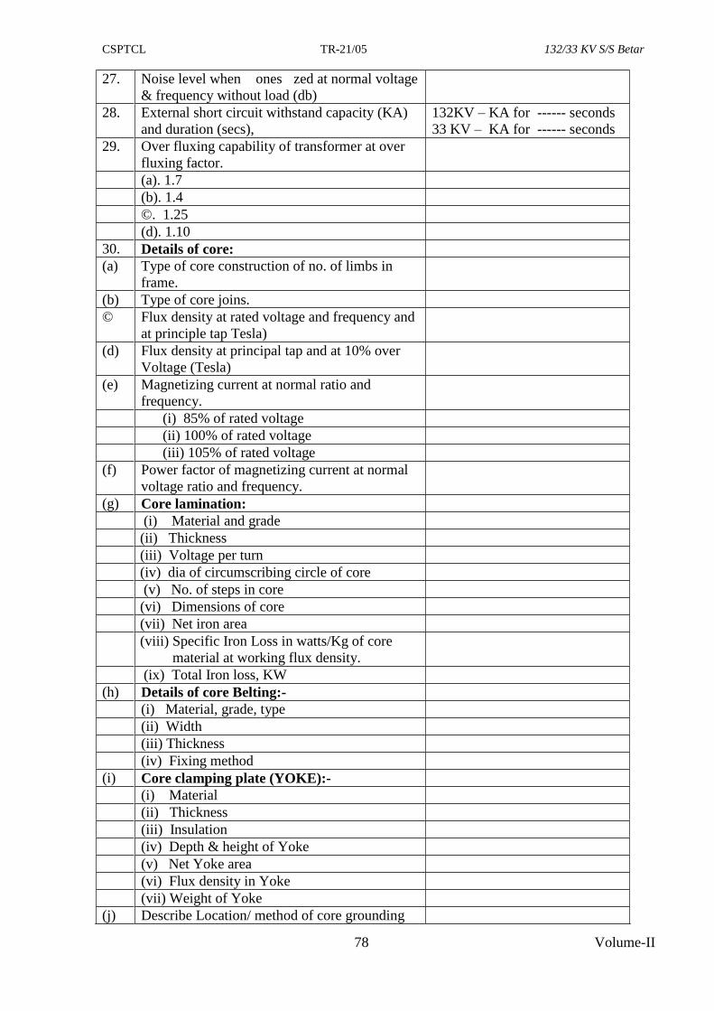
CSPTCL TR-21/05 132/33 KV S/S Betar
78 Volume-II
27. Noise level when ones zed at normal voltage
& frequency without load (db)
28. External short circuit withstand capacity (KA)
and duration (secs),
132KV – KA for ------ seconds
33 KV – KA for ------ seconds
29. Over fluxing capability of transformer at over
fluxing factor.
(a). 1.7
(b). 1.4
©. 1.25
(d). 1.10
30. Details of core:
(a) Type of core construction of no. of limbs in
frame.
(b) Type of core joins.
© Flux density at rated voltage and frequency and
at principle tap Tesla)
(d) Flux density at principal tap and at 10% over
Voltage (Tesla)
(e) Magnetizing current at normal ratio and
frequency.
(i) 85% of rated voltage
(ii) 100% of rated voltage
(iii) 105% of rated voltage
(f) Power factor of magnetizing current at normal
voltage ratio and frequency.
(g) Core lamination:
(i) Material and grade
(ii) Thickness
(iii) Voltage per turn
(iv) dia of circumscribing circle of core
(v) No. of steps in core
(vi) Dimensions of core
(vii) Net iron area
(viii) Specific Iron Loss in watts/Kg of core
material at working flux density.
(ix) Total Iron loss, KW
(h) Details of core Belting:-
(i) Material, grade, type
(ii) Width
(iii) Thickness
(iv) Fixing method
(i) Core clamping plate (YOKE):-
(i) Material
(ii) Thickness
(iii) Insulation
(iv) Depth & height of Yoke
(v) Net Yoke area
(vi) Flux density in Yoke
(vii) Weight of Yoke
(j) Describe Location/ method of core grounding
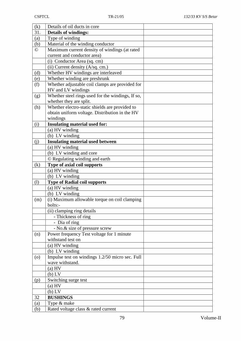
CSPTCL TR-21/05 132/33 KV S/S Betar
79 Volume-II
(k) Details of oil ducts in core
31. Details of windings:
(a) Type of winding
(b) Material of the winding conductor
© Maximum current density of windings (at rated
current and conductor area)
(i) Conductor Area (sq. cm)
(ii) Current density (A/sq. cm.)
(d) Whether HV windings are interleaved
(e) Whether winding are preshrunk
(f) Whether adjustable coil clamps are provided for
HV and LV windings
(g) Whether steel rings used for the windings, If so,
whether they are split.
(h) Whether electro-static shields are provided to
obtain uniform voltage. Distribution in the HV
windings
(i) Insulating material used for:
(a) HV winding
(b) LV winding
(j) Insulating material used between
(a) HV winding
(b) LV winding and core
© Regulating winding and earth
(k) Type of axial coil supports
(a) HV winding
(b) LV winding
(l) Type of Radial coil supports
(a) HV winding
(b) LV winding
(m) (i) Maximum allowable torque on coil clamping
bolts:-
(ii) clamping ring details
- Thickness of ring
- Dia of ring
- No.& size of pressure screw
(n) Power frequency Test voltage for 1 minute
withstand test on
(a) HV winding
(b) LV winding
(o) Impulse test on windings 1.2/50 micro sec. Full
wave withstand.
(a) HV
(b) LV
(p) Switching surge test
(a) HV
(b) LV
32 BUSHINGS
(a) Type & make
(b) Rated voltage class & rated current
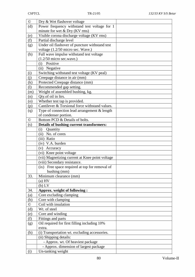
CSPTCL TR-21/05 132/33 KV S/S Betar
80 Volume-II
© Dry & Wet flashover voltage
(d) Power frequency withstand test voltage for 1
minute for wet & Dry (KV rms)
(e) Visible corona discharge voltage (KV rms)
(f) Partial discharge level
(g) Under oil flashover of puncture withstand test
voltage (1.2/50 micro sec. Wave.)
(h) Full wave impulse withstand test voltage
(1.2/50 micro sec.wave.)
(i) Positive
(ii) Negative
(i) Switching withstand test voltage (KV peal)
(j) Creepage distance in air (mm)
(k) Protected Creepage distance (mm)
(l) Recommended gap setting.
(m) Weight of assembled bushing, kg.
(n) Qty.of oil in ltrs.
(o) Whether test tap is provided.
(p) Cantilever & Torsional force withstand values.
(q) Type of connection lead arrangement & length
of condenser portion.
© Bottom PCD & Details of bolts.
(s) Details of bushing current transformers:
(i) Quantity
(ii) No. of cores
(iii) Ratio
(iv) V.A. burden
(v) Accuracy
(vi) Knee point voltage
(vii) Magnetizing current at Knee point voltage
(viii) Secondary resistance.
(ix) Free space required at top for removal of
bushing (mm)
33. Minimum clearance (mm)
(a) HV
(b) LV
34. Approx. weight of following :
(a) Core excluding clamping
(b) Core with clamping
© Coil with insulation
(d) Wt. of steel
(e) Core and winding
(f) Fittings and parts
(g) Oil required for first filling including 10%
extra.
(h) (i) Transportation wt. excluding accessories.
(ii) Shipping details:
- Approx. wt. Of heaviest package
- Approx. dimension of largest package
(i) Un-tanking weight
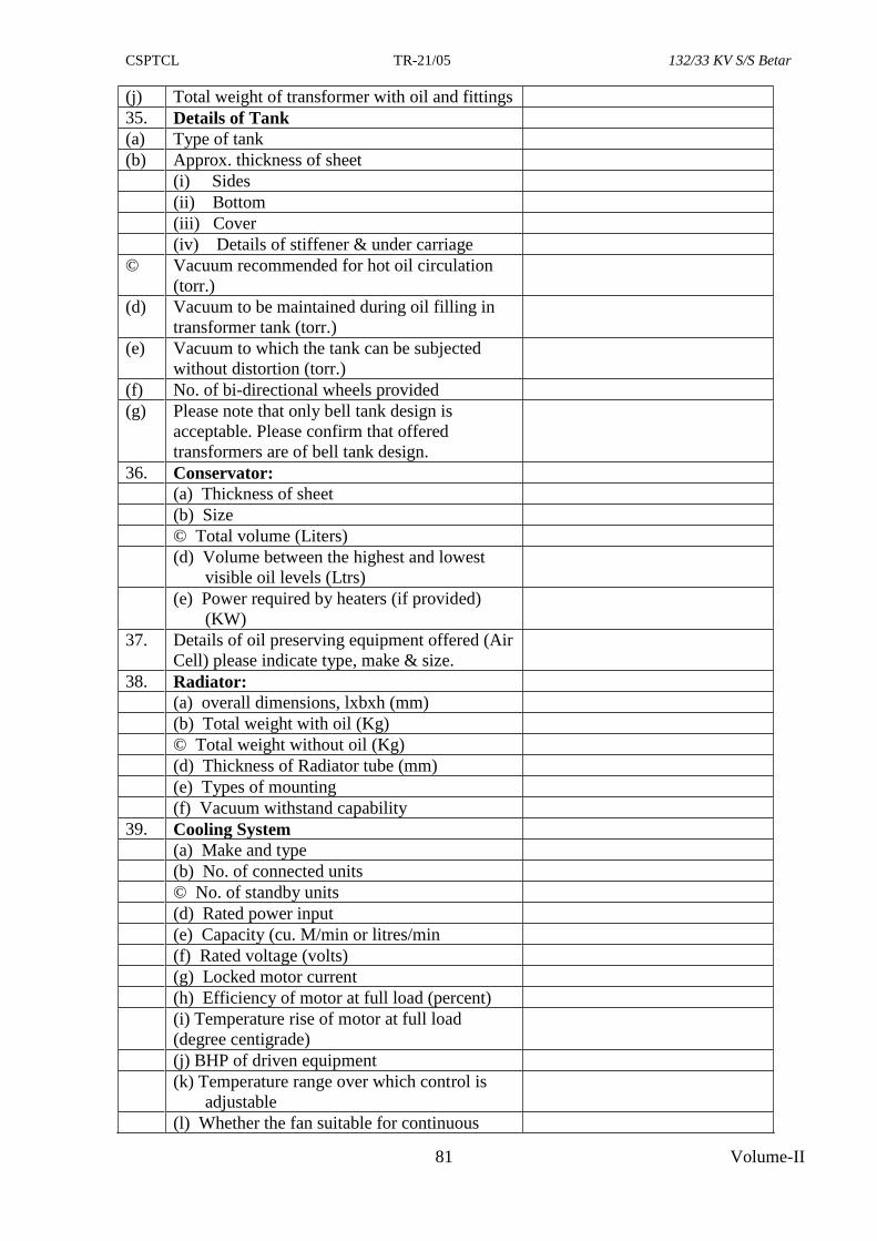
CSPTCL TR-21/05 132/33 KV S/S Betar
81 Volume-II
(j) Total weight of transformer with oil and fittings
35. Details of Tank
(a) Type of tank
(b) Approx. thickness of sheet
(i) Sides
(ii) Bottom
(iii) Cover
(iv) Details of stiffener & under carriage
© Vacuum recommended for hot oil circulation
(torr.)
(d) Vacuum to be maintained during oil filling in
transformer tank (torr.)
(e) Vacuum to which the tank can be subjected
without distortion (torr.)
(f) No. of bi-directional wheels provided
(g) Please note that only bell tank design is
acceptable. Please confirm that offered
transformers are of bell tank design.
36. Conservator:
(a) Thickness of sheet
(b) Size
© Total volume (Liters)
(d) Volume between the highest and lowest
visible oil levels (Ltrs)
(e) Power required by heaters (if provided)
(KW)
37. Details of oil preserving equipment offered (Air
Cell) please indicate type, make & size.
38. Radiator:
(a) overall dimensions, lxbxh (mm)
(b) Total weight with oil (Kg)
© Total weight without oil (Kg)
(d) Thickness of Radiator tube (mm)
(e) Types of mounting
(f) Vacuum withstand capability
39. Cooling System
(a) Make and type
(b) No. of connected units
© No. of standby units
(d) Rated power input
(e) Capacity (cu. M/min or litres/min
(f) Rated voltage (volts)
(g) Locked motor current
(h) Efficiency of motor at full load (percent)
(i) Temperature rise of motor at full load
(degree centigrade)
(j) BHP of driven equipment
(k) Temperature range over which control is
adjustable
(l) Whether the fan suitable for continuous
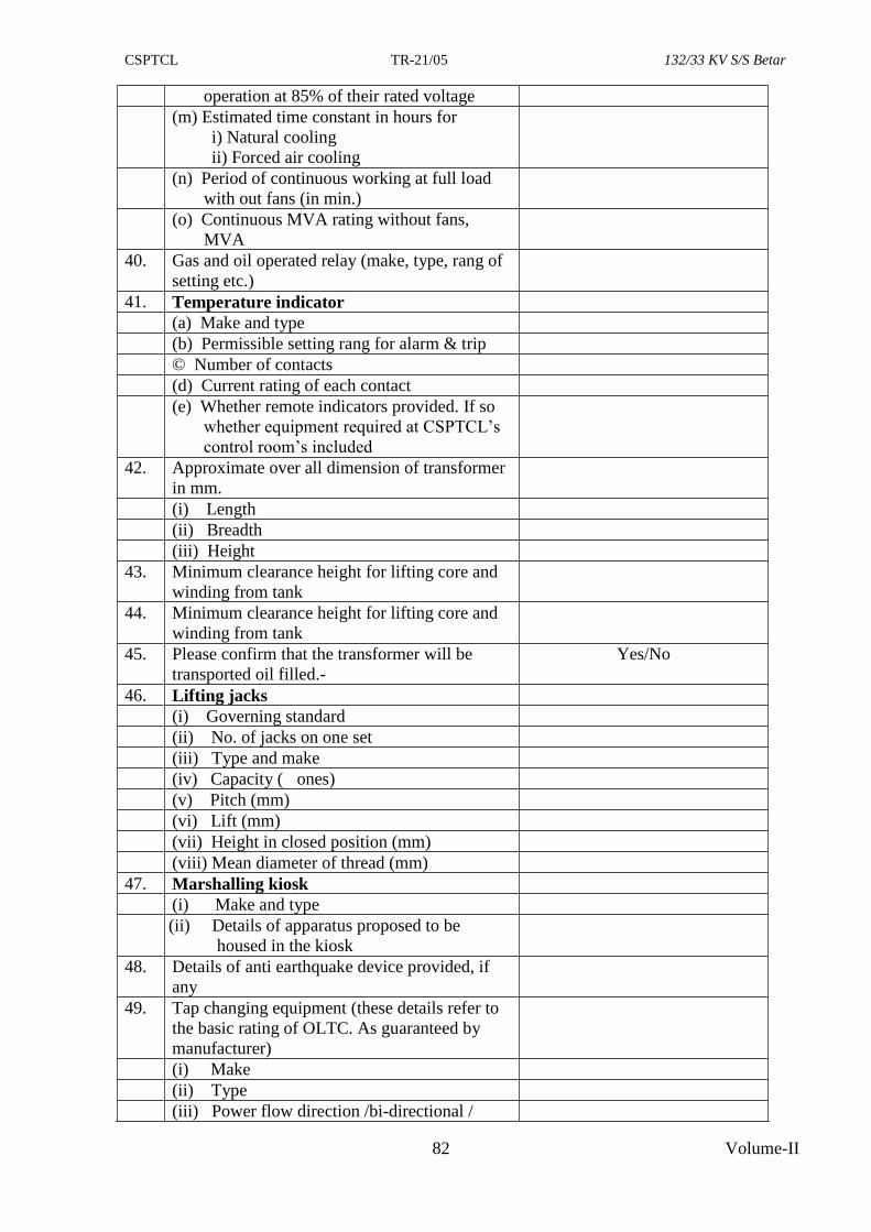
CSPTCL TR-21/05 132/33 KV S/S Betar
82 Volume-II
operation at 85% of their rated voltage
(m) Estimated time constant in hours for
i) Natural cooling
ii) Forced air cooling
(n) Period of continuous working at full load
with out fans (in min.)
(o) Continuous MVA rating without fans,
MVA
40. Gas and oil operated relay (make, type, rang of
setting etc.)
41. Temperature indicator
(a) Make and type
(b) Permissible setting rang for alarm & trip
© Number of contacts
(d) Current rating of each contact
(e) Whether remote indicators provided. If so
whether equipment required at CSPTCL’s
control room’s included
42. Approximate over all dimension of transformer
in mm.
(i) Length
(ii) Breadth
(iii) Height
43. Minimum clearance height for lifting core and
winding from tank
44. Minimum clearance height for lifting core and
winding from tank
45. Please confirm that the transformer will be
transported oil filled.-
Yes/No
46. Lifting jacks
(i) Governing standard
(ii) No. of jacks on one set
(iii) Type and make
(iv) Capacity ( ones)
(v) Pitch (mm)
(vi) Lift (mm)
(vii) Height in closed position (mm)
(viii) Mean diameter of thread (mm)
47. Marshalling kiosk
(i) Make and type
(ii) Details of apparatus proposed to be
housed in the kiosk
48. Details of anti earthquake device provided, if
any
49. Tap changing equipment (these details refer to
the basic rating of OLTC. As guaranteed by
manufacturer)
(i) Make
(ii) Type
(iii) Power flow direction /bi-directional /
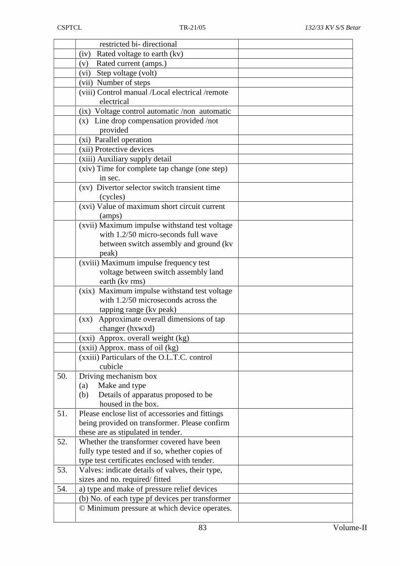
CSPTCL TR-21/05 132/33 KV S/S Betar
83 Volume-II
restricted bi- directional
(iv) Rated voltage to earth (kv)
(v) Rated current (amps.)
(vi) Step voltage (volt)
(vii) Number of steps
(viii) Control manual /Local electrical /remote
electrical
(ix) Voltage control automatic /non automatic
(x) Line drop compensation provided /not
provided
(xi) Parallel operation
(xii) Protective devices
(xiii) Auxiliary supply detail
(xiv) Time for complete tap change (one step)
in sec.
(xv) Divertor selector switch transient time
(cycles)
(xvi) Value of maximum short circuit current
(amps)
(xvii) Maximum impulse withstand test voltage
with 1.2/50 micro-seconds full wave
between switch assembly and ground (kv
peak)
(xviii) Maximum impulse frequency test
voltage between switch assembly land
earth (kv rms)
(xix) Maximum impulse withstand test voltage
with 1.2/50 microseconds across the
tapping range (kv peak)
(xx) Approximate overall dimensions of tap
changer (hxwxd)
(xxi) Approx. overall weight (kg)
(xxii) Approx. mass of oil (kg)
(xxiii) Particulars of the O.L.T.C. control
cubicle
50. Driving mechanism box
(a) Make and type
(b) Details of apparatus proposed to be
housed in the box.
51. Please enclose list of accessories and fittings
being provided on transformer. Please confirm
these are as stipulated in tender.
52. Whether the transformer covered have been
fully type tested and if so, whether copies of
type test certificates enclosed with tender.
53. Valves: indicate details of valves, their type,
sizes and no. required/ fitted
54. a) type and make of pressure relief devices
(b) No. of each type pf devices per transformer
© Minimum pressure at which device operates.
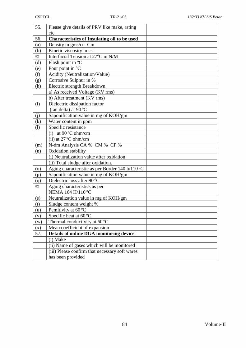
CSPTCL TR-21/05 132/33 KV S/S Betar
84 Volume-II
55. Please give details of PRV like make, rating
etc.
56. Characteristics of Insulating oil to be used
(a) Density in gms/cu. Cm
(b) Kinetic viscosity in cst
© Interfacial Tension at 27oC in N/M
(d) Flash point in oC
(e) Pour point in oC
(f) Acidity (Neutralization/Value)
(g) Corrosive Sulphur in %
(h) Electric strength Breakdown
a) As received Voltage (KV rms)
b) After treatment (KV rms)
(i) Dielectric dissipation factor
(tan delta) at 90 oC
(j) Saponification value in mg of KOH/gm
(k) Water content in ppm
(l) Specific resistance
(i) at 90 oC ohm/cm
(ii) at 27 oC ohm/cm
(m) N-dm Analysis CA % CM % CP %
(n) Oxidation stability
(i) Neutralization value after oxidation
(ii) Total sludge after oxidation.
(o) Aging characteristic as per Border 140 h/110 oC
(p) Saponification value in mg of KOH/gm
(q) Dielectric loss after 90 oC
© Aging characteristics as per
NEMA 164 H/110 oC
(s) Neutralization value in mg of KOH/gm
(t) Sludge content weight %
(u) Pemitivity at 60 oC
(v) Specific heat at 60 oC
(w) Thermal conductivity at 60 oC
(x) Mean coefficient of expansion
57. Details of online DGA monitoring device:
(i) Make
(ii) Name of gases which will be monitored
(iii) Please confirm that necessary soft wares
has been provided
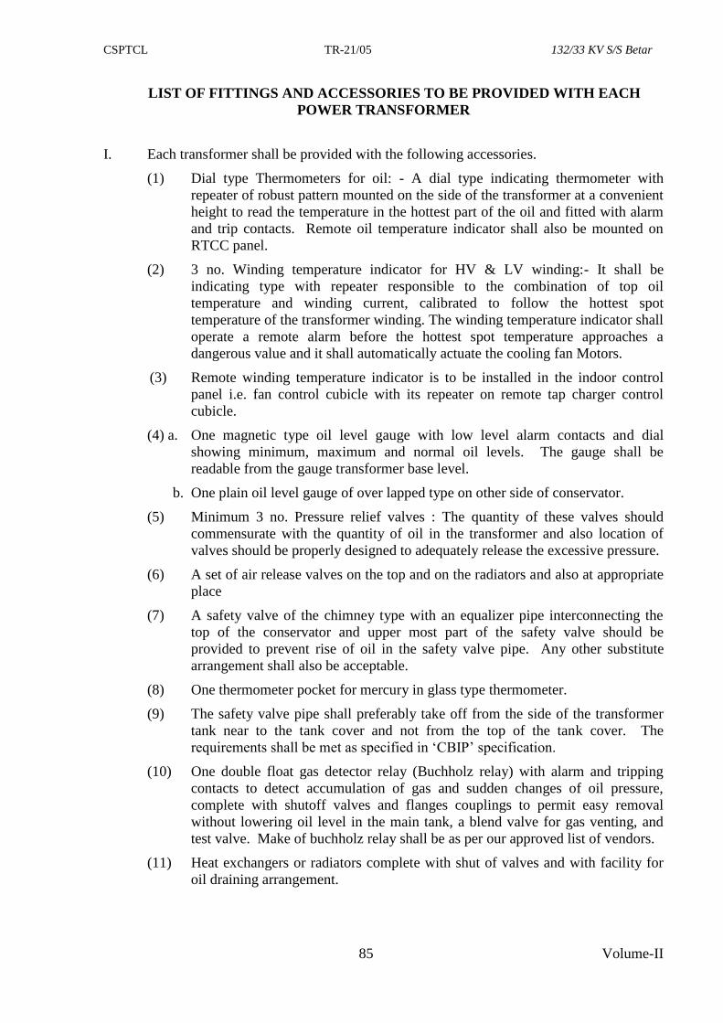
CSPTCL TR-21/05 132/33 KV S/S Betar
85 Volume-II
LIST OF FITTINGS AND ACCESSORIES TO BE PROVIDED WITH EACH
POWER TRANSFORMER
I. Each transformer shall be provided with the following accessories.
(1) Dial type Thermometers for oil: - A dial type indicating thermometer with
repeater of robust pattern mounted on the side of the transformer at a convenient
height to read the temperature in the hottest part of the oil and fitted with alarm
and trip contacts. Remote oil temperature indicator shall also be mounted on
RTCC panel.
(2) 3 no. Winding temperature indicator for HV & LV winding:- It shall be
indicating type with repeater responsible to the combination of top oil
temperature and winding current, calibrated to follow the hottest spot
temperature of the transformer winding. The winding temperature indicator shall
operate a remote alarm before the hottest spot temperature approaches a
dangerous value and it shall automatically actuate the cooling fan Motors.
(3) Remote winding temperature indicator is to be installed in the indoor control
panel i.e. fan control cubicle with its repeater on remote tap charger control
cubicle.
(4) a. One magnetic type oil level gauge with low level alarm contacts and dial
showing minimum, maximum and normal oil levels. The gauge shall be
readable from the gauge transformer base level.
b. One plain oil level gauge of over lapped type on other side of conservator.
(5) Minimum 3 no. Pressure relief valves : The quantity of these valves should
commensurate with the quantity of oil in the transformer and also location of
valves should be properly designed to adequately release the excessive pressure.
(6) A set of air release valves on the top and on the radiators and also at appropriate
place
(7) A safety valve of the chimney type with an equalizer pipe interconnecting the
top of the conservator and upper most part of the safety valve should be
provided to prevent rise of oil in the safety valve pipe. Any other substitute
arrangement shall also be acceptable.
(8) One thermometer pocket for mercury in glass type thermometer.
(9) The safety valve pipe shall preferably take off from the side of the transformer
tank near to the tank cover and not from the top of the tank cover. The
requirements shall be met as specified in ‘CBIP’ specification.
(10) One double float gas detector relay (Buchholz relay) with alarm and tripping
contacts to detect accumulation of gas and sudden changes of oil pressure,
complete with shutoff valves and flanges couplings to permit easy removal
without lowering oil level in the main tank, a blend valve for gas venting, and
test valve. Make of buchholz relay shall be as per our approved list of vendors.
(11) Heat exchangers or radiators complete with shut of valves and with facility for
oil draining arrangement.
CSPTCL TR-21/05 132/33 KV S/S Betar
86 Volume-II
(12) a/ Two oil conservator, with required accessories, one for main tank and
other for OLTC.
b/ Air cell type breathing arrangement with oil preserving equipment
complete in all respects.
(13) Eye bolts and lugs on all parts for easy handling.
(14) Two grounding earth terminals at diagonally opposite corner of tank.
(15) One rating and diagram plate.
(16) A set of minimum 4 nos. Flanged bi-directional wheels for rail mounting (for
1676mm rail gauge).
(17) A set of fans required for ONAF cooling of the transformer with following
information.
a. Number of Radiator Banks.
b. No. Of cooling fans (of adequate voltage & rpm) provided in each bank
to ensure 100% ONAF rating of the transformer. As per our
specification, for each bank one additional cooling fan is to be included
which will be duly wired-up.
(18) Suitable jacking lugs and haulage holes.
(19) Inspection window & main holes with bolted cover
(20) Lifting arrangement for the complete transformer, core coil assembly and also
tank.
(21) One foldable ladder on main tank.
(22) For the purpose of taking earthing connection from the neutral bushing,
adequate number of brackets with small support insulators shall be provided on
the body of the tank so that earthing could be arranged by us near the earthing
pit of transformer itself.
(23) A separate weather proof FCC (Fan/Cooler control) cubicle shall be mounted on
the transformer containing dial type thermometer and winding temperature
indicator and terminals of dial, type thermometer, winding temperature
indicator, Buchholz relay, MDG, control of fans etc.
Please note provision of separate Fan Control Cubicle (FCC) is a must. FCC
shall be suitably dimensioned to accommodate following:-
(a) The wiring from RTCC shall be brought to marshalling box and for terminating
the same adequate number of suitably rated terminal connectors shall be
provided.
(b) Necessary cable glands shall be included in the scope of supply.
(c) Arrangement for terminating the connecting leads of OTI, WTI, buchholz,
magnetic oil level gauge etc. shall be made in the marshalling box. It should be
possible to read OTI and ETI readings without opening the box through suitable
glass window. All trip alarm and repeater signals will be transferred to control
room for which arrangement will have to be made.
(d) Starters for cooling fans shall be housed in marshalling box and necessary
switches for local operation of fans shall be provided.
(e) Local remote control switch for OLTC shall be provided.
CSPTCL TR-21/05 132/33 KV S/S Betar
87 Volume-II
(f) Space heater with switch, cubicle illumination lamp, fuses, links overload
protection arrangement for motors and other accessories shall be included in the
scope of supply.
(24) One set of indoor RTCC (Remote tap changer control) cubicle complete with
provision for remote operation of OLTC, as independent or master/follower
scheme, with oil and winding temperature repeater, tap position indicator with
annunciation for fan group ON/OFF and cooler supply fail indicator and Tap
changer in progress.
(25) One set of erection manual/relevant drawing/leaflets should be secured
permanently inside the RTCC cubicle as a guideline for site erection and
commissioning.
(26) Three separate connection i.e. connection from core, connection from end frame
and connection from tank shall be brought out on to a terminal box with cover.
Arrangement for inter connecting these terminals in the terminal box shall also
be provided. This arrangement shall facilitate verification of core, end frame
and tank insulation.
(27) In no case, the radiators should be projected above the main tank height.
(28) Transformer shall be supplied with a full outfit of tools, spanners, jacks, special
tools for assembly and all spanners shall be single ended and of very good
quality of “Gedore” or “Taparia” make.
II. The equipments and accessories furnished with the transformer shall be suitably
mounted on the transformer for ease of operation, inspection and maintenance and the
mounting details shall be subject to the approval of CSPTCL. All valves shall be
provided either with blind companion flanges or with pipe plugs for protection.
III. Indication, alarm and relay equipment shall have contacts suitable for operation with
110V DC supply. Any other accessories or appliances recommended by the
manufacturer for the satisfactory operation of the transformer shall also have 110 DC as
input.
IV. (a) OLTC and its controls shall be as per relevant clause of specification.
(b) All cabinets & panels shall be conforming to stipulations under relavent clause
of specifications.
© All 132/33KV and neutral bushings shall be of OIP condenser type and as per
relevant clause of specifications.
V. On line DGA Monitoring device as per relevant clause.
Accessories, which are not included in the above schedule but details of which are given in
tender specification and which are necessary for satisfactory operation of Transformer
shall be deemed to have been included in the contract without any extra cost to CSPTCL.
CSPTCL TR-21/05 132/33 KV S/S Betar
88 Volume-II
LIST OF TRANSFORMER ACCESSORIES AND TEST CERTIFICATES REQUIRED
S.No Accessory Test-certificates required
1. Condenser
Bushing
1. Appearance, construction and dimensional check.
2. Test for leakage of internal filling at a pressure of 1.0
Kg/cm for 12 hours.
3. Insulation resistance measurement with 2000V megger.
4. Dry/wet power frequency voltage withstand test.
5. Dry/wet power frequency voltage withstand test for test
tap insulation
6. Partial discharge measurement upto 1.5 UN 3Kv.
7. Measurement of tangent delta and capacitance.
2. Pressure Gauges/
Differential
Pressure Gauges
1. Appearance, construction and dimensional check.
2. Calibration test.
3. Alarm contact setting test.
3. OLTC.
1. Oil tightness test for the diverter switch oil chamber at an
oil pressure of 0.5 Kg/cm2 at 100 degree centigrade for 1
hour.
2. Mechanical operation test.
3. Operation sequence measurement
4. Insulation resistance measurement using 2000V megger.
5. Power frequency voltage withstand test on diverter switch
to earth and between even and odd contacts.
6. Power frequency voltage withstand test on tap selector-
between stationary contacts, between max. And min. Taps,
between phases and supporting frames, between phases.
7. Operation test of complete tap changer.
8. Operation and dielectric test of driving mechanism.
4. Winding & Oil
Temperature
Indicator
1. Calibration test.
2. Dielectric test at 2 KV for one minute.
3. Accuracy test for indication and switch setting scales.
4. Test for adjustability of switch setting.
5. Test for switch rating.
6. Measurement of temperature rise with respect to the heater
coil current.
5. PRV
1. Functional test with Compressed air to check bursting
pressure, indicating flag operation and switch operation.
2. Dielectric test at 2 Kv for one minute.
3. Switch contact test at 5A, 240 Volt AC.
6. Cooling fans 1. Insulation resistance measurement.
2. Dielectric test at 2 KV between winding and body for one
minute.
3. Operation check.
4. Appearance, construction and dimensional check.
CSPTCL TR-21/05 132/33 KV S/S Betar
89 Volume-II
7. Buchholz relay
1. Leak test with transformer oil at a pressure of 3 Kg/cm2 for
30 minutes at ambient temperature for relay casing.
2. Insulation resistance measurement with 500V megger.
3. Dielectric test at 2KV for 1 minute.
4. Elements test at 1.75 Kg/cm2 for 15 minutes using
transformer oil at ambient temperature.
5. Loss of oil and surge test.
6. Gas volume test.
7. Mechanical strength test.
8. Velocity calibration test.
9. Appearance construction and dimensional check.
8. Oil level indictor
1. Test for oil levels.
2. Switch operation for low level alarm.
3. Switch contact test at 5A 240V AC.
4. Dielectric test at 2 KV for 1 minute.
5. Appearance, construction and dimensional check.
9. Pressed steel
radiators
1. Air pressure test at 2 kg/cm2 under water for 15 minutes.
2. Appearance, construction and dimensional check.
10. OLTC control
cubicle/ cooler
control cabinet
1. Appearance, construction and dimensional check.
2. Electric operation.
3. Insulation resistance measurement using 500V megger at
ambient temperature.
4. Dielectric test at 2 KV for 1 minute.
11. Bushing current
transformer
1. Appearance, construction and dimensional check.
2. Polarity check.
3. Measurement of insulation resistance.
4. High voltage power frequency test.
5. Determination of ratio error and phase angle of measuring
and protection BCTs.
6. Determination of Turns ratio error for PS class BCT.
7. Determination of composite error for protective class BCT.
8. Interturn insulation withstand test.
9. Exciting current characteristic test.
10. Secondary winding resistance measurement.
11. Knee-Point voltage, measurement for PS class BCT.
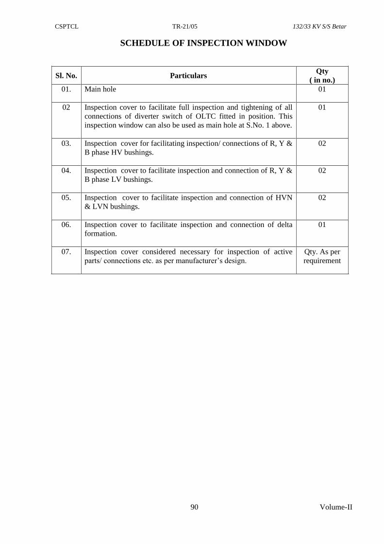
CSPTCL TR-21/05 132/33 KV S/S Betar
90 Volume-II
SCHEDULE OF INSPECTION WINDOW
Sl. No. Particulars Qty
( in no.)
01. Main hole 01
02 Inspection cover to facilitate full inspection and tightening of all
connections of diverter switch of OLTC fitted in position. This
inspection window can also be used as main hole at S.No. 1 above.
01
03. Inspection cover for facilitating inspection/ connections of R, Y &
B phase HV bushings.
02
04. Inspection cover to facilitate inspection and connection of R, Y &
B phase LV bushings.
02
05. Inspection cover to facilitate inspection and connection of HVN
& LVN bushings.
02
06. Inspection cover to facilitate inspection and connection of delta
formation.
01
07. Inspection cover considered necessary for inspection of active
parts/ connections etc. as per manufacturer’s design.
Qty. As per
requirement
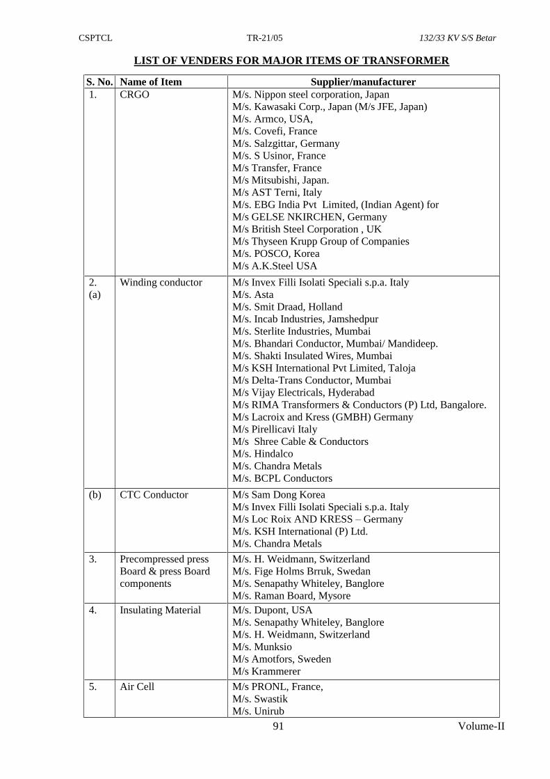
CSPTCL TR-21/05 132/33 KV S/S Betar
91 Volume-II
LIST OF VENDERS FOR MAJOR ITEMS OF TRANSFORMER
S. No. Name of Item Supplier/manufacturer
1. CRGO M/s. Nippon steel corporation, Japan
M/s. Kawasaki Corp., Japan (M/s JFE, Japan)
M/s. Armco, USA,
M/s. Covefi, France
M/s. Salzgittar, Germany
M/s. S Usinor, France
M/s Transfer, France
M/s Mitsubishi, Japan.
M/s AST Terni, Italy
M/s. EBG India Pvt Limited, (Indian Agent) for
M/s GELSE NKIRCHEN, Germany
M/s British Steel Corporation , UK
M/s Thyseen Krupp Group of Companies
M/s. POSCO, Korea
M/s A.K.Steel USA
2.
(a)
Winding conductor M/s Invex Filli Isolati Speciali s.p.a. Italy
M/s. Asta
M/s. Smit Draad, Holland
M/s. Incab Industries, Jamshedpur
M/s. Sterlite Industries, Mumbai
M/s. Bhandari Conductor, Mumbai/ Mandideep.
M/s. Shakti Insulated Wires, Mumbai
M/s KSH International Pvt Limited, Taloja
M/s Delta-Trans Conductor, Mumbai
M/s Vijay Electricals, Hyderabad
M/s RIMA Transformers & Conductors (P) Ltd, Bangalore.
M/s Lacroix and Kress (GMBH) Germany
M/s Pirellicavi Italy
M/s Shree Cable & Conductors
M/s. Hindalco
M/s. Chandra Metals
M/s. BCPL Conductors
(b) CTC Conductor M/s Sam Dong Korea
M/s Invex Filli Isolati Speciali s.p.a. Italy
M/s Loc Roix AND KRESS – Germany
M/s. KSH International (P) Ltd.
M/s. Chandra Metals
3. Precompressed press
Board & press Board
components
M/s. H. Weidmann, Switzerland
M/s. Fige Holms Brruk, Swedan
M/s. Senapathy Whiteley, Banglore
M/s. Raman Board, Mysore
4. Insulating Material M/s. Dupont, USA
M/s. Senapathy Whiteley, Banglore
M/s. H. Weidmann, Switzerland
M/s. Munksio
M/s Amotfors, Sweden
M/s Krammerer
5. Air Cell M/s PRONL, France,
M/s. Swastik
M/s. Unirub
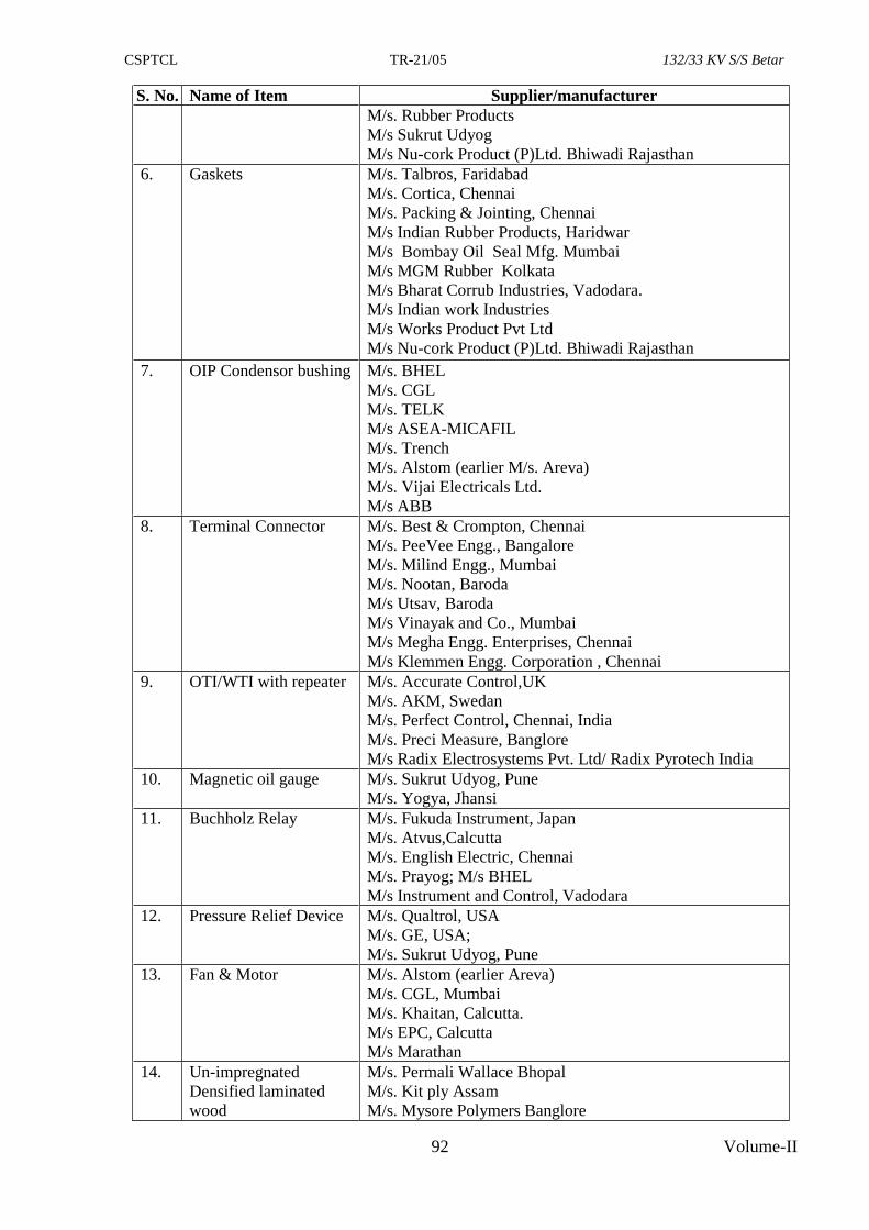
CSPTCL TR-21/05 132/33 KV S/S Betar
92 Volume-II
S. No. Name of Item Supplier/manufacturer
M/s. Rubber Products
M/s Sukrut Udyog
M/s Nu-cork Product (P)Ltd. Bhiwadi Rajasthan
6. Gaskets M/s. Talbros, Faridabad
M/s. Cortica, Chennai
M/s. Packing & Jointing, Chennai
M/s Indian Rubber Products, Haridwar
M/s Bombay Oil Seal Mfg. Mumbai
M/s MGM Rubber Kolkata
M/s Bharat Corrub Industries, Vadodara.
M/s Indian work Industries
M/s Works Product Pvt Ltd
M/s Nu-cork Product (P)Ltd. Bhiwadi Rajasthan
7. OIP Condensor bushing M/s. BHEL
M/s. CGL
M/s. TELK
M/s ASEA-MICAFIL
M/s. Trench
M/s. Alstom (earlier M/s. Areva)
M/s. Vijai Electricals Ltd.
M/s ABB
8. Terminal Connector M/s. Best & Crompton, Chennai
M/s. PeeVee Engg., Bangalore
M/s. Milind Engg., Mumbai
M/s. Nootan, Baroda
M/s Utsav, Baroda
M/s Vinayak and Co., Mumbai
M/s Megha Engg. Enterprises, Chennai
M/s Klemmen Engg. Corporation , Chennai
9. OTI/WTI with repeater M/s. Accurate Control,UK
M/s. AKM, Swedan
M/s. Perfect Control, Chennai, India
M/s. Preci Measure, Banglore
M/s Radix Electrosystems Pvt. Ltd/ Radix Pyrotech India
10. Magnetic oil gauge M/s. Sukrut Udyog, Pune
M/s. Yogya, Jhansi
11. Buchholz Relay M/s. Fukuda Instrument, Japan
M/s. Atvus,Calcutta
M/s. English Electric, Chennai
M/s. Prayog; M/s BHEL
M/s Instrument and Control, Vadodara
12. Pressure Relief Device M/s. Qualtrol, USA
M/s. GE, USA;
M/s. Sukrut Udyog, Pune
13. Fan & Motor M/s. Alstom (earlier Areva)
M/s. CGL, Mumbai
M/s. Khaitan, Calcutta.
M/s EPC, Calcutta
M/s Marathan
14. Un-impregnated
Densified laminated
wood
M/s. Permali Wallace Bhopal
M/s. Kit ply Assam
M/s. Mysore Polymers Banglore
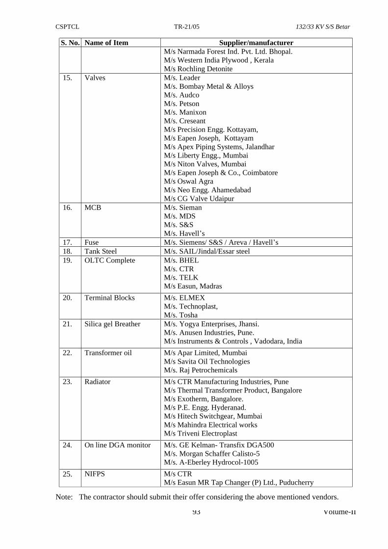
CSPTCL TR-21/05 132/33 KV S/S Betar
93 Volume-II
S. No. Name of Item Supplier/manufacturer
M/s Narmada Forest Ind. Pvt. Ltd. Bhopal.
M/s Western India Plywood , Kerala
M/s Rochling Detonite
15. Valves M/s. Leader
M/s. Bombay Metal & Alloys
M/s. Audco
M/s. Petson
M/s. Manixon
M/s. Creseant
M/s Precision Engg. Kottayam,
M/s Eapen Joseph, Kottayam
M/s Apex Piping Systems, Jalandhar
M/s Liberty Engg., Mumbai
M/s Niton Valves, Mumbai
M/s Eapen Joseph & Co., Coimbatore
M/s Oswal Agra
M/s Neo Engg. Ahamedabad
M/s CG Valve Udaipur
16. MCB M/s. Sieman
M/s. MDS
M/s. S&S
M/s. Havell’s
17. Fuse M/s. Siemens/ S&S / Areva / Havell’s
18. Tank Steel M/s. SAIL/Jindal/Essar steel
19. OLTC Complete M/s. BHEL
M/s. CTR
M/s. TELK
M/s Easun, Madras
20. Terminal Blocks M/s. ELMEX
M/s. Technoplast,
M/s. Tosha
21. Silica gel Breather M/s. Yogya Enterprises, Jhansi.
M/s. Anusen Industries, Pune.
M/s Instruments & Controls , Vadodara, India
22. Transformer oil M/s Apar Limited, Mumbai
M/s Savita Oil Technologies
M/s. Raj Petrochemicals
23. Radiator M/s CTR Manufacturing Industries, Pune
M/s Thermal Transformer Product, Bangalore
M/s Exotherm, Bangalore.
M/s P.E. Engg. Hyderanad.
M/s Hitech Switchgear, Mumbai
M/s Mahindra Electrical works
M/s Triveni Electroplast
24. On line DGA monitor M/s. GE Kelman- Transfix DGA500
M/s. Morgan Schaffer Calisto-5
M/s. A-Eberley Hydrocol-1005
25. NIFPS M/s CTR
M/s Easun MR Tap Changer (P) Ltd., Puducherry
Note: The contractor should submit their offer considering the above mentioned vendors.
CSPTCL TR-21/05 132/33 KV S/S Betar
94 Volume-II
DRAWINGS AND DATA TO BE FURNISHED BY THE CONTRACTOR .
The following drawings and data are to be submitted by the contractor for approval:
(a) Outline dimensional drawings of transformer and its accessories including
conservator complete with Bill of material and details of all parts, their quantity,
rating & name of Vendors indicating clearances of transformer body from live
terminals i.e. HV,LV.
(b) Drawing of transformer tank with location of inspection windows, thickness of
side/bottom/top of tank, details of stiffener.
(c) Drawing indicating limbed core construction with complete details of no., width and
wt. of core laminations with size of steps; thickness of core laminations ; dimension of
window; size of limbs; Gross and net core ; wt. of complete core.
(d) Drawing indicating core belting arrangement with details of belting, belting material etc.
(e) Large scale dimensioned drawings for HV & LV windings of the transformer; size and
no. of parallel of HV, LV and of cooling ducts, coil clamping arrangement, no./size &
location of pressure screws, clamping ring; top yoke arrangement etc. The details
should commensurate with the short circuit calculations submitted by you for each
rating of transformer
(f) Detailed drawing of transformer tank with complete core and winding indicating
clearances inside transformer tank as also passage and space for free movement of
at least two persons for inspection of active parts etc .
(g) Schematic diagram showing the flow of oil in the cooling system as well as each limb
and winding. Longitudinal and cross-sectional views showing the duct sizes, cooling
pipes etc. for the transformers/radiators drawn to scale .
(h) Drawings giving the weights for foundations.
(i) Combined Rating and diagram plate including tap changing, which should also include
details of guaranteed and measured no load and load losses as also winding resistances
and percentage impedances at all taps.
(j) Schematic control and wiring diagram for all auxiliary equipment and control cubicle.
(k) Drawing showing constructional details, dimensions, mechanical & technical
particulars of bushings. Arrangement of terminals and details of connection of bushing
shall also be indicated in drawing with their technical particulars.
(l) Transportation drawing of transformer.
(m) Details of fittings and cable box.
(n) Drawing showing arrangement and details of tap changing gear including selector
switch, diverter switch and drive mechanism.
(o) Valve Schedule plate.
CSPTCL TR-21/05 132/33 KV S/S Betar
95 Volume-II
(p) Oil filling instruction plate for conservator fitted with Air cell breather arrangement
including equalizing arrangement if any required at the time of taking full Vacuum at
site.
(q) Drawing and instruction for fitting ofAir Cell.
(r) Drawing of conservator indicating internal details of air cell MOG, oil level gauge and
silica gel breather pipe fitting arrangement.
(s) Drawings of all HV & LV bushings with complete details meeting TS requirement.
(t) Drawings of HV, LV& neutral terminal connectors indicating plate thickness, no. of nut
bolts with size and other details.
(u) Drawing of foldable & detachable ladder with its complete details and fitting
arrangement on transformer/ conservator tank.
(v) Drawing for HV/LV neutral earthing arrangement indicating voltage rating of
insulators and its fitting arrangements, size of copper strips, terminal connectors etc.
(w) Detailed drawing indicating two views of all valves provided in the transformer tank.
(x) Detailed internal drawing of transformer indicating transportation locking arrangement
provided to avoid shifting of core assembly.
(y) Drawing showing weights of transformers, cooling fan structures, FCC structures with
distance from central line of transformer for casting of civil foundation for transformer
and associated equipments.
(aa) Drawing of Earthing terminal box showing earthing arrangement for core, end frame,
tank giving details of voltage class and current rating of terminal bushings.
(ab) Drawing indicating insulation thickness details and other arrangement provided
between core assembly and bottom yoke and base of bottom of tank.
(ac) Drawing indicating details of ‘O’ ring gasketting arrangement provided in transformer
tank covers.
(ad) Detailed Drawing of jacks.
(ae) Drawing of stiffeners provided on top, each faces/sides of tank with their number and
size.
(af) Drawing indicating number, location, size of shields/ magnetic shunts and its material
provided inside the tank as per clause 11.1 (g).
(ag) Drawing indicating internal details of transformer giving complete details of clearances
from live parts.
(ah) Drawing of internal LV winding termination arrangement indicating minimum
clearance between core and LV take off lead.
(ai) Drawing for Lead termination to bottom of HV & LV Neutral Bushings
(aj) Drawing for Lead termination to bottom of HV & LV bushings.
CSPTCL TR-21/05 132/33 KV S/S Betar
96 Volume-II
(ak) Internal drawing & design of Core & Winding indicating all attachment with
identification numbers, description including take-off arrangement of lead connection
for Core & End frame and related Bill of Material
(al) Locking arrangement drawing for tank top cover, core & winding with complete
dimension & details.
(am) Plan view of the bottom of Bell Tank for complete details of core coil resting
arrangement, indicating clearly dimensional details, material of insulation, clamping
arrangement with details of nuts/ bolts, clearance from all sides provided at bottom.
(an) Drawing indicating complete details, dimension & mounting arrangement of OLTC
inside the tank with respect to End frame.
(ao) Drawing indicating complete details, dimensions & fixing arrangement of static end
rings if used.
(ap) Other relevant drawings.
The manufacturer shall supply four (4) copies of the drawings as listed out above, which
will describe the equipment in details for approval.Three sets of instruction books,
operation and maintenance manuals and spare part bulletin, shall be supplied. In addition to
above two sets of manuals and drawings with test certificates for each unit to be despatched as
per despatch instructions.
It will be obligatory on the part of the manufacturer to ensure that the weight of core
lamination, weight of copper, weight of steel, weight of transformer tank along with fitting and
accessories, quantity of oil for first filling including wastage and 10 % extra of that quantity,
total weight of core plus winding after assembly, total weight of transformer and other
dimension of transformer are worked out carefully. It may be noted that at the time of
submission of final drawings, variation in these weights beyond the limits of (+) 5% shall not
be permitted.
CSPTCL TR-21/05 132/33 KV S/S Betar
97 Volume-II
DETAILS OF INSPECTION PROGRAMME
(A). Inspections to be performed at manufacturer’s works in presence of CSPTCL’s
representative and/ or a representative of NABL accredited third party.
1.0 Stage Inspection:
It may be noted that stage inspection for all the units at CSPTCL’s discretion shall be
done at manufacturer’s works in presence of CSPTCL’s representative and
representative of third party authorized by CSPTCL at the following stages.
1.1 After the core is built but before its clamping, CSPTCL’s representative will inspect the
core to take complete weight of the core and also to measure approximate core loss. If
necessary, a small strip of core shall also be taken for testing at ERDA/ CPRI at our
discretion.
1.2 Once the coils are prepared and are fitted on to the core, stage inspection of the core coil
assembly shall be done to take measurements of HV/ LV windings. A small piece of
conductor for each type of winding shall be made available by the manufacture. The
magnetic balance test shall also be carried out during this stage inspection.
Apart from the above, the CSPTCL also reserves the right to carry out stage inspections
at other stages also, for which advance intimation shall be given and all necessary
cooperation shall be rendered by the manufacturer.
2.0 Final inspection:
After satisfactory stage inspections, ovening of core coil assembly and tanking
thereafter shall be carried out by the manufacturer. Call for final inspection of the
transformer shall be given after readiness of transformer in all respects. During the final
inspection, all routine and additional routine tests shall be carried out on each unit
according to the methods specified in IS:2026 (Part-I):2011 and IS:2026 (Part-III):2009.
These tests shall be witnessed by CSPTCL’s representative and representative of third
party authorized by CSPTCL The details of the tests to be carried out are as given here
under:
Sl. Particulars
(A) Routine tests:
1 Measurement of winding resistance
2 Measurement of voltage ratio and check of phase displacement
3 Measurement of Impedance voltage/ short circuit impedance (Principal tap) &
load loss
4 Measurement of no load loss at 90%, 100% & 110% of rated voltage and no
load current
5 Measurement of Insulation resistance
6 Dielectric routine tests as per IS:2026 (Part-III) i.e. lightning impulse tests on
all phases of HV/LV windings, short duration induced AC withstand voltage
tests, separate source AC withstand voltage tests
7 Tests on load tap changers
CSPTCL TR-21/05 132/33 KV S/S Betar
98 Volume-II
(B) Addl. Routine Tests:
1 Dimensional checks as per approved drawing & specification
2 Magnetic circuit test. After assembly ,core shall be tested for 1 minute for 2000
volts AC between all bolts, side plates & structures steel works
3 Polarisation index – IR value for 15 sec, 60 sec & 600 sec duration shall be
recorded and PI for 600/60 sec and DAR i.e. ratio of IR values of 60/15
seconds shall be recorded. The PI value (600/60 sec) should be ≥2 and DAR
value (60/15 sec) should be ≥1.3. These values should be recorded both before
and after HV tests.
4 Tank oil leakage test – the complete transformer assly filled with oil shall be
subjected to nitrogen pressure of 0.35 Kg/cm2 above the normal oil head for a
period of 12 Hrs to ensure that there is no oil leakage.
5 Capacitance and tan delta measurement to determine capacitance between
wingding and earth. This test should be carried out before and after series of
dielectric tests by ANSI II method.
6 Test on bushings and tan delta capacitance and IR values
7 Checking of recording of IR values
(a) Between core & coil frame
(b) Between core & tank
(c) Between coil frame & main tank
The measured IR values should be more than 1000 M Ohms.
8 Magnetic balance and magnetizing current (3 phase & 1 phase at normal tape)
test
9 Tests of PRDs for successful operation
10 Oil BDV test before & after HV tests
11 Sweep Frequency response analysis (FRA)- SFRA shall be carried out at
manufacturer’s works with his own SFRA test set. The test shall be repeated at
site with same test set.
Further, following type & special tests as per clause 6.2, Section-II of tender
specifications shall be carried out on one unit out of the lot.
(i) Temperature rise test as per IS:2026 (part-I) & clause 4 of IS:2026 (part-II) on
both ONAN/ONAF ratings.
(ii) Tank vacuum test and tank pressure test
(iii) Test on pressure relief devices
(iv) Measurement of zero Seq. Reactance.
(v) Measurement of acoustic noise level.
(vi) Measurement of power taken by fans.
(vii) Measurement of harmonic level in no load current.
(viii) Lighting impulse with chop on tail on all 3 phase of HV and LV terminals.
CSPTCL TR-21/05 132/33 KV S/S Betar
99 Volume-II
(ix) One cooler cabinet and OLTC cabinet of the transformers (preferably for the
first unit of the lot) shall be tested for IP:55 protection in accordance with IS:
2147. In case facility for this test is not available with the manufacturer, the test
has to be carried out at the laboratory of either CPRI or ERDA in presence of
CSPTCL’s representative and test report should be furnished.
Tests on Assembled Transformer:
a) Check completed transformer against approved out line drawing, provision for all
fittings, finish level etc.
b) Jacking test on the assembled Transformer.
3.0 Tests to be conducted at destination site of CSPTCL: On delivery / receipt, after erection at site, the transformer shall be subject to the
following tests, in presence of supplier’s engineer.
3.1 Tests on reaching at site:
(i) Immediately upon receipt of transformer at site and before unloading of
transformer from trailor, core earthing, end frame earthing and tank earthing
shall be checked. Only after satisfactory verification that there is not multiple
core earthing in transformer, unloading of transformer shall be undertaken.
(ii) After receipt of transformer at site physical inspections shall be done for
checking any physical damage to transformer tank and accessories. Further,
data of impact recorder shall be analyzed for any changes before unloading of
transformer.
3.2 Pre commissioning tests:
(i) Insulation resistance test and polarization index.
(ii) Ratio and polarity test
(iii) DGA of oil and di-electric, tan delta, resistivity & moisture content test of oil.
(iv) OLTC operational test at each tap for lower and raise operation of tap changer.
(v) Magnetic balance tests and measurement of magnetizing current.
(vi) Vector group test
(vii) Percentage impedance test at all taps
(viii) Short circuit current measurement at low voltage and at all taps
(ix) Measurement of winding resistance at all taps
(x) Tangent delta, capacitance and insulation resistance tests of bushings
(xi) Measurement of IR values between core & coil frame, core & tank end coil
frame and tank.
(xii) Dew point measurement and recording of pressure of nitrogen gas.
(xiii) SFRA test.
The SFRA test and Dew point measurement shall be carried out in presence of
manufacturer’s representative. The test kits shall be same as used for carrying out these
tests in the factory and shall be brought by manufacturer’s representative.
(B). Checks to be performed by the manufacturer during various stages of
manufacturer of transformer. The in house test reports may be reviewed by
CSPTCL’s representative during stage / final inspection.
1. Tank and conservator:
a) Certification of chemical analysis and material tests of plates.
CSPTCL TR-21/05 132/33 KV S/S Betar
100 Volume-II
b) Welder’s qualification and weld procedure.
c) Testing of electrodes for quality of base materials and coatings.
d) Inspection of major weld preparation and joint.
e) Crack detection of major strength weld seams by ‘dye penetration test’.
f) Measurement of film thickness of:
i) Oil insoluble varnish.
ii) Zinc chromate paint.
iii) Finished coat.
g) Check correct dimensions between wheels, demonstrate turning of wheels
through 90 degrees and further dimensional check.
h) Check for physical properties of materials for lifting lugs, jacking pads etc. All
load bearing welds including lifting lug welds shall be subjected to NDT.
i) Tank vacuum & Tank pressure tests as per CBIP manual on transformer & as
per this specification.
j) Leakage test of the conservator and tank.
k) Measurement of thickness of tank plates i.e. top, Bottom & Sides.
l) All double welds shall be tested for leaks with dry nitrogen, at the pressure not
less than 7 kg/sq.cms. (atm)
m) All tanks, single welds, cooling coils, radiators valve and other parts necessary
for complete transformer shall be tested for leaks and strength by applying
pressure not less than 0.7 atm for a period of 24 hrs or not less than 1 atm for a
period of 06 hours. If leaks occur, the tests shall be conducted after all leaks
have been stopped.
n) Certification of all test results.
2. Core:
a) Sample testing of core material for checking thickness of lamination, special
loss, bend properties, magnetization characteristics (B-H Curve) and Epstein
curve.
b) Check on the quality of varnish, if used on the stampings.
i) Measurement of thickness and hardness of varnish on stampings.
ii) Solvent resistance test to check that varnish does not react in hot oil.
iii) Check overall quality of varnish by sampling to ensure uniform shining
colour, no bare spot, no over burnt varnish layer and not bubbles on
varnished surface.
c) Check on the amount of burrs.
d) Bow check on stampings.
e) Check for the over lapping of stampings, Corners of the sheets are to be apart.
f) Visual and dimensional check during assembly stage.
g) Check on completed core for measurement of iron loss characteristic and check
for any hot spot by exciting the core so as to induce the designed value of flux
density in the core.
CSPTCL TR-21/05 132/33 KV S/S Betar
101 Volume-II
h) Visual and dimensional checks for straightness and roundness of core, thickness
of limbs and suitability of clamps. Weightment of core with belting after
building up.
i) High voltage test of 2KV for one minute between core and clamps.
j) Certification of all test results.
3. Insulating material:
a) Sample check for physical properties of materials.
b) Check for dielectric strength, .
c) Visual and dimensional checks.
d) Check for the reaction of hot oil on insulating materials.
e) Dimensional stability test at high temperature for insulating material.
f) Tracking resistance test on insulating material.
g) Certification of all test results.
4. Winding:
a) Sample check on winding conductor for mechanical properties and electrical
conductivity.
b) Check insulating distance between high voltage/low voltage connection, cable
and earth and other live parts.
c) Check for proper cleanliness and absence of dust.
d) Visual dimensional checks on conductor for scratches, dent marks etc.
e) Sample check on insulating paper for PH values bursting strength and electric
strength.
f) Check for bonding of insulating paper on conductor and absence of short circuit
between parallel strands.
g) Check for brazed joints wherever applicable.
h) Measurement of voltage, when yoke/core is completely restocked and all
connection are ready.
i) Measurement of no. of turns in each winding and cross sectional area of
windings. Weightment of windings.
j) Certification of all test results.
5. Checks before drying process:
Weight of complete core, winding and insulation.
a) Check condition of insulation of the conductor and between windings, Insulation
gap between HV connection, cables, earth and other live parts. Similarly check
for HV/LV connections.
b) Insulation of core shall be tested at 2KV /min between core to bolts and core to
clamp plates.
c) Check for proper cleanliness and absence of dust etc.
d) Certification of all test results.
CSPTCL TR-21/05 132/33 KV S/S Betar
102 Volume-II
6. Checks after drying process:
a) Record measurement of temperature, vacuum and drying time during vacuum
treatment.
b) Check for completeness of drying by measuring IR values and Tan Delta.
c) DP test shall be carried out after jacking test.
7. Pre shipment check at manufacturer’s works:
a) Check for inter changeability of components of similar transformers for
mounting dimensions.
b) Check for proper packing and preservation of accessories like radiators,
bushings, explosion vent, dehydrating breather, rollers, buchholz relay, fans,
control cubicle, connecting pipes, conservator etc.
c) Check for proper provision of bracing to arrest the movement of core and
winding assembly inside the tank.
d) Gas tightness test to conform tightness.
e) Derivation of leakage rate and ensure adequate reserve gas capacity.
Note:
(i). Further tests:
The Purchaser reserves the right to having other reasonable, tests carried out at his own
expenses either before shipment or at site to ensure that the transformer complies with
the requirements of this specifications.
(ii). Test reports:
After all tests have been completed seven certified copies of each test report shall be
furnished. Each report shall supply the following information:
(i) Complete identification data including serial number of the transformer.
(ii) Method application, where applied duration and interpretation of results for each
test.
(iii) Temperature data corrected to 75 degree centigrade including ambient
temperature.
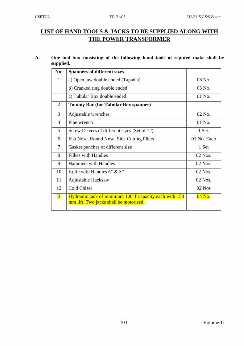
CSPTCL TR-21/05 132/33 KV S/S Betar
103 Volume-II
LIST OF HAND TOOLS & JACKS TO BE SUPPLIED ALONG WITH
THE POWER TRANSFORMER
A. One tool box consisting of the following hand tools of reputed make shall be
supplied.
No. Spanners of different sizes
1 a) Open jaw double ended (Tapadia) 08 No.
b) Cranked ring double ended 03 No.
c) Tubular Box double ended 01 No.
2 Tommy Bar (for Tabular Box spanner)
3 Adjustable wrenches 02 No.
4 Pipe wrench 01 No.
5 Screw Drivers of different sizes (Set of 12) 1 Set.
6 Flat Nose, Round Nose, Side Cutting Pliers 01 No. Each
7 Gasket punches of different size 1 Set
8 Filkes with Handles 02 Nos.
9 Hammers with Handles 02 Nos.
10 Knife with Handles 6” & 8” 02 Nos.
11 Adjustable Hacksaw 02 Nos.
12 Cold Chisel 02 Nos
B Hydraulic jack of minimum 100 T capacity each with 150
mm lift. Two jacks shall be motorised.
04 No.
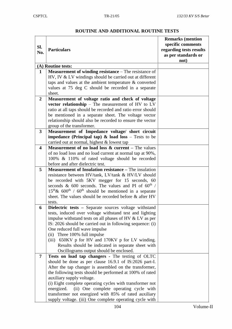
CSPTCL TR-21/05 132/33 KV S/S Betar
104 Volume-II
ROUTINE AND ADDITIONAL ROUTINE TESTS
Sl.
No. Particulars
Remarks (mention
specific comments
regarding tests results
as per standards or
not)
(A) Routine tests:
1 Measurement of winding resistance – The resistance of
HV, IV & LV windings should be carried out at different
taps and values at the ambient temperature & converted
values at 75 deg C should be recorded in a separate
sheet.
2 Measurement of voltage ratio and check of voltage
vector relationship – The measurement of HV to LV
ratio at all taps should be recorded and ratio error should
be mentioned in a separate sheet. The voltage vector
relationship should also be recorded to ensure the vector
group of the transformer.
3 Measurement of Impedance voltage/ short circuit
impedance (Principal tap) & load loss – Tests to be
carried out at normal, highest & lowest tap
4 Measurement of no load loss & current – The values
of no load loss and no load current at normal tap at 90%,
100% & 110% of rated voltage should be recorded
before and after dielectric test.
5 Measurement of Insulation resistance – The insulation
resistance between HV/tank, LV/tank & HV/LV should
be recorded with 5KV megger for 15 seconds, 60
seconds & 600 seconds. The values and PI of 60th /
15th& 600th / 60th should be mentioned in a separate
sheet. The values should be recorded before & after HV
tests.
6 Dielectric tests – Separate sources voltage withstand
tests, induced over voltage withstand test and lighting
impulse withstand tests on all phases of HV & LV as per
IS: 2026 should be carried out in following sequence: (i)
One reduced full wave impulse
(ii) Three 100% full impulse
(iii) 650KV p for HV and 170KV p for LV winding.
Results should be indicated in separate sheet with
Oscillograms output should be enclosed.
7 Tests on load tap changers - The testing of OLTC
should be done as per clause 16.9.1 of IS:2026 part-I.
After the tap changer is assembled on the transformer,
the following tests should be performed at 100% of rated
auxiliary supply voltage.
(i) Eight complete operating cycles with transformer not
energized. (ii) One complete operating cycle with
transformer not energized with 85% of rated auxiliary
supply voltage. (iii) One complete operating cycle with
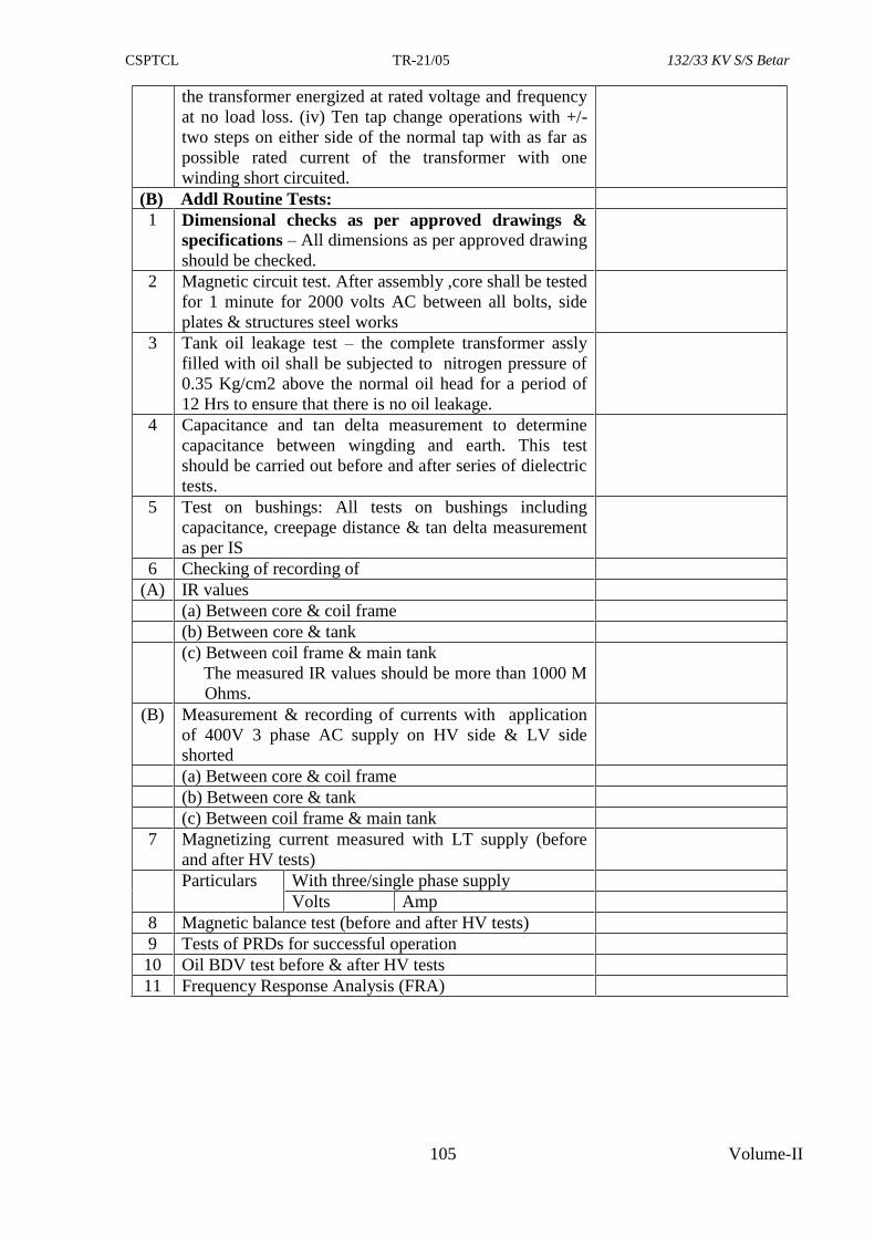
CSPTCL TR-21/05 132/33 KV S/S Betar
105 Volume-II
the transformer energized at rated voltage and frequency
at no load loss. (iv) Ten tap change operations with +/-
two steps on either side of the normal tap with as far as
possible rated current of the transformer with one
winding short circuited.
(B) Addl Routine Tests:
1 Dimensional checks as per approved drawings &
specifications – All dimensions as per approved drawing
should be checked.
2 Magnetic circuit test. After assembly ,core shall be tested
for 1 minute for 2000 volts AC between all bolts, side
plates & structures steel works
3 Tank oil leakage test – the complete transformer assly
filled with oil shall be subjected to nitrogen pressure of
0.35 Kg/cm2 above the normal oil head for a period of
12 Hrs to ensure that there is no oil leakage.
4 Capacitance and tan delta measurement to determine
capacitance between wingding and earth. This test
should be carried out before and after series of dielectric
tests.
5 Test on bushings: All tests on bushings including
capacitance, creepage distance & tan delta measurement
as per IS
6 Checking of recording of
(A) IR values
(a) Between core & coil frame
(b) Between core & tank
(c) Between coil frame & main tank
The measured IR values should be more than 1000 M
Ohms.
(B) Measurement & recording of currents with application
of 400V 3 phase AC supply on HV side & LV side
shorted
(a) Between core & coil frame
(b) Between core & tank
(c) Between coil frame & main tank
7 Magnetizing current measured with LT supply (before
and after HV tests)
Particulars With three/single phase supply
Volts Amp
8 Magnetic balance test (before and after HV tests)
9 Tests of PRDs for successful operation
10 Oil BDV test before & after HV tests
11 Frequency Response Analysis (FRA)
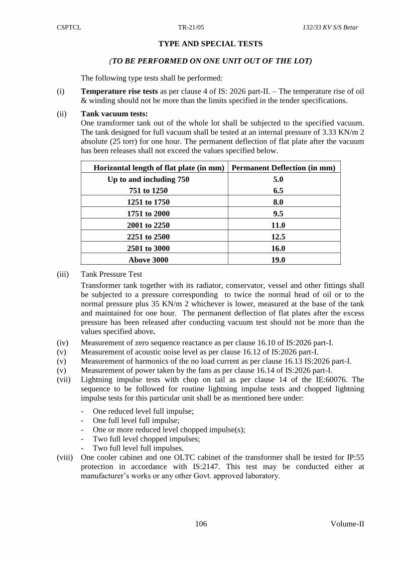
CSPTCL TR-21/05 132/33 KV S/S Betar
106 Volume-II
TYPE AND SPECIAL TESTS
(TO BE PERFORMED ON ONE UNIT OUT OF THE LOT)
The following type tests shall be performed:
(i) Temperature rise tests as per clause 4 of IS: 2026 part-II. – The temperature rise of oil
& winding should not be more than the limits specified in the tender specifications.
(ii) Tank vacuum tests:
One transformer tank out of the whole lot shall be subjected to the specified vacuum.
The tank designed for full vacuum shall be tested at an internal pressure of 3.33 KN/m 2
absolute (25 torr) for one hour. The permanent deflection of flat plate after the vacuum
has been releases shall not exceed the values specified below.
Horizontal length of flat plate (in mm) Permanent Deflection (in mm)
Up to and including 750
751 to 1250
5.0
6.5
1251 to 1750 8.0
1751 to 2000 9.5
2001 to 2250 11.0
2251 to 2500 12.5
2501 to 3000 16.0
Above 3000 19.0
(iii) Tank Pressure Test
Transformer tank together with its radiator, conservator, vessel and other fittings shall
be subjected to a pressure corresponding to twice the normal head of oil or to the
normal pressure plus 35 KN/m 2 whichever is lower, measured at the base of the tank
and maintained for one hour. The permanent deflection of flat plates after the excess
pressure has been released after conducting vacuum test should not be more than the
values specified above.
(iv) Measurement of zero sequence reactance as per clause 16.10 of IS:2026 part-I.
(v) Measurement of acoustic noise level as per clause 16.12 of IS:2026 part-I.
(v) Measurement of harmonics of the no load current as per clause 16.13 IS:2026 part-I.
(v) Measurement of power taken by the fans as per clause 16.14 of IS:2026 part-I.
(vii) Lightning impulse tests with chop on tail as per clause 14 of the IE:60076. The
sequence to be followed for routine lightning impulse tests and chopped lightning
impulse tests for this particular unit shall be as mentioned here under:
- One reduced level full impulse;
- One full level full impulse;
- One or more reduced level chopped impulse(s);
- Two full level chopped impulses;
- Two full level full impulses.
(viii) One cooler cabinet and one OLTC cabinet of the transformer shall be tested for IP:55
protection in accordance with IS:2147. This test may be conducted either at
manufacturer’s works or any other Govt. approved laboratory.
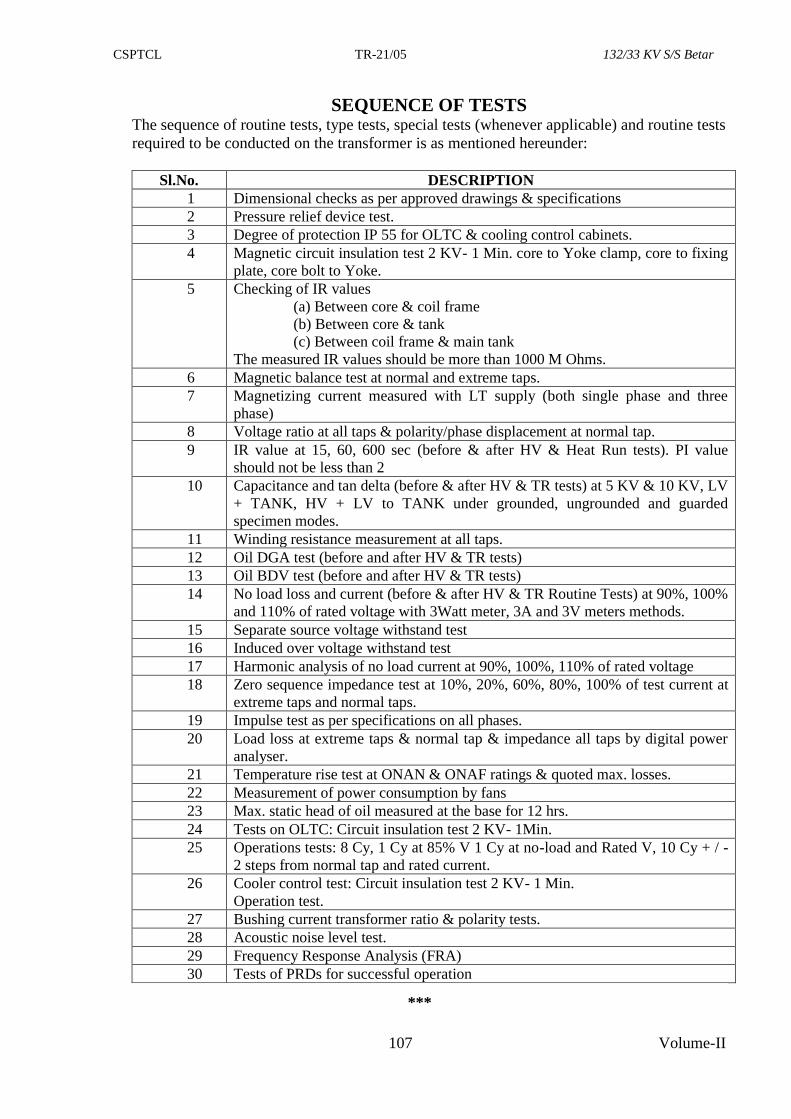
CSPTCL TR-21/05 132/33 KV S/S Betar
107 Volume-II
SEQUENCE OF TESTS The sequence of routine tests, type tests, special tests (whenever applicable) and routine tests
required to be conducted on the transformer is as mentioned hereunder:
Sl.No. DESCRIPTION
1 Dimensional checks as per approved drawings & specifications
2 Pressure relief device test.
3 Degree of protection IP 55 for OLTC & cooling control cabinets.
4 Magnetic circuit insulation test 2 KV- 1 Min. core to Yoke clamp, core to fixing
plate, core bolt to Yoke.
5 Checking of IR values
(a) Between core & coil frame
(b) Between core & tank
(c) Between coil frame & main tank
The measured IR values should be more than 1000 M Ohms.
6 Magnetic balance test at normal and extreme taps.
7 Magnetizing current measured with LT supply (both single phase and three
phase)
8 Voltage ratio at all taps & polarity/phase displacement at normal tap.
9 IR value at 15, 60, 600 sec (before & after HV & Heat Run tests). PI value
should not be less than 2
10 Capacitance and tan delta (before & after HV & TR tests) at 5 KV & 10 KV, LV
+ TANK, HV + LV to TANK under grounded, ungrounded and guarded
specimen modes.
11 Winding resistance measurement at all taps.
12 Oil DGA test (before and after HV & TR tests)
13 Oil BDV test (before and after HV & TR tests)
14 No load loss and current (before & after HV & TR Routine Tests) at 90%, 100%
and 110% of rated voltage with 3Watt meter, 3A and 3V meters methods.
15 Separate source voltage withstand test
16 Induced over voltage withstand test
17 Harmonic analysis of no load current at 90%, 100%, 110% of rated voltage
18 Zero sequence impedance test at 10%, 20%, 60%, 80%, 100% of test current at
extreme taps and normal taps.
19 Impulse test as per specifications on all phases.
20 Load loss at extreme taps & normal tap & impedance all taps by digital power
analyser.
21 Temperature rise test at ONAN & ONAF ratings & quoted max. losses.
22 Measurement of power consumption by fans
23 Max. static head of oil measured at the base for 12 hrs.
24 Tests on OLTC: Circuit insulation test 2 KV- 1Min.
25 Operations tests: 8 Cy, 1 Cy at 85% V 1 Cy at no-load and Rated V, 10 Cy + / -
2 steps from normal tap and rated current.
26 Cooler control test: Circuit insulation test 2 KV- 1 Min.
Operation test.
27 Bushing current transformer ratio & polarity tests.
28 Acoustic noise level test.
29 Frequency Response Analysis (FRA)
30 Tests of PRDs for successful operation
***
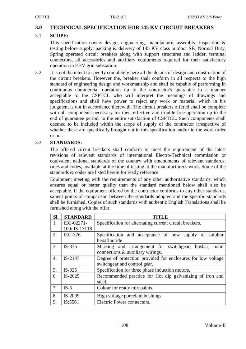
CSPTCL TR-21/05 132/33 KV S/S Betar
108 Volume-II
3.0 TECHNICAL SPECIFICATION FOR 145 KV CIRCUIT BREAKERS
3.1 SCOPE:
This specification covers design, engineering, manufacture, assembly, inspection &
testing before supply, packing & delivery of 145 KV class outdoor SF6 Normal Duty,
Spring operated circuit breakers along with support structures and ladder, terminal
connectors, all accessories and auxiliary equipments required for their satisfactory
operation in EHV grid substation.
3.2 It is not the intent to specify completely here all the details of design and construction of
the circuit breakers. However the, breaker shall conform in all respects to the high
standard of engineering design and workmanship and shall be capable of performing in
continuous commercial operation up to the contractor's guarantee in a manner
acceptable to the CSPTCL who will interpret the meanings of drawings and
specifications and shall have power to reject any work or material which in his
judgment is not in accordance therewith. The circuit breakers offered shall be complete
with all components necessary for their effective and trouble free operation up to the
end of guarantee period, to the entire satisfaction of CSPTCL. Such components shall
deemed to be included within the scope of supply of the contractor irrespective of
whether these are specifically brought out in this specification and/or in the work order
or not.
3.3 STANDARDS:
The offered circuit breakers shall conform to meet the requirement of the latest
revisions of relevant standards of international Electro-Technical commission or
equivalent national standards of the country with amendments of relevant standards,
rules and codes, available at the time of testing at the manufacturer's work. Some of the
standards & codes are listed herein for ready reference.
Equipment meeting with the requirements of any other authoritative standards, which
ensures equal or better quality than the standard mentioned below shall also be
acceptable. If the equipment offered by the contractor conforms to any other standards,
salient points of comparison between the standards adopted and the specific standards
shall be furnished. Copies of such standards with authentic English Translations shall be
furnished along with the offer.
Sl. STANDARD TITLE
1. IEC-62271-
100/ IS-13118
Specification for alternating current circuit breakers.
2. IEC-376 Specification and acceptance of new supply of sulphur
hexafluoride
3. IS-375 Marking and arrangement for switchgear, busbar, main
connections & auxiliary wirings.
4. IS-2147 Degree of protection provided for enclosures for low voltage
switchgear and control gear.
5. IS-325 Specification for three phase induction motors.
6. IS-2629 Recommended practice for Hot dip galvanizing of iron and
steel.
7. IS-5 Colour for ready mix paints.
8. IS-2099 High voltage porcelain bushings.
9. IS:5561 Electric Power connectors.
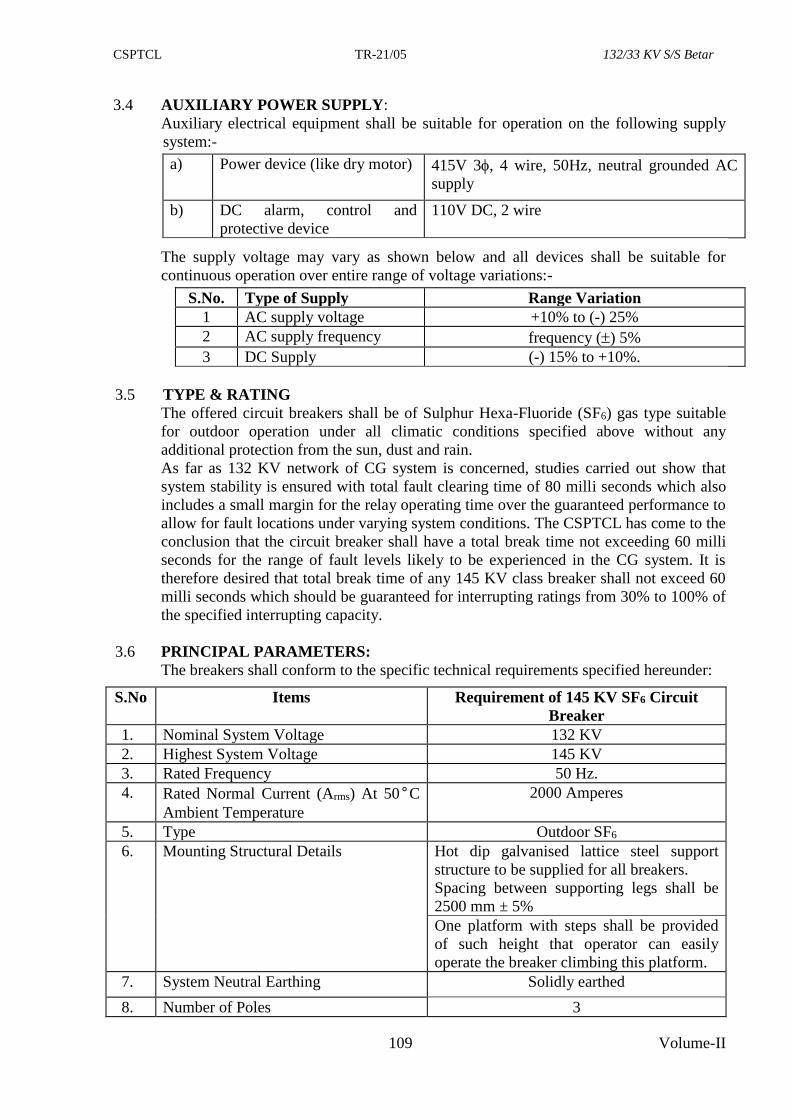
CSPTCL TR-21/05 132/33 KV S/S Betar
109 Volume-II
3.4 AUXILIARY POWER SUPPLY:
Auxiliary electrical equipment shall be suitable for operation on the following supply
system:-
a) Power device (like dry motor) 415V 3, 4 wire, 50Hz, neutral grounded AC
supply
b) DC alarm, control and
protective device
110V DC, 2 wire
The supply voltage may vary as shown below and all devices shall be suitable for
continuous operation over entire range of voltage variations:-
S.No. Type of Supply Range Variation
1 AC supply voltage +10% to (-) 25%
2 AC supply frequency frequency () 5%
3 DC Supply (-) 15% to +10%.
3.5 TYPE & RATING
The offered circuit breakers shall be of Sulphur Hexa-Fluoride (SF6) gas type suitable
for outdoor operation under all climatic conditions specified above without any
additional protection from the sun, dust and rain.
As far as 132 KV network of CG system is concerned, studies carried out show that
system stability is ensured with total fault clearing time of 80 milli seconds which also
includes a small margin for the relay operating time over the guaranteed performance to
allow for fault locations under varying system conditions. The CSPTCL has come to the
conclusion that the circuit breaker shall have a total break time not exceeding 60 milli
seconds for the range of fault levels likely to be experienced in the CG system. It is
therefore desired that total break time of any 145 KV class breaker shall not exceed 60
milli seconds which should be guaranteed for interrupting ratings from 30% to 100% of
the specified interrupting capacity.
3.6 PRINCIPAL PARAMETERS:
The breakers shall conform to the specific technical requirements specified hereunder:
S.No Items Requirement of 145 KV SF6 Circuit
Breaker
1. Nominal System Voltage 132 KV
2. Highest System Voltage 145 KV
3. Rated Frequency 50 Hz.
4. Rated Normal Current (Arms) At 50°C
Ambient Temperature
2000 Amperes
5. Type Outdoor SF6
6. Mounting Structural Details Hot dip galvanised lattice steel support
structure to be supplied for all breakers.
Spacing between supporting legs shall be
2500 mm ± 5%
One platform with steps shall be provided
of such height that operator can easily
operate the breaker climbing this platform.
7. System Neutral Earthing Solidly earthed
8. Number of Poles 3
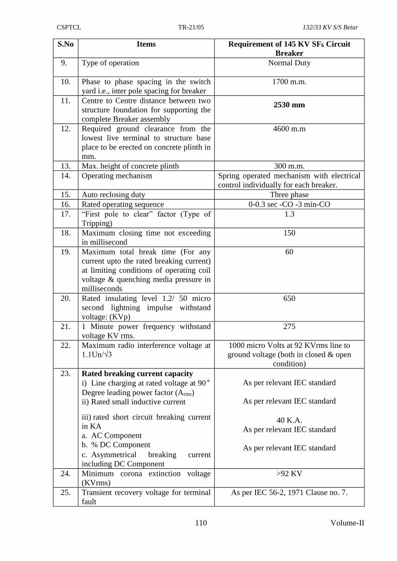
CSPTCL TR-21/05 132/33 KV S/S Betar
110 Volume-II
S.No Items Requirement of 145 KV SF6 Circuit
Breaker
9. Type of operation Normal Duty
10. Phase to phase spacing in the switch
yard i.e., inter pole spacing for breaker
1700 m.m.
11. Centre to Centre distance between two
structure foundation for supporting the
complete Breaker assembly
2530 mm
12. Required ground clearance from the
lowest live terminal to structure base
place to be erected on concrete plinth in
mm.
4600 m.m
13. Max. height of concrete plinth 300 m.m.
14. Operating mechanism Spring operated mechanism with electrical
control individually for each breaker.
15. Auto reclosing duty Three phase
16. Rated operating sequence 0-0.3 sec -CO -3 min-CO
17. “First pole to clear” factor (Type of
Tripping)
1.3
18. Maximum closing time not exceeding
in millisecond
150
19. Maximum total break time (For any
current upto the rated breaking current)
at limiting conditions of operating coil
voltage & quenching media pressure in
milliseconds
60
20. Rated insulating level 1.2/ 50 micro
second lightning impulse withstand
voltage: (KVp)
650
21. 1 Minute power frequency withstand
voltage KV rms.
275
22. Maximum radio interference voltage at
1.1Un/√3
1000 micro Volts at 92 KVrms line to
ground voltage (both in closed & open
condition)
23. Rated breaking current capacity
i) Line charging at rated voltage at 90°
Degree leading power factor (Arms)
ii) Rated small inductive current
iii) rated short circuit breaking current
in KA
a. AC Component
b. % DC Component
c. Asymmetrical breaking current
including DC Component
As per relevant IEC standard
As per relevant IEC standard
40 K.A.
As per relevant IEC standard
As per relevant IEC standard
24. Minimum corona extinction voltage
(KVrms)
>92 KV
25. Transient recovery voltage for terminal
fault
As per IEC 56-2, 1971 Clause no. 7.
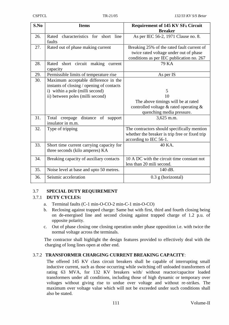
CSPTCL TR-21/05 132/33 KV S/S Betar
111 Volume-II
S.No Items Requirement of 145 KV SF6 Circuit
Breaker
26. Rated characteristics for short line
faults
As per IEC 56-2, 1971 Clause no. 8.
27. Rated out of phase making current Breaking 25% of the rated fault current of
twice rated voltage under out of phase
conditions as per IEC publication no. 267
28. Rated short circuit making current
capacity
79 KA
29. Permissible limits of temperature rise As per IS
30. Maximum acceptable difference in the
instants of closing / opening of contacts
i) within a pole (milli second)
ii) between poles (milli second)
5
10
The above timings will be at rated
controlled voltage & rated operating &
quenching media pressure.
31. Total creepage distance of support
insulator in m.m.
3,625 m.m.
32. Type of tripping The contractors should specifically mention
whether the breaker is trip free or fixed trip
according to IEC 56-1.
33. Short time current carrying capacity for
three seconds (kilo amperes) KA
40 KA.
34. Breaking capacity of auxiliary contacts 10 A DC with the circuit time constant not
less than 20 mili second.
35. Noise level at base and upto 50 metres. 140 dB.
36. Seismic acceleration 0.3 g (horizontal)
3.7 SPECIAL DUTY REQUIREMENT
3.7.1 DUTY CYCLES:
a. Terminal faults (C-1 min-O-CO-2 min-C-1 min-O-CO)
b. Reclosing against trapped charge: Same but with first, third and fourth closing being
on de-energised line and second closing against trapped charge of 1.2 p.u. of
opposite polarity.
c. Out of phase closing one closing operation under phase opposition i.e. with twice the
normal voltage across the terminals.
The contractor shall highlight the design features provided to effectively deal with the
charging of long lines open at other end.
3.7.2 TRANSFORMER CHARGING CURRENT BREAKING CAPACITY:
The offered 145 KV class circuit breakers shall be capable of interrupting small
inductive current, such as those occurring while switching off unloaded transformers of
rating 63 MVA, for 132 KV breakers with/ without reactor/capacitor loaded
transformers under all conditions, including those of high dynamic or temporary over
voltages without giving rise to undue over voltage and without re-strikes. The
maximum over voltage value which will not be exceeded under such conditions shall
also be stated.
CSPTCL TR-21/05 132/33 KV S/S Betar
112 Volume-II
3.7.3 DYNAMIC OVER VOLTAGES:
The circuit breaker shall be capable of satisfactorily performing all their duties
including, but not limited to, clearing of faults and interrupting the line charging and
transformer charging currents without causing undue over voltage and showing signs of
undue strain while operating under conditions of high temporary (Power frequency)
over voltage of the order of 1.5 p.u.
The stability of circuit breakers for working satisfactorily under such conditions should
be explicitly guaranteed by the contractor and it should be supported with clear
technical elaborations and details.
3.8 PROTECTION SCHEMES:
Two independent trip coils shall be provided on the breakers for segregation of two
main relaying schemes. The local breaker back-up protection is also being provided and
the breaker shall be suitable for its operation. Two separate DC sources shall be
available one for each trip coil.
3.8.1 DEVELOPING FAULTS:
The circuit breakers shall be capable to withstand the high stresses imposed on them
during fault clearing, developing faults, load rejection and re-energization of line, with
trapped charges within the full rating of the breaker. The breaker shall also withstand
the voltage specified in "Principal Parameters of this specification"
3.8.2 TRIP FREE OPERATION:
The circuit breakers mechanism shall be suitable for trip-free operation.
3.8.3 SMALL FAULT-CURRENT INTERRUPTING CAPACITY:
The circuit breakers shall be capable of interrupting Small fault Currents of magnitude
between 0.5 KA to 10 KA along with the usual short circuit current interrupting
capacity in the range of 2 KA to 40 KA without causing any re-strikes or causing un-
permissible over-voltage on the system in which these are to be installed. The over-
voltage shall not exceed 2.3 pu.
The test certificates in support of this capacity of circuit breaker must be submitted.
3.8.4 RECOVERY VOLTAGE AND POWER FACTOR:
Each circuit breaker shall be capable of interrupting rated short circuit breaking current
under the condition of recovery voltage corresponding to highest system voltage and to
power factor not exceeding 0.15
3.8.5 The circuit breakers shall be capable of satisfactory operation even under conditions of
phase opposition that may arise due to faulty synchronising or otherwise. The maximum
power in accordance with relevant IEC Specification which the circuit breaker can
satisfactorily interrupt under-phase opposition shall be stated in the offer.
3.8.6 RESTRIKING VOLTAGE:
The rated transient recovery voltage for terminal faults shall be as specified in IEC. The
measures adopted for ensuring proper operation at high rate of rise of restriking voltage
and for limiting the actual values across the breakers shall be described in the offer. No
opening resistors shall be necessary for ensuring conformity with the duty cycle.
3.9 LINE CHARGING CURRENT INTERRUPTING CAPACITY
Circuit breaker shall be designed so as to be capable of interrupting line charging
currents as given in "Principal Parameters" of this specification under the conditions of
high dynamic over voltages of the order of 1.5 pu without showing signs of undue
CSPTCL TR-21/05 132/33 KV S/S Betar
113 Volume-II
strain. The contractor shall have to carry out adequate acceptance tests with proper
representation of actual system conditions, including correct simulation of natural
frequency of bus bars so as to properly reproduce the initial part of the recovery voltage,
to prove the charging current interrupting capability of the breaker. The contractor shall
furnish complete details of procedure in respect of this acceptance test.
The guaranteed over voltage, if any, which will not be exceeded while interrupting line
charging current as given in clause 3.6' "Principal parameters" shall be furnished.
The over voltage caused while interrupting the line charging current shall not exceed
the limits of switching surges and dynamic over voltages as given in the specification.
The result of the test conducted along with copies of the oscillo-graphs to prove the
capability of the circuit breakers to interrupt these and lower line charging current
values shall also be furnished.
3.10 INSULATING SUPPORTS
The basic impulse insulation level of the external insulator supports bushing &
interrupting insulator bushing shall match with that of the SF6 circuit breakers and shall
be specified and suitable for insulation in the contaminated atmosphere. Insulating
supports shall be designed to have ample insulation and adequate mechanical strength
and rigidity for satisfactory operation under various operating conditions detailed in this
specification.
All hollow insulator & interrupter housing of identical rating shall be interchangeable.
The puncture strength of the hollow insulator & interrupter housing shall be greater than
the flash over value.
The hollow insulator & interrupter housing shall be type tested as per relevant IEC
standards and the type test reports shall be submitted.
3.11 BREAKING CAPACITY FOR KILOMETRIC FAULTS:
All circuit breakers shall have high capacity for breaking short line (kilometric faults)
with source impedance behind the bus equivalent to symmetrical fault current specified.
The interrupting capacity of the circuit breakers for kilometric faults (short line faults)
should be equal to its interrupting capacity. The details of tests conducted to guarantee
the capability of the circuit breaker operation under kilometric fault condition shall be
furnished.
3.12 AUTOMATIC RAPID RECLOSING:
132 KV circuit breakers shall be suitable for three pole automatic rapid reclosing. The
dead time corresponding to automatic rapid reclosing of the circuit breakers shall be
adjustable at least within limits of 15 cycles (0.3 sec) to 35 cycles and actual limits of
adjustment provided in the offered circuit breaker shall be stated in the offer. The relay
or timer required for adjustment of the dead time shall form a part of the scope of
supply. The breaking capacity of the circuit breakers shall be guaranteed for second and
third interruptions.
3.13 TEMPERATURE RISE:
The temperature rise and the maximum temperature attained by any part of the
equipment when in service at site under continuous full load conditions and exposed
continuously to the direct rays of the sun shall not exceed the permissible limits as per
limits given. The permissible temperature rise indicated is for a maximum ambient
temperature of 50° deg. centigrade. If the maximum ambient temperature is higher, the
temperature rise permissible limit shall be reduced accordingly.
CSPTCL TR-21/05 132/33 KV S/S Betar
114 Volume-II
3.14 INSULATION OF CIRCUIT BREAKERS:
The insulation to ground, insulation between open contacts and the insulation between
phases of the completely assembled circuit breaker shall be capable of withstanding
satisfactorily dielectric test voltage corresponding to the stipulations made in "Principal
parameters". The exposed live parts shall be placed high enough above ground to meet
the requirements of local safety codes.
3.15 ADDITIONAL REQUIREMENTS:
a) The circuit breakers shall be single pressure type, the design and construction of the
circuit breaker shall be such that there is minimum possibility of gas leakage and
entry of moisture. There should not be any condensation of SF6 gas on the internal
insulating surface of the circuit breaker.
b) All gasketed surfaces shall be smooth, straight and reinforced, if necessary to
minimise distortion and to make a tight seal, the operating rod connecting the
operating mechanism to the arc chamber (SF6 media) shall have adequate seals,
Double "O" ring seals and test holes for leakage test of the internal seal shall be
provided on each static joint.
c) In the interrupter assembly there shall be an absorbing product box to eliminate SF6
decomposition products and moisture. The material used in the construction of the
circuit breakers shall be fully compatible with SF6 gas.
d) The SF6 gas density monitor shall be adequately temperature compensated. The
density monitor shall meet the following requirements:
i) It shall be possible to dismantle the density monitor for checking/ replacement
without draining the SF6 gas by using suitable interlocked non-return couplings.
ii) It shall damp the pressure pulsation while filling the gas in service so that the
flickering of the pressure switch contacts does not take place.
iii) Air & gas pressure indicator shall also be supplied. The pressure indicator shall
have uniform graduated dial.
e) Means for pressure relief shall be provided in the gas chamber of circuit breaker to
avoid the damages or distortion during occurrence of abnormal pressure increase or
shock waves generated by internal electric fault / arcs. The position of vents,
diaphragms and pressure relief devices shall be arranged so as to minimize danger
to the operators in the event of gas or vapour escaping under pressure.
f) Facility shall also be provided to reduce the gas pressure within the breaker to a
value not exceeding 8 milli-bars within 4 hours or less. Each circuit breaker shall be
capable of withstanding this degree of vacuum without distortion or failure of any
part.
g) Sufficient SF6 gas shall be provided to fill all the circuit breakers installed. In
addition to this 20% of the total gas requirement shall be supplied in separate
cylinders as spare requirement.
h) Provisions shall be made for attaching an operation analyser after installation at site
to record contact travel, speed and making measurement of operation timings and
synchronisation of contacts in one pole.
3.16 GENERAL TECHNICAL REQUIREMENTS:
3.16.1 Circuit breaker offered shall be Sulphur hexafluoride (SF6) type only suitable for
outdoor installation. Circuit breaker shall be designed to withstand seismic
acceleration equivalent to 0.3g. If construction of the breaker is of wheel mounted
type suitable locking clamps shall be provided designed to sustain above seismic
acceleration.
CSPTCL TR-21/05 132/33 KV S/S Betar
115 Volume-II
3.16.2 Exposed live parts shall be placed high enough above ground to meet the requirement
of local safety codes.
3.16.3 Any part of' the breaker, especially the removable ones, shall be freely inter-
changeable without the necessity of any modification at site.
3.16.4 Circuit-breaker shall comprise of three identical single pole units which should be
linked together.
3.16.5 Complete circuit breaker with all the necessary items for successful operation shall be
supplied, including but not limited to the following:
a) Breaker assemblies with bases, support - structure for circuit breaker as well as for
control cabinet, central control cabinet and foundation bolts for main structure as
well as control cabinet and central control cabinet (except concrete foundations),
terminals and operating mechanisms.
b) Compressed SF6 gas, pneumatic systems complete including compressors, tanks,
pipings, fittings, valves and controls and necessary supports for inter-pole piping
for pneumatic systems.
c) One central control cabinet for each breaker and one control box with all the
required electrical devices mounted therein and the necessary terminal blocks for
termination of inter-pole wiring. The supply of necessary inter pole cables &
cabling at site shall be in the scope of contractor based on the schematic wiring
diagram and termination schedule provided by the contractor & approved by
CSPTCL.
d) Instruments, gauges and leakage detector for SF6 gas pressures pneumatic
pressure supervision.
e) All necessary parts to provide a complete & operatable circuit breaker installation
such as main equipment, terminal connectors, control parts, cable connectors, pipe
lines and other devices, whether specifically called for herein or not.
3.16.6 Circuit breaker shall be suitable for hot line washing.
3.16.7 All breakers shall be supplied with terminal connectors having double nut GI and
double set of washers for firm connections. The contractors are required to confirm
that the offered prices are inclusive of terminal connectors.
3.16.7 The current density adopted for the design of the terminal pads shall in no case exceed
the following values. For copper pads - 1.5 A/sq.mm and aluminium - 1.0 A/sq.mm.
3.17 CONTACTS:
i) Main contacts shall have ample area and contact pressure for carrying the rated
current and the short time rated current of the breaker without excessive
temperature rise which may cause pitting or welding. Contacts shall be adjustable
to allow for wear, easily replaceable and shall have a minimum of moveable parts
and adjustments to accomplish these results.
ii) All making and breaking contacts shall be sealed free from atmospheric effects.
Contacts shall be designed to have adequate thermal and current carrying capacity
for the duty specified and to have a life expectancy so that frequent replacements
due to excessive burning will not be necessary. Provision shall be made for rapid
dissipation of heat generated by the arc on opening.
iii) Main contacts shall be first to open and the last to close so that there will be little
contact burning and wear.
CSPTCL TR-21/05 132/33 KV S/S Betar
116 Volume-II
iv) If arcing contacts are used, they shall be first to close and the last to open. These
shall be easily accessible for inspection and replacement. If there are no separately
mounted arcing contacts, the main contacts shall be easily accessible for inspection
and replacements. Tips of arcing contacts and main contacts shall be silver plated
or have tungsten alloy tips.
v) Any device provided for voltage grading to damp oscillations or to prevent re-
strike prior to the complete interruption of the circuit or to limit over voltages on
closing shall have a life expectancy comparable to that of the breaker as a whole.
vi) Breakers shall be so designed that when operated within their specified rating, the
temperature of each part will be limited to values consistent with a long life or the
material used. The temperature shall not exceed that indicated in IEC-56 under
specified ambient conditions.
vii) Contacts shall be kept permanently under pressure of SF6 gas. The gap between the
open contacts shall be such that it can withstand atleast the rated phase to ground
voltage continuously at zero gauge pressure of SF6 gas due to its leakage.
viii) If multi-break interrupters are used, these shall be so designed and augmented that
a uniform voltage distribution is developed across them. Calculations/ test reports
in support of the same shall be furnished. The thermal and voltage withstands of
the grading elements shall be adequate for the service conditions and duty
specified.
3.18 PORCELAIN HOUSING:
i) The porcelain housing shall be of single piece construction without any joint or
coupling. It shall be homogeneous, free from lamination, cavities and other
flaws or imperfections that might affect high mechanical, and dielectric strength
and shall be thoroughly vitrified, tough and impervious to moisture.
ii) Glazing of porcelain shall be uniform brown or dark brown colour, free from
blisters, burns and similar other defects with a smooth surface arranged to shed
away rain water or, condensed water particles (fog).
iii) Housings shall be designed to have ample insulation, mechanical strength and
rigidity for satisfactory operation for the conditions under which they will be
used. All housings of identical ratings shall be interchangeable.
iv) Puncture strength of housings shall be greater than the dry flash-over value.
When operating at normal rated voltage there shall be no electric discharge
between the conductors and housing which would cause corrosion or injury to
conductors, insulators or supports by the formation of substance produced by
chemical action. No radio disturbance shall be caused by the housing when
operating at the normal rated voltage.
v) All iron parts shall be hot dip galvanized and all joints shall be air-tight.
Surfaces of the joint shall be made burr free, porcelain parts by grinding and
metal parts by machining. Bushing design shall be such as to ensure a uniform
compressive pressure on the joints.
vi) All current carrying contact surfaces shall be silver plated.
vii) Bushings shall satisfactorily withstand the insulation level specified in the IEC
Specification.
3.19 SULPHUR HEXA FLUORIDE GAS (SF6 GAS)
a. The SF6 gas shall comply with IEC 376, 376A & 376 B and be suitable in all
respects for use in the switch gear under the worst operating conditions,
CSPTCL TR-21/05 132/33 KV S/S Betar
117 Volume-II
b. The high pressure cylinders in which the SF6 gas is shipped and stored at site
shall comply with requirement of the following standards and regulations:
i) IS: 4379 Identifications for the contents of industrial gas cylinder.
ii) IS: 7311 Seamless high carbon steel cylinders for permanent and high
pressure liquefiable gases.
iii) The cylinders shall also meet Indian boiler regulations.
c. Test: SF6 gas shall be tested for purity, dew point, break down voltage, water
contents as per IEC 376, 376A & 376B and test certificates shall be furnished to
CSPTCL indicating all the tests as per IEC 376 for each lot of SF6 gas.
3.20 AUXILIARY CONTACTS:-
The auxiliary switches (contacts) required for satisfactory operation of the circuit
breaker including automatic reclosing (single shot three phases) ON/ OFF indicators
both in control room and switch yard semaphore indicators in the mimic diagram in the
control room and anti pumping in the mimic diagram in the control room and anti
pumping features shall be provided on each circuit breaker and shall be clearly
indicated in the offer. All these auxiliary switches shall be included in the scope of
supply. In addition to the auxiliary switches mentioned above, the contractor shall
provide as spares 10 auxiliary contacts each of the “normally open” and “normally
closed” types which shall be used to operate the closing or opening of each of the three
poles of circuit breakers. These spare switches shall be utilised for safety interlocking
and other monitoring devices by the CSPTCL. Special contacts for use with the trip
coils and single shot reclosing operations which permit the relative adjustment with
respect to the travel of the circuit breaker shall also be provided. All auxiliary switches
shall be placed in a weather proof galvanised casing and current rating of the switches
shall be mentioned in the offer. There shall be provision to add more auxiliary switches
at a later date and to convert the “normally open” contacts to the “normally closed” type
and vice versa. Minimum two auxiliary switch set (NO & NC contact) be provided
which should operate independently.
Arrangement proposed for connecting control cables to the auxiliary switches shall be
clearly stated. Provision shall be made for suitable cable glands for receiving control
cable for terminating connections in the auxiliary switches.
3.21 TOTAL BREAK TIME:
3.21.1 The "Total Break Time" as specified in clause 3.6, "Principal Parameters" of this
section shall not be exceeded under any of the following duties:
i) Test duties 1,2,3,4,5 (with TRV as per IEC)
ii) Short line fault L90, L75 (with TRV as per IEC-56).
3.21.2 The Contractor may please note that there is only one specified break time of the
breaker which shall not be exceeded under any duty conditions specified such as with
the combined variation of the trip coil voltage, (70-110%) pneumatic/ pressure and arc
extinguishing medium pressure etc. while furnishing the proof for the total break time
of complete circuit breaker, the Contractor may specifically bring out the effect of non-
simultaneity between contacts within a pole or between poles and show how it is
covered in the guaranteed total break time.
3.21.3 The values guaranteed shall be supported with the type test reports.
3.22 OPERATING MECHANISM AND ASSOCIATED EQUIPMENTS:
i) Each circuit breaker shall be designed for remote control operation from the
control room. In addition there shall be provision for local tripping & closing
CSPTCL TR-21/05 132/33 KV S/S Betar
118 Volume-II
operations both by electrical control. Mechanical arrangement should also be
provided to facilitate manual tripping of circuit breaker for emergency trip when
DC is not available or tripping coil is burnt or trip lever mechanism becomes
defective etc., under healthy arc quenching medium condition.
ii) Only spring type tripping & closing mechanisms are acceptable. It may be noted
offers for pneumatic or other type of mechanisms shall not be considered. The
mechanism shall be adequately designed & capable of performing satisfactorily
the specified tripping and re-closing duty indicated above within the time
specified. The entire operating mechanism control circuitry including electrical
controls & monitoring devices and all other accessories, etc., as required, shall be
housed in an outdoor type, hot dip galvanised steel enclosure. This enclosure shall
conform to the degree of protection IP-55 of BIS 2147. The enclosure shall be
invariably mounted on a separate concrete plinth of 300 mm height. However in
case due to IP-55 protection limitations, if operating mechanism is mounted below
the pole housing, in that case it should be possible for operating personnel to
charge the spring from ground level including making ON/OFF operation without
using any stool/platform or otherwise a suitable operating platform with steps
shall be essentially provided and the same shall be deemed to be included in the
scope of supply. Please note manually spring charging mechanism should be
such that the operator shall charge the spring from the front side only
iii) All working parts in the mechanism shall be of corrosion resistant material. All
bearings which require greasing, shall be equipped with pressure grease fittings.
Bearing pins, bolts, nuts and other parts shall be adequately pinned or blocked to
prevent loosening or charging adjustment with repeated operation of the breaker.
iv) The design of the operating mechanism shall be such that it shall be practically
maintenance free. The guaranteed years of maintenance free operation, the number
of full load and full rated short circuit current breaking/operation without
requiring any maintenance or overhauling, shall be clearly stated in the offer. As
far as possible the need for lubricating the operating mechanism shall be kept to
the minimum and eliminated altogether if possible.
v) The operating mechanism shall be suitable for high speed three phase re-closing.
It shall be non-pumping and trip free electrically and mechanically under every
method of closing. A latch checking switch shall be provided on mechanically trip
free mechanism to prevent re-closing before the breaker latches have reset. There
shall be no objectionable rebounds in the mechanism and it shall not require any
critical adjustments at site. It shall be string, rigid, positive and fast in operation.
Mechanism shall be such that the failure of any auxiliary spring will not cause
tripping or closing. Operation of the power operated closing device, when the
circuit breaker is already closed, shall not cause damage to the circuit breaker or
endanger the operator life. Provision shall be made for attaching an operation
analyser similar to concinnatic operation analyser to facilitate speed test after
installation of the breaker at site. ON-OFF indicating lamps shall be provided on
the mechanism box.
vi) A mechanical indicator shall be provided to show open and close position of each
pole of the breaker in addition to facilitate remote electrical indication. An
operation counter shall also be provided in the central control cabinet. The
mechanical indicator and operation counter shall be located in a position where it
will be visible to a man standing on the ground level with the mechanism housing
closed.
CSPTCL TR-21/05 132/33 KV S/S Betar
119 Volume-II
vii) Should the settings of the three breaker poles not be the same (e.g. failure of an
operating or closing coil) all three poles shall trip simultaneously on appropriate
electrical command. An out of step relay shall be supplied with each breaker to
give a remote trip discrepancy alarm.
viii) Should the most unlikely situation occur in SF6 breakers where there is a
substantial pressure loss in a pole already open, the main interrupting chamber
column should be blocked off (by a non return valve) so that the main interrupting
chambers remain pressurised and can retain their full insulating capacity for
several more hours.
ix) Circuit breaker operating mechanism shall incorporate an electrically achieved
positive acting anti-pumping feature to prevent the circuit breaker from re-closing
after an automatic opening when the initiating closing device is maintained in the
position for closing. Necessary anti-pumping relay shall be included in the scope
of supply.
x) The contractor shall furnish detailed operation and maintenance manual of the
mechanism alongwith the operation manual for the circuit breaker.
xi) All material for making connection between the circuit breaker and its local
control cabinet shall be included in the scope of supply.
xii) All the similar contacts of 3 pole circuit breaker shall be designed to touch or open
essentially simultaneously & in any case shall close or open within a period of
half a cycle or less. The auxiliary circuit through resistors shall be closed in
sufficient time before the main contacts closes to ensure that the over-voltage will
be held to guarantee value under most favourable sequence of contact closing.
xiii) MOTOR COMPRESSED SPRING CHARGING MECHANISM:
Spring operated mechanism shall be complete with motor, opening & closing
spring with mechanical electric lamp indication for spring charged / discharged
condition which should be easily visible through the glass section provided in the
front door and all necessary accessories to make the mechanism a complete
operating unit. Each mechanism shall be so designed as to enable a continuous
sequence of circuit breaker opening and closing operations to be obtained by the
control switch as long as power is available to the motor and at least one circuit
breaker opening and closing after failure of power supply to the motor. Breaker
operation shall be independent of the motor which shall be used solely for the
purpose of compressing the closing spring. Motor rating shall be such that it
required only about 30 seconds for fully charging the closing spring. Closing
action of the circuit breaker shall compress the opening spring ready for tripping.
Motors for spring charging mechanism shall operate satisfactorily at all supply
voltages between 85% and 110% of the rated voltage. Spring charging motor shall
be AC motor (Single or 3 phase 230/ 400 volts). DC Motors are not acceptable.
The mechanism shall be capable of performing the rated operating duty cycle of 0-
0.3 sec-CO-3 min-CO as per IEC: 56. and in the event of failure of power supply
to spring charging motor, the mechanism shall be capable of performing one
sequence of 0-0.3 Sec-CO duty.
xiv) Motors rated 1 KW and above, being controlled from the control cabinet would be
suitable for operation on a 400 V, 3 phase 50 Hz system.
xv) Facility shall be provided for manual charging of closing springs by operating
personnel from ground level standing in up right position on the front side of the
panel i.e. the operating handle should be on the front side of control cubicle
CSPTCL TR-21/05 132/33 KV S/S Betar
120 Volume-II
(horizontal type spring charging drive). Suitable preventive (Blocking) scheme be
provided to avoid manual overcharge of spring.
3.23 CONTROL:
i) The close and trip circuits shall be designed to permit use of momentary contact
switches and push buttons.
ii) Each breaker pole shall be provided with the tripping coils, each connected to a
different set of protective relays. The trip coils circuit shall be such that to
facilitate trip circuit supervision in Pre & post closing the control panel of
control room. The trip circuit supervision relay & necessary terminals shall be
provided in the central control cabinet of the circuit breaker by the
manufacturer.
Two trip coils shall be arranged separately suitable for the operation through two
different DC sources. Separate DC fuse circuit shall be wired with schematic
connections to monitor the healthiness of both trip coils individually.
iii) The breaker shall normally be operated by remote electrical control. The
electrical tripping shall be performed by shunt trip coils. However, provisions
shall be made for local electrical control. For this purpose a local / remote
selector switch and close and trip push buttons shall be provided in the breaker
central control cabinet. Remote located push buttons and indicating lamps shall
also be provided by the contractor in the control room panel.
iv) A conveniently located manual mechanical tripping lever or push button shall
also be provided for tripping the breaker and simultaneously opening the re-
closing circuit.
v) Closing coil shall operate correctly at all values of voltage between 70% and
110% of the rated voltage of closing coil. Shunt trip coils shall operate correctly
under all operating conditions of the circuit breaker up to the rated breaking
capacity of the circuit breaker and at all values of DC supply voltage between
70% and 110% of rated voltage. However, even at 50% of rated voltage, the
breaker shall be able to perform all its duties. If additional elements are
introduced in the trip coil circuit their successful operation and reliability for
similar applications on outdoor circuit shall be clearly brought out in the
additional information schedules.
vi) Suitable relay for monitoring of DC Supply voltage to the control cabinet shall
be provided. The pressure switches used for interlock purposes shall have
adequate contact ratings to be directly used in the closing and tripping circuits.
In case the contacts are not adequately rated or not provided in sufficient
numbers then multiplying relays shall be used.
vii) The auxiliary switch of the breaker be preferably positively driven by the
breaker operating rod and where due to construction features, same is not
possible a plug in device shall be provided to simulate the opening and closing
operations of circuit breaker for the purpose of testing control circuits.
viii) INTERLOCKS: It is proposed to electrically interlock the circuit breaker with
associated air break isolating switches in accordance with switchyard safety
interlocking scheme. All accessories required on breaker side for satisfactory
operation of the scheme shall be deemed to be included in the scope of supply.
ix) The connectors shall be of stud and bolt type.
CSPTCL TR-21/05 132/33 KV S/S Betar
121 Volume-II
3.24 SUPPORT STRUCTURE:
The price of GI support structure, foundation bolts and operating platform etc. is
deemed to be included in the price of the circuit breakers. The support structure shall
meet the following requirements:-
i) The minimum vertical clearance from any energised metal part to the bottom of
the circuit breaker (structure) base, where it rests on the foundation pads shall be
4.6 meters for 132 KV.
ii) The minimum clearance between the live parts and earth shall be 1.3 meters for
145 KV circuit breakers.
iii) Spacing between supporting legs shall be 2500 mm ± 5%
3.25 FITTINGS AND ACCESSORIES:
Following is a partial list of some of the major fittings and accessories to be furnished
by manufacturer as an integral part of equipment. Number and exact location of these
parts shall be indicated in the offer.
a) Operating mechanism box:-Each 145KV Circuit breaker shall be provided with a
Operating mechanism box (separate from control cubicle).
Operating mechanism box shall be complete with -
i) Padlocks and duplicating keys,
ii) trip coils/ closing coil,
iii) Space heater equipped with industrial grade switch.
iv) Cable glands.
v) Industrial grade receiptable type pin 15 Amps, power plug & socket with
switch.
vi) Terminal Boards.
vii) Mechanical Spring charged / discharged indicator.
viii) Operation counter.
ix) Facility for manual charging of spring (from front side only).
x) SF6 pressure gauges.
xi) The number of terminals provided shall be adequate enough to wire out all
contacts and control circuits plus 20% spare terminals for CSPTCL's use.
All the terminals connector shall be of stud type.
xii) Manual charging spring operating handle for maintenance.
xiii) Auxiliary switch.
xiv) Mechanical ON & OFF Indicator.
xv) Cubicle lamp with cage & switch.
xvi) 2 Nos. earthing terminals.
xvii) Rating and diagram plate in accordance with IEC incorporating year of
manufacture.
xviii) Any other component as required.
b) Control cubicle:-Each 145KV Circuit breaker shall be provided with a control
cabinet (separate from operating mechanism). Control cabinets shall be of the free
standing floor mounting type.
Control cubicle shall be complete with -
i) Padlocks and duplicating keys,
ii) Space heater equipped with industrial grade switch.
iii) Cable glands.
CSPTCL TR-21/05 132/33 KV S/S Betar
122 Volume-II
iv) Industrial grade receiptable type pin 15 Amps, power plug & socket with
switch.
v) Local/ remote changeover switch.
vi) Manually operated tripping Push button / lever (mechanical device
conveniently located to trip all three phases simultaneously).
vii) Pistol grip circuit breaker control switch having trip /normal / close
position.
viii) Terminal Boards.
ix) Fuses/ MCBs as required for AC & DC supply.
x) The number of terminals provided shall be adequate enough to wire out
all contacts and control circuits plus 20% spare terminals for CSPTCL's
use. All the terminals connector shall be of stud type.
xi) Auxiliary switch.
xii) Cubicle lamp with cage & switch.
xiii) Anti-pumping relay.
xiv) Lamp(LED type) ON , OFF and spring charge Indicator
xv) Contactor for SF6 trip block and closing block.
xvi) 2 Nos. earthing terminals.
xvii) Rating and diagram plate in accordance with IEC incorporating year of
manufacture.
xviii) Any other component as required.
c ) Set of 6 nos. gravity die cast terminal connector clamps as per tender
specifications.
3.26 SURFACE FINISH, PAINTING & GALVANIZING
i) All interiors and exteriors of tanks, mechanism, enclosures, cabinets and other
metal parts shall be thoroughly cleaned to remove all rust, scales, corrosion,
greases or other adhering foreign matter. All steel surfaces in contact with
insulating oil, as far as accessible, shall be painted with not less than two coats
of heat resistant, oil insoluble, insulating paint. Steel surfaces exposed to the
weather shall be hot dip galvanised.
ii) All metal surfaces exposed to atmosphere shall be given two primer coats of
zinc chromate and two coats of epoxy paint with epoxy base thinner. All metal
parts not accessible for painting shall be made of corrosion resisting material.
All machine finished or bright surfaces shall be coated with a suitable preventive
compound and suitably wrapped or otherwise protected. All paints shall be
carefully selected to withstand tropical heat and extremes of weather within the
limits specified. The paint shall not scale off or wrinkle or be removed by
abrasion due to normal handling.
iii) All external paintings shall be as per shade no. 697 of IS-5.
iv) All ferrous hardware exposed to atmosphere shall be hot dip galvanised.
v) GALVANIZING : All ferrous parts & steel structure including all sizes of nuts,
bolts plain and spring washers, support channels, structures, etc. shall be hot dip
galvanised to conform to latest version of IS: 2629 or any other equivalent
authoritative standard.
3.27 EARTHING:
The operating mechanism housing, cabinets, dead tanks, support structure etc shall be
provided with two separate earthing terminals suitable for bolted connection to 50 x 8
mm MS flat to be provided by the contractor for connection to station earth mat.
CSPTCL TR-21/05 132/33 KV S/S Betar
123 Volume-II
3.28 RATING AND NAME PLATE
3.28.1 Circuit breaker and its operating device shall be provided with a rating plate or plates
marked with but not limited to following data:
i) Manufacturer's name or trade mark.
ii) Serial number or type designation making it possible to get all the relevant
information from the manufacturer.
iii) Year of manufacture.
iv) Rated nominal / highest voltage.
v) Rated insulation level.
vi) Rated frequency.
vii) Rated normal current.
viii) Rated capacitive /inductive breaking current.
ix) Rated short circuit breaking current.
x) First pole to clear factor.
xi) Rated duration of short circuit.
xii) Rated auxiliary DC supply voltage of closing and opening devices.
xiii) Rated pressure of compressed air for operation and interruption.
xiv) Rated out of phase breaking current.
xv) Rated AC supply voltage of auxiliary circuits.
xvi) Rated DC supply voltages of auxiliary circuits.
xvii) Mass of circuit breaker.
xviii) CSPTCL’s work order number & date
xix) The rating plate shall be visible in position of normal service and installation.
The rating plate shall be weather proof and corrosion proof.
3.28.2 Breaker wiring diagram should be engraved on the back side of the front door of the
panel.
3.29 LIMITS OF TEMPERATURE RISE:
The temperature rise and the maximum temperature attained on any part of equipment
when in service at site under continuous full load conditions and exposed continuously
to the direct rays of the sun shall not exceed the maximum temperature rise specified
below in the table. The permissible temperature rise indicated in the table is for a
maximum ambient, temperature of 50 deg. C. If the maximum ambient temperature
rises, permissible values shall be reduced accordingly.
S.
No.
Nature of the Part or of the Liquid
Maximum
values of
Temperature
Temperature rise
at a maximum
ambient air
temperature not
exceeding 50°C
1 Contacts In Air Silver Faced Copper,
Copper Alloys Or Aluminium Alloys (See
Notes 1 &2)
Bare Copper Or Tinned Aluminium Alloy.
105
75
55
25
2 Contacts In Oil
Silver Faced Copper Alloy Or Aluminium
Alloy (See Notes 2)
Bare Copper Or Tinned Aluminium Alloys
90
80
40
30
CSPTCL TR-21/05 132/33 KV S/S Betar
124 Volume-II
S.
No.
Nature of the Part or of the Liquid
Maximum
values of
Temperature
Temperature rise
at a maximum
ambient air
temperature not
exceeding 50°C
3 Terminal To Be Connected To External
Conductor By Screws Or Bolts, Silver
Faced (See Notes 3)
105 55
4 Metal Parts Acting As Springs See note iv See note iv
5 Metal Parts In Contact With Insulation Of
Following Clauses
Class Y: For Non Impregnated Materials 90 40
Class A: For Materials Immersed In Oil Or
Impregnated
100 50
Class “E”
a. In Air
b. In Oil
120
100
70
50
Class “B”
a. In Air
b. In Oil
130
100
80
50
Class “F”
a. In Air
b. In Oil
155
100
105
50
Enamel: Oil Base
a. Synthetic In Air
b. Synthetic In Oil
100
120
100
50
70
50
6 Any Part Of Metal Or Of Insulating
Material In Contact With Oil Except
Contacts
100 50
7
Oil 90 40
Notes:
i) While applying the temperature rise of 55 deg. C, care should be taken to ensure
that no damage is caused to the surrounding insulating materials.
ii) The quality of the silver facing shall be such that a layer of silver remains at the
points of contact after the mechanical endurance test. Otherwise, the contacts shall
be regarded as "bare".
iii) The values of temperature and temperature rise are valid whether or not the
conductor connected to the terminals is silver-faced.
iv) The temperature shall not reach a value where the elasticity of the material is
impaired. For pure copper, this implies a temperature limit of 75° C.
3.30 ISOLATING SWITCHES:
The incoming power supply isolating switch, operating handle shall be interlocked with
the control cabinet door so as to prevent opening of door when main switch is closed.
Device for by-passing the door interlock shall also be provided. Switch handle shall
have provision for locking in both fully open and fully closed positions.
3.31 FUSES:
All fuses shall be of the HRC cartridge type, conforming to IS: 2208 and suitable for
mounting on plug-in type of fuse bases. Fuses shall be provided with visible operation

CSPTCL TR-21/05 132/33 KV S/S Betar
125 Volume-II
indicators to show that they have operated. All accessible live connections shall be
adequately shrouded, and it shall be possible to change fuses with the circuit alive,
without danger of contact with live conductor. Insulated fuses pulling handle shall be
supplied with each control cabinet.
3.32 TERMINAL CONNECTORS:
Terminal clamp for 132 KV Circuit breakers shall be suitable for Zebra ACSR
conductors. Clamps shall be designed adequately to take care of any bimetallic effect.
The temperature at the clamp shall not exceed 80° deg. C. Corona rings shall be
provided at the breaker terminals to control the radio interference.
The terminal connectors shall also meet the following requirements:
i) Terminal connectors shall be manufactured and tested as per IS: 5561.
ii) Terminal connector shall be tested for short circuit current capability test,
temperature rise test, corona test etc. The terminal connectors should be
manufactured by gravity die-casting process only.Bushing terminals shall be
provided with terminal connectors of approved type and size for connection
to external parts. Terminal connectors must have been successfully type
tested strictly as per IS: 5561. The drawing of terminal connector offered
shall have to be got approved by CSPTCL
iii) All castings shall be free from blow holes, surface blisters, cracks and
cavities. All sharp edges and corners shall be blurred and rounded off.
iv) No part of a clamp shall be less than 12 mm thick.
v) Minimum conductor coverage on the clamp shall be 100mm. Minimum
bushing terminal coverage in the clamp shall be 100mm and minimum pad
overlap in the clamp shall be 100*100 mm.
vi) The nut, bolts & washers used in current carrying path shall be hot dip
galvanized.
vii) For bimetallic connectors, copper alloy liner of minimum thickness of 4 mm
(2 mm cu and 2 mm Al) shall be integral with aluminium body.
viii) Flexible connectors shall be made from tinned copper/aluminium sheets.
ix) All current carrying parts shall be designed and manufactured to have
minimum contact resistance. The connectors shall be designed for minimum
120% of the maximum current carrying capacity of the ACSR conductor and
the temperature rise under these conditions shall not be more than 50% of that
of the main conductor.
x) Connectors shall be designed to be corona free in accordance with the
requirements stipulated in IS: 5561
Two numbers grounding terminals for connection with station earth mat shall be
provided on each circuit breaker. Size of the earthing pad shall be suitable for 50
x 8 mm or 60 x 8 mm GI flat.
3.33 SPECIFICATION FOR CONTROL CABINETS:
Each 145KV Circuit breaker shall be provided with a control cabinet (separate from
operating mechanism)
i) Control cabinets shall be of the free standing floor mounting type.
ii) Control cabinet and all accessories shall be enclosed in weather & vermin proof
mechanism cabinet of hot dip galvanised sheet steel construction. The thickness
of which shall not be less than 3 mm intended for outdoor operation. Control
cabinets shall be provided with a hinged door. The door hinges shall be of union
Joint type and giving access to the mechanism at the front and sides shall be
properly braced to prevent wobbling. Suitable gasket shall be provided to make
CSPTCL TR-21/05 132/33 KV S/S Betar
126 Volume-II
the mechanism housing water proof and dust proof. The housing latch shall
accommodate padlock requiring a 12 mm dia hole. Padlock and duplicate keys
shall be furnished.
iii) Equipment and devices shall be suitable for operation on a 400 V, 3 phase 4
wire 50 Hz AC system or single phase 230 volts 2 wire systems. The frequency
can vary between 95% to 105% of normal frequency of 50 Hz and voltage from
110% to 75% of normal value.
iv) Busbar shall be of tinned copper of adequate cross-section to carry the normal
current, without exceeding the permissible temperature rise over an ambient
temperature of 50 deg. C outside the cubicle. The buses shall be braced to
withstand forces corresponding to short circuit current of 25 KA.
v) Isolating switches shall be group operated units (3 pole for use on 3-phase
supply systems and 2 pole for single phase supply systems) quick make quick
break type, capable of Breaking safely and without deterioration, the rated
current of the associated circuit.
vi) Fuses shall be HRC cartridge link type having prospective current rating of not
less than 46 KA (r.m.s.). They shall be provided with visible operation
indicators to show when they have operated. One fuse pulling handle shall be
supplied for every ten fuses or a part thereof.
vii) Push button shall be rated for not less than 6 Amps, 400 V AC. or 2 Amp, 110V
DC and shall be flush mounted on the cabinet door and provided with Red,
Green and Amber indicating lamps shall be flush mounted and provided with
series resistors to eliminate the possibility of short circuiting of control supply in
the event of fusing of lamps.
viii) For motors upto 5 KW, contractors shall be direct-on-line, air break single throw
type and shall be suitable for making and breaking the stalled current of the
associated motor which shall be assumed equal to 6.5 times the full load current
of the motor at 0.2 p.f., 3 pole contactors shall be furnished for 3 phase motors
and 2-pole contactors for single phase motors. Reversing contactors shall be
provided with electrical interlocks between forward and reverse contractors. If
possible mechanical interlock shall also be provided. Contactors shall be
suitable for uninterrupted duty and shall be of duty category class AC4 as
defined in IS: 2959. The main contacts of the contactors shall be Silver plated
and the insulation class for the coils shall be class E or better. The dropout
voltage of the contactors shall not exceed 70% of the rated voltage.
ix) Contactors shall be provided with a three element Positive acting, ambient
Temperature compensated, time lagged, hand reset type thermal overload relay
with adjustable setting. Hand reset button shall be flush with the front door of
the cabinet and suitable for resetting with starter compartment door closed,
Relays shall be either direct connected or CT operated depending on the rated
motor current.
x) Single phasing preventing relays shall be provided for 3 phase motors to provide
positive protection against single phasing.
xi) Mini starters shall be provided with no volt coils whenever required.
xii) Power cables will be of 1100volts grade stranded aluminium conductor. PVC
insulated, PVC sheathed single steel wire armoured and PVC jacketed. All
necessary cable terminating accessories such as glands, crimp type tinned
copper lugs etc. for power as well as control cables shall be included in
Contractor's scope of supply. Requisite number of suitable brass cables glands
CSPTCL TR-21/05 132/33 KV S/S Betar
127 Volume-II
shall be provided for cable entry at the bottom of the operating cabinet to receive
CSPTCL’s Control cables. Number & size of cable glands will be provided by
the contractor. These shall be mounted in accessible position and floor level so
joints can be made easily. Cable glands shall be double compression type.
xiii) Separate terminal blocks shall be provided in the control cubicle for terminating
circuits of various voltage classes. Terminals for DC & AC shall be provided
separately and isolated from each other. Terminals for the control & other
circuits shall be suitable for accommodating 3 mm stranded conductor cable
leads. A minimum of 06 spares terminals for control wiring shall be provided.
The housing shall be complete with all necessary wiring.
xiv) Wiring for all control circuits shall be carried out with 1100 volts grade PVC
insulated tinned copper stranded conductors of sizes not smaller than 2.5 m.m. at
least 20% spare terminal blocks for control wire terminations shall be provided
on each panel. The terminal blocks shall be ELMEX type or equivalent. All
terminals shall be provided with ferrules indelibly marked or numbered and
these identifications shall correspond to the designations on the relevant wiring
diagrams. The stud type terminals shall be rated for adequate capacity which
shall not be less than 10 Amperes. White coloured wire shall be used for trip
(positive) circuits.
xv) Control cabinet shall be provided with 230 V, 1 phase 50 Hz, 20 W fluorescent
light fixture and a suitably rated 230V, 1 phase, 5 amps, 3 pin socket for hand
lamps. Suitably rated switches shall be provided to enable the control supply to
the breaker to be cut off from the mechanism housing.
xvi) Suitable strip heaters shall be provided inside each cabinet with thermostat to
prevent moisture condensation. Heaters shall be controlled by suitably rated
industrial switch unit with fuse shall be provided. Heater shall be suitable for
230 volts AC supply unless otherwise specified.
xvii) Signal lamps provided shall be of neon screw type with series resistors, enclosed
in bakelite body. Each signal lamp shall be provided with a fuse integrally
mounted in the lamp body.
xviii) Items inside the cabinet made of organic material shall be coated with a fungus
resistant varnish.
xix) All doors, panels removable covers and breaker openings shall be gasketed all
around. All louvers shall have screen and filters. Cabinet shall be dust, moisture
and vermin proof.
3.34 MOTORS:
I) Motors shall be "squirrel cage" three phase induction motors or self starting single
phase motor of sufficient size capable of satisfactory operation for the applications
and duty as required for driven equipment.
The rating plate shall conform to the requirements of IEC incorporating the year of
manufacture.Continuous motor rating (name plate rating) shall be at least ten (10)
percent above the maximum load demand of the driven equipment at design duty point
and the motor shall not be overloaded at any operating point of driven equipment that
will arise in service.
Motors shall be capable of giving rated output without reduction in expected life span
when operated continuously in the system having the particulars as given in principal
parameters.
CSPTCL TR-21/05 132/33 KV S/S Betar
128 Volume-II
II) STARTING REQUIREMENTS.
a) All induction motors shall be suitable for full voltage direct-on-line starting.
These shall be capable of starting and accelerating to the rated speed alongwith
the driven equipment without exceeding the acceptable winding temperature
even when the supply voltage drops down to 85% of the rated voltage.
b) Motors shall be capable of withstanding the electro-dynamic stresses and heating
imposed if it is started at a voltage of 110% of the rated value.
c) The locked rotor current shall not exceed six (6) times the rated full load current
for all motors, subject to tolerance as given in IS: 325.
d) Motors, when started with the driven equipment imposing full starting torque
under the supply voltage conditions specified under clause 8.31.9 (a) above,
shall be capable of withstanding atleast two successive starts from cold
condition at room temperature and one start from hot condition without injurious
heating of winding. The motors shall also be suitable for three equally spread
starts per hour under the above referred supply condition.
e) The locked rotor withstand time under hot condition at 110% of rated voltage
shall be more than starting time with the driven equipment of minimum
permissible voltage by atleast two seconds or 15% of the accelerating time
whichever is greater. In case it is not possible to meet the above requirement, the
supplier shall offer centrifugal type speed switch mounted on the motor shaft
which shall remain closed for speeds lower than 20% and open for speeds above
20% of the rated speed. The speed switch shall be capable of withstanding 120%
of the rated speed in either direction of rotation.
3.35 TESTS & TEST REPORTS
i. The equipment offered shall be fully type tested as per the relevant standards. In
case the equipment of the type and design offered has already been type tested,
the manufacturer shall furnish two sets of the type test reports along with the
offer. The type tests should not be older than ten years as on last date of
submission of bid. For any change in the design/ type already type tested and
the design/ type offered against this specification the CSPTCL reserves the right
to demand repetition of tests without any extra cost. In case the equipment have
not been type tested earlier, all the type tests as per relevant standards shall be
carried out by the successful supplier in the presence of CSPTCL’s
representative without any extra cost.
ii. Contractor shall indicate the manufacturer’s standard routine tests. Contractor
shall completely assemble and test each breaker to ensure satisfactory working
of all component Parts and also assembled breakers as a whole. Routine test and
acceptance test as per latest IEC publication shall be carried out on breakers
without any extra cost.
iii. All vessels and accessories which operate under pressure shall be tested
according to relevant standards and adequate number of copies of test
certificates shall be submitted.
iv. All tests shall be conducted in accordance with the latest IEC Standards and in
the presence of CSPTCL’s representative The contractor shall give advance
notice of readiness for inspection of components parts and / or before final
assembly and tests so that CSPTCL’s representative may witness such final and
acceptance tests before shipment. CSPTCL’s representative may at any time
inspect and copy any or all test data.
v. Speed curves for each breaker shall be obtained with the help of a suitable
operation analyser to determine the breaker contact movement during opening,

CSPTCL TR-21/05 132/33 KV S/S Betar
129 Volume-II
closing, auto-reclosing and trip free operation under, normal as well as limiting
operating conditions (control voltage, pneumatic pressure etc.). The tests shall
show the speed of contacts directly at various stages of operation, travel of
contacts, opening time, closing time, shortest time between separation and
meeting of contacts at break/ make operation etc. This test shall also be
performed at site for which the necessary operation analyser alongwith
necessary transducers, cables, console etc. shall be provided if required.
vi. A preliminary copy of the test results shall be supplied for approval before
despatch shipment of the circuit breakers Two copies of complete test results
shall be furnished with the circuit breakers. These shall include complete reports
and results of the routine test.
vii ADDITIONAL TESTS: The CSPTCL reserves the right for carrying out any
other tests of a reasonable nature at the works of the manufacturer or at any
other recognized laboratory/ research institute in addition to the above
mentioned type, acceptance and routine tests at the cost of the CSPTCL to
satisfy that the material complies with the intent of this specification.
3.36 INSPECTION:
i. The CSPTCL reserves the right to insist for witnessing the acceptance/ routine
testing of the bought out items.
ii. No material shall be dispatched from its point of manufacture unless the material
has been satisfactorily inspected and tested.
iii. The manufacturer shall submit the routine test certificates of bought out items
and raw material at the time of routine testing of the fully assembled breaker.
3.37 DOCUMENTATION
i. All drawings shall conform to International Standards Organisation (ISO) 'A'
series of drawing sheet/ Indian Standards Specification IS.-656. All drawings
shall be in ink and suitable for micro filming. All dimensions and data shall be
in S.I. Units.
3.38 LIST OF DRAWINGS AND DOCUMENTS:
The contractor shall furnish sets of relevant descriptive and illustrative published
literature, pamphlets and the following drawings for preliminary study during detailed
engineering-
a) General outline drawings showing dimensions and shipping weights,
quantity of insulating media, air receiver capacity etc.,
b) Sectional views the general constructional features of the circuit breaker
including operating mechanism, arcing chambers, contacts with lifting
dimensions for maintenance.
c) All drawings & data typical and recommended schematic diagram for
control supervision & reclosing.
d) Drawings & details of terminal connectors.
e) Structural drawing, design calculations and loading data for support
structures.
f) General arrangement of foundation structure mounting plan including
weights of various components and impact loading data for foundation
design.
g) Type test reports of short circuit withstand capability of 3 sec including
oscillogram & relevant certificate of similar type tested breaker.
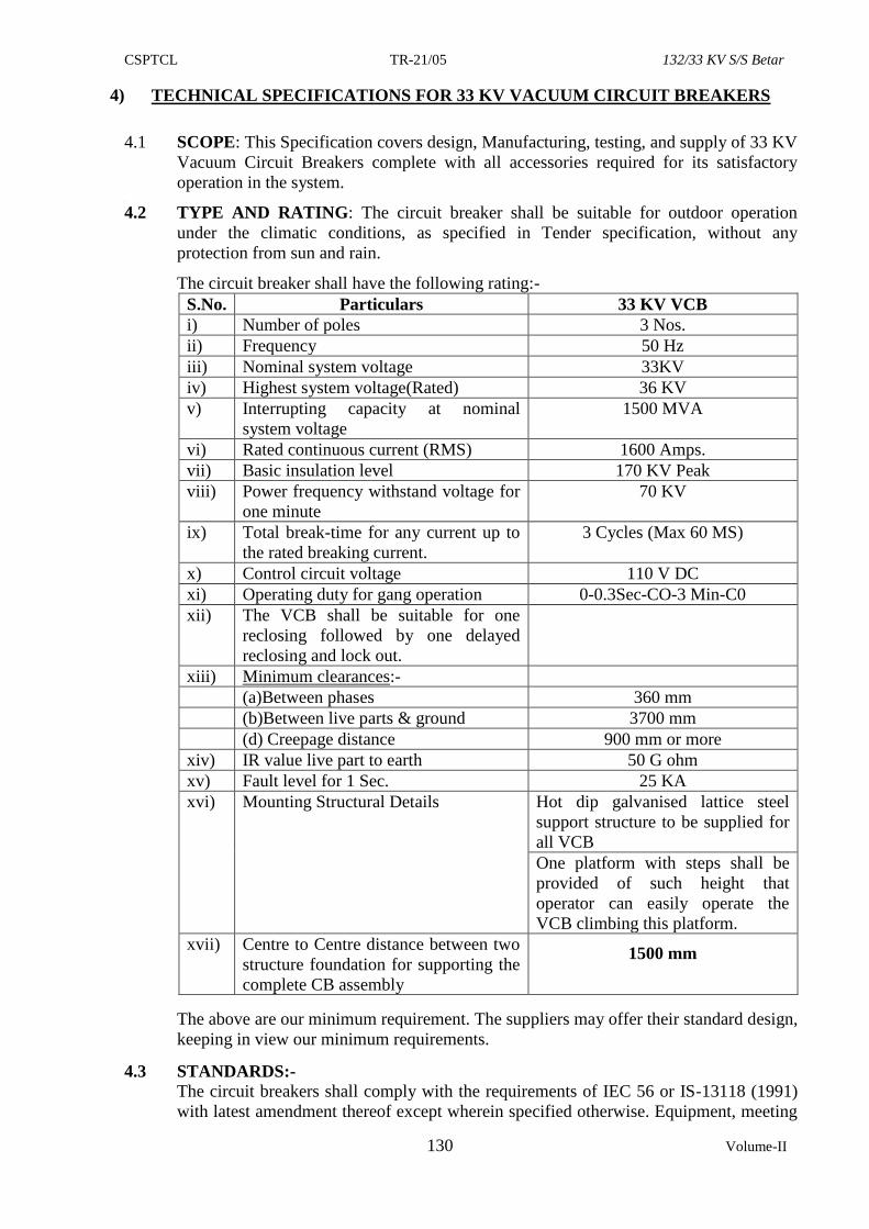
CSPTCL TR-21/05 132/33 KV S/S Betar
130 Volume-II
4) TECHNICAL SPECIFICATIONS FOR 33 KV VACUUM CIRCUIT BREAKERS
4.1 SCOPE: This Specification covers design, Manufacturing, testing, and supply of 33 KV
Vacuum Circuit Breakers complete with all accessories required for its satisfactory
operation in the system. ]
4.2 TYPE AND RATING: The circuit breaker shall be suitable for outdoor operation
under the climatic conditions, as specified in Tender specification, without any
protection from sun and rain.
The circuit breaker shall have the following rating:-
S.No. Particulars 33 KV VCB
i) Number of poles 3 Nos.
ii) Frequency 50 Hz
iii) Nominal system voltage 33KV
iv) Highest system voltage(Rated) 36 KV
v) Interrupting capacity at nominal
system voltage
1500 MVA
vi) Rated continuous current (RMS) 1600 Amps.
vii) Basic insulation level 170 KV Peak
viii) Power frequency withstand voltage for
one minute
70 KV
ix) Total break-time for any current up to
the rated breaking current.
3 Cycles (Max 60 MS)
x) Control circuit voltage 110 V DC
xi) Operating duty for gang operation 0-0.3Sec-CO-3 Min-C0
xii) The VCB shall be suitable for one
reclosing followed by one delayed
reclosing and lock out.
xiii) Minimum clearances:-
(a)Between phases 360 mm
(b)Between live parts & ground 3700 mm
(d) Creepage distance 900 mm or more
xiv) IR value live part to earth 50 G ohm
xv) Fault level for 1 Sec. 25 KA
xvi) Mounting Structural Details Hot dip galvanised lattice steel
support structure to be supplied for
all VCB
One platform with steps shall be
provided of such height that
operator can easily operate the
VCB climbing this platform.
xvii) Centre to Centre distance between two
structure foundation for supporting the
complete CB assembly
1500 mm
The above are our minimum requirement. The suppliers may offer their standard design,
keeping in view our minimum requirements.
4.3 STANDARDS:-
The circuit breakers shall comply with the requirements of IEC 56 or IS-13118 (1991)
with latest amendment thereof except wherein specified otherwise. Equipment, meeting
CSPTCL TR-21/05 132/33 KV S/S Betar
131 Volume-II
any other authoritative standard, which ensures equal or better quality then the
standards mentioned above, will also be acceptable. The contractors shall clearly
indicate the applicable standards to which their equipment complies-with. A copy of
such standard, may also be enclosed.
4.4 GENERAL:-
The circuit breaker shall be of porcelain clad vacuum type. The breaker, complete in all
respect, shall be supplied with all accessories in place and all internal wiring installed
and terminated in the mechanism housing and the equipment shall be complete in all
respects.
The circuit breaker shall provide rapid and smooth interruption of current under all
conditions, completely suppressing all undesirable phenomena, even under the most
severe and persistent short-circuit conditions or when interrupting small current or
leading/lagging reactive currents. The details of any device incorporated to limit or
control the rate of rise of restriking voltage across the circuit breaker contacts shall be
stated. The over voltage caused by the circuit breaker switching on inductive or
capacitive load shall not exceed 3.2 times the normal phase to neutral voltage. The total
break-time for the circuit breaker, throughout the range of breaker operating duty, shall
be stated in the tender and shall be guaranteed. The breaker shall be fit for capacitor
switching (breaking) capacity atleast 400 Amps for Single Capacitor Bank breaking
current.The breakers shall be provided with trip free mechanism.
Circuit breakers shall be suitable for mounting on steel structures. The cost of necessary
frames for mounting the circuit breakers shall be included in the offered prices. All the
structures shall be hot dip galvanized with 3 dips. Please note that cantilever type
supports for mechanism box are not acceptable. The mechanism box shall have firm
supports from bottom. This is necessary to minimize vibration of mechanism box,
which in turn may disturb various settings.
The mechanism box shall be centrally mounted in front of the middle pole, Breaker
with mechanism box mounted by the side of one of the extreme poles is not
acceptable.
The CSPTCL intends to operate the rural 33 KV feeders with automatic reclosing
scheme, the arrangement envisaged is as under:-
On the occurrence of a fault the concerned protective relay will open the circuit breaker
as per its own characteristic. Thereafter, the breaker shall reclose but after pre-set time
delay, which shall be adjustable (say range 4-10 sec. or near about).There shall be no
further automatic reclosing. A simple type of reclosing relay (reputed make) for this
purpose shall be provided under this kind of operation. It is also necessary that the
breaker shall be suitable for this reclosing duty.
4.5 SPECIFICATION FOR CIRCUIT BREAKER:-
The circuit breakers shall consist of three identical phase units with a common
operating mechanism. While offering the circuit breaker, the following details should be
confirmed and furnished:-
Complete construction details of the equipment offered. It should be noted that the
breakers should be suitable for outdoor duty, indoor breakers accommodated in outdoor
kiosks are not acceptable.
Type, Make & source of vacuum bottles with relevant details shall be indicated in the
offer, clearly.
CSPTCL TR-21/05 132/33 KV S/S Betar
132 Volume-II
The capacity of breaker to interrupt inductive and capacitive currents shall be indicated
in the offer (rating of capacitor bank should be stated and type test report shall be
furnished).
4.6 VACUUM INTERRUPTER:-
The design of the vacuum interrupter shall be such that it gives trouble free operation
under normal load and fault conditions throughout the life of the equipment. As the
efficiency of the breaker depends on the degree of vacuum inside the interrupter
manufacturer shall ensure that the same is maintained consistently during service. To
know the Residual life of vacuum interrupter, an indicator to indicate the status of
contact erosion shall be provided.
The insulating ceramic body of the interrupter should have high mechanical strength
and it should be capable of withstanding high temperature without any significant
deterioration in its mechanical and electrical properties.
The metal/alloy used for the fixed and moving contacts shall have very low resistivity
and low gas content. They should be resistant to arc erosion and the contact should have
no tendency to get cold-welded under the high vacuum in the interrupter.
The interrupter design should ensure rapid denomination of the gas so that normal
electrical strength of the gap is restored instantaneously.
The metallic below or any other similar vacuum sealing arrangement should be
provided at the moving contact and should have a long fatigue life.
Manufacturers catalogue on vacuum bottle, indicating all the details shall essentially be
submitted with the tender.
4.7 TEMPERATURE RISE:-
The maximum temperature attained by any part of the equipment, when in service, at
site, under continuous full load conditions, exposed to the direct rays of the sun, shall
not exceed 45 degree centigrade, above ambient temperature. The limits of temperature
rise shall be as per relevant standards. The corrections proposed shall be stated in the
tender and shall be subject to approval of the CSPTCL.
4.8 INSULATION OF THE CIRCUIT BREAKER:- The insulation to ground, the
insulation between open contacts and the insulation between phases of the completely
assembled circuit breaker shall be capable of withstanding satisfactorily di-electric test
voltage corresponding to specified basic insulation level in the standard.
4.9 INSULATORS:- The basic insulation level of the Insulator and insulating porcelains
shall be as specified and porcelain shall be homogenous and free from cavities and other
flaws. They shall be designed to have ample insulation, mechanical strength and rigidity
for satisfactory operation under conditions specified above. All insulators of identical
ratings shall be interchangeable. The puncture strength of the insulators shall be greater
than the flash over value. The insulators shall be type tested from independent Govt.
Lab. as per relevant standards.
4.10. OPERATING MECHANISM:-
4.10.1 The circuit breaker shall be designed for remote control from the control room and in
addition there shall be provision for manual operation of circuit breakers during
maintenance and for local tripping and closing by the normal means.
4.10.2 The circuit breakers shall have operation control and mechanical open closed indicator
in addition to facilities for remote electrical indication.
CSPTCL TR-21/05 132/33 KV S/S Betar
133 Volume-II
4.10.3 The operating mechanism shall be of the spring charging type by electric control under
normal operation. The mechanism shall be trip free electrically and mechanically. The
mechanism shall be capable of performing satisfactorily, the reclosing duty cycles
indicated above, within the time specified. All working parts in the mechanism shall be
of corrosion resistant material and all bearings which require greasing shall be equipped
with pressured grease fittings. The mechanism shall be strong quick in action and shall
be removable without disturbing the other parts of the circuit breaker.The mechanism
and breaker shall be such that the failure of any spring will not prevent tripping and at
the same time will not cause any false tripping or closing. The operating mechanism
should be motor operated spring charged type preferably without chain drive. The
motor for spring charging shall be suitable for operation on 230 volt AC supply.The AC
Motor should have overload protection. Provision should also be made for Mounting of
Mechanism Box at an adequate height and gear ratios shall be so chosen that one man
should be able to charge the spring, without any additional efforts. Please note that
providing DC motor with rectifier is not acceptable.
4.10.4 CONTROL CUBICLE:-
A common control cubicle shall be provided to house electrical, Controls, monitor
devices and all other accessories except those which must be located on individual
poles. The cubicle shall be IP 55 class protection and shall have weatherproof
construction fabricated from sheet steel of minimum 2.5 mm. Thickness. The type test
report on degree of protection test (IP--55) shall also be furnished.
The cubicle shall have front access door with lock and keys, Space heater, internal
illumination lamp, 3 pin 5A socket with individual ON-OFF switches shall be provided
in the cubicle.
For local operation following shall be provided:-
LOCAL/REMOTE selector switch
TRIP/NORMAL/CLOSE control switches with pistol grip handle.
4.10.5 The control circuits shall be designed to operate on 110 V DC & it shall be possible to
adopt to work on other voltages by simply changing the operating coils. The closing and
tripping coils shall be designed to operate satisfactorily at any control voltage from 70%
to 110% of the specified normal DC voltage.
4.10.6 AC Power supply for auxiliaries will be available at 230 volt single phase 50 C/s.
4.10.7 Necessary cable glands for the cables of the operating mechanism shall be provided.
The cables used for operation are all un-armoured 2.5 sq. mm copper control cables of
1100 V grade. The cable glands shall be suitable for 1 no. 8 core and 2 nos. 4 core
cables.
4.10.8 The Circuit breaker shall be provided with trip free Mechanism so that tripping
instructions could over-ride the closing instructions. An additional tripping coil shall
also be provided in the trip circuit. The second coil shall have separate tripping level
arrangement in the mechanism so as to avail advantages of second trip coil. Two trip
coil shall be arranged separately for the operation of two different DC sources. Separate
DC fuse circuit and electrically wired for schematic connection such that the healthiness
of both trip coils could be checked individually.
4.10.9 The circuit diagram of Control circuit of VCB along with operating instructions
(DO’S/DON’T) shall be embossed on metallic plate duly laminated and the same shall
be fixed on the rear door of the Control cubicle from inside.
4.10.10 WIRING:-Wiring shall be completed in all respects to ensure proper functioning of the
control, protection, monitoring and interlocking schemes.
CSPTCL TR-21/05 132/33 KV S/S Betar
134 Volume-II
a. All the wiring shall be carried out with 1100 V grade, PVC insulated stranded
copper conductor of 2.5 Sq.mm.
b. Each wire shall be identified at both ends with permanent markers bearing wire
numbers as per wiring diagram.
c. Wire termination shall be done with crimping type connectors with insulating
sleeves. Wires shall not be spliced between terminals.
d. All spare contacts of auxiliary switches etc. shall be wired upto terminal blocks
in the control cubicle.
4.10.11 TERMINAL BLOCKS:-
Stud type Terminal blocks shall be of 1100 V grade box clamp type ELMEX 10 Sq mm
or approved equivalent, not more than two wires shall be connected in one terminal,
Spare terminals equal in number to 20% of active terminals shall be provided. All the
terminals should be of stud type only.
Terminal block shall be such located as to allow easy access. Wiring shall be so
arranged that individual wires of an external can be connected to consecutive terminals.
4.10.12 TERMINAL CONNECTORS:-
6 Nos Terminal connector suitable for Zebra conductor shall be supplied with each
breaker. The terminal connectors shall also meet the following requirements:
i) Terminal connectors shall be manufactured and tested as per IS: 5561.
ii) Terminal connector shall be tested for short circuit current capability test,
temperature rise test, corona test etc. The terminal connectors should be
manufactured by gravity die-casting process only.Bushing terminals shall be
provided with terminal connectors of approved type and size for connection to
external parts. Terminal connectors must have been successfully type tested
strictly as per IS: 5561. The drawing of terminal connector offered shall have to
be got approved by CSPTCL
iii) All castings shall be free from blow holes, surface blisters, cracks and cavities.
All sharp edges and corners shall be blurred and rounded off.
iv) No part of a clamp shall be less than 12 mm thick.
v) Minimum conductor coverage on the clamp shall be 100mm. Minimum bushing
terminal coverage in the clamp shall be 100mm and minimum pad overlap in the
clamp shall be 100 x 100 mm.
vi) The nut, bolts & washers used in current carrying path shall be hot dip
galvanized.
vii) For bimetallic connectors, copper alloy liner of minimum thickness of 4 mm (2
mm cu and 2 mm Al) shall be integral with aluminium body.
viii) Flexible connectors shall be made from tinned copper/aluminium sheets.
ix) All current carrying parts shall be designed and manufactured to have minimum
contact resistance. The connectors shall be designed for minimum 120% of the
maximum current carrying capacity of the ACSR conductor and the temperature
rise under these conditions shall not be more than 50% of that of the main
conductor.
x) Connectors shall be designed to be corona free in accordance with the
requirements stipulated in IS: 5561
Two numbers grounding terminals for connection with station earth mat shall be
provided on each circuit breaker. Size of the earthing pad shall be suitable for 50
x 8 mm or 60 x 8 mm GI flat.
CSPTCL TR-21/05 132/33 KV S/S Betar
135 Volume-II
4.10.13 AUXILIARY CONTACTS:-
Eight numbers each of auxiliary contacts both of the normally open and normally closed
types shall be provided in each circuit breaker for use in the remote indication and
control scheme of the circuit breaker and for providing safety interlocking. Special
contacts for use with trip coils which permit for relative adjustment with respect to the
travel of the circuit breaker contact shall also be provided, wherever required. There
shall be provision to add more auxiliary contacts at a later date. If required.
4.10.14 ACCESSORIES:-
The vacuum circuit breaker shall be supplied as a complete unit with internal wiring
installed and terminated in mechanism box and equipped with the following
accessories:-
S.NO. PARTICULARS QTY.
1. Motor operated spring charged mechanism Motor
voltage- 230 V AC)
1 No.
2. Trip coils suitable for 110 V DC: 2 Nos.
3. Closing coil suitable for 110 V DC: 1 No.
4. Pistol grip C.B, Control switch having trip/ Normal/
Close position:
1 No.
5. Local/Remote selector switch 1 No.
6. Mechanical Spring Charged indicator 1No.
7. Manual operating handle for maintenance 1 No
8. Facility for manual charging of spring 1 No.
9. Operation counter 1 No.
10. Auxiliary contacts 8 NO - 8 NC 1 Set
11. Anti pumping device suitable for 110V DC 1 No.
12. Terminal connectors suitable for connecting Zebra
conductor
6 Nos.
13. Cubical illuminating lamp with cage & switch 1 No.
14. MCB for both AC and DC supply 1 No. each
15. Spare terminal connectors 20% of total
terminals
16. Mechanical ON /OFF indicator 1 No
17. Space Heater with thermostat and ON /OFF switch 1 No
18. Power Type 3 PIN socket with ON /OFF switch (5A) 1Set
19. Earthing terminals 2 Nos.
20. Duly laminated metallic Plate embossed with Circuit
Diagram of control circuit of VCB along with
Operating Instructions
1 No.
21 Lamp (LED) ON /OFF and spring charge indicator
(Red lamp for ON,Green Lamp for OFF and Blue for
Spring charge)
3 Nos
4.11 Other standard accessories which are not specifically mentioned above, but are required
for efficient and trouble free operation of breaker, should also be provided, without any
extra cost.
CSPTCL TR-21/05 132/33 KV S/S Betar
136 Volume-II
4.12 TYPE TESTS:-
5. Type test certificates on VCB for the following tests as per IS 13118 with latest
amendment there of from any of the Govt. of independent Govt. approved Laboratory
shall invariably be furnished:-
(i) Short circuit duty test.
(i) Short time current rating test.
(ii) Mechanical endurance test.
(iv) Temperature rise test.
(iii) Lightning impulse voltage withstand test.
(iv) Capacitor switching off duty test for single bank of atleast 400 Amps
for Single capacitor bank breaking current.
vi) Power Frequency with stand voltage test dry and wet
vii) Degree of protection IP 55 for the Control Cubicle
4.12.2 The above type test certificates must accompany drawings of type tested equipment
duly signed by type testing authority.
4.12.3 The above tests must not have been conducted on the equipment earlier than 10 years
from the last date of submission of bid.
4.12.4 In case of any change in design of Breaker already type tested and the one offered
against this specification the CSPTCL reserves the right to demand repetition of tests,
without any extra cost.
4.13. ACCEPTANCE AND ROUTINE TESTS:-
4.13.1 All acceptance and routine tests as stipulated in relevant standards shall be carried out
by the supplier in presence of CSPTCL representative.
4.13.2 Immediately after finalisation of the programme of type testing, the suppliers shall give
fifteen days advance intimation to the CSPTCL, to enable him depute his representative
for witnessing the tests.
4.14 RATING PLATES:-
The detailed rating plate shall be as per IS and in addition, shall indicate serial number
of the equipment manufacturer’s name our order number and date.
4.15 SCHEDULE OF IMPORTANT TECHNICAL SPECIFICATION /
REQUIREMENT FOR 33 KV VCBs TO BE ORDERED AGAINST THIS
TENDER
Certain important technical specification requirements have been described hereunder.
The requirement may please be studied and incorporated carefully in the equipment.
1) Please note that support structure shall be hot dip galvanized and this should be
incorporated on OGA Drawing. Ensure furnishing details of loading on the
structure both vertical and horizontal in normal condition as well as in broken wire
condition at plinth level to develop foundation design of your make VCBs. This
information should be indicated in general arrangement drawing.
2) Please note that all breakers shall be provided with trip free mechanism. In order to
ensure full proof trip free operation of circuit breaker the design should ensure that
the stored energy is definitely available for tripping operation before closing
operation of circuit breaker is performed. In the absence of stored tripping energy
closing operation is to be prevented.
CSPTCL TR-21/05 132/33 KV S/S Betar
137 Volume-II
3) In order to improve reliability, circuit breaker shall be provided with double trip
coil. However, as far as possible efforts should be made to provide both trip coils at
different locations to actuate individual trip latch. Independent DC circuit may be
provided for the two trip coils and a separate DC circuit for the closing coil. These
two trip coils shall be electrically wired upto control cubicle so that healthiness of
both trip coils could be checked individually.
4) The circuit breaker shall be designed for remote control from the control room and
in addition there shall be provision for manual operation of circuit breakers during
maintenance and for local tripping and closing. In addition there shall be provision
for mechanical arrangement for emergency trip.
5) The circuit breakers shall have a mechanical “Open” / “Close” indicator in addition
to electrical indication. It shall be visible to operating personnel standing on the
ground level.
6) An operation counter shall be provided with the operating mechanism.
7) The terminal connector for connection of conductor should be suitable for Zebra
conductor with Universal take off arrangement. In case if required one “L” shaped
clamp may be provided to facilitate horizontal as well as vertical take off
arrangement. Terminal connector shall be manufactured out of Aluminium alloy
grade LM 6 or LM 25 as per IS and by gravity die casting process only and should
have six bolts to hold the conductor and conductor hold length shall be 100 mm
approximately.
All nuts and bolts shall be stainless steel and no part of the terminal connector
clamps shall be less than 12 mm thick.
8) For bimetallic connector bimetallic strips of electrical grade copper of adequate
thickness well amalgamated surface to surface with aluminium sheet should be
provided.
9) Following drawings are required to be submitted on priority for scrutiny and
approval incorporating above observations / requirement positively:-
i) General arrangement drawing indicating location of control cubicle,
mechanical ON-OFF indicator, operation counter, device for manual /
emergency trip upper and lower terminal connector, and bushing creepage
distance (at least 900 mm for 33 KV).
ii) Detailed structure drawing clearly indicating the foundation details, details
of loading on the structure as explained above, various dimensions details
of various members of structure and weight of circuit breaker etc.
iii) Schematic diagram indicating details of auxiliary contacts, ON, OFF
healthy trip and spring charge indication, double trip coil arrangement,
antipumping and trip free mechanism feature etc.
iv) Wiring diagram for above schematic diagram.
v) Details of auxiliary contacts utilized for various internal scheme and details
of auxiliary contacts available for customer use.
vi) Packing details drawing indicating total number of package and content of
each package.
vii) The name (rating) plate shall be engraved / anodise in which apart from
basic details following information may also be incorporated.
CSPTCL TR-21/05 132/33 KV S/S Betar
138 Volume-II
Capacitor bank switching off capacity in MVA,
Applicable standard IES/ IS,
Interrupting capacity of the breaker in MVA
viii) Engraved electrical wiring diagram could be permanent / refixed on the rear
of front door of the control cubicle. Details required for casting of
foundation may also be engraved / refixed by the side of electrical / diagram
or this purpose, the various schematic drawing may be condense and one
separate drawing may be submitted to us for our approval.
10) All wirings in the cabinet shall be done neatly and accommodated in plastic
channels with sliding cover. Practice of colour coding / feruling / bunching etc.
shall be followed to present a neat installation. All glands / cable entry points shall
be provided with suitable blanking plates to prevent entry of moisture / vulture. At
least 20% spare terminals shall be provided. Three-pin power plug shall be of
control panel grade with removable lid.
11) Backup mechanical tripping arrangement should be provided to facilitate tripping
of circuit breaker for the condition when DC is not available or tripping coil is
burnt and other similar emergencies. Suitable lever device may be provided for trip
operation under these conditions.
12) Please ensure that no wire / cable is left exposed to atmosphere directly. In case if
any connection is required from circuit breaker operating box to control cubicle
etc, these connections should be taken through cable but through proper guided
channel with sliding covers rigidly fixed on support structure. Please note that both
ends of this connecting cable shall be properly sealed to prevent ingress of rain
water / moisture.
13) The support structure should have proper Earthing arrangement and this should be
indicated in the drawing.
14) In case if cementing of porcelain bushing is required, please ensure that proper
cementing process has been adopted.
15) The auxiliary switches shall be properly designed wherein change of contacts takes
place by snap action and change of status of contact is visible physically.
16) Identification mark may be done on the each breaker pole to co-relate the serial
number of bottles engraved on breaker poles with that of circuit breaker Sl. No.
17) For spring charging operating through operating handle it is desired that
mechanism box may be mounted at adequate height and gear ratio shall be so
chosen that one man is able to charge the spring without any additional efforts.
Suitable latching arrangement shall be provided such that during manual charging
operation, if power supply gets restored, jerk to operating personnel is avoided.
The handle shall be either at normal operable height or otherwise a suitable
foldable ladder shall be provided to facilitate manual charging of spring. Suitable
arrangement for storage of handle in the box shall be provided.
***
CSPTCL TR-21/05 132/33 KV S/S Betar
139 Volume-II
5) TECHNICAL SPECIFICATION FOR INSTRUMENT TRANSFORMERS
(Note:- 132 KV CT & 132 KV PT shall be provided by CSPTCL.)
5.1 SCOPE
This specification provides for design, manufacture, stage testing, inspection and
testing before despatch, packing and delivery of outdoor instrument transformer (CT
and PT) for protection/metering .
5.2 STANDARDS
The rating as well as performance and testing of the instrument transformers shall
conform but not limited to the latest revision and amendments available of all the
relevant standards as listed hereunder.
Sl.
No.
STANDARD
No.
TITLE
1 IS 2165 Insulation co-ordination for equipment of 100 KV and above
2 IS2705
(I – IV)
Current transformers
3 IS 2099 High voltage porcelain bushings
4 IS 3347 Dimensions of porcelain transformer bushings
5 IS 2071 Method of high voltage testing
6 IS 335 Insulating oil for transformers and switchgears
7 IS 2147 Degree of protection provided by enclosures for low voltage
switchgear and control
8 IEC 185 Current transformers
9 IEC 270 Partial discharge measurement
10 IEC 44 (4) Instrument transformer measurement for P.D.s
11 IEC 171 Insulation co-ordination
12 IEC 60 High voltage testing techniques
13 IEC 8263 Method of R.I.V. test on high voltage insulators
14 IS 3156
(Part IV)
Capacitor voltage transformers
15 IEC 186 Voltage transformers
16 IEC 186 A First supplement of IEC publication 186
17 Indian electricity rules 1956.
5.3 BASIC DESIGN FOR INSTRUMENT TRANSFORMERS:-
The Instrument Transformers for solidly grounded system shall be outdoor type. Single-
phase oil immersed and self cooled type suitable for services indicated as above
complete in all respect, conforming to modern practices of design and manufacture.
As stated, all CTs shall be paper-insulated oil filled. After providing paper insulation
they shall be housed in the tank containing oil. Please note epoxy casting in primary &
secondary cores is not acceptable. Compound filled CTs are also not acceptable.
5.3.1 The insulation as per IS: 4800 of the instrument transformers shall be so designed that
the internal insulation shall have higher electrical withstand capability than the external
insulation. The designed dielectric withstands values of external and internal
insulations shall be clearly brought out in the guaranteed technical particulars. The
dielectric withstand values specified in this specification are meant for fully assembled
instrument transformers.
CSPTCL TR-21/05 132/33 KV S/S Betar
140 Volume-II
5.3.2 The Instrument transformers should be designed using single Porcelain housing. The
OIP insulation in porcelain portion is to be provided with condenser grading. Details
like number of grading foils, the method of insertion of grading tools in insulation,
method to ensure grading foil location during manufacturing may be furnished.
5.3.3 No joints shall be provided in the porcelain. The housing shall be made of
homogeneous, vitreous porcelain of high mechanical and dielectric strength, glazing of
porcelain shall be of uniform brown or dark brown colour with a smooth surface
arranged to shed away rain water or condensed water particles, (fog). The profile of
porcelain shall be aerodynamic type as per IEC-815. To make the instrument
transformer leak proof a metallic flange should be cemented to the porcelain.
5.3.4 Special precaution will have to be taken towards selection of material for the metal tank
and the following will have to be ensured.
i) Material for metal tank should be minimum 3 mm thick.
ii) Welded joints have to be minimized to avoid possibility of oil leakage. In any
case welding in horizontal plane shall be avoided.
5.3.5 Prevention of Oil leakages and Entry of Moisture:-
The sealing of CTs shall be properly achieved. The following should be properly taken
care of & arrangement provided by the manufacturer shall be described:
i) Locations of emergence of primary and secondary terminals.
ii) Interface between porcelain housing and metal tank/s.
iii) Cover of the secondary terminal box.
iv) Oil level indicator should be provided with leak proof Teflon sealing
arrangement and wide area visible indication and a float to indicate the oil level.
The oil level shall be visible from ground level. Projected type oil level indicator
welded into main metal tank shall be preferred to avoid oil leakage.
5.3.5 While forming the OIP Insulation, the Insulating Paper has to be procured from Reputed
Paper Manufacturers. The list of original paper suppliers is required to be submitted
along with the tender. The new insulating oil is required to be used for impregnation of
paper insulation and CT filling. Use of reclaimed or once used oil is prohibited.
5.3.7 The Insulating Oil used for impregnation and flooding is to be processed before use.
The processing includes drying and degassing. Stainless steel bellows shall be used for
volumetric compensation of oil.
5.3.8 All the sealing locations have to be provided with Moulded Rubber “O” Rings/ flat
Gaskets. CT Designs with Cork Sheet as the sealing material are not acceptable. In case
the gasket sealing surface is provided on mild steel material, details have to be provided
regarding corrosion protection treatment provided on such surfaces. Also a description
has to be provided on how the compression of the”O” Ring or Gasket is limited &
controlled.
5.3.9 During inspection, each CTs will be subjected to pressure test at 0.7 kg /cm2 for 8hrs.
5.3.10 The CTs should be provided with pressure relief diaphragm.
5.3.11 The secondary terminals shall be brought out in a weather proof terminal box. Firstly
the connections will be terminated on internal board and then the same shall be brought
out in the Secondary terminal box. The terminal box shall be provided with removable
gland plate and gland/s suitable for 1100 volts grade, PVC insulated, PVC sheathed
multi core 4 or 6 sq.mm for CT.
CSPTCL TR-21/05 132/33 KV S/S Betar
141 Volume-II
The terminal box shall be dust and vermin proof. Suitable arrangement shall be made
for drying of air inside the secondary terminal box. The dimensions of the terminal box
and its openings shall be adequate to enable easy access and working space with use of
normal tools. The outer cover of secondary terminal box shall have provision for sealing
by way of insertion of wire in the bolt hole.
5.3.12 Polarity shall be invariably marked on each primary & secondary terminals. All
marking shall be engraved or through anodised plate to be fixed firmly.
5.3.13 The Instrument transformers shall be provided with a rating plate with dimensions and
markings as per IS:2705. The markings shall be punched / engraved and not painted.
This rating plate shall also contain CSPTCL’s work order No. and date.
5.3.14 The instrument transformer shall be vacuum filled with oil after processing and
thereafter hermetically sealed to eliminate breathing and to prevent air and moisture
from entering the tanks. Provision of oil sampling is required for each CT with proper
sealing arrangement. The construction details and method to sample oil should be
provided. Manufacturer shall provide limits of BDV Tan delta, moisture content and
DGA to be followed for evaluation on oil samples at the time of routine testing.
5.3.15 The castings of base, collar etc. shall be die-cast and tested before assembly to detect
cracks and voids if any.
5.3.16 The instrument security factor of metering core shall be low enough and not greater
than 5. This shall be demonstrated on all the ratios of the metering core, in accordance
with procedure specified in IEC-816 or IS:2705.
5.3.17 Instrument transformer shall be provided with two separate earthing terminals for bolted
connection to 50 x 8 mm MS flat to be provided by the Purchase for connection to
station earth-mat.
5.3.18 Instrument transformer shall be provided with suitable lifting arrangement, to lift the
entire unit. The lifting arrangement shall be clearly shown in the general arrangement
drawing. Lifting arrangement (lifting eye) shall be positioned in such a way as to avoid
any damage to the porcelain housing or the tanks during lifting for installation/transport.
Necessary string guides shall be offered which shall be of removable type.
5.4 PRIMARY WINDINGS:-
5.4.1 Primary winding shall be made out of electrolytic grade 99.9% conductivity copper.
The primary winding shall be housed in rigid metallic shell. Joints in the primary
winding shall not be provided.
5.4.2 It is desired that from the point of view of adequate mechanical strength in the normal
course and also during short circuit, proper precaution should be taken as under :-
i) The primary winding should be housed in rigid metallic shell.
ii) The winding assembly should be held firmly and for this purpose suitable
clamping arrangement at the bottom shall be provided and explained through
suitable sketch. Firm clamping arrangement is a must and holding of winding
using nylon rope etc. shall not be acceptable.
5.4.3 The primary winding current density shall not exceed 1.5 A/sq.mm. The design density
for short circuit current as well as conductivity of the metal used for primary windings
of CTs shall meet the requirement of IS:2705. The manufacturer shall submit the
detailed calculation for selection of winding cross sections. The selected Amp turns for
the CT shall be justified on the basis of Type test reports.
CSPTCL TR-21/05 132/33 KV S/S Betar
142 Volume-II
5.5. SECONDARY WINDINGS:-
Suitably insulated copper wire of 99.9% conductivity electrolytic grade shall be used
for secondary windings. The exciting current of the CTs shall be as low as possible. The
magnetization curve for all the cores of CTs should be submitted with the offer.
5.6 PRIMARY TERMINALS:-
Current Transformer’s primary terminal shall be made of HDEC.The primary terminal
on either side of the tank shall be of not less than 100 mm clear length (i.e. after
bolts/washers/check-nuts) to accommodate terminal connector. For CTs the dia /size of
the primary terminal shall be 30mm diameter copper.
The primary terminals shall be of heavily tinned electrolytic copper. The minimum
thickness of tinning shall be 15 microns.
5.7 SECONDARY TERMINALS:-
Secondary terminal studs shall be provided with at least three nuts and adequate plain
and spring washers for fixing the leads. The studs, nuts and washers shall be of brass,
duly nickel plated. The minimum out side diameter of the studs shall be 10 mm. The
length of at least 15 mm shall be available on the studs for inserting the leads. The
horizontal spacing between centers of the adjacent studs shall be at least 1.5 times the
outside circum dia of the nuts. The arrangement should be shown through suitable
sketch.
5.8 CORE:-
The grade M4 toroidal core shall be of high-grade non-ageing electrical silicon
laminated steel of low hysterics loss and high permeability to ensure high accuracy.
The instrument transformer core to be used for metering shall be of accuracy class
specified or appropriate class suitable for commercial and industrial metering.
Enamel, if used for conductor insulation, shall be either polyvinyl acetate type or amide
type and shall meet the requirements of IS:4800. Polyester enamel shall not be used.
In case of CTs the saturation factor of the metering core shall be low enough not to
cause any damage to measuring instruments in the event of maximum short circuit
current. As far as PS class core is concerned all precautions shall be taken in design to
achieve KPV & magnetization curve for the same shall be furnished with the drawings.
It may please be noted that additional devices / components such as condenser/
resisters/ inductor should not be used internally or externally to achieve the accuracy
class/ ISF of CTs.
5.9 INSULATION OIL :-
The quantity of oil for first filling of oil in each transformer shall be in the scope of
supplier. Only best quality new EHV Gr-I transformer oil should be filled in the
equipments with BDV of 70 KV. The BDV of oil filled in the equipment will have to
be recorded in the test certificate.
5.10 SURFACE FINISH:-
The metal tanks & all the ferrous parts/hardware, exposed to atmosphere, shall be hot
dip galvanised conforming to IS; 2633. All other fixing nuts, bolts, washers shall be
made out of galvanized steel.
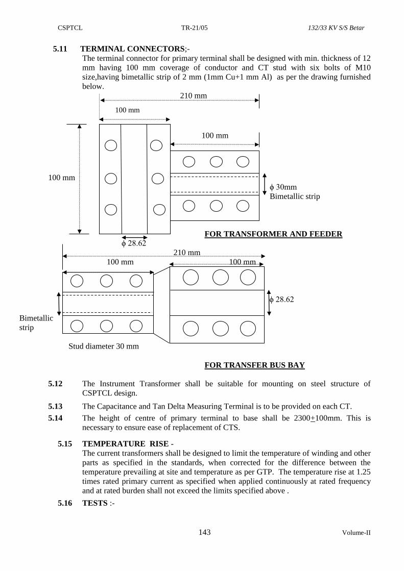
CSPTCL TR-21/05 132/33 KV S/S Betar
143 Volume-II
5.11 TERMINAL CONNECTORS;-
The terminal connector for primary terminal shall be designed with min. thickness of 12
mm having 100 mm coverage of conductor and CT stud with six bolts of M10
size,having bimetallic strip of 2 mm (1mm Cu+1 mm Al) as per the drawing furnished
below.
210 mm
100 mm
100 mm
100 mm
ϕ 30mm
Bimetallic strip
FOR TRANSFORMER AND FEEDER
ϕ 28.62
210 mm
100 mm 100 mm
ϕ 28.62
m
Bimetallic
strip
Stud diameter 30 mm
FOR TRANSFER BUS BAY
5.12 The Instrument Transformer shall be suitable for mounting on steel structure of
CSPTCL design.
5.13 The Capacitance and Tan Delta Measuring Terminal is to be provided on each CT.
5.14 The height of centre of primary terminal to base shall be 2300+100mm. This is
necessary to ensure ease of replacement of CTS.
5.15 TEMPERATURE RISE -
The current transformers shall be designed to limit the temperature of winding and other
parts as specified in the standards, when corrected for the difference between the
temperature prevailing at site and temperature as per GTP. The temperature rise at 1.25
times rated primary current as specified when applied continuously at rated frequency
and at rated burden shall not exceed the limits specified above .
5.16 TESTS :-
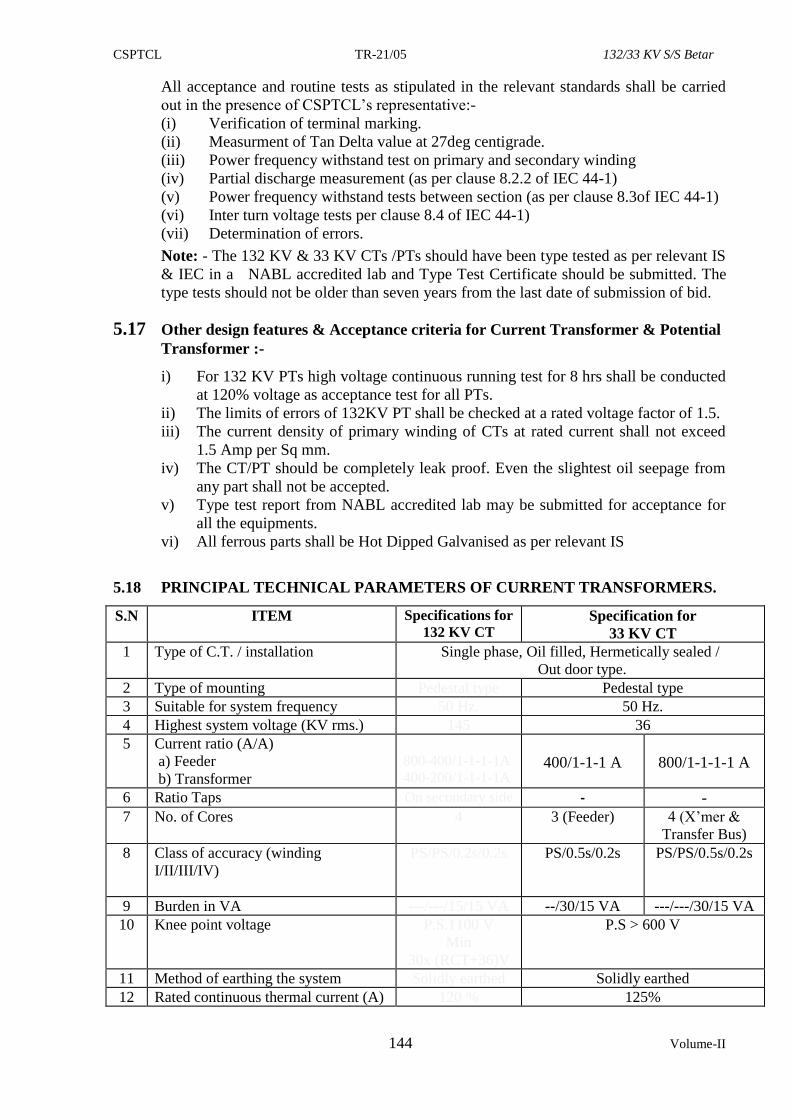
CSPTCL TR-21/05 132/33 KV S/S Betar
144 Volume-II
All acceptance and routine tests as stipulated in the relevant standards shall be carried
out in the presence of CSPTCL’s representative:-
(i) Verification of terminal marking.
(ii) Measurment of Tan Delta value at 27deg centigrade.
(iii) Power frequency withstand test on primary and secondary winding
(iv) Partial discharge measurement (as per clause 8.2.2 of IEC 44-1)
(v) Power frequency withstand tests between section (as per clause 8.3of IEC 44-1)
(vi) Inter turn voltage tests per clause 8.4 of IEC 44-1)
(vii) Determination of errors.
Note: - The 132 KV & 33 KV CTs /PTs should have been type tested as per relevant IS
& IEC in a NABL accredited lab and Type Test Certificate should be submitted. The
type tests should not be older than seven years from the last date of submission of bid.
5.17 Other design features & Acceptance criteria for Current Transformer & Potential
Transformer :-
i) For 132 KV PTs high voltage continuous running test for 8 hrs shall be conducted
at 120% voltage as acceptance test for all PTs.
ii) The limits of errors of 132KV PT shall be checked at a rated voltage factor of 1.5.
iii) The current density of primary winding of CTs at rated current shall not exceed
1.5 Amp per Sq mm.
iv) The CT/PT should be completely leak proof. Even the slightest oil seepage from
any part shall not be accepted.
v) Type test report from NABL accredited lab may be submitted for acceptance for
all the equipments.
vi) All ferrous parts shall be Hot Dipped Galvanised as per relevant IS
5.18 PRINCIPAL TECHNICAL PARAMETERS OF CURRENT TRANSFORMERS.
S.N ITEM Specifications for
132 KV CT Specification for
33 KV CT
1 Type of C.T. / installation Single phase, Oil filled, Hermetically sealed /
Out door type.
2 Type of mounting Pedestal type Pedestal type
3 Suitable for system frequency 50 Hz. 50 Hz.
4 Highest system voltage (KV rms.) 145 36
5 Current ratio (A/A)
a) Feeder
b) Transformer
800-400/1-1-1-1A
400-200/1-1-1-1A
400/1-1-1 A
800/1-1-1-1 A
6 Ratio Taps On secondary side - -
7 No. of Cores 4 3 (Feeder) 4 (X’mer &
Transfer Bus)
8 Class of accuracy (winding
I/II/III/IV)
PS/PS/0.2s/0.2s PS/0.5s/0.2s PS/PS/0.5s/0.2s
9 Burden in VA ---/---/15/15 VA --/30/15 VA ---/---/30/15 VA
10 Knee point voltage P.S.1100 V
Min
30x (RCT+36)V
P.S > 600 V
11 Method of earthing the system Solidly earthed Solidly earthed
12 Rated continuous thermal current (A) 120 % 125%
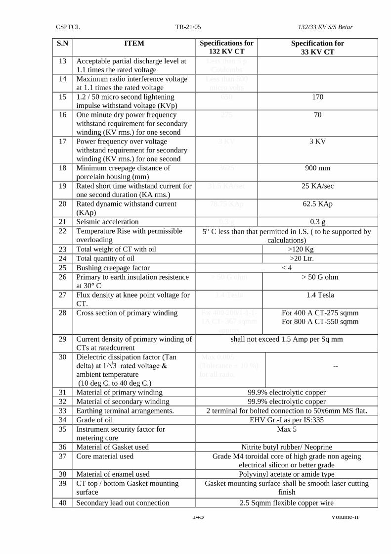
CSPTCL TR-21/05 132/33 KV S/S Betar
145 Volume-II
S.N ITEM Specifications for
132 KV CT Specification for
33 KV CT
13 Acceptable partial discharge level at
1.1 times the rated voltage
Less than 5 p
Coulombs
14 Maximum radio interference voltage
at 1.1 times the rated voltage
Less than 500
micro volts
15 1.2 / 50 micro second lightening
impulse withstand voltage (KVp)
650 170
16 One minute dry power frequency
withstand requirement for secondary
winding (KV rms.) for one second
275 70
17 Power frequency over voltage
withstand requirement for secondary
winding (KV rms.) for one second
3 KV 3 KV
18 Minimum creepage distance of
porcelain housing (mm)
3625 900 mm
19 Rated short time withstand current for
one second duration (KA rms.)
31.5 KA/sec 25 KA/sec
20 Rated dynamic withstand current
(KAp)
78.75 KAp 62.5 KAp
21 Seismic acceleration 0.3 g 0.3 g
22 Temperature Rise with permissible
overloading 5 C less than that permitted in I.S. ( to be supported by
calculations)
23 Total weight of CT with oil >120 Kg
24 Total quantity of oil >20 Ltr.
25 Bushing creepage factor < 4
26 Primary to earth insulation resistence
at 30° C
> 50 G ohm > 50 G ohm
27 Flux density at knee point voltage for
CT.
1.4 Tesla 1.4 Tesla
28 Cross section of primary winding For 400-200/1-1-1-
1A CT- 367 sqmm
approx
For 400 A CT-275 sqmm
For 800 A CT-550 sqmm
29 Current density of primary winding of
CTs at ratedcurrent
shall not exceed 1.5 Amp per Sq mm
30 Dielectric dissipation factor (Tan
delta) at 1/√3 rated voltage &
ambient temperature
(10 deg C. to 40 deg C.)
Max 0.005
(Tolerance + 10 %)
for all ratio.
--
31 Material of primary winding 99.9% electrolytic copper
32 Material of secondary winding 99.9% electrolytic copper
33 Earthing terminal arrangements. 2 terminal for bolted connection to 50x6mm MS flat.
34 Grade of oil EHV Gr.-I as per IS:335
35 Instrument security factor for
metering core
Max 5
36 Material of Gasket used Nitrite butyl rubber/ Neoprine
37 Core material used Grade M4 toroidal core of high grade non ageing
electrical silicon or better grade
38 Material of enamel used Polyvinyl acetate or amide type
39 CT top / bottom Gasket mounting
surface
Gasket mounting surface shall be smooth laser cutting
finish
40 Secondary lead out connection 2.5 Sqmm flexible copper wire
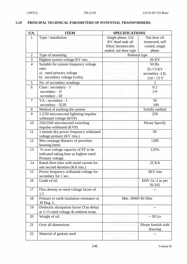
CSPTCL TR-21/05 132/33 KV S/S Betar
146 Volume-II
5.19 PRINCIPAL TECHNICAL PARAMETERS OF POTENTIAL TRANSFORMERS.
S.N. ITEM SPECIFICATIONS
1 Type / installation Single phase, 132
KV dead tank oil
filled, hermetically
sealed, out door type
Out door oil
immersed, self
cooled, single
phase
2 Type of mounting Pedestal type
3 Highest system voltage KV rms. 145 KV 36 KV
4 Suitable for system frequency voltage
ratio
a) rated primary voltage
b) secondary voltage (volts)
50 Hz.
132/ 3 KV
secondary -I,II,III
110 / 3 V
50 Hz.
33 /3 KV
secondary -I,II,
110 / 3 V
5 No. of secondary windings 3 2
6 Class : secondary – I
secondary – II
secondary - III
0.2
3 P
3P
0.2
3 P
7 VA : secondary - I
secondary – II,III
50
100
50
100
8 Method of earthing the system Solidly earthed Solidly earthed
9 1.2/50 microsecond lightning impulse
withstand voltage (KVP)
650 250
10 250/2500 microsecond switching
impulse withstand (KVP)
Please Specify Please Specify
11 1 minute dry power frequency withstand
voltage primary (KV rms.)
275 95
12 Min creepage distance of porcelain
housing (mm)
3625 1300
13 % over voltage capacity of PT to be
indicated taking base as highest rated
Primary voltage.
125% 125%
14 Rated short time with stand current for
one second duration (KA rms.)
31.5 KA 25 KA
15 Power frequency withstand voltage for
secondary for 1 sec.
3 KV rms 3KV rms
16 Grade of oil EHV Gr.-I as per
IS:335
EHV Gr.-I as per
IS:335
17 Flux density at rated voltage factor of
1.5
Max. 1.8 Tesla --
18 Primary to earth insulation resistance at
30 Deg. C.
Min. 50000 M Ohm
19 Dielectric dissipation factor (Tan delta)
at 1/3 rated voltage & ambient temp.
Max. 0.003 --
20 Weight of oil. ≥ 120 Ltr > 30 Ltr
21 Over all dimensions 2450x600x600 mm Please furnish with
drawing
22 Material of gaskets used Nitrite butyl rubber/
Neoprine
--
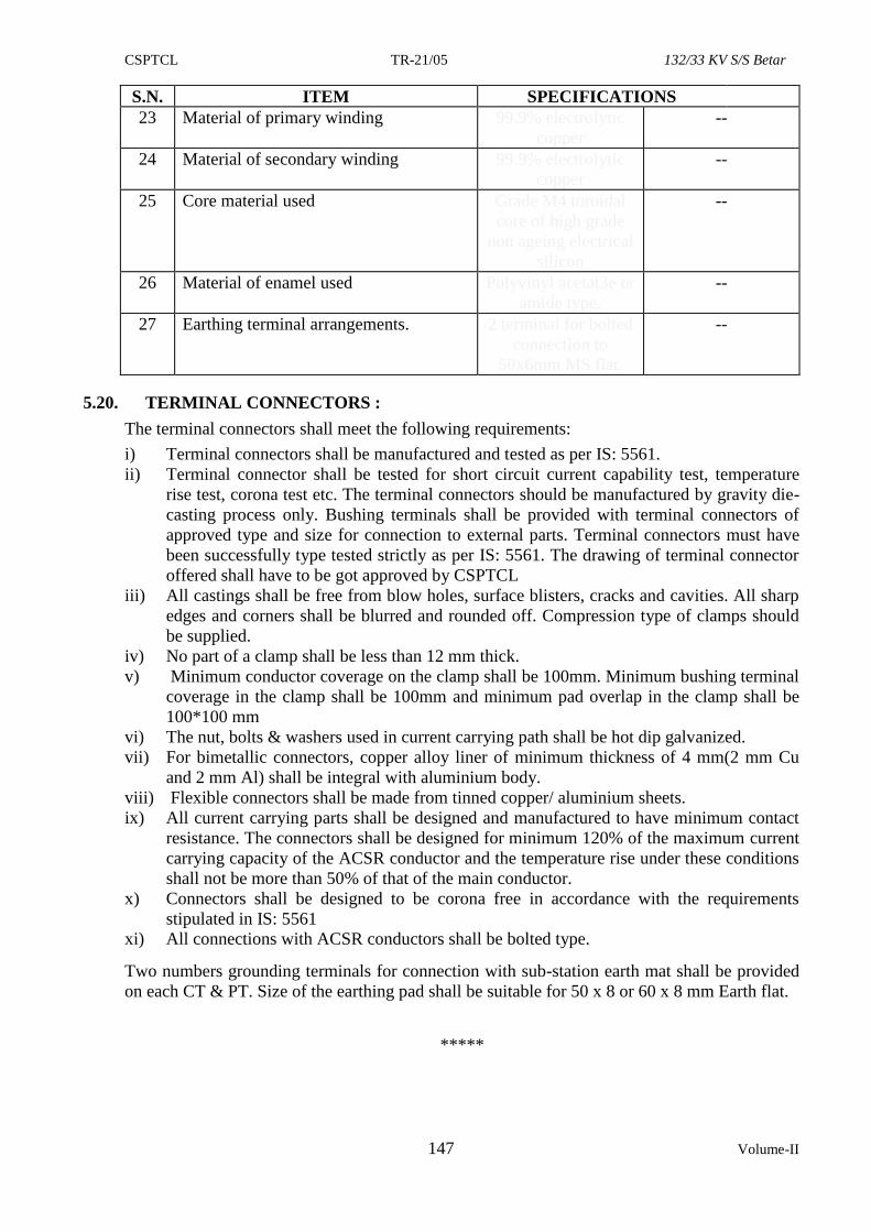
CSPTCL TR-21/05 132/33 KV S/S Betar
147 Volume-II
S.N. ITEM SPECIFICATIONS
23 Material of primary winding 99.9% electrolytic
copper
--
24 Material of secondary winding 99.9% electrolytic
copper
--
25 Core material used Grade M4 toroidal
core of high grade
non ageing electrical
silicon
--
26 Material of enamel used Polyvinyl acetat3e or
amide type.
--
27 Earthing terminal arrangements. 2 terminal for bolted
connection to
50x6mm MS flat.
--
5.20. TERMINAL CONNECTORS :
The terminal connectors shall meet the following requirements:
i) Terminal connectors shall be manufactured and tested as per IS: 5561.
ii) Terminal connector shall be tested for short circuit current capability test, temperature
rise test, corona test etc. The terminal connectors should be manufactured by gravity die-
casting process only. Bushing terminals shall be provided with terminal connectors of
approved type and size for connection to external parts. Terminal connectors must have
been successfully type tested strictly as per IS: 5561. The drawing of terminal connector
offered shall have to be got approved by CSPTCL
iii) All castings shall be free from blow holes, surface blisters, cracks and cavities. All sharp
edges and corners shall be blurred and rounded off. Compression type of clamps should
be supplied.
iv) No part of a clamp shall be less than 12 mm thick.
v) Minimum conductor coverage on the clamp shall be 100mm. Minimum bushing terminal
coverage in the clamp shall be 100mm and minimum pad overlap in the clamp shall be
100*100 mm
vi) The nut, bolts & washers used in current carrying path shall be hot dip galvanized.
vii) For bimetallic connectors, copper alloy liner of minimum thickness of 4 mm(2 mm Cu
and 2 mm Al) shall be integral with aluminium body.
viii) Flexible connectors shall be made from tinned copper/ aluminium sheets.
ix) All current carrying parts shall be designed and manufactured to have minimum contact
resistance. The connectors shall be designed for minimum 120% of the maximum current
carrying capacity of the ACSR conductor and the temperature rise under these conditions
shall not be more than 50% of that of the main conductor.
x) Connectors shall be designed to be corona free in accordance with the requirements
stipulated in IS: 5561
xi) All connections with ACSR conductors shall be bolted type.
Two numbers grounding terminals for connection with sub-station earth mat shall be provided
on each CT & PT. Size of the earthing pad shall be suitable for 50 x 8 or 60 x 8 mm Earth flat.
*****
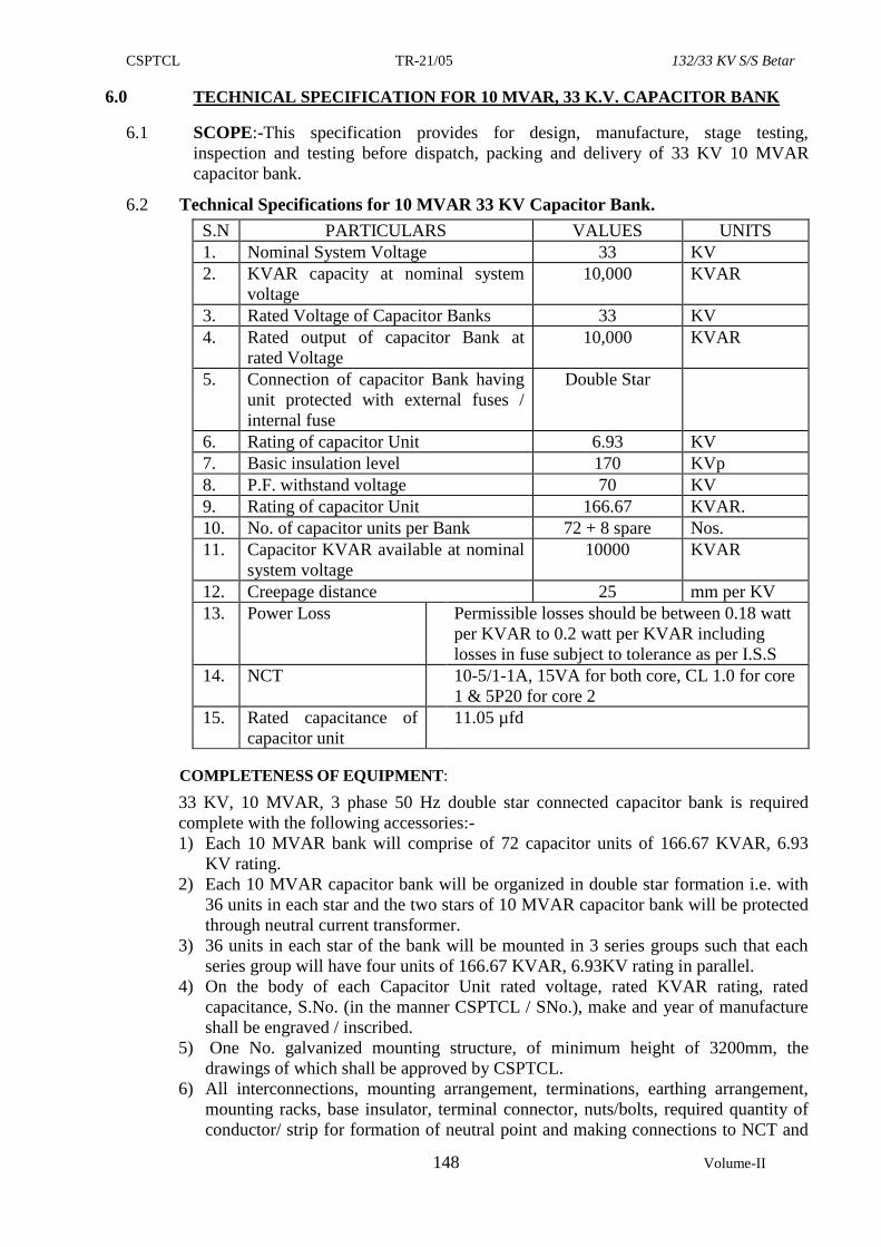
CSPTCL TR-21/05 132/33 KV S/S Betar
148 Volume-II
6.0 TECHNICAL SPECIFICATION FOR 10 MVAR, 33 K.V. CAPACITOR BANK
6.1 SCOPE:-This specification provides for design, manufacture, stage testing,
inspection and testing before dispatch, packing and delivery of 33 KV 10 MVAR
capacitor bank.
6.2 Technical Specifications for 10 MVAR 33 KV Capacitor Bank.
S.N PARTICULARS VALUES UNITS
1. Nominal System Voltage 33 KV
2. KVAR capacity at nominal system
voltage
10,000 KVAR
3. Rated Voltage of Capacitor Banks 33 KV
4. Rated output of capacitor Bank at
rated Voltage
10,000 KVAR
5. Connection of capacitor Bank having
unit protected with external fuses /
internal fuse
Double Star
6. Rating of capacitor Unit 6.93 KV
7. Basic insulation level 170 KVp
8. P.F. withstand voltage 70 KV
9. Rating of capacitor Unit 166.67 KVAR.
10. No. of capacitor units per Bank 72 + 8 spare Nos.
11. Capacitor KVAR available at nominal
system voltage
10000 KVAR
12. Creepage distance 25 mm per KV
13. Power Loss Permissible losses should be between 0.18 watt
per KVAR to 0.2 watt per KVAR including
losses in fuse subject to tolerance as per I.S.S
14. NCT 10-5/1-1A, 15VA for both core, CL 1.0 for core
1 & 5P20 for core 2
15. Rated capacitance of
capacitor unit
11.05 µfd
COMPLETENESS OF EQUIPMENT:
33 KV, 10 MVAR, 3 phase 50 Hz double star connected capacitor bank is required
complete with the following accessories:-
1) Each 10 MVAR bank will comprise of 72 capacitor units of 166.67 KVAR, 6.93
KV rating.
2) Each 10 MVAR capacitor bank will be organized in double star formation i.e. with
36 units in each star and the two stars of 10 MVAR capacitor bank will be protected
through neutral current transformer.
3) 36 units in each star of the bank will be mounted in 3 series groups such that each
series group will have four units of 166.67 KVAR, 6.93KV rating in parallel.
4) On the body of each Capacitor Unit rated voltage, rated KVAR rating, rated
capacitance, S.No. (in the manner CSPTCL / SNo.), make and year of manufacture
shall be engraved / inscribed.
5) One No. galvanized mounting structure, of minimum height of 3200mm, the
drawings of which shall be approved by CSPTCL.
6) All interconnections, mounting arrangement, terminations, earthing arrangement,
mounting racks, base insulator, terminal connector, nuts/bolts, required quantity of
conductor/ strip for formation of neutral point and making connections to NCT and
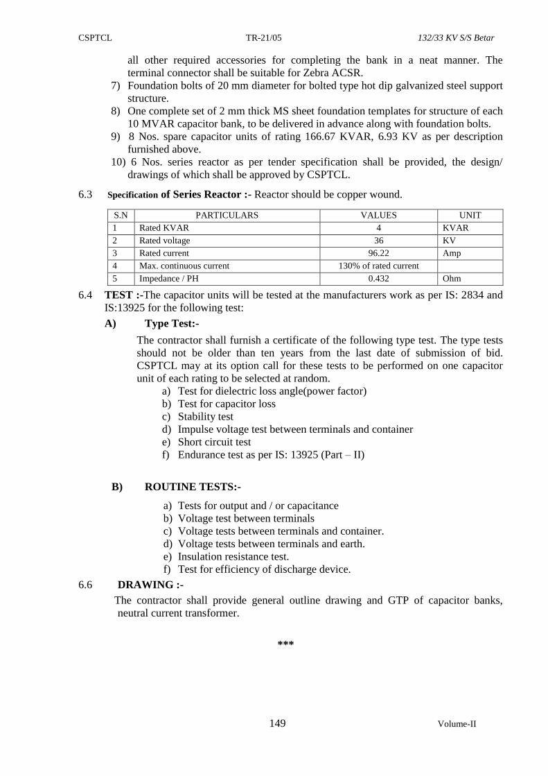
CSPTCL TR-21/05 132/33 KV S/S Betar
149 Volume-II
all other required accessories for completing the bank in a neat manner. The
terminal connector shall be suitable for Zebra ACSR.
7) Foundation bolts of 20 mm diameter for bolted type hot dip galvanized steel support
structure.
8) One complete set of 2 mm thick MS sheet foundation templates for structure of each
10 MVAR capacitor bank, to be delivered in advance along with foundation bolts.
9) 8 Nos. spare capacitor units of rating 166.67 KVAR, 6.93 KV as per description
furnished above.
10) 6 Nos. series reactor as per tender specification shall be provided, the design/
drawings of which shall be approved by CSPTCL.
6.3 Specification of Series Reactor :- Reactor should be copper wound.
S.N PARTICULARS VALUES UNIT
1 Rated KVAR 4 KVAR
2 Rated voltage 36 KV
3 Rated current 96.22 Amp
4 Max. continuous current 130% of rated current
5 Impedance / PH 0.432 Ohm
6.4 TEST :-The capacitor units will be tested at the manufacturers work as per IS: 2834 and
IS:13925 for the following test:
A) Type Test:-
The contractor shall furnish a certificate of the following type test. The type tests
should not be older than ten years from the last date of submission of bid.
CSPTCL may at its option call for these tests to be performed on one capacitor
unit of each rating to be selected at random.
a) Test for dielectric loss angle(power factor)
b) Test for capacitor loss
c) Stability test
d) Impulse voltage test between terminals and container
e) Short circuit test
f) Endurance test as per IS: 13925 (Part – II)
B) ROUTINE TESTS:-
a) Tests for output and / or capacitance
b) Voltage test between terminals
c) Voltage tests between terminals and container.
d) Voltage tests between terminals and earth.
e) Insulation resistance test.
f) Test for efficiency of discharge device.
6.6 DRAWING :-
The contractor shall provide general outline drawing and GTP of capacitor banks,
neutral current transformer.
***
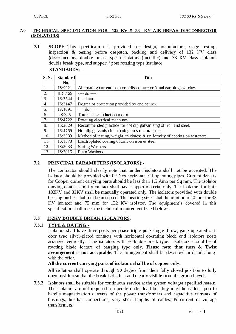
CSPTCL TR-21/05 132/33 KV S/S Betar
150 Volume-II
7.0 TECHNICAL SPECIFICATION FOR 132 KV & 33 KV AIR BREAK DISCONNECTOR
(ISOLATORS)
7.1 SCOPE:-This specification is provided for design, manufacture, stage testing,
inspection & testing before despatch, packing and delivery of 132 KV class
(disconnectors, double break type ) isolators (metallic) and 33 KV class isolators
double break type, and support / post rotating type insulator
STANDARDS:-
7.2 PRINCIPAL PARAMETERS (ISOLATORS):-
The contractor should clearly note that tandem isolators shall not be accepted. The
isolator should be provided with 02 Nos horizontal GI operating pipes. Current density
for Copper current carrying parts should be less than 1.5 Amp per Sq mm. The isolator
moving contact and fix contact shall have copper material only. The isolators for both
132KV and 33KV shall be manually operated only. The isolators provided with double
bearing bushes shall not be accepted. The bearing sizes shall be minimum 40 mm for 33
KV isolator and 75 mm for 132 KV isolator. The equipment’s covered in this
specification shall meet the technical requirement listed below:-
7.3 132KV DOUBLE BREAK ISOLATORS.
7.3.1 TYPE & RATING:-
Isolators shall have three posts per phase triple pole single throw, gang operated out-
door type silver-plated contacts with horizontal operating blade and isolators posts
arranged vertically. The isolators will be double break type. Isolators should be of
rotating blade feature of banging type only. Please note that turn & Twist
arrangement is not acceptable. The arrangement shall be described in detail along-
with the offer.
All the current carrying parts of isolators shall be of copper only.
All isolators shall operate through 90 degree from their fully closed position to fully
open position so that the break is distinct and clearly visible from the ground level.
7.3.2 Isolators shall be suitable for continuous service at the system voltages specified herein.
The isolators are not required to operate under load but they must be called upon to
handle magnetization currents of the power transformers and capacitive currents of
bushings, bus-bar connections, very short lengths of cables, & current of voltage
transformers.
S. N. Standard
No.
Title
1. IS:9921 Alternating current isolators (dis-connectors) and earthing switches.
2. IEC:129 ---- do ----
3. IS:2544 Insulators
4. IS:2147 Degree of protection provided by enclosures.
5. IS:4691 ---- do ----
6. IS:325 Three phase induction motor
7. IS:4722 Rotating electrical machines
8. IS:2629 Recommended practice for hot dip galvanising of iron and steel.
9. IS:4759 Hot dip galvanisation coating on structural steel.
10. IS:2633 Method of testing, weight, thickness & uniformity of coating on fasteners
11. IS:1573 Electroplated coating of zinc on iron & steel
12. IS:3033 Spring Washers
13. IS:2016 Plain Washers
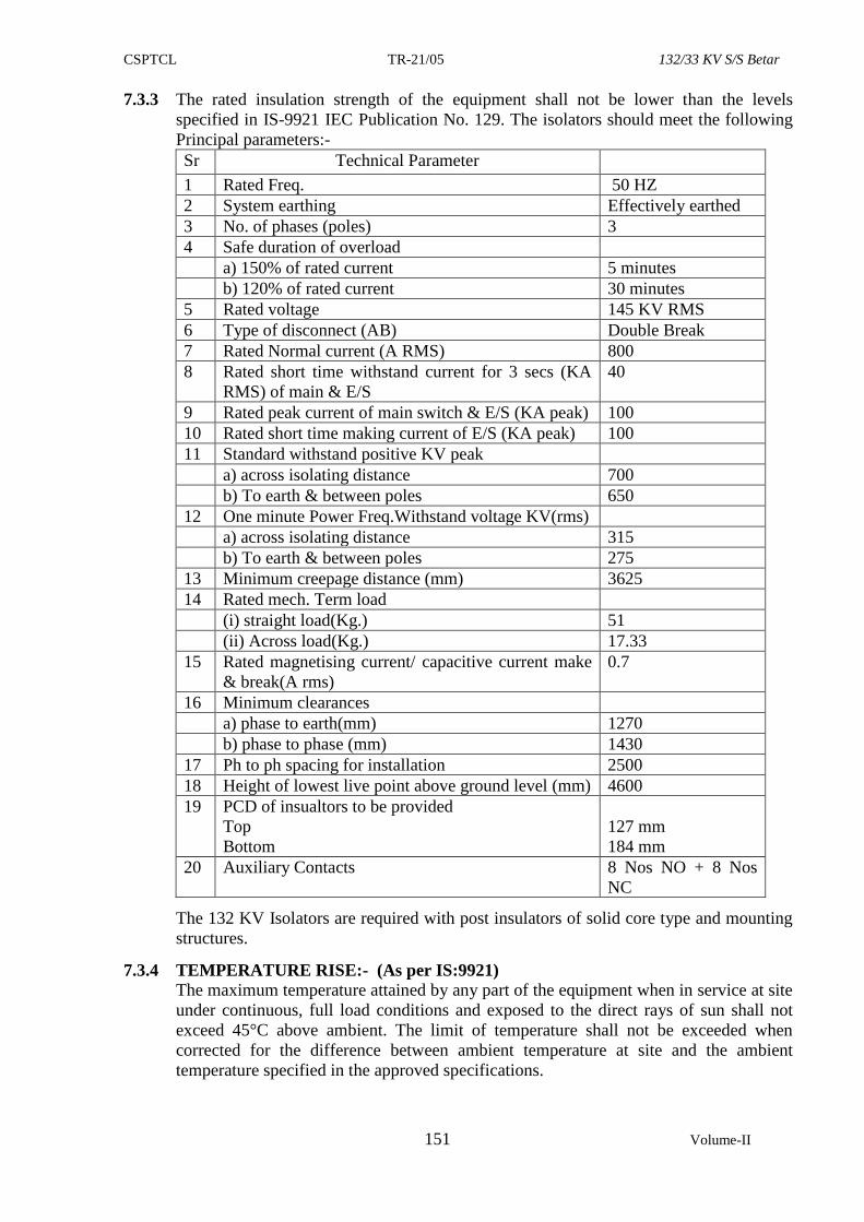
CSPTCL TR-21/05 132/33 KV S/S Betar
151 Volume-II
7.3.3 The rated insulation strength of the equipment shall not be lower than the levels
specified in IS-9921 IEC Publication No. 129. The isolators should meet the following
Principal parameters:-
Sr Technical Parameter
1 Rated Freq. 50 HZ
2 System earthing Effectively earthed
3 No. of phases (poles) 3
4 Safe duration of overload
a) 150% of rated current 5 minutes
b) 120% of rated current 30 minutes
5 Rated voltage 145 KV RMS
6 Type of disconnect (AB) Double Break
7 Rated Normal current (A RMS) 800
8 Rated short time withstand current for 3 secs (KA
RMS) of main & E/S
40
9 Rated peak current of main switch & E/S (KA peak) 100
10 Rated short time making current of E/S (KA peak) 100
11 Standard withstand positive KV peak
a) across isolating distance 700
b) To earth & between poles 650
12 One minute Power Freq.Withstand voltage KV(rms)
a) across isolating distance 315
b) To earth & between poles 275
13 Minimum creepage distance (mm) 3625
14 Rated mech. Term load
(i) straight load(Kg.) 51
(ii) Across load(Kg.) 17.33
15 Rated magnetising current/ capacitive current make
& break(A rms)
0.7
16 Minimum clearances
a) phase to earth(mm) 1270
b) phase to phase (mm) 1430
17 Ph to ph spacing for installation 2500
18 Height of lowest live point above ground level (mm) 4600
19 PCD of insualtors to be provided
Top
Bottom
127 mm
184 mm
20 Auxiliary Contacts 8 Nos NO + 8 Nos
NC
The 132 KV Isolators are required with post insulators of solid core type and mounting
structures.
7.3.4 TEMPERATURE RISE:- (As per IS:9921)
The maximum temperature attained by any part of the equipment when in service at site
under continuous, full load conditions and exposed to the direct rays of sun shall not
exceed 45°C above ambient. The limit of temperature shall not be exceeded when
corrected for the difference between ambient temperature at site and the ambient
temperature specified in the approved specifications.
CSPTCL TR-21/05 132/33 KV S/S Betar
152 Volume-II
7.3.5 ISOLATOR INSULATION:
Insulation to ground, insulation between open contacts and the insulation between
phases of the completely assembled isolating switch shall be capable of withstanding
the dielectric test voltage specified in clause 7.3.3 above.
7.3.6 MAIN CONTACTS
(i) All current carrying parts in the lsolator shall be of Hard Drawn Electrolytic copper.
Aluminium shall not be used at all.
All isolators shall have heavy-duty self-aligning, self cleaning contacts and so
design that binding can not occur after remaining closed for prolonged period of
time in a heavily polluted atmosphere. The fixed contact of the Isolator shall be
made of hard drawn electrolytic copper. The fixed contact should be of reverse
loop type. The various parts shall be accordingly reverse loop type. The various
parts shall be accordingly finished to ensure inter-changeability of similar
components.
The fingers of fixed contacts shall be preferably in two pieces of section 4.5 X 30
mm and each shall form the reverse loops with a oval shape to hold fixed contact
intact. The ends of the reverse loops of the fixed contact shall touch the stopper.
The fixed contact finger shall be mounted on a copper pad of size 200 x 100x 8 mm
thickness (Please note aluminium pad will not be accepted). No aluminium coating
on the copper pad or bimetallic material shall be used in fixed contact assembly.
The fixed contacts would be placed in ‘C’ clamp. The thickness of ‘C’ clamp shall
be 5 mm. This ‘C’ clamp shall be placed on a channel of 5 mm thickness. This
channel shall be welded on a insulator mounting plate of 10 mm thickness. The
spring of fixed contact shall have housing to hold the moving contact in place. This
spring shall be made of stainless steel with adequate thickness. Since the Isolator
design is banging type, the proper spring pressure is a must for good contact. The
spring shall not carry any current and shall not loose their characteristic due to
heating effects.
Contacts and spring shall be designed so that readjustment in contact pressure shall
not be necessary throughout the life of the Isolator or earth switch. Each contact or
pair of contact shall be independently sprung so that full pressure is maintained on
contacts at all time.
(ii) MOVING BLADE:
The switch blades forming the moving contacts shall be made from tubular section
of hard drawn electrolytic copper with OD 50 mm and ID 42 mm for 800 Amp.The
moving blade shall be of length 2220 mm. The contact should be in a single piece
and there should not be any joint in the moving blade. These contacts should
withstand safely the highest short circuit and over voltage that may be encountered
during service. The surfaces of the contacts shall be rendered smooth and silver-
plated. In nut shell, the male and female contacts assemblies shall be of robust
construction and design of these assemblies shall ensure that :
a. Electro-dynamic withstand capability of contacts should be sufficient to
ensure that during short circuit there is no risk of repulsion of contacts.
b. The current density in the Copper parts shall not be more than 1.5A/sq.mm
but may be less.
c. Thermal withstand capability during short circuit should be adequate to
ensure that during short circuit there is no over heating of contacts.
CSPTCL TR-21/05 132/33 KV S/S Betar
153 Volume-II
d. Constant contact pressure even when the live parts of the insulator stacks are
subjected to tensile stresses due to linear expansion of connected bus bar of
flexible conductors either because of temperature variations or strong winds.
e. Wiping action during closing and opening.
f. Self-alignment assuring closing of the switch without minute adjustment.
7.3.7. ARCING CONTACTS/HORN:-
Arcing contacts are not required.
7.3.8 AUXILIARY SWITCHES:--The operating mechanism of main switch shall be
equipped with eight nos. each of NO & NC contacts exclusively for CSPTCLs
interlocking & protective schemes. The aux. switches should be rated to carry a current
of 10 amps continuously. The operation of Auxiliary switches should be as per clause
8.3 of IS: 9921(part-III). The Aux. switches should be actuated by a cam or similar
arrangement mounted on the isolator shaft without any intermediate levers, linkages etc.
to ensure fool-proof operation.
7.3.9 TERMINAL CONNECTORS:-
The connectors for isolators shall be suitable for Zebra ACSR conductor. The material
should be Aluminium LM6 grade.The terminal connector should have the dimensions
of 205x100x12mm.Total 12 nos nut bolts of M-10 size should be provided & connector
should be suitable for accommodating conductor clear length of 100 mm .The drawings
of the terminal connectors is shown below.Also Bimetallic sleeve/liner with minimum 2
mm thickness should be provided. The current density in the Aluminium parts shall not
be more than 1.0A/sq.mm but may be less.
The groove provided in the connector should be able to accommodate conductor size
mentioned above smoothly. The design of clamp shall be subject to CSPTCL’s
approval. The clamps to be offered should be manufactured by gravity die-casting
method only and not by sand casting process. Six nos. pad clamps suitable for zebra
conductor, as per drawing shown below shall be supplied with each Isolator.
100 mm 5 mm 100 mm
100 mm
7.3.10 OPERATING MECHANISM FOR 132 KV ISOLATOR
All Isolators and earthing switches shall have separate independent manual operation.
The isolator should be provided with padlocking arrangements for locking in both the
end position to avoid unintentional operation. For this purpose padlocks with three keys
shall be provided. The isolating distances should be visible for isolators.
The isolators with or without earth switch inclusive of their operating mechanism,
should be such that they cannot come out of their open or closed position by gravity
wind pressure, vibrations reasonable shocks or accidental touching of connecting rods
of the operating mechanism. Isolators should be capable of resisting in closed position,
the dynamic and thermal effects of maximum possible short circuit current at the
installation point. They shall be so constructed that they do not open under the influence
of the short circuit current. The operating mechanism should be robust construction,
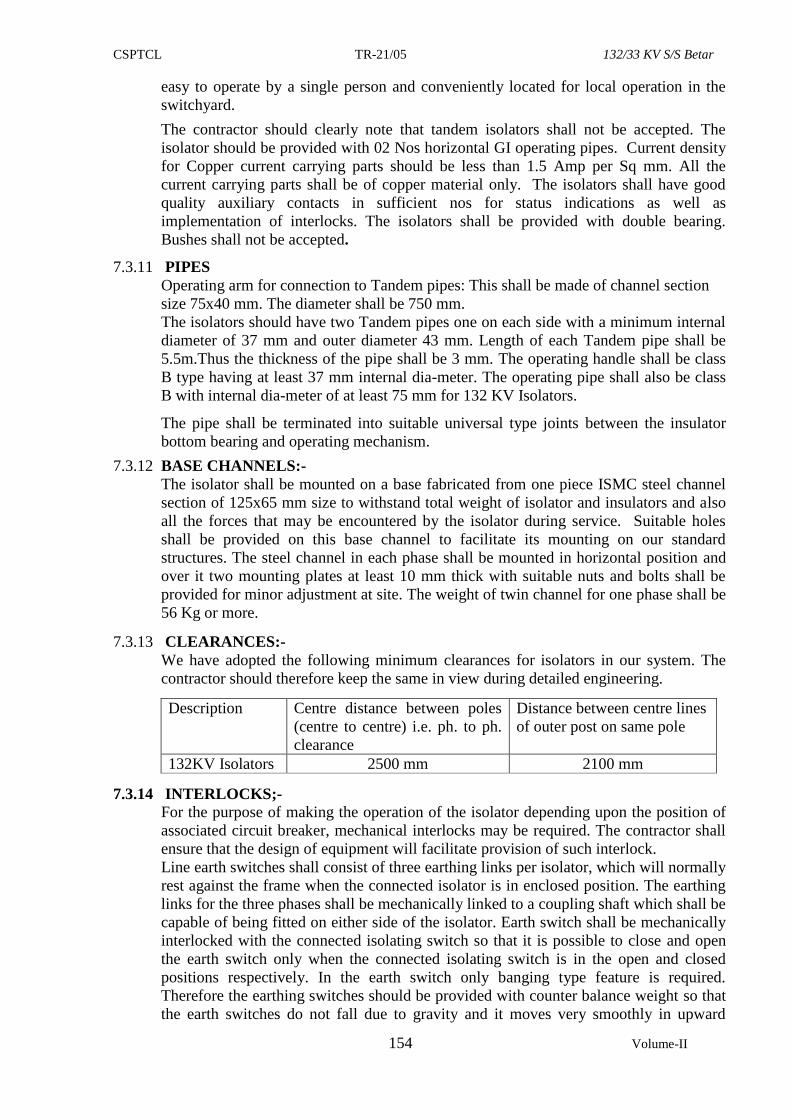
CSPTCL TR-21/05 132/33 KV S/S Betar
154 Volume-II
easy to operate by a single person and conveniently located for local operation in the
switchyard.
The contractor should clearly note that tandem isolators shall not be accepted. The
isolator should be provided with 02 Nos horizontal GI operating pipes. Current density
for Copper current carrying parts should be less than 1.5 Amp per Sq mm. All the
current carrying parts shall be of copper material only. The isolators shall have good
quality auxiliary contacts in sufficient nos for status indications as well as
implementation of interlocks. The isolators shall be provided with double bearing.
Bushes shall not be accepted.
7.3.11 PIPES
Operating arm for connection to Tandem pipes: This shall be made of channel section
size 75x40 mm. The diameter shall be 750 mm.
The isolators should have two Tandem pipes one on each side with a minimum internal
diameter of 37 mm and outer diameter 43 mm. Length of each Tandem pipe shall be
5.5m.Thus the thickness of the pipe shall be 3 mm. The operating handle shall be class
B type having at least 37 mm internal dia-meter. The operating pipe shall also be class
B with internal dia-meter of at least 75 mm for 132 KV Isolators.
The pipe shall be terminated into suitable universal type joints between the insulator
bottom bearing and operating mechanism.
7.3.12 BASE CHANNELS:-
The isolator shall be mounted on a base fabricated from one piece ISMC steel channel
section of 125x65 mm size to withstand total weight of isolator and insulators and also
all the forces that may be encountered by the isolator during service. Suitable holes
shall be provided on this base channel to facilitate its mounting on our standard
structures. The steel channel in each phase shall be mounted in horizontal position and
over it two mounting plates at least 10 mm thick with suitable nuts and bolts shall be
provided for minor adjustment at site. The weight of twin channel for one phase shall be
56 Kg or more.
7.3.13 CLEARANCES:-
We have adopted the following minimum clearances for isolators in our system. The
contractor should therefore keep the same in view during detailed engineering.
Description Centre distance between poles
(centre to centre) i.e. ph. to ph.
clearance
Distance between centre lines
of outer post on same pole
132KV Isolators 2500 mm 2100 mm
7.3.14 INTERLOCKS;-
For the purpose of making the operation of the isolator depending upon the position of
associated circuit breaker, mechanical interlocks may be required. The contractor shall
ensure that the design of equipment will facilitate provision of such interlock.
Line earth switches shall consist of three earthing links per isolator, which will normally
rest against the frame when the connected isolator is in enclosed position. The earthing
links for the three phases shall be mechanically linked to a coupling shaft which shall be
capable of being fitted on either side of the isolator. Earth switch shall be mechanically
interlocked with the connected isolating switch so that it is possible to close and open
the earth switch only when the connected isolating switch is in the open and closed
positions respectively. In the earth switch only banging type feature is required.
Therefore the earthing switches should be provided with counter balance weight so that
the earth switches do not fall due to gravity and it moves very smoothly in upward
CSPTCL TR-21/05 132/33 KV S/S Betar
155 Volume-II
direction i.e. against gravity. Each earthing switch shall be designed to withstand
electrodynamics stress due to currents up to 50 KA (peak) as per IEC recommendations.
All the current carrying parts of earth switch shall be of copper material only.
All shafts, couplings etc. shall be galvanised. Flexible copper connectors of at least 50
sq. mm cross-section shall be provided between the rotating shafts and the frame works.
7.3.15 BEARINGS FOR MOVING INSULATORS & OPERATING VERTICAL PIPE:-
The design and construction of the various bearings shall embody all the features
required to withstand climatic conditions specified, so as to ensure dependable and
effective operation even after long periods of inaction of these isolators. Bearing
housings should be weather proof. Facilities should be provided for lubrication of
bearings. The number of bearings to be provided for reducing friction for smooth
operation of Isolator shall be total 8 Nos., 2 No. on each on 3 phase rotating insulators
and 2 No. for operating vertical pipe.
The bearing housing for insulators shall be made of gravity die-cast aluminium with
smooth surface suitably machined for sealing the bearings. For each phase, below the
moving insulator, there shall be an assembly of 2 bearing .The top one will be
tapered or load bearing. The lower one shall be normal ball bearing. In addition
there shall be two nos ball bearings for operating(down) pipe. Then overall 8 Nos
bearings for each isolator.Complete details of arrangement offered shall be furnished
with the offer.
The complete bearing assembly for moving insulator shall be such that the moving
insulator is exactly VERTICAL and there is no play around the vertical position.
7.3.16 DESIGN, MATERIAL AND WORKMANSHIP:-
The contractor shall assume full responsibility for co-ordination and adequate design.
All materials used in the construction of the equipment shall be of the appropriate class,
well finished and of approved design and make. All similar parts should be accurately
finished and inter-changeable.
The control cabinets shall be hot dip galvanized only with minimum thickness of
galvanization of 60 microns. All ferrous parts shall be heavily hot dip galvanized. Bolts,
nuts pins and washers, etc. used on the isolators shall also be galvanized. All the nuts,
bolts and washers in current carrying parts shall be of GI only. Special attention shall be
paid to give tropical treatment to all the equipment as it will be subjected during service
to extremely severe exposure to atmospheric moisture and for a long period to high
ambient temperature. All current carrying parts shall be of non-ferrous metal or alloys
and shall be designed to limit sharp points edges and similar sharp faces.
All flanges should be galvanized and should be dispatched duly welded. No welding at
destination site shall be done.
7.4 SPECIFICATION FOR POST INSULATOR: 132 KV solid core post insulators shall be procured from approved vendor of the vendor
list of this tender. The solid core insulators shall conform to the latest applicable Indian
or IEC standard and in particulars to the IS:2544 & 5354/IEC 168 specification for
porcelain post insulators. The porcelain used to manufacture or solid core insulators
shall be homogeneous, free from flaws or imperfections that might affect the
mechanical or dielectric quality. They shall be thoroughly vitrified, tough and
impervious to moisture. The glazing of the porcelain shall be uniform brown colour,
free from blisters, burns and other similar defects. Insulators of the same rating and type
shall be interchangeable.
The porcelain and metal parts shall be assembled in such a manner that any thermal
expansion difference between the metal and the porcelain parts throughout the range of
CSPTCL TR-21/05 132/33 KV S/S Betar
156 Volume-II
temperature variation shall not loosen the parts or create undue internal stresses which
may affect the electrical or mechanical strength and rigidity. Each cap and base shall be
of high-grade cast steel or malleable steel casting and they shall be machine faced and
smoothly galvanized. The cap and base of the insulators shall be interchangeable with
each other.
132 KV solid core insulators used in the isolators should have technical particulars as
detailed below:-
1. Nominal system voltage KV (rms) 132
2. Highest system voltage KV (rms) 145
3. Dry. P.F. One minute withstand KV (rms) 275
4. Wet P.F. One minsute withstand KV (rms) 275
5. P.F. Puncture withstand test voltage KV Puncture proof.
6. Impulse voltage withstand test KV (Peak) 650
7. Power frequency withstand KV(rms) 275
8. Visible discharge test KV voltage 105 rms
9. Creepage distance mm (min) 3625
10. Tensile strength in kN 70 KN
11. Torsional strength 3 KNM
11. Bending strength 4 KN
12. Compression strength 140 KN
13. Height 1472 mm.
14. PCD Top/bottom Top: 127 mm
Bottom: 184 mm
The design of the structure shall be as per the relevant standards and shall be got
approved by CSPTCL.
7.5 33KV ISOLATORS:
7.5.1 TYPE & RATING:-
Isolators shall have three posts per phase triple pole single throw, gang operated out-
door type silver-plated contacts with horizontal operating blade and isolators posts
arranged vertically. The isolators will be double break type. Isolators should be of
rotating blade feature of banging type only. Please note that turn & Twist
arrangement is not acceptable. The arrangement shall be described in detail along-
with the offer.
All isolators shall operate through 90 degree from their fully closed position to fully
open position so that the break is distinct and clearly visible from the ground level.
7.5.2 1600/1200/800 Amp rms suitable for continuous service at the system voltages specified
herein. The isolators are not required to operate under load but they must be called upon
to handle magnetization currents of the power transformers and capacitive currents of
bushings, busbar connections, very short lengths of cables, & current of voltage
transformers.
7.5.3 The rated insulation strength of the equipment shall not be lower than the levels
specified in IS-9921 IEC Publication No. 129. The isolators should meet the following
Principal parameters:-
Sr. Technical Parameter Requirement
1 Rated Frequency 50 HZ
2 System earthing Effectively earthed
3 No. of phases(poles) 3
4 Safe duration of overload
CSPTCL TR-21/05 132/33 KV S/S Betar
157 Volume-II
Sr. Technical Parameter Requirement
a) 150% of rated current 5 minutes
b) 120% of rated current 30 minutes
5 Rated voltage 36 KV RMS
6 Type of disconnect (AB) Double Break
7 Rated Normal current (Amp RMS) 1600/1200/800
8 Rated short time withstand current for 3 secs (KA RMS)
of main & E/S
30
9 Rated peak current of main switch & E/S(KA peak) 75
10 Rated short time making current of E/S(KA peak) 63
11 Standard withstand positive KV peak
a) across isolating distance 195
b) To earth & between poles 170
12 One minute Power Freq. Withstand voltage KV(rms)
a) across isolating distance 80
b) To earth & between poles 70
13 Minimum creepage distance(mm) 900
14 Rated magnetising current/ capacitive current make &
break(A rms)
0.7
15 Minimum clearances
a) phase to earth (mm) 430
b) phase to phase (mm) 1400
16 Phase to phase spacing for installation 1400
17 Height of lowest live point above ground level (mm) 3700
18 PCD of insulators to be used
Top
Bottom
76 mm
76 mm
7.5.4 The 33 KV Isolators are required with insulators of solidcore type and mounting
structures. The isolators shall be supplied with base channels alongwith fixing nuts,
bolts and washers for mounting on the structure.
7.5.5 TEMPERATURE RISE: - (as per IS:9921)
The maximum temperature attained by any part of the equipment when in service at site
under continuous, full load conditions and exposed to the direct rays of sun shall not
exceed 45 degree centigrade above ambient. The limit of temperature shall not be
exceeded when corrected for the difference between ambient temperature at site and the
ambient temperature specified in the approved specifications.
7.5.6 ISOLATOR INSULATION:
Insulation to ground, insulation between open contacts and the insulation between
phases of the completely assembled isolating switch shall be capable of withstanding
the dielectric test voltage specified in clause 7.5.3 above.
7.5.7 MAIN CONTACTS
(i) Fixed Contact: All isolators shall have heavy-duty self-aligning and high pressure
line type fixed contact of modern design and made of hard drawn electrolytic copper.
The fixed contact should be of reverse loop type. The various parts shall be
accordingly reverse loop type. The various parts shall be accordingly finished to
ensure inter-changability of similar components. The spring of fixed contact shall
have housing to hold in place. This spring shall be made of stainless steel with
CSPTCL TR-21/05 132/33 KV S/S Betar
158 Volume-II
adequate thickness. The pad for connection of terminal connector shall be of copper
with thickness not less than 12 mm for isolators with current rating of 800 Amp,
1200Amp and thickness not less than 16mm for isolators with current rating 1600
Amp
(ii) Moving blades: The switch blades forming the moving contactsshall be made from
tubular section of hard drawn electrolytic copper. The Outer & Inner diameter of the
blade shall be sufficient to fulfill the requirements mentioned from (a) to (f)
below.These contacts shall be liberally dimensioned so as to withstand safely the
highest short circuit and over voltage that may be encountered during service. The
surfaces of the contacts shall be rendered smooth and silver plated. In nut shell, the
male and female contacts assemblies shall be of robust construction and design of
these assemblies shall ensure the follwing :
(a) Electro-dynamic withstand ability during short circuit without any risk of
repulsion of contacts.
(b) The current density in the Copper parts shall not be more than 1.5 A/sq.mm.
(c) Thermal withstand ability during short circuit.
(d) Constant contact pressure even when the live parts of the insulator stacks are
subjected to tensile stresses due to liner expansion of connected busbar of
flexible conductors either because of temperature variations or strong winds.
(e) Wiping action during closing and opening.
(f) Self alignment assuring closing of the switch without minute adjustment.
The earthing switch each shall be provided with three sets of suitable type of fixed
contacts below the fixed contacts assemblies of the main switch on the incoming supply
side and the sets of moving contacts having ganged operation. These contacts shall be
fabricated out of electrolytic copper for 33 KV Isolators with earth switch and
dimensioned to withstand current on the line. The earthing switch shall have the same
short time current rating as that of main switch.
7.5.8 ARCING CONTACTS/HORN:-
Arcing contacts are not required.
7.5.9 AUXILIARY SWITCHES:--
The operating mechanism of main switch shall be equipped with four nos. each of NO
& NC contacts exclusively for purchasers interlocking & protective schemes. The aux
switches should be rated to carry a current of 10 amps continuously. The operation of
Auxiliary switches should be as per clause 8.3 of IS:9921 (part III). The Aux. switches
should be actuated by a cam or similar arrangement mounted on the isolator shaft
without any intermediate levers, linkages etc. to ensure fool-proof operation.
7.5.10 CONNECTORS:-
The connectors for isolators shall be suitable for Zebra ACSR conductor with horizontal
and vertical take off arrangement. The details in regard to dimensions, the number of
bolts to be provided, material and manufacture shall be furnished. The groove provided
in the connector should be able to accommodate conductor size mentioned above
smoothly. The design of clamp shall be subject to CSPTCL’s approval. The clamps to
be offered should be manufactured by gravity die-casting method only and not by sand
casting process.
It is necessary that suitable clamps are offered along with the isolator and also it is
obligatory to give complete technical particulars of clamps along with the drawing, as
per details given above and also as per following details:-
a) The terminal connector shall be manufactured and tested as per IS-5561.
CSPTCL TR-21/05 132/33 KV S/S Betar
159 Volume-II
b) All castings shall; be free from blow holes, surface blistors, cracks and cavities.
c) All the sharp edges shall be blurred and rounded off.
d) No part of the clamp shall be less than 12 mm thick.
e) All current carrying parts shall be designed and manufactured to have minimum
contact resistance.
f) Connectors shall be designed to be corona free in accordance with the
requirement of IS-5561.
g) The nut, bolts & washers used in current carrying path shall be hot dip
galvanized.
h) Bimetallic sleeve/liner shall be 4 mm thick. (2mm copper and 2mm aluminium)
Wherever necessary bimetallic strip of standard quality and adequate dimension
shall be used.
7.5.11 SPECIFICATION FOR POST INSULATOR:
33 KV solid core post insulators shall be of approved vendor as per vendor list enclosed
with this tender.The solid core insulators shall conform to the latest applicable Indian or
IEC standard and in particulars to the IS:2544 & 5354/IEC 168 specification for
porcelain post insulators. The porcelain used to manufacture or solid core insulators
shall be homogeneous, free from flaws or imperfections that might affect the
mechanical or dielectric quality. They shall be thoroughly vitrified, tough and
impervious to moisture. The glazing of the porcelain shall be uniform brown colour,
free from blisters, burns and other similar defects. Insulators of the same rating and type
shall be interchangeable.
The porcelain and metal parts shall be assembled in such a manner that any thermal
expansion difference between the metal and the porcelain parts throughout the range of
temperature variation shall not loosen the parts or create undue internal stresses which
may affect the electrical or mechanical strength and rigidity. Each cap and base shall be
of high-grade cast steel or malleable steel casting and they shall be machine faced and
smoothly galvanized. The cap and base of the insulators shall be interchangeable with
each other.
The contractors shall invariably enclose with the offer, the type test certificates and
other relevant technical guaranteed particulars of insulators offered by them.
33 KV solid core insulators used in the isolators should have technical particulars as
detailed below:-
1. Nominal system voltage KV (rms) 33
2. Highest system voltage KV(rms) 36
3. Dry. P.F. One minute withstand KV(rms) 75
4. Wet P.F. One minsute withstand KV(rms) 75
5. P.F. Puncture withstand test voltage KV 1.3 times the actual dry flash over voltage of
the unit.
6. Impulse voltage withstand test KV (Peak) 170
7. Power frequency withstand KV(rms) 75
8. Visible discharge test KV voltage 27 rms
9. Creepage distance mm (min) 900
10. Tensile strength in kN 50 KN
11. Torsional strength 2 KNM
11. Bending strength 4 KN
12. Compression strength 100 KN
13. Height 508 mm.
14. PCD Top/bottom 76 mm
CSPTCL TR-21/05 132/33 KV S/S Betar
160 Volume-II
7.5.12 OPERATING MECHANISM FOR 33 KV ISOLATOR
All Isolators and earthing switches shall have separate dependent manual operation. The
isolator should be provided with padlocking arrangements for locking in both the end
position to avoid unintentional operation. For this purpose padlocks with three keys
shall be provided. The isolating distances should be visible for isolators.
The isolators inclusive of their operating mechanism should be such that they cannot
come out of their open or closed position by gravity wind pressure, vibrations
reasonable shocks or accidental touching of connecting rods of the operating
mechanism. Isolators should be capable of resisting in closed position, the dynamic and
thermal effects of maximum possible short circuit current at the installation point. They
shall be so constructed that they do not open under the influence of the short circuit
current. The operating mechanism should be robust construction, easy to operate by a
single person and conveniently located for local operation in the switchyard.
7.5.13 PIPES The isolators should have two Tandem pipes one on each side with a minimum internal
diameter of 25 mm & class-B. The operating pipe shall also be class B with internal dia-
meter of at least 50 mm for 33 KV Isolators.
The pipe shall be terminated into suitable universal type joints between the insulator
bottom bearing and operating mechanism.
7.5.14 BASE CHANNELS;-
The isolator shall be mounted on a base fabricated from steel channel section of
adequate size not less than 100x50 mm to withstand total weight of isolator and
insulators and also all the forces that may be encountered by the isolator during service.
Suitable holes shall be provided on this base channel to facilitate its mounting on our
standard structures. The steel channel in each phase shall be mounted in horizontal
position and over it two mounting plates at least 8 mm thick with suitable nuts and bolts
shall be provided for minor adjustment at site.
7.5.15 CLEARANCES:-
We have adopted the following minimum clearances for isolators in our system. The
contractors should therefore keep the same in view while submitting their offers.
Description Centre distance between
poles (centre to centre) i.e. ph
to ph clearance
Distance between centre
lines of outer posts on
same pole
33KV Isolators 1400 mm 960 mm
7.5.16 INTERLOCKS:-
For the purpose of making the operation of the isolator depending upon the position of
associated circuit breaker, mechanical interlocks may be required. The contractor shall
ensure that the design of equipment will facilitate provision of such interlock.
All shafts, couplings etc. shall be galvanised. Flexible copper connectors of at least 50
sq. mm cross-section shall be provided between the rotating shafts and the frame works
7.5.17 BEARINGS:-
The design and construction of the various bearings shall embody all the features
required to withstand climatic conditions specified, so as to ensure dependable and
CSPTCL TR-21/05 132/33 KV S/S Betar
161 Volume-II
effective operation even after long periods of inaction of these isolators. Bearing
housings should be weatherproof. Facilities should be provided for lubrication of
bearings. The location and number of bearings provided for reducing friction shall be
clearly intimated alongwith suitable drawings.
The bearing housing shall be made of gravity die-cast aluminum with smooth surface
suitably machined for sealing the bearings. Each bearing assembly shall have two nos.
(thrust and ball) bearing adequate shaft diameter. Suitable distance between thrust and
ball bearings shall be provided. All other friction locations shall be provided with
suitable bearings/stainless steel or brass bushes. The bearings shall be of at least 50 mm
shaft diameter. Complete details of arrangement shall be offered at the time of detailed
engineering.
7.6 TESTS:-
7.6.1 Type Tests:-
All the isolators offered shall be fully type tested as per the relevant standards.
Each Isolator and earth switch shall strictly comply with the requirements of all the type
tests and shall be subjected to all routine tests stipulated in the relevant standard. All
tests shall be made prior to dispatch in the presence of the CSPTCL’s representative.
Copies of the following type tests already performed on similar type of Isolators must
be submitted to judge the merits of the equipment offered by the contractor.
The type test certificate should not be older than ten years from the last date of
submission of bid. The type test should be performed in Govt. Laboratory preferably in
CPRI or equivalent.
7.6.2 ACCEPTANCE & ROUTINE TESTS
All acceptance and routine tests are stipulated in the relevant standards shall be carried
out in presence of CSPTCL’s representative.
Mechanical operation tests (Routine tests) shall be conducted on dis-connects (main
switch and earth switch).
7.6.3 SPECIAL TESTS:-
Special tests listed as under shall be carried out in presence of CSPTCL’s
representative.
S. No. Name of the Test Standard to which it Conforms
1. Tests on insulators IS: 2544, IEC: 168
2. Tests on terminal connectors IS:5561
3. Test on Galvanised component IS:2633
7.6.4 DRAWINGS & LITERATURES:
All the dimensioned drawings alongwith illustrated and descriptive literature for 132
KV & 33 KV isolators of various rating shall be submitted at the time of detailed
engineering. The following drawings shall be submitted.
(a) The drawing showing the outline dimensions of the isolator.
(b) Drawing showing details of main contacts.
(c) Drawings showing arrangement of mechanical interlock.
(d) Drawing showing the details of fixed and moving contacts and the arrangement of
pressure relief.
(e) Drawing showing bearing assembly.
(f) Drawings for terminal connectors shall be as per drawing shown in 7.3.9
(g) Name plate to be provided.
CSPTCL TR-21/05 132/33 KV S/S Betar
162 Volume-II
8.0 TECHNICAL SPECIFICATION FOR LIGHTNING ARRESTORS (SURGE
ARRESTORS)
8.1 SCOPE:-
This specification provides for the design, manufacture, stage testing, inspection &
testing before despatch, packing and delivery of Metal Oxide (gapless) surge arrestors
with discharge counter, insulating base and other accessories for 132 K.V. system,
complete with discharge counters, insulating base and other accessories.
8.2 STANDARDS:- The surge arrestors shall conform to the latest editions and
amendments available of the standards listed hereunder:-
S.
No.
Standard reference
No.
TITLE
1 IEC: 99-4 Specification For Metal Oxide Surge Arrestors
Without Gap For AC Systems.
2 IS: 3070
(Part-I & III)
Specification For Lightning Arrestors For A C System
3 IS: 4759 Hot Dip Zinc Coating On Structural Steel And Allied
Products
4 IS: 2633 Method For Testing Uniformity Of coating on Zinc
Coated Articles.
5 IS: 5621 Specification For Large Hollow Porcelain For Use In
Electrical Installations
6 IS: 2147 Degree Of Protection Provided By Enclosures For
Low Voltage Switchgear & Control.
7. - Indian Electricity Rules - 1956
8. IS: 5561 Specification for Electric Power Connector
9. IS: 2629 Recommended Practice For Hot Dip Galvanisation of
Iron & Steel
8.3 PRINCIPAL PARAMETERS: The equipment offered under this specification shall
conform to the following parameters given below:
S.
No.
Particulars System
132 KV
Voltage
33 KV
1 Nominal system voltage KV (rms.) 132 33
2 Highest system voltage KV (rms.) 145 36
3 1.2 / 50 Micro second impulse withstand level
650 KVp 170 KVp
4 One minute power frequency withstand
voltage(KV rms)
275 70
5 Anticipated levels of temperature over voltage and
its duration.
a. Voltage (P.U.)
b. Duration (Seconds.)
------- 1.5/1.2 -----
-------- 1/10 -----
6 Neutral grounding Solidly earthed
7 Rated arrestor voltage 120 30
8 M.C.O.V.(KV rms.)
102 25
CSPTCL TR-21/05 132/33 KV S/S Betar
163 Volume-II
S.
No.
Particulars System
132 KV
Voltage
33 KV 9 Installation ------ Out door-----
10 Class -- Station Class --
11 Type of construction Single Column, Single Phase
12 Nominal discharge current corresponding to 8 /20
micro seconds wave shape.
----- 10 KA -----
13 Type of mounting Please Specify
14 Connection
15 Long Duration discharge class 3
16 Ratio switching impulse residual voltage to rated
voltage of arrestor.
--
17 Minimum prospective symmetrical fault current
for pressure relief test
31.5 KA 25 KA
18 Voltage corona extinction (KV rms.) Rated Voltage
19 Maximum radio interference voltage when
energised at MCOV (micro volts)
----- 2500 -----
20 Minimum creepage distance of arrestor housing
(mm)
3625 900
21 High current impulse withstand value in KA
(peak)
100 100
22 Partial discharge Less than 10 PC Less than 10 PC
8.4 TESTS:
Lightning arrestors shall conform to the type tests and shall be subject to routine tests
in accordance with IEC-99. The type tests should not be older than ten years from the
last date of submission of bid. The following additional type tests are proposed to be
conducted for 132 K.V. arrestors.
i) Radio interference voltage tests (as per I.S. 8263)
ii) Seismic withstand Test.
8.5 ACCEPTANCE AND ROUTINE TESTS:
All acceptance and routine tests as stipulated in the relevant standards shall be carried
out in presence of CSPTCL’s representative.
i) Acceptance tests wherever possible, shall be conducted on the complete
arrestor unit.
ii) The artificial pollution test shall be carried out as per applicable standards.
iii) The special thermal stability test shall be carried out as acceptance test.
iv) The acceptance test shall include the galvanisation test on metal parts.
v) The functional (operational) acceptance test shall be carried out on the surge
counter.
****
CSPTCL TR-21/05 132/33 KV S/S Betar
164 Volume-II
9. TECHNICAL SPECIFICATIONS FOR INDOOR CONTROL AND RELAY
PANELS.
9.1 SCOPE:-
This section contains the technical specifications for the indoor control, indication, relay
and metering panels associated with the outdoor switch gear for the sub-station. The
various control and relay panels shall be complete in themselves with all main and
auxiliary relays, fuses, link switches wherever necessary, wiring, labels, terminal
boards, earthing terminals, foundation bolts etc. All the main numerical relays such as
Distance Protection Relay, Differential Relay, REF Relay, O/C and E/F Relay, LBB
Relay shall comply to IEC 61850 protocol. The DC Control voltage should be 110V
DC. The supplier of C&R panel should ensure to supply all the relays from the
approved vendor list.
9.2 STANDARD SPECIFICATION:-
9.2.1 Panel finish and Colour :-
The CSPTCL has standardised the colour finish and this shall be opaline green as per
colour no. 275 of B.S.271-C: 1948, equivalent colour as per relevant Indian Standards
or any other standard shall be accepted. This colour finish shall be applied on the
exterior steel works of the panels.
9.2.2 Protective Relays & Instruments :-
The protective relays shall be manufactured tested and supplied with guaranteed
particulars generally confirming to the latest issue of following Indian standards
Specifications.
IS-3842
(Part I to V)
Application guides for electric relays for AC system
IS-3231 Electric relays for power system protection.
IS-1885
(Part I to II)
Electric technical vocabulary electrical relay And Electrical power
system protection.
IS-1248 Indicating instruments
IS-722 &
IS-15959
DLMS
Energy meters, control switches (LV switching devices for control
& auxiliary circuits.)
IS-2715 Current transformer
IS-3156 Voltage transformer
IS-4237 General requirements for switch gear & Control gear for voltage
not exceeding 1KV
IS-375 Marking & arrangement for switch gear bus bars, main connection
& auxiliary wiring.
IS-8686 Specification for static relays.
9.3 CONTROL & RELAY PANELS:-The panels shall be required for 132 KV (3- ) &
33 KV lines, transformers, bus transfer, 33 KV capacitor bank. All panels shall be of
Duplex type for 132 KV and simplex type for 33 KV. Simplex type panels consist of
equipments mounted on the front side of the panel and having wiring access from the
rear. Double leaf door with lift off hinges shall be provided at the back of the simplex
panels. The control panels have a floor mounting type.
9.3.1 PANEL CUT OUT AND DIMENSIONS: i) The panels shall be fabricated of not less than 14 SWG sheet steel free from all
surface defects. The panels shall have sufficient structural reinforcement to ensure
CSPTCL TR-21/05 132/33 KV S/S Betar
165 Volume-II
a plain surface to limit vibration and to provide rigidity during despatch and
installation.
ii) The 132 KV Panels shall have the following dimensions:
Type 132 KV Duplex Panel
Height 2300 mm
Depth 400 + 700 + 400 mm.
Width 800 mm.
iii) The control panels shall be floor mounting dead front sheets steel assemblies of
unitized design.
iv) The panels shall be made in suitable sections as described elsewhere in the
specification so that while mounting, the panels can be located side by side bolted
together to form a compact unit.
v) Design material selection and workmanship shall be such as to present a peak
appearance, outside and inside with no works of welds, reverts, screw or bolts
head apparent from the exterior surfaced of the control boards.
vi) The control panels shall be placed over the cable trench supported by channel of
not less than 100x100mm size.
9.3.2 PANEL LIGHTING:-
a. In each control and relay panel for interior illumination one tube light 20 W
operating at 230 V 50 cycle with door operated switch shall be provided in the
corridor. The tube light shall be located at the ceiling and guarded with a
protective cage. In addition to corridor tube light, two incandescent lamp one each
on front and rear panel with switch shall also be provided.
b. One 15 A, 3 pin socket with plug and switch shall be provided for each of the
control board of duplex type C&R panels. The third pin of the socket shall be
effectively earthed through the metallic structure. The socket shall be industrial
grade control panel type complete with protective metallic cover.
c. A test lamp 230V AC 18 W CFL with 3 M lead and holder with a controllable 5
A switch is to be mounted at the top inside each panel.
9.3.3 AUXILIARY SUPPLY:- For each group of control boards, the CSPTCL will arrange
to provide at one point only the following:
i. (415 V + 10% to –25% 4 wire, 3 phase 4 wire 50 C/s, neutral grounded AC
supply.
The contractor shall arrange for providing proper looping of these power supplies
to the different panels of the control board group.
ii. H.R.C. fuses shall be provided at each panel for both the AC and DC power
supplies. Distribution and wiring of the same shall be utilised through fuses and
links in such a way so that isolation of respective system unit is possible without
affecting the rest of the system or unit.
iii. All H.R.C. fuses and links shall be with holder, and the same shall be mounted on
slant support and with identification labels.
iv. For each control and relay panel, the contractor will arrange to provide a separate
cable from DCDB for 110 V DC supply.
v. The H.R.C. fuses as per following details shall be provided:
S. No. CIRCUIT FUSE RATING 132 KV
1. Circuit breaker closing circuit. 10A
2. Trip circuit I & II 16 A
3. Main protection 10 A
4. Back up protection 10 A
5. Indication 4A
CSPTCL TR-21/05 132/33 KV S/S Betar
166 Volume-II
6. Annunciation 4A
7. P.T. Circuit 4 A
9.3.4 CONTROL WIRING:
i) Wiring shall be done with flexible heat resistant multi strand wires, PVC
insulated with standard copper conductor. The conductor size shall be equivalent
to 2.5 mm square for CT/PT and LV AC and 1.5 mm square for control circuit
unless otherwise specified in this tender.
ii) Coloured wires shall be used for wiring as per latest revision of IS-375 viz; red,
yellow, blue and black for R,Y,B, phases and neutral respectively, green for
earthing , grey for annunciation & control circuits & white for trip circuit.
iii) Each wire shall be identified at both ends with wire designation number by
plastic ferrule as per wiring diagram based on latest revision of IS-375 to denote
the different circuit functions. The contractor shall take approval for the system
of wire numbering.
iv) All wires termination shall be made with compression type connectors. Wires
shall not be tapped or spliced between terminal points. All wire shall have crimp
type termination and direct connection at any place is not at all required.
v) All series connected devices and equipment shall be wired up in sequence.
Loop-in Loop out system of wiring shall be avoided as far as possible and the
common buses shall normally be made through the terminal block for better
reliability of testing and maintenance.
vi) Fuses and links shall be provided for isolation of individual circuit from bus bars
without disturbing other circuits and equipments.
vii) The DC trip and DC voltage supplies and wiring to main protective gear shall be
segregated from those for special purposes. Each such group shall be fed
through separate fuses, either direct from main supply fuses or the bus wires.
viii) Since a number of wires will run from one point to another, it is desired that the
support arrangement should be adequate and neat. The conventional method of
bunching of wires should not be adopted since the same creates problems in case
any wire is to be removed. The wires should be accommodated in a suitable
plastic channels with sliding plastic cover, which may be mounted inside the
panels suitably. Inspection/removal of wires should be possible by sliding the
covers.
ix) Blank plastic channels should be provided by the sides of the panels to
accommodate the incoming cables from switchyard through the cable glands.
9.3.5 TERMINAL BLOCKS:
i) Multi-way stud type 10 A current carrying capacity terminal blocks complete
with necessary binding nut and bolt , washers for wire connection and making
strip for circuit identification shall be furnished for terminating the panel wiring
and outgoing cables. The terminal block shall be suitable for receiving at least
2x7/0.737 mm standard copper or aluminium conductor wire per terminal. It may
also be noted that the current rating shall be double the current rating of 2x7/0.737
non-stranded copper wire and the terminal shall be suitable to receive 2 x 2.5 sq.
mm/ 2x4 sq. mm copper conductor of copper control cables.
ii) Terminal blocks shall have shorting and disconnection facilities. The Board side
and outgoing wires can be disconnected just by opening the disconnecting links
which slides up or down without lodging the wires from their position. ‘ASEA’
type sliding links shall be provided. However, disconnecting type terminal
connectors may be limited to CT & PT circuits only. All other terminals should be
of bolted type.
iii) Highly reliable terminal blocks with facilities of shorting and easy removal of
connection shall be provided for CT & PT circuits. Instrument transformer wires
CSPTCL TR-21/05 132/33 KV S/S Betar
167 Volume-II
shall be terminated through suitably mounted test terminal blocks for site testing
facility.
iv) The terminal blocks shall be grouped according to the circuit functions and each
terminal block group shall have at least 20% spare terminals.
v) Not more than two wires shall be connected to any terminal or either side of the
terminal block. If necessary, a number of terminals shall be jumpered together to
provide the wiring points.
vi) Each terminal point shall be marked with designation obtained from the
CSPTCL’s schematic drawings.
vii) Adjacent rows of terminal blocks shall be spaced not less than 100 mm apart.
They shall be mounted vertically at the sides of the cubicle and set obliquely
towards the rear doors to give easy access to terminating end to enable ferrule
number to be read without difficulty.
viii) The bottom of terminal blocks shall be spaced at least 200 mm above the cable
trench incoming multicore cables.
ix) Separate test terminal block should be provided for the KWH meters to facilitate
the testing and calibration of energy meters without disturbing the other circuits
such as ammeter/MW meters. The TTBs should be 3 phase, 4 wire with screw
type CT shorting arrangement.
x) Stud type terminal connectors rated for not less than 10 Amps shall be used in the
CRP panel.
9.3.6 CABLE ENTRY:-
i) The control board shall have provision of cable entry from the bottom. Necessary
cable glands should also be provided. The CSPTCL will arrange for necessary
floor opening below the panels to suit the cable trench design of CSPTCL’s
requirement.
ii) The wiring through the terminal blocks shall be so located so as to be convenient
for floor openings.
iii) The control board shall have provisions for fixing the multi-core cable glands
which shall be included by the contractor in scope of supply. For fixing these
cable glands, detachable gland plates of 4 mm thickness shall be mounted.
iv) Gland plate shall be supplied with factory made gland holes with suitable
blanking arrangement for un used gland holes. The gland plate and doors shall be
properly gasketted.
v) Rigid supports shall be provided along with terminal block for holding plastic
channel. Suitable clamps may also be provided in plastic channel for holding
cables.
vi) The following quantities of cable glands with blanking plate shall be supplied
fitted along with each panel:-
i) For 8 core x 2.5 sq. mm 1.1 kV control cable 4 Nos.
ii) For 4 core x 2.5 Sq. mm 1.1 KV Control cable 8 Nos.
iii) For 12 core x 2.5 sq. mm 1.1 KV Control cable 2 Nos.
iv) For 10core x 2.5 sq. mm 1.1 KV Control cable 2 Nos.
9.3.7 GROUNDING:-
i) 25 mm x 6 mm copper ground bus shall be providing for each control boards
extending along with entire length of the board and effectively grounding all
metal structures.
ii) Each continuous length of ground bus shall have provision of two terminals at
two separate points for connection to main ground grid of the substation.
CSPTCL TR-21/05 132/33 KV S/S Betar
168 Volume-II
iii) Whenever a circuit is shown grounded on the drawings a single wire for the
circuit shall be run independently to the ground bus and connected to it.
9.3.8 Invariably for all the panels end doors with suitable lock and handle on both the sides
should be included in the offered prices. As per our standardisation end doors should be
of full size without requiring any end sheets on the sides.
9.3.9 CONTROL AND RELAY PANELS:
i. The control and relay boards required for 132 KV side shall be duplex type panels
of the back to back corridor type with central roofed access. The control, recording
and indication apparatus shall be mounted in the front panel. These shall be of the
flush pattern. The relays shall be mounted on the rear panels and these may be of
the projecting pattern. However, if relays of “draw out” type are offered, these may
be arranged to be flush.
ii The central access way shall be provided with interchangeable lockable doors.
Suitable tube light shall be provided inside the panels for adequate illumination &
the same being controlled by a switch provided on one end, including two
incandescent lamps with switch one each on the front & rear panel.
iii The labelling for the circuits shall be provided at the front control panels, at the rear
relay panels as well as on the inside of the panels.
iv The panels shall be of uniform thickness and level sheet steel of minimum14 gauge
( 3 mm for load bearing sides & 2mm for other sides). The bottom of the cubicle
shall be open for the purpose of wiring and cable entrance. The panel shall be
designed to be self supporting and wherever additional structural strength is
required, inconspicuous braking, gusset, welding etc., shall be used. All control
panels and switchgear cubicles shall be made absolutely vermin proof design of the
approval of the CSPTCL.
v The panels shall be made in suitable sections to facilitate easy transport and
handling and shall be later assembled at site. It may please be noted carefully that it
should be possible to dissemble the relay control board of a substation in length of
700/800 mm for ease of handling, single continuous sheet steel should not be used
to make a single board for all the panels required. The panels should have unitized
construction with facility to bolt together the panels where more than one panel is
involved.
vi. The panels shall be provided with best quality independent TTBs for Differential
relay, REF relay, O/C & E/F relay, Distance Protection relay, Over fluxing relay,
LBB relay and overload relay etc.
9.3.10 CONTROL & INDICATION CIRCUITS:
9.3.11 The control and indication circuit for each circuit breaker controlling feeder or
transformer shall generally comprise the following:
a) Mimic diagram (main and transfer bus scheme)
b) Ammeters and voltmeters where specified.
c) PF, Mega Watt, MVAR meter where specified.
d) Circuit Breaker Control switch.
e) “Trip Circuit Healthy” I & II lamps.
f) Alarm Cancellation arrangement.
g) Breaker ON/OFF indication lamps.
h) Breaker Spring Charge indication lamp.
9.3.12 The mimic diagram offered shall be at the eye level to indicate the position of each
breaker, isolating and grounding switch. Other equipments such as transformer, voltage
transformers etc., shall be represented by suitable symbols. The arrangement shall be of
CSPTCL TR-21/05 132/33 KV S/S Betar
169 Volume-II
over laid design. Painted type mimic diagram is not acceptable. Mimic diagram shall be
for single main & single transfer arrangement.
The mimic diagram offered shall be of Azure blue shade 104 of IS-5.
9.3.13 LED type semaphore indicator shall be used to indicate the position of each breaker.
The position of the circuit breaker whether closed or open shall be indicated by
semaphore indicator to be provided for this purpose. It may be noted that the circuit
breaker will have two trip coils in parallel and since their DC source of supply is one at
present, necessary arrangement shall be made in the panel circuitry. For this purpose
contact multiplication will not be involved but the rating of the control switch should be
adequate to handle; the burden of two trip coils. Along with pistol grip type control
switches red and green indicating lamps for ON/OFF indication shall be provided.
9.3.14 ANNUNCIATION SYTEM:
9.3.15 Alarm annunciation system shall be provided for the control board by means of visual
and audible alarm in order to draw the attention of the operator to the abnormal
operating conditions or the operation of some protective devices. The annunciation
equipment shall be suitable for operation on the voltages specified in this specification.
9.3.16 The annunciation shall be of visual and audible type. The visual annunciation shall be
provided by annunciation facia, mounted flush on the top of the control panels. The
audible alarm shall be provided by alarm hooter or bell .The annunciator facia shall be
provided with translucent plastic window for alarm point with minimum size of 35 mm
x 50 mm. The facia plates shall be engraved in black lettering with respective
inscriptions which will be furnished to the contractor by CSPTCL. Alarm inscriptions
shall be engraved on each window in not more than three lines and size of the lettering
shall not be less than 5 mm.
9.3.17 Each annunciation window shall be provided with two white lamps in parallel to
provide safety against lamp failure. Long-life lamps shall be used. The lamp circuit
shall include series resistor of adequate rating. The cover plate of the facia windows
shall be flush with the panel and shall be capable of easy removal to facilitate
replacement of lamps. The transparency of cover plates and wattage of the lamps
provided in the facia windows shall be adequate to ensure clear visibility of the
inscriptions in the control room having high illumination intensity (500 Lux) from the
location of the operator’s desk.
9.3.18 TRIP AND NON TRIP facia shall be differentiated. All trip shall have red colour and
all non trip facia shall have white colour.
Sequence of operation of the annunciator shall be as follows:-
Sl.
No. Alarm condition
Fault
contact Visual
Annunciation Audible
Annunciation
1 Normal Open OFF OFF
2 Abnormal Close Flashing ON
3. Acknowledge push button is
pressed. Close Steady on OFF
Open Steady on OFF
4 Reset push button is pressed. Close On OFF
Open Off OFF
5 Lamp test push button pressed. Open Steady on ON
9.3.19 The annunciation system described above shall meet the following additional
requirements:
i The annunciation system shall be capable of catering to atleast 80% simultaneous
signals (of windows provided) at a time.
ii. One self resetting push button shall be provided on each panel for testing the facia
window lamps. Push buttons for testing flasher and audible alarm circuit of
CSPTCL TR-21/05 132/33 KV S/S Betar
170 Volume-II
annunciation system and for testing the annunciation supply failure monitoring
circuit shall also be provided. These testing circuits shall also be so connected that
while test is being done it shall not prevent the registering of any new annunciation
that may land during the test.
One set each of the following push buttons shall be provided on each panel as
shown in the front view drawing:
a) Reset push button for annunciation system.
b) Accept push button for annunciation system.
iii. The annunciations shall be repetitive type and shall be capable of registering the
fleeting signal. Minimum duration of the fleeting signal registered by the system
shall be 15 milli seconds.
iv. The annunciation shall be suitable for operation with normally open fault contacts
which close on a fault. For fault contacts which open on a fault it shall be possible at
site to change annunciators from “close to fault” to “open to fault” and vice versa.
v. In case of static annunciation scheme, special precaution shall be taken by
contractor to ensure that spurious alarm condition does not appear due to influence
of external electromagnetic/electrostatic interferences on the annunciation wiring
and switching disturbances from the neighbouring circuits within the panels.
vi. The annunciation scheme (wherever called for) offered shall be complete in all
respects including annunciation relay, flasher relay test, accept and reset
arrangement.
vii. CSPTCL reserves the right to ask for a sample of annunciation system for approval,
if so considered necessary from the successful contractor.
9.3.20 Multi-Functional Transducer (MFT):
1 No. MFT shall be provided for each panel. The MFT should be accommodated in
respective feeder/ transformer panel and output signal of MFT shall be taken to RTU
panel through 1.5 Sq mm multi strand copper wire (screened cable). The analog
parameters of all feeders, transformers, bus voltages and frequency shall be measured
through MFT and Breaker ON/ OFF indications shall be double point indication and
isolator indication shall be single point indication and will be coupled to RTU through
OPTO isolator print. The wiring of digital indication shall be done by 1.5 sq mm multi
strand copper wire, Bus PT voltage and frequency signal shall be terminated to RTU
panel. The MFT should have accuracy class of 0.2, 3 ph-4wire type with 2 no digital &
4 no.20mA analog outputs, should have USB & RS485 ports for communication and
operating voltage 40-276V AC/DC. Necessary software interface shall also be provided.
9.3.21 Digital Multi function Energy Meter: -
1 No. Digital Multi Function Energy Meter of 0.2s accuracy class shall be provided on
each panel to measure currents & voltage of all the 3 phases and MW, MVAR, PF. etc.
The multi function energy meter shall have suitable CT and PT ratio with dial factor of
unity for 132 KV & 33 KV C&R panels. The specification of multifunction energy
meter is:-P-N Voltage, Average P-N voltage, P-P voltage, (L1, L2, L3 and Average),
Active/Reactive Current, Frequency, Power factor, Average Power factor, Active
Power, Total Active Power, Reactive Power, Total Reactive Power, Apparent Power,
Total Apparent Power, Active Total Import/ Export Energy. Active/Apparent
Forwarded, Reactive Lag/Lead Forwarded, Phase Angle, Power On/Off Hours, Load
On/Off Hours, Feeder Interruption Count(When Aux is also off), RPM with Freq and
VUnb and IUnb, Modbus on RS485.
Ethernet pluggable port by separate detachable Module, Calibration LED for accuracy
test on site. Load Survey: 40 days for 6 parameters @ 30 min IP, Options for 15or 60
minute integration period.Type tested by NABL accredited Lab.
CSPTCL TR-21/05 132/33 KV S/S Betar
171 Volume-II
9.4.0 PROTECTION SCHEME
The protection schemes to be supplied under this contract shall cover the following type
of panels for 132 KV System:
(a).Transformer panel (b). Transmission line panels (c). Transfer breaker panel
9.4.1 TECHNICAL REQUIREMENT OF 132/33 KV, 40 MVA TRANSFORMER CONTROL
& RELAY PANELS :-
01. DC SUPPLY:-The panel wiring shall be made considering a single source of
110V DC battery but two independent protection DC circuits to be wired by
providing separate DC fuses in such a way that even with the availability of one
set of protection fuses C.B. tripping should take place.
02. DC FAIL INDICATION:- One No. DC fail relay energizing an AC bell shall
be provided for monitoring the DC supply to the protection circuit. The DC fail
relay should have a reverse flag.
03. P.T.SUPPLY:- The panel shall be wired for a double set of 132 KV PTs having
metering and protection cores. Thus, the provision of P.T. Selection switch is
required. The selection shall be through a manual stay put switch having VT-1,
inter, VT-2 positions. There shall be a lamp indication for the selected PT
supply so that when VT-1 is selected, the lamp for VT-1 shall be lighted and
similarly for VT-2. PT selection switch shall be break before make type to avoid
paralleling of PT ckt.
1. PROTECTIONS AND CONTROL PROVIDED IN THE PANEL:-
a) Numerical Differential Relay:
i) A two winding numerical differential relay shall be provided. The
operating time of the relay should be less than 30 ms. The relay shall be
suitable for display of load current and fault data through a HMI. Relay
shall have IRIG-B port for time synchronising. It shall conform to clause
9.6.4 and 9.6.5 also.
ii) It shall have an adjustable bias setting range and dual bias slope.
iii) It shall be stable under severe through fault condition.
iv) It shall be suitable for rated current of 1 Amp.
v) It shall be IEC61850 compliant.
vi) The exact model of the offered relay shall be finalised by the CSPTCL at
the time of the engineering based on the requirement of protection
scheme and it shall be binding on the contractor.
vii) It shall have internal feature in the relay to take care of the angle & ratio
correction.
viii) It shall have second, fifth and higher harmonic and other inrush proof
features and should be stable under normal over fluxing conditions.
Magnetising inrush proof feature shall not be achieved through any
intentional time delay e.g use of timers to block relay operation
ix) It shall have an operating current setting of 15% or less. Shall have
settable operating current setting.
x) It shall have Bus PT voltage inputs also. PT input shall be rated for 110 V.
xi) There shall be at least two protection setting groups.
xii) The connecting leads from the relay to the computer as well as the
software interface for setting and data extraction from relay shall also be
supplied
xiii) Shall have a minimum of 12 output out of which a min of four should be
CSPTCL TR-21/05 132/33 KV S/S Betar
172 Volume-II
trip heavy duty type and 12 Opto input contacts.
xiv) All the instantaneous values of wdg currents, operating and bias currents
shall be displayed on the HMI on demand.
xv) It shall have an unrestrained instantaneous high set Id>> feature.
xvi) The relay shall have following inbuilt protection features. However,
these are not to wired in the protection scheme as separate relays are to
be provided for below given protection functions.
a ) Over excitation (V/f) protection
b) Overvoltage protection
c) REF protection
d) Definite time and IDMT Over current protection with settable time
xvii) The relay shall have a disturbance recording feature to record graphic
form of instantaneous values of current in both the windings in analogue
channels, operate current, restraining current and voltages in separate
analogue channels, during faults and disturbances for the pre fault and post
fault period. The disturbance recorder shall have the facility to record the
following minimum external digital channel signals apart from the digital
signals pertaining to differential relay.
1. REF protection operated ( HV and LV)
2. HV breaker status
3. LV breaker status
4. Bucholtz /OLTC Bucholz alarm and Trip ; PRD trip
5. WTI/OTI alarm/trip of transformer
The Relay shall be suitable for :
i. CT secondaries : 1A
ii. PT Secondary: - 110V
iii. DC auxiliary supply: - suitable for 110V DC nominal
iv. System earthing: - solidly grounded
v. Max. Ambient temperature: - 55 degrees centigrade
Necessary hardware and software for down loading the data captured by disturbance
recorder to the workstation computer in the substation shall be included in the
scope.
b) Numerical Back-up Over Current and Earth fault (Directional) protection
scheme with high set feature;
It shall be IEC 61850 compliant. It shall have continuous self-monitoring and
diagnostic features. It shall have a trip value recorder feature to record
instantaneous fault values of current & voltage. It shall have oscillographic
disturbance recording feature facility. It;
(i) Shall have three over current and one earth fault element(s)
(ii) The scheme shall include necessary VT fuse failure relays for alarm purpose
(iii) Shall have freely configurable 4 nos each of input and output contacts. Shall
have a minimum of four nos LEDs for indications.
(iv) Over current relay shall
have multiple characteristic including a directional IDMT
characteristic with a definite minimum time of 3.0 seconds at 10
times setting and have a variable setting range of 50-200% of rated
current
have low transient, over reach high set instantaneous unit of
continuously variable setting range 200-2000 % of rated current
have a variable selectable characteristic angle
(v) Earth fault relay shall
CSPTCL TR-21/05 132/33 KV S/S Betar
173 Volume-II
have multiple characteristics (including a directional and non-
directional IDMT definite minimum time of 3.0 seconds at 10 times
setting) and have a variable setting range of 0.20-3.0 times of rated
current.
have low transient, high set instantaneous unit of continuously variable
setting range 200-1500 % of rated current with settable time delay
have a variable selectable characteristic angle
have internal feature in the relay for open delta voltage
(vi) It shall have power and energy measurement facility. Shall also have
measurement facility of instantaneous voltage and currents on HMI.
(vii) It shall have at least two setting groups
(viii) Shall have negative sequence over current feature also.
(ix) The O/C and E/F relay shall have disturbance recording capability and
event logger. It should display at least previous five fault data on HMI on
demand.
(x) The relay model shall be Micom P141/Siemens 7SJ6611/Schneider P141
or higher version or equivalent model of approved make of relay. The
exact model of the offered relay shall be finalised by the CSPTCL at the
time of the engineering based on the requirement of protection scheme of
CSPTCL and it shall be binding on the contractor.
c) Transformer body protections:- A total of 08 Nos. self reset type heavy duty
tripping relays with operating time less than 12 ms having indicating flags shall
be provided for the following:-
a) Transformer Buchholz trip.
b) Transformer OLTC Buchholz trip
c) Transformer winding temperature trip
d) Transformer oil temperature trip.
e) Transformer PRV trip.
f) Transformer OLTC PRV trip.
g) Spare 2 Nos.
d) In addition to the above, a total of 11 nos of VAA Self Resetting elements
as above for alarm circuits shall also be provided, as follows:-
a) Low Oil Level alarm.
b) Main Buchholz alarm.
c) W.T.I. Alarm.
d) O.T.I. Alarm.
e) Low SF6 Alarm.
f) Low Air pressure alarm.
g) Low SF6 CB Lock out
h) Low Air Pressure CB Lock out
i) Over flux alarm.
j) Spare – 1 No.
e) Over fluxing protection:- A numerical over flux relay with
instantaneous alarm & time delayed tripping shall be provided (timer 01
to 30 sec in steps of 1 sec.).
f) Trip circuit supervision relays:- Two Nos. trip circuit supervisory
relays for monitoring healthiness of trip circuit shall be provided with
indicating flags.
g) Trip transfer scheme:- A 32A lockable best quality NORMAL, INTER
and TRANSFER switch shall be provided for transfer of trip to the
CSPTCL TR-21/05 132/33 KV S/S Betar
174 Volume-II
transfer breaker. A lamp indication shall be provided for transfer
position.
h) L.B.B.:- In case the breaker fails to trip within 200 m.s. of the trip relay
operation; the phase segregated LBB relay shall be allowed to trip all the
breakers connected to the BUS. An independent LBB relay shall have
the provision for independent setting of current and time delay. The relay
contacts shall be terminated up to terminal block. LBB trip circuits
ferrule numbers shall be ‘P’ series.
The LBB relay shall be of Numerical type and separate from Dist/Diff/Back
up relays. It shall be IEC61850 complaint. It shall
i) be phase segregated type.
ii) have an operating time of less than 15 milli seconds
iii) have a resetting time of less than 15 milli seconds
(d) have three over current elements.
(e) be arranged to get individual initiation from the corresponding phase
of main protections of x’mer for each over current element.
(f) have a setting range of 20-150% of rated current
(g) have a continuous thermal withstand two times rated current
irrespective of the setting.
(h) have a timer with continuously adjustable setting range of 0.1-1
seconds
(i) have necessary auxiliary relays to make a comprehensive scheme.
(j) have event logger and oscillographic Disturbance Recorder,
(k) The relay model shall be Micom P141/ Siemens7SJ6611/
Schneider P141 or higher version or equivalent model of
approved make of relay. The exact model of the offered relay
shall be finalised by the CSPTCL at the time of the final
engineering based on the requirement of protection scheme of
CSPTCL and it shall be binding on the contractor.
i) Tripping relays:- Two separate hand reset type trip relays shall be
provided. The relay should have enough contacts for TC-1 & TC-2 trip
of main CB as well as provision for tripping of transfer CB & inter
tripping of 33 KV breakers. Further the trip relays shall have NC type
contacts for CB close interlock. The operating time of trip relays shall
not exceed 12 ms. Contactors shall not be accepted as trip relays.
9.4.2 DIFFERENTIAL RELAY, NUMERICAL OVER CURRENT & E/F
RELAY, REF Relay etc: -
a) All protective relays shall be of numerical type and communication protocol
IEC 61850 compliant. All main relays shall have Ethernet/RJ45 ports. Further, the
test levels of EMI as indicated in IEC 61850 shall be applicable to these .The
exact model of the relays shall be finalised by CSPTCL at the time of
engineering and that shall be binding on the contractor. The input and output
contacts shall be freely configurable. These relays shall conform to clause 9.6.4
& 9.6.5 also.
b) All the Numerical relays shall have self monitoring feature. The Numerical
relays shall have event logger, trip value recorder and oscillographic
Disturbance Recorder and on initiation of event, the DR shall automatically be
downloaded at the workstation.
c) All the Numerical Relays shall have 20 % spare input and output contacts
over what has been utilised in the scheme.
CSPTCL TR-21/05 132/33 KV S/S Betar
175 Volume-II
9.4.3 FREQUENCY METER:- Digital frequency meter suitable for 45 – 55 Hz with
up to two decimal digits shall be provided. The make shall be Motwane, AE ,
Rishub of display LED size 1 inch.
9.4.4 METERING AND CONTROL:-
i All the ampere meters shall be digital meters of class-0.2S accuracy. One
number digital voltmeter shall be provided with voltmeter selector switch. The 3
Phase 4 wire MW and MVAR meter shall also be digital having CT ratio
200/1A and PT ratio 132 KV / 110V.
ii Secure Meters Ltd make One number 3 phase 4 wire static Trivector Exp/Imp
meter of 0.2S class of accuracy having facility of load survey for a minimum
period of 35 days of 15 minutes block & instantaneous load parameters like
ampere, KW, KVA and KVAR. The dial factor shall be unity for a CT ratio of
200/1A and PT ratio of 132 KV/110V. Meter shall be provided with suitable
TTB. The meter shall have RS 485 port for data communication and shall
support Modbus protocol. The relay shall have optical front port for MRI
communication.
iii A 24-window facia enunciator with following inscription shall be provided on
the front with audible DC alarm bell. The make shall be Alan Electronics
systems (P) Ltd, Bombay / Bharni.
S. No. Name of Annunciation Initiation From
1. Differential Protection Trip Differential Relay
2. Back Up Trip Over Current / Earth Fault
3. Over Load Trip Over Load Trip Timer
4. Main Buchholz Trip Main Buchholz Trip Auxiliary
Relay
5. OLTC Buchholz Trip OLTC Trip Relay
6. W.T.I. Trip W.T.I. Trip Relay
7. O.T.I. Trip O.T.I. Trip Relay
8. P.R.V. Trip P.R.V. Trip Relay
9. Over flux Trip Over flux Trip Relay
10. L.B.B. Operated L.B.B. Operated
11. Main Buchholz Alarm Auxiliary Relay Of Main Buchholz
12. W.T.I. Alarm Auxiliary Relay Of W.T.I. Alarm
13. O.T.I. Alarm Auxiliary Relay Of O.T.I. Alarm
14. Over fluxing Alarm Output From Instantaneous Element
of Over fluxing Relay
15. Over Load Alarm Alarm Contact Of Over Load Relay
16. Low Oil Level Alarm Auxiliary Relay For Low Oil Level
Indicator
17. Low SF6 Gas Alarm Auxiliary Relay For Low SF6 Gas
Alarm
18. Low Air Pressure Alarm Auxiliary Relay For Low Air
Pressure Alarm
19. SF6 / Air Pressure Low Trip
Block
Auxiliary Relay For SF6 / Air
Pressure Low Trip Block
20. Trip Circuit-1 Fail TCH Relay Coil 1
21. Trip Circuit-2 Fail TCH Relay Coil 2.
22. Differential Relay Faulty From Differential Relay Supervision
Contact
CSPTCL TR-21/05 132/33 KV S/S Betar
176 Volume-II
iv Breaker indication:- Separate breaker ON – OFF lamp indication shall be
provided in addition to CB semaphore indications.
v Mimic diagram:- It is not necessary for the manufacturer to match the other
details of the switch yard. The standard mimic diagram of single main and
transfer bus feeding the x-mer is sufficient.
9.4.5 The CT & PT circuit wires should be colour coded i.e. red, yellow, blue and black for
three phases and neutral respectively. The DC and control wires should be grey. The
cable size shall be 2.5 mm2 for CT & PT and 1.5 mm2 for control circuit. However, for
tripcircuit, white wires should be used & it shall be 2.5 Sq. mm
9.4.6 GENERAL:-
Terminal connectors for control and other circuits shall be of stud type. For CT & PT
circuits the terminal connectors shall be of best quality disconnecting type. The terminal
connector size shall be 16A current rating.
The DC circuit wires shall be grey of size of 1.5 Sq. mm. However, for trip wires shall
be of 2.5 Sq. mm size.
9.5 TECHNICAL SPECIFICATIONS OF 132 KV FEEDER CONTROL AND
RELAY PANELS.
9.5.1 THE DETAILS OF RELAY TO BE PROVIDED IN EACH PANEL ARE MENTIONED
BELOW :
132 KV Feeder & Transfer breaker protection panel: - The 132 KV C&R panel
shall be provided for protection of 132 KV (3-) line with trip transfer facility. The
protection for 132 KV (3-) lines is one Main distance protection (numerical relays with
min. 4-zones) with separate Numerical directional backup protection (IDMT) shall be
provided. These relays should have disturbance recording facility, event recording &
time synchronising facility. The relay shall comply to IEC61850.The LBB protections
should be provided for all the 132 KV breakers. All the inbuilt features of numerical
DPR such as over current protection, SOTF. LBB, reverse power flow protection, power
swing blocking and out of step blocking, pole discrepancy, trip circuit supervision, DC
supply supervision & PT fuse failure etc. shall also be provided. Separate relays shall be
provided for LBB protection, trip circuit supervision and DC supply supervision.
The exact model of the offered relay shall be finalised by CSPTCL at the time of the
engineering based on the requirement of protection scheme of CSPTCL and it shall be
binding on the contractor.
9.5.2 DC. Supply:-The panel wiring should be made considering one single source of 110V
DC supply, but two independent protection DC circuits, to be wired by providing
separate DC fuses in such a way that even with the availability of one set of protection
fuses CB tripping should take place.
9.5.3 DC Fail Indications:-Two Nos. DC fail relay energising an AC bell shall be provided
for monitoring of DC supply to the protection circuit. The DC fail relay shall have a
reverse flag. It shall monitor both Main & back up protection ckt. DC.
9.5.4 PT Supply:-The panel shall be wired for a double set of 132 KV PT, having metering
and protection cores. Thus the provision of PT selection switch is required. Further
DPR relays should not mal-operate during the changeover period of PT supply. Lamp
23. IDMT Relay faulty From Numerical IDMT Relay
Supervision Contact
24. Spare ---
CSPTCL TR-21/05 132/33 KV S/S Betar
177 Volume-II
indications shall be provided to indicate the selected PT supply. Suitable HRC fuse
protections shall be provided on the incoming side of the PT supply. Neutral wire of the
PT supply shall be provided with a fuse link. Disconnecting type good quality terminal
connecters shall be used for PT circuits. ‘E’ series ferrules shall be used for PT circuits.
Further 1100V grade flexible copper wires of R Y B and Black coloured 1.5 sq mm
shall be used for easy phase identification. PT selection switch shall have intermediate
position where in DPR may be blocked during change over.
Digital Ampere meters shall be used on all the 3 phases having ratio 800-400/1A
without ammeter selection switch. The panel shall be provided with 3phase 4 wire MW
& MVAR meters of digital type suitable to 400/1A CT ratio & 132KV/110V PT ratio.
All the ampere meters shall be of class 0.2S accuracy, of reputed manufacture like AE
or equivalent make only.
9.5.5 Protection Transfer Switch:-Provision shall be made to provide a trip transfer switch
to transfer the protection trip command to Bus-Transfer Bay CB. Special care may be
taken not to mix the DC circuits of main and bus transfer protection circuits. The
lockable switch shall have normal-inter-transfer positions and the key shall be
removable only in normal positions. A lamp indication shall be provided to indicate the
transfer positions. The switch shall be of make Alstom / Switron.
9.5.6 Panel shall be provided with semaphore indications for CB on-off. Semaphore shall be
needed to provide to indicate the positions of isolators/earth switch with separate lamp
indications. Separate lamp indications shall be provided to indicate CB on-off positions.
9.5.7 SEMS make 0.2S class, electronic 4 quadrant, import-export, 3phase 4wire, tri-vector
energy meters shall be provided with suitable TTB on the front panel. The energy
meters shall indicate instantaneous parameters like KW, KVA, KVAR, pf, current,
voltage etc. The energy meter shall have 15 minutes load survey for KW & KVA for a
minimum period of 35 days and meter shall have provision to configure 15 or 5 minute
time block.The energy meter shall be suitable to CT ratio 400/1A and PT ratio
132KV/110V, and without any external M.F. The meter should have RS485 port for
data communication on Modbus protocol. Meter shall have front optical port for the
purpose of extraction of data through MRI.
9.5.8 All the CT terminal connectors shall be of best quality, sliding type connectors of
suitable size. 2.5 square mm flexible 1100V grade copper wires shall be used. The
colour of wires shall be R Y B and black for easy identification. The ‘A’ series ferrules
shall be used for DPR CT circuits, ‘C’ series ferrules shall be used for back up
O/C&E/F, CT circuits, and ‘D’ series ferrules shall be used for metering CT circuits.
9.5.9 All the control, tripping and indications circuit wiring shall be of grey wires of 1100v
grade flexible best quality copper wires. All the wires shall be ferruled systematically
without repetition. Control protection wires shall be provided with ‘K’ series ferrules
and alarm /indications circuits shall be provided with ‘L’ series ferrules. AC 230 V
supply wires shall have H ferrules. All the terminal connecters shall be of stud type of
suitable size, except of CT-PT circuits. All the wires shall be provided with insulated
copper lugs properly crimped. The ferrules used shall be of best quality printed sleeve
type ferrule having legible letters/numbers.
9.5.10 For back-up protection, numerical directional relay having 3 no. directional over
current and one earth fault shall be provided. It shall be IEC61850 compliant. It shall
have RJ45 port/Ethernet port. It shall have continuous self monitoring and diagnostic
feature .It shall have a trip value recorder feature to record instantaneous fault values of
current & voltage. It shall have event logger and oscillographic disturbance recording
feature facility.
CSPTCL TR-21/05 132/33 KV S/S Betar
178 Volume-II
(a) It shall have three over current and one earth fault element(s)
(b) The scheme shall include necessary VT fuse failure relays for alarm purposes
(c) Over current relay shall
have multiple characteristic with a directional IDMT characteristic
with a definite minimum time of 3.0 seconds at 10 times setting and
have a variable setting range of 50-200% of rated current
have low transient, over reach high set instantaneous unit of
continuously variable setting range 200-2000 % of rated current
have a variable selectable characteristic angle
include hand reset flag indicators or LEDs.
(d) Earth fault relay shall
have multiple characteristics (with a directional IDMT definite
minimum time of 3.0 seconds at 10 times setting) and have a variable
setting range of 0.20-3.0 times of rated current.
have low transient, over reach high set instantaneous unit of
continuously variable setting range 200-1500 % of rated current
have a variable selectable characteristic angle
include hand reset flag indicators or LEDs
have internal feature in the relay for open delta voltage to the relay
(e) The relay model shall be Micom P141/Siemens 7SJ6611/Schneider P141 or
higher version or equivalent model of approved make of relay. The exact model
of the offered relay shall be finalised by the CSPTCL at the time of the
engineering based on the requirement of protection scheme and it shall be
binding on the contractor.
9.5.11 Two separate high speed hand reset type tripping relays shall be provided with adequate
no. of contacts for tripping through trip coil 1 and trip coil 2, and also the additional
contacts required for Bus transfer CB trip. The tripping relays shall have NC contacts
for CB close inter locks. The operating time of trip relays shall not exceed 12 ms.
Contactors shall not be acceptable as trip relays.
9.5.12 Two nos. of TCH monitoring relays shall be provided with flag/LED indicators. The
relay shall be connected to an audible facia annunciation scheme. The TCH relay shall
be capable of monitoring complete trip circuit.
9.5.13 Flag Relays:- Two nos. flag relays of type VAA 33 of Areva make or equivalent type
for CB trouble shall be provided in the panel to route annunciation from yard to
electronic facia for CB SF6 low gas pressure Alarm & CB Low SF6 gas lock out etc.
9.5.14 LBB Relay :- The LBB relay shall be of Numerical type and separate from
Dist/Diff/Back up relays. It shall be IEC61850 complaint. It shall
i) be phase segregated type.
ii) have an operating time of less than 15 milli seconds
iii) have a resetting time of less than 15 milli seconds
iv) have three over current elements.
v) be arranged to get individual initiation from the corresponding phase of
main protections of line/x’mer for each over current element.
vi) have a variable setting range of 20-150% of rated current
vii) have a continuous thermal withstand two times rated current irrespective
of the setting.
viii) have a timer with continuously adjustable setting range of 0.1-1
seconds
ix) have necessary auxiliary relays to make a comprehensive scheme.
CSPTCL TR-21/05 132/33 KV S/S Betar
179 Volume-II
x) The exact model of the LBB relay shall be finalised by the customer at
the time of the engineering and it shall be binding on the contractor.
xi) have event logger,trip value recorder and oscillographic Disturbance
Recorder.
xii) The relay model shall be Micom P141/Siemens 7SJ6611/Schneider P141
or higher version or equivalent model of approved make of relay. The
exact model of the offered relay shall be finalised by the CSPTCL at the time of
the engineering based on the requirement of protection scheme and it shall be
binding on the contractor.
9.5.15 Minimum 18 way facia annunciator with following indications shall be provided.
9.5.16
The C&R panel shall be provided with necessary wiring suitable to single phase
230V AC supply for internal lighting and cubical heaters. Two nos 2 feet size tube
lights shall be provided with suitable switches. Further a 15A size 3pin plug with switch
shall be provided. Necessary HRC fuse protection shall be provided on phase side and
solid fuse link on the neutral side. A separate TB shall be used for 230 V circuits. ‘H’
series ferrules shall be used for the AC supply circuits
9.5.17 The panel shall be provided an earthing bar of copper of adequate size to connect the
earth wires of various relays, CT secondary earthing etc. Necessary holes shall be
provided to interconnect the earthing bar to the adjacent panels. Green coloured flexible
copper wire of size 2.5 sq mm shall be used for earthing of relays/ equipments/ CT star
point etc.
9.5.18 Wiring in the panel : The CT & PT circuit wires should be colour coded i.e. red,
yellow, blue and black for three phases and neutral. The DC and control wires should be
grey. The cable size shall be 2.5 mm² for CT & PT and 1.5 mm² for control circuit.
However, for trip circuit, white wires should be used & it shall be 2.5 mm².
S.
No.
Name of Annunciation Initiation From
1. Distance Protection Trip Distance Relay 2. Zone 1 Distance Relay 3. Zone 2 Distance Relay 4. Zone 3 Distance Relay 5. Back Up Trip Over Current / Earth Fault Relay 6. SOTF Optd Distance Relay 7. Fuse Failure Optd Distance Relay 8. Distance Relay Faulty Distance Relay 9. Back up Relay faulty Over Current / Earth Fault Relay 10. L.B.B. Relay Operated L.B.B. Relay 11. Low SF6 Gas (CB)Alarm Auxiliary Relay For Low SF6 Gas Alarm 12. SF6 / Air Pressure Low
Trip Block
Auxiliary Relay For SF6 / Air Pressure
Low Trip Block 13. Trip Circuit-1 Fail TCH Relay Coil 1 14. Trip Circuit-2 Fail TCH Relay Coil 2. 15. Spare 16. Spare 17. Spare 18. Spare ---
CSPTCL TR-21/05 132/33 KV S/S Betar
180 Volume-II
9.5.19 A min. 4 zone numerical distancerelay shall be provided as the main protection to
clear all type of line faults. The DPR relays shall be provided with suitable test blocks
to test the relays with out disturbing any of the panel wiring. Necessary arrangements
shall be made to block the trip commands to CB while testing on line. The relay shall
conform to clause 9.6.5 also. The DPR relay shall be of numerical type and IEC61850
compliant.
The relay shall be suitable to the following:-
i. CT ratio: - 400A/1A
ii. PT ratio: - 132KV/110V
iii. DC auxiliary supply: - suitable for 110V DC nominal
iv. System earthing: - solidly grounded
v. Max. Ambient temperature: - 55 degrees centigrade
The relay shall have the following features:-
a. Maximum operating trip output time in zone 1:- 25 ms.
b. Operating characteristic:- Mho/ quadrilateral;
c. Fuse failure monitoring:- Should be available internally. The relay shall be
blocked during fuse fail condition. A contact shall be available for fuse fail
alarm. An inbuilt feature of O/C and E/F trip shall be available as back up
protection during fuse fail block condition.
d. Operating Zones:- Min 4 Zone protections excluding the power swing
boundaries. Zone1 is instantaneous and the other zones with a settable time
delay from 0 to 2000 ms in steps of 1ms.
e. SOTF: - Shall be provided as inbuilt feature.
f. Power swing detection:- Inbuilt feature shall be available to detect power swing
condition. Provision shall be available to set the relay to block in any desired
zone. Setting shall also be available to set the nature/ severity of power swing.
g. Distance to fault location:- Shall be available as an integral part.
h. Disturbance Analog Record of fault current, voltage and other parameters:-
Record of previous fault current, voltage and other parameters for at least 4
events for a duration of 1.5 Sec. each in the oscilloscopic form.
i. Protection signalling:- Internal arrangement shall be available to ‘send’ and
‘receive’ carrier signal for carrier aided protections schemes.
j. Inbuilt feature shall be available for parallel feeder compensation.
k. Inbuilt LBB feature.
l. Inbuilt directional over current and earth fault protection shall be available.
m. Necessary software for viewing the fault currents fault voltages and other
measurements in a PC.
n. Minimum 08 nos. of output contacts of trip duty.
o. Minimum 12 no of input contacts/ input Opto connectivity.
p. Relay shall have independent port for IRIG-B.
q. Carrier / fibre optic signal aided remote end tripping.
r. The relays shall have terminal blocks suitable for wiring ring (eye) type lugs
for CT and PT wires.
s. Shall be IEC61850 compliant and shall have RJ45/ethernet ports. It shall have
continuous self monitoring and diagnostic feature .It shall have a trip value
recorder feature to record instantaneous fault values of current & voltage. It shall
have oscillographic disturbance recording feature facility.
t. It shall have broken conductor detection feature.
u. The relay shall preferably have Trip Circuit monitoring feature.

CSPTCL TR-21/05 132/33 KV S/S Betar
181 Volume-II
v. The exact model of the relay shall be the latest proven model and shall be
finalised by the CSPTCL at the time of the engineering and it shall be binding
on the contractor.
w. Shall have sufficient nos of freely configurable output and input contacts.(shall have
min 20% extra output and input contacts over and above what is required in the
scheme for future use)
NOTE :- The contractor shall arrange/provide the software required for setting
and data extraction of the numerical relays along with panels.
9.6.0 TECHNICAL SPECIFICATIONS OF 132 KV BUS TRANSFER CONTROL
AND RELAY PANEL.
9.6.1 THE BUS TRANSFERCONTROL AND RELAY PANEL is intended to be used as
a line or transformer breaker using the by-pass isolator for taking out normal circuit
breaker for maintenance purpose or to transfer the feeder or transformer circuit from
Main bus to Transfer bus or vice-versa. Therefore this panel is required to be provided
with one no. numerical distance protection relay with requirements similar to that of a
feeder panel. Further 3 nos. directional over current and one earth fault with facility to
switch over to Non Directional type shall be provided. All other requirements shall be
similar to feeder panels.
9.6.2 MISCLLANEOUS
9.6.2.1 INSTRUMENTS:
i) All indicating instruments shall be conforming to IS-722 and shall be of type and
sizes specified under relevant sections. The Ampere meters and all the other
meters should be of Digital type. They shall be capable of carrying their full load
currents continuously without undue heating. All indicating instruments shall be
provided with non reflecting type glass fronts. Instruments connected to double
ratio current transformers shall be provided with reversible scale, instrument
transformer ratios names etc. shall not appear on the dials but shall be marked in
approved positions.
ii) The instruments shall not be damaged by the passage of fault current through the
primary of their corresponding instrument transformers. All potential circuits to
instruments shall be protected by a fuse on each pole of the circuit placed as
close as possible to the instruments transformer terminals or where instruments
are direct-connected as close as possible to the main connection. All instruments
and apparatus shall be back connected and all instrument cases shall be earthed.
All indicating instruments shall be of accuracy class 0.2S.
iii) SEMS make 0.2S class, electronic 4 quadrant, import-export, 3phase 4wire, tri-
vector energy meters shall be provided with suitable TTB on the front panel. The
energy meters shall indicate instantaneous parameters like KW, KVA, KVAR, pf,
current, voltage etc. The energy meter shall have 15 minutes load survey for KW
& KVA for a minimum period of 35 days. The meter shall be suitable to CT ratio
400/1A and PT ratio 132KV/110V, and without any external M.F. The meter
should have RS485 port for data communication on Modbus protocol. Meter
shall have front optical port for the purpose of extraction of data through MRI.
9.6.2.2 SWITCHES:
(i) Control and instrument switches shall be rotary operated type with escutcheon
plates clearly marked to show operating position and circuit designation plates
and suitable for flush mounting with only switch front plate and operating
CSPTCL TR-21/05 132/33 KV S/S Betar
182 Volume-II
handle projecting out. Handles of different shapes and suitable inscriptions on
switches shall be provided as an aid to switch identification.
(ii) The selection of operating handles for the different type of switches shall be as follows:
a) Breaker control switches Pistol grip, black
b) Selector switches Oval or knob black.
c) Instrument switches Round, Knurled, black.
d) Protection transfer switch Pistol grip lockable and black.
e) PT Selection switch Pistol grip lockable and black
(iii) The control switch of breaker shall be of spring return to neutral type. The
control springs shall be strong and robust enough to prevent inadvertent
operation due to light touch. The spring return type switch shall have spring
return from close and trip positions to neutral position after close and after trip
position respectively. Protection transfer switch shall be provided on each
control panel i.e. on feeder as well as transformer control panel except Bus
transfer bay panel.
(iv) Instrument selection switches shall be of maintained contact (stay put) type.
Ammeter selection switches shall have make-before-break type contacts (heavy
duty) so as to prevent open circuiting of CT secondary when charging the
position of the switch. Voltmeter transfer switches for AC shall be suitable for
reading all line to line and line to neutral voltages.
(v) Lockable type of switches which can be locked in particular positions shall be
provided when specified. The key locks shall be fitted on the operating handles.
(vi) The contacts of all switches shall preferably open and close with snap action to
minimise arcing. Contacts of switches shall be spring assisted and contact faces
shall be with rivets of pure silver or silver alloy. Spring shall not be used as
current carrying parts. The contact combination and their operation shall be such
as to give completeness to the interlock and function of the scheme.
9.6.2.4 INDICATING LAMPS:
(i) Indicating lamps shall be panel mounting multiple bright LED type with rear
terminal connections. Lamps shall be provided with series connected resistors
preferably built in the lamp assembly. Lamps shall have translucent lamp covers
to diffuse lights coloured red, green, amber, clear white or blue as specified.
(ii) Multiple LED indicating lamps shall be provided wherever specified.
(iii) The indicating LED lamps with resistors shall withstand 120% of rated voltage
on a continuous basis and should also give sufficient illumination with – 20%
auxiliary voltage condition.
9.6.2.5 POSITION INDICATORS:
(i) Position indicators of “semaphore” type shall be provided when specified as part
of the mimic diagrams on panels for indicating the position of circuit breakers.
The indicator shall be suitable for semi-flush mounting with only the front disc
projecting out and with terminal connection from the rear. Their strips shall be
of the same colour and size as the associated mimic.
(ii) Position indicators shall be suitable for operation as specified. When the
supervised object is in the closed position, the pointer of the indicator shall take
up a position in line with the mimic bus bars, and at right angles to them, when
the object is in the open position. When the supply failure to the indicator
CSPTCL TR-21/05 132/33 KV S/S Betar
183 Volume-II
occurs, the pointer shall take up an intermediate position to indicate the supply
failure. The rating of the indicator shall not exceed 2.5 W.
(iv) The position indicators shall withstand 120% of rated voltage on a continuous
basis
9.6.3 TIME SYNCHRONISATION EQUIPMENT
i) The Time synchronisation equipment shall receive the co-ordinated Universal
Time (UTC) transmitted through Geo Positioning Satellite System (GPS) and
synchronise equipments to the Indian Standard Time in a substation.
ii) Time synchronisation equipment shall include antenna, all special cables and processing
equipment etc.
iii) It shall be compatible for synchronisation of Numerical Relays, Disturbance
recorders at substation through individual port or through Ethernet realised through
optic fibre bus.
iv) Equipment shall operate up to the ambient temperature of 50 degree centigrade
and 100% humidity.
v) The synchronisation equipment shall have accuracy better than 500ns.
Equipment shall give real time corresponding to IST (taking into consideration all
factors like voltage, & temperature variations, propagation & processing delays
etc).
vi) Equipment shall meet the requirement of IEC 60255 for storage & operation.
vii) The system shall be able to track the satellites to ensure no interruption of
synchronisation signal.
viii) The output signal from each port shall be programmable at site for either one hour,
half hour, minute or second pulse, as per requirement.
ix) The equipment offered shall have four (4) spare output ports over and above
required ports. Various combinations of output ports shall be selected by the
customer, during detailed engineering, from the following:
Voltage signal : Normally 0-5V with 50 milli seconds minimum pulse
duration. In case any other voltage signal required, it shall be decided during
detailed engineering.
Potential free contact (Minimum pulse duration of 50 milli seconds.)
IRIG-B
RS232C
x) The equipment shall have a periodic time correction facility of one second
periodicity or better.
xi) Time synchronisation equipment shall be suitable to operate from 110V DC
xii) Equipment shall have real time digital display in hour, minute, second (24 hour
mode).
xiii) It shall have a separate Visual Time Display Unit to be mounted on the top of
control panels having display size of approx. 100 mm height.
9.6.4 RELAYS: All protective relays shall be of numerical type and communication
protocol IEC 61850 compliant. All main relays shall have Ethernet/RJ45 ports.
Further, the test levels of EMI as indicated in IEC 61850 shall be applicable to
these. The exact model of all the relays shall be finalised by CSPTCL at the
time of engineering and that shall be binding on the contractor. All the
Numerical Relays shall have 20 % spare input and output contacts over what
has been utilised in the scheme. The Numerical Relays shall have freely
configurable input and output contacts. All the Numerical relays shall have self
monitoring feature. The Numerical relays shall have event logger, trip value
CSPTCL TR-21/05 132/33 KV S/S Betar
184 Volume-II
recorder and oscillographic Disturbance Recorder and on initiation of event, it
shall automatically be downloaded at the workstation of S/S.
9.6.5 OTHER REQUIREMENTS FOR RELAYS:
9.6.5.1 All relays shall be contained in dust proof cases. All cases shall be mounted on the
control and relay panels and the details of mounting shall be to CSPTCL’s approval.
Relays shall be of the projecting pattern or flush pattern as specified. Main relays
shall have protocol IEC 61850 and IRIG–B for GPS time synchronising and have
facility of oscillographic disturbance recording as well as trip value recording. Main
protective relays should preferably have facility to log in Aux. supply failure and
restoration time accurately.
9.6.5.2 Indicators shall also be provided on such additional elements as will enable the type
of phase of the fault condition to be identified. Each indicator whether of the
electrically or mechanically operated type shall be capable of the reset by hand
without opening the relay case. Each indicator shall be so designed that it cannot
move before the relay has completed its operation. It shall not be possible to test
and operate any relay by hand without opening case. On operation of protective
relay, operation indicator shall appear permanently unless reset. On demand type
indicators are not acceptable.
9.6.5.3 All relays shall be so arranged that on opening the case it shall be impossible for
any dust, which have collected in or upon the case to fall on the relay mechanism.
9.6.6.4 All relays shall confirm to the requirement of IS-3231 or other applicable approved
standards. Relays shall be suitable for flush or semi flush mounting on the front
with connections from the rear. Relays shall be rectangular in shape and shall have
dust tight, dull black or egg shell black enamel painted cases with transparent cover
removable from the front.
9.6.5.5 All protective relays shall be in draw out or plug in type/module cases with proper
testing facilities. The testing facilities provided on the relays shall be specifically
stated in the bid. Necessary test plugs shall be supplied loose and shall be
included in contractor’s scope of supply. Test block and switches shall be located
immediately below each relay for testing. CSPTCL reserves the right for accepting
any one of the above two testing facilities. Unless otherwise specified all auxiliary
relays and times shall be supplied in non-draw out cases/plug in tight modular
cases.
9.6.5.6 All AC relays shall be suitable for operation at 50 Hz AC voltage operated relays
shall be suitable for 110 Volt VT secondaries and current operated relays of 1 amp
CT secondaries as specified in the specification. DC auxiliary relays and timers
shall be designed for the 110 V DC and shall operate satisfactorily on ±20% of
rated voltage. Voltage operated relays shall have adequate thermal capacity of
continuous operation.
9.6.5.7 The protective relays shall be suitable for efficient and reliable operation of the
protection scheme described in the specification. Necessary auxiliary relays and
timers required for interlocking schemes for multiplying of contacts/suiting contact
duties of protective relays and monitoring of control supplies and circuits, lockout
relay monitoring circuits etc. and also required for the complete protection schemes
described in the specification shall be provided. All protective relays shall be
provided with at least three pairs of potential free isolated output contacts.
Auxiliary relays and timers shall have pairs of contacts as required to complete the
scheme; contacts shall be silver faced with spring action. Relay cases size shall be
CSPTCL TR-21/05 132/33 KV S/S Betar
185 Volume-II
so chosen as not to introduce any limitations on the use of available contacts on the
relay due to inadequacy of terminals.
9.6.5.8 All protective relays, auxiliary relays and timers except the lock out relays and
interlocking relays, specified shall be provided with self reset type contacts. All
protective relays and timers shall be provided with externally hand reset positive
action operation indicators with inscription subject to CSPTCL’s approval. All
protective relays which do not have built-in-hand reset operation indicators shall
have additional auxiliary relays with operating indicators (Flag relays) for this
purpose. Similar separate operating indicator (auxiliary relays) shall also be
provided in the trip circuits of protections located outside the board such as
Buchholtz relays, low oil level alarm, oil and winding temperature protection,
sudden pressure devices, fire protection, etc.
9.6.5.9 Timers shall be of numerical or solid state type.
9.6.5.10 No control relay which shall trip the power circuit breaker when the relay is de-
energised shall be employed in the circuits.
9.6.5.11 Provision shall be made for easy isolation of trip circuits of each relay for the
purpose of testing and maintenance.
9.6.5.12 All relays shall withstand a test voltage of 2.5 KV 50 Hz. rms voltage for one
second except static relays.
9.6.5.13 Auxiliary seal-in-units provided on the protective relays shall preferably be of shunt
reinforcement type. If series relays are used the following shall be strictly ensured.
9.6.5.14 The operating time of the series seal-in-unit shall be sufficiently shorter than that of
the trip coil or trip relay in series with which it operates to ensure definite operation
of the flag indicator of the relay.
9.6.5.15 In order to minimise the effects of electro-osmosis, flag coils and DC relay
operating coils shall be so placed in the circuit that they are not connected to the
positive pole of the battery except through contacts which are normally open.
9.6.5.16 All protective relays and alarm relays shall be provided with minimum three extra
isolated pair of contacts wired to terminals exclusively for future use.
9.6.5.17 The setting ranges of the relays offered, if different from the ones specified shall also be
acceptable if they meet the functional requirements.
9.6.5.18 All relays and their drawings shall have phase indications as R-Red, Y-yellow, B-
Blue. For numerical relays, the scope shall include the following:
a) Necessary software and hardware to up/down load the data to/from the relay
from/to the personal computer installed in the substation.
b) The relay shall have suitable communication facility for connectivity to
workstation of S/S. The relays shall be capable of supporting IEC 61850 protocol.
9.6.6 CONTROL CONNECTIONS AND INSTRUMENT WIRING:
9.6.6.1 Panel connection shall be insulated and shall be neatly and securely fixed to the
back of the panel. All instrument and panel wiring shall be of an approved type
which will not support combustion and shall run in porcelain or non-rustable metal
cleats or in non-rustable tubes or galvanised steel tubes as may be approved. All
panel wiring shall be taken to approve terminal boards which shall comply with
requirements of multicore cable boxes where applicable. Switch board wiring shall
be PVC or VC braid impregnated with flame proof compound. Rubber insulation is
not acceptable.
CSPTCL TR-21/05 132/33 KV S/S Betar
186 Volume-II
9.6.6.2 All wiring diagrams shall be clearly marked with the number which are shown on
the ferrules of the individual cores. 20% spare and blank ferrule shall be supplied
with each panel.
9.6.6.3 Flat terminals shall not be used but each end of each instrument or control wire
shall be terminated with a Rose Corstney or other approved type of washer.
9.6.6.4 Each set of current/ voltage transformer secondary connections shall be complete in
itself and shall be earthed at one point only. Each such earthing connection to the
earth bar shall be made in accordance with the requirement of the earthing system
and shall be made through a link of approved design which can be removed when
insulation tests are required without breaking any circuit normally carrying current.
9.6.6.5 For each circuit on the panel, the control indication and trip wiring shall be suitably
segregated so that these could be isolated to permit testing or other work. The
semaphore and other indication circuits shall be connected to the DC bus by a set of
fuses. Similarly, the trip and close circuits shall also be connected by a separate set
of fuses. The fuses shall be labelled clearly showing the circuits connected.
9.6.6.6 All secondary fuses shall be of an approved type. HRC fuses of some standard
make shall only be used.
9.6.6.7 Where specified test blocks shall be provided for testing of meters and relays. They
shall be of the switch board type back connected for front of panel mounting. The
test blocks shall provide complete isolation of meters, instruments and relays and
the arrangements shall be such that testing power could be connected at the test
block from the external source or may be taken from the instrument transformer.
Provision shall be made for short circuiting current transformers, by sliding type
element connectors.
9.6 33 KV CONTROL & RELAY PANELS
9.7.1 THE DETAILS OF RELAY TO BE PROVIDED IN EACH PANEL HAS BEEN
MENTIONED BELOW :
i) 33 KV Transformer C&R panel: - The C&R panel shall be provided with a
numerical IDMT non-directional over current relay with 2 Nos. of trip relays,
Amp meter, MW meter etc. The transformer panel shall have export/import
MVAR meter also. The 33 KV transformer C&R panel shall have -
a) 1 No. 3 O/C + 1 E/F back up IDMT numerical relay with high set feature. The
relay should be IEC61850 compliant.It shall have trip value recording and
oscillographic recording facility. It shall have -
(i) Shall have three over current and one earth fault element(s)
(ii) Shall have freely configurable 5 nos each of opto inputs and output contacts.
Shall have a minimum of four nos LEDs for indications.
(iii) Over current relay shall
have multiple characteristic including an IDMT characteristic with a
definite minimum time of 3.0 seconds at 10 times setting and have a
variable setting range of 50-200% of rated current
have low transient, high set instantaneous unit of continuously
variable setting range 200-2000 % of rated current
(iv) Earth fault relay shall
have multiple characteristics (including an IDMT definite minimum
time of 3.0 seconds at 10 times setting) and have a variable setting range
of 0.20-3.0 times of rated current.
CSPTCL TR-21/05 132/33 KV S/S Betar
187 Volume-II
have low transient, high set instantaneous unit of continuously variable
setting range 200-1500 % of rated current
(v) It shall have Double stage Under Frequency feature ,each having
independent timer and output contact
(vi) Shall also have measurement facility of instantaneous value of currents.
(vii) It shall have at least two setting groups
(viii) Shall have negative sequence Over current feature also.
(ix) The O/C and E/F relay shall have disturbance recording capability and
event logger. It should display at least previous five fault data on HMI
on demand.
(x) The instantaneous voltage values shall be displayed on HMI.
(xi) The relay model shall be Micom P141/Siemens 7SJ6611/Schneider P141
or higher version or equivalent model of approved make of relay.
However the exact model of the offered relay shall be finalised by the
CSPTCL at the time of the engineering based on the requirement of
protection scheme and it shall be binding on the contractor.
b) Single phase numerical over voltage relay with time delay settable. The
numerical relay shall have self monitoring features, disturbance recorder, event
logger in addition to general features described for Numerical relays in this
section. The instantaneous voltage values shall be displayed on HMI.
c) Numerical LBB Relay - shall have same features as described for 132 KV panels
d) 2 No. Master Trip relay & CB status indicating lamps, semaphores, annunciator
& breaker TNC switches.
e) The C&R panels should be provided with digital ammeter, digital volt meter,
digital MW and MVAR meter (Export-Import type) and SEMS make import –
export trivector energy meter (3,4W).
f) The panel also should be provided with trip transfer switch and two nos TCH
relays and one no DC monitoring relay.
g) Over load protection :- Numerical three phase relay IEC 61850 compliant relay
having fixed time delay over load protection having current setting 0.5A to 1.5A
in steps of 0.05A or continues. The relay should have two independent, variable
time delayed output contacts one for alarm / load shedding and the other, for
trip. The relay shall be provided in Y phase only. The trip out put contact shall
be wired up to terminal connector however the alarm contact shall be connected
to annunciator of transformer panel.
ii) 33 KV Feeder C&R panel :
The C&R panel shall be provided with the following;
a) 1 No. 3 O/C + 1 E/F back up IDMT numerical relay with high set feature. The
relay should be IEC61850 compliant, shall have RJ45/ethernet ports .It shall
have trip value recording and oscillographic recording facility. It shall have
same features as described for 33 KV transformer panels.
b) The relay model shall be Micom P141/Siemens 7SJ6611/Schneider P141 or
higher version or equivalent model of approved make of relay.
However the exact model of the offered relay shall be finalised by the CSPTCL
at the time of the engineering based on the requirement of protection scheme and
it shall be binding on the contractor.
c) Single phase over voltage relay with time delay settable.
d) Numerical LBB Relay as described for 132KV panels
CSPTCL TR-21/05 132/33 KV S/S Betar
188 Volume-II
e) 2 No. Master Trip relay & CB status indicating lamps, semaphores, annunciator
& CB TNC switches.
f) The C&R panels should be provided with digital Ammeter, digital volt meter,
digital MW and MVAR meter (Export-Import type) and SEMS make import –
export tri vector energy meter (3,4W).
g) The panel also should be provided with trip transfer switch and two nos TCH
relays and one no DC monitoring relay.
iii) 33 KV Transfer Breaker C&R panel
The C&R panel shall be provided with the following;
a) 1 No. 3 O/C + 1 E/F back up IDMT numerical relay with high set feature. The
relay should be IEC61850 compliant.It shall have trip value recording and
oscillographic recording facility.It shall have same features as described for 33
KV transformer panels.
b) The relay model shall be Micom P141/Siemens 7SJ6611/Schneider P141 or
higher version or equivalent model of approved make of relay.
However the exact model of the offered relay shall be finalised by the CSPTCL
at the time of the engineering based on the requirement of protection scheme
and it shall be binding on the contractor.
c) Single phase over voltage relay with time delay settable.
d) Numerical LBB Relay - shall have same features as described in 132 KV panels
e) 2 No. Master Trip relay & indicating lamps, semaphores, annunciates & CB
TNC switches.
f) The C&R panels should be provided with digital Ammeter, digital volt meter,
digital MW and MVAR meter (Export-Import type) and SEMS make import –
export tri vector energy meter (3,4W).
g) The panel also should be provided with two nos TCH relays and one no DC
monitoring relay.
iv) 33 KV Capacitor Bank C&R panel
The C&R panel shall be provided with the following;
a) 1 No. 3 O/C + 1 E/F back up IDMT numerical relay with high set feature. The
relay should be IEC61850 compliant.It shall have same features as described for
33 KV transformer panels.
b) The relay model shall be Micom P141/Siemens 7SJ6611/Schneider P141 or
higher version or equivalent model of approved make of relay.
However the exact model of the offered relay shall be finalised by the CSPTCL
at the time of the engineering based on the requirement of protection scheme
and it shall be binding on the contractor.
c) Single phase over voltage and under voltage relay with time delay settable.
d) Numerical LBB Relay – shall have same features as in 132 KV panels
e) 2 No. Master Trip relay & CB status indicating lamps, semaphores, annunciator
& CB TNC switches.
f) The C&R panels should be provided with digital Ammeter, digital Voltmeter,
MVAR meter (Export-Import type) and SEMS make import – export tri vector
energy meter (3,4W).
CSPTCL TR-21/05 132/33 KV S/S Betar
189 Volume-II
g) The panel also should be provided with two nos TCH relays and one no DC
monitoring relay.
h) The panel shall be provided with Timer for closing circuit.
i) The panel shall have Numerical Unbalance Current relay with a Neutral CT
arrangement. The Numerical Unbalance Current relay shall have disturbance
recording, event logging and self-monitoring features. It shall have facility for
display of instantaneous current values on its HMI.
9.7.2 PANEL CUT OUT AND DIMENSIONS:
i) The panels shall be fabricated of not less than 14 SWG sheet steel free from all surface
defects. The panels shall have sufficient structural reinforcement to ensure a plain
surface to limit vibration and to provide rigidity during despatch and installation.
ii) The 33 KV Panels shall have the following dimensions:
Type 33 KV Simplex Panel
Height 2250 mm
Depth 500 mm.
Width Min 660 mm.
iii) The panels shall be made in suitable sections as described elsewhere in the
specification so that while mounting, the panels can be located side by side bolted
together to form a compact unit.
iv) Design material selection and workmanship shall be such as to present a good
appearance, outside and inside with no works of welds, reverts, screw or bolts
head apparent from the exterior surfaced of the control boards.
v) The mimic diagram offered shall be at the eye level to indicate the position of
each breaker, isolating and grounding switch. Other equipments such as
transformer, voltage transformers etc., shall be represented by suitable symbols.
The arrangement shall be of over laid design. Painted type mimic diagram is not
acceptable.
vi) The mimic diagram offered shall be of Azure blue shade 104 of IS-5.
vii) Rotating disc type semaphore shall be used to indicate the position of each
breaker. The position of the circuit breaker whether closed or open shall be
indicated by semaphore indicator to be provided for this purpose.
viii) It may be noted that the circuit breaker will have two trip coils in parallel and
since their DC source of supply is one at present, necessary arrangement shall be
made in the panel circuitry. For this purpose contact multiplication will not be
involved but the rating of the control switch should be adequate to handle; the
burden of two trip coils. Along with pistol grip type control switches red and
green indicating lamps for ON/OFF indication shall be provided.
ix) Other requirements regarding indicating meters, control wiring, energy meters,
switches, position indicators etc shall be same as for 132 KV Panels.
x) SEMS make 0.2S class, electronic 4 quadrant, import-export, 3phase 4wire, tri-
vector energy meters shall be provided with suitable TTB on the front panel. The
energy meters shall indicate instantaneous parameters like KW, KVA, KVAR, pf,
current, voltage etc. The energy meter shall have 15 minutes load survey for KW
& KVA for a minimum period of 35 days. The meter shall be suitable to CT ratio
400/1A and PT ratio 33KV/110V, and without any external M.F. The meter
should have RS485 port for data communication on Modbus protocol. Meter shall
have front optical port for the purpose of extraction of data through MRI.
9.8 TESTS: Relay and control panels shall be subjected to following tests:

CSPTCL TR-21/05 132/33 KV S/S Betar
190 Volume-II
a. Mechanical operation test.
b. Verification of Degree of protection as per IS: 2147
c. High voltage test as per IS or IEC as may be applicable
d. Electrical control, interlock and sequential operation tests
e. Verification of wiring as per approved schematic diagram.
f. Type tests and routine tests shall be carried out on all associated Equipment as per
relevant Indian Standards or IEC. The type tests should not be older than seven
years from the last date of submission of bid.
g. Certified copies of all type and Routine test certification shall be submitted for
Company’s approval before dispatch in the control relay panel.
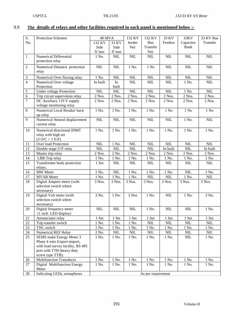
CSPTCL TR-21/05 132/33 KV S/S Betar
191 Volume-II
9.9 The details of relays and other facilities required in each panel is mentioned below :-
S.
No.
Protection Schemes 40 MVA 132 KV
feeder
bay
132 KV
Bus
Transfer
bay
33 KV
Feeders
33KV
Capacitor
Bank
33 KV Bus
Transfer 132 KV
Side
X’mer
33 KV
Side
X’mer
1 Numerical Differential
protection relay
1 No. NIL NIL NIL NIL NIL NIL
2 Numerical Distance protection
relay
NIL NIL 1 No. 1 No NIL NIL NIL
3 Numerical Over fluxing relay 1 No. NIL NIL NIL NIL NIL NIL
4 Numerical Over voltage
Protection
In built In
built
NIL NIL NIL 1 No. NIL
5 Under voltage Protection NIL NIL NIL NIL NIL 1 No. NIL
6 Trip circuit supervision relay 2 Nos. 2 Nos. 2 Nos. 2 Nos. 2 Nos. 2 Nos. 2 Nos.
7 DC Auxiliary 110 V supply
voltage monitoring relay
2 Nos. 2 Nos. 2 Nos. 2 Nos. 2 Nos. 2 Nos. 2 Nos.
8 Numerical Local Breaker back
up relay
1 No. 1 No. 1 No. 1 No. 1 No 1 No 1 No
9 Numerical Neutral displacement
current relay
NIL NIL NIL NIL NIL 1 No. NIL
10 Numerical directional IDMT
relay with high set
(3 O/C + 1 E/F)
1 No. 1 No. 1 No. 1 No. 1 No. 1 No. 1 No.
11 Over load Protection NIL 1 No. NIL NIL NIL NIL NIL
12 Double stage U/F relay NIL NIL NIL NIL In built NIL In built
13 Master trip relay 2 Nos. 2 No. 2 Nos. 2 Nos. 2 Nos. 2 Nos. 2 Nos.
14 LBB Trip relay 1 No. 1 No. 1 No. 1 No. 1 No. 1 No. 1 No.
15 Transformer body protection
relays.
1 Set NIL NIL NIL NIL NIL NIL
16 MW Meter 1 No. NIL 1 No. 1 No. 1 No. NIL 1 No.
17 MVAR Meter 1 No. 1 No. 1 No. NIL NIL 1 No. NIL
18 Digital Ampere meter (with
selection switch where
necessary)
3 Nos. 3 Nos. 3 Nos. 3 Nos. 3 Nos. 3 Nos. 3 Nos.
19 Digital Volt meter (with
selection switch where
necessary)
3 No. 1 No. 3 Nos 1 No. NIL 1 No. 3 No.
20 Digital frequency meter
(1 inch LED display)
NIL NIL NIL 1 No. NIL NIL 1 No.
21 Annunciator relay 1 Set 1 Set 1 Set 1 Set 1 Set 1 Set 1 Set
22 Trip transfer switch 1 No. 1 No. 1 No. NIL NIL NIL NIL
23 TNC switch 1 No. 1 No. 1 No. 1 No. 1 No. 1 No. 1 No.
24 Numerical REF Relay 2 No. NIL NIL NIL NIL NIL NIL
25 SEMS make Energy Meter 3
Phase 4 wire Export-import,
with load survey facility, RS 485
port with TTB (heavy duty
screw type TTB).
1 No. 1 No. 1 No. 1 No. 1 No. NIL 1 No.
26 Multifunction Transducer 1 No. 1 No. 1 No. 1 No. 1 No. 1 No. 1 No.
27 Digital Multifunction Energy
Meter
1 No. 1 No. 1 No. 1 No. 1 No. 1 No. 1 No.
28 Indicating LEDs, semaphores As per requirement
CSPTCL TR-21/05 132/33 KV S/S Betar
192 Volume-II
10.0 TECHNICAL SPECIFICATION FOR (110 VOLT AND 48 VOLT) BATTERY SETS
10.1 SCOPE:-
This specification covers manufacture, testing at works and delivery FOR destination
of 110 V/300 AH and 48 V/300 AH Battery sets at discharge voltage 1.85V/Cell.
10.2 STANDARD.
Batteries shall conform to the latest edition and amendments available of IS 1651.
10.3 PRINCIPAL PARAMETERS.
The DC Batteries shall be Lead-Acid type and shall be Normal Discharge type. These
shall be suitable for a long life under continuous float operations and occasional
discharges. The 110 V DC system is unearth and 48 V DC system is + ve earth
system.
Lead Acid Battery shall be of conventional type cells shall be supplied in transparent
Styrene Acrylo Nitrile (SAN) polymer container boxes (with Lid of opaque SAN) and
ample space must be provided below the plate for accumulation of deposit. Spray
arrestors shall be provided to prevent loss of acid by spraying during charge. The
imported design of tubular type batteries may be offered. The design of battery shall
be as per field proven practices. Partial plating of cells is not permitted. Paralleling of
cells externally for enhancement of capacity is not permitted. Protective transparent
front covers with each module shall be provided to prevent accidental contact with live
module/electrical connections. The intercell connector shall be of insulated type.
10.3.2 Lead acid battery, comprising of closed type cells shall be complete with tubular
positive plate assemblies, glass boxes or hard rubber boxes, lids providing micro
porous and plastic separators, poly-styrene dwells and buffers, inter cell connectors
and plastic encapsulated bolt-on terminal and units. The battery shall be offered
complete with:-
i. Inter row connectors, acid jars and packing case.
ii. Stands.
iii. Stand insulator, and,
iv. Cable sockets for end and tapping connections.
10.3.3 Containers
The container material shall be supplied in transparent Styrene Acrylo Nitrile (SAN) polymer container boxes (with Lid of opaque SAN) and shall have chemical and electro-chemical compatibility and shall be acid resistant. The material shall meet all the requirements of batteries and be consistent with the life of battery. The container shall be fire retardant and shall have an Oxygen Index of at least 28 %. The porosity of the container shall be such as not to allow any gases to escape except through air vent with a vapour trap. The tensile strength of the material of the container shall be such as to handle the internal cell pressure of the cells in the worst working condition. Cell shall not show any deformity or bulge on the sides under all working conditions. The container shall be capable of withstanding the rigours of transport, storage and handling.
10.3.4 Cell Covers
The cell covers shall be made of suitable material compatible with the container material and permanently fixed with the container. It shall be capable to withstand internal pressure without bulging or cracking. It shall also be fire retardant. Fixing of Pressure Regulation Valve & terminal posts in the cover shall be such that the seepage of electrolyte, gas escapes and entry of electro-static spark are prevented.
10.3.5. Separators
The design of separators shall ensure that there is no misalignment during normal operation and handling.
CSPTCL TR-21/05 132/33 KV S/S Betar
193 Volume-II
10.3.6. Terminal Posts Both the +ve and –ve terminals of the cells shall be capable of proper termination and shall ensure its consistency with the life of the battery. The surface of the terminal post extending above the cell cover including bolt hole shall be coated with an acid resistant and corrosion retarding material. Terminal posts or any other metal part which is in contact with the electrolyte shall be made of the same alloy as that of the plates or of a proven material that does not have any harmful effect on cell performance. Both + ve and –ve posts shall be clearly and unambiguously identifiable.
10.3.7 Connectors, Nuts & Bolts, Heat Shrinkable Sleeves
Where it is not possible to bolt the cell terminals directly to assemble a battery, separate non-corroding lead or copper connectors of suitable size shall be provided to enable connection of the cells. The inter cell connectors shall be of insulated type. Copper connections shall be suitably lead coated to withstand corrosion due to sulphuric acid at a very high rate of charge or discharge. Nuts and bolts for connecting the cells shall be made of copper. Copper or brass nuts and bolts shall be effectively lead coated to prevent corrosion. All inter cell connectors shall be protected with heat shrinkable silicon sleeves for reducing the environmental impact including a corrosive environment.
10.3.8 Flame Arrestors
Each cell shall be equipped with a Flame Arrestor to defuse the Hydrogen gas escaped during charge and discharge. Material of the flame arrestor shall not affect the performance of the cell.
10.3.9 Battery Bank Stand
All batteries shall be mounted in a suitable single tier wooden stand at a convenient height for maintenance. The frame shall be properly painted with the acid resistant paint. The suitable insulation shall be provided between stand/frame and floor to avoid the grounding of the frame/stand.
10.3.10 Capacity Requirements
When the battery is discharged at 10 hour rate, it shall deliver 80% of C (rated capacity,
corrected at 27º Celsius) before any of the cells in the battery bank reaches 1.85V/cell.
The battery shall be capable of being recharged from the fully exhausted condition
(1.75V/cell) within 10 hrs up to 90% state of charge. All the cells in a battery shall be
designed for continuous float operation at the specified float voltage throughout the life. Loss in capacity during storage at an average ambient temperature of 35° Celcius for a period of 6 months shall not be more than 60% and the cell/battery shall achieve 85% of its rated capacity within 3 charge/discharge cycles and full rated capacity within 5 cycles, after the storage period of 6 months. Voltage of each cell in the battery set shall be within 0.05V of the average voltage throughout the storage period. Ampere hour efficiency shall be better than 90% and watt hour efficiency shall be better than 80%.
10.3.11 Expected Battery Life
The battery shall be capable of giving 1200 or more charge/discharge cycles at 80% Depth of discharge (DOD) at an average temperature of 27° Celsius. DOD (Depth of Discharge) is defined as the ratio of the quantity of electricity (in Ampere-hour) removed from a cell or battery on discharge to its rated capacity. The battery sets shall have a minimum expected life of 20 years at float operation.
10.3.12 The cells shall be accommodated in double tier stands constructed of selected timber
and painted with 3 coats of acid proof paint. Necessary paint for this purpose shall be
supplied no metal fastening shall be used. The stands shall be supported on insulators
to obtain necessary insulation from earth and there shall be insulators between each
cell and stand. The price of stand shall be included in the cost of the battery. The
following accessories shall be supplied along with batteries and prices for the same
shall be quoted separately:
CSPTCL TR-21/05 132/33 KV S/S Betar
194 Volume-II
1 One Battery Log Book
2 Two Copies Of Printed Instruction Sheet
3 1 No. Cell Testing digital Voltmeter (3-0-3) Volts complete with Leads
4 1 No. Rubber Syringe
5 1 No. of Syringe type Hydro Meter suitable for Specific Gravity Reading.
6 2 No. Thermometer (0- 100 Deg C) With Specific Gravity Scale
7 1 Set of Bridging Connector
8 Anti Sulphuric acid Enamel Paint
a) Red Colour in Required Quantity
b) Black Colour 2 Litres
9 Battery Stand suitable for accommodating the Cells coated with 3 Coats of
anti acid paint.
10 Hard Rubber Cells Insulators in required quantity with 4 No.extra (Spare)
11 P.V.C. Sheet Stand Insulators in required quantity with 4 No.extra (Spare)
12 1 Set of Cell No. Plates With Fixing Pins.
13 1 Pair of Spanners
14 1 No. Acid Resisting Funnel
15 1 No. Acid Resisting Jug Of 2 Litres Capacity
16 Requisite Quantity Of Electrolyte With 10% Extra In Non-Returnable
Containers
17 1 Set Of Inter Connectors.
18 Torque wrench – 2 Nos
19 One set of spanners
10.3.13 One set of batteries shall comprise of 55 cells with capacity not less than 300AH
for 110 volts, 10 hour rate of discharge to 1.85 volts per cell.
One set of batteries shall comprise of 24 cells with capacity not less than for 48 volt
batteries at 10 hour rate of discharge to 1.85 volts per cell.
10.3.14 Type Test of Battery
Contractor shall submit type test reports of following tests as per IEC 60896-21 & IEC 60896-22, 2004. The type test reports shall be submitted . The type tests should not be older than seven years from the last date of submission of bid. Tests shall be conducted in accordance with IEC 60896-2 1 & IEC 60896-22, 2004
10.3.15 Installation and commissioning
10.3.15.1 Manufacturer of Battery shall supervise installation and commissioning and
perform commissioning tests as recommended in O&M manual/or relevant
standards. All necessary instruments, material, tools and tackles required for
installation, testing at site and commissioning are to be arranged by Battery
manufacturer/ Contractor.
10.3.15.2. Contractor shall submit following documents for approval:
a) Data sheet
b) GA of cell and layout drawing
c) Discharge Data for 10 Hour, 8 Hour, 3 Hour, 2 Hour, 1 Hour, 15 Minutes and 1
Minute indicating capacity factors for end cell voltage of 1.75 V & 1.85 V
d) Temperature correction factors
e) Installation and commissioning Instructions
f) O & M Manual
10.4 TESTS:
The batteries shall be tested after manufacture as per the requirements of I.S.
1651:1991 (with latest amendments if any).
The Batteries used during inspection shall be discarded & not supplied to CSPTCL.
CSPTCL TR-21/05 132/33 KV S/S Betar
195 Volume-II
11.0 TECHNICAL SPECIFICATIONS FOR (110 VOLTS AND 48 VOLTS)
BATTERY CHARGER.
11.1 SCOPE:-
This specification covers important details regarding design, manufacture and testing
at manufacturer’s works for 110 volts and 48 volts battery chargers.
11.2 STANDARDS.
Unless otherwise specified, the equipment shall conform to the latest applicable
Indian, IEC, British or USA standards, and in particular to the following standards:-
1. IS:1651 Specifications For Stationery Cells And Batteries, Lead Acid
Type With Tubular Positive Plates
2. IS:3895 Specification For Rectifier Equipments
3. IS:9224 Specifications For HRC Fuses
4. IS:1248 Indication Instruments
5. IS:2147 Degree Of Protection For Cubicles
6. IS:375 Specification For Wiring
7. IS:4540 Mono Crystalline Semi Conductor Rectifier Assemblies And
Equipment
8. IS:6619 Safety Code For Semi Conductor Rectifiers
9. IS:2026 Transformers
10. IS:2959 AC Contractors For Voltage Not Exceeding 1000 V
11. IS:4237 General Requirements For Switch Gear In Control Gear For
Voltage < 1000 Volts
12. IS:4064 Air Break Switches And Fuse Units
13. IS:6005 Code Of Practice For Phosphating
14. IS:5568 Colour For Ready Mix Paints
15. IS:2489,
5921
Printed Circuit Boards
16. IS:5578 Guide For Making Insulated Conductors
11.3 CONSTRUCTIONAL FEATURES:
One single sheet steel cabinet shall accommodate both boost & float chargers. The
dimensions of battery charger shall be as under
a) Height- 1600 mm including base channel
b) Depth- 800 mm
c) Width- as per requirement.
d) Color – Opaline Green No 275 of BIS 271-C:1948
11.4 PARAMETERS
11.4.1 Basic requirement of 48 volt and 110 volt 300 AH battery charger is that under all
conditions of failure of any component of trickle charger, boost charger, A.C.
supply, faults during the short circuit etc. over voltage conditions, under voltage
conditions etc. load and battery should always remain paralleled. The interruption of
CSPTCL TR-21/05 132/33 KV S/S Betar
196 Volume-II
D.C. supply to load under any circumstances cannot be afforded and therefore this
requirement should be kept in view carefully.
The DC system for 110 V DC is unearthed and for 48 V DC is +ve earthed. The
Battery Chargers as well as their automatic regulators shall be of static type and
shall be compatible with offered Lead Acid batteries. All battery chargers shall be
capable of continuous operation at the respective rated load in float charging
mode, i.e. Float charging the associated Lead-Acid Batteries at 2.2 Volts per cell
while supplying the DC load. The chargers shall also be capable of Boost charging the
associated DC Battery at up to 2.7 volts per cell at the desired rate.
11.4.2 The battery charger should consist of two independent float and one boost charger.
Out of two floats one shall be in standby mode. Each charger should be built with
power SCR/ diodes in full wave fully controlled bridge configuration. The FC/BC
charger should meet the requirement of load. All battery chargers shall have a
constant voltage characteristics throughout the range (from zero to full load) in
the floating mode of the voltage so as to keep the battery fully charged but without
harmful overcharge.
Float charger should be capable to supply trickle charging current to battery and the
station load. During Boost Charging, the Battery Charger shall operate on
constant current mode (when automatic regulator is in service). It shall be possible
to adjust the Boost charging current continuously over a range of 50 to 100% of
the rated output current for Boost charging mode. During boost charging, the battery
tap shall be connected to the load through blocking diodes.
All chargers shall have load limiters having drooping characteristic, which shall
cause, when the voltage control is in automatic mode, a gradual lowering of the
output voltage when the DC load current exceeds the Load limiter setting of the
Charger. The Load-limiter characteristics shall be such that any sustained
overload or short circuit in DC System shall not damage the Charger, nor shall it
cause blowing of any of the Charger fuses. The Charger shall not trip on overload or
external short circuit.
11.4.3 The boost charger unit shall work independently and will be utilised for boost
charging the battery.
11.4.4 The output voltage of boost charger should be designed on the basis of maximum cell
voltage of 2.7 per cell.
11.4.5 The battery charger should fulfil the following salient features:
(a) Float & boost change over arrangement.
(b) Built in digitally controlled automatic regulation circuit.
(c) Built in auto phase sequence detector.
(d) Current limiting device.
(e) Smoothing filter circuit to limit AC ripple.
(f) Charger over load protection.
(g) LED indications for mains on, DC on, battery on charge, battery
charged, rectifier trip, input over voltage and input under voltage.
11.5 VOLTAGE REGULATION
11.5.1 Battery charger shall be provided with a facility for both automatic and manual control
out put voltage and current. A selector switch shall be provided for selecting the mode
of out put voltage / current control, whether automatic or manual. When on automatic
control mode during float charging, the charger out put voltage shall remain within
CSPTCL TR-21/05 132/33 KV S/S Betar
197 Volume-II
±1% of the set value for AC input voltage variation of ±10%, frequency variation of
±5%, a combined voltage and frequency variation of ± 10%, and a DC load variation
from zero to full load.
11.6 FAULT LEVEL
The fault level of the auxiliary AC supply at the terminals of the charge shall be 10
KA. All accessories shall be selected and equipment shall be designed accordingly.
11.7 INPUT SUPPLY
Input supply where the charger shall be 415 V with a variation from 360V to 450V.
11.8 CONSTRUCTION
11.8.1 Charger cabinets shall sheet metal enclosed and shall be dust, weather and vermin
proof. Sheet steel used shall be at least 2.0 m.m. thick and properly braced to prevent
wobbling wherever necessary. The cubicle shall be of iron angle frame, i.e. suitable
sturdy frame shall be prepared with strong base channels, to bear the load of heavy
accessories.
11.8.2 Charger cabinet shall be free standing, floor mounting type and shall be provided with
a hinged door in the back with suitable pad locking arrangements.
11.8.3 All doors, removable covers and plates shall have gasket all around with neoprene
gaskets. Louvers where provided shall have screens and filters. The screens shall have
fine wire mesh made of G.I. wire.
11.9 WIRING.
11.9.1 For the wiring purpose standard 1100 volt stranded copper conductor of 2.5 mm2 area
with minimum seven strands should only be used.
11.9.2 The terminations shall be crimped tag solder-less type with covering sleeves only.
Colour coded wire should be used to facilitate easy tracing of wires as under:-
a) AC circuit
1. Red, yellow and blue for RYB phases
2. Green for earthing
3. Black for neutral
b) DC Circuit.
1. Red for positive.
2. Black for negative.
c) Control Wiring
1. Grey for annunciation & other control circuits.
11.9.3 Electrical indicating instruments shall be mounted flush on the front panel.
11.9.4 Since a number of wires run from one point to another, it is desired that the support
arrangement should be adequate and neat. The conventional method of bunching of
wires should not be adopted since the same creates problems in case any wire is to be
removed. The blank plastic channels should be provided by the sides of the panels to
accommodate the incoming channels from switch-yard.
11.9.5 The input and output terminals should be neatly brought out on the backside of the
charger. The terminals to be provided are 4 Nos. for AC input i.e. RYB and two nos
from load i.e. positive (+), and Negative (-), plus two numbers from battery
connections i.e. positive, negative and all tap cell connections.
CSPTCL TR-21/05 132/33 KV S/S Betar
198 Volume-II
11.10 PRE-TREATMENT & PAINTING PROCESS
The sheet steel fabricated members shall be subjected to pre treatment process before
painting. The process of pre treatment and final painting shall be in conformity with
latest engineering practices.
11.11 CAPACITY & RATING FOR CHARGERS.
For battery chargers of different ratings the ultimate capacity shall be designed based
on the following requirements.
Requirements 48 V
300 AH
110 V
300 AH
a. FLOAT CHARGER UNIT
1. Load (Amperes)
2. Trickle current (mA )
30
300
25
300
b. BOOST CHARGER UNIT
1. Load (Amperes)
30
25
2. Boost current (Amps)
3. Boost charger capacity
30
60
30
55
11.12 COMMON FEATURES AND GENERAL REQUIREMENTS:- The Battery
Charger shall have two independent units one for Boost charging and the other for
the float charger. At a time only one unit shall be in service through a selector switch.
11.12.1 RATING OF MAIN X-MER FOR FLOAT & BOOST CHARGER:-The main
step down transformer rating shall be decided considering the rated DC out put,
efficiency and a factor of safety of 1.2. The current density in the copper windings
shall be 1.5A/mm2. The X’mer shall be double wound type. The magnetizing current
shall be less than 3% of the rated current at 415V AC. Thus the Xmer shall function
at low value of flux density. The temperature rise of the transformer when supplying
full load DC out put shall not exceed 40 Deg. C above an ambient temperature of 45
Deg. C. These features shall be checked at the time of inspection.
11.12.2 MEASUREMENT OF BATTERY CURRENT:- Normal Trickle current is in the
range of 300-600 mA. The charge/discharge Ammeter should have a range of –45 A
to + 60 Amp.
Further, it is desired that a suitable arrangement shall be made to display the battery
trickle current in the mA range during normal float charger operation. This mA
meter will remain shunted through a selector switch so that the above meter will be
by-passed during boost charging condition. A Red Colour light emitting diode
(LED) shall glow immediately as soon as the battery goes in discharge mode.
This will be provided on the front panel.
11.12.3 MEASUREMENT OF DC VOLTAGE:- Separate DC volt meter shall be
provided for boost voltage, float voltage & load voltage.
11.12.4 PROTECTION & SPECIAL FEATURES:-The charger shall incorporate the
following features:-
i) Over voltage alarm:- If the voltage exceeds +10% across load terminal charger
shall give an over voltage alarm.
ii) Under voltage alarm:-If the load voltage falls to 90% the charger shall give an
under voltage alarm.
CSPTCL TR-21/05 132/33 KV S/S Betar
199 Volume-II
iii) Earth leakage for 110V battery charger:-There shall be an earth leakage
ammeter in addition to an audible alarm for the earth leakage of DC circuit.
iv) Single phasing:-In case of single phasing of input AC supply to float / boost
charger, the charger shall give an alarm. The single phasing detector shall work
on current principle and not on voltage.
v) Other protections:-The charger shall be provided with over load alarm,
rectifier fuse failure alarm for float and boost charger and also fuse failure alarm
for filter capacitors.
The annunciation circuit shall be simple and robust design and shall provide a
disconnecting fuse link at the front panel in series with the bell so that the
ringing of the bell can be stopped by the operator.
11.12.5 AC Circuit:-The AC Circuit shall consist of input main switch, supply
indication lamps in put ammeter and volt meter with selector switches, control
MCBs, contactors for float and boost chargers, single phasing preventer etc.
11.12.6 Soft start feature :-The Thyristor control unit to be provided for Trickle
charger unit should incorporate soft start feature. The voltage should not
shoot up when the supply of the charger is switched ON and soft start feature
shall be incorporated.
11.12.7 Output Ammeter:-The float charger shall be provided with an output DC
ammeter of range depending on a float out put current.
11.12.8 Limits of Ripple Content:-The ripple content shall be 1% or less of the out put
voltage for float charger and in case of boost charger the ripple shall be less than
2%.
11.12.9 Control of load voltage:-All the 24/55 Cells will remain across the load
terminals while boost charging. Hence the control of load voltage at the time of
boost charging shall be done by means of dropping diodes. The number of
dropping diodes in the circuit shall be selectable by means of a rotary switch on
a front panel. In one position of the switch all the diodes shall be by passed.
Further all the dropping diodes shall also be by passed by means of an AC
contactor in case of AC supply failure or boost charger off. Thus the dropping
diodes shall come into circuit only in case of boost charger in service.
11.12.10 Make & Rating of the components:-It is necessary that the contractor adheres
to the following makes & ratings for the components to be used in the battery
charger:-
(i) 3 Phase Auto X’mer for boost charger :- In case of use of 3 phase
Auto X’mer for boost charger , this transformer shall be of full rating i.e.
0 to 415 Volts. The current rating of the Auto Transformer shall be
selected considering the DC out put and a factor of safety of 1.5.
(ii) Rectifiers for Float & Boost Chargers:-These shall be of Hirect,
USHA, RIR make only.
(iii) Ammeter & Volt Meters:-These shall be of AE, MECO, Rishabh
make only.
(iv) Selector Switches:-These shall be KAYCEE/ Switron make only. No
switches below the rating of 16 Amp shall be provided except for the
Volt Meter Selector switch for the AC voltage selection.
CSPTCL TR-21/05 132/33 KV S/S Betar
200 Volume-II
(v) Diodes:-
a) All dropper diodes shall be of not less than 70 Amp rating.
b) All diodes / SCR for 110V battery charger shall be 1000V and
current rating shall be selected with a factor of safety of 2.5.
c) All diodes/ SCR for 48 V battery charger shall be 600 V and
current rating shall be selected with a factor of safety of 2.5.
(vi) HRC Fuses:-The HRC fuses shall be of AREVA / Standard / S&S
make only.
11.12.11 AC Contactors:-The AC Contactors to be used in a charger shall be of ABB /
L&T/ Siemens only. The AC current rating of the contactors shall be selected
with a factor of safety of 1.5.
i) MCBs:- Havells or Siemens.
ii) Filter Capacitors:-The voltage rating of filter capacitors shall not be
less than 450 V for 48V and also for 110V chargers. The make shall be
Alcon / RESCON/ SFPL. The capacity shall be selected to achieve the
ripple content. There shall be at least two capacitors for the construction
of pie circuits.
iii) Annunciator Relay:- Minilec, Alan, JVS.
11.12.13 The charger should have a short circuit protection. Charger shall have load
limiters having drooping characteristic, which shall cause gradual lowering of
output voltage when the DC load current exceeds the load limiters setting of the
charger in automatic voltage control mode. The load limiter characteristic shall
be such that any sustained over load or short circuit in DC system shall not
damage the charger or shall cause blowing of any other charger fuses.
11.13 TESTS
11.13.1. Battery chargers shall conform to all type tests as per relevant Indian
Standard. The type tests should not be older than seven years from the last date
of submission of bid.
Performance test on the Chargers as per Specification shall also be carried out on
each Charger as per specification. Rectifier transformer shall conform to all type
tests specified in IS : 4540 and short circuit test as per IS:2026. Following type
tests shall be carried out for compliance of specification requirements:
i) Voltage regulation test
ii) Load limiter characteristics test
iii) Efficiency tests
iv) High voltage tests
v) Temperature rise test
vi) Short circuit test at no load and full load at rated voltage for sustained
short-circuit.
vii) Degree of protection test
viii) Measurement of ripple by oscilloscope.
ix) Temperature compensation feature demonstration
11.13.2 The Contractor may be required to demonstrate to CSPTCL that the Chargers
conform to the specification particularly regarding continuous rating, ripple free
CSPTCL TR-21/05 132/33 KV S/S Betar
201 Volume-II
output, voltage regulation and load limiting characteristic, before despatch as
well as after installation at site. At site the following tests shall be carried out :
i) Insulation resistance test
ii) Checking of proper annunciation system operation.
11.13.3 If a Charger fails to meet the specified requirements, the Contractor shall
replace the same with appropriate Charger without affecting the commissioning
schedule of the Sub-station, and without any extra cost to CSPTCL.
11.13.4. The Contractor shall present for inspection, the type and routine test certificates for
the following components whenever required by CSPTCL.
(i) Switches.
(ii) Relays/ MCCBs
(iii) Instruments.
(iv) DC fuses.
(v) SCR.
(vi) Diodes.
(vii) Condensers.
(viii) Potentiometers.
(ix) Semiconductor
(x) Annunciator.
(xi) Control wiring
(xii) Push buttons and contactors.
Makes of above equipment shall be subject to CSPTCL’s approval.
CSPTCL TR-21/05 132/33 KV S/S Betar
202 Volume-II
12.0 COMMUNICATION SYSTEM :-
12.1 REMOTE TERMINAL UNIT
12.1.1. SCOPE :
It comprises the supply, installation & commissioning of Remote Terminal Unit for
SCADA System of CSPTCL.
12.1.2 STANDARDS:
The RTUs under this tender specification shall have IEC-870-5-101 standard protocol
supported by the Front-end-server. The RTU shall additionally support IEC 61850, IEC
870-5-103, MODBUS & DNP 3.0 protocol and all relevant IEC standards.
12.1.3 TECHNICAL SPECIFICATION:-
This specification covers detailed Design, Engineering, Testing, Supply and
Commissioning of Remote Terminal Units, Interface Cabinets, Multi-Function
Transducers and other associated equipments. Such as suitable test software &
accessories for telemetry of real time electrical data from various EHV Sub-stations and
Power Stations located in Chhattisgarh.
The Load Dispatching functions at SLDC Bhilai is supplemented with the real time
SCADA system, installed & commissioned under ULDC project, using Remote
Terminal Units, which use IEC 870-5-101 protocol.
The RTUs proposed to be procured under this tender specification shall have IEC-870-
5-101 standard protocol supported by the Front-end-server along with support of
IEC61850, IEC 870-5-103 & MODBUS protocol for data acquisition from the field.
12.1.4 FUNCTIONAL REQUIREMENT OF RTUs : The overall functions to be performed by the RTUs are as below :-
Each function are presented in detail for initial and future requirements of the RTUs.
The contractor shall provide all functional capabilities described herein even if a
function is not initially implemented.
As a minimum, the RTUs shall be capable of performing the following functions:
i) Collecting, processing and transmitting status changes, accumulated values and
analog values.
ii) Receiving and processing digital and analog commands from the master station.
iii) Accepting polling messages from the master station.
iv) Supporting data transmission rates from 300 to 19200 bits per second as per IEC
870-5-101 specifications.
v) Shall have four communication ports.
vi) The RTU shall additionally support IEC61850, IEC 870-5-103, MODBUS
protocol also for acquiring data from field devices like digital relays & meters.
vii) All ports of the RTU shall be capable to communicate with different master,
operating on above mentioned different protocol, at a time without affecting the
performance of the RTU. The RTU shall also be capable of acquiring data from
digital relays & energy meters using IEC61850, IEC 870-5-103 & MODBUS
protocol respectively.
viii) At the time of communication failure, the performance of the RTU should not be
affected due to buffer overflow or any other reason and the RTU should start
CSPTCL TR-21/05 132/33 KV S/S Betar
203 Volume-II
communicating to its master automatically as & when the communication
restores, without re-setting the RTU unit.
ix) Analog and digital input points (including points reported by exception) shall be
assignable to scan groups.
x) The RTU communication protocol shall report status changes by exception
(spontaneous change of status indication). The communication protocol shall
also support an update demand scan of all status data by master station
regardless of the lack of any changed data. The update scan will report the status
of all RTU data assigned to the scan group.
xi) Each RTU communication message shall include an error code, the use of which
shall result in a very low probability of an erroneous message being accepted as
valid. The error code shall be determined and appended to the message for all
messages transmitted by the RTU and verified by the RTU for all message
addressed and received by the RTU. Cyclic error detection codes such as CRC
are required.
xii) Although the control functions are not being implemented at present, the RTU
should be capable of supporting the same. By putting additional hardware
modules only the control functions shall be possible, necessary software shall be
an integral part of the RTU SCADA software.
12.1.5 COMMUNICATION INTERFACE: Each RTU shall be equipped with a minimum of four (4) communication ports. The
communication ports and their usage are as follows:
(a) Port 1 and 2 shall be for normal communication to the LD Control Centre.
(b) Port 3 shall be for output to a local printer. The outputs shall be:
(i) Report of all S/S status indication and all telemetry values with a time
stamp.
(ii) Upon user request, print the RTU sequence of event with time stamps.
(c) Port 4 shall be a maintenance port.
RTU should have provision for two more ports for communication with the Field
devices like Digital Relays & Energy Meter over IEC61850,IEC 870-5-103 and
MODBUS protocol respectively, if required. The ports shall support the EIA RS232C
or RS485 (CCITT V.24/V.28) asynchronous / synchronous interface capable of
operating between 50 and 9600 bps. All communication ports shall use CCITT V.24
and V.28 signal specifications to interface to the modems, local logger and local support
terminal. All ports shall be accessible to employer to attach the interface equipment and
to provide access for the maintenance, test and monitoring equipment. The RTU shall
be equipped with of 100 Mbps, 10/100 Base T Ethernet port.
12.1.6 MASTER STATION COMMUNICATION INTERFACE: The RTU shall be connected to master station over either power line carrier
communication (PLCC) channel or OFC or VSAT communication using RS232C or
other suitable port. Therefore, RTU should be compatible to be connected to these
communication mediums. However, the RTU shall also have provision to make
compatible for other modes of communication media such as, UHF / Microwave etc.
12.1.7 MODEM: The modem shall be supplied for communication with the front-end server / master
station. A modem combining all of the characteristics defined below is required such
that changing the communication data rate shall only require reconfiguration of the
CSPTCL TR-21/05 132/33 KV S/S Betar
204 Volume-II
RTU modem. The modems shall not require manual equalization and shall include self-
test features such as manual mark/space keying, analog loop-back. The modems shall
provide for convenient adjustment of output level and receive sensitivity. The
configuration of tones and speed shall be programmable and maintained in non-volatile
memory in the modem.
The modems shall meet the following requirements as a minimum:
i) Use CCITT standards including V.24, V.28, V.52 & V.54
ii) Communicate at data rates from 50 to 1200 bits per second, factory set at 200
Bauds.
iii) Use CCITT V.21, V.23, R.35, R.37, R.38a and R.38b standard tones for the
selected data rate.
iv) Use frequency shift keying (FSK) modulation.
v) Use both 2 wire and 4 wire communication lines.
vi) Receive level adjustable from 0 to -40 dBm @ 600 Ohms.
vii) Transmit level adjustable from 0 to -30 dBm @ 600 Ohms.
viii) Have a minimum sensitivity of -48dBm.
ix) LED’s shall be provided on modem for indicating Tx/Rx activity (ON/OFF) and
carrier fail alarm.
x) The modem shall be fed through the DC auxiliary supply available in the RTU
itself.
xi) Supporting data transmission rate shall be minimum 300-1200 bits per second for
PLCC modems. For RTUs, the data transmission rate shall be 300-19200 bits per
second.
12.1.8 MASTER STATION COMMUNICATION PROTOCOL : A communication protocol for communicating with the front-end server conforming to
IEC-870-5-101 communication standard shall be provided. The communication
protocol shall be non-proprietary. Complete implementation details of IEC-870-5-101
protocol shall be provided and contractor shall be responsible for tuning / configuring,
in the front-end server/ master station, to establish communication with existing/ new
SCADA computer system.
12.1.9 COMMUNICATION CHANNEL CONTROL: The RTU shall perform as a slave on the communication channel to CSPTCL’s SCADA
system. All communication shall be initiated by the SCADA system front-end server/
master station. The RTU must notify the master station on an unusual condition in the
RTU (such as a power fail/restoration or RTU malfunction) or must initiate the transfer
of changed data. The notification shall be accomplished within the framework of the
periodic data acquisition exchanges.
12.1.10 (a) ANALOG INPUT: The RTU shall accommodate analog current inputs, which are isolated, uni-polar, or
bipolar, 2 wire ungrounded differential signal with full resolutions as follows:-
i) +4 to 20 mA
ii) 0 to 10 mA
iii) -10 to 10 mA
iv) 0 to 20 mA
(b) ANALOG OUTPUT:
RTU shall support analog output of 4-20 mA
CSPTCL TR-21/05 132/33 KV S/S Betar
205 Volume-II
12.1.11 (a) DIGITAL STATUS INPUTS:
The digital status input interface shall be capable of accepting isolated, wet or dry
contract status input. The contractor shall apply necessary sensing voltage, current
limiting, and optical isolation and debounce filtering independently for each digital
status input. The sensing voltage source shall be isolated from that of the RTUs logic
power such that any noise or short circuit across the sensing supply’s output terminals
would not disrupt the RTU operation other than the shorted digital status input.
The following types of digital inputs shall be supported:
a) Status inputs
b) SOE Inputs
c) BCD inputs
d) Binary Word inputs
e) Pulse accumulator inputs
The following types of status inputs shall be supported:
a) Single Contact Digital Status input (SS)
b) Double Contract Digital Status input point (DS)
c) Three-state status
(b) DIGITAL STATUS OUTPUTS:
For command purpose
12.1.12 CLOCK: The internal RTU time base shall have a stability of 1 ppm that is 3.6 milli seconds per
hour or better. The RTU time will be set from time synchronization messages received
from a master station. The RTU shall synchronize its internal clock with the master
station system clock when the Time synchronization is available. It shall be possible to
display the RTU time on a local digital clock.
12.1.13 INTERFACE CABINETS:
The contractor shall provide interface cabinets between the RTU and the field
equipment. The interface cabinet shall house all transducers, interposing relays / opto-
isolator, and interface terminal blocks. The interface cabinet shall be mounted adjacent
to the RTU cabinet. All RTU signals shall be connected to the transducers, interposing
relays, and field signals in the interface cabinets. However, as per field conditions
transducers may be required to be installed in respective control panels and the out put
of transducers shall be brought to RTU panel.
The Contractor shall submit a cabinet design to the Employer for approval upon award of
contract. The cabinet shall be logically partitioned to have transducers in one section,
interposing relays / opto isolators in another section and interface connections to the RTU
in another section. The Contractor shall install all components and inter wire all
components prior to shipment. The entire cabinet shall be lockable. If multiple locks are
provided, the same key shall open any lock.
The interface cabinet shall house various pieces of equipment that are needed to
interface to the RTU. It shall be of modular type. The equipment shall be rail / wall
mounted type. The connections shall be on the front end for incoming and outgoing
circuits and on the rear end for internal connections different sub-assemblies of the
interface cabinet.
CSPTCL TR-21/05 132/33 KV S/S Betar
206 Volume-II
Pre-wired and standardized solutions for cabling shall be used. This shall enable a few
standardized designs for the interface cabinet to be developed, all of which shall have
identical provision for various types of plug –in Company / modules (e.g. position
indication, MW and MVAR measuring signals).
The interface components for each typical bay shall comprise typical modules and sub-
assemblies logically sorted by type of interface. For example, interface component
associated to a double bus bar type feeder shall consists of a module for the circuit
breaker position indication, a module for the associated bus bar isolators position
indication, a module associated to power measurements and a module associated to
position control. Each module or sub-assembly shall be provided with all testing
(switching, disconnecting and inserting) facilities, allowing easy maintenance.
Wire ways not more than 50% full for maximum RTU configuration, shall be provided
to route the necessary connectors from the CSPTCL’s choice of top or bottom access to
the I/O terminations. For wire way-sizing purposes, the RTU supplier shall assure that
each point uses a independent cable.
The terminal connectors should be stud type only both in the inter phase cabinet as well
as RTU. The RTU should have minimum 20% spare connectors.
The provided RTU must have 100% expandability. Each RTU shall be provided with 05
Nos of analog input card (each having capacity to accommodate 08 Nos of analog
input) and 06 Nos of digital input cards to accommodate 16 Nos single point
indications. The RTU shall be supplied with 02 Nos of CPU and 02 Nos. of modems
along with rack & power supply. The system provided should be along with basic
licence i.e it should communicate with 101, mod bus, 103 and other international
protocol. It will be the responsibility of the contractor to integrate RTU with our
SCADA. The MFT may be accommodated in respective feeder panel of RTU and
output signal of MFT shall be taken to RTU panel through 1.5 Sq mm multi strand
copper wire. The analog parameters of all 132 KV feeders & provision for 33 KV
feeders for future use, transformers, 132 KV&33KV bus voltages and frequency shall
be measured through MFT (Multi-Functional Transducer) and Breaker ON/OFF
indications shall be double point indication and isolator indication shall be single point
indication and will be coupled to RTU through OPTO isolator print (if digital input card
is provided with opto isolator then separate opto isolator print is not required). The
wiring of digital indication shall be done by 1.5 sq mm multi strand copper wire, Bus
PT voltage and frequency signal shall be terminated to RTU panel.
The RTU provided should be compatible to work with transducers as well as be able to
communicate with energy meters and numerical relays which are working on different
protocols (other than 101) . The supplied RTU’s should be with 2 Nos. modems along
with power supply unit and other accessories (1 NO. for RTU & 1 NO. for SCADA
end). Opto isolators Print shall be similar to C&R panels size. All digital indication
wiring shall be terminated in this panel and before routing to RTU.
Although the control functions are not being implemented at present, the RTU should
be capable of supporting the same. The supply of digital out put card is not in the scope.
However, RTU should have functionality to support control functions so that as per
requirement CSPTCL may obtain control functions by simply providing digital out put
cards without any further modification in RTU.
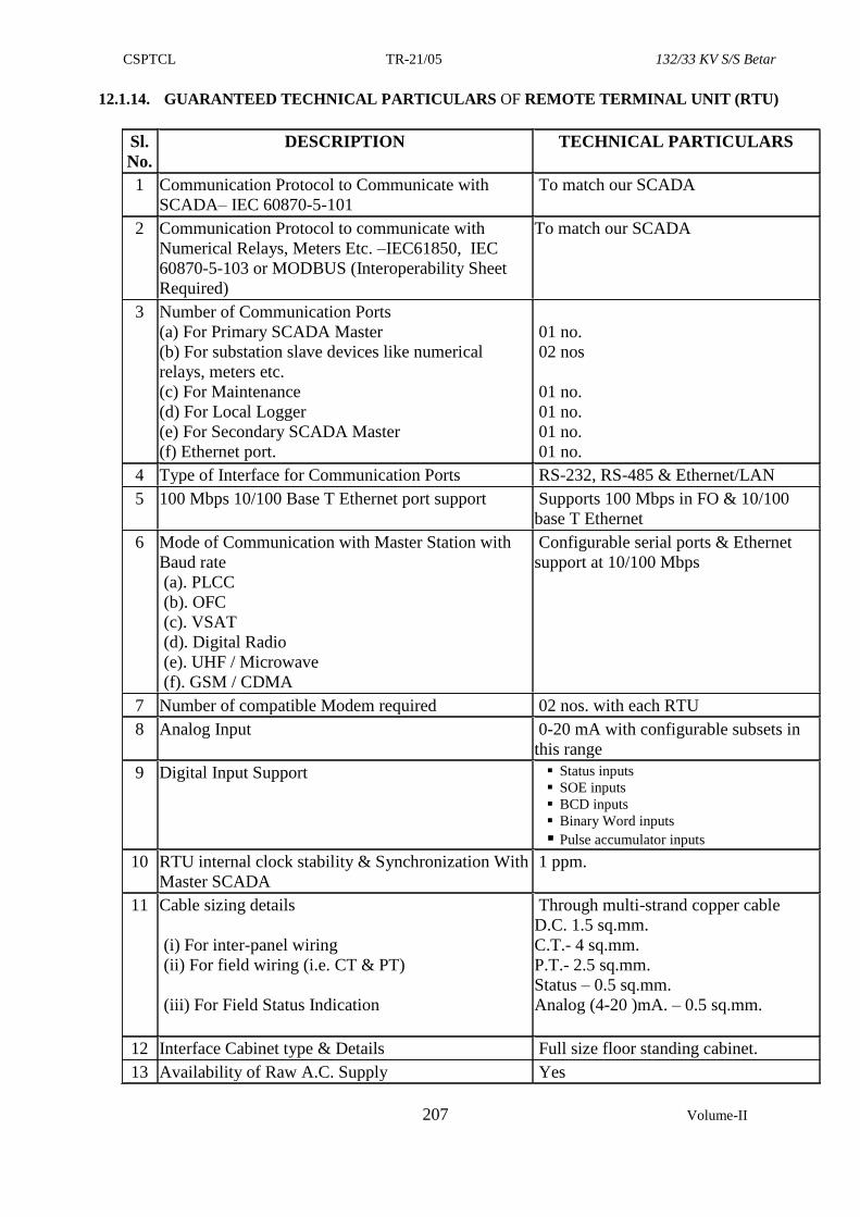
CSPTCL TR-21/05 132/33 KV S/S Betar
207 Volume-II
12.1.14. GUARANTEED TECHNICAL PARTICULARS OF REMOTE TERMINAL UNIT (RTU)
Sl.
No.
DESCRIPTION TECHNICAL PARTICULARS
1 Communication Protocol to Communicate with
SCADA– IEC 60870-5-101
To match our SCADA
2 Communication Protocol to communicate with
Numerical Relays, Meters Etc. –IEC61850, IEC
60870-5-103 or MODBUS (Interoperability Sheet
Required)
To match our SCADA
3 Number of Communication Ports
(a) For Primary SCADA Master
(b) For substation slave devices like numerical
relays, meters etc.
(c) For Maintenance
(d) For Local Logger
(e) For Secondary SCADA Master
(f) Ethernet port.
01 no.
02 nos
01 no.
01 no.
01 no.
01 no.
4 Type of Interface for Communication Ports RS-232, RS-485 & Ethernet/LAN
5 100 Mbps 10/100 Base T Ethernet port support Supports 100 Mbps in FO & 10/100
base T Ethernet
6 Mode of Communication with Master Station with
Baud rate
(a). PLCC
(b). OFC
(c). VSAT
(d). Digital Radio
(e). UHF / Microwave
(f). GSM / CDMA
Configurable serial ports & Ethernet
support at 10/100 Mbps
7 Number of compatible Modem required 02 nos. with each RTU
8 Analog Input 0-20 mA with configurable subsets in
this range
9 Digital Input Support Status inputs
SOE inputs
BCD inputs
Binary Word inputs
Pulse accumulator inputs
10 RTU internal clock stability & Synchronization With
Master SCADA
1 ppm.
11 Cable sizing details
(i) For inter-panel wiring
(ii) For field wiring (i.e. CT & PT)
(iii) For Field Status Indication
Through multi-strand copper cable
D.C. 1.5 sq.mm.
C.T.- 4 sq.mm.
P.T.- 2.5 sq.mm.
Status – 0.5 sq.mm.
Analog (4-20 )mA. – 0.5 sq.mm.
12 Interface Cabinet type & Details Full size floor standing cabinet.
13 Availability of Raw A.C. Supply Yes
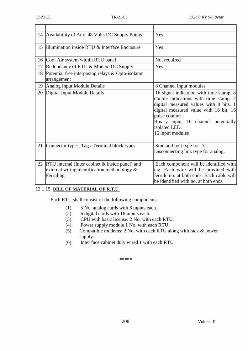
CSPTCL TR-21/05 132/33 KV S/S Betar
208 Volume-II
14 Availability of Aux. 48 Volts DC Supply Points
Yes
15 Illumination inside RTU & Interface Enclosure
Yes
16 Cool Air system within RTU panel Not required
17 Redundancy of RTU & Modem DC Supply Yes
18 Potential free interposing relays & Opto-isolator
arrangement
19 Analog Input Module Details 8 Channel input modules
20 Digital Input Module Details 16 signal indication with time stamp, 8
double indications with time stamp. 2
digital measured values with 8 bits, 1
digital measured value with 16 bit, 16
pulse counter
Binary input, 16 channel potentially
isolated LED.
16 input modules
21 Connector types, Tag / Terminal block types Stud and bolt type for D.I.
Disconnecting link type for analog.
22 RTU internal (Inter cabinet & inside panel) and
external wiring identification methodology &
Ferruling
Each component will be identified with
tag. Each wire will be provided with
ferrule no. at both ends. Each cable will
be identified with no. at both ends.
12.1.15 BILL OF MATERIAL OF R.T.U.
Each RTU shall consist of the following components:
(1). 5 No. analog cards with 8 inputs each.
(2). 6 digital cards with 16 inputs each.
(3). CPU with basic license: 2 No. with each RTU.
(4). Power supply module 1 No. with each RTU.
(5). Compatible modems: 2 No. with each RTU along with rack & power
supply.
(6). Inter face cabinet duly wired 1 with each RTU
*****
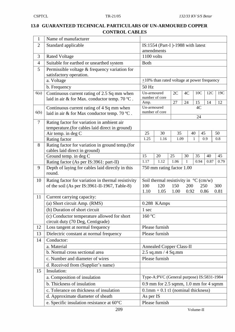
CSPTCL TR-21/05 132/33 KV S/S Betar
209 Volume-II
13.0 GUARANTEED TECHNICAL PARTICULARS OF UN-ARMOURED COPPER
CONTROL CABLES
1 Name of manufacturer
2 Standard applicable IS:1554 (Part-I )-1988 with latest
amendments
3 Rated Voltage 1100 volts
4 Suitable for earthed or unearthed system Both
5 Permissible voltage & frequency variation for
satisfactory operation.
a. Voltage +10% than rated voltage at power frequency
b. Frequency 50 Hz
6(a) Continuous current rating of 2.5 Sq mm when
laid in air & for Max. conductor temp. 70 ºC .
Un-armoured
number of core 2C 4C 10C 12C 19C
Amp. 27 24 15 14 12
6(b) Continuous current rating of 4 Sq mm when
laid in air & for Max conductor temp. 70 ºC .
Un-armoured
number of core 4C
24
7 Rating factor for variation in ambient air
temperature.(for cables laid direct in ground)
Air temp. in deg C 25 30 35 40 45 50
Rating factor 1.25 1.16 1.09 1 0.9 0.8
8 Rating factor for variation in ground temp.(for
cables laid direct in ground)
Ground temp. in deg C 15 20 25 30 35 40 45
Rating factor (As per IS:3961: part-II) 1.17 1.12 1.06 1 0.94 0.87 0.79
9 Depth of laying for cables laid directly in this
round.
750 mm rating factor 1.00
10 Rating factor for variation in thermal resistivity
of the soil (As per IS:3961-II-1967, Table-8)
Soil thermal resistivity in °C (cm/w)
100 120 150 200 250 300
1.10 1.05 1.00 0.92 0.86 0.81
11 Current carrying capacity:
(a) Short circuit Amp. (RMS) 0.288 KAmps
(b) Duration of short circuit 1 sec
(c) Conductor temperature allowed for short
circuit duty (70 Deg, Centigrade)
160 oC
12 Loss tangent at normal frequency Please furnish
13 Dielectric constant at normal frequency Please furnish
14 Conductor:
a. Material Annealed Copper Class-II
b. Normal cross sectional area 2.5 sq.mm / 4 Sq.mm
c. Number and diameter of wires Please furnish
d. Received from (Supplier’s name)
15 Insulation:
a. Composition of insulation Type-A:PVC (General purpose) IS:5831-1984
b. Thickness of insulation 0.9 mm for 2.5 sqmm, 1.0 mm for 4 sqmm
c. Tolerance on thickness of insulation 0.1mm + 0.1 t1 (nominal thickness)
d. Approximate diameter of sheath As per IS
e. Specific insulation resistance at 60°C Please furnish
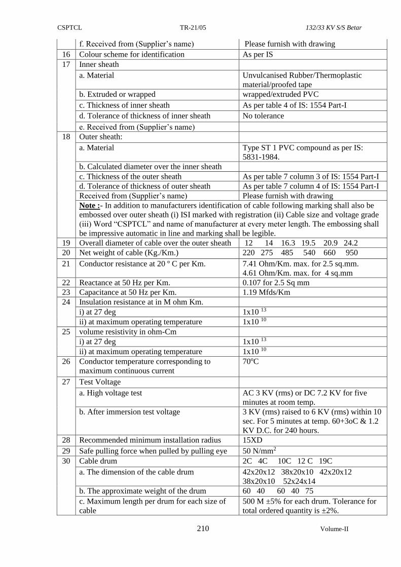
CSPTCL TR-21/05 132/33 KV S/S Betar
210 Volume-II
f. Received from (Supplier’s name) Please furnish with drawing
16 Colour scheme for identification As per IS
17 Inner sheath
a. Material Unvulcanised Rubber/Thermoplastic
material/proofed tape
b. Extruded or wrapped wrapped/extruded PVC
c. Thickness of inner sheath As per table 4 of IS: 1554 Part-I
d. Tolerance of thickness of inner sheath No tolerance
e. Received from (Supplier’s name)
18 Outer sheath:
a. Material Type ST 1 PVC compound as per IS:
5831-1984.
b. Calculated diameter over the inner sheath
c. Thickness of the outer sheath As per table 7 column 3 of IS: 1554 Part-I
d. Tolerance of thickness of outer sheath As per table 7 column 4 of IS: 1554 Part-I
a. Received from (Supplier’s name) Please furnish with drawing
Note :- In addition to manufacturers identification of cable following marking shall also be
embossed over outer sheath (i) ISI marked with registration (ii) Cable size and voltage grade
(iii) Word “CSPTCL” and name of manufacturer at every meter length. The embossing shall
be impressive automatic in line and marking shall be legible.
19 Overall diameter of cable over the outer sheath 12 14 16.3 19.5 20.9 24.2
20 Net weight of cable (Kg./Km.) 220 275 485 540 660 950
21 Conductor resistance at 20 º C per Km. 7.41 Ohm/Km. max. for 2.5 sq.mm.
4.61 Ohm/Km. max. for 4 sq.mm
22 Reactance at 50 Hz per Km. 0.107 for 2.5 Sq mm
23 Capacitance at 50 Hz per Km. 1.19 Mfds/Km
24 Insulation resistance at in M ohm Km.
i) at 27 deg 1x10 13
ii) at maximum operating temperature 1x10 10
25 volume resistivity in ohm-Cm
i) at 27 deg 1x10 13
ii) at maximum operating temperature 1x10 10
26 Conductor temperature corresponding to
maximum continuous current
70oC
27 Test Voltage
a. High voltage test AC 3 KV (rms) or DC 7.2 KV for five
minutes at room temp.
b. After immersion test voltage 3 KV (rms) raised to 6 KV (rms) within 10
sec. For 5 minutes at temp. 60+3oC & 1.2
KV D.C. for 240 hours.
28 Recommended minimum installation radius 15XD
29 Safe pulling force when pulled by pulling eye 50 N/mm2
30
Cable drum 2C 4C 10C 12 C 19C
a. The dimension of the cable drum 42x20x12 38x20x10 42x20x12
38x20x10 52x24x14
b. The approximate weight of the drum 60 40 60 40 75
c. Maximum length per drum for each size of
cable
500 M ±5% for each drum. Tolerance for
total ordered quantity is ±2%.
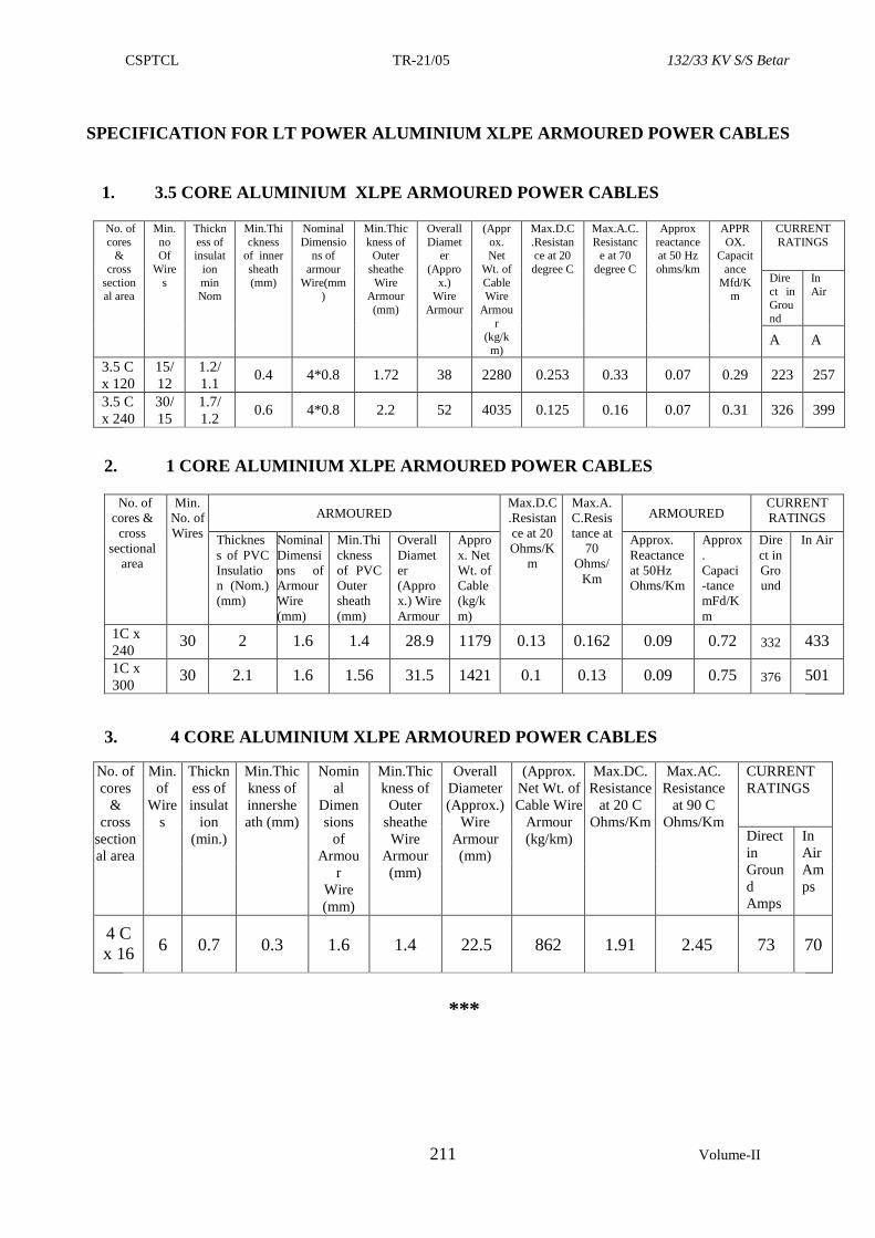
CSPTCL TR-21/05 132/33 KV S/S Betar
211 Volume-II
SPECIFICATION FOR LT POWER ALUMINIUM XLPE ARMOURED POWER CABLES
1. 3.5 CORE ALUMINIUM XLPE ARMOURED POWER CABLES
No. of
cores &
cross
sectional area
Min.
no Of
Wire
s
Thickn
ess of insulat
ion
min Nom
Min.Thi
ckness of inner
sheath
(mm)
Nominal
Dimensions of
armour
Wire(mm)
Min.Thic
kness of Outer
sheathe
Wire Armour
(mm)
Overall
Diameter
(Appro
x.) Wire
Armour
(Appr
ox. Net
Wt. of
Cable Wire
Armou
r (kg/k
m)
Max.D.C
.Resistance at 20
degree C
Max.A.C.
Resistance at 70
degree C
Approx
reactance at 50 Hz
ohms/km
APPR
OX. Capacit
ance
Mfd/Km
CURRENT
RATINGS
Dire
ct in Grou
nd
In
Air
A A
3.5 C
x 120
15/
12
1.2/
1.1 0.4 4*0.8 1.72 38 2280 0.253 0.33 0.07 0.29 223 257
3.5 C
x 240
30/
15
1.7/
1.2 0.6 4*0.8 2.2 52 4035 0.125 0.16 0.07 0.31 326 399
2. 1 CORE ALUMINIUM XLPE ARMOURED POWER CABLES
No. of
cores &
cross
sectional
area
Min.
No. of
Wires
ARMOURED Max.D.C
.Resistan
ce at 20
Ohms/K
m
Max.A.
C.Resis
tance at
70
Ohms/
Km
ARMOURED CURRENT
RATINGS
Thicknes
s of PVC
Insulatio
n (Nom.)
(mm)
Nominal
Dimensi
ons of
Armour
Wire
(mm)
Min.Thi
ckness
of PVC
Outer
sheath
(mm)
Overall
Diamet
er
(Appro
x.) Wire
Armour
Appro
x. Net
Wt. of
Cable
(kg/k
m)
Approx.
Reactance
at 50Hz
Ohms/Km
Approx
.
Capaci
-tance
mFd/K
m
Dire
ct in
Gro
und
In Air
1C x
240 30 2 1.6 1.4 28.9 1179 0.13 0.162 0.09 0.72 332 433
1C x
300 30 2.1 1.6 1.56 31.5 1421 0.1 0.13 0.09 0.75 376 501
3. 4 CORE ALUMINIUM XLPE ARMOURED POWER CABLES
No. of
cores
&
cross
section
al area
Min.
of
Wire
s
Thickn
ess of
insulat
ion
(min.)
Min.Thic
kness of
innershe
ath (mm)
Nomin
al
Dimen
sions
of
Armou
r
Wire
(mm)
Min.Thic
kness of
Outer
sheathe
Wire
Armour
(mm)
Overall
Diameter
(Approx.)
Wire
Armour
(mm)
(Approx.
Net Wt. of
Cable Wire
Armour
(kg/km)
Max.DC.
Resistance
at 20 C
Ohms/Km
Max.AC.
Resistance
at 90 C
Ohms/Km
CURRENT
RATINGS
Direct
in
Groun
d
Amps
In
Air
Am
ps
4 C
x 16 6 0.7 0.3 1.6 1.4 22.5 862 1.91 2.45 73 70
***
CSPTCL TR-21/05 132/33 KV S/S Betar
212 Volume-II
14. TECHNICAL SPECIFICATION FOR AUTOMATIC DATA LOGGING
SYSTEM:-
14.1 Features & Specification of Automatic Data Logging System
This feature is intended for local monitoring of Sub-station parameters on computer
screen installed in control room, automatic acquisition of energy meter data &
preparation of customized reports and automatic download of disturbance records in
workstation computer of control room. The objective shall be achieved with the help of
customized software and hardware connection to IEDs like relays and meters.
14.2 Communication Protocol
The communication protocol for gateway to control centre must be open protocol
and shall support IEC 60870-5-101,104 and IEC 61850 for all levels of
communication such as IEDs (protective numerical relays) to station HMI, gateway
to remote station etc.
The Automatic data logging System shal l be designed, manufactured,
tested, installed and commissioned at the substation as per IEC-61850 for protective
relays & Modbus for Energy meters.
The Automatic data logging System shall contain the following main functional
parts:
Intelligence Electronic Devices (IEDs) for monitoring (Numerical
protective relays and Energy meter IEDs of C&R panels).
Station Human Machine Interface (HMI)
Redundant managed switched Ethernet Local Area Network communication
infrastructure for remote monitoring via industrial grade hardware.
Gateway - Each IED shall communicate data to the Gateway through a serial or
Ethernet network connection using a selected protocol. Additionally, the
gateway should have the capability to communicate with SLDC on IEC
60870-5-101& 104 protocol.
Peripheral equipment like printers, display units, key boards, Mouse etc.
Automatic data logging System shall be realised via a PC by means of
human machine interface (HMI) and software package, which shall contain an
extensive range of data acquisition functions. The contractor shall arrange for necessary
software Licences.
The communication gateway shall have the provision to facilitate the
information flow with remote control centres. The bay level intelligent
electronic devices (numerical relay IED) for protection shall provide the direct
connection to the switchgear without the need of interposing components and
perform protection and monitoring functions.
14.3 System Architecture – The Automatic data logging system shall have following
minimum components:
14.3.1 Gateway - Hardware capability: It shall have a flexible high performance
expandable disc less & fan less platform. It should be powered by 2 GHz or better
processor. It shall have networked time protocol (NTP) & IRIG B format time
protocol support. It shall have centralised user authentication. It shall have built in
calculative function (Math /logic). The communication protocol for gateway must
support IEC 60870-5-101,104, IEC 60870-5-103, IEC 61850 and all other
protocol required for all levels of communication such as numerical relay IEDs
and energy meter IEDs to station HMI etc.
CSPTCL TR-21/05 132/33 KV S/S Betar
213 Volume-II
The primary function of the Gateway shall be to concentrate substation data by polling
and receiving information from connected IEDs. Each device shall communicate data
to the Gateway through a serial or Ethernet network connection using a selected
protocol. The Gateway shall retrieve point information from and shall send control
requests to each communicating device. The Gateway can manipulate the data from
devices to produce additional local/pseudo data points. The real data collected from
devices and the calculated data shall be stored in a database in the Gateway and shall
be available to pass on to remote master stations and/or HMI (Human-Machine
Interface) applications.
The Gateway shall be able to accomplish these tasks through the use of embedded
software applications. These software applications shall be configurable to set up the
Gateway to operate as per the requirement of the system.
Salient Features of Gateway
1 . Data concentration
2 . Ease of use /configuration
3. Embedded substation HMI and alarm system
4 . Embedded security applications
5 . Expandable and upgradeable platform
6 . Redundancy
7 . Role based access control
8. Support for network time protocol (NTP)
9. Support for multiple Scada protocols for communication to multiple masters
14.3.2 Ethernet switch –
The switch shall be a Industrial grade managed Ethernet switch, designed for reliable
high speed networking for all critical applications in substations. The switch shall
provide flexibility in usage, security and shall offer ease of maintenance. The Ethernet
switches shall be Industrially Hardened and IEC 61850 Compliant for networking
equipment used in utility substations. It shall also be IEEE 1613 Compliant for
Electric Power Substation communications equipment.
The switch shall have advanced network management and security features including
SNMP, SNTP, web management ,interface, VLAN, IPV6, SSL web encryption and
SSH securing switch access over unauthorized network.
The following functions shall be available in the switch;
1. RJ45 Ports – It shall have a minimum of 6 Nos spares over and above that
utilised in the scheme (of 100 MBPS or above)
2. It should support all common media types
3. Power Supply - 110 VDC/240 VAC Power Supply
4. Link Loss Alert feature
5. Recovery of Ring Network Architectures feature
6. Modbus Protocol Support enabling integrating Switch Data and Network
Alarms into monitoring systems.
7. Simple Switch Configuration and System Integration
8. The software shall allow for easy to use configuration, monitoring and
integration of the Ethernet Switch.
9. The software shall cover following functionality also;
- The Software shall allow for programming of all settings
- Monitoring of all Ports and Alarming of network problems including:
Port
Failures, Power Supply Failures, Security Intruder Alarms
CSPTCL TR-21/05 132/33 KV S/S Betar
214 Volume-II
- The Integrator shall retrieve all of the information such as port status,
network statistics and Network Alarms in the switch and send this data to
monitoring systems
14.3.3 Automatic data logging system Work station
Computer System Configuration - Dual Core Processor,2.5 GHz or better, SDRAM-
4GB, HDD-500 GB, Drive-52X, Ethernet Card, Serial Ports – min. 4 Nos, USB port-
min 2 nos, Color 29” LCD Monitor, Operating System – Windows 10 Professional or
equivalent.
14.4 Objectives of Automatic data logging system
14.4.1 For Energy meter :
1. It shall have Graphical user interface (GUI) based software on Windows platform.
2. Online views – Tabular and Graphical. The Substation SLD mimic shall be realized
on computer screen. One screen of SLD mimic shall be populated by data from
energy meter.
3. Meter Support – The software shall acquire data from the Secure Meters Ltd make
Apex meters over Ethernet and RS485 port on DLMS and MODBUS protocol.
4. Viewing Online Data- The software shall provide facility to monitor instantaneous
electrical parameters on real time basis and disturbance recording. Online data can
be viewed in graphical / tabular formats/substation SLD mimic.
5. Viewing Historical Data –The software shall provide historical data views for
analysis purpose.
6. Group Definition - The software shall provide facility for grouping of meters to
define virtual meters. This feature shall be used for calculation of total energy loss
and consumption of a location
7. Alarm Management - It shall provide User definable alarms for different
parameters. These alarms shall be available for system monitoring on real time
basis.
8. Reports - The software shall provide various types of reports like min-max,
consumption, alarm data, interruption data, meter replacement, demand data,
energy loss data etc. The reports shall provide time-related follow-ups of
measured and calculated values. The data displayed shall comprise:
> Trend reports:
Day (mean, peak)
Month (mean, peak)
Year (mean, peak)\
> Historical reports of selected analogue Values:
Day (at 15 minutes interval)
Week
Month
• Year
It shall be possible to select displayed values from the database in the process
display on-line, scrolling between days etc. It shall be possible to select the
time period for which the specific data are kept in the memory.
Following printouts shall be available from the printer and shall be printed on
demand :-
i. Daily voltage, load and frequency curves depicting time on X-axis and the
appropriate parameters on the Y-axis. The time duration of the curve is 24
hours.
ii. Weekly trend curves for real and derived analogue values.
CSPTCL TR-21/05 132/33 KV S/S Betar
215 Volume-II
iii. Printouts of the maximum and minimum values and frequency of occurrence
and duration of maximum and minimum values for each analogue parameter
for each circuit in 24 hr period.
iv. Printout on adjustable time period as well as on demand for MW, MVAR,
Current, Voltage on each feeder and transformer
v. Printout on adjustable time period as well as on demand system
frequency and average frequency.
vi. Reports in specified formats which shall be handed over to contractor.
Trend display (historical data)
It shall be possible to illustrate all types of process data as trends – input and
output data, binary and analogue data. The trends shall be displayed in graphical
form as column or curve diagrams. Adjustable time span and scaling ranges
must be provided.
It shall be possible to change the type of value logging (direct, mean, sum, or
difference) on-line in the window. It shall also be possible to change the update
intervals on-line in the picture as well as the selection of threshold values for
alarming purposes.
9. Data Import and Export - The software shall have facility to import CSV files
from a third party application. User should export the meter data to CSV format.
14.4.2 For Relays :
1. Graphical user interface (GUI) based software on Windows platform.
2. Online views – Tabular and Graphical. The Substation SLD mimic shall be
realized on computer screen. One screen of SLD mimic shall be populated by data
from relays.
3. Relay Support – The software shall acquire data from the IEC61850 compliant
IEDs.
4. Viewing Online Data- The software shall provide facility to monitor
instantaneous electrical parameters on real time basis and disturbance recording.
Online data can be viewed in graphical /tabular formats/substation SLD mimic.
5. Automatic disturbance file transfer
All recorded data from the IEDs with integrated disturbance recorder as well
as dedicated disturbance recording systems shall be automatically uploaded
(event triggered or once per day) to a workstation computer of the system and
be stored on the hard disc. The software shall provide historical data views of
disturbance records and events for analysis purpose.
6. Disturbance analysis
The PC-based work station shall have necessary software to evaluate all
the required information for proper fault analysis.
14.5 List of Inputs:
The list of input for typical bays is as below:-
14.5.1 . Analogue inputs:
i) For line
Current: R phase, Y phase, B phase
Voltage R-Y phase, Y-B phase B-R phase
MW, MVAR, MVA, PF
ii) For transformer:
Current: R phase, Y phase, B phase,
MW, MVAR, MVA, PF
iii) For TBC
Current: R phase, Y phase, B phase
MW, MVAR, MVA, PF
CSPTCL TR-21/05 132/33 KV S/S Betar
216 Volume-II
iv) Common
a) Voltage for Bus
Voltage R-Y phase,Y-B phase, B-R phase
b) Frequency
v) Current from station LT transformer (CSPTCL)
vi) Current from CSPDCL supply
14.5.2 Digital Inputs:
The list of inputs for various bays/Systems is as follows:
1. Line bays
i) Status of CB,
ii) Trip coil faulty
iii) LBB optd
iv) PT FUSE FAIL
v) DISTANCE PROTN TRIP
vi) DPR SOTF TRIP
vii) DPR R-PH TRIP
viii) DPR Y-PH TRIP
ix) DPR B-PH TRIP
x) DPR ZONE-2 TRIP
xi) DPR ZONE-3 TRIP
xii) Back-up O/C optd
xiii) Back-up E/F optd
xiv) Any other input as listed in relevant section
2. Transformer bays
i) Status of CB
ii) Trip coil faulty
iii) LBB optd
iv) REF OPTD
v) DIFF OPTD
vi) OVERFLUX ALARM
vii) OVERFLUX TRIP
viii) OTI ALARM/TRIP
ix) PRD OPTD
x) OVERLOAD ALARM
xi) BUCHOLZ TRIP
xii) BUCHOLZ ALARM
xiii) OLTC BUCHOLZ ALARM
xiv) OLTC BUCHOLZ TRIP
xv) WTI ALARM/TRIP
xvi) Back-up O/C HV optd
xvii) Back-up E/F HV optd
xviii) GR-A PROTN Optd
xix) GR-B PROTN Optd
xx) Back-up O/C (LV) optd
xxi) Back-up E/F (LV) optd
xxii) Any other as listed in relevant section
The exact number and description of digital inputs shall be as per detailed engineering
requirement. Apart from the above mentioned digital inputs, minimum of 100 inputs
shall be kept for future use of CSPTCL.
CSPTCL TR-21/05 132/33 KV S/S Betar
217 Volume-II
14.6 User-authority levels
It shall be possible to restrict activation of the process within a certain user
authorisation group. Each user shall then be given access rights to each group of
process, e.g.:
> Display only
> System administrator
For maintenance and engineering purposes of the station HMI, the following
authorisation levels shall be available:
> No engineering allowed
> Engineering/configuration allowed
> Entire system management allowed
The access rights shall be defined by passwords assigned during the log-in
procedure. Only the system administrator shall be able to add/remove users and
change access rights.
14.7 LIST OF EQUIPMENTS
Quantity of equipments shall include but not l imited to the following ;
a. Substation Automatic Data LoggingWork Station: 1 No.
Computer System Configuration - Dual Core Processor, 2.5 GHz or better
SDRAM- 4GB, HDD-500 GB, Drive-52X, Ethernet Card, Serial Ports – min. 4
Nos, USB port- min 2 nos, Color 29” LCD Monitor, Operating System –
Windows 7 professional or equivalent.
b. Gateway : Minimum 1 No.
c. Ethernet switches : Minimum 1 No. ( with 6 Nos redundant ports )
d. Laser Printer – 1 No. (For Reports & Disturbance records).
e. Dot matrix printer – 2 Nos.
f. Communication infrastructure between Bay level units, Station HMI, Printers,
redundant LAN etc. as required.
g. 1 KVA or higher size inverters as per requirement: 1 No.
h. ADLS Panel for housing Ethernet switch, Gateway, UPS & various connectors.
i. Furniture for arranging Automatic Data Logging System : One Godrej make
Computer table of adequate size and chair.
j. Other equipment as detailed in the technical specifications and any other necessary
for Automatic Data Logging System and not listed.
***
CSPTCL TR-21/05 132/33 KV S/S Betar
218 Volume-II
15.0 TECHNICAL SPECIFICATIONS OF CLAMPS, CONNECTORS AND
HARDWARES:
15.1 CLAMPS & CONNECTORS :-The drawing & Samples of Clamps, Connectors &
Spacers shall be approved by CSPTCL before use in the substation. In the switchyard
only ZEBRA conductor has been provided. It should be noted that the requirement is
for a minimum of 100 mm coverage of the conductor inside the clamp for all clamps.
The pad clamp shall have SIX bolts and T clamp shall have 12 bolts. For all types of
clamps, the drawings shall be approved by the CSPTCL.
However, at high locations i.e., main 3 phase droppers on HV and LV side of
transformer as also for 132 KV line take off, either T clamp should be completely
avoided by using long through jumper or wherever essential (at high attitude point) T
clamp shall be replaced by a set of PG clamp as shown below point.
The nuts & bolts used in the clamps shall be fine machined screws of reputed make, so
that the screws do not become loose during service. Nuts & bolts should be hot dipped
galvanized.
For power transformer 40 MVA bushing clamps where an aluminium conductor has to
be connected to a copper stud-two separate clamps, one of Copper & other of
Aluminium shall be provided with bi-metallic strip joint on the plain pad surfaces of
both clamps.
A factor of safety of 1.5 shall be used i.e. clamp for 400 Ampere conductor shall have
thickness and area for current at least 600 Amperes.
15.1.1 CLAMP MATERIALS:-
The clamps and the connectors shall be made of materials listed below:-
a) For connection ACSR conductors Aluminium alloy casting conforming to
designation LM-6 of IS-617. Sand casting is not permitted.
b) For connecting equipment terminals made of Copper or Brass & ACSR
conductor, Bi-metallic connectors made from Aluminium Alloy casting
conforming to designation A6 of IS 617 with 4 mm thick cast copper liner (2 mm
Cu and 2 mm Al) shall be used (for C.T. & P.T. clamps). Clamps for connecting
GI shield shall be of malleable Iron casting. Nuts & bolts should be hot dipped
galvanized.
15.1.2 TERMINAL CONNECTORS :
The terminal connectors shall meet the following requirements:
i) Terminal connectors shall be manufactured and tested as per IS: 5561.
ii) Terminal connector shall be tested for short circuit current capability test,
temperature rise test, corona test etc. The terminal connectors should be
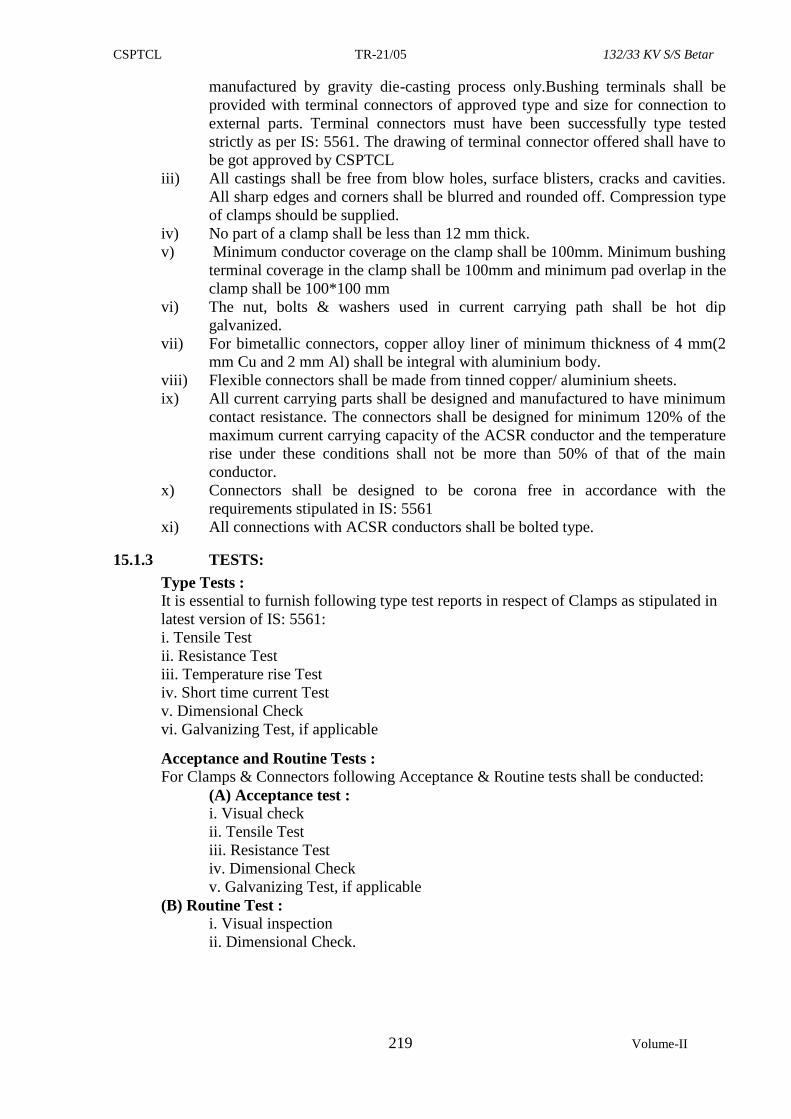
CSPTCL TR-21/05 132/33 KV S/S Betar
219 Volume-II
manufactured by gravity die-casting process only.Bushing terminals shall be
provided with terminal connectors of approved type and size for connection to
external parts. Terminal connectors must have been successfully type tested
strictly as per IS: 5561. The drawing of terminal connector offered shall have to
be got approved by CSPTCL
iii) All castings shall be free from blow holes, surface blisters, cracks and cavities.
All sharp edges and corners shall be blurred and rounded off. Compression type
of clamps should be supplied.
iv) No part of a clamp shall be less than 12 mm thick.
v) Minimum conductor coverage on the clamp shall be 100mm. Minimum bushing
terminal coverage in the clamp shall be 100mm and minimum pad overlap in the
clamp shall be 100*100 mm
vi) The nut, bolts & washers used in current carrying path shall be hot dip
galvanized.
vii) For bimetallic connectors, copper alloy liner of minimum thickness of 4 mm(2
mm Cu and 2 mm Al) shall be integral with aluminium body.
viii) Flexible connectors shall be made from tinned copper/ aluminium sheets.
ix) All current carrying parts shall be designed and manufactured to have minimum
contact resistance. The connectors shall be designed for minimum 120% of the
maximum current carrying capacity of the ACSR conductor and the temperature
rise under these conditions shall not be more than 50% of that of the main
conductor.
x) Connectors shall be designed to be corona free in accordance with the
requirements stipulated in IS: 5561
xi) All connections with ACSR conductors shall be bolted type.
15.1.3 TESTS:
Type Tests :
It is essential to furnish following type test reports in respect of Clamps as stipulated in
latest version of IS: 5561:
i. Tensile Test
ii. Resistance Test
iii. Temperature rise Test
iv. Short time current Test
v. Dimensional Check
vi. Galvanizing Test, if applicable
Acceptance and Routine Tests :
For Clamps & Connectors following Acceptance & Routine tests shall be conducted:
(A) Acceptance test :
i. Visual check
ii. Tensile Test
iii. Resistance Test
iv. Dimensional Check
v. Galvanizing Test, if applicable
(B) Routine Test :
i. Visual inspection
ii. Dimensional Check.
CSPTCL TR-21/05 132/33 KV S/S Betar
220 Volume-II
15.2 SUBSTATION TYPE HARDWARE:-
15.2.1 REQUIRED GUARANTEED STRENGTH OF HARDWARE OF INSULATOR STRINGS:-
The Hardwares and Clamps of 132kV single suspension and double suspension strings suitable
for Zebra ACSR and all types of suspension and tension strings suitable for sub-station shall
have the ultimate breaking strength of not less than 7,000 kgs. The slipping strength of the
suspension clamp shall not be less than 15% and more than 20% of the Conductor strength with
which it is to be used. Each individual Hardware component of double suspension and double
tension strings such as ball-clevis, socket clevis etc. shall have minimum breaking strength as
specified for respective single suspension and tension string respectively.
15.2.2 PARTICULARS OF HARDWARE FITTINGS:
Each substation Hardware fitting shall be complete in all respect and the contractor shall
furnish complete drawings and technical particulars of the Hardware fittings comprising items
as under: -
i) Single Suspension Hardware Fittings For Zebra/Twin-Zebra for Sub Station:-
The 132KV sub-stations Hardware fittings shall comprise of one Ball Hook, one Socket Clevis
Eye Horn holder, one Arcing Horn and one Suspension Clamp suitable for ACSR Zebra
Conductor. The Socket Eye and Ball Clevis shall be made of forged steel.
ii) Double Tension Hardware for for Zebra/Twin Zebra ACSR Zebra for substation:-
Double Tension Hardware shall comprise of U Clevis, one Ball Link, Socket Clevis, Yoke
Plate, two Clevis Eyes and two Tension Clamps of bolted type suitable for ACSR Zebra. U
Clevis shall be made of forged steel complete with galvanised steel rivets washer and
Phosphorus Bronze/Stainless Steel pins. The Ball fittings shall be made of forged steel in one
piece.
iii) Ground wire Assemblies:
The Ground wire tension assembly shall have minimum breaking strength equal to that of the
Ground Wire. The slipping strength of the Compression Clamp shall not be less than 95% of
the breaking strength of Ground Wire. The Ground wire tension assembly for Substation shall
comprise of one bolted type Clamp and one `D’ Shackle complete with minor accessories such
as bolts, nuts pins etc. The assembly shall be hot dip galvanized and made inherently resistant
to the atmosphere corrosion.
iv) Ball and Socket Dimensions:
The Ball and Socket for Hardware fittings shall necessarily conform to the dimensions as
stipulated in the Indian Standards. The Ball and Socket dimensions of the Hardware sets to be
used with 7000 kg and 9100 kg Electro Mechanical strength Disc Insulators shall conform to
designation 16mm/16mm-B in accordance with IS:2486(Part-II) or equivalent International
Standard.
The minimum breaking and slipping strength of single tension Hardware fitting shall not
be less than 7000 kgs. One set of additional nuts (as check nuts) should be provided
alongwith the bolts and nuts to fix the tension clamp with the conductor so as to avoid the
possibility of relative/looseness due to vibration of strings.
15.2.3 Dimensions & Tolerances:
The dimensions and tolerances of pin balls and socket ends shall conform to IS 2486
Part-II/IEC-120 and shall be checked by the gauge therein after galvanizing.
The bearing surfaces of balls and machined sockets, before galvanizing shall not have surface
roughness more than 250 micro inches.
The bearing surface of socket ends shall be uniform about the entire circumference without
depressions or high spots. The internal contour of the socket ends shall be concentric with the
CSPTCL TR-21/05 132/33 KV S/S Betar
221 Volume-II
axis of fittings. The axis of the bearing surface of socket ends shall be coaxial with the axis of
fittings with no appreciable tilting.
(i) Socket Fittings:
Socket fittings shall be made of clause IV steel as per IS:2004 or steel of equivalent grade and
shall be forged in one piece. They shall be normalized to achieve the minimum breaking
strength specified on the respective drawings.
(ii) Security clip for Socket fittings:
Socket fittings shall be provided with R-shaped security clip in accordance with IS:2486 (Part-
III) to provide positive locking against unintentional disengagement of socket from the ball of
the insulator. The security clip shall be humped to maintain the clip in the locked position and
shall have both prongs spread to prevent complete withdrawal from the socket. The clip end
shall not project outside the recess of socket when the clip is in locked position.
The hole for the security clip shall be on the side of the socket opposite to the socket opening.
The hole for the clip shall be counter sunk. The force required to pull the clip to its unlocked
position shall not be less than 50 N or more than 500N. The security clip shall be made of
stainless steel of type AISI 302 or 304 or phosphor bronze as per IS:7814.
(iii) Clevis-Eye:
These shall be forged steel of malleable cast iron and shall be complete with galvanised pin
with flat washer and split pin of Phosphorus Bronze/Stainless Steel.
(iv) Yoke Plate:
The yoke plates/link plate shall be made of mild steel plate as per IS:226 or equivalent
standards. Shearing/cutting of the plates shall be clean without drawn or ragged edges. If the
plates are flame cut, mechanical guides shall be used.
Holes shall be cylindrical clean cut and perpendicular to the plane of the material. The
periphery of the holes shall be free from burrs and all the corners and edges should be rounded
off with a radius of at least 3mm.
(v) Sag Adjustment Device
The sag adjustment devices to be provided with double tension hardware fittings shall be of
three plate type. The sag adjustment device shall be provided with a safety locking
arrangement.
Sag adjuster plates shall be made from high qualify mild steel plate as per IS:226. The grain
flow shall not be in a direction transverse to the tensile load. Cutting/shearing and drilling of
holes shall be similar to those for yoke plate.
The maximum length of the sag adjustment plate from the connecting part of the rest of the
hardware fittings shall be 520 mm. The details of the minimum and maximum adjustment
possible and the steps of adjustment shall be clearly indicated in the drawing. An adjustment of
150mm maximum at the interval of 6mm shall be possible with the sag adjustment plate.
15.2.4 IMPORTANT CONDITIONS:
a) All Hardware items shall be complete with minor items such as security clip, bolts, nuts,
washer, split pins and inners etc.
b) All ferrous fittings shall be hot dip galvanized, after all machining and fitting has been
completed, in accordance with relevant Indian Standard. All Hardware items (other than
clamps) and those specified otherwise should be made of Drop Forged Steel. Socket items in
forged steel must be forged. The items like Yoke Plate, Arcing Horn, Bolts and Nuts shall be
of mild steel and rest of the items shall be of forged steel.
c) All Bolts, Nuts and Screw heads shall have only wide worth standard thread .Bolts head and
Nuts shall be hexagonal. The thread in Nuts shall be over tapped after galvanizing and shall be
cut before galvanizing. The threads shall not be under cut. The Nuts should be tapped such that
they are fit on the bolt threads i.e. these should not have loose fitting.
CSPTCL TR-21/05 132/33 KV S/S Betar
222 Volume-II
15.2.5 LENGTH OF STRINGS:
The clearance to the tower steel parts under service conditions of Insulator have been decided
on the basis that the overall length of 9 Disc for 132kV line (7000 kgs EMS for single
suspension string) will not exceed the length as indicated in the attached drawings. The
dimension of the Disc for Ball and Socket type will be 255mm x145mm for 7000 kgs EMS to
be used with suspension strings.
15.2.6 GALVANISING:
Hot dip galvanizing shall conform to Indian Standard specification IS-2633 or equivalent
International Standard. Galvanising shall be uniform, free from blisters, and shall not peel off
due to abrasion, Zinc coating shall be thick enough to withstand 6 one minute dips in Copper
Sulphate solution (precee test) for all ferrous parts except for threaded portions which shall
withstand atleast 4 one minute dips.
15.2.7 TESTS
The following Type Tests, Stage Tests, Routine Tests and Acceptance Test shall be carried out
on power Conductor & Ground wire Hardware fittings.
i) Type Tests
The material offered shall be fully Type Tested as per relevant specification and the contractor
shall furnish a set of Type Test reports along with the drawings. These tests must not have been
conducted earlier than seven years as on last date of submission of bid.
ii) Stage Tests:
Stage Tests during manufacturing shall mean those test required to be carried out during the
process of manufacturing to ensure quality control such that last product is of the designed
quality conforming to the intent of this specification.
iii) Routine Tests:
Routine Tests are those tests, which required to be carried out on each and every finished
product so as to check with requirements that are likely to vary during production.
iv) Acceptance Tests:
Acceptance Tests shall mean those tests, which required to be carried out on samples taken
from each lot offered for pre-despatch inspection for purposes of acceptance of that lot.
15.2.8 DRAWING AND LITERATURE:
The detailed drawings of each component assembly drawings and descriptive literature
of the Hardware assembly shall be submitted. The detailed dimension drawings for each and
all-individual Hardware items such as clamps, U Clevis, Socket Eye, Yoke Plate and Socket
Clevis etc. shall also be submitted. Test certificates for different tests conducted as per relevant
ISS, for all the offered items must also be submitted essentially.
15.2.9 MATERIALS AND WORKMANSHIP:
All the materials shall be of the latest design and conform to the best modern practice adopted
in the extra high voltage field.
The design, manufacturing process and quality control of all the materials shall be such as to
give maximum factor of safety, maximum possible working load, highest mobility, elimination
of sharp edges and corners, best resistance to corrosion and a good finish.
All ferrous parts shall be hot dip galvanised, after all machining has been completed.
Fasteners shall withstand four dips while spring washers shall be guaranteed to withstand at
least six dips each lasting one minute under the standard precee test for galvanising. The Zinc
coating shall be perfectly adhere, of uniform thickness, smooth, reasonably bright, continuous
and free from imperfections such as flux, ash, rust stains, bulky while deposits and blisters.
The Zinc used for galvanising shall be grade Zn. 99.95 as per IS: 209-1966 or equivalent
International Standard. In case of castings, the same shall be free from all internal defects like
shrinkage, inclusion, blowholes, cracks etc. All current carrying parts shall be so designed and
manufactured that contact resistance is reduced to minimum. No item which would produce
CSPTCL TR-21/05 132/33 KV S/S Betar
223 Volume-II
high electrical and mechanical stresses in normal working shall have sharp ends or edges,
abrasions or projections and shall not cause any damage to the Conductor in any way during
erection or during continuous operation. The design of adjacent metal parts and mating surfaces
shall be such as to prevent corrosion of the contact surface and no maintain good electrical
contact under service conditions. Particular care shall be taken during manufacturing and
subsequent handling to ensure smooth surface free from abrasion or dents. The fasteners shall
conform to the requirement of IS: 6639-1972 or equivalent International Standard. All fasteners
and clamps shall have locking arrangements to guard against vibration loosening.
15.2.10 INSPECTION: CSPTCL or its representatives shall at all times be entitled to have access to the works and to
all places of manufacturing and the successful Contractor/Supplier shall afford all facilities to
them for unrestricted inspection of the works, inspection of material, inspection of
manufacturing process and for conducting necessary tests as specified herein.
The acceptance of any quantity of material shall in no way relieve the successful
Contractor of his responsibility for meeting all the requirement of this specification and
shall not prevent subsequent rejection, if such materials are later found to be defective.
15.2.11 DOCUMENTATION & LIST OF DRAWINGS FOR CLAMPS, CONNECTORS,
SPACERS AND HARDWARES:
The contractor shall furnish full description, illustrated catalogues and dimensional drawings.
The drawing shall include the following information:-
(i) General outline & assembly drawings of all the items /material covered in the
specification.
(ii) Dimensions, unit spacings
(iii) Unit mechanical and electrical characteristics as also for the complete
assembly/set.
(iv) Weight of each component.
(v) Identification mark.
(vi) Material designation used for different components with reference to Standards.
(vii) Fabrication details such as welds, finishes and coatings
(viii) Manufacturer’s catalogue number.
(ix) Brief installation instructions.
(x) Reference of type testing.
(xi) Relevant technical details of significance
Each Clamps & Connectors / Spacers and hardwares shall be marked with the trade
mark of the manufacturer and year of manufacturing. Marks shall be forged or
stamped with a steel die before galvanizing. The mark shall be distinct, durable and
conspicuous
***
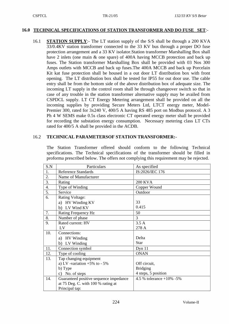
CSPTCL TR-21/05 132/33 KV S/S Betar
224 Volume-II
16.0 TECHNICAL SPECIFICATIONS OF STATION TRANSFORMER AND DO FUSE SET:-
16.1 STATION SUPPLY:- The LT station supply of the S/S shall be through a 200 KVA
33/0.4KV station transformer connected to the 33 KV bus through a proper DO fuse
protection arrangement and a 33 KV isolator.Station transformer Marshalling Box shall
have 2 inlets (one main & one spare) of 400A having MCCB protection and back up
fuses. The Station transformer Marshalling Box shall be provided with 03 Nos 300
Amps outlets with MCCB and back up fuses.The 400A MCCB and back up Porcelain
Kit kat fuse protection shall be housed in a out door LT distribution box with front
opening. The LT distribution box shall be tested for IP55 for out door use. The cable
entry shall be from the bottom side of the above distribution box of adequate size. The
incoming LT supply in the control room shall be through changeover switch so that in
case of any trouble in the station transformer alternative supply may be availed from
CSPDCL supply. LT CT Energy Metering arrangement shall be provided on all the
incoming supplies by providing Secure Meters Ltd, LTCT energy meter, Model-
Premier 300, rated for 3x240 V, 400/5 A having RS 485 port on Modbus protocol. A 3
Ph 4 W SEMS make 0.5s class electronic CT operated energy meter shall be provided
for recording the substation energy consumption. Necessary metering class LT CTs
rated for 400/5 A shall be provided in the ACDB.
16.2 TECHNICAL PARAMETERSOF STATION TRANSFORMER:-
The Station Transformer offered should conform to the following Technical
specifications. The Technical specifications of the transformer should be filled in
proforma prescribed below. The offers not complying this requirement may be rejected.
S.N Particulars As offered
As specified
1. Reference Standards IS:2026/IEC 176
2. Name of Manufacturer
3. Rating 200 KVA
4. Type of Winding Copper Wound
5. Service Outdoor
6. Rating Voltage:
a) HV Winding KV
b) LV Wind KV
33
0.415
7. Rating Frequency Hz 50
8. Number of phase 3
9. Rated current: HV
LV
3.5 A
278 A
10. Connections:
a) HV Winding
b) LV Winding
Delta
Star
11. Connection symbol Dyn 11
12. Type of cooling ONAN
13. Tap changing equipment
a) LV -variation +5% to - 5%
b) Type
c) No. of steps
Off circuit,
Bridging
4 steps, 5 position
14. Guaranteed positive sequence impedance
at 75 Deg. C. with 100 % rating at
Principal tap:
4.5 % tolerance +10% -5%
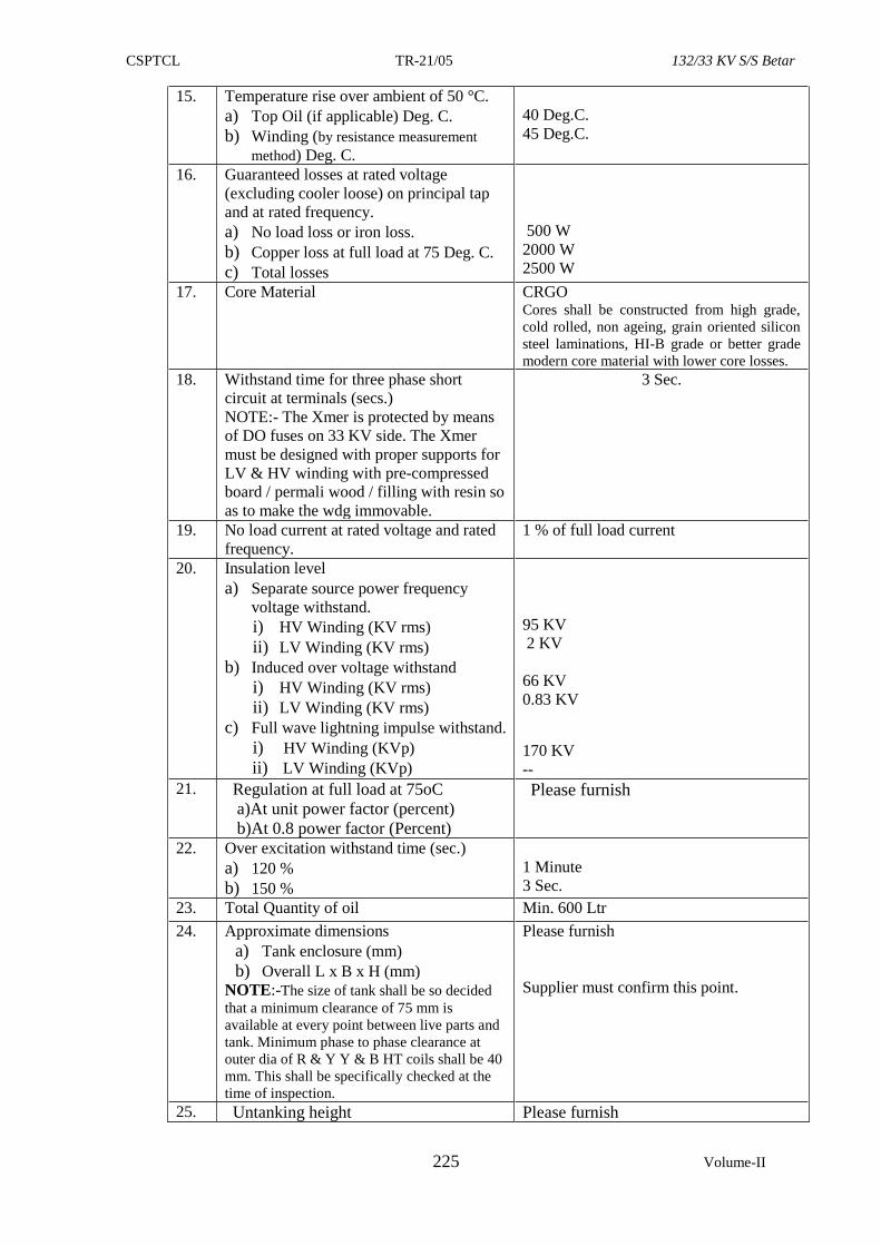
CSPTCL TR-21/05 132/33 KV S/S Betar
225 Volume-II
15. Temperature rise over ambient of 50 °C.
a) Top Oil (if applicable) Deg. C.
b) Winding (by resistance measurement
method) Deg. C.
40 Deg.C.
45 Deg.C.
16. Guaranteed losses at rated voltage
(excluding cooler loose) on principal tap
and at rated frequency.
a) No load loss or iron loss.
b) Copper loss at full load at 75 Deg. C.
c) Total losses
500 W
2000 W
2500 W
17. Core Material
CRGO Cores shall be constructed from high grade,
cold rolled, non ageing, grain oriented silicon
steel laminations, HI-B grade or better grade
modern core material with lower core losses.
18. Withstand time for three phase short
circuit at terminals (secs.)
NOTE:- The Xmer is protected by means
of DO fuses on 33 KV side. The Xmer
must be designed with proper supports for
LV & HV winding with pre-compressed
board / permali wood / filling with resin so
as to make the wdg immovable.
3 Sec.
19. No load current at rated voltage and rated
frequency.
1 % of full load current
20. Insulation level
a) Separate source power frequency
voltage withstand.
i) HV Winding (KV rms)
ii) LV Winding (KV rms)
b) Induced over voltage withstand
i) HV Winding (KV rms)
ii) LV Winding (KV rms)
c) Full wave lightning impulse withstand.
i) HV Winding (KVp)
ii) LV Winding (KVp)
95 KV
2 KV
66 KV
0.83 KV
170 KV
--
21. Regulation at full load at 75oC
a)At unit power factor (percent)
b)At 0.8 power factor (Percent)
Please furnish
22. Over excitation withstand time (sec.)
a) 120 %
b) 150 %
1 Minute
3 Sec.
23. Total Quantity of oil Min. 600 Ltr
24. Approximate dimensions
a) Tank enclosure (mm)
b) Overall L x B x H (mm)
NOTE:-The size of tank shall be so decided
that a minimum clearance of 75 mm is
available at every point between live parts and
tank. Minimum phase to phase clearance at
outer dia of R & Y Y & B HT coils shall be 40
mm. This shall be specifically checked at the
time of inspection.
Please furnish
Supplier must confirm this point.
25. Untanking height
Please furnish
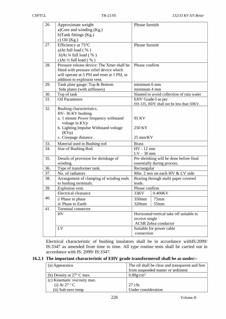
CSPTCL TR-21/05 132/33 KV S/S Betar
226 Volume-II
26. Approximate weight
a)Core and winding (Kg.)
b)Tank fittings (Kg.)
c) Oil (Kg.)
Please furnish
27. Efficiency at 75°C
a)At full load ( % )
b)At ¾ full load ( % )
c)At ½ full load ( % )
Please furnish
28. Pressure release device: The Xmer shall be
fitted with pressure relief device which
will operate at 5 PSI and reset at 1 PSI, in
addition to explosion vent.
Please confirm
29. Tank plate gauge: Top & Bottom
Side plates (with stiffeners)
minimum 6 mm
minimum 4 mm
30. Top of tank Slanted to avoid collection of rain water
31. Oil Parameters EHV Grade-I as per ISS 335, BDV shall not be less than 50KV.
32. Bushing characteristics.
HV- 36 KV bushing
a. 1 minute Power frequency withstand
voltage in KVp
b. Lighting Impulse Withstand voltage
(KVp)
c. Creepage distance .
95 KV
250 KV
25 mm/KV
33. Material used in Bushing rod Brass
34. Size of Bushing Rod. HV - 12 mm
LV – 30 mm
35. Details of provision for shrinkage of
winding.
Pre shrinking will be done before final
essentially during process.
36. Type of transformer tank. Rectangular
37. No. of radiators Min. 2 nos on each HV & LV side
38. Arrangement of clamping of winding ends
to bushing terminals.
Brazing through multi paper covered
leads.
39. Explosion vent. Please confirm
40.
Electrical clearance 33KV 0.400KV
i/ Phase to phase
ii/ Phase to Earth
350mm
320mm
75mm
55mm
41. Terminal connector
HV
Horizontal/vertical take off suitable to
receive single
ACSR Zebra conductor
LV Suitable for power cable
connection
Electrical characteristic of bushing insulators shall be in accordance withIS:2099/
IS:3347 as amended from time to time. All type routine tests shall be carried out in
accordance with IS: 2099/ IS:3347.
16.2.1 The important characteristic of EHV grade transformeroil shall be as under:-
(a) Appearance
The oil shall be clear and transparent and free
from suspended matter or sediment
(b) Density at 27o C max. 0.89g/cm3
(c) Kinematic viscosity max.
(i) At 27 o C
(ii) Sub-zero temp
27 cSt.
Under consideration
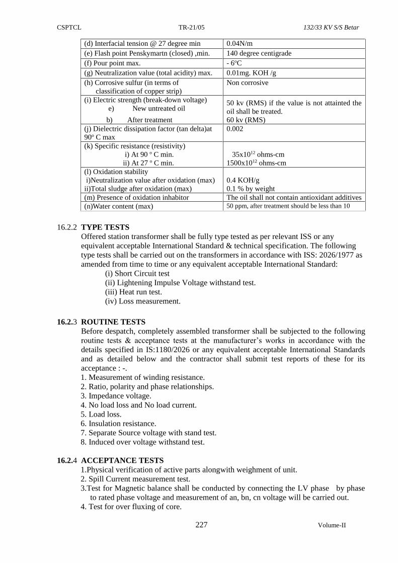
CSPTCL TR-21/05 132/33 KV S/S Betar
227 Volume-II
(d) Interfacial tension @ 27 degree min 0.04N/m
(e) Flash point Penskymartn (closed) ,min. 140 degree centigrade
(f) Pour point max. - 6oC
(g) Neutralization value (total acidity) max. 0.01mg. KOH /g
(h) Corrosive sulfur (in terms of
classification of copper strip)
Non corrosive
(i) Electric strength (break-down voltage)
e) New untreated oil
b) After treatment
50 kv (RMS) if the value is not attainted the
oil shall be treated.
60 kv (RMS)
(j) Dielectric dissipation factor (tan delta)at
90o C max
0.002
(k) Specific resistance (resistivity)
i) At 90 o C min.
ii) At 27 o C min.
35x1012 ohms-cm
1500x1012 ohms-cm
(l) Oxidation stability
i)Neutralization value after oxidation (max)
ii)Total sludge after oxidation (max)
0.4 KOH/g
0.1 % by weight
(m) Presence of oxidation inhabitor The oil shall not contain antioxidant additives
(n)Water content (max) 50 ppm, after treatment should be less than 10
16.2.2 TYPE TESTS
Offered station transformer shall be fully type tested as per relevant ISS or any
equivalent acceptable International Standard & technical specification. The following
type tests shall be carried out on the transformers in accordance with ISS: 2026/1977 as
amended from time to time or any equivalent acceptable International Standard:
(i) Short Circuit test
(ii) Lightening Impulse Voltage withstand test.
(iii) Heat run test.
(iv) Loss measurement.
16.2.3 ROUTINE TESTS
Before despatch, completely assembled transformer shall be subjected to the following
routine tests & acceptance tests at the manufacturer’s works in accordance with the
details specified in IS:1180/2026 or any equivalent acceptable International Standards
and as detailed below and the contractor shall submit test reports of these for its
acceptance : -.
1. Measurement of winding resistance.
2. Ratio, polarity and phase relationships.
3. Impedance voltage.
4. No load loss and No load current.
5. Load loss.
6. Insulation resistance.
7. Separate Source voltage with stand test.
8. Induced over voltage withstand test.
16.2.4 ACCEPTANCE TESTS
1.Physical verification of active parts alongwith weighment of unit.
2. Spill Current measurement test.
3.Test for Magnetic balance shall be conducted by connecting the LV phase by phase
to rated phase voltage and measurement of an, bn, cn voltage will be carried out.
4. Test for over fluxing of core.
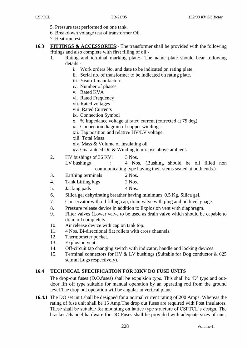
CSPTCL TR-21/05 132/33 KV S/S Betar
228 Volume-II
5. Pressure test performed on one tank.
6. Breakdown voltage test of transformer Oil.
7. Heat run test.
16.3 FITTINGS & ACCESSORIES:- The transformer shall be provided with the following
fittings and also complete with first filling of oil:-
1. Rating and terminal marking plate:- The name plate should bear following
details:-
i. Work orders No. and date to be indicated on rating plate.
ii. Serial no. of transformer to be indicated on rating plate.
iii. Year of manufacture
iv. Number of phases
v. Rated KVA
vi. Rated Frequency
vii. Rated voltages
viii. Rated Currents
ix. Connection Symbol
x. % Impedance voltage at rated current (corrected at 75 deg)
xi. Connection diagram of copper windings.
xii. Tap position and relative HV/LV voltage.
xiii. Total Mass
xiv. Mass & Volume of Insulating oil
xv. Guaranteed Oil & Winding temp. rise above ambient.
2. HV bushings of 36 KV: 3 Nos.
LV bushings : 4 Nos. (Bushing should be oil filled non
communicating type having their stems sealed at both ends.)
3. Earthing terminals 2 Nos.
4. Tank Lifting lugs 2 Nos.
5. Jacking pads 4 Nos.
6. Silica gel dehydrating breather having minimum 0.5 Kg. Silica gel.
7. Conservator with oil filling cap, drain valve with plug and oil level guage.
8. Pressure release device in addition to Explosion vent with diaphragm.
9. Filter valves (Lower valve to be used as drain valve which should be capable to
drain oil completely.
10. Air release device with cap on tank top.
11. 4 Nos. Bi-directional flat rollers with cross channels.
12. Thermometer pocket.
13. Explosion vent.
14. Off-circuit tap changing switch with indicator, handle and locking devices.
15. Terminal connectors for HV & LV bushings (Suitable for Dog conductor & 625
sq.mm Lugs respectively).
16.4 TECHNICAL SPECIFICATION FOR 33KV DO FUSE UNITS
The drop-out fuses (D.O.fuses) shall be expulsion type. This shall be ‘D’ type and out-
door lift off type suitable for manual operation by an operating rod from the ground
level.The drop out operation will be angular in vertical plane.
16.4.1 The DO set unit shall be designed for a normal current rating of 200 Amps. Whereas the
rating of fuse unit shall be 15 Amp.The drop out fuses are required with Post Insulators.
These shall be suitable for mounting on lattice type structure of CSPTCL’s design. The
bracket /channel hardware for DO Fuses shall be provided with adequate sizes of nuts,
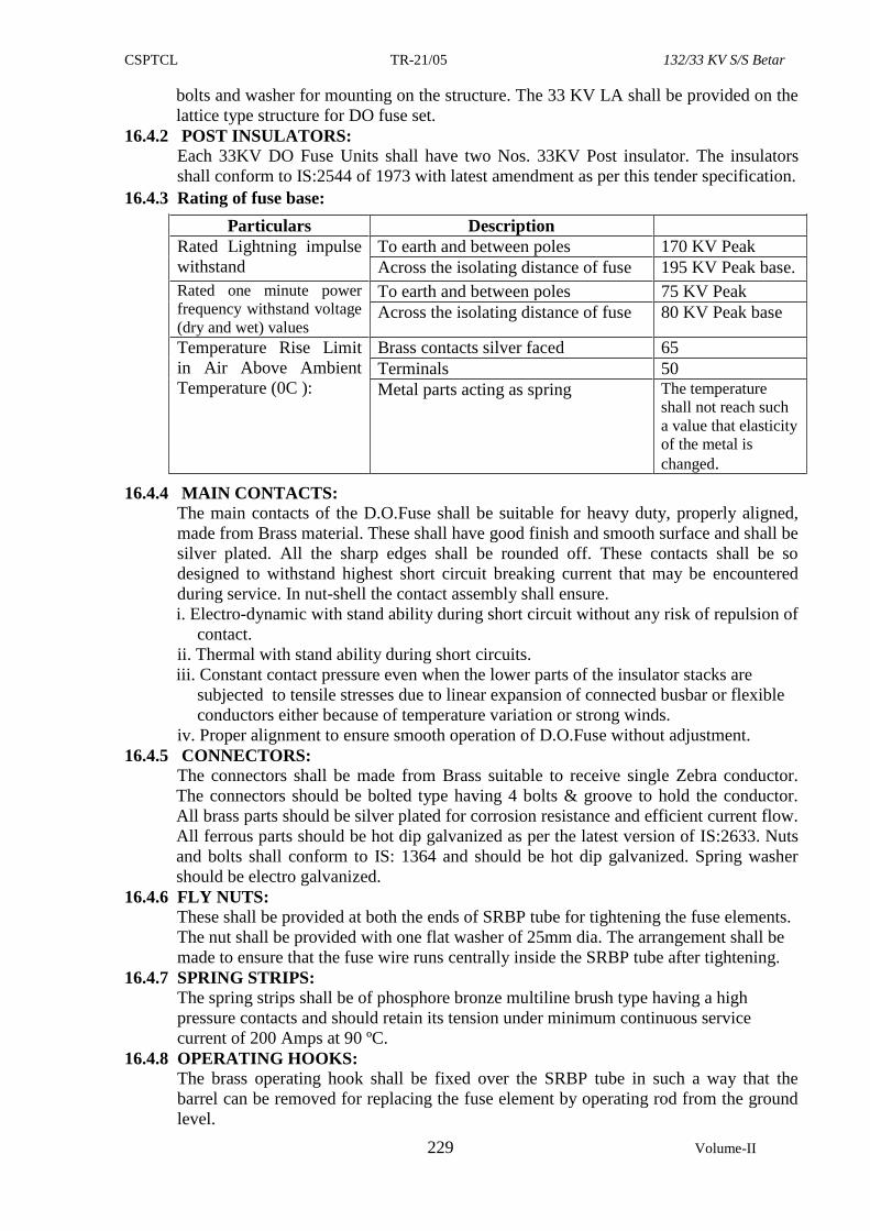
CSPTCL TR-21/05 132/33 KV S/S Betar
229 Volume-II
bolts and washer for mounting on the structure. The 33 KV LA shall be provided on the
lattice type structure for DO fuse set.
16.4.2 POST INSULATORS:
Each 33KV DO Fuse Units shall have two Nos. 33KV Post insulator. The insulators
shall conform to IS:2544 of 1973 with latest amendment as per this tender specification.
16.4.3 Rating of fuse base:
Particulars Description
Rated Lightning impulse
withstand
To earth and between poles 170 KV Peak
Across the isolating distance of fuse 195 KV Peak base.
Rated one minute power
frequency withstand voltage
(dry and wet) values
To earth and between poles 75 KV Peak
Across the isolating distance of fuse 80 KV Peak base
Temperature Rise Limit
in Air Above Ambient
Temperature (0C ):
Brass contacts silver faced 65
Terminals 50
Metal parts acting as spring The temperature
shall not reach such
a value that elasticity
of the metal is
changed.
16.4.4 MAIN CONTACTS:
The main contacts of the D.O.Fuse shall be suitable for heavy duty, properly aligned,
made from Brass material. These shall have good finish and smooth surface and shall be
silver plated. All the sharp edges shall be rounded off. These contacts shall be so
designed to withstand highest short circuit breaking current that may be encountered
during service. In nut-shell the contact assembly shall ensure.
i. Electro-dynamic with stand ability during short circuit without any risk of repulsion of
contact.
ii. Thermal with stand ability during short circuits.
iii. Constant contact pressure even when the lower parts of the insulator stacks are
subjected to tensile stresses due to linear expansion of connected busbar or flexible
conductors either because of temperature variation or strong winds.
iv. Proper alignment to ensure smooth operation of D.O.Fuse without adjustment.
16.4.5 CONNECTORS:
The connectors shall be made from Brass suitable to receive single Zebra conductor.
The connectors should be bolted type having 4 bolts & groove to hold the conductor.
All brass parts should be silver plated for corrosion resistance and efficient current flow.
All ferrous parts should be hot dip galvanized as per the latest version of IS:2633. Nuts
and bolts shall conform to IS: 1364 and should be hot dip galvanized. Spring washer
should be electro galvanized.
16.4.6 FLY NUTS:
These shall be provided at both the ends of SRBP tube for tightening the fuse elements.
The nut shall be provided with one flat washer of 25mm dia. The arrangement shall be
made to ensure that the fuse wire runs centrally inside the SRBP tube after tightening.
16.4.7 SPRING STRIPS:
The spring strips shall be of phosphore bronze multiline brush type having a high
pressure contacts and should retain its tension under minimum continuous service
current of 200 Amps at 90 ºC.
16.4.8 OPERATING HOOKS:
The brass operating hook shall be fixed over the SRBP tube in such a way that the
barrel can be removed for replacing the fuse element by operating rod from the ground
level.
CSPTCL TR-21/05 132/33 KV S/S Betar
230 Volume-II
The drop out fuse units shall operate efficiently. Speed of operation shall not depend on
the inclination of the fuse. However, the inclination of the fuse barrel shall be adjusted
in such a way that the barrel does not drop by gravitational force.
16.4.9 D.O.BARRELS:
The D.O. Fuse Barrels shall be made from SRBP and shall conform to BSS:1314. The
supplier shall furnish the test certificate for the fuse barrels offered for use in the drop
out fuses alongwith each lot offered for inspection to the inspecting officer. The test
certificates of SRBP barrel should indicate the following test results:-
i. Dimension:
(a) External dia
(b) Wall thickness
(c) Internal dia
ii. Max. wraping in 12" length of the tube.
iii. Axial electric strength (Proof test in oil at 90ºC at 25KV rms 50 C/S.)
The barrel should with stand this test satisfactorily for one minute
iv. Radial electric strength (Proof test in oil at 90ºC at 19 KV rms 50 C/S.)
The barrel should with stand this test satisfactorily for one minute
v. Surface electric strength (Proof test in air at room temp.(32°C) at 14 KV rms at
50 C/s)
The barrel should withstand this test satisfactorily for one minute.
vi. Water absorption in 14 hours
vii. Resistance to Hot Oil
viii. Cohesion between layers (Proof test)
ix. Machine-ability
16.4.10 The contractor should indicate the name of manufactures of SRBP tube from where
they will purchase the Barrel to make available the above test certificate. The barrels
should have the property to resist fire whenever the fuse is blown off. It should not
catch fire easily during blowing off of fuse element inside the barrel which causes
short time high temperature.
16.4.11 TESTS:
Type Test Certificate:
The contractor shall furnish the type test certificate of DO Fuses alongwith certified
copy of the drawing and other guaranteed technical particulars. The following type test
certificate as per ISS:9385 Part-II-1980 (with latest amendment) or any equivalent
International Standards must be furnished. The type test should not be older than 5
(five) years and should be performed in the Govt. recognized Lab as on the last date of
submission of bid.
(i) Impulse voltage withstand test,
(ii) H.V. Power Frequency dry / wet withstand test.
(iii) Temperature rise test.
(iv) Breaking Current test.
Alongwith the inspection report of D.O.Fuse Units, the contractor shall invariably
furnish Routine Test certificate of DO Fuse barrels & Post Insulator of their
manufacturers.
***
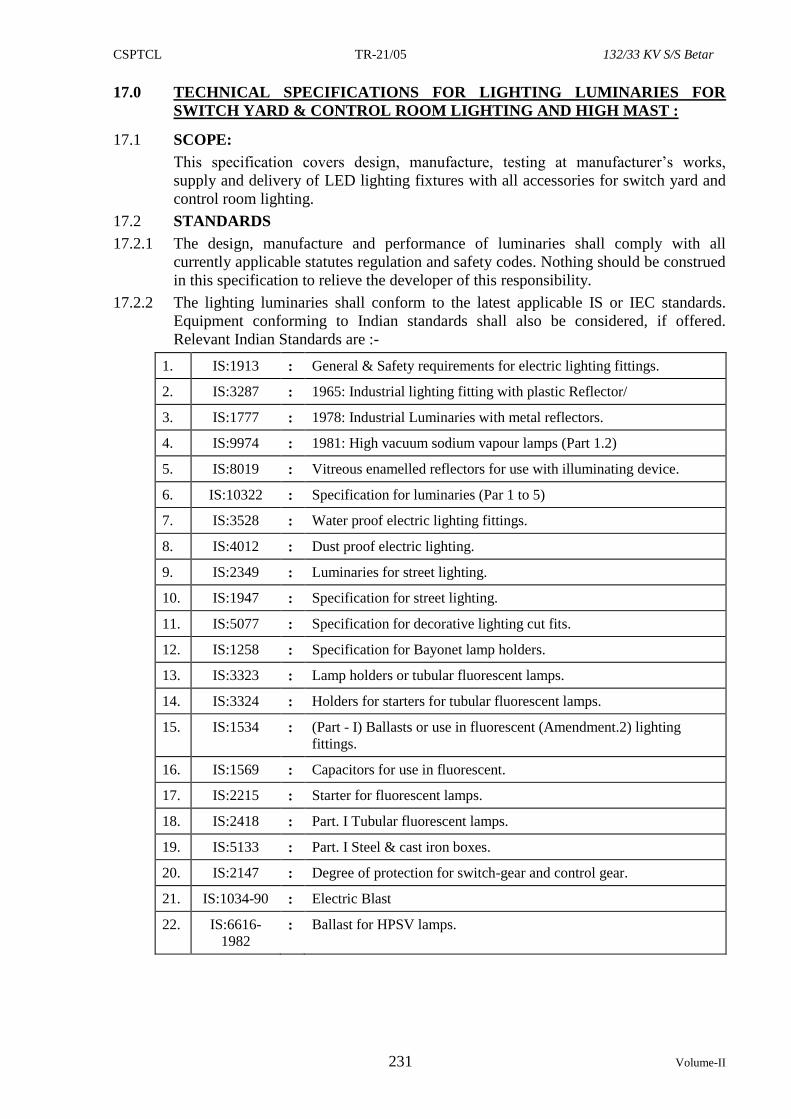
CSPTCL TR-21/05 132/33 KV S/S Betar
231 Volume-II
17.0 TECHNICAL SPECIFICATIONS FOR LIGHTING LUMINARIES FOR
SWITCH YARD & CONTROL ROOM LIGHTING AND HIGH MAST :
17.1 SCOPE:
This specification covers design, manufacture, testing at manufacturer’s works,
supply and delivery of LED lighting fixtures with all accessories for switch yard and
control room lighting.
17.2 STANDARDS
17.2.1 The design, manufacture and performance of luminaries shall comply with all
currently applicable statutes regulation and safety codes. Nothing should be construed
in this specification to relieve the developer of this responsibility.
17.2.2 The lighting luminaries shall conform to the latest applicable IS or IEC standards.
Equipment conforming to Indian standards shall also be considered, if offered.
Relevant Indian Standards are :-
1. IS:1913 : General & Safety requirements for electric lighting fittings.
2. IS:3287 : 1965: Industrial lighting fitting with plastic Reflector/
3. IS:1777 : 1978: Industrial Luminaries with metal reflectors.
4. IS:9974 : 1981: High vacuum sodium vapour lamps (Part 1.2)
5. IS:8019 : Vitreous enamelled reflectors for use with illuminating device.
6. IS:10322 : Specification for luminaries (Par 1 to 5)
7. IS:3528 : Water proof electric lighting fittings.
8. IS:4012 : Dust proof electric lighting.
9. IS:2349 : Luminaries for street lighting.
10. IS:1947 : Specification for street lighting.
11. IS:5077 : Specification for decorative lighting cut fits.
12. IS:1258 : Specification for Bayonet lamp holders.
13. IS:3323 : Lamp holders or tubular fluorescent lamps.
14. IS:3324 : Holders for starters for tubular fluorescent lamps.
15. IS:1534 : (Part - I) Ballasts or use in fluorescent (Amendment.2) lighting
fittings.
16. IS:1569 : Capacitors for use in fluorescent.
17. IS:2215 : Starter for fluorescent lamps.
18. IS:2418 : Part. I Tubular fluorescent lamps.
19. IS:5133 : Part. I Steel & cast iron boxes.
20. IS:2147 : Degree of protection for switch-gear and control gear.
21. IS:1034-90 : Electric Blast
22. IS:6616-
1982 : Ballast for HPSV lamps.
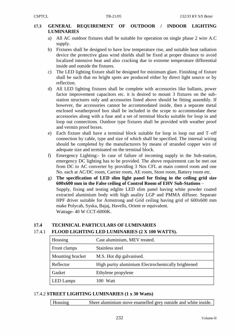
CSPTCL TR-21/05 132/33 KV S/S Betar
232 Volume-II
17.3 GENERAL REQUIREMENT OF OUTDOOR / INDOOR LIGHTING
LUMINARIES
a) All AC outdoor fixtures shall be suitable for operation on single phase 2 wire A.C
supply.
b) Fixtures shall be designed to have low temperature rise, and suitable heat radiation
device the protective glass wind shields shall be fixed at proper distance to avoid
localized intensive heat and also cracking due to extreme temperature differential
inside and outside the fixtures.
c) The LED lighting fixture shall be designed for minimum glare. Finishing of fixture
shall be such that no bright spots are produced either by direct light source or by
reflection.
d) All LED lighting fixtures shall be complete with accessories like ballasts, power
factor improvement capacitors etc. it is desired to mount 3 fixtures on the sub-
station structures only and accessories listed above should be fitting assembly. If
however, the accessories cannot be accommodated inside, then a separate metal
enclosed weatherproof box shall be included in the scope to accommodate these
accessories along with a fuse and a set of terminal blocks suitable for loop in and
loop out connections. Outdoor type fixtures shall be provided with weather proof
and vermin proof boxes.
e) Each fixture shall have a terminal block suitable for loop in loop out and T–off
connection by cable, type and size of which shall be specified. The internal wiring
should be completed by the manufacturers by means of stranded copper wire of
adequate size and terminated on the terminal block.
f) Emergency Lighting:- In case of failure of incoming supply in the Sub-station,
emergency DC lighting has to be provided. The above requirement can be met out
from DC to AC converter by providing 3 Nos CFL at main control room and one
No. each at AC/DC room, Carrier room, AE room, Store room, Battery room etc.
g) The specification of LED slim light panel for fixing in the ceiling grid size
600x600 mm in the False ceiling of Control Room of EHV Sub-Stations –
Supply, fixing and testing edglite LED slim panel having white powder coated
extracted aluminium body with high auality LGP and PMMA diffuser. Separate
HPF driver suitable for Armstrong and Grid ceiling having grid of 600x600 mm
make Polycab, Syska, Bajaj, Havells, Orient or equivalent.
Wattage- 40 W CCT-6000K.
17.4 TECHNICAL PARTICULARS OF LUMINARIES
17.4.1 FLOOD LIGHTING LED LUMINARIES (2 X 100 WATTS).
Housing Cast aluminium, MEV treated.
Front clamps Stainless steel
Mounting bracket M.S. Hot dip galvanised.
Reflector High purity aluminium Electrochemically brightened
Gasket Ethylene propylene
LED Lamps 100 Watt
17.4.2 STREET LIGHTING LUMINARIES (1 x 30 Watts)
Housing Sheet aluminium stove enamelled grey outside and white inside.
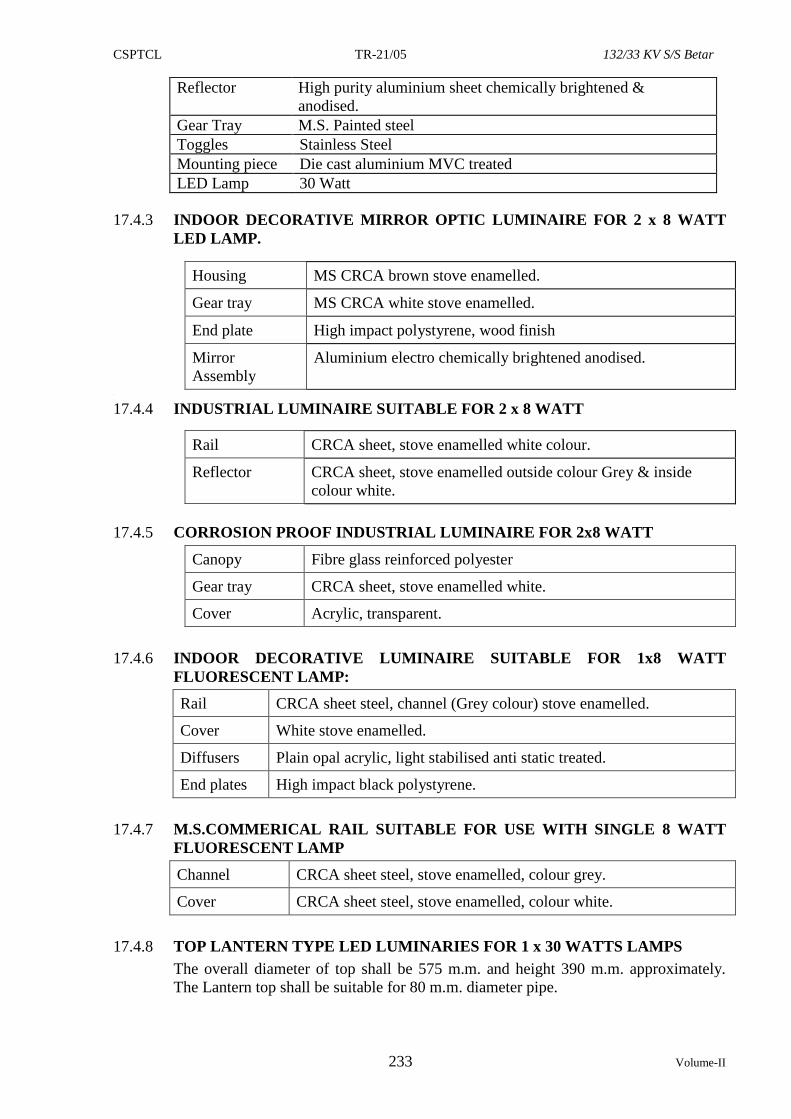
CSPTCL TR-21/05 132/33 KV S/S Betar
233 Volume-II
Reflector High purity aluminium sheet chemically brightened &
anodised.
Gear Tray M.S. Painted steel
Toggles Stainless Steel
Mounting piece Die cast aluminium MVC treated
LED Lamp 30 Watt
17.4.3 INDOOR DECORATIVE MIRROR OPTIC LUMINAIRE FOR 2 x 8 WATT
LED LAMP.
Housing MS CRCA brown stove enamelled.
Gear tray MS CRCA white stove enamelled.
End plate High impact polystyrene, wood finish
Mirror
Assembly
Aluminium electro chemically brightened anodised.
[
17.4.4 INDUSTRIAL LUMINAIRE SUITABLE FOR 2 x 8 WATT
Rail CRCA sheet, stove enamelled white colour.
Reflector CRCA sheet, stove enamelled outside colour Grey & inside
colour white.
17.4.5 CORROSION PROOF INDUSTRIAL LUMINAIRE FOR 2x8 WATT
Canopy Fibre glass reinforced polyester
Gear tray CRCA sheet, stove enamelled white.
Cover Acrylic, transparent.
17.4.6 INDOOR DECORATIVE LUMINAIRE SUITABLE FOR 1x8 WATT
FLUORESCENT LAMP:
Rail CRCA sheet steel, channel (Grey colour) stove enamelled.
Cover White stove enamelled.
Diffusers Plain opal acrylic, light stabilised anti static treated.
End plates High impact black polystyrene.
17.4.7 M.S.COMMERICAL RAIL SUITABLE FOR USE WITH SINGLE 8 WATT
FLUORESCENT LAMP
Channel CRCA sheet steel, stove enamelled, colour grey.
Cover CRCA sheet steel, stove enamelled, colour white.
17.4.8 TOP LANTERN TYPE LED LUMINARIES FOR 1 x 30 WATTS LAMPS
The overall diameter of top shall be 575 m.m. and height 390 m.m. approximately.
The Lantern top shall be suitable for 80 m.m. diameter pipe.
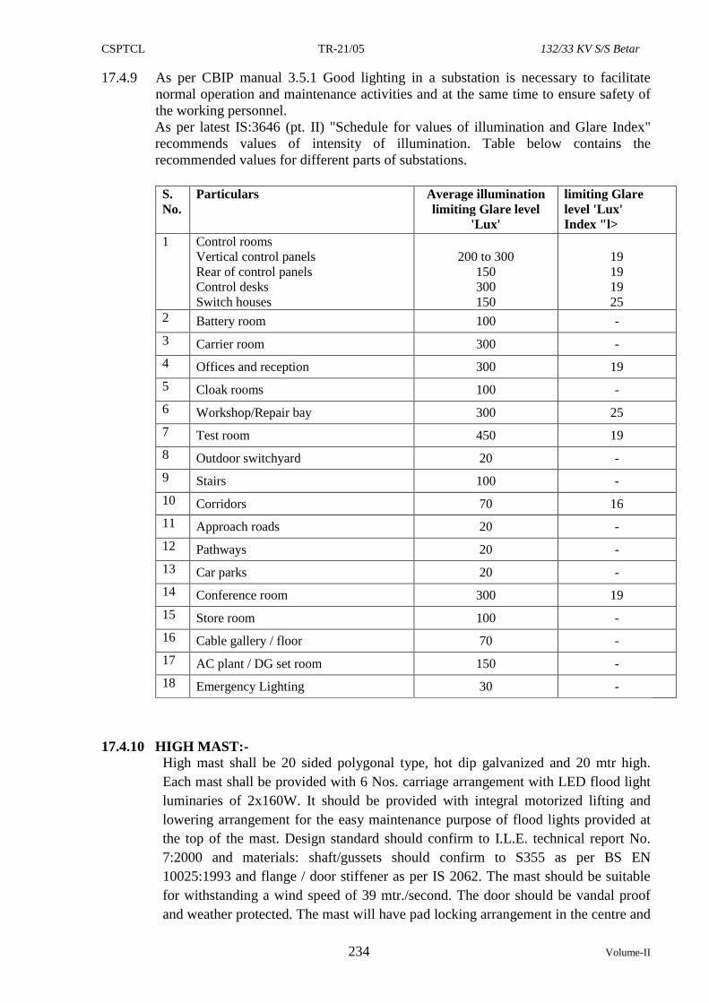
CSPTCL TR-21/05 132/33 KV S/S Betar
234 Volume-II
17.4.9 As per CBIP manual 3.5.1 Good lighting in a substation is necessary to facilitate
normal operation and maintenance activities and at the same time to ensure safety of
the working personnel.
As per latest IS:3646 (pt. II) "Schedule for values of illumination and Glare Index"
recommends values of intensity of illumination. Table below contains the
recommended values for different parts of substations.
S.
No.
Particulars Average illumination
limiting Glare level
'Lux'
limiting Glare
level 'Lux'
Index "l>
1 Control rooms
Vertical control panels
Rear of control panels
Control desks
Switch houses
200 to 300
150
300
150
19
19
19
25
2 Battery room 100 -
3 Carrier room 300 -
4 Offices and reception 300 19
5 Cloak rooms 100 -
6 Workshop/Repair bay 300 25
7 Test room 450 19
8 Outdoor switchyard 20 -
9 Stairs 100 -
10 Corridors 70 16
11 Approach roads 20 -
12 Pathways 20 -
13 Car parks 20 -
14 Conference room 300 19
15 Store room 100 -
16 Cable gallery / floor 70 -
17 AC plant / DG set room 150 -
18 Emergency Lighting 30 -
17.4.10 HIGH MAST:- High mast shall be 20 sided polygonal type, hot dip galvanized and 20 mtr high.
Each mast shall be provided with 6 Nos. carriage arrangement with LED flood light
luminaries of 2x160W. It should be provided with integral motorized lifting and
lowering arrangement for the easy maintenance purpose of flood lights provided at
the top of the mast. Design standard should confirm to I.L.E. technical report No.
7:2000 and materials: shaft/gussets should confirm to S355 as per BS EN
10025:1993 and flange / door stiffener as per IS 2062. The mast should be suitable
for withstanding a wind speed of 39 mtr./second. The door should be vandal proof
and weather protected. The mast will have pad locking arrangement in the centre and
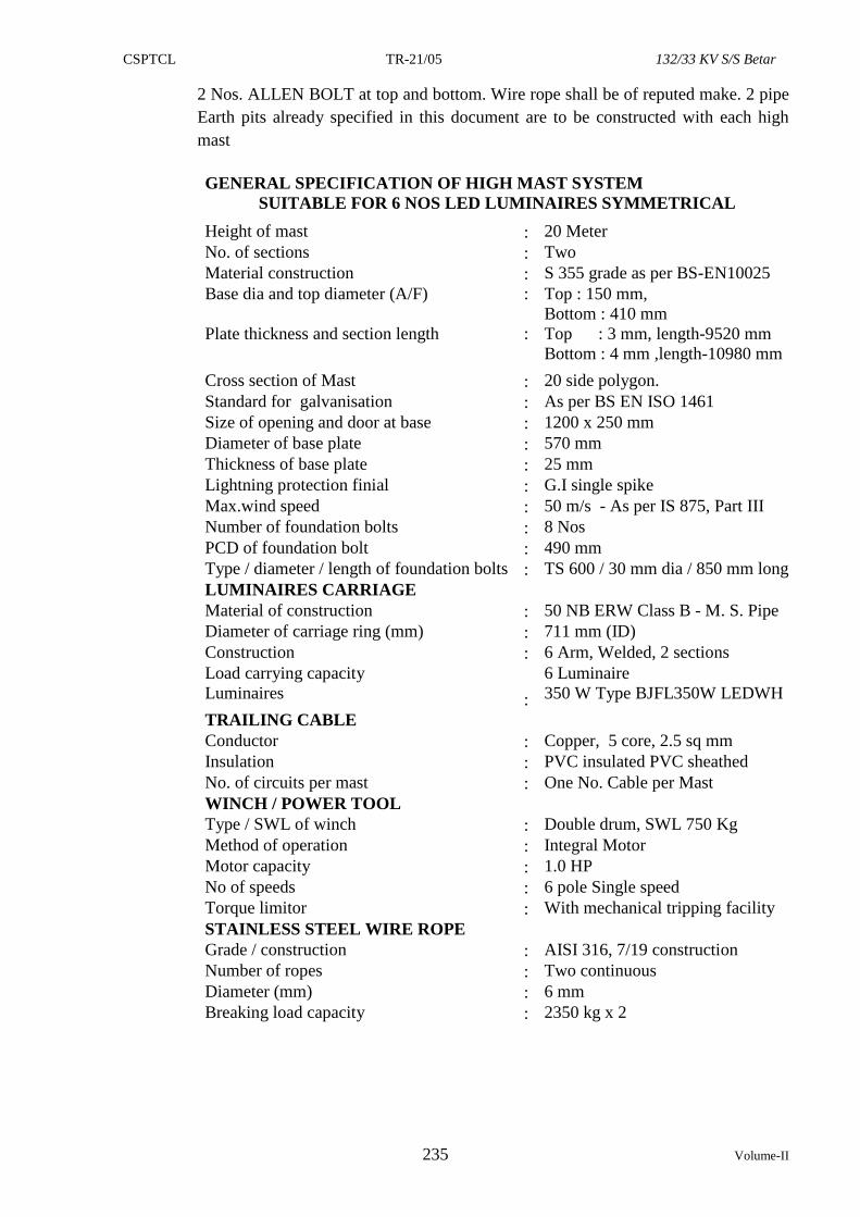
CSPTCL TR-21/05 132/33 KV S/S Betar
235 Volume-II
2 Nos. ALLEN BOLT at top and bottom. Wire rope shall be of reputed make. 2 pipe
Earth pits already specified in this document are to be constructed with each high
mast
GENERAL SPECIFICATION OF HIGH MAST SYSTEM
SUITABLE FOR 6 NOS LED LUMINAIRES SYMMETRICAL
Height of mast : 20 Meter
No. of sections : Two
Material construction : S 355 grade as per BS-EN10025
Base dia and top diameter (A/F) : Top : 150 mm,
Bottom : 410 mm
Plate thickness and section length : Top : 3 mm, length-9520 mm
Bottom : 4 mm ,length-10980 mm
Cross section of Mast : 20 side polygon.
Standard for galvanisation : As per BS EN ISO 1461
Size of opening and door at base : 1200 x 250 mm
Diameter of base plate : 570 mm
Thickness of base plate : 25 mm
Lightning protection finial : G.I single spike
Max.wind speed : 50 m/s - As per IS 875, Part III
Number of foundation bolts : 8 Nos
PCD of foundation bolt : 490 mm
Type / diameter / length of foundation bolts : TS 600 / 30 mm dia / 850 mm long
LUMINAIRES CARRIAGE
Material of construction : 50 NB ERW Class B - M. S. Pipe
Diameter of carriage ring (mm) : 711 mm (ID)
Construction : 6 Arm, Welded, 2 sections
Load carrying capacity
Luminaires
:
6 Luminaire
350 W Type BJFL350W LEDWH
TRAILING CABLE
Conductor : Copper, 5 core, 2.5 sq mm
Insulation : PVC insulated PVC sheathed
No. of circuits per mast : One No. Cable per Mast
WINCH / POWER TOOL
Type / SWL of winch : Double drum, SWL 750 Kg
Method of operation : Integral Motor
Motor capacity : 1.0 HP
No of speeds : 6 pole Single speed
Torque limitor : With mechanical tripping facility
STAINLESS STEEL WIRE ROPE
Grade / construction : AISI 316, 7/19 construction
Number of ropes : Two continuous
Diameter (mm) : 6 mm
Breaking load capacity : 2350 kg x 2
CSPTCL TR-21/05 132/33 KV S/S Betar
236 Volume-II
18.0 SPECIFICATION FOR SUPPLY OF GALVANISED STEEL STRUCTURES
AND EARTHING STEEL, AC DC DISTRIBUTION BOARD AND
MARSHELLING BOX. ERECTION, TESTING AND COMMISSIONING OF
132 KV / 33 KV SUB STATION.
18.1 GALVANISED STEEL STRUCTURES
18.1.1 SCOPE.
This specification covers following works.
a) Engineering and supply of galvanised fabricated steel structures for gantry and
equipments for sub-station as per CSPTCL design & drawing and associated bay
work design engineering & supply of earthing steel for Earth mat.
b) Erection of gantry, bus bar, and equipment’s structures, stringing of gantry, bus
bar and shielding wires, installation of out door / in-door equipments, inter
equipment connections using Panther / Zebra ACSR conductors.
c) Installation of cable trays in trenches, laying of control and power cables,
construction of earth mat, earthing pits, grounding electrodes and risers.
Note:- The contractor shall have to supply steel structures required for construction of
bays at 132 / 33 KV sub-station where ever required. These structures should
match standards in all respects.
18.1.2 STANDARDS.
The steel structures shall conform to the latest edition of the standard as stated
hereunder.
a) I.S. 2062 / 226 Specification for structural steel and quality steel.
b) I.S. 802. Use of structural steel in over head transmission line.
c) I.S 806 Code of practice for use of steel tubes.
d) I.S. 808 Specification of rolled steel, channel, beam and angle sections.
18.2 DESIGN REQUIREMENTS:
Following general guide lines shall be followed for verification of design:-
a. For design of steel structures loads such as dead loads, live loads, wind loads
etc. shall be based on IS 875 Part IV as per CSPTCL drawings.
b. For materials & permissible stresses, IS 802 Part I Section 2 shall be followed
in general.
c. Maximum slenderness ratios of leg members, other stressed members and
redundant members for compressive force shall be as per IS 802.
d. In order to facilitate inspection & maintenance the structures shall be provided
with step bolts not less than 16 mm diameter & 175 mm long spaced not more
than 450 mm apart, staggered on faces on one leg extending from about 0.5
metre above ground level to top of the tower. The step bolts shall conform to
IS: 10238.
e. All Structures shall be designed for worst condition of dead loads, live loads
wind loads etc. as per IS 875 Seismic forces as per IS: 1893, importance factor
of 1.5, loads due to deviation of conductor, loads due to un-balanced vertical
and horizontal forces, erection loads, short circuit forces. Short Circuit forces
shall be calculated considering a fault level of 31.5 KA IEC: 865 may be
followed for evaluation of short circuit forces.
f. Substation gantry structures shall be designed for 2 conditions i.e. Normal
condition & Short Circuit Conditions. In both conditions the design will be
CSPTCL TR-21/05 132/33 KV S/S Betar
237 Volume-II
based on assumption that stringing is done only on one side i.e. all the three
phases wire broken on the other side. Factor of safety of 2.0 under Normal
conditions & 1.5 under Short Circuit condition shall be taken.
g. Vertical levels of half the span of conductors/ string & the Earth wire on
either side of beam shall be taken for design. Weight of man with tools shall
be considered as 150 Kg. for design.
h. Terminal / take off gantries shall be designed for a minimum conductor
tension of 1 metric tonne per phase for 132 KV or as per requirement
whichever is higher. The distance between the terminal gantry & take off
tower shall be taken as 200 metres. The design shall also be checked
considering ± 30° degree deviation of conductor in both vertical and
horizontal planes. For other gantries structural layout requirements shall be
adopted.
i. The contractor shall furnish design, drawing, Bill of Material (BoM) of
structures on award of contract. The design drawing should clearly indicate
sections numbers and sizes of the bolts & details of typical joints, member
wise weights & total weight of the structure.
j. There should be provision of connectivity of beam in the last feeder gantries
for future beam.
As designing is in the scope of contractor, supply/approval of design & drawing shall
not relieve the contractor from his responsibility for :–
i) Observing all the required clearances (phase to phase, phase to earth, sectional
clearances & ground clearances) as per tender specifications.
ii) Calculation of force at all the joints/sections and their load carrying capacity shall
be as per details of design requirements (e) given above.
iii) In case, the structures not complies with points (i & ii) given above, the contractor
shall have to modify/replace the structure as the case may be and agreeable to
CSPTCL without any cost implication.
Note: Please note that separate columns for bus bar structures, take off gantries,
transformer gantry etc should be provided. In no case common column for take
off or other type of gantries and bus bar structures shall be accepted.
CSPTCL TR-21/05 132/33 KV S/S Betar
238 Volume-II
18.3 TECHNICAL SPECIFICATIONS FOR ACDB & DCDB PANELS AND
MARSHALLING/ JUNCTION BOX
18.3.1 TECHNICAL SPECIFICATION FOR ACDB & DCDB PANELS
SCOPE.
This specification covers the complete design, manufacture, testing, inspection,
packing and delivery of the following equipments.
1. 3 phase 415V AC Board with Metal clad switches
2. 110V DC Board with Metal clad switches
3. 48V DC Board with Metal clad switches
18.3.2 STANDARDS.
Unless otherwise specified, the equipments covered under this specification shall be
manufactured, tested and supplied with the guarantee particulars as per the following
Indian Standards Specifications.
IS-4237 - General requirements for switch gear & control gear for
voltage not exceeding 1000V
IS-2147 - Degrees of protection provided by enclosures for low voltage
switch gear and control gear.
IS-375 - Marking and arrangement for switch gear bus bars main
connection and aux. wiring
IS-2208 - HRC Cartridge fuse link up to 650V.
IS-1248 - Electrical Indicating Instruments.
IS-1554 - PVC Insulated electrical cables.
IS-2516 - AC circuit breakers.
IS-2705 - Current Transformers.
IS-3156 - Voltage Transformers
IS-4047 Heavy duty Air break switches and composite unit’s & fuses for
voltage not exceeding 1000V.
18.3.3 GENERAL REQUIREMENT
18.3.3.1 AC/DC Boards shall be metal enclosed and floor mounted. Boards shall be provided
with metal frame made of structural steel channel section properly drilled for
mounting the switchgear. These shall be of single front execution with dimension (H
x B x D) not exceeding 1600x 2000 x 400 mm (H x B x D) and having provisions for
cable entry from the bottom with removable gland plate. Provision shall also be
available for putting labels on the front doors indicating the switchgear designation.
Suitable gaskets shall be provided all round the perimeter of covers, gland plates,
door etc.
AC/DC Boards shall be divided into distinct vertical sections each comprising of:
i. Individual feeder modules arranged in the multitier formation vertically on both
sides of the Bus.
ii. Enclosed vertical busbar running in vertical section in the middle.
iii. Vertical cable alley covering the entire height on the sides.
iv. Metal sheets shall be provided between two adjacent vertical sections running to
the full height of the switchgear.
The AC Board shall be provided with incoming supply of 3 phase 4 wire 415 Volts
AC through a change over switch rated 400 Amps, so that the incoming to the bus bar
can be either taken from the station transformer or from other alternative LT supply.
CSPTCL TR-21/05 132/33 KV S/S Betar
239 Volume-II
The copper bus bar of the AC board shall be of min. 400A capacity. The AC board
shall be designed for fault current of 8KA on LT side for 3sec. The distribution of
single/ 3 phase shall be arranged through metal clad switches of 3 no. 3 phase 200
amp, 6 no. 3 phase 100 amp, 6 no. 3 phase 32 amp 4 pole and 20 no. 32 amp DP SF
with separate boxes in ACDB to various load points in the sub-station. The ACDBs
& DCDBs should have arrangement of physical Isolation through knife switches in
addition to the above mentioned features.
18.3.3.2 The 110 volt DC distribution board shall comprise of bus section of bus bars of
adequate rating suitable for 110 volt two wire un-grounded supply from the battery
charger. The out going circuits shall be 20 in numbers with a rating of 32 Amps for
each. There shall be two incomings, one main and one spare each rated 200 Amps.
Each incoming/ outgoing bay should be made with 2 no. HRC fuses and 2 pole on/off
switch. Separate section box should be provided for each outgoing bay. Heavy duty
terminal connectors, stud bolt and nut type, of proper size should be provided.
18.3.3.3 The AC/DC boards shall be metal enclosed and floor mounted. The contractor shall
provide metal frame made of structural steel channel section properly drilled for
mounting the switchgear. These shall of single front execution with a height not
exceed 1600 mm and having provisions for cable entry and exit from the bottom with
removable glade plate. HRC fuses of suitable rating shall be provided for DCDB for
the protection. No MCCB shall be provided for the protection in DCDB panels.
18.3.3.4 The cabinet shall have cool glades, lungs, heater, plugs, sockets with switch and fuse
and one lamp inside with suitable switching arrangements duly wired up for
extending supply of 420 volts AC. Suitable metal enclosed plug socket arrangement
on side wall of the box shall be provided. All terminal blocks shall be of the 1100
volts grade stud type. Only copper cable should be used.
18.3.3.5 Each Distribution board shall have 2 compartments namely-Instruments compartment
and Feeder compartment. These compartments shall have doors as described below.
a. For Instrument compartment, one no. door with indicating instruments,
indicating lamps, selector switches, nameplate mounted on it.
b. For feeders compartment, one no. inner door with one opening for handle to
operate switch fuse unit and four cut outs for outgoing MCBs. One outer door
with out cut outs & non breakable transparent sheet shall be provided.
18.3.3.6 Detachable gland plates suitable for receiving the cable shall be provided at the
bottom side of Distribution board with glands.
18.3.3.7 Each Distribution Board shall be provided with :- a. One No.name plate showing the details such as manufacturer’s name, Sr. No.,
rating etc.
b. One no. danger board scripted in Hindi and English
c. One no. flush mounted 96x96mm size ammeter with selector switch
d. One no. flush mounted 96x96mm size voltmeter with selector switch
e. One no. switch fuse disconnector unit with 100 Amp rating
f. 3 nos. LED type phase indication lamps for incoming feeder
g. 3 nos. single phase LTCTs of 10VA and CT ratio 100/5A.
18.3.3.8 The enclosure shall be provided with proper earthing arrangement. Earthing
arrangement shall consist of 2 G.I. Bolts of 12 mm (min.) with 2 spring/ plain
washers and 2 check nuts.
Two nos. Earthing studs of galvanized M.S. 25 X 6 mm shall be provided for
external earth connections at the bottom. These should be complete with plain
washer, spring washer, nuts etc. Earthing Bolts must be welded to prevent removal of
the same from the cabinet.
CSPTCL TR-21/05 132/33 KV S/S Betar
240 Volume-II
18.3.3.9 Stud type Terminal blocks shall be of 1100 V grade box clamp type ELMEX or
approved equivalent, not more than two wires shall be connected in one terminal,
Spare terminals equal in number to 20% of active terminals shall be provided. All the
terminals should be of stud type only.
18.3.4 MAIN BUS-BARS
18.3.4.1 The switch gear shall be provided with three phase and a neutral bus bars for AC and
two bus bars for DC and shall be suitable for carrying continuous current and short
circuit current.
18.3.4.2 All bus bars shall be made of EC grade Copper bars having size not less than 25 x 8
sq. mm. All bus bars, bus taps, and joints shall be insulated by using PVC tapes. In
case of DC switchboards, positive and Negative bus bars shall be completely
separated from each other by insulating sheet. Separate supports shall be provided for
DC bar of each polarity.
18.3.5 TESTS.
18.3.5.1 AC / DC boards shall be subjected to following tests.
a. Temperature rise test on power circuits.
b. Short time current tests on power circuits.
c. Mechanical operation test.
d. Verification of the degrees of protection as per I.S. 2147.
e. Electrical control interlock and sequential operation tests.
f. High voltage test (2000 V for one minute).
g. Verification of wiring as per approved schematic drawing.
18.3.5.2 Type tests and routine tests shall be carried out on all associated equipments as per
relevant Indian Standards.
18.3.6 DRAWINGS/ DATA/GTP.
Contractor shall furnish one set of following drawings/data:-
i. Complete assembly drawings of the AC / DC boards showing plan, elevation
and typical sectional views and locations of terminal blocks for external wiring
connections.
ii. Electrical Single line diagram of the AC / DC boards.
iii. Time- current characteristics curve for each type and rating of MCCBs.
iv Foundation plan showing location of channels sills, anchor bolts etc.
v. Item wise bill of material listing all devices mounted or otherwise furnished
indicating manufacturers type.
vi Developed diagram of electrical switches
vii Operation and maintenance manual for individual equipment and complete
switchgear.
viii Illustrated literature/write-up for each equipment i.e. CTs, Voltmeter, ammeter,
switches, lamps, MCCB etc.,
18.3.7 MOULDED CASE CIRCUIT BREAKERS:
Moulded case circuit breakers (MCCB) shall be quick acting, preferably with a total arc
extinction time of not less than 25 milliseconds, trip-free, and should be able to operate
satisfactorily under, (i) over load and (ii) short circuit conditions.
MCCB shall be provided with arrangement of separate tripping system for over load
and short circuit conditions. For instance, over-load tripping could be provided through
a suitably calibrated bimetallic strip and tripping under short circuit conditions could be
achieved through a solenoid coil. Any other arrangement of tripping, reliable and sturdy
in design, would be acceptable.
CSPTCL TR-21/05 132/33 KV S/S Betar
241 Volume-II
In case of AC Boards the MCCB shall be provided with a common trip bar for 3 phase
supply, so as to ensure opening of all three phase even when fault occurs in only one
phase. Current carrying contact of the MCCB shall be silver plated and sturdy in design.
MCCBs should be housed in a heat resistant moulded insulated housing.
Following information regarding MCCBs of various rating shall be furnished:-
i. Make of MCCB offered and experience of the manufacturer.
ii. A copy of type test report in regard to short time current rating of the MCCB.
iii. Complete constructional details of the MCCB illustrated in suitable cross sectional
drawings indicating type of housing, type of contacts, type and arrangement of various
types of operating mechanism, arrangement of quenching of arc, mounting details etc.
iv. Suitable pamphlet explaining the working of MCCB.
v. MCCB must be type tested as per IS:13947 (Pt- II)/ 1993 / or to any equivalent
International Standards / done by CPRI Bhopal, Banglore or ERDA and other
recognized and reputable International Laboratory or Institutions.
18.4 TECHNICAL SPECIFICATION FOR MARSHALLING/JUNCTION BOXES.
18.4.1 SCOPE.
Suitable size Junction/marshalling boxes shall be provided for the termination of CT,
PT, secondary connections. The boxes shall be suitable for outdoor use and tested for
IP55. The size should be able to accommodate incoming & out going cables properly.
Necessary arrangement shall also be made for the single phase AC supply connection
with 1 No. lighting arrangement plus 1 No. 15A plug.
18.4.2 CONSTRUCTION.
Junction (Marshalling) boxes shall be made of MS sheet steel of thickness 2.5 m.m.
with suitable rubber beading and gaskets to make the box completely water proof and
suitable for outdoor installation. Quality gaskets shall be utilized to prevent ingress of
rain water inside the box. Suitable mounting arrangements shall be provided for these
boxes
i) Boxes shall be suitable for outdoor mounting as stated above and shall be
provided with knock-outs both in top and bottom plated for cable/conduit
connectors. The box cover should be hinged at one end in addition nuts/bolts
shall be provided in all four corners for tightening the box cover. All hardwares
used in junction boxes shall be zinc passivated. Junction (Marshalling) boxes
shall be of 48 ways (24 terminal blocks) with a dimension (H x W x D) not
exceeding 350 x 450 x 250 (H x W x D).
ii) Junction (Marshalling) boxes shall be provided with two earthing terminals and
shall be complete with end plate, end clamps, fixing channels (vertically
mounted), flange, covers and brass cable glands etc.
iii) Box shall be painted in accordance with the pre-treatment and painting process
as per clause ‘3.0’. . Each box shall be given a coat of read lead primer, one coat
of oil primer, followed by two finishing coats of shade 631 of I.S.5 (Light Grey)
for exterior and glossy white for the interior surfaces.
iv) Moulded barriers of suitable size shall be provided between terminals to prevent
flashover. The terminals shall have a voltage withstand capability of at least
5KV between phase to earth as well as between two adjacent blocks for one
minute. Each junction (marshalling) box shall have provision of addition of one
more row terminal blocks in future and each row shall have provision for 5 to 10
terminal blocks, if required.
CSPTCL TR-21/05 132/33 KV S/S Betar
242 Volume-II
v) Terminal blocks shall be Elmex/connectwell make and shall be of the
disconnectable type only. Please note that non disconnecting type terminal
blocks are not required and all such Boxes shall not be accepted. Terminal
blocks shall be mounted in 2 rows of 24 ways.
vi) All terminals shall be complete with insulated barriers, terminals, studs,
washers, nuts, lock nuts & identification strips and shall have facility for
measurement of voltage/current using banana pins
18.4.3 IMPORTANT DESIGN REQUIREMENTS.
i) The terminal blocks should necessarily be of disconnecting type only.
ii) The cover of the box should cover the complete surface of the box, so that
installation may be water proof. A stopper should be provided so that at the
times of opening full load may not come on the hinges.
iii) A small copper strip measuring 450x25x3mm with five nuts should be provided
inside the box, so that earthing of five star points of CT secondary could be
possible without any difficulty.
iv) Terminal blocks should be numbered serially.
v) Double compression type Brass cable glands, rubber gaskets and Elemex make
terminal blocks should be of best quality. Suitable handle type locking
arrangement shall be provided for the box. A small circular plate should be
provided with each of the cable gland, so that the gland not in use may be closed
properly, so as to avoid entry of rain water in the box.
vi) Each type of box shall however have a provision for one additional row of
terminals blocks to be added in future. The slotted steel channels of 14 SWG
size and each row shall have provision for addition of 10 to 15 terminals blocks
if required.
18.4.4 CABLE ENTRY AND GLANDS.
In all marshalling boxes cable entry shall be from bottom. The marshalling box shall
have brass cable glands suitable for different cores, 2.5 mm2. Copper control cables,
which are to be used to connect equipments with control or relay panels. No any cable
whether control or power cables should be terminated without using proper size copper
lugs of different sizes & should be crimped with correct size crimping tools.
18.4.5 Contractor shall furnish one set of following drawings/data:-
i. Complete assembly drawings of the Junction boxes showing plan, elevation and
typical sectional views and locations of terminal blocks for external wiring
connections.
ii. Foundation plan showing location of channels sills, anchor bolts etc.
iii. General arrangement drawing of Junction box showing the terminal connectivity
mounted.
iv. Itemised bill of material listing all devices mounted or otherwise furnished
indicating manufacturers type. BAY MARSHALLING KIOSKS (BMK):
The bay marshalling kiosk shall have three distinct compartments for the following purpose:-
(i) To receive two incoming 415V, 3 phase, 63Amps, AC supply with auto changeover and
MCB unit and distribution of 1 No. 63A for lighting and to distribute minimum six
outgoing 415V, 3 phase, 16 Amps AC supplies controlled by MCB.
(ii) To distribute minimum ten outgoing 240V, 10 Amps single phase supplies to be
controlled by MCB to be drawn from above 3 phase incomers.
(iii) 50 Nos.terminal blocks in vertical formation as spare.
(iv) CFL illumination and spaceheater in the kiosk
CSPTCL TR-21/05 132/33 KV S/S Betar
243 Volume-II
18.5 INSTALLATION AND ERECTION OF EQUIPMENTS
a) The installation, storage, testing and commissioning of transformer shall be in
accordance with I.S. 186 and manufacturer’s instructions. All commissioning
tests as per manufacturer’s specifications shall be carried out.
b) Switch gear and control panel shall be installed in accordance with IS 3072 as
per manufacturer’s instruction.
c) Induction motor, where ever applicable, shall be installed and commissioned as
per IS 900.
d) Battery and battery chargers installation and testing shall be done in strict
compliance with manufacturer’s instructions.
e) Installation of GI cable trays in trenches and laying of cable shall be carried out
as per IS 1255 and as per relevant standards.
f) The earthing system shall be installed as per designed drawing including
welding/brazing/ bolting.
18.5 EARTHING OF SUB STATION:-
18.5.1 The Earthing shall be done in accordance with requirements given hereunder. The earth
mat design shall be done by the contractor as per IEEE – 80 for the safe step and touch
potential. The soil resistivity measurement shall also be done by the contractor. Neutral
points of the system of different voltages, metallic parameters & frameworks associated
with all current carrying equipments & extraneous networks associated with electric
system shall be connected to a single earthing system. Earthing system & lightning
protection system installation shall be in strict accordance with the latest editions of
Indian Electricity Rules, relevant Indian Standards & Codes of Practice & Regulations
existing in the locality where the system is installed.
a) Code of Practice for Earthing IS: 3043
b) Code of Practice for the protection of building & allied structures against
lightning IS: 2309
c) Indian Electricity Rules 1956 with latest amendments.
d) National Electricity Safety Code IEEE – 80.
18.5.2 EARTHING CONDUCTOR LAYOUT:-
a. Earthing Conductors in outdoor areas shall be buried at least 600 m.m. below
finished ground level unless stated other wise.
b. Whenever earthing conductor crosses cable trenches, under ground service ducts,
pipes, tunnels, railway tracks etc., it shall be laid minimum 300 m.m. below them
and shall be circumvented in case it fouls with equipment / structure foundations.
c. Tap connectors from the earthing grid to the equipment / structure to be earthed,
shall be terminated on the earthing terminals of the equipment / structure.
d. Earthing conductors or leads along their run on cable trench, ladder, walls etc.
shall be supported by suitable welding / cleating at intervals of 750 m.m.
wherever it passes through walls, floors etc. galvanised steel sleeves shall be
provided for the passage of the conductor and both ends of the sleeve shall be
sealed to prevent the passage of water through the sleeves.
e. Earthing conductor around the building shall be buried in earth at a minimum
distance of 1500 m.m. from the outer boundary of the building.
f. Earthing conductors crossing the road shall be laid 300 m.m. below road or at
greater depth to suit the site conditions.
CSPTCL TR-21/05 132/33 KV S/S Betar
244 Volume-II
18.5.3 EQUIPMENT & STRUCTURE EARTHING:-
a. Earthing pads shall be provided for the apparatus / equipment at accessible
position. The connection between earthing pads and the earthing grid shall be
made by two short earthing leads (one direct and another through the support
structure.) free from kinks and splices.
b. Metallic pipes, conduits and GI cable tray sections for cable installation shall be
bonded to ensure electrical continuity and connected to earthing conductors at
regular interval. Apart from intermediate connections, beginning points shall also
be connected to earthing system.
c. Metallic conduits shall not be used as earth continuity conductors.
d. Light poles, junction boxes on poles, cable and cable boxes / glands, lock out
switches etc, shall be connected to the earthing conductor running alongwith the
supply cable which in turn shall be connected to earthing grid conductor at a
minimum two points.
e. Earthing conducor shall be extended 2 Mtr. outside the switch yard fencing. All
gates and every alternated post of the fence shall be connected to earthing grid.
f. All lighting panels, junction boxes, receptable fixtures, conduits etc. shall be
grounded in compliance with provisions of I.E. Rules.
18.5.4 SPECIFIC REQUIREMENTS FOR EARTHING SYSTEMS:-
a. Each earthing lead from the neutral of the power transformer shall be directly
connected to four pipe electrodes in treated earth pit (as per IS). The connection
from transformer neutral to the earthing pits shall be taken through a small cable
trench supported on 33 KV pin insulator. The neutral of HV & LV of the
transformer shall be connected to 2 Number of earth pits each. All accessories
associated with transformer like cooling banks, radiators etc. shall be connected
to the earthing grid at minimum two points.
b. Earthing terminal of each lightning arrester & capacitor voltage transformer shall
be directly connected to two pipe electrode, which in turn, shall be connected to
station earthing grid.
c. Auxiliary earthing mat comprising of 65 x 8 m.m. G.I. Flats closely spaced (300
m.m. x 300 m.m.) conductors shall be provided at depth of 300 m.m. from ground
level below the operating handles of the M.O.M. Box of the Isolators. M.O.M.
Boxes shall be directly connected to auxiliary earthing mat.
S.
N.
Item Size of Earthing Material
1 Main Earthing conductor
buried in ground at
minimum 600 m.m. below
finished ground level
65 x 8 m.m. Flat (as per design
requirement. However if design
calculations require higher size, the same
shall be provided.)
Galvanised
Steel
2 Earth Spikes 25 m.m. Diameter 2500 m.m. long,
(minimum 100 Nos.)
Galvanised
Steel
Equipment Earthing
3 40 MVA Transformer
Pipe100m.m.diameter ( 4 nos pipes per
pit.), minimum 3 metres length
Galvanised
Steel
4 Other Equipments 100 m.m. diameter 3 meters long
(minimum) (Minimum 2 nos pipes per pit)
Galvanised
Steel
The earth pits shall be provided as per requirement of 1.5 m x 1.5 m x 3.0 m size. The
minimum earth pits to be constructed shall be as given below:-
The contractor shall construct the following earth pits :-
CSPTCL TR-21/05 132/33 KV S/S Betar
245 Volume-II
i) 1 No. earth pit of two electrode of GI pipe having size 100mm dia of 3mtr.
length for each set of 132 KV PTs & 33 KV PTs.
ii) 1 No. of earth pit of two electrode of GI pipe having size 100mm dia of 3mtr.
length for each set of 132 KV LAs .
iii) 1 No. of earth pit of two electrode of GI pipe having size 100mm dia of 3mtr.
length for each high mast.
iv) 1 No. of earth pit of two electrode of GI pipe having size 100mm dia of 3mtr.
length for each set of 2 Nos. 33 KV LAs .
v) 1 No. of earth pit of two electrode of GI pipe having size 100mm dia of 3mtr.
length for 33/0.4 KV Station Transformer .
vi) 2 No. of earth pits of 04 electrode of GI pipe having size 100mm dia of 3mtr.
length for 40 MVA Xmer HV & LV neutral. The earth pit shall be excavated up
to the full depth of 3 m of size 1.25 m X 1.25 m. The earth pit shall be filled
with black cotton soil mixed with wooden charcoal powder and bentonite clay.
vii) For 132 KV, 33 KV bus bar, gantry structures etc. the number of earth pits shall
be in compliance with IS specifications.
viii) 2 No. Earth pit of 2 electrodes of GI Pipe having size 100mm dia of 3mtr. length
for earthing of control room equipments.
Apart from the above pits, there shall be a GI earth mat designed with at least 100
Nos, 25mm diameter 2500mm long GI Earth Spikes & 65 x 8 mm GI Flats. All the
pits & earth mat shall be interconnected. The spacing of the earth mat grid conductor
shall depend upon the soil resistivity of the area and the requirement of safe step and
touch potential as per the earth mat design.
In any case, the spacing of the GI Flats shall be at a distance not more than 7
meters in the 132 KV yard and not more than 5 meters in the 33 KV yard.
The combined earth resistance under maximum dry soil conditions shall be less than
0.5 ohms. The earth resistance should be taken in presence of engineer-in-charge, EE
(MRT) or EE (S/S) of that area. The earth mat shall be designed as per IEEE 80 -
2000 for safe step & touch potential any where in the yard and also on the
boundary for a fault current of 40 KA.
There shall be a Tube Well Boring with associated motor pump & water pipe lines
for watering of Earth Pits.
The earth resistance of the earthing mat shall be measured in the presence of engineer-
in-charge / EE (S/S) / EE (MRT) of the area.
There shall be a tube well boring with associated motor pump & water pipe line for
watering of Earth pits. The combined earth resistance under dry soil conditions shall
not be more than 0.5 Ohms under dry weather conditions.
18.5.5 LIGHTNING PROTECTION OF SUB STATION:-
The system of lightening protection of substation switch yard equipment shall be
through conventional earth wire installed at adequate height & in adequate numbers to
protect the complete switch yard.
In addition, individual spikes not less than 2.5mtrs shall be provided on each column
of the switch yard.
18.5.6 EARTH RESISTIVITY TEST:-
This test shall be conducted by the contractor to determine the Electrical resistivity of
soil for designing of grounding system for safe touch & step potential for the entire
station area. The specifications for the equipments and other accessories required for
performing electrical resistivity test, the test procedure and reporting of field
observations shall conform to IS:3043. The test shall be conducted using Wagner’s
CSPTCL TR-21/05 132/33 KV S/S Betar
246 Volume-II
four electrode method as specified in IS:1892, Appendix – B2. The earth resistance
test shall be witnessed by engineer-in-charge, EE (MRT) or EE (S/S) of the area.
Unless otherwise specified at each test location, the test shall be conducted along two
perpendicular directions parallel to the coordinate axis. On each direction a minimum
of 8 to 10 readings shall be taken by changing the spacing of the electrodes from an
initial small value of 0.5 in upto a distance of 10.0 m. The earth resistance test shall
be repeated at multiple suitable locations to assess the average value of the earth
resistivity of the switch yard area.
18.5.7 SUPPLY OF EARTHING STEEL:-
The earthing material shall be supplied by the contractor 65x8 mm GI flat :-
a) 25 mm GI round 2,500 m.m. long.
b) MS Plate
c) The contractor will under take preparation of earthing pits and installation of
spikes.
*********
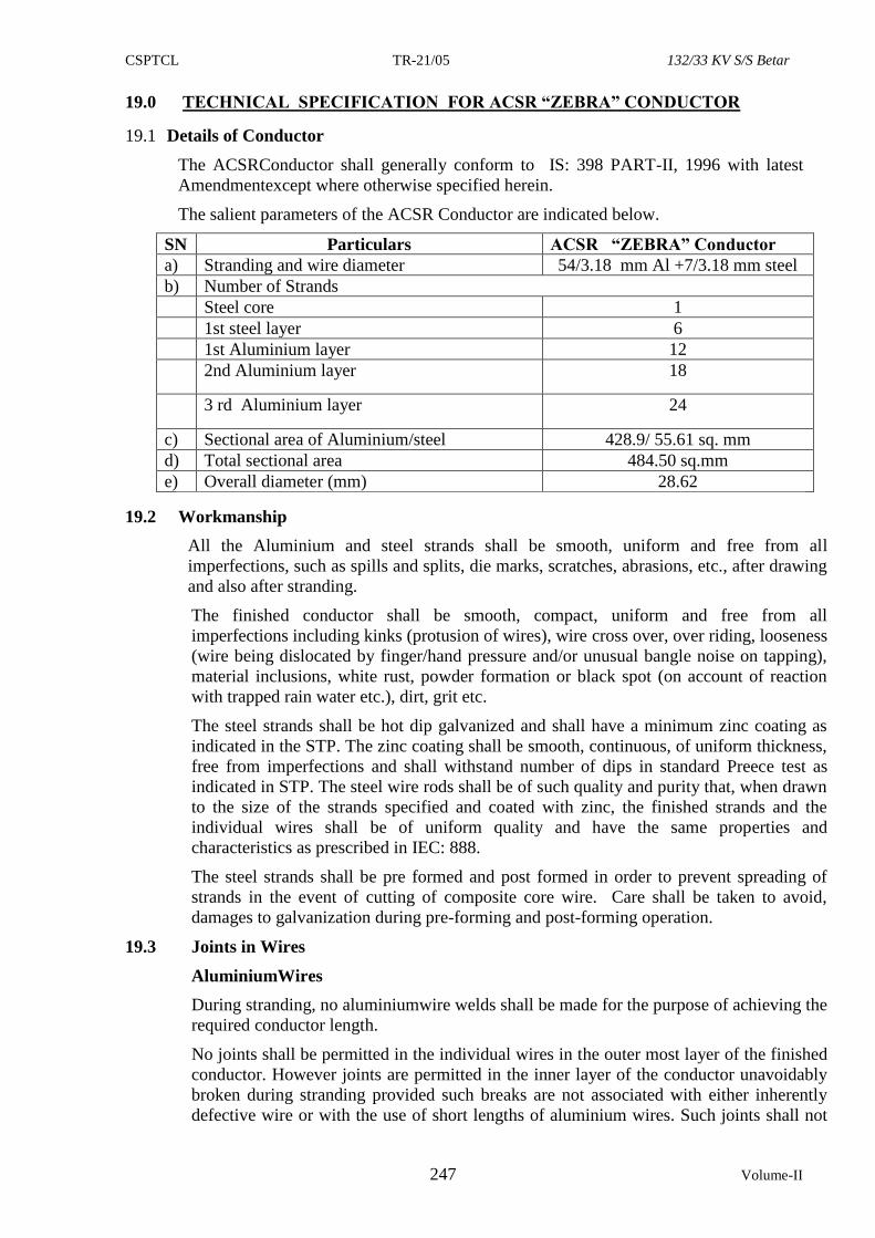
CSPTCL TR-21/05 132/33 KV S/S Betar
247 Volume-II
19.0 TECHNICAL SPECIFICATION FOR ACSR “ZEBRA” CONDUCTOR
19.1 Details of Conductor
The ACSRConductor shall generally conform to IS: 398 PART-II, 1996 with latest
Amendmentexcept where otherwise specified herein.
The salient parameters of the ACSR Conductor are indicated below.
SN Particulars ACSR “ZEBRA” Conductor
a) Stranding and wire diameter 54/3.18 mm Al +7/3.18 mm steel
b) Number of Strands
Steel core 1
1st steel layer 6
1st Aluminium layer 12
2nd Aluminium layer 18
3 rd Aluminium layer 24
c) Sectional area of Aluminium/steel 428.9/ 55.61 sq. mm
d) Total sectional area 484.50 sq.mm
e) Overall diameter (mm) 28.62
19.2 Workmanship
All the Aluminium and steel strands shall be smooth, uniform and free from all
imperfections, such as spills and splits, die marks, scratches, abrasions, etc., after drawing
and also after stranding.
The finished conductor shall be smooth, compact, uniform and free from all
imperfections including kinks (protusion of wires), wire cross over, over riding, looseness
(wire being dislocated by finger/hand pressure and/or unusual bangle noise on tapping),
material inclusions, white rust, powder formation or black spot (on account of reaction
with trapped rain water etc.), dirt, grit etc.
The steel strands shall be hot dip galvanized and shall have a minimum zinc coating as
indicated in the STP. The zinc coating shall be smooth, continuous, of uniform thickness,
free from imperfections and shall withstand number of dips in standard Preece test as
indicated in STP. The steel wire rods shall be of such quality and purity that, when drawn
to the size of the strands specified and coated with zinc, the finished strands and the
individual wires shall be of uniform quality and have the same properties and
characteristics as prescribed in IEC: 888.
The steel strands shall be pre formed and post formed in order to prevent spreading of
strands in the event of cutting of composite core wire. Care shall be taken to avoid,
damages to galvanization during pre-forming and post-forming operation.
19.3 Joints in Wires
AluminiumWires
During stranding, no aluminiumwire welds shall be made for the purpose of achieving the
required conductor length.
No joints shall be permitted in the individual wires in the outer most layer of the finished
conductor. However joints are permitted in the inner layer of the conductor unavoidably
broken during stranding provided such breaks are not associated with either inherently
defective wire or with the use of short lengths of aluminium wires. Such joints shall not
CSPTCL TR-21/05 132/33 KV S/S Betar
248 Volume-II
be more than four (4) per conductor length and shall not be closer than 15 meters from
joint in the same wire or in any other aluminium wire of the completed conductor.
Joints shall be made by cold pressure butt welding and shall withstand a stress of not less
than the breaking strength of individual strand guaranteed.
Steel Wires
There shall be no joint of any kind in the finished wire entering into the manufacture of
the strand. There shall also be no strand joints or strand splices in any length of the
completed stranded steel core of the conductor.
19.4 Tolerances
The manufacturing tolerances to the extent indicated in the STPshall be permitted in the
diameter of individual aluminium and steel strands and lay-ratio of the conductor.
19.5 Materials
Physical constant of hard- drawn Aluminium
a) Resistivity: - Theresistivity of the aluminium depends upon its purity and its physical
condition. However as per the specified value of purity of this specification the
maximum value permitted is 0.028264 Ohm.Sq.mm/ meter at 20 0 C and this value has
been used for calculation of maximum permissible values of resistance.
b) Density:- At a temperature 20 0 C the density of hard drawn aluminium shall be 2.703
g/ cm3.
c) Constant –Mass temperature Co- efficient of Resistance:- At a temperature of 20 0 C
the constant-mass temperature co-efficient of resistance of hard drawn aluminium
measured between two potential points rigidly fixed to the wire, the metal being
allowed to expand freely, has been taken as 0.004 per degree Celsius.
d) Co-efficient of linear expansion:- The co-efficient of linear expansion of hard drawn
aluminum at 0 0 C has been taken as 23.0 x10 -6
Hard- drawn Galvanised Steel Wire:-
a) Density:- At a temperature 20 0 C the density of Galvanised Steel wire shall be 7.8 g/ cm3.
b) Co-efficient of linear expansion:- In order to obtain infirmity in calculations a value of
11.5x10 -6 per degree C. may be taken for galvanized steel wire used in ACSR Conductor.
Aluminium
The aluminium strands shall be hard drawn from electrolytic aluminium rods having purity
not less than 99.5% and a copper content not exceeding 0.04%. They shall have the same
properties and characteristics as prescribed in ISS, BSS/IEC: 889.
Steel The steel wire strands shall be drawn from high carbon steel wire rods produced by either
the acid or the basic open-hearth process, the electric furnace process, or the basic oxygen
process and shall conform to the chemical composition indicated in the STP and to the
relevant standard.
The Steel wire strands shall have the same properties and characteristics as prescribed for
regular strength steel wire in IEC: 888.
Zinc
The zinc used for galvanizing shall be electrolytic High Grade Zinc of 99.95% purity as per
IS:209. It shall conform to and satisfy all the requirements of IS: 209. Galvanizing has to be
done hot dip galvanizing process. Natural grease may be applied between the layer of wires
(Lithium soap grease corresponding to the Gr.II of IS:7623-1974 its suitable for such
application.
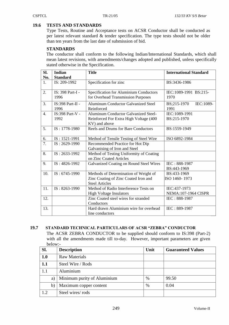
CSPTCL TR-21/05 132/33 KV S/S Betar
249 Volume-II
19.6 TESTS AND STANDARDS
Type Tests, Routine and Acceptance tests on ACSR Conductor shall be conducted as
per latest relevant standard & tender specification. The type tests should not be older
than ten years from the last date of submission of bid.
STANDARDS
The conductor shall conform to the following Indian/International Standards, which shall
mean latest revisions, with amendments/changes adopted and published, unless specifically
stated otherwise in the Specification.
Sl.
No.
Indian
Standard
Title International Standard
1. IS: 209-1992 Specification for zinc BS:3436-1986
2. IS: 398 Part-I -
1996
Specification for Aluminium Conductors
for Overhead Transmission Purposes
IEC:1089-1991 BS:215-
1970
3. IS:398 Part-II -
1996
Aluminum Conductor Galvanized Steel
Reinforced
BS;215-1970 IEC:1089-
1991
4. IS:398 Part-V -
1992
Aluminum Conductor Galvanized Steel-
Reinforced For Extra High Voltage (400
KV) and above
IEC:1089-1991
BS:215-1970
5. IS : 1778-1980 Reels and Drums for Bare Conductors BS:1559-1949
6. IS : 1521-1991 Method of Tensile Testing of Steel Wire ISO 6892-1984
7. IS : 2629-1990 Recommended Practice for Hot Dip
Galvanising of Iron and Steel
8. IS : 2633-1992 Method of Testing Uniformity of Coating
on Zinc Coated Articles
9. IS : 4826-1992 Galvanized Coating on Round Steel Wires IEC : 888-1987
BS:443-1969
10. IS : 6745-1990 Methods of Determination of Weight of
Zinc Coating of Zinc Coated Iron and
Steel Articles
BS:433-1969
ISO 1460- 1973
11. IS : 8263-1990 Method of Radio Interference Tests on
High Voltage Insulators
IEC:437-1973
NEMA:107-1964 CISPR
12. Zinc Coated steel wires for stranded
Conductors
IEC : 888-1987
13. Hard drawn Aluminium wire for overhead
line conductors
IEC : 889-1987
19.7 STANDARD TECHNICAL PARTICULARS OF ACSR “ZEBRA” CONDUCTOR
The ACSR ZEBRA CONDUCTOR to be supplied should conform to IS:398 (Part-2)
with all the amendments made till to-day. However, important parameters are given
below:-
Sl. Description Unit Guaranteed Values
1.0 Raw Materials
1.1 Steel Wire / Rods
1.1 Aluminium
a) Minimum purity of Aluminium % 99.50
b) Maximum copper content % 0.04
1.2 Steel wires/ rods
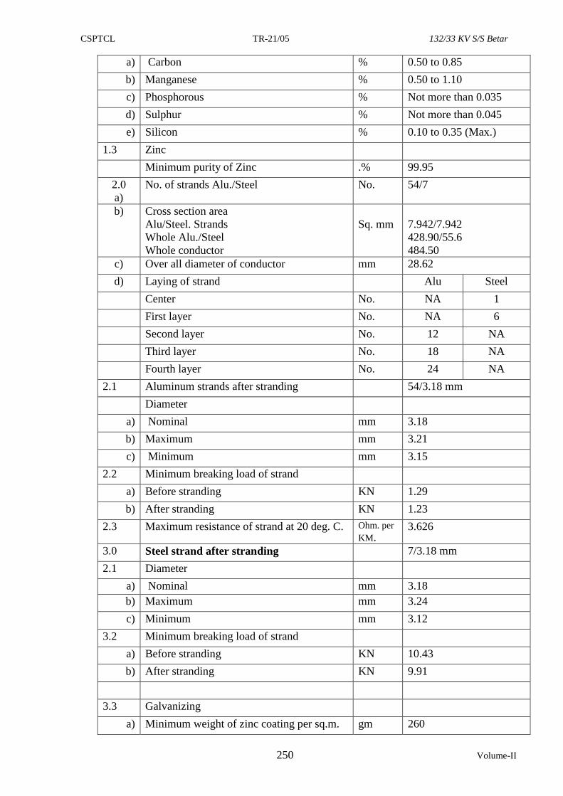
CSPTCL TR-21/05 132/33 KV S/S Betar
250 Volume-II
a) Carbon % 0.50 to 0.85
b) Manganese % 0.50 to 1.10
c) Phosphorous % Not more than 0.035
d) Sulphur % Not more than 0.045
e) Silicon % 0.10 to 0.35 (Max.)
1.3 Zinc
Minimum purity of Zinc .% 99.95
2.0
a)
No. of strands Alu./Steel No. 54/7
b) Cross section area
i) Alu/Steel. Strands
ii) Whole Alu./Steel
iii) Whole conductor
Sq. mm
7.942/7.942
428.90/55.6
484.50
c) Over all diameter of conductor mm 28.62
d) Laying of strand Alu Steel
i) Center No. NA 1
ii) First layer No. NA 6
iii) Second layer No. 12 NA
iv) Third layer No. 18 NA
v) Fourth layer No. 24 NA
2.1 Aluminum strands after stranding 54/3.18 mm
Diameter
a) Nominal mm 3.18
b) Maximum mm 3.21
c) Minimum mm 3.15
2.2 Minimum breaking load of strand
a) Before stranding KN 1.29
b) After stranding KN 1.23
2.3 Maximum resistance of strand at 20 deg. C. Ohm. per
KM. 3.626
3.0 Steel strand after stranding 7/3.18 mm
2.1 Diameter
a) Nominal mm 3.18
b) Maximum mm 3.24
c) Minimum mm 3.12
3.2 Minimum breaking load of strand
a) Before stranding KN 10.43
b) After stranding KN 9.91
3.3 Galvanizing
a) Minimum weight of zinc coating per sq.m. gm 260
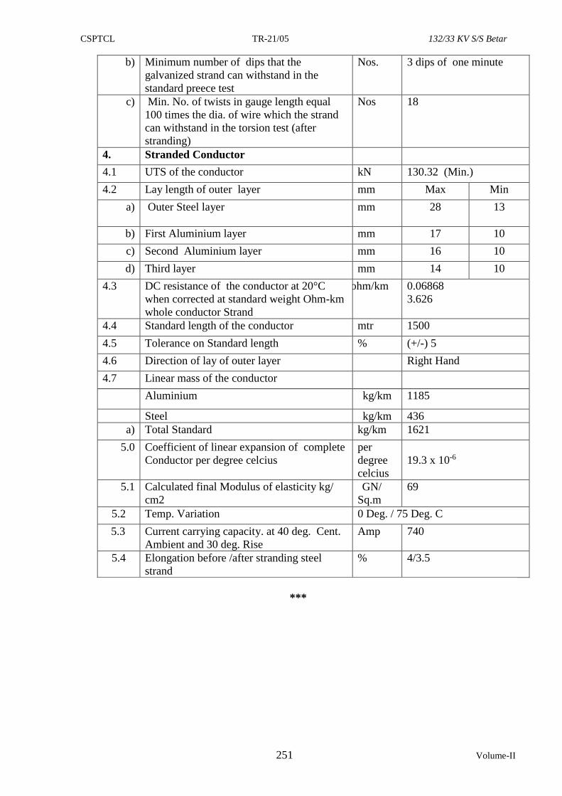
CSPTCL TR-21/05 132/33 KV S/S Betar
251 Volume-II
b) Minimum number of dips that the
galvanized strand can withstand in the
standard preece test
Nos. 3 dips of one minute
c) Min. No. of twists in gauge length equal
100 times the dia. of wire which the strand
can withstand in the torsion test (after
stranding)
Nos 18
4. Stranded Conductor
4.1 UTS of the conductor kN 130.32 (Min.)
4.2 Lay length of outer layer mm Max Min
a)
Outer Steel layer mm 28 13
b) First Aluminium layer mm 17 10
c) Second Aluminium layer mm 16 10
d) Third layer mm 14 10
4.3 DC resistance of the conductor at 20°C
when corrected at standard weight Ohm-km
i) whole conductor Strand
ohm/km 0.06868
3.626
4.4 Standard length of the conductor mtr 1500
4.5 Tolerance on Standard length % (+/-) 5
4.6 Direction of lay of outer layer Right Hand
4.7 Linear mass of the conductor
Aluminium kg/km 1185
Steel kg/km 436
a) Total Standard kg/km 1621
5.0 Coefficient of linear expansion of complete
Conductor per degree celcius
per
degree
celcius
19.3 x 10⁻⁶
5.1 Calculated final Modulus of elasticity kg/
cm2
GN/
Sq.m
69
5.2 Temp. Variation 0 Deg. / 75 Deg. C
5.3 Current carrying capacity. at 40 deg. Cent.
Ambient and 30 deg. Rise
Amp 740
5.4 Elongation before /after stranding steel
strand
% 4/3.5
***
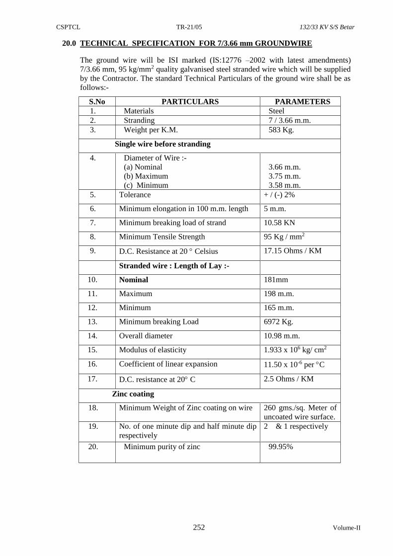
CSPTCL TR-21/05 132/33 KV S/S Betar
252 Volume-II
20.0 TECHNICAL SPECIFICATION FOR 7/3.66 mm GROUNDWIRE
The ground wire will be ISI marked (IS:12776 –2002 with latest amendments)
7/3.66 mm, 95 kg/mm2 quality galvanised steel stranded wire which will be supplied
by the Contractor. The standard Technical Particulars of the ground wire shall be as
follows:-
S.No PARTICULARS PARAMETERS
1. Materials Steel
2. Stranding 7 / 3.66 m.m.
3. Weight per K.M. 583 Kg.
Single wire before stranding
4. Diameter of Wire :-
(a) Nominal
(b) Maximum
(c) Minimum
3.66 m.m.
3.75 m.m.
3.58 m.m.
5. Tolerance + / (-) 2%
6. Minimum elongation in 100 m.m. length 5 m.m.
7. Minimum breaking load of strand 10.58 KN
8. Minimum Tensile Strength 95 Kg / mm2
9. D.C. Resistance at 20 Celsius 17.15 Ohms / KM
Stranded wire : Length of Lay :-
10. Nominal 181mm
11. Maximum 198 m.m.
12. Minimum 165 m.m.
13. Minimum breaking Load 6972 Kg.
14. Overall diameter 10.98 m.m.
15. Modulus of elasticity 1.933 x 10⁶ kg/ cm2
16. Coefficient of linear expansion 11.50 x 10⁻⁶ per C
17. D.C. resistance at 20 C 2.5 Ohms / KM
Zinc coating
18. Minimum Weight of Zinc coating on wire 260 gms./sq. Meter of
uncoated wire surface.
19. No. of one minute dip and half minute dip
respectively
2 & 1 respectively
20. Minimum purity of zinc 99.95%
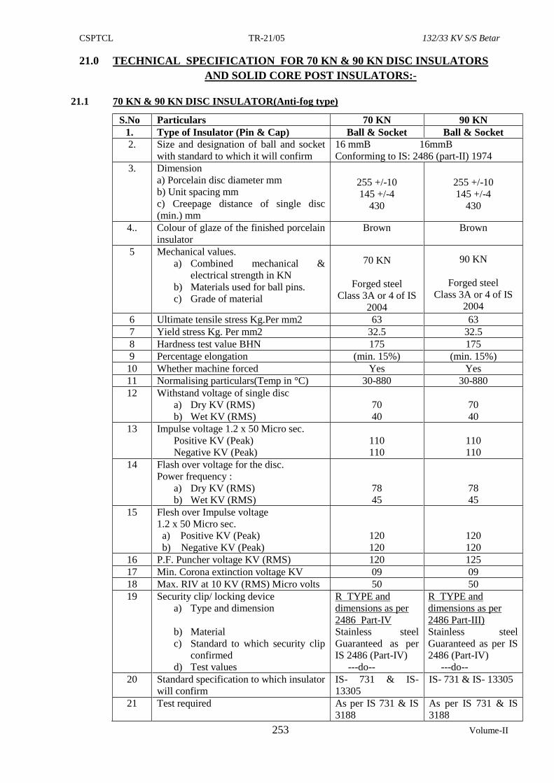
CSPTCL TR-21/05 132/33 KV S/S Betar
253 Volume-II
21.0 TECHNICAL SPECIFICATION FOR 70 KN & 90 KN DISC INSULATORS
AND SOLID CORE POST INSULATORS:-
21.1 70 KN & 90 KN DISC INSULATOR(Anti-fog type)
S.No Particulars 70 KN 90 KN
1. Type of Insulator (Pin & Cap) Ball & Socket Ball & Socket
2. Size and designation of ball and socket
with standard to which it will confirm
16 mmB 16mmB
Conforming to IS: 2486 (part-II) 1974
3. Dimension
a) Porcelain disc diameter mm
b) Unit spacing mm
c) Creepage distance of single disc
(min.) mm
255 +/-10
145 +/-4
430
255 +/-10
145 +/-4
430
4.. Colour of glaze of the finished porcelain
insulator
Brown Brown
5 Mechanical values.
a) Combined mechanical &
electrical strength in KN
b) Materials used for ball pins.
c) Grade of material
70 KN
Forged steel
Class 3A or 4 of IS
2004
90 KN
Forged steel
Class 3A or 4 of IS
2004
6 Ultimate tensile stress Kg.Per mm2 63 63
7 Yield stress Kg. Per mm2 32.5 32.5
8 Hardness test value BHN 175 175
9 Percentage elongation (min. 15%) (min. 15%)
10 Whether machine forced Yes Yes
11 Normalising particulars(Temp in °C) 30-880 30-880
12 Withstand voltage of single disc
a) Dry KV (RMS)
b) Wet KV (RMS)
70
40
70
40
13 Impulse voltage 1.2 x 50 Micro sec.
Positive KV (Peak)
Negative KV (Peak)
110
110
110
110
14 Flash over voltage for the disc.
Power frequency :
a) Dry KV (RMS)
b) Wet KV (RMS)
78
45
78
45
15 Flesh over Impulse voltage
1.2 x 50 Micro sec.
a) Positive KV (Peak)
b) Negative KV (Peak)
120
120
120
120
16 P.F. Puncher voltage KV (RMS) 120 125
17 Min. Corona extinction voltage KV 09 09
18 Max. RIV at 10 KV (RMS) Micro volts 50 50
19 Security clip/ locking device
a) Type and dimension
b) Material
c) Standard to which security clip
confirmed
d) Test values
R TYPE and
dimensions as per
2486 Part-IV
Stainless steel
Guaranteed as per
IS 2486 (Part-IV)
---do--
R TYPE and
dimensions as per
2486 Part-III)
Stainless steel
Guaranteed as per IS
2486 (Part-IV)
---do--
20 Standard specification to which insulator
will confirm
IS- 731 & IS-
13305
IS- 731 & IS- 13305
21 Test required As per IS 731 & IS
3188
As per IS 731 & IS
3188
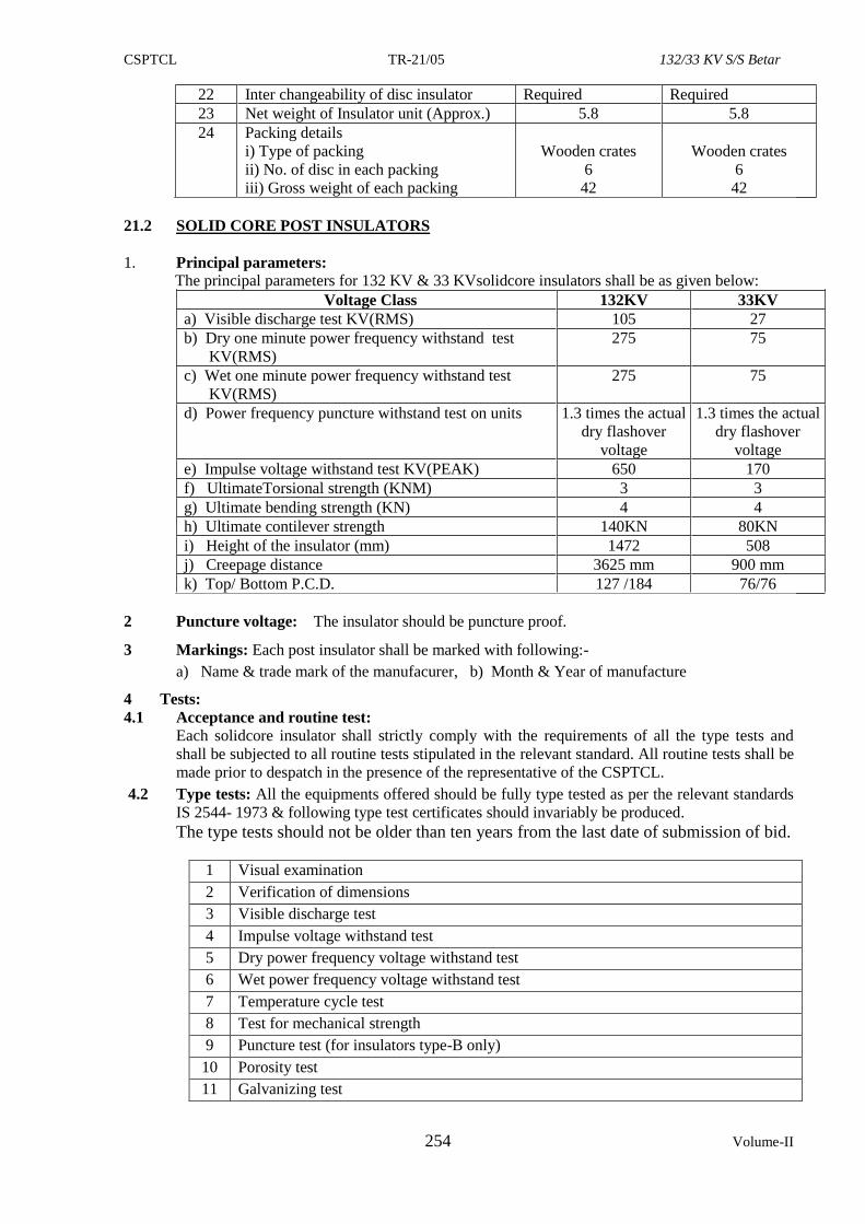
CSPTCL TR-21/05 132/33 KV S/S Betar
254 Volume-II
22 Inter changeability of disc insulator Required Required
23 Net weight of Insulator unit (Approx.) 5.8 5.8
24 Packing details
i) Type of packing
ii) No. of disc in each packing
iii) Gross weight of each packing
Wooden crates
6
42
Wooden crates
6
42
21.2 SOLID CORE POST INSULATORS
1. Principal parameters: The principal parameters for 132 KV & 33 KVsolidcore insulators shall be as given below:
Voltage Class 132KV 33KV
a) Visible discharge test KV(RMS) 105 27
b) Dry one minute power frequency withstand test
KV(RMS)
275 75
c) Wet one minute power frequency withstand test
KV(RMS)
275 75
d) Power frequency puncture withstand test on units 1.3 times the actual
dry flashover
voltage
1.3 times the actual
dry flashover
voltage
e) Impulse voltage withstand test KV(PEAK) 650 170
f) UltimateTorsional strength (KNM) 3 3
g) Ultimate bending strength (KN) 4 4
h) Ultimate contilever strength 140KN 80KN
i) Height of the insulator (mm) 1472 508
j) Creepage distance 3625 mm 900 mm
k) Top/ Bottom P.C.D. 127 /184 76/76
2 Puncture voltage: The insulator should be puncture proof.
3 Markings: Each post insulator shall be marked with following:-
a) Name & trade mark of the manufacurer, b) Month & Year of manufacture
4 Tests:
4.1 Acceptance and routine test:
Each solidcore insulator shall strictly comply with the requirements of all the type tests and
shall be subjected to all routine tests stipulated in the relevant standard. All routine tests shall be
made prior to despatch in the presence of the representative of the CSPTCL.
4.2 Type tests: All the equipments offered should be fully type tested as per the relevant standards
IS 2544- 1973 & following type test certificates should invariably be produced.
The type tests should not be older than ten years from the last date of submission of bid.
1 Visual examination
2 Verification of dimensions
3 Visible discharge test
4 Impulse voltage withstand test
5 Dry power frequency voltage withstand test
6 Wet power frequency voltage withstand test
7 Temperature cycle test
8 Test for mechanical strength
9 Puncture test (for insulators type-B only)
10 Porosity test
11 Galvanizing test
CSPTCL TR-21/05 132/33 KV S/S Betar
255
22. TECHNICAL SPECIFICATION FOR FIRE DETECTION SYSTEM
22.1 Suitable fire detection system using smoke detectors and/or heat detectors shall be provided for
the control room building. Fire detectors shall be located at strategic locations in various rooms
of the building. The operation of any of the fire detectors/ manual call point should result in
the following;
1. A visual signal exhibited in the annunciation panels indicating the area where the fire is
detected.
2. An audible alarm sounded in the panel,
3. An external audible alarm sounded in the building, location of which shall be decided
during detailed engineering.
4. If the zone comprises of more than one room, a visual signal shall be exhibited on the
outer wall of each room.
22.2 Each zone shall be provided with two zone cards in the panel so that system will remain healthy
even if one of the cards becomes defective.
22.3 Fire detectors shall be provided on false ceiling in control room building. Coverage area of
each smoke detector shall not be more than 60 m2 and that of heat detectors shall not be
more than 40 m2. Photoelectric smoke detectors shall be provided in all areas. If a detector is
concealed, a remote visual indication of its operation shall be provided. Manual call points
(Break glass Alarm Stations) shall be provided at strategic locations in the control room
building. All cabling shall be done through concealed conduits.
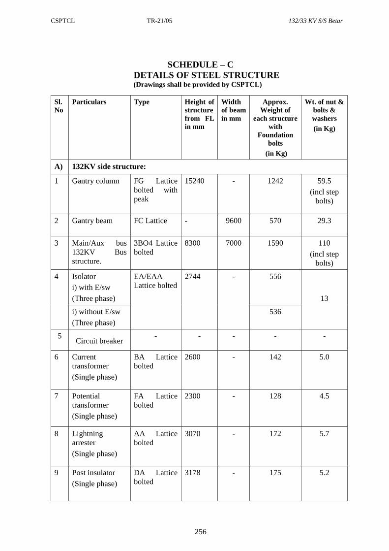
CSPTCL TR-21/05 132/33 KV S/S Betar
256
SCHEDULE – C
DETAILS OF STEEL STRUCTURE (Drawings shall be provided by CSPTCL)
Sl.
No
Particulars Type Height of
structure
from FL
in mm
Width
of beam
in mm
Approx.
Weight of
each structure
with
Foundation
bolts
(in Kg)
Wt. of nut &
bolts &
washers
(in Kg)
A) 132KV side structure:
1 Gantry column FG Lattice
bolted with
peak
15240
- 1242
59.5
(incl step
bolts)
2 Gantry beam FC Lattice - 9600 570 29.3
3 Main/Aux bus
132KV Bus
structure.
3BO4 Lattice
bolted
8300 7000 1590 110
(incl step
bolts)
4 Isolator
i) with E/sw
(Three phase)
EA/EAA
Lattice bolted
2744 - 556
13
i) without E/sw
(Three phase)
536
5
Circuit breaker
- - - - -
6 Current
transformer
(Single phase)
BA Lattice
bolted
2600 - 142 5.0
7 Potential
transformer
(Single phase)
FA Lattice
bolted
2300 - 128 4.5
8 Lightning
arrester
(Single phase)
AA Lattice
bolted
3070 - 172 5.7
9 Post insulator
(Single phase)
DA Lattice
bolted
3178 - 175 5.2
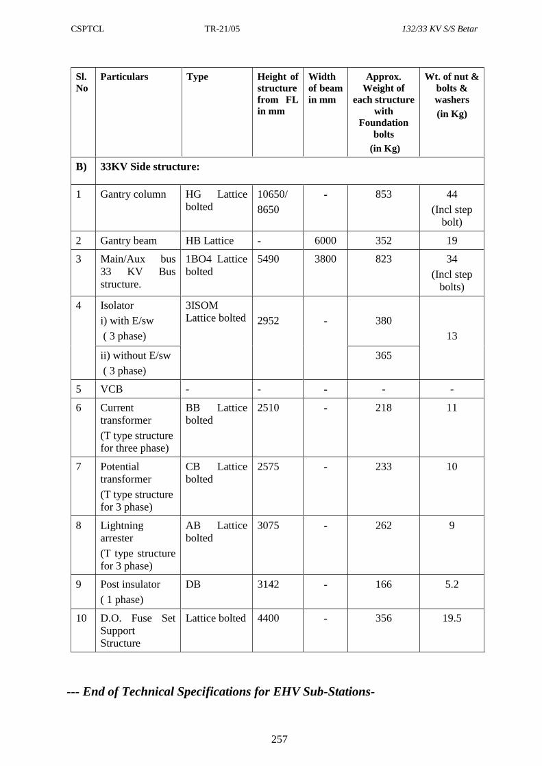
CSPTCL TR-21/05 132/33 KV S/S Betar
257
Sl.
No
Particulars Type Height of
structure
from FL
in mm
Width
of beam
in mm
Approx.
Weight of
each structure
with
Foundation
bolts
(in Kg)
Wt. of nut &
bolts &
washers
(in Kg)
B) 33KV Side structure:
1 Gantry column HG Lattice
bolted
10650/
8650
- 853 44
(Incl step
bolt)
2 Gantry beam HB Lattice - 6000 352 19
3 Main/Aux bus
33 KV Bus
structure.
1BO4 Lattice
bolted
5490 3800 823 34
(Incl step
bolts)
4 Isolator
i) with E/sw
( 3 phase)
3ISOM
Lattice bolted
2952
-
380
13
ii) without E/sw
( 3 phase)
365
5 VCB - - - - -
6 Current
transformer
(T type structure
for three phase)
BB Lattice
bolted
2510 - 218 11
7 Potential
transformer
(T type structure
for 3 phase)
CB Lattice
bolted
2575 - 233 10
8 Lightning
arrester
(T type structure
for 3 phase)
AB Lattice
bolted
3075 - 262 9
9 Post insulator
( 1 phase)
DB 3142 - 166 5.2
10 D.O. Fuse Set
Support
Structure
Lattice bolted 4400 - 356 19.5
--- End of Technical Specifications for EHV Sub-Stations-
CSPTCL TR-21/05 132/33 KV S/S Betar
258
SECTION – III
PRICE VARIATION FORMULAE FOR
EHV SUBSTATION EQUIPMENTS
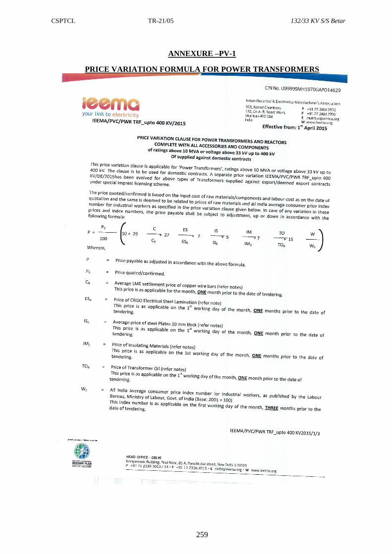
CSPTCL TR-21/05 132/33 KV S/S Betar
259
ANNEXURE –PV-1
PRICE VARIATION FORMULA FOR POWER TRANSFORMERS
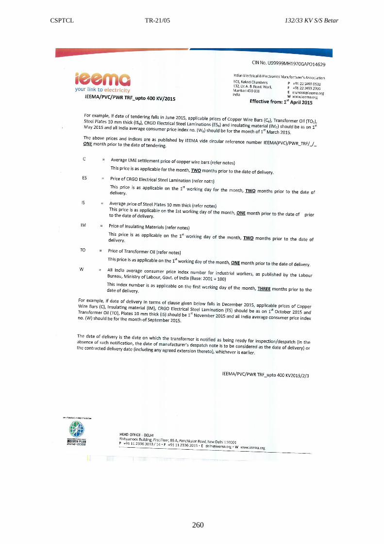
CSPTCL TR-21/05 132/33 KV S/S Betar
260
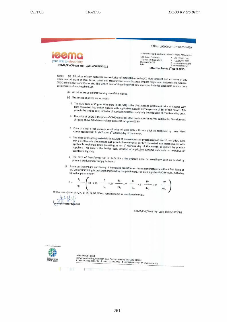
CSPTCL TR-21/05 132/33 KV S/S Betar
261
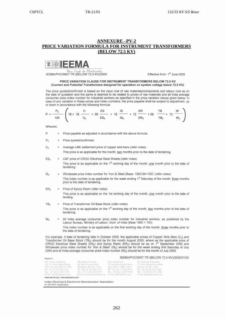
CSPTCL TR-21/05 132/33 KV S/S Betar
262
ANNEXURE –PV-2
PRICE VARIATION FORMULA FOR INSTRUMENT TRANSFORMERS
(BELOW 72.5 KV)
CSPTCL TR-21/05 132/33 KV S/S Betar
263
CSPTCL TR-21/05 132/33 KV S/S Betar
264
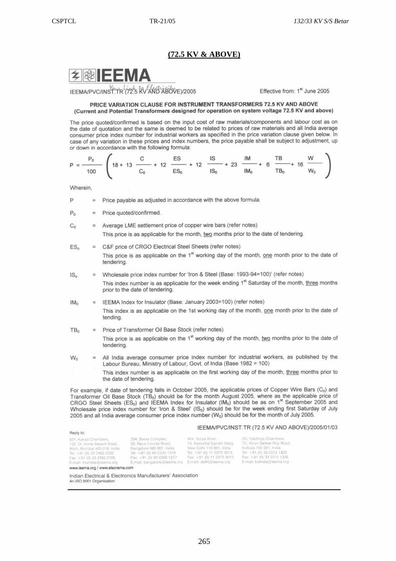
CSPTCL TR-21/05 132/33 KV S/S Betar
265
(72.5 KV & ABOVE)
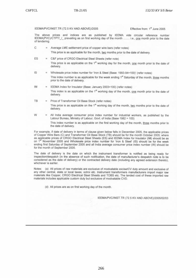
CSPTCL TR-21/05 132/33 KV S/S Betar
266
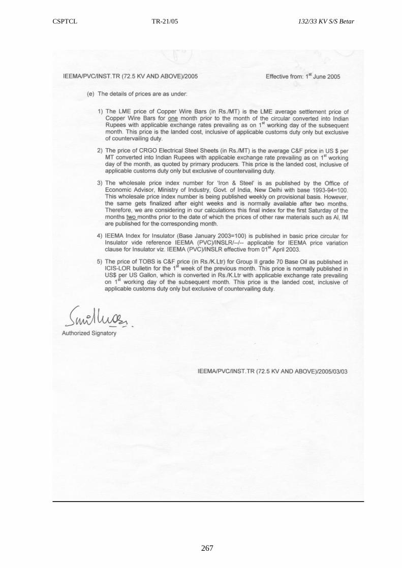
CSPTCL TR-21/05 132/33 KV S/S Betar
267
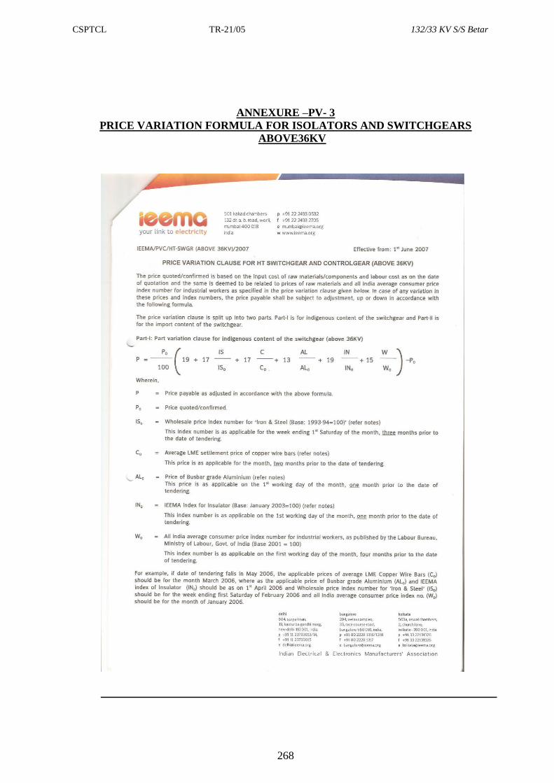
CSPTCL TR-21/05 132/33 KV S/S Betar
268
ANNEXURE –PV- 3
PRICE VARIATION FORMULA FOR ISOLATORS AND SWITCHGEARS
ABOVE36KV
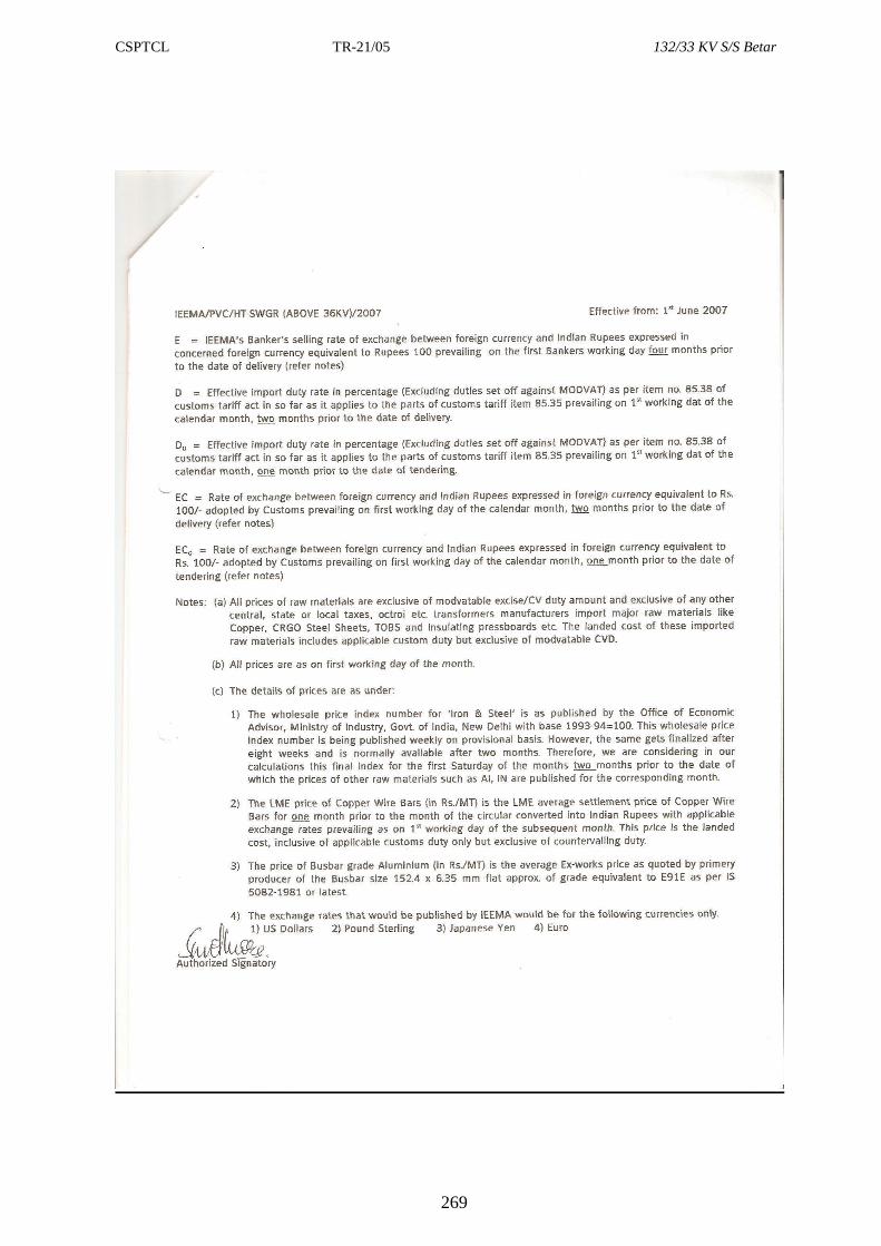
CSPTCL TR-21/05 132/33 KV S/S Betar
269
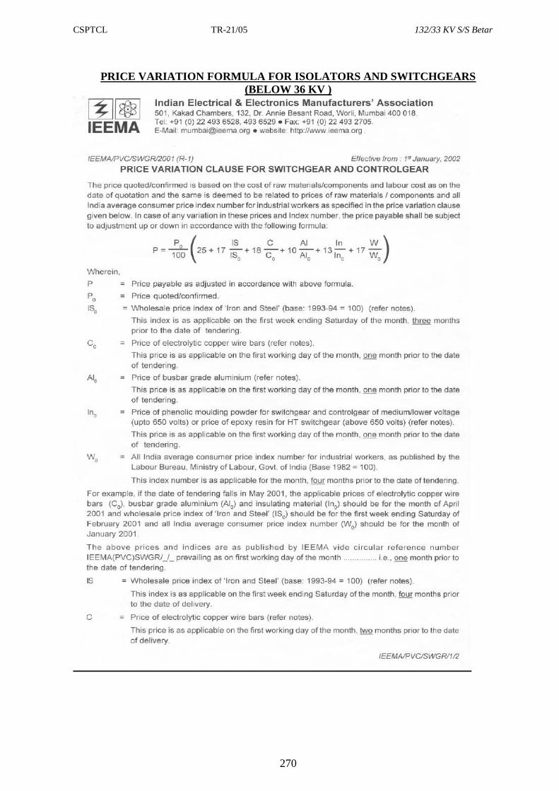
CSPTCL TR-21/05 132/33 KV S/S Betar
270
PRICE VARIATION FORMULA FOR ISOLATORS AND SWITCHGEARS
(BELOW 36 KV )
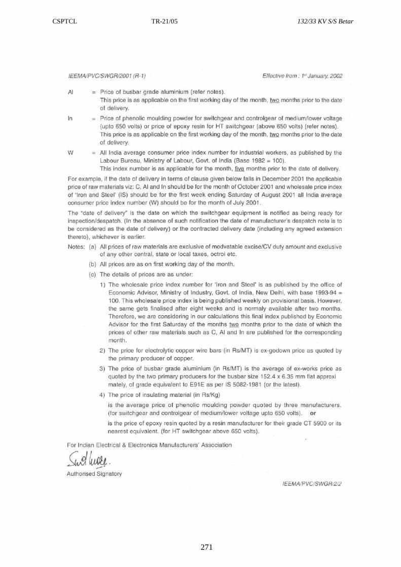
CSPTCL TR-21/05 132/33 KV S/S Betar
271
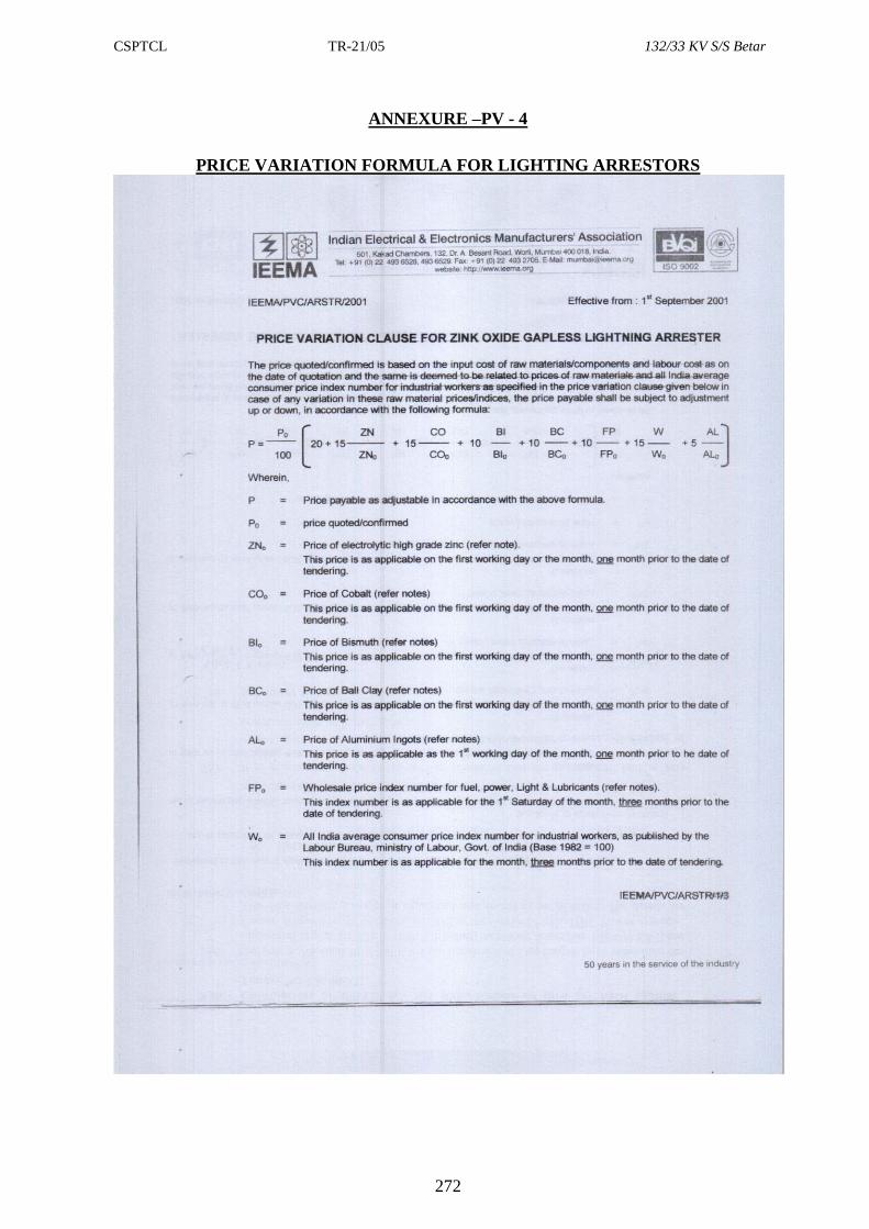
CSPTCL TR-21/05 132/33 KV S/S Betar
272
ANNEXURE –PV - 4
PRICE VARIATION FORMULA FOR LIGHTING ARRESTORS
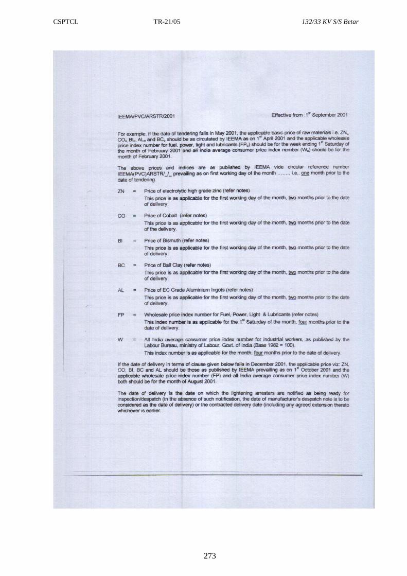
CSPTCL TR-21/05 132/33 KV S/S Betar
273
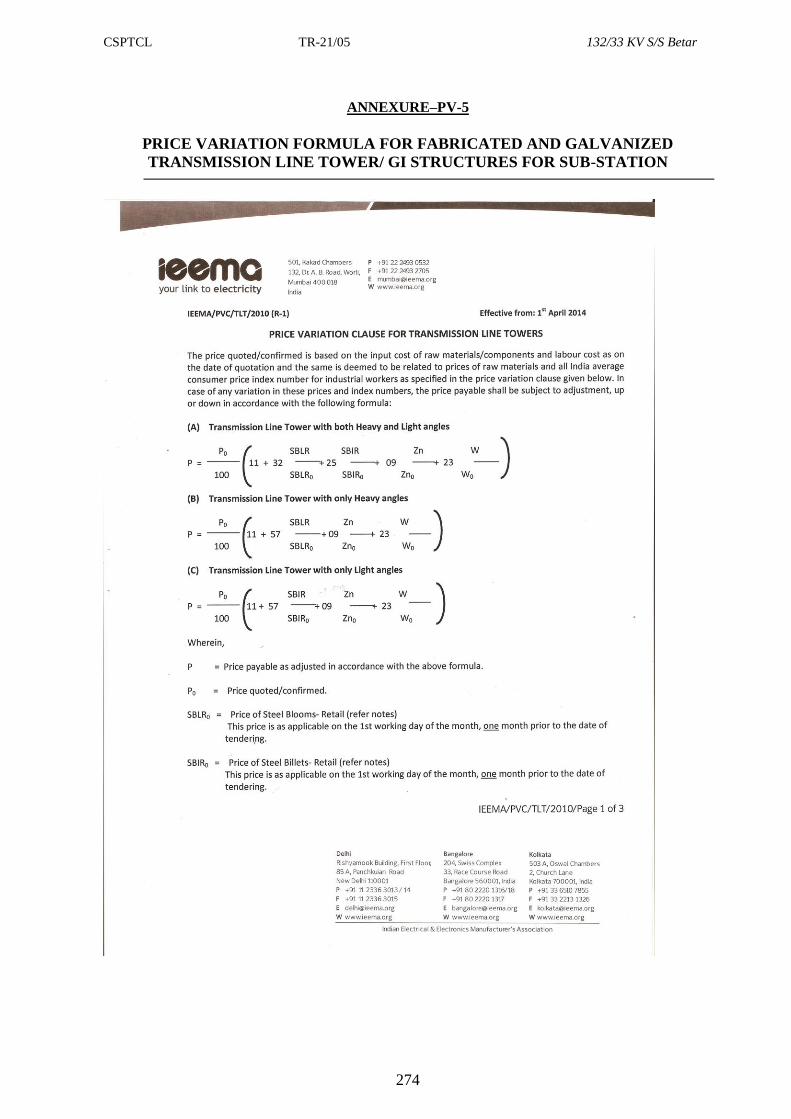
CSPTCL TR-21/05 132/33 KV S/S Betar
274
ANNEXURE–PV-5
PRICE VARIATION FORMULA FOR FABRICATED AND GALVANIZED
TRANSMISSION LINE TOWER/ GI STRUCTURES FOR SUB-STATION
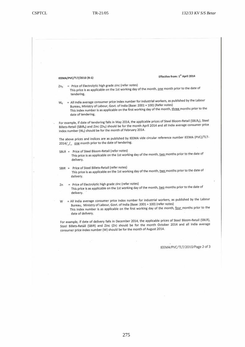
CSPTCL TR-21/05 132/33 KV S/S Betar
275
Copyright © 2022 FDOKUMEN


![CVRUj W`c R_j VgV_efR]Zej+ :_UZR - Daily Pioneer](https://static.fdokumen.com/doc/165x107/631c58d276d2a44505037fff/cvruj-wc-rj-vgvefrzej-uzr-daily-pioneer.jpg)
![5ZUZ SRed W`c @aa f_Zej X]`Red `gVc 4`_X c`fe - Daily ...](https://static.fdokumen.com/doc/165x107/6323a3573a06c6d45f0634e4/5zuz-sred-wc-aa-fzej-xred-gvc-4x-cfe-daily-.jpg)