I-8014(C)W/I-9014(C) I/O Module User Manual
126
I-8014(C)W/I-9014(C) I/O Module User Manual V 2.0.0 April 2018 Written by Martin Hsu Edited by Anna Huang
-
Upload
khangminh22 -
Category
Documents
-
view
0 -
download
0
Transcript of I-8014(C)W/I-9014(C) I/O Module User Manual

I-8014(C)W/I-9014(C)
I/O Module User Manual
V 2.0.0 April 2018
Written by Martin Hsu
Edited by Anna Huang

I-8014(C)W/I-9014(C) I/O Module User Manual, v2.0.0 P. 2
Warranty
All products manufactured by ICP DAS are under warranty regarding defective materials for a period
of one year, beginning from the date of delivery to the original purchaser.
Warning
ICP DAS assumes no liability for any damage resulting from the use of this product. ICP DAS reserves
the right to change this manual at any time without notice. The information furnished by ICP DAS is
believed to be accurate and reliable. However, no responsibility is assumed by ICP DAS for its use,
nor for any infringements of patents or other rights of third parties resulting from its use.
Copyright
Copyright © 2018 by ICP DAS Co., Ltd. All rights are reserved.
Trademarks
Names are used for identification purposes only and may be registered trademarks of their
respective companies.
Contact Us
If you have any problems, please feel free to contact us.
You can count on us for a quick response.
Email: [email protected]
I-8014(C)W/I-9014(C) I/O Module User Manual, v2.0.0 P. 3
Table of Contents
Table of Contents ........................................................................................................................................... 3
Preface ........................................................................................................................................................... 5
1. Introduction ........................................................................................................................................... 6
1.1. Features ..................................................................................................................................... 7
1.2. Specifications ............................................................................................................................. 9
1.3. Pin Assignments ....................................................................................................................... 10
1.4. Jumper Settings ....................................................................................................................... 12
1.5. Wire Connections .................................................................................................................... 15
1.6. Block Diagram .......................................................................................................................... 16
1.7. Demo Programs ....................................................................................................................... 17
2. Quick Start ........................................................................................................................................... 21
2.1. MiniOS7-based Controllers ...................................................................................................... 22
2.1.1. Getting Started ............................................................................................................. 23
2.1.2. Calibration .................................................................................................................... 25
2.2. Windows-based Controllers ..................................................................................................... 35
2.2.1. Getting Started ............................................................................................................. 36
2.2.2. Calibration .................................................................................................................... 38
3. Magic Scan ........................................................................................................................................... 45
3.1. The Advantages of Magic Scan ................................................................................................ 46
3.1.1. High speed AD with high precision Timer request ...................................................... 47
3.1.2. Magic Scan, read AD from 4K AI FIFO .......................................................................... 48
3.1.3. 4K AI FIFO with FIFO level limit interrupt to reduce the CPU loading greatly ............. 49
3.1.4. Application Examples ................................................................................................... 50
3.2. Magic Scan Mode ..................................................................................................................... 54
3.2.1. Standard Mode ............................................................................................................ 55
3.2.2. Virtual Sample and Hold Mode.................................................................................... 56
3.3. Trigger Methods ....................................................................................................................... 57
3.3.1. Software Trigger Method ............................................................................................. 58
3.3.2. Internal Hardware Trigger Method .............................................................................. 59
3.3.3. External Hardware Trigger Method ............................................................................. 60
3.4. FIFO .......................................................................................................................................... 61
3.5. Magic Scan Procedure ............................................................................................................. 62
3.6. Magic Scan Example ................................................................................................................ 63
3.6.1. Magic.exe ..................................................................................................................... 64
3.6.2. Mag_ISR.exe................................................................................................................. 70

I-8014(C)W/I-9014(C) I/O Module User Manual, v2.0.0 P. 4
3.7. Case Study ................................................................................................................................ 71
4. API References ..................................................................................................................................... 73
4.1. i8014W_Init ............................................................................................................................. 75
4.2. i8014W_GetFirmwareVer_L1 .................................................................................................. 77
4.3. i8014W_GetFirmwareVer_L2 .................................................................................................. 78
4.4. i8014W_GetLibVersion ............................................................................................................ 79
4.5. i8014W_GetLibDate ................................................................................................................. 80
4.6. i8014W_GetSingleEndJumper ................................................................................................. 81
4.7. i8014W_ReadGainOffset ......................................................................................................... 83
4.8. i8014W_Read_mA_GainOffset ................................................................................................ 85
4.9. i8014W_ReadAI ....................................................................................................................... 87
4.10. i8014W_ReadAIHex ............................................................................................................. 89
4.11. i8014W_ConfigMagicScan ................................................................................................... 91
4.12. i8014W_StartMagicScan ...................................................................................................... 94
4.13. i8014W_StopMagicScan ...................................................................................................... 95
4.14. i8014W_ReadFIFO ............................................................................................................... 96
4.15. i8014W_CalibrateData ......................................................................................................... 98
4.16. i8014W_CalibrateDataHex .................................................................................................100
4.17. i8014W_UnLockFIFO .........................................................................................................102
4.18. i8014W_ClearFIFO .............................................................................................................103
4.19. i8014W_InstallMagicScanISR .............................................................................................104
4.20. i8014W_UnInstallMagicScanISR ........................................................................................107
4.21. i8014W_ClearInt ................................................................................................................108
5. Troubleshooting .................................................................................................................................109
5.1. How to verify the AI function on a WinCE or WES unit .........................................................110
5.2. Service/Request Requirements .............................................................................................113
5.3. What to do when the data read from I-8014W seems unstable ...........................................114
5.4. How to solve the FIFO LATCHED error (-6) .............................................................................115
Appendix A. Error Code .............................................................................................................................116
Appendix B. Revision History .....................................................................................................................117

I-8014(C)W/I-9014(C) I/O Module User Manual, v2.0.0 P. 5
Preface
The I-8014(C)/I-9014(C) is a high speed isolated analog input module providing 16 single-ended or 8
differential analog input channels at 16-bit resolution. Besides including basic usage instructions and
details of the SDK interface, this manual also introduces the Magic Scan function incorporated in the
I-8014W that can be used for scanning multi-channel systems.
The information contained in this manual is divided into the following topics:
Chapter 1, “Introduction” – This chapter provides information related to the hardware, such as the
specifications, the jumper settings details and wiring information.
Chapter 2, “Quick Start” – This chapter provides information on how to get started, an overview of
the location of the demo programs, a “Getting Started Guide”, and an outline of the calibration
process.
Chapter 3, “Magic Scan” – This chapter introduces the attributes related to the Magic Scan function,
the programming procedures, and demo programs.
Chapter 4, “API References” – This chapter describes the functions provided in the I-8014W library
together with an explanation of the differences in the naming rules used for the MiniOS7 and
Windows platforms.
Chapter 5, “Troubleshooting” – This chapter provides some troubleshooting solutions should you
encounter any problems while operating the I-8014W.

I-8014(C)W/I-9014(C) I/O Module User Manual, v2.0.0 P. 6
1. Introduction
The I-8014(C)W/I-9014(C) are high performance analog input modules. I-8014W/I-9014is up to
16-channel single-ended or 8-channel differential inputs.I-8014CW/I-9014C isup to 8-channel differential
inputs. They feature 16-bit resolution, 250Ks/s sampling rates, and 4K-sample FIFO. They provide
isolation protection of2500 VRMS.
The I-8014(C)W/I-9014(C) (Hereinafter referred to as I-8014W) contain an impressive scan function
called Magic Scan, which are able to improve many of the functions and meets the demands of high-end
users. The Magic Scan mechanism not only scans the different input channels at vastly different rates,
but also at different gains.
Even in a multi-channel scan, the sampling rates can be maintained at 250KS/s.
I-8014W contains two types of Magic Scan. One is a standardScan and the other is a virtual sample and
hold function. Almost all AI Cardsare expensive if they provide a sample and hold function, but ICP DAS
cannow provide you with a low-cost alternative.
I-8014W module includes a 4K onboard FIFO buffer for A/D conversion. With the Magic Scan function
and 4K FIFO, the I-8014W can easily implement high-speed and time-critical data acquisition
applications.
The differences between I-8014W/I-9014 and I-8014CW/I-9014C are as below:
I-8014W/I-9014 I-8014CW/I-9014C
Input Range +/- 10 V, +/- 5 V, +/- 2.5 V, +/- 1.25 V
and +/- 20 mA +/- 20 mA only
Select Input Type Differential or Single-Ended Mode Differential Mode only
Wire Connection for
currentmeasurement
Need external 125 ohm resistor for
currentmeasurement
Do need external 125 ohm resistor
for currentmeasurement
Calibration Parameter 8 channels AI using 1 calibration
parameter
8 channels AI using independent
calibration parameter

I-8014(C)W/I-9014(C) I/O Module User Manual, v2.0.0 P. 7
1.1. Features
I-8014W/I-9014
16 single-ended/8 differential inputs (jumper selectable)
Input Range : +/- 10V, +/- 5V, +/- 2.5V, +/- 1.25V, +/- 20mA
I-8014CW/I-9014C
8 differential inputs
Input Range : +/- 20mA
16-bit 250KHz ADC converter
4K-samples FIFO buffer
External trigger mode : post-trigge
Internal/external trigger start
Magic Scan Type
Type 1: General
Each Sample clock only samples a single.
General type
When set as Standard mode,
1. The maximum sample rate can set as 250 KHz.
2. If scan multi channels, the sample rate for each channel will be (Sample Rate)/(channel count)
For example, if set sample rate as 250 KHz and scan 2 channels, the sample rate for each channel is
125 KHz.
Sample channel count Hz/Ch
1 250KHz
2 125KHz
3 83.3KHz
4 62.5KHz

I-8014(C)W/I-9014(C) I/O Module User Manual, v2.0.0 P. 8
Type 2: virtual Sample and hold
Each sample clock will to sample all scan channels that have been set.
Virtual Sample and hold type
When set as Virtual Sample and Hold mode,
1. The maximum sample rate is 125 KHz.
2. It use 250 KHz (4 us) internal sample clock to scan each channel.
3. All channels are the sample rate.
4. The total sample rate for all channel must <= 125 KHz
Scanned Ch Count Hz/Ch Total Sample Rate
1 125KHz 125KHz
2 62.5KHz 125KHz
4 31.25 KHz 125 KHz

I-8014(C)W/I-9014(C) I/O Module User Manual, v2.0.0 P. 9
1.2. Specifications
Model I-8014W/I-9014 I-8014CW/I-9014C
Analog Output
Channels 8-ch Differential/16-Single-ended 8-ch Differential
Voltage Input Range ±1.25, ±2.5, ±5 V, ±10 V -
Current Input Range -20 mA ~ +20 mA(Requires
OptionalExternal 125 Ω Resistor)
-20 mA ~ +20 mA
Resolution 16-bit
Sample Rate Single Channel Polling Mode :250K S/s
FIFO 4 k Words
Accuracy 0.05% of FSR
Input Mode Polling, Pacer (Magic Scan)
Magic Scan Mode Mode 1: Standard Mode
Mode 2: Virtual Sample and Hold
Overvoltage Protection -45 V ~ +60 V
Input Impedance 20 K, 200 K, 20 M (Jumper Select) 125 Ω
LED Indicators
Power LED Indicator Yes
Isolation
Intra-module Isolation, Field-to-Logic 2500 Vrms
Power
Power Consumption 2.5 W Max.
Mechanical
Dimension (L x W x H) For I-8014(C)W: 102 mm x 30 mm x 115 mm
For I-9014(C): 144 mm x 31 mm x 134 mm
Environment
Operating Temperature -25 °C ~ +75°C
Storage Temperature For I-8014(C)W: -30 °C ~ +85°C
For I-9014(C): -40°C ~ +85°C
Humidity 10 % ~ 90% RH, non-condensing

I-8014(C)W/I-9014(C) I/O Module User Manual, v2.0.0 P. 10
1.3. Pin Assignments

I-8014(C)W/I-9014(C) I/O Module User Manual, v2.0.0 P. 11

I-8014(C)W/I-9014(C) I/O Module User Manual, v2.0.0 P. 12
1.4. Jumper Settings
I-8014W/I-8014CW
Differential / Single-ended Jumper Selection
Input impedance Jumper Selection
Note : I-8014CW do not have those Jumper, it is only with Differential Mode and Input impedance 20 KΩ
Secondary FPGA
Primary FPGA

I-8014(C)W/I-9014(C) I/O Module User Manual, v2.0.0 P. 13
I-9014W/I-9014C
Differential / Single-ended Jumper Selection
Input impedance Jumper Selection
Note : I-9014C do not have those Jumper, it is only with Differential Mode and Input impedance 20 KΩ

I-8014(C)W/I-9014(C) I/O Module User Manual, v2.0.0 P. 14
Adjusting the Input impedance
The I-8014W allows three input impedance options, including 20 kΩ, 200 kΩ (default setting) and 20 MΩ
to meet system requirements. In most cases, 200 kΩ is sufficient.
Note that each time the input impedance is adjusted on a calibrated module, the module must be
recalibrated. Refer to the Calibration section on page 19 if you are using an I-8000 or iPAC-8000 (MiniOS7
platform controller), or refer to page 32 for details of the calibration process if you are using a module
based on the WinCE or WES platform.
I-8014(C)W/I-9014(C) I/O Module User Manual, v2.0.0 P. 15
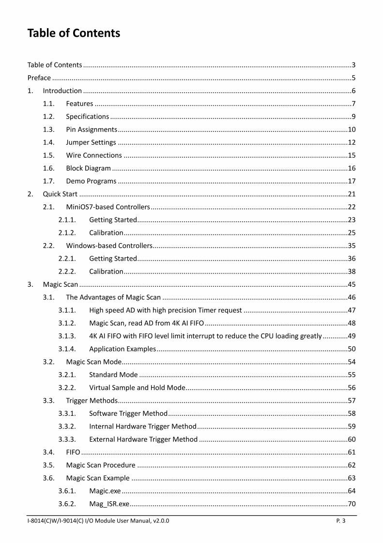
1.5. Wire Connections
I-8014W/I-9014
Voltage Input Wiring Current Input Wiring
Differential
Single-ended
I-8014CW/I-9014C
Current Input Wiring
Differential

I-8014(C)W/I-9014(C) I/O Module User Manual, v2.0.0 P. 16
1.6. Block Diagram
I-8014W/I-9014
I-8014CW/I-9014C

I-8014(C)W/I-9014(C) I/O Module User Manual, v2.0.0 P. 17
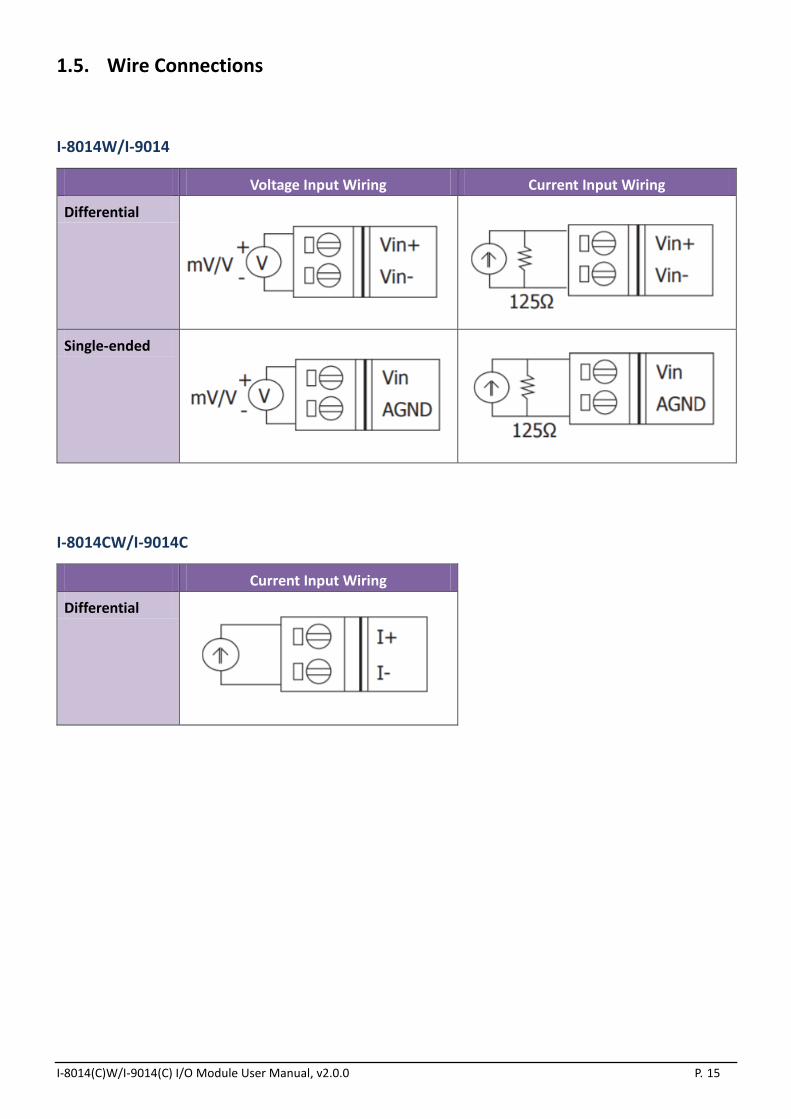
1.7. Demo Programs
ICP DAS provides a range of demo programs for different platforms that can be used to verify the
functions of the I-8014W. The source code contained in these programs can also be reused in your own
custom programs if needed. The following is a list of the locations where both the demo programs and
associated libraries can be found on either the ICP DAS web site or the enclosed CD.
Both I-8014W and I-8014CW use the same library, but demo. The I-8014W demo is located at 8014w
folder and I-8014CW is located at 8014cw folder.
For example:
I-8014W demo for I-8000 is located at
ftp://ftp.icpdas.com/pub/cd/8000cd/napdos/8000/841x881x/demo/io_in_slot/8014w/
I-8014CW demo for I-8000 is located at
ftp://ftp.icpdas.com/pub/cd/8000cd/napdos/8000/841x881x/demo/io_in_slot/8014cw/
Platform Location
For I-8000
Library CD:\Napdos\8000\841x881x\demo\Lib or
ftp://ftp.icpdas.com/pub/cd/8000cd/napdos/8000/841x881x/demo/lib/
Demo CD:\Napdos\8000\841x881x\demo\IO_in_Slotor
ftp://ftp.icpdas.com/pub/cd/8000cd/napdos/8000/841x881x/demo/io_in_slot/
For iPAC-8000
Library
CD:\Napdos\iPAC8000\Demo\Basic\iP-84x1_iP-88x1\Lib or
ftp://ftp.icpdas.com/pub/cd/8000cd/napdos/ipac8000/demo/basic/ip-84x1_ip-88
x1/lib/
Demo
CD:\Napdos\iPAC8000\Demo\Basic\iP-84x1_iP-88x1\IO_in_Slot or
ftp://ftp.icpdas.com/pub/cd/8000cd/napdos/ipac8000/demo/basic/ip-84x1_ip-88
x1/io_in_slot/

I-8014(C)W/I-9014(C) I/O Module User Manual, v2.0.0 P. 18
Platform Location
For Windows CE5
Library CD:\ napdos\wp-8x4x_ce50\SDK\IO_Modules or
ftp://ftp.icpdas.com/pub/cd/winpac/napdos/wp-8x4x_ce50/sdk/io_modules/
Demo
eVC Demo:
CD:\napdos\ wp-8x4x_ce50\Demo\WinPAC\eVC\IO\Local or
ftp://ftp.icpdas.com/pub/cd/winpac/napdos/wp-8x4x_ce50/demo/winpac/evc/io
/local/
C# Demo:
CD:\napdos\ wp-8x4x_ce50\Demo\WinPAC\C#\IO\Local or
ftp://ftp.icpdas.com/pub/cd/winpac/napdos/wp-8x4x_ce50/demo/winpac/c%23/
io/local/
For XP-8000-CE6
Library CD:\ SDK\Special_IO
ftp://ftp.icpdas.com/pub/cd/xp-8000-ce6/sdk/special_io/
Demo
VC2005 Demo:
CD:\ demo\XPAC\VC2005\IO\Local
ftp://ftp.icpdas.com/pub/cd/xp-8000-ce6/demo/xpac/vc2005/io/local/
C# Demo:
CD:\ demo\XPAC\C#\IO\Local
ftp://ftp.icpdas.com/pub/cd/xp-8000-ce6/demo/xpac/c%23/io/local/
For XP-8000-Atom-CE6
Library CD:\ SDK\Special_IO
ftp://ftp.icpdas.com/pub/cd/xpac-atom-ce6/sdk/special_io/
Demo
VC 2005 Demo:
CD:\ demo\XPAC\VC2005\IO\Local
ftp://ftp.icpdas.com/pub/cd/xpac-atom-ce6/demo/xpac/vc2005/io/local/
C# Demo:
CD:\ demo\XPAC\C#\IO\Local
ftp://ftp.icpdas.com/pub/cd/xpac-atom-ce6/demo/xpac/c%23/io/local/
I-8014(C)W/I-9014(C) I/O Module User Manual, v2.0.0 P. 19
Platform Location
For XP-8000
Library CD:\SDK\IO
ftp://ftp.icpdas.com/pub/cd/xp-8000/sdk/io/
Demo
VC Demo:
CD:\Demo\pacsdk\vc\IO\Local
ftp://ftp.icpdas.com/pub/cd/xp-8000/demo/pacsdk/vc/io/local/
C# Demo:
CD:\ Demo\pacsdk\csharp.net\IO\Local\windows_forms
ftp://ftp.icpdas.com/pub/cd/xp-8000/demo/pacsdk/csharp.net/io/local/windows
_forms/
For XP-Atom
Library CD:\ SDK\IO
ftp://ftp.icpdas.com/pub/cd/xpac-atom/sdk/io/
Demo
VC Demo:
CD:\Demo\pacsdk\vc\IO\Local
ftp://ftp.icpdas.com/pub/cd/xp-8000/demo/pacsdk/vc/io/local/
C# Demo:
CD:\ Demo\pacsdk\csharp.net\IO\Local\windows_forms
ftp://ftp.icpdas.com/pub/cd/xpac-atom/demo/pacsdk/csharp.net/io/local/windo
ws_forms/
For WP-9000
Library CD:\WinPAC_AM335x\wp-9000\SDK\IO_Modules
ftp://ftp.icpdas.com/pub/cd/winpac_am335x/wp-9000/sdk/io_modules/
Demo
VC2008 Demo:
CD:\WinPAC_AM335x\wp-9000\demo\PAC\Vc2008\IO\Local
ftp://ftp.icpdas.com/pub/cd/winpac_am335x/wp-9000/demo/pac/vc2008/io/loca
l/ C# Demo:
CD:\WinPAC_AM335x\wp-9000\demo\PAC\C#\IO\Local
ftp://ftp.icpdas.com/pub/cd/winpac_am335x/wp-9000/demo/pac/c%23/io/local/

I-8014(C)W/I-9014(C) I/O Module User Manual, v2.0.0 P. 20
Platform Location
For IPPC-WES7
Library CD:\ippc-wes7\sdk\IO
ftp://ftp.icpdas.com/pub/cd/ippc-wes7/sdk/io/
Demo
VC Demo:
CD:\ippc-wes7\demo\pacsdk\vc\io\local\io-9k
ftp://ftp.icpdas.com/pub/cd/ippc-wes7/demo/pacsdk/vc/io/local/io-9k/
C# Demo:
CD:\ippc-wes7\demo\pacsdk\csharp.net\io\local\io-9k
ftp://ftp.icpdas.com/pub/cd/ippc-wes7/demo/pacsdk/csharp.net/io/local/io-9k/

I-8014(C)W/I-9014(C) I/O Module User Manual, v2.0.0 P. 21
2. Quick Start
This section provides a Getting Started guide and details of the calibration process when using the
I-8014W module on either the MiniOS7 or Windows platforms.
This section contains a Getting Started guide and details of the calibration process when using the
I-8014W:
For MiniOS7-based Controllers, see section 2.1 (i-8000 and iPAC-8000 modules)
For Windows-based Controllers, see section 2.2 (WinCE and WES modules)

I-8014(C)W/I-9014(C) I/O Module User Manual, v2.0.0 P. 22
2.1. MiniOS7-based Controllers
This section contains:
Getting Started, see section 2.1.1
Calibration, see section 2.1.2

I-8014(C)W/I-9014(C) I/O Module User Manual, v2.0.0 P. 23
2.1.1. Getting Started
The AI_INFO.EXE executable file, which is located in the basic_info folder of the I-8014W demo programs,
can be used to retrieve the basic configuration information related to the I-8014W and to verify the AI
read functions. The basic configuration information includes:
The Version number and the published date of the library.
The FPGA version
The single-ended/differential jumper settings
The gain and offset values for each input range
The data read on each channel
(See the Location of the Demo Programs section on page 12 for details of where to find the AI_INFO.EXE
in the I-8014W demo programs folder)
Step 1. Refer to the Jumper Settings section on page 8. Ensure that the Differential/Single-ended
selection jumper is in the differential position.
Step 2. Step 2. Connect a stable signal source (e.g., a battery output) to the I-8014W using the
differential wiring method, as illustrated below.
I-8014(C)W/I-9014(C) I/O Module User Manual, v2.0.0 P. 24
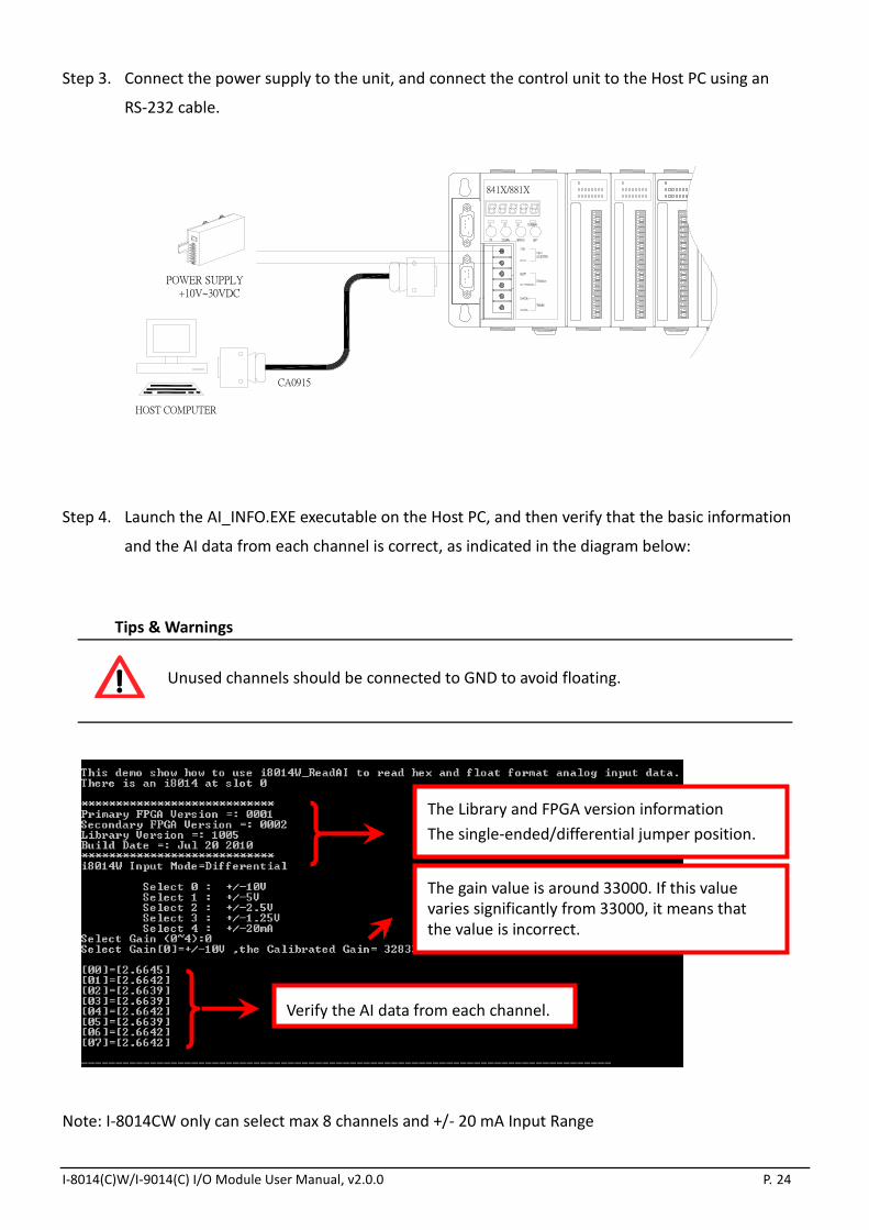
Step 3. Connect the power supply to the unit, and connect the control unit to the Host PC using an
RS-232 cable.
Step 4. Launch the AI_INFO.EXE executable on the Host PC, and then verify that the basic information
and the AI data from each channel is correct, as indicated in the diagram below:
Tips & Warnings
Unused channels should be connected to GND to avoid floating.
Note: I-8014CW only can select max 8 channels and +/- 20 mA Input Range
HOST COMPUTER
+10V~30VDCPOWER SUPPLY
CA0915
841X/881X
The Library and FPGA version information
The single-ended/differential jumper position.
Verify the AI data from each channel.
The gain value is around 33000. If this value varies significantly from 33000, it means that the value is incorrect.
I-8014(C)W/I-9014(C) I/O Module User Manual, v2.0.0 P. 25
2.1.2. Calibration
Each I-8014W module is factory calibrated and well verified before shipment, so it is usually unnecessary
to calibrate the module again, unless the input impedance is changed on a calibrated module or the
accuracy is lost.
To calibrate the I-8014W, in addition to inserting the I-8014W into a controller slot, the following items
are required:
A single stable calibration source, such as a 3 1/2 digit power supply (or better) or a battery output.
A single 4 1/2 digit voltage meter (15-bit resolution or better)
A Calibration Program. See page 12 for the Location of the Demo Programs contained in the
I-8014W demo programs folder.
Tips & Warnings
1. An unstable calibration source will cause calibration errors and will affect the
accuracy of the data acquisition.
2. If you wish to perform calibration using ± 20 mA, select ± 2.5 V instead as both
types use the same gain and offset values.
3. The calibration program uses channel 0 to accept the calibration source only.
This section contains:
Calibrating the I-8014W on i-8000 and iPAC-8000,see section 2.1.2.1
Verifying the Calibration, see section 2.1.2.2
Restoring the Default Calibration Settings, see section 2.1.2.3

I-8014(C)W/I-9014(C) I/O Module User Manual, v2.0.0 P. 26
2.1.2.1. Calibrating the I-8014W on i-8000 and iPAC-8000
Step 1. Repeat Steps 1 to 3 as described in the Quick Start guide on page 14.
a. Attach the power supply to the control unit and then connect the control unit to the Host
PC.
b. Set the Differential/Single-ended jumper to the differential position and connect the
calibration source to channel 0 using the differential wiring method.
c. Connect tnhe meter, as illustrated in the following figure.
d. Turn on the control unit.

I-8014(C)W/I-9014(C) I/O Module User Manual, v2.0.0 P. 27
Step 2. Launch the MiniOS7 Utility on the Host PC. Upload the calibration program to the control unit
and execute it.
The MiniOS7 Utility can be downloaded from the web site shown below. Select the
appropriate calibration program for your controller.
MiniOS7 Utility: http://www.icpdas.com/download/minios7.htm
8014cal.exe: This is the calibration program for I-8000 units, which is located in the same
folder as the I-8014W demo programs. (See the Location of the Demo Programs section
on page 12)
iP_8014cal.exe: This is the calibration program for iP-8000 units, which is located in the
same folder as the I-8014W demo programs. (See the Location of the Demo Programs
section on page 12)
a. Launch the MiniOS7 Utility on the
Host PC, and then choose New
connection from the Connection
menu, or press F2.
b. From the drop-down list, select the COM port for the Host PC that is connected to the
control unit, configure the communication parameters to match those indicated below,
and then click the OK button.

I-8014(C)W/I-9014(C) I/O Module User Manual, v2.0.0 P. 28
c. Select the name of the calibration program and then click the Upload button (or press F5)
to upload the program to the I-8014 serial module.
I-8014(C)W/I-9014(C) I/O Module User Manual, v2.0.0 P. 29
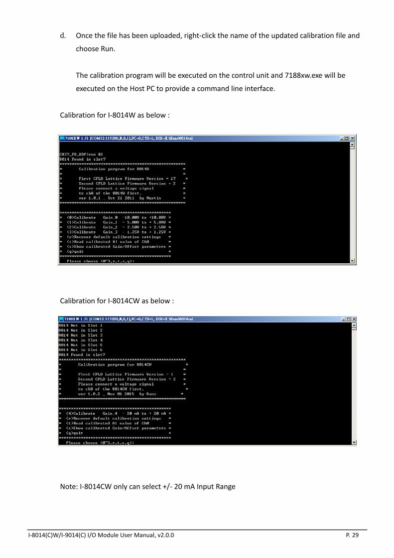
d. Once the file has been uploaded, right-click the name of the updated calibration file and
choose Run.
The calibration program will be executed on the control unit and 7188xw.exe will be
executed on the Host PC to provide a command line interface.
Calibration for I-8014W as below :
Calibration for I-8014CW as below :
Note: I-8014CW only can select +/- 20 mA Input Range

I-8014(C)W/I-9014(C) I/O Module User Manual, v2.0.0 P. 30
Step 3. Calibrate the I-8014 serial module using the following procedure.
a. Select the required input type by typing an option from 0 to 3, and then press Enter.
b. Determine two values (points) within the range of the input type selected for the
calibration process.
For example, after selecting option 0 (-10 V - +10 V), +8 V and -8 V can be used as the two
calibration points.
c. Set the calibration source output to one of the two points (e.g., 8 V in this example)

I-8014(C)W/I-9014(C) I/O Module User Manual, v2.0.0 P. 31
d. At the input 1st voltage prompt on the console, type the value displayed on the meter
and then press Enter.
e. Set the calibration source output to the other point (e.g., - 8 V in this example).
I-8014(C)W/I-9014(C) I/O Module User Manual, v2.0.0 P. 32
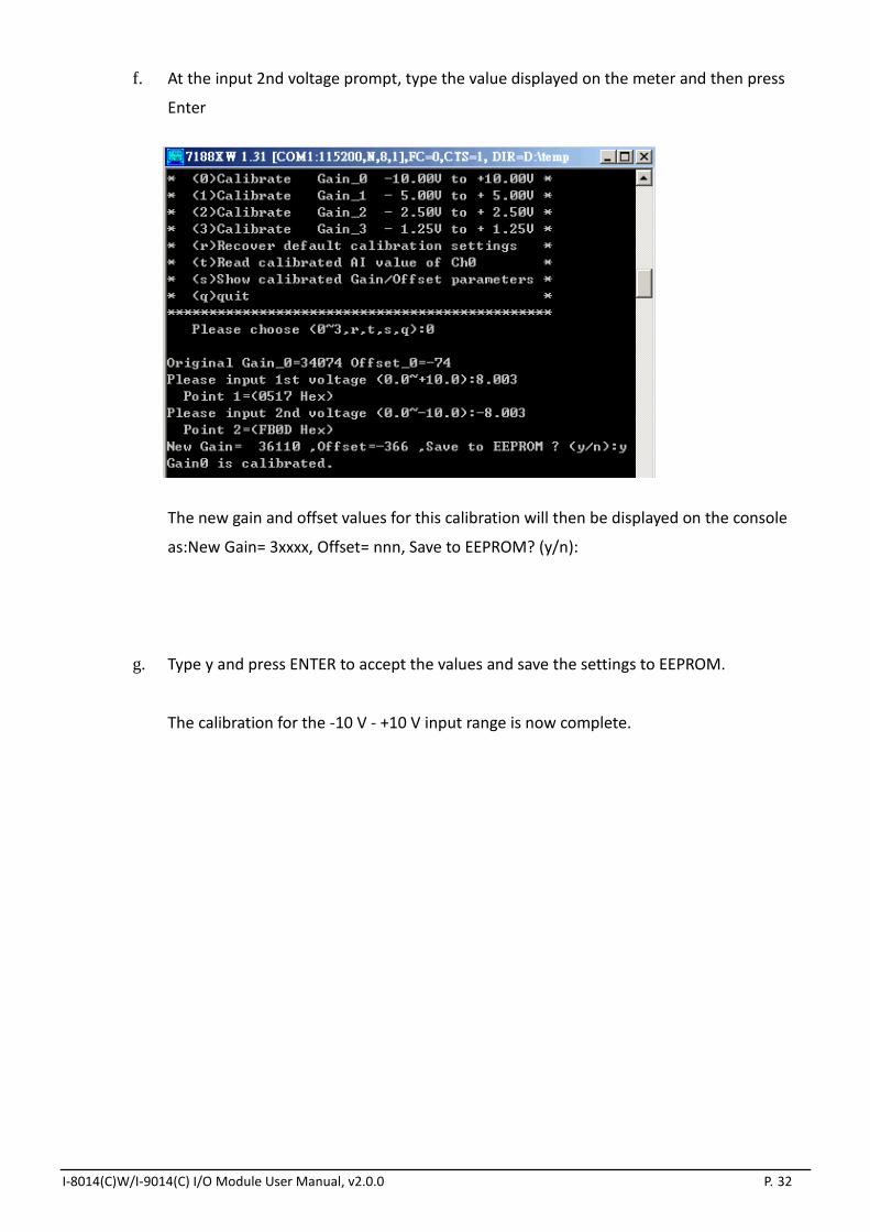
f. At the input 2nd voltage prompt, type the value displayed on the meter and then press
Enter
The new gain and offset values for this calibration will then be displayed on the console
as:New Gain= 3xxxx, Offset= nnn, Save to EEPROM? (y/n):
g. Type y and press ENTER to accept the values and save the settings to EEPROM.
The calibration for the -10 V - +10 V input range is now complete.

I-8014(C)W/I-9014(C) I/O Module User Manual, v2.0.0 P. 33
2.1.2.2. Verifying the Calibration
Step 1. Set the calibration source to output a voltage to channel 0 on the I-8014W module. For example,
-2 V.
Step 2. In the same calibration program console window, type t (Read the calibrated AI value for Ch0),
and then select the input type that was just calibrated (e.g., 0, -10 V -10 V ).
Step 3. Confirm that the values displayed for channel 0 are correct.
I-8014(C)W/I-9014(C) I/O Module User Manual, v2.0.0 P. 34
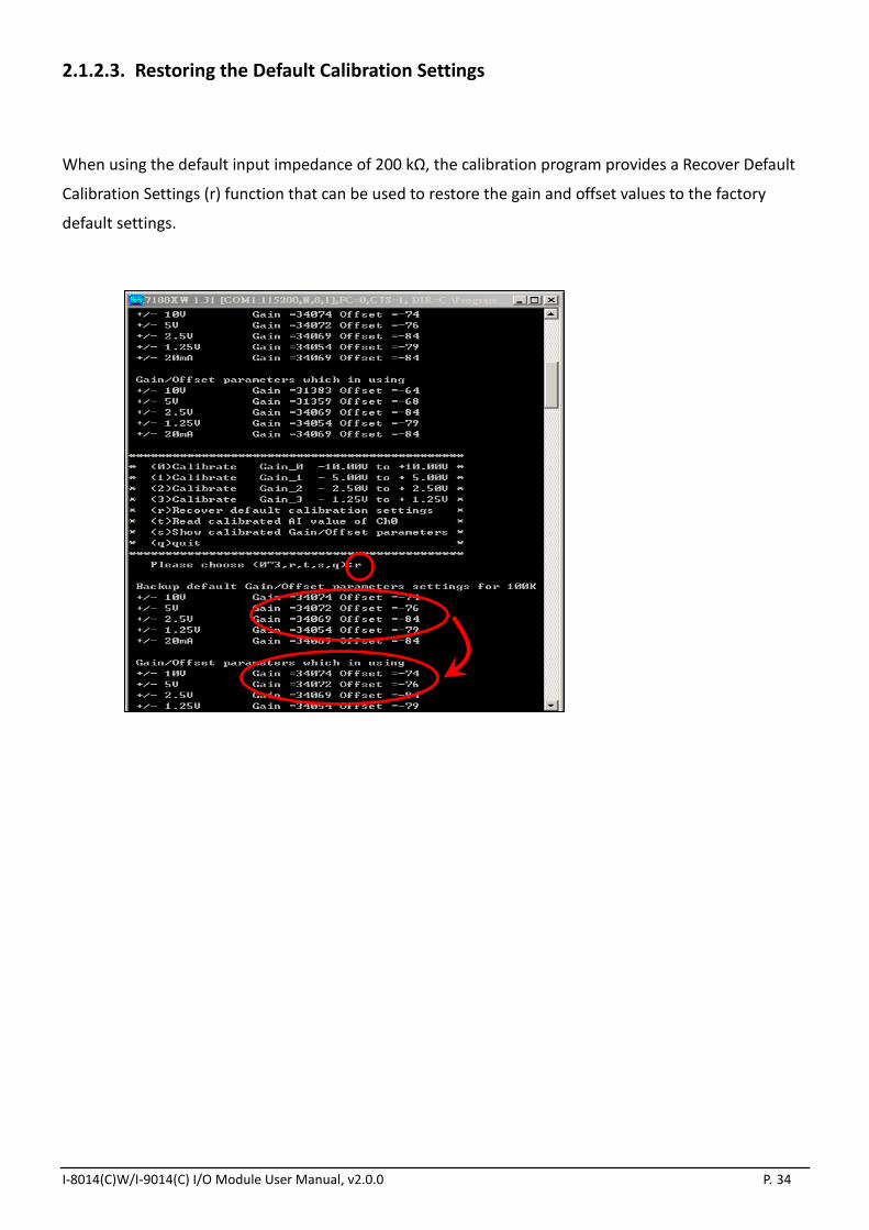
2.1.2.3. Restoring the Default Calibration Settings
When using the default input impedance of 200 kΩ, the calibration program provides a Recover Default
Calibration Settings (r) function that can be used to restore the gain and offset values to the factory
default settings.

I-8014(C)W/I-9014(C) I/O Module User Manual, v2.0.0 P. 35
2.2. Windows-based Controllers
This section contains:
Getting Started, see section 2.2.1
Calibration, see section 2.2.2

I-8014(C)W/I-9014(C) I/O Module User Manual, v2.0.0 P. 36
2.2.1. Getting Started
The pac_i8014W_BasicInfo.exe executable file, which is located in the BasicInfo folder of the I-8014W
demo programs, can be used to retrieve the basic configuration information related to the I-8014W and
to verify the AI read functions. The basic configuration information includes:
The Version number and the published date of the library.
The FPGA version
The single-ended/differential jumper settings
The gain and offset values for each input range
The data read on each channel
(See the Location of the Demo Programs section on page 12 for details of where to find the
pac_i8014W_BasicInfo.exe in the I-8014W demo programs folder)
Step 1. Refer to the Jumper Settings section on page 8. Ensure that the Differential/Single-ended
selection jumper is in the differential position.
Step 2. Connect a stable signal source (e.g., a battery output) to the I-8014W using the differential iring
method.
Step 3. Insert the I-8014W into a vacant slot in the control unit and power on the controller.

I-8014(C)W/I-9014(C) I/O Module User Manual, v2.0.0 P. 37
Step 4. Launch the pac_i8014W_BasicInfo.exe executable file on the controller, and verify that the basic
information and the AI data read from each channel is correct, as indicated in the diagram
below:
Tips & Warnings
Unused channels should be connected to GND to avoid floating.
Note: I-8014CW only can select max 8 channels and +/- 20 mA Input Range
Library and FPGA version informationSingle-ended/differential jumper position.
Verify the AI data from each channel.
The gain value is around 33000. If this value varies significantly from 33000, it means that the value is incorrect.
I-8014(C)W/I-9014(C) I/O Module User Manual, v2.0.0 P. 38
2.2.2. Calibration
Each I-8014W is factory calibrated and well verified before shipment, so it is usually unnecessary to
calibrate the module again, unless the input impedance is changed on a calibrated module, or the
accuracy is lost.
To calibrate the I-8014W, in addition to inserting the I-8014W into a controller slot, the following items
are required:
A single stable calibration source, such as a 3 1/2 digit power supplier (or better), or a battery
output.
A single 4 1/2 digit voltage meter (15-bit resolution or better)
A Calibration Program. See page 12 for the Location of the Demo Programs contained in the
I-8014W demo programs folder.
Tips & Warnings
1. An unstable calibration source will cause calibration errors and affect the accuracy
of the data acquisition.
2. If you wish to perform calibration using ±20 mA, select ±2.5 V instead as both types
use the same gain and offset values.
3. The calibration program uses channel 0 to accept the calibration source only.
This section contains:
Calibrating the I-8014W on WinCE and WES units,see section 2.2.2.1
Verifying the Calibration, see section 2.2.2.2
Restoring the Default Calibration Settings, see section 2.2.2.3

I-8014(C)W/I-9014(C) I/O Module User Manual, v2.0.0 P. 39
2.2.2.1. Calibrating the I-8014W on WinCE and WES units
Step 1. Refer to the Jumper Settings section on page 8. Ensure that the Differential/Single-ended
selection jumper is in the differential position.
Step 2. Connect your calibration source to channel 0 of the I-8014W using the differential wiring
method, as illustrated.
Step 3. Insert the I-8014W into a vacant slot on the controller and power on the controller.
Step 4. Launch the pac_i8014W_Calibration.exe executable file on the controller to display the
Calibration dialog box.
(See the Location of the Demo Programs section on page 12 for details of where to find the c# demos for
the I-8014W)
Tips & Warnings
Only channel 0 can be used to perform calibration.
I-8014(C)W/I-9014(C) I/O Module User Manual, v2.0.0 P. 40
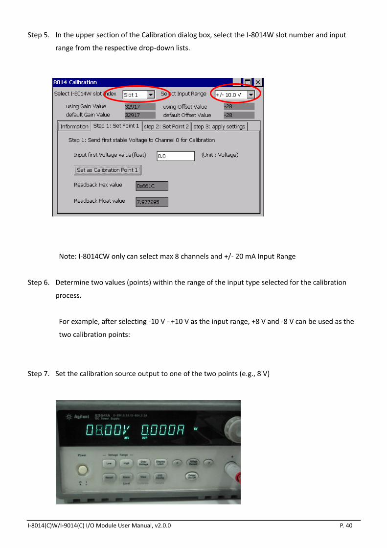
Step 5. In the upper section of the Calibration dialog box, select the I-8014W slot number and input
range from the respective drop-down lists.
Note: I-8014CW only can select max 8 channels and +/- 20 mA Input Range
Step 6. Determine two values (points) within the range of the input type selected for the calibration
process.
For example, after selecting -10 V - +10 V as the input range, +8 V and -8 V can be used as the
two calibration points:
Step 7. Set the calibration source output to one of the two points (e.g., 8 V)
I-8014(C)W/I-9014(C) I/O Module User Manual, v2.0.0 P. 41
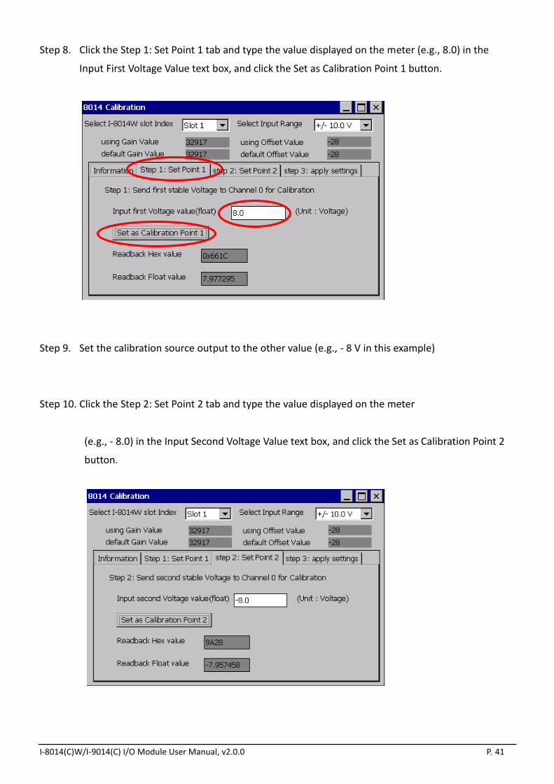
Step 8. Click the Step 1: Set Point 1 tab and type the value displayed on the meter (e.g., 8.0) in the
Input First Voltage Value text box, and click the Set as Calibration Point 1 button.
Step 9. Set the calibration source output to the other value (e.g., - 8 V in this example)
Step 10. Click the Step 2: Set Point 2 tab and type the value displayed on the meter
(e.g., - 8.0) in the Input Second Voltage Value text box, and click the Set as Calibration Point 2
button.

I-8014(C)W/I-9014(C) I/O Module User Manual, v2.0.0 P. 42
Step 11. Click the Step 3: Apply Settings tab, and then check that the calibration parameters are correct.
Click the Save New Calibration Settings button to save the calibration settings.
The calibration for the -10 V - +10 V input range is now complete.

I-8014(C)W/I-9014(C) I/O Module User Manual, v2.0.0 P. 43
2.2.2.2. Verifying the Calibration
Step 1. Set the calibration source to output a voltage to channel 0 on the I-8014W module. For example,
-2 V.
Step 2. In the Calibration dialog box, click the Step 1: Set Point 1 tab and confirm that the AI Readback
Float value is as illustrated in the image below:
I-8014(C)W/I-9014(C) I/O Module User Manual, v2.0.0 P. 44
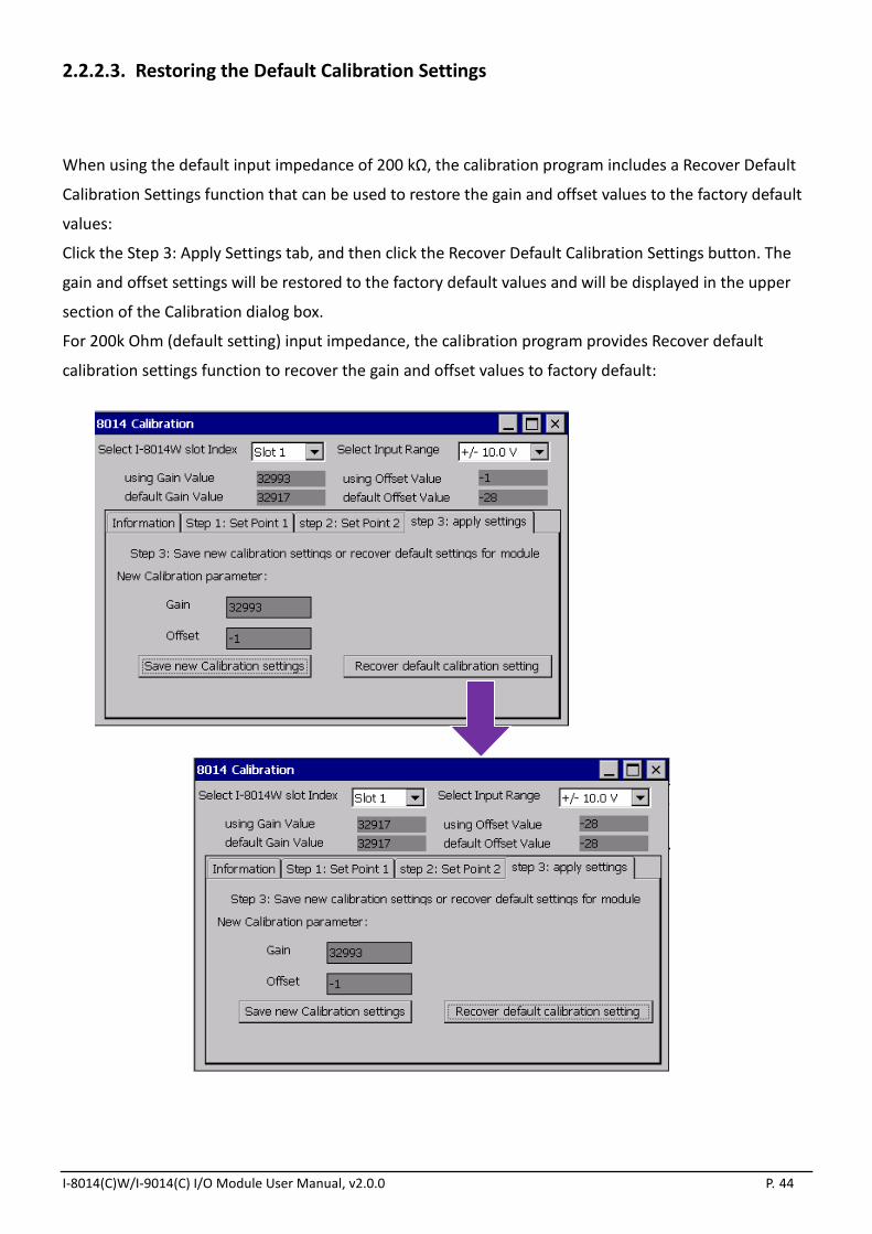
2.2.2.3. Restoring the Default Calibration Settings
When using the default input impedance of 200 kΩ, the calibration program includes a Recover Default
Calibration Settings function that can be used to restore the gain and offset values to the factory default
values:
Click the Step 3: Apply Settings tab, and then click the Recover Default Calibration Settings button. The
gain and offset settings will be restored to the factory default values and will be displayed in the upper
section of the Calibration dialog box.
For 200k Ohm (default setting) input impedance, the calibration program provides Recover default
calibration settings function to recover the gain and offset values to factory default:

I-8014(C)W/I-9014(C) I/O Module User Manual, v2.0.0 P. 45
3. Magic Scan
This chapter provides details related to Magic Scan, which is a key function included on the I-8014W for
multi-channel analog data acquisition at high sampling rates.
Two demo programs that can be used to implement Magic Scan functionality are included at the end of
this chapter. Either Magic Scan mode or the trigger method can be selected for use in the two programs,
and the only difference is that Magic Scan mode uses polling to transfer data and the trigger method
transfers data using interrupts.
This chapter contains:
The Advantages of Magic Scan, see section 3.1

I-8014(C)W/I-9014(C) I/O Module User Manual, v2.0.0 P. 46
3.1. The Advantages of Magic Scan
This section contains:
High speed AD with high precision Timer request, see section 3.1.1
Magic Scan, read AD from 4K AI FIFO, see section 3.1.2
4K AI FIFO with FIFO level limit interrupt to reduce the CPU loading greatly, see section 3.1.3
Application Examples, see section 3.1.4

I-8014(C)W/I-9014(C) I/O Module User Manual, v2.0.0 P. 47
3.1.1. High speed AD with high precision Timer request
For normal AD sampling application, it needs a high precision timer to handle the sample rate, and it is
very difficult to have less than 1 ms timer ISR on multi task operation system,
For I-8014W to sample AD, If we configure the sample rate of Magic Scan , it will use independent
internal hardware clock to trigger AD, it does not rely on platform’s Timer ISR

I-8014(C)W/I-9014(C) I/O Module User Manual, v2.0.0 P. 48
3.1.2. Magic Scan, read AD from 4K AI FIFO
Magic Scan convert AD to 4K FIFO automatically, program can read AI data from FIFO any time before
FIFO full.
For normal AD modules, they need to use command to trigger the AD convert and wait time for ready
signal for each sampling event.

I-8014(C)W/I-9014(C) I/O Module User Manual, v2.0.0 P. 49
3.1.3. 4K AI FIFO with FIFO level limit interrupt to reduce the CPU loading greatly
I-8014W can set FIFO limit level for interrupt service notification. This feature can increase the
performance for sampling application. Program don’t need to sample data all the time, but to wait for
CPU’s interrupt notification if AI data count in FIFO reach the limit level.
FIFO limit level Limit Data count to trigger interrupt
0 8
1 16
2 32
3 64
4 128
5 256
6 512
7 2048

I-8014(C)W/I-9014(C) I/O Module User Manual, v2.0.0 P. 50
3.1.4. Application Examples
This section contains:
To sample 16 channels’AI in1 ms Timer ISR, see section 3.1.4.1
250KHz application, see section 3.1.4.2
10KHz sample rate for two I-8014W, see section 3.1.4.3

I-8014(C)W/I-9014(C) I/O Module User Manual, v2.0.0 P. 51
3.1.4.1. To sample 16 channels’AI in1 ms Timer ISR
To achieve this specification
1. System must provide 1ms Timer Interrupt Service.
2. The maximum sample rate of Analog Input module must above 16KHz/sec (16 Data/ms),if
application need PID control or other operation in 1 ms, it need higher sample rate.
If we take a 16-channel AI module with maximum sample rate 30KHz for example, to sample 16 data by
using this AI module needs about 0.54 ms ( (1000ms/30000)*16 = 0.54ms) , it means in 1ms Timer
Interrupt Service Routine, it spends 540us to scan 16 channels AI data, and there will have 460us left to
do other control logic.
If we set I-8014W scan mode as Sample and Hold, FIFO level limit trigger as16 AI data, sample rate 1KHz.
It means that there will be a FIFO ISR in every 1ms, when program receive Interrupt notification, it just
needs 11us~26us to read 16 AI data from FIFO, it remains 970 us can do its control logic work.

I-8014(C)W/I-9014(C) I/O Module User Manual, v2.0.0 P. 52
3.1.4.2. 250KHz application
I-8014W can set 250 KHz sample rate in standard mode. Below diagram shows how it works. The key
feature is the speed to read1 AI data from FIFO is faster than AD convert.
If we set FIFO Limit level as 7 (2048 AI to trigger Interrupt Service), it needs 8.2 ms to convert 2048 AI
data, and 3~6.5 ms to read 2048 AI data from FIFO.

I-8014(C)W/I-9014(C) I/O Module User Manual, v2.0.0 P. 53
3.1.4.3. 10KHz sample rate for two I-8014W
Scan parameters for each I-8014W.
Sample rate Scan channels Scan Mode FIFO limit level
10KHz 8 Sample and Hold 7 (2048 AI)
Under 10KHz Sample and Hold mode,
1. It will be (80K AI data)/sec for each slot
2. It will trigger FIFO limit Interrupt every 25.6 ms, (2048*1000)/(80000)=25.6
3. There will be about 11 ms left after to get data from two slot FIFO
In this application, it needs to convert 160K AI Data from two I-8014W, and this is done by I-8014W itself
without using any CPU resource, program just needs to wait for FIFO ISR notification and read data from
FIFO.
Magic Scan Mode, see section 3.2

I-8014(C)W/I-9014(C) I/O Module User Manual, v2.0.0 P. 54
Trigger Methods, see section 3.3
FIFO, see section 3.4
Magic Scan Procedure, see section 3.5
Magic Scan Example,see section 3.6 -- which describes the two data transfer modes used with
Magic Scan.
Case Study, see section 3.7

I-8014(C)W/I-9014(C) I/O Module User Manual, v2.0.0 P. 55
3.2. The Advantages of Magic Scan
This section contains:
High speed AD with high precision Timer request, see section 3.1.1
Magic Scan, read AD from 4K AI FIFO, see section 3.1.2
4K AI FIFO with FIFO level limit interrupt to reduce the CPU loading greatly, see section 3.1.3
Application Examples, see section 3.1.4

I-8014(C)W/I-9014(C) I/O Module User Manual, v2.0.0 P. 56
3.2.1. High speed AD with high precision Timer request
For normal AD sampling application, it needs a high precision timer to handle the sample rate, and it is
very difficult to have less than 1 ms timer ISR on multi task operation system,
For I-8014W to sample AD, If we configure the sample rate of Magic Scan , it will use independent
internal hardware clock to trigger AD, it does not rely on platform’s Timer ISR

I-8014(C)W/I-9014(C) I/O Module User Manual, v2.0.0 P. 57
3.2.2. Magic Scan, read AD from 4K AI FIFO
Magic Scan convert AD to 4K FIFO automatically, program can read AI data from FIFO any time before
FIFO full.
For normal AD modules, they need to use command to trigger the AD convert and wait time for ready
signal for each sampling event.

I-8014(C)W/I-9014(C) I/O Module User Manual, v2.0.0 P. 58
3.2.3. 4K AI FIFO with FIFO level limit interrupt to reduce the CPU loading greatly
I-8014W can set FIFO limit level for interrupt service notification. This feature can increase the
performance for sampling application. Program don’t need to sample data all the time, but to wait for
CPU’s interrupt notification if AI data count in FIFO reach the limit level.
FIFO limit level Limit Data count to trigger interrupt
0 8
1 16
2 32
3 64
4 128
5 256
6 512
7 2048

I-8014(C)W/I-9014(C) I/O Module User Manual, v2.0.0 P. 59
3.2.4. Application Examples
This section contains:
To sample 16 channels’AI in1 ms Timer ISR, see section 3.1.4.1
250KHz application, see section 3.1.4.2
10KHz sample rate for two I-8014W, see section 3.1.4.3

I-8014(C)W/I-9014(C) I/O Module User Manual, v2.0.0 P. 60
3.2.4.1. To sample 16 channels’AI in1 ms Timer ISR
To achieve this specification
3. System must provide 1ms Timer Interrupt Service.
4. The maximum sample rate of Analog Input module must above 16KHz/sec (16 Data/ms),if
application need PID control or other operation in 1 ms, it need higher sample rate.
If we take a 16-channel AI module with maximum sample rate 30KHz for example, to sample 16 data by
using this AI module needs about 0.54 ms ( (1000ms/30000)*16 = 0.54ms) , it means in 1ms Timer
Interrupt Service Routine, it spends 540us to scan 16 channels AI data, and there will have 460us left to
do other control logic.
If we set I-8014W scan mode as Sample and Hold, FIFO level limit trigger as16 AI data, sample rate 1KHz.
It means that there will be a FIFO ISR in every 1ms, when program receive Interrupt notification, it just
needs 11us~26us to read 16 AI data from FIFO, it remains 970 us can do its control logic work.
16 A/D 16 A/D
1ms Timer ISR
Control Logic Control Logic T
1ms Timer ISR
1KHz 1 AI FIFO ISR
Control Logic
1KHz 1 AI FIFO ISR
Control Logic
T

I-8014(C)W/I-9014(C) I/O Module User Manual, v2.0.0 P. 61
3.2.4.2. 250KHz application
I-8014W can set 250 KHz sample rate in standard mode. Below diagram shows how it works. The key
feature is the speed to read1 AI data from FIFO is faster than AD convert.
If we set FIFO Limit level as 7 (2048 AI to trigger Interrupt Service), it needs 8.2 ms to convert 2048 AI
data, and 3~6.5 ms to read 2048 AI data from FIFO.
1 AI data for every 4us
250KHz 4KFIFO
Read 1 AI need about 0.7 ~ 1.6us
(depend on data bus speed)

I-8014(C)W/I-9014(C) I/O Module User Manual, v2.0.0 P. 62
3.2.4.3. 10KHz sample rate for two I-8014W
Scan parameters for each I-8014W.
Sample rate Scan channels Scan Mode FIFO limit level
10KHz 8 Sample and Hold 7 (2048 AI)
Under 10KHz Sample and Hold mode,
4. It will be (80K AI data)/sec for each slot
5. It will trigger FIFO limit Interrupt every 25.6 ms, (2048*1000)/(80000)=25.6
6. There will be about 11 ms left after to get data from two slot FIFO
In this application, it needs to convert 160K AI Data from two I-8014W, and this is done by I-8014W itself
without using any CPU resource, program just needs to wait for FIFO ISR notification and read data from
FIFO.
Need 14 ms to read 2 slot FIFO
2048 FIFO ISR trigger every 25.6 ms
11.6 ms left T
Two I-8014W FIFO trigger the FIFO
ISR every 25.6ms
7ms to read 2048 data from FIFO
4KFIFO
7ms to read 2048 data from FIFO
4KFIFO

I-8014(C)W/I-9014(C) I/O Module User Manual, v2.0.0 P. 63
3.3. Magic Scan Mode
For multi-channel high speed data acquisition systems, the I-8014W provides sampling rates of up to 250
kHz and a 4k-sample FIFO that reduces the loading of the CPU and enhances the performance of your
system.
The following is an overview of the Magic Scan specifications:
Max. Channels 16
Sampling Rate 2 Hz ~ 250 kHz
FIFO 4 k samples
Sampling Mode - Standard
- Virtual Sample and Hold
Trigger Method - Software
- Internal Hardware
- External Hardware
Data Transfer Mode - polling
- Interrupt
This section describes the two Magic Scan modes that can be used on the I-8014W:
Standard Mode, see section 3.1.1
Virtual Sample and Hold Mode, see section 3.1.2
I-8014(C)W/I-9014(C) I/O Module User Manual, v2.0.0 P. 64
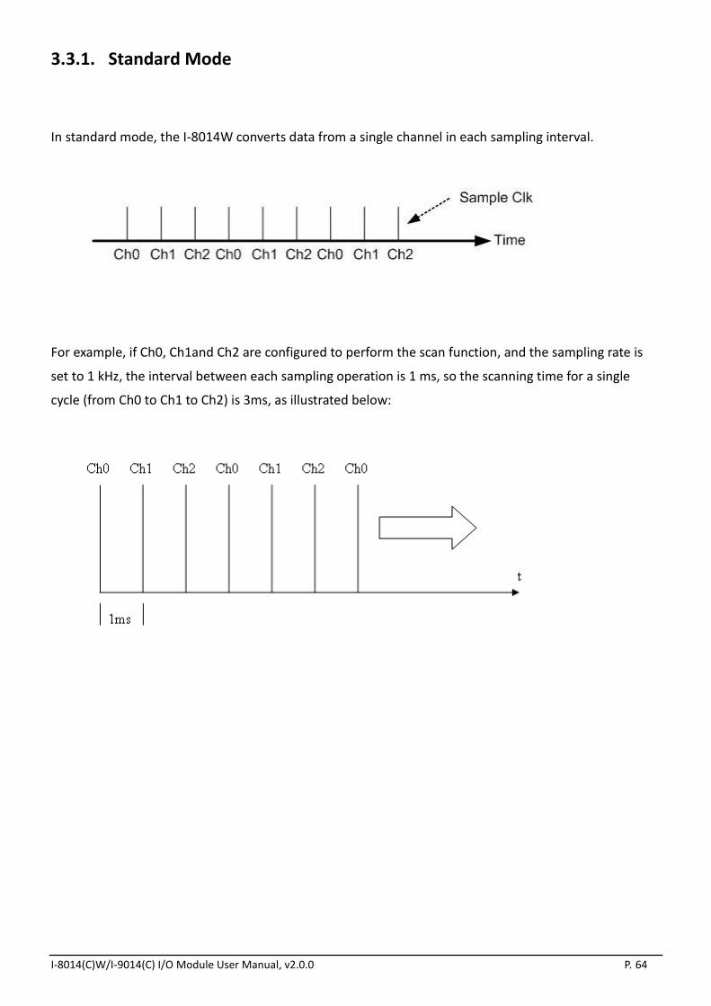
3.3.1. Standard Mode
In standard mode, the I-8014W converts data from a single channel in each sampling interval.
For example, if Ch0, Ch1and Ch2 are configured to perform the scan function, and the sampling rate is
set to 1 kHz, the interval between each sampling operation is 1 ms, so the scanning time for a single
cycle (from Ch0 to Ch1 to Ch2) is 3ms, as illustrated below:

I-8014(C)W/I-9014(C) I/O Module User Manual, v2.0.0 P. 65
3.3.2. Virtual Sample and Hold Mode
Virtual sample and hold mode operates such that several channels can be configured to perform
scanning functions and are sampled at the same time. The sampling rate is set to 250 kHz by default, and
the scan cycle time is the interval that is set in the Magic Scan function.
For example, if the sampling rate is set to1 kHz and Ch0, Ch1, and Ch2 are configured to perform the
scanning functions, the sampling rate for scanning Ch0 to Ch2 is 250 kHz, and the frequency of the scan
cycle is 1 kHz, the interval between one scan cycle and the next is 1 ms.

I-8014(C)W/I-9014(C) I/O Module User Manual, v2.0.0 P. 66
3.4. Trigger Methods
This section contains:
Software Trigger Method, see section 3.2.1
Internal Hardware Trigger Method, see section 3.2.2
External Hardware Trigger Method, see section 3.2.3

I-8014(C)W/I-9014(C) I/O Module User Manual, v2.0.0 P. 67
3.4.1. Software Trigger Method
The API provides a trigger instruction that initiates Magic Scan. If you have two or more modules, you
need to configure the Magic Scan parameters for each module and execute the Magic Scan instructions
for the modules individually.
Execute Magic Scan on the first module and then repeat for
the subsequent modules using software instructions.

I-8014(C)W/I-9014(C) I/O Module User Manual, v2.0.0 P. 68
3.4.2. Internal Hardware Trigger Method
If you wish to simultaneously initiate the Magic Scan function on two or more modules, set the internal
hardware signal as the trigger source in your program, and then the internal trigger signal will trigger the
Magic Scan operation for the individual modules at almost the same time.
Trigger Magic Scan for each module using an internal hardware
signal.

I-8014(C)W/I-9014(C) I/O Module User Manual, v2.0.0 P. 69
3.4.3. External Hardware Trigger Method
The Magic Scan function is also able to accept an external trigger source from the first two terminals,
using this method, the trigger can be set as either rising edge or falling edge triggered. After setting the
external trigger source and the triggering conditions, execute Magic Scan in your program. The I-8014W
will wait until it receives the external signal from the Trig+ and Trig- terminals and will then execute
Magic Scan.

I-8014(C)W/I-9014(C) I/O Module User Manual, v2.0.0 P. 70
3.5. FIFO
The I-8014W is equipped with a 4 k-sample FIFO buffer, which may be used to store 4096 data samples
from Magic Scan to ensure that no data is lost. The acquisition data is sequentially saved to the FIFO
buffer during the scan process. To prevent the FIFO buffer from being filled, the data needs to be read
from the FIFO buffer within a specific timeframe. If the FIFO buffer is filled, data can no longer be saved
until a command is executed that clears the FIFO buffer. In contrast, if data is read from the FIFO buffer
too frequently, CPU resources will be wasted and performance will be affected. To achieve the optimum
balance, two modes for transferring data from the FIFO are provided, polling mode and interrupt mode.
Note: I-8014CW only can select max 8 channels Differential Mode and +/- 20 mA Input Range
I-8014(C)W/I-9014(C) I/O Module User Manual, v2.0.0 P. 71
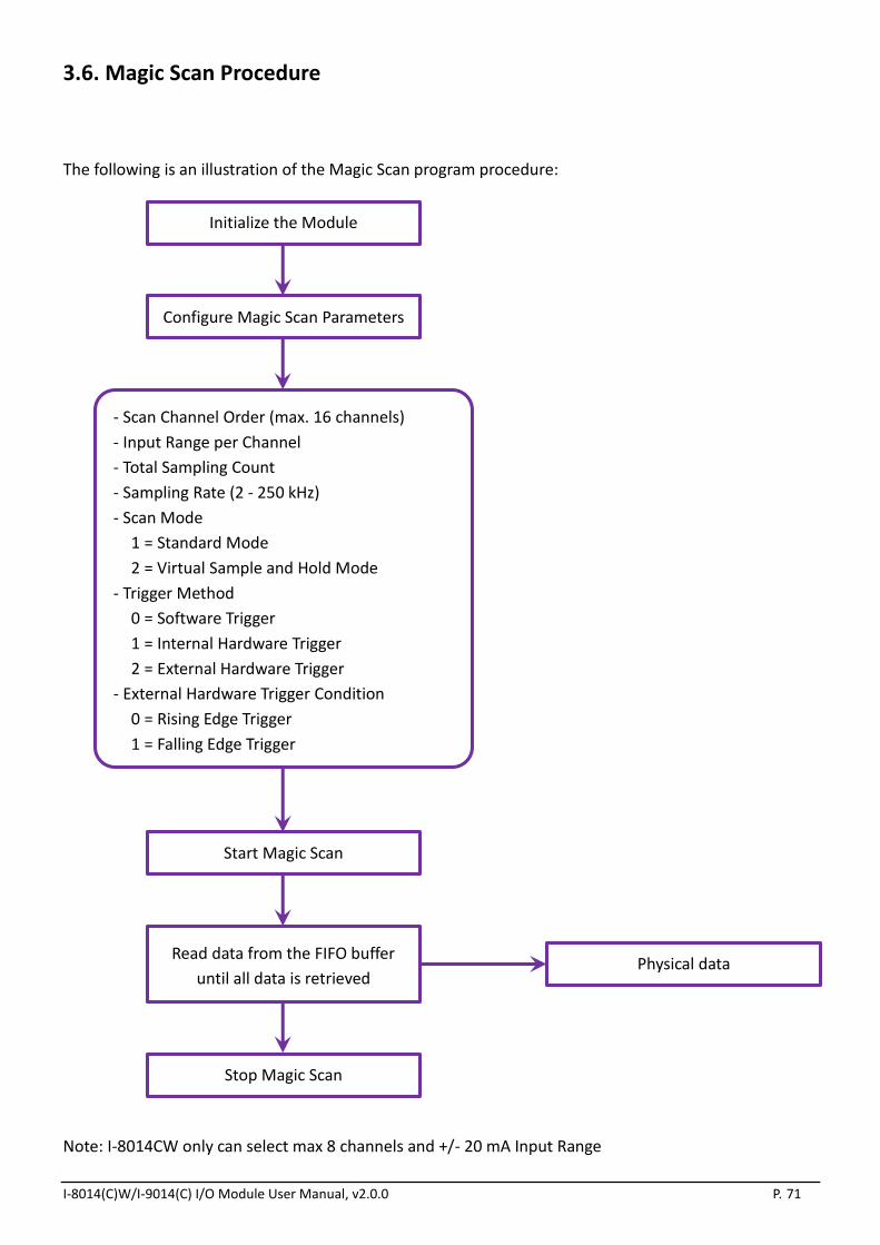
3.6. Magic Scan Procedure
The following is an illustration of the Magic Scan program procedure:
Note: I-8014CW only can select max 8 channels and +/- 20 mA Input Range
Physical data
Initialize the Module
Configure Magic Scan Parameters
- Scan Channel Order (max. 16 channels)
- Input Range per Channel
- Total Sampling Count
- Sampling Rate (2 - 250 kHz)
- Scan Mode
1 = Standard Mode
2 = Virtual Sample and Hold Mode
- Trigger Method
0 = Software Trigger
1 = Internal Hardware Trigger
2 = External Hardware Trigger
- External Hardware Trigger Condition
0 = Rising Edge Trigger
1 = Falling Edge Trigger
Start Magic Scan
Read data from the FIFO buffer
until all data is retrieved
Stop Magic Scan

I-8014(C)W/I-9014(C) I/O Module User Manual, v2.0.0 P. 72
3.7. Magic Scan Example
This section includes information related to the two Magic Scan demo programs that are provided for
different data transfer modes. See the Location of the Demo Programs section on page 12 for details of
how to locate the demo program for your controller.
This section contains:
Magic.exe, see section 3.5.1– for transferring data using the polling method
Mag_ISR.exe, see section 3.5.2– for transferring data using the interrupt method

I-8014(C)W/I-9014(C) I/O Module User Manual, v2.0.0 P. 73
3.7.1. Magic.exe
This section describes the parameters that should be set in Magic.exe, and separates the description for
MiniOS7 and Windows platforms.
This section contains:
Demo Program for MiniOS7, see section 3.5.1.1
Demo Program on the Windows Platform, see section 3.5.1.2
I-8014(C)W/I-9014(C) I/O Module User Manual, v2.0.0 P. 74
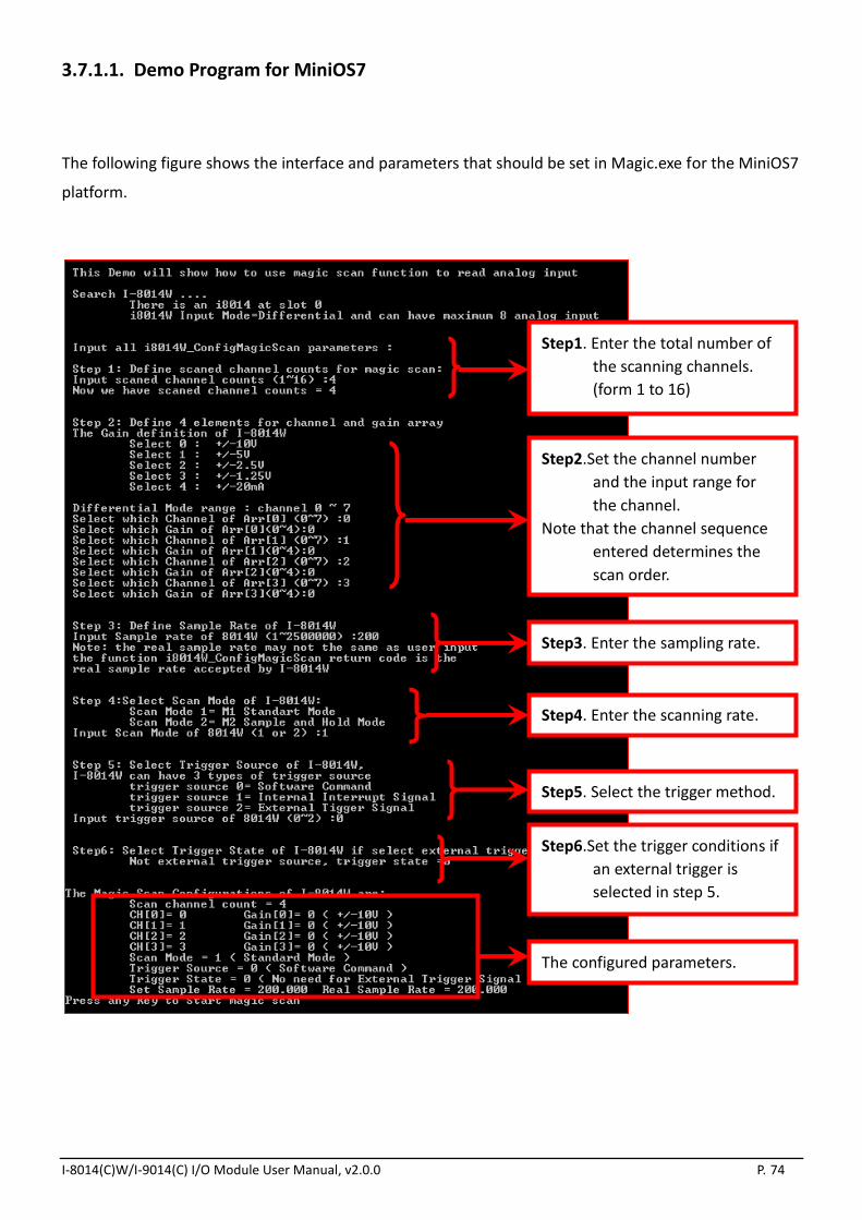
3.7.1.1. Demo Program for MiniOS7
The following figure shows the interface and parameters that should be set in Magic.exe for the MiniOS7
platform.
Step1. Enter the total number of
the scanning channels.
(form 1 to 16)
Step2.Set the channel number
and the input range for
the channel.
Note that the channel sequence
entered determines the
scan order.
Step3. Enter the sampling rate.
Step4. Enter the scanning rate.
Step5. Select the trigger method.
Step6.Set the trigger conditions if
an external trigger is
selected in step 5.
The configured parameters.

I-8014(C)W/I-9014(C) I/O Module User Manual, v2.0.0 P. 75
After the Magic Scan parameters have been set, press any Key to Start Magic Scan, as shown in the
figure below.
If the scan mode is set to standard mode, the total spend time will be equal to [1000] multiplied by the
[sampling period]. (1000 is the total sample count defined in the demo program)
Note: I-8014CW only can select max 8 channels and +/- 20 mA Input Range
Check the total spend time.

I-8014(C)W/I-9014(C) I/O Module User Manual, v2.0.0 P. 76
3.7.1.2. Demo Program on the Windows Platform
The following figure illustrates the interface and parameters that need be set when using Magic.exe on a
Windows platform.
Step6. Click the Start Magic Scan tab, and press the Start Magic Scan button.
The data will be displayed in the right frame for each channel.
Step1. Select the slot and the scan channel count. (From 1 to 16)
Step3. Select the scan mode.
Step4. Select the channel scan order
and the type for each channel.
Step5: Press the Set button.
Step2. Select the trigger source and enter the input sampling rate.If
an external trigger source is selected, also select the trigger state.

I-8014(C)W/I-9014(C) I/O Module User Manual, v2.0.0 P. 77
Viewing the Results for Standard Scan Mode
To view the results of the scan in Standard Scan Mode, click the Start Magic Scan tab. When the
sampling rate is set to 200 Hz, the sampling period will be 1/200 * 1000 = 5 ms. The spend time equals
the [total sample count] multiplied by the [sampling period].
In this example, the spend time is 5004 ms, which is equal to about 1000 (the total sample count defined
in the code) multiplied by 5 (the sampling period).
Note: I-8014CW only can select max 8 channels and +/- 20 mA Input Range

I-8014(C)W/I-9014(C) I/O Module User Manual, v2.0.0 P. 78
Viewing the Results for Virtual Sample and Hold Mode
To view the results of the scan in Virtual Sample and Hold Mode, click the Start Magic Scan tab. When
the sampling rate is set to 200 Hz, the period for one scan cycle is 1/200 * 1000 = 5 ms.
The number of scan cycles = [Total sample count] / [Total number of scanning channels].
In this example, the spend time 1254 ms = (1000 / 4) * 5
(Spend time = [number of scan cycles] * [scan cycle period])
The spend time can be used to verify the sampling rate on the I-8014W.
Note: I-8014CW only can select max 8 channels and +/- 20 mA Input Range

I-8014(C)W/I-9014(C) I/O Module User Manual, v2.0.0 P. 79
3.7.2. Mag_ISR.exe
Mag_ISR.exe demonstrates how to transfer data using interrupts. When using this method, the Magic
Scan parameter settings are identical to those used for Magic.exe. See the Magic Scan Procedure section
on page 48 and the Magic.exe section on page 50 for more details. The only difference is that an
interrupt service routine (ISR) must be installed before starting Magic Scan. This is achieved by adding
the following code to your program:
i8014W_InstallMagicScanISR(slotIndex,Slot_ISR,triggerLevel);
i8014W_StartMagicScan(slotIndex);
The installed ISR will process any interrupt tasks when an interrupt signal is detected from the FIFO, and
the parameter triggerLevel is used to configure the interrupt conditions, as indicated in the following
table:
triggerLevel Data Count
0 8
1 16
2 32
3 64
4 128
5 256
6 512
7 2048
Once the amount of data in the FIFO buffer meets the level that was set via the triggerLevel parameter,
an interrupt signal will be generated, and the code in the installed ISR will be processed. Note that you
need to ensure that the interrupt function in the ISR is cleared, otherwise any subsequent interrupt
requests will not be processed.
Using interrupts to transfer data helps to reduce CPU usage time which could be wasted when used for
polling and waiting for data from the FIFO buffer.

I-8014(C)W/I-9014(C) I/O Module User Manual, v2.0.0 P. 80
3.8. Case Study
The requirements in this case are:
1. Measure four differential signals ranging from -10 V to +10V.
2. The sampling rate per channel is 200 Hz, and sampling time interval from one channel to the next
channel is less than 10 μs.
3. Once 2000 data samples have been collected, transfer the data via the Ethernet to a data center or
a remote data storage disk.
Use the following procedure to meet the requirements:
Step 1. Set the jumper on the I-8014W to differential input mode.
Step 2. Set the input channels as ch0 - ch3, and set the input range for each channel to -10 - +10 V.
(Gain = 0)
Step 3. Set the sampling rate to 200 Hz, and set the scan mode to Mode2: Virtual Sample and Hold
Mode. With Virtual Sample and Hold Mode, the sampling time interval between one channel
and another channel is 4 μs.
Step 4. Collect 2000 samples, which means collecting 500 samples per channel. (i.e., 2000 divided by
four channels). The elapsed time will be 500 * (1/ 200 Hz) = 2500 ms.
Step 5. If the system uses the MiniOS7 platform, converting the data from hexadecimal format to
floating point format and then transferring it via the Ethernet will add to the CPU load. It is
recommended that the hexadecimal data is first transferred to a PC client and then converted to
floating point data on the PC.
Note: I-8014CW only can select max 8 channels and +/- 20 mA Input Range

I-8014(C)W/I-9014(C) I/O Module User Manual, v2.0.0 P. 81
If the system uses the Windows platform, converting data from hexadecimal format to floating point
format will not affect the CPU load. The data can be converted to floating point format locally and then
transferred via the Ethernet.
Tips & Warnings
It is recommended that several buffers are created to process the data obtained from
the FIFO, which can then be reused in the processing flow, as illustrated in the figure
below. This allows the system time to convert the data, and then save and transfer it.
Buffer 0
2000 data samples collected
Buffer 1
2000 data samples collected
Buffer 2
2000 data samples collected
Buffer 0
Transfer data via the Ethernet
Buffer 1
Transfer data via the Ethernet
Time axis T0 T1 T2

I-8014(C)W/I-9014(C) I/O Module User Manual, v2.0.0 P. 82
4. API References
ICPDAS supplies a range of C/C++ API functions for the I-9028U module. When developing a custom
program, refer to either the 9028W.h header file, or the API functions described in the following sections
for more detailed information.
ICPDAS also supplies a range of C# function that can be used to develop custom .NET programs. These
functions are ported from the relevant C/C++ functions. For more information related to the .NET
functions, refer to the pac_i9028.cs file.
More details of where to find the relevant libraries and files, refer to Chapter 1.7 Location of the Demo
and Library Programs.
The following is an overview of the functions provided in the 9028.lib for use with the 9000 PAC platform.
Detailed information related to individual functions can be found in the following sections.
Function Description
i8014W_Init This function is used to initialize the driver and confirm the
hardware ID.
i8014W_GetFirmwareVer_L1 This function is used to retrieve the version number of the primary
FPGA firmware for a module.
i8014W_GetFirmwareVer_L2 This function is used to retrieve the version number of the
secondary FPGA firmware for a module.
i8014W_GetLibVersion This function is used to retrieve the version number of the
8014W.lib.
i8014W_GetLibDate This function is used to retrieve the release date of the 8014W.lib.
i8014W_GetSingleEndJumper This function is used to retrieve the single-ended/differential
jumper position settings on the I-8014(C)W/I-9014(C).
i8014W_ReadGainOffset This function is used to obtain the gain and offset values on each
input type for I-8014W/I-9014.
i8014W_Read_mA_GainOffset This function is used to obtain the gain and offset values on each
input type for I-8014CW/I-9014C.
i8014W_ReadAI This function is used to read a floating point input (calibrated) from
one specified channel.

I-8014(C)W/I-9014(C) I/O Module User Manual, v2.0.0 P. 83
i8014W_ReadAIHex This function is used to read a hexadecimal input (calibrated) from
a single specified channel.
i8014W_ConfigMagicScan This function is used to configure all the parameters needed when
using Magic Scan, and should be called before executing any Magic
Scan instructions.
i8014W_StartMagicScan This function is used to start Magic Scan.
i8014W_StopMagicScan This function is used to stop Magic Scan.
i8014W_ReadFIFO This function is used to read data from the FIFO buffer after the
Magic Scan function has been triggered.
i8014W_CalibrateData This function is used to calibrate the raw data read during the
Magic Scan process and to convert the data to a floating point
value.
i8014W_CalibrateDataHex This function is used to calibrate the raw data read in Magic Scan
process.
i8014W_UnLockFIFO This function is used to unlock the FIFO buffer when it is locked
after being filled.
i8014W_ClearFIFO This function is used to clear the FIFO buffer after the UnlockFIFO
function has been executed.
i8014W_InstallMagicScanISR This function is used to install the ISR to control to control interrupt
events form the FIFO buffer.
i8014W_UnInstallMagicScanISR This function is used to uninstall the Magic Scan ISR.
i8014W_ClearInt This function is used to clear the status of the Magic Scan
interrupts.

I-8014(C)W/I-9014(C) I/O Module User Manual, v2.0.0 P. 84
4.1. i8014W_Init
This function is used to initialize the driver and confirm the hardware ID.
Syntax
For MiniOS7
short i8014W_Init(int slot);
For Windows (CE and WES)
short pac_i8014W_Init(int slot);
Parameter
slot:
specifies the slot number (0 - 7).
Return Values
0 = the module in the slot is an I-8014(C)W/I-9014(C).
-1 = there is no I-8014(C)W/I-9014(C) module in this slot.
For other return values, see the Appendix A. Error Code.
Note
Before executing any functions on the I-8014(C)W/I-9014(C), the i8014W_Init function needs to be
called once for each I-8014(C)W/I-9014(C). If there are two or more I-8014(C)W/I-9014(C)modules,
you need call the i8014W_Init function for each I-8014(C)W/I-9014(C)module individually by
passing the slot number that the I-8014(C)W/I-9014(C)module is plugged into.

I-8014(C)W/I-9014(C) I/O Module User Manual, v2.0.0 P. 85
Example
[C/C++]
intslotIndex,err;
err=i8014W_Init(slotIndex);
if(err==0)
{
printf(“There is an I-8014W module in slot %d\n”,slotIndex);
}
else
{
printf(“There is no I-8014W module in slot %d\n”,slotIndex);
}
I-8014(C)W/I-9014(C) I/O Module User Manual, v2.0.0 P. 86
4.2. i8014W_GetFirmwareVer_L1
This function is used to retrieve the version number of the primary FPGA firmware for a module. The
function is only used for troubleshooting or recording purposes.
Syntax
For MiniOS7
short i8014W_GetFirmwareVer_L1(int slot);
For Windows (CE and WES)
short pac_i8014W_GetFirmwareVer_L1(int slot);
Parameter
slot:
specifies the slot number (0 - 7).
Return Values
The version number of the primary FPGA firmware for the I-8014(C)W/I-9014(C)module.
Example
[C++]
short ver_L1=0, slot=0;
ver_L1= i8014W_GetFirmwareVer_L1 (slot);
printf( "\nPrimaryFPGA Version =: %04X",i8014W_GetFirmwareVer_L1(slot) );

I-8014(C)W/I-9014(C) I/O Module User Manual, v2.0.0 P. 87
4.3. i8014W_GetFirmwareVer_L2
This function is used to retrieve the version number of the secondary FPGA firmware for a module. The
function is only used for troubleshooting or recording purposes.
Syntax
For MiniOS7
short i8014W_GetFirmwareVer_L2(int slot);
For Windows (CE and WES)
short pac_i8014W_GetFirmwareVer_L2(int slot);
Parameter
slot:
specifies the slot number (0 - 7).
Return Values
The version number of the secondary FPGA firmware for the I-8014(C)W/I-9014(C)module.
Example
[C++]
short ver_L2=0, slot=0;
ver_L2= i8014W_GetFirmwareVer_L2 (slot);
printf( "\nSecondaryFPGA Version =: %04X",i8014W_GetFirmwareVer_L2(slot) );

I-8014(C)W/I-9014(C) I/O Module User Manual, v2.0.0 P. 88
4.4. i8014W_GetLibVersion
This function is used to retrieve the version number of the 8014W.lib. The function is only used for
troubleshooting or recording purposes.
Syntax
For MiniOS7
short i8014W_GetLibVersion(void);
For Windows (CE and WES)
short pac_i8014W_GetLibVersion(void);
Parameter
None
Return Values
The version number of the 8014W.lib.
Example
[C++]
short version;
version = i8014W_GetLibVersion();
printf("\nLibrary Version =: %04X",i8014W_GetLibVersion());
I-8014(C)W/I-9014(C) I/O Module User Manual, v2.0.0 P. 89
4.5. i8014W_GetLibDate
This function is used to retrieve the release date of the 8014W.lib. The function is only used for
troubleshooting or recording purposes.
Syntax
For MiniOS7
void i8014W_GetLibDate(char *LibDate);
For Windows (CE and WES)
void pac_i8014W_GetLibDate(char libDate[]);
Parameter
*libDate:
[Output] the release date of the 8014W.lib.
Return Values
None
Example
[C++]
charlibDate [32];
i8014W_GetLibDate(libDate);
printf("\nBuild Date =: %s",libDate);

I-8014(C)W/I-9014(C) I/O Module User Manual, v2.0.0 P. 90
4.6. i8014W_GetSingleEndJumper
This function is used to retrieve the single-ended/differential jumper position settings on the
I-8014(C)W/I-9014(C). If you wish to use 8-channel differential input, the jumper needs to be put in
differential position; similarly, the jumper needs be set to the single-ended position before 16-channel
single-ended input will works correctly.
Syntax
For MiniOS7
short i8014W_GetSingleEndJumper(int slot);
For Windows (CE and WES)
short pac_i8014W_GetSingleEndJumper(int slot);
Parameter
slot:
specifies the slot number (0 - 7).
Return Values
0: The jumper is in the differential position.
1: The jumper is in the single-ended position.

I-8014(C)W/I-9014(C) I/O Module User Manual, v2.0.0 P. 91
Example
[C++]
short jumper=0, maxCh=0;
jumper = i8014W_GetSingleEndJumper(slot);
if(jumper)
{
maxCh=16;
printf("i8014W Input Mode=Single-End\n\r");
}
else
{
maxCh=8;
printf("i8014W Input Mode=Differential\n\r");
}

I-8014(C)W/I-9014(C) I/O Module User Manual, v2.0.0 P. 92
4.7. i8014W_ReadGainOffset
This function is used to obtain the gain and offset values on each input type for
I-8014W/I-9014.I-8014CW/I-9014C can use i8014W_Read_mA_GainOffset function. Please refer to
section 4.1.8.
Syntax
For MiniOS7
void i8014W_ ReadGainOffset
(
int slot,
int gain,
unsigned short* gainValue,
short* offsetValue
);
For Windows (CE and WES)
void pac_i8014W_ReadGainOffset
(
int slot,
short gain,
unsigned short* gainValue,
short* offsetValue
);
Parameter
slot:
specifies the slot number (0 - 7).
gain:
specifies the input type (0 - 4), where:0: +/-10 V, 1: +/-5 V, 2: +/-2.5 V, 3: +/-1.25 V, 4: +/-20 mA
*gainValue:
[Output] the gain value for the input range.
*offsetValue:
[Output] the offset value for the input range.

I-8014(C)W/I-9014(C) I/O Module User Manual, v2.0.0 P. 93
Return Values
None
Example
[C++]
unsigned short gVal=0;
shortoVal=0;
i8014W_ReadGainOffset(slot,gain,&gVal,&oVal);
printf("\nThe Gain and Offset values for Calibration are: Gain=%u; Offset=%d",ch,gVal,oVal);

I-8014(C)W/I-9014(C) I/O Module User Manual, v2.0.0 P. 94
4.8. i8014W_Read_mA_GainOffset
This function is used to obtain the gain and offset values on each input type for I-8014CW/I-9014C.
I-8014W/I-9014 can use i8014W_ReadGainOffset function. Please refer to section 4.1.7.
Syntax
For MiniOS7
void i8014W_Read_mA_GainOffset
(
int slot,
int channel,
unsigned short* gainValue,
short* offsetValue
);
For Windows (CE and WES)
voidpac_ i8014W_Read_mA_GainOffset
(
int slot,,
int channel,
unsigned short* gainValue,
short* offsetValue
);
Parameter
slot:
specifies the slot number (0 - 7).
channel:
specifies the channel (0 - 7), for +/-20 mA
*gainValue:
[Output] the gain value for the input range.
*offsetValue:
[Output] the offset value for the input range.

I-8014(C)W/I-9014(C) I/O Module User Manual, v2.0.0 P. 95
Return Values
None
Example
[C++]
unsigned short gVal=0;
shortoVal=0;
i8014W_Read_mA_GainOffset (slot,ch,&gVal,&oVal);
printf("\nThe channel and Offset values for Calibration are: Gain=%u; Offset=%d",ch,gVal,oVal);

I-8014(C)W/I-9014(C) I/O Module User Manual, v2.0.0 P. 96
4.9. i8014W_ReadAI
This function is used to read a floating point input (calibrated) from one specified channel.
Syntax
For MiniOS7
short i8014W_ReadAI(
int slot,
intch,
int gain,
float* fVal
);
For Windows (CE and WES)
short pac_i8014W_ReadAI(
int slot,
shortch,
short gain,
float* fVal
);
Parameter
slot:
specifies the slot number (0 - 7).
ch:
specifies the channel number, 0 - 7 for differential input, or 0 - 15 for single-ended input.
gain:
specifies the input type (0 - 4), where:0: +/-10 V, 1: +/-5 V, 2: +/-2.5 V, 3: +/-1.25 V, 4: +/-20 mA
*fVal:
[Output] the floating-point data.

I-8014(C)W/I-9014(C) I/O Module User Manual, v2.0.0 P. 97
Return Values
0 = No Error
For other return values, see the Appendix A. Error Code.
Example
[C++]
intslot,ch,gain;
floatfVal=0.0;
slot = 0;
gain = 0; // "+/-10V"
for(ch=0;ch<8;ch++)
{
i8014W_ReadAI( slot, ch, gain, &fVal);
printf("\n[%02d]= [ %05.4f ]",ch,,fVal);
}
Note
I-8014CW/I-9014Conly can select max 8 channels and +/- 20 mA Input Range

I-8014(C)W/I-9014(C) I/O Module User Manual, v2.0.0 P. 98
4.10. i8014W_ReadAIHex
This function is used to read a hexadecimal input (calibrated) from a single specified channel.
Syntax
For MiniOS7
short i8014W_ReadAIHex(
int slot,
intch,
int gain,
short* hVal
);
For Windows (CE and WES)
short pac_i8014W_ReadAIHex(
int slot,
shortch,
short gain,
short* hVal
);
Parameter
slot:
specifies the slot number (0 - 7).
ch:
specifies the channel number, 0 - 7 for differential input, or 0 - 15 for single-ended input.
gain:
specifies the input type (0 - 4), where:0: +/-10 V, 1: +/-5 V, 2: +/-2.5 V, 3: +/-1.25 V, 4: +/-20 mA
*hVal:
[Output] the hexadecimal data.

I-8014(C)W/I-9014(C) I/O Module User Manual, v2.0.0 P. 99
Return Values
0 = No Error
For other return values, see the Appendix A. Error Code.
Example
[C++]
intslot,ch,gain;
shorthVal=0.0;
slot = 0;
gain = 0; // "+/-10V"
for(ch=0;ch<8;ch++)
{
i8014W_ReadAIHex( slot, ch, gain, &hVal);
printf("\n[%02d]= [ %04X ] ",ch,,hVal);
}
Note
I-8014CW/I-9014C only can select max 8 channels and +/- 20 mA Input Range
I-8014(C)W/I-9014(C) I/O Module User Manual, v2.0.0 P. 100
4.11. i8014W_ConfigMagicScan
This function is used to configure all the parameters needed when using Magic Scan, and should be
called before executing any Magic Scan instructions.
Syntax
For MiniOS7
void i8014W_ConfigMagicScan
(
int slot,
intchArr[],
intgainArr[],
intscanChCount,
floatsampleRate,
intscanMode,
inttriggerSource,
inttriggerState ,
float* realSampleRate
);
For Windows (CE and WES)
void pac_i8014W_ConfigMagicScan
(
int slot,
shortchArr[],
shortgainArr[],
shortscanChCount,
floatsampleRate,
shortscanMode,
shorttriggerSource,
shorttriggerState,
float* realSampleRate
);
I-8014(C)W/I-9014(C) I/O Module User Manual, v2.0.0 P. 101
Parameter
slot:
specifies the slot number (0 - 7)
chArr[]:
creates an array that is used to set the channels to be scanned. The channel indices define the
scanning order; the maximum number of channels is 16.
gainArr[]:
creates an array that is used to set the input type for the corresponding channel with the same
index as that stored in chArr[], where:0: +/-10 V, 1: +/-5 V, 2: +/-2.5 V, 3: +/-1.25 V, 4: +/-20 mA
scanChCount:
a count of the channels, that have been added to chArr[].
sampleRate:
the total sampling rate, 2 - 250 kHz.
scanMode:
1: Standard mode
2: Virtual Sample and Hold mode
triggerSource:
0: Software trigger
1: Internal hardware trigger
2: External hardware trigger
triggerState:
0: Rising edge trigger. This is only valid when using an external hardware trigger.
1: Falling edge trigger. This is only valid when using an external hardware trigger.
*realSampleRate:
[Output] the real sampling rate that was used by the I-8014W.
Return Values
None

I-8014(C)W/I-9014(C) I/O Module User Manual, v2.0.0 P. 102
Example
[C++]
int slot, chArr[16], gainArr[16], scanChCount;
floatsampleRate,realsampleRate;
intscanMode, triggerSource, triggerState;
slot = 0;
chArr[0]=0; // element 0 assigned to channel 0
chArr[1]=1;
…
chArr[15]=15; // element 15 assigned to channel 15
gainArr[0]=0; // element 0 assigned to input type 0
gainArr[1]=1; // element 1 assigned to input type 1
…
gainArr[15]=4; // element 15 assigned to input range 4
scanChCount=1; //only sample chArr[0] (channel 0 )
sampleRate=25000.0; //set the sample rate to 25 KHz
scanMode=1; // use M1 standard mode
triggerSource=1; // use internal interrupt signal Mode
triggerState=0;
realsampleRate=i8014W_ConfigMagicScan(slotIndex,chArr,gainArr,scanChCount, sampleRate,
scanMode,triggerSource,triggerState);
printf ("Set Sample Rate = %6.3f Real Sample Rate = %6.3f \n",sampleRate, realsampleRate);
i804W_StartMagicScan(slot);
…
i8014W_ReadFIFO();
Note
I-8014CW/I-9014C only can select max 8 channels and +/- 20 mA Input Range

I-8014(C)W/I-9014(C) I/O Module User Manual, v2.0.0 P. 103
4.12. i8014W_StartMagicScan
This function is used to start Magic Scan. Once Magic scan starts, the converted data is immediately
saved to the FIFO buffer. When an external hardware trigger is selected, after this function is executed,
the I-8014(C)W/I-9014(C) will wait until it receives a trigger signal.
If you wish to simultaneously initial Magic Scan on two or more I-8014(C)W/I-9014(C) modules using an
internal hardware trigger source, configure each module and then execute the StartMagicScan function
only once. The slot number can be any of the slots that contain an I-8014(C)W/I-9014(C) modules.
Syntax
For MiniOS7
short i804W_StartMagicScan(int slot);
For Windows (CE and WES)
short pac_i8014W_StartMagicScan(int slot);
Parameter
slot:
specifies the slot number (0 - 7).
Return Values
0 = No Error
For other return values, see the Appendix A. Error Code.
Example
[C++]
int slot;
slot=0;
i804W_StartMagicScan(slot);

I-8014(C)W/I-9014(C) I/O Module User Manual, v2.0.0 P. 104
4.13. i8014W_StopMagicScan
This function is used to stop Magic Scan. All operations for saving data to the FIFO buffer are also
stopped because no further data will be converted.
Syntax
For MiniOS7
short i804W_StopMagicScan(int slot);
For Windows (CE and WES)
short pac_i8014W_StopMagicScan(int slot);
Parameter
slot:
specifies the slot number (0 - 7).
Return Values
0 = No Error
For other return values, see the Appendix A. Error Code.
Example
[C++]
int slot;
slot = 0;
i804W_StopMagicScan (slot);

I-8014(C)W/I-9014(C) I/O Module User Manual, v2.0.0 P. 105
4.14. i8014W_ReadFIFO
This function is used to read data from the FIFO buffer after the Magic Scan function has been triggered.
If the amount of data in the FIFO buffer is less than the value set using the readCount parameter, the
function will read all the data and return it immediately. You will then need to reset the hexData [ ] and
readCount parameters and continue to call this function until all the data required is obtained and then
stop Magic Scan.
Syntax
For MiniOS7
short i804W_ReadFIFO
(
int slot,
shorthexData[],
shortreadCount,
short* dataCountFromFIFO
);
For Windows (CE and WES)
short pac_i8014W_ReadFIFO
(
int slot,
shorthexData[],
shortreadCount,
short* dataCountFromFIFO
);

I-8014(C)W/I-9014(C) I/O Module User Manual, v2.0.0 P. 106
Parameter
slot:
specifies the slot number (0 - 7).
hexData []:
specifies the starting address of the data array used to store the data that is read in hexadecimal
format..
readCount:
specifies the amount of data required.
* dataCountFromFIFO:
[Output] the amount of data read in this process.
Return Values
0 = No Error
For other return values, see the Appendix A. Error Code.
Example
[C++]
int slot;
shorthexData[8192];
longreadCnt=0;
shorttotalScaned=0;
shortTargetCnt=1000;
slot = 0;
i8014W_ReadFIFO(slot,hexData+totalScaned, TargetCnt-totalScaned,&readCnt);
if(readCnt>0)
totalScaned+=readCnt;
if(readCnt==MAX_FIFO || totalScaned>=TargetCnt)
{
i8014W_StopMagicScan(slot);
i8014W_UnLockFIFO(slot);
i8014W_ClearFIFO(slot);
}

I-8014(C)W/I-9014(C) I/O Module User Manual, v2.0.0 P. 107
4.15. i8014W_CalibrateData
This function is used to calibrate the raw data read during the Magic Scan process and to convert the
data to a floating point value.
Syntax
For MiniOS7
void i8014W_CalibrateData
(
int slot,
shortiGain,
shortdataFromFIFO,
float* calibratedAI
);
For Windows (CE and WES)
void pac_i8014W_CalibrateData
(
int slot,
shortiGain,
shortdataFromFIFO,
float* calibratedAI
);
Parameter
slot:
specifies the slot number (0 - 7).
iGain:
specifies the input type (0 - 4), where:0: +/-10 V, 1: +/-5 V, 2: +/-2.5 V, 3: +/-1.25 V, 4: +/-20 mA
dataFromFIFO:
the raw data read from the FIFO buffer.
* calibratedAI:
[Output] the floating point value.
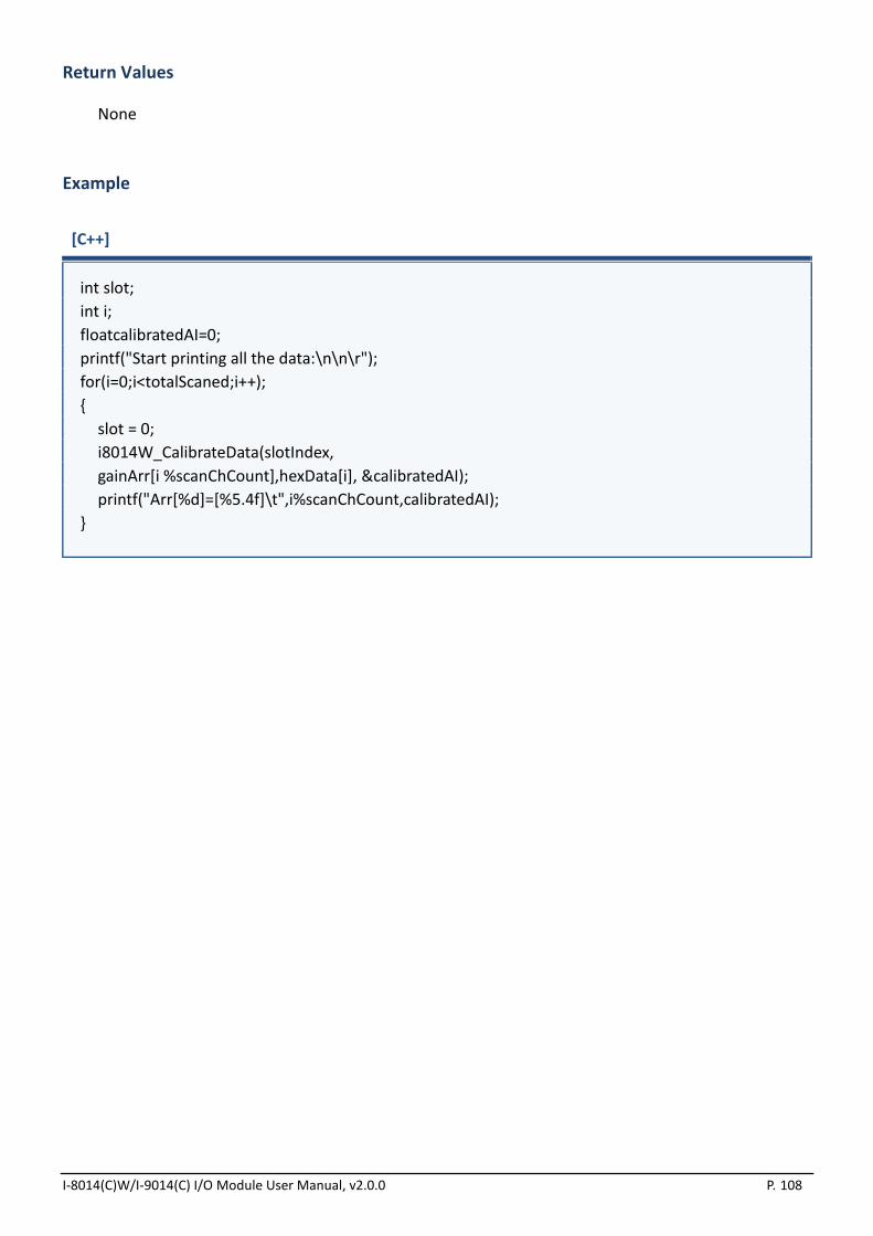
I-8014(C)W/I-9014(C) I/O Module User Manual, v2.0.0 P. 108
Return Values
None
Example
[C++]
int slot;
int i;
floatcalibratedAI=0;
printf("Start printing all the data:\n\n\r");
for(i=0;i<totalScaned;i++);
{
slot = 0;
i8014W_CalibrateData(slotIndex,
gainArr[i %scanChCount],hexData[i], &calibratedAI);
printf("Arr[%d]=[%5.4f]\t",i%scanChCount,calibratedAI);
}

I-8014(C)W/I-9014(C) I/O Module User Manual, v2.0.0 P. 109
4.16. i8014W_CalibrateDataHex
This function is used to calibrate the raw data read in Magic Scan process.
Syntax
For MiniOS7
void i8014W_CalibrateDataHex
(
int slot,
shortiGain,
shortdataFromFIFO,
short* calibratedAI
);
For Windows (CE and WES)
void pac_i8014W_ CalibrateDataHex
(
int slot,
shortiGain,
shortdataFromFIFO,
short* calibratedAI
);
Parameter
slot:
specifies the slot number (0 - 7).
iGain:
specifies the input type (0 - 4), where:0: +/-10 V, 1: +/-5 V, 2: +/-2.5 V, 3: +/-1.25 V, 4: +/-20 mA
dataFromFIFO:
the raw data read from the FIFO buffer.
* calibratedAI :
[Output] the calibrated hexadecimal value.

I-8014(C)W/I-9014(C) I/O Module User Manual, v2.0.0 P. 110
Return Values
None
Example
[C++]
int slot;
int i;
floatcalibratedAI=0;
printf("Start printing all the data:\n\n\r");
for(i=0;i<totalScaned;i++);
{
slot = 0;
i8014W_CalibrateDataHex (slotIndex,
gainArr[i %scanChCount],hexData[i], &calibratedAI);
printf("Arr[%d]=[%#x]\t",i%scanChCount,calibratedAI);
}

I-8014(C)W/I-9014(C) I/O Module User Manual, v2.0.0 P. 111
4.17. i8014W_UnLockFIFO
This function is used to unlock the FIFO buffer when it is locked after being filled. Ensure that the FIFO
buffer is unlocked and cleared before starting the next Magic Scan process.
Syntax
For MiniOS7
void i804W_UnLockFIFO (int slot);
For Windows (CE and WES)
void pac_i8014W_UnLockFIFO(int slot);
Parameter
slot:
specifies the slot number (0 - 7).
Return Values
None
Example
[C++]
int slot;
slot = 0;
i804W_UnLockFIFO (slot);

I-8014(C)W/I-9014(C) I/O Module User Manual, v2.0.0 P. 112
4.18. i8014W_ClearFIFO
This function is used to clear the FIFO buffer after the UnlockFIFO function has been executed. Ensure
that the FIFO buffer is unlocked and cleared before starting the next Magic Scan process.
Syntax
For MiniOS7
void i804W_ClearFIFO (int slot);
For Windows (CE and WES)
void pac_i8014W_ClearFIFO(int slot);
Parameter
slot:
specifies the slot number (0 - 7).
Return Values
None
Example
[C++]
int slot;
slot = 0;
i804W_ClearFIFO (slot);

I-8014(C)W/I-9014(C) I/O Module User Manual, v2.0.0 P. 113
4.19. i8014W_InstallMagicScanISR
This function is used to install the ISR to control to control interrupt events form the FIFO buffer. When
the amount of data in the FIFO buffer is greater than the value defined by the triggerLevel parameter (as
per the table below), an interrupt event will occurs and the ISR will be executed to handle the event. In
the ISR, use the ReadFIFO to transfer data from the FIFO buffer and then ClearInt to restart the status of
the interrupt.
Syntax
For MiniOS7
short i804W_ InstallMagicScanISR
(
int slot,
void (*isr)
(int slot),
inttriggerLevel
);
For Windows (CE and WES)
short pac_i8014W_InstallMagicScanISR
(
int slot,
void(*isr)
(int slot),
shorttriggerLevel
);
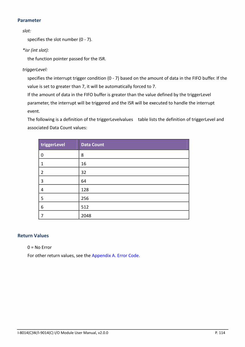
I-8014(C)W/I-9014(C) I/O Module User Manual, v2.0.0 P. 114
Parameter
slot:
specifies the slot number (0 - 7).
*isr (int slot):
the function pointer passed for the ISR.
triggerLevel:
specifies the interrupt trigger condition (0 - 7) based on the amount of data in the FIFO buffer. If the
value is set to greater than 7, it will be automatically forced to 7.
If the amount of data in the FIFO buffer is greater than the value defined by the triggerLevel
parameter, the interrupt will be triggered and the ISR will be executed to handle the interrupt
event.
The following is a definition of the triggerLevelvalues table lists the definition of triggerLevel and
associated Data Count values:
triggerLevel Data Count
0 8
1 16
2 32
3 64
4 128
5 256
6 512
7 2048
Return Values
0 = No Error
For other return values, see the Appendix A. Error Code.

I-8014(C)W/I-9014(C) I/O Module User Manual, v2.0.0 P. 115
Example
[C++]
void main()
{
intslot,TrgLevel;
slot = 0;
TrgLevel=100;
i8014W_Install_MagicScanISR(slot,ISRFUN, TrgLevel);
i8014W_ConfigMagicScan(…);
i8014W_StartMagicScan(slot);
…
while(1)
{
if(IntCnt>1)
{
i8014W_UnInstall_MagicScanISR(slot);
break;
}
}
…
}
voidISRFUN(int slot);
{
IntIntCnt=0;
IntCnt++;
ret=i8014W_ReadFIFO(slot, hexData+totalScaned,
TargetCnt-totalScaned,&readCnt);
if(readCnt>0)
{
totalScaned+=readCnt;
printCom1("TotalScaned= %d\n\r",totalScaned);
totalRead+=readCnt;
}
i8014W_ClearInt(slot);
}
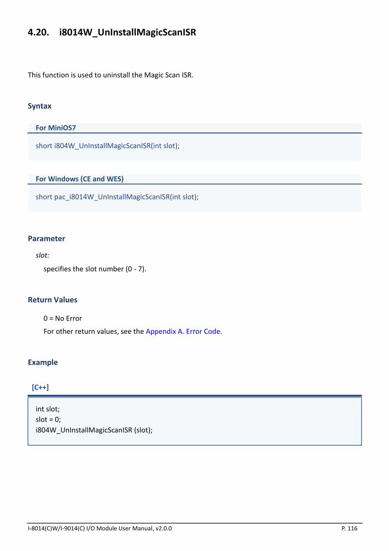
I-8014(C)W/I-9014(C) I/O Module User Manual, v2.0.0 P. 116
4.20. i8014W_UnInstallMagicScanISR
This function is used to uninstall the Magic Scan ISR.
Syntax
For MiniOS7
short i804W_UnInstallMagicScanISR(int slot);
For Windows (CE and WES)
short pac_i8014W_UnInstallMagicScanISR(int slot);
Parameter
slot:
specifies the slot number (0 - 7).
Return Values
0 = No Error
For other return values, see the Appendix A. Error Code.
Example
[C++]
int slot;
slot = 0;
i804W_UnInstallMagicScanISR (slot);

I-8014(C)W/I-9014(C) I/O Module User Manual, v2.0.0 P. 117
4.21. i8014W_ClearInt
This function is used to clear the status of the Magic Scan interrupts. When using ISR, this function
should be called to clear the status of any interrupts that have been triggered in order to continue
processing future interrupt events.
Syntax
For MiniOS7
void i804W_ClearInt (int slot);
For Windows (CE and WES)
void pac_i8014W_ClearInt(int slot);
Parameter
slot:
specifies the slot number (0 - 7).
Return Values
None
Example
[C++]
int slot;
slot = 0;
i804W_StopMagicScan (slot);

I-8014(C)W/I-9014(C) I/O Module User Manual, v2.0.0 P. 118
5. Troubleshooting
This chapter discusses how to solve any problems you may encounter.
This chapter contains:
How to verify the AI function on a WinCE or WES unit(See section 5.1)
Service/Request Requirements (See section 5.2)
What to do when the data read from I-8014W seems unstable(See section 5.3)
How to solve the FIFO LATCHED error (-6) (See section 5.4)
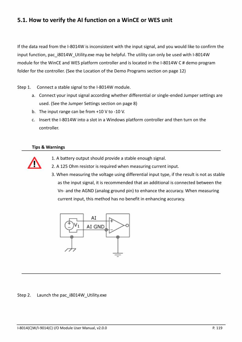
I-8014(C)W/I-9014(C) I/O Module User Manual, v2.0.0 P. 119
5.1. How to verify the AI function on a WinCE or WES unit
If the data read from the I-8014W is inconsistent with the input signal, and you would like to confirm the
input function, pac_i8014W_Utility.exe may be helpful. The utility can only be used with I-8014W
module for the WinCE and WES platform controller and is located in the I-8014W C # demo program
folder for the controller. (See the Location of the Demo Programs section on page 12)
Step 1. Connect a stable signal to the I-8014W module.
a. Connect your input signal according whether differential or single-ended Jumper settings are
used. (See the Jumper Settings section on page 8)
b. The input range can be from +10 V to -10 V.
c. Insert the I-8014W into a slot in a Windows platform controller and then turn on the
controller.
Tips & Warnings
1. A battery output should provide a stable enough signal.
2. A 125 Ohm resistor is required when measuring current input.
3. When measuring the voltage using differential input type, if the result is not as stable
as the input signal, it is recommended that an additional is connected between the
Vn- and the AGND (analog ground pin) to enhance the accuracy. When measuring
current input, this method has no benefit in enhancing accuracy.
Step 2. Launch the pac_i8014W_Utility.exe

I-8014(C)W/I-9014(C) I/O Module User Manual, v2.0.0 P. 120
Step 3. Read the information from the I-8014W module
a. Form the I-8014W slot index drop-down list, select the slot that the I-8014W is connected
to.
b. Click the Basic Information tab.
The Basic Information page includes:
The version numbers for the 8014W.lib, the primary FPGA firmware (Firmware 1) and the
secondary FPGA firmware (Firmware 2)
The current position of the single-ended/ differential jumper
The gain and offset values for each input type
Click the Save button to save all the information to Slot1_8014W_Info.txt file file. The
information is useful for troubleshooting when service is requested.
Verifying the Gain and Offset Values
In a normal situation, the gain value should be around 33000. If the value is greatly different
from 33000, it means that the value is incorrect. To correct this situation, try the following:
a. Press Refresh to retrieve the gain values again and confirm whether or not they are
correct.
b. Relocate the I-8014W to a different slot, and then repeat Steps 2 and 3 to confirm whether
or not the gain values are correct.
Note: I-8014CW only can select max 8 channels and +/- 20 mA Input Range

I-8014(C)W/I-9014(C) I/O Module User Manual, v2.0.0 P. 121
Step 4. Test the input function.
a. Click the AI test tab, and then select the required input range from the Gain drop-down
list.
b. Enter the required sample count, and choose the data format from the format drop-down
list.
c. Click the Start button.
Note: I-8014CW only can select max 8 channels and +/- 20 mA Input Range
After the sampling process is completed, the data will be displayed in the respective columns
for each channel.
d. If necessary, click the Save button to save the data and the sampling time to the
SampleData_Hex_mm_dd_hh_mim_sec.csv file.

I-8014(C)W/I-9014(C) I/O Module User Manual, v2.0.0 P. 122
5.2. Service/Request Requirements
If you are using a stable signal source such as a battery to output a signal to the I-8014W module and are
getting incorrect or unstable data, prepare the following three items and e-mail them to
● The image of the physical wiring
● The file saved from the Basic Information tab (See section 5.1, step 3)
● The file saved from the AI Test tab (See section 5.1, step 4)

I-8014(C)W/I-9014(C) I/O Module User Manual, v2.0.0 P. 123
5.3. What to do when the data read from I-8014W seems unstable
If the voltage can be measured correctly when testing using a battery, but not when using the real signal
source, the error may be caused by any or all of the following factors:
A noise-corrupted signal source
Instability in the signal source
A floating signal source that is not referenced to a system ground
(earth or building ground)
Because of the high-speed data acquisition function of the I-8014W, any noise coupled to a signal or any
change in voltage on an unstable source is also captured. In this situation, signal filtering or isolation
should be considered in order to enhance the quality of the signal.
It is recommended that the V- pin is connected to the AGND (system ground) pin when measuring
differential signals, as shown in the figure.
I-8014(C)W/I-9014(C) I/O Module User Manual, v2.0.0 P. 124
5.4. How to solve the FIFO LATCHED error (-6)
After the StartMagicScan instruction is executed, it will continue scanning the channels and converting
data unless the StopMagicScan command is executed. Consequently, the converted data is continuously
saved to the FIFO buffer. If the Magic Scan is not stopped after obtaining the required data, or the data is
not read from the FIFO buffer within the required time frame, the FIFO buffer will be filled and then
locked. When the FIFO buffer is locked, the FIFO LATCHED error (-6) will occur and any new data will not
be able to be saved to the FIFO buffer.
To solve this error, execute the following instructions:
1. Stop Magic Scan using the StopMagicScan function.
2. Read the remaining data in the FIFO buffer using the ReadFIFO function, or clear it using the
ClearFIFO function.
3. Unlock the FIFO buffer using the UnLockFIFO function.
4. Restart Magic Scan using the StartMagicScan function.

I-8014(C)W/I-9014(C) I/O Module User Manual, v2.0.0 P. 125
Appendix A. Error Code
Error Code Definition Description
0 NoError This indicates that there have been no errors
-1 ID_ERROR There was a problem with the module ID
-2 SLOT_ERROR There was a Slot index error (0 - 7)
-3 CHANNEL_ERROR There was a Channel index error (0 - 15)
-4 GAIN_ERROR There was a Gain error (0 - 4)
-5 FIFO_EMPTY There is no data in the FIFO buffer
-6 FIFO_LATCHED The FIFO buffer is full and has been latched
-7 FIFO_OVERFLOW The FIFO buffer is full
-8 TX_NOTREADY There was an error between the primary FPGA and the
secondary FPGA

I-8014(C)W/I-9014(C) I/O Module User Manual, v2.0.0 P. 126
Appendix B. Revision History
This chapter provides revision history information to this document.
The table below shows the revision history.
Revision Date Description
1.0.0 January 2018 Initial issue