12. C++ at Turbine-Part Twelve.pptx - Russell W. Hanson
50
C++ is Fun – Part 12 at Turbine/Warner Bros.! Russell Hanson
-
Upload
khangminh22 -
Category
Documents
-
view
1 -
download
0
Transcript of 12. C++ at Turbine-Part Twelve.pptx - Russell W. Hanson

C++ is Fun – Part 12 at Turbine/Warner Bros.!
Russell Hanson

Syllabus 1) First program and introduction to data types and control structures with applications for games learning how to use the programming environment Mar 25-27 2) Objects, encapsulation, abstract data types, data protection and scope April 1-3 3) Basic data structures and how to use them, opening files and performing operations on files – April 8-10 4) Algorithms on data structures, algorithms for specific tasks, simple AI and planning type algorithms, game AI algorithms April 15-17 Project 1 Due – April 17 5) More AI: search, heuristics, optimization, decision trees, supervised/unsupervised learning – April 22-24 6) Game API and/or event-oriented programming, model view controller, map reduce filter – April 29, May 1 7) Basic threads models and some simple databases SQLite May 6-8 8) Graphics programming, shaders, textures, 3D models and rotations May 13-15 Project 2 Due May 15 9) How to download an API and learn how to use functions in that API, Windows Foundation Classes May 20-22 10) Designing and implementing a simple game in C++ May 27-29 11) Selected topics – Gesture recognition & depth controllers like the Microsoft Kinect, Network Programming & TCP/IP, OSC June 3-5 12) Working on student projects - June 10-12 Final project presentations Project 3/Final Project Due June 12

Woah! Tic Tac Toe!!! Welcome to Tic-‐Tac-‐Toe You will make your move by entering a number, 0-‐8. The number will correspond to the board posiEon as illustrated: 0 | 1 | 2 3 | 4 | 5 6 | 7 | 8 You want to go first? (y/n) : y You want to be X or O? (x/o) : X You want to be X or O? (x/o) : x | | | | | | | | | Where do you want to move? (0 -‐ 8): 0 X | | | | | | | | | X | | | | O | | | | | Where do you want to move? (0 -‐ 8): 8 X | | | | O | | | | X | X | | O | | O | | | | X | Where do you want to move? (0 -‐ 8): 6 X | | O | | O | | X | | X | X | | O | | O | | X | O | X | Where do you want to move? (0 -‐ 8): 1 X | X | O | | O | | X | O | X | X | X | O | O | O | | X | O | X | Where do you want to move? (0 -‐ 8): 5 X | X | O | O | O | X | X | O | X | TIE! sh: PAUSE: command not found Russells-‐MacBook-‐Pro:mgraessle_Homework4 russell$
X | | O | | O | | X | O | X | Where do you want to move? (0 -‐ 8): 1 X | X | O | | O | | X | O | X | X | X | O | O | O | | X | O | X | Where do you want to move? (0 -‐ 8): 5 X | X | O | O | O | X | X | O | X | TIE! sh: PAUSE: command not found Russells-‐MacBook-‐Pro:mgraessle_Homework4 russell$

/* Use the current empty pieces to have the computer choose the best move to counter the last human move */ void Board::computerMove() {
// set the list of all the ways to win int WAYS_TO_WIN [8][3] = {{0, 1, 2}, {3, 4, 5}, {6, 7, 8}, {0, 3, 6}, {1, 4, 7}, {2, 5, 8}, {0, 4, 8}, {2, 4, 6}};
// if computer can win, take that move for (int i = 0; i < 8; ++i) { if ( board_pieces[WAYS_TO_WIN[i][0]] == COMPUTER && board_pieces[WAYS_TO_WIN[i][1]] == COMPUTER &&
board_pieces[WAYS_TO_WIN[i][2]] == EMPTY) { setPiece(WAYS_TO_WIN[i][2], COMPUTER); return; }
else { if ( board_pieces[WAYS_TO_WIN[i][1]] == COMPUTER && board_pieces[WAYS_TO_WIN[i][2]] ==
COMPUTER && board_pieces[WAYS_TO_WIN[i][0]] == EMPTY) { setPiece(WAYS_TO_WIN[i][0], COMPUTER); return; }
else { if ( board_pieces[WAYS_TO_WIN[i][0]] == COMPUTER &&
board_pieces[WAYS_TO_WIN[i][2]] == COMPUTER && board_pieces[WAYS_TO_WIN[i][1]] == EMPTY ) { setPiece(WAYS_TO_WIN[i][1], COMPUTER); return; } } } }
// if human can win, block that move for (int i = 0; i < 8; ++i) { if ( board_pieces[WAYS_TO_WIN[i][0]] == HUMAN && board_pieces[WAYS_TO_WIN[i][1]] == HUMAN &&
board_pieces[WAYS_TO_WIN[i][2]] == EMPTY) { setPiece(WAYS_TO_WIN[i][2], COMPUTER); return; }
else { if ( board_pieces[WAYS_TO_WIN[i][1]] == HUMAN && board_pieces[WAYS_TO_WIN[i][2]] == HUMAN
&& board_pieces[WAYS_TO_WIN[i][0]] == EMPTY) { setPiece(WAYS_TO_WIN[i][0], COMPUTER); return; }
else { if ( board_pieces[WAYS_TO_WIN[i][0]] == HUMAN &&
board_pieces[WAYS_TO_WIN[i][2]] == HUMAN && board_pieces[WAYS_TO_WIN[i][1]] == EMPTY ) { setPiece(WAYS_TO_WIN[i][1], COMPUTER); return; } } } }
int BEST_MOVES[10] = {4, 0, 2, 6, 8, 1, 3, 5, 7};
// if one of the best squares is empty, take it for (int i = 0; i < 10; ++i) { if ( isMoveLegal(BEST_MOVES[i]) ) { setPiece(BEST_MOVES[i], COMPUTER); break; }// end if }// end for
}// end computerMove

Graphics and OpenGL!

Figure 1-1 : White Rectangle on a Black Background
Example 1-1 : Chunk of OpenGL Code
#include <whateverYouNeed.h>
main() {
InitializeAWindowPlease();
glClearColor (0.0, 0.0, 0.0, 0.0); glClear (GL_COLOR_BUFFER_BIT); glColor3f (1.0, 1.0, 1.0); glOrtho(0.0, 1.0, 0.0, 1.0, -1.0, 1.0); glBegin(GL_POLYGON); glVertex3f (0.25, 0.25, 0.0); glVertex3f (0.75, 0.25, 0.0); glVertex3f (0.75, 0.75, 0.0); glVertex3f (0.25, 0.75, 0.0); glEnd(); glFlush();
UpdateTheWindowAndCheckForEvents();}
The first line of the main() routine initializes a window on the screen: The InitializeAWindowPlease()routine is meant as a placeholder for window system-specific routines, which are generally not OpenGLcalls. The next two lines are OpenGL commands that clear the window to black: glClearColor()establishes what color the window will be cleared to, and glClear() actually clears the window. Once theclearing color is set, the window is cleared to that color whenever glClear() is called. This clearing colorcan be changed with another call to glClearColor(). Similarly, the glColor3f() command establisheswhat color to use for drawing objects - in this case, the color is white. All objects drawn after this pointuse this color, until it’s changed with another call to set the color.
The next OpenGL command used in the program, glOrtho(), specifies the coordinate system OpenGLassumes as it draws the final image and how the image gets mapped to the screen. The next calls, whichare bracketed by glBegin() and glEnd(), define the object to be drawn - in this example, a polygon withfour vertices. The polygon’s "corners" are defined by the glVertex3f() commands. As you might be ableto guess from the arguments, which are (x, y, z) coordinates, the polygon is a rectangle on the z=0 plane.
Finally, glFlush() ensures that the drawing commands are actually executed rather than stored in abuffer awaiting additional OpenGL commands. The UpdateTheWindowAndCheckForEvents()placeholder routine manages the contents of the window and begins event processing.
Actually, this piece of OpenGL code isn’t well structured. You may be asking, "What happens if I try tomove or resize the window?" Or, "Do I need to reset the coordinate system each time I draw therectangle?" Later in this chapter, you will see replacements for both InitializeAWindowPlease() andUpdateTheWindowAndCheckForEvents() that actually work but will require restructuring the code tomake it efficient.
OpenGL Command SyntaxAs you might have observed from the simple program in the previous section, OpenGL commands usethe prefix gl and initial capital letters for each word making up the command name (recallglClearColor(), for example). Similarly, OpenGL defined constants begin with GL_, use all capitalletters, and use underscores to separate words (like GL_COLOR_BUFFER_BIT).
You might also have noticed some seemingly extraneous letters appended to some command names (forexample, the 3f in glColor3f() and glVertex3f()). It’s true that the Color part of the command nameglColor3f() is enough to define the command as one that sets the current color. However, more than onesuch command has been defined so that you can use different types of arguments. In particular, the 3part of the suffix indicates that three arguments are given; another version of the Color command takesfour arguments. The f part of the suffix indicates that the arguments are floating-point numbers. Havingdifferent formats allows OpenGL to accept the user’s data in his or her own data format.
Some OpenGL commands accept as many as 8 different data types for their arguments. The letters usedas suffixes to specify these data types for ISO C implementations of OpenGL are shown in Table 1-1,along with the corresponding OpenGL type definitions. The particular implementation of OpenGL thatyou’re using might not follow this scheme exactly; an implementation in C++ or Ada, for example,wouldn’t need to.
Table 1-1 : Command Suffixes and Argument Data Types

Suffix Data Type Typical CorrespondingC-Language Type
OpenGL TypeDefinition
b 8-bit integer signed char GLbyte
s 16-bit integer short GLshort
i 32-bit integer int or long GLint, GLsizei
f 32-bit floating-point float GLfloat, GLclampf
d 64-bit floating-point double GLdouble, GLclampd
ub 8-bit unsigned integer unsigned char GLubyte, GLboolean
us 16-bit unsigned integer unsigned short GLushort
ui 32-bit unsigned integer unsigned int or unsigned long GLuint, GLenum,GLbitfield
Thus, the two commands
glVertex2i(1, 3);glVertex2f(1.0, 3.0);
are equivalent, except that the first specifies the vertex’s coordinates as 32-bit integers, and the secondspecifies them as single-precision floating-point numbers.
Note: Implementations of OpenGL have leeway in selecting which C data type to use to representOpenGL data types. If you resolutely use the OpenGL defined data types throughout your application,you will avoid mismatched types when porting your code between different implementations.
Some OpenGL commands can take a final letter v, which indicates that the command takes a pointer to avector (or array) of values rather than a series of individual arguments. Many commands have bothvector and nonvector versions, but some commands accept only individual arguments and others requirethat at least some of the arguments be specified as a vector. The following lines show how you mightuse a vector and a nonvector version of the command that sets the current color:
glColor3f(1.0, 0.0, 0.0);
GLfloat color_array[] = {1.0, 0.0, 0.0};glColor3fv(color_array);
Finally, OpenGL defines the typedef GLvoid. This is most often used for OpenGL commands thataccept pointers to arrays of values.
Finally, glFlush() ensures that the drawing commands are actually executed rather than stored in abuffer awaiting additional OpenGL commands. The UpdateTheWindowAndCheckForEvents()placeholder routine manages the contents of the window and begins event processing.
Actually, this piece of OpenGL code isn’t well structured. You may be asking, "What happens if I try tomove or resize the window?" Or, "Do I need to reset the coordinate system each time I draw therectangle?" Later in this chapter, you will see replacements for both InitializeAWindowPlease() andUpdateTheWindowAndCheckForEvents() that actually work but will require restructuring the code tomake it efficient.
OpenGL Command SyntaxAs you might have observed from the simple program in the previous section, OpenGL commands usethe prefix gl and initial capital letters for each word making up the command name (recallglClearColor(), for example). Similarly, OpenGL defined constants begin with GL_, use all capitalletters, and use underscores to separate words (like GL_COLOR_BUFFER_BIT).
You might also have noticed some seemingly extraneous letters appended to some command names (forexample, the 3f in glColor3f() and glVertex3f()). It’s true that the Color part of the command nameglColor3f() is enough to define the command as one that sets the current color. However, more than onesuch command has been defined so that you can use different types of arguments. In particular, the 3part of the suffix indicates that three arguments are given; another version of the Color command takesfour arguments. The f part of the suffix indicates that the arguments are floating-point numbers. Havingdifferent formats allows OpenGL to accept the user’s data in his or her own data format.
Some OpenGL commands accept as many as 8 different data types for their arguments. The letters usedas suffixes to specify these data types for ISO C implementations of OpenGL are shown in Table 1-1,along with the corresponding OpenGL type definitions. The particular implementation of OpenGL thatyou’re using might not follow this scheme exactly; an implementation in C++ or Ada, for example,wouldn’t need to.
Table 1-1 : Command Suffixes and Argument Data Types

In the rest of this guide (except in actual code examples), OpenGL commands are referred to by theirbase names only, and an asterisk is included to indicate that there may be more to the command name.For example, glColor*() stands for all variations of the command you use to set the current color. If wewant to make a specific point about one version of a particular command, we include the suffixnecessary to define that version. For example, glVertex*v() refers to all the vector versions of thecommand you use to specify vertices.
OpenGL as a State MachineOpenGL is a state machine. You put it into various states (or modes) that then remain in effect until youchange them. As you’ve already seen, the current color is a state variable. You can set the current colorto white, red, or any other color, and thereafter every object is drawn with that color until you set thecurrent color to something else. The current color is only one of many state variables that OpenGLmaintains. Others control such things as the current viewing and projection transformations, line andpolygon stipple patterns, polygon drawing modes, pixel-packing conventions, positions andcharacteristics of lights, and material properties of the objects being drawn. Many state variables refer tomodes that are enabled or disabled with the command glEnable() or glDisable().
Each state variable or mode has a default value, and at any point you can query the system for eachvariable’s current value. Typically, you use one of the six following commands to do this:glGetBooleanv(), glGetDoublev(), glGetFloatv(), glGetIntegerv(), glGetPointerv(), orglIsEnabled(). Which of these commands you select depends on what data type you want the answer tobe given in. Some state variables have a more specific query command (such as glGetLight*(),glGetError(), or glGetPolygonStipple()). In addition, you can save a collection of state variables on anattribute stack with glPushAttrib() or glPushClientAttrib(), temporarily modify them, and later restorethe values with glPopAttrib() or glPopClientAttrib(). For temporary state changes, you should usethese commands rather than any of the query commands, since they’re likely to be more efficient.
See Appendix B for the complete list of state variables you can query. For each variable, the appendixalso lists a suggested glGet*() command that returns the variable’s value, the attribute class to which itbelongs, and the variable’s default value.
OpenGL Rendering PipelineMost implementations of OpenGL have a similar order of operations, a series of processing stages calledthe OpenGL rendering pipeline. This ordering, as shown in Figure 1-2, is not a strict rule of howOpenGL is implemented but provides a reliable guide for predicting what OpenGL will do.
If you are new to three-dimensional graphics, the upcoming description may seem like drinking waterout of a fire hose. You can skim this now, but come back to Figure 1-2 as you go through each chapterin this book.
The following diagram shows the Henry Ford assembly line approach, which OpenGL takes toprocessing data. Geometric data (vertices, lines, and polygons) follow the path through the row of boxes
that includes evaluators and per-vertex operations, while pixel data (pixels, images, and bitmaps) aretreated differently for part of the process. Both types of data undergo the same final steps (rasterizationand per-fragment operations) before the final pixel data is written into the framebuffer.
Figure 1-2 : Order of Operations
Now you’ll see more detail about the key stages in the OpenGL rendering pipeline.
Display Lists
All data, whether it describes geometry or pixels, can be saved in a display list for current or later use.(The alternative to retaining data in a display list is processing the data immediately - also known asimmediate mode.) When a display list is executed, the retained data is sent from the display list just as ifit were sent by the application in immediate mode. (See Chapter 7 for more information about displaylists.)
Evaluators
All geometric primitives are eventually described by vertices. Parametric curves and surfaces may beinitially described by control points and polynomial functions called basis functions. Evaluators providea method to derive the vertices used to represent the surface from the control points. The method is apolynomial mapping, which can produce surface normal, texture coordinates, colors, and spatialcoordinate values from the control points. (See Chapter 12 to learn more about evaluators.)
Per-Vertex Operations
For vertex data, next is the "per-vertex operations" stage, which converts the vertices into primitives.Some vertex data (for example, spatial coordinates) are transformed by 4 x 4 floating-point matrices.Spatial coordinates are projected from a position in the 3D world to a position on your screen. (SeeChapter 3 for details about the transformation matrices.)
If advanced features are enabled, this stage is even busier. If texturing is used, texture coordinates maybe generated and transformed here. If lighting is enabled, the lighting calculations are performed usingthe transformed vertex, surface normal, light source position, material properties, and other lighting

information to produce a color value.
Primitive Assembly
Clipping, a major part of primitive assembly, is the elimination of portions of geometry which falloutside a half-space, defined by a plane. Point clipping simply passes or rejects vertices; line or polygonclipping can add additional vertices depending upon how the line or polygon is clipped.
In some cases, this is followed by perspective division, which makes distant geometric objects appearsmaller than closer objects. Then viewport and depth (z coordinate) operations are applied. If culling isenabled and the primitive is a polygon, it then may be rejected by a culling test. Depending upon thepolygon mode, a polygon may be drawn as points or lines. (See "Polygon Details" in Chapter 2.)
The results of this stage are complete geometric primitives, which are the transformed and clippedvertices with related color, depth, and sometimes texture-coordinate values and guidelines for therasterization step.
Pixel Operations
While geometric data takes one path through the OpenGL rendering pipeline, pixel data takes a differentroute. Pixels from an array in system memory are first unpacked from one of a variety of formats intothe proper number of components. Next the data is scaled, biased, and processed by a pixel map. Theresults are clamped and then either written into texture memory or sent to the rasterization step. (See"Imaging Pipeline" in Chapter 8.)
If pixel data is read from the frame buffer, pixel-transfer operations (scale, bias, mapping, and clamping)are performed. Then these results are packed into an appropriate format and returned to an array insystem memory.
There are special pixel copy operations to copy data in the framebuffer to other parts of the framebufferor to the texture memory. A single pass is made through the pixel transfer operations before the data iswritten to the texture memory or back to the framebuffer.
Texture Assembly
An OpenGL application may wish to apply texture images onto geometric objects to make them lookmore realistic. If several texture images are used, it’s wise to put them into texture objects so that youcan easily switch among them.
Some OpenGL implementations may have special resources to accelerate texture performance. Theremay be specialized, high-performance texture memory. If this memory is available, the texture objectsmay be prioritized to control the use of this limited and valuable resource. (See Chapter 9.)
Rasterization
Rasterization is the conversion of both geometric and pixel data into fragments. Each fragment squarecorresponds to a pixel in the framebuffer. Line and polygon stipples, line width, point size, shading

Note the restructuring of the code. To maximize efficiency, operations that need only be called once(setting the background color and coordinate system) are now in a procedure called init(). Operations torender (and possibly re-render) the scene are in the display() procedure, which is the registered GLUTdisplay callback.
Example 1-2 : Simple OpenGL Program Using GLUT: hello.c
#include <GL/gl.h>#include <GL/glut.h>
void display(void){/* clear all pixels */ glClear (GL_COLOR_BUFFER_BIT);
/* draw white polygon (rectangle) with corners at * (0.25, 0.25, 0.0) and (0.75, 0.75, 0.0) */ glColor3f (1.0, 1.0, 1.0); glBegin(GL_POLYGON); glVertex3f (0.25, 0.25, 0.0); glVertex3f (0.75, 0.25, 0.0); glVertex3f (0.75, 0.75, 0.0); glVertex3f (0.25, 0.75, 0.0); glEnd();
/* don’t wait! * start processing buffered OpenGL routines */ glFlush ();}
void init (void) {/* select clearing (background) color */ glClearColor (0.0, 0.0, 0.0, 0.0);
/* initialize viewing values */ glMatrixMode(GL_PROJECTION); glLoadIdentity(); glOrtho(0.0, 1.0, 0.0, 1.0, -1.0, 1.0);}
/* * Declare initial window size, position, and display mode * (single buffer and RGBA). Open window with "hello" * in its title bar. Call initialization routines. * Register callback function to display graphics. * Enter main loop and process events. */int main(int argc, char** argv){ glutInit(&argc, argv); glutInitDisplayMode (GLUT_SINGLE | GLUT_RGB); glutInitWindowSize (250, 250); glutInitWindowPosition (100, 100); glutCreateWindow ("hello"); init (); glutDisplayFunc(display);
glutMainLoop(); return 0; /* ISO C requires main to return int. */}
Handling Input Events
You can use these routines to register callback commands that are invoked when specified events occur.
glutReshapeFunc(void (* func)(int w, int h)) indicates what action should be taken when thewindow is resized.
glutKeyboardFunc(void (* func)(unsigned char key, int x, int y)) and glutMouseFunc(void(* func)(int button, int state, int x, int y)) allow you to link a keyboard key or a mouse button with aroutine that’s invoked when the key or mouse button is pressed or released.
glutMotionFunc(void (* func)(int x, int y)) registers a routine to call back when the mouse ismoved while a mouse button is also pressed.
Managing a Background Process
You can specify a function that’s to be executed if no other events are pending - for example, when theevent loop would otherwise be idle - with glutIdleFunc(void (* func)(void)). This routine takes a pointerto the function as its only argument. Pass in NULL (zero) to disable the execution of the function.
Drawing Three-Dimensional Objects
GLUT includes several routines for drawing these three-dimensional objects:
cone icosahedron teapot
cube octahedron tetrahedron
dodecahedron sphere torus
You can draw these objects as wireframes or as solid shaded objects with surface normals defined. Forexample, the routines for a cube and a sphere are as follows:
void glutWireCube(GLdouble size);
void glutSolidCube(GLdouble size);
void glutWireSphere(GLdouble radius, GLint slices, GLint stacks);
void glutSolidSphere(GLdouble radius, GLint slices, GLint stacks);
All these models are drawn centered at the origin of the world coordinate system. (See for informationon the prototypes of all these drawing routines.)

Double Buffering
AnimationOne of the most exciting things you can do on a graphics computer is draw pictures that move. Whetheryou’re an engineer trying to see all sides of a mechanical part you’re designing, a pilot learning to fly anairplane using a simulation, or merely a computer-game aficionado, it’s clear that animation is animportant part of computer graphics.
In a movie theater, motion is achieved by taking a sequence of pictures and projecting them at 24 persecond on the screen. Each frame is moved into position behind the lens, the shutter is opened, and theframe is displayed. The shutter is momentarily closed while the film is advanced to the next frame, thenthat frame is displayed, and so on. Although you’re watching 24 different frames each second, yourbrain blends them all into a smooth animation. (The old Charlie Chaplin movies were shot at 16 framesper second and are noticeably jerky.) In fact, most modern projectors display each picture twice at a rateof 48 per second to reduce flickering. Computer-graphics screens typically refresh (redraw the picture)approximately 60 to 76 times per second, and some even run at about 120 refreshes per second. Clearly,60 per second is smoother than 30, and 120 is marginally better than 60. Refresh rates faster than 120,however, are beyond the point of diminishing returns, since the human eye is only so good.
The key reason that motion picture projection works is that each frame is complete when it is displayed.Suppose you try to do computer animation of your million-frame movie with a program like this:
open_window(); for (i = 0; i < 1000000; i++) { clear_the_window(); draw_frame(i); wait_until_a_24th_of_a_second_is_over(); }
If you add the time it takes for your system to clear the screen and to draw a typical frame, this programgives more and more disturbing results depending on how close to 1/24 second it takes to clear anddraw. Suppose the drawing takes nearly a full 1/24 second. Items drawn first are visible for the full 1/24second and present a solid image on the screen; items drawn toward the end are instantly cleared as theprogram starts on the next frame. They present at best a ghostlike image, since for most of the 1/24second your eye is viewing the cleared background instead of the items that were unlucky enough to bedrawn last. The problem is that this program doesn’t display completely drawn frames; instead, youwatch the drawing as it happens.
Most OpenGL implementations provide double-buffering - hardware or software that supplies twocomplete color buffers. One is displayed while the other is being drawn. When the drawing of a frame iscomplete, the two buffers are swapped, so the one that was being viewed is now used for drawing, andvice versa. This is like a movie projector with only two frames in a loop; while one is being projected onthe screen, an artist is desperately erasing and redrawing the frame that’s not visible. As long as the artistis quick enough, the viewer notices no difference between this setup and one where all the frames arealready drawn and the projector is simply displaying them one after the other. With double-buffering,every frame is shown only when the drawing is complete; the viewer never sees a partially drawn frame.
A modified version of the preceding program that does display smoothly animated graphics might looklike this:

OpenGL doesn’t have a swap_the_buffers() command because the feature might not be available on allhardware and, in any case, it’s highly dependent on the window system. For example, if you are usingthe X Window System and accessing it directly, you might use the following GLX routine:
void glXSwapBuffers(Display *dpy, Window window);
(See Appendix C for equivalent routines for other window systems.)
If you are using the GLUT library, you’ll want to call this routine:
void glutSwapBuffers(void);
Example 1-3 illustrates the use of glutSwapBuffers() in an example that draws a spinning square asshown in Figure 1-3. The following example also shows how to use GLUT to control an input deviceand turn on and off an idle function. In this example, the mouse buttons toggle the spinning on and off.
Figure 1-3 : Double-Buffered Rotating Square
Example 1-3 : Double-Buffered Program: double.c
#include <GL/gl.h>#include <GL/glu.h>#include <GL/glut.h>#include <stdlib.h>
static GLfloat spin = 0.0;
void init(void) { glClearColor (0.0, 0.0, 0.0, 0.0); glShadeModel (GL_FLAT);}
void display(void){ glClear(GL_COLOR_BUFFER_BIT); glPushMatrix(); glRotatef(spin, 0.0, 0.0, 1.0); glColor3f(1.0, 1.0, 1.0);

glRectf(-25.0, -25.0, 25.0, 25.0); glPopMatrix(); glutSwapBuffers();}
void spinDisplay(void){ spin = spin + 2.0; if (spin > 360.0) spin = spin - 360.0; glutPostRedisplay();}
void reshape(int w, int h){ glViewport (0, 0, (GLsizei) w, (GLsizei) h); glMatrixMode(GL_PROJECTION); glLoadIdentity(); glOrtho(-50.0, 50.0, -50.0, 50.0, -1.0, 1.0); glMatrixMode(GL_MODELVIEW); glLoadIdentity();}
void mouse(int button, int state, int x, int y) { switch (button) { case GLUT_LEFT_BUTTON: if (state == GLUT_DOWN) glutIdleFunc(spinDisplay); break; case GLUT_MIDDLE_BUTTON: if (state == GLUT_DOWN) glutIdleFunc(NULL); break; default: break; }}
/* * Request double buffer display mode. * Register mouse input callback functions */int main(int argc, char** argv){ glutInit(&argc, argv); glutInitDisplayMode (GLUT_DOUBLE | GLUT_RGB); glutInitWindowSize (250, 250); glutInitWindowPosition (100, 100); glutCreateWindow (argv[0]); init (); glutDisplayFunc(display); glutReshapeFunc(reshape); glutMouseFunc(mouse); glutMainLoop(); return 0;}
OpenGL Programming Guide (Addison-Wesley

Team LRN

Team LRN

Team LRN

Team LRN

Team LRN

Team LRN
Team LRN

Chaorer 1 1
Figure 11 - l Positive rotation directions about th(. coordinate axes are coun~erclockw~se, when looking toward the origm from a positive coordinate position on each azis.
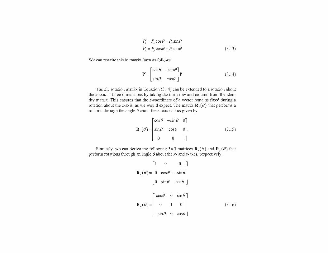
x' = .x cos 0 - y sin 0
y' = x s i n 0 + y c o s 0 t' = 2
Parameter 8 specifies the rotation angle. In homogeneous coordinate form, the three-dimensional z-axis rotation equations are expressed as

Chaorer 1 1
Figure 11 - l Positive rotation directions about th(. coordinate axes are coun~erclockw~se, when looking toward the origm from a positive coordinate position on each azis.
x' = .x cos 0 - y sin 0
y' = x s i n 0 + y c o s 0 t' = 2
Parameter 8 specifies the rotation angle. In homogeneous coordinate form, the three-dimensional z-axis rotation equations are expressed as
Section 11 -2 Kotat~on
.
Rotatlon of an object about the z
which we can write more compactly as
Flgure 11-4 iilustrates rotation of an object about the z axis. Transformation equations for rotations about the other two coordinate axes
can be obtained with a cyclic permutation of the coordinate parameters x, y, and : in Eqs. 11-4. That is, we use the replacements
as illustrated in Fig. 11-5. Substituting permutations 11-7 in Eqs. 11-4, we get the equations for an
x-axis rotation:
y' = ycos0 - zsin B
z' = y sin0 + z cose
I' = X
which can be written in the homogeneous coordinat~? form
Cycllc permutat~on of the Cartesian-coordinate axes to prsduce the three sets of coordinate-axis rotahon equations.
Three-Dimensional Gecmetrlc and Modellng lranslormat~ons
I
z -- - Figure 11-6 Rotation of an object about the
x x axis.
Rotation of an object around the x axis is demonstrated in Fig. 11.6. Cyclically permuting coordinates in Eqs. 11-8 give us the transformation
equations for a y-axis rotation:
The matrix representation for y-axis rotation is
An example of y-axis rotation is shown in Fig. 11-7.
. - - . ~ ~
I'iyrltn. 11-7 A ' Rotation ot a n object ahout the 1 y axis.

Team LRN

Team LRN

Team LRN
Team LRN

Team LRN

Team LRN

Team LRN

Team LRN

Team LRN
Team LRN


glVertex2s(2, 3); glVertex3d(0.0, 0.0, 3.1415926535898); glVertex4f(2.3, 1.0, -2.2, 2.0);
GLdouble dvect[3] = {5.0, 9.0, 1992.0};glVertex3dv(dvect);
The first example represents a vertex with three-dimensional coordinates (2, 3, 0). (Remember that if itisn’t specified, the z coordinate is understood to be 0.) The coordinates in the second example are (0.0,0.0, 3.1415926535898) (double-precision floating-point numbers). The third example represents thevertex with three-dimensional coordinates (1.15, 0.5, -1.1). (Remember that the x, y, and z coordinatesare eventually divided by the w coordinate.) In the final example, dvect is a pointer to an array of threedouble-precision floating-point numbers.
On some machines, the vector form of glVertex*() is more efficient, since only a single parameter needsto be passed to the graphics subsystem. Special hardware might be able to send a whole series ofcoordinates in a single batch. If your machine is like this, it’s to your advantage to arrange your data sothat the vertex coordinates are packed sequentially in memory. In this case, there may be some gain inperformance by using the vertex array operations of OpenGL. (See "Vertex Arrays.")
OpenGL Geometric Drawing Primitives
Now that you’ve seen how to specify vertices, you still need to know how to tell OpenGL to create a setof points, a line, or a polygon from those vertices. To do this, you bracket each set of vertices between acall to glBegin() and a call to glEnd(). The argument passed to glBegin() determines what sort ofgeometric primitive is constructed from the vertices. For example, Example 2-3 specifies the vertices forthe polygon shown in Figure 2-6.
Example 2-3 : Filled Polygon
glBegin(GL_POLYGON); glVertex2f(0.0, 0.0); glVertex2f(0.0, 3.0); glVertex2f(4.0, 3.0); glVertex2f(6.0, 1.5); glVertex2f(4.0, 0.0);glEnd();
Figure 2-6 : Drawing a Polygon or a Set of Points
If you had used GL_POINTS instead of GL_POLYGON, the primitive would have been simply the fivepoints shown in Figure 2-6. Table 2-2 in the following function summary for glBegin() lists the tenpossible arguments and the corresponding type of primitive.

Figure 2-3 : Valid and Invalid Polygons
The reason for the OpenGL restrictions on valid polygon types is that it’s simpler to provide fastpolygon-rendering hardware for that restricted class of polygons. Simple polygons can be renderedquickly. The difficult cases are hard to detect quickly. So for maximum performance, OpenGL crossesits fingers and assumes the polygons are simple.
Many real-world surfaces consist of nonsimple polygons, nonconvex polygons, or polygons with holes.Since all such polygons can be formed from unions of simple convex polygons, some routines to buildmore complex objects are provided in the GLU library. These routines take complex descriptions andtessellate them, or break them down into groups of the simpler OpenGL polygons that can then berendered. (See "Polygon Tessellation" in Chapter 11 for more information about the tessellationroutines.)
Since OpenGL vertices are always three-dimensional, the points forming the boundary of a particularpolygon don’t necessarily lie on the same plane in space. (Of course, they do in many cases - if all the zcoordinates are zero, for example, or if the polygon is a triangle.) If a polygon’s vertices don’t lie in thesame plane, then after various rotations in space, changes in the viewpoint, and projection onto thedisplay screen, the points might no longer form a simple convex polygon. For example, imagine afour-point quadrilateral where the points are slightly out of plane, and look at it almost edge-on. Youcan get a nonsimple polygon that resembles a bow tie, as shown in Figure 2-4, which isn’t guaranteed tobe rendered correctly. This situation isn’t all that unusual if you approximate curved surfaces byquadrilaterals made of points lying on the true surface. You can always avoid the problem by usingtriangles, since any three points always lie on a plane.
Figure 2-4 : Nonplanar Polygon Transformed to Nonsimple Polygon
Rectangles
Since rectangles are so common in graphics applications, OpenGL provides a filled-rectangle drawingprimitive, glRect*(). You can draw a rectangle as a polygon, as described in "OpenGL GeometricDrawing Primitives," but your particular implementation of OpenGL might have optimized glRect*()for rectangles.

Figure 2-7 : Geometric Primitive Types
As you read the following descriptions, assume that n vertices (v0, v1, v2, ... , vn-1) are describedbetween a glBegin() and glEnd() pair.
GL_POINTS Draws a point at each of the n vertices.
GL_LINES Draws a series of unconnected line segments. Segments are drawnbetween v0 and v1, between v2 and v3, and so on. If n is odd, the lastsegment is drawn between vn-3 and vn-2, and vn-1 is ignored.
GL_LINE_STRIP Draws a line segment from v0 to v1, then from v1 to v2, and so on,finally drawing the segment from vn-2 to vn-1. Thus, a total of n-1 linesegments are drawn. Nothing is drawn unless n is larger than 1. Thereare no restrictions on the vertices describing a line strip (or a line loop);the lines can intersect arbitrarily.
GL_LINE_LOOP Same as GL_LINE_STRIP, except that a final line segment is drawnfrom vn-1 to v0, completing a loop.
GL_TRIANGLES Draws a series of triangles (three-sided polygons) using vertices v0, v1,v2, then v3, v4, v5, and so on. If n isn’t an exact multiple of 3, the finalone or two vertices are ignored.
GL_TRIANGLE_STRIP Draws a series of triangles (three-sided polygons) using vertices v0, v1,

Figure 3-1 : The Camera Analogy
Note that these steps correspond to the order in which you specify the desired transformations in yourprogram, not necessarily the order in which the relevant mathematical operations are performed on anobject’s vertices. The viewing transformations must precede the modeling transformations in your code,but you can specify the projection and viewport transformations at any point before drawing occurs.Figure 3-2 shows the order in which these operations occur on your computer.

textbook on linear algebra.
A Simple Example: Drawing a Cube
Example 3-1 draws a cube that’s scaled by a modeling transformation (see Figure 3-3). The viewingtransformation, gluLookAt(), positions and aims the camera towards where the cube is drawn. Aprojection transformation and a viewport transformation are also specified. The rest of this section walksyou through Example 3-1 and briefly explains the transformation commands it uses. The succeedingsections contain the complete, detailed discussion of all OpenGL’s transformation commands.
Figure 3-3 : Transformed Cube
Example 3-1 : Transformed Cube: cube.c
#include <GL/gl.h>#include <GL/glu.h>#include <GL/glut.h>
void init(void) { glClearColor (0.0, 0.0, 0.0, 0.0); glShadeModel (GL_FLAT);}
void display(void){ glClear (GL_COLOR_BUFFER_BIT); glColor3f (1.0, 1.0, 1.0); glLoadIdentity (); /* clear the matrix */ /* viewing transformation */ gluLookAt (0.0, 0.0, 5.0, 0.0, 0.0, 0.0, 0.0, 1.0, 0.0); glScalef (1.0, 2.0, 1.0); /* modeling transformation */ glutWireCube (1.0); glFlush ();}
void reshape (int w, int h){ glViewport (0, 0, (GLsizei) w, (GLsizei) h); glMatrixMode (GL_PROJECTION); glLoadIdentity (); glFrustum (-1.0, 1.0, -1.0, 1.0, 1.5, 20.0); glMatrixMode (GL_MODELVIEW);}
int main(int argc, char** argv){ glutInit(&argc, argv);
glutInitDisplayMode (GLUT_SINGLE | GLUT_RGB); glutInitWindowSize (500, 500); glutInitWindowPosition (100, 100); glutCreateWindow (argv[0]); init (); glutDisplayFunc(display); glutReshapeFunc(reshape); glutMainLoop(); return 0;}
The Viewing Transformation
Recall that the viewing transformation is analogous to positioning and aiming a camera. In this codeexample, before the viewing transformation can be specified, the current matrix is set to the identitymatrix with glLoadIdentity(). This step is necessary since most of the transformation commandsmultiply the current matrix by the specified matrix and then set the result to be the current matrix. If youdon’t clear the current matrix by loading it with the identity matrix, you continue to combine previoustransformation matrices with the new one you supply. In some cases, you do want to perform suchcombinations, but you also need to clear the matrix sometimes.
In Example 3-1, after the matrix is initialized, the viewing transformation is specified with gluLookAt().The arguments for this command indicate where the camera (or eye position) is placed, where it isaimed, and which way is up. The arguments used here place the camera at (0, 0, 5), aim the camera lenstowards (0, 0, 0), and specify the up-vector as (0, 1, 0). The up-vector defines a unique orientation forthe camera.
If gluLookAt() was not called, the camera has a default position and orientation. By default, the camerais situated at the origin, points down the negative z-axis, and has an up-vector of (0, 1, 0). So in Example3-1, the overall effect is that gluLookAt() moves the camera 5 units along the z-axis. (See "Viewing andModeling Transformations" for more information about viewing transformations.)
The Modeling Transformation
You use the modeling transformation to position and orient the model. For example, you can rotate,translate, or scale the model - or perform some combination of these operations. In Example 3-1,glScalef() is the modeling transformation that is used. The arguments for this command specify howscaling should occur along the three axes. If all the arguments are 1.0, this command has no effect. InExample 3-1, the cube is drawn twice as large in the y direction. Thus, if one corner of the cube hadoriginally been at (3.0, 3.0, 3.0), that corner would wind up being drawn at (3.0, 6.0, 3.0). The effect ofthis modeling transformation is to transform the cube so that it isn’t a cube but a rectangular box.
Try This
Change the gluLookAt() call in Example 3-1 to the modeling transformation glTranslatef() withparameters (0.0, 0.0, -5.0). The result should look exactly the same as when you used gluLookAt().Why are the effects of these two commands similar?
Note that instead of moving the camera (with a viewing transformation) so that the cube could beviewed, you could have moved the cube away from the camera (with a modeling transformation). This

clipping planes, thereby truncating the pyramid. Note that gluPerspective() is limited to creatingfrustums that are symmetric in both the x- and y-axes along the line of sight, but this is usually what youwant.
Figure 3-14 : Perspective Viewing Volume Specified by gluPerspective()
void gluPerspective(GLdouble fovy, GLdouble aspect, GLdouble near, GLdouble far);
Creates a matrix for a symmetric perspective-view frustum and multiplies the current matrix by it.fovy is the angle of the field of view in the x-z plane; its value must be in the range [0.0,180.0].aspect is the aspect ratio of the frustum, its width divided by its height. near and far values thedistances between the viewpoint and the clipping planes, along the negative z-axis. They shouldalways be positive.
Just as with glFrustum(), you can apply rotations or translations to change the default orientation of theviewing volume created by gluPerspective(). With no such transformations, the viewpoint remains atthe origin, and the line of sight points down the negative z-axis.
With gluPerspective(), you need to pick appropriate values for the field of view, or the image may lookdistorted. For example, suppose you’re drawing to the entire screen, which happens to be 11 inches high.If you choose a field of view of 90 degrees, your eye has to be about 7.8 inches from the screen for theimage to appear undistorted. (This is the distance that makes the screen subtend 90 degrees.) If your eyeis farther from the screen, as it usually is, the perspective doesn’t look right. If your drawing areaoccupies less than the full screen, your eye has to be even closer. To get a perfect field of view, figureout how far your eye normally is from the screen and how big the window is, and calculate the angle thewindow subtends at that size and distance. It’s probably smaller than you would guess. Another way tothink about it is that a 94-degree field of view with a 35-millimeter camera requires a 20-millimeter lens,which is a very wide-angle lens. (See "Troubleshooting Transformations" for more details on how tocalculate the desired field of view.)
The preceding paragraph mentions inches and millimeters - do these really have anything to do withOpenGL? The answer is, in a word, no. The projection and other transformations are inherently unitless.If you want to think of the near and far clipping planes as located at 1.0 and 20.0 meters, inches,kilometers, or leagues, it’s up to you. The only rule is that you have to use a consistent unit of

measurement. Then the resulting image is drawn to scale.
Orthographic Projection
With an orthographic projection, the viewing volume is a rectangular parallelepiped, or more informally,a box (see Figure 3-15). Unlike perspective projection, the size of the viewing volume doesn’t changefrom one end to the other, so distance from the camera doesn’t affect how large an object appears. Thistype of projection is used for applications such as creating architectural blueprints and computer-aideddesign, where it’s crucial to maintain the actual sizes of objects and angles between them as they’reprojected.
Figure 3-15 : Orthographic Viewing Volume
The command glOrtho() creates an orthographic parallel viewing volume. As with glFrustum(), youspecify the corners of the near clipping plane and the distance to the far clipping plane.
void glOrtho(GLdouble left, GLdouble right, GLdouble bottom, GLdouble top, GLdouble near, GLdouble far);
Creates a matrix for an orthographic parallel viewing volume and multiplies the current matrix byit. (left, bottom, -near) and (right, top, -near) are points on the near clipping plane that aremapped to the lower-left and upper-right corners of the viewport window, respectively. (left,bottom, -far) and (right, top, -far) are points on the far clipping plane that are mapped to the samerespective corners of the viewport. Both near and far can be positive or negative.
With no other transformations, the direction of projection is parallel to the z-axis, and the viewpointfaces toward the negative z-axis. Note that this means that the values passed in for far and near are usedas negative z values if these planes are in front of the viewpoint, and positive if they’re behind theviewpoint.
For the special case of projecting a two-dimensional image onto a two-dimensional screen, use theUtility Library routine gluOrtho2D(). This routine is identical to the three-dimensional version,glOrtho(), except that all the z coordinates for objects in the scene are assumed to lie between -1.0 and1.0. If you’re drawing two-dimensional objects using the two-dimensional vertex commands, all the zcoordinates are zero; thus, none of the objects are clipped because of their z values.

Some links:
• hqp://www.glprogramming.com/manpages/opengl-‐quick-‐reference-‐card.pdf
• The Official Guide to Learning OpenGL, Version 1.1 www.glprogramming.com/red/index.html
• OpenGL Tutorial • hqp://www.loria.fr/~roegel/cours/iut/opengl/addison.pdf