Towards Real Time Data Reduction and Feature Abstraction for Robotics Vision
18
Towards Real Time Data Reduction and Feature Abstraction for Robotics Vision Rafael B. Gomes, Renato Q. Gardiman, Luiz E. C. Leite, Bruno M. Carvalho and Luiz M. G. Gonçalves Universidade Federal do Rio Grande do Norte DCA-CT-UFRN, Campus Universitário, Lagoa Nova, 59.076-200, Natal, RN Brazil 1. Introduction We introduce an approach to accelerate low-level vision in robotics applications, including its formalisms and algorithms. We depict in detail image the processing and computer vision techniques that provide data reduction and feature abstraction from input data, also includ- ing algorithms and implementations done in a real robot platform. Our model shows to be helpful in the development of behaviorally active mechanisms for integration of multi-modal sensory features. In the current version, the algorithm allows our system to achieve real-time processing running in a conventional 2.0 GHz Intel processor. This processing rate allows our robotics platform to perform tasks involving control of attention, as the tracking of objects, and recognition. This proposed solution support complex, behaviorally cooperative, active sensory systems as well as different types of tasks including bottom-up and top-down aspects of attention control. Besides being more general, we used features from visual data here to validate the proposed sketch. Our final goal is to develop an active, real-time running vision system able to select regions of interest in its surround and to foveate (verge) robotic cameras on the selected regions, as necessary. This can be performed physically or by software only (by moving the fovea region inside a view of a scene). Our system is also able to keep attention on the same region as necessary, for example, to recognize or manipulate an object, and to eventually shift its focus of attention to another region as a task has been finished. A nice contribution done over our approach to feature reduction and abstraction is the construction of a moving fovea implemented in software that can be used in situations where avoiding to move the robot resources (cameras) works better. On the top of our model, based on reduced data and on a current functional state of the robot, attention strategies could be further developed to decide, on-line, where is the most relevant place to pay attention. Recognition tasks could also be successfully done based on the features in this perceptual buffer. These tasks in conjunction with tracking experiments, including motion calculation, validate the proposed model and its use for data reduction and abstraction of features. As a result, the robot can use this low level module to make control decisions, based on the information contained in its perceptual state and on the current task being executed, selecting the right actions in response to environmental stimuli. 19
-
Upload
independent -
Category
Documents
-
view
2 -
download
0
Transcript of Towards Real Time Data Reduction and Feature Abstraction for Robotics Vision
Towards Real Time Data Reduction and Feature Abstraction for Robotics Vision 345
Towards Real Time Data Reduction and Feature Abstraction for Robotics Vision
Rafael B. Gomes, Renato Q. Gardiman, Luiz E. C. Leite, Bruno M. Carvalho and Luiz M. G. Gonçalves
0
Towards Real Time Data Reductionand Feature Abstraction for Robotics Vision
Rafael B. Gomes, Renato Q. Gardiman, Luiz E. C. Leite,Bruno M. Carvalho and Luiz M. G. Gonçalves
Universidade Federal do Rio Grande do NorteDCA-CT-UFRN, Campus Universitário, Lagoa Nova, 59.076-200, Natal, RN
Brazil
1. Introduction
We introduce an approach to accelerate low-level vision in robotics applications, including itsformalisms and algorithms. We depict in detail image the processing and computer visiontechniques that provide data reduction and feature abstraction from input data, also includ-ing algorithms and implementations done in a real robot platform. Our model shows to behelpful in the development of behaviorally active mechanisms for integration of multi-modalsensory features. In the current version, the algorithm allows our system to achieve real-timeprocessing running in a conventional 2.0 GHz Intel processor. This processing rate allows ourrobotics platform to perform tasks involving control of attention, as the tracking of objects,and recognition.This proposed solution support complex, behaviorally cooperative, active sensory systemsas well as different types of tasks including bottom-up and top-down aspects of attentioncontrol. Besides being more general, we used features from visual data here to validate theproposed sketch. Our final goal is to develop an active, real-time running vision system able toselect regions of interest in its surround and to foveate (verge) robotic cameras on the selectedregions, as necessary. This can be performed physically or by software only (by moving thefovea region inside a view of a scene).Our system is also able to keep attention on the same region as necessary, for example, torecognize or manipulate an object, and to eventually shift its focus of attention to anotherregion as a task has been finished. A nice contribution done over our approach to featurereduction and abstraction is the construction of a moving fovea implemented in software thatcan be used in situations where avoiding to move the robot resources (cameras) works better.On the top of our model, based on reduced data and on a current functional state of therobot, attention strategies could be further developed to decide, on-line, where is the mostrelevant place to pay attention. Recognition tasks could also be successfully done based onthe features in this perceptual buffer. These tasks in conjunction with tracking experiments,including motion calculation, validate the proposed model and its use for data reduction andabstraction of features. As a result, the robot can use this low level module to make controldecisions, based on the information contained in its perceptual state and on the current taskbeing executed, selecting the right actions in response to environmental stimuli.
19
Robot Vision346
The developed technique is implemented in a built stereo head robot operated by a PC witha 2.0 GHz processor. This head operates on the top of a Pioneer AT robot with an embed-ded PC with real-time operating system. This computer is linked to the stereo head PC by adedicated bus, thus allowing both to run different tasks (perception and control). The robotcomputer provides control of the robotic devices, as taking navigation decisions according tothe goal and sensors readings. It is also responsible for moving the head devices. On its way,the stereo head computer provides the computing demands for the visual information givenby the stereo head, including image pre-processing and feature acquisition, as motion anddepth. Our approach is currently implemented and running inside the stereo head computer.Here, besides better formalizing the proposed approach for reduction of information from theimages, we also describe shortly the stereo head project.
2. Related works
Stereo images can be used in artificial vision systems when a unique image does not pro-vide enough information of the observed scene. Depth (or disparity) calculation (Ballard &Brown, 1982; Horn, 1986; Marr & Poggio, 1979; Trucco & Verri, 1998) is such kind of data thatis essential to tasks involving 3D modeling that a robot can use, for example, when acting in3D spaces. By using two (or more) cameras, by triangulation, it is possible to extract the 3Dposition of an object in the world, so manipulating it would be easier. However, the computa-tional overloading demanded by the use of stereo techniques sometimes difficult their use inreal-time systems Gonçalves et al. (2000); Huber & Kortenkamp (1995); Marr (1982); Nishihara(1984). This extra load is mostly caused by the matching phase, which is considered to be theconstriction of a stereo vision system.Over the last decade, several algorithms have been implemented in order to enhance preci-sion or to reduce complexity of the stereo reconstruction problem (Fleet et al., 1997; Gonçalves& Oliveira, 1998; Oliveira et al., 2001; Theimer & Mallot, 1994; Zitnick & Kanade, 2000). Re-sulting features from stereo process can be used for robot controlling (Gonçalves et al., 2000;Matsumoto et al., 1997; Murray & Little, 2000) that we are interested here between severalother applications. We remark that depth recovering is not the only purpose of using stereovision in robots. Several other applications can use visual features as invariant (statisticalmoments), intensity, texture, edges, motion, wavelets, and Gaussians. Extracting all kind offeatures from full resolution images is a computationally expensive process, mainly if realtime is a need. So, using some approach for data reduction is a good strategy. Most methodsaim to reduce data based on the use of the classical pyramidal structure (Uhr, 1972). In thisway, the scale space theory (Lindeberg, n.d.; Witkin, 1983) can be used towards acceleratingvisual processing, generally on a coarse to fine approach. Several works use this approachbased on multi-resolution (Itti et al., 1998; Sandon, 1990; 1991; Tsotsos et al., 1995) for allow-ing vision tasks to be executed in computers. Other variants, as the Laplacian pyramid (Burt,1988), have been also integrated as a tool for visual processing, mainly in attention tasks (Tso-tos, 1987; Tsotsos, 1987). Besides we do not rely on this kind of structure but a more compactone that can be derived from it, some study about them would help to better understandingour model.Another key issue is related to feature extraction. The use of multi-features for vision is aproblem well studied so far but not completely solved yet. Treisman (Treisman, 1985; 1986)provides an enhanced description of a previous model (Treisman, 1964) for low-level per-ception, with the existence of two phases in low-level visual processing: a parallel featureextraction and a sequential processing of selected regions. Tsotsos (Tsotsos et al., 1995) depicts
an interesting approach to visual attention based on selective tuning. A problem with multi-feature extraction is that the amount of visual features can grow very fast depending on thetask needs. With that, it can also grow the amount of processing necessary to recover them.So using full resolution images can make processing time grows up.In our setup, the cameras offer a video stream at about 20 frames per second. For our real-time machine vision system to work properly, it should be able to make all image operations(mainly convolutions) besides other attention and recognition routines at most in 50 millisec-onds. So to reduce the impact of image processing load, we propose the concept of multi-resolution (MR) retina, a dry structure that used a reduced set of small images. As we show inour experiments, by using this MR retina, our system is able to execute the processing pipelineincluding all routines in about 3 milliseconds (that includes calculation of stereo disparity, mo-tion, and several other features).Because of a drastic reduction on the amount of data that is sent to the vision system, ourrobot is able to react very fast to visual signals. In other words, the system can release moreresources to other routines and give real-time responses to environmental stimuli, effectively.The results show the efficiency of our method compared to other traditional ways of doingstereo vision if using full resolution images.
3. The stereo head
A stereo head is basically a robotic device composed by an electronic-mechanical apparatuswith motors responsible for moving two (or more) cameras, thus able to point the camerastowards a given target for video stream capture. Several architectures and also built stereosystems can be found in the literature (A.Goshtasby & W.Gruver, 1992; D.Lee & I.Kweon,2000; Garcia et al., 1999; Nickels et al., 2003; S.Nene & S.Nayar, 1998; TRACLabs, 2004; Truonget al., 2000; Urquhart & Siebert, 1992; W.Teoh & Zhang, 1984). Here, we use two video camerasthat allow capture of two different images from the same scene. The images are used as ba-sis for feature extraction, mainly a disparity map calculation for extracting depth informationfrom the imaged environment. A stereo should provide some angle mobility and precisionto the cameras in order to minimize the error when calculate the depth making the wholesystem more efficient. As said previously, the aim of using stereo vision is to recover three-dimensional geometry of a scene from disparity maps obtained from two or more images ofthat scene, by way of computational processes and without reduction of data this is com-plex. Our proposed technique helps solving this problem. It has been used by our built stereohead that is shown in Figure 1 to reduce sensory data. Besides using analogic cameras, testswere also successfully performed using conventional PCs with two web cameras connected tothem. Structures Multiresolution (MR) and Multifeatures (MF) used here represent the map-ping of topological and spatial indexes from the sensors to multiple attention or recognitionfeatures.Our stereo head has five degrees of freedom. One of them is responsible for vertical axisrotation of the whole system (pan movement, similar to a neck movement as a "not" with ourhead). Other two degrees of freedom rotate each camera horizontally (tilt movement, similarto look up and look down). The last two degrees of freedom rotate each camera in its verticalaxis, and together converge or diverge the sight of stereo head. Each camera can point up ordown independently. Human vision system does not have this behavior, mainly because weare not trained for that despite we are able to make the movement.

Towards Real Time Data Reduction and Feature Abstraction for Robotics Vision 347
The developed technique is implemented in a built stereo head robot operated by a PC witha 2.0 GHz processor. This head operates on the top of a Pioneer AT robot with an embed-ded PC with real-time operating system. This computer is linked to the stereo head PC by adedicated bus, thus allowing both to run different tasks (perception and control). The robotcomputer provides control of the robotic devices, as taking navigation decisions according tothe goal and sensors readings. It is also responsible for moving the head devices. On its way,the stereo head computer provides the computing demands for the visual information givenby the stereo head, including image pre-processing and feature acquisition, as motion anddepth. Our approach is currently implemented and running inside the stereo head computer.Here, besides better formalizing the proposed approach for reduction of information from theimages, we also describe shortly the stereo head project.
2. Related works
Stereo images can be used in artificial vision systems when a unique image does not pro-vide enough information of the observed scene. Depth (or disparity) calculation (Ballard &Brown, 1982; Horn, 1986; Marr & Poggio, 1979; Trucco & Verri, 1998) is such kind of data thatis essential to tasks involving 3D modeling that a robot can use, for example, when acting in3D spaces. By using two (or more) cameras, by triangulation, it is possible to extract the 3Dposition of an object in the world, so manipulating it would be easier. However, the computa-tional overloading demanded by the use of stereo techniques sometimes difficult their use inreal-time systems Gonçalves et al. (2000); Huber & Kortenkamp (1995); Marr (1982); Nishihara(1984). This extra load is mostly caused by the matching phase, which is considered to be theconstriction of a stereo vision system.Over the last decade, several algorithms have been implemented in order to enhance preci-sion or to reduce complexity of the stereo reconstruction problem (Fleet et al., 1997; Gonçalves& Oliveira, 1998; Oliveira et al., 2001; Theimer & Mallot, 1994; Zitnick & Kanade, 2000). Re-sulting features from stereo process can be used for robot controlling (Gonçalves et al., 2000;Matsumoto et al., 1997; Murray & Little, 2000) that we are interested here between severalother applications. We remark that depth recovering is not the only purpose of using stereovision in robots. Several other applications can use visual features as invariant (statisticalmoments), intensity, texture, edges, motion, wavelets, and Gaussians. Extracting all kind offeatures from full resolution images is a computationally expensive process, mainly if realtime is a need. So, using some approach for data reduction is a good strategy. Most methodsaim to reduce data based on the use of the classical pyramidal structure (Uhr, 1972). In thisway, the scale space theory (Lindeberg, n.d.; Witkin, 1983) can be used towards acceleratingvisual processing, generally on a coarse to fine approach. Several works use this approachbased on multi-resolution (Itti et al., 1998; Sandon, 1990; 1991; Tsotsos et al., 1995) for allow-ing vision tasks to be executed in computers. Other variants, as the Laplacian pyramid (Burt,1988), have been also integrated as a tool for visual processing, mainly in attention tasks (Tso-tos, 1987; Tsotsos, 1987). Besides we do not rely on this kind of structure but a more compactone that can be derived from it, some study about them would help to better understandingour model.Another key issue is related to feature extraction. The use of multi-features for vision is aproblem well studied so far but not completely solved yet. Treisman (Treisman, 1985; 1986)provides an enhanced description of a previous model (Treisman, 1964) for low-level per-ception, with the existence of two phases in low-level visual processing: a parallel featureextraction and a sequential processing of selected regions. Tsotsos (Tsotsos et al., 1995) depicts
an interesting approach to visual attention based on selective tuning. A problem with multi-feature extraction is that the amount of visual features can grow very fast depending on thetask needs. With that, it can also grow the amount of processing necessary to recover them.So using full resolution images can make processing time grows up.In our setup, the cameras offer a video stream at about 20 frames per second. For our real-time machine vision system to work properly, it should be able to make all image operations(mainly convolutions) besides other attention and recognition routines at most in 50 millisec-onds. So to reduce the impact of image processing load, we propose the concept of multi-resolution (MR) retina, a dry structure that used a reduced set of small images. As we show inour experiments, by using this MR retina, our system is able to execute the processing pipelineincluding all routines in about 3 milliseconds (that includes calculation of stereo disparity, mo-tion, and several other features).Because of a drastic reduction on the amount of data that is sent to the vision system, ourrobot is able to react very fast to visual signals. In other words, the system can release moreresources to other routines and give real-time responses to environmental stimuli, effectively.The results show the efficiency of our method compared to other traditional ways of doingstereo vision if using full resolution images.
3. The stereo head
A stereo head is basically a robotic device composed by an electronic-mechanical apparatuswith motors responsible for moving two (or more) cameras, thus able to point the camerastowards a given target for video stream capture. Several architectures and also built stereosystems can be found in the literature (A.Goshtasby & W.Gruver, 1992; D.Lee & I.Kweon,2000; Garcia et al., 1999; Nickels et al., 2003; S.Nene & S.Nayar, 1998; TRACLabs, 2004; Truonget al., 2000; Urquhart & Siebert, 1992; W.Teoh & Zhang, 1984). Here, we use two video camerasthat allow capture of two different images from the same scene. The images are used as ba-sis for feature extraction, mainly a disparity map calculation for extracting depth informationfrom the imaged environment. A stereo should provide some angle mobility and precisionto the cameras in order to minimize the error when calculate the depth making the wholesystem more efficient. As said previously, the aim of using stereo vision is to recover three-dimensional geometry of a scene from disparity maps obtained from two or more images ofthat scene, by way of computational processes and without reduction of data this is com-plex. Our proposed technique helps solving this problem. It has been used by our built stereohead that is shown in Figure 1 to reduce sensory data. Besides using analogic cameras, testswere also successfully performed using conventional PCs with two web cameras connected tothem. Structures Multiresolution (MR) and Multifeatures (MF) used here represent the map-ping of topological and spatial indexes from the sensors to multiple attention or recognitionfeatures.Our stereo head has five degrees of freedom. One of them is responsible for vertical axisrotation of the whole system (pan movement, similar to a neck movement as a "not" with ourhead). Other two degrees of freedom rotate each camera horizontally (tilt movement, similarto look up and look down). The last two degrees of freedom rotate each camera in its verticalaxis, and together converge or diverge the sight of stereo head. Each camera can point up ordown independently. Human vision system does not have this behavior, mainly because weare not trained for that despite we are able to make the movement.
Robot Vision348
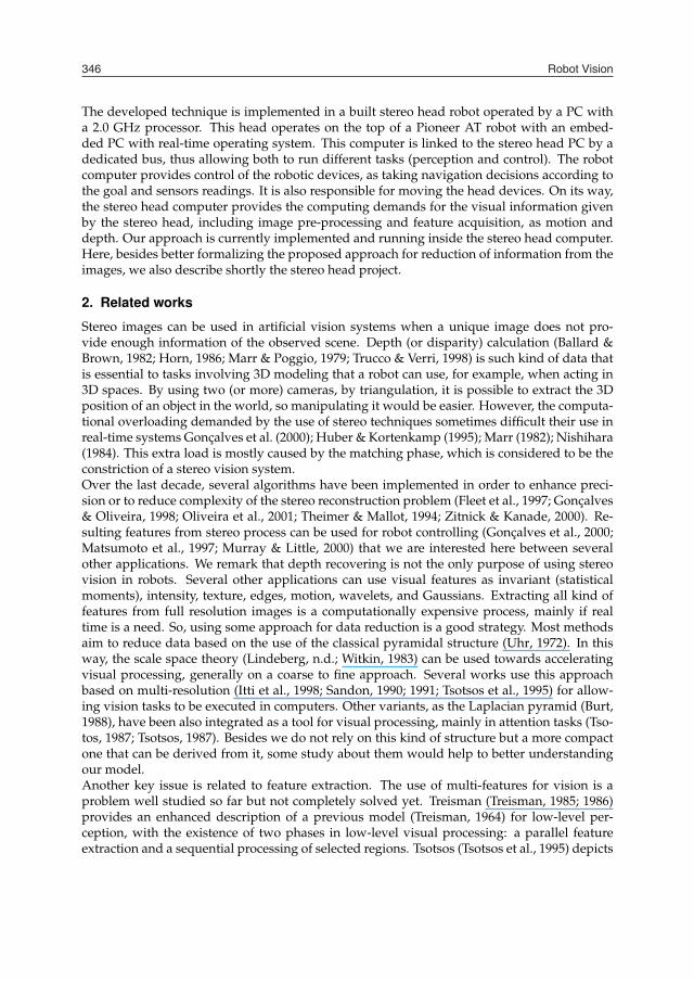
Fig. 1. UFRN Stereo Head platform with 5 mechanical degrees of freedom
The stereo head operate in two distinct behaviors, in the first, both cameras center the sightin the same object, so in this case we will use stereo algorithm. But the second behavior eachcamera can move independently and deal with different situations.
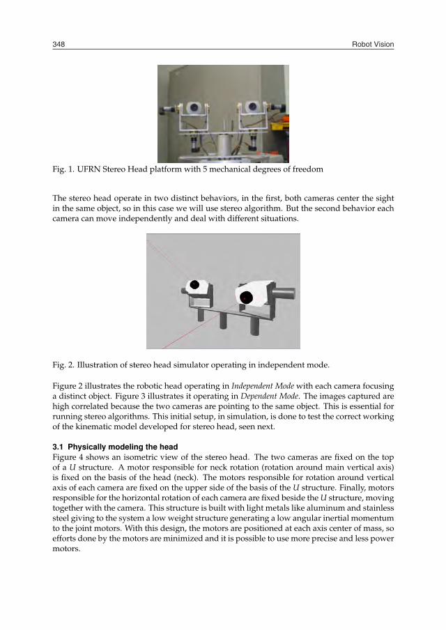
Fig. 2. Illustration of stereo head simulator operating in independent mode.
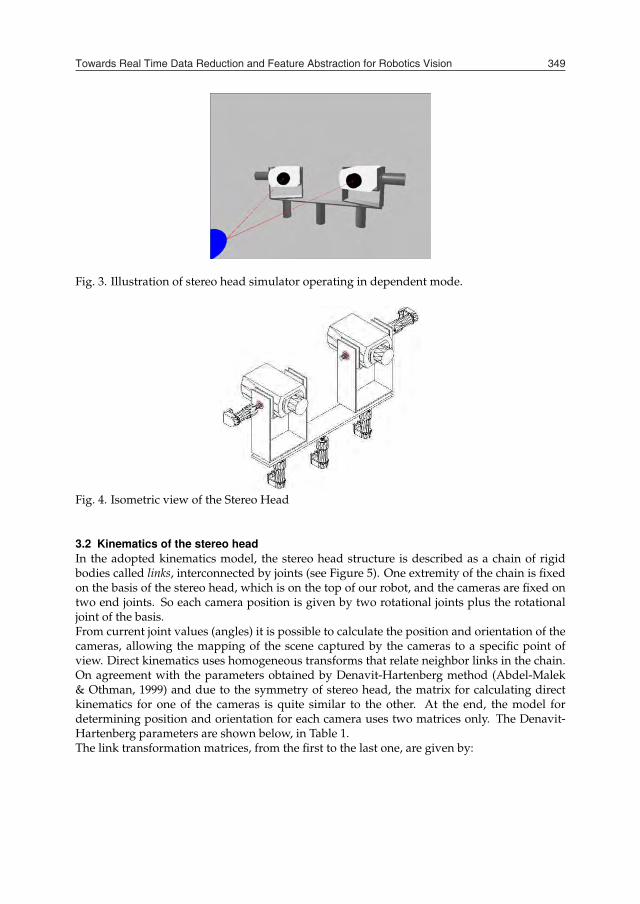
Figure 2 illustrates the robotic head operating in Independent Mode with each camera focusinga distinct object. Figure 3 illustrates it operating in Dependent Mode. The images captured arehigh correlated because the two cameras are pointing to the same object. This is essential forrunning stereo algorithms. This initial setup, in simulation, is done to test the correct workingof the kinematic model developed for stereo head, seen next.
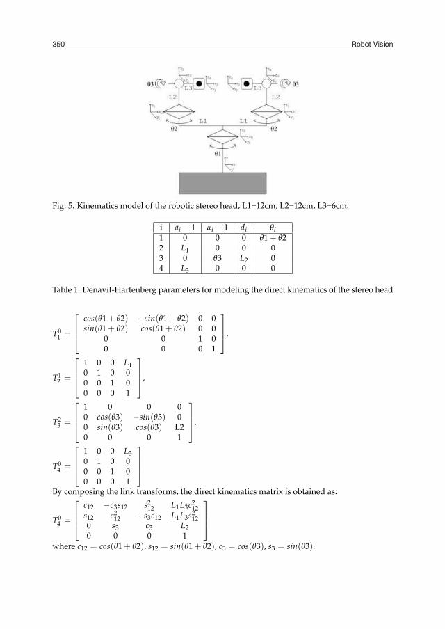
3.1 Physically modeling the headFigure 4 shows an isometric view of the stereo head. The two cameras are fixed on the topof a U structure. A motor responsible for neck rotation (rotation around main vertical axis)is fixed on the basis of the head (neck). The motors responsible for rotation around verticalaxis of each camera are fixed on the upper side of the basis of the U structure. Finally, motorsresponsible for the horizontal rotation of each camera are fixed beside the U structure, movingtogether with the camera. This structure is built with light metals like aluminum and stainlesssteel giving to the system a low weight structure generating a low angular inertial momentumto the joint motors. With this design, the motors are positioned at each axis center of mass, soefforts done by the motors are minimized and it is possible to use more precise and less powermotors.
Fig. 3. Illustration of stereo head simulator operating in dependent mode.
Fig. 4. Isometric view of the Stereo Head
3.2 Kinematics of the stereo headIn the adopted kinematics model, the stereo head structure is described as a chain of rigidbodies called links, interconnected by joints (see Figure 5). One extremity of the chain is fixedon the basis of the stereo head, which is on the top of our robot, and the cameras are fixed ontwo end joints. So each camera position is given by two rotational joints plus the rotationaljoint of the basis.From current joint values (angles) it is possible to calculate the position and orientation of thecameras, allowing the mapping of the scene captured by the cameras to a specific point ofview. Direct kinematics uses homogeneous transforms that relate neighbor links in the chain.On agreement with the parameters obtained by Denavit-Hartenberg method (Abdel-Malek& Othman, 1999) and due to the symmetry of stereo head, the matrix for calculating directkinematics for one of the cameras is quite similar to the other. At the end, the model fordetermining position and orientation for each camera uses two matrices only. The Denavit-Hartenberg parameters are shown below, in Table 1.The link transformation matrices, from the first to the last one, are given by:
Towards Real Time Data Reduction and Feature Abstraction for Robotics Vision 349
Fig. 1. UFRN Stereo Head platform with 5 mechanical degrees of freedom
The stereo head operate in two distinct behaviors, in the first, both cameras center the sightin the same object, so in this case we will use stereo algorithm. But the second behavior eachcamera can move independently and deal with different situations.
Fig. 2. Illustration of stereo head simulator operating in independent mode.
Figure 2 illustrates the robotic head operating in Independent Mode with each camera focusinga distinct object. Figure 3 illustrates it operating in Dependent Mode. The images captured arehigh correlated because the two cameras are pointing to the same object. This is essential forrunning stereo algorithms. This initial setup, in simulation, is done to test the correct workingof the kinematic model developed for stereo head, seen next.
3.1 Physically modeling the headFigure 4 shows an isometric view of the stereo head. The two cameras are fixed on the topof a U structure. A motor responsible for neck rotation (rotation around main vertical axis)is fixed on the basis of the head (neck). The motors responsible for rotation around verticalaxis of each camera are fixed on the upper side of the basis of the U structure. Finally, motorsresponsible for the horizontal rotation of each camera are fixed beside the U structure, movingtogether with the camera. This structure is built with light metals like aluminum and stainlesssteel giving to the system a low weight structure generating a low angular inertial momentumto the joint motors. With this design, the motors are positioned at each axis center of mass, soefforts done by the motors are minimized and it is possible to use more precise and less powermotors.
Fig. 3. Illustration of stereo head simulator operating in dependent mode.
Fig. 4. Isometric view of the Stereo Head
3.2 Kinematics of the stereo headIn the adopted kinematics model, the stereo head structure is described as a chain of rigidbodies called links, interconnected by joints (see Figure 5). One extremity of the chain is fixedon the basis of the stereo head, which is on the top of our robot, and the cameras are fixed ontwo end joints. So each camera position is given by two rotational joints plus the rotationaljoint of the basis.From current joint values (angles) it is possible to calculate the position and orientation of thecameras, allowing the mapping of the scene captured by the cameras to a specific point ofview. Direct kinematics uses homogeneous transforms that relate neighbor links in the chain.On agreement with the parameters obtained by Denavit-Hartenberg method (Abdel-Malek& Othman, 1999) and due to the symmetry of stereo head, the matrix for calculating directkinematics for one of the cameras is quite similar to the other. At the end, the model fordetermining position and orientation for each camera uses two matrices only. The Denavit-Hartenberg parameters are shown below, in Table 1.The link transformation matrices, from the first to the last one, are given by:
Robot Vision350
Fig. 5. Kinematics model of the robotic stereo head, L1=12cm, L2=12cm, L3=6cm.
i ai − 1 αi − 1 di θi1 0 0 0 θ1 + θ22 L1 0 0 03 0 θ3 L2 04 L3 0 0 0
Table 1. Denavit-Hartenberg parameters for modeling the direct kinematics of the stereo head
T01 =
cos(θ1 + θ2) −sin(θ1 + θ2) 0 0sin(θ1 + θ2) cos(θ1 + θ2) 0 0
0 0 1 00 0 0 1
,
T12 =
1 0 0 L10 1 0 00 0 1 00 0 0 1
,
T23 =
1 0 0 00 cos(θ3) −sin(θ3) 00 sin(θ3) cos(θ3) L20 0 0 1
,
T04 =
1 0 0 L30 1 0 00 0 1 00 0 0 1
By composing the link transforms, the direct kinematics matrix is obtained as:
T04 =
c12 −c3s12 s212 L1L3c2
12s12 c2
12 −s3c12 L1L3s212
0 s3 c3 L20 0 0 1
where c12 = cos(θ1 + θ2), s12 = sin(θ1 + θ2), c3 = cos(θ3), s3 = sin(θ3).
3.3 Head controlThe control of the head motors is done by microcontrollers all interconnected by a CAM bus.Each motor that is responsible for a joint movement has its own microcontroller. A moduleoperating in software is responsible for coordinating the composed movement of all joints ac-cording to a profile of the angular velocities received from each motor. In order to do this, itis necessary to correct drive the five joint’s motors and to perform the calibration of the setbefore it starts operating. The head control software determines the signal position by calcu-lating the error between the desired position and de actual position given by the encoders.With this approach, the second embedded computer, which is responsible for the image pro-cessing, has only this task. This solution makes the two tasks (head’s motors control and highlevel control) faster. This is also a fundamental factor for the functioning of the system in realtime.
4. The proposed solution
Figure 6 shows a diagram with the logical components of the visual system. Basically, theacquisition system is composed by two cameras and two video capture cards, which convertanalog signals received from each camera into a digital buffer in the memory system. Thenext stage is the pre-processing functions that create various small images, in multiresolution,all with the same size in a schema inspired by the biological retina. The central region of thecaptured image that has the maximum of resolution, called fovea, is represented in one of thesmall images (say the last level image). Then, growing to the periphery of the captured image,the other small images are created by down-sampling bigger regions, increasing in sizes onthe captured image, but with decreasing degrees of resolution according to the augmentationof the distance to the fovea. This process is made for both images and, thus, feature extractiontechniques can be applied on them, including stereo disparity, motion and other features asintensity and Gaussian derivatives. This set of characteristic maps are extracted to feed higherlevel processes like attention, recognition, and navigation.
Fig. 6. Stereo vision stages
4.1 Reduction of resolutionPerforming stereo processing in full resolution images usually requires great power of pro-cessing and a considerable time. This is due to the nature of the algorithms used and also tothe huge amount of data that a pair of large images have. Such restrictions make the task of

Towards Real Time Data Reduction and Feature Abstraction for Robotics Vision 351
Fig. 5. Kinematics model of the robotic stereo head, L1=12cm, L2=12cm, L3=6cm.
i ai − 1 αi − 1 di θi1 0 0 0 θ1 + θ22 L1 0 0 03 0 θ3 L2 04 L3 0 0 0
Table 1. Denavit-Hartenberg parameters for modeling the direct kinematics of the stereo head
T01 =
cos(θ1 + θ2) −sin(θ1 + θ2) 0 0sin(θ1 + θ2) cos(θ1 + θ2) 0 0
0 0 1 00 0 0 1
,
T12 =
1 0 0 L10 1 0 00 0 1 00 0 0 1
,
T23 =
1 0 0 00 cos(θ3) −sin(θ3) 00 sin(θ3) cos(θ3) L20 0 0 1
,
T04 =
1 0 0 L30 1 0 00 0 1 00 0 0 1
By composing the link transforms, the direct kinematics matrix is obtained as:
T04 =
c12 −c3s12 s212 L1L3c2
12s12 c2
12 −s3c12 L1L3s212
0 s3 c3 L20 0 0 1
where c12 = cos(θ1 + θ2), s12 = sin(θ1 + θ2), c3 = cos(θ3), s3 = sin(θ3).
3.3 Head controlThe control of the head motors is done by microcontrollers all interconnected by a CAM bus.Each motor that is responsible for a joint movement has its own microcontroller. A moduleoperating in software is responsible for coordinating the composed movement of all joints ac-cording to a profile of the angular velocities received from each motor. In order to do this, itis necessary to correct drive the five joint’s motors and to perform the calibration of the setbefore it starts operating. The head control software determines the signal position by calcu-lating the error between the desired position and de actual position given by the encoders.With this approach, the second embedded computer, which is responsible for the image pro-cessing, has only this task. This solution makes the two tasks (head’s motors control and highlevel control) faster. This is also a fundamental factor for the functioning of the system in realtime.
4. The proposed solution
Figure 6 shows a diagram with the logical components of the visual system. Basically, theacquisition system is composed by two cameras and two video capture cards, which convertanalog signals received from each camera into a digital buffer in the memory system. Thenext stage is the pre-processing functions that create various small images, in multiresolution,all with the same size in a schema inspired by the biological retina. The central region of thecaptured image that has the maximum of resolution, called fovea, is represented in one of thesmall images (say the last level image). Then, growing to the periphery of the captured image,the other small images are created by down-sampling bigger regions, increasing in sizes onthe captured image, but with decreasing degrees of resolution according to the augmentationof the distance to the fovea. This process is made for both images and, thus, feature extractiontechniques can be applied on them, including stereo disparity, motion and other features asintensity and Gaussian derivatives. This set of characteristic maps are extracted to feed higherlevel processes like attention, recognition, and navigation.
Fig. 6. Stereo vision stages
4.1 Reduction of resolutionPerforming stereo processing in full resolution images usually requires great power of pro-cessing and a considerable time. This is due to the nature of the algorithms used and also tothe huge amount of data that a pair of large images have. Such restrictions make the task of
Robot Vision352
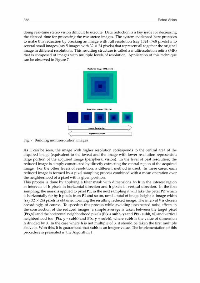
doing real-time stereo vision difficult to execute. Data reduction is a key issue for decreasingthe elapsed time for processing the two stereo images. The system evidenced here proposesto make this reduction by breaking an image with full resolution (say 1024×768 pixels) intoseveral small images (say 5 images with 32 × 24 pixels) that represent all together the originalimage in different resolutions. This resulting structure is called a multiresolution retina (MR)that is composed of images with multiple levels of resolution. Application of this techniquecan be observed in Figure 7.
Fig. 7. Building multiresolution images
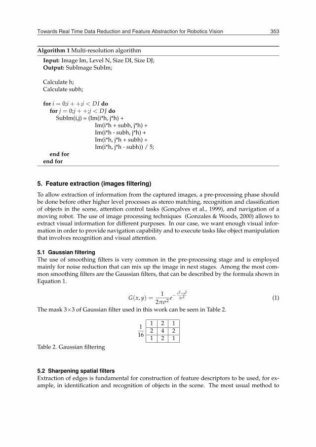
As it can be seen, the image with higher resolution corresponds to the central area of theacquired image (equivalent to the fovea) and the image with lower resolution represents alarge portion of the acquired image (peripheral vision). In the level of best resolution, thereduced image is simply constructed by directly extracting the central region of the acquiredimage. For the other levels of resolution, a different method is used. In these cases, eachreduced image is formed by a pixel sampling process combined with a mean operation overthe neighborhood of a pixel with a given position.This process is done by applying a filter mask with dimensions h×h in the interest regionat intervals of h pixels in horizontal direction and h pixels in vertical direction. In the firstsampling, the mask is applied to pixel P1, in the next sampling it will take the pixel P2, whichis horizontally far by h pixels from P1 and so on, until a total of image height × image width(say 32 × 24) pixels is obtained forming the resulting reduced image. The interval h is chosenaccordingly, of course. To speedup this process while avoiding unexpected noise effects inthe construction of the reduced images, a simple average is taken between the target pixel(P(x,y)) and the horizontal neighborhood pixels (P(x + subh, y) and P(x - subh, y)) and verticalneighborhood too (P(x, y - subh) and P(x, y + subh), where subh is the value of dimensionh divided by 3. In the case where h is not multiple of 3, it should be taken the first multipleabove it. With this, it is guaranteed that subh is an integer value. The implementation of thisprocedure is presented in the Algorithm 1.
Algorithm 1 Multi-resolution algorithm
Input: Image Im, Level N, Size DI, Size DJ;Output: SubImage SubIm;
Calculate h;Calculate subh;
for i = 0;i ++;i < DI dofor j = 0;j ++;j < DJ do
SubIm(i,j) = (Im(i*h, j*h) +Im(i*h + subh, j*h) +Im(i*h - subh, j*h) +Im(i*h, j*h + subh) +Im(i*h, j*h - subh)) / 5;
end forend for
5. Feature extraction (images filtering)
To allow extraction of information from the captured images, a pre-processing phase shouldbe done before other higher level processes as stereo matching, recognition and classificationof objects in the scene, attention control tasks (Gonçalves et al., 1999), and navigation of amoving robot. The use of image processing techniques (Gonzales & Woods, 2000) allows toextract visual information for different purposes. In our case, we want enough visual infor-mation in order to provide navigation capability and to execute tasks like object manipulationthat involves recognition and visual attention.
5.1 Gaussian filteringThe use of smoothing filters is very common in the pre-processing stage and is employedmainly for noise reduction that can mix up the image in next stages. Among the most com-mon smoothing filters are the Gaussian filters, that can be described by the formula shown inEquation 1.
G(x, y) =1
2πσ2 e−x2+y2
2σ2 (1)
The mask 3×3 of Gaussian filter used in this work can be seen in Table 2.
116
1 2 12 4 21 2 1
Table 2. Gaussian filtering
5.2 Sharpening spatial filtersExtraction of edges is fundamental for construction of feature descriptors to be used, for ex-ample, in identification and recognition of objects in the scene. The most usual method to
Towards Real Time Data Reduction and Feature Abstraction for Robotics Vision 353
doing real-time stereo vision difficult to execute. Data reduction is a key issue for decreasingthe elapsed time for processing the two stereo images. The system evidenced here proposesto make this reduction by breaking an image with full resolution (say 1024×768 pixels) intoseveral small images (say 5 images with 32 × 24 pixels) that represent all together the originalimage in different resolutions. This resulting structure is called a multiresolution retina (MR)that is composed of images with multiple levels of resolution. Application of this techniquecan be observed in Figure 7.
Fig. 7. Building multiresolution images
As it can be seen, the image with higher resolution corresponds to the central area of theacquired image (equivalent to the fovea) and the image with lower resolution represents alarge portion of the acquired image (peripheral vision). In the level of best resolution, thereduced image is simply constructed by directly extracting the central region of the acquiredimage. For the other levels of resolution, a different method is used. In these cases, eachreduced image is formed by a pixel sampling process combined with a mean operation overthe neighborhood of a pixel with a given position.This process is done by applying a filter mask with dimensions h×h in the interest regionat intervals of h pixels in horizontal direction and h pixels in vertical direction. In the firstsampling, the mask is applied to pixel P1, in the next sampling it will take the pixel P2, whichis horizontally far by h pixels from P1 and so on, until a total of image height × image width(say 32 × 24) pixels is obtained forming the resulting reduced image. The interval h is chosenaccordingly, of course. To speedup this process while avoiding unexpected noise effects inthe construction of the reduced images, a simple average is taken between the target pixel(P(x,y)) and the horizontal neighborhood pixels (P(x + subh, y) and P(x - subh, y)) and verticalneighborhood too (P(x, y - subh) and P(x, y + subh), where subh is the value of dimensionh divided by 3. In the case where h is not multiple of 3, it should be taken the first multipleabove it. With this, it is guaranteed that subh is an integer value. The implementation of thisprocedure is presented in the Algorithm 1.
Algorithm 1 Multi-resolution algorithm
Input: Image Im, Level N, Size DI, Size DJ;Output: SubImage SubIm;
Calculate h;Calculate subh;
for i = 0;i ++;i < DI dofor j = 0;j ++;j < DJ do
SubIm(i,j) = (Im(i*h, j*h) +Im(i*h + subh, j*h) +Im(i*h - subh, j*h) +Im(i*h, j*h + subh) +Im(i*h, j*h - subh)) / 5;
end forend for
5. Feature extraction (images filtering)
To allow extraction of information from the captured images, a pre-processing phase shouldbe done before other higher level processes as stereo matching, recognition and classificationof objects in the scene, attention control tasks (Gonçalves et al., 1999), and navigation of amoving robot. The use of image processing techniques (Gonzales & Woods, 2000) allows toextract visual information for different purposes. In our case, we want enough visual infor-mation in order to provide navigation capability and to execute tasks like object manipulationthat involves recognition and visual attention.
5.1 Gaussian filteringThe use of smoothing filters is very common in the pre-processing stage and is employedmainly for noise reduction that can mix up the image in next stages. Among the most com-mon smoothing filters are the Gaussian filters, that can be described by the formula shown inEquation 1.
G(x, y) =1
2πσ2 e−x2+y2
2σ2 (1)
The mask 3×3 of Gaussian filter used in this work can be seen in Table 2.
116
1 2 12 4 21 2 1
Table 2. Gaussian filtering
5.2 Sharpening spatial filtersExtraction of edges is fundamental for construction of feature descriptors to be used, for ex-ample, in identification and recognition of objects in the scene. The most usual method to
Robot Vision354
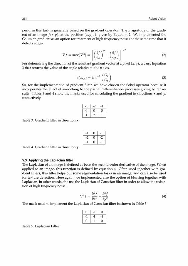
perform this task is generally based on the gradient operator. The magnitude of the gradi-ent of an image f (x, y), at the position (x, y), is given by Equation 2. We implemented theGaussian gradient as an option for treatment of high frequency noises at the same time that itdetects edges.
∇ f = mag(∇f) =
[(∂ f∂x
)2+
(∂ f∂y
)]1/2
(2)
For determining the direction of the resultant gradient vector at a pixel (x, y), we use Equation3 that returns the value of the angle relative to the x axis.
α(x, y) = tan−1(
Gy
Gx
)(3)
So, for the implementation of gradient filter, we have chosen the Sobel operator because itincorporates the effect of smoothing to the partial differentiation processes giving better re-sults. Tables 3 and 4 show the masks used for calculating the gradient in directions x and y,respectively.
-1 -2 -10 0 01 2 1
Table 3. Gradient filter in direction x
-1 0 -1-2 0 -2-1 0 -1
Table 4. Gradient filter in direction y
5.3 Applying the Laplacian filterThe Laplacian of an image is defined as been the second-order derivative of the image. Whenapplied to an image, this function is defined by equation 4. Often used together with gra-dient filters, this filter helps out some segmentation tasks in an image, and can also be usedfor texture detection. Here again, we implemented also the option of blurring together withLaplacian, in other words, the use the Laplacian of Gaussian filter in order to allow the reduc-tion of high frequency noise.
∇2 f =∂2 f∂x2 +
∂2 f∂y2 (4)
The mask used to implement the Laplacian of Gaussian filter is shown in Table 5.
0 -1 0-1 4 -10 -1 0
Table 5. Laplacian Filter
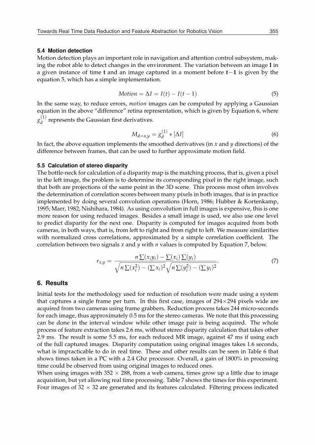
5.4 Motion detectionMotion detection plays an important role in navigation and attention control subsystem, mak-ing the robot able to detect changes in the environment. The variation between an image I ina given instance of time t and an image captured in a moment before t−1 is given by theequation 5, which has a simple implementation.
Motion = ∆I = I(t)− I(t − 1) (5)
In the same way, to reduce errors, motion images can be computed by applying a Gaussianequation in the above “difference” retina representation, which is given by Equation 6, where
g(1)d represents the Gaussian first derivatives.
Md=x,y = g(1)d ∗ [∆I] (6)
In fact, the above equation implements the smoothed derivatives (in x and y directions) of thedifference between frames, that can be used to further approximate motion field.
5.5 Calculation of stereo disparityThe bottle-neck for calculation of a disparity map is the matching process, that is, given a pixelin the left image, the problem is to determine its corresponding pixel in the right image, suchthat both are projections of the same point in the 3D scene. This process most often involvesthe determination of correlation scores between many pixels in both images, that is in practiceimplemented by doing several convolution operations (Horn, 1986; Hubber & Kortenkamp,1995; Marr, 1982; Nishihara, 1984). As using convolution in full images is expensive, this is onemore reason for using reduced images. Besides a small image is used, we also use one levelto predict disparity for the next one. Disparity is computed for images acquired from bothcameras, in both ways, that is, from left to right and from right to left. We measure similaritieswith normalized cross correlations, approximated by a simple correlation coefficient. Thecorrelation between two signals x and y with n values is computed by Equation 7, below.
rx,y =n ∑(xiyi)− ∑(xi)∑(yi)√
n ∑(x2i )− (∑ xi)2
√n ∑(y2
i )− (∑ yi)2. (7)
6. Results
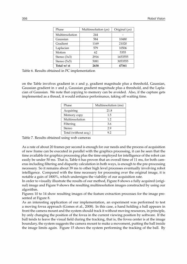
Initial tests for the methodology used for reduction of resolution were made using a systemthat captures a single frame per turn. In this first case, images of 294×294 pixels wide areacquired from two cameras using frame grabbers. Reduction process takes 244 micro-secondsfor each image, thus approximately 0.5 ms for the stereo cameras. We note that this processingcan be done in the interval window while other image pair is being acquired. The wholeprocess of feature extraction takes 2.6 ms, without stereo disparity calculation that takes other2.9 ms. The result is some 5.5 ms, for each reduced MR image, against 47 ms if using eachof the full captured images. Disparity computation using original images takes 1.6 seconds,what is impracticable to do in real time. These and other results can be seen in Table 6 thatshows times taken in a PC with a 2.4 Ghz processor. Overall, a gain of 1800% in processingtime could be observed from using original images to reduced ones.When using images with 352 × 288, from a web camera, times grow up a little due to imageacquisition, but yet allowing real time processing. Table 7 shows the times for this experiment.Four images of 32 × 32 are generated and its features calculated. Filtering process indicated
Towards Real Time Data Reduction and Feature Abstraction for Robotics Vision 355
perform this task is generally based on the gradient operator. The magnitude of the gradi-ent of an image f (x, y), at the position (x, y), is given by Equation 2. We implemented theGaussian gradient as an option for treatment of high frequency noises at the same time that itdetects edges.
∇ f = mag(∇f) =
[(∂ f∂x
)2+
(∂ f∂y
)]1/2
(2)
For determining the direction of the resultant gradient vector at a pixel (x, y), we use Equation3 that returns the value of the angle relative to the x axis.
α(x, y) = tan−1(
Gy
Gx
)(3)
So, for the implementation of gradient filter, we have chosen the Sobel operator because itincorporates the effect of smoothing to the partial differentiation processes giving better re-sults. Tables 3 and 4 show the masks used for calculating the gradient in directions x and y,respectively.
-1 -2 -10 0 01 2 1
Table 3. Gradient filter in direction x
-1 0 -1-2 0 -2-1 0 -1
Table 4. Gradient filter in direction y
5.3 Applying the Laplacian filterThe Laplacian of an image is defined as been the second-order derivative of the image. Whenapplied to an image, this function is defined by equation 4. Often used together with gra-dient filters, this filter helps out some segmentation tasks in an image, and can also be usedfor texture detection. Here again, we implemented also the option of blurring together withLaplacian, in other words, the use the Laplacian of Gaussian filter in order to allow the reduc-tion of high frequency noise.
∇2 f =∂2 f∂x2 +
∂2 f∂y2 (4)
The mask used to implement the Laplacian of Gaussian filter is shown in Table 5.
0 -1 0-1 4 -10 -1 0
Table 5. Laplacian Filter
5.4 Motion detectionMotion detection plays an important role in navigation and attention control subsystem, mak-ing the robot able to detect changes in the environment. The variation between an image I ina given instance of time t and an image captured in a moment before t−1 is given by theequation 5, which has a simple implementation.
Motion = ∆I = I(t)− I(t − 1) (5)
In the same way, to reduce errors, motion images can be computed by applying a Gaussianequation in the above “difference” retina representation, which is given by Equation 6, where
g(1)d represents the Gaussian first derivatives.
Md=x,y = g(1)d ∗ [∆I] (6)
In fact, the above equation implements the smoothed derivatives (in x and y directions) of thedifference between frames, that can be used to further approximate motion field.
5.5 Calculation of stereo disparityThe bottle-neck for calculation of a disparity map is the matching process, that is, given a pixelin the left image, the problem is to determine its corresponding pixel in the right image, suchthat both are projections of the same point in the 3D scene. This process most often involvesthe determination of correlation scores between many pixels in both images, that is in practiceimplemented by doing several convolution operations (Horn, 1986; Hubber & Kortenkamp,1995; Marr, 1982; Nishihara, 1984). As using convolution in full images is expensive, this is onemore reason for using reduced images. Besides a small image is used, we also use one levelto predict disparity for the next one. Disparity is computed for images acquired from bothcameras, in both ways, that is, from left to right and from right to left. We measure similaritieswith normalized cross correlations, approximated by a simple correlation coefficient. Thecorrelation between two signals x and y with n values is computed by Equation 7, below.
rx,y =n ∑(xiyi)− ∑(xi)∑(yi)√
n ∑(x2i )− (∑ xi)2
√n ∑(y2
i )− (∑ yi)2. (7)
6. Results
Initial tests for the methodology used for reduction of resolution were made using a systemthat captures a single frame per turn. In this first case, images of 294×294 pixels wide areacquired from two cameras using frame grabbers. Reduction process takes 244 micro-secondsfor each image, thus approximately 0.5 ms for the stereo cameras. We note that this processingcan be done in the interval window while other image pair is being acquired. The wholeprocess of feature extraction takes 2.6 ms, without stereo disparity calculation that takes other2.9 ms. The result is some 5.5 ms, for each reduced MR image, against 47 ms if using eachof the full captured images. Disparity computation using original images takes 1.6 seconds,what is impracticable to do in real time. These and other results can be seen in Table 6 thatshows times taken in a PC with a 2.4 Ghz processor. Overall, a gain of 1800% in processingtime could be observed from using original images to reduced ones.When using images with 352 × 288, from a web camera, times grow up a little due to imageacquisition, but yet allowing real time processing. Table 7 shows the times for this experiment.Four images of 32 × 32 are generated and its features calculated. Filtering process indicated
Robot Vision356
Phase Multiresolution (µs) Original (µs)
Multiresolution 244 –Gaussian 584 10480Gradient 1169 21020Laplacian 579 10506Motion 62 5355Stereo (3x3) 2916 1653555Stereo (5x5) 5081 3053555Total w/ st 2638 47361
Table 6. Results obtained in PC implementation
on the Table involves gradient in x and y, gradient magnitude plus a threshold, Gaussian,Gaussian gradient in x and y, Gaussian gradient magnitude plus a threshold, and the Lapla-cian of Gaussian. We note that copying to memory can be avoided. Also, if the capture getsimplemented as a thread, it would enhance performance, taking off waiting time.
Phase Multiresolution (ms)
Acquiring 21.8Memory copy 1.5Multiresolution 1.2Filtering 3.6Stereo 2.9Total (without acq.) 9.2
Table 7. Results obtained using web cameras
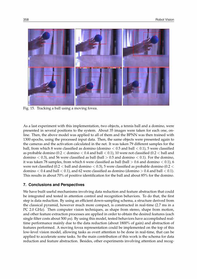
As a rate of about 20 frames per second is enough for our needs and the process of acquisitionof new frame can be executed in parallel with the graphics processing, it can be seen that thetime available for graphics processing plus the time employed for intelligence of the robot caneasily be under 50 ms. That is, Table 6 has proven that an overall time of 11 ms, for both cam-eras including filtering and disparity calculation in both ways, is enough to the pre-processingnecessary. So it remains about 39 ms to other high level processes eventually involving robotintelligence. Compared with the time necessary for processing over the original image, it isnotable a gain of 1800%, which undersigns the viability of our acquisition rate.In order to visually illustrate the results of our method, Figure 8 shows a fully acquired (origi-nal) image and Figure 9 shows the resulting multiresolution images constructed by using ouralgorithm.Figures 10 to 14 show resulting images of the feature extraction processes for the image pre-sented at Figure 8.As an interesting application of our implementation, an experiment was performed to testa moving fovea approach (Gomes et al., 2008). In this case, a hand holding a ball appears infront the camera mount and the system should track it without moving resources, in principle,by only changing the position of the fovea in the current viewing position by software. If theball tends to leave the visual field during the tracking, that is, the fovea center is at the imageboundary, the system suggests the camera mount to make a movement, putting the ball insidethe image limits again. Figure 15 shows the system performing the tracking of the ball. By
Fig. 8. Original image
Fig. 9. Multiresolution representation
Fig. 10. Gaussian filter
Fig. 11. Gradient filter in X direction
Fig. 12. Gradient filter in Y direction
Fig. 13. Laplacian filter
Fig. 14. Detection of motion
using the moving fovea, it is possible to disengage attention from one position and to engageit to another position from a frame to another. If using our stereo head robot, even using thedefault MRMF approach (fovea in the image center), this task could take some 500 because itneeds a motion of the cameras. Of course, even with the moving fovea, when it gets the imageperiphery a physical motion is necessary. Then the robot has to eventually wait for this taskto be completed in order to acquire other pair of frames.

Towards Real Time Data Reduction and Feature Abstraction for Robotics Vision 357
Phase Multiresolution (µs) Original (µs)
Multiresolution 244 –Gaussian 584 10480Gradient 1169 21020Laplacian 579 10506Motion 62 5355Stereo (3x3) 2916 1653555Stereo (5x5) 5081 3053555Total w/ st 2638 47361
Table 6. Results obtained in PC implementation
on the Table involves gradient in x and y, gradient magnitude plus a threshold, Gaussian,Gaussian gradient in x and y, Gaussian gradient magnitude plus a threshold, and the Lapla-cian of Gaussian. We note that copying to memory can be avoided. Also, if the capture getsimplemented as a thread, it would enhance performance, taking off waiting time.
Phase Multiresolution (ms)
Acquiring 21.8Memory copy 1.5Multiresolution 1.2Filtering 3.6Stereo 2.9Total (without acq.) 9.2
Table 7. Results obtained using web cameras
As a rate of about 20 frames per second is enough for our needs and the process of acquisitionof new frame can be executed in parallel with the graphics processing, it can be seen that thetime available for graphics processing plus the time employed for intelligence of the robot caneasily be under 50 ms. That is, Table 6 has proven that an overall time of 11 ms, for both cam-eras including filtering and disparity calculation in both ways, is enough to the pre-processingnecessary. So it remains about 39 ms to other high level processes eventually involving robotintelligence. Compared with the time necessary for processing over the original image, it isnotable a gain of 1800%, which undersigns the viability of our acquisition rate.In order to visually illustrate the results of our method, Figure 8 shows a fully acquired (origi-nal) image and Figure 9 shows the resulting multiresolution images constructed by using ouralgorithm.Figures 10 to 14 show resulting images of the feature extraction processes for the image pre-sented at Figure 8.As an interesting application of our implementation, an experiment was performed to testa moving fovea approach (Gomes et al., 2008). In this case, a hand holding a ball appears infront the camera mount and the system should track it without moving resources, in principle,by only changing the position of the fovea in the current viewing position by software. If theball tends to leave the visual field during the tracking, that is, the fovea center is at the imageboundary, the system suggests the camera mount to make a movement, putting the ball insidethe image limits again. Figure 15 shows the system performing the tracking of the ball. By
Fig. 8. Original image
Fig. 9. Multiresolution representation
Fig. 10. Gaussian filter
Fig. 11. Gradient filter in X direction
Fig. 12. Gradient filter in Y direction
Fig. 13. Laplacian filter
Fig. 14. Detection of motion
using the moving fovea, it is possible to disengage attention from one position and to engageit to another position from a frame to another. If using our stereo head robot, even using thedefault MRMF approach (fovea in the image center), this task could take some 500 because itneeds a motion of the cameras. Of course, even with the moving fovea, when it gets the imageperiphery a physical motion is necessary. Then the robot has to eventually wait for this taskto be completed in order to acquire other pair of frames.
Robot Vision358
Fig. 15. Tracking a ball using a moving fovea.
As a last experiment with this implementation, two objects, a tennis ball and a domino, werepresented in several positions to the system. About 35 images were taken for each one, on-line. Then, the above model was applied to all of them and the BPNN was then trained with1300 epochs, using the processed input data. Then, the same objects were presented again tothe cameras and the activation calculated in the net. It was taken 79 different samples for theball, from which 8 were classified as domino (domino < 0.5 and ball < 0.1), 5 were classifiedas probable domino (0.2 < domino < 0.4 and ball < 0.1), 10 were not classified (0.2 < ball anddomino < 0.3), and 56 were classified as ball (ball > 0.5 and domino < 0.1). For the domino,it was taken 78 samples, from which 6 were classified as ball (ball > 0.6 and domino < 0.1), 6were not classified (0.2 < ball and domino < 0.3), 5 were classified as probable domino (0.2 <domino < 0.4 and ball < 0.1), and 62 were classified as domino (domino > 0.4 and ball < 0.1).This results in about 70% of positive identification for the ball and about 85% for the domino.
7. Conclusions and Perspectives
We have built useful mechanisms involving data reduction and feature abstraction that couldbe integrated and tested in attention control and recognition behaviors. To do that, the firststep is data reduction. By using an efficient down-sampling schema, a structure derived fromthe classical pyramid, however much more compact, is constructed in real-time (2.7 ms in aPC 2.0 GHz). Then computer vision techniques, as shape from stereo, shape from motion,and other feature extraction processes are applied in order to obtain the desired features (eachsingle filter costs about 500 µs). By using this model, tested behaviors have accomplished real-time performance mainly due to the data reduction (about 1800% of gain) and abstraction offeatures performed. A moving fovea representation could be implemented on the top of thislow-level vision model, allowing tasks as overt attention to be done in real-time, that can beapplied to accelerate some tasks. So the main contribution of this work is the schema for datareduction and feature abstraction. Besides, other experiments involving attention and recog-
nition, with novel approaches were also done. So we believe that the main result obtainedwas the definition of a methodology that can be applied to different types of tasks involvingattention and recognition, without needs of strong adaptation, just by changing weight tuningstrategies and thus the set of features on the robot platforms. So, high-level processes can relyon this methodology, in order to accomplish other tasks, as navigation or object manipulationfor example. Main results of this work show the efficiency of the proposed method and howit can be used to accelerate high level algorithms inside a vision system.Besides using only visual data in this work, similar strategies can be applied to a more generalsystem involving other kind of sensory information, to provide a more discriminative featureset. We believe that the low level abilities of data reduction and feature abstraction are thebasis not only for experiments described here, but also for other more complex tasks involvedin robot cognition. This model was inspired by the biological model in the sense that the moreprecise resolution levels are located in the center of the image. In this way, the less resolutionlevels can be used for example to detect motion or features to be used in navigation tasks(mainly bottom-up stimuli) and the finer levels of resolution can be applied to tasks involvingrecognition as reading or object manipulation. A search task can use a combination of one ormore levels. Of course, in this case, a moving fovea does play an important role, avoiding thehead of performing motions, only if necessary.
8. Acknowledgments
We thanks Brazilian Research Sponsoring Agency CNPQ the financial supports given to LuizGonçalves, Rafael Gomes, Bruno Carvalho and Renato Gardiman.
9. References
Abdel-Malek, K. & Othman, S. (1999). Multiple sweeping using the denavit-hartenberg rep-resentation method.
A.Goshtasby & W.Gruver (1992). Design of a single-lens stereo camera system, Design of aSingle-Lens Stereo Camera System, Pattern Recognition.
Ballard, D. H. & Brown, C. M. (1982). Computer Vision, Prentice-Hall, Englewood Cliffs, NJ.Burt, P. (1988). Smart sensing within a pyramid vision machine, Proceedings of the IEEE
76(8): 1006–1015.D.Lee & I.Kweon (2000). A novel stereo camera system by a bipirism, A Novel Stereo Camera
System by a Bipirism, IEEE Journal of Robotics and Automation.Fleet, D. J., Wagner, H. & Heeger, D. J. (1997). Neural encoding of binocular disparity: Energy
models, position shifts and phase shifts, Technical report, Personal Notes.Garcia, L. M., Oliveira, A. A. & A.Grupen, R. (1999). A framework for attention and object
categorization using a stereo head robot, A framework for Attention and Object Catego-rization Using a Stereo Head Robot.
Gomes, R. B., Carvalho, B. M. & Gonçalves, L. M. G. (2008). Real time vision for roboticsusing a moving fovea approach with multi resolution., Proceedings of InternacionalConference on Robotics and Automation.
Gonçalves, L. M. G., Giraldi, G. A., Oliveira, A. A. F. & Grupen, R. A. (1999). Learning policiesfor attentional control, IEEE International Symposium on Computational Intelligence inRobotics ans Automation.

Towards Real Time Data Reduction and Feature Abstraction for Robotics Vision 359
Fig. 15. Tracking a ball using a moving fovea.
As a last experiment with this implementation, two objects, a tennis ball and a domino, werepresented in several positions to the system. About 35 images were taken for each one, on-line. Then, the above model was applied to all of them and the BPNN was then trained with1300 epochs, using the processed input data. Then, the same objects were presented again tothe cameras and the activation calculated in the net. It was taken 79 different samples for theball, from which 8 were classified as domino (domino < 0.5 and ball < 0.1), 5 were classifiedas probable domino (0.2 < domino < 0.4 and ball < 0.1), 10 were not classified (0.2 < ball anddomino < 0.3), and 56 were classified as ball (ball > 0.5 and domino < 0.1). For the domino,it was taken 78 samples, from which 6 were classified as ball (ball > 0.6 and domino < 0.1), 6were not classified (0.2 < ball and domino < 0.3), 5 were classified as probable domino (0.2 <domino < 0.4 and ball < 0.1), and 62 were classified as domino (domino > 0.4 and ball < 0.1).This results in about 70% of positive identification for the ball and about 85% for the domino.
7. Conclusions and Perspectives
We have built useful mechanisms involving data reduction and feature abstraction that couldbe integrated and tested in attention control and recognition behaviors. To do that, the firststep is data reduction. By using an efficient down-sampling schema, a structure derived fromthe classical pyramid, however much more compact, is constructed in real-time (2.7 ms in aPC 2.0 GHz). Then computer vision techniques, as shape from stereo, shape from motion,and other feature extraction processes are applied in order to obtain the desired features (eachsingle filter costs about 500 µs). By using this model, tested behaviors have accomplished real-time performance mainly due to the data reduction (about 1800% of gain) and abstraction offeatures performed. A moving fovea representation could be implemented on the top of thislow-level vision model, allowing tasks as overt attention to be done in real-time, that can beapplied to accelerate some tasks. So the main contribution of this work is the schema for datareduction and feature abstraction. Besides, other experiments involving attention and recog-
nition, with novel approaches were also done. So we believe that the main result obtainedwas the definition of a methodology that can be applied to different types of tasks involvingattention and recognition, without needs of strong adaptation, just by changing weight tuningstrategies and thus the set of features on the robot platforms. So, high-level processes can relyon this methodology, in order to accomplish other tasks, as navigation or object manipulationfor example. Main results of this work show the efficiency of the proposed method and howit can be used to accelerate high level algorithms inside a vision system.Besides using only visual data in this work, similar strategies can be applied to a more generalsystem involving other kind of sensory information, to provide a more discriminative featureset. We believe that the low level abilities of data reduction and feature abstraction are thebasis not only for experiments described here, but also for other more complex tasks involvedin robot cognition. This model was inspired by the biological model in the sense that the moreprecise resolution levels are located in the center of the image. In this way, the less resolutionlevels can be used for example to detect motion or features to be used in navigation tasks(mainly bottom-up stimuli) and the finer levels of resolution can be applied to tasks involvingrecognition as reading or object manipulation. A search task can use a combination of one ormore levels. Of course, in this case, a moving fovea does play an important role, avoiding thehead of performing motions, only if necessary.
8. Acknowledgments
We thanks Brazilian Research Sponsoring Agency CNPQ the financial supports given to LuizGonçalves, Rafael Gomes, Bruno Carvalho and Renato Gardiman.
9. References
Abdel-Malek, K. & Othman, S. (1999). Multiple sweeping using the denavit-hartenberg rep-resentation method.
A.Goshtasby & W.Gruver (1992). Design of a single-lens stereo camera system, Design of aSingle-Lens Stereo Camera System, Pattern Recognition.
Ballard, D. H. & Brown, C. M. (1982). Computer Vision, Prentice-Hall, Englewood Cliffs, NJ.Burt, P. (1988). Smart sensing within a pyramid vision machine, Proceedings of the IEEE
76(8): 1006–1015.D.Lee & I.Kweon (2000). A novel stereo camera system by a bipirism, A Novel Stereo Camera
System by a Bipirism, IEEE Journal of Robotics and Automation.Fleet, D. J., Wagner, H. & Heeger, D. J. (1997). Neural encoding of binocular disparity: Energy
models, position shifts and phase shifts, Technical report, Personal Notes.Garcia, L. M., Oliveira, A. A. & A.Grupen, R. (1999). A framework for attention and object
categorization using a stereo head robot, A framework for Attention and Object Catego-rization Using a Stereo Head Robot.
Gomes, R. B., Carvalho, B. M. & Gonçalves, L. M. G. (2008). Real time vision for roboticsusing a moving fovea approach with multi resolution., Proceedings of InternacionalConference on Robotics and Automation.
Gonçalves, L. M. G., Giraldi, G. A., Oliveira, A. A. F. & Grupen, R. A. (1999). Learning policiesfor attentional control, IEEE International Symposium on Computational Intelligence inRobotics ans Automation.
Robot Vision360
Gonçalves, L. M. G., Grupen, R. A., Oliveira, A. A., Wheeler, D. & Fagg, A. (2000). Tracingpatterns and attention: Humanoid robot cognition, The Intelligent Systems and theirApplications 15(4): 70–77.
Gonçalves, L. M. G. & Oliveira, A. A. F. (1998). Pipeline stereo matching in binary images,XI International Conference on Computer Graphics and Image Processing (SIBGRAPI’98)pp. 426–433.
Gonzales, R. C. & Woods, R. E. (2000). Processamento de Imagens Digitais, Edgard Blücher Ltda.Horn, B. K. P. (1986). Robot Vision, MIT Press.Hubber, E. & Kortenkamp, D. (1995). Using stereo vision to pursue moving agents with a
mobile robot, proceedings on Robotics and Automation .Huber, E. & Kortenkamp, D. (1995). Using stereo vision to pursue moving agents with a
mobile robot, IEEE Conference on Robotics and Automation.Itti, L., Koch, C. & Niebur, E. (1998). A model of saliency-based visual attention for rapid scene
analysis, IEEE Transactions on Patten Analysis and Machine Intelligence 20(11): 1254–1259.
Lindeberg, T. (n.d.). Scale-space theory in computer vision, Kluwer Academic Publishers .Marr, D. (1982). Vision – A Computational Investigation into the Human Representation and Pro-
cessing of Visual Information, The MIT Press, Cambridge, MA.Marr, D. & Poggio, T. (1979). A computational theory of human stereo vision, Proc. of the Royal
Society of London, Vol. 204, pp. 301–328.Matsumoto, Y., Shibata, T., Sakai, K., Inaba, M. & Inoue, H. (1997). Real-time color stereo
vision system for a mobile robot based on field multiplexing, Proc. of IEEE Int. Conf.on Robotics and Automation .
Murray, D. & Little, J. (2000). Using real-time stereo vision for mobile robot navigation, Au-tonomous Robots .
Nickels, K., Divin, C., Frederick, J., Powell, L., Soontornvat, C. & Graham, J. (2003). Designof a low-power motion tracking system, Design of a low-power motion tracking system,The 11th International Conferece on Advanced Robotics.
Nishihara, K. (1984). Practical real-time stereo matcher, Ai lab technical report, optical engeneer-ing, Massachusetts Institute of Technology.
Oliveira, A. A. F., Gonçalves, L. M. G. & Matias, I. d. O. (2001). Enhancing the volumetricapproach to stereo matching., Brazilian Symposium on Computer Graphics and ImageProcessing, pp. 218–225.
Sandon, P. (1990). Simulating visual attention., Journal of Cognitive Neuroscience 2: 213–231.Sandon, P. A. (1991). Logarithmic search in a winner-take-all network, IEEE Joint Conference
on Neural Networks pp. 454–459.S.Nene & S.Nayar (1998). Stereo with mirrors, Stereo with Mirrors, In Proceedings International
Conference Computer Vision.Theimer, W. M. & Mallot, H. A. (1994). Phase-based binocular vergence control and depth
reconstruction using active vision, Computer Vision, Graphics, and Image Processing:Image Understanding 60(3): 343–358.
TRACLabs (2004). Introduncing biclops, Introduncing biclops,http://www.traclabs.com/tracbiclops.htm.
Treisman, A. (1964). Selective attention in man, British Medical Bulletin .Treisman, A. (1985). Preattentive processing in vision, Computer Graphics and Image Processing
(31): 156–177.Treisman, A. (1986). Features and objects in visual processing, Scientific American 255(5).
Trucco, E. & Verri, A. (1998). Introductory Techniques for 3D Computer Vision, Prentice Hall.Truong, H., Abdallah, S., Rougenaux, S. & Zelinsky, A. (2000). A novel mechanism for stereo
active vision, A Novel Mechanism for Stereo Active Vision.Tsotos, J. K. (1987). A complexity level analysis of vision, in I. Press (ed.), Proceedings of Inter-
national Conference on Computer Vision: Human and Machine Vision Workshop, Vol. 1.Tsotsos, J., Culhane, S., Wai, W., Lai, Y., Davis, N. & Nuflo, F. (1995). Modeling visual attention
via selective tuning, Artificial Intelligence Magazine 78(1-2): 507–547.Tsotsos, J. K. (1987). Knowledge organization and its role in representation and interpretation
for time-varying data: the alven system, pp. 498–514.Uhr, L. (1972). Layered ‘recognition cone’ networks that preprocess, classify and describe,
IEEE Transactions on Computers, pp. 758–768.Urquhart, C. W. & Siebert, J. (1992). Development of a precision active stereo system, Develop-
ment of a Precision Active Stereo System, The Turing Institute Limited.Witkin, A. P. (1983). Scale-space filtering, Proc. 8th International Joint Conference on Artificial
Intelligence 1(1): 1019–1022.W.Teoh & Zhang, X. (1984). An inexpensive stereo-scopic vision system for robots, An inex-
pensive stereo-scopic vision system for robots, In Proceeedings IEEE International Con-ference Robotics and Automation.
Zitnick, C. L. & Kanade, T. (2000). A cooperative algorithm for stereo matching and occlusiondetection, Transactions on Pattern Analysis and Machine Intelligence 22(7): 675–684.
Towards Real Time Data Reduction and Feature Abstraction for Robotics Vision 361
Gonçalves, L. M. G., Grupen, R. A., Oliveira, A. A., Wheeler, D. & Fagg, A. (2000). Tracingpatterns and attention: Humanoid robot cognition, The Intelligent Systems and theirApplications 15(4): 70–77.
Gonçalves, L. M. G. & Oliveira, A. A. F. (1998). Pipeline stereo matching in binary images,XI International Conference on Computer Graphics and Image Processing (SIBGRAPI’98)pp. 426–433.
Gonzales, R. C. & Woods, R. E. (2000). Processamento de Imagens Digitais, Edgard Blücher Ltda.Horn, B. K. P. (1986). Robot Vision, MIT Press.Hubber, E. & Kortenkamp, D. (1995). Using stereo vision to pursue moving agents with a
mobile robot, proceedings on Robotics and Automation .Huber, E. & Kortenkamp, D. (1995). Using stereo vision to pursue moving agents with a
mobile robot, IEEE Conference on Robotics and Automation.Itti, L., Koch, C. & Niebur, E. (1998). A model of saliency-based visual attention for rapid scene
analysis, IEEE Transactions on Patten Analysis and Machine Intelligence 20(11): 1254–1259.
Lindeberg, T. (n.d.). Scale-space theory in computer vision, Kluwer Academic Publishers .Marr, D. (1982). Vision – A Computational Investigation into the Human Representation and Pro-
cessing of Visual Information, The MIT Press, Cambridge, MA.Marr, D. & Poggio, T. (1979). A computational theory of human stereo vision, Proc. of the Royal
Society of London, Vol. 204, pp. 301–328.Matsumoto, Y., Shibata, T., Sakai, K., Inaba, M. & Inoue, H. (1997). Real-time color stereo
vision system for a mobile robot based on field multiplexing, Proc. of IEEE Int. Conf.on Robotics and Automation .
Murray, D. & Little, J. (2000). Using real-time stereo vision for mobile robot navigation, Au-tonomous Robots .
Nickels, K., Divin, C., Frederick, J., Powell, L., Soontornvat, C. & Graham, J. (2003). Designof a low-power motion tracking system, Design of a low-power motion tracking system,The 11th International Conferece on Advanced Robotics.
Nishihara, K. (1984). Practical real-time stereo matcher, Ai lab technical report, optical engeneer-ing, Massachusetts Institute of Technology.
Oliveira, A. A. F., Gonçalves, L. M. G. & Matias, I. d. O. (2001). Enhancing the volumetricapproach to stereo matching., Brazilian Symposium on Computer Graphics and ImageProcessing, pp. 218–225.
Sandon, P. (1990). Simulating visual attention., Journal of Cognitive Neuroscience 2: 213–231.Sandon, P. A. (1991). Logarithmic search in a winner-take-all network, IEEE Joint Conference
on Neural Networks pp. 454–459.S.Nene & S.Nayar (1998). Stereo with mirrors, Stereo with Mirrors, In Proceedings International
Conference Computer Vision.Theimer, W. M. & Mallot, H. A. (1994). Phase-based binocular vergence control and depth
reconstruction using active vision, Computer Vision, Graphics, and Image Processing:Image Understanding 60(3): 343–358.
TRACLabs (2004). Introduncing biclops, Introduncing biclops,http://www.traclabs.com/tracbiclops.htm.
Treisman, A. (1964). Selective attention in man, British Medical Bulletin .Treisman, A. (1985). Preattentive processing in vision, Computer Graphics and Image Processing
(31): 156–177.Treisman, A. (1986). Features and objects in visual processing, Scientific American 255(5).
Trucco, E. & Verri, A. (1998). Introductory Techniques for 3D Computer Vision, Prentice Hall.Truong, H., Abdallah, S., Rougenaux, S. & Zelinsky, A. (2000). A novel mechanism for stereo
active vision, A Novel Mechanism for Stereo Active Vision.Tsotos, J. K. (1987). A complexity level analysis of vision, in I. Press (ed.), Proceedings of Inter-
national Conference on Computer Vision: Human and Machine Vision Workshop, Vol. 1.Tsotsos, J., Culhane, S., Wai, W., Lai, Y., Davis, N. & Nuflo, F. (1995). Modeling visual attention
via selective tuning, Artificial Intelligence Magazine 78(1-2): 507–547.Tsotsos, J. K. (1987). Knowledge organization and its role in representation and interpretation
for time-varying data: the alven system, pp. 498–514.Uhr, L. (1972). Layered ‘recognition cone’ networks that preprocess, classify and describe,
IEEE Transactions on Computers, pp. 758–768.Urquhart, C. W. & Siebert, J. (1992). Development of a precision active stereo system, Develop-
ment of a Precision Active Stereo System, The Turing Institute Limited.Witkin, A. P. (1983). Scale-space filtering, Proc. 8th International Joint Conference on Artificial
Intelligence 1(1): 1019–1022.W.Teoh & Zhang, X. (1984). An inexpensive stereo-scopic vision system for robots, An inex-
pensive stereo-scopic vision system for robots, In Proceeedings IEEE International Con-ference Robotics and Automation.
Zitnick, C. L. & Kanade, T. (2000). A cooperative algorithm for stereo matching and occlusiondetection, Transactions on Pattern Analysis and Machine Intelligence 22(7): 675–684.

Robot Vision362