TouchWin edit tool
356
TouchWin edit tool User manual XINJE Electric Co., Ltd. Data No.: HC 02 20111221 2C6
-
Upload
khangminh22 -
Category
Documents
-
view
0 -
download
0
Transcript of TouchWin edit tool

TouchWin edit tool User manual
XINJE Electric Co., Ltd.
Data No.: HC 02 20111221 2C6


1
CATALOGUE
1 TOUCHWIN EDITING SOFTWARE ........................................................................................................ 6
1-1. INSTALLATION AND UNINSTALLATION OF TOUCHWIN EDITING SOFTWARE ........................................................ 6 1-1-1. Installation .......................................................................................................................... 6 1-1-2. Uninstall .............................................................................................................................. 9
1-2. INSTALLATION AND UNINSTALL THE USB DOWNLOAD CABLE ........................................................................ 9
2 SIMPLIFIED PROJECT MANUFACTURE ............................................................................................... 11
2-1. CREATE PROJECT ............................................................................................................................ 11 2-2. SCREEN EDITING ............................................................................................................................ 13 2-3. OFF-LINE SIMULATION..................................................................................................................... 14 2-4. ON-LINE SIMULATION ..................................................................................................................... 14 2-5. PROGRAM DOWNLOAD.................................................................................................................... 15
2-5-1. Common download ............................................................................................................ 15 2-5-2. Complete download ........................................................................................................... 16 2-5-3. U flash disk download ........................................................................................................ 16
2-6. UPLOAD PROGRAM ........................................................................................................................ 17
3 SOFTWARE SCREEN AND WINDOW .................................................................................................. 18
3-1. SOFTWARE STRUCTURE .................................................................................................................... 18 3-2. PROJECT AREA............................................................................................................................... 19
3-2-1. Insert ................................................................................................................................. 19 3-2-2. Cut copy paste ................................................................................................................... 19 3-2-3. Delete ................................................................................................................................ 20
3-3. MENU BAR................................................................................................................................... 20 3-3-1. File .................................................................................................................................... 20 3-3-2. Edit .................................................................................................................................... 29 3-3-3. View .................................................................................................................................. 30 3-3-4. Part ................................................................................................................................... 31 3-3-5. Tool ................................................................................................................................... 32 3-3-6. window.............................................................................................................................. 33 3-3-7. Help ................................................................................................................................... 33
3-4. SCREEN EDITING AREA ..................................................................................................................... 34 3-5. TOOL BAR .................................................................................................................................... 34 3-6. STATUS BAR .................................................................................................................................. 35
4 PARTS ............................................................................................................................................... 36
4-1. OVERALL OPERATION ...................................................................................................................... 36 4-1-1. Standard tool bar ............................................................................................................... 36 4-1-2. Operation tool bar ............................................................................................................. 36 4-1-3. Picture adjustment ............................................................................................................. 37 4-1-4. Zoom tool bar .................................................................................................................... 38 4-1-5. Status tool bar ................................................................................................................... 38
4-2. DRAWING TOOL BAR ....................................................................................................................... 39

2
4-2-1. Line ................................................................................................................................... 39 4-2-2. Arc .................................................................................................................................... 41 4-2-3. Rectangle .......................................................................................................................... 46 4-2-4. Round rectangle ................................................................................................................ 48 4-2-5. Ellipse ................................................................................................................................ 51 4-2-6. Fold - polygon .................................................................................................................... 54 4-2-7. Block ................................................................................................................................. 58 4-2-8. Frame ................................................................................................................................ 60 4-2-9. Insert map ......................................................................................................................... 62 4-2-10. Move animation .............................................................................................................. 64 4-2-11. Rotate animation ............................................................................................................. 66 4-2-12 Material library................................................................................................................. 68
4-3. COMPONENT TOOL BAR ................................................................................................................... 69 4-3-1. Text ................................................................................................................................... 69 4-3-2. Dynamic text ..................................................................................................................... 72 4-3-3. Variational text .................................................................................................................. 77 4-3-4. Lamp ................................................................................................................................. 82 4-3-5. Button ............................................................................................................................... 86 4-3-6. Lamp button ...................................................................................................................... 91 4-3-7. Screen jump ....................................................................................................................... 96 4-3-8. Digital display .................................................................................................................. 100 4-3-9. Alarm display................................................................................................................... 104 4-3-10. Text display .................................................................................................................... 108 4-3-11. Digital input ................................................................................................................... 111 4-3-12. ASCII code input ............................................................................................................. 117 4-3-14. Set data ......................................................................................................................... 121 4-3-15. Digital keyboard ............................................................................................................ 125 4-3-16. ASCII keyboard ............................................................................................................... 127 4-3-17. User input ...................................................................................................................... 128 4-3-18. Bar ................................................................................................................................ 131 4-3-19. Dynamic map ................................................................................................................ 134 4-3-20. Call window ................................................................................................................... 137 4-3-21. Window button ............................................................................................................. 139 4-3-22. Down recipe .................................................................................................................. 143 4-3-23. Up recipe ....................................................................................................................... 148 4-3-24. Function button ............................................................................................................. 152 4-3-25. Function field ................................................................................................................. 180 4-3-26. Discrete column map ..................................................................................................... 182 4-3-27. Continue column map .................................................................................................... 185 4-4-28. Process orbit .................................................................................................................. 188
4-4. DISPLAY TOOL BAR ....................................................................................................................... 191 4-4-1. Date ................................................................................................................................ 191 4-4-2. Clock ............................................................................................................................... 193 4-4-3. Buzzer ............................................................................................................................. 195

3
4-4-4. Backlight ......................................................................................................................... 197 4-4-5. Scale ................................................................................................................................ 199 4-4-6. Instrument ....................................................................................................................... 201 4-4-7. Valve ............................................................................................................................... 205 4-4-8. Pipe ................................................................................................................................. 209 4-4-9. Pump ............................................................................................................................... 212 4-4-10. Fan ................................................................................................................................ 215 4-4-11. Motor ............................................................................................................................ 218 4-4-12. Retort ............................................................................................................................ 220 4-4-13. Inverter alarm information ............................................................................................. 224 4-4-14. Scroll text ....................................................................................................................... 227 4-4-15. Real trend map .............................................................................................................. 228 4-4-16. History trend map .......................................................................................................... 233 4-4-17. Event button .................................................................................................................. 239 4-4-18. XY trend map ................................................................................................................. 245 4-4-19. XY fold map ................................................................................................................... 249 4-4-20. Time trend map ............................................................................................................. 253 4-4-21. Alarm list ....................................................................................................................... 261 4-4-22. Display real time event ................................................................................................... 265 4-4-23. Display history event ...................................................................................................... 269 4-4-24. Common grid ................................................................................................................. 272 4-4-25. Data grid ....................................................................................................................... 277 4-4-26. Sample save ................................................................................................................... 282 4-4-27. Sample export ................................................................................................................ 284
5 HMI INTERNAL REGISTER ................................................................................................................ 290
5-1. HMI INTERNAL REGISTERS .............................................................................................................. 290 5-2. SPECIAL INTERNAL REGISTERS .......................................................................................................... 291
6 Q&A ............................................................................................................................................ 294
Q1 HOW TO CHOOSE THE SOFTWARE ACCORDING TO THE HARDWARE VERSION OF THE HMI? ............................... 294 Q2 HOW TO INSTALL TWO OR MORE VERSIONS OF SOFTWARE IN PC? .............................................................. 294 Q3 WHY THE SOFTWARE CAN NOT BE INSTALLED OR USED NORMALLY? ............................................................ 296 Q4 DOES THE SOFTWARE HAVE TRADIONAL VERSION? DOES IT SUPPORT TRADIONAL CHINESE INPUT? ..................... 296 Q5 WHAT SHALL WE DO WHEN THE HMI PROGRAM OF TH SERIES AND TG SERIES CAN NOT BE DOWNLOADED? ......... 297 Q6 WHAT SHALL WE DO WHEN THE PROGRAMS OF TP SERIES HMI CAN NOT BE DOWNLOADED?............................ 298 Q7 WHY DOES IT SHOW THE ERROR HMI CAPACITY IS NOT ENOUGH WHEN DOWNLOADING THE PROGRAM? ............. 299 Q8 HOW TO CHOOSE THE DOWNLOAD CABLE OF HMI? ............................................................................... 300 Q9 WHY THE PROGRAM CAN NOT BE UPLOADED? HOW TO SET TO UPLOAD THE PROGRAM?.................................. 300 Q10 HOW TO CHOOSE THE RIGHT COMMUNICATION CABLE? ......................................................................... 300 Q11 WHY THE SCREEN CAN NOT COMMUNICATE NORMALLY AND IT DISPLAYED ERROR “COMMUNICATING”? ............. 301 Q12 WHY THE COMMUNICATION SPEED BETWEEN TP, TH SERIES HMIS AND COMMUNICATION EQUIPMENTS IS SO SLOW?...................................................................................................................................................... 302 Q13 HOW TO CHANGE THE DOWNLOAD MODE OF HMI TO COMMUNICATION MODE? ......................................... 303 Q14 HOW TO USE THE BROADCASTING FUNCTION OF HMI? ......................................................................... 304

4
Q15 HOW TO SET WHEN THE SCREEN IS SLAVE STATION? .............................................................................. 305 Q16 WHAT SHALL WE DO IF HMI DOES NOT SUPPORT THE CURRENT EQUIPMENT MODEL? ................................... 305 Q17 WHY THE HMI ONLY CAN READ THE DATA BUT CANNOT WRITE WHEN COMMUNICATING WITH OMRON PLC? ..... 305 Q18 CANNOT PRINT THE WHOLE CONTENTS WHEN USING MICROPRINTER. ....................................................... 305 Q19 HOW TO CALIBRATE THE SCREEN OF HMI? ........................................................................................ 305 Q20 HOW TO CALIBRATE THE SYSTEM TIME IN THE HMI? ............................................................................ 306 Q21 HOW TO MODIFY THE PASSWORD IN THE HMI? .................................................................................. 306 Q22 WHICH MODEL SUPPORT U-DISK DATA IMPORT AND EXPORT? ................................................................. 306 Q23 CAN THE MOUSE CONNECT TO THE USB-A PORT OF HMI? .................................................................... 306 Q24 CAN THE REGISTER IN THE KEEPING AREA WITHOUT ELECTRICITY IN THE HMI BE EXPANDED? .......................... 306 Q25 WHAT IS THE FUNCTION OF THE HMI DAIL SWITCH?............................................................................. 307 Q26 HOW TO OPEN THE ADVANCED FUNCTIONS OF HMI? ........................................................................... 307 Q27 HOW TO MODIFY THE CHINESE INPUT AND THE FONT SIZE OF HISTORICAL EVENTS IN THE SOFTWARE? ............... 308 Q28 HOW TO DISPLAY THE TIME AND THE WEEK IN HMI? ............................................................................ 309 Q29 IS THE HMI PASSWORD FUNCTIONAL AGAIN AFTER OPEN? ..................................................................... 309 Q30 HOW TO CLEAR THE DATA IN TREND MAP AND DATA GRID? ..................................................................... 309 Q31 HOW TO MAKE THE SCROLL TEXTS IN THE SCREEN? ............................................................................... 311 Q32 HOW TO SET PASSWORD FOR HMI COMPONENTS? .............................................................................. 312 Q33 HOW TO SWITCH I/O TERMINALS OF PLC IN THE HMI? ........................................................................ 313 Q34 HOW TO MAKE A KEYBOARD IN THE SOFTWARE? ................................................................................. 314 Q35 WHY THE SOFTWARE CANNOT OPERATE THE OFF-LINE SIMULATION?......................................................... 314 Q36 WHY THE ON-LINE SIMULATION SHOWS COMMUNICATING? ................................................................... 315 Q37 WHICH SOFTWARE DOES THE OP560 USE? ....................................................................................... 315 Q38 CAN THE PROGRAM OF MP SERIES BE CONVERTED TO THE PROGRAM OF TP, TH, TG SERIES? ......................... 316 Q39 CAN THE HMI PROGRAMS OF DIFFERENT TYPES BE CONVERTED TO EACH OTHER? ........................................ 316 Q40 HOW MANY FUNCTIONS CAN BE ADDED IN FUNCTION BUTTON OR FUNCTION FIELD? .................................... 316 Q41 HOW TO CALCULATE THE PFW QUANTITY USED IN THE PROGRAM? .......................................................... 316 Q42 WHAT’S THE MEANING OF PSW/PFW/PSB/PRW/PHW? .................................................................. 318 Q43 WHY DOES THE HMI SCREEN SHOW CHIP PICTURE? ............................................................................. 319 Q44 WHY DOES THE HMI SCREEN BECOME WHITE? ................................................................................... 320 Q45 THE HMI TOUCH SCREEN HAS PROBLEM? .......................................................................................... 320 Q46 WHAT IS THE OPERATING TEMPERATURE AND THE STORAGE TEMPERATURE OF HMI? .................................... 320
7 TOUCHWIN V2.D NEW FUNCTIONS ................................................................................................ 321
7-1. MULTI-LANGUAGE ....................................................................................................................... 321 7-2. ETHERNET FUNCTION .................................................................................................................... 323
7-2-1. Make Ethernet operation ................................................................................................. 323 7-2-2. Communicate with Siemens S7-1200 PLC.......................................................................... 326 7-2-3. Communicate with TBOX.................................................................................................. 330
7-3. SHOW THE BUTTON ADDRESS .......................................................................................................... 334 7-4. SAVE ENCRYPT ............................................................................................................................ 334 7-5. BATCH COPY ............................................................................................................................... 335 7-6. FONT BATCH SETTING .................................................................................................................... 337 7-7. HIDE THE BUTTON........................................................................................................................ 338 7-8. HEX KEYBOARD ........................................................................................................................... 338

5
7-9. PICTURE ROTATION ....................................................................................................................... 339 7-10. SET LIMIT THROUGH REGISTER FOR DATA INPUT BUTTON....................................................................... 340 7-11. BUTTON ALIGNMENT .................................................................................................................. 341 7-12. UNDO ..................................................................................................................................... 341 7-13. VARIABLE STRING ....................................................................................................................... 341 7-14. IMPORT/EXPORT DATA TYPE .......................................................................................................... 342 7-15. PRINT FUNCTION ....................................................................................................................... 343 7-16. PROPORTION FUNCTION .............................................................................................................. 345
7-16-1. Proportion function of data input ................................................................................... 345 7-16-2. Proportion function of data display ................................................................................ 347
7-17. UPPER/LOWER LIMIT FOR CALCULATION RESULT ................................................................................. 348 7-18.SCROLLING TEXT ......................................................................................................................... 349 7-19.DYNAMIC SPECIFIED FILE NAME FOR DATA IMPORT AND EXPORT FUNCTION ................................................ 350 7.20 ROTATE ANIMATION ..................................................................................................................... 351 7-21. MODBUS FUNCTION CODE SWITCHING ............................................................................................ 353
6
1 TouchWin editing software
1-1. Installation and uninstallation of TouchWin editing software
1-1-1. Installation
If you want to install more than two versions of editing software, you need to choose different installaton paths. If you make overwrite installation, the software will operate unusually and even not operate.
1. Software source
CDROM or enter the xinje company website www.xinje.com to get the installation software and the installation instructions.
2. Hardware settings of computer CPU:above INTEL Pentium II RAM:above 64MB HARD DISK:above 2.5GB the disk space can not be less than 1GB
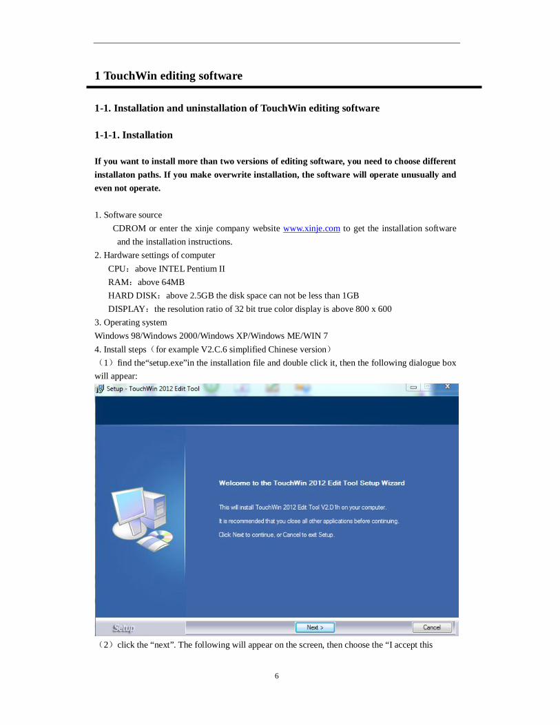
DISPLAY:the resolution ratio of 32 bit true color display is above 800 x 600 3. Operating system Windows 98/Windows 2000/Windows XP/Windows ME/WIN 7 4. Install steps(for example V2.C.6 simplified Chinese version) (1)find the“setup.exe”in the installation file and double click it, then the following dialogue box will appear:
(2)click the “next”. The following will appear on the screen, then choose the “I accept this

7
agreement” and click the “next”;
(3)Input the username, company name and serial number. Serial No. is “XinjeTouchWin”. (you can copy from the “serial_no.txt” in the software setup package) Then click the “next”.
(4)click the “browse” and set the software installation catalogue or use the default installation path, then click the “next”.

8
(5)click the “browse” and choose the shortcut path of creating the program in the start menu.
(6)click the “install” button according to guide. At last click the “finish” button to install the software successfully. (7)The following shortcut will appear on the desktop after finishing the installation. Please double click the icon to open the software.
9
1-1-2. Uninstall
1. Click the “start/program/ Thinget/TouchWin for TH/ unload” or double click “ ” in the
setup package. 2. According to the step one, click the “yes(Y)” to confirm to uninstall the software. 3. click the “confirm” button. After uninstalling the software, please delete the catalogue folder.
1-2. Installation and uninstall the USB download cable
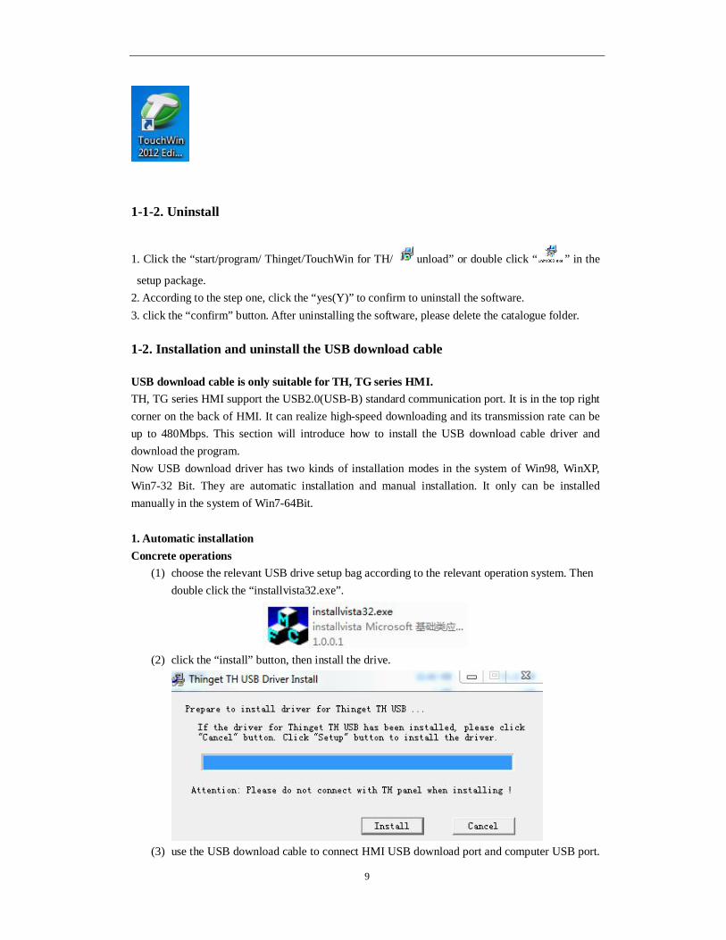
USB download cable is only suitable for TH, TG series HMI. TH, TG series HMI support the USB2.0(USB-B) standard communication port. It is in the top right corner on the back of HMI. It can realize high-speed downloading and its transmission rate can be up to 480Mbps. This section will introduce how to install the USB download cable driver and download the program. Now USB download driver has two kinds of installation modes in the system of Win98, WinXP, Win7-32 Bit. They are automatic installation and manual installation. It only can be installed manually in the system of Win7-64Bit. 1. Automatic installation Concrete operations
(1) choose the relevant USB drive setup bag according to the relevant operation system. Then double click the “installvista32.exe”.
(2) click the “install” button, then install the drive.
(3) use the USB download cable to connect HMI USB download port and computer USB port.

10
then give the HMI power again and download program. 2. Manual installation Concrete operation
(1) use the USB download cable to connect HMI USB download port and computer USB port. Then give the HMI power again. The catalogue box “find the guide of new hardware” will appear. Please choose “no” and click the “next”.
(2) Choose the “install from list or assigned address (advance)”, then click the “next”. (3) choose “include this place in the search” in the option of “search the best drive program in
those places”. Click the “browse” and find the relevant drive file. Click the “confirm”, then click the “next”.
Win98 system should choose Win98. WinXP and Win7-32Bit system should choose WinXP. Win7-64Bit system should choose Win7.
(4) Click the “finish” to install the drive successfully. (5) Download program.
3. Uninstall the USB download cable drive (1) Use the USB download cable to connect HMI USB download port and computer USB port. Then repower the HMI, and right click the “my computer” to choose “device manager”. Click the “universal serial bus controllers”, then you can see the information of installed USB drive such as “Thinget TH USB Device”. (2) According to above operation, choose the “Thinget TH USB Device”. Right click to choose “uninstall”. (3) Click the “confirm” button, then the drive will be uninstalled.

11
2 Simplified project manufacture
The characteristic of TouchWin editing software is simple and fast. It provides an ideal editing platform for beginners or those who have some basis. This chapter introduces the use method of HMI editing software by a simple project manufacture.
Please confirm the HMI type and the communication equipment type before making the screen. This is the premise of making the screen program and equipment operate normally.
2-1. create project
1. open the software and click the standard tool bar “ ” icon or “new” in the “file” menu. 2. Choose the correct HMI type.
3. Set PLC port and choose the correct PLC type and set the communication parameters.
4. Set download port. When Download port communicates without external equipment, please choose ”don’t use Download port”. When Download port communicates with external equipment, please choose the correct equipment type and set communication parameters.

12
5. Set expanded port like Download port. Please choose the “unused equipment” when expanded
port communicates without external equipment. Please choose the correct equipment type and set communication parameters when expanded port communicates with external equipment.
Only TH765-NT3, TH765-NU3 needs to set expanded port. Please pay attention to the
operation. 6. Input name, author and remarks according to requirement. Click the “finish” button at last, then
the project will be created.

13
2-2. Screen editing
We will make a simple button. The function is to set ON /OFF the PLC output terminal Y0. 1. Bit Button Click the menu “part/operate/bit button” or icon “ ”, click in the editing screen.
Object
Object type: set to “Y0”
operate Button operation: set to “reverse”.
button
text: input “reverse”
2. Lamp Click the menu “part/operate/lamp” or icon “ ”, click in the editing screen, and set attributes in the attribute catalogue box. object
object type: set to “Y0”.

14
2-3. Off-line simulation
To debug the program, you can simulate the program in the software without connecting the PLC.
1. Click the menu “file/off-line simulation” or icon “ ”
2. Click the “reverse” button. You can set ON and set OFF the Y0.
ON status OFF status
2-4. On-line simulation
Simulate practical operation situation of the HMI and PLC in the computer. Realize the monitoring function for lower-computer. (PLC should be connected to computer, and the operation time of on-line simulation should be within half an hour)
1. click the menu bar “file/on-line simulation” or “on-line simulation” icon “ ”, the following
catalogue box will appear. Please click the “ok” button to enter the simulation screen.
on-line simulation only support equipment of Modbus RTU protocol. Such as XINJE

15
PLC, XINJE inverter and so on.
2. Click the right key of mouse in the blank of screen. Choose the “Com Port” in the catalogue box, and set the PLC Port to the serial port of connecting to the computer. The other keep default. Close the “COM Port” catalogue box at last.
Log history record of logging in and quiting time About informations about AutoWin version Com Port the above catalogue box will appear. Set the computer serial port number which
is connected with HMI PLC port /Download port. Exit exit
3. Please click the right key of mouse in the blank area again after those operations above. Choose the “Exit” to exit current on-line simulation operation, then open the on-line simulation again to perform the simulation function for lower-computer PLC.
If “communicating” window appears in the on-line simulation screen, you need to check if the setting is correct for “PLC Port”. Then check if you open the simulation screen again after exiting simulation operation. Then check if the serial port is occupied by other softwares.
2-5. Program download
TouchWin software support two kinds of download style, and they are common download and complete download. Please choose the revelant download cable to download according to different kinds of HMI. This case uses USB download cable to download program. If you want to know the serial port download, please refer to the HMI hardware handbook.
2-5-1. Common download
Click the menu bar “file/download” or “download” icon “ ”, then you can download the program. This download style doesn’t have upload function.

16
2-5-2. Complete download
Click the “complete download” icon “ ”, then you can download the program. This download
style can upload the HMI program to computer.
the following versions can not support upload function
(1) V2.78 version doesn’t have complete download function. So the program can not be uploaded. (2) V2.99-V2.C.6 versions should set parameters in the software. Please choose the “complete download” in “tool/option”, and choose “complete download”. If the program has been downloaded to HMI and you didn’t set as above before downloading, program can not be uploaded into computer.
2-5-3. U flash disk download
Note: only suitable for V2.C.6d to V2.C.6i version software. TH(-U), TG(-U), TG(-E)series HMI has USB-A(USB2.0) port. You can use U flash disk to download HMI program to many HMI. The process of downloading is simple and fast. Suitable occasion: the local with machine has no computer or it is far away from office, no download cable, equipment need to upgrade and update program. Concrete operations: 1. Click “export project” in the “file” menu. 2. Following interface will appear in the editing screen. Please click “ok” button and export data.
3. According to the above operations, open the C:\ in the computer to find Export.dat and copy it into the U flash disk.
4. Set the third DIP switch of HMI to ON. Then repower the HMI, and the following picture will

17
appear in the screen.
5. Insert U flash disk ino the U flash disk port and click “import”. Set the third DIP switch of HMI to OFF after dowloading, and repower it to display program.
(1) The chosen type should be same as HMI when you are programming. (2) If the chosen type is wrong, click “import”. The interface of import program will not
appear and the alarm of inconsistent type will not appear also. (3) U flash disk download function only can be supported by V2.C.6d-V2.C.6i version
software. But this function is forbidden in the V2.C.6i version. So customer need to install 2C.6d version software if he wants to use the U flash disk download function. After installing the software, you need to download a empty program to use U flash disk download function. It is aimed at updating the lower-computer system. If not, the above import interface will not appear even if the third dial switch is ON.
(4) U flash disk download function, insert the U flash disk into the HMI. The U flash disk will import program to HMI automatically if there is no operation after 3s. You can not pull out the U flash disk in the process of importing. If not, the program can not be downloaded successfully.
(5) You need to use U flash disk which its capacity is less than 32G. (6) It doesn’t support mobile HDD.
2-6. Upload program
HMI support uploading project. It is useful for data resource management. Click the “upload” icon “ ” to upload program. Please make the operations in chapter 2-5-2 at first. If not, the message “project is inexistent” will appear.
No encryption You don’t need to input password. It is open to all customers
Encryption You need to input password to upload the project

18
3 Software screen and window
This chapter will have complete introductions of HMI editing software TouchWin.
Part of this handbook is based on primary function software. If you want to know advanced functions, please contact us to get advanced function manual.
3-1. Software structure
Project area about the basic operations, such as the creation, delete, copy, cut of screen
and window. Screen editing area project screen editing platform Menu bar It has seven teams of menu. It contains file, edit, check, component, tool,
window and help. Parts and buttons it contains tools such as standard, picture, operate, zoom, picture
adjustment, display, status, parts, etc. Status bar display HMI type, PLC port connection equipment, display informations
of download port connection equipment, etc.

19
3-2. Project area
Insert, cut, copy, paste and delete the screen, window.
3-2-1. Insert
Choose the project bar “screen” and click the right key of mouse. Please choose “insert” or click “ ” icon. The following attributes catalogue box will appear.
Screen number add the screen serial number and click ok, then the screen number can not
be changed. Screen name project screen define name. Screen background the background color of project screen. Prompt message input relevant screen note informations.
Please click “ ” icon to change the screen attributes.
3-2-2. Cut copy paste
1. Choose screen2, click the right mouse and choose “cut” or “copy”. 2. Choose project bar “screen”, and click the right mouse to choose “paste” to finish the operation.

20
3-2-3. Delete
Choose the screen which you want to delete and click the right mouse, then choose the “delete” or click “ ” icon to delete the screen.
The insert, cut, copy, paste, delete of window are the same.
3-3. Menu bar
3-3-1. File
File contains different kinds of operation such as create, open, close, save, download project data, simulation, export project, etc.
1. New
Please refer to chapter 2-1.
2. Open Click “file/open” or “ ” icon to open project.
3. Close Click “file/close” to close current project. But it doesn’t mean to exit TouchWin editing software.
4. Save Click “file/save” or “ ” icon to save the project.
You need to save at all times to prevent losing data at the process of editing screen.

21
5. Save as This operaton is different from “save”. “Save” uses new file to replace the old file based on the project. “Save as” save the current project at the form of new project. After the “save” catalogue box appears, please choose the saved path and input the file name and click “save” button.
6. Download Download the project in the HMI, click “ or ” icon to perform the same function.
Please refer to chapter 2-5. 7. Export project
Please refer to chapter 2-5-3. 8. Run online This function is similar to SCADA. Connect the PLC with the software; simulate the project functions in the software.
Please refer to chapter 2-4. 9. Run offline Simulate the project functions in Autowin software without connecting the PLC.
Please refer to chapter 2-3. 10. PFW set Initialize the PFW data after downloading program again. Click “file/PFW set”, and following catalogue box will appear.
set the address range of PFW

22
Start PFW set the start address of PFW register. End PFW set the end address of PFW register. Add click “add” after setting the start and end addresses. Then the set data range
will be listed in the data set list. Modify range when the start and end address need to modified, please change the start or
end address, then click modify range, the following message will appear, please click ok.
Modify data modify the register data in the set range.
Set the data of PFW. Choose the PFW register address range and click “modify data” or double click the PFW address range. Then the following window will appear.
Display data can be decimal or hex format. Reset 0: set all the data to 0. Set FF: set all the data to 65535(HFF).
The first address of data begins with PFW256, and PFW0~PFW255 is internal system data which is not allowed to modify. Specific content please refer to the chapter 5.
11. Setting

23
Parameter
Screen Define the start screen No. when the HMI start. When downloading and repowering,
the first sreen is generally the main screen or the most used screen. Password password has the function of protecting data to improve security of program. Project password has nine levels. The range is from level 1 to 9. The first level is the lowest priority, and the 9th level is the highest priority). Level 9 password can open all the password from level 1 to 9. Level 1 only can open its own password. Level 2 can open level 1 and 2 password… Screen save When there is no operation for a long time, the HMI will close the backlight
or jump into the assigned screen. Latency time you can choose the waiting time according to your request or you can also choose no screen protection.
Close LCD when time is up to your waiting time, the backlight will be closed. Show screen when the time is over, it will jump to the certain screen.
Alternation

24
Change screen control jump screen according to the data of register; for example, the register data is 10, it means to jump to screen ID10. System will clear the data of register to 0 after jumping screen. Device current equipment port of communicating Virstano communication equipment address No. Object set the object style and address No. of register controlling screen transform. Station No. Connected equipment No. Indirect current register address changes by the data of indirect designated register. Dx[Dy]=D[x+Dy data],(x, y=0,1,2,3……)
report current screen ID display the number of current screen. for example, if the current screen is 7, the register will display 7. Device current equipment port of communicating Virstano communication equipment address No. Object set the object style and address No. of reporting current screen number register. Station No. Connected equipment No. Indirect current register address changes by the data of indirect designated register. Dx[Dy]=D[x+Dy data],(x,y=0,1,2,3……)
virtual station: it is not open to use for all components. Follow-up no longer need.

25
clock
Use RTC this function will export current time to related equipment for saving data.
Device current equipment port of communicating Virstano communication equipment address No. object set the object style and first address No. of exporting clock register; if the address is set to D0, D0~D6 will display year, month, day, hour, minute, second and week. They occupy seven register addresses station connected equipment No. indirect current register address will change by the data of indirect designated register. Dx[Dy]=D[x+Dy data] ,(x,y=0,1,2,3……)
Time display is in hex format. Panel
Model display current HMI types. If you want to modify the display type and choose
new display type, please click “ok” to make it effective. description display current screen size and pixel;

26
Set parameter set the internal spaces of HMI and you can modify the number of PFW register and PSW register.
PFW number set the total number of PFW in storage area PSB number set the total number of PSB in storage area Visible PSW number normal PSW number. Such as data area of data input and display,and
so on. Invisible PSW number internal storage number of data. Such as the automatic data
storage area of historial trend diagram and real-time trend diagram. Cache number number of PFW data cache register
Specific contents of PSW, PFW, PSB, please refer to the fifth chapter. Zoom when you are changing display type. Proportional relationship of component’s width
and height size and display size in the screen. Same size width and height value of components unchanged Same ratio zoom the width and height value of components according to aspect ratio of
display. Small ratio zoom the width and height value of component according to the lowest aspect
ratio of display. Big ratio zoom the width and height value of component according to the highest aspect
ratio of display. Device

27
Single control system is one screen one machine or one screen many machines. Adjust
HMI to unit mode. Host net control system is many screens one machine or many screens many machines.
This HMI is in the master mode. Slave net control system is many screens one machine or many screens many machines.
This HMI is in the slave mode. PLC port
Model PLC port connected equipment type
Parameter bit rate, data bit, verification mode, stop bit display. Click “ ” to
modify parameters. Download port
Model Download port connected equipment type. “Don’t use Download port” in default situation. It means that Download doesn’t participate in communication of external equipment.
Parameters bit rate, data bit, verification mode, stop bit display. Click “ ” to modify
parameter.
Expand device This content is mainly related to system attribute of HMI and equipment which is connected with HMI by expanded port.

28
TH765-NT3 and TH765-NU3 have expand port. Font This function is used to set input font of project screen. The font can be modified by “settings”.
This setting is only effective for input real-time event display and historical event display of components.
project This attribute records project informations, such as name, writer and remarks of this project.

29
12. Build SCADA Its function is the same to on-line simulation. Steps: Open “file/build SCADA”. Please choose saving path. The AutoWin file will be generated.
Double click “ ”, then you can simulate the HMI project in the software.
please refer to chapter 2-4 for details.
13. Last If you have opened or edited some projects recently, software will save names of these projects automatically. It will help you find them faster and you don’t need to check their paths any more. Please you can click the editing project name to edit.
14. Exit This function is used to exit TouchWin editing software, but it is different from the “close” operation. If you don’t save the project, the saving window wil appear to prevent losing operation.
3-3-2. Edit
Editing menu is used for editing component. “cut, copy, paste and cancel” is corresponding to shortcuts of standard tool bar. As the following picture:
from left to right: cut, copy, paste and cancel
from left to right: public unit, private unit
Please refer to chapter 4-1-1 for details. Replacement
30
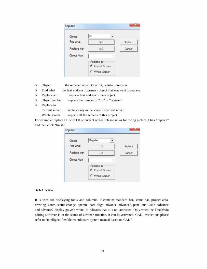
Object the replaced object type: bit, register, nregister Find what the first address of primary object that you want to replace. Replace with replace first address of new object Object number replace the number of “bit” or “register” Replace in
Current screen replace only in the scape of current screen Whole screen replace all the screens of this project
For example: replace D5 with D0 of current screen. Please set as following picture. Click “replace” and then click “finish”.
3-3-3. View
It is used for displaying tools and columns. It contains standard bar, status bar, project area, drawing, zoom, status change, operate, part, align, advance, advance2, panel and CAD. Advance and advance2 display grayish white. It indicates that it is not activated. Only when the TouchWin editing software is in the status of advance function, it can be activated. CAD instructions please refer to “intelligent flexible manufacture system manual based on CAD”.
31
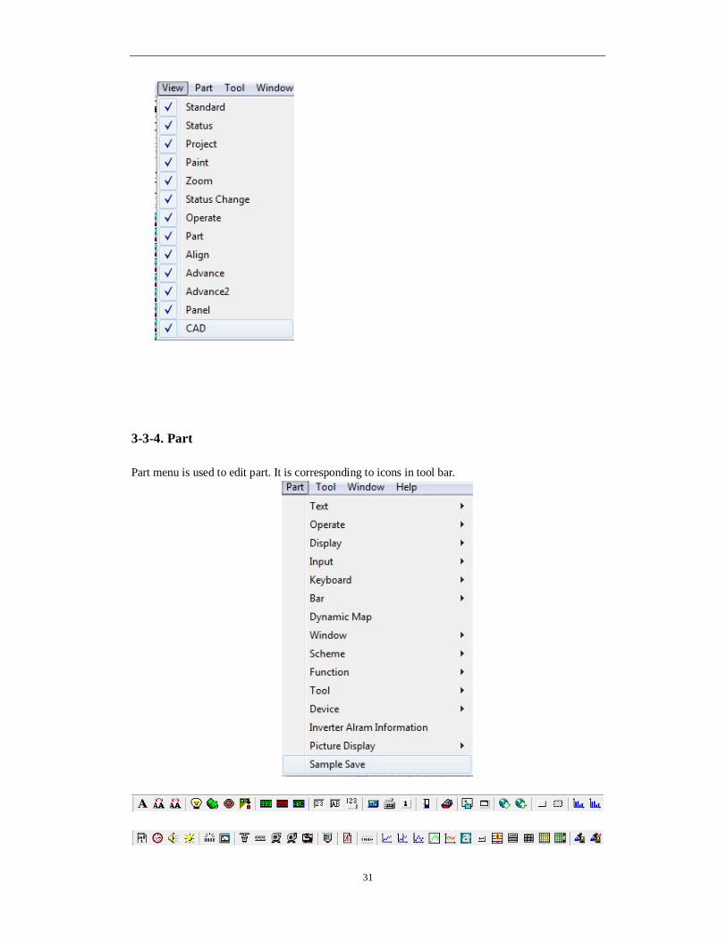
3-3-4. Part
Part menu is used to edit part. It is corresponding to icons in tool bar.

32
Please refer to chapter 4-3 for details.
3-3-5. Tool
This content contains basic tool segment, rectangle, ellipse, fold, map and options. The front five options are corresponding to tools in drawing bar. You can make the frame, polygon block and so on by cutshorts in drawing bar.
Option This content refers to special settings, such as displaying, downloading data and uploading data, etc.
grid size
move grid least grid number when moving object. Grid ratio set density of grid in screen. The smaller values are, the denser they will be.

33
For example: when the “display grid” is changed from “20” to “5”, difference is as follow::
Display grid: 20 display grid: 5
Auto save you can set the automatic saving time to prevent losing data when launching this option. You can also save project data manually without lauching this option.
Download port default communicatin port first choice when you are downloading data.
TW Display mouse cursor check if display mouse in the screen according to TW series. Hit key errors touch sensitivity
print top to bottom/bottom to top set printing direction
other Undo enable the undo operations optimize enable optimization operation for download serial port build and exit enable compiling function block when exiting. User mode open or close advance function.
3-3-6. window
Window menu is mainly used to edit screen window. It contains create window, cascade, tile and arrange icon.
New creat a new screen cascade arrange all the opening screen in the mode of cascade tile arrange all the opening screen in the mode of tile arrange icons arrange the icons
3-3-7. Help
Version and copyright information of software or click “ ” icon.

34
3-4. Screen editing area
You can right click the part in the screen editing area.
Property part setting, such as “display”, “font”, “color” and “location”, etc. Lock relative position lock. After operation, this component can not be moved.
You can realize the moving function by “unlock”. Public unit the unit can be used in all the screen cut cut the part copy copy the part delete delete the part save save current part into material store, and you can directly use it from material
store.
3-5. Tool bar
Tool bar refers to all the operations about parts and screen. Relative font will appear when you move the mouse to relative component in operation. The specific distribution is as follows:
Drawing tool bar: line, animation, webpage, etc. webpage can only operate simulation or configuration.
Material store: add and save materials which are manufactured at the time of editing project.

35
Parts tool bar: it contains font, operation key, display, input, keypad, bar, dynamic map,window, recipe, function, continue column map, etc.
specific content about parts tool bar please refer to the fourth chapter.
Display tool bar: it contains basic tool, equipment, inverter alarm information, picture display, saving collected data, etc.
Standard tool bar: it contains new, open, save, cut, copy, paste, cancel, about, etc.
Status tool bar: it contains button status, animation status,etc.
Picture adjustment tool bar: it contains align left, align centre, align right, align top, align middle, align bottom, etc.
Operation tool bar: it contains public unit, private unit, create screen, screen attribute, delete, off-line simulation, on-line simulation, download, upload, complete download, etc.
Zoom tool bar: it contains zoom out screen, display proportion selection, zoom in screen, grid display, etc.
3-6. Status bar
Display current HMI type, PLC port communication device; coordinate position of the mouse in the editing screen, etc.

36
4 Parts
4-1. Overall operation
Overall operation will main refer to the following tool bar.
4-1-1. Standard tool bar
1. cut “ ”
Choose target object and cut it to shear plate. Choose target element or many elements at operation, then click “ ”. 2. copy“ ” Choose target element and copy it. Choose target element or many elements at operation, then click “ ”. The difference with cut is: the cut operation makes the original component not exist, but the original component still exists after copy operation. 3. paste“ ” It is the operation of “cut” and “copy”. When you do “paste” operation after cutting or coping object element, you have moved or copied successfully. 4. cancel“ ” Recover historical operation by “cancel” button. This operation can not be used aquiescently. You need to choose “cancel”of “option” in the “tool” manually.
Specific content about “ ” and “ ”, please refer to chapter 3-3-1 and 3-3-7.
4-1-2. Operation tool bar
Specific content about “ ” please refer to the second chapter.
1. Public unit “ ”
The part can be used to all project screens. It is the same to copying part to all screens. 2. Private unit “ ” This part is only effective for current screen. It is the same to deleting the same part which is copied to other page.
3. Create screen“ ”

37
Specific content please refer to chapter 3-2-1
4. Screen attribute “ ”
Choose the screen name which is needed to be modified in project bar. Click “ ” icon in the
overall tool bar to open catalogue box of screen attribute, then you can modify screen attribute in it.
Project bar screen attribute
For the built screen, its number can not be modified.
5. delete screen“ ”
Specific content please refer to chapter 3-2-3.
4-1-3. Picture adjustment
It is mainly used to arrange globality of chosed elements.
“Align tool bar”can only be used when two or more than two elements are chosed at the same time. If not, the tool bar will be grey. It means that it can not be used.
For example:as the following picture, elements don’t arrange in a line in the screen. You can
choose all of them and click align midde “ ”.
Before align

38
After alignment
4-1-4. Zoom tool bar
edit display proportion of screen
zoom out editng screen according to proportion
zoom in editing screen according to proportion
display grid
4-1-5. Status tool bar
1. “ ” can reverse the status.
For example: indicator light “ ” in the screen. Choose this element to reverse the status of ON
and OFF by “ ”.

39
OFF status ON status
2、“ ”can choose the status of dynamic picture. There are 32 kinds of status display.
For example: it is dynamic picture “ ” in the screen. You can display relative status in the
screen by choosing status number. Below is the display of “0” status and “20” status.
“0”status “20”status
4-2. Drawing tool bar
Drawing tool bar contains line, arc, rectangle, round rectangle, ellipse, fold, polygon block, frame, map, web, move animal, rotate animal. Web is used in configuration to log in a website or open a designated path. Here we don’t describe detailly. Move animal and rotate animal is refered to the application of advance function. Specific instructions please refer to “HMI advance function manual”.
4-2-1. Line
1. Click the “ ” icon in the drawing tool bar, and drag the left mouse. Then move the cursor to
the end to release the left mouse. If you need to cancel this operation, please press “ESC” or click the right mouse.

40
This line can move location, change the size, rotate angle, etc. 2. Double click “line” or choose “line”, then click right mouse. Choose “attribute” or set the attribute by “ ” button. line
Pattern “real line”, it can not be modified. Thick change thick of line according to the value. The greater the value, the greater the
width.(integer between 0 and 255) light without this function now color
kind choose the color type which is need to be modified. color set the color of the kind. position
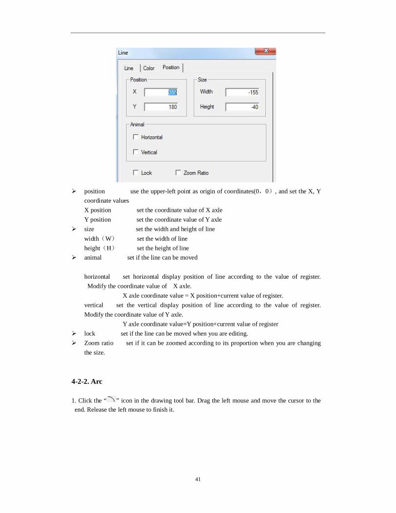
41
position use the upper-left point as origin of coordinates(0,0), and set the X, Y coordinate values X position set the coordinate value of X axle Y position set the coordinate value of Y axle
size set the width and height of line width(W) set the width of line height(H) set the height of line
animal set if the line can be moved
horizontal set horizontal display position of line according to the value of register. Modify the coordinate value of X axle.
X axle coordinate value = X position+current value of register. vertical set the vertical display position of line according to the value of register. Modify the coordinate value of Y axle. Y axle coordinate value=Y position+current value of register
lock set if the line can be moved when you are editing. Zoom ratio set if it can be zoomed according to its proportion when you are changing
the size.
4-2-2. Arc
1. Click the “ ” icon in the drawing tool bar. Drag the left mouse and move the cursor to the end. Release the left mouse to finish it.

42
Start point, end point move this point to change length of arc Boundary point move boundary point to change the width and length of arc
2、double click “arc” or click right mouse, and choose “attribute” or set the attribute by “ ”
button. line
pattern “real line”, it can not be modified. thick change the width of line according to the value. The greater the value, the greater
the width(integer between 0 and 255).
Port
start point set to display the horizontal and vertical coordinate position of arc. End point set to display the horizontal and vertical coordinate position of arc. Angle set the angle of arc.
Starting angle the central point of arc is the basic point. Make the direction of
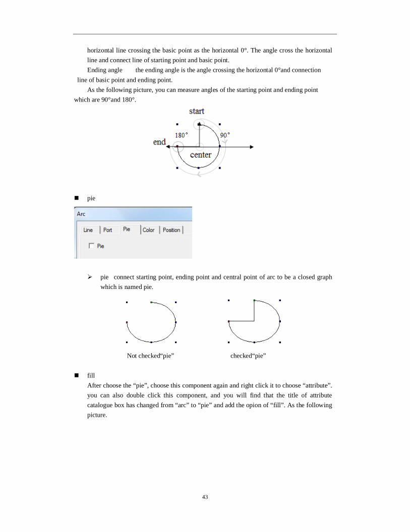
43
horizontal line crossing the basic point as the horizontal 0°. The angle cross the horizontal line and connect line of starting point and basic point. Ending angle the ending angle is the angle crossing the horizontal 0°and connection
line of basic point and ending point. As the following picture, you can measure angles of the starting point and ending point
which are 90°and 180°.
pie
pie connect starting point, ending point and central point of arc to be a closed graph which is named pie.
Not checked“pie” checked“pie”
fill After choose the “pie”, choose this component again and right click it to choose “attribute”. you can also double click this component, and you will find that the title of attribute catalogue box has changed from “arc” to “pie” and add the opion of “fill”. As the following picture.

44
None the interior of pie is performed as transparent. Solid choose the target tone from the pull-down list and you can choose the tone
you need or customer color from “more”. Dot fill the internal of pie in the form of punctiform pattern. The greater the points,
the greater the intensive degree; Meek choose target tone and the desalt proportion of starting tone should be 0%.
When the desalt proportion is positive value, the tone will be desalted. When the proportion is negative value, the tone will be deepening.
Hatch the internal of pie is filled in the form of pattern. Origin point coordinate the origin point position of pattern contains X ordinate and Y
ordinate. Foreground color choose the own tone of pattern Background color choose the filled bottom color of pattern.
Linear First color the tone choosing of starting point of graph Last color the tone choosing of ending point of graph Direction of gradual change you can choose the gradual change type and direction of
color. You can also set the angle value of “angle setting”. style color the tone of color is as same as starting color style type choose the filling mode of tone
Centerar Central color choose the central tone of filling object Border color choose the border color of filling object Central point X-% the relative position of central point X axle Central point Y-% the relative position of central point Y axle Ratio X-% X direction proportion occupied by central point RatioY-% Y direction proportion occupied by central point

45
color
kind choose the color type which need to be modified color set the type color which is chosed by you
position
position make the upper left point to be the origin point coordinate(0,0), and
set the coordinate value of arc X and Y. X position set the axle coordinate value of arc X Y position set the axle coordinate value of arc Y
size set the width and height of arc width(W) set the width of arc height(H) set the height of arc
animal set if the arc can be moved Horizontal set the horizontal position of arc according to the register value. Modify the X axle coordinate value. X axle coordinate value=X position+current value of register Vertical set the vertical position of arc according to register value. Modify the Y axle coordinate value. Y axle coordinate value=Y position+current value of register
Lock set if the arc can be moved when editing. Zoom ratio set if it can be zoomed when editing its size.

46
4-2-3. Rectangle
1. Click the “ ” icon in the drawing tool bar. Drag the left mouse at the starting point. Move the curser to the end and release the left mouse to finish it.
Starting point and ending point move this point to change the length and width of
rectangle by equal proportion. Boundary point move this point to change the width or height of rectangle. 2. Double click“rectangle” or choose “rectangle” and click the right mouse. Choose “attribute” or set the attribute by “ ” button. line
Pattern it is “real line”. It can not be modified Thick change the line thick according to the value. The greater the value, the greater the
width. (integer between 0~255)
color
kind choose the color type which need to be modified. color set the color of the chosed type

47
fill
None the interior of pie is performed as transparent. Solid choose the target tone from the pull-down list and you can choose the tone
you need or customer color from “more”. Dot fill the internal of pie in the form of punctiform pattern. The greater the
points, the greater the intensive degree; Meek choose target tone and the desalt proportion of starting tone should be 0%.
When the desalt proportion is positive value, the tone will be desalted. When the proportion is negative value, the tone will be deepening.
Hatch choose target tone and the desalt proportion of starting tone should be 0%. When the desalt proportion is positive value, the tone will be desalted. When the proportion is negative value, the tone will be deepen.
Linear Starting color the tone choosing of starting point of graph Ending color the tone choosing of ending point of graph Direction of gradual change you can choose the gradual change type and direction of
color. You can also set the angle value of “angle setting”. style color the tone of color is as same as starting color style type choose the filling mode of tone
Centerar Central color choose the central tone of filling object Border color choose the border color of filling object Central point X-% the relative position of central point X axle Central point Y-% the relative position of central point Y axle Ratio X-% X direction proportion occupied by central point RatioY-% Y direction proportion occupied by central point

48
position
position make the upper left point to be the origin point coordinate(0,0), and
set the coordinate value of arc X and Y. X position set the axle coordinate value of arc X Y position set the axle coordinate value of arc Y
size set the width and height of arc width(W) set the width of arc height(H) set the height of arc
animation set if the arc can be moved Horizontal set the horizontal position of arc according to the register value. Modify the X axle coordinate value. X axle coordinate value=X position+current value of register Vertical set the vertical position of arc according to register value. Modify the Y axle coordinate value. Y axle coordinate value=Y position+current value of register
Lock set if the arc can be moved when editing. Zoom ratio set if it can be zoomed when editing its size.
4-2-4. Round rectangle
1. Click the“ ”icon in the drawing tool bar. Drag the left mouse at the starting point. Move the cursor to the ending point and release the left mouse to finish it.
Starting point and ending point move this point to change the length and width of
rectangle by equal proportion. Boundary point move this point to change the width or height of round rectangle.

49
2. Double click the “round rectangle” or choose “round rectangle” and click right mouse to choose “attribute” or set the attribute by “ ” button. line
pattern It is “real line” and can not be modified thick change the width of line according to value. The greater the value, the greater the
width. (integer between 0~255) round rectangle
Round diameter modify by inputing value. Greater the value, greater the round diameter.
color
kind choose the type of color which need to modify color set the color of kind

50
fill
none graph’s inside will lucidly display solid choose the target color by pull-down list. You can choose the color which
you chose by “more”. dot fill the graph’s inside with dots. Dot’s value decides the dot density. meek choose the target color. Desalt proportion of original color is 0%. When the
proportion is positive value, the color will be desalted. When it is negative value, the color will be deepening.
hatch fill round rectangle’s inside with hatch. Origin coordinate graph’s origin coordinate. It contains positions of horizontal and
vertical coordinate. Fore color choose the graph’s color Back color choose the graph’s back color
linear first color choose the graph’s first color last color choose the graph’s last color linear direction you can choose the linear type and direction of color and also can set
agle value by “set angle”. Style color color tone is as same as first color. Style kind choose the filling mode.
centerar center color choose the center color of filling object brink color choose the brink color of filling object center pointX-percentage relative position of center point X center pointY- percentage relative position of center point Y ratioX- percentage X direction ratio occupied by center point ratioY- percentage Y direction ratio occupied by center point

51
position
position make the upper left point in screen as the origin point (0, 0) and set X, Y
coordinate value of round rectangle. X position set X coordinate value of round rectangle. Y position set Y coordinate value of round rectangle.
size set the width and height of round rectangle. width(W) set the width of round rectangle height(H) set the height of round rectangle
animal set if the round rectangle can be moved Horizontal set the horizontal position of round rectangle according to register value, modifing the X coordinate value. X coordinate value=X position+current value of register
vertical set the vertical position of round rectangle according to register value, modifying the Y coordinate value.
Y coordinate value=Y position+current register value lock set if round rectangle can be moved when editing it. Zoom proportion set if it can be zoomed when changing its size. Now this function can
not work.
4-2-5. Ellipse
1. Click “ ” icon in drawing tool bar. Drag the left mouse at the first point. Move the cursor to the end and release left mouse to finish it.

52
First point, boundary point, last point edit width or height of ellipse by these points 2. Double click “ellipse”, or choose “ellipse” and right click the mouse. Then choose “attribute” or set attribute by “ ” button. line
Pattern it is “real line” which can not be modified. Thick change width of line according to value. Greater the value, greater the width.
(integer between 0~255)
color
kind choose the color kind which need to be modified. color set the color of the kind fill set if ellipse need to be filled with fill color.

53
fill
none graph’s inside will lucidly display solid choose the target color by pull-down list. You can choose the color which
you chose by “more”. dot fill the graph’s inside with dots. Dot’s value decide the dot density. meek choose the target color. Desalt proportion of original color is 0%. When the
proportion is positive value, the color will be desalted. When it is negative value, the color will be deepen.
hatch fill round rectangle’s inside with hatch. Origin coordinate graph’s origin coordinate. It contains positions of horizontal and
vertical coordinate. Fore color choose the graph’s color Back color choose the graph’s back color
linear first color choose the graph’s first color last color choose the graph’s last color linear direction you can choose the linear type and direction of color and also can set
agle value by “set angle”. Style color color tone is as same as first color. Style kind choose the filling mode.
centerar center color choose the center color of filling object brink color choose the brink color of filling object center pointX-percentage relative position of center point X center pointY- percentage relative position of center point Y ratioX- percentage X direction ratio occupied by center point ratioY- percentage Y direction ratio occupied by center point

54
position
position make the upper left point in screen as the origin point (0, 0) and set X, Y
coordinate value of round rectangle. X position set X coordinate value of round rectangle. Y position set Y coordinate value of round rectangle.
size set the width and height of round rectangle. width(W) set the width of round rectangle height(H) set the height of round rectangle
animal set if the round rectangle can be moved Horizontal set the horizontal position of round rectangle according to register value, modifing the X coordinate value. X coordinate value=X position+current value of register vertical set the vertical position of round rectangle according to register value, modifying
the Y coordinate value. Y coordinate value=Y position+current register value
Lock set if round rectangle can be moved when editing it. Zoom proportion set if it can be zoomed when changing its size. Now this function can
not work.
4-2-6. Fold - polygon
The difference between fold and polygon is whether it is closed. 1. Click “ ” icon in the drawing tool bar and press left mouse at the first point. Move the cursor and confirm positions of endpoints. When it is the last endpoint, please click left mouse to finish it.

55
2. Double click “fold” or choose “fold”, then click right mouse to choose “attribute or set the attribute by “ ” button. line
Pattern it is “real line” which can not be modified. Thick change the width of line according to its value. Greater the width, greater the
value. (integer between 0~255) color
kind choose the kind of color you want to modify color set the kind of color polygon

56
polyline its mode is polyline. When you don’t choose it, the polyline will connect first point and last point to be a polygon. Then it will fill the polygon area in default filling pattern.
Choose “polygon” don’t choose“polygon” modify coordinate set the first point as the starting point. List the coordinates in the
form in the order according to paths. Choose the coordinate of object point. Input relative X, Y coordinates and press “enter” key to be effective.
revolve click this button to set the revolve angle of polyline click the “revolve” button in “polyline”. Following catalogue box will appear
Input the value of target angle. (positive value is anticlockwise revolve and negative value is clockwise revolve) then you can click “confirm”.
fill Don’t choose “fold” and confirm it. Then choose this component to click right mouse to choose “attribute” or double click this component directly. Then you will find that the title of catalogue box has been changed from fold to polygon. Add the “fill” option.

57
none polygon’s inside will lucidly display solid choose the target color by pull-down list. You can choose the color which
you chose by “more”. dot fill the graph’s inside with dots. Dot’s value decide the dot density. meek choose the target color. Desalt proportion of original color is 0%. When the
proportion is positive value, the color will be desalted. When it is negative value, the color will be deepen.
hatch fill round rectangle’s inside with hatch. Origin coordinate graph’s origin coordinate. It contains positions of horizontal and
vertical coordinate. Fore color choose the graph’s color Back color choose the graph’s back color
linear first color choose the graph’s first color last color choose the graph’s last color linear direction you can choose the linear type and direction of color and also can set
agle value by “set angle”. Style color color tone is as same as first color. Style kind choose the filling mode.
centerar center color choose the center color of filling object brink color choose the brink color of filling object center pointX-percentage relative position of center point X center pointY- percentage relative position of center point Y ratioX- percentage X direction ratio occupied by center point ratioY- percentage Y direction ratio occupied by center point

58
position
position set the upper left point in the screen to coordinate point(0,0), and set the X and Y coordinate value of fold and polygon. X position set the X coordinate value of fold and polygon. Y position set the Y coordinate value of fold and polygon.
size set the width and height of fold and polygon. width(W) set the width of fold and polygon height(H) set the height of fold and polygon
animal0 set if the fold and polygon can be moved. Horizontal set the horizontal position of fold and polygon according to register value, modifying X coordinate value. X coordinate value X position+current value of register Vertical set the vertical position of fold and polygon according to the register value, modifying Y coordinate value.
Y coordinate value=Y position+current value of register lock set if the fold and polygon can be moved when editing. Zoom proportion set if it can be zoomed when editing its size. This function can not
work.
4-2-7. Block
Change the area size occupied by color block in the polygon by setting the block value. 1. Click “ ” icon in the drawing tool bar. Press left mouse at the first point and confirm the position of top point. Then loosen the left mouse and confirm the position of second point. According to top point number, do this operation repeatedly. Please double click left mouse at the end. At this time the end and the first point will connect automatically to finish the drawing of “block”.

59
2. Double click “block” or choose “block” and click the right mouse to choose “attribute” or set the attribute by “ ” button. Polygon block
Direction choose the filling direction of block. Block the value of block For example: choose the direction “from up to down” and set the block value to “50”.
color
kind choose the kind of color color set the color of the kind

60
position
position set the upper left point in the screen as the coordinate point(0,0), and
set the X and Y coordinate value of block. X position set the block X coordinate value. Y position set the block Y coordinate value.
size set the width and height of block width(W) set the width of block height(H) set the height of block
animal set if the block can be moved Horizontal movement set the horizontal position of block according to register value, modifying X coordinate value. X coordinate value=X position+current value of register Vertical movement set the vertical position of block according to register value, modifying Y coordinate value. Y coordinate value=Y position+current value of register
set if the block can be moved when editing . Zoom proportion set if the size can be zoomed when editing its size. This function can not
work.
4-2-8. Frame
1. Click the “ ” icon in the drawing tool bar. Keep pressing the left mouse at the first point andmove the mouse to make a path of rectangle. Then loosen the left mouseasssss at the end point. No the frame has been finished.

61
Edit the length, width and other attributes according to the modification of first point, boundary point and end point. 2. doubel click “frame” or choose “frame” and click right mouse to choose “attribute” or set theattribute by “ ” button. color
kind choose the type of color which need to be modified. color set the color of the kind. Fill set if the frame needs to be filled with color.
position

62
position set the upper left point as the coordinate point (0,0). Set the X and Y coordinate values of frame. X position set the X coordinate value of frame Y position set the Y coordinate value of frame
size set the width and height of frame width(W) set the width of frame height(H) set the height of frame
animal set if the frame can be moved. Horizontal set the horizontal position of frame according to register value, modifying the X coordinate value. X coordinate value=X position+current value of register. Vertical set the vertical position of frame according to register value, modifying the Y
coordinate value. Y coordinate value=Y position+current value of rigster
lock set if the frame can be moved zoom proportion se if it can be zoomed when editing its size. This function can not
work now.
4-2-9. Insert map
Realize the insert function of screen in HMI by this function.
1. Click “ ” icon in the drawing tool bar. When the cursor is cross-shaped, please press the left
mouse to open the window of inserting paths. 2. Choose the goal display picture. (Now it support pictures of BMP and JPG form) Click “open” or double click the goal picture. Then it will be added to current screen automatically and its size and position can be moved freely as the following picture.
3. Double click the ‘picture” or choose “picture” and click right mouse. Then set the attribute by “attribute” or “ ” button. picture
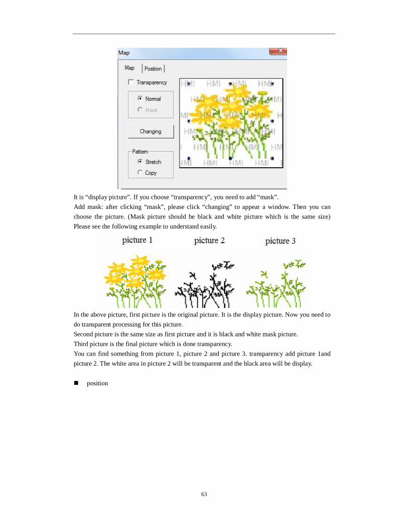
63
It is “display picture”. If you choose “transparency”, you need to add “mask”. Add mask: after clicking “mask”, please click “changing” to appear a window. Then you can choose the picture. (Mask picture should be black and white picture which is the same size) Please see the following example to understand easily.
In the above picture, first picture is the original picture. It is the display picture. Now you need to do transparent processing for this picture. Second picture is the same size as first picture and it is black and white mask picture. Third picture is the final picture which is done transparency. You can find something from picture 1, picture 2 and picture 3. transparency add picture 1and picture 2. The white area in picture 2 will be transparent and the black area will be display.
position

64
position set the upper left point in the screen as coordinate point (0, 0). Set the X and
Y coordinate value of picture. X position set the X coordinate value of picture. Y position set the Y coordinate value of picture.
size set the width and height of picture. width(W) set the width of picture height(H) set the height of picture
animal set if the picture can be moved horizontal set the horizontal position of picture according to register value, modifying X
coordinate value. X coordinate value=X position+current value of register vertical set the vertical position of picture according to register value. Y coordinate value=Y position+current value of register.
lock set if the picture can be moved when editing it. Zoom ratio set if it can be zoomed when editing its size. This function can not work now.
4-2-10. Move animation
This function can make animation with other parts.
1. Click icon in the menu, draw the animation track. Left click mouse to draw the track, left
click mouse again to draw the second track, double click mouse to finish the drawing.

65
2. Double click move animation to open the attribute window. Coordinate
coordinate the coordinate of animation X the position of X-axis Y the position of Y-axis
Escape time the time from one position to another, the unit is second. Control
Enable the animation is activated by the coil. When the coil is on, the animation starts to move.
Reset when the coil is on, the animation will move from the starting position. Repeat repeat moving the animation

66
4-2-11. Rotate animation
1. Click and put it in the screen. Right click it or press ESC to cancel.
2. Double click the rotate animation to open the attribute window. Animation clip
Material the pictures of animation, it can contain many pictures Add open material library to add new picture and set the picture position Delete delete the pictures Modify open the material library, change the picture and the position Move up move up the picture Move down move down the picture Preview display the picture

67
Animation
Period the time to finish the animation, the time can be set through register or constant Enable please always choose this item to ensure the animation can work. Register
control means the animation can work when the coil is ON. Reset when the rising edge of signal is coming, the animation will start again. Random switch the pictures as the order defined by user Continue switch the pictures as the default order Single switch the pictures from first to final one, then from first to final one again. Trip switch the pictures from first to final one, then from the final to first one, then
from the first to final one… Repeat repeat the switching picture operation Coil control when the coil is ON, the animation is visible. When the coil is OFF, the
animation is invisible.

68
Position
Position set the coordinate of animation according to the origin on the upper left corner X the X-axis coordinate Y the Y-axis coordinate
Size set the width and height of animation Width the width of animation Height the height of animation
Animal the move direction of animation Horizontal horizontal moving the animation. Set the X-axis position through register. X coordinate = X position + current register value Vertical vertical moving the animation. Set the Y-axis position through register. Y coordinate = Y position + current register value
Lock lock the animation, it cannot move
4-2-12 Material library
Click “ ” icon in the drawing tool bar. Then the dialogue box of choosing picture will appear. It is as follow.

69
You can click “add file” or “delete file” to add or delete folder. Choose the picture in the right side, click open to insert it in the screen. Click “add
material” or “delete material” to add or delete the picture.
4-3. Component tool bar
Component tool bar contains all basic buttons of data processing.
From left to right: text, dynamic text, variational text, lamp, button, lamp button, screen jump, digital display, alarm display, tet display, digital input, text input, set data, digital keyboard, ASCII keyboard, user input, bar, dynamic map, call window, window button, down recipe, up recipe, function button, function field, discrete column map and continue column map.
4-3-1. Text
1. Click “ ” icon in the component tool bar. Move the cursor to the screen and click left mouse to place it. Then click right mouse or ESC button to cancel it. Modify the height and width of text by boundary point.
2. Double click “text” or choose “text” and click right mouse. Then set the attribute by choosing “attribute” or “ ” button. display
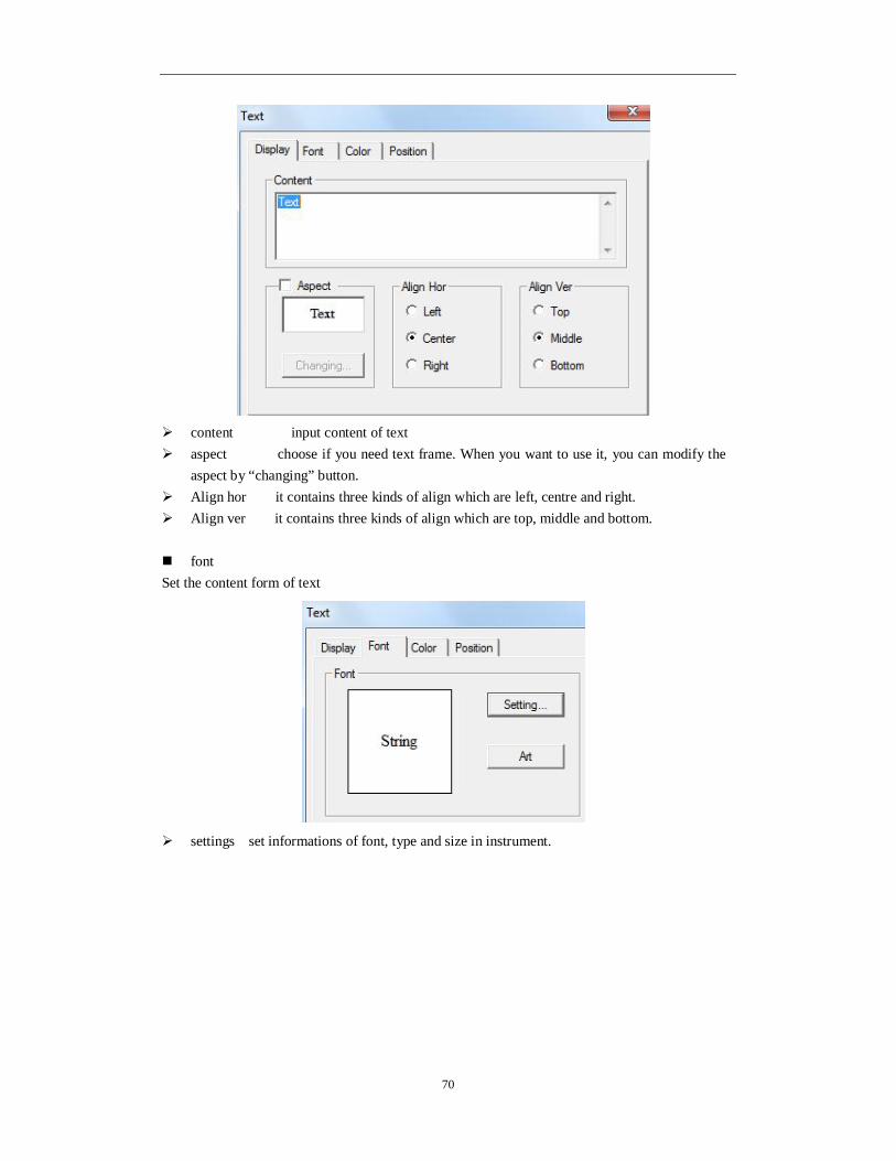
70
content input content of text aspect choose if you need text frame. When you want to use it, you can modify the
aspect by “changing” button. Align hor it contains three kinds of align which are left, centre and right. Align ver it contains three kinds of align which are top, middle and bottom. font Set the content form of text
settings set informations of font, type and size in instrument.

71
art set the art type of displaying font in instrument.
color

72
kind choose the type of color in text. color modify the color according to the kind.
position
position set the upper left point in screen as coordinate point (0, 0). Set the X and Y
coordinate value of text. X position set the X coordinate value of text. Y position set the Y coordinate value of text.
Size set the width and height of text. width(W) set the width of text height(H) set the height of text
animal set if text can be moved horizontal set the horizontal position of text in screen according to register value, modifying X coordinate value. X coordinate value=X position+current value of register vertical set the vertical position of text in screen according to register value, modifying Y coordinate value. Y coordinate value=Y position+current value of register.
lock set if the text can be moved in screen. zoom ratio set if it can be zoomed when editing its size. This function can not work
now.
4-3-2. Dynamic text
Dynamic text can transfer the displaying content by values of relative link register. 1. Click “ ”icon in component tool bar. Move the cursor to the screen and click the left mouse
to place it. Please click right mouse or ESC button to cancel it. You can modify the height and width of text area by boundary points.

73
2. Double click “dynamic text” or choose “dynamic text” and click right mouse. Then set the attribute by choosing “attribute” or “ ” button. object
station
device current device port which is communicating. station address number of communication equipment.
object set the object type and address number of dynamic text. indirect set the offset of current address as following picture.
Current address of dynamic text changed with register PSW256. D0[PSW256]= D[0+PSW256 value]. value set the data type as separate or double words.
We suggest using internal address of HMI for indirect specified address. (PSW, PFW) if not, the communication will be slow. display The display content of register is determined by object register value. It contains 16 kinds of display content of dynamic text.

74
content input the content of text aspect choose if you need text frame. When you are choosing, you can modify the
appearance by “change” button. Align hor it contains three kinds of align type which are left, centre and right. Align ver it contains three kinds of align type which are top, middle and bottom. For example: when the register value is 0, it will display the content of text 0. When the value is 1, it will display content of text 1 and so on.
When the object register value is above 15, the text content will not appear. font Set the content form of dynamic text.
set it contains font, type, size, effect, example, color and character set. You can set
for your requirement.

75
art it contains projection, brink, fill and angle and so on. You can set for your
requirement.
color

76
kind choose dynamic text to modify the kind of color. color modify the color according to the kind. position
position set the upper left point in screen as coordinate point (0, 0). Set the X and Y
coordinate value of dynamic text. X position set the X coordinate value of dynamic text. Y position set the Y coordinate value of dynamic text.
size set the width and height of dynamic text wdth(W) set the width of dynamic text height(H) set the height of dynamic text
animal set if the dynamic text need to be moved. horizontal set the dynamic text in the horizontal position of HMI according to register value, modifying X coordinate value.
X coordinate value=X position+current value of regster vertical set the dynamic text in the vertical position of HMI according to register value, modifying Y coordinate value. Y coordinate=Y position+current value of register
lock set if the dynamic text can be move in screen. zoom ratio set if it can be zoomed when editing its size. But this function can not work
now.
We will explain the using process. Object register is PSW300. Change the value of PSW register by input data. When PSW300 is 1, it will display “temperature over warning value. When PSW300 is 5, it will display “temperature over alarming value”. The interface is as follow:

77
4-3-3. Variational text
1. Click “ ” icon in component tool bar. Move the cursor to screen and click left mouse to set it. Then cancel it by clicking right mouse or ESC button. Modify the length and height of variational text by boundary point. 2. Double click “variational text” or click “variational text” and click right mouse. Then set attribute by choosing “attribute” or “ ” button.

78
Object
device current device port which is communicating.
station address number of communication device. object set the object type and address number of dynamic text. Indirect set offset off current address as follow.
Current address of variational text will change with the value of register PSW256. It is D0[PSW256] = D[0+PSW256 value].
value set the data type to separate or double characters.
We suggest using internal address of HMI(internal address PSW and PFW) for indirect address. If not, it will make communication be slow. display

79
content input display content of text
data display the content number of text string descipt edit content of text
add add the project number of variational text by this button. delete delete the project of variational text by this button. aspect choose if you need text frame. When you are choosing, please modify the
aspect by “changing” button. Align hor it contains three kinds of align type which are left, centre, right. Align ver it contains three kinds of align type which are top, middle, bottom. font
set the content form of variational text.
settings it contains font, type, size, effect, example, color, character set and son on. You can set it freely.

80
art it contains projection, brink, fill, angle and so on. You can set it freely.
color
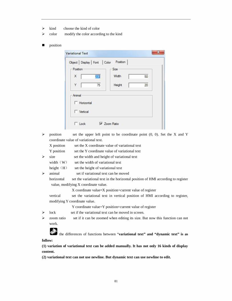
81
kind choose the kind of color color modify the color according to the kind position
position set the upper left point to be coordinate point (0, 0). Set the X and Y
coordinate value of variational text. X position set the X coordinate value of variational text Y position set the Y coordinate value of variational text
size set the width and height of variational text width(W) set the width of variational text height(H) set the height of variational text
animal set if variational text can be moved horizontal set the variational text in the horizontal position of HMI according to register value, modifying X coordinate value.
X coordinate value=X position+current value of register vertical set the variational text in vertical position of HMI according to register, modifying Y coordinate value. Y coordinate value=Y position+current value of register
lock set if the variational text can be moved in screen. zoom ratio set if it can be zoomed when editing its size. But now this function can not
work.
the differences of functions between “variational text” and “dynamic text” is as
follow: (1) variation of variational text can be added manually. It has not only 16 kinds of display content. (2) variational text can not use newline. But dynamic text can use newline to edit.

82
4-3-4. Lamp
You can display object status by this button. 1. Click “ ” icon in component tool bar. Move the cursor to screen and click left mouse to set.
Cancel it by clicking right mouse or ESC button. You can realize to adjust the boundary size of object lamp button by boundary point.
2. Double click “lamp” or click “lamp” and click right mouse. Then set attribute by choosing “attribute” or “ ” button. object
station
device current device port which is communicating station the address of communication device
object set address and trigger signal object type of lamp indirect set the offset of current address as follow
Current trigger signal address of lamp will change with D0 value of register. It is M0[D0]=M[0+D0 value]

83
Click the pull-down box of object type. Change the relative object by choosing type in the pull-down menu. Because lamp is double state component, so relative object type can only be relay types or a bit of register. We suggest using internal address of HMI (PSW, PFW) for indirect address. If not, the communication will be slow.
lamp
ON right frame display lamp when object cable is ON. OFF right frame display lamp when object cable is OFF. Change aspect modify the aspect of lamp. Because it has own material library, so you
can choose freely. User defined modify the aspect of lamp. It has user defined material library. Save aspect save the aspect of lamp. It is convenient when you are programming. Use text modify the content, font, align type of lamp text.
content set the display content of text font set the size, font, type of text. align user can choose align type freely according to your requirement.
(1) change aspect: choose relative pictures in lamp library to display. Click “change aspect”. Following editing screen will appear.

84
choose the lamp icon in material library and press “confirm”.
(2) User defined: you can define displaying picture freely from material library. Click “use defined”, then the following editing screen will appear.
Choose target icon in material library and click “open”. Then the target icon will be added
into lamp. (3)save aspect: you can put user defined lamp into lamp library. If you want to use it next time, you can call it directly.
twinkle

85
choose the twinkle status of lamp.
status
stop it will stop twinkling whenever the lamp is ON or OFF. ON lamp will twinkle when it is ON. OFF lamp will twinkle when it is OFF.
speed choose the twinkle speed when lamp is triwkling. Slow or fast color
kind choose the kind of color for lamp. color modify the color according to the kind.
position
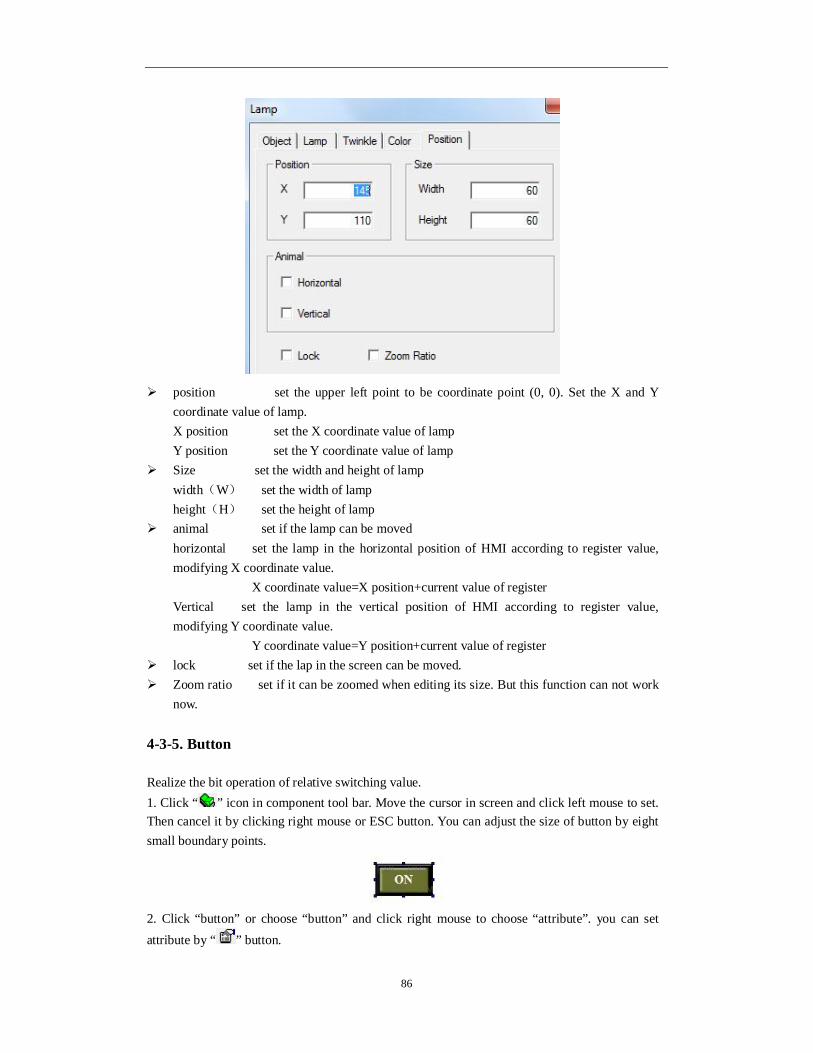
86
position set the upper left point to be coordinate point (0, 0). Set the X and Y coordinate value of lamp. X position set the X coordinate value of lamp Y position set the Y coordinate value of lamp
Size set the width and height of lamp width(W) set the width of lamp height(H) set the height of lamp
animal set if the lamp can be moved horizontal set the lamp in the horizontal position of HMI according to register value, modifying X coordinate value. X coordinate value=X position+current value of register Vertical set the lamp in the vertical position of HMI according to register value, modifying Y coordinate value. Y coordinate value=Y position+current value of register
lock set if the lap in the screen can be moved. Zoom ratio set if it can be zoomed when editing its size. But this function can not work
now.
4-3-5. Button
Realize the bit operation of relative switching value. 1. Click “ ” icon in component tool bar. Move the cursor in screen and click left mouse to set. Then cancel it by clicking right mouse or ESC button. You can adjust the size of button by eight small boundary points.
2. Click “button” or choose “button” and click right mouse to choose “attribute”. you can set attribute by “ ” button.

87
object
station device current device port which is communicating station address of communication device
object set the object type and address of button. indirect set the offset of current address as follow
Trigger signal address of current button changes with D0 value of register. M0[D0]=M[0+D0 value]
We suggest using internal address of HMI (PSW, PFW) for indirect address. If not, communication will be slow. operate
button
set ON set the control cable to be ON set OFF set the control cable to be OFF reverse set the control cable to be reverse

88
ON instant when the button is pressed, the cable is ON at the moment. If the button is pressed again, the cable will be OFF.
button
Key type define the button code of touch or enter. Enter key is only for OP560,
MP360, MP760, XMP, XMH.

89
hide button if you want the button visible or invisible when it is operating, please choose
this option. The aspect and text of button can no be operated.
Normal the status picture when the button display normally or after the button was
released. Press the status picture when the button is pressed. Change aspect modify the aspect of button. It has its own material library. You can choose
it freely. User defined modify the button aspect. It has its own material library.

90
Save aspect save the button aspect. It is convenient when you are programming. Use text modify the content, font, align of button text.
content set the content of button font set the size, font, type of button text. align you can choose align type according to your requirement.
Password set if the button needs to be protected by password. If you choose “password”,
please use password protection function and choose the password level. color
kind choose the kind of color which neef to be modified. color modify the color according to the kind. position

91
position set the upper left point to be the coordinate point (0, 0). Set the X and Y
of button. X position set the X coordinate value Y position set the Y coordinate value
size set the wdth and height of button width(W) set the width of button height(H) set the height of button
animal set if the button can be moved horizontal set the button in the horizontal position according to register value, modifying X coordinate value. X coordinate value=X position+current value of register vertical set the button in the vertical position according t register value, modifying Y coordinate value.
Y coordinate value=Y position+current value of register lock set if the button in screen can be moved. Zoom ratio set if it can be zoomed when editing its size. But this function can not work
now.
4-3-6. Lamp button
Lamp button can control and display the object status. 1. Click “ ” icon in component tool bar. Move the cursort to screen and click left mouse to set. Click right mouse or ESC button to cancel it. You can modify the size of lamp button by pulling boundary points.

92
2. double “lamp button” or choose “lamp button” and click right mouse. Choose “attribute” or “ ” button to set the attribute. object (1) Operate object object controlled by button
station
device current device port which is communicating station address of communication device
object set the object type and address of lamp button indirect set the offset of current address as follow.

93
Current signal address of lamp button changed as register D0 value. M0[D0]=M[0+D0 value]
We suggest using the internal address of HMI (PSW, PFW) for indirect address. If not, the communication will be slow. (2) Watch object display object of lamp button
When you don’t choose it, the display object is as same as operate object and they can not be modified. When you choose it, you can choose the device station number and object type of watch target.
station device current device port which is communicating. station address of communication device
object set the watching object type and address of lamp button. Indirect set the offset of current address as follow.
Current watch object address of lamp button changes with register D0 value. M0[D0]=M[0+D0 value].

94
We suggest using internal address of HMI (PSW, PFW) for indirect address. If not, the communication will be slow. general
Button operate it is used for “operate object” of “object” option. You can choose set ON,
set OFF, reverse and ON instant set ON set the control cable to be ON
set OFF set the control cable to be OFF reverse reverse the status of control cable ON instant When you press it, the cable will be ON. When you release it, the cable wil be OFF.
Twinkle status it is used for “watch object” of “object” option. You can choose stop, ON and OFF. When you choose twinkle, you can use “twinkle speed” to decide its speed. Stop it will stop twinkling whenever the lamp is ON or OFF. ON it will twinkle when the lamp is ON. OFF it will twinkle when the lamp is OFF.
password set if the “operate object” in “object” option need to protected by password. If you choose “password”, please use password protection function and choose the relative password level.
aspect

95
ON the lamp will display when the “watch object” is ON in the right box
“object”. OFF the lamp will display when the “watch object” is OFF in the right box
“object”. pressing it is used for “operate object” in “object” option, displaying aspect when
pressing. release it is used for “operate object” in “object” option, displaying aspect when
releasing. Change aspect modify the aspect of lamp button. It has its own material library.
Customers can choose from it freely. User defined modify aspect of lamp button. It has user defined material library. Save aspect save aspect of lamp button. It is convenient when programming. Use text modify the content, font align type of lamp button.
color
kind choose the type of color for lamp button color modify the color according to the kind.

96
position
position set the upper left point to be coordinate point (0, 0). Set the X and Y
coordinate value of lamp button X position set the X coordinate value of lamp button. Y position set the Y coordinate value of lamp button.
size se the width and height of lamp button. width(W) set the width of lamp button. height(H) set the height of lamp button
aniaml set if the lamp button can be moved. horizontal set the lamp button in the horizontal position of HMI according to register value, modifying the X coordinate value.
X coordinate value=X position+current value of register vertical set the lamp button in the vertical position of HMI according to register value.
Y coordinate value=Y position+current value of register lock set if the lamp button in screen can be moved. Zoom ratio set if it can be zoomed when editing its size. But this function can not work
now.
4-3-7. Screen jump
This component will realize the jump function between different screens. At the same time, you can set the limits of authority.
1. Click “ ” icon in the component tool bar. Move the cursor to the screen and click left mouse to set. Click right mouse or ESC button to cancel it.

97
2. Double click “screen jump” or choose “screen jump” to click right mouse. Set the attribute by
choosing “attribute” or “ ” button. operate
screen ID input screen ID mode
log on in this mode you need’t set the limit of authority and it can jump screen directly.
validate in this mode, it operate password protection. You can jump the screen only when you input correct password. It is as same as “password function” in the “button” option.
button

98
key type define the button code of touch key or enter key. Enter key is only for MP,
XMP, XMH.
hide button set if the button is visible when operating it. If you choose this option, screen
jump and text can not be operated.

99
normal screen jump button display normally or the status picture after releasing button.
press the status picture when pressing screen jump button. Change aspect modify the aspect of screen jump button. It has its own material library.
Customers can choose from it freely. User defined modify the aspect of screen jump button. It belongs to the user defined
material library. Save aspect save the aspect of screen jump button. It is convenient for programming. Use text modify the text content, font and align type of screen jump button.
content set the displaying content of screen jump button. font set the size, font, type of screen jump button. align customers can choose align type according to requirement.
password set if the screen jump button need to be protected by password. If you choose “password”, please use password protection function and choose the relative password level.
color
kind choose the screen jump to the kind of color.

100
color modify the color according the kind.
position
position set the upper left point as coordinate point (0, 0). Set the X and Y
coordinate value of screen jump. X position set the X coordinate value of screen jump. Y position set the Y coordinate value of screen jump.
size set the width and height of screen jump. width(W) set the width of screen jump. height(H) set the height of screen jump.
animal set if the screen jump need to be moved. horizontal set the screen jump in the horizontal position of HMI according to register value, modifying the X coordinate value. X coordinate value=X position+current value of register
vertical set the screen jump in the vertical position of HMI according to register value,根据
modifying Y coordinate value. Y coordinate value=Y position+current value of register;
lock set if the screen jump in screen can be moved. Zoom ratio set if it can be zoomed when editing its size. But this function can not work
now.
4-3-8. Digital display
Display the register value. 1. Click the “ ” icon in the component tool bar. Move the cursor to the screen and click left mouse to set. Click right mouse or ESC button to cancel it. The size of difital box can be edited by boundary points.

101
2. Double click “digital display” or choose “digital display” and click right mouse. Set the attribute by “attribute” or “ ” button. object
station device current device port which is communicating station address of communication device
object set the object type and address of digital display. indirect set the offset of current address as follow
Current address of digital display will change with register PSW256 value. D0[PSW256]=D[0+PSW256 value] data set the data type to separate word or double words.
We suggest using the internal address of HMI (PSW, PFW) for indirect address. If not, the communication will be slow.

102
display
type choose the form of digital display. It can be decimal, hexadecimal, floating
number and unsigned number. length total bit of digital display and length setting of decimal place. aspect choose if it need digital display frame and modify the aspect by “changing”
button. Align hor it contains left, centre and right. Align ver it contains top, middle and bottom. 0 lead add 0 when the data digits fails to meet figures.
For example: the register value is 23. The setting bits of digital display are 5 and decimal place is 0. When you choose 0 lead, the digital display will be 00023. font
setting it contains font, type, size, effect, example, color, character set and so on. You can set it freely.
art it contains projection, brink, fill and angle. You can set it freely.

103
color
kind choose digital display to modify the kind of color. color modify the color according to the kind.
position
position set the upper left point as the coordinate point(0, 0). Se the X and Y
coordinate value of digital display. X position set the X coordinate value of digital display. Y position set the Y coordinate value of digital display.
size set the width and height of digital display. width(W) set the width of digital display height(H) set the height of digital display
animal set if the digital display need to be moved. horizontal set the digital display in the horizontal position of HMI according to register value, modifying X coordinate value.
X coordinate value = X position+current value of register vertical set the digital display in the vertical position of HMI according to register value, modifying Y coordinate value.

104
Y coordinate value=Y position+current value of register lock set if the digital display in screen can be moved. Zoom ratio set if it can be zoomed when editing its size. But it can not work now.
4-3-9. Alarm display
Realize the limit function of data. It will twinkling when the data is over limit. 1. Click “ ” icon in the component tool bar. Move the cursor to screen and click left mouse to set. Click the right mouse or ESC button to cancel it. The size of digital frame can be adjusted by boundary points.
2. Double click “alarm digital display” or choose “alarm digital display” and click right mouse. Set the attribute by choosing “attribute” or “ ” button. object
station device current device port which is communicating. station address of communication device
object set the object type and address of alarm display indirect set the offset of current address as follow.
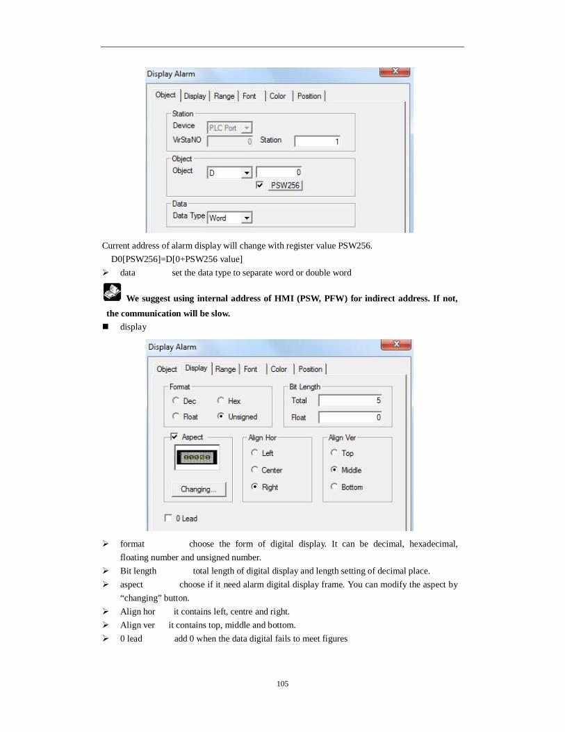
105
Current address of alarm display will change with register value PSW256. D0[PSW256]=D[0+PSW256 value]
data set the data type to separate word or double word
We suggest using internal address of HMI (PSW, PFW) for indirect address. If not, the communication will be slow. display
format choose the form of digital display. It can be decimal, hexadecimal, floating number and unsigned number.
Bit length total length of digital display and length setting of decimal place. aspect choose if it need alarm digital display frame. You can modify the aspect by
“changing” button. Align hor it contains left, centre and right. Align ver it contains top, middle and bottom. 0 lead add 0 when the data digital fails to meet figures

106
Range
Max check set the alarm max of digital display. When the data is over the max, it will alarm by
twinkling. Min check set the alarm min of digital display. When the data is over Min, it will twinkling.
font
setting it contains font, type, size, effect, example, color and character set. You can set it
freely. art it contains projection, brink, fill and angle. You can set it freely.

107
color
kind choose the alarm digital display to modify the kind of color. color modify the color according to the kind.
position
position set the upper left point as the coordinate point(0, 0). Set the X and Y
coordinate value of alarm digital display. X position set the X coordinate value of alarm digital display. Y position set the Y coordinate value of alarm digital display.
size set the width and height of alarm digital display. width(W) set the width of alarm digital display. height(H) set the height of alarm digital display.
animal set if the alarm digital display need to be moved. horizontal set the alarm digital display in the horizontal position of HMI according to register value, modifying X coordinate value.
X coordinate value=X position+current value of register Vertical set the alarm figital display in the vertical position of HMI according to register value, modifying Y coordinate value.
Y coordinate value=Y position+current value of register

108
lock set if the alarm digital display in screen can be moved. Zoom ratio set if it can be zoomed when editing its size. But this function can not work
now.
4-3-10. Text display
Display the texts of register. 1. Click the “ ” icon in the component tool bar. Move the cursor in screen and click left mouse to set. Click right mouse or ESC button to cancel it. The size of data frame can be adjusted by boundary points.
2. Double click “text display” or choose “text display” and click right mouse. Set the attribute by choosing “attribute” or “ ” button.
One word (WORD) is consisted of two characters. One character occupies a bit. One register is a character. So you can change the displaying content of character by setting register number (displaying length). For example, register number is set to be one. It will display two characters. Character is showed by ASCII code and one character ASCII code is two bits hexadecimal. object
station device current device port which is communicating. station address of communication device
object set the object type and address of text display. indirect set the offset of current address as follow.

109
Current address of text display will change with register value PSW256. D0[PSW256]= D[0+PSW256 value] data set the length of text display. One register will display two characters
We suggest using internal address of HMI (PSW and PFW) for indirect address. If not, the communication will be slow.
display
aspect choose the aspect of text display frame and you can modify the aspect by
“changing” button. Align hor it contains left, centre and right. Align ver it contains top, middle and bottom.

110
font
setting it contains font, type, size, effect, example, color, character set and so on. You
can set it freely. art it contains projection, brink, fill, angle and so on. You can set it freely.
color
kind choose the text display to mdify the kind of color. color modify the color according to the kind.
position

111
position set the upper left point to be coordinate point(0, 0). Set the X and Y
coordinate value of text display. X position set the X coordinate value of text display. Y position set the Y coordinate value of text display.
size set the width and height of text display width(W) set the width of text display height(H) set the height of text display
animal set if the text display need to be moved. horizontal set the text display in the horizontal position of HMI according to register value, modifying X coordinate value. X coordinate value=X position+current value of register
vertical set the text display in the vertical position of HMI according to register value, modifying Y coordinate value.
Y coordinate value=Y position+current value of register lock set if the text display in screen can be moved. Zoom ratio set if it can be zoomed when editing its size. But this function can not work
now.
4-3-11. Digital input
Input digital value through digital keyboard. 1. Click “ ” icon in the component tool bar. Move the cursor to screen and click left mouse to set. Click right mouse or ESC button to cancel it. You can also set many components of digital input. You can adjust the size of input frame by boundary points.

112
2. Double click “digital input” or choose “digital input” and click right mouse. Set the attribute
by choosing “attribute” or “ ” button. object (1)operate object object register of digital input
station device current device port which is ommunicating station address of communication device
object set the object type and address of digital input indirect set the offset of current address as follow

113
Current address of digital input will change with register value PSW256. D0[PSW256]= D[0+PSW256 value]. data set the data type to be WORD or D WORD.
We suggest using internal address of HMI (PSW and PFW) for indirect address. If not, the communication will be slow. (2)watch object when you are choosing, the digital input box will display the data of register.
station
device current device port which is communicating station address of communication device
object set the watch object type and address of digital input indirect set the offset of current address as follow
Current watch object address of digital input will change with register value PSW256 D0[PSW256]=D[0+PSW256 value].

114
We suggest using internal address of HMI (PSW and PFW) for indirect address. If not, the communication will be slow. display
format choose the format of digital display. It can be Dec, Hex, float and unsigned. Bit length total bit of digital display and the length setting of float. aspect choose if you need digital input frame and you can modify the aspect by
“changing” button. Align hori it contains left, centre and right. Align vert it contains top, middle and bottom. 0 lead add 0 when data digits fails to meet figures password data is in the form of password. It will display “*”
input

115
password set if the digital input need to be protected by password. If you choose “password”, please use the password protection function. At the same time, please choose the relative password level. Notify make the target relay to be on after inputting. You can reset it manually. Setting of the range the limit data of digital input. Popup keyboard when you choose it, a small keyboard will appear. If not, the keyboard will not appear. font
setting it contains font, type, size, effect, example, color, character set and so on. You
can set it freely.

116
art it contains projection, brink, fill and angle, etc. you can set it freely. color
kind choose digital input to modify the kind of color color modify the color according to the kind. position
kind set the upper left point to be coordinate point (0, 0). Set the X and Y
coordinate value of digital input. X position set the X coordinate value of digital input. Y position set the Y coordinate value of digital input
size set the width and height of digital input. width(W) set the width of digital input height(H) set the height of digital input
animal set if the digital input need to be moved. horizontal set the digital input in the horizontal position of HMI according to register value, modifying the X coordinate value. X coordinate value=X position+current value of register
vertical set the digital input in the vertical position of HMI according to register value, modifying Y coordinate value.
Y coordinate value=Y position+current value of register

117
Lock set if the digital input in screen can be moved. Zoom ratio set if it can be zoomed when editing its size. But this function can not work
now. 3. Enter the off-line status by component “ ”. When you don’t set password level in the processing, please press he digital input component and small keyboard will appear. The simulation operating is as follow.
After inputting data, please press “ENT” to confirm. If you need to input data again, press”CLR” to clear inputting box. If you don’t need to modify and you want to exit, please press “ESC”.
4-3-12. ASCII code input
Input ASCII code for target register by small keyboard. It is corresponded with character. 1. Click “ ” icon in the component tool bar. Move the cursor to the screen and click left mouse to set. You can click right mouse or ESC button to cancel it. You can set many ASCII input component. You can also adjust the size of input frame by boundary points.
2. Double click “ASCII input” or choose the “ASCII input” and click right mouse. Set the
attribute by choosing “attribute” or “ ” button. object

118
station
device current port which is communicating. station address of communication device.
object set the object type and address of text input indirect set the offset of current address as follow.
Current address of text input will change with register value PSW256 D0[PSW256]=D[0+PSW256 value] data set the length of text input. One register can display two characters
We suggest using the internal address of HMI (PSW and PFW) for indirect address. If not, the communication will be slow.

119
display
Aspect choose if you need text input frame and you can modify the aspect by
“changing” button. Align hor it contains left, centre and right. Align ver it contains top, middle and bottom. password set if the text input need to be protected by password. If you choose
“password”, you need to use password protection. At the same time choose the relative password level.
notify trigger the target relay to be on after inputting. You can reset it manually. Popup keyboard when you choose it, small keyboard will appear. If not, the keyboard
will not appear.
font

120
setting it contains font, type, size, effect, example, color and character set. You can set it freely.
art it contains projection, brink, fill, angle and so on. You can set it freely. color
kind choose the text input to modify the kind of color color modify the color according to the kind. position
position set the upper left point to be coordinate point(0, 0). Set the X and Y
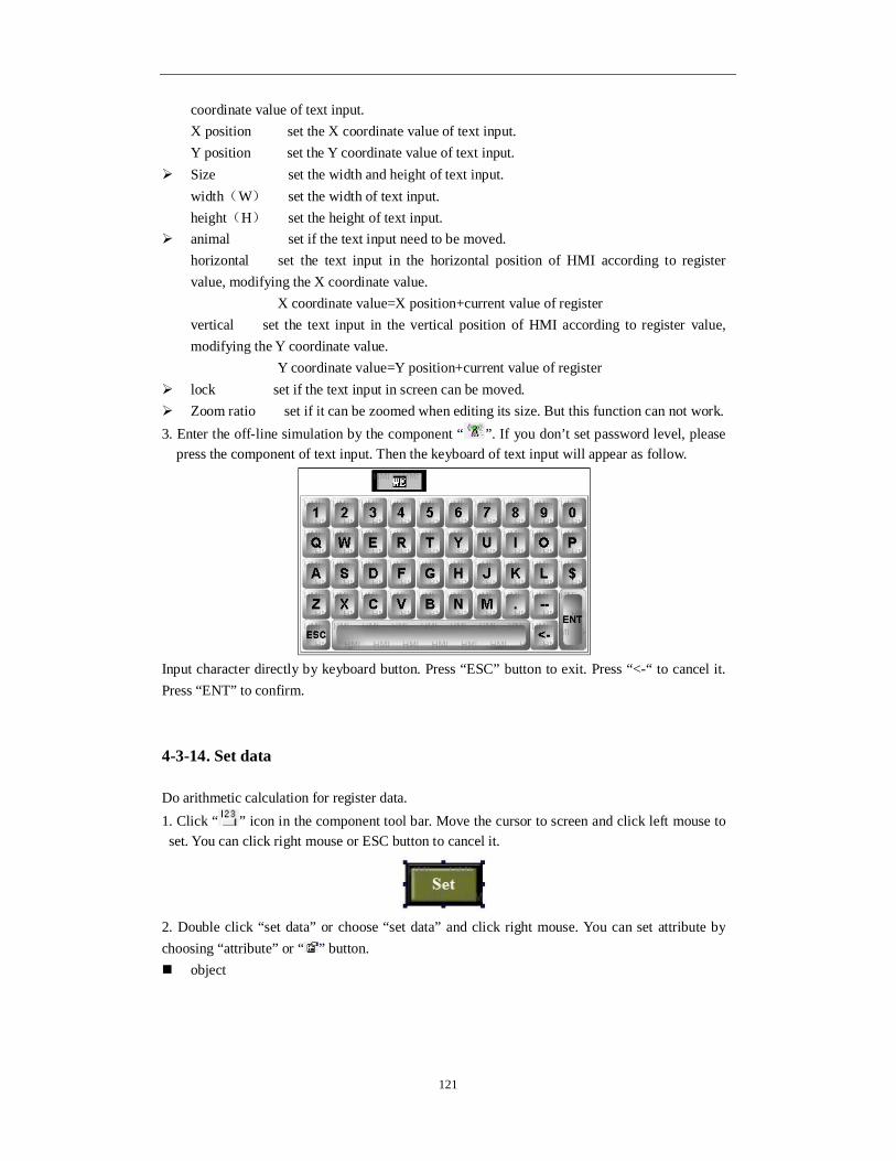
121
coordinate value of text input. X position set the X coordinate value of text input. Y position set the Y coordinate value of text input.
Size set the width and height of text input. width(W) set the width of text input. height(H) set the height of text input.
animal set if the text input need to be moved. horizontal set the text input in the horizontal position of HMI according to register value, modifying the X coordinate value. X coordinate value=X position+current value of register vertical set the text input in the vertical position of HMI according to register value, modifying the Y coordinate value. Y coordinate value=Y position+current value of register
lock set if the text input in screen can be moved. Zoom ratio set if it can be zoomed when editing its size. But this function can not work. 3. Enter the off-line simulation by the component “ ”. If you don’t set password level, please
press the component of text input. Then the keyboard of text input will appear as follow.
Input character directly by keyboard button. Press “ESC” button to exit. Press “<-“ to cancel it. Press “ENT” to confirm.
4-3-14. Set data
Do arithmetic calculation for register data. 1. Click “ ” icon in the component tool bar. Move the cursor to screen and click left mouse to set. You can click right mouse or ESC button to cancel it.
2. Double click “set data” or choose “set data” and click right mouse. You can set attribute by choosing “attribute” or “ ” button. object
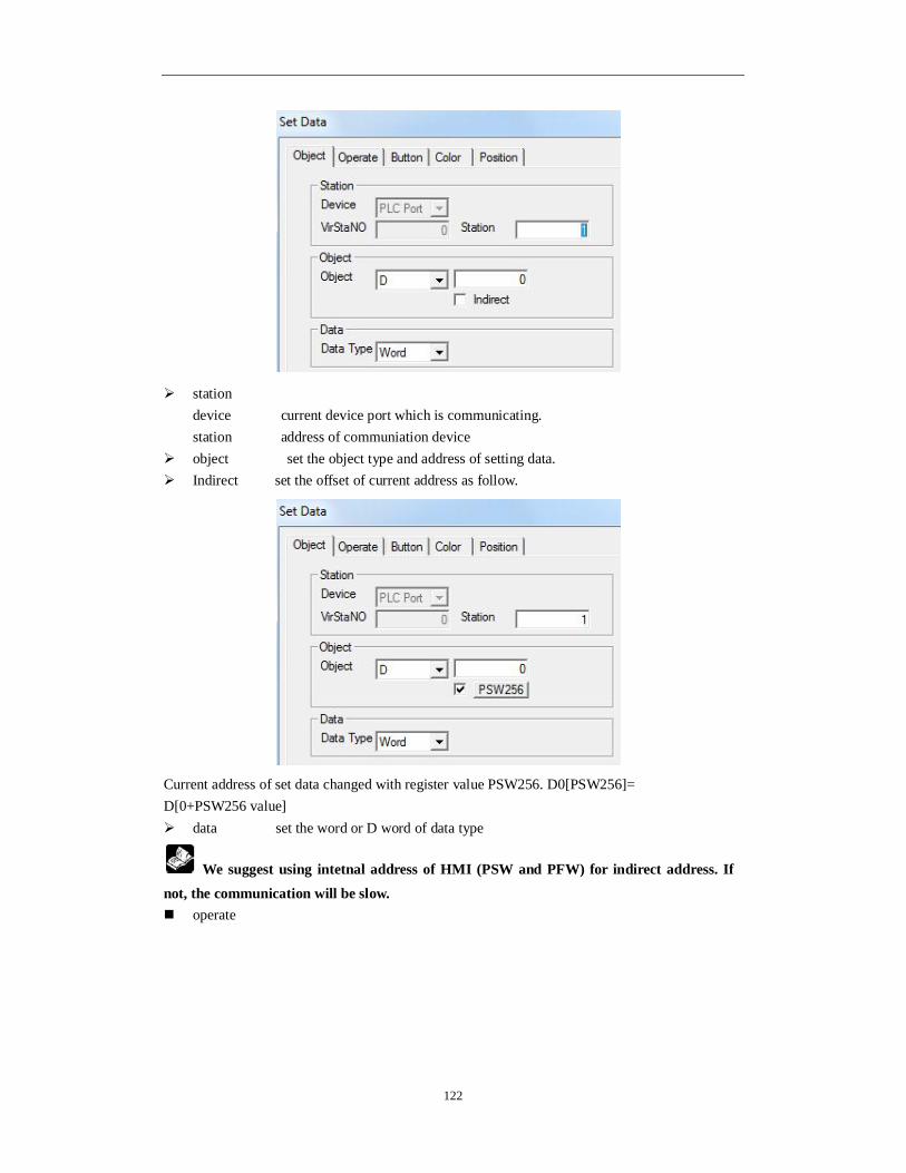
122
station device current device port which is communicating. station address of communiation device
object set the object type and address of setting data. Indirect set the offset of current address as follow.
Current address of set data changed with register value PSW256. D0[PSW256]= D[0+PSW256 value] data set the word or D word of data type
We suggest using intetnal address of HMI (PSW and PFW) for indirect address. If not, the communication will be slow. operate

123
function data operation of object register
add object register value+operand= object register value substract object register value-operand= object register value multiply object register data X operand=register data division object register data÷operand=register data constant operand is the data of current object register
format it contains decimal, hexadecimal, float and unsigned.
button
Key type define the button code of touch key or enter key. Enter key is only for OP560, MP360, MP760, XMP, XMH.
Hide button set if the button can be visible when it is operating. Choose this option. The aspect and text cannot be operated.

124
normal set the normal display or the status picture after releasing the button. press set the status picture when pressing the button. Change aspect set the aspect. It belongs to software’s material library. You can choose
from it freely. User defined modify the data to set aspect. It belongs to user defined material library. Save aspect save data to set aspect. It is convenient when you are programming. font modify data to set the content, font and align type of text.
content set the displaying content font set the size, font and type of text. align choose the align type according to your requirement.
password set if it need to be protected by password. If you choose password, please use password pretection. At the same time choose the password level.
color
kind modify the kind of color. color modify the color according to the kind. position

125
position set the X and Y coordinate value. X position set the X coordinate value. Y position set the Y coordinate value.
size modify the data to set the width and height. width(W) modify data to set width height(H) modify data to set height
animal set if it can be moved. horizontal set in the horizontal position of HMI according to register value, modifying X coordinate value. X coordinate value=X position+value of current register vertical set in the vertical position of HMI according to register value, modifying Y coordinate value. Y coordinate value=Y position+value of current register
lock set if the set data in the screen can be moved. Zoom ratio set if it can be zoomed when editing its size. But this function can not work
now.
4-3-15. Digital keyboard
It is related to digital input component. When you don’t choose “pop-up keyboard”, digital keyboard will not appear in the process of input number and you need to add digital keyboard manually. Click “ ” icon in the component tool bar. Move the cursor in the screen and click left mouse to set. Click right mouse or ESC button to cancel it.

126
The digital keyboard will connect to digital input button automatically. Press “ENT” key will finish the digital input. You only need to set one digital keyboard for all the digital input buttons.
Only one digital input component can be used when there are many digital input buttons.
Digital keyboard will connect to them automatically. position
position set the upper left point in screen to be coordinate point(0, 0). Set the X and
Y coordinate value. X position set the X coordinate of digital keyboard. Y position set the Y coordinate value of digital keyboard.
size set the width and height of digital keyboard width(W) set the width of digital keyboard height(H) set the height of digital keyboard
animal set if the digital keyboard need to be moved
horizontal set the digital keyboard in the horizontal position of HMI according to register value, modifying X coordinate value. X coordinate value=X position+current value of register

127
vertical set the digital keyboard in the vertical position of HMI according to register value, modifying Y coordinate value.
Y coordinate value=Y position+current value of register lock set if the digital keyboard in screen can be moved. Zoom ratio set if it can be zoomed when editing its size. but this function can not work
now.
4-3-16. ASCII keyboard
ASCII keyboard is corresponded to ASCII input component. When you don’t choose “pop-up keyboard”, ASCII keyboard will not appear. You need to add ASCII keyboard manually. Click the “ ” icon in the component tool bar. Move the cursor in screen and click left mouse to set. Click right mouse or ESC button to cancel it.
Only one ASCII input component can be used when there are many text input boxes in editing screen. ASCII keyboard will connect to it automatically. position
set the upper left point to be coordinate point(0, 0). Set the X and Y coordinate value of
ASCII keyboard. X position set the X coordinate value of ASCII keyboard.

128
Y position set the Y coordinate value of ASCII keyboard. size set the width and height of ASCII keyboard.
width(W) set the width of ASCII keyboard height(H) set the height of ASCII keyboard
animal set if the ASCII keyboard need to be moved. horizontal set the ASCII keyboard in the horizontal position of HMI according to register value, modifying the X coordinate value. X coordinate value=X position+current value of register
vertical set the ASCII keyboard in the vertical position of HMI according to register value, modifying the Y coordinate value.
Y coordinate value=Y position+current value of register lock set if the ASCII keyboard in screen can be moved. Zoom ratio se if it can be zoomed when editing its size. But this function can not work
now.
4-3-17. User input
The keyboard is formed by user input components. Every button value is corresponded to an ASCII code. Then the input data will be separated. Customer can use defined input keyboard of this component. 1. Click “ ” icon in component tool bar. Move the cursor in the screen and click left mouse to set. Click right mouse or ESC button to cancel it.
2. Double click the “user input” or choose “user input” and click right mouse. Set the attribute by choosing “attribute” or “ ” button. operate
input input relative ASCII code of button The following are common ASCII code value of buttons.
1 - 0X31 2 - 0X32 3 - 0X33 4 - 0X34 5 - 0X35 6 - 0X36 7 - 0X37 8 - 0X38 9 - 0X39 0 - 0X30
ESC - 0X1D CLR - 0X7F ENT - 0XD

129
button
Key type define the key code of touch or enter key. Enter key is only for OP560, MP360, MP760, XMP, XMH.
hide button if it is visible when the button is operating. Choose this option. User input aspect and text cannot be operated.
normal the status picture after normal display or releasing button of user input. press displaying status picture when pressing the user button. Change aspect modify the aspect of user input.it belongs to its own material library. You can
choose from it freely. User defined modify the aspect of user input. It belongs to user defined material library. Save aspect save the aspect of user input. It is convenient for programming. Use text modify the content, font and align type of user input.
content set the displaying content of user input. font set the size, font and type of user input text. align you can choose align type according to your requirement.

130
password if the user input need to be protected by password. If you choose “password”, please use password protection. At the same time choose the relative password level.
color
kind choose the user input to modify the kind of color color modify the color according to the kind.
position
position set the upper left point in screen to be coordinate point (0, 0). Set the X
and Y coordinate value of user input. X position set the X coordinate value of user input Y position set the Y coordinate value of user input
size set the width and height of user input width(W) set the width of user input height(H) set the height of user input
animal set if the user input need to be moved.
horizontal set the user input in the horizontal position according to register value, modifying X coordinate value.

131
X coordinate value=X position+current value of register vertical set the user input in the vertical position according to register value, modifying Y coordinate value. Y coordinate value=Y position+current value of register
lock set if the user input in screen can be moved. Zoom ratio set if it can be zoomed when editing its size. But this function can not work
now.
4-3-18. Bar
This function will display the bar of object data. It is direct to show it. It is usually for analog quantity such as pressure change, level change and temperature change. As the following picture, it shows the relation between current value and full scale value.
1. Click the “ ” icon in component tool bar. Move the cursor to screen and click left mouse to set. Click right mouse or ESC button to cancel it. You can also edit the size by adjusting boundary points.
2. double click “bar” or choose “bar” and click right mouse. Set the attribute by choosing “attribute” or “ ” button. object

132
station device current device port which is communicating. station address of communiation device
object set the object type and address of bar indirect set the offset of current address as follow.
Current address of bar will change with register PSW256. D0[PSW256]= D[0+PSW256 value] data set the data type to be word or D word.
We suggest using internal address of HMI (PSW, PFW internal address type) for indirect address. If not, the communication will be slow. bar
preview display simple picture of current bar aspect aspect setting of bar

133
For vertical bar, choose top or bottom type. For horizontal bar, choose the left or right type. Transform the horizontal and vertical display direction by “mode” button. You can also
choose aspect of bar. Scale set the centigrade of upper limit and lower limit. Set the main scale and slave
scale. Data set the data format, max and min value.
color
kind choose the bar to modify the kind of color. color modify the color according to the kind.
position
position set the upper left point to be coordinate point (0, 0). Set the X and Y
coordinate value of bar. X position set the X coordinate value of bar Y position set the Y coordinate value of bar
size set the width and height of bar width(W) set the width of bar height(H) set the height of bar
animal set if the bar need to be moved.

134
horizontal set the bar in the horizontal position of HMI according to register value, modifying X coordinate value. X coordinate value=X position+current value of register vertical set the bar in the vertical position of HMI according to register value, modifying Y coordinate value. Y coordinate value=Y position+current value of register
lock set if the bar in screen can be moved. Zoom ratio set if it can be zoomed when editing its size. But this function can not work
now.
4-3-19. Dynamic map
Switch the pictures according to register value. The range of register value and the status of picture are 0 to 15.
1. Click the “ ” icon in the component tool bar. Move the cursor to the screen and click left mouse to set. Click right mouse or ESC button to cancel it. You can edit its size by adjusting the boundary points.
2. Double click “dynamic map” or choose “dynamic map” and click right mouse. Set the attribute by choosing “attribute” or “ ” button. object
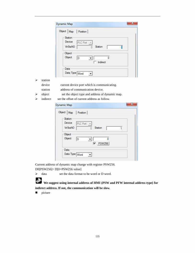
135
station
device current device port which is communicating. station address of communication device.
object set the object type and address of dynamic map. indirect set the offset of current address as follow.
Current address of dynamic map change with register PSW256. D0[PSW256]= D[0+PSW256 value] data set the data format to be word or D word.
We suggest using internal address of HMI (PSW and PFW internal address type) for indirect address. If not, the communication will be slow. picture

136
From picture 0 to picture 15. It is corresponed to “object” register value.(0~15)choose the object picture number. You can choose the object picture by “changing”(bmp and jpg picture).
position
position set the upper left point to be the coordinate point (0, 0). Set the X and Y
coordinate value of dynamic map. X position set the X coordinate value of dynamic map. Y position set the Y coordinate value of dynamic map.
size set the width and height of dynamic map. width(W) set the width of dynamic map height(H) set the height of dynamic map
animal set if the dynamic map need to be moved. horizontal set the dynamic map in the horizontal position of HMI according to register value, modifying the X coordinate value.
X coordinate value=X position+current value of register vertical set the dynamic map in the vertical position of HMI according to register value, modifying the Y coordinate value.

137
Y coordinate value=Y position+current value of register lock set if the dynamic map in screen can be moved. Zoom ratio set if it can be zoomed when editing its size. But this function can not work
now.
4-3-20. Call window
Object window is called by controlling the ON/OFF of auxiliary relay.
M0=1, call window ID60001 1. Click “ ” icon in the component tool bar. Move the cursor to the screen and click left mouse to set. Click right mouse or ESC button to cancel it. Pop-up window will be based on its position.
2. Double click “call window” or choose “call window” and click right mouse. Set the attribute by choosing “attribute” or “ ” button. object
station
device current device port which is communicating station address of communication device
object set the trigger signal object type and address of call window. indirect set the offset of current address as follow.

138
Current trigger signal address of call window will change with register D0. M0[D0]=M[0+D0
value]
When the auxiliary relay is ON, the called window will appear in screen. When it is OFF, this window will be closed. We suggest using internal address of HMI (PSW and PFW internal address type) for indirect address. If not, the communication will be slow.
window
window set the call window ID
position

139
Position set the upper left point to be the coordinate point(0,0). Set the X and Y
coordinate value of call window. X position set the X coordinate value of call window Y position set the Y coordinate value of call window Call window component is invisible after downloading to the HMI. So its size can not be
edited. Animal set if the call window in screen can be moved.
horizontal set the call window in the horizontal position of HMI according to register value, modifying the X coordinate value X coordinate value=X position+current value of register
vertical set the call window in the vertical position of HMI according to register value, modifying the Y coordinate value.
Y coordinate value=Y position+current value of register lock set if the call window in screen can be moved. Zoom ratio set if it can be zoomed when editing its size. But this function can not work
now.
4-3-21. Window button
Direct close or open the window without the controlling of auxiliary relay. 1. Click “ ” icon in the component tool bar. Move the cursor to screen and click left mouse to set. Click right mouse or ESC button to cancel it. You can eidt its size by boundary points.
2. Double click the “window button” or choose “window button” and click right mouse. Set the attribute by choosing “attribute” or “ ” button. operate

140
Current window when you are choosing, please aim at theoperation of current window.
Window ID object window ID of inputting target. function choose the function for window operation
type choose the current function to open window, close window or window status. You can choose the window status as hide or show. Position pop-up window is in the coordinate position of editing screen.
X set the X coordinate value of pop-up window Y set the Y coordinate value of pop-up window
Button

141
Key type define the code of touch key or enter key. The enter key is only for OP560,
MP360, MP760, XMP, XMH. Hide button set if it can be visible when button is operating. If you choose this option,
the operation of window button aspect and text will be forbidden.
normal displaying status picture after the window button display normal or releasing
window button. press the displaying status picture when the window button is pressed. Change aspect modify the aspect of window buton. It belongs to its own material library.
You can choose from it freely. User defined modify the aspect of window button. It belongs to user defined material
library. Save aspect save the aspect of window button. It is convenient for programming. Text modify the content, font and align type of window button text.
content set the display content of window button. font set the size, font and type of window button font. align you can choose the align type according to your requirement.

142
Password set if the window button can be protected by password. If you choose “password”, use password protection. At the same time choose the relative password level.
color
kind choose the window button to modify the kind of color. color modify the color according to the kind.
position
position set the upper left point to be the coordinate point (0, 0). Set the X and Y coordinate value of window button. X position set the X coordinate value of window button. Y position set the Y coordinate value of window button.
size set the width and height of window button width(W) set the width of window button height(H) set the height of window button
animal set if the window button need to be moved. horizontal set the window button in the horizontal position of HMI according to register
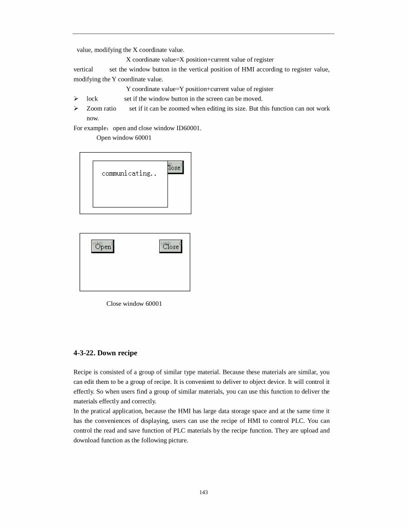
143
value, modifying the X coordinate value. X coordinate value=X position+current value of register
vertical set the window button in the vertical position of HMI according to register value, modifying the Y coordinate value.
Y coordinate value=Y position+current value of register lock set if the window button in the screen can be moved. Zoom ratio set if it can be zoomed when editing its size. But this function can not work
now. For example:open and close window ID60001. Open window 60001
Close window 60001
4-3-22. Down recipe
Recipe is consisted of a group of similar type material. Because these materials are similar, you can edit them to be a group of recipe. It is convenient to deliver to object device. It will control it effectly. So when users find a group of similar materials, you can use this function to deliver the materials effectly and correctly. In the pratical application, because the HMI has large data storage space and at the same time it has the conveniences of displaying, users can use the recipe of HMI to control PLC. You can control the read and save function of PLC materials by the recipe function. They are upload and download function as the following picture.

144
So the recipe function meets the requirement of industry control, transfer the data between device data and recipe data library. Down recipe function can transfer from recipe data library to device data section. 1. Click the “ ” icon in the component tool bar. Move the cursor to the screen and click left mouse to set. Click right mo use or ESC button to cancel it. You can also edit its size by adjusting boundary points.
2. Double click “Down recipe” or choose the “Down recipe” and click right mouse. Set the attribute by choosing “attribute” or “ ” button. object
device data the address information of data download object register. station set the connecting device and station
device current device port which is communiating station address of communication device
object address and serial number of download object register. indirect set the offset of current address as follow.
Download Recipe group Group 1 XXX XXX XXX Group 2 XXX XXX XXX Group 3 XXX XXX XXX ......................
Object device such as PLC Group 1 XXX XXX XXX Group 2 XXX XXX XXX Group 3 XXX XXX XXX .........................
Upload

145
Device data address of current recipe download will change with register PSW256. D0[PSW256]=D[0+PSW256data]
We suggest using internal address (PSW and PFW internal address type) for indirect
address. If not, the communication will be slow. Recipe data address and serial number of HMI internal data register. data set the recipe of recipe data according to actual data capacity.
recipe
count the total group of recipe data.
HMI has PSW and PFW registers. PSW is not power-loss retentive register and the PFW
is power-loss retentive register. PFW is suitable for recipe data. Save the recipe data in a group of registers, then choose the recipe by reference number PSW40. It can be input only after PSW40 have been opened in advanced function.
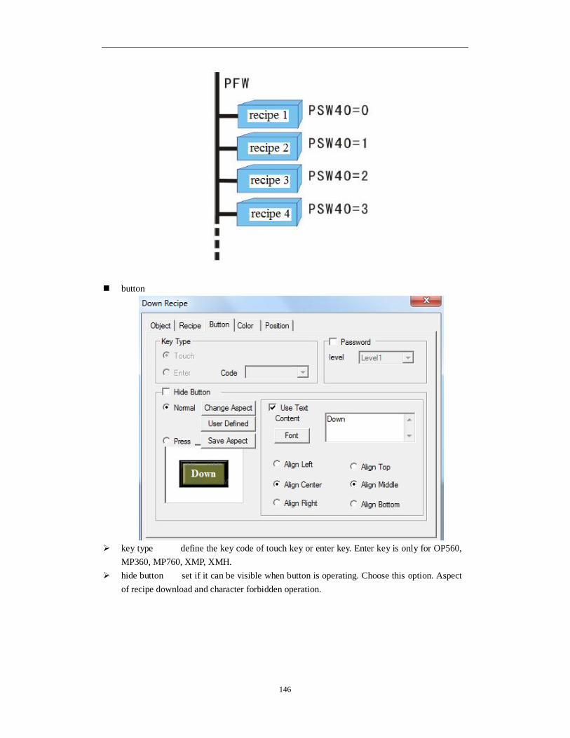
146
button
key type define the key code of touch key or enter key. Enter key is only for OP560,
MP360, MP760, XMP, XMH. hide button set if it can be visible when button is operating. Choose this option. Aspect
of recipe download and character forbidden operation.

147
normal displaying status picture when the recipe download button display normally or after releasing recipe download button.
press displaying status picture when the recipe download button is pressed. Change aspect modify the aspect of recipe download button. It belongs to its own material
library. You can choose from it freely. User defined modify the aspect of recipe download button. It belongs to user defined
material library. Save aspect save the asoect of recipe download button. It is convenient for programming. text modify the content, font and align type of recipe download button.
content set the displaying content of recipe download button. font set the size, font and type of rrcipe download button. align you can choose the relative align type according to your requirement.
Password if the recipe download button need to be protected by password. If you choose “password” and use password protection. At the same time choose the relative password level.
color
kind choose the recipe download button to modify the kind of color. color modify the color according to the kind.

148
position set the upper left point to be the coordinate point(0, 0). Set the X and Y coordinate value. X position set the X coordinate value of recipe download button. Y position set the Y coordinate value of recipe download button.
size set the width and height of recipe download button. width(W) set the width of recipe download button. height(H) set the height of recipe download button.
animal set if the recipe download button can be moved.
horizontal set the recipe download button in the horizontal position according to register value, modifying X coordinate value. X coordinate value=X position+current value of register vertical set the recipe download button in the vertical position according to register value, modifying the Y coordinate value. Y coordinate value=Y position+current value of register
lock set if the recipe download button in the screen can be moved. Zoom ratio set if it can be zoomed when editing its size. But this function can not work
now.
4-3-23. Up recipe
It is corresponded to download recipe function. This function transfers the device data to internal register of HMI. 1. Click the “ ” icon in the component tool bar. Move the cursor to the screen and click left mouse to set. Click right mouse or ESC button to cancel it. You can modify its size by boundary points.

149
2. Double click “up recipe” or choose “up recipe” and click right mouse. Set the attribute by choosing “attribute” or “ ” button. object
device data the address information of up data object register. station set the connected device and station.
device current device port which is communicating. station address of communication device.
object address and serial number of upload source register indirect set the offset of current address as follow.
Current data address of up recipe will change with register value PSW256. D0[PSW256]=D[0+PSW256 value]
We suggest using internal address of HMI (PSW and PFW) for indirect address. If not, the communication will be slow. Recipe data the address and serial number of HMI internal data register.

150
data set the recipe of recipe data and confirm the recipe according to actual data capacity.
recipe
count total group of recipe data
button
key type define the key code of touch key or enter key. Enter key is only for OP560,
MP360, MP760, XMP, XMH. Hide button hide the button when operating

151
normal displaying status picture when the button of up recipe display normally or after releasing the button of up recipe.
press displaying status picture when the button of up recipe is pressed. Change aspect modify the button aspect of up recipe. It belongs to its own material library.
You can choose from it freely. User defined modify the button aspect of up recipe. It belongs to user defined library. Save aspec save the button aspect of up recipe. It is convenient for programming. text modify the content, font and align type of up recipe button text.
content set the displaying content of up recipe button. font set the size, font and type of up recipe button text. align you can choose align type according to requirement.
Password set if the button of up recipe need to be protected by password. If you choose “password”, please use password protection.at the same time choose the password level.
color
kind choose the up recipe button to modify the kind of color color modify the color according to the kind.
position
position set the upper left point to be the coordinate point(0, 0). Set the X and Y

152
coordinate value of up recipe button. X position set the X coordinate value of up recipe button. Y position set the Y coordinate value of up recipe button.
size set the width and height of up recipe button. width(W) set the width of up recipe button height(H) set the height of up recipe button
animal set if the up recipe button need to be moved. horizontal set the up recipe button in the horizontal position of HMI according to register value, modifying X coordinate value. X coordinate value=X position+current value of register
vertical set the up recipe button in the vertical position of HMI according to register value, modifying the Y coordinate value.
Y coordinate value=Y position+current value of register lock set if the up recipe button in screen can be moved. Zoom ratio set if it can be zoomed when editing its size. But this function can not work
now.
4-3-24. Function button
Function button contains many functions such as set ON/OFF the coil, copy register, import/export csv file, arithmetic and so on. 1. Click “ ” icon in the component tool bar. Mov the cursor to the screen and click left mouse
to set. Click right mouse or ESC key to cancel it. You can also edit its size by boundary points.
2. Double click “function button” or choose “function button” and click right mouse. Set the attribute by choosing “attribute” or “ ”. function

153
function set the operation type. It contains released, pressed, releasing, pressing.
function options
add add the selectable functions. modify modify the relative function attribute delete clear the relative optional function move up move the object option up a physical location. move down move the object option down a physical location.
Released: OFF
Releasing: falling edge of pulse
Pressing: rising edge of pulse Released:
OFF
Pressed: ON

154
password operate the password protection function and choose the password level. At the same time please set the relative level in “system setting”.
Limited by coil when it is ON, the function button can be used. Selectable function choose the relative function. It contains 21 functions. Now the write
data base, copy file, delete file and download file are in research. They can be used in the programming software of following version.
(1)set coil Set ON the coil. Choose the “set coil” and click “add” button to add this function to the left list. In the left list, please double click this option or click “modify” to enter the setting window. Then you can modify the relative coil address.
station
device device port which is communicating station address of communication device
object set the coil address Indirect set the offset of current address

155
The object address is M0[D0]=M[0+D0 value]
We suggest using internal address of HMI(PSW and PFW) for indirect address. If not, the communication will be slow. (2)reset coil Set OFF the coil
station
device device port which is communicating station address of communication device
object set the coil address indirect set the offset of current address
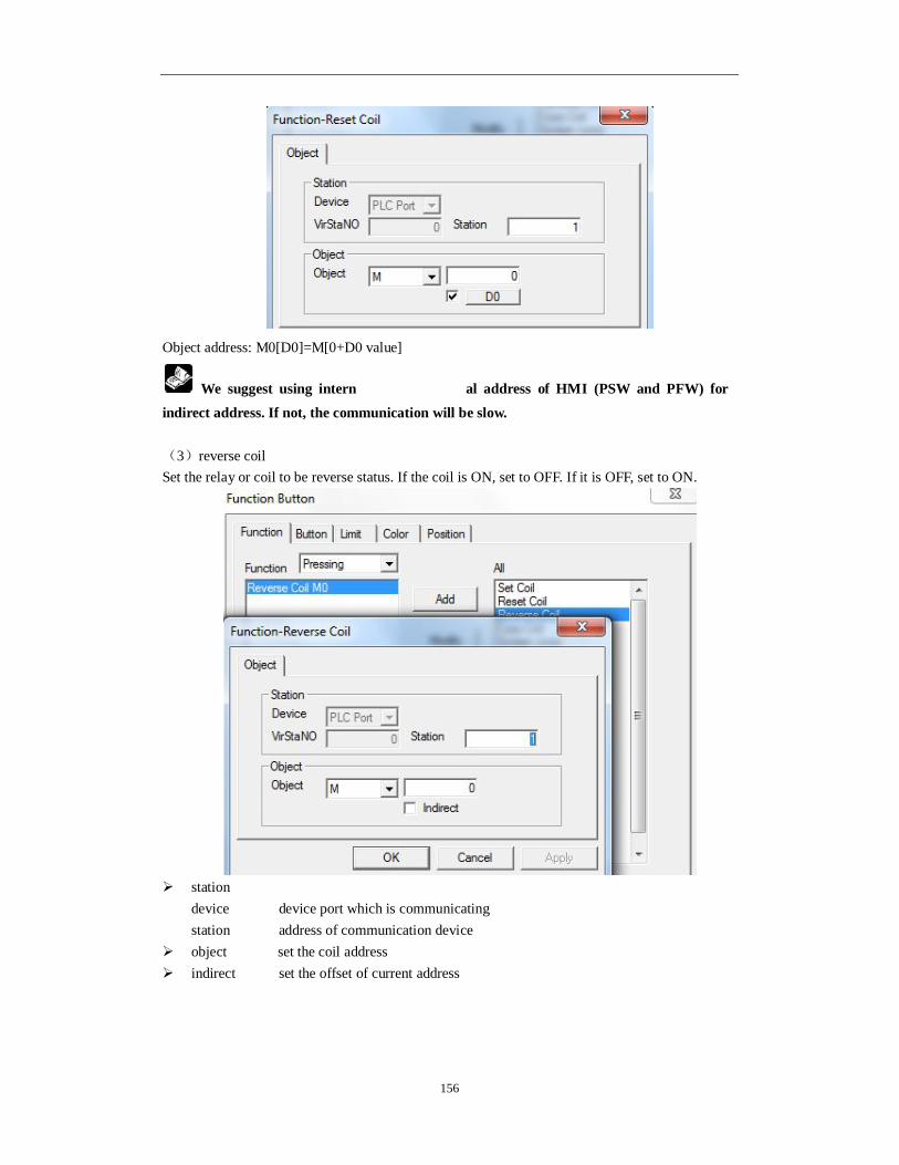
156
Object address: M0[D0]=M[0+D0 value]
We suggest using intern al address of HMI (PSW and PFW) for indirect address. If not, the communication will be slow. (3)reverse coil Set the relay or coil to be reverse status. If the coil is ON, set to OFF. If it is OFF, set to ON.
station
device device port which is communicating station address of communication device
object set the coil address indirect set the offset of current address

157
The object address: M0[D0]=M[0+D0 value]
We suggest using internal address of HMI(PSW and PFW) for indirect address. If not, the communication will be slow. (4)copy coil Copy the status of source coil to target coil.
source coil the address information of readed relay or bit target coil the address information of readed relay or bit station
device device port which is communicating station address number of communication device
object set the coil address

158
indirect set the offset of current address
The object address: D0[PSW256]=D[0+PSW256 value].
We suggest using internal address of HMI (PSW and PFW) for indirect address. If not, the communication will be slow. (5)screen jump Jump to target screen. Click “modify” button, then you can set the target screen ID.
start screen the screen when system is starting up. Previous screen jump to original screen Screen ID input the jumping screen number

159
(6)set data Set the object value
station
device device port which is communicating station address of communication device
object set the object address indirect set the offset of current address
The object address: D0[PSW256]=D[0+PSW256 value]
data data type set if the data type is Word or DWord set data set the assigned data
We suggest using internal address of HMI (PSW and PFW) for indirect address. If not, the communication will be slow.

160
(7)copy register Copy the source register data to the target register
source register read the address information of register target register write the address information of register station
device device port which is communicating station address of communication device
object set the object address indirect set the offset of current address

161
The object address: D0[PSW256]=D[0+PSW256 value] data set the data type to be Word or Dword.
We suggest using the internal address of HMI (PSW and PFW) for indirect address. If not, the communication will be slow. (8)user input Set the ASCII code of input button.
input key code the corresponding ASCII code of input button

162
(9)open window Open the target window ID
window ID set the target pop-up window ID open mode choose the target window to be hide or show hide the opened window is not visible, but the component in window can still be
effective. show the opened window is visible in project screen.
position set the upper left corner of pop-up window in the coordinate position of
programming screen. lock set if the function button-open window in the screen can be moved.
(10)close window Close the target window.
current window the window will be closed. Window ID target closed window ID

163
(11)down recipe Download the recipe data saved in HMI to relative device.
Device data address information of down recipe object register station
device device port which is communicating station address of communication device
object address and serial number of download target register indirect set the offset of current address as follow.

164
Current address will change with the register value PSW256. Object address: D0[PSW256]=D[0+PSW256 value] recipe data address and serial number of internal data register of HMI. recipe set the recipe data according to actual data capacity.
We suggest using the internal address of HMI (PSW and PFW interna address type) for indirect address. If not, the communication will be slow. (12)up recipe Upload the recipe data from relative device to the HMI.

165
device data address information of up recipe object register station
device device port which is communicating station address of communication device
object address and serial number of upload target register indirect set the offset of current address as follow.
Current address will change with register value PSW256. Object address: D0[PSW256]=D[0+PSW256 value]

166
recipe data address and serial number of HMI internal digital register recipe set the recipe data according to actual data capacity.
We suggest using internal address of HMI (PSW and PFW internal address type) for indirect address. If not, the communication will be slow. (13)data block transmit Transmit the register data group from source address to the target address.
source address read register first address target register write register first address station
device device port which is communicating station address of communication device
object set the object type and address of function button-data block transmit indirect set the offset of current address as follow.

167
Current object address will change with register PSW256. Object address: D0[PSW256]=D[0+PSW256 value] data set the register number of data block transmit
We suggest using internal address of HMI(PSW and PFW internal address type) for indirect address. If not, the communication will be slow. (14)arithmetic Operate arithmetic for target register data and save the value to target register. The object of arithmetic can be constant or variable.

168
station
device device port which is communicating station address of communication device
object set the object type and address of function button-arithmetic storage. indirect set the offset of current address as follow.
Current object address will change with register PSW256. Object address: D0[PSW256]=D[0+PSW256 value] data set the data type to be Word or DWord.
We suggest using internal address of HMI(PSW and PFW internal address type) for indirect address. If not, the communication will be slow.

169
operate kind plus, substract, multiply and divide Left operand it contains the setting of constant and variable Right operand it contains setting of constant and variable
When you choose constant, you can set the variable by “ ” button.
(15)import CSV data Importing the CSV format file from U disk to XINJE TH(-U), TG(-U), TG(-E)series HMI. You can use the saved data to consult or update the data in HMI.
(1) The title contents of CSV file can not import. (2) CSV file is produced when HMI exported CSV file data.

170
Device ID U disk number. To mark up different U disk (in order to mark up
different disk in SCADA function, C disk no. is 0, D disk is 1, E disk is 2…) Import ctrl the bit to control the import operation.when this bit is ON, the import is
allowed. Path/file the CSV file name need to import Fix name only use the name in path/file Add ID after name choose the file by name and number mode. number can be inputted
manually or set through register Start ID CSV file has many rows. Start ID defines importing from which rows.
0 means the first row. The row no. can be set through register or input directly.

171
Register capacity import data group quantity Register mode data storage mode. You need to choose the mode same to CSV file.
First confirm if the import data address contains “covered buffer”. If yes, you need to choose “loop”. If not, please choose “line”(real trend map, history data map, time trend control and sample save have covered buffer). Loop when the data reach the max group quantity, it will cover the original
data and store from the first address again line when the data reach the max group quantity, it stop store.
Add/delete add/delete the import column Move up/move down change the column order title set the title format please set the same format to CSV file Data type please set the same data type to CSV file Bit length/float length choose the same bit lengthand float length in CSV file
Object the import data will store in HMI register PSW or PFW. Please set the PSW or
PFW register address.

172
Execute status When the bit is ON, the data is importing Execute result it shows the execute result through the data in register
execute result: 0—import successful 1—import device doesn’t exist 2—the memory is low 3—the file name is wrong 4—failed to read/write the file
Execute process it show the importing percent. The percent range is 0~100.
Data time import the time of CSV file.
Date format/time format the date format displayed in HMI
(16)Export CSV data Export CSV data function can export the HMI register data to U disk. CSV is the file format which support EXCEL. You can use EXCEL to open and edit the CSV file. The memory of HMI will extend after using this function. It is convenient for production and maintenance of device.
Data in HMI

173
Device ID the number of U disk. If there are many U disks, it can distinguish
different disk (when in the configuration, it is hard disk partition number. C disk is 0. D disk is 1 and so on. The no. can be input by manual or register).
Path/file set the name of saved CSV file Fix name only save file by the name set in “path/file” Re-export title export the title everytime Name add automatic generate file by the mode of name and serial number. The serial
number will be added every time.(range: 000~999). The generated file is as following picture.
Add number after name you can set the serial number after file manually or use a register to set dynamically.
Named by date use the current date (year, month and day) to name the file. (Now the file name written in “path/file” is invalid) the generated file is as following picture.

174
Register capacity data group quantity which need to be exported every time Register mode data storage mode. You need to choose the mode as same as CSV
file. You need to confirm if the exported data address has “ring buffer”. If it has, please choose “loop”. If not, please choose “line”(normally the data range which save “real trend map”, “history trend data map”, “time trend” and “data storage” all has “ring buffer”). Loop: continue to export data after exporting the setting groups. The new data will cover
the original data. Line: finish an exporting process according to the group quantity. Then the export process
end. Add/delete add/delete the list title which is contained in CSV file Move up/move down move up/down the generated list title Title modify the current list title (displaying list) Data format define the data format (decimal, hex, float number, unsigned
number) Data type define the data type (Bool, word, dword, byte, string) Bit length/float length the data bit length and the bit length after decimal point

175
object choose the object type and first address number of data source.
Execute status the bit show the exporting status. When it is ON, the file is exporting Execute result the register value will show the result of exporting
Execute result: 0—export successfully 1—no exporting device 2—low RAM 3—path and file name is wrong 4—reading and writing file failed
Execute process show the export process by percent 0~100
Date time export the date time information Date format/time format choose the date/time format which is displayed in CSV file.

176
(17)call function Call the C function to do more complicated operation and communication.
Name choose C function name Exec mode the execute environment of function can operate many tasks at the same
time. parallel call the task of this function and create new task to execute function. Caller can continue to deal with it. serial call the task of this function. Only by finishing this function, then you can continue to deal with it. So this function must contain suitable exiting conditions.
About the relation introduction and instructions of function please refer to “HMI C function manual”. Button
Key type define the key code of touch key or enter key. It is only for OP560, MP360,
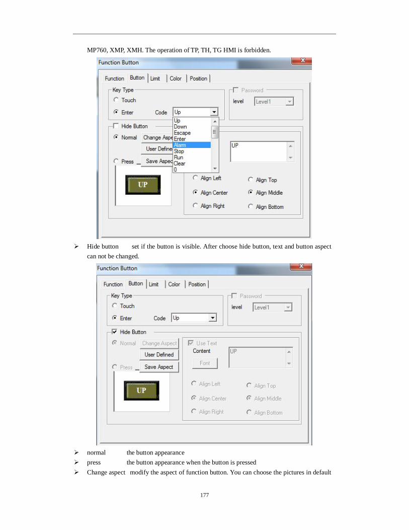
177
MP760, XMP, XMH. The operation of TP, TH, TG HMI is forbidden.
Hide button set if the button is visible. After choose hide button, text and button aspect
can not be changed.
normal the button appearance press the button appearance when the button is pressed Change aspect modify the aspect of function button. You can choose the pictures in default

178
library User defined aspect modify the aspect of function button. The picture library is from
user. Save aspect save the aspect of function button. It is convenient for programming. Use text modify the content, font and align type of function button.
content set the displaying content of function button. font set the size, font and type of function button align you can choose the align type freely according to your requirement.
limit Support the limit function. The function button will be effective when the control bit is ON. Otherwise, the hide button function cannot be operated.
color
kind choose the button color type color modify the color according to the kind.

179
position
position set the upper left point to be the coordinate point (0, 0). Set the X and Y
coordinate value of function button X position set the X coordinate value of function button. Y position set the Y coordinate value of function button.
size set the width and height of function button. width(W) set the width of function button height(H) set the height of function button
animal set if the function button need to be moved.
horizontal set the function button in the horizontal position of HMI according to register value, modifying X coordinate value.
X coordinate value=X position+current value of register vertical set the function button in the vertical position of HMI according to register value,modifying Y coordinate value.
Y coordinate value =Y position+current value of register lock if choose this item, the button cannot be moved in the screen Zoom proportion set if it can be zoomed when editing its size. But this function can
not work now.

180
4-3-25. Function field
The operation is activated by internal system or logical conditions. This is similar to function button. But the differences are as below.
The difference is: function field will activate automatically when the condition is satisfied. But the function field button is invisible in the screen. 1. click the “ ” icon in component tool bar. Move the cursor to the screen and click left mouse to confirm. Click right mouse or ESC button to cancel it. “Function field” component is invisible button and it will be invisible in HMI.
2. Double click “function field” or choose “function field” and click right mouse. Set the attributes by choosing “attribute” or “ ” button. Mode
Start screen when the screen of function field is called, the relative function will be executed once.
Coil spring when the coil change from OFF to ON, the relative function will be executed once.
Time(sec.) it will execute relative function when the screen is called. It will execute function by certain time (it can be set).
Time (sec) the time, the unit is second Run immediately execute the function immediately every certain time. If not choose “run immediately”, it will execute the function every certain time from the second period.

181
Continue when the screen is called, every scan will execute relative function. When you choose “time” or “continue”, you can choose
to set control coil. This function can be executed only when this coil is ON. First scan after down this function will be executed when the screen is scanned first
time after downloading. First scan after power this function will be executed when the system is scanned after
power on.
Only one of the act modes can be choosed. function
The setting of this function is the same to “function button”. Please refer to “function button”.
T
Call the screen
Period t
Period t
Period t
Execute Execute
Execute
Run immediately
T
Call the screen
Period t
Period t
Period t
Execute
Execute
Not run immediately

182
position
position set the upper left point to be the coordinate point(0,0). Set the X and Y
coordinate value of function field. X position set the X coordinate value of function field. Y position set the Y coordinate value of function field.
lock set if the function field in screen can be moved. visible set if the function field is visible when editing it. This function is canceled in
Touchwin 2012.
4-3-26. Discrete column map
Show the data of the discrete register in the form of column map or line graph
X axis is register no., the Y axis is the value in register. The serial number 1~4 from left to right stand for PFW300, PFW302, PFW304, PFW306.
1. Click “ ” icon in component tool bar. Move the cursor to screen and click left mouse
to confirm. Click right mouse or ESC button to cancel it. You can edit the size by the boundary points.

183
2. Double click “discrete column map” or choose “discrete column map” and click right mouse. Set the attribute by choosing “attribute” or “ ” button. object
Add/delete add/delete data reigster Move up/move down change the order of register modify modify the attribute of corresponded register
display
Degree set the max and min value of Y axis. Format it contains decimal, hex, float and unsigned. Pattern data is showed in the pattern of fold, dot and column.

184
color
kind choose the discrete column map to modify the kind of color. color modify the color according to the kind.
position
position set the upper left point to be the coordinate point(0,0)and set the X and Y
coordinate value of discrete column map. X position set the X coordinate value of discrete column map. Y position set the Y coordinate value of discrete column map.
size set the width and height of discrete column map. width(W) set the width of discrete column map height(H) set the height of discrete column map
animal set if the discrete column map need to be moved.

185
horizontal set the discrete column map in the horizontal position of HMI according to register value, modifying the X coordinate value. X coordinate value=X position+current value of register vertical set the discrete column map in the vertical position of HMI according to register value, modifying the Y coordinate value. Y coordinate value=Y position+current value of register
lock lock the column map in the screen, then it cannot move Zoom proportion set if it can be zommed by proportion when editing the size. But this
function can not work now. This function is canceled in Touchwin 2012.
4-3-27. Continue column map
Display the value of continuous register in column map.
The four columns are PFW300, PFW301, PFW302, PFW303. 1. Click “ ” in the software menu, move the cursor in the screen, click left mouse to confirm, click ESC to cancel. Modify the map size through the boundary point.
2. Double click the continue column map or right click the mouse then choose property or “ ” to set the parameters.

186
Object The differences from discrete column map: continue column map only needs to set the start register address.
Station Device the device port station device station no.
object set the register type and adress indirect set the address offset The object address is D0[PSW256] = D[0+PSW256 value]. Data set the data type: word or Dword Display
Data the register quantity For example, the object is PFW300, data number is 5. The continue column map will display the value of PFW300, PFW301, PFW302, PFW303, PFW304.

187
Range, format, pattern please refer to discrete column map. Color
kind choose the color type color choose the colors of column map Position
position set the upper left point to be the coordinate point(0,0)and set the X and Y coordinate value of continue column map.
X position set the X coordinate value of continue column map. Y position set the Y coordinate value of continue column map.
size set the width and height of continue column map. width(W) set the width of continue column map height(H) set the height of continue column map
animal set if the continue column map need to be moved.

188
horizontal set the continue column map in the horizontal position of HMI according to register value, modifying the X coordinate value. X coordinate value=X position+current value of register vertical set the continue column map in the vertical position of HMI according to register value, modifying the Y coordinate value. Y coordinate value=Y position+current value of register
lock lock the continue column map in the screen, then it cannot move Zoom proportion set if it can be zommed by proportion when editing the size. But this
function can not work now. This function is canceled in Touchwin 2012.
4-4-28. Process orbit
With the new Xinje precise cutting technology, CAD file can be sent from U-disk to HMI. Then CAD file can be sent from HMI to PLC. PLC can send the cutting parameter file to HMI and show the cutting image.
1. Click to put it in the screen, click ESC to cancel.

189
2. Double click the process orbit, it will show attribute window. Orbit
Label
Bit Length the value bit length showing on X/Y axis Float length the value decimal bit length showing on X/Y axis Font the value font showing on X/Y axis
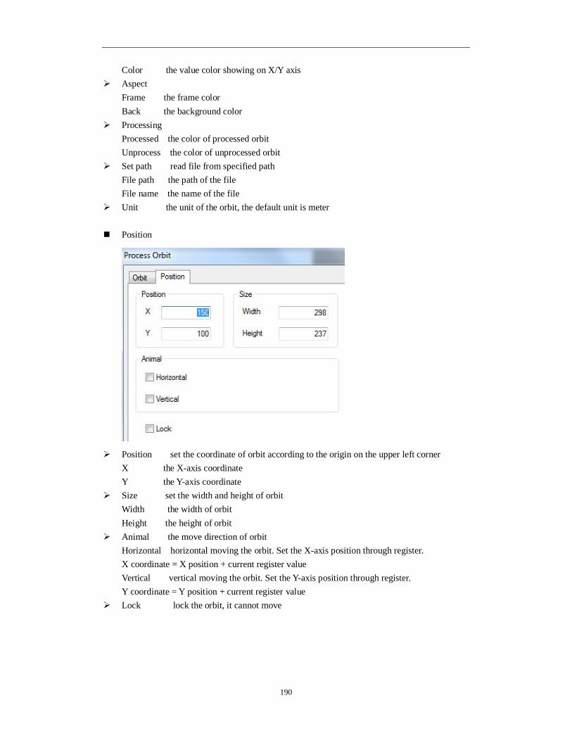
190
Color the value color showing on X/Y axis Aspect
Frame the frame color Back the background color
Processing Processed the color of processed orbit Unprocess the color of unprocessed orbit
Set path read file from specified path File path the path of the file File name the name of the file
Unit the unit of the orbit, the default unit is meter
Position
Position set the coordinate of orbit according to the origin on the upper left corner X the X-axis coordinate Y the Y-axis coordinate
Size set the width and height of orbit Width the width of orbit Height the height of orbit
Animal the move direction of orbit Horizontal horizontal moving the orbit. Set the X-axis position through register. X coordinate = X position + current register value Vertical vertical moving the orbit. Set the Y-axis position through register. Y coordinate = Y position + current register value
Lock lock the orbit, it cannot move

191
4-4. Display tool bar
The buttons from left to right are: date, clock, buzzer, backlight, scale, meter, valve, pipe, pump, fan, motor, retort, inverter alarm information, scroll text, real time trend map, history trend map, XY trend map, time trend map, event button, alarm list, real time event, history event, common grid control, data grid control, sample save, sample export.
4-4-1. Date
Display the date. 1. click and move the cursor in the screen, click left mouse to confirm, click ESC to cancel.
2. Double click date button or right click mouse then choose property to modify the parameters. display
Manner the date display mode
Font
setting set the font of date
color

192
kind choose the color type color set the colors transparent back the background of date is transparent
Digital back color and text back color are valid when the transparent back is not choosen. Position
position set the upper left point to be the coordinate point(0, 0)and set the X and Y
coordinate value of date X position set the X coordinate value of date Y position set the Y coordinate value of date
size set the width and height of date width(W) set the width of date height(H) set the height of date
animal set if the date need to be moved.

193
horizontal set the date in the horizontal position of HMI according to register value, modifying the X coordinate value. X coordinate value=X position+current value of register vertical set the date in the vertical position of HMI according to register value, modifying the Y coordinate value. Y coordinate value=Y position+current value of register
lock lock the date in the screen, then it cannot move Zoom proportion set if it can be zommed by proportion when editing the size. But this
function can not work now. This function is canceled in Touchwin 2012.
4-4-2. Clock
Display the time.
1. Click and move the cursor in the screen. Click left mouse to confirm and click ESC to
cancel.
2. Double click clock or right click mouse then choose property to modify the parameters.
Sample preview the clock display format Manner set the clock display format second display the second
Font

194
Setting set the font of time Color
kind choose the color type color set the colors transparent back the background of date is transparent
Digital back color and text back color are valid when the transparent back is not choosen. Position

195
Position set the upper left point to be the coordinate point(0, 0)and set the X and Y
coordinate value of clock X position set the X coordinate value of clock Y position set the Y coordinate value of clock
Size set the width and height of clock width(W) set the width of clock height(H) set the height of clock
Animal set if the clock needs to be moved.
Horizontal set the clock in the horizontal position of HMI according to register value, modifying the X coordinate value. X coordinate value=X position+current value of register Vertical set the clock in the vertical position of HMI according to register value, modifying the Y coordinate value. Y coordinate value=Y position+current value of register
lock lock the clock in the screen, then it cannot move Zoom proportion set if it can be zommed by proportion when editing the size. But this
function can not work now. This function is canceled in Touchwin 2012.
4-4-3. Buzzer
The Buzzer will ring when the activate condition is satisfied.
1. Click “ ”, move the cursor in the screen, click left mouse to confirm, click ESC to cancel.

196
Buzzer is invisible in the screen.
2. Double click buzzer or right click mouse then choose property to modify the parameters. Object
Station Device the HMI port no. communicate to the device Station the device station no.
Object the buzzer object address Indirect set the address offset
The object address is M0[D0]=M[0+D0 value]
Please choose HMI internal register for indirect address (PSW, PFW).
Buzzer

197
Bell mode set the ring mode
One ring once Continue continue ring
Position
Position set the upper left point to be the coordinate point(0, 0)and set the X and Y
coordinate value of buzzer X position set the X coordinate value of buzzer Y position set the Y coordinate value of buzzer
Lock lock the buzzer in the screen, it cannot be moved Visible the buzzer is visible when editing
4-4-4. Backlight
Turn on the backlight.
1. Click “ ”, move the cursor in the screen. Click left mouse to confirm, click ESC to cancel.
Backlight is invisible in the screen.
2. Double click backlight or click right mouse then choose property to modify the parameters. Object

198
Station
Device the port no. communicate with device station device station no.
Object the backlight object address Indirect set the offset of object address
The object address is, M0[D0] = M[0+D0 value]
Please choose HMI internal register for indirect address. (PSW, PFW) Position

199
Position set the upper left point to be the coordinate point(0, 0)and set the X and Y
coordinate value of backlight X position set the X coordinate value of backlight Y position set the Y coordinate value of backlight
Lock lock the backlight in the screen, it cannot be moved Visible the backlight is visible when editing
4-4-5. Scale
1. Click “ ” and move the cursor in the screen. Click left mouse to confirm and click ESC to cancel. Modify the scale size through the boundary point.
2. Double click scale or right click scale then choose property to modify the parameters. Scale
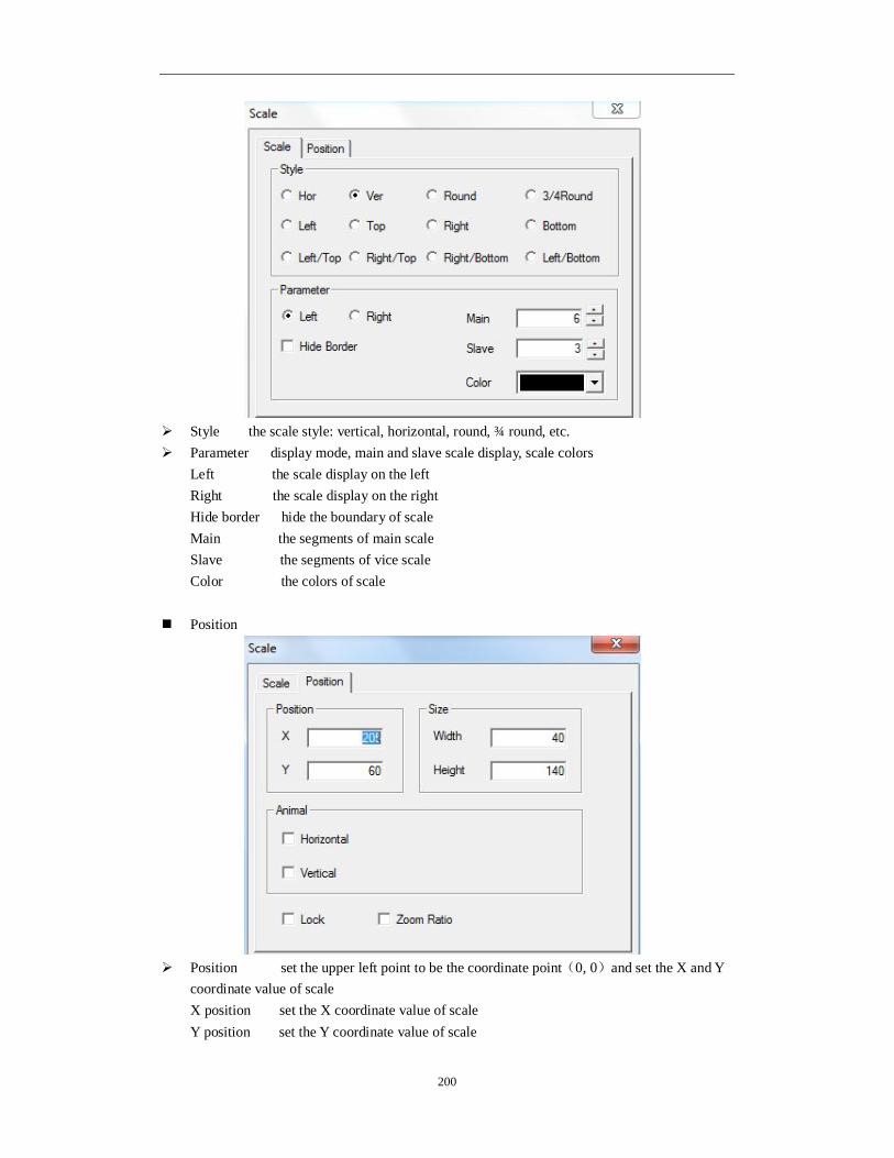
200
Style the scale style: vertical, horizontal, round, ¾ round, etc. Parameter display mode, main and slave scale display, scale colors
Left the scale display on the left Right the scale display on the right
Hide border hide the boundary of scale Main the segments of main scale Slave the segments of vice scale Color the colors of scale
Position
Position set the upper left point to be the coordinate point(0, 0)and set the X and Y
coordinate value of scale X position set the X coordinate value of scale Y position set the Y coordinate value of scale

201
Size set the width and height of scale width(W) set the width of scale height(H) set the height of scale
Animal set if the scale needs to be moved.
Horizontal set the scale in the horizontal position of HMI according to register value, modifying the X coordinate value. X coordinate value=X position+current value of register Vertical set the scale in the vertical position of HMI according to register value, modifying the Y coordinate value. Y coordinate value=Y position+current value of register
lock lock the scale in the screen, then it cannot move Zoom proportion set if it can be zommed by proportion when editing the size. But this
function can not work now. This function is canceled in Touchwin 2012.
4-4-6. Instrument
The register value will show in the instrument. 1. Click and move the cursor in the screen, right click mouse to confirm, click ESC to cancel. Drag the boundary to change the size.
2. Double click the instrument, it will show the attribute window. Object

202
Station
Device the communication port connect the HMI Virstano the station no. of the communication device
Object the instrument object address Indirect set the offset of object address
The object address = D [0+ the value of PSW256] Value set the value format (Dword or word)
We suggest using internal register for indirect address (PSW, PFW), otherwise the communication speed will be slow. Display

203
Text the text on the instrument, user can set many language Horizontal align horizontal align the text Vertical align vertical align the text Aspect change the appearance of instrument
Set
Direction the instrument pointer rotating direction

204
Graphics the pointer width and the scale quantity Data set set the range of scale, alarm value, danger value
Up danger between setting value and max scale, Up alarm between setting value and up danger Down alarm between down danger and setting value Down danger between min scale and setting value
Up danger value is larger than up alarm value, down alarm value is larger than down danger. Color
Kind the color type Color set the color
Position
Position set the upper left point to be the coordinate point(0, 0)and set the X and Y
coordinate X position set the X coordinate of instrument Y position set the Y coordinate of instrument

205
Size set the width and height of instrument width(W) set the width of instrument height(H) set the height of instrument
Animal the instrument can move
Horizontal the instrument can horizontal move according to register value, X coordinate value =X position+current value of register Vertical the instrument can vertical move according to register value, Y coordinate value=Y position+current value of register
Lock lock the instrument in the screen, then it cannot move
4-4-7. Valve
Simulate the valve status in process control system. For example: the following valve is in close status and open status.
Close status open status
1. Click and move the cursor in the screen, right click mouse to confirm, click ESC to cancel.
Drag the boundary to change the size.
2. Double click the valve, it will show the attribute window. Object
(1) Valve object set the trigger signal. When the signal is ON, the valve open; when the signal is OFF, the valve close.
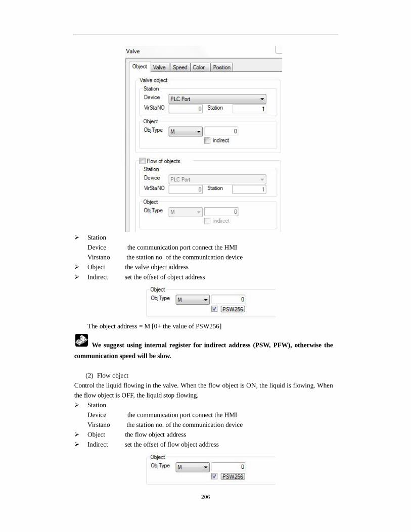
206
Station
Device the communication port connect the HMI Virstano the station no. of the communication device
Object the valve object address Indirect set the offset of object address
The object address = M [0+ the value of PSW256]
We suggest using internal register for indirect address (PSW, PFW), otherwise the communication speed will be slow.
(2) Flow object
Control the liquid flowing in the valve. When the flow object is ON, the liquid is flowing. When the flow object is OFF, the liquid stop flowing. Station
Device the communication port connect the HMI Virstano the station no. of the communication device
Object the flow object address Indirect set the offset of flow object address

207
The object address = M [0+ the value of PSW256]
We suggest using internal register for indirect address (PSW, PFW), otherwise the communication speed will be slow. Valve
Manner preview the appearance of valve Change aspect change the appearance of valve User defined user can define the appearance of valve Save aspect save the appearance of valve
Direction the liquid flowing direction in the valve Act the action of valve
Set on the valve always open when trigger signal is ON Set off the valve always close when trigger signal is ON Reverse the valve status will reverse when trigger signal is ON Instant the valve open when keep pressing the trigger signal
Speed

208
Constant the flowing speed in the valve is constant value, the value should be in the range of max and min value
Register the flowing speed is controlled through the register, the speed should be in the range of max and min value Min the min speed Max the max speed
Color
Kind set the color type Color set the color Position
Position set the upper left point to be the coordinate point (0, 0) and set the X and Y coordinate X position set the X coordinate of valve Y position set the Y coordinate of valve
Size set the width and height of valve Width (W) set the width of valve

209
Height (H) set the height of valve Animal the valve can move
Horizontal the valve can horizontal move according to register value, X coordinate value =X position+current value of register Vertical the valve can vertical move according to register value, Y coordinate value=Y position+current value of register
Lock lock the valve in the screen, then it cannot move
4-4-8. Pipe
Simulate the pipe function in process control system. 1. Click and move the cursor in the screen, right click mouse to confirm, click ESC to cancel. Drag the boundary to change the size.
2. Double click the pipe, it will show the attribute window. Object When the coil is ON, the liquid is flowing in the pipe. When the coil is OFF, the liquid stops flowing in the pipe.
Station Device the communication port connect the HMI Virstano the station no. of the communication device
Object the pipe object address Indirect set the offset of object address

210
The object address = M [0+ the value of PSW256]
We suggest using internal register for indirect address (PSW, PFW), otherwise the communication speed will be slow. Aspect
Aspect preview the appearance of pipe Change aspect change the appearance of pipe User defined user can define the appearance of pipe Save aspect save the appearance of pipe
Direction the liquid flowing direction in the pipe
Speed
Constant the flowing speed in the pipe is constant value, the value should be in the

211
range of max and min value Register the flowing speed is controlled through the register, the speed should be
in the range of max and min value Min the min speed Max the max speed
Color
Kind set the color type Color set the color
Position
Position set the upper left point to be the coordinate point (0, 0) and set the X and Y
coordinate X position set the X coordinate of pipe Y position set the Y coordinate of pipe
Size set the width and height of pipe Width (W) set the width of pipe Height (H) set the height of pipe

212
Animal the pipe can move
Horizontal the pipe can horizontal move according to register value, X coordinate value =X position+current value of register Vertical the pipe can vertical move according to register value, Y coordinate value=Y position+current value of register
Lock lock the pipe in the screen, then it cannot move
4-4-9. Pump
Simulate the running status of pump. 1. Click and move the cursor in the screen, right click mouse to confirm, click ESC to cancel. Drag the boundary to change the size.
2. Double click the pump, it will show the attribute window. Object When the coil is ON, the liquid is flowing in the pump. When the coil is OFF, the liquid stops flowing in the pump.
Station
Device the communication port connect the HMI Virstano the station no. of the communication device
Object the pump object address Indirect set the offset of object address

213
The object address = M [0+ the value of PSW256]
We suggest using internal register for indirect address (PSW, PFW), otherwise the communication speed will be slow. Aspect
Aspect preview the appearance of pump
Change aspect change the appearance of pump User defined user can define the appearance of pump Save aspect save the appearance of pump
Direction the liquid flowing direction in the pump
Speed
Constant the flowing speed in the pump is constant value, the value should be in the
range of max and min value

214
Register the flowing speed is controlled through the register, the speed should be in the range of max and min value Min the min speed Max the max speed
Color
Kind set the color type Color set the color
Position
Position set the upper left point to be the coordinate point (0, 0) and set the X and Y
coordinate X position set the X coordinate of pump Y position set the Y coordinate of pump
Size set the width and height of pump Width (W) set the width of pump Height (H) set the height of pump
Animal the pump can move

215
Horizontal the pump can horizontal move according to register value, X coordinate value =X position+current value of register Vertical the pump can vertical move according to register value, Y coordinate value=Y position+current value of register
Lock lock the pump in the screen, then it cannot move
4-4-10. Fan
Simulate the running status of fan. 1. Click and move the cursor in the screen, right click mouse to confirm, click ESC to cancel. Drag the boundary to change the size.
2. Double click the fan, it will show the attribute window. Object When the coil is ON, the fan is running. When the coil is OFF, the fan stops running.
Station
Device the communication port connect the HMI Virstano the station no. of the communication device
Object the fan object address Indirect set the offset of object address

216
The object address = M [0+ the value of PSW256]
We suggest using internal register for indirect address (PSW, PFW), otherwise the communication speed will be slow. Aspect
Aspect preview the appearance of fan
Change aspect change the appearance of fan User defined user can define the appearance of fan Save aspect save the appearance of fan
Direction the running direction of fan
Speed
Constant the running speed of fan is constant value, the value should be in the range
of max and min value Register the running speed is controlled through the register, the speed should be
in the range of max and min value Min the min speed Max the max speed

217
Color
Kind set the color type Color set the color
Position
Position set the upper left point to be the coordinate point (0, 0) and set the X and Y
coordinate X position set the X coordinate of fan Y position set the Y coordinate of fan
Size set the width and height of fan Width (W) set the width of fan Height (H) set the height of fan
Animal the fan can move

218
Horizontal the fan can horizontal move according to register value, X coordinate value =X position+current value of register Vertical the fan can vertical move according to register value, Y coordinate value=Y position+current value of register
Lock lock the fan in the screen, then it cannot move
4-4-11. Motor
Simulate the running status of motor.
1. Click and move the cursor in the screen, right click mouse to confirm, click ESC to
cancel. Drag the boundary to change the size.
2. Double click the motor, it will show the attribute window. Object When the coil is ON, the motor is running. When the coil is OFF, the motor stops running.
Station
Device the communication port connect the HMI Virstano the station no. of the communication device
Object the motor object address Indirect set the offset of object address

219
The object address = M [0+ the value of PSW256]
We suggest using internal register for indirect address (PSW, PFW), otherwise the communication speed will be slow. Map
ON Map Preview the running image of motor OFF Map Preview the stop status image of motor Change aspect change the appearance of motor User defined user define the motor appearance Save aspect save the appearance of motor
Color
Kind choose the color type Color set the color Position

220
Position set the upper left point to be the coordinate point (0, 0) and set the X and Y
coordinate X position set the X coordinate of motor Y position set the Y coordinate of motor
Size set the width and height of motor Width (W) set the width of motor Height (H) set the height of motor
Animal the motor can move
Horizontal the motor can horizontal move according to register value, X coordinate value =X position+current value of register Vertical the motor can vertical move according to register value, Y coordinate value =Y position+current value of register
Lock lock the motor in the screen, then it cannot move
4-4-12. Retort
Simulate the running status of retort.
1. Click and move the cursor in the screen, right click mouse to confirm, click ESC to
cancel. Drag the boundary to change the size.

221
2. Double click the retort, it will show the attribute window. Object
Station Device the communication port connect the HMI Virstano the station no. of the communication device
Object the retort object address Indirect set the offset of object address
The object address = D [0+ the value of PSW256] Value set the value format (Dword or word)
We suggest using internal register for indirect address (PSW, PFW), otherwise the communication speed will be slow. Range

222
Max the max value of retort, it can be set through the register Min the min value of retort, it can be set through the register Alarm display the liquid level in the retort according to the alarm information Upper limit value < max value Upper limt alarm: in the range of upper limit to max value Lower limit value > min value Lower limit alarm: in the range of min value and lower limit value
Alrm mode: fast mode and slow mode
Manner
User defined user define the retort appearance Changing change the appearance of retort
Scale

223
Use scale
Main scale set the main scale of retort Slave scale set the vice scale of retort
Color
Kind set the color type Color set the color
Position
Position set the upper left point to be the coordinate point (0, 0) and set the X and Y
coordinate
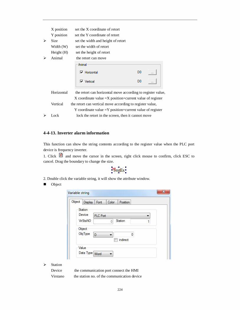
224
X position set the X coordinate of retort Y position set the Y coordinate of retort
Size set the width and height of retort Width (W) set the width of retort Height (H) set the height of retort
Animal the retort can move
Horizontal the retort can horizontal move according to register value, X coordinate value =X position+current value of register Vertical the retort can vertical move according to register value, Y coordinate value =Y position+current value of register
Lock lock the retort in the screen, then it cannot move
4-4-13. Inverter alarm information
This function can show the string contents according to the register value when the PLC port device is frequency inverter. 1. Click and move the cursor in the screen, right click mouse to confirm, click ESC to cancel. Drag the boundary to change the size.
2. Double click the variable string, it will show the attribute window. Object
Station Device the communication port connect the HMI Virstano the station no. of the communication device

225
Object the object address Indirect set the offset of object address
The object address = D [0+ the value of PSW256] Value set the value format (Dword or word)
We suggest using internal register for indirect address (PSW, PFW), otherwise the communication speed will be slow. Display
Content the contents of variable string Value the value to show the string Text des… the string contents
Add add one text Delete delete one text Aspect the background of text Alignment the alignment mode of text
Font

226
Setting set the font, size of string Art set art style of string Color
Kind set the color type Color set the color
Position

227
Position set the upper left point to be the coordinate point (0, 0) and set the X and Y coordinate X position set the X coordinate of string Y position set the Y coordinate of string
Size set the width and height of string Width (W) set the width of string Height (H) set the height of string
Animal the string can move
Horizontal the string can horizontal move according to register value, X coordinate value =X position+current value of register Vertical the string can vertical move according to register value, Y coordinate value =Y position+current value of register
Lock lock the string in the screen, then it cannot move
4-4-14. Scroll text
The text can move from left to right. 1. Click and move the cursor in the screen, right click mouse to confirm, click ESC to cancel.
2. Double click the scroll text, it will show the attribute window. Message
Control it includes show always and limited by coil Show always input the contents in it Limited by coil the contents will display when the coil is ON
Content right click the text to copy, delete and build new text, double click the text to change the contents
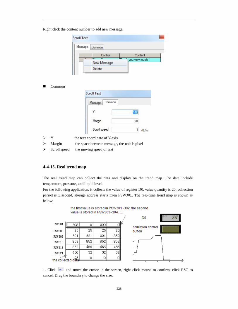
228
Right click the content number to add new message.
Common
Y the text coordinate of Y-axis Margin the space between message, the unit is pixel Scroll speed the moving speed of text
4-4-15. Real trend map
The real trend map can collect the data and display on the trend map. The data include temperature, pressure, and liquid level. For the following application, it collects the value of register D0, value quantity is 20, collection period is 1 second, storage address starts from PSW301. The real-time trend map is shown as below:
1. Click and move the cursor in the screen, right click mouse to confirm, click ESC to cancel. Drag the boundary to change the size.

229
2. Double click the real trend map, it will show the attribute window. Trend map
Add add the collection object Delete delete the collection object Modify modify the collection object
(1) Object

230
Station
Device the communication port connect the HMI Virstano the station no. of the communication device
Object the object address Indirect set the offset of object address
The object address = D [0+ the value of PSW256] Value set the value format (Dword or word)
We suggest using internal register for indirect address (PSW, PFW), otherwise the communication speed will be slow. (2) Trend map

231
Data Count the collection data quantity Pick period the collection period
Format decimal, hex, float, unsigned value Range max and min value of Y-axis coordinate Display the display mode of map: fold, dot. column Move mode
Move pen the curve will move according to the value Move paper the coordinate axis will move according to the value
(3) Pick
Control when the coil is ON, the map starts collecting data (4) Save

232
Object the storage address of collection data Auto locate the system will auto store the collection data in the HMI
(5) Color
Set the the color of curve in the map
Color Set the coordinate axis color
Position

233
Position set the upper left point to be the coordinate point (0, 0) and set the X and Y
coordinate X position set the X coordinate of real trend map Y position set the Y coordinate of real trend map
Size set the width and height of real trend map Width (W) set the width of real trend map Height (H) set the height of real trend map
Animal the real trend map can move
Horizontal the real trend map can horizontal move according to register value, X coordinate value =X position+current value of register Vertical the real trend map can vertical move according to register value, Y coordinate value =Y position+current value of register
Lock lock the real trend map in the screen, then it cannot move
4-4-16. History trend map
The history trend map can display the history data and real-time data at the same time. The history data can be seen through event button.

234
1. Click and move the cursor in the screen, right click mouse to confirm, click ESC to cancel. Drag the boundary to change the size.
2. Double click the history trend map, it will show the attribute window. Trend source
Add add the collection object Delete delete the collection object Modify modify the collection object, double click the object to modify

235
Register
Station
Device the communication port connect the HMI Virstano the station no. of the communication device
Object the object address Indirect set the offset of object address
The object address = D [0+ the value of PSW256] Value set the value format (Dword or word)
We suggest using internal register for indirect address (PSW, PFW), otherwise the communication speed will be slow. (2) Trend data
Format the data format: decimal, hex, float, unsigned value

236
Range the max and min value of value, the default value is 1024 and 0
(3) Color
Set the curve color Display
Page data the data quantity displayed in the map, for example the following map displayed 5 page data
Total data the total collection data quantity. For example total data is 10, Each collection value occupied register quantity = (collection data quantity n + collection time

237
6)*data capacity Pick period the collection period Time the time display format Control control the collection action through coil Current data store the first group of data on every page. Occupied registers = current
collection objects n + collection time 6
Object
Object type the register address to store the data Auto locate the HMI will auto-store the data in registers
Color
Kind set the color type Color set the colors
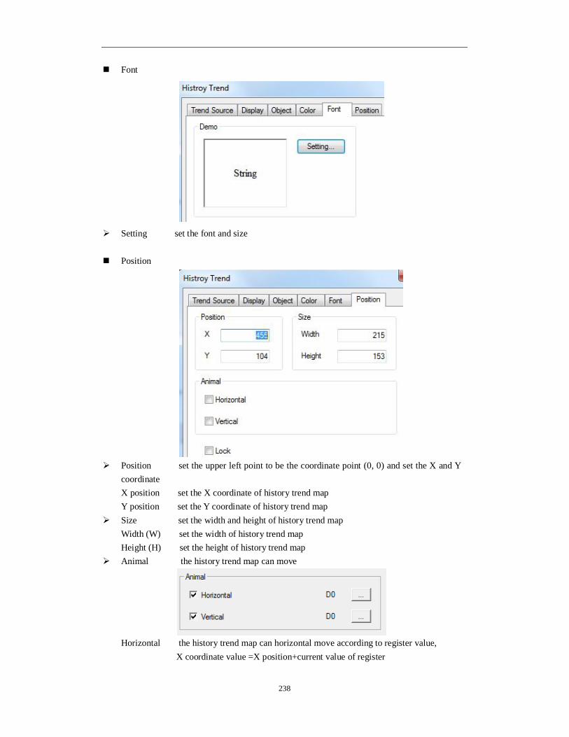
238
Font
Setting set the font and size Position
Position set the upper left point to be the coordinate point (0, 0) and set the X and Y
coordinate X position set the X coordinate of history trend map Y position set the Y coordinate of history trend map
Size set the width and height of history trend map Width (W) set the width of history trend map Height (H) set the height of history trend map
Animal the history trend map can move
Horizontal the history trend map can horizontal move according to register value, X coordinate value =X position+current value of register

239
Vertical the history trend map can vertical move according to register value, Y coordinate value =Y position+current value of register
Lock lock history trend map in the screen, then it cannot move
4-4-17. Event button
Event button has page up and page down function for data storage function. This button is used together with history trend map, history event, time trend map, XY trend map. 1. Click and move the cursor in the screen, right click mouse to confirm, click ESC to cancel. Drag the boundary to change the size.
2. Double click the event button, it will show the attribute window. Event
Trend type choose trend/event, time trend or XY poly trend according to the
requirements (1) Trend/event This item is for history event and all the trend maps

240
Prev page page up (this function is also fit for common grid and data grid) Next page page down (this function is also fit for common grid and data grid) Prev item last item (this function is also fit for common grid and data grid) Next item next item (this function is also fit for common grid and data grid) Ok confirm the current value and record the current time (only fit for history
event) Reset content clear all the collection data Move up move up the current coordinate scale (only fit for trend map) Move down move down the current coordinate scale (only fit for trend map) Move left move left the current coordinate scale (only fit for trend map) Move right move right the current coordinate scale (only fit for trend map) Zoom out zoom out the current coordinate scale (only fit for trend map) Zoom in zoom in the current coordinate scale (only fit for trend map)
(2) Time trend

241
Left (Thin/wide) move left the current coordinate scale (thin/wide means the move
distance) Right (Thin/wide) move right the current coordinate scale (thin/wide means the move
distance) Zoom out (Thin/wide) zoom out the current coordinate scale (thin/wide means the zoom
rate) Zoom in (Thin/wide) zoom in the current coordinate scale (thin/wide means the zoom
rate) Show show the curve Hide hide the curve Reset reset the curve Zoom out/in (rate) zoom out/in the current coordinate scale according to the rate
(3) XY poly trend

242
Clear clear all the fold line Clear&draw clear the fold line, and draw new fold line Reserve&draw reserve the old fold line and draw the new fold line Repeat&draw draw new line and cover the old fold line once the data coordinate
changed
Button

243
More language the text showing on the button can be set to multi-language, click “text
library” to add language Coil control when the coil is ON, the button is functional Password the button will be protected by password. Please choose the password
level. Please refer to “Touchwin special function component” manual Key type touch key(for TP, TH and TG series) or membrane key(for OP560,
MP360, MP760, XMH, XMP) Key hide hide the button Released/pressed set the released and pressed button appearance
Change: change the appearance; custom: user defines the appearance; save: save the appearance
Align choose the button alignment mode
Color

244
Kind set the color type Color set the colors
Position
Position set the upper left point to be the coordinate point (0, 0) and set the X and Y coordinate X position set the X coordinate of event button Y position set the Y coordinate of event button
Size set the width and height of event button Width (W) set the width of event button Height (H) set the height of event button
Animal the event button can move
Horizontal the event button can horizontal move according to register value, X coordinate value =X position+current value of register

245
Vertical the event button can vertical move according to register value, Y coordinate value =Y position+current value of register
Lock lock event button in the screen, then it cannot move
4-4-18. XY trend map
User sets the reference curve in advance and compares it to the actual curve to analysis the stability of actual curve. For example: X-axis object is PSW300, Y-axis object is PSW301. This curve compares to the reference curve. Reference curve: XY ;
Actual curve: X25Y ;
Display in fold line mode display in point mode 1. Click and move the cursor in the screen, right click mouse to confirm, click ESC to cancel. Drag the boundary to change the size.
2. Double click the XY trend map, it will show the attribute window. Coordinates

246
Horizontal
Data type the data type include unsigned, decimal, hex, float number Segment the X-axis scale Value show the X-axis scale value Up the max X-axis scale Low the min X-axis scale Total the total bit of data Float the decimal bit of data
Vertical please refer to horizontal settings Color
Coordinate the color of X-axis and Y-axis Scale the color of scale Value the color of the coordinate value Background the color of background
Set curve
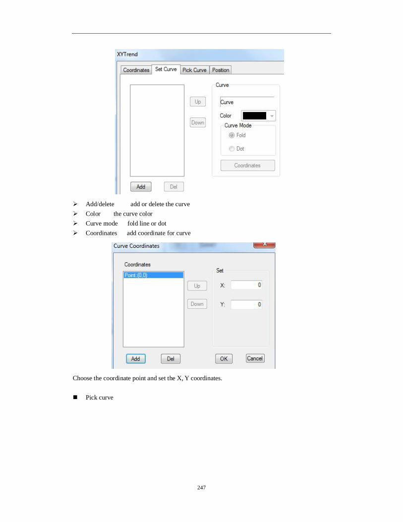
247
Add/delete add or delete the curve Color the curve color Curve mode fold line or dot Coordinates add coordinate for curve
Choose the coordinate point and set the X, Y coordinates.
Pick curve

248
Add/delete add or delete the curve X/Y object the register to store the XY axis coordinates Set parameter the parameters include update mode, color
Update mode the drawing curve mode Interval the updating period Color the curve color Total data the max coordinates Curve mode fold line and dot
Auto save the HMI will auto-store the data in the system Control pick control the data collection process through coil
Position

249
Position set the upper left point to be the coordinate point (0, 0) and set the X and Y
coordinate X position set the X coordinate of XY trend map Y position set the Y coordinate of XY trend map
Size set the width and height of XY trend map Width (W) set the width of XY trend map Height (H) set the height of XY trend map
Animal the XY trend map can move
Horizontal the XY trend map can horizontal move according to register value, X coordinate value =X position+current value of register Vertical the XY trend map can vertical move according to register value, Y coordinate value =Y position+current value of register
Lock lock XY trend map in the screen, then it cannot move
4-4-19. XY fold map
Note: only fit for TH, TG series HMI The XY fold map can collect two groups of register and draw the curve in point, line mode. For example: the two groups of register are PSW300~PSW309, PSW310~PSW319. PSW256 is drawing mode. PSW256=1 clear and re-draw; PSW256=2 save and re-draw; PSW256=3 clear; PSW256=4 repeat re-draw.

250
1. Click and move the cursor in the screen, right click mouse to confirm, click ESC to
cancel. Drag the boundary to change the size.
2. Double click the XY fold map, it will show the attribute window. Graph

251
Aspect set the frame and background color of curve Trend
Style the curve display mode: point, line, point-line Line the color/width/curve style Style solid line and dash line Point the color/width/curve style Style rectangle point, round point
Pick

252
Share buffer the X/Y axis data are from the same register (1) If share buffer is effective, the (X, Y) coordinates are the value starting from PSW300. First
coordinate is (PSW300, PSW300), the second is (PSW301, PSW301)…. (2) If share buffer is not effective, the coordinates of X and Y are from different register groups.
X data set the X-axis data type, min and max value Y pick add set the Y-axis data type, min and max value
Dynamic set this function is selected: set the coordinates quantity through register This function is not selected: set the coordinates quantity directly
Draw mode First status set the drawing mode at the beginning. The modes can be never draw, draw once, and repeat drawing Register control set the drawing mode through the register Register value=1 clear the drawing and draw the new one Register value=2 reserve the old one and continue drawing behind the old fold line Register value=3 clear the current fold line Register value=4 repeat drawing The drawing mode can be set through event button, please refer to chapter 4-4-17.

253
Position
Position set the upper left point to be the coordinate point (0, 0) and set the X and Y
coordinate X position set the X coordinate of XY fold map Y position set the Y coordinate of XY fold map
Size set the width and height of XY fold map Width (W) set the width of XY fold map Height (H) set the height of XY fold map
Animal the XY fold map can move
Horizontal the XY fold map can horizontal move according to register value, X coordinate value =X position+current value of register Vertical the XY fold map can vertical move according to register value, Y coordinate value =Y position+current value of register
Lock lock XY fold map in the screen, then it cannot move
4-4-20. Time trend map
The curve collects the data according to the time. For example, the collection period of the following curve is 1s. The storage mode is continuous storing until full.

254
The collection period of following curve is 3s; the storage mode is cyclic covering.
1. Click and move the cursor in the screen, right click mouse to confirm, click ESC to
cancel. Drag the boundary to change the size. 2. Double click the time trend map, it will show the attribute window. Common

255
Storage size the data quantity. For example: the storage size 10 means 10 groups of data.
Each group of data occupies some registers. Rotate overwrite registers=curve quantity n+time 6(year/month/day/hour/minute/second) Full stop registers=curve quantity n+ time (according to time axis)
Storage mode the mode to store the data Rotate overwrite store from the beginning address when the data is full and cover the
original data. If the fix mode is stop or the variable mode coil is OFF, it will stop collecting when the data is full.
Full stop stop storing when the data is full Pick mode the data collection mode, this mode is effective when the storage mode is
rotate overwrite Pick period the data colletion period, the unit is 1s; if the pick control is effective, it
starts to collect data when the coil is ON Variable mode and fix mode If variable mode coil is ON or fix mode is circle, the storage mode will be rotate overwrite If variable mode coil is OFF or fix mode is stop, the storage mode will be full stop
Variable mode and fix mode cannot be selected at the same time.
Pick feel when the rising edge of coil is coming, it will collect the data once

256
View
Grid style display the grid for time axis and Y axis Time info the time type displaying on the time axis Init time the range of time axis, the min unit is second Time section divide the time axis in sections Scale section display the scale value for each time axis section Y section divide the Y axis in sections Scale section display the scale value for each Y axis section

257
Object The object registers are used to store the collection data. The storage data type depends on the storage mode. (1) Storage mode is rotate overwrite: store the collection data and time
Object type the register type and first address Auto locate auto-allocate the register address according to the object type (2) Storage mode is full stop: set the collection data register address
Object type the register type and address
The auto locate is unavailable in full stop mode.

258
Trend
Add/delete add or delete the curve Batch add add the curve in batch Map mode
Fold/dot/column display the data in the mode of fold line, dot, or column curve Color the color of curve Pick the collection data register
Indirect set the address offset

259
The object address changed with PSW256. The address = D[0+PSW256 value]
We suggest using the internal register of HMI for indirect address (PSW, PFW), otherwise the communication speed will be slow. Another group display the scale data of Y axis
Unselect another group select another group
Note: (1) The first curve cannot set another group (2) If “another group” is not selected, the initial max and min value will refer to the last curve Show scale set the scale value format Data type the data type: byte, word, Dword Initial min the min value of curve Initial max the max value of curve
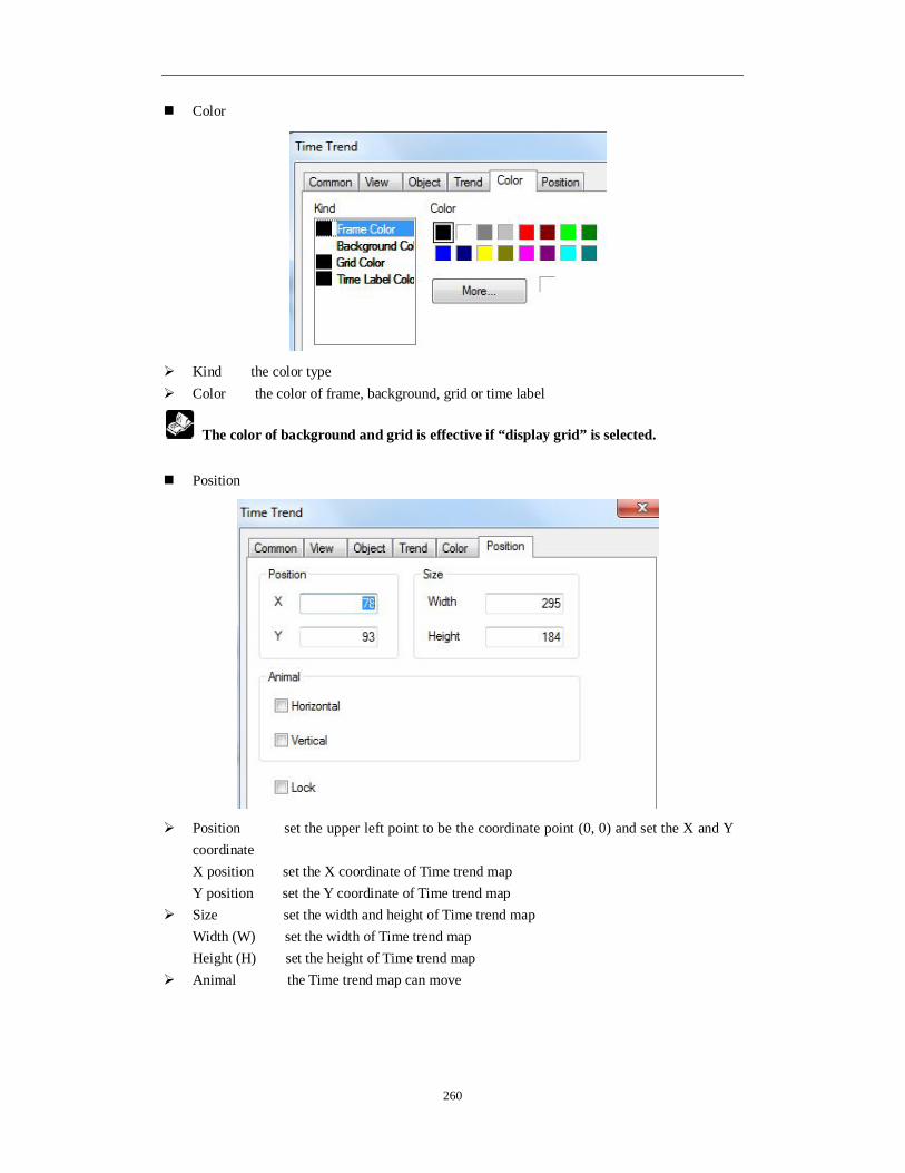
260
Color
Kind the color type Color the color of frame, background, grid or time label
The color of background and grid is effective if “display grid” is selected. Position
Position set the upper left point to be the coordinate point (0, 0) and set the X and Y coordinate X position set the X coordinate of Time trend map Y position set the Y coordinate of Time trend map
Size set the width and height of Time trend map Width (W) set the width of Time trend map Height (H) set the height of Time trend map
Animal the Time trend map can move

261
Horizontal the Time trend map can horizontal move according to register value, X coordinate value =X position+current value of register Vertical the Time trend map can vertical move according to register value, Y coordinate value =Y position+current value of register
Lock lock Time trend map in the screen, then it cannot move
4-4-21. Alarm list
The alarm list will show the alarm information when there is trigger signal of controller. 1. Click and move the cursor in the screen, right click mouse to confirm, click ESC to cancel. Drag the boundary to change the size.
2. Double click the alarm list, it will show the attribute window. Common

262
Title display the alarm title More language the title can be set to 8 different languages
Title height the size of title Alarm width the row width of alarm information Row count the row quantity of alarm information Cell height the row height of alarm information Align the alignment mode of alarm information Border bold the frame of list is bold
Alarm
Control set the coil to control the alarm information Content the contents of alarm infomation (1) Add, delete alarm information Right click the information number to add or delete information.
(2) Modify the control coil Double click the coil to modify the information
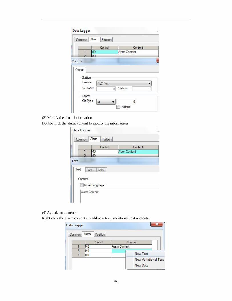
263
(3) Modify the alarm information Double click the alarm content to modify the information
(4) Add alarm contents Right click the alarm contents to add new text, variational text and data.

264
Text Double click the text to modify the contents, font and color.
Variable text
It displays the text according to the register value.
Data
It will display the register value when the alarm occurs.

265
(5) Copy, delete the contents Right click the alarm contents to copy and delete the contents.
Each piece of contents can add different kinds of information including text, variable
text, and data. Position
Position set the upper left point to be the coordinate point (0, 0) and set the X and Y
coordinate X position set the X coordinate of alarm list Y position set the Y coordinate of alarm list
Lock the alarm list cannot move
4-4-22. Display real time event
This function is to real-time show the information. 1. Click and move the cursor in the screen, right click mouse to confirm, click ESC to cancel. Drag the boundary to change the size.

266
2. Double click the real time event, it will show the attribute window. Aspect
More language the title can be set to 8 languages Rows the row number Width the width of information Height the height of information Align the alignment mode of information
Event
Add add information Batch add batch add information

267
Modify modify the information Note: double click the information to modify the contents Delete delete the information (1) Coil
Station
Device the communication port Station the device station
Object the coil address Indirect the offset of address
Object address=M[0+PSW256]
We suggest using internal register of HMI (PSW, PFW) for indirect address
otherwise the communication speed will be slow. (2) Information

268
Event add or modify the contents displayed in the real time event Color
Kind the color kind Color the color of title, frame, message Position
Position set the upper left point to be the coordinate point (0, 0) and set the X and Y coordinate X position set the X coordinate of real-time event Y position set the Y coordinate of real-time event
Lock the real-time event cannot move

269
4-4-23. Display history event
History event will real-time show the event information and store the state and data.
1. Click and move the cursor in the screen, right click mouse to confirm, click ESC to
cancel. Drag the boundary to change the size.
2. Double click the history event, it will show the attribute window. Aspect
Column set each column title, alignment mode and column width
Title set the title name More language the title can be set to 8 kinds of language Align the alignment mode of title Column width change the column width
Row height change the row height Rows per page set the row numbers on each page Show year display the year behind information Event capacity the total event numbers The event will occupy register numbers = [event capacity n+start end code 1]* Every event occupied register numbers 13 + start end pointer 4 Which is (n+1)*13+4

270
Each event occupied register numbers =trigger time 6+event information 1+confirm time 6=13
Event
Add/batch add/modify/ delete add/batch add/modify or delete the event information Double click the information in the event list to modify the objects:
Station set the communication port device and station no. Object the coil address to trigger the history event

271
Descript the contents of history event Spring the event will be activated by rising edge or falling edge of coil signal Pick The history event will collect data when this item is choosen. When the coil is ON, the data will be collected.
Save
Object the object address to store the history event data Auto locate the system will auto-assign the registers to store the data

272
Color
Kind choose the kind of color Color set the color Position
Position set the upper left point to be the coordinate point (0, 0) and set the X and Y
coordinate X position set the X coordinate of history event Y position set the Y coordinate of history event
Lock the history event cannot move
4-4-24. Common grid
Common grid can display and input data in the table. It can be used together with column map, XY fold map for data input function. For display function, it is used together with sample save and sample export. Note: please use event button to make the operations including prev item, next item, prev page, next page. Please refer to chapter 4-4-17.
1. Click and move the cursor in the screen, right click mouse to confirm, click ESC to
cancel.

273
Note: don’t change the table size by dragging the boundary of table. Otherwise the table cannot be touched correctly. Please modify the column width and row height in the grid control property. 2. Double click the common grid, it will show the property window. Object
Station communication port device and station no. Object the first address of the common grid
The address arrangement of grid object
The address order in the table is from left to right, up to down

274
Common
Total rows the total rows of table Visible lines visible lines ≤ total rows Title height the height of title row Cell height the height of each row Title display the title row Bold border the frame of grid is bold line Title font the font of title words Cell font the font of each word in the row Auto-increment column display the number of column
Title(more language) set the number title, support 8 kinds of language Width the width of number column
Static column the name of column Title(more language) set the title of static column, support 8 kinds of language Width the width of static column
Static column name set the name column contents

275
Column
Modifiable the data in the table can be changed Add add a new column Modify modify the data in the grid Delete delete one column Keyboard choose the keyboard type which is used to change the data

276
Double click the data in the list to modify the details:
Title the title of the column Width the width of column Bitlength the data bit length before decimal point Dotlength the data bit length after decimal point Type the data type (word, Dword) Format the data format Note: the time is in hex format Position

277
Position set the common grid position and size X position set the X coordinate of common grid
Y position set the Y coordinate of common grid Lock the common grid cannot move
4-4-25. Data grid
Note: this function is only suitable for TH and TG series HMI. Data grid can display continuous register data. It is used together with sample save and sample export. Data grid has circular buffer and time displaying. Common grid is suitable for mass data monitoring and modifying. The following example shows the data of sample save function. The purpose is to display the data collected by sample save function.
Note: please use event button to make the operations including prev item, next item, prev page, next page. Please refer to chapter 4-4-17.
1. Click and move the cursor in the screen, right click mouse to confirm, click ESC to
cancel.
2. Double click the data grid, it will show the property window. Object

278
Station the communication port and station no. Object the first object address of the grid The address arrangement of grid object
The address order in the table is from left to right, up to down
Common

279
Total rows the total rows of table Visible lines visible lines ≤ total rows Title height the height of title row Cell height the height of each row Title display the title row Bold border the frame of grid is bold line Title font the font of title words Cell font the font of each word in the row Auto-increment column display the number of column
Title(more language) set the number title, support 8 kinds of language Width the width of number column
Static column the name of column Title(more language) set the title of static column, support 8 kinds of language Width the width of static column
Static column name set the name column contents

280
Column
Circle buffer auto-allocation the head and tail pointer Add add a new column Modify modify the data in the table Delete delete one column Double click the data in the list to modify the details:

281
Title the title of the column Width the width of column Bitlength the data bit length before decimal point Dotlength the data bit length after decimal point Type the data type (word, Dword) Format the data format Time to display the time and set the time format

282
Position
Position set the data grid position and size X position set the X coordinate of data grid
Y position set the Y coordinate of data grid Lock the data grid cannot move
4-4-26. Sample save
Sample save can collect the local data and store in the HMI. The data can be displayed in data grid and export to U-disk in csv format. The following is the application of sample save and data grid. The sample save button collects the data from PSW256 to PSW259 and store in the address beginning with PSW300 then show in the data grid.
Note: please use event button to make the operations including prev item, next item, prev page, next page. Please refer to chapter 4-4-17. 1. Click and move the cursor in the screen, right click mouse to confirm, click ESC to cancel. This button is invisible after downloading in the HMI.
2. Double click the sample save button, it will show the property window.

283
Object
Add add collection object Batch add add more objects at once Modify modify the collection object Move up move up the object Move down move down the object
Pick
Count the collection data amount The registers occupied by data collection function=every piece of data information * data amount n The registers occupied by every piece of data information=collection object (m) + time (year/month/day/hour/minute/second=6)
If there is no collection time, the registers = m Period the data collection period, the min unit is 1s Manner the time format

284
Control the collection process is controlled by the coil, when the coil is ON, it is collecting data.
Pick save data
Object the storage register address of collection data, the default address is PFW or
PSW register
Position
Position set the sample save position and size X position set the X coordinate of sample save
Y position set the Y coordinate of sample save Lock the sample save cannot move
4-4-27. Sample export
The sample save function cannot store mass real-time data in actual project. Sample export can solve the problem. It can export the data in U-disk and backup in PC. 1. Click and move the cursor in the screen, right click mouse to confirm, click ESC to cancel. This button is invisible after downloading in the HMI.
2. Double click the sample export button, it will show the property window.

285
Common
Storage size the export data amount The registers occupied by sample export =every piece of data information * data amount n The registers occupied by every piece of data information=collection object (m) + time (year/month/day/hour/minute/second=6) Pick mode period pick and feel pick Period the collection data period, the min unit is 1s
Pick control when the coil is ON, it starts to collect data Dynamic pick when the coil is ON, circular store the data; otherwise it will stop collecting
when the memory is full. Fix mode recycle: circular store the data; stop: when the memory is full, stop storing
data
Dynamic pick and fix mode can not work at the same time. User can choose one of them to work.
Feel pick it will collect data when the rising edge of signal is coming.

286
Sample
Add add one piece of collection data Batch add add many pieces of collection data at once Delete delete the collection data Move up move up the collection data Move down move down the collection data Title the title of collected data Sample the collected data address, click the address to modify the details
Data type word, Dword (32 bits), string Data format the data format: decimal, hex, float, unsigned number Bit length the bit length before decimal point Float length the bit length after decimal point

287
Destination
Device ID the storage route of export data. 0 means C:\ in PC.
The device ID must be 0 when it is used in the HMI.
Path/file export file name and export mode Fix name export to the same file Re-export title export the data title every time Name add automatic auto-increase the export file name number, for example the name is
002, the next file name is 0020001, 0020002, 0020003…. The mex number is 0029999
Add number after name add fix number after file name, the number can be set through register, the max number is 9999
Named by date name the file by date Save

288
Object the collection register address
Export control
After export finish reset register data
Clear all the data after the export is successful Control exporting when the memory is full, the coil is ON, the data will be exported Real time export it will export data when the rising edge of signal is coming Export status when the coil is ON, it means exporting status; Export result the register will show different exporting result Register = 0, exporting is successful Register = 1, the export device doesn’t exist Register = 2, U-disk memory is low Register = 3, the file name or route is wrong Register = 4, read write file failed Export process the register will show the exporting process percentage
Date time

289
Date time export the collection data time Date format the date display format Time format the time display format
Position
Position set the sample export position and size X position set the X coordinate of sample export
Y position set the Y coordinate of sample export Lock the sample export cannot move

290
5 HMI internal register
5-1. HMI internal registers
The internal register of TH series HMI include PSB, PSW, PFW, PRW, PHW Register Note
PSB Bit object PSW Word object PFW Power-off retentive word object PRW Power-off retentive word object (for TH) PHW Power-off retentive word object (for TH)
Note: PHW only exist when it is required in order, TH465 doesn’t have PHW. The register range:
PSB, PSW, PFW amount and range can be set in File/setting/panel/set parameters.
Model Register
TH465 TH765/TH865/THA62/THA65 TG865/TGA62
PSB 256~1024 PSW 256~4096
PFW 8M-occupied by screen-occupied by system
256~246016 256~4000256
PRW 0-1000 -
PHW - 0~520000 -

291
5-2. Special internal registers
PSW, PFW, PSB address 0~255 are used by system.
1. Bit object PSB
Register Function Explanation PSB0 Always close coil PSB1 Always open coil PSB2 First start scanning ON coil
PSB3 100ms pulse coil O NO FF
50m s
50ms
PSB4 1s pulse coil O NO FF
500m s
500m s
PSB5 1minute pulse coil O NO FF
30s
30s
PSB6 300ms pulse coil O NO FF
150m s
150m s
PSB15 Communication flag 0: successful 1: failed PSB16 Scan the screen first time successful PSB30 First scan after download PSB31 First scan after power on PSB39 Shut down the touch screen PSB60 Level 1 password flag 1: password open 0: password close PSB61 Level 2 password flag 1: password open 0: password close PSB62 Level 3 password flag 1: password open 0: password close PSB63 Level 4 password flag 1: password open 0: password close PSB64 Level 5 password flag 1: password open 0: password close PSB65 Level 6 password flag 1: password open 0: password close PSB66 Level 7 password flag 1: password open 0: password close PSB67 Level 8 password flag 1: password open 0: password close PSB68 Level 9 password flag 1: password open 0: password close
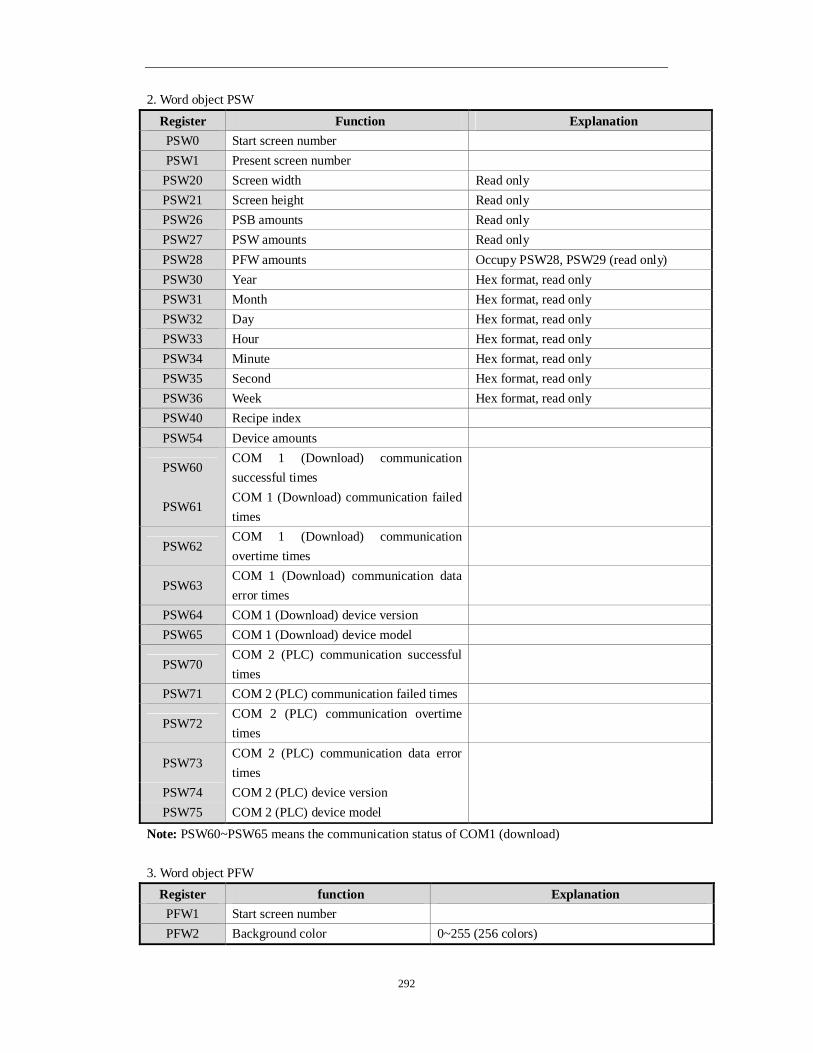
292
2. Word object PSW
Register Function Explanation PSW0 Start screen number PSW1 Present screen number
PSW20 Screen width Read only PSW21 Screen height Read only PSW26 PSB amounts Read only PSW27 PSW amounts Read only PSW28 PFW amounts Occupy PSW28, PSW29 (read only) PSW30 Year Hex format, read only PSW31 Month Hex format, read only PSW32 Day Hex format, read only PSW33 Hour Hex format, read only PSW34 Minute Hex format, read only PSW35 Second Hex format, read only PSW36 Week Hex format, read only PSW40 Recipe index PSW54 Device amounts
PSW60 COM 1 (Download) communication successful times
PSW61 COM 1 (Download) communication failed times
PSW62 COM 1 (Download) communication overtime times
PSW63 COM 1 (Download) communication data error times
PSW64 COM 1 (Download) device version PSW65 COM 1 (Download) device model
PSW70 COM 2 (PLC) communication successful times
PSW71 COM 2 (PLC) communication failed times
PSW72 COM 2 (PLC) communication overtime times
PSW73 COM 2 (PLC) communication data error times
PSW74 COM 2 (PLC) device version PSW75 COM 2 (PLC) device model
Note: PSW60~PSW65 means the communication status of COM1 (download) 3. Word object PFW
Register function Explanation PFW1 Start screen number PFW2 Background color 0~255 (256 colors)

293
PFW10 Screen save wait time PFW11 screen number for screen save PFW20 COM 1 (Download) baud rate 4800, 9600, 19200, 38400, 115200, 187500 PFW21 COM 1 (Download) data bit 7, 8 PFW22 COM 1 (Download) stop bit 0-1 bit, 1-1.5 bits, 2-2 bits PFW23 COM 1 (Download) parity 0-None, 1-Odd, 2-Even PFW24 COM 1 (Download) station no. PFW25 COM 1 (Download) sending delay Unit: ms PFW30 COM 2 (PLC) baud rate 4800, 9600, 19200, 38400, 115200, 187500 PFW31 COM 2 (PLC) data bit 7, 8 PFW32 COM 2 (PLC) stop bit 0-1 bit, 1-1.5 bits, 2-2 bits PFW33 COM 2 (PLC) parity 0-None, 1-Odd, 2-Even PFW34 COM 2 (PLC) station no. PFW35 COM 2 (PLC) sending delay Unit: ms PFW60 Password level 1 Occupy PFW60, PFW61 PFW62 Password level 2 Occupy PFW62, PFW63 PFW64 Password level 3 Occupy PFW64, PFW65 PFW66 Password level 4 Occupy PFW66, PFW67 PFW68 Password level 5 Occupy PFW68, PFW69 PFW70 Password level 6 Occupy PFW70, PFW71 PFW72 Password level 7 Occupy PFW72, PFW73 PFW74 Password level 8 Occupy PFW74, PFW75 PFW76 Password level 9 Occupy PFW76, PFW77 PFW100 Adjust the backlight Only TH765-N(V 1.0) has this function
PFW101 Multi-language switching Touchwin v2.D and higher versions support this function

294
6 Q&A
Q1 How to choose the software according to the hardware version of the HMI?
TP series:
Hardware version Visible on the label at the back cover of HMI
Software version Visible in the “HELP” menu of the software
V2.6, V2.7 V2.78/V2.99 V2.C and above V2.C.6i
TH series:
Hardware version Visible on the label at the back cover of HMI
Software version Visible in the “HELP” menu of the software
V2.C and above V2.C.6i
TG series:
Hardware version Visible on the label at the back cover of HMI
Software version Visible in the “HELP” menu of the software
New version V2.D and above
Q2 How to install two or more versions of software in PC?
1. Change the path of the software as following in the installation process.

295
2. According to the above, the default path for software installation is as “C:\Program Files\Thinget\TouchWin editing tool”. Click the “VIEW”button to change the installation path manually to “C:\Program Files\Thinget\16\TouchWin editing tool”. Then click the “OK”. As following,

296
Q3 Why the software can not be installed or used normally?
1. Please close the anti-virus software and the system optimization tools before the installation; 2. Double click the shortcut of the software on the desktop after the success of the installation. then the following picture will pop up:
Reason: the current color mode is too low. Method: right click the desktop, then choose the “attribute”. Please change the color quality
to the “highest (32 bit) ” in the “settings” option.
Q4 Does the software have tradional version? Does it support Tradional Chinese input?
There is no traditional version of the installation software. But in the simplified Chinese system, you can input traditional Chinese, Spanish, Japanese, German, French, etc. At present, our company supports four software version such as simplified Chinese version, English version, German version and Korean version.

297
Q5 What shall we do when the HMI program of TH series and TG series can not be downloaded?
You need to use the USB download line to download the programs of TH and TG series HMI, and you can also buy or borrow the USB printer communication line. But the printer communication line must be complied with USB2.0 standards, and it should have the shielding layer, one side of the line is square, and the other side is flat.
1. Check whether the computer is installed with the USB driver Get the USB driver from XINJE CD. Please give the power to the HMI again after the success of the driver’s installation. Note: Please read the installation instructions in the driver package before installation.
2. Please check whether the driver is abnormal if it is already installed. Connect the USB download cable to the USB port of computer and the HMI, then give the power to the HMI again. Right click the “my computer” button on the desktop of computer, then choose the “attribute”, and choose the “device manager” in the “hardware”, If the computer is installed the USB driver, there will be red marked information in the “Device Manager/Universal Serial Bus Controller ”.
(1) If there is no information, you need to install the USB driver again. (2) If there is red marked information, please confirm whether there is a yellow exclamation mark before it. If so, you need to update the driver program again.
3. The USB driver can not be installed (1) Please close the anti-virus software and the system optimization tool. (2) Please check which operating system your computer belongs to. If your operating system isWin7 64 bit, you need to use the special driver of Win7 64 bit to update your driver.
(3) There are two kinds of installation methods for the USB driver. The instructions are in the driver package, so you can have a try in turn.
(4) If the USB driver still can not be installed, you should contact us to get the technical support. 4. Cannot download program through the USB driver is installed normally (1) Check whether the display model is in accodance with the HMI model;

298
Reason: customers may replace the TP screen with TH and TG screen, but they forgot to convert the model in the program and downloaded the program of TP to the TH and TG screen.
Solution: Check the display model in the “document/system settings/display”. (2) The USB download cables are not qualified; You can replace a new cable if it is not confirmed. Now some USB download cables on market are not shielding wires, and the anti-interference ability is poor. We suggest you to use the shielding cable within 1.2m. (3) Try to pull up and insert the USB download cable or restart the HMI; (4) If the program still can not be downloaded, you should set on DIP switch 2 which is on the back of the TH and TG series HMI and resume the power. Then you can forced download from USB and serial port. (5) Check whether there is interference; We suggest you to use the independent 24V power supply. The power can not be connected with other devices at the same time. Don’t put the high interference equipment around HMI, such as frequency inverter and so on. If the conditions allows, you should put the HMI to the place without high interference, such as office. (6) the USB Port anti-interference ability of some computers is poor, or the USB port is easily damaged; We suggest change another PC to try again. Then you can check if the program is downloaded successfully. (7) Charging powers of some notebook computers are not very stable. We suggest you to disconnect the power supply of the computer before downloading the programs.
Q6 What shall we do when the programs of TP series HMI can not be downloaded?
1. Is the hardware version matched the software version? According to the configuration table of hardware and software, you can check whether current software version is matched the hardware version that you can find from the back cover of the TP HMI.(you can click the “help/about”)
TP series
Hardware version Visible on the label at the back cover of HMI
Software version Visible in the”HELP” menu of the software
V2.6, V2.7 V2.78/V2.99 V2.C and above V2.C.6i
2. Please use the multimeter to check whether the download cable is damaged or the contact of it is undesirable.

299
3. Check the serial port of the computer (1) Change a serial port or a computer to try again if you are using the computer with serial port; (2) If you are using a USB convertor:
a. check whether the USB convertor driver is installed; b. If the system of computer is win7 system, please use V2.C.6i. If the system of computer
is XP system, please check the port number of the convertor. If it is more than COM10, please change the number to COM1 or COM2 manually, and then give the power to download again.
Note: If the program of the HMI can be downloaded by serial port card and can not be downloaded by the USB convertor, you should change the USB convertor. You can buy the USB convertor from us. The reason is that the USB convertor of other companies can not be connected with the 7 pin of download cable of the HMI.
4. If all of the above is ok, you may connect the pin5 and the pin8 of the download port. Then you should give the power again and forced download.
Note: The pin5 and pin8 must be connected in the process of cut power and power on again.
Q7 Why does it show the error HMI capacity is not enough when downloading the program?
Reason: the capacity of the program is larger than HMI capacity. Methods: simplify the picture content 1. In the “tool/option” of the software version before V2.C.6b, we suggest you to cancel this fuction if you choose the “Encryption Download”. 2. If you don’t use download port communication, we suggest you to choose the “not use Download port”. Otherwise the download port will occupy the resources. 3. Don’t choose “automatical save” and “redo” in “tool/option”

300
Q8 How to choose the download cable of HMI?
Choose the right cables according to the series of HMI TH and TG series screen download cable: It supports the USB2.0 standard and has the
shielding layer. One side of it is square and the other side is flat.
TP series screen download cable:
Q9 Why the program can not be uploaded? How to set to upload the program?
Reason: has not choosed the “full download” in the “tool/option”, so programs can not be uploaded. Phenomenon: “there is no project” will be prompted when the programs are being upload
ed. Programs of HMI can be uploaded if you do the following operations before downloading. 1. For software version before the V2.c.6b, you should choose the “full download” or “upload” in the “tool/option”.
Note: You need to choose this option to make the upload effective before downloading programs. 2. Please use the double download arrows like this “ ” if your version is V2.c.6b or above.
Q10 how to choose the right communication cable?
Please refer to “HMI and PLC connection manual”; If the instructions can not explain the

301
connection of communication cable, customers can make their own communication cable referring to the definition of our HMI pin.
PLC communication port support: RS232/RS485/RS422 Download communication port support: RS232/RS485
Download port:
12345
6789
Pin number definition description 1 NC Empty signal pin terminal 2 RXD RS232 communication recieve data 3 TXD RS232 communicaiton send data 4 A RS485 communication“+”signal 5 GND Signal ground 6 NC Empty signal pin terminal 7 B RS485 communication“—”signal 8 NC Empty signal pin terminal 9 NC Empty signal pin terminal
PLC port:
12345
6789
Pin number definition Description 1 TD+ RS422 communication send “+” signal 2 RXD RS232 communication receive data 3 TXD RS232 communication send data 4 A RS485 communication “+” signal 5 GND Signal ground 6 TD- RS422 communication send“—” signal 7 B RS485 communication “—” signal 8 RDD- RS422 communication “—” signal
9 RDD+ RS422 communication receive “+” signal
Q11 Why the screen can not communicate normally and it displayed error “communicating”?
1. Refer to HMI and PLC connection manual; you can find the related device connection diagram and refer to some special communication tips. 2. Check whether the connection of communication cable is correct Check whether connection of the screen and equipment is correct. 3. Please use the multimeter to check whether the communication cable is damaged; 4. Check whether the type of project PLC is suitable with the type of actual connection; 5. Check the settings of communication parameters; The communication parameters must fit for the communication equipment. For example: equipment model, modbus number, bit rate, stop bit, data bit, odd and even parity.
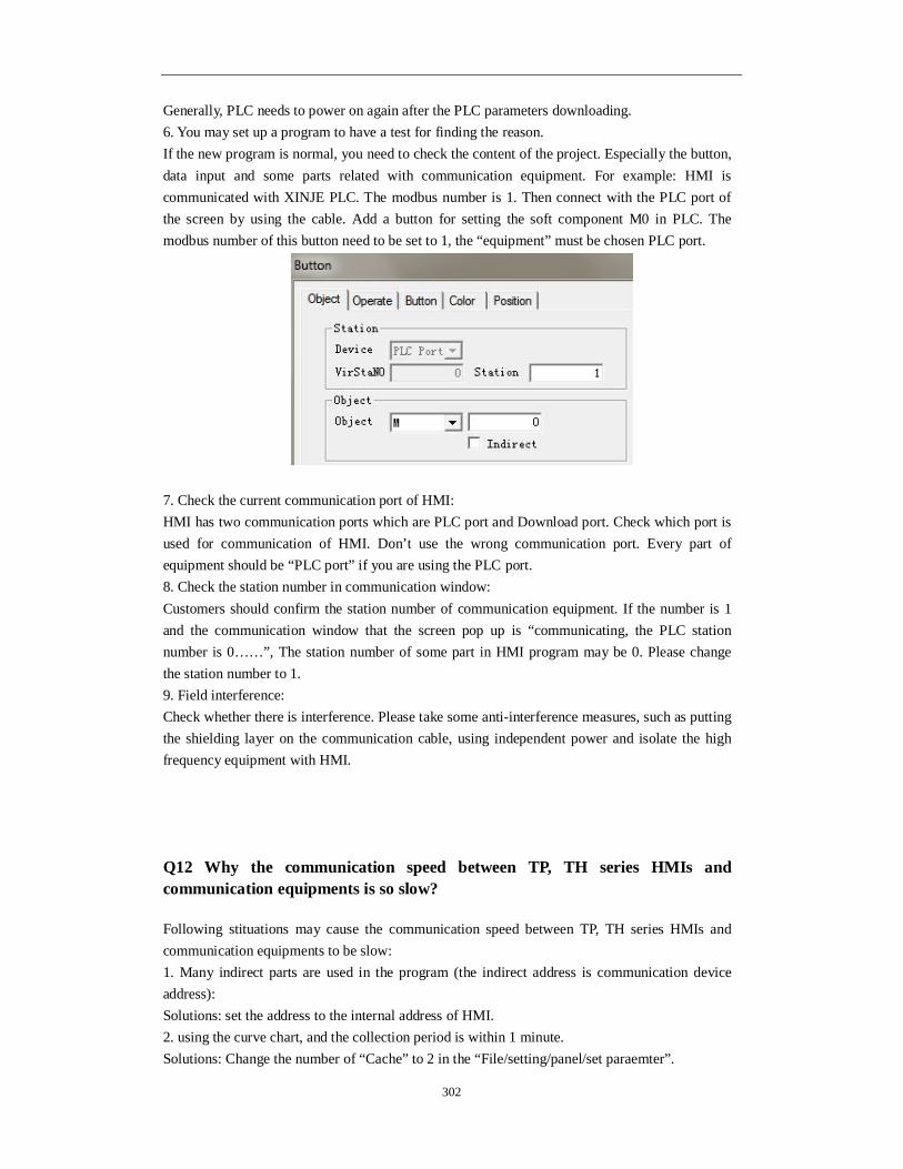
302
Generally, PLC needs to power on again after the PLC parameters downloading. 6. You may set up a program to have a test for finding the reason. If the new program is normal, you need to check the content of the project. Especially the button, data input and some parts related with communication equipment. For example: HMI is communicated with XINJE PLC. The modbus number is 1. Then connect with the PLC port of the screen by using the cable. Add a button for setting the soft component M0 in PLC. The modbus number of this button need to be set to 1, the “equipment” must be chosen PLC port.
7. Check the current communication port of HMI: HMI has two communication ports which are PLC port and Download port. Check which port is used for communication of HMI. Don’t use the wrong communication port. Every part of equipment should be “PLC port” if you are using the PLC port. 8. Check the station number in communication window: Customers should confirm the station number of communication equipment. If the number is 1 and the communication window that the screen pop up is “communicating, the PLC station number is 0……”, The station number of some part in HMI program may be 0. Please change the station number to 1. 9. Field interference: Check whether there is interference. Please take some anti-interference measures, such as putting the shielding layer on the communication cable, using independent power and isolate the high frequency equipment with HMI.
Q12 Why the communication speed between TP, TH series HMIs and communication equipments is so slow?
Following stituations may cause the communication speed between TP, TH series HMIs and communication equipments to be slow: 1. Many indirect parts are used in the program (the indirect address is communication device address): Solutions: set the address to the internal address of HMI. 2. using the curve chart, and the collection period is within 1 minute. Solutions: Change the number of “Cache” to 2 in the “File/setting/panel/set paraemter”.

303
Note: If the collection period is within 1 minute, please use TG series HMI.
Q13 How to change the download mode of HMI to communication mode?
Software editing: 1. Please choose download port device:

304
2. Please choose the “download port” in the device options and set the right station number.
hardware connection: TH, TG: the Download port of TH and TG series HMI can communicate with device directly. TP: You need to connect pin 5 with pin 6 of download port. The method is like this . 1. connect pin 5 with pin 6 directly on the communication cable, then insert it into the download port of HMI. At last you must give the HMI power again; 2. Please connect the pin 5 with pin 6 by wire when HMI has no electricity. Then you need to give the power again and move the wire. Note: This method will be ineffective after you give the HMI power again, then you need to connect again.
Q14 How to use the broadcasting function of HMI?
The boardcasting station number of HMI is 0, so you can not use readable components such as indicator light, button indicator light, data input and data display,etc. If not, the screen will be

305
white.
Q15 How to set when the screen is slave station?
1. Customers can choose the “Modbus slave(panel is slave)” or “free type”(panel is slave)”. The former is used to Modbus protocol, and the latter is used to free communication protocol. 2. Please get the free format protocol manual from XINJE CD.
Q16 What shall we do if HMI does not support the current equipment model?
1. If the devices that the HMI supports are the same brand and different series,but the device communication protocol are same and they have the same device address, you can choose the device type matched with the screen. 2. Please confirm the communication protocol of the device. If it support Modbus, “Modbus RTU” or “Modbus ASCII”can be chosen. 3. If the communication protocol of the device can not meet the two coditions above, please use the following methods.
① You can write the communication protocol by yourself. Refer to HMI user defined protocol manual. ② You can use C language function if the device has few variables such as meters. Please
refer to Touchwin C language manual.
Q17 Why the HMI only can read the data but cannot write when communicating with Omron PLC?
1. The old version Omron editing tools can change the settings of DM6600 directly, then it can change the former default-value to Monitor. 2. The new version Omron editing tools: “tools/internet settings/PLC settings”. You need to change the startup conditions of PLC to monitor state. After changing the Omron settings, repower on the PLC. Then the HMI can read/write the data of Omron PLC.
Q18 Cannot print the whole contents when using microprinter.
Solutions: increase the width and length of the print window.
Q19 How to calibrate the screen of HMI?
TP series HMI is matrix screen. Touch drift doesn’t exist, and it can’t do touch calibration. If it

306
can not be touched, please confirm reasons referring to the method of Q47. The calibration method of TH and TG HMI: 1. Turn on DIP switch 3 and give the power to HMI again; 2. Click the cross-shaped centre according to the order; 3. It shows the calibration success if the centre appears a “○”. Click it into the screen of customers, and then turn off the DIP switch 3. If the centre appears a “X”, you need to calibrate again till the centre appears the circle.
Q20 How to calibrate the system time in the HMI?
1. Set a screen jump button in the screen. Set the screen ID to 60002. 2. Download the program in the HMI. Press this button to jump to time/date setting screen.
Q21 How to modify the password in the HMI?
1. Set a screen jump button and set the screen ID to 60003; 2. Download the program to the HMI. Press this button to jump to password changing screen. Note: the current password should be opened before changing the password.
Q22 which model support U-disk data import and export?
1. TH-UT/NU/NU3, TG (-U) or TG (-E) series HMI; 2. The U-disk capacity should less than 32G; 3. It doesn’t support the mobile hard disk.
Q23 Can the mouse connect to the USB-A port of HMI?
No, it can not.
Q24 Can the register in the keeping area without electricity in the HMI be expanded?
It is expandable. TH series HMI can add two kinds of power loss retentive registers. They are PHW(0.52 million registers) and PRW (one thousand registers). PHW will be provided when you indicate specially when ordering, and the TH465 don’t have PHW. Only the initial address of PRW and PHE start from 0.

307
Q25 What is the function of the HMI dail switch?
TP765: Number 1 is ON. Change the download port to communication port; Number 2 is ON. Forced Download; Number 3 and 4 are not defined TH, TG series: Number 1 and 4 are not defined; Number 2 is ON, forced download; Number 3 is ON, system menu: clock calibration, touch calibration and the USB-disk data import.
Q26 How to open the advanced functions of HMI?
V2.C version and above: 1. Open the programming software, and create or open any program; 2. Click the “tool/option”, and click the “user mode”.
3. and then open the programme software again.

308
V2.C version and below: If the software is installed, please do from the first step. If the software has been used for a long time, please do from the second step. 1. Create a file after opening the software. Then save it. After that, a system file named Option.dat will be generated automatically in the root directory of the system. 2. Open the file by using the text file; 3. Add two lines in the end like this: [software] usermode=1 Note: please confirm that whether the [software] is in the file at first. If it exists, please cancle
them first and add the two lines above. If not, the advanced functions will not be opened.
4. Please open the HMI software again after saving the file of “Option.dat”. Then the advanced function will open.
Q27 How to modify the Chinese input and the font size of historical events in the software?
Modify in the “ File/ settings/font”.

309
Q28 How to display the time and the week in HMI?
1. Click the “date” and the “clock” component, and place them in the screen;
2. Display the week: set a data display. The address is PSW36, and the type of display is hex. 3. Download to the screen or do the off-line simulation.
Q29 Is the HMI password functional again after open?
1. Screen jump will make the password functional again. 2. The other parts: after the screen saver lighten again, the password will be functional again.
Q30 How to clear the data in trend map and data grid?
1. time trend
If the saved address of the historical data of the time trend is PFW256.
Clear method:
a. place a function button. b. add “set data”.
c. set the PFW256 (Dword) to 260, and also set the PFW258 (Dword) to 260 (the formula is “PFWm =m+4,PFW(m+2)=m+4”)

310
d. At last, modify the button content to clear. 2. clear the data grid, common grid Refer to the steps in item 1. 3. clear real time trend map Refer to the steps in item 1. 4. clear the history data map/XY trend/display history event Clear method: a. click the event button b. choose reset content in trend/event item

311
c. At last, modify the button content to clear. 5. Clear XY curve
Similar to clear trend/event, choose reset content in XY poly trend item.
Q31 How to make the scroll texts in the screen?
1. scroll text: the text can move from right to left of the screen, and it will disappear when it
moves to the end of left. Then it will come out from right.
2. move animation: you can draw the moving line, and also can control the speed of it. (the
best choice) 3. The animation function in the text button.

312
To move the text in different direction by changing the register value.
Q32 How to set password for HMI components?
1. For example, we use button. Please choose the password function and choose the password level.
2. Open the “File/setting/para, choose password function and choose the password level.

313
3. Set the screen jump button, the screen ID is 60001(the screen to input password). 4. Download the program to the HMI. Press screen jump button to input the password. Then you can operate the button which has password.
Q33 How to switch I/O terminals of PLC in the HMI?
If the PLC terminal is broken, you can switch the terminal through HMI without changing the PLC program.
1. Use a screen jump button, set the screen ID to 60004. 2. Download the program to the HMI, press the screen jump button. 3. Click output port.
Note: HMI only support XINJE PLC terminal switching. Common problems:
1. the I/O switching screen is not functional, all the register become D0. Your PLC program is from other brands of PLC. Then change the model to XINJE PLC.

314
It is not useful. 2. The I/O switching screen is not functional.
The I/O switch screen button size cannot be changed. If changed, the function will not useful. After switching the terminal, the PLC must restart again.
Q34 How to make a keyboard in the software?
Set the ASCII code in user input button. Then arrange these buttons as the keyboard order.
Q35 Why the software cannot operate the off-line simulation?
1. More than one versions of Touchwin software are installed in the computer, and the
current one is not the one installed at last.
There are two kinds of solutions: a. Uninstall all the versions. Then install only one version in the PC. b. you just need to modify the contents of registry without uninstalling the software. Click start/run in the PC, input “regedit” to open the registry editor. Click HKEY_LOCAL_MACHINE/SOFTWARE/THINGET/TouchWin. Double click AutowinPath. Input the software installation route (the software version you want to off-line simulation) in the value data item.
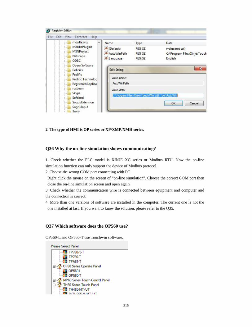
315
2. The type of HMI is OP series or XP/XMP/XMH series.
Q36 Why the on-line simulation shows communicating?
1. Check whether the PLC model is XINJE XC series or Modbus RTU. Now the on-line simulation function can only support the device of Modbus protocol. 2. Choose the wrong COM port connecting with PC Right click the mouse on the screen of “on-line simulation”. Choose the correct COM port then close the on-line simulation screen and open again.
3. Check whether the communication wire is connected between equipment and computer and the connection is correct. 4. More than one versions of software are installed in the computer. The current one is not the one installed at last. If you want to know the solution, please refer to the Q35.
Q37 Which software does the OP560 use?
OP560-L and OP560-T use Touchwin software.

316
Q38 Can the program of MP series be converted to the program of TP, TH, TG series?
No. The programs cannot copy and paste. If not, the program will has error. Reason: MP series have both touch buttons and normal buttons. The properties of many parts are different from that of the TP, TH and TG series. If paste or copy the program, the project cannot open anymore.
Q39 Can the HMI programs of different types be converted to each other?
Yes. 1. The resolution of each model are different. After changing the model, the buttons will mix up in the sceen. Before changing the model, please choose all the buttons in the screen and right click the mouse, then choose group. 2. Then change the model of HMI in the software menu “file/setting/panel”.
Q40 How many functions can be added in function button or function field?
The max is 126.
Q41 How to calculate the PFW quantity used in the program?
1. PFW quantity of data sample export
a. the storage size is m.
b. sample data quantity is n.
c. the time and date occupy six PFW registers.

317
ThePFW quantity: If exporting the clock, the quantity of PFW is: m× (n+6) If not exporting the clock, the quantity of the PFW is: m×n
2. The PFW quantity of sample save.
The same method of item 1.
3. The PFW quantity of history trend map a. the trend source is n
b. the total data is m
c. The history trend map can save the time and date. The date and time will occupy 6 registers. The quantity of PFW is: m× (n+6)
4. The PFW quantity of time trend map.
a. the storage size is m
b. the line quantity is n

318
c. The time trend map can save the time and date. The date and time will occupy 6 registers. The quantity of PFW is: m× (n+6)
5. The PFW quantity of history event.
a. the event capacity is m
b. every event contains: spring time (occupy six registers) and informations (occupy one register) and affirm time (occupy six registers). Every event will occupy 13 PFW registers.
The PFW quantity is: (m+1)*13+4
Q42 What’s the meaning of PSW/PFW/PSB/PRW/PHW?
There are 5 kinds of internal registers: PSB, PSW, PFW, PRW, PHW Register Notes PSB Bit object PSW Word object
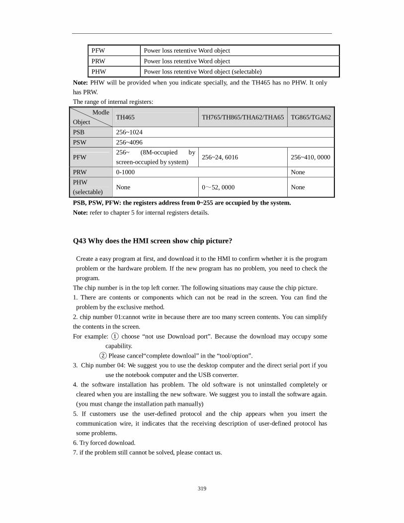
319
PFW Power loss retentive Word object PRW Power loss retentive Word object PHW Power loss retentive Word object (selectable)
Note: PHW will be provided when you indicate specially, and the TH465 has no PHW. It only has PRW. The range of internal registers:
PSB, PSW, PFW: the registers address from 0~255 are occupied by the system. Note: refer to chapter 5 for internal registers details.
Q43 Why does the HMI screen show chip picture?
Create a easy program at first, and download it to the HMI to confirm whether it is the program problem or the hardware problem. If the new program has no problem, you need to check the program.
The chip number is in the top left corner. The following situations may cause the chip picture. 1. There are contents or components which can not be read in the screen. You can find the problem by the exclusive method.
2. chip number 01:cannot write in because there are too many screen contents. You can simplify the contents in the screen. For example: ① choose “not use Download port”. Because the download may occupy some
capability. ② Please cancel“complete downloal” in the “tool/option”. 3. Chip number 04: We suggest you to use the desktop computer and the direct serial port if you
use the notebook computer and the USB converter. 4. the software installation has problem. The old software is not uninstalled completely or cleared when you are installing the new software. We suggest you to install the software again. (you must change the installation path manually)
5. If customers use the user-defined protocol and the chip appears when you insert the communication wire, it indicates that the receiving description of user-defined protocol has some problems.
6. Try forced download. 7. if the problem still cannot be solved, please contact us.
Modle Object
TH465 TH765/TH865/THA62/THA65 TG865/TGA62
PSB 256~1024 PSW 256~4096
PFW 256~ (8M-occupied by screen-occupied by system)
256~24, 6016 256~410, 0000
PRW 0-1000 None PHW (selectable)
None 0~52, 0000 None

320
Q44 Why does the HMI screen become white?
1. some project has many screens and much communication data. The screen will become white if the PLC communication cable is not inserted in the screen. If you insert the communication cable, the white screen will disappear immediately. 2. The power supply voltage of HMI is low. 3. short connect pin 5 and pin 8 of TP com port. Turn on DIP switch 2 of TG, TH series. Then power on the HMI again. If it shows loading screen, it is not the reason of hardware. Some system address, such as PFW0~256 or PSW0~256 and so on, may be used by the program. If the screen is still white, the hardware may have some problems.
Q45 The HMI touch screen has problem?
1. The HMI mounting problem
Take off the HMI from the control cabinet, and operate it. If the operation has no problem, it indicates that it is caused by mounting problem. You need to measure the installation size. Don’t mount too tight, otherwise the pressure of the touch panel will be too high.
2.The communication is not well
3.Make a program and test
Set a light button PSB300, and download it to the HMI to test the touch situation. If the touch function is not good, turn on DIP switch 3 to calibrate the touch screen for TH and TG series. If the new program has no problem, you need to check according to the following steps: a. indirect address is used (the indirect address is from communication device) b. when you use the event buttons, please don’t set two or more trend maps or common grid at the same time. c. When adjust the size of common grid, it will have offset after downlosading to the HMI. You can click each attribute in the softwre and download again.
Q46 What is the operating temperature and the storage temperature of HMI?
Operating temperature: 0°C~ 50°C Storage temperature: -10°C~ 60°C

7 Touchwin v2.d new functions
7-1. Multi-language
The button text can show 8 kinds of language. For example: we make two kinds of language for lamp button. 1. Choose more language in lamp button window (lamp button state is ON).
2. Click text library, set the language count to 2, and input the text in each language window:
If the entire text fonts are the same, please choose font applied to all.

322
3. Repeat step 1 and 2 when lamp button state is OFF.
4. Then make a data input button, the address is PFW101. This button is used to choose the language. PFW101= 0, it shows English. PFW101=1, it shows Chinese.

323
7-2. Ethernet function
There are two modes for Ethernet connection: 1. RJ45 straight through cable with hub; 2. RJ45 crossover cable without hub, but only for one to one connection (HMI-HMI,
PLC-HMI, HMI-PC). Ethernet can make multiple networks: one to many, many to one, many to many.
7-2-1. Make Ethernet operation
TG765-ET, TG865-ET and TGA62-ET support Ethernet function.
TG765-ET TG865-ET
TGA62-ET
Please use Touchwin software version 2.D and later. (1) Open Touchwin software, select HMI type

324
(2) Select Net device. The IP address of own devices is HMI IP.
(3) Right click Net device/New to make a new project.
(4) Right click the project name, there are delete and rename menu.

325
(5) Select Modbus_Tcp, the IP is PC IP address. Protocol is TCP.
(6) Communication status register If choose this item, PSW set to 256, PSW256 is communication successful times, PSW257 is communication failure times, PSW258 is communication overtime times, PSW259 is error times.

326
(7) after doing these steps, click next to finish the new project building. (8) use a data input button on the screen, choose device 1 in the station device item.
(9) after choosing device 1, the object is modbus address: 4x, 3x
(10) HMI is Modbus_TCP master station in this project. HMI also can be slave station.
7-2-2. Communicate with Siemens S7-1200 PLC
We use TG865-ET and S7-1200 CPU1211C 6ES7 211-1BD30-0XB0 for this application.

327
(1) choose HMI type in Touchwin software
(2) Choose net device. The own device IP address is TG865-ET IP
(3) Right click net device, build a new project.

328
(4) Choose Siemens S7-1200 series in the device list. The IP is S7-1200 IP address. Port no. 102 cannot be changed. The IP address can be changed in PLC software.
(5) Set the communication parameters. The timeout time cannot be larger than 3000ms. Retries time is 1.
(6) Communication status register If choose this item, PSW set to 256, PSW256 is communication successful times, PSW257 is communication failure times, PSW258 is communication overtime times, PSW259 is error times.
(7) Click next to finish the process. Then enter the editing screen. (8) Use data input button on the screen. The device is S7-1200 (device 1)
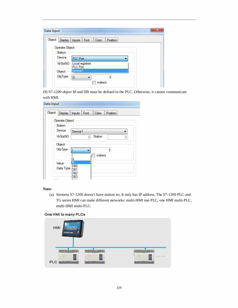
329
(9) S7-1200 object M and DB must be defined in the PLC. Otherwise, it cannot communicate with HMI.
Note:
(a) Siemens S7-1200 doesn’t have station no. It only has IP address. The S7-1200 PLC and TG series HMI can make different networks: multi-HMI one PLC, one HMI multi-PLC, multi-HMI multi-PLC.

330
(b) The RX/TX LED light when the communication is successful. The RX/TX shining means the PLC is finding network.
(c) S7-1200 can connect the entire Siemens Ethernet device. Modbus_Tcp can connect to TBOX and XINJE PLC.
7-2-3. Communicate with TBOX
This application uses TG865-ET and XINJE PLC XC3-24R-E, Ethernet module TBOX. (1) Material XINJE HMI: TG865-ET XINJE XC series PLC: XC3-24R-E XINJE Ethernet module: TBOX Ethernet switch and Ethernet cables (2) Network diagram

331
(3) TBOX setting please refer to Ethernet module TBOX manual. (4) Touchwin software setting: a. choose TG865 in the type list:
b. choose net device, the TG865-ET IP address cannot be conflict with other device in the network.
c. right click net device, build a new project.

332
d. choose modbus_Tcp device
The IP 192.168.0.14 is TBOX IP address. It can be set through XCPpro software. Port 502 cannot be changed.

333
e. click next to finish and enter the editing screen. f. for example: use data input button. Choose device 1 in device list.
Note: please fill in the object address as the Modbus address list in XC series PLC manual. g. after making the program, download it to the TG865-ET. Then the TG865-ET can control the remote device through Ethernet. Note: TBOX can connect many PLCs through RS485. The PLC station no. can be set through XCPpro software.
Please see above window from XCPpro software. If there are many PLC stations, the send delay time should be set to improve the communication speed.

334
7-3. Show the button address
Click to show the button address.
Before:
After click :
7-4. Save encrypt
Sometime, users have to send the program to their customers to download. But users don’t like the customer to know the program contents. Users can use save encrypt function in this case. If the program is saved in encrypt mode, this program can download in HMI. But the program contents cannot be seen in the software. How to use save encrypt function: 1. After making the program, click File/save encrypt to save the file.
2. Then when you open the encrypt file in Touchwin software, you cannot see the program contents anymore. But you still can download the file to HMI.

335
7-5. Batch copy
If user needs to make many buttons, the button address is increasing by one, other settings are the same. Batch copy function is easy to do this. For example, user makes many lamp buttons, the addresses are M0~M9.
1. Make the first lamp button, the address is M0.
2. Right click the button, choose batch copy.
3. In the batch copy window:

336
Layout settings: set the row, column quantity and the distance between them. Hor add: the address increases in horizontal direction. For example, the buttons have 2 rows, 5 columns. The buttons are as the following:
Ver add: the address increases in vertical direction.
Seg: for some devices such as Omron CP series PLC, the address has two segments. This setting can decide which segment address is increased. Interval: the address cumulative value. For example: interval=1, the addresses are M0, M1, M2…. Interval=5, the addresses are M0, M5, M10….

337
7-6. Font batch setting
If there are many buttons and texts in the screen, this function can set all the fonts together at the same time.
1. choose all the texts or buttons (press shift to choose more buttons)
2. click font setting , set the font in the following window:
3. These texts will have the same font settings.

338
7-7. Hide the button
The buttons support hide function: text, dynamic text, variable text, button, lamp, lamp button, data display, alarm display, text display, data input, text input, Chinese input, set data, user input, window button, down recipe, up recipe, function button, clock button. For example, hide the lamp button.
1. Choose coil control in the lamp button setting window.
2. When M0=1, the lamp button will hide.
7-8. Hex keyboard
When data input type is hex:
Please choose keyboard_8 (hex input keyboard):

339
7-9. Picture rotation
Picture rotation function only support the pictures import from material library or map. For example, import one picture from material library. Choose 11.bmp and click open to add it in the screen.

340
Click rotate 90 degree (clockwise/counterclockwise) button , the picture will rotate as
required.
7-10. Set limit through register for data input button
For example, up limit = D0, lower limit = D10. If D0=100, D10=10, the data input range is from 10 to 100.

341
7-11. Button alignment
If the buttons in the screen is messy, please use aligment function to make them in order. The alignment modes include left-aligned, middle-aligned, right-aligned, up-aligned, down-aligned, etc.
7-12. Undo
undo function can cancel the former operations.
7-13. Variable string
Compared to version v2.c.6, new version v2.d.1 supports row change of text label.
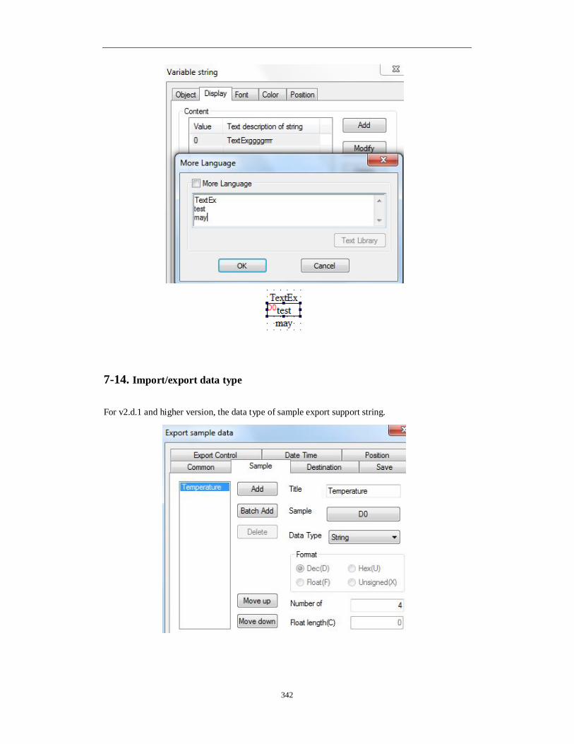
342
7-14. Import/export data type
For v2.d.1 and higher version, the data type of sample export support string.

343
Data grid also can support string.
7-15. Print function
The print function only supports micro-printer. User can set the print function in File/setting. The print modes include 8 lattice and 24 lattice.

344
The print directions include horizontal and vertical direction. User needs to test the best print direction; otherwise, the print contents will be garbled. Right click print window to add new print window.
The print setting window has two tabs: object and print window.
The object will trigger the print function. For PLC address, the object should be ON for 3s at least. For HMI internal address, the object should be instant ON.

345
Print window tab: set the window name, size. If the micro-printer support cutter, please choose cut function. The print direction can be horizontal or vertical.
7-16. Proportion function
Proportion function is Double word calculation; please use Dword data type in PLC.
7-16-1. Proportion function of data input
For example, HMI data input range is 4~20 (float), PLC data range is 0~18432. When user input 4 in HMI, the real data in PLC D0 is 0.
1. Click data input button , set the object address to D0, data type is Dword.

346
2. The display tab defines the input data format and bit length.
3. Convert tab Input convert: source data range is 4~20 (HMI); result data range is 0~18432 (PLC). Show convert: make the calculation result 0~18432 as data source, then change them to float value 4~20. After setting, when user input 4 in HMI, the HMI will show 4, but in PLC D0, the value is 0 in fact.

347
7-16-2. Proportion function of data display
For example, PLC data range is 0~18432, HMI data display range is 4~20. 1. Click data display button, set the object address to D0, data type to Dword.
2. As the proportion of 18432/20, the result is float value. Please choose float type data in data display button.
3. In convert item, please enter the source and result value range.
4. Then when the D0 in PLC is 18432, the data displayed in HMI is 20.00.

348
7-17. Upper/lower limit for calculation result
The calculation result of set data, function button, function field support upper and lower limit. For example, use two set data buttons. One button is auto plus one, another button is auto minus one. The result range is 0-5.
1. Click set data button , the object address is D0, the data type is word.
2. The function is plus operation, the operand is 1. The upper limit is 5, the lower limit is 0.

349
3. The button name is +1. 4. Repeat the step 1-3 to make button -1. Then download the program in the HMI. Press +1 and -1 button to change the D0 value. When D0=5, +1 button cannot increase the D0 value. When D0=0, -1 button cannot decrease the D0 value.
Function button and function field also have upper limit and lower limit for calculation result.
7-18.Scrolling text
This function can set the scrolling speed. The pixels that the text has walked in 0.1s are the scrolling speed value. The larger the value, the faster the scrolling speed.

350
7-19.Dynamic specified file name for data import and export function
1. For “import CSV data”, “export CSV data” in function field or function button and sample export; the csv file name can be set dynamically. For example: open “import csv data” function, please see the following window. The “dynamic set” choice is in source path tab. Please select this item and set the register address. Then user can input the csv file name in this address through character input button or data input button.

351
2. Dynamic-specified file name can only specify 8 characters which occupied four registers.
7.20 Rotate animation
1. Place a rotate animation component.

352
2. Click ‘add’ or ‘modify’ and select your picture from the material library; 3. You can double click the picture and modify the picture size, position.
4. Animation attribute Period: the animation running time, can be set to constant or specified by register. Enable and reset: If only select ‘enable’ option and unselect the ‘register controls’ option, then the animation will always be running. If select the ‘register controls’ option at the same time, the animation will run only when corresponding coil is on. So does the reset function. Mode: animation have random and continue mode. In continue mode, the picture will switch according to the default sequence. In random mode, the picture will switch according to your setting. For example, if write 1, 3 after random, picture will change between picture 1 and 3, picture 2 is not included. Animation moving mode: single mode and trip mode. It also can set repeat the animation or not. Coil control: when coil is on, the animation is visible; otherwise it is invisible.

353
7-21. Modbus function code switching
Some Modbus devices send 0x06 function code when write single word while others send 0x10 function code. The HMI register PFW36.2 can switch them in this software. When PFW36.2=0, send 0x06 function code. When PFW36.2=1, send 0x10 function code. After changing the value of PFW36.2, please restart the HMI to activate the function.

354
XINJE Electric Co., Ltd. 4th Floor, Building 7th, No.100 Dicui Rd, Wuxi, China Tel: 86-0510-85134139 Fax: 86-0510-85111290 www.xinje.com Email: [email protected]