
TM 8370-50097-OR/15 U.S. MARINE CORPS TECHNICAL ...
194
TM 8370-50097-OR/15 U.S. MARINE CORPS TECHNICAL MANUAL OPERATOR’S MANUAL WITH COMPONENTS LIST FOR SNIPER RIFLE, 7.62 X 54R MM, SVD, NSN: 1005-LL- MC9-2796 P/N: TBD DISTRIBUTION STATEMENT C : DISTRIBUTION AUTHORIZED TO U.S. GOVERNMENT AGENCIES AND THEIR CONTRACTORS. THIS PUBLICATION IS REQUIRED FOR ADMINISTRATION AND OPERATION PURPOSES. OTHER REQUESTS FOR THIS DOCUMENT MUST BE REFERRED TO COMMANDER, MARINE CORPS SYSTEMS COMMAND (PG-13, PM, IW), QUANTICO, VA 22134-6050. DESTRUCTION NOTICE : DESTROY BY ANY METHOD THAT WOULD PREVENT DISCLOSURE OF CONTENTS OR RECONSTRUCTION OF THE DOCUMENTS. FOR OFFICIAL USE ONLY MAY 2010 PCN 184 837014 00
-
Upload
khangminh22 -
Category
Documents
-
view
0 -
download
0
Transcript of TM 8370-50097-OR/15 U.S. MARINE CORPS TECHNICAL ...

TM 8370-50097-OR/15
U.S. MARINE CORPS TECHNICAL MANUAL
OPERATOR’S MANUAL
WITH COMPONENTS LIST
FOR SNIPER RIFLE, 7.62 X 54R MM, SVD, NSN: 1005-LL- MC9-2796 P/N: TBD
DISTRIBUTION STATEMENT C: DISTRIBUTION AUTHORIZED TO U.S. GOVERNMENT AGENCIES AND THEIR CONTRACTORS. THIS PUBLICATION IS REQUIRED FOR ADMINISTRATION AND OPERATION PURPOSES. OTHER REQUESTS FOR THIS DOCUMENT MUST BE REFERRED TO COMMANDER, MARINE CORPS SYSTEMS COMMAND (PG-13, PM, IW), QUANTICO, VA 22134-6050.
DESTRUCTION NOTICE: DESTROY BY ANY METHOD THAT WOULD PREVENT DISCLOSURE OF CONTENTS OR RECONSTRUCTION OF THE DOCUMENTS.
FOR OFFICIAL USE ONLY
MAY 2010 PCN 184 837014 00

INTENTIONALLY BLANK

DEPARTMENT OF THE NAVY Headquarters, U.S. Marine Corps
Washington, DC 20380-0001
31 May 2010
1. This Technical Manual (TM), authenticated for Marine Corps use and effective upon receipt, provides information on the sniper rifle, 7.62 x 54R mm, SVD; NSN: 1005-LL- MC9-2796.
2. Submit notice of discrepancies or suggested changes on NAVMC 10772. The NAVMC may be submitted via the Internet using website https://pubs.ala.usmc.mil/front.htm, scrolling down to the NAVMC 10772 Tracking Program and following instructions provided. It may also be submitted by electronic mail to [email protected], or by mailing a paper copy of NAVMC 10772 addressed to: Commanding General, Marine Corps Systems Command, Attn: Assistant Commander Acquisition and Logistics (LOG/TP), 814 Radford Blvd., Suite 20343, Albany, Georgia 31704-0343.
BY DIRECTION OF THE COMMANDANT OF THE MARINE CORPS
OFFICIAL:
MARK T. BRINKMAN Program Manager, IW, PG-13 Marine Corps Systems Command Quantico, Virginia
DISTRIBUTION: EDO

INTENTIONALLY BLANK

A/B blank
LIST OF EFFECTIVE PAGES/WORK PACKAGES Date of issue for original manual is: 31 May 2010.
TOTAL NUMBER OF PAGES FOR FRONT AND REAR MATTER IS 26 AND TOTAL NUMBER OF WORK PACKAGES IS 20 CONSISTING OF THE FOLLOWING:
Page/WP No. Change No.
Front Cover ........................ 0 A through B ....................... 0 a through h ......................... 0 i though viii ........................ 0 Chapter 1 Title Page .......... 0 WP 0001 00 (4 pgs) ........... 0 WP 0002 00 (6 pgs) ........... 0 WP 0003 00 (4 pgs) ........... 0 Chapter 2 Title Page .......... 0 WP 0004 00 (10 pgs) ......... 0 WP 0005 00 (34 pgs) ......... 0 WP 0006 00 (6 pgs) ........... 0 Chapter 3 Title Page .......... 0 WP 0007 00 (2 pgs) ........... 0
Page/WP No. Change No.
WP 0008 00 (2 pgs) ........... 0 WP 0009 00 (8 pgs) ........... 0 Chapter 4 Title Page .......... 0 WP 0010 00 (4 pgs) ........... 0 WP 0011 00 (18 pgs) ......... 0 WP 0012 00 (6 pgs) ........... 0 WP 0013 00 (10 pgs) ......... 0 WP 0014 00 (24 pgs) ......... 0 WP 0015 00 (2 pgs) ........... 0 Chapter 5 Title Page .......... 0 WP 0016 00 (2 pgs) ........... 0 WP 0017 00 (2 pgs) ........... 0 WP 0018 00 (6 pgs) ........... 0 WP 0019 00 (2 pgs) ........... 0
Page/WP No. Change No
WP 0020 00 (4 pgs) ........... 0 Index (6 pgs) .......................... 0

INTENTIONALLY BLANK
TM 8370-50097-OR/15
a
WARNING SUMMARY
This warning summary contains safety warnings that must be understood and applied during operation and maintenance of this equipment. Failure to observe these precautions could result in serious injury or death to personnel.
WARNING Ensure the weapon is unloaded and on SAFE before performing these procedures. Failure to follow this warning may result in injury or death to personnel.
WARNING If the weapon is dropped or jarred with a loaded magazine in place, it could chamber a round and subsequently cause a negligent discharge. Failure to follow this warning may result in injury or death to personnel.
WARNING The telescopic sight’s eyepiece may injure the shooter’s brow if the telescopic sight is mounted too far rearward. In addition, shooting at an uphill angle or from other positions can increase the hazard by shortening eye relief. Mount the telescopic sight for maximum eye relief. The telescopic sight’s final position should be as far forward in the rings as possible, consistent with having a full field of view while in the shooting position. Failure to follow this warning may result in injury or death to personnel.
TM 8370-50097-OR/15
b
WARNING If a noticeable difference in sound or recoil of the weapon is experienced, stop firing. Either condition could indicate an incomplete powder burn or a projectile lodged in the bore.
If the weapon stops firing with a live round in the chamber of a hot barrel, remove the round immediately. If the round cannot be removed within 10 seconds, wait 15 minutes with the weapon pointed in a safe direction. This will avoid possible injury to personnel from the cook-off of the chambered round. Keep the face away from the ejection port while clearing a hot chamber. Failure to follow these warnings may result in injury or death to personnel.
WARNING If the weapon stops firing with a live round in the chamber of a hot barrel, remove the round immediately. If the round cannot be removed within 10 seconds, wait 15 minutes with the weapon pointed in a safe direction. This will avoid possible injury to personnel from cook-off of the chambered round. Keep the operator’s face away from the ejection port while clearing a hot chamber. Failure to follow these warnings may result in injury or death to personnel.
WARNING Immediately cease fire if an audible popping sound or reduced recoil is experienced during firing. DO NOT apply immediate action. DO NOT attempt to remove a projectile that is lodged in the barrel. Notify the unit armorer. Failure to follow these warnings may result in injury or death to personnel.
TM 8370-50097-OR/15
c
WARNING Use only authorized ammunition manufactured to U.S. specifications. Failure to follow this warning may result in injury or death to personnel.
WARNING Store ammunition under protective cover and away from excessive heat and extreme temperatures. Failure to follow this warning may result in injury or death to personnel.
WARNING DO NOT attempt to disassemble a cartridge or any of its components. DO NOT polish the brass components of the cartridges. Failure to follow this warning may result in injury or death to personnel.
WARNING Use only authorized ammunition manufactured to U.S. or NATO specifications.
DO NOT fire seriously corroded ammunition, dented cartridges, cartridges with loose projectiles, cartridges exposed to extreme heat (135°F or more) until they are cooled, or cartridges with loose projectiles are pushed in (short rounds). Failure to follow these warnings may result in injury or death to personnel.
TM 8370-50097-OR/15
d
WARNING DO NOT fire the weapon if water is present in the barrel. Failure to follow this warning may result in injury or death to personnel.
WARNING Ensure that the weapon is unloaded and on SAFE with the chamber cleared before performing these procedures. Failure to follow this warning may result in injury or death to personnel.
WARNING Confirm the weapon is unloaded, clear, and on SAFE before performing the following procedures. Do not keep live ammunition near the work area. Failure to follow these warnings may cause injury or death to personnel.
WARNING Ensure the weapon is clear prior to performing the following function checks. If the weapon fails any of the following function checks, attempt to repair. If beyond repair, replace the weapon.
WARNING If trigger is hard (heavy) or very easy (light) to pull, replace springs or hammer. Failure to follow this warning may cause injury or death to personnel.

TM 8370-50097-OR/15
e
WARNING Do not interchange bolt assemblies between weapons. Failure to follow this warning may cause injury or death to personnel.
WARNING Ensure the weapon is clear before performing the following procedures. DO NOT interchange parts from one weapon to another. Failure to follow this warning may result in injury or death to personnel.
WARNING Ensure the weapon is clear and on SAFE before performing these procedures. Failure to follow this warning may cause injury or death to personnel.
WARNING DO NOT store a weapon with live ammunition in either the chamber or the magazine. Always assume a weapon is loaded until it is determined through visual and physical inspection that it is not. Procedures for clearing/unloading the weapon are outlined in WP 0005 00. Failure to follow these warnings may result in injury or death to personnel.
TM 8370-50097-OR/15
f
CAUTION SUMMARY
CAUTION Ensure ammunition is free of sand, mud, moisture, frost, snow, ice, grease, or other foreign debris. Also, check the ammunition for dents in cartridges or bad primers.
CAUTION The use of oil or grease on cartridges is prohibited.
CAUTION Areas with hot, dry climates usually contain blowing sand and fine dust. Deserts can be hot during daylight hours and freezing during hours of darkness. This will severely tax the weapon as well as other types of equipment. The weapon’s continued operation will depend on strictly and routinely following detailed cleaning and lubricating procedures.
CAUTION Do not dry clean the weapon. Do not use hot water or other solvents to clean the weapon. This will remove the teflon lubricant built up as a result of using CLP.
CAUTION Apply only a light coat of CLP to the firing pin and firing pin hole in the bolt.

TM 8370-50097-OR/15
g/h blank
CAUTION DO NOT mix lubricants on the same weapon. The weapon must be cleaned thoroughly during any change from one lubricant to another. Dry cleaning solvent (SD) is recommended for cleaning before changing lubricants.
CAUTION Ensure the patch goes completely through the muzzle. Do not reverse the direction while the patch is in the bore or muzzle.
CAUTION When using bore brush, DO NOT reverse direction while brush is in bore.
CAUTION DO NOT allow CLP to contact the lenses. DO NOT use cotton patches, cotton swabs, or cotton products such as T-shirts to clean the lenses. Use only lens paper or soft tissue paper. Anything else will scratch the lenses and render them unserviceable.

INTENTIONALLY BLANK
TM 8370-50097-OR/15
i
TECHNICAL MANUAL MARINE CORPS SYSTEMS COMMAND TM 8370-50097-OR/15 Quantico, VA, MAY 2010
U.S. MARINE CORPS TECHNICAL MANUAL OPERATOR’S MANUAL
WITH COMPONENTS LIST
FOR
SNIPER RIFLE, 7.62 X 54R MM, SVD, NSN: 1005-LL-MC9-2796 P/N TBD
DISTRIBUTION STATEMENT C: DISTRIBUTION AUTHORIZED TO U.S. GOVERNMENT AGENCIES AND THEIR CONTRACTORS. THIS PUBLICATION IS REQUIRED FOR ADMINISTRATION AND OPERATION PURPOSES. OTHER REQUESTS FOR THIS DOCUMENT MUST BE REFERRED TO COMMANDER, MARINE CORPS SYSTEMS COMMAND (PG-13, PM, IW), QUANTICO, VA 22134-6050.
DESTRUCTION NOTICE: DESTROY BY ANY METHOD THAT WILL PREVENT DISCLOSURE OF CONTENTS OR RECONSTRUCTION OF THE DOCUMENTS.

TM 8370-50097-OR/15
ii
Table of Contents WP/Page Number
List of Effective Pages/Work Packages ............................................................................................................................................. A Warning Summary ............................................................................................................................................................................. a Caution Summary ............................................................................................................................................................................... f How to Use This Manual ................................................................................................................................................................... iv
CHAPTER 1 – GENERAL INFORMATION, EQUIPMENT DESCRIPTION AND DATA, AND PRINCIPLES OF OPERATION
General Information ............................................................................................................................................................. 0001 00-1 Equipment Description and Data ......................................................................................................................................... 0002 00-1 Principles of Operation ........................................................................................................................................................ 0003 00-1
CHAPTER 2 – OPERATOR INSTRUCTIONS Description and Use of Operator Controls and Indicators ................................................................................................... 0004 00-1 Operation Under Usual Conditions ...................................................................................................................................... 0005 00-1 Operation Under Unusual Conditions .................................................................................................................................. 0006 00-1
CHAPTER 3 – TROUBLESHOOTING Troubleshooting Introduction ............................................................................................................................................... 0007 00-1 Troubleshooting Symptom Index ......................................................................................................................................... 0008 00-1 Troubleshooting Procedures ............................................................................................................................................... 0009 00-1

TM 8370-50097-OR/15
iii
Table of Contents – Continued WP/Page Number
CHAPTER 4 – MAINTENANCE INSTRUCTIONS Service Upon Receipt .......................................................................................................................................................... 0010 00-1 Preventive Maintenance Checks and Services (PMCS), Including Lubrication Instructions ................................................ 0011 00-1 General Maintenance Instructions ....................................................................................................................................... 0012 00-1 Weapon Cleaning ................................................................................................................................................................ 0013 00-1 Weapon Maintenance (Field Stripping) ................................................................................................................................ 0014 00-1 Preparation for Storage ....................................................................................................................................................... 0015 00-1
CHAPTER 5 – SUPPORTING INFORMATION References .......................................................................................................................................................................... 0016 00-1 Supply System Responsibility Items (SSRI) List .................................................................................................................. 0017 00-1 Using Unit Responsibility Items (UURI) List ......................................................................................................................... 0018 00-1 Expendable and Durable Items List ..................................................................................................................................... 0019 00-1 Inventory Sheet .................................................................................................................................................................... 0020 00-1 Index ........................................................................................................................................................................................ Index-1
TM 8370-50097-OR/15
iv
HOW TO USE THIS MANUAL
INTRODUCTION
1. This manual contains operating instructions, maintenance instructions, troubleshooting procedures, and supporting information for the sniper rifle, 7.62 x 54R mm, SVD. It is divided into five chapters.
2. This manual is written in work package format:
a. Chapters divide the manual into major categories of information (e.g., General Information, Equipment Description and Data, and Principles of Operation).
b. Each chapter is divided into work packages, which are identified by a 6-digit number (e.g., 0001 00, 0002 00) located at the upper right-hand corner of each page. The work package page number (e.g., 0001 00-1, 0001 00-2) is located centered at the bottom of each page.
c. If a Change Package is issued to this manual, added work packages will use the 5th and 6th digits of their numbers to indicate new material. For instance, work packages inserted between WP 0001 00 and WP 0002 00 are numbered WP 0001 01, WP 0001 02.
3. Read through this manual to become familiar with its organization and contents before attempting to operate or maintain the weapon.
TM 8370-50097-OR/15
v
CONTENTS OF THIS MANUAL
1. A Warning Summary and Caution Summary are located at the beginning of this manual. Become familiar with these warnings and cautions before operating or maintaining the weapon.
2. A Table of Contents, located in the front of this manual, lists all chapters and work packages in the publication. If you cannot find what you are looking for in the Table of Contents, refer to the alphabetical Index at the back of the manual.
3. Chapter 1, General Information, Equipment Description and Data, and Principles of Operation, provides general information about the equipment, identifies the major components and systems, and describes how the components and systems work.
4. Chapter 2, Operator Instructions, identifies operator controls and indicators and explains how to use them. It also shows how to properly operate the SVD sniper rifle under usual and unusual conditions.
5. Chapter 3, Troubleshooting, provides symptoms and procedures pertaining to failures that could occur during operation of the SVD sniper rifle.
6. Chapter 4, Maintenance Instructions, provides procedures to maintain the SVD sniper rifle at the operator level.
7. Chapter 5, Supporting Information, provides information pertaining to references, components listing, and an expendable and durable items list.
8. An alphabetical Index is located at the back of this manual.
TM 8370-50097-OR/15
vi
FEATURES OF THIS MANUAL
1. This manual contains information on operating and maintaining the sniper rifle, 7.62 x 54R mm, SVD.
2. WARNINGs, CAUTIONs, NOTEs, subject headings, and other important information are highlighted in BOLD print as a visual aid.
WARNING A WARNING indicates a hazard which may result in injury or death to personnel.
CAUTION A CAUTION is a reminder of safety practices or directs attention to usage practices that may result in damage to equipment.
NOTE A NOTE is a statement containing information that will make the procedures easier to perform.
3. Statements and words of particular interest may be printed in CAPITAL LETTERS to create emphasis.

TM 8370-50097-OR/15
vii/viii blank
4. Within a procedural step, reference may be made to another chapter or work package in this manual or to another manual. These references indicate where you should look for more complete information. If you are told: “Disassemble the weapon (WP 0014 00)”, go to WP 0014 00 in this manual for instructions.
5. Illustrations are placed after, and close to, the procedural steps to which they apply. Callouts placed on art are text or numbers.
END OF WORK PACKAGE

INTENTIONALLY BLANK

TM 8370-50097-OR/15
CHAPTER 1
GENERAL INFORMATION, EQUIPMENT DESCRIPTION AND DATA, AND PRINCIPLES OF OPERATION

INTENTIONALLY BLANK
TM 8370-50097-OR/15 0001 00
GENERAL INFORMATION
0001 00-1
SCOPE 1. Type of Manual. This manual contains operating instructions for the 7.62 x 54R mm, Dragunov sniper rifle (SVD).
2. Equipment Name and Model Number. SVD sniper rifle.
3. Procedures. There are different models of the SVD sniper rifle. Only two models are depicted in this manual, but procedures are common to most models.
MAINTENANCE FORMS AND PROCEDURES The Marine Corps forms and record procedures used for equipment maintenance will be those prescribed in the current edition of TM 4700-15/1_, Ground Equipment Record Procedures.
CORROSION PREVENTION AND CONTROL (CPC) Corrosion prevention and control (CPC) of weapons material is a continuing concern. While corrosion is typically associated with rusting metal, it can also include the deterioration of other items such as contacts, injection molded plastics, wood, and foam inserts in the case. Unusual cracking, softening, swelling, or breaking of these or other materials may be signs of corrosion.

TM 8370-50097-OR/15 0001 00
GENERAL INFORMATION - CONTINUED
0001 00-2
DESTRUCTION OF MATERIAL TO PREVENT ENEMY USE To render the equipment useless to the enemy, U.S. Marine Corps personnel shall destroy the equipment by weapons fire, smashing, disassembly, burning, or other means.
ABBREVIATION/ACRONYM LIST DEFINITION be ....................................................................................................................................................................................... Bale bk ..................................................................................................................................................................................... Book CAGEC .................................................................................................................. Commercial and Government Entity Code CLP ................................................................................................................................. Cleaner, Lubricant, and Preservative CP ......................................................................................................................................................................... Check Point CPC ..................................................................................................................................... Corrosion Prevention and Control ea ....................................................................................................................................................................................... Each ft ................................................................................................................................................................................. Foot/Feet HELR ............................................................................................................................................. High, Energy, Low Reflect LAW ............................................................................................................................................. Lubricant, Arctic, Weapons lb ..................................................................................................................................................................................... Pound m ...................................................................................................................................................................................... Meter mm ........................................................................................................................................................................... Millimeter MPI ........................................................................................................................................................ Mean Point of Impact NSN .................................................................................................................................................... National Stock Number
TM 8370-50097-OR/15 0001 00
GENERAL INFORMATION - CONTINUED
0001 00-3/4 blank
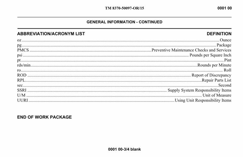
ABBREVIATION/ACRONYM LIST DEFINITION oz .................................................................................................................................................................................... Ounce pg ................................................................................................................................................................................. Package PMCS ............................................................................................................... Preventive Maintenance Checks and Services psi ....................................................................................................................................................... Pounds per Square Inch pt ......................................................................................................................................................................................... Pint rds/min ........................................................................................................................................................Rounds per Minute ro ........................................................................................................................................................................................ Roll ROD ..................................................................................................................................................... Report of Discrepancy RPL .................................................................................................................................................................Repair Parts List sec .................................................................................................................................................................................. Second SSRI ............................................................................................................................... Supply System Responsibility Items U/M ................................................................................................................................................................ Unit of Measure UURI ..................................................................................................................................... Using Unit Responsibility Items
END OF WORK PACKAGE

INTENTIONALLY BLANK
TM 8370-50097-OR/15 0002 00
EQUIPMENT DESCRIPTION AND DATA
0002 00-1
GENERAL DESCRIPTION 1. The SVD sniper rifle is a gas-operated, magazine-fed, air-cooled weapon fired from the closed bolt position,
originally developed in the Soviet Union. The SVD sniper rifle is equipped with an adjustable gas regulator forward of the receiver assembly to redirect expanding gas from escaping the bore, reducing recoil, and allowing for a steadier shot.
2. Other features of this weapon include:
a. Receiver and Barrel Assembly. Has an adjustable front sight post, front sight aperture, rear leaf sight, and ejector.
b. Gas Regulator. Has two setting to regulate the flow of gas from the barrel to the gas piston.
c. Bolt Catch. Is located in the rear of the magazine well.
d. Selector Lever. Selects SAFE or SEMI mode and prevents charging the weapon when on SAFE.
e. Telescopic Sight. Can be mounted to the left side of the receiver.
f. Top Cover. Houses the recoil assembly and covers and protects the mechanisms housed in the receiver.
TM 8370-50097-OR/15 0002 00
EQUIPMENT DESCRIPTION AND DATA - CONTINUED
0002 00-2
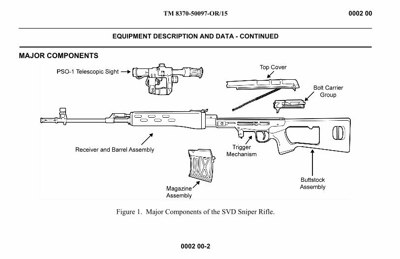
MAJOR COMPONENTS
Figure 1. Major Components of the SVD Sniper Rifle.
TM 8370-50097-OR/15 0002 00
EQUIPMENT DESCRIPTION AND DATA - CONTINUED
0002 00-3
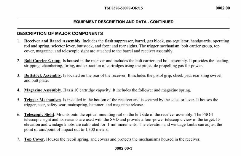
DESCRIPTION OF MAJOR COMPONENTS 1. Receiver and Barrel Assembly. Includes the flash suppressor, barrel, gas block, gas regulator, handguards, operating
rod and spring, selector lever, buttstock, and front and rear sights. The trigger mechanism, bolt carrier group, top cover, magazine, and telescopic sight are attached to the barrel and receiver assembly.
2. Bolt Carrier Group. Is housed in the receiver and includes the bolt carrier and bolt assembly. It provides the feeding, stripping, chambering, firing, and extraction of cartridges using the projectile propelling gas for power.
3. Buttstock Assembly. Is located on the rear of the receiver. It includes the pistol grip, cheek pad, rear sling swivel, and butt plate.
4. Magazine Assembly. Has a 10 cartridge capacity. It includes the follower and magazine spring.
5. Trigger Mechanism. Is installed in the bottom of the receiver and is secured by the selector lever. It houses the trigger, sear, safety sear, mainspring, hammer, and magazine release.
6. Telescopic Sight. Mounts onto the optical mounting rail on the left side of the receiver assembly. The PSO-1 telescopic sight and its variants are used with the SVD and provide a four-power telescopic view of the target. Its elevation and windage knobs are calibrated for .1 mil increments. The elevation and windage knobs can adjust the point of aim/point of impact out to 1,300 meters.
7. Top Cover. Houses the recoil spring, and covers and protects the mechanisms housed in the receiver.
TM 8370-50097-OR/15 0002 00
EQUIPMENT DESCRIPTION AND DATA - CONTINUED
0002 00-4
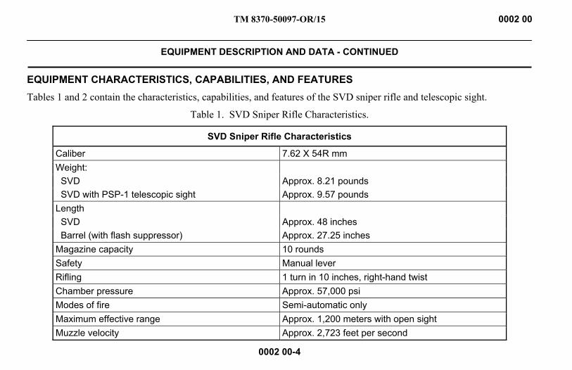
EQUIPMENT CHARACTERISTICS, CAPABILITIES, AND FEATURES Tables 1 and 2 contain the characteristics, capabilities, and features of the SVD sniper rifle and telescopic sight.
Table 1. SVD Sniper Rifle Characteristics.
SVD Sniper Rifle Characteristics
Caliber 7.62 X 54R mm Weight: SVD Approx. 8.21 pounds SVD with PSP-1 telescopic sight Approx. 9.57 pounds Length SVD Approx. 48 inches Barrel (with flash suppressor) Approx. 27.25 inches Magazine capacity 10 rounds Safety Manual lever Rifling 1 turn in 10 inches, right-hand twist Chamber pressure Approx. 57,000 psi Modes of fire Semi-automatic only Maximum effective range Approx. 1,200 meters with open sight Muzzle velocity Approx. 2,723 feet per second

TM 8370-50097-OR/15 0002 00
EQUIPMENT DESCRIPTION AND DATA - CONTINUED
0002 00-5/6 blank
Table 2. Telescopic Sight Characteristics.
Telescopic Sight Characteristics
Weight Approx. 1.36 pounds Length Approx. 14.8 inches Optic 4 X 24, point of aim, point of impact Sight Adjustments: Windage Adjustable in .1 mil increments Elevation Adjustable in .1 mil increments Maximum effective range Approx. 1,300 meters with optical sight
END OF WORK PACKAGE

INTENTIONALLY BLANK
TM 8370-50097-OR/15 0003 00
PRINCIPLES OF OPERATION
0003 00-1
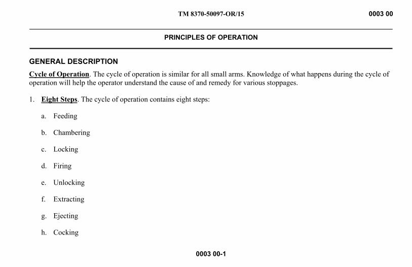
GENERAL DESCRIPTION Cycle of Operation. The cycle of operation is similar for all small arms. Knowledge of what happens during the cycle of operation will help the operator understand the cause of and remedy for various stoppages.
1. Eight Steps. The cycle of operation contains eight steps:
a. Feeding
b. Chambering
c. Locking
d. Firing
e. Unlocking
f. Extracting
g. Ejecting
h. Cocking
TM 8370-50097-OR/15 0003 00
PRINCIPLES OF OPERATION - CONTINUED
0003 00-2
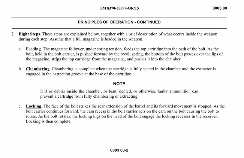
2. Eight Steps. These steps are explained below, together with a brief description of what occurs inside the weapon during each step. Assume that a full magazine is loaded in the weapon.
a. Feeding. The magazine follower, under spring tension, feeds the top cartridge into the path of the bolt. As the bolt, held in the bolt carrier, is pushed forward by the recoil spring, the bottom of the bolt passes over the lips of the magazine, strips the top cartridge from the magazine, and pushes it into the chamber.
b. Chambering. Chambering is complete when the cartridge is fully seated in the chamber and the extractor is engaged in the extraction groove at the base of the cartridge.
NOTE Dirt or debris inside the chamber, or bent, dented, or otherwise faulty ammunition can prevent a cartridge from fully chambering or extracting.
c. Locking. The face of the bolt strikes the rear extension of the barrel and its forward movement is stopped. As the bolt carrier continues forward, the cam recess in the bolt carrier acts on the cam on the bolt causing the bolt to rotate. As the bolt rotates, the locking lugs on the head of the bolt engage the locking recesses in the receiver. Locking is then complete.

TM 8370-50097-OR/15 0003 00
PRINCIPLES OF OPERATION - CONTINUED
0003 00-3
d. Firing. The rifle is taken off SAFE to the SEMI position. When the trigger is pulled, it is displaced to the rear along with the trigger bar. The catch of the trigger bar rotates the sear and disengages it from the hammer sear notch. Under tension from the mainspring, the hammer rotates on its pin and strikes the primer, which ignites the percussive component. The resulting flame penetrates through the two flash holes in the cartridge base toward the propellant charge and ignites the propellant. The round is fired. The bullet is pushed down the barrel by the expanding propellant gases.
e. Unlocking. As the round passes through the barrel and past the gas block, some of the gas (under high pressure) expands into the gas tube. The gas pushes the gas piston that in turn presses on the operating rod. The operating rod compresses its spring, strikes the forward surface of the bolt carrier, and drives the bolt carrier with the bolt to the rear. As the bolt carrier is pushed to the rear, the cam recess in the bolt carrier acts on the cam on the bolt, causing the bolt to rotate. As the bolt rotates, the locking lugs on the head of the bolt disengage from the locking recesses in the receiver. Unlocking is then complete.
f. Extracting. As the bolt continues moving to the rear, the bolt extractor holds the base of the cartridge against the bolt. Extraction is complete when the front of the cartridge casing clears the rear of the chamber.
g. Ejecting. As the bolt moves to the rear, the empty cartridge case is held by the extractor. The base of the cartridge strikes the fixed ejector, and the extractor serves as a pivot point for the cartridge, which is deflected out of the ejection opening of the receiver.
TM 8370-50097-OR/15 0003 00
PRINCIPLES OF OPERATION - CONTINUED
0003 00-4
h. Cocking. Cocking occurs when the hammer is forced into position for firing the next cartridge. This happens as the bolt and the bolt carrier travel toward the rear. The rear end of the bolt carrier forces the hammer back and rides over it. The hammer is caught by the sear if the trigger is still held to the rear and by the trigger hook if the trigger has been released.
END OF WORK PACKAGE

TM 8370-50097-OR/15
CHAPTER 2
OPERATOR INSTRUCTIONS

INTENTIONALLY BLANK
TM 8370-50097-OR/15 0004 00
DESCRIPTION AND USE OF OPERATOR CONTROLS AND INDICATORS
0004 00-1
GENERAL This section describes the various controls and provides sufficient information to ensure the proper operation of the 7.62 x 54R mm SVD sniper rifle.
TM 8370-50097-OR/15 0004 00
DESCRIPTION AND USE OF OPERATOR CONTROLS AND INDICATORS - CONTINUED
0004 00-2
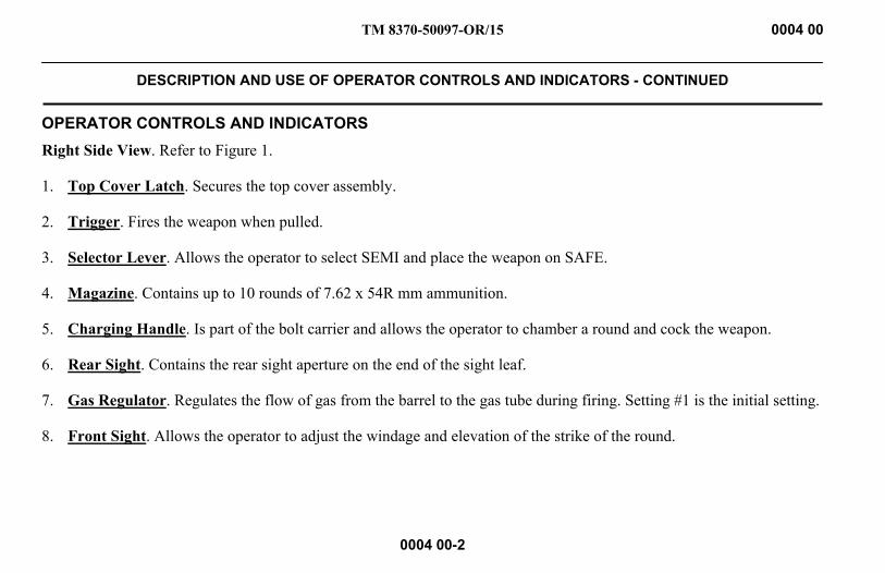
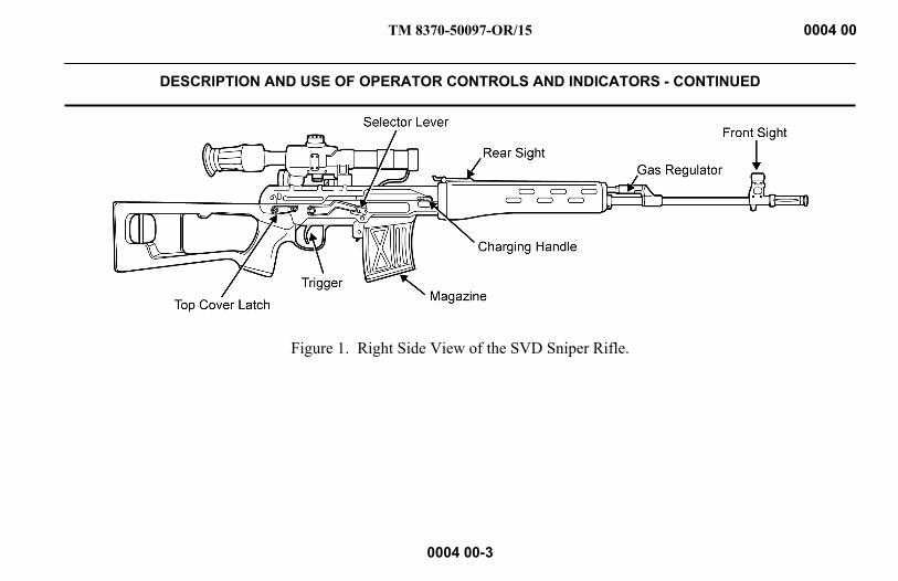
OPERATOR CONTROLS AND INDICATORS Right Side View. Refer to Figure 1.
1. Top Cover Latch. Secures the top cover assembly.
2. Trigger. Fires the weapon when pulled.
3. Selector Lever. Allows the operator to select SEMI and place the weapon on SAFE.
4. Magazine. Contains up to 10 rounds of 7.62 x 54R mm ammunition.
5. Charging Handle. Is part of the bolt carrier and allows the operator to chamber a round and cock the weapon.
6. Rear Sight. Contains the rear sight aperture on the end of the sight leaf.
7. Gas Regulator. Regulates the flow of gas from the barrel to the gas tube during firing. Setting #1 is the initial setting.
8. Front Sight. Allows the operator to adjust the windage and elevation of the strike of the round.
TM 8370-50097-OR/15 0004 00
DESCRIPTION AND USE OF OPERATOR CONTROLS AND INDICATORS - CONTINUED
0004 00-3
Figure 1. Right Side View of the SVD Sniper Rifle.
TM 8370-50097-OR/15 0004 00
DESCRIPTION AND USE OF OPERATOR CONTROLS AND INDICATORS - CONTINUED
0004 00-4
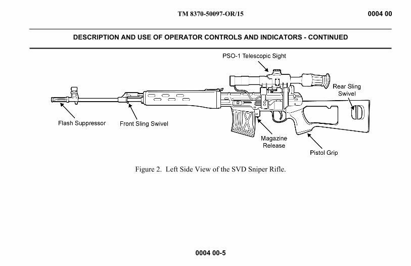
Left Side View. Refer to Figure 2.
1. Flash Suppressor. Reduces the visibility of the muzzle flash.
2. Front Sling Swivel. Allows the operator to attach a sling to the weapon.
3. Magazine Release. Allows the operator to release the magazine to remove it from the weapon.
4. Telescopic Sight. Mounts to the left side of the receiver assembly. The PSO-1 telescopic sight and its variants are used with the SVD sniper rifle and provide a 4-power telescopic view of the target.
5. Pistol Grip. Allows the operator to steady and aim the weapon during firing.
6. Rear Sling Swivel. Allows the operator to attach a sling to the weapon.
TM 8370-50097-OR/15 0004 00
DESCRIPTION AND USE OF OPERATOR CONTROLS AND INDICATORS - CONTINUED
0004 00-5
Figure 2. Left Side View of the SVD Sniper Rifle.

TM 8370-50097-OR/15 0004 00
DESCRIPTION AND USE OF OPERATOR CONTROLS AND INDICATORS - CONTINUED
0004 00-6
FRONT SIGHT ASSEMBLY 1. Front Sight Post. The front sight post is screwed up or down when zeroing the rear sight.
2. Front Sight Aperture. The front sight aperture is adjusted left or right on the front sight base when zeroing the rear sight by drifting the front sight aperture,
Figure 3. Front Sight Assembly.

TM 8370-50097-OR/15 0004 00
DESCRIPTION AND USE OF OPERATOR CONTROLS AND INDICATORS - CONTINUED
0004 00-7
REAR SIGHT ASSEMBLY 1. Rear Sight Aperture. The rear sight aperture is on the end of the sight leaf.
2. Sight Leaf. The sight leaf has distance markings for up to 1,200 meters.
3. Slide Assembly. To adjust for distance to target, move the slide assembly to the proper distance marking on the sight leaf (e.g. upside-down “U” for less than 100 meters, “1” for 100 meters, and “2” for 200 meters).
Figure 4. Rear Sight Assembly.
TM 8370-50097-OR/15 0004 00
DESCRIPTION AND USE OF OPERATOR CONTROLS AND INDICATORS - CONTINUED
0004 00-8
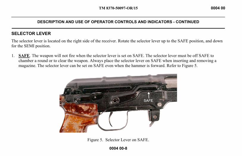
SELECTOR LEVER The selector lever is located on the right side of the receiver. Rotate the selector lever up to the SAFE position, and down for the SEMI position.
1. SAFE. The weapon will not fire when the selector lever is set on SAFE. The selector lever must be off SAFE to chamber a round or to clear the weapon. Always place the selector lever on SAFE when inserting and removing a magazine. The selector lever can be set on SAFE even when the hammer is forward. Refer to Figure 5.
Figure 5. Selector Lever on SAFE.
TM 8370-50097-OR/15 0004 00
DESCRIPTION AND USE OF OPERATOR CONTROLS AND INDICATORS - CONTINUED
0004 00-9
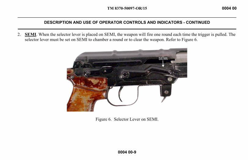
2. SEMI. When the selector lever is placed on SEMI, the weapon will fire one round each time the trigger is pulled. The selector lever must be set on SEMI to chamber a round or to clear the weapon. Refer to Figure 6.
Figure 6. Selector Lever on SEMI.
TM 8370-50097-OR/15 0004 00
DESCRIPTION AND USE OF OPERATOR CONTROLS AND INDICATORS - CONTINUED
0004 00-10
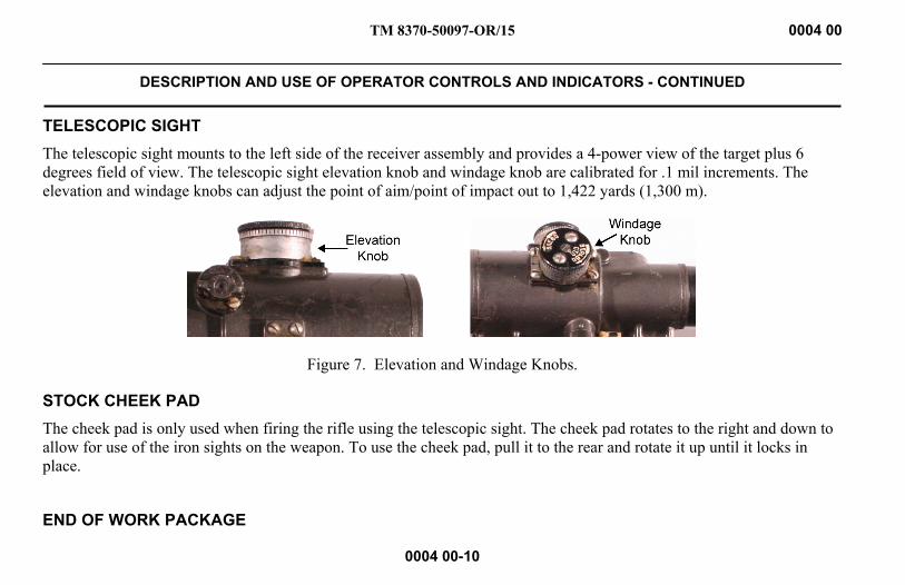
TELESCOPIC SIGHT The telescopic sight mounts to the left side of the receiver assembly and provides a 4-power view of the target plus 6 degrees field of view. The telescopic sight elevation knob and windage knob are calibrated for .1 mil increments. The elevation and windage knobs can adjust the point of aim/point of impact out to 1,422 yards (1,300 m).
Figure 7. Elevation and Windage Knobs.
STOCK CHEEK PAD The cheek pad is only used when firing the rifle using the telescopic sight. The cheek pad rotates to the right and down to allow for use of the iron sights on the weapon. To use the cheek pad, pull it to the rear and rotate it up until it locks in place.
END OF WORK PACKAGE

TM 8370-50097-OR/15 0005 00
OPERATION UNDER USUAL CONDITIONS
0005 00-1
GENERAL This section contains instructions for the operation of the 7.62 x 54R mm, SVD sniper rifle, under conditions of moderate temperature and humidity.
PREPARATION FOR FIRING WARNING
Ensure the weapon is unloaded and on SAFE before performing these procedures. Failure to follow this warning may result in injury or death to personnel.
1. Make sure the weapon is properly lubricated.
2. Check the weapon for correct assembly and proper operation.
3. Check the ammunition for grade, identification marking, and serviceability.
4. Operate and inspect controls for satisfactory functioning.

TM 8370-50097-OR/15 0005 00
OPERATION UNDER USUAL CONDITIONS - CONTINUED
0005 00-2
LOADING A MAGAZINE CAUTION
Ensure ammunition is free of sand, mud, moisture, frost, snow, ice, grease, or other foreign debris. Also, check the ammunition for dents in cartridges or bad primers.
1. Insert each cartridge with the projectile toward the front of the magazine.
2. Ensure that the base of the cartridges are seated against the rear of the magazine.
3. Fill the magazine with no more than ten cartridges.
LOADING THE WEAPON WARNING
If the weapon is dropped or jarred with a loaded magazine in place, it could chamber a round and subsequently cause a negligent discharge. Failure to follow this warning may result in injury or death to personnel.

TM 8370-50097-OR/15 0005 00
OPERATION UNDER USUAL CONDITIONS - CONTINUED
0005 00-3
1. With the weapon on SEMI, pull the charging handle to the rear and check that the chamber is clear of ammunition. Refer to Figure 1.
Figure 1. Chamber Clear.
TM 8370-50097-OR/15 0005 00
OPERATION UNDER USUAL CONDITIONS - CONTINUED
0005 00-4
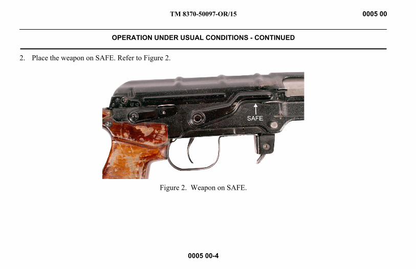
2. Place the weapon on SAFE. Refer to Figure 2.
Figure 2. Weapon on SAFE.

TM 8370-50097-OR/15 0005 00
OPERATION UNDER USUAL CONDITIONS - CONTINUED
0005 00-5
3. Seat the front lip of the magazine against the front of the magazine well and rock the magazine up and to the rear, until an audible “click” is heard indicating that the magazine release has locked the magazine in place. Push up and pull down on the magazine to ensure that it is firmly seated. Refer to Figure 3.
Figure 3. Load the Magazine.
TM 8370-50097-OR/15 0005 00
OPERATION UNDER USUAL CONDITIONS - CONTINUED
0005 00-6
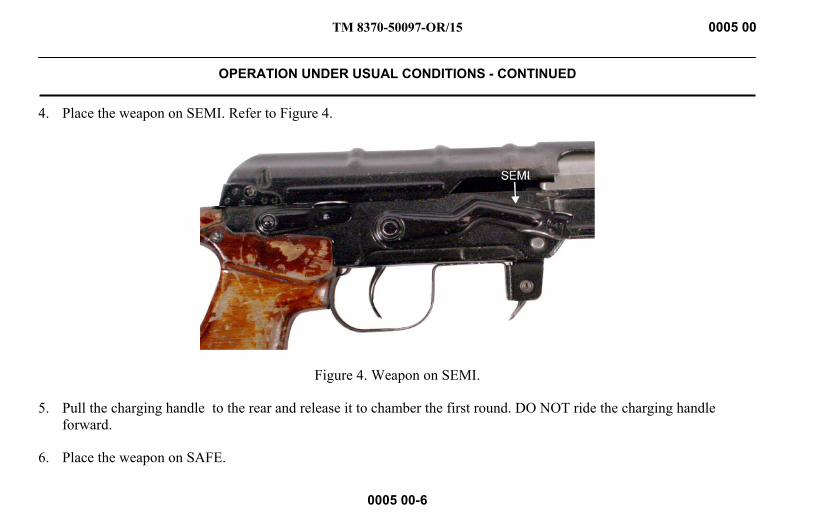
4. Place the weapon on SEMI. Refer to Figure 4.
Figure 4. Weapon on SEMI.
5. Pull the charging handle to the rear and release it to chamber the first round. DO NOT ride the charging handle forward.
6. Place the weapon on SAFE.
TM 8370-50097-OR/15 0005 00
OPERATION UNDER USUAL CONDITIONS - CONTINUED
0005 00-7
UNLOADING AND CLEARING THE WEAPON 1. Point the weapon in a safe direction.
2. Place the selector lever on SEMI.
3. Depress the magazine release and rock the magazine forward and down, out of the magazine well.
4. Pull and hold the charging handle to the rear to extract and eject the cartridge from the chamber.
5. Visually and physically inspect the chamber and receiver to ensure they contain no ammunition.
6. Release the charging handle, allowing it to return forward. Set the selector weapon on SAFE.
7. The weapon is now cleared and SAFE.
TM 8370-50097-OR/15 0005 00
OPERATION UNDER USUAL CONDITIONS - CONTINUED
0005 00-8
SETTING THE SIGHTS AND FIELD FIRING TECHNIQUES NOTE
Detailed zeroing procedures will be covered in a separate period of instruction. This section will describe how to set the front and rear sight to adjust the strike of the round
The front sight post and windage drum are used to zero the rear sight. The rear sight assembly is used to adjust for distance to target during field fire.
A rule of thumb for adjusting the front sight post and the windage drum is to move the post or drum in the OPPOSITE direction of the desired adjustment of the strike of the round.
TM 8370-50097-OR/15 0005 00
OPERATION UNDER USUAL CONDITIONS - CONTINUED
0005 00-9
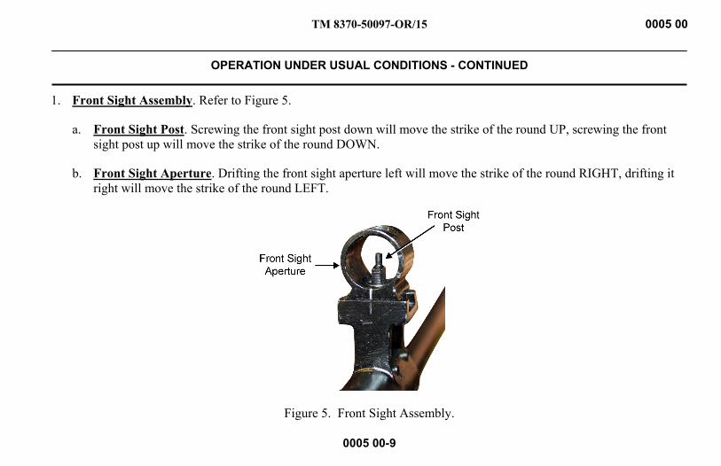
1. Front Sight Assembly. Refer to Figure 5.
a. Front Sight Post. Screwing the front sight post down will move the strike of the round UP, screwing the front sight post up will move the strike of the round DOWN.
b. Front Sight Aperture. Drifting the front sight aperture left will move the strike of the round RIGHT, drifting it right will move the strike of the round LEFT.
Figure 5. Front Sight Assembly.
TM 8370-50097-OR/15 0005 00
OPERATION UNDER USUAL CONDITIONS - CONTINUED
0005 00-10
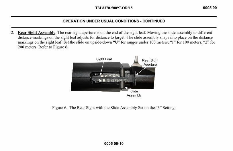
2. Rear Sight Assembly. The rear sight aperture is on the end of the sight leaf. Moving the slide assembly to different distance markings on the sight leaf adjusts for distance to target. The slide assembly snaps into place on the distance markings on the sight leaf. Set the slide on upside-down “U” for ranges under 100 meters, “1” for 100 meters, “2” for 200 meters. Refer to Figure 6.
Figure 6. The Rear Sight with the Slide Assembly Set on the “3” Setting.
TM 8370-50097-OR/15 0005 00
OPERATION UNDER USUAL CONDITIONS - CONTINUED
0005 00-11
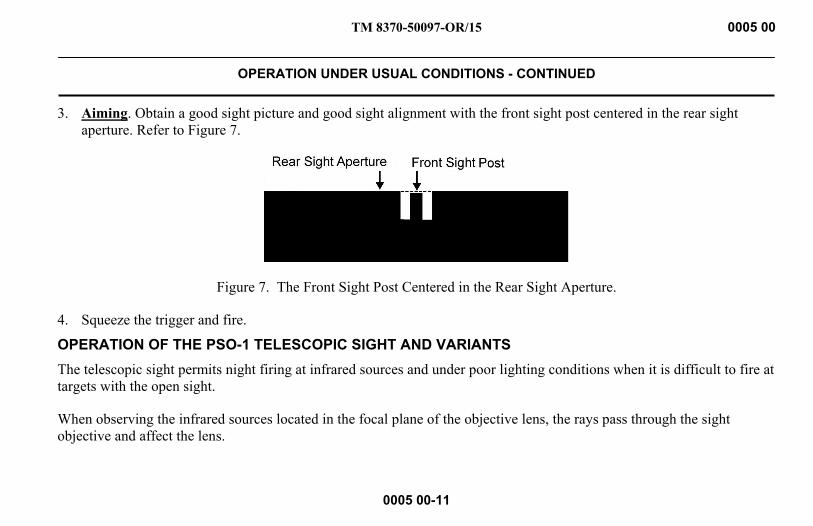
3. Aiming. Obtain a good sight picture and good sight alignment with the front sight post centered in the rear sight aperture. Refer to Figure 7.
Figure 7. The Front Sight Post Centered in the Rear Sight Aperture.
4. Squeeze the trigger and fire.
OPERATION OF THE PSO-1 TELESCOPIC SIGHT AND VARIANTS The telescopic sight permits night firing at infrared sources and under poor lighting conditions when it is difficult to fire at targets with the open sight.
When observing the infrared sources located in the focal plane of the objective lens, the rays pass through the sight objective and affect the lens.
TM 8370-50097-OR/15 0005 00
OPERATION UNDER USUAL CONDITIONS - CONTINUED
0005 00-12
In place of acting, the infrared rays’ luminescence appears on the lens, which results in a visible source image in the form of a round greenish spot. The telescopic sight consists of the following main parts:
1. Body
2. Rubber eye shield
3. Elevation knob
4. Windage knob
5. Reticle lamp
6. Reticle switch (behind the reticle switch guard)
7. Sun shade
8. Infrared detector switch (not present on all models, such as the one pictured)
9. Battery housing
Refer to Figures 8 and 9.

TM 8370-50097-OR/15 0005 00
OPERATION UNDER USUAL CONDITIONS - CONTINUED
0005 00-13
Figure 8. Left Side of the Telescopic Sight.
TM 8370-50097-OR/15 0005 00
OPERATION UNDER USUAL CONDITIONS - CONTINUED
0005 00-14
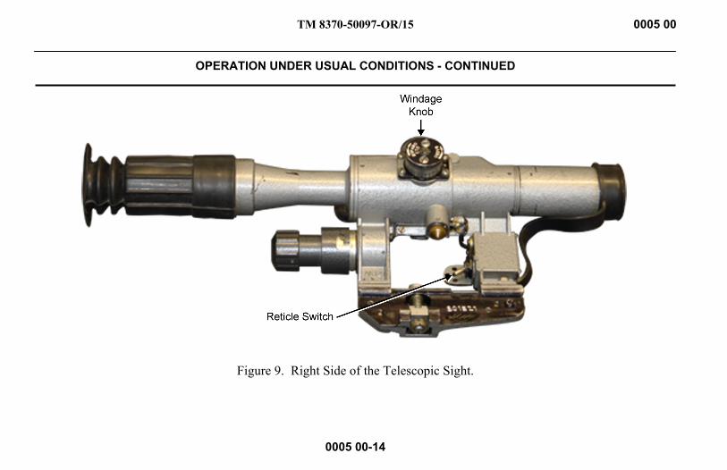
Figure 9. Right Side of the Telescopic Sight.
TM 8370-50097-OR/15 0005 00
OPERATION UNDER USUAL CONDITIONS - CONTINUED
0005 00-15
The objective in a mount with a collapsible blind is screwed into the body. The eyepiece in assembly with the eye shield is screwed into the body. The power source of the reticle lamp is located in the seat of the body. The seat is covered with a cap.
1. Sight Angle Scale. A knob is on the top of the body with a sight angle scale plotted on its cylindrical portion. The inscriptions in the sight angle scale are in Russian cyrillic: “BBepx” (Upward), “BHN3” (Downward), and “CTn” (mean point of impact [MPI]). Arrows plotted on the knob nut indicate the direction of the knob rotation when adjusting the sight. The sight angle scale is provided with 10 settings (from 0 to 10). The value of the scale setting equals 100 m. Beginning from Setting 3, sight angles can be set every 50 m using the knob retainer.
2. Scale of Deflection. A knob is on the right side of the body with the scale of deflection corrections. The cylindrical portion of the knob is provided with 21 settings (from 0 to 10 in both directions). Dash lines and digits are printed in black and located to the right from 0; those located to the left from 0 are printed in red. The value of the scale setting equals 0-01. Deflection corrections may be set every 0-00.5 by the knob retainer. Inscriptions are in Russian cyrillic: “BnpaBo” (to the right), “BJieBo” (to the left), and “CTn” (MPI).
NOTE The band of the sight angle knob and the band of the deflection correction knob each bear 60 Settings. The value of one setting equals 0-00.5. Settings on the knob bands serve for reading the correction when adjusting the sight on the weapon.
TM 8370-50097-OR/15 0005 00
OPERATION UNDER USUAL CONDITIONS - CONTINUED
0005 00-16
WARNING The telescopic sight’s eyepiece may injure the shooter’s brow if the telescopic sight is mounted too far rearward. In addition, shooting at an uphill angle or from other positions can increase the hazard by shortening eye relief. Mount the telescopic sight for maximum eye relief. The telescopic sight’s final position should be as far forward in the rings as possible, consistent with having a full field of view while in the shooting position. Failure to follow this warning may result in injury or death to personnel.
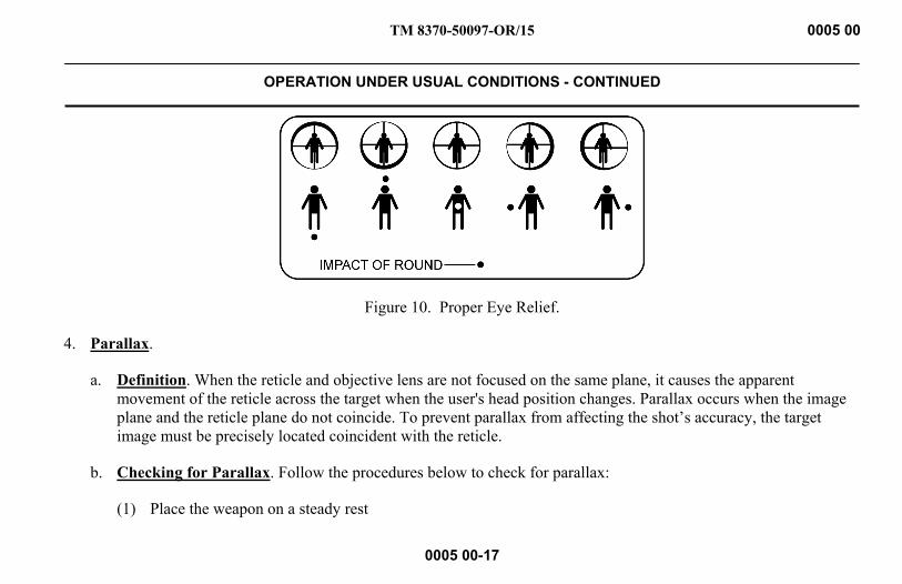
3. Proper Eye Relief. Proper eye relief is achieved when the field of view is clear, with no shadows along the edges. Place the eye at the proper eye relief setting (approximately 3 to 4 inches from the rear of the sight) and view an object at least 100 yards away. Adjust the cheek piece until proper eye relief is achieved. Refer to Figure 10.
TM 8370-50097-OR/15 0005 00
OPERATION UNDER USUAL CONDITIONS - CONTINUED
0005 00-17
Figure 10. Proper Eye Relief.
4. Parallax.
a. Definition. When the reticle and objective lens are not focused on the same plane, it causes the apparent movement of the reticle across the target when the user's head position changes. Parallax occurs when the image plane and the reticle plane do not coincide. To prevent parallax from affecting the shot’s accuracy, the target image must be precisely located coincident with the reticle.
b. Checking for Parallax. Follow the procedures below to check for parallax:
(1) Place the weapon on a steady rest
TM 8370-50097-OR/15 0005 00
OPERATION UNDER USUAL CONDITIONS - CONTINUED
0005 00-18
(2) Sight a target at 300 yards.
(3) Without disturbing the weapon, look at the target through the telescopic sight.
(4) If movement is seen or the target is unclear, parallax is present and must be adjusted.
5. Eliminating Parallax. Follow the procedures below to eliminate parallax:
a. Look through the sight at a target at a selected range.
b. Turn the parallax knob (on the opposite side of the windage knob) until it reads “correct target range.” For example, if the target is at 500 m, turn the parallax adjustment knob until it reads “500.”
c. Make adjustments necessary to eliminate reticle movement.
d. Once the movement is stilled, parallax is eliminated.
ZEROING 1. The SVD sniper rifle being serviced by a subunit should be zeroed. The necessity of rifle zeroing is determined by test
firing. Rifles are subjected to test firing when:
a. The rifle is received by the subunit.
TM 8370-50097-OR/15 0005 00
OPERATION UNDER USUAL CONDITIONS - CONTINUED
0005 00-19
b. Rifle parts are repaired or replaced, which may affect the rifle fire accuracy.
c. There has been excessive deviation to the MPI, or bullet dispersion, which does not meet the accuracy requirements.
d. The situation permits under combat conditions.
2. The SVD sniper rifle is test-fired by four shots, aiming thoroughly and uniformly with the aid of the open sight at a black rectangular target 20 cm wide and 30 cm high. The target is secured on a white board 1 m high and 0.5 m wide. The point of aim is the middle of the target’s bottom edge. During firing, when the open sight is used, the normal position of the MPI is marked with chalk or a colored pencil by the plumb line 16 cm above the point of aim. This point serves as the check point (CP).
3. The range is 100 m and the sight is set at 3. Firing is conducted from the prone position with support. To test-fire and zero a rifle, use cartridges with ordinary steel-core bullets. Fire is conducted with the knife bayonet removed. Upon firing the shots, examine the target and arrangement of hits to determine accuracy of fire and position of the MPI. SVD sniper rifle fire accuracy is considered normal when all four hits are arranged within the circle, which is 8 mm in diameter.
a. If the shot group does not meet the requirements, repeat test firing.
b. If the second test results are unsatisfactory, send the SVD sniper rifle to the repair shop.

TM 8370-50097-OR/15 0005 00
OPERATION UNDER USUAL CONDITIONS - CONTINUED
0005 00-20
c. If the shot group is found normal, determine the MPI and its position relative to the CP.
4. The SVD sniper rifle fire accuracy is considered normal if the MPI coincides with the CP or if it deviates no more than 5 cm in any direction.
a. If during test firing the MPI deviates by more than 5 cm from the CP in any direction, adjust the front sight post or aperture. If the MPI is below the CP, screw in the front sight post; if the MPI is above the CP, unscrew the front sight post.
b. If the MPI is to the left of the CP, drift the front sight aperture to the left; if to the right, drift it to the right.
NOTE Front sight aperture displacement by 1 mm to the side and one complete revolution of the front sight post (when screwed in or out) will change the position of the MPI by 16 cm when fire is delivered at a range of 100 m.
5. Repeat test firing to make sure the front sight post and aperture are displaced. After the SVD sniper rifle has been zeroed, remove the old notch and make a new notch on the front sight aperture.
TM 8370-50097-OR/15 0005 00
OPERATION UNDER USUAL CONDITIONS - CONTINUED
0005 00-21
6. To zero the rifle with the optical sight, attach the optical sight to the rifle and put the cheek plate on the butt. Rotate the knobs to set the sight angle knob at Setting 3 and the deflection correction knob at 0. Perform test firing with the aid of the optical sight, the same conditions for test firing the rifle with the aid of the open sight. However, the CP in this case should be marked at a height of 14 cm from the point of aim.
a. As a result of the test firing, if all four hits are arranged in a circle (8 cm in diameter) and the MPI deviates from the CP by more than 3 cm, determine the deviation of the MPI and introduce the appropriate corrections into the settings of the nuts on knobs of the sight angles and deflection corrections.
b. Displacement of the nuts by one setting, relative to the scales on the bands of the knobs in firing at 100 m range, will change the position of MPI by 5 cm. To introduce corrections, release screws on the knob ends by 1.5 turns while manually rotating the sight angle nut and the deflection correction nut. Displace the sight angle nut and the deflection correction nut by a necessary amount and tighten the screws.
c. After the corrections have been introduced in the knob setting, repeat test firing. As a result of the repeated test firing, if all four hits are arranged in a circle (8cm in diameter), and the MPI matches with the CP or deviates from it to either side by no more than 3 cm, the rifle is considered zeroed.
d. After zeroing the rifle, record the position of the MPI in the Service Log.

TM 8370-50097-OR/15 0005 00
OPERATION UNDER USUAL CONDITIONS - CONTINUED
0005 00-22
FAILURE TO FIRE WARNING
If a noticeable difference in sound or recoil of the weapon is experienced, stop firing. Either condition could indicate an incomplete powder burn or a projectile lodged in the bore.
If the weapon stops firing with a live round in the chamber of a hot barrel, remove the round immediately. If the round cannot be removed within 10 seconds, wait 15 minutes with the weapon pointed in a safe direction. This will avoid possible injury to personnel from the cook-off of the chambered round. Keep the face away from the ejection port while clearing a hot chamber. Failure to follow these warnings may result in injury or death to personnel.
TM 8370-50097-OR/15 0005 00
OPERATION UNDER USUAL CONDITIONS - CONTINUED
0005 00-23
If the weapon stops firing, seek cover and perform the following actions:
1. Immediate Action. Follow these steps:
a. Pull the magazine rearward then push it forward to ensure it is properly seated.
b. Pull and hold the charging handle to the rear.
c. Observe the chamber for rounds and debris.
d. Release the charging handle to strip a round from the magazine.
e. Tap the charging handle forward to ensure the bolt is fully seated.
f. Shoot the weapon.
2. Notify the Unit Armorer. If immediate action (step 1) has been applied and the weapon fails to fire, notify the unit armorer when the situation permits.

TM 8370-50097-OR/15 0005 00
OPERATION UNDER USUAL CONDITIONS - CONTINUED
0005 00-24
3. Remedial Action.
WARNING If the weapon stops firing with a live round in the chamber of a hot barrel, remove the round immediately. If the round cannot be removed within 10 seconds, wait 15 minutes with the weapon pointed in a safe direction. This will avoid possible injury to personnel from cook-off of the chambered round. Keep the operator’s face away from the ejection port while clearing a hot chamber. Failure to follow these warnings may result in injury or death to personnel.
Use the following steps to clear a cartridge case stuck in the chamber.
a. Remove the magazine. Refer to Unloading and Clearing the Weapon in this work package.
b. Pull the charging handle and hold it to the rear.

TM 8370-50097-OR/15 0005 00
OPERATION UNDER USUAL CONDITIONS - CONTINUED
0005 00-25
c. If the cartridge is intact, insert the cleaning rod into the barrel from the muzzle end and tap out the cartridge case. Refer to Figure 11.
Figure 11. Cleaning Rod Inserted into the Muzzle.
TM 8370-50097-OR/15 0005 00
OPERATION UNDER USUAL CONDITIONS - CONTINUED
0005 00-26
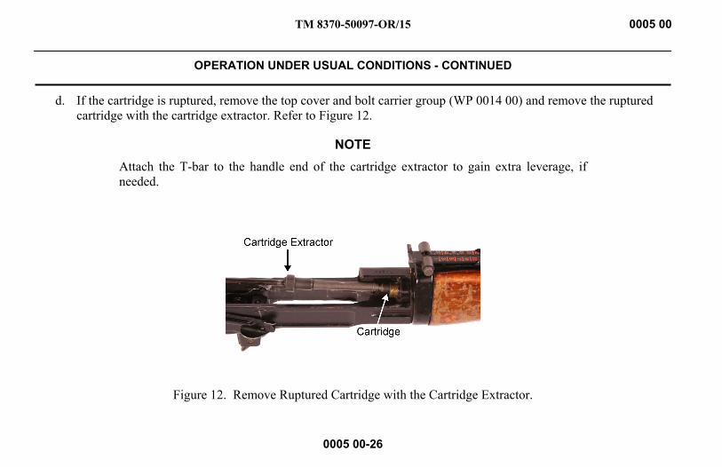
d. If the cartridge is ruptured, remove the top cover and bolt carrier group (WP 0014 00) and remove the ruptured cartridge with the cartridge extractor. Refer to Figure 12.
NOTE Attach the T-bar to the handle end of the cartridge extractor to gain extra leverage, if needed.
Figure 12. Remove Ruptured Cartridge with the Cartridge Extractor.
TM 8370-50097-OR/15 0005 00
OPERATION UNDER USUAL CONDITIONS - CONTINUED
0005 00-27
4. Projectile Lodged in the Barrel.
WARNING Immediately cease fire if an audible popping sound or reduced recoil is experienced during firing. DO NOT apply immediate action. DO NOT attempt to remove a projectile that is lodged in the barrel. Notify the unit armorer. Failure to follow these warnings may result in injury or death to personnel.
Use the following steps if projectile is lodged in the barrel:
a. Retract the bolt slowly and remove the spent cartridge case.
b. Clear the weapon and check for unburned powder grains in the receiver or the bore. Check for a projectile lodged in the bore.
c. Remove unburned powder from the bore before resuming fire.
d. If a projectile is lodged in the bore, notify the unit armorer.
TM 8370-50097-OR/15 0005 00
OPERATION UNDER USUAL CONDITIONS - CONTINUED
0005 00-28
AMMUNITION WARNING
Use only authorized ammunition manufactured to U.S. specifications. Failure to follow this warning may result in injury or death to personnel.
Use only authorized ammunition cartridges in these weapons. Unauthorized assembly and use of ammunition cartridges is extremely dangerous. To avoid substitution of unauthorized ammunition cartridges in the field, ammunition is issued in necessary quantities by type to meet tactical requirements.
UNAUTHORIZED AMMUNITION 1. Reloaded or remanufactured ammunition
2. Corrosive ammunition (primer or propellant)
3. Tracers
TM 8370-50097-OR/15 0005 00
OPERATION UNDER USUAL CONDITIONS - CONTINUED
0005 00-29
CARE, HANDLING, AND PRESERVATION 1. Packing. Ammunition is packed to withstand conditions ordinarily encountered in the field. Care must be exercised to
keep packing from becoming broken or otherwise damaged. All broken packing must be repaired immediately and all markings must be transferred to replacement parts. Ammunition may be packed in metal-lined wooden boxes or metal boxes. Damaged boxes containing metal liners should be air-tested and sealed if equipment to perform this work is available.
2. Storing in the Open. When it is necessary to leave ammunition in the open, raise it at least 6 inches from the ground and cover it with tarpaulins. Whenever possible, use wood between each row to permit full air circulation. Dig suitable trenches to prevent water from running under the stack. Arrange tarpaulins to permit air circulation through the stack, keeping the tarps at least 6 inches from the top, ends, and sides of the stack.
WARNING Store ammunition under protective cover and away from excessive heat and extreme temperatures. Failure to follow this warning may result in injury or death to personnel.
3. Moisture and High Temperature.
a. Keep boxes closed until the ammunition is needed. Ammunition removed from airtight containers, particularly in damp climates, can corrode and become unserviceable.
TM 8370-50097-OR/15 0005 00
OPERATION UNDER USUAL CONDITIONS - CONTINUED
0005 00-30
b. Protect the ammunition from high temperatures and prolonged exposure to direct sun rays. Such exposure is likely to affect the ballistic performance of the cartridges. The combination of high temperature and humidity can destabilize propellant and the tracer mixture in tracer ammunition.
WARNING DO NOT attempt to disassemble a cartridge or any of its components. DO NOT polish the brass components of the cartridges. Failure to follow this warning may result in injury or death to personnel.
CAUTION The use of oil or grease on cartridges is prohibited.
4. General Care.
a. Protect the ammunition from sand, mud, moisture, frost, snow, ice, grease, and other foreign matter. Immediately wipe off wet or dirty ammunition with a clean, dry cloth. If corrosion forms on cartridges, wipe it off with a clean, dry cloth.
b. Brass cartridge cases are easily dented. Protect them from damage.
c. Protect a partially used box of ammunition from unauthorized use by firmly fastening the box cover in place.
TM 8370-50097-OR/15 0005 00
OPERATION UNDER USUAL CONDITIONS - CONTINUED
0005 00-31
PREPARATION FOR FIRING After removing all packing materials, cartridges for the SVD sniper rifle are ready for use. Return unfired cartridges to their original packing or pack them in suitable boxes. Use these cartridges first in subsequent firings in order to reduce stocks of opened containers. Mark packing containers with the cartridge nomenclature, the quality of the cartridges, and the ammunition lot number.
PRECAUTIONS IN FIRING WARNING
Use only authorized ammunition manufactured to U.S. or NATO specifications.
DO NOT fire seriously corroded ammunition, dented cartridges, cartridges with loose projectiles, cartridges exposed to extreme heat (135°F or more) until they are cooled, or cartridges with loose projectiles are pushed in (short rounds). Failure to follow these warnings may result in injury or death to personnel.
SLING The sling is affixed to the weapon by snapping the hooks onto the front and rear sling swivels.
TM 8370-50097-OR/15 0005 00
OPERATION UNDER USUAL CONDITIONS - CONTINUED
0005 00-32
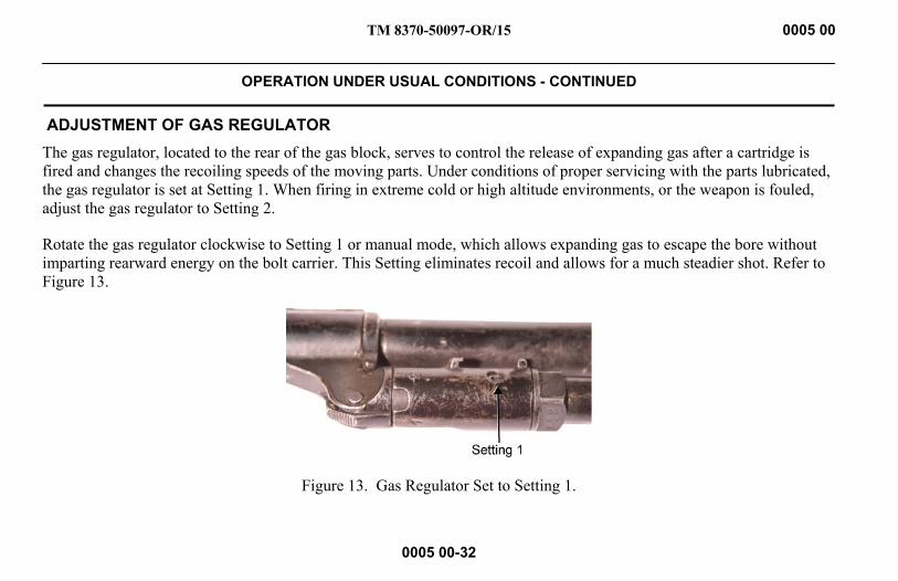
ADJUSTMENT OF GAS REGULATOR The gas regulator, located to the rear of the gas block, serves to control the release of expanding gas after a cartridge is fired and changes the recoiling speeds of the moving parts. Under conditions of proper servicing with the parts lubricated, the gas regulator is set at Setting 1. When firing in extreme cold or high altitude environments, or the weapon is fouled, adjust the gas regulator to Setting 2.
Rotate the gas regulator clockwise to Setting 1 or manual mode, which allows expanding gas to escape the bore without imparting rearward energy on the bolt carrier. This Setting eliminates recoil and allows for a much steadier shot. Refer to Figure 13.
Figure 13. Gas Regulator Set to Setting 1.
TM 8370-50097-OR/15 0005 00
OPERATION UNDER USUAL CONDITIONS - CONTINUED
0005 00-33
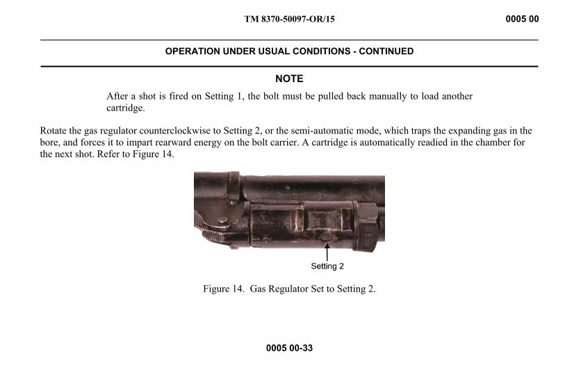
NOTE After a shot is fired on Setting 1, the bolt must be pulled back manually to load another cartridge.
Rotate the gas regulator counterclockwise to Setting 2, or the semi-automatic mode, which traps the expanding gas in the bore, and forces it to impart rearward energy on the bolt carrier. A cartridge is automatically readied in the chamber for the next shot. Refer to Figure 14.
Figure 14. Gas Regulator Set to Setting 2.
TM 8370-50097-OR/15 0005 00
OPERATION UNDER USUAL CONDITIONS - CONTINUED
0005 00-34
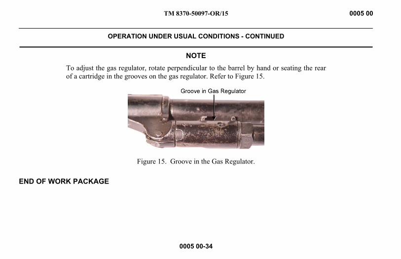
NOTE To adjust the gas regulator, rotate perpendicular to the barrel by hand or seating the rear of a cartridge in the grooves on the gas regulator. Refer to Figure 15.
Figure 15. Groove in the Gas Regulator.
END OF WORK PACKAGE

TM 8370-50097-OR/15 0006 00
OPERATION UNDER UNUSUAL CONDITIONS
0006 00-1
NOTE Adjustment of the gas regulator may be needed for the following conditions, to include high altitude.
EXTREME COLD CLIMATE - ARCTIC Cleaning and lubrication should be done inside a warm room. The weapon should be at room temperature if possible.
Use Cleaner, Lubricant, and Preservative (CLP) to clean and lubricate the weapon.
1. Perform normal maintenance as outlined in Preventive Maintenance Checks and Services (PMCS) (WP 0011 00).
2. Clean and lubricate the weapon more frequently. Inspect hidden surfaces of the bolt carrier group, upper receiver and chamber/barrel extension, lower receiver assembly, and buttstock assembly for corrosion. Pay close attention to all spring-loaded detents on the weapon.
3. To help prevent corrosion, remove handprints with a dry wiping rag. Lubricate lightly with CLP.
4. Unload and check the insides of the magazine frequently for corrosion and moisture. Wipe ammunition dry before reloading.
5. Apply a light coat of Lubricant, Arctic, Weapons (LAW) to all functional parts.

TM 8370-50097-OR/15 0006 00
OPERATION UNDER UNUSUAL CONDITIONS - CONTINUED
0006 00-2
6. To prevent condensation and freezing, allow gradual cooling by keeping the weapon covered when moving from a warm area to a cold area.
7. Always attempt to keep the weapon dry.
8. Unload and hand function the weapon every 30 minutes to prevent freezing of functional parts.
9. Do not lay a warm weapon directly in snow or on ice.
10. When moving a cold weapon into a warm area, condensation will form in and on the weapon. If possible, leave the weapon in a protected, cold area outside. When the weapon is brought into a warm area, as it reaches room temperature, it should be disassembled and wiped dry several times.
11. Ensure the insides of the weapon are wiped dry. Moisture can freeze and cause malfunctions. Do not lubricate ammunition.
12. Use a clean cloth to protect the muzzle and receiver from blowing snow.

TM 8370-50097-OR/15 0006 00
OPERATION UNDER UNUSUAL CONDITIONS - CONTINUED
0006 00-3
HOT, WET CLIMATE - JUNGLE Use Cleaner, Lubricant, and Preservative (CLP) to clean and lubricate the weapon.
Keep the weapon in its carrying case when not in use.
Perform normal maintenance as outlined in WP 0011 00.
1. Protect the weapon from rain whenever possible.
2. Clean and lubricate the weapon, the bore, and chamber daily; preserve with CLP.
3. Do not expose the telescopic sight to direct sunlight.
4. Inspect and clean the telescopic sight frequently to avoid rust and corrosion.
5. To help prevent corrosion, remove hand prints with a dry wiping rag. Lubricate lightly with CLP.

TM 8370-50097-OR/15 0006 00
OPERATION UNDER UNUSUAL CONDITIONS - CONTINUED
0006 00-4
HOT, DRY CLIMATE - DESERT Use CLP to clean and lubricate the weapon.
CAUTION Areas with hot, dry climates usually contain blowing sand and fine dust. Deserts can be hot during daylight hours and freezing during hours of darkness. This will severely tax the weapon as well as other types of equipment. The weapon’s continued operation will depend on strictly and routinely following detailed cleaning and lubricating procedures.
1. Dust and sand will get into the weapon causing malfunctions. Perform a thorough cleaning of the weapon daily and after all firing missions.
NOTE Always shake CLP prior to use.
2. Corrosion is less likely to form on metal parts in a dry climate. Therefore, lubricant should only be applied to internal working surfaces and functioning parts. Use normal amounts of CLP for lubrication. Unload the magazine, dry the inside of the magazine, and wipe down ammunition daily. DO NOT lubricate magazines.
3. The use of an overall weapon protection cover and muzzle cap will help protect the weapon and ammunition from sand and dust. Use these items when the tactical situation permits.
TM 8370-50097-OR/15 0006 00
OPERATION UNDER UNUSUAL CONDITIONS - CONTINUED
0006 00-5
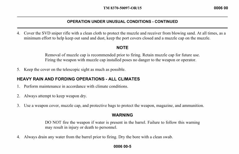
4. Cover the SVD sniper rifle with a clean cloth to protect the muzzle and receiver from blowing sand. At all times, as a minimum effort to help keep out sand and dust, keep the port covers closed and a muzzle cap on the muzzle.
NOTE Removal of muzzle cap is recommended prior to firing. Retain muzzle cap for future use. Firing the weapon with muzzle cap installed poses no danger to the weapon or operator.
5. Keep the cover on the telescopic sight as much as possible.
HEAVY RAIN AND FORDING OPERATIONS - ALL CLIMATES 1. Perform maintenance in accordance with climate conditions.
2. Always attempt to keep weapon dry.
3. Use a weapon cover, muzzle cap, and protective bags to protect the weapon, magazine, and ammunition.
WARNING DO NOT fire the weapon if water is present in the barrel. Failure to follow this warning may result in injury or death to personnel.
4. Always drain any water from the barrel prior to firing. Dry the bore with a clean swab.
TM 8370-50097-OR/15 0006 00
OPERATION UNDER UNUSUAL CONDITIONS - CONTINUED
0006 00-6
NUCLEAR, BIOLOGICAL, AND CHEMICAL (NBC) General procedures can be found in Marine Corps Warfighting Publication: MCWP 3-37.2A_ and MCWP 3-37.3_.
END OF WORK PACKAGE

TM 8370-50097-OR/15
CHAPTER 3
TROUBLESHOOTING

INTENTIONALLY BLANK

TM 8370-50097-OR/15 0007 00
TROUBLESHOOTING INTRODUCTION
0007-1/2 blank
TROUBLESHOOTING This chapter contains troubleshooting information for locating and correcting malfunctions that may develop in the SVD sniper rifle. The Troubleshooting Symptom Index (WP 0008 00) serves as a quick reference to aid in troubleshooting the weapon. Table 1, in WP 0009 00, is a guide for troubleshooting. Perform the tests, inspections, and corrective actions in the order shown in the table. The table does not cover all possible malfunctions that may occur; it includes common malfunctions. If the weapon malfunction is not listed or actions listed do not correct the fault, notify the unit armorer.
END OF WORK PACKAGE

INTENTIONALLY BLANK

TM 8370-50097-OR/15 0008 00
TROUBLESHOOTING SYMPTOM INDEX
0008 00-1/2 blank
Malfunction/Symptom Troubleshooting Procedure Page
1. Failure to Fire ..................................................................................................................................................... 0009 00-1 2. Failure to Unlock ............................................................................................................................................... 0009 00-2 3. Failure to Extract ............................................................................................................................................... 0009 00-2 4. Failure to Eject ................................................................................................................................................... 0009 00-3 5. Failure to Feed ................................................................................................................................................... 0009 00-3 6. Failure to Chamber ............................................................................................................................................ 0009 00-4 7. Bolt Fails to Lock .............................................................................................................................................. 0009 00-4 8. Short Recoil ....................................................................................................................................................... 0009 00-5 9. Failure to Load ................................................................................................................................................... 0009 00-5 10. Magazine Inserts with Difficulty ....................................................................................................................... 0009 00-6 11. Magazine Cannot be Retained in the Weapon ................................................................................................... 0009 00-7 12. When Adjusting Telescopic Sight Windage or Elevation Knobs, Point of Aim Does Not Change .................. 0009 00-8 13. Cheek Pad Difficult to Adjust ............................................................................................................................ 0009 00-8
END OF WORK PACKAGE

INTENTIONALLY BLANK
TM 8370-50097-OR/15 0009 00
TROUBLESHOOTING PROCEDURES
0009 00-1
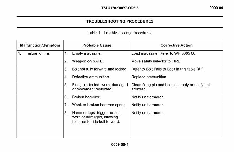
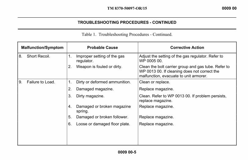
Table 1. Troubleshooting Procedures.
Malfunction/Symptom Probable Cause Corrective Action
1. Failure to Fire. 1. Empty magazine. Load magazine. Refer to WP 0005 00.
2. Weapon on SAFE. Move safety selector to FIRE.
3. Bolt not fully forward and locked. Refer to Bolt Fails to Lock in this table (#7).
4. Defective ammunition. Replace ammunition.
5. Firing pin fouled, worn, damaged, or movement restricted.
Clean firing pin and bolt assembly or notify unit armorer.
6. Broken hammer. Notify unit armorer.
7. Weak or broken hammer spring. Notify unit armorer.
8. Hammer lugs, trigger, or sear worn or damaged, allowing hammer to ride bolt forward.
Notify unit armorer.
TM 8370-50097-OR/15 0009 00
TROUBLESHOOTING PROCEDURES - CONTINUED
0009 00-2
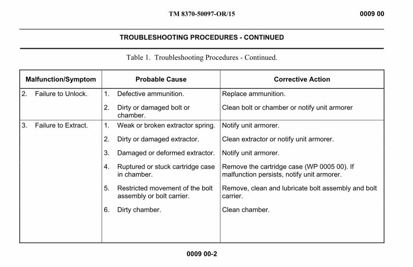
Table 1. Troubleshooting Procedures - Continued.
Malfunction/Symptom Probable Cause Corrective Action
2. Failure to Unlock. 1. Defective ammunition. Replace ammunition.
2. Dirty or damaged bolt or chamber.
Clean bolt or chamber or notify unit armorer
3. Failure to Extract. 1. Weak or broken extractor spring. Notify unit armorer.
2. Dirty or damaged extractor. Clean extractor or notify unit armorer.
3. Damaged or deformed extractor. Notify unit armorer.
4. Ruptured or stuck cartridge case in chamber.
Remove the cartridge case (WP 0005 00). If malfunction persists, notify unit armorer.
5. Restricted movement of the bolt assembly or bolt carrier.
Remove, clean and lubricate bolt assembly and bolt carrier.
6. Dirty chamber. Clean chamber.
TM 8370-50097-OR/15 0009 00
TROUBLESHOOTING PROCEDURES - CONTINUED
0009 00-3
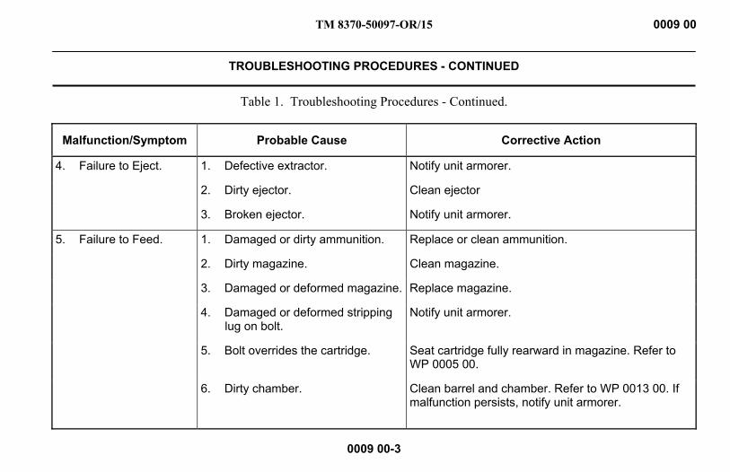
Table 1. Troubleshooting Procedures - Continued.
Malfunction/Symptom Probable Cause Corrective Action
4. Failure to Eject. 1. Defective extractor. Notify unit armorer.
2. Dirty ejector. Clean ejector
3. Broken ejector. Notify unit armorer.
5. Failure to Feed. 1. Damaged or dirty ammunition. Replace or clean ammunition.
2. Dirty magazine. Clean magazine.
3. Damaged or deformed magazine. Replace magazine.
4. Damaged or deformed stripping lug on bolt.
Notify unit armorer.
5. Bolt overrides the cartridge. Seat cartridge fully rearward in magazine. Refer to WP 0005 00.
6. Dirty chamber. Clean barrel and chamber. Refer to WP 0013 00. If malfunction persists, notify unit armorer.

TM 8370-50097-OR/15 0009 00
TROUBLESHOOTING PROCEDURES - CONTINUED
0009 00-4
Table 1. Troubleshooting Procedures - Continued.
Malfunction/Symptom Probable Cause Corrective Action
6. Failure to Chamber. 1. Dirty, damaged, or corroded ammunition.
Clean or replace ammunition.
2. Dirty chamber. Clean barrel and chamber. Refer to WP 0013 00. If malfunction persists, notify unit armorer.
7. Bolt Fails to Lock. 1. Cartridge case stuck in the chamber.
Remove cartridge case. Refer to WP 0005 00. If malfunction persists, notify unit armorer.
2. Dirty chamber. Clean barrel and chamber. Refer to WP 0013 00. If malfunction persists, notify unit armorer.
3. Damaged or dented receiver. Notify unit armorer.
4. Weapon is not loaded properly. Load weapon properly. Refer to WP 0005 00.
TM 8370-50097-OR/15 0009 00
TROUBLESHOOTING PROCEDURES - CONTINUED
0009 00-5
Table 1. Troubleshooting Procedures - Continued.
Malfunction/Symptom Probable Cause Corrective Action
8. Short Recoil. 1. Improper setting of the gas regulator.
Adjust the setting of the gas regulator. Refer to WP 0005 00.
2. Weapon is fouled or dirty. Clean the bolt carrier group and gas tube. Refer to WP 0013 00. If cleaning does not correct the malfunction, evacuate to unit armorer.
9. Failure to Load. 1. Dirty or deformed ammunition. Clean or replace.
2. Damaged magazine. Replace magazine.
3. Dirty magazine. Clean. Refer to WP 0013 00. If problem persists, replace magazine.
4. Damaged or broken magazine spring.
Replace magazine.
5. Damaged or broken follower. Replace magazine.
6. Loose or damaged floor plate. Replace magazine.
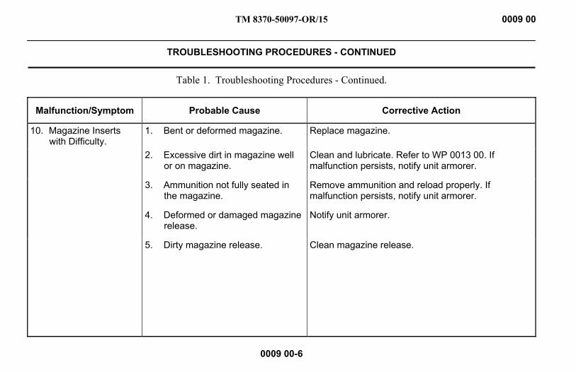
TM 8370-50097-OR/15 0009 00
TROUBLESHOOTING PROCEDURES - CONTINUED
0009 00-6
Table 1. Troubleshooting Procedures - Continued.
Malfunction/Symptom Probable Cause Corrective Action
10. Magazine Inserts with Difficulty.
1. Bent or deformed magazine. Replace magazine.
2. Excessive dirt in magazine well or on magazine.
Clean and lubricate. Refer to WP 0013 00. If malfunction persists, notify unit armorer.
3. Ammunition not fully seated in the magazine.
Remove ammunition and reload properly. If malfunction persists, notify unit armorer.
4. Deformed or damaged magazine release.
Notify unit armorer.
5. Dirty magazine release. Clean magazine release.

TM 8370-50097-OR/15 0009 00
TROUBLESHOOTING PROCEDURES - CONTINUED
0009 00-7
Table 1. Troubleshooting Procedures - Continued.
Malfunction/Symptom Probable Cause Corrective Action
11. Magazine Cannot be Retained in the Weapon.
1. Magazine is not fully inserted. Remove and insert properly. Ensure magazine release clicks. Refer to WP 0005 00. If malfunction persists, notify unit armorer.
2. Damaged magazine. Replace magazine.
3. Magazine release is damaged or deformed.
Notify unit armorer.
4. Magazine release spring is damaged or broken.
Notify unit armorer.

TM 8370-50097-OR/15 0009 00
TROUBLESHOOTING PROCEDURES - CONTINUED
0009 00-8
Table 1. Troubleshooting Procedures - Continued.
Malfunction/Symptom Probable Cause Corrective Action
12. When Adjusting Telescopic Sight Windage or Elevation Knobs, Point of Aim Does Not Change.
Optic has loss of motion. Notify unit armorer.
13. Cheek Pad Difficult to Adjust.
Heavy accumulation of foreign material on cheek pad or in buttstock.
Clean cheek pad and buttstock. If malfunction persists, notify unit armorer.
END OF WORK PACKAGE

TM 8370-50097-OR/15
CHAPTER 4
MAINTENANCE INSTRUCTIONS

INTENTIONALLY BLANK

TM 8370-50097-OR/15 0010 00
SERVICE UPON RECEIPT
0010 00-1
INSPECTING THE WEAPON WARNING
Ensure that the weapon is unloaded and on SAFE with the chamber cleared before performing these procedures. Failure to follow this warning may result in injury or death to personnel.
Inspect all assemblies for missing, broken, or loose parts. Refer to Table 1 in this work package. Inspect for cracks, dents, burrs, excessive wear, rust, or corrosion. Ensure all items are cleaned and lubricated. If defects in this work package are noted, bring them to the attention of the unit armorer. The unit armorer will determine if a defect exists. Confirm zero of weapon and PSO-1 telescopic sight by live fire, if possible.
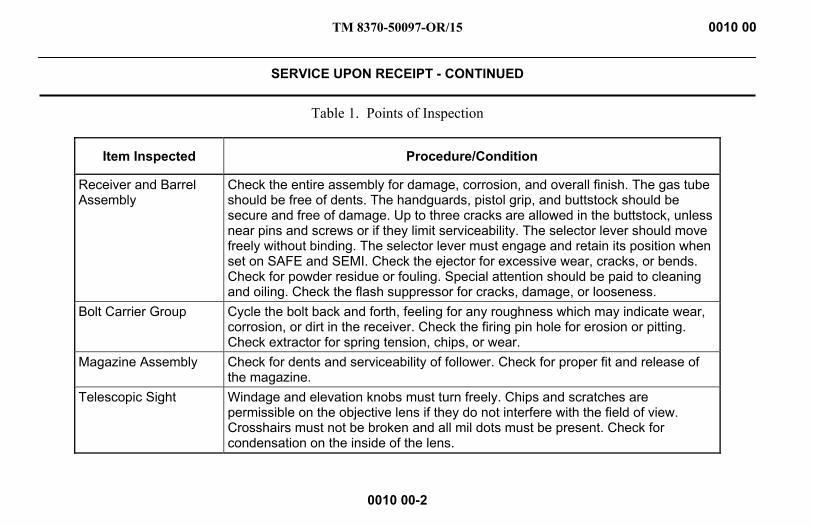
TM 8370-50097-OR/15 0010 00
SERVICE UPON RECEIPT - CONTINUED
0010 00-2
Table 1. Points of Inspection
Item Inspected Procedure/Condition
Receiver and Barrel Assembly
Check the entire assembly for damage, corrosion, and overall finish. The gas tube should be free of dents. The handguards, pistol grip, and buttstock should be secure and free of damage. Up to three cracks are allowed in the buttstock, unless near pins and screws or if they limit serviceability. The selector lever should move freely without binding. The selector lever must engage and retain its position when set on SAFE and SEMI. Check the ejector for excessive wear, cracks, or bends. Check for powder residue or fouling. Special attention should be paid to cleaning and oiling. Check the flash suppressor for cracks, damage, or looseness.
Bolt Carrier Group Cycle the bolt back and forth, feeling for any roughness which may indicate wear, corrosion, or dirt in the receiver. Check the firing pin hole for erosion or pitting. Check extractor for spring tension, chips, or wear.
Magazine Assembly Check for dents and serviceability of follower. Check for proper fit and release of the magazine.
Telescopic Sight Windage and elevation knobs must turn freely. Chips and scratches are permissible on the objective lens if they do not interfere with the field of view. Crosshairs must not be broken and all mil dots must be present. Check for condensation on the inside of the lens.
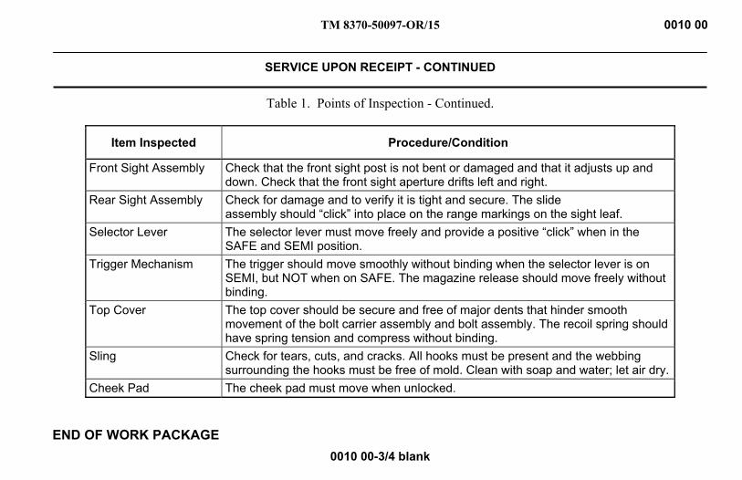
TM 8370-50097-OR/15 0010 00
SERVICE UPON RECEIPT - CONTINUED
0010 00-3/4 blank
Table 1. Points of Inspection - Continued.
Item Inspected Procedure/Condition
Front Sight Assembly Check that the front sight post is not bent or damaged and that it adjusts up and down. Check that the front sight aperture drifts left and right.
Rear Sight Assembly Check for damage and to verify it is tight and secure. The slide assembly should “click” into place on the range markings on the sight leaf.
Selector Lever The selector lever must move freely and provide a positive “click” when in the SAFE and SEMI position.
Trigger Mechanism The trigger should move smoothly without binding when the selector lever is on SEMI, but NOT when on SAFE. The magazine release should move freely without binding.
Top Cover The top cover should be secure and free of major dents that hinder smooth movement of the bolt carrier assembly and bolt assembly. The recoil spring should have spring tension and compress without binding.
Sling Check for tears, cuts, and cracks. All hooks must be present and the webbing surrounding the hooks must be free of mold. Clean with soap and water; let air dry.
Cheek Pad The cheek pad must move when unlocked.
END OF WORK PACKAGE

INTENTIONALLY BLANK
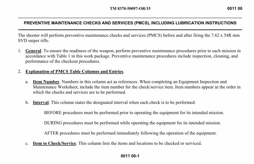
TM 8370-50097-OR/15 0011 00
PREVENTIVE MAINTENANCE CHECKS AND SERVICES (PMCS), INCLUDING LUBRICATION INSTRUCTIONS
0011 00-1
The shooter will perform preventive maintenance checks and services (PMCS) before and after firing the 7.62 x 54R mm SVD sniper rifle.
1. General. To ensure the readiness of the weapon, perform preventive maintenance procedures prior to each mission in accordance with Table 1 in this work package. Preventive maintenance procedures include inspection, cleaning, and performance of the checkout procedures.
2. Explanation of PMCS Table Columns and Entries.
a. Item Number. Numbers in this column act as references. When completing an Equipment Inspection and Maintenance Worksheet, include the item number for the check/service item. Item numbers appear in the order in which the checks and services are to be performed.
b. Interval. This column states the designated interval when each check is to be performed.
BEFORE procedures must be performed prior to operating the equipment for its intended mission.
DURING procedures must be performed while operating the equipment for its intended mission.
AFTER procedures must be performed immediately following the operation of the equipment.
c. Item to Check/Service. This column lists the items and locations to be checked or serviced.
TM 8370-50097-OR/15 0011 00
PREVENTIVE MAINTENANCE CHECKS AND SERVICES (PMCS), INCLUDING LUBRICATION INSTRUCTIONS -
CONTINUED
0011 00-2
d. Procedure. This column contains a brief description of PMCS procedures to be performed. The procedure must follow the time stated in the interval column.
e. Not Fully Mission Capable If. This column states which faults will prevent the weapon from being capable of performing its primary mission. The weapon should not be used if it meets any of the faults listed in this column. Follow standard operating procedures for correcting or reporting weapon failure.
3. Other Table Entries. Observe all WARNINGs, CAUTIONs, and NOTEs.
WARNING Confirm the weapon is unloaded, clear, and on SAFE before performing the following procedures. Do not keep live ammunition near the work area. Failure to follow these warnings may cause injury or death to personnel.

TM 8370-50097-OR/15 0011 00
PREVENTIVE MAINTENANCE CHECKS AND SERVICES (PMCS), INCLUDING LUBRICATION INSTRUCTIONS -
CONTINUED
0011 00-3
Table 1. Preventive Maintenance Service Checks and Services (PMCS) for the SVD Sniper Rifle.
(1)
Item No.
(2)
Interval
(3)
Item to Check/Service
(4)
Procedure
(5)
Not Fully Mission Capable If:
1 Before Visual Inspection of the Weapon
Check the weapon for missing or damaged parts. Report missing or damaged parts to the unit armorer.
Parts are missing or damaged to the point of being unserviceable.
2 During Periodic Inspection of the Weapon
Periodically inspect the weapon to ensure it is clean and there are no foreign materials and obstructions in the bore. If foreign materials or obstructions are present, clean the bore.
Foreign materials and obstructions in the bore cannot be removed.
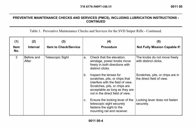
TM 8370-50097-OR/15 0011 00
PREVENTIVE MAINTENANCE CHECKS AND SERVICES (PMCS), INCLUDING LUBRICATION INSTRUCTIONS -
CONTINUED
0011 00-4
Table 1. Preventive Maintenance Checks and Services for the SVD Sniper Rifle - Continued.
(1)
Item No.
(2)
Interval
(3)
Item to Check/Service
(4)
Procedure
(5)
Not Fully Mission Capable If:
3 Before and After
Telescopic Sight a. Check that the elevation, windage, power knobs move freely in both directions with distinct clicks.
The knobs do not move freely with distinct clicks.
b. Inspect the lenses for scratches, pits, or chips that interfere with the field of view. Scratches, pits, or chips are acceptable as long as they are not in the direct field of view.
Scratches, pits, or chips are in the direct field of view.
c. Ensure the locking lever of the telescopic sight securely fastens the sight to the mounting rail and receiver.
Locking lever does not fasten securely.

TM 8370-50097-OR/15 0011 00
PREVENTIVE MAINTENANCE CHECKS AND SERVICES (PMCS), INCLUDING LUBRICATION INSTRUCTIONS -
CONTINUED
0011 00-5
Table 1. Preventive Maintenance Checks and Services for the SVD Sniper Rifle - Continued.
(1)
Item No.
(2)
Interval
(3)
Item to Check/Service
(4)
Procedure
(5)
Not Fully Mission Capable If:
4 Before and After
Magazine Assembly a. Disassemble as in WP 0014 00. Inspect the magazine body for bulges, dents, or damaged feeder lips. Inspect the spring and follower for kinks and damage. Replace the magazine if any of these conditions exist.
Magazine is not available, is dented or feeder lips are damaged, spring is damaged or has flat spots.
b. Reassemble magazine and check for binding during operation of the follower. Replace the magazine if the follower binds.
Follower binds.
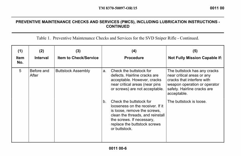
TM 8370-50097-OR/15 0011 00
PREVENTIVE MAINTENANCE CHECKS AND SERVICES (PMCS), INCLUDING LUBRICATION INSTRUCTIONS -
CONTINUED
0011 00-6
Table 1. Preventive Maintenance Checks and Services for the SVD Sniper Rifle - Continued.
(1)
Item No.
(2)
Interval
(3)
Item to Check/Service
(4)
Procedure
(5)
Not Fully Mission Capable If:
5 Before and After
Buttstock Assembly a. Check the buttstock for defects. Hairline cracks are acceptable. However, cracks near critical areas (near pins or screws) are not acceptable.
The buttstock has any cracks near critical areas or any cracks that interfere with weapon operation or operator safety. Hairline cracks are acceptable.
b. Check the buttstock for looseness on the receiver. If it is loose, remove the screws, clean the threads, and reinstall the screws. If necessary, replace the buttstock screws or buttstock.
The buttstock is loose.
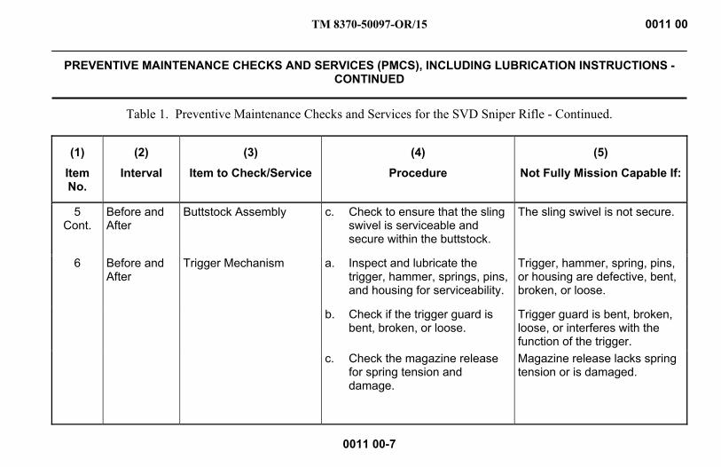
TM 8370-50097-OR/15 0011 00
PREVENTIVE MAINTENANCE CHECKS AND SERVICES (PMCS), INCLUDING LUBRICATION INSTRUCTIONS -
CONTINUED
0011 00-7
Table 1. Preventive Maintenance Checks and Services for the SVD Sniper Rifle - Continued.
(1)
Item No.
(2)
Interval
(3)
Item to Check/Service
(4)
Procedure
(5)
Not Fully Mission Capable If:
5 Cont.
Before and After
Buttstock Assembly c. Check to ensure that the sling swivel is serviceable and secure within the buttstock.
The sling swivel is not secure.
6 Before and After
Trigger Mechanism a. Inspect and lubricate the trigger, hammer, springs, pins, and housing for serviceability.
Trigger, hammer, spring, pins, or housing are defective, bent, broken, or loose.
b. Check if the trigger guard is bent, broken, or loose.
Trigger guard is bent, broken, loose, or interferes with the function of the trigger.
c. Check the magazine release for spring tension and damage.
Magazine release lacks spring tension or is damaged.

TM 8370-50097-OR/15 0011 00
PREVENTIVE MAINTENANCE CHECKS AND SERVICES (PMCS), INCLUDING LUBRICATION INSTRUCTIONS -
CONTINUED
0011 00-8
Table 1. Preventive Maintenance Checks and Services for the SVD Sniper Rifle - Continued.
(1)
Item No.
(2)
Interval
(3)
Item to Check/Service
(4)
Procedure
(5)
Not Fully Mission Capable If:
7 Before and After
Receiver and Barrel Assembly
a. Inspect the muzzle end of the barrel for a serviceable crown; the lands and grooves in the bore should have no nicks or burrs.
The muzzle is defective.
b. Inspect ejector for wear and damage.
The ejector is damaged or worn.
c. Check that the gas regulator can be adjusted and secures in place. Check for cracks, deformities, and fouling. Check for proper setting. Refer to WP 0005 00.
Gas regulator cannot be adjusted or is loose.
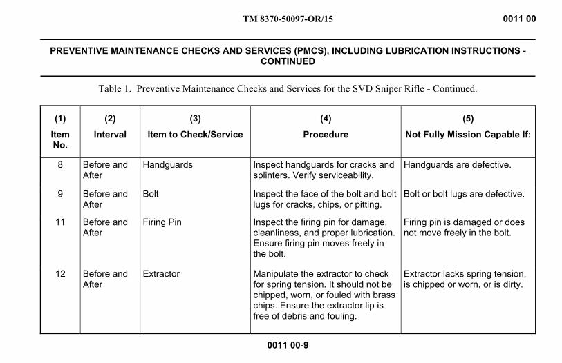
TM 8370-50097-OR/15 0011 00
PREVENTIVE MAINTENANCE CHECKS AND SERVICES (PMCS), INCLUDING LUBRICATION INSTRUCTIONS -
CONTINUED
0011 00-9
Table 1. Preventive Maintenance Checks and Services for the SVD Sniper Rifle - Continued.
(1)
Item No.
(2)
Interval
(3)
Item to Check/Service
(4)
Procedure
(5)
Not Fully Mission Capable If:
8 Before and After
Handguards Inspect handguards for cracks and splinters. Verify serviceability.
Handguards are defective.
9 Before and After
Bolt Inspect the face of the bolt and bolt lugs for cracks, chips, or pitting.
Bolt or bolt lugs are defective.
11 Before and After
Firing Pin Inspect the firing pin for damage, cleanliness, and proper lubrication. Ensure firing pin moves freely in the bolt.
Firing pin is damaged or does not move freely in the bolt.
12 Before and After
Extractor Manipulate the extractor to check for spring tension. It should not be chipped, worn, or fouled with brass chips. Ensure the extractor lip is free of debris and fouling.
Extractor lacks spring tension, is chipped or worn, or is dirty.
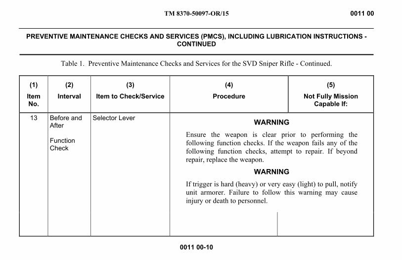
TM 8370-50097-OR/15 0011 00
PREVENTIVE MAINTENANCE CHECKS AND SERVICES (PMCS), INCLUDING LUBRICATION INSTRUCTIONS -
CONTINUED
0011 00-10
Table 1. Preventive Maintenance Checks and Services for the SVD Sniper Rifle - Continued.
(1)
Item No.
(2)
Interval
(3)
Item to Check/Service
(4)
Procedure
(5)
Not Fully Mission Capable If:
13 Before and After Function Check
Selector Lever
WARNING Ensure the weapon is clear prior to performing the following function checks. If the weapon fails any of the following function checks, attempt to repair. If beyond repair, replace the weapon.
WARNING If trigger is hard (heavy) or very easy (light) to pull, notify unit armorer. Failure to follow this warning may cause injury or death to personnel.
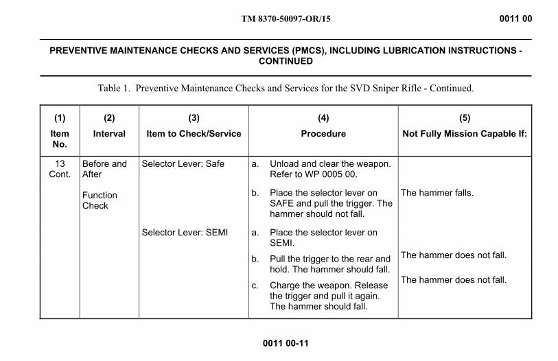
TM 8370-50097-OR/15 0011 00
PREVENTIVE MAINTENANCE CHECKS AND SERVICES (PMCS), INCLUDING LUBRICATION INSTRUCTIONS -
CONTINUED
0011 00-11
Table 1. Preventive Maintenance Checks and Services for the SVD Sniper Rifle - Continued.
(1)
Item No.
(2)
Interval
(3)
Item to Check/Service
(4)
Procedure
(5)
Not Fully Mission Capable If:
13 Cont.
Before and After Function Check
Selector Lever: Safe
a. Unload and clear the weapon. Refer to WP 0005 00.
b. Place the selector lever on SAFE and pull the trigger. The hammer should not fall.
The hammer falls.
Selector Lever: SEMI a. Place the selector lever on SEMI.
b. Pull the trigger to the rear and hold. The hammer should fall.
c. Charge the weapon. Release the trigger and pull it again. The hammer should fall.
The hammer does not fall.
The hammer does not fall.
TM 8370-50097-OR/15 0011 00
PREVENTIVE MAINTENANCE CHECKS AND SERVICES (PMCS), INCLUDING LUBRICATION INSTRUCTIONS -
CONTINUED
0011 00-12
LUBRICATION 1. Inspect Before Lubrication. If items are found to be unsatisfactory during inspection, notify the unit armorer.
WARNING Do not interchange bolt assemblies between weapons. Failure to follow this warning may cause injury or death to personnel.
a. Bolt. Inspect for cracks or fractures. Bolts containing pits extending into the firing pin hole need to be replaced.
b. Firing Pin. Inspect the firing pin for a bent, cracked, blunted, or sharp end.
c. Extractor and Extractor Spring. Inspect the extractor for chipped or broken edges in the area of the lip that engages the cartridge rim. Check the extractor spring tension.
2. Cleaner, Lubricant, and Preservative (CLP).
a. CLP performs the following:
(1) Dissolves firing residue and carbon.
(2) Provides a layer of teflon for lubrication of parts.

TM 8370-50097-OR/15 0011 00
PREVENTIVE MAINTENANCE CHECKS AND SERVICES (PMCS), INCLUDING LUBRICATION INSTRUCTIONS -
CONTINUED
0011 00-13
(3) Prevents rust from forming.
CAUTION Do not dry clean the weapon. Do not use hot water or other solvents to clean the weapon. This will remove the teflon lubricant built up as a result of using CLP.
b. Use CLP as follows:
(1) Shake the bottle well before each use.
(2) Place a few drops on a patch or rag.
(3) Clean the weapon with patches or rags until no residue is found.
(4) Use another patch or rag to apply a fresh, light coat.
3. Lubrication. CLP is the lubricant to be used under all but the coldest arctic conditions when Lubricant, Arctic, Weapons (LAW) is used. Remove excessive lubricant from the bore and chamber before firing. For a lubricant guide, refer to Figure 1.
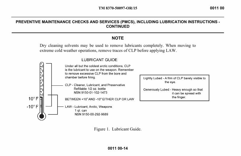
TM 8370-50097-OR/15 0011 00
PREVENTIVE MAINTENANCE CHECKS AND SERVICES (PMCS), INCLUDING LUBRICATION INSTRUCTIONS -
CONTINUED
0011 00-14
NOTE Dry cleaning solvents may be used to remove lubricants completely. When moving to extreme cold weather operations, remove traces of CLP before applying LAW.
Figure 1. Lubricant Guide.

TM 8370-50097-OR/15 0011 00
PREVENTIVE MAINTENANCE CHECKS AND SERVICES (PMCS), INCLUDING LUBRICATION INSTRUCTIONS -
CONTINUED
0011 00-15
a. Receiver and Barrel Assembly.
(1) Lightly lubricate the inside of the receiver, bore, and chamber, outer surfaces of the barrel, front sight, gas tube, and surfaces under the handguards.
(2) Apply one drop of CLP to the front sight post, rotate to work in the CLP, wipe away excess CLP, and return to original position.
(3) Lightly lubricate the operating rod, operating rod spring, and gas piston.
b. Trigger Mechanism. Lightly lubricate all parts with CLP. Manipulate the magazine release, trigger, and hammer to work in the CLP. Wipe away excess CLP.
c. Bolt Carrier Group.
(1) Dry the bolt carrier and lightly lubricate with CLP. Generously lubricate the cam recess and receiver rail recesses of the bolt carrier.
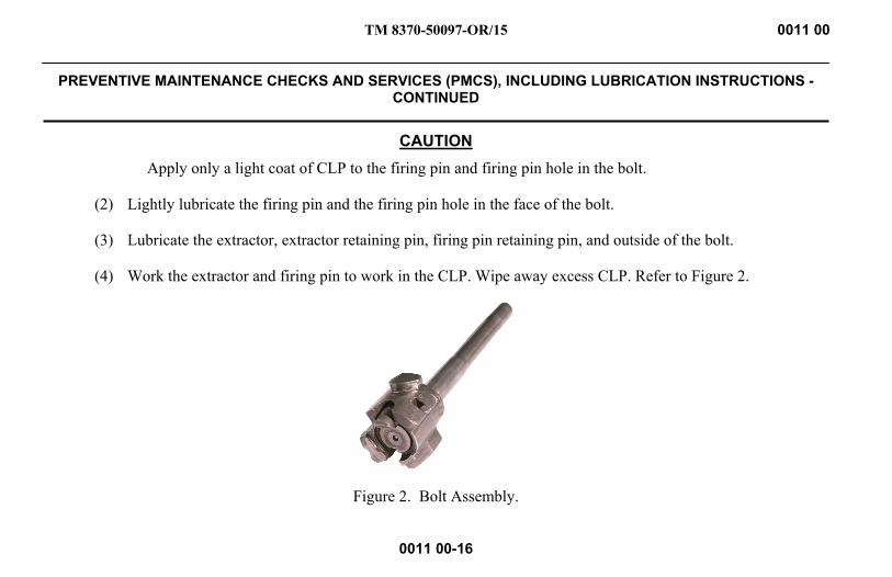
TM 8370-50097-OR/15 0011 00
PREVENTIVE MAINTENANCE CHECKS AND SERVICES (PMCS), INCLUDING LUBRICATION INSTRUCTIONS -
CONTINUED
0011 00-16
CAUTION Apply only a light coat of CLP to the firing pin and firing pin hole in the bolt.
(2) Lightly lubricate the firing pin and the firing pin hole in the face of the bolt.
(3) Lubricate the extractor, extractor retaining pin, firing pin retaining pin, and outside of the bolt.
(4) Work the extractor and firing pin to work in the CLP. Wipe away excess CLP. Refer to Figure 2.
Figure 2. Bolt Assembly.

TM 8370-50097-OR/15 0011 00
PREVENTIVE MAINTENANCE CHECKS AND SERVICES (PMCS), INCLUDING LUBRICATION INSTRUCTIONS -
CONTINUED
0011 00-17/18 blank
d. Top Cover. Lightly lubricate the recoil spring and guide rod assembly.
e. Rear Sight Assembly.
(1) Apply one drop of CLP to the base of the sight leaf. Flip up and down to work in the CLP.
(2) Apply one drop of CLP to the slide assembly. Press the button several times and slide the sight leaf up and down to work in the CLP.
(3) Apply one drop of CLP to the windage knob and turn it both directions several times to work in the CLP.
(4) Reset the rear sight to its original setting.
END OF WORK PACKAGE

INTENTIONALLY BLANK

TM 8370-50037-OR/3 0012 00
GENERAL MAINTENANCE INSTRUCTIONS
0012 00-1
THIS WORK PACKAGE COVERS Scope, Work Safety, General Information, Cleaning Instructions, Inspection Instructions, and Lubrication Instructions.
INITIAL SETUP Maintenance Level
Operator
References
WP 0011 00 WP 0013 00 WP 0018 00
TM 8370-50037-OR/3 0012 00
GENERAL MAINTENANCE INSTRUCTIONS - CONTINUED
0012 00-2
SCOPE These general maintenance instructions contain general shop practices and specific methods you must be familiar with to properly maintain the SVD sniper rifle.
WORK SAFETY 1. Before starting a task, think about the risks and safety hazards. Wear protective gear such as safety goggles or lenses,
safety shoes, a rubber apron, and gloves.
2. Observe all WARNINGs, CAUTIONs, and NOTEs.
GENERAL INFORMATION CAUTION
DO NOT mix lubricants on the same weapon. The weapon must be cleaned thoroughly during any change from one lubricant to another. Dry cleaning solvent (SD) is recommended for cleaning before changing lubricants.
When the term lubricant is used in this TM, it is to be interpreted to mean CLP (Cleaner, Lubricant, and Preservative); LSA (Lubricating Oil, Semi-fluid, Automatic Weapons); or LAW (Lubricant, Arctic, Weapons).
1. Disassemble, thoroughly clean, inspect, and lubricate the weapon.
TM 8370-50037-OR/3 0012 00
GENERAL MAINTENANCE INSTRUCTIONS - CONTINUED
0012 00-3
2. Always shake CLP prior to use.
3. After firing, clean the weapon with CLP according to instructions in WP 0013 00. Wipe the weapon dry and lubricate according to instructions in WP 0011 00.
NOTE Contact the unit armorer if parts from the cleaning kit are missing or defective.
4. Cleaning materials (e.g., patches, pipe cleaners, and CLP) are expendable items. For a complete list of cleaning materials refer to WP 0018 00.
CLEANING INSTRUCTIONS NOTE
Use only CLP for cleaning and lubrication in all but the most severe conditions.
Cloths or rags saturated with CLP must be disposed of in accordance with authorized facilities’ procedures.
Cleaning instructions are the same for the majority of the parts and components of the weapon.

TM 8370-50037-OR/3 0012 00
GENERAL MAINTENANCE INSTRUCTIONS - CONTINUED
0012 00-4
The importance of cleaning must be thoroughly understood by operators and maintenance personnel. Great care and effort are required in cleaning. Dirt and foreign material are a constant threat to satisfactory maintenance. The following apply to all cleaning, inspection, repair, and assembly operations:
a. Clean all parts before inspection, after repair, and before assembly.
b. To prevent contamination, hands should be kept free of any accumulation of grease which can collect dust, dirt, or grit.
c. After cleaning, all parts should be covered or wrapped to protect them from dust and dirt. Parts that are subject to rust should be lightly oiled.
1. Cleaning Disassembled Parts.
a. Dry and cover all cleaned parts.
b. All parts subject to rusting must be lightly oiled and wrapped.
c. Keep all related parts and components together. Do not mix parts.
2. Castings.
a. Clean the inner and outer surfaces of castings with CLP.
b. Use a stiff brush to remove sludge and gum deposits.
TM 8370-50037-OR/3 0012 00
GENERAL MAINTENANCE INSTRUCTIONS - CONTINUED
0012 00-5
3. Machined Surfaces.
a. Clean machined surfaces with CLP.
b. Dry surfaces thoroughly.
4. Mated Surfaces. Lightly coat with CLP and wrap all parts subject to rust before storing.
INSPECTION INSTRUCTIONS 1. General. All components and parts must be checked carefully to determine if they are serviceable for reuse or if they
must be scrapped.
2. Castings.
a. Replace all cracked castings.
b. Inspect machined surfaces for nicks, burrs, or raised metal. Mark damaged areas for repair or replacement.
c. Inspect all screws and screw openings for damaged or stripped threads.
3. Machine-Tooled Parts. Inspect for cracks, breaks, elongated holes, wear, and chips.
4. Machined Surfaces. Inspect for cracks, evidence of wear, galled or pitted surfaces, burrs, nicks, and scratches.
5. Mating Surfaces. Inspect mating surfaces for seal, secure fit, and pitting.
TM 8370-50037-OR/3 0012 00
GENERAL MAINTENANCE INSTRUCTIONS - CONTINUED
0012 00-6
6. Rusted Surfaces. Inspect for pitting, holes, and severe damage.
7. Internal Parts. Inspect for cracks, nicks, burrs, evidence of overheating, and wear.
8. Externally Exposed Parts. Inspect for breaks, cracks, rust damage, and wear.
9. Springs. Inspect for broken, collapsed, and twisted coils.
LUBRICATION INSTRUCTIONS Refer to Preventive Maintenance Checks and Services (PMCS) (WP 0011 00) for detailed, illustrated instructions on proper lubrication. The following are some general practices to remember:
a. Use the correct lubricant.
b. Keep lubricants clean.
c. Lubricate clean, disassembled, and new parts to prevent rust.
END OF WORK PACKAGE
TM 8370-50097-OR/15 0013 00
WEAPON CLEANING
0013 00-1
THIS WORK PACKAGE COVERS Cleaning the weapon.
INITIAL SETUP Maintenance Level
Operator
Materials/Parts
Cleaner, Lubricant, and Preservative (CLP) Cleaning kit Pipe cleaner Rag, wiping
References
WP 0005 00 WP 0014 00 WP 0018 00
Equipment Conditions Weapon field stripped (WP 0014 00).
TM 8370-50097-OR/15 0013 00
WEAPON CLEANING - CONTINUED
0013 00-2
WARNING Ensure the weapon is clear before performing the following procedures. DO NOT interchange parts from one weapon to another. Failure to follow this warning may result in injury or death to personnel.
CLEANING THE WEAPON Cleaning the weapon is part of scheduled maintenance and should always begin with an inspection of the weapon. Use equipment listed in WP 0018 00 for cleaning and lubrication. The weapon should be cleaned within two hours of firing or as soon as the tactical situation permits.
1. Field Expedient Cleaning.
NOTE After cleaning and before reassembly, lightly lubricate all parts with CLP.
a. Clear the weapon. Refer to WP 0005 00.
b. Check the bore and chamber for fouling.
c. Clean carbon and oil from the firing pin and all surfaces of the bolt and operating rod with clean, dry swabs.

TM 8370-50097-OR/15 0013 00
WEAPON CLEANING - CONTINUED
0013 00-3
d. Clean the firing pin hole with a pipe cleaner.
e. Apply a light coat of CLP. Give special attention to the cam recesses and receiver rail recesses of the operating rod.
CAUTION Ensure the patch goes completely through the muzzle. Do not reverse the direction while the patch is in the bore or muzzle.
f. Swab out the weapon from chamber to muzzle.
(1) Insert a clean patch in the cleaning rod. Apply several drops of CLP to the patch.
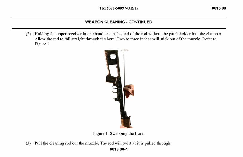
TM 8370-50097-OR/15 0013 00
WEAPON CLEANING - CONTINUED
0013 00-4
(2) Holding the upper receiver in one hand, insert the end of the rod without the patch holder into the chamber. Allow the rod to fall straight through the bore. Two to three inches will stick out of the muzzle. Refer to Figure 1.
Figure 1. Swabbing the Bore.
(3) Pull the cleaning rod out the muzzle. The rod will twist as it is pulled through.
TM 8370-50097-OR/15 0013 00
WEAPON CLEANING - CONTINUED
0013 00-5
2. Detailed Cleaning Techniques - with an Otis Kit.
a. Attach the bore obstruction remover tip to one end of the flexible cleaning rod and attach the slotted tip to the other end of the rod.
b. Place the slotted tip into an outside hole on a cleaning patch.
NOTE The size of the patch may be varied by pinching the patch in locations further away from the slot.
c. Pinch a portion of the patch and insert it through the slot in the slotted tip. Pull it tight to tie the knot and ensure that the patch scrubs efficiently.
d. Turn the outer edge of the patch down over itself.
NOTE If done correctly, the patch forms a symmetrical cone centering it in the bore, ensuring 360° cleaning occurs. Always use a clean patch each time it is passed through the bore.
e. Apply three to five drops of CLP to the front end of the knot in the patch. Do not dip the patch into the CLP.
f. Insert the bore obstruction remover tip and flexible cleaning rod into the chamber until the patch enters the receiver.
g. Use the patch to clean the receiver.

TM 8370-50097-OR/15 0013 00
WEAPON CLEANING - CONTINUED
0013 00-6
h. Hold the flexible cleaning rod by the knurled bore obstruction remover and rotate the rod as the patch enters the locking lugs. Use fingers or the cleaning brush to force the patch into the recesses in front of the locking lugs.
NOTE Give special attention to the following areas in step h, particularly if the weapon has been firing blank rounds.
i. Continue to turn the patch as it passes through the chamber and enters the neck area.
j. Continue to pull the flexible cleaning rod and patch through the barrel until the patch exits the muzzle.
k. Remove the patch and slotted tip from the flexible cleaning rod.
l. Attach the chamber brush to one end of the short chamber cleaning rod and the T-handle to the other end.
m. Cover the chamber brush with a used patch. Mop out the chamber while turning it in a clockwise direction with the T-handle. Let the brush feed itself into the chamber.
n. Give the brush and patch several turns while in the chamber, ensuring the shoulder of the chamber is cleaned.
o. Turn and pull the brush and patch from the chamber.
p. Attach the bore brush to the flexible cleaning rod.
NOTE Do not push the bore brush into the bore at first.

TM 8370-50097-OR/15 0013 00
WEAPON CLEANING - CONTINUED
0013 00-7
q. Insert the flexible cleaning rod into and down through the bore.
r. Turn the flexible rod as the bore brush enters the chamber and goes into the neck so that the brush can be felt scrubbing the shoulder of the neck.
s. Pull the bore brush into and through the bore in a “breech-to-muzzle” direction.
t. Using a clean, dry patch for each pass through the chamber and bore, repeat steps f through k.
u. If the patch does not come out clean, repeat steps p through s until the patch comes out clean.
3. Thorough Cleaning.
a. Receiver and Barrel Assembly.
(1) Clean all areas of powder fouling, corrosion, dirt, debris, and rust.
(2) Clean the chamber, gas tube, gas regulator, gas block, gas piston, operating rod, and operating rod spring with a brush and CLP.
CAUTION When using bore brush, DO NOT reverse direction while brush is in bore.
(3) Clean the bore, starting at the receiver, dropping the cleaning rod with bore brush attached through the chamber and pulling through the barrel and muzzle.
TM 8370-50097-OR/15 0013 00
WEAPON CLEANING - CONTINUED
0013 00-8
(4) Remove the handguards and wipe them with a cloth.
(5) Clean the front and rear sights with a brush and CLP.
(6) Clean the flash suppressor with a brush and CLP.
b. Buttstock Assembly.
(1) Do not use CLP on the pistol grip, cheek pad, or buttstock. Clean with a brush and cloth. Remove any debris.
(2) Clean the buttplate with a brush and CLP.

TM 8370-50097-OR/15 0013 00
WEAPON CLEANING - CONTINUED
0013 00-9
c. Bolt Carrier Group.
(1) Scrub surfaces of the bolt and bolt carrier with a well worn bore brush and CLP.
(2) Clean the firing pin hole (using a pipe cleaner) and firing pin with CLP. Wipe off excess CLP.
(3) Check the extractor for spring tension and clean any carbon and debris from under the extractor lip.
(4) Apply CLP to the extractor and depress it several times to work in the CLP. Wipe off excess CLP.
d. Trigger Mechanism.
(1) Clean all parts with a brush, pipe cleaners, and CLP.
(2) Scrub the trigger housing with a well worn brush and CLP.
e. Telescopic Sight.
(1) The telescopic sight lenses are coated with high energy, low reflect (HELR) chemical for improved light transmission. The coating is a very thin film; use extreme care to prevent damage.

TM 8370-50097-OR/15 0013 00
WEAPON CLEANING - CONTINUED
0013 00-10
CAUTION DO NOT allow CLP to contact the lenses. DO NOT use cotton patches, cotton swabs, or cotton products such as T-shirts to clean the lenses. Use only lens paper or soft tissue paper. Anything else will scratch the lenses and render them unserviceable.
(2) To remove dust, lint, and other foreign matters from the lenses, brush them lightly with the clean camelhair brush included in the cleaning kit.
(3) To remove oil or grease from the optical surfaces, fog the lens with breath and wipe them clean with lens papers or soft tissue paper. To remove heavy deposits, dampen lens paper with acetone and wipe carefully.
END OF WORK PACKAGE

TM 8370-50097-OR/15 0014 00
WEAPON MAINTENANCE (FIELD STRIPPING)
0014 00-1
THIS WORK PACKAGE COVERS Disassembly/Field Stripping and Reassembly, Magazine Disassembly and Reassembly.
INITIAL SETUP References
WP 0005 00
Equipment Conditions
Weapon cleared (WP 0005 00)
DISASSEMBLY/FIELD STRIPPING
WARNING Ensure the weapon is clear and on SAFE before performing these procedures. Failure to follow this warning may cause injury or death to personnel.
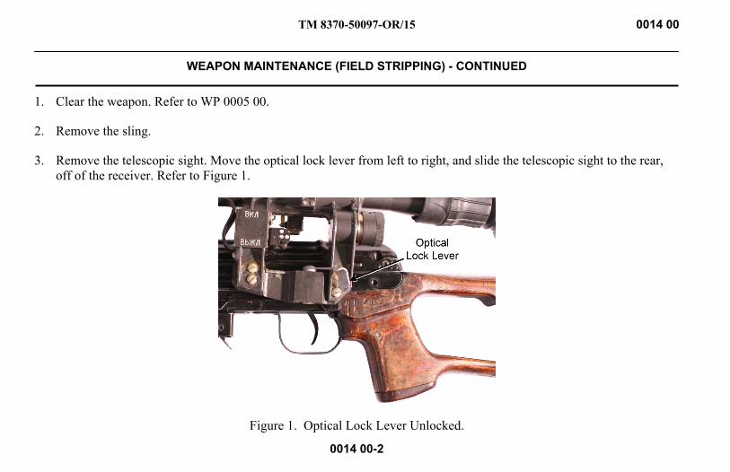
TM 8370-50097-OR/15 0014 00
WEAPON MAINTENANCE (FIELD STRIPPING) - CONTINUED
0014 00-2
1. Clear the weapon. Refer to WP 0005 00.
2. Remove the sling.
3. Remove the telescopic sight. Move the optical lock lever from left to right, and slide the telescopic sight to the rear, off of the receiver. Refer to Figure 1.
Figure 1. Optical Lock Lever Unlocked.

TM 8370-50097-OR/15 0014 00
WEAPON MAINTENANCE (FIELD STRIPPING) - CONTINUED
0014 00-3
4. Rotate the top cover latch down and to the rear, then lift the top cover up. Refer to Figure 2.
Figure 2. Removing the Top Cover.

TM 8370-50097-OR/15 0014 00
WEAPON MAINTENANCE (FIELD STRIPPING) - CONTINUED
0014 00-4
5. Slide the bolt carrier group back and lift it off of the receiver. Refer to Figure 3.
Figure 3. Remove the Bolt Carrier Group.

TM 8370-50097-OR/15 0014 00
WEAPON MAINTENANCE (FIELD STRIPPING) - CONTINUED
0014 00-5
6. Push the bolt assembly back in the bolt carrier and rotate the bolt assembly until the cam on the bolt disengages from the cam recess in the bolt carrier. Pull the bolt assembly out of the bolt carrier. Refer to Figure 4.
Figure 4. Remove the Bolt Assembly from the Bolt Carrier.
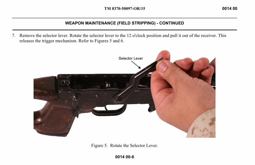
TM 8370-50097-OR/15 0014 00
WEAPON MAINTENANCE (FIELD STRIPPING) - CONTINUED
0014 00-6
7. Remove the selector lever. Rotate the selector lever to the 12 o'clock position and pull it out of the receiver. This releases the trigger mechanism. Refer to Figures 5 and 6.
Figure 5. Rotate the Selector Lever.
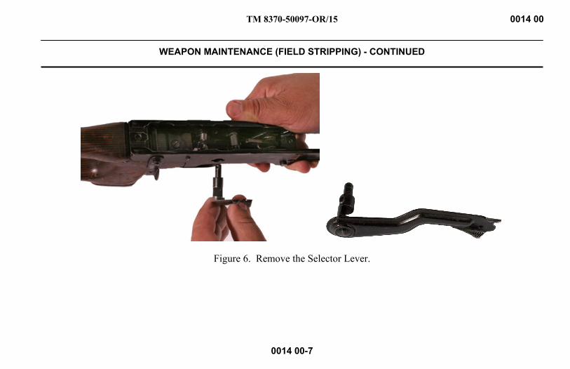
TM 8370-50097-OR/15 0014 00
WEAPON MAINTENANCE (FIELD STRIPPING) - CONTINUED
0014 00-7
Figure 6. Remove the Selector Lever.

TM 8370-50097-OR/15 0014 00
WEAPON MAINTENANCE (FIELD STRIPPING) - CONTINUED
0014 00-8
8. Remove the trigger mechanism. Refer to Figure 7.
Figure 7. Removing the Trigger Mechanism.

TM 8370-50097-OR/15 0014 00
WEAPON MAINTENANCE (FIELD STRIPPING) - CONTINUED
0014 00-9
9. Using a thumb, or a field expedient tool if necessary, depress the handguard retaining latch, until it can be rotated out of the retaining ring. Refer to Figure 8.
Figure 8. Rotate the Handguard Retaining Latch.

TM 8370-50097-OR/15 0014 00
WEAPON MAINTENANCE (FIELD STRIPPING) - CONTINUED
0014 00-10
10. Slide the retaining ring forward off of the handguards and remove the handguards. Refer to Figure 9.
Figure 9. Slide the Retaining Ring Forward and Remove the Handguards.
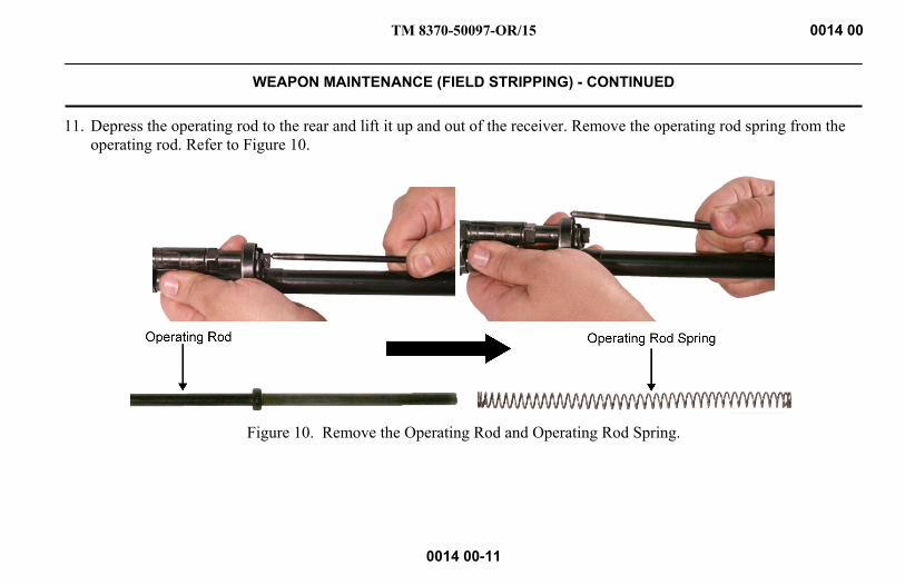
TM 8370-50097-OR/15 0014 00
WEAPON MAINTENANCE (FIELD STRIPPING) - CONTINUED
0014 00-11
11. Depress the operating rod to the rear and lift it up and out of the receiver. Remove the operating rod spring from the operating rod. Refer to Figure 10.
Figure 10. Remove the Operating Rod and Operating Rod Spring.

TM 8370-50097-OR/15 0014 00
WEAPON MAINTENANCE (FIELD STRIPPING) - CONTINUED
0014 00-12
12. Slide the gas piston out of the gas tube. Refer to Figure 11.
Figure 11. Gas Piston.

TM 8370-50097-OR/15 0014 00
WEAPON MAINTENANCE (FIELD STRIPPING) - CONTINUED
0014 00-13
REASSEMBLY WARNING
DO NOT interchange bolt assemblies between weapons. Failure to follow this warning may cause injury or death to personnel.
1. Slide the gas piston into the gas tube, flat end first. Refer to Figure 12.
Figure 12. Gas Piston.

TM 8370-50097-OR/15 0014 00
WEAPON MAINTENANCE (FIELD STRIPPING) - CONTINUED
0014 00-14
2. Install the operating rod spring onto the flat end of the operating rod. Insert the end of the operating rod and the operating rod spring into the hole under the rear sight and depress the operating rod to the rear until the pointed end can be inserted into the gas tube. Refer to Figure 13.
Figure 13. Install the Operating Rod Spring and Operating Rod.
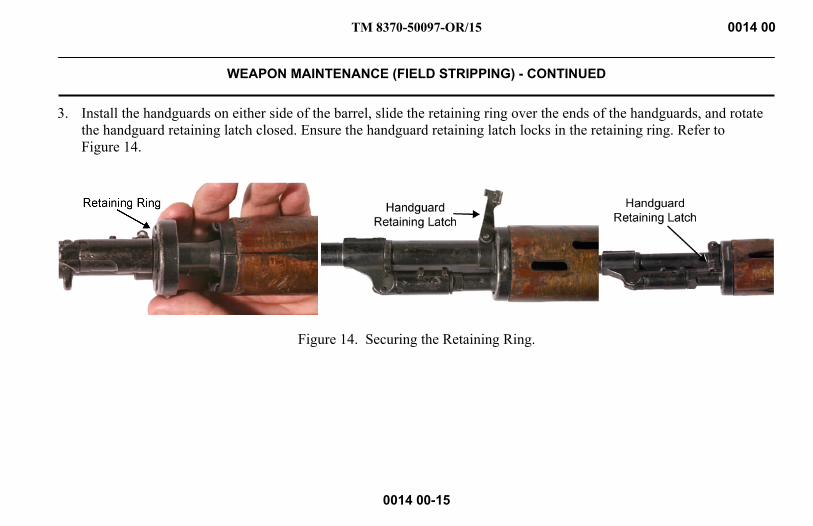
TM 8370-50097-OR/15 0014 00
WEAPON MAINTENANCE (FIELD STRIPPING) - CONTINUED
0014 00-15
3. Install the handguards on either side of the barrel, slide the retaining ring over the ends of the handguards, and rotate the handguard retaining latch closed. Ensure the handguard retaining latch locks in the retaining ring. Refer to Figure 14.
Figure 14. Securing the Retaining Ring.
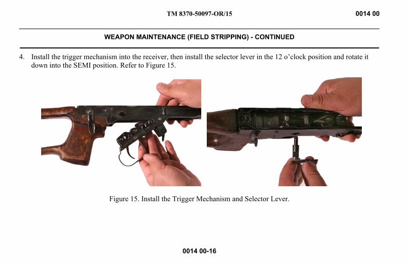
TM 8370-50097-OR/15 0014 00
WEAPON MAINTENANCE (FIELD STRIPPING) - CONTINUED
0014 00-16
4. Install the trigger mechanism into the receiver, then install the selector lever in the 12 o’clock position and rotate it down into the SEMI position. Refer to Figure 15.
Figure 15. Install the Trigger Mechanism and Selector Lever.

TM 8370-50097-OR/15 0014 00
WEAPON MAINTENANCE (FIELD STRIPPING) - CONTINUED
0014 00-17
5. Slide the bolt assembly into the bolt carrier and rotate it until the cam on the bolt engages the cam recess in the bolt carrier. Pull the bolt assembly forward in the bolt carrier Refer to Figure 16.
Figure 16. Install the Bolt Assembly into the Bolt Carrier.
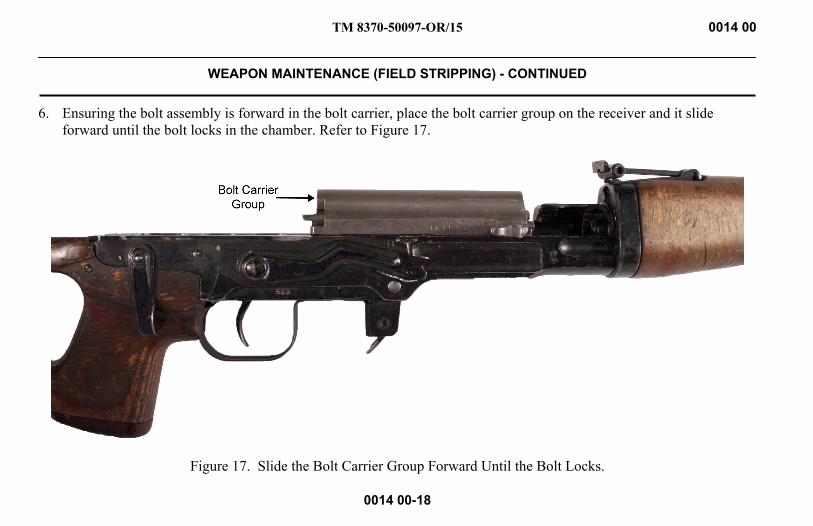
TM 8370-50097-OR/15 0014 00
WEAPON MAINTENANCE (FIELD STRIPPING) - CONTINUED
0014 00-18
6. Ensuring the bolt assembly is forward in the bolt carrier, place the bolt carrier group on the receiver and it slide forward until the bolt locks in the chamber. Refer to Figure 17.
Figure 17. Slide the Bolt Carrier Group Forward Until the Bolt Locks.
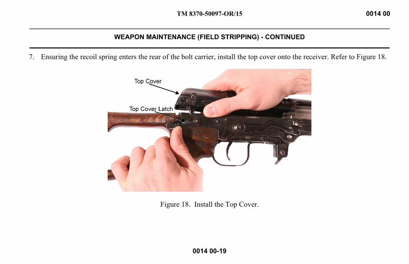
TM 8370-50097-OR/15 0014 00
WEAPON MAINTENANCE (FIELD STRIPPING) - CONTINUED
0014 00-19
7. Ensuring the recoil spring enters the rear of the bolt carrier, install the top cover onto the receiver. Refer to Figure 18.
Figure 18. Install the Top Cover.

TM 8370-50097-OR/15 0014 00
WEAPON MAINTENANCE (FIELD STRIPPING) - CONTINUED
0014 00-20
8. Rotate the top cover latch up, until it locks in place. Refer to Figure 19
Figure 19. Rotate the Top Cover Latch Up.

TM 8370-50097-OR/15 0014 00
WEAPON MAINTENANCE (FIELD STRIPPING) - CONTINUED
0014 00-21
9. Slide the telescopic sight forward onto the mounting rail on the left side of the receiver. Rotate the optical lock lever from right to left to secure it in place. Refer to Figure 20.
Figure 20. Install the Telescopic Sight.
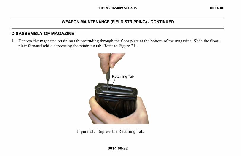
TM 8370-50097-OR/15 0014 00
WEAPON MAINTENANCE (FIELD STRIPPING) - CONTINUED
0014 00-22
DISASSEMBLY OF MAGAZINE 1. Depress the magazine retaining tab protruding through the floor plate at the bottom of the magazine. Slide the floor
plate forward while depressing the retaining tab. Refer to Figure 21.
Figure 21. Depress the Retaining Tab.

TM 8370-50097-OR/15 0014 00
WEAPON MAINTENANCE (FIELD STRIPPING) - CONTINUED
0014 00-23
2. While cupping a hand over the bottom of the magazine, remove the floor plate. Remove the spring plate, magazine spring, and follower from the magazine body. Refer to Figure 22.
Figure 22. Disassembled Magazine.
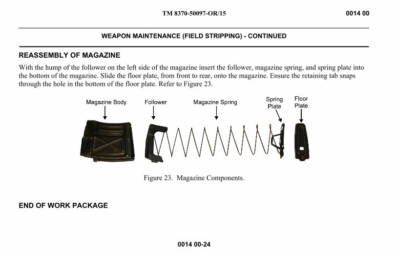
TM 8370-50097-OR/15 0014 00
WEAPON MAINTENANCE (FIELD STRIPPING) - CONTINUED
0014 00-24
REASSEMBLY OF MAGAZINE With the hump of the follower on the left side of the magazine insert the follower, magazine spring, and spring plate into the bottom of the magazine. Slide the floor plate, from front to rear, onto the magazine. Ensure the retaining tab snaps through the hole in the bottom of the floor plate. Refer to Figure 23.
Figure 23. Magazine Components.
END OF WORK PACKAGE

TM 8370-50097-OR/15 0015 00
PREPARATION FOR STORAGE
0015 00-1/2 blank
STORAGE PROCEDURES WARNING
DO NOT store a weapon with live ammunition in either the chamber or the magazine. Always assume a weapon is loaded until it is determined through visual and physical inspection that it is not. Procedures for clearing/unloading the weapon are outlined in WP 0005 00. Failure to follow these warnings may result in injury or death to personnel.
1. Storage for Extended Periods. When the weapon is to be stored for an extended period (greater than 90 days), follow the procedures outlined in MCO P4450.7, Preparation for Storage. Ensure the weapon is thoroughly cleaned, as outlined in WP 0013 00.
2. Storage Procedures.
a. Ensure the chamber and magazine do not contain live ammunition.
b. Inspect the bore and chamber and apply a medium coat of CLP.
c. Apply a light coat of CLP to all other metal surfaces of the weapon to provide extra lubrication and corrosion protection. Ensure the CLP does not come in contact with the telescopic sight.
END OF WORK PACKAGE

INTENTIONALLY BLANK

TM 8370-50097-OR/15
CHAPTER 5
SUPPORTING INFORMATION

INTENTIONALLY BLANK

TM 8370-50097-OR/15 0016 00
REFERENCES
0016 00-1
SCOPE This work package lists all forms, field manuals, technical manuals, tables, regulations, standards, and miscellaneous publications referenced in this manual and relevant to this weapon.
MARINE CORPS ORDERS Preparation for Storage ...................................................................................................................................... MCO P4450.7 Multiservice Tactics, Techniques, and Procedures for Chemical, Biological, Radiological, and Nuclear Contamination Avoidance ............................................................................................................. MCWP 3-37.2A_ Multiservice Tactics, Techniques, and Procedures for Chemical, Biological, Radiological, and Nuclear Decontamination ............................................................................................................................... MCWP 3-37.3_
TECHNICAL MANUALS Corrosion Control for Marine Corps Ground Equipment ............................................................................... TM 3080-25/2_ Ground Equipment Record Procedures ........................................................................................................... TM 4700-15/1_ Organizational Corrosion Prevention and Control Procedures for USMC Equipment ................................... TM 4795-12/1_ Organizational Maintenance Manual with Repair Parts list for Sniper Rifle, 7.62 X 54R MM, SVD ........................................................................................................................ TM 8370-50097-IN/16 Ammunition, General .................................................................................................................................... TM 9-1300-200_ Military Use of Cleaner, Lubricant, Preservative (CLP) for Weapons and Support Equipment .................... TM 9150-15/1_
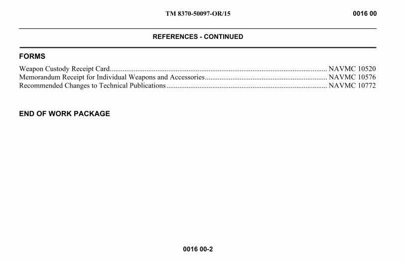
TM 8370-50097-OR/15 0016 00
REFERENCES - CONTINUED
0016 00-2
FORMS Weapon Custody Receipt Card ....................................................................................................................... NAVMC 10520 Memorandum Receipt for Individual Weapons and Accessories ................................................................... NAVMC 10576 Recommended Changes to Technical Publications ........................................................................................ NAVMC 10772
END OF WORK PACKAGE

TM 8370-50097-OR/15 0017 00
SUPPLY SYSTEM RESPONSIBILITY ITEMS (SSRI) LIST
0017 00-1
SCOPE This work package lists Supply System Responsibility Items (SSRI) required for operation of the 7.62 x 54R mm, SVD sniper rifle. The list contains SSRI that are essential for operating the weapon. Refer to Table 1.
EXPLANATION OF COLUMNS 1. Column (1) - Item Number. This number is assigned to the entry in the list and is referenced in the narrative
instructions to identify the item.
2. Column (2) - Level. This column identifies the lowest level of maintenance that requires the listed item.
C = Operator/Crew
3. Column (3) - National Stock Number. This is the NSN assigned to the item that will be used for requisitioning.
4. Column (4) - Description, Part Number and CAGEC. This provides the other information needed to identify the item.
5. Column (5) - Unit of Measure (U/M). This code shows the physical measurement or count of an item, such as gallon, dozen, gross, kit (kt), each (ea), package (PG), or bottle (BT), etc.
6. Column (6) – Quantity Recommended (QTY REC’M). Qty Rec’m indicates the quantity recommended.
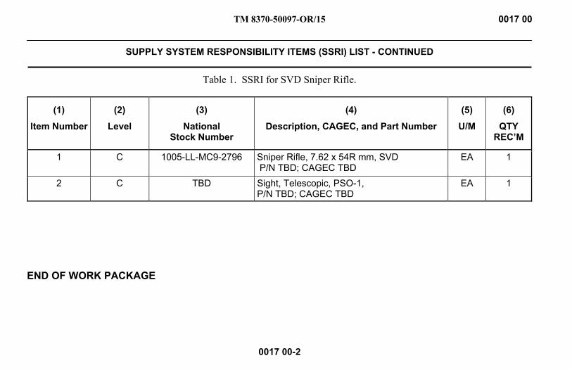
TM 8370-50097-OR/15 0017 00
SUPPLY SYSTEM RESPONSIBILITY ITEMS (SSRI) LIST - CONTINUED
0017 00-2
Table 1. SSRI for SVD Sniper Rifle.
(1)
Item Number
(2)
Level
(3)
National Stock Number
(4)
Description, CAGEC, and Part Number
(5)
U/M
(6)
QTY REC’M
1 C 1005-LL-MC9-2796 Sniper Rifle, 7.62 x 54R mm, SVD P/N TBD; CAGEC TBD
EA 1
2 C TBD Sight, Telescopic, PSO-1, P/N TBD; CAGEC TBD
EA 1
END OF WORK PACKAGE
TM 8370-50037-OR/3 0018 00
USING UNIT RESPONSIBILITY ITEMS (UURI) LIST
0018 00-1
SCOPE This work package lists Using Unit Responsibility Items (UURI) authorized for support of the 7.62 x 54R mm SVD sniper rifle. Items listed will not be issued with the weapon and must be requisitioned through the supply system.
EXPLANATION OF COLUMNS 1. Column (1) – National Stock Number. Indicates the National Stock Number (NSN) assigned to the item that will be
used for requisitioning purposes.
2. Column (2) - Description, Part Number, and CAGEC. Indicates the Federal item name followed by a minimum description when needed. The entry for each item ends with the Commercial and Government Entity Code (CAGEC) in parentheses followed by the part number.
3. Column (3) - Usable on Code. Indicates a code if the item needed is not the same for different models of equipment.
4. Column (4) - Unit of Measure (U/M). Indicates how the item is issued for the National Stock Number (NSN) shown in Column (1), such as package (PG), kit (KT), each (EA), bottle (BT), etc.
5. Column (5) - Quantity Recommended (QTY REC’M). Indicates the quantity recommended.

TM 8370-50037-OR/3 0018 00
USING UNIT RESPONSIBILITY ITEMS (UURI) LIST - CONTINUED
0018 00-2
Table 1. UURI for the SVD Sniper Rifle.
(1)
National Stock Number
(2)
Description, Part Number, and CAGEC
(3)
Usable on Code
(4)
U/M
(5)
QTY REC’M
9150-01-102-1473 Cleaner, Lubricant, and Preservative (CLP), 2/3 oz P/N 900; CAGEC 65983 BT 1
1005-00-288-3565 Patch, cleaning, small caliber, 7.62 mm P/N 5019316, CAGEC 19204 PG 10
1005-00-494-6602 Brush, cleaning, small arms P/N 8448462; CAGEC 19204 EA 1
TBD Magazine, ammunition, 10 round P/N TBD; CAGEC TBD EA 6
1005-01-451-5119 Cleaning kit, gun, (7.62 mm, Otis, soft belt pack) P/N 308-6; CAGEC 01VS3 KT 1
OTIS, 7.62 MM CLEANING KIT CONSISTS OF:TBD Case, soft pack (w/ ALICE clips)
P/N 915-DMR, CAGEC 01VS3 EA 1
1005-01-449-8902 Handle, Tee P/N 01-5; CAGEC 01VS3 EA 1
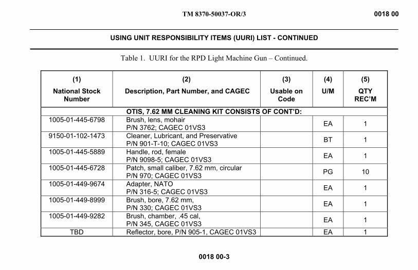
TM 8370-50037-OR/3 0018 00
USING UNIT RESPONSIBILITY ITEMS (UURI) LIST - CONTINUED
0018 00-3
Table 1. UURI for the RPD Light Machine Gun – Continued.
(1)
National Stock Number
(2)
Description, Part Number, and CAGEC
(3)
Usable on Code
(4)
U/M
(5)
QTY REC’M
OTIS, 7.62 MM CLEANING KIT CONSISTS OF CONT’D: 1005-01-445-6798 Brush, lens, mohair
P/N 3762; CAGEC 01VS3 EA 1
9150-01-102-1473 Cleaner, Lubricant, and Preservative P/N 901-T-10; CAGEC 01VS3 BT 1
1005-01-445-5889 Handle, rod, female P/N 9098-5; CAGEC 01VS3 EA 1
1005-01-445-6728 Patch, small caliber, 7.62 mm, circular P/N 970; CAGEC 01VS3 PG 10
1005-01-449-9674 Adapter, NATO P/N 316-5; CAGEC 01VS3 EA 1
1005-01-449-8999 Brush, bore, 7.62 mm, P/N 330; CAGEC 01VS3 EA 1
1005-01-449-9282 Brush, chamber, .45 cal, P/N 345, CAGEC 01VS3 EA 1
TBD Reflector, bore, P/N 905-1, CAGEC 01VS3 EA 1
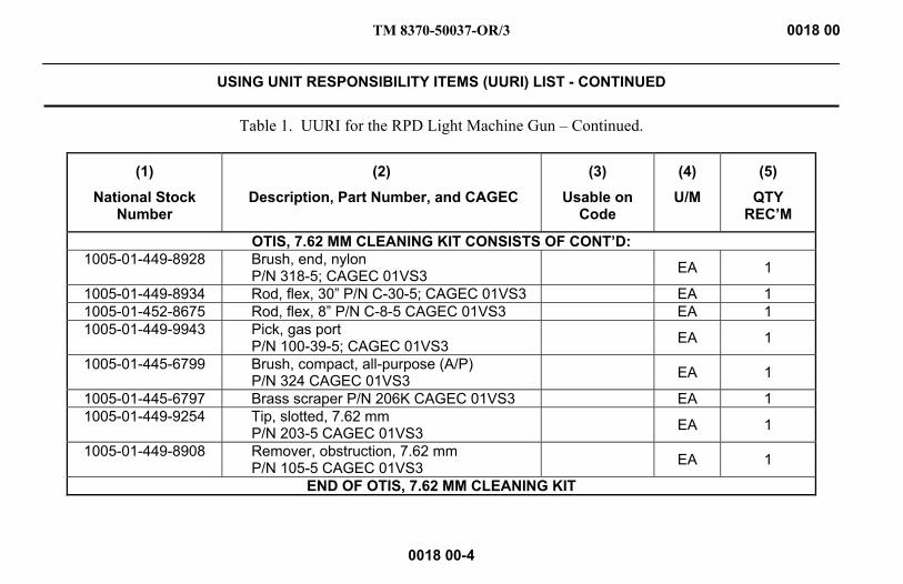
TM 8370-50037-OR/3 0018 00
USING UNIT RESPONSIBILITY ITEMS (UURI) LIST - CONTINUED
0018 00-4
Table 1. UURI for the RPD Light Machine Gun – Continued.
(1)
National Stock Number
(2)
Description, Part Number, and CAGEC
(3)
Usable on Code
(4)
U/M
(5)
QTY REC’M
OTIS, 7.62 MM CLEANING KIT CONSISTS OF CONT’D: 1005-01-449-8928 Brush, end, nylon
P/N 318-5; CAGEC 01VS3 EA 1
1005-01-449-8934 Rod, flex, 30” P/N C-30-5; CAGEC 01VS3 EA 1 1005-01-452-8675 Rod, flex, 8” P/N C-8-5 CAGEC 01VS3 EA 1 1005-01-449-9943 Pick, gas port
P/N 100-39-5; CAGEC 01VS3 EA 1
1005-01-445-6799 Brush, compact, all-purpose (A/P) P/N 324 CAGEC 01VS3 EA 1
1005-01-445-6797 Brass scraper P/N 206K CAGEC 01VS3 EA 1 1005-01-449-9254 Tip, slotted, 7.62 mm
P/N 203-5 CAGEC 01VS3 EA 1
1005-01-449-8908 Remover, obstruction, 7.62 mm P/N 105-5 CAGEC 01VS3 EA 1
END OF OTIS, 7.62 MM CLEANING KIT
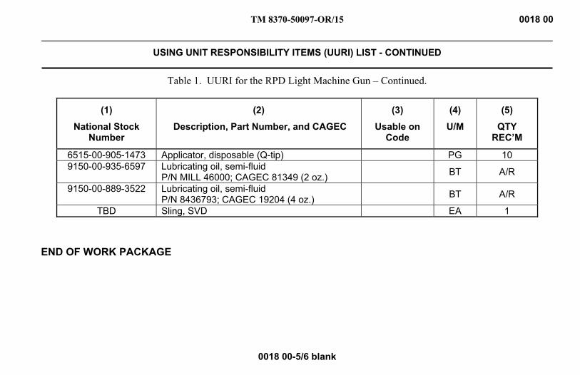
TM 8370-50097-OR/15 0018 00
USING UNIT RESPONSIBILITY ITEMS (UURI) LIST - CONTINUED
0018 00-5/6 blank
Table 1. UURI for the RPD Light Machine Gun – Continued.
(1)
National Stock Number
(2)
Description, Part Number, and CAGEC
(3)
Usable on Code
(4)
U/M
(5)
QTY REC’M
6515-00-905-1473 Applicator, disposable (Q-tip) PG 10 9150-00-935-6597 Lubricating oil, semi-fluid
P/N MILL 46000; CAGEC 81349 (2 oz.) BT A/R
9150-00-889-3522 Lubricating oil, semi-fluid P/N 8436793; CAGEC 19204 (4 oz.) BT A/R
TBD Sling, SVD EA 1
END OF WORK PACKAGE

INTENTIONALLY BLANK

TM 8370-50097-OR/15 0019 00
EXPENDABLE AND DURABLE ITEMS LIST
0019 00-1
SCOPE This work package lists expendable and durable items authorized for support and operation of the 7.62 x 54R mm SVD sniper rifle.
EXPLANATION OF COLUMNS 1. Column (1) - Item Number. This number is assigned to the entry in the list and is referenced in the narrative
instructions to identify the item.
2. Column (2) - National Stock Number. This is the National Stock Number (NSN) assigned to the item that will be used to requisition it.
3. Column (3) - Item Identification. This provides additional descriptive information needed to identify the item.
4. Column (4) - Unit of Measure (U/M). This code shows the physical measurement or count of an item, such as gallon, dozen, gross, each (EA), bottle (BT), package (PG), book (BK), or bale (BE).
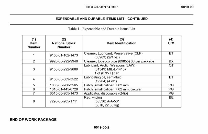
TM 8370-50097-OR/15 0019 00
EXPENDABLE AND DURABLE ITEMS LIST - CONTINUED
0019 00-2
Table 1. Expendable and Durable Items List
(1) Item
Number
(2) National Stock
Number
(3) Item Identification
(4) U/M
1 9150-01-102-1473 Cleaner, Lubricant, Preservative (CLP) (65983) (2/3 oz.)
BT
2 9920-00-292-9946 Cleaner, tobacco pipe (89855) 36 per package BX
3 9150-00-292-9689 Lubricant, Arctic, Weapons (LAW)
(81349) MIL-L-14107 1 qt (0.95 L) can
QT
4 9150-00-889-3522 Lubricating oil, semi-fluid (19204) (4 oz.)
BT
5 1005-00-288-3565 Patch, small caliber, 7.62 mm PG 6 1010-01-445-6728 Patch, small caliber, 7.62 mm, circular PG 7 6515-00-905-1473 Applicator, disposable (Q-tip) PG
8 7290-00-205-1711 Rag, wiping
(58536) A-A-531 (50 lb, 22.68 kg)
BE
END OF WORK PACKAGE
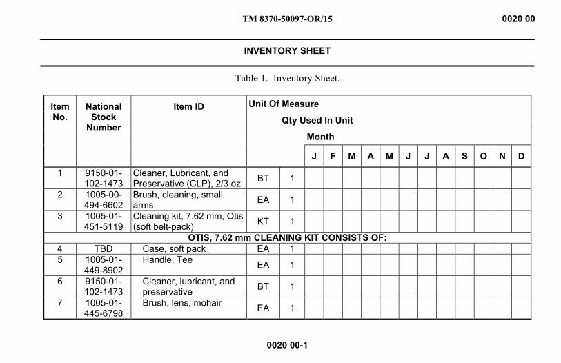
TM 8370-50097-OR/15 0020 00
INVENTORY SHEET
0020 00-1
Table 1. Inventory Sheet.
Item No.
National Stock
Number
Item ID Unit Of Measure
Qty Used In Unit
Month
J F M A M J J A S O N D
1 9150-01-102-1473
Cleaner, Lubricant, and Preservative (CLP), 2/3 oz BT 1
2 1005-00-494-6602
Brush, cleaning, small arms EA 1
3 1005-01-451-5119
Cleaning kit, 7.62 mm, Otis (soft belt-pack) KT 1
OTIS, 7.62 mm CLEANING KIT CONSISTS OF: 4 TBD Case, soft pack EA 1 5 1005-01-
449-8902 Handle, Tee EA 1
6 9150-01-102-1473
Cleaner, lubricant, and preservative BT 1
7 1005-01-445-6798
Brush, lens, mohair EA 1

TM 8370-50097-OR/15 0020 00
INVENTORY SHEET - CONTINUED
0020 00-2
Table 1. Inventory Sheet - Continued
Item No.
Stock Number
Item ID Unit Of Measure
Qty Used In Unit
Month
J F M A M J J A S O N D
8 1005-01-445-5889
Handle, rod, female EA 1
9 1005-01-445-6728
Patch, small caliber, 7.62 mm, circular EA 1
10 1005-01-449-9674
Adapter, NATO EA 1
11 1005-01-449-8999
Brush, bore, 7.62 mm EA 1
12 1005-01-449-8928
Brush, end EA 1
13 1005-01-449-9282
Brush, chamber, .45 cal EA 1
14 TBD Bore lite, fiber optic EA 1 15 1005-01-
449-8928 Brush, end, nylon EA 1

TM 8370-50097-OR/15 0020 00
INVENTORY SHEET - CONTINUED
0020 00-3
Table 1. Inventory Sheet – Continued
Item No.
National Stock
Number
Item ID Unit Of Measure
Qty Used In Unit
Month
J F M A M J J A S O N D
16 1005-01-449-8934
Rod, flex, 30” EA 1
17 1005-01-452-8675
Rod, flex, 8” EA 1
18 1005-01-449-9943
Pick, gas port EA 1
19 1005-01-445-6799
Brush, compact, all-purpose (A/P)
EA 1
20 1010-01-445-6797
Brass scraper EA 1
21 1005-01-449-9254
Tip, slotted, 7.62 mm EA 1
22 1005-01-449-8908
Remover, obstruction, 7.62 mm
EA 1
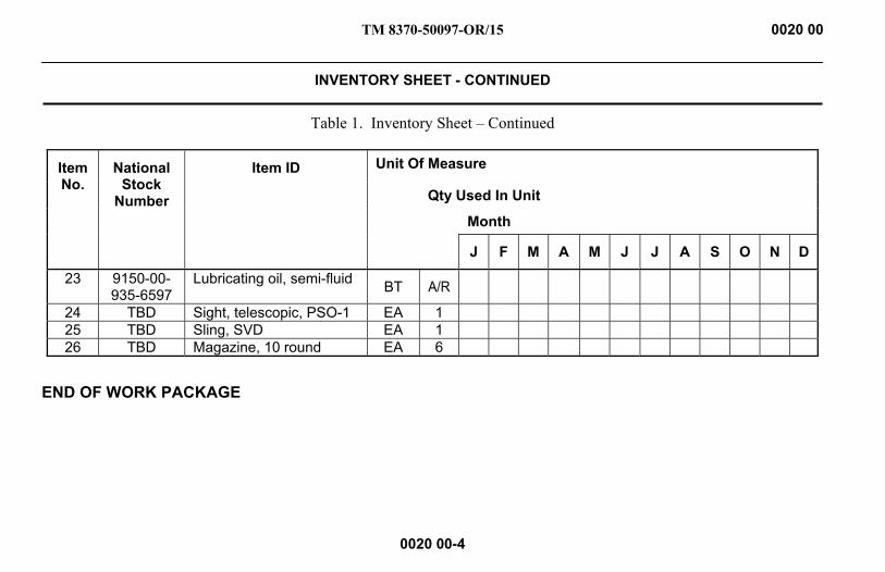
TM 8370-50097-OR/15 0020 00
INVENTORY SHEET - CONTINUED
0020 00-4
Table 1. Inventory Sheet – Continued
Item No.
National Stock
Number
Item ID Unit Of Measure
Qty Used In Unit
Month
J F M A M J J A S O N D
23 9150-00-935-6597
Lubricating oil, semi-fluid BT A/R
24 TBD Sight, telescopic, PSO-1 EA 1 25 TBD Sling, SVD EA 1 26 TBD Magazine, 10 round EA 6
END OF WORK PACKAGE
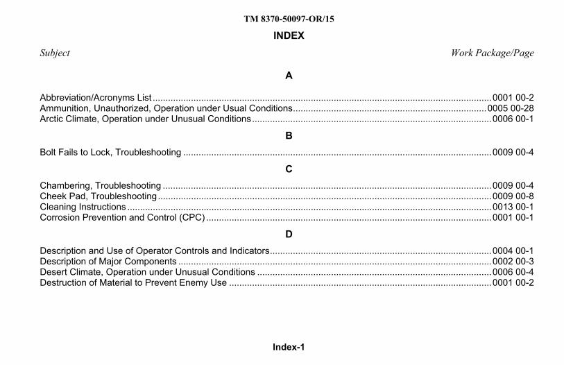
TM 8370-50097-OR/15
Index-1
INDEX Subject Work Package/Page
A
Abbreviation/Acronyms List ..................................................................................................................................... 0001 00-2 Ammunition, Unauthorized, Operation under Usual Conditions ............................................................................ 0005 00-28 Arctic Climate, Operation under Unusual Conditions .............................................................................................. 0006 00-1
B Bolt Fails to Lock, Troubleshooting ......................................................................................................................... 0009 00-4
C Chambering, Troubleshooting ................................................................................................................................. 0009 00-4 Cheek Pad, Troubleshooting ................................................................................................................................... 0009 00-8 Cleaning Instructions ............................................................................................................................................... 0013 00-1 Corrosion Prevention and Control (CPC) ................................................................................................................ 0001 00-1
D Description and Use of Operator Controls and Indicators ....................................................................................... 0004 00-1 Description of Major Components ........................................................................................................................... 0002 00-3 Desert Climate, Operation under Unusual Conditions ............................................................................................ 0006 00-4 Destruction of Material to Prevent Enemy Use ....................................................................................................... 0001 00-2

TM 8370-50097-OR/15
Index-2
INDEX - Continued Subject Work Package/Page
E Ejecting, Troubleshooting ........................................................................................................................................ 0009 00-3 Elevation Knob, Troubleshooting ............................................................................................................................. 0009 00-8 Equipment Characteristics, Capabilities, and Features ........................................................................................... 0002 00-4 Equipment Description and Data ............................................................................................................................. 0002 00-1 Expendable and Durable Items List ......................................................................................................................... 0019 00-1 Extracting, Troubleshooting ..................................................................................................................................... 0009 00-2
F Feeding, Troubleshooting ........................................................................................................................................ 0009 00-3 Failure to Fire, Operation under Usual Conditions ................................................................................................ 0005 00-22 Field Stripping .......................................................................................................................................................... 0014 00-1 Firing, Troubleshooting ............................................................................................................................................ 0009 00-1 Front Sight Assembly ............................................................................................................................................... 0004 00-6
G Gas Regulator, Adjustment, Operation under Usual Conditions ........................................................................... 0005 00-32 General Information ................................................................................................................................................. 0001 00-1 General Maintenance Instructions ........................................................................................................................... 0012 00-1
H
Heavy Rain and Fording, Operation under Unusual Conditions ............................................................................. 0006 00-5

TM 8370-50097-OR/15
Index-3
INDEX - Continued Subject Work Package/Page
I Inspecting the Weapon ............................................................................................................................................ 0010 00-1 Inspection Instructions ............................................................................................................................................. 0012 00-5 Inventory Sheet ....................................................................................................................................................... 0020 00-1
J Jungle Climate, Operation under Unusual Conditions ............................................................................................ 0006 00-3
L Loading a Magazine, Operation under Usual Conditions ........................................................................................ 0005 00-2 Loading the Weapon, Operation under Usual Conditions ....................................................................................... 0005 00-2 Loading, Troubleshooting ........................................................................................................................................ 0009 00-5 Lubrication Instructions ........................................................................................................................0011 00-12; 0012 00-6
M Magazine, Disassembly ......................................................................................................................................... 0014 00-22 Magazine, Reassembly ......................................................................................................................................... 0014 00-24 Magazine, Troubleshooting ..................................................................................................................................... 0009 00-6 Maintenance Forms and Procedures ...................................................................................................................... 0001 00-1 Major Components .................................................................................................................................................. 0002 00-2
TM 8370-50097-OR/15
Index-4
INDEX - Continued Subject Work Package/Page
N Nuclear, Biological, and Chemical (NBC), Operation under Unusual Conditions ................................................... 0006 00-6
O Operation under Unusual Conditions ...................................................................................................................... 0006 00-1 Operation under Usual Conditions .......................................................................................................................... 0005 00-1 Operator Controls and Indicators............................................................................................................................. 0004 00-2
P Parallax .................................................................................................................................................................. 0005 00-17 Precautions in Firing, Operation under Usual Conditions ..................................................................................... 0005 00-31 Preparation for Firing, Operation under Usual Conditions .................................................................................... 0005 00-31 Preparation for Storage ........................................................................................................................................... 0015 00-1 Preventive Maintenance Checks and Services (PMCS), Including Lubrication Instructions .................................. 0011 00-1 Principles of Operation ............................................................................................................................................ 0003 00-1 PSO-1 Telescopic Sight and Variants, Operation of the ....................................................................................... 0005 00-11
R Reassembly of Weapon ......................................................................................................................................... 0014 00-13 Rear Sight Assembly ............................................................................................................................................... 0004 00-7 References ............................................................................................................................................................... 0016 00-1
TM 8370-50097-OR/15
Index-5
INDEX - Continued Subject Work Package/Page
S Selector Lever.......................................................................................................................................................... 0004 00-8 Service Upon Receipt .............................................................................................................................................. 0010 00-1 Setting the Sights and Field Firing Techniques, Operation under Usual Conditions .............................................. 0005 00-8 Short Recoil, Troubleshooting ................................................................................................................................. 0009 00-5 Sling, Operation under Usual Conditions .............................................................................................................. 0005 00-31 Stock Cheek Pad ................................................................................................................................................... 0004 00-10 Storage Procedures ................................................................................................................................................. 0015 00-1 Supply System Responsibility Items (SSRI) List ..................................................................................................... 0017 00-1
T Telescopic Sight ................................................................................................................................. 0002 00-5; 0004 00-10 Telescopic Sight, Cleaning ...................................................................................................................................... 0013 00-9 Troubleshooting Introduction ................................................................................................................................... 0007 00-1 Troubleshooting Procedures ................................................................................................................................... 0009 00-1 Troubleshooting Symptom Index ............................................................................................................................. 0008 00-1
U Unloading and Clearing the Weapon, Operation under Usual Conditions .............................................................. 0005 00-7 Unlocking, Troubleshooting ..................................................................................................................................... 0009 00-2 Using Unit Responsibility Items (UURI) List ............................................................................................................ 0018 00-1
TM 8370-50097-OR/15
Index-6
INDEX - Continued Subject Work Package/Page
W Weapon Cleaning .................................................................................................................................................... 0013 00-1 Weapon Maintenance (Field Stripping) ................................................................................................................... 0014 00-1 Windage Knob, Troubleshooting ............................................................................................................................. 0009 00-8 Work Safety ............................................................................................................................................................. 0012 00-2
Z Zeroing, Operation under Usual Conditions .......................................................................................................... 0005 00-18
END OF WORK PACKAGE