TM 55-1520-236-23-1 ARMY MODEL AH-1P (PROD) AH-1E ...
1262
TM 55-1520-236-23-1 TECHNICAL MANUAL AVIATION UNIT AND INTERMEDIATE MAINTENANCE MANUAL ARMY MODEL AH-1P (PROD) AH-1E (ECAS) AH-1F (MODERNIZED COBRA) HELICOPTERS DISTRIBUTION STATEMENT A: Approved for public release; distribution is unlimited. This manual supersedes TM 55-1520-236-23-1, dated 8 May 1980, including all changes. HEADQUARTERS, DEPARTMENT OF THE ARMY 12 APRIL 1996
-
Upload
khangminh22 -
Category
Documents
-
view
1 -
download
0
Transcript of TM 55-1520-236-23-1 ARMY MODEL AH-1P (PROD) AH-1E ...
TM 55-1520-236-23-1
TECHNICAL MANUAL
AVIATION UNIT AND INTERMEDIATEMAINTENANCE MANUAL
ARMY MODELAH-1P (PROD)AH-1E (ECAS)
AH-1F (MODERNIZED COBRA)HELICOPTERS
DISTRIBUTION STATEMENT A: Approved for public release; distribution is unlimited.
This manual supersedes TM 55-1520-236-23-1, dated 8 May 1980, including all changes.
HEADQUARTERS, DEPARTMENT OF THE ARMY12 APRIL 1996


TM 55-1520-236-23-1
TECHNICAL MANUAL
NO. 55-1520-236-23-1
HEADQUARTERSDEPARTMENT OF THE ARMY
WASHINGTON, D.C., 12 April 1996
Aviation Unit and IntermediateMaintenance Manual
For
ARMY MODELAH-1P (PROD)AH-1E (ECAS)
AH-1F (MODERNIZED COBRA)HELICOPTERS
NOTE
This manual is printed in five volumes, as follows:
TM 55-1520-236-23-1, dated 12 April 1996, consisting of Table of Contents, Preface, Chapters 1through 6.
TM 55-1520-236-23-2, dated 8 May 1980, consisting of Table of Contents, Chapters 7 through 17,Appendix A through C.
TM 55-1520-236-23-3, dated 8 May 1980, consisting of Table of Contents, Appendix D through G,and Index.
TM 55-1520-236-23-4, dated 8 May 1980, consisting of Table of Contents, FO-1 thru FO-142.
TM 55-1520-236-23-5, dated 31 July 1990, consisting of Table of Contents. FO-143 thru FO-144.
The Preface, Appendices and Index are applicable to all volumes.


WARNING PAGE TM 55-1520-236-23
WARNING
Personnel performing operations, procedures, and practices which areincluded or implied in this technical manual shall observe the followingwarnings. Disregard of these warnings and precautionary information cancause serious injury, or death.
Warnings, cautions, and notes are used to emphasize important and criticalinstructions and shall be used for the following conditions:
STARTING ENGINE
Starting and Operationof the helicopter will be performed only by
authorized personnel in accordance with AR 95-11
HIGH VOLTAGE
The helicopter should be electrically grounded when parked.Turn off all power switches before making electrical connections or disconnections.
Serious bums and electrical shock can result from contactwith exposed electrical wires or connectors.
RADIATION HAZARD
Self-luminous dials contain radioactive materials.If such an instrument is broken or becomes unsealed, avoid personal contact.
Use forceps or gloves made of rubber or polyethylene to pick up contaminated material.Place material and gloves in a plastic bag.
Seal bag and dispose of it as radioactive wastein accordance with AR 385-11 and TM 3-261 (TB 43-0108).
Repair procedures shall conform to requirements in AR 700-52.
RADIATION HAZARD
Thorium Fluoride
Some of the FLIR optics inside the C-NITE telescopic sight unit (TSU)have a coating that is slightly radioactive.
Accidental inhaling or swallowing of this material is hazardous to health.If the C-NITE TSU has been ruptured (by crash damage, etc.), dispose of broken optics in
accordance with AR 385-11 and TB 750-237.
a
TM 55-1520-236-23 WARNING PAGE
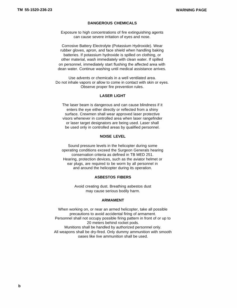
DANGEROUS CHEMICALS
Exposure to high concentrations of fire extinguishing agentscan cause severe irritation of eyes and nose.
Corrosive Battery Electrolyte (Potassium Hydroxide). Wearrubber gloves, apron, and face shield when handling baking
batteries. If potassium hydroxide is spilled on clothing, orother material, wash immediately with clean water. If spilled
on personnel, immediately start flushing the affected area withdean water. Continue washing until medical assistance arrives.
Use advents or chemicals in a well ventilated area.Do not inhale vapors or allow to come in contact with skin or eyes.
Observe proper fire prevention rules.
LASER LIGHT
The laser beam is dangerous and can cause blindness if itenters the eye either directly or reflected from a shiny
surface. Crewmen shall wear approved laser protectivevisors whenever in controlled area when laser rangefinder
or laser target designators are being used. Laser shallbe used only in controlled areas by qualified personnel.
NOISE LEVEL
Sound pressure levels in the helicopter during someoperating conditions exceed the Surgeon Generals hearing
conservation criteria as defined in TB MED 251.Hearing, protection devices, such as the aviator helmet or
ear plugs, are required to be worm by all personnel inand around the helicopter during its operation.
ASBESTOS FIBERS
Avoid creating dust. Breathing asbestos dustmay cause serious bodily harm.
ARMAMENT
When working on, or near an armed helicopter, take all possibleprecautions to avoid accidental firing of armament.
Personnel shall not occupy possible firing pattern in front of or up to20 meters behind rocket pods.
Munitions shall be handled by authorized personnel only.All weapons shall be dry-fired. Only dummy ammunition with smooth
oases like Iive ammunition shall be used.
b

WARNING PAGE TM 55-1520-236-23
JETTISON
All ground safety pins must be removed before flight.Failure to do so will prevent emergency jettison of stores.
Jettison circuit may be activated with BAT switch OFFand pilot WING STORES JTSN circuit breaker OPEN. For
positive deactivation of jettison circuit, open boththe PLT JTSN circuit breaker and the GNR JTSN circuit
breaker located in the pilot’s side console.Serious injury can result from accidental ground jettison.
Sanding on reinforced laminated glass producesfine dust that may cause skin irritations.
Observed necessary protective measures.
TRANSMISSION LEVELING
Do not attempt to level transmission with "Jacks Only".Hoist must be used in conjunction with jacks while lifting transmission.
EXTERNAL STORES
Prior to any helicopter maintenance functions thatrequire external stores be removed, JETTISON cartridge
shall be removed.Remove jettison cartridges from pylon stores ejection
device prior to placing helicopter in a hangar, to preventinjury to personnel and damage to equipment.
Exception: Removal is not necessary when helicopter isto be placed in hangar for short-term, providing both
PLT JTSN and GNR JETSN circuit breakers in the pilot’s sideconsole ore OPEN, and warning signs indicate that helicopter
has an armed jettison system.
CANOPY REMOVAL SYSTEM
Ground safety pins must be installed inpilot and gunner arming firing handles
of canopy removal system whenever thehelicopter is on the ground. Pins should
be installed by crew.
CLEANING HYDRAULIC COMPONENTS
The use of any alcohol in cleaning components which contacthydraulic fluids is prohibited. Formation of a
polymeric residue can result, which could impair mechanicaloperation of the component.
c

TM 55-1520-236-23 WARNING PAGE
HANDLING HYDRAULIC FLUID (MIL-H-83282)
When handling hydraulic fluid (MIL-H-83282), Table 1-3,Item 61, observe the following:
– Prolonged contact with liquid or mist can irritate eyesand skin.
– After any prolonged contact with skin, immediately washcontacted area with soap and water. If liquid contacts eyes,flush them immediately with clear water.
– If liquid is swallowed, do not induce vomiting; get im-mediate medical attention.
– Wear rubber gloves when handling liquid. If prolongedcontact with mist is likely, wear an appropriate respirator.
– When fluid is decomposed by heating, toxic gases arereleased.
EPOXY BASED ADHESIVE
Epoxy based adhesive, P/N EA934, contains an asbestosfiller which could be inhaled or ingested during grinding,cutting, or sanding operations on cured epoxy material.
TOOLS
Use only chrome plated steel or unplated steel tools for dis-assembly or reassembly procedures described in this man-ual. Use of cadmium or zinc plated tools is not permitted.
GROUNDING
All aircraft parked outside will be grounded and bonded,in accordance with FM 1-500, to the aerospace groundequipment while servicing, i.e., fueling or defueling, arming(ammunition or explosives), oxygen, hydraulic fluids or anyflammable liquids. Grounding is not necessary for aircraftparked outside unless one of the above is beingaccomplished.
INSPECTION OF REMOVED COMPONENTS
When components are being removed from an aircraft, allinspections required by the next phase maintenance inspec-tion must be accomplished prior to either immediate re-useor storage. Upon installation, the component will be in-spected in accordance with the current phase either thatphase the receiving aircraft is in or if in between phase, thelast phase performed). This will ensure that a are-used com-ponent will not overfly any PM inspections, and that it willbe properly interfaced with the receiving aircraft phasesequence.
d

TM 55-1520-236-23
TECHNICAL MANUAL HEADQUARTERSDEPARTMENT OF THE ARMY
NO. 55-1520-236-23 WASHINGTON, D. C., 8 May 1980
AVIATION UNIT AND INTERMEDIATE MAINTENANCE MANUALARMY MODEL
AH-1P (PROD)AH-1E (ECAS)
AH-1F (MODERNIZED COBRA)HELICOPTERS
REPORTING OF ERRORS
You can help improve this manual, if you find any mistakes or if you know of a way to improve the procedures, please letus know. Mail your letter, DA Form 2028 (Recommended Changes to Publications and Blank Forms), or DA Form 2028-2located in the back of this manual directly to: Commander, U.S. Army Aviation and Troop Command, ATTN: AMSAT-I-MP4300 Goodfellow Blvd.. St Louis, MO 63120-1798. A reply will be furnished to you. You may also submit yourrecommended changes by E-mail directly to <mpmt%avma28@st-louis-emh7 army. mil>. A reply will be furnished to you
DISTRIBUTION STATEMENT A: Approved for public release; distribution is unlimited.
TABLE OF CONTENTS
VOLUME 1
CHAPTER 1
Section I
Section II
section IllSection IVsection V
section VI
CHAPTER 2
Section ISection II
section Illsection IVSection V
CHAPTER 3
Section lSection II
Section IllSection IVSection V
CHAPTER 4
Section I
Section II
AIRCRAFT GENERAL
Servicing. . . . . . . . . . . . . . . . . . . . . . . . . . . . . . . . . . . . . . . . . . . . . .Lubrication. . . . . . . . . . . . . . . . . . . . . . . . . . . . . . . . . . . . . . . . . . . .
HandIing, jacking, mooring, hoisting, and sling Ioading . . . . . .Inspection requirements . . . . . . . . . . . . . . . . . . . . . . . . . . . . . . . . .
Overhaul and retirement schedule . . . . . . . . . . . . . . . . . . . . . . .Flight safety critical aircraft parts (FSCAP) . . . . . . . . . . . . . . . . .
AIRFRAME
Structural repair . . . . . . . . . . . . . . . . . . . . . . . . . . . . . . . . . . . . . . . .Fuselage . . . . . . . . . . . . . . . . . . . . . . . . . . . . . . . . . . . . . . . . . . . . . .Tailboom . . . . . . . . . . . . . . . . . . . . . . . . . . . . . . . . . . . . . . . . . . . . . .Wing . . . . . . . . . . . . . . . . . . . . . . . . . . . . . . . . . . . . . . . . . . . . . . . . .Deleted
LANDING GEAR
Landing Gear. . . . . . . . . . . . . . . . . . . . . . . . . . . . . . . . . .Skids/Struts (Not Applicable) . . . . . . . . . . . . . . . . . . . . . . . . . . . .Floats (Not Applicable) . . . . . . . . . . . . . . . . . . . . . . . . . . . . . . . . . .Skis (Not Applicable) . . . . . . . . . . . . . . . . . . . . . . . . . . . . . . . . . . .Brakes (Not Applicable). . . . . . . . . . . . . . . . . . . . . . . . . . . . . . . . . . . . . . . . . . . ..
POWER PLANT
Power plant . . . . . . . . . . . . . . . . . . . . . . . . . . . . . . . . . . . . . . . . .
Cooling system (Not Applicable) . . . . . . . . . . . . . . . . . . . . . . . . .
1-11-28
1-301-551-581-59
2-12-412-2812-3352-352
3-1
4-1
1-11-41
1-451-581-871-89
2-12-1132-2292-2452-258
3-13-293-293-293-29
4-1
4-17
i
Richard Woods
12 April 1996

TM 55-1520-236-23
Section Ill
Section IV
Section V
Section VI
Section Vll
Section Vlll
CHAPTER 5
Section I
Section II
Section Ill
Section IV
Section V
Section VI
Section VII
Section Vlll
CHAPTER 6
Section I
Section II
Section Ill
Section IV
Section V
Section VI
Section VII
VOLUME II
CHAPTER 7
CHAPTER 8
Section I
Section II
Section Ill
Section IV
Section V
Section VI
CHAPTER 9
Section I
Section II
Section Ill
Section IV
Section V
Section VI
Section VII
Section Vlll
PARAGRAPH
4-24
4-39
4-59
4-98
4-114
5-3
5-8
5-47
5-72
5-79
5-89
5-107
5-114
6-1
6-5
6-20
6-75
6-96
6-113
6-129
8-1
8-10
8-114
8-185
8-198
8-285
9-1
9-37
9-119
9-238
9-246
9-254
9-340
9-412
PAGE
4-18
4-36
4-50.2
4-69
4-69
4-79
5-1
5-2.2
5-103
5-138
5-141
5-148
5-170
5-181
6-1
6-7
6-24
6-75
6-86
6-103
6-120.1
7-1
8-1
8-7
8-25
8-36
8-38
8-52
9-1
9-27
9-56
9-73
9-75
9-76
9-102
9-122
ii

TM 55-1520-236-23
Section IX
Section X
CHAPTER 10
Section I
Section II
CHAPTER 11
Section ISection II
CHAPTER 12
Section I
Section II
Section Ill
Section IV
CHAPTER 13
Section I
Section II
CHAPTER 14
CHAPTER 15
CHAPTER 16
CHAPTER 17
APPENDIX A
APPENDIX B
APPENDIX C
VOLUME Ill
APPENDIX D
APPENDIX E
Section I
Section II
Section Ill
Section IV
APPENDIX F
APPENDIX G
INDEX . . . . . . . . . .
Armament systems circuitry . . . . . . . . . . . . . . . . . . . . . . . .
Armament and fire control systems circuitry . . . . . . . . . . .
FUEL SYSTEMS
Fuel systems . . . . . . . . . . . . . . . . . . . . . . . . . . . . . . . . . . . . . . . . . .
Fuel cells . . . . . . . . . . . . . . . . . . . . . . . . . . . . . . . . . . . . . . . . . . . . .
FLIGHT CONTROLS
Flight contols . . . . . . . . . . . . . . . . . . . . . . . . . . . . . . . . . . . . . . . . . . .Flight controls components . . . . . . . . . . . . . . . . . . . . . . . . . . . . . .
UTILITY SYSTEMS
Fire detection system . . . . . . . . . . . . . . . . . . . . . . . . . . . . . . . . . . .
Rain removal system . . . . . . . . . . . . . . . . . . . . . . . . . . . . . . . . . . .
Defroster system . . . . . . . . . . . . . . . . . . . . . . . . . . . . . . . . . . . . . . .
Low G Warning System . . . . . . . . . . . . . . . . . . . . . . . . . . . . . . . . .
ENVIRONMENTAL CONTROL SYSTEM
Heating systems . . . . . . . . . . . . . . . . . . . . . . . . . . . . . . . . . . . . . . .Air cooling systems . . . . . . . . . . . . . . . . . . . . . . . . . . . . . . . . . . . . .
HOIST AND WINCHES (Not Applicable) . . . . . . . . . . . . . . . . . .
AUXILIARY POWER PLANT (Not Applicable) . . . . . . . . . . . . . .
MISSION Equipment . . . . . . . . . . . . . . . . . . . . . . . . . . . . . . . . .
EMERGENCY EQUIPMENT . . . . . . . . . . . . . . . . . . . . . . . . . . .
REFERENCES . . . . . . . . . . . . . . . . . . . . . . . . . . . . . . . . . . . . . . . .
MAINTENANCE ALLOCATION CHART . . . . . . . . . . . . . . . . . . .
AIRCRAFT lNVENTORY MASTER GUIDE . . . . . . . . . . . . . . . .
ILLUSTRATED FIELD MANUFACTURE LIST . . . . . . . . . . . . . .
STORAGE OF AIRCRAFT
General information . . . . . . . . . . . . . . . . . . . . . . . . . . . . . . . . . . . .Flyable storage . . . . . . . . . . . . . . . . . . . . . . . . . . . . . . . . . . . . . . . .
Short term storage . . . . . . . . . . . . . . . . . . . . . . . . . . . . . . . . . . . . .lntermediate storage . . . . . . . . . . . . . . . . . . . . . . . . . . . . . . . . . . . .
WIRING DIAGRAMS . . . . . . . . . . . . . . . . . . . . . . . . . . . . . . . . . . .
WIRE LISTS . . . . . . . . . . . . . . . . . . . . . . . . . . . . . . . . . . . . . . . . . . .
. . . . . . . . . . . . . . . . . . . . . . . . . . . . . . . . . . . . . . . . . . . . . . . . . . . . . .
VOLUME IV
FOLDOUTS . . . . . . . . . . . . . . . . . . . . . . . . . . . . . . . . . . . . . . . . . . . . . . . . . . .
VOLUME V
FOLDOUTS . . . . . . . . . . . . . . . . . . . . . . . . . . . . . . . . . . . . . . . . . . . . . . . . .
PARAGRAPH
9-442
9-496
10-1
10-73
11-111-145
12-1
12-9
12-10
12-11
13-1
13-125
14-1
15-1
16-1
17-1
E-1E-6
E-10
E-14
PAGE
9-154
9-185
10-1
10-17
11-111-81
12-1
1 2 4
12-4
12-5
13-113-37
14-1
15-1
16-1
17-1
A-1
B-1
C-1
D-1
E-1E-2
E-4E-11
F-1
G-1
Index-1
FO-1
FO-143
iii
TM 55-1520-236-23
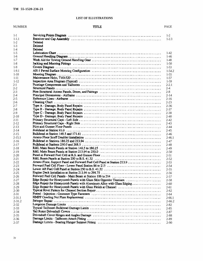
LIST OF ILLUSTRATIONS
NUMBER
1-11-1.11-21-31-41-51-61-71-81-91-9.11-101-111-122-12-22-32-42-52-62-72-82-92-102-112-122-132-142-152-15.12-162-172-182-192-202-212-222-232-242-252-262-272-282-292-302-312-31.12-31.22-322-332-342-352-362-37
iv
PAGE
1-21-2.3
1-421-461-481-501-531-54.21-551-571-592-2.12-42-82-142-162-232-362-372-382-402-422-432-442-452-462-46.12-472-482-492-502-512-522-532-542-552-562-572-582-602-612-622-642-66.12-66.22-822-852-872-882-892-90
TM 55-1520-236-23
LIST OF ILLUSTRATIONS (CONT)
NUMBER
2-382-392-402-412-422-432-43.12-442-452-462-46.12-472-482-48.12-492-502-512-522-532-542-54.12-552-562-572-57.1
2-582-58.1
2-592-602-612-622-632-642-652-662-672-682-692-702-70.12-70.22-712-722-732-742-752-762-772-77.1
PAGE
2-912-922-962-1002-1012-1022-1042-104.12-1052-1062-106.12-1072-1112-112.22-1152-1232-1262-1322-1392-1422-144.32-1462-1522-154
2-154.12-155
2-158.12-1612-1642-1672-1692-1702-1762-1782-1792-1802-1832-1882-190.12-190.22-1912-1922-1962-1992-2002-2022-2042-2062-206.1
v

TM 55-1520-236-23
NUMBER
2-782-792-79.12-79.22-79.3
2-79.4
2-79.5
2-802-812-822-83
2-842-85
2-86
2-87
2-882-892-902-91
2-92
2-92.1
2-93
2-94
2-952-962-972-98
2-99
2-100
2-1012-102
2-1032-104
2-105
3-1
3-1.1
3-2
3-33-4
3-4.13-53-6
vi
PAGE
2-209
2-2102-212.22-212.32-212.3
2-212.4
2-212.4
2-2142-2152-2162-217
2-2182-2192-221
2-2232-2242-2262-2302-231
2-2322-232.1
2-234
2-237
2-2402-2422-2442-246
2-2502-251
2-2522-2532-2542-256
3-2
3-4.1
3-5
3-63-9
3-10.23-123-15

TM 55-1520-236-23
LIST OF ILLUSTRATIONS (CONT)
NUMBER3-73-83-93-103-114-14-24-34-3.14-44 -5
4-64-7
4-7.1
4 -8
4-8.1
4 -9
4-104-10.1
4-114-12
4-13
4-144-15 4 - 4 1
4-15.14-15.24-164-17
4-17.1
4-184-18.14-194-19.14-19.24-19.34-20
TITLE PAGE
Ground Handling Gear-Assembly . . . . . . . . . . . . . . . . . . . . . . . . . . . . . . . . . . . . . . . . . . . . . . . 3-17Ground Handling Gear Pump, P/N BU0953B-Assembly . . . . . . . . . . . . . . . . . . . . . . . . . . . . 3-19Ground Handling Gear Pump, P/N HP9902-41-10 . . . . . . . . . . . . . . . . . . . . . . . . . . . . . . . . . 3-21Work Aid - Packing Nut Tool Removal/Installation - Fabrication Instructions . . . . . . . . . . . . 3-23Ground Handling Wheels -Adjustment Dimensions . . . . . . . . . . . . . . . . . . . . . . . . . . . . . . . . 3-25Power Plant Installation - Right Side . . . . . . . . . . . . . . . . . . . . . . . . . . . . . . . . . . . . . . . . . . . . . . 4-2Power Plant installation -Left Safe . . . . . . . . . . . . . . . . . . . . . . . . . . . . . . . . . . . . . . . . . . . . . . . 4-2.2Engine VibrationTest Equipment Cabling Tiedown . . . . . . . . . . . . . . . . . . . . . . . . . . . . . . . . . . 4-4DeletedEngine lnstallation . . . . . . . . . . . . . . . . . . . . . . . . . . . . . . . . . . . . . . . . . . . . . . . . . . . . . . . . 4-7Engine Mount Fittings (Trunnions) lnstallation . . . . . . . . . . . . . . . . . . . . . . . . . . . . . . . . . . . . . . 4-13
Damage Limits Aft Engine Mount Fittings (Trunnions) and Bearings . . . . . . . . . . . . . . . . . . . 4-16Particle Separator and FOD Screen Installation (Prior to Incorporation of
MWO 55-1520-236-50-12) . . . . . . . . . . . . . . . . . . . . . . . . . . . . . . . . . . . . . . . . . . . . 4-19
Centrisep Particle Separator Installation (After Incorporation ofMWO 55-1520-236-50-12) . . . . . . . . . . . . . . . . . . . . . . . . . . . . . . . . . . . . . . . . . 4-22.2
Particle Separator-Air Flow Diagram (Prior to Incorporation ofMWO 55-152-236-50-12) . . . . . . . . . . . . . . . . . . . . . . . . . . . . . . . . . . . . . . . . . . . . . . . . . . . 4-23
Centrisep Particle Separator Air Flow Diagram (After Incorporation ofMMO 55-1520-236-50-12) . . . . . . . . . . . . . . . . . . . . . . . . . . . . . . . . . . . . . . . . . .4-24.1
Particle Separator and FOD Screen Assemblies (Prior to Incorporation ofMWO 55-1520-236-50-12) . . . . . . . . . . . . . . . . . . . . . . . . . . . . . . . . . . . . . . . . . . . . . . . . . . 4-26
Inlet Vane Reinforcement Doubler - Fabrication . . . . . . . . . . . . . . . . . . . . . . . . . . . . . . . . . . . . 4-30
Centrisep Particle Separator Repair/Replacement (After Incorporation ofMWO 55-1520-236-50-12) . . . . . . . . . . . . . . . . . . . . . . . . . . . . . . . . . . . . . . . . .4-30.1
FOD (Foreign Object Damage) Screen lnstallation . . . . . . . . . . . . . . . . . . . . . . . . . . . . . . . . . . 4-34
Exhaust System Components . . . . . . . . . . . . . . . . . . . . . . . . . . . . . . . . . . . . . . . . . . .4-37
Engine Tailpipe Repair . . . . . . . . . . . . . . . . . . . . . . . . . . . . . . . . . . . . . . . . . . . . .4-38Engine Deck and Firewall Sealing . . . . . . . . . . . . . . . . . . . . . . . . . . . . . . . . . . . . . . . . . . . . . . 4-40
Exhaust System Components with IR Suppression Installation . . . . . . . . . . . . . .Hot Metal Plus Plume suppressor . . . . . . . . . . . . . . . . . . . . . . . . . . . . . . . . . . . . . . . . . . . . . . . 4-44.10Outer Body Half - Section. . . . . . . . . . . . . . . . . . . . . . . . . . . . . . . . . . . . . . . . . . . . . . . . . . . . . . . 4-44.11Repair Procedures - Infrared Suppression System . . . . . . . . . . . . . . . . . . . . . . . . . . . . . . . . . 4-45
Exhaust System Components with IR Suppression - Installation . . . . . . . . . . . . . . . . 4-47
Suppresor Major Structural Elements. . . . . . . . . . . . . . . . . . . . . . . . . . . . . . . . . . . . . . . 4-50Engine Oil System lnstallation . . . . . . . . . . . . . . . . . . . . . . . . . . . . . . . . . . . . . . . . . . . . . . . . . . . 4-50.1ODDS Oil Separator and Oil Filter Installation (MWO 1-1520-236-50-30) . . . . . . . . . . . . 4-50.3Engine Oil System Schematic . . . . . . . . . . . . . . . . . . . . . . . . . . . . . . . . . . . . . . . . . . . . . . . . . . . . 4-54.3Oil Separator (Lubriclone) Assembly . . . . . . . . . . . . . . . . . . . . . . . . . . . . . . . . . . . . . . . . . . . . . . 4-54.4DeletedEngine External Oil Filter . . . . . . . . . . . . . . . . . . . . . . . . . . . . . . . . . . . . . . . . . . . . . . . . . . . . . . . . 4-54.7Oil Tank lnstallation . . . . . . . . . . . . . . . . . . . . . . . . . . . . . . . . . . . . . . . . . . . . . . . . . . . . . . . . . . . . . 4-57
Vi.1

TM 55-1520-236-23
NUMBER4-214-224-234-244-254-264-274-284-294-304-314-324-33
LIST OF ILLUSTRATIONS (CONT)
TITLEEngine Oil Cooler lnstallation . . . . . . . . . . . . . . . . . . . . . . . . . . . . . . . . . . . . . . . . . . . . . . . . . . . .Oil Cooler Cleaning Schematic . . . . . . . . . . . . . . . . . . . . . . . . . . . . . . . . . . . . . . . . . . . . . . . . . . .Engine Oil Cooler Turbine Fan Assembly . . . . . . . . . . . . . . . . . . . . . . . . . . . . . . . . . . . . . . . . . .Oil Cooler Turbine Fan Assembly . . . . . . . . . . . . . . . . . . . . . . . . . . . . . . . . . . . . . . . . . . . . . . . . .Power Lever Control System lnstallation . . . . . . . . . . . . . . . . . . . . . . . . . . . . . . . . . . . . . . . . . .Engine idle Stop installation . . . . . . . . . . . . . . . . . . . . . . . . . . . . . . . . . . . . . . . . . . . . . . . . . . . . .Droop Cpmpensator Controls lnstallation . . . . . . . . . . . . . . . . . . . . . . . . . . . . . . . . . . . . . . . . . .
Rigging Procedures - Droop Compensator Controls . . . . . . . . . . . . . . . . . . . . . . . . . . . . . . . .Engine Shipping Container . . . . . . . . . . . . . . . . . . . . . . . . . . . . . . . . . . . . . . . . . . . . . . . . . . . . . .Ignition Unit . . . . . . . . . . . . . . . . . . . . . . . . . . . . . . . . . . . . . . . . . . . . . . . . . . . . . . . . . . . . . . . . . . .Aft Engine Trunnion installation . . . . . . . . . . . . . . . . . . . . . . . . . . . . . . . . . . . . . . . . . . . . . . . . . .Trunnion, Cambox, and Linear Actuator Installation . . . . . . . . . . . . . . . . . . . . . . . . . . . . . . . . .Power Turbine Tachometer Generator, Oil Pressure Transducer, Oil Pressure Switch,
and Fuel Pressure Switch lnstallation . . . . . . . . . . . . . . . . . . . . . . . . . . . . . . . . . . . . . . . . . . . .
PAGE4-604-614-644-664-704-734-754-794-814-834-844-85
4-86
vi.2

TM 55-1520-236-23
LIST OF ILLUSTRATIONS (CONT)
NUMBER TITLE PAGE
4-344-35
4-364-374-384-394-404-414-425-15-25-35 -45-4.15-4.25-55-65-75 -85 -95-105-115-125-135-145-155-165-16.15-17
5-18
5-195-19.15-205-20.15-21
5-225-235-245-24.15-24.25-255-265-27
4-874-894-914-924-934-954-964-974-1005-25-45-65 -75 -85-8.15-8.25 -95-115-135-145-165-175-185-235-255-275-30.15-31
5-32
5-335-36.25-375-385-38.1
5-395-405-435-525-52.15-52.35-545-565-60
vii

TM 55-1520-236-23
NUMBER5-285-28.15-28.25-28.35-28.45-28.55-28.6
5-68
5-28.75-28.85-28.95-28.105-28.115-28.12
5-28.135-28.145-28.155-28.165-295-305-315-325-335-34
5-365-375-38
5-35 5-825-83
5-865-38.1
5-395 4 05-40.15-40.25-415-425-42.15-435-445-455-465-475-485-495-505-515-525-52.1
LIST OF ILLUSTRATIONS (CONT)
TITLETypical Double Plug Patch Repair (K747 Blade) . . . . . . . . . . . . . . . . . . . . . . . . . . . . . . . . . . . . . . . . .Application of Trailing Edge Doubler Patch (K747 Blade) . . . . . . . . . . . . . . . . . . . . . . . . . . . . . .wine Repair (K747 Blade) . . . . . . . . . . . . . . . . . . . . . . . . . . . . . . . . . . . . . . . . . . . . . . . . . . . . . . . . . . . . . .Rebinding Delaminated Leading Edge Erosion Guard (K747 Blade) . . .. . . . . . . . . . . . . . . . . . . .Typical Repair of fluorocarbon Erosion Guard Nicks and Cuts Using Kit, P/N 747-207 .. .. . . .Application of Leading Edge Erosion Guard Patch (K747 Blade) . . . . . . . . . . . . . . . . . . . . . . . . . .Placement of Erosion Guard Replacement Part (Kit, P/N K747-206-1) Method for Determing Cur
rent Boot Material and Thickness (K747 Blade Series) . . . . . . .. . . . . . . . . . . . . . . . . . . . . . . . . .K747 Blade Uralite Repair . . . . . . . . . . . . . . . . . . . . . . . . . . . . . . . . . . . . . . . . . . . . . . . . . . . . . . . . .Application of Vacuum Bagging Materials and Placement of Erosion Guard . . . .. . . . . . . . . . .Repair Parts and Specimen Orientation (Kit, P/N 747-206) . . . . . . . . . . . . . . . . . . . . . . . . . . . . . .Vacuum Bagging for Installation of Erosion Guard Repair Kit, P/N K747-206 . . . . . . . . . . . . . . .lmprovised Mod for Casting Small Section of Leading Edge Filler . . . . . . . . . . . . . . . . . . . . .Repair Parts Orientation Use for Removal and Installation of Stainless Steel Erosion Guard -
K747-003-303/403 and -303/403 Field Modified Blades . . . . . . . . . . . . . . . . . . . . . . . . . . . . . . . . .Preparation of K747-003/-403 BIade for Application of Sealant . . . . . . . . . . . . . . . . . . . . . . . . . .Application of SeaIant to Stainless Steel Guard for K747-003-303/403 Blade . . . . . . . . . . . . . .Stainless Steel Erosion Guard Holding Fixture . . . . . . . . . . . . . . . . . . . . . . . . . . . . . . . . . . . . . . . . . . .Masking for Paint Touch-Up After installation of Kit K747-206 . . .. . . . . . . . . . . . . . . . . . . . . . . . .Main Rotor Hub Yoke Extension and Grip Assembly . . .. . . . . . . . . . . . . . . . . . . . . . . . . . . . . . . . . .Main Rotor Hub Yoke and Trunnion . . . . . . . . . . . . . . . . . . . . . . . . . . . . . . . . . . . . . . . . . . . . . . . . . . .Main Rotor Bearing Wear Patters . . . . . . . . . . . . . . . . . . . . . . . . . . . . . . . . . . . . . . . . . . . . . . . . . .Damage Limits - Main Rotor Hub Yoke Extension . . . . . . . . . . . . . . . . . . . . . . . . . . . . . . . . . . . . . . .Damage Limits - Main Rotor Hub Bolt Holes . . . . . . . . . . . . . . . . . . . . . . . . . . . . . . . . . . . . . . . . . . .Damage Limits - Main Rotor Hub Yoke.... . . . . . . . . . . . . . . . . . . . . . . . . . . . . . . . . . . . . . . . . . . . . . . . .Damage Limits - Main Rotor Hub Grip . . . . . . . . . . . . . . . . . . . . . . . . . . . . . . . . . . . . . . . . . . . . . . . .Damage Limits- Main Rotor Hub Strap Fitting . . . . .. . . . . . . . . . . . . . . . . . . . . . . . . . . . . . . . . . . . . . .Damage Limits - Pitch Horn Bushing . . . . . . . . . . . . . . . . . . . . . . . . . . . . . . . . . . . . . . . . . . . . . . . . . . .Damage Limits - Main Rotor Hub Pitch Horn 209-010-109-5 (Prior to Accomplishment of MWO
55-1520 -244-50-6) . . . . . . . . . . . . . . . . . . . . . . . . . . . . . . . . . . . . . . . . . . . . . . . . . . . . . . . . . . . . . . . . . .Damage Limits - Main Rotor Hub Pitch Horn 209-010-109-109 (After Accomplishment of MWO
55-1520-244-50-6 and MWO 55-1520-244-50-9) . . . . . . . . . . . . . . . . . . . . . . . . . . . . . . . . . . . . . . .Damage Limits -Main Rotor Drag Brace . . . . . . . . . . . . . . . . . . . . . . . . . . . . . . . . . . . . . . . . . . . . . .Damage Limits- Main Rotor HubTrunnion . . . . . . . . . . . . . . . . . . . . . . . . . . . . . . . . . . . . . . . . . . . .Damage Limits -Hub Moment Spring Plate . . . . . . . . . . . . . . . . . . . . . . . . . . . . . . . . . . . . . . . . . . .Damage Limits- Hub Moment Spring Strap . . . . . . . . . . . . . . . . . . . . . . . . . . . . . . . . . . . . . . . . . . . .Damage Limits- Main Rotor Hub Elastomeric Bearing . . . . . . . . . . . . . . . . . . . . . . . . . . . . . . . . .Main Rotor Hub Yoke Chafing Pad Installation Dimensions . . . . . . . . . . . . . . . . . . . . . . . . . . . .Main Rotor Hub Yoke Buffer Installation -Dimensions . . . . . . . . . . . . . . . . . . . . . . . . . . . . . . . .Tool Application -Bearing Removal From Housing . . . . .. . . . . . . . . . . . . . . . . . . . . . . . . . . . . . . . .Tool Application -Bearing Removal From Grip .. . . . . . . . . . . . . . . . . . . . . . . . . . . . . . . . . . . . . . . .Tool Application - Bearing and Seal Installation in Grip . .. . . . . . . . . . . . . . . . . . . . . . . . . . . . . . .Tool Application- Main Rotor Hub Trunnion Centering . . . . .. . . . . . . . . . . . . . . . . . . . . . . . . . . . . . .Tool Application - Grip Spacing Adjustment . . . . . .. . . . . . . . . . . . . . . . . . . . . . . . . . . . . . . . . . . .Main Rotor Hub Grip Dust Seal to Radius Ring Dimension . . . . . . . . . . . . . . . . . . . . . . . . . . . . . .Rotor Balancing Kit P/N 7A050. . . . . . . . . . . . . . . . . . . . . . . . . . . . . . . . . . . . . . . . . . . . . . . . . . . . .Tool Application - Main Rotor Hub Balancing . . . . . . . . . . . . . . . . . . . . . . . . . . . . . . . . . . . . . . . . . .Main Rotor Controls Installation . . . . . . . . . . . . . . . . . . . . . . . . . . . . . . . . . . . . . . . . . . . . . . . . . . . . . .Tool Application - Spline Plate Wear Measurement . . .. . . . . . . . . . . . . . . . . . . . . . . . . . . . . . . . . . .Hub Moment Spring Support Assembly - Installation (MWO 55-1520-244-50-3 Incorporated)
PAGE5-67
5-715-72.15-72.35-72.5
5-72.75-72.105-72.115-72.155-72.185-72.21
5-72.235-72.245-72.265-72.275-72.315-72.355-745-775-785-795-81
5-85
5-86.15-875-885-88.15-88.25-895-905-905-90.25-925-935-965-975-995-1015-1025-1045-107
5-108
viii

TM 5-1520-236-23
LIST OF ILLUSTRATIONS (CONT)
NUMBER5-535-53.15-53.25-54
5-54.1
5-555-565-575-585-595-605-615-625-635-63.1
5-63.25-645-655-65.15-65.25-665-675-685-695-705-715-726-735-745-755-765-775-785-795-805-815-825-835-845-85
TITLE
Collective Lever Trust Washer Wear Limits . . . . . . . . . . . . . . . . . . . . . . . . . . . . . . . . . . . . . . . .
Rod End Clevis Movement . . . . . . . . . . . . . . . . . . . . . . . . . . . . . . . . . . . . . . . . . . . . . . . . . . . . .Rod End Bearing. . . . . . . . . . . . . . . . . . . . . . . . . . . . . . . . . . . . . . . . . . . . . . . . . . . . . . . . . . . . . . .Damage Limits - Pitch Link Assembly (Prior to Accomplishment of
MWO 55-1520-244-50-9) . . . . . . . . . . . . . . . . . . . . . . . . . . . . . . . . . . . . . . . . . . . . . . . . . . .Damage Limits - Pitch Link Assembly 209-010-520-103 (After Accomplishment of
MWO 55-1520-244-50-9) . . . . . . . . . . . . . . . . . . . . . . . . . . . . . . . . . . . . . . . . . . . . . . . . . . .
Damage Limits- Spline Plate. . . . . . . . . . . . . . . . . . . . . . . . . . . . . . . . . . . . . . . . . . . . . . . . . . . .Damage Limits - Collectivr Lever . . . . . . . . . . . . . . . . . . . . . . . . . . . . . . . . . . . . . . . . . . . . . . . .Damage Limits - Collective Lever ldle Link . . . . . . . . . . . . . . . . . . . . . . . . . . . . . . . . . . . . . . . .Collective Lever Idle Link Assembly . . . . . . . . . . . . . . . . . . . . . . . . . . . . . . . . . . . . . . . . . . . . . . .Damage Limits - Swashplate Anti-Drive Link . . . . . . . . . . . . . . . . . . . . . . . . . . . . . . . . . . . . . .Swashplate Anti - Drive Link . . . . . . . . . . . . . . . . . . . . . . . . . . . . . . . . . . . . . . . . . . . . . . . . . . . . . .Damage Limits - Swashplate Anti-Drive Assembly Bellcrank . . . . . . . . . . . . . . . . . . . . . . . .Damage Limits - Swashplate Anti - Drive Assembly Support . . . . . . . . . . . . . . . . . . . . . . . . .Swashplate Anti - Drive Assembly . . . . . . . . . . . . . . . . . . . . . . . . . . . . . . . . . . . . . . . . . . . . . . . . .
PAGE5-108.1
5-108.45-108.5
5-109
5-110.15-110.25-1115-1125-1135-1145-1155-1165-1175-118
5-120.25-120.35-1215-1245-130.15-130.15-1325-1355-1395-1445-1465-1505-1515-1525-1535-1555-1565-1605-1615-1625-1635-1645-1655-1665-1675-168
viii.1/(viii.2 blank)


TM 55-1520-236-23
LIST OF ILLUSTRATIONS (cont)
NUMBER5-865-875-885-895-905-915-925-935-945-955-965-975-985-995-1005-1015-1025-1035-1045-1055-1065-1075-108
PAGE5-1695-1715-1725-1735-1745-1765-1785-1825-1835-1855-1875-1885-1895-1915-1945-1955-1965-1985-2005-2015-2025-2035-204
ix

TM 55-1520-236-23
NUMBER5-1095-1105-1115-1125-1135-1145-1155-1165-1176-16-26-2.16-2.26-36-46-56-66-76-7.16-86-96-9.16-9.26-9.36-9.46-106-116-12
6-136-146-156-15.16-166-16.16-16.26-16.36-176-186-196-206-216-22
6-236-246-24.16-24.26-256-266-276-286-296-306-31
x
PAGE5-205
5-2085-2095-2105-2125-2145-2155-2176-46-56-6.3
6-86-106-116-136-14.16-176-186-206-20.16-20.26-20.26-20.36-256-276-28
6 - 3 26 - 3 46-41644.16 4 5646.1646.2646.36 4 76-506-536-566-566-59
6-626-646-656-666-66.16-696-696-736-766-776-81

TM 55-1520-236-23
NUMBER
6-326-336-346-356-35.16-366-376-386-39
6-416-42
6-44
6-40
6-43
6-45
6-45.16-45.26-466-476-486-496-506-50.16-516-526-536-546-55
PAGE
6-826-856-876-886-90.26-916-996-1036-1056-1066-1086-1156-116
6-119
6-1206-120.26-120.26-1266-1276-1296-1316-1326-132.26-1356-1376-1386-1396-140
x.1/(x.2 blank)
. .


TM 55-1520-236-23
LIST OF ILLUSTRATIONS (CONT)
NUMBER6-566-576-586-596-606-616-626-636-646-656-666-676-67.1
6-67.26-686-696-707-1
7-2
7-37 -47-5
7-67-77-87-97-10
7-117-127-13
7-147-157-167-17
7-187-197-207-217-227-22.1
PAGE6-1416-1426-1436-144
6-1466-147
6-1486-1496-1496-1506-1516-153
6-154.36-154.46-1556-1586-159
7-3
7-87-97-28
7-297-317-377-417-42
7-437-467-47
7-497-527-537-55
7-597-617-627-637-667-677-68.4
xi

TM 55-1520-236-23
LIST OF ILLUSTRATIONS (CONT)
NUMBER7-22.27-237-247-25
7-267-27
7-287-29
7-30
7-31
7-32
7-33
7-347-357-367-377-387-397-40
7-41
7-42
7-43
8-1
8-28-2.18-2.28-38 -48-5
8-5.18-5.28-5.38 -69-1
9-2
9-3
9-4
PAGE7-68.67-737-75
7-807-81
7-817-84
Solenoid Valve P/N 7U7464 lnstallation . . . . . . . . . . . . . . . . . . . . . . . . . . . . . . . . . . . . . . . 7-92
Solenoid Valve P/N 7U7464 Assembly . . . . . . . . . . . . . . . . . . . . . . . . . . . . . . . . . . . . . . . . 7-95
Functional Test Setup for Solenoid Valve P/N 7U7464 . . . . . . . . . . . . . . . . . . . . . . . . . . . 7-98
Flow Diagram for Solenoid Valve P/N 7U7464 . . . . . . . . . . . . . . . . . . . . . . . . . . . . . . . . . . 7-98
7-987-1027-1047-1057-1077-1087-109
7-111
7-117
7-144
Solenoid Valves (SCAS System) - lnstallation . . . . . . . . . . . . . . . . . . . . . . . . . . . . 7-149
lnstrument System Equipment Location . . . . . . . . . . . . . . . . . . . . . . . . . . . . . . . . . . 8-2Pitot - Static System . . . . . . . . . . . . . . . . . . . . . . . . . . . . . . . . . . . . . . . . . . . . . . . . . . . . . . . . . . . . 8-26.3Connection for Pitot Leak Check (Typical) . . . . . . . . . . . . . . . . . . . . . . . . . . . . . . . . . . . . . . . . . 8-26.4Connection for Static Leak Check (Typical) . . . . . . . . . . . . . . . . . . . . . . . . . . . . . . . . . . . . . . . . 8-26.5Test Circuit Setup for Fuel Tank Unit Capacitance and Resistance Tests . . . . . . . . . . . . . . . 8-42Test Circuit Setup for Fuel Quantity indicator Bench Test . . . . . . . . . . . . . . . . . . . . . . . . . . . . 8-43Circuit Arrangement and Adapter Cable for Fuel Quantity Adjustment Procedures on . . .
Installed System . . . . . . . . . . . . . . . . . . . . . . . . . . . . . . . . . . . . . . . . . . . . . . . . . . . . . . . . . . . . . . 8-44Fuel Quantity Test Set P/N PSD60 - 1AF . . . . . . . . . . . . . . . . . . . . . . . . . . . . . . . . . . . . . . . . . . . 8-44.4Fuel Quantity "T" Cable P/N PSDAF - 537 . . . . . . . . . . . . . . . . . . . . . . . . . . . . . . . . . . . . . . . . . . 8-44.5Fuel Quantity Calibration Worksheet . . . . . . . . . . . . . . . . . . . . . . . . . . . . . . . . . . . . . . . . . . . . . . 8-44.6
Volt-Ammeter Test Set-up . . . . . . . . . . . . . . . . . . . . . . . . . . . . . . . . . . . . . . . . . . . . . . . . . . . . . . 8-49
Simplified Electrical Wiring Schematic . . . . . . . . . . . . . . . . . . . . . . . . . . . . . . . . . . . . . 9-2
Simplified Electrical Bus Wiring Schematic . . . . . . . . . . . . . . . . . . . . . . . . . . . . . . . . 9-3
Electrkal Equipment Location Forward Section . . . . . . . . . . . . . . . . . . . . . . . . . . . . . . . . 9-4
Electrical Equipment Location Pilot Section . . . . . . . . . . . . . . . . . . . . . . . . . . . . . . . . . . . . 9-6
xii
TM 55-1520-236-23
NUMBER
8-5
9-6
9-7
9-8
9-9
9-109-11
9-12
9-13
9-149-14.1
9-159-15.1
9-16
9-179-17.19-17.29-17.39-17.49-17.59-17.69-17.78-17.89-17.9
LIST OF ILLUSTRATIONS (CON'T)
TITLE PAGE
Electrical Equipment Location Gunner Section . . . . . . . . . . . . . . . . . . . . . . . . . . . . . . . . 9-8
Electrical Equipment Location Aft Section . . . . . . . . . . . . . . . . . . . . . . . . . . . . . . . . . . . . 9-10
Electrical Equipment Locaton Forward Section . . . . . . . . . . . . . . . . . . . . . . . . . . . . . . . 9-13
Electrical Equipment Location Pilot Section . . . . . . . . . . . . . . . . . . . . . . . . . . . . . . . . . . . 9-13
Electrical Equipment Location Gunner Section . . . . . . . . . . . . . . . . . . . . . . . . . . . . . . . . 9-18
Electrical Equipment Location Aft Section . . . . . . . . . . . . . . . . . . . . . . . . . . . . . . . . . . . .9-20Environmental Connector Test Adapter . . . . . . . . . . . . . . . . . . . . . . . . . . . . . . . . . . . . . . . . . . . . 9-23
Stanby lnverter Adjustment . . . . . . . . . . . . . . . . . . . . . . . . . . . . . . . . . . . . . . . . . . . . . . . . 9-66
Pilot Caution Panel . . . . . . . . . . . . . . . . . . . . . . . . . . . . . . . . . . . . . . . . . . . . . . . . . . . . . . . 9-80.1
Pilot Caution Panel . . . . . . . . . . . . . . . . . . . . . . . . . . . . . . . . . . . . . . . . . . . . . . . . . . . . . . . . 9-80.1Deleted
Pilot Caution Panel . . . . . . . . . . . . . . . . . . . . . . . . . . . . . . . . . . . . . . . . . . . . . . . . . . . . . . . . 9-81Deleted
Gunner Caution Panel . . . . . . . . . . . . . . . . . . . . . . . . . . . . . . . . . . . . . . . . . . . . . . . . . . . . . 9-82.1
Gunner Caution Panel . . . . . . . . . . . . . . . . . . . . . . . . . . . . . . . . . . . . . . . . . . . . . . . . . 9-82.1
DeletedPilots Caution Panel Assembly . . . . . . . . . . . . . . . . . . . . . . . . . . . . . . . . . . . . . . . . . . . . . . . . . . . 9-88.7Pilots Caution Panel Subassembly . . . . . . . . . . . . . . . . . . . . . . . . . . . . . . . . . . . . . . . . . . . . . . . 9-88.8Housing Subassembly . . . . . . . . . . . . . . . . . . . . . . . . . . . . . . . . . . . . . . . . . . . . . . . . . . . . . . . . . .9-88.11Cover Assembly . . . . . . . . . . . . . . . . . . . . . . . . . . . . . . . . . . . . . . . . . . . . . . . . . . . . . 9-88.11lndicating Light Circuit Card . . . . . . . . . . . . . . . . . . . . . . . . . . . . . . . . . . . . . . . . . . . . . . . . . . . . . 9-88.12Contact Assembly . . . . . . . . . . . . . . . . . . . . . . . . . . . . . . . . . . . . . . . . . . . . . . . . . . . . . . . . . . . . .9-88.16Polarizing Keys Lotion . . . . . . . . . . . . . . . . . . . . . . . . . . . . . . . . . . . . . . . . . . . . . . . . . . . . . . . . 9-88.17Removal of Finish for Electrical Bonding . . . . . . . . . . . . . . . . . . . . . . . . . . . . . . . . . . . . . . . . . . 9-88.19
xii.1/(xii.2 blank)

TM 55-1520-236-23
NUMBER
9-17.109-17.119-17.129-17.139-189-199-209-219-229-239-249-259-269-279-289-299-309-31
9-329-33
10-110-210-3
10-410-4.110-4.210-510-610-711-111-211-311-411-511-611-711-811-911-1011-1111-1211-1311-14
LIST OF ILLUSTRATIONS (CON’T)
TITLE PAGE
Position of Contacts in Latch Base.... . . . . . . . . . . . . . . . . . . . . . . . . . . . .9-88.23Gunners Caution Panel Schematic Diagram . . . . . . . . . . . . . . . . . . . . . . . . . . . . . . . . . . . . 9-88.25Gunners Caution Panel. . . . . . . . . . . . . . . . . . . . . . . . . . . . . . . . . . . . . . . . . . . . . . . . . . . . 9-88.32Gunners Caution Panel Wiring Connections . . . . . . . . . . . . . . . . . . . . . . . . . . . . . . . . . . . . 9-88.35Bench Test Set-Up for RPM Limits Warning Detector . . . . . . . . . . . . . . . . . . . . . . . . . . . . 9-93
Amment Equipment Location . . . . . . . . . . . . . . . . . . . . . . . . . . . . . . . . . . . . . . . . . . . . . 9-128TOWMissile Launcher Positions . . . . . . . . . . . . . . . . . . . . . . ..9-131Wing Stores Armament Test Panel . . . . . . . . . . . . . . . . . . . . . . . . . 9-139Wing Stores Armament Test Panel Schematic . . . . . . . . . . . . . . . . . . . . . . . . . . . . . . . . 9-140Armament Equipment Location . . . . . . . . . . . . . . . . . . . . . . . . . . . . . . . . . . 9-155TOW Missile Launcher Positions . . . . . . . . . . . . . . . . . . . . . . . . . . . . . . . . . . . . . . . . . . . . 9-164DU Digital Display Test . . . . . . . . . . . . . . . . . . . . . . . . . . . . . . . . . . . . . . . . . . . . . . . . .9-173LRUFault Identification and Location Test . . . . . . . . . . . . . . . . . . . . . . . . . . . . . . . . . . 9-173XM18 Minigun Circuitry Test Panel . . . . . . . . . . . . . . . . . . . . . . . . . . . . . . . . . . . . . . . . . 9-175Wing Stores Circuitry Test Panel . . . . . . . . . . . . . . . . . . . . . . . . . . . . . .9-180TOWMissile Launcher Positions . . . . . . . . . . . . . . . . . . . . . . . . . . . . . . . . . . . . . . . . . . 9-195DUDigital Display Test . . . . . . . . . . . . . . . . . . . . . . . . . . . . . . .9-204LRUFault Identification and Location Test . . . . . . . . . . . . . . . . . . . . . . . . . . . . . . . .9-204
XM18 Minigun Circuitry Test Panel . . . . . . . . . . . . . . . . . . . . . . . . . . . . . . . . . . . . . . . . 9-206Wing Stores Circuitry Test Panel . . . . . . . . . . . . . . . . . . . . . . . . . . . . . . . . . . . . . . . . . . .9-211
Fuel Systems Schematic . . . . . . . . . . . . . . . . . . . . . . . . . . . . . . . . . . . . . . . . . . . . . . . . . . . . . . .10-3Fuel System. . . . . . . . . . . . . . . . . . . . . . . . . . . . . . . . . . . . . . . . . . . . . . . . . . . . . . . . .......
10-4
Fuel Shutoff Valve . . . . . . . . . . . . . . . . . . . . . . . . . . . . . . . . . . . . . . . . . . . . . . . . .........10-9
Fuel Boost Pump . . . . . . . . . . . . . . . . . . . . . . . . . . . . . . . . .. . . ............10-12.2Fuel Boost Pump Cartridge . . . . . . . . . . . . . . . . . . . . . . . . . . . . . . . . . . . . . . . . . . . . . . .10-12.3Work Aid for Fuel Pump Cartridge Removal . . . . . . . . . . . . . . . . . . . . . . . . . . . . . . . . . . . . . . .10-22Collapsing Forward Fuel Cell . . . . . . . . . . . . . . . . . . . . . . . . . . . . . . . . . . . . . . . . . . . . . . . . . . . 10-24Installed Forward Fuel Cell . . . . . . . . . . . . . . . . . . . . . . . . . . . . . . . . . . . . . . . . . . . . . .10-26Collapsing Aft Fuel Cell . . . . . . . . . . . . . . . . . . . . . . . . . . . . . . . . . . . . . . . . . . . . . . . . . . . . . . . . 10-26Collective Controls, . . . . . . . . . . . . . . . . . . . . . . . . . . . . . . . . . . . . . . . . . . . .........Pilot Collective Stick Installation . . . . . . . . . . . . . . . . . . . . . . . . . . . . . . . . . . . . . . . . . . . . . . . 11-8
Pilot Collective Stick Assembly. . . . . . . . . . . . . . . . . . . . . . . . . . . . . . . . . . . . . . . . . . . . . . . . 11-9
Bearing Installation- Pilot Throttle Grip . . . . . . . . . . . . . . . . . . . . . . . . . . . . . . . . . . . . . . . . 11-14
Friction Lining Repair . . . . . . . . . . . . . . . . . . . . . . . . . . . . . . . . . . . . . . . . . . . . . . . . . . . . . . . . . 11-16
Throttle Lever Bearing Installation . . . . . . . . . . . . . . . . . . . . . . . . . . . . . . . . . . . . . . . . . . . . . 11-17
Collective Friction Tube Repairs. . . . . . . . . . . . . . . . . . . . . . . . . . . . . . . . . . . . . . . . . . . . . . . .11-18Pilot Collective Stick Adjustments. . . . . . . . . . . . . . . . . . . . . . . . . . . . . . . . . . . . . . . . . . . . . . 11-20Gunner Collective Stick Installation . . . . . . . . . . . . . . . . . . . . . . . . . . . . . . . . . . . . . . . . . . . . . . . . . . .. . . . . 11-22Gunner Collective Stick - Assembly . . . . . . . . . . . . . . . . . . . . . . . . . . . . . . . . . . . . . . . . . . . . . 11-25Gunner Collective Stick Adjustment . . . . . . . . . . . . . . . . . . . . . . . . . . . . . . . . . . . . . . . . . . . . 11-27Force-And-Aft Cyclic Controls . . . . . . . . . . . . . . . . . . . . . . . . . . . . . . . . . . . . . . . . . . . . . . . . . 11-30Lateral Cyclic Controls . . . . . . . . . . . . . . . . . . . . . . . . . . . . . . . . . . . . . . . . . . . . . . . . . . . . . . . . 11-32
Work Aid for Rigging Swashplate . . . . . . . . . . . . . . . . . . . . . . . . . . . . . . . . . . . . . . . . . . . . . . . 11-34
10-12.1
11-4
Xiii

TM 55-1520-236-23
LIST OF ILLUSTRATIONS (CON’T)
NUMBER TITLE PAGE
11-1511-1611-1711-1811-1911-2011-2111-2211-2311-2411-2511-2611-2711-27.111-2811-2911-3011-3111-3211-3311-3411-3511-3611-3711-3811-3912-112-212-312-412-512-6
13-113-213-313-413-513-613-6.113-713-813-913-1013-1113-1213-1313-14 13-1513-1613-1713-1816-116-2
Swashplate Rigging Dimensions. . . . . . . . . . . . . . . . . . . . . . . . . . . . . . . . . . . . . . . . . . . . . . . . 11-35Pilot Cyclic Stick Installation . . . . . . . . . . . . . . . . . . . . . . . . . . . . . . . . . . . . . . . . . . . . . . . . . . 11-36Pilot Cyclic Stick Assembly.. . . . . . . . . . . . . . . . . . . . . . . . . . . . . . . . . . . . . . . . . . . . . . . . . . . 11-40Collar and Bushing Installation. . . . . . . . . . . . . . . . . . . . . . . . . . . . . . . . . . . . . . . . . . . . . . . . . 11-42Pilot Cyclic Stick Friction Adjustment . . . . . . . . . . . . . . . . . . . . . . . . . . . . . . . . . . . . . . . . . . 11-44Gunner Cyclic Stick Installation . . . . . . . . . . . . . . . . . . . . . . . . . . . . . . . . . . . . . . . . . . . . . . . . 11-46Gunner Cyclic Stick Assembly. . . . . . . . . . . . . . . . . . . . . . . . . . . . . . . . . . . . . . . . . . . . . . . . . 11-48Fore-And-Aft Cyclic Jackshaft Installation . . . . . . . . . . . . . . . . . . . . . . . . . . . . . . . . . . . . . . 11-51Force Gradient Assembly . . . . . . . . . . . . . . . . . . . . . . . . . . . . . . . . . . . . . . . . . . . . . . . . . . . . . . 11-56.1Tail Rotor Controls. . . . . . . . . . . . . . . . . . . . . . . . . . . . . . . . . . . . . . . . . . . . . . . . . . . . . . . . . . . 11-57Tail Rotor Pedal Installation. . . . . . . . . . . . . . . . . . . . . . . . . . . . . . . . . . . . . . . . . . . . . . . . . . . 11-62
Stability and Control Augmentation System (SCAB) . . . . . . . . . . . . . . . . . . . . . . . . . 11-70Stability and Control Augmentation System (SCAS) . . . . . . . . . . . . . . . . . . . . . . 11-71
SCAS Transducer Calibration . . . . . . . . . . . . . . . . . . . . . . . . . . . . . . . . . . . . . . . . . . . . . . . . . . . . .11-74.2Elevator Control System . . . . . . . . . . . . . . . . . . . . . . . . . . . . . . . . . . . . . . . . . . . . . . . . . . . . . . . 11-76Elevator Installation. . . . . . . . . . . . . . . . . . . . . . . . . . . . . . . . . . . . . . . . . . . . . . . . . . . . . . . . . . . 11-79Damage Limits - Fixed Length Flight Control Tubes and Links (Typical) . . . . . . . . . . . 11-82Control System Linkage Installation . . . . . . . . . . . . . . . . . . . . . . . . . . . . . . . . . . . . . . . . . . . . 11-85Damage Limits - Anti-Torque System . . . . . . . . . . . . . . . . . . . . . . . . . . . . . . . . . . . . . . . . . . . 11-95Damage Limits - Elevator Control System . . . . . . . . . . . . . . . . . . . . . . . . . . . . . . . . . . . . . . . 11-102Damage Limits - Collective Control System . . . . . . . . . . . . . . . . . . . . . . . . . . . . . . . . . . . . . . 11-104Damage Limits -Cyclic Control System . . . . . . . . . . . . . . . . . . . . . . . . . . . . . . . . . . . . . . . . . 11-110Flight Control System Bearings . . . . . . . . . . . . . . . . . . . . . . . . . . . . . . . . . . . . . . . . . . . . . . . . 11-118Lateral Cyclic and Collective Controls Power Cylinder Support Installation . . . . . . . 11-119Fore-And-Aft Cyclic Controls Power Cylinder Support Installation. . . . . . . . . . . . . . . 11-120Damage Limits- Power Cylinder Supports . . . . . . . . . . . . . . . . . . . . . . . . . . . . . . . . . . . . . . . 11-121
Engine Fire Detection System. . . . . . . . . . . . . . . . . . . . . . . . . . . . . . . . . . . . . . . . . . . . . . . . . . . . . . . 12-3Low G Warning System . . . . . . . . . . . . . . . . . . . . . . . . . . . . . . . . . . . . . . . . . . . . . . . . . . . . . . . . . . . . 12-5Low G Warning Assemb1y 8A10. . . . . . . . . . . . . . . . . . . . . . . . . . . . . . . . . . . . . . . . . . . . . . . . . . . . . 12-9Accelcrometer 8A11 . . . . . . . . . . . . . . . . . . . . . . . . . . . . . . . . . . . . . . . . . . . . . . . . . . . . . . . . . . . . . . . 12-10Low G Warning Light/Switch 8DS25 . . . . . . . . . . . . . . . . . . . . . . . . . . . . . . . . . . . . . . . . . . . . . . . . . 12-12Converter 8M1 . . . . . . . . . . . . . . . . . . . . . . . . . . . . . . . . . . . . . . . . . . . . . . . . . . . . . . . . . . . . . . . . . . . 12-13Environmental Control System . . . . . . . . . . . . . . . . . . . . . . . . . . . . . . . . . . . . . . . . . . . . . . . . . 13-3Environmental Control Unit. . . . . . . . . . . . . . . . . . . . . . . . . . . . . . . . . . . . . . . . . . . . . . . . . . . 13-5Environmental Control System Schematic . . . . . . . . . . . . . . . . . . . . . . . . . . . . . . . . . . . . . . . 13-7Temperature Control Valve.. . . . . . . . . . . . . . . . . . . . . . . . . . . . . . . . . . . . . . . . . . . . . . . . . . 13-8Temperature Control Valve Schematic . . . . . . . . . . . . . . . . . . . . . . . . . . . . . . . . . . . . . . . . 13-9ECU Cooling Turbine . . . . . . . . . . . . . . . . . . . . . . . . . . . . . . . . . . . . . . . . . . . . . . . . . . . . . . . . 13-12
ECU Cooling Turbine Lubrication . . . . . . . . . . . . . . . . . . . . . . . . . . . . . . . . . . . . . . . . . . 13-12.1Pressure Regulator and Shutoff Valve. . . . . . . . . . . . . . . . . . . . . . . . . . . . . . . . . . . . . . . . . . . 13-14
Pressure Regulator and Shutoff Valve Schematic . . . . . . . . . . . . . . . . . . . . . . . . . . . . . . . . 13-16Blower Impeller Assembly . . . . . . . . . . . . . . . . . . . . . . . . . . . . . . . . . . . . . . . . . . . . . . . . . . . . . 13-18Vent Air Control Valve - Installation . . . . . . . . . . . . . . . . . . . . . . . . . . . . . . . . . . . . . . . . . . . . 13-21Vent Air Control Valve . . . . . . . . . . . . . . . . . . . . . . . . . . . . . . . . . . . . . . . . . . . . 13-22Vent Air Control Valve Test Set-Up . . . . . . . . . . . . . . . . . . . . . . . . . . . . . . . . . . . . . . . . . . . . . 13-24Rain Removal Manifold . . . . . . . . . . . . . . . . . . . . . . . . . . . . . . . . . . . . . . . . . . . . . . . . . . . . . . 13-28Rain Removal Thermal Switch-Installation . . . . . . . . . . . . . . . . . . . . . . . . . . . 13-30Rain Removal Nozzle and Cleared Air Pattern . . . . . . . . . . . . . . . . . . . . . . . 13-31Rain Removal Valve . . . . . . . . . . . . . . . . . . . . . . . . . . . . . . . . . . . . . 13-34L i m i t s C h a r t - A i r D i s t r i b u t i o n V a l v e . . . . . . 13-36T o o l A p p l i c a t i o n - T e f l o n L i p S e a l I n s t a l l a t i o n . . . . . . 13-38
Turret Installation . . . . . . . . 16-4Special Tools for Ejector Racks. 16-12
xiv

TM 55-1520-236-23
NUMBER16-316-416-516-616-6.116-6.216-716-817-117-2C-1F-1F-1.lF-1.2F-2F-3F-4F-5F-6F-7F-8F-9F-10F-11F-12F-13F-14F-15F-16F-17F-17.1F-18F-18.1F-19F-20F-21F-22F-23F-24F-25F-26F-27F-28F-29F-30F-31F-32F-33F-34F-35F-36F-36.1
F-37
PAGE16-2116-2416-2716-3216-32.116-32.216-3416-3517-217-4C-3F-5F-6
F-45F-47F-49F-50F-51F-52F-53F-54F-55F-56F-57F-58F-59F-60F-61F-63F-64
F-65F-65F-66F-67F-83F-85F-87F-89F-90F-91F-92F-93F-94F-95F-97F-98F-99
F-100
F-101F-102F-103
F-104F-105
xv
TM 55-1520-236-23
LIST OF ILLUSTRATIONS (CON'T)
NUMBER TITLEF-38F-38.1F-39F-40F-41F-42F-43F-44F-45F-46F-47F-48F-49F-50F-51F-52F-53F-54F-55F-56F-57F-58F-59F-60F-61F-62F-63F-64F-65F-66F-67F-68
F-69F-70F-71F-71.1
F-72F-73F-74F-75F-76
F-77F-78F-79F-80
FO-1FO-2FO-3FO-4FO-5FO-6
F-106F-106.1F-108F-109F-110F-121F-131F-141
Turn and Slip Indicating System . . . . . . . . . . . . . . . . . . . . . . . . . . . . . . . . . . . . . . . . . F-147Fuel Quantity Indicating System . . . . . . . . . . . . . . . . . . . . . . . . . . . . . . . . . . . . . . . . . . . F-151Altimeter Vibrator System . . . . . . . . . . . . . . . . . . . . . . . . . . . . . . . . . . . . . . . . . . . . . . . . . F-160DCGenerator Power System (Equipment Location) . . . . . . . . . . . . . . . . . . . . . . . . . . F-167Battery System (Equipment Location) . . . . . . . . . . . . . . . . . . . . . . . . . . . . . . . . . . . . . . . F-177External Power Provisions . . . . . . . . . . . . . . . . . . . . . . . . . . . . . . . . . . . . . . . . . . . . . . . . . F-184DC Power Distribution and Interconnect Logic (Equipment Location) . . . . . . . . . F-189AC Power System (Equipment Location) . . . . . . . . . . . . . . . . . . . . . . . . . . . . . . . . . . . . F-197Starter System. . . . . . . . . . . . . . . . . . . . . . . . . . . . . . . . . . . . . . . . . . . . F-207Ignition System . . . . . . . . . . . . . . . . . . . . . . . . . . . . . . . . . . . . . . . . . F-213Interior Lights System (Equipment Location) . . . . . . . . . . . . . . . . . . . . . . . . . . . . . . . . F-221Caution Lights System (Equipment Location) . . . . . . . . . . . . . . . . . . . . . . . . . . . . . . . . F-235RPM Limit Warning System [Equipment Location) . . . . . . . . . . . . . . . . . . . . . . . . . . . F-259Position Lights System . . . . . . . . . . . . . . . . . . . . . . . . . . . . . . . . . . . . . . . . . . . . . . . . . . . F-269Anticollision Light System . . . . . . . . . . . . . . . . . . . . . . . . . . . . . . . . . . . . . . . . . . . . . . . . F-276Searchlight System. . . . . . . . . . . . . . . . . . . . . . . . . . . . . . . . . . . . . . . . . . . . . . . . . . . . . . F-279Engine De-Ice System . . . . . . . . . . . . . . . . . . . . . . . . . . . . . . . . . . . . . . . . . . . . . . . . . . . . . F-284Fuel Valve and Engine Oil Bypass Valve Systems . . . . . . . . . . . . . . . . . . . . . . . . . . . . F-292Fuel Boost System . . . . . . . . . . . . . . . . . . . . . . . . . . . . . . . . . . . . . . . . . . . . . . . . . . . . . . . . . F-300Governor Control System . . . . . . . . . . . . . . . . . . . . . . . . . . . . . . . . . . . . . . . . . . . . . . . . . . F-307Idle Stop System . . . . . . . . . . . . . . . . . . . . . . . . . . . . . . . . . . . . . . . . . . . . . . . . . . . . . . . . . . F-316Force Trim System . . . . . . . . . . . . . . . . . . . . . . . . . . . . . . . . . . . . . . . . . . . . . . . . . . . . . F-322Hydraulic Control System (Equipment Location) . . . . . . . . . . . . . . . . . . . . . . . . . . . . F-331Environmental Control System . . . . . . . . . . . . . . . . . . . . . . . . . . . . . . . . . . . . . . . . . . . . . F-341
Pitot Heater System . . . . . . . . . . . . . . . . . . . . . . . . . . . . . . . . . . . . . . . . . . . . . . . . . . F-350TOW Blower Cooling System . . . . . . . . . . . . . . . . . . . . . . . . . . . . . . . . . . . . . . . . . . . F-354Radio Blower Cooling System . . . . . . . . . . . . . . . . . . . . . . . . . . . . . . . . . . . . . . . . . . . . . F-361Centrisep Particle Separator Wiring Diagram (After Incorporation
of MWO 55-1520-236-50-12) . . . . . . . . . . . . . . . . . . . . . . . . . . . . . . . . . . . . . . . . . . . F-366.1Universal Turret Subsystem (Equipment Location) . . . . . . . . . . . . . . . . . . . . . . . . . . F-367TWMisaile Armament Subsystem (Equipment Location) . . . . . . . . . . . . . . . . . . . F-383Fire Control System (Equipment Location) . . . . . . . . . . . . . . . . . . . . . . . . . . . . . . . . . . F-399Wing Stores Armament Subsystem (Equipment Location) . . . . . . . . . . . . . . . . . . . . F-413Electrical Equipment Component Replacement . . . . . . . . . . . . . . . . . . . . . . . . . . . . . . F-425
Electrical Equipment Component Replacement (After MWO 55-1520-236-50-4) . . . F-466C-NITE Subsystem (Equipment Location) . . . . . . . . . . . . . . . . . . . . . . . . . . . . . . . F-469
C-NITE Electrical Equipment Component Replacement. . . . . . . . . . . . . . . . . . . F-471FLIR Subsystem Jumper Cable Assemblies . . . . . . . . . . . . . . . . . . . . . . . . . . . . . . F-472
Hydraulic System Schematic . . . . . . . . . . . . . . . . . . . . . . . . . . . . . . . . . . . . . . . . . . . . . . . . FO-1Hydraulic System Schematic . . . . . . . . . . . . . . . . . . . . . . . . . . . . . . . . . . . . . . . . . . . FO-2
Balancer and Strobex Description . . . . . . . . . . . . . . . . . . . . . . . . . . . . . . . . . . . . . . . . . . . . . . FO-3AC Electrical Load Chart . . . . . . . . . . . . . . . . . . . . . . . . . . . . . . . . . . . . . . . . . . . . . . . . . . . FO-4AC Electrical Load Chart . . . . . . . . . . . . . . . . . . . . . . . . . . . . . . . . . . . . . . . . . . . . . . . . . . . FO-5
AC Electrical Load Chart . . . . . . . . . . . . . . . . . . . . . . . . . . . . . . . . . . . . . . . . . . . . . . . . . . FO-6
xvi
TM 55-1520-236-23
N U M B E R
FO-7FO-8FO-9FO-10FO-11FO-12FO-13FO-14FO-15FO-16FO-17
LIST OF ILLUSTRATIONS (CON’T)
T I T L E PAGE
FO-7FO-8FO-9
FO-10FO-11FO-12FO-13FO-14FO-15FO-16FO-17
xvi.1/(xvi.2 blank)


TM 55-1520-236-23
NUMBER
FO-18
FO-19
FO-20
FO-21
FO-21.1
FO-22
FO-22.1
FO-23
FO-24
FO-25
FO-26
FO-27
FO-28
FO-29
FO-30
FO-31
FO-32
FO-33
FO-34
FO-35
FO-36
FO-37
FO-38
FO-39
FO-41
FO-42
FO-43
FO-46
FO-47
FO-49
LIST OF ILLUSTRATIONS (CON’T)
TITLE PAGE
Generator and DC Bus System . . . . . . . . . . . . . . . . . . . . . . . . . . . . . . . . . . . . . . . . . . . . . . FO-18
AC Power Supply . . . . . . . . . . . . . . . . . . . . . . . . . . . . . . . . . . . . . . . . . . . . . . . . . . . . . . . . . . . . . . . . . . . . . . . . . .FO-19
lnterior Lights Sysem . . . . . . . . . . . . . . . . . . . . . . . . . . . . . . . . . . . . . . . . . . . . . . . . . . . . . . . FO-20
lnterior Lights System . . . . . . . . . . . . . . . . . . . . . . . . . . . . . . . . . . . . . . . . . . . . . . . . . . . . . . . FO-21
lnterior Lights System . . . . . . . . . . . . . . . . . . . . . . . . . . . . . . . . . . . . . . . . . . . . . . . . . . . . . . . FO-21.1
lnterior Lights System . . . . . . . . . . . . . . . . . . . . . . . . . . . . . . . . . . . . . . . . . . . . . . . . . . . . . . . FO-22
lnterior Lights System . . . . . . . . . . . . . . . . . . . . . . . . . . . . . . . . . . . . . . . . . . . . . . . . . . . . . . . FO-22.1
Caution Lights System . . . . . . . . . . . . . . . . . . . . . . . . . . . . . . . . . . . . . . . . . . . . . . . . . . . . . . FO-23
Caution Lights System . . . . . . . . . . . . . . . . . . . . . . . . . . . . . . . . . . . . . . . . . . . . . . . . . . . . . . FO-24
RPM Limit Warning System . . . . . . . . . . . . . . . . . . . . . . . . . . . . . . . . . . . . . . . . . . . . . . . . . . FO-25
Hydraulic Control System . . . . . . . . . . . . . . . . . . . . . . . . . . . . . . . . . . . . . . . . . . . . . . . . . . . FO-26
Armament Turret System . . . . . . . . . . . . . . . . . . . . . . . . . . . . . . . . . . . . . . . . . . . . . . . . . . . . FO-27
Armament Turret System . . . . . . . . . . . . . . . . . . . . . . . . . . . . . . . . . . . . . . . . . . . . . . . . . . . . FO-28
Armament Turret System . . . . . . . . . . . . . . . . . . . . . . . . . . . . . . . . . . . . . . . . . . . . . . . . . . . . . . . . . . . . . . . FO-29
Armament Wing Stores System . . . . . . . . . . . . . . . . . . . . . . . . . . . . . . . . . . . . . . . . . . . . . . FO-30
Armament Wing Stores System . . . . . . . . . . . . . . . . . . . . . . . . . . . . . . . . . . . . . . . . . . . . . . FO-31
Armament Wing Stores System . . . . . . . . . . . . . . . . . . . . . . . . . . . . . . . . . . . . . . . . . . . . . . FO-32
Armament TOW Missile Wiring Diagram . . . . . . . . . . . . . . . . . . . . . . . . . . . . . . . . . . . . . . . FO-33
Armament TOW Missile Wiring Diagram . . . . . . . . . . . . . . . . . . . . . . . . . . . . . . . . . . . . . . . FO-34
Armament TOW MissiIe Wiring Diagram . . . . . . . . . . . . . . . . . . . . . . . . . . . . . . . . . . . . . . . FO-35
Armament TOW Missile Wiring Diagram . . . . . . . . . . . . . . . . . . . . . . . . . . . . . . . . . . . . . . . FO-36
Pressure Indicating System . . . . . . . . . . . . . . . . . . . . . . . . . . . . . . . . . . . . . . . . . . . . . . . . . . FO-37
Tachtiometer Indicating Systems . . . . . . . . . . . . . . . . . . . . . . . . . . . . . . . . . . . . . . . . . . . . . . FO-38
Temperature lndicating Systems . . . . . . . . . . . . . . . . . . . . . . . . . . . . . . . . . . . . . . . . . . . . . FO-39
RPM Limit Warning Test Set Schematic . . . . . . . . . . . . . . . . . . . . . . . . . . . . . . . . . . . . . . . FO-40
AC Electrical Load Chart . . . . . . . . . . . . . . . . . . . . . . . . . . . . . . . . . . . . . . . . . . . . . . . . . . . . . . . . . . . . . . . . . . . .FO-41
DC Electrical Load Chart . . . . . . . . . . . . . . . . . . . . . . . . . . . . . . . . . . . . . . . . . . . . . . . .FO-42
DC Electrical Load Chart . . . . . . . . . . . . . . . . . . . . . . . . . . . . . . . . . . . . . . . . . . . . . . . . . . . . FO-43
Battery System . . . . . . . . . . . . . . . . . . . . . . . . . . . . . . . . . . . . . . . . . . . . . . . . . . . . . . . . . . . . . . . . . . . . .FO-44
DC Generator Power System . . . . . . . . . . . . . . . . . . . . . . . . . . . . . . . . . . . . . . . . . . . . . . . . FO-45
DC Power Distribution and Interconnect Logic. . . . . . . . . . . . . . . . . . . . . . . . . . . . . . . . . FO-46
DC Power Distribution and lnterconnect Logic. . . . . . . . . . . . . . . . . . . . . . . . . . . . . . . . . FO-47
AC Power System . . . . . . . . . . . . . . . . . . . . . . . . . . . . . . . . . . . . . . . . . . . . . . . . . . . . . . . . . . FO-48
lgnition System . . . . . . . . . . . . . . . . . . . . . . . . . . . . . . . . . . . . . . . . . . . . . . . . . . . . . . . . . . . . FO-49
FO-40
FO-44FO-45
FO-48
xvii
TM 55-1520-236-23
LIST OF ILLUSTRATIONS (CON'T)
TITLE PAGE
lnterior Lights System . . . . . . . . . . . . . . . . . . . . . . . . . . . . . . . . . . . . . . . . . . . . . . . . . . . . . . . FO-50
lnterior Lights System . . . . . . . . . . . . . . . . . . . . . . . . . . . . . . . . . . . . . . . . . . . . . . . . . . . . . . . FO-50.1
lnterior Lights System . . . . . . . . . . . . . . . . . . . . . . . . . . . . . . . . . . . . . . . . . . . . . . . . . . . . . . . FO-51
lnterior Lights System . . . . . . . . . . . . . . . . . . . . . . . . . . . . . . . . . . . . . . . . . . . . . . . . . . . . . . . FO-51.1
lnterior Lights System . . . . . . . . . . . . . . . . . . . . . . . . . . . . . . . . . . . . . . . . . . . . . . . . . . . . . . . FO-52
Caution Lights System . . . . . . . . . . . . . . . . . . . . . . . . . . . . . . . . . . . . . . . . . . . . . . . . . . . . . . FO-53
Caution Lights Lights System . . . . . . . . . . . . . . . . . . . . . . . . . . . . . . . . . . . . . . . . . . . . . . . . . . . . . . FO-54
Caution Lights System (After Incorporation of MWO 1-1520-236-50-30) . . . . . . . . . FO-54.1
Caution Lights System (After Incorporation of MWO 1-1520-236-50-30) . . . . . . . . . FO-54.2
Caution Lights System (After Incorporation of MWO 1-1520-236-50-30) . . . . . . . . . FO-54.3
Caution Lights System (After Incorporation of MWO 1-1520-236-50-30) . . . . . . . . . FO-54.4
RPM Limit Warning System . . . . . . . . . . . . . . . . . . . . . . . . . . . . . . . . . . . . . . . . . . . . . . . . . . FO-55
Anticollision and Position Lights System . . . . . . . . . . . . . . . . . . . . . . . . . . . . . . . . . . . . . . . FO-56
Hydraulic Control System . . . . . . . . . . . . . . . . . . . . . . . . . . . . . . . . . . . . . . . . . . . . . . . . . . . FO-57
Turret System . . . . . . . . . . . . . . . . . . . . . . . . . . . . . . . . . . . . . . . . . . . . . . . . . . . . . . . . . . . . . FO-58
Turret System . . . . . . . . . . . . . . . . . . . . . . . . . . . . . . . . . . . . . . . . . . . . . . . . . . . . . . . . . . . . . FO-59
Turret System . . . . . . . . . . . . . . . . . . . . . . . . . . . . . . . . . . . . . . . . . . . . . . . . . . . . . . . . . . . . . FO-60
Turret System . . . . . . . . . . . . . . . . . . . . . . . . . . . . . . . . . . . . . . . . . . . . . . . . . . . . . . . . . . . . . FO-61
Turret System . . . . . . . . . . . . . . . . . . . . . . . . . . . . . . . . . . . . . . . . . . . . . . . . . . . . . . . . . . . . . FO-62
Turret System . . . . . . . . . . . . . . . . . . . . . . . . . . . . . . . . . . . . . . . . . . . . . . . . . . . . . . . . . . . . . FO-63
Turret System . . . . . . . . . . . . . . . . . . . . . . . . . . . . . . . . . . . . . . . . . . . . . . . . . . . . . . . . . . . . . FO-64
Wing Stores System . . . . . . . . . . . . . . . . . . . . . . . . . . . . . . . . . . . . . . . . . . . . . . . . . . . . . . . . FO-65
Wing Stores System . . . . . . . . . . . . . . . . . . . . . . . . . . . . . . . . . . . . . . . . . . . . . . . . . . . . . . . . FO-66
Wing Stores System . . . . . . . . . . . . . . . . . . . . . . . . . . . . . . . . . . . . . . . . . . . . . . . . . . . . . . . . FO-67
TOW Missile System . . . . . . . . . . . . . . . . . . . . . . . . . . . . . . . . . . . . . . . . . . . . . . . . . . . . . . . FO-68
TOW Missile System . . . . . . . . . . . . . . . . . . . . . . . . . . . . . . . . . . . . . . . . . . . . . . . . . . . . . . . FO-69
TOW Missile System . . . . . . . . . . . . . . . . . . . . . . . . . . . . . . . . . . . . . . . . . . . . . . . . . . . . . . . FO-70
TOW Missile System . . . . . . . . . . . . . . . . . . . . . . . . . . . . . . . . . . . . . . . . . . . . . . . . . . . . . . . FO-71
TOW Missile System . . . . . . . . . . . . . . . . . . . . . . . . . . . . . . . . . . . . . . . . . . . . . . . . . . . . . . . FO-72
TOW Missile System . . . . . . . . . . . . . . . . . . . . . . . . . . . . . . . . . . . . . . . . . . . . . . . . . . . . . . . FO-73
TOW Missile System . . . . . . . . . . . . . . . . . . . . . . . . . . . . . . . . . . . . . . . . . . . . . . . . . . . . . . . FO-74
TOW Missile System . . . . . . . . . . . . . . . . . . . . . . . . . . . . . . . . . . . . . . . . . . . . . . . . . . . . . . . FO-75
TOW Missile System . . . . . . . . . . . . . . . . . . . . . . . . . . . . . . . . . . . . . . . . . . . . . . . . . . . . . . . FO-76
TOW Missile System . . . . . . . . . . . . . . . . . . . . . . . . . . . . . . . . . . . . . . . . . . . . . . . . . . . . . . . FO-77
xviii

TM 55-1520-236-23
NUMBER
FO-78
FO-79
FO-80
FO-81
FO-81.1
FO-82
FO-83
FO-84
FO-85
FO-86
FO-87
FO-88
FO-89
FO-90
FO-91
FO-92
FO-93
FO-94
FO-95
FO-96
FO-97
FO-98
FO-99
FO-100
FO-100.1
FO-101
FO-101.1
FO-102
FO-102.1
FO-103
FO-104
FO-105
FO-106
FO-107
FO-108
FO-109
FO-110
FO-78FO-79FO-80FO-81
FO-81.1
FO-82FO-83FO-84FO-85FO-86
FO-87FO-88FO-89FO-90FO-91
F O - 9 2
F O - 9 3
F O - 9 4
F O - 9 5
F O - 9 6
F O - 9 7
FO-98FO-99
FO-100
FO-100.1
FO-101
FO-101.1
FO-102
FO-102.1
FO-103
FO-104
FO-105
FO-106
FO-107
FO-108
FO-109
FO-110
xviii.1
TM 55-1520-236-23
FO-111
FO-112
FO-113
FO-114
FO-115
FO-116
FO-117
FO-118
FO-119
FO-120
FO-121
FO-122
FO-123
FO-124
FO-125
FO-126
FO-127
FO-128
FO-129
FO-130
FO-131
FO-132
FO-133
FO-134
FO-135
FO-136
FO-137
FO-138
FO-139
FO-140
FO-141
FO-142
FO-143
FO-199
FO-211
FO-213
FO-215
xviii.2
TM 55-1520-236-23
LIST OF TABLES
NUMBER1-11-21-31-41-51-61-71-81-91-101-111-11.11-122-12-22-32 -42-5
4-14-1.14-1.24-24-2.14-35-15-1.15-1.2
5-25-35-46-16-1.16-1.26-26 -37-17-2
7-3
7-47-4.17-4.27-4.37-5
PAGE1-31-41-10.11-191-24.11-24.1
1-24.21-54.11-892-132-172-262-692-2484-434-44.44-44.84-514-54.54-675-345-455-495-585-1405-2186-26-6.26-6.46-90.16-1227-117-15
7-20
7-347-68.37-68.67-68.7
7-71
xix

LIST OF TABLES (CON'T)
NUMBER
7-6
7-7
7-8
7-9
7-107-11
7-12
7-13
7-148-1
8-28-38 -48-4.1
8-4.28-4.38-58-68-78-88-98-108-118-12
8-139-19-2
9-3
9-49-4.1
9 -5
9-6
9-7
9-8
9-99-10
TITLE PAGE
Non-Destructive Test Requirements for solenoid Valve P/N 204-076-504-3FSCM 94641 P/N 1-U-1025-63 (AVIM) . . . . . . . . . . . . . . . . . . . . . . . . . . . . . . . . . . . . . . . . . 7-76
Diametrical Clearance Requirements for Solenoid Valve P/N 204-076-504-3FSCM 94641 P/N 1-U-1025-63 (AVIM) . . . . . . . . . . . . . . . . . . . . . . . . . . . . . . . . . . . . . . . . . 7-77
Troubleshooting During Testing Solenoid Valve P/N 204-076-504-3 FSCM 94641P/N 1-U-1025-63 (AVIM) . . . . . . . . . . . . . . . . . . . . . . . . . . . . . . . . . . . . . . . . . . . . . . . . . . . . . 7-79
Non-Destructive Test Requirements for Solenoid Valve P/N 7U7464 (AVIM) . . . . . . . 7-94
Diametrical Clearance Requirements for Solenoid Valve P/N 7U7464 (AVIM) . . . . . . . 7-95Troubleshooting During Testing of Solenoid Valve P/N 7U7464 (AVIM) . . . . . . . . . . . . . . . . 7-97
Emergency Hydraulic System Operational Switching Sequence . . . . . . . . . . . . . .7-122
Troubleshooting Hydraulic System . . . . . . . . . . . . . . . . . . . . . . . . . . . . . . . . . . . . . . . . 7-125Leading Particulars for Solenoid Valve P/N 204-076-504-3 FSCM 94641
P/N 1-U-1025-63 . . . . . . . . . . . . . . . . . . . . . . . . . . . . . . . . . . . . . . . . . . . . . . . . . . . . . . . . . . . . 7-142Troubleshooting -Tachometer lnd&tingSystem . . . . . . . . . . . . . . . . . . . . . . . . . . . . . . . . . . . 8-8Troubleshooting - Engine and Transmission Oil Temperature and Pressure indicating
System . . . . . . . . . . . . . . . . . . . . . . . . . . . . . . . . . . . . . . . . . . . . . . . . . . . . . . . . . . . . . . . . . . . . . . 8-14Troubleshooting - Turbine Gas Temperature Indicating System . . . . . . . . . . . . . . . . . . . . . . 8-20Troubleshooting - Torque Pressure lndicating System . . . . . . . . . . . . . . . . . . . . . . . . . . . . . . 8-22Tolerance - (± Knots). . . . . . . . . . . . . . . . . . . . . . . . . . . . . . . . . . . . . . . . . . . . . . . . . . . . . . . . . . . 8-26Vertial Speed Tolerance Scale Accuracy . . . . . . . . . . . . . . . . . . . . . . . . . . . . . . . . . . . . . 8-26.1Altimeter Scale Error . . . . . . . . . . . . . . . . . . . . . . . . . . . . . . . . . . . . . . . . . . . . . . . . . . . . . . . . . . . . 8-26.1Troubleshooting - Airspeed Indicators . . . . . . . . . . . . . . . . . . . . . . . . . . . . . . . . . . . . . . . . . . . . 8-29Troubleshooting - Altimeters . . . . . . . . . . . . . . . . . . . . . . . . . . . . . . . . . . . . . . . . . . . . . . . . . . . . . 8-30Troubleshooting - Attitude lndicators . . . . . . . . . . . . . . . . . . . . . . . . . . . . . . . . . . . . . . . . . . . . . 8-32Troubleshooting -Vertical Speed Indicators . . . . . . . . . . . . . . . . . . . . . . . . . . . . . . . . . . . . . . . 8-34Troubleshooting- Free Air Temperature Gage . . . . . . . . . . . . . . . . . . . . . . . . . . . . . . . . . . . . . 8-38Troubleshooting -Fuel Quantity indicating System . . . . . . . . . . . . . . . . . . . . . . . . . . . . . . . . . 8-39
Fuel Tank Table of Limits . . . . . . . . . . . . . . . . . . . . . . . . . . . . . . . . . . . . . . . . . . . . . . . . . . . . . . . . 8-43Troubleshooting - Voltmeter/Ammeter . . . . . . . . . . . . . . . . . . . . . . . . . . . . . . . . . . . . . . . . . . . . 8-48
Troubleshooting - Pilots Steering lndicator (PSl) . . . . . . . . . . . . . . . . . . . . . . . . . . . 8-51Troubleshooting - Battety System. . . . . . . . . . . . . . . . . . . . . . . . . . . . . . . . . . . . . . . . . . . . . . . . 9-29Troubleshooting - External Power System . . . . . . . . . . . . . . . . . . . . . . . . . . . . . . . . . . . . . . . . . 9-34
Troubleshooting - Generator and DC Bus System . . . . . . . . . . . . . . . . . . . . . . . . . . . . . 9-37
Troubleshooting - DC Generator Power System . . . . . . . . . . . . . . . . . . . . . . . . . . . . 9-41Voltage Regulator Adjustment Settings . . . . . . . . . . . . . . . . . . . . . . . . . . . . . . . . . . . . . . . . . . . . 9-44.2
Troubleshooting - TRU Power System . . . . . . . . . . . . . . . . . . . . . . . . . . . . . . . . . . . . 9-46
DC Power Distribution and Interconnect Logic Chart . . . . . . . . . . . . . . . . . . . . . . . .9-49
Troubleshooting - DC Power Distribution and lnterconnect Logic . . . . . . . . . . . . . 9-50
Troubleshooting - lnverter System . . . . . . . . . . . . . . . . . . . . . . . . . . . . . . . . . . . . . . . . . . . 9-58
Troubleshooting - AC Power System . . . . . . . . . . . . . . . . . . . . . . . . . . . . . . . . . . . . .9-62Troubleshooting -Starting System . . . . . . . . . . . . . . . . . . . . . . . . . . . . . . . . . . . . . . . . . . . . . . . 9-74
xx
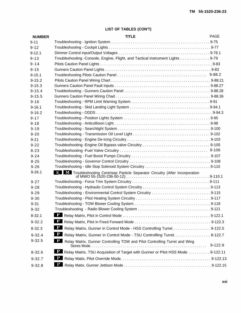
TM 55-1520-236-23
LIST OF TABLES (CON'T)
NUMBER9-119-129-12.19-139-14
9-159-15.19-15.29-15.39-15.49-15.59-169-16.19-16.29-179-189-199-209-219-228-239-248-259-269-26.1
9-279-289-299-309-319-32
8-32.1
9-32.2
8-32.3
9-32.49-32.5
8-32.6
9-32.7
9-32.8
TITLE PAGETroubleshooting - Ignition System. . . . . . . . . . . . . . . . . . . . . . . . . . . . . . . . . . . . . . . . . . . . . . . . 9-75Troubleshooting - Cockpit Lights . . . . . . . . . . . . . . . . . . . . . . . . . . . . . . . . . . . . . . . . . . . . . . . . . 9-77Dimmer Control input/Output Voltages . . . . . . . . . . . . . . . . . . . . . . . . . . . . . . . . . . . . . . . . . . . . 9-78.1Troubleshooting -Console, Engine, Flight, and Tactical instrument Lights . . . . . . . . . . . . . 9-79
Pilots Caution Panel Lights . . . . . . . . . . . . . . . . . . . . . . . . . . . . . . . . . . . . . . . . . . . . . . . . . . . . . . 9-83Gunners Caution Panel Lights . . . . . . . . . . . . . . . . . . . . . . . . . . . . . . . . . . . . . . . . . . . . . . . . . . . 9-83Troubleshooting Pilots Caution Panel . . . . . . . . . . . . . . . . . . . . . . . . . . . . . . . . . . . . . . . . . . . . . 9-88.2
Pilots Caution Panel Wiring Chart . . . . . . . . . . . . . . . . . . . . . . . . . . . . . . . . . . . . . . . . . . . . . . . . 9-88.21Gunners Caution Panel Fault Inputs . . . . . . . . . . . . . . . . . . . . . . . . . . . . . . . . . . . . . . . . . . . . . . 9-88.27Troubleshooting - Gunners Caution Panel . . . . . . . . . . . . . . . . . . . . . . . . . . . . . . . . . . . . . . . . . 9-88.28Gunners Caution Panel Wiring Chad . . . . . . . . . . . . . . . . . . . . . . . . . . . . . . . . . . . . . . . . . . . . . 9-88.36Troubleshooting - RPM Limit Warning System . . . . . . . . . . . . . . . . . . . . . . . . . . . . . . . . . . . . . 9-91Troubleshooting - Skid Landing Light System . . . . . . . . . . . . . . . . . . . . . . . . . . . . . . . . . . . . . . 9-94.1Troubleshooting - ODDS . . . . . . . . . . . . . . . . . . . . . . . . . . . . . . . . . . . . . . . . . . . . . . . . . . . . . . . . 9-94.3Troubleshooting - Position Lights System . . . . . . . . . . . . . . . . . . . . . . . . . . . . . . . . . . . . . . . . . 9-95Troubleshooting - Anticollision Light . . . . . . . . . . . . . . . . . . . . . . . . . . . . . . . . . . . . . . . . . . . . . . 9-98Troubleshooting - Searchlight System . . . . . . . . . . . . . . . . . . . . . . . . . . . . . . . . . . . . . . . . . . . . 9-100Troubleshooting - Transmission Oil Level Light . . . . . . . . . . . . . . . . . . . . . . . . . . . . . . . . . . . . 9-102Troubleshooting - Engine De-Icing Circuitry . . . . . . . . . . . . . . . . . . . . . . . . . . . . . . . . . . . . . . . 9-103Troubleshooting -Engine Oil Bypass valve Circuitry . . . . . . . . . . . . . . . . . . . . . . . . . . . . . . . . 9-105Troubleshooting -Fuel Valve Circuitry . . . . . . . . . . . . . . . . . . . . . . . . . . . . . . . . . . . . . . . . . . . . 9-106
Troubleshooting - Fuel Boost Pumps Circuitry . . . . . . . . . . . . . . . . . . . . . . . . . . . . . . . . . . . . . 9-107Troubleshooting - Governor Control Circuitry . . . . . . . . . . . . . . . . . . . . . . . . . . . . . . . . . . . . . . 9-108Troubleshooting - Idle Stop Solenoid System Circuitry . . . . . . . . . . . . . . . . . . . . . . . . . . . . . . 9-110
Troubleshooting Centrisep Particle Separator Circuitry (After Incorporationof MWO 55-1520-236-50-12). . . . . . . . . . . . . . . . . . . . . . . . . . . . . . . . . . . . . . . 9-110.1
Troubleshooting - Force Trim System Circuitry . . . . . . . . . . . . . . . . . . . . . . . . . . . . . . . . . . . . . 9-111Troubleshooting - Hydraulic Control System Circuitry . . . . . . . . . . . . . . . . . . . . . . . . . . . . . . . . 9-113
Troubleshooting - Environmental Control System Circuitry . . . . . . . . . . . . . . . . . . . . . . . . . . . 9-115Troubleshooting - Pitot Heating System Circuitry . . . . . . . . . . . . . . . . . . . . . . . . . . . . . . . . . . . 9-117Troubleshooting - TOW Blower Cooling System . . . . . . . . . . . . . . . . . . . . . . . . . . . . . . . . . . . . 9-118Troubleshooting - Radio Blower Cooling System . . . . . . . . . . . . . . . . . . . . . . . . . . . . . . . . . . . 9-121
Relay Matrix, Pilot in Control Mode . . . . . . . . . . . . . . . . . . . . . . . . . . . . . . . . . . . . . . . . . . 9-122.1
Relay Matrix, Pilot in Fixed Forward Mode . . . . . . . . . . . . . . . . . . . . . . . . . . . . . . . . . . . . 9-122.3
Relay Matrix, Gunner in Control Mode - HSS Controlling Turret . . . . . . . . . . . . . . . . . 9-122.5
Relay Matrix, Gunner in Control Mode - TSU Controllling Turret. . . . . . . . . . . . . . . . 8-122.7
Relay Matrix, Gunner Controlling TOW and Pilot Controlling Turret and WingStores Mode. . . . . . . . . . . . . . . . . . . . . . . . . . . . . . . . . . . . . . . . . . . . . . . . . . . . . . . . . . . . 9-122.9
Relay Matrix, TSU Acquisition of Target with Gunner or Pilot HSS Mode . . . . . . . . . . 9-122.11
Relay Matix, Pilot Override Mode. . . . . . . . . . . . . . . . . . . . . . . . . . . . . . . . . . . . . . . . . . 9-122.13
Relay Matix, Gunner Jettison Mode . . . . . . . . . . . . . . . . . . . . . . . . . . . . . . . . . . . . . . . . . 9-122.15
xxi

TM 55-1520-236-23
NUMBER
9-32.9
9-33
9-34
9-35
9-36
9-36.1
9-36.29-36.3
9-36.4
9-36.5
9-36.6
9-36.7
9-36.8
9-37
9-38
9-39
9-40
9-41
9-42
9-43
9-4410-111-112-112-213-113-2
16-1
16-2
16-3
F-1
F-2
F-3
F-4
F-5
F-6
xxii
9-122.16
9-143
9-145
9-150
9-152
9-156.19-156.3
9-156.5
9-156.7
9-156.9
9-156.11
9-156.13
9-156.14
9-176
9-177
9-181
9-183
9-207
9-208
9-212
9-214
10-1
11-1
12-6
13-1
13-32
16-13
16-16
16-39
F - 9
F-15
F-19
F-26
F-32
F-39

TM 55-1520-236-23
P R E F A C E
P - 1 . G E N E R A L .
a. This manual is the official document for AviationUnit and Intermediate Maintenance of Army Model AH-1P/E/F Helicopters. Refer to the following for serialnumber effectivity.
1. AH-1P (Production).(Coded )76-22567 through 76-2261076-22692 through 76-2271377-22729 through 77-22762
2. AH-1E (Enhanced Cobra Armament System)
(Code )78-22763 through 78-2281078-23043 through 78-23092
3. AH-1F (Modernized Configuration)(Coded )76-22567 and 76-22600 (Production Prototypes)78-23093 through 78-23125 Selected aircraft-66-15248 through 71-21052. All aircraft-78-All aircraft-78-23093 and subsequent.
b. The purpose of this manual is to familiarize youwith the maintenance functions to be performed atthe Aviation Unit and Intermediate Maintenancelevels. The Table of Contents for this manual isprovided to assist in determining the chapter in themanual in which individual functions are covered.This manual provides all essential information forpersonnel to accomplish Aviation Unit andIntermediate Maintenance on the complete airframe,its components, and systems, excluding armamentand avionics subsystems, as indicated for AviationUnit and Intermediate Maintenance activities in theMaintenance Allocation Chart (MAC). Refer toAppendix B.
c. Designator symbols are used in conjunctionwith text contents, text headings and illustration titlesto show limited affectivity of material. Designatorsymbols may precede a text heading or illustrationtitle to indicate proper affectivity, unless the materialapplies to all series and configurations within themanual. Designator symbols precede proceduralsteps and designated material in the text. If thematerial applies to all series and configurations. nodesignator symbols will be used. Where practical,descriptive information is condensed and combinedfor all models to avoid duplication. Data in thismanual are coded as follows:
(1) AH-1P (Production)
(2) AH-1E (Enhanced Cobra Armament Sys-tem)
(3) AH-1F (Modernized Configuration)
(3.1) AH-1F (Modernized Configurationwith C-NITE)
(4) No Code - All models
(5) B540 Bell HelicopterBlades
Textron Main Rotor
(6) K747 Kaman Aircraft Corporation MainRotor Blades
d. Changes, except as noted below, to the text andtables, including new material on added pages, areindicated by a vertical line in the outer marginextending close to the entire area of the materialaffected. Symbols show current changes only. Aminiature pointing hand symbol is used to denote achange to an illustration. However, a vertical line inthe outer margin, rather than miniature pointinghands, is utilized when there have been extensivechanges made to an illustration. Change symbols arenot utilized to indicate changes in the following:
(1) Introductory material.
(2) Indexes and tabular data where the changecannot be identified.
(3) Blank space resulting from the deletion oftext, an illustration, or a table.
(4) Correction of minor inaccuracies, such asspelling, punctuation, relocation of material, etc.,unless such correction changes the meaning ofinstructive information end procedures.
P - 2 . Q U A L I T Y A S S U R A N C E / Q U A L I T YC O N T R O L ( Q A / Q C ) .
Personnel will assure proper maintenance has beenperformed by verifying dimensions and tolerancescontained throughout this technical manual havebeen complied with.
P - 3 . D E S C R I P T I O N .
A. Fuselage. The helicopter is a two-place assaulttype with a narrow fuselage, single main and tail
P-1

TM 55-1520-236-23
rotors, short wings, and provisions for a variety ofarmament, The forward fuselage is built up on twomain longitudinal beams with lateral bulkheads,floors, shear panels, and decks of honeycomb panelconstruction, forming a box beam. Crewcompartments are arranged in tandem, with the pilotseated behind and above the gunner, and are coveredby a transparent canopy with two doors. Both doorsare sections of the canopy, hinged at top with thegunner door opening at left and the pilot door openingat right side. Both seats are protected by armor onbacks, seats and sides of supports. The compartmentarea is ventilated by forced air from a transmission-drive blower. The short wings provide support fora rmament mount ing py lons and a lso a idmaneuverability by providing lift at higher airspeeds.
b. Tailboom Section. The tailboom section,attached to the forward fuselage by four bolts, is atapered semimonocoque structure with a vertical finslanting up and aft at the rear end to support the tailrotor. Ballast is added to the aft end of tailboom tocontrol helicopter center of gravity limits. Lead shot isadded inside the tailskid on coded helicopters. Tailrotor driveshafts and gearboxes are mounted underrovers along the top of the tailboom and front of thevertical fin. A controllable elevator is also mounted onthe tailboom.
c. Propulsion System. The propulsion systemconsists of a gas turbine engine, main driveshaft,transmission and mast, main rotor, and tail rotor withdriveshafts and gearboxes. The transmission andengine are mounted on the fuselage aft of the crewcompartment and covered by cowling and fairing. Theengine drives the transmission through the maindriveshaft, rototating the mast and main rotor. Poweris also taken off the transmission to drive the tailrotor, which compensates for main rotor torque tocontrol the helicopter heading. Fuel tanks consist oftwo interconnected celIs, located in the fuselage.
d. Flight Controls. Flight controls are directmechanical linkages from sticks and pedals at pilotand gunner stations, assisted by hydraulic cylinderspowered by transmission-driven hydraulic pumps. Astabilization and control augmentation system is alsoincorporated in the control linkage to steady thehelicopter during use of armament.
e. Armament Provisions. Armament provisionsinclude mounting, wiring, and hydraulic lines for anarmament turret under the forward end of thefuselage, an ammunition compartment immediatelyaft of the turret location, sights and control panels at
crew stations, and mounting pylons for externalarmament pods on each wing. Helicopterscoded utilize hydraulically operated armamentturrets. Helicopters code and utilizeelectrically operated armament turrets.
f. Landing Gear. Lending gear is skid type witharched cross tubes attached to the fuselage. Exposedportions of cross tubes are covered by streamlinedfairings to reduce drag. A tail skid is provided to warnthe pilot in the event of a tail-low landing.
P-4. Destruction of Army Material to PreventEnemy Use.
For destruction of Army material to prevent enemyuse, refer to TM 750-244-1-5.
P-5. Maintenance of Forms and Records.
Maintenance of forms, records, and reports which areto be used by maintenance personnel at all mainte-nance levels are listed in and prescribed by DA PAM738-751.
P-6. Authority for Substitution.
Substitution or interchange of items of materiel formaintenance of Department of the Army helicoptershall not be authorized, nor shall orders be issued forshipment. Substitution or interchangeability shall onlybe authorized by US Army Aviation Systems Command(AVSCOM).
P-7. Special Tools and Equipment.
Aviation Unit and Intermediate Maintenance specialtools and equipment will be found in TM 55-1520-236-23P (Repair Parts and Special Tools List). Use ofspecial tools and equipment for complex tasks isdescribed in this manual.
P-8. Calibration.
Equipment requiring calibration shall be indicatedand reference made to publications containing theapplicable procedures.
a. Helicopter components, accessories, andinstruments requiring calibration shall be specified inChapter 1.
b. Special tools and test equipment shall becalibrated as specified in TB 750-25, Army Metrologyand Calibration System.
P-2
TM 55-1520-236-23
P-9. Storage. AVSCOM, ATTN: AMSAV-ME, 4300 Goodfellow Blvd., St.Louis, MO., 63120. Urgent requests shall be clearly iden-
Refer to TM 740-90-1 and Appendix E for Storage of tified to insure priority handling and response. The re-helicopter. quests shall include detailed information on the pro-
blem, e.g., sketches, photographs, dimensional data,P-10. Engineering Authorization. etc., to assist in the evaluation and prompt reply.
All requests for engineering authorization, whenrequired by this manual will be forwarded to USA
P-3/(P-4 blank)

TM 55-1520-236-23
C H A P T E R 1
A I R C R A F T G E N E R A L
SECTION I.
1-1. SERVICING.
1-2. DESCRIPTION – SERVICING.
Servicing information and procedures are presentedby system or components in the following paragraphs.Points used infrequent servicing and replenishment offuels, oil, hydraulic fluid, and other materials are shownin figure 1-1.
1-3. SERVICING – FUEL SYSTEM.
a. The fuel supply tank consists of two cells,located in the fuselage forward and aft of the wings,interconnected by a crossover and vented through acommon outlet line. Each cell has a sump and a fuelpump with drains (figure 1-1) accessible through doorsin the fuselage lower skin. The fuel tank filler cap andstatic ground receptacle serve both tanks.The cap and adapter assembly allows for gravity
refueling. A closed circuit fueling receiver allowsfor dosed port or open port gravity refueling.
b. Total tank capacity for the fuel system is 262Us. gallons, and normal service capacity is 260 Us.gal fens.
Servicing personnel shall comply withall safety precautions and proceduresspecified in FM 10-68, Aircraft Refuelingfield manual.
c. Closed Circuit Refueling (Power Off).
(1) Refer to Figure 1-1 for fuel filter location.
(2) Assure that fire guard is in position withfire extinguisher.
(3) Ground servicing unit to ground stake.
(4) Ground servicing unit to helicopter.
(5) Ground fuel nozzle to ground receptaclelocated adjacent to fuel receptacle on helicopter.
(6) Remove fuel filler cap, and assure thatrefueling module is in locked position (refer to figure1-1.1).
SERVICING
(7) Remove nozzle cap and insert nozzle intofuel receptacle and lock into position.
(6) Activate flow control handle to ON orFLOW position. Fuel flow will automatically shut offwhen fuel cdl is full. Just prior to normal shut off, fuelflow may cycle several times, as maximum fuel levelis reached.
(9) Assure that flow control handle is in OFFor NO FLOW position and remove nozzle.
(10) Replace fuel nozzle cap.
(11) Replace fuel filler cap.
(12) Disconnect fuel nozzle ground.
(13) Disconnect ground from helicopter toservicing unit.
(14) Disconnect servicing unit ground fromground stake.
(15) Return fire extinguisher to designatedlocation.
c.1. Gravity or Open-Port Refueling (Power Off).
(1) Refer to Figure 1-1 for fuel filler location.
(2) Assure that fire guard is in position withfire extinguisher.
(3) Ground servicing unit to ground stake.
(4) Ground servicing unit to helicopter.
(5) Ground fuel nozzle to ground receptaclelocated adjacent to fuel receptacle on helicopter.
(6) Remove fuel filler cap.
(7) Using latch tool, attached to filler capcable open refueling module if equipped with dosedcircuit receptacle (refer to figure 1-1.1).
(8) Remove nozzle cap and insert nozzle intofuel receptacle.
(9) Initiate fuel flow by squeezing trigger gripon nozzle. When using a CCR open-port/gravitynozzle adapter; prior to squeezing trigger grip, actuateflow control handle on CCR nozzle to ON or FLOWposition.
1-1

TM 55-1520-236-23
Figure 1-1. Servicing Points Diagram (Typical)
1-2

TM 55-1520-236-23
(10) Closely monitor fuel quantity; when fuel isat desired level, release trigger grip to shut-off/stopfuel flow. When using a CCR open-portUgravity nozzleadapter, actuate flow control handle to OFF or NOFLOW position. Remove nozzle.
(11) Replace fuel nozzle cap.
(12) Close refueling module by pulling cableuntil latch is in locked position, if equipped with dosedcircuit receptacle (refer to figure 1-1.1).
(13) Replace fuel filler cap.
(14) Disconnect fuel nozzle ground.
(15) Disconnectservicing unit.
(16) Disconnectground stake.
(17) Return firelocation.
ground from helicopter to
servicing unit ground from
extinguisher to designated
c.2. Rapid (Hot) Refueling (Closed Circuit).
(1) Before RAPID Refueling.
(a) Throttle – Idle.
(b) FORCE TRIM Switch – FORCE TRIM.
In case of helicopter fire, observe fireemergency procedures In Chapter 9 ofTM 55-1520-236-10.
(2) During RAPID Refueling. A crewmember,shall observe the refueling operation (performed byauthorized refueling personnel) and stand fire guard asrequired. One crewmember shall remain in the heli-copter to monitor controls. Only emergency radiotransmission should be made during (rapid) refueling.
(3) Refer to figure 1-1 for fuel filler Iocation.
(4) Assure that fire guard is in position withfire extinguisher.
(5) Ground servicing unit to ground stake.
(6) Ground servicing unit to helicopter.
(7) Ground fuel nozzle to ground receptaclelocated adjacent to fuel receptacle on helicopter.
(8) Remove fuel filler cap, end assure that re-fueling module is in dosed position (refer to figure1-1.1.)
(9) Remove nozzle cap and insert nozzle intofuel receptacle and lock into position.
(10) Activate flow control handle to ON orFLOW position. Fuel flow will automatically shut offwhen fuel cell is full. Just prior to normal shutoff, fuelflow may cycle several times, as maximum fuel levelis reached.
(11) Assure that flow control handle is in OFFor NO FLOW position and remove nozzle.
(12) Replace fuel nozzle cap.
(13) Replace fuel filler cap.
(14) Disconnect fuel nozzle ground.
(15) Disconnect ground from helicopter toservicing unit. AFTER RAPID REFUELING. The pilotshall be advised by the refueling crew that fuel cap issecure and grounding cables have been removed.
(16) Disconnect servicing unit ground fromground stake.
(17) Return fire extinguisher to designatedlocation.
c.3. RAPID (HOT) GRAVITY Refueling.
(1) Before RAPID Refueling.
(a) Throttle – Idle.
(b) FORCE TRIM Switch – FORCE TRIM.
In case of helicopter fire, observe fireemergency procedures in Chapter 9 ofTM 55-1520-236-10.
(2) During RAPID Refueling. A crewmember,shall observe the refueling operation (performed byauthorized refueling personnel) and stand fire guard asrequired. One crewmember shall remain in the heli-copter to monitor controls. Only emergency radiotransmission should be made during (rapid) refueling.
(3) Refer to figure 1-1 for fuel filler location.
(4) Assure that fire guard is in position withfire extinguisher.
(5) Ground servicing unit to ground stake.
(6) Ground servicing unit to helicopter.
(7) Ground fuel nozzle to ground receptaclelocated adjacent to fuel receptacle on helicopter.
(8) Remove fuel filler cap.
1-2.1
TM 55-1520-236-23
(9) Using latch tool, attached to filler capcable open refueling module if equipped with dosedcircuit rapid refueling receptacle (refer to figure 1-1.1).
During RAPID GRAVITY Refueling,exercise extreme caution to prevent fuelsplashing from fuel cell or fuel nozzle.Any fuel leakage could be extremelyhazardous If Ingested Into engine airintake.
(10) Remove nozzle cap and insert nozzle intofuel receptacle.
(11) Initiate fuel flow by squeezing trigger gripon nozzle. When using a CCR open-port/gravitynozzle adapter; prior to squeezing trigger grip, actuatefuel control handle on CCR nozzle to ON or FLOWposition.
(12) Closely monitor fuel quantity; when fuel isat desired level, release trigger grip to shut-off/stopfuel flow. When using CCR open-port/gravity nozzleadapter, actuate flow control handle to OFF or NOFLOW position. Remove nozzle. Close refuelingmodule by pulling cable until latch is in locked position,if equipped with dosed circuit receptacle (refer tofigure 1-1.1).
e.
(13) Replace fuel nozzle cap.
(14) Replace fuel filler cap.
(15) Disconnect fuel nozzle ground.
(16) Disconnect ground from helicopter toservicing unit. AFTER RAPID REFUELING. The pilotshall be advised by the refueling crew that fuel cap issecure and grounding cables have been removed.
(17) Disconnect servicing unit ground fromground stake.
(18) Return fire extinguisher to designatedIocation.
d. Defuel ing.
(1) Remove lower section of drain valve fromaft fuel cell.
NOTE
Aft fuel drain valve assembly is a twoplace valve which will automaticallydose valve opening when lower valve isremoved
(2) Install AN815-12D fitting, with flexiblehose installed, in valve assembly in bottom of cell.Valve will open as fitting is being installed.
(3) After defueling, remove AN815-12Dfitting. Install lower section of valve and lockwire(C137).
Fuel Requirements. Fuel requirements forthe engine are listed in table 1-1. A general listing ofacceptable fuels is provided in table 1-2. The fuelsIisted in table 1-2 for each type have nearly identicalcharacteristics. All of the fuels are compatible and maybe mixed in aircraft fuel tanks. The use of fuels shall bein accordance with TB 55-9150-200-25.
Turbine engine fuels, as well asgasoline, form explosive mixturesreadily. To ensure safety of personnel,aircraft handling and filling operationsshall conform to TM 10-1101 and FM10-68.
1-2.2 Change 77
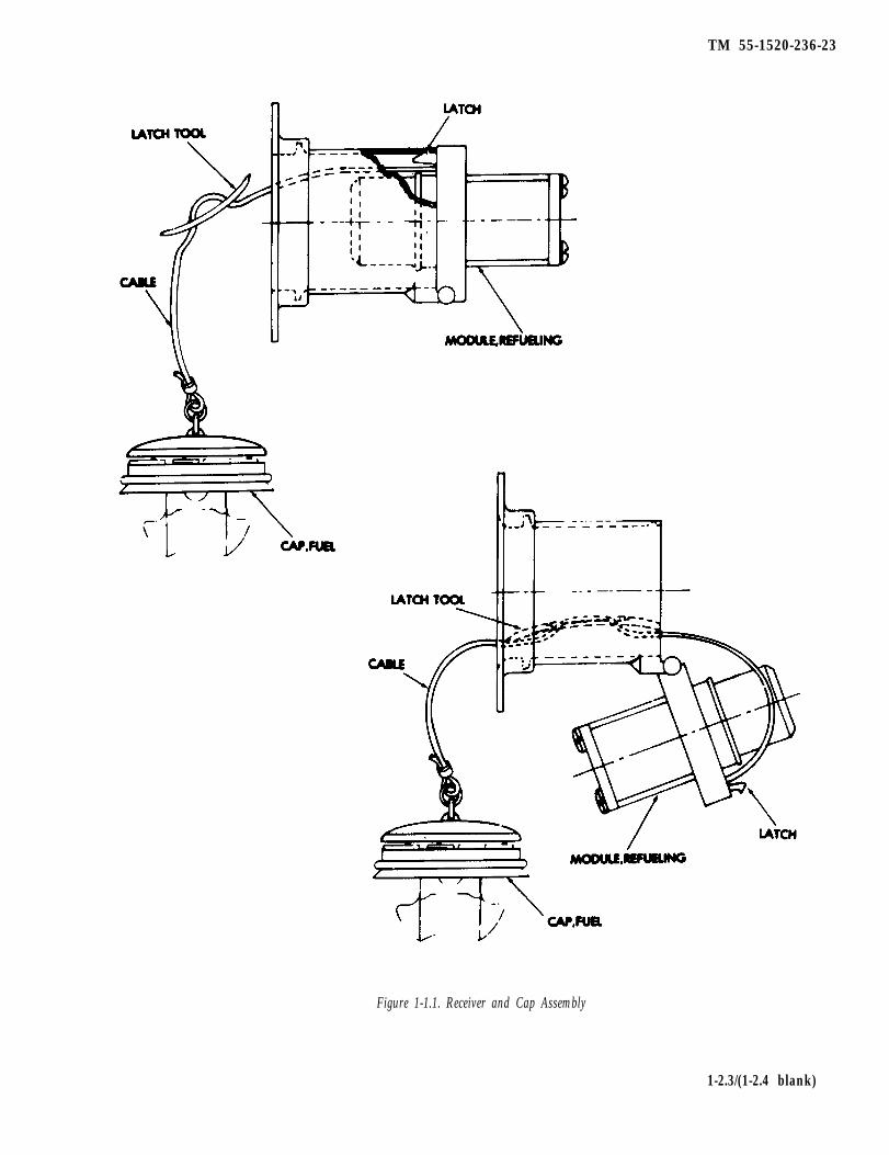
TM 55-1520-236-23
Figure 1-1.1. Receiver and Cap Assembly
1-2.3/(1-2.4 blank)

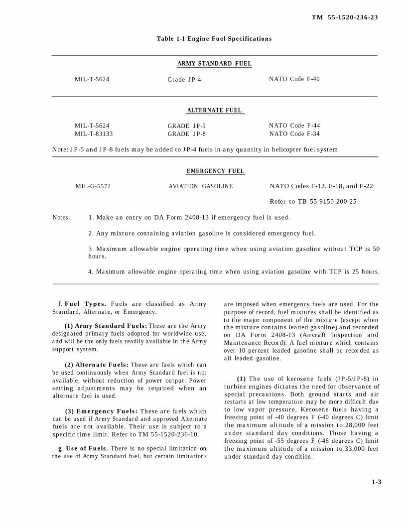
TM 55-1520-236-23
Table 1-1 Engine Fuel Specifications
ARMY STANDARD FUEL
MIL-T-5624 Grade JP-4 NATO Code F-40
ALTERNATE FUEL
MIL-T-5624 GRADE JP-5 NATO Code F-44MIL-T-83133 GRADE JP-8 NATO Code F-34
Note: JP-5 and JP-8 fuels may be added to JP-4 fuels in any quantity in helicopter fuel system
EMERGENCY FUEL
MIL-G-5572 AVIATION GASOLINE NATO Codes F-12, F-18, and F-22
Refer to TB 55-9150-200-25
Notes: 1. Make an entry on DA Form 2408-13 if emergency fuel is used.
2. Any mixture containing aviation gasoline is considered emergency fuel.
3. Maximum allowable engine operating time when using aviation gasoline without TCP is 50hours.
4. Maximum allowable engine operating time when using aviation gasoline with TCP is 25 hours.
f. Fuel Types. Fuels are classified as ArmyStandard, Alternate, or Emergency.
(1) Army Standard Fuels: These are the Armydesignated primary fuels adopted for worldwide use,and will be the only fuels readily available in the Armysupport system.
(2) Alternate Fuels: These are fuels which canbe used continuously when Army Standard fuel is notavailable, without reduction of power output. Powersetting adjustments may be required when analternate fuel is used.
(3) Emergency Fuels: These are fuels whichcan be used if Army Standard and approved Alternatefuels are not available. Their use is subject to aspecific time limit. Refer to TM 55-1520-236-10.
g. Use of Fuels. There is no special limitation onthe use of Army Standard fuel, but certain limitations
are imposed when emergency fuels are used. For thepurpose of record, fuel mixtures shall be identified asto the major component of the mixture (except whenthe mixture contains leaded gasoline) and recordedon DA Form 2408-13 (Aircraft Inspection andMaintenance Record). A fuel mixture which containsover 10 percent leaded gasoline shall be recorded asall leaded gasoline.
(1) The use of kerosene fuels (JP-5/JP-8) inturbine engines dictates the need for observance ofspecial precautions. Both ground starts and airrestarts at low temperature may be more difficult dueto low vapor pressure, Kerosene fuels having afreezing point of -40 degrees F (-40 degrees C) limitthe maximum altitude of a mission to 28,000 feetunder standard day conditions. Those having afreezing point of -55 degrees F (-48 degrees C) limitthe maximum altitude of a mission to 33,000 feetunder standard day condition.
1-3

TM 55-1520-236-23
Table 1-2. Approved Fuels
PRIMARY ORSOURCE STANDARD FUEL ALTERNATE FUEL
US MILITARY FUEL JP-4 (MIL-T-5624) JP-5 (MIL-T-5624) or JP-8 (MIL-T-83133)
NATO CODE NO. F-40 (WIDE CUT TYPE) F-44 or F-34 (High Flash Type)
COMMERCIAL FUEL(ASTM-D-1655)
American Oil Co.Atlantic RichfieldRichfield DivB.P. TradingCaltex Petroleum
Corp.Cities Service Co.Continental Oil Co.Gulf OilEXXON Co., USAMobil OilPhillips PetroleumShell OilSinclairStandard Oil Co.ChevronTexacoUnion Oil
JET B
American JP-4Aerojet B
B.P.A.T.G.
Caltex Jet B
Conoco JP-4Gulf Jet BEXXON Turbo Fuel BMobil Jet BPhiljet JP-4Aeroshell JP-4
Chevron BTexaco Avjet BUnion JP-4
JET A
American Type AAerojet ARichfield A
CITGO AConoco Jet-50Gulf Jet AEXXON AMobil Jet APhiljet A-50Aeroshell 640Superjet AJet A KeroseneChevron A-50Avjet A76 Turbine Fuel
JET A-1NATO F-34
Aerojet A-1Richfield A-1B.P.A.T.K.
Caltex Jet A-1
Conoco Jet-60Gulf Jet A-1EXXON A-1Mobil Jet A-1
Aeroshell 650Superjet A-1Jet A-1 KeroseneChevron A-1Avjet A-1
FOREIGN FUEL
BelgiumCanadaDenmarkFranceGermany (WestGreeceItalyNetherlandsNorwayPortugalTurkeyUnited Kingdom
(Britain)
NATO F-40 JP-5 (NATO F-44 (High flash type))JP-8 (NATO F-34 (High flash type)
BA-PF-2B3GP-22F 3-6P-24eJP-4 MIL-T-5624Air 3407AVTL-9130-006 UTL-9130-007/-TL 9130-010JP-4 MIL-T-5624AA-M-C-1421 AMC-143JP-4 MIL-T-5624 D. Eng RD 2493JP-4 MIL-T-5624JP-4 MIL-T-5624JP-4 MIL-T-5624D. Eng RD 2454 D. Eng RD 2498
NOTEAnti-icing and Biocidal Additive for Commercial Turbine Engine Fuel — The fuel system icing inhibitor shallconform to MIL-I-27686. The additive provides anti-icing protection and also functions as a biocide to killmicrobial growths in helicopter fuel systems. Icing inhibitor conforming to MIL-I-27686 shall be added tocommercial fuel not containing an icing inhibitor during refueling operations regardless of ambienttemperatures. Refueling operations shall be accompanied in accordance with accepted commercialprocedures. This additive (prist or eq.) is not available in the Army Supply System, but will be locallyprocured when needed.
1-4
TM 55-1520-236-23
(2) The use of straight unleaded gasolinemay shorten the operating life of combustor parts;therefore, its use between scheduled internal (hot end)inspections is limited. When the time limit has beenreached, the use of unleaded gasoline must be discon-tinued pending result of internal inspection.
NOTE
Two parts of unleaded gasoline mixedwith one part d kerosene fuel(JP-5/JP-8) produce a fuel which is pre-ferred above straight unleaded gaso-line. In the fueling record this mixtureshould be identified as unleaded gaso-line.
Unleaded gasoline leaves combustorparts dean: therefore, no special clean-ing is required between scheduledinternal (hot end) inspections
(3) Leaded gasoline, either straight or mixedwith other fuels in any proportion, will deposit a layerof lead oxide on combustor parts. The lead oxideattacks the underlying metal and also acts as aninsulator which reduces combustion efficiency andcauses the formation and deposition of carbon.Therefore, the operating time between scheduledinternal (hot end) inspections is limited. If the,permissible accumulated operating time is exceeded,a special cleaning and inspection is mandatory (TM55-2840-229-24).
NOTE
Special cleaning and Inspection maybedelayed for 10 operating hours pro-vialed that only Army Standard fuel isused during the delay.
1-4. SERVICING – ENGINE OIL SYSTEM.
The engine oil tank is located above the engine in theaft fairing. Oil level sight gage and filler cap (figure 1-1)are on front of tank, accessible through doors on pyloncenter fairing. Tank drain valve is accessible throughthe engine compartment, and has an overboard drainline.
a. fill engine oil tank to spill-over for normalservicing. Sight gage is positioned to show low oil level.When oil level is below spill-over level the tank shouldbe filled. Useful capacity of tank is 2.25 U.S. gallons,with expansion space of 1.15 gallons.
b. Before adding oil, determine whether systemcontains oil (C79) or oil (C80). Type of oil used shouldbe shown on DA Form 2408-13. If type oil is not known,comply with paragraph c Maximum oil consumptionfor T53-L703 engine is 0.3 gal./hr. (2.4 US pints). Theoil level sight gage is provided for the purpose of deter-mining a low oil condition. When oil level is at sightgage level, oil supply is 2.75 +0.25 quarts low. Whenservicing oil tank, fill completely to a spill-over condi-tion. The system warning light will come ON and thebypass valve will open when the oil is down 3.8 quartslow from spill-over.
c. Usage of Oils. It is not advisable to mix oil(MIL-L-23699) (C80) and oil (MIL-L-7808) (C79)except when an emergency exists and conditionswarrant. If mixing becomes necessary, the engine oilsystem shall be drained within 6 hours of operationsand refilled with the appropriate oil. (See subpara-graphs (1) and (2) below for oil usage.) If engine oilsystem is to be replenished proceed in accordancewith paragraph 14, step b. When changing from oil(C79) to oil (C80), proceed in accordance withparagraph 1-4, step d (1), steps (a) thru (i). Whenchanging from oil (C80) to oil (C79) proceed in accor-dance with paragraph 1-4, step d (2), steps (a) thru (i).Transmission oil system shall be serviced inaccordance with paragraph 1-5. Gearboxes shall beserviced in accordance with paragraph 1-7.
(1) Oil (C80) used in engine, main trans-mission, and gearboxes oil systems is authorized anddirected for ambient temperatures -25 degrees F andabove.
(2) Oil (C79) used in engine, main trans-mission, and gearboxes oil systems is specified forprolonged operation in ambient temperatures below-25 degrees F. This oil may also be used when oil (C80)is not available.
Under no circumstances shall MIL-L-23699 oil be used at temperatures below-25 degrees F.
d. Procedure for Changing Engine Oils.
(1) When changing from oil (C79) to oil (C60)in engine oil system, accomplish steps below.
(a) Take oil sample.
1-5
TM 55-1520-236-23
(b) Drain oil from system.
(c) Remove, inspect, dean, and reinstall all en-gine oil filters and strainers.
(d) Fill engine oil tank to lip of filler neck with oil(C80). Motor engine to pump oil into cooler and lines.Check tank level and refill. Repeat until level does notchange, indicating the cooler lines are filled.
(e) Operate engine for 30 minutes to 1 hour.Shut down engine.
(f) Remove, inspect, dean, and reinstall all en-gine oil filters and strainers.
1 If oil filter was contaminated, accomplish allsteps below.
2 If oil fitter was not contaminated, omit steps(g) and (h) and accomplish steps (i) through (i) below.
(g) Drain all oil from engine oil system and dis-card oil.
(h) Fill engine oil system with new oil (C80) andrelease helicopter for use.
(i) After 5 hours operation, inspect and dean allengine oil filters and strainers.
(j) After 15 hours operation since oil change, re-move, inspect, and clean all engine oil filters and strainers.
(k) Revert to normal schedule of inspections ofengine oil fitter and strainers.
(2) When changing from oil (C80) to oil (C79) inengine oil system, accomplish the following:
(a)
(b)
(c)
Take oil sample.
Drain oil (C80) from system.
Remove, inspect, clean, and reinstall allengine oil strainers and filters.
(d) Fill engine oil tank with oil (C79); motor en-gine to pump oil into cooler and lines. Check tank level andadd oil. Repeat until tank level does not change, indicatingthat cooler and lines are filled.
(e) Operate engine until oil reaches operatingtemperature. Shut down engine
(f) Remove, inspect, dean, and reinstall all en-gine oil strainers and filter. Release helicopter for serviceuse.
(g) After 5 hours of operation, inspect and deanall engine oil strainers and filter.
(h) After 15 hours of operation since lost oilchange, inspect and dean engine oil strainers and fitter.
(i) Revert to normal interval of inspection for en-gine oil strainers and filter.
1-5. SERVICING — TRANSMISSION OILSYSTEM.
a. The transmission oil supply is contained in thesump case. A double sight glass (figure 1-1) sump can beviewed through a small transparent plastic window in theright-hand pylon cowling door, using a light controlled by apush-button below the door. Before servicing transmissionsump to upper sight glass level, determine whether systemcontaining oil (C79) (C79A) or oil (C80). If unable to deter-mine type of oil used, comply with paragraph 1-4, step c.System capacity is 2.25 US gallons when filled to center ofupper sight glass. When filling is required, open the cowl-ing door for access to the filler cap on the transmissionsupport ease. The sump drain valve is accessible by re-moving an access panel on fuselage below either wing.
b. When changing from oil (C79)(C79C) to oil (C80)or from oil (C80) to oil (C79)(C79C) accomplish the follow-ing steps:
(1) Take oil sample
(2) Drain oil.
(3) Remove external fitter element and inspect forcontamination. Install new filter element.
(4) Remove, inspect, dean, and reinstall primaryoil filter.
(5) Refill with appropriate oil (paragraph 1-4).
1-6

TM 55-1520-236-23
1-6. SERVICING—MAIN AND TAILROTOR SYSTEMS.
Main and tail rotor systems require no normal servicing.Lubrication requirements are covered in paragraph 1-28.
1-7. INTERMEDIATE AND TAIL ROTORDRIVE GEARBOXES.
The intermediate gearbox is under a removable cover,located between driveshaft covers of tailboom and verti-cal fin. An oil level sight glass figure 1-1, a chip detector,and drain plug, are on the right side of the gearbox; avented filler cap is on the topside of the gearbox. The tailrotor drive gearbox is covered by two removable fairingsnear upper end of the vertical fin. An oil level sight glass(2) is provided on lower left side, a chip detector and drainplug at bottom, an a vented filler cap on the aft side of thegearbox.
a. Before servicing either gearbox to indicated sightglass level with lubricating oil, determine whether sys-tem contains oil (C79)(C79A) or oil (C80). If unable todetermine type of oil used, refer to paragraph, 1-4.
b. When changing from oil (C79)(C79A) to oil(C80) or from oil (C80) to oil (C79)(C79A) accomplishthe following steps:
(1) Take oil sample.
(2) Drain oil.
(3) Perform normal inspection.
(4) Refill with appropriate oil (paragraph 1-4).
1-8. SERVICING-HYDRAULIC RESER-VOIRS.
Reservoirs (figure 1-1) for hydraulic systems No. 1 andNo. 2 are located in a compartment just aft of thecanopy. Access doors are provided at both sides of thefuselage. Fluid level sight glasses on both reservoirs arevisible through left side door. Each reservoir has a tillercap accessible from nearest door. The reservoir for theelectrical emergency hydraulic system is located behinda panel on the fuselage below the right wing. For sys-tems serviced with fire resistant hydraulic fluid, refer toTB 55-1500-334-25.
When handling hydraulic fluid (MIL-H-83282), Table 1-3,Item 61, observe the following:
—Prolonged contact with liquid or mist can irritate eyesand skin.
—After any prolonged contact with skin, immediatelywash contacted area with soap and water. If liquid contacts eyes, flush them immediately with clear water.
—If liquid is swallowed, do not induce vomiting; getimmediate medical attention.
—Wear rubber gloves when handling liquid. If prolonged contact with mist is likely, wear an appropriaterespirator.
—When fluid is decomposed by heating toxic gasesare released.
a. Open access doors and remove panel to gainaccess to hydraulic reservoirs.
To avoid contamination, a sealed canof fluid must be opened and used. Donot use previously opened cans ofhydraulic fluid.
b.C62).
Service reservoirs with hydraulic fluid (C61 or
c. Close access door or reinstall panel.
1-9. SERVICING—GROUND HANDLINGGEAR.
a. Lubricate assemblies with grease (C58) throughfittings on wheels, actuating arms, and cradles as frequent-ly as operating conditions warrant.
b. Repair tires and tubes in accordance with TM 552620-200-24. Inflate with compressed air to 75 psi.
1-7

TM 55-1520-236-23
c. Check and fill hydraulic pump as required.
(1) Hold handling gear assembly so that pump isvertical with filler hole at upper end. Remove screw fromfiller hole.
(2) Fill pump to filler hole level with hydraulicfluid (C62). Reinstall screw in filler hole.
1-10. SERVICING-BATTERY.
● Corrosive Battery Electrolyte (PotassiumHydroxide). Wear robber gloves, apronand face shield when handling leakingbatteries. If potassium hydroxide isspilled on clothing, or other material,wash immediately with clean water. Ifspilled on personnel, immediately startflushing the affected area with cleanwater. Continue washing until medicalassistance arrives.
● Battery failure and explosions may becaused by an excess of electrolyte in thecells. The specific gravity of a nickel-cadmium battery remains constant whenthe battery is in either a charged or dis-charged condition, consequently thestate of charge cannot be determined bya test of the electrolyte. Neither can thestate of charge be determined by a volt-age test, due to the fact that the voltageremains constant over 90 percent of thedischarge time. Since the state of chargecannot be determined by a check ofeither voltage or the electrolyte, thecharging input to a completely dis-charged battery must be monitored inboth current and time until the amperehour capacity of the battery has beenreached.
The nickel-cadmium battery is mounted in BATTERYcompartment. The battery is a 24 volt 22 ampere-hour bat-tery unit. It is connected to the helicopter electrical systemthrough a relay which is controlled by the battery switchon the pilot console. Two overflow, or vent tubes extendfrom the battery to the outside of the fuselage. Access tothe battery is gained through a door in the helicopter bat-tery compartment. The battery shall be removed from thehelicopter at 100 hour intervals or 120
calendar day inspection, whichever comes first, and sent tothe Battery Shop for inspection, repair, charging capacitytest, and adjustment of electrolyte level. For additional ser-vicing instructions refer to TM 11-6140-203-15-2.
1-11. CLEANING OF HELICOPTER.
1-12. DESCRIPTION—CLEANING OFHELICOPTER
Cleaning procedures and information are presented in thefollowing paragraphs. Helicopter must be grounded priorto any cleaning maintenance, disassembly, or preservation.See TM 55-1500-344-23 for additional cleaning informa-tion.
To preclude damage to bonded panels,solvents and water are to be applied atthe minimum pressure required tomaintain a constant flow suitable forwashing and rinsing. Steam is not to beutilized.
NOTE
Additional cleaning procedures arecovered in this manual under individ-ual components.
1-13. CLEANING-INTERIOR.
Clean the interior of the helicopter to prevent debris fromfalling into operating mechanisms. If the seats and cush-ions need cleaning, use mild soap (C113) and water. Toremove grease or oil spots use cleaning compound (C133).Wipe dry with a clean cloth. Finally, thoroughly clean thehelicopter with a vacuum cleaner.
1-14. CLEANING-EXTERIOR
Exercise extreme caution when cleaning theSU-130 Laser Detection sensor units.
Clean the exterior structure by applying a mixture of onepart cleaning compound (C33) and three to seven partswater. Use the stronger mixtures for exhaust outlet areasand other very dirty surfaces. Wash a small area at a timemaking sure to rinse thoroughly with water under pressure.If allowed to dry or if not completely rinsed off, streakingwill occur.
1-8

TM 55-1520-236-23
1-15. CLEANING – ACRYLIC PLASTIC.
Do not use compounds other than thosespecified. Avoid excessive scrubbing ofplastic panels during washing operation.
a. Clean all transparent acrylic plastic withcleaning compound (C33) mixed with three to sevenparts of water.
b. Gently free all caked mud or dirt with fingers.Do not use sponges or coarse cloths. Rinse the areacontinuously while removing the mud.
1-8.1/(1-8.2 blank)

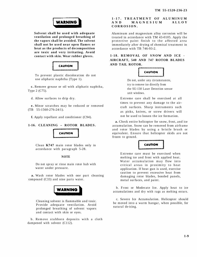
TM 55-1520-236-23
Solvent shall be used with adequateventilation and prolonged breathing ofthe vapors shall be avoided. The solventshall not be used near open flames orheat as the products of decompositionare toxic and very irritating. Avoidcontact with skin. Wear rubber gloves.
To prevent plastic discoloration do notuse aliphatic naphtha (Type 1).
c. Remove grease or oil with aliphatic naphtha,Type 2 (C75).
d. Allow surfaces to drip dry.
e. Minor scratches may be reduced or removed(TB 55-1560-276-24/1).
f. Apply repellant and conditioner (C94).
1-16. CLEANING – ROTOR BLADES.
Clean K747 main rotor blades only inaccordance with paragraph 5-28.
NOTE
Do not spray or rinse main rotor hub withwater under pressure.
a. Wash rotor blades with one part cleaningcompound (C33) and nine parts water.
1 - 1 7 . T R E A T M E N T O F A L U M I N U MA N D M A G N E S I U M A L L O YCORROSION.
Aluminum and magnesium alloy corrosion will betreated in accordance with TM 43-0105. Apply theprotective paint finish to the affected areaimmediately after drying of chemical treatment inaccordance with TB 746-93-2.
1-18. REMOVAL OF SNOW AND ICE -AIRCRAFT, 540 AND 747 ROTOR BLADESAND TAIL ROTOR.
Do not, under any circumstances,try to remove ice directly fromthe SU-130 Laser Detection sensorunit windows.
Extreme care shall be exercised at alltimes to prevent any damage to the air-craft surfaces. Sharp instruments suchas picks, knives, or screw drivers willnot be used to loosen the ice formation.
a. Check entire helicopter for snow, frost, and iceaccumulation. Snow can be removed from airframeand rotor blades by using a bristle brush orequivalent. Ensure that helicopter skids are notfrozen to ground.
Extreme care must be exercised whenmelting ice and frost with applied heat.Water accumulation may flow intocritical areas in proximity to heatapplication. If heat gun is used, exercisecaution to prevent excessive heat fromdamaging rotor blades, bonded panels,metal surfaces, and paint.
b. Frost or Moderate Ice. Apply heat to iceaccumulations and dry with rags as melting occurs.
Cleaning solvent is flammable and toxic.Provide adequate ventilation. Avoidprolonged breathing of solvent vaporsand contact with skin or eyes.
c. Severe Ice Accumulation. Helicopter shouldbe moved into a warm hangar, when possible, fornatural de-icing.
b. Remove stubborn deposits with a clothdampened with solvent (C112).
1-9
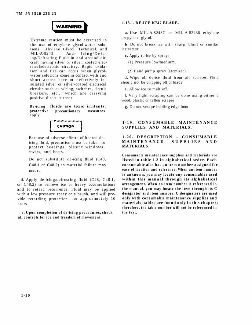
TM 55-1520-236-23
Extreme caution must be exercised inthe use of ethylene glycol-water solu-tions, Ethylene Glycol, Technical, andMIL-A-8243 Anti- I c i n g / D e i c -ing/Defrosting Fluid in and around air.craft having silver or silver. coated elec-trical/electronic circuitry. Rapid oxida-tion and fire can occur when glycol-water solutions come in contact with andshort across bare or defectively in-sulated silver or silver-coated electricalcircuits such as wiring, switches, circuitbreakers, etc., which are carryingpositive direct current.
De-icing fluids are toxic irritants;protective precautionary measuresapply.
Because of adverse effects of heated de-icing fluid, precaution must be taken toprotect bearings, plastic windows,covers, and boots.
Do not substitute de-icing fluid (C48,C48.1 or C48.2) as material failure mayoccur.
d. Apply de-icing/defrosting fluid (C48, C48.1,or C48.2) to remove ice or heavy occumulationsand to retard recurrence. Fluid may be appliedwith a low pressure spray or a brush, and will pro-vide retarding protection for approximately 10hours.
e. Upon completion of de-icing procedures, checkall controls for ice and freedom of movement.
1-18.1. DE-ICE K747 BLADE.
a. Use MIL-A-8243C or MIL-A-82438 ethylenepropylene glycol.
b. Do not break ice with sharp, blunt or similarinstrument.
c. Apply to ice by spray:
(1) Pressure low/medium.
(2) Hand pump spray (atomizer).
d. Wipe off de-ice fluid from allshould not be dripping off of blade.
e. Allow ice to melt off.
surfaces. Fluid
f. Very light scraping can be done using either awood, plastic or teflon scraper.
g. Do not scrape leading edge boot.
1-19. CONSUMABLE MAINTENANCESUPPLIES AND MATERIALS.
1-20. DESCRIPTION – CONSUMABLEM A I N T E N A N C E S U P P L I E S A N DMATERIALS.
Consumable maintenance supplies and materials arelisted in table 1-3 in alphabetical order. Eachconsumable also has an item number assigned forease of location and reference. When an item numberis unknown, you may locate any consumables usedwithin this manual through its alphabeticalarrangement. When an item number is referenced inthe manual. you may locate the item through its Cdesignator and item number. C designators are usedonly with consumable maintenance supplies andmaterials; tables are found only in this chapter;therefore, the table number will not be referenced inthe text.
1-10

TM 55-1520-236-23
Table 1-3. Consumable Maintenance Supplies and Materials
The supplies and material listed in this table are required for maintenance supportof this equipment and are authorized to be requisitioned by Common Table ofAllowances (CTA) 50-970.
ITEM DESCRIPTION/ REFERENCE NUMBERNo. NOMENCLATURE AND FSCM NSN
01
1
2
3
4
4.1
4.2
5
6
7
8
Abrasive Pads, Nylon Web,Scotch-Brite, Type A, VeryFine, L-P-50, Type 1, Class 1,Size 1
Acid, Chromic, Type II
Acid, Hydrochloric (Muriatic)
Acid Nitric
Adhesive, EA9330
Adhesive, EA956
Adhesive Promoter, A934BX
Adhesive, A-6 with Activator A
Adhesive, EC-776
Adhesive, EC2216-BAScotchweld
Adhesive, Metalset A-4
81348
O-C-303
O-H-765
O-N-350
(33564)
(33564)
(03461)
A6 (98911)
MMM-A-122
(94960)
MMM-A-1754
7920-00-659-9175
6810-00-264-6517
6810-00-222-9641
6810-00-237-2918
8040-01-089-9073
8040-01-104-5388
8040-00-152-0075
8040-00-691-1322
8040-00-664-0439
8040-00-145-0019
8040-00-944-7292
1-10.1/(1-10.2 blank)


TM 55-1520-236-23
Table 1-3. Consumable Maintenance Supplies and Materials (Cont)
ITEM DESCRIPTION/ REFERENCE NUMBERNO. NOMENCLATURE AND FSCM NSN
8.1
9
9.1
10
11
12
12.1
13
13.1
14
15
15.1
16
17
17.1
18
18.1
19
20
21
22
23
Deleted
Adhesive
Accelerator
Adhesive, PS-30
Adhesive, RTU 106, Type I
Adhesive, Rubber Base, EC2126
Adhesive, Ethyl-2-Versamid 125
Adhesive, Silicone Rubber
Adhesive Mixture,Epon 826Versamid 125Diethylenetriamine (DTA)
Adhesive, Two PartEA934NA
Adhesive, EA9309. 3NA
Adhesive, EA9320
Adhesive, Two-PartLiquid Silicone
Adhesive, Uralane (Part Aand B) EC3549, Type I
Adhesive
Alcohol, Methyl
Anodic, Black
Deleted
Use C74.1
Antiseize Compound
Barrier Material,Grease-Proofed
Barrier Material,Waterproof, Vaporproof
FA956A/B, Type II, Class 3,(33564)
Accelerator No. 5
(77902)
(01139)
MMM-A-1617
MIL-A-46050Type 2, Class 3
MIL-A-46146
(86961)(11884)(79741)
MMM-A-132, Type I,Class 3 (33564)
299-947-125Type I (33564)
299-947-125, Type II,Class 2 (33564)
SR529 and SRC18(01139)
(04963)
Versilok 204
O-M-232F
MIL-A-8625, Type H
MIL-A-907
MIL-B-121, Grade A
MIL-B-131 , Class 1
8040-01-126-6271
8040-01-174-4684
8040-01-152-2312
8040-00-843-0802
8040-00-281-1977
8040-01-140-0954
8040-00-224-4655
8030-00-144-96588030-00-893-42248040-01-194-3933
8040-00-016-8662
8040-01-163-3481
8040-01-043-5423
8040-00-097-6524
8040-01-016-4726
8040-01-184-1704
6810-00-275-6010
8030-00-597-5367
8135-00-224-8885
8135-00-282-0565
1-11

TM 55-1520-236-23
Table 1-3. Consumable Maintenance Supplies and Materials (Cont)
ITEM DESCRIPTION/ REFERENCE NUMBERNO. NOMENCLATURE AND FSCM NSN
23.1
23.2
24
25
26
27
28
28.1
29
30
30.1
31
31.1
32
33
34
35
35.1
36
36.1
37
Bottle, Screw Cap, 16 oz.
Bottle, Screw Cap, 32 oz.
Bungee Cord, Type I
Deleted
Cap, Protective
Cellophane
Cement (EC1357)
Cement Proseal 584
Cement, 3230
Cheesecloth
Chemical FilmAlodine No. 1201
Chemical Film,Alodine No. 1200S
Cleaner, Engine, B andB 3100
Cleaning and PolishingCompound, Biodegradable
Cleaning Compound, Air-craft Surface, Alkaline,Waterbase
Cleaning Compound, Alumi-num Nonflame Sustaining
Cleaning Compound, OilCooler Solvent
Cleaning Cloth, Type III
Cloth, Abrasive
Cloth, Screen, Abrasive
Cloth, Crocus
MIL-C-5651
NAS816-158
L-C-110
MMM-A-121 (76381)
(83527)
MIL-A-9117 (89373)
CCC-C-440 (81348)
MIL-C-81706Class 1-A, Form III
MIL-C-81706 (84563)
MIL-C-85704 (21361)
P-P-560
MIL-C-25769
MIL-C-5410
MIL-C-6864
MIL-C-85043
P-C-451
3-738-7011-0 (27712)
P-C-458
6640-00-404-0660
6640-00-404-0661
8305-00-267-3119
5340-00-815-0890
8135-00-392-8971
8040-00-165-8614
8040-00-964-6757
8040-00-262-9060
8305-00-267-3015
8030-00-613-3131
8030-00-057-2354
6850-00-181-7594
7930-00-634-5340
6850-00-935-0995
6850-00-282-6770
6850-00-551-3694
7920-00-044-9281
5350-00-192-5050
5350-00-221-0872
1-12
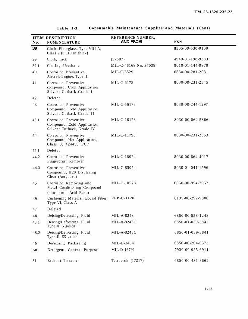
TM 55-1520-236-23
Table 1-3. Consumable Maintenance Supplies and Materials (Cont)
ITEM DESCRIPTION REFERENCE NUMBER,No. NOMENCLATURE NSN
8505-00-530-0109
39
39.1
40
41
42
43
43.1
44
44.1
44.2
44.3
45
46
47
48
48.1
48.2
46
50
51
Cloth, Fiberglass, Type VIII A,Class 2 (0.010 in thick)
Cloth, Tack
Coating, Urethane
Corrosion Preventive,Aircraft Engine, Type III
Corrosion Preventivecompound, Cold ApplicationSolvent Cutback Grade 1
Deleted
Corrosion PreventiveCompound, Cold ApplicationSolvent Cutback Grade 11
Corrosion PreventiveCompound, Cold ApplicationSolvent Cutback, Grade IV
Corrosion PreventiveCompound, Hot Application,Class 3, 424450 PC7
Deleted
Corrosion PreventiveFingerprint Remover
Corrosion PreventiveCompound, H20 DisplacingClear (Amguard)
Corrosion Removing andMetal Conditioning Compound(phosphoric Acid Base)Cushioning Material, Bound Fiber,Type VI, Class A
Deleted
Deicing/Defrosting Fluid
Deicing/Defrosting FluidType II, 5 gallon
Deicing/Defrosting FluidType II, 55 gallon
Desiccant, Packaging
Detergent, General Purpose
Etchant Tetraetch
(57687) 4940-01-198-9333
MIL-C-46168 No. 37038 8010-01-144-9879
MIL-C-6529 6850-00-281-2031
MIL-C-6173 8030-00-231-2345
MIL-C-16173
MIL-C-16173
MIL-C-11796
MIL-C-15074
MIL-C-85054
MIL-C-10578
PPP-C-1120
MIL-A-8243
MIL-A-8243C
MIL-A-8243C
MIL-D-3464
MIL-D-16791
Tetraetch (17217)
6850-00-558-1248
6850-01-039-3842
6850-01-039-3841
6850-00-264-6573
7930-00-985-6911
6850-00-431-8662
8030-00-244-1297
8030-00-062-5866
8030-00-231-2353
8030-00-664-4017
8030-01-041-1596
6850-00-854-7952
8135-00-292-9800
1-13

TM 55-1520-236-23
Table 1-3. Consumable Maintenance Supplies and Materials (Cont)
ITEM DESCRIPTION/ REFERENCE NUMBER,NO. NOMENCLATURE AND FSCM NSN
52
53
53.1
53.2
53.3
54
55
56
57
58
58.1
59
60
61
62
63
63.1
64
65
66
67
Deleted
Fabric, Synthetic, 5066
Filler, Urethane Compound
Film, Teflon, Unperforated0.002 inch
Felt, Sheet 0.062 inchThick, Hard Rabbit Fur
Gloves, White Cotton
Grease, AircraftOscillating Bearing
Grease, Extreme Pressure(Tube Pack)
Grease (Lubriplate)
Grease, Acft Multipurpose
Grease, Aircraft.Multi-Purpose
Grease Silicons, DowCorning II, or Equiv
Grease, Ball and Roller
Hydraulic Fluid FirsResistant
Hydraulic Fluid Petro-leum Base
Hydraulic Fluid, Preser-vative, Petroleum Base
Insulating Compound
Isopropyl Alcohol
Deleted
Lacquer, Camouflage Gray,36231
Lacquer, Acrylic, LowReflective, Aircraft Green
(89616) 9320-00-949-8363
RP3265 (DC182-72)
E3760-P2 Richmond Corp.,Highland, CA
CF206(81348)
MIL-G-3866
MIL-G-25537
204-040-755-5 (97499) or(ASN TECH 3913-GI)
Aerolubriplate (73219)
MIL-G-81322
MIL-G-8132214 oz. Cartridge
8490010
DC33 Fluid (71984)ASUM 100 (78510)
MIL-H-83282
MIL-H-5606
MIL-H-6083Type 1
MIL-I-46058, Type UR
TT-I-735
TT-L-20
MIL-L-46159, Type I
9150-00-935-9807
6810-00-855-6160
8010-00-515-1568
8010-01-042-9438
8305-00-262-1672
8415-00-268-8353
9150-00-478-0055
9150-00-506-8497
9150-00-068-6268
9150-00-944-8953
9150-01-262-3358
9150-00-616-9212
9150-00-823-8048
9150-00-149-7431
9150-00-180-6181
1-14
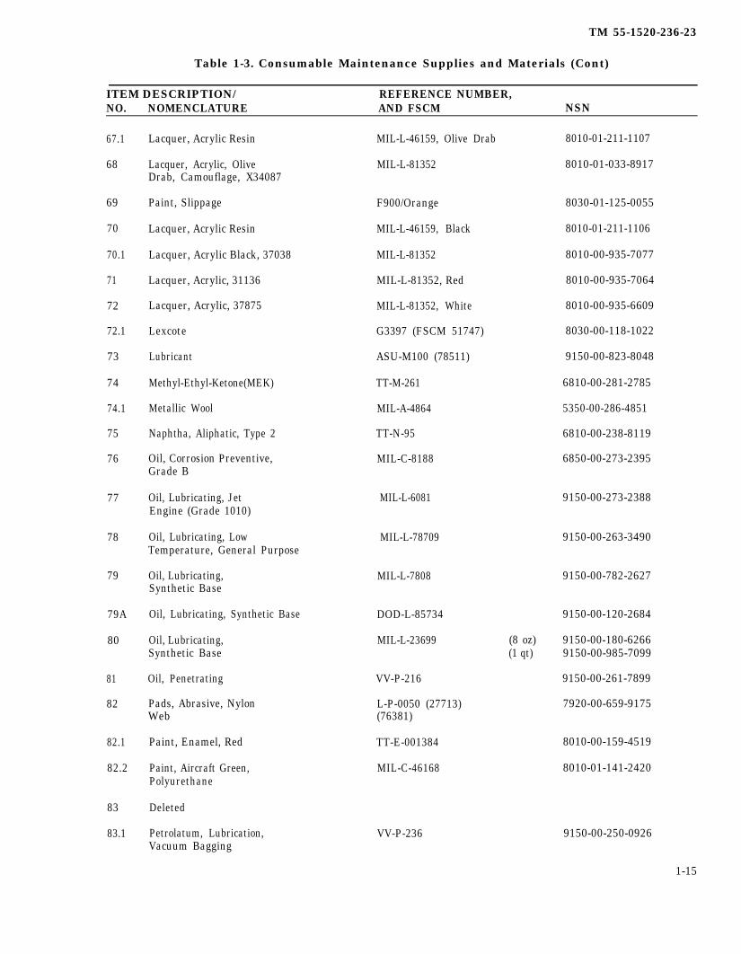
TM 55-1520-236-23
Table 1-3. Consumable Maintenance Supplies and Materials (Cont)
ITEM DESCRIPTION/ REFERENCE NUMBER,NO. NOMENCLATURE AND FSCM NSN
67.1
68
69
70
70.1
71
72
72.1
73
74
74.1
75
76
77
78
79
79A
80
81
82
82.1
82.2
83
83.1
Lacquer, Acrylic Resin
Lacquer, Acrylic, OliveDrab, Camouflage, X34087
Paint, Slippage
Lacquer, Acrylic Resin
Lacquer, Acrylic Black, 37038
Lacquer, Acrylic, 31136
Lacquer, Acrylic, 37875
Lexcote
Lubricant
Methyl-Ethyl-Ketone(MEK)
Metallic Wool
Naphtha, Aliphatic, Type 2
Oil, Corrosion Preventive,Grade B
Oil, Lubricating, JetEngine (Grade 1010)
Oil, Lubricating, LowTemperature, General Purpose
Oil, Lubricating,Synthetic Base
Oil, Lubricating, Synthetic Base
Oil, Lubricating,Synthetic Base
Oil, Penetrating
Pads, Abrasive, NylonWeb
Paint, Enamel, Red
Paint, Aircraft Green,Polyurethane
Deleted
Petrolatum, Lubrication,Vacuum Bagging
MIL-L-46159, Olive Drab
MIL-L-81352
F900/Orange
MIL-L-46159, Black
MIL-L-81352
MIL-L-81352, Red
MIL-L-81352, White
G3397 (FSCM 51747)
ASU-M100 (78511)
TT-M-261
MIL-A-4864
TT-N-95
MIL-C-8188
MIL-L-6081
MIL-L-78709
MIL-L-7808
DOD-L-85734
MIL-L-23699
VV-P-216
L-P-0050 (27713)(76381)
TT-E-001384
MIL-C-46168
VV-P-236
8010-01-211-1107
8010-01-033-8917
8030-01-125-0055
8010-01-211-1106
8010-00-935-7077
8010-00-935-7064
8010-00-935-6609
8030-00-118-1022
9150-00-823-8048
6810-00-281-2785
5350-00-286-4851
6810-00-238-8119
6850-00-273-2395
9150-00-273-2388
9150-00-263-3490
9150-00-782-2627
9150-00-120-2684
(8 oz) 9150-00-180-6266(1 qt) 9150-00-985-7099
9150-00-261-7899
7920-00-659-9175
8010-00-159-4519
8010-01-141-2420
9150-00-250-0926
1-15

TM 55-1520-236-23
Table 1-3. Consumable Maintenance Supplies and Materials (Cont)
ITEM DESCRIPTION/ REFERENCE NUMBER,NO. NOMENCLATURE AND FSCM NSN
84
85
86
86.1
86.2
86.3
87
88
89
90
91
91.1
92
93
94
95
96
97
97.1
98
99
100
1-16
Pigment, Aluminized
Plastilube, Moly No. 3
TT-P-320 8010-00-687-4019
9150-00-141-4481Plastilube Moly 3(02307)
Deleted
8010-00-482-5671Polyurethane, ColorBlack, 37038
MIL-C-83286
Potting Resin Uralite#3148A/B
(01490)
8010-01-146-2646Polyurethane CoatingBlack 37038
MIL-C-46168
Primer, A934B A934B (03481)
MIL-P-23377
SS4004 (01139)
8040-00-943-2502
8010-00-082-2450
8010-00-701-9616
Primer, Epoxy Polyamide
Primer, Silicone Adhesive,1200RTV
Primer, Silicone Adhesive,S-2260
(02988) 8040-00-712-9058
Primer, Zinc Chromate TT-P-1757, MIL-P-8585
TT-P-1757, MIL-P-23377
MIL-P-30501
8010-00-297-0593
Zinc, Chromate 8010-00-145-0312
8010-00-281-4105Prussian Blue Paste,Bearing Surface (thinnedwith oil)
Putty, Zinc Chromate MIL-P-8116
MIL-W-006882
TT-R-248B
MIL-R-81294
8030-00-664-4968
6850-00-139-5297
8010-00-515-2258
8010-00-926-1488
Rain Repellent Windshield
Remover, Paint
Remover, Paint, EpoxySystem
205-706-083-1(97499)
1560-00-103-3459Repair Kit, InfraredSuppression System
K747-207-1 (84955) 1560-01-161-2805Repair Kit, Erosion
MIL-R-9000O-D-1271
8040-00-822-64306810-00-995-4804
Resin Epoxy, LiquidEA828 and CatalystDiethylenetramine (DTA)
Deleted
Rubber, Silicone, RTV (71984) 8030-00-903-6566
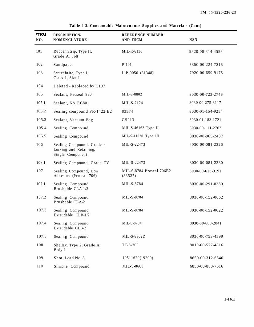
TM 55-1520-236-23
Table 1-3. Consumable Maintenance Supplies and Materials (Cont)
DESCRIUPTION/ REFERENCE NUMBER.NO. NOMENCLATURE AND FSCM NSN
101
102
103
104
105
105.1
105.2
105.3
105.4
105.5
106
106.1
107
107.1
107.2
107.3
107.4
107.5
108
109
110
Rubber Strip, Type II,Grade A, Soft
Sandpaper
Scotchbrite, Type I,Class 1, Size I
Deleted - Replaced by C107
Sealant, Proseal 890
Sealant, No. EC801
Sealing compound PR-1422 B2
Sealant, Vacuum Bag
Sealing Compound
Sealing Compound
Sealing Compound, Grade 4Locking and Retaining,Single Component
Sealing Compound, Grade CV
Sealing Compound, LowAdhesion (Proseal 706)
Sealing CompoundBrushable CLA-1/2
Sealing CompoundBrushable CLA-2
Sealing CompoundExtrudable CLB-1/2
Sealing CompoundExtrudable CLB-2
Sealing Compound
Shellac, Type 2, Grade A,Body 1
Shot, Lead No. 8
Silicone Compound
MIL-R-6130 9320-00-814-4583
P-101 5350-00-224-7215
L-P-0050 (81348) 7920-00-659-9175
MIL-S-8802
MIL-S-7124
83574
GS213
MIL-S-46163 Type II
MIL-S-11030 Type III
MIL-S-22473
MIL-S-22473
MIL-S-8784 Proseal 706B2(83527)
MIL-S-8784
MIL-S-8784
MIL-S-8784
MIL-S-8784
MIL-S-8802D
TT-S-300
10511620(19200)
MIL-S-8660
8030-00-723-2746
8030-00-275-8117
8030-01-154-9254
8030-01-183-1721
8030-00-111-2763
8030-00-965-2437
8030-00-081-2326
8030-00-081-2330
8030-00-616-9191
8030-00-291-8380
8030-00-152-0062
8030-00-152-0022
8030-00-680-2041
8030-00-753-4599
8010-00-577-4816
8650-00-312-6640
6850-00-880-7616
1-16.1

TM 55-1520-236-23
Table 1-3. Consumable Maintenance Supplies and Materials (Cont)
ITEM DESCRIPTION/ REFERENCE NUMBER,No. NOMENCLATURE AND FSCM NSN
111 Smoother, Aerodynamic, EA960A-B 8010-00-006-7089Type I, RP-1257-3
112 Solvent, Dry Cleaning P-D-680, Type II (81348) 6850-00-274-5421
113 Soap, Liquid (Detergent) P-S-624 8520-00-228-0598
1-16.2

TM 55-1520-236-23
Table 1-3. Consumable Maintenance Supplies and Materials (Cont)
ITEM DESCRIPTION/ REFERENCE NUMBER,NO. NOMENCLATURE AND FSCM NSN
114
115
116
117
118
118.1
118.2
119
120
121
122
123
124
125
126
127
128
128.1
129
129.1
Soap, Toilet, Cake
Steel Wool
Stone, India, Pine
Talc , Technical
Tap, Ant ichafe Tef lon
Tape, Nylon, Wright Lon
Sealing Compound
Deleted
Tape, Dissimilar MetalSeparation
Tape , Electr i ca l , Black
Tape, Insulation SpiralWrap (0.006 x 1.0 inch)
Tape, Masking
Tape, Mystic, 7455
Tape, Pressure Sensitive
8520-00-531-6484
FF-W-1825 5350-00-250-2920
SSS736 5345-00-144-6894
6810-01-080-9589
5490 (76381) 7510-00-923-0591
Internat ional P last i csProducts, Carson, CA
MIL-S-22473 8030-00-081-2326
MIL-T-23142
MIL-I-24391
MIL-I-18746
PPP-T-42
(83301)
Y9265A (76381)
Tape, Fastener Hook, Velcro MIL-L-21840 (83149)
Tape, Pressure Sensitive, PPP-T-60Waterproof, Type II
Tape, Teflon, Self-Adhesive MIL-I-23594
Tape, Multi-Purpose Double- (99742)faced Cloth P50
Thinner, Acrylic Lacquer MIL-T-19544
Thinner, Polyurethane MIL-T-81772/AS
7510-00-472-4021
5970-00-419-4290
5970-00-935-0098
7510-00-290-2026
7510-00-180-6288
7510-00-145-0171
8315-00-926-4931
7510-00-663-0199
5970-00-812-7387
7510-00-584-2848
8010-00-527-2897
1-17

TM 55-1520-236-23
Table 1-3. Consumable Maintenance. Supplies and Materials (Cont)
ITEM DESCRIPTION/ REFERENCE NUMBER,NO. NOMENCLATURE AND FSCM NSN
130
131
132
133
134
135
136
137
138
139
140
141
142
143
Toluene
Toluene-Methyl IsobutylKetone Mixture
Trichloroethylene Technical
TrichlorotrifluoroethaneCleaning Compound
Varnish, Alkali-Resistant
Deleted
Wire, Steel (Lockwire)
Wire, Steel (Lockwire)
Wire, Steel (Lockwire)
Trichloroethane, TechnicalInhibited
Use C12
Deleted.
Deleted.
Repair Kit, Tube
TT-T-548
MIL-T-19588
O-T-634
MIL-C-81302
MS35637-1
MS20995C20
MS20995C32
MS20995C41
O-T-620C
AC-8101-1008KT
6810-00-281-2002
6810-00-286-0458
6810-00-184-4800
6850-00-033-8851
8010-00-597-7856
9505-00-221-2650
9505-00-293-4208
9505-00-603-4120
6810-00-664-0387
2945-01-324-8328
1-18
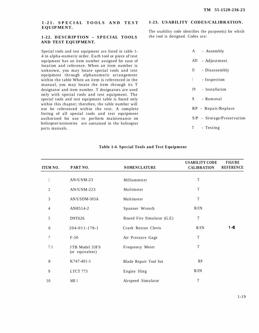
1 - 2 1 . S P E C I A L T O O L S A N D T E S TEQUIPMENT.
1-22. DESCRIPTION – SPECIAL TOOLSAND TEST EQUIPMENT.
Special tools and test equipment are listed in table 1-4 in alpha-numeric order. Each tool or piece of testequipment has an item number assigned for ease oflocation and reference. When an item number isunknown, you may locate special tools and testequipment through alphanumeric arrangementwithin the table When an item is referenced in themanual, you may locate the item through its Tdesignator and item number. T designators are usedonly with special tools and test equipment. Thespecial tools and test equipment table is found onlywithin this chapter; therefore, the table number willnot be referenced within the text. A completelisting of all special tools and test equipmentauthorized for use tohelicopter/accesories areparts manuals.
perform maintenance oncontained in the helicopter
TM 55-1520-236-23
1-23. USABILITY CODES/CALIBRATION.
The usability code identifies the purpose(s) for whichthe tool is designed. Codes are:
A - Assembly
AD - Adjustment
D - Disassembly
I - Inspection
IN - Installation
R - Removal
RP - Repair/Replace
S/P - Storage/Preservation
T - Testing
Table 1-4. Special Tools and Test Equipment
USABILITY CODE FIGUREITEM NO. PART NO. NOMENCLATURE CALIBRATION REFERENCE
1
2
3
4
5
6
7
7.1
8
9
10
AN/USM-23
AN/USM-223
AN/USDM-303A
AN8514-2
D9T626
204-011-178-1
F-50
JTB Model 33FS(or equivalent)
K747-401-1
LTCT 773
MB 1
Milliammeter
Multimeter
Multimeter
Spanner Wrench
Round Fire Simulator (G.E)
Crash Rescue Clevis
Air Pressure Gage
Frequency Meter
Blade Repair Tool Set
Engine Sling
Airspeed Simulator
T
T
T
R/IN
T
R/IN
T
T
RP
R/IN
T
1-19

TM 55-1520-236-23
Table 1-4. Special Tools and Test Equipment (Cont)
USABILITY CODE FIGUREITEM NO. PART NO. NOMENCLATURE CALIBRATION REFERENCE
11
12
13
14
15
15.1
15.2
15.3
15.4
16
17
18
19
20
21
21.1
22
23
24
25
26
27
28
29
1-20
MJ2A
MP1
M1A1
NC2A
PD1201
PD1468
PD1469
PD1470
PD1471
PD2659
PD2660
R02-4CO-RMM-4U
AA1730-1310
TK-100/G
BH-907
22196
141000310-1
T100619-2
T100220
T101306
T101307
T101308
T101338
T101356
Portable Hydraulic Test Stand
Pressure Tester(0-150 PSI)
Gunner Control Quadrant
Auxiliary Power Unit
Torque Multiplier
Adapter
Socket
Socket Co l lec t ive
Extension, Socket WRN
Mast Nut Socket
Reaction Adapter
Regulator
Engine Adapter
Tool Kit
RPM Adapter Cable
RPM Adapter Cable
Torque Fixture
Torque Fixture
Sling, Rotor
External Spline Wrench,Main Driveshaft
Wrench Assembly
Jackscrew Set
Jackscrew Set
Build-up Bench, Main Rotor
T
T
T
T
R/IN/D/A
D/A
D/A
D/A
D/A
R/IN/D/A
R/IN
T
D/A/RP
T
T
T
R/IN
R/IN
R/IN
R/IN
D/A
R
R
R/IN/D/A/AD
7-13
7-13

TM 55-1520-236-23
Table 1-4. Special Tools and Test Equipment (Cont)
USABILITY CODE FIGUREITEM NO. PART NO. NOMENCLATURE CALIBRATION REFERENCE
29.1 T101369 Support Plate D/A
29.2 T101382 Ram Adapter D/A
29.3 T101392 Wrench D/A
30 T101401 Scope Assembly AD
31 T101414 Blase Bolt Wrench R/IN
32 T101419 Alignnent Tool Set T
33 T101420 Holding Fixture T
1-20.1/(1-20.2 blank)


TM 55-1520-236-23
Table 1-4. Special Tools and Test Equipment (Cont)
USABILITY CODE FIGUREITEM NO. PART NO. NOMENCLATURE CALIBRATION REFERENCE
3434.135
35.1
36
37
38
39
40
41
42
43
4444.145
46
47
48
49
50
51
52
5353.1
T101421T101424T101440
T101447
T101449
T101455
T101467
T101468
T101475
T101485
T101487
T101488
T101491T101493T101520
T101524
T101525
T101530
T101549
T101550
T101551
T101553
T101559T101560
Adapter PlateHolding BarJack Set
Holding Fixture
Wrench, TransmissionFan Drive Quill
Holding Plate Assembly
Support, Main Rater Blade
Flap Stop
Bearing Tool
Bending Gage
Bearing and SealTool
Input Quill Wrench
Hub Bearing PullerWrenchHoist Assembly
Rigging Fixture,Flight Controls
Tab Bender, MainRotor Blade
Staking Tool
Holding Fixture,Transmission
Disassembly Tool,Transmission
Puller
Tool Set
Grip Spacing GageFixture, Holding
6-44, 6-45
R/IN/D/A/AD 5-6R/INAD
D/A
D/A
D/A
AD
AD
RP
AD
RP
D/A
RPD/AR/IN
AD
AD
RP
D/A
D
D
A
ADR/IN/D
1-21
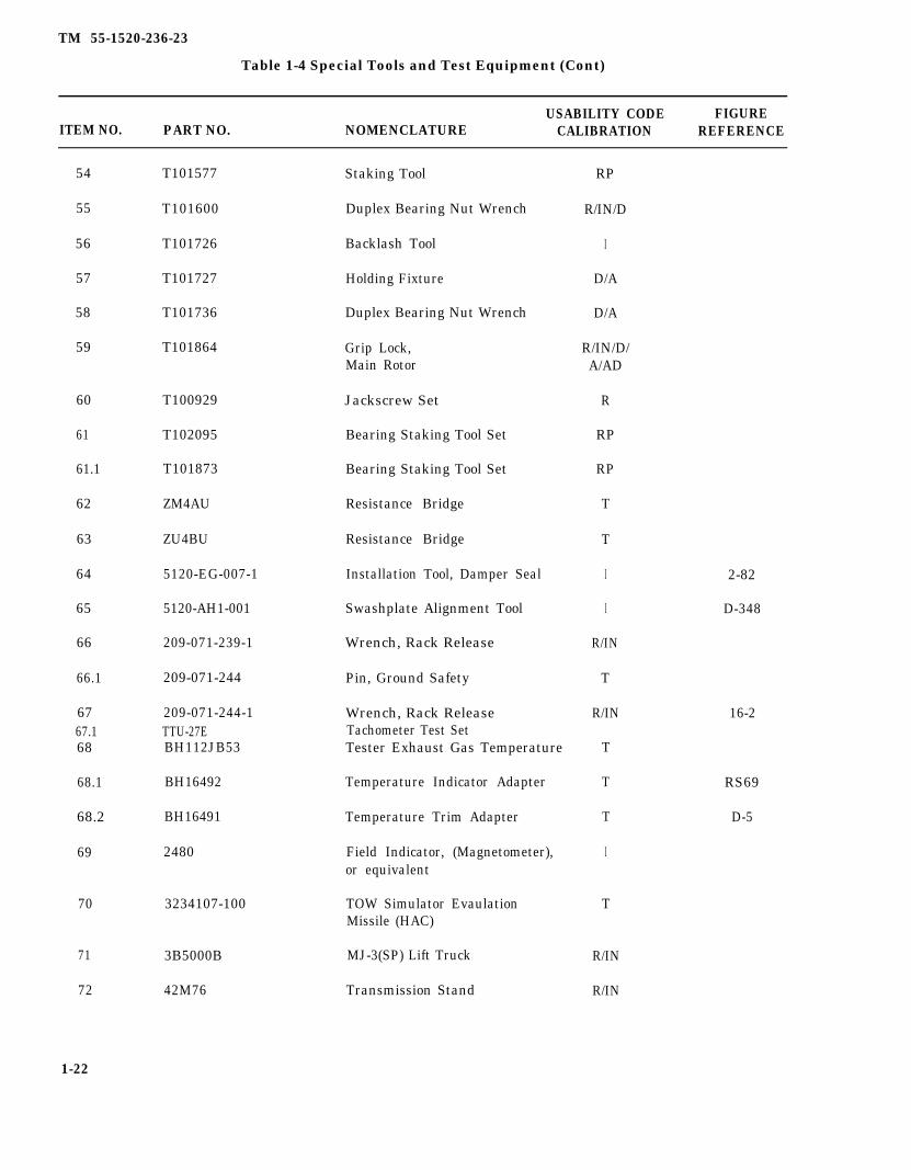
TM 55-1520-236-23
Table 1-4 Special Tools and Test Equipment (Cont)
USABILITY CODE FIGUREITEM NO. PART NO. NOMENCLATURE CALIBRATION REFERENCE
54
55
56
57
58
59
60
61
61.1
62
63
64
65
66
66.1
6767.168
68.1
68.2
69
70
71
72
1-22
T101577
T101600
T101726
T101727
T101736
T101864
T100929
T102095
T101873
ZM4AU
ZU4BU
5120-EG-007-1
5120-AH1-001
209-071-239-1
209-071-244
209-071-244-1TTU-27EBH112JB53
BH16492
BH16491
2480
3234107-100
3B5000B
42M76
Staking Tool
Duplex Bearing Nut Wrench
Backlash Tool
Holding Fixture
Duplex Bearing Nut Wrench
Grip Lock,Main Rotor
Jackscrew Set
Bearing Staking Tool Set
Bearing Staking Tool Set
Resistance Bridge
Resistance Bridge
Installation Tool, Damper Seal
Swashplate Alignment Tool
Wrench, Rack Release
Pin, Ground Safety
Wrench, Rack ReleaseTachometer Test SetTester Exhaust Gas Temperature
Temperature Indicator Adapter
Temperature Trim Adapter
Field Indicator, (Magnetometer),or equivalent
TOW Simulator EvaulationMissile (HAC)
MJ-3(SP) Lift Truck
Transmission Stand
RP
R/IN/D
I
D/A
D/A
R/IN/D/A/AD
R
RP
RP
T
T
I
I
R/IN
T
R/IN
T
T
T
I
T
R/IN
R/IN
2-82
D-348
16-2
RS69
D-5
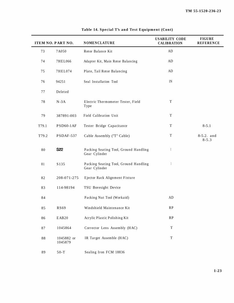
TM 55-1520-236-23
Table 14. Special T’s and Test Equipment (Cont)
USABILITY CODE FIGUREITEM NO. PART NO. NOMENCLATURE CALIBRATION REFERENCE
73
74
75
76
77
78
79
T79.1
T79.2
80
81
82
83
84
85
86
87
88
89
7A050
7HEL066
7HEL074
94251
Deleted
N-3A
387891-003
PSD60-1AF
PSDAF-537
S135
208-071-275
114-98194
RS69
EAB20
1045864
1045882 or1045879
50-T
Rotor Balance Kit
Adapter Kit, Main Rotor Balancing
Plate, Tail Rotor Balancing
Seal Installation Tool
Electric Thermometer Tester, FieldType
Field Calibration Unit
Tester Bridge Capacitance
Cable Assembly ("T" Cable)
Packing Seating Tool, Ground HandlingGear Cylinder
Packing Seating Tool, Ground HandlingGear Cylinder
Ejector Rack Alignment Fixture
TSU Boresight Device
Packing Nut Tool (Workaid)
Windshield Maintenance Kit
Acrylic Plastic Polishing Kit
Corrector Lens Assembly (HAC)
IR Target Assemble (HAC)
Sealing Iron FCM 18836
AD
AD
AD
IN
T
T
T
T
I
I
AD
RP
RP
T
T
8-5.1
8-5.2. and8-5.3
1-23
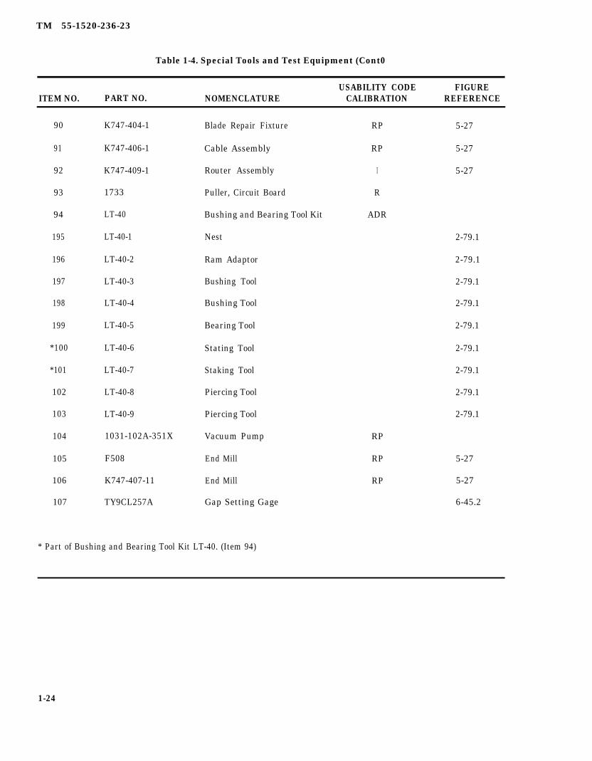
TM 55-1520-236-23
Table 1-4. Special Tools and Test Equipment (Cont0
USABILITY CODE FIGUREITEM NO. PART NO. NOMENCLATURE CALIBRATION REFERENCE
90
91
92
93
94
195
196
197
198
199
*100
*101
102
103
104
105
106
107
K747-404-1
K747-406-1
K747-409-1
1733
LT-40
LT-40-1
LT-40-2
LT-40-3
LT-40-4
LT-40-5
LT-40-6
LT-40-7
LT-40-8
LT-40-9
1031-102A-351X
F508
K747-407-11
TY9CL257A
Blade Repair Fixture RP 5-27
Cable Assembly RP 5-27
Router Assembly I 5-27
Puller, Circuit Board R
Bushing and Bearing Tool Kit ADR
Nest
Ram Adaptor
Bushing Tool
Bushing Tool
Bearing Tool
Stating Tool
Staking Tool
Piercing Tool
Piercing Tool
Vacuum Pump
End Mill
End Mill
Gap Setting Gage
RP
RP
RP
2-79.1
2-79.1
2-79.1
2-79.1
2-79.1
2-79.1
2-79.1
2-79.1
2-79.1
5-27
5-27
6-45.2
* Part of Bushing and Bearing Tool Kit LT-40. (Item 94)
1-24
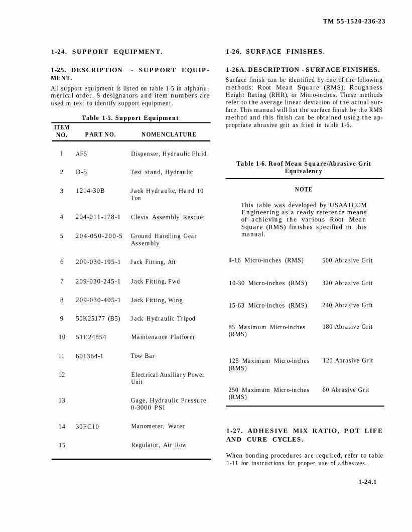
TM 55-1520-236-23
1-24. SUPPORT EQUIPMENT.
1-25. DESCRIPTION - SUPPORT EQUIP-MENT.
All support equipment is listed on table 1-5 in alphanu-merical order. S designators and item numbers areused m text to identify support equipment.
Table 1-5. Support EquipmentITEMNO. PART NO. NOMENCLATURE
1
2
3
4
5
6
7
8
9
10
11
12
13
14
15
AF5
D-5
1214-30B
204-011-178-1
204-050-200-5
209-030-195-1
209-030-245-1
209-030-405-1
50K25177 (B5)
51E24854
601364-1
30FC10
Dispenser, Hydraulic Fluid
Test stand, Hydraulic
Jack Hydraulic, Hand 10Ton
Clevis Assembly Rescue
Ground Handling GearAssembly
Jack Fitting, Aft
Jack Fitting, Fwd
Jack Fitting, Wing
Jack Hydraulic Tripod
Maintenance Platform
Tow Bar
Electrical Auxiliary PowerUnit
Gage, Hydraulic Pressure0-3000 PSI
Manometer, Water
Regulator, Air Row
1-26. SURFACE FINISHES.
1-26A. DESCRIPTION - SURFACE FINISHES.Surface finish can be identified by one of the followingmethods: Root Mean Square (RMS), RoughnessHeight Rating (RHR), or Micro-inches. These methodsrefer to the average linear deviation of the actual sur-face. This manual will list the surface finish by the RMSmethod and this finish can be obtained using the ap-propriate abrasive grit as fried in table 1-6.
Table 1-6. Roof Mean Square/Abrasive GritEquivalency
NOTE
This table was developed by USAATCOMEngineering as a ready reference meansof achieving the various Root MeanSquare (RMS) finishes specified in thismanual.
4-16 Micro-inches (RMS)
10-30 Micro-inches (RMS)
15-63 Micro-inches (RMS)
85 Maximum Micro-inches(RMS)
125 Maximum Micro-inches(RMS)
250 Maximum Micro-inches(RMS)
500 Abrasive Grit
320 Abrasive Grit
240 Abrasive Grit
180 Abrasive Grit
120 Abrasive Grit
60 Abrasive Grit
1-27. ADHESIVE MIX RATIO, POT LIFEAND CURE CYCLES.
When bonding procedures are required, refer to table1-11 for instructions for proper use of adhesives.
1-24.1

TM 55-1520-236-23
Table 1-11. Adhesive Mix Ratio, Pot Life, and Cure Cycles.
All data on pages 1-25 through 1-40, includingfigures 1-2 through 1-4 and tables 1-7 through
1-10, deleted.
1-24.2
TM 55-1520-236-23
1-28.
1-29.
SECTION II.
LUBRICATION INSTRUCTIONS.
DESCRIPTION – LUBRICATION.
The lubrication chart consists of a main drawing whichis a perspective diagram of the helicopter, with enlarg-ed or detail views where required to show items clearly
LUBRICATION
(figure 1-5). The chart shows all parts requiring periodiclubrications, except the engine and transmission andtail rotor gearboxes, which are lubricated by oil in ac-cordance with servicing instructions. The lubricationchart uses symbols and abbreviations to indicate the re-quired lubricant, method of application, and time inter-val for lubrication of each part listed. A key on thechart defines the meanings of symbols and abbrevia-tion.
1-41

TM 55-1520-236-23
1-42
Figure 1-5. Lubrication Chart (Typical) (Sheet 1 of 4)
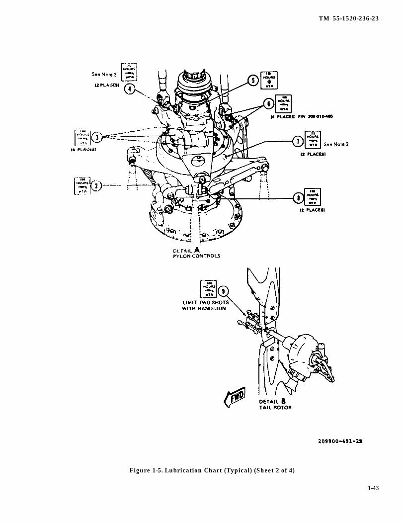
TM 55-1520-236-23
Figure 1-5. Lubrication Chart (Typical) (Sheet 2 of 4)
1-43
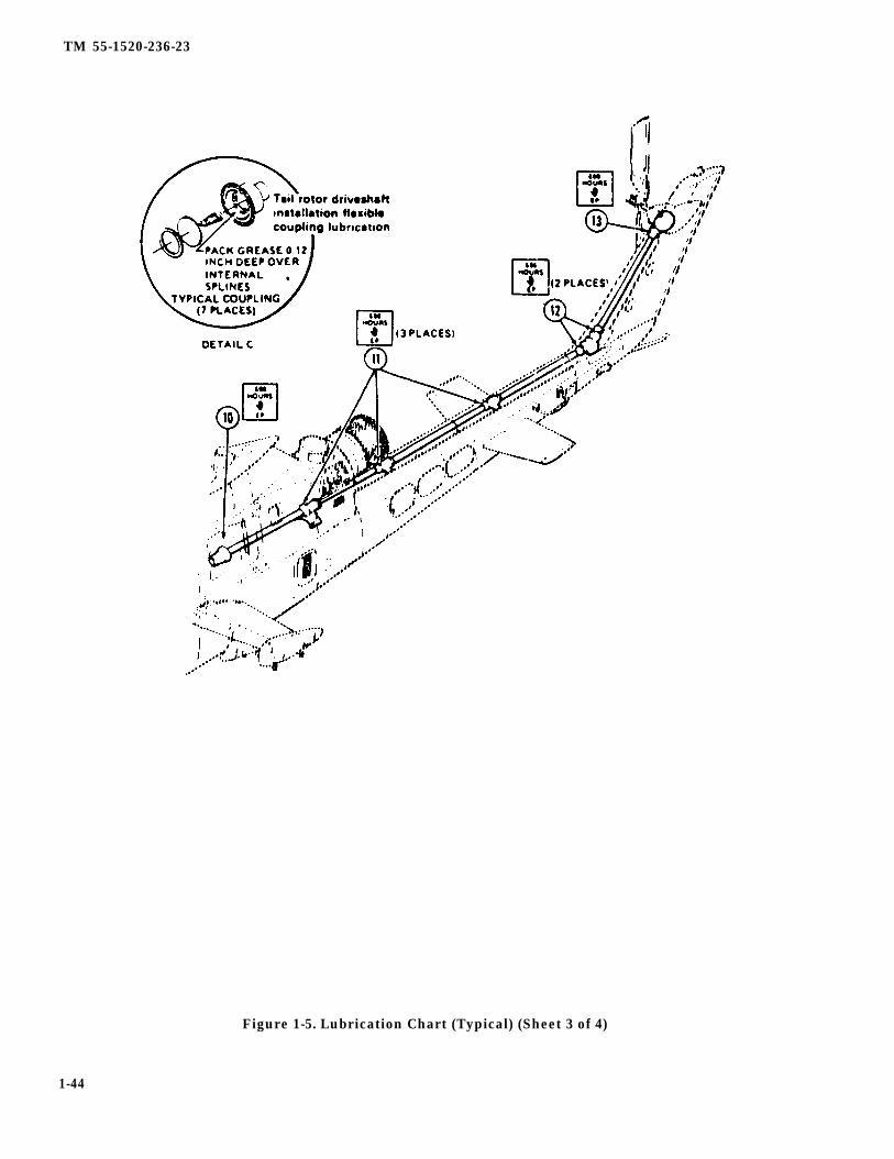
TM 55-1520-236-23
Figure 1-5. Lubrication Chart (Typical) (Sheet 3 of 4)
1-44
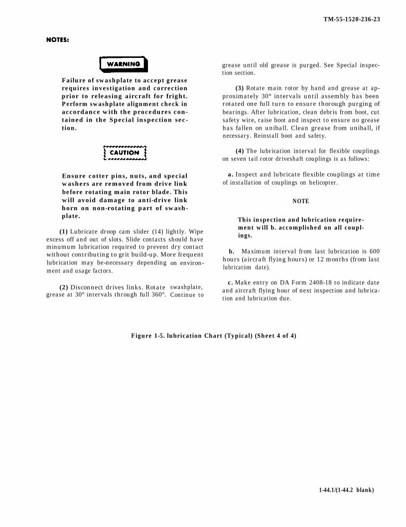
TM-55-1520-236-23
Failure of swashplate to accept greaserequires investigation and correctionprior to releasing aircraft for fright.Perform swashplate alignment check inaccordance with the procedures con-tained in the Special inspection sec-tion.
Ensure cotter pins, nuts, and specialwashers are removed from drive linkbefore rotating main rotor blade. Thiswill avoid damage to anti-drive linkhorn on non-rotating part of swash-plate.
(1) Lubricate droop cam slider (14) lightly. Wipeexcess off and out of slots. Slide contacts should haveminumum lubrication required to prevent dry contactwithout contributing to grit build-up. More frequentlubrication may be-necessary dependingment and usage factors.
(2) Disconnect drives links. Rotategrease at 30° intervals through full 360°.
on environ-
swashplate,Continue to
grease until old grease is purged. See Special inspec-tion section.
(3) Rotate main rotor by hand and grease at ap-proximately 30° intervals until assembly has beenrotated one full turn to ensure thorough purging ofbearings. After lubrication, clean debris from boot, cutsafety wire, raise boot and inspect to ensure no greasehas fallen on uniball. Clean grease from uniball, ifnecessary. Reinstall boot and safety.
(4) The lubrication interval for flexible couplingson seven tail rotor driveshaft couplings is as follows:
a. Inspect and lubricate flexible couplings at timeof installation of couplings on helicopter.
b.
NOTE
This inspection and lubrication require-ment will b. accomplished on all coupl-ings.
Maximum interval from last lubrication is 600hours (aircraft flying hours) or 12 months (from lastlubrication date).
c. Make entry on DA Form 2408-18 to indicate dateand aircraft flying hour of next inspection and lubrica-tion and lubrication due.
Figure 1-5. lubrication Chart (Typical) (Sheet 4 of 4)
1-44.1/(1-44.2 blank)

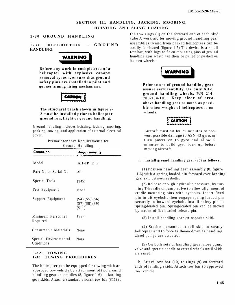
TM 55-1520-236-23
SECTION III, HANDLING, JACKING, MOORING,HOISTING AND SLING LOADING
1-30 GROUND HANDLING
1 - 3 1 . DESCRIPTION – G R O U N DHANDLING.
Before any work in cockpit area of ahelicopter with explosive canopyremoval system, ensure that groundsafety pins are installed in pilot andgunner arming firing mechanisms.
The structural panels shown in figure 2-2 must be installed prior to helicopterground run, fright or ground handling.
Ground handling includes hoisting, jacking, mooring,parking, towing, and application of external electricalpower.
Premaintenance Requirements forGround Handling
Model
Part No or Serial No
Special Tools
Test Equipment
Support Equipment
Minimum PersonnelRequired
Consumable Materials
Special EnvironmentalConditions
AH-1P E F
All
(T45)
None
(S4) (S5) (S6)(S7) (S8) (S9)(S11)
Four
None
None
1-32 . TOWING.1-33. TOWING PROCEDURES.
The helicopter can be equipped for towing with anapproved tow vehicle by attachment of two groundhandling gear assemblies (8, figure 1-6) on landinggear skids. Attach a standard aircraft tow bar (S11) to
the tow rings (9) on the forward end of each skidtube A work aid for moving ground handling gearassemblies to and from parked helicopters can belocally fabricated (figure 1-7) The device is a smalltow bar, with lugs to fit on mounting pins of groundhandling gear which can then be pulled or pushed onits own wheels.
Prior to use of ground handling gearassure serviceabllity. Us. only AH-1ground handling wheels, P/N 214-706-104-101. Keep clear of areaabove handling gear as much as possi-ble when weight of helicopters is onwheels.
Aircraft must sit for 25 minutes to pre-vent possible damage to ASN 43 gyro, orturn power on to gyro and allow 5minutes to build gyro back up beforemoving aircraft.
a . Install ground handling gear (S5) as follows:
(1) Position handling gear assembly (8, figure1-6) with a spring loaded pin forward over landinggear skid between eyebolts.
(2) Release enough hydraulic pressure, by tur-ning T-handle of pump valve to allow alignment ofcradle mounting pins with eyebolts. Insert fixedpin in aft eyebolt, then engage spring-loaded pinsecurely in forward eyebolt. Install safety pin inspring-loaded pin. Spring-loaded pin can be movedby means of flat-headed release pin.
(3) Install handling gear on opposite skid.
(4) Station personnel at tail skid to steadyhelicopter and to force tailboom down as handlingwheel pumps are actuated.
(5) On both sets of handling gear, close pumpvalve and operate handle to extend wheels until skidsare raised.
b. Attach tow bar (10) to rings (9) on forwardends of landing skids. Attach tow bar to approvedtow vehicle.
1-45
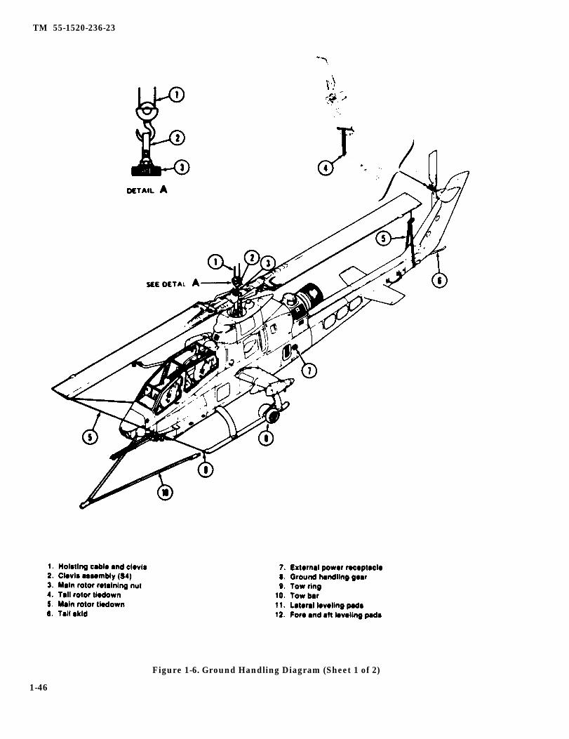
TM 55-1520-236-23
Figure 1-6. Ground Handling Diagram (Sheet 1 of 2)
1-46

TM 55-1520-236-23
Figure 1-6. Ground Handling Diagram (Sheet 2 of 2)
1-47
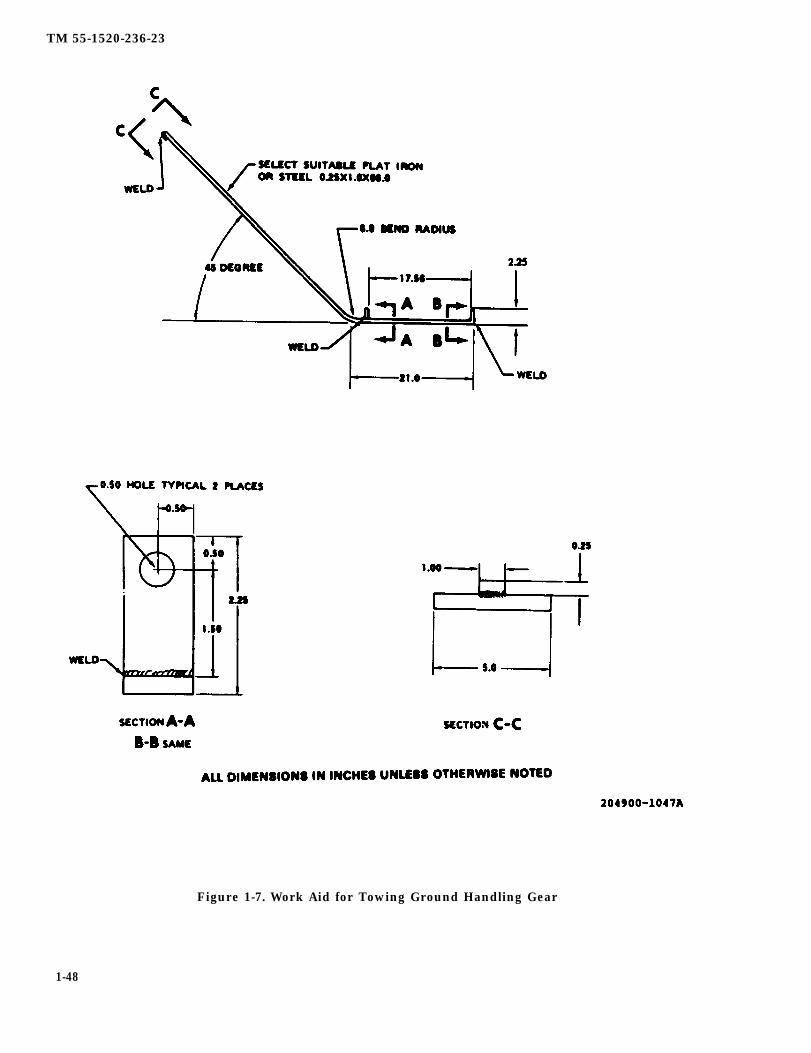
TM 55-1520-236-23
Figure 1-7. Work Aid for Towing Ground Handling Gear
1-48

CAUTION
c.
Ground handling forces should notexceed 460 pounds (vertical direc-tion) and 150 pounds (horizontaldirection) pressure exerted on tail-boom.
Station a person at aft end of tailboom tobalance helicopter on handling gear and to assist incontrol while towing.
CAUTION
d.
e.
Towing the helicopter on groundhandling gear over prepared sur-faces at a gross weight in excess of9660 pounds may cause permanentset in the aft cross tube. Do not towhelicopter on unprepared surfaces atgross weights in excess of 7500pounds. Caution should be exercisedwhen towing on unprepared surfacesat any gross weight. Do not tow atspeeds in excess of 5 miles per hour.Avoid sudden starts and stops.
Tow helicopter to desired area.
Remove ground handling gear as follows:
(1) Station a person at tailboom to assist bysteadying helicopter.
(2) Release hydraulic pressure by turningT-handle of pump valve on each set of handling gear,allowing wheels to retract and landing skids to reston ground. Close valve.
(9) Push release pin on rear of cradle todisengage spring-loaded mounting pin from eyebolt.Pull front pin free of eyebolt and remove handlinggear assembly. Remove opposite ground handlinggear in the same manner.
(4) Remove tow-bar.
1-34. JACKING.
TM 55-1520-236-23
1-35. JACKING PROCEDURES.
Four jack fittings with mooring shackles attached areprovided as loose equipment for use at two jack pointson the fuselage and inboard of wing pylona (figure 1-8).The forward jack fitting is attached by bolts under thestruture of the right main beam and the ammunitioncompartment rear bulkhead. The aft jack fitting isscrewed into a socket on the left main beam ahead ofthe tailboom attach splice. Wing pylon jack fittings aresubstituted for ejector tube assemblies in outboardarmament racks.
WARNING
Do not jack helicopter in open area duringwindy or gusty conditions.
CAUTION
Outboard articulated pylons must be in thestowed position (four degrees up) when thehelicopter is to be jacked for any purpose.Jacking fitting (S8) must be installed.
CAUTION
All structural panels must be installed priorto jacking and leveling. Helicopter must beleveled prior to removing structural panels,except tailboom structural panels. Do notlower jacks until structural panels havebeen reinstalled to prevent possible per-manent set to helicopter structure.
a. Remove aft section of bottom forward electricalaccess panel (station 138.7). Remove heat sink ap-
proximately 10 inches right of center. Carefully securePheat sink to one side using masking tape to preventdamage to the wire connectors for transistors (8Q5 and8Q6). Remove three screws to gain access to the jackfitting mounting nutplates. Install jack fitting (S7),using three bolts and washers provided with fitting.
b. Remove aft jack fitting cover plate. Select jackfitting (S6) with threaded end approximately 1.0 inchlong, from shoulder to end. Install fitting in aft jackpoint socket, on bottom of left main beam just forwardof tailboom.
1-49

TM 55-1520-236-23
Figure 1-8. Jacking and Mooring Fittings
1-50

TM 55-1520-236-23
c. Remove outboard armament pods (paragraph16-22), Check that two remaining jack fittings (S8),for wing jack points are similar to fitting used in stepb. except for shorter threaded ends approximately0.49 inch long.
Ejector cartridges must be removedbefore installing jack fittings in outboardwing pylons.
d. At each outboard rack, remove lockwire andremove complete ejector tube assembly (paragraph16-41). Install jack fitting.
e. Place jacks under four jack point fittings. Ifremoving landing gear, align all jacks with inboardlegs parallel at approximately 27 degrees to axis offuselage.
f.
g.
High center of gravity makes itimperative that all jacks be raised evenlywith wings level.
Raise helicopter slowly and evenly.
Observe the following precautions whilehelicopter is on jacks.
(1) Rope off area around helicopter andprominently display warning signs stating CAUTION:HELICOPTER ON JACKS.
(2) All personnel in immediate area shallexercise extreme caution not to bump or otherwisedisturb helicopter while raised or supported on jacks.
(3) Personnel shall not climb into or ontohelicopter while raised or supported on jacks.
h. After necessary work, lower helicopter slowlyand evenly. Remove jacks.
i. Remove jack fittings from outboard pylonejector racks. Reinstall and lockwire ejector tubeassemblies. Reinstall cartridges (paragraph 16-36).
j. Remove forward jack fitting with bolts andwashers. Reinstall screws in jack point bolt holes.
k. Install heat sink and aft section of forwardelectrical access panel.
l. Remove aft jack fitting Install aft jack fittingcover plate. Return all fittings to loose equipment.
m. Install outboard armament pods.
1-36 . LEVELING.
Leveling pads located in the ammunitioncompartment floor are used with a bubbleprotractor when it IS necessary to level thehelicopter. Pallet must be removed for access. Forfore-and-aft leveling, use two pads (12, figure 1-6),located in depression near left side of floor. Forlateral leveling, use two pads (11), located left andright on top of aft ammunition pallet track. Applyjacking procedures to correct helicopter position(paragraph 1-35).
NOTE
If leveling pads are damaged or missing,refer to paragraph 2-280 for padreplacement.
1 - 3 7 . P A R K I N G .
1-38. DESCRIPTION – PARKING.
Parking, as used in this manual, IS defined as thecondition in which helicopter will be secured while onthe ground. Direction of heading and location ofhelicopter is normally determined by ease ofmaintenance and servicing, to allow removal of anyone helicopter from parking area and to permit readyaccess of mobile fire fighting equipment within area.Although parking arrangements may vary accordingto local facilities, the general procedures in thefollowing paragraph should be observed.
1-39. PARKING PROCEDURES.
a. Double-row lateral parking, with front and rearhelicopter of each double row placed tail to tail,should be used where possible.
b. Helicopter should be parked not less than 750feet from ends of center line of nearest runway, andnot less than 250 feet from edge of connecting taxistrips.
c. Width of fire lanes between each double rowshould be slightly greater than rotor span of parkedhelicopters. This spacing will facilitate removal of any
1-51

TM 55-1520-236-23
helicopter from parking area, as well as permittinggreater ease of movement of mobile fire fightingequipment within area.
d. Fire lanes having a minimum width of 50 feetshould be provided to cross main fire lanes and isolateblocks of 10 helicopters or less.
e . Helicopters parked on concrete ramps or apronsshould be placed to utilize mooring rings whenavailable.
f. Parked helicopter will be provided with a staticground.
g. Under normal conditions park the helicopter asfollows:
(1) Park helicopter on a level surface, wheneverpossible, so that load will be evenly distributed on lan-ding gear.
(2) Retract or remove ground handling wheels toallow helicopter to rest an landing skids.
NOTE
If helicopter is to remain parked morethan 14 days, use suitable blocks orshoring to raise skids slightly off supporting surface.
Do not use a rope to pull rotor bladesinto alignment for tiedown. Damageto loading edge may result. Manuallyposition rotor blades.
(3) Align main rotor blades fore and horizontal,and tail rotor blades parallel to vertical fin.
NOTE
If the collective stick is positioned inother than full down, place EMER HYDswitch to EMER HYD PUMP and BATswitch to ON and fully lower collectivestick. Place both switches to OFF aftercollective is lowered.
NOTE
Use 1/2 inch polyester rope, NSN 4020-00-630-4873, for blade tie-down. Refer-ence TM 1-1520-250-23-1 for additionalinformation.
(4) Engage hook of main rotor tiedown (6, figure1-6) in hole of fitting on each end of rotor blade andposition blade above tailboom. Pull on tiedown toremove the spanwise slack from the rotor system andsecure rotor by wrapping tiedown rope firmly aroundtailboom on aft end. Tie forward tiedown rope to towrings (10) on landing gear skid. Additional security ofthe main rotor tiedown can be accomplished by insert-ing an AN416-2 safety pin through a 0.060 inch holedrilled through the hook of the main rotor tiedown. Thehole is drilled perpendicular to the plane of the handle0.25 inch from the insertion end of the hook. Securethe safety pin to the hook handle with a six inch pieceof NAS1455B30-6 chain and safety wire. Insert the pinthrough the hook after inserting the hook through therotor blade fitting.
(5) Attach tail rotor tiedown rope (5) to tail rotorand secure to loop provided on side of vertical fin.
(6) Install TSU cover (9).
Before entry into cockpit area, ensurethat canopy removal system groundsafety pins are installed in pilot andgunner arming/firing mechanisms.
(7) Check that all switches are OFF and externalpower disconnected; close all doors and accessplates. Lock ignition and canopy doors. Remove keys.
(8) Install pitot tube cover (2, figure 1-9), engine
NOTEIf required and available, install can-opy cover (1).
h. Under turbulent weather conditions, park thehelicopter os follows:
Structural damage can occur from tur-bulent weather conditions. Anchoringand mooring should be accomplishedwhen wind is expected to exceed 45knots. When possible, helicoptershould be evacuated to a safe weatherarea if a tornado, hurricane or windcondition above 75 knots is expected.
1-52

TM 55-1520-236-23
Figure 1-9. Covers Diagram
1-53

TM 55-1520-236-23
(1) Park helicopter. (3) Install aft jack and mooring fitting at aft jackpoint (paragraph 1-35).
(2) Moor helicopter in accordance with para-graph 1-39
(3) Fill fuel cell to capacity if time permits.
(4) Disconnect battery. Secure ail loose equip-ment. Moor all ground support equipment at safe dis-tance from helicopter.
(5) After high winds have passed, inspecthelicopter for damage.
1-40. MOORING.
1-41. DESCRIPTION – MOORING.
Mooring is a process of securing perked helicopter toavoid damage by high winds or turbulent weather.Mooring fittings are provided at locations shown onfigure 1-10. Where properly spaced rings are notavailable, marring can be accomplished with astandard mooring kit. Refer to paragraph 2-267 fordescription of mooring fittings.
1-42. MOORING PROCEDURE.
1-42.1. Mooring Hardware (See Table 1-7).
1-42.2. Mooring Procedure On UnpavedSurface.
a. Park helicopter on unpaved parking area,headed in direction of highest winds forecast.
b. Install Mooring Fittings.
(1) Assemble mooring fittings (figure 1-8) forinstallation at wing attach points by assembling twoparts of fitting and installing bolt, nut and washer.
(2) Position mooring fitting on helicopter atwing attach point (figure 1 -8) and install bolt andwasher. Torque bolt to 400 inch-pounds. Back off tozero torque or until threads disengage. Tighten boltuntil contact occurs between bolt head and washer oruntil torque begins to increase. Record torque value.Apply 100 inch-pounds torque above torque valuerecorded before, but do not apply more than 460inch-pounds torque. Install opposite fitting in thesame manner.
(4) Position forward jack and mooring fitting(figure 1-8) on helicopter fuselage. (paragraph 1-35).
(5) Install wing jack and mooring fittings (figure1-8) (paragraph 1-35).
c. Assemble and install anchor rods.
(1) Screw anchor rod (1, figure 1-10) into arrow(3).
(2) Slip driving rod (2) over anchor rod and intosocket of arrow.
(3) Turn cam of driving rod so that prongs ofarrow are not spread by driving.
(4) If necessary, loosen surface of ground.
(5) Position driving rods as shown in figure 1-10.
(6) Drive each arrow into ground until drivingrod handle is approximately three inches abovesurface.
(7) Rotate driving rod handle approximately 90degrees and give it a sharp blow to spread arrowprongs.
(8) Return driving rod to driving position andremove it from anchor rod.
(9) Align squared socket of eye (4) with squaredend of anchor rod. Fit in place and tighten knurled nut.
(10) Set arrow prongs by pulling up on eyeassembly.
Do not overtighten cables or rope.Overtightening may cause the moor-ing fitting bolt to bond.
d. Secure helicopter to anchor rods with quarter-inch cables or one-inch manila rope, as shown onfigure 1-10.
e. Remove mooring cables or ropes installed instep d.
1-54

TM 55-1520-236-23
f. Remove anchor rods installed in step c.
g. Remove mooring fittings from helicopter asfollows:
(1) Remove combination mooring and jackfittings (figure 1-8) from aft jack mounting points andwing Jack mounting points by rotating the mooringand jack fitting in a counterclockwise direction,
(2) Remove combination jacking and mooringfittings (figure 1-8) from forward jack mounting pointby removing three bolts and washers.
(3) Remove mooring fitting at wing attachpoints (figure 1-8) by removing bolt and washer.
1-42.3. Mooring Procedure On PavedSurface.
a. Position the aircraft on the mooring pad with thelongitudinal centerline of the aircraft directly aboveand parallel to the longitudinal axis of the pad asshown in figure 1-9.1. The aft mooring ring is to be lo-cated directly opposite the center pair of mooringpoints on the pad as illustrated.
NOTE
It will be necessary to remove the fairingwhich covers the forward jack-point, byremoving the flush head bolts whichsecure the fairing to the aircraft. Withthe fairing removed, install the stainlesssteel jack-point in the uncovered recess,as described in this TM. With the jack-point installed, install the mooringclevis to the jack-point as described inthis TM. A mechanics tool kit will be re-quired.
b. Place the hook-ends of the two forward chainsinto the mooring clevis. Adjust the chains with thechain adjusters provided on each chain. Chainsshould be adjusted to the point where the slack hasbeen removed.
c. Remove the fairing covering the aft jack-point.Four flush head bolts must be removed. With the fair-ing removed install the jack-point in the uncoveredrecess and install the aft mooring clevis on the jack-point as described in this TM. A Frearson head screwdriver will be required.
d. Place the hook-ends of the two aft mooringchains into the aft mooring ring. Place the hook-end ofthe two center mooring chains into the most aft of thethree D-rings provided under the aircraft wings. Adjustthe chains with the chain adjusters provided with eachchain. Chains should be adjusted to the point wherethe slack has been removed.
NOTE
It is highly recommended that AH-1helicopters be flown with the mooringhardware installed at all times to permita rapid response to weather emergen-cies, unless it is the commandersdecision that to fly without the fairingswould significantly impact the mission.
NOTE
The mooring hardware is not con-sidered flyaway equipment. All activemooring points shall be equipped withthis hardware.
ITEM NSN Q T Y
1
2
Table 1-11.1. Mooring Hardware Chart
MOORING HARDWARE
DESCRIPTION P/N
CHAIN ADJUSTER MB-1 1670-00-212-1149 6
CHAIN WITH HOOK FOR MB-1 4010-00-516-8405 12
1-54.1

TM 55-1520-236-23
Figure 1-9.1 AH-1 Paved Surface Mooring Configuration
1-54.2
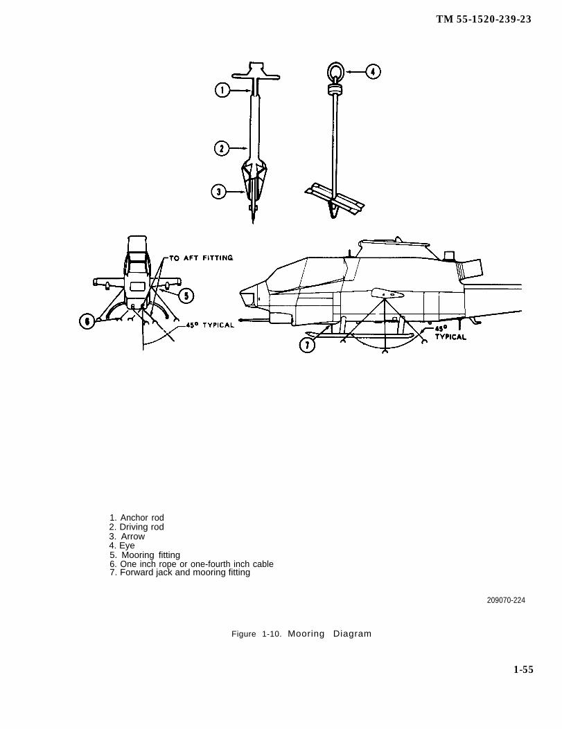
TM 55-1520-239-23
1. Anchor rod2. Driving rod3. Arrow4. Eye5. Mooring fitting6. One inch rope or one-fourth inch cable7. Forward jack and mooring fitting
209070-224
Figure 1-10. Mooring Diagram
1-55
TM 55-1520-236-23
1-43. HELlCOPTER COVERS.
1 - 4 4 . D E S C R I P T I O N — HELlCOPTERCOVERS.
The helicopter covers consist of the canopy cover, pitotcover, exhaust cover, and the engine air inlet shields(figure 1-9). The pitot cover, exhaust cover, and engineair inlet shields should be installed whenever helicopteris parked outside. The canopy cover is made of vinylcoated cloth with elastic cord straps attached. Thecanopy cover should be installed during extendedoutside parking or when stormy weather is expected.
1-45. HOISTING.
1-46. DESCRIPTION — HOISTING.
The entire helicopter can be lifted by a suitable hoistattached to an eye provided on the main rotor retainingnut at top of the mast. This hoisting point can also beused to lift out the mast assembly (with or without themain rotor and rotating controls assemblies), or thecomplete mast and transmission assembly.
1-47. HOISTING — HELlCOPTER.
a. Attach a hoisting cable and clevis or clevisassembly (S4) to lifting eye of main rotor retaining nut(figure 1-6). Connect a suitable hoist and take up slack.
b. Station a person at tail skid to steady helicopteragainst swinging or turning when hoisted. If liftingbeyond reach, attach a suitable rope for this purpose.
c. Hoist slowly, maintaining a steady lifting force.
1-48. HOISTING – COMPONENTS.
a. For hoisting or handling tailboom as a separatecomponent use straps or slings at both ends of boom,Use tail skid for steadying boom.
b. To hoist engine, main rotor, or mast andtransmission from helicopter use maintenance hoist(T45) or other suitable hoist.
1-49. MAINTENANCE HOIST.
1 - 5 0 . D E S C R I P T I O N — M A I N T E N A N C EHOIST.
A maintenance hoist (T45), designed to mount on leftside of the fuselage, is provided for use in removing andinstalling main rotor, mast, transmission, or engine
1-56
assemblies. The hoist consists of a tube assembly, ahub assembly, and attaching parts. The tube assemblyhas a hand-operated winch, with cable, pulleys andweighted hook. The hub is a socket made from largerdiameter tubing, with attachment fittings, sleevebearings, and a platform to aid the operator. The tubeassembly rests on a steel ball in the hub, and can berotated by means of the crossbar handle to move thehook into position.
Do not exceed maximum hoist hook loadof 935 pounds and maximum cableangular displacement of 10 degrees fromthe vertical.
1 - 5 1 . I N S T A L L A T I O N – M A I N T E N A N C EHOIST.
a. At left side of fuselage, remove two screws andwashers from bolt holes of upper hoist supports, locatedjust ahead of engine forward firewall. Remove sixscrews and washers from lower support bolt holes,located in vertical rows of three ahead of and behindlanding gear aft crosstube.
Prior to installation of maintenance hoistinspect hoist and support visually forcracks and other damage which mayaffect function. Replace parts If damaged.
b. Install bracket (14, figure 1-11) above Iondinggear crosstube, using six bolts and washers instead ofscrews removed in preceding step.
c. Insert lower end of tube assembly (1) into hubassembly (10). Align lower fitting of hub in supportbracket and install pin (11).
d. Raise hoist assembly. Attach upper fitting of hubto upper supports, using two bolts and washers insteadof screws previously removed.
Handle hoist with care to avoid personalinjury or damage to aircraft.

TM 55-1520-236-23
Figure 1-11. Maintenance Hoist, T101520
1-57
TM 55-1520-236-23
1 - 5 2 . R E M O V A L - M A I N T E N A N C EHOIST.
a. Detach hub fitting from upper supports byremoving two bolts and washers.
b. Carefully awing top of hoist assembly outwardand down until resting on ground. Remove tubeassembly (1, figure 1-11) form hub assembly (10).
c. Detach lower fitting of hub from bracket (14) bypulling out pin (11). Remove hub assembly.
d. Remove bracket with attaching bolts andwashers from fuselage. Bracket can be l teched withpin to hub for conveince.
e. Reinstall screws and washers in bolt holes ofupper and lower support points.
1-53 . SLING LOADING.
Refer to FM 55-413.
1 - 5 4 . A P P L I C A T I O N O F E X T E R N A LPOWER.
Art external power receptacle (7. figure 1-6) forapplication of external 28 Vdc power is located in leftside of the fuselage at station 274, covered by aspring-loaded access door. When the door is open, aswitch causes the EXTERNAL POWER caution panel
segment to be lighted. Battery switch should be atOFF position. Use a 28 Vdc power source capable ofdelivering 650 amperes. When cable connector frompower source is connected to the receptacle, theexternal power relay in the helicopter DC circuit wiIIbe energized l nd power will be supplied to the mainbus for distribution.
NOTE
If battery charge is less than 24 volts,external power may be required to avert hot starts.
a. On E M when an external power source is pro-vialing electrical power, the helicopter batteryshould be connected to the essential hue. Duringextended armament checks, the condition of thebattery should be checked every 30 minutes. If anoverheated battery is suspected or detected, exter-nal power should be disconnected and BATTERYswitch turned to OFF position. No attempt shouldbe made to disconnect or remove an overheatedbattery.
b. E M The BATTERY switch should be in theRUN position, only during armament checks whenexternal power is being applied to the helicopter.At completion of armament testing the externalpower should be disconnected. The BATTERYswitch should be returned to OFF position, andbattery should be disconnected. Hours ac-cumulated on the battery during armament testingwith battery on the line should be added to DAForm 2408-18.
SECTION IV . INSPECTION REQUIREMENTS
1-55 . GENERAL INFORMATION.
a. This section contains complete requirementsfor special inspections, overhaul and retirementschedule, and standards of serviceability ap-plicable to the aircraft. The inspections prescrib-ed in this chapter shall be accomplished at specificperiods by aviation unit maintenance activities withthe assistance of intermediate maintenance activitieswhen required. Daily inspection are contained in TM55-1500-220-PMD, Preventive Maintenance DailyCheck List. Phased maintenance inspections are con-tained in TM 55-1500-220-PM, Phased Maintenancechecklists.
c. Special inspections based on calendar times willhave a tolerance of plus or minus ten percent not toexceed thirty days.
1 - 5 6 . S T A N D A R D S O F S E R -VICEABILITY.
Standards of serviceability to be utilized in the day-to-day inspection and maintenance of the helicopter canbe found as fits, tolerances, wear limits, andspecifications in the applicable chapter. Standards ofserviceability for tranfer of helicopters are containedin TM 55-1500-326-25.
b. Special inspection frequencies that are based onflight hours may be accomplished within a plus orminus ton percent tolerance from the nominal timewhen such inspections would ordinarily be duo.
1-58

TM 55-1520-236-23
1-57 . SPECIAL INSPECTION.
T h i s s e c t i o n s u p p l e m e n t s t h einspect ions c o n t a i n e d i n T M220-PM, Phased Maintenance
scheduled55-1500-r e q u i r e -
ments. T h i s s e c t i o n a l s o i n c l u e d s i n -s p e c t i o n s o f i tems wh ich a re requ i redt o b e i n s p e c t e d a t i n t e r v a l s n o t c o m -p a t i b l e w i t h a i r f r a m e o p e r a t i n g t i m e o ra i r f r a m e i n s p e c t i o n i n t e r v a l s . Re fe rto DA PAM 738-751 for appl icable forms,r e c o r d s , a n d w o r k s h e e t s r e q u i r e d f o rt h e s e i n s p e c t i o n i n t e r v a l s . T y p i c a l o ft h i s t y p e i n s p e c t i o n i t e m s a r e :
a. An inspection which is contingent uponspecific conditions or incidents that arise, and onlybecause of these conditions or incidents, whoseimmediate inspection is required to ensure safeflight. Typical of these conditions are hard landings,overspeed, and sudden stoppage.
b. Inspection of components of airframe on acalendar basis: first aid kits, weight and balance check,aircraft inventory, etc.
When components are being removedfrom on aircraft, all inspections re-quired by the next phase maintenanceinspection must be accomplished priorto either immediate re-use or storage.Upon installation, the component willbe inspected in accordance with thecurrent phase (either that phase thereceiving aircraft is in or if in betweenphase, the last phase performed). Thiswill ensure that a re-used componentwill not overfly any PM inspections,and that it will be properly interfacedwith the receiving airdraft phase se-quence.
Special inspections are listed in the following Aircraftinspection Checksheet. Use figure 1-12 with theAircraft Inspection Checklsheet to locate componentto be inspected.
Figure 1-12. Inspection Area Diagram (Typical) (Sheet 1 of 2)
1-59
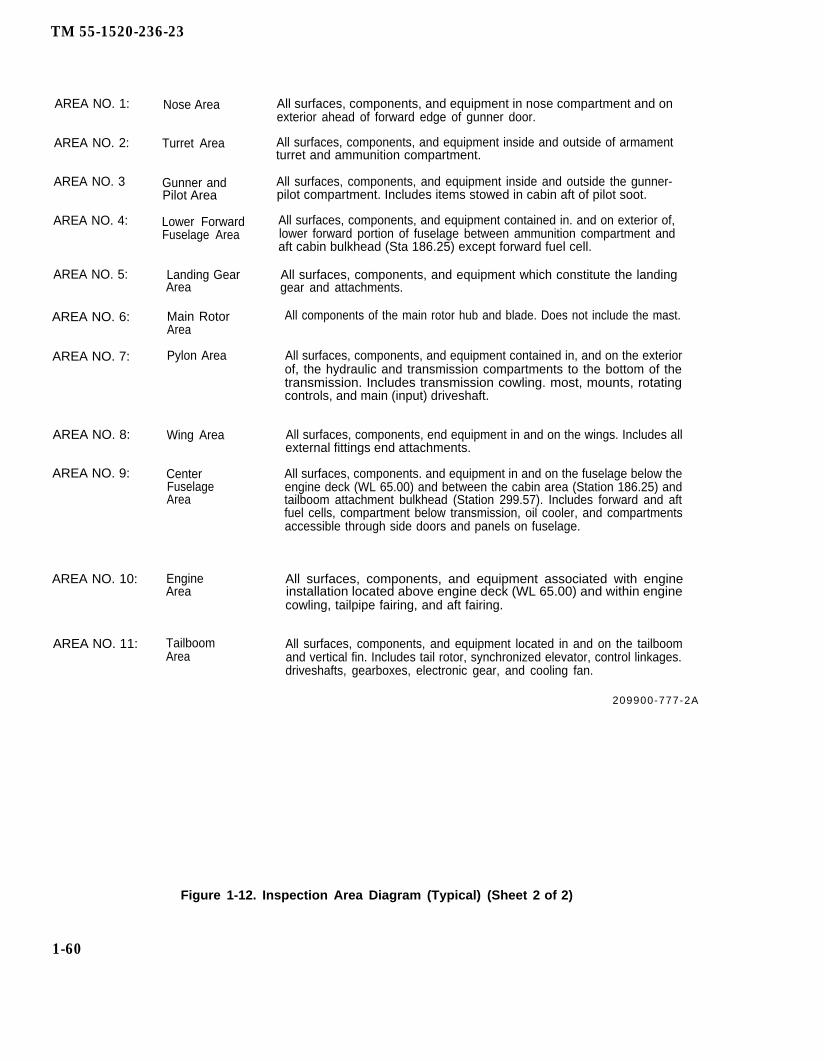
TM 55-1520-236-23
AREA NO. 1: Nose Area
AREA NO. 2: Turret Area
AREA NO. 3 Gunner andPilot Area
AREA NO. 4: Lower ForwardFuselage Area
AREA NO. 5: Landing GearArea
AREA NO. 6: Main RotorArea
AREA NO. 7: Pylon Area
AREA NO. 8: Wing Area
AREA NO. 9: CenterFuselageArea
AREA NO. 10: EngineArea
AREA NO. 11: TailboomArea
All surfaces, components, and equipment in nose compartment and onexterior ahead of forward edge of gunner door.
All surfaces, components, and equipment inside and outside of armamentturret and ammunition compartment.
All surfaces, components, and equipment inside and outside the gunner-pilot compartment. Includes items stowed in cabin aft of pilot soot.
All surfaces, components, and equipment contained in. and on exterior of,lower forward portion of fuselage between ammunition compartment andaft cabin bulkhead (Sta 186.25) except forward fuel cell.
All surfaces, components, and equipment which constitute the landinggear and attachments.
All components of the main rotor hub and blade. Does not include the mast.
All surfaces, components, and equipment contained in, and on the exteriorof, the hydraulic and transmission compartments to the bottom of thetransmission. Includes transmission cowling. most, mounts, rotatingcontrols, and main (input) driveshaft.
All surfaces, components, end equipment in and on the wings. Includes allexternal fittings end attachments.
All surfaces, components. and equipment in and on the fuselage below theengine deck (WL 65.00) and between the cabin area (Station 186.25) andtailboom attachment bulkhead (Station 299.57). Includes forward and aftfuel cells, compartment below transmission, oil cooler, and compartmentsaccessible through side doors and panels on fuselage.
All surfaces, components, and equipment associated with engineinstallation located above engine deck (WL 65.00) and within enginecowling, tailpipe fairing, and aft fairing.
All surfaces, components, and equipment located in and on the tailboomand vertical fin. Includes tail rotor, synchronized elevator, control linkages.driveshafts, gearboxes, electronic gear, and cooling fan.
209900-777-2A
Figure 1-12. Inspection Area Diagram (Typical) (Sheet 2 of 2)
1-60

TM 55-1520-236-23
TYPE OF INSP. (Daily, PAGE NO. NO. OF PAGESAIRCRAFT INSPECTION CHECKSHEET Intermediate, etc.)
SPECIAL1 26
AIRCRAFT AND SERIAL NO. INSPECTION NO. DATE OF INSPECTION
REQUIRE- STA- RECORDEDAREA MENT ITEM ONNO. EVERY TUS WORKSHEET
All AFTER A HARD LANDINGAreas
Definition: Hard landing is defined as any accident or incident in whichground impact of the helicopter causes severe pitching of main rotor,allowing hard contact of hub with mast, or results in cracking or yielding ofthe mounting lugs of the transmission support case or noticeable yieldingor cracking of fuselage pylon support structure or landing gear. Thisdefinition is confined only to those accidents not involving suddenstoppage of main rotor or tail rotor.
Inspections: When a probable hard landing incident has occurred,proceed as follows:
a. Inspect main and tail rotor blades for evidence of strike damage. Ifsuch evidence is found on either rotor, perform AFTER SUDDENSTOPPAGE Special Inspection.
b. Visually inspect underside of fuselage and tailboom for evidence ofground contact.
c. Inspect landing gear for yielding of cross tubes to cause skid tubedeflection to exceed allowable dimensions. If not obvious, determinecondition by measurements according to instructions in chapter 3.
(1) If crosstubes have yielded, remove landing gear and inspectsupports and structure to which they are attached for signs ofyielding or other damage. Inspect crosstubes and retainingplates for cracks using fluorescent penetrant or ultrasonicshear wave inspection methods.
(2) If supports and attaching structure are undamaged, replacelanding gear.
(3) Penetrant inspect tubes for cracks in area from saddle fittingsto fuselage mount.
d. Inspect mast for evidence of hard rotor hub contact sufficient to causeyielding or deformation. None is acceptable.
e. Inspect supports of dampers under pylon aft mounts for loose rivets orother damage.
1-61
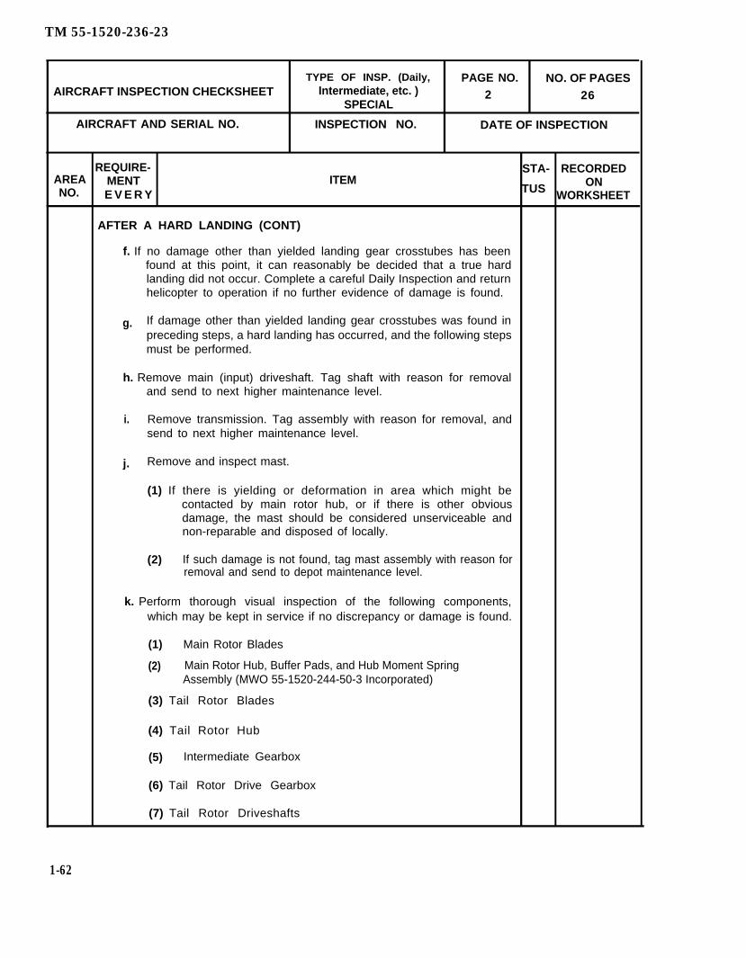
TM 55-1520-236-23
TYPE OF INSP. (Daily, PAGE NO. NO. OF PAGESAIRCRAFT INSPECTION CHECKSHEET Intermediate, etc. ) 2
SPECIAL26
AIRCRAFT AND SERIAL NO. INSPECTION NO. DATE OF INSPECTION
REQUIRE- STA- RECORDEDAREA MENT ITEMNO.
ONE V E R Y TUS WORKSHEET
AFTER A HARD LANDING (CONT)
f. If no damage other than yielded landing gear crosstubes has beenfound at this point, it can reasonably be decided that a true hardlanding did not occur. Complete a careful Daily Inspection and returnhelicopter to operation if no further evidence of damage is found.
g. If damage other than yielded landing gear crosstubes was found inpreceding steps, a hard landing has occurred, and the following stepsmust be performed.
h. Remove main (input) driveshaft. Tag shaft with reason for removaland send to next higher maintenance level.
i. Remove transmission. Tag assembly with reason for removal, andsend to next higher maintenance level.
j. Remove and inspect mast.
(1) If there is yielding or deformation in area which might becontacted by main rotor hub, or if there is other obviousdamage, the mast should be considered unserviceable andnon-reparable and disposed of locally.
(2) If such damage is not found, tag mast assembly with reason forremoval and send to depot maintenance level.
k. Perform thorough visual inspection of the following components,which may be kept in service if no discrepancy or damage is found.
(1) Main Rotor Blades
(2) Main Rotor Hub, Buffer Pads, and Hub Moment SpringAssembly (MWO 55-1520-244-50-3 Incorporated)
(3) Tail Rotor Blades
(4) Tail Rotor Hub
(5) Intermediate Gearbox
(6) Tail Rotor Drive Gearbox
(7) Tail Rotor Driveshafts
1-62
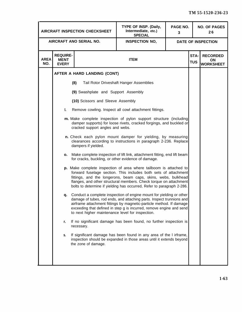
TM 55-1520-236-23
TYPE OF INSP. (Daily, PAGE NO. NO. OF PAGESAIRCRAFT INSPECTION CHECKSHEET Intermediate, etc.)
SPECIAL3 2 6
AIRCRAFT ANO SERIAL NO. INSPECTION NO, DATE OF INSPECTION
REQUIRE- STA- RECORDEDAREA MENT ITEM ONNO. EVERY TUS WORKSHEET
AFTER A HARD LANDING (CONT)
(8) Tail Rotor Driveshaft Hanger Assemblies
(9) Swashplate and Support Assembly
(10) Scissors and Sleeve Assembly
l. Remove cowling. Inspect all cowl attachment fittings.
m. Make complete inspection of pylon support structure (includingdamper supports) for loose rivets, cracked forgings, and buckled orcracked support angles and webs.
n. Check each pylon mount damper for yielding, by measuringclearances according to instructions in paragraph 2-236. Replacedampers if yielded.
o. Make complete inspection of lift link, attachment fitting, end lift beamfor cracks, buckling, or other evidence of damage.
p. Make complete inspection of area where tailboom is attached toforward fuselage section. This includes both sets of attachmentfittings, and the longerons, beam caps, skins, webs, bulkheadflanges, and other structural members. Check torque on attachmentbolts to determine if yielding has occurred, Refer to paragraph 2-286.
q. Conduct a complete inspection of engine mount for yielding or otherdamage of tubes, rod ends, and attaching parts. Inspect trunnions andairframe attachment fittings by magnetic-particle method. If damageexceeding that defined in step g is incurred, remove engine and sendto next higher maintenance level for inspection.
r. If no significant damage has been found, no further inspection isnecessary.
s. If significant damage has been found in any area of the l irframe,inspection should be expanded in those areas until it extends beyondthe zone of damage.
1-63
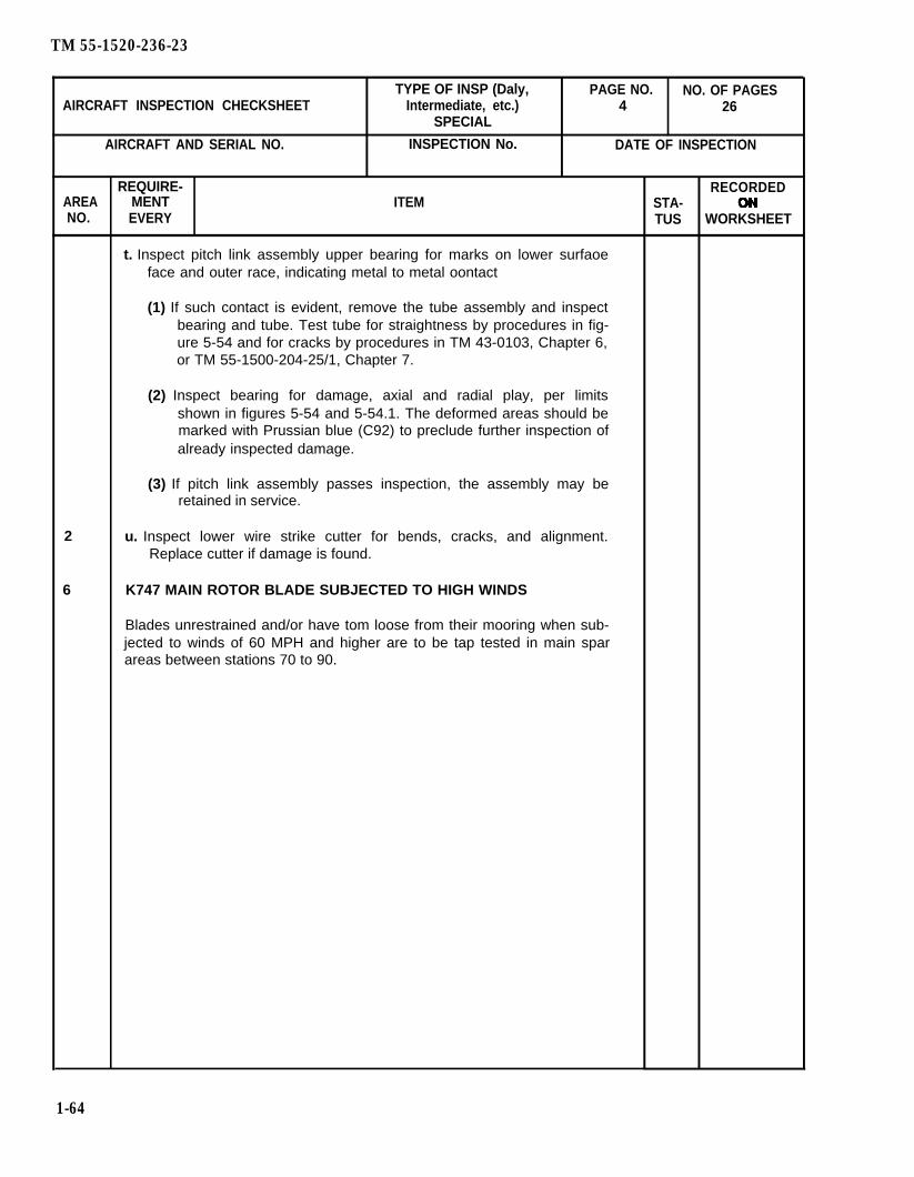
TM 55-1520-236-23
TYPE OF INSP (Daly, PAGE NO. NO. OF PAGESAIRCRAFT INSPECTION CHECKSHEET Intermediate, etc.) 4 26
SPECIAL
AIRCRAFT AND SERIAL NO. INSPECTION No. DATE OF INSPECTION
REQUIRE- RECORDEDAREA MENT ITEM STA-NO. EVERY TUS WORKSHEET
t. Inspect pitch link assembly upper bearing for marks on lower surfaoeface and outer race, indicating metal to metal oontact
(1) If such contact is evident, remove the tube assembly and inspectbearing and tube. Test tube for straightness by procedures in fig-ure 5-54 and for cracks by procedures in TM 43-0103, Chapter 6,or TM 55-1500-204-25/1, Chapter 7.
(2) Inspect bearing for damage, axial and radial play, per limitsshown in figures 5-54 and 5-54.1. The deformed areas should bemarked with Prussian blue (C92) to preclude further inspection ofalready inspected damage.
(3) If pitch link assembly passes inspection, the assembly may beretained in service.
2 u. Inspect lower wire strike cutter for bends, cracks, and alignment.Replace cutter if damage is found.
6 K747 MAIN ROTOR BLADE SUBJECTED TO HIGH WINDS
Blades unrestrained and/or have tom loose from their mooring when sub-jected to winds of 60 MPH and higher are to be tap tested in main sparareas between stations 70 to 90.
1-64

TM 55-1520-236-23
AFTER SUDDEN STOPPAGE (Power On or Power Off)
Sudden Stoppage is defined as an instantaneous shock load applied to thedrive train and rotor systems either POWER ON or POWER OFF.
Shock loads result from:
Blade(s) striking an object.
Seizures which occur as a result of an internal failure ofa drive train/rotor system.
Engine compressor stall.
After a sudden stoppage, one of the following special inspections shall beconducted, depending on origin of shock load.
a. Main Rotor Blade Strike.
(1) No visible damage to either blade.
(a) Wipe upper and lower surfaces of main rotor bladeswith a clean, soft cloth and inspect both surfaces forcracks, distortion, or bond separation.
(b) Visually inspect hub assembly and mast for damage.
(c) If no damage is found, inspection is complete. Ifdamage is found in either of the above inspections,proceed to paragraph (2) below:
(2) Mirror damage to either blade.
NOTE
This category includes both field repairable damage and skin tearswhether repairable or not.
1-64.1 /(1-64.2 blank)

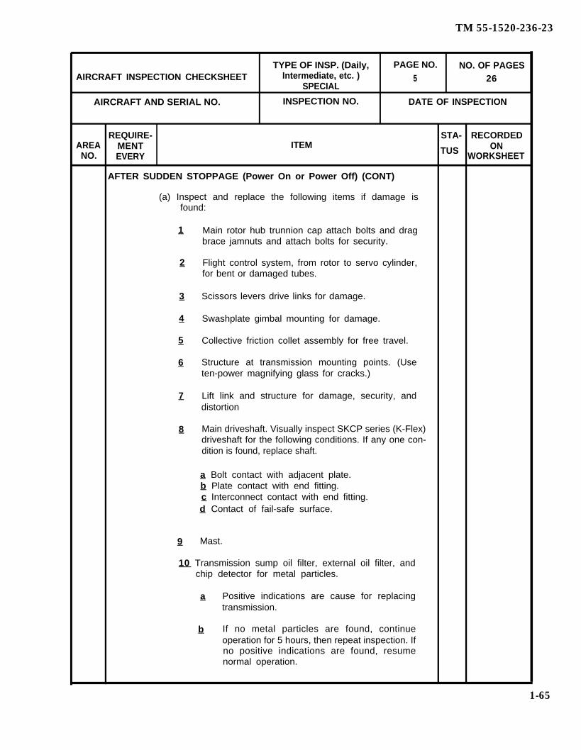
TM 55-1520-236-23
TYPE OF INSP. (Daily, PAGE NO. NO. OF PAGESAIRCRAFT INSPECTION CHECKSHEET Intermediate, etc. ) 5
SPECIAL26
AIRCRAFT AND SERIAL NO. INSPECTION NO. DATE OF INSPECTION
REQUIRE- STA- RECORDEDAREA MENT ITEM ONNO. EVERY
TUS WORKSHEET
AFTER SUDDEN STOPPAGE (Power On or Power Off) (CONT)
(a) Inspect and replace the following items if damage isfound:
1 Main rotor hub trunnion cap attach bolts and dragbrace jamnuts and attach bolts for security.
2 Flight control system, from rotor to servo cylinder,for bent or damaged tubes.
3 Scissors levers drive links for damage.
4 Swashplate gimbal mounting for damage.
5 Collective friction collet assembly for free travel.
6 Structure at transmission mounting points. (Useten-power magnifying glass for cracks.)
7 Lift link and structure for damage, security, anddistortion
8 Main driveshaft. Visually inspect SKCP series (K-Flex)driveshaft for the following conditions. If any one con-dition is found, replace shaft.
a Bolt contact with adjacent plate.b Plate contact with end fitting.c Interconnect contact with end fitting.d Contact of fail-safe surface.
9 Mast.
10 Transmission sump oil filter, external oil filter, and chip detector for metal particles.
a Positive indications are cause for replacingtransmission.
b If no metal particles are found, continueoperation for 5 hours, then repeat inspection. Ifno positive indications are found, resumenormal operation.
1-65
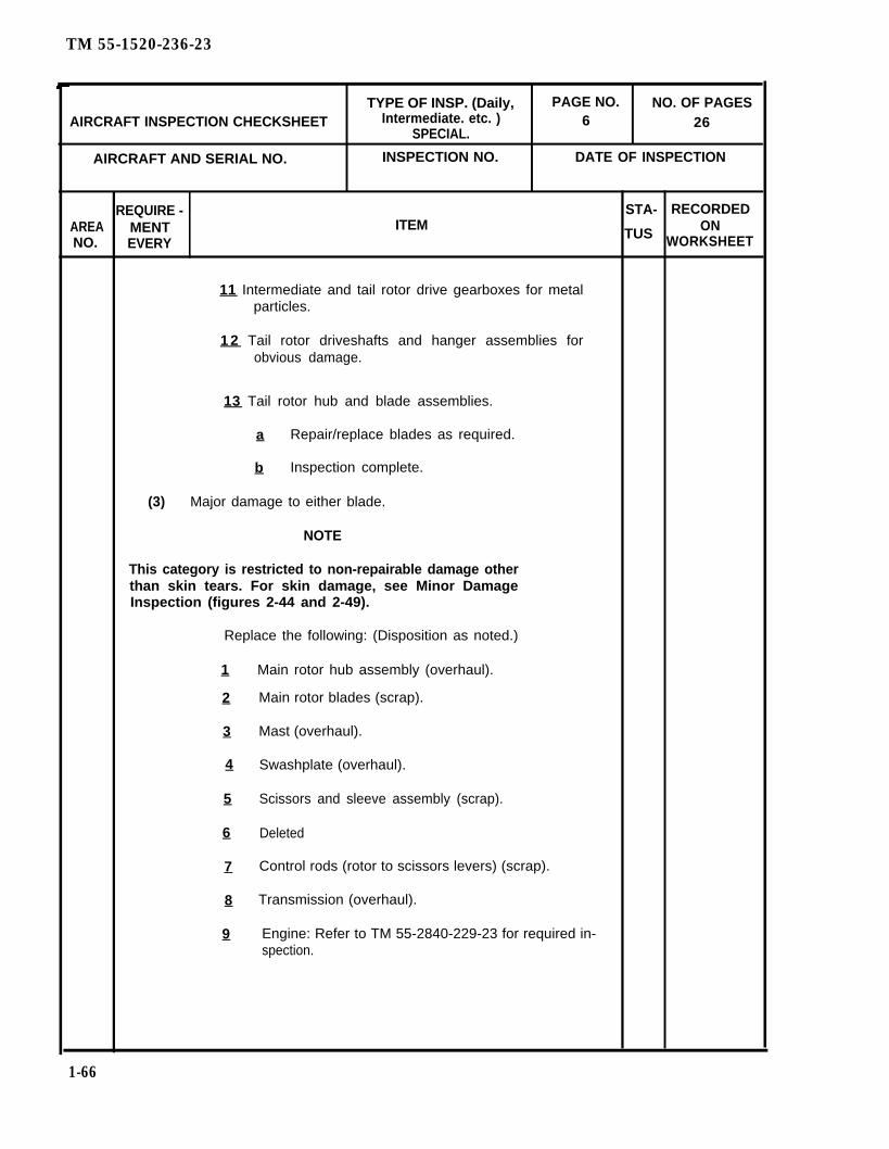
TM 55-1520-236-23
TYPE OF INSP. (Daily, PAGE NO. NO. OF PAGESAIRCRAFT INSPECTION CHECKSHEET Intermediate. etc. ) 6
SPECIAL.26
AIRCRAFT AND SERIAL NO. INSPECTION NO. DATE OF INSPECTION
REQUIRE - STA- RECORDEDAREA MENT ITEM ONNO. EVERY
TUS WORKSHEET
11 Intermediate and tail rotor drive gearboxes for metalparticles.
1 2 Tail rotor driveshafts and hanger assemblies forobvious damage.
13 Tail rotor hub and blade assemblies.
a Repair/replace blades as required.
b Inspection complete.
(3) Major damage to either blade.
NOTE
This category is restricted to non-repairable damage otherthan skin tears. For skin damage, see Minor DamageInspection (figures 2-44 and 2-49).
Replace the following: (Disposition as noted.)
1 Main rotor hub assembly (overhaul).
2 Main rotor blades (scrap).
3 Mast (overhaul).
4 Swashplate (overhaul).
5 Scissors and sleeve assembly (scrap).
6 Deleted
7 Control rods (rotor to scissors levers) (scrap).
8 Transmission (overhaul).
9 Engine: Refer to TM 55-2840-229-23 for required in-spection.
1-66

TM 55-1520-236-23
TYPE OF INSP. (Daily, PAGE NO. NO. OF PAGESAIRCRAFT INSPECTION CHECKSHEET Intermediate, etc.) 7 26
SPECIALAIRCRAFT AND SERIAL NO. INSPECTlON NO. DATE OF lNSPECTION
REWIRE - STA- RECORDEDAREA MENT ITEM TUS ONNO. EVERY WORKSHEET
b. Tail Rotor Blade Strike.
(1) No visible damage to either blade.
(a) Inspect doublers for bonding separation, attachment area fordistortion.
(b) Tail rotor hub assembly for damage.
(c) Inspect tail rotor rotating controls for damage.
(d) Inspect intermediate and tail rotor drive gearboxes for metalparticles.
(e) Tail rotor driveshafts and hangers for obvious damage.
(f) If no damage is found, inspection complete. If damage is found,proceed to paragraph (2) below:
(2) Visible damage to either blade.
NOTE
Damage to tail rotor system that requires blade replace-ment will cause mandatory tail rotor yoke replacement.
(a) Scrap both blades.
(b) Replace intermediate and tail rotor drive gearboxes and return foroverhaul.
(c) Inspect and replace the following items if damage is found.
1 Tail rotor hub assembly.
2 Tail rotor rotating controls.
3 Tail rotor driveshafts.
4 Tail rotor hanger assemblies (inspect for internal spline andcurvic coupling damage).
5 Transmission sump oil filter, external oil filter and chip detectorfor metal particles.
a Positive indications are cause for replacing transmission
b If no metal particles are found, continue operation for 5 hours,then repeat inspection. If no positive indications are found,resume normal operation.
1-67

TM 55-1520-236-23
1-68
Main driveshaft.
Tailboom attachment points.
Mast assembly.
Main rotor rotating controls.
Main rotor blades.
Main rotor hub trunnion cap attach bolts-and drag bracejamnuts for security.
Transmission tail rotor output quill.
Inspection complete.
AFTER SUDDEN STOPPAGE (Power On or Power Off) (CONT)
(c) Inspect and replace the following items if damage is found.
Tail rotor hub assembly.
Tail rotor rotating controls.
Tail rotor driveshafts.
Tail rotor hanger assemblies (inspect for internal spline andcurvic coupling damage).
Tailboom attachment points.
(3) Inspection Complete.
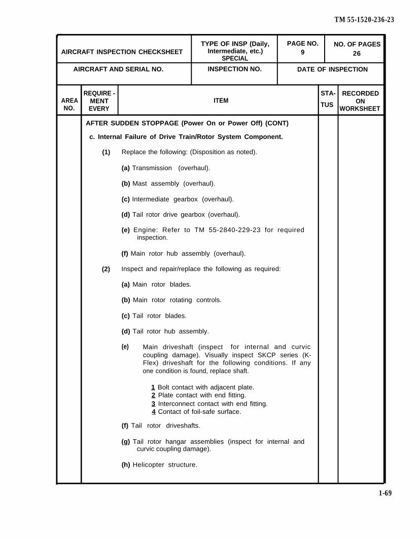
TM 55-1520-236-23
TYPE OF INSP (Daily, PAGE NO. NO. OF PAGESAIRCRAFT INSPECTION CHECKSHEET Intermediate, etc.) 9
SPECIAL26
AIRCRAFT AND SERIAL NO. INSPECTION NO. DATE OF INSPECTION
REQUIRE - STA- RECORDEDAREA MENT ITEM
TUS ONNO. EVERY WORKSHEET
AFTER SUDDEN STOPPAGE (Power On or Power Off) (CONT)
c. Internal Failure of Drive Train/Rotor System Component.
(1) Replace the following: (Disposition as noted).
(a) Transmission (overhaul).
(b) Mast assembly (overhaul).
(c) Intermediate gearbox (overhaul).
(d) Tail rotor drive gearbox (overhaul).
(e) Engine: Refer to TM 55-2840-229-23 for requiredinspection.
(f) Main rotor hub assembly (overhaul).
(2) Inspect and repair/replace the following as required:
(a) Main rotor blades.
(b) Main rotor rotating controls.
(c) Tail rotor blades.
(d) Tail rotor hub assembly.
(e) Main driveshaft (inspect for internal and curviccoupling damage). Visually inspect SKCP series (K-Flex) driveshaft for the following conditions. If anyone condition is found, replace shaft.
1 Bolt contact with adjacent plate.2 Plate contact with end fitting.3 Interconnect contact with end fitting.4 Contact of foil-safe surface.
(f) Tail rotor driveshafts.
(g) Tail rotor hangar assemblies (inspect for internal andcurvic coupling damage).
(h) Helicopter structure.
1-69
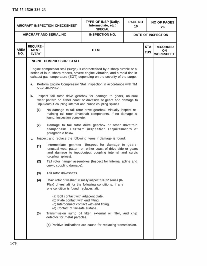
TM 55-1520-236-23
TYPE OF INSP (Daily, PAGE NO NO OF PAGESAIRCRAFT INSPECTION CHECKSHEET Intermediate, etc.) 10
SPECIAL26
AIRCRAFT AND SERIAL NO INSPECTION NO. DATE OF INSPECTION
REQUIRE - STA- RECORDEDAREA MENT ITEMNO.
ONEVERY TUS WORKSHEET
ENGINE COMPRESSOR STALL
Engine compressor stall (surge) is characterized by a sharp rumble or aseries of loud, sharp reports, severe engine vibration, and a rapid rise inexhaust gas temperature (EGT) depending on the severity of the surge.
a. Perform Engine Compressor Stall Inspection in accordance with TM55-2840-229-23.
b. Inspect tail rotor drive gearbox for damage to gears, unusualwear pattern on either coast or driveside of gears and damage toinput/output coupling internal and curvic coupling splines.
(1) No damage to tail rotor drive gearbox. Visually inspect re-maining tail rotor driveshaft components. If no damage isfound, inspection complete.
(2) Damage to tail rotor drive gearbox or other drivetraincomponent . Per fo rm inspec t ion requ i rements o fparagraph c below.
c. Inspect and replace the following items if damage is found:
(1) Intermediate gearbox (inspect for damage to gears,unusual wear pattern on either coast of drive side or gearsand damage to input/output coupling internal and curviccoupling splines).
(2) Tail rotor hanger assemblies (Inspect for Internal spline andcurvic coupling damage).
(3) Tail rotor driveshafts.
(4) Main rotor driveshaft. visually inspect SKCP series (K-Flex) driveshaft for the following conditions. If anyone condition is found, replaceshaft.
(a) Bolt contact with adjacent plate.(b) Plate contact with end fitting.(c) Interconnect contact with end fitting.(d) Contact of fail-safe surface.
(5) Transmission sump oil filter, external oil filter, and chipdetector for metal particles.
(a) Positive indications are cause for replacing transmission.
1-70
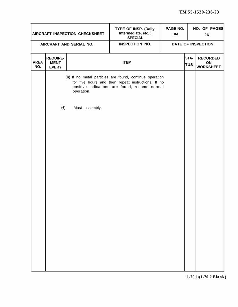
TM 55-1520-236-23
TYPE OF INSP. (Daily, PAGE NO. NO. OF PAGESAlRCRAFT INSPECTION CHECKSHEET Intermediate, etc. ) 10A
SPECIAL26
AIRCRAFT AND SERIAL NO. INSPECTION NO. DATE OF INSPECTION
REQUIRE- STA- RECORDEDAREA MENT ITEM
TUS ONNO. EVERY WORKSHEET
(b) If no metal particles are found, continue operationfor five hours and then repeat instructions. If nopositive indications are found, resume normaloperation.
(6) Mast assembly.
1-70.1/(1-70.2 Blank)


TM 55-1520-236-23
TYPE OF INSP (Daily. PAGE NO NO OF PAGESAlRCRAFT INSPECTION CHECKSHEET Intermediate, etc.) 11 26
SPECIAL
AIRCRAFT ANO SERIAL NO. INSPECTION NO DATE OF INSPECTION
AREANo.
REQUIRE-MENT ITEMEVERY
ENGINE COMPRESSOR STALL (CONT)
(7) Helicopter structure including tailboom attachment area andvertical fin.
(8) Replace main rotor hub trunnion attach bolts.
(9) Tail rotor blades.
(10) Tail rotor hub assembly.
d. Inspection complete.
HELICOPTER STRUCK BY LIGHTING OR HIGH TENSION WIRE STRIKE
a. General Inspection Requirements.
(1)
(2)
(3)
(4)
(5)
(6)
(7)
(8)
Inspect fuselage interior and exterior, the landing gear, rotorsystems and static ground wire for burn marks, cracks, pitting,or other signs of high temperature stress to determinelightning entry and exit points.
Trace path of lightning strike to extent possible, using a fieldindicator (magnetometer) (T64.1).
Check magnetic compass for accuracy (the degree ofinaccuracy may serve as an indicator of severity of strike).
Inspect wiring in tunnel areas and exposed areas for burns.
Inspect antennas for burns and pitting.
Inspect all electrically operated components and lightingsystem for damage.
Inspect communications and navigation equipment fordamage.
lf the preceding steps (1) through (7) reveal major damage hasoccurred, proceed as follows:
(a) Bench test all avionics and electrical systems andcomponents.
STA -TUS
RECORDEDON
WORKSHEET
1-71
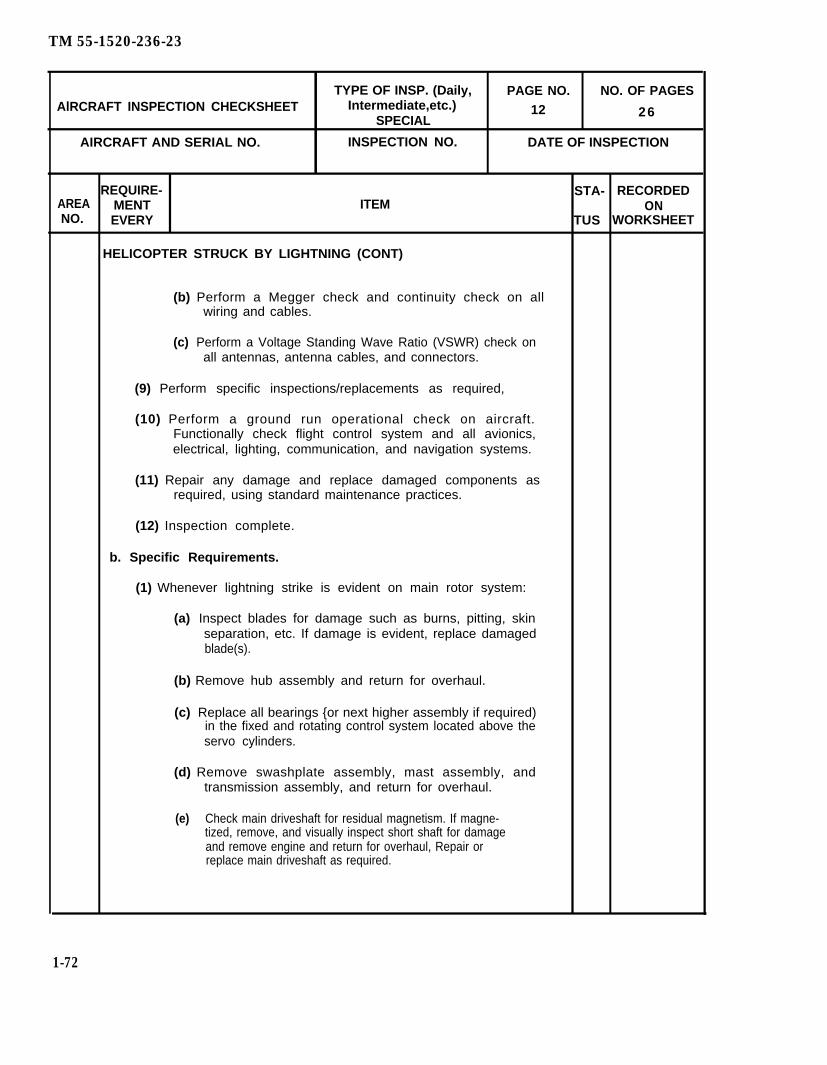
TM 55-1520-236-23
TYPE OF INSP. (Daily, PAGE NO. NO. OF PAGESAlRCRAFT INSPECTION CHECKSHEET Intermediate,etc.) 12
SPECIAL26
AIRCRAFT AND SERIAL NO. INSPECTION NO. DATE OF INSPECTION
REQUIRE- STA- RECORDEDAREA MENT ITEMNO.
ONEVERY TUS WORKSHEET
HELICOPTER STRUCK BY LIGHTNING (CONT)
(b) Perform a Megger check and continuity check on allwiring and cables.
(c) Perform a Voltage Standing Wave Ratio (VSWR) check onall antennas, antenna cables, and connectors.
(9) Perform specific inspections/replacements as required,
(10) Perform a ground run operational check on aircraft.Functionally check flight control system and all avionics,electrical, lighting, communication, and navigation systems.
(11) Repair any damage and replace damaged components asrequired, using standard maintenance practices.
(12) Inspection complete.
b. Specific Requirements.
(1) Whenever lightning strike is evident on main rotor system:
(a) Inspect blades for damage such as burns, pitting, skinseparation, etc. If damage is evident, replace damagedblade(s).
(b) Remove hub assembly and return for overhaul.
(c) Replace all bearings {or next higher assembly if required)in the fixed and rotating control system located above theservo cylinders.
(d) Remove swashplate assembly, mast assembly, andtransmission assembly, and return for overhaul.
(e) Check main driveshaft for residual magnetism. If magne-tized, remove, and visually inspect short shaft for damageand remove engine and return for overhaul, Repair orreplace main driveshaft as required.
1-72

TM 55-1520-236-23
TYPE OF lNSP. (Daily, PAGE NO. NO. OF PAGESAIRCRAFT INSPECTION CHECKSHEET Intermediate, etc.) 13 26
SPECIAL
AIRCRAFT AND SERIAL NO. INSPECTION NO. DATE OF INSPECTION
REQUIRE- STA- RECORDEDAREA MENT ITEM ONNO. EVERY TUS WORKSHEET
HELICOPTER STRUCK BY LIGHTNING (CONT)
(2) Whenever lightning strike is evident on tail rotor system:
(a) Inspect blades for damage such as burns, pitting, skinseparation, etc. If damage is evident, replace damagedblade(s).
(b) Inspect tail rotor hub for arcing damage. If damaged,replace.
(c) Remove and condemn pitch change links, counterweightlinks, crosshead bearing.
(d) Inspect crosshead, idler, lever, bellcranks, counterweightassemblies, and control rod for any indications of arcing.Replace as necessary.
{e) Remove both the intermediate and tail rotor drivegearboxes and return for overhaul.
(f) Check hangers for residual magnetism. Replace anymagnetized hanger bearings.
1 If all hangers are magnetized, remove transmissionand return for overhaul.
2 Check main driveshaft for residual magnetism. Ifmagnetized, return engine for overhaul and teardown main driveshaft for inspection. Repair orreplace main driveshaft as required.
AFTER MAIN ROTOR OVERSPEED
Inspection and/or replacements are required after any report that mainrotor has exceeded 105 percent limit, When 110 percent has been ex-ceeded, additional requirements apply.
MAIN ROTOR OVERSPEED OF 110 PERCENT OR LESS.
Inspect the following:
a. Main rotor blades for damage, bond separation, and distortion.
1-73

TM 55-1520-236-23
TYPE of lNSP (Daily, PAGE NO NO OF PAGESAIRCRAFT INSPECTION CHECKSHEET Intermediate, etc.)
SPECIAL14 26
AIRCRAFT AND SERIAL NO. INSPECTION NO. DATE OF INSPECTION
REQUIRE- STA- RECORDEDAREA MENT ITEMNO.
ONEVERY TUS WORKSHEET
6 & 11 AFTER MAIN ROTOR OVERSPEED (CONT)
b. Tail rotor blades for damage, bond separation, and distortion.
MAIN ROTOR OVERSPEED EXCEEDING 110 PERCENT:
a. Inspect main rotor blades follows:
(1) Inspect blade bolt holes for elongation. Inspect inboard holeof root fitting for maximum elongation of 0.002 inch. Max-imum hot. diameter shall not exceed 2.5025 inch.
(2) Visually inspect blade skins. Any wrinkle or deformationfound should be reported to AVSCOM Engineering.
(3) Remove tip cap and inspect balance weights. Deformation ofweights and/or studs is cause for blade replacement. Looseweights is not a cause for blade replacement. Inspect stud reten-tion nuts for looseness by applying 30 inch pound torque. Tor-que loose stud retention nuts to 130 to 145 inch pounds.
K747(4) Remove tip cap. Inspect balance weights. If weights aredeformed, reshape and secure.
K747(5) Visually inspect for any crescent shaped raised areas on theupper and lower inertia weight repair patches roughly cor-responding to a segment of a two-huh diameter circle (not toexceed 0.060 inch in height).
(6) Blades which pass these inspection are acceptable for futherservice. Return faulty blades to next higher maintenance levelwith details of overspeed incident.
b. Replace main rotor hub assembly. Send removed hub to depotmaintenance with information on overspeed incident. Boltsshould remain with hub.
c. Deleted.
d. Inspect tail totor blades:
(1) Sand separation anywhere on the blade& cause for replacingblades. Send removed blades to next higher maintenancelevel.
(2) lf any movement of the tip or root and balance weights has oc-curred, dispose of the blade locally.
(3) Check the retention bushings for evidence of looseness. If anybushing is loose, dispose of the blade locally.
1-74
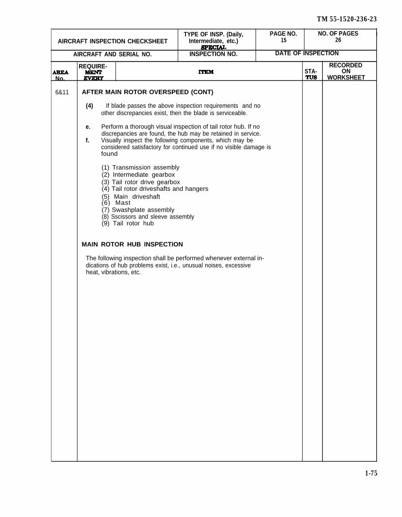
TM 55-1520-236-23
TYPE OF INSP. (Daily, PAGE NO. NO. OF PAGES IAIRCRAFT INSPECTION CHECKSHEET Intermediate, etc.) 15 26
AIRCRAFT AND SERIAL NO. INSPECTION NO. DATE OF INSPECTION
REQUIRE- RECORDEDSTA- ON
No. WORKSHEET
6&11 AFTER MAIN ROTOR OVERSPEED (CONT)
(4) If blade passes the above inspection requirements and noother discrepancies exist, then the blade is serviceable.
e. Perform a thorough visual inspection of tail rotor hub. If nodiscrepancies are found, the hub may be retained in service.
f. Visually inspect the following components, which may beconsidered satisfactory for continued use if no visible damage isfound
(1) Transmission assembly(2) Intermediate gearbox(3) Tail rotor drive gearbox(4) Tail rotor driveshafts and hangers(5) Main driveshaft(6) Mast(7) Swashplate assembly(8) Sscissors and sleeve assembly(9) Tail rotor hub
MAIN ROTOR HUB INSPECTION
The following inspection shall be performed whenever external in-dications of hub problems exist, i.e., unusual noises, excessiveheat, vibrations, etc.
1-75
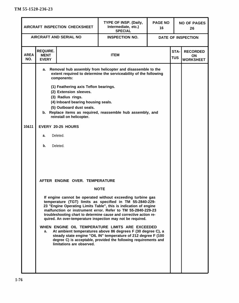
TM 55-1520-236-23
TYPE OF INSP. (Daily, PAGE NO NO OF PAGESAIRCRAFT INSPECTION CHECKSHEET Intermediate, etc.)
SPECIAL16 26
AIRCRAFT AND SERIAL NO INSPECTION NO. DATE OF INSPECTION
REQUIRE. STA- RECORDEDAREA MENT ITEMNO.
ONEVERY TUS WORKSHEET
a. Removal hub assembly from helicopter and disassemble to theextent required to determine the serviceability of the followingcomponents:
(1) Feathering axis Teflon bearings.(2) Extension sleeves.(3) Radius rings.(4) Inboard bearing housing seals.(5) Outboard dust seals.
b. Replace items as required, reassemble hub assembly, andreinstall on helicopter.
10&11 EVERY 20-25 HOURS
a. Deleted.
b. Deleted.
AFTER ENGINE OVER. TEMPERATURE
NOTE
If engine cannot be operated without exceeding turbine gastemperature (TGT) limits as specified in TM 55-2840-229-23 "Engine Operating Limits Table", this is indication of enginemalfunction or instrument error. Refer to TM 55-2840-229-23troubleshooting chart to determine cause and corrective action re-quired. An over-temperature inspection may not be required.
WHEN ENGINE OIL TEMPERATURE LIMITS ARE EXCEEDEDa. At ambient temperatures above 86 degrees F (30 degree C), a
steady state engine "OIL IN" temperature of 212 degree F (100degree C) is acceptable, provided the following requirements andlimitations are observed.
1-76
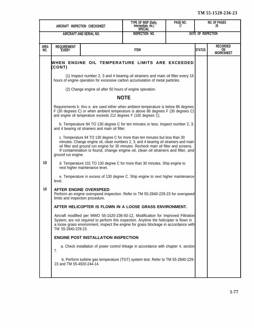
TM 55-1520-236-23
TYPE OF INSP (Daily, PAGE NO. NO. OF PAGESAIRCRAFT INSPECTION CHECKSHEET Intermediate, etc.) 17 26
SPECIALAIRCRAFT AND SERIAL NO. INSPECTION NO. DATE OF INSPECTION
AREA REQUIREMENT RECORDEDNO. EVERY ITEM STATUS ON
WORKSHEET
WHEN ENGINE OIL TEMPERATURE LIMITS ARE EXCEEDED(CONT)
(1) Inspect number 2, 3 and 4 bearing oil strainers and main oil filter every 15hours of engine operation for excessive carbon accumulation of metal particles.
(2) Change engine oil after 50 hours of engine operation.
NOTE
Requirements b. thru e. are used either when ambient temperature is below 86 degreesF (30 degrees C) or when ambient temperature is above 86 degrees F (30 degrees C)and engine oil temperature exceeds 212 degrees F (100 degrees C).
b. Temperature 94 TO 130 degree C for ten minutes or less. Inspect number 2, 3,and 4 bearing oil strainers and main oil filter.
c. Temperature 94 TO 130 degree C for more than ten minutes but less than 30minutes. Change engine oil, clean numbers 2, 3, and 4 bearing oil strainers and mainoil filter and ground run engine for 30 minutes. Recheck main oil filter and screens.If contamination is found, change engine oil, clean oil strainers and filter, and
ground run engine.
10 d. Temperature 101 TO 130 degree C for more than 30 minutes. Ship engine tonext higher maintenance level.
e. Temperature in excess of 130 degree C. Ship engine to next higher maintenancelevel.
10 AFTER ENGINE OVERSPEEDPerform an engine overspeed inspection. Refer to TM 55-2840-229-23 for overspeedlimits and inspection procedure.
AFTER HELICOPTER IS FLOWN IN A LOOSE GRASS ENVIRONMENT.
Aircraft modified per MWO 55-1520-236-50-12, Modification for Improved FiltrationSystem, are not required to perform this inspection. Anytime the helicopter is flown ina loose grass environment, inspect the engine for grass blockage in accordance withTM 55-2840-229-23.
ENGINE POST INSTALLATION INSPECTION
a. Check installation of power control linkage in accordance with chapter 4, section7.
b. Perform turbine gas temperature (TGT) system test. Refer to TM 55-2840-229-23 and TM 55-4920-244-14.
1-77

TM 55-1520-236-23
c. Perform a daily inspection.
NOTE
The following stop d. need not be performed if engine hasbeen removed and reinstalled for reasons other than en-gine maintenance. However, engine should be inspectedfor leaks and security of mounting provisions, hoses, andaccessories prior to flight.
d. Perform inspection before and after initial check-run. Refer toTM 55-2840-229-23.
e. Perform a limited test fight (TM 55-1520-236-MTF).
f. Perform an engine vibration test. Refer to TM 55-2840-229-23.
ENGINES DROPPED DURING HANDLING
If an engine is dropped during handling, perform inspection, Refer toTM 55-2840-229-23.
AFTER OVERTORQUEOvertorque is defined as any inicident in which torsional loads are introducedinto the helicopter dynamic system in excess of 100 percent as determined onthe engine torquemeter (calibrated).
NOTE
Use calibrated torque for overtorque limits. The followingtable shall be used to convert indicated torque to cali-brated torque.
Calibration Factor Multiply Indicated Torque By
64 0.9663 0.976261
0.99
601.001.02
59 1.0458 1.06
1-78
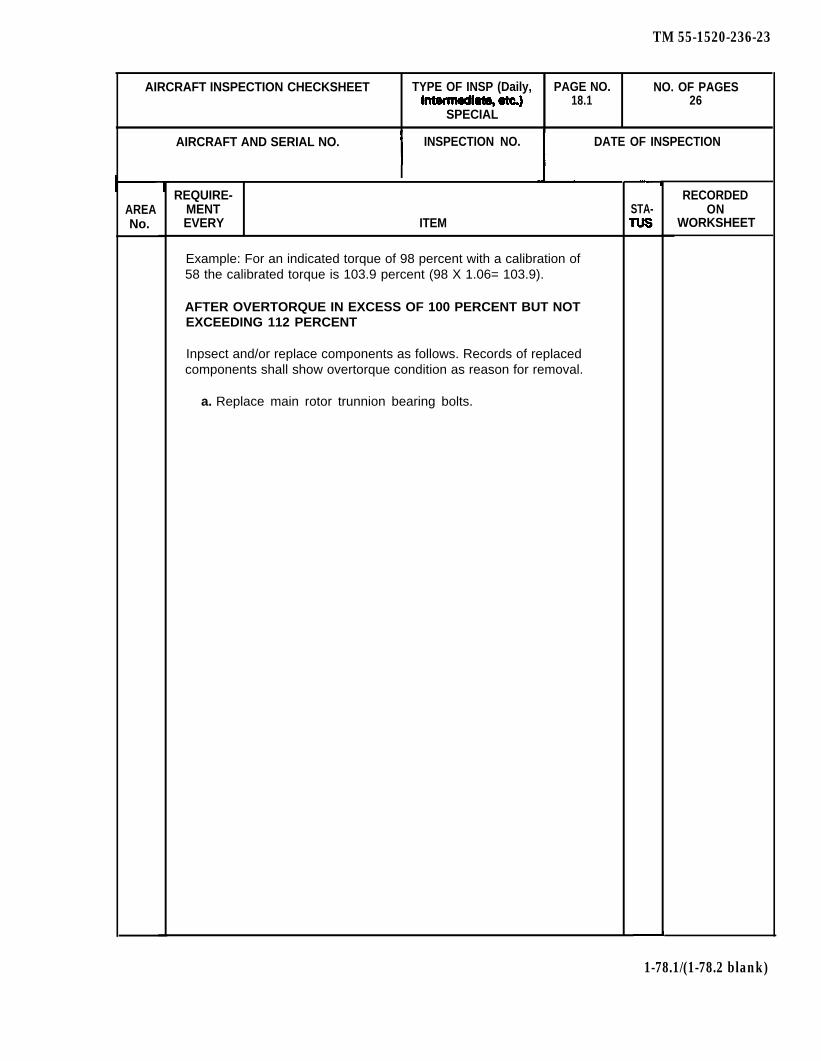
TM 55-1520-236-23
AIRCRAFT INSPECTION CHECKSHEET TYPE OF INSP (Daily, PAGE NO. NO. OF PAGES18.1 26
SPECIAL
AIRCRAFT AND SERIAL NO. INSPECTION NO. DATE OF INSPECTION
AREANo.
REQUIRE-MENTEVERY ITEM
Example: For an indicated torque of 98 percent with a calibration of58 the calibrated torque is 103.9 percent (98 X 1.06= 103.9).
AFTER OVERTORQUE IN EXCESS OF 100 PERCENT BUT NOTEXCEEDING 112 PERCENT
Inpsect and/or replace components as follows. Records of replacedcomponents shall show overtorque condition as reason for removal.
a. Replace main rotor trunnion bearing bolts.
STA-RECORDED
ONWORKSHEET
1-78.1/(1-78.2 blank)

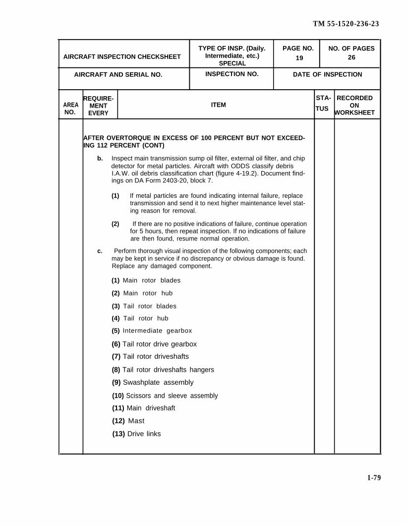
TM 55-1520-236-23
TYPE OF INSP. (Daily. PAGE NO. NO. OF PAGESAIRCRAFT INSPECTION CHECKSHEET Intermediate, etc.) 19 26
SPECIAL
AIRCRAFT AND SERIAL NO. INSPECTION NO. DATE OF INSPECTION
REQUIRE- STA- RECORDEDAREA MENT ITEM TUS ONNO. EVERY WORKSHEET
AFTER OVERTORQUE IN EXCESS OF 100 PERCENT BUT NOT EXCEED-ING 112 PERCENT (CONT)
b. Inspect main transmission sump oil filter, external oil filter, and chipdetector for metal particles. Aircraft with ODDS classify debrisI.A.W. oil debris classification chart (figure 4-19.2). Document find-ings on DA Form 2403-20, block 7.
(1) If metal particles are found indicating internal failure, replacetransmission and send it to next higher maintenance level stat-ing reason for removal.
(2) If there are no positive indications of failure, continue operationfor 5 hours, then repeat inspection. If no indications of failureare then found, resume normal operation.
c. Perform thorough visual inspection of the following components; eachmay be kept in service if no discrepancy or obvious damage is found.Replace any damaged component.
(1) Main rotor blades
(2) Main rotor hub
(3) Tail rotor blades
(4) Tail rotor hub
(5) Intermediate gearbox
(6) Tail rotor drive gearbox
(7) Tail rotor driveshafts
(8) Tail rotor driveshafts hangers
(9) Swashplate assembly
(10) Scissors and sleeve assembly
(11) Main driveshaft
(12) Mast
(13) Drive links
1-79
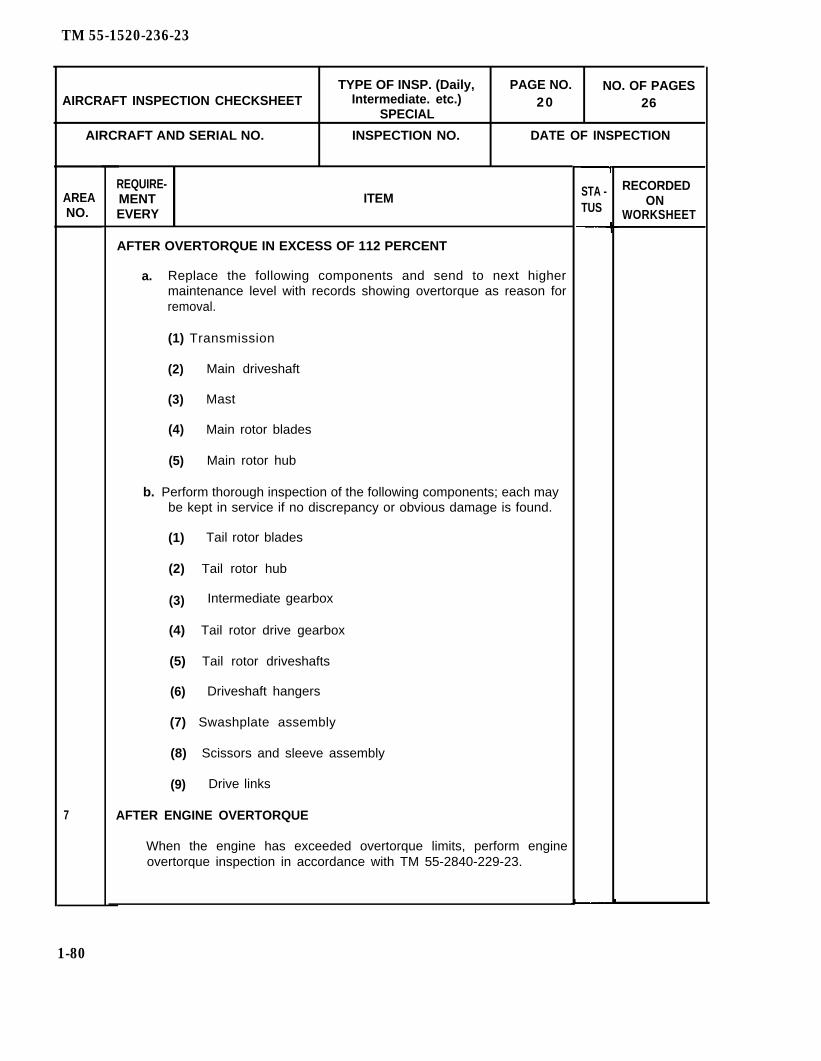
TM 55-1520-236-23
TYPE OF INSP. (Daily, PAGE NO. NO. OF PAGESAIRCRAFT INSPECTION CHECKSHEET Intermediate. etc.) 20
SPECIAL26
AIRCRAFT AND SERIAL NO. INSPECTION NO. DATE OF INSPECTION
AREANO.
7
REQUIRE-MENT ITEMEVERY
AFTER OVERTORQUE IN EXCESS OF 112 PERCENT
a. Replace the following components and send to next highermaintenance level with records showing overtorque as reason forremoval.
(1) Transmission
(2) Main driveshaft
(3) Mast
(4) Main rotor blades
(5) Main rotor hub
b. Perform thorough inspection of the following components; each maybe kept in service if no discrepancy or obvious damage is found.
(1) Tail rotor blades
(2) Tail rotor hub
(3) Intermediate gearbox
(4) Tail rotor drive gearbox
(5) Tail rotor driveshafts
(6) Driveshaft hangers
(7) Swashplate assembly
(8) Scissors and sleeve assembly
(9) Drive links
AFTER ENGINE OVERTORQUE
When the engine has exceeded overtorque limits, perform engineovertorque inspection in accordance with TM 55-2840-229-23.
STA -TUS
RECORDEDON
WORKSHEET
1-80

TM 55-1520-236-23
TYPE OF INSP. (Daily, PAGE NO. NO. OF PAGESAIRCRAFT INSPECTION CHECKSHEET Intermediate, etc.) 21
SPECIAL26
AIRCRAFT ANO SERIAL NO. INSPECTION NO. DATE OF INSPECTION
REQUIRE-AREA
STA- RECORDEDMENT ITEM ON
NO. EVERY TUS WORKSHEET
AFTER ENGINE OVERTORQUE (CONT)
The following limits are engine torque limits only. Pilotmonitoring is necessary to prevent the engine fromexceeding dynamic components (airframe) limits.
a. Output shaft torque limits:
(1) Intermediate (30 minutes) 64 PSl 114 Percent
(2) Normal (continuous) 60 PSl 107 Percent
(3) Transient operation 86 PSl 153 Percent(2 seconds of less)
AFTER TAIL ROTOR DRIVE SYSTEM OVERTORQUE
NOTE
If tail rotor rigging is known to be correct, flightmaneuvers with maximum allowable engine powerwhich result in insufficient tail rotor control can causea possible overtorque.
a. Remove output quill assembly from intermediate gearbox, andinspect output gear teeth for damage as described in chapter 6. If noscoring or scuffing is found, and if there are no other indications ofdamage, reassemble gearbox and retain in service. If gear teeth arescored or scuffed, or if there are other indications of damage, replacegearbox and perform inspection in step b.
b. Remove output quill assembly from tail rotor gearbox, and inspectcondition of gears as in step a. If no scoring or scuffing is found and ifthere are no other indications of damage, reassemble gearbox andretain in service. If gear teeth are scored or scuffed, or if there areother indications of damage, replace gearbox and perform inspectionin step c.
1-81
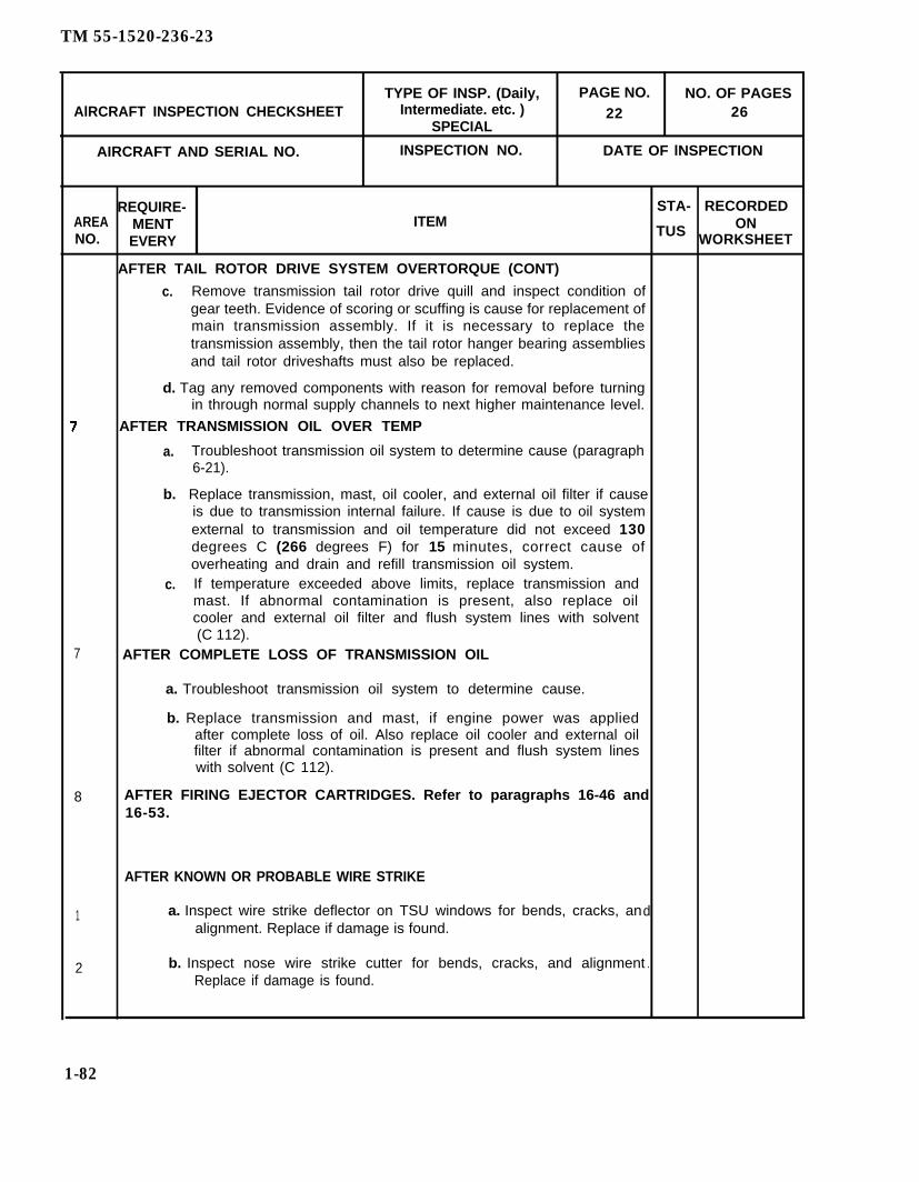
TM 55-1520-236-23
TYPE OF INSP. (Daily, PAGE NO. NO. OF PAGESAlRCRAFT INSPECTION CHECKSHEET Intermediate. etc. ) 22 26
SPECIAL
AIRCRAFT AND SERIAL NO. INSPECTION NO. DATE OF lNSPECTION
REQUIRE- STA- RECORDEDAREA MENT ITEM ONNO. EVERY
TUS WORKSHEET
AFTER TAIL ROTOR DRIVE SYSTEM OVERTORQUE (CONT)
c. Remove transmission tail rotor drive quill and inspect condition ofgear teeth. Evidence of scoring or scuffing is cause for replacement ofmain transmission assembly. If it is necessary to replace thetransmission assembly, then the tail rotor hanger bearing assembliesand tail rotor driveshafts must also be replaced.
d. Tag any removed components with reason for removal before turningin through normal supply channels to next higher maintenance level.
AFTER TRANSMISSION OIL OVER TEMP
a. Troubleshoot transmission oil system to determine cause (paragraph6-21).
b. Replace transmission, mast, oil cooler, and external oil filter if causeis due to transmission internal failure. If cause is due to oil systemexternal to transmission and oil temperature did not exceed 130degrees C (266 degrees F) for 15 minutes, correct cause ofoverheating and drain and refill transmission oil system.
c. If temperature exceeded above limits, replace transmission andmast. If abnormal contamination is present, also replace oilcooler and external oil filter and flush system lines with solvent(C 112).
7 AFTER COMPLETE LOSS OF TRANSMISSION OIL
a. Troubleshoot transmission oil system to determine cause.
b. Replace transmission and mast, if engine power was appliedafter complete loss of oil. Also replace oil cooler and external oilfilter if abnormal contamination is present and flush system lineswith solvent (C 112).
8 AFTER FIRING EJECTOR CARTRIDGES. Refer to paragraphs 16-46 and16-53.
AFTER KNOWN OR PROBABLE WIRE STRIKE
1 a. Inspect wire strike deflector on TSU windows for bends, cracks, andalignment. Replace if damage is found.
2 b. Inspect nose wire strike cutter for bends, cracks, and alignment .Replace if damage is found.
1-82
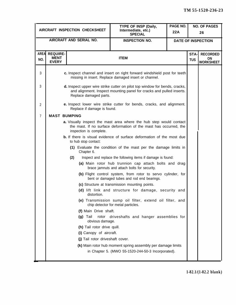
TM 55-1520-236-23
TYPE OF INSP (Daily, PAGE NO. NO. OF PAGESAIRCRAFT INSPECTION CHECKSHEET Intermediate, etc.)
SPECIAL 22A 26
AIRCRAFT AND SERIAL NO. INSPECTION NO. DATE OF INSPECTION
AREA REQUIRE- STA- RECORDEDNO. MENT ITEM
EVERY TUS ONWORKSHEET
3 c. Inspect channel and insert on right forward windshield post for teethmissing in insert. Replace damaged insert or channel.
3 d. Inspect upper wire strike cutter on pilot top window for bends, cracks,and alignment. Inspect mounting panel for cracks and pulled inserts.Replace damaged parts.
2 e. Inspect lower wire strike cutter for bends, cracks, and alignment.Replace if damage is found.
7 MAST BUMPING
a. Visually inspect the mast area where the hub step would contactthe mast. If no surface deformation of the mast has occurred, theinspection is complete.
b. If there is visual evidence of surface deformation of the most dueto hub stop contact:
(1) Evaluate the condition of the mast per the damage limits inChapter 6.
(2) Inspect and replace the following items if damage is found:
(a) Main rotor hub trunnion cap attach bolts and dragbrace jamnuts and attach bolts for security.
(b) Flight control system, from rotor to servo cylinder, forbent or damaged tubes and rod end bearings.
(c) Structure at transmission mounting points.
(d) l ift l ink and structure for damage, security anddistortion.
(e) Transmission sump oil filter, extend oil filter, andchip detector for metal particles.
(f) Main Drive shaft.
(g) Tail rotor driveshafts and hanger assemblies forobvious damage.
(h) Tail rotor drive quill.
(i) Canopy of aircraft.
(j) Tail rotor driveshaft cover.
(k) Main rotor hub moment spring assembly per damage limits
in Chapter 5. (MWO 55-1520-244-50-3 Incorporated).
1-82.1/(1-82.2 blank)


TM 55-1520-236-23
AIRCRAFT INSPECTION CHECKSHEET TYPE OF INSP (Daily, PAGE NO. NO. OF PAGESIntermediate, etc.)
SPECIAL 23 26
AIRCRAFT AND SERIAL NO. INSPECTION NO. DATE OF lNSPECTION
REQUIRE- RECORDEDAREA MENT STA- ONNO. EVERY ITEM TUS WORKSHEET
All AFTER PROBABLE EXPOSURE TO RADIOACTIVITYAreas
Accomplish the following:
a. Survey helicopter for level of radioactivity.
b. Decontaminate helicopter as required. Refer to TM 3-220.
9 AFTER INDICATION OF UNUSUALLY HIGH OR LOW FUEL CAPACITYOR UNUSUALLY HIGH OR LOW FUEL CONSUMPTION
Perform inspection of fuel cells with special attention to possible self seal-ing material and/or inner liner separation.
All AFTER INSTALLATION, REMOVAL OR RELOCATION OF EQUIPMENTOR MAJOR MODIFICATION WHICH RESULT IN UNKNOWN CHANGEIN BASIC WEIGHT AND BALANCE OR AFTER REPORT OF UNSATIS-FACTORY FLIGHT CHARACTERISTICS.
Weigh helicopter and accomplish necessary entries in Weight andBalance Data, DD Form 365. Refer to AR 95-3 and TM 55-1500-342-23.
9 AFTER OVERFLOW OF BATTERY
a. Refer toTM43-0105 for treatment of affected areas.
b. Sheet metal surfaces and overlaps, both internal and external fordamage.
C. Rivets, bolts, screws, and other hardware for damage.
d Troubleshoot battery system to determine cause.
11 AFTER TOW MISSILE HAS BEEN FIRED (ONE OR MORE)
Inspect tailboom skins for nicks, dents, scratches, creases, and cracks.
11 AFTER FIRING 2.75 INCH ROCKETS
Visually inspect tailboom skins, synchronized elevators, and tail rotorblades for damage.
1-83

TM 55-1520-236-23
AIRCRAFT INSPECTION CHECKSHEET TYPE OF INSP (Daily, PAGE NO. NO. OF PAGESIntermediate, etc.)
SPECIAL 24 26
AIRCRAFT AND SERIAL NO. INSPECTION NO. DATE OF INSPECTION
REQUIRE- RECORDEDAREA MENT STA- ONNo. EVERY ITEM TUS WORKSHEET
All AFTER THE HELICOPTER HAS BEEN SUBJECTED TO SALT WATER,Areas SALT SPRAY OR VOLCANIC ACTIVITY
Wash entire helicopter with fresh water, particularity inside of enginecompartment doors, wash all compartments which were exposed to saltwater; make a detail check of all surfaces for corrosion. Apply corrosionpreventive compound (C41) to exposed nonpainted, anodized, or cad-mium plated assemblies. Water-wash engine internally, per TM55-2840-229-23.
3 AFTER WASHING HELICOPTER
Check pitot-static system for moisture.
All WHEN OVERHAULS, MAJOR MODIFICATIONS OR MAJOR AIR-FRAME REPAIRS ARE ACCOMPLISHED, ANY SPECIAL EQUIPMENTHAS BEEN ADDED TO OR REMOVED FROM THE BASIC AIRFRAMEOR WHEN WEIGHT AND BALANCE DATA ARE SUSPECTED TO BE INERROR
For general weight and balance information, refer to TM 55-1500-342-23,Army Aviation Maintenance Engineering Manual and AR 95-3, Weightand Balance, Appendix B, Maintenance Allocation Chad should be con-sulted for responsibility of weighing and balancing of the aircraft.
All WHEN HELICOPTER IS TRANSFERRED, RECEIVED, PLACED INSTORAGE, OR REMOVED FROM STORAGE.
Inventory helicopter for availability of inventoriable property (DA PAM738-751).
All UPON TRANSFER AND UPON RECEIPT OF A HELICOPTER; UPONeXPIRATION OF 12 MONTHS ELAPSED TIME SINCE LASTI N V E N T O R Y ; PLACING A HELICOPTER IN STORAGE ANDUPON REMOVAL FROM STORAGE (HELICOPTER NEED NOT BElNVENTORIED WHILE IN STORAGE)
Perform an inventory check. Refer to DA Form 2408-17 and Appendix C.
3 FIRST AID KIT INSPECTION
Inspect in accordance with TM 1-1500-204-23-1.
6 and DAiLY WHEN OPERATING IN HIGH HUMIDITY OR SALT-LADEN AIR11
Wash main and tail rotor with mild detergent (Ch 3), rinse with dear waterand dry.
1-84
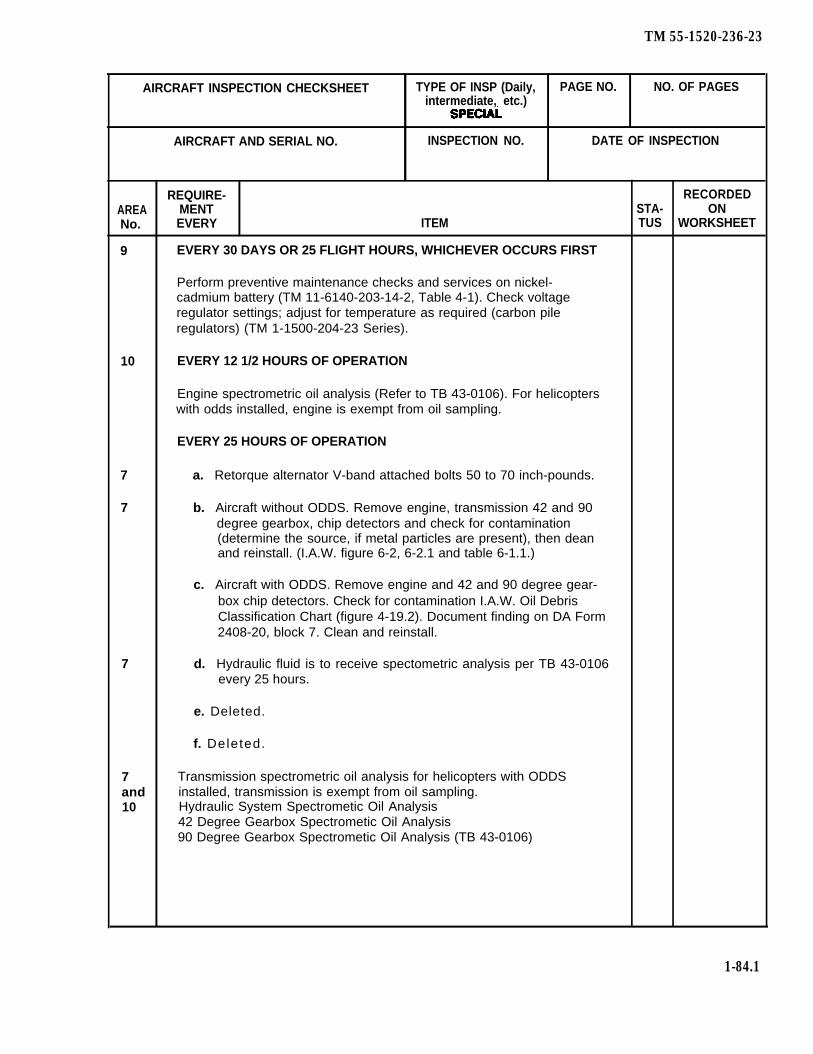
TM 55-1520-236-23
AIRCRAFT INSPECTION CHECKSHEET TYPE OF INSP (Daily, PAGE NO. NO. OF PAGESintermediate, etc.)
AIRCRAFT AND SERIAL NO. INSPECTION NO. DATE OF INSPECTION
REQUIRE- RECORDEDAREA MENT STA- ONNo. EVERY ITEM TUS WORKSHEET
9 EVERY 30 DAYS OR 25 FLIGHT HOURS, WHICHEVER OCCURS FIRST
Perform preventive maintenance checks and services on nickel-cadmium battery (TM 11-6140-203-14-2, Table 4-1). Check voltageregulator settings; adjust for temperature as required (carbon pileregulators) (TM 1-1500-204-23 Series).
10 EVERY 12 1/2 HOURS OF OPERATION
Engine spectrometric oil analysis (Refer to TB 43-0106). For helicopterswith odds installed, engine is exempt from oil sampling.
EVERY 25 HOURS OF OPERATION
7 a. Retorque alternator V-band attached bolts 50 to 70 inch-pounds.
7 b. Aircraft without ODDS. Remove engine, transmission 42 and 90degree gearbox, chip detectors and check for contamination(determine the source, if metal particles are present), then deanand reinstall. (I.A.W. figure 6-2, 6-2.1 and table 6-1.1.)
c. Aircraft with ODDS. Remove engine and 42 and 90 degree gear-box chip detectors. Check for contamination I.A.W. Oil DebrisClassification Chart (figure 4-19.2). Document finding on DA Form2408-20, block 7. Clean and reinstall.
7 d. Hydraulic fluid is to receive spectometric analysis per TB 43-0106every 25 hours.
e. Deleted.
f. Deleted.
7 Transmission spectrometric oil analysis for helicopters with ODDSand installed, transmission is exempt from oil sampling.10 Hydraulic System Spectrometic Oil Analysis
42 Degree Gearbox Spectrometic Oil Analysis90 Degree Gearbox Spectrometic Oil Analysis (TB 43-0106)
1-84.1

TM 55-1520-236-23
AIRCRAFT INSPECTION CHECKSHEET
AREANo.
7
AIRCRAFT AND SERIAL NO.
TYPE OF INSP (Daily, PAGE NO. NO. OF PAGESIntermediate,, etc.)
SPECIAL
INSPECTION NO. DATE OF INSPECTION
REQUIRE-MENTEVERY ITEM
IMMEDIATELY PRECEDING 25 HOUR LUBRICATION AND AT INSTAL-LATION
a. Swashplate and Support.
(1)
(2)
(3)
(4)
(5)
Visually inspect for evidence of contact between outer ring ordrive Iink and stationary swashplate. Measure vertical clear-ance from the bottom of both drive links. P/N 209-010-408-7 toall three horns of stationary swashplate. The minimum clear-ance must be not less than .035 (thirty five thousandths) inch.Replace swashplate if any contact is evident or if clearance isbelow minimum.
Disconnect main rotor drive finks from swashplate and secureto prevent damage. Rotate swashplate ring, checking forroughness, binding, or unusual noise from swashplate bearing.
Using a soft, dean, lint free cloth dampened with cleaning sol-vent (Ch 2), dean the inner ring assembly and outer ring as-sembly at the dust cover. Insure all surface grit, sand and othersurface materials are removed.
Using a grease gun with a flexible hose, purge lubricate theswashplate per figure 1-5. If the swashplate fails to acceptgrease, perform a swashplate bearing sleeve alignment check
Remove old grease purged from swashplate using a woodentongue depressor NSN 6515-00-324-5500. Place sample of oldgrease in plastic bottle NSN 8125-01-082-9697 ensuring thatthe bottle is more than half filled. On the bottle Iabel, printaircraft serial number, swashplate serial number and date ofsample.
STA-TUS
RECORDEDON
WORKSHEET
1-84.2

TM 55-1520-236-23
AIRCRAFT INSPECTION CHECKSHEET TYPE OF INSP (Daily, PAGE NO. NO. OF PAGESIntermediate, etc.)
SPECIAL
AIRCRAFT AND SERIAL NO. INSPECTION NO. DATE OF INSPECTION
REQUIRE- RECORDEDAREA MENT STA-NO. EVERY ITEM TUS WORKSHEET
(6) Prepare DD Form 2026, Transit Aircraft Oil Analysis Record,and submit along with grease sample to the AOAP Laboratorydesignated in TB 43-0106. Make appropriate entries on DAForm 2408-20 in accordance with DA PAM 738-751.
(7) Reconnect drive links and perform maintenance operationalcheck of at least 15 minutes duration.
b. Scissors and Sleeve Assembly.
(1) Visually inspect visible part of scissors hub assembly and bootfor signs of heat. Any heat discoloration or distortion of compo-nents is cause for replacement.
(2) Using a soft, dean, lint-free cloth dampened with cleaning sol-vent (C112), remove all surface grit sand, and other surfacematerials.
(3) Using a grease gun with a flexible hose, purge/lubricate thescissors bearing in accordance with figure 1-5, at approximateIy 30-degree intervals until the assembly has been lubricatedthrough one full turn (360 degrees). Check for up and downplay in bearing between inner and outer swashplate. Replacesvvashplate if any roughness, binding, noise or play is evident.Where rotation of main rotor blades is not possible, this proce-dure can be accomplished as follows; disconnect the pitchchange links at the upper universal and remove the 6 (ea) boltssecuring tie collet extention and the collet spline plate. This willallow you to rotate the swashplate as required.
(4) Remove old grease purged using a wooden tongue depressor(NSN 6515-00-324-5500). Place sample of old grease in plasticbottle (NSN 8125-01-082-9697), ensuring that the bottle ismore than half filled. The bottle label should be filled out ascompletely as possible to avoid confusion with other greasesamples. Label to show operating activity, scissors and sleeveassembly serial number, aircraft serial number, and date ofsample.
1-85
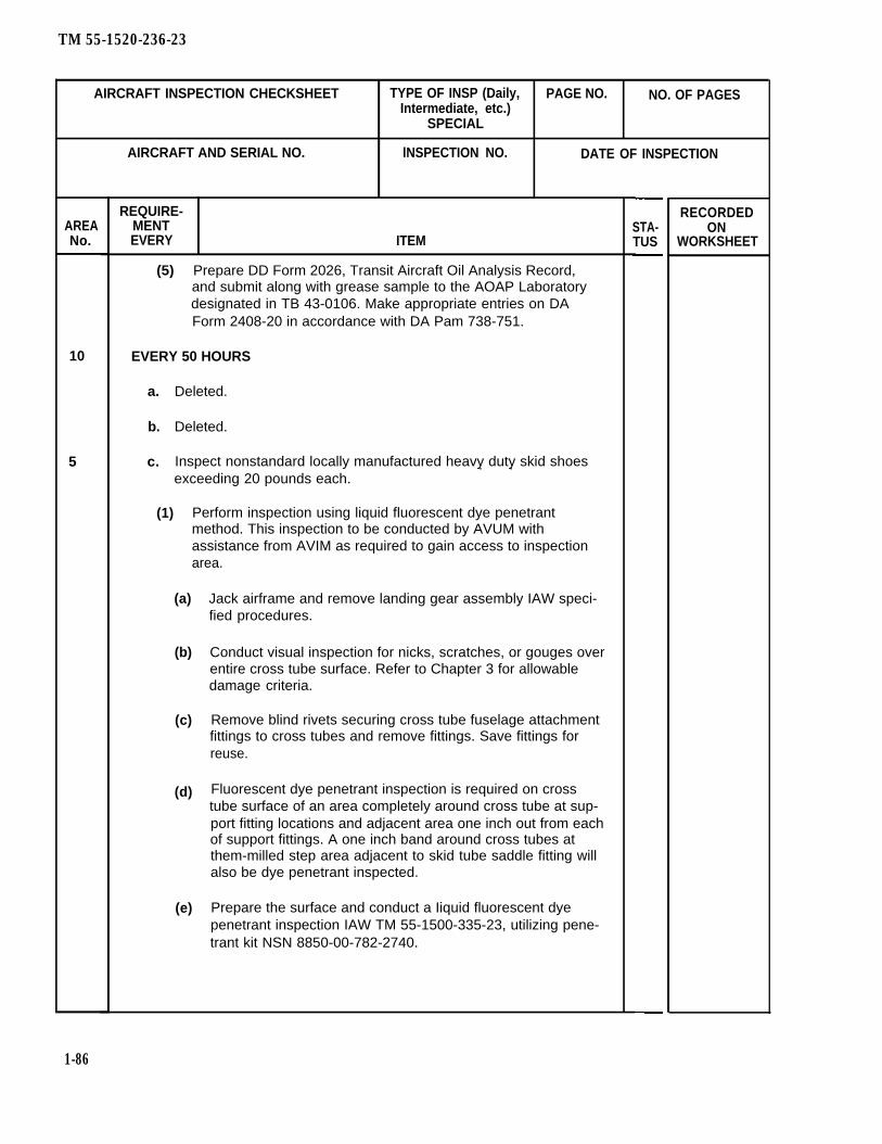
TM 55-1520-236-23
AIRCRAFT INSPECTION CHECKSHEET TYPE OF INSP (Daily, PAGE NO. NO. OF PAGESIntermediate, etc.)
SPECIAL
AREANo.
10
5
1-86
AIRCRAFT AND SERIAL NO. lNSPECTION NO. DATE OF INSPECTION
REQUIRE-MENTEVERY ITEM
(5) Prepare DD Form 2026, Transit Aircraft Oil Analysis Record,and submit along with grease sample to the AOAP Laboratorydesignated in TB 43-0106. Make appropriate entries on DAForm 2408-20 in accordance with DA Pam 738-751.
EVERY 50 HOURS
a.
b.
c.
Deleted.
Deleted.
Inspect nonstandard locally manufactured heavy duty skid shoes. .exceeding 20 pounds each.
(1) Perform inspection using liquid fluorescent dye penetrantmethod. This inspection to be conducted by AVUM withassistance from AVIM as required to gain access to inspectionarea.
(a)
(b)
(c)
(d)
(e)
Jack airframe and remove landing gear assembly IAW speci-fied procedures.
Conduct visual inspection for nicks, scratches, or gouges overentire cross tube surface. Refer to Chapter 3 for allowabledamage criteria.
Remove blind rivets securing cross tube fuselage attachmentfittings to cross tubes and remove fittings. Save fittings forreuse.
Fluorescent dye penetrant inspection is required on crosstube surface of an area completely around cross tube at sup-port fitting locations and adjacent area one inch out from eachof support fittings. A one inch band around cross tubes atthem-milled step area adjacent to skid tube saddle fitting willalso be dye penetrant inspected.
Prepare the surface and conduct a Iiquid fluorescent dyepenetrant inspection IAW TM 55-1500-335-23, utilizing pene-trant kit NSN 8850-00-782-2740.
STA-TUS
RECORDEDON
WORKSHEET

TM 55-1520-236-23
AIRCRAFT INSPECTION CHECKSHEET TYPE OF INSP (Daily, PAGE NO. NO. OF PAGESIntermediate, etc.)
SPECIAL
AIRCRAFT AND SERIAL NO. INSPECTION NO. DATE OF INSPECTION
REQUIRE- RECORDEDAREA MENT STA- ONNO. EVERY ITEM TUS WORKSHEET
(f) Wash and remove all excess penetrant and developer fromcross tube surfaces.
(g) Recoat surface of cross tube to be covered by the attachmentfittings with sealant (C105).
(h) Reinstall attachment fittings to cross tubes. Diameter and length of rivets to be determined at time of installation.
(2) Cross tubes with crack indications will be scrapped. All crosstubes with no crack indications are to be returned to service.
7 EVERY 75 HOURS OF OPERATION
Remove transmission sump oil filters (wafer disk screen), check for con-tamination, then dean and install.
3 EVERY 100 HOURS
9 EVERY 100 HOURS OR 120 CALENDAR DAYS WHICHEVERFIRST
a. Perform preventive maintenance checks and services on the nickelcadmium battery (TM 11-6140-203-23-2)
b. Check voltage regulator settings as required (Solid State Regulators)(TM 1-1500-204-23 Series).
5 EVERY 150 HOURS
Inspect nonstandard locally manufactured heavy duty skid shoes weigh-ing 20 pounds or less each using same procedures as 50 hours inspec-tion on same item of more weight.
7 EVERY 300 HOURS
Remove, disassemble, dean and inspect main rotor hub assembly (SeeChapter 5).
1-86.1
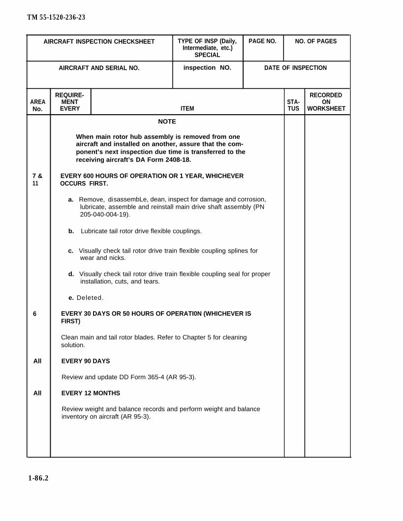
TM 55-1520-236-23
AIRCRAFT INSPECTION CHECKSHEET TYPE OF INSP (Daily, PAGE NO. NO. OF PAGESIntermediate, etc.)
SPECIAL
AIRCRAFT AND SERIAL NO. inspection NO. DATE OF INSPECTION
REQUIRE- RECORDEDAREA MENT STA- ONNo. EVERY ITEM TUS WORKSHEET
NOTE
When main rotor hub assembly is removed from oneaircraft and installed on another, assure that the com-ponent’s next inspection due time is transferred to thereceiving aircraft’s DA Form 2408-18.
7 & EVERY 600 HOURS OF OPERATION OR 1 YEAR, WHICHEVER11 OCCURS FIRST.
a. Remove, disassembLe, dean, inspect for damage and corrosion,lubricate, assemble and reinstall main drive shaft assembly (PN205-040-004-19).
b. Lubricate tail rotor drive flexible couplings.
c. Visually check tail rotor drive train flexible coupling splines forwear and nicks.
d. Visually check tail rotor drive train flexible coupling seal for properinstallation, cuts, and tears.
e. Deleted.
6 EVERY 30 DAYS OR 50 HOURS OF OPERATI0N (WHICHEVER ISFIRST)
Clean main and tail rotor blades. Refer to Chapter 5 for cleaningsolution.
All EVERY 90 DAYS
Review and update DD Form 365-4 (AR 95-3).
All EVERY 12 MONTHS
Review weight and balance records and perform weight and balanceinventory on aircraft (AR 95-3).
1-86.2

TM 55-1520-236-23
AIRCRAFT INSPECTION CHECKSHEET TYPE OF INSP (Daily, PAGE NO. NO. OF PAGESIntermediate, etc.)
SPECIAL
AIRCRAFT AND SERIAL NO. INSPECTION NO. DATE OF INSPECTION
REQUIRE- RECORDEDAREA MENT STA- ON
NO. EVERY ITEM TUS WORKSHEET
3 EVERY 6 M0NTHS
a. Weight check CF3BR fire extinguisher. Refer to TM 1-1500-204-23(Series).
b. Inspect and test connector receptacle (ground). Refer to TM55-1500-323-23 or TM 1-1500-204-23 (Series).
3 EVERY 12 MONTHS OR NEAREST SCHEDULED PHASED INSPECTION
3 EVERY 12 MONTHS
a. Deleted.
b. Deleted.
c. Magnetic compass for discoloration of liquid and proper calibration;recompensate if necessary.
d Gyromagnetic compass system for proper calibration; recompen-sate if necessary TM 1-1500-204-23 (Series).
3 EVERY 15 MONTHS
Replace ejector rack cartridges. P/N ARD863-1 and P/N P7911-2. Referto paragraph 16-40.
7 EVERY 18 MONTHS
2 EVERY 24 MONTHS
Pitot-Static System-Perform a functional check of system. Refer toparagraph 8-117.1.
3 EVERY 36 M0NTHS
Replace ejector rack cartridges P/N CCU-44B. Refer to paragraph 16-40.
All AFTER 7 DAYS
After the aircraft has remained inactive for 7 consecutive days, processthe aircraft into the appropriate storage category. (See Appendix E.)
All EVERY 30 DAYS
Clean aircraft (TM 1-1500-344-23).
1-86.3

TM 55-1520-236-23
AIRCRAFT INSPECTION CHECKHEET TYPE OF INSP (Daily, PAGE NO. NO. OF PAGESIntermediate, etc.)
SPECIAL
AIRCRAFT AND SERIAL NO. lNSPECTION NO. DATE OF lNSPECTION
REQUIRE- RECORDEDAREA MENT STA-
NO. EVERY ITEM TUS WORKSHEET
10 EVERY 900 HOURS OR EACH TIME THE ENGINE IS REMOVED ANDREPLACED. AIRCRAFT WITHOUT ODDS.
a. Engine oil system, including oil cooler, drained and refilled. Ifengine is replaced due to internal failure, flush all airframemounted engine oil lines and engine oil tank and replace engine oilWaler.
NOTE
Only to airdraft engine serviced with MIL-L-23699. IfMIL-L-7808 is used, oil change Is required every 300hours.
b. If engine is changed, check gyromagnetic compass for proper cal-ibration: Recompensate if necessary (TM 55-15800-204-25/1).
10 EVERY 1200 HOURS
Hot end inspection on T53-L-703 engine, P/N 1-000-060-23, TM55-2840-229-23.
7 EVERY 900 HOURS OR EACH TIME THE TRANSMISSION ISREMOVED AND REPLACED. AIRCRAFT WITHOUT ODDS.
Transmission and transmission oil cooler drained and oil pump screeninspected for metallic particles and other contaminants. Clean screen,replace and refill transmission oil system to proper level. If transmissionis replaced due to internal failure, flush all airframe-mounted transmissionoil lines and replace transmission oil cooler.
NOTE
Only to aircraft transmission serviced withMIL-L-23699. If ML-L-7808 is used, oil change isrequired every 300 hours.
9 EVERY 1100 HOURS OR AT OVERHAUL. (WHICHEVER COMES FlRST)
Inspect diagonal brace fitting, P/N 209-030-183-1 fior cracks using fluores-cent penetrant method.
1-86.4

TM 55-1520-236-23
AIRCRAFT INSPECTION CHECKSHEET TYPE OF INSP (Daily, PAGE NO.Intermediate, etc.)
SPECIAL
NO. OF PAGES
AREANo.
7
AIRCRAFT AND SERIAL NO. INSPECTION NO. DATE OF INSPECTION
REQUIRE-MENTEVERY ITEM
SWASHPLATE BEARING SLEEVE ALIGNMENT CHECK
Perform the following whenever the shashplate fails to accept grease orupon andy indication of linear misalignment (overheating; difficulty in lubing).
Using pliers, remove lubrication fitting (NAS516) from one side ofswashplate.
Insert alignment tool (T65) into lubrication port. Any stoppagebefore tool is fully seated is cause for rejecting the swashplate.
Lightly tap a new fitting (NAS516) into place.
Lubricate swashplate and support in accordance with figure 1-5.
STA-TUS
RECORDEDON
WORKSHEET
1-86.5/(1-86.6 blank)

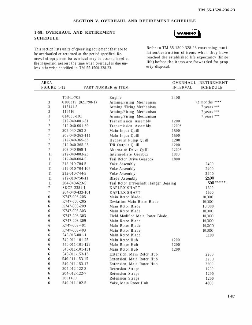
TM 55-1520-236-23
SECTION V. OVERHAUL AND RETIREMENT SCHEDULE
1-58. OVERHAUL AND RETIREMENTSCHEDULE.
This section lists units of operating equipment that are to Refer to TM 55-1500-328-23 concerning muti-
be overhauled or returned at the period specified. Re- lation/destruction of items when they havemoval of equipment for overhaul may be accomplished at reached the established life expectancy (finitethe inspection nearest the time when overhaul is due un- life) before the items are forwarded for propless otherwise specified in TM 55-1500-328-23. erty disposal.
AREA OVERHAUL RETIREMENTFIGURE 1-12 PART NUMBER & ITEM INTERVAL SCHEDULE
3333777777711111111111111776666666666666666666
T53-L-7036106319 (821798-1)115141-5116416814033-101212-040-001-51212-040-001-39205-040-263-3205-040-263-111212-040-365-33212-040-365-25209-040-069-1212-040-003-23212-040-004-9212-010-704-5212-010-704-107212-010-744-5212-010-750-11204-040-623-5SKCP 2381-1204-040-433-101K747-003-205K747-003-205K747-003-209K747-003-303K747-003-303K747-003-309K747-003-401K747-003-403540-015-001-1540-011-101-25540-011-101-129540-011-101-131540-011-153-13540-011-153-15540-011-153-17204-012-122-3204-012-122-72601400540-011-102-5
Engine 2400Arming/Firing Mechanism 72 months ****Arming /Firing Mechanism 7 years ***Arming/Firing Mechanism 7 years ***Arming/Firing Mechanism 7 years ***Transmission Assembly 1200Transmission Assembly 1200*Main Input Quill 1500Main Input Quill 1500Hydraulic Pump Quill 1200T/R Output Quill 1200Alternator Drive Quill 1200*Intermediate Gearbox 1800Tail Rotor Drive Gearbox 1800Yoke AssemblyYoke AssemblyYoke AssemblyBlade AssemblyTail Rotor Driveshaft Hanger BearingKAFLEX SHAFTKAFLEX SHAFTMain Rotor BladeDeviation Main Rotor BladeMain Rotor BladeMain Rotor BladeField Modified Main Rotor BladeMain Rotor BladeMain Rotor BladeMain Rotor BladeMain Rotor BladeMain Rotor Hub 1200Main Rotor Hub 1200Main Rotor Hub 1200Extension, Main Rotor HubExtension, Main Rotor HubExtension, Main Rotor HubRetension StrapsRetension StrapsRetension StrapsYoke, Main Rotor Hub
240024002400
16001500
10,OOO10,OOO10,00010,OOO10,OOO10,OOO10,OOO10,OOO
1100
2200220022001200120012004800
1-87
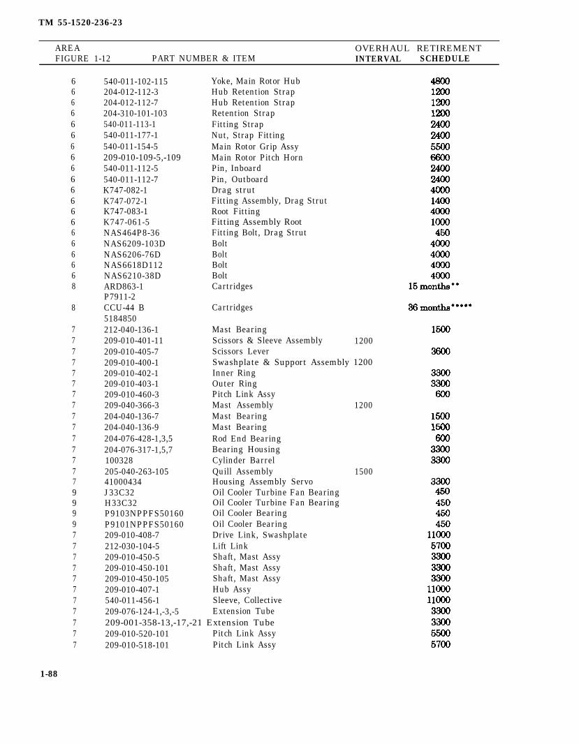
TM 55-1520-236-23
AREA OVERHAUL RETIREMENTFIGURE 1-12 PART NUMBER & ITEM INTERVAL SCHEDULE
66666666666666666668
8
777777777777777999977777777777
1-88
540-011-102-115204-012-112-3204-012-112-7204-310-101-103540-011-113-1540-011-177-1540-011-154-5209-010-109-5,-109540-011-112-5540-011-112-7K747-082-1K747-072-1K747-083-1K747-061-5NAS464P8-36NAS6209-103DNAS6206-76DNAS6618D112NAS6210-38DARD863-1P7911-2CCU-44 B5184850212-040-136-1209-010-401-11209-010-405-7209-010-400-1209-010-402-1209-010-403-1209-010-460-3209-040-366-3204-040-136-7204-040-136-9204-076-428-1,3,5204-076-317-1,5,7100328205-040-263-10541000434J33C32H33C32P9103NPPFS50160P9101NPPFS50160209-010-408-7212-030-104-5209-010-450-5209-010-450-101209-010-450-105209-010-407-1540-011-456-1209-076-124-1,-3,-5
Yoke, Main Rotor HubHub Retention StrapHub Retention StrapRetention StrapFitting StrapNut, Strap FittingMain Rotor Grip AssyMain Rotor Pitch HornPin, InboardPin, OutboardDrag strutFitting Assembly, Drag StrutRoot FittingFitting Assembly RootFitting Bolt, Drag StrutBoltBoltBoltBoltCartridges
Cartridges
Mast BearingScissors & Sleeve Assembly 1200Scissors LeverSwashplate & Support Assembly 1200Inner RingOuter RingPitch Link AssyMast AssemblyMast BearingMast BearingRod End BearingBearing HousingCylinder BarrelQuill AssemblyHousing Assembly ServoOil Cooler Turbine Fan BearingOil Cooler Turbine Fan BearingOil Cooler BearingOil Cooler BearingDrive Link, SwashplateLift LinkShaft, Mast AssyShaft, Mast AssyShaft, Mast AssyHub AssySleeve, CollectiveExtension Tube
209-001-358-13,-17,-21 Extension Tube209-010-520-101 Pitch Link Assy209-010-518-101 Pitch Link Assy
1200
1500

TM 55-1520-236-23
AREA OVERHAUL RETIREMENTFIGURE 1-12 PART NUMBER & ITEM INTERVAL SCHEDULE
77777
209-011-208-101 Plate 5700209-011-212-101 Support set 5700209-011-219-101 Strap Assembly 5700209-310-100-105 Spring 5700204-076-511-9 Servo Cylinder 3300
The 212-040-001-39 transmission is the same as the 212-040-001-51 transmission without the209-040-069-1 alternator drive quill. The alternator drive quill must be ordered separately andinstalled in the 212-040-001-39 transmission to make the 212-040-001-51 configuration.
Not to exceed 10 years from the date of manufacture (shelf life), or 15 months from the date ofopening the sealed cartridge container (installed life) or 10 installations and/or removal fromthe cartridge housing. Explosive life is not additive; and therefore, cartridge removal is requiredwhenever any of these conditions are reached.
Denotes life is not to exceed 9 years from the date of manufacture (shelf life) or 7 years fromthe date of installation, whichever is sooner.
Denotes life is not to exceed 8 yearn from the date of manufacture (shelf life) or 72 monthsfrom the date of installation, whichever is sooner.
Not to exceed 8.5 years from date of manufacture (shelf life), or 36 months from the date ofopening the sealed cartridges container (installed life) or 10 installations and/or removals fromthe cartridge housing. Explosive life is not additive; and therefore, cartridge removal is requiredwhenever any of these conditions are reached.
This bearing has a shelf life of 5 years, effective 31 December 1990.
NOTE
All unserviceable explosive items (NSN1377 Class) shall be tagged with NSN,Installation date, reason for removal, lotnumber, helicopter type/model and serialnumber, aviation unit destination andreturned to supporting ammunition sup-ply activity in the container used to transport the replacement cartridge.
All retirement life items will have a demilcode of “L” and will be mutilated in accor-dance with DOD 4160.21-M-1, DefenseDemilitarization Manual.
1-88.1/(1-88.2 blank)

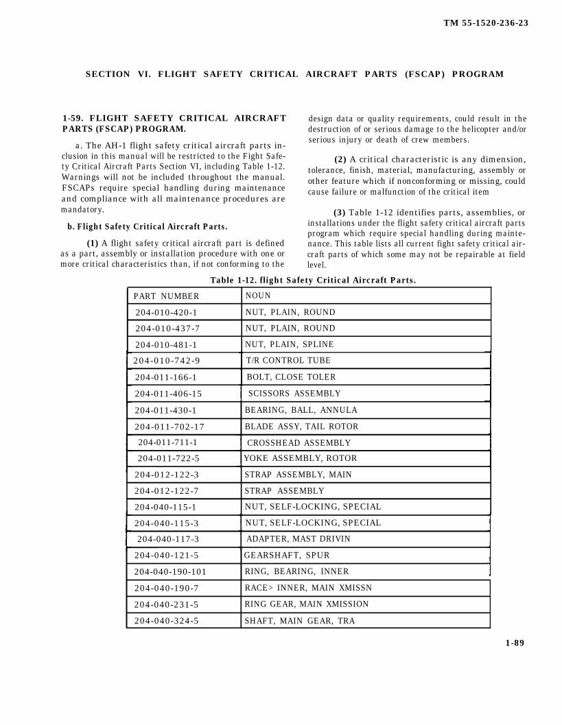
TM 55-1520-236-23
SECTION VI. FLIGHT SAFETY CRITICAL AIRCRAFT PARTS (FSCAP) PROGRAM
1-59. FLIGHT SAFETY CRITICAL AIRCRAFTPARTS (FSCAP) PROGRAM.
a. The AH-1 flight safety critical aircraft parts in-clusion in this manual will be restricted to the Fight Safe-ty Critical Aircraft Parts Section VI, including Table 1-12.Warnings will not be included throughout the manual.FSCAPs require special handling during maintenanceand compliance with all maintenance procedures aremandatory.
b. Flight Safety Critical Aircraft Parts.
(1) A flight safety critical aircraft part is definedas a part, assembly or installation procedure with one ormore critical characteristics than, if not conforming to the
design data or quality requirements, could result in thedestruction of or serious damage to the helicopter and/orserious injury or death of crew members.
(2) A critical characteristic is any dimension,tolerance, finish, material, manufacturing, assembly orother feature which if nonconforming or missing, couldcause failure or malfunction of the critical item
(3) Table 1-12 identifies parts, assemblies, orinstallations under the flight safety critical aircraft partsprogram which require special handling during mainte-nance. This table lists all current fight safety critical air-craft parts of which some may not be repairable at fieldlevel.
Table 1-12. flight Safety Critical Aircraft Parts.
PART NUMBER NOUN
204-010-420-1 NUT, PLAIN, ROUND
204-010-437-7 NUT, PLAIN, ROUND
204-010-481-1 NUT, PLAIN, SPLINE
204-010-742-9 T/R CONTROL TUBE
204-011-166-1 BOLT, CLOSE TOLER
204-011-406-15 SCISSORS ASSEMBLY
204-011-430-1 BEARING, BALL, ANNULA
204-011-702-17 BLADE ASSY, TAIL ROTOR
204-011-711-1 CROSSHEAD ASSEMBLY
204-011-722-5 YOKE ASSEMBLY, ROTOR
204-012-122-3 STRAP ASSEMBLY, MAIN
204-012-122-7 STRAP ASSEMBLY
204-040-115-1 NUT, SELF-LOCKING, SPECIAL
204-040-115-3 NUT, SELF-LOCKING, SPECIAL
204-040-117-3 ADAPTER, MAST DRIVIN
204-040-121-5 GEARSHAFT, SPUR
204-040-190-101 RING, BEARING, INNER
204-040-190-7 RACE> INNER, MAIN XMISSN
204-040-231-5 RING GEAR, MAIN XMISSION
204-040-324-5 SHAFT, MAIN GEAR, TRA
1-89

TM 55-1520-236-23
Table 1-12. Flight Safety Critical Aircraft Parts (Cont).
1-90
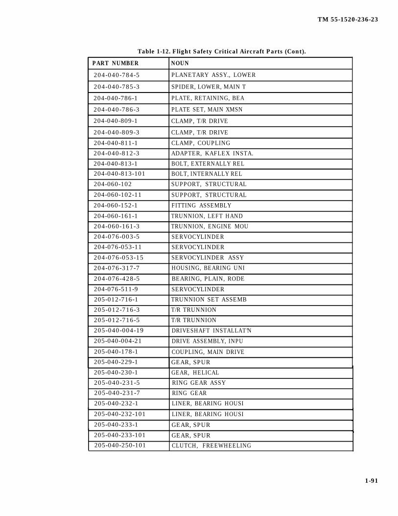
TM 55-1520-236-23
Table 1-12. Flight Safety Critical Aircraft Parts (Cont).
PART NUMBER NOUN
204-040-784-5 PLANETARY ASSY., LOWER
204-040-785-3 SPIDER, LOWER, MAIN T
204-040-786-1 PLATE, RETAINING, BEA
204-040-786-3 PLATE SET, MAIN XMSN
204-040-809-1 CLAMP, T/R DRIVE
204-040-809-3 CLAMP, T/R DRIVE
204-040-811-1 CLAMP, COUPLING
204-040-812-3 ADAPTER, KAFLEX INSTA.
204-040-813-1 BOLT, EXTERNALLY REL
204-040-813-101 BOLT, INTERNALLY REL
204-060-102 SUPPORT, STRUCTURAL
204-060-102-11 SUPPORT, STRUCTURAL
204-060-152-1 FITTING ASSEMBLY
204-060-161-1 TRUNNION, LEFT HAND
204-060-161-3 TRUNNION, ENGINE MOU
204-076-003-5 SERVOCYLINDER
204-076-053-11 SERVOCYLINDER
204-076-053-15 SERVOCYLINDER ASSY
204-076-317-7 HOUSING, BEARING UNI
204-076-428-5 BEARING, PLAIN, RODE
204-076-511-9 SERVOCYLINDER
205-012-716-1 TRUNNION SET ASSEMB
205-012-716-3 T/R TRUNNION
205-012-716-5 T/R TRUNNION
205-040-004-19 DRIVESHAFT INSTALLAT’N
205-040-004-21 DRIVE ASSEMBLY, INPU
205-040-178-1 COUPLING, MAIN DRIVE
205-040-229-1 GEAR, SPUR
205-040-230-1 GEAR, HELICAL
205-040-231-5 RING GEAR ASSY
205-040-231-7 RING GEAR
205-040-232-1 LINER, BEARING HOUSI
205-040-232-101 LINER, BEARING HOUSI
205-040-233-1 GEAR, SPUR
205-040-233-101 GEAR, SPUR
205-040-250-101 CLUTCH, FREEWHEELING
1-91
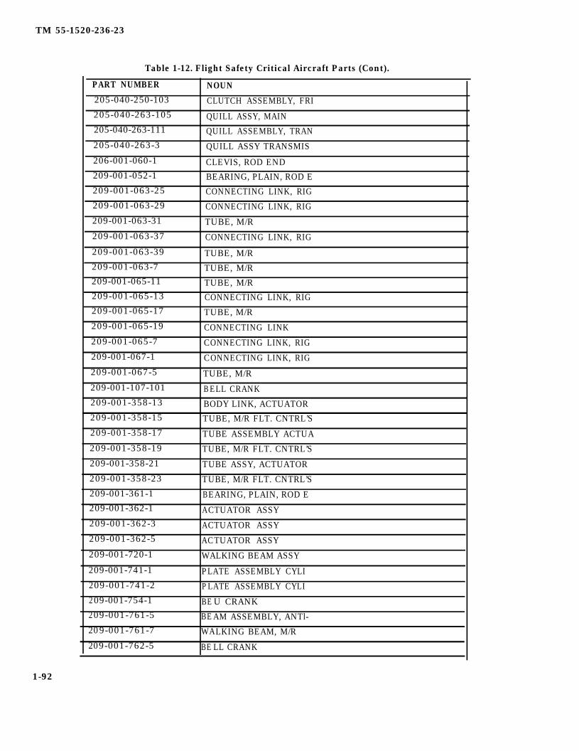
TM 55-1520-236-23
Table 1-12. Flight Safety Critical Aircraft Parts (Cont).
PART NUMBER NOUN205-040-250-103 CLUTCH ASSEMBLY, FRI205-040-263-105 QUILL ASSY, MAIN205-040-263-111 QUILL ASSEMBLY, TRAN205-040-263-3 QUILL ASSY TRANSMIS
206-001-060-1 CLEVIS, ROD END209-001-052-1 BEARING, PLAIN, ROD E209-001-063-25 CONNECTING LINK, RIG209-001-063-29 CONNECTING LINK, RIG
209-001-063-31 TUBE, M/R
209-001-063-37 CONNECTING LINK, RIG
209-001-063-39 TUBE, M/R209-001-063-7 TUBE, M/R209-001-065-11 TUBE, M/R209-001-065-13 CONNECTING LINK, RIG209-001-065-17 TUBE, M/R209-001-065-19 CONNECTING LINK209-001-065-7 CONNECTING LINK, RIG209-001-067-1 CONNECTING LINK, RIG
209-001-067-5 TUBE, M/R209-001-107-101 BELL CRANK209-001-358-13 BODY LINK, ACTUATOR209-001-358-15 TUBE, M/R FLT. CNTRL’S
209-001-358-17 TUBE ASSEMBLY ACTUA
209-001-358-19 TUBE, M/R FLT. CNTRL’S
209-001-358-21 TUBE ASSY, ACTUATOR
209-001-358-23 TUBE, M/R FLT. CNTRL’S
209-001-361-1 BEARING, PLAIN, ROD E209-001-362-1 ACTUATOR ASSY209-001-362-3 ACTUATOR ASSY209-001-362-5 ACTUATOR ASSY209-001-720-1 WALKING BEAM ASSY
209-001-741-1 PLATE ASSEMBLY CYLI209-001-741-2 PLATE ASSEMBLY CYLI209-001-754-1 BE U CRANK209-001-761-5 BEAM ASSEMBLY, ANTl-209-001-761-7 WALKING BEAM, M/R209-001-762-5 BE LL CRANK
1-92
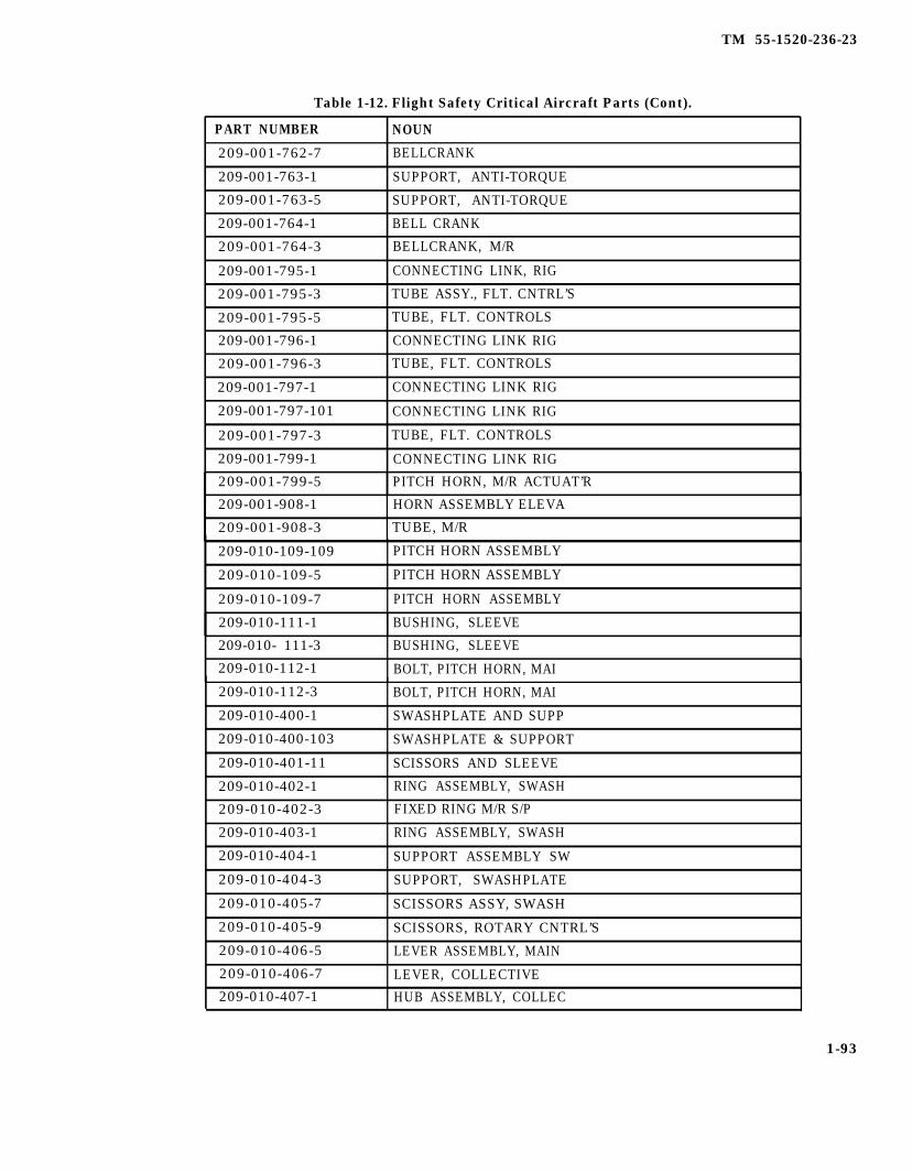
TM 55-1520-236-23
Table 1-12. Flight Safety Critical Aircraft Parts (Cont).
PART NUMBER NOUN
209-001-762-7 BELLCRANK
209-001-763-1 SUPPORT, ANTI-TORQUE
209-001-763-5 SUPPORT, ANTI-TORQUE
209-001-764-1 BELL CRANK
209-001-764-3 BELLCRANK, M/R
209-001-795-1 CONNECTING LINK, RIG
209-001-795-3 TUBE ASSY., FLT. CNTRL’S
209-001-795-5 TUBE, FLT. CONTROLS
209-001-796-1 CONNECTING LINK RIG
209-001-796-3 TUBE, FLT. CONTROLS
209-001-797-1 CONNECTING LINK RIG
209-001-797-101 CONNECTING LINK RIG
209-001-797-3 TUBE, FLT. CONTROLS
209-001-799-1 CONNECTING LINK RIG
209-001-799-5 PITCH HORN, M/R ACTUAT’R
209-001-908-1 HORN ASSEMBLY ELEVA
209-001-908-3 TUBE, M/R
209-010-109-109 PITCH HORN ASSEMBLY
209-010-109-5 PITCH HORN ASSEMBLY
209-010-109-7 PITCH HORN ASSEMBLY
209-010-111-1 BUSHING, SLEEVE
209-010- 111-3 BUSHING, SLEEVE
209-010-112-1 BOLT, PITCH HORN, MAI
209-010-112-3 BOLT, PITCH HORN, MAI
209-010-400-1 SWASHPLATE AND SUPP
209-010-400-103 SWASHPLATE & SUPPORT
209-010-401-11 SCISSORS AND SLEEVE
209-010-402-1 RING ASSEMBLY, SWASH
209-010-402-3 FIXED RING M/R S/P
209-010-403-1 RING ASSEMBLY, SWASH
209-010-404-1 SUPPORT ASSEMBLY SW
209-010-404-3 SUPPORT, SWASHPLATE
209-010-405-7 SCISSORS ASSY, SWASH
209-010-405-9 SCISSORS, ROTARY CNTRL’S
209-010-406-5 LEVER ASSEMBLY, MAIN
209-010-406-7 LEVER, COLLECTIVE
209-010-407-1 HUB ASSEMBLY, COLLEC
1-93

TM 1-1520-236-23
Table 1-12. Flight Safety Critical Aircraft Parts (Cont).
PART NUMBER NOUN
209-010-407-3 HUB, COLLECTIVE209-010-408-3 LINK, SWASHPLATE
209-010-408-7 LINK ASSY, SWASH PLA
209-010-409-1 CONNECTING LINK, RIG209-010-409-3 LINK, IDLER209-010-410-5 LINK ASSEMBLY, SWASH
209-010-410-7 LINK, SWASHPLATE
209-010-413-1 ADAPTER, PITCH LINK
209-010-414-1 BARREL, PITCH LINK
209-010-420-1 PLATE, RETAINER, SPLI
209-010-427-1 PIN, OUTER RING209-010-443-1 BEARING, PLAIN, RODE208-010-460-1 PITCH LINK ASSY208-010-460-3 TUBE ASSEMBLY, CONNE
209-010-460-5 TUBE, PITCH LINK
209-010-462-1 CLEVIS, ROD END
209-010-462-103 CLEVIS, ROD END209-010-518-101 TUBE ASSEMBLY, METAL209-010-520-101 PITCH LINK ASSY
209-010-520-103 PITCH LINK
209-011-400-101 SWASHPLATE CONTROL
209-011-710-5 TUBE ASSY, CONTROL T
209-011-711-1 I DLER, TAIL ROTOR
209-011-711-3 I DLER, T/R CONTROL
209-011-712-1 LEVER ASSY ROTOR209-011-712-3 LEVER, T/R CONTROL
209-011-713-1 LINK ASSY, ROTOR
209-011-714-1 c LEVIS, ROD END209-012-700-1 T/R INSTALLATION
209-012-700-103 T/R INSTALLATION209-040-069-1 QUILL ASSEMBLY GEN209-040-073-1 GEARSHAFT209-040-073-3 GEAR ASSY., MAIN XMSN209-040-149-1 GEAR, BEVEL
209-040-149-3 GEAR ASSY., T/R QUILL
209-040-151-1 GEARSHAFT, BEVEL
209-040-153-1 QUILL ASSEMBLY, GEAR
1-94

TM 55-1520-236-23
Table 1-12. Flight Safety Critical Aircraft Parts (Cont).
PART NUMBER NOUN
209-040-349-1 PLATE, RETAINING, XMSN
209-040-349-3 PLATE, RETAINING, XMSN
209-040-366-101 MAST ASSY.
209-040-366-3 MAST ASSY, TRANSMISS
209-050-002-41 CROSS TUBE ASSY,LAN
209-050-002-43 CROSSTUBE, AFT.
209-050-002-45 CROSS TUBE ASSY, LAN
206-050-002-47 CROSSTUBE, FWD.
209-060-112-1 ENGINE MOUNT, AFT
209-060-112-3 ENGINE MOUNT, AFT
209-060-121-101 ENGINE MOUNT FITTING
209-060-121-11 ENGINE MOUNT FITTING
209-060-123-101 ENGINE MOUNT TUBE
209-060-123-103 ENGINE MOUNT TUBE
209-060-123-11 ENGINE MOUNT TUBE
209-060-123-17 ENGINE MOUNT TUBE
209-062-120-101 MOUNT ASSEMBLY ENGI
209-062-120-5 MOUNT ASSEMBLY, ENGI
209-062-120-7 MOUNT ASSEMBLY, ENGI
209-062-122-1 LEG ASSEMBLY, ENGINE
209-062-123-21 ENGINE MOUNT TUBE
209-062-124-101 LEG ASSEMBLY, ENGINE
209-062-126-1 ENGINE MOUNT LEG ASSY
209-062-126-101 ENGINE MOUNT LEG ASSY
209-062-126-103 ENGINE MOUNT LEG ASSY
209-062-126-5 ENGINE MOUNT LEG ASSY
209-200-003-131 M/R PYLON INSTALLATION
209-200-003-133 M/R PYLON INSTALLATION
209-200-003-147 M/R PYLON INSTALLATION
209-200-003-149 M/R PYLON INSTALLATION
209-200-003-21 M/R PYLON INSTALLATION
209-200-003-23 M/R PYLON INSTALLATION
209-200-003-25 M/R PYLON INSTALLATION
209-200-003-27 M/R PYLON INSTALLATION
209-310-401-101 BEARING, PLAIN, ROD E
209-510-101-101 PITCH HORN ASSEMBLY
209-704-240-101 RETROFIT DRIVESHAFT
1-95

TM 55-1520-236-23
Table 1-12. Flight Safety Critical Aircraft Parts (Cont).
PART NUMBER NOUN
209-961-406-1 HANGER ASSEMBLY, DRI
209-961-412-1 DRIVE SHAFT ASSEMBL
209-961-412-3 DRIVESHAFT ASSY.
212-010-701-11 HUB & BLADE ASSY., T/R
212-010-701-9 HUB ASSEMBLY, TAIL R
212-010-704-3 YOKE, T/R
212-010-704-5 YOKE ASSEMBLY, TAIL
212-010-706-1 RETAINER, TAIL ROTOR
212-010-709-1 BELL CRANK
212-010-709-3 BELLCRANK, T/R
212-010-711-3 CONNECTING LINK, RIG
212-010-712-1 LINK ASSY - T/R
212-010-712-3 LINK ASSY., T/R
212-010-716-13 PITCH HORN, T/R
212-010-716-9 PITCH HORN ASSY
212-010-739-7 SUPPORT, COUNTER WE
212-010-744-3 T/R YOKE
212-010-750-11 BLADE, T/R
212-010-750-3 BLADE, T/R
212-010-762-1 BEARING, BALL, ANNULA
212-010-775-1 CROSSHEAD ASSEMBLY,
212-040-001-39 TRANSMISSION
212-040-001-51 MAIN XMSN
212-040-003-15 QUILL ASSEMBLY
212-040-003-17 QUILL ASSEMBLY
212-040-003-23 GEARBOX ASSEMBLY
212-040-004-11 QUILL ASSEMBLY
212-040-004-9 GEARBOX ASSEMBLY
212-040-054-3 SUPPORT CASE, XMSN
212-040-054-7 CASE ASSEMBLY, TRANS
212-040-150-5 PINION, GEAR, ROTOR
212-040-151-11 GEAR ASSY., T/R QUILL
212-040-151-9 PINION, GEAR, ROTOR
212-040-201-1 GEAR, SPUR
212-040-202-3 GEAR, PINION
212-040-206-3 ADAPTER, QUILL
212-040-208-3 QUILL ASSY., BEVEL GEAR
1-96

TM 55-1520-236-23
Table 1-12. Flight Safety Critical Aircraft Parts (Cont).
1-97
Richard Woods
212-040-365-23
Richard Woods
212-040-365-25
Richard Woods
212-040-365-31
Richard Woods
212-040-365-33
Richard Woods
212-040-450-5
Richard Woods
212-040-450-7
Richard Woods
212-040-451-1
Richard Woods
212-040-451-3
Richard Woods
212-040-452-1
Richard Woods
212-040-452-3
Richard Woods
212-040-462-1
Richard Woods
212-040-468-1
Richard Woods
212-040-468-3
Richard Woods
212-040-500-6
Richard Woods
212-040-500-7
Richard Woods
212-040-506-15
Richard Woods
212-040-506-5
Richard Woods
212-040-506-7
Richard Woods
212-040-600-7
Richard Woods
214-010-434-1
Richard Woods
41001221
Richard Woods
540-001-102-7
Richard Woods
540-001-904-5
Richard Woods
540-001-904-7
Richard Woods
540-001-905-1
Richard Woods
540-001-905-3
Richard Woods
540-011-101-25
Richard Woods
540-011-012-5
Richard Woods
540-011-102-7
Richard Woods
540-011-109-5
Richard Woods
540-011-112-5
Richard Woods
540-011-112-7
Richard Woods
540-011-113-1
Richard Woods
540-011-116-1
Richard Woods
540-011-117-1
Richard Woods
540-011-117-3
Richard Woods
540-011-118-1
Richard Woods
540-011-118-3
Richard Woods
540-011-119-17
Richard Woods
540-011-119-19
Richard Woods
540-011-153-11

TM 55-1520-236-23
Table 1-12. Flight Safety Critical Aircraft Parts (Cont).
PART NUMBER NOUN
540-011-153-17 YOKE EXTENSION, M/R
540-011-154-5 GRIP ASSEMBLY MAIN
540-011-154-7 GRIP ASSEMBLY, MAIN
540-011-162-1 BOLT, SHEAR
540-011-177-1 NUT, RETENTION STRAP
540-011-192-1 TRUNNION, MAIN ROTOR
540-011-192-3 TRUNNION, MAIN ROTOR
540-011-193-1 BEARING UNIT, PLAIN
540-011-404-5 RING ASSEMBLY OUTER
540-011-404-7 RING, SWASHPLATE
540-011-449-3 BEARING, BALL, STACK
540-011-456-1 SLEEVE, COLLECTIVE, A
540-011-459-1 PIN, SHOULDER
540-012-125-3 SLEEVE
540-015-001-1 BLADE, ROTARY WING
K747-003-205 BLADE, ROTARY WING
K747-003-209 BLADE, ROTARY WING
K747-003-303 BLADE, ROTARY WING
K747-003-309 BLADE, ROTARY WING
K747-003-401 BLADE, ROTARY WING
K747-003-403 BLADE, ROTARY WING
K747-061-5 ROOT FITTING ASSEMB
K747-072-1 FITTING ASSEMBLY, DR
K747-082-1 STRUT, FITTING
K747-083-1 ROOT FITTMG ASSEMB
NAS1310-29D BOLT, SHEAR
NAS1310-40D BOLT, SHEAR
NAS1310-46H BOLT, SHEAR
NAS464P8-36 BOLT, SHEAR
NAS6206-76D BOLT, SHEAR
NAS6208-103D BOLT, SHEAR
NAS6210-38D BOLT, SHEAR
NAS6618D112 BOLT, SHEAR
PAM9107NPPA2702 BEARING, BALL, ANNULA
1-98

TM 55-1520-236-23
CHAPTER 2
AIRFRAME
SECTION I.
2 - 1 . G E N E R A L I N F O R M A T I O NAIRFRAME.
STRUCTURAL REPAIR
a. This chapter contains airframe instructions forAVUM (Aviation Unit Maintenance) and AVIM (Avia-tion Intermediate Maintenance) on the army model AH-1P/E/F single rotor, single engine, at tackhelicopter. The airframe consists of the fuselage,tailboom, and wings (figure 2-1).
b. Qualified Engineering Authority, as used in thismanual, is AVSCOM Engineering. EngineeringAuthority may be contacted by writing to:
HEADQUARTERSU.S. Army Aviation Systems CommandATTN: AMSAV-ME4300 Goodfellow Blvd.St. Louis, MO 63120
c.
The structural panels shown on figure 2-2 must be installed prior to helicoptorground run, flight, jacking, towing, orhoisting. Non-structural panels must beinstalled prior to flight operations.
NOTEInstall all fasteners in structural panel.Non-structural panels (figure 2-3) mayhave every third fastener missing;however, no panel shall have more thanthirty-three percent of the total numberof fasteners missing.
This chapter contains the following sections:
Section I — Structural RepairSection II — FuselageSection III — TailboomSection IV — WingsSection V — Deleted
d. Structural repair of the airframe is covered inSection I. Maintenance functions other thanstructural repair are covered in the applicablesections II thru IV.
e . Structural repairs described in this section areintended for use in conjunction with TM 55-1500204-25/1, General Aircraft Maintenance Manual.
f. The limitations in the following note should beobserved when performing structural repair on theairframe.
NOTE
Repair at (AVUM) is limited to minorrepair of sheetmetal cracks, scratches,corrosion, and loose or missinghardware. These repairs can beaccomplished using the airframerepairman’s tool kit and portable handtools. If any extensive damage occurs ormajor repair is required, repairs shall beaccomplished by (AVIM). Repair at(AVIM) is limited to repair of sheet metalcracks, scratches, corrosion, halos, andloose or missing hardware. If majordamage occurs requiring jigs andfixtures, repairs shall be accomplished bynext higher maintenance level.
g. The damage limits provided in chapter 2 onbonded panels are not intended to red X the air-craft. The limits are to provide guidance forscheduling repair or replacement at a schedulemaintenance interval. When damage limits, par-ticularly bond voids in bonded panels, are exceed-ed, the responsible unit maintenance authority willestablish a reoccurring special inspection on thedamaged area until the damage to the structure iscorrected. If the damage is in the area that requiresengineering authority for repair, engineeringshould be contacted in writing with a descriptionof damage. If depot assistance will be required,unit should contact AVSCOM, AMSAV-MPD,with your requirement.
2-1

TM 55-1520-236-23
2 - 2 . T Y P E O F C O N S T R U C T I O N – a. Main and Tail Rotor Group. The bonded, all-AIRFRAME. metal main rotor blade assembly consists of a main
spar, a honeycomb core, aluminum skins, andThe AH-1S model attack helicopter basic structural laminated root plates to provide rigid support forconfiguration is composed of four main groups. mounting to the hub. Tail rotor blades are of similar
construction. Maintenance and repair procedures forthe main and tail rotor group are covered in chapter 6.
2-2

TM 55-1520-236-23
Figure 2-1. Fuselage Components and Tailboom (Sheet 1 of 2)
2-2.1 /(2.2.2 blank)

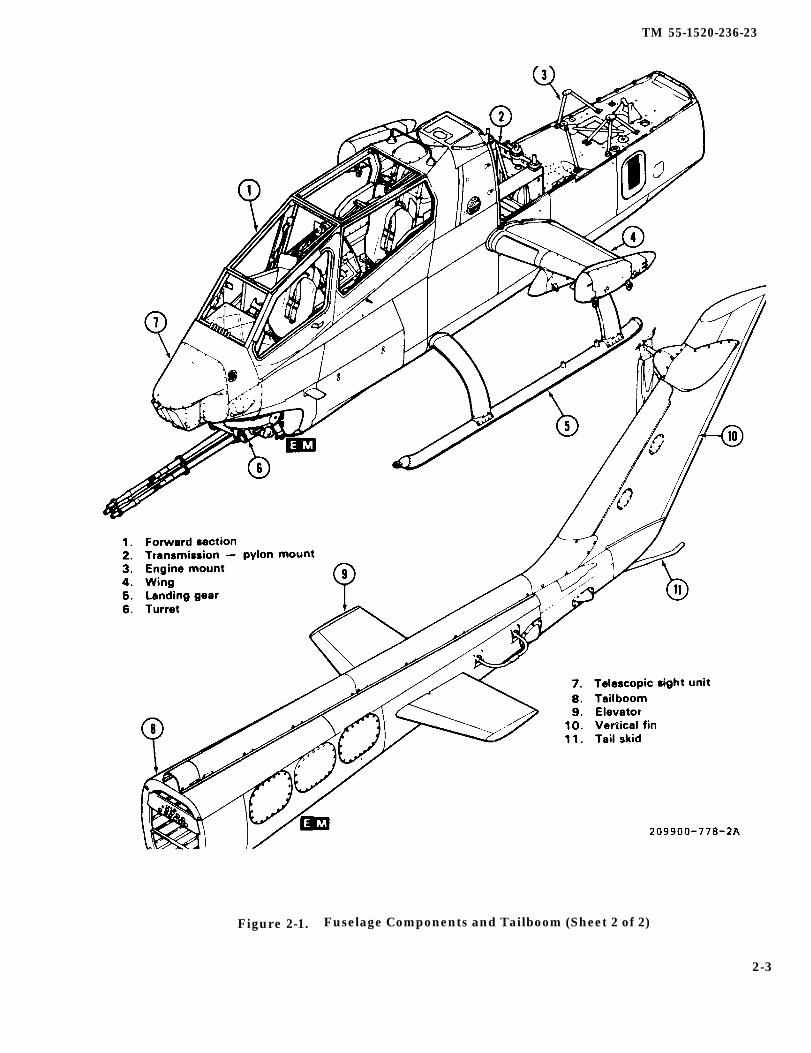
TM 55-1520-236-23
Figure 2-1. Fuselage Components and Tailboom (Sheet 2 of 2)
2-3

TM 55-1520-236-23
Figure 2-2. Structural Panels (Sheet 1 of 4)
2-4
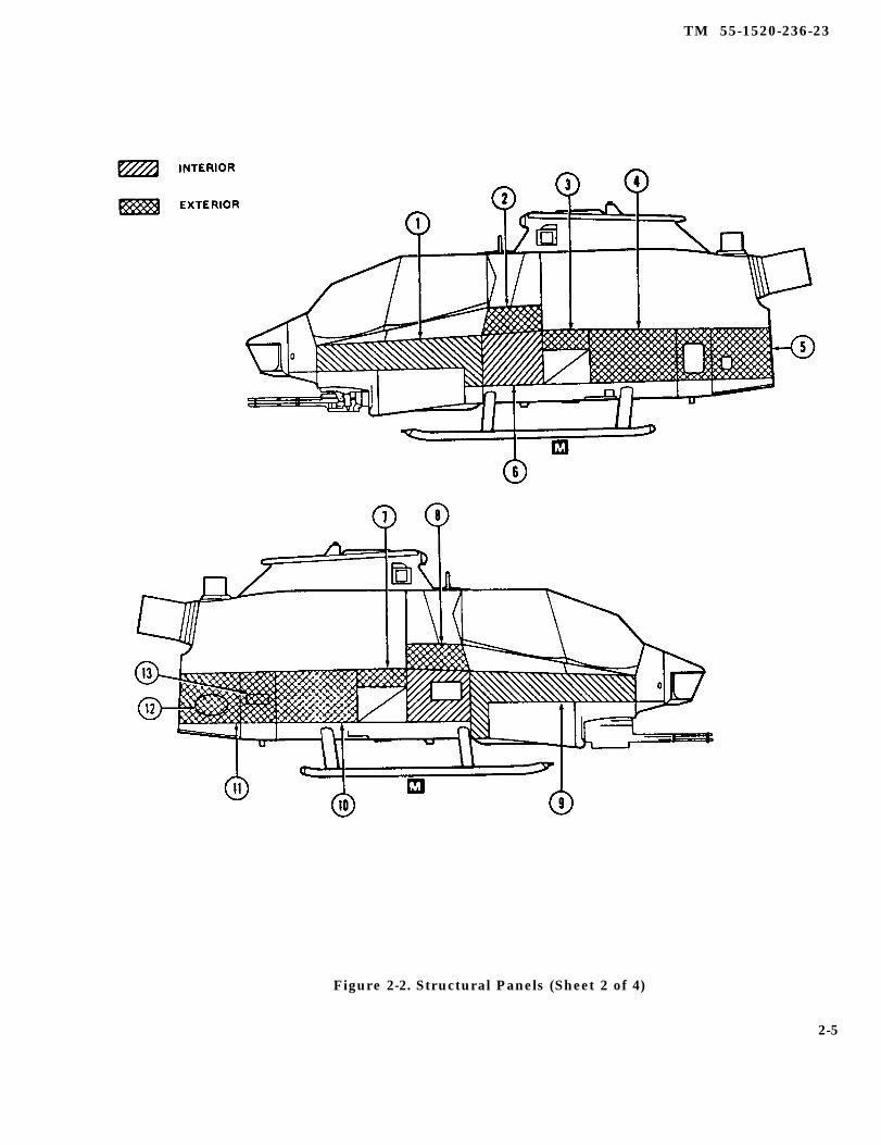
TM 55-1520-236-23
Figure 2-2. Structural Panels (Sheet 2 of 4)
2-5

TM 55-1520-236-23
Figure 2-2. Structural Panels (Sheet 3 of 4)
2-6

TM 55-1520-236-23
Figure 2-2. Structural Panels (Sheet 4 of 4)
2-7

TM 55-1520-236-23
Figure 2-3. Nonstructural Access Panels, Doors, and Fairings (Sheet 1 of 4)
2-8

TM 55-1520-236-23
Figure 2-3. Nonstructural Access Panels, Doors, and Fairings (Sheet 2 of 4)
2-9

TM 55-1520-236-23
Figure 2-3. Nonstructural Access Panels, Doors, and Fairings (Sheet 3 of 4)
2-10

TM 55-1520-236-23
Figure 2-3. Nonstructural Access Panels, Doors, and Fairings (Sheet 4 of 4)
b. Body and Wing Group. The body is dividedinto a forward fuselage section and a tailboom. In theforward fuselage, titanium, aluminum, and fiberglasshoneycomb deck panels and main beams form aprimary box beam structure which is covered withaluminum alloy skin and honeycomb sandwichpanels. The forward fuselage structure supports theengine, pylon assembly, tailboom, landing gear,wings, fuel tanks, weapons turret, and the tandemcockpit. The cockpit enclosure is an acrylic plasticcanopy incorporating crew access doors. The wings,which provide additional lift and support for externalstores, are constructed of two main spars, ribs, andaluminum skin. The tailboom is semi-monocoqueconstruction with bulkheads, longerons, stringers,and aluminum skin. The tail fin, built up of spars, ribs,and skin, is an integral part of the tailboom. Thetailboom is attached to the forward fuselage sectionwith four bolts and supports the aft section of the tailrotor drive system, the tail rotor, and elevator.
c. Landing Gear Group. The aluminum alloyskid-type landing gear consists of two skid tubes and
two arched cross tubes and is bolted to the primarystructure of the forward fuselage section at fourpoints. Maintenance and repair procedures for thelanding gear are covered in chapter 3.
d. Power Plant Group. The power plant issupported by a horizontal titanium deck on the upperaft part of the forward fuselage section. This group,which includes the engine, transmission, and relatedaccessories, is enclosed by hinged fiberglass andaluminum cowling. Maintenance and repairprocedures for the power plant are covered in chapter4.
2-3 . INVESTIGATION OF DAMAGE –AIRFRAME.
a. Remove grease, dirt, and paint in area of damageso that the extent of damage can be determined.
2-11
TM 55-1520-236-23
b. Inspect structure for dents, scratches,abrasions, punctures, cracks, distortion, andcorrosion. Deep scratches, nicks, and abrasions shallbe treated as a crack.
c. Inspect all riveted and bolted joints in vicinity ofdamage area for sheared, loose, or missing rivets andbolts. Inspect for elongated rivet and bolt holes. Ifthere is any doubt whether a rivet or bolt has failed,remove the fastener for inspection.
d. Inspect ail adjacent structure for secondarydamage that may have resulted from a shock loadtransmitted from the primary damage.
2 - 4 . C L A S S I F I C A T I O N O F D A M A G EAND TYPE REPAIR – AIRFRAME.
a. Negligible Damage. Damage that can bepermitted to remain as is or damage repairable bysimple procedure, such as removing dents, stopdrilling short cracks in non-critical structure,temporary patches, etc., without placing restrictionson flight.
b. Damage Repairable by Patching. Damageexceeding the specified negligible limits may berepairable by application of a patch.
c. Damage Repairable by Insertion. Damage to amember which is repairable by removing the materialat the point of damage and applying a newlyfabricated insert having identical characteristics tothat removed, plus the necessary reinforcement.
2 - 5 . S U P P O R T O F S T R U C T U R EDURING REPAIR – AIRFRAME.
When replacing any riveted structuralhoneycomb panels or the right aft fuelcell panel which is installed with screws,structural loads must be relieved tomaintain alignment of airframe.
a. Use the following procedures to ensure thatairframe alignment is maintained.
Do not use aircraft structure as workplatform when structural panels orengine decks are removed becauseairframe warpage may result.
(1) Attach hoist to mast retaining nut andsupport the main rotor by hoisting vertically until thelift link retaining bolt can be freely rotated. A free liftlink retaining bolt indicates that the load has beenremoved.
Alternate method: Remove main rotor, mast,controls, and transmission.
(2) Attach engine sling (T9) and hoist (T45) toengine. Loosen pillow blocks on engine mounts.Support the engine by hoisting vertically until engineis loose in the pillow blocks.
Alternate method: Remove engine. Refer toparagraph 4-12.
d. Damage Necessitating Replacement of (3) Support tailboom at two locations, forwardParts. Damage which cannot be repaired or damage and aft, to remove load from forward fuselage,so severe that the repair thereof would not warrantthe time expended, Alternate procedure: Remove tailboom.
e. Riveted Repairs. The finished aluminum alloyparts and magnesium alloy sheets used in thehelicopter are heat treated, Only rivets and/or bolted All structural panels must be installedrepairs shall be permitted. For instruction on the use prior to jacking or lowering on jacks,and installation of rivets, refer to General AircraftMaintenance Manual, TM 55-1500-204-25/1.
to prevent possible warpage. Refer toparagraphs 1-34 and 1-45 for hoistingand jacking instructions.
f. Welded Repairs. For welded repair information (4) Place jacks (S3 and S9) under jack pointsto components such as tailpipe and spot welds, refer and raise until hand-tight against jack fittings (S6, S7,to TM 55-1500-204-25/1. and S8).
2-12

TM 55-1520-236-23
Remove and install the panels listed inthe following step one at a time unlessa work aid fixture is used to restrain thestructure and maintain alignment, ordamage to the fuselage may result.
b. Replacement of structural panels is restrictedto only one at a time unless a work aid fixture is usedto restrain the structure and prevent misalignment.Panels that can be replaced one at a time without theuse of a fixture are listed below.
Table 2-1. Main Beam Panels (Structural)
FIGURE 2-2 FUSELAGEINDEX NO. SIDE STATION REF.
123456789
1011
LeftLeftLeftLeftLeftLeftRightRightRightRightRight
61.25 to 148.50148.50 to 186.25186.25 to 213.94213.94 to 250.00250.00 to 300.68148.50 to 186.25186.25 to 213.94148.50 to 186.2561.25 to 148.50
213.94 to 250.00250.00 to 300.68
c. Deleted.
2-6. LOCATIONAIRFRAME.
OF LEVELING POINTS –
Refer to paragraph 1-34 for leveling procedure.
2-7. PRINCIPAL DIMENSIONS - AIRFRAME
Refer to figure 2-4 for principal dimensions of thehelicopter.
2-8. REFERENCE LINES — AIRFRAME.
Refer to figure 2-5 for major reference lines of thehelicopter. Definitions of reference lines are as follows:
a. Fuselage Station Lines. Station lines (FS)are vertical reference lines against the helicopterwhich are used to locate major assemblies and partsof the structure. FS numbers indicate the distance ininches from the reference datum line, which is located24.4 inches forward of the most forward nose contourand designated as Station 0.
b. Boom Station Lines. Boom station lines(BS) are reference tines perpendicular to the centerline of the tailboom. Boom stations indicate thedistance in inches from the reference datum line,which is located 41.37 inches forward of the mostforward surface of the boom structure.
c. Water Lines. Water lines (WL) arehorizontal reference lines (viewed from the side orfront of helicopter) used to locate major assembliesand parts of the structure by a number indicating thedistance in inches from a line of origin, located 21.62inches below the tower contour of the turret fairing anddesignated as water line 0.
d Butt Lines. Butt tines (BL) are verticalreference lines as viewed from front of helicopter usedto locate major assemblies and parts of the structureby a number indicating the distance in inches on eachside of the helicopter centerline, which is designatedas butt line 0.
Wing Station Lines. Wing station lines(WS) are vertical reference lines as viewed from frontof helicopter and are used to locate parts of the wingstructure by a number indicating the distance in inchesfrom the helicopter centerline (BLO).
2-9. STRUCTURAL REPAIR MATERIALS.
Structural repair materials are listed in table 2-2 inalphabetical order.
2-10. CORROSION CONTROL — AIRFRAME.
This paragraph contains information requiredfor identification and control of corrosion. Refer to TM1-1500-343-23 or TM 1-1500-344-23 for additionalinformation. Preventive maintenance for corrosioncontrol should include the following procedures:
(1) Periodic inspection to detect corrosion inthe early stages.
2-13

TM 55-1520-236-23
Figure 2-4. Principal Dimensions — Airframe (Sheet 1 of 2)
2-14

TM 55-1520-236-23
Figure 2-4. Principal Dimensions – Airframe (Sheet 2 of 2)
2-15

TM
55-1520-236-23
Figu
re 2-5. Referen
ce Lin
es. – Airfram
e
2-1
6

(2) Adequate cleaningmize the effects of corrosion.
of helicopter to mini-
(3) Removal and treatment of corrosion.
(4) Draining of moisture entrapment areas.
(5) Sealing of watertight areas.
(6) Preservation, including paint touch-upand replacement of finishes.
TM 55-1520-236-23
(7) All exposed common hardware requiresovercoating with MIL-C-16173, Grade IV (C43.1) andall exposed weapon system connectors required over-spraying with MIL-C-85054 (C443) IAW TM1-1500-344-23.
b. Types of Corrosion.
(1) Uniform etch corrosion. The surfaceeffect produced by most direct chemical attacks (as byan add) is a uniform etching of the metal. On apolished surface, this type of corrosion is first seen asa general dulling of the surface. if such corrosion isallowed to continue, the surface becomes rough andpossibly frosted in appearance.
Table 2-2. Structural Repair Materials
ITEM REF. NO.No. DESCRIPTION AND FSCM NSN
1
2
3
4
5
6
7
8
9
10
11
12
Aluminum Alloy Sheet,0.010 inch the 2024-T3
Aluminum Alloy Sheet,0.012 inch thick, 2024-T3
Aluminum Alloy Sheet,0.016 inch thick, 2024-T3
Aluminum Alloy Sheet,0.020 inch thick, 2024-T3
Aluminum Alloy Sheet,0.025 inch thick, 2024-T3
Aluminum Alloy Sheet,0.032 inch thick, 2024-T3
Aluminum Alloy Sheet,0.040 inch thick, 2024-T3
Aluminum Alloy Sheet,0.050 inch thick, 2024-T3
Aluminum Alloy Sheet,0.063 inch thick, 2024-T3
Aluminum Alloy Sheet,0.071 inch thick, 2024-T3
Aluminum Alloy Sheet,0.080 inch thick, 2024-T3
Aluminum Alloy Sheet,0.100 inch thick, 2024-T3
QQ-A-250/5(81348)
QQ-A-250/5(81348)
QQ-A-250/5(81348)
QQ-A-250/5(81348)
QQ-A-250/5(81348)
QQ-A-250/5(81348)
QQ-A-250/5(81348)
QQ-A-250/5(81348)
QQ-A-250/5(81348)
QQ-A-250/5(81348)
QQ-A-250/5(81348)
QQ-A-250/5(81348)
9535-01-024-1983
9535-00-167-2274
9535-00-232-0543
9535-00-167-2277
8535-00-167-2278
9535-00-086-9729
9535-00-167-2280
9535-00-232-0569
9535-01-049-0763
9535-00-106-0609
9535-00-232-0398
9535-00-288-4675
2-17

TM 55-1520-236-23
Table 2-2. Structural Repair Materials (cont)
ITEM REF. NO.NO. DESCRIPTION AND FSCM NSN
12.1 Aluminum Alloy Sheet,
13
14
15
16
17
18
19
20
21
22
23
24
25
26
27
2-18
0.040 inch thick, 2024-TO
Aluminum Alloy Sheet,0.020 inch thick, 5052-H32
Aluminum Alloy Sheet,0.025 inch thick, 5052-H34
Aluminum Alloy Sheet,0.040 inch thick, 5052-H32
Aluminum Alloy Sheet,0.025 inch thick, 6061-T6
Aluminum Alloy Sheet,0.032 inch thick, 6061-T6
Aluminum Alloy Sheet,0.010 inch thick, 7075-T6
Aluminum Alloy Sheet,0.012 inch thick, 7075-T6
Aluminum Alloy Sheet,0.016 inch thick, 7075-T6
Aluminum Alloy Sheet,0.020 inch thick, 7075-T6
Aluminum Alloy Sheet,0.025 inch thick, 7075-T6
Aluminum Alloy Sheet,0.032 inch thick, 7075-T6
Aluminum Alloy Sheet,0.040 inch thick, 7075-T6
Aluminum Alloy Sheet,0.050 inch thick, 7075-T6
Aluminum Alloy Sheet,0.063 inch thick, 7075-T6
Aluminum Alloy Tubing (4" Dia.)0.083 thickness, 2024-T3
QQ-A-250/5 9535-00-167-2267(81348)
QQ-A-250/8 9535-00-242-8598(81348)
QQ-A-250/8 9535-00-832-1868(81348)
QQ-A-250/8 9535-00-232-6864(81348)
QQ-A-250/11 9535-00-250-6502(81348)
QQ-A-250/11 9535-00-085-4133(81348)
QQ-A-250/13(81348)
QQ-A-250/13(81348)
QQ-A-250/13(81348)
QQ-A-250/13(81348)
QQ-A-250/13(81348)
QQ-A-250/13(81348)
QQ-A-250/13(81348)
QQ-A-250/13(81348)
QQ-A-250/13(81348)
QQ-A-300-3B
9535-00-236-7091
9535-00-084-4438
9535-00-086-9808
9535-00-086-9864
9535-00-249-5811
9535-00-084-4581
9535-00-086-9465
9535-00-088-6599
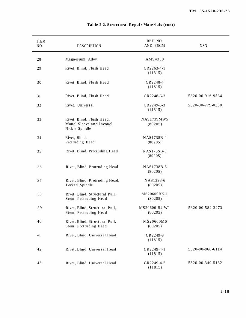
TM 55-1520-236-23
Table 2-2. Structural Repair Materials (cont)
ITEM REF. NO.NO. DESCRIPTION AND FSCM NSN
28
29
30
31
32
33
34
35
36
37
38
39
40
41
42
43
Magnesium Alloy
Rivet, Blind, Flush Head
Rivet, Blind, Flush Head
Rivet, Blind, Flush Head
Rivet, Universal
Rivet, Blind, Flush Head,Monel Sleeve and InconelNickle Spindle
Rivet, Blind,Protruding Head
Rivet, Blind, Protruding Head
Rivet, Blind, Protruding Head
Rivet, Blind, Protruding Head,Locked Spindle
Rivet, Blind, Structural Pull.Stem, Protruding Head
Rivet, Blind, Structural Pull,Stem, Protruding Head
Rivet, Blind, Structural Pull,Stem, Protruding Head
Rivet, Blind, Universal Head
Rivet, Blind, Universal Head
Rivet, Blind, Universal Head
AMS4350
CR2263-4-1(11815)
CR2248-4(11815)
CR2248-6-3
CR2249-6-3(11815)
NAS1739MW5(80205)
NAS1738B-4(80205)
NAS173SB-5(80205)
NAS1738B-6(80205)
NAS1398-6(80205)
MS20600BK-1(80205)
MS20600-B4-W1(80205)
MS20600M6(80205)
CR2249-3(11815)
CR2249-4-1(11815)
CR2249-4-5(11815)
5320-00-916-9534
5320-00-779-0300
5320-00-582-3273
5320-00-866-6114
5320-00-349-5132
2-19
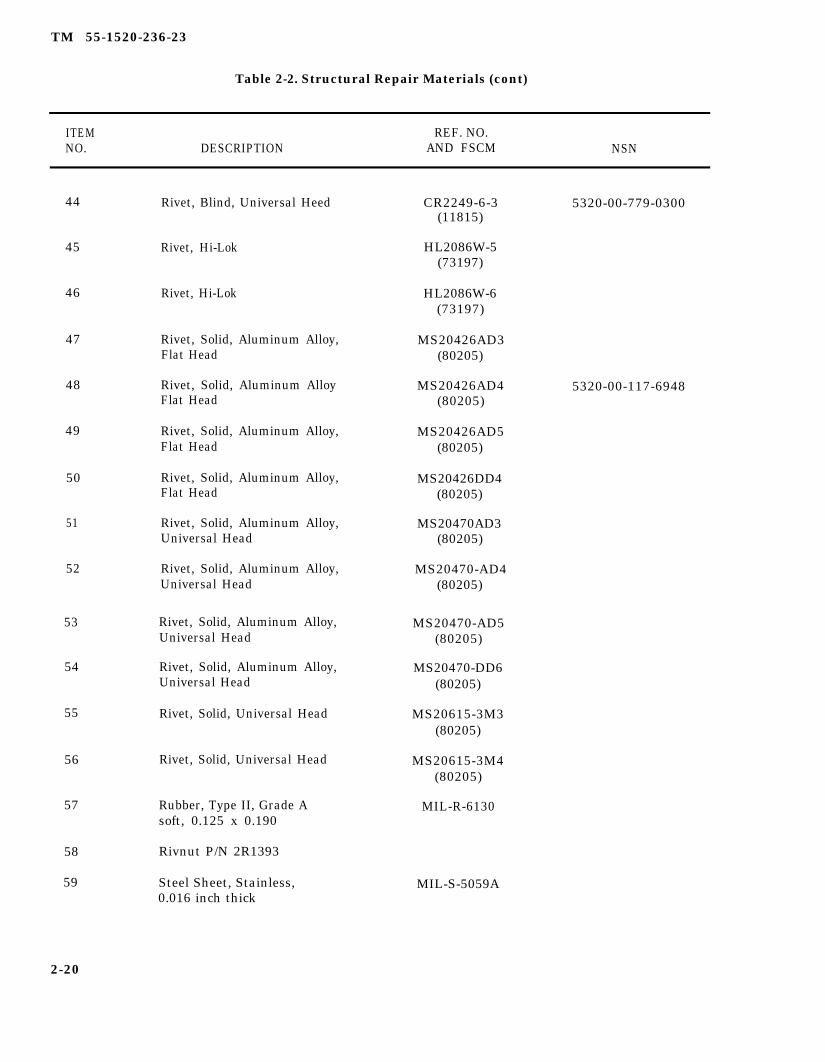
TM 55-1520-236-23
Table 2-2. Structural Repair Materials (cont)
ITEM REF. NO.NO. DESCRIPTION AND FSCM NSN
44
45
46
47
48
49
50
51
52
53
54
55
56
57
58
59
Rivet, Blind, Universal Heed
Rivet, Hi-Lok
Rivet, Hi-Lok
Rivet, Solid, Aluminum Alloy,Flat Head
Rivet, Solid, Aluminum AlloyFlat Head
Rivet, Solid, Aluminum Alloy,Flat Head
Rivet, Solid, Aluminum Alloy,Flat Head
Rivet, Solid, Aluminum Alloy,Universal Head
Rivet, Solid, Aluminum Alloy,Universal Head
Rivet, Solid, Aluminum Alloy,Universal Head
Rivet, Solid, Aluminum Alloy,Universal Head
Rivet, Solid, Universal Head
Rivet, Solid, Universal Head
Rubber, Type II, Grade Asoft, 0.125 x 0.190
Rivnut P/N 2R1393
Steel Sheet, Stainless,0.016 inch thick
CR2249-6-3 5320-00-779-0300(11815)
HL2086W-5(73197)
HL2086W-6(73197)
MS20426AD3(80205)
MS20426AD4 5320-00-117-6948(80205)
MS20426AD5(80205)
MS20426DD4(80205)
MS20470AD3(80205)
MS20470-AD4(80205)
MS20470-AD5(80205)
MS20470-DD6(80205)
MS20615-3M3(80205)
MS20615-3M4(80205)
MIL-R-6130
MIL-S-5059A
2-20
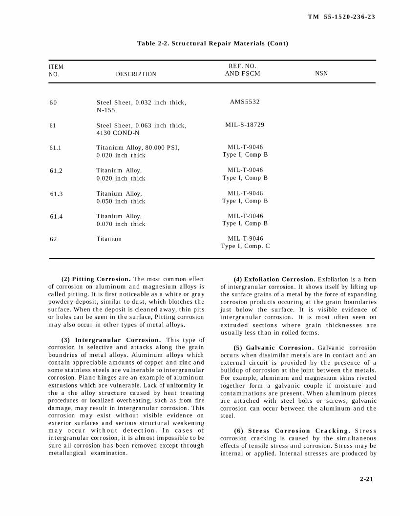
TM 55-1520-236-23
Table 2-2. Structural Repair Materials (Cont)
ITEM REF. NO.NO. DESCRIPTION AND FSCM NSN
60 Steel Sheet, 0.032 inch thick,N-155
61 Steel Sheet, 0.063 inch thick,4130 COND-N
61.1 Titanium Alloy, 80.000 PSI,0.020 inch thick
61.2 Titanium Alloy,0.020 inch thick
61.3 Titanium Alloy,0.050 inch thick
61.4 Titanium Alloy,0.070 inch thick
62 Titanium
AMS5532
MIL-S-18729
MIL-T-9046Type I, Comp B
MIL-T-9046Type I, Comp B
MIL-T-9046Type I, Comp B
MIL-T-9046Type I, Comp B
MIL-T-9046Type I, Comp. C
(2) Pitting Corrosion. The most common effectof corrosion on aluminum and magnesium alloys iscalled pitting. It is first noticeable as a white or graypowdery deposit, similar to dust, which blotches thesurface. When the deposit is cleaned away, thin pitsor holes can be seen in the surface, Pitting corrosionmay also occur in other types of metal alloys.
(3) Intergranular Corrosion. This type ofcorrosion is selective and attacks along the grainboundries of metal alloys. Aluminum alloys whichcontain appreciable amounts of copper and zinc andsome stainless steels are vulnerable to intergranularcorrosion. Piano hinges are an example of aluminumextrusions which are vulnerable. Lack of uniformity inthe a the alloy structure caused by heat treatingprocedures or localized overheating, such as from firedamage, may result in intergranular corrosion. Thiscorrosion may exist without visible evidence onexterior surfaces and serious structural weakeningmay occur without detection. In cases ofintergranular corrosion, it is almost impossible to besure all corrosion has been removed except throughmetallurgical examination.
(4) Exfoliation Corrosion. Exfoliation is a formof intergranular corrosion. It shows itself by lifting upthe surface grains of a metal by the force of expandingcorrosion products occuring at the grain boundariesjust below the surface. It is visible evidence ofintergranular corrosion. It is most often seen onextruded sections where grain thicknesses areusually less than in rolled forms.
(5) Galvanic Corrosion. Galvanic corrosionoccurs when dissimilar metals are in contact and anexternal circuit is provided by the presence of abuildup of corrosion at the joint between the metals.For example, aluminum and magnesium skins rivetedtogether form a galvanic couple if moisture andcontaminations are present. When aluminum piecesare attached with steel bolts or screws, galvaniccorrosion can occur between the aluminum and thesteel.
(6) Stress Corrosion Cracking. Stresscorrosion cracking is caused by the simultaneouseffects of tensile stress and corrosion. Stress may beinternal or applied. Internal stresses are produced by
2-21
TM 55-1520-236-23
nonuniform deformation during cold working, byunequal cooling from high temperatures, and byinternal structural rearrangement involving volumechanges. Stresses induced when apiece is deformed,those induced by press and shrink fits, and those inrivets and bolts are internal stresses.
(7) Fatigue Corrosion. Fatigue corrosion is aspecial case of stress corrosion caused by thecombined effects of cyclic stress and corrosion. Nometal is immune to some reduction of its resistance tocyclic stressing if the metal is in a corrosiveenvironment. Damage from fatigue corrosion isgreater than the sum of the damage from both cyclicstresses and corrosion.
(a) Fatigue corrosion failure occurs in twostages. During the first stage, the combined action ofcorrosion and cyclic stresses damages the metal bypitting and cracking to such a degree that fracture bycyclic stressing will ultimately occur, even if thecorrosive environment is completely removed. Thesecond stage is essentially a fatigue stage in whichfailure proceeds by propagation of the crack and iscontrolled primarily by stress concentration effectsand the physical properties of the metal.
(b) Fracture of a metal part due to fatiguecorrosion generally occurs at a stress far below thefatigue limit in laboratory test, though the amount ofcorrosion is very small. For this reason, protection ofall parts subject to alternating stress is particularlyimportant when practical, even in environments thatare only mildly corrosive.
(8) Fretting Corrosion. This type of corrosiveattack develops when two heavily loaded surfaces incontact with each other are subject to slight vibratorymotion. The rubbing contact removes small particlesof virgin metal from surface. These particles willusually oxidize to form abrasive materials. Thecontinuing motion prevents formation of anyprotective oxide film, and in conjunction with theabrasive formed, creates a prime area of furthercorrosion to occur. Fretting is evident at an early stageby surface discoloration and the presence ofcorrosion products in any lubricant present.Continued fretting will ruin bearing surfaces, destroycritical dimensions, and may be serious enough toeventually cause cracking and fatigue failure.Fretting may be controlled by preventing slippage oftwo surfaces or by lubricating the surfaces.
c. Surface Maintenance.
(1) Helicopter External Surfaces. Thehelicopter should be cleaned as often as necessary tokeep surface free of salt, soil, and other corrosivedeposits. The term “clean” means to do the best jobpossible using the materials and facilities available. Awipe down with water or oil soaked cloth is betterthan no cleaning at all. The importance of frequentcleaning when operating in coastal areas cannot beoveremphasized. The cleaning procedure usedshould be the mildest method which will produce thedesired results. For example, steam cleaning is a veryeffective soil and grease remover, but it also mayerode paint and damage electrical insulation. In thefollowing instructions a specific cleaning method isoutlined. Refer to cleaning chart, figure 2-6 and TM55-1500-204-25/1.
(2) Fuselage and Tailboom. Clean the paintedareas of the helicopter fuselage and tailboom asindicated in the cleaning chart, figure 2-6.
(3) Helicopter Interior Surfaces. Clean thecabin compartment, engine compartment, fuselagecompartment, beneath the engine, and the tailboomwith materials indicated on the cleaning chart, figure2-6.
(4) Clear Plastic Surfaces. Clean clear plasticsurfaces, where polishing for scratch removal is notrequired, as follows:
Remove rings or any object from thehands which might scratch the plasticsurface.
(a) Flush plastic with fresh water, using thebare hand to dislodge dirt and solid particles.
(b) Wash with mild soap (C113) and watersolution. Be sure that the solution is free of abrasivematerial. Go over the surface with the bare hand todetect any abrasive material.
(c) Dry with a clean damp chamois or softclean cloth. Do not continue rubbing after plastic isdry.
Do not rub plastic with a dry cloth. Thisbuilds up an electrostatic charge whichattracts dust particles to the surface.
2-22
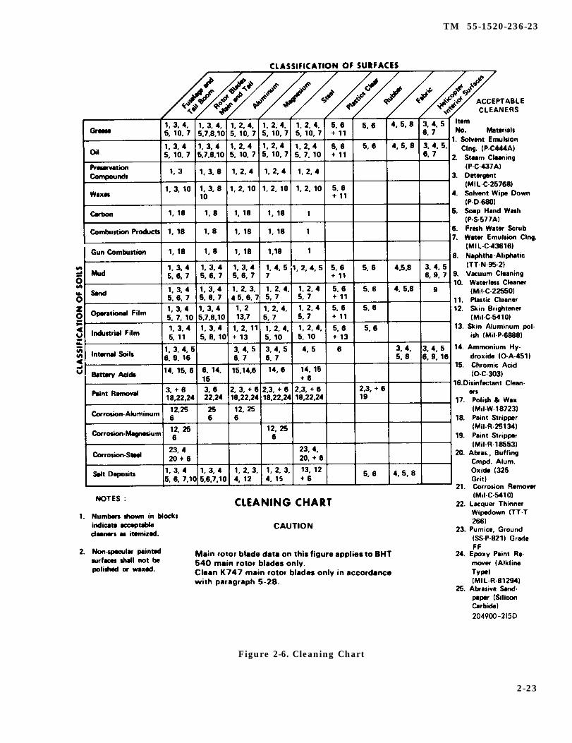
TM 55-1520-236-23
Figure 2-6. Cleaning Chart
2-23
TM 55-1520-236-23
(d) Clean plastic(C32).
with an approved cleaner
NOTE
If cleaner is not available, rinse with clearwater, in a shaded area if possible, toprevent water spotting.
d. Corrosion Removal and Treatment.
Paint strippers are highly toxic. Use inwell ventilated area and avoid skincontact by use of protective clothing andappropriate eye protection. If strippercomes in contact with skin or eyes,promptly flush with water and seekmedical attention.
Corrosion removal must be complete.Failure to remove all corrosion allowscorrosion to continue even after cleaningand refinishing. All surfaces to be treatedmust be clean, unpainted, and free fromoil and grease. Care must be taken not toexceed the limits of corrosion removalestablished for a particular part.
(1) Clean aluminum parts which are corrodedin accordance with figure 2-6. Treat and refinishanodized and painted aluminum parts as indicated inthe following steps. Anodized aluminum parts havebeen treated to form a supplemental film of aluminumoxide on the surface of the part. When processinganodized surfaces, avoid unnecessary destruction ofthe oxide film.
Use of steel wool, steel wire brushes, orsevere abrasive materials is prohibited onany aluminum surface.
(a) Brush paint remover (C96) on area to bestripped. Allow remover to remain on surface for asufficient length of time for paint to loosen (do notallow remover to dry on surface). Scrub the area with
a bristle brush, wet with paint remover, to loosenany paint still adhering to the metal. Repeat asrequired until all paint is removed.
(b) Flush paint remover from area with freshwater and a long handle brush. Remove any residualpaint with a non-metallic scraper. Remove maskingmaterials and thoroughly rinse area.
(c) Clean stains and lightly corroded areaswith cleaning compound (C34). Use aluminum wool,aluminum wire brushes, or stiff fiber brushes to cleanmore severely corroded areas.
Acid is extremely dangerous. Avoidcontact with skin or clothing. Avoidbreathing fumes. Rubber gloves shouldbe used when handling and applying anyacid solution.
(d) Treat corroded areas with a solution of 10percent chromic acid (C1), to which 20 drops of leadacid battery electrolyte per gallon has been added.Apply the solution with a bristle brush and scrub toensure penetration to the bottom of any pits. Allowsolution to remain in place 5 to 20 minutes then rinseor wipe off with a damp cloth. Alcoholic phosphoricacid (C19) may be used as an alternate for the chromicacid solution.
(e) Wipe the area dry with a clean cloth andinspect with a magnifying glass to ensure that allcorrosion has been removed and that the corrosiondamage limits have not been exceeded.
(f) Smooth all rough edges with a burnishingtool or an aluminum oxide impregnated rubber wheel.
(g) When skin seams and other placessubject to water leakage are involved seal withsealant (C105). Use zinc chromate putty (C93) as analternate material in small areas if necessary.
(h) Repaint the area.
NOTE
Protect surrounding areas fromoverspray with paper and masking tape.In addition, ensure that an in-line waterseparator is in the compressed air line tothe spray equipment.
2-24
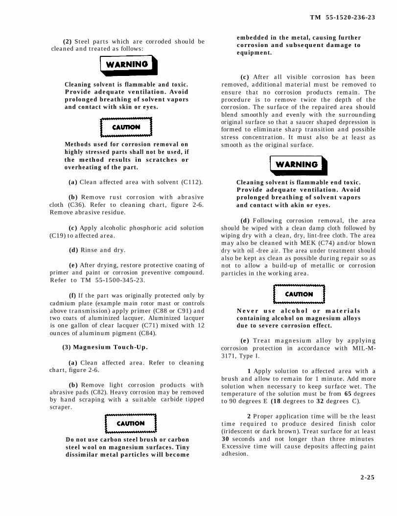
TM 55-1520-236-23
(2) Steel parts which are corroded should becleaned and treated as follows:
Cleaning solvent is flammable and toxic.Provide adequate ventilation. Avoidprolonged breathing of solvent vaporsand contact with skin or eyes.
Methods used for corrosion removal onhighly stressed parts shall not be used, ifthe method results in scratches oroverheating of the part.
(a) Clean affected area with solvent (C112).
(b) Remove rust corrosion with abrasivecloth (C36). Refer to cleaning chart, figure 2-6.Remove abrasive residue.
(c) Apply alcoholic phosphoric acid solution(C19) to affected area.
(d) Rinse and dry.
(e) After drying, restore protective coating ofprimer and paint or corrosion preventive compound.Refer to TM 55-1500-345-23.
(f) If the part was originally protected only bycadmium plate (example main rotor mast or controlsabove transmission) apply primer (C88 or C91) andtwo coats of aluminized lacquer. Aluminized lacqueris one gallon of clear lacquer (C71) mixed with 12ounces of aluminum pigment (C84).
(3) Magnesium Touch-Up.
(a) Clean affected area. Refer to cleaningchart, figure 2-6.
(b) Remove light corrosion products withabrasive pads (C82). Heavy corrosion may be removedby hand scraping with a suitablescraper.
carbide tipped
Do not use carbon steel brush or carbonsteel wool on magnesium surfaces. Tinydissimilar metal particles will become
embedded in the metal, causing furthercorrosion and subsequent damage toequipment.
(c) After all visible corrosion has beenremoved, additional material must be removed toensure that no corrosion products remain. Theprocedure is to remove twice the depth of thecorrosion. The surface of the repaired area shouldblend smoothly and evenly with the surroundingoriginal surface so that a saucer shaped depression isformed to eliminate sharp transition and possiblestress concentration. It must alsosmooth as the original surface.
be at least as
Cleaning solvent is flammable end toxic.Provide adequate ventilation. Avoidprolonged breathing of solvent vaporsand contact with akin or eyes.
(d) Following corrosion removal, the areashould be wiped with a clean damp cloth followed bywiping dry with a clean, dry, lint-free cloth. The areamay also be cleaned with MEK (C74) and/or blowndry with oil -free air. The area under treatment shouldalso be kept as clean as possible during repair so asnot to allow a build-up of metallic or corrosionparticles in the working area.
Never use alcohol or materialscontaining alcohol on magnesium alloysdue to severe corrosion effect.
(e) Treat magnesium alloy by applyingcorrosion protection in accordance with MIL-M-3171, Type I.
1 Apply solution to affected area with abrush and allow to remain for 1 minute. Add moresolution when necessary to keep surface wet. Thetemperature of the solution must be from 65 degreesto 90 degrees E (18 degrees to 32 degrees C).
2 Proper application time will be the leasttime required to produce desired finish color(iridescent or dark brown). Treat surface for at least30 seconds and not longer than three minutesExcessive time will cause deposits affecting paintadhesion.
2-25
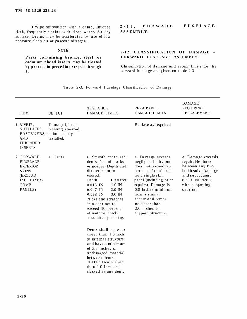
TM 55-1520-236-23
3 Wipe off solution with a damp, lint-free 2 - 1 1 . F O R W A R D F U S E L A G Ecloth, frequently rinsing with clean water. Air dry ASSEMBLY.surface. Drying may be accelerated by use of lowpressure clean air or gaseous nitrogen.
NOTE 2-12. CLASSIFICATION OF DAMAGE –Parts containing bronze, steel, or FORWARD FUSELAGE ASSEMBLY.cadmium plated inserts may be treatedby process in preceding steps 1 through Classification of damage and repair limits for the3. forward fuselage are given on table 2-3.
Table 2-3. Forward Fuselage Classification of Damage
DAMAGENEGLIGIBLE REPAIRABLE REQUIRING
ITEM DEFECT DAMAGE LIMITS DAMAGE LIMITS REPLACEMENT
1. RIVETS, Damaged, loose, Replace as requiredNUTPLATES, missing, sheared,FASTENERS, or improperlyAND installed.THREADEDINSERTS.
2. FORWARD a. DentsFUSELAGEEXTERIORSKINS(EXCLUD-ING HONEY-COMBPANELS)
a. Smooth contoureddents, free of cracksor gouges. Depth anddiameter not toexceed;Depth Diameter0.016 IN 1.0 IN0.047 IN 2.0 IN0.063 IN 3.0 INNicks and scratchesin a dent not toexceed 10 percentof material thick-ness after polishing.
Dents shall come nocloser than 1.0 inchto internal structureand have a minimumof 3.0 inches ofundamaged materialbetween dents.NOTE: Dents closerthan 1.0 inch areclassed as one dent.
a. Damage exceedsnegligible limits butdoes not exceed 25percent of total areafor a single skinpanel (including priorrepairs). Damage is6.0 inches minimumfrom a similarrepair and comesno closer than2.0 inches tosupport structure.
a. Damage exceedsrepairable limitsbetween any twobulkheads. Damageand subsequentrepair interfereswith supportingstructure.
2-26

TM 55-1520-236-23
Table 2-3. Forward Fuselage Classification of Damage (cont)
DAMAGENEGLIGIBLE REPAIRABLE REQUIRING
ITEM DEFECT DAMAGE LIMITS DAMAGE LIMITS REPLACEMENT
2. FORWARDFUSELAGEEXTERIORSKINS(EXCLUD-ING HONEY-COMBPANELS)(Cent)
b. Corrosion b. Not to exceed 10percent of materialthickness and lessthan 4.0 squareinches afterclean up.Damage 1.0 inchminimum frominternal structure.
c. Holes, cracks c. Noneor tears.
d. Nicks andscratches.
d. No deeper than 10percent of materialthickness and lessthan 4.0 squareinches aftercleanup.
e. Trapped or e. Inward or out-stretched skin. ward bulges located
in a sectional area,that can be correctedby removing attach-hardware, allow-ing skin to shift.Mismatch of rivetholes shall not exceedthat which can becleaned up by drill-ing and installingone size larger rivetand maintain properrivet edge distance.However, if conditiondoes not disappearafter unloading
b. Damage exceedsnegligible limits.Cleanup shall notexceed 5 percentof skin panel area.and come no closerthan 2.0 inch tosupporting structure.
c. Cracks or tearsno longer than 25percent of shortestskin dimension.Holes 3.0 inch max.dia. Cleanup nocloser than 2.0inch to supportingstructure and affectno more than 5percent of skinarea.
d. Same as precedingstep c.
e. Creased dentsnot classified asoil can or stretchedskin, not exceeding26% of a sectionalarea and no closerthan 1.0 inch to asupporting structure.Oil can condition,free of sharp dentsor creases and notextending over orinto supportingstructure, may berepaired by insertinga backup stiffenerover the damagedarea.
b. Damage exceedsrepairable damagelimits.
c. Damage exceedsrepairable limits.
d. Damage exceedsrepairable limits.
e. Stretched skin,oil cans, or creaseddents that cannotbe repaired byunloading, insertionrepair or back upstiffeners.
2-27

TM 55-1520-236-23
Table 2-3. Forward Fuselage Classification of Damage (Cont)
DAMAGENEGLIGIBLE REPAIRABLE REQUIRING
ITEM DEFECT DAMAGE LIMITS DAMAGE LIMITS REPLACEMENT
2. FORWARDFUSELAGEEXTERIORSKINS(EXCLUD-ING HONEY-COMBPANELS)(Cont)
e. Trapped or panel, area isstretched akin stretched or oil(Continued) canned and must be
replaced or repaired.Oil canning orstretched conditioncan be determinedby pressing in on asectional area andthat section remainsdepressed and a bulgeappears in that sectionor adjacent structure.
3. FORWARD a. DentsFUSELAGEHONEYCOMBPANELS,INCLUDINGBULKHEADS,BEAMPANELS, ANDENGINE DECK
b. Voids.
a. Dentssmooth contoureddents up to 5 percentof panelthicknessprovided:1. Total damagedoes not exceed6 percent ofpanel area.2. No voidsexist underdents.
b. Voids up to 0.26square inch (0.50 x0.50) provided:1. No more than twosuch areas can beencompassed by a4.0 inch circle.2. The edge of anyvoid is a minimumof 3.0 inches fromsupporting structure,panel edge bevel orinsert or fitting.NOTE: Voids closerthan 1.0 inch are
a. Damage exceedsnegligible damagelimits. If nocracks, holes, orvoids exist, seefigure 2-7 forlimits. Voidlimits are shownon figure 2-8.Limits forsharp dent ordents whichpenetratepanel surfacesare shown onfigures 2-9and 2-10.
b. Damage exceedsnegligible limits.See figure 2-8.
a. Damage ex-ceeds repair-able limits.Corrosion inhoneycomb core.
b. Damage ex-ceeds repair-able limits.
2-28
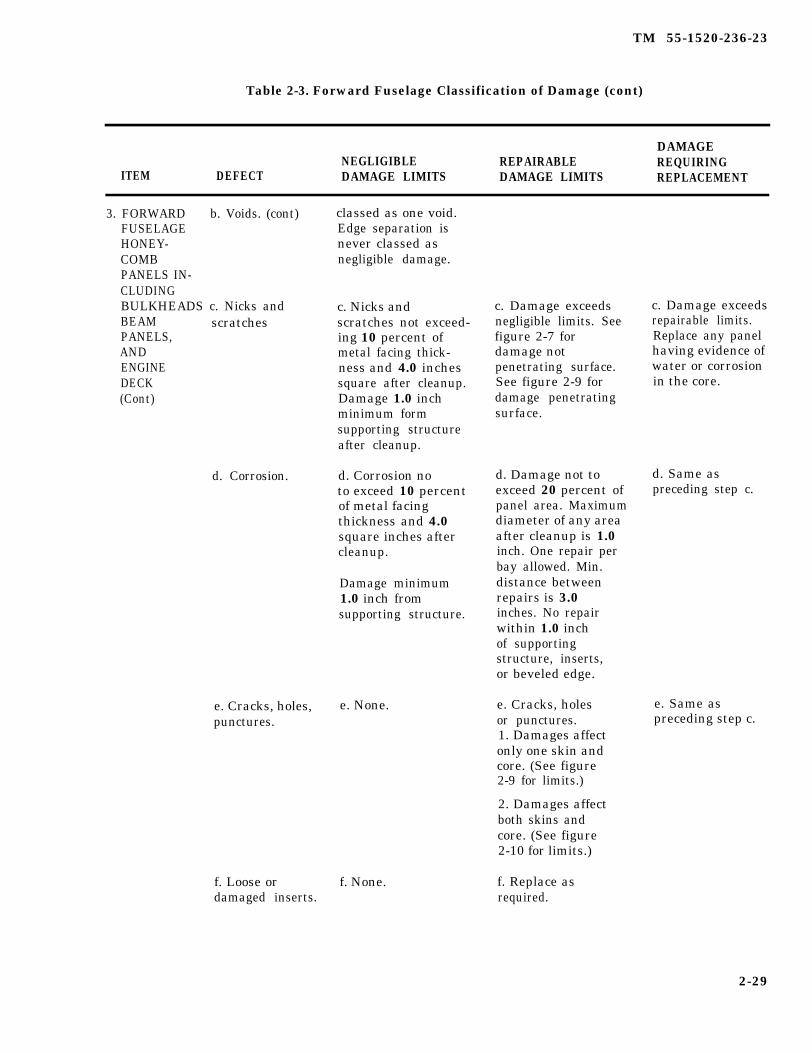
TM 55-1520-236-23
Table 2-3. Forward Fuselage Classification of Damage (cont)
DAMAGENEGLIGIBLE REPAIRABLE REQUIRING
ITEM DEFECT DAMAGE LIMITS DAMAGE LIMITS REPLACEMENT
3. FORWARD b. Voids. (cont)FUSELAGEHONEY-COMBPANELS IN-CLUDINGBULKHEADS c. Nicks andBEAM scratchesPANELS,ANDENGINEDECK(Cont)
d. Corrosion.
classed as one void.Edge separation isnever classed asnegligible damage.
c. Nicks andscratches not exceed-ing 10 percent ofmetal facing thick-ness and 4.0 inchessquare after cleanup.Damage 1.0 inchminimum formsupporting structureafter cleanup.
d. Corrosion noto exceed 10 percentof metal facingthickness and 4.0square inches aftercleanup.
Damage minimum1.0 inch fromsupporting structure.
e. Cracks, holes, e. None.punctures.
f. Loose or f. None.damaged inserts.
c. Damage exceedsnegligible limits. Seefigure 2-7 fordamage notpenetrating surface.See figure 2-9 fordamage penetratingsurface.
d. Damage not toexceed 20 percent ofpanel area. Maximumdiameter of any areaafter cleanup is 1.0inch. One repair perbay allowed. Min.distance betweenrepairs is 3.0inches. No repairwithin 1.0 inchof supportingstructure, inserts,or beveled edge.
e. Cracks, holesor punctures.1. Damages affectonly one skin andcore. (See figure2-9 for limits.)
2. Damages affectboth skins andcore. (See figure2-10 for limits.)
f. Replace asrequired.
c. Damage exceedsrepairable limits.Replace any panelhaving evidence ofwater or corrosionin the core.
d. Same aspreceding step c.
e. Same aspreceding step c.
2-29
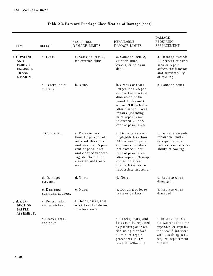
TM 55-1520-236-23
Table 2-3. Forward Fuselage Classification of Damage (cont)
DAMAGENEGLIGIBLE REPAIRABLE REQUIRING
ITEM DEFECT DAMAGE LIMITS DAMAGE LIMITS REPLACEMENT
4. COWLINGANDFAIRINGENGINE &TRANS-MISSION.
5. AIR IN-DUCTIONBAFFLEASSEMBLY.
a. Dents. a. Same as Item 2,for exterior skins.
b. Cracks, holes, b. None.or tears.
c. Corrosion. c. Damage lessthan 10 percent ofmaterial thicknessand less than 5 per-cent of panel areaand clear of support-ing structure aftercleaning and treat-ment.
d. Damaged d. None.screens.
e. Damaged e. None.seals and gaskets,
a. Dents, nicks, a. Dents, nicks, andand scratches. scratches that do not
puncture metal.
b. Cracks, tears,and holes.
a. Same as Item 2,exterior skins,cracks, or holes indent.
b. Cracks or tearslonger than 25 per-cent of the shortestdimension of thepanel. Holes not toexceed 3.0 inch dia.after cleanup. Totalrepairs (includingprior repairs) notto exceed 25 per-cent of panel area.
c. Damage exceedsnegligible less than20 percent of panelthickness but doesnot exceed 5 per-cent of panel areaafter repair. Cleanupcomes no closerthan 2.0 inches tosupporting structure.
d. None.
e. Bonding of looseseals or gaskets.
b. Cracks, tears, andholes can be repairedby patching or inser-tion using standardaluminum repairprocedures in TM55-1500-204-25/1.
a. Damage exceeds25 percent of panelarea or repairaffects the functionand serviceabilityof cowling.
b. Same as dents.
c. Damage exceedsrepairable limitsor repair affectsfunction and service-ability of cowling.
d. Replace whendamaged.
e. Replace whendamaged.
b. Repairs that donot warrant the timeexpended or repairsthat would interferewith attaching partsrequire replacementof parts.
2-30

TM 55-1520-236-23
Table 2-3. Forward Fuselage Classification of Damage (cont)
DAMAGENEGLIGIBLE REPAIRABLE REQUIRING
ITEM DEFECT DAMAGE LIMITS DAMAGE LIMITS REPLACEMENT
5. AIR IN-DUCTIONBAFFLEASSEMBLY(CONT)
6. FORWARDFIREWALL,AFT FIRE-WALL ANDTAIL ROTORDRIVESHAFTFIRESHIELD
c. Torn ordamaged sealsor gaskets.
a. Dents, nicks, a. Dents, nicks, andand scratches. scratches that do not
puncture metal.b. Cracks, tears, b. Cracks, tears, andand holes. holes can be repaired
by patching or inser-tion using standardtitanium repairprocedures in TM55-1500-204-25/1.
c. Torn ordamaged sealsor gaskets
7. FUSELAGE a. Nicks, a. Nicks, scratches,TAILBOOM scratches, and and gouges in fuselageATTACH gouges. tailboom fitting mayFITTINGS be polished out if they
do not exceed theselimits:(1) Axial damage(parallel to boltholes) must notexceed 0.020 inchin depth and 0.300inch in length.(2) Radial damage(normal to bolt axis)must not exceed 0.010inch in depth or0.300 inch in length.(3) Nicks, scratchesor gouges are notpermitted within onediameter of bolt hole.
b. Corrosion.
c. Seals and gasketstorn or damaged tothe extent that theirfunction is affectedmust be replaced.
Repairs that do notwarrant the timeexpanded or repairsthat would interferewith mating partsrequire replacementof parts.
c. Seals and gasketstorn or damaged tothe extent that theirfunction is affectedmust be replaced.
a. Damage exceedingnegligible limits.
b. No corrosionallowed.
2-31
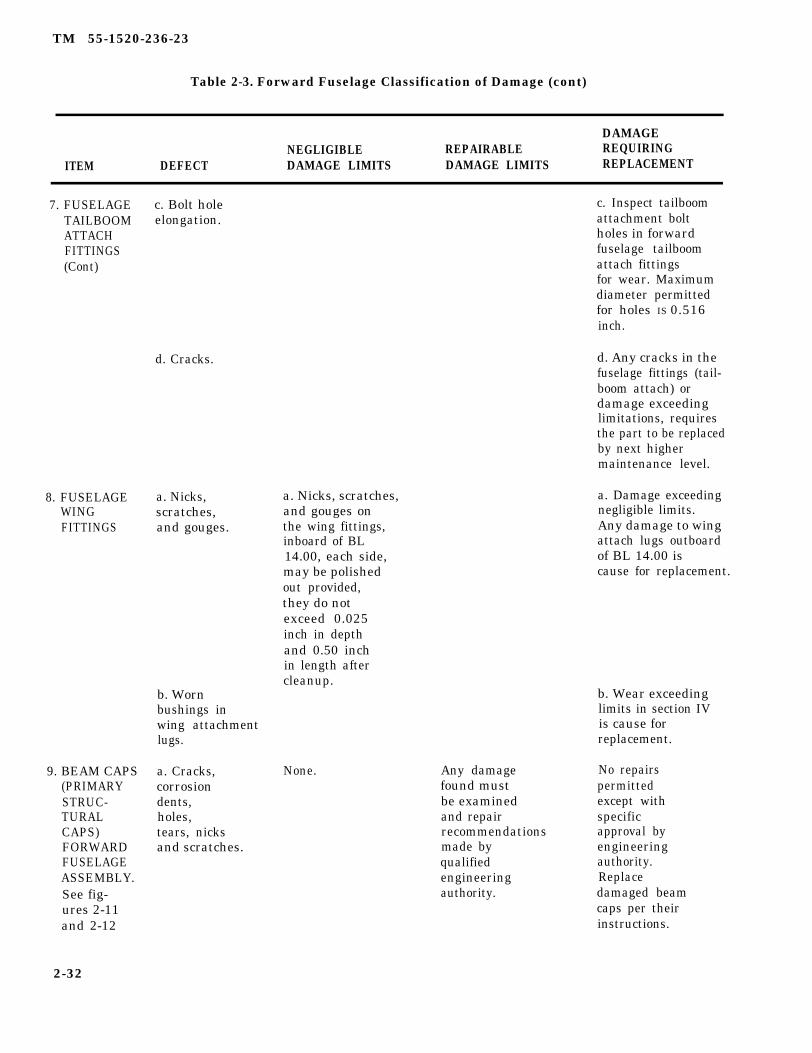
TM 55-1520-236-23
Table 2-3. Forward Fuselage Classification of Damage (cont)
DAMAGENEGLIGIBLE REPAIRABLE REQUIRING
ITEM DEFECT DAMAGE LIMITS DAMAGE LIMITS REPLACEMENT
7. FUSELAGE c. Bolt hole c. Inspect tailboomTAILBOOM elongation. attachment boltATTACH holes in forwardFITTINGS fuselage tailboom(Cont) attach fittings
for wear. Maximumdiameter permittedfor holes IS 0.516inch.
8. FUSELAGEWINGFITTINGS
9. BEAM CAPS(PRIMARYSTRUC-TURALCAPS)FORWARDFUSELAGEASSEMBLY.See fig-ures 2-11and 2-12
d. Cracks.
a. Nicks,scratches,and gouges.
b. Wornbushings inwing attachmentlugs.
a. Cracks,corrosiondents,holes,tears, nicksand scratches.
a. Nicks, scratches,and gouges onthe wing fittings,inboard of BL14.00, each side,may be polishedout provided,they do notexceed 0.025inch in depthand 0.50 inchin length aftercleanup.
None. Any damagefound mustbe examinedand repairrecommendationsmade byqualifiedengineeringauthority.
d. Any cracks in thefuselage fittings (tail-boom attach) ordamage exceedinglimitations, requiresthe part to be replacedby next highermaintenance level.
a. Damage exceedingnegligible limits.Any damage to wingattach lugs outboardof BL 14.00 iscause for replacement.
b. Wear exceedinglimits in section IVis cause forreplacement.
No repairspermittedexcept withspecificapproval byengineeringauthority.Replacedamaged beamcaps per theirinstructions.
2-32

TM 55-1520-236-23
Table 2-3. Forward Fuselage Classification of Damage (cont)
DAMAGENEGLIGIBLE REPAIRABLE REQUIRING
ITEM DERECT DAMAGE LIMITS DAMAGE LIMITS REPLACEMENT
10. ENGINEDECK(FORWARDFUSELAGEASSEMBLYSeefigure2-26
PRESSORCOWLINGMOUNTBRACKETS,ROD ENDBEARINGS,ANDCLEVISPINS.Seefigures2-51and2-52.
a. Cracksb. Corrosionc. Dentsd. Holesend tearse. Nicks andscratchesf. Buckledorwrinkled.
a. Cracks
b. Bracketlug holeelonga-tion.
See figure See figure Authorized2-26. 2-26. repair to
the enginedeck installationonly byqualifiedengineeringauthority.
a. None
b. Total out-ofround condi-tion does notexceed 0.015inch. Diame-ter must notexceed 0.323inch.
c. Loose c. Nonefasteners.
d. Corrosion. d. Damage leasthan 5 per-cent of mate-rial thick-ness and leasthan 5 percentof area.
e. Nicksandscratches.
e. Nicks andscratchesless than0.060 deep1.0 inchlong.
a. None
b. None
c. Replaceas required.
d. Damageless than10 percentof thick-ness ofarea aftercleaningwith crocuscloth andtreatment.
e. Nicks andscratches0.060 deepand greaterthan 1.0inch long.Dress out,polish-zinc
e. Replace ifcracked.
b. Damageexceedsnegligiblelimits.
d. Pittingcorrosion.
e. Damageexceedsrepairablelimits.
2-33

TM 55-1520-236-23
Table 2-3. Forward Fuselage Classification of Damage (Cont)
DAMAGENEGLIGIBLE REPAIRABLE REQUIRING
ITEM DEFECT DAMAGE LIMITS DAMAGE LIMITS REPLACEMENT
e. Nicks and chromatePRESSOR scratches less and paintCOWLING then 0.060 to suitMOUNT deep and less surroundings.BRACKETS, than 1 inchROD END long.BEARINGS,AND CLEVIS f. Bearing f. NonePINS, forSee elongation.figures2-51and g. Radial2-52 play in(Cent} bearing.
h. Axialplay inbearing.
i. Clevispin worn.
a. Cracks.PRESSORASSEMBLY–UNFINNEDAREAS.
b. Holes.
c. Skin dents.
f. Less than0.006 inchTIR.
g. Lass than0.010 inch.
h. Less than0.012 inch.
i. Diameter notless than0.303 inch.
a. Cracks insheet metalsurfaces notexceeding one inchand non-triangu-lating.
b. No more then3 holes each lessthan 5/16 inchdiameter.
c. Dents with nocracks or gougles:Depth 0.250 inchmaximum.Diameter 3.0 inches.
g. None
h. None
i. None
a. Cracks oneto three inchesin length-stopdrill and weld.Crocks greaterthan three inchesin length - patchand weld.
b. Patch andweld hales greaterthan 5/16 inchbut less than 2inches diameter.
c. Dents in ex-cess of serviceable limits thatcan be straight-ened, or cut outand patched.
f. Damageexceedsnegligiblelimits.
g. Damageexceedsnegligiblelimits.
h. Damageexceedsnegligiblelimits.
i. Damageexceedsnegligiblelimits.
a. N/A
b. Holesgreater thantwo inchdiameter.
c. Dents thatcannot berestored toserviceablelimits
2-34

TM 55-1520-236-23
Table 2-3. Forward Fuselage Classification of Damage (Cont)
DAMAGENEGLIGIBLE REPAIRABLE REQUIRING
ITEM DEFECT DAMAGE LIMITS DAMAGE LIMITS REPLACEMENT
2-34.1

TM 55-1520-236-23
Table 2-3. Forward Fuselage Classification of Damage (Cont)
2-34.2
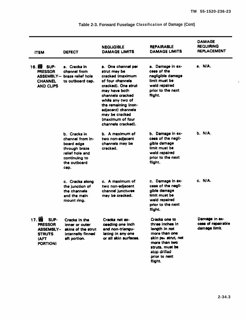
TM 55-1520-236-23
Table 2-3. Forward Fuselage Classification of Damage (Cont)
2-34.3
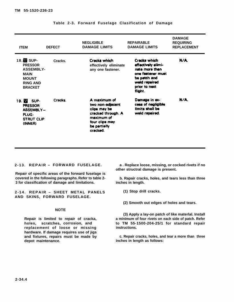
TM 55-1520-236-23
Table 2-3. Forward Fuselage Clasification of Damage
DAMAGENEGLIGIBLE REPAIRABLE REQUIRING
ITEM DEFECT DAMAGE LIMITS DAMAGE LIMITS REPLACEMENT
18. SUP-PRESSORASSEMBLY-MAINMOUNTRING ANDBRACKET
Cracks.effectively eliminateany one fastener.
2 - 1 3 . R E P A I R – FORWARD FUSELAGE.
Repair of specific areas of the forward fuselage iscovered in the following paragraphs. Refer to table 2-3 for classification of damage and limitations.
2 - 1 4 . R E P A I R – SHEET METAL PANELSAND SKINS, FORWARD FUSELAGE.
a . Replace loose, missing, or cocked rivets if noother structral damage is present.
b. Rapair cracks, holes, and tears less than threeinches in length.
(1) Stop drill cracks.
(2) Smooth out edges of holes and tears.
NOTE
Repair is limited to repair of cracka,holes, scratches, corrosion, andreplacement of loose or missinghardware. If damage requires use of jigsand fixtures, repairs must be made bydepot maintenance.
(3) Apply a lay-on patch of like materlal. Installa minimum of four rivets on each side of patch. Referto TM 55-1500-204-25/1 for standard repairinstructions.
c. Repair cracks, holes, and tear a more than threeinches in length as follows:
2-34.4
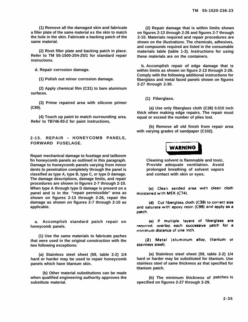
TM 55-1520-236-23
(1) Remove all the damaged skin and fabricatea filler plate of the same material as the skin to matchthe hole in the skin. Fabricate a backing patch of thesame material.
(2) Rivet filler plate and backing patch in place.Refer to TM 55-1500-204-25/1 for standard repairinstructions.
d. Repair corrosion damage.
(1) Polish out minor corrosion damage.
(2) Apply chemical film (C31) to bare aluminumsurfaces.
(3) Prime repaired area with silicone primer(C89).
(4) Touch up paint to match surroundingRefer to TB746-93-2 for paint instructions,
area.
2-15. REPAIR – HONEYCOMB PANELS,FORWARD FUSELAGE.
Repair mechanical damage to fuselage and tailboomfin honeycomb panels as outlined in this paragraph.Damage to honeycomb panels varying from minordents to penetration completely through the panel isclassified as type A, type B, type C, or type D damage.The damage descriptions, damage limits, and repairprocedures are shown in figures 2-7 through 2-10.When type A through type D damage is present on apanel and is in the “repair permissible” area asshown on figures 2-13 through 2-26, repair thedamage as shown on figures 2-7 through 2-10 asapplicable.
a. Accomplish standard patch repair onhoneycomb panels.
(1) Use the same materials to fabricate pachesthat were used in the original construction with thetwo following exceptions:
(a) Stainless steel sheet (59, table 2-2) 1/4hard or harder may be used to repair honeycombpanels which have titanium skin.
(b) Other material substitutions can be madewhen qualified engineering authority approves thesubstitute material.
(2) Repair damage that is within limits shownon figures 2-13 through 2-26 and figures 2-7 through2-10. Materials required and repair procedures areshown on the illustrations. The chemicals, adhesives,and compounds required are listed in the consumablematerials table (table 1-3). Instructions for usingthese materials are on the containers.
b. Accomplish repair of edge damage that iswithin limits as shown on figure 2-13 through 2-26.Comply with the following additional instructions forfiberglass and metal faced panels shown on figures2-27 through 2-30.
(1) Fiberglass.
(a) Use only fiberglass cloth (C38) 0.010 inchthick when making edge repairs. The repair mustequal or exceed the number of plies lost.
(b) Remove all old finish from repair areawith varying grades of sandpaper (C102).
Cleaning solvent is flammable and toxic.Provide adequate ventilation. Avoidprolonged breathing of solvent vaporsand contact with skin or eyes.
(a) Stainless steel sheet (59, table 2-2) 1/4hard or harder may be substituted for titanium. Usestainless steel of same thickness as that specified fortitanium patch.
(b) The minimum thickness ofspecified on figures 2-27 through 2-29.
patches is
2-35
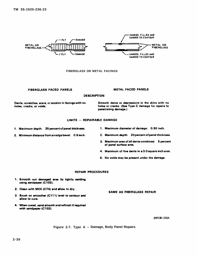
TM 55-1520-236-23
FIBERGLASS OR METAL FACINGS
Figure 2-7. Type A – Damage, Body Panel Repairs
2-36

TM 55-1520-236-23
Figure 2-8. Type B – Damage. Body Panel Repairs
2-37

TM 55-1520-236-23
Figure 2-9. Type C – Damage, Body Panel Repairs (Sheet 1 of 2)
2-38
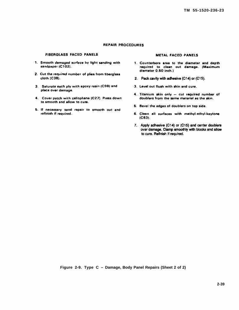
TM 55-1520-236-23
Figure 2-9. Type C – Damage, Body Panel Repairs (Sheet 2 of 2)
2-39
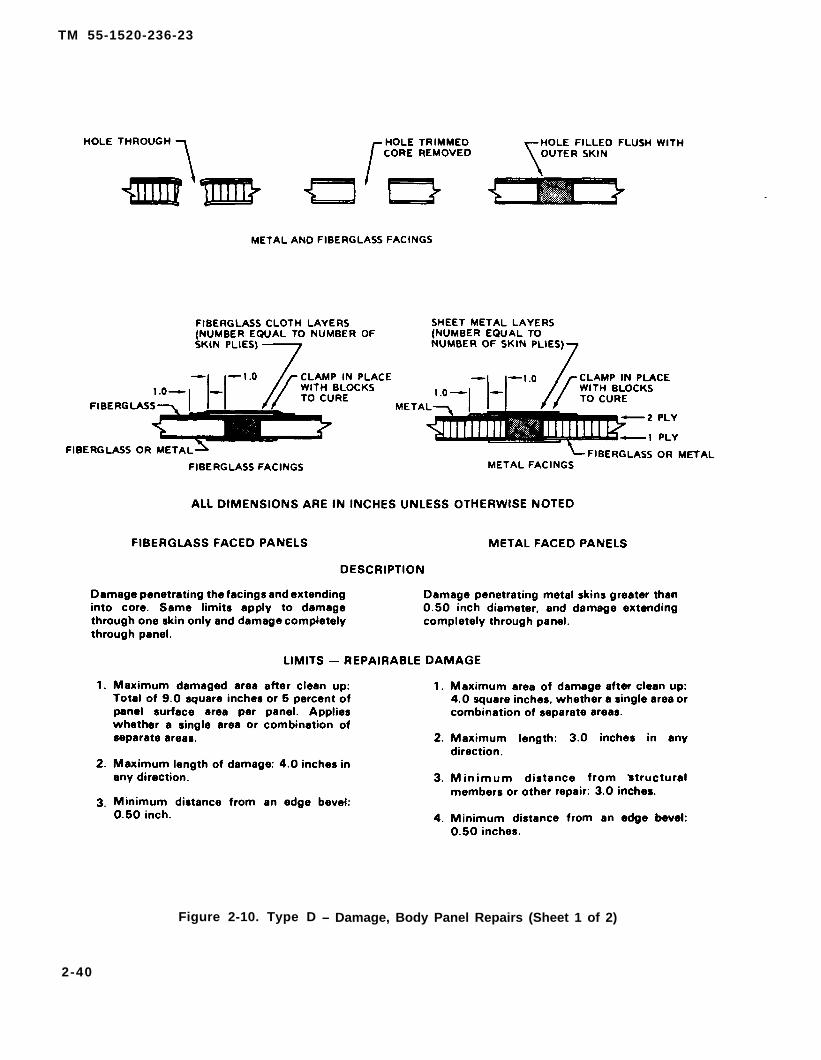
TM 55-1520-236-23
Figure 2-10. Type D – Damage, Body Panel Repairs (Sheet 1 of 2)
2-40

TM 55-1520-236-23
Figure 2-10. Type D — Damage, Body Panel Repairs (Sheet 2 of 2)
2-41

TM 55-1520-236-23
Primary structural caps. No repairs permitted except withspecific approval by engineering authority.
Refer to TM 55-1500-345-23 for paint instructions.
Figure 2-11. Primary Structural Cap — Left Side
2-42

TM 55-1520-236-23
Refer to TM 55-1500-345-23 for paint instructions.
Figure 2-12. Primary Structural Cape — Right Side
2-43

TM 55-1520-236-23
f i g u r e 2 - 2 8 a n d 2 - 2 9 .
Figure 2-13. Pilot and Gunner Floor Panels
2-44
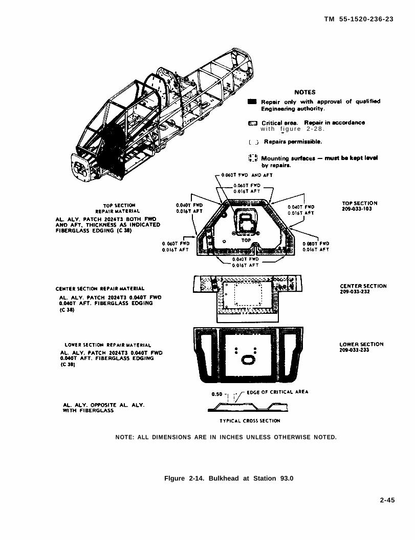
TM 55-1520-236-23
w i t h f i g u r e 2 - 2 8 .
NOTE: ALL DIMENSIONS ARE IN INCHES UNLESS OTHERWISE NOTED.
Flgure 2-14. Bulkhead at Station 93.0
2-45

TM 55-1520-236-23
figure 2-27, 2-28, 2-29, and 2-30.
Figure 2-15. Bulkhead at Station 148.5 and 171.61
2-46
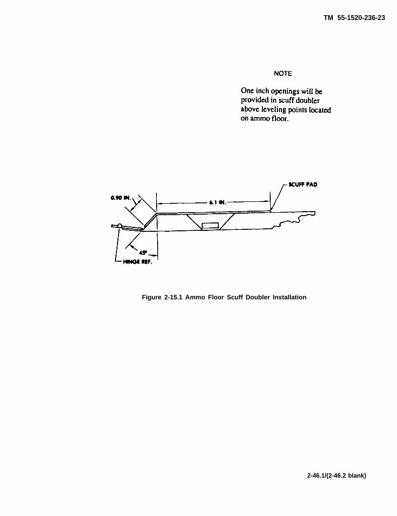
TM 55-1520-236-23
Figure 2-15.1 Ammo Floor Scuff Doubler Installation
2-46.1/(2-46.2 blank)

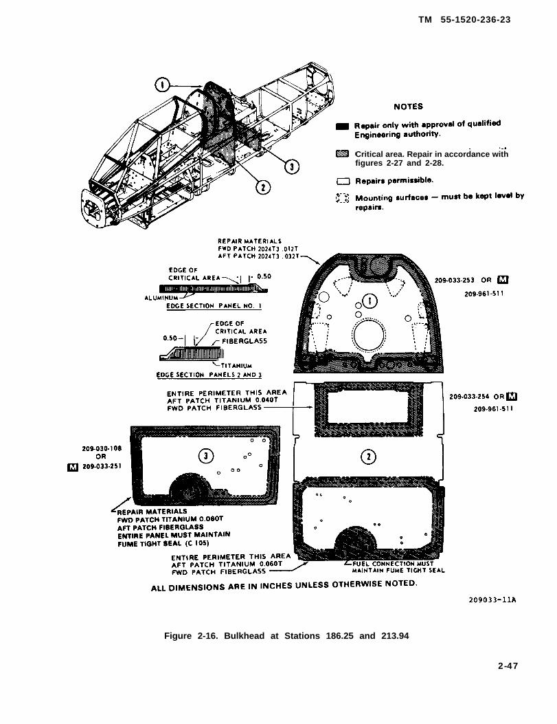
TM 55-1520-236-23
Critical area. Repair in accordance withfigures 2-27 and 2-28.
Figure 2-16. Bulkhead at Stations 186.25 and 213.94
2-47

TM 55-1520-236-23
with figure 2-28 and 2-29.
Figure 2-17. Bulkhead at Stations 250.0 and 268.5
2-48

TM 55-1520-236-23
figure 2-28
Figure 2-18. R & L Main Beam Panels at Station 148.5 to 186.26
2-49
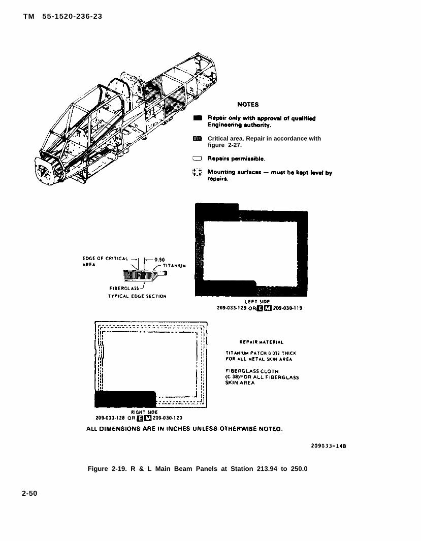
TM 55-1520-236-23
Critical area. Repair in accordance withfigure 2-27.
Figure 2-19. R & L Main Beam Panels at Station 213.94 to 250.0
2-50

TM 55-1520-236-23
Critical area. Repair in accordance withfigure 2-28.
Figure 2-20. Panel at Forward Fuel Cell at R.S. and Gunner Floor
2-51

TM 55-1520-236-23
figure 2-28 and 2-29.
Figure 2-21. R & L Beam Panels at Station 250 to B.S. 41.32
2-52

TM 55-1520-236-23
Critical area. Repair in accordance withfigures 2-28 and 2-29.
Repairs permissible.
Mounting surfaces – must be kept level byrepairs.
Repair IAW paragraph 2-15A.
Figure 2-22. Ammo Floor, Support Panel and Forward Fuel Cell Panel at Station 213.9
2-53
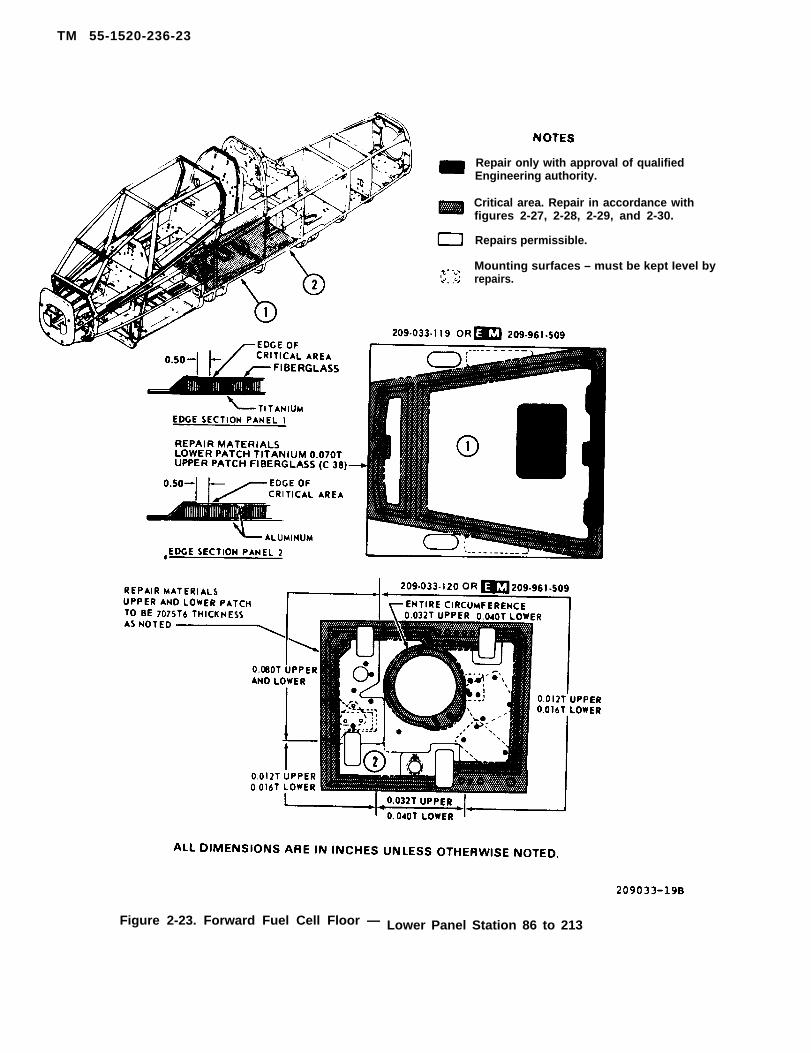
TM 55-1520-236-23
Repair only with approval of qualifiedEngineering authority.
Critical area. Repair in accordance withfigures 2-27, 2-28, 2-29, and 2-30.
Repairs permissible.
Mounting surfaces – must be kept Ievel byrepairs.
Figure 2-23. Forward Fuel Cell Floor — Lower Panel Station 86 to 213
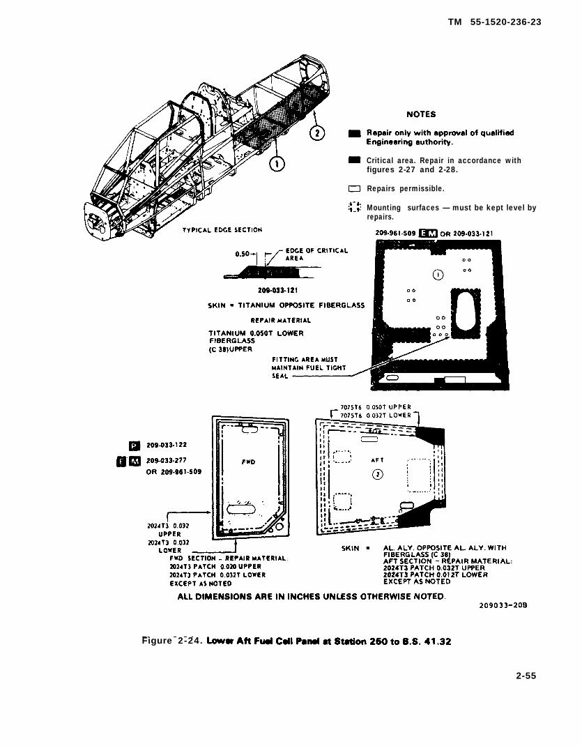
TM 55-1520-236-23
Critical area. Repair in accordance withfigures 2-27 and 2-28.
Repairs permissible.
Mounting surfaces — must be kept level byrepairs.
Figure 2-24.
2-55
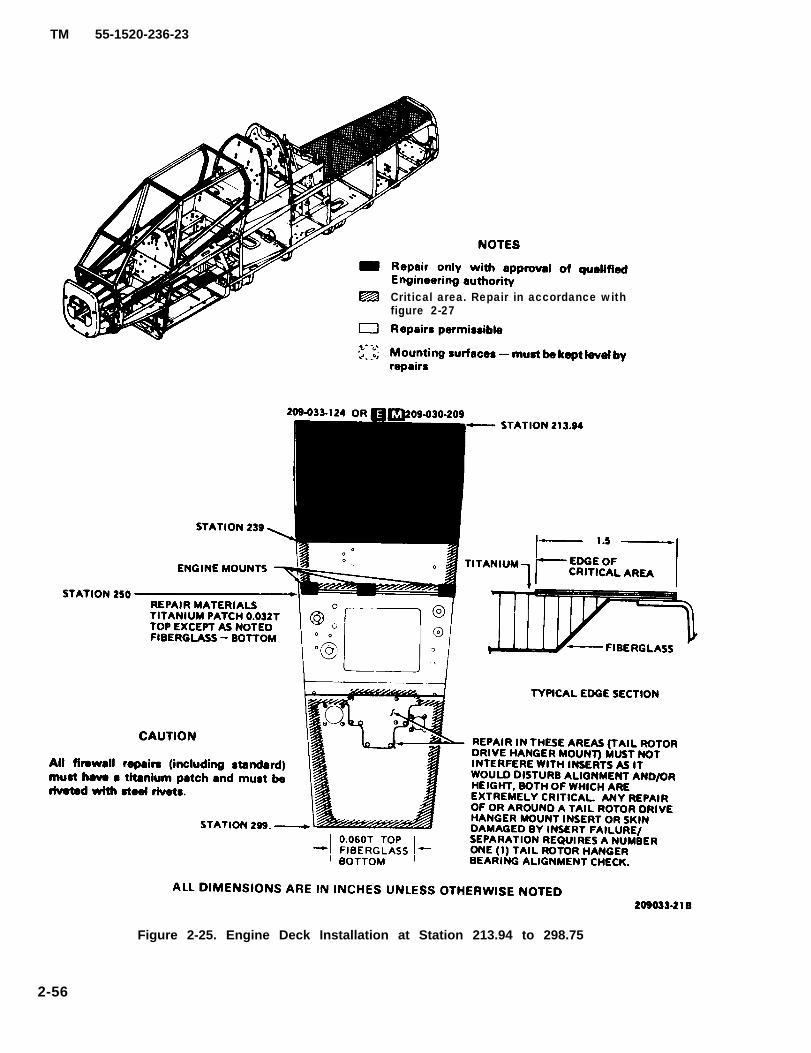
TM 55-1520-236-23
Critical area. Repair in accordance withfigure 2-27
Figure 2-25. Engine Deck Installation at Station 213.94 to 298.75
2-56
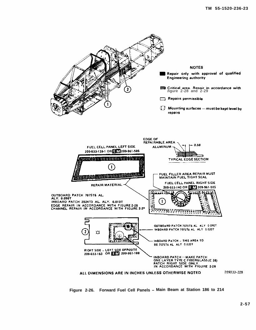
TM 55-1520-236-23
figure 2-28 and 2-29
Figure 2-26. Forward Fuel Cell Panels – Main Beam at Station 186 to 214
2-57
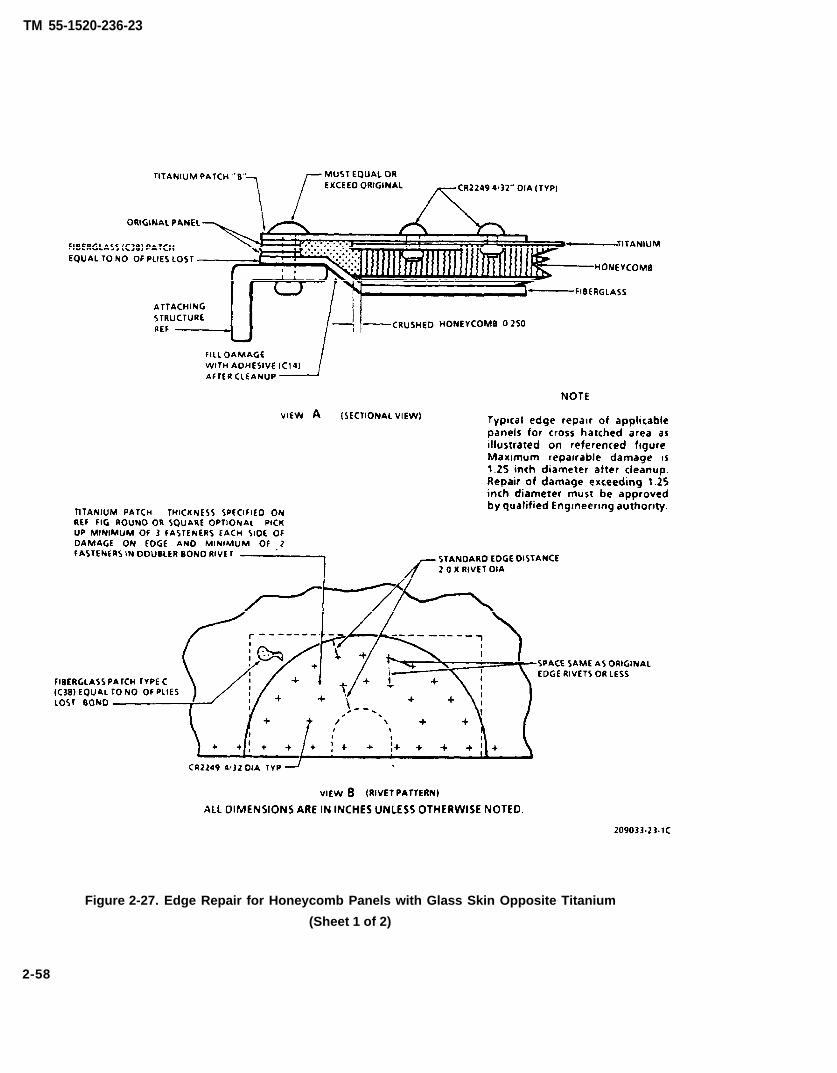
TM 55-1520-236-23
Figure 2-27. Edge Repair for Honeycomb Panels with Glass Skin Opposite Titanium
(Sheet 1 of 2)
2-58

TM 55-1520-236-23
Figure 2-27. Edge Repair for Honeycomb Panels with Glass Skin Opposite Titanium(Sheet 2 of 2)
2-59

TM 55-1520-236-23
Figure 2-28. Edge Repair for Honeycomb Panels with Aluminum Alloy with Glass Edging
2 - 6 0

TM 55-1520-236-23
figure 2-27
Figure 2-29. Edge Repair for Honeycomb Panels with Glass Finish at Channel
2-61
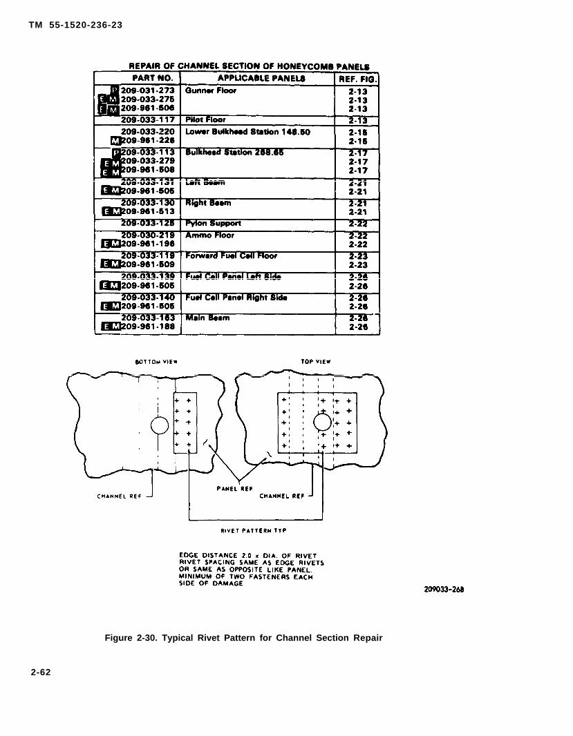
TM 55-1520-236-23
Figure 2-30. Typical Rivet Pattern for Channel Section Repair
2-62

TM 55-1520-236-23
Cleaning solvent is flammable and toxic.Provide adequate ventilation. Avoidprolonged breathing of solvent vaporsand contact with skin or eyes.
(c) Clean the area where patch is to beapplied with scotchbrite (C103) in lieu of sandpaper toavoid leaving residue. It is permissible to use 320 gritsandpaper (C102) in critical areas. If sandpaper isused, clean the sanded area with MEK (C74).
(d) Bond metal patches with adhesive (C14).
(e) After adhesive (C14) has cured, applysealant (C105) to entire surface of titanium patch.
(f) Rivet patch with rivets of equal or largersize than original rivets in areas that were rivetedprior to application of patch. Use the standard edgedistance of two rivet diameters or space the rivets thesame as the original panel. if the panel being workedis not riveted, use rivet spacing in opposite panel.
c. Replace damaged fasteners (inserts) infuselage honeycomb panels.
(1) Determine whether the fastener (insert) is apotted-type, injection-type or grommet-type. Seefigure 2-31 for view of the fasteners (inserts).
(2) Remove damaged fastener (insert) bymachining with a counterbore of the same diameteras the fastener. Note that the grommet-type fastener(insert) flanges overlap the skin of the honeycombpanel.
(3) Install new fastener (insert) as outlined insteps (4) through (6).
(4) Install potted-type fastener (insert).
Cleaning solvent is flammable and toxic.Provide adequate ventilation. Avoidprolonged breathing of solvent vaporsand contact with skin or eyes.
(a) Immediately prior to installation, cleannew fastener (insert) by soaking in MEK (C74). Air dryuntil moisture free. Handle fastener (insert) withclean white gloves after cleanup,
(b) Place masking tape (C123) over threads offastener (insert) to prevent entry of adhesive.
An insufficient amount of adhesive willallow moisture or other fluids to enter thehoneycomb panel core. This will result inultimate failure of the panel.
(c) Fill cavity approximately two-thirds full ofadhesive as shown on figure 2-31. Use adhesive (C8)in areas where the temperature will not exceed 180degrees F (83 degrees C). Use adhesive (C14) in areaswhere panel will be subjected to higher temperaturesbut not exceeding 300 degrees F (149 degrees C).Install fastener (insert) while adhesive is in tackystate. Ensure that there are no pin holes In theadhesive, and that the fastener (insert) is properlyaligned and is a snug fit where the fastener (insert)flange mates with the honeycomb panel face.
Cleaning solvent is fiammabie and toxic.Provide adequate ventilation. Avoidproionged breathing of solvent vaporsand contact with skin or eyes.
(d) Remove excess adhesive f romhoneycomb panel before adhesive sets up. Usecheese cloth (C30) dampened with MEK (C74).Exercise caution to prevent the MEK from diluting theadhesive in the potted areas.
2-63

TM 55-1520-236-23
Figure 2-31 Potted –
2-64

TM 55-1520-236-23
Figure 2-31. Potted — Injection –
2-65
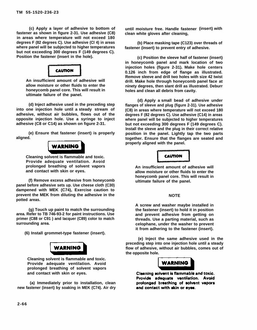
TM 55-1520-236-23
(c) Apply a layer of adhesive to bottom offastener as shown in figure 2-31. Use adhesive (C8)in areas where temperature will not exceed 180degrees F (82 degrees C). Use adhesive (Cl 4) in areaswhere panel will be subjected to higher temperaturesbut not exceeding 300 degrees F (149 degrees C).Position the fastener (insert in the hole).
An insufficient amount of adhesive willallow moisture or other fluids to enter thehoneycomb panel core. This will result inultimate failure of the panel.
(d) Inject adhesive used in the preceding stepinto one injection hole until a steady stream ofadhesive, without air bubbles, flows out of theopposite injection hole. Use a syringe to injectadhesive (C8 or C14) as shown on figure 2-31.
(e) Ensure that fastener (insert) is properlyaligned.
Cleaning solvent is flammable and toxic.Provide adequate ventilation. Avoidprolonged breathing of solvent vaporsand contact with skin or eyes.
(f) Remove excess adhesive from honeycombpanel before adhesive sets up. Use cheese cloth (C30)dampened with MEK (C74), Exercise caution toprevent the MEK from diluting the adhesive in thepotted areas.
(g) Touch up paint to match the surroundingarea. Refer to TB 746-93-2 for paint instructions. Useprimer (C88 or C91 ) and lacquer (C89) color to matchsurrounding area.
(6) Install grommet-type fastener (insert).
Cleaning solvent is flammable and toxic.Provide adequate ventilation. Avoidprolonged breathing of solvent vaporsand contact with skin or eyes.
(a) Immediately prior to installation, cleannew fastener (insert) by soaking in MEK (C74). Air dry
until moisture free. Handle fastenerclean white gloves after cleaning,
(insert) with
(b) Place masking tape (C123) over threads offastener (insert) to prevent entry of adhesive.
(c) Position the sleeve half of fastener (insert)in honeycomb panel and mark location of twoinjection holes (figure 2-31). Make hole centers0.126 inch from edge of flange as illustrated.Remove sleeve and drill two holes with size 42 twistdrill. Make hole through honeycomb panel face atninety degrees, then slant drill as illustrated. Deburrholes and clean all debris from cavity.
(d) Apply a small bead of adhesive underflanges of sleeve and plug (figure 2-31). Use adhesive(C8) in areas where temperature will not exceed 180degrees F (82 degrees C). Use adhesive (C14) in areaswhere panel will be subjected to higher temperaturesbut not exceeding 300 degrees F (149 degrees C).Install the sleeve and the plug in their correct relativeposition in the panel. Lightly tap the two partstogether. Ensure that the flanges are seated andproperly aligned with the panel.
An insufficient amount of adhesive willallow moisture or other fluids to enter thehoneycomb panel core. This will result inultimate failure of the panel.
NOTE
A screw and washer maybe installed inthe fastener (insert) to hold it in positionand prevent adhesive from getting onthreads. Use a parting material, such ascelophane, under the washer to preventit from adhering to the fastener (insert).
(e) Inject the same adhesive used in thepreceding step into one injection hole until a steadyflow of adhesive, without air bubbles, comes out ofthe opposite hole.
2-66
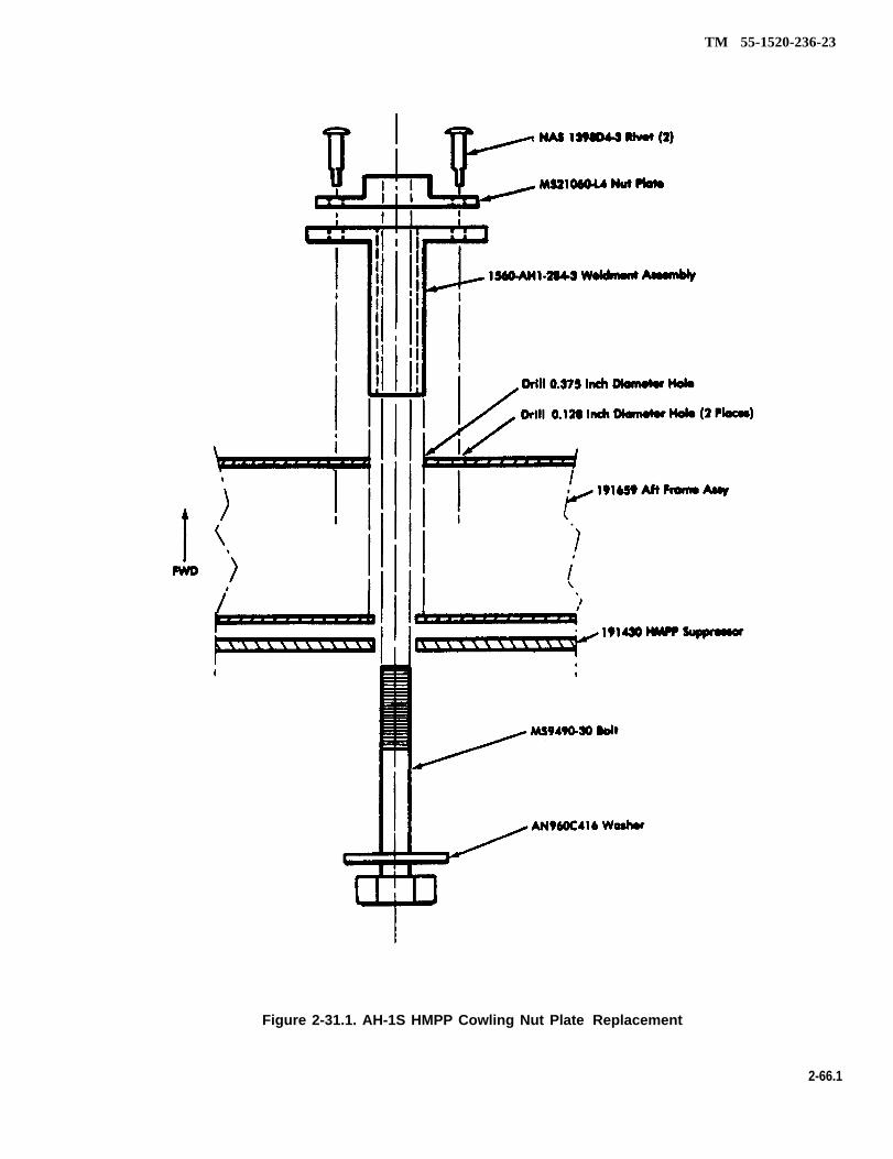
TM 55-1520-236-23
Figure 2-31.1. AH-1S HMPP Cowling Nut Plate Replacement
2-66.1
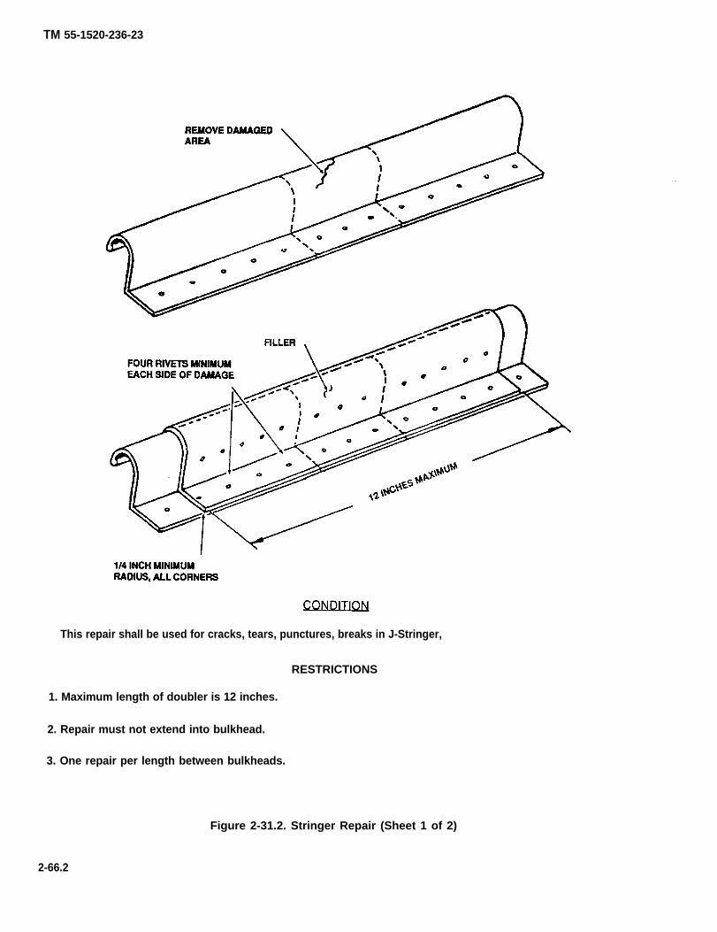
TM 55-1520-236-23
This repair shall be used for cracks, tears, punctures, breaks in J-Stringer,
RESTRICTIONS
1. Maximum length of doubler is 12 inches.
2. Repair must not extend into bulkhead.
3. One repair per length between bulkheads.
Figure 2-31.2. Stringer Repair (Sheet 1 of 2)
2-66.2
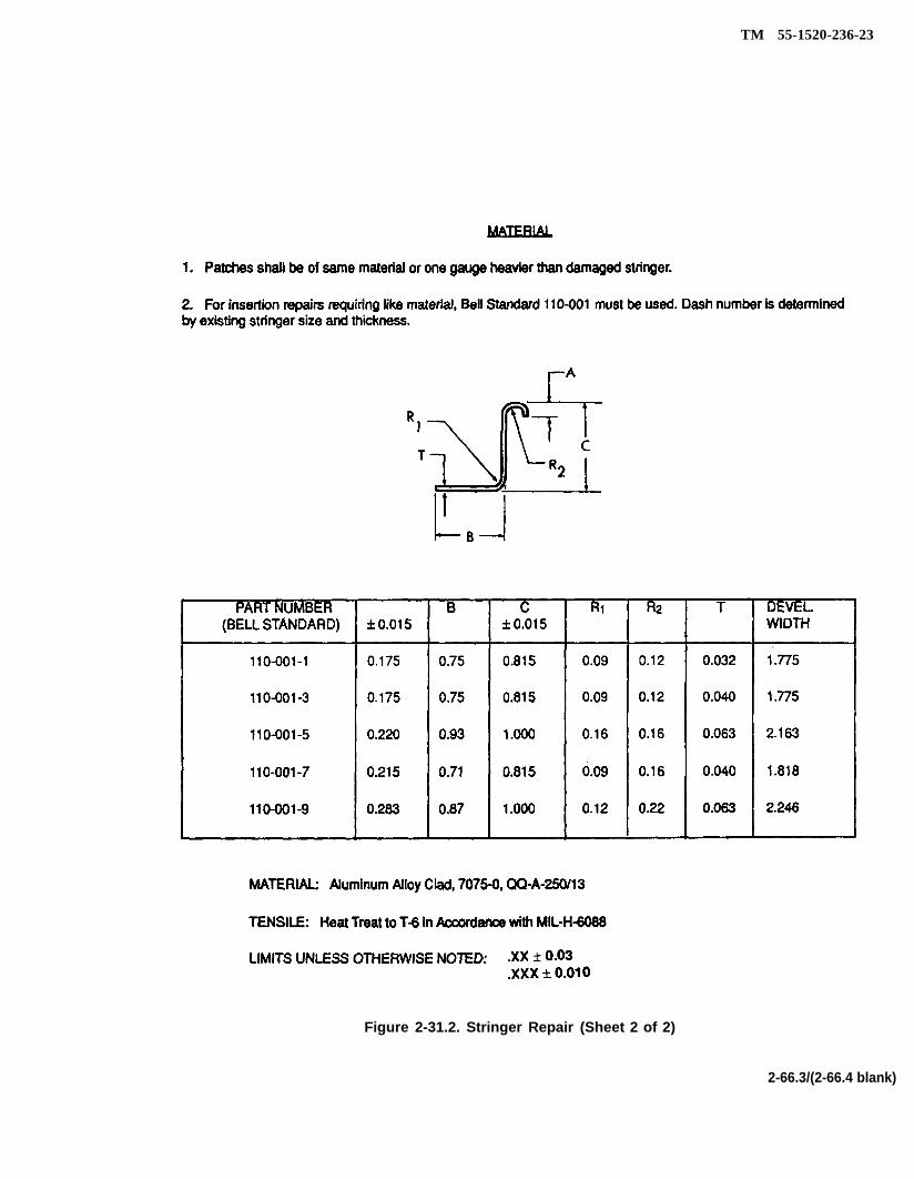
TM 55-1520-236-23
Figure 2-31.2. Stringer Repair (Sheet 2 of 2)
2-66.3/(2-66.4 blank)


TM 55-1250-236-23
(f) Remove excess adhesive from honeycombpanel before adhesive sets up, Use cheese cloth (C30)dampened with MEK (C74). Exercise caution to preventthe MEK from diluting the adhesive in the potted areas.
(g) Touch up paint to match the surroundingarea. Refer to TB746-93-2 for paint instructions.
2 -15 .1 . R E P A I R — A M M O FLOORHONEYCOMB PANEL.
a. Repair damage within allowable limits as outlinedin table 2-3.
b. Fabricate scuff doublers from stainless steel,MIL-S-5059A, 301 (item 59, table 2-2), NSN9515-00-203-5899, as illustrated in figure 2-15.1.Required stock is 0.016 x 44.20 inches.
c. Bend doubler 45 degrees as illustrated in figure2-31.1. Make bend with 0.06 inch radius.
d. Remove Teflon rub strip 209-030-203-4 andretain for reinstallation.
e. Using a hole finder tool, locate four holes indoubler to align with screws retaining Teflon strips.
f. To prevent crushing honeycomb core at edge ofpanel, apply Proseal 890 (C105) along entire length ofdoubler under short leg.
g. Install doublers on both sides of panel. InstallTeflon rub strip to original configuration and secure withoriginal screws.
h. Remove and replace rub strip (209-030-224-13)on track assembly (209-030-224-19) if worn or damaged.Use adhesive (C14).
2-16. REPAIR — FLOOR PANELS, FORWARDFUSELAGE.
Repair pilot and gunner floor panels shown on figure2-13 as outlined in paragraph 2-15.
2-17. REPAIR — ENGINE DECK PANELS, FOR-WARD FUSELAGE.
Repair engine deck panels shown on figure 2-25 asoutlined in paragraph 2-15.
2 -18 . REPAIR — ACCESS COVERS ANDDOORS, FORWARD FUSELAGE.
a. Repair access covers and doors, using sheetmetal repairs outlined in paragraph 2-14. Refer to TM55-1500-204-25/1 for standard repair instructions.
b. Replace seals on covers and doors as outlined inparagraph 2-20.
2-19. REPAIR — COWLING AND FAIRING,FORWARD FUSELAGE.
a. Repair metal cowling and fairing, using sheetmetal repairs outlined in paragraph 2-14. Refer to TM55-1500-204-25/1 for standard sheet metal repairinstructions.
b. Repair fiberglass cowling and fairing, usingfiberglass repair instructions outlined in paragraph 2-15.Refer to TM 55-1500-204-25/1 for standard fiberglassrepair instructions.
c. Replace seals on cowling and fairing as outlinedin paragraph 2-20.
d. Repair hot metal plus plume suppressorcowling using following procedures. Refer to figure2-31.1.
(1) Clear off ring hole of defective nut plate.
(2) Remove rivet on forward face of cowling aftring directly in line with nut plate hole to be repaired.
(3) Drill 0.375 inch diameter hole in aft ring for-ward face, coaxial with aft hole, using removed rivet holeas pilot hole.
(4) Insert weldment assembly 1560-AH1-284-3into forward face until contact is made with aft face. Trimweldment length as required.
(5) With weldment assembly in place, insertMS9490-30 bolt with AN960C416 washer through aftface of weldment. Screw nut plate firmly into weldmentassembly. Align weldment and nut plate holes. Drill0.128 inch holes through nut plate, weldment assembly,and fonward side of 191659 aft frame (2 places). Removeassembly and deburr holes. Reinstall weldment and nutplate, and fasten to cowling forward face using NAS1398 D4-3 rivets.
(6) Remove MS9490-30 bolt and AN960C416washer.
2-20. SEAL REPLACEMENT — FORWARDFUSELAGE.
Many of the doors, cowlings, and fairings havereplaceable seals. The seals may be either of rubber orsilicone composition. Seals that are subjected to fueland/or oil contamination are of the polysulfide orneoprene rubber type.
a. Inspection. Inspect seals for failed bonding,tears, breaks, and deterioration that would affectfunction.
b. Removal. Remove damaged or worn seal. Usepaint remover (C95) to remove old adhesive, paint, andprimer from area where new seal will be installed.
2-67
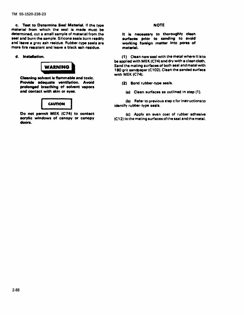
TM 55-1520-238-23
2-88

TM 55-1520-236-23
(d) Allow adhesive to air dry 10 to 15 minutesat 75 degrees F (24 degrees C) or above, Checkadhesive by touching with finger. When adhesive willadhere to finger but not transfer, apply a second coatof adhesive and air dry to the same degree.
(e) When second coat of adhesive has airdried until tacky, install seal on metal. Start at one endand roll seal onto metal. Press down on seal to ensurethat all air is expelled and that the seal is in fullcontact with the metal.
(f) Allow bond to air dry for a minimum offours hours at 75 degrees F (24 degrees C) or above.Adhesive should be cured at a temperature of 75degrees F (24 degrees C) or higher. If temperature isbelow 75 degrees F (24 degrees C) double theamount of cure time for each 12 degrees F (7 degreesC) below 75 degrees F (24 degrees C). Do not attemptto cure adhesive at temperatures below 50 degrees F(10 degrees C).
Typical temperatures and cure times:
Temperature Cure TimeDegrees F Degrees C Hours
75 24 563 17 851 11 16
(3) Bond silicone composition seals.
(a) Clean surface, as outlined in step (1)above.
(b) Refer to step c for instructions to identifysilicone composition seals.
Do not place a cap on the adhesive usedin the following step after it is mixed. Thistwo-part adhesive releases hydrogen gasafter mixing which could result in highpressures. The pot life on the mixedadhesive is six hours.
(c) Mix adhesive (C16) in accordance withinstructions on the container. Apply an even coat ofadhesive to the mating surfaces of the seal and themetal.
(d) Allow the adhesive to air dry at 75degrees F (24 degrees C) or above for 15 to 30minutes. Install seal on metal. Start at one end androll seal onto metal. Press down on seal to ensure thatall air is expelled and that the seal is in full contactwith the metal.
(e) Allow bond to cure for a minimum oftwelve hours at 75 degrees F (24 degrees C) or above.Adhesive should be cured at a temperature of 75degrees F (24 degrees C) or higher. If temperature isbelow 75 degrees F (24 degrees C) double theamount of cure time for each 12 degrees F (7 degreesC) below 75 degrees F (24 degrees C). Do not atemptto cure adhesive at temperatures below 50 degrees F(10 degrees C).
Typical temperature and cure times:
Temperature CureDegrees F Degrees C Hours
75 24 1263 17 2451 11 48
e. Functional Check. Install door, cowling, orfairing and check to ensure that the new seal fitsproperly.
2 - 2 1 . R E P A I R – FIREWALLS, FORWARDFUSELAGE.
Repair firewall using titanium repair instructions inTM 55-1500-204-25/1. Stainless steel can besubstituted for titanium of the same thickness. Usemonel rivets for all repairs.
2 - 2 2 . R E P A I R – BULKHEADS, FORWARDFUSELAGE.
Repair bulkheads shown on figures 2-14 through 2-17 as outlined in paragraph 2-15.
2 - 2 3 . R E P A I R – FUSELAGE FITTINGS,FORWARD FUSELAGE.
a. Negligible damage to forward fuselagetailboom attachment fittings should be polished outusing fine India stone (C116). See table 2-3 for limits.Fittings with damage or wear exceeding limits mustbe replaced by next higher maintenance level.
2-68.1/(2-68.2 blank)

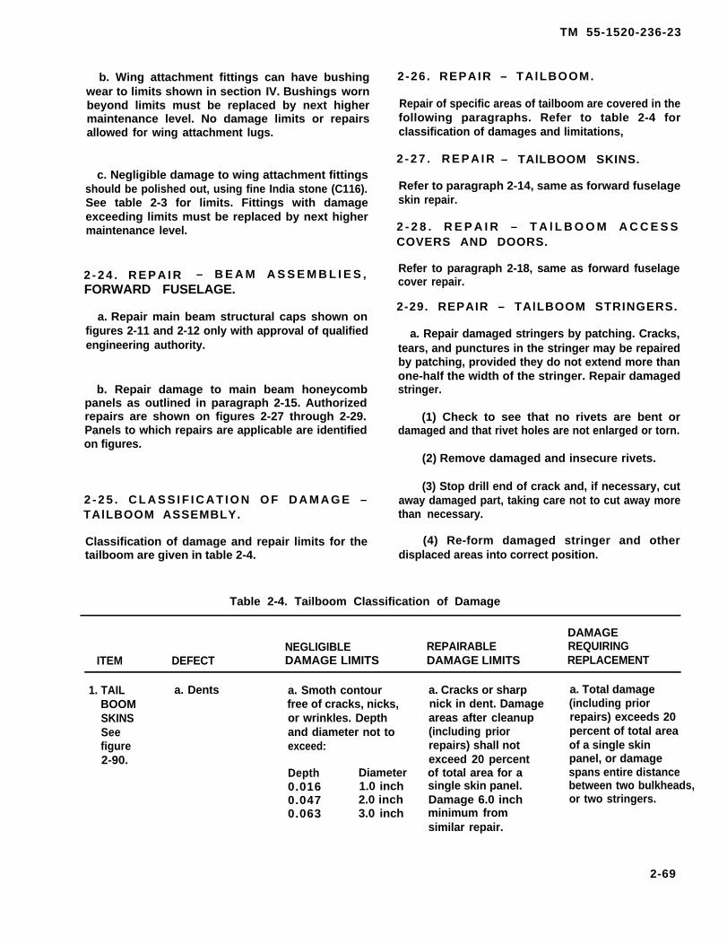
TM 55-1520-236-23
b. Wing attachment fittings can have bushingwear to limits shown in section IV. Bushings wornbeyond limits must be replaced by next highermaintenance level. No damage limits or repairsallowed for wing attachment lugs.
c. Negligible damage to wing attachment fittingsshould be polished out, using fine India stone (C116).See table 2-3 for limits. Fittings with damageexceeding limits must be replaced by next highermaintenance level.
2 - 2 4 . R E P A I R – B E A M A S S E M B L I E S ,FORWARD FUSELAGE.
a. Repair main beam structural caps shown onfigures 2-11 and 2-12 only with approval of qualifiedengineering authority.
b. Repair damage to main beam honeycombpanels as outlined in paragraph 2-15. Authorizedrepairs are shown on figures 2-27 through 2-29.Panels to which repairs are applicable are identifiedon figures.
2 - 2 5 . C L A S S I F I C A T I O N O F D A M A G E –TAlLBOOM ASSEMBLY.
Classification of damage and repair limits for thetailboom are given in table 2-4.
2 -26 . REPAIR – TAlLBOOM.
Repair of specific areas of tailboom are covered in thefollowing paragraphs. Refer to table 2-4 forclassification of damages and limitations,
2 - 2 7 . R E P A I R – TAlLBOOM SKINS.
Refer to paragraph 2-14, same as forward fuselageskin repair.
2 - 2 8 . R E P A I R – T A l L B O O M A C C E S SCOVERS AND DOORS.
Refer to paragraph 2-18, same as forward fuselagecover repair.
2-29. REPAIR – TAlLBOOM STRINGERS.
a. Repair damaged stringers by patching. Cracks,tears, and punctures in the stringer may be repairedby patching, provided they do not extend more thanone-half the width of the stringer. Repair damagedstringer.
(1) Check to see that no rivets are bent ordamaged and that rivet holes are not enlarged or torn.
(2) Remove damaged and insecure rivets.
(3) Stop drill end of crack and, if necessary, cutaway damaged part, taking care not to cut away morethan necessary.
(4) Re-form damaged stringer and otherdisplaced areas into correct position.
Table 2-4. Tailboom Classification of Damage
DAMAGENEGLIGIBLE REPAIRABLE REQUIRING
ITEM DEFECT DAMAGE LIMITS DAMAGE LIMITS REPLACEMENT
1. TAIL a. Dents a. Smoth contourBOOM free of cracks, nicks,SKINS or wrinkles. DepthSee and diameter not tofigure exceed:2-90.
Depth Diameter0.016 1.0 inch0.047 2.0 inch0.063 3.0 inch
a. Cracks or sharpnick in dent. Damageareas after cleanup(including priorrepairs) shall notexceed 20 percentof total area for asingle skin panel.Damage 6.0 inchminimum fromsimilar repair.
a. Total damage(including priorrepairs) exceeds 20percent of total areaof a single skinpanel, or damagespans entire distancebetween two bulkheads,or two stringers.
2-69

TM 55-1520-236-23
Table 2-4. Tailboom Classification of Damage (cont)
DAMAGENEGLIGIBLE REPAIRABLE REQUIRING
ITEM DEFECT DAMAGE LIMITS DAMAGE LIMITS REPLACEMENT
1. TAIL a. DentsBOOM (cont)SKINSseefigure2 - 9 0(cont)
b. Cracks, holestears, nicks,scratches, corro-sion and wrinkles.
c. Trapped orstretched skin.
3.0 inch minimumundamaged materialbetween dents and1.0 inch minimumfrom internalstructure. Nicks andscratches which canbe blended out not toexceed 10 percentof material depth.
c. Inward or out-ward bulges locatedin a sectional area,that can be correctedby removing attach-ing hardware, allow-ing skin to shift.Mismatch of rivetholes shall not ex-ceed that whichcan be cleaned upby drilling andinstalling onesize larger rivet andmaintain properrivet edge distance.However, if conditiondoes not disappearafter unloading panel,
b. Damage exceeds b. Same as dents.negligible limits butdoes not exceed 20percent (includingprior repairs) of totalarea for a singleskin panel.
2-70
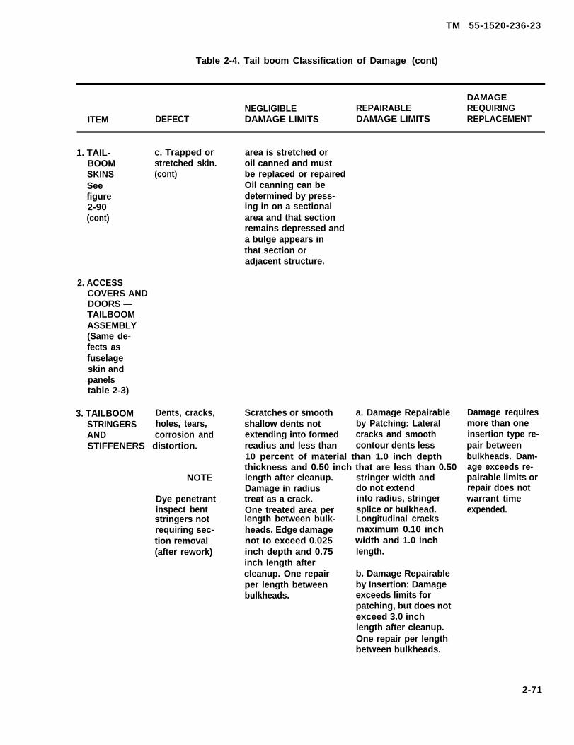
TM 55-1520-236-23
Table 2-4. Tail boom Classification of Damage (cont)
DAMAGENEGLIGIBLE REPAIRABLE REQUIRING
ITEM DEFECT DAMAGE LIMITS DAMAGE LIMITS REPLACEMENT
1. TAIL-BOOMSKINSSeefigure2-90(cont)
2. ACCESSCOVERS ANDDOORS —TAILBOOMASSEMBLY(Same de-fects asfuselageskin andpanelstable 2-3)
c. Trapped or area is stretched orstretched skin. oil canned and must(cont) be replaced or repaired
Oil canning can bedetermined by press-ing in on a sectionalarea and that sectionremains depressed anda bulge appears inthat section oradjacent structure.
3. TAILBOOM Dents, cracks,STRINGERS holes, tears,AND corrosion andSTIFFENERS distortion.
NOTE
Dye penetrantinspect bentstringers notrequiring sec-tion removal(after rework)
Scratches or smooth a. Damage Repairableshallow dents not by Patching: Lateralextending into formed cracks and smoothreadius and less than contour dents less10 percent of material than 1.0 inch depththickness and 0.50 inch that are less than 0.50length after cleanup. stringer width andDamage in radius do not extendtreat as a crack. into radius, stringerOne treated area per splice or bulkhead.length between bulk- Longitudinal cracksheads. Edge damage maximum 0.10 inchnot to exceed 0.025 width and 1.0 inchinch depth and 0.75 length.inch length aftercleanup. One repair b. Damage Repairableper length between by Insertion: Damagebulkheads. exceeds limits for
patching, but does notexceed 3.0 inchlength after cleanup.One repair per lengthbetween bulkheads.
Damage requiresmore than oneinsertion type re-pair betweenbulkheads. Dam-age exceeds re-pairable limits orrepair does notwarrant timeexpended.
2-71

TM 55-1520-236-23
Table 2-4. Tailboom Classification of Damage (cont)
DAMAGENEGLIGIBLE REPAIRABLE REQUIRING
ITEM DEFECT DAMAGE LIMITS DAMAGE LIMITS REPLACEMENT
3. TAIL-BOOMSTRINGERSANDSTIFFENERS(cont)
b. Nicks, scratches,and dents.
c. Holes, tears,and other damageexceeding thelimits in a.and b. above
Damage not to extendinto splice or bulk-heads. If combinedstringer and skindamage is present,above limits and limitsfor skin damage shallnot be exceeded.
Cracks that areno deeper than20 percent ofdoubler thickness, andnot exceeding 1.0inch in length canbe stop drilled ateach end providedthe crack is not closerthan 1.0 inch to anyadjacent structure.
Nicks, scratches anddents that are nodeeper than 20 per-cent of the doublerthickness and notexceeding 1.0 inchin length, or 0.025inch in width maybe polished out andrequire no patching.
Holes, tears, and otherdamage exceeding thelimits in steps a. and b.above and no longerthan 4.0 inches orgreater than 6.0 squareinches may be repairedby patching.
2-72
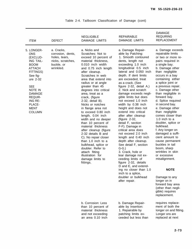
TM 55-1520-236-23
Table 2-4. Tailboom Classification of Damage (cont)
DAMAGENEGLIGIBLE REPAIRABLE REQUIRING
ITEM DEFECT DAMAGE LIMITS DAMAGE LIMITS REPLACEMENT
5. LONGER-ONS(EXCLUD-ING TAIL-BOOMATTACHFlTTlNGS)See fig-ure 2-32
SEENOTE INDAMAGEREQUIR-ING RE-PLACE-MENTCOLUMN
a. Cracks, a. Nicks andcorrosion, dents, Scratches: Not toholes, tears, exceed 10 percent ofnicks, scratches, material thickness,buckle, or 0.010 inch widthwrinkled. and 0.75 inch length
after cleanup.Scratches in webarea that extend intoradius or at anglegreater than 45degrees into criticalarea, treat as acrack, (figure2-32, detail B).Nicks or notchesin flange area notto exceed 0.80 inchlength, 0.04 inchwidth and no deeperthan 10 percent ofmaterial thicknessafter cleanup (figure2-32 details B andC). No repair closerthan 1.0 inch to abulkhead, splice ordoubler. Refer toattach fittingillustration fordamage limits tofittings.
b. Corrosion: Lessthan 10 percent ofmaterial thicknessand not exceedingan area 0.10 inch
a. Damage Repair-able by Patching:1. Smooth contoureddents, length notexceeding 1.0 inchlongitudinal 0.5 inchlateral and 0.050 inchdepth. If dent limitsare exceeded, treatas a crack. (Seefigure 2-32, detail A.)2. Nick and scratchdamage exceeds negli-gible limits but doesnot exceed 1.0 inchwidth by 0.38 inchheight and does notextend into criticalafter after cleanup(figure 2-32,detail F, sectionF-F). Damage incritical area doesnot exceed 2.0 inchlength and 0.40 inchdepth after cleanup.See detail F, sectionG-G.)3. Crack, hole ortear damage not ex-ceeding limits offigure 2-32, detailsD and E, and extend-ing no closer than 1.0inch to a splice,doubler or bulkheadafter repair.
b. Damage Repair-able by Insertion:1. Repairable bypatching limits ex-ceeded but less than
a. Damage exceedsrepairable Iimitsor two or more re-pairs required ina single bay.b. Damage otherthan negligibleoccurs in a baycontaining eithera splice joint ora previous repair.c. Damage otherthan negligible inforward bay.d. Splice requiredin second bay.e. Damage otherthan negligiblecomes closer than1.0 inch to adoubler, splice orbulkhead.f. Any Ionger ondamaged a suffi-cient amount tocause permanentbuckles in tailboom, sharpwrinkles in skinor excessivemisalignment.
NOTE
Damage to anyIonger on inforward bay area(other than negli-gible) requiresreplacement.
requires replace-ment of both theIonger on and fitting.Longer ons arereplaced at next
2-73

TM 55-1520-236-23
Table 2-4. Tailboom Classification of Damage (cont)
DAMAGENEGLIGIBLE REPAIRABLE REQUIRING
ITEM DEFECT DAMAGE LIMITS DAMAGE LIMITS REPLACEMENT
5. LONGER-ONS(EXCLUD-ING TAIL-BOOMATTACHFlTTINGS)See fig-ure 2-32(cont]
6. TAIL-BOOMBULK-HEADS(Does notincludecantedbulkhead)See fig-ure 2-33
width by 0.75 inchlength after cleanup.Damage confined toweb area only andno closer than 1.0inch to a splice,doubler or bulkhead,One repair for eachlongeron in a bayarea. No damagein forward bay(figure 2-32,detail B).
Corrosion, dents, Corrosion less than 10cracks, holes percent of web materialnicks, and thickness and notwrinkles. exceeding 4.0 square
inch after cleanup.Damage no closerthan 0.250 inch toa former, stiffeneror radius. Dents,nicks, scratchesin bulkhead web,refer to skin dam-age limits, item 1.Damage in a radiusDamage in a radiustreat as a crack.
2.60 inch length aftercleanup, (figure 2-32,details F and G).2. Cracks or sharpnicks in dent ordamage exceeds repairby patching, but lessthan 2.60 inch aftercleanup.
a. Damage Repair-able by Patching.1. Corrosiondamage greater thannegligible but doesnot exceed 0.70 inchwidth or 33 percentof a cross section aftercleanup. (See figure2-33, detail B.)Damage no closerthan 0.50 inch to astiffener or attach-ing parts aftercleanup.2. Dent, cracks,holes and scratchesgreater than negligiblebut does not exceedlimits of figure 2-33,details A and B.Maximum threedamages not to exceedlimits of detail Aallowed for each bulk-head quadrant. Cracksor damage in radiusof former on forwardbulkhead except inarea of attachfittings.b. Damage Repair-able by Insertion:
higher mainten-ance level
Replace stiffenersor any attachingparts for damageother than negligible.Replace bulkheadif repairable limitsare exceeded or ifmore than one repairto the limits offigure 2-33, detailD, is required
NOTE
Bulkheads are re-placed by highermaintenance level.
2-74

TM 55-1520-236-23
Table 2-4. Tailboom Classification of Damage (cont)
DAMAGENEGLIGIBLE REPAIRABLE REQUIRING
ITEM DEFECT DAMAGE LIMITS DAMAGE LIMITS REPLACEMENT
6. TAIL-BOOMBULK-HEADS(Does notincludecantedbulkhead)See fig-ure 2-33(cont)
7. TAILBOOMCANTEDBULKHEAD
8. COVERS,TAIL ROTORDRIVE-SHAFTINTER-MEDIATEGEARBOXSee fig-ure 2-34
Cracks, holes,nicks, corro-sion, andwrinkles.
Dents, nicksscratches, cracks,holes, corrosion,and worn rubstrips.
Corrosion not toexceed 1.0 squareinch for singlearea, 4.0 squareinch total areaand 10 percentmaterial thicknessafter cleanup. Nicksand scratches not toexceed 1.0 inchlength, 0.025 inchwidth and 10 percentmaterial thicknessafter cleanup. Treatdamage in radius asa crack.
Same as tailboomskins.
1. Corrosion damageexceeds repairableby patching but doesnot exceed limits offigure 2-33, detail C.2. Dent, cracksor hole damage ex-ceeds limits of figure2-33, details A andB, but less than limits.
Three holes maximumnot exceeding 1.0inch diameter in webarea and 3.0 inchminimum distancebetween damage.Cracks in nutplatehole but not extendinginto radius. Cracksin web area not ex-ceeding 1.0 inchlength after cleanup.No damage to comecloser than 0.50 inchto stringer, longeronor structure attach-ing point and nocloser than 1.0 inchto a fin spar capattachment.
Same as tailboomskins except repairshall not interferewith fit or functionof the cover. Replaceworn rub strips.
Cracks or holes inarea of Iongeron,stringer, orfin sparcap attachmentpoints. Damageexceeds repair-able damagelimits.
Replace covers ifdamage is imprac-tical to repair.
2-75

TM 55-1520-236-23
Table 2-4. Tailboom Classification of Damage (Cont)
DAMAGENEGLIGIBLE REPAIRABLE REQUIRING
ITEM DEFECT DAMAGE LIMITS DAMAGE LIMITS REPLACEMENT
9. HINGESANDSUPPORTANGLES,DRIVE-SHAFTCOVER
10. TAIL-BOOMATTACHFlTTINGSSee fig-ure 2-36
Inspect hingesfor cracked,worn, or missingloops. Checkangles forcracks, holes,distortion anddamaged or miss-ing fasteners.Check covers forloose anti-chafingtape.
a. Nicks,scratches, andgouges.
See figure 2-35 See figure 2-35 Damage exceedinglimits of figure 2-35.Refer to TM 55-1500-204-25/1.
a. Nicks, scratches,and gouges in tail-boom attach fittingmay be polished outif they do not exceedthese limits:(1) Axial damage(parallel to bolt holes)must not exceed 0.020inch in depth and0.300 inch in length.(2) Radial damage(normal to bolt axis)must not exceed0.010 inch in depthor 0.300 inch in length.(3) Nicks, scratches,or gouges are notpermitted withinone diameter ofbolt hole, longeronsplice rivets or within0.250 inch of end ofsheet metal longeronlocated at splice.
Any cracks to theIongeron attachfittings forward ofboom station 70.00,or damage exceedingthe above Iimitationrequire the part tobe replaced by nexthigher maintenancelevel.
b. Corrosion No corrosion allowedin first 5.50 inchesof attach fitting.
2-76

TM 55-1520-236-23
Table 2-4. Tailboom Classification of Damage (cont)
DAMAGENEGLIGIBLE REPAIRABLE REQUIRING
ITEM DEFECT DAMAGE LIMITS DAMAGE LIMITS REPLACEMENT
10. TAIL-BOOMATTACHFITTlNGSSeefigure2-36 (cont)
11. BEARINGHANGERSUPPORTFlTTlNG.See fig-ure 2-37
c. Bolt holeelongation.
a. Cracksb. Corrosionc. Hole elonga-tion. Bearingsupport attachholes.
12. INTER- a. Cracks.MEDIATEGEARBOXSUPPORTINSTAL-LATION. b. Distortion ofSee figure support in-2-38. stallation
components.
c. Gearboxattachmenthole damage.
d. Scratches,nicks, dents.
Inspect attachmentbolt holes in tail-boom fuselagefittings for wear.Maximum diameterpermitted for holes is0.516 inch.
See figure 2-37. Cracks in fittingor damage ex-ceeding limitsshown in figure2-37. No cor-rosion damageallowed insidediameter ofattachmenthole surfaces.Refer toparagraph2-35b.
Any cracksare causefor replace-ment.
Replace dis-torted components.Replacement ofsupport fit-tings must bedone by nexthigher mainten-ance level.
See figure 2-38.
See figure 2-38. Treat deepscratches,nicks, anddents ascracks forinspection.
2-77

TM 55-1520-236-23
Table 2-4. Tailboom Classification of Damage (cont)
DAMAGENEGLIGIBLE REPAIRABLE REQUIRING
ITEM DEFECT DAMAGE LIMITS DAMAGE LIMITS REPLACEMENT
12. INTER-MEDIATEGEARBOXSUPPORTlNSTAL-LATION.seefigure2-38(cont)
13. TAlL-ROTORGEARBOXSUPPORTFlTTlNGsee fig-ure 2-39
e. Corrosion. See figure 2-38. Treat deepcorrosionsame ascracking forinspection.
f. Stud pindamaged.
g. Nutplatesdamaged.
a. Cracks
b. Scratches,nicks, dentsand corrosion.
c. Chafing
d. Gearboxmounting holeelongation. Studholes diametercannot exceed0.400 inch
Replace damagedstud pin.
Replace damagednutplates.
a. Any cracks are causefor replacement.
b. Repairable scratches,nicks, dents, andcorrosion on topsurface and on studholes may be polishedout with Scotchbrite(C103) or No. 400 gritsandpaper (C102).When removingcorrosion be sure tocheck pockets andhidden areas for in-dications. Determinethe proper cleaningprocedures and treat-ment of corroded parts.
c. Total depth ofchafing allowed inarea A is 0.075 inch.For total depth ofchafing allowed inarea B refer to fig-ure 2-39.
d. If limits are ex-ceeded the tailrotor gearboxfitting must be re-paired or replacedby next highermaintenance level.
2-78
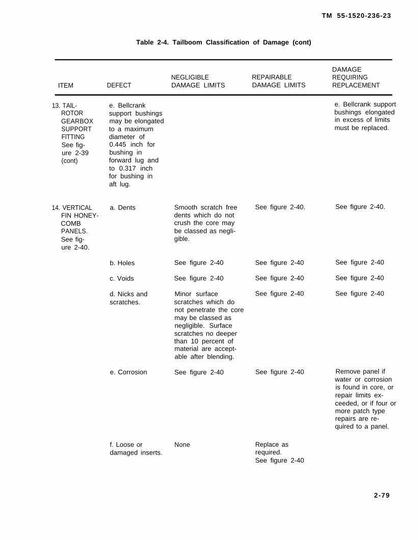
TM 55-1520-236-23
Table 2-4. Tailboom Classification of Damage (cont)
DAMAGENEGLIGIBLE REPAIRABLE REQUIRING
ITEM DEFECT DAMAGE LIMITS DAMAGE LIMITS REPLACEMENT
13. TAlL-ROTORGEARBOXSUPPORTFlTTINGSee fig-ure 2-39(cont)
14. VERTICALFIN HONEY-COMBPANELS.See fig-ure 2-40.
e. Bellcrank e. Bellcrank supportsupport bushings bushings elongatedmay be elongated in excess of limitsto a maximum must be replaced.diameter of0.445 inch forbushing inforward lug andto 0.317 inchfor bushing inaft lug.
a. Dents Smooth scratch free See figure 2-40.dents which do notcrush the core maybe classed as negli-gible.
b. Holes See figure 2-40 See figure 2-40
c. Voids See figure 2-40 See figure 2-40
d. Nicks and Minor surface See figure 2-40scratches. scratches which do
not penetrate the coremay be classed asnegligible. Surfacescratches no deeperthan 10 percent ofmaterial are accept-able after blending.
e. Corrosion See figure 2-40 See figure 2-40
f. Loose or Nonedamaged inserts.
Replace asrequired.
See figure 2-40.
See figure 2-40
See figure 2-40
See figure 2-40
Remove panel ifwater or corrosionis found in core, orrepair limits ex-ceeded, or if four ormore patch typerepairs are re-quired to a panel.
See figure 2-40
2-79
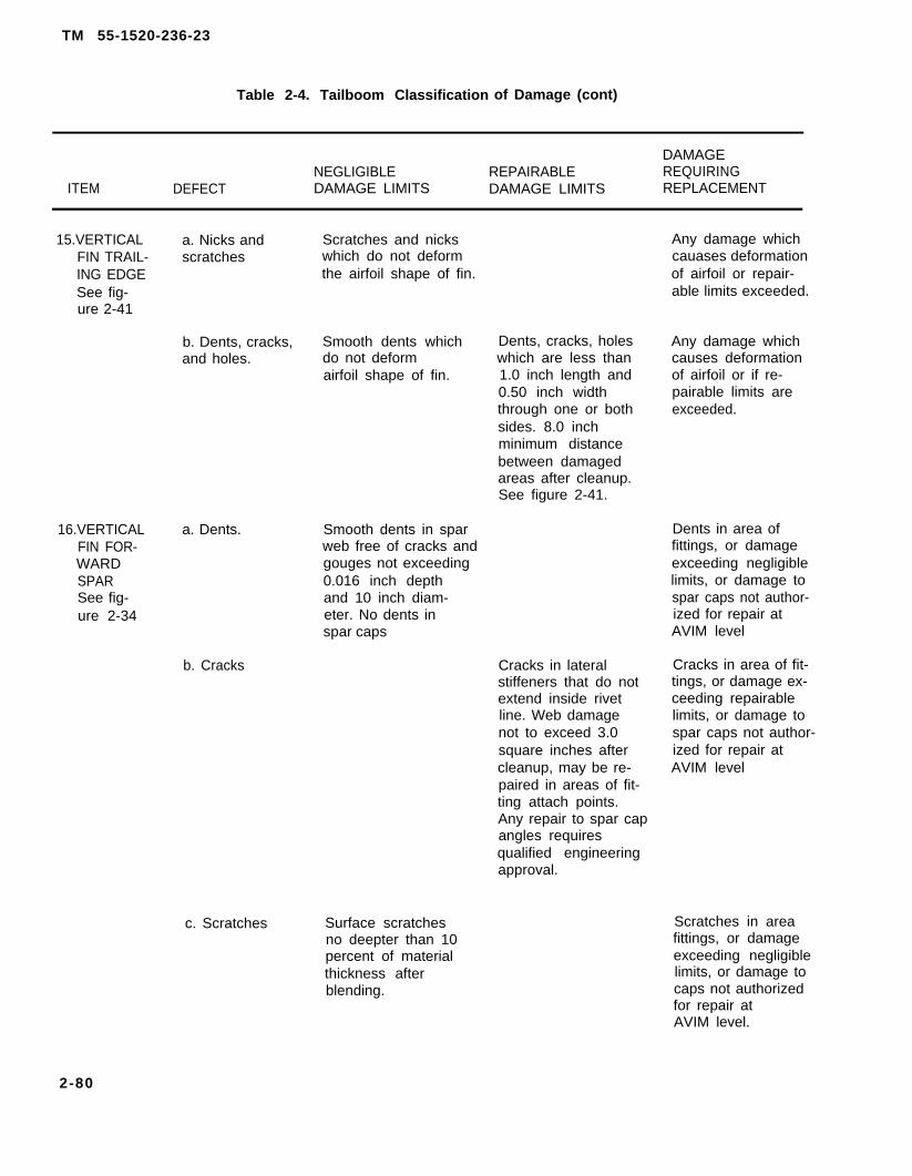
TM 55-1520-236-23
Table 2-4. Tailboom Classification of Damage (cont)
DAMAGENEGLIGIBLE REPAIRABLE REQUIRING
ITEM DEFECT DAMAGE LIMITS DAMAGE LIMITS REPLACEMENT
15.VERTICAL a. Nicks and Scratches and nicksFIN TRAIL- scratches which do not deformING EDGE the airfoil shape of fin.See fig-ure 2-41
b. Dents, cracks, Smooth dents whichand holes. do not deform
airfoil shape of fin.
16.VERTICAL a. Dents.FIN FOR-WARDSPARSee fig-ure 2-34
b. Cracks
c. Scratches
Smooth dents in sparweb free of cracks andgouges not exceeding0.016 inch depthand 10 inch diam-eter. No dents inspar caps
Surface scratchesno deepter than 10percent of materialthickness afterblending.
Dents, cracks, holeswhich are less than1.0 inch length and0.50 inch widththrough one or bothsides. 8.0 inchminimum distancebetween damagedareas after cleanup.See figure 2-41.
Cracks in lateralstiffeners that do notextend inside rivetline. Web damagenot to exceed 3.0square inches aftercleanup, may be re-paired in areas of fit-ting attach points.Any repair to spar capangles requiresqualified engineeringapproval.
Any damage whichcauases deformationof airfoil or repair-able limits exceeded.
Any damage whichcauses deformationof airfoil or if re-pairable limits areexceeded.
Dents in area offittings, or damageexceeding negligiblelimits, or damage tospar caps not author-ized for repair atAVIM level
Cracks in area of fit-tings, or damage ex-ceeding repairablelimits, or damage tospar caps not author-ized for repair atAVIM level
Scratches in areafittings, or damageexceeding negligiblelimits, or damage tocaps not authorizedfor repair atAVIM level.
2-80
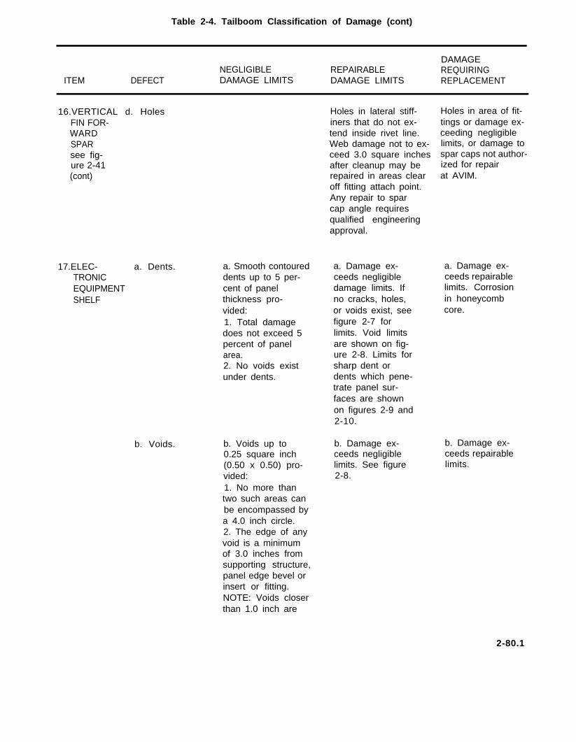
Table 2-4. Tailboom Classification of Damage (cont)
DAMAGENEGLIGIBLE REPAIRABLE REQUIRING
ITEM DEFECT DAMAGE LIMITS DAMAGE LIMITS REPLACEMENT
16.VERTICAL d. HolesFIN FOR-WARDSPARsee fig-ure 2-41(cont)
17.ELEC- a. Dents.TRONICEQUIPMENTSHELF
b. Voids.
a. Smooth contoureddents up to 5 per-cent of panelthickness pro-vided:1. Total damagedoes not exceed 5percent of panelarea.2. No voids existunder dents.
b. Voids up to0.25 square inch(0.50 x 0.50) pro-vided:1. No more thantwo such areas canbe encompassed bya 4.0 inch circle.2. The edge of anyvoid is a minimumof 3.0 inches fromsupporting structure,panel edge bevel orinsert or fitting.NOTE: Voids closer
Holes in lateral stiff-iners that do not ex-tend inside rivet line.Web damage not to ex-ceed 3.0 square inchesafter cleanup may berepaired in areas clearoff fitting attach point.Any repair to sparcap angle requiresqualified engineeringapproval.
a. Damage ex-ceeds negligibledamage limits. Ifno cracks, holes,or voids exist, seefigure 2-7 forlimits. Void limitsare shown on fig-ure 2-8. Limits forsharp dent ordents which pene-trate panel sur-faces are shownon figures 2-9 and2-10.
b. Damage ex-ceeds negligiblelimits. See figure2-8.
Holes in area of fit-tings or damage ex-ceeding negligiblelimits, or damage tospar caps not author-ized for repairat AVIM.
a. Damage ex-ceeds repairablelimits. Corrosionin honeycombcore.
b. Damage ex-ceeds repairablelimits.
than 1.0 inch are
2-80.1

TM 55-1520-236-23
Table 2-4. Tailboom Classification of Damage (cont)
DAMAGENEGLIGIBLE REPAIRABLE REQUIRING
ITEM DEFECT DAMAGE LIMITS DAMAGE LIMITS REPLACEMENT
17. ELEC- b. Void. (cont).TRONICEQUIPMENTSHELF(CONT)
c. Nicks andscratches.
d. Corrosion.
e. Cracks,holes,punctures.
classed as one void.Edge separation isnever classed asnegligible damage.
c. Nicks andscratches not ex-ceeding 10 percentof metal facingthickness and 4.0inches square aftercleanup. Damage1.0 inch minimumfrom supportingstructure aftercleanup.
d. Corrosion not toexceed 10 percentof metal facingthickness and 4.0square inches aftercleanup.
Damage minimum1.0 inch from sup-porting structure.
e. None.
c. Damage ex-ceeds negligiblelimits. See figure2-7 for damagenot penetratingsurface. See figure2-9 for damagepenetrating sur-face.
d. Damage not toexceed 20 percentof panel area.Maximum diameterof any area aftercleanup is 1.0 inch.One repair per bayallowed. Minimumdistance betweenrepairs is 3.0inches. No repairwithin 1.0 inch of
c. Damage ex-ceeds repairableIimits. Replaceany panel havingevidence of wateror corrosion inthe core.
d. Same as pre-ceding atop c.
supporting struc-ture, inserts, orbeveled edge.
e. Cracks, holes e. Same as pre-or punctures. ceding atop c.1. Damages affectonly one skin andcore. (See figure2-9 for limits.)2. Damages affectboth skins andcore. (See figure2-10 for limits.]
2-80.2
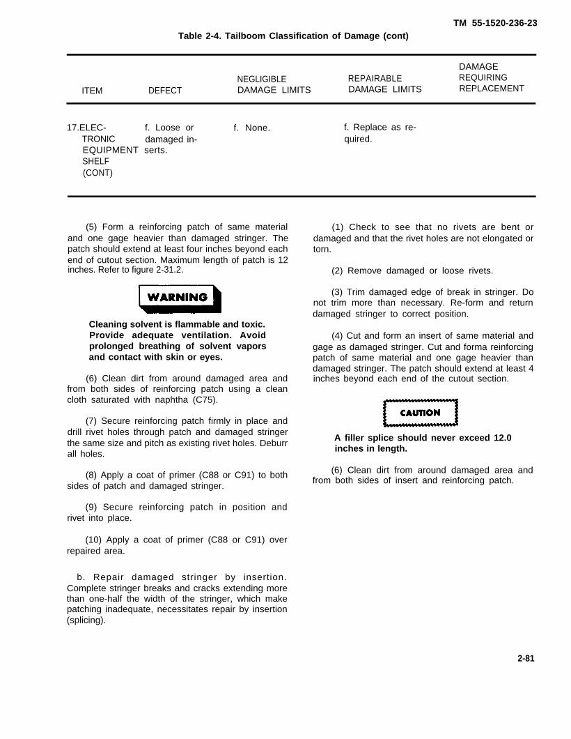
TM 55-1520-236-23Table 2-4. Tailboom Classification of Damage (cont)
DAMAGENEGLIGIBLE REPAIRABLE REQUIRING
ITEM DEFECT DAMAGE LIMITS DAMAGE LIMITS REPLACEMENT
17.ELEC- f. Loose or f. None. f. Replace as re-TRONIC damaged in- quired.EQUIPMENT serts.SHELF(CONT)
(5) Form a reinforcing patch of same materialand one gage heavier than damaged stringer. Thepatch should extend at least four inches beyond eachend of cutout section. Maximum length of patch is 12inches. Refer to figure 2-31.2.
Cleaning solvent is flammable and toxic.Provide adequate ventilation. Avoidprolonged breathing of solvent vaporsand contact with skin or eyes.
(6) Clean dirt from around damaged area andfrom both sides of reinforcing patch using a cleancloth saturated with naphtha (C75).
(7) Secure reinforcing patch firmly in place anddrill rivet holes through patch and damaged stringerthe same size and pitch as existing rivet holes. Deburrall holes.
(8) Apply a coat of primer (C88 or C91) to bothsides of patch and damaged stringer.
(9) Secure reinforcing patch in position andrivet into place.
(10) Apply a coat of primer (C88 or C91) overrepaired area.
b. Repair damaged stringer by insertion.Complete stringer breaks and cracks extending morethan one-half the width of the stringer, which makepatching inadequate, necessitates repair by insertion(splicing).
(1) Check to see that no rivets are bent ordamaged and that the rivet holes are not elongated ortorn.
(2) Remove damaged or loose rivets.
(3) Trim damaged edge of break in stringer. Donot trim more than necessary. Re-form and returndamaged stringer to correct position.
(4) Cut and form an insert of same material andgage as damaged stringer. Cut and forma reinforcingpatch of same material and one gage heavier thandamaged stringer. The patch should extend at least 4inches beyond each end of the cutout section.
A filler splice should never exceed 12.0inches in length.
(6) Clean dirt from around damaged area andfrom both sides of insert and reinforcing patch.
2-81

TM 55-1520-236-23
Figure 2-32. Longeron Damage Limits (Sheet 1 of 3)
2-82

TM 55-1520-236-23
1.
2.
NOTES
All longitudinal cracks are repairable ifthey are 0.45 inch minimum height fromIongeron flange, 1.04 inches maximumheight from Iongeron flange.
Refer to figure 2-43 for repairinstructions.
Figure 2-32. Longeron Damage Limits (Sheet 2 of 3)
2-83

TM 55-1520-236-23
1.
2.
NOTES.
When trimmed area exceeds limitsshown for either critical area or flangeand web, or if combined damageextends from the flange and web intocritical area, inspect to limits of detail G.
Refer to figure 2-43 for repairinstructions.
Figure 2-32. Longeron Damage Limits (Sheet 3 of 3)
2-84

TM 55-1520-236-23
Figure 2-33. Typical Tailboom Bulkhead Damage Limits (Sheet 1 of 2)
2-85
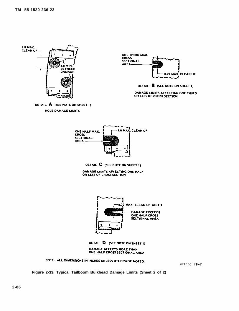
TM 55-1520-236-23
Figure 2-33. Typical Tailboom Bulkhead Damage Limits (Sheet 2 of 2)
2-86

TM 55-1520-236-23
Figure 2-34. Tail Rotor Driveshaft Covers
2 - 8 7
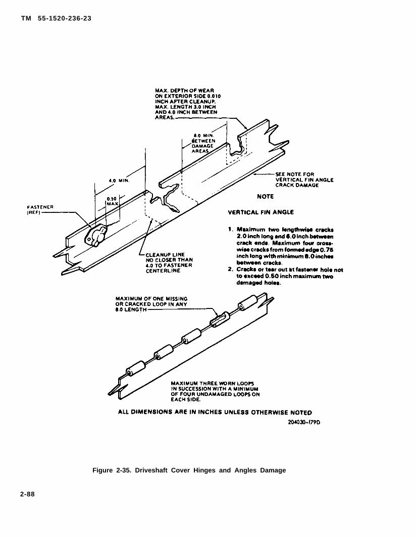
TM 55-1520-236-23
Figure 2-35. Driveshaft Cover Hinges and Angles Damage
2-88
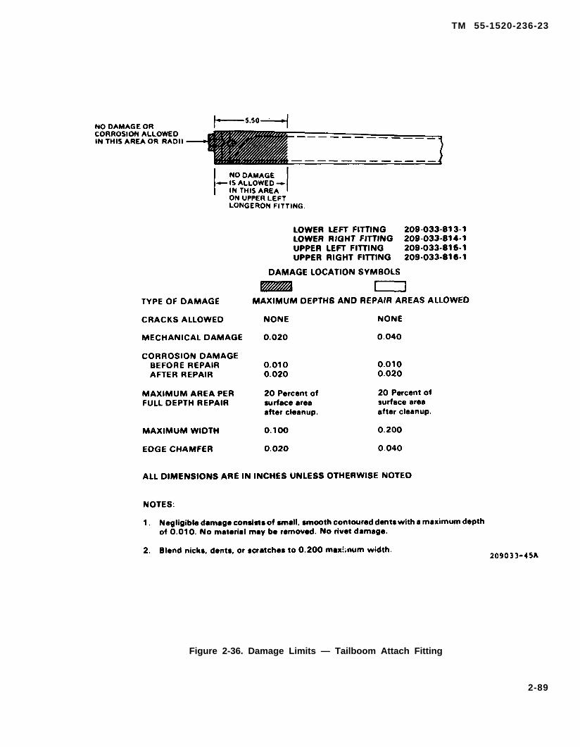
TM 55-1520-236-23
Figure 2-36. Damage Limits — Tailboom Attach Fitting
2-89

TM 55-1520-236-23
Figure 2-37. Damage Limits – Searing Hanger Support Fitting
2-90
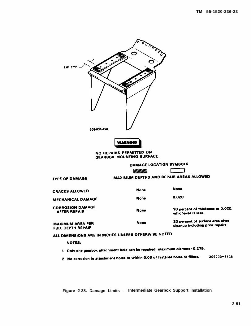
TM 55-1520-236-23
Figure 2-38. Damage Limits — Intermediate Gearbox Support Installation
2-91

TM 55-1520-236-23
Figure 2-39. Damage Limits – Tail Rotor Drive Support Fitting (Sheet 1 of 4)
2 - 9 2
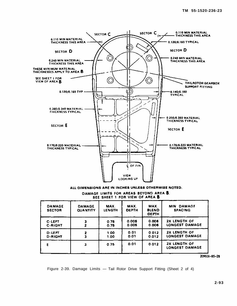
TM 55-1520-236-23
Figure 2-39. Damage Limits — Tail Rotor Drive Support Fitting (Sheet 2 of 4)
2-93
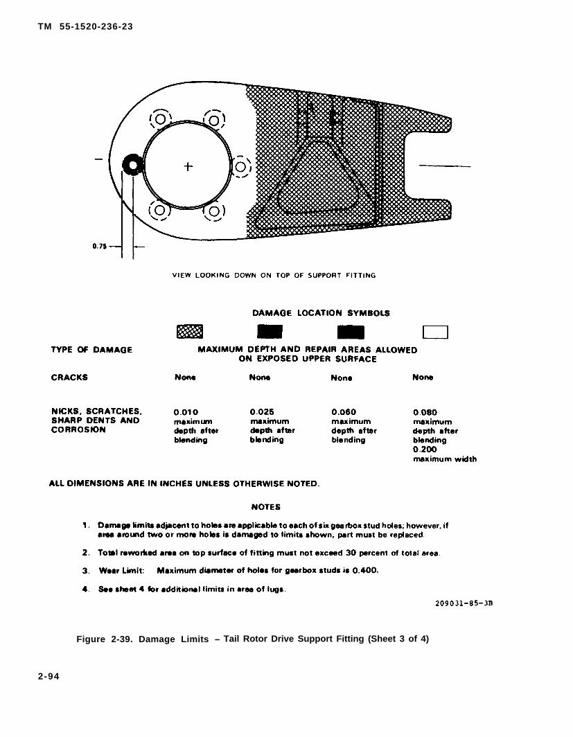
TM 55-1520-236-23
Figure 2-39. Damage Limits – Tail Rotor Drive Support Fitting (Sheet 3 of 4)
2-94
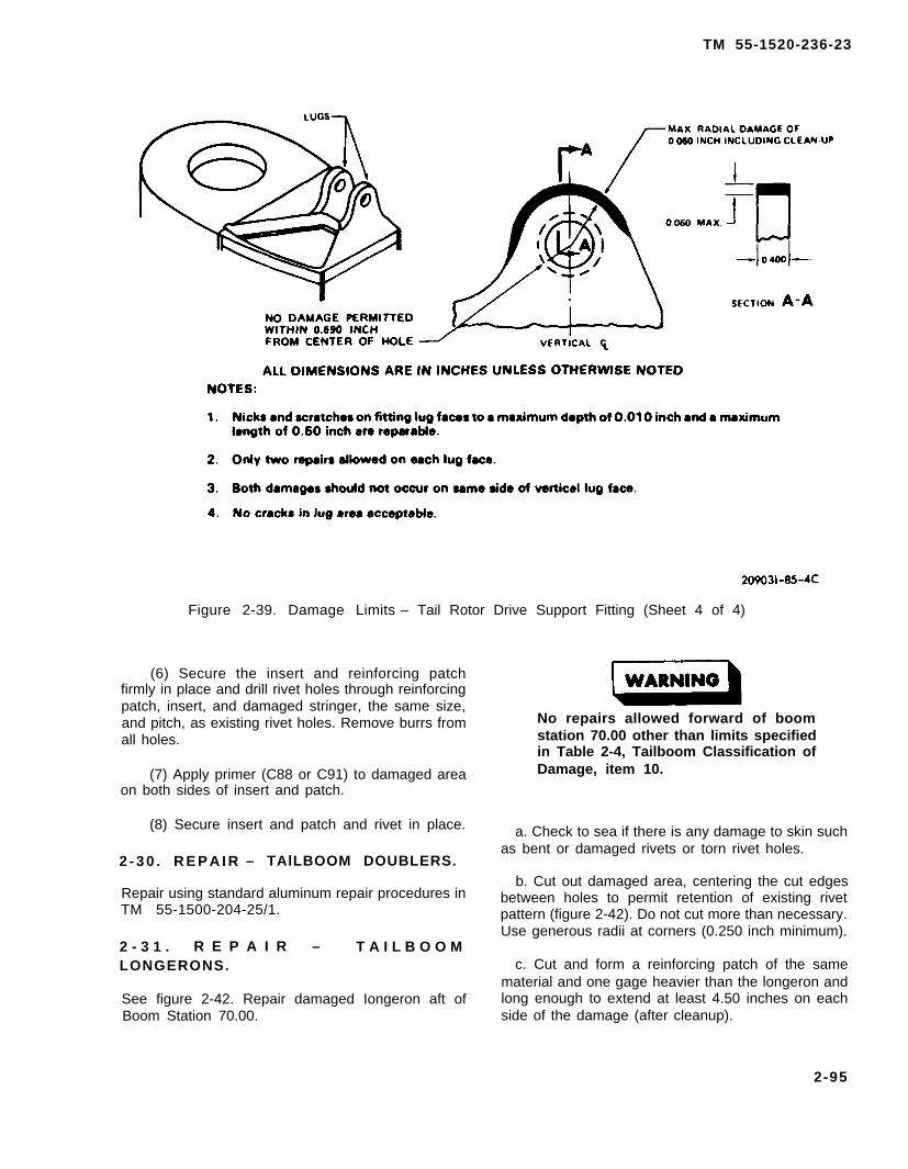
TM 55-1520-236-23
Figure 2-39. Damage Limits – Tail Rotor Drive Support Fitting (Sheet 4 of 4)
(6) Secure the insert and reinforcing patchfirmly in place and drill rivet holes through reinforcingpatch, insert, and damaged stringer, the same size,and pitch, as existing rivet holes. Remove burrs fromall holes.
(7) Apply primer (C88 or C91) to damaged areaon both sides of insert and patch.
(8) Secure insert and patch and rivet in place.
2 - 3 0 . R E P A I R – TAlLBOOM DOUBLERS.
Repair using standard aluminum repair procedures inTM 55-1500-204-25/1.
2 - 3 1 . R E P A I R – T A I L B O O MLONGERONS.
See figure 2-42. Repair damaged Iongeron aft ofBoom Station 70.00.
No repairs allowed forward of boomstation 70.00 other than limits specifiedin Table 2-4, Tailboom Classification ofDamage, item 10.
a. Check to sea if there is any damage to skin suchas bent or damaged rivets or torn rivet holes.
b. Cut out damaged area, centering the cut edgesbetween holes to permit retention of existing rivetpattern (figure 2-42). Do not cut more than necessary.Use generous radii at corners (0.250 inch minimum).
c. Cut and form a reinforcing patch of the samematerial and one gage heavier than the longeron andlong enough to extend at least 4.50 inches on eachside of the damage (after cleanup).
2-95
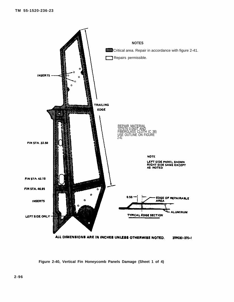
TM 55-1520-236-23
NOTES
Critical area. Repair in accordance with figure 2-41.
Repairs permissible.
REPAIR MATERIAL7075T6 0.050T ANDFIBERGLASS CLOTH (C 38)USE OUTLINE ON FIGURE2-41
Figure 2-40, Vertical Fin Honeycomb Panels Damage (Sheet 1 of 4)
2-96
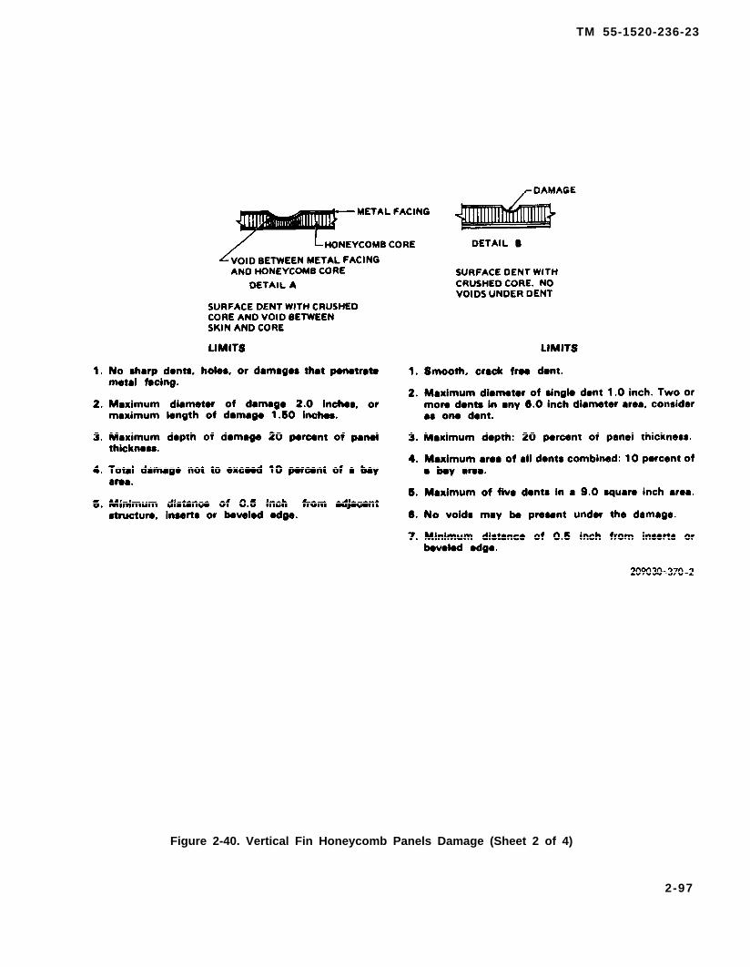
TM 55-1520-236-23
Figure 2-40. Vertical Fin Honeycomb Panels Damage (Sheet 2 of 4)
2-97
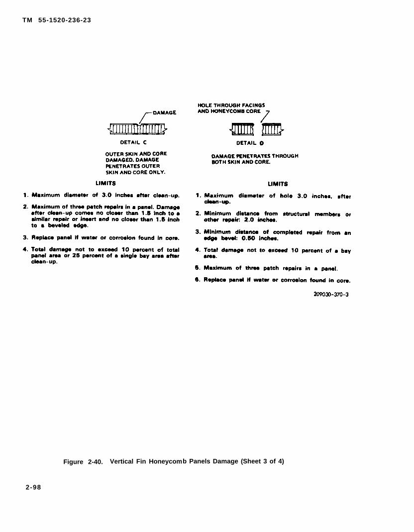
TM 55-1520-236-23
Figure 2-40. Vertical Fin Honeycomb Panels Damage (Sheet 3 of 4)
2-98

TM 55-1520-236-23
Figure 2-40. Vertical Fin Honeycomb Panels Damage (Sheet 4 of 4)
d. Secure the reinforcing patch in position anddrill out rivet holes of the same size and pitch asshown in figure 2-42.
e. Mark a line around outer edge of patch using asoft pencil. Remove patch and deburr holes.
f.lines
Cleaning advent is flammable and toxic.Provide adequate ventilation. Avoidprolonged breathing of solvent vaporsand contact with akin or eyes.
Remove paint from between previously markedof damaged area using a clean cloth saturated
with MEK (C74).
g. Buff both sides of patch with Scotchbrite(C103) and wipe with a clean cloth.
h.
i.
Do not touch patch with bare hands aftercleaning.
Apply adhesive (C8) to mating surface of patch.
Secure reinforcing patch in position and rivet inpiece while adhesive is still wet.
j. Apply a coat of primer (C88 or C91) over therepaired area.
2-32. REPAIR – TAILBOOM BULKHEADS.
Repair damaged bulkheads by patching and insertion.
a. Cracks, tears, and punctures in the bulkhead,web, and flanges may be repaired by patching,provided the damage does not extend more than one-half the width of the bulkhead. Refer to figures 2-44through 2-47. Repair damage.
2-99

TM 55-1520-236-23
Figure 2-41. Edge Repair on Vertical Fin
2-100

TM 55-1520-236-23
When trimmed area exceeds 1.0 inch, or more Before making repairs refer to "Limitation ofthan two rivets (in flanges) are lost or damaged, Repairs at Speci f ic Locat ions" inrepair as directed on figure 2-43. accompanying text.
Note 2 Note 3
Under no circumstances may an MS20600 or NAS1738B5 blind rivets or MS20470AD-5similar nonlocking stem blind rivet be used in astructural application.
rivets, where installation is not blind.
Figure 2-42. Tailboom Longerons
2-101
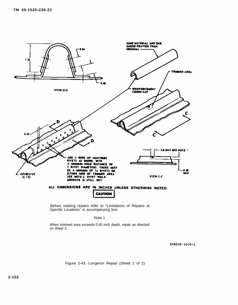
TM 55-1520-236-23
Before reeking repairs refer to "Limitations of Repairs atSpecific Locations" in accompanying text.
Note 1
When trimmed area exceeds 0.40 inch depth, repair as directedon sheet 2.
Figure 2-43. Longeron Repair (Sheet 1 of 2)
2-102
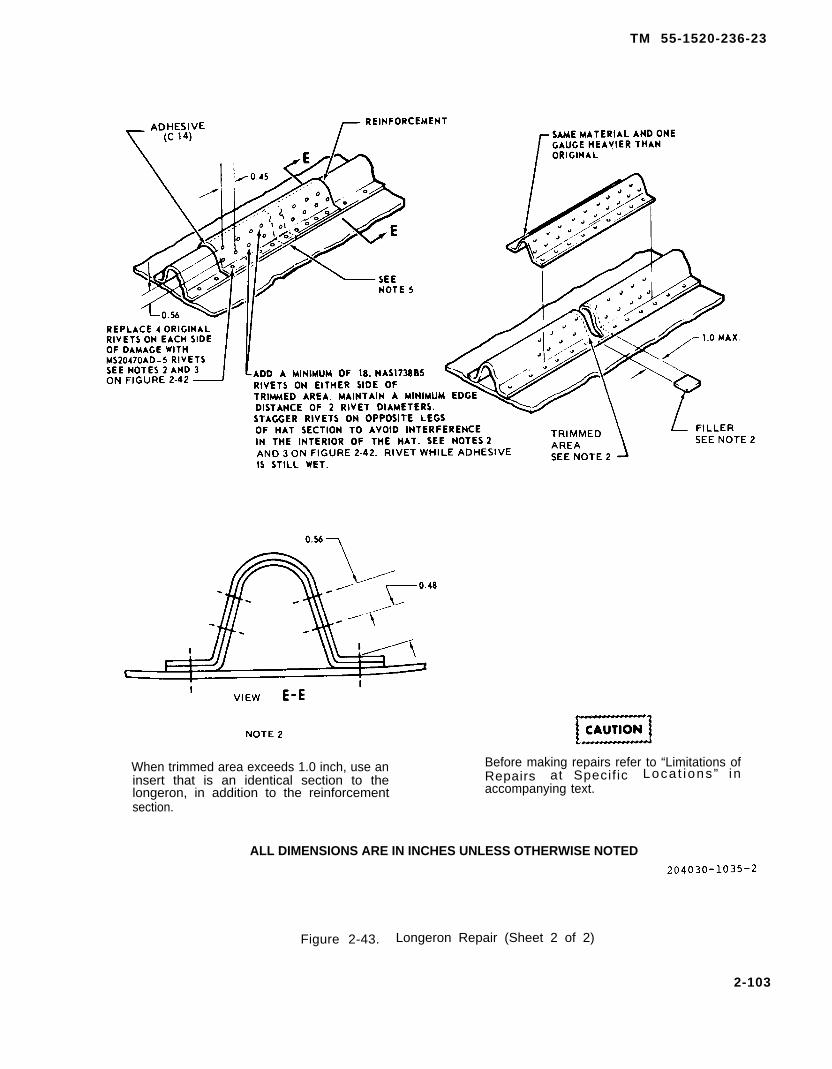
TM 55-1520-236-23
When trimmed area exceeds 1.0 inch, use an Before making repairs refer to “Limitations ofinsert that is an identical section to the Repairs at Specif ic Loca t ions ” in
longeron, in addition to the reinforcement accompanying text.section.
ALL DIMENSIONS ARE IN INCHES UNLESS OTHERWISE NOTED
Figure 2-43. Longeron Repair (Sheet 2 of 2)
2-103

TM 55-1520-236-23
RESTRICTIONS
1. Only one repair maybe made on each Iongeron in any one bay area.
2. No repairs allowed in forward bay.
3. Holes in Iongerons must not exceed 1.0 inches in diameter after cleanup.
Figure 2-43.1 Longeron Material Chart
2-104

TM 55-1520-236-23
Figure 2-44. Damaged Skin, Frame, and Bulkhead Repair
2-104.1/(2-104.2 blank)


TM 55-1520-236-23
Figure 2-45. Repair – Damaged Ribs — Bulkhead
2-105

TM 55-1520-236-23
FORSEE
NOTE
RIVET SPACINGTM 55-1500-204-25/1
Figure 2-46. Repair — Bulkhead Flanged Member
2-106
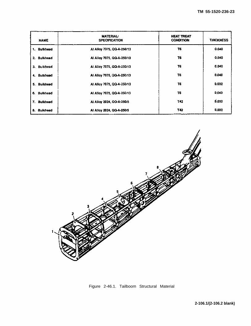
TM 55-1520-236-23
Figure 2-46.1. Tailboom Structural Material
2-106.1/(2-106.2 blank)

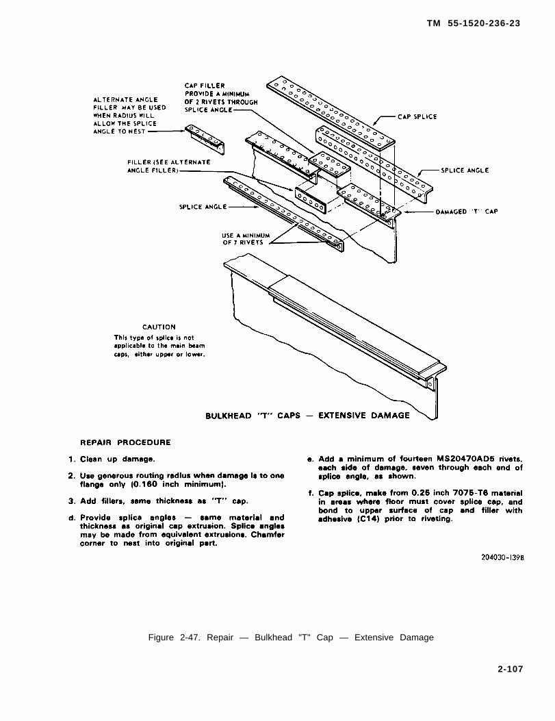
TM 55-1520-236-23
Figure 2-47. Repair — Bulkhead "T" Cap — Extensive Damage
2-107
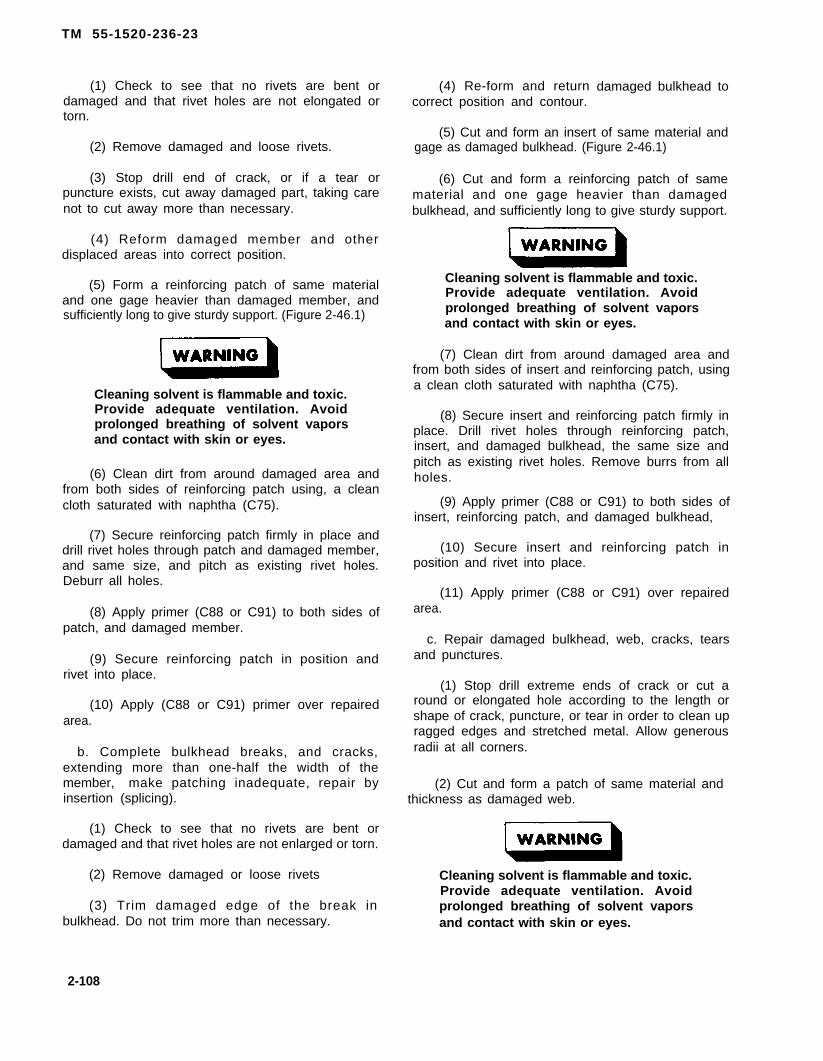
TM 55-1520-236-23
(1) Check to see that no rivets are bent ordamaged and that rivet holes are not elongated ortorn.
(2) Remove damaged and loose rivets.
(3) Stop drill end of crack, or if a tear orpuncture exists, cut away damaged part, taking carenot to cut away more than necessary.
(4) Reform damaged member and otherdisplaced areas into correct position.
(5) Form a reinforcing patch of same materialand one gage heavier than damaged member, andsufficiently long to give sturdy support. (Figure 2-46.1)
Cleaning solvent is flammable and toxic.Provide adequate ventilation. Avoidprolonged breathing of solvent vaporsand contact with skin or eyes.
(6) Clean dirt from around damaged area andfrom both sides of reinforcing patch using, a cleancloth saturated with naphtha (C75).
(7) Secure reinforcing patch firmly in place anddrill rivet holes through patch and damaged member,and same size, and pitch as existing rivet holes.Deburr all holes.
(8) Apply primer (C88 or C91) to both sides ofpatch, and damaged member.
(9) Secure reinforcing patch in position andrivet into place.
(10) Apply (C88 or C91) primer over repairedarea.
b. Complete bulkhead breaks, and cracks,extending more than one-half the width of themember, make patching inadequate, repair byinsertion (splicing).
(1) Check to see that no rivets are bent ordamaged and that rivet holes are not enlarged or torn.
(2) Remove damaged or loose rivets
(3) Trim damaged edge of the break inbulkhead. Do not trim more than necessary.
(4) Re-form and returncorrect position and contour.
damaged bulkhead to
(5) Cut and form an insert of same material andgage as damaged bulkhead. (Figure 2-46.1)
(6) Cut and form a reinforcing patch of samematerial and one gage heavier than damagedbulkhead, and sufficiently long to give sturdy support.
Cleaning solvent is flammable and toxic.Provide adequate ventilation. Avoidprolonged breathing of solvent vaporsand contact with skin or eyes.
(7) Clean dirt from around damaged area andfrom both sides of insert and reinforcing patch, usinga clean cloth saturated with naphtha (C75).
(8) Secure insert and reinforcing patch firmly inplace. Drill rivet holes through reinforcing patch,insert, and damaged bulkhead, the same size andpitch as existing rivet holes. Remove burrs from allholes.
(9) Apply primer (C88 or C91) to both sides ofinsert, reinforcing patch, and damaged bulkhead,
(10) Secure insert and reinforcing patch inposition and rivet into place.
(11) Apply primer (C88 or C91) over repairedarea.
c. Repair damaged bulkhead, web, cracks, tearsand punctures.
(1) Stop drill extreme ends of crack or cut around or elongated hole according to the length orshape of crack, puncture, or tear in order to clean upragged edges and stretched metal. Allow generousradii at all corners.
(2) Cut and form a patch of same material andthickness as damaged web.
Cleaning solvent is flammable and toxic.Provide adequate ventilation. Avoidprolonged breathing of solvent vaporsand contact with skin or eyes.
2-108

TM 55-1520-236-23
(3) Remove dirt from around damaged area 2 - 3 6 . R E P A I R – I N T E R M E D I A T Eusing clean cloth saturated with naphtha (C75). GEARBOX SUPPORT FlTTING.
(4) Secure patch in position and drill out adouble row of holes of same size and pitch assurrounding areas. Remove patch and deburr holes.
(5) Apply primer (C88 or C91) to damaged areaand both sides of patch.
(6) Secure patch and rivet in place.
(7) Apply primer (C88 or C91) over repairedarea.
2 - 3 3 . R E P A I R T A I L B O O M D R I V E S H A F TCOVERS AND SUPPORT HINGES.
Repair using standard aluminum repair procedures inTM 55-1500-204-25/1.
2 - 3 4 . R E P A I R – T A I L B O O M A T T A C HFlTTINGS.
Any cracks in tailboom attach fittingforward of boom station 70.00, orattachment bolt hole elongation wearexceeding the maximum diameter of0.516 inch, is cause for replacement bynext higher maintenance level.
Repair of tailboom attach fittings consisting of minornicks, scratches,. and gouges may be polished outusing fine india stone (C116), provided they donot exceed damage limits in table 2-4, TailboomClassification of Damage.
2 - 3 5 . R E P A I R – B E A R I N G H A N G E RSUPPORT FlTTING.
a. Repair corrosion and damage areas on thebearing hanger support fitting per figure 2-37.
b. Damage to bearing hanger support fittingsevere enough to require replacement:
(1) Two or more bulkhead attach holesexceeding the new part dimension of 0.203 to 0.208inch diameter.
(2) Two bearing hanger attach holes exceeding0.270 inch diameter,
No repairs are permitted on mountingsurface of intermediate gearbox supportfitting.
NOTE
Refer to table 2-4 for repairable damagelimits of the intermediate gearboxsupport fitting.
a. Because of critical alignment requirements,replacement of distorted, damaged or crackedintermediate gearbox support fitting parts must bedone by depot maintenance. An intermediate gearboxalignment check must be made by depot maintenanceafter repair or replacement of supporting structure.
b. Repair gearbox attachment holes within limitsshown in figure 2-38.
c. Check laminated shims at gearbox attachmentholes for security.
d. Inspect all scratches, dents and corroded areasfor cracks. Inspect affected area using fluorescentpenetrant method. Refer to TM 43-0103.
2 - 3 7 . R E P A I R – T A I L R O T O R D R I V ESUPPORT FlTTING.
a. Repairable chafing damage to the tail rotordrive support fitting may be repaired as follows:
Cleaning solvent is flammable and toxic.Provide adequate ventilation. Avoidprolonged breathing of solvent vaporsand contact with skin or eyes.
(1) Clean the chafed area with MEK (C74).
(2) Polish chafed area to not less thanminimum allowable thickness as shown on figures 2-39 with Scotchbrite (C103) or No. 400 grit abrasivepaper (C36).
2-109

TM 55-1520-236-23
(3) If minimum thickness have not beenexceeded, area B, figure 2-39, sheet 1 maybe built upwith adhesive (C8 or C14) to provide a new seat forthe driveshaft cover. Buildup portions of sector C,figure 2-39, sheet 2, to a thickness of 0.12 to 0.15and buildup portions of section D to a thickness of0.25 to 0.29. Area A, figure 2-39, sheet 1 may bebuilt up with adhesive (C8 or C14) to provide a newseat for the gearbox cover. Buildup area to a thicknessof 0.800 to 0.820.
Cleaning solvent is flammable and toxic.Provide adequate ventilation, Avoidprolonged breathing of solvent vaporsand contact with skin or eyes.
(4) After adhesive is thoroughly dry, clean therepaired area with MEK (C74) and wipe dry with aclean cloth.
(5) Apply two coats of primer (C88 or C91) tothe repaired area. When dry, apply two coats oflacquer of color to match finish.
(6) Install teflon tape, (C118) on forward upperedge of fitting where tail rotor driveshaft doorcontacts fitting.
b. Repair support fittings with gearbox hold downstud holes which exceed 0.40 inch.
(1) Ream out existing hole to maximum diameterof 0.4304 + 0.0003 - 0.0000 inch. Maintain hole relation-ship. If corrosion is still present, replace fitting.
(2) Treat machines surface per MIL-M-3171, typeVI.
(3) Fabricate a bushing from 310 Stainless Steel(QQ-S-763, class 310). Grind O.D. to provide an inter-face fit of 0.0001 to 0.0003 with reamed hole in step (1)above. Make I.D. 0.383 +0.007 -0.000 inch and length0.008 to 0.850 inch. Heat support fitting in bushingreplacement area with a heat gun for approximately ½hour (maximum temperature 275 degrees F). Chillbushing in dry ice (BB-C-104) and alcohol (O-E-760) for aminumum of ½ hour. Remove bushing from dry iceand install in aluminum casting using wet primer (MIL-P-23377).
(4) Ream bushing to final tolerances indicated instep (3) above.
(C102) or No. 400 grit abrasive paper (C36). Radialdamage to top of lugs may be blended out to amaximum depth of 0.060 inch. Refer to figure 2-39sheet 4, section A-A.
d. Bellcrank support bushing I.D.s may beelongated to a maximum diameter of 0.445 inch forbushing in forward lug and to 0.317 inch for bushingin aft lug. Bushings elongateddimensions must be replaced.
(1) Forward lug bushing:
(a) Press out bushing.
in excess of these
(b) Press in new bushing.
(c) Ream bushing hole to 0.4425 TO0.4430 inch diameter.
(2) Aft lug bushing:
(a) Press out bushing.
(b) Press in new bushing.
(c) Ream bushing hole to 0.3130 to 0.3145inch diameter.
2 - 3 8 . R E P A I R – V E R T I C A L F I NHONEYCOMB PANELS.
a. Repair honeycomb panels on the vertical fin.Refer to paragraph 2-15. (Repair same as forwardfuselage.)
b. Replace damaged fastener (insert) in verticalfin honeycomb panels. Refer to figure 2-48.
(1) Remove damaged fastener (insert) bydrilling with counter bore of the same diameter, If thefastener (insert) is loose and turns, drill out two holesshown for injecting adhesive on figure 2-48. Use aspacer on twist drill while drilling out holes to avoiddrilling too deep and damaging panel. Attach a pullerto fastener (insert) with self-tapping screws andremove the fastener (insert) from the panel.
(2) Remove honeycomb core a minimum of0.0625 inch and maximum of 0.250 inch on figure2-48. Clean all metal particles out of hole.
c. Blend out repairable damage to fitting lug facesto a maximum blend depth of 0.010 inch, using
2-110

TM-55-1520-236-23
Cleaning solvent is flammable and toxic.Provide adequate ventilation. Avoidprolonged breathing of solvent vaporsand contact with skin or eyes.
(3) Immediately prior to installation, clean newfastener (insert) with MEK (C74) and air dry untilmoisture free. Handle fastener (insert) with whitecotton gloves (C54) after cleaning.
(4) Cover threaded hole and injection holeswith masking tape then open the injection holes witha pointed instrument. Apply adhesive (C8) to bottomof fastener (insert) as shown on figure 2-48 andposition in hole in panel. Inject adhesive (C8) in oneinjection hole with a syringe until it comes out of theopposite injection hole as shown of figure 2-48.
2.110.1/(2-110.2 blank)

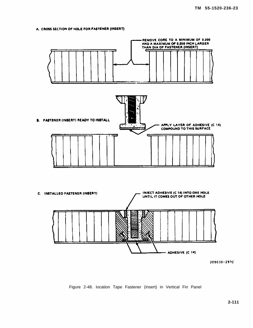
TM 55-1520-236-23
Figure 2-48. Iocation Tape Fastener (Insert) in Vertical Fin Panel
2-111

TM 55-1520-236-23
Cleaning solvent is flammable and toxic.Provide adaquate ventilation, Avoidprolonged breathing of solvent vaporsand contact with skin or eyes.
(5) Remove excess adhesive with clothdampened with MEK (C74) or naphtha (C75).
(6) Touch up pa in t to match sur -round ing a r e a . Refer to TM 55-1500-345-23.
2 - 3 9 . R E P A I R – VERTICAL FIN TRAILINGEDGES.
Comply with the following instructions for fiberglassor metal for repairing trailing edge. Refer to figure 2-41.
a. Fiberglass.
(1) Use only fiberglass cloth 0.010 inch thick(C38) when making edge repairs. The repair mustequal or exceed the numer of plies lost.
(5) If multiple layers of fiberglass are requred,overlap each successive patch for a minimumdistance of one inch.
b. Aluminum alloy patching material.
(1) Use aluminum patching material asspecified on figure 2-41.
Cleaning solvent is flammable and toxic.Provide adequate ventilation. Avoidprolonged breathing of solvent vaporsand contact with skin or eyes.
(2) Clean the area where the patch is to beapplied with MEK (C74).
(3) Bond the metal doubler patch to vertical fintrailing edge, using adhesive (C8 or C14).
(4). Rivet patch with rivets of equal or larger sizethan original rivets in areas that were riveted prior toapplication of patch. Use the standard edge distanceof two rivet diameters or space the rivets the same asthe original panel. If the panel being worked is notriveted, use rivet spacing in opposite panel.
(2) Remove all old finish from repair area withverying grades of sandpaper (C102).
(6) Fill and fair all edges of doubler patchesafter riveting. Touch up the area. Refer to TB746-93-2for paint instructions.
Cleaning solvent is flammable and toxic.Provide adequate ventilation. Avoidprolonged breathing of solvent vaporsand contact with akin or eyes.
(3) Clean sanded area with clean clothmoistened with MEK (C74).
(4) Cut fiberglass cloth (C38) to correct size andsaturate with epoxy resin (C98) and apply as a patch.
2-40. REPAIR – VERTICAL FIN FORWARDSPAR.
a. Repair smooth dents, lateral stiffeners, surfacescratches, and holes according to TM 55-1500-204-25/1.
.
b. All other repairs must be approved by qualifiedengineering authority.
2-40.1. REPAIR – ELECTRONIC EQUIPMENTSHELF.
a. The electronic equipment shelf is constructedof aluminum alloy honeycomb core and 2024T3aluminum alloy skins. Edging material is two plyglass fabric. The lower skins are 0.008 inch thick.
2 - 1 1 2

TM 55-1520-236-23
The upper skins are 0.012 inch thick except for theright side between BS 80.44 and BS 122.33, theseskins are 0.016 inch.
b. Repair acceptable damage in accordancewith paragraph 2-15. Repairs shall not interfere withmounting surfaces or affect the serviceability ofpanel.
c. Replace damaged or loose insertsaccordance with paragraph 2-38, step b., withfollowing exceptions:
(1) Adhesive (C15.1) shall be used
the
inthe
forbonding inserts. Cure adhesive for 16 hours at75 °F.
(2) Perform proof load test of 100 pounds onthreaded inserts after adhesive cure, using poundreading spring scale.
2-40.2. REPAIR — VERTICAL FIN BALLASTWEIGHT PANELS.
a. Repair of outer skin surface cracks aroundBallast Weight inserts.
b. Remove existing inserts and potting com-pound (7 places).
c. Remove cracks in panel by routing out a 1/4inch of material around and below the damagedarea. Fill void with adhesive (C-14) and preparesurface for doubler. Other damage, such as tears,gouges, etc., should have 1/4 inch of materialrouted around and below damage, filled withadhesive (C-14) and smoothed to surrounding sur-face level (see figure 248.1).
d. Install doubler on outboard surface of panel,covering all seven insert panel holes. Edges ofdoubler. must extend a minimum of 0.75 inchesbeyond the cracked and insert hole area. Bonddoubler to panel with adhesive (C-15) and installrivets NAS1738B4-2. When rivets are to be install-ed, remove 1/4 inch of internal material aroundand below rivet hole. Fill rivet hole with adhesive(C-14) and install rivets immediately (see figure2-48.1). Rivets should be spaced 1 1/2 inches apartaround doubler; rivets should be at least two rivetdiameters from edge of doubler (see figure 2-48.1).If o rivet is to be installed within 0.372 inches froman area of damage, do not install that rivet.Doubler material is made from 0.032 inches thick2024 aluminum alloy QQ-A-250/0 temp T3.
e. Insert areas should have 1 1/2 inches of in-ternal material removed through the inboard sur-face panel. Void area is then filled with adhesive(C-14) and prepared for doubler (see figure 248.1).
f. Install individual doublers on each inserthole on the inboard side of panel. Doublers shouldbe minimum of 2 inches in diameter and cornersrounded to a minimum of 0.25 inches in radius (seefigure 2-48.1).
g. Drill a 0.427 inch hole for each insert. Installsleeve 80-013-S4D3-9 through outboard surface andplug 80-013P4F06-9 through inboard surface. Useadhesive (C15) on both sleeve and plug when installing(see figure 2-48.1).
2-112.1

TM 55-1520-236-23
Figure 2-48.1 Vertical Fin Ballast Weight Panel
2-112.2
TM 55-1520-236-23
SECTION Il. FUSELAGE
2-41. FUSELAGE ASSEMBLY.
2 - 4 2 . D E S C R I P T I O N – F U S E L A G EASSEMBLY.
The fuselage constitutes the primary structuralassembly of the helicopter. It encloses and/orsupports such major provisions and systems as thetandem crew compartment, engine, fuel and oilsystems, armament system, transmission and mainrotor pylon, alighting gear, wings and tailboom. Seefigure 2-1.
2-43. HONEYCOMB PANELS.
2 -44 . DESCRIPTION – HONEYCOMBPANELS.
The principal part of the fuselage structure ishoneycomb panels. The panels have an, aluminumcore that resembles honeycomb. Facings are bondedto the honeycomb to form the panel. The facings maybe fiberglass or metal. The panels are joined togetherand supported by the primary structural caps whichare shown on figure 2-11 and 2-12 by solid blackshading. Panels on the unshaded portion of figure 2-2are either of honeycomb panel construction or ofconventional sheet metal construction. Refer to TM55-1500-204-25/1 for repair instructions for thesheet metal construction panels.
2 - 4 5 . R E M O V A L – H O N E Y C O M BPANELS.
a. Replace honeycomb panels that have damagein excess of limits specified in table 2-3. Refer toparagraph 2-5 for support of structure duringairframe repair. Refer to figure 2-2 for exterior panelssecured with screws.
b. Remove screws or twist-type fasteners andremove panel. Do not remove riveted panels unlessthe entire panel is to be replaced.
2 -46 . I N S P E C T I O N – H O N E Y C O M BPANELS .
Refer to paragraph 2-12 and table 2-3 for inspectionand classification of damage.
2 - 4 7 . C L E A N I N G – H O N E Y C O M BPANELS.
Refer to paragraph 2-10, figure 2-7, and TM 55-1500-204-25/1 for cleaning instructions.
2-48. R E P A I R – HONEYCOMB PANELS.
Refer to paragraph 2-15 for repair instructions.
2-49. INSTALLATION – HONEYCOMBPANELS.
Cleaning solvent is flammable and toxic.Provide adequate ventilation. Avoidprolonged breathing of advent vaporsand contact with akin or eyes.
a. Clean mating surfaces of the forward fuselagepanels with MEK (C74) and wipe dry with clean drycloth.
b. Install panels on forward fuselage with screws.
2-50. PAINTING – HONEYCOMB PANELS– TOUCH-UP.
a. Clean area where paint requires touch-up withcleaning compound (C32) and rinse with water. Allowto dry thoroughly.
b. Apply primer (C88 or C91) to area that requirestouch-up.
c. Apply lacquer (C71) finish coat color to matchexisting finish in accordance with TB746-93-2.
2-51 . SHEET METAL PANELS ANDSKIN.
2-52. DESCRIPTION – SHEET METALPANELS AND SKIN.
A limited amount of sheet metal skin and panels areused on the fuselage. The major portions of the
2-113
TM 55-1520-236-23
fuselage are covered with structural honeycombpanels. See figure 2-49 for description of sheet metalpanels (doors) and skins used on the fuselage.
2-53. REMOVAL – SHEET METAL PANELSAND SKIN.
a. Removal of riveted skins illustrated on figure 2-49 must be accomplished at next higher maintenancelevel.
b. Remove panels (doors) illustrated on figure 2-49 by removing attaching screws.
2 - 5 4 . I N S P E C T I O N – S H E E T M E T A LPANELS AND SKIN.
Refer to table 2-3 for instructions to inspect sheetmetal panels and skin.
2 - 5 5 . C L E A N I N G – S H E E T M E T A LPANELS AND SKIN.
a. Clean sheet metal panels and skin withcleaning compound (C33) and water.
Cleaning solvent is flammable and toxic.Provide adequate ventilation. Avoidprolonged breathing of solvent vaporsand contact with skin or eyes.
b. Remove stubborn deposits with solvent (C112)and clean cloths.
2-56. REPAIR – SHEET METAL PANELSAND SKIN.
a. Refer to paragraph 2-14 for instructions torepair damage to skin and sheet metal panels anddoors that is within repairable limits. See figure 2-49for description of skin and panel (door) fabricationmaterial.
b. Do not remove riveted skin panels fromfuselage to accomplish repair (paragraph 2-53).
2 - 5 7 . I N S T A L L A T I O N – S H E E T M E T A LPANELS AND SKIN.
a. Installation of riveted sheet metal skinsillustrated on figure 2-49 must be accomplished atnext higher maintenance level.
b. Install panels (doors) illustrated on figure 2-49.Position panel on fuselage and install attachingscrews.
2-58. PAINTING – SHEET METAL PANELSAND SKIN – TOUCH-UP.
a. Clean area where paint requires touch-up withcleaning compound (C32) and rinse with water. Allowto dry thoroughly.
b. Apply primer (C88 or C91) to area that requirestouch-up.
c. Apply finish coat to match existing finish.
2-59. ACCESS COVERS AND DOORS.
2-60. DESCRIPTION – ACCESS COVERSAND DOORS.
The access covers and doors are shown on figure 2-3.The components which are accessible through eachcover and door are listed on the illustration legend.
The small covers and doors are constructed fromaluminum sheet metal. The hydraulic compartmentdoors (8) are constructed from laminated fiberglass,honeycomb core and aluminum skin. Theammunition compartment doors (21) areconstructed from aluminum frame and skin.
2 - 6 1 . R E M O V A L — A C C E S S C O V E R SAND DOORS.
a. Remove hydraulic compartment doors (8,figure 2-3).
(1) Release latches and open doors.
(2) Remove air duct hose from inside of leftdoor if installed.
(3) Remove bolt to separate door holding spring(restrainer) at the lower hinge. Remove bolts todisconnect hinges from hinge supports and removedoor.
b. Remove ammunition compartment doors (21).
(1) Release latches and open door.
(2) Support door in horizontal position anddisconnect the support cables.
2-114

TM 55-1520-236-23
Figure 2-49. Sheet Metal Panels and Skin (Sheet 1 of 4)
2-115

MWO 55-1520-236-50-23
TM 55-1520-236-23
Figure 2-49. Sheet Metal Panels and Skin (Sheet 2 of 4)
2-116
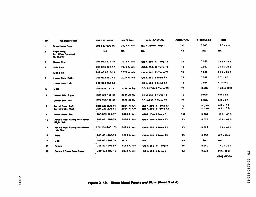
Figure 2-49.
TM
5
5-1
52
0-2
36
-23
2-1
17
Richard Woods
Richard Woods
Richard Woods
209-033-005-15
Richard Woods
209-033-525-15
Richard Woods
209-033-525-17
Richard Woods
209-033-525-18
Richard Woods
209-033-150-49
Richard Woods
209-033-150-50
Richard Woods
209-033-127-9
Richard Woods
209-033-150-65
Richard Woods
209-033-150-66
Richard Woods
209-033-276-11
Richard Woods
209-033-276-11
Richard Woods
209-033-005-17
Richard Woods
209-031-203-19
Richard Woods
209-031-203-103
Richard Woods
209-031-203-73
Richard Woods
209-031-203-75
Richard Woods
209-031-203-57
Richard Woods
209-033-190-15

Figure 2-49.
TM
55
-15
20
-23
6-2
3
2-118
Richard Woods
209-033-150-87
Richard Woods
209-033-150-89
Richard Woods
209-033-190-17
Richard Woods
209-033-150-63
Richard Woods
209-033-150-83
Richard Woods
209-030-133-7
Richard Woods
209-033-150-67
Richard Woods
209-033-150-79
Richard Woods
209-033-194-1
Richard Woods
209-033-193-1
Richard Woods
209-033-150-90
Richard Woods
209-033-192-1
Richard Woods
209-033-191-1
Richard Woods
209-033-150-121
Richard Woods
209-033-150-123
TM 55-1520-236-23
(3) Remove hinge pin from hinge and removedoor.
a. Remove other access covers and doors shownon figure 2-3 by removing screws or releasingturnlock fasteners as applicable.
2-62. INSPECTION – ACCESS COVERSAND DOORS.
a . Inspect hydraulic compartment doors (8, figure2-3).
(1)
(2)surface.
(3)removemethod
(4)
Latches for correct operation.
Seals for cuts, chafing, and secure adhesion
Hinges for cracks. If cracks are suspected,hinges and inspect by fluorescent penetrantin accordance with TM 43-0103.
Doors for cracks, dents, holes, deformation,and corrosion.
b. Inspect ammunition compartment doors (21).
(1) Catch assemblies for correct operation anddamage. Catch assembly covers and strips fordamage.
(2) Door support cables and cable fasteners forproper safetying and condition.
(3) Doors for cracks, dents, holes, deformationand corrosion.
(4) Door hinges for damage.
(6) Door rubber strips (seals) for cuts, chafing,and secure adhesion to door surface.
c. Refer to table 2-3 for instructions to inspectother access covers and doors shown on figure 2-3.
2-63. CLEANING – ACCESS COVERSAND DOORS.
a . Clean access covers and doors with cleaner(C33) and water.
Cleaning solvent is flammable and toxic.Provide adequate ventilation. Avoidprolonged breathing of solvent vaporsand contact with skin or eyes.
b. Remove stubborn deposits with solvent (C112)and clean cloths.
2-64. REPAIR – ACCESS COVERS ANDDOORS.
a. Repair hydraulic compartment doors (8, figure2-3).
(1) Replace faulty latches.
(2) Replace damaged seals or rebond sealswith adhesive. Refer to paragraph 2-20 for procedure.
(3) Replace faulty hinges.
(4) Repair cracks, dents, and holes that arewithin limits shown on figures 2-7 through 2-10. Userepair procedures shown on the illustrations.
(6) Repair corrosion damage. Refer toparagraph 2-10.
(6) Replace door if it is distorted to the degreethat it will not close properly and fit smoothly with thefuselage.
b. Repair ammunition compartment doors (21,figure 2-3).
(1) Replace faulty catch assemblies, damagedcatch assembly covers, and strips.
(2) Replace damaged door support cables andcable fasteners (attachment brackets).
(3) Repair cracks, dents, holes, deformation,and corrosion. Refer to TM 55-1500-204-25/1 forgeneral repair instructions. Refer to paragraph 2-10for corrosion damage repair instructions. Repairfatigue-type vertical cracks along aft spotweld seamon outer skin of ammunition compartment doors.
(a) Stop drill ends of cracks.
(b) Remove rubber strip (seal) from inside aftedge of door.
2-119
TM 55-1520-236-23
(c) Fabricate doubler of 2024T3 aluminum 2-65. lNSTALLATION – ACCESS COVERSalloy 0.040 inch thick. Make doubler to fit the width AND DOORS,and length of the inside edge of door.
(d) Fabricate overlay patch for outside skin ofdoor 2024T3 aluminum alloy 0.025 inch thick. Makeoverlay patch to overlap cracks in skin by 1.50 inches.
(e) Clamp inside doubler and overlaypatch todoor. Drill holes for rivets (51, table 2-2) throughoverlay patch, aft edge of door and doubler. Use oneinch spacing between rivets and 0.25 inch edgedistance. Countersink the doubler for installation ofthese rivets. Drill holes for bulb-type cherryrivets(32,table 2-2) on remaining three edges of patch. Use thesame spacing.
(f) Remove overlay patch and doubler fromdoor. Clean and deburr parts and coat outside surfacewith primer (C88 or C91). Clean inside surface ofdoubler, patch, and mating surfaces on door withMEK (C74).
a. Install hydraulic compartment doors (8, figure2-3).
(1) Position door on fuselege and install bolts toattach hinges to supports. Attach door-holding springto the Iower hinge.
(2) Open and close door several times to ensurethat latches operate properly.
(3) Attach air duct hose to vent on left door.
b. Install ammunition compartment doors (21).
(1) Align door hinge half with the meting hingehalf on the fuselage and install pin.
(2) Install two door support cables.
(3) Check operation of door catches to ensurethat they function properly. Check that door fitssmoothly with fuselage and that rubber strips (seals)are in position on the door.
c. Install other access covers and doors shown onfigure 2-3 by securing with turnlock fasteners orscrews as applicable.
(g) Apply a thin smooth layer of adhesive(C14) on mating surfaces of door, patch, and doubler. 2-66. PAINTING–ACCESS COVERS ANDPosition the patch and doubler in the door. Install DOORS – TOUCH-UP.rivets (51, table 2-2) in holes prepared in step (e).Install cherry rivets (32, table 2-2) in remaining three Touch-up damaged paint by same procedure outlined
sides of patch.for cowling and fairing. Refer to paragraph 2-93 andTB746-93-2 for paint instructions.
(h) Install rubber strip (seal) that wasremoved in step (b). Refer to paragraph 2-20 forprocedure. 2-67. FLOORS AND DECKS.
(i) Touch-up paint to match surroundingarea.
(4) Replace damaged rubber strips (seals) orrebond with adhesive. Refer to paragraph 2-20 forprocedure.
(6) Replace faulty hinges.
c. Refer to paragraph 2-18 for instructions torepair other access covers and doors shown on figure2-3.
2-68. DESCRIPTION – FLOORS ANDDECKS.
The floors and decks described in this paragraph arethe ammunition compartment floor, gunnercompartment floor, pilot compartment floor, enginedeck, rear panel, and the floor (bottom panels) of thecompartments below the engine compartment.These floors and decks are constructed of bondedhoneycomb.
2-120
TM 55-1520-236-23
2-69. REMOVAL – FLOORS AND DECKS.(AVIM)
a. Except for engine deck, removal of floors anddecks listed in paragraph 2-68 must be accomplishedby depot maintenance.
b. Removal of Engine Deck.
Aircraft must be Ieveled prior to startingengine deck removal. Do not removefront engine deck panel (209-033-152)and center deck skin (209-033-154) atthe same time. Structural misalign-ment can result when both sections ofthe deck are removed together.
All structural stress must be relievedprior to removing engine deck front panelor center skin. The primary method forrelieving the stress is to remove all wingstores, engine assembly, all rotatingcontrols, transmission assembly, andtailboom assembly.
Fuel system must be defueled and therear fuel ceil removed to prevent in-advertant puncture and FOD during thedrilling process in removing the frontdock panel.
Do not use helicopter structure as workplatform when engine deck is remov-ed. All maintenance personnel mustwork from maintenance stands ratherthan the helicopter structure, to pre-clude structural misalignment.
(1) Remove engine assembly, including allmounts and linkage (paragraph 4-12).
(2) Remove transmission assembly, includingall rotating controls (paragraphs 5-12 and 6-24).
(3) Remove tail boom assembly, including tailrotor driveshaft and number one hanger support(paragraphs 2-283 and 6-84).
(4) Install rear jack fitting and supporthelicopter with a suitable jack.
(5) Remove rear fuel cell side panel and cell(paragraphs 2-61 and 10-77).
NOTE
Cap all lines and cover ail componentopening to prevent entry of foreignmatter.
(6) Remove lines and wiring in work area.
(7) Identify all removed components and storein a secure location to prevent loss or damage.
(8) Preserve fuel cell to preclude deterioration.
(9) Cover oil cooler air inlet to prevent entry offoreign matter.
(10) Drill out rivets holding deck section inplace, being careful not to drill into existing helicopterstructure.
(11) Remove old sealant from edges of deckmating surface.
(12) Remove all foreign matter from work areaincluding drill shavings and rivet fragments in fuelcell cavity.
2-70. INSPECTION – FLOORS ANDDECKS.
Refer to table 2-2 for inspection requirements for thefloors and decks listed in paragraph 2-68.
2-71. CLEANING – FLOORS AND DECKS.
a. Clean the floors and decks listed in paragraph2-68 with cleaner (C32) and water.
Cleaning solvent is flammable and toxic.Provide adequate ventilation. Avoidprolonged breathing of solvent vaporsand contact with skin or eyes.
b. Remove stubborn deposits with solvent (C112)and clean cloths.
2-72. REPAIR – FLOORS AND DECKS.
Refer to paragraphs 2-16 and 2-17 for procedure torepair floors and decks listed in paragraph 2-68.
2-121

TM 55-1520-236-23
2-73. INSTALLATION – FLOORS ANDDECKS (AVIM)
a. Except for engine deck, installation of floorsand decks listed in paragraph 2-68 must beaccomplished by higher maintenance level.
b. Installation of Engine Decks:
Cleaning solvent is flammable and toxic.Provide adequate ventilation. Avoidprolonged breathing of solvent vaporsand contact with skin or eyes.
(1) Clean deck mating surfaces with MEK(C74).
(2) Apply a bead of sealant (C105) to matingsurface and install deck section, being careful not tobend corners or damage bonding.
(3) Rivet in place and seal edges to ascertainwater-tight condition, using sealant (C105).
(4) Reinstall all removed components, lines,wiring, mounts, and fittings in reverse order. Insurethat rear fuel cell cavity is completely free of foreignmatter prior to installing fuel cell.
(5) Perform engine to transmission alignmentcheck (paragraph 6-7).
(6) Rig all affected systems, performmaintenance operational checks, and maintenancetest flight to ascertain airworthiness.
2-74. PAINTING – FLOORS AND DECKS– TOUCH-UP.
a. Clean area where paint requires touch-up withcleaning compound (C32) and rinse with water. Allowto dry thoroughly.
b. Apply primer (C88 or C91) to area that requirestouch-up.
c. Apply finish coat to match existing finish.
2-75. COWLING AND FAIRING.
2-76. DESCRIPTION – COWLING ANDFAIRING.
a. The pylon fairings (1, 3, and 4, figure2-50) are primarily honeycomb construction with theexception of the horizontal firewalls (5 and 8) whichare titanium.
b. The pylon fairings (1, 3, and 4, figure 2-51) are primarily honeycomb construction with theexception of the horizontal firewalls (5 and 17) whichare titanium.
c. The honeycomb construction parts havefiberglass facings with aluminum or fiberglass cores.The fairings are not structural members and do notcarry primary loads; therefore, larger size damagemay be repaired on these fairings than can berepaired on the fuselage honeycomb panels. It isnecessary to maintain contours and restore thefairings to original strength when repair isaccomplished.
d. The transmission cowling (14, figure2-50) consists of the right and left doors.
e. The transmission cowling (8, figure 2-51) consists of the right and left doors.
f. Openings in the doors form the engine air inletducts. A small window in the right door permitsviewing the transmission oil level. A latch safetyindicator, which is a red-painted knob, protrudesslightly past the surface of the door when the door isproperly latched in the closed position. The doors areequipped with articulated hinges.
g. The engine cowling (11, figure 2-50)consists of the right and left doors. Ram air inlets (12)form inlets for outside air into the enginecompartment.
h. The engine cowling (6, figure 2-51)consists of the right and left doors. Ram air inlets (7)form inlets for outside air into the enginecompartment.
i. The engine cowl doors are equipped withhinges and latch safety indicators similar to thosedescribed in the preceding paragraph for thetransmission doors.
2-122
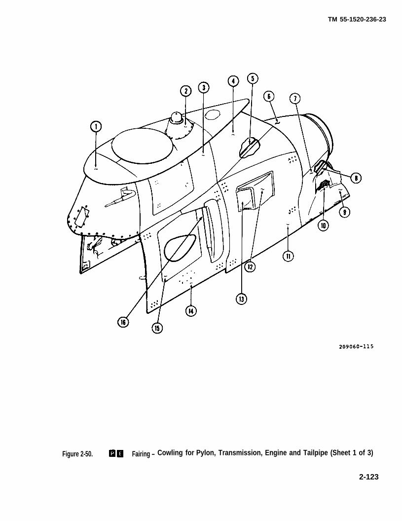
TM 55-1520-236-23
Figure 2-50. Fairing – Cowling for Pylon, Transmission, Engine and Tailpipe (Sheet 1 of 3)
2-123

Figure 2-50.
TM
5
5-1
52
0-2
36
-23
2-1
24
Richard Woods
209-061-801-1
Richard Woods
209-060-812-17
Richard Woods
209-060-811-96
Richard Woods
209-060-811-96
Richard Woods
209-060-807-13
Richard Woods
209-060-902-3
Richard Woods
209-040-810-7
Richard Woods
209-060-810-7
Richard Woods
209-060-810-17
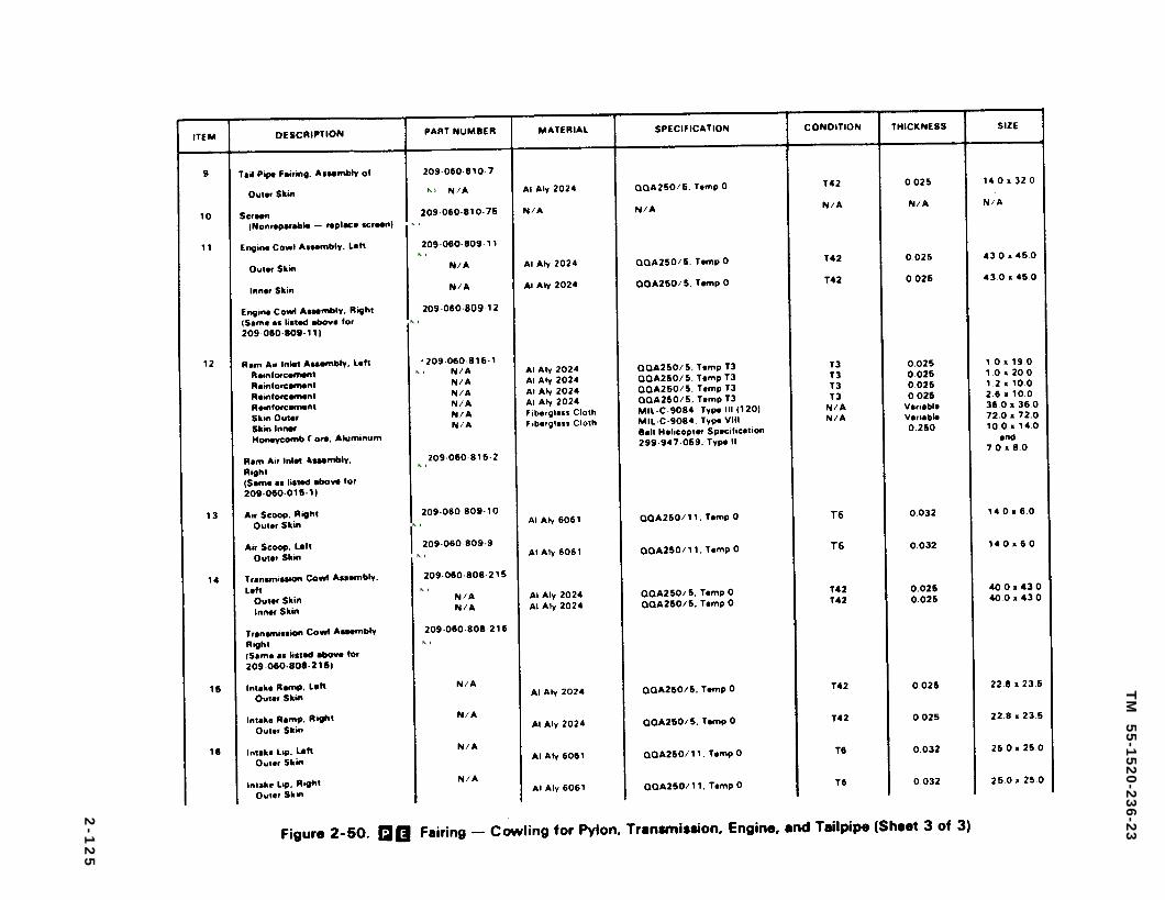
Figure 2-50.
TM
5
5-1
52
0-2
36
-23
2-1
25
Richard Woods
209-060-810-7
Richard Woods
209-060-810-75
Richard Woods
209-060-809-11
Richard Woods
209-060-809-12
Richard Woods
209-060-815-1
Richard Woods
209-060-815-2
Richard Woods
209-050-809-10
Richard Woods
209-060-809-9
Richard Woods
209-060-808-215
Richard Woods
209-080-808-216
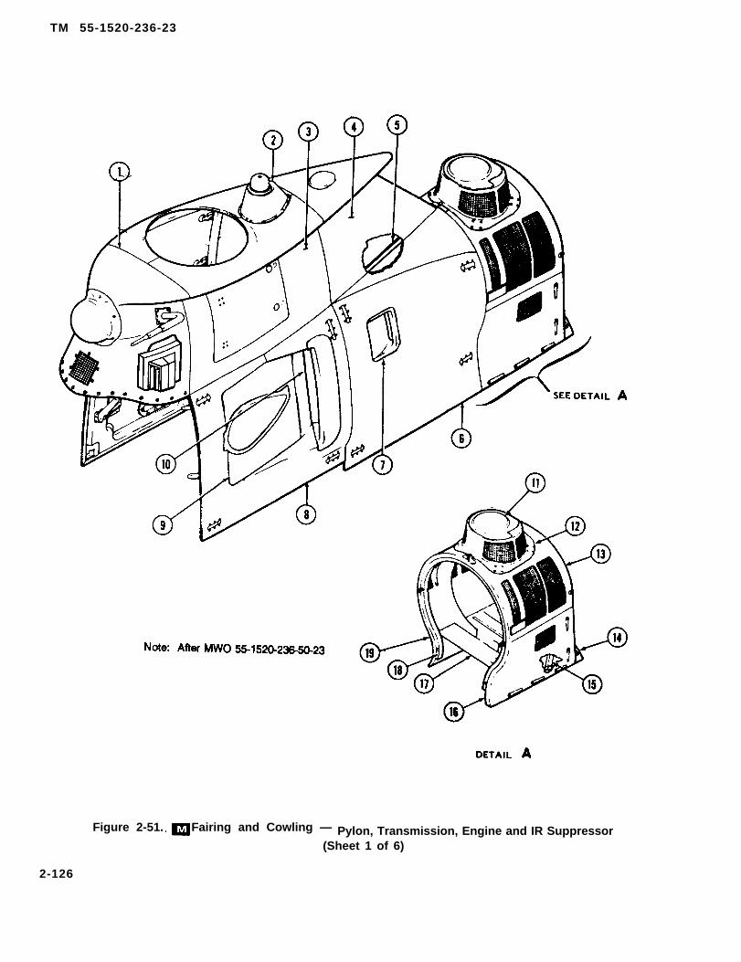
TM 55-1520-236-23
Figure 2-51. Fairing and Cowling — Pylon, Transmission, Engine and IR Suppressor(Sheet 1 of 6)
2-126
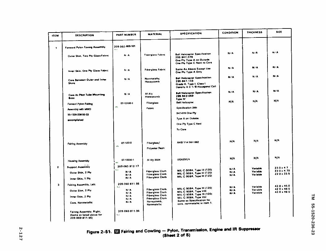
Figure 2-51.
TM
5
5-1
52
0-2
36
-23
2-1
27
Richard Woods
209-050-803-101
Richard Woods
07-12100-1
Richard Woods
07-12210
Richard Woods
07-12230-1
Richard Woods
209-060-812-17
Richard Woods
209-050-811-95
Richard Woods
209-060-811-95
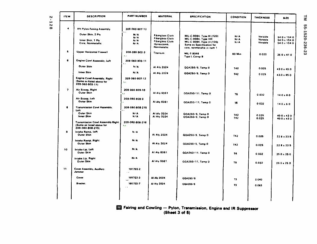
Sheet 3 of 5
TM
5
5-1
52
0-2
36
-23
2-1
28
Richard Woods
209-060-807-13
Richard Woods
209-060-902-3
Richard Woods
209-060-809-11
Richard Woods
209-060-807-12
Richard Woods
209-060-809-10
Richard Woods
209-060-809-9
Richard Woods
209-060-808-216
Richard Woods
209-060-808-216
Richard Woods
191722-2
Richard Woods
191722-3
Richard Woods
191722-7
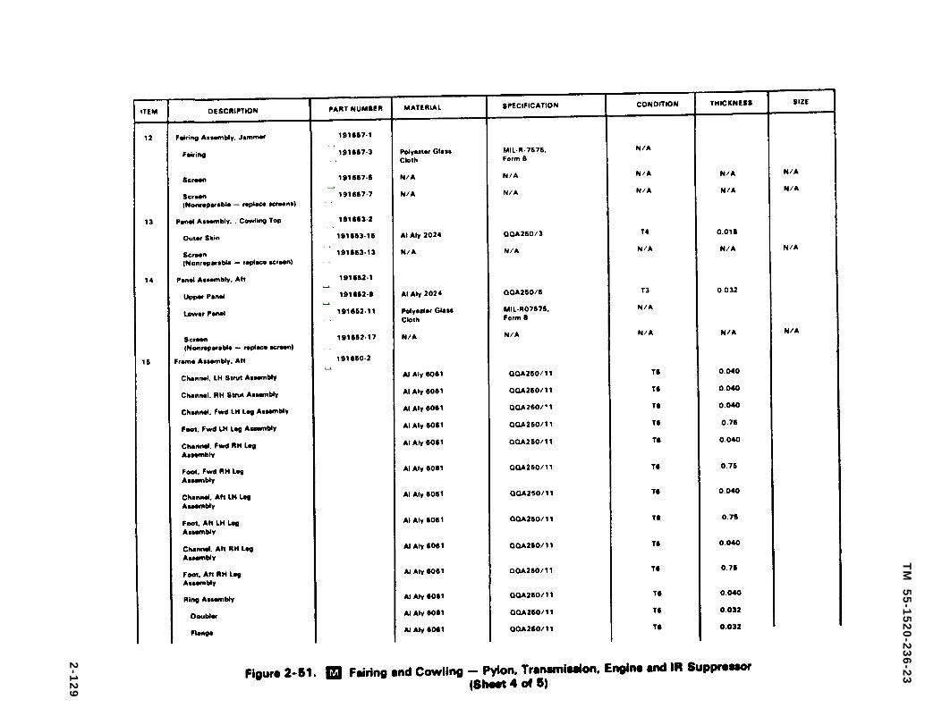
Figure 2-51.
TM
5
5-1
52
0-2
36
-23
2-1
29
Richard Woods
191657-1
Richard Woods
191657-3
Richard Woods
191657-5
Richard Woods
191657-7
Richard Woods
191653-2
Richard Woods
191653-15
Richard Woods
191653-13
Richard Woods
191652-1
Richard Woods
191652-9
Richard Woods
191652-11
Richard Woods
191652-17
Richard Woods
1911650-2
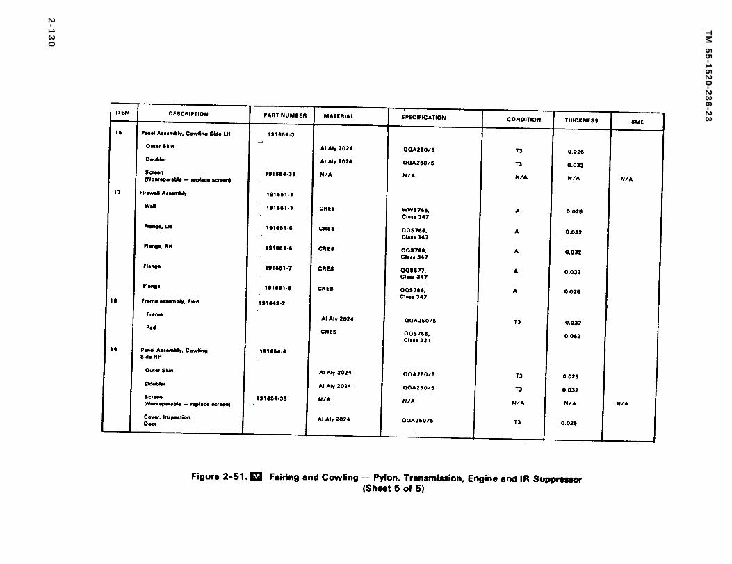
Figure 2-51.
TM
55
-15
20
-23
6-2
3
2-1
30
Richard Woods
191654-3
Richard Woods
191654-35
Richard Woods
191651-1
Richard Woods
191651-3
Richard Woods
191651-5
Richard Woods
191651-6
Richard Woods
191651-7
Richard Woods
191651-9
Richard Woods
191649-2
Richard Woods
191654-4
Richard Woods
191654-35

j. The tailpipe assembly fairing (6, figure2-50) encloses the engine tailpipe and supports theexhaust duct.
k. The IR suppressor cowling (detail A,figure 2-51) encloses the engine exhaust duct andsupports the IR suppressor.
2-77. REMOVAL – COWLING ANDFAIRING.
Refer to paragraph 2-78 through 2-82.
2-78. REMOVALCOWL ASSEMBLY.
a. Remove shields,inlet ducts.
– TRANSMISSION
if installed, from engine air
b. Open transmission cowl assembly(door) (14, figure 2-50) that is to be removed.
c. Open transmission cowl assembly (door)(8, figure 2-51) that is to be removed.
d. Remove bolts that attach hinges to fittings oncowl frame. Identify washers and shims forreinstallation in the same relative location to avoidrequirement to align cowling assembly when it isreinstalled.
e. Remove cowling assembly from helicopter.
2-79. REMOVAL – ENGINE COWLASSEMBLY.
a. Remove engine cowl assembly doors(11, figure 2-50) in same manner as transmissioncowl doors (paragraph 2-78).
b. Remove engine cowl assembly door (6,figure 2-51) in same manner as transmission cowldoors (paragraph 2-78).
2-80. REMOVAL – TAILPIPEFAIRING.
Disconnect fasteners and remove machine screws torelease tailpipe assembly fairing (6, figure 2-50) fromfuselage and from pylon fairings. Disconnect drain lines fromfittings on tailpipe and ejector. Remove tailpipe assemblyfakings.
TM 55-1520-236-23
2-81. REMOVAL– IR SUPPRESSORCOWLING.
a. Release fasteners (9, figure 2-52), and removeside panels (10) from cowling.
b. Remove IR suppressor (paragraph 4-54).
c. Disconnect auxiliary jammer connectors (3) ataft engine firewall.
d. Disconnect fuel drain lines.
(1) Overboard drain line (4) at aft enginefirewall.
(2) Engine exhaust duct drain line (6) at teefitting. Cap open drain lines.
(11).
f.
g.
h.
i.
j.
(22).
k.
Release fasteners (13) on aft panel assembly
Remove screws (15) and washers (14).
Remove bolts and washers (5).
Remove safety clips (1) from dowel pins (2).
Open cowl support latch.
Remove cotter pins (18), washers (19) and pins
Remove suppressor cowling.
(1) Pull upon aft end of cowling to disengageeyebolts (7) from lugs on mount brackets (26 and 29).
(2) Pull cowling aft to disengage dowel pins (2)from aft engine firewall.
(3) Remove cowling from helicopter.
2-82. REMOVAL – PYLON FAIRING.
a. Disconnect electrical wiring insideforward and aft pylon fairings (1, 3, and 4, figure 2-50).
b. Disconnect electrical wiring insideforward and aft pylon fairings (1, 3, and 4, figure 2-51).
c. Disconnect tubing at pitot tube.
2-131

TM 55-1520-236-23
Figure 2-52. IR Suppressor Cowling Installation (Sheet 1 of 2)
2 -132

TM 55-1520-236-23
c.1 (After incorporation of MWO 1-1520-236-50-30) Disconnect ODDS inlet end outlet hoses(23.1 and 49, figure 4-4).
2-132.1/(2-132.2 blank)

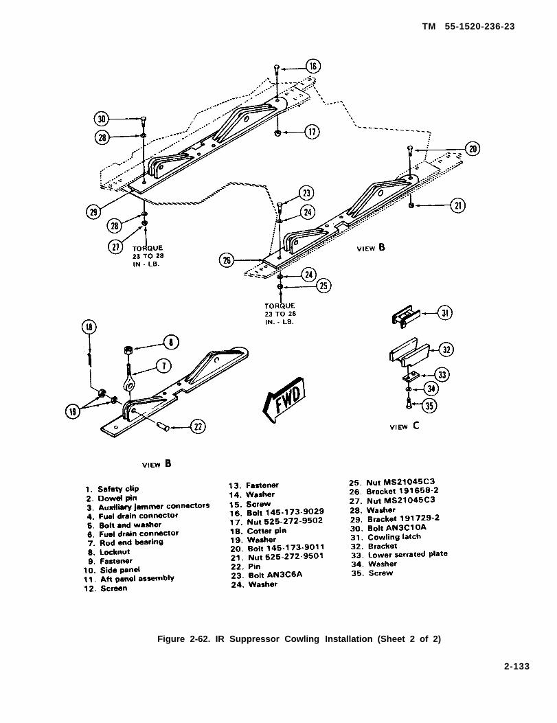
TM 55-1520-236-23
Figure 2-62. IR Suppressor Cowling Installation (Sheet 2 of 2)
2-133

TM 55-1520-236-23
d. Remove anti-collison light.
e. Disconnect oil tank from aft pylon.
f. Disconnect shut off valve and pressure regulatorgoing to E.C.U.
g. Disconnect fasteners and remove pylon fairings.
2-83. INSPECTION – COWLING ANDFAIRING.
a. Refer to table 2-3 to classify damage tostructure and fasteners of cowling and fairing.
b. Inspect rubber seals and bumpers fordeterioration, damage, and secure installation.
c. Inspect latch assemblies ontransmission and engine cowling (14 and 11, figure2-50) for wear and damage that could affect function.
d. Inspect latch assemblies ontransmission and engine cowling (8 and 6, figure 2-51) for wear and damage that could affect function,
e. Inspect hinge assemblies ontransmission and engine cowling (14 and 11, figure2-50) for wear and damage that could affect function.
f. Inspect h inge assembl ies ontransmission and engine cowling (8 and 6, figure 2-51) that could affect function.
g. Inspect SU-130 Laser Detection sensor tiringand housing assemblies (1, figure 2-51) far cracks, wear, anddamage that could affect function. (After MWO 55-1520-236-50-23.)
2-84. CLEANING — COWLING ANDFAIRING.
a. Clean cowling and fairingcompound (C32) and water.
with cleaning
Cleaning solvent is flammable and toxic.Provide adequate ventilation. Avoidprolonged breathing of solvent vaporsand contact with skin or eyes.
b. Remove stubborn deposits with solvent (C112)and clean cloths.
2-134
2-85. REPAIR – COWLING AND FAIRING.
a. Repair structural damage and replacedamaged fasteners (paragraph 2-19).
b. Refer to figure 2-50 for cowling andfairing construction material.
c. Refer to figure 2-51 for cowling andfairing construction material.
d. Replace damaged latches and hinges.
e. Replace damaged rubber seals and bumpers,Refer to paragraph 2-20.
f. Replace damaged screen (10, figure2-50). Carefully drill out rivets and remove thealuminum alloy spoiler to gain access to the rivetsthat retain the screen. Carefully drill out the rivetsthat retain the screen. Remove the damaged screenand retainer strips. Deburr holes and touch-up baremetal with chemical film (C31) and primer (C88 orC91), Trim new screen to fit. Install new screen,retainer strips and spoiler with blind rivets (37, table2-2).
2-86. REPAIR – I R SUPPRESSORCOWLING.
a. Refer to paragraph 2-19 for procedure to repairstructural damage and to replace damaged fasteners,See figure 2-51 for partial list of materials used inconstruction of cowling.
b. Replace damaged latches.
c. Replace damaged rubber seals (paragraph 2-20).
d. Replace damaged screen (12, figure 2-52).
{1) Carefully drill out rivets and removedoublers around screen.
(2) Deburr holes, touch up bare metal withchemical film (C31) and primer (C88 or C91).
(3) Trim new screen to fit.
(4) Install screen, doublers, and rivets.
e. Replace damaged cowling mount brackets(26 and 29) (Refer to table 2-3, item 11.)
(1) Remove IR suppressor cowling (paragraph2-81).
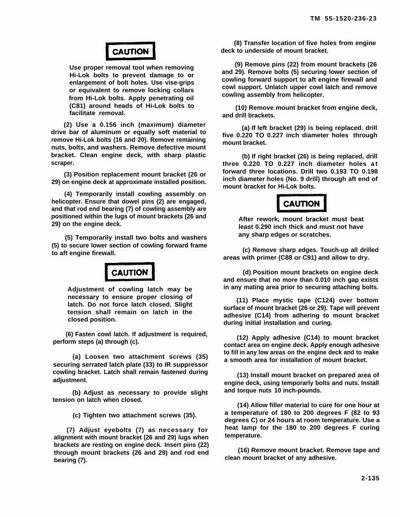
TM 55-1520-236-23
Use proper removal tool when removingHi-Lok bolts to prevent damage to orenlargement of bolt holes. Use vise-gripsor equivalent to remove locking collarsfrom Hi-Lok bolts. Apply penetrating oil(C81) around heads of Hi-Lok bolts tofacilitate removal.
(2) Use a 0.156 inch (maximum) diameterdrive bar of aluminum or equally soft material toremove Hi-Lok bolts (16 and 20). Remove remainingnuts, bolts, and washers. Remove defective mountbracket. Clean engine deck, with sharp plasticscraper.
(3) Position replacement mount bracket (26 or29) on engine deck at approximate installed position.
(4) Temporarily install cowling assembly onhelicopter. Ensure that dowel pins (2) are engaged,and that rod end bearing (7) of cowling assembly arepositioned within the lugs of mount brackets (26 and29) on the engine deck.
(5) Temporarily install two bolts and washers(5) to secure lower section of cowling forward frameto aft engine firewall.
Adjustment of cowling latch may benecessary to ensure proper closing oflatch. Do not force latch closed. Slighttension shall remain on latch in theclosed position.
(6) Fasten cowl latch. If adjustment is required,perform steps (a) through (c).
(a) Loosen two attachment screws (35)securing serrated latch plate (33) to IR suppressorcowling bracket. Latch shall remain fastened duringadjustment.
(b) Adjust as necessary to provide slighttension on latch when closed.
(c) Tighten two attachment screws (35).
(7) Adjust eyebolts (7) as necessary foralignment with mount bracket (26 and 29) lugs whenbrackets are resting on engine deck. Insert pins (22)through mount brackets (26 and 29) and rod endbearing (7).
(8) Transfer location of five holes from enginedeck to underside of mount bracket.
(9) Remove pins (22) from mount brackets (26and 29). Remove bolts (5) securing lower section ofcowling forward support to aft engine firewall andcowl support. Unlatch upper cowl latch and removecowling assembly from helicopter.
(10) Remove mount bracket from engine deck,and drill brackets.
(a) If left bracket (29) is being replaced. drillfive 0.220 TO 0.227 inch diameter holes throughmount bracket.
(b) If right bracket (26) is being replaced, drillthree 0.220 TO 0.227 inch diameter holes a tforward three locations. Drill two 0.193 TO 0.198inch diameter holes (No. 9 drill) through aft end ofmount bracket for Hi-Lok bolts.
After rework, mount bracket must beatleast 0.290 inch thick and must not haveany sharp edges or scratches.
(c) Remove sharp edges. Touch-up all drilledareas with primer (C88 or C91) and allow to dry.
(d) Position mount brackets on engine deckand ensure that no more than 0.010 inch gap existsin any mating area prior to securing attaching bolts.
(11) Place mystic tape (C124) over bottomsurface of mount bracket (26 or 29). Tape will preventadhesive (C14) from adhering to mount bracketduring initial installation and curing.
(12) Apply adhesive (C14) to mount bracketcontact area on engine deck. Apply enough adhesiveto fill in any low areas on the engine deck and to makea smooth area for installation of mount bracket.
(13) Install mount bracket on prepared area ofengine deck, using temporarly bolts and nuts. Installand torque nuts 10 inch-pounds.
(14) Allow filler material to cure for one hour ata temperature of 180 to 200 degrees F (82 to 93degrees C) or 24 hours at room temperature. Use aheat lamp for the 180 to 200 degrees F curingtemperature.
(16) Remove mount bracket. Remove tape andclean mount bracket of any adhesive.
2-135
TM 55-1520-236-23
(16) Install mount brackets (26 and 29) asfollows:
(a) Position mount bracket (29) on enginedeck. Install three bolts (30), six washers (28) andthree nuts (27) at front of bracket. Do not torque nuts(27) at this time.
(b) Install two hi-lok bolts (16) and two nuts(17) at rear of bracket (29) in accordance with TM55-1500-204-25/1.
(c) Torque nuts (27), that were installed instep a., 23 TO 28 inch-pounds.
(d) Position mount bracket (26) on enginedeck. Install three bolts (23), six washers (24) andthree nuts (25) at front of bracket. Do not torque nuts(25) at this time.
(e) Install two hi-lok bolts (20) and two nuts(21) at rear of bracket (26) in accordance with TM55-1500-204-25/1.
(f) Torque nuts (25), that ware installed instep d., 23 TO 28 inoh-pounds.
Replace damaged or worn rod end bearings(7), locknuts (8), and pins (22). Refer to table 2-3, item11.
2-87. INSTALLATION – COWLING ANDFAIRlNG.
Refer to paragraph 2-88 through 2-92.
2-88. INSTALLATION – TAILPIPEFAIRlNG.
a. Position tailpipe faking (6, figure 2-50) onhelicopter and secure.
b. Ensure that engine tailpipe overboard fueldrain is properIy positioned to prevent chafing.
2-89. INSTALLATION – IR SUPPRES-SOR COWLING.
a. Position aft panel assembly (11, figure 2-52)on helicopter, but do not secure at this time.
b. Position IR suppressor cowling on helicopter(figure 2-52). Ensure that dowel pins (2) are engagedin holes in aft engine firewall and rod end bearings (7)are within lugs of mount brackets (26 and 29). Securecowling.
(1) Maintain 0.040 TO 0.190 inch (minimum)clearance at IR suppressor cowling and aft pylonfairing interface.
(2) Check alignment of rod end bearings (7)to holes in lugs on mount brackets (26 and 29).
(3) If necessary, move cowling rearward andadjust rod end bearings (7) to obtain alignment.
(4) Tighten locknuts (8) on rod end bearingsafter adjustment. Secure locknuts to cowling supportlegs with Iockwire (C137).
NOTE
Pins (22) shall be Installed wet coatedwith MIL-C-16173 Grade IV (C43.1), andthen overspray. The entlre rod endassembly shall be covered with twocoats of MIL-C-16173 Grade IV (C43.1).Reason: Pins are lightly susceptible tocorrosion In a salt-air environment.
Install pins (22), washers (19), and cotter pins(18)
d. Install bolts and washers (5).
e. Install safety dips (1).
f. Remove caps and connect fuel drain fines:
(1) Engine exhaust drain line (6) at tee fitting.
(2) Overboard drain line (4) at aft engine fire-Wall.
g. Connect IR jammer cannon plugs (3).
h. Install lR suppressor (paragraph 4-57).
i. Install panels (10) with fasteners (9).
j. Secure aft panel assembly (11). Install screws(15) and washers (14). Secure fasteners (13).
2-136

TM 55-1520-236-23
2-90. INSTALLATION — PYLON FAIRING. d. Position forward pylon fairing (1,figure 2-51 ) on helicopter and secure.
a. Position aft pylon fairing (4,figure 2-50) on helicopter and secure.
e. Connect electrical wiring inside pylon fairing.
b. Position aft pylon faking (4, figureConnect tubing at pitot tube. -
2-51 ) on helicopter and secure.f. (After incorporation of MWO 1-1520-236-
C. Position forward pylon fairing 50-30). Connect ODDS inlet and outlet hoses (23.1(1, figure 2-50) on helicopter and secure. and 49, figure 4-4).
2-136.1/(2-136.2 blank)

TM 55-1520-236-23
2-91. INSTALLATION – TRANSMISSIONCOWL.
8. Position transmission cowl (14, figure2-50) on helicopter.
b. Position transmission cowl (8, figure 2-51) on helicopter.
c. Install bolts, washers, shims, and nuts toattach hinges to fittings on cowl frame. Install theshims in same location from which removed.
d. Close cowling and check alignment of cowlingand operation of latches. Adjust shims on hingesand/or latch bolt assemblies if required.
(1) See figure 2-50 for view of latchand hinge.
(2) See figure 2-51 for view of latch andhinge.
e. Open cowling and check standoff to ensurethat it operates properly. Close cowling.
f. Install protective shields in air inlet ducts.
2-92. INSTALLATION – ENGINE COWL.
a. Install engine cowling (11, figure 2-50) in same manner outlined for transmissioncowling (paragraph 2-91).
b. Install engine cowling (6, figure 2-51) in samemanner outlined for transmission cowling (paragraph2-91).
2 - 9 3 . P A I N T I N G – C O W L I N G A N DFAIRING – TOUCH-UP.
a. Clean area where paint requires touch-up withcleaning compound (C32) and rinse with water. Allowto dry,
b. Apply primer (C88 or C91) to area that requirestouch-up.
c. Apply finish coat to match existing finish.d . Refer to TM 55-1500-345-23 for
paint inst ruct ions.
2 - 9 4 . B E A M I N S T A L L A T I O N –FUSELAGE RIGHT SIDE AND LEFT SIDE.
2 - 9 5 . D E S C R I P T I O N – BEAMINSTALLATION FUSELAGE RIGHT SIDEAND LEFT SIDE.
The right and left side beam installations inconjunction with floor installations, bulkheadinstallations, pylon installation, and the engine deckvent and drain installation form a primary box beamstructure fuselage. The major components of the twobeam installations are panel installations and themain beam caps.
2-96. REMOVAL – FUSELAGESIDE A N D L E F T S I D ElNSTALLATIONS.
Removal of beams must be accomplishedmaintenance level.
RIGHTB E A M
at higher
2-97. INSPECTION – FUSELAGE RIGHTSIDE A N D L E F T S I D E BEAMINSTALLATIONS.
Refer to table 2-3 to classify damage to beam panels.See figure 2-11 and 2-12 for damage repair limits onbeam caps.
2-98. REPAIR – FUSELAGE RIGHT SIDEAND LEFT SIDE BEAM INSTALLATIONS.
Refer to paragraph 2-24 for procedure to repair rightside and left side beam installations.
2 - 9 9 . F I T T I N G S – F O R W A R DFUSELAGE TAILBOOM ATTACHMENT.
2-100. DESCRIPTION – FORWARDFUSELAGE TAILBOOM ATTACHMENTFlTTINGS.
Four tailboom attachment fittings are installed at theaft bulkhead of the forward fuselage to provide strongpoints for the four tailboom attaching bolts.
2-137

TM 55-1520-236-23
2 - 1 0 1 . C L E A N I N G – F O R W A R DFUSELAGE TAILBOOM ATTACHMENTFITTINGS.
Cleaning solvent is flammable and toxic.Provide adequate ventilation. Avoidprolonged breathing of solvent vaporsand contact with skin or eyes.
Clean fittings with clean cloths dampened withsolvent (C112). Dry with clean cloths.
2 - 1 0 2 . I N S P E C T I O N – F O R W A R DFUSELAGE TAILBOOM ATTACHMENTFITTINGS.
Refer to table 2-3 to classify damage to fittings.
2 - 1 0 3 . R E M O V A L – F O R W A R DFUSELAGE TAILBOOM ATTACHMENTFITTlNGS.
Removal of fittings must be accomplished at highermaintenance level.
2-104. REPAIR – FORWARD FUSELAGETAILBOOM Attachment FITTINGS.
Repair of fittings must be accomplished at highermaintenance level.
2-105. INSTALLATION – FORWARDFUSELAGE TAILBOOM ATTACHMENTFITTINGS.
Installation of fittings must be accomplished at highermaintenance level facility.
2 - 1 0 6 . P A I N T I N G , T O U C H - U P –FORWARD FUSELAGE TAILBOOMATTACHMENT FITTINGS.
a. Remove tail boom if necessary to gain adequateaccess to fittings. Refer to paragraph 2-283.
b. Clean area where paint is damaged with finegrit sandpaper (C102). If damage exceeds limits setforth in table 2-3, the damaged fitting must bereplaced. If damage is within limits, touch-up withtwo coats of primer (C88 or C91).
2-107. FORWARD AND AFT ENGINEFIREWALLS.
2-108. DESCRIPTION – FORWARD ANDAFT ENGINE FIREWALLS.
The forward and aft engine firewalls in conjunctionwith the engine, deck panel, the aft pylon fairingfirewall, and the engine cowling doors forma closedcompartment around the powerplant to protect theremaining structure in event of fire. The firewalls areconstructed primarily of titanium with somealuminum clips, doublers and brackets.
2-109. REMOVAL – FORWARD ENGINEFIREWALL.
a. Remove the engine (paragraph 4-12).
b. Remove the tail rotor driveshaft fireshield.Refer to paragraph 2-119.
c. Disconnect engine power control lever (notillustrated) that passes through boot (32, figure 2-53).Disconnect lever at bellcranks and leave the lever inplace in boot (32).
d. Disconnect the following lines et the forwardfirewall. Cap or plug open lines to prevent entry offoreign matter.
(1)
(2)
(3)
(4)firewall.
Fuel lines at lower left side of firewall.
Pneumatic line at upper left side of firewall.
Pneumatic line at lower side of firewall.
Lubrication lines at lower right side of
e. Remove nuts (27, figure 2-53), washers (26),and bolts (24).
f. Remove screw (15) at left side of firewall.Remove two screws (20) at right side.
g. Remove screws (17).
h. Remove screws (21) at right side of firewall.Remove similar screws (not illustrated) at left side offirewall. Carefully lift firewall off engine deck andremove shims (16) and six shims (19). Index shims forreinstallation in the same location.
2-138

TM 55-1520-236-23
Figure 2-53. Firewalls and Driveshaft Fireshield Installation (Sheet 1 of 2)
2-139

TM 55-1520-236-23
1. Forward engine firewall 17. Screw2. Gasket 18. Gasket3. Tail rotor driveshaft fireshaft 19. Shim4. Gasket 20. Screw5. Aft engine firewall and cowl support 21. Screw6. Screw 22. Bolt7. Seal 23. Washer8. Seal 24. Bolt9. Seal 25. Clip
10. Seal 26. Washer11. Seal 27. Nut12, Panel (engine deck) 28. Clamps13. Screw 29. Retainer ring14. Screw 30. Boot retainer15. Screw 31. Split bushing bearing16. Shim 32. Power lever boot
33. screw34. Retainer36. Deleted36. Clamp, screw, washer and nut37. Clamp, screw, washer and nut38. Deleted39. Deleted
Figure 2-53. Firewalls and Driveshaft Fireshield Installation (Sheet 2 of 2)
2-140
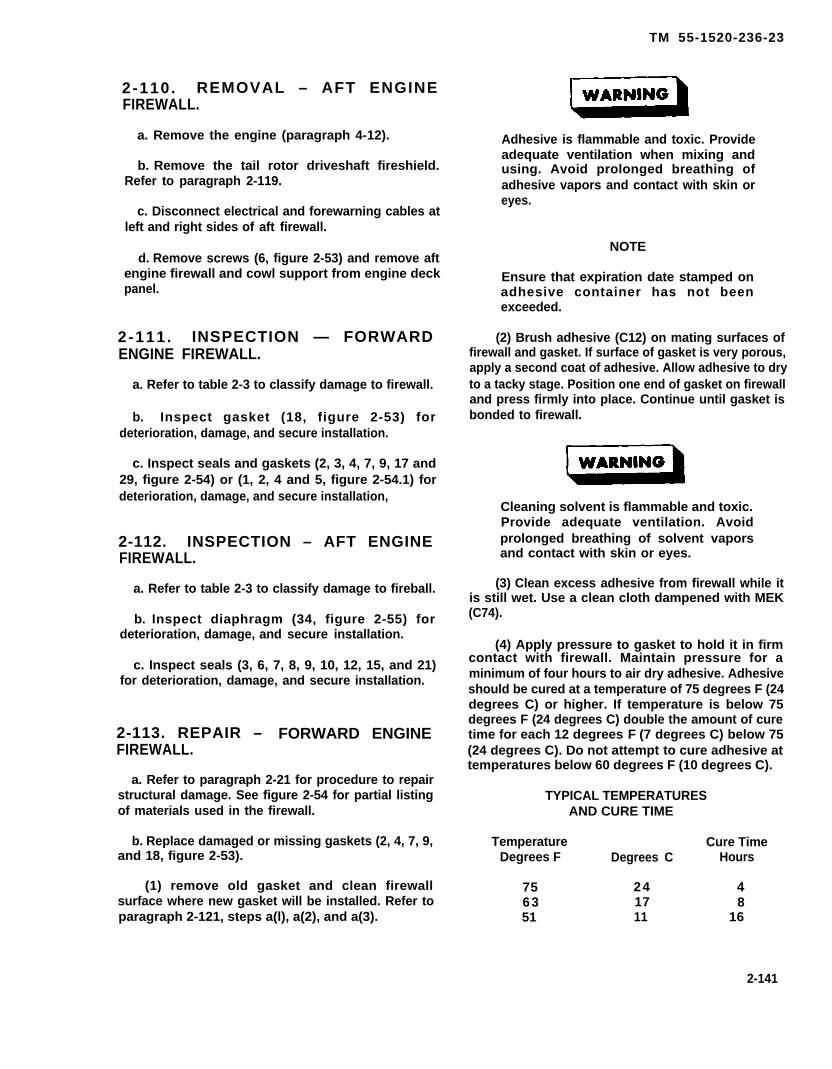
TM 55-1520-236-23
2-110. REMOVAL – AFT ENGINEFIREWALL.
a. Remove the engine (paragraph 4-12).
b. Remove the tail rotor driveshaft fireshield.Refer to paragraph 2-119.
c. Disconnect electrical and forewarning cables atleft and right sides of aft firewall.
d. Remove screws (6, figure 2-53) and remove aftengine firewall and cowl support from engine deckpanel.
2-111. INSPECTION — FORWARDENGINE FIREWALL.
a. Refer to table 2-3 to classify damage to firewall.
b. Inspect gasket (18, figure 2-53) fordeterioration, damage, and secure installation.
c. Inspect seals and gaskets (2, 3, 4, 7, 9, 17 and29, figure 2-54) or (1, 2, 4 and 5, figure 2-54.1) fordeterioration, damage, and secure installation,
2-112. INSPECTION – AFT ENGINEFIREWALL.
a. Refer to table 2-3 to classify damage to fireball.
b. Inspect diaphragm (34, figure 2-55) fordeterioration, damage, and secure installation.
c. Inspect seals (3, 6, 7, 8, 9, 10, 12, 15, and 21)for deterioration, damage, and secure installation.
2-113. REPAIR – FORWARD ENGINEFIREWALL.
a. Refer to paragraph 2-21 for procedure to repairstructural damage. See figure 2-54 for partial listingof materials used in the firewall.
b. Replace damaged or missing gaskets (2, 4, 7, 9,and 18, figure 2-53).
(1) remove old gasket and clean firewallsurface where new gasket will be installed. Refer toparagraph 2-121, steps a(l), a(2), and a(3).
Adhesive is flammable and toxic. Provideadequate ventilation when mixing andusing. Avoid prolonged breathing ofadhesive vapors and contact with skin oreyes.
NOTE
Ensure that expiration date stamped onadhesive container has not beenexceeded.
(2) Brush adhesive (C12) on mating surfaces offirewall and gasket. If surface of gasket is very porous,apply a second coat of adhesive. Allow adhesive to dryto a tacky stage. Position one end of gasket on firewalland press firmly into place. Continue until gasket isbonded to firewall.
Cleaning solvent is flammable and toxic.Provide adequate ventilation. Avoidprolonged breathing of solvent vaporsand contact with skin or eyes.
(3) Clean excess adhesive from firewall while itis still wet. Use a clean cloth dampened with MEK(C74).
(4) Apply pressure to gasket to hold it in firmcontact with firewall. Maintain pressure for aminimum of four hours to air dry adhesive. Adhesiveshould be cured at a temperature of 75 degrees F (24degrees C) or higher. If temperature is below 75degrees F (24 degrees C) double the amount of curetime for each 12 degrees F (7 degrees C) below 75(24 degrees C). Do not attempt to cure adhesive attemperatures below 60 degrees F (10 degrees C).
TYPICAL TEMPERATURESAND CURE TIME
Temperature Cure TimeDegrees F Degrees C Hours
75 24 463 17 851 11 16
2-141
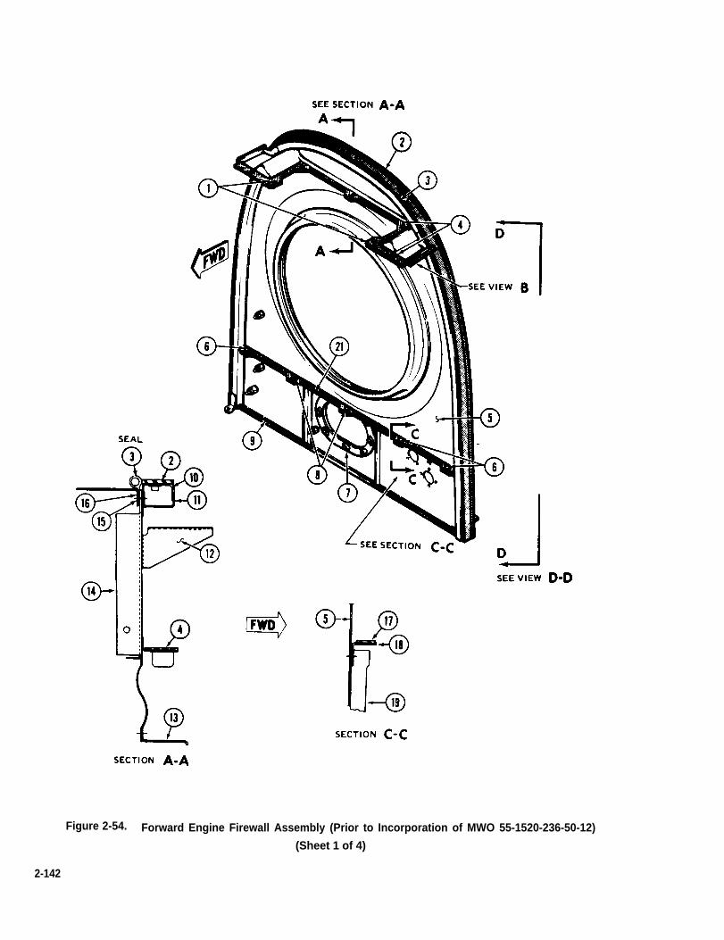
Figure 2-54. Forward Engine Firewall Assembly (Prior to Incorporation of MWO 55-1520-236-50-12)
(Sheet 1 of 4)
2-142
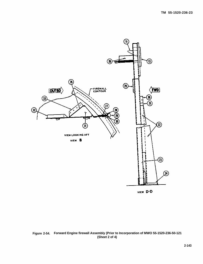
TM 55-1520-236-23
Figure 2-54. Forward Engine firewall Assembly (Prior to Incorporation of MWO 55-1520-236-50-121(Sheet 2 of 4)
2-143

TM 55-1520-236-23
Figure 2-54. Forward Engine Firewall Assembly (Prior to Incorporation of MWO 55-1520-236-50-12)(Sheet 3 of 4)
2-144
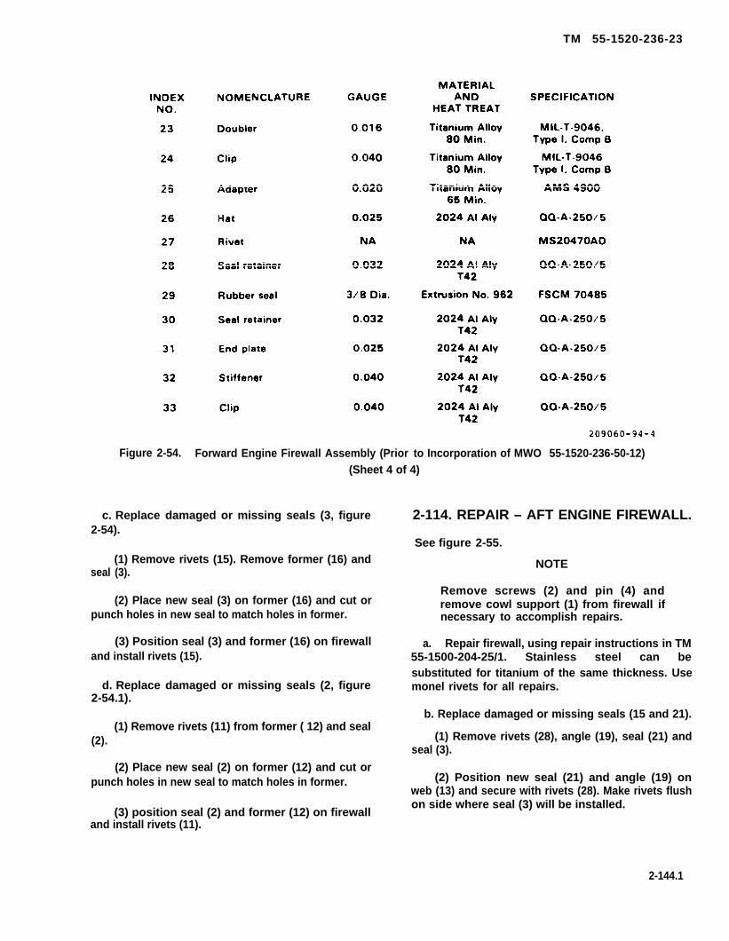
TM 55-1520-236-23
Figure 2-54. Forward Engine Firewall Assembly (Prior to Incorporation of MWO 55-1520-236-50-12)(Sheet 4 of 4)
c. Replace damaged or missing seals (3, figure2-54).
(1) Remove rivets (15). Remove former (16) andseal (3).
(2) Place new seal (3) on former (16) and cut orpunch holes in new seal to match holes in former.
(3) Position seal (3) and former (16) on firewalland install rivets (15).
d. Replace damaged or missing seals (2, figure2-54.1).
(1) Remove rivets (11) from former ( 12) and seal(2).
(2) Place new seal (2) on former (12) and cut orpunch holes in new seal to match holes in former.
(3) position seal (2) and former (12) on firewalland install rivets (11).
2-114. REPAIR – AFT ENGINE FIREWALL.
See figure 2-55.
a.
NOTE
Remove screws (2) and pin (4) andremove cowl support (1) from firewall ifnecessary to accomplish repairs.
Repair firewall, using repair instructions in TM55-1500-204-25/1. Stainless steel can besubstituted for titanium of the same thickness. Usemonel rivets for all repairs.
b. Replace damaged or missing seals (15 and 21).
(1) Remove rivets (28), angle (19), seal (21) andseal (3).
(2) Position new seal (21) and angle (19) onweb (13) and secure with rivets (28). Make rivets flushon side where seal (3) will be installed.
2-144.1

TM 55-1520-236-23
(3) Install new seal (3). Refer to step c.
(4) Replace seal (15) in the same mannerdescribed in preceding steps.
c. Replace damaged seals (3, 6, 7, 8, 9, 10 and12). Refer to paragraph 2-113 for procedure to bondnew seals to firewall.
d. Replace damaged diaphragm (34).
(1) Remove rivets (32), plate (33), anddiaphragm (34) from panel (11).
2-144.2

TM 55-1520-236--23
Figure 2-54.1 Forward Engine Firewall Assembly (After Incorporation ofMWO 55-1520-236-50-12) (Sheet 1 of 5)
2-144.3

TM 55-1520-236-23
Figure 2-54.1 Forward Engine Firewall Assembly (After Incorporation ofMWO 55-1520-236-50-12) (Sheet 2 of 5)
2-144.4

TM 55-1520-236-23
Figure 2-54.1 Forward Engine Firewall Assembly (After Incorporation ofMWO 55-1520-236-50-12) (Sheet 3 of 5)
2-144.5

TM 55-1520-236-23
Figure 2-54.1 Forward Engine Firewall assembly (After Incorporation of MWO 55-1520-236-50-12) (Sheet 4 of 5)
2-144.6

TM 55-1520-236-23
Figure 2-54.1 Forward Engine Firewall Assembly (After Incorporation ofMWO 55-1520-236-50-12) (Sheet 5 of 5)
2-145

TM 55-1520-236-23
Figure 2-55. Aft Engine Firewall and Cowl Support (Sheet 1 of 4)
2-146
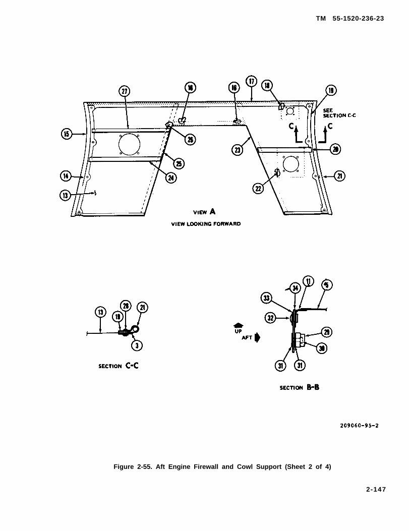
TM 55-1520-236-23
Figure 2-55. Aft Engine Firewall and Cowl Support (Sheet 2 of 4)
2-147

TM 55-1520-236-23
Figure 2-55. Aft Engine Firewall and Cowl Support (Sheet 3 of 4)
2-148

TM 55-1520-236-23
Figure 2-55. Aft Engine Firewall and Cowl Support (Sheet 4 of 4)
2-149
TM 55-1520-236-23
(2) Remove rivets (30), nutplate (29), and plates(31).
(3) Install plates (31) and nutplates (29) on newdiaphragm with rivets (30).
(4) Position diaphragm and parts assembled mpreceding step on firewall panel (11) with plate (33).Secure with rivets (32).
(5) If cowl support (1) was removed, ensure thatserviceable seals (3 and 12) are bonded to firewall.Position cowl support (1) on aft firewall web (13) andsecure with screws (20 and pins (4).
2-115. INSTALLATION – FORWARDENGINE FIREWALL.
a. Ensure that a serviceable gasket (18, figure 2-53) iS bonded to lower surface of firewall and that allholes for firewall attachment screws (17) are openthrough gasket.
b. Position forward firewall (1) on engine deckpanel with twelve shims (16 and 19) in position understiffeners on aft side of firewall. Install screws( 15, 17and 20).
NOTE
It may be necessary to add or removeshims (16 and 19) to adjust positionof firewall. The maximum allowable gaparound the adjacent engine andtransmission compartment cowlingaccess doors after rigging and finaladjustments is 0.190 inch. Minimumgap is 0.040 inch.
c. Install cowling and check to ensure that fit iSwithin limits noted in preceding note. Adjustthickness of shims ( 16 and 19) if necessary. Removecowling.
d. Install two bolts (24), washers (26) and nuts(27).
Cleaning solvent is flammable and toxic,Provide adequate ventilation. Avoidprolonged breathing of solvent vaporsand contact with skin or eyes.
e. Inspect for gaps and voids where firewallcontacts engine service deck and also at edges wherelndividual parts of firewall are jointed If any gaps or
voids are detected, clean the area with clothsdampened with MEK (C74) and dry with clean cloths.Fill gaps and voids with sealant (C104), Use a woodenspatula (tongue depressor) to apply the sealant.
f. Assemble engine power control lever (notIllustrated), boot (32) and associated parts If notpreviously accomplished, Connect ends of enginepower control lever to bellcranks on each side of thefirewall.
g. Install tail rotor driveshaft and tail rotordriveshaft fireshield, Refer to paragraph 2-122.
h. Install engine (paragraph 4-15).
i. Connect the following lines.
(1) Lubrication lines at lower right sides offirewall.
(2) Pneumatic line at lower side of firewall.
(3) Pneumatic line at upper left side of firewall.
(4) Fuel lines at lower left side of firewall.
Perform functional check of engine andenvironmental control system. Refer to TM 55-1520-236-10.
2-116. INSTALLATION – AFT ENGINEFIREWALL AND COWL SUPPORT.
a. Ensure that serviceable seals (7, 8, 9, 10, and 11,figure 2-53) are bonded to firewall.
b. Position assembled firewall and cowl support(5) on engine deck panel (12) and Install screws (6).
Install tail rotor driveshaft and tail rotordriveshaft fireshleld (paragraph 2-122).
d. Seal all gaps and voids where firewall contactsservice deck and also at edges where individual partsof firewall join. Refer to paragraph 2-115 forprocedure.
e. Install engine (paragraph 4-15)
f. Connect electrical and fire detection cables atleft and right sides of aft firewall.
g. Perform functional check of engine.
2-150

TM 55-1520-236-23
2-117. TAIL ROTOR DRIVESHAFTFIRESHIELD.
2-118. DESCRIPTION – TAIL ROTORDRIVESHAFT FIRESHIELD.
The tail rotor driveshaft fireshield is constructed oftitanium. It protects the section of tail rotor driveshaftbetween the two engine firewalls. See figure 2-53.
2-119. REMOVAL – TAIL ROTORDRIVESHAFT FIRESHIELD.
a. Remove section of tail rotor driveshaft locatedbelow engine. Refer to paragraph 6-77.
b. Remove screws (13 and 14, figure 2-53), ateach end of fireshield (3).
c. Remove fireshield (3), gaskets (2 and 4) whichshould be bonded to the fireshield.
2-120. INSPECTION – TAIL ROTORDRIVESHAFT FIRESHIELD.
a. Refer to table 2-3 to classify damage todriveshaft fireshield.
b. Inspect fireshield for dents, holes, anddistortion.
(1) Surfaces of flanges (2 and 5, figure 2-56), atends of tail rotor driveshaft fireshield must be flatwithin 0.020 inch.
(2) For damage limits for dents, holes etc. referto table 2-3.
2 - 1 2 1 . R E P A I R – TAIL ROTORDRIVESHAFT FIRESHIELD.
a. Replace damaged or missing gaskets ( 1 and 6,figure 2-56) as follows:
(1) Remove old gasket from flanges atfireshield.
Cleaning solvent is flammable and toxic,Provide adequate ventilation.prolonged breathing of solventand contact with skin or eyes.
Avoidvapors
(2) Clean flange in area where gasket will beinstalled by sanding with 400 grit sandpaper (C102).Remove sanding residue with naphtha (C75) or MEK(C74).
(3) Ensure that new gasket is clean and dry andthat hole pattern in gasket and flange match.
Sealant is flammable and toxic. Provideadequate ventilation when mixing andusing prosed 880. Avoid prolongedbreathing of vapors and contact with skinor eyes.
(4) Mix two-part sealant (C105) in accordancewith directions on container. Apply a thin, even coatof sealant to mating surfaces of gasket and to flange.If gasket is very porous, apply a second coat ofsealant. Allow sealant to dry to a tacky stage. Positionone edge of gasket on flange and press firmly intoplace. Continue until gasket is bonded to flange.Ensure that all holes match.
Cleaning solvent is flammable and toxic.Provide adequate ventilation. Avoidprolonged breathing of solvent vaporsand contact with skin or eyes.
(6) Clean excess sealant from flange while it isstill wet. Use a clean cloth dampened with MEK (C74).
(6) Apply pressure to gasket to hold it in firmcontact with flange. Maintain pressure for fifteenhours to air dry sealant.
b. Repair hole-type damage. Refer to TM 55-1500-204-25/1 .
2 - 1 2 2 . I N S T A L L A T I O N – T A I L R O T O RDRIVESHAFT FIRESHIELD.
a. Ensure that serviceable gaskets (2 and 4, figure2-53) are bonded to fireshield (3).
b. Position fireshield in helicopter with cover (3,figure 2-56) up and with flange (2) forward asillustrated. Note that flange (2) has seven holes and
2-151

TM 55-1520-236-23
Figure 2-56. Tail Rotor Driveshaft Fireshield Assembly
2-152

TM 55-1520-236-23
that flange (5) has eight holes. Install screws (7) tosecure fireshield to gasket (1), forward firewall gasket(6) and aft firewall.
Install section of tail rotor driveshaft Iocatedbelow engine. Refer to paragraph 6-77.
2-123. ENGINE AIR INDUCTION BAFFLES.
2-124. DESCRIPTION — ENGINE AIR INDUGTION BAFFLES.
The engine air induction baffles are constructedprimarily of aluminum with rubber seals attached at theedges. The induction baffles enclose the sand anddust separator on the forward side of the forwardengine firewall. Air enters the area endosed by the airinduction baffles through scoops located on the leftand right transmission cowling doors. The air exitsthrough the particle separator into the engine.
2-125. REMOVAL – AIR INDUCTION BAFFLES( P R I O R T O I N C O R P O R A T I O N O F M W O55-1520-236-50-12).
a. Open transmission cowling.
b. Release fasteners and remove shaft accesspanel (4, figure 2-57) which forms the forward left sideof the induction baffle assembly.
c. Detach electrical Iead from three brackets (10)on top panel and three brackets (9) on forward panel.
d Release fasteners and remove top panel (2).
Disconnect tube assembly (7). Remove for-ward panel (8) and floor assembly (5).
2-125.1. REMOVAL — CENTRISEPPARTICLE SEPARATOR ENGINE AIR INDUCTIONBAFFLES. (AFTER INCORPORATION OF MWO55-1520-236-50-12).
a. Open transmission and engine cowling.
b. Remove center pylon left and right fairings(paragraph 2-82).
c. Deleted.
d. Deleted.
e. Deleted.
Remove bolts (12, figure 2-57.1) and washers(13) attaching baffle (1) to forward firewall.
Release turnlock fasteners (15) and removebaffle (1) and straps (14).
h. Remove four screws (17) and washers (16)from aft side of baffle (18).
i. Release turnlock fasteners (20) from bottomside of baffle (19).
j. Remove screws (21) and washers (22) frombottom side of baffle (19).
k. Remove centrisep particle separator (para-graph 4-28.1).
l. Remove three screws (24) and washers (25)from top right side of baffle (19).
m. Release turnlock fasteners (23) from bottomside of baffle (19) and remove.
2-152.1/(2-152.2 blank)


TM 55-1520-236-23
2 - 1 2 6 . I N S P E C T I O N – E N G I N E A I RINDUCTION BAFFLES.
a. Refer to table 2-3 to classify damage to structureand fasteners in engine air induction panels.
b. Inspect gaskets (28, figure 2-58) or (23, figure2-58.1) for deterioration, damage, and secureinstallation.
c. Inspect seals (1, 8, 20, 25, 33, and 35, figure2-58) or (1, 8, 18, 32, and 34, figure 2-58.1) fordeterioration, damage, and secure installation.
2 -127 . – ENGINE AIR INDUCTION.
a. Refer to table 2-3 for procedure to repairstructural damage and to replace damaged fasteners.
b. Replace damaged or missing gaskets (28, figure2-58) or (23, figure 2-58.1).
The procedures in this paragraph areapplicable to bonding gaskets (28) which arefabricated from silicone rubber.
(1) Remove all traces of old gasket withscrapers and 80 grit sandpaper (C102). Clean the areawhere the new gasket will be installed down to baremetal.
(2) Abrade the bonding surface of the newgasket with 80 grit sandpaper (C102).
(3) Clean mating surfaces of new gasket andthe air induction baffle with clean cloths dampenedwith toluene (C130). Dry with clean dry cloths.
SiIicone adhesive primer is flammableand toxic. Provide adequate ventilation.Avoid prolonged breathing of primervapors and contact with skin or eyes.
(4) Use a pure bristle adhesive priming brush toapply a coat of silicone adhesive primer (C90) on thecleaned area of the air induction baffle. Do not applyprimer to the rubber gasket. Allow the primer to airdry for thirty minutes.
Adhesive is flammable. Hydrogen gas isreleased after the two-compnentadhesive is mixed. Do not cap oontainerafter combining components or pressurebuild-up may oocur.
2-153

TM 55-1520-236-23
Fire 2-57. Engine Air Induction Baffle Installation (Prior to Incorporation of MWO 55-1520-236-50-12)
2-154
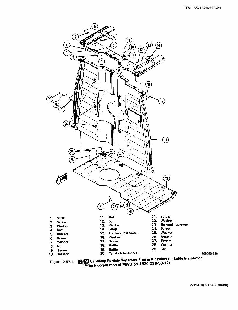
TM 55-1520-236-23
Figure 2-57.1.
209060-160
2-154.1/(2-154.2 blank)

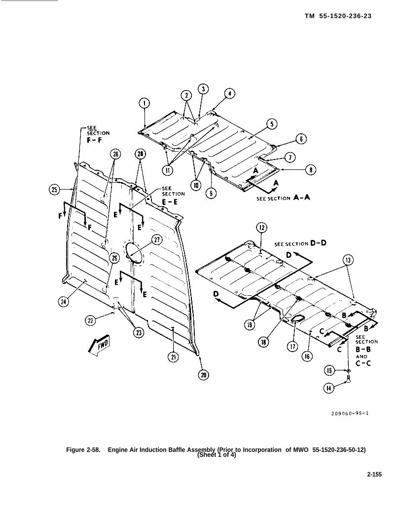
TM 55-1520-236-23
Figure 2-58. Engine Air Induction Baffle Assembly (Prior to Incorporation of MWO 55-1520-236-50-12)(Sheet 1 of 4)
2-155
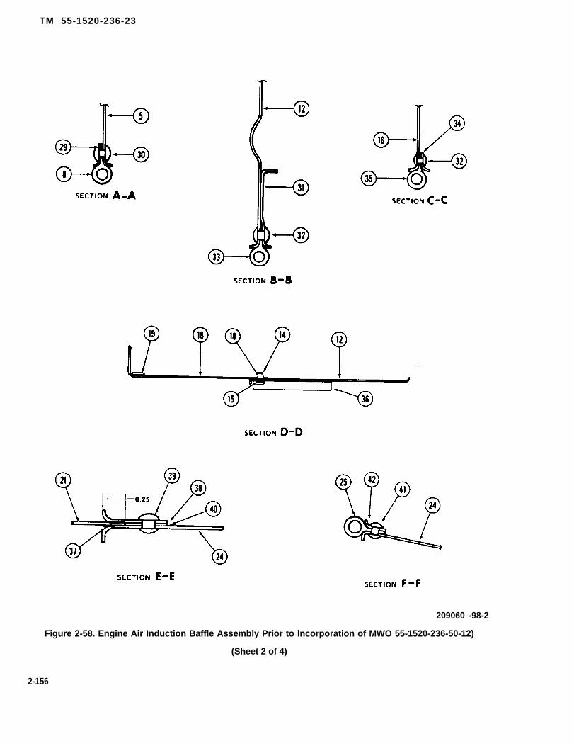
TM 55-1520-236-23
209060 -98-2
Figure 2-58. Engine Air Induction Baffle Assembly Prior to lncorporation of MWO 55-1520-236-50-12)
(Sheet 2 of 4)
2-156
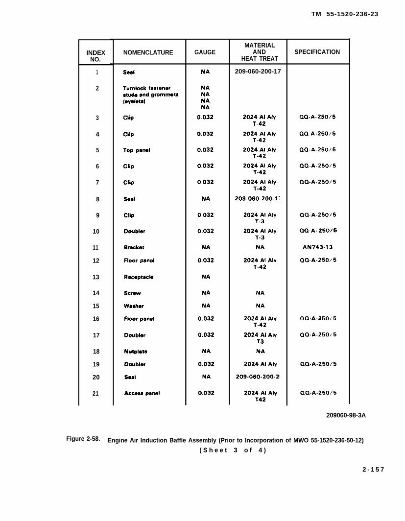
TM 55-1520-236-23
INDEXNO.
1
2
3
4
5
6
7
8
9
10
11
12
13
14
15
16
17
18
19
20
21
NOMENCLATURE GAUGEMATERIAL
ANDHEAT TREAT
209-060-200-17
SPECIFICATION
209060-98-3A
Engine Air Induction Baffle Assembly (Prior to Incorporation of MWO 55-1520-236-50-12)Figure 2-58.
( S h e e t 3 o f 4 )
2 - 1 5 7

TM 55-1520-236-23
INDEXNO.
Figure 2-58.
NOMENCLATURE GAUGEMATERIAL
ANDHEAT TREAT
SPECIFICATION
209060-98-4A
Engine Air Induction Baffle Assembly (Prior to Incorporation of MWO 55-1520-236-50-12)(Sheet 4 of 4)
2-158
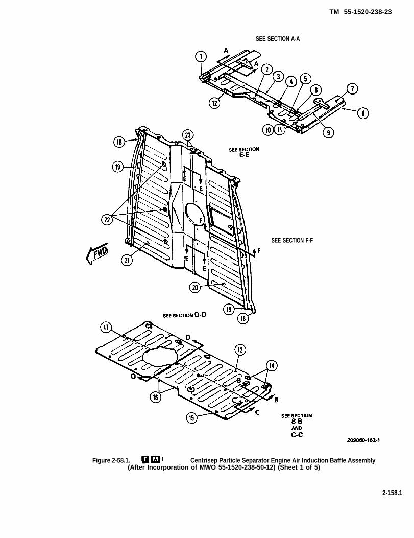
TM 55-1520-238-23
SEE SECTION A-A
SEE SECTION F-F
Figure 2-58.1. Centrisep Particle Separator Engine Air Induction Baffle Assembly(After Incorporation of MWO 55-1520-238-50-12) (Sheet 1 of 5)
2-158.1

TM 55-1520-236-23
Figure 2-58.1. Centrisep Particle Separator Engine Air Induction Baffle Assembly(After Incorporation of MWO 55-1520-236-50-12) (Sheet 2 of 5)
2-158.2

TM 55-1520-236-23
Figure 2-58.1. Centrisep Particle Separator Engine Air Induction Baffle Assembly (After Incorporation of MWO 55-1520-236-50-12) (Sheet 3 of 5)
2-158.3

TM 55-1520-236-23
INDEXNO.
GAUGEMATERIAL
ANDHEAT TREAT
SPECIFICATION
Figure 2-58.1. Centrisep Particle Separator Engine Air Induction Baffle Assembly(After Incorporation of MWO 55-1520-236-50-121 (Sheet 4 of 5)
2-158.4

TM 55-1520-236-23
Figure 2-58.1. Centrisep Particle Separator Engine Air Induction Baffle Assembly(After Incorporation of MWO 55-1520-235-50-12) Sheet 5 of 5)
2-158.5

TM 55-1520-236-23
NOTE
Inspect containers for expiration date priorto use.
(5) Mix two-component adhesive (C16) at aratio, by weight, of 100 parts resin to 5 parts catalyst.The pot life of mixture-adhesive is four to eight hours,but best results are obtained when adhesives are usedimmediately after mixing.
(6) Use a pure bristle adhesive priming brush toapply a 10 to 15 mil coating of adhesive prepared inthe preceding step to the rubber gasket and the metalair induction baffle. Allow the adhesive to air dry for 15to 30 minutes. Start with one end of gasket and pressonto baffle. Adhesive should be cured at a temperatureof 75 degrees F (24 degrees C) or higher. Iftemperature is below 75 degrees F (24 degrees C)double the amount of cure time for each 12 degrees F(7 degrees C) below 75 degrees F (24 degrees C). Donot attempt to cure adhesive at temperatures below 50degrees F (10.0 degrees C).
TYPICAL TEMPERATURES AND CURE TIME
Temperature Cure TimeDegrees F Degrees C Hours
75 24 4 to 763 17 8 to 1451 11 16 to 28
(7) Inspect bond after 24 hour cure time. Theremust be no evidence of dege lifting of the gasket.
c. Replace damaged or missing seals ( 1, 8, 20, 25,33, and 35, figure 2-58) or (1, 8, 18, 32, and 34, figure2-58.1).
(1) Remove rivets and doublers then retain sealsto panels. See figure 2-58 or 2-58.1 for typical view ofseal installation.
(2) Place new seal (1, 8, 20, 25, 33, or 35), asapplicable, on panel and cut or punch holes in new sealto match holes in new seal to match holes in panel.
(3) Place seal and doubler on panel and securewith rivets. See figures 2-58 or 2-58.1 for typical views.
d. Replace damaged or missing vinyl tape (C128)on edge of access panel (21, figure 2-58) or (20, figure2-58.1). See sectional view E-E. Wrap tape aroundedge of panel to form a strip approximately 0.25 inchwide on each side as illustrated.
2 - 1 2 8 . I N S T A L L A T I O N – E N G I N E A I RI N D U C T I O N B A F F L E S . ( P R I O R T OINCORPORATION OF M W O55-1520-236-50-12)
a. Assemble two halves of flow assembly (5, figure2-57) and forward panel assembly (8).
b. Position flow assembly (5) and forward panel (8)on forward engine firewall (1) and secure to firewall.
c.
d.
e.
f.
Install hose (6) and tube assembly (7).
Install forward access panel (4}.
Install top panel (2).
Install antenna lead on brackets (9) and (10).
2-128.1. INSTALLATION – ENGINE AIRINDUCTION BAFFLES. (AFTER INCORPORATIONOF MWO 55-1520-236-50-12)
a. Position baffle (19. figure 2-57.1) on forwardengine firewall and secure in place with turnlockfasteners (23).
b. Install screws (24) and washers (25), securingbaffle (19) to structure.
c. Install centrisep particle separator (paragraph4-32.1).
d. Position baffle (18) in place and assemble twohalves using screws (17) and washers (16).
e. Fasten baffles (18 and 19) in place with turnlockfasteners (20).
f. Install screws (21) and washers (22).
g. Position baffle (1) on baffle (18), secure in placewith turnlock fasteners (15).
h. Install bolts (12) and washers (13) throughstraps (14) securing baffle (1) to structure.
2-158.6
TM 55-1520-236-23
i. Deleted.
j. Deleted.
k. Deleted.
l. Install center pylon left and right fairings (para-graph 2-82).
has a single piano-type hinge at the top and a gasspring (door support brace) to support the door when inthe open position. The doors can be removed(jettisoned) in an emergency by the canopy removalsystem. Refer to chapter 17 for description of thecanopy removal system. The door handles have lockcylinders installed so the door can be locked with a key.Both doors can be locked or unlocked with the samekey.
m. Close transmission and engine cowling.2-131. REMOVAL — CREW DOORS.
2-129. CREW DOORS.
2-130. DESCRIPTION – CREW DOORS.
The pilot door (1, figure 2-59) and the gunner door (1,figure 2-60) consist of metal frames with inset windowpanels of transparent acrylic plastic. The door handlesare located on the lower side of the doors. Each door
Ensure that both the pilot and gunnerarming/firing mechanism handles aresecured with safety pins prior to entryInto the cockpit area.
2-159
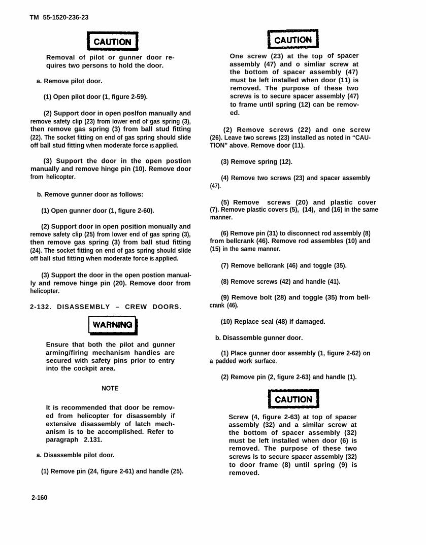
TM 55-1520-236-23
Removal of pilot or gunner door re-quires two persons to hold the door.
a. Remove pilot door.
(1) Open pilot door (1, figure 2-59).
(2) Support door in open poslfon manually andremove safety clip (23) from lower end of gas spring (3),then remove gas spring (3) from ball stud fitting(22). The socket fitting on end of gas spring should slideoff ball stud fitting when moderate force IS applied.
(3) Support the door in the open postionmanually and remove hinge pin (10). Remove doorfrom helicopter.
b. Remove gunner door as follows:
(1) Open gunner door (1, figure 2-60).
(2) Support door in open position monually andremove safety clip (25) from lower end of gas spring (3),then remove gas spring (3) from ball stud fitting(24). The socket fitting on end of gas spring should slideoff ball stud fitting when moderate force iS applied.
(3) Support the door in the open postion manual-ly and remove hinge pin (20). Remove door fromhelicopter.
2-132. DISASSEMBLY – CREW DOORS.
Ensure that both the pilot and gunnerarming/firing mechanism handies aresecured with safety pins prior to entryinto the cockpit area.
NOTE
It is recommended that door be remov-ed from helicopter for disassembly ifextensive disassembly of latch mech-anism is to be accomplished. Refer toparagraph 2.131.
a. Disassemble pilot door.
(1) Remove pin (24, figure 2-61) and handle (25).
One screw (23) at the top of spacerassembly (47) and o simliar screw atthe bottom of spacer assembly (47)must be left installed when door (11) isremoved. The purpose of these twoscrews is to secure spacer assembly (47)to frame until spring (12) can be remov-ed.
(2) Remove screws (22) and one screw(26). Leave two screws (23) installed as noted in “CAU-TION” above. Remove door (11).
(3) Remove spring (12).
(4) Remove two screws (23) and spacer assembly(47).
(5) Remove screws (20) and plastic cover(7). Remove plastic covers (5), (14), and (16) in the samemanner.
(6) Remove pin (31) to disconnect rod assembly (8)from bellcrank (46). Remove rod assembles (10) and(15) in the same manner.
(7) Remove bellcrank (46) and toggle (35).
(8) Remove screws (42) and handle (41).
(9) Remove bolt (28) and toggle (35) from bell-crank (46).
(10) Replace seal (48) if damaged.
b. Disassemble gunner door.
(1) Place gunner door assembly (1, figure 2-62) ona padded work surface.
(2) Remove pin (2, figure 2-63) and handle (1).
Screw (4, figure 2-63) at top of spacerassembly (32) and a similar screw atthe bottom of spacer assembly (32)must be left installed when door (6) isremoved. The purpose of these twoscrews is to secure spacer assembly (32)to door frame (8) until spring (9) isremoved.
2-160

TM 55-1520-236-23
VIEW LOOKING INBOARDRIGHT SIDE
209033-58-1
Figure 2-59. Pilot Door - Installation (Sheet 1 of 3)
2-161

TM 55-1520-236-23
SECTION C-C
NOTE: ALL DIMENSIONS IN INCHES UNLESS OTHERWISE NOTED.
209033-58-2
Figure 2-59. Pilot Door – Installation (Sheet 2 of 3)
2-162

TM 55-1520-236-23
Figure 2-59.Pilot Door - Installation (Sheet 3 of 3
2-163

TM 55-1520-236-23
209033-35-1
Figure 2-60. Gunner Door - Installation (Sheet 1 of 3)
2 - 1 6 4

TM 55-1520-236-23
Figure 2-30. Gunner Door - Installation (Sheet 2 of 3)
2-165
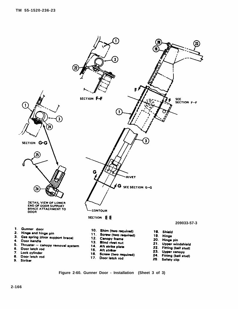
TM 55-1520-236-23
209033-57-3
Figure 2-60. Gunner Door - Installation (Sheet 3 of 3)
2-166
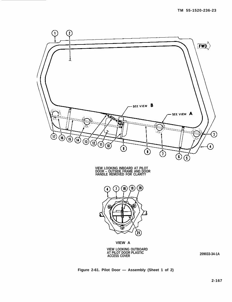
TM 55-1520-236-23
VIEW LOOKING INBOARD AT PILOTDOOR – OUTSIDE FRAME AND DOORHANDLE REMOVED FOR CLARITY
VIEW A
VIEW LOOKING OUTBOARDAT PILOT DOOR PLASTICACCESS COVER 209033-34-1A
Figure 2-61. Pilot Door — Assembly (Sheet 1 of 2)
2-167
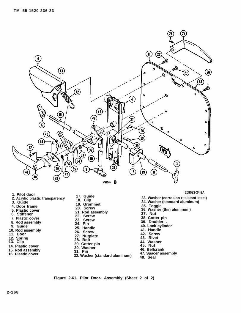
TM 55-1520-236-23
1. Pilot door2. Acrylic plastic transparency3. Guide4. Door frame5. Plastic cover6. Stiffener7. Plastic cover8. Rod assembly9. Guide
10. Rod assembly11. Door12. Spring13. Clip14. Plastic cover15. Rod assembly16. Plastic cover
17. Guide18. Clip19. Grommet20. Screw21. Rod assembly22. Screw23. Screw24. Pin25. Handle26. Screw27. Nutplate28. Bolt29. Cotter pin30. Washer31. Pin32. Washer (standard aluminum)
209033-34-2A33. Washer (corrosion resistant steel)34. Washer (standard aluminum)35. Toggle36. Washer (thin aluminum)37. Nut38. Cotter pin39. Doubler .40. Lock cylinder41. Handle42. Screw43. Rivet44. Washer45. Nut46. Bellcrank47. Spacer assembly48. Seal
Figure 2-61. Pilot Door- Assembly (Sheet 2 of 2)
2-168
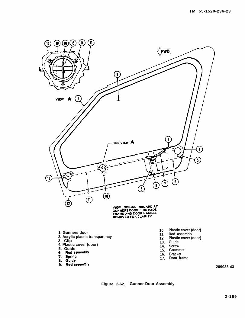
TM 55-1520-236-23
1. Gunners door2. Acrylic plastic transparency3. Clip4. Plastic cover (door)5. Guide
10.11.12.13.14.15.16.17.
Plastic cover (door)Rod assemblvPlastic cover (door)GuideScrewGrommetBracketDoor frame
209033-43
Figure 2-62. Gunner Door Assembly
2-169

TM 55-1520-236-23
1. Handle2. Pin3. Screw4. Screw5. Screw6. Door7. Nutplate8. Doorframe9. Spring
10. Clip11. Nutplate12. Guide13. Rod assembly
14. Toggle15. Nut16. Washer17. Doubler18. Screw19. Handle20. Lock cylinder21. Cotter pin22. Nut23. Washer (thin aluminum)24. Rivet25. Washer (standard aluminum)26. Washer (corrosion resistant steel)
27. Washer (standard aluminum )28. Bellcrank29. Guide30. Rod assembly31. Pin32. Spacer assembly33. Bracket34. Grommet35. Rod assembly36. Guide37. Washer38. Cotter pin39. Bolt40. Seal
Figure 2-63. Gunner Door Latch Assembly
2-170
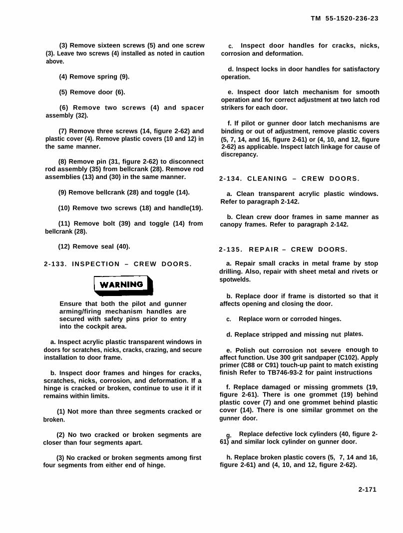
TM 55-1520-236-23
(3) Remove sixteen screws (5) and one screw(3). Leave two screws (4) installed as noted in cautionabove.
(4) Remove spring (9).
(5) Remove door (6).
(6) Remove two screws (4) and spacerassembly (32).
(7) Remove three screws (14, figure 2-62) andplastic cover (4). Remove plastic covers (10 and 12) inthe same manner.
(8) Remove pin (31, figure 2-62) to disconnectrod assembly (35) from bellcrank (28). Remove rodassemblies (13) and (30) in the same manner.
(9) Remove bellcrank (28) and toggle (14).
(10) Remove two screws (18) and handle(19).
(11) Remove bolt (39) and toggle (14) frombellcrank (28).
(12) Remove seal (40).
2 -133 . INSPECTION – CREW DOORS.
Ensure that both the pilot and gunnerarming/firing mechanism handles aresecured with safety pins prior to entryinto the cockpit area.
a. Inspect acrylic plastic transparent windows indoors for scratches, nicks, cracks, crazing, and secureinstallation to door frame.
b. Inspect door frames and hinges for cracks,scratches, nicks, corrosion, and deformation. If ahinge is cracked or broken, continue to use it if itremains within limits.
(1) Not more than three segments cracked orbroken.
(2) No two cracked or broken segments arecloser than four segments apart.
(3) No cracked or broken segments among firstfour segments from either end of hinge.
c. Inspect door handles for cracks, nicks,corrosion and deformation.
d. Inspect locks in door handles for satisfactoryoperation.
e. Inspect door latch mechanism for smoothoperation and for correct adjustment at two latch rodstrikers for each door.
f. If pilot or gunner door latch mechanisms arebinding or out of adjustment, remove plastic covers(5, 7, 14, and 16, figure 2-61) or (4, 10, and 12, figure2-62) as applicable. Inspect latch linkage for cause ofdiscrepancy.
2 -134 . CLEANING – CREW DOORS.
a. Clean transparent acrylic plastic windows.Refer to paragraph 2-142.
b. Clean crew door frames in same manner ascanopy frames. Refer to paragraph 2-142.
2 - 1 3 5 . R E P A I R – CREW DOORS.
a. Repair small cracks in metal frame by stopdrilling. Also, repair with sheet metal and rivets orspotwelds.
b. Replace door if frame is distorted so that itaffects opening and closing the door.
c. Replace worn or corroded hinges.
d. Replace stripped and missing nut
e. Polish out corrosion not severe
plates.
enough toaffect function. Use 300 grit sandpaper (C102). Applyprimer (C88 or C91) touch-up paint to match existingfinish Refer to TB746-93-2 for paint instructions
f. Replace damaged or missing grommets (19,figure 2-61). There is one grommet (19) behindplastic cover (7) and one grommet behind plasticcover (14). There is one similar grommet on thegunner door.
g. Replace defective lock cylinders (40, figure 2-61) and similar lock cylinder on gunner door.
h. Replace broken plastic covers (5, 7, 14 and 16,figure 2-61) and (4, 10, and 12, figure 2-62).
2-171
TM 55-1520-236-23
i. Replace cracked or crazed acrylic plastictransparent windows in doors.
j. Polish out cracks or nicks in acrylic plastictransparent windows in doors provided that length ofdamaged area does not exceed 0.5 inch and depth ofpolished area does not exceed 0.025 inch. Usewindshield maintenance kit (T85), acrylic plasticpolishing kit (T86) and
k. Replace door ifhinge or latch.
l. Replace cracked
water.
frame is cracked in area of
or broken hinge that is notwithin limits. Refer to paragraph 2-133, step b.
m. Replace seal (48) if damaged.
2-136. ASSEMBLY – CREW DOORS.
a. Assemble pilot door. See figure 2-59 and 2-61.
Ensure that both the pilot and gunnerarming/firing mechanism handles aresecured with safety pins prior to entryinto the cockpit area.
NOTE
It is recommended that door be removedfrom helicopter for assembly if intensivedisassembly has been accomplished.Refer to paragraph 2-131.
(1) Position toggle (35, figure 2-61) onbellcrank (46) in position shown. Install bolt (28) withstandard aluminum washer (32), corrosion resistantsteel washer (33) and standard aluminum washer(34) in position shown. Install nut (37) with thinaluminum washer (36). Install nut fingertight andcheck that toggle will move freely on bolt. Installcotter pin (38).
(2) Position handle (41) on door frame andinstall two screws (42).
(3) Position toggle (35) and bellcrank (46) inhandle (41) with handle pointing aft as shown.
(4) Position spacer assembly (47) on bellcrank(46). Secure spacer assembly to door frame (4) withone screw (23) at the top and one similar screw at thebottom.
Spring (12) applies a strong force tospacer assembly (47) when the spring isinstalled. Ensure that screw (23) and asimilar screw at the bottom of the spacerassembly are installed at all times whenspring (12) is installed.
(5) Ensure that grommet (19) is in place andinstall rod assembly (8) through guide (3). Secure tobellcrank with pin (31), washer (30) and cotter pin(29). Install rod assemblies (10) and (15) in a similarmanner.
(6) Install spring (12) on clip (13) and toggle(35). Operate handle (41) and check operation. Thereshould be no binding of linkage. Spring (12) shouldreturn handle to horizontal position.
(7) Position door (11) on door frame (4) andinstall one screw (26) and sixteen screws (22).
(8) Install handle (25) on bellcrank (46), handlepointing forward as illustrated, with adhesive (C11)applied to that surface of the handle that engages withbellcrank shaft. Install pin (24). Cure adhesive permanufacturer’s package instructions.
(9) Install plastic covers (5, 7, 14 and 16) withthree screws each.
(10) Check operation of handle and latchlinkage as outlined in step (6).
(11) Replace seal (48) if damaged.
b. Assemble gunner door as follows:
(12) Position gunner door (1, figure 2-62) on apadded work surface.
(2) Position toggle (14, figure 2-63) onbellcrank (28) in position shown. Install bolt (39) withstandard aluminum washer (27), corrosion resistantsteel washer (26) and standard aluminum washer(25) in position shown. Install nut (22) with thinaluminum washer (23). Install nut fingertight andcheck that toggle will move freely on bolt. Installcotter pin (21).
(3) Position handle (19, figure 2-63) on doorframe (8) and install two screws (18).
(4) Position assembled toggle (14) andbellcrank (28) in handle (19) with handle pointing aftas shown.
2-172
TM 55-1520-236-23
(5) Position spacer assembly (32) on bellcrank(28). Secure spacer assembly (32) to door frame (8)with one screw (4) at the top and one similar screw atthe bottom.
Spring (9) applies a strong force tospacer assembly (32) when the spring isinstalled. Ensure that screw (4) anda similar screw at the bottom of thespacer assembly are installed at all timeswhen spring (9) is installed.
(6) Ensure that grommet (34) is in place. Installrod assembly (35) through guide (36). Secure rod tobellcrank with pin (31), washer (37), and cotter pin(38). Install rods (13) and (30) in the same manner.
(7) Install spring (9) on clip (10) and toggle (14).Operate handle (19) and check operation of latchmechanism. There should be no binding and spring(9) should return handle to horizontal position.
(8) Position door (6) on door frame (8) andinstall sixteen screws (5) and one screw (3).
(9) Install handle (1) on bellcrank (28), handlepointing forward as illustrated, with silicone adhesive(C11) applied to that surface of the handle that engageswith bellcrank shaft. Install pin (2). Cure adhesive permanufacturer’s package instructions.
(10) Install plastic covers (4, 10, and 12, figure2-62) with three screws each.
(11) Replace seal (40, figure 2-63) if damaged.
2-137. INSTALLATION – CREW DOORS.
Ensure that both the pilot and gunnerarming/firing mechanism handles aresecured with safety pins prior to entryinto the cockpit area.
a. Install pilot door. See figure 2-59.
(1) Position door (1) on helicopter. Support thedoor in the open position, align hinge halves andinstall hinge pin (10).
(2) Align the socket on lower end of gas spring(3) with ball stud fitting (22). The socket on the end ofthe gas spring should slide on the ball stud fittingwhen moderate force is applied. Install safety clip(23).
(3) Close the door and check for 0.250 inchdimension at strikers (14) and (17). See sectionalviews B-B and D-D. Adjust thickness of shims (12)and/or (19) if required.
(4) Operate door handle (5) and check doorlatch rods (13) and (18) to ensure that they fullyengage strikers and that the door latch mechanismoperates smoothly.
(5) Lock and unlock cylinder (4) to ensure thatoperation is satisfactory.
b. Install gunner door. See figure 2-60.
(1) Position door (1) on helicopter. Support thedoor in the open position. align hinge halves andinstall hinge pin (20).
(2) Align the socket on lower end of gas spring(3) with ball stud fittings (24). The socket on the end ofthe gas spring should slide on the ball stud fittingwhen moderate force is applied. Install safety clip(25).
(3) Close the door and check for 0.250 inchdimension at strikers (9) and (15). See sectional viewsB-B and D-D. Adjust thickness of shim (10) and/orposition of aft striker plate (14) if required.
(4) Operate door handle (4) and check doorlatch rods (8) and (17) to ensure that they fully engagestrikers and that the door latch mechanism operatessmoothly.
(5) Lock and unlock lock cylinder (7) to ensurethat operation is satisfactory.
2-138. ADJUSTMENT – CREW DOORS.
Refer to paragraph 2-137.
2-139. PAINTING – CREW DOORS.
Touch up paint to match original finish. Refer to TM 55-1500-345-23 for general painting instructions.
2 - 1 4 0 . C A N O P Y A N D C R E W D O O RW I N D O W S A N D W I N D S H I E L D S .
2 - 1 4 1 . D E S C R I P T I O N – C A N O P Y A N DC R E W D O O R W I N D O W S A N DWINDSHIELDS.
See figure 2-64. The canopy and crew door windowsand windshields are fabricated from acrylic plastic.Acrylic impregnated nylon fabric edging is bonded to
2-173
TM 55-1520-236-23
the edges of window and windshield sections. Thewindows and windshields are secured in the doorframes or canopy frames as applicable with screws.
2-142. CLEANING – CANOPY AND CREWDOOR WINDOWS AND WINDSHIELDS.
Ensure that both the pilot and gunnerarming/firing mechanism handles aresecured with safety pins prior to entryinto the cockpit area.
Do not use compounds that contain anyabrasive material or solutions thatcontain chlorinated carbons. Avoidexcessive scrubbing of plastic panelsduring washing operation.
a. Clean the transparent plastic windows withclear water. Free all caked dirt with fingers. Do notuse sponges or coarse cloths. Rinse frequently withwater while removing dirt.
Cleaning solvent is flammable and toxic.Provide adequate ventilation.Avoidprolonged breathing of solvent vaporsand contact with skin or eyes.
Do not use aliphatic naphtha Type 1 in oraround cockpit. Use of this solvent canresult in damage to acrylic, plastic.
b. Remove any grease or oil that remains onwindows after washing as describer in step a., withaliphatic naphtha, Type II (C75) and repeat cleaningwith cleaning compound as described in step a.
c. Allow surfaces to drip dry.
d. Polish out minor scratches which mayinterfere with pilot or gunner vision, Use windshieldmaintenance kit (T85), acrylic plastic polishing kit
(T86) and water.
2 - 1 4 3 . I N S P E C T I O N – C A N O P Y A N DC R E W D O O R W I N D O W S A N DWINDSHIELDS.
a. Nicks, chips, and gouges. Allowed if not deeperthan 0.050 and not larger than can be, enclosed with a0.50 diameter circle after cleanup. If more then twosuch damage areas fall within a 3.04nch circle, thepanel should be replaced.
b. Penetrating damage. A hole that can be cleanedup not to exceed 0.75 may be patched with a taperedplug if no other damage occurs within 3.0 inches.
C. Scratches. Up to 0.016 deep and not exceeding 1.0inch in length allowed if no other damage occurswithin 1.0 inch.
d. Inspect for bond separation between acrylicplastic and nylon fabric edging.
e. No defects or repairs are acceptable which impairvision of crew members.
2-144. REMOVAL – CANOPY AND CREWDOOR WINDOWS AND WINDSHIELDS.
Ensure that both the pilot and gunner arming/firingmechanism handles are secured with safety pinsprior to entry into the cockpit area.
a. Pilot window (10, figure 2-64) and gunnerwindow (7) are equipped with explosive windowcutting assemblies. The window cutting assembliesare retained by the window installation screws. Referto Paragraph 17-6 for instructions to remove thesetwo windows.
b. Remove fire and high air data subsystem boom.
c. Remove windshields and windows (1, 5, 8, 9and 11).
NOTEProcedure for removal of upperwindshield (6) is given. Remove otherwindows and windshield in the samemanner.
(1) Removewindshield (5).
screws (4) around edge of upper
e. Apply rain repellant in accordance withdirections on container.
2-174

TM 55-1520-236-23
Do not exceed 250 degrees F (121degrees C) or acrylic plastic may bedamaged.
(2) Push upper windshield (5) out of canopyframe (6). If windshield (5) is difficult to remove, applyheat with heat lamp to soften sealant.
2-174.1/(2.174.2 blank)


TM 55-1520-236-23
(3) Clean old sealant from canopy frames (6).If the same upper windshield is to be reinstalled, alsodean sealant from the windshield. Use a sharp plasticscraper to remove old sealant.
(4) Refer to paragraph 13-104 for removal ofrain removal thermal switch from lower windshield (1).
2-145. REPAIR — CANOPY AND CREW DOOR— WINDOWS AND WINDSHIELDS.
Ensure that both the pilot and gunnerarming/firng mechanism handles aresecured with safety pins prior to entryInto the cockpit area.
a. Polish out minor scratches and nicks in wind-shields and windows. Use windshield maintenance kit(T85) and acrytic plastic polishing kit (T86).
b. Repair leaks at edges of windshields andwindows by removing windshield or window andreinstalling with new sealant. Refer to paragraphs2-144 and 2-146.
2-146. INSTALLATION – CANOPY AND CREWDOOR WINDOWS AND WINDSHIELDS
Ensure that both the pilot and gunnerarming/fitlng handles are secured withsafety pins prior to entry Into the cock-pit area.
a. Pilot window (10, figure 2-64) and gunnerwindow (7) are equipped with explosive window cuttingassemblies. The cutting assemblies are retained bythe window installation screws. Refer to paragraph17-8 for instructions to install windows.
Install windshields and windows (1, 5, 8, 9,and 11).
NOTE
Procedure for Installation of upperwindshield (5) is given. Install otherwindows and wlndshield In the samemanner.
(1) Ensure that each rivet nut and nut plate forwindshield attaching screws (4) is securely installedand the threads are not damaged. Replace any dam-aged rivet nuts or nut plates.
(2) Ensure that there are no obstructions onthe canopy frame (6) or the windshield (5) that wouldprevent a dose fit when the windshield is installed.
(3) tf a new windshield (5) is being installed,drill holes in windsheild for screws (4) to match holesin frame (6). Use hole finder to locate holes. Drill holes0.203 to 0206 inches in diameter.
Adhesive and sealants are flammable and toxic. Provide adequate ventilation.Avoid prolonged breathing of adhesivevapor and contact with skin, or eyes.
(4) Ensure that edgings (2) and (3) aresecurely bonded to upper windshield (5). If any smallareas are not bonded, repair loose area with adhesive(C10). Mix two-part adhesive in accordance withinstructions on container. Mask off acrylic plastic toavoid damage by contact with adhesive. Apply mixedadhesive to unbended area with a small squeegee.Clean up excess adhesive and remove masking. Allowadhesive to cure for 24 hours at room temperature.
Cleaning solvent is flammable andtoxic. Provide adequate ventilation.Avoid prolonged breathing of solventvapors and contact with skin or eyes
(5) Clean mating surfaces of frame (6) andupper windshield (5) with naphtha (C75) and cleancloths.
Sealant is flammable and toxic. Provideadequate ventilation. Avoid prolongedbreathing of vapors and contact withskin or eyes.
(6) Mix two-part sealant (C105),alternates are (C105.5), (C107), (C107.3),(C107.4). Use 10 parts of grey color baseto one part white color accelerator by weight.Mix in a clean, non-absorbent container. Mix
2-175
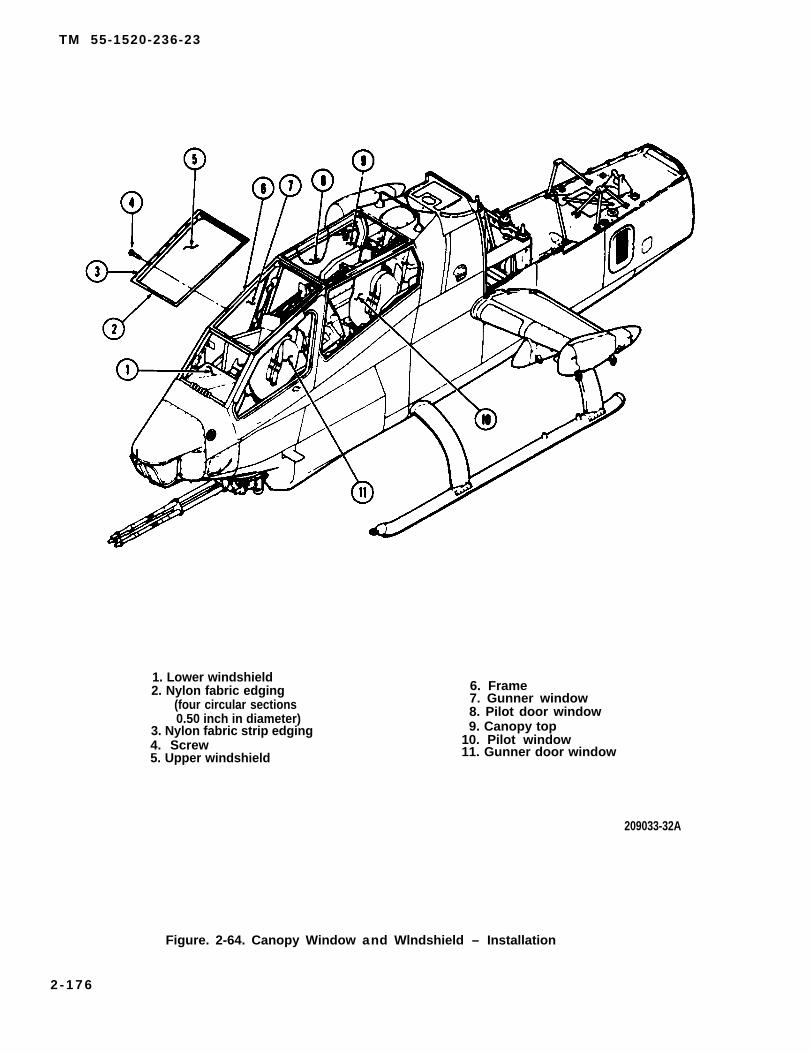
TM 55-1520-236-23
1. Lower windshield2. Nylon fabric edging
(four circular sections0.50 inch in diameter)
3. Nylon fabric strip edging4. Screw5. Upper windshield
6. Frame7. Gunner window8. Pilot door window9. Canopy top
10. Pilot window11. Gunner door window
209033-32A
Figure. 2-64. Canopy Window and Wlndshield – Installation
2 - 1 7 6

TM 55-1520-236-23
the accelerator thoroughly in its container beforemixing with the base material; then mix the twoaccelerators with the base material. Pot life of themixed sealant is two hours.
(7) Apply a small bead of sealant prepared inpreceding step to edge of frame (6) just outboard ofholes for screws (4). The correct size bead of sealantwill result in a slight amount of squeeze out whenwindshield is installed. Use a pressure gun to applysealant if available.
(8) Position windshield (5) in frame (6) andinstall screws (4) finger tight. Use screws (4) ofcorrect length for thread engagement with rivet nuts.Tighten screws (4) evenly. Clean excess sealantsqueeze out with a sharp plastic scraper after sealantcures. It may take up to 14 days for sealant to cure.
(9) Refer to paragraph 13-105 for installationof rain removal thermal switch in lower windshield(1).
2 - 1 4 7 . C A N O P Y F R A M E S .
2 - 1 4 8 . D E S C R I P T I O N – C A N O P YFRAMES.
The canopy frame assembly supports the pilot and
c. Inspect canopy frames for secure installation ofwindshields, windows, and doors.
d. If any windows or windshields have beenremoved from canopy frames, inspect exposed blindrivet nuts for secure installation and for damagedthreads.
2 -151 . CLEANING – CANOPY FRAMES.
a. Clean canopy frames with biodegradablecleaner (C32), water, and clean cloths.
b. Remove all cleaner and water with clean drycloths.
c. If any windows of windshields have beenremoved, clean old sealant from frames with sharpplastic scraper.
2 - 1 5 2 . R E P A I R – CANOPY FRAMES.
a . Replace damaged blind rivet nuts. Two types ofblind rivet nuts are used. Refer to TM 55-1520-236-23P.
b . Touch-up damaged paint to matche x i s t i n g f i n i s h . Refer to TM 55-15ØØ-345-23.
gunner doors, windows, and windshields. The frames 2 - 1 5 3 . I N S T A L L A T I O N – C A N O P Yare constructed from aluminum alloy (figure 2-65). FRAMES.
2-149 . REMOVAL – CANOPY FRAMES. Canopy frames must be replaced at highermaintenance level.
Canopy frames must be removed at the depot levelmaintenance activity.
2 - 1 5 4 . P I L O T A N D G U N N E R S E A TA S S E M B L I E S .
2-150. INSPECTION – CANOPY FRAMES.
Ensure that both the pilot end gunnerarming/firing mechanism handles aresecured with safety pins prior to entryinto the cockpit area.
a . Inspect canopy frames for obvious damagesuch as distortion and cracks. Canopy frames withthis type damage must be replaced.
b. Inspect canopy frames for nicks, dents,distortion and corrosion.
2 - 1 5 5 . D E S C R I P T I O N – P I L O T A N DGUNNER SEAT ASSEMBLIES.
a. The pilot seat is one-piece, bucket-type seatmounted on two vertical tubes which hold it in placeon the airframe structure and serve to make the seatadjustable vertically. See figure 2-66. The seat isconstructed of armor steel with fittings for armor sidepanels.
b. The gunner seat is a two-piece, bucket typeseat. The two major components are the back and thebottom. See figure 2-67. Construction is ceramicplate armor.
2-177
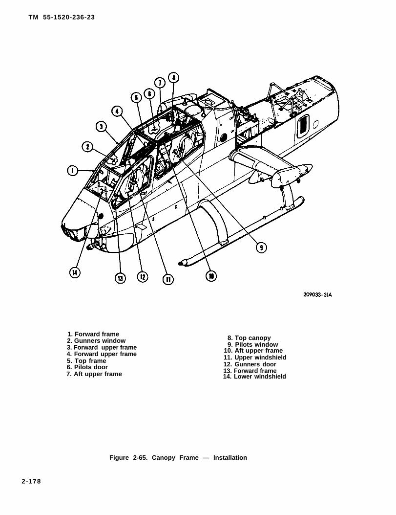
TM 55-1520-236-23
1. Forward frame2. Gunners window3. Forward upper frame4. Forward upper frame5. Top frame6. Pilots door7. Aft upper frame
8. Top canopy9. Pilots window
10. Aft upper frame11. Upper windshield12. Gunners door13. Forward frame14. Lower windshield
Figure 2-65. Canopy Frame — Installation
2-178

TM 5-1520-236-23
1. Seat cushion2. Side armor panel3. Air ducts4. Washer5. Screw6. Seat back cushion7. Air inlet8. Seat assembly9. Bolt
10. Shoulder harness11. Washer
12. Nut13. Screw14. Bolt15. Washer16. Nut17. Cover, inertia reel18. Inertia real19. Bolt20. Seat lap belt21. Spacer
22. Spacer23. Inertia real control24. Screw25. Washer26. Screw27. Bolt28. Washer29. Nut30. Screw31. Screw
209070-188C
Figure 2-66. Pilot Seat – Installation
2-179

TM 55-1520-236-23
Figure 2-67. Gunner Seat – Installation (Sheet 1 of 2)
2-180

TM 55-1520-236-23
1. Seat cushion2. Air ducts3. Side armor panel4. Screw5. Washer6. Screw7. Washer8. Seat back cushion9. Air inlet
10. Seat back11. Inertia real12. Washer13. Screw14. Screw15. Nut
16. Washer17. Seat bottom panel18. Attaching strap19. Spacer20. Bolt21. Seat lap belt22. Bolt23. Screw24. Washer25. Screw26. Inertia reel control27. Spacer28. Screw29. Screw30. Screw
209070-187-2C
Figure 2-67. Gunner Seat – Installation (Sheet 2 of 2)
2-156. REMOVAL – PILOT AND GUNNERSEAT ASSEMBLIES.
Ensure that both pilot and gunnerarming/firing mechanism handles aresecured by safety pins prior to entry intothe cockpit area.
a. Remove pilot seat from cockpit.
(1) Loosen clamp and disconnect airdistribution duct from duct cushion air inlet (7, figure2-66).
(2) Remove seat back cushion (6) and air ducts(3).
(3) Remove seat cushion (1).
Handle side armor panels and seat withcare; ceramic tile is easily broken.
(4) Remove side armor panels (2) by removingscrews (5, 26, 30, and 31), washers (4 and 25), andspacers (21).
(5) Detach inertia reel control (23) from side ofcockpit by removing screws (24), washers (15), andspacer (22).
(6) Remove bolts (9 and 14), washers (11), andnuts (12). Remove seat assembly from helicoter.
(7) Remove nuts (12), washers (11), and bolts(19) and remove seat lap belt (20).
(8) Detach shoulder harness (10) from inertiareel strap by removing nut (29), washer (28), and bolt(27).
(9) Remove four nuts (16), washers (15), andscrews (13) attaching inertia reel (18) and cover (17).Remove cover and inertia reel.
b. Remove gunner seat from cockpit.
(1) Loosen clamp and disconnectdistribution duct from air inlet (9, figure 2-67).
(2) Remove seat cushion (1) and air ducts
(3) Remove seat back cushion (8).
Handle armor panels and seat with care;ceramic tile is easily cracked.
air
(2).
(4) Remove side armor panels (3) by removingscrews (4, 23, 25, 29, and 30) and washers (5 and 24).
(5) Remove six screws (6) and washers (7)which attach seat back (10) to bulkhead and removeseat back.
2-181

TM 55-1520-236-23
(6) Remove screws (28), washers (12) andspacers (27) which attach inertia red control (26) toside of cockpit. Loosen knurled nut and disconnectcontrol cable from handle.
(7) Remove four screws (13 and 14) andwashers (12). Work shoulder harness back throughbulkhead and remove inertia reel (11) from helicopter.
(8) Remove bolts (22), washers (16) and nuts(15) which attach seat lap belt (21) to attaching strap(18). Remove seat lap belt from helicopter.
Handle side armor panels and seat withcare; ceramic tile is easily broken.
(9) Remove screws (29) and washers (7)whichattach seat bottom panel (17) to structure. Removeseat bottom panel from helicopter.
2 - 1 5 7 . I N S P E C T I O N – P I L O T A N DGUNNER SEAT ASSEMBLIES.
a. lnspection. Inspect installed pilots seat for thefollowing defects:
(1) Refer to paragraph 2-178 for inspectionprocedure for side armor panels (2 figure 2-66) andarmor seat (2, figure 2-68).
(2) Seat cushion (1) and back cushion (8) forwear and damage. Use same procedure described forpilot seat cushions.
(3) Secure mounting of the seat in thehelicopter and secure installation of the inertia realand armor panels.
c. Inspect disassembled pilot seat assembly asfollows: See figure 2-68.
(1) Inspect upper guide fittings (4) and lowerguide fittings (7) by fluorescent penatrant method.Refer to TM 43-0103.
(2) Inspect handle assembly (1), support tubes(3), latch springs (9), return spring (5), and latch pins(10) by magnetic particle method. Refer to TM 43-0103.
(3) Inspect seat netting for tears, cuts andholes. Damage greater than one inch in length ordiameter is not repairable. Temporary repairs can bemade to damage less than one inch in length ordiameter.
(4) Inspect seat netting for deterioration anddiscoloration which indicate a decrease in strength. Ifintegrity of netting is doubtful, the netting must bereplaced.
2 - 1 5 8 . D I S A S S E M B L Y – P I L O T A N DGUNNER SEAT ASSEMBLIES.
(2) Cracks. No cracks allowed.a . Disassemble pilot seat.
(3) Secure mounting of the seat in thehelicopter and secure installation of the inertia reeland armor panels.
(4) Seat cushion and back cushion for wear anddamage. Sun fading is not cause for rejection. Wearand damage that affect comfort must be corrected byrepair or replacement.
(5) Check seat vertical adjustment, ease ofoperation, and secure locking in various heightpositions.
b. Inspection. Inspect installed gunner seat forthe following defects.
(1) Refer to paragraph 2-175 for inspectionprocedure for side armor panels (3, figure 2-67), seatback (10) and seat bottom panel (17).
(1) Adjust the pilot seat to “UP” position onsupport tubes (3, figure 2-68). Remove two returnsprings (5).
(2) Pull upon handle (1) to withdraw latch pins(10) from support tubas (3). Pull upward on supporttubas (3) and removal them from finings (4 and 7).
(3) Disconnect handle Ievers (6) from latch pins(10) by removing cotter pins (11), washers (13), andpins (12) at latch side of seat.
(4) Remove screwa (14), washers (16) andretainer plates (8) from lower fittings (7) and removelatch pins (10) and latch springs (9).
(5) Remove two upper faiings (4) and lowerfittings (7) from seat (2).
2- 182
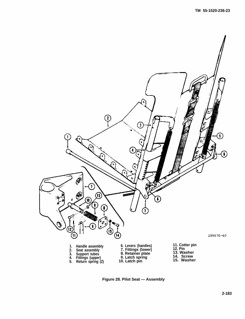
1.2.3.4.5.
Handle assemblySeat assemblySupport tubesFittings (upper)Return spring (2)
6. Levers (handles)7. Fittings (lower)8. Retainer plate9. Latch spring
10. Latch pin
Figure 28. Pilot Seat — Assembly
TM 55-1520-236-23
11. Cotter pin12. Pin13. Washer14. Screw15. Washer
2-183

TM 55-1520-236-23
b. Disassemble gunner seat. The gunner seat is dis-assembled during removal (paragraph 2-156).
2-159. REPAIR — PILOT AND GUNNER SEAT
ASSEMBLIES. Refer to TM 1-1500-204-23(Ser ies) .
2-160. ASSEMBLY — PILOT AND GUNNERSEAT ASSEMBLIES.
a. Assemble pilot seat.
(1) Position handle assembly (1, figure 2-68) inplace of each lower fitting (7).
(2) Install lower fittings (7) on seat assembly (2).
(3) Install upper fittings (4) on seat assembly.
(4) Install a latch pin (10) and latch spring (9) ineach lower fitting (7). Install retainer plates (8) to securelatch pins and springs.
(5) Connect latch pins (10) to levers (6) of handleassembly (1) with clevis pins, washers, wand cotter keys.
(6) Install support tubes (3) down through upperfittings (4) and lower fittings (7). Hold handle (1) in UP po-sition to permit passage of support tubes through lower fittings (7).
(7) Install return springs (5).
b. Assemble gunner seat. The gunner seat is as-sembled during installation in the helicopter (paragraph 2-161).
2-161. INSTALLATION — PILOT ANDGUNNER SEAT ASSEMBLIES.
Before performing any maintenance in or nearthe cockpit area, ensure that both pilot andgunner arming/iring mechanism handles aresecured by safety pins.
The pilot’s and gunner’s shoulder harness in-ertia reels are not interchangeable.
a. Install pilot seat assembly,
(1) Position inertia reel (18, figure 2-66) and cover(17) on back of seat assembly (8). Install screws (13),washers (15), and nuts (16) with heads of screws on insideof seat bucket.
(2) Thread shoulder harness (10) through guide attop of seat assembly (8). Attach inertia reel strap with bolthead facing seat back.
(3) Install seat lap belt (20) with bolts (19), wash-ers (11), and nuts (12). Install belt half with lock on left side,install bolts (19) with bolt heads on inside of seat bucket
2-184

TM 55-1520-236-23
(4) Position seat assembly (2, figure 2.68) in (5) Tighten knurled nut on inertia reel controlhelicopter. Fit support tubes (3) into fittings (4 and 7). (23). Position inertia reel control (23) on side ofRoute inertia reel cable inboard of left support tuba as cockpit and secure with spacers (22), washers (15),illustrated on figure 2-66. Install seat attaching bolts and screws (24). Lockwire knurled nut with Iockwire(9 and 14. figure 2-66), washers (11), and nuts (12). (C137).
2-184.1/(2-184.2 blank)


TM 55-1520-236-23
(6) Install seat (1), air ducts (3), and seat back c. The gunner seat is non-adjustable and has nocushion (6). functional check.
(7) Position air distribution duct on air inlet (7). 2 - 1 6 3 . S H O U L D E R H A R N E S S A N DTighten clamp to secure duct. INERTIA REEL.
(8) Install side armor panels (2) with screws (5,26, 30, and 31), washers (4 and 25), and spacers (21). 2 - 1 6 4 . D E S C R I P T I O N – S H O U L D E R
HARNESS AND INERTIA REEL.b. Install gunner seat assembly.
The pilot and gunner shoulder harness serves to(1) Position seat bottom panel (17, figure 2-67) prevent injury and restrain their movement during
in cockpit and secure with screws (29) and washers helicopter operations. The inertia reel controls the(1). shoulder harness through cable connections
between the harness and the reel. The pilot and(2) Position seat back (10) in cockpit and secure gunner can select "Lock” or “Auto” with their
with bolts (4) and washers (7). individual controls.
(3) Work shoulder harness through bulkhead.Position inertia reel (11) on bulkhead. Secure withscrews (13 and 14) and washers (12). Place onewasher (12) under each screw head and one washer(12) under each inertia reel (11) attachment lug.
(4) Route inertia reel control cable along leftside of seat and connect to inertia reel control (26).Tighten knurled nut and position inertia reel control(26) on beam. Install screws (28), washers (12) andspacers (27). Lockwire knurled nut with lockwire(C137).
(5) Attach seat lap belt (21) to attaching strap(18) with bolts) 22), washers (16), and nuts (15).
(6) Connect air ducts (2) on seat cushions (1)and install cushion.
(7) Connect air ducts (2) to seat back cushion (8)
2 - 1 6 5 . R E M O V A L – S H O U L D E RHARNESS AND INERTIA REELS.
2 - 1 6 6 . I N S P E C T I O N – S H O U L D E RHARNESS AND INERTIA REEL.
T h e p i l o t s and gunners shoulderharness webbing adjusters are notthe same. The pilots shoulder harn-ess webbing adjuster i n c l u d e s aspr ing for proper operation. Thegunners shoulder harness webbingadjuster d o e s n o t r e q u i r e t h i sspr ing. I f the spr ing is insta l led ,remove i t pr ior to the next f l ight .
and install cushion.a. Inspect pilot and gunner shoulder harness
(8) Position air distribution duct on air inlet (9) and inertia reel strap for tears, fraying, wear, andand tighten clamp to secure duct. general condition.
(9) Install side armor panels (3) with swcrew (4,b. Refer to TM 55-1500-204-25/1. See figures
6, 23, 25, 30) and washers (5, 7, and 24).2-66 and 2-67.
c. Inspect pilot inertia reel (18, figure 2-66) and2 - 1 6 2 . A D J U S T M E N T – P I L O T A N D control (23). (Refer to TM 55-1500-204-25/1.)GUNNER SEAT ASSEMBLIES.
(1) Place control (23) in “Lock” position and . Adjust pilot and gunner inertia reel and control pull on shoulder harness; the inertia reel should hold
to make sure the inertia reel will lock, unlock and the shoulder harness and not extend. Inertia reelsrewind as applicable. that will not lock are not acceptable.
b. Perform funcitonal check of pilot seat vertical (2) P lace contro l (23) in “Auto”
adjustment to make sure pilot seat will lock in all p o s i t i o n and pull on shoulder harness.
vertical positions, up and down. The i n e r t i a r e e l s h o u l d p e r m i t t h eshoulder harness t o b e p u l l e d o u t
2-185

TM 55-1520-236-23
against spring tension and shouldrewind when pressure is decreased.Sharply pul l shoulder harness exer t inga two to three G force to check lockingmechanism. When pul l ing pressure isdecreased, h a r n e s s s h o u l d r e w i n d i ni n e r t i a r e e l . Locking mechanism willnot re lease u n t i l auto lockingm e c h a n i s m i s cycled through f u l lt r a v e l . Cycle c o n t r o l h a n d l e t ore lease auto locking mechanism.I n e r t i a r e e l s that wil l not operate asd e s c r i b e d i n t h i s p a r a g r a p h a r e n o tacceptable.
(3) Inspect inertia reel strap for wear, fraying,and general condition.
(4) Inspect inertia reel (18) and control (23) forsecure mounting and damage.
(5) Inspect cable between inertia reel (18) andcontrol (23) visually for fraying and damage.
(6) Inspect gunner Inertia reel and control insimilar manner See figure 2-67.
2 - 1 6 7 . R E P A I R – SHOULDER HARNESSAND INERTIA REEL.
a. Replace inertia reel that fails to pass functionalcheck.
b. Replace worn inertia reel strap.
(1) Move inertia reel control handle to “Auto”position and pull out slowly on strap assembly untilweb retaining insert is visible through lower slot inreel housing.
If reel is inadvertently released whilestrap is removed, replace entire realassembly.
(2) Move control handle to LOCK position.
(3) Remove web retaining insert and withdrawstrap from reel.
(4) Insert end of new strap through upper slot inreel housing and through slot in main shaft until endof strap protrudes through lower slot in real housing.Install web retaining insert. Pull upward on strap withat least six pounds force and hold. Move controlhandle to AUTO position and allow strap to rewind.
c. Replace inertia reel and/or control if cable isfrayed or if the components have incurred damagethat may affect function.
d. Refer to TM 55-1500-204-25/1 for repairprocedures for pilot and gunner shoulder harness.
2 - 1 6 8 . I N S T A L L A T I O N – S H O U L D E RHARNESS AND INERTIA REEL.
Refer toinstallation
2 - 1 6 9 .
paragraph 2-161 as applicable forand functional check instructions.
SEAT BELTS.
2-170. DESCRIPTION – SEAT BELTS.
The pilot and gunner seat lap belts are secure to thesides of the seats. The belts serve to restrainmovement of the crew during helicopter operations.2 - 1 7 1 . R E M O V A L –
Refer to paragraph 2-156
2 - 1 7 2 . I N S P E C T I O N
SEAT BELTS.
as applicable.
– SEAT BELTS.
a. Inspect pilot and gunner seat lap belts forfraying, wear, tears, and general condition.
b. Refer to TM 55-1500-204-25-1/1.
2-173. REPAIR – SEAT BELTS.
Refer to TM 55-1500-204-25/1 for repair proceduresfor pilot and gunner seat belts.
2-174. INSTALLATION – SEAT BELTS.
Refer to paragraph 2-161 as applicable.
2 - 1 7 5 . A R M O R P A N E L S .
2-176. DESCRIPTION – ARMOR PANELS.
The crew and engine are protected against hostilearms fire by ceramic-plastic armor panels. The pilotand gunner seats have armor installed on sides, back,and bottom. The engine compartment has armorinstalled at station 195 to protect the fuel control.
2 -177 . REMOVAL – ARMOR PANELS.
a. Refer to paragraph 2-156 for removal of armorpanels at pilot and gunner seats. See figure 2-66 and2-67.
2-186
TM 55-1520-236-23
b. Open engine cowling and remove enginearmor assembly on left and right side. See figure 2-69.
2 -178 . INSPECTION – ARMOR PANELS.
a. Inspect armor installations on pilot and gunnerseats and engine cowl for damaged brackets andcracks.
b. Inspect armor panels for the following defects:
(1) Damage caused by a ballistic projectile.Panels with this type damage are not reparable andmust be replaced.
(2) Damage that results in loose nylon clothshield and/or neoprene rubber edge moulding. Markloose areas for rebonding.
2-186.1/(2-186.2 blank)


TM 55-1520-236-23
(3) Damage that results in delamination is notreparable.
(4) Damage to threads in threaded inserts,loose bonding of threaded inserts to panel andmissing threaded inserts.
(5) Damage to armor panel attaching brackets.Minor damage is reparable.
(6) Refer to TM 55-1500-204-25/1 foradditional inspection criteria if required.
2 - 1 7 9 . R E P A I R – ARMOR PANELS.
Adhesive is flammable and toxic. Provideadequate ventilation when mixing andusing. Avoid prolonged breathing ofvapors and contact with skin or ayes.
a. Rebond loose nylon cloth shield or neoprenerubber edge moulding with adhesive (C17).
b. Repair threaded fasteners with slightlydamaged threads by cleaning up threads with a tap.Replace the threaded fastener with a new fastener ifthread damage is severe. Refer to step d. for bondingprocedure.
c. Repair a loose threaded insert by rebonding.Drill two small holes in the backing at an angle downto bottom of threaded insert and clean out holes.Place masking tape over the two small holes and thethreaded hole in the insert to keep adhesive out of thethreads. use a sharp pointed tool to open holesthrough the masking tape at the two drilled holes.Inject adhesive (C8) into one hole with a syringe.Continue injecting adhesive until it is forced from thesecond hole. Allow to cure for 24 hours.
d.
Adhesive is flammable and toxic. Provideadequate ventilation when mixing andusing. Avoid prolonged breating ofadhesive vapors and contact with skin oreyes.
Replace threaded fastener with faulty threadsor one that is very loose in the panel. Drill out the oldfastener carefully to avoid damage to the panel. Clean
out the hole and bond a new fastener in the panel inthe same manner outlined in the preceding step.
e. Repair cracked or distorted armor panelattaching brackets with standard metalworkingprocedures if practical. Replace brackets that are notreparable.
2 - 1 8 0 . I N S T A L L A T I O N – A R M O RPANELS.
a. Refer to paragraph 2-161 for installation ofarmor panels at pilot and gunner seats.
b. Open engine cowling. Install armor panels leftand right as shown in figure 2-69.
NOTE
Temporary removal of armor panels: Allcrew and engine armor may be removedin non-combat areas at the discretion ofthe unit commander. If armor isremoved, comply with the fallowingrequirements.
Identify armor panels for installation and retain asflyaway equipment in a safe storage area where it isreadily available.
Reinstall armor prior to transfer of helicopter.
Makerecord
NOTE
entries in helicopter weighingand chart C, basic weight and
balance record, when armor is removedand again when it is reinstalled.
2 - 1 8 1 . S O U N D P R O O F I N G B L A N K E T .
2 - 1 8 2 . D E S C R I P T I O N – S O U N D -PROOFING BLANKET.
A soundproofing blanket assembly is installed behindthe pilot station to reduce the noise level during flightoperations. The blanket is made from flame resistantquilted material and bound with cloth tape.
2-187
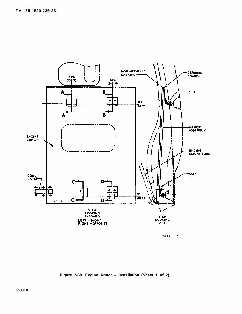
TM 55-1520-236-23
Figure 2-69. Engine Armor – Installation (Sheet 1 of 2)
2-188

TM 55-1520-236-23
Figure 2-69. Engine Armor - Installation (Sheet 2 of 2)
TM 55-1520-236-23
2 - 1 8 3 . R E M O V A L – S O U N D P R O O F I N GBLANKET.
Ensure that both the pilot and gunnerarming/firng mechanism handles aresecured with safety pins prior to entryinto the cockpit area.
a. Remove first aid kit, survival kit andstorage net. Remove control box (SCAS pyloncompensator unit). Refer to TM 11-1520-236-20.
b. Remove first aid kit, survival kit andstorage net.
Remove survival kit, storage net andADS unit (air data system). Refer to TM 11-1520-236-20.
d. Release hook and pile fasteners and removesoundproofing blanket.
2 - 1 8 4 . I N S P E C T I O N – S O U N D -PROOFING BLANKET.
Inspect blanket for minor tears, loose or missing tapeor fasteners, and security of installation.
2 - 1 8 5 . R E P A I R – S O U N D P R O O F I N GBLANKET.
Refer to TM 55-1500-204-25/1 for instructions forminor repairs to soundproofing blanket.
2 - 1 8 6 . I N S T A L L A T I O N – S O U N D -PROOFING BLANKET.
Ensure that both the pilot and gunnerarming/firing mechanism handles aresecured with safety pins prior to entryinto the cockpit area.
a . Position the soundproofing blanket (figure 2-70) assembly behind the pilot station and fasten thehook and pile fasteners.
b. Install storage net, survival kit and firstaid kit. Install control box (SCAS pylon compensatorunit). Refer to TM 11-1520-236-20, Chapter 2.
c. Install first aid kit, survival kit, andstorage net.
d. Install storage net, survival kit and ADSunit (air data system). Refer to TM 11-1520-236-20,Chapter 2.
2 - 1 8 6 . 1 . W I R E S T R I K E P R O T E C T I O NSYSTEM.2-186.2 . DESCRIPTION – WIRE STRIKEPROTECTION SYSTEM.The w i r e s t r i k e protection systemconsists of t h r e e c u t t e r s a n d t w od e f l e c t i o n d e v i c e s . See figure 2-70.1f o r v i e w o f s y s t e m . A deflector ismounted on the nose of the helicopter.A c h a n n e l w i t h a s a w t o o t h i n s e r t i smounted on the right forward windshieldpost . A wire cutter is mounted on ahoneycomb panel and secured on the afte n d o f t h e p i l o t o v e r h e a d w i n d o w . Asecond wire cut ter is mounted on theaccess d o o r b e l o w t h e t u r r e t s i g h tu n i t , a n d f o r w a r d o f t h e t u r r e t . Thet h i r d w i r e c u t t e r i s m o u n t e d o n t h eaccess door b e l o w t h e ammunitioncompartment.
2-186.3. REMOVAL – WIRE STRIKE CUTTER(UPPER).
a. Remove screws (4, 29, and 30, figure 2-70.1),and remove cutter (2) and panel (1) as a unit.
b. Remove attaching screws (3 and 35), andremove cutter from panel.
2 - 1 8 6 . 4 . I N S P E C T I O N – W I R E S T R I K ECUTTER (UPPER).
a. Inspect cutter for bends, cracks, nicks,alignment, and presence of protective sealant onblade.
b. Inspect panel for cracks, punctures,delamination, and pulled or loose inserts.
2-186.5. REPAIR – WIRE STRIKE CUTTER(UPPER).
a. Replace cutter blade using existing hardvvare, whichshows evidence of wire strike. Recoat cutter blade withsealant (C105.2) that have protective sealant missing.
2-190

TM 55-1520-236-23
Figure 2-70. Soundproofing Blanket – Installation
2-190.1

TM 55-1520-236-23
1. Panel2. Cutter3. Screw4. Screw5. Door6. Strut7. Washer8. Bait9. Rlvet
10. Bolt11. Washer12. Rivet13. Cutter14. Bolt
15. Washer16. Nut17. Strut18. Screw19. Cutter20. Washer21. Bolt22. Bolt23. Washer24. Deflector25. Screw26. Insert27. Channel28. Screw
29. Screw30. Screw31. Strut32. Bolt33. Washer34. Nut35. Screw36. Bolt37. BoIt38. Screw39. Washer40. Washer41. Nut (Torque 30-35 in-lbs)
NOTEWir strike protection system installesby MWO 55-1520-236-50-3
Figure 2-70.1 Wire Strike Protection System.
2-190.2
b. Touch up damaged paint to match existingfinish using green paint, MIL-L-46159.
c. Repair panel in accordance with paragraph2-15.
2-186.6. INSTALLATION – WIRE STRIKECUTTER (UPPER).
a. Position panel (1, figure 2. 70.1) and cutter (2)on aft end of pilot upper window.
b. Preassemble cutter assembly (2, 3, 4, 31through 35) (through holes of strut (31) and panel(1)) prior to assembling panel (1) to the airframe.
c. Apply a 2-inch wide bead of sealing compound(C107.5) to fill the gap between the window and thebottom of the cutter panel.
d. Secure panel and cutter with screws (4, 29,and 30).
2 - 1 8 6 . 7 . R E M O V A L – C H A N N E L A N DINSERT (WIRE STRIKE).
a. Remove screws (25, figure 2-70.1) andremove insert (26).
b. Remove screws (28) and remove channel (27).
2-186.8. INSPECTION – CHANNEL ANDINSERT (WIRE STRIKE).
a . Inspect insert for bends, cracks, loose ormissing fasteners, missing teeth, and presence ofprotective sealant on saw teeth.
b. Inspect channel for distortion, loose or missingfasteners, and damage to paint.
2-186.9, REPAIR - CHANNEL AND INSERT(WIRE STRIKE).
b. Touch up damaged paint on channel usinggreen paint, MIL-L-46159.
2-186.10. INSTALLATION - CHANNEL ANINSERT (WIRE STRIKE).
a . Position channel (27, figure 2-70.1) on rightforward windshield post. Trim lower end of channel(27) for 0.03 inch clearance.
2 -186 .11 .
b. Position insert (26) into channel (27) with teethof insert pointing forward. Trim lower end of insert(26) for 0.03 inch clearance.
c. Attach channel (27) to airframe with screws(28).
d. Attach insert (26) to(25).
TM 55-1520-236-23
channel (27) with screws
a. Remove bolts (21 and 36, figure 2-70.1) andwashers (20).
b. Remove cutter (19).
2-186.12. INSPECTION – WIRE STRIKECUTTER (NOSE).
a . Inspect cutter for bends, cracks, nicks, andalignment.
b. Inspect condition of protective sealant oncutter blade.
2-186.13. REPAIR – WIRE STRIKE CUTTER(NOSE).
a. Replace cutter blade using existing hardware, whichshows evidence of wire strike. Recoat cutter blade withsealant (C105.2) that have protective sealant missing.
b. Touch up damaged paint using red paint,TT-E-001384.
2-186.14 INSTALLATION - WIRE STRIKECUTTER (NOSE).
a . Position cutter (19, figure 2-70.1) tohelicopter.
b. Secure with bolts (21 and 36) and washers(20).
2 - 1 8 6 . 1 5 . R E M O V A L - W I R E S T R I K ECUTTER (LOWER).
a . Remove screws (18, figure 2-70.1) securingdoor (5) to bottom of ammunition compartment.Remove door with cutter ( 13) attached.
b. Remove bolts (8 and 14), washers (7 and 15),and rivets (9 and 12). Remove cutter (13) from door(5).
c. Remove bolt (10), washer (11), and nut (16)and remove struts (6 and 17).
2 -186 .16 . INSPECTION - WIRE STRIKECUTTER (LOWER).
a Inspect cutter for bends, cracks andalignment.
b. Inspect condition of protective sealant oncutter blade.
c. Inspect door for delamination, impact damage,and loose inserts.
2-190.3

TM 55-1520-236-23
2-186.17. REPAIR - WIRE STRIKE CUTTER(LOWER).
a. Replace cutter blade using existing hardware, whichshows evidence of wire strike. Recoat cutter blade withsealant (C105.2) that have protective sealant missing.
b. Touch up paint to match existing finish usinggreen paint, MIL-L-46159.
c. Repair door in accordance with paragraph2-15.
2-186.18. INSTALLATION – WIRE STRIKECUTTER (LOWER).
a . Install struts (6 and 17, figure 2-70.1) on cutter(13) with bolt (10), washer (11), and nut (16).
b. Install cutter (13) on ammunition compartmentbottom door (5) with bolts (8 and 14), washers (7 and15), and new rivets (9 and 12).
. Install door on helicopter, using previouslyremoved screws (18).
2 - 1 8 6 . 1 9 . R E M O V A L – WIRE STRIKEDEFLECTOR.
a. Remove bolts (22 and 37, figure 2-70.1) andwashers (23).
b. Remove deflector (24).
2 -186 .20 . INSPECTION – WIRE STRIKEDEFLECTOR.Inspect deflector for damage in accordance withfigure 2-70.2.
2 - 1 8 6 . 2 1 . R E P A I R – WIRE STRIKEDEFLECTOR.
a . Replace deflector if damaged beyond limitsshown in figure 2-70.2.
Cleaning solvent is flammable and toxicProvide adequate ventilation. Avoidprolonged breathing of solvent vapors andcontact with skin or eyes.
b. Polish out corrosion, nicks, scratches anddents not severe enough to reject deflector. Use 300grit sandpaper (C102). Clean sanding residue withMEK (C74), and touch up bare metal with primer(C88) and paint to match existing finish. Refer to TM55-1500-345-23.
2-186.22. INSTALLATION - WIRE STRIKEDEFLECTOR.
NOTE
When installing a new wire strike deflec-tor, the unit must be demagnitized priorto installation.
a . Position deflector (24, figure 2-70.1) onhelicopter.
b. Install bolts (22 and 37) and washers (23).
c. Position TSU and laser window covers andcheck clearance around deflector (24). Install covers.
2 - 1 8 7 . E N G I N EINSTALLATION.
M O U N T
Perform an engine to transmissionalignment check (paragraph 6-7) whenan engine mount component is replacedor when any engine deck mount fitting isremoved and installed.
2-188. DESCRIPTION – ENGINE MOUNTlNSTALLATION.
The engine is supported by two aft mounts (bipod andtripod) and the engine mount leg (forward). See figure2-71 for view of engine mounts. All three mounts aremade from steel tubing and rod end bearings.Investment casting-type fittings are used at the upperend of the two aft mounts (bipod and tripod). Hingedpillow blocks are attached to the two aft mounts(bipod and tripod). The pillow blocks support theengine through trunnions mounted on the enginediffuser housing. The engine mount leg (forward)supports the forward end of the engine through atrunnion mounted on engine inlet housing. The threeengine mounts attach to fittings on the enginecompartment deck. Shims are installed under thefittings to align the engine with the transmission. Ballbearings in the rod end bearings are softer than theouter part of the rod end bearing. If the ball bearingsare worn, they may be replaced without replacing theentire rod end bearing.
2-189. AFT ENGINE MOUNT (BIPOD).
2 - 1 9 0 . D E S C R I P T I O N – A F T E N G I N EMOUNT (BIPOD).
Refer to paragraph 2-188.
2-190.4

TM 55-1520-236-23
TYPE OF DAMAGE
No cracks allowed
DAMAGE LOCATION SYMBOLS
MAXIMUM DAMAGE AND REPAIR DEPTH
Nicks, scratches,and dents 0.015 0.030 0.050
Corrosion:Before repair:After repair:
0.0075 0.015 0.0250.015 0.030 0.050
Maximum area perfull depth repair 0.5 Sq. in. 1.0 Sq. in. Not critical
Number ofrepair areas 2 5 Unlimited
Edge chamfer 0.04 0.06 0.08
Bore damage 0.002 For 1/4 N/A N/Acircumference
NOTE: ALL DIMENSIONS ARE IN INCHES UNLESS OTHERWISE NOTED.
Figure 2-70.2. Damage limits – Wire strike deflector
2-191
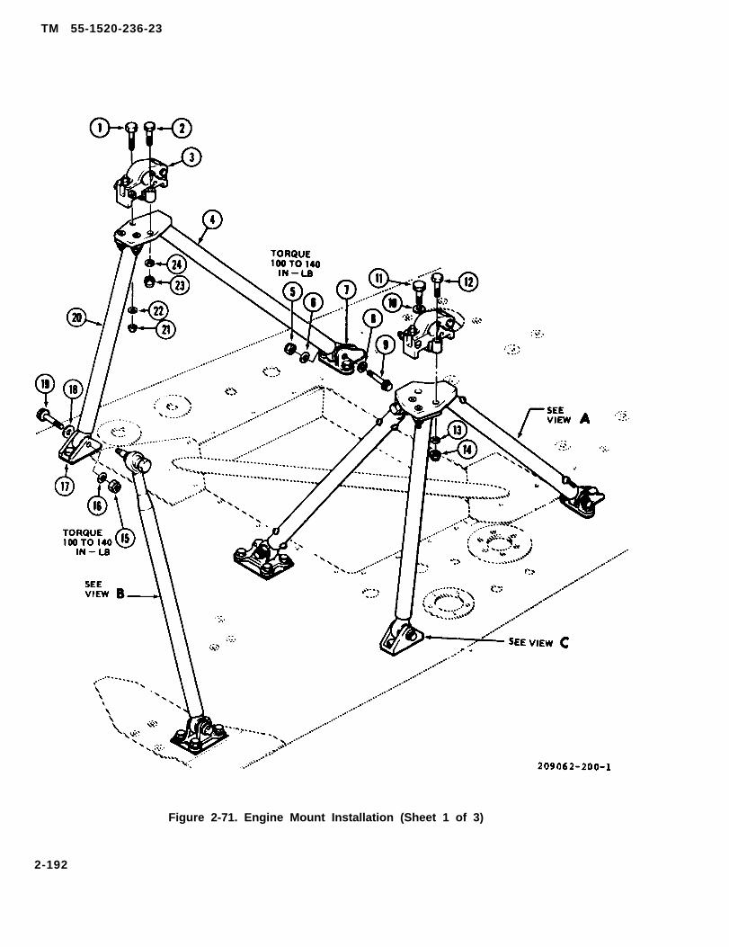
TM 55-1520-236-23
Figure 2-71. Engine Mount Installation (Sheet 1 of 3)
2-192

TM 55-1520-236-23
VIEW B 209062-200-2
Figure 2-71. Engine Mount Installation (Sheet 2 of 3)
2-193

TM 55-1520-236-23
1.2.3.4.5.6.7.8.9.
10.11.12.13.14.15.16.17.18.19.20.21.22.23.24.25.26.27.
28.
BoltBoltPillow blockEngine mount legNutFlat washerEngine mount fittingRecessed washerFlanged boltWasherBoltBoltWasherNutNutFlat washerEngine mount fittingRecessed washerFlanged boltEngine mount legNutWasherNutWasherTension boltRecessed washerFlat washerExtended washer nut
29.30.31.32.33.34.35.36.37.38.39.40.41.42.43.44.45.46.47.48.49.50.51.52.53.54.55.56.
Engine mount legNutFlat washerEngine mount fittingRecessed washerFlanged boltFlanged boltRecessed washerEngine mount fittingFlat washerNutEngine mount legEngine mount legNutFlat washerEngine mount fittingRecessed washerFlanged boltFlat washerEngine mount boltEngine mount lagNutFlat washerEngine mount fittingRecessed washerFlanged boltBoltRecessed washer
57. Shim209062-200-3
Figure 2-71. Engine Mount Installation (Sheet 3 of 3)
2-191. REMOVAL – AFT ENGINE MOUNT(BIPOD).
Do not remove fittings (7 and 17, figure2-71) under biped mounts on enginecompartment deck unless fittings mustbe replaced.
a. Support engine with engine sling (T9) end hoist(T45) to relieve weight from mounts. Refer toparagraph 1-31.
NOTE
Engine may be supported with suitablestrap running underneath combustionsection and a spreader bar to clearstrap from aft pylon fairing.
b. Remove nut and washer from eyebolt andhinge open pillow block (3, figure 2-71).
c. Remove aft engine mount (bipod).
(1) Remove nut (5), bolt (9), and washers (6 and8) from engine mount fitting (7).
2-194
(2) Remove nut (15), bolt (19), and washers(16and 18) from engine mount fitting ( 17).
(3) Remove aft engine mount (bipod) fromhelicopter.
d. If engine mount fittings (7 and 17) must beremoved, remove bolts (53), washers, and fittings(7 and 17) with shims (55).
2 - 1 9 2 . I N S P E C T I O N – A F T E N G I N EMOUNT (BIPOD).
a. Inspect aft engine mount (bipod) for following:
(1) Dents. Small, smooth dents which have notremoved material from tubing and occur at least 1.5inches from upper fittings are considered negligibleand do not require repair. Dents greater thannegligible are cause for replacement of the affectedengine mount.
(2) Scratches. Transverse scratches longerthan 0.313 inch are cause for replacement of themount. Other scratches that are less than 0.010 inchdeep may be polished out.

TM 55-1520-236-23
(3) Distortion. Inspect for bends, nicks, pinhole elongation, and similar damage. Any distortion-type damage that can be detected visually is cause forreplacement of the affected mount.
(4) Wear. Inspect for worn rod end bearings(10, figure 2-72) in the engine mount tubes. Ifnoticeable wear is present, remove the affectedengine mount and check bearing wear with a dialindicator. Maximum allowable radial play is 0.008inch. Maximum allowable axial play 0.016 inch.
(5) Corrosion. Inspect for corrosion damagethat could affect function of engine mounts.
(6) Cracks. No cracks are acceptable. Inspectfor cracks visually. If any area are suspect, inspect byfluorescent penetrant method. Refer to TM 43-0103.
(7) Inspect for security of bolts and rivets.
b. Inspect fittings (7 and 17, figure 2-71) forfollowing:
(1) Cracks. No cracks are acceptable.
(2) Nicks and dents severe enough to affectfunction.
(3) Secure attachment to deck.
(4) Corrosion damage severe enough to affectfunction.
c. Inspect pillow block (3) eye bolt for damagedthreads.
2 - 1 9 3 . R E P A I R – A F T E N G I N E M O U N T(BIPOD).
a.
Rod ends and ball bearings are notreparable by polishing.
Polish out minor corrosion damage using fineIndia stone (C116), and touch up with primer (C88 orC91).
b. (AVIM) Replace engine mount parts that aredamaged or worn beyond allowable limits. Replacerod end bearings in the engine mounts that are wornbeyond allowable limits, or are not suitable for furtherservice for other reasons, as follows:
The 209-062-127-1 rod end allowsremoval and replacement of the ballbearing (11) only. The replaceable ballbearing is made of softer steel than therod end.
(1) Rotate ball bearing (11) ninety degrees,axially align with slot in rod end and push outreplaceable ball bearing with finger pressure.
( 2 ) P o s i t i o n n e w b a l l b e a r i n g ( 1 1 )perpendicular to slots in outer portion of rod endbearing (10). Push ball bearing into outer portion ofrod end bearing and rotate ball bearing ninetydegrees.
2 - 1 9 4 . I N S T A L L A T I O N – A F T E N G I N EMOUNT (BIPOD).
a. Install fittings (7 and 17, figure 2-71) if notpreviously accomplished. It may be necessary tochange shim thickness under fittings during engineto transmission alignment procedure (paragraph 6-7).
b. Install aft engine mount (bipod).
(1) Position engine mount legs (4 and 20) inengine mount fittings (7 and 17).
NOTE
Install recessed washers (8 and 18) withcountersinks against heads of bolts (9and 19).
(2) Install bolts (9 and 19), washers (6, 8, 16,and 18), and nuts (5 and 15).
(3) Torque nuts (5 and 15) 100 TO 140 inch-pounds.
c. Install pillow block (3) if not previouslyaccomplished. Refer to paragraph 2-206.
2 - 1 9 5 .
2 - 1 9 6 .M O U N T
AFT ENGINE MOUNT (TRIPOD).
D E S C R I P T I O N – A F T E N G I N E(TRIPOD).
Refer to paragraph 2-188 for description of aft enginemount (tripod).
2-195

TM 55-1520-236-23
Figur 2-72. Damage Limits – Aft Engine Mount Assembly (Tripod) (Sheet 1 of 2)
2-196

TYPE OF DAMAGE
CRACKS
NICKS, DENTS &CORROSION
SCRATCHES
Maximum area perfull depth repair
Number ofrepair areas
Edge chamfer
Rod endbearing wear(looseness)
Pins and collars(Hy-Loks)
T M
DAMAGE LOCATION SYMBOLS
55-1520-236-23
MAXIMUM DAMAGE AND REPAIR DEPTH
None None None None
0.002 0.005 0.010 0.010
Aany transverse scratch longer than5/16 inch on a leg is cause to replacethe affected part. Other scratches thatare within limits below after polishingout are acceptable.
0.002 0.005
Not Notcritical critical
Not Notcritical critical
0.002 0.005
Radial Loosenessaxial looseness
No loose or missing pins andcollars (Hy-Loks) are acceptable
0.010
Notcritical
Notcritical
0.010
0.0050.012
0.010
Notcritical
Notapplicable
Notapplicable
NOTE:ALL DIMENSIONS ARE IN INCHES UNLESS OTHERWISE NOTED.
209060-138-2
Figure 2-72. Damage Limits – Aft Engine Mount Assembly (Tripod) (Sheet 2 of 2)
2-197. REMOVAL – AFT ENGINE MOUNT(TRIPOD).
Do not remove fittings (32, 37, or 44,figure 2-71) under engine mount legsunless fitting must be replaced.
a. Support engine with engine sling (T9) and hoist(T45) to relieve weight from mounts. Refer toparagraph 1-31.
NOTE
Engine may be supported with suitablestrap running underneath combustionsection and a spreader bar to clearstrap from aft pylon fairing.
b. Remove engine fuel control linkage andbell crank from tripod mount on left side. Remove baseclamps from mount tubes.
c. Remove nut and washer from eyebolt andhinge open pillow block.
d. Remove aft engine mount (tripod).(1) Remove nut (30), bolt (34), and washers (31
and 33) from engine mount fitting (32).(2) Remove nut (39), bolt (35), and washers (36
and 38) from engine mount fitting (37).(3) Remove nut (42), bolt (46), and washers (43
and 45) from engine mount fitting (44).(4) Remove aft engine mount (tripod) from
helicopter.
2-197
TM 55-1520-236-23
e. If engine mount fittings (32, 37, or 44) must beremoved, remove bolts (53), washers (54), and fittingswith shims (55).
f. Refer to paragraph 2-203 for pillow block (3)removal.
2 - 1 9 8 . I N S P E C T I O N – A F T E N G I N EMOUNT (TRIPOD).
a. Inspect aft engine mount (tripod) for damage inexcess of limits shown on figure 2-72.
b. Assemble engine mount legs (5 and 9, figure 2-74) with two bolts (2), washers (1) and nuts (8)
c. Position engine mount leg (13) on two enginemount legs assembled in step b. Install tension bolt(14), recessed washer (15) with countersink againstbolt head, washer (3) and nut (4).
d. Identify engine mount leg (13) as the forwardinboard leg of the tripod. This is the only leg of thetripod that has a rod end bearing in each end of theleg.
b. If aft engine mount (tripod) is installed on e. Position assembled aft engine mount (tripod)
helicopter, inspect all attaching bolts for secure on engine mount fittings (32, 37, and 44, figure 2-71)
installation. with engine mount leg (41) in engine mount fitting(44).
c. Inspect engine mount fittings (32, 37, and 44,figure 2-71) for damage in excess of limits shown on f. Secure aft engine mount (tripod) to enginefigure 2-73. mount fittings.
2 - 1 9 9 . R E P A I R – A F T E N G I N E M O U N T NOTE
(TRIPOD). Install recessed washers (33, 36, and 45)
a. Replace engine mount legs (32, 37 and 44, with countersinks against heads of bolts
figure 2-71) that have damage in excess of limits (34, 35, and 46).
(paragraph 2-198). (1) Install bolt (34), washers (33 and 31), and
b. Replace ball bearings (1 or 11, figure 2-74) innut (30).
rod end bearings (10) that have wear (looseness) inexcess of limits shown on figure 2-72 as follows: (2) Install bolt (35), washers (36 and 38), and
nut (39).
(1) Rotate ball bearing ninety degrees axially toouter portion of rod end bearing. Align ball bearingwith slots in outer portion. Push the ball bearing outthrough the slots.
(2) Position new ball bearing perpendicular toslots in outer portion of rod end bearing. Push ballbearing into outer portion of rod end bearing androtate ball bearing ninety degrees.
c. Polish out mechanical and corrosion damagethat is within limits shown on figure 2-72 with fineIndia stone (C116). Touch up repair area with primer(C88 or C91).
2 - 2 0 0 . I N S T A L L A T I O N – A F T E N G I N EMOUNT (TRIPOD).
a. Install engine mount fittings (32, 37 and 44,figure 2-71) on engine service deck if not previouslyaccomplished. It may be necessary to change shimsunder the engine mount fittings during engine totransmission alignment procedure (paragraph 6-7).
(3) Install bolt (46), washers (45 and 43), andnut (42).
(4) Torque nuts (30, 39, and 42) 100 TO 140inch-pounds.
g. Install pillow block (paragraph 2-206).
h. Install engine fuel control linkage, Move fuelcontrol linkage through full throw and inspect forbinding and interference with adjacent parts.
Perform an engine to transmissionalignment check (paragraph 6-7) whenany engine mount component is replacedor when any engine deck mount fitting isremoved and installed.
i. Remove engine hoist (T45) and sling (T9).
2-198

TM 55-1520-236-23
No cracks allowed
Nicks, scratches, 0.002 0.010and dents
Corrosion 0.001 Before repair 0.005 Before repair0.002 after repair 0.010 after repair
Maximum area per Not critical Not criticalfull depth repair
Number of One Tworepair areas
Edge chamfer 0.002 0.010
Bore damage 0.002 for 1/4 circumference
NOTE: ALL DIMENSIONS ARE IN INCHES UNLESS OTHERWISE NOTED209062-198
Figure 2-73. Damage Limits — Fittings for Aft Engine Mount (Tripod)
2-199
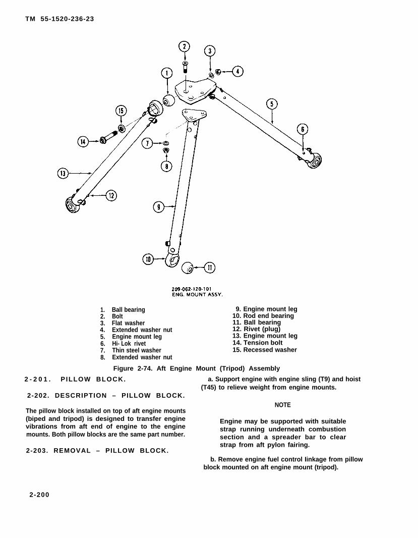
TM 55-1520-236-23
1.2.3.4.5.6.7.8.
Ball bearingBoltFlat washerExtended washer nutEngine mount legHi- Lok rivetThin steel washerExtended washer nut
9. Engine mount leg10. Rod end bearing11. Ball bearing12. Rivet (plug)13. Engine mount leg14. Tension bolt15. Recessed washer
Figure 2-74. Aft Engine Mount (Tripod) Assembly
2 - 2 0 1 . P ILLOW BLOCK. a. Support engine with engine sling (T9) and hoist(T45) to relieve weight from engine mounts.
2-202. DESCRIPTION – PILLOW BLOCK.NOTE
The pillow block installed on top of aft engine mounts(biped and tripod) is designed to transfer engine Engine may be supported with suitablevibrations from aft end of engine to the enginemounts. Both pillow blocks are the same part number.
strap running underneath combustionsection and a spreader bar to clear
2-203. REMOVAL – PILLOW BLOCK.strap from aft pylon fairing.
b. Remove engine fuel control Iinkage from pillowblock mounted on aft engine mount (tripod).
2-200

c. Remove nut and washer from eyebolt andhinge open pillow block (3, figure 2-71 ).
d. Remove nuts (21 and 23), washers (22 and 24),and bolts ( 1 and 2).
e. Remove pillow block (3) from biped mount.
NOTE
An additional washer (10) is used underthe head of bolt (11) for pillow blockinstallation on tripod mount.
f. Remove pillow block from tripod mount insimilar manner.
2-204. INSPECTION – PILLOW BLOCK.
a. Inspect pillow block (3, figure 2-71) for damagein excess of limits shown on figure 2-75.
b. If pillow block is installed, inspect attachingbolts for secure installation.
2 - 2 0 5 . R E P A I R – PILLOW BLOCKS.
a. Replace eye bolt, and/or pillow block ifdamaged in excess of limits (paragraph 2-204).
b. Polish out mechanical and corrosion damagethat is within limits shown on figure 2-75 with fineIndia stone (C116). Touch up repair area with primer(C88 or C91).
2 - 2 0 6 . I N S T A L L A T I O N – P I L L O WBLOCKS.
a. Support engine with engine sling (T9) and hoist(T45).
b. Install aft engine mount fittings (trunnions) ifnot previously accomplished (paragraph 4-119).
c. Position pillow block (3, figure 2-71) on aftengine mount (bipod) with eye bolt forward. Installbolt (1), washer (22), and nut (21). Install bolt (2),washer (24), and nut (23).
d.with
TM 55-1520-236-23
NOTE
An additional washer (10) is used underthe head of bolt (11) for pillow blockinstallation on tripod mount.
Install pillow block on aft engine mount (tripod)eyebolt forward. Install bolt (1 1) and washer (10),
Iockwire bolt (11) with Iockwire (C137). Install bolt (12),washer (13), and nut (14).
e. Hinge upper half of pillow block (3, figure 2-71)on aft engine mount (bipod) closed over bearing onengine mount fitting (trunnion). Install washer andnut. Repeat this procedure for pillow block on aftengine mount (tripod).
f. Remove hoist (T45) and engine sling (T9).
g. Install engine fuel control linkage. Move fuelcontrol linkage through full throw and Inspect forbinding and interference with adjacent parts.
2 -207 .
2 -208 .
ENGINE MOUNT LEG (FORWARD)
DESCRIPTION – ENGINE MOUNTLEG (FORWARD).
The engine mount leg is a steel tube with replaceablerod end bearings, which is installed between the lefttrunnion on the engine and a fitting on the enginecompartment deck. The leg supports the forward endof the engine.
2-209. REMOVAL – ENGINE MOUNT LEG(FORWARD).
a. Support engine with suitable hoist to relieveweight from the mounts.
Do not remove fitting (52) and shimunder engine mount leg (forward) oncompartment deck unless fitting must bereplaced.
2-201
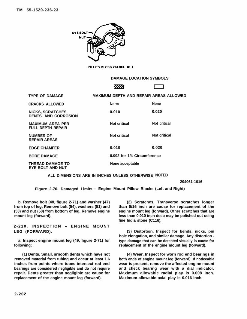
TM 55-1520-236-23
TYPE OF DAMAGE
CRACKS ALLOWED
NICKS, SCRATCHES,DENTS. AND CORROSION
MAXIMUM AREA PERFULL DEPTH REPAIR
NUMBER OFREPAIR AREAS
EDGE CHAMFER
BORE DAMAGE
DAMAGE LOCATION SYMBOLS
MAXIMUM DEPTH AND REPAIR AREAS ALLOWED
Norm None
0.010 0.020
Not critical Not critical
Not critical Not critical
0.010 0.020
0.002 for 1/4 Circumference
THREAD DAMAGE TO None acceptableEYE BOLT AND NUT
ALL DIMENSIONS ARE IN INCHES UNLESS OTHERWISE
Figure 2-76. Damaged Limits – Engine Mount Pillow Blocks
b. Remove bolt (48, figure 2-71) and washer (47)from top of leg. Remove bolt (54), washers (51) and(53) and nut (50) from bottom of leg. Remove enginemount leg (forward).
2 - 2 1 0 . I N S P E C T I O N – E N G I N E M O U N TLEG (FORWARD).
a. Inspect engine mount leg (49, figure 2-71) forfollowing:
(1) Dents. Small, srnooth dents which have notremoved material from tubing and occur at least 1.6inches from points where tubes intersect rod endbearings are considered negligible and do not requirerepair. Dents greater than negligible are cause forreplacement of the engine mount leg (forward).
NOTED
204061-1016
(Left and Right)
(2) Scratches. Transverse scratches longerthan 5/16 inch are cause for replacement of theengine mount leg (forward). Other scratches that areless than 0.010 inch deep may be polished out usingfine India stone (C116).
(3) Distortion. Inspect for bends, nicks, pinhole elongation, and similar damage. Any distortion -type damage that can be detected visually is cause forreplacement of the engine mount leg (forward).
(4) Wear. Inspect for worn rod end bearings inboth ends of engine mount leg (forward). If noticeablewear is present, remove the affected engine mountand check bearing wear with a dial indicator.Maximum allowable radial play is 0.008 inch.Maximum allowable axial play is 0.016 inch.
2-202

TM 55-1520-236-23
(5) Corrosion. Inspect for corrosion damagethat could affect function of engine mount leg(forward).
(6) Cracks. No cracks are acceptable. Inspectfor cracks visually. If any areas are suspect, inspect byfluorescent penetrant method. Refer to TM 43-0103.
(7) Security. Check for secure installation of allbolts and rivets.
b. Inspect engine mount fitting (52, figure 2-71)for secure attachment to engine compartment deckand for damage in excess of limits shown on figure 2-73.
2 - 2 1 1 . R E P A I R – E N G I N E(FORWARD).
MOUNT LEG
The forward engine mount leg (49, figure2-71) has a replaceable ball type bearingin the lower end. The bearing at the upperend is a high misalignment bearing and isnot replaceable.
Repair engine mount leg (forward) by sameprocedures outlined for aft engine mount (tripod)(paragraph 2-119).
2-212. INSTALLATION – ENGINE MOUNTLEG (FORWARD).
a. Support engine with suitable hoist to relieveweight from the mounts.
b. Position engine mount leg (forward) (49, figure 2-71) on engine and install bolt (48) and washer (47). Tor-que bolt 50 TO 70 inch-pounds. Install flanged bolt(54), washers (51 and 53), and nut (50). Torque nut 100TO 140 inch-pounds.
c. Remove hoist.
2 - 2 1 3 . D I A G O N A L B R A C E T U B E S .
2 - 2 1 4 . D E S C R I P T I O N – D I A G O N A LBRACE TUBES.
The diagonal brace tube is a load carrying member ofthe fuselage structure. The right is larger in diameterthan the left diagonal brace tube. The tubes are
adjustable to specified lengths and are located in thefuselage adjacent to the wing attachment area.
2 - 2 1 5 . R E M O V A L – D I A G O N A L B R A C ETUBES.
a. Remove right and left access panels (17,figure 2-76).
b. Remove nuts (1 and 17, figure 2-76), specialbolt (3), bolt (13), and washers (2, 11, and 13). Removeright diagonal brace tube (18) from helicopter.
c. Remove nuts (7 and 10), bolts (4 and 12), andwashers (5, 6, 9, and 11). Remove left diagonal bracetube (8) from helicopter.
2-216. INSPECTION – DIAGONAL BRACETUBES.
Inspect diagonal brace tubes for damage inexcess of the following limits as follows
(1) Dents in excess of 0.010 inch. Smoothdents up to 0.010 inch deep are acceptable withoutpolishing out.
(2) Nicks and scratches in excess of 0.010 inchdepth. Nick and scratch damage Iess than 0.010 inchdeep is acceptable if the damage is polished out usingfine India stone (C116).
(3) Corrosion damage in excess of 0.010 inchdeep after polishing out and/or which affects overtwenty percent of the area of the tube is notacceptable. Replace tube.
(4) Wear in bolt holes, dimension .3135, in fit-tings in ends of diagonal brace assemblies in ex-cess of 0.005 inch is not acceptable. Make the in-spection for bolt hole wear only if the diagonalbrace tubes are removed for some other purpose.
(6) Distortion of the diagonal brace assembliesthat can be detected visually is not acceptable.Replace tube.
(6) Cracks. No cracks are acceptable.
2 - 2 1 7 . R E P A I R – D I A G O N A L B R A C ETUBES.
a. Polish out nicks, scratches and corrosiondamage that is within limits, using fine India stone(C116).
2-203

TM 55-1520-236-23
1.2.3.4.5.6.7.
NOTE :
The right diagonal brace (18) is larger in diameter than the left diagonal brace (8). Whendiagonal brace tubes are being installed, refer to current Repair Parts and Special Tools Listto ensure that correct P/N diagonal braces are installed.
Nut 8.WasherSpecial bolt 9.Bolt 10.Washer 11.Washer 12.Nut 13.
Figure 2-76.
Left diagonal brace 14. Washertube assembly 15. Fitting
Washer 16. WasherNut 17. NutWasher 18. Right diagonal braceBolt tube assemblyBolt 209030-296B
Diagonal Brace Tube – Installation
2-204

TM 55-1520-236-23
b. Touch up repair area with primer (C88 or C91). f. One lift link.
c. Replace adjustable rod end connector if bolt holeis worn beyond 0.005 inch limit. Replace entire diagonalbrace tube assembly if the bolt hole in the fixed fitting isworn beyond the 0.005 inch limit.
2-218. INSTALLATION — DIAGONAL BRACETUBES.
Diagonal brace tubes must be installed priorto flight.
a. Position left diagonal brace tube assembly (8, fig-ure 2-76) in helicopter. Install bolt (4), washers (5 and 6)and nut (7). Adjust rod end connector in opposite end of leftdiagonal brace tube assembly if necessary, Install bolt(12), washers (9 and 11) and nut (10). Torque nuts (7 and10) 70 TO 90 inch-pounds.
b. Position right diagonal brace tube (18) in helicop-ter. Install special bolt (3), washer (2), and nut (1) in forwardend. Adjust rod end connector in opposite end of bracetube assembly if necessary. Install bolt (13), washers (14and 16), and nut (17). Torque nuts (1 and 17) 70 TO 90inch-pounds.
c. Install right and left access panels (17, figure 2-3).
2-221. TRANSMISSION MOUNTS.
2-222. DESCRIPTION — TRANSMISSIONMOUNTS.
Four transmission mount assemblies are located on thepylon support structure. The transmission support caserests on the mount assemblies. See figure 2-77. Eachtransmission mount assembly consists of a cylindricalmolded rubber core bonded between steel outer andinner sleeves, with outer sleeve flange secured on thepylon support by four bolts. A large mount bolt extendsup through the mount inner sleeve to seat in taperedbushing of transmission support case leg, and is securedby a retaining bolt installed from top through a broad spe-cial washer and threaded into tapped upper end of themount bolt. Silicone rubber protective boots, with support-ing bushings, cover both ends of mount.
2-223. REMOVAL — TRANSMISSIONMOUNTS.
NOTE
New aircraft are delivered without Iockwire onbolts (1 and 20, figure 2-77). This is an accept-able condition. However, all subsequent boltinstallations must be accomplished withdrilled heed bolts and must be Iockwired.
2-219. PYLON SUPPORT INSTALLATION. a. Remove transmission (Paragraph 6-24).
2-220. DESCRIPTION — PYLON SUPPORTINSTALLATION.
The pylon support installation consists of provisions formounting the transmission in the airframe. See figure 2- Anytime transmission mount bolts (21, figure
77. Major components of the pylon support installation 2-77) are loosened or removed, care must be
are as follows: taken to ensure they do not fall. Damage to air-frame panels could occur.
a. Four transmission mount assemblies.NOTE
b. Two damper assemblies.To aid in removing and installing bolts (6, fig-
C. Two damper fittings. ure 2-77) attaching dampers (7) to mount bolts(21), holes may be drilled in pylon supports
d. One fifth mount support fitting assembly. (14) (figure 2-78). Use a hole cutter or othersuitable tool. Care must be taken to prevent
e. One lift beam assembly. damage to adjacent parts. Clean and deburredges of holes to preclude stress risers. Applyprimer (C88 or C91) to edges of holes.
2-205

TM 55-1520-236-23
Bushing (22) P/N 212-030-199-1 and
1.2.3.4.5.6.7.8.9.
10.11.12.13.
BoltRecessed WasherPylon mount assemblyNutFlat washerBoltDamper assemblyBoltFifth mount support fittingFifth mountNutFlat washerFiller plate
Bushing (26) P/N 204-030-930-19 arenot interchangeable.
14.15.16.17.18.19.20.21.22.23.24.25.26.
Pylon supportDamper fittingLift beamFiller platePylon mount assemblyRecessed washerBoltMount boltBushingBootPylon mountBootBushing
209030-366
Figure 2-77. Pylon Support — Installation
2-206
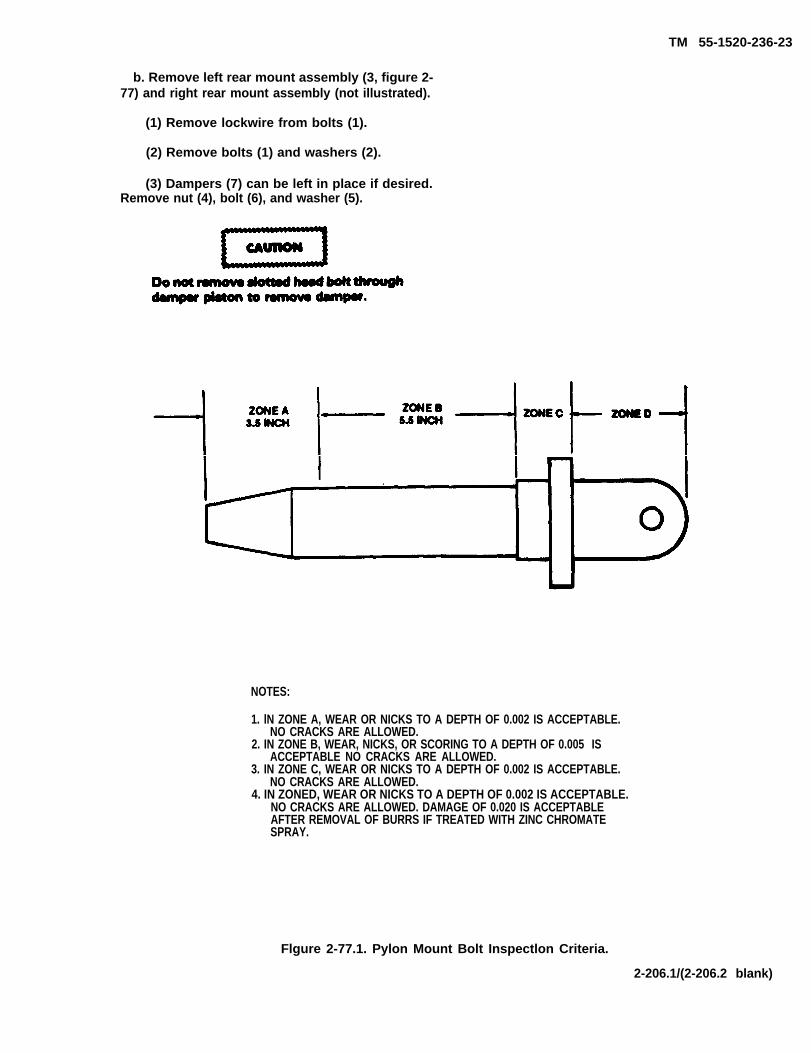
TM 55-1520-236-23
b. Remove left rear mount assembly (3, figure 2-77) and right rear mount assembly (not illustrated).
(1) Remove lockwire from bolts (1).
(2) Remove bolts (1) and washers (2).
(3) Dampers (7) can be left in place if desired.Remove nut (4), bolt (6), and washer (5).
NOTES:
1. lN ZONE A, WEAR OR NICKS TO A DEPTH OF 0.002 IS ACCEPTABLE.NO CRACKS ARE ALLOWED.
2. IN ZONE B, WEAR, NICKS, OR SCORING TO A DEPTH OF 0.005 ISACCEPTABLE NO CRACKS ARE ALLOWED.
3. IN ZONE C, WEAR OR NICKS TO A DEPTH OF 0.002 IS ACCEPTABLE.NO CRACKS ARE ALLOWED.
4. IN ZONED, WEAR OR NICKS TO A DEPTH OF 0.002 IS ACCEPTABLE.NO CRACKS ARE ALLOWED. DAMAGE OF 0.020 IS ACCEPTABLEAFTER REMOVAL OF BURRS IF TREATED WITH ZINC CHROMATESPRAY.
Flgure 2-77.1. Pylon Mount Bolt Inspectlon Criteria.
2-206.1/(2-206.2 blank)


NOTE
Remove hydraulic cylinders if damper (7) is tobe removed with pylon mount assembly.
(3) Refer to paragraph 7-60.
(4) Remove nut (11), bolt (8) and washer (12).Lift damper out with mount assembly.
(5) Secure filler plate (13) in position with Iockwire(C 137).
(6) Separate upper and lower bushings (26 and22) and upper and lower boots (25 and 23), from mountbolt (21).
(7) Remove right rear mount assembly, using pro-cedures outlined in steps (1) through (6) above.
c. Remove left forward mount assembly (18) andright forward mount assembly (not illustrated).
(1) Remove Iockwire from bolts (20).
(2) Remove bolts (20) and washers (19).
(3) Keep filler plate (17) at location.
(4) Separate upper and lower bushings (26 and22) and upper and lower boots (25 and 23) from mount bolt(21).
(5) Remove right forward mount assembly usingprocedures outlined in steps (1) through (4) above.
2-224. INSPECTION — TRANSMISSIONMOUNTS.
a. Inspect mount bolts, bushings, and retainingwashers for wear, nicks or cracks.
b. Inspect boots for tears or deterioration.
c. Inspect rubber and steel washers on inner face ofbushing for securing of bonding.
Exercise care in inserting feeler gage to avoiddamaging rubber core.
TM 55-1520-236-23
d. Inspect rubber core at both ends of mount for de-terioration and separation. If vibration, roughness or mountbottoming was noted, inspect mount for bond separationbetween rubber core and inner and outer sleeves with a0.010 inch feeler gage. If any separation exceeds 0.250inch maximum depth for 33 percent of the circumferenceor if separation exceeds 0.750 inch at any one point, re-place the mount.
2-225. REPAIR — TRANSMISSION MOUNTS.
a. Replace defective mounts or boots.
NOTE
It is important to note that a properly installedboot will extend the service life of the mountby keeping it free and clean of oil contamina-tion. Any boot that is ripped or cut should bereplaced.
b. Replace unserviceable protective boots. Replacebushings and retaining washers when worn, scored,nicked, or cracked. See figure 2-77.1 for inspection ofpylon mount bolts.
Adhesive is flammable and toxic. Provide ade-quate ventilation. Avoid prolonged breathingof vapors and contact with skin or eyes.
c. If rubber and steel washers on inner face of bush-ing become detached, rebond with adhesive (C12) or re-place bushing assembly. Adhesive should be cured at atemperature of 75 degrees F (24 degrees C) or higher. Iftemperature is below 75 degrees F (24 degrees C) doublethe amount of cure time for each 12 degrees F (7 degreesC) below 75 degrees F (24 degrees C). Do not attempt tocure adhesive at temperatures below 50 degrees F (10 de-grees C).
TYPICAL TEMPERATURESAND CURE TIME
TemperatureDegrees F Degrees C
75 2463 1751 11
Cure TimeHours
48
16
2-207

TM 55-1520-236-23
d. Replace mounts under following conditions:
(1) When excessive vibration in operation is be-lieved to indicate that mounts no longer have proper springrate to isolate normal pylon vibrations.
(2) When rubber-to-metal bond has separateddeeper than raised rubber fillets at inner or outer sleeves.
2-226. INSTALLATION — TRANSMISSIONMOUNTS.
a. Install left rear mount assembly (3, figure 2-77)and right rear mount assembly (not illustrated).
(1) Assemble boot (25) and bushing (26) on upperend of mount (24).
(2) Assemble boot (23) and bushing (22) on lowerend of pylon mount (24).
(3) Insert mount bolt (21) through assembly fromlower end of mount.
(4) If damper assembly (7) is not installed, positiondamper assembly on rear mount (3) and install bolt (6) withflat washer (5) under bolt head. Install nut (4). If damper as-sembly (7) is already installed, proceed to step (5).
NOTE
Ensure that replacement filler plate (13) is cor-rect part number. Check TM 55-1520-236-23P.
(5) Position mount assembly (3) in pylon support(14) and on filler plate (13).
(6) Install four bolts (1) and washers (2). Torquebolts 100 TO 140 inch-pounds.
(7) Lockwire heads of bolts (1) in pairs withIockwire (C137).
(8) If damper (7) was installed with mount assem-bly (3), install bolt (8), with washer (12) under bolt head,and nut (11). If damper was already installed, proceed tostep (9).
(9) If damper (7) was installed previously, installbolt (6), flat washer (5), and nut (4).
b. Install left forward mount assembly (18) and rightforward mount assembly (not illustrated).
(1) Assemble mount (18) using procedures insteps (1) through (3), above.
NOTE
Ensure that replacement ffl plate (17) is cor-rect part number. Check TM 55-1520-236-23P.
(2) Position mount assembly (18) in pylon support(14) and on filler plate (17).
(3) Install bolts (20) and washers (19).
(4) Lockwire head of bolts (20) in pairs withIockwire (C137).
(5) Install right forward mount using proceduresgiven for left forward mount.
2-227. FIFTH MOUNT AND FIFTH MOUNTSUPPORT FlTTING.
2-228. DESCRIPTION — FIFTH MOUNT ANDFIFTH MOUNT SUPPORT FlTTING.
A fifth mount (10, figure 2-77), similar to the four transmis-sion mounts (3 and 18), is located at the center of thefifth mount support fitting (9), across the rear of the pylonsupport (14). The purpose of the fifth mount is to assistthe other four transmission mounts in the isolation of nor-mal pylon vibrations and to restrict fore and aft move-ment of the transmission. The fifth mount is attached tothe transmission support case by a bolt through a self-aligning bearing in the mount upper end.
2-229. REMOVAL— FlFTH MOUNT ANDFlFTH MOUNT SUPPORT FITTING.
NOTE
Removal of the fifth mount while transmissionis installed in helicopter requires removal ofthe fifth mount support fitting (15, figure 2-79).
a. Remove induction baffle mounted aft of fifthmount support fitting (15).
(10) Install hydraulic cylinders if they were re-moved during pylon mount removal procafure (para-graph 7-63).
2-208

b. Remove fifth mount bolt.
(1) Remove cotter pin (1), nut (2),washer (3), and fifth mount bolt assembly (5).
(2) Remove cotter pin (11), nut (10), bolt(6), and washers (7 and 9).
(3) Remove fifth mount spacer (8) fromtransmission case fifth mount support (4).
c. Remove pylon transducer from pylontransducer bracket (20) in accordance withinstructions contained in paragraph 11-.129.
d. Remove forward section of tail rotor driveshaft.Refer to paragraph 6-77.
e . Remove four bolts (17) and washers (16)securing each end of fifth mount support fitting (16) topylon support (19) and remove fifth mount supportfitting.
TM 55-1520-236-23
f. If shims (18) are loose, remove and identify forreinstallation at same location.
g. Remove Iockwire, four bolts (22) and washers(21).
h. Remove pylon transducer bracket (20).
i. Lift fifth mount (13) and shim (14) from fifthmount support fitting (12). Save the shim forreinstallation.
i. Remove boot (12) from to of fifth mount (13).
2 - 2 3 0 . I N S P E C T I O N – F l F T H M O U N TAND FIFITH MOUNT SUPPORT FlTTING.
a . Inspect fifth mount (13, figure 2-78).
(1) Inspect boot (12) for cuts, tears ordeterioration.
Figure 2-78.
2-209
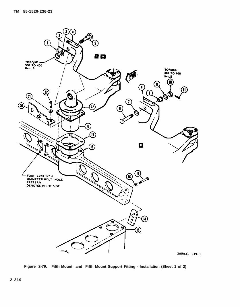
TM 55-1520-236-23
Figure 2-79. Fifth Mount and Fifth Mount Support Fitting - Installation (Sheet 1 of 2)
2-210
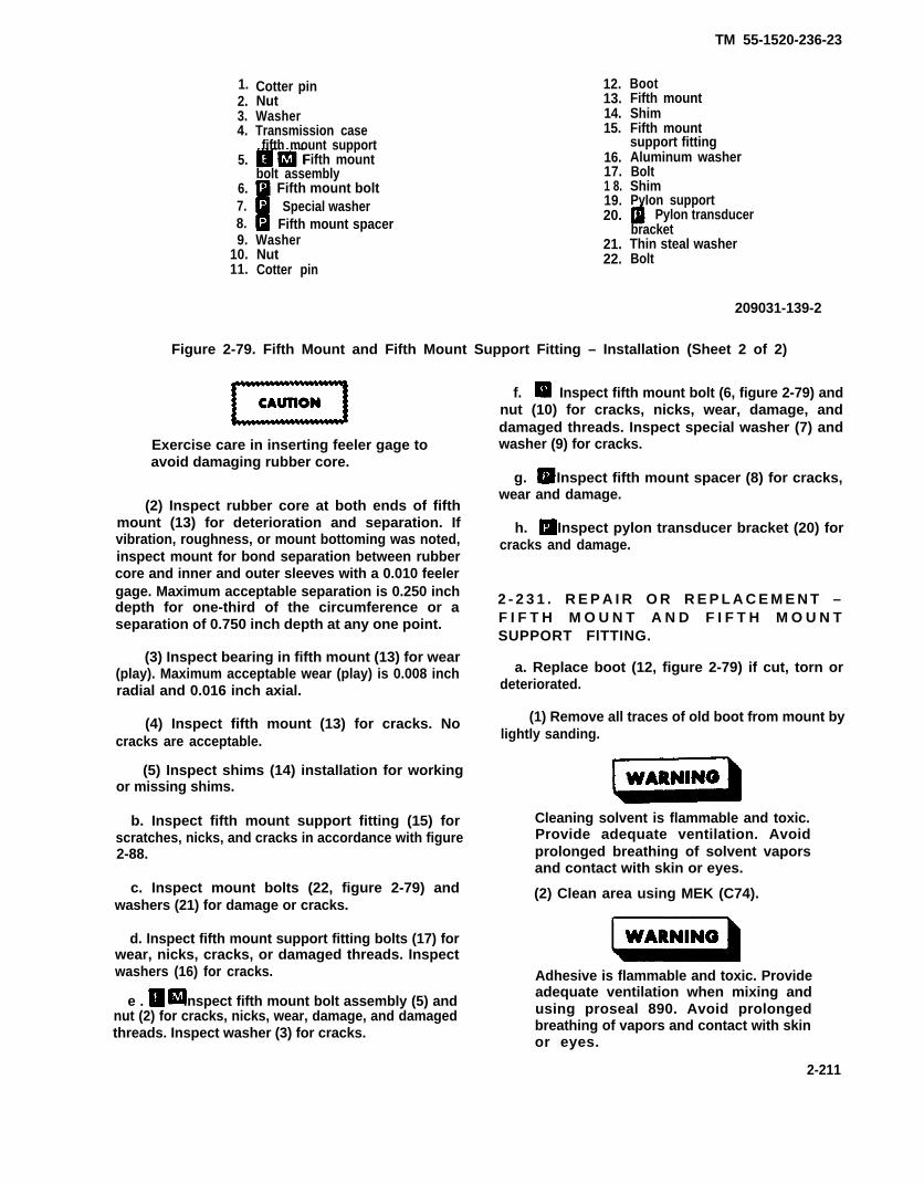
TM 55-1520-236-23
2.3.4.
5.
6.7.8.9.
10.11.
1. Cotter pinNutWasherTransmission casefifth mount support
Fifth mountbolt assembly Fifth mount bolt Special washer Fifth mount spacer
WasherNutCotter pin
12.13.14.15.
16.17.1 8.19.20.
21.22.
BootFifth mountShimFifth mountsupport fittingAluminum washerBoltShimPyIon support
Pylon transducerbracketThin steal washerBolt
209031-139-2
Figure 2-79. Fifth Mount and Fifth Mount Support Fitting – Installation (Sheet 2 of 2)
Exercise care in inserting feeler gage toavoid damaging rubber core.
(2) Inspect rubber core at both ends of fifthmount (13) for deterioration and separation. Ifvibration, roughness, or mount bottoming was noted,inspect mount for bond separation between rubbercore and inner and outer sleeves with a 0.010 feelergage. Maximum acceptable separation is 0.250 inchdepth for one-third of the circumference or aseparation of 0.750 inch depth at any one point.
(3) Inspect bearing in fifth mount (13) for wear(play). Maximum acceptable wear (play) is 0.008 inchradial and 0.016 inch axial.
(4) Inspect fifth mount (13) for cracks. Nocracks are acceptable.
(5) Inspect shims (14) installation for workingor missing shims.
b. Inspect fifth mount support fitting (15) forscratches, nicks, and cracks in accordance with figure2-88.
c. Inspect mount bolts (22, figure 2-79) andwashers (21) for damage or cracks.
d. Inspect fifth mount support fitting bolts (17) forwear, nicks, cracks, or damaged threads. Inspectwashers (16) for cracks.
e . Inspect fifth mount bolt assembly (5) andnut (2) for cracks, nicks, wear, damage, and damagedthreads. Inspect washer (3) for cracks.
f. I Inspect fifth mount bolt (6, figure 2-79) andnut (10) for cracks, nicks, wear, damage, anddamaged threads. Inspect special washer (7) andwasher (9) for cracks.
g. Inspect fifth mount spacer (8) for cracks,wear and damage.
h. Inspect pylon transducer bracket (20) forcracks and damage.
2 - 2 3 1 . R E P A I R O R R E P L A C E M E N T –F I F T H M O U N T A N D F I F T H M O U N TSUPPORT FlTTING.
a. Replace boot (12, figure 2-79) if cut, torn ordeteriorated.
(1) Remove all traces of old boot from mount bylightly sanding.
Cleaning solvent is flammable and toxic.Provide adequate ventilation. Avoidprolonged breathing of solvent vaporsand contact with skin or eyes.
(2) Clean area using MEK (C74).
Adhesive is flammable and toxic. Provideadequate ventilation when mixing andusing proseal 890. Avoid prolongedbreathing of vapors and contact with skinor eyes.
2-211

TM 55-1520-238-23
(3) Apply adhesive (C14) to area where bootmakes contact with mount.
(4) Position new boot on mount and cure inaccordance with table 1-11.
b. Replace fifth mount (13) if damage exceedsinspection limits.
c. Deleted.
d. Replace mount bolts (22) and washers (21) ifdamaged or cracked.
e.
NOTE
Fifth mount support beam bolts may havenon-drilled head bolts installed; however,when bolt removal and/or tare torque can-not be met, replace the fifth mount support beam bolts with drilled head bolts.Tare torque need not be checked until boltremoval becomes necessary.
Replace fifth mount support fitting bolts (17) ifworn, nicked, cracked, or threads damaged; washers(16) if worn.
f. R Replace fifth mount bolt assembly (5), or nut(2) if cracked, nicked, worn, damaged or if threads aredamaged.
g. Replace fifthcracked, nicked, worn,damaged.
mount bolt (6) or nut (10) ifdamaged, or if threads are
h. Replace fifth mount spacer (8) if cracked,worn or damaged.
i. Replace pylon transducer bracket (20, figure2-79) if cracked or damaged.
j. Replace missing shims (14). When working shimsare evident, check shim adjustment and bolt (22) torque.
2-231.1. REMOVAL - FIFTH MOUNT BEARINGAND BUSHING. (Refer to f igure 2-79.1for bushing and bearing tool kit .)
a . Remove mount a s s e m b l y P NJ-12292-1 f rom a i rcra f t .
V i s u a l l y inspect elastomer end( f i g u r e 2 - 7 9 . 2 ) .
Note
No cracks, gouges, and/or separa-tions are allowed on elastomer sur-face . I f p r e s e n t , contact LAR orAVSCOM Engineering for guidance.
c . I f e l a s t o m e r i s a c c e p t a b l e , r e -move bushing and bearings.
( 1 ) P l a c e mount on tool (T103) .Care should be taken not to punctureb o o t d u r i n g e n t i r e r e p l a c e m e n t o p e r -a t i o n s . (See figure 2-79.3.)
C a r e s h o u l d b e t a k e n t o p r o p e r l yalign tools (T102 and T103) to avoidi n t e r f e r e n c e d u r i n g normal opera-t i o n s .
( 2 ) P r e s s b u s h i n g a n d b e a r i n g o u tof housing by us ing a hydraul ic pressand tools (T102 and T103).
( 3 ) A f t e r b u s h i n g a n d b e a r i n g r e -moval, inspect hole d iameter us ing aninside micrometer or equiva lent . Holediameter should be 1.2182/1.2162inches.
2 -231 .2 . CLEANING - FIFTH MOUNTBEARING AND BUSHING.
a . D e b u r r a l l e d g e s u s i n g c r o c u scloth (C37) .
Do not handle new or cleaned bear-ings and bushings with bare hands.Use whi te cot ton g loves (C54) toavoid contamination to the bearing,bushing, and housing mat ing sur -faces.
b . Thoroughly clean h o u s i n g a n dbushing using toluene/xylene (C130) ors i m i l a r , appl ied w i t h cheesecloth(C30) , then a lcohol (C64) appl ied wi thc l e a n c h e e s e c l o t h ( C 3 0 ) . G i v e s p e c i a la t t e n t i o n t o c o r n e r scausal by removal o fi n g .
arid any gougesbushing and bear-
2-212
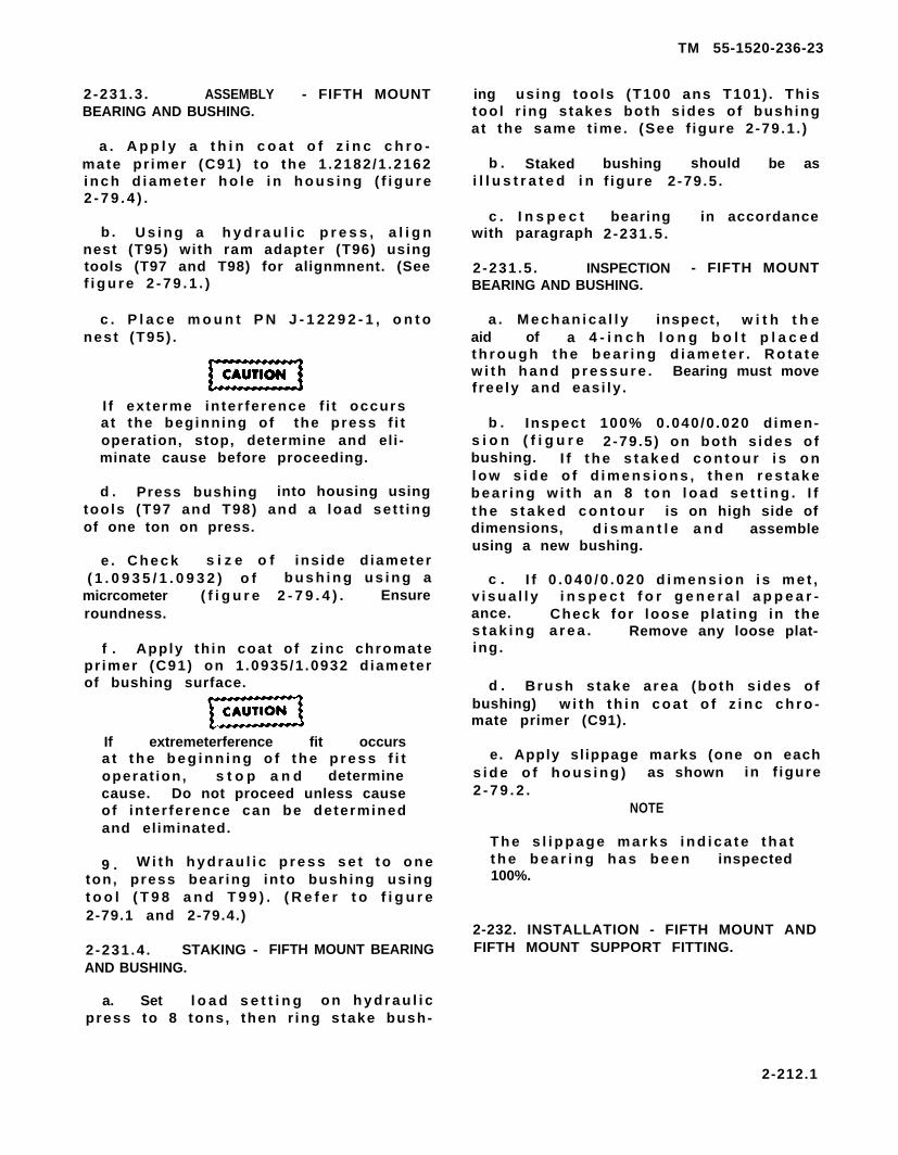
2-231 .3 . ASSEMBLY - FIFTH MOUNTBEARING AND BUSHING.
a . A p p l y a t h i n c o a t o f z i n c c h r o -mate pr imer (C91) to the 1 .2182 /1 .2162i n c h d i a m e t e r h o l e i n h o u s i n g ( f i g u r e2 - 7 9 . 4 ) .
b . U s i n g a h y d r a u l i c p r e s s , a l i g nnest (T95) with ram adapter (T96) usingtools (T97 and T98) for alignmnent. (Seef i g u r e 2 - 7 9 . 1 . )
c . P l a c e m o u n t P N J - 1 2 2 9 2 - 1 , o n t onest (T95) .
I f ex terme in ter ference f i t occursat the beginning of the press f i toperation, stop, determine and eli-minate cause before proceeding.
d . Press bushing into housing usingtools (T97 and T98) and a load set t ingof one ton on press.
e . C h e c k s i z e o f ins ide d iameter( 1 . 0 9 3 5 / 1 . 0 9 3 2 ) o f b u s h i n g u s i n g a
micrcometer ( f i g u r e 2 - 7 9 . 4 ) . Ensureroundness.
f . Apply th in coat o f z inc chromatepr imer (C91) on 1 .0935/1 .0932 d iameterof bushing surface.
If extremeterference fit occursa t t h e b e g i n n i n g o f t h e p r e s s f i toperat ion, s t o p a n d determinecause. Do not proceed unless causeof in ter ference can be determinedand eliminated.
9 . W i t h h y d r a u l i c p r e s s s e t t o o n eton, press bear ing into bushing usingt o o l ( T 9 8 a n d T 9 9 ) . ( R e f e r t o f i g u r e2-79.1 and 2-79.4.)
2 -231 .4 . STAKING - FIFTH MOUNT BEARINGAND BUSHING.
a. Set l o a d s e t t i n g o n h y d r a u l i cpress to 8 tons, then r ing s take bush-
TM 55-1520-236-23
ing using tools (T100 ans T101) . Th istool r ing s takes both s ides of bushingat the same t ime. (See f igure 2 -79 .1 . )
b . Stakedi l l u s t r a t e d i n
c . I n s p e c twith paragraph
bushing should be asf igure 2 -79 .5 .
bearing in accordance2-231 .5 .
2 -231 .5 . INSPECTION - FIFTH MOUNTBEARING AND BUSHING.
a . M e c h a n i c a l l y inspect, w i t h t h eaid of a 4 - i n c h l o n g b o l t p l a c e dt h r o u g h t h e b e a r i n g d i a m e t e r . R o t a t ew i t h h a n d p r e s s u r e . Bearing must movefree ly and eas i ly .
b . Inspect 100% 0 .040 /0 .020 d imen-s i o n ( f i g u r e 2-79 .5 ) on both s ides ofbushing. I f t h e s t a k e d c o n t o u r i s o nl o w s i d e o f d i m e n s i o n s , t h e n r e s t a k eb e a r i n g w i t h a n 8 t o n l o a d s e t t i n g . I ft h e s t a k e d c o n t o u r is on high side ofdimensions, d i s m a n t l e a n d assembleusing a new bushing.
c . I f 0 . 0 4 0 / 0 . 0 2 0 d i m e n s i o n i s m e t ,v i s u a l l y i n s p e c t f o r g e n e r a l a p p e a r -ance. Check for loose p la t ing in thes t a k i n g a r e a . Remove any loose plat-ing.
d . Brush s take area (both s ides ofbushing) w i t h t h i n c o a t o f z i n c c h r o -mate primer (C91).
e. Apply sl ippage marks (one on eachs i d e o f h o u s i n g ) as shown in f igure2 - 7 9 . 2 .
NOTE
T h e s l i p p a g e m a r k s i n d i c a t e t h a tt h e b e a r i n g h a s b e e n inspected100%.
2-232. INSTALLATION - FIFTH MOUNT ANDFIFTH MOUNT SUPPORT FITTING.
2-212.1
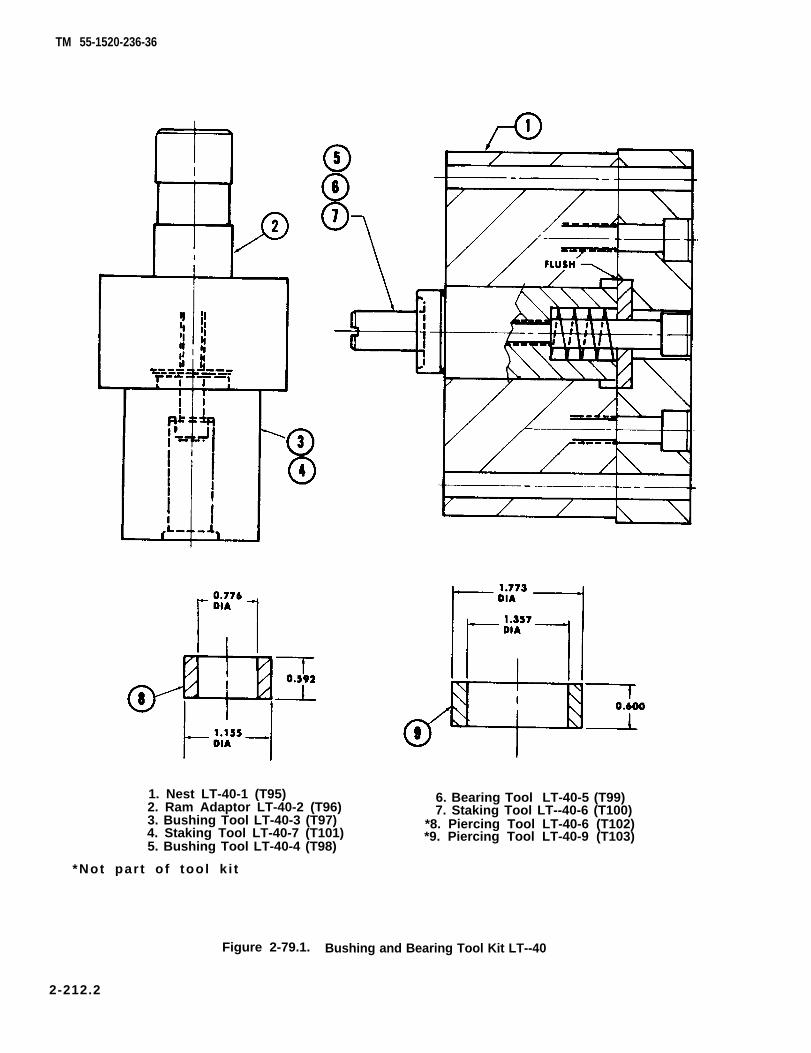
TM 55-1520-236-36
1. Nest LT-40-1 (T95)2. Ram Adaptor LT-40-2 (T96)3. Bushing Tool LT-40-3 (T97)4. Staking Tool LT-40-7 (T101)5. Bushing Tool LT-40-4 (T98)
*Not par t o f too l k i t
6. Bearing Tool LT-40-5 (T99)7. Staking Tool LT--40-6 (T100)
*8. Piercing Tool LT-40-6 (T102)*9. Piercing Tool LT-40-9 (T103)
Figure 2-79.1. Bushing and Bearing Tool Kit LT--40
2-212.2
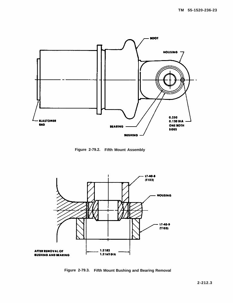
TM 55-1520-236-23
Figure 2-79.2. Fifth Mount Assembly
Figure 2-79.3. Fifth Mount Bushing and Bearing Removal
2-212.3
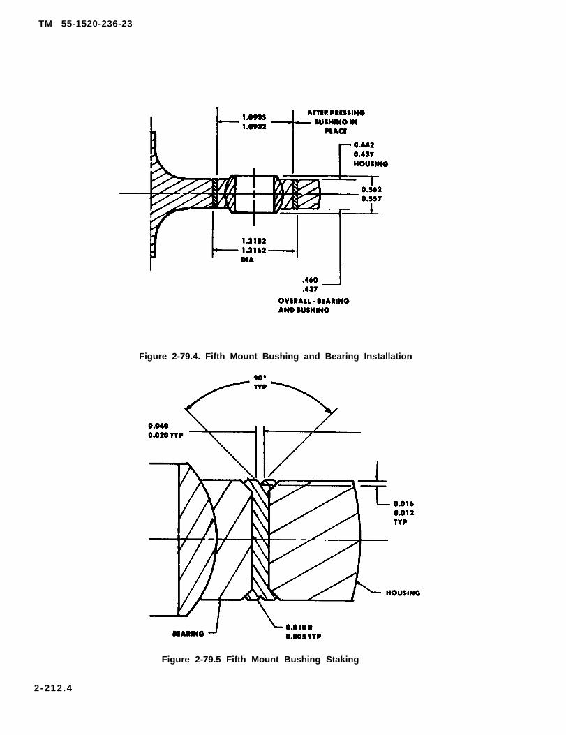
TM 55-1520-236-23
Figure 2-79.4. Fifth Mount Bushing and Bearing Installation
Figure 2-79.5 Fifth Mount Bushing Staking
2-212 .4
TM 55-1520-236-23
NOTE
It is possible to install the fifth mount sup-port fitting backwards. Ensure that four0.250 inch diameter bolt hole pattern is onright side when fitting is installed. See figure 2-79.
a. Position shim (14, figure 2-79) on fifth mount support fitting (15).
b. Insert fifth mount (13) into fifth mount support fit-ting (15) and align holes.
c. Position pylon transducer bracket (20) onflange of fifth mount.
d. Install four bolts (22) with thin steel washers (21).Do not Iockwire bolts at this time.
e. Ensure that shims (18) are in place on aft side ofpylon support (19) for both ends of fifth mount supportfitting (15). Bond Ioose shims (18) to pylon support (19)with adhesive (C12), if necessary.
f. Support transmission with a suitable hoist torelieve tension on eyebolt of fifth mount (13).
g. Position ends of fifth mount support fitting (15) onshims (18). Align holes and install bolts (17) with alumi-num washers (16) under heads.
h. Align fifth mount (15) eyebolt with bushing oftransmission case fifth mount support (4).
When replacement of bolt (6) becomesnecessary, replace with bolt assembly (5).
(1) Fifth mount bolt assembly (5) should beeasily inserted without moving transmission.
(2) Fifth mount bolt (6) should be easily insertedwithout moving transmission.
1. If unable to align, procure new shim (14) and/orshim (18). Peel shims as necessary to obtain properalignment.
NOTE
Bolts (17) or (22) must not bottom out. Foreach 0.06 Inch shim removed, install steelwashers on attaching bolts at thatlocation.
j. Reinstall bolt (22) and thin steel washer (21) ifremoved. Lockwire bolts in pairs with Iockwire (C137).
k. Reinstall bolts (17) and washers (16) if removed.
l. Install fifth mount bolt assembly (5),through eyebolt of fifth mount (13) and transmissioncase fifth mount support (4). Install washer (3) and nut(2). Torque bolt (5) 300 TO 400 inch-pounds. Install cot-ter pin (1).
2-212.5/(2-212.6 blank)

m. Install fifth mount spacer (8, figure 2-79,detail A) in transmission case fifth mount support (4).
n. Install bolt (6) with special washer (7),(countersink against bolt head), through eyebolt offifth mount (13, figure 2-79) and transmission case fifthmount support (4).
o. Install washer (9) and nut (10). Torque nut(10) 300 TO 400 inch-pounds. Install cotter pin (11).
p. Install pylon transducer on pylon transducerbracket (20) using instructions contained inparagraph 11-130.
q. Install tail rotor driveshaft using instructionscontained in paragraph 6-81.
r. Install induction baffle.
2 - 2 3 3 . T R A N S M I S S I O N D A M P E R S .
2-234. DESCRIPTION – TRANSMISSIONDAMPERS.
Two fluid-type dampers are used in the pylonmounting system to help control motion of the pylonand prevent vibration. One damper is connectedbetween the pylon support structure and the lowerend of each of the rear pylon mounts (figure 2-77).
2 - 2 3 5 . R E M O V A L – T R A N S M I S S I O NDAMPERS.
To remove dampers with transmission and mountsinstalled, remove bolts from upper and lowerattachment fittings. Remove hydraulic cylinder foraccess; where necessary (figure 2-77).
2 - 2 3 6 . I N S P E C T I O N – T R A N S M I S S I O NDAMPERS.
a. Mount boots for proper installationdeterioration.
b. Mounts for evidence of bottoming outdeterioration.
c. Underside of dampers for leaks.
and
and
d. Bearing in damper and damper fitting formaximum of 0.012 axial and 0.006 inch radial play.
TM 55-1520-236-23
e. After any hard landing, remove mount dampersto check for possible internal yielding as follows:(figure 2-80).
(1) Use calibrated dial indicator to measure the0.030 inch max end play of barrel assembly. (15, figure2-81)
(2) Measure gap between spring seat (12) andshims (9 and 11) under end of cylinder barrel.
(3) Damper is unserviceable if either measuredgap exceeds 0.030 inch. See figure 2-80.
2-237. DISASSEMBLY – TRANSMISSIONDAMPERS (AVIM).
a. Remove cotter pin (32, figure 2-81) nut (31),washer (30), and bolt (18) from piston (17) and clevisend (26).
b. Remove clevis end (26), dowel pin (27), andspool assembly (24) from piston (17).
c. Remove dowel pin (27) from spool assembly(24) and separate clevis end (26) from spool assembly.Remove and discard packings (25) from spoolassembly.
d. Remove spirolox retainer (10), upper shim (7),barrel assembly (8), and lower shim (9) from bodyassembly (2).
NOTE
Shims must be placed in the sameposition on reassembly. Tag and identifythe upper and lower shim.
e. Remove spirolox retainer (23), end capand piston (17) from barrel assembly (8).
f. Remove spirolox retainer (14), spring seats
21),
spring (13), and shim (11) from barrel (15). Discardspirolox retainer (14).
g. Remove and discard packing (28), double deltaseal (22), and packing (29) from end cap (21).
h. Remove and discard double delta seal (20) andpacking (19) from piston (17).
i. Remove retaining ring (6) and retainer (3) frombody assembly (2).
2-213

TM 55-1520-236-23
Figure 2-80. Damper – Internal YieldingInspection
j. Remove and discard double delta seal (16),packing (4), and packing (51 from retainer (3).
2 - 2 3 8 . C L E A N I N G – T R A N S M I S S I O NDAMPERS (AVIM).
Cleaning solvent is flammable and toxic.Provide adequate ventilation. Avoidprolonged breathing of solvent vaporsand contact with skin or eyes.
Clean disassembled parts with solvent (C112) and drywith clean cloth or compressed air.
2 - 2 3 9 . R E P A I R – T R A N S M I S S I O NDAMPERS (AVIM).
a. Replace dampers if leaking or if found to beyielding after a hard landing. See figure 2-80.
b. Replace bearing (1, figure 2-81) if not withintolerance specified. Stake bearing using standardmaintenance practices and staking tool.
c. Inspect detail parts far nicks,rosion, wear, and broken shims.
NOTE
scratches, minor cor-
The mechanical and corrosion damagelimits for the external part of the pylondamper housing assembly should not ex-ceed 0.010 before cleanup (sanding, etc.)end 0.020 after cleanup. There are nodamage limits required for the inner pylonhousing adjacent to the shim retainer.
2 - 2 4 0 . A S S E M B L Y – T R A N S M I S S I O NDAMPERS (AVIM).
a. Lubricate all packings and seals with hydraulicfluid (C62) prior to assembly.
b. Install packing (19, figure 2-81) in groove ofpiston (17). Install double delta seal (20) over packing(19). Use care to prevent stretching and malforming ofseal and packing.
c. Assemble pylon damper seal installation tool(T64) and pylon damper piston as follows:
(1) Place seal holder (2, figure 2-82) on shaft(1).
(2) Place bolt end of piston (17, figure 2-81) onshaft (1).
(3) Thread guide (3, figure 2-82) into shaft (1).
d. Work double delta seal (20, figure 2-81) underlip of seal holder (2, figure 2-82) and hold in position.Insert guide end of assembled parts into large hole ofbarrel (15, figure 2-81) until the seal holder bottomsinside barrel. Hold parts in position.
Double delta seal (20) is easily damaged.Maintain pressure to hold lip of doubledelta seal under lip of seal holder and tokeep assembled parts bottomed insidebarrel (15).
2-214
TM 55-1520-236-23
e. Hold barrel (15) firmly and rap shaft ( 1, figure 2-82) with heel of hand to force piston (17, figure 2-81)into position within barrel (15).
f. Remove guide (3, figure 2-82) from shaft (1) andremove shaft and seal holder from barrel and pistonassembled in preceding step. Remove seal holder (2)from shaft (1).
g. Insert shaft ( 1 ) through piston (17, figure 2-81),thread guide (3, figure 2-82) into shaft (1), and alignholes in piston and guide. Install pin (4) in alignedholes and install screw (5) in pin (4) to lock specialtools to piston.
h. Install packing (29, figure 2-81) inside grooveof end cap (21). Place double delta seal (22) overpacking (29). Install packing (28) in groove on outsideof end cap.
i. Place beveled end of end cap (21) down on guidethat was pinned to piston (17) in step g. Force end capinto position within barrel (15).
2-214.1/(2-214.2 blank)


TM 55-1520-236-23
Figure 2-81. Transmission Damper - Assembly
2-215

TM 55-1520-236-23
j. Remove screw (5, figure 2-82), pin (4), andguide (3) from shaft (1). Remove shaft (1).
k. Install spirolox retainer (23, figure 2-81) intobarrel (8).
l. Install packing (4) in retainer (3) and installdouble-delta seal (16) over packing. Install packing (5)on retainer. Install retainer (3) and packings on barrel(15). Turn retainer on barrel to seat and size double-delta seal (16). After a minimum of five minutes,remove retainer from barrel and inspect double deltaseal for correct seating and for damage.
m. If double delta seal (16) is properly seated andis not damaged, install the retainer, seal, andpackings into body assembly (2) and secure withretaining ring (6).
n. Select shim (11) of proper thickness as follows:
(1) Determine dimension A and dimension B asshown on figure 2-83.
(2) Subtract dimension B from dimension A toobtain measured gap. Determine proper shim fromtable on figure 2-83.
o. Install shim (11, figure 2-81) with insidechamfer of shim against radius of barrel (15). Installspring seat (12), spring (13), second spring seat (12),and spirolox retainer (14) on barrel (15).
p. Install clevis-end (26) in piston (17). Alignround holes in piston and clevis-end and install bolt(18), washer (30) and nut (31). Do not install cotter pin(32) at this time.
q. Select upper shim (7) of proper thickness asfollows:
(1) Determine dimension C as shown on figure2-84.
(2) Subtract dimension C from 5.82 inches toobtain measured gap. Determine proper shim byusing table on figure 2-84.
r. Remove barrel assembly (8, figure 2-81) frombody assembly (2). Install upper shim (7) in bodyassembly (2) and reinstall barrel assembly (8).
s. Temporarily install spirolox retainer (10). Usingfeeler gage measure gap between spring seat andspirolox retainer as shown on figure 2-85. Selectproper lower shim based on measured gap from tableon figure 2-85.
1. Shaft2. Holder3. Guide4. Pin5. Screw 209900-345A
Figure 2-82. Damper Seal – lnstallation Tool
2-216

TM 55-1520-236-23
Figure 2-83. Damper Barrel Shim — Replacement
t. Remove spirolox retainer (10, figure 2-81).Install lower shim (9) and reinstall spirolox retainer(10).
u. Remove bolt (18) and clevis-end (26) frompiston (17).
v. Hold damper in vertical position. Addhydraulic fluid (C62) through piston rod (17).Slowly cycle piston rod (17) until air is removed.Leave piston rod (17) in retracted position.
w. Install packings (25) on spool assembly (24).Align holes in spool assembly (24) and clevis-end(26). Insert dowel pin (27).
x. Install spool assembly (24) in piston (17). Alignholes in piston (17) and clevis-end (26). Install bolt(18), washer (30), nut (31), and cotter pin (32).
y. Pack bearing (1) with grease (C55).
Any attempt to move the piston, spool,or clevis assembly with the damper in aposition other than vertical mayintroduce air into the piston and spoolassemblies.
2-217
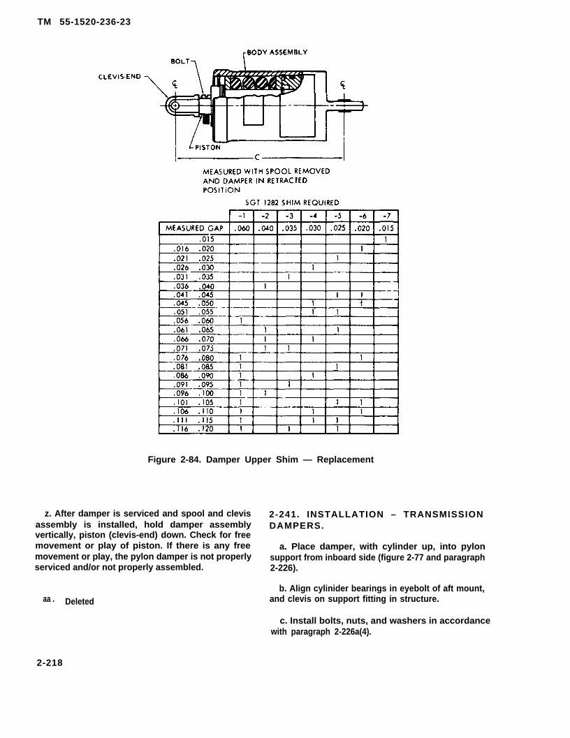
TM 55-1520-236-23
Figure 2-84. Damper Upper Shim — Replacement
z. After damper is serviced and spool and clevisassembly is installed, hold damper assemblyvertically, piston (clevis-end) down. Check for freemovement or play of piston. If there is any freemovement or play, the pylon damper is not properlyserviced and/or not properly assembled.
aa . Deleted
2-241. INSTALLATION – TRANSMISSIONDAMPERS.
a. Place damper, with cylinder up, into pylonsupport from inboard side (figure 2-77 and paragraph2-226).
b. Align cylinider bearings in eyebolt of aft mount,and clevis on support fitting in structure.
c. Install bolts, nuts, and washers in accordancewith paragraph 2-226a(4).
2-218

5 5 - 1 5 2 0 - 2 3 6 - 2 3
Figure 2-85. Damper Lower Shim – Replacement
2-219

TM 55-1520-236-23
d. Reinstall hydraulic cylinder removed foraccess.
2 - 2 4 2 . T R A N S M I S S I O N B U S H I N G S .
2 - 2 4 3 . D E S C R I P T I O N – T R A N S M I S S I O NBUSHINGS.
The transmission bushings are tapered metal wearsurfaces which have steel and rubber washersbonded to the bushing inner face. The bushingscushion and support each of the five transmissionmounts and are installed on the mount between theleg of the transmission and the pylon support.
2 - 2 4 4 . R E M O V A L – T R A N S M I S S I O NBUSHINGS.
Refer to paragraph 2-223 for removal of transmissionmounts.
2 - 2 4 5 . I N S P E C T I O N – T R A N S M I S S I O NBUSHINGS.
Refer to paragraph 2-224 for inspection oftransmission mounts.
2 - 2 4 6 . R E P A I R – T R A N S M I S S I O NBUSHINGS.
Refer to paragraph 2-225 for repair of transmissionmounts.
2 - 2 4 7 . I N S T A L L A T I O N – T R A N S M I S S I O NBUSHINGS.
Refer to paragraph 2-226 for installation oftransmission mounts.
2 - 2 4 8 . T R A N S M I S S I O N F I T T I N G S( A V I M ) .
2 - 2 4 9 . D E S C R I P T I O N – T R A N S M I S S I O NFlTTINGS.
The transmission fittings form structural attachmentpoints for the pylon support and the lower end of thedampers. See figures 2-86 and 2-77.
2 - 2 5 0 . R E M O V A L – T R A N S M I S S I O NFlTTINGS.
a. Remove support (1, figure 2-86) as follows:
(1)supportentry of
(2)
Remove hydraulic lines and fittings from(1). Cap or plug hydraulic lines to preventforeign material.
Remove nut, screw and clamp fromoutboard side of support (1).
(3) Carefully remove six rivets which securesupport to lift beam and remove support. Do notelongate holes in lift beam.
b. Remove the pylon damper fitting (15, figure 2-77).
(1) Remove transmission (paragraph 6-24).
(2) Remove the two aft transmission mountassemblies (3, figure 2-77) (paragraph 2-223).
(3) Carefully drill out rivets which securedamper fittings to structure and remove fitting. Seefigure 2-87 for detail view of rivet. Remove fitting.
c. Remove fifth mount support fitting (15, figure2-79) (paragraph 2-229).
2 - 2 5 1 . I N S P E C T I O N – T R A N S M I S S I O NFITTINGS.
a. Inspect support (1, figure 2-86) and supportassembly (2) for cracks, corrosion damage, andsecure attachment to lift beam (3).
b. Inspect damper fitting (15, figure 2-77) fordefects:
(1) Cracks. No cracks allowed.
(2) Corrosion. Severe corrosion damage iscause for replacement of damper fittings. Minorcorrosion damage may be repaired, using fine Indiastone (C116).
(3) Secure installation of all rivets which attachthe two fittings (15) to the structure.
(4) Secure installation of bearing in damperfitting and condition of bearing.
c. Inspect fifth mount support fitting (15, figure 2-79) for damage in excess of limits shown on figure 2-88.
2-220
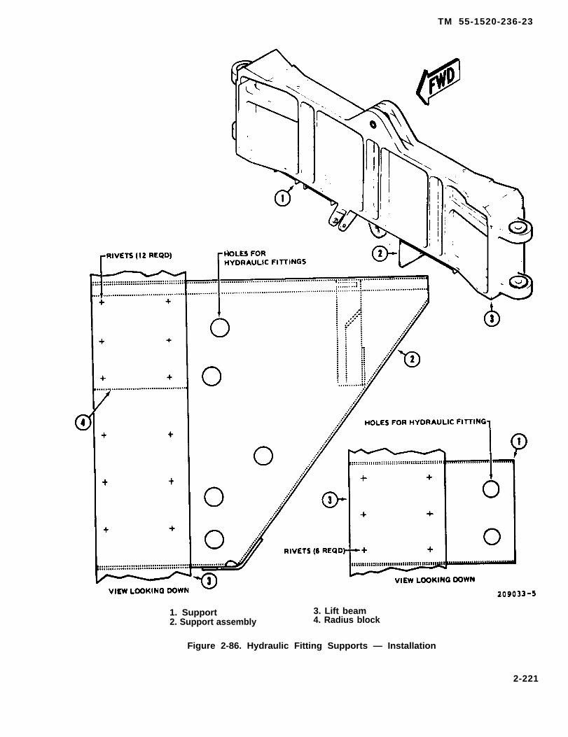
TM 55-1520-236-23
1. Support 3. Lift beam2. Support assembly 4. Radius block
Figure 2-86. Hydraulic Fitting Supports — Installation
2-221

TM 55-1520-236-23
2 - 2 5 2 . R E P A I R – T R A N S M I S S I O NFlTTINGS.
NOTE
Do not repair a damaged supportassembly (2, figure 2-86). Install a newsupport assembly.
a. Remove radius block (4) from old supportassembly or fabricate a new support from 0.060 inchthick material.
a.1. INSPECTION — PYLON DAMPER FITTINGS.Inspect pylon damper fittings for loose or missingrivets.
b. Repair damper fitting (6, figure 2-87).
(1) Raplace damper fitting if cracked.
Do not replace loose or missing rivets withsteel fasteners unless it is Hi-Lok rivetHL20PB5-6 (forward) or HL20PB-6-6 (aft).Rivets are designed to shear before doingexcessive damage to pylon.
(2) Polish out superficial corrosion damageusing fine India stone (C116). Apply primer (C88 orC91) to bare metal surfaces.
(3) If bearing in pylon damper fitting failed tomeet inspection requirements, remove old bearingand install new bearing by roll staking method. Referto chapter 5 for general instructions to remove andinstall roll staked bearings. If roll staking tools are notavailable install a new fitting.
(4) If rivet holes in pylon damper fitting areelongated, install a new fitting.
(6) If rivet holes in helicopter structure forrivets (1) are not elongated, proceed to step (b.7). Ifany holes in structure are elongated, install bushingsas outlined in steps (6) through (9).
(6) Drill out elongated holes in web (3) andextrusion (4). Use a letter size N twist drill. Ream thehole for a class FN2 fit with a NAS 77-3-31 bushing.Make the hole 0.0004 TO 0.0014 inch smaller than thebushing.
(7) Coat bushing (2) and the hole with primer(C88 or C91) and press bushing into position whileorimer iS wet. Install the bushing with the flanged end
on the opposite side of the structure from fitting (6) asillustrated. The bushing must extend through the wef(3) and extrusion (4). Face off bushing flush withextrusion (4) as shown on detail view A.
(8) If Hi-Lok rivets are to be installed, proceed usfollows:
(a) Remove two forward 5/32 inch rivets andtwo aft 3/16 inch rivets. Exercise extreme caution topreclude further enlargement of original hole.
(b) Ream original 5/32 inch holes to 0.1615 to0.1635 inch diameter and install HL20PB-5-6 Hi-Lok fasteners with HL86PB-5 collars.
(c) Ream original 3/16 inch holes to 0.1885 to0.1895 inch diameter and install HL20PB-6-6 Hi-Lok fasteners with HL86PB-6 collars.
(9) Touch up bare metal with primer (C88 orC91).
c. Repair fifth mount support fitting (15, figure 279) as follows:
(1) Polish out mechanical and corrosiondamage using fine India stone (C116) that is withinlimits shown on figure 2-88.
(2) Replace support fitting if damage exceedslimits or if any cracks are detected.
(3) Touch-up repair areas with chemical film(C31) and primer (C88 or C91).
2-253. INSTALLATION – TRANSMISSIONFITTINGS.
a. Install support (1, figure 2-86).
(1) Position support (1) on lift beam in originalposition so that hydraulic fittings can be reinstalledand clamp in place. Drill out holes for six rivets tomatch holes in lift beam. Remove support and deburrholes. Position support on lift beam and install sixrivets (53, table 2-2).
(2) Install hydraulic fittings on support andinstall hydraulic lines on fittings.
(3) Install clamp removed from outboard side ofsupport.
2-222
TM 55-1520-236-23
(4) Per form funct ional check of hydraul icsystem with hydraulic teat stand or by ground run ofhelicopter. Refer to paragraph 7-3. Check for correctoperation of hydraulic system and for hydraulic fluidleaks.
b. Install support assembly (2).
(1) Clamp support assembly (2) and radiusblock (4) on lift boom at position illustrated. En-aura that radius block (4) is nested against matingradius of the support assembly.
( 2 ) D r i l l o u t r i v e t h o l e s i n n e w s u p p o r tassembly (2) and radius block to match holes in liftbeam. Remove support and radius block (4). Deburrholes.
Cleaning solvent is flammable and toxic.Provide adequate ventilation. Avoidprolonged breathing of solvent vaporsand contact with skin or eyes.
2-222.1/(2-222.2 blank)


TM 55-1520-236-23
Figure 2-87. Damper Support Fitting – Elongated Holes
(3) Clean mating surfaces at support assembly(2) and radius block (4) with 400 grit sandpaper(C102). Remove all residue with MEK (C74).
(4) Mix a smalI quantity of adhesive (C14)according to instructions on container and apply athin coat of adhesive to mating surfaces of supportassembly and radius block (table 1-11).
(5) Place a 4 mil glass yarn string in bond Iine atone inch intervals. The glass yarn will serve as aspacer to ensure that adhesive thickness will be 3 TO8 mils after curing.
(6) Clamp support assembly (2) and radiusblock (4) in position on lift beam with radius blockradius nested in support assembly radius. Installtwelve rivets.
(7) Clean all adhesive squeeze out from theparts before adhesive hardens.
(8) Paint support assembly (2) and radius block(4) with primer (C88 or C91).
( 9 ) I ns ta l l h yd rau l i c f i t t i ngs on suppo r tassembly (2) and install hydraulic lines on fittings.
(10) Per form funct iona l check for cor rectoperation of hydraulic system with hydraulic teststand or by ground run of helicopter. Check for correctoperation of hydraulic system and for hydraulic fluidleaks. Refer to chapter 7.
c. Install damper fitting (15, figure 2-77).
(1) Position fitting in helicopter and install rivetsMS20470DD6 (1, figure 2-87).
(2) Install damper (7, figure 2-77), mount (3)and transmission. Refer to chapter 6.
2 - 2 2 3

TM 55-1520-236-23
Figure 2-88. Damage Limits – Fifth Mount Support Fitting
2-224

TM 55-1520-236-23
(3) Perform ground run for functional check offlight controls and hydraulic system componentsaffected by transmission removal/installation. Referto chapter 7.
b. The tow fitting is a casting with an eyeholewhich is riveted to the front of the skid tubes (figure 2-8 9 ) .
2 - 2 6 2 . R E M O V A L — T O W A N D J A C KFITTINGS.
d. Install fifth mount support fitting (15, figure 2-79). Refer to paragraph 2-227.
a. If damaged, drill out rivets and remove the towfitting from each skid tube as applicable.2 - 2 5 4 . M A P A N D D A T A C A S E .
2-255 . DESCRIPTION – MAP AND DATACASE.
b. Remove forward jack and mooring fitting(figure 2-89), aft jack and mooring fitting, and twowing jack and mooring fittings (paragraph 1-33).
The data case for maps, flight reports etc., is locatedunder the right arm rest in gunner compartment.
2 - 2 6 3 . I N S P E C T I O N – T O W A N D J A C KFlTTINGS.2 - 2 5 6 . R E M O V A L – M A P A N D D A T A
CASE.a. Inspect forward jack fitting for cracks and other
defects which would affect its function.Release fasteners and remove data case on gunnerright arm rest.
b. Inspect aft jack fitting for cracks and otherdefects which would affect its function.2 - 2 5 7 . I N S P E C T I O N – M A P A N D D A T A
CASE.c. Inspect wing jack fittings for cracks and other
defects which would affect their function.Inspect data case for damage which would affect itsfunction.
d. Inspect tow ring on skid tube for cracks andother defects which would affect its function. Inspectfor loose, cracked or missing rivets.
2 - 2 5 8 . R E P A I R – MAP AND DATA CASE.
Replace data case if damage is beyond functionallimits. e. Perform fluorescent penetrant inspection of tow
and lack fittings in accordance with MIL-STD 6866.
2-259. INSTALLATION – MAP AND DATACASE.
2 - 2 6 4 . R E P A I R – T O W A N D J A C KFlTTlNGS.Install data case and secure fasteners as applicable.
a. Replace cracked or damaged jack fittings.2 - 2 6 0 . T O W A N D J A C K F l T T l N G S .
b. Polish out minor scratches, nicks, or gouges,using fine India stone (C116).2-261 . DESCRIPTION – TOW AND JACK
FITTINGS.c. Replace cracked or damaged tow fitting.
a. Four jack fittings with mooring shacklesattached are provided as loose equipment for use attwo jack points on the fuselage and on two outboardwing locations. (Figure 2-89). The forward jack fittingis attached by bolts under the structure of the rightmain beam and the ammunition compartment rearbulkhead. The aft jack fitting is screwed into a socketon the left main beam ahead of the tailboom attachsplice. Wing jack fittings are attached by bolts tosockets under the outboard ejector racks.
2-265. INSTALLATION – TOW AND JACKFITTINGS.
a. Install tow fitting (figure 1-8) with rivets (TM55-1520-236-23P).
b. Refer to paragraph 1-35 for removal of jackfittings.
2-225

TM 55-1520-236-23
Figure 2-89. Tow, Jack, and Mooring Fittings
2-226
TM 55-1520-236-23
2-266. MOORING FITTINGS.
2 - 2 6 7 . D E S C R I P T I O N - M O O R I N GFITTINGS.
a. Mooring fittings are steel rings that swivel andare baited to the forward, aft and wing jack fittings.
b. Two additional mooring fittings are installedunder the wings at wing attach points (figure 2-89).
2-268. REMOVAL - MOORING FITTINGS.
(Refer to paragraph 1-40.)
2 - 2 6 9 . I N S P E C T I O N - M O O R I N GFlTTlNGS.
a. Refer to paragraph 2-263. Inspect all mooringfittings in same manner.
b. Inspect wing attach mooring fitting bolts(figure 2-89) for cracks, nicks, and damaged threads.
c. Inspect washers and bushings at wing attachmooring fittings (figure 2-89) for cracks and damage.
2-270. REPAIR - MOORING FITTINGS.
a. Replace cracked or damaged mooring fittings.
b. Polish out minor scratches, nicks, or gougeswith fine India stone (C116).
c. Replace bolts at wing attach mooring fittings(figure 2-89) that do not pass inspection.
d. Replace washers and bushings at wing attachmooring fittings (figure 2-88) that do not passinspection.
2 - 2 7 1 . I N S T A L L A T I O N – M O O R I N GFITTINGS.
(Refer to paragraph 1-40).
2-272. T IEDOWN ASSEMBLY.
2-273. DESCRIPTION — TIEDOWNASSEMBLY.
The helicopter is provided with 1/2" polyester ropes,NSN 4020-00-630-4873, for rotor blade tie-down.
2-274. REMOVAL — TIEDOWN ASSEMBLY.
Remove tiedown ropes as applicable. Refer to para-graph 1-39.
2-275. INSPECTION — TIEDOWNASSEMBLY.
Inspect tiedown ropes for fraying, tom straps, or otherdefects which may affect function.
2-276. REPAIR — TIEDOWN ASSEMBLY.
Repair tom or frayed ropes and replace defectiveropes as applicable.
2-277. INSTALLATION — TIEDOWNASSEMBLY.
Install tiedown ropes as applicable. Refer to para-graph 1-39 and Figure 1-6. In the final tie-down posi-tion the blades must be in a level attitude. Foradditional information refer to TM 1-1520-250-23-1.
2-278. LEVELING PADS.
2-279. DESCRIPTION – LEVELING PADS.
Six leveling pads are located on floor of ammunitioncompartment. Two are used to level helicopter infore-and-aft direction. Two (either two on forwardtrack for ammunition pallet or two on aft track forammunition pallet) are used to level helicopter inlateral direction. Each fore-and-aft leveling pad is aleveling shim assembly consisting of a spacer with alaminated shim bonded to it. Each leveling shimassembly is bonded to splice plate runningIengthwise along left side of ammunitioncompartment floor. Each lateral leveling pad is aleveling pad attached near outboard ends of track forammunition pallet by means of two rivets. Locationsof leveling pads are shown in figure 1-6. Lateral level-ing pads ore installed on forward track for ammunitionpollet as well as on aft track. Height and condition ofeach leveling pad is of critical importance in levelinghelicopter.
2 - 2 8 0 . R E P L A C E M E N T – L E V E L I N GPADS.
Do not attempt to replace leveling pad(s)if structure In pylon area of helicopter isdamaged. Sand helicopter havingdamaged pylon structure to depot.
2-227
TM 55-1520-236-23
2-3).
b.
NOTE
Any or all leveling pads may be replacedas necessary.
Open transmission cowl assembly (11, figure
Check structure in pylon area including liftbeam (16, figure 2-77) pylon support (14) and fifthmount support (9).
c. Place bubble protractor in fore-and-aftdirection on lift beam (16).
NOTE
Fore-and-aft member of pylon support(14) may be used instead of Iift beam(16).
d. Jack up helicopter. Refer to paragraph 1-32,steps a. through g.
e. Adjust jacks to level helicopter in fore-and-aftdirection. Use bubble protractor to check level.
f. Place bubble protractor in lateral direction onlift beam (16) or fore-and-aft member of pylon support(14).
g. Adjust jacks to level helicopter in lateraldirection. Use bubble protractor to check level.
h. Repeat steps c. and e. through g. to make surehelicopter is level.
i. Open ammunition compartment doors (21,figure 2-3).
j. lf either or both fore-and-aft leveling pads aredamaged or missing, replace as follows:
(1) Remove any remaining portion of levelingshim assembly.
(2) Use Scotch-brite (C103) to clean area.
(3) Use adhesive (C8) to bond new levelingshim assembly in place. Allow adhesive to dry.
(4) Place bubble protractor on leveling pads.Check fore-and-aft level of leveling pads.
(5) As necessary, peel laminations from shimuntil leveling in fore-and-aft direction isaccomplished.
k. If any or all lateral leveling pads are damaged ormissing, replace as follows:
(1) Remove five screws and remove ammunitionfloor track having damaged or missing leveling pads.
(2) Place new ammunition floor track inposition and attach with five screws.
(3) Place bubble protractor on leveling pads ofnew ammunition floor track. Check lateral level ofleveling pads.
(4) Place shim under ammunition floor track asnecessary, and repeat steps (3) and (4) until levelingin lateral direction is accomplished.
l. Check leveling in both directions to ensure thatit is satisfactory.
m. Remove bubble protractor and other tools.Lower helicopter slowly and evenly.
n. Remove jacks (paragraph 1-32, steps h.through k.).
o. Close access doors.
2-228

TM 55-1520-236-23
S E C T I O N I l l . T A l L B O O M
2 - 2 8 1 . T A I L B O O M A S S E M B L Y .
2 - 2 8 2 . D E S C R I P T I O N – T A I L B O O MASSEMBLY.
The tailboom (10, figure 2-90) is an aluminum alloysemi-monocoque structure made up of bulkheads,Iongerons and stringers covered by aluminum skin.The tail fin is an integral part of the tailboom and ismade up of aluminum ribs, a spar and honeycombpanels. The tailboom supports the synchronizedelevator, tail rotor, tail rotor driveshaft, control sys-tems, avionics equipment, armament system equip-ment, and cooling equipment for the avionicsequipment.
2 - 2 8 3 . R E M O V A L – T A I L B O O MASSEMBLY.
If the tailboom is removed with the tailrotor gearbox and tail rotor installed, thetailboom may rotate out of control due tothe turning moment caused by the highcenter of gravity.
a. Remove tail pipe fairing and open tail rotordriveshaft covers.
b. Remove clamps on tail rotor driveshaft sectionat forward end of tailboom and remove section ofdriveshaft.
c. Open access panel on right side of fuselage andjust forward of tail boom attachment point.
d. Disconnect electrical connectors.
e. Disconnect tail rotor control.
f. Disconnect synchronized elevator controls.
g. Fabricate a stand or padded support to hold thetailboom after removal (figure 2-91).
h. Place stands, prepared in preceding step,under tail boom.
i. Position three persons on each side of tailboomto support the tailboom and lower it into stands.Remove two lower bolts (15 and 16, figure 2-92).Direct persons to support tailboom. Remove twoupper bolts (1 and 6). Lift up on vertical fin and slidetailboom back to clear helicopter. Lower tail boom intoposition on stands and install bolts to secure tail boomto forward stand as shown on figure 2-91.
2 - 2 8 4 . I N S P E C T I O N — T A l L B O O MASSEMBLY.
a. Inspect for loose orloose or missing rivets.
b. Inspect for minorscratches and corrosion.
missing hardware and
dents, cracks, holes,
2-285. REPAIR – TAILBOOM ASSEMBLY.
NOTE
Repair is limited to repair of minor oil candents, cracks, holes, scratches,corrosion and replacement of loose ormissing hardware. If major damageoccurs which requires use of jigs andfixtures to repair, forward tailboom todepot maintenance for repair.
2 - 2 8 6 . I N S T A L L A T I O N – T A l L B O O MASSEMBLY.
NOTE
If a new tailboom is being installed,install electrical/avionics equipment,synchronized elevator and controls asoutlined in steps a. through f. If the sametailboom is being installed, proceed tostep g.
a. Install electrical and avionics equipment intailboom.
b. Install synchronized elevator and controlsystem. Refer to paragraphs 2-334 and 11-159.
c. Install tail rotor control linkage. Refer toparagraph 11-71.
d. Install intermediate and tail rotor gearboxes(paragraphs 6-105 and 6-121).
2-229
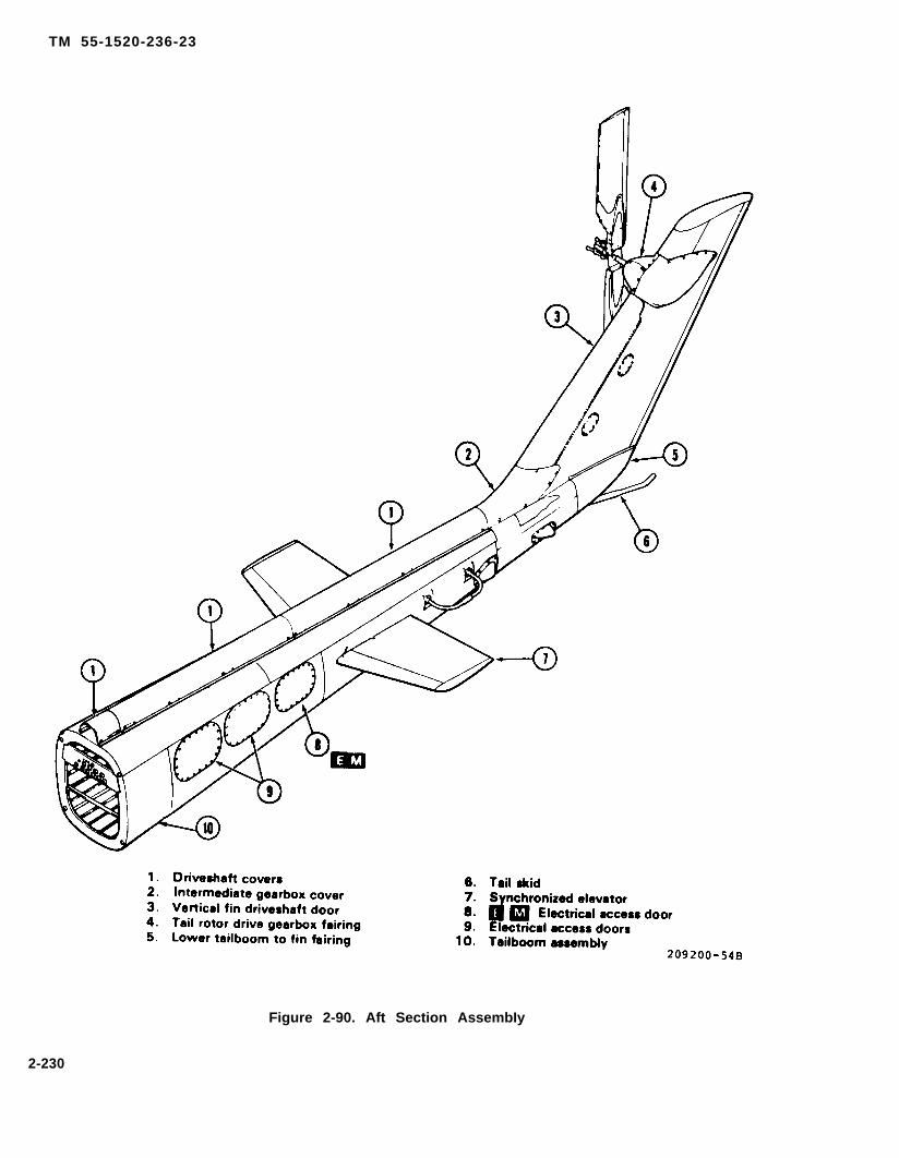
TM 55-1520-236-23
Figure 2-90. Aft Section AssembIy
2-230

TM 55-1520-236-23
F i g u r e 2 - 9 1 . T a i l S u p p o r t - W o r k a i d
2-231
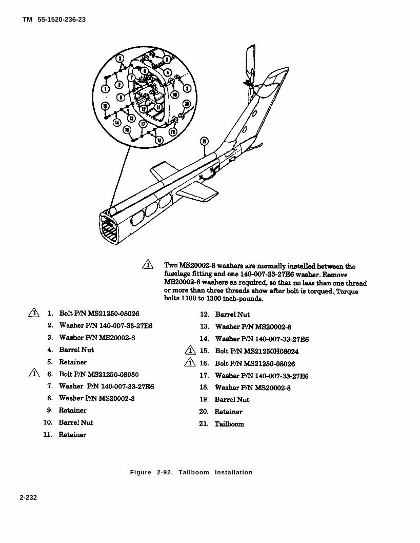
TM 55-1520-236-23
Figure 2-92. Tailboom Installation
2-232

TM 55-1520-236-23
Serial No. 66-15248 thru 71-21052
1. Bolt P/N NAS628-20
2. Washer P/N MS20002C8
3. Washer P/N AN960-816
4. Barrel Nut
5. Retainer
6. Bolt P/N NAS628-26
7. Washer P/N MS20002C8
8. Washer P/N AN960-816
9. Retainer
10. Barrel Nut
11. Retainer
Two AN960-816 washera are normally installed between thefuselage fitting and one MS20002C8 washer. RemoveAN960-816 washers as required, so that no less than one threador more than three threads show after bolt is torqued. Torquebolts 1100 to 1300 inch-pounds.
12.
13.
17.
18.
19.
20.
21.
Barrel Nut
Washer P/N AN960-816
Washer P/N MS20002C8
Bolt P/N NAS628-20
Bolt P/N NAS628-30
Washer P/N MS20002C8
Washer P/N AN960-816
Barrel Nut
Retainer
Tailboom
Figure 2-92.1. Tailboom Installation
2-232.1/(2-232.2 blank)

TM 55-1520-236-23
e. Install tail rotor driveshaft (paragraph 6-81).
f. Install tail rotor assembly (paragraph 5-87).
g. Open access panel on right side of fuselage justforward of tailboom attachment point.
h. Place recessed washers (2, 7, 14, and 17, figure2-92) on tailboom attaching bolts with recessed sideof washers toward bolt heads. Note that the bolts areof varying lengths. Identify bolts so they can be in-stalled in the proper location.
i. Position three persons on each side of tailboomto lift the tailboom into position for installation.Direct persons to support tailboom. Remove bolts thatsecure front stand to tailboom (figure 2-91).
j. Ensure that four retainers (5, 9, 11 and 20,figure 2-92) are in place and that barrel nuts (4, 10,12, and 19) are aligned for installation of bolts.
k. Lift tailboom into position and install bolts withwashers that were prepared in step h. Ensure thatthe correct length bolt is installed for each location.Install two upper bolts (1 and 6) first, then install twolower bolts (15 and 16). Tighten bolts carefully toensure that bolt threads do not bottom in barrel nuts.Two MS20002-8 washers (3, 8, 13, and 18) are nor-really installed between recessed washers (2, 7, 14,and 17) and fuselage fittings to obtain proper threadengagement. See NOTE on figure 2-92. Torque thefour bolts (1, 6, 15, and 16) 1100 to 1300 inch-pounds.Retorque bolts after first flight and apply slippageindex marks with lacquer (C69) or other suitablemarking materiel. Apply thin bead of proseal (C105)around tailboom to fuselage attachment point to min-imize water intrusion.
l. Install tail rotor driveshaft section.m. Connect synchronized elevator controls and
check rigging.n. Connect tail rotor controls and check rigging.
Refer to chapter 5 for illustration andinstallation instructions for nylatronwasher.
o. Connect electrical connectors for electrical andavionics equipment.
p. Install access panels.
q. Perform funct ional check o f e lec tr i -cal/avionics/armament equipment in the tailboomand perform maintenance test flight. Refer to TM55-1520-236-MTF.
2-287. PAINTING-TAILBOOM ASSEMBLY.
Refer to TB746-93-2 for general painting instructions.
2-288. TAILBOOM SHEET METAL PANELSAND SKINS.
2-289. DESCRIPTION-TAILBOOM SHEETMETAL PANELS AND SKINS.
Sheet metal panels, fairings, and skins cover the tailrotor gearboxes and internal components of the tail-boom. The panels make the component accessible,the fairings lessen aerodynamic drag, and the skinsconsist of structural end non-structural sections.
2-290. REMOVAL-TAILBOOM SHEET METALPANELS AND SKINS.
Remove fasteners and remove panels and/or skins asapplicable (figure 2-93).
2-291. INSPECTION-TAILBOOM SHEETMETAL PANELS AND SKINS.
a. Inspect panels and fairings for the followingdefects (paragraph 2-25).
(1) Cracks.NOTE
(2) Corrosion.If tail rotor controls are found to beout of rig during preceding step,determine whether tail rotor has beenremoved and reinstalled. If tail rotorhas been removed and reinstalled,check for proper installation ofnylatron washer under bearing atoutboard end of crosshead that sup-ports tail rotor counterweights.
(3) Security of fasteners and/or hinges.
(4) Deformity that causes improper fit.
2-233
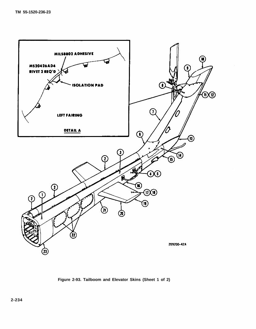
TM 55-1520-236-23
Figure 2-93. Tailboom and Elevator Skins (Sheet 1 of 2)
2-234

TM 55-1520-236-23
Figure 2-93. Tailboom and Elevator Skins (Sheet 2 of 2)
(5) Deteriorated or missing chafing strips,
(6) Security and condition of isolation pad on90° gearbox fairing. (See figure 2-93.)
b. Inspect tailboom skin.(1) Wrinkles and buckled areas. No damage of
this type is allowable.(2) Popped and cocked rivets. No damage of this
type is allowable.(3) Holes through skin. Limits for holes and
tears in skin are the same as for cracks. Refer tofollowing step.
(4) Cracks in skin. Identify cracks less than 3.0inches in length for repair by stop drilling andapplication of a lay-on patch. Identify cracks over 3.0inches in depth for repair by installation of a fillerplate and backing patch of like material and gage.
(6) Surface scratches, dents and nicks.Disregard this type damage if dents are smoothcontour, there is no evidence of cracks and no otherdamage to adjoiningdetected. If it appearsinto a crack, classify it
structure or rivets can bethat damage could progressas a crack. Refer to step (4).
(6) Corrosion damage severe enough to affectfunction of tailboom skin is cause to replace tailboom.Refer to paragraph 2-10 for corrosion treatmentinformation.
2 - 2 9 2 . REPAIR – T A I L B O O M S H E E TMETAL PANELS AND SKINS.
a. Repair tailboom skins. Refer to paragraph 2-27.
(1) Replace loose, missing or cocked rivets if noother structural damage is present.
(2) Repair cracks, holes and tears less thanthree inches in length as follows:
(a) Stop drill cracks.
(b) Smooth out edges of holes and tears.
(c) Apply a lay-on patch of like material. Seefigure 2-93. Install a minimum of four rivets on eachside of patch. Install rivets using same rivet spacingas skin being repaired. Refer to TM 55-1500-204-25/1 for standard repair instructions.
2-235
TM 55-1520-236-23
(3) Repair cracks,3.0 inches in length.
(a) Remove all
holes and tears more than
the damaged skin andfabricate a filler plate of the same material as the skinto match the hole in the skin. Fabricate a backingpatch of the same material. See figure 2-93.
(b) Rivet filler plate and backing patch inplace. Refer to TM 55-1500-204-25/1 for standardrepair instructions.
(4) Repair corrosion damage.
(a)
(b)aluminum
(c)
Polish out minor corrosion damage.
Apply chemical fi lm (C31) to baresurfaces.
Prime repaired area with primer (C89).
(d) T o u c h u p p a i n t t o m a t c hsur round ing a r e a . Refer to TM 55-1500-3 4 5 - 2 3 f o r g e n e r a l p a i n t i n g i n s t r u c -t i o n s .
b. Repair tailboom panels and fairings.
(1) Repair minor cracks. Refer to TM 55-1500-204-25/1.
(2) Polish out minor corrosion on aluminumparts. Apply chemical film (C31) to bare metalsurfaces. Touch up with primer (C89) and paint tomatch surrounding area.
(3) Replace missing and unserviceableturnlock fasteners, hinges and screws.
(4) Replace panels and fairings that aredeformed to the degree that they do not fit wheninstalled.
(5) Replace deteriorated or missing chafingstrips.
2 - 2 9 3 . I N S T A L L A T I O N – T A I L B O O MSHEET METAL PANELS AND SKINS.
a. Position panels on tailboom and engagefasteners.
b. Posi t ion skins on tai lboom and instal lfasteners.
2 - 2 9 4 . TAlLBOOM STRUCTURALM E M B E R S .
2 - 2 9 5 . D E S C R I P T I O N – T A l L B O O MSTRUCTURAL MEMBERS.
The tailboom structure consists primarily ofbulkheads, Iongerons, and stringers (figure 2-94).
2 - 2 9 6 . R E M O V A L – T A l L B O O MSTRUCTURAL MEMBERS.
Remove skins, panels, and/or fairings to gain accessand remove structural members as applicable (figure2-94).
2 - 2 9 7 . I N S P E C T I O N – T A I L B O O MSTRUCTURAL MEMBERS.
a. Inspection. Inspect tailboom structure (suchas; stringers, bulkheads, Iongerons, channels, andfittings) for defects (paragraph 2-25).
(1) Cracks. No cracks are allowed in tailboomstructural members.
(2) Distortion. No distortion is allowed intailboom structural members.
(3) Corrosion. Corrosion damage severeenough to affect function of a tailboom structuralmember is cause to replace the tail boom.
b. Inspect Iongeron attach fittings between Doomstations 41.37 and 70.00. Nicks, scratches, andgouges may be polished with fine India stone (C116)provided they do not exceed following limitations.
(1) Axial damage (parallel to bolt axis) must notexceed 0.020 inch in depth or 3.00 inches in length.
(2) Radial damage (perpendicular to bolt axis)must not exceed 0.010 inch in depth or 3.00 inchesin length.
(3) Nicks, scratches or gouges are not allowedwithin one diameter of bolt hole, Iongeron splicerivets or within 0.250 inch of end of Iongeron atsplice.
2-236

TM 55-1520-236-23
Figure 2-94. Tailboom and Synchronized Elevator — Structure
2-237
TM 55-1520-236-23
Any cracks to the Iongeron attach fittingsforward of boom station 70.00, ordamage exceeding the above limitations,require the part to be replaced by depotmaintenance.
(4 ) Turn lock Fas tener Rep lacement –Vertical Fin. Replace turn lock receptacles, located onvertical fin, with less than 0.025 inch materialremaining in stud pin slot.
2 - 2 9 8 . R E P A I R –STRUCTURAL MEMBERS.
Refer to paragraphs 2-29, 2-30,
NOTE
T A l L B O O M
2-31, and 2-32.
Repair is limited to repair of minorscratches, corrosion and replacement ofloose or missing hardware. If damagesuch as cracking or other damage thatrequires use of jigs and fixtures to repairis incurred, forward tailboom to depotmaintenance.
a. Cracks and damage resulting in distortion ofstructural members is not repairable. Replacetailboom.
b. Cracks or other damage that does not result indistortion of structural members may be repairable.
c. Corrosion. Use fine India stone (C116) topolish out minor corrosion damage to structuralmembers. Apply chemical film (C31) to bare metal.Prime repair area with primer (C88 or C91).
2 - 2 9 9 . I N S T A L L A T I O N – T A I L B O O MSTRUCTURAL MEMBERS.
Install structural members and skins, panels, fairingsas applicable (figure 2-94).
2 - 3 0 0 . T A l L B O O M A C C E S S C O V E R SA N D D O O R S .
2 - 3 0 1 . D E S C R I P T I O N – T A I L B O O MACCESS COVERS AND DOORS.
The access covers and doors of the tailboom areshown in figure 2-90. They include tail rotor
driveshaft covers, intermediate gearbox cover, andelectrical access doors.
2-302 . REMOVAL – TAILBOOM ACCESSCOVERS AND DOORS.
a. Remove fasteners and/or hinges to removetailboom doors as applicable (figure 2-90).
b. Remove fasteners and/or hinges to removeaccess covers on tailboom as applicable (figure 2-90).
2 - 3 0 3 . I N S P E C T I O N – T A I L B O O MACCESS COVERS AND DOORS.
Refer to paragraph 2-25 for inspection.
2-304. CLEANING – TAlLBOOM ACCESSCOVERS AND DOORS.
Refer to TM 55-1500-204-25/1 for cleaningrequirements.
2 - 3 0 5 . R E P A I R – T A I L B O O M A C C E S SCOVERS AND DOORS.
Refer to paragraph 2-28 for repair.
2 - 3 0 6 . I N S T A L L A T I O N – T A l L B O O MACCESS COVERS AND DOORS.
a. Install tailboom doors with fasteners and/orhinges as applicable (figure 2-90).
b. Install tailboom covers with fasteners and/orhinges as applicable (figure 2-90).
2-307 . PAINTING – TAlLBOOM ACCESSCOVERS AND DOORS.
Refer to 7B746-93-2 for general paintinginstructions.
2 - 3 0 8 . T A I L R O T O R D R I V E S H A F TA C C E S S D O O R S .
2 - 3 0 9 . D E S C R I P T I O N – T A I L R O T O RDRIVESHAFT ACCESS DOORS.
The tail rotor driveshaft access doors consist of threehinged door sections made from aluminum alloy. Thefirst two sections are installed between the front of
2-238

TM 55-1520-236-23
the tailboom and the intermediate gearbox. The thirdsection is installed between the aft end of theintermediate gearbox and the tail rotor gearbox on thevertical fin (figure 2-90).
2 - 3 1 0 . R E M O V A L – T A I L R O T O RDRIVESHAFT ACCESS DOORS.
a. Open fasteners and door sections betweenfront of tailboom and gearbox. Remove hinges anddoor sections.
b. Open fasteners and door section on vertical fin.Remove hinge and door section.
2 - 3 1 1 . I N S P E C T I O N – T A I L R O T O RDRIVESHAFT ACCESS DOORS.
Refer to paragraph 2-25 for inspection.
2 - 3 1 2 . C L E A N I N G – T A I L R O T O RDRIVESHAFT ACCESS DOORS.
Refer to TM 55-1500-204-25/1 for cleaningrequirements.
2 - 3 1 3 . R E P A I R – T A I L R O T O RDRIVESHAFT ACCESS DOORS.
Refer to paragraph 2-33 for repair.
2 - 3 1 4 . I N S P E C T I O N – T A I L R O T O RDRIVESHAFT ACCESS DOORS.
a. Install hinges and door sections between thefront of tailboom and gearbox. Close door and securefasteners (figure 2-90).
b. Install hinge and door section on vertical fin.Close door and secure fasteners.
2 - 3 1 5 . P A I N T I N G – T A I L R O T O RDRIVESHAFT ACCESS DOORS.
Refer to TM 55-1500-345-23 fo r genera lp a i n t i n g i n s t r u c t i o n s .
2 - 3 1 6 . T A I L B O O M S K I D .
2-317. DESCRIPTION – TAILBOOM SKID.
The tailboom skid is located at the aft end of thetailboom. The purpose of the tail skid is to warn thepilot of a tail-low attitude when landing.
It is possible to install the wrongtailboom skid. Helicopters codedrequire lead shot ballast in the skid tube.If skid is to be replaced, ensure old andnew parts have identical part numbers.
Ground handling forces should notexceed 450 pounds (vertical direction)and 150 pounds (horizontal direction).
2 -318 . REMOVAL – TAlLBOOM SKID.
a. Remove taillight and access covers (1, figure 2-95) on aft end of tailboom.
b. Remove nut (8), washer (7), and bolt (6) thatattach forward end of skid to tail boom. Removescrews (4), and support block (3).
c. Pull tail skid aft out through hole at boomstation 227 with packing (5). Discard packing.
2-319. INSPECTION – TAILBOOM SKID.
a. Scratches and Nicks. Minor surface scratchesand nicks are negligible and do not require repair.Slight scratches and nicks require polishing out.Replace tail skid if very deep scratches or nicks arepresent.
b. Dents. Smooth dents up to 0.0625 inch deepare negligible and do not require repair.Replace tailskid if dents deeper than 0.0625 inch are present.
c. Cracks. No cracks allowed. Replace tail skid ifany cracks are present.
d. Deformity. Replace tail skid if deformed (bent)to the degree that it can be detected visually.
e. Loose Attachment to Tailboom. Determinecause for loose attachment.
f. Insufficient Lead Shot. Ensure tailboomskid tube is completely filled with lead shot (C109).
2 - 3 2 0 . R E P A I R – TAILBOOM SKID.
a. Polish out slight scratches and nicks. Ifcomplete clean up of damage results in removal ofenough material to weaken the tail skid, replace the
2-239
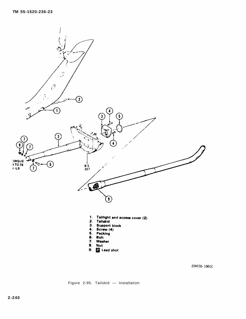
TM 55-1520-236-23
Figure 2-95. Tailskid — Installation
2-240
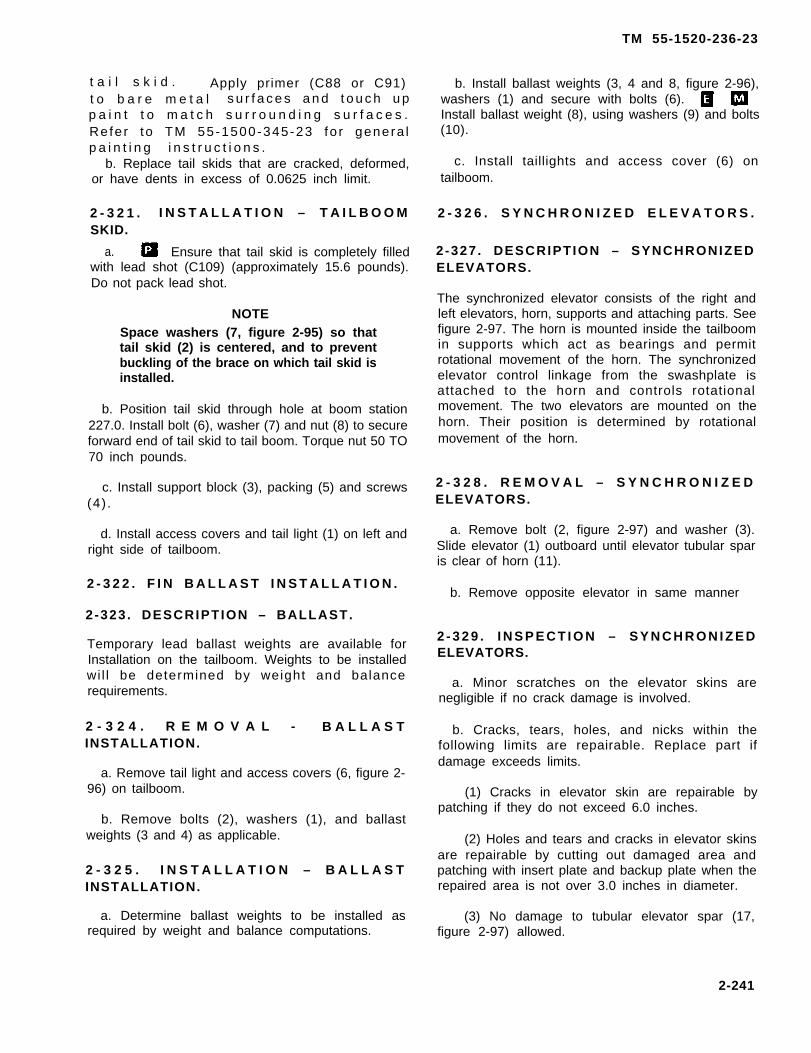
TM 55-1520-236-23
t a i l s k i d . Apply primer (C88 or C91)t o b a r e m e t a l s u r f a c e s a n d t o u c h u pp a i n t t o m a t c h s u r r o u n d i n g s u r f a c e s .Re fe r to TM 55-1500-345-23 fo r genera lp a i n t i n g i n s t r u c t i o n s .
b. Replace tail skids that are cracked, deformed,or have dents in excess of 0.0625 inch limit.
2 - 3 2 1 . I N S T A L L A T I O N – T A I L B O O MSKID.
a. Ensure that tail skid is completely filledwith lead shot (C109) (approximately 15.6 pounds).Do not pack lead shot.
NOTESpace washers (7, figure 2-95) so thattail skid (2) is centered, and to preventbuckling of the brace on which tail skid isinstalled.
b. Position tail skid through hole at boom station227.0. Install bolt (6), washer (7) and nut (8) to secureforward end of tail skid to tail boom. Torque nut 50 TO70 inch pounds.
c. Install support block (3), packing (5) and screws(4) .
d. Install access covers and tail light (1) on left andright side of tailboom.
2 - 3 2 2 . F I N B A L L A S T I N S T A L L A T I O N .
2-323 . DESCRIPTION – BALLAST.
Temporary lead ballast weights are available forInstallation on the tailboom. Weights to be installedwi l l be determined by weight and balancerequirements.
2 - 3 2 4 . R E M O V A L - B A L L A S TINSTALLATION.
a. Remove tail light and access covers (6, figure 2-96) on tailboom.
b. Remove bolts (2), washers (1), and ballastweights (3 and 4) as applicable.
2 - 3 2 5 . I N S T A L L A T I O N – B A L L A S TINSTALLATION.
a. Determine ballast weights to be installed asrequired by weight and balance computations.
b. Install ballast weights (3, 4 and 8, figure 2-96),washers (1) and secure with bolts (6).Install ballast weight (8), using washers (9) and bolts(10).
c. Install taillights and access cover (6) ontailboom.
2 - 3 2 6 . S Y N C H R O N I Z E D E L E V A T O R S .
2-327 . DESCRIPTION – SYNCHRONIZEDELEVATORS.
The synchronized elevator consists of the right andleft elevators, horn, supports and attaching parts. Seefigure 2-97. The horn is mounted inside the tailboomin supports which act as bearings and permitrotational movement of the horn. The synchronizedelevator control linkage from the swashplate isattached to the horn and controls rotationalmovement. The two elevators are mounted on thehorn. Their position is determined by rotationalmovement of the horn.
2 - 3 2 8 . R E M O V A L – S Y N C H R O N I Z E DELEVATORS.
a. Remove bolt (2, figure 2-97) and washer (3).Slide elevator (1) outboard until elevator tubular sparis clear of horn (11).
b. Remove opposite elevator in same manner
2 - 3 2 9 . I N S P E C T I O N – S Y N C H R O N I Z E DELEVATORS.
a. Minor scratches on the elevator skins arenegligible if no crack damage is involved.
b. Cracks, tears, holes, and nicks within thefollowing limits are repairable. Replace part ifdamage exceeds limits.
(1) Cracks in elevator skin are repairable bypatching if they do not exceed 6.0 inches.
(2) Holes and tears and cracks in elevator skinsare repairable by cutting out damaged area andpatching with insert plate and backup plate when therepaired area is not over 3.0 inches in diameter.
(3) No damage to tubular elevator spar (17,figure 2-97) allowed.
2-241

TM 55-1520-236-23
(4) Nicks in elevator trailing edge that are lessthan 0.025 inch deep are acceptable if polished out.
(5) Inspect for correct drag on elevators(paragraph 11-144).
(6) Prior to removal of elevator, inspect supportbrackets (4) on both sides of tailboom for loose attachingrivets. Inspect rivets visually and by hand contact forsigns of movement. Replace loose, damaged, or miss-ing rivets.
NOTE
Apply a moderate force when moving theelevator and use care not to bend theelevator thus causing false indications.
(7) Check axial play of elevator horn assembly(11) in support assemblies (8) as follows:
(a) Mount dial indicator inside of the tailboomplacing the stylus against the elevator horn at the pivotpoint.
(b) Move elevator inboard and outboard (span-wise) and observe the total indicator reading, Aminimum of 0.005 inch and maximum of 0.030 inch playshould be indicated (figure 2-97).
(c) if the indicator readings are not withintolerance, adjust shims (7) as necessary.
(8) Check radial play as follows:
(a) Mount dial indicator inside tailboom withstylus in contact with the upper surface of elevator hornnear the inboard edge of pivot point.
(b) Lightly move elevator up and down andobserve total reading on dial indicator. A maximumreading of 0.010 inch is permissible (figure 2-97).
THE 209-033-839-1 AND 209-033-840-1 WEIGHTS TO BE TRIMMED TO OBTAIN ACOMBINED WEIGHT OF 21.0 PLUS OR MINUS 0.2 POUNDS, EXCLUDINGATTACHING HARDWARE.
1. Washer (AN960PD416) 5. Tailskid (with lead shot)2. Bolt (AN4-13) 6. Access cover3. Ballast (209-033-839-1) (LH) 7. Tailboom4. Ballast (209-033-840-1) (RH)
Figure 2-96. Aft Ballast — Installation (Sheet 1 of 2)
2-242

TM 55-1520-236-23
NOTE
Heavy force In moving the elevator willcause flexing of elevator spar tube thusproducing false indications of excessradial play.
(c) If dial indicator readings are not withintolerance, adjust shims (16) as necessary.
(9) Negligible damage limit. Dents, smooth con-tour, free of nicks or wrinkles. Depth and diameter notto exceed:
Depth Diameter
1/64 1.0 inch3/64 2.0 inches1/16 3.0 inches
Three inches minumum undamaged material betweendents and one inch minimum from internal structure.
(10) Repairable damage limit. Sharp nick indent. Damage areas after cleanup (including priorrepairs) shall not exceed 25% of area for a single skinpanel. Damage six inches minimum from similarrepair.
(11) Damage requiring replacement. Totaldamage (including prior repairs) exceeds 25% of totalarea of a single skin panel.
c. Corrosion. Inspect elevators for corrosion dam-age. Minor corrosion damage that does not exceed0.005 inch in depth is repairable. Maximum allowablecorroded area is 4.0 square inches in a single area or20 percent of the elevator skin area.
d. Refer to paragraph 11-161 for inspection of horn(11), support assembly (8), and bracket (4).
2 - 3 3 0 . C L E A N I N G – S Y N C H R O N I Z E DELEVATORS.
Refer to TM 55-1500-204-25/1 for cleaning re-quirements.
2-331 . R E P A I R – SYNCHRONIZEDELEVATORS.
a. Polish out minor scratch damage on elevators.Apply primer (C88 or C91) and touch up paint to matchadjacent area.
b. Repair elevators with crack damage that is withinlimits for patch repairs.
(1) Stop drill each end of crack.
(2) Ensure that tubular spar inside elevator hasnot been damaged.
(3) Fabricate a patch from the same material asthe skin. See figure 2-93 for description of elevator skin.Install patch in accordance with standard instructions inTM 55-1500-204-25/1.
2-242.1/(2-242.2 blank)


TM 55-1520-236-23
1.2.3.4.5.
NOTES.
1. Weights P/N 209-033-839-101, 209-033-840-101, and 209-033-841-1 are trimmed toa combined weight of 62.0 ± 0.2 pounds at time of installation.
2. The exact required combined weight of the weights listed above is determined when weightand balance is computed.
Washer (AN960PD416) 6.Bolt (AN4-13) 7.Ballast (209-033-839-101 (LH) 8.Ballast (209-033-840-101 (RH) 9.Tailskid (no lead shot) 10.
Access coverTailboomBallast (209-033-841-1) (RH)Washer (AN960-416L)Bolt (AN4-14)
204071-1005B
Figure 2-96. Aft Ballast — Installation (Sheet 2 of 2)
2-243
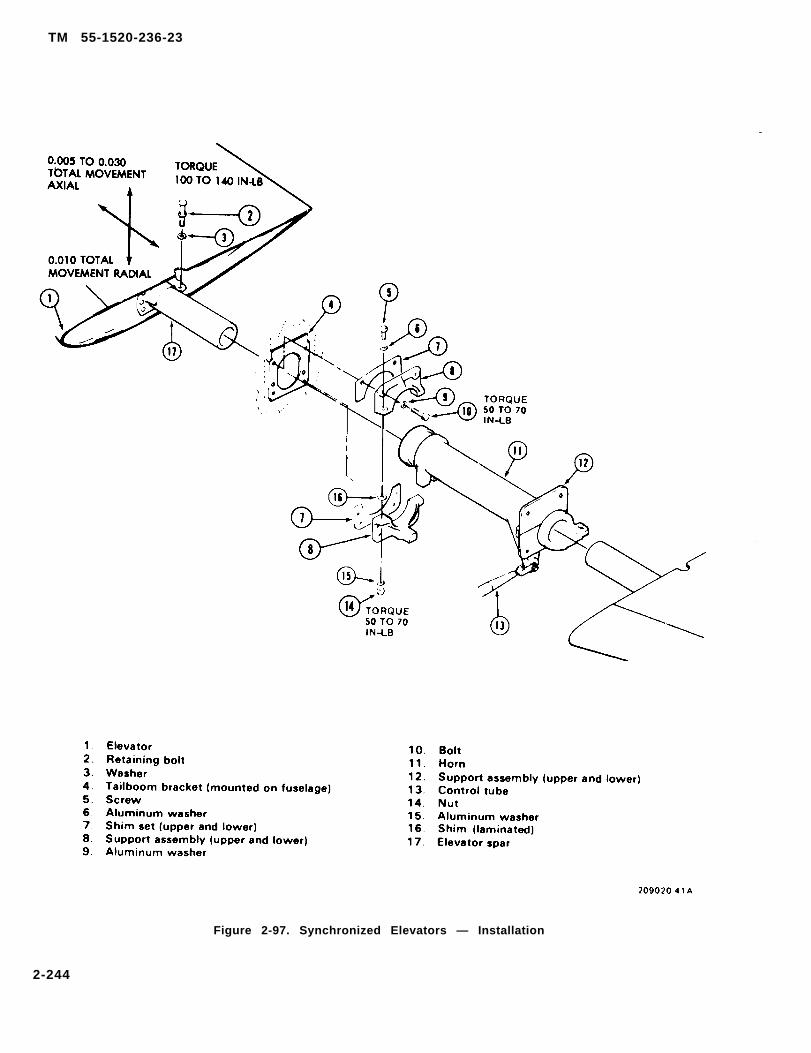
TM 55-1520-236-23
Figure 2-97. Synchronized Elevators — Installation
2-244

TM 55-1520-236-23
c. Repair holes and tears that are within 3.0 inchdiameter limit.
(1) Cut out the damaged area. Ensure thattubular spar inside elevator has not been damaged.
(2) Fabricate a filler plate to fit the cutoutprepared in the preceding step from the samematerial as the skin. See figure 2-93 for description ofelevator skin. Fabricate backup patch from the samematerial to use with filler plate. Install filler plate andbackup patch in accordance with standardinstructions in TM 55-1500-204-25/1.
d . Repair minor corrosion damage one l e v a t o r s . P o l i s h o u t c o r r o s i o n a n da p p l y c h e m i c a l fiIm treatment (C31).A p p l y p r i m e r ( C 8 8 o r C 9 1 ) . T o u c h u pp a i n t o n e l e v a t o r s t o m a t c h a d j a c e n ta r e a . Refe r to TM 55-1500-345-23 fo rg e n e r a l p a i n t i n g i n s t r u c t i o n s .
e. Repair smooth dents by using a suction cup. Onlyone pull per dent is allowed. Inspect for crocks afterrepair. If only one crack is found, repair per paragraph2-331.b. If two or more cracks are found, send elevatorto depot for repair.
NOTE
D e n t s w h i c h c a n n o t b e p u l l e d o u tw i th a suc t ion cup sha l l be repa i redin accordance wi th paragraph 2-33lb.
f. If dents are found in rivet pattern, send elevator todepot for repair.
2 - 3 3 2 . I N S T A L L A T I O NSYNCHRONIZED ELEVATORS.
Cleaning solvent is flammable and toxic.Provide adequate ventilation. Avoidprolonged breathing of solvent vaporsand contact with skin or eyes.
NOTE
If solid film lubricant is accidentallyremoved, It may be reapplied to the areafrom which it was removed.
a. Clean the inside part of the horn (11, figure 2-97)that mates with the tabular spars (17) of the elevators.Also clean tabular spars. If there is any zinc chromate orsimilar material in mating surfaces, clean down to boremetal with MEK (C74) and clean cheesecloth (C30). Donot use excess MEK or aIIow it to saturate the tabularspar as it may remove the solid film lubricant. Allow theMEK to dry.
b. Apply a thin coat of compound (C43) or (C44) tothe surfaces of horn (11) contacted by the elevatorspars.
c. Position elevator tubular spar (17) in horn (11).
d. Install bolt (2) and washer (3). Torque bolt 100TO 140 inch-pounds.
e. Check rigging of elevator. Refer to paragraph 11-138.
2-333 . ADJUSTMENT - SYNCHRONIZEDELEVATORS.
Refer to paragraph 11-138 for adjustmentprocedures.
2 - 3 3 4 . P A I N T I N G – S Y N C H R O N I Z E DELEVATORS.
Refer to TM 55-1500-345-23 fo r genera lp a i n t i n g i n s t r u c t i o n s .
S E C T I O N I V . W I N G
2 - 3 3 5 . W I N G A S S E M B L Y . 2-337 . REMOVAL - WING ASSEMBLY.
2 - 3 3 6 . D E S C R I P T I O N – W I N GASSEMBLY.
Stub wings, mounted on the fuselage, supplyadditional lift and provide mounting accommodationsfor weapons pylons. The structure is built up with a.
NOTE
The removal procedure is the same forboth wings.
Remove external stores from weapon pylon, ifaluminum alloy spars and ribs covered with sheet installed. Refer to chapter 16.aluminum skin. Each wing is attached to fuselagefittings with attaching bolts. Four removable panels b. Remove lower access panel (9 figure 2-98) onallow access to internal provisions. each wing.
2-245
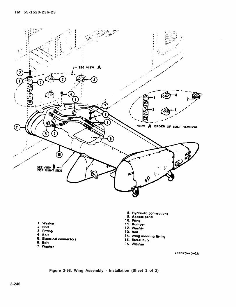
TM 55-1520-236-23
Figure 2-98. Wing Assembly - lnstallation (Sheet 1 of 2)
2-246
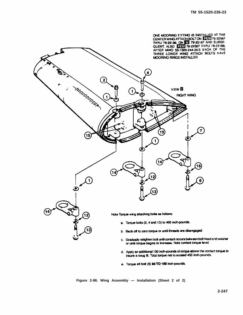
TM 55-1520-236-23
Figure 2-98. Wing Assembly — Installation (Sheet 2 of 2)
2-247

TM 55-1520-236-23
c. Disconnect two pylon hydraulic connections (8) d. Remove five attachment bolts and washers and sepa-in each wing. Cap all open lines. rate wing from fuselage.
e. Disconnect electrical connectors (5) betweenwing root and fuselage.
2-338. INSPECTION – WING ASSEMBLY.Support wings to prevent bolts frombinding. Remove bolts in sequence as a. Inspect wing skins, access doors, and Ieadingshown in figure 2-98, view A. and trading edge of fairing. Refer to table 2-5.
Table 2-5. WING Classification of Damage
WING,SKIN,ACCESSDOORS,COVERS,ANDLEADINGANDTRAILINGEDGEFAIRINGS
WING;SPARS,RIBS,ANDOTHERINTERNALSTRUC-TURE
Dents, nicks,scratches, andgouges.
Corrosion
Sharp dents,holes, and cracksor nicks, scratchesand gouges whichexceed negligibleIimits.
Wrinkled skin
Dents, nicks,scratches andgouges.
Cracks, holesor other damage.
small smooth dents,nicks, scratches, andgouges that do notexceed 0.005 inchafter polishing out.
Small smooth dents,and minor nicks,scratches, and gougeswhich will not affectstrength.
Damage exceedingnegligible limits canbe patched if patchingIimits are notexceeded.
Minor surface corro-sion can be polishedout and arearefinished.
Damage to skin notexceeding 1.25 incheslong and not involvingdamage to wing struc-ture can be repairedby patching (figure2-101).
Corrosion other thanminor surface typerequires replacementof wing.
Damage exceedingrepairable limitsrequires replacementof wing.
Replace wing if skinis wrinkled to thedegree that internalstructure is Involved.
Damage whichexceeds negligiblerequires replacementof wing.
Any cracks, hole orother damage towinginternal structurerequires replacementof wing.
2-248

TM 55-1520-236-23
Table 2-5. WING Classification of Damage (Cont)
DAMAGENEGLIGIBLE REPAIRABLE REQUIRING
ITEM DEFECT DAMAGE LIMITS DAMAGE LIMITS REPLACEMENT
WING Cuts, debonding, Bumpers damagedBUMPERS or deterioration. enough to affect func-
tion will be replaced.
b. Inspect wing bumper (11, figure 2-98) for cuts,tears, deterioration and debonding which wouldaffect its function.
c. Inspect wing fitting bushing and correspondingbushings on pylon structure for damage and wearbeyond limits shown on figure 2-99.
2 - 3 3 9 . R E P A I R – WING ASSEMBLY.
a. Repair damage to skin that is within repairablelimits. See figures 2-100 through 2-102 for typicalrepairs. Wing materials are shown on figure 2-103.
b. Repair damage to leading and trailing edgefairings that is within repairable limits. See figure 2-104 for typical repair.
c. Replace damaged bumpers (11, figure 2-88).
( 1 ) R e m o v e w i n g i f n o t p r e v i o u s l yaccomplished.
Cleaning solvent is flammable and toxic.Provide adequate ventilation. Avoidprolonged breathing of solvent vaporsand contact with skin or eyes.
(2) Remove defective bumper with plasticscraper. Clean remaining particles with MEK(C74)ornaphtha (C75). Wipe area dry with clean cloth.
(3) Sand mating surfaces of bumper and metalwith 180 grit sandpaper (C102).
Cleaning solvent is flammable and toxic.Provide adequate ventilation. Avoidprolonged breathing of solvent vaporsand contact with skin or eyes.
(4) Clean sanded area with MEK (C74) ornaphtha (C75). Dry with a clean cloth.
(6) Apply an even coat of adhesive (C12) to bondsurfaces of bumper and metal.
(6) Allow adhesive to air dry 10 to 15 minutes at70 TO 80 degrees F (21 TO 27 degrees C) or untiltacky to touch. Apply second coat of adhesive in samemanner.
(7) Install bumper on wing. Roll bumper toexpel air from bond area. Air cure adhesive for aminimum of four hours.
2-340. PAINTING – WING ASSEMBLY.
P a i n t r e p a i r s o n w i n g t o m a t c h s u r -r o u n d i n g a r e a . Refer to TM 55-1500-3 4 5 - 2 3 f o r g e n e r a l p a i n t i n g i n s t r u c -t i o n s .
2 - 3 4 1 . I N S T A L L A T I O N – W I N GASSEMBLY.
NOTE
Installation procedure is the same forboth wings.
a. Install and align barrel nuts in fittings.
2-249

TM 55-1520-236-23
Figure 2-99. Wing Bushings – Limits Chart (Sheet 1 of 2)
2-250
Richard Woods
209-032-167-7
Richard Woods
209-032-167-9
Richard Woods
209-032-167-3
Richard Woods
209-032-167-5
Richard Woods
209-032-167-1
Richard Woods
209-030-319-1

TM 55-1520-236-23
Figure 2-99. Wing Bushings - Limits Chart (Sheet 2 of 2)
2-250.1/(2.250.2 blank)


TM 55-1520-236-23
Figure 2-100. Wing Skin Repair (External Hole)
2-251
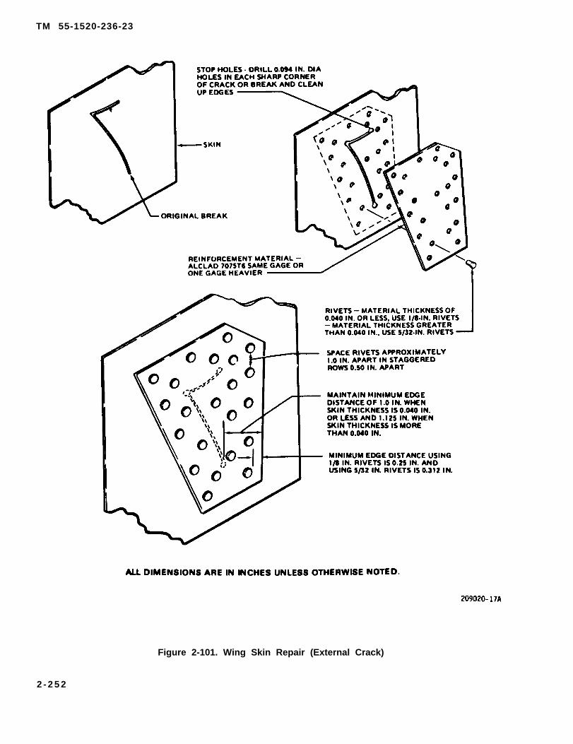
TM 55-1520-236-23
Figure 2-101. Wing Skin Repair (External Crack)
2 - 2 5 2

TM 55-1520-236-23
Figure 2-102. Wing Skin Repair (Close to Frame, Spar, or Ribs)
2-253

TM 55-1520-236-23
INDEXNO. NOMENCLATURE MATERIAL SPECIFICATION CONDITION THICKNESS
1 Bumper Rubber synthetic MIL-R-6855,extruded Class 3, Grade 60
2 Bumper Same Same3 Bumper Same Same4 Skin, upper 7075 Al. alloy QQ-A-250/13 16 0.0635 Fairing, aft 2024 Al. alloy QQ-A-250/5 T3 0.0326 Cover 2024 Al. alloy QQ-A-250/5 13 0.0327 Cover 2024 Al. alloy QQ-A-250/5 13 0.0328 Fairing 2024 Al. alloy QQ-A-250/5 13 0.0329 Closure 2024 Al. alloy QQ-A-250/5 T3 0.040
Figure 2-103. Wing Skins, Fairings, Covers, Doors (Sheet 1 of 2)
2-254

TM 55-1520-236-23
INDEXNO. NOMENCLATURE MATERIAL SPECIFICATION CONDITION THICKNESS
10 Double 2024 Al. alloy QQ-A-250/5 T3 0.02011 Doubler 7075 Al. alloy QQ-A-250/13 T6 0.06312 Door 7075 Al. alloy QQ-A-250/13 T6 0.06313 Doubler 2024 Al. alloy QQ-A-250/5 T3 0.03214 Doubler 2024 Al. alloy QQ-A-250/5 T3 0.04015 7075 Al. alloy QQ-A-250/13 T6 0.06316 Doubler 7075 Al. alloy QQ-A-250/13 T6 0.06317 Doubler 2024 Al. alloy QQ-A-250/5 T3 0.03218 Skin, Iower 7075 Al. alloy QQ-A-250/13 T6 0.063
Figure 2-103. Wing Skins, Fairings, Covers, Doors (Sheet 2 of 2)
2-255
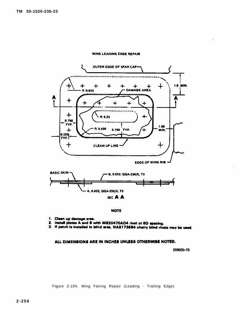
TM 55-1520-236-23
Figure 2-104. Wing Fairing Repair (Leading - Trailing Edge)
2 - 2 5 6
TM 55-1520-236-23
b. Connect and Iockwire electrical connectors (5,figure 2-98).
c. After MWO 55-1520-244-30-3, mount wing infuselage fittings and install bolts and washers. Tighten wingattach bolts.
(1) Torque bolts (2, 4, and 13) 400 inch- pounds.
(2) Back off to zero torque or until threads aredisengaged.
(3) Gradually retighten bolts until contactoccurs between bolthead and washer or until torquebegins to increase. Note contact torque level.
(4) Apply an additional 100 inch-pounds oftorque above the contact torque to ensure a snug fit,but do not exceed 450 inch-pounds torque.
(5) Torque aft bolt (6) 80 to 100 inch-pounds.
c.1. Before MWO 55-1520-244-30-3, mount wing infuselage fittings and install bolts. Tighten wing attachbolts. Torque bolts (2, 4, and 13) 100 10 150 inch-pounds, and aft bolt 80 TO 100 inch-pounds.
d. Remove caps from hydraulic connections (8)and connect.
e. Install lower access panel (9).
f. Attach weapons pylon to wing, if required.Refer to Installation — Outboard Ejection Rack andInstallation — Inboard Ejector Rack, chapter 16.
g. Perform functional check of hydraulicallyactuated articulated pylon and all electrical circuits inthe wing (chapters 7, 9, 16).
2 - 3 4 2 . W I N G A C C E S S C O V E R S A N DD O O R S .
2-343 . DESCRIPTION – WING ACCESSCOVERS AND DOORS.
To provide access to internal provisions in the wingtwo doors are on the wing lower skin and two coversare in the wing leading edge fairing. The inboardleading edge cover is hinged at the top and secured atthe bottom with two turnlock fasteners. Doors andcovers are made of aluminum alloy.
2 - 3 4 4 . R E M O V A L – W I N G A C C E S SCOVERS AND DOORS.
a. To remove doors (12 and 15, figure 2-103) andcover (6), remove attaching screws and remove dooror cover.
b. To. remove cover (7), release fasteners atbottom of cover, remove hinge pin and remove cover.
2 - 3 4 5 . I N S P E C T I O N – W I N G A C C E S SCOVERS AND DOORS.
Inspect covers and doors for damage. (Refer to table2-5.)
2 - 3 4 6 . C L E A N I N G – W I N G A C C E S SCOVERS AND DOORS.
Cleaning solvent is flammable and toxic.Provide adequate ventilation. Avoidprolonged breathing of solvent vaporsand contact with skin or eyes.
a. Clean covers and doors with solvent (C112).
b. Dry with clean dry cloths.
2-347. REPAIR – ACCESS COVERS ANDDOORS.
a. Repair doors on bottom skin using skin repairprocedures in figures 2-98, 2-100, 2-102, 2-103 and2-104.
b. Repair covers on leading edge using fairingrepair procedures in figures 2-98, 2-100, 2-102, 2-103 and 2-104.
c. Replace hinge half on cover (7, figure 2-103) onmating hinge half on wing using rivets of same type.Use rivets of same diameter or one size larger.
2-257
TM 55-1520-236-23
2 - 3 4 8 . I N S T A L L A T I O N – A C C E S S 2 - 3 5 0 . W I N G P Y L O N l N S T A L L A T I O N S .
COVERS AND DOORS.
a. Position doors (12 and 15, figure 2-103) andcover (6) in place and install attaching screws.
b. Position cover (7) to align hinge half on coverwith hinge half on wing. install hinge pin. Securefasteners at bottom of cover.
2 - 3 5 1 . D E S C R I P T I O N - W I N G P Y L O N2 - 3 4 9 . P A I N T I N G – A C C E S S C O V E R S lNSTALLATIONS.AND DOORS.
The wing pylon consists of an inboard and outboardP a i n t c o v e r s a n d d o o r s t o m a t c h s u r - ejector rack each enclosed in an aerodynamic shapedround ing area . Refer to TM 55-1500- fiberglass fairing. Refer to paragraph 16-40 for3 4 5 - 2 3 f o r g e n e r a l p a i n t i n g i n s t r u c - maintenance Instruction on the ejector rack fairings.t i o n s .
SECTION V. DELETED
2 - 3 5 2 . D E L E T E D .
All data on pages 2-259 through 2-282 including figure 2-105, sheets 1 through 24, deleted.
2-258
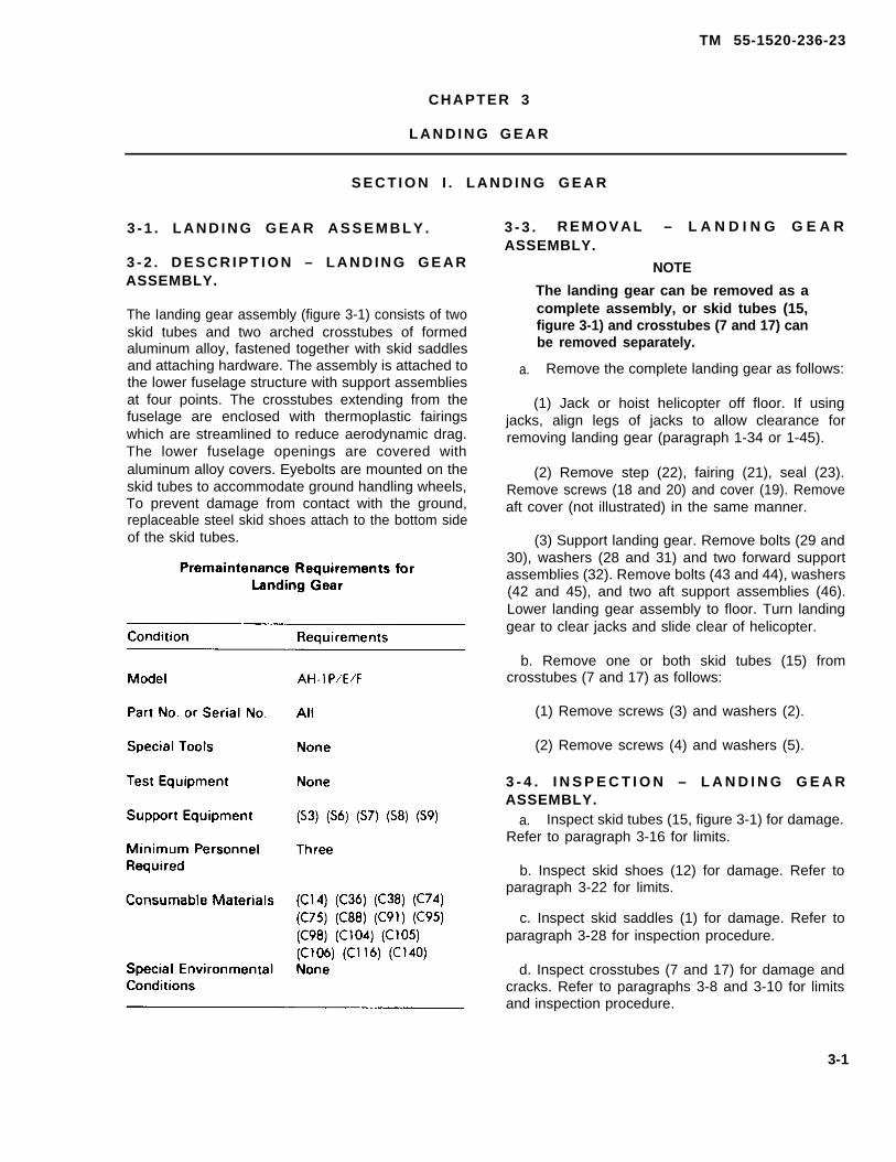
TM 55-1520-236-23
CHAPTER 3
L A N D I N G G E A R
S E C T I O N I . L A N D I N G G E A R
3 - 1 . L A N D I N G G E A R A S S E M B L Y .
3 - 2 . D E S C R I P T I O N – L A N D I N G G E A RASSEMBLY.
The Ianding gear assembly (figure 3-1) consists of twoskid tubes and two arched crosstubes of formedaluminum alloy, fastened together with skid saddlesand attaching hardware. The assembly is attached tothe lower fuselage structure with support assembliesat four points. The crosstubes extending from thefuselage are enclosed with thermoplastic fairingswhich are streamlined to reduce aerodynamic drag.The lower fuselage openings are covered withaluminum alloy covers. Eyebolts are mounted on theskid tubes to accommodate ground handling wheels,To prevent damage from contact with the ground,replaceable steel skid shoes attach to the bottom sideof the skid tubes.
3 - 3 . R E M O V A L – L A N D I N G G E A RASSEMBLY.
cracks. Refer to paragraphs 3-8 and 3-10 for limitsand inspection procedure.
3-1
a.
NOTE
The landing gear can be removed as acomplete assembly, or skid tubes (15,figure 3-1) and crosstubes (7 and 17) canbe removed separately.
Remove the complete landing gear as follows:
(1) Jack or hoist helicopter off floor. If usingjacks, align legs of jacks to allow clearance forremoving landing gear (paragraph 1-34 or 1-45).
(2) Remove step (22), fairing (21), seal (23).Remove screws (18 and 20) and cover (19). Removeaft cover (not illustrated) in the same manner.
(3) Support landing gear. Remove bolts (29 and30), washers (28 and 31) and two forward supportassemblies (32). Remove bolts (43 and 44), washers(42 and 45), and two aft support assemblies (46).Lower landing gear assembly to floor. Turn landinggear to clear jacks and slide clear of helicopter.
b. Remove one or both skid tubes (15) fromcrosstubes (7 and 17) as follows:
(1) Remove screws (3) and washers (2).
(2) Remove screws (4) and washers (5).
3 - 4 . I N S P E C T I O N – L A N D I N G G E A RASSEMBLY.
a. Inspect skid tubes (15, figure 3-1) for damage.Refer to paragraph 3-16 for limits.
b. Inspect skid shoes (12) for damage. Refer toparagraph 3-22 for limits.
c. Inspect skid saddles (1) for damage. Refer toparagraph 3-28 for inspection procedure.
d. Inspect crosstubes (7 and 17) for damage and

TM 55-1520-236-23
Figure 3-1. Landing Gear and Support Installation (Sheet 1 of 2)
3-2
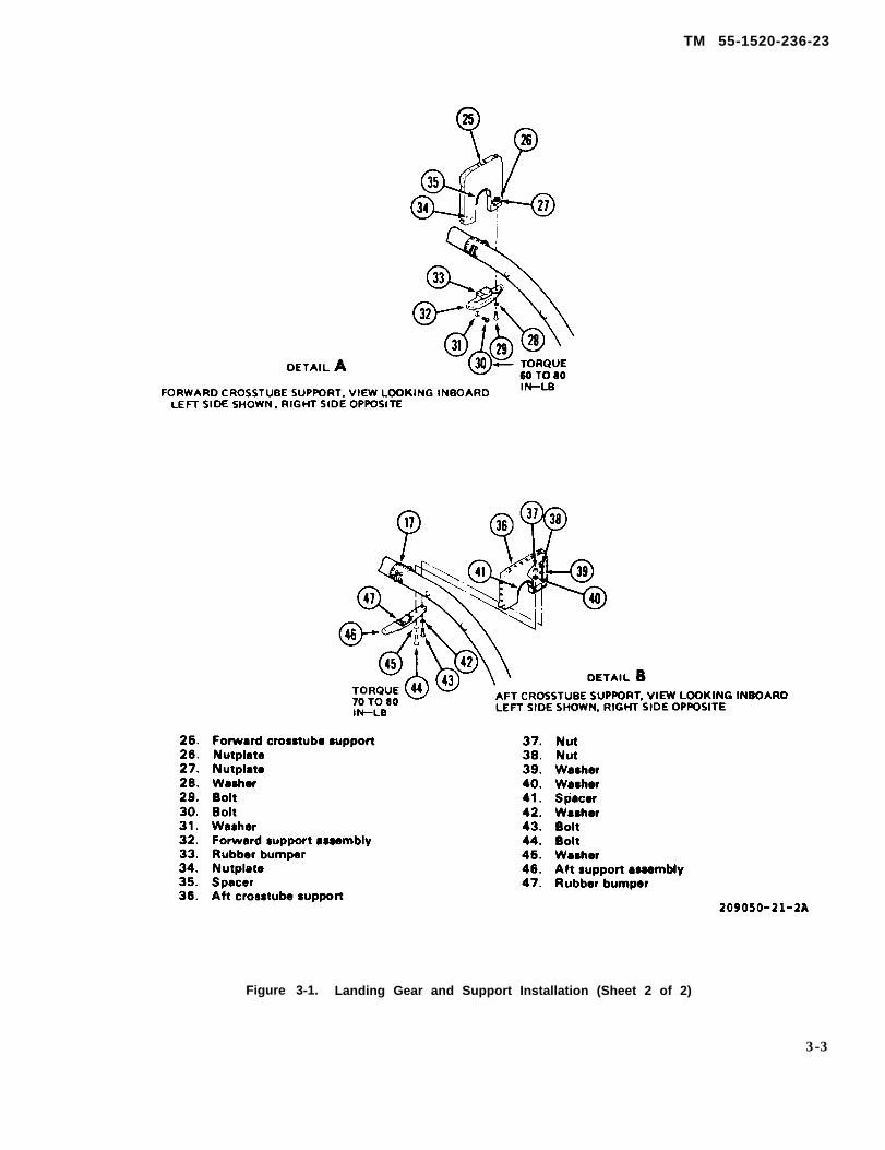
TM 55-1520-236-23
Figure 3-1. Landing Gear and Support Installation (Sheet 2 of 2)
3-3
TM 55-1520-236-23
e. Inspect crosstube fairings (21) for damage.Refer to paragraph 3-41 for inspection procedure.
f. Inspect tow rings (14) for damage. Refer to para-graph 3-35 for inspection procedure.
g. Inspect crosstube covers (19) and support as-semblies (32 and 46) for damage. Refer to paragraph3-48 for inspection procedure.
3-5 . INSTALLATION-LANDING GEAR AS-SEMBLY.
CAUTION
Do not interchange fore and aftcrosstubes during installation. Referto TM 55-1520-236-23P.
a. If not previously accomplished, assemble skidtubes (15, figure 3-1) and crosstubes (7 and 17) asfollows:
(1) Apply a thin coat of sealing compound(C106) to mating surfaces of skid tube and crosstubesaddle (1).
(2) Align saddle (1) on skid tube carefully toprevent damage to screw and rivnut threads. Main-tain position of saddle on skid tube with "C" clampsif necessary.
(3) Using sealing compound (C106), installnew screws (3 and 4) and washers (2 and 5).
b. Position lending gear in crosstube supports (25,figure 3-1). Ensure that both front retainers (16)properly engage both front supports (25). Maintainthe landing gear in position. Position forward supportassembly (32) on support (25). Install bolt (29) andwasher (28); snug up to align holes for bolts (30).Install four bolts (30) and washers (31). Tighten bolts,but do not torque at this time.
c. Raise aft end of landing gear and ensure thatboth aft retainers (8) properly engage aft crosstubesupport (36). Maintain the landing gear in position.Position aft support assembly (46) on aft crosstubesupport (36). Install two bolts (44), washers (40 and45), and nut (37). Install two bolts (43), washers (39and 42), and nuts (38). Snug nuts, but do not torqueat this time. Install opposite support assembly (46) inthe same manner. Do not torque nuts at this time.
NOTE
Prior to torque application, the gapbetween the top of the support as-sembly and the bottom of the fuselageat the crosstube mount ing areashould be in accordance with figure3-1.1. The gap shall be measured withappropriate feeler gage. If the gap islarger than recommended, fabricateshims per figure 3-1.1. If the gap issmaller than recommended, the rub-ber pad is worn and the cap should bereplaced. Tighten bolts to a snug fitwhile aircraft is still supported byjacks or hoist. Depending on thick-ness of shim required, longer bolts ofsame part number may be needed toinstall caps.
d. Torque bolts (30) 60 TO 80 inch-pounds. Nofurther tightening of bolt (29) is necessary.
NOTE
Check for minimum of 0.020 inch gapbetween support bracket assembly atbolt (29) location and support ofaircraft. This is to insure there is nopreloaded shear stress on bolts (30).
e. Lower helicopter to ground.
f. Torque bolts (43 and 44) 70 TO 80 inch-pounds.
g. Install forward cover (19) with screws (18 and20). Install aft cover in the same manner.
h. Align eyebolts (9) for Installation of groundhandling gear.
3-6. CROSSTUBES.
3-7. DESCRIPTION-CROSSTUBES.The forward crosstube (17, figure 3-1) and aftcrosstube (7) are made of formed aluminum alloy. Thecrosstubes are attached to the helicopter with twoforward support assemblies (32) and two aft supportassemblies (46).
3-8. INSPECTION-CROSSTUBES(CROSSTUBES INSTALLED ON HELICOP-TER).
3-4
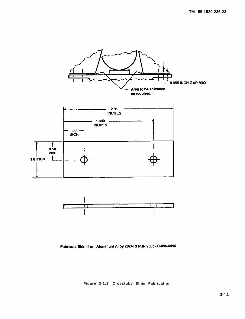
TM 55-1520-236-23
Figure 3-1.1. Crosstube Shim Fabrication
3-4.1

TM 55-1520-236-23
NOTE c. Level helicopter (paragraph 1-36).
Perform crosstube deflection inspec- d. Measure the distance between the crosstubetion after a hard landing or overload- retainers and divide that distance by 2 to determineing to determine whether crosstubes helicopter centerline (figure 3-2).(7 and 17) have taken a permanent setwith excessive spread. e. Drop a plumb line from helicopter centerline to
ground or floor surface. Measure froma. Position helicopter on a smooth surface.
b. Raise helicopter off the surface with jacks,removing all weight from the landing gear (para-graph 1-34).
3 - 4 . 2

TM 55-1520-236-23
Figure 3-2. Crosstube — Deflection Inspection
plumb line to the inside of each skid tube atcrosstube locations. Distance should be 38 TO40 inches from inside edge of skid tube to plumbline. If distance exceeds 40 inches from theinside edge o f e i the r sk id tube , rep lacecrosstubes.
f. Lower helicopter to surface and removejacks.
3 - 9 . R E M O V A L – C R O S S T U B E S .
Refer to paragraph 3-3.
3 - 1 0 . I N S P E C T I O N – C R O S S T U B E S( C R O S S T U B E S R E M O V E D F R O MHELICOPTER).
a. Remove crosstubeaccomplished (paragraph
b. Inspect two aft crosstube retainers (8, figure3-1) and two forward crosstube retainers (16) forsecure installation on crosstubes. Inspect retainersfor obvious wear and for cracks. Replace retainers ifloose or damaged.
c. Inspect forward and aft crosstubes forscratches, nicks, and dents. Surface nicks andscratches and smooth contour dents within the limitsshown on figure 3-3 and less than 0.50 inch in lengthradially or 2.00 inches in length longitudinally areacceptable if polished out in accordance withparagraph 3-11. The number of repairs is limited toone per cross section cut of the tube. Minimumlongitudinal distance between repairs is 2.0 inches.Shot peen the areas around and within 2.0 inches ofthe fuselage support fittings after making repairs int h e s e a r e a s .
fairings if not previously d. If it is suspected that crosstubes are cracked3-40). due to a hard landing or other cause, prepare
3 -5
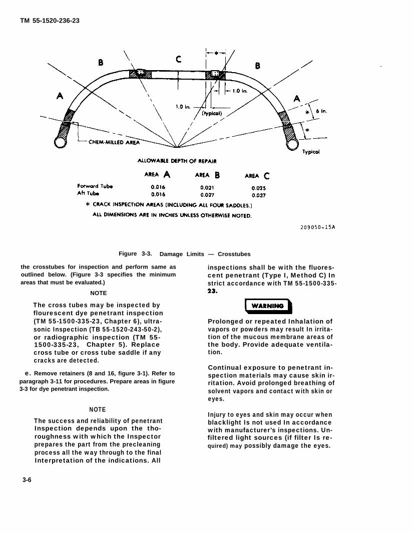
TM 55-1520-236-23
Figure 3-3. Damage Limits — Crosstubes
the crosstubes for inspection and perform same as inspections shall be with the fluores-outlined below. (Figure 3-3 specifies the minimum cent penetrant (Type I, Method C) Inareas that must be evaluated.) strict accordance with TM 55-1500-335-
NOTE
The cross tubes may be inspected byflourescent dye penetrant inspection(TM 55-1500-335-23, Chapter 6), ultra- Prolonged or repeated Inhalation ofsonic Inspection (TB 55-1520-243-50-2), vapors or powders may result In irrita-or radiographic inspection (TM 55- tion of the mucous membrane areas of1500-335-23, Chapter 5). Replace the body. Provide adequate ventila-cross tube or cross tube saddle if any tion.cracks are detected.
Continual exposure to penetrant in-e. Remove retainers (8 and 16, figure 3-1). Refer to spection materials may cause skin ir-
paragraph 3-11 for procedures. Prepare areas in figure ritation. Avoid prolonged breathing of3-3 for dye penetrant inspection. solvent vapors and contact with skin or
eyes.
NOTE
The success and reliability of penetrantInjury to eyes and skin may occur when
Inspection depends upon the tho-blacklight Is not used In accordancewith manufacturer’s inspections. Un-
roughness with which the Inspector filtered light sources (if filter Is re-prepares the part from the precleaningprocess all the way through to the final
quired) may possibly damage the eyes.
Interpretation of the indications. All
3-6

TM 55-1520-236-23
Temperatures in excess of 120 degree Fmay cause burst ing of pressurized cansand injury to personnel.
Volatile fumes may occur, creatingboth a fire and health hazard.
NOTE
Paint will not be removed by anymechanical means under any cir-cumstances because it may mask overany potential surface cracks.
f. With a soft hair brush, apply MEK (C74), or paintremover (C95) and remove the paint.
g. Clean the prepared surfaces with a soft cloth.
h. Apply a fluorescent dye penetrant to the preparedsurfaces from either a spray can or with a soft hairbrush and in strict conformance to the procedurespecified to TM 55-1500-335-23, Chapter 6.
i. Allow penetrant to dwell for a minimum of 30minutes.
complete excess penetrant removal from surface by us-ing a backlight).
k. Apply applicable developer consistent with Type I,Method C penetrant method in TM 55-1500-335-23.
l. Inspect suspected area with backlight source insubdued white light.
m.
n.
NOTE
Normal manufacturing machiningmarks may be observed on the tubesurfaces. These will not be cause ofpart rejection.
Clean tube with solvent and wipe dry.
Refer to paragraph 3-11 for instructions to repaintcross tubes.
3 -11 . R E P A I R O R R E P L A C E M E N T –CROSSTUBES.
a. Replace loose or damaged retainers (8 and 16,figure 3-1) as follows:
(1) Carefully drill out rivets that secure retainerto crosst ube and remove retainer.
j. Clean off all excess penetrant in accordance withTM 55-1500-335-23, standard procedures. (Check for
3-6.1/(3-6.2 blank)


TM 55-1520-236-23
(2) Remove old sealant from crosstube with300 grit to 400 grit abrasive cloth (C36). Nocircumferential sanding or grooves permitted.
(3) Check crosstube surfaces previouslycovered by retainer (8 or 16) for cracks (paragraph3-10).
(4) Coat mating surface of new retainer (8 or16) and crosstube with sealant (C105).
(5) position retainer (8) on aft crosstube (7).Secure with blind rivets NAS 1399MW5-8. Installrivets while wet with primer (C88 or C91).
(6) Position retainer (16) on forward crosstube(17). Secure with blind rivets NAS 1399MW5-6.Install rivets while wet with primer (C88 or C91).
b. Polish out mechanical damage that is withinlimits noted in paragraph 3-10. Use 300 grit to 400grit abrasive cloth (C36). Ensure that limits shown onfigure 3-3 are not exceeded. No circumferentialsanding or grooves permitted.
c. Touch up or completely repaint crosstube withprimer (C88 or C91). Paint crosstube to match originalf in ish (TM 55-1500-345-23) .
d. Install crosstube fairings (paragraph 3-43).
3-12. INSTALLATION – CROSSTUBES.
Refer to paragraph 3-5.
3-13. SKID TUBES.
3-14. DESCRIPTION – SKID TUBES.
The aluminum skid tubes support the helicopter onthe ground. Each skid tube has two steel skid shoes(12, figure 3-1) attached to the skid tube to extend thelife of the skid tubes. The skid tubes have provisionsfor mounting ground handling wheels. When theground handling wheels are attached and placed inthe extended position, the helicopter may be towedwith a tow bar attached to towing rings (14).
3-15. REMOVAL – SKID TUBES.
Refer to paragraph 3-3.
3-16. INSPECTION – SKID TUBES.
a. Inspect skid shoes (12, figure 3-1) for damage(paragraph 3-22). If damage is detected, remove skidshoes (paragraph 3-2 1).
b. Inspect skid tubes (15, figure 3-1) forscratches, nicks, dents, and holes.
(1) Smooth dents, not exceeding 0.25 inch indepth and 1.0 TO 1.2 inches in diameter between thecrosstube saddles, are acceptable without repair.
(2) Scratches, dents, and holes in the skidtubes in front of forward crosstube saddle may berepaired at discretion of local maintenance officer.
(3) Scratches and gouges up to 0.03 inch deepand 1.0 TO 1.2 inches long running directly acrosstop of skid tube between crosstube saddles areacceptable if polished out.
(4) Scratches and gouges running directlyacross top of skid tube that are more than 0.03 inchdeep and more than 1.2 inches long but less than 4.0inches long are reparable by patching if the damage isin area where repairs by patching are authorized. Seefigure 3-4 for illustration of area where repairs bypatching are authorized.
(5) Dents more than 0.25 inch deep and 1.2inches up to a maximum of 4.0 inches across arereparable by patching if the damage is in area whererepairs by patching are authorized. See figure 3-4 forillustration of area where repairs by patching areauthorized.
(6) Holes up to 4.0 inches in diameter throughone surface of skid tube only are reparable bypatching if the damage is in area where repairs bypatching are authorized. See figure 3-4 forillustration of area where repairs by patching areauthorized.
(7) Dents and holes on either top or bottom sideof skid tube that are greater than 4.0 inches across inany direction are repairable by inserting a splice. Thistype repair is restricted to areas shown on figure 3-4.
(8) Damage in excess of the limits noted in thepreceding steps is cause to replace the skid tube.
(9) Inspect skid tubes for damaged or missingthreaded inserts.
3-7

TM 55-1520-236-23
3-17. REPAIR OR REPLACEMENT – SKIDTUBES.
a. Polish out scratches and gouges that are withinreparable limits noted in paragraph 3-16.b. (3).
b. Repair damage by patching that is withinlimits. Refer to paragraphs 3-16.b. (4) through 3-16.b.(6) for limits. Apply patch repairs as follows:
(1) Polish out scratches; trim and smooth roughedges of holes.
(2) Fabricate a patch from 0.100 inch thickaluminum alloy (12, table 2-1) of the required size asshown in figure 3-4 or make a patch from materialsalvaged from scrap skid tube.
(3) Lay out the rivet hole pattern and form patchto fit contour of skid tube as shown in figure 3-4.
(4) Locate and securely clamp patch to skidtube and drill rivet holes with a No. 10 twist drill.
(5) Rivet patch in place using blind rivets (32,table 2-1).
(6) Touch-up repair area or paint entire skidtube (paragraph 3-72).
c. Repair damage by insertion that is withinlimits. Refer to paragraph 3-16, b. (7) for limits. Installinsert as follows:
(1) Cut out damaged portion of skid tube withhand or powered metal saw.
(2) Fabricate an insert of the required lengthfrom tubing 0.095 inch wall thickness (27, table 2-1)or from scrap skid tube, as shown in figure 3-4.
(3) Fabricate splice plates as follows:
(a) Cut four plates to the required dimensionsas shown in figure 3-4 from sheet stock 0.100 inch-thick (12, table 2-1) or use material salvaged fromscrap skid tube.
(b) Form two plates to fit the outside diameterof skid tube and the other two plates to fit the insidediameter as shown in figure 3-4.
(4) Apply a coat of primer (C88 or C91) to platesand tubes.
(6) Lay out rivet hole pattern on upper spliceplates and lower side of tubes as shown in figure 3-4.
(6) Maintain proper alignment and securelyclamp splice plates and tubes together.
(7) Drill rivet holes in plates end tubes with No.10 twist drill. Countersink lower holes with 100degree countersink. Install protruding head blindrivets (36, table 2-1) in upper half of splice. Installflush head blind rivets (31, table 2-1) in lower half ofsplice as shown in figure 3-4.
(8) If repair involves removal of skid shoe boltsleeves, mark sleeve locations using skid shoe as atemplate and install new sleeves.
d. Replace damaged or worn threaded inserts.Refer to TM 55-1500-204-25/1.
e. Install skid shoes (paragraph 3-24).
3-18. INSTALLATION – SKID TUBES.
Refer to paragraph 3-5.
3-19. SKID SHOES.
3-20. DESCRIPTION – SKID SHOES.
The skid shoes are two steel plate assembliesattached with screws to the bottom of each skid tubeto minimize abrasive damage to the skid tubes fromground contact.
3-21. REMOVAL – SKID SHOES.
Remove skid shoes (12, figure 3-1) from bottom ofskid tubes (15) by removing screws (13).
3-22. INSPECTION – SKID SHOES.
Inspect skid shoes (12, figure 3-1) for damage andwear which is severe enough to affect function.Check for loose or missing fasteners.
3-23. REPAIR OR REPLACEMENT – SKIDSHOES.
a. Replace skid shoes (12, figure 3-1) if worn toothin to give proper protection to skid tubes.
b. Replace skid shoes if mounting holes areelongated or cracked.
c. Replace missing fasteners.
3-8
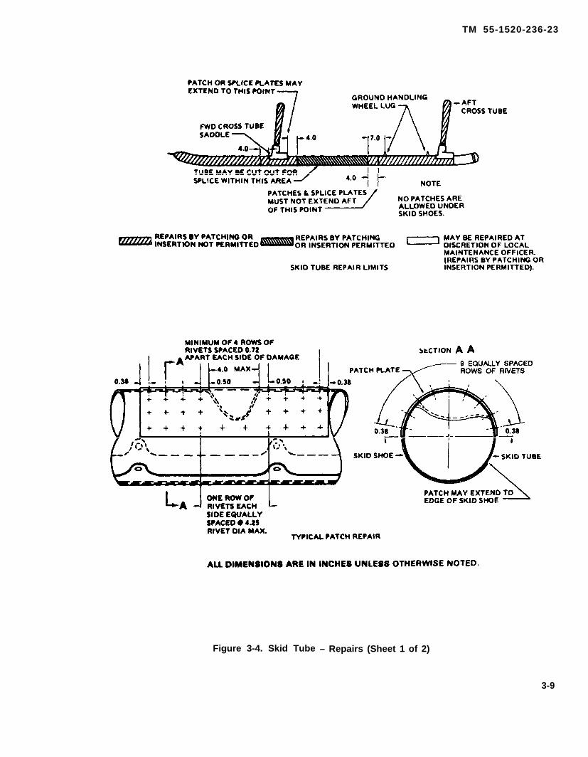
TM 55-1520-236-23
Figure 3-4. Skid Tube – Repairs (Sheet 1 of 2)
3-9

TM 55-1520-236-23
Figure 3-4. Skid Tube – Repairs (Sheet 2 of 2)
3-10

TM 55-1520-236-23
3-24. INSTALLATION – SKID SHOES.
Install skid shoes (12, figure 3-1) to bottom of skid tube(15) with screws (13). Make sure proper length screwis used to prevent bottoming out.
3-24.1. SKID SHOES – STANDARD HEAVYDUTY (SURFACITE) (NON-LOCALLY FABRI-CATED).
Description, standard heavy duty skid shoes manufac-tured with a special surfacite treated steel bottomplate, anti-slip brackets and stainless steel attachingdamps. These skid shoes have extended wear life andweight 19.6 pounds per shoe, 39.2 pounds per set(Figure 3-4.1).
3-24.2. INSTALLATION – STANDARD HEAVYDUTY (SURFACITE) SKID SHOES.
a. Remove Bell factory skid shoes, refer to para-graph 3-21.
(5) Lower helicopter and torque all damps to60 inch pounds using the following sequence: (Fonwarddamp is number 1 and aft damp is number 9) tightendamp 5 first, damp 4 second, damp 6 third, damp 3fourth, damp 7 fifth, damp 2 sixth, damp 8 seventh,clamp 1 eighth, and damp 9 last
3-24.3. INSPECTION - STANDARD HEAVYDUTY SKID SHOES (SURFACITE).
a. Inspect attaching damps for looseness.
b. Inspect anti-slip bracket bolts for looseness.
c. Inspect skid shoe bottom plate for excessivewear. The last 18 inches of shoe receives the mostwear.
3-24.4. REPLACEMENT OR REPAIR — STAN-DARD HEAVY DUTY SKID SHOES (SURFACITE).
a. Replacement Replace excessively wornskid shoes.
b. Ensure skid tube is free of dirt and debris.b. Repair.
(1) Screw holes used to attach Bell factoryskid shoes will not be reused. Seal holes with sealingcompound (C-105).
NOTE
On some aircraft crosstube to saddleretaining bolts are one long bolt ratherthan two separate opposing bolts
(2) Remove lower inboard and two outboardcrosstube to saddle retaining bolts on all four saddles(figure 3-4.1).
(3) Install and loosely clamp skid shoe on skidtube. Install skid shoe with damp T-bolt nut inboardside of skid tube. Do not fully tighten damps at thistime.
NOTE
A flat washer may be required underhead of crosstube to saddle bolts tocover edges of oblong holes on anti-slip brackets.
(4) Position skid shoes on skid tubes sooblong holes in anti-slip brackets are aligned overcrosstube to saddle retaining bolt holes. Re-installcrosstube to saddle retaining bolts and tighten fully.
(1) 45 degree ramps at front and rear of skidshoe can be repaired by re-welding and regrinding the45 degree angle. (Figure 3-4.1).
(2) Anti-slip brackets that are bent or dis-torted can be reworked by carefully bendng to originalshape. (Figure 3-4.1).
3-24.5. REMOVAL – STANDARD HEAVY DUTYSKID SHOE (SURFACITE).
a. Jack or hoist helicopter dear of ground (para-grapj 1-34, 1-35, 1-36, 1-38, and 1-49).
b. Loosen 9 mounting damps on skid shoe.
c. Remove lower inboard and two outboardcrosstube to saddle retaining bolts. (Figure 3-4.1).
d Remove skid shoe.
3-25. SKID SADDLES.
3-26. DESCRIPTION – SKID SADDLES.
The skid saddle (1, figure 3-1) is a reinforced aluminumforging that connects the forward and aft crosstubes tothe skid tubes.
3-10.1
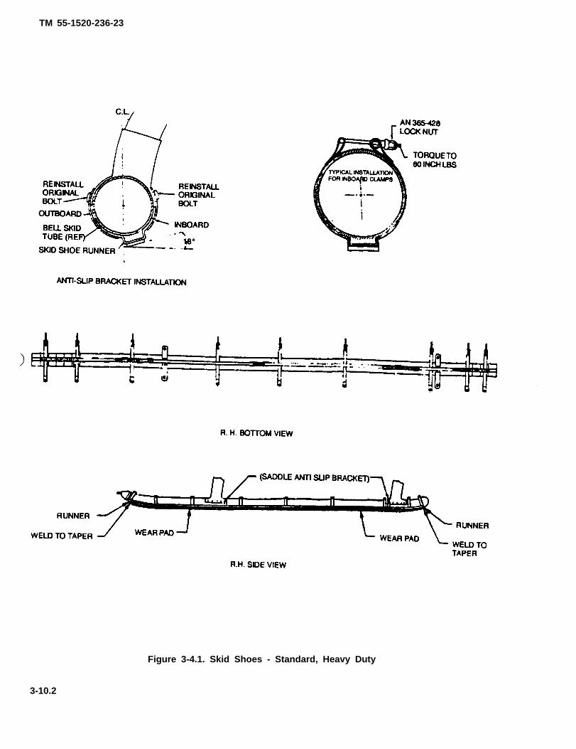
TM 55-1520-236-23
Figure 3-4.1. Skid Shoes - Standard, Heavy Duty
3-10.2
TM 55-1520-236-23
3-27. REMOVAL – SKID SADDLES
a. Remove skid tubes (paragraph 3-3).
b. Carefully drill out rivets that secure saddle (1,figure 3-1) to crosstube (7 or 17). Remove saddle fromcrosstube.
3-28. INSPECTION – SKID SADDLES.
a. Inspect skid saddle for cracks in area of screwand rivet holes, using fluorescent penetrant inspectionmethod (TM 55-1500-335-23).
b. Inspect for secure installation of rivets andscrews.
c. Inspector elongated screw and/or rivet holes.Elongation of screw holes at the 1/4 inch screw loca-tions shall not exceed 0.281 inch. Elongation of screwholes at the 5/1 6 inch screw locations shall not exceed0.344 inch.
d. Inspect nutplates on lower part of saddle forloose rivets and damaged threads.
3-29. REPAIR – SKID SADDLES
Repair is limited to replacement of attaching screws.Rivets (figure 3-1) attaching saddle to crosstube maybe replaced or oversize rivets OSB100 T6-3/16 inchbuck oversize may be used. (Next size fasteners notpermitted.)
3-30. INSTALLATION - SKID SADDLES
a. Position skid saddle (1, figure 3-1) or cross-tube and install rivets.
b. Install skid tube (paragraph 3-5).
3-31. PAINTING — SKID SADDLES
Refer to paragraph 3-72.
3-32. TOW RINGS.
3-33. DESCRIPTION - TOW RINGS.
The tow ring (14, figure 3-1) is a one-piece casting witheyehole which is riveted to the front end of each skidtube (15) to facilitate ground handling and towing of thehelicopter.
3-34. REMOVAL – TOW RINGS.
Drill out rivets and remove how ring (14, figure 3-1) fromfront end of skid tube (15).
3-35. INSPECTION – TOW RINGS
a. Inspect tow ring (14, figure 3-1) and attachingrivets for damage or recks.
b. Perform magnetic particle inspection (TM55-1500-335-23).
3-38. REPAIR OR REPLACEMENT – TOWRINGS.
a. Repair is limited to replacement of attachingrivets and polishing out minor surface damage with fineIndia stone (C116).
b. Replace tow rings that exceed repair limits.
3-37. INSTALLATION – TOW RINGS.
a. Insert tow ring (14, figure 3-1) into front end ofskid tube (15) with eyehole horizontal and the partnumber facing up. Install with sealant (C104).
b. Install rivets (CR2538-6-4).
3-38. CROSSTUBE FAIRINGS.
3-39. DESCRIPTION – CROSSTUBE FAIRINGS.
The crosstube fairings (figure 3-5) are plastic cover-ings designed to lessen the dragon the landing gear.The fairings are attached to the crosstubes withscrews. It is permissible to fly this aircraft with bothcrosstube fairings removed. No additional flightrestrictions will be required when troth fairings areremoved.
3-11
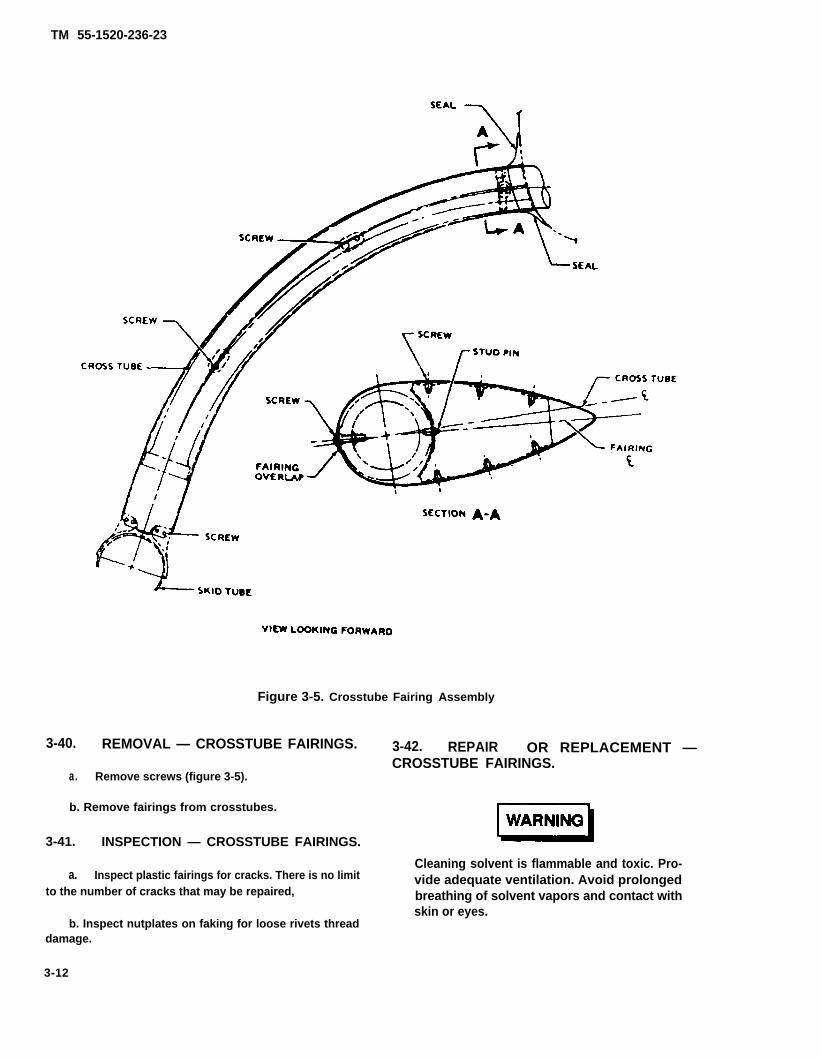
TM 55-1520-236-23
Figure 3-5. Crosstube Fairing Assembly
3-40. REMOVAL — CROSSTUBE FAIRINGS.
a. Remove screws (figure 3-5).
b. Remove fairings from crosstubes.
3-41. INSPECTION — CROSSTUBE FAIRINGS.
a. Inspect plastic fairings for cracks. There is no limitto the number of cracks that may be repaired,
b. Inspect nutplates on faking for loose rivets threaddamage.
3-12
3-42. REPAIR OR REPLACEMENT —CROSSTUBE FAIRINGS.
Cleaning solvent is flammable and toxic. Pro-vide adequate ventilation. Avoid prolongedbreathing of solvent vapors and contact withskin or eyes.

TM 55-1520-236-23
a. Repair cracks as follows:
(1) Clean area around the crack perimeterusing a clean cloth dampened with aliphatic naphtha(C75). Lightly sand area using fine grade of sandpaper. Clean the surface as described above withaliphatic naphtha after sanding.
(2) Two layers of fiberglass patches arerequired. Measure and cut one fiberglass patch fromfiberglass cloth (C38) to cover cracks by a minimum ofone inch around the perimeter. Cut a second patch tooverlap the first patch by one inch on all sides.
(3) Using a brush, apply a coat of epoxy resin(C98) to the cleaned surface of fairing to match size ofpatch. Apply fiberglass patch (C38) and brush epoxyresin (C98) to cover patch completely, using brush towork out air bubbles.
(4) Apply another coat of epoxy resin (C98) tocover area for second patch. Apply fiberglass patch(C38) and brush epoxy resin (C98) to completely coverand saturate fiberglass patch. Work out air bubbles.
(5) Allow epoxy resin (C98) to cure for 4 hoursat 70 degrees F (21 degrees C) prior to flyinghelicopter. The complete cure time for epoxy resin(C98) is 24 hours at 70 TO 80 degrees F (21 TO 27degrees C). Refinish repaired area to matchsurrounding surface.
b. Replace nutplates as required.
3 - 4 3 . I N S T A L L A T I O N – CROSSTUBEFAIRINGS.
a. Align screw holes in fairing with fasteners andstart all screws before tightening.
b. Tighten screws evenly to prevent stress onfairing.
3 - 4 4 . P A I N T I N G – CROSSTUBEFAIRINGS.
Refer to paragraph 3-72.
3-45. CROSSTUBE COVERS A N DSUPPORT ASSEMBLIES.3 - 4 6 . D E S C R I P T I O N — C R O S S T U B E
COVERS AND SUPPORT ASSEMBLIES.The aluminum alloy crosstube covers (19, figure 3-1)are contoured plates designed to lessen drag. Thecrosstube covers are secured to the supportassemblies (32 and 46) with screws. The supportassemblies (32 and 46) secure the crosstubes (7 and17) to helicopter structure.
3-47. REMOVAL – CROSSTUBE COVERSAND SUPPORT ASSEMBLIES.
NOTE
It is not necessary to remove completelanding gear assembly if only repairingor replacing support assembly. Re-move and replace support assembliesone at a time.
a. Remove screws (18 and 20) and cover (19).Remove aft cover in same manner.
b. Remove bolts (29 and 30), washers (28 and 31)and two forward support assemblies (32). Remove baits(43 and 44), washers (42 and 45) and two aft supportassemblies (46).
3 - 4 8 . I N S P E C T I O N – C R O S S T U B ECOVERS AND SUPPORT ASSEMBLIES.
a. Inspect crosstube covers (19, figure 3-1) forcracks, holes, and corrosion. Damage that can berepaired by standard structural repair procedures isacceptable if repairs are made.
b. Inspect support assemblies (32 and 46) as
(1) Presence of deteriorated, or worn rubberbumpers is not cause to replace the supportassembly. Missing rubber bumpers is cause to changethe support assembly.
(2) Inspect metal portion of the supportassemblies for cracks, distortion, and elongatedholes. Obvious damage is cause to replace thesupport assembly.
3-49. REPAIR OR REPLACEMENT –CROSSTUBE COVERS AND SUPPORTASSEMBLIES.
a. All traces of fuel, oil and grease will be removed.Clean support assembly with MEK (C74) and dry.
b. Apply adhesive, EC-2126 (C12 or equivalent) tosupport assembly and allow adhesive to dry tack free.Align rubber bumper on support assembly and hold firmcontact pressure. Place support assembly in oven andheat to 250°-260°F, remove immediately and allow tocool before installing on crosstubes.
c. Deleted.
d. Repair crosstube covers in accordance with stan-dard structural repair procedures for stopdrilling andpatching.
3-13

TM 55-1520-236-23
3-50. INSTALLATION - CROSSTUBE COVERSAND SUPPORT ASSEMBLIES.
Refer to paragraph 3-5.
3-51. CROSSTUBE SUPPORT SPACERS.
3-52. DESCRIPTION-CROSSTUBE SUP-PORT SPACERS.
The crosstube support spacers (35 and 41, figure 3-1)are fabricated by the investment casting process.They are bonded and riveted to the crosstube sup-ports (25 and 36).
3-53. REMOVAL-CROSSTUBE SUPPORTSPACERS.
a. Remove landing gear (paragraph 3-3).
b. Carefully drill out two rivets which secure eachspacer (35 and 41) to crosstube supports (25 and 36).
c. Heat spacer with heat lamp to soften adhesiveif necessary and remove spacer from support.
3-54. INSPECTION-CROSSTUBE SUPPORTSPACERS.
NOTE
The spacers can be inspected onlywhen the landing gear crosstubes areremoved.
a. Inspect spacers (35 and 41, figure 3-1) for secureinstallation on supports (25 and 36). Loose spacerinstallation is cause for removal and inspection. In-spect spacers for cracks ardor wear damage. Anycracking is cause for replacement. Wear damage isacceptable up to 1/3 original spacer thickness.
b. Reinstall spacers per paragraph 3-55.
3-55. INSTALLATION-CROSSTUBE SUP-PORT SPACERS.
a. Clean old adhesive from forward crosstube sup-port (25, figure 3-1) or aft crosstube support (36) asapplicable. Use 300 grit to 400 grit abrasive cloth(C36) and sharp plastic scrapers
b. Position new or acceptable old spacer oncrosstube support and drill two holes for rivets (Fig-ure 3-6). If old spacer is used, the existing holes mustbe countersunk so that a depth of bevel portion is0.042 inch.
WARNING
Cleaning solvent is flammable andtoxic. Provide adequate ventilation.Avoid prolonged breathing of solventvapors and contact with skin or eyes.
Clean mating surfaces of crosstube supports(25) and spacers with MEK (C74).
. .
d. Apply a thin coat of adhesive (C14) to matingsurfaces of spacer and support (25). Position spaceron support and install two MS20427M4-4 rivetsbefore adhesive cures.
e. Install landing gear (paragraph 3-5).
3-56. PAINTING-LANDING GEAR.
NOTE
Use the procedures in this paragraphto touch-up small areas or to repaintentire landing gear.
a. Apply coat of primer (C88 or C91) to area to bepainted.
b. Paint primed area to match existing finish
3-57. GROUND HANDLING GEAR
3-58. DESCRIPTION-GROUND HANDLINGGEAR
Two ground handling wheel assemblies are providedfor quick mounting on landing skids to facilitatemoving helicopter on ground. Each assembly consistsof two wheels on an offset axle, a supporting cradleand hand-operated hydraulic jack with two ramswhich actuate axle to extend or retract wheels, Seefigure 3-7, The cradle is mounted on eyebolts onlanding skid by means of a fixed rear pin end spring-loaded gear front pin.
3-14

TM 55-1520-236-23
Figure 3-6. Landing Gear Support Spacer Installation (Sheet 1 of 2)
3-15

TM 55-1520-236-23
Figure 3-6. landing Gear Support Spacer Installation (Sheet 2 of 2)
3-16

TM 55-1520-236-23
Figure 3-7. Ground Handling Gear — Assembly
3-17

TM 55-1520-236-23
3 -69 . D ISASSEMBLY – GROUNDHANDLING GEAR. (AVIM)
Premaintenance Requirements forGround Handling Gear
Condition Requirements
Model
Part No. or Serial No.
Special Tools
Test Equipment
Support Equipment
Minimum PersonnelRequired
Consumable Materials
Special EnvironmentalConditions
A H - I S
All
(T80) (T81) (T84)
None
(S2)
One
(C30) (C37) (C62)(C63) (C112) (C116)
Dust Free
Deflate tire prior to wheel assemblyremoval.
a. Remove ball-lock pin (13, figure 3-7) andremove support rod (12) from axle.
b. Remove wheel assembly (16) with tire and tubeassembled, by removing cotter pin (11), nut (10), andretainer (9).
c. Disconnect and remove flexible hose (8) fromfitting (6) on hydraulic pump (1) and hydraulic ram (7).
d. Remove nuts (23) and washers (24) and liftU-bolts (4) attaching hydraulic pump (1) to cradleassembly (5). Remove hydraulic pump (1).
e. Remove cotter pin (21), washers (18 and 20),and lubrication pin (17) attaching ram arm (2) to clevis(19) of hydraulic ram (7).
f. Back out set screw (3) and remove hydraulicram (7) from trunnion (14). Using clevis (19) ashandle, hold hydraulic ram (7) and separate rampiston (not illustrated) from cylinder of hydraulic ram(7).
3-18
NOTE
When connecting pin (28) is removed,support pin (26) can be released andspring (26) will slide from cradle.
g. Remove lubrication fitting (29), unscrew andremove connecting pin (28) and release pin (27).
3 - 6 0 . D I S A S S E M B L Y – HYDRAULICPUMP P/N BU0953B. (AVIM)
a. Remove tank filler hole screw (24, figure 3-8)and packing (25) and drain oil from tank (26).
b. Remove retaining rings (1, 2, 6, and 36),fulcrum pins (5 and 37), and separate handleassembly (3) from pump body (15).
c. Pull out piston (7) and remove clip (48) byspreading clip slightly. Unscrew gland nut (8) usingadjustable spanner wrench and remove packingsupport (9), leather packings (10 and 11). rubberpacking (12), leather packing (13), and spreader (14).
d. Pry out filter screen (30) from hose hole.Remove retaining screw (31). discharge valve spring(32), 0.3125 inch diameter ball (33), suction valvespring (34), and 0.1875 inch diameter ball (35).
e. Remove screw (42). Lift up on knob (41) todisengage from stem (44), and turn knob clockwise torelieve tension on spring (39). Remove pin (40) frompump body (15). Position knob (41) on stem (44), andinstall screw (42). Remove knob (41), spring (39),stem (44), spring (45), washer (46), packing (38), andball (47). Remove screw (43), and remove spring (39)from knob (41).
f. Remove nut (27) and packing (28). Twist tank(26) off pump body (15). Remove seal (16).
g. Remove screw (22) and screen (23). Dispose ofscreen.
h. Remove overload valve body (19) from tie rod(29). Remove spring (21) and plunger (20) from valvebody (19).
3-61. DISASSEMBLY – HYDRAULICPUMP P/N HP9902-41-10. (AVIM)
a. Remove filler plug (27, figure 3-9) and gasket(26). Drain hydraulic fluid from reservoir (25).

TM 55-1520-236-23
Figure 3-8. Ground Handling Gear Pump PN BU0953B – Assembly (Sheet 1 of 2)
3-19

TM 55-1520-236-23
Figure 3-8. Ground Handling Gear Pump PN BU0953B – Assembly (Sheet 2 of 2)
b. Remove handle (1).
c. Remove cotter pin (4 and 31), beam pin (30),and plunger cross pin (3). Separate beam (2) fromplunger (5) and base (11).
d. Pull out plunger (5). Use packing nut tool(workaid) (T84) (figure 3-10) to unscrew packing nut(6, figure 3-9). Remove pump cup (9), cup retainer (8),packing (7), and spreader (10).
e. Remove reducer bushing (12).
f. Unhook return spring (15) from handle (17).
g. Remove capscrew (20) and washer (21).
h. Remove screw (19), Iockwasher (18), handle(17), and return spring (15).
i. Remove release spindle (16) with releasepacking (13) and release packing nut (14).
j. Remove release packing (13) and releasepacking nut (14) from release spindle (16).
k. Remove reservoir (25), reservoir shim washers(28), and shim washer(s) (29).
NOTE
Use of shim washers and reservoir shimwashers varies from O to a total of 4.
l. Remove screen (22).
m. Remove relief valve (23) and gasket (24).
n. Remove valve plug (35), outlet check spring(34), 0.3125 inch diameter ball (33), and 0.2188 inchdiameter ball (32).
3 - 6 2 . I N S P E C T I O N — G R O U N DHANDLING GEAR (AVIM).
a. Ball-lock pin (13, figure 3-7) for cracks,corrosion, wear, and distortion.
b. Lubrication pin (17) for damage, distortion, andwear.
c. Internal threads of trunnion (14) for damageand set screw (3) and its internal threads in trunnionfor damage.
d. Lubrication fitting (29) for serviceability.
3 - 2 0
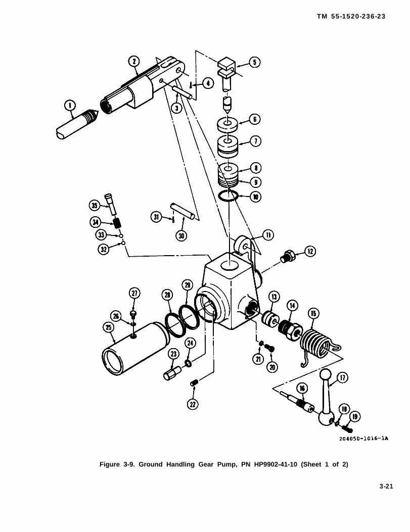
TM 55-1520-236-23
Figure 3-9. Ground Handling Gear Pump, PN HP9902-41-10 (Sheet 1 of 2)
3-21
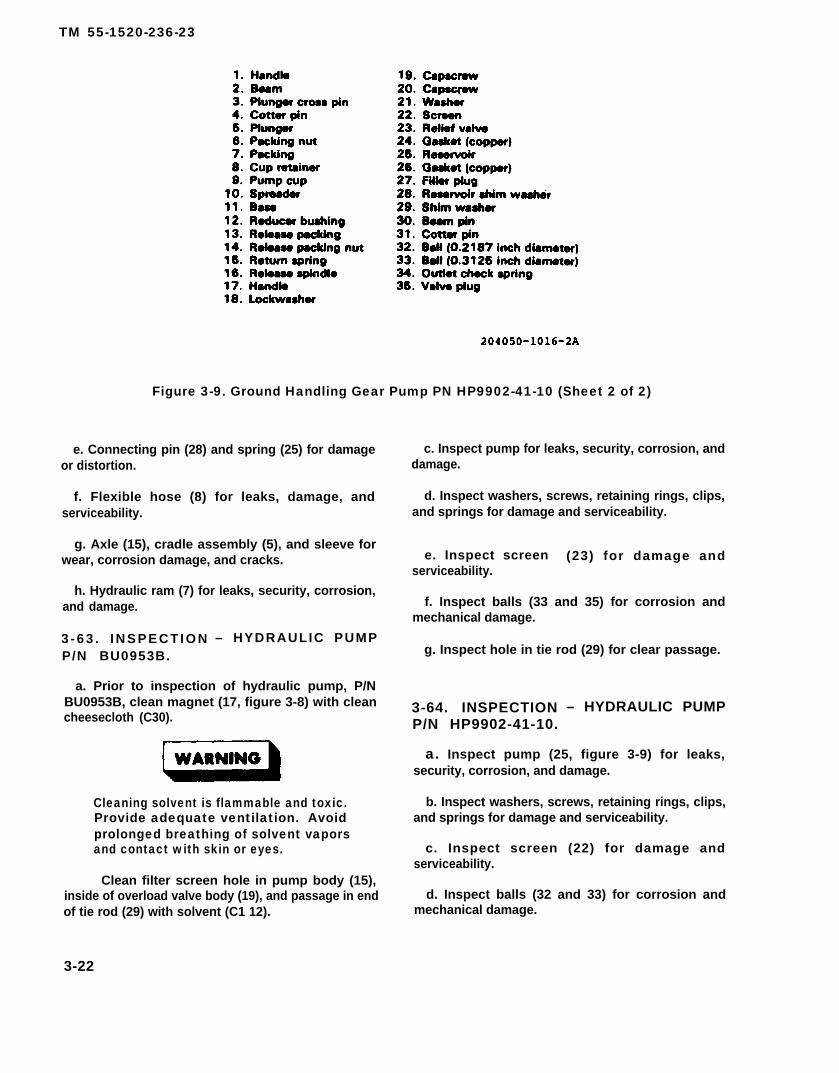
TM 55-1520-236-23
Figure 3-9. Ground Handling Gear Pump PN HP9902-41-10 (Sheet 2 of 2)
e. Connecting pin (28) and spring (25) for damageor distortion.
f. Flexible hose (8) for leaks, damage, andserviceability.
g. Axle (15), cradle assembly (5), and sleeve forwear, corrosion damage, and cracks.
h. Hydraulic ram (7) for leaks, security, corrosion,and damage.
3 - 6 3 . I N S P E C T I O N – HYDRAULIC PUMPP/N BU0953B.
a. Prior to inspection of hydraulic pump, P/NBU0953B, clean magnet (17, figure 3-8) with cleancheesecloth (C30).
Cleaning solvent is flammable and toxic.Provide adequate ventilation. Avoidprolonged breathing of solvent vaporsand contact with skin or eyes.
Clean filter screen hole in pump body (15),inside of overload valve body (19), and passage in endof tie rod (29) with solvent (C1 12).
3-22
c. Inspect pump for leaks, security, corrosion, anddamage.
d. Inspect washers, screws, retaining rings, clips,and springs for damage and serviceability.
e. Inspect screen (23) for damage andserviceability.
f. Inspect balls (33 and 35) for corrosion andmechanical damage.
g. Inspect hole in tie rod (29) for clear passage.
3-64. INSPECTION – HYDRAULIC PUMPP/N HP9902-41-10.
a. Inspect pump (25, figure 3-9) for leaks,security, corrosion, and damage.
b. Inspect washers, screws, retaining rings, clips,and springs for damage and serviceability.
c. Inspect screen (22) for damage andserviceability.
d. Inspect balls (32 and 33) for corrosion andmechanical damage.

TM 55-1520-236-23
Figure 3-10. Workaid for Packing Nut
3-65. REPAIR OR REPLACEMENTGROUND HANDLING GEAR. (AVIM)
a. Replace ball-lock pin (13, figure 3-7)unserviceable.
b. Replace lubrication pin (17) if worndistorted.
Removal/lnstallation — Fabrication Instructions
—
if
or
c. Replace trunnion (14) if internal threads aredamaged.
d. Replace lubrication fitting (29) if damaged.
e. Replace connecting pin (28), support pin (26),and spring (25) if distorted or damaged.
f. Replace flexible hose (8) if leaking or damaged.
g. Replace axle sleeve (15) or cradle assembly (5),if cracked or damaged.
3-66. REPAIR OR REPLACEMENT –HYDRAULIC PUMP P/N BU0953B. (AVIM)
Procure a hydraulic pump parts kit, P/N JS953(TM 55-1520-236-23P).
b. Replace clip (48, figure 3-8), leather packings(10, 11, and 13), and rubber packing (12).
c. Replace filter screen (23), discharge valvespring (21 ), 0.3125 inch ball (33), suction valve spring(34), and 0.1875 inch bail (35).
d. Replace release valve spring (45), washer (46),packing (38), and 0.3125 inch diameter ball (47).
e. Replace packing (25) and seal (16).
f. Replace screw (22).
3-23
TM 55-1520-236-23
3-67. REPAIR OR REPLACEMENT –HYDRAULIC PUMP, P/N HP9902-41-10.(AVIM)
a. Procure a hydraulic pump service kit, P/NKH9000 (TM 55-1520-236-23P).
b. Replace packing (7, figure 3-9), cup retainer (8),pump cup (9), and spreader (10).
c. Replace release packing (13).
d. Replace outlet check spring (34), 0.312. inchdiameter ball (33), and 0.2187 inch diameter ball .
e. Replace gaskets (24 and 26).
3-68. REPAIR OR REPLACEMENT –HYDRAULIC RAM. (AVIM)
NOTE
If hydraulic ram (7, figure 3-7) does nothave piston P/N 330617, which ismachined for packing and beck-up ring,requisition new piston P/N 330617.
a. Carefully slip new beck-up ring over inboardend of piston P/N 330617 and into packing groove,
b. Carefully slip new packing over inboard end ofpiston and into packing groove.
NOTE
Ensure each packing is not twisted ingroove.
c. Burnish scratches inside hydraulic ramcylinder that are less than 0.005 inch deep, usingcrocus cloth (C37).
d. Replace hydraulic ram if inside of cylinder hasnicks, scratches, or pits deeper than 0.005 inch.
3-69. ASSEMBLY – GROUND HANDLINGGEAR. (AVIM)
a. Insert trunnion (14, figure 3-7) in cradleassembly (5) with threaded openings aft.
NOTE
To prepare a new hydraulic pump (1,figure 3-7) and hydraulic mm (7)assembly for installation, remove pipeplug on each and drain hydraulic fluid.
b. Install hydraulic ram (7) on each end oftrunnion (14) to bottom out in hole. Back off untilhydraulic outlet is directed down. Secure with setscrew (3).
c. Position hydraulic ram arm (2) on sleeve, insertaxle (15), and secure with bolts, insert sleeve throughcradle (5) and install hydraulic ram arm (2) and axle onopposite end. Hydraulic ram must be forward ofwheel hub center line 1.98 inches. Refer to figure3-11.
d. Position hydraulic pump (1, figure 3-7) oncradle (5) and secure with U-bolts (4), washer (24),and nut (23).
e. Install ram clevis (19). With hydraulic ram fullyextended, adjust clevis to hold 1.48 inches diameter(figure 3-11).
f. Insert spring (25, figure 3-7) and support pin(26) into lower orifice of cradle (5). At same time insertrelease pin (27) into upper orifice of cradle (5). Alignholes in both pins and install connecting pin (28).
g. Attach support rod (12) to clevis pin on axle andinsert ball-lock pin (13).
h. Install tire and wheel assembly (16).
i. Bleed hydraulic pump as follows:
(1) Fill hydraulic pump cylinder (1) withhydraulic fluid (C62).
(2) Operate pump handle for several strokes tobuild up pressure.
(3) Crack (loosen) hose coupling (8) at tee ofhydraulic pump (1).
(4) Operate pump handle until air bubbles nolonger show at loose hose coupling (8) and fluid runssmoothly.
(6) Refill hydraulic pump and repeat previoussteps to be sure all air is expelled from system.
3-24
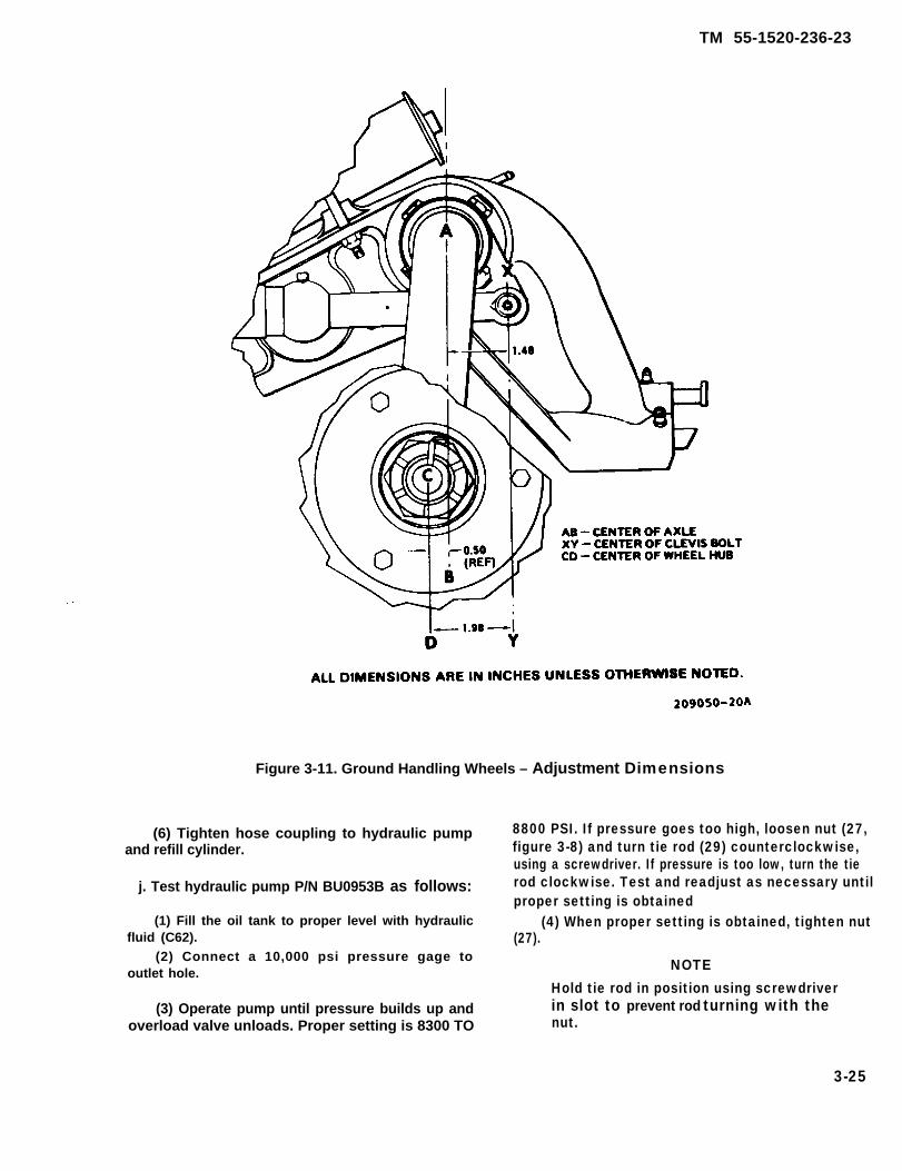
TM 55-1520-236-23
Figure 3-11. Ground Handling Wheels – Adjustment Dimensions
(6) Tighten hose coupling to hydraulic pumpand refill cylinder.
j. Test hydraulic pump P/N BU0953B as follows:
(1) Fill the oil tank to proper level with hydraulicfluid (C62).
(2) Connect a 10,000 psi pressure gage tooutlet hole.
(3) Operate pump until pressure builds up andoverload valve unloads. Proper setting is 8300 TO
8800 PSI. If pressure goes too high, loosen nut (27,figure 3-8) and turn tie rod (29) counterclockwise,using a screwdriver. If pressure is too low, turn the tierod clockwise. Test and readjust as necessary untilproper setting is obtained
(4) When proper setting is obtained, tighten nut(27).
NOTE
Hold tie rod in position using screwdriverin slot to prevent rod turning with thenut.
3-25

TM 55-1520-236-23
k. Test hydraulic ram as follows:
(1) Screw ram (7, figure 3-7) into trunnion (14)and connect ram to hydraulic pump (1).
(2) Pump until overload in pump goes off withram against trunnion stop.
(3) Check for leaks.
(4) Release pressure and pump ram outhalfway. Allow to stand a few minutes.
(5) Check for leaks. Ram is ready for servicewhen no leaks are found.
3-70. ASSEMBLY – HYDRAULIC PUMPP/N BU0953B. (AVIM)
a. Insert brass spreader (14, figure 3-8) into pumpbody (15) flat side down.
b. Slide packing support (9) onto piston (7).
NOTE
The “V” must face away from groove onpiston.
C. Dip two leather packings (10 and 11), one
rubber packing (12), and third leather packing (13)into hydraulic fluid (C63), and assemble in that orderover bottom end of piston.
d.hole
e.
NOTEThe “‘V” on packing must rest on brassspreader (14).
Place assembly bushing tool (180) into top ofin pump body (15).
Insert piston (7) with packings installed intobellmouth of assembly bushing tool (T80).
f. Slip packing seating tool (T81) over piston (7).
g. Drive piston (7) and packing down solid, usingmedium weight hammer on seating tool (T81).
h. Remove packing seating tool (T81) andassembly bushing tool (T80).
i. Install and tighten gland nut (8) usingadjustable spanner wrench. Install clip (48).
3 - 2 6
an
j. Insert 0.1875 inch diameter ball (35), suctionvalve spring (34), 0.3125 inch diameter ball (33), anddischarge valve spring (32). Install screw (31).
k. Install filter screen (30) in hose hole.
1. Insert 0.3125 inch diameter ball (47), rubberpecking (38), steel washer (46), and spring (45) intopump body (15).
To prevent damage to ball (47) and seatin Pump body (16), do not force knob(41) down tight.
m. Install valve stem (44) in base and turn downagainst ball by slipping knob (41) onto stem andtightening. Remove knob (41) from stem (44).
n. Position spring (39) on knob (41) and installscrew (43). Position knob (41) and spring (39) overstem (44). Install pin (40) through eye of spring (39)and into hole in pump body (15).
NOTE
Do not place knob onto hex of valvestem. Knob and valve stem should workfree and valve should close firmly whenopened and released.
o. Hold pump body (15) and valve stem (44) firmlyand twist knob (41) to the left two faces of the hex.Push knob onto the hex of the valve stem at thisposition Insert flat head socket screw (42) andtighten. Try knob action to see if closing is positive. Ifaction is not positive, move knob to the left anotherface on hex, and recheck closing.
p. Install filter screen (23) in pump body (15) andsecure with screw (22).
q. Install plunger (20) and spring (21) in overloadvalve body (19). Screw tie rod (29) into valve body (19)and position in tank (26).
r. Install gasket (18) and seal (16) and assembletank (26) to pump body (15).
s. install packing (28) and nut (27). Tighten nutlightly. Rotate tank so that filler hole is on top and in

TM 55-1520-236-23
line with pump handle. Tighten nut (27) and replacetank filler hole screw (24) and packing (25).
t. Position handle assembly (3) to pump body (15)and secure with fulcrum pins (5 and 37) and retainingrings (1, 2, 6, and 36).
3-71. ASSEMBLY – HYDRAULIC PUMP,P/N HP9902-41-10. (AVIM)
a. Insert spreader (10, figure 3-9) into pump base(11 ) flat side down.
b. Slide packing nut (6) onto plunger (5).
c. Dip packing (7), cup retainer (8), and pump cap(9) into hydraulic fluid (C63) and assemble in thatorder over bottom end of plunger (5).
NOTE
The “V” on pump cup must rest onspreader.
d. Place assembly bushing tool (T80) into top holein pump base (11).
e. Insert plunger (5) with packing nut, packing,cup retainer, and pump cup installed into bellmouthof assembly bushing tool (C80).
f. Slip packing seating tool (T81) over plunger.
g. Drive plunger (5) and assembled parts downsolid, using medium weight hammer on packingseating tool.
h. Remove packing seating tool (T81) andassembly bushing tool (T80).
i. Tighten packing nut (6) using packing nut toolworkaid (T84) (figure 3-10).
j. Insert 0.3125 inch diameter ball (33, figure3-9), 0.2187 inch diameter ball (32), and outlet checkspring (34). Install valve plug (35).
k. Install screen (22) in pump base (11).
1. Install release packing nut (14) on releasespindle (16). Check threads on release packing nut(14) and release spindle (16) for free turning. Removerelease packing nut (14) from release spindle (1 6).
NOTE
Touch up threads if damaged or binding.
m. Dip release packing (13), release packing nut(14) and release spindle (16) into hydraulic fluid (C63)and assemble parts in that order. Install releasespindle (16) with release packing (13) and releasepacking nut (14) in pump base (11). Tighten releasepacking nut (14) until release packing (13) bottomsout in pump base (11). Loosen release packing nut(14) and torque to 20 inch-pounds.
n. Position return spring (15) over release spindle(16). Use capscrew (20) and washer (21) to attachreturn spring (15) to pump base (11).
o. Hold pump base (11) and release spindle (16)firmly. Place handle (17) on release spindle. Handleshall be vertical with release valve in closed position.Install capscrew (19) and lock washer (18). Hookreturn spring (15) around handle (17). Try handleaction to check for positive closing of release valve.
NOTEIf handle action is not positive, movehandle to the left another face on hexshank of release spindle, and check againfor positive closing.
p. Install relief valve (23) and gasket (24) in pump
base (11).
q. Set relief valve as follows:
(1) Connect hydraulic pump to hydraulic teststand (S2).
(2) Set relief valve to open at 8500 (±300) psi.
(3) Release pressure. Then increase pressureto 8000 psi. Observe for 15 seconds. Loss ofpressure in excess of 500 psi is cause for rejection.
(4) Open release valve to drop pressure. From a10 degree open position on handle (17), releasequickly, letting return spring (15) close release valve.
NOTE
Do not push on handle.
(5) Increase pressure to 8000 psi observe for14 seconds. Loss of pressure in excess of 500 psi iscause for rejection.
3-27

TM 55-1520-236-23
r. Install shim washer (29) and/or reservoir shimwasher (28) as required to line up filler plug (27) on reser-voir (25) with top of pump within plus or minus 10degrees, Use of shim washers (29) and reservoir shimwashers (28) varies from 0 to a total of 4. Install reser-voir (25) in pump base (11). Ensure that filler plug onreservoir (25) lines up with top of pump within plus orminus 10 degrees.
s. Position beam (2) to plunger (5) and pump base(11). Install plunger cross pin (3) and beam pin (30).Secure beam pin (30) with two cotter pins (4 and 31).
t. Connect air line to fill port in reservoir (25). Apply100 psi air pressure, and check hydraulic pump underwater for signs of leakage Reject hydraulic pump ifthere are signs of leakage. Remove hydraulic pumpfrom water. Remove air line from reservoir (25). Installgasket (26) and filler plug (27).
3-72. PAINTING — GROUND HANDLINGGEAR.
a. Clean components (TM 55-1500-204-25/1).
b. Repaint ground handling gear (TM 55-1500-345-23).
3 - 7 3 . W H E E L S , T I R E S , A N D T U B E S —GROUND HANDLING GEAR.
3-74. DESCRIPTION – WHEELS, TIRES, ANDTUBES.
The ground handling gear wheel assembly consists oftwo aluminum alloy wheels two rubber tubes, and two7.00-6, 6-ply rating, type Ill aircraft tires.
3-75. REMOVAL – WHEELS, TIRES, A N DTUBES.
b. Deflate tire and use suitable tools to remove tireand tube from wheel rim,
3-76, INSPECTION – WHEELS, TIRES, ANDTUBES.
a. Inspect rim of wheel for deformation, wear, ordamage. Deformation is cause for rejection.
b. Inspect tires and tubes for excessive wear ordamage.
c. If tire is mounted on wheel, make sure airpressure is 75 PSI.
3-77 . REPAIR OR REPLACEMENT –WHEELS, TIRES, AND TUBES.
a. Replace tire if tread is worn excessively or cut towhere cord is visible
b. Repair or replace tires and tube (TM55-2620-200-24).
c. Repair of wheels is limited to polishing out minorscratches, nicks, or dents with fine India stone (C116).
d. Repaint wheels (TM 55-1500-345-23).
3-78. INSTALLATION – WHEELS, TIRES,AND TUBES.
a. Install tube wheel with tire. Make sure tube is notpinched or rolled under.
b. inflate tire to 75 PSI with low pressure air source.
c. Place wheel assembly (16, figure 3-7) on axle (15)and secure with retainer (9), nut (10), and cotter pin (11).
3-79. PAINTING – WHEELS, TIRES, ANDTUBES.
Deflate tire prior to wheel assemblyremoval.
a. Remove wheels from axle (15, figure 3-7) byremoving cotter pin (11), with nut (10), and retainer (9).
a. Touch up rim of wheel to match original finish.
b. Repaint rim of wheels (TM 55-1500-345-23).
3-28
TM 55-1520-236-23
SECTION Il. SKIDS/STRUTS
(Not Applicable)
SECTION Ill. FLOATS
(Not Applicable)
SECTION IV. SKIS
(Not Applicable)
SECTION V. BRAKES
(Not Applicable)
3-29/(3-30 blank)


TM 55-1520-236-23
CHAPTER 4
POWER PLANTS
SECTION I. POWER PLANT
4-1.
4-2.
POWER PLANT.
DESCRIPTION – POWER PLANT.
The power plant consists of a T53-L-703 series shaftturbine engine mounted horizontally on the fuselagebehind the main rotor pylon, with adapting parts andconnections to the airframe structure and to fuel, oil,electrical, instrument, and engine control systems(figures 4-1 and 4-2). The engine and transmissionare enclosed by cowling and fairing. Hinged pylonfairing doors at each side give access to the airinduction and driveshaft area ahead of the engineforward firewall. These doors also have engine airinlet scoops. The engine compartment betweenforward and rear firewalls has hinged side doorsequipped with cooling air inlets. Doors also havearmor panels to protect the fuel control andcompressor section, The exhaust area, behind therear firewall, is enclosed by removable fairing.
4 - 3 . C L E A N I N G – P O W E R P L A N T
Refer to TM 55-2840-229-23.
4 - 4 . O P E R A T I O N A L C H E C K – P O W E RPLANT.
Refer to TM 55-1520-236 MTF and TM 55-2840-229-23.
4-5. ENGINE ASSEMBLY.
4-6. D E S C R I P T I O N – ENGINEASSEMBLY.
The T53-L-703 engine is an improved version of theT53-L-13 series. The engine is a free-type powerturbine, turboshaft. The engine incorporates a twostage power turbine and two stage gas producerturbine. Major sections of the engine are the air-inlet,compression, diffuser, combustion and exhaust. Theengine is flat rated at 1485 shp, and derated to 1280shp due to transmission limitations. The engine iscooled by ram and ambient air.
4-7. SERVICING – ENGINE ASSEMBLY.
Refer to chapter 1.
4-8. A D J U S T M E N T – ENGINEASSEMBLY.
Refer to TM 55-2840-229-23.
4-9. VIBRATION TESTING – ENGINEASSEMBLY.
a. Refer to TM 55-2840-229-23 to detailedinstructions to perform engine vibration check.
Premaintenance Requirements ForVibration Test of Engine Assembly
Condition Requirements
Model
Part No. or Serial
Special Tools
Test Equipment
No.
Support Equipment
Minimum PersonnelRequired
Consumable Materials
Special EnvironmentalConditions
AH-IS
All T53-L-703 engines
Refer to TM55-2840-229-23
Refer to TM55-2840-229-23
Refer to TM55-2840-229-23
TWO
(C24)
None
b. Prepare helicopter for vibration testing.
4-1

TM 55-1520-236-23
Figure 4-1. Power Plant Installation – Right Side (Sheet 1 of 2)
4-2

Figure 4-1. Power Plant Installation – Right Side (Sheet 2 of 2)
TM 55-1520-236-23
4-2.1

TM 55-1520-236-23
Figure 4-2. Power Plant Installation – Left Side (Sheet 1 of 2)
4-2.2

TM 55-1520-236-23
Figure 4-2. Power Plant Installation – Left Side (Sheet 2 of 2)
4-2.3/(4-2.4 blank)


To prevent a possible electrical shockhazard to personnel and damage toequipment, set vibration tester meterpower switch to OFF, while breaking ormaking connections to a source ofelectrical power.
Leave enough slack in cables to preventunnecessary strain on pickups andconnectors. Avoid conditions that wouldcause cables to deteriorate from heat orabrasion.
(1) Route vibration cable assemblies aft to onelocation. Secure to engine bleed air tube, adjacent toignition exciter box, with cable clamps (figure 4-3).
(2) Route cables out left engine compartmentdoor ventilation opening. Make sure cables are clearof engine throttle control linkages. Close and secureengine compartment door.
(3) Route cable forward over wing, along leftside of aircraft to gunner station. Remove four screwsat location shown on figure 4-3 where clamps will beinstalled. Retain screws for later installation.
(4) Secure cable to fuselage with clamps at fourpoints as shown on figure 4-3. Use AN3 bolts tosecure clamps to fuselage.
TM 55-1520-236-23
NOTE
During test it will be necessary tocompress seal on gunner access doorunder cables to allow closing of the doorfor flight.
(6) Secure vibration meter with bungee cord(shock cord) (C24) or other suitable means, to acushioned, protected location in aircraft cabin.
(7) After test, remove all test equipment, cablesand clamps. Install four screws that were removed instep (3).
4-10. MAINTENANCEENGINE ASSEMBLY.
P R E C A U T I O N S –
a. Use extreme caution to prevent dirt and foreignobjects from entering the engine. Place temp0rarycovers on all exposed openings. All open hoses andtubing shall be protected with plastic or metal caps, Ifsuitable caps are not available use commercial gradealuminum foil crimped to fit the particular opening.
Penetrating oil may cause a skin rash ifprolonged contact is allowed. Do notinhale vapors, or allow to come incontact with skin, eyes or clothing.
( 5 ) R o u t e c a b l e s i n b o a r d i n t o g u n n e rcompartment.
4 - 3
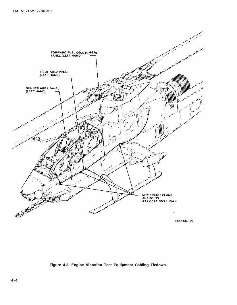
T M 5 5 - 1 5 2 0 - 2 3 6 - 2 3
Figure 4-3. Engine Vibration Test Equipment Cabling Tiedown
4-4

TM 55-1520-236-23
Cleaning solvent is flammable and toxic.Provide adequate ventilation. Avoidprolonged breathing of solvent vaporsand contact with skin or eyes.
Do not use tape to seal fuel or oilopenings. Tape adhesive is soluble in fuelor oil and can cause contamination.
b. Apply penetrating oil (C8I )as required to assistin removal of parts during disassembly. On parts to beinstalled, remove all traces of penetrating oil withsolvent (C112).
c. Protect engine from dust and inclementweather. If practical, perform engine maintenance inclosed areas.
HANDLING IGNITION UNIT
The ignition unit contains a very smallamount of radioactive material. (Cesium-Barium 137) and normally requires nohandling precautions. However, severelydamaged units that have been brokenopen must be handled with forceps orgloves and disposed of in accordancewith AR-755-15 and TB 43-0108.
d. Before removing engine components,disconnect the electric cable assembly at the ignitionunit and ground the ignition leads.
e. Discard used lockwire, packings, cotter pins,gaskets, tabwashers, lockpins, keywashers, andlockwashers.
Use care to prevent damage to lockwireholes.
f. When removing hoses and electrical lines,remove clamps from brackets. Leave brackets on theengine unless otherwise stated.
g. When disconnecting electrical connectors, orhose and tubing fittings, remove clamps on bracketsas required to gain slack and avoid damage toconnectors and fittings.
h. Remove hose assemblies that maybe damagedduring removal of engine components.
Do not use cadmium-plated tools for anyof the disassembly or reassemblyprocedure given in this manual.Cadmium plating has a tendency to chip.If these chips enter the engine, they willcontaminate the lubrication system.possibly clog the fitters, and causemagnesium parts to deteriorate.
i. Avoid hanging objects (tools, etc.) on hoseassemblies.
j. Care shall be taken to route and clamp hoseassemblies securely. Chafing shall be avoided at alltimes. Proper clamping and chafe pads shall be usedat all times.
k. During removal, examine all parts forserviceability. Look for indications of work that wasincorrectly performed during previous repairs oroverhauls. Report such indications in accordancewith current practice.
l. when removing or installing oil, fuel, and airhose assemblies, do not apply torque to the narrowhex nut of the sleeve and nipple. Torque must beapplied only to the wide hex nut. Secure the nipple orsleeve to prevent twisting of the hose assembly.
Prolonged contact with lubricating oilmay cause a skin rash. Those areas ofskin and clothing that come in contactwith lubricating oil should be thoroughlywashed immediately. Saturated clothingShould be remove Immediately. Areas inwhich lubricating oil is used should beadequately ventilated to keep mist andfumes to a minimum.
4-5
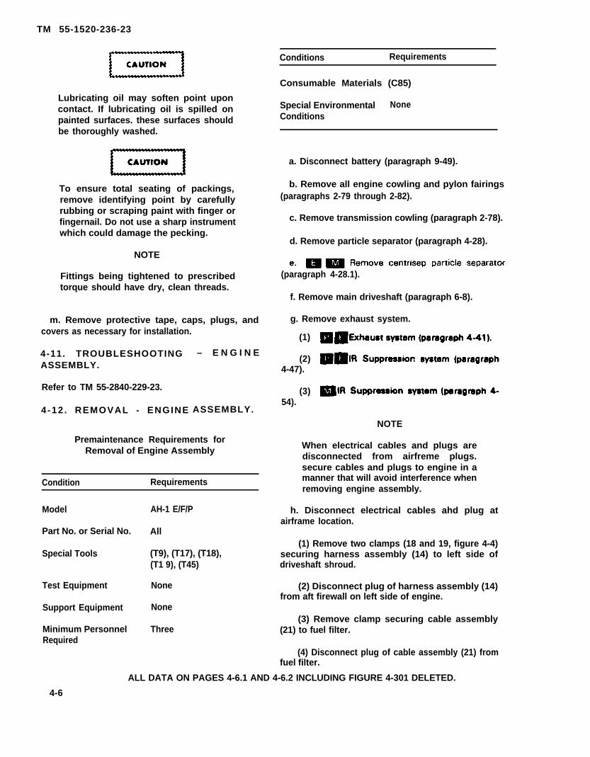
TM 55-1520-236-23
Conditions Requirements
Lubricating oil may soften point uponcontact. If lubricating oil is spilled onpainted surfaces. these surfaces shouldbe thoroughly washed.
To ensure total seating of packings,remove identifying point by carefullyrubbing or scraping paint with finger orfingernail. Do not use a sharp instrumentwhich could damage the pecking.
NOTE
Fittings being tightened to prescribedtorque should have dry, clean threads.
m. Remove protective tape, caps, plugs, andcovers as necessary for installation.
4-11. TROUBLESHOOTINGASSEMBLY.
Refer to TM 55-2840-229-23.
4 -12 . REMOVAL - ENGINE
– E N G I N E
ASSEMBLY.
Premaintenance Requirements forRemoval of Engine Assembly
Condition Requirements
Model AH-1 E/F/P
Part No. or Serial No. All
Special Tools (T9), (T17), (T18),(T1 9), (T45)
Test Equipment None
Support Equipment None
Minimum Personnel ThreeRequired
Consumable Materials (C85)
Special Environmental NoneConditions
a. Disconnect battery (paragraph 9-49).
b. Remove all engine cowling and pylon fairings(paragraphs 2-79 through 2-82).
c. Remove transmission cowling (paragraph 2-78).
d. Remove particle separator (paragraph 4-28).
(paragraph 4-28.1).
f. Remove main driveshaft (paragraph 6-8).
g. Remove exhaust system.
(1)
(2)4-47).
(3)54).
NOTE
When electrical cables and plugs aredisconnected from airfreme plugs.secure cables and plugs to engine in amanner that will avoid interference whenremoving engine assembly.
h. Disconnect electrical cables ahd plug atairframe location.
(1) Remove two clamps (18 and 19, figure 4-4)securing harness assembly (14) to left side ofdriveshaft shroud.
(2) Disconnect plug of harness assembly (14)from aft firewall on left side of engine.
(3) Remove clamp securing cable assembly(21) to fuel filter.
(4) Disconnect plug of cable assembly (21) fromfuel filter.
ALL DATA ON PAGES 4-6.1 AND 4-6.2 INCLUDING FIGURE 4-301 DELETED.
4-6

TM 55-1520-236-23
Figure 4-4. Engine Installation (Sheet 1 of 4)
4-7

TM 55-1520-236-23
Figure 4-4. Engine Installation (Sheet 2 of 4)
4-8
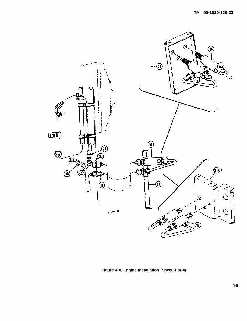
TM 55-1520-236-23
Figure 4-4. Engine Installation (Sheet 3 of 4)
4-9
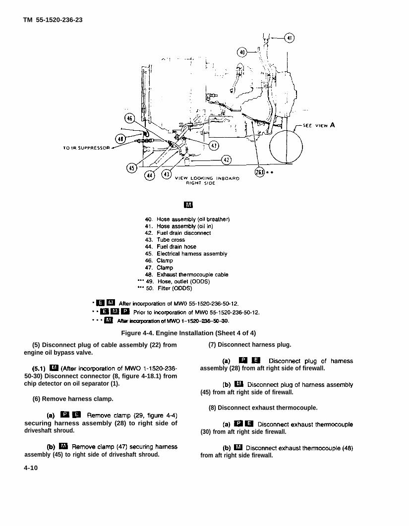
TM 55-1520-236-23
Figure 4-4. Engine Installation (Sheet 4 of 4)
(5) Disconnect plug of cable assembly (22) from (7) Disconnect harness plug.engine oil bypass valve.
assembly (28) from aft right side of firewall.50-30) Disconnect connector (8, figure 4-18.1) fromchip detector on oil separator (1).
(45) from aft right side of firewall.(6) Remove harness clamp.
(8) Disconnect exhaust thermocouple.
securing harness assembly (28) to right side ofdriveshaft shroud. (30) from aft right side firewall.
assembly (45) to right side of driveshaft shroud. from aft right side firewall.
4-10

TM 55-1520-236-23
(9) Disconnect electrical plug (9) at bleed air valve.
(10) Disconnect oil tank low level switch electricalplug (10) at airframe plug.
4-10.1/(4-10.2 blank)

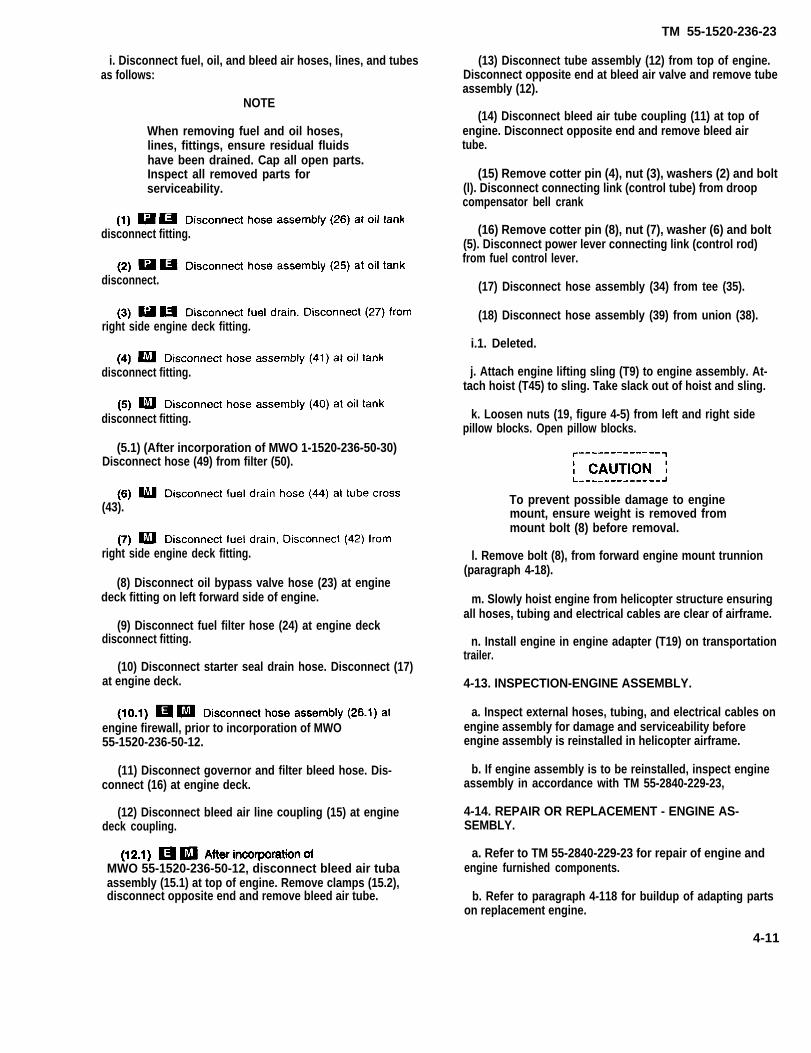
TM 55-1520-236-23
i. Disconnect fuel, oil, and bleed air hoses, lines, and tubesas follows:
(13) Disconnect tube assembly (12) from top of engine.Disconnect opposite end at bleed air valve and remove tubeassembly (12).
NOTE(14) Disconnect bleed air tube coupling (11) at top of
engine. Disconnect opposite end and remove bleed airtube.
When removing fuel and oil hoses,lines, fittings, ensure residual fluidshave been drained. Cap all open parts.Inspect all removed parts forserviceability.
(15) Remove cotter pin (4), nut (3), washers (2) and bolt(l). Disconnect connecting link (control tube) from droopcompensator bell crank
disconnect fitting. (16) Remove cotter pin (8), nut (7), washer (6) and bolt(5). Disconnect power lever connecting link (control rod)from fuel control lever.
disconnect. (17) Disconnect hose assembly (34) from tee (35).
right side engine deck fitting.(18) Disconnect hose assembly (39) from union (38).
i.1. Deleted.
disconnect fitting. j. Attach engine lifting sling (T9) to engine assembly. At-tach hoist (T45) to sling. Take slack out of hoist and sling.
disconnect fitting. k. Loosen nuts (19, figure 4-5) from left and right sidepillow blocks. Open pillow blocks.
(5.1) (After incorporation of MWO 1-1520-236-50-30)Disconnect hose (49) from filter (50).
(43). To prevent possible damage to enginemount, ensure weight is removed frommount bolt (8) before removal.
right side engine deck fitting. l. Remove bolt (8), from forward engine mount trunnion(paragraph 4-18).
(8) Disconnect oil bypass valve hose (23) at enginedeck fitting on left forward side of engine. m. Slowly hoist engine from helicopter structure ensuring
all hoses, tubing and electrical cables are clear of airframe.(9) Disconnect fuel filter hose (24) at engine deck
disconnect fitting. n. Install engine in engine adapter (T19) on transportationtrailer.
(10) Disconnect starter seal drain hose. Disconnect (17)at engine deck. 4-13. INSPECTION-ENGINE ASSEMBLY.
engine firewall, prior to incorporation of MWO55-1520-236-50-12.
a. Inspect external hoses, tubing, and electrical cables onengine assembly for damage and serviceability beforeengine assembly is reinstalled in helicopter airframe.
b. If engine assembly is to be reinstalled, inspect engineassembly in accordance with TM 55-2840-229-23,
(11) Disconnect governor and filter bleed hose. Dis-connect (16) at engine deck.
4-14. REPAIR OR REPLACEMENT - ENGINE AS-SEMBLY.
(12) Disconnect bleed air line coupling (15) at enginedeck coupling.
MWO 55-1520-236-50-12, disconnect bleed air tubaassembly (15.1) at top of engine. Remove clamps (15.2),disconnect opposite end and remove bleed air tube.
a. Refer to TM 55-2840-229-23 for repair of engine andengine furnished components.
b. Refer to paragraph 4-118 for buildup of adapting partson replacement engine.
4-11

TM 55-1520-236-23
4-15. INSTALLATION - ENGINE ASSEMBLY.
a. Attach engine lifting sling (T9) to engineassembly.
b. Attach lifting sling (T9) to hoist (T45). Take upslack in hoist and remove hardware securingengine to engine and transmission stand (T19) ortransportation trailer.
c. Hoist engine to dear airframe engine mounts.Ensure airframe pillow blocks are open and slowlylower engine assembly aligning engine trunnionbearing over engine mount pillow blocks.
d. Align forward trunnion (1, figure 4-5) with rodend bearing (12) of forward engine mount tube(10). Install bolt (8) through rod end bearing (12)and trunnion (1). Torque bolt (8) 50 to 70inch-pounds. Lockwire (C137) bolt (8) to upperbolt (5), then to lower bolt (6).
e. Close pillow block (17, figure 4-5) over left afttrunnion bearing (14). Ensure that correct specialwasher (22) is installed, and torque ring base nut(19) 50 to 70 inch-pounds. Install pillow block onright aft trunnion bearing in same manner.
e.1. install starter generator (paragraph 4-121).
f. Connect electrical cable harness and cableassemblies as follows:
(1) Connect plug of harness assembly.
assembly (28, figure 4-4) to a plug on right side ofaft firewall. Attach harness assembly (28) to rightside of driveshaft shroud with damp (29).
assembly (45, figure 4-4) to plug on right side ofaft firewall. Attach harness assembly (45) to rightside of driveshaft shroud with damp (47).
(2) Connect plug of harness assembly (14) toplug on left side of aft firewall.
(3) Connect plug of cable assembly (21) to fuelfilter plug.
(4) Connect plug of cable assembly (22) to oilbypass valve.
(4.1) (After incorporation of MWO1-1520-236-50-30) Connect plug of cable (8,
figure 4-18.1) to chip detector on oil separator (1)
(5) Attach damps (18 and 19, figure 4-4) to leftside of driveshaft shroud.
(6) Secure cable assembly (21) to fuel fitterusing existing damp on fuel filter.
(7) Connect electrical plug (9) to bleed air valveplug.
(8) Connect electrical plug (10) to airframemounted plug for oil tank lower lever switch.
g. Connect engine fuel, oil and bleed air hoses,and tubing as follows:
(1) Connect fuel drain hoses.
disconnect (27) to engine deck fitting.
(42) to engine deck fitting.
tube cross (43).
(2) Connect fuel disconnect (24) to fuel filter.
(3) Connect oil hose disconnect (23) to oilbypass valve.
(4) Connect oil drain disconnect (17) to enginedeck fittings.
(5) Connect fuel drain disconnect (16) to enginedeck fitting.
(6) Connect engine bleed air tube coupling (15)to engine deck fitting
breather hose assembly (25) to engine oil tank
assembly (26) to engine oil tank.
nose assembly (40) to engine oil tank.
assembly (41) to engine oil tank.
4-12

TM 55-1520-236-23
(c) (MWO 1-1520-236-50-30) Connect hose(23.1) between engine scavenge and oil separator(23.2). Secure with clamps (23, 24, and 26, figure 4-18.1) screws (16 and 29), washers (18), and nuts (15).
(d) (MWO 1-1520-236-50-30) Connect hose(49, figure 4-4) between oil filter (50) and oil hosedisconnect (23). Secure with clamps (26 and 27, figure4-18.1), screws (16 and 17), spacers (21), washers(18), and nuts (15).
(9) Install tube assembly (12, figure 4-4) betweenbleed air valve and bleed air fitting on top of engine.
4-12.1/(4-12.2 blank)

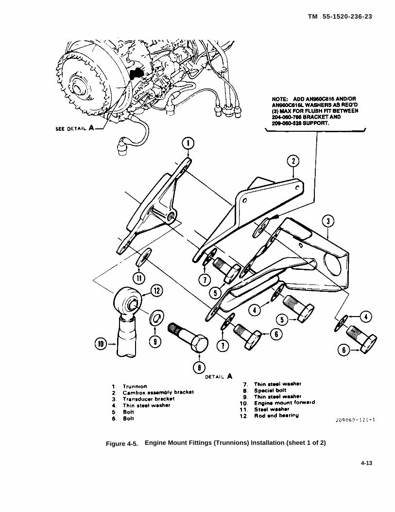
TM 55-1520-236-23
Figure 4-5. Engine Mount Fittings (Trunnions) Installation (sheet 1 of 2)
4-13

TM 55-1520-236-23
Figure 4-5. Engine Mount Fittings (Trunnions) Installation (Sheet 2 of 2)
4-14
(10) Install bleed air tube and coupling (11)between bleed air line and fitting.
(11) Install hose assembly (34) on tee (35).(12) Install hose assembly (39) on union
(38).
h. Position droop compensator control rod ondroop compensator bellcrank (3) and install bolt (1),two washers (2), nut (3), and cotter pin (4).
i. Position power lever connecting link on fuelcontrol lever and install bolt (5), washer (6), nut (7),and cotter pin (8).
j. Check rigging on power lever and droop com-pensator (paragraphs 4-105 and 4-113).
k. Install exhaust system.
Exhaust system (paragraph 4-44).
IR Suppression system (para-graph 4-51).
IR Suppression system (paragraph4-58).
l. Install main driveshaft (paragraph 6-13).
m. Install particle separator (paragraph 432).
n. Install transmission cowling (paragraph 2-91).
o. Install engine cowling and pylon fairings(paragraph 2-90 and 2-92).
4-16. ENGINE MOUNT FITTINGS (TRUN-NIONS).
4-17. DESCRIPTION-ENGINE MOUNT FIT-TINGS (TRUNNIONS).
Engine mount fittings (trunnions) are the part of theengine mount that are installed on the engine. Theforward fitting (trunnion) is bolted to the forward leftside mount pad. The two aft fittings (trunnions) arebolted to the rear mounting pads, one left and oneright.
4-18. REMOVAL-FORWARD ENGINEMOUNT FITTING (TRUNNION).
a. Attach engine lifting sling (T9) to engine as-sembly. Attach hoist (T45) to sling. Take up slackbetween hoist and sling.
TM 55-1520-236-23
NOTEEngine may be supported withsuitable strap running underneathcombustion section and spreader barto clear strap from aft pylon fairing.
b. Cut lockwire attached to bolt (8, figure 45).Remove lockwire.
c. Remove bolt (8) and washer (9) from trunnion(1).
d. Cut lockwire attached to bolts (5 and 6).Remove lockwire.
e. Remove bolts (5 and 6), washers (4, 7, and 11).
f. Remove cambox assembly bracket (2) andtransducer bracket (3).
g. Remove trunnion (1).
4-19. REMOVAL-AFT ENGINE MOUNT FIT-TINGS (TRUNNIONS).
a. Attach engine sling (T9) to engine assembly.Attach hoist (T45) to sling. Take up slack in hoistcable to relieve weight from engine mount.
NOTEEngine may be supported withsuitable strap running underneathcombustion section and a spreaderbar to clear strap from aft pylon fair-ing.
b. Remove left aft fitting (trunnion) (13, figure4-5) as follows:
CAUTIONEnsure that engine is supported byhoist and sling prior to removal ofpillow block
(1) Remove left pillow block assemblyby procedure outlined in paragraph 2-203.
(17)
(2) Remove self-locking nut (16), washer(15), and bearing (14) from trunnion on left side ofengine.
(3) Remove lockwire from four bolts (20).Remove bolts (20) and washers (21).
(4) Remove trunnion (13).c. Remove aft right engine mount fitting (trun-
nion) by same procedure outlined in step b.
4-15
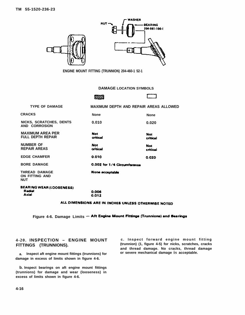
TM 55-1520-236-23
ENGINE MOUNT FITTING (TRUNNION) 204-460-1 52-1
DAMAGE LOCATION SYMBOLS
TYPE OF DAMAGE
CRACKS
NICKS, SCRATCHES, DENTSAND CORROSION
MAXIMUM AREA PERFULL DEPTH REPAIR
NUMBER OFREPAIR AREAS
EDGE CHAMFER
BORE DAMAGE
THREAD DAMAGEON FITTING ANDNUT
MAXIMUM DEPTH AND REPAIR AREAS ALLOWED
None None
0.010 0.020
Figure 4-6. Damage Limits
4-20. INSPECTION – ENGINE MOUNT c . Inspec t fo rward eng ine mount f i t t i ng
FlTTINGS (TRUNNIONS). (trunnion) (1, figure 4-5) for nicks, scratches, cracksand thread damage. No cracks, thread damage
a. Inspect aft engine mount fittings (trunnions) for or severe mechanical damage is acceptable.
damage in excess of limits shown in figure 4-6.
b. Inspect bearings on aft engine mount fittings(trunnions) for damage and wear (looseness) inexcess of limits shown in figure 4-6.
4-16

4-21. REPAIR OR REPLACEMENT – ENGINEMOUNT FITTING (TRUNNIONS).
Replace bearings if damaged or worn inexcess of limits (paragraph 4-20).
(1) Remove nut (16, figure 4-5), washer (15)and bearing (14).
(2) Position serviceable bearing (14) on fitting(trunnion). Install thin steel washer (15) and self-lock-ing nut (16). Torque 160 TO 190 inch-pounds.
Replace engine mount fittings (trunnions) ifdamaged in excess of limits (paragraph 4-20).
c. Polish out mechanical and corrosion damagethat is within Iimits shown on figure 4-6 with fine Indiastone (C116). Touch up repair area with primer (C88 orC91).
4-22. INSTALLATION – FORWARD ENGINEMOUNT FITTING (TRUNNION).
a.
NOTE
If trunnlon was removed from anInstalled englne, the engine should besupported by a hoist (paragraph 4-18).
Position trunnion (1, figure 4-5) on engineforward left mount pad.
b. Position cambox assembly bracket (2) on topmounting holes of tin. Position transducerbracket (3) on tower portion of trunnion (1) with washer(11) between bracket and trunnion.
c. Install two thin steel washers (4) and bolts (5).Do not tighten bolts. If required, add a maximum ofthree AN960C816 and/or AN960C816L washers(pargraph 4-120) to obtain a flush fit between trans-ducer bracket (3) and trunnion (1).
TM 55-1520-236-23
d Install two bolts (6) and thin steel washers (7).Torque bolts (5) and bolts (6) 290 to 410 inch-pounds.
e. Position forward engine mount (10) ontrunnion (1) and install special bolt (8) and thin steelwasher (9). Torque bolt (8) 50 to 70 inch-pounds.
Lockwire (C137) bolt (8) to upper forward bolt(6), then to lower forward bolt (6). Lockwire (C137)lower aft bolts (5), to upper aft bolts (5).
4-23. INSTALLATION – AFT ENGINE MOUNTFITTINGS (TRUNNIONS).
NOTE
If trunnions wera removed from a ninstalled engine, the angina should besupported by a hoist (paragraph 4-19).
a. Install left aft trunnion (13, figure 4-5) asfollows:
(1) Position trunnion (13) on engine left aftmount pad
(2) Install four bolts (20) and thin steelwashers (21). Torque bolts (20) 95 to 110 inch-pounds.Lockwire (C137) bolts in pairs.
b. Install right aft trunnion in same manner out-lined in step a.
c. Remove hoist and engine sling if applicable.
d. Install main driveshaft (paragraph 6-13).
e. Install particle separator (paragraph 4-32).
f. Install engine cowling and transmission cowl-ing (chapter 2).
g. Connect battery.
h. Perform runup and maintenance test fright.
SECTION Il. COOLING SYSTEM
4-17

TM 55-1520-236-23
S E C T I O N I l l . A I R I N D U C T I O N S Y S T E M
4 - 2 4 . A I R I N D U C T I O N S Y S T E M .
4-25 . DESCRIPTION – AIR lNDUCTIONSYSTEM.
Engine Intake aIr passes through large vertical scoopson both transmission cowling doors, into a chamberenclosed by induction baffles and the forwardfirewall. From this chamber, air IS drawn into theengine air Inlet through a particle separator whichremoves particles of foreign matter.
4 - 2 6 . P A R T I C L E S E P A R A T O R .
4-27. DESCRIPTION – PARTICLE SEPARATOR.(PRIOR TO INCORPORATION OF MWO 55-1520-236-50-12)
The particle separator is a self-purging, inertial typeseparator. Engine inlet air entering the particleseparator must first pass through the foreign objectdamage screens (13 and 33, figure 4-7). Refer toparagraph 4-34 for description of foreign objectdamage screen. Foreign particles which pass throughthe foreign object screen enter the air filter upper half(14) and air filter lower half (32) with engine inlet air.The particles are separated by inertial action asillustrated in figure 4-8.. The air filter halves consist ofcurved, annular, radial flow bellmouths. When engineinlet air flows through the bellmouths, foreign particlesseparate as the air passes around the curve. theparticles are forced into the concave inner flow walland caught by a protruding lip. Clean air continues intothe engine inlet. The foreign particle contaminated air isdrawn through a second turn which results in furtherseparation of foreign particles. The clean air passingthrough the second turn is returned to the engine inletarea. Foreign particle laden air flows into the air cleanermounted on the front of the air filter lower half. Theengine compressor discharges (P3) bleed air from afitting mounted on the engine diffuser. The bleed air isrouted through hose (8, figure 4-7) to ejector unit (5),Venturi effect within the ejector carries the foreignparticles overboard through hose (3).
4-27.1. DESCRIPTION – CENTRISEPP A R T I C L E S E P A R A T O R . ( A F T E RINCORPORATION OF MWO 55-1520-236-50-12)
The centrisep particle separator (3, figure 4-7.1) IS aself-purging, inertial type particle separator. Engineintake air enters into a chamber enclosed by baffles (1,2, and 22) and the forward firewall (17) throughscoops mounted on left and right transmission cowlingdoors (see figure 4-8.1 for air flow diagram). From thischamber, air is drawn through the centrisep particleseparator. The spiral vanes within each of the vortextubes (13, figure 4-7.1) causes passing air to swirl andcentrifugal force throws dirt and other particles offoreign matter out of the intake air path. Clean airpasses through vortex tubes (13) into engine bellmouthwhile dirt and foreign matter are drawn to bottom ofcentrisep particle separator into the scavenge box (23)and attached ejector duct. Engine bleed air entersejector duct through side port. Air is dischargedthrough bleed air ejector nozzles into ejector tubes. Theair exits the ejector tubes into the atmosphere; at thesame time, debris is exhausted overboard.
4-18 Change 76

TM 55-1520-236-23
Model
Part No. or Serial No.
Special Tools
Test Equipment
‘Support Equipment
Minimum PersonnelRequired
Consumable Materials
Special EnvironmentalConditions
AH-1P/E/F
All
None
None
Regulated Source of AirPressure
One
None
*After MWO 55-1520-236-50-12 is incorporated.
4 - 2 8 . R E M O V A L – P A R T I C L ESEPARATOR. (PRIOR TO INCORPORATIONOF MWO 55-1520-236-50-12)
a. Remove baffles (paragraph 2-123).
b. Remove top half of FOD screen (13, figure 4-7),(paragraph 4-35).
c. Release air filter latches (42 and 45) b ysimultaneously pressing the safety latch up andlifting up on the release catch.
4-18.1/(4-18.2 blank)

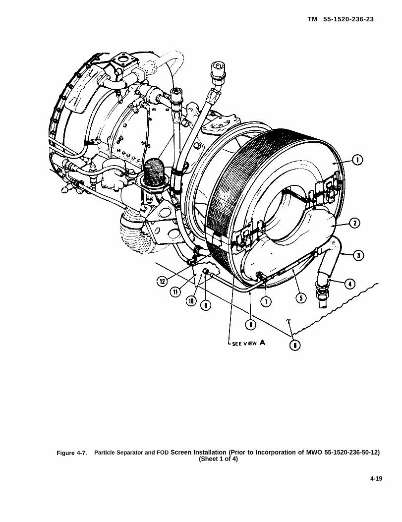
TM 55-1520-236-23
Figure 4-7. Particle Separator and FOD Screen Installation (Prior to Incorporation of MWO 55-1520-236-50-12)(Sheet 1 of 4)
4-19

Figure 4-7.
TM
5
5-1
52
0-2
36
-23
4-20
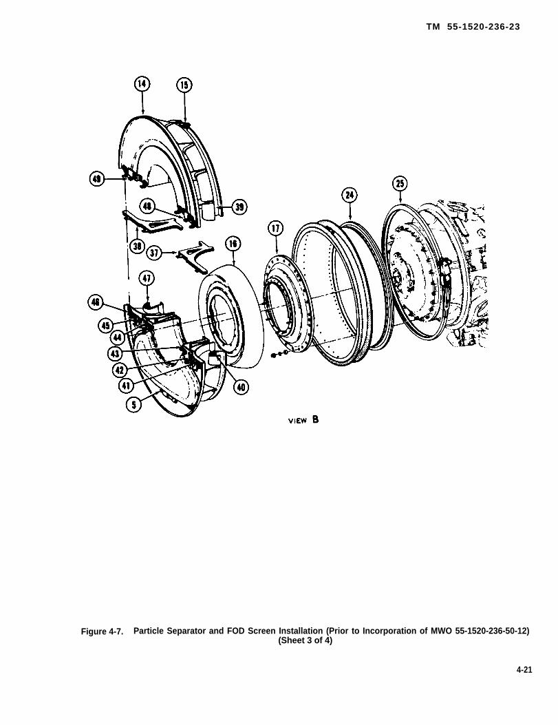
TM 55-1520-236-23
Figure 4-7. Particle Separator and FOD Screen Installation (Prior to Incorporation of MWO 55-1520-236-50-12)(Sheet 3 of 4)
4-21

TM 55-1520-236-23
Figure 4-7. Particle Separator and FOD Screen Installation (Prior to Incorporation ofMWO 55-1520-236-50-12) (Sheet 4 of 4)
NOTE
It is not necessary to furtherdisassemble the separator unless theinspection procedures indicate thatgaskets and seals may be damaged. iffurther inspection is required, proceedwith the following steps.
h. Remove the lower half of the FOD screen,(paragraph 4-35).
i. Remove main driveshaft and curvic couplingadapter from engine output shaft (paragraph 6-16).
j. Remove hose (3).
k. Disconnect nut (9) from fitting (10).
l. Remove five nuts (35) and washers (36).Remove air filter lower half (32) and deflectorassembly (16).
m. Remove two screws (20) and washers (19).Remove filter assembly upper half (18) and lower half(28).
n. Cut and remove lockwire from clamp latch (26).Loosen nut (27). Release clamp latch (26). Remove
flange assembly (24) and V-band clamp assembly(25).
o. Remove twenty-four nuts (31), washers (30),and sleeve spacers (29). Remove ring assembly (17).Install sleeve spacers (29), washers (30), and nuts(31) on studs from which they were removed, do nottorque nuts,
4-28.1.TICLE SEPARATOR. (AFTER INCORPORATIONOF MWO 55-1520-236-50-12)
a. Open left and right transmission and enginecowlings.
b. Remove center pylon left and right fairings(paragraph 2-82).
c. Remove bolt (27, figure 4-7.1), washer (26), nut(25) and right side firewall fitting (14).
d. Remove top baffle (2) and forward baffle (1)(paragraph 2-125.1)
e. On aft side of engine bellmouth (12), removefour bolts (10) and washers (11) securing left sectionof centrisep particle separator (3).
4-22
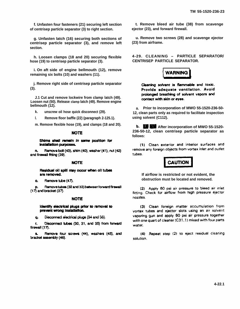
f. Unfasten four fasteners (21) securing left sectionof centrisep particle separator (3) to right section.
g. Unfasten latch (16) securing both sections ofcentrisep particle separator (3), and remove leftsection.
h. Loosen clamps (18 and 20) securing flexiblehose (19) to centrisep particle separator (3).
i. On aft side of engine bellmouth (12), removeremaining six bolts (10) and washers (11).
j. Remove right side of centrisep particle separator(3).
J.1 Cut and remove lockwire from clamp latch (49).Loosen nut (50). Release clamp latch (49). Remove enginebellmouth (12).
k. unscrew oil hose quick disconnect (29).
l. Remove floor baffle (22) (paragraph 2-125.1).
m. Remove flexible hose (19), and clamps (18 and 20).
TM 55-1520-236-23
t. Remove bleed air tube (38) from scavengeejector (23), and forward firewall.
u. Remove two screws (28) and scavenge ejector(23) from airframe.
4-29. CLEANING – PARTICLE SEPARATOR/CENTRISEP PARTICLE SEPARATOR.
a. Prior to incorporation of MWO 55-1520-236-50-12, clean parts only as required to facilitate inspectionusing solvent (C112).
After incorporation of MWO 55-1520-236-50-12, clean centrisep particle separator asfollows:
If airflow is restricted or not evident, theobstruction must be located and removed.
4-22.1

TM 1-1520-236-23
Figure 4-7.1 Centrisep Particle Seperator Installation (After Incorporation of MWO55-1520-236-50-12) (Sheet 1 of 3)
4-22.2

TM 55-1520-236-23
Figure 4-7.1. Centrisep Particle Separator Installation (After Incorporation of MWO 55-1520-236-50-12)(Sheet 2 of 3)
4-22.3
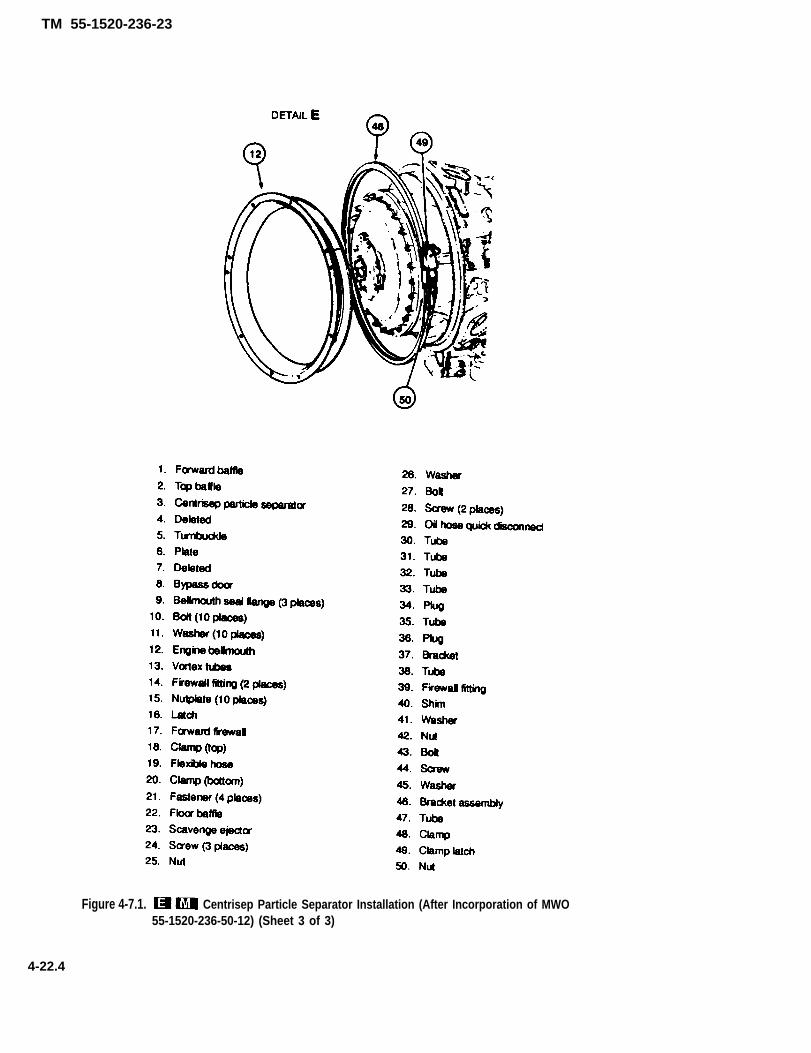
TM 55-1520-236-23
Figure 4-7.1. Centrisep Particle Separator Installation (After Incorporation of MWO55-1520-236-50-12) (Sheet 3 of 3)
4-22.4
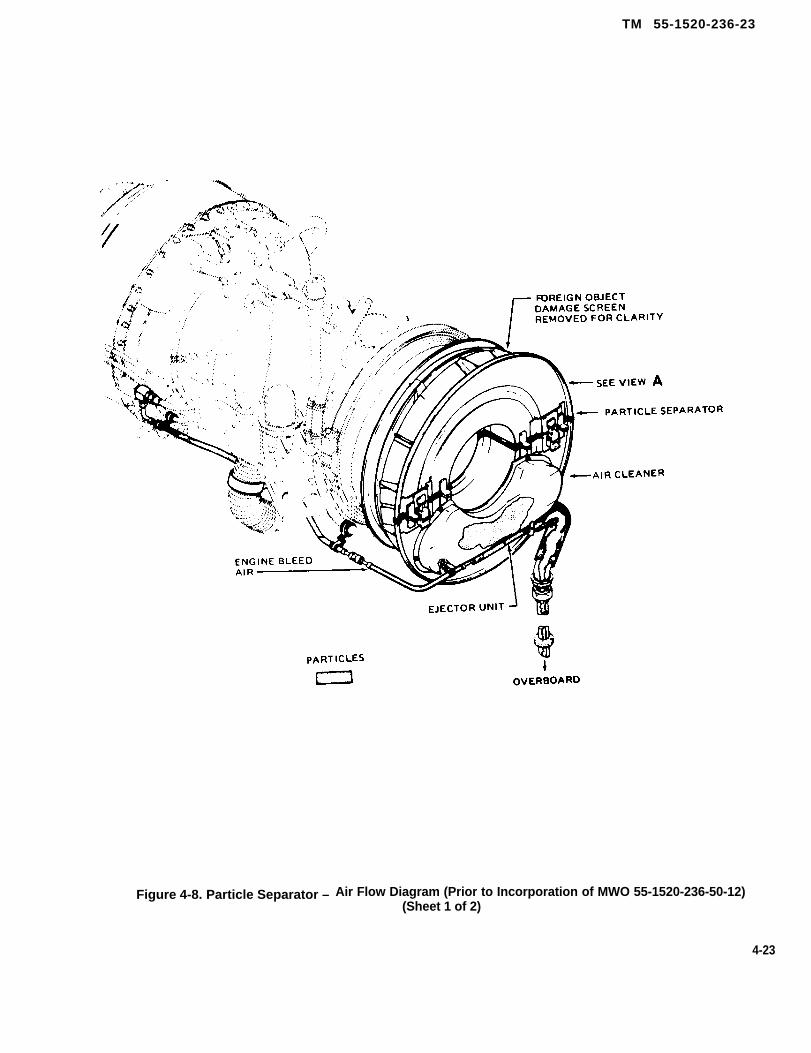
TM 55-1520-236-23
Figure 4-8. Particle Separator – Air Flow Diagram (Prior to Incorporation of MWO 55-1520-236-50-12)(Sheet 1 of 2)
4-23

TM 55-1520-236-23
Figure 4-8. Particle Separator -Air Flow Diagram (Prior to Incorporation of MWO 55-1520-236-50-12)
(Sheet 2 of 2)
4-24

TM 55-1520-236-23
Figure 4-8.1. Centrisep Particle Separator – Air Flow Diagram (After Incorporation ofMWO 55-1520-236-50-12) (Sheet 1 of 2)
4-24.1
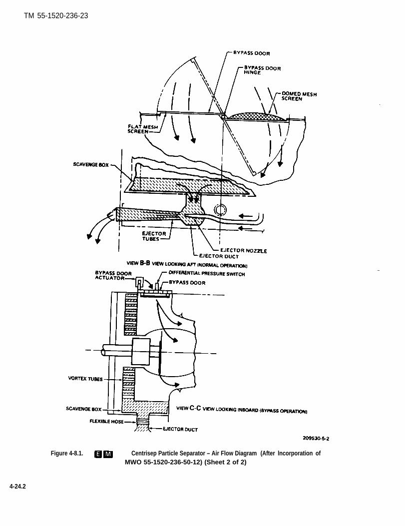
TM 55-1520-236-23
Figure 4-8.1. Centrisep Particle Separator – Air Flow Diagram (After lncorporation ofMWO 55-1520-236-50-12) (Sheet 2 of 2)
4-24.2
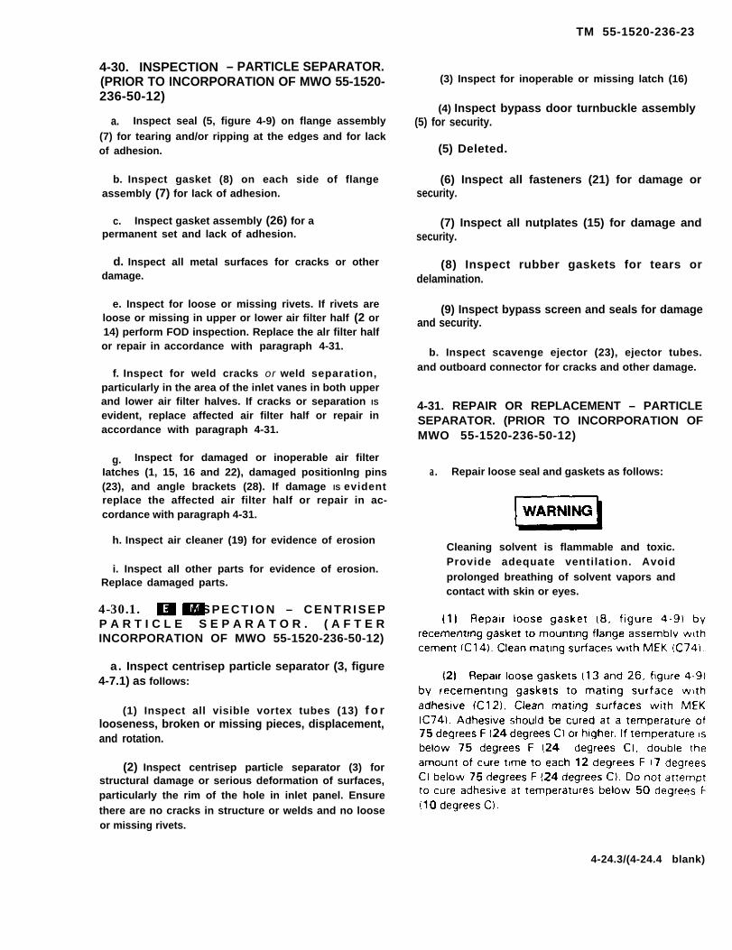
TM 55-1520-236-23
4-30. INSPECTION – PARTICLE SEPARATOR.(PRIOR TO INCORPORATION OF MWO 55-1520-236-50-12)
a. Inspect seal (5, figure 4-9) on flange assembly(7) for tearing and/or ripping at the edges and for lackof adhesion.
b. Inspect gasket (8) on each side of flangeassembly (7) for lack of adhesion.
c. Inspect gasket assembly (26) for apermanent set and lack of adhesion.
d. Inspect all metal surfaces for cracks or otherdamage.
e. Inspect for loose or missing rivets. If rivets areloose or missing in upper or lower air filter half (2 or14) perform FOD inspection. Replace the alr filter halfor repair in accordance with paragraph 4-31.
f. Inspect for weld cracks or weld separation,particularly in the area of the inlet vanes in both upperand lower air filter halves. If cracks or separation IS
evident, replace affected air filter half or repair inaccordance with paragraph 4-31.
g. Inspect for damaged or inoperable air filterIatches (1, 15, 16 and 22), damaged positionlng pins(23), and angle brackets (28). If damage IS evidentreplace the affected air filter half or repair in ac-cordance with paragraph 4-31.
h. Inspect air cleaner (19) for evidence of erosion
i. Inspect all other parts for evidence of erosion.Replace damaged parts.
4-30.1. I N S P E C T I O N – C E N T R I S E PP A R T I C L E S E P A R A T O R . ( A F T E RINCORPORATION OF MWO 55-1520-236-50-12)
a. Inspect centrisep particle separator (3, figure4-7.1) as follows:
(1) Inspect all visible vortex tubes (13) f o rlooseness, broken or missing pieces, displacement,and rotation.
(2) Inspect centrisep particle separator (3) forstructural damage or serious deformation of surfaces,particularly the rim of the hole in inlet panel. Ensurethere are no cracks in structure or welds and no loose
(3) Inspect for inoperable or missing latch (16)
(4) Inspect bypass door turnbuckle assembly(5) for security.
(5) Deleted.
(6) Inspect all fasteners (21) for damage orsecurity.
(7) Inspect all nutplates (15) for damage andsecurity.
(8) Inspect rubber gaskets for tears ordelamination.
(9) Inspect bypass screen and seals for damageand security.
b. Inspect scavenge ejector (23), ejector tubes.and outboard connector for cracks and other damage.
4-31. REPAIR OR REPLACEMENT – PARTICLESEPARATOR. (PRIOR TO INCORPORATION OFMWO 55-1520-236-50-12)
a. Repair loose seal and gaskets as follows:
Cleaning solvent is flammable and toxic.Provide adequate ventilation. Avoidprolonged breathing of solvent vapors andcontact with skin or eyes.
or missing rivets.
4-24.3/(4-24.4 blank)


TM 55-1520-236-23
TYPICAL:
Temperature Cure TimeDegrees F Degrees C Hours
75 24 4
63 17 8
51 11 16
Cleaning solvent is flammable and toxic.Provide adequate ventilation. Avoidprolonged breathing of solvent vaporsand contact with skin or eyes.
(3) Repair loose seal (5, figure 4-9) byrecementing seal to mating surface, using adhesive(C13). Clean mating surfaces with trichloroethylene(C132) and then with MEK (C74).
b. Replace damaged gaskets (13) as follows:
(1) Remove defective gasket (13) and oldadhesive from deflector assembly (12).
4-25
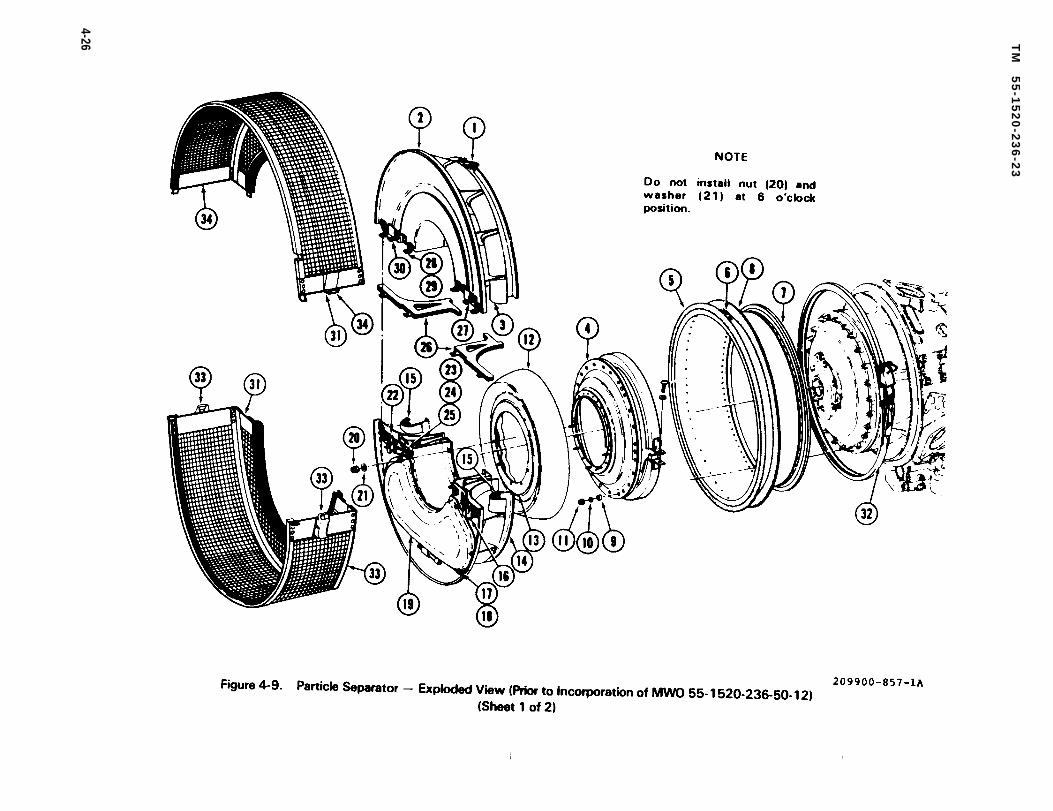
Figure 4-9.
TM
5
5-1
52
0-2
36
-23
4-26
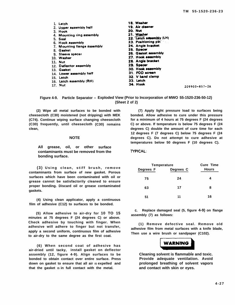
T M 5 5 - 1 5 2 0 - 2 3 6 - 2 3
1.2.3.4.5.6.7.8.9.
10.11.12.13.14.15.16.17.
Figure 4-9. Particle Separator – Exploded View (Prior to Incorporation of MWO 55-1520-236-50-12)(Sheet 2 of 2)
(2) Wipe all metal surfaces to be bonded withcheesecloth (C30) moistened (not dripping) with MEK(C74). Continue wiping surface changing cheesecloth(C30) frequently, until cheeseclothclean,
NOTE
All grease, oil, or other
(C30) remains
surfacecontaminants must be removed from thebonding surface.
(3 ) U s i n g c l e a n , s t i f f b r u s h , r e m o v econtaminants from surface of new gasket. Poroussurfaces which have been contaminated with oil orgrease cannot be satisfactorily cleaned to ensureproper bonding. Discard oil or grease contaminatedgaskets.
(4) Using clean applicator, apply a continuousfilm of adhesive (C12) to surfaces to be bonded.
(5) Allow adhesive to air-dry for 10 TO 15minutes at 75 degrees F (24 degrees C) or above.Check adhesive by touching with finger. Whenadhesive will adhere to finger but not transfer,apply a second uniform, continuous film of adhesiveto air-dry to the same degree as the first coat.
(6) When second coat of adhesive hasair-dried until tacky, install gasket on deflectorassembly (12, figure 4-9). Align surfaces to bebonded to obtain contact over entire surface. Pressdown on gasket to ensure that all air IS expelled andthat the gasket IS in full contact with the metal.
(7) Apply light pressure load to surfaces beingbonded. Allow adhesive to cure under this pressurefor a minimum of 4 hours at 75 degrees F (24 degreesC) or above. If temperature is below 75 degrees F (24degrees C) double the amount of cure time for each12 degrees F (7 degrees C) below 75 degrees F (24degrees C). Do not attempt to cure adhesive attemperatures below 50 degrees F (10 degrees C).
Temperature Cure TimeDegrees F Degrees C Hours
75 24 4
63 17 8
51 11 16
c. Replace damaged seal (5, figure 4-9) on flangeassembly (7) as follows:
(1) Remove defect ive seal . Remove oldadhesive film from metal surfaces with a knife blade,Then use a wire brush or sandpaper (C102).
Cleaning solvent is flammable and toxic.Provide adequate ventilation. Avoidprolonged breathing of solvent vaporsand contact with skin or eyes.
4 - 2 7

TM 55-1520-236-23
(2) Wipe metal surfaces to be bonded withcheesecloth (C30), moistened (not dripping) withtrichloroethylene (C132) followed by MEK (C74).Continue wiping, changing cheesecloth frequently,until cheesecloth remains clean.
To ensure proper bonding of seal, ensurethat all grease, oil, or other surfacecontaminants are removed.
NOTE
Determine whether new seal (5) is propersize by fitting it to metal mating flange offlange assembly. Do not stretch sealwhen installing it for fit. If the seal is toolarge, it may have developed an oversizeset during shipment. If so, cut the seal (5)to the required circumferential lengthand adhere as a strip with the “butt joint”located at either the 6-or 12-o’clockposition.
(3) Using sandpaper (C102), roughen sealsurfaces to be bonded.
Cleaning solvent is flammable and toxic.Provide adequate ventilation. Avoidprolonged breathing of solvent vaporsand contact with skin
(4) Using cheeseclothall surfaces to be bonded(C132).
or eyes.
(C30), thoroughly cleanwith trochloroethylene
(5) Apply a uniform layer (0.01 TO 0.03 inchthick) of adhesive (C13) to surfaces to be bonded.
(6) Fit seal (5) to flange of the flange assemblyand press surfaces together.
NOTE
Use only enough pressure to displace airbut not so much that the adhesive isforced out of the joint.
(7) Allow adhesive to cure undisturbed.
4-28
NOTE
Under light pressure, the adhesive willtake 24 hours to cure. Under warm,damp conditions the adhesive may curesufficiently in 4 hours to permitreinstallation of flange assembly (7).
d. R e p l a c e d a m a g e d g a s k e t ( 8 , f i g u r e 4 - 9 )on each side of support of flange assembly (7)as follows:
Cleaning solvent is flammable and toxic,Provide adequate ventilation. Avoidprolonged breathing of solvent vaporsand contact with skin or eyes.
(1) Remove gasket material.
(2) Wipe metal surfaces to be bonded withcheesecloth (C30) moistened (not dripping) with MEK(C74). Continue wiping and changing cheeseclothfrequently, until cheesecloth remains clean.
For proper bonding of gasket, ensure thatall grease, oil, and other surfacecontaminants are removed.
(3) Fit new 0.047 inch thick gasket (8)to flange assembly (7).
(4) Using sandpaper (C102) roughen surfaceof gasket to be bonded.
(5) Wipe all gasket surfaces to be bondedwith cheesecloth (C30) moistened (not dripping)with MEK (C74) to remove al l powder andsurface contaminants. Allow gasket (8) to dry for15 minutes,
(6) Apply a continuous uniform film of cement(C28) to both metal and rubber surfaces to be bonded.Allow approximately 2 TO 3 hours drying time,
(7) Wipe the surface of one adhesive film withcheesecloth (C30) moistened with MEK (C74), onesection at a time. The reactive surface shouldimmediately become tacky,
(8) Align mating surfaces, one section at a timeto obtain contact over entire surface, and press tacky

TM 55-1520-236-23
surface to dry surface. Allow adhesive to cure under lightpressure for a minimum of 4 hours.
e. Replace air cleaner (19, figure 4-9) as follows:
(1) Remove six nuts (17) and six washers (18).Remove air cleaner (19) from lower air filter half (14).
(2) Position new air cleaner (19) on lower air filterhalf (14) and secure with six washers (18) and six nuts(17). Torque nuts 30 TO 35 inch-pounds.
f. Repair nonconverging cracks by stopdrilling crackends. Where necessary to prevent air leakage, seal withtape or silicone rubber, RTV (C100).
g. Use rivets or tack welds to patch-repair converg-ing cracks. Follow standard airframe sheet metal repairprocedures.
NOTE
Any standard aluminum aircraft rivets,including Huck, Cherry, etc., of propersize may be used for all rivet repairs.
h. Patch-repair punctures too large to repair withsilicone rubber. Follow standard airframe sheet metalrepair procedures. Secure patches with rivets or tackwelds.
i. Repair torn tack and spot welds with tack, inter-rupted, or plug weld repairs; use doublers as needed(figure 4-10). Rivet repairs, using doublers as needed,are acceptable.
j. Repair serious erosion damage by replacingdamaged parts or using doublers.
k. Reshape deformed parts if feasible. If reasonableconformity cannot be achieved, particularly at matingedges, sealing surfaces, etc., replace part.
i. Replace damaged latches (15, 16, and 22, figure4-9) on lower air filter half (14) as follows:
NOTE
The tape (C118) between hardware itemsand air filter half must be replaced ifdamaged during removal of hardware.
(1) Remove two rivets and remove latch.
2) Assemble upper and lower air filter halves (2and 14) without gaskets (26) installed between halves.
(3) Position latch on lower assembly half in linewith hook or upper assembly half. Mark lines to positionlatch.
(4) Separate assembly halves.
(5) Position latch on Iower air filter half (14) withinmarked lines, and drill 0.128 TO 0.133 inch holes forrivets.
NOTE
If rivet holes are elongated during driliingor if new holes are drilled, back up sheetmetal with douber before riveting.
(6) Secure latch with two rivets.
m. Replace damaged positioning pins (23) or anglebrackets (28) on lower air filter half as follows:
(1) Remove rivets, bracket (28), and spacer (29).
(2) Assemble upper and lower air filter halveswithout gaskets.
(3) Position spacer and bracket on lowerassembly half in line with bracket on upper air filter half.Top of bracket will be slightly higher than the edge of theair filter half. Mark lines to position spacer (29) andbracket (28).
(4) Separate assembly halves.
(5) Position spacer (29) and bracket (28) withinmarked lines and drill two 0.128 TO 0.133 inch holes forrivets.
NOTE
Use teflon tape (C118) between spacer(29) and bracket (28).
(6) Secure bracket (28) to spacer (29) with tworivets.
(7) Align assembly halves and identify centerof bracket in line with hole of bracket on upper air filterhalf (2).
4-29

T M 5 5 - 1 5 2 0 - 2 3 6 - 2 3
MATERIAL: 6061-T6 ALUM (ITEM 17, TABLE 2-2)
Figure 4-10. Inlet Vane Reinforcement Doubler — Fabrication
4-30
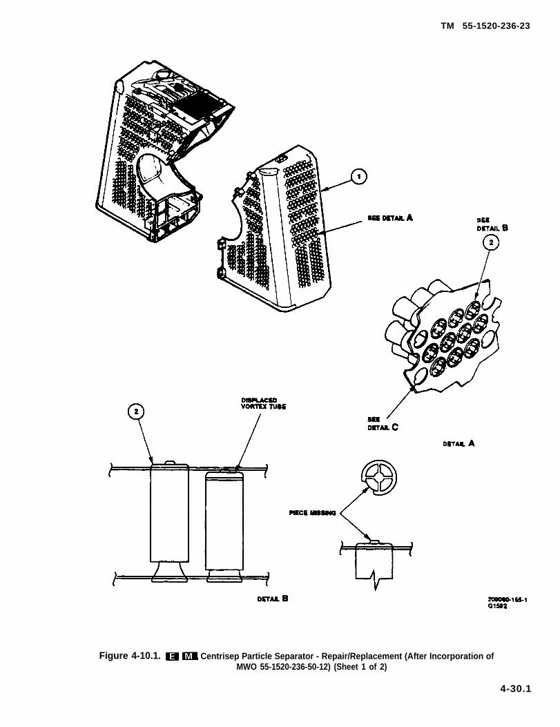
TM 55-1520-236-23
Figure 4-10.1. Centrisep Particle Separator - Repair/Replacement (After Incorporation ofMWO 55-1520-236-50-12) (Sheet 1 of 2)
4-30.1

TM 55-1520-236-23
Figure 4-10.1. Centrisep Particle Separator – Repair/Replacernant (After Incorporationof MWO 55-1520-236-50-12) (Sheet 2 of 2)
TM 55-1520-236-23
(8) Drill a 0.250 TO 0.252 inch hole throughbracket.
(9) (AVIM) Install new pin in bracket, and tackweld in two places, 180 degrees apart.
n. (AVIM) Replace new pin in bracket, and tackassembly half as follows:
(1) Remove rivets, and remove hook.
(2) Assemble upper and lower air fitter halves(2 and 14, figure 4-9) without gasket (26) assemblies.
(3) Position hook (30) on upper air filter half(2) in line with latch (22) on lower air filter half (14).Mark lines to position.
(4) Separate assembly halves.
(5) Position latch (22) within marked lines anddrill 0.128 TO 0.133 inch holes for rivets.
NOTE
Use Teflon tape (C118) between hook(30) and mounting surface.
NOTE
If rivet holes are elongated duringdrilling or if new holes are drilled, backup sheet metal with doubler beforeriveting.
(6) Secure hook (27) with two rivets.
4-31.1. REPAIR OR REPLACEMENT–CENTRISEP PARTICLE SEPARATOR. (AFTERINCORPORATION OF MWO 55-1520-50-12)
a. Swirl tubes are divided into four groups, oneon each side of the centrisep particle separator, andtwo on front side, separated by the parting surface.Fifty percent of the swirl tube tips are authorized to bemissing from each group before replacement of anyswirl tubes are required.
a.1. Replace particle separator that have 50% ofswirl tube types missing from any one group orrequired 10% replacement of total particle separatortubes or group of 10 or more required replacement forother than missing tips.
b. Replace vortex tubes using repair kit (C143).
Pulling the vortex tube with excessiveforce will cause damage to the thingauge sheet metal inlet panel.
The integrity of vortex tube hole notch(detail C) must be maintained to keepthe repair tube from rotating.
NOTE
Should the vortex tube hole or holenotch In the inlet panel be enlarged ordamage the air cleaner must bereturned to manufacturer for overhaul.
(1) Remove remains of damaged vortex tube(2, figure 4-10.1, detail B) from centrisep particle sepa-rator (1) by carefully gripping the center of the vortextube with needle nose pliars and twisting to break thetube into pieces.
NOTE
A shop towel is recommended forthumb protection and ease of insertingtube.
(2) Position the repair tube in vacant hole(Detail D), push tube through the hole using thumbpressure until groove in the tube OD engages the inletpanel (4). The repair tube is considered propertyinstalled when the groove on the repair tube fullyengages with inlet panel hole (see detail E).
(3) Check for proper installation of repair tubeas shown in detail E. The groove in the repair tubemust fully engage the inlet panel. The repair tube mustbe tight and should not rotate or appear loose.
(4) Inspect engine inlet.
Replace flexible hose (19, figure 4-7.1) andscavenge ejector (23).
4-31
TM 55-1520-236-23
4 - 3 2 . I N S T A L L A T I O N – P A R T I C L ESEPARATOR. (PRIOR TO INCORPORATION OFMWO 55-1520-236-50-121
Cleaning solvent is flammable and toxic.Provide adequate ventilation. Avoidprolonged breathing of solvent vaporsand contact with skin or eyes.
a. Wipe engine inlet housing clean with cleancloth moistened with dry cleaning solvent (C112).
b. Remove nuts (11, figure 4-9), washers (10),and sleeve spacers (9). Install ring assembly (4)with five studs of ring assembly positioned at thebottom, and with the center stud located at the 6o’clock posltlon.
c. Secure ring assembly (4), with twenty-foursleeve’ spacers (9), washers (10), and nuts (11).Torque nuts 70 TO 80 inch-pounds.
NOTE
Leave flange assembly (7) looseenough to be rotated.
d. Posltlon flange assembly (7) in front ofairframe firewall and on engine inlet housing.Retain flange assembly loosely with V-band clampassembly (32) and on firewall with formerassemblies.
e. Position deflector assembly (12) overIocating pins and studs on ring assembly (4) andpress in until firmly seated.
f. Secure hose assembly (3, figure 4-7) to ejectorunit inlet with clamphalf (14, figure 4-9)port of air cleaner.
before installing lower air filterand push hose onto discharge
NOTE
Washer (21) and nut (20), may beomitted from 6 o’clock position of ringassembly (4) to eliminate having toremove main driveshaft at next particleseparator removal.
g. Position lower air filter half (14) on Iocatlngpins and studs on ring assembly (4) Secure with
4-32
washers (21) and nuts (20). Torque 30 TO 3 5inch-pounds
h. Connect nut offoward firewall andlower baffle.
i. Install curvicof engine and Install6-16)
j. Install lower
hose assembly to fitting onconnect hose to elbow on
coupling in output shaftmain drlveshaft (paragraph
half FOD (foreign objectdamage) screen (31). Refer to paragraph 4-38.
k. Posit ion gasket assembly (26) overpositioning pins (23) (R/H and L/H) side oflower air filter half (14).
l. Position upper air filter half (2) on lowerhalf (14),
Rotate flange assembly (7) on engineinlet housing to align mounting bracket (hook) (6)with latch (1) on upper air filter half (2).
NOTE
Install V-band clamp assembly (32)with clamp latch on left side of engineand gap (drain) at the 6 o’clock position.
n. Secure flange assembly (7) with V-band clamp(32). Tap around V-band clamp from middle towardeach end with a soft-faced mallet to seat properly.Torque V-band clomp nut 40 TO 50 inch-pounds.Lockwire V-band clamp latch per TM 55-2840-229-23.
Ensure that safety catch on latches isengaged by exerting a slight pull onrelease catch. Catch should not open.
o. Secure alr filter latches (1, 15, 16, and 22).
p. Check for proper seating of seals byappearance, Approximately 1/8 inch of rubber ongaskets (26) wiII be uniformly exposed. Seal (5)on flange assembly wIII be approximately halfway compressed.
q. Install upper FOD screen (31). Refer toparagraph 4-38. Secure upper and lower FODscreens with latches (33).
r. Install baffle panels forward of firewall(paragraph 2-128).
4-32.1. lNSTALLATION – CENTRISEPPARTlCLE SEPARATOR. (AFTER INCORPO-RATION OF MWO 55-1520-236-50-12)
a. Wipe engine inlet housing with dean clothmoistened with dry cleaning solvent (C112). Wipe drybefore solvent evaporates.
a.1. Using v-bond damp (49, figure 4-7.1) installbellmouth (12) leave damp loose to position bellmouthassembly when installing particle separator.
Position scavenge ejector (23, figure 4-7.1) inplace.
c. Install tube (38) to back side of scavengeejector (23), and forward firewall.
d. Install screws (28) in scavenge ejector (23)
e. Install bracket assembly (46) with attachinghardware on top of scavenge ejector (23) with fourscrews (44) and washers (45).
f. Install tubes (32 and 33) between fittings onfirewall (17) and fittings on bracket (37).
Install tubes (30, 31, and 35) to fittings on fire-wall (17).
h. Install tube (47).
i. Install plugs (34 and 36).
j. Install firewall fitting (39) with bolts (43), shims(40), washers (41) and nuts (42).
k. Install floor baffle (22) forward and aft sectionsover top of scavenge ejector (23) (paragraph 2-128.1).
Install flexible hose (19) with two loose damps(18 and 20) on scavenge ejector (23).
m. Position right side, centrisep particle separa-tor (3) and connect flexible hose (19) to bottom.
n.
o.
TM 55-1520-236-23
Tighten flexible damps (18 and 20).
Install six bolts (10) and washers (11) throughaft side of engine bellmouth (12) and bellmouth sealflanges (9) into nutplates (15) in aft side of centrisepparticle separator (3).
p. Install right side firewall fitting (14) using bolts(27), washers (26) and nuts (25).
q. Position centrisep particle separator remov-able section (3) in line with centrisep particle separatorfixed section (3) previously installed.
r. Install four washers (11) and bolts (10) throughaft side of engine bellmouth (12) and bellmouth sealflange (9) into nutplates in centrisep particle separator.
s. Secure four fasteners (21) on forward left sideof centrisep particle separator (3).
t. Secure latch (16).
NOTE
t.1. Secure bellmouth (12) with damp (48). Taparound damp from middle toward each end with soft-faced mallet to seat properly. Torque damp nut 40 to50 inch-pounds. Lockwire damp latch per TM55-2840-229-23.
u. Install baffles (1 and 2) (paragraph 2-128.1).
v. Connect oil hose quick disconnects (29).
Install center pylon left and right fairings (para-graph 2-82).
x. Close and secure transmission and enginecowling doors.
4-33. FOREIGN OBJECT DAMAGE SCREEN.
4-34. DESCRIPTION — FOD SCREEN.
4-32.1

TM 55-1520-236-23
4-35. REMOVAL — FOD SCREEN.
4-9) from the particle separator as follows:
particle separator paragraph 4-28).
(1) Lift forwardsplit portion of the butt molding(figure 4-11) free of the vane and hold in position.
4-36. lNSPECTlON - FOD SCREEN.
a. Inspect FOD screens (31, figure 4-9) for dam-
(3) Loose or missing rivets.
d. Inspect aft molding (figure 4-11) for cuts orother damage.
4-37. REPAIR — FOD SCREEN.
a. Replace components thatfigure
fail to meetinspection requirements of paragraph 4-36.
b. Reshape deformed parts, if feasible. Ifreasonable conformity cannot be obtained, replaceeither half or both as required.
c. Replace FOD small mesh screen.
(1) Cut screen (1560-AH-1-080-3) in halflengthwise (figure D-185).
NOTE
(2) Line screen (1560-AH-1-080-3) alongIeading edge of FOD screen. Form screen to existingFOD screen.
(3) Using Iockwire (C-137), secure one endand single wire lace every fifth opening along outerperimeter of screen (1560-AH-1-080-3) to existing
(4) Repeat steps (2) and (3) for other half ofFOD screen.
d (AVIM) Replace damaged hooks (34, figure4-9) on upper screen (31) as follows:
(1) Remove rivets and remove hook (34).
4-32.2

TM 55-1520-236-23
(2)position
Assemble upper and lower screens andhook (34) in line with latch (33) on lower
screen (31).
(3) Mark lines to position hook (34).
(4) Separate assembly halves.
(5) Position latch (33) within marked linesa n d d r i l l 0 . 1 2 8 T O 0 . 1 3 3 i n c h h o l e sfor rivets.
(6) Secure hook (34) with two rivets.
e. Replace damaged latches (33, figure 4-9) onlower screen (31) as follows:
(1) Remove rivets and latch (33).
(2) Assemble upper and lower screens andposition latch (33) on lower screen (31) in linewith hook (34) on upper screen.
(3) Mark lines to position latch (33).
(4) Separate assembly halves.
(5) Posit ion latch (33) within markedlines and drill 0.128 TO 0.133 inch holesfor rivets.
(6) Secure latch (33) with two rivets.
4-38. INSTALLATION – FOD SCREEN.
a. Position bottom half of the foreign objectdamage screen (31, figure 4-9), aft molding sidetoward engine inlet, under the particle separator
so butt molding (figure 4-11) is approximately2.25 inches below horizontal centerline, and aftmolding is seated over the particle separator splitflange.
b. Check for proper seating by running handalong the lower split flange to ensure that the moldedchannel is properly fitted over both sides of the splitflange (figure 4-11).
c. insert aft molding while holding butt moldingaway from the vane in the separator (steps I and Il,figure 4-11).
d. Line up the slot in forward portion of buttmolding with the vane over which it is to be fitted andpress into place. (step iii, figure 4-11).
NOTE
4-11.
e. if removed, install top half of the particleseparator (paragraph 4-32).
f. Position top half of the FOD screen (31, figure4-9) so as to engage the aft screen molding slot overthe separator split flange. Position the screen cutoutover the latch (1) at the 12-o’clock position of theseparator.
NOTE
4-33

TM 55-1520-236-23
Figure 4-11. FOD (Foreign Object Damage) Screen lnstallation (Sheet 1 of 2)
4-34

TM 55-1520-236-23
Figure 4-11. FOD (Foreign Object Damage) Screen Installation (Sheet 2 of 2)
4-35

TM 55-1520-236-23
SECTION IV. EXHAUST SYSTEM.
4-39. E X H A U S T S Y S T E M .
4-40. DESCRIPTION – EXHAUSTSYSTEM.
The exhaust diffuser section on rear of the engineprovides passage for gas flow from the combustionchamber. The exhaust passage is extended aft andslightly upward by a tailpipe and ejector assembly. Athermocouple assembly, mounted on the diffuser hasprobes in the exhaust stream to provide continuousindication through the exhaust temperature gagesystem. To aid in engine compartment cooling, a heatshield is mounted around the end of the diffuser, thetailpipe is covered by an insulation blanket, and theejector surrounds the exhaust gas flow with a coolingair stream. The exhaust tailpipe and heat shield aremounted on flanges of the engine exhaust diffuser byV-bend clamps (figure 4-12).
4-41. REMOVAL – EXHAUSTSYSTEM.
Condition Requirements
Model
Part No. or Serial No.
Special Tools
Test Equipment
Support Equipment
Minimum PersonnelRequired
Consumable Materials
Special EnvironmentalConditions
All
None
None
None
One
(C105), (C1 37)
None
a. Disconnect drain lines from fittings on tailpipeand ejector.
b. Remove ejector and tailpipe fairing as follows:
(1) If ejector is attached to tailpipe, removescrews and washers at five sets of brackets to detachand remove ejector. Release fasteners along loweredge of fairing. Lift fairing rearward to remove.
(2) If ejector is attached to fairing, releasefasteners and remove fairing with ejector attached.Detach ejector from fairing by removing screws andnuts at three mounting clips.
c. Loosen nuts to open V-band clamp whichsecures tailpipe to engine diffuser flange. Pull aft todisengage locating pins. Remove tailpipe.
d. Remove Iockwire and unwrap insulationblanket from tailpipe.
e. Remove V-band clamp and heatshield fromflange of diffuser support cone.
4 - 4 2 .SYSTEM.
a. Inspect tailpipe and ejector for cracks, dents,and burned out or buckled areas.
b. Inspect insulation blanket for visible damage.
c. Inspect heatshield for cracks and distortion.
4 - 4 3 .SYSTEM.
a. Ejector (figure 4-12).
(1) Shallow dents and scratches may bedisregarded.
(2) Cracks 3.0 inches or less in length maybewelded. Welds must be ground down as smooth aspossible to match contour of ejector.
(3) Cracks in excess of 3.0 inches, tears orsmall bullet holes in any area of the ejector may berepaired by stop-drilling ends of each crack or tearand welding a patch of titanium, MIL-T-9046, Type 1,Composition C, over the crack or tear on both insideand outside of the ejector. Patch edge distance to be aminimum of 0.5 inch beyond stop-drill.
4-36

TM 55-1520-236-23
Figure 4-12. Exhaust System Components
4-37

TM 55-1520-236-23
(4) Cracks in the bellmouth-to-tube weld jointat angle bracket may be repaired and future crackingeliminated as follows:
(a) Remove angle bracket and spot-weldeddoubler. Fabricate a new doubler from titanium ofsame width but 0.5 inch longer than removeddoubler. Position doubler so that it extends pastcracked weld joint up onto bellmouth 0.6 inch. Formdoubler to fit contour.
(b) Clean and reweld cracked joint. Grindweld smooth. Place new doubler in position and weldto assembly.
(c) Attach angle bracket per step (5) below,using rivet holes in ejector as a guide to drill throughdoubler.
(5) Replace brackets as follows:
(a) Drill out six rivets which attach angle to berepaired. Use rivet holes in ejector as a guide to alignnew angle, mark locations and drill six Number 30(0.128) holes in angle.
NOTE
Prior to riveting new angle to ejector totailpipe, align flange of new angle withflange of angle to tailpipe. Mark locationfor attachment bolt hole in new angleusing mating hole in tailpipe angle as aguide. Maintain flat plane between thetwo angles within 0.020 inch TIR.
(b) Drill a number 1 (0.288) hole in angleflange at location determined in note above. Attachnew angle to ejector with six rivets.
(6) Burned out parts or dents which cannot besmoothed out to original contour are cause forreplacement.
b. Tailpipe.
(1) Scratches and shallow dents may beignored.
(2) Cracks or tears in any area of the tailpipemay be repaired by stop-drilling ends of each crackand welding a patch of titanium over the crack or tear.The outside patch must have a 0.75 inch overlap ofany damaged area. The inside patch must beapproximately 0.50 inch larger than the outside
patch in all dimensions (figure 4-13). The patch shallbe welded on both inside and outside of the tailpipe. Ifthe tailpipe ring is welded, care must be taken that theflange is filed or machined to a flat surface afterwelding to provide a flat seat against the attachmentpoint on the engine.
(3) Burned out parts or damage greater thanthat which is repairable by patching is cause forreplacement.
(4) Replace insulation blanket, if damaged.
c. Heat shield.
(1) Replace heat shield if cracks or distortioncannot be repaired or straightened.
Figure 4-13. Engine Tailpipe Repair
4-38
4 - 4 4 . I N S T A L L A T I O N – E X H A U S TSYSTEM.
a. Remove protective cover from engine exhaustdiffuser.
b. Position tailpipe, with drain fitting down, onflange of exhaust diffuser, Make sure locating dowelsare engaged, and that inside of pipe aligns withdiffuser. Secure with V-bend clamp around matingflanges.
(1) Seat clamp by tapping with soft mallet frommiddle toward ends. Torque nuts 100 TO 130 inch-pounds.
(2) Check torque again after first ground run-Up.
c. If removed, install insulation blanket aroundtailpipe with joint at top. Secure with Iockwire (C137)installed in zig-zag pattern (figure 4-12).
d. Position heat shield against flange ofdiffuser support cone. Secure with V-band clamparound matching flanges. Torque clamp nuts40 TO 50 inch-pounds and safety clomp with Iockwire(C138).
e. Install ejector and tailpipe fairing as follows:
Adjustment of latch mating fitting maybe necessary to ensure proper closing oflatch. Do not force latch closed. Slighttension shall remain on latch in theclosed position.
(1) Place ejector into fairing, align clips andsecure at three locations with screws and nuts. Ifnecessary, remove plug buttons (detail A, figure 4-12)and loosen bolts to realign clips on serrated plates,tighten bolts, and reinstall plug buttons. Install fairingwith attached ejector.
(2) Measure gap between tailpipe fairingengine cowl doors and pylon fairing, Inspect for a gapof 0.040 inch at the lower extremities of cowlcomponents to a maximum of 0.190 inch at the top. Ifadjustment is necessary, proceed as follows:
(a) Loosen two attachment screws securinglatch plate to tailpipe fairing bracket (detail B, figure
TM 55-1520-236-23
4-11). Latch shall remain fastened duringadjustment.
(b) Adjust fairing to proper clearance,allowing serrated plate to self-adjust.
(c) After proper clearance is obtained,tighten two attachment screws.
f. Connect drain lines to fittings on tailpipe andejector.
g. Seal all open areas between base of forwardand/or aft firewall and engine deck (figure 4-14).Use sealant (C 105).
4 - 4 6 .S U P P R E S S I O N S Y S T E M .
4 - 4 6 .SUPPRESSION SYSTEM.
Some helicopters are equipped with an IRsuppression system. This system includes anupturned, insulated exhaust duct assembly, anexhaust extension, and a forward duct assembly. Forhelicopters which do not have the system installedrefer to paragraph 4-40.
Premaintenance Requirements ForIR Suppression System
Condition Requirements
Model
Part No. or Serial No.
Special Tools
Test Equipment
Support Equipment
Minimum PersonnelRequired
Consumable Materials
Special EnvironmentalConditions
AH-l S
All
None
None
None
Two
(C14), (C74), (C112),(C97)
None
4-39

TM 55-1520-236-23
Figure 4-14. Engine Deck and Firewall Sealing
4-47. REMOVAL – IRSUPPRESSION SYSTEM.
a. Disconnect drain line (6, figure 4-15) fromfitting on tailpipe (1).
b. Release fasteners on fairing (4) and removefairing, duct assemblies (2 and 5), and extension (3) asan assembly.
c. Detach forward duct assembly(2) from exhaustextension (3) by removing bolts (13) and washers (12)from extension (3).
d. Detach exhaust extension (3) from aft ductassembly (5) by removing nuts (14) and washers (15)from Iockpins (20).
e. Remove fairing assembly (7) from aft ductassembly (5) and fairing (4) by removing screws (16)and washers (17).
f. Detach aft duct assembly (5) from cowling (4) byremoving 12 screws (18) and washers (19).
4-40

TM 55-1520-236-23
Figure 4-15. Exhaust System Components with IR Suppression — Installation
4-41

TM 55-1520-236-23
4 - 4 8 .
Clean duct assemblies (2 and 5) and exhaustextension (3) with a wire brush and solvent (C112)when necessary. Clean clamps and heat shield withsolvent (C112). Do not used solvent on insulationblanket.
4 - 4 9 .SUPPRESSION SYSTEM.
a. Inspect ducts for cracks, dents, andoverheating.
(1) Cracks and holes in surface of duct shouldnot exceed 3.0 inches in diameter after cleanup.Adjacent pair areas must allow a minimum of 2.0inches of parent metal between patches.
(2) Aft exhaust cracks and holes in exteriorsurface of duct shall not exceed 4.0 inches indiameter after cleanup. Adjacent repair areas mustallow a minimum of 2.0 inches of parent metalbetween patches.
(3) Damage which penetrates the aft exhaustduct (5) tempmat insulation between interior andexterior surfaces of duct shall not exceed 4.0 inchesin diameter after cleanup.
(4) Dents in surface of duct are permissibleprovided surface is not broken and there are no sharpcreases or projections into exhaust stream.
(5 ) Heat ing as evidenced merely bydiscoloration of the metal is permissible. However, ifthe condition becomes progressive, indicating apossible burnthrough, the part should be replaced.
b. Inspect ducts for exterior damage.
(1) Damage to circumferential mountingframes of duct assembly and exhaust extension (3)shall be evaluated Iocally as to feasibility to repair orneed for replacement. It is deemed not feasible toreplace the frame on duct.
(2) Damage to mounting flange and outlet rimof the aft exhaust duct (5) shall be evaluated locally asto feasibility to repair or need for replacement.
(3) Ensure that all attaching screws are secure.
(4) Check aft exhaust duct (5) and fairing (4) forsecurity of mounting and for loose or missing rivets.
(5) Check that drain hose on forward exhaustduct is intact and securely attached.
A repair kit (C97) is available for use in repairingdamaged components. The kit contains the following
(1) Minor dents in exterior surfaces require norework if surface is not broken, or if no sharp crease orprojection exists in the interior surface.
(2) Work out minor dents having sharpprojections into the interior of duct, by restoring tooriginal contour and smoothing off any sharpprojections with fine abrasive paper.
(3) Large dents (sucface impressions) shall beworked out by restoring the surface to originalcontour.
4-42
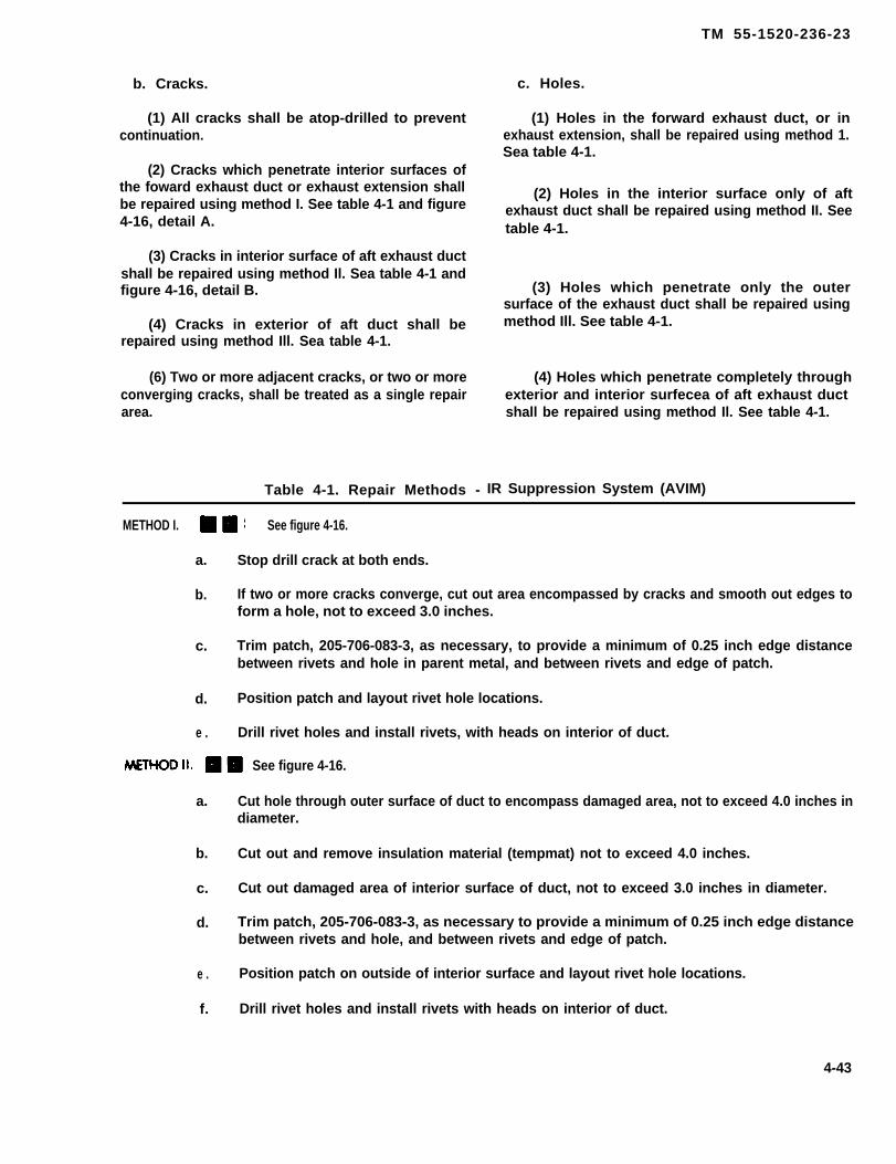
TM 55-1520-236-23
b. Cracks.
(1) All cracks shall be atop-drilled to preventcontinuation.
(2) Cracks which penetrate interior surfaces ofthe foward exhaust duct or exhaust extension shallbe repaired using method I. See table 4-1 and figure4-16, detail A.
(3) Cracks in interior surface of aft exhaust ductshall be repaired using method Il. Sea table 4-1 andfigure 4-16, detail B.
(4) Cracks in exterior of aft duct shall berepaired using method Ill. Sea table 4-1.
(6) Two or more adjacent cracks, or two or moreconverging cracks, shall be treated as a single repairarea.
c. Holes.
(1) Holes in the forward exhaust duct, or inexhaust extension, shall be repaired using method 1.Sea table 4-1.
(2) Holes in the interior surface only of aftexhaust duct shall be repaired using method II. Seetable 4-1.
(3) Holes which penetrate only the outersurface of the exhaust duct shall be repaired usingmethod Ill. See table 4-1.
(4) Holes which penetrate completely throughexterior and interior surfecea of aft exhaust ductshall be repaired using method Il. See table 4-1.
Table 4-1. Repair Methods - IR Suppression System (AVIM)
METHOD I. See figure 4-16.
a. Stop drill crack at both ends.
b. If two or more cracks converge, cut out area encompassed by cracks and smooth out edges toform a hole, not to exceed 3.0 inches.
c. Trim patch, 205-706-083-3, as necessary, to provide a minimum of 0.25 inch edge distancebetween rivets and hole in parent metal, and between rivets and edge of patch.
d. Position patch and layout rivet hole locations.
e . Drill rivet holes and install rivets, with heads on interior of duct.
See figure 4-16.
a. Cut hole through outer surface of duct to encompass damaged area, not to exceed 4.0 inches indiameter.
b. Cut out and remove insulation material (tempmat) not to exceed 4.0 inches.
c. Cut out damaged area of interior surface of duct, not to exceed 3.0 inches in diameter.
d. Trim patch, 205-706-083-3, as necessary to provide a minimum of 0.25 inch edge distancebetween rivets and hole, and between rivets and edge of patch.
e . Position patch on outside of interior surface and layout rivet hole locations.
f. Drill rivet holes and install rivets with heads on interior of duct.
4-43
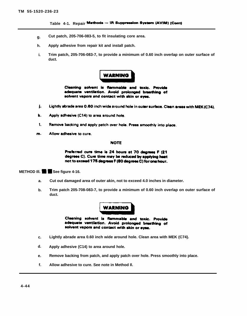
TM 55-1520-236-23
Table 4-1. Repair
g. Cut patch, 205-706-083-5, to fit insulating core area.
h. Apply adhesive from repair kit and install patch.
i. Trim patch, 205-706-083-7, to provide a minimum of 0.60 inch overlap on outer surface ofduct.
METHOD Ill. See figure 4-16.
a. Cut out damaged area of outer akin, not to exceed 4.0 inches in diameter.
b. Trim patch 205-708-083-7, to provide a minimum of 0.60 inch overlap on outer surface ofduct.
c. Lightly abrade area 0.60 inch wide around hole. Clean area with MEK (C74).
d. Apply adhesive (C14) to area around hole.
e. Remove backing from patch, and apply patch over hole. Press smoothly into place.
f. Allow adhesive to cure. See note in Method Il.
4-44
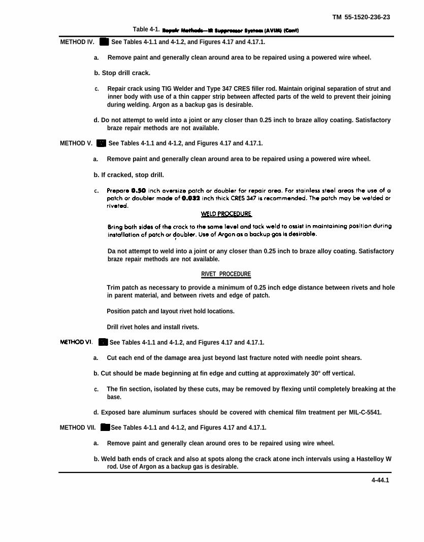
TM 55-1520-236-23
Table 4-1.
METHOD IV. See Tables 4-1.1 and 4-1.2, and Figures 4.17 and 4.17.1.
a. Remove paint and generally clean around area to be repaired using a powered wire wheel.
b. Stop drill crack.
c. Repair crack using TIG Welder and Type 347 CRES filler rod. Maintain original separation of strut andinner body with use of a thin capper strip between affected parts of the weld to prevent their joiningduring welding. Argon as a backup gas is desirable.
d. Do not attempt to weld into a joint or any closer than 0.25 inch to braze alloy coating. Satisfactorybraze repair methods are not available.
METHOD V. See Tables 4-1.1 and 4-1.2, and Figures 4.17 and 4.17.1.
a. Remove paint and generally clean around area to be repaired using a powered wire wheel.
b. If cracked, stop drill.
Da not attempt to weld into a joint or any closer than 0.25 inch to braze alloy coating. Satisfactorybraze repair methods are not available.
RIVET PROCEDURE
Trim patch as necessary to provide a minimum of 0.25 inch edge distance between rivets and holein parent material, and between rivets and edge of patch.
Position patch and Iayout rivet hold Iocations.
Drill rivet holes and install rivets.
See Tables 4-1.1 and 4-1.2, and Figures 4.17 and 4.17.1.
a. Cut each end of the damage area just beyond last fracture noted with needle point shears.
b. Cut should be made beginning at fin edge and cutting at approximately 30° off vertical.
c. The fin section, isolated by these cuts, may be removed by flexing until completely breaking at thebase.
d. Exposed bare aluminum surfaces should be covered with chemical film treatment per MIL-C-5541.
METHOD VII. See Tables 4-1.1 and 4-1.2, and Figures 4.17 and 4.17.1.
a. Remove paint and generally clean around ores to be repaired using wire wheel.
b. Weld bath ends of crack and also at spots along the crack at one inch intervals using a Hastelloy Wrod. Use of Argon as a backup gas is desirable.
4-44.1

TM 55-1520-236-23
Table 4-1. Repair Methods-IR Suppressor System (AVIM) (Cont)
See table 4-1.1.
CAUTION
Do not grind into the mounting ringsurface.
c. Knock out rivets (NAS-139886-5) end spacers (NSN 5365-01-094-2453) from the stainless mounting ringwith a punch or drift.
d. Knock out the rivets from spacers with a punch or drift.
e. Dress and/or shape the stainless mounting ring es required.
f. Check the diameters of holes in the stainless mounting ring for 0.192 to 0.196 inch diameter. For thoseholes falling within the 0.192 to 0.196 inch dimension, a blind rivet (standard) shall be used. For holes exceedingthe 0.196 inch dimension but less than 0.210 inch diameter, an oversize blind rivet (repair) shall be used afterdrilling the stainless mounting ring, spaces and companion holes in tailpipe to 0.205 to 0.209 inch, No. 5 drill,For holes 0.210 inch or more, leave empty and apply replacement criteria of table 4-1.1, item 7a. Any aluminumtailpipe holes enlarged should be treated with chemical film (C31) or equivalent.
g. Install Cleco fasteners in every other hole with spacers or proper hole size in position, The sides of spacersthat were lightly chamfered during removal should face the aluminum tailpipe.
NOTE
Should Cleco fasteners not be avail-able, NO. 10 x 3/4 inch long screws andnuts may be used, but do not tightenat this time.
h. Insert spacers of proper hole size and rivets of proper size in remaining holes. The sides of spacerschamfered during disassembly should again face the aluminum.
NOTE
If No. 10 screws were used in lieu ofCleco fasteners, tighten the screws atthin time.
i. Pull rivets using a cherry installation toolkit (NSN 5130-00-478-7214). Use a Model G784 installation toolwith a H681-6U 3/16 universal pulling head or equivalent.
j. Remove Cleco fasteners or screws and nuts and replace with rivets of proper size, pull the rivets inaccordances with step i. above. Spacers must be positioned with the sides chamfered during disassembly facingthe aluminum as in step g. above.
4-44.2

TM 55-1520-236-23
Table 4-1. Repair Methods-lR Suppressor System (AVIM) (Cont)
k. Inspect rivet installation in accordance with TM 55-1500-204-25/1.
See table 4-1.1.6.f:
One or two flat pieces of .016 or .020 inch stainless steel type 321,3 1/2 inches by 3 1/2 inches are to be attachedby screws MS1957-31, nuts MS21043-08, with washers 5310-00-531-9514 to the inside of suppressor, spanningthe joint between panels 2, 3, and 7 (see figure 4-15.2.). This is to repair the separation that sometimes occursbetween these section.
4-44.3

TM 55-1520-236-23
Table 4-1.1 IR Suppressor Damage and Repair Limits (Non Structural Area)
4-44.4
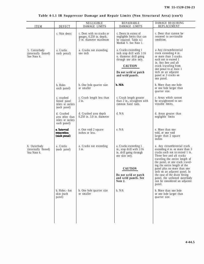
TM 55-1520-236-23
Table 4-1.1 IR Suppressor Damage and Repair Limits (Non Structural Area) (con’t)
ITEM
5. Centerbody(internally finned)See Note 4.
6. Outerbody(internally finned)Sea Note 4.
DEFECT
c. Skin dents
a. Crackseach penal)
b. Holeseach panel)
c. crushedfinned panelinlets or outlets(each panel)
d. Crushedarea other thaninlets or outletseach panel)
a. Cracks(each panel)
b. Holes - hotskin (eachpanel)
NEGLIGIBLEDAMAGE LIMITS
c. Dent with no cracks orgouges, 0.250 in. depth,3 in. diameter maximum
a. Cracks not exceedingone inch
b. One hole quarter sizeor smaller
c. Crush length less than2 in.
d. Crushed area depth0.250 in. 3.0 in. diameter
e. One void 2 squareinches or less.
a. Cracks not exceeding1 in.
b. One hole quarter sizeor smaller
REPAIRABLEDAMAGE LIMITS
c. Dents in excess ofnegligible limits that canbe repaired. Table 4.1Method V. See Note 1.
a. Cracks exceeding 1inch stop drill with 1/16n. diameter drill goingthrough one akin only.
CAUTION
Do not weld or patchand weld panels.
c. Crush length greaterthan 2 in., straighten withcommon hand tools.
d. N/A
e. N/A
a. Cracks exceeding 1in., stop drill with 1/16in. drill going throughone skin only.
CAUTION
Do not weld or patchand weld panels. SeeNote 2.
b. N/A
DAMAGE REQUIRINGREPLACEMENT
c. Dent that cannot berestored to serviceablecondition.
a Any circumferentialcrack exceeding 4 in.or more than 3 crackseach not to exceed 1in. Any fore and aftcrack traveling fromone penal to at least 1inch on an adjacentpanel or 3 cracks onone panel.
b. More than one holeor one hole larger thanquarter size.
c. Areas which cannotbe straightened to ser-viceable limits.
d. Areas greater thannegligible limits
e. More than onevoid, or one voidlarger than 2 squareinches
a. Any circumferential crackexceeding 4 in. or more than 3cracks each not to exceed 1 in.Three fore and aft crackstraveling the entire length ofthe panel, or one crack travel-ing the entire length of thepanel plus no more than oneinch on an adjacent panel. Inthe case of the drain fittingpanel, the unfinned outerbodycan be considered an adjacentpanel.
b. More than one holeor one hole larger thanquarter size.
4-44.5

TM 55-1520-236-23
Table 4-1.1 IR Suppressor Damage and Repair Limits (Non Structural Area) (Con’t)
ITEM
7. Externally finnedaluminum sectionof suppressorassembly.
DEFECT
c. Holes -coolskin (eachpanel)
d. Crushedfinned panal in-lets outlets(each panel)
D. Crushedfinned areaother than in-lets & outlets(each pad)
f. Internalseparation(each panel)
a. Loose rivets
b. skin dents
c. skin Cracks
NEGLIGIBLEDAMAGE LIMITS
c. No more than 3 holeseach less than 0.312 in.diameter
d. Crushed length lamthan 2 in.
e. Crushed area depth0.25 in. 3.0 in. diametermaximum
f. Voids 2 square inchesor less
a. Three loose/missing. .rivets. No more than 2adjacent.
b. Dents with no cracksor gouges: Depth 0.250inch: Diameter 3.0 inch.
c. Cracks not exceeding1 inch in length and non-branching.
d. Fins bent or crushedso as to impede air flowbetween fin rows lessthan 60 linear inches parquadrant. See Note 3.
REPAIRABLEDAMAGE LIMITS
c. Less than 5 holestotal, each less than 1 in. diameter-patch. SeeTable 4-1, Method V.
d. Crushed lengthgreater than 2 in.straighten Withcommon tools
e. N/A
f. N/A
a. If more than 3remove and replaceloose rivets and replacemissing rivets. Table 4-1,Method VIII.
b. Dents in excess ofserviceable limits thatcan be straightened.
c. Branching cracks andcracks less than 4 inchesin length that can becontained by stop drill-ing at each and.
d. See Note 3.
DAMAGE REQUIRINGREPLACEMENT
c. Holes greater than 1in. diameter or morethan 5 holes
d. Areas which cannotbe straightened to ser-viceable limits
e. Areas greater thannegligible limits
f. More than one avoidor one void larger than2 square inches
a. Three missing rivetsthat cannot be replacedper Table 4-1,Method VIII. No morethan 2 adjacent.
b. Dents that cannotbe restored to ser-viceable limits.
c. Damage exceedsrepeirable limits.
d. Bent fins in excessof negligible limits.
4-44.6
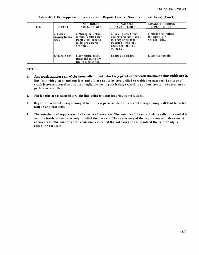
TM 55-1520-236-23
Table 4-1.1 IR Suppressor Damage and Repair Limits (Non Structural Area) (Con’t)
ITEM
NOTES:
1.
2.
3.
4.
DEFECT
e. Loose or
tions.
f. Cracked fins
NEGLIGIBLEDAMAGE LIMITS
e. Missing fin sectionscovering a total linearlength of less than 60inches per quadrant.See Note 3.
f. Any vertical crack.Horizontal cracks aretreated as loose fins.
REPAIRABLEDAMAGE LIMITS
e. Fins separated fromduct skin for more than 1inch may be cut to themaximum serviceablelimits. See Table 4-1,Method VI.
f. Same as loose fins.
DAMAGE REQUIRINGREPLACEMENT
e. Missing fin sectionsin excess of ser-viceable limits.
f. Same as loose fins.
line (aft) with a strut and run fore and aft, are not to be stop drilled or welded or patched. This type ofcrack is nonstructural and causes negligible cooling air leakage which is not detrimental to operation orperformance of Unit.
Fin lengths are measured straight line point to point ignoring convolutions.
Repair of localized straightening of bent fins is permissible but repeated straightening will lead to metalfatigue and cracking.
The outerbody of suppressor shall consist of two areas. The outside of the outerbody is called the cool skinand the inside of the outerbody is called the hot skin. The centerbody of the suppressor will also consistof two areas. The outside of the centerbody is called the hot skin and the inside of the centerbody iscalled the cool skin.
4-44.7

TM 55-1520-236-23
Table 4-1.2 IR Suppressor Damage and Repair Limits (Major Structured Elements Only)(See Figure 4-17.1)
ITEM
1. Plug-strut clip(Outer)
2. channel &Clips
DEFECT
a. Cracks inplug strut clipfrom brazerelief hole tooutboard edgeof clip.
b. Cracks inplug-strut clipfrom inboardedge, thru thebraze reliefhole and contin-uing totlleoutboard edgeof clip.
c. Crack inplug-strut clipto plug com-pound contourpanel joint.
a. Cracks inchannel frombraze reliefhole to out-board cap.
b. Cracks inchannel frominboard edgethru brazerelief hole andcontinuing tothe outboardcap.
NEGLIGIBLEDAMAGE LIMITS
a. One clip per strutmay be cracked (max-imum 4 clips cracked).One strut may havecracks in both clipswhile any other strutmay have 1 clip cracked(maximum 3 clips cracked).
b. A maximum of 2non-adjacent clips maybe cracked.
c. A maximum of 2non-adjacent joints maybe affectively cut.
II
a. One channel perstrut may be cracked(maximum of 4channels cracked). onestrut may have bothchannels cracked whileany 2 of the remaining(non-adjacent) channelsmay be cracked (max-imum of 4 channelscracked).
b. A maximum of 2non-adjacent channelsmay be cracked.
REPAIRABLEDAMAGE LIMITS
a. Cracks in excess ofnegligible damage limitmust be weld repairedprior to next flight. SeeTable 4-1, Method IV.
b. Cracks in excess ofnegligible damage limitmust be weld repairedprior to next flight. SeeTable 4-1, Method IV.
c. Not repairable.
a. Damage in excess ofthe negligible damagelimit must be weldrepaired prior to thenext flight. See Table4-1, Method IV.
b. Damage in excess ofthe negligible damagelimit must be weldrepaired prior to thenext flight See Table 4-1, Method IV.
I
I
II
I
DAMAGE REQUIRINGREPLACEMENT
a. N./A
b. N/A
c. Damage in excessof the negligibledamage limit.
a. N/A
b. N/A
4-44.8

TM 55-1520-236-23
Table 4-1.2. IR Suppressor Damage and Repair Limits (Major Structural Elements Only) (con’t)(See Figure 4-17.1)
ITEM
3. Struts (Aft Por-tion) (Hot Skin)
4. Main MountRing & Bracket
5. Plug-Strut Clip(Inner)
6. Braze Joint
DEFECT
c. Cracksalong the junc-tion of thechannels andthe mainmount ring.
a. Cracks
b. Holes
a. Cracks
a. Cracks
a. Crack in thebraze alloyjoining two sur-faces.
NEGLIGIBLEDAMAGE LIMITS
c. A maximum of 2non-adjacent channeljunctures may be cracked.
a. Cracks not exceeding1 inch and non-branching in any 1 or allakin surfaces.
b. No more than 3 holeseach lace than 0.312 inchdiameter.
a. Cracks which effec-tively eliminate any onefastener.
a. A maximum of 2non-adjacent clips maybe cracked through. Amaximum of 4 clips maybe partially cracked.
a. Up to 50% ofperimeter of joint.
REPAIRABLEDAMAGE LIMITS
c. Damage in excess ofthe negligible damagelimit must be weldrepaired prior to thenext flight. See Table 4-1, Method IV.
a. Branching or cracks 1to 3 inches in length innot more than 1 skin perstrut, not more than 2struts, must be stop drilledprior to next flight.
b. Less than 5 holes totaleach less than 1 inchdiameter - patch. SeeTable 4-1, Method V.
a. Cracks which effec-tively eliminate morethan 1 fastener must bepatched and weldrepaired prior to nextfright. See Table 4-1,Method V.
a. Damage in excess ofnegligible limits shall beweld repaired. SeeTable 4-1, Method IV.
a. Greater than 50% ofperimeter of joint, weldrepair. See Table 4-1,Method VII. See Note 1.
DAMAGE REQUIRINGREPLACEMENT
c. N/A
b. Holes greater than 1inch diameter or in ex-cess of 5 holes.
a. N/A
a. N/A
a. N/A
4-44.9
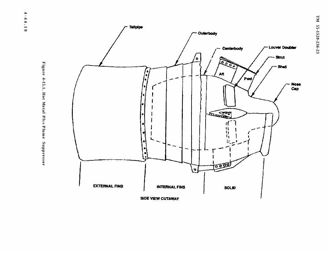
TM
55-1520-236-23
Figu
re 4-15.1. Hot M
etal PlU
S P
lum
e S
up
pressor
4-4
4.1
0
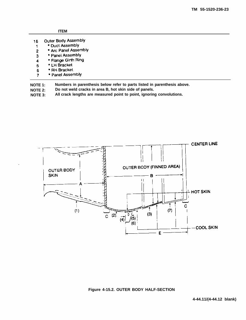
TM 55-1520-236-23
ITEM
NOTE 1: Numbers in parenthesis below refer to parts listed in parenthesis above.NOTE 2: Do not weld cracks in area B, hot skin side of panels.NOTE 3: All crack lengths are measured point to point, ignoring convolutions.
Figure 4-15.2. OUTER BODY HALF-SECTION
4-44.11/(4-44.12 blank)


TM 55-1520-236-23
Figure 4-16. Repair Procedures — Infrared Suppression System
4-45

TM 55-1520-236-23
4-51. INSTALLATION –SUPPRESSION SYSTEM.
Use extreme care in positioning the aftduct assembly (5, figure 4-15). Failure todo so will damage gasket.
a. Position aft duct assembly (5) on rear flange offairing (4) with lower external supports extendingover external supports mounted on the fairingtransition section. Support aft duct assembly with 12bolts and washers (18 and 19). Position fairingassembly (7) in place and secure to aft duct (5) andfairing (4) with 10 bolts and washers (16 and 17).
b. Position exhaust extension (3) inside fairingand mount to forward section of duct assembly (5)with nuts (14) and washers (15) on Iockpins (20).
IR Premaintenance Requirements forIR Suppression System
Install forward duct assembly (2) on forwardsection of exhaust extension (3) and install bolts (13)and washers (12).
d. Place fairing (4) with extension (3) and ductassemblies (2 and 5) installed, in place and overtailpipe (1). Engage fasteners around tailpipe fairing.
e. Connect drain line (6) to fitting on tailpipe.
4 - 5 2 . I N F R A R E D ( I R )SUPPRESSION SYSTEM.
4-53. D E S C R I P T I O N – I RSUPPRESSION SYSTEM.
The exhaust system on coded (modernized)helicopters is an infrared suppression systemcomprised of the following major components:infrared suppressor, engine exhaust duct assembly,and infrared suppressor cowling (figure 4-17). Theengine exhaust diffuser on the rear of the enginedirects the engine exhaust gases into the exhaustduct and IR suppressor. To aid in exhaustcompartment cooling, a heat shield is mountedaround the end of the diffuser. The exhaust duct iscovered with a Hi-temp insulating blanket, The IRsuppressor and exhaust duct act as an ejector. mixingambient air with exhaust gases. The exhaust duct andheat shield are mounted on flanges of the diffuserwith V-band clamps. A countermeasures set isincorporated into the system (TM 11-1520-236-20).
Condition Requirements
Model AH-1S
Part No. or Serial No. All
Special Tools None
Test Equipment None
Support Equipment None
Minimum Personnel TwoRequired
Consumable Materials (C14), (C33), (C74),(C97)
Special Environmental NoneConditions
4-54. R E M O V A L – I R S U P P R E S S I O NSYSTEM .
a. Remove both panels from IR suppressorcowling (7, figure 4-17).
b. Disconnect drain lines (10).
C. Disconnect countermeasures set (1) electricalcable connectors located on aft firewall.
Support suppressor (2, figure 4-17)during removal. Improper handling candamage external cooling cores.
d. Remove eight bolts (4) and washers (5).
e. Remove suppressor (2) from cowling (7).
f. Remove cotter pins, washers and clevis pinsfrom cowling (7) mounts. Remove bolts and washersthat attach lower forward section of cowling frame(chapter 2).
g. Release top cowling latch and turnlockfasteners.
4-46

TM 55-1520-236-23
Figure 4-17. Exhaust System Components With IR Suppression — Installation
4-47
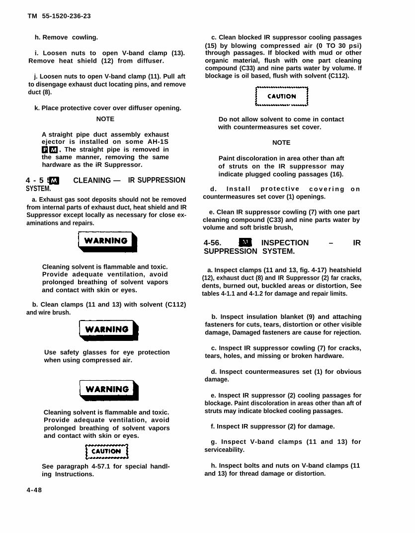
TM 55-1520-236-23
h. Remove cowling.
i. Loosen nuts to open V-band clamp (13).Remove heat shield (12) from diffuser.
j. Loosen nuts to open V-band clamp (11). Pull aftto disengage exhaust duct locating pins, and removeduct (8).
k. Place protective cover over diffuser opening.
NOTE
A straight pipe duct assembly exhaustejector is installed on some AH-1S . The straight pipe is removed inthe same manner, removing the samehardware as the iR Suppressor.
4 - 5 5 . CLEANING — IR SUPPRESSIONSYSTEM.
a. Exhaust gas soot deposits should not be removedfrom internal parts of exhaust duct, heat shield and IRSuppressor except Iocally as necessary for close ex-aminations and repairs.
Cleaning solvent is flammable and toxic.Provide adequate ventilation, avoidprolonged breathing of solvent vaporsand contact with skin or eyes.
b. Clean clamps (11 and 13) with solvent (C112)and wire brush.
Use safety glasses for eye protectionwhen using compressed air.
Cleaning solvent is flammable and toxic.Provide adequate ventilation, avoidprolonged breathing of solvent vaporsand contact with skin or eyes.
See paragraph 4-57.1 for special handl-ing Instructions.
4-48
c. Clean blocked IR suppressor cooling passages(15) by blowing compressed air (0 TO 30 psi)through passages. If blocked with mud or otherorganic material, flush with one part cleaningcompound (C33) and nine parts water by volume. Ifblockage is oil based, flush with solvent (C112).
Do not allow solvent to come in contactwith countermeasures set cover.
NOTE
Paint discoloration in area other than aftof struts on the IR suppressor mayindicate plugged cooling passages (16).
d. Insta l l protect ive c o v e r i n g o ncountermeasures set cover (1) openings.
e. Clean IR suppressor cowling (7) with one partcleaning compound (C33) and nine parts water byvolume and soft bristle brush,
4-56. INSPECTION – IRSUPPRESSION SYSTEM.
a. Inspect clamps (11 and 13, fig. 4-17) heatshield(12), exhaust duct (8) and IR Suppressor (2) far cracks,dents, burned out, buckled areas or distortion, Seetables 4-1.1 and 4-1.2 for damage and repair limits.
b. Inspect insulation blanket (9) and attachingfasteners for cuts, tears, distortion or other visibledamage, Damaged fasteners are cause for rejection.
c. Inspect IR suppressor cowling (7) for cracks,tears, holes, and missing or broken hardware.
d. Inspect countermeasures set (1) for obviousdamage.
e. Inspect IR suppressor (2) cooling passages forblockage. Paint discoloration in areas other than aft ofstruts may indicate blocked cooling passages.
f. Inspect IR suppressor (2) for damage.
g. Inspect V-band clamps (11 and 13) forserviceability.
h. Inspect bolts and nuts on V-band clamps (11and 13) for thread damage or distortion.

TM 55-1520-236-23
4-57 . REPAIR- IR SUPPRESSION SYS-TEM. (AVIM)
a. Replace exhaust system V-band clamps (11 and13, figure 417) if damaged.
b. Replace damaged insulation blanket (9).
c. Replace heatshield (12) if cracks, holes or dentscannot be repaired.
d. Exhaust duct.
(1) Shallow dents and scratches are accept-able. Deep dents must be repaired by same methodas outlined for holes.
(2) Repair cracks three inches long or lessby welding. Grind weld as smooth as possible tomatch contour of duct.
(3) Cracks in excess of three inches, tears,small holes, and deep dents are acceptable if repairedby welding on patches.
(4) Replace duct if damaged beyond repairlimitations.
e. IR suppresseor.
(1) Refer to table 4-1 for repair method.Fabricate patches for repair of unfinned suppressorarea from 0.040 stainless steel (MIL-S-6721 Comp347). Patch internal finned panel section with 0.020stainless steel (MIL-S-6721 Comp 347).
(2) Repaint discolored painted areas, otherthan area aft of struts, after cleaning blocked coolingpassages (TB 746-93-2).
(3) Replace Nose Cap, inapplicable, (17, Fig-ure 4-17).
(4) Replace Forward Inner Shell, if ap-plicable, (18, Figure 4-17).
(5) Replace Reinforcement Sleeve, if ap-plicable, (19, Figure 4-17).
f. To replace broken or damaged cowling nutplates, refer to paragraph 2-19d.
4-57.1. HANDLING INSTRUCTIONS
NOTEThe finned surfaces of tailpipe as-sembly are susceptible to physicaldamage and require careful handling.
a. Removal of suppressor from the carton shouldbe done by two people. After top of carton has beenopened and tailpipe packing plug removed, lift outercarton vertically until the suppressor has beencleared.
b. Before removing suppressor from lower carton,a provision should be made for a suppressor supportto receive the nose cone and allow the suppressor tostared fully supported in a vertical position, or for aprotective support blanket on which to lay the suppresser in a horizontal position.
c. After first carton has been opened, the foambase used in shipping carton to support suppressormay be used as a support base. The cardboard linersurrounding the suppressor has no bottom and maybe removed by lifting vertically in the same manneras the outer carton. This will leave the suppressorexposed from the mounting ring aft.
d. Using mounting that rests on four cardboardsupports, lift suppressor from carton by placing handinside of duct and thumb on lip of duct.
e. Suppressor should be rotated by two people,lifting it clear of its support. Do not roll suppressorin the horizontal position or along the aft edge oftailpipe.
f. Suppressor may be placed in upright positionfor inspection using care not to damage aft fins ontailpipe.
g. When installing suppressor on aircraft, thesupport sling should not be placed on tailpipe.
h. Tailpipe cover should be removed and installedwith care to prevent snagging of fins.
i. For inspection refer to tables 4-1.1 and 4-1.2.
4-58. I N S T A L L A T I O N - I R S U P P R E S S I O NSYSTEM.
a. Seal all open areas between base of forwardand aft firewall and engine deck (figure 4-14). Usesealant (C105).
b. Remove protective cover from engine diffuser.
c. Install insulation blanket (9, figure 4-17). Laceblanket on top side of exhaust duct (8) using zig-zagpattern.
4-49
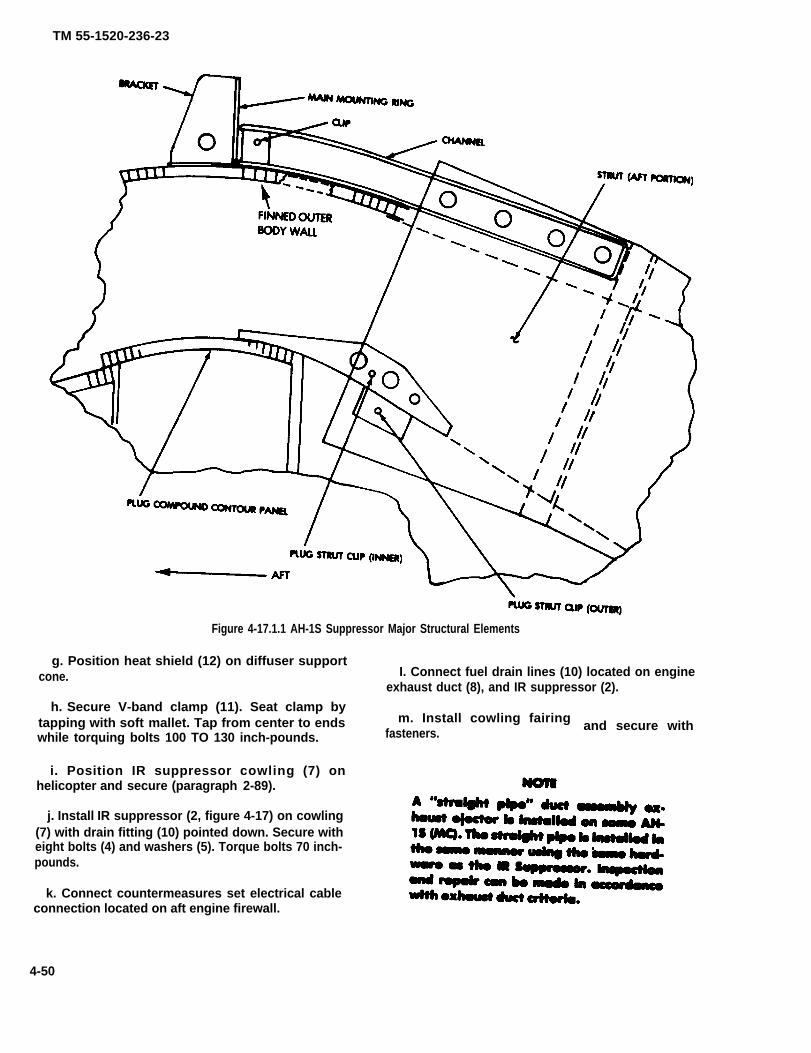
TM 55-1520-236-23
Figure 4-17.1.1 AH-1S Suppressor Major Structural Elements
g. Position heat shield (12) on diffuser supportI. Connect fuel drain lines (10) located on enginecone.
exhaust duct (8), and IR suppressor (2).
h. Secure V-band clamp (11). Seat clamp bytapping with soft mallet. Tap from center to endswhile torquing bolts 100 TO 130 inch-pounds.
i. Position IR suppressor cowling (7) onhelicopter and secure (paragraph 2-89).
m. Install cowling fairingfasteners. and secure with
j. Install IR suppressor (2, figure 4-17) on cowling(7) with drain fitting (10) pointed down. Secure witheight bolts (4) and washers (5). Torque bolts 70 inch-pounds.
k. Connect countermeasures set electrical cableconnection located on aft engine firewall.
4-50
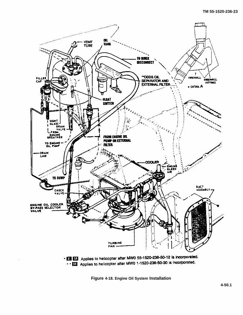
TM 55-1520-236-23
Figure 4-18. Engine Oil System Installation
4-50.1

TM 55-1520-236-23
d. Position exhaust duct (8) on flange of diffuser (9, of damp to ends. Torque damp nuts 100 TO 130 inch-figure 4-15) with drain fitting (10, figure 4-17) pointed pounds.down.
e. Engage exhaust duct (8) locating dowels withNOTE
diffuser.Torque on V-band clamps (11 and 13)
f. Secure mating flange with V-band damp (13). must be rechecked after first engineSeat clamp by tapping with soft mallet. Tap from center runs.
SECTION V. OIL SYSTEM
4-59. OIL SYSTEM.
4-60. DESCRIPTION - OIL SYSTEM. (GENER-AL)
Oil is supplied to the engine from a self-sealing tankmounted in the aft fairing above the engine (figure4-18). After passing through the engine, oil is deliveredfrom the scavenge side of the engine oil pump to a by-pass mounted on the engine compartment deck at leftside. In normal operation, oil passes through the oilcooler and then returns to the tank. The coder ismounted below an engine deck opening, under a metalplenum. Cooling air is drawn in through a screened ducton left side of the fuselage up through the cooler, thenaft to pass out through screened openings of the tailpipefairing. A turbine fan driven by engine bleed air ismounted under the cooler. The engine oil cooler bypassselector valve (figure 4-18) is controlled by a float switchin the oil tank and the ENG OIL BYP switch on the pilotconsole. If oil level in the tank becomes low enough tooperate the float switch, (3.8 quarts low from spill over)the ENG OIL BYPASS caution panel segment will light,and the valve will automatically shut off flowfothecoolerand return engine oil directly to the tank. The pilot canuse his switch to reopen the valve and use oil coolingwhen conditions warrant such action. The engine oilcooler temperature regulating valve, mounted in the oilcooler, automatically bypasses the oil cooler core whenoil is cold. A chip detector drain plug at lower right onaccessory gear box is wired to the ENGINE CHIP cau-tion light.
4-60.1 AIRCRAFT EQUIPPED WITH OIL DEBRISDETECTION SYSTEM (ODDS).
a. The primary benefit of ODDS system is improvedfiltration of the engine and main transmission lubrication
systems. The ODDS system is designed to provideearly identification of potential component failures. Finefiltration (3 micron) increases system life by removingoil-borne particles which cause wear in the component.Analysis shows that catastrophic failure modes that aredetected through spectrometric oil analysis(SOA)/AOAP will be detected by the ODDS system chipdetectors. The ODDS equipped engine and main trans-ission do not require routing oil sampling. Spectrometricoil analysis (SOA)/AOAP measures concentrations ofwear metal debris in the three to ten micron range. Notenough debris of significant size particles exist to allowan accurate indication of wear metal concentration byspectrometric analysis. Therefore routine oil samplingis not required or authorized.
b. Although routine oil sampling of the engine andmain transmission on ODDS equipped aircraft is notrequired or authorized, samples may be taken in theevent of a chip light, and provided along with chip detec-tor debris to an AOAP lab for analysis using ferrographyor similar techniques. The results of this analysis will beused with the oil debris classification chart guidelines todetermine the serviceability of the component.
c. Replacement of ODDS equipped engine andmain transmission external oil filters are preformed “ONCONDITION” (as required by maintenance actions-such as bypass buttons, major component change,etc...). Since operation of fine filtration deans the lubri-cant in the component, do not replace lubricant whenreplacing the filter. Flushing and filtering of ODDS sys-tem and lubricant change is not required or authorized.Flushing, filtering, and lubricant change is only doneduring replacement of engine or main transmission.
d. During the modification of aircraft I.A.W. MWO1-1520-236-50-30 (ODDS) chip detectors in the 42-and 90-degree gearbox were changed, they are notpart of the ODDS oil filtering system and still require(SOA)/AOAP samples and inspections.
4-50.2
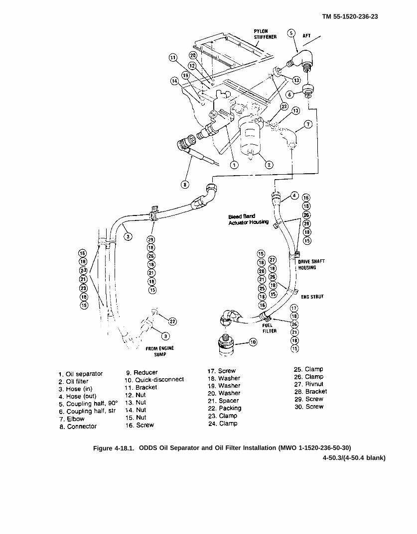
TM 55-1520-236-23
Figure 4-18.1. ODDS Oil Separator and Oil Filter Installation (MWO 1-1520-236-50-30)
4-50.3/(4-50.4 blank)


TM 55-1520-236-23
4-61. TROUBLESHOOTING - OILSYSTEM.
Use troubleshooting chart (table 4-2) in conjunction withoil system schematic (figure 4-19) to locate and correctmalfunctions in the engine oil system.
NOTE
Before using this table, be sure allnormal operational checks havebeen performed. In event of amalfunction which is not listed inthis table, notify the next higherlevel of maintenance.
Table 4-2. Troubleshooting Engine Oil System
CONDITION
TEST OR INSPECTION
Corrective ACTION
Do not operate engine until it is determined that oil pump failure or oil starvation has notoccurred.
1. No engine oil pressure.
STEP 1. Ensure that tank is filled to proper level. Fill tank to proper level if required (paragraph 1-4).
STEP 2. Check for loose connection and/or clogged hose. Inspect entire lubrication system for leaks andobstruction. Pay particular attention to quick disconnect fittings (figure 4-20).
STEP 3. Check for proper operation of oil pressure transmitting system.
Check system using pressure source at pressure tap. Replace oil pressure transducer if faulty.Replace oil pressure indicator if faulty. Check continuityand indicator (paragraph 9-229).
of wiring circuit between transducer
STEP 4. Check that oil pump coupling is not sheared and female spline on oil pump driveshaft gear is not worn.
4-51
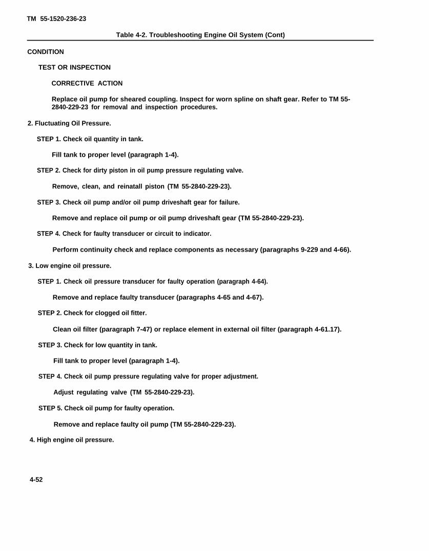
TM 55-1520-236-23
Table 4-2. Troubleshooting Engine Oil System (Cont)
CONDITION
TEST OR INSPECTION
CORRECTIVE ACTION
Replace oil pump for sheared coupling. Inspect for worn spline on shaft gear. Refer to TM 55-2840-229-23 for removal and inspection procedures.
2. Fluctuating Oil Pressure.
STEP 1. Check oil quantity in tank.
Fill tank to proper level (paragraph 1-4).
STEP 2. Check for dirty piston in oil pump pressure regulating valve.
Remove, clean, and reinatall piston (TM 55-2840-229-23).
STEP 3. Check oil pump and/or oil pump driveshaft gear for failure.
Remove and replace oil pump or oil pump driveshaft gear (TM 55-2840-229-23).
STEP 4. Check for faulty transducer or circuit to indicator.
Perform continuity check and replace components as necessary (paragraphs 9-229 and 4-66).
3. Low engine oil pressure.
STEP 1. Check oil pressure transducer for faulty operation (paragraph 4-64).
Remove and replace faulty transducer (paragraphs 4-65 and 4-67).
STEP 2. Check for clogged oil fitter.
Clean oil filter (paragraph 7-47) or replace element in external oil filter (paragraph 4-61.17).
STEP 3. Check for low quantity in tank.
Fill tank to proper level (paragraph 1-4).
STEP 4. Check oil pump pressure regulating valve for proper adjustment.
Adjust regulating valve (TM 55-2840-229-23).
STEP 5. Check oil pump for faulty operation.
Remove and replace faulty oil pump (TM 55-2840-229-23).
4. High engine oil pressure.
4-52

TM 55-1520-236-29
STEP 1. Check for restrictions in oil flow lines.
NOTE
Oil pressure transducers may foil to either the high or low stole level of cockpit pressuregage. Test engine oil pressure transducer with o direct reading pressure gage before rnak-ing any adjustments to engine oil pressure.
4-52.1/(4-52.2 blank)

TM 55-1520-236-23
Table 4-2. Troubleshooting Engine Oil System (Cont)
CONDITIONTEST OR INSPECTION
CORRECTIVE ACTION
Check quick disconnect couplings for proper connections.Clear oil lines of restrictions (figure 4-20).
STEP 2. Check oil pump pressure regulating valve for proper adjustment.
Adjust regulating valve. (TM 55-2840-229-23.)
STEP 3. Check oil pressure transducer for faulty operation (paragraph 4-64).
Remove and replace faulty oil pressure transducer (paragraphs 4-65 and 4-67).
NOTE
High engine oil pressure may be due to cold oil on start. Allow engine to reach operating temperature byoperating engine at idle.
5. High engine oil temperature.
STEP 1. Ensure that cooling air inlet is not blocked.
Inspect screened inlet and remove all gross, leaves and other foreign material. Also check coder core airpassage and remove any grass dirt or other foreign material (paragraph 4-79).
STEP 2. Ensure that oil cooler blower is operating correctly.
Check for proper blower operation. Repair and replace as necessary (paragraph 4-89).
STEP 3. Check that temperature regulating valve (20, figure 4-21) is not stuck in bypass position (paragraphs 4-79and 4-80).
If valve is stuck in bypass position, remove and replace valve or oil cooler (paragraph 4-81).
STEP 4. Check that emergency bypass is not stuck in bypass position.
If valve is stuck in bypass position, remove and replace valve (paragraphs 4-94 and 4-97).
STEP 5. Check engine oil level.
Fill tank to proper level (paragraph 1-4).
STEP 6. Ensure that temperature indicating system is operating correctly.
Check operation of oil temperature indicator, resistance bulb and related circultry. Replace faultycomponents (paragraph 8-57).
STEP 7. Check for bleed air leak between engine and oil cooler turbine fan.
Isolate and correct any leaks (figure 4-18).
4 - 5 3

TM 55-1520-236-23
Table 4-2. Troubleshooting Engine Oil System (Cont)
CONDITION
TEST OR INSPECTION
CORRECTIVE ACTION
STEP 8. Check operation of low level emergency system float switch in oil tank (paragraph 4-70).
Replace faulty float switch in oil tank (paragraph 4-71).
6. Low oil temperature.
STEP 1. Check operation of temperature indicating system.
Check operation of oil temperature indicator, resistance bulb. and related circuitry. Replace faultycomponents (paragraph 8-57).
STEP 2. Check that engine oil cooler bypass selector valve (figure 4-18) is not stuck in bypass position.
Replace oil cooler (paragraph 4-81).
7. No oil temperature.
STEP 1. Check operation of temperature indicating system
Check operation of oil temperature indicator, resistancecomponents (paragraph 8-57).
8. Excessive engine oil consumption.
STEP 1. Check for leakage at fittings and hose connection.
Tighten or replace fittings or hose assemblies.
NOTE
bulb, and related circuitry. Replace faulty
Refer to TM 55-2840-229-23 for additional excessive engine oil consumption troubleshootingprocedures.
4-61.1. EXTERNAL OIL SEPARATOR(LUBRICLONE) (Helicopters with MWO 1-1520-236-50-30)
4-61.2. DESCRIPTION. A cyclonic oil separator andmonitor (Lubriclone) (23.2, figure 4-4) is mountedoverhead on bracket on firewall of engine compartment.Oil from engine sump enters tangential port, causingvortex flow in main chamber. Flow swirls particlesoutward and downward to small trap which contains
chip detector. Oil exits at top and flows to external filter.Magnets in chip detector draw ferrous particles into thechip gap, where they are sensed and pulsed by oildebris detection system (ODDS). Small chips arepulsed (burned) away. Larger chips bridge a gap tolight ENG CHIP caution light. Oil separator captures allparticles over 100 microns and a proportion of particlesbetween 15 and 100 microns which increases almostlinearly with size.
4-54
TM 55-1520-236-23
4-61.3. REPLACEMENT OF DRAIN VALVE - OILSEPARATOR. Proceed as follows: (figure 4-19.1)
a. Access oil separator by opening engine cowling.
b. Place container below oil separator to catch oil.Drain oil using drain valve (8).
c. Remove body of drain valve (8) and packings (7and 15).
d. Install replacement body and new packing (7).Torque body to 16-20 inch pounds. Lockwire (C137)body.
e. Install new packing (15) on body.
f. Install cap on drain valve. Torque cap to 20-25inch-pounds. Lockwire (C137) cap.
g. Service system with oil (paragraph 1-4).
4-61.4. REMOVAL - OIL SEPARATOR.
a. Access oil separator by opening engine cowling.
b. Disconnect connector (8, figure 4-18.1) from chipdetector probe.
c. Place container below oil separator to catch oil.Remove Iockwire and cap of drain valve (8, figure 4-19.1). Drain oil.
Make sure torques applied to fit-tings and hoses are not applied toports or oil separator. Oil separatorcan be damaged.
d. Disconnect hose (3, figure 4-18.1) and couplinghalf (5) from coupling half (6) in inlet (aft) port.
e. Disconnect zero - clearance fitting of oil filter atfitting (6, figure 4-19.1) in outlet (right) port and discardpacking (4).
f. Remove eight nuts (14, figure 4-18.1) and washers(19) and lower bracket (11).
g. Remove three bolts (2, figure 4-19.1), and washers(3) and remove oil separator.
i. Inspect for serviceability and for cracks, particularlyat ports and mounting holes.
j. If oil separator is to be replaced, disassemble asfollows:
(1) Remove fitting (6) and packing (5) from outletport. Remove coupling half (6, figure 4-18.1), nut (13),and packing (22) from inlet port. Discard packing.
(2) Remove body of drain valve (8, figure 4-19.1)and packings (7 and 15). Discard packings.
(3) Remove probe (14), body (12), cup (10), spring(9), and packings (13 and 11). Discard packings.
4-61.5. INSTALLATION - OIL SEPARATOR
Make sure torques applied to fit-tings and hoses are not applied toports or oil separator. Oil separatorcan be damaged.
a. If oil separator is a replacement, assemble asfollows:
(1) Install spring (9, figure 4-19.1), small end first,cup (10), packing (11), and body (12). Torque body to32-38 inch-pounds and Iockwire (C137). Installpacking (13) and probe (14).
(2) Install packing (7) and body of drain valve (8).Torque body to 16-20 inch-pounds and Iockwire(C137).
(3) Install fitting (6) and new packings (4 and 5) inoutlet (right) port. Install packing (22, figure 4-18.1), nut(13), and coupling half (6) in inlet (aft) port.
b. Position oil separator below mount bracket (1,figure 4-19.1), outlet fitting inboard.
c. Install washers (3), and bolts (2). Torque bolts to74-82 inch-pounds.
d. Position bracket (11, figure 4-18.1) on threadedstuds of pylon stiffener and install eight washers (19)and nuts (14). Torque nuts to 120 to 140 inch-pounds.
e. (See figure 4-19.1.) Connect zero - clearancefitting of oil filter to fitting (6).
h. Clean oil separator. Use solvent (C112) and cleancloths.
4-54.1
TM 55-1520-236-23
f. Install packing (15) on body of drain valve (8) andinstall cap. Torque cap to 20-25 inch-pounds. Lock-wire (C137) cap.
g. Connect cable to chip detector probe (14).
h. Connect hose (3, figure 4-18.1) and coupling half(6) to coupling half (5).
i. Lockwire (C137) mounting bolts and cable plug.
j. Service system with oil (paragraph 14) andcheck for leaks at first runup (TM 55-1520-236-10).
4-61.6. OIL SEPARATOR CHIPDETECTOR (HELlCOPTERS WITH MWO 1-1 5 2 0 - 2 3 6 - 5 0 - 3 0 )
4-61.7. DESCRlPTlON - CHIP DETECTOR. A mag-netic chip detector (14, figure 4-19.1) is installed in self-dosing valve in bottom of oil separator. Chip detector isconnected to power module which pulses away nuisancechips and to ENG CHIP caution capsule in caution panel.
4-61.8. INSPECTION - CHIP DETECTOR.
NOTE
Chip detector is Inspected when ENGCHIP caution light comes on.
a. Disconnect cable plug from chip detector probe(14, figure 4-19.1)
4-61.8.1. ENGINE OIL CONTAMINATION TROU-BLESHOOTING (HELICOPTERS WITHOUT MWO 1-1520-236-50-30) (ODDS)
a. If an excessive amount of chips is found on engineoil filter element chip detector, (figure 6-2, 6-2.1 andtable 6-1.1) but output reduction carrier and gear assem-bly has freedom of movement and emits no unusualnoises, proceed as outlined in steps (1) through (5). Ifcontamination is caused by carbon particles, refer to step(6).
(1) Remove chips from engine internal oil filterelement and retain for analysis. Clean filter element andreinstall.
(2) Drain all oil from accessory drive gearbox, oiltank, and oil cooler.
(3) Remove and inspect strainer for No. 2 bearingand strainer for No. 3 and 4 bearings for metal chips. Ifchips are present, remove and inspect three reductiongear oil transfer tube strainers and overspeed governorand tachometer drive oil throttle strainer. If metal chipshave dogged more than one-third of flow area of anystrainer, forward engine to overhaul. If amount of metalchips is not excessive, dean and reinstall strainers andproceed to Step (4).
(4) Replace oil filter (TM 55-2840-229-23).Presence of chips in strainers indicates oil fitter has beenbypassed.
b. Remove chip detector probe. (5) Disconnect oil scavenge hose for No. 2 bear-ing and for No. 3 and 4 bearings and determine whetherresidual oil in these hose assemblies is contaminatedwith chips. If oil is contaminated, remove engine andforward to overhaul.
If fragment can be Identified as piece fromspecific part, replace engine. (6) If amount of carbon particles found on fitter
element is excessive, proceed as follows:c. Inspect chip gap of chip detector probe for par-
ticles. Retain particles. (Refer to paragraph 4-61.9.) (a) Drain oil from accessory drive gearbox,
Discard packing (13). oil tank and oil cooler.
d. Clean probe. Use dean cloths and cleaning sol- (b) Remove and inspect oil strainers for No.2 bearing and for No. 3 and 4 bearings. If carbon par-vent (C112).tides are present, oil fitter has been bypassed. Remove
e. install new packing (13) on chip detector probe clean, and reinstall reduction gear oil transfer tube strain-(14). ers and overspeed governor and tachometer drive oil
filter assembly (torquemeter). Clean and reinstall No. 2f. Install chip detector. and No. 3 and 4 bearing strainers.
g. Connect cable plug to chip detector and Iockwire (c) Clean and reinstall engine oil fitter assem-(C137). bly. (Refer to TM 55-2840-229-23.)
4-54.2

TM 55-1520-236-23
Figure 4-19. Engine Oil System Schematic4-54.3

TM 55-1520-236-23
Figure 4-19.1. Oil Separator (Lubriclone) Assembly
4-54.4

TM 55-1520-236-23
Table 4-2.1. Oil Debris Classification Chart (Aircraft with ODDS)
NOTEFigure 4-19.2 has been deleted.
4-54.5

TM 55-1520-236-23
4-61.9. ENGINE OIL CONTAMINATION TROU-BLESHOOTING (Helicopters with MWO 1-1520-236-50-30) (ODDS)
NOTE
It is very difficult to provide proceduresfor all types of chip light occurrences.Units should take full advantage of all in-formation available, such as DA Form2408-20 History, Oil Debris Classifica-tion Chart Supporting Oil Labs, CCADEngine Service Center, etc . . . . . . . . . .
NOTE
Determine the different types of dedrison the chip detector, since it is possibleto have more than one type of debris onthe chip detector. An example would bethe presence of both flakes and granuleson the chip detector. More than 10 flakesor more than 50 granule particles wouldbe cause for removal. Anycomponentcombination of less than 10 flakes and 50granules would be acceptable.
NOTE
Replacement of external oil filter onODDS aircraft is “ON CONDITION” andonly when associated impending bypassindicator button is extended (second re-set) or engine changed. The affectedchip detector should also be removedand inspected whenever the impendingbypass indicator button is extended.Shine fine filtration deans the Iubricantin the component, do not replace the lu-bricant when replang filter. Flushingand filtering of system (unless there is acomponent replacement) is not requiredor authorized as this may mask problemsand prevents trending of data.
a. In the event of engine chip light illumination:
(1) Inspect chip detector. If there are chips ondetector but output reduction carrier and gear assemblyhas freedom of movement and emits no unusal noises,proceed as outlined in steps (2) through (7):
(2) Remove chips from chip detector. Classifydebris I.A.W. Oil Debris Classification Chart (figure4-19.2). Document findings on DA Form 2408-20,block 7.
NOTE
More frequent chip lights may be en-countered in the first 50 hours of opera-tion of a component which has under-gone an overhaul or major repair, as wellas break-in wear debris being present inlube system. This type of debris is nor-mal and not indicative of a problem withODDS system.
(3) Remove and inspect strainer for no. 2 bear-ing and strainer for no. 3 and 4 bearings for metal chips.Classify debris I.A.W. Oil Debris Classification Chart(figure 4-19.2), Document findings on DA Form2408-20, block 7. If chips are present, remove andinspect three reduction gear oil transfer tube strainersand overspeed governor and tachometer drive oilthrottle strainer. If metal chips have dogged more thanone third of the flow area of any strainer classify debrisI.A.W. Oil Debris Classification Chart (figure 4-19.2).Document findings on DA Form 2408-20, block 7, andforward engine to overhaul. If amount of metal chips iswithin limits, classify debris I.A.W. Oil Debris Classifica-tion Chart (figure 4-19.2). Document findings on DAForm 2408-20, block 7, then dean and reinstall strain-ers.
(4) Disconnect oil scavenge hose for no. 2 bear-ing and for no. 3 and 4 bearings and determine whetherresidual oil in these hose assemblies is contaminatedwith chips. If oil is contaminated, classify debris I.A W.Oil Debris Classification Chart (figure 4-19.2). Docu-ment findings on DA Form 2408-20, block 7. Removeengine and forward to overhaul.
(5) If evaluation of debris does not require com-ponent removal, classify debris I.AW. Oil Debris Classi-fication Chart (figure 4-19.2). Document findings on DAForm 2408-20, block 7. Operate aircraft for one hour,(30 minutes flat pitch ground run and 30 minutes hoverin ground effect). Recheck drip detector. Classify de-bris I.A.W. Oil Debris Classification Chart (figure4-19.2). Document findings on DA Form 2408-20,block 7.
(6) If the number or size of debris has increasedremove defective component.
(7) If the number or size of debris decreases orremains the same return aircraft to service.
4-61.10. REMOVAL - CHIP DETECTOR PROBE.Remove chip detector probe (14, figure 4-19.1) as fol-lows:
a. Disconnect cable plug from chip detector.
b. Press probe (14) and turn counterclockwise toremove it.
4-54.6

TM 55-1520-236-23
4-61.11. REPLACEMENT OF SELF-SEALINGVALVE. Replace defective parts only (figure 4-19.1).
a. Remove chip detector probe (paragraph4-61.10).
b. Remove body (12), packing (11), cup (10), andspring (9). Discard packing.
c. Install spring (9), smaller end first, and cup (10).Install packing (11) on body (12) and install body.Torque body to 32-38 inch-pounds and Iockwire(C137).
d. lnstall chip detector probe (paragraph 4-61.12).
4-61.12. INSTALLATION - CHIP DETECTORPROBE. Install chip detector as follows: (figure4-19.1).
a. Install new packing (13) on probe (14).
b. Install probe by pressing and turning CW.
c. Connect cable plug to chip detector and Iockwire(C137).
4 - 6 1 . 1 3 . E X T E R N A L O I L F l L T E R ( H e l i -copters with MWO 1-1520-236-50-30).
4-61.14. DESCRIPTION.
a. Oil filter (50, figure 4-4) is mounted overhead onbracket on firewall of engine compartment. Filter is inexternal oil circuit between oil separator and oil cooler.Fifter includes 3-micron disposable element and popoutdifferential pressure indicator. It bypasses at 7 to 9 psi;low-temperature lockout prevents actuation below 120°to 160°F. Filter design prevents re-entry of trappeddebris into system during bypass. Drain valve on bot-tom of filter can be used to drain filter bowl for removal.Fitter head is marked ENGINE.
4-61.15. CLEANING - EXTERNAL OIL FILTER.Clean the filter bowl and head with dean cloth and sol-vent (C112). Dry with compressed air.
4-61.16. INSPECTION - EXTERNAL OIL FILTER.a. Make sure filter head (6, figure 4-19.3) is marked
ENGINE.
b. Check bypass indicator. Reset if extended. Ifreset, check for proper operation at next runup.
c. Inspect filter head and bowl (9) for corrosion,cracks, and evidence of leaks.
1. Zero-clearance fitting 8. Nut2. Packing 9. Filter bowl3. Bracket 10. Packing4. Washer 11. Drain valve5. Bolt 12. Element6. Filter head 13. Packing7. Coupling clamp 14. Packing
Figure 4-19.3. Engine External Oil Filter
4-54.7
TM 55-1520-236-23
4-61.17. REPLACEMENT OF ELEMENT ORBOWL- EXTERNAL OIL FILTER. Proceed as follows:(figure 4-19.3).
NOTE
Replacement of engine external oil filteron aircraft with ODDS is “ON CONDl-TION” change only when associated im-ending bypass indicator button is ex-tended (second reset) or when engine ischanged The affected chip detectorshould also be removed and inspectedwhenever the impending bypass indica-tor button is extended. Since operationwith fine filtration deans the lubricant inthe component do not replace lubricantwhen replacing filter. Flushing and filter-ing of system (unless there is a compnenf replacement) is not required or authorized as this may mask problems andprevents trending data.
a. Access oil fitter by opening engine cowling.
b. Place container below filter to catch oil. RemoveIockwire from cap of drain valve (11). Remove cap todrain oil.
c.
d.ward.
e.
f.
Remove Iockwire and coupling damp (7).
Remove filter bowl (9) and element (12) down-
Remove packing (13) from head (6).
Clean head and bowl. Use cloths and cleaningsolvent (C112). Inspect bowl for cracks and serviceabili-ty.
g. Install new packing in head.
h. Install new or serviceable element in filter bowl.
i. Position bowl in head.
j. Install and tighten coupling damp. Torque cou-pling nut (8) to 40-50 inch-pounds. Lockwire (C137)clamp.
k. Install packing (14) and cap of drain valve (11).Torque cap to 20-25 inch-pounds. Lockwire (C137)cap.
I. Service system with oil (paragraph 1-4).
4-61.18. REPLACEMENT OF DRAIN VALVE - EX-TERNAL OIL FILTER. Proceed as follows: (figure4-19.3).
a. Access oil filter by opening engine cowling.
4-54.8
b. Place container below filter to catch oil. Drain oilusing drain valve (11).
c. Remove body of drain valve (11) and packings(10 and 14) from bowl (9).
d. Install body and new packing (10) in bowl. Torquebody to 16-20 inch-pounds. Lockwire (C137) body.
e. Install new packing (14) on body. Install cap ondrain valve. Torque cap to 20-25 inch-pounds Lock-wire (C137).
f. Service the system with oil (paragraph 14).
4-61.19. REMOVAL - EXTERNAL OIL FILTER. Ac-cess oil filter by opening engine cowling.
a. Place container below filter to catch oil. Removelockwire from cap of drain valve (11, figure 4-19.3).Remove cap to drain oil.
b. Disconnect hose (4, figure 4-18.1) from elbow(7) in OUT port
c. Disconnect zero-clearance fitting (1, figure4-19.3) from oil separator.
d. Remove eight nuts (14, figure 4-18.1) and wash-ers (19) end lower bracket (11).
e. Remove four bolts (5, figure 4-19.3), and wash-ers (4) from bracket (1) and remove fitter. Inspect filterhead and bowl for serviceability.
f. If fitter or head will be replaced, remove fitting (1)and packing (2) from IN port of head (6). Remove elbow(7, figure 4-18.1), nut (13), and packing (22) from OUTport. Retain fitting and elbow. Discard packings.
4-61.20. REPLACE OF FILTER HEAD - EXTERNALOIL FILTER. (See figure 4-19.3).
a. Remove filter (paragraph 4-61.19).
b. Remove Iockwire and coupling damp (7).
c. Remove fitter bowl (9) and element (12) down-ward. Remove and discard packing (13) from head.Inspect element.
Make sure replacement filter head ismarked ENGINE. Otherwise, oil systemperformance will be degraded and pres-sure bypass mechanism will not functionas required.
d. Install new packing (13) in replacement head (6).

TM 55-1520-236-23
e. Install serviceable element and bowl. e. Connect oil hose (49, figure 44) (from valve fit-
f. Install and tighten coupling damp. Torque cou-ting at service deck) to elbow in OUT port.
pling nut (8) to 40-50 inch-pounds f. Install packing (15, figure 4-19.3) on body of
g. Install filter (paragraph 4-61.21). drain valve (11).
4-61.21. INSTALLATION - EXTERNAL OIL FlLTER.g. Install cap on drain valve (11). Torque cap to
20-25 inch-pounds Iockwire (C137) cap.
a. If filter or head is a replacement, install fitting (1, h. Service system with oil (paragraph 14) and per-figure 4-19.3) and new packing (2) in IN port. Install form maintenance operational check for leaks and prop-elbow, pointing downward (7, figure 4-18.1), packing er operation at first runup (TM 55-1520-236-10).(22) and nut (13) in OUT port.. .
b. Position oil filter below bracket (1, figure 4-19.3),4 -62 . OIL PRESSURE TRANSDUCER.
IN port fitting toward oil separator fitting. 4-63. DESCRIPTION - OIL PRESSURE TRANS-DUCER.
An oil pressure transducer is located on left forward sideof engine. The oil pressure transducer transmits actual
Make sure filter head Is marked ENGINEoil pressure to oil pressure gages on pilot and gunner
and that filter is installed IN port towardinstrument panel.
oil separator. Otherwise, oil system per-formance will be degraded and pressure
4-64. lNSPECTlON - OIL PRESSURE TRANS-
bypass mechanism will not function asDUCER.
required.a. Inspect pressure transducer for leakage, proper
c. Install four bolts (5), and washers (4). Torque operation, general condition and security.bolts to 87-93 inch-pounds
b. Inspect pressure transducer for proper operationd. Connect zero clearance fitting (1) to oil separator. (paragraph 8-61)
4-55
TM 55-1520-236-23
4-65. R E M O V A L - O I L P R E S S U R ETRANSDUCER.
Refer to paragraph 8-72.
4 -66 . REPAIR OR REPLACEMENT - OILPRESSURE TRANSDUCER.
a. Replace transducer if inspection requirements arenot met (paragraph 4-64).
4 -67 . INSTALLATION - OIL PRESSURETRANSDUCER.
Refer to paragraph 8-74.
4 -68 .
4-69.
OIL TANK.
DESCRIPTION - OIL TANK.
The engine oil system tank is a self-sealing cellequipped with a filler cap, an oil level sight glass, anda scupper with drain line (figure 4-20). The tank islocated in the aft fairing, secured by bolts on ahorizontal firewall above the engine, and accessible forservice through right side of transmission cowling.Bosses on bottom of the tank provide mounting for anoutlet coupling, a drain valve (14), and a float switchassembly (25). A plate on top of the tank providesconnections for a vent tube (1), and for oil return andengine breather line tubes.
4-70. INSPECTION – OIL TANK.
a. Inspect oil tank (7, figure 4-20) for evidence ofleakage and general condition. If oil tank is damaged,send to depot maintenance for evaluation.
b. Inspect sight glass (21) for cracks, clear condition,and security.
c. Inspect filler cap andlocking action.
d. Inspect all detail partsdamage and corrosion
adapter (27) for correct
of oil tank assembly for
e. Inspect oil tank float switch assembly (25) forproper operation as follows:
(1) Fill oil tank to overfill (spillover) condition
(2) Apply electrical power to helicopter
(3) Using drain valve, remove oil from tankassembly. If low level warning switch is operatingcorrectly and electrical circuit is intact, ENG OILBYPASS caution panel segment should illuminate whenapproximately 3.8 quarts of oil are removed.
4-71. REMOVAL - OIL TANK.
a. Open engine compartment cowling. Removecenter fairing to allow access through front of aftfairing.
Prolonged contact with lubricatingoil may cause a skin rash. Thoseareas of skin and clothing thatcome in contact with lubricating oilshould be thoroughly washedimmediately. Areas in whichlubricating oil is used should beadequately ventilated to keep mistand fumes to a minimum.
b. Place a suitable vessel under drain line. Drain oiltank by opening valve.
c. Disconnect hose assembly (10, figure 4-20) fromcoupling (9).
d. Disconnect drain tube assembly (13) from drainvalve (14).
e. Disconnect drain tube assembly (34) fromscupper (31).
f. Loosen nut (15) and remove drain valve (14). nut(15) and packing (16) from oil tank.
g. Remove coupling (9) and attached packing (8).
4-56

TM 55-1520-236-23
Figure 4-20. Oil Tank Installation
4-57

TM 55-1520-236-23
h. Disconnect engine breather tube assembly(35), vent tube (1), and engine oil bypass valve tubeassembly (2) from oil tank plate assembly (26).
i. Disconnect electrical leads of float switchassembly (25) from relay on airframe. Removesupport (12) and switch from tank.
j. Remove three bolts (17) and three washers (18).Remove oil tank assembly.
k. Disassemble detail parts of tank assembly asrequired to replace detail parts or replace oil tank (7).
4-72. CLEANING – OIL TANK.
Cleaning solvent is flammable and toxic.Provide adequate ventilation. Avoidprolonged breathing of solvent vaporsand contact with akin or eyes.
a. Clean oil tank (7, figure 4-20) externally and oiltank detail parts using dry cleaning solvent (C112).Drain off solvent and dry with filtered compressed air.
b. Clean minor corrosion from metal parts usingsendpaper (C102).
4-73. REPAIR OR REPLACEMENT – OILTANK.
a. Replace packings or gaskets under oil tank (7,figure 4-20) parts if leakage exists.
b. Replace oil tank (7, figure 4-20) and/ordamaged fittings or detail parts that fail to meetinspection requirements (paragraph 4-70).
c. Replace tank (7) if punctured, cut or otherwisedamaged. Send tank to depot maintenance forevaluation.
4-74. INSTALLATION – OIL TANK.
a. Ensure that filler cap and adapter (27, figure 4-20), scupper (31), sight glass {21), and plate assembly(26) are installed on tank.
b. Place tank (7) in position on horizontal firewallof aft fairing, with filler cap (27) forward. Align holes
and install three bolts (17), with washer (18), throughfirewall into threaded inserts of tank.
c. Install coupling (9) with packing (8) in lowerboss of oil tank. Connect hose assembly (10) tocoupling (9).
d. Assemble nut (15) and packing (16) to drainvalve (14). Install valve in drain port of tank andtighten nut (15). Connect drain tube assembly(13) todrain valve.
e. Install support (12) with packing (11) in tankassembly.
f. Assemble packing (24) to float switch assembly(25). Route wires of float switch through support (12)and secure float switch to support. Connect electricalleads to relay on airframe.
g. Connect tube assemblies (35), (2) and vent (1)to plate assembly (26).
4-76. SERVICING – OIL TANK.
Service oil tank in accordance with instructionscontained in paragraph 1-4.
4 - 7 5 . O I L C O O L E R .
4-77. DESCRIPTlON – OIL COOLER.
The engine oil cooler is mounted on underside of theengine compartment deck. Its inboard side is attachedto mating flanges of the transmission oil cooler, butthere is no oil connection between the two oil coolers.The oil cooler is equipped with an integral bypassvalve.
Oil cooling turbine fan does notincorporate a protective fan screen. Donot attempt oil cooler or oil coolingturbine fan maintenance with engineoperating. Disconnect bleed air hoseprior to maintenance.
4-58

TM 55-1520-236-23
4-78. REMOVAL – OIL COOLER.
If oil cooler is known to have beencontaminated with metal particles,replace cooler and tag removed cooler asbeing contaminated. Forward to depot.Refer to TM 55-1500-204-25/1 fordetailed procedures.
Use back-up wrenches when removingand installing oil cooler drain fittings,valves and lines.
Premaintenance Requirements forEngine Oil Cooler
Condition Requirements
Model AH-1S
Part No. or Serial No. All
Special Tools None
Test Equipment None
Support Equipment None
Minimum Personnel OneRequired
Consumable Materials (C35), (C76), (C100),(C101), (C112)
Special Environmental Dust FreeConditions
a. Remove oil cooling duct from left side andaccess door from right side of fuselage. Removeturbine fan and duct (paragraph 4-85).
b. Drain trapped oil from cooler.
c. Disconnect inlet and outlet oil lines from coolerfittings. Cap open lines.
Prolonged contact with lubricating oilmay cause a akin rash. Those areas ofakin and clothing that come in contactwith lubricating oil should be thoroughlywashed immediately. Areas in whichlubricating oil is used should beadequately ventilated to keep mist andfumes to a minimum.
d. Remove bolts (27, figure 4-21), nuts (29), andwashers (28) that attach engine oil cooler totransmission oil cooler.
e. Remove bolts (1) and washers (2) aroundmounting flange of engine oil cooler. Remove coolerfrom fuselage.
f. If cooler is being replaced, remove inlet andoutlet fittings and hardware for use on replacementassembly.
4-79. CLEANING – OIL COOLER (AVIM).
a.
When using steam and compressed air,be careful not to damage air fins by highpressures.
Steam clean the exterior surfaces andcorrugated air fins of each core. Remove obstructionsfrom air fins with a pick and compressed air.
b. Prepare oil cooler for internal cleaning asfollows:
(1) Remove Iockwire and unscrew oil coolerbypass valve body (20, figure 4-21) from valvehousing in cooler.
(2) Press a rubber plug into the bypass openingin the valve housing.
(3) Reinstall temperature regulating valve (20)into valve housing so valve body bears up against therubber plug.
4-59

TM 55-1520-236-23
Figure 4-21. Engine Oil Cooler Installation
4-60

TM 55-1520-236-23
c. Connect oil cooler in line with cleaningequipment in reverse of normal flow for first flush(figure 4-22).
NOTE
Centrifugal pump in cleaning equipmentmust be capable of supplying fluid atapproximately 40 gpm while maintainingpressure of 76 psi.
d. To remove oil and loose sludge and to reducecontamination of cleaning solutions during followingoperations, pre-clean cooler interior as follows:
Cleaning solvent is flammable and toxic.Provide adequate ventilation. Avoidprolonged breathing of solvent vaporsand contact with skin or eyes.
(1) Flush core, in reverse direction, withsolvent (C112)for 30 minutes or until solvent appearsclean.
(2) Reverse lines to cooler and flush core indirection of normal flow for approximately 15minutes.
(3) Remove oil cooler from cleaning equipmentand drain all fluid from cooler.
e. Remove dirt, carbon deposits, oil gum, leaddeposits, and other contaminants by connecting oilcooler to cleaning equipment (figure 4-22). Usecleaning compound (C35).
(1) Flush core 30 TO 60 minutes in directionopposite to normal flow.
(2) Reverse lines and flush core in normaldirection for 16 minutes.
Figure 4-22. Oil Cooler Cleaning Schematic
4-61

TM 55-1520-236-23
(3) Remove plug installed in bypass opening ofvalve housing and insert plug in cooling sectionopening. Reinstall temperature regulating valve (20,figure 4-21).
(4) Flush oil cooler in normal direction for 16minutes to clean bypass passage.
(5) Remove plug from cooling section openingin valve housing and install into bypass opening.Reinstall temperature regulating valve (20).
Cleaning solvent is flammable and toxic.Provide adequate ventilation. Avoidprolonged breathing of solvent vaporsl nd contact with skin or eyes.
f. Connect oil cooler to cleaning equipmentcontaining cleaning compound (C35). Install 100-mash screen at inlet and outlet ports of oil cooler.
(1) Flush core for 10 minutes in each direction.
(2) Check 100-mesh screens between eachflush.
(3) If screens are not clear, reflush core for 6minutes in each direction, repeat until screens areclear.
g. Remove rubber plug from bypass valve housingm oil cooler.
4-80. INSPECTION – OIL COOLER.
a . Inspect air fins and air passages for distortionand foreign particles that may obstruct air flow.
b. Inspect cooler for damaged or bulged plates,cracked castings and flanges and broken welds.Inspect studs for stripped threads and cracked orineffective lock rings.
c. Inspect all openings in oil cooler for evidence offoreign matter inside of the cooler.
d. Inspect rubber gaskets on top of cooler forsecurity, rips, tears, or scores, and missing sectionsthat may prevent gaskets from sealing.
e. Inspect temperature regulating valve (20,figure 4-21) and valve housing for stripped threadsand distortion, scoring, or wear of the seal surfaces.Check functioning of bypass control valve as follows:
(1) Submerge valve in water heated to 150 TO155 degrees F. (66 TO 68 degrees C) for fiveminutes. Valve should open.
(2) Remove valve from water and measurelength and record.
(3) Submerge valve in water heated to 176 TO180 degrees F. (80 TO 82 degrees C) for fiveminutes. Valve should open.
(4) Remove valve from water and measurelength. Minimum acceptable increase in valve lengthfrom dimension recorded in step (2) is 0.080 inch.
f. With temperature regulating valve installed,pressure-check oil cooler.
(1) Make preliminary check of oil cooler for airbake as follow:
(a) Plug outlet port and connect an air line toinlet port.
(b) Connect other end of air line to anadjustable air pressure source and adjust pressure to12 psig.
(c ) Submerge cooler in water a tapproximately 140 degrees F (80 degrees C).Gradually heat water to 180 degrees F (82 degrees C)and check for leaks.
Increase air pressure gradually to avoidbums from leakage and hot water.
(d) After 6 minutes of submersion, graduallyincrease air pressure to 100 psig. inspect cooler forleaks as evidenced by presence of air bubbles.
(e) Remove cooler from water and relieve airpressure.
(2) Make final check of oil cooler as follows:
(a) Dry oil cooler externally usingcompressed air.
4-62

(b) Plug outlet port and apply roomtemperature water at 400 psig to the other (inlet)port.
(c) Lock liquid in oil cooler for 10 minutes.
(d) Inspect cooler for visible leaks, blown orbulged plates.
(e) Release pressure and drain cooler.
4 -81 . REPAIR OR REPLACEMENT –COOLER.
OIL
a. Replace oil cooler if damaged, other than minordistortion to air fins, is defective or if cooler fails tomeet inspection requirements (paragraph 4-80).
b. Repair minor bends or distortion of accessibleair fins with flat duckbill pliers.
c. Replace missing, torn, ripped, and scoredgaskets with rubber (C101). Attach gaskets to oilcooler surface with rubber adhesive (C100). Replaceengine oil cooler bypass selector valve seal.
d. Replace damaged or faulty engine oil coolerbypass selector valve or replace oil cooler.
e. If oil cooler is unserviceable,with corrosion preventive oil (C76)
NOTE
The interior of the coolercompletely dry before final
flush thoroughlyas follows:
should beflush with
corrosion preventive oil to preventfouling of the mixture.
(1) Connect cooler to cleaning equipmentcontaining corrosion preventive oil and 100-meshscreens.
(2) Flush oil through cooler in each direction for10 minutes.
(3) Check 100-mesh screens between eachflush to ensure that no metal particles have appeared.
(4) Drain cooler and install plugs in both inletand outlet ports. Secure bypass control valve withIockwire.
TM 55-1520-236-23
f. Prepare oil cooler for storage or shipment asfollows:
(1) Flush oil cooler thoroughly with corrosionpreventive oil (C76).
(2) Store cooler in container which will preventdamage during shipment or storage.
4 -82 .
a. If
INSTALLATION – OIL COOLER.
replacing cooler, install inlet and outletfittings with new gaskets.
b. Position cooler on underside of support, belowengine deck and secure to airframe with bolts (1,figure 4-21) and washers (2). Install bolts (27) throughmating flanges of engine and transmission oilcoolers, and secure with nuts (29) and washers (28).
c.
d.
e.
f.
Install trubine fan (paragraph 4-91).
Check proper alignment of flared ends oftubing to valves and fittings. Do notallow preloading or stresses due tomisalignment or improper fit.
Align and connect oil lines to cooler fittings.
Install cooling duct and access door.
Service oil tank. Check for leaks and properoperation at next ground run. After completion ofground run, reservice oil tank as required.
4 - 8 3 . O I L C O O L I N G T U R B I N E F A N .
4 - 8 4 . D E S C R I P T I O N – O I L C O O L I N GTURBINE FAN.
a. A turbine fan (7, figure 4-23) driven by enginebleed air is used to blow air through the engine andtransmission oil coolers. A fan is suspended on anadapting duct under the coalers, in the fuselagecompartment below the engine deck.
4-63

TM 55-1520-236-23
Figure 4-23. Engine Oil Cooler Turbine Fan
4 - 6 4
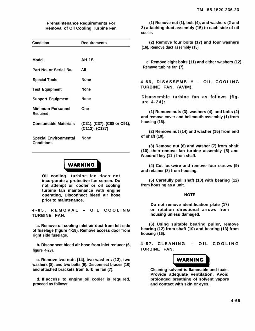
Premaintenance Requirements ForRemoval of Oil Cooling Turbine Fan
Condition Requirements
Model
Part No. or Serial
Special Tools
Test Equipment
No.
Support Equipment
Minimum PersonnelRequired
Consumable Materials
Special EnvironmentalConditions
AH-1S
All
None
None
None
One
(C31), (C37), (C88 or C91),(C112), (C137)
None
Oil cooling turbine fan does notincorporate a protective fan screen. Donot attempt oil cooler or oil coolingturbine fan maintenance with engineoperating, Disconnect bleed air hoseprior to maintenance.
4 - 8 5 . R E M O V A L – O I L C O O L I N GTURBINE FAN.
a. Remove oil cooling inlet air duct from left sideof fuselage (figure 4-18). Remove access door fromright side fuselage.
b. Disconnect bleed air hose from inlet reducer (6,figure 4-23).
c. Remove two nuts (14), two washers (13), twowashers (8), and two bolts (9). Disconnect braces (10)and attached brackets from turbine fan (7).
d. If access to engine oil cooler is required,proceed as follows:
TM 55-1520-236-23
(1) Remove nut (1), bolt (4), and washers (2 and3) attaching duct assembly (15) to each side of oilcooler.
(2) Remove four bolts (17) and four washers(16). Remove duct assembly (15).
e. Remove eight bolts (11) and either washers (12).Remove turbine fan (7).
4 - 8 6 , D I S A S S E M B L Y – O I L C O O L I N GTURBINE FAN. (AVIM).
Disassemble turbine fan as follows (fig-ure 4 - 2 4 ) :
(1) Remove nuts (3), washers (4), and bolts (2)and remove cover and bellmouth assembly (1) fromhousing (16).
(2) Remove nut (14) and washer (15) from endof shaft (10).
(3) Remove nut (6) and washer (7) from shaft(10), then remove fan turbine assembly {5) andWoodruff key (11 ) from shaft.
(4) Cut Iockwire and remove four screws (9)and retainer (8) from housing.
(5) Carefully pull shaft (10) with bearing (12)from housing as a unit.
NOTE
Do not remove identification plate (17)or rotation directional arrows fromhousing unless damaged.
(6) Using suitable bearing puller, removebearing (12) from shaft (10) and bearing (13) fromhousing (16).
4 - 8 7 . C L E A N I N G – O I L C O O L I N GTURBINE FAN.
Cleaning solvent is flammable and toxic.Provide adequate ventilation. Avoidprolonged breathing of solvent vaporsand contact with skin or eyes.
4-65

TM 55-1520-236-23
Figure 4-24. Oil Cooler Turbine Fan — Assembly
4 - 6 6
TM 55-1520-236-23
Prolonged contact with Iubricating oilmay cause a akin rash. Those areas ofakin and clothing that coma in contactwith lubricating oil should be thoroughlywashed immediately. Saturated clothingshould be removed immediately. Areas inwhich lubricating oil is used should beadequately ventilated to keep mist andfumes to a minimum.
4-66.1/(4-66.2 blank)
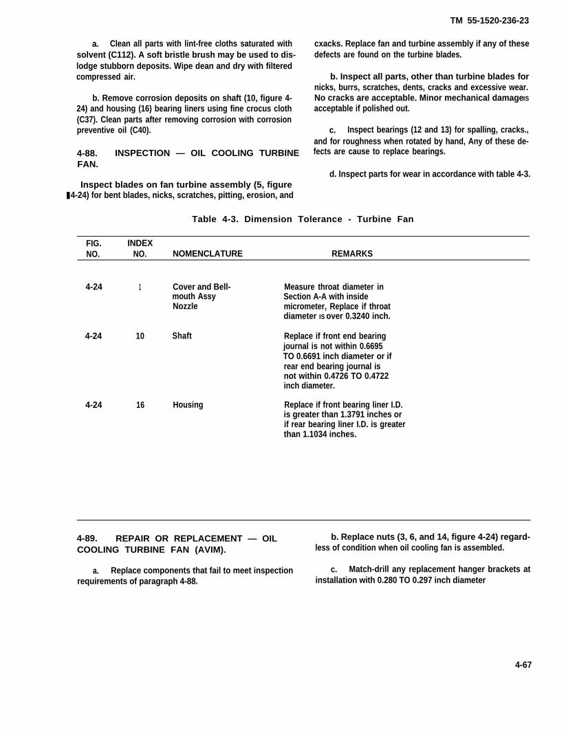
a. Clean all parts with lint-free cloths saturated withsolvent (C112). A soft bristle brush may be used to dis-lodge stubborn deposits. Wipe dean and dry with filteredcompressed air.
b. Remove corrosion deposits on shaft (10, figure 4-24) and housing (16) bearing liners using fine crocus cloth(C37). Clean parts after removing corrosion with corrosionpreventive oil (C40).
4-88. INSPECTION — OIL COOLING TURBINEFAN.
Inspect blades on fan turbine assembly (5, figure 4-24) for bent blades, nicks, scratches, pitting, erosion, and
TM 55-1520-236-23
cxacks. Replace fan and turbine assembly if any of thesedefects are found on the turbine blades.
b. Inspect all parts, other than turbine blades fornicks, burrs, scratches, dents, cracks and excessive wear.No cracks are acceptable. Minor mechanical damage ISacceptable if polished out.
c. Inspect bearings (12 and 13) for spalling, cracks.,and for roughness when rotated by hand, Any of these de-fects are cause to replace bearings.
d. lnspect parts for wear in accordance with table 4-3.
Table 4-3. Dimension Tolerance - Turbine Fan
FIG. INDEXNO. NO. NOMENCLATURE REMARKS
4-24 1 Cover and Bell- Measure throat diameter inmouth Assy Section A-A with insideNozzle micrometer, Replace if throat
diameter IS over 0.3240 inch.
4-24 10 Shaft Replace if front end bearingjournal is not within 0.6695TO 0.6691 inch diameter or ifrear end bearing journal isnot within 0.4726 TO 0.4722inch diameter.
4-24 16 Housing Replace if front bearing liner I.D.is greater than 1.3791 inches orif rear bearing liner I.D. is greaterthan 1.1034 inches.
4-89. REPAIR OR REPLACEMENT — OIL b. Replace nuts (3, 6, and 14, figure 4-24) regard-COOLING TURBINE FAN (AVIM). less of condition when oil cooling fan is assembled.
a. Replace components that fail to meet inspection c. Match-drill any replacement hanger brackets atrequirements of paragraph 4-88. installation with 0.280 TO 0.297 inch diameter
4-67

TM 55-1520-236-23
holes through ends to match existing bolt holes in coolerflanges and deck structure and 0.256 TO 0.263 inch diam-eter holes in lower legs of hanger brackets to match exist-ing holes in brackets on duct.
d. Refinish all exposed aluminum surfaces, after re-pair, with chemical film (C31) and repaint with one coat ofprimer (C88 or C91) as required.
4-90. ASSEMBLY — OIL COOLING TURBINEFAN. (AVIM).
Press bearing (12, figure 4-24) on shaft (1O) to seatfirmly against shoulder on shaft.
Do not force bearings Into housing. Ifbearings do not slip into piece with slighthand pressure, check bearing Iiners for burrsor corrosion
b. Insert bearing (13) into housing (16). Add sealingcompound (C105.4) to outside diameter of bearing (13).Insert bearing (13) into housing (16).
NOTE
Movement of the outer race of bearing (13) ispermitted during non-powered operation.
c. Carefully insert shaft (10) with bearing (12) as a unit,into shaft bore of housing (16).
d. Position retainer (8) in housing with four screws (9).Tighten screws and seine with Iockwire (C137).
e. Install Woodruff key (11) in ahaft (1O) end install fanturbine assembly (5) on shaft, align keyway in fan with key inshaft.
f. Install washer (7) and nut (6) on shaft and holdingfan and turbine assembly to prevent rotation, torque nut 115TO 140 inch-pounds.
g. Install washer (15) and nut (14) on shafttorque nut 48 TO 55 inch-pounds.
h. Position cover and bellmouth assemblhousing (16) and secure with bolts (2), washersnuts (3). Torque nuts 50 TO 70 inch-pounds.
10) and
(1) on4), and
4-91. INSTALLATION — OIL COOLINGTURBINE FAN.
a. If duct assembly (15, figure 4-23) has been re-moved, proceed as follows:
(1) Position duct (15) to oil cooler and bolts (4)washers (2 and 3) and nut (1).
(2) Secure duct to oil cooler flange and airframestructure with four bolts (17) and four washers (16).
b. Position fan (7) to duct (15) and install eight bolts(11) and eight washers (12).
c. Position two braces (1O), with attached brackets,on turbine fan (7) and install two bolts (9), washers (8 and13), and nuts (14).
d. Connect bleed air hose to reducer (6).
e. Reinstall access door and cooling duct on fuse-lage openings.
f. At next ground run-up, check installation for leaksand proper operation.
4-92. ENGINE OIL COOLER BYPASS SELEC-TOR VALVE.
4-93. DESCRIPTION — ENGINE OIL COOLERBYPASS SELECTOR VALVE.
This valve is a two-position, motorized valve located on theleft side of the engine compartment deck. It is connected inthe engine to oil cooler line. See figure 4-18. The purposeof the valve is to automatically bypass the oil cooler whenoil level is low. Refer to TM 55-1520-236-10 for additionalinformation on switching action for this valve.
4-94. REMOVAL — ENGINE OIL COOLERBYPASS SELECTOR VALVE.
a. Open engine compartment cowling at left side.
b. Remove oil cooling duct (figure 4-18) from leftside of fuselage. Drain oil cooler and lines.
4 - 6 8

c. Disconnect electrical cable connector fromvalve.
d. Disconnect engine scavenge oil hose fromvalve coupling. Disconnect oil cooler Iines and tankreturn line from valve fittings. Cap open ends of lines.
e. Detach valve from brackets by removing twoscrews at each side. Lift out valve assembly.
f. Remove fittings from valve by removingattachment screws. Remove check valve and gasketfrom right fitting.
4 - 9 6 . I N S P E C T I O N – E N G I N E O I LCOOLER BYPASS SELECTOR VALVE.
Inspect mating surfaces of valve and fittings for nicksand burrs. Inspect threads for damage.
4 - 9 6 . R E P A I R O R R E P L A C E M E N T –ENGINE OIL COOLER BYPASS SELECTORVALVE.
Replace any damaged fittings or attaching parts.Replace valve assembly if malfunction occurs.
TM 55-1520-236-23
4 - 9 7 . I N S T A L L A T I O N – E N G I N E O I LCOOLER BYPASS SELECTOR VALVE.
NOTE
Be sure flow arrow is toward fitting.
a. Assemble fittings on valve (figure 4-18) withattaching screws. Use new gasket when installingcheck valve in return line fitting.
b. Position valve assembly between brackets andinstall two screws at each side.
c. Connect oil cooler lines and tank return linevalve fittings. Connect engine scavenge oil hose tocoupling.
d. Connect electrical cable to connector on valve.
e. Service oil tank. Reinstall oil cooling duct withscrews. Close cowling.
f. Check for leaks and proper operation at nextground run.
S E C T I O N V I . I G N I T I O N S Y S T E M
Refer to TM 55-2840-229-23
S E C T I O N V I I . P O W E R L E V E R C O N T R O L S
4 - 9 8 . P O W E R L E V E R C O N T R O L S .
4 - 9 9 . D E S C R I P T I O N – P O W E R L E V E RCONTROLS.
A mechanical linkage system, actuated by twist-gripson collective pitch control sticks, provides manualcontrol of the power lever on the engine fuel controlunit. The power lever modulates the engine from zeroto full power by controlling the gas producer turbineRPM (N1) limits. The fuel control power lever shaft (l,figure 4-25) is serrated and grooved to accept controlarm (3), and has a quadrant marked with powersettings in its range of travel between stops which are
preadjusted by the engine manufacturer or overhaulfacility. The linkage is a series of control rods,bellcranks, idlers, and Ievers. control rods (7 and 28),at each end of the series, are adjustable. Bellcrank(20) has an adjustable connection for control rod (21),which determines the travel of linkage above thebellcrank. The idle stop cam (5) makes contact withthe spring-loaded plunger of a solenoid (17) to arrestlinkage motion at the engine idle position whenpower is being reduced from higher settings. Thesolenoid plunger can be retracted by use of theENGINE IDLE STOP REL pushbutton switch, locatedon the pilot collective stick to allow controlmovements in the OFF position.
4-69
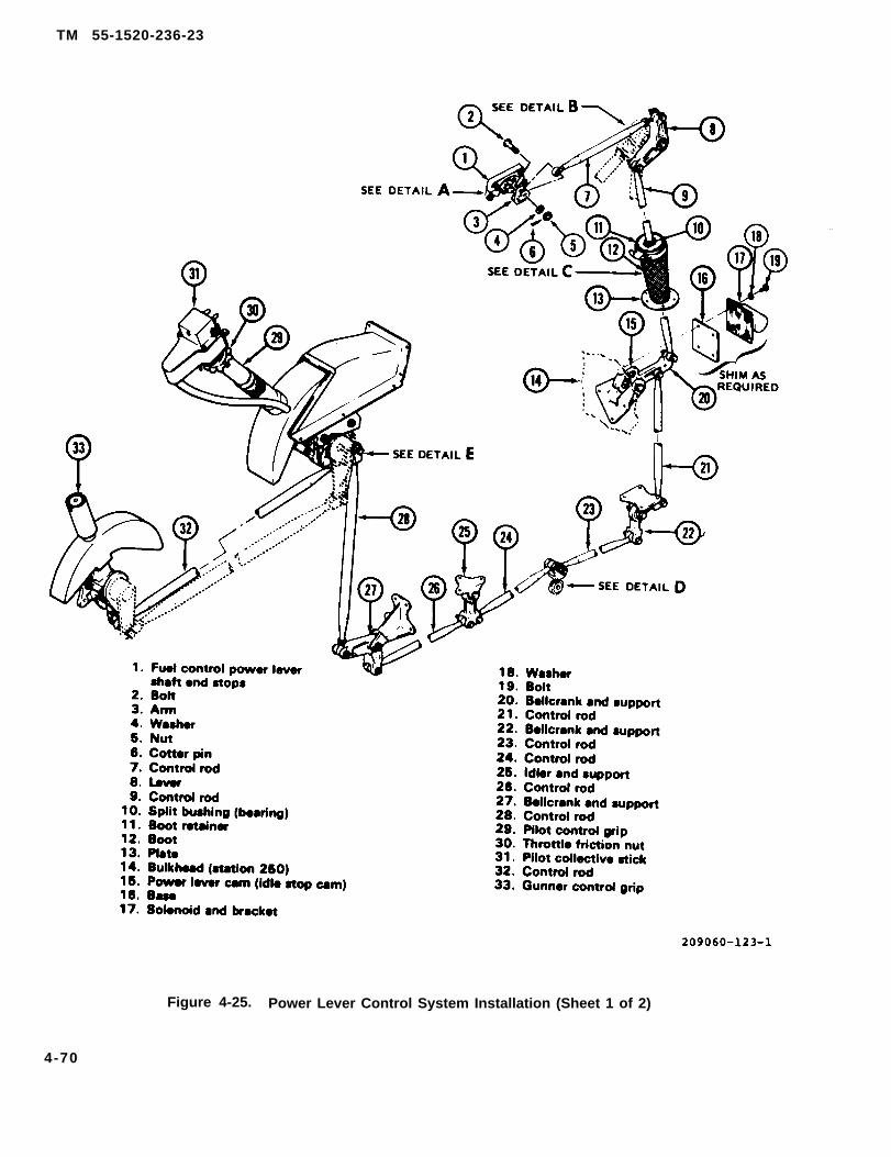
TM 55-1520-236-23
Figure 4-25. Power Lever Control System Installation (Sheet 1 of 2)
4-70
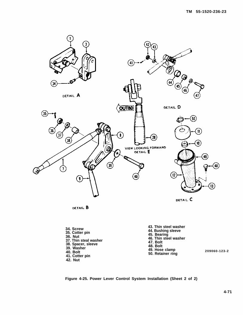
TM 55-1520-236-23
34. Screw35. Cotter pin36. Nut37. Thin steal washer38. Spacer, sleeve39. Washer40. Bolt41. Cotter pin42. Nut
43. Thin steel washer44. Bushing sleeve45. Bearing46. Thin steel washer47. Bolt48. Bolt49. Hose clamp50. Retainer ring
209060-123-2
Figure 4-25. Power Lever Control System Installation (Sheet 2 of 2)
4-71

TM 55-1520-236-23
4 - 1 0 0 . R E M O V A L – P O W E R L E V E RCONTROLS.
a. To remove control rod (28, figure 4-25):Remove screw-mounted access panel from left side Cleaning solvent is flammable and toxic.of fuselage in line with lower end of pilot collective Provide adequate ventilation. Avoidcontrol stick. Remove bolts, nuts, washers, and cotter prolonged breathing of solvent vaporspins to remove control rod (28). and contact with skin or eyes.
b. Leave lower linkage (22 through 27) in place Clean external surfaces of parts by wiping with a cloth
for normal maintance and inspection. If necessary to moistened with solvent (C112). Do not permit solvent
replace damaged parts, obtain access by removing to enter bearings or solenoid.
screw-mounted panels from lower skin and detachparts by removing bolts, washers, and nuts. 4 - 1 0 2 . I N S P E C T I O N – P O W E R L E V E R
CONTROLS.
c. To remove bellcrank (20) and cam (15): Obtainaccess to compartment, below engine and behind aftfuel cell, by removing oil cooler air intake duct fromleft side of fuselage. Disconnect control rods (9) and(21) from bellcrank (20), keeping attaching parts withrod-ends. Remove attaching bolt and lift out bellcrank(20) with cam (15) attached. To remove cam (15), usean allen wrench to remove two special bolts andserrated washers.
d. To remove solenoid (17): Obtain access as instep (c). Disconnect electrical connector fromsolenoid. Remove four bolts (19) and washers (18) todetach solenoid assembly and base (16) frombulkhead (14).
e. To remove control rod (9) and boot (12): Loosenhose clamp (49) on boot (12). Disconnect control rod(9) from bellcrank (20) and lever (8). Remove controlrod (9) with boot retainer (11) attached. Removeretainer ring (50) and split bushing (10) and separateboot retainer (11) from rod (9). Remove boot (12) fromplate (13).
f. To remove lever (8): Disconnect control rods (7and 9). Remove bolt (40), nut (36), washers (37 and39), spacer (38), and cotter pin (35) to detach leverfrom engine mount pillow block.
g. To remove control arm (3): Disconnect controlrod (7). Remove Iockwire and screw (34) from arm.Pull arm from fuel control power lever shaft (1). Keepscrew (34) with arm (3).
4 - 1 0 1 . C L E A N I N G – P O W E R L E V E RCONTROLS.
a. Control rods for cracks and general condition.End fittings for security. Bearings for binding or roughoperation.
b. Bellcranks, levers, and idlers for security.cracks, or damage, binding, or rough bearings.
c. Solenoid for security and proper operation.
d. Boot assembly for cracks, tears, or wear.
4 - 1 0 3 . R E P A I R O R R E P L A C E M E N T –POWER LEVER CONTROLS.
a. Replace parts which fail to meet inspectionrequirements of paragraph 4-102.
b. If solenoid replacement is required, installsolenoid and bracket (17, figure 4-25) and base (16)with four bolts (19) and washers (18). Use shims asrequired so that plunger operates freely in bracketbushing.
4-104. INSTALLATION – POWER LEVERCONTROLS.
a. Position arm (3, figure 4-25) an fuel controlpower lever shaft (1). Install screw (34) through armand groove on shaft. After rigging, Iockwire (C137)screw (34).
b. Position lever (8) on outboard side of enginemount pillow block, with spacer (38) between lever (8)and pillow block and with marked arm of leverpointing up. Install bolt (40), washer (39), thin steelwasher (37), nut (36), and cotter pin (35).
4-72
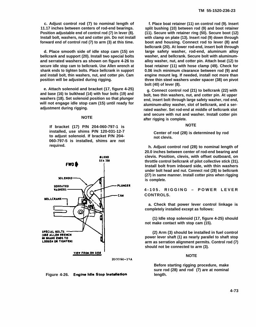
TM 55-1520-236-23
c. Adjust control rod (7) to nominal length of11.17 inches between centers of rod-end bearings.Position adjustable end of control rod (7) in lever (8).Install bolt, washers, nut and cotter pin. Do not installforward end of control rod (7) to arm (3) at this time.
d. Place smooth side of idle stop cam (15) onbellcrank and support (20). Install two special boltsand serrated washers as shown on figure 4-26 tosecure idle stop cam to bellcrank. Use Allen wrench atshank ends to tighten bolts. Place bellcrank in supportand install bolt, thin washers, nut, and cotter pin. Camposition will be adjusted during rigging.
e. Attach solenoid and bracket (17, figure 4-25)and base (16) to bulkhead (14) with four bolts (19) andwashers (18). Set solenoid position so that plungerwill not engage idle stop cam (15) until ready foradjustment during rigging.
NOTE
If bracket (17) P/N 204-060-797-1 isinstalled, use shims P/N 120-031-12-7to adjust solenoid. If bracket P/N 204-060-797-5 is installed, shims are notrequired.
Figure 4-26.
f. Place boat retainer (11) on control rod (9). Insertsplit bushing (10) between rod (9) and boot retainer(11). Secure with retainer ring (50). Secure boot (12)with clamp on plate (13). Insert rod (9) down throughboot and housing. Connect rod to lever (8) andbellcrank (20). At lower rod-end, insert bolt throughlarge safety washer, rod-end, aluminum alloywasher, and bellcrank. Secure bolt with aluminum-alloy washer, nut, and cotter pin. Attach boat (12) toboat retainer (11) with hose clamp (49). Check for0.06 inch minimum clearance between rod (9) andengine mount leg. If needed, install not more thanthree thin steel washers under spacer (38) on pivotbolt (40) of lever (8).
g. Connect control rod (21) to bellcrank (22) withbolt, two thin washers, nut, and cotter pin. At upperend, insert bolt through large safety washer, rod end,aluminum-alloy washer, slot of bellcrank, and a ser-rated washer. Set rod-end at middle of bellcrank slotand secure with nut and washer. Install cotter pinafter rigging is complete.
NOTE
Center of rod (28) is determined by rodnot clevis.
h. Adjust control rod (28) to nominal length of20.0 inches between center of rod-end bearing andclevis. Position, clevis, with offset outboard, onthrottle control bellcrank of pilot collective stick (31).Install bolt from inboard side, with thin washersunder bolt head and nut. Connect rod (28) to bellcrank(27) in same manner. Install cotter pins when riggingis complete.
4 - 1 0 5 . R I G G I N G – P O W E R L E V E RCONTROLS.
a. Check that power lever control linkage iscompletely installed except as follows:
(1) Idle stop solenoid (17, figure 4-25) shouldnot make contact with stop cam (15).
(2) Arm (3) should be installed in fuel controlpower lever shaft (1) as nearly parallel to shaft stoparm as serration alignment permits. Control rod (7)should not be connected to arm (3).
NOTE
Before starting rigging procedure, makesure rod (28) and rod (7) are at nominallength.
4-73

TM 55-1520-236-23
b. Center control rod (21) in bellcrank (20) beforetrying to obtain center of travel in step c.
c. Support free end of control rod (7) level withfuel control power lever shaft (1). Operate pilotcontrol grip (29) to full on to full off, end check that endof control rod (7) moves equal distances fromcenterline of shaft (1) at both positions. Adjust controlrode (7 and 28) to obtain equal movement notedabove. Keep control rods (7 and 28) as close tonominal lengths as possible. Refer to paragraph 4-104, step c and step h for nominal lengths.
d. Position control rod (7) in arm (3). lnstall bolt (2) withhead outboard (Until final adjustment on 50 cushion, andthen install bolt head inboard), install washer (4) and nut(5). Do not install cotter pin (6) at this time.
e. Turn pilot control grip (29) in one direction untilfuel control shaft bottoms on stop. Disconnect controlrod (7) from arm and check that control grip (29) willturn approximately 5 degrees further beforebottoming. Repeat procedure with grip rotated inopposiste direction. Make corrections by adjustingposition of control rod (21) on slotted bellcrank (20).When satisfactory, leave control rod (7) connected toarm (3). Install cotter pin (6).
f. Operate control grip (29) to set power levershaft stop arm (3) to 47 degree mark on fuel control.Adjust positions of idle stop cam (16) and solenoid(17) so that cam rests against extended plunger ofsolenoid. Check that solenoid bracket clears cam by0.06 inch in all conditions.
Serrations of cam and square washersmust be matched.
g. In next ground run, make final adjustment ofidle atop cam to obtain 68 TO 72 percent gasproducer rpm.
h. Lockwire (C137) screw (34).
i. Ensure that entire power lever control systemhas all required cotter pins installed and that controlsmove through full throw without binding orinterference.
4 - 1 0 6 . D R O O P C O M P E N S A T O RC O N T R O L S .
4 - 1 0 7 . D E S C R I P T I O N – D R O O PCOMPENSATOR CONTROLS.
Engine power turbine (N2 rpm) is controlled throughthe overspeed governor by means of an actuator and adroop compensator cam and linkage.
An electrically operated linear actuator (20, figure 4-27), controlled by the GOV RPM lNCR/DECR switchon the pilot collective pitch control stick, moves alever (21) on the fuel control overspeed governor tochange settings of power turbine rpm. Droopcompensation, to stabilize tpm as engine loadfluctuates with changes of main rotor pitch, isprovided by mounting the actuator to a cambox (19)which is mechanically linked to a bellcrank (2) in thecollecting pitch control system. The droopconmpensator linkage consists of control rods, levers,arms, and belkcranks. Bellcrank (4) is attached onshaft (7) by means of a shear pin (9), which isdesigned to shear to allow unhindered operation ofthe collective pitch controls if the compensatorlinkage should becone fouled.
4 - 1 0 8 . R E M O V A L – D R O O PCOMPENSATOR CONTROLS.
a . Removal — Actautor and Control Lever.
(1) Open engine compartment cowling at leftside.
(2) Remove terminal cover with attachingscrews from top of linear actuator (20, figure 4-27).Disconnect and stow electrical leads. Reininstall cover.
(3) Detach actuator jackshaft end-fitting fromlever (21) on governor control shaft and from slider ofcambox (19), by removing bolts with nuts, washers,and cotter pins. Use care to avoid losing springwasher, which is installed between actuator clevisand slidier, also washers installed between rod-endand lever (21).
(4) RemOVe lockwire and and clamping bolt, andpull lever (21) from serrated shaft at top of overspeedgovernor.
b. Removal - Cambox and Linkage.
(1) Disconnect control rod (18) from belkrankof cambox (19) by removing bolt with nut, washers,end cotter pin.
4-74

TM 55-1520-236-23
Figure 4-27. Droop Compensator Controls Installation
4-75
TM 55-1520-236-23
(2) Remove nuts and washers from inboardends of two bolts that attach cambox to supportbracket. Remove cambox with bolts in place. Reinstallnuts and washers on bolts, with care that shimsremain in place on bellcrank pivot bolt betweenbearing and sides of housing.
NOTE
As an altenate method, remove camboxand bracket as and assembly by removingtwo bolts that secure bracket to forwardengine mount trunnion. Reinstall bolts tosecure mount trunnion.
(3) To remove bellcrank (4) and shaft (7) andassociated parts, disconnect control rods (3 and 13).Remove nut and washer from inboard end of shaft.Remove three attaching bolts and bracket (11) fromoutboard end of shaft. Pull shaft free of inboardbracket (8). Remove shaft assembly with bellcrank,shear pin (9), shims (5), and special washer (6). Whenreplacement of shear pin (9) is required, remove oldshear pin and install new shear pin as follows:
(a) Remove special washer (6) from shaft (7).
(b) Remove shims (5) from shaft (7).
(c) Use aluminum drift or press to removeshear pin (9) from bellcrank (4) and shaft (7).
(d) Remove belkcrank (4) from shaft (7).
NOTE
Sheer pin (9) must be an interenfence fitwith bellcrank (4) and shaft (7). If pin holeor oounterbore in bellcrank (4) or shaft(7) is elongated, procure a new bellcrankor shaft.
(e) Position bellcrank (4) on shaft (7) withcounterbore for head of shear pin (9) exposed.
(f) Press shear pin (9) into bellcrank (4) andshaft (7). Ensure that head of shear pin (9) is flushwith surface of belkrank (4).
(g) Install shims (5) on shaft (7).
(h) Install special washer (6) on shaft (7).
(4) If control rod (15) must be removed,disassemble firewall retainer and boot (16).
(a) Remove cotter pin, nut, washers, and boltfrom inboard end of arm (14).
(b) Remove cotter pin, nut, washers and boltfrom upper end of lever (17).
(c) Loosen clamps on boot and retainer (16}.
(d) Pull control rod (15) forward throughfirewall and remove from helicopter.
(e)(16).
(f)
(9)
Remove clamps from boot and retainer
Remove boot from control rod (15).
Remove snap ring, retainer and splitbushing from control rod (15).
4 - 1 0 9 . C L E A N I N G – D R O O PCOMPENSATOR CONTROLS.
Cleaning solvent is flammable and toxic.Provide adequate ventilation. Avoidprolonged breathing of solvent vaporsand contact with skin or eyes.
Clean external surfaces of parts by wiping with a clothmoistened with solvent (C112). Do not permit solventto enter bearings or actuator.
4 - 1 1 0 . I N S P E C T I O N – D R O O PCOMPENSATOR CONTROLS.
a . Inspect linear actuator for evidence of damageor malfunction.
b. Inspect cambox for security of parts andsmooth operation with no evidence of binding.Check for proper clearance of 0.001 TO 0.006 inch bet-ween bellcrank (4) cmd flange of shaft (7). (Refer tofigure 4-27, view A-A.)
c. Check for broken shear pin (9, figure 4-27) bymanually holding lever (10) and applying slight forceto bellcrank (4).
4 -76

d. Inspect otherlinkage for freedorndamage.
parts of droop compensatorof operation, looseness, and
4 - 1 1 1 . REPAIR - D R O O PCOMPENSATOR CONTROLS.
a . Replace components that fail to passinspection requirements of paragraphs 4-110.
b. Replace show pin (9, figure 4-27) in event offailure. Investigate cause of failure and correct anyfouling of Iinkage or other faulty condition.
4 - 1 1 2 . I N S T A L L A T I O NCOMPENSATOR CONTROLS.
a . Cambox and Linkage.
– D R O O P
(1) Position cambox (19, figure 4-27) onoutboard side of bracket. Insert two bolts and securewith nuts and washers. Be sure shims are in piece onbellcrank pivot bolt.
(2) If bracket was removed, reinstall on twoupper bolts of forward engine mount trunnion.
(3) Deleted.
(4) Adjust control rod (18) to nominal length of19.0 inches between centers of rod-end bearings.Connect non-adjustable end to forward arm of lever(17) with bolt, thin aluminum alloy washers, nut, andinter pin. Adjustable end will be connected tobelkrank of cambox (19) during rigging.
(5) If bellcrank (4), shaft (7), and associatedparts are removed, reinstell as follows:
(a) Attach bracket (8) on pylon auppoft withtwo bolts and washers.
(b) Place shims (5), special washer (6), andthin steal washer on shaft.
(c) heart shaft through bearing of inboardbracket and secure with thin steel washer and nut.finger tight.
(d) Install bracket (11) over outboard and of shaft and attach to pylon support with twobolts and washers
TM 55-1520-236-23
(e) Tighten nut on inboard end of shaft.
(f) Check for 0.001 TO 0.006 inch clearance bet-ween bellcrank and shaft as shown. (See section A-A.)If necessary, disassemble to change shim thickness andreassemble.
(6) Adjust control rod (3) to nominal length of32.46 inches between center of bolt holes in rod-endand clevis. Connect clevis to collective systembellcrank (2) forward hole with bolt, thin aluminumalloy washers, nut, and tatter pin. Align upper rod-and in fork of bellcrank (4), with a thin steal washerbetween each side of bearing and inside of fork.Install bolt secured by washer, nut, and cotter pin.
(7) Assemble retainer, split bushing, snap ringand boot with clamps on rod (15). Insert rod-end aftthrough firewalll retainer and connect to upper arm oflever (17) with bolt, thin aluminum alloy washers,nut, and cotter pin. Connect forward end of rod toinboard end of arm (14) in the same manner. Secureboot with clamps on retainers.
b.
Arm (14) should be installed with angledclevis outboard and sloping downforward to meet with control rod (13).
Actuator and Control Lever.
(1) Place control lever (21) on control shaft offuel control overspeed governor, approximately 90degrees to centerline of stop arm on shaft. Installretaining bolt into lever and through shaft groove.Torque bolt 12 TO 15 inch-pounds. Lockwire (C137) boltto lever.
(2) Align actuator (20) with front end-fitting clevison end of cambox slider. Insert spring washer betweenclevis and underside of slider and install both from top,secured with washer and nut. Torque nut 5 to 15 inch-pounds. Install cotter pin.
(3) Attach actuator shaft rod end with a thin steelwasher on each side of rod-end bearing into clevis ofgovernor control lever with bolt (washer underheed). Install washer and nut, omit cotter pin untilrigging is complete. If necessary, loosen bolts at-taching cambox bracket on engine to align actuatorto lever. Torque and Iockwire bracket bolts(paragraph 4-120).
4-77
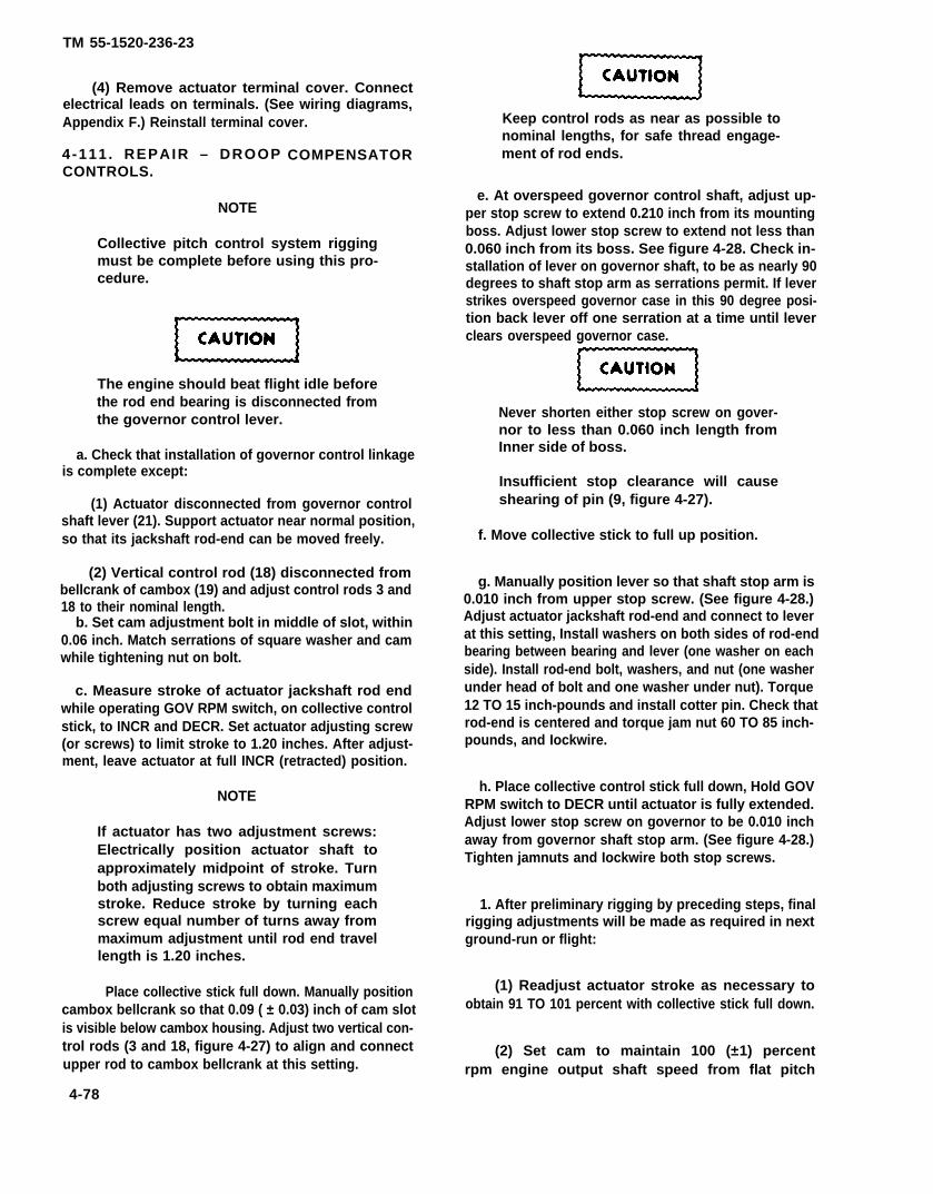
TM 55-1520-236-23
(4) Remove actuator terminal cover. Connectelectrical leads on terminals. (See wiring diagrams,Appendix F.) Reinstall terminal cover.
4 -111 . REPAIR – DROOPCONTROLS.
NOTE
COMPENSATOR
Collective pitch control system riggingmust be complete before using this pro-cedure.
The engine should beat flight idle beforethe rod end bearing is disconnected fromthe governor control lever.
a. Check that installation of governor control linkageis complete except:
(1) Actuator disconnected from governor controlshaft lever (21). Support actuator near normal position,so that its jackshaft rod-end can be moved freely.
(2) Vertical control rod (18) disconnected frombellcrank of cambox (19) and adjust control rods 3 and18 to their nominal length.
b. Set cam adjustment bolt in middle of slot, within0.06 inch. Match serrations of square washer and camwhile tightening nut on bolt.
c. Measure stroke of actuator jackshaft rod endwhile operating GOV RPM switch, on collective controlstick, to INCR and DECR. Set actuator adjusting screw(or screws) to limit stroke to 1.20 inches. After adjust-ment, leave actuator at full INCR (retracted) position.
NOTE
If actuator has two adjustment screws:Electrically position actuator shaft toapproximately midpoint of stroke. Turnboth adjusting screws to obtain maximumstroke. Reduce stroke by turning eachscrew equal number of turns away frommaximum adjustment until rod end travellength is 1.20 inches.
Place collective stick full down. Manually positioncambox bellcrank so that 0.09 ( ± 0.03) inch of cam slotis visible below cambox housing. Adjust two vertical con-trol rods (3 and 18, figure 4-27) to align and connectupper rod to cambox bellcrank at this setting.
4-78
Keep control rods as near as possible tonominal lengths, for safe thread engage-ment of rod ends.
e. At overspeed governor control shaft, adjust up-per stop screw to extend 0.210 inch from its mountingboss. Adjust lower stop screw to extend not less than0.060 inch from its boss. See figure 4-28. Check in-stallation of lever on governor shaft, to be as nearly 90degrees to shaft stop arm as serrations permit. If leverstrikes overspeed governor case in this 90 degree posi-tion back lever off one serration at a time until leverclears overspeed governor case.
Never shorten either stop screw on gover-nor to less than 0.060 inch length fromInner side of boss.
Insufficient stop clearance will causeshearing of pin (9, figure 4-27).
f. Move collective stick to full up position.
g. Manually position lever so that shaft stop arm is0.010 inch from upper stop screw. (See figure 4-28.)Adjust actuator jackshaft rod-end and connect to leverat this setting, Install washers on both sides of rod-endbearing between bearing and lever (one washer on eachside). Install rod-end bolt, washers, and nut (one washerunder head of bolt and one washer under nut). Torque12 TO 15 inch-pounds and install cotter pin. Check thatrod-end is centered and torque jam nut 60 TO 85 inch-pounds, and Iockwire.
h. Place collective control stick full down, Hold GOVRPM switch to DECR until actuator is fully extended.Adjust lower stop screw on governor to be 0.010 inchaway from governor shaft stop arm. (See figure 4-28.)Tighten jamnuts and Iockwire both stop screws.
1. After preliminary rigging by preceding steps, finalrigging adjustments will be made as required in nextground-run or flight:
(1) Readjust actuator stroke as necessary toobtain 91 TO 101 percent with collective stick full down.
(2) Set cam to maintain 100 (±1) percentrpm engine output shaft speed from flat pitch
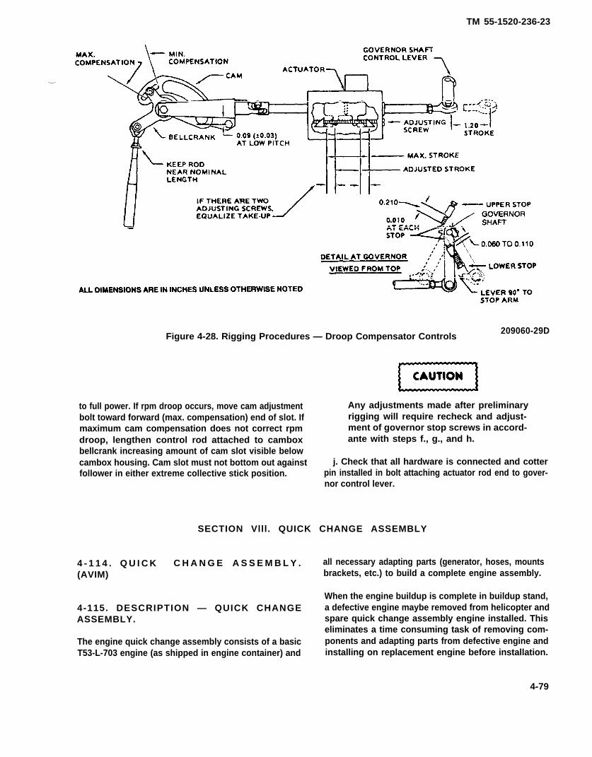
TM 55-1520-236-23
Figure 4-28. Rigging Procedures — Droop Compensator Controls209060-29D
to full power. If rpm droop occurs, move cam adjustment Any adjustments made after preliminarybolt toward forward (max. compensation) end of slot. If rigging will require recheck and adjust-maximum cam compensation does not correct rpm ment of governor stop screws in accord-droop, lengthen control rod attached to cambox ante with steps f., g., and h.bellcrank increasing amount of cam slot visible belowcambox housing. Cam slot must not bottom out against j. Check that all hardware is connected and cotterfollower in either extreme collective stick position. pin installed in bolt attaching actuator rod end to gover-
nor control lever.
SECTION Vlll. QUICK CHANGE ASSEMBLY
4 - 1 1 4 . Q U I C K C H A N G E A S S E M B L Y . all necessary adapting parts (generator, hoses, mounts(AVIM) brackets, etc.) to build a complete engine assembly.
When the engine buildup is complete in buildup stand,4-115. DESCRIPTION — QUICK CHANGE a defective engine maybe removed from helicopter andASSEMBLY. spare quick change assembly engine installed. This
eliminates a time consuming task of removing com-The engine quick change assembly consists of a basic ponents and adapting parts from defective engine andT53-L-703 engine (as shipped in engine container) and installing on replacement engine before installation.
4-79

TM 55-1520-236-23
Premaintenance Requirements forEngine Buildup (QCA)
Condition Requirements
Model
Part No or Serial No.
Special Tools
Test Eqiprment
Support Equipment
Minimum PersonnelRequired
Consumable Material
Special EnvironmentalConditions
AH-1S
All T53-L-703Engines
(T9), (T19)
None
None
Two
(C13), (C85), (C113),(C137)
None
4 - 1 1 6 . R E M O V A L – E N G I N E F R O MSHIPPING CONTAINER.
a. Remove engine records from recordsreceptacle (figure 4-29).
b. Release air pressure from container byremoving filter valve oore.
Do not open oontainer until oompletetydepressurized
c. Remove nuts and bolts securing upper half ofcontainer to bottom half.
When removing, ensure upper half ofcontainer does not strike engine.
d. Attach a suitable chain or cable to lifting eyeson container upper half. Using a suitable hoist,attached to chain, lift container upper half from lowerhalf and set to one side. Reinstall filler valve core.
e. Attach Iifting sling (T9) to attaching points onengine.
NOTE
One engine attaching point is Iocated onthe diffuser housing and one is located onthe inlet housing.
f. Attach lifting sling (T9) to suitable hoist.
g. Remove nuts and washers that secure fourshipping trunnions to mounts in lower half ofshipping container.
h. Remove engine from shipping container.
i. Install engine in engine and transmission stand(T19).
j. Remove shipping trunnions from engine mountpads.
k. If another engine is not to be installes inshipping container proceed with the following:
(1) Reinstall shipping trunnions in bottom halfof shipping container.
(2) Place top half of shipping container onbottom half. Install four bolts and nuts, one at eachcorner, tighten finger tight. Shift upper half ofcontainer as necessary to align flange bolt holes intop and bottom halves of container.
(3) Install bolts and nuts at midpoints of sidesand ends of shipping container, and the bolts and nutat midpoints between them. Install all remaining boltsand nuts. Torque nuts in order of installation 500 TO640 inch-pounds.
(4) Using clean dehydrated air, pressurizecontainer 4 to 6 PSI. Check container seals for leaksby applying liquid soap (C113) and observing for airbubbles.
4-80
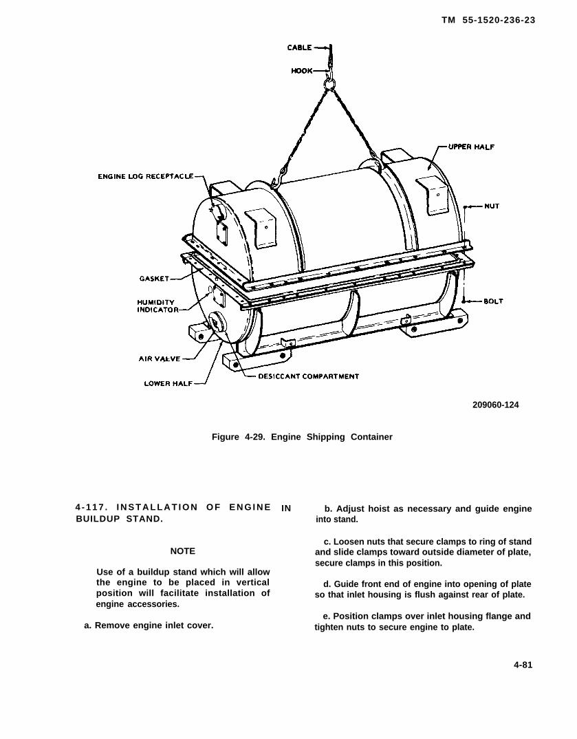
TM 55-1520-236-23
209060-124
Figure 4-29. Engine Shipping Container
4 - 1 1 7 . I N S T A L L A T I O N O F E N G I N EBUILDUP STAND.
NOTE
Use of a buildup stand which will allowthe engine to be placed in verticalposition will facilitate installation ofengine accessories.
a. Remove engine inlet cover.
IN b. Adjust hoist as necessary and guide engineinto stand.
c. Loosen nuts that secure clamps to ring of standand slide clamps toward outside diameter of plate,secure clamps in this position.
d. Guide front end of engine into opening of plateso that inlet housing is flush against rear of plate.
e. Position clamps over inlet housing flange andtighten nuts to secure engine to plate.
4-81
TM 55-1520-236-23
4-118. ENGINE PREPARATION.
HANDLING IGNITION UNIT
The ignition unit contains a vary smallamount of radioactive material (Cesium-Barium 137) and normally requires nohandling precautions. However, severlydamaged units that leave been brokenopen must be handled with forceps orgloves and disposed of in accordancewith AR-755-15 and TB 55-1600-314-26.
Disconnect electrical lead (1, figure 4-30) fromignition unit (2). Install danger tag stating, “DO NOTCONNECT UNTIL GROUND RUN”.
a . Rotate engine in maintenance stand until inthe vertical position.
b. Remove all plastic plugs from around engineinlet housing.
4 - 1 1 9 . I N S T A L L A T I O N – A F T E N G I N EMOUNT TRUNNIONS.
a . Position fitting (1, figure 4-31) on left side ofengine and install bolts (5) with washers underheads.
b. Tighten bolts and Iockwire (C137).
c. Place bearing (4), washer (3), and nut (2), onfitting (1). Torque nut.
d. Install fitting (1) on right side of engine inaccordance with step (1), (2), and (3).
4 - 1 2 0 . I N S T A L L A T I O N – C O M P O N E N T SON ENGINE LEFT SIDE.
a. Forward trunnion, cambox, and oil preassuretransducer mounting bracket.
(1) Position trunnion (3, figure 4-32) on Ieft sideengine pad. Install cambox assembly mountingbracket (4) over top mounting holes of trunnion.Install one bolt (5) and washer (6) in upper left hale toattach cambox bracket and trunnion.
(2) Position oil pressure transducer bracket (7)over cambox and trunnion. Secure using three bolts(5) and three washers (6).
NOTE
Add AN960C816 and/or AN960C816Lwashers (8) as required (3 maximum) forflush fit between trunnion (3) andbracket (7).
(3) Tighten all bolts (5) and Iockwire (C137) aftbolts together. After installation of engine,Iockwire mount bolt to upper forward bolt, then tolower forward bolt.
b. Linear actuator and N1 and N2 control levers(figure 4-32).
(1) Position engine governor control shaft tomid-position between governor stops.
(2) Install lever (19, figure 4-32) on governorcontrol shaft at ninety degree angle to centerline ofshaft arm, as serrations permit. Install bolt (18) andIockwire (C137).
(3) Attach linear actuator (15) to lever (19) asfallows:
(a) Position linear actuator (15) with terminalblock facing up. Position rod end of linear actuator(15) in lever (19) with washers (21) on each side of rodend.
(b) Install bolt (20) through lever and rod end.install nut (17). Tighten nut (17) and install cotter pin(16).
(4) Attach linear actuator (15) to camboxassembly as follows:
(a) Position slider of cambox assembly (9) inclevis of linear actuator (15) with spring washer (13)positioned against lower side of slider.
(b) install bolt (14) through slider and clevis.Install washer (12) and nut (11). Tighten nut andinstall cotter pin (10).
(5) Install power lever arm on fuel control asfollows:
(a) Position power lever control arm (2) onfuel control power lever shaft as nearly parallel tofuel shaft stop arm as serrations will permit.Install screw (1) in arm and Iockwire (C137) to hale inarm.
4-82

TM 55-1520-236-23
HANDLING IGNITION UNIT
The ignition unit contains a very small amount of radioactivematerial (Cesium-Barium 137) and normally requires nohandling pracautions. However severly damagad units thathave been broken open must be handled with forceps or gloves,and disposed of in accordance with AR-756-15 and TB55-1500-314-25.
205706-1016
1. Electrical lead2. Ignition unit
Figure 4-30. Ignition Unit
4-83

TM 55-1520-236-23
205706-1015
1. Fitting2. Nut3. Washer4. Bearing5. Bolt6. Lockwire
Figure 4-31. Aft Engine Trunnion Installation
(b) Check rigging (paragraph 4-113).
c. Power turbine tachometer generator (figure 4-33).
(1) Remove nuts and washers and removeshipping cover from tachometer generator mountingpad.
(2) Remove and discard gasket on mountingpad and install new gasket.
(3)(C85).
(4)33) on
Lubricate tachometer shaft using lubricant
Position tachometer generator (26, figure 4-mounting pad with electrical receptacle
pointing up.
(6) Install washers (27) and nuts (28).
d. Oil pressure transducer.
(1) Attach transducer (13, figure 4-33) tobracket (18) as follows:
4-84
(a) Install clamp (23) over transducer (13}.Attach clip (19) to clamp using screw (24), washer(20), and nut (21).
(b) Install screw (9) through plate (10),bracket (18), and clip (19). Secure using nut (22).
e. Oil pressure switch.
(1) Install nut (7) and packing (6) on elbow (8).
(2) Install elbow (8) in oil pressure switch (4).Tighten nut (7).
(3) Attach oil pressure switch through plate(10) and bracket (18) using screws (3 and 11) and nuts(5 and 25).
(4) Install nut (16) and packing (17) on restrictor(15). Install tee in oil pressure port of engine. Tightennut (16) fingertight.
(5) Install tube assembly (14) between lowerport of restrictor (15) and elbow (8).
(6) Install tube assembly (12) between upperport of restrictor (15) and oil pressure transducer (13).
(7) Tighten nut (16). Tighten all tube assemblyend nuts.
(8) Connect electrical plugs (cable assembly) tooil pressure switch (4) and oil pressure transducer(13).
f. Fuel pressure switches.
(1) Remove two plugs from lower fuel pumpports of fuel control.
(2) Install two packings (1) on two pressureswitches (2). Install pressure switches in ports andtighten.
(3) Connect electrical plugs to pressureswitches (2).
4 -121 . INSTALLATION – COMPONENTSON ENGINE RIGHT SIDE.
a. Starter-generator and shroud (figure 4-34).
(1) Remove nuts and washers and removeshipping cover from starter generator mounting pad.
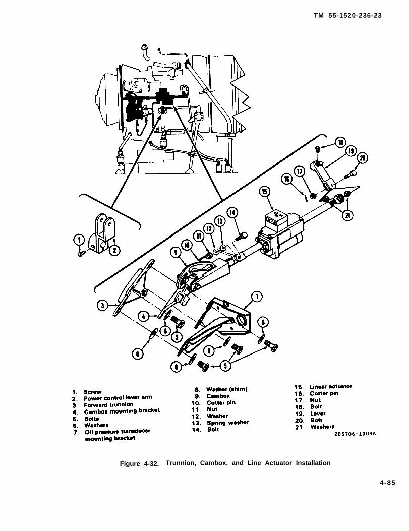
TM 55-1520-236-23
Figure 4-32. Trunnion, Cambox, and Line Actuator Installation
4-85
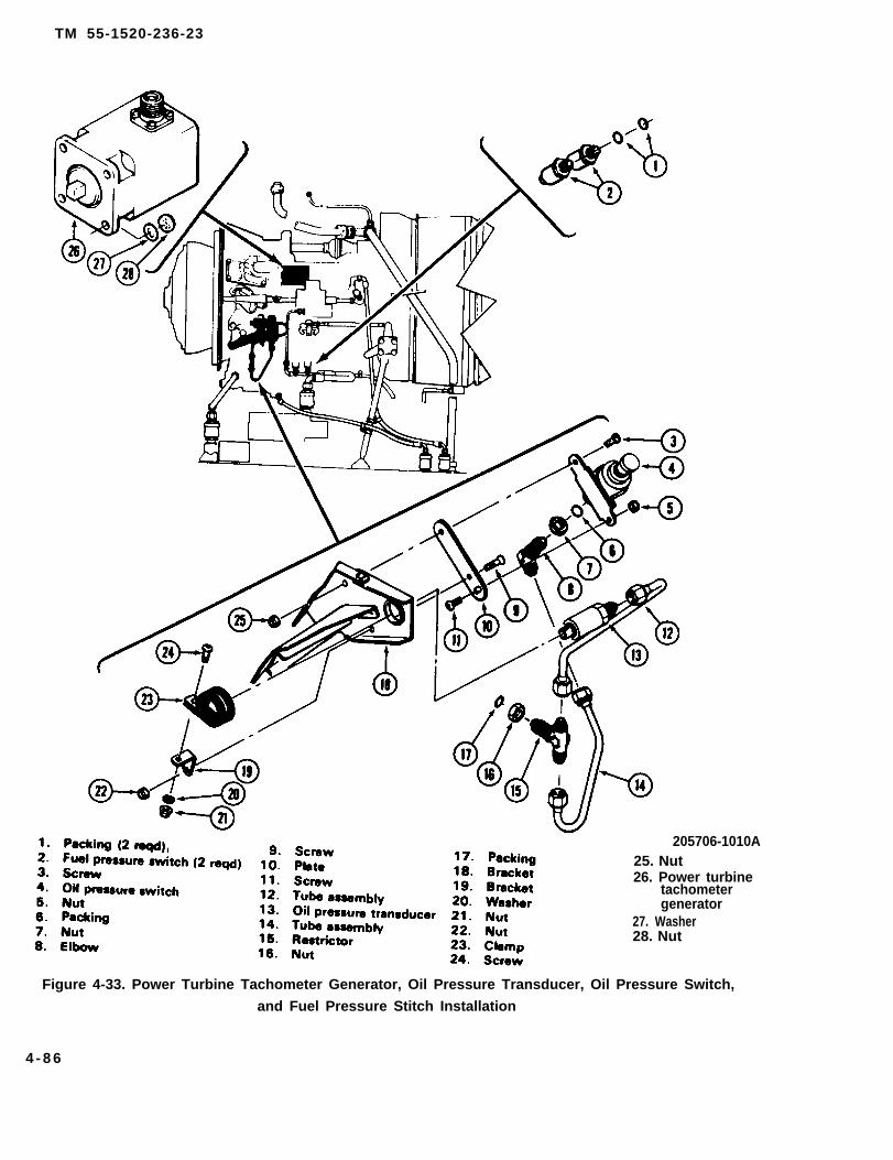
TM 55-1520-236-23
205706-1010A25. Nut26. Power turbine
tachometergenerator
27. Washer28. Nut
Figure 4-33. Power Turbine Tachometer Generator, Oil Pressure Transducer, Oil Pressure Switch,
and Fuel Pressure Stitch Installation
4 - 8 6

TM 55-1520-236-23
1. Nut2. Washer3. Gas producer tachometer generator4. Starter generator6. Shroud6. Washer7. Bolt
8. Screw 15. Screw9. Clamp 16. Clamp
10. Washer 17. Washer11. Nut 18. Nut12. Washer 19. Bracket13. Nut 20. Screw14. HOse assembly 21. Air inlet adapter
22. Gasket
Figure 4-34. Starter-Generator and Gas Producer Tachometer Generator
4 -87

TM 55-1520-236-23
(2) Install new gasket (22) on mounting pod.
NOTE
To aid in starter-generator installation,washers (12, figure 4-34) may becemented to nuts (13) using adhesive(C12) or equivalent. Due toinaccessibility, upper left nut and washermay be omitted.
(3) Install nuts (13) and washers (12) onstarter generator mounting studs.
NOTE
Coat startar-generator shaft and female slines in gearbox two-thirds fullwith lubricant (C85).
(4) Position inlet shroud (5) on starter-generator (4) with flange of shroud toward mountinggenerator mounting flange. Install bolts (7) withwashers (6) under heads, do not tighten bolts (7) atthis time.
(5) Engage starter-generator (4) splined shaftto drive splines. Install starter-generator mountingstuds and turn generator to locked position. Ensurestarter-generator is mounted with terminals atapproximately seven o’clock position. Tighten nuts(13).
NOTE
Shaft splines maybe aligned by rotatingthe N1 tachometer generator driveshaftwith a 1/4 inch extension.
(6) Ensure inlet shroud is positioned correctlyand tighten bolts (7).
b. Gas producer tachometer generator.
(1) Remove nuts and washers and removeshipping cover from tachometer generator mountingpad, Iocated on aft right side of engine accessorygearbox.
(2) Install new gasket on mounting pad.
(3) Lubricate tachometer driveshaft usinglubricant (C85).
(4) Position tachometer generator (3) on enginemounting pad with electrical connection positionedup.
(5) Install washers (2) and nuts (1). Tightennuts.
c. Hose, bracket and air inlet adapter (generatorcooling).
(1) Install bracket (19, figure 4-33) to enginemount pad using existing engine supplied hardware.
(2) Install air inlet adapter (21) to bracket (19)using four screws (20).
(3) Install flex hose (14) between generatorshroud and bracket.
(4) Secure hose to bracket using clamp (16),screw (15), washer (17), and nut (18).
(5) Secure hose to shroud using clamp (9),screw (8), washer (10), and nut (11).
d. Engine torque transducer hose and restrictor.
NOTE
Refer to paragraphs 8-111 and 8-113 forremoval/installation instructions forengine torque transducers.
NOTE
Orifice in restrictor (4, figure 4-35) is0.0250 to 0.0270 inch in diameter.
(1) Install restrictor (4, figure 4-35) with newpacking.
(2) Install hose assembly (2) on restrictor (4).
(3) Install two clamps (1).
(4) Install three clamps (3).
(5) Install three clamps (5).
(6) Install union (7) with new packing.
(7) Install hose assembly (6) on union (7).
4 -88
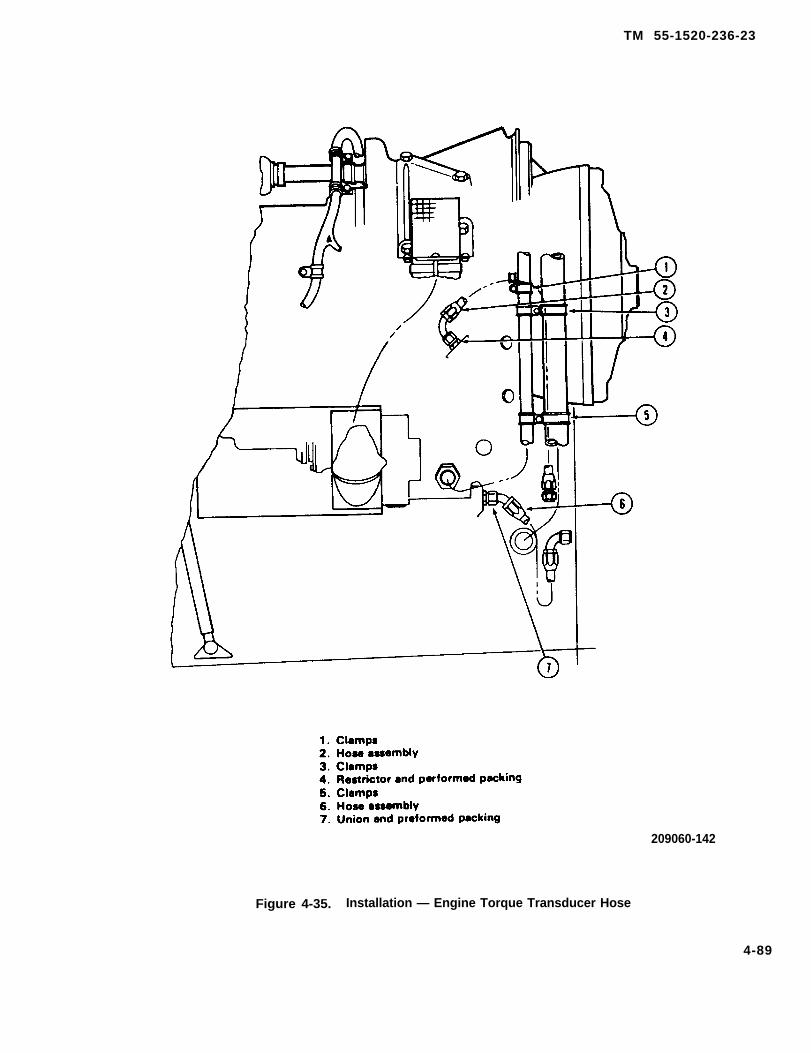
TM 55-1520-236-23
209060-142
Figure 4-35. Installation — Engine Torque Transducer Hose
4-89

TM 55-1520-236-23
4-122. INSTALLATION-HOSES, TUBES,AND FITTINGS.
a. Fuel drain hoses and tubing.
(1) Install packing (1, figure 4-35) on reducer (2).Install reducer in seal drain port of governor
(2) Install nut (5) and packing (4) on tee (6). Installtee in seal drain port of fuel control.
(3) Install tube assembly (3) between tee (6) andreducer (2).
(4) Connect hose assembly (7) to tee (6) at sealdrain port of fuel control.
(5) Install hose assembly (12) to combustionchamber drain on engine assembly.
(6) Install three unions (13) with three packings (14)to cross (16). Install coupling (15) with one packing (14)to cross (16).
(7) Connect lower end of hose assembly (7) toforward port of cross (16).
(8) Connect lower end of hose assembly (12) to topport of cross (16).
(9) Connect lower end of hose assembly (21) to aftport of cross (16).
NOTE
Tube assembly (22) and hoseassembly (21) are not installed atthis time. Refer to paragraph 4-44,4-51, or 4-58 as applicable forinstructions to install drain lines.
(10) Clamp hose assembly (7) at two locations asshown in figure 4-36. Clamp in a butterfly fashion,secure using screws (8), washers (10), and nuts (11).
(11) Clamp hose assemblies (12) and (21) togetherusing two clamps (20). Loosely assemble remaining twoclamps (20), screw (17), washer (18), and nut (19).Leave clamp installation loose until after installation ofelectrical cables.
b. Starter, fuel filter, and oil bypass valve hoses -engine left side.
(1) Install hose assembly (1, figure 4-36) to manifoldinlet port of engine. Refer to paragraph 10-62 for specialinspection requirements for fuel hose assembly (12,figure
4-90
10-2). Install coupling (2, figure 4-37) in 90 degree endof hose assembly (1).
(2) Install nut (12) and packing (11) on elbow (13).Install elbow in bleed port of governor.
(3) Connect hose assembly (7) to elbow (13). Installcoupling (8) to hose assembly (7).
(4) Install packing (15) on reducer (14). Installreducer (14) in seal drain port of starter-generator.
(5) Connect hose assembly (10) to reducer (14).Install coupling (9) to hose assembly (10).
(6) Install two clamps (5) on hose assemblies (7 and10) at locations shown. Connect clamps together ateach location using screw (6), washer (4), and nut (3).Leave clamps loose until engine installation.
(7) Install packing (19) on union (18). Install union(18) on OIL OUT port of engine.
(8) Install hose assembly (17) to union (18). Connectcoupling (16) to opposite end of hose assembly (17).
(9) On helicopters with MWO 1-1520-236-50-30,connect hose (3, figure 4-18.1) between reducer (9) insump and coupling halves (6 and 5) in IN port of oilseparator. Connect hose (4) between elbow (7) in OUTport of oil filter and coupling (10).
c. Bleed air tubing installation. (Prior to incorporationof MWO 55-1520-236-50-12).
NOTE
Install plugs in open ends of tubaassemblies (1 and 14, figure 4-38).Place half coupling (8) in plastic bag.Tubes and half coupling will beconnected when engine is installedin helicopter.
(1) Install fitting (5, figure 4-38) with gasket (18) totop bleed air port of engine. Secure using four bolts (16)and four washers (17).
(2) Install packings (2 and 4) to reducer (3). Installreducer in port of fitting (5).
(3) Connect tube assembly (1) to reducer (3).
(4) Install tube assembly (14) to fitting (5) usingcoupling assembly (15). Install coupling half, washer,and packing on each end of fitting (5) and tubeassembly (14). Place flexible center part of coupling overtube beads and tighten coupling halves.

TM 55-1520-236-23
Figure 4-36.
4-91
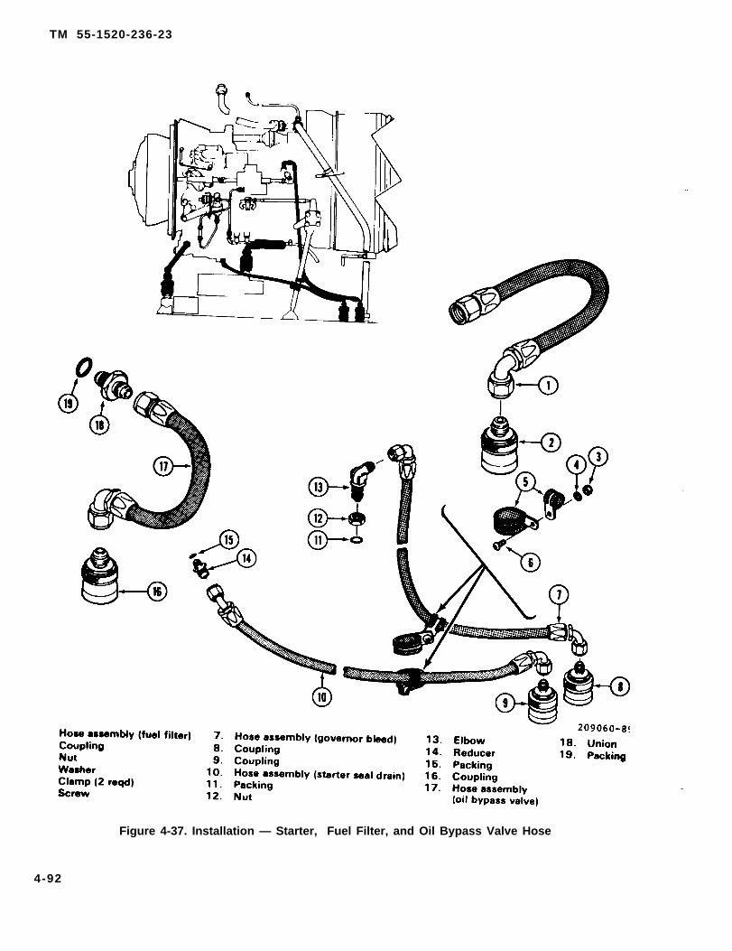
TM 55-1520-236-23
Figure 4-37. Installation — Starter, Fuel Filter, and Oil Bypass Valve Hose
4-92

TM 55-1520-236-23
1. Tube assembly2. Packing3. Reducer4. Packing5. Fitting6. Coupling assembly7. Tube assembly8. Half coupling9. Screw
10.11.12.13.14.15.16.17.18.
ClampClampWasherNutTube assemblyCoupling assemblyBoltWasherGasket
Applies to helicopters after MWO 55-1520-236-50-12 is incorporated. 205706-1013B
Figure 4-38. Installation — Bleed Air Tubing
4-93

TM 55-1520-236-23
(5) Install tube assembly (7) to fitting (5), usingcoupling assembly (6). Assemble as outlined inpreceding step.
(6) Install clamp (11) on tube assembly (7).Secure to hose on engine assembly, using clamp (10),screw (9), washer (12), and nut (13). Arrange clampsin a butterfly fashion.
c. 1 Bleed air tubing installation. (Afterincorporation of MWO 55-1520-236-50-12)
NOTE
Install plugs in open ends of tube assemblies(1, 7, 14, and 21). Place half coupling (8) inplastic bag. Tubes and half coupling will beconnected when engine is installed inhelicopter.
(1) Install fitting (19) with gasket (18) to topbleed air port of engine. Secure using four bolts (16)and four washers (17).
(2) Install packings (2 and 4) to reducer (3).Install reducer in port of fitting (19).
(3) Connect tube assembly (1) to reducer (3).
(4) Install tube assembly (14) to fitting (19) usingcoupling assembly (15). Install coupling half, washer,and packing on each end of fitting (19) and tubeassembly (14). Place flexible center part of couplingover tube beads and tighten coupling halves.
(5) Install tube assembly (7) to fitting (19) usingcoupling assembly (6). Assemble as outlined inpreceding step.
(6) Install tube assembly (21) to fitting (19) withcoupling assembly (20).
(7) Secure coupling assemblies (6, 15, and 20)with lockwire (C-138).
(8) Install clamps (22 and 25) on tube assemblies(7 and 21) in butterfly fashion using screws (24),washers (23 and 26), and nuts (27).
(2) Connect oil breather hose assembly (14) tounion (12).
(3) Install coupling (13) to hose assembly (14).
(4) Install union (10) with packing (9) in OIL INport of engine.
(5) Connect hose assembly (2) to union (10).
(6) Install coupling (1) to hose assembly (2).
(7) Install clamps (6 and 7) to oil hoses asshown. Secure to engine, using screw (8), spacer (5),washer (4), and nut (3).
(8) Install clamp (18) to hose assembly (2).Secure to tube on assembly, using screw (19), clamp(17), washer (16), and nut (15).
(9) Install clamp (22) to hose assembly (2).Install clamp (23) to hose assembly (14). Secureclamps together, using screw (24), washer (21), andnut (20).
4-123. INSTALLATION – HEATSHIELD, TAILPIPE, AND EJECTOR.
NOTE
Installation of the following componentsshould be accomplished after engine isinstalled in helicopter.
a. Attach heat shield (2, figure 4-40) to engineassembly, using clamp (1). Seat clamp using a plasticmallet while tightening. Torque clamp 100 TO 130inch-pounds.
b. Attach tailpipe (5) to heatshield (2), usingclamp (3). Seat clamp using a plastic mallet whiletightening. Torque clamp 100 TO 130 inch-pounds.
c. Position ejector (9) over tailpipe. Secure ejectorto aft fairing, using three screws(7) and three nuts (8).
d. Connect hose assembly (11) to tailpipe.d. Oil hose assemblies.
(1) Install union (12, figure 4-39) with packing(11) in engine accessory gearbox port.
e. Install tube assembly between hose (11) andejector (9).
4-94

TM 55-1520-236-23
4-124 . INSTALLATION – EXHAUSTS Y S T E M C O M P O N E N T S ( I N F R A R E DSUPPRESSION SYSTEM).
NOTE
The infrared suppression systemillustrated on figure 4-17 is attached to,and partially supported by, the IRsuppressor cowling; therefore, infraredsuppression system illustrated on figure4-17 must be installed after engine isinstalled in helicopter.
a. Install Infrared Suppressor Cowling (7, figure4-17) as outlined in paragraph 2-89.
b. Install Infrared Suppressor SystemComponents as outlined in paragraph 4-58.
4 - 1 2 5 . I N S T A L L A T I O N – E N G I N EELECTRICAL CABLES.
NOTE
Refer to wiring diagram in Appendix F forwiring or connector identification.
a. Install nipples over ends of wires of starter-generator cable (6, figure 4-41).
(1) One nipple on wires K5C4 and K5A1.
(2) One nipple on wires P26A1 and P26C4.
(3) One nipple on wires K4B4 and K4D4.
(4) One nipple on wire P25A16.
b. Remove nuts and washers from terminals C, B,and E of starter-generator.
4-94.1/(4-94.2 blank)

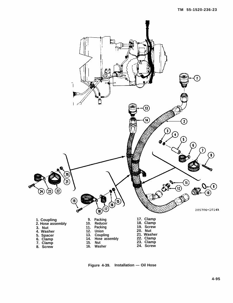
TM 55-1520-236-23
1. Coupling2. Hose assembly3. Nut4. Washer5. Spacer6. Clamp7. Clamp8. Screw
9.10.11.12.13.14.15.16.
PackingReducerPackingUnionCouplingHose assemblyNutWasher
17. Clamp18. Clamp19. Screw20. Nut21. Washer22. Clamp23. Clamp24. Screw
Figure 4-39. Installation — Oil Hose
4-95

Figure 4-40.
TM
55-1
520-2
36-2
3
4-9
6

TM 55-1520-236-23
Figure 4-41. Electrical Cable Installation — Engine Left Side (Sheet 1 of 2)
4-97
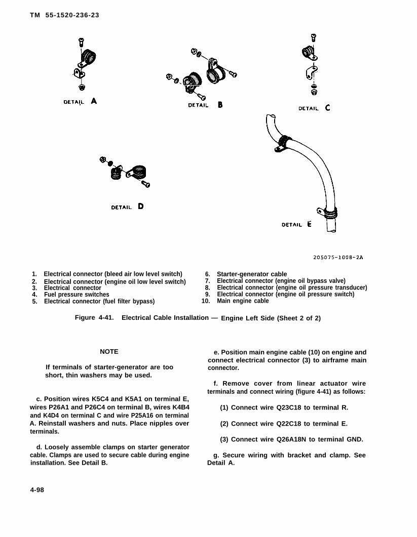
TM 55-1520-236-23
1.2.3.4.5.
Electrical connector (bleed air low level switch) 6.Electrical connector (engine oil low level switch) 7.Electrical connector 8.Fuel pressure switches 9.Electrical connector (fuel filter bypass) 10.
Starter-generator cableElectrical connector (engine oil bypass valve)Electrical connector (engine oil pressure transducer)Electrical connector (engine oil pressure switch)Main engine cable
Figure 4-41. Electrical Cable Installation — Engine Left Side (Sheet 2 of 2)
NOTE
If terminals of starter-generator are tooshort, thin washers may be used.
e. Position main engine cable (10) on engine andconnect electrical connector (3) to airframe mainconnector.
f. Remove cover from linear actuator wireterminals and connect wiring (figure 4-41) as follows:
c. Position wires K5C4 and K5A1 on terminal E,wires P26A1 and P26C4 on terminal B, wires K4B4and K4D4 on terminal C and wire P25A16 on terminalA. Reinstall washers and nuts. Place nipples overterminals.
d. Loosely assemble clamps on starter generatorcable. Clamps are used to secure cable during engineinstallation. See Detail B.
(1) Connect wire Q23C18 to terminal R.
(2) Connect wire Q22C18 to terminal E.
(3) Connect wire Q26A18N to terminal GND.
g. Secure wiring with bracket and clamp. SeeDetail A.
4-98

h. Connect electrical connector (8) to engine oilpressure transducer and connect electrical connector(9) to engine oil pressure switch.
i. Secure cable with clamps as shown in details Dand E.
j. Install one nipple on wire W71D18 and one nippleon wire W71E18.
k. Remove nuts and washers from terminals of fuelpressure switches (4). Position one wire on eachpressure switch and reinstall washers and nuts. Placenipples over terminals.
l. Connect electrical connector (5) to fuel filter bypassswitch and connect electrical connector (7) to engine oilbypass valve.
m. Secure cable with bracket and clamp. Seedetail C.
n. Connect electrical connector (1) to bleed air valveand connect electrical connector (2) to engine oil lowlevel switch receptacle.
TM 55-1520-238-23o. Secure harness to bleed air duct with clamps. See
figure 4-42, detail C.
p. Connect electrical connectors (1 and 2) to torquepressure transducers.
q. Assemble terminal board assembly details (6 thru11) to engine support. Connect engine ground wires toterminal board ITBI. Secure wires to terminal board withwashers (5), nuts (4), and cover (3).
r. Secure cable with clamps. See detail D.
s. On helicopters without MWO 1-1520-236-50-30,install nipple on wire W10C18. Remove nut and washerfrom terminal of chip detector (12). Install wire W10C18on chip detector terminal. Reinstall washer and nut andplace nipple over terminal. Secure wire with clamps.See detail E.
t. On helicopter with MWO 1-1520-236-50-30,connect cable plug (wire W10C18) to the oil separatorchip detector.
u. Secure remainder of harness to engine usingclamps and brackets. See details A, B, F, G, and H.
v. Secure exhaust thermocouple cable (13) to enginewith clamp and bracket. See detail J.
4-99

TM 55-1520-236-23
Figure 4-42. Electrical Cable Installation - Engine Right Side (Sheet 1 of 2)
4-100

TM 55-1520-236-23
1. Electrical connector2. Electrical connector3. Terminal board cover4. Nut5. Washer6. Link
7. Insulator8. Nut9. Terminal board
10. Washer11. Screw12. Chip detector13. Exhaust thermocouple cable
205075-1009-2C
Figure 4-42. Electrical Cable Installation — Engine Right Side (Sheet 2 of 2)
4-101/(4-102 blank)


TM 55-1520-236-23
CHAPTER 5
R O T O R S
5-1. ROTOR SYSTEM. The rotor system is comprised of the main rotorsystem and the tail rotor system. Refer to paragraph
5-2. DESCRIPTION — ROTOR SYSTEM. 5-4 for description of the main rotor system. Refer toparagraph 5-73 for description of the tail rotor system.
SECTION I. MAIN ROTOR SYSTEM
5-3. MAIN ROTOR SYSTEM.
5-4. DESCRIPTION — MAIN ROTOR SYSTEM.
The main rotor system consists of the main rotor huband blade assembly, swashplate assembly, scissorsand sleeve assembly and connecting tubes (pitchlinks). The main rotor hub trunnion (2, figure 5-1) andthe main rotor mast (11) are splined in the area wherethe trunnion mounts on the mast so that the main rotorrotates with the mast. The trunnion is supported onthe lower side with a cone set (not illustrated) and issecured by the mast nut (3). The mast nut also servesas a cap for the hollow mast and as a lifting eye.
NOTE
Refer to paragraph 5-25 for descriptionof K747 main rotor blades (7, figure 5-1).
The main rotor hub is of the semi-rigid, underslungdesign consisting basically of the yoke (1), trunnion(2), elastomeric bearing (4), yoke extensions, pitchhorns (9), drag braces (8), and grips (5). The yoke ismounted to the trunnion by elastomeric bearings (4)which permit rotor flapping. Cyclic and collective pitchchange inputs are received through pitch hornsmounted on the trailing edge of the grips. The grips inturn are permitted to rotate about the yoke extensionson teflon impregnated fabric friction bearings resultingin the desired blade pitch. Adjustable drag braces (8)are attached to the grips (5) and main rotor bladesmaintaining alignment. Blade centrifugal loads aretransferred from the blade grips to the extensions bywire wound, urethane coated, tension torsion straps.The hub moment spring assembly (MWO55-1520-244-50-3 Incorporated) consists of anelastomeric spring (28), support assembly (29), plates(30) and straps (31). The hub moment spring
assembly prevents the main rotor hub from contactingthe mast during high flapping maneuvers.
The swashplate inner ring (22), outer ring (21),swashplate support (15), anti-drive link (13) andscissors and sleeve assembly (23) serve to control thepitch of the main rotor blades.
Forward and aft cyclic input and lateral cyclic inputfrom the pilot/gunner is transmitted from the hydrauliccontrol cylinders (18 and 17) to the non-rotatingswashplate inner ring (22). The anti-drive link (13) isconnected to the aft swashplate support horn andprevents the swashplate inner ring (22) from rotatingabout the outer ring (21). The control is changed torotating at the swashplate outer ring (21). It is thentransmitted through the scissors and sleeve assembly(23), and pitch links (10) to the main rotor hub pitchhorns (9) and main rotor blades.
Collective control input from the pilot/gunner isaccomplished through the collective control cylinder(16), collective levers (14), scissors and sleeveassembly (23) and the friction collet (12). Thecollective lever (14) is attached to the lower end of thescissors and sleeve assembly (23) and moves theseparts vertically. The sleeve is inside the swashplateand does not rotate, and the scissors are mounted atthe top of the sleeve with a hub and bearings. A splineplate, bolted to the top of the hub, contacts splines onthe main rotor mast (11). An extension on top of thespline plate carries a friction collet (12) which bears ona sleeve bonded on the mast. The spline plate canmove vertically on the main rotor mast to permitvertical movement of the scissors and sleeveassembly. The spline plate rotates with the main rotormast and causes the scissors hub, scissors andswashplate outer ring (21) to rotate with the mast.Collective pitch control input and cyclic pitch controlinput to the scissors is transmitted through the pitchlinks (10) to the main rotor blade pitch horns (9).
5-1

TM 55-1520-236-23
NOTE: View A applicable after MWO 55-1520-244-50-9 is incorporated. 209200-35D
Figure 5-1. Main Rotor System (sheet 1 of 2)
5-2
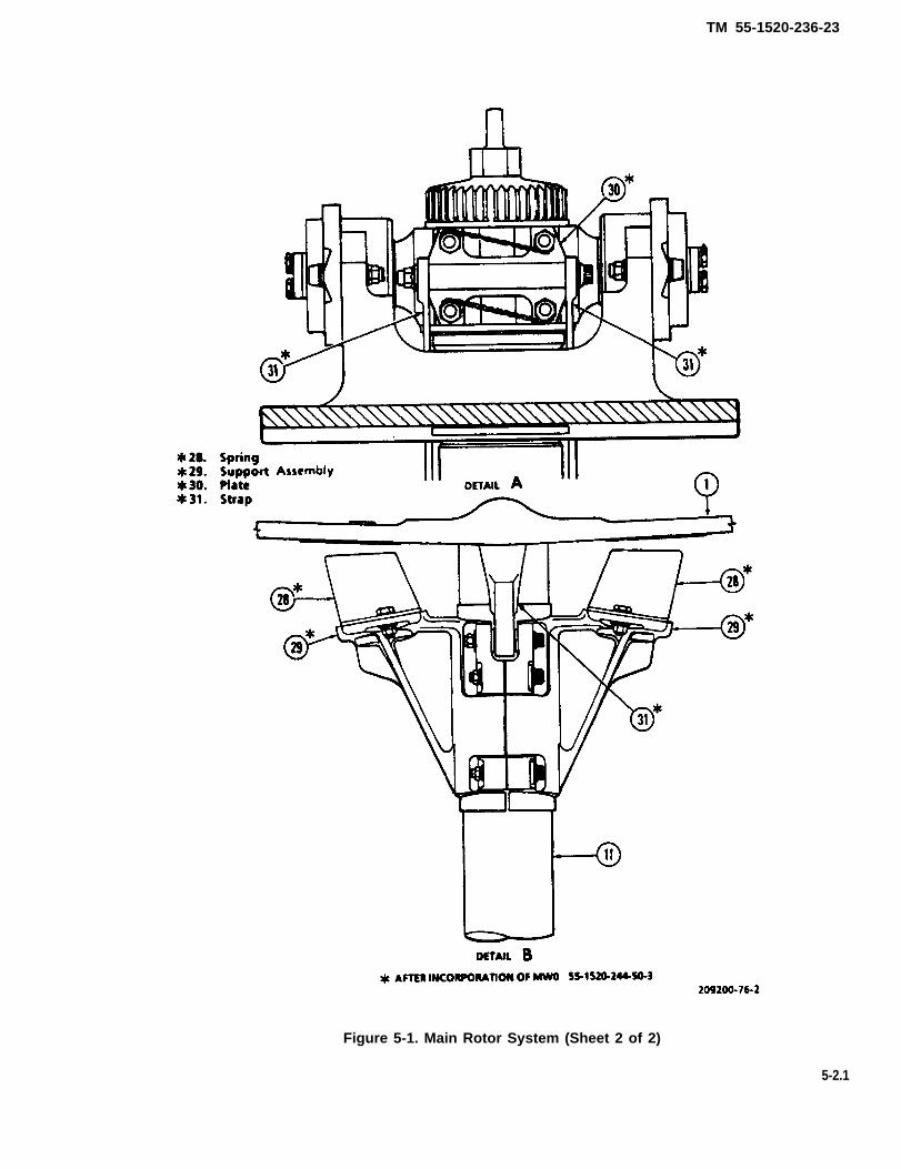
TM 55-1520-236-23
Figure 5-1. Main Rotor System (Sheet 2 of 2)
5-2.1

TM 55-1520-238-23
5-5. ADJUSTMENT-MAIN ROTOR SYSTEM. b. Perform functional test flight (TM 55-1520-236-MTF).
Refer to Section VIII.c. If fictional test flight performed Ill preceding
5-6. OPERATIONAL CHECK-MAIN ROTOR step indicates that additional adjustments and/orSYSTEM. maintenance is required, troubleshoot the main rotor
system in accordance with paragraph 5-7.Perform the following checks after installation ofmain rotor system. 5-7. TROUBLESHOOTING-MAIN ROTOR SYS-
a. Track main rotor blades (paragraph 5-114).Utilize figures 5-93 through 5-96 to troubleshoot themain rotor system.
S E C T I O N I I . M A I N R O T O R H U B A N D B L A D E S
5-8. B540 MAIN ROTOR HUB AND BLADES.
5 - 9 . B 5 4 0 D E S C R I P T I O N - M A I N R O T O RHUB AND BLADES.
The semi-rigid type main rotor consists of two metalblades (31, figure 5-2) and the hub. The hub yoke (24)is underslung relative to the trunnion (1). The trun-nion is attached to the yoke with elastomeric bear-ings (2). The splined hub trunnion mounts on themain rotor mast. The elastomeric bearings allow thehub yoke and blades to move on the flapping axis.The hub moment spring assembly (MWO 55-1520-244-50-3 Incorporated) prevents main rotor hubfrom contacting the mast during high tippingmaneuvers. The grips (19) rotate on the yoke exten-sions for change in blade pitch when pitch horns (20)are raised or lowered by control linkage. Blade align-ment is maintained by adjustable drag braces (12).Refer to paragraph 5-25 for K747 blades. Specialtorque values for the main rotor system are shownon figure 5-3.
5-10. CLEANING-MAIN ROTOR HUB ANDBLADES.
a. Clean blades thoroughly with cleaning com-pound (C33).
b. Rinse with clear water and allow to dry.
WARNING
Cleaning solvent is flammable andtoxic. Provide adequate ventilation.Avoid prolonged breathing of vaporsand contact with skin or eyes.
CAUTION
The erosion guard on K747 main rotorblades is very susceptible to solvents.Use care to prevent spillage or run-offof solvent onto the guard.
c. Remove stubborn deposits with a cloth damp-ened with solvent (C112), except on K747 blade theerosion guard shall be cleaned only with detergent(C50) or clean compound (C33).
d. Clean main rotor hub with cloths dampened withsolvent (C112).
5-11. INSPECTION-MAIN ROTOR HUB ANDBLADES.
NOTERefer to TM 55-1600-322-24 for inspec-tion criteria of Teflon lined bearings.
a. Remove two send deflectors, if installed, fromeach main rotor hub to be inspected.
b. Check the clearance between each extension andgrip assembly by inserting the 0.100 to 0.125 inch thickstrap between them. Move the strap through the fullrange of gap between grip and extension with hub andmetal blade angle set in accordance with paragraph5-14.q.(5) and for clearance on hubs with fiberglassblades in accordance with paragraph 5-14. q. (6). Dis-connect pitch links per paragraph 5-12.b. Rotate hubend blade and check for clearance with a total positiveangle of attack of 17 degrees on hub with metal bladesor 20 degrees on hub with fiberglass blades. Rotate huband blades and check for zero angle of attack. Mainrotor hubs which do not allow the 0.100 to 0.125 inchthick strap to pass should be disassembled for visual
5-2.2

TM 55-1520-236-23
check for interference, rubbing or other signs of con-tact between grip and extension. Inspect carefullythe outboard end of extension barrel and grip forinterference. If there are no visual signs of contact ongrip and extension the hub maybe reassembled. Allparts with signs of interference must be replaced.
5-2.3/(5-2.4 blank)

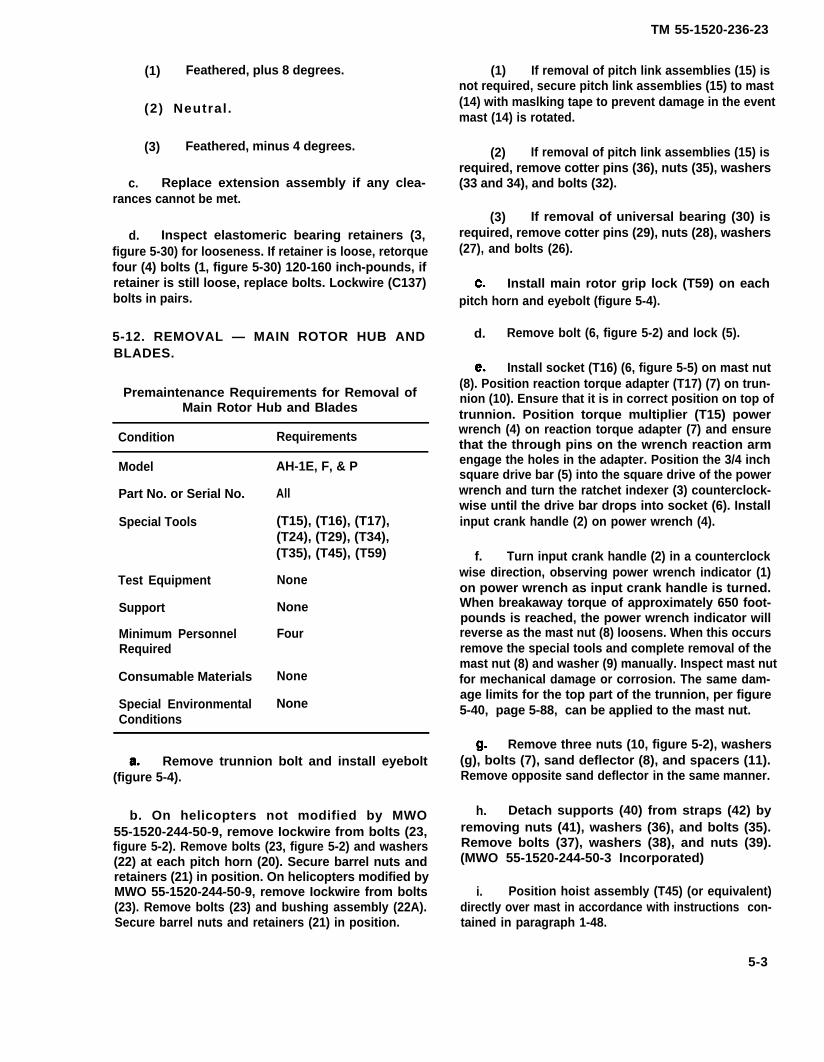
(1) Feathered, plus 8 degrees.
(2) Neutral .
(3) Feathered, minus 4 degrees.
c. Replace extension assembly if any clea-rances cannot be met.
d. Inspect elastomeric bearing retainers (3,figure 5-30) for looseness. If retainer is loose, retorquefour (4) bolts (1, figure 5-30) 120-160 inch-pounds, ifretainer is still loose, replace bolts. Lockwire (C137)bolts in pairs.
5-12. REMOVAL — MAIN ROTOR HUB ANDBLADES.
Premaintenance Requirements for Removal ofMain Rotor Hub and Blades
Condition Requirements
Model
Part No. or Serial No.
Special Tools
Test Equipment
Support
Minimum PersonnelRequired
Consumable Materials
Special EnvironmentalConditions
AH-1E, F, & P
All
(T15), (T16), (T17),(T24), (T29), (T34),(T35), (T45), (T59)
None
None
Four
None
None
Remove trunnion bolt and install eyebolt(figure 5-4).
b. On helicopters not modified by MWO55-1520-244-50-9, remove Iockwire from bolts (23,figure 5-2). Remove bolts (23, figure 5-2) and washers(22) at each pitch horn (20). Secure barrel nuts andretainers (21) in position. On helicopters modified byMWO 55-1520-244-50-9, remove Iockwire from bolts(23). Remove bolts (23) and bushing assembly (22A).Secure barrel nuts and retainers (21) in position.
TM 55-1520-236-23
(1) If removal of pitch link assemblies (15) isnot required, secure pitch link assemblies (15) to mast(14) with maslking tape to prevent damage in the eventmast (14) is rotated.
(2) If removal of pitch link assemblies (15) isrequired, remove cotter pins (36), nuts (35), washers(33 and 34), and bolts (32).
(3) If removal of universal bearing (30) isrequired, remove cotter pins (29), nuts (28), washers(27), and bolts (26).
Install main rotor grip lock (T59) on eachpitch horn and eyebolt (figure 5-4).
d. Remove bolt (6, figure 5-2) and lock (5).
Install socket (T16) (6, figure 5-5) on mast nut(8). Position reaction torque adapter (T17) (7) on trun-nion (10). Ensure that it is in correct position on top oftrunnion. Position torque multiplier (T15) powerwrench (4) on reaction torque adapter (7) and ensurethat the through pins on the wrench reaction armengage the holes in the adapter. Position the 3/4 inchsquare drive bar (5) into the square drive of the powerwrench and turn the ratchet indexer (3) counterclock-wise until the drive bar drops into socket (6). Installinput crank handle (2) on power wrench (4).
f. Turn input crank handle (2) in a counterclockwise direction, observing power wrench indicator (1)on power wrench as input crank handle is turned.When breakaway torque of approximately 650 foot-pounds is reached, the power wrench indicator willreverse as the mast nut (8) loosens. When this occursremove the special tools and complete removal of themast nut (8) and washer (9) manually. Inspect mast nutfor mechanical damage or corrosion. The same dam-age limits for the top part of the trunnion, per figure5-40, page 5-88, can be applied to the mast nut.
Remove three nuts (10, figure 5-2), washers(g), bolts (7), sand deflector (8), and spacers (11).Remove opposite sand deflector in the same manner.
h. Detach supports (40) from straps (42) byremoving nuts (41), washers (36), and bolts (35).Remove bolts (37), washers (38), and nuts (39).(MWO 55-1520-244-50-3 Incorporated)
i. Position hoist assembly (T45) (or equivalent)directly over mast in accordance with instructions con-tained in paragraph 1-48.
5-3
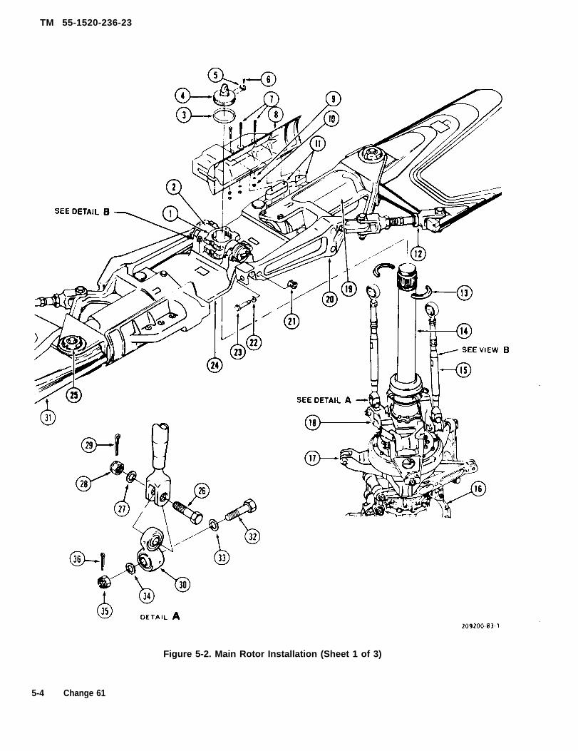
TM 55-1520-236-23
Figure 5-2. Main Rotor Installation (Sheet 1 of 3)
5-4 Change 61
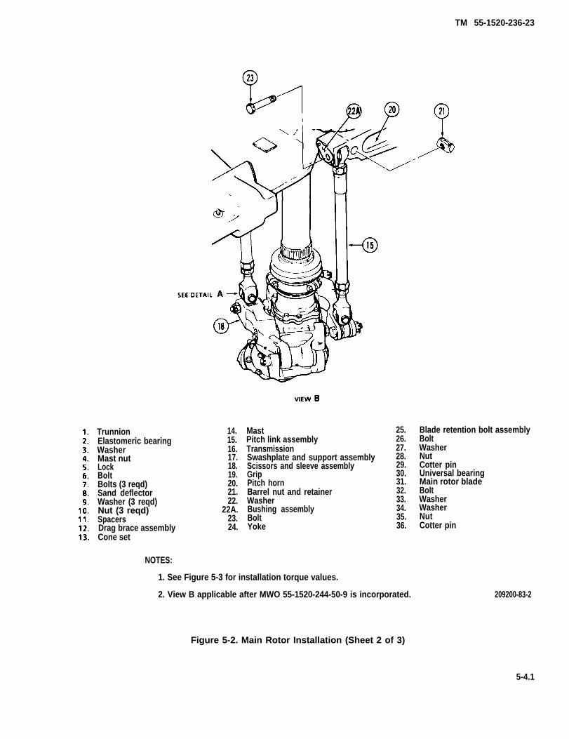
TM 55-1520-236-23
TrunnionElastomeric bearingWasherMast nutLockBoltBolts (3 reqd)Sand deflectorWasher (3 reqd)Nut (3 reqd)SpacersDrag brace assemblyCone set
14.15.16.17.18.19.20.21.22.
22A.23.24.
MastPitch link assemblyTransmissionSwashplate and support assemblyScissors and sleeve assemblyGripPitch hornBarrel nut and retainerWasherBushing assemblyBoltYoke
NOTES:
1. See Figure 5-3 for installation torque values.
25.26.27.28.29.30.31.32.33.34.35.36.
2. View B applicable after MWO 55-1520-244-50-9 is incorporated.
Blade retention bolt assemblyBoltWasherNutCotter pinUniversal bearingMain rotor bladeBoltWasherWasherNutCotter pin
209200-83-2
Figure 5-2. Main Rotor Installation (Sheet 2 of 3)
5-4.1

TM 55-1520-236-23
32. BOLT 41. NUT33. WASHER 42 STRAP34. NUT 43. SPRING35. BOLT 44. WASHER36. WASHER 45. BOLT37. BOLT 46. BOLT38. WASHER 47. WASHER39. NUT 48. NUT40. SUPPORT 49. PLATE
50. WASHER
Figure 5-2. Main Rotor Installation (Sheet 3 of 3)
5-4.2

TM 55-1520-236-23
j. Position two rotor slings (T24) on main rotorhub and attach to hiost. (Do not wrap Iiftng sling cablearound sharp corners on rotor hub.)
k. Attach a tiedown assembly on each rotorblade for use in guiding and steadying rotor duringremoval.
Loosen nut (48, figure 5-2) prior to re-moval of hub moment springs and supports to prevent damage to assembly.
l. Carefully hoist the main rotor hub and bladeassembly dear of the mast.
m. Remove cone set (13). Attach cone set halvestogether and retain as a matched set.
Place adapter plate (T34) on buildup bench(T29) and position hub and blade assembly on thebench. Place padded supports under each bide. Seefuture 5-6 for view of hub mounted on buildup bench.
o. Install sand defectors (8), spacers (11),washers (9), bolts (7), and nuts (10) that were removedin step g.
5-13. ALIGNMENT – MAIN ROTOR HUB ANDBLADES.
Premaintenance Requirements for Alignmentof Main Rotor Hub and Blades
Condition Requirements
Model AH-1E, F,& P
Part No. or Serial No. All
Special Tools (T59), (T34), (T29),(T30), (T31), (T38),
Test Equipment Protractor
Support Equipment Main rotor bladesupport with wheels(two required)
Minimum Personnel TwoRequired
Consumable Materials None
Special Environmental NoneConditions
Install main rotor grip locks (T59) on eachpitch horn if not previously accomplished (figure 5-4).
b. Remove nuts (46, future 5-2), washers (47),and bolts (46). Remove straps (42). Remove Iockwire,bolts (45), and washers (44). Remove plates (49) andwashers (50) (MWO 55-1520-244-50-3 Incorporated).Install flap stop plates (T39) to lock trunnion.
c. Position main rotor hub and blade assemblyon stands for accomplishment of alignment procedureas follows:
(1) Place adapter plate (T34) on build-upbench (T29).
(2) Place main rotor hub and blade assemblyon build-up bench shown on figure 5-6.
(3) Place stand equipped with wheels undereach blade to support the blades at a precone angle ofapproximately 2-1/2 degrees up so blades will moveeasily in grips if drag brace adjustment is required.
(4) Remove main rotor grip locks (T59).Install barrel jacks (figure 5-4.1) as a work aid asshown in figure 5-4.2. Place protractor on machinedsurface adjacent to blade retention bolt assembly (25,figure 5-2) and shim or wedge each blade supportstand and adjust barrel jack on main rotor grip to obtainzero degree chordwise.
d. Position alignment scope support (T38) overelastomeric bearings as shown in figure 5-6.
e. Install and adjust scope (T30) as follows:
(1) Position scope (T30) on support as shownon figure 5-6.
(2) Zero cross-hair on an object approximate-ly fifty feet away. Draw a vertical line on the object toalign with the vertical cross-hair.
(3) Loosen damp screws, rotate scope 180degrees on scope tube axis, and tighten damp screws.
(4) Observe vertical line drawn in step (2). Ifvertical cross-hair aligns with first vertical line drawn instep (1), proceed to step f. If vertical cross-hair doesnot align with first vertical line drawn, draw a secondvertical line on object to align with vertical cross-hair.Measure one half the distance between the two verti-cal lines and draw a third vertical line.
5-5

TM 55-1520-236-23
Figure 5-3. Main Rotor System Torque Values (Sheet 1 of 3)
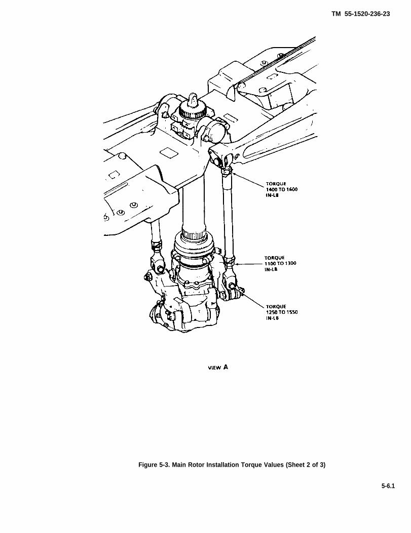
TM 55-1520-236-23
Figure 5-3. Main Rotor Installation Torque Values (Sheet 2 of 3)
5-6.1

TM 55-1520-236-23
Figure 5-3. Main Rotor Installation Torque Values (Sheet 3 of 3)
5-6.2
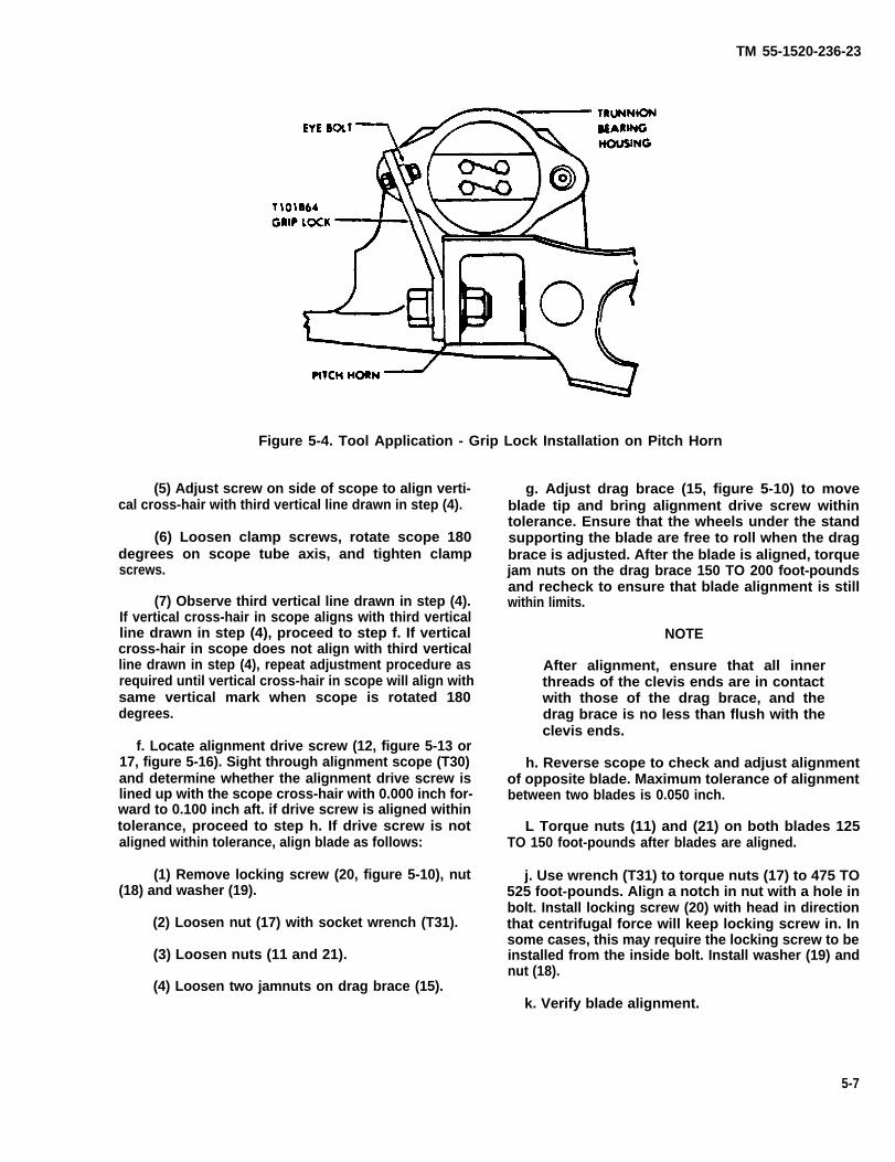
TM 55-1520-236-23
Figure 5-4. Tool Application - Grip Lock Installation on Pitch Horn
(5) Adjust screw on side of scope to align verti-cal cross-hair with third vertical line drawn in step (4).
(6) Loosen clamp screws, rotate scope 180degrees on scope tube axis, and tighten clampscrews.
(7) Observe third vertical line drawn in step (4).If vertical cross-hair in scope aligns with third verticalline drawn in step (4), proceed to step f. If verticalcross-hair in scope does not align with third verticalline drawn in step (4), repeat adjustment procedure asrequired until vertical cross-hair in scope will align withsame vertical mark when scope is rotated 180degrees.
f. Locate alignment drive screw (12, figure 5-13 or17, figure 5-16). Sight through alignment scope (T30)and determine whether the alignment drive screw islined up with the scope cross-hair with 0.000 inch for-ward to 0.100 inch aft. if drive screw is aligned withintolerance, proceed to step h. If drive screw is notaligned within tolerance, align blade as follows:
(1) Remove locking screw (20, figure 5-10), nut(18) and washer (19).
(2) Loosen nut (17) with socket wrench (T31).
(3) Loosen nuts (11 and 21).
(4) Loosen two jamnuts on drag brace (15).
g. Adjust drag brace (15, figure 5-10) to moveblade tip and bring alignment drive screw withintolerance. Ensure that the wheels under the standsupporting the blade are free to roll when the dragbrace is adjusted. After the blade is aligned, torquejam nuts on the drag brace 150 TO 200 foot-poundsand recheck to ensure that blade alignment is stillwithin limits.
NOTE
After alignment, ensure that all innerthreads of the clevis ends are in contactwith those of the drag brace, and thedrag brace is no less than flush with theclevis ends.
h. Reverse scope to check and adjust alignmentof opposite blade. Maximum tolerance of alignmentbetween two blades is 0.050 inch.
L Torque nuts (11) and (21) on both blades 125TO 150 foot-pounds after blades are aligned.
j. Use wrench (T31) to torque nuts (17) to 475 TO525 foot-pounds. Align a notch in nut with a hole inbolt. Install locking screw (20) with head in directionthat centrifugal force will keep locking screw in. Insome cases, this may require the locking screw to beinstalled from the inside bolt. Install washer (19) andnut (18).
k. Verify blade alignment.
5-7

TM 55-1520-236-23
Figure 5-4.1. Barrel Jack Installation
5 - 8
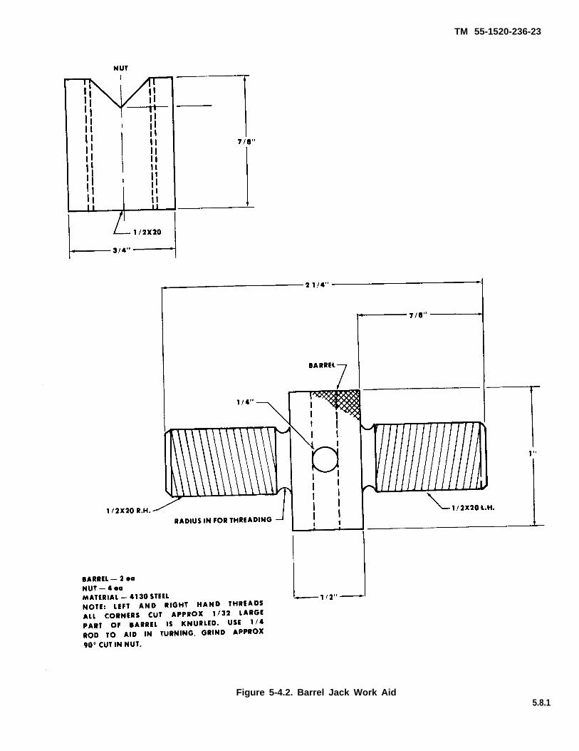
TM 55-1520-236-23
Figure 5-4.2. Barrel Jack Work Aid5.8.1

TM 55-1520-236-23
Figure 5-5. Tool Application - Main Rotor Mast Nut Removal/Installation
5-8.2
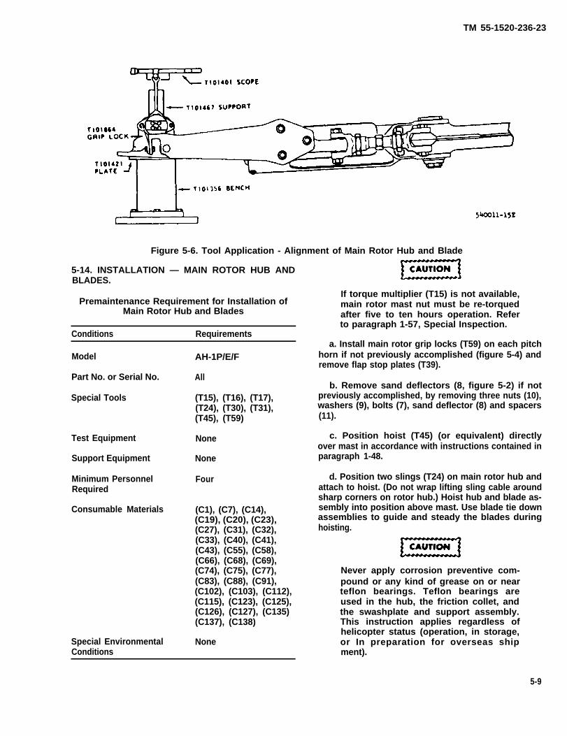
TM 55-1520-236-23
Figure 5-6. Tool Application - Alignment of Main Rotor Hub and Blade
5-14. INSTALLATION — MAIN ROTOR HUB ANDBLADES.
Premaintenance Requirement for Installation ofMain Rotor Hub and Blades
Conditions Requirements
Model
Part No. or Serial No.
Special Tools
Test Equipment
Support Equipment
Minimum PersonnelRequired
Consumable Materials
Special EnvironmentalConditions
AH-1P/E/F
All
(T15), (T16), (T17),(T24), (T30), (T31),(T45), (T59)
None
None
Four
(C1), (C7), (C14),(C19), (C20), (C23),(C27), (C31), (C32),(C33), (C40), (C41),(C43), (C55), (C58),(C66), (C68), (C69),(C74), (C75), (C77),(C83), (C88), (C91),(C102), (C103), (C112),(C115), (C123), (C125),(C126), (C127), (C135)(C137), (C138)
None
If torque multiplier (T15) is not available,main rotor mast nut must be re-torquedafter five to ten hours operation. Referto paragraph 1-57, Special Inspection.
a. Install main rotor grip locks (T59) on each pitchhorn if not previously accomplished (figure 5-4) andremove flap stop plates (T39).
b. Remove sand deflectors (8, figure 5-2) if notpreviously accomplished, by removing three nuts (10),washers (9), bolts (7), sand deflector (8) and spacers(11).
c. Position hoist (T45) (or equivalent) directlyover mast in accordance with instructions contained inparagraph 1-48.
d. Position two slings (T24) on main rotor hub andattach to hoist. (Do not wrap lifting sling cable aroundsharp corners on rotor hub.) Hoist hub and blade as-sembly into position above mast. Use blade tie downassemblies to guide and steady the blades duringhoisting.
Never apply corrosion preventive com-pound or any kind of grease on or nearteflon bearings. Teflon bearings areused in the hub, the friction collet, andthe swashplate and support assembly.This instruction applies regardless ofhelicopter status (operation, in storage,or In preparation for overseas shipment).
5-9

TM 55-1520-236-23
e. Coat splines of mast (14) with corrosionpreventive compound (C41 or C43).
CAUTIONEnsure that cone set is a matched set.Rotor hub must be aligned carefullyto avoid damaging mast threads.
NOTEDo not coat the mast threads of splitcone groove with corrosion preven-tive compound (C41 or C43).
Split cones are installed with equalend gap spacing. If the split conestouch at anytime thereafter, there isno need to respace them.
f. Inspect split cones (13) for any nicks, scratches,indentions, and deformities of any type. Droppingthe split cone does not constitute automatic replace-ment unless the damage limits shown in figure 5-7are exceeded. Place cone set (13, figure 5-2) in grooveof mast upper splines with bevel side up and the gapsevenly spaced.
g. Align master spline in hub with master splineon mast. Carefully lower the hub and blade on themast splines to avoid damage to mast threads. Lowerthe hub assembly slowly until it rests on the cone set.
h. Remove excess corrosion preventive com-pound.
i. Remove hoisting slings.
NOTEBefore installing retaining nut, besure cap plug is installed in mast.
j. Install washer (3, figure 5-2) and mast nut (4).Tighten mast nut snug with socket (T16). Installmain rotor mast nut special installation tools inaccordance with paragraph 5-12(e). Turn inputcrank handle (2, figure 5-5) in a clockwise directionand observe indicator (1) on torque multiplier (T15).Torque to 650 foot-pounds. Continue to observe theindicator for three full minutes. It will be normal ifthe indicator reading decreases. This is caused byseating of the cone set. Do not back off torque if theindicator reading decreases.
k. If the indicator reading decreases during thethree minute observation period in the preceding
step, retorque to 650 foot-pounds and monitor for oneminute. Repeat one additional time if necessary. Afterobtaining 650 foot-pound indication with no loss, turnthe crank counterclockwise until the torque indicatorreturns to zero (green) to remove holding force on thewrench.
l. Remove crank handle, power wrench, drivebar, adapter and socket.
m. Check lock (5) installation to ensure that it willalign. If lock (5) will not align, reinstall the powerwrench and increase torque, but do not exceed 780foot-pounds. Use the protractor on the face of thepower wrench (3, figure 5-5) to estimate the degreeof turn required to obtain alignment.
n. Install lock (5, figure 5-2) and bolt (6). Lockwire(C137) bolt head.
o. Install spacers (11) and sand deflectors (8) withthree bolts (7), washers (9), and nuts (10). If spacersdo not fit snugly in place, wrap with tape (C126)until snug fit is obtained.
p. Remove main rotor locks (T59) from pitchhorns. Remove eyebolts shown on figure 5-4 andreplace with trunnion bearing retaining bolts.Torque nuts 160 TO 190 inch-pounds. If more thanfive threads show at nut, add a washer under thenut.
CAUTIONClose-tolerance, high-tensile bolts andspecial washers are used in the mainrotor flight control linkage. Refer toTM 55-1520-236-23P for part numbers.
NOTEIf same rotor and associated parts arebeing reinstalled, the pitch link as-semblies (15, figure 5-2) should alreadybe installed on the scissors and it willnot be necessary to adjust pitch linkassemblies to nominal length. In thiscase, skip steps (1) through (3) and in-stall pitch link assemblies per steps (4)through (6).
Install pitch link assemblies (15, figure 5-2).
Use only new, unused nut referencedfor installation in step (1) below.
5-10
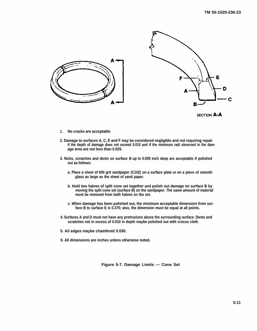
TM 55-1520-236-23
1. No cracks are acceptable
2. Damage to surfaces A, C, E and F may be considered negligible and not requiring repairif the depth of damage does not exceed 0.010 and if the minimum radi observed in the dam-age area are not less than 0.025.
3. Nicks, scratches and dents on surface B up to 0.005 inch deep are acceptable if polishedout as follows:
a. Place a sheet of 600 grit sandpaper (C102) on a surface plate or on a piece of smoothglass as large as the sheet of sand paper.
b. Hold two halves of split cone set together and polish out damage on surface B bymoving the split cone set (surface B) on the sandpaper. The same amount of materialmust be removed from both halves on the set.
c. When damage has been polished out, the minimum acceptable dimension from sur-face B to surface E is 0.370; also, the dimension must be equal at all points.
4. Surfaces A and D must not have any protrusions above the surrounding surface. Dents andscratches not in excess of 0.010 in depth maybe polished out with crocus cloth.
5. Ail edges maybe chamfered 0.030.
6. All dimensions are inches unless otherwise noted.
Figure 5-7. Damage Limits — Cone Set
5-11

TM 55-1520-236-23
NOTE
During installation of pitch link assem-bly (15), assure that the universal linkbolts are Installed and torqued correct-ly. The upper universal bolt will beinstalled with the bolt head Inboard(toward mast). The lower universal boltwill be installed with the bolt headtoward opposite scissors link. Torquenut on bolts 800 TO 1000 inch-poundsand install cotter pins.
NOTE
The adhesive bond can be broken whenthe adjustment barrel jam nuts are loos-ened and torqued without using a back-up wrench on the adjustment barrelwrench flats.
(3) Prior to incorporation of MWO 55-1520-244-50-9, install universal bearing end of pitch linkassembly (15, figure 5-2) on scissors (18) with bolt(32), washer (33 and 34), and new nut (35). Torque nut(35) 800 TO 1000 inch-pounds and install alter pin.Repeat procedure for opposite pitch link assembly.
Bushing assembly, P/N 209-010-523-107is required in modified pitch hornassembly, P/N 209-010-109-109, toproperly Install old pitch link assembly,P/N 209-010-460-1. Bushing assembly,P/N 209-010-523-107 is not used inmodified pitch horn assembly, P/N209-010109-109 to install new pitch linkassembly, P/N 209-010-520-103.
(1) If previously removed, install universalbearing (30) on pitch link assembly (15) with bolt (26),
NOTE
washer (27) installed on thread portion only, and newnut (28). Prior to incorporation of MWO 55-1520-244- Bolt (23) may not extend past barrel nut50-9, torque nut 600 TO 1000 inch-pounds and install (21) the necessary minimum threecotter pin (29). After incorporation of MWO 55-1520- threads As long as the end of the bolt Is244-50-9, torque nut (28) 1250 TO 1550 inch-pounds visible and flush with aft side of barreland install cotter pin (29). Repeat procedure for oppo- nut and proper torque has been accom-site pitch link assembly. plished, this Is an acceptable condition.
(2) Prior to incorporation of MWO 55-1520-244-50-9, measure both pitch link assemblies, and ifnecessary adjust length to 27.05 inches as shown infigure 5-8. Also, comply with the equal thread require-ment shown. Tighten jamnuts at each end of barrelsnug. Do not torque at this time.
(2.1) After incorporation of MWO 55-1520-244-50-9, measure both pitch link assemblies (15) andif necessary adjust length to 27.00 TO 27.05 inches asshown in figure 5-8. Also, comply with the initial settingof 2.495 to 2.505 inches on rod end bearing as shown.Tighten jamnuts at each end of tube assembly finger-tight. Do not torque at this time.
Use only new, unused nut referencedfor installation in step (3) below.
Ensure proper shimming of scissorslever clevis end of bushings outboardsurfaces. Refer to paragraph 5-60.
(4) Prior to incorporation of MWO55-1520-244-50-9 install barrel nut (21, figure 5-2) ifnot previously installed in pitch horn (20). Prior toinstalling pitch link assembly, insert bolt (23), checkand record tare torque (friction torque). Tare torquemust be a minimum of 32 inch-pounds. if tare torqueis below limits, replace barrel nut (21) and recheck.
(4.1) Remove bolt (23) and install barrel end ofpitch link assembly (15) to pitch horn (20). Installrecessed washer (22) (with recess toward bolt head)and install bolt (23). Torque bolt (23) 1250 TO 1550inch-pounds above the tare torque previouslyrecorded. For example: If tare torque was 100 inch-pounds, you would torque the bolt 1350 TO 1650 inch-pounds Lockwire (C137) bolt (23) to the hole in pitchhorn (20). Repeat the procedure for the opposite side.
Ensure that the self-locking feature ofbarrel nut (21) has adequate tare torque,minimum of 32 inch-pounds
5-12
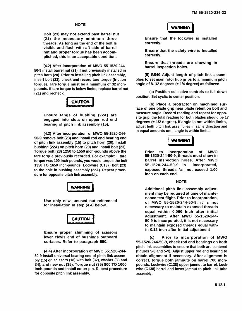
TM 55-1520-236-23
NOTE
Bolt (23) may not extend past barrel nut(21) the necessary minimum threethreads. As long as the end of the bolt Isvisible and flush with aft side of barrelnut and proper torque has been accom-plished, this is an acceptable condition.
(4.2) After incorporation of MWO 55-1520-244-50-9 install barrel nut (21) if not previously installed inpitch horn (20). Prior to installing pitch link assembly,insert bolt (23), check and record tare torque (frictiontorque). Tare torque must be a minimum of 32 inch-pounds. if tare torque is below limits, replace barrel nut(21) and recheck.
Ensure tangs of bushing (22A) areengaged into slots on upper rod endbearing of pitch link assembly (15).
(4.3) After incorporation of MWO 55-1520-244-50-9 remove bolt (23) and install rod end bearing endof pitch link assembly (15) to pitch horn (20). Installbushing (22A) on pitch horn (20) and install bolt (23).Torque bolt (23) 1250 to 1550 inch-pounds above thetare torque previously recorded. For example: ii taretorque was 100 inch-pounds, you would torque the bolt1350 TO 1650 inch-pounds. Lockwire (C137) bolt (23)to the hole in bushing assembly (22A). Repeat proce-dure for opposite pitch link assembly.
Use only new, unused nut referencedfor installation In step (4.4) below.
Ensure proper shimming of scissorslever clevis end of bushings outboardsurfaces. Refer to paragraph 550.
(4.4) After incorporation of MWO 551520-244-50-9 install universal bearing end of pitch link assem-bly (15) on scissors (18) with bolt (32), washer (33 and34), and new nut (35). Torque nut (35) 800 TO 1000inch-pounds and install cotter pin. Repeat procedurefor opposite pitch link assembly.
Ensure that the lockwire is installedcorrectly.
Ensure that the safety wire is Installedcorrectly.
Ensure that threads are showing inbarrel inspection holes.
(5) B540 Adjust length of pitch link assem-blies to set main rotor hub grips to a minimum pitchangle of 8-1/2 degrees (± 1/4 degree) as follows:
(a) Position collective controls to full downposition. Set cyclic to center position.
(b) Place a protractor on machined sur-face of one blade grip near blade retention bolt andmeasure angle. Record reading and repeat for oppo-site grip. the total reading for both blades should be 17degrees (± 1/2 degree). If angle is not within limits,adjust both pitch link assemblies in same direction andin equal amounts until angle is within limits.
Prior to incorporation of MWO55-1520-244-50-9, threads must show inbarrel inspection holes. After MWO55-1520-244-50-9 is incorporated,exposed threads *ail not exceed 1.00inch on each end.
NOTE
Additional pitch link assembly adjust-ment may be required at time of mainte-nance test flight. Prior to incorporation,of MWO 55-1520-244-50-9, it is notnecessary to maintain exposed threadsequal within 0.060 Inch after initialadjustment. After MWO 55-1520-244-50-9 is incorporated, it is not necessaryto maintain exposed threads equal with-in 0.12 inch after Initial adjustment
(c) Prior to incorporation of MWO55-1520-244-50-9, check rod end bearings on bothpitch link assemblies to ensure that both are centered(figures 5-8 and 5-9). Adjust upper rod end bearing toobtain alignment if necessary. After alignment iscorrect, torque both jamnuts on barrel 700 inch-pounds. Lockwire (C138) upper jamnut to barrel. Lock-wire (C138) barrel and lower jamnut to pitch link tubeassembly.
5-12.1

TM 55-1520-236-23-1
NOTE
After application of lockwire, apply athin coat of sealant (C105) around thelock nut and threads of the rod end toprevent water intrusion.
(c.1) After incorporation of MWO55-1520-244-50-9, make sure that alignment ofpitch link assembly is correct and torque both jam-nuts on tube assembly. Torque upper jamnut closestto rod end bearing 1400 TO 1600 inch-pounds andlower jam nut closest to universal bearing 1100 TO1300 inch-pounds. Lockwire (C138), jamnuts topitch fink tube assembly.
(6) K747 Adjust length of pitch fink assem-blies to set main rotor hub grips to a minimum pitchangle of 9- 3/4 degrees (± 1/2 degree) as follows:
(a) Position collective controls to fulldown position. Set cycIic to center position.
(b) Place a protractor on machined sur-face of one blade grip near blade retention bolt andmeasure angle. Record reading and repeat for op-posite grip. The total reading for both blades shouldbe 19-1/2 degrees (±1 degree). If angle is not withinlimits, adjust both pitch link assemblies in samedirection and in equal amounts until angle is withinlimits.
Prior to incorporation of MWO 55-1520-244-50-9, threads must showin barrel inspection holes. After MWO55-1520-244-50-9 is Incorporated,exposed threads shall not exceed1.00 inch on each end.
NOTE
Additional pitch link assembly ad-justment may be required at time ofmaintenance test flight. Prior to in-corporation of MWO 55-1520-244-50-9, it is not necessary to main-tain exposed threads equal within0.060 inch after initial adjustment. Af-ter MWO 55-1520-244-50-9 is incor-porated, it is not necessary tomaintain exposed threads equal with-in 0.12 inch after initial adjustment.
(c) Prior to incorporation of MWO55-1520-244-50-9, check rod end bearings onboth pitch link assemblies to ensure that both are
centered (figures 5-8 and 5-9). Adjust upper rodend bearing to obtain alignment if necessary. Afteralignment is correct, torque both jamnuts on barrel700 inch pounds. Lockwire (C138) upper jamnut tobarrel. Lockwire (C138) barrel and lower jamnut topitch link assembly tube.
NOTE
After application of Iockwire, apply athin coat of sealant (C105) around thelock nut and threads of the rod end toprevent water intrusion.
(c.1) After incorporation of MWO55-1520-244-50-9, make sure that alignment ofpitch link assembly is correct and torque both jam-nuts on tube assembly. Torque upper jamnut closestto rod end bearing 1400 TO 1600 inch-pounds andlower jamnut closest to universal bearing 1100 TO1300 inch-pounds. Lockwire (C138), jamnuts topitch link assembly tube.
(7) Lubricate lower bearing on pitch link as-semblies (15, figure 5-2) with grease (C58).
NOTE
To prevent interference between thetrunnion (1, figure 5-2) and strap (42),AN960-716L washers (50) may beplaced between strap (42) and theplate (49) on bolt (46). A maximum oftwo washers may be used per bolt.
(8) Install plates (49, figure 5-2) using bolts(45) and washers (44). Torque bolts 70 T0 90 inch-pounds. Lockwire bolts (45) in pairs as shown usingMS20995C32 Iockwire (C137). Install straps (42)using bolts (46), washers (47), and nuts (48).Torque nuts (48) 270 TO 300 inch- pounds. Attachsupports (40, detail B) to straps (42) using bolts(35), washers (36), and nuts (41). Torque nuts (41)540 TO 650 inch-pounds. Install bolts (37), wash-ers (38), and nuts (39). Torque nuts (39) 300 TO 335inch-pounds.
r.
K747 main rotor blades have a ten-dency to attain a higher percent RPMduring autorotation than B540 mainrotor blades DO NOT RIG beyond thelimits established in paragraph 5-14,step (q) to obtain a lower main rotorpercent RPM.Perform maintenance test flight to ensure that
main rotor rigging is satisfactory (TM 55-1520-236MTF).
5-12.2
TM 55-1526-236-23
s. It the maintenance test flight indicates theneed for rotor adjustment recheck blade alignmentwith blades on helicopter. Using alignment scope(T30), make required adjustments. (Maximum toler-ance of alignment between two blades is 0.050inch.)
5-15. ADJUSTMENT — MAIN ROTORHUB AND BLADES.
Refer to paragraph 5-114
5-16. B540 MAIN ROTOR BLADES.
Use of paragraphs 5-17 through 5-24for K747 main rotor blades will resultin severe damage.
NOTE
When operating aircraft in geographi-cal areas where excessive blade ero-sion will occur, refer to TB1-1615-351-23 for instructions forapplication of anti-erosion tape pro-cedures.
5-12.3/(5-12.4 blank)

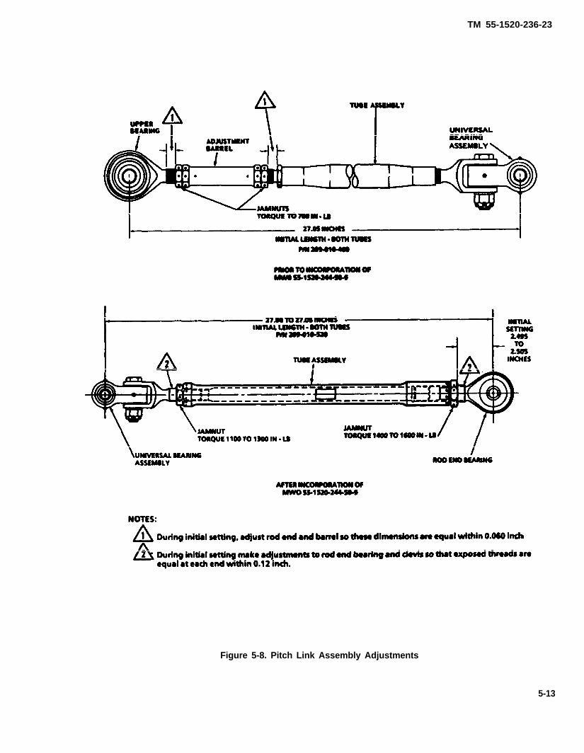
TM 55-1520-236-23
Figure 5-8. Pitch Link Assembly Adjustments
5-13

TM 55-1520-236-23
Figure 5-9. Pitch Link Assembly
5-14
TM 55-1520-236-23
NOTE
Refer to paragraph 5-25 for maintenanceof K747 main rotor blades.
NOTE
When operating aircraft in geographicalareas where excessive blade erosionwill occur, refer to TB 1-1615-351-23 forinstructions for application of anti-erosion tape procedures.
5-17. DESCRIPTION – B540 MAIN ROTORBLADES.
The main rotor blades are metal, bonded assemblies.Each blade is attached in the hub with a retaining boltassembly and is held in alignment by adjustable dragbraces.
5-18. REMOVAL — B540 MAIN ROTOR BLADES.
a. Position main rotor hub and blade assembly onbuildup bench (paragraph 5-12, step n). Place paddedsupports under blades so that leading edge is ap-proximately straight.
b. Remove locking screw (20, figure 5-10) washer(19), and nut (18).
c. Remove nut (17) and washer (16) with bladebolt wrench (T31).
d. Remove nut (11), washers (12 and 13) andbolt (14). Loosen nut (21) and swing drag brace ( 15)away from rotor blade. Retain shims (10) for reinstalla-tion.
514.1/(5-14.2 blank)

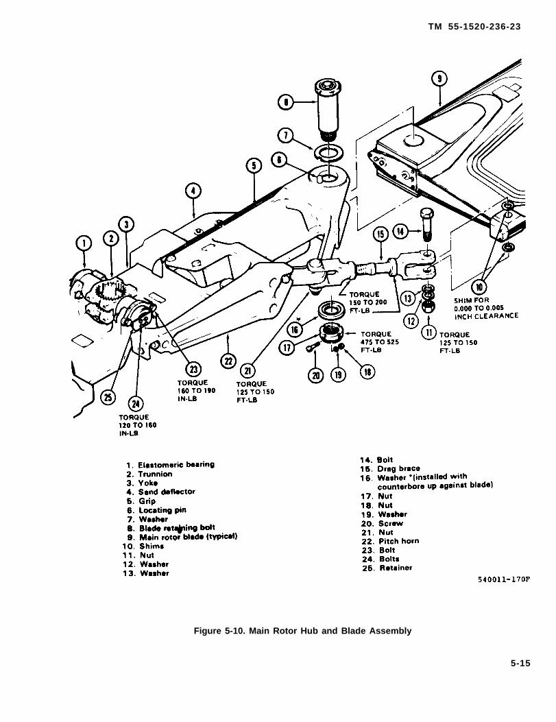
TM 55-1520-236-23
Figure 5-10. Main Rotor Hub and Blade Assembly
5-15

TM 55-1520-236-23
Avoid blade contact with the drag braceand hub during removal procedure toprevent possible blade damage.
e. Remove blade retaining bolt (8) and washer (7).Slowly raise and lower blade tip while tapping boltwith fiber mallet. If bolt is difficult to remove, use abolt removal work aid similar to the one shown infigure 5-11 as follows:
(1) Remove threaded plugs from upper andlower ends of blade retaining bolt. If weights arepresent in bolt, retain for reinstallation.
(2) Position work aid on bolt as shown in figure5-12 and place a piece of hard rubber or similarmaterial between work aid tuba and grip to preventmarring the grip. Hold puller rod and tighten hexagonnut to remove blade retaining bolt.
(3) Remove work aid from blade retaining bolt.Reinstall weight and plugs in blade retaining bolt andidentify the blade retaining bolt for reinstallation inthe same grip.
f. Remove blade from grip and place in a paddedstand.
g. Remove opposite blade from hubmanner.
5 - 1 9 . C L E A N I N G – B 5 4 0 M A I NBLADES.
in same
ROTOR
Cleaning solvent is flammable and toxic.Provide adequate ventilation. Avoidprolonged breathing of solvent vaporsand contact with skin or eyes.
a. Clean main rotor blade with cleaningcompound (C33).
b. Remove stubborn deposits with a clothdampened with solvent (C112).
5-20. INSPECTION – B540 MAIN ROTORBLADES.
a. Inspect blade historical records and the bladefor evidence that the blade has been subjected to anaccident or incident outside the realm of normalusage. If such evidence exists, perform SpecialInspections outlined in paragraph 1-57.
b. Inspect blade for nick, scratch, dent andcorrosion damage (figure 5-14).
(1) Nicks and scratches anywhere on thesurface of the skins or trailing edge strip that do notexceed 0.008 inch in depth are acceptable if they arepolished out.
NOTE
If a nick or scratch in the skin in excess of0.008 inch depth can be polishedsmooth without leaving the skin in thepolished area so thin that skin can bedented with fingernail pressure, a patchmay be applied over the area. Refer toparagraph 5-21 for instructions to applypatch to this type damage.
(2) Nicks and notches in the extreme trailingedge of the blade that are 0.120 inch or less in depthare acceptable if they are polished and faired out overa minimum distance of 2 inches on each side of thenick or notch.
(3) Any dent in the skin in the outboard four feetof the blade that does not tear the skin, produce anunacceptable void or affect flight characteristics isacceptable without repair.
(4) Dents in the skin inboard of the stationlocated four feet inboard of the tip of the blade that donot exceed 0.060 inch are acceptable without repair.
(5) If a nick or scratch exists in a sharp dent inthe skin, the total depth of both must not exceed0.060 inch. Nicks and scratches must be polishedout. Refer to step (1).
(6) Nicks or scratches in the abrasion strips,doublers. Grip plates or drag plates that are not inexcess of 0.012 inch in depth are acceptable if theyare polished out.
(7) If a leading edge abrasion strip is worn,eroded or damaged so that any holes appear, the
5-16
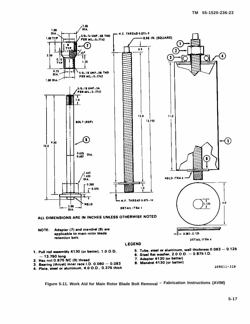
TM 55-1520-236-23
Figure 5-11. Work Aid for Main Rotor Blade Bolt Removal – Fabrication Instructions (AVIM)
5-17
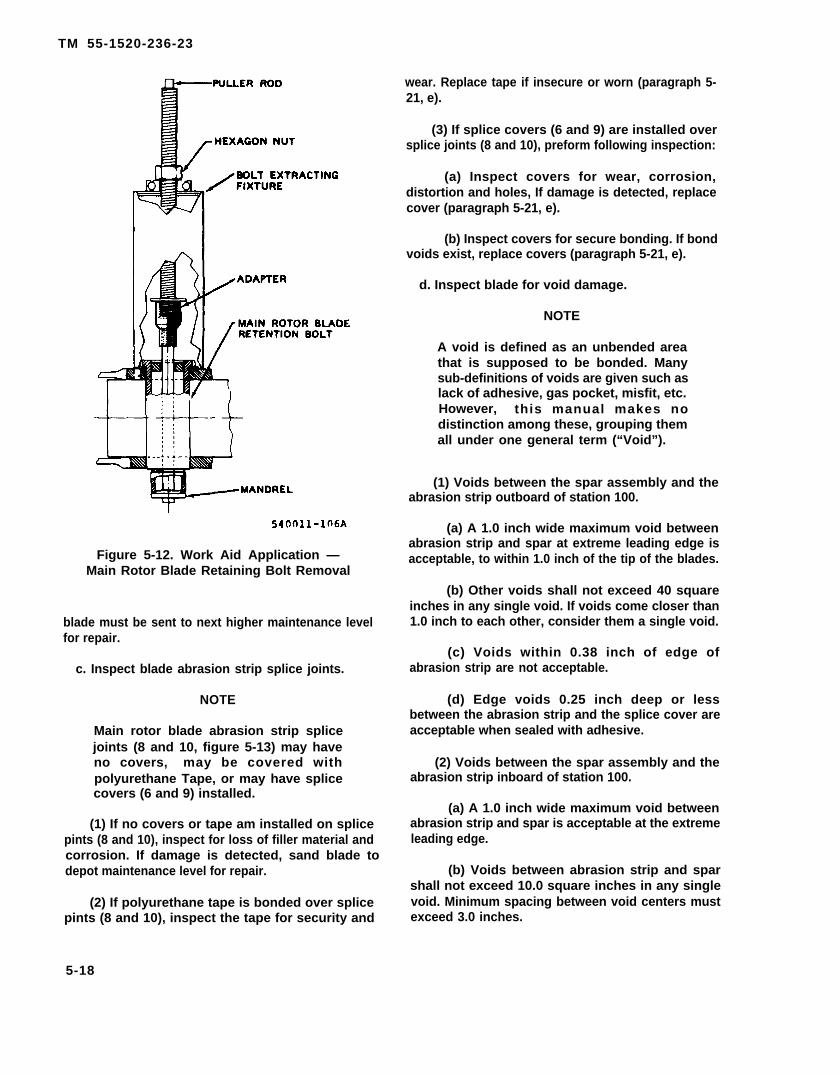
TM 55-1520-236-23
Figure 5-12. Work Aid Application —Main Rotor Blade Retaining Bolt Removal
blade must be sent to next higher maintenance levelfor repair.
c. Inspect blade abrasion strip splice joints.
NOTE
Main rotor blade abrasion strip splicejoints (8 and 10, figure 5-13) may haveno covers, may be covered withpolyurethane Tape, or may have splicecovers (6 and 9) installed.
(1) If no covers or tape am installed on splicepints (8 and 10), inspect for loss of filler material andcorrosion. If damage is detected, sand blade todepot maintenance level for repair.
(2) If polyurethane tape is bonded over splicepints (8 and 10), inspect the tape for security and
wear. Replace tape if insecure or worn (paragraph 5-21, e).
(3) If splice covers (6 and 9) are installed oversplice joints (8 and 10), preform following inspection:
(a) Inspect covers for wear, corrosion,distortion and holes, If damage is detected, replacecover (paragraph 5-21, e).
(b) Inspect covers for secure bonding. If bondvoids exist, replace covers (paragraph 5-21, e).
d. Inspect blade for void damage.
NOTE
A void is defined as an unbended areathat is supposed to be bonded. Manysub-definitions of voids are given such aslack of adhesive, gas pocket, misfit, etc.However, this manual makes nodistinction among these, grouping themall under one general term (“Void”).
(1) Voids between the spar assembly and theabrasion strip outboard of station 100.
(a) A 1.0 inch wide maximum void betweenabrasion strip and spar at extreme leading edge isacceptable, to within 1.0 inch of the tip of the blades.
(b) Other voids shall not exceed 40 squareinches in any single void. If voids come closer than1.0 inch to each other, consider them a single void.
(c) Voids within 0.38 inch of edge ofabrasion strip are not acceptable.
(d) Edge voids 0.25 inch deep or lessbetween the abrasion strip and the splice cover areacceptable when sealed with adhesive.
(2) Voids between the spar assembly and theabrasion strip inboard of station 100.
(a) A 1.0 inch wide maximum void betweenabrasion strip and spar is acceptable at the extremeleading edge.
(b) Voids between abrasion strip and sparshall not exceed 10.0 square inches in any singlevoid. Minimum spacing between void centers mustexceed 3.0 inches.
5-18
TM 55-1520-236-23
(c) Voids within 0.38 inch of edge of theabrasion strip are not acceptable except at the buttend, per step (a) above.
(d) Edge voids 0.25 inch deep or lessbetween the abrasion strip and the splice cover areacceptable when sealed with adhesive.
(e) Voids defined in steps (a), (b), and (c) thatare apparent at the butt end of the blade must besealed with adhesive (paragraph 5-21, f).
(3) Voids at butt end of blade.
(a) Voids are not acceptable within 0.6 inchof the front or rear edge of either grip plate or grippads, viewing the “Section” of the butt end.
(b) Voids between trailing edge extrusionand skin deeper than 1.0 inch nor wider than 1.0 inchare acceptable if sealed with adhesive.
(c) Any other void not longer than 1.0 inch ordeeper than 0.35 inch is acceptable if sealed withadhesive.
(d) Voids are not acceptable between thespar and spar closure.
(4) Voids in the retention area, inboard ofstation 100.00.
(a) Edge voids of 0.10 inch maximum depthon edge of the doublers are acceptable if sealed withadhesive. Edge voids are not acceptable in outboard 7inches of each finger of the doublers. Edge voids inthe outer 3 inches of grip plate and outer 1.5 inchesof the drag plate are not acceptable. Up to 0.50 inchmaximum may be removed from the outboard tip inthe drag plate tang, grip plate tang, or outboard tip ofdoublers to eliminate a void.
(b) Voids between the doublers, doubler andskin, doubler and grip plate, grip plate and grip pad arenot acceptable, except as allowed in steps (3) (c) and(4) (a) above.
(c) Voids between the skin and the core shallnot exceed 1.0 inch by 25.0 inches spanwise. Thetotal area of all voids must not exceed 30 squareinches.
(d) Edge voids between the edge of the skinand the trailing edge extrusion that are less than 0.06
inch wide by any length or less than 0.25 inch wideby 7 inches long are acceptable if they are sealed withadhesive.
(e) Other voids between the skin and thetrailing edge extrusion which do not exceed one-halfthe width of the faying surfaces by 20.0 inches longor 0.60 inch wide by any length are acceptable.
(f) Voids other than edge voids between theskin and the spar that are less than 1.25 inch and lessthan one-half the width of faying surfaces areacceptable.
(5) Voids under skin, outboard of Station 100.
(a) Voids between the skin and trailing edgeextrusion shall not exceed one-third the width of thefaying surfaces.
(b) Voids between the skin and the core mustnot exceed 1.0 inch in width chordwise. If two voidsare within 1.0 inch of each other, consider them asone void.
Voids between the skin and core adjacent to the sparshall not exceed 1.0 inch wide by 15 inches longspanwise. At the splice between the inboard andoutboard core (Station 156), a void of 0.50 inchmaximum spanwise by the full chordwise width of thecore is acceptable.
(c) Voids between the skin and the spar notwider (chordwise) than one-third the width of themating surfaces are acceptable. Edge voids are notacceptable.
(d) Edge voids between the edge of the skinand the trailing edge extrusion that are less than 0.06inch wide by any length or less than 0.25 inch wideby 10.0 inches long are acceptable if they are sealedwith adhesive.
NOTE
Where two voids of two different typesare closer than 1.0 inch apart considerthem as one void and apply the morestrict limitations. (Example: Voidsbetween skin and trailing edge extrusionnext to a void between the akin and thecore. )
e. Inspect blade for worn retention bolt hole andworn drag brace bolt hole.
5-19
TM 55-1520-236-23
(1) If wear allowance listed in steps (2) or (3)below is exceeded, send blade to next highermaintenance level.
(2) Main retention bolt hole is oversize whenthe diameter exceeds 2.505 inches.
(3) Drag plate bolt hole is oversize when thediameter exceeds 0.877 inch.
f. Inspect blade for cracks.
(1) Visually inspect top and bottom surfacesalong entire length of blade for damage. Any fatiguecrack at any location is cause for blade replacement.Evaluate cracks caused by strikes and other damageto other damage criteria.
(2) Penetration through spar or trailing edgestrip is cause for blade replacement.
(3) Damage penetrating skin and at least 1.0inch from doublers may be repaired, provided thatafter cleanup, damage does not exceed 2.0 inches indiameter.
(4) Spanwise damage penetrating skin at least1.0 inch from doublers may be repaired, provided thatafter cleanup, using an oblong hole, damage does notexceed 4.0 inches by 1.0 inch and direction of oblonghole falls within 15 degrees of a line parallel toleading or trailing edge of blade.
g. Inspect blade for holes in skin. If any holes arefound, classify them as reparable by patching ornonreparable in accordance with the following limits(figure 5-14)
Repairs inboard of station 210 must beinspected daily for cracks.
(1) No patches are permitted within 1.0 inch ofdoublers.
(2) Inboard of station 216, only one repair onsame chordline is permitted. After cleanup, holes arelimited to 2.0 inches maximum diameter and arerestricted to a minimum of 2.0 inches betweenrepairs.
(3) Between station 216 and station 240, twoholes are permitted on same chordline on same skin
surface. Maximum diameter of holes is 2.0 inchesand a minimum spacing of 2.0 inches after cleanup isrequired between repairs.
(4) Between station 240 and outboard tip ofblade, two holes are permitted on same chordline onsame skin surface. Maximum diameter of holes is 3.0inches and a minimum spacing of 2.0 inches isrequired between repairs after cleanup.
(5) Spanwise holes maybe repaired providingthat after cleanup, damage does not exceed 1.0 inchwide and 4.0 inches long. Direction of oblong holemust fall within 15 degrees of a line parallel to leadingor trailing edge of blade. Ends of the hole must have aminimum radius of 0.25 inch to break corners.
(6) Any damage or defect in the skin that can bepolished smooth without leaving the skin in the areaso thin that it can be dented with fingernail pressuredoes not require a cutout. In these cases a patch mustbe applied as though a hole exists. Maximumdiameter of a patch of this type is 4.0 inches with aminimum of 0.75 inch of bonded area around theperimeter of the dent.
h. Inspect main rotor blade trim tab for thefollowing defects:
(1) Distortion that can be repaired bystraightening.
(2) Cracks, tears, rips and holes. This typedamage must be repaired by replacement of the trimtab.
i. Inspect blade for secure installation of balanceweights (18, figure 5-13). Inspect cover plate (1) andtip cap (13) for secure installation. If the cover plateand/or tip cap is loose, inspect weights under therover plate and/or tip cap for secure installation ofweights.
j. Inspect main rotor blade for the followingdefects and replace blades damaged to the extentdescribed:
(1) Any penetration damage through spar ortrailing edge strip, doublers, grip plates or drag plates.
(2) Skin penetration inlimits allowed for patching.
(3) Water in honeycomb
any area exceeding
core.
5-20

TM 55-1520-236-23
(4) Voids between skin and honeycomb core largerthan 30 square inches.
(5) Edge voids deeper than 0.50 inch in tip end ofany doublers or grip plates.
(6) Edge voids in the leading edge of the doublersthat exceed 0.060 inch in depth and at the trailing edgeof the doublers that exceed 0.10 inch in depth.
(7) Any corrosion that penetrates entirely throughskin.
(8) If one or more cracks develop and extend froma previously repaired area.
(9) More than two patches on the same chordlineon the same side (paragraph 5-20, g, (4).
(10) Obvious deformation of blade.
k. Tip balance weight inspection.
(1) Remove tip cap from rotor blade.
(2) Visually inspect lead weights for distortion.Distorted weights are cause for blade removal.
(3) Inspect for loose weights. Loose weightsalone are not cause for blade removal. Inspect studretention nuts for looseness by applying 30 inchpound torque. Torque loose stud retention nuts to130 to 145 inch pound.
(4) Striking of rotor blades to check for loosebalance weights is not an acceptable inspection pro-cedure.
(5). Inspect studs for looseness and distortion.Loose or distorted studs are unacceptable and iscause for blade removal.
5-21. REPAIR — B540 MAIN ROTOR BLADES.
NOTE
Repair at AVIM is limited by availabletools, equipment, personnel and skills.Send blades to Depot Maintenance formajor repair.
a. Polish out nick and scratch damage in skin that iswithin limits stated in inspection paragraph 5-20b. Use320 grit sandpaper (C102) to polish out damage. Usefine aluminum wool (C20) or scotchbrite (C103) to finishpolishing the area. Rub spanwise to remove sandpapermarks and polish to a fine finish. Touch up repair areawith alodine (C31), primer (C88 or 91) and paint to matchsurrounding area (paragraph 5-24).
b. Polish out nick and scratch damage in the abra-sive strips, doublers, grip plates, and drag plates that iswithin limits stated in inspection paragraph 5-20b. Use400 grit sandpaper (C102) or equivalent. Steel wool(C115) may also be used providing that no aluminumparts are touched with it. Touch up repair area withprimer and paint to match surrounding area (paragraph5-24).
c. Repair nick, scratch, and notch damage in the trail-ing edge strip that is within limits stated in inspectionparagraph 5-20,b. Use varying grades of sandpaper(C102) to polish out damage and fair out over a distanceof 2.0 inch minimum on each side of damage. Touch uprepair area with primer (C88 or C91) and paint to matchsurrounding area (paragraph 5-24).
d. (AVIM) Repair hole damage and nick or scratchdamage in skin that is within limits stated in inspectionparagraph 5-20, g.
NOTE
If a nick or scratch in the skin in excess of0.008 inch depth can be polished smoothwithout leaving the skin in the polishedarea so thin that skin can be dented withfingernail pressure, apply patch over areawithout cutting a hole. Comply with step(1). Skip steps (2) and (3) and proceed withstep (4). Otherwise proceed with steps (1)through (8).
Cleaning solvent is flammable and toxic.Provide adequate ventilation Avoidprolonged breathing of vapors and con-tact with skin or eyes.
Do not allow MEK to enter the blade.
5-20.1/(5-20.2 blank)


TM 55-1520-236-23
(1) Remove paint from repair area with MEK (C74).Remove paint primer by sanding spanwise using 300grit sandpaper (C1 02).
(2) Draw a circle around the damaged area justlarge enough to encompass damage.
(3) Remove skin just inside the circled area, dis-turbing the honeycomb core as little as possible. Heatthe cut out disk to 200 degrees F (93 degrees C) maxi-mum and lift out the disk of skin while heated.
(4) Deburr edges of hole and polish out scratchesand nicks.
(5) Prepare a patch to cover the hole that will over-lap by 0.75 inch. Fabricate patch from 2024-T3 alumi-num (4, table 2-2) large enough to overlap the hole atleast 0.75 inch all around the perimeter. Deburr andblend out edges. Sand the bond area of patch and bladewith 400 grit sandpaper (C102).
5-21

TM 55-1520-236-23
Cleaning solvent is flammable and toxic.Provide adequate ventilation. Avoidprolonged breathing of vapors andcontact with skin or eyes.
(6) Clean bond area on patchMEK (C74). Dry with a clean cloth.
and blade with
Area must be clean, dry, and free ofgrease. Oil and wax.
(7) Apply adhesive (C14) to patch area aroundhole and to patch. Apply patch to blade and moveslightly under pressure to expel alr and prevent voidsin bond. Blend out excess adhesive.
(8) Hold patch in place with rubber bands(made from inner tube) or other mechanical means.Refer to table 1-11, for adhesive, mix ratio, pot Ilfe.and curing schedule.
e. Repair blade abrasion strip splice joints.
(1) Splice joints covered with polyurethanetape.
Cleaning solvent is flammable and toxic.Provide adequate ventilation. Avoidprolonged breathing of solvent vaporsand contact with skin or eyes.
NOTE
Polyurethane tape bonded in place overthe splice joints is recommended fordusty or sandy environments to provideprotection for the joint filler material.
(a) Remove insecure or worn polyurethanetape from splice joint (8 or 10, figure 5- 13) with sharp,plastic scraper and small amount of MEK (C74).
(b) Remove tape residue from abrasion stripwith cloth dampened with MEK (C74) and plastic
scraper, then sand with 100 grit or finer sandpaper(C102), Sand in spanwise direction.
Cleaning solvent is flammable and toxic.Provide adequate ventilation. Avoidprolonged breathing of vapors andcontact with skin or eyes.
(c) Clean leading edge of rotor blade, in areawhere tape will be applied, with clean clothdampened with aliphatic naptha (C75).
(d) Cut a piece of polyurethane tape (C125)seven inches long.
(e) Center polyurethane tape chordwise overthe splice joint, press into place, and force out all airbubbles. If necessary, make pin hole in tape to allowtrapped air to escape
(2) Splice joints covered with splice cover.
Do not exceed 200 degrees F (93degrees C) during splice cover removal ordamage to rotor blade may result.
(a) Heat damaged or insecure splice cover to200 degrees F (93 degrees C) maximum with a heatgun and maintain temperature during removal ofcove r
When removed, cover will be extremelyhot. Handle only with appropriate tools,and place in safe area to cool afterremoval.
(b) Remove cover with putty knife or chisel,being careful not to damage rotor blade.
Allow rotor blade to cool completelybefore proceeding.
5-22

TM 55-1520-236-23
(c) After rotor blade is cool, mask area of rotorblade around splice cover installation area with tape(C133). Leave a one inch border between where newsplice cover will go and masking tape.
(d) Remove old adhesive, paint and othercontaminants from masked-off area with 100 grit orfiner sandpaper (C102). Sand in spanwise direction
Cleaning solvent is flammable and toxic.Provide adequate ventilation. Avoidprolonged breathing of vapors andcontact with skin or eyes.
(e)dampenedcloths.
Clean masked-off area with clean clothwith MEK (C74) and wipe dry with clean
Rotor Blade
NOTE
Wear clean, dry gloves when handlingparts that have been prepared forbonding. Avoid contamination of partswith oil, grease, or mold release.
(f) Remove peel ply from inside surface ofnew splice cover.
(g) Lightly sand cured adhesive on new splicecover with 300 grit sandpaper (C102). Wipe offresidue with clean cloth.
(h) Refer to table 1-11 for instructions to mixadhesive (C14). Apply thin coat of adhesive (C14) toinside surface of new splice cover and to matingsurface of rotor blade. Use wooden spatula and rubadhesive around on splice cover and blade to assurecomplete wetting of mating surfaces.
Figure 5-13. B540 Main
5-23

TM 55-1520-236-23
(i) Position new splice cover (6 or 9, figure 5-13) on rotor blade as shown in figure 5-13.
(j) Move splice cover back and forth slightly toexpell air pockets.
(k) Wipe off excess adhesive and fair inadhesive at edges of cover.
(l) Place cellophane (C27) over splice cover toprevent adhesion to bands installed in following step.
(m) Place heavy rubber bands or bungeecords around rotor blade to hold splice cover in place.
(n) Allow adhesive to cure in accordancewith instructions in table 1-11.
(o) Fair in adhesive by sanding with 180 gritor finer sandpaper (C102), Touch up finish on rotorblade (paragraph 5-24).
f. Repair voids as follows:
(1) Repair voids up to a maximum of 0.50 inchfrom tips of drag plate tang, grip plate tang, oroutboard tip of doublers as follows:
(a) Cut material from grip, drag plate ordoubler a maximum of 0.50 inch, following the sameradius as original tip. Use extreme care to avoidcutting into adjacent parts.
(b) After cutting, deburr and break sharpedges.
(c) Refinish in accordance with procedures inparagraph 5-24.
(2) Seal edge voids 0.25 inch deep or lessbetween the abrasion strip and the splice cover bycleaning the area and filling void with adhesive (C14),
(3) Repair void damage that is within limitsdefined in inspection paragraph 5-20 steps d. (3), d.(4), and d. (5) by sealing with adhesive. Clean area tobe sealed and fill void with adhesive (C14).
g. Repair distorted main rotor blade trim tab thatis within limits stated in inspection, paragraph 5-20,h.
(1) Straighten the trailing edge of the mainrotor trim tab with a mallet and a heavy back-up block.
(2) Set trim tab to trail with tab bending tool(T47) and tab bending gage (T41).
h. (AVIM) Remove damaged main rotor blade trimtab and install new trim tab if replacement isindicated by inspection paragraph 5-20, h.
(1) Cut through the trim tab (8, figure 5-14) at aline approximately one-eighth inch aft, and parallel toblade trailing edge.
(2) Drill out rivets, if installed, attaching trimtabs to rotor blade.
(3) Apply heat to tab with a heat gun, but do notexceed 200 degrees F (93 degrees C), Start at outercorner of trim tab and peel tab off blade in spanwisedirection.
(4) Mask blade area around trim tab; allow one-half inch border from trim edge for squeeze-out.
(5) Remove old adhesive in masked area bysanding spanwise with 180 grit sandpaper (C102),Use progressively finer sandpaper 320 and 400 grit toobtain a smooth finish.
Cleaning solvent is flammable and toxic.Provide adequate ventilation. Avoidprolonged breathing of vapors andcontact with skin or eyes.
(6) Clean trim tab area of blade with clothsmoistened with MEK (C74). Dry the area with dry,clean cloth.
(7) Fill rivet holes in trim tab area of rotor blade,if existing, with adhesive (C8). Refer to table 1-11 forinstructions to mix adhesive.
(8) Drill nine Number 30 holes in new trim tabas illustrated in figure 5-15. (If the previous trim tabwas riveted, reverse top and bottom hole locationswith trim tab.) Deburr all holes.
(9) Position trim tab on rotor blade in the installposition and using holes in trim tab as template, drillmatching Number 30 holes to a maximum depth of0.125 inch in rotor blade.
5-24

TM 55-1520-236-23
Figure 5-14. B540 Main Rotor Blade Authorized Patch Area (AVIM) (Sheet 1 of 2)
5-25
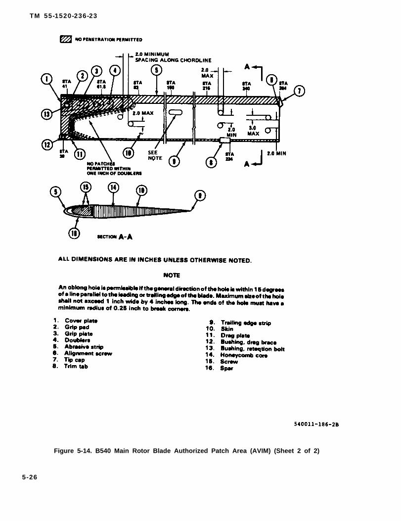
TM 55-1520-236-23
Figure 5-14. B540 Main Rotor Blade Authorized Patch Area (AVIM) (Sheet 2 of 2)
5-26

TM 55-1520-236-23
Figure 5-15. B540 Main Rotor Blade Trim Tab Installation
(10) Remove trim tab from rotor blade, sandand smooth areas around drilled holes in trim tab andblade.
(11) Sand inside mating sides of trim tab with200 grit sandpaper (C102) and finish with 400 gritsandpaper (C102).
Cleaning solvent is flammable and toxic.Provide adequate ventilation. Avoidprolonged breathing of vapors andcontact with akin or eyes.
(12) Clean mating surfaces of rotor blade andtrim tab with cloth moistened with MEK (C74); thendry surfaces with clean, dry cloth.
(13) Spread a thin film of adhesive (C14) onmating areas of rotor blade and trim tab.
(14) Position and secure trim tab in installposition on rotor blade, with holes in trim tab alignedwith corresponding holes in rotor blade.
(16) Install a special blind rivet in each of nineholes drilled in trim tab and blade; dip each rivet inadhesive used in step (13) before installation.
(16) Use two wooden blocks approximately thesame size as trim tab and two sections of hard rubber0.0625 inch thick and approximately the same sizeas the wooden blocks to use as pressure pads. Placethe rubber sections next to the trim tab bond area andplace the wooden blocks over the rubber sections;apply 2 TO 10 PSI pressure on the trim tab bond area.Allow adhesive to cure in accordance withinstructions in table 1-11.
5-27
TM 55-1520-236-23
(17) Remove pressure pads after curing timeand smooth squeeze-out with 180, 320, and 400 gritsandpaper (C102).
Cleaning solvent is flammable and toxic.Provide adequate ventilation. Avoidprolonged breathing of vapors andcontact with skin or eyes.
(18) Clean up adhesive squeeze out in trim tabarea with MEK (C74) and dry with clean, dry cloth.
(19) Apply ten percent solution of chromic acid(C1) and dry with clean, dry cloth.
(20) Apply one coat of epoxy primer (C88 orC91) to trim tab, and adjacent blade area and allow todry for period of 30 minutes to four hours.
NOTE
Adhesion difficulty will be encountered ifacrylic lacquer is not applied within a fourhour period.
(21) Apply lacquer (C66) to trim tab andadjacent blade area.
i. Send blade to next higher maintenance level ifany weights are missing or if there is any evidence ofloose mounting or shifting of weights.
j. Preparation for storage or shipment of mainrotor blades.
NOTE
The following instruction cover storageor shipment of main rotor blades in eithercardboard or metal containers.
(1) Condemn, demilitarize and locally disposeof any blade which has incurred non-reparabledamage. Refer to inspection paragraph 5-20, j.
Cleaning solvent is flammable and toxic.Provide adequate ventilation. Avoidprolonged breathing of vapors andcontact with skin or eyes.
(2) Thoroughly remove foreign matter fromentire exterior surface of blade. Use clean cheesecloth dampened with naphtha (C75)
(3) Tape all holes in the blade such as bulletdamage, tree damage, foreign object damage, etc. toprotect the interior of the blade.
(4) Apply a coating of wax (C135) to all exteriorsurfaces of the blade, except the main retention bolthole and the drag brace retention hole. If non-siliconed composition wax is not available, coatexterior blade surfaces with oil (C77).
(5) Apply grease (C55) to main bolt hole anddrag brace retention bolt hole.
(6) Wrap blade with barrier material (C23),shiny side next to the blade, at all locations where theblade will contact the hog hair supports (5 places) andsecure with tape (C127).
(7) Secure contours to the blade at the paperwrapped areas.
(8) Attach a properly filled out DO Form 15772(Unserviceable/Repairable Tag) directly to the blade.
(9) Secure blade to shock mounted support.
(10) Secure lid. If cardboard container is used,bend container shut with 0.50 inch steel bends. Ifmetal container is used, install top half of containerwith top cushions attached, on lower half of containerand secure with turnlock fasteners.5 - 2 2 . I N S T A L L A T I O N – B 5 4 0 M A I NROTOR BLADES.
Main rotor blades (540-011-001-5) dullnot be intermixed with main rotorblades (540-011-250-1/540-015-001-1)because of weight and stiffness varia-tions.
N O T E
Main rotor blades (540-011-250-1) andmain rotor blades (540-015-001-1) may beintermixed
a. Position main rotor hub on a build-up bench inaccordance with instructions contained in paragraph5-12, I. Check that locating pin (6, figure 5-10) isinstalled in upper surface of each grip (5) at inboardside of retaining bolt hole.
b. Apply corrosion preventive compound (C41) toblade retaining nuts in hub grip and blade butte. Insertblade (9) in grip. Place washer (7) on retaining bolts (8).Align bolt holes carefully end insert bolt from top. Ifbolt binds, move tip of blade up and down slowly to findposition which allows bolt to pass through without bin-ding. Seat bolt and washer with notches on locating pin(6).
5-28
c. Place padded support under blade approximatelyone third blade length inboard from blade tip.
Install washer (16) with counterbore up facinggrip.
d. Install washer (16) with counterbore up asIllustrated and install nut (17). Do not tighten nut at this time.
NOTE
Do not take a total measurement and split theshims evenly as this may cause a bind in thedreg brace.
e. Align drag brace (15) and blade for installation ofbolt (14). Select shims (10) in order to obtain a clearance of0.000 to 0.005 inch total. Measure the clearance from theupper surface of the drag plate to the clevis arm and shim.Measure the clearance on the bottom of the blade (somearea) and shim. Install bolt (14), shims (10), washers (12and 13), and nut (11). Instal washers (12 and 13) on lowerside as illustrated. Do not tighten nut at this time. Apply cor-rosion preventive compound (C43) to drag brace bolts andclevis holes.
f. Install opposite blade in the same manner.
g. If the blades are to be aligned in the hub, followinstructions contained in paragraph 5-13.
h. if the blades are not to be aligned in the hub,torque both nuts (11) 125 TO 150 foot-pounds.
i. Use (T31) wrench to torque nuts (17) to 475 TO525 foot-pounds. Align o notch in nut with a hole in bolt. in-stall locking screw (20) with head in direction that centrifu-gal force will keep locking screw in. In some cases, thismay require the locking screw to be installed from the in-side of bolt. Install washer (19) and nut (18).
Install main rotor grip locks (T59) on each pitchhorn if not previously accomplished (figure 5-4).
5-23. ALIGNMENT — B540 MAIN ROTORBLADES.
Refer to paragraph 5-13.
5-24. PAINTING — B540 MAIN ROTORBLADES (AVIM).
a. Remove tip cap assembly (7, figure 5-1 4) andplug the holes in the end of the spar and inertia weight tokeep paint out.
TM 55-1520-236-23
Cleaning solvent is flammable and toxic. Pro-vide adequate ventilation. Avoid prolongedbreathing of vapors and contact with skin andeyes.
b. Degrease with naphtha (C75) or any gooddecreasing solvent.
Cleaning solvent is flammable and toxic. Pro-vide adequate ventilation. Avoid prolongedbreathing of vapors and contact with skin oreyes.
c. Using MEK (C74), strip old paint from blade areato be refinished.
d. If skins are pitted or eroded (especially in the areajust behind the abrasion strip) polish out the pits with 320grit sandpaper (C102). Use fine aluminum wool (C20) and320 grit sandpaper (Cl 02) to finish polish the damagedarea. Rub spanwise to remove burnishing or sandpapermarks and all traces of pitting. If the depth of the repairedarea is no greater than 0.008 inch the repair is satisfactory
NOTE
Prior to refinishing, blade must have allscratches, nicks, dents, etc. repaired asshown under repair or nicks, dents, scratches,notches, and bent trim tab.
e. Using abrasive cloth (C36) or equivalent, removeall surface oxides and all aged chemical conversion coat-ings from all bare aluminum surfaces.
f. Wash blade with compound (C32) or equivalent.Achieve water break free surface, which will be evident bycontinuous unbroken film of water on the surface after thor-oughly rinsing the soap from the surface
NOTE
From completion of f. above through finalpainting, surfaces of blades should not behandled with bare hands.
5-29
TM 55-1520-236-23
g. On all surfaces where corrosion was present, useapplication of all phosphoric solution (C19). On al bare alu-minum, apply brush or spray application of alodine (C31).
h. Thoroughly dry the cleaned surfaces. Apply a 0.3TO 0.5 mil thick coat of primer (C88 or C91). Allow to air dryfrom 45 minutes to 8 hours before next step.
i. Paint main rotor blades as follows:
Cleaning solvent is flammable and toxic. Pro-vide adequate ventilation. Avoid prolongedbreathing of vapors and contact with skin oreyes,
(1) Mix a small quantity of adhesive (C7) accord-ing to directions on container. Mix 13 to 15 percent byweight of primer (C88 or C91) into the adhesive (C7). Mixthoroughly, and then to sprayable consistency by addingMEK (C74). Do not exceed 50 percent by volume; 35 per-cent should produce a sprayable consistency. The pot lifeof the epoxy primer mixture is approximately 3 hours.
(2) Apply three wet spray coats of adhesive mix-ture from the butt end of the blade to a distance of 0.75 inchto 3 inches outboard (follow contour of the largest doubler,including the tip and root covers. Do not apply to surfacesof the grip plates and drag plates that become faying sur-faces with the grips and drag braces.
(3) Apply three wet spray coats of adhesive mix-ture over all adhesive squeeze-outs and surfaces of thetrim tab. Extend outer edge of the adhesive onto the bladesurface a minimum 0.50 inch beyond the squeeze-out.
(4) Apply one wet spray coat of adhesive the en-tire length of both sides of the blade, using the skin stop onthe spar as the centerline of spray.
(5) Apply one wet spray coat of adhesive the en-tire length of both sides of the blade, using the butt joint be-tween the trailing edge strip and the skin as the centerlineof spray.
(6) Apply first coat of lusterless black lacquer(C86.3) to the upper and lower surfaces of the blade. Allowone hour minimum drying time, then apply second coat.Allow one hour minimum drying time before putting anyother paint over the second coat. Spray only the repairedareas. Paint thickness to be approximately 1.2 TO 1.5 mils.
j. Unplug holes in end of spar and interia weight andinstall tip cap assembly.
5-26. DESCRIPTION – K747 MAIN ROTORBLADES.
NOTE
When operating aircraft in geographical areaswhere excessive blade erosion will occur, referto TB 1-1615-351-23 for instructions for applica-tion of anti-erosion tape procedures.
NOTE
After incorporation of drag strut K747-082-1and root fitting K747-083-1, per MWO 55-1520-244-50-11, main rotor blades K747-003205,-209, and -303, become K747-003-309, -401,and -403, respectively
a. The K747-003 improved main rotor blade (figures5-16 and 5-16.1) is an advanced technology compositestructure which offers improved performance, reliability,maintainability, and reduced radar cross section, It is aglass fiber epoxy resin bonded assembly with an elasto-merit erosion guard. The blade is attached in the hub witha retaining bolt assembly (root fitting) and is held in align-ment by a drag strut.
b. Difference Between Models. K747-003 seriesmain rotor blades have the following part numbers and dif-ferences as noted (See table 5-1).
(1) K747-003-205/-309 incorporates an improvedblade weight retention (IBWR) feature not implemented inearlier K747 blades. (See figures 5-17 and 5-18.) Thischange alters physical appearance in that a slightly raisedarea is visible on the top and bottom of the leading edge(LE) erosion guard surfaces between stations 213.5 and260.0. An almost invisible seam maybe detected at station213.5. The leading edge erosion guard is completely com-posed of estane material. No other material composition isused.
(2) K747-003-205/-309 Deviation implements theuse of fluorocarbon leading edge erosion guard materialbetween stations 213.5 and 260.0. This is a higher impactresistant material covering implemented IBWR features, Avery slight difference in sheen between the estane and flu-orocarbon material may be detected. A very slight seammay be visible at station 213,5. If these differences are notreadily apparent, the blade log component DA Form 2408-16 must be consulted.
(3) K747-003-209/-401 is visually the same as the205/-309 blade with the exception of the leading edge ero-sion guard. A full fluorocarbon guard is used instead of afull guard composed of estane materials. If there is anydoubt as to material composition, the blade log componentDA Form 2408-16 and blade ID plate must be consulted.
5-25. K747 MAIN ROTOR BLADES.
5-30

TM 55-1520-236-23
Figure 5-16. K747 Main Rotor Blade (Part Numbers K747-003-205, -209, -303)
5-30.1/(5-30.2 blank)


TM 55-1520-236-23
Figure 5-16.1. K747 Main Rotor Blade (Part Numbers K747-003-309, -401, -403)
5-31

TM 55-1520-236-23
Figure 17. External Appearance Changes to K747-003-205/-309, -209/-401,and -303/-403 Blades Resulting From Improved Weight Retention Features.
5-32

TM 55-1520-236-23
Figure 5-18. Internal Modifications Incorporated in K747-003-205/-309, -209/-401,and -303/-403 Blades for Improved WeightRetention.
5-33

Table 5-1.
TM
55-1520-236-23
5-3
4
TM 55-1520-236-23
K747-003-303/-403 blades shall only beflown with other -303/-403 blades Theyshall not be flown with K747-003-205/-309, -205/-309 deviation, -209/-401, or-303/-403 field modified blades. TheK747-003-303/-403 blade can be easilyidentified by the stainless steel erosionguard installed on the outboard leadingedge. Do not mistake a -303/-403 fieldmodified blade (stainless steel guardremoved and screws and shieidsInstalled) for -303/-403 blade.
(4) K747-003-303/-403 incorporates all theimprovements of the -209/-401 blade and adds a stain-less steel erosion guard over the fluorocarbon guardon the blade outer leading edge. Stainless steel guardlocation is between stations 217.5 and 261.0. The-303/-403 blade cannot be mixed with other blademodels for flight. All skin/core repairs and repair kitsused to repair -205/-309, -205/-309 deviation, and-209/-401 blades can be used to repair the -303/-403blade.
K747-003-303/-403 field modified bladesshall not be flown with K747-003-303/-403 blades. K747-003-303/-403 fieldmodified blades are easily indentified bythe adsence of a stainless steel erosionguard and by six shields secured byself-locking screws located on the out-board area of the fluorocarbon erosionguard,
(5) K747-003-303/-403 field modificationremoves the stainless steel erosion guard from the-303/-403 blade. This modification makes the-303/-403 blade compatible for use with the -205/-309,-205/-309 deviation, -209/-401, and other -303/-403field modified blades only. Al skin/core repairs and re-pair kits used to repair -205/-309, -205/-309 deviation,and -209/-401 blades can be used to repair -303/-403field modified blades.
5 -27 . REMOVAL — K747 MAIN ROTORBLADES.
a. Position main rotor hub and blade assemblyon build-up bench (paragraph 5-12m). Place paddedsupports under blades so that leading edge is approxi-mately straight.
b. Remove locking screw (20, figure 5-10).
c. Remove nut (17) and washer (16) with bladebolt wrench (T31).
d. Remove nut (11), washers (12 and 13), andbolt (14). Loosen nut (21) and swing drag brace (15)away from rotor blade. Retain shims (10) for reinstalla-tion.
Avoid blade contact with the drag braceand hub during removal procedure toprevent possible blade damage.
e. Remove blade retaining bolt (8) and washer(7). Slowly raise and lower blade tip while tapping boltwith fiber mallet. If bolt is difficult to remove, use a boltremoval work aid similar to the one shown in figure5-11. Remove blade retaining bolt as follows:
(1) Remove threaded plugs from upper andlower ends of blade retaining bolt. If weights arepresent in bolt, retain for reinstallation.
(2) Position work aid on bolt as shown infigure 5-12, and also place a piece of hard rubber orsimilar material between work aid tube and grip to pre-vent marring the grip. Hold puller rod and tighten hexa-gon nut to remove blade retaining bolt.
(3) Remove work aid from blade retainingbolt. Reinstall weight and plugs in blade retaining boltand identify the blade retaining bolt for reinstallation inthe same grip.
f. Remove blade from grip and place in a paddedstand.
g. Remove opposite blade from hub in samemanner.
5 -28 . CLEANING — K747 MAIN ROTORBLADES.
a. Clean main rotor blade with one part cleaningcompound (C33) and nine parts water.
Cleaning solvent is flammable andtoxic. Provide adequate ventilation.Avoid prolonged breathing of vaporsand contact with skin or eyes.
5-35
TM 55-1520-236-23
e. Inspect drag strut for damage in accordancewith figures 5-20 and 5-20.1.
The erosion boot Is very susceptible to f. Tap test blade spar area for cracks betweensolvents Use care to prevent spillage or stations 70 to 90 from the leading edge erosion guardinn-off of solvents onto the boot to back side of spar. The tap sound from untracked
area to cracked area is from a solid sound to a highlyb. Remove stubborn deposits with a cloth damp- muffled sound.
ened with solvent (C112) except the boot shall becleaned only with detergent (C50) or one part cleaning 5-29.1. INSPECTION — K747 MAIN ROTORcompound (C33) and nine parts water. BLADE TIP WEIGHT RETENTION.
5 - 2 9 . I N S P E C T I O N — K747 MAIN ROTORBLADES. a. Inspect blades in tip area of leading edge of
erosion guard. Both upper and lower surfaces of the
a. Inspect blade historical records and the blade blade must be inspected. Inspector crescent-shaped,
for evidence that the blade has been subjected to an raised areas or circular delamination of the erosion
accident, overspeed or incident outside the realm of guard from the spar. These will appear as circular
normal usage. If such evidence exists, perform special raised areas approximately 2.0 inches in diameter, not
inspections outlined in paragraph 1-57. to exceed 0.060 inch in height. (See figure 5-21.)
b. Inspect blades for damage. Classify damage b. If discrepancy noted in step a above isas acceptable or repairable, using the limits in tables detected but still within limits look for the following5-1.1 and 5-1.2. Acceptable damage shall not be re- conditions:paired. Blades having damage which is not acceptableor repairable shall be replaced. (1) High torque.
c. The top of the painted surface shall be used to (2) High fuel consumption.measure dents, cuts and scratches by using a dialindicator with a probe. The fibers of the basketweavemay appear to be raised or rough; this is not cause for (3) Low engine performance.
rejection.c. If the discrepancy noted in step a above is
NOTE detected, replace the blade.
Faces of the spar wrap fittings withcracks at the 6 o'clock and 12 o'clockpositions, plus or minus 30°, areacceptable. Cracks on all eight facesand across the bolt hole on one bladeare acceptable. Multiple cracks on oneface at the 6 and/or 12 o’clock positionare acceptable providing no metal Islost.
d. Inspect mot fitting for damage in accordancewith figures 5-19 and 5-19.1.
NOTE
Ensure the cotter pins are Installed inthe castellated nuts on the attachinghardware of the root fitting. Root fittingattaching hardware may turn by hand.This Is not an Indication of a loss oftorque and Is an acceptable Installation.
5-30. REPAIR OR REPLACEMENT – K747MAIN ROTOR BLADES.
The fallowing protective equipmentmust be used when working with fiber-glass repair kits:
5-36

TM 55-1520-236-23
CAUTION
Use only tools specified for repair ofK747 main rotor blades.
a. Main rotor blades meeting ail of the followingrequirements shall be repaired.
(1) Blades shall have only damage that is listedas repairable or acceptable in tables 5-1.1 and 5-1.2,and damage shall not be in any area previouslyrepaired. Damage listed as acceptable shall not berepaired.
(2) All required repairs shall be within theproximity limits shown in figure 5-22.
(3) Blade shall contain sufficient existingbalance weight to permit adjustment of Made balanceas shown in figure 5-23.
(4) Blades showing evidence of blade weightretention failure as defined in paragraph 5-29.1 shallnot be repaired.
b. Main rotor blades not meeting the requirementsof step a. above, shall be replaced
5-36.1
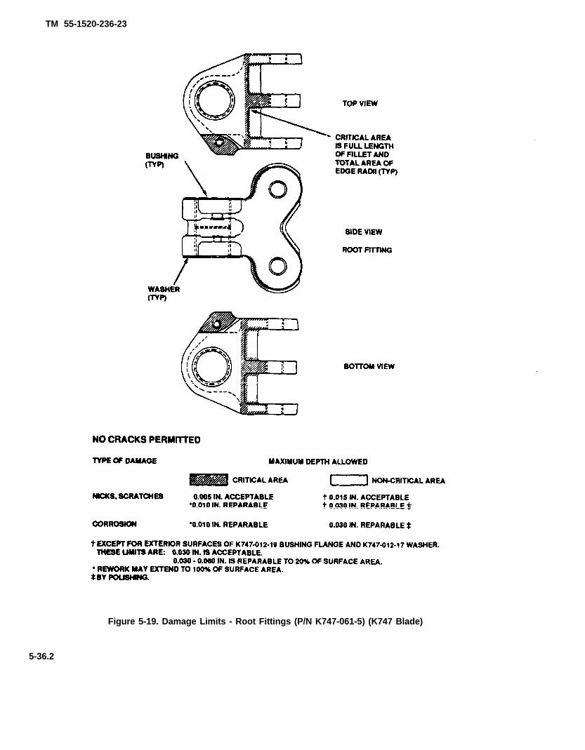
TM 55-1520-236-23
Figure 5-19. Damage Limits - Root Fittings (P/N K747-061-5) (K747 Blade)
5-36.2
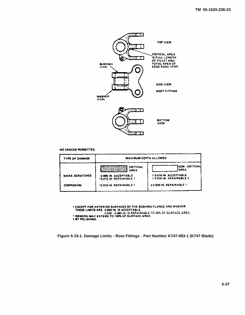
TM 55-1520-236-23
Figure 5-19.1. Damage Limits - Root Fittings - Part Number K747-083-1 (K747 Blade)
5-37

TM 55-1520-236-23
Figure 5-20. Damage Limits - Drag Strut (P/N K747-072-1) (K747 Blade)
5-38
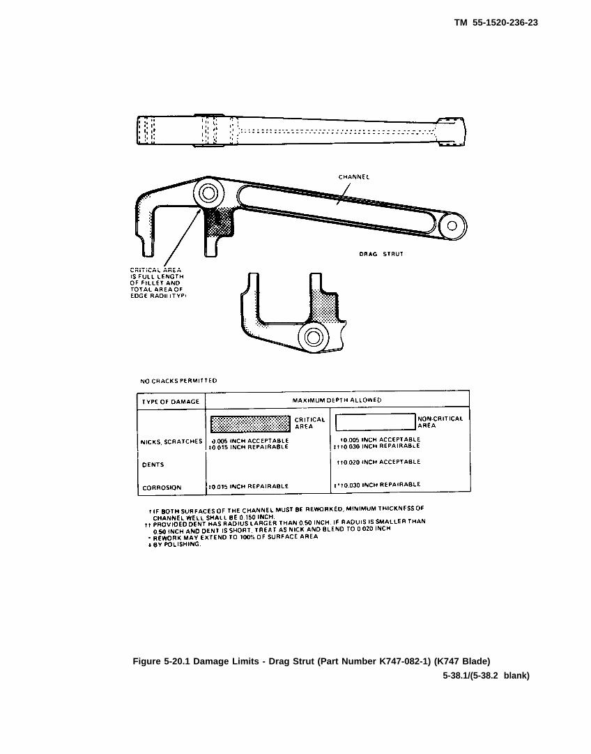
TM 55-1520-236-23
Figure 5-20.1 Damage Limits - Drag Strut (Part Number K747-082-1) (K747 Blade)
5-38.1/(5-38.2 blank)

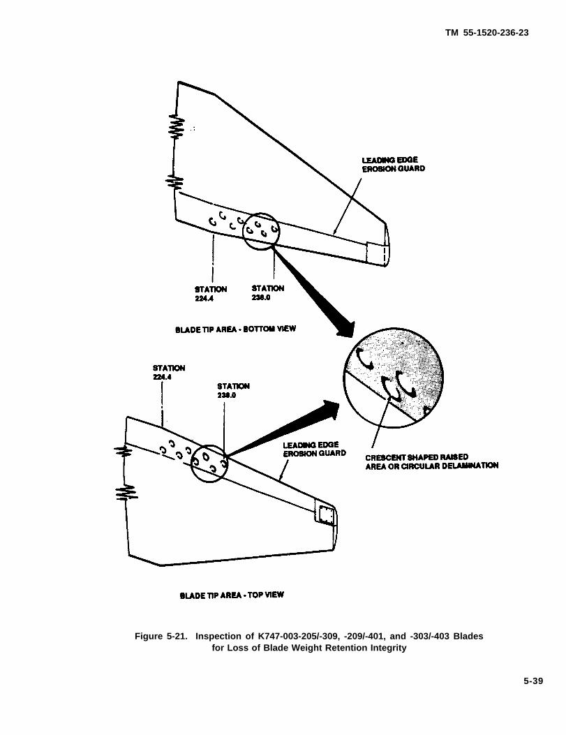
TM 55-1520-236-23
Figure 5-21. Inspection of K747-003-205/-309, -209/-401, and -303/-403 Bladesfor Loss of Blade Weight Retention Integrity
5-39

TM 55-1520-236-23
Figure 5-22. Proximity Limits for Patches - K747 Main Rotor Blades (Sheet 1 of 3)
5-40

TM 55-1520-236-23
Figure 5-22. Proximity Limits for Patches. K747 Main Rotor Blades (Sheet 2 of 3)
5-41
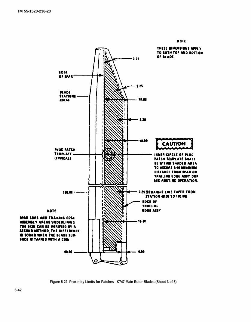
TM 55-1520-236-23
Figure 5-22. Proximity Limits for Patches - K747 Main Rotor Blades (Shoot 3 of 3)
5-42

TM 55-1520-236-23
Figure 5-23. Balance Adjustment for Patches (K747 Blade) (Sheet 1 of 2)
5-43

TM 55-1520-236-23
Figure 5-23. Balance Adjustment for Patches (K747 Blade) (Sheet 2 of 2)
5-44
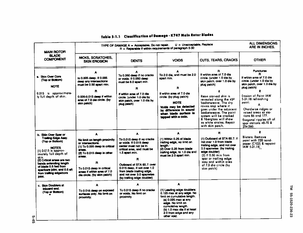
Table 5-1.1
TM
55-1520-236-235-45
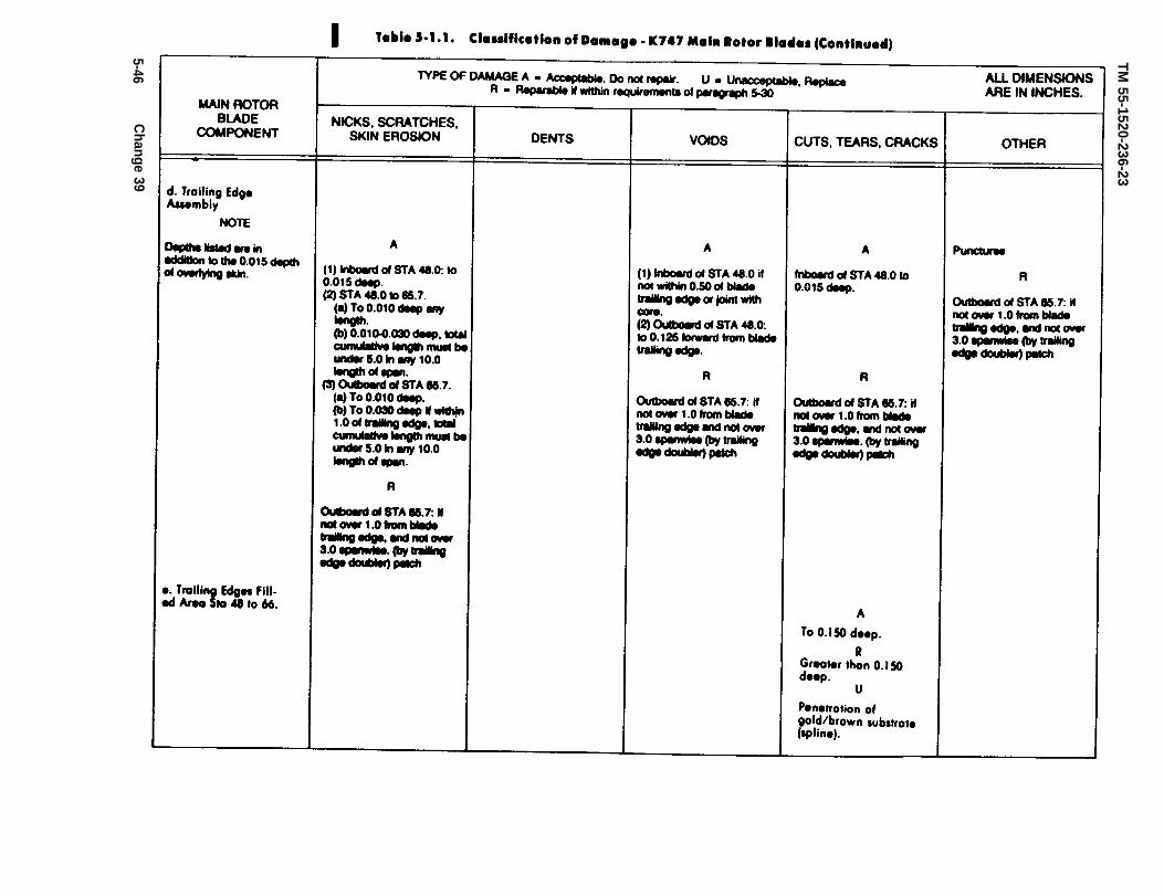
Table 5-1.1.
TM 55-1520-236-23
5-46C
hange 39
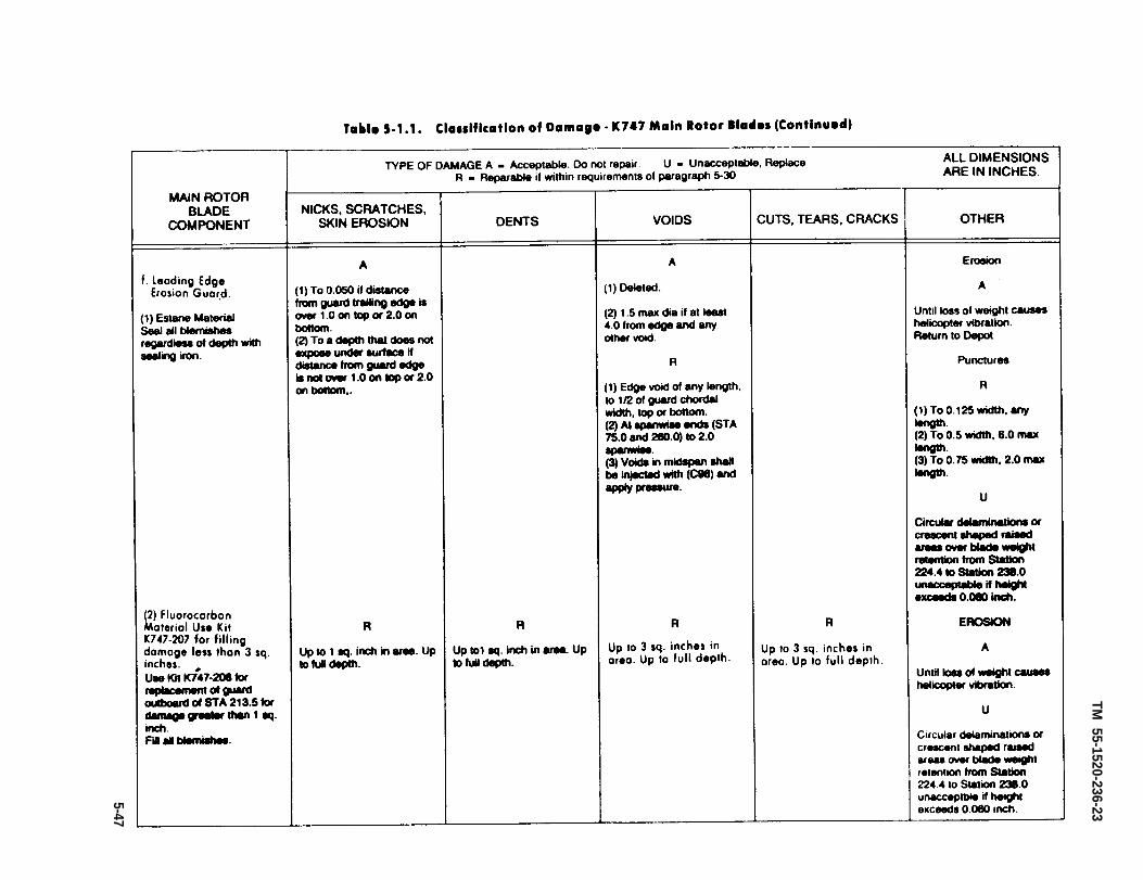
Table 5-1.1.
TM 55-1520-236-23
5-47

Table 5-1.1.
TM
55-1520-236-23
5-4
8
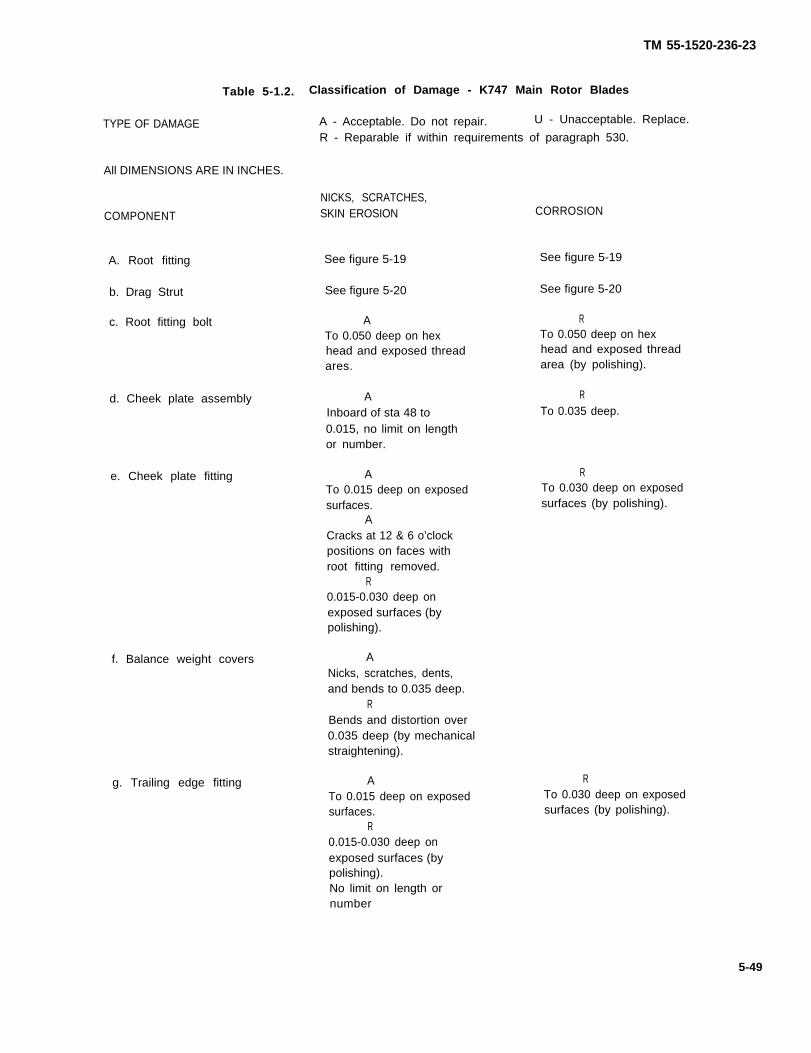
TM 55-1520-236-23
Table 5-1.2.
TYPE OF DAMAGE
All DIMENSIONS ARE IN INCHES.
COMPONENT
A. Root fitting
b. Drag Strut
c. Root fitting bolt
d. Cheek plate assembly
e. Cheek plate fitting
f. Balance weight covers
g. Trailing edge fitting
Classification of Damage - K747 Main Rotor Blades
A - Acceptable. Do not repair. U - Unacceptable. Replace.
R - Reparable if within requirements of paragraph 530.
NICKS, SCRATCHES,SKIN EROSION
See figure 5-19
See figure 5-20
ATo 0.050 deep on hexhead and exposed threadares.
AInboard of sta 48 to0.015, no limit on lengthor number.
ATo 0.015 deep on exposedsurfaces.
ACracks at 12 & 6 o’clockpositions on faces withroot fitting removed.
R0.015-0.030 deep onexposed surfaces (bypolishing).
ANicks, scratches, dents,and bends to 0.035 deep.
RBends and distortion over0.035 deep (by mechanicalstraightening).
ATo 0.015 deep on exposedsurfaces.
R0.015-0.030 deep onexposed surfaces (bypolishing).No limit on length ornumber
CORROSION
See figure 5-19
See figure 5-20
RTo 0.050 deep on hexhead and exposed threadarea (by polishing).
RTo 0.035 deep.
RTo 0.030 deep on exposedsurfaces (by polishing).
RTo 0.030 deep on exposedsurfaces (by polishing).
5-49

TM 55-1520-236-23
Table 5-1.2. Classification of Damage - K747 Main Rotor Blades (Continued)
TYPE OF DAMAGE A – Acceptable. Do not repair. U – Unacceptable. Replace.R – Reparable if within requirements of paragraph 5-30.
ALL DIMENSlONS ARE IN INCHES.
NICKS, SCRATCHES,COMPONENT SKIN EROSION
h. Tip cap, forward A(see note) To 0.030 deep.
R0.030-0.060 deep (bypolishing).
i. Tip weight cover No limit on length ornumber.
A
CORROSION
Erosion:A
Until loss of weightcauses helicoptervibration.
RGap around tip cap.Sealer missing. Applysealant (C107).
Erosion
ATo 0.030 deep.
To 0.030 deep.R
0.030-0.060 deep (bypolishing).
NOTE: The balance weights consist of several plates that are free to move within the cavity of thetip-balance weight cap. If the cavity is not full, the balance weight plates are able to move, pro-ducing the clicking noise during the static vertical movement of the blade. The clicking noiseis to be considered normal, unless the tip-balance weight cap is not properly secured to its at-taching pocket bracket.
5-50
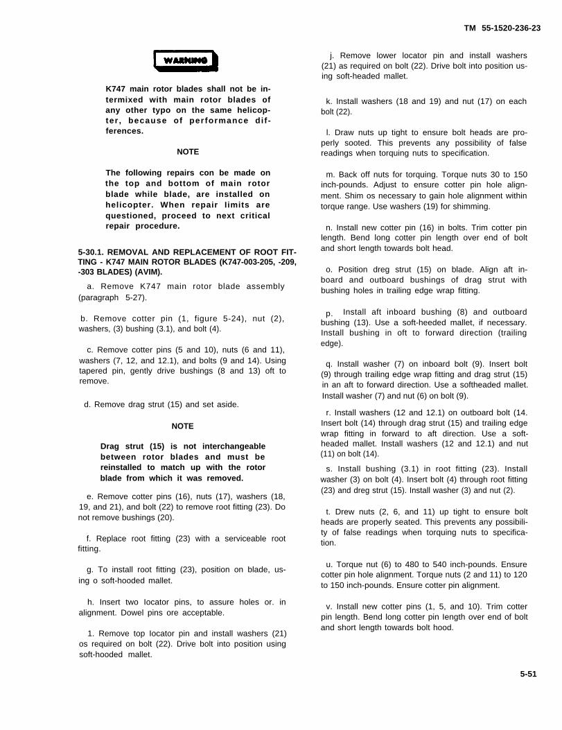
TM 55-1520-236-23
j. Remove lower locator pin and install washers(21) as required on bolt (22). Drive bolt into position us-ing soft-headed mallet.
K747 main rotor blades shall not be in-termixed with main rotor blades ofany other typo on the same helicop-ter , because of performance di f -ferences.
NOTE
The following repairs con be made onthe top and bottom of main rotorblade while blade, are installed onhelicopter. When repair Iimits arequestioned, proceed to next criticalrepair procedure.
5-30.1. REMOVAL AND REPLACEMENT OF ROOT FIT-TING - K747 MAIN ROTOR BLADES (K747-003-205, -209,-303 BLADES) (AVIM).
a. Remove K747 main rotor blade assembly(paragraph 5-27).
b. Remove cotter pin (1, figure 5-24), nut (2),washers, (3) bushing (3.1), and bolt (4).
c. Remove cotter pins (5 and 10), nuts (6 and 11),washers (7, 12, and 12.1), and bolts (9 and 14). Usingtapered pin, gently drive bushings (8 and 13) oft toremove.
d. Remove drag strut (15) and set aside.
NOTE
Drag strut (15) is not interchangeablebetween rotor blades and must bereinstalled to match up with the rotorblade from which it was removed.
e. Remove cotter pins (16), nuts (17), washers (18,19, and 21), and bolt (22) to remove root fitting (23). Donot remove bushings (20).
f. Replace root fitting (23) with a serviceable rootfitting.
g. To install root fitting (23), position on blade, us-ing o soft-hooded mallet.
h. Insert two Iocator pins, to assure holes or. inalignment. Dowel pins ore acceptable.
1. Remove top Iocator pin and install washers (21)os required on bolt (22). Drive bolt into position usingsoft-hooded mallet.
k. Install washers (18 and 19) and nut (17) on eachbolt (22).
l. Draw nuts up tight to ensure bolt heads are pro-perly sooted. This prevents any possibility of falsereadings when torquing nuts to specification.
m. Back off nuts for torquing. Torque nuts 30 to 150inch-pounds. Adjust to ensure cotter pin hole align-ment. Shim os necessary to gain hole alignment withintorque range. Use washers (19) for shimming.
n. Install new cotter pin (16) in bolts. Trim cotter pinlength. Bend long cotter pin length over end of boltand short length towards bolt head.
o. Position dreg strut (15) on blade. Align aft in-board and outboard bushings of drag strut withbushing holes in trailing edge wrap fitting.
p. Install aft inboard bushing (8) and outboardbushing (13). Use a soft-heeded mallet, if necessary.Install bushing in oft to forward direction (trailingedge).
q. Install washer (7) on inboard bolt (9). Insert bolt(9) through trailing edge wrap fitting and drag strut (15)in an aft to forward direction. Use a softheaded mallet.Install washer (7) and nut (6) on bolt (9).
r. Install washers (12 and 12.1) on outboard bolt (14.Insert bolt (14) through drag strut (15) and trailing edgewrap fitting in forward to aft direction. Use a soft-headed mallet. Install washers (12 and 12.1) and nut(11) on bolt (14).
s. Install bushing (3.1) in root fitting (23). Installwasher (3) on bolt (4). Insert bolt (4) through root fitting(23) and dreg strut (15). Install washer (3) and nut (2).
t. Drew nuts (2, 6, and 11) up tight to ensure boltheads are properly seated. This prevents any possibili-ty of false readings when torquing nuts to specifica-tion.
u. Torque nut (6) to 480 to 540 inch-pounds. Ensurecotter pin hole alignment. Torque nuts (2 and 11) to 120to 150 inch-pounds. Ensure cotter pin alignment.
v. Install new cotter pins (1, 5, and 10). Trim cotterpin length. Bend long cotter pin Iength over end of boltand short length towards bolt hood.
5-51

TM 55-1520-236-23
Figure 5-24. Root Fitting Assembly (K747-205, -209, -303 Blades)
5-52

TM 55-1520-236-23
Figure 5-24.1. Root Fitting Assembly (-309, -401, -403 Blades)(Sheet 1 of 2)
5-52.1

TM 55-1520-236-23
Figure 5-24.1 Root Fitting Assembly (-309, -401, -403 Blades)
(Sheet 2 of 2)
5-52.2
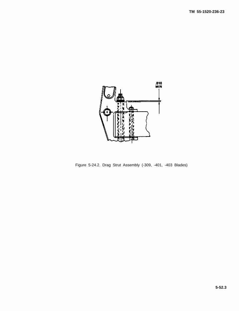
TM 55-1520-236-23
Figure 5-24.2. Drag Strut Assembly (-309, -401, -403 Blades)
5-52.3

TM 55-1520-236-23
5-30.2. REMOVAL AND REINSTALLATION OFROOT FITTING - K747 MAIN ROTOR BLADES(K747-003-309, -401, -403 BLADES).
a. Remove K747 main rotor blade assembly (para-graph 5-27).
b. Remove cotter pins (1 and 6, Figure 5-24.2),nuts, (2 and 7), washers (3, 4, 8, 26, 27), and bolts (5and 9), from drag strut at trailing edge wrap fitting.
c. Remove cotter pin (10), nut (11), washers (12,13, and 28), and bolt (14), scouring drag strut to rootfitting.
d Remove bushing (22) from leading edge of dragstrut at root fitting.
Do not drive inboard aft drag strut bushingout in direction of leading edge. lrreparabledamage to the drag strut couId result. Sup-port drag strut assembly during bushingremoval.
e. Drive two bushings (20 and 21) out of drag strutand trailing edge wrap fitting in aft direction, support-ing drag stint assembly during bushing removal, usinga phenolic, aluminum, or wooden dowel and a soft-headed hammer. Keep dowel axis in line with axis ofbushing being removed.
f. Remove drag strut from bide and set aside.
NOTE
Drag strut (23) is not interchangeable be-tween rotor blades and must be reinstalledto match up with the rotor blade from whichit was removed.
g. Remove cotter pins (15), nuts (16), washers (17,18, 25), and bolts (19), to remove root fitting.
h. Replace root fitting (24) only if required. Refer toTable 5.1.1 and Figure 5-19.2.
i. To install root fitting (24), position on blade usinga soft-headed mallet.
j. Insert two Iocator pins, to ensure holes are inalignment. Dowel pins are acceptable.
Beveled lD on washer (18) must face bolthead. Do not damage bolt threads or bush-ing bores when installing bolts.
k. Apply corrosion preventive compound, Brayco599 (C44.1) to bolt shank. Remove top locator pin andinstall washer (18), beveled ID toward bolthead, onbolt (19). Drive bolt into position using a soft-headedmallet.
l. Apply corrosion preventive compound, Brayco599 (C44.1) to bolt shank. Remove lower Iocator pinand install washer (18), beveled ID toward bolthead,on bolt (19). Drive bolt into position using a soft-headed mallet.
m. Install washer (17) under nut (16) on each bolt.If required, add washers (17 and/or 25) under nut (16)on each bolt to obtain cotter pin hole alignment.
n. Draw all nuts up tight to ensure boltheads areproperly seated. This prevents any possibity of falsereadings when torquing nuts to specification.
o. Back off nuts for torquing. Torque nuts to 30 to150 inch-pounds. Adjust to ensure cotter pin holealignment.
p. Install new rotter pins (1, 6 and 10). Trim cotterpin length. Bend long cotter pin length over end of boltand bend short length toward bolt head. Ensure thatno sharp edges are exposed.
5-52.4

TM 55-1520-236-23
5-31. POLISHING AND CORROSION TREATMENT.K747 MAIN ROTOR BLADES (AVUM).
a. Polish out nicks, scratches, and corrosion on ex.posed metallic parts with No. 320 or finer sandpaper(C102) and touchup os required in accordance withparagraph 5-31.18:
b. Repairs requiring removal of drag strut (15, figure5.16) may be made by removing attaching hardware.Following repairs as specified in step a. above, reinstalldreg strut using figure 5-16 as a guide.
5-31.1. APPLICATION OF SKIN PATCH - K747MAIN ROTOR BLADES (AVUM).
5-30
b. Position blade for acces to damaged area (figure5-25). Support blade to prevent movement and droop.
g. Plato the template (kit) an the blade. Position theinner circle to enclose the damage. Hold the templatefrom dipping, and draw a Iine around the outer circle ofthe template (View A, figure 5.25).
h. Starting with 120 grit and finishing with 220 gritabrasive paper (kit), sand the paint and yellow primerfrom the blade from the area within the guide circle.Sand only until yellow color is removed. Do not sendskin fibers. Also, sand off any damaged matertial raisedabove normal contour of blade (View A, figure 5-25).
l. Cut short Iengths of the masking tape (kit) andmask around the outside of guide circle (View B, figure
5-25).
5-53
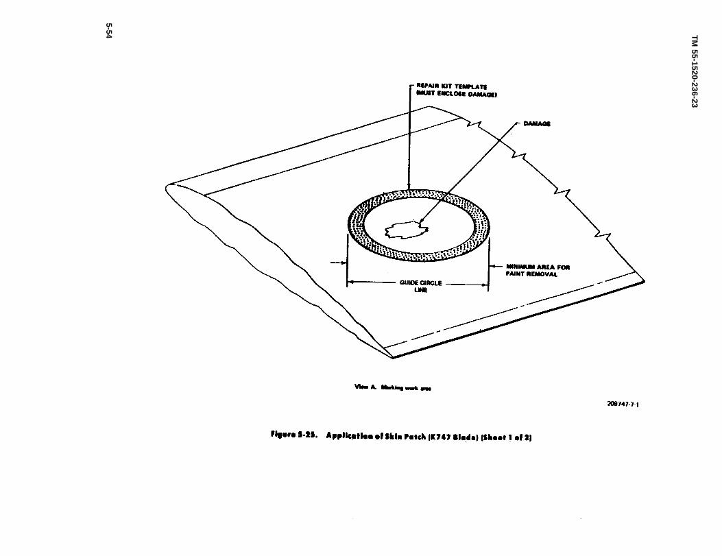
Figure 5-25.
TM
55-1520-236-23
5-54
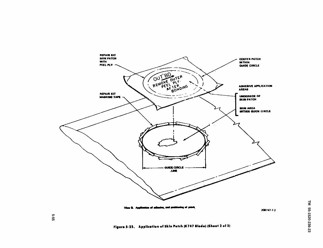
Figure 5-25.
TM 55-1520-236-23
5-55

TM 55-1520-236-23
5-56
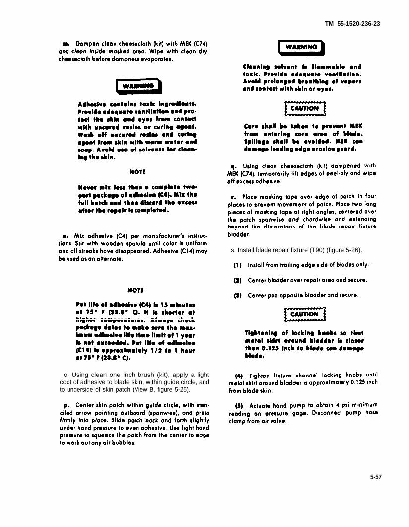
TM 55-1520-236-23
o. Using clean one inch brush (kit), apply a lightcoot of adhesive to blade skin, within guide circle, andto underside of skin patch (View B, figure 5-25).
s. Install blade repair fixture (T90) (figure 5-26).
5-57
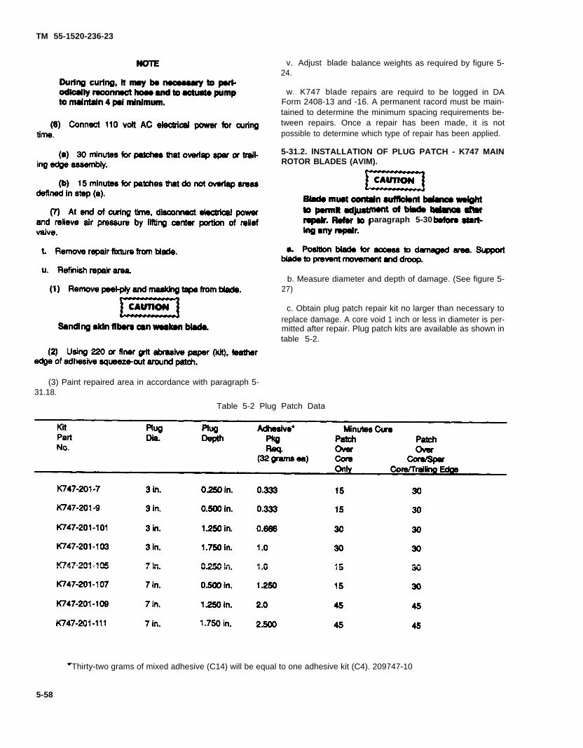
TM 55-1520-236-23
(3) Paint repaired area in accordance with paragraph 5-31.18.
v. Adjust blade24.
w. K747 blade
balance weights as required by figure 5-
repairs are requird to be logged in DA
paragraph 5-30
Form 2408-13 and -16. A permanent racord must be main-tained to determine the minimum spacing requirements be-tween repairs. Once a repair has been made, it is notpossible to determine which type of repair has been applied.
5-31.2. lNSTALLATION OF PLUG PATCH - K747 MAINROTOR BLADES (AVIM).
b. Measure diameter and depth of damage. (See figure 5-27)
c. Obtain plug patch repair kit no larger than necessary toreplace damage. A core void 1 inch or less in diameter is per-mitted after repair. Plug patch kits are available as shown intable 5-2.
Table 5-2 Plug Patch Data
Thirty-two grams of mixed adhesive (C14) will be equal to one adhesive kit (C4). 209747-10
5-58
TM 55-1520-236-23
d. Damage not more than 1.750 inches deep can berepaired with a single patch. Damage that passes com-pletely through blade and is Iarger then 1 inch indiameter, will be repaired by installing plug patchesfrom both top and bottom sides of blade. Install largerdiameter and depth plug patch first (figure 5-28).
e. Obtain required number of adhesive packages(C4) as shown in table 5-2. If adhesive (C14) is used, ob-tain an equal amount.
f. Place the template (kit) on the blade. Position theinner circle to enclose the damage. Hold the templatefrom slipping and draw lines around the inner and outercircles of the template (View A, figure 5-27).
g. Starting with 120 grit and finishing with 220 gritabrasive paper (kit), sand the paint and the yellowprimer from the blade from the area between circles Aand B. Sand only until yellow color is removed. Do notsand skin fibers (View A, figure 5-27).
it is absolutely necessary to takeevery precaution not to damage thespar and trailing edge during routing.The spar in the loading edgo and trail-ing edge can be Iocated by using theInstructions in figure 5-23.
j. Insert rasp-type bit, P/N 4-BR, in router collet. Setrouter depth of cut for 0.1875 inch. Rout a complete cir-cle through the skin, inside of, and following circle A(View B, figure 5-27).
k. Using duckbill pliers, lift the edge of the cut cir-cle of skin and peel the cut circle of skin off core (View8, figure 5-27). After removing skin, check depth ofcore at trailing edge of circle. Core thickness at trailingedge side less than depth of plug selected will requireuse of more shallow plug or a double plug patchrepair.
5-59

Figure 5-27.
TM 55-1520-236-23
5-60

Figure 5-27.
TM
55-1520-236-23
5-61
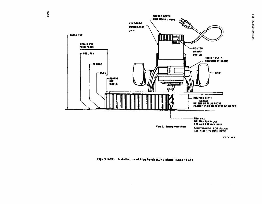
Figure 5-27.
TM
55-1520-236-23
5-62

Figure 5-27.
TM
55-1520-236-23
5-63
TM 55-1520-236-23
l. lnsert end mill in router collet. Set router depth ofcut to match depth of plug plus thickness of wafer (kit)(View C, figure 5-27). Rout out core. First rout a com-plete circle, following inside circle A. Then rout out re-mainder of core moving router in chordwise direction(View D, figure 5-27).
m. Wipe off all cuttings, sanding dust, etc. fromrepair ores.
n. Use template to redraw circle B.
o. Cut short lengths of masking tape (kit) and maskaround the outside of circle B (View D, figure 5.27).
p. Put on cotton gloves (kit), then plastic gloves (kit).leave on until completion of step y.
s. Using clean one inch brush (kit), apply a Iiberalcoat of adhesive to one side of wafer (kit) (View D,figure 5-27).
5-64

aa. Install blade repair fixture (figure 5-26).
(1) Install from trailing edge side of blade on-ly .
(2) Center bladder over repair ares andsecure.
(3) Center pad apposite bladder and secure.
TM 55-1520-236-23
(5) Actuate bond pump to obtain 4 psiminimum reading an pressure gage. Disconnectpump base clamp from air valve.
(6) Connect 110 volt ac electrical power forcuring time shown in table 5-2.
(3) Paint repaired area in accordance withparagraph 5-31.18.
ad. Adjust blade balance weights as requiredby figure 5-24.
ae. K747 blade repairs are required to be logg-ed in DA Form 2408-13 and -16. A permanentrecord must be maintained to determine theminimum spacing requirement between repairs.Once a repair has been made, it is not possibleto determine which type of repair has been ap-plied.
5-31.3. REPAIR OF TRAILING EDGE FlLL-ED AREAS - K747 MAIN ROTOR BLADES(AVIM).
5-65

TM 55-1520-236-23
b. Determine depth of damage at deepestpoint. If depth of damage is less then 0.150 inch.no repair is necessary. If depth of damage isgreeter then 0.150 inch but less then 0.250 inch,proceed to step f. If depth of damage is greaterthan 0.250 inch, proceed os follows.
C. Remove point from surface of damaged areaby hand abrading with 220 grit abrasive paperto expose red/purple filler and clear skin bon.ding resin.
5 - 3 0
5-66
f . Refinish repair area in accordance withparagraph 5-31.18.
5.31.4. APPLICATION OF TRAILING EDGEDOUBLER PATCH. K747 MAIN ROTOR BLADES(AVIM).
a. Position blade for access to damaged area. (Seefigure 5-28.1.)
b. Support blade to prevent movement and droop.
c. Obtain trailing edge doubler patch repair kit P/NK747-201-113, and adhesive package (C4). Adhesive(C14) maybe used as an alternate.

Figure 5-28.
TM 55-1520-236-23
5-67
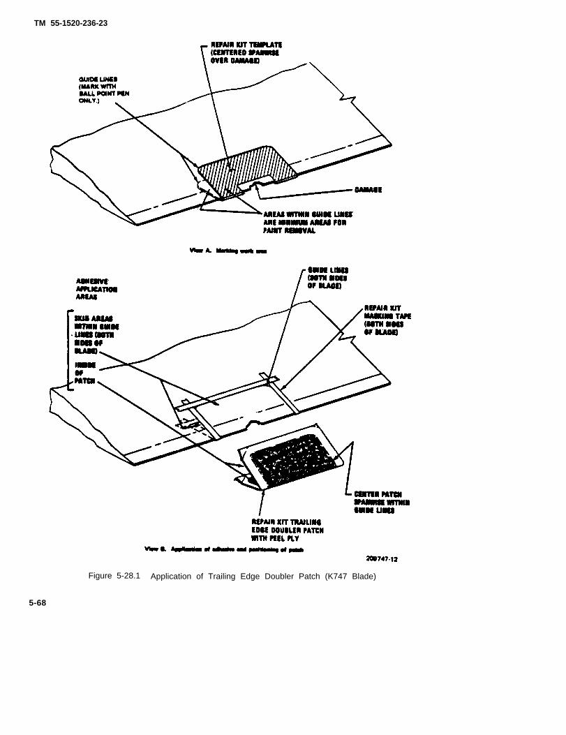
TM 55-1520-236-23
Figure 5-28.1 Application of Trailing Edge Doubler Patch (K747 Blade)
5-68
TM 5-1520-236-23
d. Place the template (kit) on the blade, centering itspanwise over the damage. Hold the template from slip-ping and draw a Iine around the template on both the topand bottom of the blade (View A figure 5-28.1).
e. Starting with 120 grit and finishing with 220 gritabrasive paper (kit), sand the point and the yellowprimer from the blade from the area within the guidelines an both sides of blade and along trailing edge.Sand only until yellow color is removed. Also sand offany material that may be raised above the normal con-tour of the blade at edges of damage. Da not sand un-damaged skin fibers (View A, figure 5-28.1).
h. Use template to redraw guide lines (View A,figure 5-28.1).
l. Cut lengths of masking tape (kit) and maskaround the outside of the guide lines (View B, figure 5-28.1).
k. Mix adhesive (C4) per. manufacturer’s instruc-tions. Stir with wooden spatula until color is uniformand all streaks have disappeared. Transfer to plastictooted paper cup.
5-69
TM 55-1520-236-23
l. Using clean one inch brush (kit), apply a light coatof adhesive to inside surfaces of doubler patch (ViewB, figure 5-28.1) and to skin.
m. Center doubler patch within guide Iines andpress into place. Slide patch back and forth slightlyunder hand pressure to even adhesive. Push patchfirmly against trailing edge and center within guidelines. Use light bond pressure to squeeze the patchfrom the center to edges to work out any air bubbles.
n. Using clean cheesecloth (kit) dampened withMEK (C74), temporarily lift edges of peel-ply and wipeoff excess adhesive.
o. Place masking tape ever edges of patch to pre-vent movement of patch.
p. Install blade repair fixture (figure 5-26).
(1) Install from trailing edge side of blade onlywith bladder side on blade upper surface.
(2) Position bladder aver repair area and secure.
(3) Center pad opposite bladder and secure.
(4) Tighten fixture channel lacking knobs untilmetal skirt around bladder is approximately 0.125 inchfrom blade skin.
(3) Actuate hand pump to obtain 4 psi minimumreading on pressure gage. Disconnect pump hose fromair valve.
(2) Using 220 grit abrasive paper (kit), featheredge of adhesive squeeze-out around patch.
(3) Paint repaired area in accordance with.paragraph 5-31.18.
s. Adjust blade balance weights as required byfigure 5-24.
t. K747 blade repairs are required to be logged inDA Farm 2408-13 and -16. A permanent record must bemaintained to determine the minimum spacing re-quirement between repairs.
5-31.5. FIBER SEPARATION AND RESIN CRACKS -TRAILING EDGE SPLINE - K747 MAIN ROTORBLADES.
a. The trailing edge spline, located at station 49.00to 41.00, is made up of Kevlar fibers in a matrix ofcured resin. Fiber separations may give the false ap-pearance of a crack. Fiber separations filled and unfill-ed with resin are acceptable to the standards specifiedbelow. (See figure 5-28.2.)
5-70

TM 55-1520-236-23
Figure 5-28.2. Spline Repair (K747 Blade)
5-71
TM 55-1520-236-23
b. Area A. Fiber separations not filled with resin areacceptable to a depth of 0.060 inch. Fiber separationswith a depth of 0.060 to 0.200 inch shell be filled withsealer (C105) or adhesive (C14). Fibers ore orientedspanwise in this area, therefore, separations aregenerally oriented spanwise, too.
c. Area B. Fiber separations not filled with resin areacceptable to a depth of 0.025 inch. Fiber separationswith o depth greater than 0.025 inch have penetratedinto the area A type composite material and,therefore, foil under the area A allowable. Fiberseparations may be filled with sealer (C105) oradhesive (C14) as desired.
d. K747 blade repairs are required to be logged inDA Form 2408-13 and -16. A permanent record must bemaintained to determine the minimum spacing re-quirement between repairs. Once a repair has beenmade, it is not possible to determine which type ofrepair has been applied.
5.31.6. REBONDING DELAMINATED LEADINGEDGE EROSION GUARD - K747 MAIN ROTORBLADES (AVUM) .
a. Position blade for access to delaminated erosionguard. Support blade to prevent movement and droop.(See figure 5-28.3.)
b. Obtain erosion guard patch kit P/N K747-201-119and epoxy resin (C98).
Cleaning solvent is flammable andtoxic. Provide adequate ventilation.Avoid prolonged broathing of vaporsand contact with skin or eyes.
Isopropyl alcohol can damage Ieadingedge erosion guard. Avoid spillage.
c. Prior to cleaning both the erosion guard and theblade surface, peel back the erosion guard approx-imately 0.5 inch to insure that total void ordelaminated area is identified for repair. Using cottontipped swab (kit) dipped in isopropyl alcohol (C64) sol-vent, clean surfaces to be banded.
d. Using masking tape (kit), mask blade along trail-ing edge of boot to prevent squeezed-out adhesivefrom coming in contact with the exposed blade sur-face.
e. Put on cotton gloves (kit), then plastic gloves (kit).
Adhesive contains toxic Ingrediants.Provide adequate ventilation and pro-tect the skin and eyes from contactwith uncured rosins or curing agent.Wash off uncured rosins and curingagent from skin with warm water andsoap. Avoid us. of solvents for clean-ing the skin.
Protectiva equipment must be usedwhen performing those repairs.
Both erosion guard and blade leadingedge surfaces must be clean, dry, andfree of finger prints and foreign mat-ter.
f. Mix 100 parts/weight of epoxy resin (C98) with 12parts/weight of DTA activator (C98) in a clean glass,metal, polyethylene, or plastic coated paper container.
NOTE
Pot life of adhesive is 15 minutes at75° F (23.8° C). It is shorter at highertemperatures. Always check packagedates to make sure the adhesive lifelimit of 1 year is not exceeded. Workwithout delay.
g. Using clean 0.25 inch brush (kit), apply a lightcoat of adhesive (C98) to both surfaces to be bonded.
h. Using finger pressure, press erosion guard toblade while working out excess adhesive from underthe erosion guard. Wipe away excess adhesive withclean cheesecloth (kit) to prevent adhesive from runn-ing off the masking tape onto the exposed blade sur-face.
i. Lay teflon parting blanket (kit) over repair. Placemasking tape (kit) over edges of parting blanket to pre-vent movement.
5-72
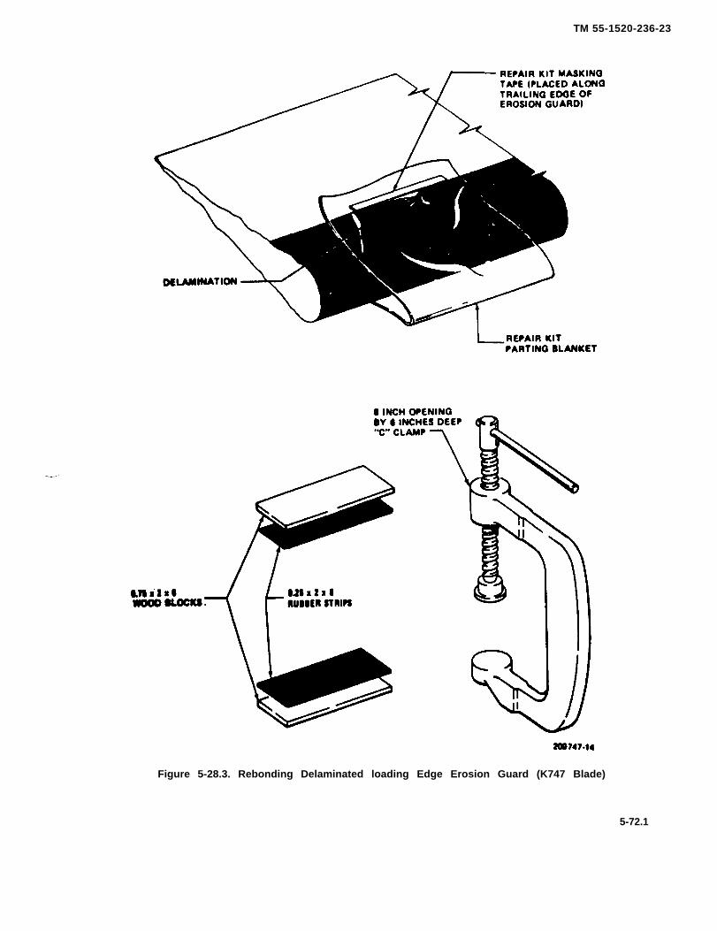
TM 55-1520-236-23
Figure 5-28.3. Rebonding Delaminated loading Edge Erosion Guard (K747 Blade)
5-72.1

TM 55-1520-236-23
j. Obtain two wooden blocks approximately 0.75 x2 x 6 inches and a C clomp (8 inch opening by 6 inchesdeep). Place 0.25 x 2 x 6 inches strip of rubber betweenblock and parting blanket. Place remaining block andrubber strip on opposite surface and, using C clamp,apply Iight pressure to rebonded area.
k. At end of four hours, at room temperature,remove clomp, blocks, rubber strip, parting blanketand masking tape.
5-31.7. REPAIR OF ESTANE EROSION GUARDK747-003-205/-309 MAIN ROTOR BLADES (AVUM).
a. This repair is for station 213.5 inboard, however,may be used outboard of station 213.5 (on estanematerial only) when time requirements dictate a needfor quick repair. Obtain Ieading edge erosion guardpatch kit P/N K747-201-119.
b. The cuts and nicks are repaired by softening theguard with sealing iron (T89).
c. Set the temperature at the minimum. Use justenough heat to cause the estane guard material to besoft. Keep the iron moving.
d. Small damage con be repaired by moving thematerial from each side of the damage with the seal-ing iron.
e. A 0.25 inch damage can be repaired by addingslivers of estane guard (kit).
f. Using a clean 1-inch brush, apply one coat of MEK(C74). Do not overbrush the some ares more than threetimes.
g. Allow to air dry for a minimum of 1 hour.
NOTE
The coating will develop optimumdurability in approximately 6 to 8hours. Flying in rain conditions withless drying time may cause rapid ero-sion of resurfaced area.
5-31.8. REPAIR OF FLUOROCARBON EROSIONGUARD. K747 MAIN ROTOR BLADES (AVUM) .
a. This procedure uses kit P/N K747-207-1 for therepair of nicks and cuts which involve loss then onesquare inch of damaged area in the following areas:
(1) K747-003-205/-309, between stations 213.5 and260.0 where fluorocarbon leading edge erosion guard re-placement has been accomplished. Check blade DAForm 2408-16 to determine this fact.
(2) K747-003-209-401 and -303/-403, any leadingedge erosion guard surface.
b. Remove damaged leading edge erosion guard inarea being repaired. Cut material away using a razorblada or equivalent to form an oval area. The sides ofcut must slope inward toward center of damaged area.(See figure 5-28.4.)
c. Wipe exposed area with a cheesecloth (C30)dampened with MEK (C74).
d. Form a mold to contain injected adhesive. Pro-ceed as follows:
(1) Cut a piece of #Y8412 tape (kit) in a rectanglewhich is approximately 1/2 inch Iarger than repairarea.
(2) Cut a second piece of #Y8412 tape (kit) one inchIarger in Iength and width than the piece cut above.
5-72.2
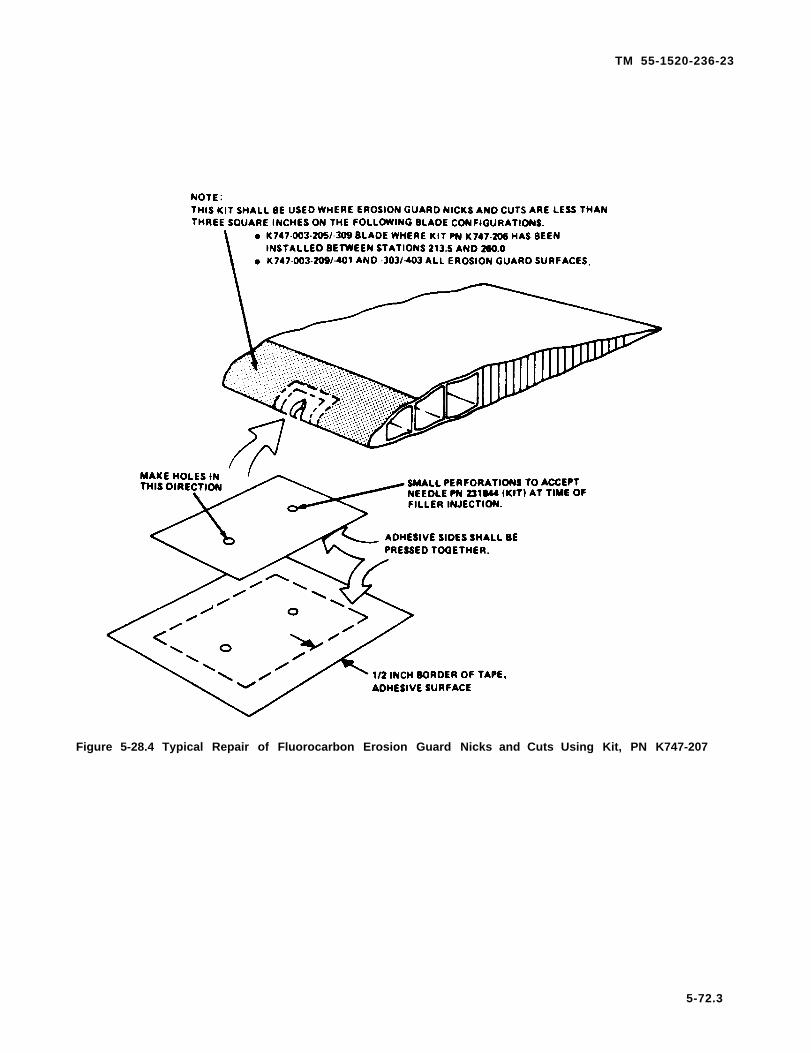
TM 55-1520-236-23
Figure 5-28.4 Typical Repair of Fluorocarbon Erosion Guard Nicks and Cuts Using Kit, PN K747-207
5-72.3

TM 55-1520-236-23
(3) Position smaller piece of tape (mating theadhesive surfaces) in the center of the Iarger one. A1/2 inch exposod adhesive border will result. (Seefigure 5-28.4.)
(4) Locate tape mold centrally over damaged areaso meting surface (adhesive border) faces outward.Poke two holes in the tape, one at each end of majoraxis of cut out repair area. The two hales should bemode with a 5/64 inch diameter drill bit and be largeenough to accept syringe supplied with kit.
(5) Turn tape over (mating surface toward blade)and press into position as shown in figure 5-28.4. En-sure good tape adhesion is made. Do not press tapemold into void.
f. lnject adhesive filler into one hole until it seepsfrom second hole. Reverse action by injecting into se-cond hole until the adhesive filler seeps from firsthole. Ensure no air pockets are left beneath tape meld.
g. Cure repair using one of the following pro-cedures:
(1) Three days at room temperature.
(2) Four hours at room temperature followed by 4hours at 160 ± 10° F (71 ± 6° C). (Heat con be appliedby lamps or a hot air gun.)
h. Cut excess adhesive protruding from injectionholes with a razor blade.
i. Remove tape mold and abrade any high spots orexcess matertial from erasion guard surface. Blendpatch to match contour of surrounding areas using 240grit abrasive paper.
5-31.9 APPLICATION OF LEADING EDGE EROSIONGUARD PATCH . K747-003-205/-309 MAIN ROTORBLADES (AVUM).
a. This repair is for station 213.5 inboard, however,may be used outboard of station 213.5 (on estanematerial only) when time requirements dictate o needfor quick repair.
Blade must contain sufficient balanceweight to permit adjustment of bladeb a l a n c e a f t e r r e p a i r . R e f e r t oparagraph 5-30 before starting anyrepair.
b. Position blade for access to damaged Ieadingedge erosion guard. Support blade to prevent move-ment and droop.
c. Obtain leading edge erosion guard patch kit P/NK747-201-119 and estane contact cement.Prepare estane contact cement far estane erosionguards as follows:
(1) Obtain a piece of estane material and someMEK (C74).
(2) Cut estane material into very small slivers ap-proximately 0.025 inch in size.
(3) Combine estane and MEK. Suggested mix ratiois 15 grams of estane to 85 grams of MEK. Allow tostand for 24 hours. Agitate intermittently throughoutthis 24 hour period to ensure that the estane is totallydissolved.
(4) The solution is now ready to use and should beagitate before any such use.
5-72.4

TM 55-1520-236-23
Figure 5-28.5. Application of Loading Edge Erosion Guard Patch (K747 Blade)
5-72.5

TM 55-1520-236-23
d. Place the template (kit) on the erosion guardcentering it over the damage. Hold template fromslipping and mark outline of template on erosion guard.(See figure 5-28.5).
e. Cut lengths of masking tape (kit) and maskaround outside of the guide lines.
f. Using 180 or 220 grit sandpaper (kit), abradearea of erosion guard inside guidelines and undersidesurface of patch.
Put on cotton gloves (kit) and then plasticgloves (kit). Leave on until completion of step 1.
Using clean cheesecloth (kit), and isopropylalcohol (C64) solvent, wipe surfaces to be bonded.
i . Using clean one inch brush (kit), apply a Iightcoat of estane contact cement within masked area oferosion guard and to the underside surface of thepatch. Allow to air dry for five minutes.
Patch will adhere to erosion guard oncontact. Make certain that patch is cor-rectly aligned before making contact.
j . Starting towards Ieading edge of blade, installpatch, working it carefully into place with fingers, usingextreme care not to entrap air under patch. Press allareas of patch firmly into contact with erosion guard.
k. Remove masking tape.
l. Using one inch brush (kit), apply a mediumthick coat of estane contact cement to the patch,extending over the edges of the patch to blend intoadjacent area of the erosion guard.
m. Adjust blade balance weights as required byfigure 5-23.
n. Allow to air dry 12 hours.
5 - 3 1 . 1 0 . A P P L I C A T I O N O F L E A D I N G E D G EEROSION GUARD - K747 MAIN ROTOR BLADES(AVIM).
This repair is for use between stations 213.5and 260.0 using kit P/N K747-206-1.
b. Remove the Ieading edge erosion guardbetween stations 215.5 and 260.0.
(1) Mark a straight line chordwise on the top,bottom, and Ieding edge erosion guard surfaces atstation 215.5 for defining the cut line. (See figure5-28.6.)
(2) Cut with a sharp knife and Iii the Ieadingedge erosion guard edge at station 215.5 on blade topsurface using a one inch chisel or sharpened file blank.Peel leading edge erosion guard away in the outboarddirection, working it Ioose by hand with a sharpened fileblank.
(3) Repeat preceding step for blade bottomsurfaces. Observe the necessary caution.
NOTE
A new thicker erosion guard repair partis supplied in kit K747-206-1. Someblades may still have a thinner originalor replacement fluorocarbon erosionpart in position. It is necessary to checkeach blade prior to application of arepair part to determine if the part beingremoved is the early thin or later thickdimension. All blades having a fullestane or early fluorocarbon erosionguard, or a thin replacement fluoro-carbon outboard guard section willrequire recontouring of the blade lead-ing edge filler material.
5-72.6

TM 55-1520-236-23
Figure 5-28.6 Placement of Erosion Guard Replacement Part (Kit K747-206-1) Method for DeterminingCurrent Boot Material and Thickness (K747 Blade Series)
5-72.7
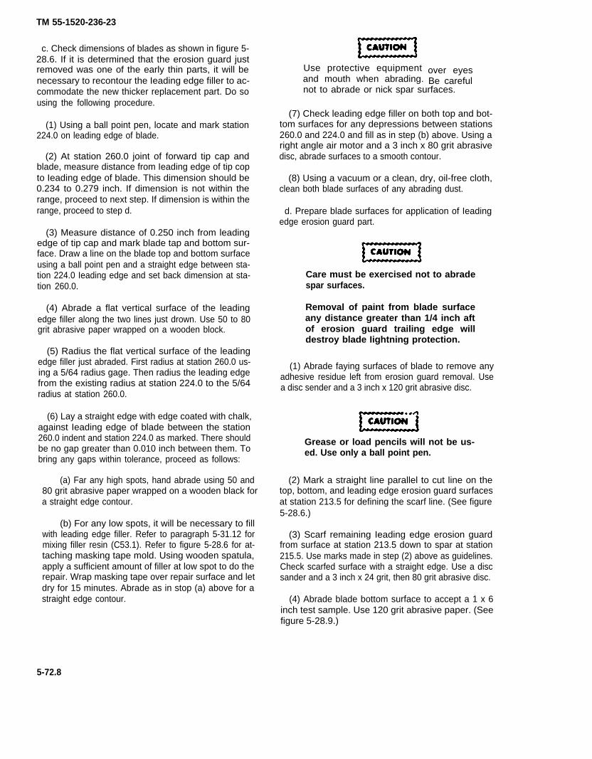
TM 55-1520-236-23
c. Check dimensions of blades as shown in figure 5-28.6. If it is determined that the erosion guard justremoved was one of the early thin parts, it will benecessary to recontour the Ieading edge filler to ac-commodate the new thicker replacement part. Do sousing the following procedure.
(1) Using a ball point pen, locate and mark station224.0 on leading edge of blade.
(2) At station 260.0 joint of forward tip cap andblade, measure distance from Ieading edge of tip copto Ieading edge of blade. This dimension should be0.234 to 0.279 inch. If dimension is not within therange, proceed to next step. If dimension is within therange, proceed to step d.
(3) Measure distance of 0.250 inch from leadingedge of tip cap and mark blade tap and bottom sur-face. Draw a line on the blade top and bottom surfaceusing a ball point pen and a straight edge between sta-tion 224.0 Ieading edge and set back dimension at sta-tion 260.0.
(4) Abrade a flat vertical surface of the leadingedge filler along the two lines just drown. Use 50 to 80grit abrasive paper wrapped on a wooden block.
(5) Radius the flat vertical surface of the leadingedge filler just abraded. First radius at station 260.0 us-ing a 5/64 radius gage. Then radius the leading edgefrom the existing radius at station 224.0 to the 5/64radius at station 260.0.
(6) Lay a straight edge with edge coated with chalk,against Ieading edge of blade between the station260.0 indent and station 224.0 as marked. There shouldbe no gap greater than 0.010 inch between them. Tobring any gaps within tolerance, proceed as follows:
(a) Far any high spots, hand abrade using 50 and80 grit abrasive paper wrapped on a wooden black fora straight edge contour.
(b) For any low spots, it will be necessary to fillwith leading edge filler. Refer to paragraph 5-31.12 formixing filler resin (C53.1). Refer to figure 5-28.6 for at-taching masking tape mold. Using wooden spatula,apply a sufficient amount of filler at low spot to do therepair. Wrap masking tape over repair surface and letdry for 15 minutes. Abrade as in stop (a) above for astraight edge contour.
Use protective equipmentand mouth when abrading.
over eyesBe careful
not to abrade or nick spar surfaces.
(7) Check leading edge filler on both top and bot-tom surfaces for any depressions between stations260.0 and 224.0 and fill as in step (b) above. Using aright angle air motor and a 3 inch x 80 grit abrasivedisc, abrade surfaces to a smooth contour.
(8) Using a vacuum or a clean, dry, oil-free cloth,clean both blade surfaces of any abrading dust.
d. Prepare blade surfaces for application of Ieadingedge erosion guard part.
Care must be exercised not to abradespar surfaces.
Removal of paint from blade surfaceany distance greater than 1/4 inch aftof erosion guard trailing edge willdestroy blade Iightning protection.
(1) Abrade faying surfaces of blade to remove anyadhesive residue left from erosion guard removal. Usea disc sender and a 3 inch x 120 grit abrasive disc.
Grease or load pencils will not be us-ed. Use only a ball point pen.
(2) Mark a straight line parallel to cut line on thetop, bottom, and leading edge erosion guard surfacesat station 213.5 for defining the scarf line. (See figure5-28.6.)
(3) Scarf remaining Ieading edge erosion guardfrom surface at station 213.5 down to spar at station215.5. Use marks made in step (2) above as guidelines.Check scarfed surface with a straight edge. Use a discsander and a 3 inch x 24 grit, then 80 grit abrasive disc.
(4) Abrade blade bottom surface to accept a 1 x 6inch test sample. Use 120 grit abrasive paper. (Seefigure 5-28.9.)
5-72.8

TM 55-1520-236-23
(5) Restore any uralite surfaces (aver weight reten-tion bolts) which may have been damaged duringleading edge erosion guard removal using the follow-ing method. If no damage occurred in this area, pro-ceed to step (6).
(a) Remove any loose uralite from damagedarea.
(b) Place bag sealant, if needed, around damag-ed uralite area to act as a dam as shown in figure 5-28.7.
(c) Mix enough potting resin (C86.2) part A 100parts/weight with part B 40 parts/weight to restorearea being repaired.
(d) Pour resin into and fill area dammed by bagsealant (if used) or wipe in place with a squeegee.
(e) Allow resin to cure for a minimum of 12 hoursat 75° F (23.8° C).
(6) Wipe any fore ign mater ia l f rom bladerepair area using a cheesecloth (C30) dampenedwith solvent (C132). Repeat this step two moretimes, wiping solvent dry before it evaporates.Allow 15 minutes for solvent evaporation.
(7) Wipe replacement erosion guard on matingand outside surfaces with MEK (C74). Repeat thisstep two more times, wiping solvent dry before itevaporates. Allow 15 minutes to dry.
(8) Apply 2 inch wide nylon tape to both top andbottom blade surfaces as shown in figure 5-28.8, detailA. The tape should be 0.250 inch oft of erosion guardtrailing edge on blade top and bottom surfaces. Thiswill provide an area to include a test specimen undervacuum bagging on blade bottom surface as shown infigures 5-28.8, detail A, and 5-28.9.
(9) Apply bag sealant and tabs of double facedtape (C128.1). Secure vacuum hoses and vacuum gageas shown in figure 5-28.8, detail B. A vacuum hoseshould be applied to both blade sides.
(10) Pre-fit 2.50 inch wide bleeder cloth to theblade as shown in figure 5-28.8, detail C, and remove.
(11) Pre-fit replacement erosion guard part toblade.
(a) Trim extreme ends of replacement guard atflash lines.
(f) Remove bag sealant dam surrounding the castresin (if used). Abrade resin flush with blade contourusing a 3 inch x 24 grit then 80 grit sanding disc.
5-72.9
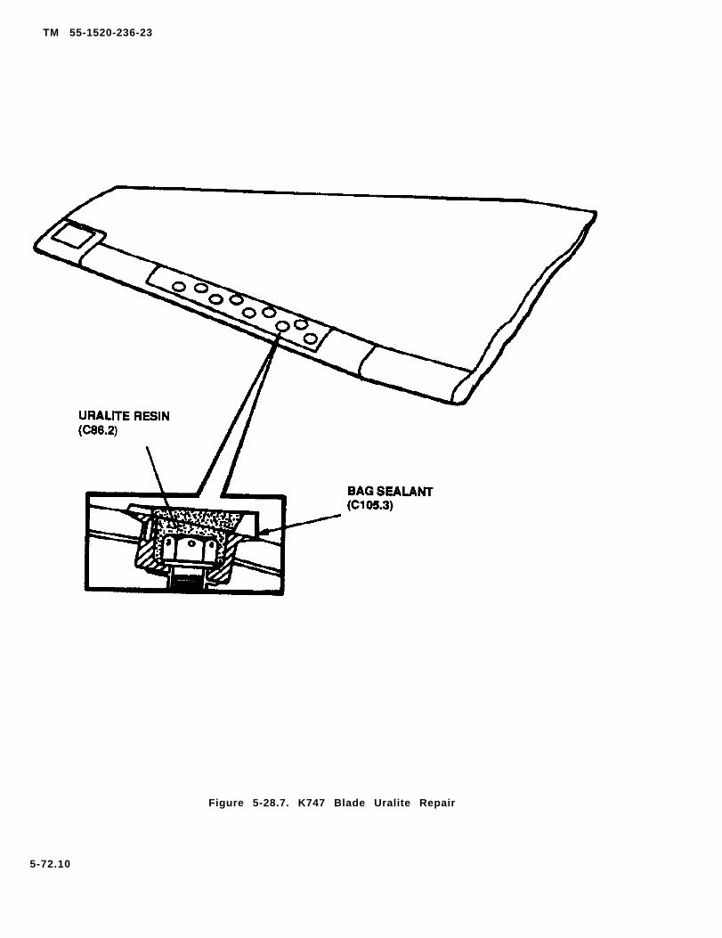
TM 55-1520-236-23
Figure 5-28.7. K747 Blade Uralite Repair
5-72.10

TM 55-1520-236-23
FIGURE 5-28.8. APPLICATION OF VACUUM BAGGING MATERIALS AND PLACEMENTOF EROSION GUARD (SHEET 1 of 4)
5-72.11
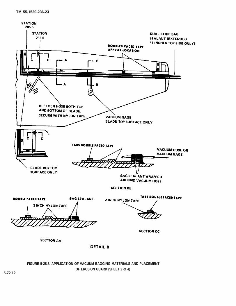
TM 55-1520-236-23
FIGURE 5-28.8. APPLlCATlON OF VACUUM BAGGING MATERIALS AND PLACEMENTOF EROSION GUARD (SHEET 2 of 4)
5-72.12

TM 55-1520-236-23
FIGURE 5-28.8. APPLICATION OF VACUUM BAGGING MATERIALS AND PLACEMENTOF EROSION GUARD (SHEET 3 of 4)
5.72.13

TM 55-1520-236-23
FIGURE 5-28.8. APPLICATION OF VACUUM BAGGING MATERIALS AND PLACEMENT
OF EROSION GUARD (SHEET 4 of 4)
5-72.14
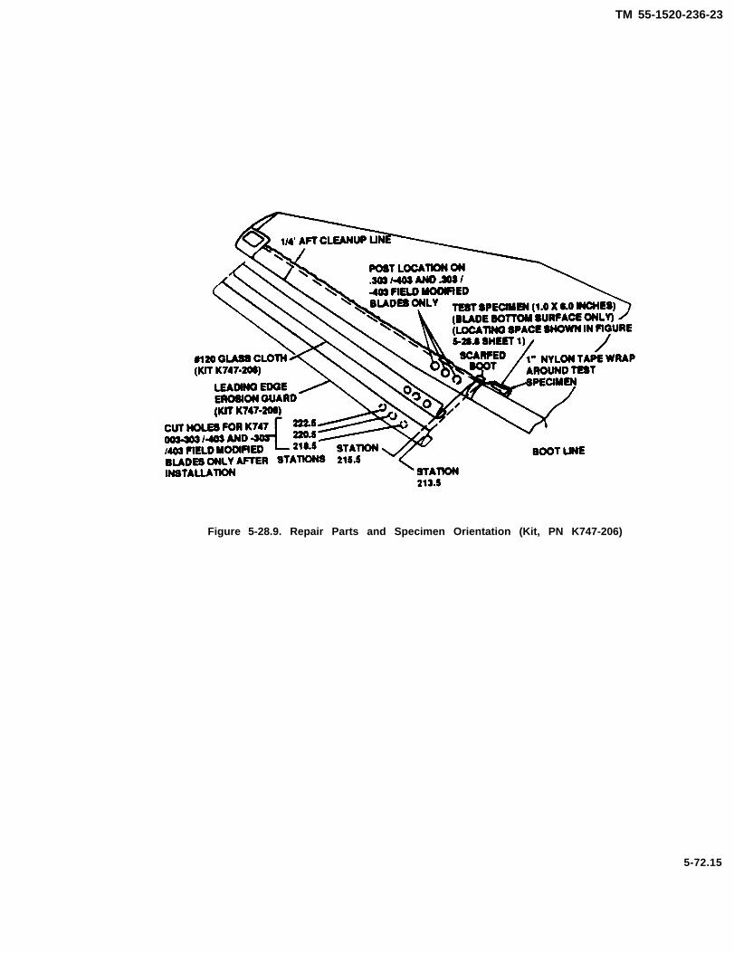
TM 55-1520-236-23
Figure 5-28.9. Repair Parts and Specimen Orientation (Kit, PN K747-206)
5-72.15

TM 55-1520-236-23
(b) Fit erosion guard to blade Ieading edge. Tem-porarily secure in position with strips of masking tape.(See figure 5-28.8, detail D.)
(c) Trim extreme ends of replacement guard partat station 213.5 and then at station 260.0 to fit, ifnecessary.
(d) Apply a wrap of 1 inch wide nylon tape toone end of 1 x 6 inch test specimen as shown in figure5-28.9.
(e) Remove erosion guard and the masking tapesecuring it.
(12) Abrade mating surfaces of replacement ero-sion guard and test specimen as follows:
(a) Abrade inboard end of replacement erasionguard part that will be fitted between stations 213.5and 215.5. Taper guard material from stations 215.5 to213.5 to fit scarfed surface of existing guard. Use a discsender and 3 inch x 60 grit abrasive disc.
(b) Hand abrade remaining replacement portmating surface. Use 180 grit abrasive paper.
(c) Abrade mating surface of test specimen. Usea disc sander and a 3 inch x 80 grit abrasive disc.
(13) Wipe replacement erosion guard on matingand outside surfaces with MEK (C74). Repeat this steptwo more times. Wipe solvent dry before it evaporates.Allow 15 minutes to dry.
(14) Wipe blade repair area surfaces withcheesecloth (C30) dampened with solvent (C132).Repeat this step two more times, wiping solvent drybefore it evaporates. Allow 15 minutes to dry.
(15) Inspect repair for cleanliness and surfacepreparation.
e. Mix and apply adhesive (C13.1).
(1) Mix 100 ports/weight of epoxy resin (Epon 826)with 10 parts/weight of Versamid 125 and 6parts/weight DTA activator. Stir until streaks disappear.Do not induce air bubbles while stirring.
(2) Apply a uniform light coat of adhesive to bladebottom surface, leading edge, and top surface. Use a 3inch paint roller for adhesive application.
f. Apply the #120 glass cloth, leading edge guard,and test specimen to blade.
5-72.16
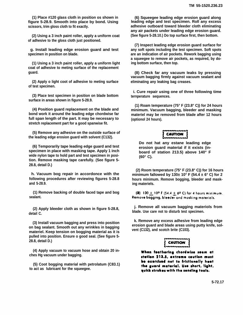
TM 55-1520.236.23
(1) Place #120 glass cloth in position os shown infigure 5-28.9. Smooth into place by bond. Usingscissors, trim gloss cloth to fit exactly.
(2) Using a 3 inch paint roller, apply a uniform coatof adhesive to the gloss cloth just positioned.
g. Install leading edge erosion guard and testspecimen in position on blade.
(1) Using a 3 inch paint roller, apply a uniform lightcoat of adhesive to meting surface of the replacementguard.
(2) Apply o light coot of adhesive to meting surfaceof test specimen.
(3) Place test specimen in position on blade bottomsurface in areas shown in figure 5-28.9.
(4) Position guard replacement on the blade andbond work it around the leading edge chordwise farfull span length of the part. It may be necessary tostretch replacement part for a good spanwise fit.
(5) Remove any adhesive on the outside surface ofthe leading edge erosion guard with solvent (C132).
(6) Temporarily tape leading edge guard and testspecimen in place with masking tape. Apply 1 inchwide nylon tape to hold part and test specimen in posi-tion. Remove masking tape carefully. (See figure 5-28.8, detail D.)
h. Vacuum bog repair in accordonce with thefollowing procedures after reviewing figures 5-28.8and 5-28.9.
(1) Remove backing of double faced tape and bogsealant.
(2) Apply bleeder cloth as shown in figure 5-28.8,detail C.
(3) Install vacuum bagging and press into positionon bag sealant. Smooth out any wrinkles in baggingmateriel. Keep tension on bogging material as it ispulled into position. Ensure o good seal. (See figure 5-28.8, detail D.)
(4) Apply vacuum to vacuum hose and obtain 20 in-ches Hg vacuum under bagging.
(5) Coot bogging material with petrolatum (C83.1)to act as lubricant for the squeegee.
(6) Squeegee leading edge erosion guard alongleading edge and test specimen. Roll any excessadhesive outboard toward bleeder cloth eliminatingany air packets under leading edge erosion guard.(See figure 5-28.10.) Do top surface first, then bottom.
(7) Inspect Ieading edge erosion guard surface forany soft spots including the test specimen. Soft spotsare an indication of air pockets. Rework bagging usinga squeegee to remove air pockets, as required, by do-ing bottom surface, then top.
(8) Check far any vacuum Ieaks by pressingvacuum bagging firmly against vacuum sealant andeliminating any leaking bag creases.
i. Cure repair using one of three following timeternperature sequences.
(1) Roam temperature (75° F (23.8° C)) for 24 hoursminimum. Vacuum bagging, bleeder and maskingmateriel may be removed from blade after 12 hours(optionol 24 hours).
Do not hat any estane leading edgeerosion guard material if it exists (in-board of station 213.5) above 140° F(60° C).
(2) Room temperature (75° F (23.8° C)) for 16 hoursminimum fallowed by 130± 10° F (54.4 ± 6° C) for 2hours minimum. Remove bogging, bleeder and mask-ing materiels.
j. Remove all vacuum bagging materiols fromblade. Use care not to disturb test specimen.
k. Remove any excess adhesive from leading edgeerosion guard and blade areas using putty knife, sol-vent (C132), and scotch brite (C103).
5-72.17
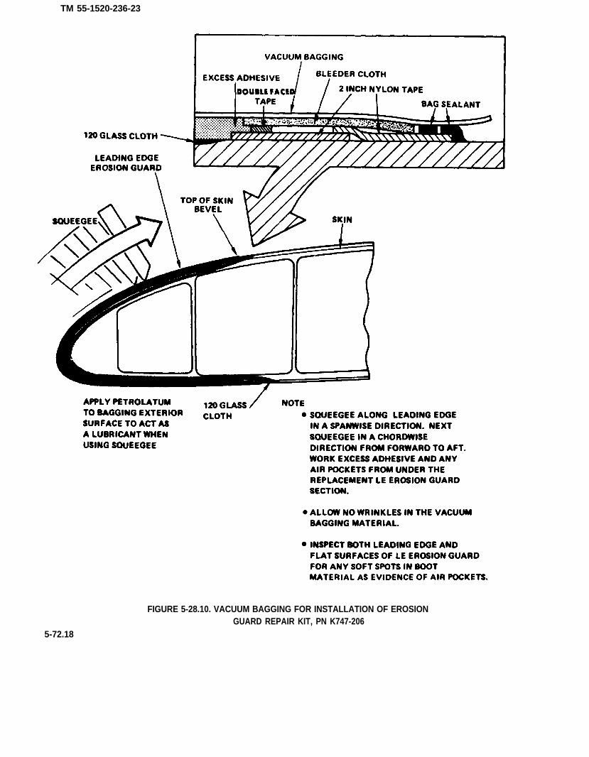
TM 55-1520-236-23
FIGURE 5-28.10. VACUUM BAGGING FOR INSTALLATION OF EROSIONGUARD REPAIR KIT, PN K747-206
5-72.18

TM 55-1520-236-23
l. Feather peripheral seams of repair area and testspecimen. Use o disc sender and 3 inch x 80 gritabrasive disc. Follow with 120 grit if necessary. DO notfeather trailing edge of leading edge erosion guard.
NOTE
A peel test wiII be peformed 24 hoursafter the cure cycle is completed. Donot exceed limits of fish scale duringthe peel test.
m. Perform a peel test on test specimen attached toblade surface.
(1) Securely attach a C clamp to taped l nd of testspecimen.
(2) Attach a fish scale (capable of measuring 15 or20 pounds) to C clamp.
(3) Pull specimen bock across its Iongitudinal axisRecord on component DA Form 2408-16, the amount offorce measured on the stole to peel specimen fromblade, the minimum accepted peel strength is 6pounds which ensures a good adhesive bond. This stopwill be verified by a QA/QC inspector.
(4) If peel test results ore less then 6 pounds, thebond is unacceptable. The new leading edge erosionguard must be replaced by repeating this procedure.
n. Remove the test specimen (if it did not come offduring peel (test) and any residue left by testspecimen. Use a disc sander with 3 inch x 80 gritabrasive disc. Follow with 120 grit if necessary.
o. Restore blade finish in accordance withparagraph 5-31.18.
5-31.11. BONDING OF LEADING EDGE EROSIONGUARD STATION 213.5 OUTBOARD - K474-003-303/-403 AND -303/-403 FIELD MODIFIED MAIN ROTORBLADES (AVIM).
e . Make up six bonding intensifiers by attachingtogether two AN960-1416 washers, one AN970-5washer, and one AN960-1416 washer in that sequence.Attach by spot welding or using a suitable adhesive.
b. Install the fluorcarbon erosion guard in ac-cordance with paragraph 5-31.10a thru h. Be sure tocover both ands of posts with circular tabs of maskingtape. to prevent entry of adhesive into post holes.
c, After vacuum bagging has been completed, in-stall the six intensifiers, made in step a above.
(1) Position an intensifier, with the two AN960-1416washer side towards blade surface, over opposite posthumps on both blade surfaces. Make sure the two in-tensifiers are seated overtly around humps. Install a Cclamp around them and tighten clomp only until inten-sifiers ore bottomed around post circumferences.Repeat for other two posts.
(2) Squeegee ores around post to remove any airbubbles that may hove formed when securing clamps.
d. Cure repair in accordance with paragraph 5-31.10i. Remove clamps, intensifiers, and vacuum bog-ging materials.
e. Cut holes in fluorocarbon erosion guard overends of posts, both blade surfaces, as follows:
(1) Manufacture a 2 x 6 inch, hole cutting templateout of any suitable material. Drill three 1 inch diameterholes with their centers spaced 2 inches apart.
(2) Place template over post hole area withtemplate holes seated evenly around the humps.Scribe circles at humps using a lead pencil.
(3) With template removed and using a utility knifewith a sharp cutting edge, cut around circumference ofmarked circles with cutting plane of blade slantedtowards posts. Ensure that erosion guard and fiberglasslayer is completely severed and pry off the rubberplugs. Remove masking tape over ends of posts.
(4) Using a right angle air motor with a 1-1/2 inch x80 grit abrasive disc, chamfer edge of rubber aroundholes.
(5) Repeat steps (2) thru (4) above for other side ofblade.
f. Proceed with paragraph 5-31.10k thru p.
5-72.19

TM 55-1520-236-23
531.12 REPAIR OF DAMAGED PORTION OF LEADINGEDGE FILLER - K747 MAIN ROTOR BLADES (AVIM).
NOTE
Repair of loading edge filler is Iimited toreplacement of filler, not to exceed 6Inches In length, and only one repalr parblade.
a. This repair is to be used for damage between sta-tions 224.4 and 260.0.
b. Position blade, top surface up, in fixed rack
Wear polythylene gloves over cottongloves to prevent skin contact with sol-vent and eliminate possibility of gettingskin oils on blade surfaces.
Wear splash-proof goggles when workingwith solvent
c. Remove any contamination by wiping repair areawith a cheesecloth (C30) dampened with solvent (C132).Repeat this step three times, wiping solvent dry before itevaporates.
d. Apply several strips of 2 inch wide masking tape (toform a mold) to blade bottom surface. (See figure5-28.11.) Do not attach tape to blade top surface.
NOTE
Both parts of two-part urethane filler mustbe at room tepmerature (70° F (21° C))before use.
Two-part urethane filler must be thorough-ly mixed in order to preserve repairstrength.
e. Mix filler resin (C53.1).
(1) Stir base and catalyst in their respec-tive supply containers until thoroughly mixed.
(2) Weigh out equal amounts by wiehgt (as required) ofcatalyst and base material in separate paper cups.
(3) Combine catalyst into base and stir with a woodenspatula. Ensure a thorough mixutre is obtained.
f. Pour filler into the masking tape mold applied to bladesurface. Fold masking tape over blade leading edge and at-tach to blade top curface. (See figure 5-28.11.)
g. . Remove masking tape mold after 15 to 20 minutes.Rough sand the filler, removing high spotes and excessmaterial. Use right angle air mototr and 3 inch x 60 grit ad-hesive disc.
A straight egde used as a guide and flatwood block covered by 50 grit abrasivepaper provides ameans of obtainingfinished contour and leading edge accept-able limits
h. Fine sand filler to match blade outline and oontour.Place a straight edge across the leading edge to gage lead-ing edge outline. Use a wooden block (approximately 10 to12 inches in length) covered with 50 grit abrasive paper.
i. Repeat previous task for both and bottom filler sur-faces. Always use the straight edge as a guide in obtainingproper contour.
j. Install leading edge erosion guard in accordance withparagraph 5-31.10.
k. Refinish by painting affected areas in accordance withparagraph 5-31.18.
1. K747 blade repairs are required to be logged in DAForm 2408-13 and -16. A permanent reoord must be main-tained to determine the minimum spacing requirement be-tween repairs. Once a repair has been made it is notpossible to determine which type of repair has been ap-plied.
The resin compound used in casting lead-ing edge f i l ler is fast sett ing Iy 15 minutes between mixing and gelling).Work without delay.
5-72.20

TM 55-1520-236-23
Figure 5-28.11. Improvised Mold For Casting A Small Section Of loading Edge Filler
5.72.21

TM 55-1520-236-23
5-31.13. REMOVAL OF STAINLESS STEEL EROSIONGUARD - K747-003-303/-403 MAIN ROTOR BLADE.
a. Inspect erosion guard for damage. Refer to table5-1.1 for limits.
b. Remove six screws (3, figure 5-28.12) securingerosion guard (1) to blade posts (4), using a No. 4Philips screwdriver. Remove two screws (2) securingerosion guard to forward tip cop, using a standardPhilips screwdriver. Retain screws (2 and 3) for lateruse.
NOTE
It is advisable to wear a leather gloveto cushion the palm for this task.
c. Insert putty knife under lip of stainless steel ero-sion guard, with rounded underside edge againstfluorocarbon erosion guard. Starting at outboard endof guard and working towards inboard end, apply ofirm wedging force to pry stainless steel guard loosefrom sealant.
d. Turn blade over in rock and repeat step b abovefor loosening stainless steel guard on underside ofblade. Remove guard when completely broken free ofsealant.
Cleaning solvent is flammable andtoxic. Provide adequate ventilation.Avoid prolonged breathing of vaporsand contact with skin or yes.
g. If the stainless steel erosion guard is to bereinstalled, lightly wipe inside surface withcheesecloth dampened with MEK (C74) to removesealant residue.
5-31.14. INSTALLATION OF STAINLESS STEELEROSION GUARD - K747-003-303/-403 MAIN ROTORBLADES (AVIM).
a. Prepare blade for installation of stainless steelerosion guard.
(1) locate stainless steel erosion guard onfluorocarbon erosion guard to align mounting holes.Install screws (2 and 3, figure 5-28.12) and tighten untilthey bottom out.
(2) Mask erosion guard area using one inch nylontape (C118.1) positioned 1/4 inch from periphery ofstainless steel erosion guard, both surfaces of blade.(See figure 5-28.13.)
(3) Remove the eight self-locking screws fromstainless steel erosion guard and remove guard fromblade. Discard screws.
5-72.22
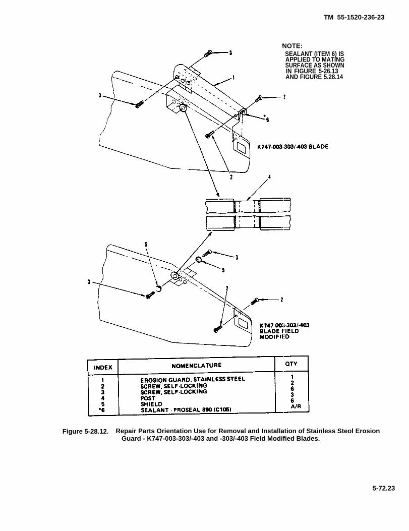
TM 55-1520-236-23
NOTE:SEALANT (ITEM 6) ISAPPLIED TO MATINGSURFACE AS SHOWNIN FIGURE 5-26.13AND FIGURE 5.28.14
Figure 5-28.12. Repair Parts Orientation Use for Removal and Installation of Stainless Steol ErosionGuard - K747-003-303/-403 and -303/-403 Field Modified Blades.
5-72.23

T M 5 5 - 1 5 2 0 - 2 3 6 - 2 3
Figure. 5-28.13 Preparation of K747-003-303/-403 Blade for Application of Sealant
5-72.24
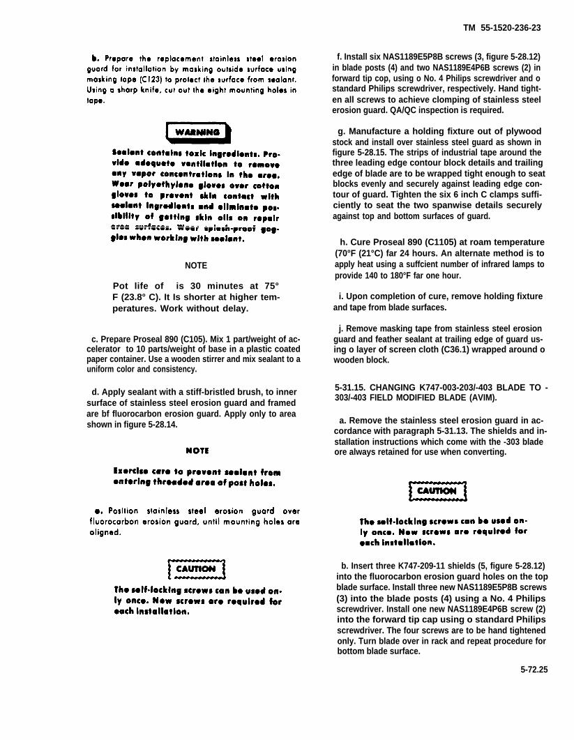
TM 55-1520-236-23
NOTE
Pot life of is 30 minutes at 75°F (23.8° C). It Is shorter at higher tem-peratures. Work without delay.
c. Prepare Proseal 890 (C105). Mix 1 part/weight of ac-celerator to 10 parts/weight of base in a plastic coatedpaper container. Use a wooden stirrer and mix sealant to auniform color and consistency.
d. Apply sealant with a stiff-bristled brush, to innersurface of stainless steel erosion guard and framedare bf fluorocarbon erosion guard. Apply only to areashown in figure 5-28.14.
f. Install six NAS1189E5P8B screws (3, figure 5-28.12)in blade posts (4) and two NAS1189E4P6B screws (2) inforward tip cop, using o No. 4 Philips screwdriver and ostandard Philips screwdriver, respectively. Hand tight-en all screws to achieve clomping of stainless steelerosion guard. QA/QC inspection is required.
g. Manufacture a holding fixture out of plywoodstock and install over stainless steel guard as shown infigure 5-28.15. The strips of industrial tape around thethree leading edge contour block details and trailingedge of blade are to be wrapped tight enough to seatblocks evenly and securely against Ieading edge con-tour of guard. Tighten the six 6 inch C clamps suffi-ciently to seat the two spanwise details securelyagainst top and bottom surfaces of guard.
h. Cure Proseal 890 (C1105) at roam temperature(70°F (21°C) far 24 hours. An alternate method is toapply heat using a suffcient number of infrared lamps toprovide 140 to 180°F far one hour.
i. Upon completion of cure, remove holding fixtureand tape from blade surfaces.
j. Remove masking tape from stainless steel erosionguard and feather sealant at trailing edge of guard us-ing o layer of screen cloth (C36.1) wrapped around owooden block.
5-31.15. CHANGING K747-003-203/-403 BLADE TO -303/-403 FIELD MODIFIED BLADE (AVIM).
a. Remove the stainless steel erosion guard in ac-cordance with paragraph 5-31.13. The shields and in-stallation instructions which come with the -303 bladeore always retained for use when converting.
b. Insert three K747-209-11 shields (5, figure 5-28.12)into the fluorocarbon erosion guard holes on the topblade surface. Install three new NAS1189E5P8B screws(3) into the blade posts (4) using a No. 4 Philipsscrewdriver. Install one new NAS1189E4P6B screw (2)into the forward tip cap using o standard Philipsscrewdriver. The four screws are to be hand tightenedonly. Turn blade over in rack and repeat procedure forbottom blade surface.
5-72.25
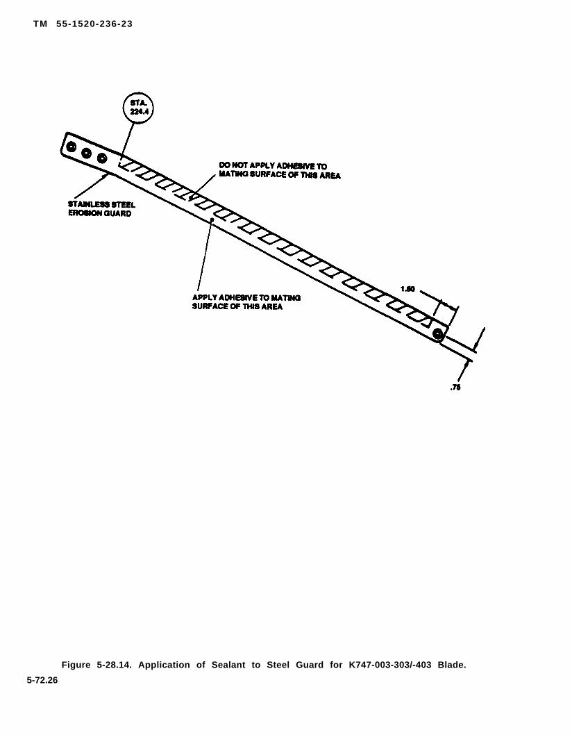
TM 55-1520-236-23
Figure 5-28.14. Application of Sealant to Steel Guard for K747-003-303/-403 Blade.
5-72.26
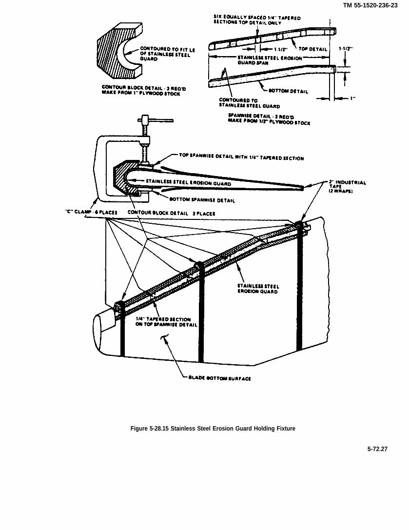
TM 55-1520-236-23
Figure 5-28.15 Stainless Steel Erosion Guard Holding Fixture
5-72.27
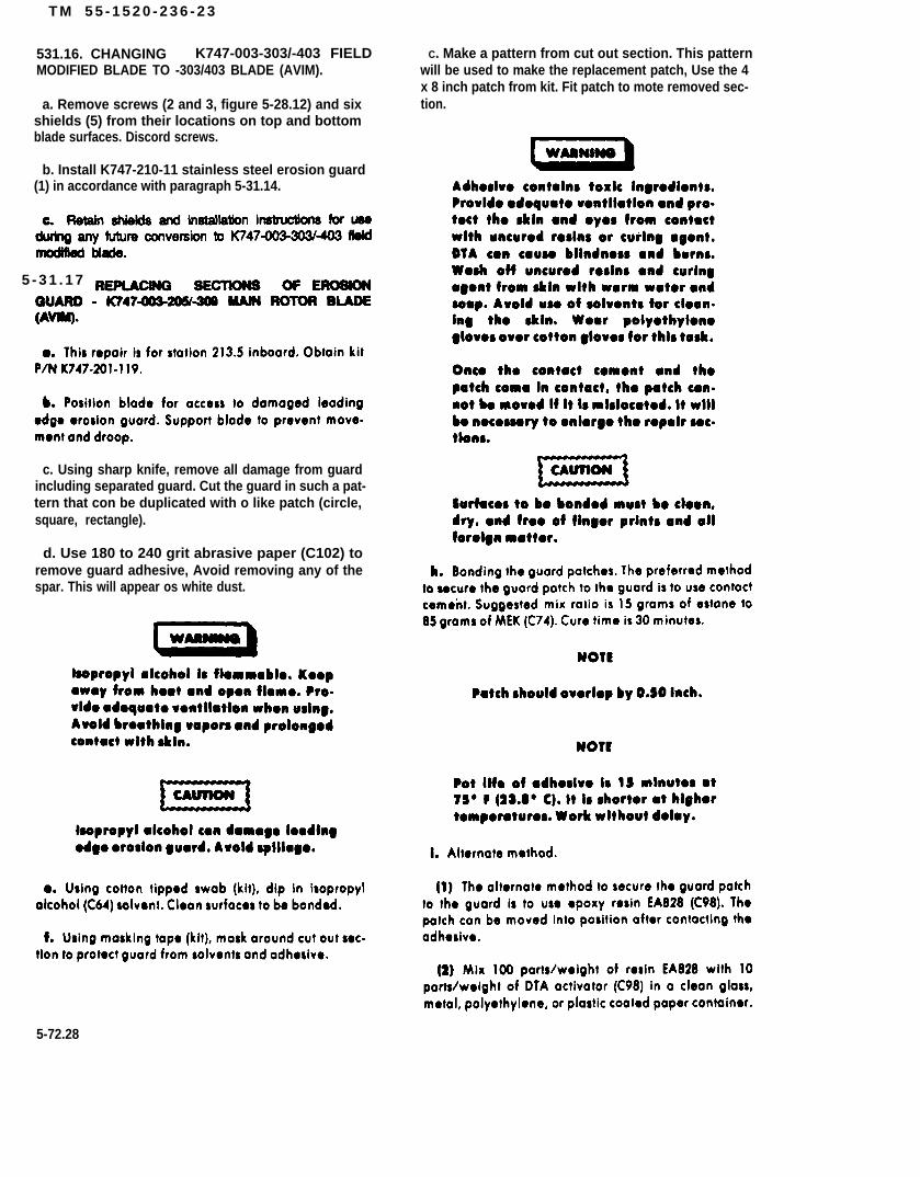
T M 5 5 - 1 5 2 0 - 2 3 6 - 2 3
531.16. CHANGING K747-003-303/-403 FIELDMODIFIED BLADE TO -303/403 BLADE (AVIM).
a. Remove screws (2 and 3, figure 5-28.12) and sixshields (5) from their locations on top and bottomblade surfaces. Discord screws.
b. Install K747-210-11 stainless steel erosion guard(1) in accordance with paragraph 5-31.14.
5 - 3 1 . 1 7
c. Using sharp knife, remove all damage from guardincluding separated guard. Cut the guard in such a pat-tern that con be duplicated with o like patch (circle,square, rectangle).
d. Use 180 to 240 grit abrasive paper (C102) toremove guard adhesive, Avoid removing any of thespar. This will appear os white dust.
C. Make a pattern from cut out section. This patternwill be used to make the replacement patch, Use the 4x 8 inch patch from kit. Fit patch to mote removed sec-tion.
5-72.28

TM 55-1520-236-23
(8) After cure cycle, bond the patch to the guard byapplying heat with a sealing iron as described inparagraph 5-31.7.
5-31.18. REFINISHING PAINT - K747 MAINROTOR BLADES (AVIM).
NOTE
(1) Permit the chemical components to partly react.
(2) Shorten the drying time.
(3) Reduce cratering.
(4) Preclude component II from sweating out ormigrating.
(5) Allow any bubbles (formed while stirring) toescape.
5-72.29
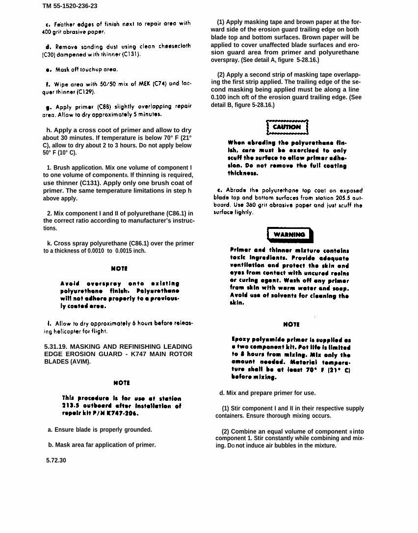
TM 55-1520-236-23
h. Apply a cross coot of primer and allow to dryabout 30 minutes. If temperature is below 70° F (21°C), allow to dry about 2 to 3 hours. Do not apply below50° F (10° C).
1. Brush applicotion. Mix one volume of component Ito one volume of component II. If thinning is required,use thinner (C131). Apply only one brush coat ofprimer. The same temperature limitations in step habove apply.
2. Mix component I and II of polyurethane (C86.1) inthe correct ratio according to manufacturer’s instruc-tions.
k. Cross spray polyurethane (C86.1) over the primerto a thickness of 0.0010 to 0.0015 inch.
5.31.19. MASKING AND REFINISHING LEADINGEDGE EROSION GUARD - K747 MAIN ROTORBLADES (AVIM).
a. Ensure blade is properly grounded.
b. Mask area far application of primer.
(1) Apply masking tape and brown paper at the for-ward side of the erosion guard trailing edge on bothblade top and bottom surfaces. Brown paper will beapplied to cover unaffected blade surfaces and ero-sion guard area from primer and polyurethaneoverspray. (See detail A, figure 5-28.16.)
(2) Apply a second strip of masking tape overlapp-ing the first strip applied. The trailing edge of the se-cond masking being applied must be along a line0.100 inch oft of the erosion guard trailing edge. (Seedetail B, figure 5-28.16.)
d. Mix and prepare primer for use.
(1) Stir component I and II in their respective supplycontainers. Ensure thorough mixing occurs.
(2) Combine an equal volume of component II intocomponent 1. Stir constantly while combining and mix-ing. DO not induce air bubbles in the mixture.
5.72.30

`TM 55-1520-236-23
DETAIL B
FIGURE 5-28.16. MASKING FOR PAINT TOUCH-UP AFTERINSTALLATION OF KIT K747-206
5-72.31
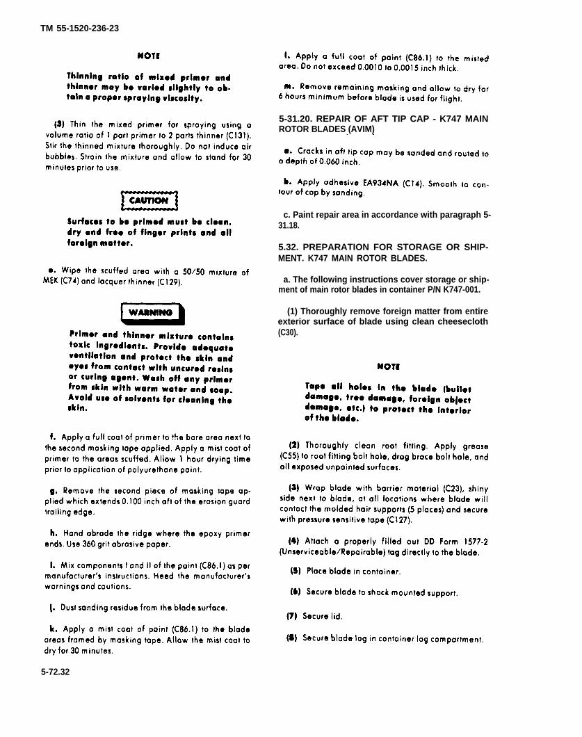
TM 55-1520-236-23
5-31.20. REPAIR OF AFT TIP CAP - K747 MAINROTOR BLADES (AVIM)
c. Paint repair area in accordance with paragraph 5-31.18.
5.32. PREPARATION FOR STORAGE OR SHIP-MENT. K747 MAIN ROTOR BLADES.
a. The following instructions cover storage or ship-ment of main rotor blades in container P/N K747-001.
(1) Thoroughly remove foreign matter from entireexterior surface of blade using clean cheesecloth(C30).
5-72.32

5-33. INSTALLATION — K747 MAIN ROTORBLADES.
Do not use finger to line up shims.
Obtain a balanced main rotor hub (paragraph 5-45). “
b. Support main rotor hub on a build-up bench in ac-cordance paragraph 5-12m. Check that locating pin (6, fig-ure 5-10) is installed in upper surface of each grip (5) of in-board side of retaining bolt hole.
c. Install drag strut (15, figure 5-16).
d. Remove preservative grease from blade gripbore and retaining bolt.
e. Apply corrosion preventive compound (C44) toblade retaining bolt, hub grip and blade butts. Slide blade(9, figure 5-10) gently into grip (use of sling is optional).Place washer (7) on retaining bolt (8). Align bolt holes care-fully and insert bolt from top. If bolt binds, move tip of bladeup and down slowly to find position which allows bolt topass through without binding. Seat bolt and washer withnotches on Iocating pin (6).
f. Place padded support under blade approximatelyone third blade length inboard from blade fin.
Install washer (16) with counterbore up facinggrip.
The erosion guard is a polycarbonate materialwhich will cut easily upon impact with a rigidstructure. Seal all openings immediately withsealing iron.
g. Install washer (16) with counterbore up asillustrated and install nut (17). Do not tighten nut at thistime.
h. Preset drag brace (15) length to 14.750 inches,hole center to hole center. Align clevis of drag brace (15) onbolt hole of the blade drag plates. Install shims (10) equallybetween clevis and upper and lower drag plates to obtain0.000 to 0.005 inch clearance. Install bolt (14) and securewith two washers (12 and 13) and nut (11) on lower end.Do not tighten at this time.
TM 55-1520-236-23
i. Install opposite blade in the some manner.
j. If the blades are to be aligned in the hub, follow in-structions in paragraph 5-13.
k. If the blades are not to be aligned in the hub,torque both nuts (11) 125 to 150 foot- pounds.
l. If the blades are not to be aligned in the hub, usewrench (T31) to tighten nuts(17) to a torque of 475 to 525foot-pounds. Align a notch in the nut with a hole in the bolt.Install locking screw (20) with head in a direction so thatcentrifugal force will keep the locking screw in. In somecases, this may mean the locking screw may be installedfrom the inside of the bolt. Install washer (19) and nut (18).
install grip locks (T59) on each pitch horn, if notpreviously accomplished (figure 5-4).
5-34. ALIGNMENT — K747 MAIN ROTORBLADES.
Refer to paragraph 513.
5-35. MAIN ROTOR HUB.
5-36. DESCRIPTION — MAIN ROTOR HUB.
The Main Rotor Hub major components are the yoke, trun-nion, yoke extensions, blade grips, drag braces, pitchhorns, and elastomeric bearings (figures 5-29 and 5-30).The elastomeric bearings (6, figure 5-30) are composed ofalternating layers of an elastic material (elastomer) withconcentric cylindrical metal laminations molded to steelinner and outer housings. The bearing outer housing isbolted to the trunnion. Movement of the hub and blades onthe flapping axis is accomplished by flexing of the bearingelastomer.
5-37. REMOVAL — MAIN ROTOR HUB.
Premaintenance Requirements for Removal of MainRotor Hub
Condition Requirements
5-72.33
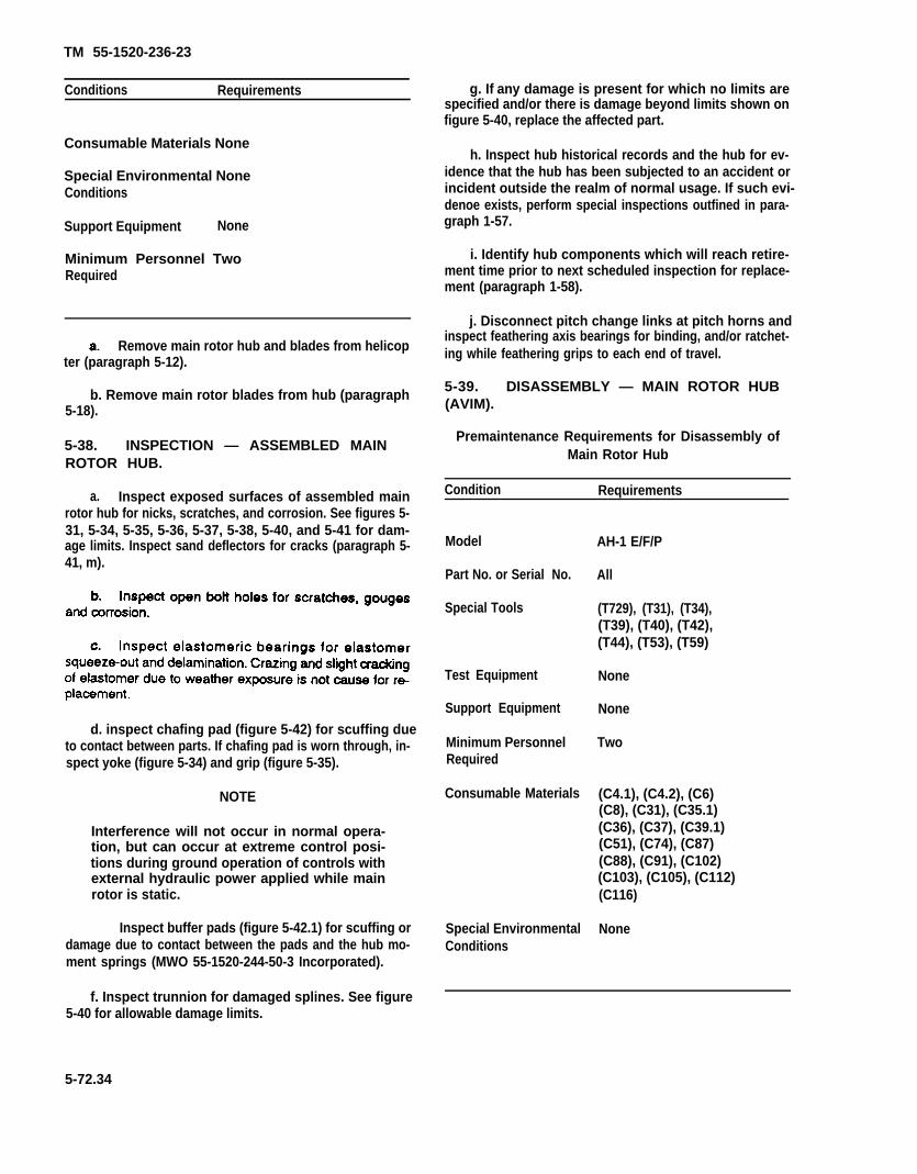
TM 55-1520-236-23
Conditions Requirements
Consumable Materials None
Special Environmental NoneConditions
Support Equipment None
Minimum Personnel TwoRequired
Remove main rotor hub and blades from helicopter (paragraph 5-12).
b. Remove main rotor blades from hub (paragraph5-18).
5-38. INSPECTION — ASSEMBLED MAINROTOR HUB.
a. Inspect exposed surfaces of assembled mainrotor hub for nicks, scratches, and corrosion. See figures 5-31, 5-34, 5-35, 5-36, 5-37, 5-38, 5-40, and 5-41 for dam-age limits. Inspect sand deflectors for cracks (paragraph 5-41, m).
d. inspect chafing pad (figure 5-42) for scuffing dueto contact between parts. If chafing pad is worn through, in-spect yoke (figure 5-34) and grip (figure 5-35).
NOTE
Interference will not occur in normal opera-tion, but can occur at extreme control posi-tions during ground operation of controls withexternal hydraulic power applied while mainrotor is static.
Inspect buffer pads (figure 5-42.1) for scuffing ordamage due to contact between the pads and the hub mo-ment springs (MWO 55-1520-244-50-3 Incorporated).
g. If any damage is present for which no limits arespecified and/or there is damage beyond limits shown onfigure 5-40, replace the affected part.
h. Inspect hub historical records and the hub for ev-idence that the hub has been subjected to an accident orincident outside the realm of normal usage. If such evi-denoe exists, perform special inspections outfined in para-graph 1-57.
i. Identify hub components which will reach retire-ment time prior to next scheduled inspection for replace-ment (paragraph 1-58).
j. Disconnect pitch change links at pitch horns andinspect feathering axis bearings for binding, and/or ratchet-ing while feathering grips to each end of travel.
5-39. DISASSEMBLY — MAIN ROTOR HUB(AVIM).
Premaintenance Requirements for Disassembly ofMain Rotor Hub
Condition Requirements
Model
Part No. or Serial No.
Special Tools
Test Equipment
Support Equipment
Minimum PersonnelRequired
Consumable Materials
Special EnvironmentalConditions
AH-1 E/F/P
All
(T729), (T31), (T34),(T39), (T40), (T42),(T44), (T53), (T59)
None
None
Two
(C4.1), (C4.2), (C6)(C8), (C31), (C35.1)(C36), (C37), (C39.1)(C51), (C74), (C87)(C88), (C91), (C102)(C103), (C105), (C112)(C116)
None
f. Inspect trunnion for damaged splines. See figure5-40 for allowable damage limits.
5-72.34
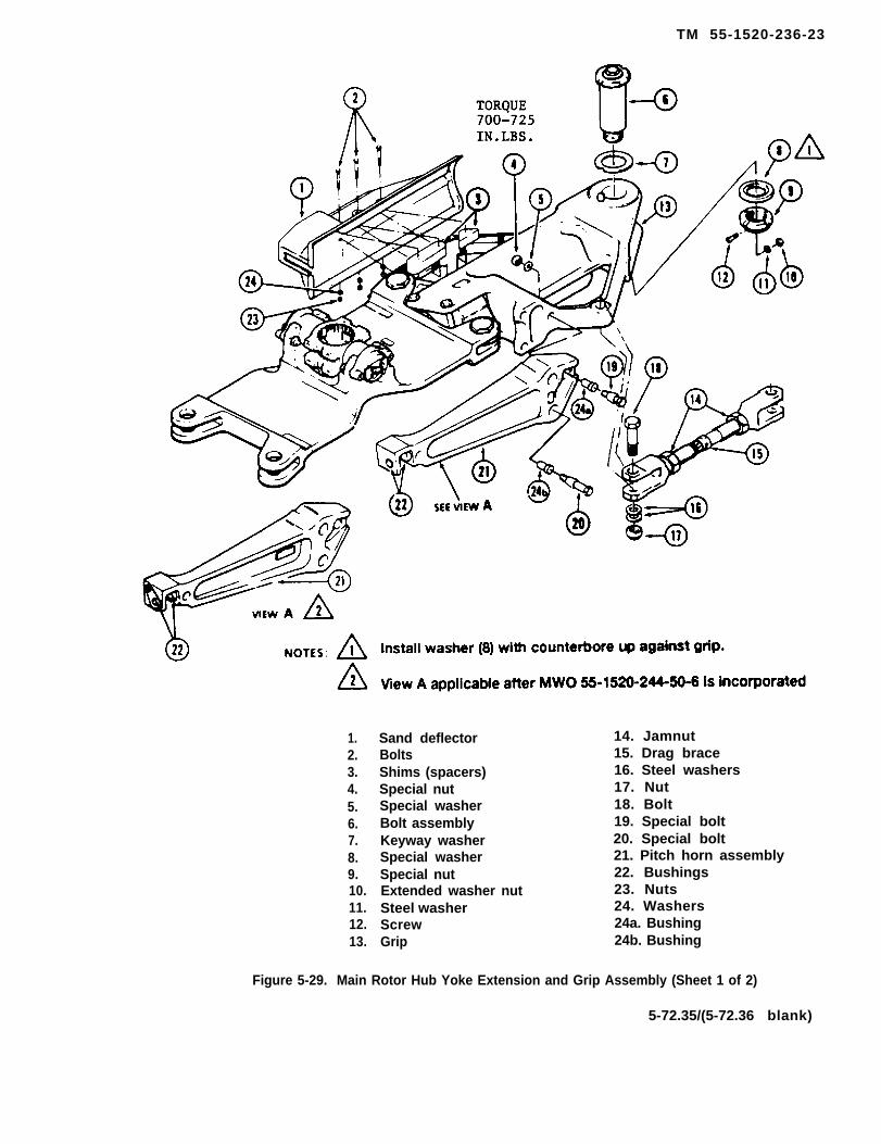
TM 55-1520-236-23
1.2.3.4.5.6.7.8.9.10.11.12.13.
Sand deflectorBoltsShims (spacers)Special nutSpecial washerBolt assemblyKeyway washerSpecial washerSpecial nutExtended washer nutSteel washerScrewGrip
14. Jamnut15. Drag brace16. Steel washers17. Nut18. Bolt19. Special bolt20. Special bolt21. Pitch horn assembly22. Bushings23. Nuts24. Washers24a. Bushing24b. Bushing
Figure 5-29. Main Rotor Hub Yoke Extension and Grip Assembly (Sheet 1 of 2)
5-72.35/(5-72.36 blank)


TM 55-1520-236-23
Figure 5-29. Main Rotor Hub Yoke Extension and Grip Assembly (Sheet 2 of 2)
5-73

TM 55-1520-236-23
¤After incorporation of MWO 55-1520-244-50-3.
two washers between strap and plate.
5-74
Figure 5-30. Main Rotor Hub Yoke and Trunnion
TM 55-1520-236-23
a. Position main rotor hub on build-up bench (T29)equipped with adapter plate (T34) if not previously accom-plished in accordance with instructions contained in para-graph 5-12, m.
b. Remove main rotor blades from hub if not pre-viously accomplished (paragraph 5-18).
c. Identify blade retaining bolt assemblies (6, figure5-29), including washers (7, 8, 11), screw (12), and nuts (9and 10), for reinstallation in the same grip. Use paint or felttip pen. Remove both bolts. Use socket wrench (T31) to re-move nuts from blade retaining bolts. Use work aid shownin figure 5-12 to remove blade retaining bolts if necessary(paragraph 5-18).
NOTE
Units operating AH-1 aircraft may remove thesand deflectors P/N 540-011-174-11, NSN1615-00-116-7110, from the rotor head. Uponremoval, deflectors should be inspected forserviceability and repaired as required. Thedeflectors will be retained as part of the air-craft mission equipment. Deflectors will be in-stalled in extreme sand/dust conditions or inarctic areas where there are extreme ice/snowconditions. Both deflectors must be either in-stalled on the aircraft or removed from the air-craft.
d. Remove three bolts (2, figure 5-29), nuts (23),washers (24), sand deflector (1), and spacers (3). Removeopposite sand deflector in the same manner.
e. Remove bolt (18), washers (16), nut (17), anddrag brace (15). Remove opposite drag brace in samemanner.
f. Remove bolts (19 and 20) and pitch horn (21). Re-move opposite pitch horn in the same manner.
h. Remove nuts (48) and washers (47) from bolts(60). Remove bolts. Remove blade grip (41) from yoke ex-tension (28). Use care to prevent damage to threads on fit-ting (52) and damage to dust seal (51). The dust seal (51),bearing (50) and strap indexing ring (49) should be bondedto the grip near the outboard end.
i. Remove the opposite grip in the same manneroutlined in steps g. and h.
j. Remove nuts (40), washers (39), bolts (27) andwashers (26). Remove yoke extension (28) and housing(38) from yoke (25). Remove housing (38) from extension.Remove opposite yoke extension in the same manner.
k. Clean sealant from retaining rings (31, 34, 53,and 59) with a sharp plastic scraper. Remove pin (33 and58) and strap (54). Remove opposite strap in the samemanner.
l. Remove yoke and trunnion from build-up standand place on a work-bench with supports under the flatportion of the yoke.
m. Identify elastomeric bearings (2, figure 5-30)trunnion (5) and yoke (6) with felt-tipped marker so thebearings and trunnion can be reinstalled in the same posi-tion on the yoke.
n. Remove four bolts (20), washers (19) and re-tainer (1) from each side of trunnion.
o. Remove two nuts (10), washers (11), internal hexbolts (18) and recessed washers (17) to free one elasto-meric bearing from yoke. Thread a bolt with 1/2 x 20 UNFthreads into tapped hole in elastomeric bearing (2). Torquebolt 100 foot-pounds maximum to remove elastomericbearing from yoke and trunnion. Heat to 200 degrees Fmaximum if necessary to aid removal. Remove oppositeelastomeric bearing in the same manner and remove trun-nion (5) from yoke (6).
g. Remove cotter pin (57), nut (55), and washer (58)from bolt (42). Remove bolt (42), damp (43) and lock (44).Remove dome nut (45) and washer (46).
5-75

TM 55-1520-236-23
p. Remove shims (7) from both sides of trunnionand identify for reinstallation in the same location.
5 - 4 0 .
b. Clean Teflon bearings in housing (38, figure 5-29)and grip (41) with dean cloths dampened with MEK (C74).
c. Clean sealant and zinc ohromate primer fromspindles of trunnion and inner metal housing of elastomericbearings (2, figure 5-30). Use a sharp plastic scraper andcloths moistened with MEK (C74). Do not allow the MEK tocontact the elastomeric bearings.
5-41. INSPECTION — DISASSEMBLED MAINROTOR HUB (AVIM).
NOTE
Bearings (37 and 50, figure 5-29) will normallybe inspected while installed in housing (38)and grip (41), respectively.
a Inspect liner portion of bearings (37 and 50, figure5-29) for secure bonding to the stainless steel sleeve(outer potion) of bearings. Inspect liner portion of the bear-ings for wear and damage. Sea figure 5-31 for examples ofbearing wear patterns to determine if bearings are satisfac-tory for further servics
b. Inspect yoke extension for damaged, worn orloose bearing sleeves (30 and 35, figure 5-29). If the bear-ing sleeves are loose or have damage in excess of limitsshown in figure 5-32, the yoke extension must be replaced.If bearing sleeves have any superficial marks, polish outmarks with Scotchbrite (C103) and reinspect the bearingsleeves. If tungsten carbide coated sleeves (i.e. 540-011-153-17 extensions or new spare sleeves) are found tohave mechanical/corrosion damage within limits, repair byusing jewelers files or similar items capable of cutting asurface with a hardness of RC70. If such items are notavailable, replace extensions.
c. Inspect yoke extensions for worn or missingbuffer pads (32, figure 5-29) - four pads on each extension.
d. Inspect mating surfaces of the hub componentsfor damage. See figure 5-32, 5-34, 5-35 and 5-36 for dam-age limits for individual hub components to determinewhether damage exceeds limits. All hub components mustassemble without misalignment or cocking after polishingout mechanical and corrosion damage.
e. Inspect the holes in the hub componentsillustrated in figure 5-33 for wear in excess of limits.
f. Inspect seals (36, figure 5-29) for damage whichwould affect function and for secure bonding to housings.
g. Inspect grip bearing dust seals (51 ) for damagewhich would affect function and/or secure bonding to grips.
5-76

A
TM 55-1520-236-23
B
Figure 5-31. Main Rotor Bearing Wear Patterns
h. Inspect radius rings (29) for damage and wear. NOTEReplace radius rings if the following limits areexceeded: Partially unbended abrasion shield.
discoloration of the shield and/or leasthan 10 cracks in the shield are not cause
(1) Cracks in the carbon face running from for replacement.
the inside diameter to the outside diameter.
i. Inspect straps (54) for damage and wear inexcess of the following maximum limits:
(2) Grooves in the carbon face which revealuneven contact with seal. NOTE
(3) Any chips of carbon missing from thecarbon face.
(4) Unbended abrasion shield.
When replacing straps, do not intermixpart numbers.
(1) Fifty loose wire ends protruding throughthe urethane coating of strap in any one cornerand/or 400 loose ends over the entire strapassembly. If a lesser number of wire ends are found,
5-77

-1
TM 55-1520-236-23
ALL DIMENSIONS ARE IN INCHES UNLESS OTHERWISE NOTED
NOTES:1. The area of repair on surfaces mating with the yoke should not exceed one-half of any
quadrant.2. Thickness of barrel wall is 0.100 minimum.
Figure 5-32. Damage Limits - Main Rotor Hub Yoke Extension
5-78
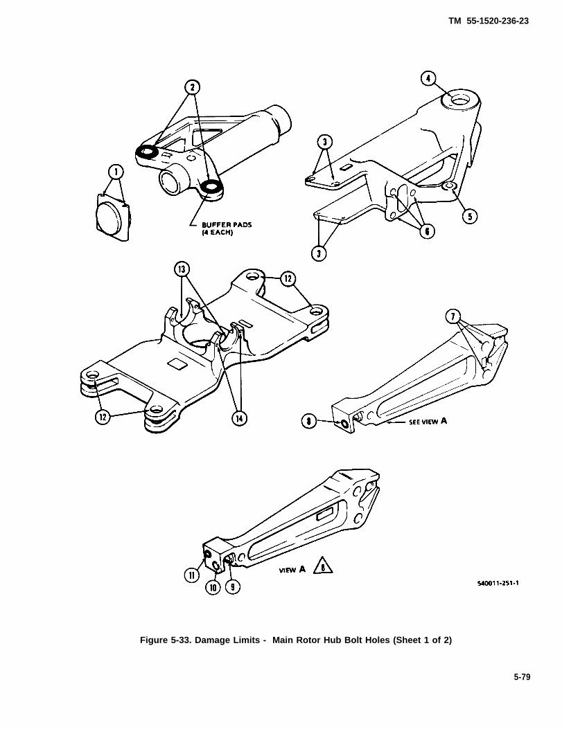
TM 55-1520-236-23
Figure 5-33. Damage Limits - Main Rotor Hub Bolt Holes (Sheet 1 of 2)
5-79
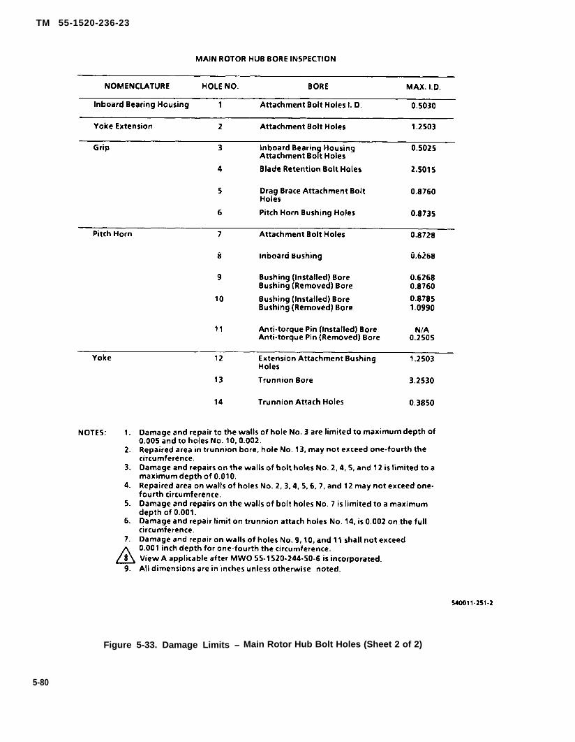
TM 55-1520-236-23
Figure 5-33. Damage Limits – Main Rotor Hub Bolt Holes (Sheet 2 of 2)
5-80
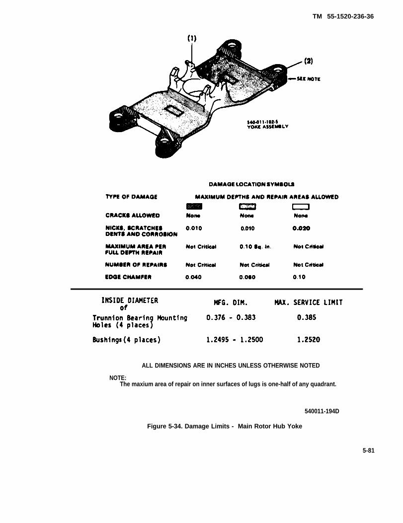
TM 55-1520-236-36
ALL DIMENSIONS ARE IN INCHES UNLESS OTHERWISE NOTED
NOTE:The maxium area of repair on inner surfaces of lugs is one-half of any quadrant.
540011-194D
Figure 5-34. Damage Limits - Main Rotor Hub Yoke
5-81
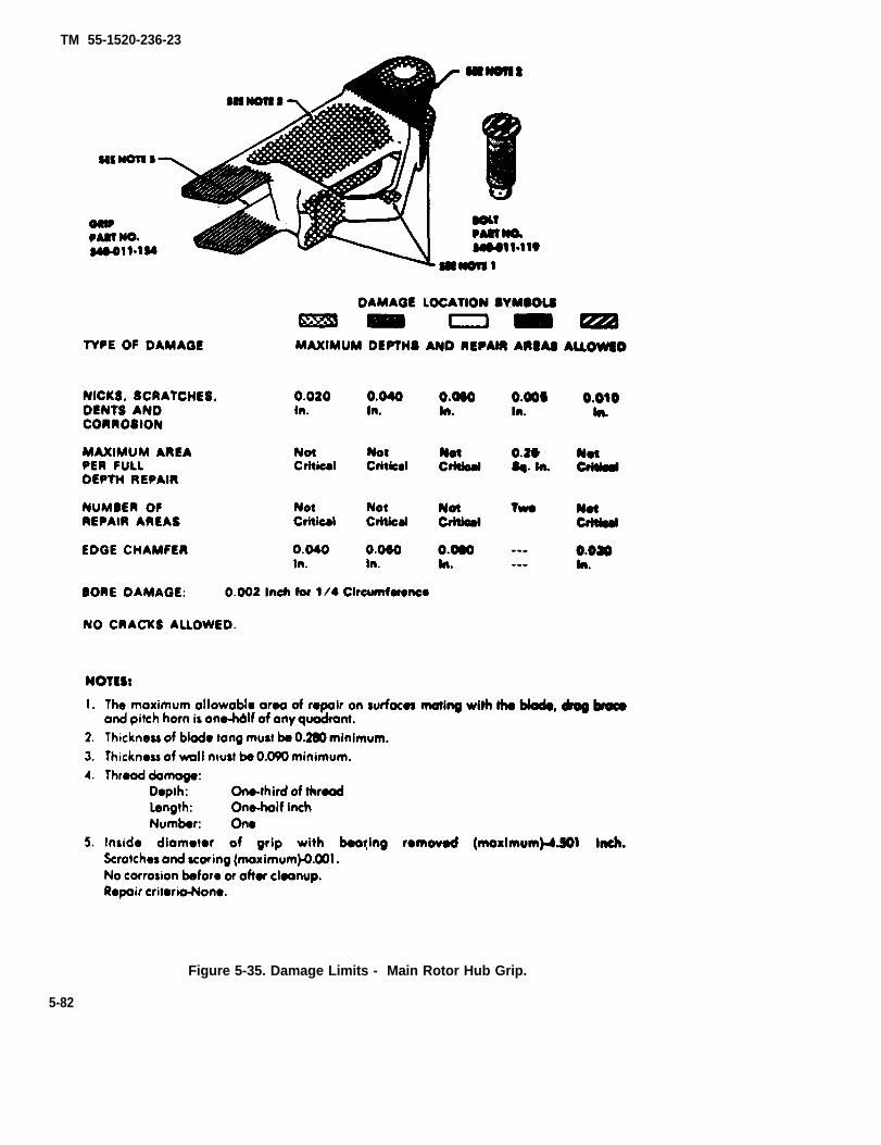
TM 55-1520-236-23
Figure 5-35. Damage Limits - Main Rotor Hub Grip.
5-82

TM 55-1520-236-23
Figure 5-36. Damage Limits — Main Rotor Hub Strap Fitting
5-83
TM 55-1520-236-23
record the serial number of the strap and the number ofwire ends found in the historical record of the main rotorhub.
(2) Use a ten power magnifyhg glass to check forcracks in flanges of strap bushings and urethane wedges.A crack in these parts is cause for rejection of the strap.
(3) Severe rupture of the urethane coating iscause for rejection.
(4) Displacement of urethane wedges betweenbushing and inner surface of wire bundle is cause for rejec-tion.
NOTE
A permanent set twist in the strap and/or aslight bulging of wire cross section is normaland not cause for rejection of the strap.
(5) Pins (33 and 58) for visible surface contactwith mating parts. Visible surface wear is cause for rejec-tion.
j. Inspect attaching bolts, nuts, and washers fordamage and corrosion.
k. Inspect retainers (1, figure 5-30) for obvious dam-age.
l. Inspect disks (4) for obvious damage.
m. Inspect sand deflectors (1, figure 5-29) forcracks, abrasion damage, oversize bolt holes and cor-roded, worn, darnaged, separated or missing washers. Re-place sand deflectors having any cracks greater than twoinches in length in any portion. Cracks less than two inchesin length are acceptable if stop drilled, provided crack doesnot permit material fallout.
n. Inspect elastomeric bearings for damage in ac-cordance with instructions on figure 5-41.
o. Inspect elastomeric bearing housing for cracks bymagnetic particle method (TM 43-0103) if cracks are sus-pected.
p. Inspect hub components illustrated in figures 5-32 through 5-41 for damage in excess of limits.
q. Inspect yoke for damages and/or missing chafingpads (figure 5-42).
r. Inspect yoke for loose or missing buffer pads (fig-ure 5-42.1). (MWO 55-1520-244-50-3 incorporated).
5-42. REPAIR — MAIN ROTOR HUB (AVIM).
NOTE
If allowable repair limits on yoke are exceeded,send the yoke to Depot Maintenance. Replaceother parts that have damage in excess of re-pair limits.
a. Polish out all traces of corrosion and mechanicaldamage on hub components. Polish out corrosion darnageon aluminum parts to twice the depth of the pit. Use fine tomedium grades of abrasive cloth (36) or fine India stone(C116). Blend the edges of the repair into the surroundingarea with a smooth contour, Make final cleanup with crocuscloth (C37) to obtain a smooth, scratch-free surface. Ifdamage exceeds limits specified in paragraph 5-41 dis-pose of part locally.
b. if cadmium plate is removed, proceed as follows:Clean area with MEK (C74). Prime area with two coats ofunreduced Zinc Chromate Primer (C91). Allow first mat tocurs 30 minutes before applying second coat.
Touch up rework areas on aluminum parts withchemical film (C31).
d. Replace damaged or missing buffer pads (32, fig-ure 5-29) as follows:
Do not remove cadmium plate from yoke ex-tension except in the area where buffer padswill be installed.
(1) Remove any buffer pad material that remainsbonded to the yoke extension with a plastic or aluminumscraper
Cleaning solvent is flameable and toxic. Provide adequate ventilation. Avoid prolongedbreathing of vapors and contact with skin oreyes.
(2) Clean area where the new buffer pad will be in-stalled with 400 grit sandpaper (C102). Remove residuewith dean cloths dampened with MEK (C74). Clean theside of the new buffer pad that will be bonded in the samemanner.
Use primer in a well ventilated area away fromopen frame.
5 - 8 4
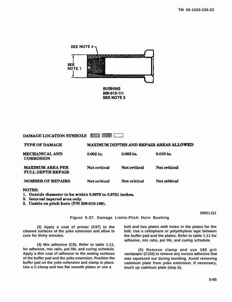
TM 55-1520-236-23
540011-213Figure 5-37. Damage Limits-Pitch Horn Bushing
(3) Apply a coat of primer (C87) to thecleaned surfaces of the yoke extension and allow tocure for thirty minutes.
(4) Mix adhesive (C8). Refer to table 1-11,for adhesive, mix ratio, pot life, and curing schedule.Apply a thin coat of adhesive to the mating surfacesof the buffer pad and the yoke extension. Position thebuffer pad on the yoke extension and clamp in place.Use a C-clamp and two flat smooth plates or use a
bolt and two plates with holes in the plates for thebolt. Use a cellophane or polyethylene tape betweenthe buffer pad and the plates. Refer to table 1-11 foradhesive, mix ratio, pot life, and curing schedule.
(5) Remove clamp and use 180 gritsandpaper (C102) to remove any excess adhesive thatwas squeezed out during bonding. Avoid removingcadmium plate from yoke extension. If necessary,touch up cadmium plate (step b).
5-85

TM 55-1520-236-23
Figure 5-38. Damage Limits – Main Rotor Hub Fitch Horn 209-010-109-5(Prior to Incorporation of MWO 55-1520-244-50-6)
5-86
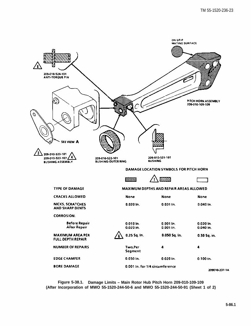
TM 55-1520-236-23
Figure 5-38.1. Damage Limits – Main Rotor Hub Pitch Horn 209-010-109-109(After Incorporation of MWO 55-1520-244-50-6 and MWO 55-1520-244-50-91 (Sheet 1 of 2)
5-86.1

TM 55-1520-236-23
Figure 5-38.1. Damage Limits – Main Rotor Hub Pitch Horn 209-010-109-109(After Incorporation of MWO 55-1520-244-50-6 and MWO 55-1520-244-50-9) (Sheet 2 of 2)
5-86.2
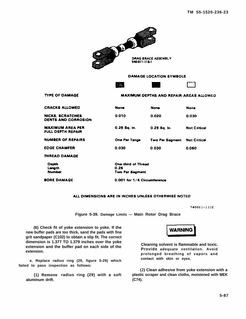
TM 55-1520-236-23
Figure 5-39. Damage Limits — Main Rotor Drag Brace
(6) Check fit of yoke extension to yoke. If thenew buffer pads are too thick, sand the pads with finegrit sandpaper (C102) to obtain a slip fit. The correctdimension is 1.377 TO 1.379 inches over the yokeextension and the buffer pad on each side of the Cleaning solvent is flammable and toxic.
extension. Provide adequate ventilation. Avoidprolonged breathing of vapors and
e. Replace radius ring (29, figure 5-29) which contact with skin or eyes.
failed to pass inspection as follows:
(1) Removealuminum drift.
(2) Clean adhesive from yoke extension with aradius ring (29) with a soft plastic scraper and clean cloths, moistened with MEK
(C74).
5-87
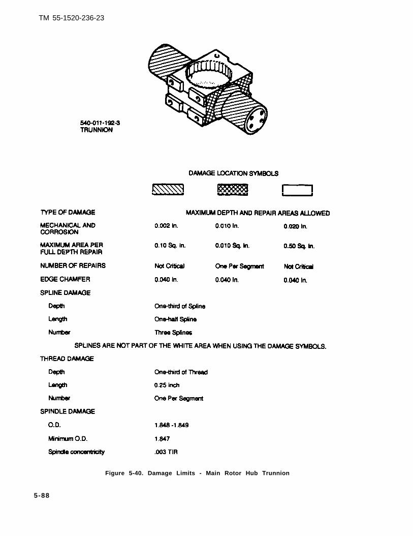
TM 55-1520-236-23
Figure 5-40. Damage Limits - Main Rotor Hub Trunnion
5-88

TM 55-1520-236-23
Figure 5-40.1. Damage Limits - Hub Moment Spring Plate
5-88.1

TM 55-1520-236-23
Figure 5-40.2. Damage Limits - Hub Moment Spring Strap
5-88.2

TM 55-1520-236-23
Figure 5-41. Damage Limits — Main Rotor Hub Elastomeric Bearing.
5 -89

TM 55-1520-236-23
(3) Apply a light coat of primer (C87) to matingsurfaces of yoke extension and radius ring and allowto cure for thirty minutes.
(4) Mix adhesive (C8). Refer 10 table 1-11, foradhesive, mix ratio, pot life, and curing schedule.Apply a thin coat of adhesive to the mating surfaces ofthe yoke extension and the radius ring.
(5) Press the radius ring into position on theyoke extension. Ensure that the radius ring is com-pletely seated, Wipe off excess adhesive. Install grip(41) and housing (38) on yoke extension (28). Installdome nut (45) and tighten until grip bearing dust seal(51) evenly contacts radius ring (29) and then tightenan additional one-half turn. Refer to table 1-11, for ad-hesive, mix ratio, pot life, and curing schedule.
(6) Remove dome nut (45), grip (41) and hous-ing (38) and ensure that radius ring is completelyseated on yoke extension (28).
NOTE
Chafing pads are located on the upperand the lower surfaces of the yoke.
f. Replace damaged or missing(figure 5-42).
chafing pads
(1) Remove any chafing pad material thatremains on the yoke with a plastic scraper and cleancloths dampened with naphtha (C75). Do not removepaint.
Figure 5-42. Main Rotor Hub Yoke ChafingPad Installation Dimensions
Figure 5-42.1. Main Rotor Hub Yoke BufferInstallation — Dimensions
5-90

TM 55-1520-236-23
(2) Clean new chafing pad with MEK (C74)Treat the side of the pad that is to be bonded withtetra-etch (C61).
Cleaning solvent is flammable and toxic.Provide adequate ventilation. Avoidprolonged breathing of vapors andcontact with skin or eyes.
(3) After etching, rinse the chafing pad withMEK (C74).
(4) Mix adhesive (C14). Refer to table 1-11, foradhesive mix ratio, pot life, and curing schedule.Apply a thin coat of adhesive to the mating surfaces ofthe chafing pad and the yoke.
Cleaning solvent is flammable and toxic.Provide adequate ventilation. Avoidprolonged breathing of vapors andcontact with skin or eyes.
5-90.1

TM 55-1520-236-23
(5) When adhesive applied in preceding stepbecomes tacky, install chafing pad at locationillustrated in figure 5-42 Work out any air pocketsand excess adhesive with a cloth dampened withMEK (C74). Apply weights or use a clamp to holdchafing pad firmly in position. Refer to table 1-11 foradhesive, mix ratio, pot life, and curing schedule.
g. Replace seal (36, figure 5-29) and baring (37)in bearing housing (38) as follows:
(1] Grasp seal (36) with duck bill pliers and tappliers with mallet to remove the seal.
(2) Install bearing puller (T44) into housing (38).Use the aluminum block as shown in figure 5-43 to pre-vent damage to the housing. Apply moderate tensionwith puller.
Do not use flame any form on thehousing assembly.
(3) Apply treat to housing with heat lamp forapproximately thirty minutes or until yielding ofadhesive is evident. Increase tension with puller andremove bearing (37)
Cleaning solvent is flammable and toxic.Provide adequate ventilation. Avoidprolonged breathing of vapors andcontact with skin or eyes.
(4) Clean all traces of adhesive from bearinghousing (38) with a plastic scraper and clothsmoistened with MEK (C74)
Use primer in a well ventilated area andaway from open flame.
(5) Apply a light coat of primer (C87) and allowto cure for thirty minutes.
Cleaning solvent is flammable and toxic.Provide adequate ventilation. Avoidprolonged breathing of vapors andcontact with skin or eyes.
Ensure that adhesive does not contactteflon bearing fabric.
(6) Mix adhesive (C8). Refer to table 1-11, foradhesive. mix ratio, pot life, and curing schedule.Apply a coat of adhesive to the mating surfaces ofbearing (37) and housing (38). Install bearing inhousing and seat fully as shown in figure 5-43. Wipeoff excess adhesive with a cheese cloth moistenedwith MEK (C74). Refer to table 1-11, for adhesive, mixratio, pot life, and curing schedule.
Figure 5-43. Tool Application. BearingRemoval From Housing
5-90.2

TM 55-1520-236-23
NOTE
Larger metal surface of seal which ismarked with part number will be in-stalled flush against bearing, inboard ofbearing cap.
(7) Apply a thin, even coat of adhesive (C6) tomating surface of seal (36, figure 5-29). Allow ad-hesive to dry about ten minutes or until it becomestacky and press seal into housing (38) with lip of sealfacing outboard. Allow it to cure for four hours at 70TO 80 degrees F (21 TO 27 degrees C).
NOTE
Following step applies to helicopterswith MWO 55-1520-244-50-3 incor-porated.
(8) Replace damaged or missing buffer pads(figure 5-42.1) as follows:
Provide adequate ventilation whenusing methyl-ethyl-ketone (MEK). Avoidbreathing solvent vapors and avoidprolonged skin contact.
NOTE
Buffer pads are located on bottom sur-face of the yoke.
(a) Remove buffer material remaining on yokeusing a plastic scraper and cleaning cloth (C35.1)dampened with MEK (C74).
(b) Sand area on yoke where buffer is to bebonded using 400 grit sandpaper (C102).
(c) Clean area with cleaning cloth (C35.1)dampened with MEK (C74). Dry with clean dry clean-ing cloth.
(e) Lightly abrade side of new buffer to bebonded to yoke using 400 grit sandpaper (C102).Remove sanding residue with dry compressed air.
(f) Mix adhesive (C4.1) according to instruc-tions on container.
(9) Apply mixed adhesive to mating surfacesof buffer and yoke.
(h) Position buffer on yoke at location shownin figure 5-42.1. Work out any air pockets and exces-sive adhesive using a cloth dampened with MEK(C74).
(i) Apply clamp or weight to hold buffer untiladhesive cures. Cure adhesive for 24 hours at 75 ± 10degrees F (23.8±55 degrees C).
(j) Prime bare areas around buffer using onecoat primer (C88).
(k) Paint primed areas using two coatsurethane coating (C39.1) No. 37038.
h. Replace seal (51, figure 5-29) and bearing (50)in grip (41) as follows:
NOTE
if bearing (50) is satisfactory for furtherservice, perform only the steps ap-plicable to removal and installation ofseal (51).
(1) Grasp seal (51) with duck bill pliers and tappliers with mallet to remove seal.
(2) install bearing remover (T40) in grip withslot of tool over tang of strap indexing ring (49). Seefigure 5-44 for view of installed tool. Drive ring andbearing from grip.
(3) Clean all old adhesive from grip with plasticscraper.
(d) Apply light coat of adhesive promoter(C4.2) to cleaned area. Use only enough to wet sur-face. Let dry for thirty minutes.
5-91

TM 55-1520-236-23
Figure 5-44. TOOI Application — BearingRemoval From Grip
(4) Install strap indexing ring (49, figure 5-29)in grip with lugs on ring engaged with slots in grip. Fillkeyway gap between strap index ring and grip withsealant (C105).
(5) Press new bearing (50) into grip with arbor(T42). See figure 5-45 for view of installed tool withring of tool positioned to engage bearing. Press bear-ing into grip as described in figure 5-45 until it fullyengages the strap indexing ring. Remove dome nutand special tools.
(6) Apply a thin even coat of adhesive (C6) tomating surfaces of dust seal (51, figure 5-29) and grip(41). Allow adhesive to dry about ten minutes or until itbecomes tacky. Position dust seal on arbor of sealtool (T42) as shown on figure 5-45 and position ingrip. Press dust seal into grip as described in the notein figure 5-45, until it fully engages the seat. Removedome nut and special tools. Spread any excess ce-ment that has squeezed out to form a filler betweenthe dust seal and the grip.
(1) Cracks of two inches in length or less maybe stop drilled.
(2) Corrosion, erosion, or damage to doublersmay be polished out and painted with primer (C88 orC91).
(3) Surface damage (nicks, scratches, sharpdents) on doubler (aluminum strip) must not exceed0.020 inch in depth. Corrosion damage shall bepolished out to twice the depth of the pit, but must notexceed 0.020 inch in depth. Polish out damage usingfine India Stone (C116), 400 grit or finer sandpaper(C102) or soft wire brush on air motor. Treat allpolished areas with alodine (C31).
(4) Replace corroded, worn, damaged,separated, or missing washers (AN970-4) as follows:
(a) Remove all remaining adhesive usingaluminum or plastic scraper.
i. Repair sand deflector.
5-92

TM 55-1520-236-23
Figure 5-45. Tool Application — Bearing and Seal Installation in Grip
5-93

TM 55-1520-236-23
5-43. ASSEMBLY-MAIN ROTOR HUB.NOTE
NOTETwo, flat smooth plates may beclamped on deflector using C clampor plates with holes through bothplates. Refer to table 1-11, for adhe-sive, mix ratio, pot life, and curingschedule.
(5) Paint repaired sand deflector.
(a) Upon completion of repair apply one coatof epoxy primer (C88 or C91) followed by one coat ofepoxy coating (MIL-C-22750B Color 16473 per FED-ERAL STANDARD 595).
(b) Air dry. Refer to table 1-11, for adhesive,mix ratio, pot life, and curing schedule.
NOTE
The installation of sand and dustdeflector is optional.
j. Pitch horn (P/N 209-010-109). Replace worn ordamaged bushings (20) figure 5-29 in pitch horn (21).Replace bushings (24a) and (24b), exceeding the limitsof figure 5-37.
NOTE
Bushings are the expandable typeand should not be a tight fit exceptunder torque load
(1) Replace bushing (22), exceeding the limitsof Figure 5-37.
WARNING
After assembly, trunnion must have0.000 to 0.002 inch clamp-up oneach end (0.002 to 0.004 inch total)and must be centered within 0.002inch.
a. Position trunnion (5, figure 5-30) in ears of yoke(6).
b. Install disk (4) in counterbore in end of each trun-nion spindle.
C. Obtain four new shims (3).
d. Place two new shims (3) in each elastomericbearing (2). Align holes in shims and bearings. Use twobolts (20) to maintain alignment.
e. Carefully push bearings over end of trunnionspindles. Thread bolts (20) into trunnion finger tight.
5-94

TM 55-1520-236-23
being checked). Torque nuts (11) 160 TO 190 inchpounds.
m. Center trunnion as follows:
(1) Modify plug of grip spacing tool (T53) asshown in figure 5-46, to make work aid for centeringtrunnion.
f igure 5 -46 .
5-94.1/(5-94.2 blank)

TM 55-1520-236-23
(5) Rotate work aid 180 degrees and repeat steps(3) and (4).
(6) If recorded measurements are not equal within0.002 inch, determine difference and divide this dimensionby two. This determines the thickness of shim which mustbe transferred from side with higher measurement to sidewith lower measurement.
(7) Disassemble the trunnion/bearing assemblyas necessary to gain access to the shims under both bear-ings and transfer shims as determined necessary above.
(8) Reinstall bearings to trunnion as describedabove and recheck trunnion centering. Repeat process iftrunnion is not centered within 0.002 inch.
NOTE
During the following operation, ensure shimsare retained with their respective bearings.
n. When trunnion is centered within 0.002 removenuts (10, figure 5-30), washers (11), bolts (18), and wash-ers (17). Remove trunnion (5) and elastomeric bearings (2)from yoke (6) and separate.
o. Bond elastomeric bearings (2) to trunnion (5) asfollows:
(1) Abrade mating areas of trunnion (5) and elas-tomeric bearings (2) with 400 grit abrasive cloth (C36).
(2) Clean abraded areas of trunnion and bearingswith alcohol (C18).
NOTE
Ensure that shims (3) are installed in the cor-rect elastomeric bearing (2).
(3) Place disks (4) in counterbore in each end oftrunnion (5). Place shims (3) in elastomeric bearings (2).Align holes in shims and bearings. Use two bolts (20) tomaintain alignment.
(4) Apply unreduced zinc chromate pri-mer (C91.1) to mating surfaces of elasto-meric bearings (2) and yoke (6).
(5) Apply unreduced zinc chromate pri-mer (C91.1) to mating surface of elasto-meric bearing (2) and trunnion (5).
(6) Carefully push bearings over ends of trunnionspindles while primer is still wet. Remove bolts (20), place
retainers (1) on elastomeric bearings (2). Install bolts (20)and washer (19), tighten bolts fingertight.
(7) Place assembled trunnion and bearings onyoke (6). Install bolts (18) recessed washers (17 and 11),and nuts (10). Torque nuts (10) 160 TO 190 inch-pounds.
(8) Torque bolts (20) 120 TO 160 inch-pounds andIockwire (C137) in pairs. Remove excess primer from faceof trunnion spindles and bearings.
(9) Deleted.
(10) Apply fillet of sealant (C105) between bear-ings (6) and trunnion (9) as shown in figure 5-46.
Place an adapter plate (T34) on buildup bench(T29). Install the yoke and trunnion on the buildup bench(figure 5-47).
q. Inspect both yoke extensions (28, figure 5-29) toensure that radius rings (29) are installed and are in satis-factory condition. Position yoke extension (28) on yokewith web on leading edge side and install bolt (27), specialwasheras(26 and 39) and nut (40) at this time. Install oppo-site yoke extension in the same manner.
r. Position strap (54) in firing (52). Install retainingring (59) on pin (58). Install pin through fitting and strap. In-stall retaining ring (53). Coat ends of pin with sealant(C104). Assemble opposite strap and fitting in same man-ner.
Insert assembled strap (54) and fitting into out-board end of yoke extension (28). Install retaining ring (31)on pin (33) and install pin through yoke extension andstrap. Install retaining ring (34). Coat both ends of pin withsealant (C105). Install opposite strap in same manner.
5-95
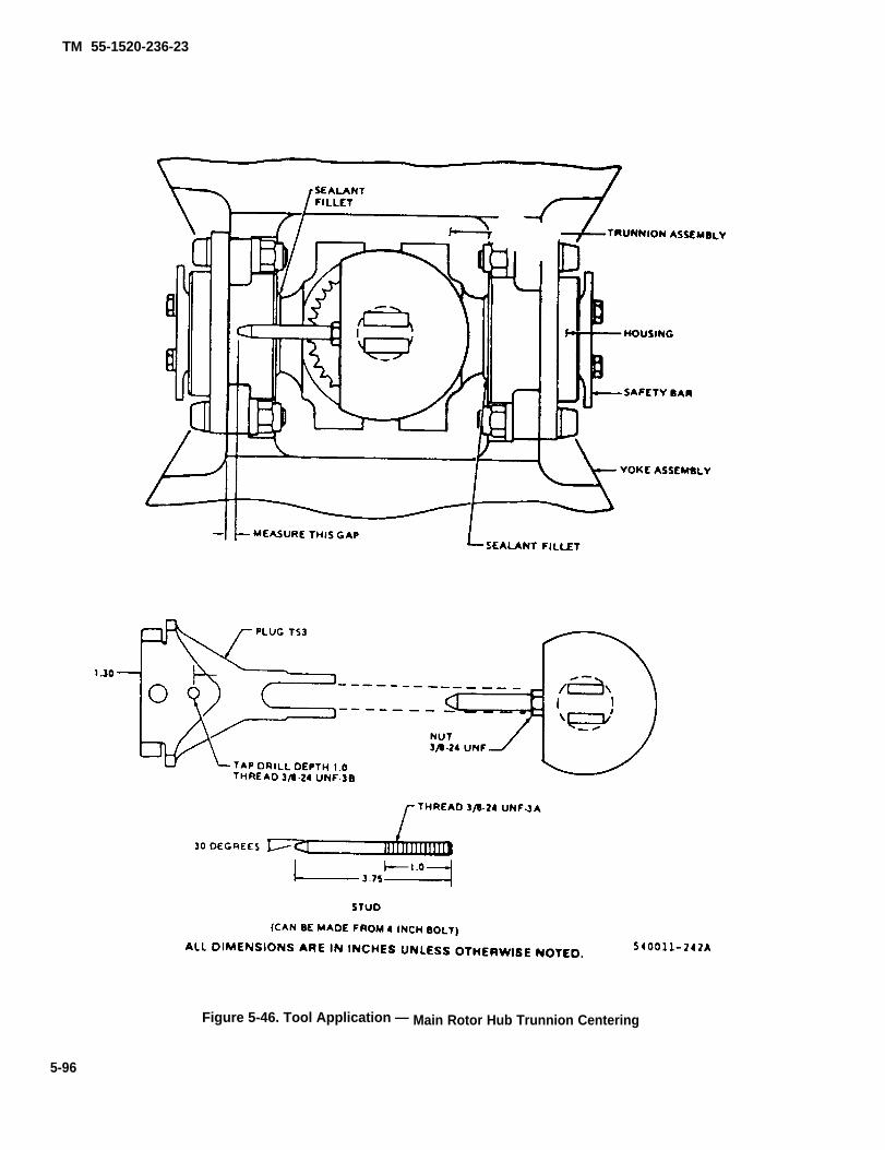
TM 55-1520-236-23
Figure 5-46. Tool Application — Main Rotor Hub Trunnion Centering
5-96

TM
55-1520-236-23
Figure 5-47. Tool Application —
Grid S
pacing Adjustm
ent
5-9
7
TM 55-1520-236-23
Inspect grip (41) to ensure that strap indexing ring(49) bearing (50) and dust seal (51) are properly installed.Apply a coating of sealant (C105) to both slots in fitting (52)so that this area will be sealed when the grip is installed.Slide the grip (41) on the grip extension with the side withprovisions for mounting the pitch horn on the trailing edgeside. Engage the lugs on the strap indexing ring in the gripwith the slots in fitting (52). Work grip onto extension farenough to expose three threads on fitting (52). Use a fibermallet to tap grip onto extension.
v. Install washer (46) and start dome nut (45). Installtwo bolts (60) through grip and housing. Install a maximumof four steel washers (47) on each bolt as required and in-stall nuts (48). Torque nuts 770 TO 950 inch-pounds. Installopposite grip in same manner. Rotate grips gently throughtheir full travel, ensuring there is no interference betweengrip and extension.
NOTE
Check clearance of extension and grip assem-bly. Refer to paragraph 5-11.a.
w. If drag brace (15) was disassembled, installjamnuts (14) and clevis ends on drag brace. Adjust clevisuntil approximately 0.25 inch of threads are exposed oneach end and the dimension between centers of clevisholes is 14.732 inches. Tighten jamnuts (14) snug but donot torque. Position drag brace on grip and install bolt (18),washers (16) and nut (17). Do not torque nut (17) at thistime. Install opposite drag brace in the same manner.
Only bolts, nuts, washers, and bushings thathave been degreased will be used to attachpitch horn to grip. During reassembly of pitchhorn to grip care should be taken to ensurethat the bolts, nuts, washers, and bushingsare clean and free of any lubricant other thanthe dry film lubricant.
NOTE
If new bofts are not available, old bofts may bereused after disassembly of pitch horn fromgrips. Reused bolts must be degreased andpeas visual and magnetic particle inspectionprior to reinstallation. Bolts, nuts, washers,and bushings will be vapor degreased usingPD680, Type 2. If vapor degreesed equipmentis not available, soak in PD680, Type 2 for onehour and wipe off grease and PD680 using alint free cloth prior to installation. Use of after-nate cleaning agents is not recommended as itmay remove dry film lubricant protective coat-ing.
Pitch horn (P/N 209-010-109) for main rotor hubassemblies (P/N 540-011-101-5, -17, and -25).
(1) Install bushings (22) figure 5-29 (P/N 209-010-111) into pitch horns (21).
(2) Fit pitch horn (21) to grip (13) with bushings(22) engaging bores in grip.
Washers with chamfered side must face bolt.
NOTE
Clevis on pitch horn (21) should be facingdown.
Bolt 209-010-112-1 may be used in place ofbolt 209-010-112-3
(3) Install bolts (19) and (20) (P/N 209-010-112)through pitch horn (21) and grip (13) with new washers (5)and nuts (4). Use two washers under nuts, as required forthread engagement.
NOTE
Bolts (19) and (20) (P/N 209-010-112) are prop-erly installed when seated internally,boltheads will not be in contact with pitch horn(21) or bushing (22).
5-98

TM 55-1520-236-23
(4) Nuts are to be torqued to 700-725 inch-poundsusing the following torque procedure.
(a) Torque nut to 700-725 inch-pounds.
(b) Tap the pitch horn and grip around thebolted area to set the parts. Use a rawhide or non-metalhammer.
(c) Retorque to 700-725 inch-pounds.
(d) Fly main rotor head for one hour andretorque to 700-725 inch-pounds.
(5) Repeat step (1) through (4) for installation ofopposite pitch horn.
y. Replace tape (C127) on inboard spacer (3) if re-quired to obtain a snug fit. Position two spacers (3) in webof yoke extension. If previously removed position sand de-flector (1) on yoke extension and install three bolts (2)through sand deflector and spacers. Ensure that there isadequate clearance between deflector and yoke (25) atboth upper and lower surfaces. Install opposite sand de-flector in the same manner.
z. Adjust grip space as follows:
(1) Install bolt assembly (6) in each grip.
(2) Install two flap stops (T39) on trunnion with540 side down as shown on figure 5-47. Use 3/8 inch UNFthreaded bolts of suitable length to secure flap stops totrunnion. Ensure that trunnion is level (zero degrees) toyoke.
(3) Remove one bolt (4, figure 5-30) from eachtrunnion bearing and install two grip locks (T59) as shownon figure 5-47.
During all grip spacing procedures, ensurethat grips are properly seated against domenuts.
(3.1) Back dome nut off one full turn in excess ofthat required for adjustment. With a fiber mallet, tap grip inan outboard direction. Turn dome nut clockwise while ob-serving dimension “A” (figure 5-48), It the dimensiondoses, the grip is properly seated.
(4) lighten dome nut (45, figure 5-29), installed instep v. until dimension between radius ring (29) and out-side metal ring of dust seal (51) is 0.001 inch. See dimen-sion “A” on figure 5-48. Adjust opposite grip in the samemanner.
(5) Install grip spacing gage (T53, figure 5-47).Adjust tip on gage to 2.0 inch dimension as illustrated. In-stall plug in trunnion and secure with knurled screw. Locatehole marked “540-011-101” on gage of spacing gage (T53)and attach gage to plug with bolt through this hole. Raiseblade bolt and position tip of spacing gage (T53) so that itrests on dowel pin in grip as shown. Measure and recorddistance between blade bolt and tip of grip spacing tool.Reverse grip spacing gage and measure distance on op-posite blade bolt.
During all grip spacing procedures, ensurethat grips are properly seated against domenuts.
(5.1) Deleted.
(6) Loosen dome nut (45, figure 5-29) on grip (41)that was found to be most inboard in the preceding step.Adjust this dome nut as required until the dimension isequal to that of the most outboard grip within 0.002 inch.
(7) Check seal gap dimension “A” shown on bothgrips. Dimension “A must be 0.001 TO 0.040 inch.
NOTE
Tolerance dimension “A” can be eased up to0.060 inch provided an assurance check willbe made anytime the grip spacing exceeds0.040 inch. Correct procedures and seal to ra-dius ring will be verified.
5-98.1

TM 55-1520-236-23
(8) Install look (44), damp (43), bolt (42), thin steelwasher (56), nut (55), and cotter pin (57).
(9) Remove grip spacing gage.
(10) Install blade bolt (6), keyway washer (7), spe-cial washer (8), special nut (9), screw (12), washer (11),and nut (10). Do not torque special nut (9).
(11) Remove two flap stops (T39).
NOTE
All bolted joints and faying surfaces to be as-sembled with corrosion preventive compound(C44). Steps 12, (a), and (b) apply to helicopters with MWO-1520-244-50-3 incorporated.
(12) Position plates (12, figure 5-30) on trunnion(5) and install bolts (14) and washers (13). Do not torquebolts at this time,
(a) Seat plates (12) on bottom edge of trunnionslot. Torque bolts (14) 70 TO 90 inch-pounds and Iookwire(C137).
(b) Install straps (8) to plates (12) using bolts(7), washers (9 and 15), and nuts (16). Refer to note forwashers (9), figure 5-30. Torque nuts (16) 270 TO 300inch-pounds.
(13) Remove two grip locks (T59). Install bolts (18,figure 5-30) with recessed washers (17). Install washerwith recessed side toward bolt head. Install recessedwasher (11) with recessed side next to nut (10). Use morethan one special washer (11) to obtain proper engagementof nut if necessary. Torque aft four nuts (10) 160 TO 190inch-pounds.
5-98.2

TM 55-1520-236-23
Figure 5-48. Main Rotor Hub Grip Dust Seal to Radius Ring Dimension
5-99

TM 55-1520-236-23
After nuts (11) are tightened, no morethan five threads of bolts are permitted tobe exposed beyond nuts (11), and a mini-mum of three threads must be exposed toensure the seif-locklng feature of the nutsIs engaged.
aa. Installation of identification plate.
Stamping directly on the surface of anydetail hub part or Installed data plateIs prohibited.
(1) Stamp applicable data on replacement plateusing 1/16 inch characters.
(2) Lightly sand contact area on component andmating surface with No. 180 grit abrasive cloth (36).
(3) Remove sanding residue using cheesecloth(C30) dampened with naphtha (C75).
(4) Mix EC2216 adhesive (C7) 100 parts base to 140parts hardener. Apply adhesive within 20 minutes toboth mating surfaces and join parts.
NOTE
Pot life of adhesive is 100 to 130 min-utos.
(5) Fair out adhesive. Remove excess adhesiveusing cheesecloth (C30) dampened with methyl-ethyl-ketone (C74).
(6) Maintain firm contact pressure and cure for24 hours at 70°F (21°C) or 30 to 60 minutes at 200°F(93° C), Edge voids ore not allowed, Maximum strength.achieved on 6 to 7 days.
ab. Balance main rotor hub assembly (paragraph5-45).
5 - 4 4 . P A I N T I N G – M A I N R O T O R H U B .
NOTE
Painting an assembled main rotor hub islimited to touch-up of damaged finish onyoke, grips and pitch horns.
a. Clean the area to be repaired by sanding with 320grit or finer sandpaper (C102). Either wet or dry sand-ing is satisfactory. Fair-in the undamaged lacquer finisharound the repair area.
b. Apply chemical film treatment (C31) to bare metalareas on the aluminum pitch horns after sanding. Usethe following procedure:
NOTE
Chemical film treatment is not required onthe yoke or the grips. If these parts arebeing touched-up, proceed to step c.
(1) If the area where chemical film is to be appliedis not completely clean from the sanding operation,scrub the area with Scotchbrite (C 103) and rinse withclean water.
(2) Apply chemical film (C31) to bare metal witha brush or swab for one to three minutes then rinse withclear water. Allow to air dry, use compressed air, orclean dry cloths to dry area.
c. Apply primer to repair area as follows:
(1) Prepare two-part epoxy primer (C88 or C91)according to instructions on container.
(2) Mask-off areas adjacent to repair area withmasking tape (C123).
(3) Immediately prior to applying primer, cleanarea with a tack rag (C119).
5-100
TM 55-1520-236-23
(4) Spray on very thin coat of primer prepared instep (1).
NOTE
Apply acrylic lacquer over primer withinone to eight hours.
d. Apply acrylic lacquer to repair areas as follows:
NOTE
If primer applied in preceding step hasdried for more than eight hours, apply amist coat of the same primer then applylacquer per this paragraph within onehour.
(1) Prepare gray acrylic lacquer in accordancewith instructions on container.
(2) Spray on very thin coat. Allow to dry thirtyminutes and apply second coat. If second coat is notapplied within one hour, clean with tack rag (C119), orequivalent, prior to application of second coat.
(3) Remove masking tape from repair area.
5-45. B A L A N C I N G — MAIN ROTOR HUB(AVIM).
NOTE
Refer to TM 55-4920-201-14 for additionalinformation on balancing tools if required.
a. Setup the hub balancing stand and accessoriesfrom balance kit (T73) as follows:
(1) Assemble hoist support structure with tubeassembly P/N 2769 instead of tube assembly P/N 2288shown in figure 5-49 to provide additional hoist armheight.
(2) Center fixture (11, figure 5-50) from kit (T73)on work stand.
(3) Install adapter (12), heavy end downward,over top of fixture (11) and seat on upper shoulder offixture central projection. Lock adapter in this positionby tightening adapter setscrew (13) using 1/8 hexwrench from kit (T73), (T70), or (T69).
5-100.1 /(5-100.2 blank)


TM 55-1520-236-23
Figure 5-49. Rotor Balancing Kit P/N 7A050
b. Balance main rotor hub assembly as follows:
(1) Carefully lower rotor hub assembly (6,figure 5-50) over fixture (11); align inside diameter ofsplined trunnion with piloting diameter of adapter(12), and ensure that cone surface of splined trunnionseats firmly on cone surface of adapter (12).
(2) Install yoke (14), legs downward, on arbor(16) and position so that top surface of its lockingcollar sensitivity setting reference aligns with
15-3/8 inch position on arbor scale (15). Lock yokefirmly in this position on arbor with its collar screw,using 3/16 inch hex wrench from kit (T73).
(3) Install arbor (16) downward through rotortrunnion and fixture assembly. Seat legs of yoke (14)in milled areas on top surfaces of hub yoke; centerwith scribed lines.
(4) Position jacks (7) on top surface of the rotorhub yoke so that their inboard ends bear against thecentral boas of the hub yoke, centered below the
5-101

TM 55-1520-236-23
Figure 5-50. Tool Applicatlon - Main Rotor Hub Balancing
5-102
TM 55-1520-236-23
scribe lines mentioned in step (3). Position outboardends of jacks (7) against the shoulders of the inboardbearing housing of the blade grip assemblies. Adjustjacks to provide uniform outward pressure sufficientto ensure blade grips are seated in their full outwardpositions.
(5) Install spacer (9) over lower end of arbor;install handwheel (10) in lower end of arbor andtighten to clamp both legs of yoke firmly against topsurfaces of hub yoke.
(6) Position two gages (2) on hub as illustratedto adjust drag braces (5) to symmetrical angularpositions. Remove gage from rotor hub duringsubsequent balance check.
5-102.1/(5-102.2 blank)


TM 55-1520-236-23
(7) Install quick-disconnect assembly with3/16 inch cable from kit (T73) on arbor suspensionrod and hoist balancing assembly approximately 1/4inch off work stand with hydraulic pump (15, figure 5-49). Check to ensure that suspended assembly is freefrom interference with work stand and adjacentobjects. If handwheel (10, figure 5-50) is not free ofinterference with the stand table, adjust the level ofthe stand assembly by installing suitable blocks underthe two tubular stand leg extensions (6, figure 5-49).
(8) After it is determined that the handwheel(10, figure 5-50) suspends free of interference, lowerthe hub to rest on the stand.
(9) Place a bubble protractor on the machinedsurfaced next to the blade retaining bolt and set bothblade grips to zero degrees. Both grips must be equalwithin zero degrees, five minutes.
(10) Raise assembly approximately 0.25 inchoff work stand to obtain balance readings.
(11) Observe balance indication at indicatordisk (17, figure 5-50) to determine whether the hub isin balance. See figure 5-50, Detail A for examples ofbalance indications at indicator disk.
(12) Balance hub assembly chordwise byplacing weight on pitch horn (light) at blade station0.000. See Detail A, figure 5-50 for balanceindications.
NOTE
Chordwise balance is accomplished onlyto aid in spanwise balance. The weightwill be removed from the pitch horn afterspanwise balance is complete.
(13) Balance spanwise about blade station0.000 by inserting lead wire, lead wool slugs or 0.44inch diameter shot into cavity of blade bolt assembly(8). Hub shall be balanced within limits shown indetail A, figure 5-50.
(14) Install plug (19) into blade bolt (8)when balance has been accomplished. Removebalance weight that was used for chordwise balancein step (12).
(15) Color code hub assembly parts afterbalance to ensure that parts of hub remain in samerespective position as they were when hub wasbalanced.
(16) Remove hub balance stand andaccessories.
5 - 4 6 . I N S T A L L A T I O N – M A I N R O T O RHUB.
Refer to paragraph 5-14.
S E C T I O N I l l . M A I N R O T O R C O N T R O L S
5 - 4 7 . M A I N R O T O R C O N T R O L S – A, are included in the main rotor controls. Refer toP Y L O N A S S E M B L Y . paragraph 5-4 for description of main rotor controls
function, Refer to paragraph 5-65 for description of5 - 4 8 . D E S C R I P T I O N – M A I N R O T O R swashplate. Refer to paragraph 5-55 for descriptionCONTROLS. of scissors and sleeve.
The two major assemblies of the main rotor controls 5 - 4 9 . R E M O V A L – M A I N R O T O Rare the swashplate and support assembly and the CONTROLS.scissors and sleeve assembly. The pitch links (10,figure 5-1), collective lever (14), the idler assembly(27) that attaches the forward end of the collectivelever to transmission case (19), and the collective Remove scissors and sleeve with cautionfriction mechanism shown in figure 5-51, detail view to avoid damage to mast.
5-103
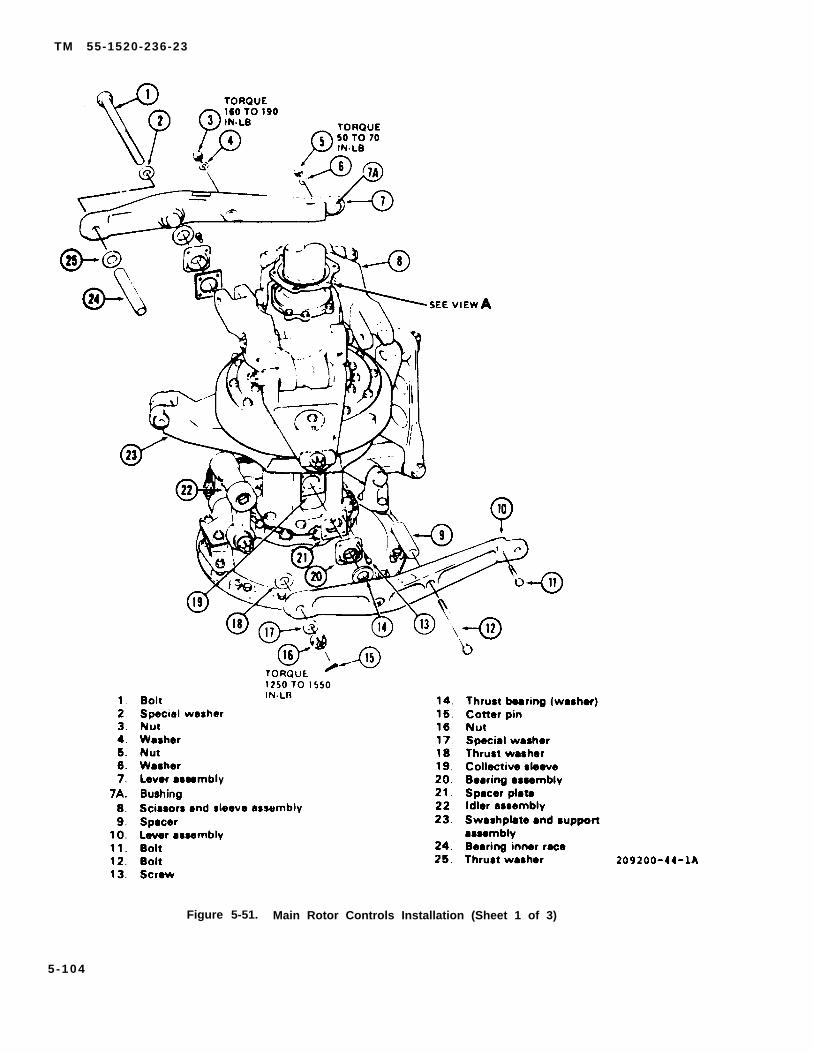
TM 55-1520-236-23
Figure 5-51. Main Rotor Controls Installation (Sheet 1 of 3)
5 - 1 0 4
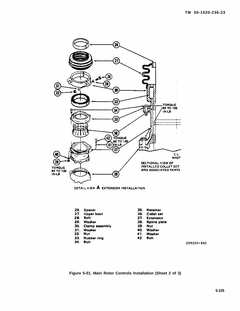
TM 55-1520-236-23
Figure 5-51. Main Rotor Controls Installation (Sheet 2 of 3)
5-105
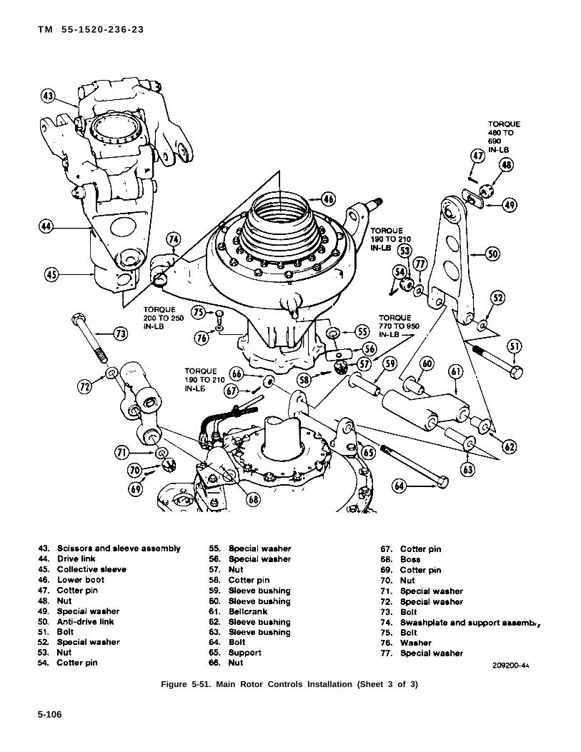
TM 55-1520-236-23
Figure 5-51. Main Rotor Controls Installation (Sheet 3 of 3)
5-106
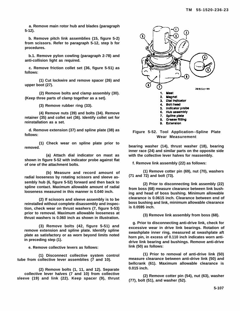
TM 55-1520-236-23
a. Remove main rotor hub and blades (paragraph5-12).
b. Remove pitch link assemblies (15, figure 5-2)from scissors. Refer to paragraph 5-12, step b forprocedures.
b.1. Remove pylon cowling (paragraph 2-78) andanti-collision light as required.
c. Remove friction collet set (36, figure 5-51) asfollows:
(1) Cut lockwire and remove spacer (26) andupper boot (27).
(2) Remove bolts and clamp assembly (30).(Keep three parts of clamp together as a set).
(3) Remove rubber ring (33).
(4) Remove nuts (39) and bolts (34). Removeretainer (35) and collet set (36). Identify collet set forreinstallation as a set.
d. Remove extension (37) and spline plate (38) asfollows:
(1) Check wear on spline plate prior toremoved.
(a) Attach dial indicator on mast asshown in figure 5-52 with indicator probe against flatof one of the attachment bolts.
(b) Measure and record amount ofradial looseness by rotating scissors and sleeve as-sembly hub (6, figure 5-52) forward and then back tospline contact. Maximum allowable amount of radiallooseness measured in this manner is 0.040 inch.
(2) If scissors and sleeve assembly is to bereinstalled without complete disassembly and inspec-tion, check wear on thrust washers (7, figure 5-53)prior to removal. Maximum allowable looseness atthrust washers is 0.060 inch as shown in illustration.
(3) Remove bolts (42, figure 5-51) andremove extension and spline plate. Identify splineplate as satisfactory or as worn beyond limits notedin preceding step (1).
e. Remove collective levers as follows:
(1) Disconnect collective system control tube from collective lever assemblies (7 and 10).
(2) Remove bolts (1, 11, and 12). Separatecollective lever halves (7 and 10) from collective
sleeve (19) and link (22). Keep spacer (9), thrust
Figure 5-52. Tool Application--Spline PlateWear Measurement
bearing washer (14), thrust washer (18), bearinginner race (24) and similar parts on the opposite sidewith the collective lever halves for reassembly.
f. Remove link assembly (22) as follows:
(1) Remove cotter pin (69), nut (70), washers(71 and 72) and bolt (73).
(2) Prior to disconnecting link assembly (22)from boss (68) measure clearance between link bush-ing and head of boss bushing. Minimum allowableclearance is 0.0615 inch. Clearance between end ofboss bushing and link, minimum allowable clearanceis 0.0595 inch.
(3) Remove link assembly from boss (68).
g. Prior to disconnecting anti-drive link, check forexcessive wear in drive link bearings. Rotation ofswashplate inner ring, measured at swashplate afthorn pin, in excess of 0.110 inch indicates worn anti-drive link bearing and bushings. Remove anti-drivelink (50) as follows:
(1) Prior to removal of anti-drive link (50)measure clearance between anti-drive link (50) andbellcrank (61). Maximum allowable clearance is0.015 inch.
(2) Remove cotter pin (54), nut (63), washer(77), bolt (51), and washer (52).
5-107
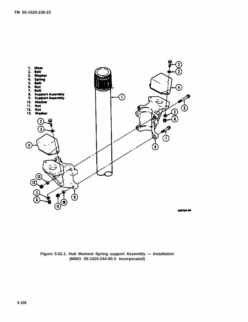
TM 55-1520-236-23
Figure 5-52.1. Hub Moment Spring support Assembly — Installation(MWO 55-1520-244-50-3 Incorporated)
5-108

TM 55-1520-236-23
Figure 5-53. Collective Lever Thrustwasher wear Limits
(3) Remove cotter pin (47), nut (48), and spe-cial washer (49).
(4) Remove anti-drive link.
(5) Install bolt (51) in bellcrank (61) to securesleeve bushings (60 and 62).
h. Remove bellcrank assembly (61) as follows:
(1) Remove cotter pin (67), nut (66) and bolt(64).
(2) Remove bellcrank (61) from support (65).
(3) Install bolt (64) in bellcrank (61) to securesleeve bushings (59 and 63).
i. Remove support assembly (65) as follows:
(1) Remove four bolts, nuts and washers thatsecure support assembly (65) to transmission.
(2) Use a sharp plastic scraper to separatebead of sealant from support assembly.
(3) Remove support assembly from transmis-sion.
j. Remove scissors and sleeve assembly (para-graph 5-58).
k. Remove swashplate and support (paragraph 5-68).
5-50. INSPECTION — MAIN ROTOR CONTROLS.
a. Prior to incorporation of MWO 55-1520-244-50-9 inspect pitch link assemblies (10, figure 5-1) fordamage such as metal to metal contact on upperbearing housing, normal bearing wear, surface wearand straightness of tube assembly. All damage limitsare given on figure 5-54.
(1) When inspecting the pitch link assembly,mask the ends of the tube to prevent liquid materialfrom contacting the metal set material. Mask the cen-ter of the tube length so that only the top and bottomthree inches of the tube are exposed.
NOTE
The success and reliability of penetrantinspection depend upon the thorough-ness with which the inspector preparesthe part from the pm-cleaning processall the way through to the final inter-pretation of the indications. All inspec-tions should be with the fluorescentpenetrant (Type I, Method C) in strict ac-cordance with TM 43-0103.
Prolonged or repeated inhalation ofvapors or powders may result in irrita-tion of the mucous membrane areas ofthe body. Provide adequate ventilation.
Continual exposure to penetrant inspec-tion materials may cause skin irritation.Avoid prolonged breathing of solventvapors and contact with skin or eyes.
Injury to eyes and skin may occur whenbacklight is not used in accordancewith manufacturer’s inspections. Unfil-tered light sources (if filter is required)may possibly damage the eyes.
5-108.1

TM 55-1520-236-23
Temperatures in excess of 120 degrees Fmay cause bursting of pressurized cans andinjury to personnel.
Volatile fumes may occur, creating both afireand health hazard.
NOTE
Paint will not be removed by mechanicalmeans under any circumstances because itmay mask over any potential surface cracks.
(2) With a soft hair brush, apply MEK (Methyl-Ethyl-Ketone) C74), or paint remover (TTR248B) andremove the paint.
NOTE
The gold colored finish on the metal is a verythin them-coat metal primer. This material isnot, repeat not to be removed. Inadvertentremoval of this metal primer does not warrantpart rejection.
(3) Clean the prepared surfaces with a soft cloth.
(4) Apply a fluorescent dye penetrant to the pre-pared surfaces from either a spray can or with a soft hairbrush and in strict conformance to the procedure speci-fied in TM 43-0103, Chapter 6.
(5) Allow penetrant to dwell for a minimum of 30minutes.
method per TM 43-0103, Chapter 3, (Tube material is2024 aluminum.)
NOTE
If a physical or penetrant crack is observedand confirmed, report failures on QDR Form368 in accordance with DA PAM 738-751 andhold tube as an exhibit.
(10) Clean tube with advent and wipe dry.
(11) Inspecting for straightness is done by doing aTotal Inline Runout (TIR).
(12) Deleted
(13) Set up bearing blocksfor pitch tube so that theedges of tube are resting between roller bearings.
(14) Set up indicator within a 1/4-inch from theedge of the larger diameter of the pitch tube. Dial indica-tor must not contact necked down area.
(15) Rotate pitch tube to find highest and lowestreading and zero dial at that position.
(16) Rotate pitch tube and record the total bend.Maximum allowed TIR is 0.020 inch; tubes in excess of0.020 inch shall be reported and held as an exhibit.
(17) Repaint areas to original color of tube usingpaint (C86.1).
a.1. After incorporation of MWO 55-1520-244-50-9inspect Elastomeric Rod End Bearings for serviceability.
(1) Remove Rod End Clevis Bolt (26, figure 5-2).
(6) Clean off all excess penetrant in accordancewith TM 43-0103, standard procedures. (Check forcomplete excess penetrant removal from surface by us-ing a blacklight).
(7) Apply applicable developer consistent with Do not rotate Pitch Link beyond the maximum
Type I, Method C penetrant method in TM 43-0103. 13 inches or damage to the Bearing could oc-cur.
(8) Inspect suspected area with blacklight sourcein subdued white light. (2) Attach Spring Scale to lower end of Pitch Link
and rotate outward so that a torsional load is applied toNOTE the Rod End Bearing.
Normal manufacturing machining marks may (3) Check that a minimum of 20 Ibs of force isbe observed on the tube surfaces. These will required to move the Rod End Clevis 13 inches. Refer-not be cause of part rejection. ence figure 5-53.1.
(9) If any apparent cracks appear (or suspect sur- (4) If Pitch Link rotates freely at the Elastomericface defects), the suspect area must be reevaluated Rod End Bearing prior to 20 Ibs of force replace Rod End,utilizing certified ND I personnel with the Eddy Current reference figure 5-53.2.
5-108.2
TM 55-1520-236-23
b. Inspect friction collet set (36, figure 5-51) for mis-sing fingers, cracks and scoring. Check for loose or mis-sing teflon strips.
f. Inspect clamp assemblies (30, figure 5-51) forcracks, corrosion and deformation.
c. Inspect rubber ring (33), boot (27) and boot (46) fordamage and deterioration. Inspect boot (46) for tearingand for evidence of broken spring. Team are not per-mitted. When spring is broken, inspect wire loops insideboot convolutions. If wires are loose enough to fall out,or corroded, remove and discard defective wire loops.The aircraft may be flown with any number of wire loopsremoved.
d. Inspect extension (37) and retainer (35) for obviousdamage that would affect function.
e. Inspect spline plate (38) as follows:
(1) Inspect for damage in excess of limits shownm figure 5-55.
(2) Inspect for cracks by fluorescent penetrantmethod. Refer to TM 43-0103.
(3) Refer to paragraph 5-49.d. for instructions tocheek spline plate for excessive wear while installed.
g. Inspect collective Ievels (7 and 10) as follows:
(1) Inspect for damage in excess of limits shownin figure 5-56.
(2) Inspect for cracks by magnetic particle meth-od. Refer to TM 43-0103.
(3) Inspection (7A, figure 5-51) for damageor excessive wear.
g.1. Deleted.
h. Inspect of collective lever link assembly (22) as fol-lows:
(1) Inspect for damage in excess of limits shownin figure 5-57.
(2) Inspect bearings (3 and 5, figure 5-56) for se-cure installation in link and for missing or damaged roll-ers. Install bearing inner race (24, figure 5-51) and
5-108.3

TM 55-1520-236-23
Figure 5-53.1. Rod End Clevis Movement
5-108.4

TM 55-1520-236-23
Figure 5-53.2. Rod End
5-108.5/(5-108.6 blank)


TM 55-1520-236-23
Figure 5-54. Damage Limits – Pitch Link Assembly(Prior to Incorporation of MWO 55-1520-244-50-9) (Sheet 1 of 2)
5-109

TM 55-1520-236-23
NOTES:
1. All edges maybe radiused or chamfered 0.030 inch to remove nicks or dents.
2. Repair of nicks and dents on threads must not exceed one-third of the thread depth. Length of repair shall notexceed 0.250 inch. Each threaded segment may have two repair areas.
3. Coat repair areas on steel parts with brush cadmium or zinc chromate and aluminum parts with zinc chromate.Do not use zinc chromate on threads.
4. Corrosion must be cleaned up to twice the depth of damage on aluminum. Corrosion must be cleaned up to re-move all trace of damage on steel.
Minimum radius of repair on adapter is 0.100 inch. The repair must be polished to match the surrounding sur-
6.
7.
8.
9.
10.
11.
12.
13.
14.
faces.
Maximum play in bearing Part No. 209-010-443-1 is 0.020 inch axial or radial.
Maximum play in bearings in universal Part No. 214-010-434-1 is 0.010 inchaxial or radial.
Do not remove adapter or clevis from tube.
Visual irregularities caused by the swaging operation at each a nd considered acceptableprovided there are no sharp edges or grooves.
Visually inspect tubes for any indications of bending. No bending allowed.
Do not change color of tube when repainting or touchup.
Every 150 hours at phase inspect control tubes for TIR. No more than 0.020 inch is allowed. Setup indicator within 0.250 inch from edge of larger diameter of pitch tube. Dial indicatormust not contact necked down area.
Repaired areas may not overlap.
No cracks allowed.
The width of repairs to the 209-010-460-3 tube cannot exceed 1/3 of the tube circumference.
Figure 5-54. Damage Limits – Pitch Link Assembly(Prior to Incorporation of MWO 55-1520-244-50-9) (Sheet 2 of 2)
5-110

TM 55-1520-236-23
All edges may be radiused or chamfered 0.030 inch to remove nicks or dents.
Repair of nicks and dents on threads must not exceed one-third of the thread depth. Lengthof repair shall not exceed 0.250 inch. Each threaded segment may have two repair areas.
Coat repair areas on steel parts with brush cadmium or zinc chromate.Do not use zinc chromate on threads.
Corrosion must be cleaned up to remove all traces of damage on steel.
Minimum radius of repair on adapter is 0.100 inch. The repair must be polished to match thesurrounding surfaces.
Deleted.
Maximum play in bearings in universal Part No. 214-010-434-1 is 0.010 inch axial or radial.
Do not change color of tube when repainting or touchup.
Repairs to the 209-010-518-101 tube cannot exceed 1/3 of tube circumference. Four repairsare allowed on 209-010-518-101 tube in this area.
Repairs may not overlap.
209010-238A
Figure 5-54.1 Damage Limits-Pitch Link Assembly 209-010-520-103(After Incorporation of MWO 55-1520-244-50-9)
5-110.1

TM 55-1520-236-23
Figure 5-55. Damage Limits – Spline Plate
5-110.2

TM 55-1520-236-23
check for radial looseness.
Flgure 5-56. Damage
(Maximum allowableradial looseness is 0.010 inch.)
(3) Inspect bushings (6, figure 5-58) for secureinstallation in link and for deterioration a n dseparation.
(4) Inspect lubrication fitting (7) for damagethat would affect function.
(5) Inspect for cracks by fluorescent penetrantmethod. Refer to TM 43-0103.
i. Inspect swashplate anti-drive link (50, figure 5-51) as follows:
(1) Inspect for damage in excess of limitsshown in figure 5-59.
(2) Inspect bushings (5, figure 5-60) for wearand damage.
(3) Inspect identification plate (3) for secureinstallation and legible markings.
(4) Inspect link (4) by fluorescent penetrantmethod. Refer to TM 43-103.
j. Inspect swashplate anti-drive assemblybellcrank (61, figure 5-51) as follow.
(1) Inspect four teflon lined bearing bushings inthe bellcrank for damage, wear and corrosion.
(2) Inspect for cracks by fluorescent penetrantmethod. Refer to TM 43-0103.
(3) Inspect for damage in excess of limitsshown in figure 5-61.
k. Inspect sleeve bushings (59, 60, 62 and 63,figure 5-51) for distortion of teflon and mechanicaldamage.
5-111
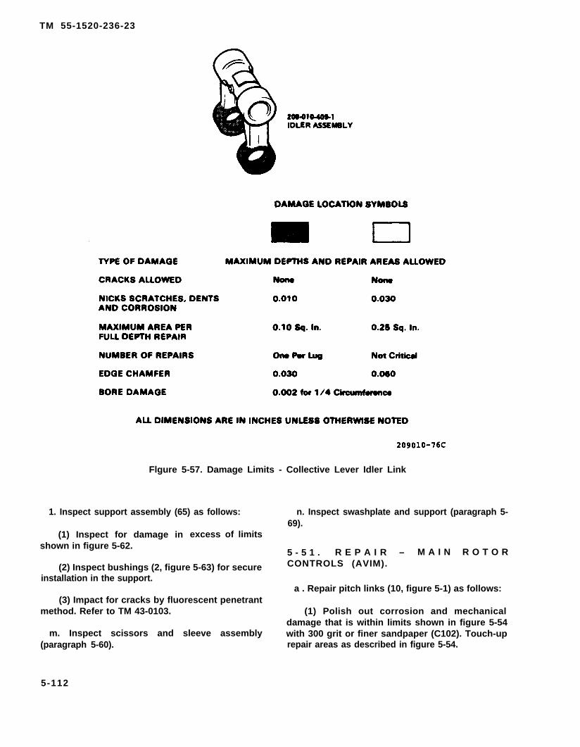
TM 55-1520-236-23
Flgure 5-57. Damage Limits - Collective Lever Idler Link
1. Inspect support assembly (65) as follows:
(1) Inspect for damage in excess of limitsshown in figure 5-62.
(2) Inspect bushings (2, figure 5-63) for secureinstallation in the support.
(3) Impact for cracks by fluorescent penetrantmethod. Refer to TM 43-0103.
m. Inspect scissors and sleeve assembly(paragraph 5-60).
5-112
n. Inspect swashplate and support (paragraph 5-69).
5 - 5 1 . R E P A I R – M A I N R O T O RCONTROLS (AVIM).
a . Repair pitch links (10, figure 5-1) as follows:
(1) Polish out corrosion and mechanicaldamage that is within limits shown in figure 5-54with 300 grit or finer sandpaper (C102). Touch-uprepair areas as described in figure 5-54.
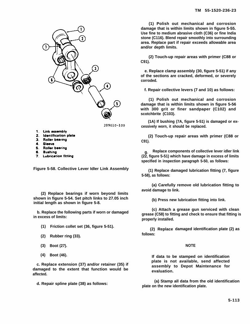
TM 55-1520-236-23
Figure 5-58. Collective Lever IdIer Link Assembly
(2) Replace bearings if worn beyond limitsshown in figure 5-54. Set pitch links to 27.05 inchinitial length as shown in figure 5-8.
b. Replace the following parts if worn or damagedin excess of limits:
(1)
(2)
(3)
(4)
Friction collet set (36, figure 5-51).
Rubber ring (33).
Boot (27).
Boot (46).
c. Replace extension (37) and/or retainer (35) ifdamaged to the extent that function would beaffected.
d. Repair spline plate (38) as follows:
(1) Polish out mechanical and corrosiondamage that is within limits shown in figure 5-55.Use fine to medium abrasive cloth (C36) or fine Indiastone (C116). Blend repair smoothly into surroundingarea. Replace part if repair exceeds allowable areaand/or depth limits.
(2) Touch-up repair areas with primer (C88 orC91).
e. Replace clamp assembly (30, figure 5-51) if anyof the sections are cracked, deformed, or severelycorroded.
f. Repair collective levers (7 and 10) as follows:
(1) Polish out mechanical and corrosiondamage that is within limits shown in figure 5-56with 300 grit or finer sandpaper (C102) andscotchbrite (C103).
(1A) If bushing (7A, figure 5-51) is damaged or ex-cessively worn, it should be replaced.
(2) Touch-up repair areas with primer (C88 orC91).
g. Replace components of collective lever idler link(22, figure 5-51) which have damage in excess of limitsspecified in inspection paragraph 5-50, as follows:
(1) Replace damaged lubrication fitting (7, figure5-58), as follows:
(a) Carefully remove old lubrication fitting toavoid damage to link.
(b) Press new lubrication fitting into link.
(c) Attach a grease gun serviced with cleangrease (C58) to fitting and check to ensure that fitting isproperly installed.
(2) Replacefollows:
damaged identification plate (2) as
NOTE
If data to be stamped on identificationplate is not available, send affectedassembly to Depot Maintenance forevaluation.
(a) Stamp all data from the old identificationplate on the new identification plate.
5-113

TM 55-1520-236-23
Figure 5-59. Damage Limits — Swashplate Anti-Drive Link
5-114

TM 55-1520-236-23
Figure 5-60. Swashplate Anti-Drive Link Assembly
5-115

T M 5 5 - 1 5 2 0 - 2 3 6 - 2 3
Figure 5-61.
Do not heat link assembly (1) totemperature above l imit noted infollowing step.
(b) Remove old identification plate from linkassembly. Heat link assembly to 200 ± 15 degrees F(93 ±9 degrees C) to loosen adhesive.
(c) Mask off face side of new identificationplate and the area of the link assembly whereidentification plate will be installed.
(d) Clean masked-off area on link assemblywith 300 grit or finer sandpaper (C102).
(e) Form new identification plate to fit closelyon link assembly.
Cleaning solvent is flammable and toxic,Provide adequate ventilation. Avoidprolonged breathing of vapors andcontact with skin or eyes.
(f) Scrub mating surfaces of identificationplate and link assembly with cheesecloth (C30)dampened with aliphatic naphtha (C75), Wear cleanwhite cotton gloves (C54) when handling parts aftercleaning and prior to bonding.
(g) Mix two-part adhesive (C7) in accordancewith instructions on container. Apply a thin coat ofadhesive to each of the mating surfaces as soon aspossible after mixing. Place identification plate on linkand anchor in position with clamps or rubber bands.
5-116
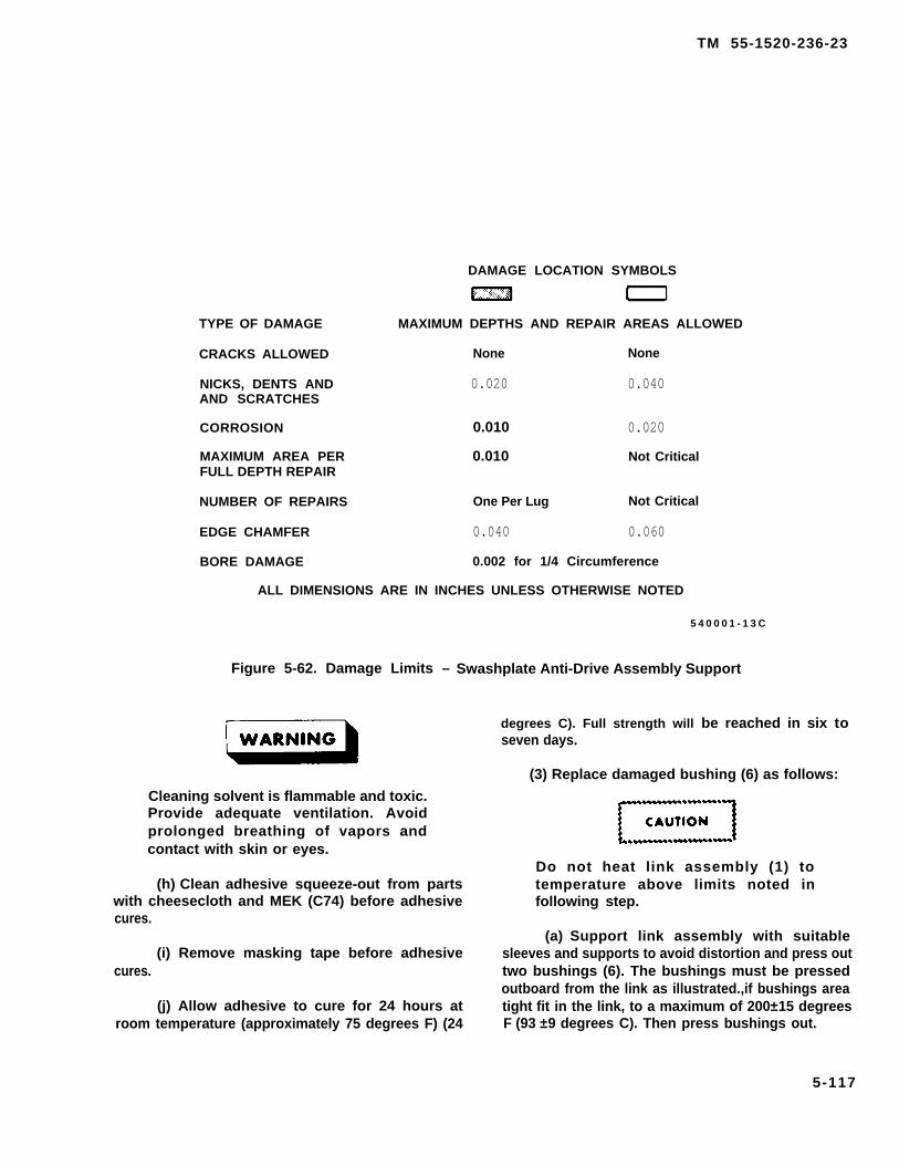
TM 55-1520-236-23
DAMAGE LOCATION SYMBOLS
TYPE OF DAMAGE MAXIMUM DEPTHS AND REPAIR AREAS ALLOWED
CRACKS ALLOWED None None
NICKS, DENTS AND 0.020 0.040AND SCRATCHES
CORROSION 0.010 0.020
MAXIMUM AREA PER 0.010 Not CriticalFULL DEPTH REPAIR
NUMBER OF REPAIRS One Per Lug Not Critical
EDGE CHAMFER 0.040 0.060
BORE DAMAGE 0.002 for 1/4 Circumference
ALL DIMENSIONS ARE IN INCHES UNLESS OTHERWISE NOTED
5 4 0 0 0 1 - 1 3 C
Figure 5-62. Damage Limits – Swashplate Anti-Drive Assembly Support
Cleaning solvent is flammable and toxic.Provide adequate ventilation. Avoidprolonged breathing of vapors andcontact with skin or eyes.
(h) Clean adhesive squeeze-out from partswith cheesecloth and MEK (C74) before adhesivecures.
(i) Remove masking tape before adhesivecures.
(j) Allow adhesive to cure for 24 hours atroom temperature (approximately 75 degrees F) (24
degrees C). Full strength will be reached in six toseven days.
(3) Replace damaged bushing (6) as follows:
Do not heat link assembly (1) totemperature above limits noted infollowing step.
(a) Support link assembly with suitablesleeves and supports to avoid distortion and press outtwo bushings (6). The bushings must be pressedoutboard from the link as illustrated.,if bushings areatight fit in the link, to a maximum of 200±15 degreesF (93 ±9 degrees C). Then press bushings out.
5-117

TM 55-1520-236-23
sleeve (4) with dry cleaning solvent (C112). Allow bear-ings to dry thoroughly and hand pack with grease (C58).
(b) Apply a thin coat of corrosion preventivecompound (C44) to mating surfaces of sleeve (4) andbearings (3 and 5). Press spacer and bearings into link.
Figure 5-63. Swashplate Anti-DriveAssembly Support
(b) Clean bores where two bushings (6) will beinstalled.
(c) Select suitable sleeves and support blocksto support legs of link assembly (1) during installation ofbushings (6).
Do not chill bushings (elastomeric-typebushings) (6) during Installationprocedure.
(d) Heat link assembly (1) to 200 ±15 degreesF (93 ± 9 degrees C). Coat mating surface of bushings(6) with primer (C88 or C91 ) and install with flanges out-board as illustrated while primer is wet.
Replace damaged bearings (3) and (5) as
Cleaning solvent is flammable and toxic.Provide adequate ventilation. Avoidprolonged breathing of vapors and con-tact with skin or eyes.
(a) Clean bore of link assembly (1) where bear-ings will be installed. Clean new bearings (3 and 5) and
(c) Polish out mechanical and corrosion dam-age that is within limits shown in figure 5-57.
h. Repair swashplate anti-drive link (50, figure 5-51)as follows:
(1) Polish out corrosion and mechanical damagethat is within limits shown in figure 5-59 with 300 grit orfiner sandpaper (C102) and scotchbrite (C103). Touch-up repair areas with alodine (C31).
(2) Replace damaged or missing identificationplate (3, figure 5-60) as outlined in step g. (2)(b) abovefor the collective lever idler link. Install identification plateon side of link illustrated in figure 5-60.
(3) Replace bearing in anti-drive link (1, figure5-60) if damaged or radial looseness is in excess of limitshown in figure 5-59, or if loose in the sleeve bushing.(Refer to TM 55-1500-322-24.)
(4) Replace damaged bushings (5) as follows:
(a) Supportbushings (5).
(b) Inspect
link (4) and press out damaged
link bore where bushings wereremoved for damage in excess of limit shown in figure5-59. If damage exceeds limits, dispose of link locally.
(c) Support link (4) and press new bushings (5)into place with bushing flanges outboard as illustrated.
(d) Check for 3.210 TO 3.212 inch dimensionbetween two bushings (5) as illustrated. Mill ends ofbushings if necessary.
(e) Check for 0.6241 TO 0.6255 inch insidediameter of bushings after installation.
5-118

TM 55-1520-236-23
(i) Repair swashplate anti-drive assemblybellcrank (61, figure 5-51) as follows:
(1) Replace teflon lined bearing bushings thatfailed to pass inspection as follows:
N O T E
The four teflon lined bearing bushingsare bonded m the bellcrank.
(a) Remove damaged bearing bushings frombellcrank. If only one bearing bushing is damagedalso remove the opposite bearing bushing. If thebearing bushings are difficult to remove, heat thebellcrank to 200 degrees F (93 degrees C) maximumto aid in removal.
(b) Inspect bore where bearing bushingwere removed. If bore damage is in excess of the limitshown in figure 5-61, dispose of bellcrank Iocally.
(c) Clean the bore where the new bearingbushings will be installed with technical trichloroe-thylene (C132) and clean cloths. Clean the matingsurfaces of the new bearing bushings in the samemanner.
(d) AppIy sealing and retaining compound(C106) to mounting surfaces of bearing bushings andbellcrank with a clean cotton swab. Allow to dry forthree minutes prior to application of sealant.
(e) position new bearing bushings in bell-crank. Hold in alignment with flanges against bell-crank. Use a bolt or other work aid to secure bearingbushings.
(f) Apply sealing and retaining compound(C106) to joint around flanges of bearing bushings.Capillary action will draw the sealant into the jointClean off excess sealant with a clean cloth. Allow tocure for 60 TO 90 minutes at room temperature.
(2) Polish out corrosion and mechanical damagethat is within limits shown in figure 5–61.
j. Replace sleeve bushings (59, 60, 62 and 63,figure 5-51) that were found to be damaged duringinspection.
k. Repair support assembly (65) as follows:
(1) Polish out corrosion and mechanical damagethat is within limits of figure 5-62.
(2) Replace damaged or missing bushings in sup-port assembly (65, figure 5–51) as follows.
(a) Press damaged bushings (2, figure 5-63)out of support assembly. Use suitable supports toavoid distortion during pressing operation. Inspectbores where bushings were removed If bore damageis in excessof limit shown in figure 5-62, dispose of
support assemby locally.
(b) Coat new bushings (2, figure 5-63) withprimer (C88 or C91) and press into support (1) whaleprimer is wet. Install the bushings with flanges out-board Use suitable supports to avoid distortion dur-ing pressing operation.
l. Repair scissors and sleeve assembly (para-graph 5-61).
m. Repair swashplate and support assembly(paragraph 5-70).
5 - 5 2 . I N S T A L L A T I O N —
MAIN ROTOR CONTROLS.
a. Install swashplate and support assembly(paragraph 5-71).
b. Install scissors and sleeve assembly (para-graph 5-63).
5 -53 . ADJUSTMENT — MAIN RO-
TOR CONTROLS.
a. Rig main rotor controls (paragraph 11-7 and11–29).
b. B540 Track main rotor blades (paragraph5- 114), step b).
5-119
TM 55-1520-236-23
K747 Track5-114, step c.
main rotor blades (paragraph
d. Adjust pitch links (paragraph 5-14).
Adjust swashplate uniball friction (paragraph5-66).
f. Adjust friction on collet set (36, figure 5-51)(paragraph 5-63)
Lubricate idler assembly (22, figure 5-51)(paragraph 1-29).
5-53.1. MAIN ROTOR HUB MOMENT SPRINGSAND SUPPORTS (MWO 55-1520-244-50-3 INCOR-PORATED).
5-53.2. DESCRIPTION — MAIN ROTOR HUBMOMENT SPRINGS AND SUPPORTS.
The main rotor hub moment springs consist of elasto-merit elements that attach to mast mounted supports.These springs prevent the hub from contacting themast during high flapping maneuvers. Spring contactinduces a moment on the mast causing the helicopterfuselage to move away from the tilting rotor plane. Thisresults in warning vibrations which indicate to the pilotthat the helicopter is approaching dangerously highflapping angles.
NOTE
The springs (43) shall be removed priorto operating aircraft when oat Is below-25 degrees Fahrenheit or if thistemperature is antcipated to occurduring flight. The springs (43) shall bereinstalled when oat Is expected toremain above -25 degrees Fahrenheit orthe threat of sub-25 degrees Fahrenheitno longer exists.
5-53.3 CLEANING — MAIN ROTOR HUBMOMENT SPRINGS AND SUPPORTS.
Clean hub moment springs and supports withcleaning compound (C33).
b. Rinse with dear water and allow to dry.
Loosen nut (48, figure 5-2) prior toremoval of hub moment springs andSupports to prevent damage to assem-bly.
5-53.4. REMOVAL — MAIN ROTOR HUBMOMENT SPRINGS AND SUPPORTS.
a. Clean hub moment spring and supports withcleaning compound (C33).
b. Remove nuts (41, figure 5-2), washers (36),and bolts (35).
Remove nuts (39), washers (36), and bolts(37).
d Remove support assemblies (40) from mast(14).
Remove nuts (34), washers (33), and bolts(32) from support assemblies (40) to remove springs(43).
5-53.5 INSPECTION – MAIN ROTOR HUBMOMENT SPRINGS AND SUPPORTS.
Inspect supports for damage in excess oflimits shown in figure 5-63.1.
b. Inspect springs for damage in excess of limitsshown in figure 5-63.2.
5-53.6. REPAIR — MAIN ROTOR HUB MOMENTSPRINGS AND SUPPORTS.
a. If any damage is present for which no limitsare specified and or there is damage beyond limitsshown on figure 5-63.1 or 5-63.2, replace the affectedpart.
5-120
TM 55-1520-236-23
b. Polish out all traces of corrosion and me-chanical damage on spring and support components.Polish out corrosion damage on aluminum parts totwice the depth of the pit. Use fine to medium gradesof abrasive cloth (C36) or fine india stone (C116).Blend the edges of the repair into the surroundingarea with a smooth contour. Make final cleanup withcrocus cloth (C38) to obtain a smooth, scratch-freeSulfate.
c. Touchup rework areas on aluminum partswith chemical conversion material (C30.1).
d. Coat all exposed surfaces with one coat ofpolyamide epoxy primer (C88).
e. Paint all primed surfaces with two coats of flatblack acrylic lacquer (C70).
5 -53 .7 . INSTALLATION — MAIN RO-
T O R H U B M O M E N T S P R I N G S A N D
SUPPORTS.
a . Apply corrosive preventive compound (C44)to all bolted joints and faying surfaces to be as-sembled
c.
d.
e.
Position springs (43, figure 5-2) on supports
Install bolts (32), washers (33), and nuts (34).
Torque nuts (34) 70 TO 90 inch-pounds.
Position supports (40) on mast (14).
f. Install bolts (35), washers (36), and nuts (41).Ensure that bolt heads are installed in the supporthalf with chamfered holes and that washers areinstalled under nut only.
g. Install bolts (37), washers (38), and nuts (39).Ensure bolt heads are installed in the supprt halfwith chamfered holes and that washers arc installedunder nut only.
h. Cross torque nuts (41), min 25 inch-pounds in-crement to 540-650 inch-pounds.
l. Cross torque nuts (39), m increments of 15
inch-pounds to ensure the gap between the supportset halves is equal within 0.030 inch. Torque to 300-335 inch-pounds
N O T E
When removing the elastomeric springsdue to cold weather, remove only thesprings and attaching hardware. DO NOTREMOVE THE SUPPORTS.
5-54. SCISSORS AND SLEEVE.
5 - 5 5 . D E S C R I P T I O N — S C I S S O R S
AND SLEEVE.
The scissors and sleeve assembly is a component ofthe main rotor controls. The scissors are attached tothe swashplate by the drive links for cylic control ofthe main rotor. The scissors are attached to the col-lective control item through the hub (12 figure5-64) and collective sleeve (19, figure 5-51) and le-ver assemblies (7 and 10) for collective pitch controlof the main rotor. Refer to paragraph 5-4 for de-scription of the function of the scissors and sleeve inthe main rotor system.
5-120.1
TM 55-1520-236-23
Cleaning solvent is flammable and toxic.Provide adequate ventilation. Avoidprolonged breathing of vapors and con-tact with skin or eyes.
(1) Clean hub (12, figure 5-64) and sleeve(13) with clean cloths dampened with dry cleaningsolvent (C112). Do not allow solvent to contami-nate bearings located inside hub (12).
(2) Deleted
5-57. LUBRICATION — SCISSORSAND SLEEVE.
a. Lubricate an installed scissors and sleeve as
5-56. CLEANING — SCISSORS AND shown on lubrication chart in Chapter 1.
SLEEVE. b. Deleted.
5-120.2
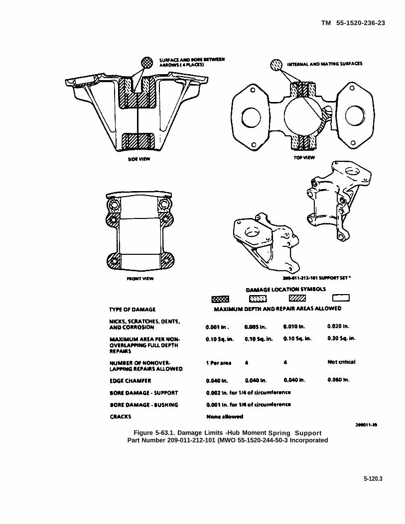
TM 55-1520-236-23
Figure 5-63.1. Damage Limits -Hub Moment Spring SupportPart Number 209-011-212-101 (MWO 55-1520-244-50-3 Incorporated
5-120.3
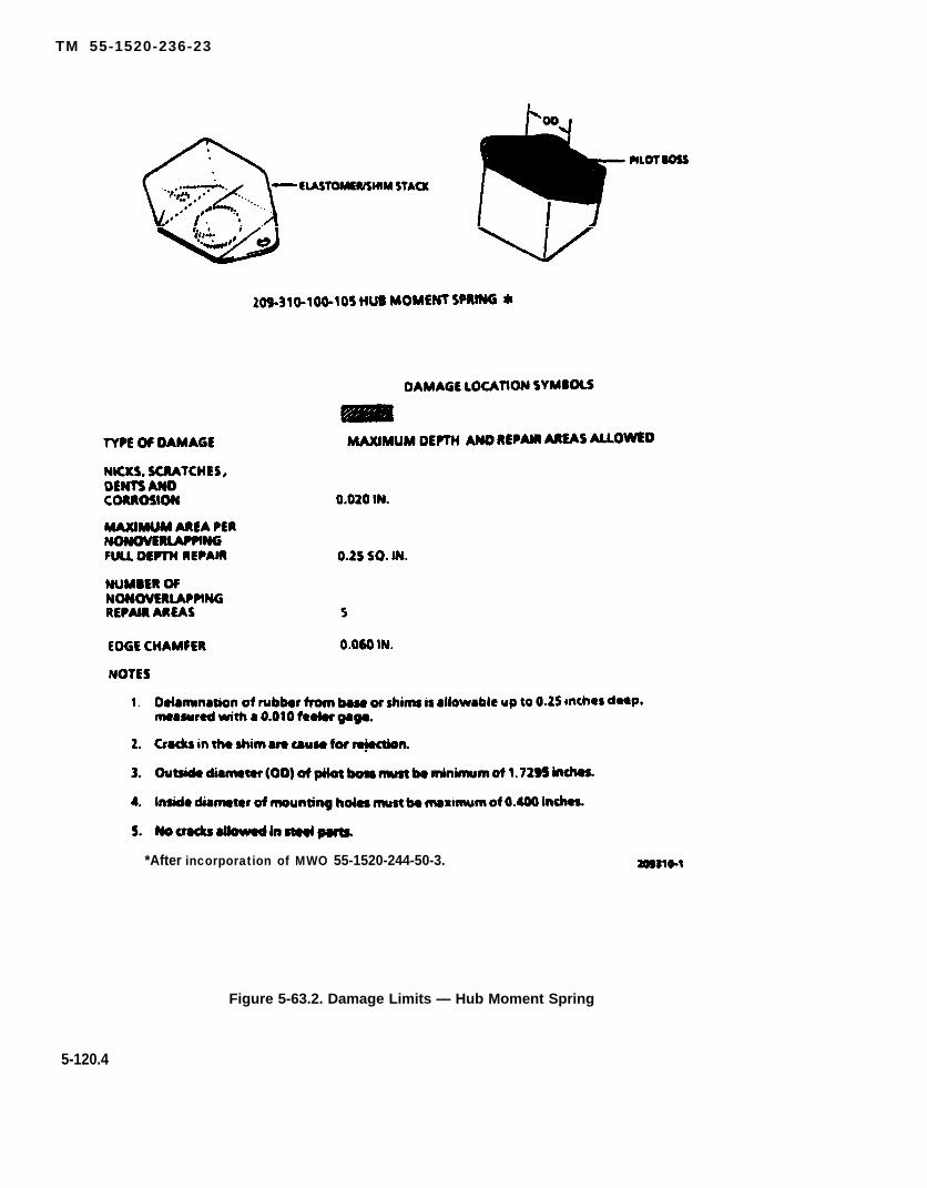
TM 55-1520-236-23
*After incorporation of MWO 55-1520-244-50-3.
Figure 5-63.2. Damage Limits — Hub Moment Spring
5-120.4
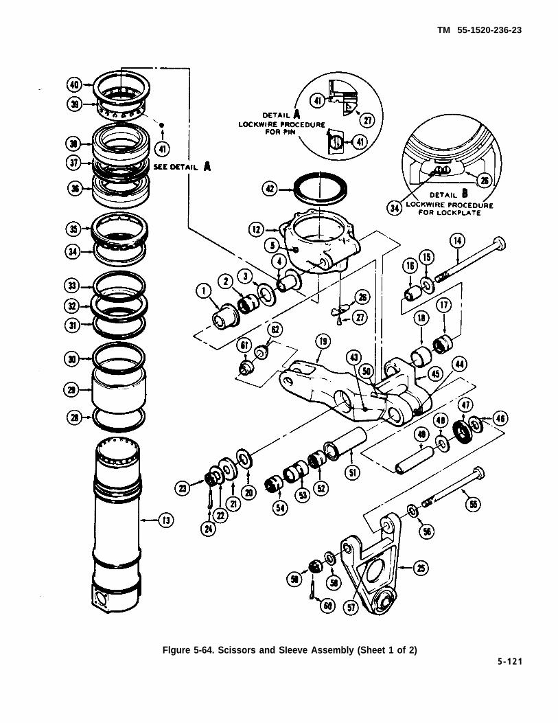
TM 55-1520-236-23
Flgure 5-64. Scissors and SIeeve Assembly (Sheet 1 of 2)5 - 1 2 1

TM 55-1520-236-23
Figure 5-64 Scissors and Sleeve Assembly (Sheet 2 of 2)
5-122
TM 55-1520-236-23
5 - 5 8 . R E M O V A L – S C I S S O R S A N DSLEEVE.
Remove scissors and sleeve with cautionto avoid damage to mast.
a. Remove main rotor (paragraph 5-12) and hubmoment spring assembly (paragraph 5-53.4).
b. Cut Iockwire and remove spacer (26, figure 5-51) and upper boot (27).
c. Remove bolts, nuts and washers and removeclamp assembly (30). (Keep three parts of clamptogether as a set.)
d. Remove rubber ring (33).
e. Remove nuts (39) and bolts (34). Removeretainer (35) and collet set (36). Identify collet set forreinstallation as a set.
f. Check wear on spline plate prior to removal(paragraph 5-49).
g. If scissors and sleeve assembly is to beinstalled without complete disassembly andinspection, check wear on thrust washers (7, figure 5-53) prior to removal. Maximum allowable play atthrust washers is 0.060 inch as shown onillustration.
h. Remove bolts (42, figure 5-51) and removeextension and spline plate. Identify spline plate assatisfactory or as worn beyond limits noted inpreceding step f.
i. Disconnect collective system control tube fromcollective lever assemblies (7 and 10). Remove bolts(1, 11, and 12). Separate collective lever halves (7 and10) from collective sleeve (19) and idler assembly (22).Keep spacer (9), thrust bearing washer (14), thrustwasher (18), bearing inner race (24) and similar partson the opposite side with the collective lever halves forassembly.
j. Remove screws (1 3), bearing assembly (20) andspacer plate (21). Remove similar parts from oppositeside.
k. Remove cotter pin (58), nut (57), and specialwasher (56). Remove drive link from swashplate.Remove special washer (55). Remove opposite drivelink in the same manner.
l. Cut Iockwire and detach lower boot (46) fromcolIective sleeve.
Do not allow scissors lever to contactscissors hub as damage to lever couldresult, Block scissors lever with wood orother suitable material to preventdamage.
m. Lift scissors and sleeve assembly (43) out ofswashplate and off mast. Use caution to preventdamage to friction sleeve and mast splines duringremoval.
n. If swashplate is not to be removed, cover openarea around top of lower boot (46) to prevent entry offoreign materials.
5-123

TM 55-1520-236-23
Figure 5-65. Damage Limits - Hub, Sleeve, Scissors and Link (Sheet 1 of 4)
5-124

TM 55-1520-236-23
Figure 5-65. Damage Limits - Hub, Slave, Scissors and Link (Sheet 2 of 4)
5-125

TM 55-1520-236-23
Figure 5-65. Damage Limits - Hub, Sleeve, Scissors and Link (Sheet 3 of 4)
5-126
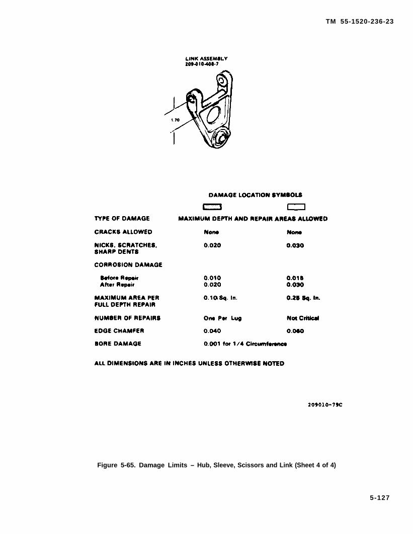
TM 55-1520-236-23
Figure 5-65. Damage Limits – Hub, Sleeve, Scissors and Link (Sheet 4 of 4)
5-127

TM 55-1520-236-23
5-59 . D ISASSEMBLY — SCISSORS ANDSLEEVE.
Remove bolt (55, figure 5-64) and remove link(25). Retain shim (46) for reassembly.
b. Remove housing (47), washer (48) and innerrace (49) from scissor.
c. Remove opposite scissor and link in the samemanner described in the preceding steps.
d. (AVIM) remove cotter pin (24), bolt (14), andwashers (15, 20, 21, and 22). Remove scissorsassembly (19) from hub.
e. Remove inner races (4 and 16) and spacer (3).
f. Install wrench (T29.3) on top of hub (12) withtwo bolts. Invert assembly and secure wrench in a vise.
Remove two screws (27) and lock plate (26).Disengage spiral retaining rings (31 and 33) and movespacer (boot support ring) (32) away from mountingshoulder for access to bottom of hub.
h. Use wrench (T15.2, T29.3, or T44.1) to turnnut (35) out of hub. Remove assembly from vise andremove took.
i. Place sleeve assembly on a press with halvesof support (T29.1) placed under hub. Insert small endof ram adapter (T29.2) in top of sleeve. Press sleeveassembly out of hub. Remove seal (42) from hub. Re-move spacer ring (40) from bearing stack of sleeve.
j. Remove Iockwire and pin (41). Install wrench(T15.2, T29.3, or T44.1) with pins engaged in holes ofnut (39). Insert bar (T34.1) in holes at lower end ofsleeve and hold against turning while removing left-hand threaded nut. Remove took
k. Place sleeve assembly on a press with sup-port halves (T29.1) placed under inner race of lowerbearing. Remove bearing sets (36 and 38) and spacerset (37) by pressing out sleeve assembly.
l. Remove loose nut, retaining rings (28 and 30)support ring from sleeve assembly. Use adapter(T29.2).
m. Remove retaining rings (31 and 33) and bear-ing sleeve (29) from collective sleeve (13).
5 - 6 0 . I N S P E C T I O N — S C I S S O R S A N DSLEEVE (AVIM).
a. Identify scissors and sleeve componentswhich will reach retirement time prior to next scheduledinspection for replacement. Refer to overhaul andretirement schedule.
b. If scissors and shave assembly is to beinstalled without complete inspection, make the follow-ing inspection to ensure that parts are suitable forinstallation on helicopter:
(1) Check end play between scissors andsleeve assembly (43, figure 5-51) and link (44) formaximum axial looseness of 0.080 inch.
(2) Upper and lower boots (27 and 46) fortears and deterioration.
(3) Rubber ring (33) for deterioration anddamage.
(4) Collet set (36) for missing fingers, cracks,scoring or other damage.
(5) Bearing assemblies (20) for bindng,roughness and maximum radial play of 0.010 inch.
(6) Spherical bearing in drive link (44) forroughness binding and maximum axial play of 0.015inch if excessive vibration does not oocur.
(7) Scissors levers for gouges and scratchesespecially on underside of pivot leg (figure 5-65).
(8) Swashplate horns for scoring.
(9) Spline plate wear in excess of 0.040 inchlimit measured in paragraph 5-58f.
(10) Inspect drive link bushing for cracks. Withdrive Iink disconnected at lower end, check for bindingor stiffness when swiveling drive link up and down. Ifbinding or stiffness is noticed, removal of the drive linkis required to check for cracked bushings. If crackedbushings are found, inspect mating surface of thescissors lever for mechanical damage caused by thecracked bushings.
5-128

TM 55-1520-236-23
C. Inspect hub, sleeve, scissors and link for corro-sion and mechanical damage in excess of limits andmechanical damage in excess of limits shown in figure5-65. Inspect clevis end of scissors outboard of bushing.If recessed between bushing end and clevis outer sur-face exceeds 0.004 inch a shim is required. Refer topara 5-61.f. (7) for installation instructions. Do notdisassemble hut (12, figure 5-64) from sleeve (13), anddo not remove bearings and bearing retainers (1) or (51)to make this inspection. Inspect drive link (25, figure 5-64), spherical bearing for roughness, binding, axialplay slippage mork, and alignment. A maximum of0.015 inch axial play is permissible if excessive vibra-tion does not occur.
NOTE
5-64
d. Inspect bolts (14 and 55) and washers (3,20,21and 22) for damage that would affect function. Max-imum lateral chucking of the scissors lever (19) will be0.020 inch. There will be no Iongitudinal chucking per-missible of bolt (14).
5 -64
5-64
5-64
e . Inspect bearing sets (36 and 38) as follows:
(1) Inspect for roughness and /or brinelling. Re-ject bearings with brinelling damage that is visibleunder 5 power magnification.
(2) Inspect for galled or flaked area on balls andraceways. Use a strong light when making this inspec-tion
f. Inspect inner races (4, 16 and 49) for damage. Ifother then a mooth, unscored surface is found, replacethe affected inner race and the bearing that matchesthat damaged area.
g. Inspect bearing (2, 17, 52 and 54) while bearingsare installed in scissors. If any bearing damage isdetected replace in accordance with paragraph 5-61.
h. Inspect spacer sets (32 and 37) for corrosion, scor-ing and other mechanical damage. No repair authoriz-ed.
i. Visually inspect sleeve (29) for indications ofwear at contact points with retaining rings (28 and 30).
j. Visually inspect cap washer (21), housing (47), re-taining rings (28, 30, 31, and 33), spacer (32), lock plate(26), pin (41), spacer ring (40) and spacer (37) for crocks,corrosion and deformation.
k. Inspect nut (39) and similar nut in lower side ofhub (12) with the nuts installed in the hub. Inspect formechanical damage and corrosion. Inspect pin (11) forsecure installation. Inspect locking plate device or nutin lower side of hub (12) far secure installation.
l. Inspect lubrication fittings (5, 43, 44, and 45) fordamage that would affect function.
m. Inspect identification plates (7, 9, 50, and 57) forsecure installation and legible markings.
n. Inspect the following parts by magnetic particlemethod code M, or fluorescent penetrant method, CodeF (TM 55-1500-335-23), Items are indexed to figure in-dicated.
o. Position unworn bolt (55) in link (25). If the boltdoes not fit freely through bushings, replace thelink. Check the opposite link in the same manner.
p. Use a straight edge to check the cylindrical por-tion of the collective sleeve for deformation. If war-page is in excess of 0.005 inch in a 5.0 inch length,replace the sleeve.
q. Use straight edge to check all machined flat sur-faces surrounding lugs, holes and bushings for defor-mation. If deviations excess 0.002 inch, replace thepart.
r. Inspect fingers for loose, missing and badly wornteflon. No missing fingers, badly worn teflon pads,crocks or scoring allowed.
6 -61 . REPAIR - SCISSORS AND SLEEVE(AVIM).
5-129
TM 55-1520-236-23
a. Polish out corrosion and mechanical damage onports inspected in paragraph 5-60. Use fine to mediumabrasive cloth (C36), crocus cloth (C37) or fine Indiastone (C116). Blend repair smoothly into surroundingarea. Replace port ,if repair exceeds allowable areaand/or depth limits.
b. Replace defective scissors bearings (52 and 54,figure 5.64) os follows:
f. Replace damaged or worn bushings (61 and 62),as follows:
(1) Support the clevis end of scissors so os toprevent o bending Ioad on tang, and press defec-tive bushing from scissor.
(2) Inspect bushing bores in scissors for scor-ing after bushings ore pressed out. Polish out scor-ing type damage to 0.002 inch maximum depth.Clean holes in clevis and clevis inboard feces withsolvent (C112).
(3) Coot bushing OD with wet, unreducedprimer (C91), Ensure that primer does not contactbuffer material on underside of bushing flange.Apply a heat Iamp to end of scissors and pressbushings into clevis holes with bushing flanges facinginboard. Check that bushings ore fully seated.
(4) line ream bushings to 0.6250 to 0.6255inch diameter.
(5) Mill inboard bushing feces to establish1.250 to 1.252 inch dimension between feces. Keepflange wall thickness equal within 0.005 inch.
(6) Chamfer the edge ID on inboard side ofbushings 0.005 to 0.010 inch x 45 degrees.
(7) When recess exceeds 0.004 maximum(figure 5-65.1) between end of bushing (6) and 62,figure 5-64) and outboard surface of the scissors(19), install a 120-006C7E21 shim and peel as re-quired to meet 0.002 to 0.004 maximum recess.Bond shim in place on end of bushing using ocyanoacrylate adhesive (C12.1).
g. Replace following ports if worn or damaged inexcess of limits:
(1) Upper and lower boots (27 and 46, figure5-51).
(2) Rubber ring (33).
(3) Collet set (36).
(4) Bearing assemblies (20).
5-130
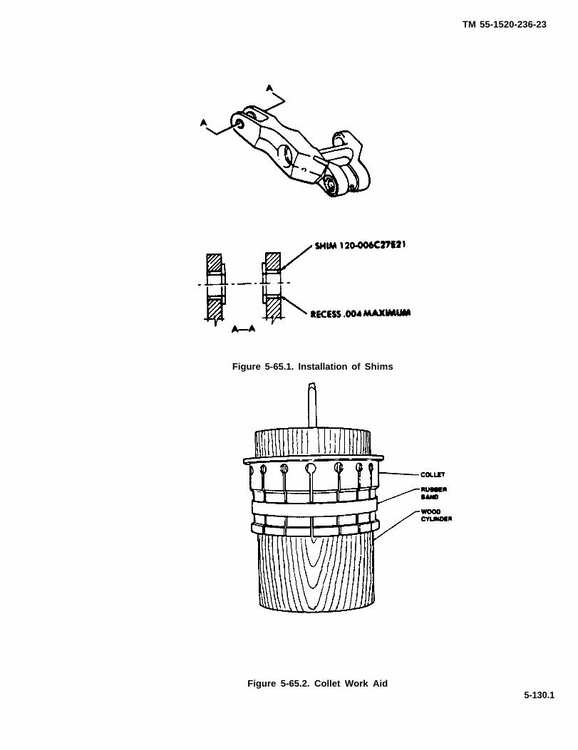
TM 55-1520-236-23
Figure 5-65.1. Installation of Shims
Figure 5-65.2. Collet Work Aid5-130.1

TM 55-1520-236-23
h. Replace damaged or missing Iubricatlon fittings(5, 43, 44 and 45, figure 5-64) by procedure outlined inparagraph 5-51, g.
i. Replace damaged or missing identification platesas follows:
(1) Identification plates (50 and 57, figure 5-64)are banded in place. Replace these ldentificationplates by some procedure outlined for collective leveridler link (paragraph 5-51).
(2) Identification plates (7 and 9) are securedwith screws (round heed, drive screws) (6 and 8).Replace these Identification plates by the some pro-cedures outlined in the preceding step except attachthe identification plates to the hub with screws Insteadof adhesive.
(C17.1) end accelerator 5 (C9.1) utilizing work aid (Figure5-65.2). Teflon pads from collet set may be used on othercollet sets.
k. Collets may be used in mixed sets providing minimumgap of 0.040 inch each side is maintained.
5-62. ASSEMBLY — DRIVE LINK.
a. Assemble inner rote (49) washer (48) and hous-ing (47) to scissor.
b. Attach Iink (25) to scissors (19) with inner race(49), washer (48) and housing (47) in position, but da notInstall shim (46) at this time. Install nut (59) on bolt (55)finger tight.
c. Measure gap between housing (47) and bushingface of drive link (25) with feeler gauge. Record thisfigure. Prepare a shim (46) by peeling off laminations toobtain a shim thickness 0.000 to 0.002 inch less thanmeasured gap. Remove bolt (55) and reinstall with in-ner rote (49) shim (46) washers (48, 56, and 58) andhousing (47) in position. Torque nut (59) 85 to 104 foot-pounds and install tatter pin (60). Repeat for oppositescissors and link.
NOTE
5 - 6 2 . 1 A S S E M B L Y — S C I S S O R S A N DSLEEVE (AVIM).
a. Position spacer (32) and retaining rings (31 and33) loosely on collective sleeve. Use adapter (T29.2) topress seal (34) into nut (35), with seal lip toward notchedside of nut. Place nut, notched side down, loosely onsleeve below shoulder. Take suitable precautions toavoid marring loose parts in handling.
(37)
NOTE
The mating surfaces of the bearings in thebearing set should be wiped free ofexcess grease before they are installed.
Assemble bearing sets (36 and 38) and spaceraccording to etched numbers and V-mark on outer
races of bearings. Use adapter (T29.2) to press bearingstack on upper end of sleeve, with V-mark pointing up.
c. Start left-hand threaded nut (39) on sleeve. Installwrench (T29.3) with pins engaged in holes of nut. Holdsleeve with bar (T34.1) through holes at lower end. Applymaximum torque, 200 foot-pounds, to nut (39). Allow thestack-up to set for 10 minutes, release the torque, andthen torque nut to 150 foot-pounds. Increase torque asneeded, maximum 200 foot-pounds, to align a hole in thenut with a hole in the collective sleeve. Do not loosen thenut. Reduce torque to align the holes. Install pin (41).Remove tools. Secure pin with Iockwire. Insert Iockwirethrough drilled head and twist in space between sleeveand nut.
d. Use adapter (T29.2) to press seal (42) with lipupward, into top of hub until bottom of seal IS flush withor slightly below lower edge of hub seal bore.
e. Place sleeve assembly on a press with supporthalves (T29.1) under bottom bearing of stack. Placespacer ring (40) on top of bearing stack. Press hubassembly down over bearings. Remove assembly frompress.
f. Install wrench (T29.3) on top of hub with two bolts.Secure wrench in vise. Start lower nut (35) into hub andtorque 400 TO 500 foot-pounds. Use wrench (T44.1).
g. Position Iockplate (26) on hub with tabs engagedin two notches of nut and secure to bottom of hub withtwo screws (8). Lockwire screws together as shown indetail B. If Iockplate does not align, use a new plate and
5-130.2

TM 55-1520-236-23
drill two 0.198 TO 0.204 inch diameter holes to matchtapped holes in hub. Remove tools.
h. Install ring (32) on collective sleeve with retainingrings (31 and 33) in mounting grooves of collective sleevebelow hub.
i. Lubricate bearing sets (36 and 38, figure 5-64) asfollows:
Use solvent in a well ventilated area. Avoidprolonged breathing of vapors and do not usein an area with open flame or high tempera-ture.
(1) Wash bearing sets (36 and 38) in solvent(C112) and air dry.
(2) Hand pack bearing sets (36 and 38) withgrease (C58).
(3) Protect bearing sets (36 and 38) from contam-ination until installation.
Position bearing sleeve (29) on collective sleeve(13), and install retaining rings (28 and 30) in grooves nearlower end of sleeve.
k. Install scissor (19) on hub with inner races (4 and18), spacer (3), washer (20), cap washer (21) and specialwashers (15 and 22) in position. One special washer (15)must be under bolt head and one special washer (22) mustbe under nut. The bolt head must face in direction of rota-tion. Torque nut (23) to 150 TO 175 foot-pounds and installcotter pin. Repeat for opposite scissors.
1. Lubricate all bearings in scissors and hub as spec-ified in Chapter 1.
5-63. INSTALLATION — SCISSOR ANDSLEEVE.
a. Install swashplate and lower boot if not previouslyaccomplished (paragraph 5-71).
b. Coat mating splines on mast and in scissors andsleeve assembly spline plate (38, figure 5-51) with grease(C58).
c. Carefully lower scissors and sleeve assemblyover mast. Insert lower end of collective sleeve downthrough lower boot (46) and top of swashplate support.
Use care to avoid damage to teflon-lined bearing insidesupport.
d. Turn collectives sleeve (19) so that the two bearingmounting bosses at lower end are aligned with openings inswashplate support as illustrated, Position spacer plate(21) and bearing assembly on boss with the "TOP” mark-ing up so that curved inner surfaced of bearing housing isaligned to mast surface. Install screws (13) and lockwire(C137) in pairs vertically. Install opposite bearing assemblyin same manner.
d.1. Install idler link assembly (2) to boss (68) withbolt (73), washer (72), special washer (71), nut (70) andcotter pin (69). Install nut finger tight.
e. Install collective lever halves (7 and 10) as fol-lows:
(1) Place a thrust bearing (washer) (14) over thebearing boss of each lever half.
(2) Mount lever halves on bearing assemblies(20) and install bolt (11), washer (6) and nut (5). Install nutfinger tight.
(3) Position lever halves on link (22), with innerrata (24) and thrust washers (18 and 25) in place. Installbolt (1), washers (2 and 17) and nut (16). Install nut fingertight.
(4) Position spacer (9) between levers and installbolt (1 2). Install washer (4) and nut (3). Install nut fingertight.
(5) Torque nut (5) 50 TO 70 inch-pounds
(6) Torque nut (3) 160 TO 190 inch-pounds
(7) Torque nuts (16 and 70) 1250 to 1550 inch-pounds and install cotter pins (15 and 69).
(8) Check for maximum of 0.060 inch clearancebetween thrust washers and bearing housings. A minimumzero clearance is acceptable as long as no binding is evi-dent. Clearance is to be measured collectively from bothlevers.
Special Washers (49 and 56, figure 5-51) arenot interchangeable and must be installed incorrect location to perform fail-safe function.
5-130.3

TM 55-1520-236-23
f. Place a special washer (55, figure 5-51) withchamfer facing outboard on swashplate outer ring asIllustrated. Position drive Iink (44) on swashplate. Installspecial washer (56) with collar inboard and the letters"AFT" facing outboard. Install nut (57) and torque 770 TO950 inch-pounds and install cotter pin. Bend cotter pinends closely around nut to avoid contact with swashplateduring operation. Install opposite drive link in the samemanner.
Measure vertical clearance from the bottom ofboth drive links, P/N 209-010-408-7, to all threehorns of stationary swashplate. The minimumclearance must not be less than .035 (thirtyfive thousandths) inch. Replace swashplate ifclearance is below minimum.
g. Slip lower boot (46) on grooved ring on collectivesleeve hub and on grooved ring on collective sleeve belowhub. Secure both ends of boot with Iockwire (C137).
h. Install extension (37) and associated parts shownon detail view A as follows:
(1) Coat mating splines on mast and spline plate(38) with grease (C58). Position spline and extension (37)on mast and install bolts (42) and washers (41). Torquebolts evenly 80 TO 100 inch-pounds and Iockwire (C137)in sets of three.
(2) Clean friction sleeve on mast, damp assembly(30), retainer (35), collet set (36) and extension (37) withMEK (C74).
(3) Seat collet set (36) in top of extension (37) andinstall retainer (35) with bolts (34), washers (40) and nuts(39). Torque nuts evenly 80 TO 100 inch-pounds.
(4) Position rubber ring (33) around collet set (36)and on top of retainer (35). Place clamp assembly (30)around rubber ring and install bolts (28), washers (29 and31) and nuts (32). Tighten nuts evenly so that gaps be-tween damp sections are equal within 0.0625 inch.
NOTE
Install bolt head (28) in the direction of rotation.
l. Adjust collet mast friction collet es follows:
(1) Disconnect collective control from oollectivelever halves (7 and 10). Disconnect pitch finks (15, figure 5-2)from main rotor.
5-130.4

TM 55-1520-236-23
Do not exceed 130 Inch-pounds torqueon nuts (32, figure 5-51) when perform-ing stop (2) below.
Car. should be ob\served when placingcollective Ievers (7 and 10, figure 5-51)In full down position to avoid damag-ing support assembly (23).
(2) Attach a force gage (fish scale) to collectivelever halves (7 and 10) at point where collective con-trols ore normally attached. Place collective levers infull down position and measure amount of force inpounds required to noise to collective levers. Adjust tor-que on nut (32) as required to obtain a load of 125 TO135 pounds on the force gage (fish scale) as required toraise the collective levers.
(3) Attach collective controls to collective leverhalves (7 and 10) with bolt, washers, nut and cotterpin. Attach pitch link (15, figure 5-2) to main rotor.
Do not exceed 130 inch-pounds torqueon nuts (32, figure 5-51) when perform-ing stop (4) below.
(4) Between five and ten hours of operationfollowing installation, check friction os outlined in steps(1), (2) and (3) above. If friction is not within limits, ad-just torque on nuts (32) os required. If correct frictioncannot be obtained within limits, check for grease onmast friction sleeve and clean with MEK (C74) if ap-plicable. Recheck friction and adjust as required.
k. Install main rotor hub and blade assembly(paragraph 5-14) and hub moment spring assembly(paragraph 5-53.7).
j. Perform maintenance test flight (TM 55-1520-236-MTF).
5-64. SWASHPLATE AND SUPPORT.
5 - 6 5 . D E S C R I P T I O N - S W A S H P L A T EAND SUPPORT.
The swashplate and support assembly is a componentof the main rotor controls (figure 5-66). The swashplatesupport is on open cylinder with a flange for mountingto the transmission at the lower end and spherical sur-face or uniball at the upper end far mounting theswashplate. Side openings are provided to ac-commodate the collective lever halves which move thecollective sleeve. The swashplate inner ring is clampedon the pivot ball of the support by upper and lower setsof contoured, teflon-lined bearings. This design allowsthe swashplate to tilt in any direction when actuated bythe cyclic control rods. The anti-drive link prevents theinner ring from rotating. The swashplate outer ring tiltswith the inner ring, but rotates with the scissors andmost. It is mounted to the inner ring through o duplexball thrust bearing, and is connected to the scissors withtwo drive links.
j. Install upper boot (27) with spacer (26). Secureupper boot with Iockwire (C137).
5-131
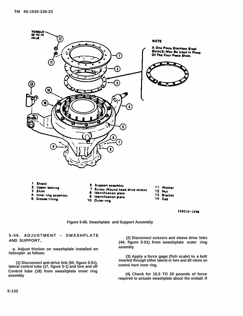
TM 55-1520-236-23
Figure 5-66. Swashplate and Support Assembly
5 - 6 6 . A D J U S T M E N T – S W A S H P L A T EAND SUPPORT,
a. Adjust friction on swashplale installed onhelicopter as follows:
(1) Disconnect anti-drive Iink (50, figure 5-51),lateral control tube (17, figure 5-1) and fore and aftControl lube (18) from swashplate inner ringassembly
(2) Disconnect scissors and sleeve drive links(44, figure 5-51) from swashplate outer ringassembly.
(3) Apply a force gage (fish scale) to a boltinserted through either lateral or fore and aft clevis oncontrol horn inner ring.
(4) Check for 15.5 TO 20 pounds of forcerequired to actuate swashplate about the uniball. If
5-132

TM 55-1520-236-23
friction is within limits, reconnect the items that waredisconnected in steps (1) and (2). If friction is notwithin limits, adjust and recheck thickness of shim (3,figure 5-66).
Ensure that wood wedges remain inposition to support inner ring during shimadjustment procedure or uniball damagemay result:
(a) Insert two wood wedges underswashplate inner ring to support the ring during shimadjustment procedure.
NOTE
A one piece stainless steel shim (3) maybe used in place of the four piece shim inthe steps below.
(b) Remove shield (1), upper bearing (2) andshims (3). Measure thickness of each section of shimwith a micrometer. All four shim sections must be thesame thickness.
(g) Remove wood wedges that ware placedunder inner ring in step (a).
(h) Lubricate thrust bearing through fittingson outer ring (10) with grease (C58).
(6) Install anti-drive link (50, figure 5-51 ) anddrive links (44).
b. Install hydraulic control cylinders for lateral andfore and aft controls (paragraphs 7-63, 7-203
5-67. L U B R I C A T I O N – S W A S H P L A T EAND SUPPORT.
Lubricate swashplate and support as shown onlubrication chart in Chapter 1.
5 -68 . REMOVAL – SWASHPLATE ANDSUPPORT.
Remove swashplate and supportcarefully to avoid damage to meet.
a . Remove main rotor hub and blade assembly(paragraph 5-12).
b. Remove scissors and sleeve assembly(paragraph 5-58).
c. Remove nut (48, figure 5-51), special washer(49) and disconnect anti-drive link (50) from rear hornof swashplate.
d. Disconnect cyclic control cylinder tube,elevator control tube and spring from right forwardhorn of swashplate.
5-133

TM 55-1520-236-23
f. Remove bolts (75) and washers (76). Lift swash- faces of spherical ball is acceptable within the follow-plate and support off mast. Use caution to avoid dam- ing:age to mast friction sleeve and mast splines.
(a) On spherical surface outside of teflon bear-g. Remove bolt (51) and remove anti-drive link ing working area - a maximum number of four (4),
(5). Remove bolt (64) and remove bellcrank (61). Re- 0.160 inch in any one direction, and 0.005 inch inmove support (65). depth. Scratch maximum length is 0.500 inch,
5 - 6 9 . I N S P E C T I O N — S W A S H P L A T EAND SUPPORT.
NOTE
If allowable inspection limits are ex-ceeded, forward swashplate and sup-port to depot maintenance.
a. Inspect swashplate inner ring horns for wearcaused by improperly installed cotter pins in drive linkto swashplate attachment bolts. Maximum permissiblewear is 0.060 inch.
b. Rotate outer ring and check for binding androughness of bearings. No binding or roughness is ac-ceptable.
NOTE
Rotation of the swashplate inner ring,measured at the swashplate aft hornpin, in excess of 0.110 inch indicatesworn anti-drive l ink bushings orbellcrank bushings.
c. Inspect swashplate and support assembly fornicks, dents, and corrosion. Refer to figure 5-67 forlimits,
d. Inspect swashplate and support for specificdamage as follows:
(1) Inspect flat surfaces at ends of collective leverpivot boss and for o distance of 0.75 inch on supportfrom flat surface faces of boss. Mechanical damageshell not exceed 0.010 inch in depth and corrosionshall not exceed 0.005 inch in depth in theseareas. Measure clearance between swashplate anti-drive link and bellcrank. Maximum allowableclearance is 0.015 inch. Also measure clearance bet-ween bellcrank and support. Maximum allowableclearance is 0.015 inch.
(b) On spherical surface within the teflon bear-ing working areas - a maximum number of four in dep-th. Scratch maximum length is 0.500 inch.
(c) Minute pinhead size nicks that are notclustered - maximum of nine (9).
(d) Combination of (a) and (b) above - a maxi-mum of four (4) if damage is on the maximum side, or amaximum of six (6) if damage is an the minimum side.
e. Check security of pin in aft horn of swashplate in-ner ring. No noticeable looseness is acceptable.
f. Check friction of swashplate to uniball. Refer toparagraph 5-66.
NOTE
If friction check is made with swash-plate and support installed on trans-mission, disconnect drive links, anti-drive link, control tube and spring frominner ring.
g. Inspect bushings in inner ring at control tube at-taching points for looseness, wear and mechanicaldamage. Maximum allowable wear on bushing innerfaces contacted by control tube bearings is 0.060 inch.
h. Inspect support, inner ring and outer ring fordamaged grease fitting and missing or damaged iden-tification plates.
i. Inspect bracket (13, figure 5-66). Replace if looseor missing. Clean mating surface of inner ring (4) withMEK (C74) and wipe dry with a clean cloth. Applyprimer (C87) to surface and allow to air dry. Removeprotective peel ply from film adhesive on bracket(13). Coat mating surface of bracket (13) with adhesive(C14). Install bracket (13) on inner ring (4) with radius ofbracket parallel to edge of inner ring and with holesaligned. Use caution to prevent adhesive squeese-outfrom obstructing bolt hole. Maintain firm contactpressure while adhesive cures.
(2) Inspect hard anodized surface of pivot ball j. Inspect for vertical and/or chuck movement bet-for any visible damage to surface, Minor damage ween support inner and outer rings. No vertical and/or(nicks, gouges, dents, scratches) to the hard coat sur- chuck movement is allowed in this area.
5-134

5-70 .PORT.
REPAIR - SWASHPLATE AND SUP-
NOTE
Replace swashplate and support Ifallowable inspectlon Iimits are exceed-ed. Send unserviceable swashplateand support to next higher mainten-ance level.
a. Polish minor damage to the hard anodized sur-face if required with crocus cloth (C37) to remove allsharp edges. Use caution when polishing outdamage. The hard anodized surface is 0.001 to 0.003inch thick. Refer to figure 5-67 to identify area that hashard anodized surface. If hard anodized surface isremoved during cleanup, return swashplate and sup-port assembly for overhaul.
b. Replace grease fitting. Refer to paragraph 5-51 g.
TM 55-1520-236-23
c. Replace identification plates secured with drivescrew as follows: (AVIM)
NOTE
If data to be stamped on identificationplate is not available, send affectedassembly to Depot Maintenance.
(1) Stamp all data from old identification plateon the new identification plate.
(2) Remove screws (7, figure 5-66) and removeold identification plate (8 or 9) from support assembly.
(3) Remove and replace retaining ring (15) andbearing bushing (16) if damaged.
5.134.1/(5-134.2 blank)


TM 55-1520-236-23
description of specific damage criteria and repair is provided in paragraphs 5-69 and 5-70.
Figure 5-67.
5-135

TM 55-1520-236-23
Figure 5-67.
5-136
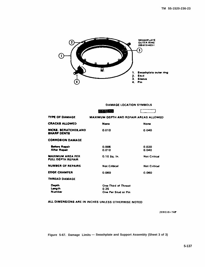
TM 55-1520-236-23
Figure 5-67. Damage Limits — Swashplate and Support Assembly (Sheet 3 of 3)
5-137

TM 55-1520-236-23
NOTE
Cleaning solvent is flammable and toxic. Pro-vide adequate ventilation. Avoid prolongedbreathing of vapors and contact with skin oreyes.
(3) Clean area for identification plate on supportassembly with dean cloth saturated with solvent (C112).
Do not overtorque screws.
(4) Position new identification plate on support (6).Place drive screw (7) through identification plate and inhole in support. Drive screw in until identification plate istight against support.
5-71. INSTALLATION — SWASHPLATE ANDSUPPORT.
NOTE
If swashplate and support assembly is new,lubricate in accordance with Figure 1-5, item 7,prior to installation.
a. Install swashplate and support as follows:
(1) Install support assembly (65, figure 5-51) ontransmission.
(2) Install bellcrank (61) on support (65) with bolt(64) and nut (66). Torque nut 190 TO 210 inch-pounds andinstall cotter pin.
(3) Install anti-drive link (50) on bellcrank (61) withbolt (51), washer (52), and nut (53). Torque nut 190 TO 210inch-pounds and install cotter pin.
NOTE
In order to obtain a proper cotter key holealignment, install one AN960PD1016 washerunder nut (53).
(4) Lower swashplate and support assembly overmast onto top of transmission. Avoid damage to mastsplines.
(5) Align holes in swashplate support with holes intransmission cap. Install bolts (75) with washers (76) andtorque 200 TO 250 inch-pounds. Lockwire (C137) boltheads in pairs.
(6) Turn swashplate inner ring to align stud withanti-drive link (50). Position link on stud and install specialwasher (49) with marked surface facing aft. Install nut (48)and torque 480 TO 690 inch-pounds. install cotter pin.
b. Connect lateral control tube (17, figure 5-1) to Iefthorn of swashplate inner ring (22).
c. Connect fore-and-aft hydraulic cylinder controltube (4, figure 11-12), elevator control tube (3), and ,spring(2) to right horn of swashplate (1).
d. Position lower boot (46, figure 5-51) loosely onswashplate.
Install scissors and sleeve assembly (paragraph5-63).
SECTION IV. TAIL ROTOR SYSTEM
5-72. TAIL ROTOR SYSTEM. beamed type yoke connected to the blades by means ofself-lubricated spherical pitch change bearings, and a two-
5-73. DESCRIPTION — TAIL ROTOR SYSTEM. piece, trunnion, connected to the yoke by self-lubricatedspherical flapping bearings. The trunnion, splined to the tail
A two blade, controllable pitch tail rotor hub and blade is lo- rotor shaft, drives the tail rotor hub and rotor blade andcated on the right side of the tail rotor gearbox. H is com- serves as a flapping stop for the tail rotor.posed of two assemblies, the hub assembly, blades, andcontrols. The hub assembly employs a preconed, flex-
5-138
TM 55-1520-236-23
5-74. CLEANING-TAIL ROTOR SYSTEM
a. Clean tail rotor blades (23, figure 5-68) withcleaning compound (C33).
WARNING
Cleaning solvent is flammable andtoxic. Provide adequate ventilation.Avoid prolonged breathing of vaporsand contact with skin or eyes.
b. Remove stubborn deposits with a clean clothdampened with solvent (C112).
5-138.1/(5-138.2 blank)


TM 55-1520-236-23
Figure 5-68. Tall Rotor Installation
5-139

TM 55-1520-236-23
c. Clean hub assembly (23) with solvent (C112)and dry with filtered, compressed air.
5 - 7 5 . L U B R I C A T I O N – T A I L R O T O RSYSTEM .
Lubricate tail rotor system as shown on lubricationchart in Chapter 1.
5 - 7 6 . A D J U S T M E N T – T A I L R O T O RSYSTEM.
Refer to paragraph 5-115 for adjustment.
5 - 7 7 . I N S P E C T I O N – T A I L R O T O RSYSTEM.
a. Inspect tail rotor assembly and control linkagefor security, completeness and lubrication.
b. Inspect tail rotor blades in accordance withparagraph 5-110.
c. Inspect tail rotor hub assembly in accordancewith paragraph 5-93.
5 - 7 8 . T R O U B L E S H O O T I N G – T A I LROTOR SYSTEM.
Troubleshoot problems in the tail rotor system usingtable 5-3.
NOTE
Before using Table 5-3, ensure that allnormal operational checks have beenperformed. If there is a malfunctionwhich is not listed in this table, notify thenext higher level of maintenance.
Table 5-3. Troubleshooting — Tail Rotor System
CONDITION
TEST OR INSPECTION
CORRECTIVE ACTION
1. High Frequency Vibration.
STEP 1. Check tail rotor track (paragraph 5-115).
Adjust pitch link to bring tail rotor in track (paragraph 5-115).
STEP 2. Tail rotor out of balance,
STEP
Remove tail rotor and balance (paragraph 5-86).
3. Check for worn or loose trunnion bearings (paragraph 5-93).
Replace trunnion bearings (paragraph 5-94).
STEP 4. Check for loose or worn blade retention bearings (paragraph 5-93).
Replace blade retention bearings (paragmph 5-94).
STEP 5. Check for loose tail rotor hub retaining nut (paragraph 5-87).
Inspect and retorque nut (paragraph 5-87).
5-140

TM 55-1520-236-23
Table 5-3. Troubleshooting – Tail Rotor System (Cont)
CONDITION
TEST OR lNSPECTION
CORRECTIVE ACTION
STEP 6. Check for bent pitch change links (paragraph 5-102).
Replace pitch change link (paragraph 5-104).
STEP 7. Check for worn or loose pitch change link bearings (paragraph 5-102).
Replace pitch change link (paragraph 5-104).
STEP 8. Check for worn or loose pitch change crosshead bearing (paragraph 5-102).
Replace pitch change bearing (paragraph 5-104).
STEP 9. Check for loose or improperly torqued biped and tripod engine mounts (paragraphs 2-192 and2-198).
Retorque bipod and tripod engine mount bolts (paragraphs 2-194 and 2-200).
STEP 10. Check for loose mounting bolts on intermediate and tail rotor gearboxes (paragraphs 6-99 and6-115).
STEP
Retorque mounting bolts (paragraphs 6-105 and 6-121).
11. Check for elongated mounting bolt holes for intermediate and tail rotor gearboxes.
Refer to paragmph 6-121 for limits for tail rotor mounting bolt holes in support fitting. Refer toParagraph 6-105 for limits for intermediate gearbox mounting bolt holes.
STEP 12. Check hanger bearings and couplings for loss of lubrication, seal failure, and coupling clamps forloose retention bolts.
Refer to table 6-1 drive train.
2. Inability to make normal right or left turn in flight.
STEP 1. Check tail rotor rigging.
Refer to paragraph 11-73 for rigging check. Refer to paragraph 5-115 for tracking instructions.
SECTION V.
5 - 7 9 . T A I L R O T O R H U BA S S E M B L Y .
TAIL ROTOR HUB AND BLADE ASSEMBLY
A N D B L A D E
5-80. DESCRIPTION – TAIL ROTOR HUBAND BLADE ASSEMBLY.
5-141

TM 55-1520-236-23
5-81 . REMOVAL – TAIL ROTOR HUB ANDBLADE ASSEMBLY.
b. Remove bolts and separate bothcounterweight links (12, figure 5-68) fromcounterweight support (17).
c. Remove Iockwire, screws (1), washer (2), lock(3), and retainer (4) from crosshead (10).
d. Push right pedal forward against stop andremove cotter pin (6), nut (5) and washer (7) from endof pitch change control tube (25).
h. Remove crosshead assembly ( 10, figure 5-68)from gearbox output shaft (26).
i. Cut Iockwire and remove shield (13) andretaining nut (14) as an assembly. Removecounterweight support (17).
j. Move hub and blade assembly (23) outboard onsplines and remove split cone set (27) as it is released.Secure and retain cone set (27) as a matched set.Remove hub and blade assembly from gearbox andplace on a rack to prevent damage to blades.
NOTE
Sleeve (24) normally remains on controltube (25) unless the sleeve or controltube is to be replaced.
k. If sleeve (24) is to be replaced, pull sleeveoutboard to engage threads and turn untildisengaged.
5-82. DISASSEMBLY – TAIL ROTOR HUBAND BLADE ASSEMBLY.
a. Remove tail rotor hub and blade assembly fromhelicopter (paragraph 5-81). Place the tail rotorassembly on a padded bench or similar work area toprevent damage.
5-142

TM 55-1520-236-23
b. Prior to disassembly, check condition ofretention bearings in the yoke. Move the bladesthrough full throw on the pitch change axis end checkthe bearings by feel. If the blades do not mow freelyon the bearings, identify the faulty bearings forreplacement.
NOTE
c. Remove nuts (5 and 10, figure 5-69) and allbalance washers. Remove bolts (20 and 25) andspecial washers (19 and 26).
d. Remove opposite blade in the same manner.
5 -83 . INSPECTION – TAIL ROTOR HUBAND BLADE ASSEMBLY.
a. Inspect tail rotor hub assembly (paragraph5-93).
b. Inspect tail rotor blade assembly (paragraph5-110).
c. Inspect pitch change horn (paragraph 5-110).
d. Inspect bolts and nuts for thread damage andgeneral condition.
5-84. R E P A I R – TAIL ROTOR HUB ANDBLADE ASSEMBLY.
a. Repair tail rotor hub assembly (paragraph5-94).
b. Repair tail rotor blade assembly (paragraph5-111).
c. Repair pitch horn assembly (paragraph 5-111).
a . Position hub assembly (1, figure 5-69) onbench with date plate side up. Install blade (14) onhub yoke with the data plate side up. Install bolts (20and 25) with special washers (19 and 26) under boltheads. Install special washers (2 and 13) next toblade. If balance washers (3, 4, 11, and 12) wereindexed at time of disassembly, reinstall them m thesame position. If they were not indexed, do not installthem until the assembly is balanced. Install nuts (5and 10) but do not torque until after the assembly hasbeen balanced.
b. Install opposite blade in the same manner. Thefour blade retention bolts (20 and 25) maybe installedfrom either side, but all four bolts must be installedfrom the same side.
c. Position pitch horn (15) on blade and installbolts (22 and 23) with steel washers (21 and 24)under heads, Install the bolts with heads in samedirections as bolts (20 and 25). I nstall steel washers(6 and 9) end nuts (7 and 8). Torque nuts 60 inch-pounds. If balance washer (18) was indexed atdisassembly, install it at this time with steel washer(17) and bolt (16). If the balance washers were notindexed, install bolt (16) and steel washer (17). Do nottorque until after the assembly has been balanced.
d. Install the opposite pitch horn in the samemanner.
e. Balance tail rotor hub and blade assembly inaccordance with paragraph 5-86.
5-86. BALANCING – TAIL ROTOR HUBAND BLADE ASSEMBLY.
Premaintenance Requirements For Tail RotorHub and Blade Assembly
d. Replace worn or damaged bolts and nuts.
5-85. A S S E M B L Y – T A I L R O T O R H U BAND BLADE ASSEMBLY. Test Equipment None
5-143

TM 55-1520-236-23
Flgure 5-69. Tall Rotor Hub and Blade Assembly
5-144

TM 55-1520-236-23
figure 5-70.
NOTE
The area used for balancing must be aroom which can be closed off to provide adraft-free environment.
a. Assemble parts of rotor balanclng kit (T73) thatare shown on the right side of figure 5-49, except donot install balancing arbor (23) Use arbor (6, figure 5-70) to balance tall rotor.
b. Install fixture (2, figure 5-70) on lower end ofarbor (6) and tighten the tWO lower set screws (10)There are a total of four set screws in fixture (2) Donot tighten the two upper set screws ,101.
NOTE
h. Move the tall rotor assembly and balancingtools to the stand that was assembled in step aAttach arbor (6) to the stand with cable P/N 2264,(13, figure 5-49) and quick disconnect coupling P/N2266 (10) Operate hydraulic pump (15) to take upslack in cable
i. Loosen two lower set screws (10, figure 5-70)(The two upper set screws should already be loose asdirected in step b ) This wiII allow fixture (2) to slidedown and contact workstand (1). Open the hydraulicpump valve to lower the arbor and rotor assemblyuntil these parts are resting on fixture (2). Ensure thatall the following conditions are met, and then tightentwo lower set screws (10).
(1) Fixture (2) must be seated firmly onworkstand (1).
(2) Pilot bushing (4) must be seated firmly onfixture (2)
(3) The rotor yoke (3) must be seated firmly onpilot bushing (4)
(4) The pitch horns (16), floating bushings (9)and indexing pins (8) must be fully engaged,
(5) The positioning yoke (5) must be orientedwith the rotor yoke as shown in the “top view”. Thelegs of positioning yoke (5) must contact a flat surfaceof the rotor yoke
j. Operate hydraulic pump (15, figure 5-49) toraise the assembly approximately 0.25 inch abovestand table. Close doors and windows, stop fans, etc.,to make the area draft free Allow the rotor to stabilizeand observe the balance indication on the black disc(detail A, figure 5-70) Record the indication andcorrect imbalance as outlined in steps k. and 1.
5-145

TM 55-1520-236-23
Figure 5-70. Tool Application . Tall Rotor Hub and Plate Assembly Balancing
5-146

TM 55-1520-236-23
k. Correct chordwise balance by adding balancewashers (18, figure 5-69) and steel washers (17)within the following limitations:
(1) Use any combination of balance washers(18) P/N AN970-4 and steel washers (17) P/NAN960-416 with a maximum of ten washers used onone bolt.
5.146.1/(5-146.2 blank)


TM 55-1520-236-23
(2) Use a bolt (16) of proper Iength to accom-modate washers. Minimum length bolt is P/N AN4H-4A. Maximum length bolt is P/N AN4H-10A.
(3) At least one washer (17) or (18) must beused if bolt (16) is installed.
(4) After chordwise balance is attained,lower the assembly until it rests on stand. Torquebolts (16) 50 TO 70 inch-pounds, Do not lockwire atthis time.
l. Correct spanwise balance by adjusting balancewashers (3, 4, 11 and 12). Operate hydraulic pumpon stand to raise the rotor assembly approximately0.25 inch above stand table and add washers withinthe following limitations:
(1) When adding washers to rotor assemblyspanwise, add balance washers to outboard bolts (20)first. Leave special washers (2, 26, 19, and 13) P/N140-007-33-32C4 next to blade. Assemble thewashers listed in step (2) below with the heaviestwashers next to washers (2 and 13).
(2) Use combinations of balance washers (3and 12) P/N AN970-8, balance washers (4 and 11)P/N AN960-816 and thin steel washers P/N AN960-816L (not illustrated) as required to balance theassembly.
(3) Use bolts (20) and (25) of the properlength to accommodate washers. Minimum lengthbolt is P/N NAS1308-34. Maximum length bolt is P/NNAS1308-36.
CAUTIONAfter nuts are torqued no more thanfive threads of bolts are permitted tobe exposed beyond nuts, and a mini-mum of one thread plus the chamferof the bolt must be exposed to ensurethe self-locking feature of the nuts isengaged.
(4) After spanwise balance is attained,recheck chordwise balance and then lower the rotorassembly until it rests on the stand. Torque nuts (5and 10) and corresponding nuts on opposite blade to500 inch-pounds.
(5) Lockwire two bolts (16) to hole in pitchhorn with Iockwire (C137).
m. Remove tail rotor assembly from balancingtools as follows:
(1) Disconnect arbor (6, figure 5-70) fromstand.
(2) Remove the tail rotor assembly andarbor from the stand and place on a work bench.
(3) Loosen two set screws (7) and removepositioning yoke (5) from arbor (6).
(4) Rotate rail rotor assembly to disengageindexing pins (8) from pitch horns and remove tailrotor assembly from arbor (6). Secure floating bush-ings (9) to pitch horns.
(5) Disassemble pilot bushing (4), arbor (6),post assemblies (15) and fixture (2).
5-87. INSTALLATION-TAIL ROTOR HUB ANDBLADE ASSEMBLY.
a. Position hub and blade assembly (23, figure 5-68) on gearbox output shaft (26) with data plate sideof hub outboard and trunnion flap stops inboard. Alignmaster tooth of trunnion with master spline of gearboxoutput shaft and install hub and blade assembly onshaft until trunnion is just started on second set ofsplines.
NOTEInstall split cones as matched set only.
Prior to installation, inspect splitcones for any nicks, scratches, inden-tations, or any type deformities in thecones. If damaged replace.
b. Place cone set (27), with bevel outboard, ingroove between splines and shoulder on gearbox out-put shaft. Ensure that cone set end gaps are equal andslide hub and blade assembly inboard to seat trunnionto cone set.
NOTESpacing between split cone sets mayvary after operation. This variation ofspacing does not adversely affect theassembly.
c. Install counterweight support (17) on gearboxoutput shaft and seat against hub. Install retainingnut (14) and shield (13) as an assembly. Hold rotor athub, rotate retaining nut (14) as far clockwise aspossible and hold in position. Torque retaining nut (14)to 900 inch-pounds with spanner wrench. Make finalcheck to ensure that split cones set (27) is properlyseated. Lockwire retaining nut (14) to counterweightsupport with lockwire (C137).
d. Install control tube (25) and sleeve (24) if notpreviously accomplished (paragraph 5-105).
e. Assemble crosshead and controls if not pre-viously accomplished (paragraph 5-104).
5-147
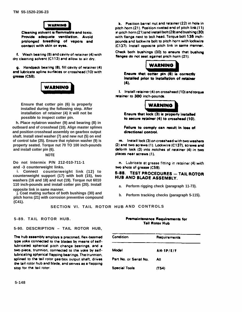
TM 55-1520-236-23
Ensure that cotter pin (6) is properlyinstalled during the following step. Afterinstallation of retainer (4) it will not bepossible to inspect cotter pin.
h. Place nylatron washer (9) and bearing (8) inoutboard and of crosshead (10). Align master splinesand position crosshead assembly on gearbox outputshaft. Install steel washer (7) and new nut (5) on endof control tube (25). Ensure that nylatron washer (9) isproperty seated. Torque nut 70 TO 100 inch-poundsand install cotter pin (6).
NOTE
Do not Intermix P/N 212-010-711-1and -3 counterweight links.
i. Connect counterweight link (12) tocounterweight support (17) with bolt (15), twowashers (16 and 18) and nut (19). Torque nut 6010110 inch-pounds and install cotter pin (20). Installopposite link in same manner.
j. Coat mating surface of both bushings (30) andpitch horns (21) with corrosion preventive compound(C41).
a.
b.
SECTION VI . TAIL ROTOR HUB
5-89 . TAIL ROTOR HUB.
5-90. DESCRIPTION – TAIL ROTOR HUB,
Perform rigging check (paragraph 11-73).
Perform tracking checks (paragraph 5-115).
A N D C O N T R O L S
5-148

5-91. REMOVAL – TAIL ROTOR HUB.
Remove tail rotor hub assembly (paragraph 5-81).
5-92. DISASSEMBLY – TAIL ROTOR HUB.
a. Remove nut (9, figure 5-71), washer (8), bolt (1)and washer (2). Remove similar parts on the oppositeaide of the trunnion.
5-93. INSPECTION – TAIL ROTOR HUB.
a. Special inspection of tail rotor hub.
(1) Inspect the tail rotor historical records, and the tailrotor hub for evidence that the tail rotor has been subjectedto an accident or incident outside the realm of normalusage. If such evidence exists, perform applicable specialinspections for overspeed, sudden stoppage, engine com-pressor stall and overtorque outlined in Chapter 1 and
steps (2) through (6).
(2) Inspect yoke (5, figure 5-71) and trunnion halvesfor obvious damage such as deformation. Replace hub ifany part is deformed.
(3)of limits
(4)
TM 55-1520-236-23
Inspect parts for surface damage in excessshown in figure 5-72 and 5-73.
Inspect trunnion retention bolts (1, figure 5-71) and blade retention bolts for shear offset. Replacehub if l ny bolts show shear offset.
(5) Inspect bearings (4 and 6) for looseness inyoke, step b. (2).
(6) inspect yoke (5) and trunnion halves (3 and7) by fluorescent penetrant method, Refer to TM 55-1500-335-23,
NOTE
When finish Is removed from yoke, re-paint using primer (C88 or C91) andoverspray with lacquer (C66).
Bearing removal is not necessary foryoke penetrant inspection. Bearingsshould be covered to prevent entry ofpenetrant.
Normal inspection of tail rotor hub.b.
(1) Move bearings (4 and 6) through full throwand check for corrosion. If any corrosion is detected,remove with Scotchbrite (C103) and clean cloths.
(2) Chock borings (4 and 6) for indication ofteflon deterioration, bond seporation, and teflonprotruding from bearing. Replace bearings if theabove conditions exist. Chock bearings (4 and 6)for axial looseness. Maximum allowable axialIooseness is 0.015 inch. Replace borings if axiallimits ore exceeded.
damage. If damage exceeds limits shown in figure 5-72, send to next higher maintenance level.
(5) Inspect trunnion set for mechanical andcorrosion damage, and wear damage on the splines. Ifdamage and/or or exceeds the limits shown infigure 5-73 on either trunnion half, dispose of bothhalves of set locally
5-149

TM 55-1520-236-23
Figure 5-71. Tall Rotor Hub Assembly
5-150

TM 55-1520-236-23
Figure 5-72. Damage Limits — Tail Rotor Hub Yoke
5-151
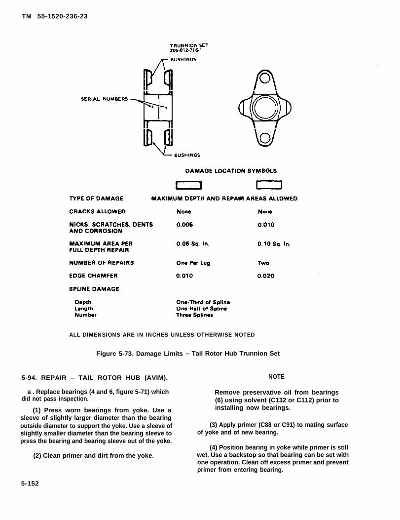
TM 55-1520-236-23
ALL DIMENSIONS ARE IN INCHES UNLESS OTHERWISE NOTED
Figure 5-73. Damage Limits – Tail Rotor Hub Trunnion Set
5-94. REPAIR – TAIL ROTOR HUB (AVIM).
a . Replace bearings (4 and 6, figure 5-71) whichdid not pass inspection.
(1) Press worn bearings from yoke. Use asleeve of slightly larger diameter than the bearingoutside diameter to support the yoke. Use a sleeve ofslightly smaller diameter than the bearing sleeve topress the bearing and bearing sleeve out of the yoke.
(2) Clean primer and dirt from the yoke.
NOTE
Remove preservative oil from bearings(6) using solvent (C132 or C112) prior toinstalling now bearings.
(3) Apply primer (C88 or C91) to mating surfaceof yoke and of new bearing.
(4) Position bearing in yoke while primer is stillwet. Use a backstop so that bearing can be set withone operation. Clean off excess primer and preventprimer from entering bearing.
5-152
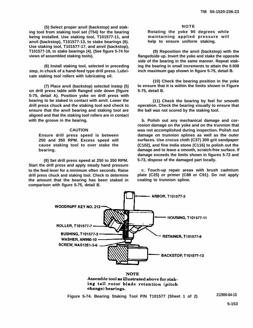
TM 55-1520-236-23
(5) Select proper anvil (backstop) and stak-ing tool from staking tool set (T54) for the bearingbeing installed. Use staking tool, T101577-11, andanvil (backstop), T101577-13, to stake bearings (6).Use staking tool, T101577-17, and anvil (backstop),T101577-19, to stake bearings (4). (See figure 5-74 forviews of assembled staking tools).
(6) Install staking tool, selected in precedingstep, in chuck of a hand-feed type drill press. Lubri-cate staking tool rollers with lubricating oil.
(7) Place anvil (backstop) selected instep (5)on drill press table with flanged side down (figure5-75, detail A). Position yoke on drill press withbearing to be staked in contact with anvil. Lower thedrill press chuck and the staking tool and check toensure that the anvil bearing and staking tool arealigned and that the staking tool rollers are in contactwith the groove in the bearing.
CAUTIONEnsure drill press speed is between250 and 350 RPM. Excess speed willcause staking tool to over stake thebearing.
(8) Set drill press speed at 250 to 350 RPM.Start the drill press and apply steady hand pressureto the feed lever for a minimum often seconds. Raisedrill press chuck and staking tool. Check to determinethe amount that the bearing has been staked incomparison with figure 5-75, detail B.
NOTERotating the yoke 90 degrees whilemaintaining applied pressure wil lhelp to ensure uniform staking.
(9) Reposition the anvil (backstop) with theflangedside up. Invert the yoke and stake the oppositeside of the bearing in the same manner. Repeat stak-ing the bearing in small increments to attain the 0.008inch maximum gap shown in figure 5-75, detail B.
(10) Check the bearing position in the yoketo ensure that it is within the limits shown in Figure5-75, detail B.
(11) Check the bearing by feel for smoothoperation. Check the bearing visually to ensure thatthe ball was not scored by the staking tool.
b. Polish out any mechanical damage and cor-rosion damage on the yoke and on the trunnion thatwas not accomplished during inspection. Polish outdamage on trunnion splines as well as the outersurfaces. Use crocus cloth (C37) 300 grit sandpaper(C102), and fine India stone (C116) to polish out thedamage and to leave a smooth, scratch-free surface. Ifdamage exceeds the limits shown in figures 5-72 and5-73, dispose of the damaged part locally.
c. Touch-up repair areas with brush cadmiumplate (C25) or primer (C88 or C91). Do not applycoating to trunnion spline.
Figure 5-74. Bearing Staking Tool P/N T101577 (Sheet 1 of 2) 212900-84-1D
5-153

TM 55-1520-236-23
Figure 5-74. Bearing Staking Tool P/N T101577 (Sheet 2 of 2)
5-95. Assembly — Tail Rotor Hub.
a. Inspect trunnion halves (3 and 7, figure 5-71) toensure that they are a matched set.
b. Position trunnion half (3), on the data plate sideof yoke (5). Position trunnion half (7), with the flappingatop ear, on the opposite side of yoke with the masterspline of trunnion halves aligned.
c. Install two bolts (1) with washers (2) under bollheads and washers (8) under nuts (9). Torque nutsevenly to 500 inch-pounds.
5-96. INSTALLATION – TAIL ROTOR HUB.
Install tail rotor hub (paragraph 5-87).
5 -97 . TAIL ROTOR CONTROLS.
5 - 9 8 . D E S C R I P T I O N – T A I L R O T O RCONTROLS.
The tail rotor controls consist of a lever assembly,idler, control tube, crosshead, pitch links,counterweight links, weights, retainer, support and
5-154
cone set. Pedal movement is transmitted throughlinkage to lever assembly (48, figure 5-76). The idler(47) attaches lever (48) to the tail rotor gearbox. Theidler also serves as the pivot for lever (48). Movementfrom lever (48) is transmitted through control tuba(34) to the crosshead (1 3). Pitch change links (31),attached to the crosshead and pitch horn, changeblade pitch. Two counterweight assemblies,consisting of a bellcrank (27) with weights (17)attached to each end is mounted on spindlesextending from crosshead perpendicular to pitch linkclevises. A fixed link (26) connects mid-point of eachbellcrank to a common support (33) mounted next tohub.
5 - 9 9 . R E M O V A L – T A I L R O T O RCONTROLS.
a. Remove crosshead, bellcrank weights andlinks as on assembly (paragraph 5-81).
b. Remove counterweight support (paragraph 5-81).
c. Slide sleeve (35, figure 5-76) outboard oncontrol tube (34) slightly and rotate counterclockwiseto engage threads. Continue to ro ta te

TM 55-1520-236-23
Figure 5-75. Tool Application-Bearing Installation (Staking) in Tail Rotor Yoke
5-155

T M 5 5 - 1 5 2 0 - 2 3 6 - 2 3
Figure 5-76. Tail Rotor Controls — Crosshead, Weights, Links and Control Tube (Sheet 1 of 3)
5-156

TM 55-1520-236-23
Figure 5-76. Tail Rotor Control – Crosshead, Weights Links and Control Tube (Sheet 2 of 3)
5-157

TM 55-1520-236-23
Figure 5-76 Tail Rotor Control – Crosshead Weight Links and Control Tube (Sheet 3 of 3)
counterclockwise until threads are disengaged and re- 5-100. DISASSEMBLY — TAIL ROTOR CON-move sleeve. TROLS.
Remove attaching bolts and remove lever(48) idler (47) and link (51). a. Remove tail rotor retaining nut (36, future
5-76) and sheild (37) from crosshead (13) if not pre-e. Remove control tube (34) from left side of viously accomplished.
gearbox.
f. Remove nuts and washer (39). Remove Remove cotter pin (10). Remove nut (11), bolthousing (40). Remove retaining ring (42), housing (15) and pitch link (31). Remove opposite pitch link in(41), excluder (43) and bearing (52). the same manner.
5-158

TM 55-1520-236-23
c. Remove nut (19), bolt (16), washer (18) andweights (17), Remove remaining weights in the samemanner.
d. Remove cotter pin (21). Remove nut (20), washer(22), bolt (30), washer (29) and counterweight Iink (26).Remove opposite counterweight link in the same manner.
Remove cotter pin (23). Remove nut (24), washer(25), bellcrank (27), and washer (28). Remove oppositebellcrank in the same manner.
5-101 . CLEANING — TAIL ROTOR CONTROLS.
Clean the parts disassembled in paragraph 5-100 with sol-vent (C112) and dry with filtered, compressed air. Use onlysolvent (C112) on bearing (8, figure 5 76).
5 - 1 0 2 . I N S P E C T I O N — TAIL ROTORCONTROLS.
NOTE
A total indicator reading (TIR) is not requiredevery time the tail rotor control tube is re-moved for other maintenance. A TIR is only forsuspected damage and at the scheduled in-spections.
a. Inspect crosshead (13, figure 5-76) for damage inexcess of limits shown in figure 5-77.
b. Inspect counterweight belkrank (27, figure 5-76)for damage in excess of limits shown in figure 5-78.
c. Inspect pitch links (31, figure 5-76) for damage inexcess of limits shown in figure 5-79.
d. Inspect counterweight links (26, figure 5-76) fordamage in excess of limits shown in figure 5-80.
NOTE
The control tube support can be any fixture,Iocally manufactured which can be placed ona flat surface and the tube rotated along thecenter axis in order to check for straightnessusing a dial indicator.
f. Inspect tail rotor control tube (34, figure 5-76) fordamage in excess of limits shown in figure 5-82. Mount thecontrol tube on centers and check runout, Maximum allow-able runout in other areas is 0.020 inch. Inspect two corksfor secure installation in tube and for damage. Inspectthreads for damage.
g. Inspect link assembly (51, figure 5-76) for dam-age in excess of limits shown in figure 5-83.
h. Inspect idler (47, figure 5-76) for damage in ex-cess of limits shown in figure 5-64.
i. Inspect lever assembly (48, figure 5-76) for dam-age in excess of limits shown in figure 5-85. Inspect bear-ings in lever for wear.
j. Inspect housing (40, figure 5-76) for corrosion andmechanical damage.
k. Inspect retaining ring (42) for damage that wouldaffect function.
I. Inspect housing (41) and excluder (43) for dam-age that would affect function.
m. Inspect bearing (52) for damage that would af-fect function,
n. Inspect shield (37) for cuts and deterioration.
Inspect tail rotor retaining nut (36, figure 5-76) fordamage in excess of limits shown in figure 5-86.
p. Inspect race (44) for corrosion and wear thatwould affect function.
q. Inspect sleeve (35) for corrosion, wear, and dam-aged threads.
e. Inspect counterweight support (33, figure 5-76)for damage in excess of limits shown in figure 5-81.
5-159

TM 55-1520-236-23
Figure 5-77. Damage Limits — Tail Rotor Control Crosshead
5-160
TM 55-1520-236-23
r. Inspect bearing (8) for evidence of separation ofraces. Rotate bearing manually, If roughness is noted orif axial looseness exceeds 0.005 inch, dispose of bear-ing locally.
s. If damage occurs, inspect the following parts bymagnetic particle method, Code M, or fluorescentpenetrant method, Code F, (TM 55-1500-335-23). Itemsore indexed to figure 5-78.
5-102.1. DISASSEMBLY - TAIL ROTOR PITCHCHANGE LINK. (AVIM)
a. Remove rivet (32, figure 5-76) from rod end.
b. Loosen Jam nuts (55) and remove rod end as-semblies (54) from link (31).
c. Remove jam nuts (55).
5-102.2 ASSEMBLY - TAIL ROTOR PITCH CHANGELINK. (AVIM)
a. Thread jam nuts (55) onto link (31).
b. Thread rod end assemblies (54) onto link (31).
c. Aline rivet hole in rod end (54) and link (31), installrivet (32).
d. Torque jam nuts (55).
5-160.1/(5-160.2 blank)

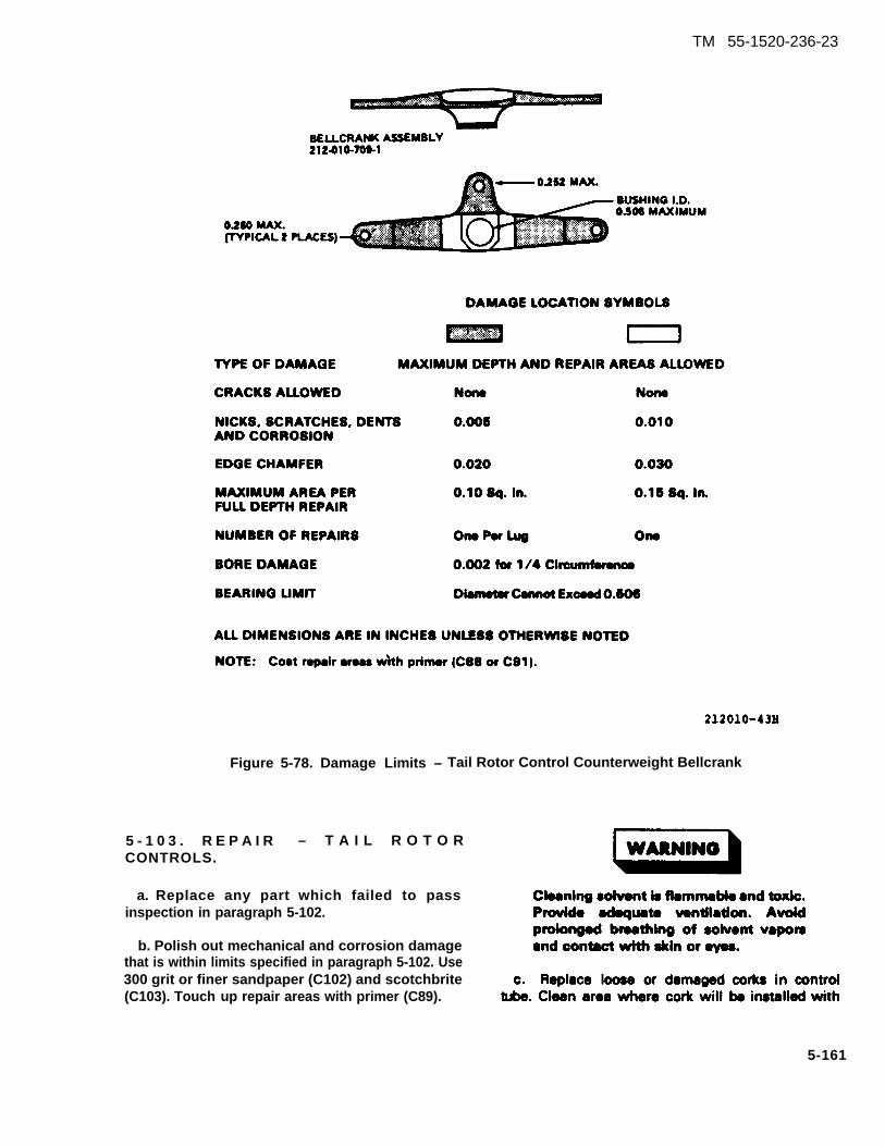
TM 55-1520-236-23
Figure 5-78. Damage Limits – Tail Rotor Control Counterweight Bellcrank
5 - 1 0 3 . R E P A I R – T A I L R O T O RCONTROLS.
a. Replace any part which failed to passinspection in paragraph 5-102.
b. Polish out mechanical and corrosion damagethat is within limits specified in paragraph 5-102. Use300 grit or finer sandpaper (C102) and scotchbrite(C103). Touch up repair areas with primer (C89).
5-161
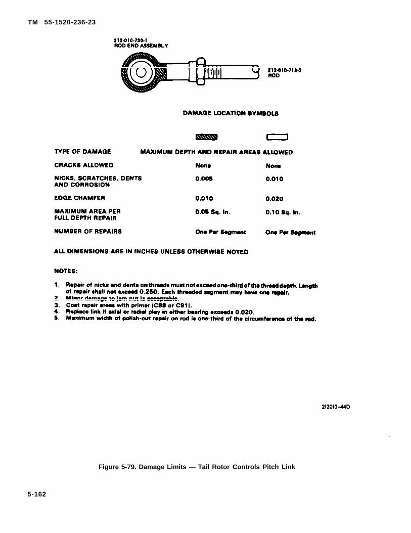
TM 55-1520-236-23
Figure 5-79. Damage Limits — Tail Rotor Controls Pitch Link
5-162

TM 55-1520-236-23
Figure 5-80. Damage Limits — Tail Rotor Control Counterweight Link
5-163
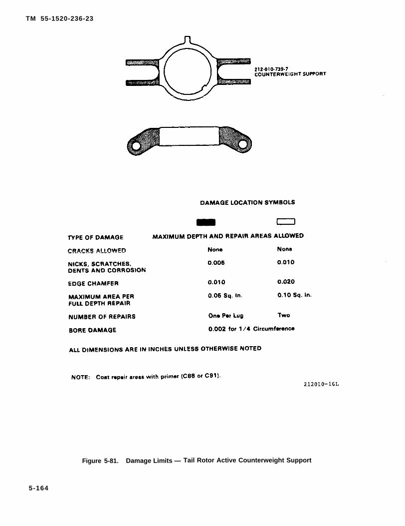
TM 55-1520-236-23
Figure 5-81. Damage Limits — Tail Rotor Active Counterweight Support
5-164

TM 55-1520-236-23
Figure 5-82. Damage Limits — Tail Rotor Control Tube
solvent (C112) and allow to dry. Coat new cork withshellac (C108) and press into position illustrated infigure 5-82.
5 - 1 0 4 . A S S E M B L Y – T A I L R O T O RCONTROLS.
a. Position nylatron washer (28, figure 5-76),bellcrank (27) and special washer (25) on crosshead(13). Install nut (24) and torque 70 TO 125 inch-pounds. Install cotter pin (23). Install oppositebellcrank in the same manner. If cotter pins do not
engage castellations in nuts, add one thin steelwasher under nuts (24).
Weights (17) must be installed onoutboard side of bellcranks (27) asillustrated or interference may occur.
5-165

TM 55-1520-236-23
1.
2.9.4 .5.
b.
Damage and subsequent repair to threads must not exceed one-third of the thread depth.Length of repair shall not exceed 0.25. The threaded segment may have two repairs.AU edges maybe radiused or chamfered 0.020 to remove nicks and dents.Corrosion must be cleaned up to twice the damage depth.Coat repair areas with primer (C88 or C91).Long clevis-two repairs; short clevis-one repair.
209011-29C
Figure 5-83. Damage Limits-Link Assembly
Install weights on each end of the twobellcranks (27). Install the same weights that wereremoved if they were indexed, if not, install twoweights (17) and one steel washer (18) at each of thefour locations. Install bolt (16) and nut (19). Torquenut 60 TO 70 inch-pounds.
(27)
CAUTIONDo not intermix link P/N 212-010-711-1with link P/N 212-010-711-3.
Position counterweight link (26) in bellcrankand install bolt (30, figure 5-76) with steel
washer (29) under head and steel washer (22) undernut (20). Torque nut 60 TO 110 inch-pounds and
5-166
install cotter pin (21). Install opposite counterweightlink in the seine manner. If cotter pins do not engagecastellations in nuts, add one thin steel washer undernuts (20).
d. Adjust both pitch links (31) to 6.115 ±0.010 inchdimension between centers of bearings. This will yielda distance of 2.72-2.92 inches between inside face ofjam nuts. (Refer to chapter 11 for additional rigginginstructions.)
e. Position pitch link (31) in crosshead (13) withthe end with rivet (32) installed away from the cross-head as illustrated. Install bolt (15) with steel washer(14) under head and steel washer (12) under nut (11).Torque nut 110 TO 165 inch-pounds and

TM 55-1520-236-23
TYPE OF DAMAGE MAXIMUM DEPTH AND REPAIR AREAS ALLOWED
CRACKS ALLOWED None None
NICKS, SCRATCHES, 0.010 0.030SHARP DENTS
CORROSIONBefore Repair 0.005 0.015After Repair 0.010 0.030
MAXIMUM AREA PER 0.25 Sq. In. 0.50 Sq. In.FULL DEPTH REPAIR
NUMBER OF REPAIRS One Per Segment Two
ALL DIMENSIONS ARE IN INCHES UNLESS OTHERWISE NOTED
NOTES:
1. Edges maybe radiused or chamfered 0.040 to remove nicks and dents.2. Corrosion must be cleaned up to twice damage depth.3. Coat repair areas with brush on chemical film (C31).4. Bearing radial wear limit maximum 0.004 inch.
Figure 5-84. Damage Units — Idler
install cotter pin (10). Install opposite pitch link in samemanner. If cotter pins do not engage castellations innuts, add one thin steel washer under nuts (11).
5-105. INSTALLATION — TAIL ROTOR CON-TROLS.
a. Install bearing (52, figure 5-76) in housing(40) Wet mating surfaces of bearing (52) and controltube (34) with lubricant (C79 or C80). Install excluder(43) so that packing (43.1) sits inboard. Install housing(41) in housing (40). Apply a small amount of sealant(C107.5) between the two housings. Secure excluder(43) and housing (41) with retaining ring (42).
b. Install new packing (38) on housing (40).
c. Apply unthinned primer (C88 or C91) to sur-face of housing (40) that contacts gearbox and installhousing while primer is wet.
d. Install steel washers and nuts (39). Torqueevenly to 60 inch-pounds. Apply sealing compound(C107) around joint where housing contacts gearbox.
e. Position idler (47) on gearbox case and securewith bolts, steel washers and nuts (50). Apply sealing
5-167
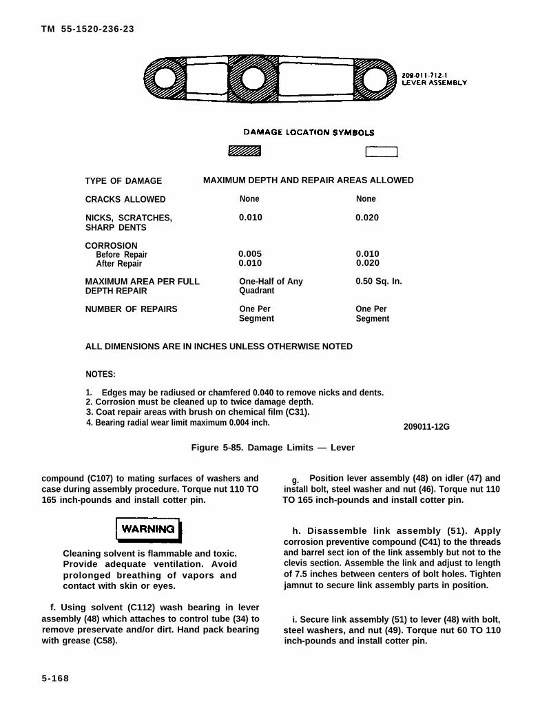
TM 55-1520-236-23
TYPE OF DAMAGE MAXIMUM DEPTH AND REPAIR AREAS ALLOWED
CRACKS ALLOWED None None
NICKS, SCRATCHES, 0.010 0.020SHARP DENTS
CORROSIONBefore Repair 0.005After Repair
0.0100.010 0.020
MAXIMUM AREA PER FULL One-Half of Any 0.50 Sq. In.DEPTH REPAIR Quadrant
NUMBER OF REPAIRS One Per One PerSegment Segment
ALL DIMENSIONS ARE IN INCHES UNLESS OTHERWISE NOTED
NOTES:
1. Edges may be radiused or chamfered 0.040 to remove nicks and dents.2. Corrosion must be cleaned up to twice damage depth.3. Coat repair areas with brush on chemical film (C31).4. Bearing radial wear limit maximum 0.004 inch. 209011-12G
Figure 5-85. Damage Limits — Lever
compound (C107) to mating surfaces of washers andcase during assembly procedure. Torque nut 110 TO165 inch-pounds and install cotter pin.
Cleaning solvent is flammable and toxic.Provide adequate ventilation. Avoidprolonged breathing of vapors andcontact with skin or eyes.
f. Using solvent (C112) wash bearing in leverassembly (48) which attaches to control tube (34) toremove preservate and/or dirt. Hand pack bearingwith grease (C58).
g. Position lever assembly (48) on idler (47) andinstall bolt, steel washer and nut (46). Torque nut 110TO 165 inch-pounds and install cotter pin.
h. Disassemble link assembly (51). Applycorrosion preventive compound (C41) to the threadsand barrel sect ion of the Iink assembly but not to theclevis section. Assemble the link and adjust to lengthof 7.5 inches between centers of bolt holes. Tightenjamnut to secure link assembly parts in position.
i. Secure link assembly (51) to lever (48) with bolt,steel washers, and nut (49). Torque nut 60 TO 110inch-pounds and install cotter pin.
5-168

TM 55-1520-236-23
TYPE OF DAMAGE
CRACKS ALLOWED
SCRATCHES, DENTSAND CORROSION
MAXIMUM AREA PERFULL DEPTH REPAIR
NUMBER OF REPAIRS
EDGE CHAMFER
THREAD DAMAGEDepthLengthNumber
MAXIMUM DEPTHS AND REPAIR AREAS ALLOWED
None
0.010
0.10 Sq. In.
2
0.030
One-third of threadOne-fourth of inchOne
ALL DIMENSIONS IN INCHES UNLESS OTHERWISE NOTED
209010-116
Figure 5-86. Damage Limits — Tail Rotor Retention Nut
5 - 1 6 9
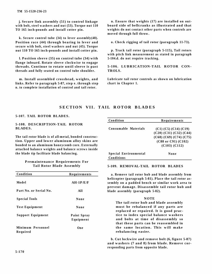
TM 55-1520-236-23
j. Secure link assembly (51) to control linkagewith bolt, steel washers and nut (53). Torque nut 110TO 165 inch-pounds and install cotter pin.
k. Secure control tube (34) to lever assembly(48).Position race (44) through bearing in lever andsecure with bolt, steel washers and nut (45). Torquenut 110 TO 165 inch-pounds and instaIl cotter pin.
l. Position sleeve (35) on control tube (34) withflange inboard. Rotate sleeve clockwise to engagethreads. Continue to rotate until sleeve is pastthreads and fully seated on control tube shoulder.
m. Install assembled crosshead, weights, andlinks. Refer to paragraph 5-87, step e. through stepn. to complete installation of control and tail rotor.
n. Ensure that weights (17) are installed on out-board side of bellcranks as illustrated and thatweights do not contact other parts when controls aremoved through full throw.
o. Check rigging of tail rotor (paragraph 11-73).
p. Track tail rotor (paragraph 5-115), Tail rotorswith pitch link measurement as stated in paragraph5-104.d. do not require tracking.
5-106. LUBRICATION-TAIL ROTOR CON-TROLS.
Lubricate tail rotor controls as shown on lubricationchart in Chapter 1.
SECTION VII. TAIL ROTOR BLADES
5-107. TAIL ROTOR BLADES.
5-108. DESCRIPTION-TAIL ROTORBLADES.
The tail rotor blade is of all-metal, bonded construc-tion. Upper and lower aluminum alloy skins arebonded to an aluminum honeycomb core. Externallyattached balance weights and balance screws insidethe blade tip facilitate blade balancing.
Premaintenance Requirements ForTail Rotor Blade Assembly
Condition Requirements
Model AH-1P/E/F
Part No. or Serial No. All
Special Tools None
Test Equipment None
Support Equipment Paint SprayEquipment
Minimum Personnel OneRequired
Condition Requirements
Consumable Materials (C1) (C5) (C14) (C19)(C20) (C31) (C32) (C44)(C68) (C69) (C74) (C75)
(C88 or C91) (C102)(C103) (C112)
Special Environmental NoneConditions
5-109. REMOVAL-TAIL ROTOR BLADES
a. Remove tail rotor hub and blade assembly fromhelicopter (paragraph 5-81). Place the tail rotor as-sembly on a padded bench or similar work area toprevent damage. Disassemble tail rotor hub andblade assembly (paragraph 5-82).
NOTEThe tail rotor hub and blade assemblymust be rebalanced if any parts arereplaced or repaired. It is good prac-tice to index special balance washersand bolts at time of disassembly sothat these parts can be reassembled inthe same location. This will makerebalancing easier.
b. Cut lockwire and remove bolt (6, figure 5-87)and washers (7 and 8) from blade. Remove cor-responding parts from opposite blade.
5-170

TM 55-1520-236-23
Flgure 5-87. Tail Rotor Blade Pitch Horn Installation
c. Remove nuts (1 and 2), and washers (3 and 13).Remove bolts (10 and 11) and washers (9 and 12).Remove pitch horn. Remove opposite pitch horn inthe same manner.
5 - 1 1 0 . I N S P E C T I O N – T A I L R O T O RBLADES.
If during a movement a tinkle or a sandysound emits from inside of blades, thepresence of this condition is not causefor rejection of the blades. This sound is debr ls (par t ic les of a luminumhoneycomb) that were not thoroughlyremoved during blade manufacture.
NOTE
Any damage caused by external forcesto installed blades that requires bladereplacement wiII cause mandatory tallrotor yoke replacement. Evidence ordocumentation of any abnormal sideload applied to the blade as a result ofground mishap sufficient to causeyoke to impact severely on flappingstop Is cause for removal.
a . Inspect tail rotor historical records and the tailrotor blades for evidence that the blades have beansubjected to an accident or incident outside the realmof normal usage. If such evidence exists, performapplicable special inspections fro overspeed, suddenstoppage, hard landing and overtorque outlined inChapter 1 and the following:
NOTE
If there is no evidence of accident orincident, proceed to step b.
(1) Overspeed inspection:
(a) Check for bond separation anywhere onthe blade. If any separation exists, dispose of theblade locally.
(b) Check balance screws (9, figurs 5-88) andexternal balance weights (3) for movement. If any ofthese parts have moved outboard due to centrifugalforce, dispose of blade locally.
(c) Check the blade grip bolt hole bushings (2)for evidence of looseness. If any of the four bushingsare loose, forward the blade to next highermaintenance level for repair.
5-171
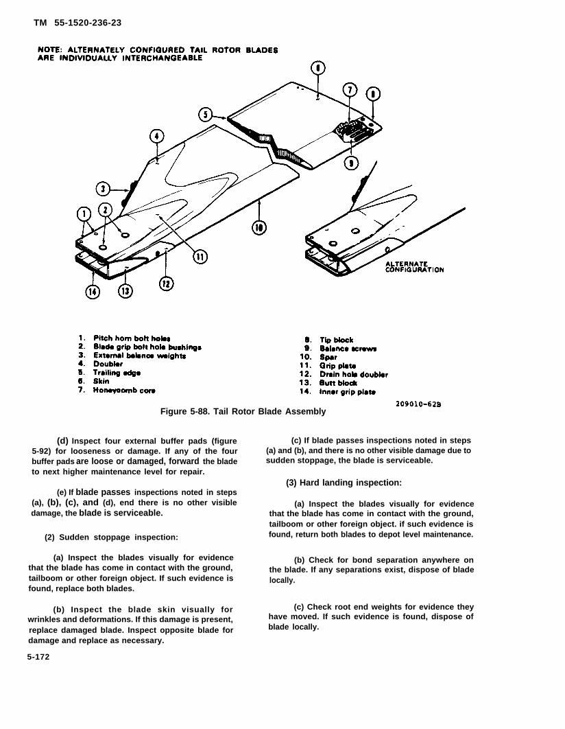
TM 55-1520-236-23
Figure 5-88. Tail Rotor Blade Assembly
(d) Inspect four external buffer pads (figure5-92) for looseness or damage. If any of the fourbuffer pads are loose or damaged, forward the bladeto next higher maintenance level for repair.
(e) If blade passes inspections noted in steps(a), (b), (c), and (d), end there is no other visibledamage, the blade is serviceable.
(2) Sudden stoppage inspection:
(c) If blade passes inspections noted in steps(a) and (b), and there is no other visible damage due tosudden stoppage, the blade is serviceable.
(3) Hard landing inspection:
(a) Inspect the blades visually for evidencethat the blade has come in contact with the ground,tailboom or other foreign object. if such evidence isfound, return both blades to depot level maintenance.
(a) Inspect the blades visually for evidence (b) Check for bond separation anywhere onthat the blade has come in contact with the ground, the blade. If any separations exist, dispose of bladetailboom or other foreign object. If such evidence is locally.found, replace both blades.
(b) Inspect the blade skin visually for (c) Check root end weights for evidence they
wrinkles and deformations. If this damage is present, have moved. If such evidence is found, dispose of
replace damaged blade. Inspect opposite blade for blade locally.
damage and replace as necessary.
5-172

TM 55-1520-236-23
(d) If one of the blades of a pair has beendamaged badly enough that metal has been torn orany bond lines have been separated, dispose ofblades Iocally.
(e) If one of the blades of a pair has beendamaged slightly by denting, scrap that blade; but theother blade may be reused after inspection by depotlevel maintenance for water tightness and spanwisebalance.
b. Accomplish normal inspection of tail rotorblades and pitch horns by inspecting blades visuallyand with standard inspection equipment. Classify anydamage present as negligible, reparable at AVIMlevel, reparable at Depot, or nonreparable.
(1) Neligible damage:
NOTE
Blades with only negligible damage maybe returned to service without repair.
(a) Non-sharp dents located inboard ofStation 30.0 that are not in excess of 0.015 inch deepare negligible (figure 5-89).
(b) Non-sharp dents located outboard ofStation 30.0 that are not in excess of 0.030 inch arenegligible (figure 5-89).
(c) Voids between doublers (4, figure 5-88)and skin (6) or spar (10) which do not exceed 0.50inch chordwise by 2.0 inches spanwise and are notwithin 0.50 inch of the edge of doubler are negligible.
(d) Voids between the skin (6) and spar (10)which do not exceed 0.50 inch chordwise by 2.0inches spanwise and are not within 0.250 inch of theedge of the skin and are not in the outboard areawhere the skin overlaps the spar are negligible. Voidsbetween the skin and spar in the outboard area wherethe skin overlaps the spar which do not exceed 0.250inch chordwise and 2.0 inches spanwise arenegligible.
(e) Voids between the skin (6) andhoneycomb core (7) which do not exceed 0.50 inchchordwise by 2.0 inches spanwise are negligible.
Figure 5-89. Tail Rotor Blade Station Diagram and Scratch-Type Damage Area Locations
5-173

TM 55-1520-236-23
(2) Nick, dent and scratch type damagereparable at AVIM level maintenance:
NOTE
Blades with the type damage defined inthis paragraph require that the damagebe polished out to the depth required toremove the damage including any nicksor scratches which may be present indents. Use 300 grit or finer sandpaper(C102) and scotchbrite (C103). Do notfair-in or fill sharp or non-sharp dentswith adhesive as thIS would interferewith subsequent inspections for crocks.Touch-up pa int in areas wheremechanical damage is polished out.
(a) Nicks and scratches inboard of Station30.0 which run within 0 TO 15 degrees of the spanline and are not in excess of 0.005 inch depth (figure5-89).
(b) Nicks and scratches inboard of Station30.0 which run within 0 TO 76 degrees of thechordline and are not in excess of 0.003 inch in depth(figure 5-89).
(c) Sharp dents inboard of Station 30.0which are not in excess of 0.010 inch in depth.
(d) Non-sharp dents inboard of Station 30.0which are not in excess of 0.030 inch in depth.
(e) Nicks and scratches outboard of Station30.0 which are not in excess of 0.010 inch in depth.
(f) Sharp dents outboard of Station 30.0which are not in excess of 0.015 inch in depth.
(g) Non-sharp dents outboard of Station 30.0and also outside of patchable area which are not inexcess of 0.040 inch in depth.
(h) Non-sharp dents outboard of Station 30.0and also within patchable area as shown in figure 5-90 which are not in excess of 0.125 inch in depth.
(i) Nicks and scratches in the trailing edge upto 0.030 inch in depth chordwise are reparable, butthe damage must be polished out over a distance ofthree inches on each side of the defect.
(3) Voids reparable at AVIM level maintenance:
NOTEBlades which have voids within the limitsdefined in this paragraph require that thevoids be repaired to return the blades toserviceable condition. R e f e r t oparagraph 5-111 for repair instructions.
Figure 5-90. Tail Rotor Blade - Area Authorized for Patch-Type Repair
5-174
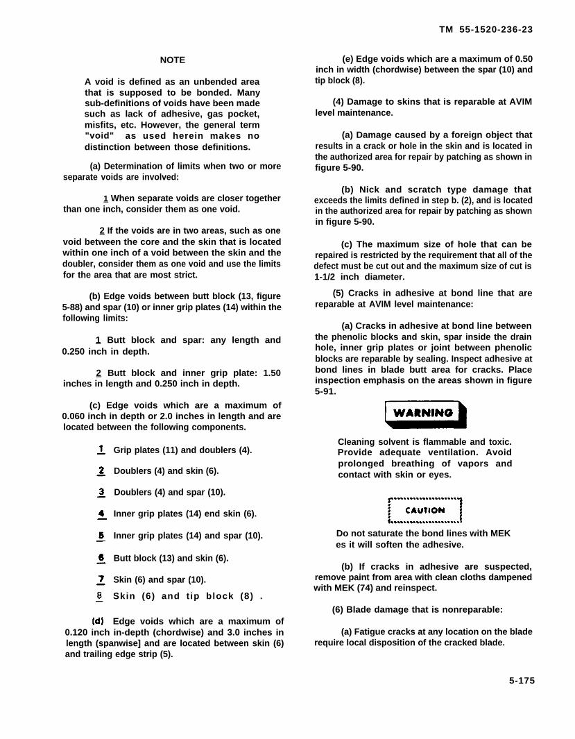
TM 55-1520-236-23
NOTE
A void is defined as an unbended areathat is supposed to be bonded. Manysub-definitions of voids have been madesuch as lack of adhesive, gas pocket,misfits, etc. However, the general term"void" as used herein makes nodistinction between those definitions.
(a) Determination of limits when two or moreseparate voids are involved:
1 When separate voids are closer togetherthan one inch, consider them as one void.
2 If the voids are in two areas, such as onevoid between the core and the skin that is locatedwithin one inch of a void between the skin and thedoubler, consider them as one void and use the limitsfor the area that are most strict.
(b) Edge voids between butt block (13, figure5-88) and spar (10) or inner grip plates (14) within thefollowing limits:
1 Butt block and spar: any length and0.250 inch in depth.
2 Butt block and inner grip plate: 1.50inches in length and 0.250 inch in depth.
(c) Edge voids which are a maximum of0.060 inch in depth or 2.0 inches in length and arelocated between the following components.
Grip plates (11) and doublers (4).
Doublers (4) and skin (6).
Doublers (4) and spar (10).
Inner grip plates (14) end skin (6).
Inner grip plates (14) and spar (10).
Butt block (13) and skin (6).
Skin (6) and spar (10).
Skin (6) and t ip block (8) .
Edge voids which are a maximum of0.120 inch in-depth (chordwise) and 3.0 inches inlength (spanwise] and are located between skin (6)and trailing edge strip (5).
(e) Edge voids which are a maximum of 0.50inch in width (chordwise) between the spar (10) andtip block (8).
(4) Damage to skins that is reparable at AVIMlevel maintenance.
(a) Damage caused by a foreign object thatresults in a crack or hole in the skin and is located inthe authorized area for repair by patching as shown infigure 5-90.
(b) Nick and scratch type damage thatexceeds the limits defined in step b. (2), and is locatedin the authorized area for repair by patching as shownin figure 5-90.
(c) The maximum size of hole that can berepaired is restricted by the requirement that all of thedefect must be cut out and the maximum size of cut is1-1/2 inch diameter.
(5) Cracks in adhesive at bond line that arereparable at AVIM level maintenance:
(a) Cracks in adhesive at bond line betweenthe phenolic blocks and skin, spar inside the drainhole, inner grip plates or joint between phenolicblocks are reparable by sealing. Inspect adhesive atbond lines in blade butt area for cracks. Placeinspection emphasis on the areas shown in figure5-91.
Cleaning solvent is flammable and toxic.Provide adequate ventilation. Avoidprolonged breathing of vapors andcontact with skin or eyes.
Do not saturate the bond lines with MEKes it will soften the adhesive.
(b) If cracks in adhesive are suspected,remove paint from area with clean cloths dampenedwith MEK (74) and reinspect.
(6) Blade damage that is nonreparable:
(a) Fatigue cracks at any location on the bladerequire local disposition of the cracked blade.
5-175
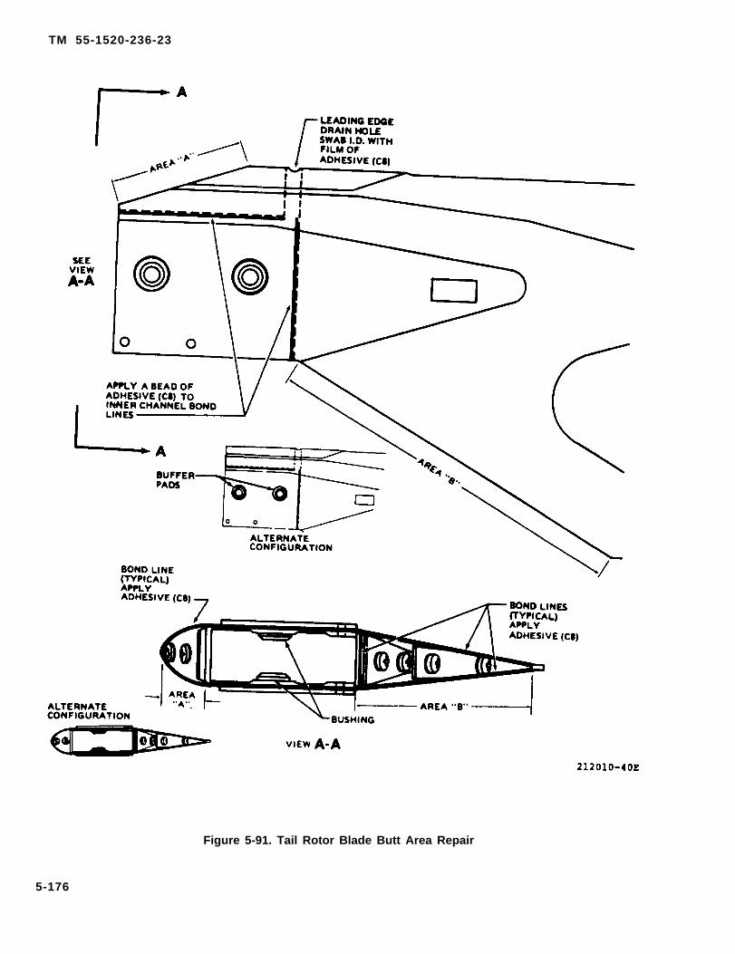
TM 55-1520-236-23
Figure 5-91. Tail Rotor Blade Butt Area Repair
5-176

TM 55-1520-236-23
(b) A blade with water in
(c) A blade with one
honeycomb core.
or more cracksdeveloped in a previously repaired area.
(d) A blade with nicks or cracks that arelocated in dents and the total depth is in excess of thelimits specified in steps b. (2) (c) through b. (2) (h) ifdamage is not within area where patches areallowed.
(e) A blade with any void within 0.50 inch ofthe edges of the drain hole doubler (12, figure 5-88).
(f) A blade with any void between the drainhole doubler (12) and spar (10) within 0.50 inch ofthe edge of the drain hole.
(g) A blade with one or more holes that do notfall within the area authorized for patches as shownin figure 5-90 and/or a blade with a hole that exceedsthe 1.5 inch diameter restriction noted in step b. (4)(c).
(h) A blade with any corrosion thatpenetrates entirely through the skin.
(i) A blade that is worn completely throughthe spar at the tip.
(j) A blade with edge voids deeper than 0.1inch at the tip end of any of the root end doublers orgrip plates.
(k) A blade with edge voids in the leadingedge or trailing edge of the doublers that are 0.25inch or more in depth and show indications ofcorrosion in the void.
(I) A blade that failed to pass the specialinspections for overspeed, overtorque and suddenstoppage.
(7) Inspect tail rotor pitch horns as follows:
(a) Inspect pitch horns for damage in excessof the limits shown in figure 5-92.
(b) Inspect threaded insert for damage tothreads.
(c) Slide a new pitch link bolt throughbushing and matching hole used for attachingpitch link. If the bolt does not fit freely through
thethethe
holes, the pitch horn is not suitable for furtherservice.
(d) Inspect for distortion of the pitch hornswith a straight edge placed against the machinedsurfaces. Any distinct deviation from flat indicatesthat the pitch horn is distorted and not suitable forfurther service.
(e) Inspect pitch horns for cracks byfluorescent penetrant method (TM 43-0103).
5 - 1 1 1 . R E P A I R – TAIL ROTOR BLADES(AVIM).
a. Replace any blade which has incurrednonreparable damage (paragraph 5-110).
b. Repair blades with voids that are within thelimits specified in paragraph 5-110.
Cleaning solvent is flammable and toxic.Provide adequate ventilation. Avoidprolonged breathing of vapors andcontact with skin or eyes.
Do not allow MEK to enter rotor bladewhen removing paint to inspect forcracks or when cleaning prior to sealingedge voids. MEK will soften the adhesiveused in manufacture of the rotor blades.
(1) Clean area around reparable edge voidswith a clean cloth moistened with MEK (C74) and drywith a clean cloth,
(2) Prepare a small quantity of adhesive (C14)in accordance with the manufacturers instructions.Apply the adhesive to the edge void with the flat sideof an applicator such as a wooden tongue depressor.Fill the void with adhesive as deeply as possible.
c. Repair blades with crack and hole type damagein the skin by patching if the damage is within limitsspecified in paragraph 5-110.
(1) Ensure that the damage to be patched is inthe authorized area for patches (figure 5-90).
5-177
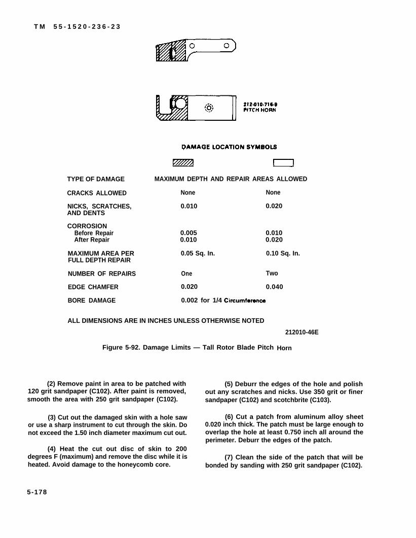
T M 5 5 - 1 5 2 0 - 2 3 6 - 2 3
TYPE OF DAMAGE
CRACKS ALLOWED
NICKS, SCRATCHES,AND DENTS
CORROSIONBefore RepairAfter Repair
MAXIMUM AREA PERFULL DEPTH REPAIR
NUMBER OF REPAIRS
EDGE CHAMFER
BORE DAMAGE
MAXIMUM DEPTH AND REPAIR AREAS ALLOWED
None
0.010
0.0050.010
0.05 Sq. In.
One
0.020
0.002 for 1/4
None
0.020
0.0100.020
0.10 Sq. In.
Two
0.040
ALL DIMENSIONS ARE IN INCHES UNLESS OTHERWISE NOTED
Figure 5-92. Damage Limits — Tall Rotor Blade Pitch
(2) Remove paint in area to be patched with120 grit sandpaper (C102). After paint is removed,smooth the area with 250 grit sandpaper (C102).
(3) Cut out the damaged skin with a hole sawor use a sharp instrument to cut through the skin. Donot exceed the 1.50 inch diameter maximum cut out.
(4) Heat the cut out disc of skin to 200degrees F (maximum) and remove the disc while it isheated. Avoid damage to the honeycomb core.
212010-46E
Horn
(5) Deburr the edges of the hole and polishout any scratches and nicks. Use 350 grit or finersandpaper (C102) and scotchbrite (C103).
(6) Cut a patch from aluminum alloy sheet0.020 inch thick. The patch must be large enough tooverlap the hole at least 0.750 inch all around theperimeter. Deburr the edges of the patch.
(7) Clean the side of the patch that will bebonded by sanding with 250 grit sandpaper (C102).
5-178

TM 55-1520-236-23
Cleaning solvent is flammable and toxic.Provide adequate ventilation. Avoidprolonged breathing of vapors andcontact with skin or eyes.
(8) Wipe the mating surfaces of the patch andblade with a clean cloth dampened with MEK (C74).
(9) Apply a thin coat of adhesive (C14) to themating surfaces of the patch and blade. Place thepatch on the blade, press down on the patch and moveit back and forth slightly to expel all air pockets in theadhesive, Blend the excess adhesive around the edgeof the patch.
(10) Maintain pressure on the patch. Useweights, clamps or rubber bands cut from innertubes.
(11 ) Refer to table 1-11, for adhesive, mix ratio,pot life, and curing schedule.
(12) Touch up paint in area of patch (paragraph5-112 and TB 746-93-2).
d. Repair blades with nick, scratch, dent andnotch damage that is within the limits specified inparagraph 5-110.
(1) Polish out all nicks and scratches, Usealuminum wool (C20) on aluminum pans. Usesandpaper (C102) on stainless steel spar.
(2) Polish out damage in trailing edge over adistance of three inches on each side of the defect.Use a steel hand file to remove most of the damagethen smooth out the area with aluminum wool (C20).
(3) Touch up paint in area of repair (paragraph5-112 and TB 746-93-2).
e. Replace Ioose or damaged buffer pads
NOTE
Exercise extreme care to ensure gripplates are not gouged or otherwisedamaged.
(1) Remove old pad, using a knife or similartool.
(2) Remove any remaining adhesive by sandingin a spanwise direction to bare metal. Surface finishshall be 32 RMS or better.
NOTE
Use cellophane or similar materialbetween washers and buffer pads toprevent adhesive squeeze-out fromcontacting washers.
(3) Bond new buffer pads to blade, usingadhesive (C14). Apply pressure to pad by installing a0.5 inch diameter bolt through a blade bolt holewith an AN970-8 washer under both the bolt headand the nut. Tighten nut to apply pressure on bufferpad. Refer to table 1-11, for adhesive, mix ratio, potlife, and curing schedule.
(4) Refinish blade as required
f. Repair blades with cracks in adhesive at bondline detected in inspection described in paragraph 5-110, as follows:
Cleaning solvent is flammable and toxic.Provide adequate ventilation. Avoidprolonged breathing of vapors andcontact with skin or eyes.
Do not saturate the bond lines with MEKas it will soften the adhesive.
(1) Clean area around cracks in adhesive atbond line in area illustrated in figure 5-91 with MEK(C74). Dry area with clean cloths.
(2) Apply a thin film of adhesive (C14) to thebond lines shown in figure 5-91 areas A and B.
(3) Apply a small bead of adhesive (C14) to areashown in figure 5-91.
(4) Swab the inside diameter of the leadingedge drain hole with a thin film of adhesive (C14) toensure that adequate sealing exists (figure 5-91).
(5) Refer to table 1-11, for adhesive, mix ratio,pot life, and curing schedule.
5-179

TM 55-1520-236-23
(6) Touch up paint112 and TB 746-93-2).
in repair area (paragraph 5-
(7) Balance the tail rotor hub and bladeassembly prior to installation on helicopter(paragraph 5-86).
g. Repair pitch horn as follows:
(1) Polish out mechanical and corrosiondamage on pitch horns. Use 300 grit or finersandpaper (C102) and scotchbrite (C103). Inspectrepaired areas to ensure that limits shown in figure 5-92 have not been exceeded.
(2) Touch up repaired areas with chemical film(C31).
(3) Replace pitch horn (5, figure 5-87) if hole forfloating bushing exceeds 0.5005 inch or is corroded.
(4) Replace bushing (30, figure 5-68) if bolt isloose in bushing or if bushing is loose in pitch horn.
5-112. PAINTING – TAIL ROTOR BLADES(AVIM).
a. Paint touchup is required when paint isdeteriorated and/or the paint is removed to repairscratches, nicks, or dents. Refer to TB 746-93-2.
b. Prepare blade for painting as follows:
(1) Polish out nick, scratch, and dent damage(paragraph 5-111).
Cleaning solvent is flammable and toxic.Provide adequate ventilation. Avoidprolonged breathing of vapors andcontact with skin or eyes.
(2) Clean area where paint is to be applied withaliphatic naphtha (C75).
(3) Mask off or plug retention bolt holes andmask off holes for attaching the pitch horns to prevententry of refinishing materials.
(4) Remove all surfacefrom aluminum surfaces.
5-180
oxides and aged paint
(5) Wash blade with cleaning and polishingcompound (C32). Thoroughly rinse soap from bladeand check for a water break free surface which is acontinuous unbroken film of water on the surface.Repeat washing as required until the water break freesurface is attained.
Do not touch blades with bare handsduring remaining procedures or qualityof paint will be adversely affected.
(6) Apply coat of chemical film (C31) to barealuminum surfaces.
c.
NOTE
If chemical film is not available,substitute commercial “Metal-Prep”,alcoholic phosphoric solution (C19) orsolution of chromic acid (C1).
Apply finish to blade as follows:
(1) Apply one coat of primer (C88 or C91) to thetouch up area.
Cleaning solvent is flammable and toxic.Provide adequate ventilation. Avoidprolonged breathing of vapors andcontact with skin or eyes.
(2) Mix a small quantity of adhesive (C5)according to directions on container. Mix 13 TO 15percent by weight of primer (C88 or C91) into theadhesive (C5). Mix thoroughly and thin to sprayableconsistency by adding MEK (C74). Do not exceed 50percent by volume; 35 percent should produce asprayable consistency. The pot life of the epoxyprimer mixture is approximately three hours.
(3) Ensure that masking tape applied in step b.(3) is still in place. Apply three wet spray coats of theadhesive prepared in the preceding step to allsurfaces at the root of the blade for a distance of0.750 inch to 2 inches outboard of the perimeter ofthe doublers. Allow each coat to dry 45 TO 60minutes. Make each coat 1.6 TO 2.0 mils thick. Applyone wet spray coat of the same adhesive material to
TM 55-1520-236-23
the entire length of the blade on both sides. Use theleading edge of the skin as the centerline of thespray.
(4) After the final coat is applied in precedingstep, allow the blade to air dry for 16 TO 24 hours.
(5) Apply one thin mist coat of primer (C88 orC91) to all touch up areas and allow to dry for aminimum of 45 minutes and a maximum of 8 hoursprior to applying next coat.
NOTE
It is necessary to cover all touch upareas with primer (C88 or C91) andcomply with the time limit noted instep (5) or the finish cost of lacquerwill not adhere to the blade.
(6) Apply the final coats of Iacquer to thetouch up areas only. Use lacquer (C68) to touch upareas except on the blade tip. Use lacquer (C69) ontouch up areas of the six inch wide band on theblade tip. Paint thickness to be approximately 1.2TO 1.5 mils.
(7) Air dry the blade for 3 hours prior to han-dling and for 48 hours prior to flying. If a faster curetime is required, air dry the blade 1 hour. Removethe roasting tape and oven dry the blade at 180 to190 degrees F (82 TO 88 degrees C) for 1 hour.
5-113. INSTALLATION-TAIL ROTORBLADES.
a. Position hub assembly (1, figure 5-69) onbench with data plate side up. Slide blade (14) onhub yoke with the data plate side up. Install bolts (20and 25) with special washers (19 and 26) under boltheads. Install special washers (2 and 13) next toblade. If special balance washers were indexed attime of disassembly, reinstall them in the same posi-tion. If they were not indexed, do not install themuntil the assembly is balanced. Install nuts (5 and10) but do not torque until after the assembly hasbeen balanced.
b. Install opposite blade in the same manner.The four blade retention boltS (20 and 25) maybeinstalled from either side but all four bolts must beinstalled from the same side.
c. Position pitch horn (5, figure 5-87) on bladeand install bolts (10 and 11) with steel washers (9and 12) under heads. Install bolts with heads facingsame direction as blade retention bolts (20 and 25,figure 5-69). Install steel washers (3 and 13, figure5-87) and nuts (1 and 2). Torque nuts 50 TO 70inch-pounds. If special washer (8) was indexed atdisassembly, install it at this time with steel washer(7) and bolt (6). If special washer (8) was not in-dexed, install steel washer (7) and bolt (6). Do nottorque until assembly has been balanced.
(8) Apply a coating of corrosion preventivecompound (C44) to the inside of the retention bolt d. Install the opposite pitch horn in the samebushings. manner.
S E C T I O N V l l l . T R A C K I N G A N D B A L A N C I N G P R O C E D U R E S
5-114. TRACKING AND BALANCING- Condition RequirementsMAIN ROTOR BLADES.
Test Equipment None
Support Equipment None
NOTE
For Aviation Vibration Analyzer (AVA)refer to TM 1-6625-724-13&P.
Premaintenance Requirements for MainRotor Hub and Blade Assembly-ticking
Condition Requirements
Model AH–1P/E/F
Part No. or Serial No. All
Special Tools (T41) (T47)
Minimum Personnel TwoRequired
Consumable Materials (C123) (C138)
Special Environmental NoneConditions
a. Following replacement or installation of themain rotor hub, blades or pitch link assemblies,track the main rotor blades.
b. B540 Perform following procedures as re-quired for acceptable smooth operation of main ro-tor. Recommended sequence of procedures is alsoprovided in charts (figures 5-93, 5-94, and 5-95).
5-181

Runup of helicopter shall be per-formed only by personnel authorizedby AR 95-1.
NOTE
The VIBREX 4591 system is the pre-ferred method of tracking main rotorblades. (Refer to paragraph 5-116.)(1) Coat tracking tips of rotor blades with suit-
able grease pencils, using different colors on eachblade as preparation for use of tracking flag. Setboth trim tabs at trail (zero degrees) using gage(T41) and tab bender (T47).
(2) Perform a low speed blade track at 71percent rpm (figure 5-97). If track is satisfactory,omit step (3) and proceed to Step (4).
(3) Prior to incorporation of MWO 55-1520-244-50-9, correct a low speed out-of-trackcondition by shortening pitch Iink assembly at-tached to the low blade to roll the blade up (figure
5-9). Loosen jamnuts and turn barrel to shortentube. Turning barrel three turns will change bladetrack approximately 0.375 inch. Tighten and lock-wire (C1 38) nuts. Repeat checks and adjustmentsuntil satisfactory.
NOTE
After application of Iockwire, apply athin coat of sealant (C105) around theIock nut and threads of the rod end toprevent water intrusion.
(3.1) After incorporation of MWO55-1520-244-50-9, correct a low speed, out-of-track condition by shortening pitch link assemblyattached to the low bide to roll the blade up (figure5-9). Loosen jamnuts and turn lube assembly toshorten tube.Tuting tube one and one-half turnswill change bide track approximately 0.375 inch.Tighten and Iockwire (C138) nuts. Repeat checks
adjustments until satisfactory.
(4) Perform a high speed track at 100 percentrpm. If out-of-track, record which blade is low butmake no adjustments.
Figure 5-93. Main Rotor Tracking Chart
5-182

TM 55-1520-236-23
(5) Test fly helicopter. If vertical vibration isnot evident proceed to step (6). If vertical vibrationrequires correction, begin sequence of adjustmentsindicated in figure 5-94 as applicable according toairspeed where vibration occurs.
(a) When bending blade trim tabs, do notexceed 8 degrees up and/or 8 degrees down (16degrees maximum both blades).
(b) To roil a blade, adjust pitch link assem-bly as in step (3) or (3.1) above.
(c) To sweep a blade, Ioosen jam nuts onblade drag brace (12, figure 5-2) enough to turn barrelone full turn as shown by decal arrows. Torque jamnuts 150 TO 200 fret-pounds without moving barrel.Record ail such adjustments, and do not exceed TWOfull turns total adjustments.
NOTE
A blade shall never be swept forward ofthe original aligned (paragraph 5-13)position.
NOTE
The blade sweep adjustment is alsoused to correct lateral vibration. (Referto step (6)).
NOTE
If maximum blade sweep adjustmentfalls to correct rotor vibrations, removemain rotor hub and blade assembly andalign blades (paragraphs 5-12 and 5-13).
Figure 5-94. Vertical Vibration Correction Chart (Sheet 1 of 2)
5-183

FIGURE 5-95.
TM 55-1520-236-23
Figure 5-94. Vertical Vibration Correction Chart (Sheet 2 of 2)
5-184
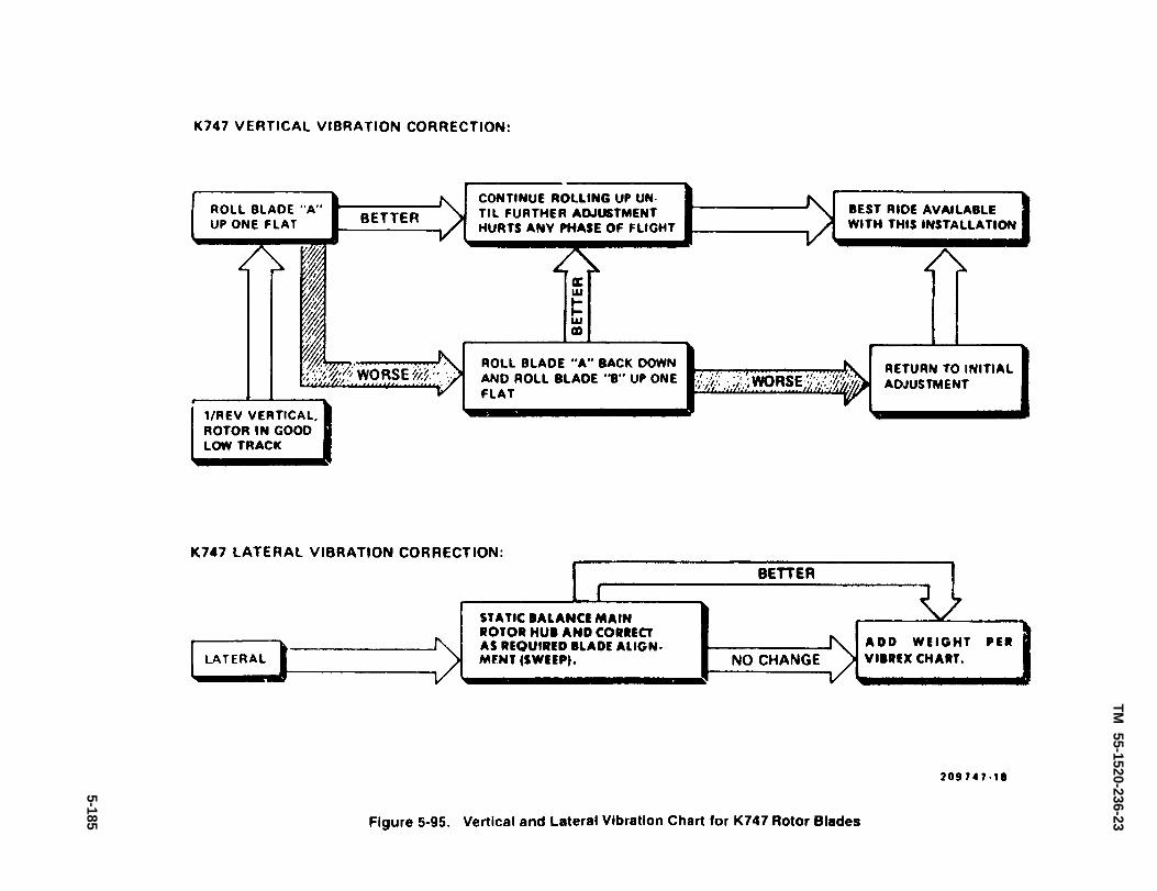
Figure 5-95.
TM
55-1520-236-23
5-185

TM 55-1520-236-23
(d) After each adjustment, test fly helicop-tar to observe effect. Continue until vertical vibration isreduced to acceptable level.
(6) Test fly helicopter through full airspeedrange to check for lateral vibrations. if lateral vibrationis severe enough to require correction, follow the se-quence below and as shown in figure 5-96.
(a) Use two-inch wide masking tape(C123) and apply to blade near the tip. When satisfac-tory operation is obtained, remove the tape and countnumber of wraps as the tape is removed. Remove hex-head plug from top of blade retaining bolt assembly(25, figure 5-2) on taped blade. For each full wrap oftape, add 2.4 ounces of lead in bolt. Reinstall plug.
(b) Sweep blade (step (5) (c) above).
(c) Check and adjust grip spacing as re-quired (paragraphs 5-43).
(d) Align blades (paragraph 5-13).
(7) Prior to incorporation of MWO 55-1520-244-50-9, check rotor rpm in autorotation. If rotor over-spends, shorten both pitch Iink assemblies equally. Ifrotor underspends, lengthen troth pitch link assem-blies equally. One turn of barrels will change rotor rpmapproximately 3 percent. Lockwire (C138) upper jam-nut to barrel. Lockwire (C138) barrel and lower jamnutto pitch link assembly tube. Repeat flight check andadjust as necessary.
(7.1) After incorporation of MWO 55-1520-244-50-9, check rotor rpm in autorotation. If rotor over-spends, shorten both pitch link assemblies equally. Ifrotor underspeeds, lengthen both pitch link assem-blies equally. One-half turn of tube assembly willchange rotor rpm approximately 3 percent. Lockwireupper and lower jamnuts to pitch link assembly tube.Repeat flight check and adjust as necessary.
c. K747 perform following procedures as re-quired for acceptable smooth operation of main rotor.Recommended sequence of procedures is also pro-vided in charts (figures 5-93, 5-94, and 5-95).
Runup of helicopter shall be performedonly by personnel authorized byAR95-1.
K747 main rotor blades have a tendencyto attain a higher percent RPM duringautorotation, then B540 main rotorblades. DO NOT RIG (adjust length ofpitch link assemblies) beyond the limitsestablished in paragraph 5-14, step q toobtain a lower main rotor percent RPM.
NOTE
K747 blades, new and repaired, mayhave tip weights (P/N 747-063-11) addedor removed to obtain proper trackingand balancing. A maximum of 32weights may be used.
(1) Adjust pitch link assembly (figure 5-9) toaccomplish main rotor tracking for K747 blades. Referto paragraph 5-116 for VIBREX 4591 system trackingprocedures.
(2) Perform a low speed blade track at 91 per-cent rpm. If track is satisfactory, omit step (3) and pro-ceed to step (4).
(3) Prior to incorporation of MWO 55-1520-244-50-9, correct a low speed out-of-track condition byshortening pitch link attached to the low blade to roll theblade up (figure 5-9). Loosen jamnuts and turn barrelto shorten tube. Turning barrel three turns will changeblade track approximately 0.375 inch. Tighten andIockwire (C138) nuts. Repeat checks and adjustmentuntil satisfactory.
NOTE
After application of lockwire, apply athin cost of sealant (C105) around thelock nut and threads of the rod end toprevent water intrusion.
(3.1) After incorporation of MWO 55-1520-244-50-9, correct a low speed out-of-track condition byshortening pitch link assembly attached to the lowblade to roil the blade up (figure 5-9). Loosen jamnutsand turn tube assembly to shorten tube. Turning tubeone and one-half turns will change blade trackapproximately 0.375 inch. Tighten and lockwire (C138)nuts. Repeat checks and adjustments until satisfac-tory.
5-186

TM 55-1520-236-23
(4) Perform a high speed track at 100 percentrpm. If out-of-track record which blade is low but makeno adjustments.
(5) Test fly helicopter. If vertical vibration isnot evident proceed to step (6). If vertical vibration re-quires correction, begin sequence of adjustments indi-cated in figure 5-95 as applicable according to air-speed where vibration occurs.
(a) To roll a blade, adjust pitch link as instep (3) above.
(b) To sweep a blade, loosen jamnuts onblade drag brace (12, figure 5-2) enough to turn barrelone full turn as shown by decal arrows. Torque jamnuts150 TO 200 foot-pounds without moving barrel.
Record all such adjustments, and do not exceed TWOfull turns total adjustments.
NOTE
The blade sweep adjustments Is alsoused to correct lateral vibration. Referto step (6).
If maximum blade sweep adjustmentfalls to correct rotor vibrations removemain rotor hub and blade assembly andalign blades (paragraphs 5-12 and 5-13).
(c) After each adjustment, test fly helicop-ter to observe effect. Continue until vertical vibration isreduced to acceptable level.
5-186.1/(5-186.2 blank)


Figure 5-96.
TM
5
5-1
52
0-2
36
-23
5-1
87

TM 55-1520-236-23
Figure 5-97. Tracking Main Rotor
(6) Test fly helicopter through full airspeed range 5 - 1 1 5 . T R A C K I N G – T A I L R O T O R
to check for lateral vibrations. If lateral vibration is BLADES.
severe enough to require correction, request AVIMassistance to check alignment of installed blades Premaintenance Requirements For Tracking
(sweep). of Tail Rotor System
K747 main rotor blades have a tendency toattain a higher percent RPM duringautorotation than B540 main rotor blades.DO NOT RIG (adjust length of pitch linkassemblies) beyond the Iimits established inparagraph 5-14, step q to obtain a lowermain rotor percent RPM.
(7) Prior to incorporation of MWO 55-1520-244-50-9, check rotor rpm in autorotation. If rotoroverspeeds, shorten both pitch link assemblies equally.If rotor underspeeds, lengthen both pitch linkassemblies equally. One turn of barrels will changerotor rpm approximately 3 percent. Lockwire (C138)jamnuts. Repeat flight check and adjustment asnecessary.
(7.1) After incorporation of MWO 55-1520-244-50-9, check rotor rpm in autorotation. If rotoroverspeeds, shorten both pitch link assemblies equally.If rotor underspeeds, lengthen both pitch linkassemblies equally. One-half turn of tube assembly willchange rotor rpm approximately 3 percent. Lockwireupper and lower jamnuts to pitch link assembly tube.repeat flight check and adjust as necessary.
Condition Requirements
Model
Part No. or Serial No.
Special Tools
Test Equipment
Support Equipment
Minimum PersonnelRequired
Consumable Materials
Special EnvironmentalConditions
AH-1E, F, & P
All
NA
Tracking stick
NA
Two
(C92)
None
NOTE
The VIBREX 4591 system is the preferredmethod of tracking tail rotor blades. (Referto paragraph 5-142.)
5-188

TM 55-1520-236-23
a. After replacement of installation of tail rotorhub blades or pitch change systems, check tail rotorrigging and set pitch links to 2.74 ± .010 inchesbetween the jam nuts. Note this jam nut to jam nutdimension does correspond to the dimension of 6.115± .010 inches between the centers of the pitch linkbearings. Tail rotor tip clearance shall be checked andboth pitch link adjusted if necessary. This proceduremay be used instead of tracking the tail rotor bladesusing a strobe light.
NOTE
The strobe-type tracking device may beused if available (paragraph 5-116).
b. Make a tracking stick by attaching a smallpiece of sponge rubber 1/8 TO 1/4 inch thick to end ofa 1/2 X 1/2 inch pin stick, approximately 4 feet long orany other flexible device. Coat sponge rubber withPrussian blue (C92) or similar type of coloring thinnedwith oil.
The runup shall be performed by per-sonnel authorized in accordance withAR 95-1.
Do not approach the tail rotor area forthe purpose of tracking until 100 per-cent rpm has been established and it iscertain that the helicopter is not goingto yaw left or right due to rigging erroror slippery parking surface. injury ordeath could result from being struck bythe tail rotor blades
c. Start engine. Run at 100 percent rpm withpedals in neutral position. Rest tracking stick on under-side of tail fin assembly as shown in figure 5-98. Slowlymove tracking stick toward disc of tail rotor just farenough to lightly contact a blade approximately oneinch from tip. Pull stick back immediately.
d After contact is made, stop engine and allowrotor to stop. Shorten pitch link assembly on unmarkedblade 1/2 turn of rod end. Reinstall pitch link assemblybolt, washers and rotter pin.
Figure 5-98. Tracking Tail Rotor
5-189

TM 55-1520-236-23
e. Recheck track of blades. Proceed with adjust-ments, if required, by adjusting pitch links equallyin opposite directions.
f. Make operational test flight and check thatnormal right and left turn can be made in autorota-tional and powered flight.
g. Check tail rotor forces as follows:
(1) Start engine and run at 100% withpedals in neutral position.
(2) Turn force trim-OFF. Place HYDRcontrol switch to SYS 2-ON, so tail rotor hydrauliccylinder is not powered. Observe pedals remainingat neutral when foot pressure is removed.
(3) If left pedal creeps forward, less weightis needed on tail rotor counterweight.
(4) If right pedal creeps forward, moreweight is needed on tail rotor counterweight.
(5) Move HYDR switch to ON position andshut down engine.
Identical weight must be maintainedat all four positions on bellcrank. Usemaximum of two weights and onewasher, or minimum of one weightand five washers.
h. Adjust tail rotor forces as follows:
(1) Remove nut (19, figure 5-76) andwasher (18) from bolt (16).
(2) Add or remove weight es determined insteps g(3) or g(4). Remove only one weight at eachposition. Replace with AN960 or AN970 washers, ora combination of both types.
(3) lnstall washer and nut on bolt. Torquenut 50 TO 70 inch-pounds.
(4) Repeat check and adjustment stepsuntil forces are satisfactory.
(5) Track tail rotor blades.
5-116. TRACKING AND BALANCING ROTORBLADES AND TROUBLESHOOTING OTHERROTATING ELEMENTS USING THE VIBREX4591 SYSTEM.
5-117. DESCRIPTION-VIBREX 4591 SYS-TEM.
a. The Vibrex 4591 System may be used toelectronically track and balance main and tail rotorblades and troubleshoot other rotating elements. Seefigure 5-99 for view of Vibrex System components.
5-190
b. Description and specifications of the Vibrex4591 System are presented in FO3 (foldout 3). Usingthe synchronized Strobex, track is visually displayedby rotor Tip Targets. One-per-revolution vibration ismeasured from an Accelerometer mounted laterallyon the airframe to indicate the condition of main rotorbalance. Another Accelerometer, mounted verticallyin the front cockpit, reads vertical vibration fromout-of-track. The Balancer meter indicates amount,and the Phazor shows location of the required correc-tion, when interpreted by the Track and BalanceCharts. Tail rotor balancing is done by mounting anAccelerometer on the fin near the tail rotor gear box.Amplitude of vibration is read from the Balancermeter to indicate the amount of weight change re-quired, and the Strobex, triggered by the Balancer,shows “Clock Angle” that tells where to put theweight. Tail rotor Balance Charts interpret thesereadings. To locate sources of vibration other than therotors, the Accelerometer is relocated and theBalancer's filter is tuned to the peak vibration levels.The RPM rate of these vibrations is related to knowncomponent RPM to identify the offending element.
c. Track and Balance Charts, CheckIist and“Clock Angle” Corrector. Charts tell what to do torotor, in response to reading from Balancer, to correcttrack or balance.
d. Magnetic Pickup, Bracket, and Cable.Mounted on stationary swashplate of main rotor, theMagnetic Pickup delivers an electrical pulse thatseines as a trigger for the Strobex for main rotortracking, and as a phase reference for the phase meterin the Balancer.
e. Accelerometers, Accelerometer Bracket,and Cable. Accelerometers sense the vibration in-duced by rotors, shafts, fans, bearings, gears, etc.
f. Tip Targets. One is mounted on each main rotorblade tip. Used for viewing main rotor track.
g. VIBREX Tester. For functional test of theVIBREX 4591 System.
h. Strobex Blade Tracker. Used for trackingboth main and tail rotors, and for measuring “ClockAngle” when balancing tail rotors.
i. Gram Scale. For weighing balance weights.
j. Carrying Case. For all the equipment.

TM 55-1520-236-23
k. Interrupters. Two Interrupters are mounted onthe rotating swashplate of the main rotor, 180° apart.Each time an Interrupter passes the Magnetic Pickup,an electrical pulse is generated in the Pickup. Thesepulses cause the Strobex to flash twice-per-revolution to illuminate reflective Targets on theblade tips for visual tracking.
One of the Interrupters is double, delivering a doublepulse from the Magnetic Pickup, once-per-revolution.
5-190.1/(5-190.2 blank)


TM 55-1520-236-23
Figure 5-99. Vibrex 4591 System Components and Carrying Case
5-191

TM 55-1520-236-23
This serves as the needed one-per-revolution phasereference signal for the Phazor section of theBalancer.
1. Balancer/Phazor Unit. Measures amplitudeand phase, or “Clock Angle, ” of the vibration inducedby rotors and other components that are out-of-balance or track.
5-118. GENERAL NOTES.
Do not plug the VIBREX into 110 voltpower. The instruments may bedamaged. Do not set Balancer “RPMTune” dial below 100. The circuits areunstable and the readings useless.
a. There are two basics which MUST beunderstood and mastered to utilize the Systemeffectively.
One is the tuning of the Balancer band-pass filter.This procedure is spelled out in detail and takes butlittle practice. Follow the instructions carefully!
The other requirement is a good grasp of the Charts. Itis important to know the direction in which the “MoveLine” SHOULD go in response to a certain change onthe rotor. (The “Move Line” is the line connecting thedata points before and after a change on the rotor.)Only then can it be determined whether the Chart is“matched” to the helicopter being worked. Chartexamples are given, with explanations.
b. It is normal operation for the “Clock Angle” tobecome uncertain and erratic as balance is improved.A “jittery” “Clock Angle” is generally an indication ofa good balance.
c. When the Balancer is first plugged in (or powerapplied), the meter will deflect to full scale for a fewseconds. This is normal, and the meter is protected sono damage results.
d. Do not change the connector on the BalancerDC Cable. Use DC Adapter #3140-9 which is a foot-Iong Cable with a connector at one end to mate withthe Balancer’s connector, and a connector at theother end to mate to the helicopter.
e. When tracking rotor blades, look directly overtop of Strobex when viewing retro-reflective Targets.Those who are sitting or standing to the side of theuser will see the Targets very dimly, or not at all,because the reflected light returns to the source andnot to the observer to the side.
f. A RULE-OF-THUMB: As long as a good “ClockAngle” can be measured in the Phazor, or with theStrobex, the balance or track can, and should, bemade better. When balance is perfected to the pointwhere the “Clock Angle” becomes too unsteady orerratic, it can no longer be determined where to putthe weight, and the job must be considered complete.
g. It may not be possible to achieve a satisfactoryride over a wide speed and load range due todifferences in rotor blade characteristics. Thesedifferences in flight characteristics are usuallyrevealed when working track with the verticalAccelerometer.
h. FOCUS OF THE FLASH TUBE IN ITSPARABOLIC REFLECTOR IS ESSENTIAL! Periodicallyshine the light on a wall 10 to 20 feet distant andcheck for a bright spot 1 to 2 feet in diameter. If this isnot seen, FOCUS IN ACCORDANCE WITHINSTRUCTIONS IN TM 55-4920-402-13&P.
(1) “IPS” (inches-per-second) or maximumvelocity as the object passes through the center of itsvibratory motion. Knowing frequency, or RPM, thiscan be related to displacement (roils) or G force (G) asfollows.
D (mils, peak-to-peak) =“IPS” x 19,000
RPM
“IPS” x RPMG (peak) = 3686
(2) When the filter is properly tuned, thereshould be no change in either “’Clock Angle” or “IPS”when the “Verify Tune” button is pushed. TheAccelerometer is sensitive only along its cylindricalaxis. If shaken radially, it will have little or no output.
5-192

TM 55-1520-236-23
5 - 1 1 9 . T R A C K A N D B A L A N C EC H A R T S .
a. The Charts are the “computers” that are usedto plot the measurement of vibration (“Clock Angle”and amplitude) obtained from the Balancer/Phazor.(The Strobex is used to measure “Clock Angle” in thecase of tail rotors. ) The main rotor Charts tell theweight or sweep required to balance the main rotor,pitch-link, or tab required to track it. Tail rotor Chartsshow amount and location of weight needed tobalance.
A different Chart is provided for each rotor of eachhelicopter type, A Chart (Figure 5-100) consists of:
(1) A clock face (12 radial lines) representing“Clock Angle, ” or location of the vibration;
(2) A set of 10 concentric circles representing“IPS,” or amplitude of vibration, drawn over the clockface, with zero at the center and 1.0 “IPS” at theoutside; and
(3) A graph over the clock face and “IPS”circles, whose axes are geometrically related to thepoints at which rotor changes (weight, sweep, pitch-Iink, or tab) can be made.
b. The intersection of “IPS” circle and “ClockAngle” line defines a point on the Charts. From thispoint, lines to the axes of the graph show amount andlocation of change or adjustment to accomplish trackor balance. The objective is to reduce the vibration tothe lowest possible level, or the center of the Chart,“Clock Angle” is not important, except as a means ofgetting there (it tells where to make the change). Low“IPS” (vibration) level is the only importantconsideration.
5 - 1 2 0 . M A I N R O T O R C H A R TE X A M P L E S A N D C O R R E C T I O N S .
NOTETake balance readings only when bladesare in-track.
5 - 1 2 1 . R E A D I N G A M A I N R O T O RBALANCE CHART. (Figure 5-101).
a. Assume a reading of 10:00 o’clock and 0.6“IPS.”
b. Plot this on the Chart, labeling it point #1.Sketch lines to the two axes of the Chart,
c. The Chart calls for about 180 grams in the“blank” blade bolt, and for sweeping the “blank”blade aft about 6 flats.
d. The first “move” should involve only onechange. Sweep should be selected, because it isfurther from the zero line and calls for the greaterchange.
e. If the “move” were perfect, the next readingshould be at 11:45 o’clock and about 0.4 “IPS,” Labelthis point #2.
f. Now, addition of 180 grams to the blank bladeshould reduce the lateral vibration to near zero, Labelit #3.
NOTEObserve that when weight is added to ablade, the “Move Line” should beparallel to the weight arrow along theedge of the Chart. If sweep is changed,the “Move Line” should be parallel to thesweep axis arrows.
NOTEIt can be seen that if weight weresubtracted from the “target” blade, itwould have exactly the same effect asweight addition to the “blank.” Theblade bolts should always be checked,and weight subtracted wheneverpossible.
5 -122 . WORKING WITH A HELlCOPTERTHAT DOES NOT “MATCH” THE CHART(INCORRECT “CLOCK ANGLE”), (Figure 5-102).
It is very seldom that a Chart needs to be corrected,but an explanation of its simplicity is important. Thedynamic response (vibration characteristics) of onehelicopter of a given type may not be exactly the sameas another. This can cause the vibration of theairframe to occur at a different time (or differentphase) in response to a given pitch-link or weightchange. Thus, the helicopter does not “match” theChart. It is easy to correct the Chart. The process isdescribed here:
a. Assume the same reading of 10.00 o’clock and0.6 “IPS.” Label it point #1.
b. Make the same 6 flat sweep change to the“blank” blade, as indicated.
5-193
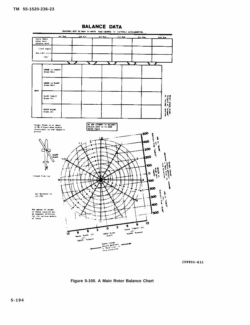
TM 55-1520-236-23
Figure 5-100. A Main Rotor Balance Chart
5 - 1 9 4

TM 55-1520-236-23
Figure 5-101. Reading a Main Rotor Balance Chart
5-195
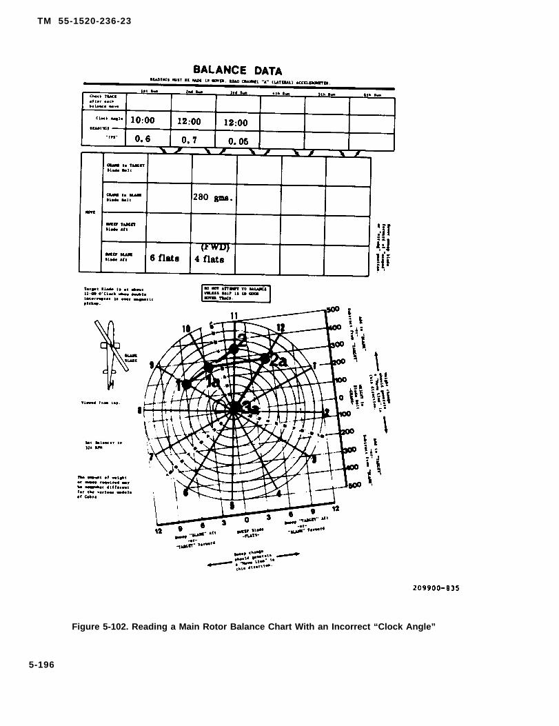
TM 55-1520-236-23
Figure 5-102. Reading a Main Rotor Balance Chart With an Incorrect “Clock Angle”
5-196
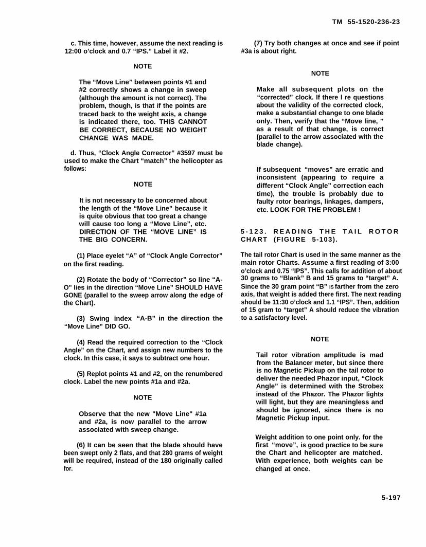
TM 55-1520-236-23
c. This time, however, assume the next reading is12:00 o’clock and 0.7 “IPS.” Label it #2.
(7) Try both changes at once and see if point#3a is about right.
NOTENOTE
The “Move Line” between points #1 and#2 correctly shows a change in sweep(although the amount is not correct). Theproblem, though, is that if the points aretraced back to the weight axis, a changeis indicated there, too. THIS CANNOTBE CORRECT, BECAUSE NO WEIGHTCHANGE WAS MADE.
d. Thus, “Clock Angle Corrector” #3597 must beused to make the Chart “match” the helicopter asfollows:
NOTE
It is not necessary to be concerned aboutthe length of the “Move Line” because itis quite obvious that too great a changewill cause too long a “Move Line”, etc.DIRECTION OF THE “MOVE LINE” ISTHE BIG CONCERN.
(1) Place eyelet “A” of “Clock Angle Corrector”on the first reading.
(2) Rotate the body of “Corrector” so Iine “A-O" Iies in the direction “Move Line” SHOULD HAVEGONE (parallel to the sweep arrow along the edge ofthe Chart).
(3) Swing index “A-B” in the direction the“Move Line” DID GO.
(4) Read the required correction to the “ClockAngle” on the Chart, and assign new numbers to theclock. In this case, it says to subtract one hour.
(5) Replot points #1 and #2, on the renumberedclock. Label the new points #1a and #2a.
NOTE
Observe that the new "Move Line" #1aand #2a, is now parallel to the arrowassociated with sweep change.
(6) It can be seen that the blade should havebeen swept only 2 flats, and that 280 grams of weightwill be required, instead of the 180 originally calledfor.
Make all subsequent plots on the“corrected” clock. If there l re questionsabout the validity of the corrected clock,make a substantial change to one bladeonly. Then, verify that the “Move line, ”as a result of that change, is correct(parallel to the arrow associated with theblade change).
If subsequent “moves” are erratic andinconsistent (appearing to require adifferent “Clock Angle” correction eachtime), the trouble is probably due tofaulty rotor bearings, linkages, dampers,etc. LOOK FOR THE PROBLEM !
5 - 1 2 3 . R E A D I N G T H E T A I L R O T O RCHART (FIGURE 5-103).
The tail rotor Chart is used in the same manner as themain rotor Charts. Assume a first reading of 3:00o’clock and 0.75 “IPS”. This calls for addition of about30 grams to “Blank” B and 15 grams to “target” A.Since the 30 gram point “B” IS farther from the zeroaxis, that weight is added there first. The next readingshould be 11:30 o’clock and 1.1 “IPS”. Then, additionof 15 gram to “target” A should reduce the vibrationto a satisfactory level.
NOTE
Tail rotor vibration amplitude is madfrom the Balancer meter, but since thereis no Magnetic Pickup on the tail rotor todeliver the needed Phazor input, “ClockAngle” is determined with the Strobexinstead of the Phazor. The Phazor lightswill light, but they are meaningless andshould be ignored, since there is noMagnetic Pickup input.
Weight addition to one point only. for thefirst “move”, is good practice to be surethe Chart and helicopter are matched.With experience, both weights can bechanged at once.
5-197
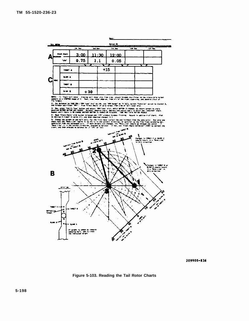
TM 55-1520-236-23
Figure 5-103. Reading the Tail Rotor Charts
5-198
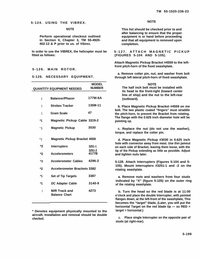
TM 55-1520-236-23
5 - 1 2 4 . U S I N G T H E V I B R E X .
NOTE
Perform operational checkout outlinedIn Section II, Chapter 3, TM 55-4920-402-13 & P prior to us. of Vibrex.
In order to use the VIBREX, the helicopter must befitted as follows:
5 - 1 2 6 . M A I N R O T O R .
5-126. NECESSARY EQUIPMENT.
MODELQUANTlTY EQUIPMENT NEEDED NUMBER
1
1
1
*1
* 1
* 1
*2
*2
*2
*2
*1
*1
1
Balancer/Phazor 177M-6A
Strobex Tracker 135M-11
Gram Scale 47
Magnetic Pickup Cable 3319-2
Magnetic Pickup 3030
Magnetic Pickup Bracket 4559
Interrupters 3251-13251-2
Accelerometers 4177B
Accelerometer Cables 4296-2
Accelerometer Brackets 3382
Set of Tip Targets 3387
DC Adapter Cable 3140-9
M/R Track and 4273Balance Chart
* Denotes equipment physically mounted to theaircraft. Installation and removal should be doublechecked.
NOTE
This list should be checked prior to andafter balancing to ensure that the properequipment is or hand before proceedingand that all equipment is removed uponcompletion.
5 - 1 2 7 . A T T A C H M A G N E T I C P I C K U P(FIGURES 5-104 AND 5-105).
Attach Magnetic Pickup Bracket #4559 to the left-front pitch-horn of the fixed swashplate.
a. Remove cotter pin, nut, and washer from boltthrough left lateral pitch-horn of fixed swashplate.
NOTEThe half inch bolt must be installed withits head to the front-right (toward centerline of ship) and the nut to the left-rear(outboard).
b. Place Magnetic Pickup Bracket #4559 on mebolt. The two plastic coated “fingers” must straddlethe pitch-horn, to prevent the Bracket from rotating.The flange with the 0.625 inch diameter hole will bepointing up.
c. Replace the nut (do not use the washer),torque, and replace the cotter pin.
d. Place Magnetic Pickup #3030 in 0.625 inchhole with connector away from mast. Use thin jamnuton each side of Bracket, leaving them loose, with thetip of the Pickup extending as little as possible. Adjustand tighten nuts later.
5-128. Attach Interrupters (Figures 5-104 and 5-105). Mount Interrupters #3251-1 and -2 on therotating swashplate.
a. Remove nuts and washers from four studsindicated by “X” (figure 5-105) on the outer ringof the rotating swashplate.
b. Turn the head so the red blade is at 11:00o’clock and place the double Interrupter, with pointedflanges down, at the left-front of the swashplate, Thisbecomes the “target” blade, (Later, you will put thehorizontal Target on the red blade tip — so RED =target = horizontal.)
c. Place single Interrupter on the opposite pair ofstuds (at right-rear).
5-199

TM 55-1520-236-23
Figure 5-104. Magnetic Pickup and Double Interrupter Installation.
d. Replace nuts, (do not reinstall washers at thistime, save washers for reinstallation after removing in-terrupters), torque nuts.
NOTE
When installing interrupters, push themin toward mast as the nuts are tightenedso they will both “seat” the same.
5-129. Adjust Magnetic Pickup Gap. Carefully -- BYHAND -- pull the rotor head through to line up an Interrupterwith the Magnetic Pickup.
a. Adjust the Pickup for a 0.060 +/-0.010 inchclearance. HINT: A coin can be used as a feeler gauge.A penny is about 0.060 inch thick. A nickel is about 0.075inch thick, A dime is about 0.050 inch thick and a quarteris about 0.070 inch thick.
b. Tighten and safety jamnuts on Pickup.
5-200
c. Pull head to other Interrupter. Check for properclearance. (Clearances need not be precisely the same;0.010 or 0.020 inch difference is acceptable.)
d. If difference is too great, loosen nuts on Interrup-ter and adjust as required.
5-130. Connect Magnetic Pickup Cable (Figure 5-106).Connect Cable #3319-2 to Magnetic Pickup.
a Move cyclic stick of helicopter to its farthestright-rear position, so left-front control rod is in its far-thest up position (Ieft-front corner of swashplate farthestup).
b. Plug Cable #3319-2 into Magnetic Pickup. Tapeor tie Cable to control rod, just below rivets in swagedend, with only an inch or so of slack.
c. Bring Cable out the swashplate access door.Secure it with enough slack to allow complete and freemovement of controls, but not enough so Cable can foulin any moving parts. Pinch Cable in door.

TM 55-1520-236-23
Figure 5-105. Magnetlc Pickup/Interrupter Installation.
d. Open hydraulics access door and pinch Cable indoor (in top and out bottom). Then, dress forward underleft side of pilot’s canopy, taping about twice. Pass Cableinto gunner’s cockpit, behind headrest, and coil excessCable between armor at gunner’s right shoulder andcanopy.
e. Remove gunner’s elbow pads. Place Balancer onthe right side and the Strobex on the left.. Leave enoughCable slack so Balancer may be used in observer’s lap.
f. Alternate method for routing Cable Run Cablethrough the E.C.U. blower hole on forward wall of trans-mission area Add enough slack to allow complete andfree movement of controls, but not enough so Cable canfoul in any moving parts. Run Cable through hydrauliccompartment on left side to grommeted hole at top ofcompartment just to the left of E.C.U., pass Cable through
hole. Pass Cable into gunner cockpit, coil excess and stowin pilot left side storage pouch.
CAUTIONAvoid using tape in front of the engine air in-take where it could F.O.D. the engine. Besure instruments cannot jam controls. Checkfor free movement of cyclic, collective, andpedals.
5.131. Connect Balancer to DC Power (Figure 5-107).Plug Balancer into helicopter DC power. Use DC AdapterCable #3140-9 and plug into map light at gunner seat.Remove retaining clip from front glass. Remove glass andbulb. Plug Cable #3140-9 into lamp socket.lamp intensity to full brightness (CW).
Be sure to turn
5-201

TM 55-1520-236-23
Figure 5-106. Magnetic Pickup Cable Installation
NOTE
In the older map lights, the lamp isremoved from the side of the fixture,with its receptacle. When Cable #3140-9 is plugged into the receptacle, it cannotbe replaced in the fixture; therefore,there is no ground connection. Usealligator clip on ground lead and clip ontoa convenient screw or protrusion for theground connection.
5-132. Mount Accelerometers and ConnectCables. (Figures 5-108 and 5-109.)
a. Using the 3382 bracket (2, figure 5-108),install one accelerometer (1 ) on the pilotscompartment aft bulkhead with the connectorpointing to the right side of the helicopter. Connectaccelerometer to the A input on Balancer with one ofthe accelerometer cables.
b. Mount another accelerometer (figure 5-109)using another bracket #3382, to the right side of thefront cockpit. Mount it with the lower forward screwof the copilot canopy removal system, arm and firemechanism mount bracket. The accelerometershould be vertical with the CONNECTOR DOWN. Anyother convenient screw may be used in the samearea, Accelerometers are both inside the canopy.Connect this to Channel B using another cable#4296-1.
5-133. Attach Tip Targets.
Attach Tip Targets #3387 to blade tips (figure5-111). Use 1/4-28 inch bolts and self-locking nutsand bolt them through the tie-down holes in the tips.The Retro-reflective bar on the target must face
5-202

TM 55-1520-236-23
Figure 5-107. Balancer Installation
inboard (to be viewed from the cockpit). Put theHORIZONTAL bar on the RED blade tip, and thevertical bar on the opposite.
Tip Targets MUST BE TANGENT to tippath (parallel to blade tip).
NOTE
As an alternate method of tracking,use reflective strips #4270 and stickthem on underside of blade tip as il-lustrated (figure 5-112). Clean the areawhere the targets are to be applied.Don’t use fuel because it is too oily.
5 - 1 3 4 . S E T C O N T R O L S .
5-135. SET BALANCER 1 7 7 M - 6 A A SFOLLOWS:
a. “Magnetic Pickup” to “Common. ”
b. “Interrupter Logic” to “Double.”
c. “Function” switch to “Track.”
d. “RPM Range” to “X 1.”Main rotor RPM.
e. “RPM Tune” to “324.”
5-203
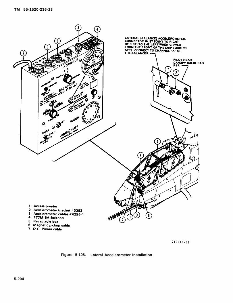
TM 55-1520-236-23
Figure 5-108. Lateral Accelerometer Installation
5-204

TM 55-1520-236-23
Figure 5-109. Vertical Accelerometer Installation(Page 5-206, Figure 5-110 Deleted)
5-205/(5-206 blank)


TM 55-1520-236-23
5-136. SET STROBEX 135M-11 ASFOLLOWS:
a. “Mode” switch to “A” in which Light is incase oscillator is inoperative and lowsetting of the “RPM” dial has no effectand is unimportant. Targets will be
intensity
seen at about 1:00 o’clock.mode.
b. “Mode” switch to “B” and “RPM” dial to about 240 or less. Seeformula on back of Strobex. Thisallows viewing the Targets at the frontof the ship. Setting the “RPM” dial toabout 500 or less allows viewing theTargets at 11:00 o’clock, and about2:00 and 8:00 o’clock as welladvancing and retreating blades).
(for
Light is inhighintensitymode.
Oscillator MUST BE SET IN MODE “A”or “B” except for tail rotor track.
5 - 1 3 7 . B A L A N C E M A I N R O T O R .
a. Zero tabs and hover helicopter. Use Strobexand search tip path in a “W” pattern to find the TipTargets at about 11:00 o’clock. Observe track andcorrect as required, using pitch-link adjustment.
b. When hover track is set, switch Balancer“Function” switch to “A”. (Lateral Accelerometer forbalance.) Balancer is set to 324 RPM. While hovering,push “Test” button and check for 12:00 and 6:00o’clock lights in Phazor. If you do not have 12:00and 6:00 o’clock Iights in Phazor with test buttonpushed, shut down aircraft and check out systemfor proper instalIation or failure.
Release “Test” button and observe “Clock Angle” oflighted light in the ring-of-lights.
c. Push “Verify Tune” button, and adjust “RPMTune” dial WHILE BUTTON IS PUSHED, to return lightto angle observed BEFORE button was pushed.Release, observe angle, push and adjust again tomatch new “unpushed” angle. Repeat until there isNO CHANGE whether button is pushed or released.
d. After tuning, read “Clock Angle” and “IPS”and record on the Balance Chart.
e.
NOTE
The “Clock Angle” readings (the lightedlight in the Phazor) will seldom beperfectly steady. It will become muchless steady (more jittery) as balance isimproved (“IPS” reading is lowered).When the “verify Tune” button ispushed, the “Clock Angle” should beless jittery than with the button released.Tuning must be adjusted so the“pushed” pattern lies in the center of the“unrushed’,’ pattern. Simply judge thecenter of the “jittery range” of the lights.
Land helicopter and plot a point on the BalanceChart at the intersection of “Clock Angle” line and“IPS” circle. Lable it point #1. Determine changesrequired in blade bolt weight and sweep, and recordin Data Section. Change either blade bolt weight, orsweep, whichever is farthest from the zero line.
NOTE
the firstto check
results (label
Make only one change far“move.” This makes it easierthe correctness of the Chart.
f. Hover helicopter and checksecond point #2). If “Move Line” (point #1 to #2) is incorrect direction, proceed to balance until reading is0.1 “IPS” or less, If “Move Line” is not in correctdirection, use “Clock Corrector” #3597 and assignnew numbers to clock. Then, proceed to balanceusing relabeled clock.
NOTEGood balance is essential for goadresults! As long as you can get areasonably usable “Clock Angle” youcan make the balance better, and should.
5 - 1 3 8 . R E A D I N G T H E M A I N R O T O RCHART (FIGURE 5-113).
The main rotor chart is used in the following manner.Assume a first reading of 10:00 o’clock and 0.65“lPS”, sketching lines to the edges of the charts, thisreading calls for a sweep change of 6 flats aft to the“blank” blade and addition of 200 grams to the“blank” blade. Since the sweep change is fartherfrom the zero axis, that adjustment is made first. Thenext reading should be 11:45 o’clock at 0.4 “IPS”.Then addition of 200 grams to the “blank”’ bladeshould reduce the vibration to a satisfactory level.
5-207

TM 55-1520-236-23
Figure 5-111. Tip Targets Installation
5-139. IN-FLIGHT TRACK MAIN ROTOR.
a. Switch Balancer “Function” switch to “track.”(Everything else is the same.)
Strobex maybe used in position “A” or “B”, see “SetControls” Section.
b. Fly the helicopter and sketch, in the spacesprovided on Tracking Chart, the track observedat 90 and 140 knots. Do not exceed a reasonableairspeed for the conditions of track, density,altitude, load, etc. at each airspeed above, switchBalancer “Function” switch to “B” (vertical Ac-celerometer). Press “Test” button and look for12:00 and 6:00 o’clock lights.
c. Release “Test”Angle” of lighted light
5-208
button and observe “Clockin ring-of-lights.
d. Push “Verify Tune” button, and adjust “RPMTune” dial WHILE BUTTON IS PUSHED, to return lightto angle observed BEFORE button was pushed.Release, observe angle, push and adjust again tomatch new “unpushed” angle, Repeat until there isNO CHANGE whether button is pushed or released.After tuning, record “Clock Angle” andand 140 knots, in the spaces provided.
NOTE
Tuning is exactly the same astaking balance readings.
“IPS” at 90
when
e. Land the helicopter, Plot the 140 knot (orhighest speed reached) readings on the TrackingChart, at the intersection of “Clock Angle” line and“IPS” circle, (USE “B” VERTICAL ACCELEROMETERFOR IN-FLIGHT TRACK).

TM 55-1520-236-23
Figure 5-112. Reflective Target Installation
5-209

TM 55-1520-236-23
Figure 5-113. Reading the Main Rotor Chart
5-210
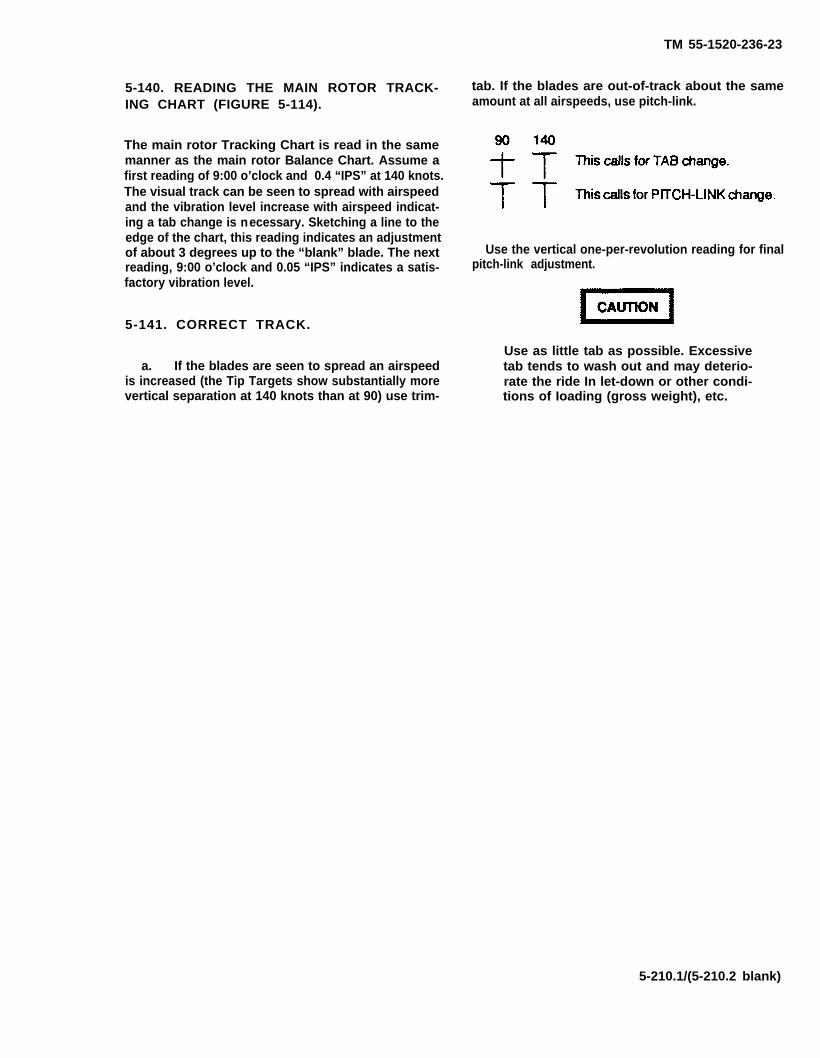
TM 55-1520-236-23
5-140. READING THE MAIN ROTOR TRACK-ING CHART (FIGURE 5-114).
The main rotor Tracking Chart is read in the samemanner as the main rotor Balance Chart. Assume afirst reading of 9:00 o’clock and 0.4 “IPS” at 140 knots.The visual track can be seen to spread with airspeedand the vibration level increase with airspeed indicat-ing a tab change is necessary. Sketching a line to theedge of the chart, this reading indicates an adjustmentof about 3 degrees up to the “blank” blade. The nextreading, 9:00 o’clock and 0.05 “IPS” indicates a satis-factory vibration level.
5-141. CORRECT TRACK.
a. If the blades are seen to spread an airspeedis increased (the Tip Targets show substantially morevertical separation at 140 knots than at 90) use trim-
tab. If the blades are out-of-track about the sameamount at all airspeeds, use pitch-link.
Use the vertical one-per-revolution reading for finalpitch-link adjustment.
Use as little tab as possible. Excessivetab tends to wash out and may deterio-rate the ride In let-down or other condi-tions of Ioading (gross weight), etc.
5-210.1/(5-210.2 blank)


b. Fly the helicopter again and check results.Repeat if required to reduce “B” readings (vertical one-per-revolution) to 0.2 "IPS" or less. Check all air-speeds.
NOTE
The “Move Line”, In response toEITHER tab or pitch-link, should fallroughly along the 3:00 through 9:00o’clock line. If the “Move Line” isapproximately parallel to this, BUTDOES NOT GO THROUGH THE CENTEROF THE CHART, it is likely that due tovariations In the blade flight character-istics that THEY CANNOT BE MADE TOFLY TOGETHER without some degreeof vibration since there is no controlavailable to cause a “Move Line” in the12:00 to 6:00 o’clock direction, the pointwhere the “Move Line” is tangent to the"IPS" circles is the best ride attainablewith that pair of blades.
Conditions of rod-ends and linkagesmay have some effect, but with every-thing tight it is probably blades.
After In-flight tracking, check auto-rotation RPM, and correct as required.Track changes will have some effect onbalance readings. Therefore, balanceshould be checked In hover after eachtrack change, before the check flight.
5-142. TAIL ROTOR TRACK AND BALANCE.
NOTE
For Aviation Vibration Analyzer (AVA)refer to TM 1-6625-724-13&P.
TM 55-1520-236-23
5-143. NECESSARY EQUIPMENT.
MODELQUANTlTY EQUIPMENT NEEDED NUMBER—
1 Balancer/Phazor 177M-6A11
*1*1*1*1*13
Strobex TrackerGram ScaleAccelerometerAccelerometer BracketAccelerometer CableDC Adapter CableDC Extension CableReflective Targets
135M-11474177B33824296-23140-93529
1 T/R Balance Chart 4471
*Denotes equipment physically mounted to the air-craft. Installation and removal should be doublechecked.
a. Check the above list prior toad after balanc-ing to ensure that the proper equipment is on hand be-fore proceeding, and that all equipment is removedupon completion.
b. Static balance the tail rotor in accordance withparagraph 5-86 prior to installation.
5 -144 . CONNECT A C C E L E R O M E T E R ,CABLES, TARGETS, AND INSTRUMENTS(FIGURE 5-115).
a. Attach Accelerometer, on Bracket #3382,under the bottom screwhead that secures gearbox
5-211

TM 55-1520-236-23
Figure 5-114. Reading the Main Rotor Tracldng Chart (Sheet 1 of 2)
5-212
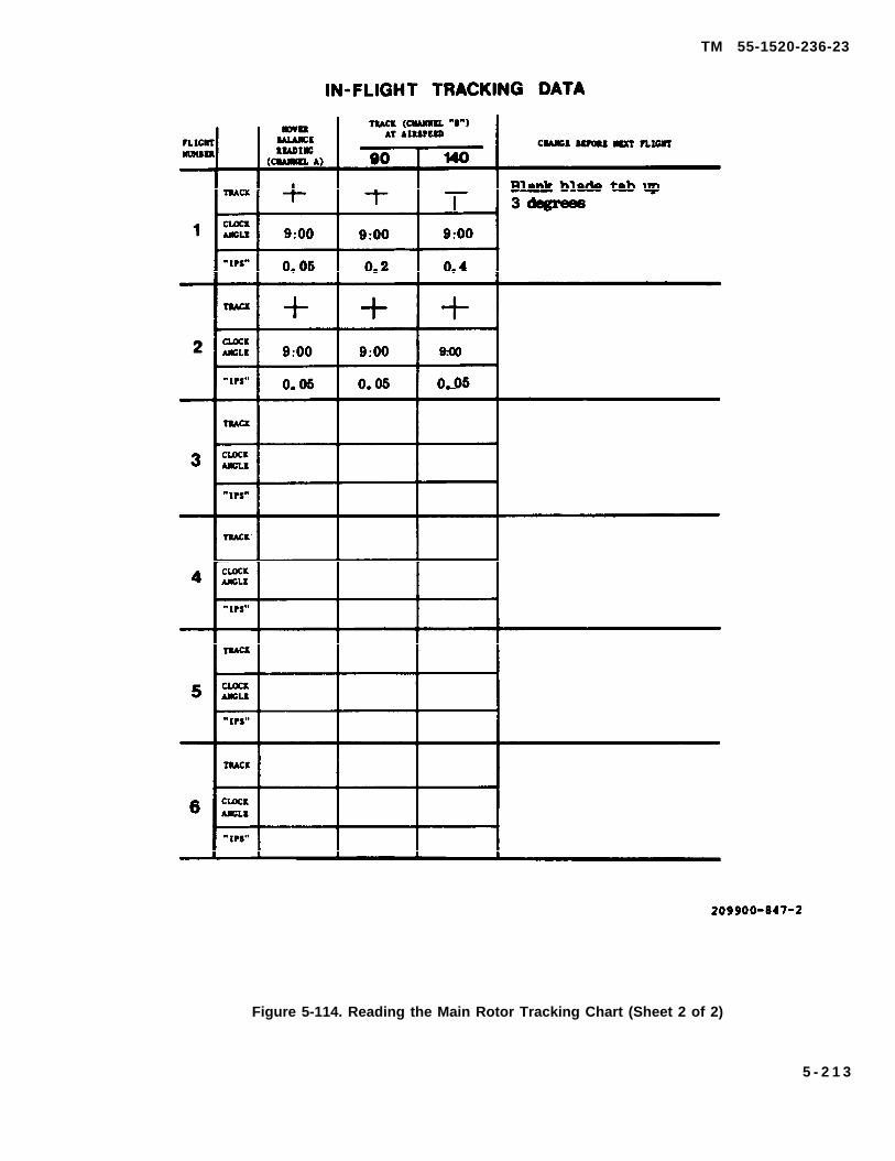
TM 55-1520-236-23
Figure 5-114. Reading the Main Rotor Tracking Chart (Sheet 2 of 2)
5 - 2 1 3

TM 55-1520-236-23
Figure 5-115. Accelerometer CableInstallation (Typical)
cover on fin opposite tail rotor. Connector must pointto lower-right (4:30). Connect Accelerometer Cable#4292-2 to Accelerometer. Dress Cable down “back”of fin, loop around tail stinger, then forward alongtailboom and over left elevator, and under tailboom toright-rear of helicopter, about 20 feet to the side of thetail rotor.
b. Using DC Extension Cable #3529 and DCAdapter Cable #3140-9, plug Balancer into map lightfor DC power. Place Balancer at the right-rear of thehelicopter (where the Cable was left from step (1)Plug Accelerometer Cable into Channel “B”Accelerometer receptacle. Plug Strobex intoBalancer.
Tie DC power and Accelerometer Cablestogether about the mid-point of their run,so Accelerometer Cable cannot foul intail rotor. Take slack out of cables whentying so there is nothing loose to get intotail rotor.
C. Apply a Retro-reflective “target patch, ” part#3300 or #4270, to grip plate area of one blade. Thisbecomes the “target” blade, Apply another target toone blade tip along the chord (to be viewed edge-on),and on the opposite tip across the chord. They must becentered, and about the same distance back fromleading edge.
5-214
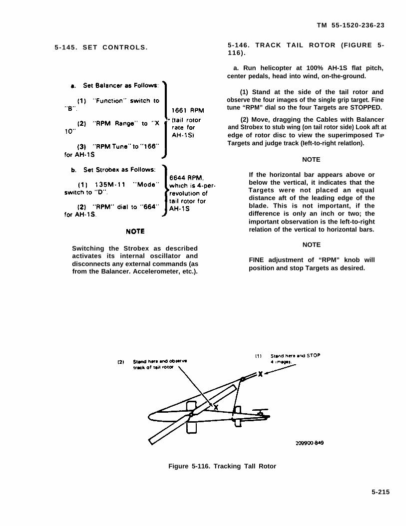
TM 55-1520-236-23
5-145 . SET CONTROLS.
Switching the Strobex as describedactivates its internal oscillator anddisconnects any external commands (asfrom the Balancer. Accelerometer, etc.).
5-146. TRACK TAIL ROTOR (FIGURE 5-116).
a. Run helicopter at 100% AH-1S flat pitch,center pedals, head into wind, on-the-ground.
(1) Stand at the side of the tail rotor andobserve the four images of the single grip target. Finetune “RPM” dial so the four Targets are STOPPED.
(2) Move, dragging the Cables with Balancerand Strobex to stub wing (on tail rotor side) Look aft atedge of rotor disc to view the superimposed TIP
Targets and judge track (Ieft-to-right relatlon).
NOTE
If the horizontal bar appears above orbelow the vertical, it indicates that theTargets were not placed an equaldistance aft of the leading edge of theblade. This is not important, if thedifference is only an inch or two; theimportant observation is the left-to-rightrelation of the vertical to horizontal bars.
NOTE
FINE adjustment of “RPM” knob willposition and stop Targets as desired.
Figure 5-116. Tracking Tall Rotor
5-215
TM 55-1520-236-23
b. Shut down and adjust track if required. If track NOTElooks good, keep running and proceed to balance.
If the rotor does not respond in an orderlyNOTE fashion after a few moves, the weights
should be restored to original and theThe finest adjustment available is one. first reading be repeated. If the firsthalf turn of rod end, so track can probably reading cannot be repeated, look fornot be made perfect. faulty bearings, shafts, etc.
5 - 1 4 7 . B A L A N C E T A I L R O T O R(FIGURE 5-117) , 5 -148 . TROUBLESHOOTING.
NOTE
Tail rotor must be in tracker pitch links sat to2.74 ± .010 inches between Jam nuts beforebalancing.
a. Return, with Balancer and Strobex, to positionat side of tail rotor. Set Strobex “Mode” switch to “A”.(TI is turns off the Strobex oscillator and makes itrespond ONLY to commands from the Balancer).Check that Balancer is set to Channel "B" (Into whichtail rotor Accelerometer is plugged) and 1650 RPM.
NOTE
The Phazor section of the Balancer isused only for main rotor balancing (itneeds reference signal from MagneticPickup). It is NOT operable whenworking the tail rotor, so IGNORE THEPHAZOR LIGHTS WHEN WORKINGTHE TAIL ROTOR.
b. With the Strobex, view “Clock Angle” of thesingle grip target. Push the "Verify Tune” button.WHILE THE BUTTON IS PUSHED, adjust the “RPMTune” dial to return the Target to the “Clock Angle”observed BEFORE THE BUTTON WAS PUSHEDRelease button, observe angle, push and adjust againto match “unpushed” angle. Repeat until there IS NOCHANGE whether button is pushed or released.
c. Record “Clock Angle” and “IPS” on BalanceChart #4471, (Read "IPS" without Strobex flashing.)
d. If the “Move Line” is in the correct direction,proceed to balance to 0.2 “IPS” or less, Both span andchord weights can be changed at once for subsequentmoves.
e. If the “Move Line” IS not in the correctdirection, use “Clock Angle Corrector” #3597, andassign new numbers to clock.
a. The Balancer is used to measure thefrequency, or RPM, of unknown vibrations in order totry to locate their source. The Accelerometer IS
mounted, or held, in the area where the vibration isfelt. If there is no reading on the “IPS” meter, it meansthere is no vibration at the RPM at which the Balancerelectronic filter is set. If the meter reads, it is becausethere is vibration at the RPM at which the filter is set.In use, the Balancer filter is tuned, or adjusted, acrossthe RPM range of interest and the meter is watchedfor response. Then the “Verify Tune” button ispushed, sharpening the filter, while the “RPM Tune”dial is adjusted to peak the meter. When the meterreading is maximized, the RPM is read directly fromthe “RPM Tune” dial, and “RPM Range” switch. Afterthe vibration rate is measured, it can usually berelated to known rotor or component rates. It IS
important, too, to consider multiples, or harmonics, ofthese rates.
Transmission mounts and loose skid gear can causeexcessive six-per-revolution (1944 per minute) thatmay feel like tail rotor (1661 for AH-1S).
The source of other vibrations may be determined bysecuring an Accelerometer in the area of the noticeddisturbance. The measured vibration rate IS generallythe same as, or harmonically related to, the source(forcing function) of the vibration. The Accelerometercan often be hand-held at various points on astructure, while “searching” with the “RPM Tune”dial. When hand-holding the Accelerometer, takecare to select “hard points” where the vibration willnot be damped (suppressed). Avoid sheet metalpanels, etc.
b. To facilitate determination of the offendingcomponent, the following operating RPM’s areprinted. Components of the different models may turnat a different RPM than those shown here. Refer tothe helicopter manual for your particular model.
5-216

TM 55-1520-236-23
Figure. 5-117. Balancing Tall Rotor5-217
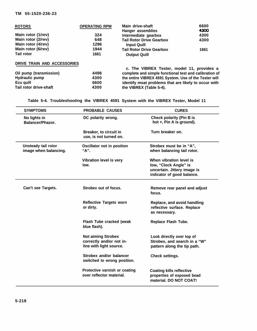
TM 55-1520-236-23
ROTORS OPERATING RPM
Main rotor (1/rev)Main rotor (2/rev)Main rotor (4/rev)Main rotor (6/rev)Tail rotor
DRIVE TRAIN AND ACCESSORIES
Oil pump (transmission)Hydraulic pumpEcu quillTail rotor drive-shaft
324648
129619441661
4498430066004300
Table 5-4. Troubleshooting the VIBREX 4591
Main drive-shaft 6600Hanger assembliesIntermediate gearbox 4300Tail Rotor Drive Gearbox 4300
Input QuillTail Rotor Drive Gearbox 1661
Output Quill
c. The VIBREX Tester, model 11, provides acomplete and simple functional test and calibration ofthe entire VIBREX 4591 System. Use of the Tester willidentify moat problems that are likely to occur withthe VIBREX (Table 5-4).
System with the VIBREX Tester, Model 11
SYMPTOMS PROBABLE CAUSES CURES
No lights in DC polarity wrong. Check polarity (Pin B isBalancer/Phazor. hot +, Pin A is ground).
Breaker, to circuit in Turn breaker on.use, is not turned on.
Unsteady tail rotor Oscillator not in position Strobex must be in “A”,image when balancing. “A”. when balancing tail rotor.
Vibration level is very When vibration level islow. low, “Clock Angle” is
uncertain. Jittery image isindicator of good balance.
Can’t see Targets. Strobex out of focus. Remove rear panel and adjustfocus.
Reflective Targets worn Replace, and avoid handlingor dirty. reflective surface. Replace
as necessary.
Flash Tube cracked (weak Replace Flash Tube.blue flash).
Not aiming Strobex Look directly over top ofcorrectly and/or not in- Strobex, and search in a “W”line with light source. pattern along the tip path.
Strobex and/or balancer Check settings.switched to wrong position.
Protective varnish or coating Coating kills reflectiveover reflector material. properties of exposed bead
material. DO NOT COAT!
5-218
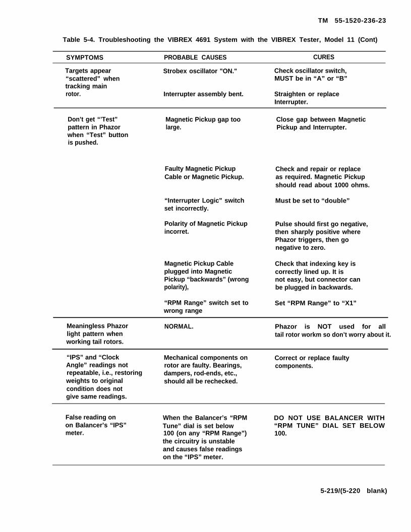
TM 55-1520-236-23
Table 5-4. Troubleshooting the VIBREX 4691 System with the VIBREX Tester, Model 11 (Cont)
SYMPTOMS PROBABLE CAUSES CURES
Targets appear Strobex oscillator "ON." Check oscillator switch,“scattered” when MUST be in “A” or “B”tracking mainrotor. Interrupter assembly bent. Straighten or replace
Interrupter.
Don’t get “’Test” Magnetic Pickup gap too Close gap between Magneticpattern in Phazor large. Pickup and Interrupter.when “Test” buttonis pushed.
Faulty Magnetic Pickup Check and repair or replaceCable or Magnetic Pickup. as required. Magnetic Pickup
should read about 1000 ohms.
“Interrupter Logic” switch Must be set to “double”set incorrectly.
Polarity of Magnetic Pickup Pulse should first go negative,incorret. then sharply positive where
Phazor triggers, then gonegative to zero.
Magnetic Pickup Cable Check that indexing key isplugged into Magnetic correctly lined up. It isPickup “backwards” (wrong not easy, but connector canpolarity), be plugged in backwards.
“RPM Range” switch set to Set “RPM Range” to “X1”wrong range
Meaningless Phazor NORMAL. Phazor is NOT used for alllight pattern when tail rotor workm so don’t worry about it.working tail rotors.
“IPS” and “Clock Mechanical components on Correct or replace faultyAngle” readings not rotor are faulty. Bearings, components.repeatable, i.e., restoring dampers, rod-ends, etc.,weights to original should all be rechecked.condition does notgive same readings.
False reading on When the Balancer’s “RPM DO NOT USE BALANCER WITHon Balancer’s “IPS” Tune” dial is set below “RPM TUNE” DIAL SET BELOWmeter. 100 (on any “RPM Range”) 100.
the circuitry is unstableand causes false readingson the “IPS” meter.
5-219/(5-220 blank)

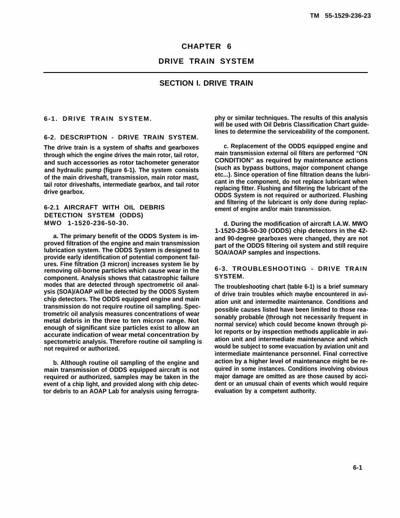
TM 55-1529-236-23
CHAPTER 6
DRIVE TRAIN SYSTEM
SECTION I. DRIVE TRAIN
6-1 . DRIVE TRAIN SYSTEM.
6-2. DESCRIPTION - DRIVE TRAIN SYSTEM.
The drive train is a system of shafts and gearboxesthrough which the engine drives the main rotor, tail rotor,and such accessories as rotor tachometer generatorand hydraulic pump (figure 6-1). The system consistsof the main driveshaft, transmission, main rotor mast,tail rotor driveshafts, intermediate gearbox, and tail rotordrive gearbox.
6-2.1 AIRCRAFT WITH OIL DEBRISDETECTION SYSTEM (ODDS)MWO 1-1520-236-50-30.
a. The primary benefit of the ODDS System is im-proved filtration of the engine and main transmissionlubrication system. The ODDS System is designed toprovide early identification of potential component fail-ures. Fine filtration (3 micron) increases system lie byremoving oil-borne particles which cause wear in thecomponent. Analysis shows that catastrophic failuremodes that are detected through spectrometric oil anal-ysis (SOA)/AOAP will be detected by the ODDS Systemchip detectors. The ODDS equipped engine and maintransmission do not require routine oil sampling. Spec-trometric oil analysis measures concentrations of wearmetal debris in the three to ten micron range. Notenough of significant size particles exist to allow anaccurate indication of wear metal concentration byspectometric analysis. Therefore routine oil sampling isnot required or authorized.
b. Although routine oil sampling of the engine andmain transmission of ODDS equipped aircraft is notrequired or authorized, samples may be taken in theevent of a chip light, and provided along with chip detec-tor debris to an AOAP Lab for analysis using ferrogra-
phy or similar techniques. The results of this analysiswill be used with Oil Debris Classification Chart guide-lines to determine the serviceability of the component.
c. Replacement of the ODDS equipped engine andmain transmission external oil filters are performed “ONCONDITION” as required by maintenance actions(such as bypass buttons, major component changeetc...). Since operation of fine filtration deans the lubri-cant in the component, do not replace lubricant whenreplacing fitter. Flushing and filtering the lubricant of theODDS System is not required or authorized. Flushingand filtering of the lubricant is only done during replac-ement of engine and/or main transmission.
d. During the modification of aircraft I.A.W. MWO1-1520-236-50-30 (ODDS) chip detectors in the 42-and 90-degree gearboxes were changed, they are notpart of the ODDS filtering oil system and still requireSOA/AOAP samples and inspections.
6-3. TROUBLESHOOTING - DRIVE TRAINSYSTEM.
The troubleshooting chart (table 6-1) is a brief summaryof drive train troubles which maybe encountered in avi-ation unit and intermedite maintenance. Conditions andpossible causes listed have been limited to those rea-sonably probable (through not necessarily frequent innormal service) which could become known through pi-lot reports or by inspection methods applicable in avi-ation unit and intermediate maintenance and whichwould be subject to some evacuation by aviation unit andintermediate maintenance personnel. Final correctiveaction by a higher level of maintenance might be re-quired in some instances. Conditions involving obviousmajor damage are omitted as are those caused by acci-dent or an unusual chain of events which would requireevaluation by a competent authority.
6-1

TM 55-1520-236-23
NOTE
Before you use this table, be sure you haveperformed all normal operational checks. Ifyou have a malfunction which is not listed inthis table, notify the next higher level of main-tenance.
Table 6-1. Troubleshooting Drive Train System
CONDITION
TEST OR INSPECTION
CORRECTIVE ACTION
1. Metal chips found on magnetic sump plug or pump screen, (paragraphs 6-176 and 6-169).
STEP 1. Internal transmission failure of gears or bearings.
Replace transmission (paragraphs 6-24 and 6-33).
Replace oil cooler and flush lines, Drain and refill with oil (paragraphs 6-143 and 6-146).
2. Excessive pylon motion (Approximately one-half revolution).
STEP 1. Pylon mounts worn or installed wrong.
Repair or replace mounts (paragraph 2-225).
STEP 2. Leaking pylon mount dampers.
Replace or repair dampers (paragraph 2-239).
3. Water in transmission.
STEP 1. Water in drain lines.
Clear obstructions from lines Disconnect lines and purge with compressed air.
MAIN DRIVESHAFT:
1. Grease leakage.
STEP 1. Cut or tom packing or boot.
Replace packing or boot assembly with care (paragraph 6-12).
2. Abnormal coupling wear.
STEP 1. Faulty lubrication or wrong lubricant (paragraph 6-12).
Clean and lubricate coupling or replace driveshaft (paragraphs 6-12 and 6-13).
3. Lubricant breakdown in forward coupling.
STEP 1. Misalignment or wrong lubricant (paragraphs 6-7 and 6-12).
Align engine and transmission; replace driveshaft and associated parts as required (parsgraphs 6-7 and 6-13).
4. Suspected vibration.
STEP 1. Coupling damps loose, improperly installed, or not matched.
Install clamp sets by instructions (paragraph 6-13).
STEP 2. Loose engine adapter.
Replace adapter and any worn associated parts (paragraph 6-19).
6-2

TM 55-1520-236-23
Table 6-1. Troubleshooting Drive Train System (Cont)
CONDITION
TEST OR INSPECTION
CORRECTIVE ACTION
STEP 3. Main driveshaft improperly assembled or missing spring.
Disassemble, inspect, and assemble properly (paragraphs 6-8, 6-10, and 6-12).
TAIL ROTOR DRIVE SYSTEM:
1. Suspected vibration.
STEP 1. Worn hanger bearings or couplings (paragraph 6-85)
Replace hanger assembly (paragraph 6-84 and 6-88).
STEP 2. Shaft balance weights lost or shaft bent (paragraph 6-79).
Replace shaft section (paragraphs 6-77 and 6-81).
STEP 3. Misaligned driveshaft clamps (paragraph 6-81).
Align clamps properly (paragraph 6-81).
2. Binding or roughness when manually checked (paragraph 6-85).
STEP 1. Dry or faulty bearing (paragraph 6-85).
Isolate faulty hanger by disconnecting shafts (paragraph 6-85).
Replace hanger assembly (paragraph 6-84 and 6-88).
STEP 2. Defective gearbox.
Check gearboxes, replace defective unit (paragraphs 6-96 and 6-113).
STEP 3. Faulty lubrication of couplings (paragraph 6-87).
Replace hanger, gearbox, or gear quills (paragraphs 6-84, 6-88, 6-100, 6-105, 6-117, 6-121, 6-124, and6-128).
3. Metal chips on gearbox chip detector (figure 6-2) or debris monitor (Table 6-1.1).
STEP 1. Internal failure of gears or bearings.
Replace gearbox (paragraphs 6-100, 6-105, 6-117, and 6-121).
6-3

TM 55-1520-236-23
Figure 6-1. Drive Train (Typical)
a. For main driveshaft troubleshooting, apply thefollowing:
(1) Trouble conditions of main driveshaft can sel-dom be detected in operation, since there are no reliableindications except possibly in art extreme condition.“Suspected vibration” is only partially accurate as a termfor renditions such as dynamic out-of-balance or faultycoupling action. Vibration would result from theseconditions, as well as abnormal stresses and wear, butwould be absorbed in structure and pylon mounts oreffectively masked by normal vibrations of the helicopter, providing no distinct indication to pilot.
(2) Driveshaft trouble indications are usuallythose revealed by careful inspection.
(3) The principal causes of driveshaft trouble arefaulty installation procedures and inadequate or improp-er lubrication of spherical tooth couplings.
b. For tail rotor drive system troubleshooting, applysame principles as for main driveshaft.
c. Indication of trouble, probable causes, and cor-rective action are shown on table 6-1.
6 - 4 . M E T A L PARTICLES lDENTlFl-CATION - GEARBOXES. (Aircraft withoutODDS. )
Metal particles found on gearbox oil strainer screens, oilfilters, or chip detectors may indicate failure of an inter-nal part of the gearbox. The presence of metal particles,however, is not necessarily an indication that the gear-box is no longer serviceable. The quantity, source, form,and type of metal found, together with the service histo-ry of the particular gearbox, must be taken into consider-ation. The time accumulated since the gearbox wasnew or overhauled, previous failures, and the type of op-eration are important factors in determining the furtherserviceability of the unit. The particles found may besteel, cadmium, aluminum, magnesium, copper(bronze), silver, or phenolic in various shapes and quan-tities. Refer to figure 6-2 for a detailed explanation ofthe action made necessary by the presence of varioustypes of particles in the gearbox. For helicopters withODDS (MWO 1-1520-236-50-30), refer to table 6-1.2for necessary actions and refer to paragraph 6-4.1.
When any particles found are readilyidentifiable as fragments of gearboxparts, such as gears, nuts, bearings, oilslingers, thrust washers, snaprings,safety wire, or other component, replace gearbox.
6-4

KIND OF METAL
Steel
TM 55-1520-236-23
METAL PARTICLES CONTAMINATION-GEARBOX OIL
QUANTITY AND/OR SIZE
Fuzz, fine hair-like particles(detail A.)
Particles in splinter or granularform (details B and C).
Thin flakes or splinters notexceeding 1/1 6 (0.060) inch inthickness and 1/16 (0.060) inch inlength. Quantity not to exceed 10flakes (detail D).
Drain and flush.
Take oil sample fromsump drain forspectrograph oilanalysis.
Examine oil filter anddetermine if chips areexcessive.
If chips are notexcessive, flushgearbox oil system andrefill with new oil.
Accomplish aircraftground run, take oilsample, check chipdetector and oil filter formetal.
If no particles arefound, hover aircraft for30 minutes, take oilsample, check chipdetector and oil filter formetal. If no metal ispresent, releasehelicopter for flight. Ifmetal is present,replace gearbox.
Drain and flush.
Result of normal wear.May have exaggeratedappearance because ofoil
Usually indicates failure.
Small quantity may notindicate bearing failure.
Figure 6-2. Gearbox Oil Contamination-Description and Corrective Action (Sheet 1 of 2)(Helicopters w/o MWO 1-1520-236-50-30)
6-5
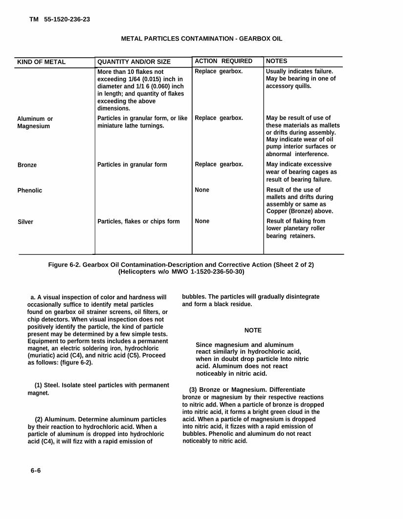
TM 55-1520-236-23
KIND OF METAL
Aluminum orMagnesium
Bronze
Phenolic
Silver
METAL PARTICLES CONTAMINATION - GEARBOX OIL
QUANTITY AND/OR SIZE
More than 10 flakes notexceeding 1/64 (0.015) inch indiameter and 1/1 6 (0.060) inchin length; and quantity of flakesexceeding the abovedimensions.
Particles in granular form, or likeminiature lathe turnings.
Particles in granular form
Particles, flakes or chips form
ACTION REQUIRED
Replace gearbox.
Replace gearbox.
Replace gearbox.
None
None
NOTES
Usually indicates failure.May be bearing in one ofaccessory quills.
May be result of use ofthese materials as malletsor drifts during assembly.May indicate wear of oilpump interior surfaces orabnormal interference.
May indicate excessivewear of bearing cages asresult of bearing failure.
Result of the use ofmallets and drifts duringassembly or same asCopper (Bronze) above.
Result of flaking fromlower planetary rollerbearing retainers.
Figure 6-2. Gearbox Oil Contamination-Description and Corrective Action (Sheet 2 of 2)(Helicopters w/o MWO 1-1520-236-50-30)
a. A visual inspection of color and hardness willoccasionally suffice to identify metal particlesfound on gearbox oil strainer screens, oil filters, orchip detectors. When visual inspection does notpositively identify the particle, the kind of particlepresent may be determined by a few simple tests.Equipment to perform tests includes a permanentmagnet, an electric soldering iron, hydrochloric(muriatic) acid (C4), and nitric acid (C5). Proceedas follows: (figure 6-2).
(1) Steel. Isolate steel particles with permanentmagnet.
(2) Aluminum. Determine aluminum particlesby their reaction to hydrochloric acid. When aparticle of aluminum is dropped into hydrochloricacid (C4), it will fizz with a rapid emission of
bubbles. The particles will gradually disintegrateand form a black residue.
NOTE
Since magnesium and aluminumreact similarly in hydrochloric acid,when in doubt drop particle Into nitricacid. Aluminum does not reactnoticeably in nitric acid.
(3) Bronze or Magnesium. Differentiatebronze or magnesium by their respective reactionsto nitric add. When a particle of bronze is droppedinto nitric acid, it forms a bright green cloud in theacid. When a particle of magnesium is droppedinto nitric acid, it fizzes with a rapid emission ofbubbles. Phenolic and aluminum do not reactnoticeably to nitric acid.
6-6

TM 55-1520-236-23
(4) Silver. Dissolve particles in nitric add. Add afew drops of distilled water and small amount of table saltor hydrochloric add (C4). Check for appearance of white(milky) cloud in the solution.
b. When the Army Oil Analysis Program is being uti-lized, check for particles at three places: the transmission,intermediate gearbox, and tail rotor drive gearbox.Instructions for taking oil sample and descripton of prob-able source of particles are as follows:
(1) Transmission. Take a sample from sumpdrain immediately after engine shutdown. Allow one-halfto three-fourths pint of oil to drain through the line beforetaking sample.
(a) Any of the gear trains, bearings, or a looseor worn shim under the mast bearing will give a high countof iron, copper, aluminum, and magnesium.
(b) A loose fitting on the sump may also showthe same trace elements, with the rate of increase sus-pected to be slightly above normal.
(c) A high iron, copper, and aluminum countcould be caused by one or both of the planetary systemswith the rate of increase suspected to be above that fornormal wear rate.
(d) High iron, copper, and aluminum contentcould be from the input quill triplex bearing or the mastbearing. This will increase rapidly and will probably prog-ress to failure.
(2) Intermediate and Tail Rotor Drive Gear-boxes. Take sample from gearbox immediately after shutdown. Use a plastic syringe or take from drain. Cleanarea before removing drain plug.
(a) High iron count, suspect gear scuffling, orbearing inner races fretting, suspected rate of increaseslightly above normal.
(b) High iron and cooper count could be rollerbearings and cage or duplex bearings in quills.
6-4.1. DECISION CRITERIA FOR REPLACEMENTOF TRANSMISSION, FOLLOWING CHIP CAUTlONLIGHT. (Helicopters without MWO1-1520-236-50-30.)
a. Collection and Analysis of Debris Samples -When XMSN CHIP caution light for transmission hascome on, proceed as follows:
(1) Remove debris monitor from transmission orremove chip detector. Remove and retain debris from thedebris monitor or chip detection. In addition, remove and
retain debris from oil filters and screens for the lubricationsystem.
(2) Clean debris monitor and screen with solvent(C112) and dean cloth and install it.
(3) Identify debris using the information in table6-1.1 and figure 6-2.1. Subparagraph b. also containsuseful information. Pay particular attention to debris cla-ssified as significant.
(4) Perform maintenance actons on referenced OilDebris Classification Chart, table 6-1.1 for transmission.
b. Decision Aids- Use following information in reach-ing a decision to replace a component or continue it inservice.
(1) Debris m oil system does not necessarily meanthat component is no longer serviceable. Quality of debrisas well as size, type, and composition must be consid-ered. Component time, gage indications, and noise andvibration levels must also be considered.
(2) Metallic debris can be result of earlier mainte-nance activity or of wear. Maintenance records should beexamined and considered first for history and possiblecause. Debris from earlier chip events should be ex-amined tor comparison.
(3) Debris from significant failure modes is usuallya single type. When several types are present, pay partic-ular attention to identifying significant types.
(4) It is likely that a maintenance-generated chiplight will occur during first 25-50 hours of operation follow-ing replacement of a component. It is also likely thatseveral maintenance-generated chip Iights will occur infirst 100 hours of operation following installation of ODDS(MWO 1-1520-236-50-30).
(5) A single clip is rarely significant.
6-4.2. DECISION CRITERIA FOR REPLACEMENTOF TRANSMISSION, FOLLOWING CHIP CAUTIONLIGHT. (Helicopters with MWO 1-1520-236-50-30).
a. Collection and Analysis of Debris Samples - Inthe event of main transmission chip light illumination, pro-ceed as follows:
NOTE
It is very difficult to provide procedures forall types of chip light occurrences. Unitsshould take full advantage of all informa-tion available, such as DA Form 2408 His-tory, Oil Debris Classification Chart, Sup-porting Oil Labs, CCAD Service Center,etc.
6-6.1

TM 55-1520-236-23
Table 6-1.1 Oil Debris Classification Chart (Aircraft wihout ODDS)
NOTES1. Refer to oil contamination troubleshooting for the
system.2. Use this table in conjunction with figure 6-2.1.3. Dimensions are in inches.
6-6.2

TM 55-1520-236-23
Figure 6-2.1. Typical Oil System Debris at 6X Magnification.Aircraft without ODDS.
NOTEFigure 6-2.2 has been replaced by Table 6-1.2.
6-6.3

TM 55-1520-236-23
Table 6-1.2. Oil Debris Classification Chart (Aircraft with ODDS)
6-6.4

TM 55-1520-236-23
NOTE
Determine the different types of debris onthe chip detector, since it is possible tohave more than one type of debris on thechip detector. An example would be thepresence of both flakes and granules onthe chip detector. More than 10 flakes ormore than 50 granule particles would because for component replacement Anycombination of less than 10 flakes and 50granules would be acceptable.
NOTE
Replacement of external oil filter on ODDSequipped aircraft is “ON CONDITION” andonly when associated impending bypassindicator button is extended (second re-set) or main transmission change. The af-fected chip detector should also be re-moved and inspected whenever theimpending bypass indicator button is ex-tended. Since fine filtration deans the lu-bricant in the component, do not replacelubricant when replacing filter. Flushingand filtering of system (unless there is acomponent replacement) is not requiredor authorized as this may mask problemsand prevents trending of data.
(1) Remove and inspect debris monitor. Classifydebris I.A.W. Oil Debris Classification Chart (table6-1.2). Document findings on DA Form 2408-20, block7.
NOTE
More frequent chip lights maybe encoun-tered In the first 50 hours of operation ofa component which has undergone anoverhaul or major repair, as well as break-in wear debris, being present in lube sys-tem. This type of debris is normal and notindicative of a problem with the ODDSSystem.
(2) Clean debris monitor, and screen with solvent(C112) and dean cloth and reinstall.
(3) Retain or replace component I.A.W. Oil DebrisClassification chart (table 6-1.2).
(4) If evaluation of debris requires component re-placement, remove component and forward to overhaul.
(5) If evaluation of debris does not require re-placement of component, operate aircraft for one hour,(30 minutes flat pitch ground run and 30 minutes hoverm ground effect). Re-check chip detector. Classify de-bris I.A.W. Oil Debris Classification Chart (table 6-12).
(6) If number or size of debris has increased, re-move defective component and forward to overhaul.
(7) If number or size of debris decreases or re-mains the same, return aircraft to service.
6-6.5/(6-6.6 blank)

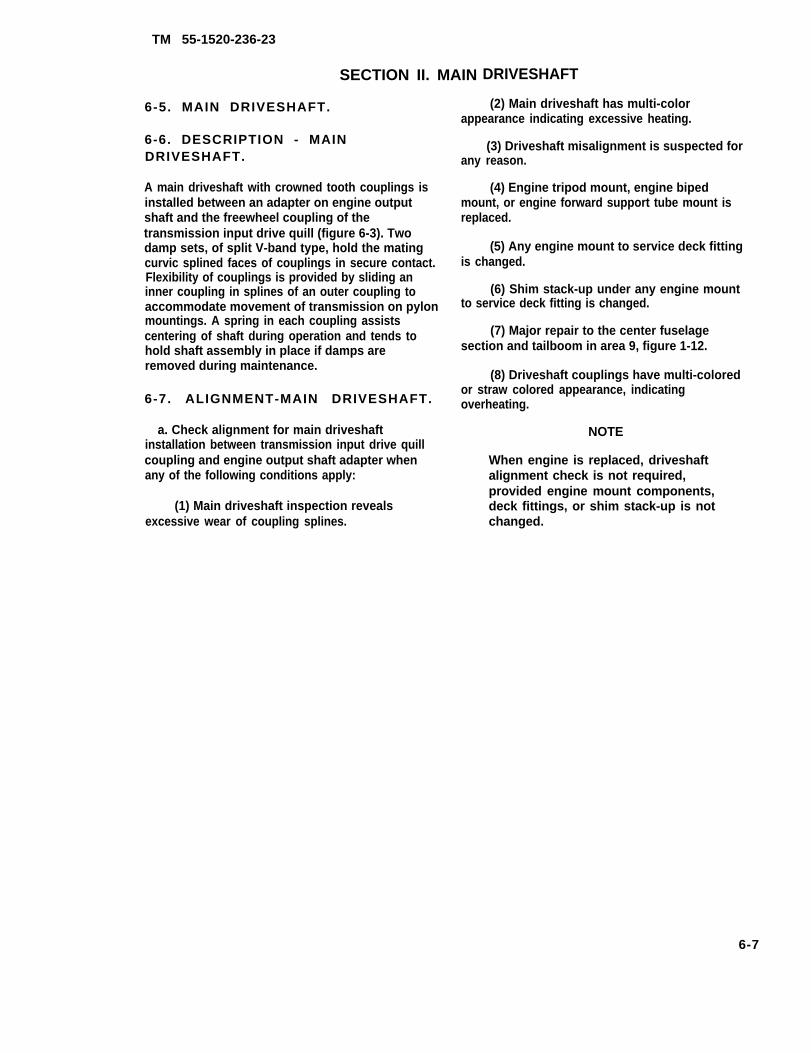
TM 55-1520-236-23
SECTION II. MAIN
6-5. MAIN DRIVESHAFT.
6-6. DESCRIPTION - MAINDRIVESHAFT.
A main driveshaft with crowned tooth couplings isinstalled between an adapter on engine outputshaft and the freewheel coupling of thetransmission input drive quill (figure 6-3). Twodamp sets, of split V-band type, hold the matingcurvic splined faces of couplings in secure contact.Flexibility of couplings is provided by sliding aninner coupling in splines of an outer coupling toaccommodate movement of transmission on pylonmountings. A spring in each coupling assistscentering of shaft during operation and tends tohold shaft assembly in place if damps areremoved during maintenance.
6-7. ALIGNMENT-MAIN DRIVESHAFT.
a. Check alignment for main driveshaftinstallation between transmission input drive quillcoupling and engine output shaft adapter whenany of the following conditions apply:
(1) Main driveshaft inspection revealsexcessive wear of coupling splines.
DRIVESHAFT
(2) Main driveshaft has multi-colorappearance indicating excessive heating.
(3) Driveshaft misalignment is suspected forany reason.
(4) Engine tripod mount, engine bipedmount, or engine forward support tube mount isreplaced.
(5) Any engine mount to service deck fittingis changed.
(6) Shim stack-up under any engine mountto service deck fitting is changed.
(7) Major repair to the center fuselagesection and tailboom in area 9, figure 1-12.
(8) Driveshaft couplings have multi-coloredor straw colored appearance, indicatingoverheating.
NOTE
When engine is replaced, driveshaftalignment check is not required,provided engine mount components,deck fittings, or shim stack-up is notchanged.
6-7

TM 55-1520-236-23-1
6-8
Figure 6-3. Main Driveshaft Installation (Sheet 1 of 2)

TM 55-1520-236-23
Figure 6-3. Main Driveshaft Installation (Sheet 2 of 2)
6-8.1
TM 55-1520-236-23
Premaintenance Requirements for Main DriveshaftAlignments
Conditions Requirements
Model
Part Number or SerialNumber
Special Tools
Test Equipment
Support Equipment
Minimum PersonnelRequired
Consumable Materials
Special EnvironmentalConditions
AH-1E, F, & P
All
(T45) (T32) (T35)
None
None
One
None
None
b. Remove main driveshaft (paragraph 6-8). Leaveadapter (4, figure 6-3) installed in end of engine outputshaft.
Do not attempt to raise transmission withjacks only. Hoist must be used in conjunctionwith jacks while lifting.
c. Attach hoist (T45) or other suitable hoist to mainrotor retaining nut at top of mast. Install four jacks (T35),two at each side between transmission support case andtop of pylon supports (figure 6-4).
d. Remove nut and washer from lower bolt of lift link,and operate hoist to raise transmission until bolt can befreely moved with fingers or wrench. Adjust jacks to holdpylon at this position with hoist stack. Replace bolt if bind-ing occurs due to corrosion or galling.
e. Check that transmission support points are paral-lel symmetrically with pylon support structure. Measure ateach mount with a micrometer depth gage as shown in fig-ure 6-4.
(1) Measure dimension from top surface of support case mounting plate to top of pylon support. All four di-mensions should now be equal within 0.020 inch.
(2) When all four points cannot be adjusted tosame dimension, take average of two front points and ad-just two rear points accordingly.
f. Install target plate of alignment tool set, (T32) ontransmission input quill coupling (figure 6-5). Index arrow ofcenter at 3.5 on inner scale. Secure by tightening twowasher-head screws at back of plate, Position plate oncoupling with 1.75 index of outer scale at top of verticalcenterline (figure 6-5). Secure with coupling damp set.
g. Install alignment gage of tool set on engine outputshaft adapter, Secure with coupling damp set (figure 6-5).
h. Check horizontal and vertical alignment by ex-tending plunger of gage toward target plate hole. Pushplunger forward against tension of retracting spring.
(1) Largest diameter of plunger must enter targethole to indicate correct alignment.
(2) If misalignment is indicated, observe amountand direction.
NOTE
No correction should be attempted beforecompleting angularity check in following step.Shim requirements can be determined best onbasis of both checks.
i. Perform angularity check with a dial indicatormounted on end of alignment gage housing as follows:
(1) Position indicator for contact at 2.5 inch radius(just inside outer scale numerals) on target plate (part ofT32).
(2) Rotate gage through a full turn to find area ofplate nearest to engine, This should occur at left side ofplate between 8 and 10 o’clock position. Zero indicator inthis area.
(3) Check run-out through a full turn of gage to bewithin 0.016 inch maximum total indicator reading. If runoutis greater than 0.016 inch, make correction of engine align-ment by use of shims under engine mount deck fitting asrequired (figure 6-5).
6-8.2
TM 55-1520-236-23
Do not exceed 0.312 inch shim thick-ness under any fitting.
j. Repeat alignment and angularity check afterany change of shims.
k. When alignment is complete, reinstall washerand nut on lift link lower bolt. Torque nut 30 TO 50foot-pounds. Remove jacks (T35) and hoist (figure 6-4).
l. Install driveshaft (paragraph 6-13).
NOTE
After alignment and angularity adjust-ments, perform the following.
Power lever control rigging
Power turbine governor rigging
Droop cam rigging
Vibration analysis
6-8. REMOVAL — MAIN DRIVESHAFT.
a. Open cowling on left and right side of pylon.Remove baffle panel (6, figure 6-3).
b. Prior to incorporation of MWO 55-1520-236-50-12, remove particle separator as follows:
(1) Remove baffle panels (1 and 6) (paragraph2-125).
(2) Remove top half of FOD screen (15) (para-graph 4-35).
(3) Remove particle separator (14). Cover openends of lower air filter assembly to keep out dirt andforeign objects.
c. After incorporation of MWO 55-1520-236-50-12, remove centrisep particle separator as follows:
(1) Remove top baffle (17) and left and rightsections of forward baffle (16) (paragraph 2-125.1).
(2) Remove centrisep particle separator (18)(paragraph 4-28.1).
d. Remove clamp sets (5) from each end of shaft,with attaching parts (7) through (12). Keep serializedclamps and attaching parts in sets.
e. Push shaft assembly (13) toward either end toshift one coupling inward and disengage coupling atopposite end. Remove shaft assembly. Apply enoughforce to compress springs in couplings.
6-9
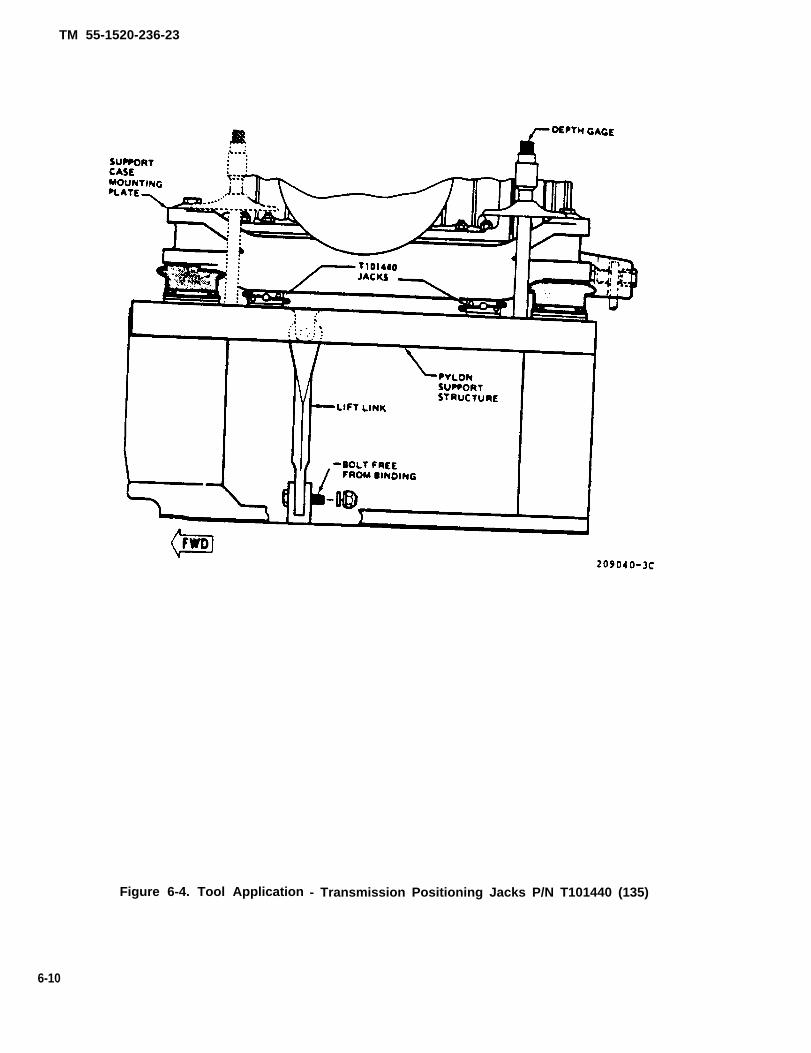
TM 55-1520-236-23
Figure 6-4. Tool Application - Transmission Positioning Jacks P/N T101440 (135)
6-10

TM 55-1520-236-23
Figure 6-5. Tool Application — Engine to Transmission Driveshaft Alignment P/N T101419 (T32)
6-11
TM 55-1520-236-23
6 - 9 . D I S A S S E M B L Y – M A I NDRIVE SHAFT.
Premaintenance Requirements forMain Driveshaft Disassembly
Conditions Requirements
Model
Part Number or SerialNumber
Special Tools
Test Equipment
Support Equipment
Minimum PersonnelRequired
Consumable Materials
Special EnvironmentalConditions
AH-IS
All
(T25) (T33)
None
None
One
(C19) (C31) (C37) (C88or C91) (C103) (C112) (C116)
None
a. Place shaft assembly on a suitable work table.Remove retaining ring (1, figure 6-6), Use care inremoving ring, which must be replaced if bent ordamaged. See details A and B in figure 6-7 forremovaI technique.
b. Push down on outer coupling (13, figure 6-6)just enough to force out retainer (3). Remove retainerpecking (2), spring (4), and locking spring (5). Seedetails C and D, figure 6-7 for removal technique.
c. Repeat steps a. and b. at opposite end of shaft.
d. Attaching holding fixture (T33) with a clamp seton one coupling of shaft with retainer reinstalled as aspacer to keep inner coupling in place. Secure fixturein a vise (detail E).
e. Use transmission wrench (T25) to loosen nut(6, figure 6-6). Do not remove nut. Remove shaft fromholding fixture.
f. Repeat steps d. and e. to loosen nut in oppositeend of shaft.
g. Remove nut (6) and spring retainer (7) from oneend of shaft. See details G and H, figure 6-7, forremoval technique.
h. Remove couplings from end of shaft (detail l).
6-12
i. Carefully remove inner coupling (14, figure 6-6)from outer coupling (13). See detail J, figure 6-7, forremovaI technique.
Inner coupling may be tight in boot ring,Use extreme care not to damage boot.
NOTE
If the driveshaft has been dynamicallybalanced, the outer couplings, innercouplings and the driveshaft will be in-dexed as shown on figure 6-6. Also, oneor more Iamination weights (15) will beinstalled.
i.1. If driveshaft has been dynamically balanc-ed (at CCAD), use marking ink to temporarily in-dex relative positions of Iaminated balanceweights (15), boots, and outer couplings. Mark eachend of shaft with different colors or marks.
j. Remove bolts (9, figure 6-6) and washers (10) toseparate boot (11) from outer coupling (13) andremove packing (12).
k. Record serial numbers of mating inner andouter couplings.
l. Repeat steps g. through k. to remove parts fromopposite end of shaft.
m. Clean main driveshaft as follows:
Cleaning solvent is flammable and toxic.Provide adequate ventilation. Avoidprolonged breathing of solvent vaporsand contact with skin or eyes.
Do not use solvent to clean assembleddriveshaft. Residue may remain inassembly and prevent proper lubrication.Do not clean boot (11) withsolvent.
(1) Clean shaft assembly,attaching parts by wiping with clean(C112) may be used if driveshaftdisassembled.
cleaning
adapter andcloth. Solventis completely
(2) Remove all grease from inner and outercouplings.
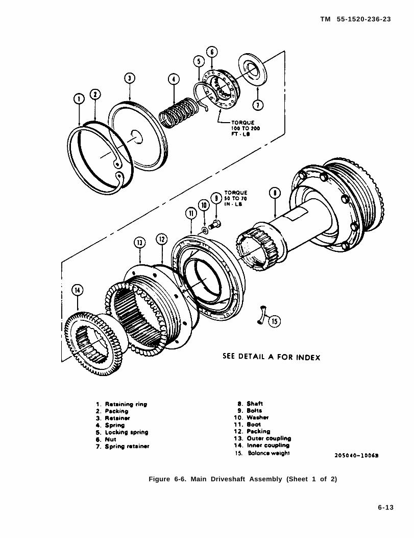
TM 55-1520-236-23
Figure 6-6. Main Driveshaft Assembly (Sheet 1 of 2)
6-13

TM 55-1520-236-23
Figure 6-6. Main Driveshaft Assembly (Sheet 2 of 2)
6-14
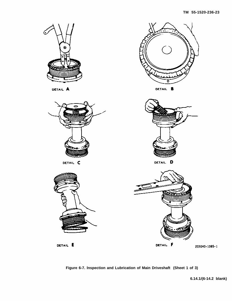
TM 55-1520-236-23
Figure 6-7. lnspection and Lubrication of Main Driveshaft (Sheet 1 of 3)
6.14.1/(6-14.2 blank)


TM 55-1520-236-23
Figure 6-7. Inspection and Lubrication of Main Driveshaft (Sheet 2 of 3)
6-15
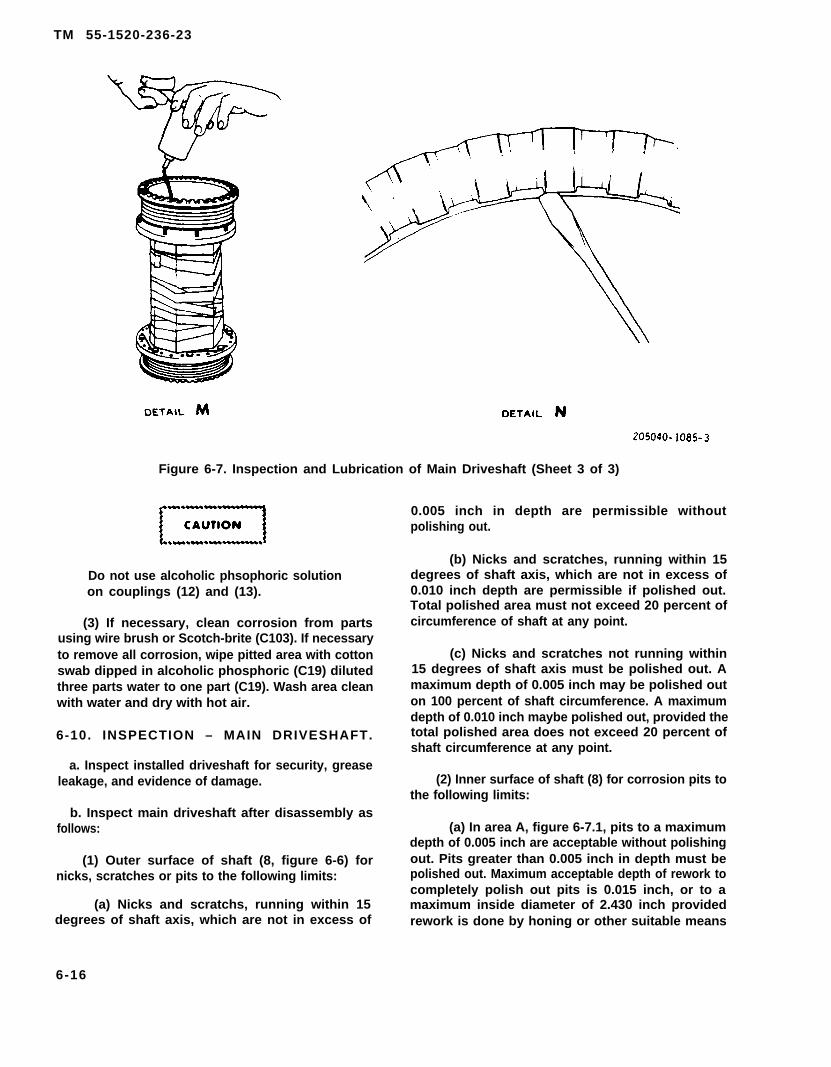
TM 55-1520-236-23
Figure 6-7. Inspection and Lubrication of Main Driveshaft (Sheet 3 of 3)
Do not use alcoholic phsophoric solutionon couplings (12) and (13).
(3) If necessary, clean corrosion from partsusing wire brush or Scotch-brite (C103). If necessaryto remove all corrosion, wipe pitted area with cottonswab dipped in alcoholic phosphoric (C19) dilutedthree parts water to one part (C19). Wash area cleanwith water and dry with hot air.
6-10. INSPECTION – MAIN DRIVESHAFT.
a. Inspect installed driveshaft for security, greaseleakage, and evidence of damage.
b. Inspect main driveshaft after disassembly asfollows:
(1) Outer surface of shaft (8, figure 6-6) fornicks, scratches or pits to the following limits:
(a) Nicks and scratchs, running within 15degrees of shaft axis, which are not in excess of
0.005 inch in depth are permissible withoutpolishing out.
(b) Nicks and scratches, running within 15degrees of shaft axis, which are not in excess of0.010 inch depth are permissible if polished out.Total polished area must not exceed 20 percent ofcircumference of shaft at any point.
(c) Nicks and scratches not running within15 degrees of shaft axis must be polished out. Amaximum depth of 0.005 inch may be polished outon 100 percent of shaft circumference. A maximumdepth of 0.010 inch maybe polished out, provided thetotal polished area does not exceed 20 percent ofshaft circumference at any point.
(2) Inner surface of shaft (8) for corrosion pits tothe following limits:
(a) In area A, figure 6-7.1, pits to a maximumdepth of 0.005 inch are acceptable without polishingout. Pits greater than 0.005 inch in depth must bepolished out. Maximum acceptable depth of rework tocompletely polish out pits is 0.015 inch, or to amaximum inside diameter of 2.430 inch providedrework is done by honing or other suitable means
6-16

TM 55-1520-236-23
Figure 6-7.1 Main Driveshaft Internal Corrosion Areas
such that material removal is uniform around the full in-side diameter. Minimum acceptable radius in reworkedarea is 0.50 inch, and surface finish must be 63 micro-inches or better.
(b) in Area B, figure 6-7.1, pits to a maximumdepth of 0.010 inch are acceptable without polishingout. Pits greater than 0.010 inch in depth must be pol-ished out. Maximum acceptable depth of rework to com-pletely polish out pits is 0.025 inch. Minimum accepta-ble wail thickness after rework is 0.060 inch. Minimumacceptable radius in reworked area is 0.09 inch, and sur-face finish must be 63 microinches or better.
(c) In Area C, figure 6-7.1, pits to a maximumdepth of 0.030 inch are acceptable.
c. Inspect couplings as follows:
(1) Inspect packing groove in each retainer (3,figure 6-6) and areas of outer couplings (13), wherepacking and retaining ring will seat, for burrs or sharpedges. Remove any such defects with a fine India stone(C116) or crocus cloth (C42). Carefully remove any for-eign material.
(2) inspect splines of couplings for wear condi-tions (figure 6-8). Use a white card or a tongue depressor
at root of each tooth to reflect light on spline surfaces.See detail K, figure 6-7 for inspection technique.
(3) Inspect exterior of outer couplings for discolo-ration of cadmium plating as evidence of overheating.Extensive discoloration or blistering of cadmium platingis cause for return to depot maintenance level for repair.
(4) Inspect shaft (8, figure 6-6) inner coupling (14)and outer coupling(13) for chipped teeth, cracks, anddamage.
c.1. Coupling overheat detector paint strip. A 1.0 by1.1 inch strip of zinc-chromate primer is painted on eachside (180° apart) of every flexible driveshaft coupling.The green zinc-chromate primer (TT-P-1757) will turnbrown at 375± 5°F, indicating:
(1)
(2)
(3)
(4)
Loss of lubricant due to seal failure.
Contaminated or improper lubricant.
incorrect cleaning and lubricating procedures.
Drive train misalignment.
d. Inspect boot (11) for breaks or tears.
6-17

TM 55-1520-236-23
Figure 6-8. Coupling Wear Criteria for Driveshaft (Sheet 1 of 2)
6-18
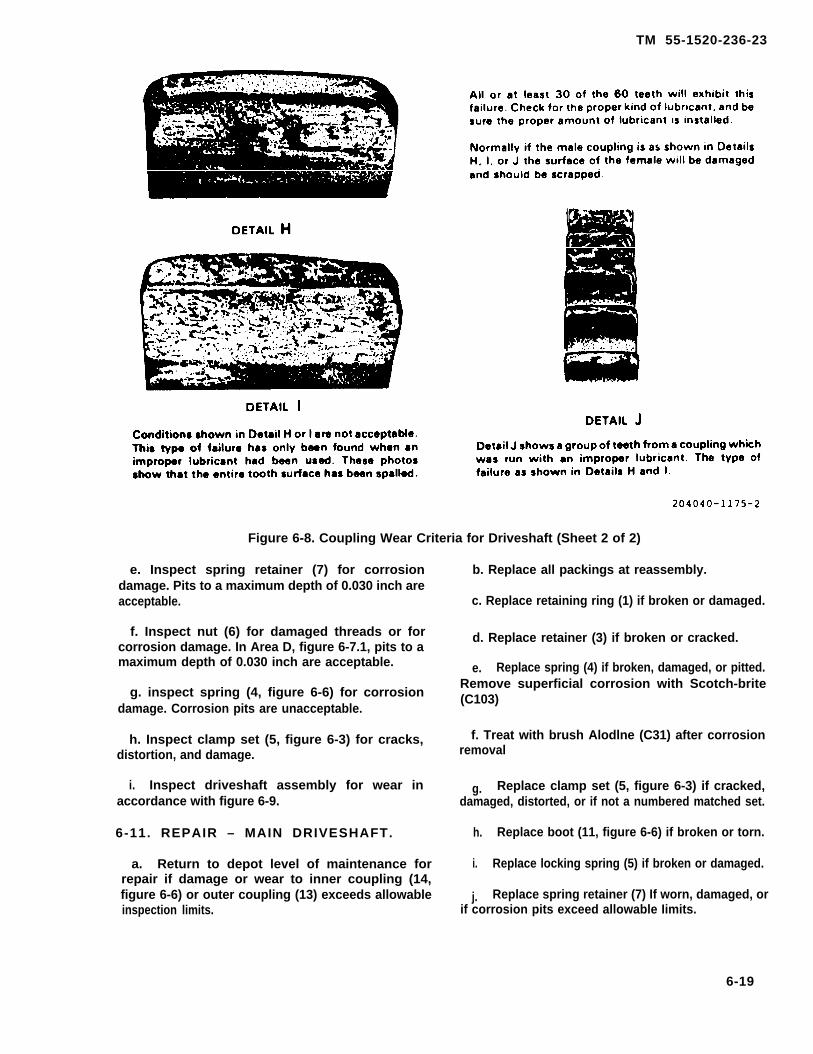
TM 55-1520-236-23
Figure 6-8. Coupling Wear Criteria for Driveshaft (Sheet 2 of 2)
e. Inspect spring retainer (7) for corrosiondamage. Pits to a maximum depth of 0.030 inch areacceptable.
f. Inspect nut (6) for damaged threads or forcorrosion damage. In Area D, figure 6-7.1, pits to amaximum depth of 0.030 inch are acceptable.
g. inspect spring (4, figure 6-6) for corrosiondamage. Corrosion pits are unacceptable.
h. Inspect clamp set (5, figure 6-3) for cracks,distortion, and damage.
i. Inspect driveshaft assembly for wear inaccordance with figure 6-9.
6-11. REPAIR – MAIN DRIVESHAFT.
a. Return to depot level of maintenance forrepair if damage or wear to inner coupling (14,figure 6-6) or outer coupling (13) exceeds allowableinspection limits.
b. Replace all packings at reassembly.
c. Replace retaining ring (1) if broken or damaged.
d. Replace retainer (3) if broken or cracked.
e. Replace spring (4) if broken, damaged, or pitted.Remove superficial corrosion with Scotch-brite(C103)
f. Treat with brush Alodlne (C31) after corrosionremoval
g. Replace clamp set (5, figure 6-3) if cracked,damaged, distorted, or if not a numbered matched set.
h.
i.
j.
Replace boot (11, figure 6-6) if broken or torn.
Replace locking spring (5) if broken or damaged.
Replace spring retainer (7) If worn, damaged, orif corrosion pits exceed allowable Iimits.
6-19

TM 55-1520-236-23
6-20

Figure 6-9.1
TM
55-1520-236-23
6-20.1

TM 55-1520-236-23
Figure 6-9.2 Main Driveshaft Installation & Removal Tool
Figure 6-9.3 Work Aid Tool installed on Main Driveshaft
6-20.2
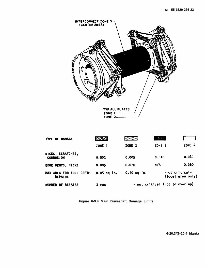
T M 55-1520-236-23
Figure 6-9.4 Main Driveshaft Damage Limits
6-20.3/(6-20.4 blank)


k. Polish out nicks, scratches, or pits on shaft (8)using fine India stone (C116) or crocus cloth (C37).
NOTE
Minimum acceptable radius in reworkedareas is 0.50 inch, except in Area B,figure 6-7.1,0.09 inch minimum radius isacceptable. Surface finish in reworkedareas must be 63 microinches or better.Polished areas, or cleaned areas with pitawithin allowable l imits must berefinished with two coats of primer(C91).
(1) Nicks and scratches on the outside of shaftrunning within 15 degrees of shaft axis may bein excess of 0.010 inch depth. Polished area must notexceed 20 percent of circumference of shaft at anypoint.
(2) Nicks and scratches on outside of shaft notrunning within 15 degrees of shaft axis, which are notpolished out. A maximum depth of 0.005 inch maybepolished out on 100 percent of shaft circumference.A maximum depth of 0.010 inch maybe polished out,provided the total polished area does not exceed 20percent of shaft circumference at any point.
(3) Corrosion pitting on inside of shaft must bereworked or polished out in accordance with limitsstated in paragraph 6-10.
(4) Replace shaft if cracked, dented or ifdamage exceeds acceptable limits.
1. Remove any defects such as burrs or sharpedges in packing groove in retainer (3, figure 6-6) andareas of outer coupling (13) where packing andretaining ring will seat. Use a fine India stone (C116)or crocus cloth (C37). Carefully remove any foreignmaterial.
m. Replace couplings (13) and (14) if teeth arechipped, pitted, corrosion pitted, discolored orblistered plating indicating overheating or if patternsare not within acceptable limits.
n. Replace nut (6) if corrosion damage exceedsacceptable limits, or if threads are galled. Repairminor nicks or dents on threads using a fine Indiastone (C116).
o. Replace any parts that are cracked or exceedacceptable dimensional limits.
TM 55-1520-236-23
6-12. ASSEMBLY – MAIN DRIVESHAFT.
Premaintenance Requirements forAssembly of Main Driveshaft
Conditions Requirements
Model
Part Number orSerial Number
Special Tools
Test Equipment
Support Equipment
Minimum PersonnelRequired
Consumable Materials
Special EnvironmentalConditions
AH-IP/E/F
All
(T25) (T33)
None
None
One
(C81) (C56) (C91)(C116) (C137) (C103)
None
a. Lubricate and assemble driveshaft as follows:
(1) Install boot (11, figure 6-6) and packing (12)on outer coupling (13), making sure large holes in bootmote with the topped holes in the outer coupl-ing. Install bolts (9), washer (10) and if installed,balance weight (15). Torque baits 50 TO 70 inch-poundsand install Iockwire (C137).
(2) Position each coupling and boot assemblywith boot down. Squeeze one-fourth of a tube oflubricant (C56) into boot of one coupling, keepingremainder of tube for later use. Apply lubricant from asecond tube in other coupling booth in same manner.See detail L, figure 6-7. Coat inner diameter of shaft(8, figure 6-6) with a light film of coupling lubricant(C56). Coat threads and thread relief in shaft, threadsand flange on nut (6) and mating surface on coupling(13) and spring retainer (7) with coupling Iubricant(C56).
6-21
TM 55-1520-236-23
NOTE
If shaft has boon dynamically balanc-ed, assure that Index parts “X” and“O” are indexed correctly per detail“A”, figure 6-6 to maintain a dynami-cally balanced shaft.
I f main driveshaft has not boondynamically balanced, or If driveshaftor couplings were replaced, disregarduse of laminated balance weights andindexing of parts.
(3) Carefully place inner couplings (14) into outercouplings (13). See detail J, figure 6-7. Be sure thatcouplings ore correctly mated according to serialnumbers recorded at disassembly No special index-ing of splines is necessary if driveshaft has not beendynamically balanced.
(4) Place a coupling assembly on end of shaft.See detail l. Install spring retainer (7, figure 6-6) and nut(6) finger-tight to bald parts in place. Repeat procedureat opposite end of shaft.
(5) Secure shaft assembly on holding fixture (T33)in a vise.
Before applying torque on nuts, be suresplines of inner and outer couplings arefully engaged, to avoid wrinkling anddamaging boots.
(6) Torque nut (6) 100 TO 200 foot-pounds, usingsplined wrench (T25). See detail F, figure 6-7. Installlocking spring (5, figure 6-6) with tang inserted througha hole in nut (6) and slot in end of shaft (8).
(7) Repeat steps (4) and (5) on opposite end ofshaft. Remove tools.
(8) Cut a piece of corrugated cardboard approxi-mately 7.25 by 16 inches. Fully extend couplings out-ward on shaft and wrap cardboard around shaft to holdin position.
(9) Apply remaining three-fourths tube of lubricant(C56) evenly inside one outer coupling with care to keepgrease out of shaft, See detail M, figure 6-7.
Six-ounce tube of grease provides correctamount of grease for one end of shaft.
(10) Install anew packing (2, figure 6-6) coated withgrease (C56) in groove around retainer (8). Place spring(4) in center of spring retainer (7). Place retainer (3) onspring, and carefully press retainer inward to normalposition. Check that retaining ring groove is clean andthat there are no rubber slivers to indicate packing dam-age, See detail N, figure 6-7.
(11) Install retaining ring (1, figure 6-6). Ensure thatring is seated securely in groove of outer coupling, Seedetails A and B, figure 6-7.
(12) Turn shaft assembly over, with incompletecoupling up.
(13) Repeat step (8), (9), and (10) to lubricate andcomplete assembly of other coupling. Remove card-board from shaft.
b. Clean all traces of grease from exterior ofdriveshaft assembly with clean dry cloth.
c. Inspect coupling boots (11, figure 6-6) for anydamage that may have occurred during assembly, Wrin-kles and tears could be caused if inner and outer coup-ling splines were not engaged before retaining nut wastightened and couplings were then twisted to align andengage splines.
6-13. INSTALLATION – MAIN DRIVESHAFT.
NOTE
Before installing driveshaft, carefully wipeclean the area surrounding the driveshaft,especially the particle separator, fifthmount support fitting, and collective tube.
a. If removed, coat adapter (4, figure 6-3) withlubricant (C56) and install into engine shaft (paragraph6-19). Install bolt (2) and locking washer (3), with shorttab of washer in slot of adapter. Torque bolt 360 TO 400inch-pounds and secure head to tab on washer (3), usingIockwire (C 137).
b. Place driveshaft assembly (13) between engineadapter and transmission input drive quill.
6-22

TM 55-1520-236-23
c. Install clamp sets (5) to secure each end of shaft.
(1) Wipe inside grooves of clamp (5) clean ofgrease, Fit clamp halves around coupling joint, checkingthat serial numbers on both halves are alike and on sameside. Clamp halves should fit snugly and hold themselvesin place without bolts.
(2) Install two bolts (7) as follows:
(a) Place chamfered washer (8) on each bolt (7)with chamfered side next to bolt head. Install pivots (9) oneach bolt (7) with curved side toward clamp set (5) withheads in direction of rotation.
(b) Install steel washer (10) and thin steelwashers (11) on bolts (7) as required to obtain properthread engagement with nuts (12). Use equal number ofwashers on opposite bolts to maintain balance.
(c) Install nuts (12) on bolts (7). Tighten nutsevenly and keep gap between ends of clamps equal within0.030 inch. Torque nuts 100 TO 130 inch-pounds. Tap onclamp set (5) with fiber mallet to ensure good seating.
(d) Recheck torque on nuts (12) and install cot-ter pins.
(3) Install opposite end clamp set, positioned 90degrees around shaft in relation to previously installedclamp set in same manner as outlined in step (2). Wipe anygrease from shaft exterior. Install upper air filter assembly(paragraph 4-24). Install top half of FOD screen (figure 4-7)
d. Prior to incorporation of MWO 55-1520-236-50-12,install particle separator as follows:
(1) Install particle separator upper half (14) (para-graph 4-32) and FOD screen upper half (15) (paragraph 4-38).
(2) Install baffle panels (1 and 6) (paragraph 2-125). Close cowling.
e. After incorporation of MWO 55-1520-236-50-12, installcentrisep particle separator as follows:
(1) Install centrisep particle separator (18) (para-graph 4-32.1).
(2) Install forward and top baffle panels (16 and17) (paragraph 2-125.1). Close cowling.
f. After first ground runup, inspect areas around bothmain driveshaft couplings, in line with coupling clamps,for evidence of grease slinging. If grease leakage is indi-cated:
(1) Remove clamp sets to check for grease ingrooves. If grease is found in clamp grooves, remove shaftand inspect couplings for lubrication and proper installa-tion of packings.
(2) If no grease is found, reinstall clamps. Watchfor further evidence of leakage in next runup.
6-14. ADAPTER-MAIN DRIVESHAFT.
6-15. DESCRIPTION-ADAPTER-MAIN DRIVE-SHAFT.
The main driveshaft adapter is installed between the engineoutput shaft and the main driveshaft. The adapter attachesto the outer coupling of the main driveshaft with a clampset.
6-16. REMOVAL—ADAPTER—MAIN DRIVE-SHAFT.
a. Remove main driveshaft (paragraph 6-8).
b. Remove Iockwire, bolt (2, figure 6-3), and lockingwasher (3). Pull adapter (4) out of engine output shaft.
6-17. INSPECTION—ADAPTER—MAIN DRIVE-SHAFT.
a. Inspect adapter splines visually for wear. If there isany evidence of wear, inspect dimensionally in accordancewith figure 6-9.
b. Inspect splines for chipped or worn teeth. Replace iflocal damage exceeds 0.002 inch depth and/or 10 percentof the total effective spline surface.
c. Inspect for nicks, burrs, and scratches. Minor nicks,burrs, and scratches are acceptable if polished out andmaximum area of damage after polishing out is less than 5percent of the plated area.
d. Inspect adapter for cracks. No cracks are acceptable.
6-22.1

TM 55-1520-236-23
6-18. REPAIR — ADAPTER — MAINDRIVESHAFT.
Replace adapter if damaged in excess of accept-able limits noted in paragraph 6-17.
b. Polish out scratches, nicks, and burrs that arewithin limits noted in paragraph 6-17. Use fine India stone(C116). Touch-up repair area with primer (C88 or C91).
c. Remove superficial corrosion with Scotch-brite(C103),
6-19. INSTALLATION — ADAPTER — MAINDRIVESHAFT.
Refer to paragraph 6-13a.
6-19.1 MAIN DRIVESHAFT (FLEXIBLE PLATE).
6-19.2. DESCRIPTION — MAIN DRIVESHAFT.
a. A main driveshaft (see figure 6-9.1) with flexibleplate couplings is installed between an adapter on engineoutput and the freewheel unit on transmission input drivequill. Two coupling clamp sets of split v-band type, holdmating curvic-splined faces of end fittings in secure con-tact.
b. Flexibility of shaft is provided by rectangularplates four in each coupling. Each plate flexes providingboth angular misalignment and length changes to accom-modate movement of transmission on pylon mounts. Eachcoupling can be considered a truss-work, in which torqueloads are carried as axial loads in straight members ofeach plate.
c. A fail-safe feature exists which enables uninter-rupted drive of the shaft after a failure has occurred in oneof the duel load paths provided by the plate couplings. Innormal operation a radial clearance exists between centershaft internal diameter and the internal protruding hub ofthe end filling (see figure 6-9.1). Upon the unlikely event ofa plate failure the center shaft shifts contacting the hub sur-face which restores the load balance, contains the whirlingparts and restores stable operation. The off center opera-tion of center shaft is sufficient to cause a noticeable unbal-ance which signals that a partial failure has occurred andfail-safe mode is in operation with lost remaining load path.
used as balance weights. These weights maybe found in-side the shaft end fittings. To assure screws are securelyfastened a high grade of adhesive is used on the threads.Do not attempt to turn screws as breakage may result dueto high Iockage force of the adhesive.
6-19.3. REMOVAL — MAIN DRIVESHAFT.
a. Open cowling on left and right side of pylon.
b. Prior to incorporation of MWO 55-1520-238-50-12, remove particle separator as follows:
(1) Remove baffle panels (1 and 6, figure 6-3)(paragraph 2-125).
(2) Remove FOD amen upper half (15).
(3) Remove particle separator upper half (14).Cover open ends of lower air filter assembly to keep dirtand foreign objects.
c. After incorporation of MWO 55-1520-236-50-12,remove centrisep part separator as follows:
(1) Remove top baffle (17) and left and right sec-tions of forward baffle (16) (paragraph 2-125.1).
(2) Remove centrisep particle separator (16)(paragraph 4-28.1).
d. Remove coupling damps at each end of maindriveshaft, keep damps together as matched sets after re-moval.
Compression of shaft is usually necessary toclear the engine adapter and transmissionfreewheeling unit.
DO NOT APPLY ANY TOOLS OR CLAMPS TOCOUPLING PLATES.
To prevent critical damage to plates and/orshaft, focally obtain and make two installationclamp aids. Refer to figure 6-9-2.
d. The shaft is dynamically balanced of time of man-ufacture by the use of washer(s) and screw(s) which are
6-22.2

TM 55-1520-236-23
e. Position two installation clamp aids over boltheads located on the arms of the end fittings. (See figure6-9.3.) Tighten damps to allow removal of shaft. Removeshaft assembly, remove damp aids.
f. To remove engine shaft adapter, remove Iockwire,retaining bolt and key washer. Pull adapter out of engineoutput shaft.
6-19.4. CLEANING — MAIN DRIVESHAFT.
a. Clean shaft assembly, adapter, and attachingparts with dry cleaning solvent (C112) or Methyl-Ethyl-Ke-tone (C74).
b. Dry with filtered compressed air or dean cloth.
6-19.5. INSPECTION AND REPAIR — MAINDRIVESHAFT.
Do not attempt to loosen or tighten any hard-ware. Any reason for necessary part removalis cause for shaft replacement.
a. Visually inspect shaft for cracks.
b. Visually inspect shaft for nicks, dents, scratchesand corrosion. Refer to figure 6-9.4 for limits.
(1) Superficial scratches not exceeding 0.002 inchin depth or well rounded dents on port edges not exceed-ing 0.005 inch in depth do not require repair.
(2) Scratches in the metal deeper than 0.002 inchor with sharp notches shall be smoothly blended into sur-rounding area so that no shaft indentations or edges re-main. Repair must be within the limits specified in figure 6-9.4, Accomplish repair by careful hand filing or stoning,using fine emery cloth for final polishing. Minimize removalof protective coating during repair.
(3) Damage to the protective coating (removal tobase metal) which exceeds 0.25 inch in width may betouched-up with aluminum colored paint for appearanceand minimal protection from corrosion. Smaller areas leftbare will not corrode due to sacrificial properties of the orig-inal protective coating.
NOTE
Black residue developing around flex plates isnot reason for rejection of driveshaft.
(4) Check for legibility of stenciled serial number,and/or existence of data plate on main driveshaft. If dis-crepancy exists, stencil number on shaft.
6-19.6. INSTALLATION — MAIN DRIVESHAFT.
a. If removed, insert adapter (11, figure 6-9.1) intoengine shaft. Install retaining bolt (9), P/N 204-040-813-101, and key washers (10) with short tab of washer toadapter slot. Torque bolt with 360 to 400 inch-pounds.Lockwire (C137) bolt head to outer tab of key washer.
b. Position two installation clamp aids over boltheads located on arms of the end fittings. Tighten dampsto allow installation of shaft between engine adapter andtransmission freewheel unit, Install main driveshaft in ei-ther direction. Remove both damps from shaft after instal-lation.
c. Install coupling damps (2, figure 6-9.1) to secureboth ends of shaft as follows:
(1) Check the serial numbers on each clamp setensuring both halves are alike and on the same side for in-stallation.
(2) Position clamp set so that gap is in line withindex mark (circular indentation) on the shaft end fitting(see figure 6-9.1).
(3) Clamp halves should fit snugly and hold them-selves in place without bolts.
(4) Place washer (4, figure 6-9.1) on bolt (3) withchamfer against head. Install bolt, with head in direction ofshaft rotation, through pivots (5) and clamp ends. Installwashers (6, 7) and nut (8).
NOTE
Thick or thin steel washers maybe added if re-quired under nut; and using like quantity onopposite bolt to maintain balance.
(5) Torque nut 100-130 inch-pounds, keepingequal gaps between ends of clamp set within 0-030 inch.Tap around outside of clamp set to ensure good seating,and recheck torque. Install cotter pin.
(6) Install opposite end clamp set, in the samemanner, positioned 90° around shaft in relation to pre-viously installed damp set.
6-23

TM 55-1520-236-23
d. Prior to incorporation of MWO 55-1520-236-50- (1) Install centrisep particle separator (18) (para-12, install particle separator as follows: graph 4-32.1).
(1) Install particle separator upper half (14, figure (2) Install forward and top baffle panels (16 and6-3) (paragraph 4-32) and FOD screen upper half (15) 17) (paragraph 2-128.1). Close cowling.(paragraph 4-38).
6-19.7. ALIGNMENT — MAIN DRIVESHAFT.(2) Install baffle panels (1 and 6) (paragraph 2-
128). Close cowling. See paragraph 6-7 for alignment instruction.
e. After incorporation of MWO 55-1520-236-50-12,install centrisep particle separator as follows:
SECTION Ill. MAIN TRANSMISSION
6-20. TRANSMISSION ASSEMBLY.
6-21. DESCRIPTION — TRANSMISSION AS-SEMBLY.
a. The transmission is located directly ahead of en-gine. It is supported in the helicopter pylon structure by fourmain mounts and the fifth mount. The engine furnishespower to the transmission through the main driveshaft. Thetransmission drives the main rotor mast through a spiralbevel gear set and two planetary reduction stages. A free-wheeling unit in the input quill coupling disengages to allowmain rotor and gear train to turn freely when engine isstopped or is idling below rotor-driving speed, as in autoro-tational descent. Secondary gear trains drive tail rotorshaft, rotor tachometer generator, hydraulic pumps, trans-mission oil pump, and alternator. See figure 6-10 for viewof quills which drive these components.
drive quill (5, figure 6-10) on the left side of transmissionmain case (11).
6-22. SERVICING — TRANSMISSION ASSEM-BLY.
Refer to paragraph. 1-5
6-23. ALIGNMENT — TRANSMISSION ASSEM-BLY.
Refer to paragraph 6-7.
6-24. REMOVAL — TRANSMISSION ASSEM-BLY
Premaintenance Requirements for Transmission
Conditions Requirements
Model
Part Number orSerial Number
Special Tools
Test Equipment
Support Equipment
Minimum PersonnelRequired
Consumable Materials
Special EnvironmentalConditions
AH-1 P/E/F
All
(T45) (T49) (T66) (T72)
None
(S4)
Two
(C25) (C26) (C41) (C46)(C52) (C53) (C57) (C66)(C79) (C79C) (C80) (C88 or C91)(C114) (C121) (C127)
None
6-24

TM 55-1520-236-23
If the transmission is being removed prior tonormal overhaul, for internal failure or metalparticles, clean all oil lines, replace cockpit airblower drive quill, hydraulic pump and ta-chometer drive quill, alternator drive quill oilcooler, mast assembly, and transmission ex-ternal oil filter.
a. When the transmission is to be replaced, unlessconditions prevent operation, perform a ten minute groundrunup and drain operating oil. If runup is not practical, re-move mast assembly and spray the interior of the trans-mission through the top opening with approximately onegallon lubricating oil (C79) (C79A) or (C80) of the type thathas been used in the transmission. While spraying, man-ually rotate internal gears and bearings by turning the inputdrive quill (3, figure 6-10) clockwise. Drain oil from trans-mission. Attach tag to the transmission stating:TRANSMISSION PRESERVED WITH LUBRICATINGOIL, MIL-L-7808, MIL-L-23699, or DOD-L-85734 as appli-cable.
NOTE
Transmission and mast maybe removed withswashplate and support, collective lever, andpitch links attached
b. Open cowl doors on both sides of engine com-partment Detach both forward doors from helicopter by re-moving nuts, washers, and bolts in hinges. Disconnectelectrical harness at door.
c. Remove both upper fairing side panels.
d. Disconnect battery and electrical connections.
e. Remove main driveshaft (paragraph 6-8).
f. Remove tail rotor forward driveshaft (paragraph6-77).
6-24.1/(6-24.2 blank)


TM 55-1520-238-23
Figure 6-10. Transmission Quills
6-25

(6, figure 6-13)
TM 55-1520-236-23
g. Without disconnecting hydraulic lines, removethe two hydraulic pumps from drive pad on rightside of transmission sump case and set back dewof transmission. Remove oil tube from sump case(14, figure 6-11).
h. Disconnect two oil hoses from oil coolerbypass valve (23, figure 6-12). Disconnect sumpdrain coupling (24).
i. Detach ducting from blower at front oftransmission.
electrical connectors from altemator. Identifylocation of wires for use on installation. Protectwires, receptacles, and plugs with caps orelectrical tape (C121).
(paragraph 11-129).
l. Disconnect transmission instrumentation wiringelectrical connector at right side of transmissioncompartment.
m. Remove main rotor (paragraph 5-12). If mastcontrols are to be removed, refer to paragraph5-49.
n. Install mast nut (1, figure 6-11) on mast (2).Attach hoist (T45) and take up cable slack.
O. Disconnect cyclic control tubes and elevatorcontrol tube from swashplate control horns.Disconnect collective control tube from collectivelever.
p. Remove bolt assembly (10). If bolt is binding,apply slight tension on hoist to lift transmissionslightly.
q. Remove bolt assembly (30). Move lift link (17)out of lift beam (29) and reinstall bolt assembly(30), washer (31), and nut (32) in lift link.
r. Remove four bolts (22), washers (23), andretaining washers (24).
Extreme care must be taken whenremoving transmission to preventdamage to Iines, hoses, and airframecomponents.
s. Carefully hoist mast and transmissionassembly dear of fuselage structure.
t. If transmission is not to be reinstalled, removebolt assembly (21). Remove lift link fromtransmission and reinstall bolt assembly (21),washer (20), and nut (19) in lift link (1 7).
u. Place transmission on stand (T72) equippedwith adapter (T49). Secure with bolts throughtransmission support case.
v. If transmission is being replaced, transfer thefollowing components to the new transmission.
(1) Electrical harness.
(2) All accessories.
(3) Cockpit air blower (paragraph 13-51).
(5) For helicopters with MWO1-1520-236-50-30, transfer bracket (73, figure6-12), external filter (9.1), hose (7), hose (10), anddebris monitor (74).
6-25. REMOVAL - TRANSMISSION RELATEDPARTS.
If the transmission was removed dueto internal failure and/or metalparticles on oil filters or magneticchip detector, replace oil coder, mastassembly, hydraulic pump drive quilland alternator drive quill, E/M. Attacha tag to each of these parts and to thetransmission, showing that the partsare suspected of being metal particlecontaminated. Clean all metalparticles from all oil hoses and tubesprior to installing the hoses and tubeson a replacement transmission.
a. Remove number 8 oil jet hose (6, figure 6-12)and damp.
b. Remove mast assembly (paragraph 6-69).
c. Remove oil cooler (paragraph 6-143).
aluminum washer (7) and transducer mountingbracket from tail rotor driveshaft quill.
6-26

TM 55-1520-236-23
6 - 2 6 . I N S P E C T I O N - T R A N S M I S S I O NRELATED PART.
a. Inspect all threaded fittings for damaged threadsand cracks.
6-26.1/(6-26.2 blank)

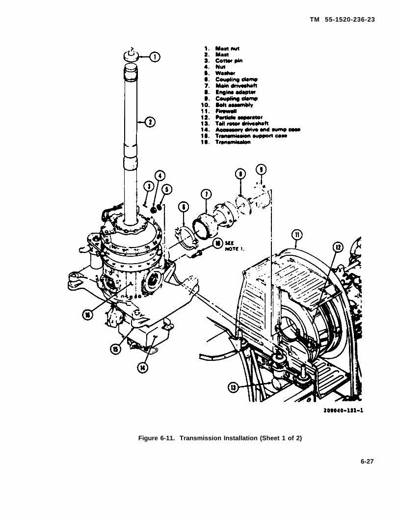
TM 55-1520-236-23
Figure 6-11. Transmission Installation (Sheet 1 of 2)
6-27
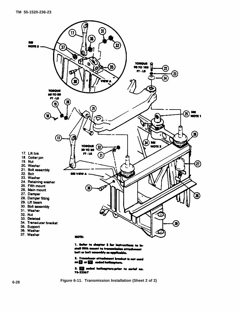
TM 55-1520-236-23
6-28 Figure 6-11. Transmission Installation (Sheet 2 of 2)
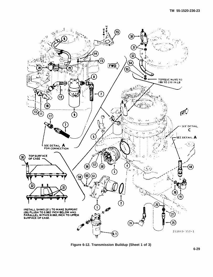
TM 55-1520-236-23
Figure 6-12. Transmission Buildup (Sheet 1 of 3)6-29
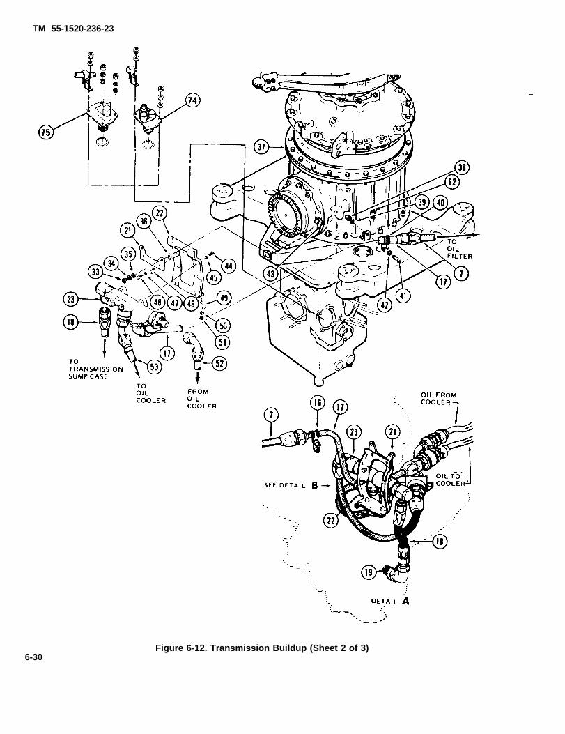
TM 55-1520-236-23
6-30Figure 6-12. Transmission Buildup (Sheet 2 of 3)

TM 55-1520-236-23
Figure 6-12. Transmission Buildup (Sheet 3 of 3)
6-31

TM 55-1520-236-23
Figure 6-13. Transducer Bracket Installation
6-32

TM 55-1520-236-23
b. Inspect all brackets and clamps for distortionand cracks.
c. Inspect all hose assemblies for deteriorationand damaged fittings.
d. Inspect all tubes for distortion and damagedfittings.
6 - 2 7 . R E P A I R – T R A N S M I S S I O NRELATED PARTS.
a. Replace all transmission related parts thatfailed to pass inspection requirements.
b. Clean hoses and tubes thoroughly.
6 - 2 8 . I N S P E C T I O N – I N S T A L L E DTRANSMISSION AND MAST ASSEMBLY.
a. Inspect the following oil strainers andmagnetic chip detector for metal particles. If anyparticles are found, refer to paragraph 6-4 forrequired corrective action.
(1) Magnetic chip detector (paragraph 6-176).
(2) External oil filter (paragraph 6-158).
(3) Internal oil filter (transmission sumpprimary) (paragraph 6-161).
b. Inspect transmission for loose, missing, anddamaged bolts and studs.
c. Inspect transmission for damage in accordancewith figure 6-14.
d. Inspect transmission for oil leakage. If anydefects are noted, refer to appropriate paragraph inSection VII.
e. Inspect transmission for corrosion andmechanical damage.
f. Inspect main rotor mast (paragraph 6-71).
6 - 2 9 . R E P A I R O R R E P L A C E M E N T –TRANSMISSION ASSEMBLY.
a. Replace transmission if damaged in excess ofreparable limits.
b. Replace any loose or damaged standard typestuds as follows:
NOTE
These instructions are for studs ofstandard type; threaded directly intotransmission case and for studs andthread inserts which have a serratedlocking ring, with inner teeth engaged ona serrated collar of stud or insert andouter teeth broached into material oftransmission case. Tools for installationand removal are made by manufacturerof these parts. When such tools are notavailable, r e p l a c e m e n t c a n b eaccomplished with other tools, providedcareful workmanship is applied.
(1) Measure stud height, if possible, beforeremoval. Use suitable tool to grip stud and turn outslowly and evenly to avoid seizure and breakage. Ifbroken off, drill hole in stud on center to use any easy-out type extractor.
(2) If tapped hole in case has a small vent holeat the bottom of the tapped hole, ensure that the venthole is open prior to installing the new stud.
(3) Select replacement stud by reference toRepair Parts Appendix, which provides an undersizeand four oversizes (by 0.003 inch increments) to eachstandard stud. Generally, next larger oversize will berequired for proper installation torque. Start new studinto tapped hole with fingers. If it turns freely beyondtwo turns, select next oversize which will engage inone or two turns with fingers.
(4) Remove replacement stud, and coat endwith primer (C88 or C91) to prevent contact ofdissimilar metals. Start stud into tapped hole.
(6) Use a suitable tool to turn stud slowly andevenly into hole. Check stud for squareness withmachined surface of case. As stud is installed toproper depth, check that torque is within limits offollowing table:
Stud Size Inch-Pounds Torque
1/4 50 TO 95
5/16 100 TO 225
3 / 8 175 TO 375
6-33

TM 55-1520-236-23
Figure 6-14. Damage Limits — Transmission (Sheet 1 of 6)
6-34
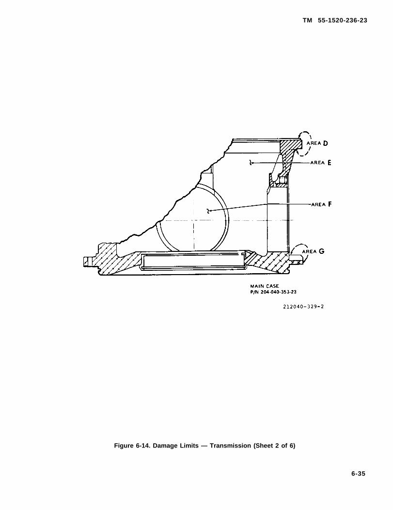
TM 55-1520-236-23
Figure 6-14. Damage Limits — Transmission (Sheet 2 of 6)
6-35
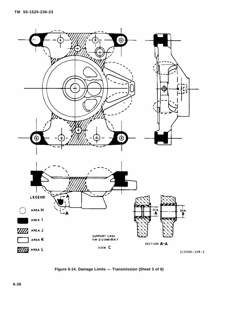
TM 55-1520-236-23
Figure 6-14. Damage Limits — Transmission (Sheet 3 of 6)
6-36

TM 55-1520-236-23
AREAAll
AandB
C
D
E
F
DandG
H
LIMITSNo cracks allowed.
Corrosion in Area "A" at mast mounting port or in Area “B” where top case to ring gear assemblyattaching bolts are installed is cause to replace transmission.
Mechanical or corrosion damage on top case outside areas noted in preceding paragraph ISacceptable if following conditions are met:
1. Maximum depth after polishing out damage is 0.020 inch.
2. Maximum area of damage is 25 percent of the total area,
3. Damaged area is treated for corrosion protection in accordance with general instructions.
Corrosion in Area “D” where main case to ring gear attaching bolts are installed is cause to replacetransmission.
Mechanical and corrosion damage limits on exterior surface of main ease and outside Area “D” and“G” are the same as stated for Area “C”.
A loose bearing liner for the bearing that supports the forward end of the input drive quill and/orcorrosion between the bearing liner and the case is cause to replace the transmission.
Corrosion in Area “D” where main case to ring gear attaching bolts are installed is cause to replacetransmission.
Corrosion in Area “G” where main case to support case attaching studs are installed is cause toreplace transmission.
Mechanical or corrosion damage in Area "D" and Area “G” that does not extend under nuts andwashers is acceptable if following conditions are met
1. Maximum depth after polishing out damage is 0.020 inch.
2. Maximum area of damage within any one square inch is 20 percent.
3. Maximum area of damage in total area IS 10 percent.
4. Damaged area is treated for corrosion protection in accordance with general instructions.
Mechanical or corrosion damage in Area “H” is acceptable if following conditions are met:
1. Maximum depth alter polishing out damage on flat surfaces is 0.010 inch, and maximum lengthis 1.0 inch.
2. Maximum depth after polishing out damage on radii is 0.030 inch, and maximum length is twoinches.
Figure 6-14. Damage Limits — Transmission (Sheet 4 of 6)
6-37

TM 55-1520-236-23
AREA LIMITS
H 3. Damage is polished out and blended smoothly into surrounding surface.
4. Damaged area is treated for corrosion protection in accordance with general instructions.
I Mechanical or corrosion damage in Area “1” is acceptable if following conditions are met:
1. Maximum depth after polishing out damage on flat surfaces is 0.040 inch.
2. Maximum depth after polishing out damage on radii is 0.060 inch.
3. Damaged area is treated for corrosion protection in accordance with general instructions.
J Mechanical or corrosion damage in Area “J” is acceptable if following conditions are met.
1. Maximum depth after polishing out damage on flat surfaces and radii is 0.060 inch
2. Damaged area is treated for corrosion protection in accordance with general instructions.
K Mechanical or corrosion damage in Area "K", which consists of all areas not covered byAreas "H", “l”, and “J”, is acceptable if following conditions are met:
1. Maximum depth after polishing out damage is 0.010 inch.
2. Damage area is treated for corrosion protection in accordance with general instructions.
L Wear and damage to Iift link bushings installed in Area “L” is acceptable if following condi-tions are met:
1. Diameter “A” must not be greater than 0.7505 inch.
2. Diameter “B” must not be greater than 1.0005 inch.
3. Surface finish inside bushings must be 40 RHS (roughness height ratio) or better.
4. Bushings must be securely mounted in case. Loose bushings, signs of yielding, and/orcracks in lift link bushing support lugs is cause to replace transmission.
GENERAL INSTRUCTIONS
1. Evidence of corrosion under shim plates at quill mounting ports is cause to replace the transmissionand/or affected quill.
2. Loose or damaged studs it Area “A” and loose studs or inserts at any of the quill mounting ports arecause to replace the transmission.
Figure 6-14. Damage Limits — Transmission (Sheet 5 of 6)
6-38

TM 55-1520-236-23
3.
4.
5.
GENERAL INSTRUCTIONS (Continued)
Polish out corrosion damage to twice the depth of the corrosion. Finish polishingout with 400 grit abrasive paper (C102) to blend repairs smoothly into surroundingsurface. Ensure that depth and /or repair does not exceed acceptable limits specifiedfor the areas designated above. Treat reworked areas for corrosion protection withMIL-M-3171C, Type VI treatment. This is commercial designation Dow No. 19. Referto TM 43-0105 for application procedures. Prime all rework areas that were paintedprior to repair. Use polyamide epoxy primer (C88). Paint to match existing finish.
Polish out mechanical damage to depth to remove all traces of the damage. Finishpolishing out with 400 grit abrasive paper (C102) to blend repair smoothly intosurrounding surface. Ensure that damage does not exceed acceptable limits. Applycorrosion protection, prime, and paint in same manner prescribed in preceding step.
Chafed areas of the sump case assembly that are smooth and do not exceed 0.070 inchdepth shall be filled with DEVCON F or equivalent and blended to surroundingsurfaces. Mechanical damage that does not exceed 0.070 inch depth shall be N.D.T. toassure no cracks exist. The area shall then be blended and filled as a chafed area.
Figure 6-14. Damage Limits—Transmission (Sheet 6 of 6)
c. Replace loose or damaged lock-in studs as fol-lows:
(1) To remove a threaded insert, select adrill equal in diameter to that of serrations betweenlocking ring and insert. Drill to depth equal to ringthickness. Remove insert with a square-type extract-ing tool. If lockring fails to come out, collapse remain-ing portion of with punch.
(2) To remove a stud, use a hollow mill withoutside diameter 1/64 inch less than mot diameter ofouter serrations of locking. Mill to depth equal toring thickness. Remove stud and any remaining por-tion of ring. If hollow mill is not available, saw studoff, use drill as in step (1), and remove stud with aneasy-out extractor.
(3) Check condition of tapped hole andcounterbore. Holes are tapped with standard Class 3tap. Counterbore has 90 degree shoulder and can becleaned up as necessary. Avoid enlargement of holes,since this would require oversize parts.
(4) If tapped hole in case has a small venthole at the bottom of the tapped hole, ensure that thevent hole is open prior to installing the new stud.
(5) Coat threads of new stud or insert withunreduced primer (C91). Install the new stud orinsert into tapped hole with suitable tool until topsurface of serrated collar is 0.010 TO 0.020 inchbelow surface of parent material.
(6) Place locking ring over stud or insertend line up teeth of ring with teeth of serrated collar.Drive ring into material flush with top of insert orstud collar.
d. Replace transmission oil system componentsthat fail to pass inspection requirements. Refer toappropriate paragraph in chapter 6, section VII.
e. Repair transmission oil system components thathave damage within repairable limits. Refer to ap-propriate paragraph in chapter 6, section VII.
6-30. INSPECTION-TRANSMISSION MOUNTCOMPONENTS.
a. Inspect pylon structure and lift beam (29, figure6-11) for damage.
b. Inspect lift. link (17) for damage.
c. Inspect four main mounts (26) (paragraph 2-224).
d. Inspect two dampers (27) for damage andleakage (paragraph 2-236). Inspect dampers for secureinstallation in pylon structure.
e. Inspect damper fitting (28) for damage and forsecure installation in pylon structure.
f. Inspect fifth mount (25) (paragraph 2-230).
6-31. REPAIR - TRANSMISSION M O U N TCOMPONENTS.
a. Replace transmission mount components thatfail to pass inspection requirements. Refer to ap-propriate paragraph in chapter 2 for main mounts
6-39
TM 55-1520-236-23
(26, figure 6-11), fifth mount (26), dampers (27), anddamper fittings (28).
b. Repair dampers (27) that have damage within reparablelimits (paragraph 2-236).
c. Replace damper fitting (28) if loose or damaged(paragraph 2-241).
6 -32 . INSTALLATION – TRANSMISSIONRELATED PARTS.
a. Place serviceable transmission on a suitablestand.
b. Remove pad covers, caps, and plugs fromserviceable transmission. See figure 6-15.
c. Install pad covers, caps, and plugs that wereremoved in preceding step on unserviceabletransmission.
d. Clean all sealant from serviceabletransmission where quill pad covers ware removed.Use a sharp plastic scraper.
e. Install electrical harness using clamps andhardware. Attach harness to electrical components.
f. Install main rotor mast (paragraph 6-73).
g. Connect number 8 oil jet hose (6) and securewith clamp.
figure 6-13).
6 -33 . INSTALLATION – TRANSMISSIONASSEMBLY.
a. Install main mast if not previouslyaccomplished (paragraph 6-73).
b. Install air distribution blower (fan). Refer toparagraph 13-59.
c. Ensure that transmission mount componentshave been inspected in l ccomlance with paragraph6-30.
d. Install mast nut (1, figure 6-11). Attach hoist(T45) to mast nut, using clevis (S4).
e. Position lift link (17) on transmission and installbolt assembly (21), washer (20), and nut (19). Torquenut 60 TO 80 foot-pounds. Install cotter pin (18).
f. Carefully hoist transmission into position abovehelicopter with input quill facing aft. Lower thetransmission onto mounts (26) and guide lift Iink (17)into clevis on lift beam (29).
g. Position height of transmission with hoist toalign holes in lift link (17) and lift beam (29). Installbit assembly (30), washer (31) and nut (32). Torquenut 30 TO 50 foot-pounds. Install cotter pin (33).
NOTE
The minimum breakaway torque is theminimum torque required to startremoval of bolt (22) from the completelyinstalled untorqued position. Thepurpose of determining breakawaytorque in the following step is to ensurethat the self-locking feature of the nyloninsert bolt (22) is serviceable.
h. Install four bolts (22), washers (23), andretaining washers (24). Thread bolts into mounts toobtain full thread engagement but do not torque.Check breakaway torque of each bolt (22). Minimumacceptable breakaway torque is 24 inch-pounds.Replace bolts which have less than acceptablebreakaway torque. Torque four bolts (22) 90 TO 105foot-pounds.
i. Install fifth mount to transmission attachingbolt assembly (10) (paragraph 2-232).
j. Install hydraulic cylinder extension tubes onswash - plate and on collective lever (paragraph11-152).
k. Install main rotor hub and blade assembly(paragraph 5-14).
l.
Ensure that crowned tooth coupling isproperly lubricated prior to installation ofdriveshaft.
Install tail rotor driveshaft (paragraph 6-81).
m. If required, make enginealignment check (paragraph 6-7).
to transmission
6-40
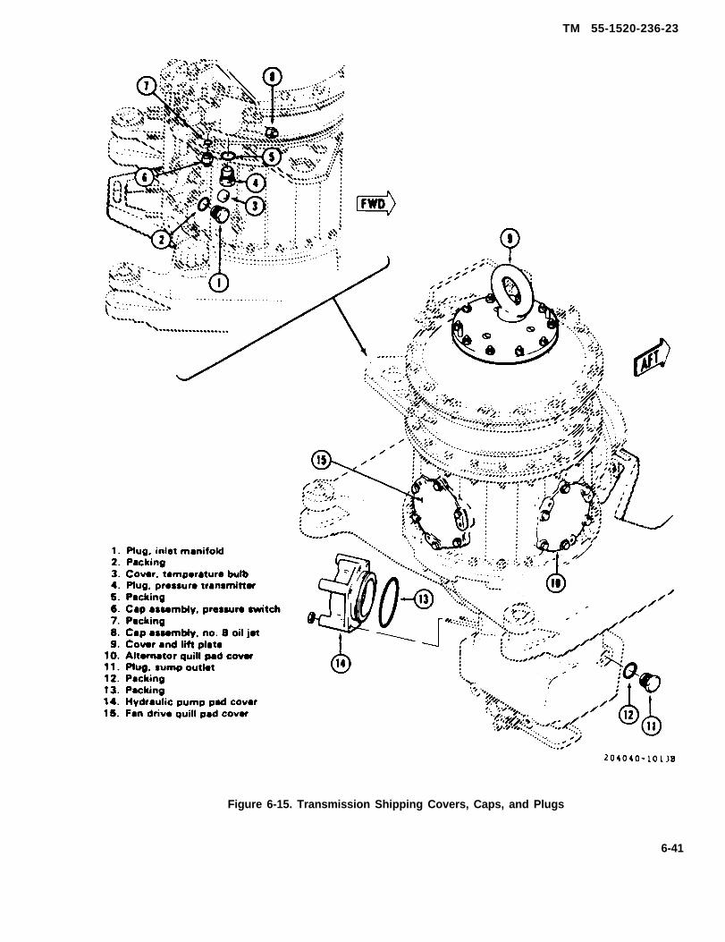
TM 55-1520-236-23
Figure 6-15. Transmission Shipping Covers, Caps, and Plugs
6-41
(paragraph 9-165)
(figure 6-13)
TM 55-1520-236-23
n. Install main driveshaft (paragraph 6-13).
o. Connect two oil hoses from oil cooler to oilcooler automatic emergency bypass valve (13, figure6-47). Ensure that oil filter (2) and external oil lines areproperly installed on transmission.
Ensure that items (38, 39) or (41, 42) offigure 6-7 are installed correctly toensure proper oil cooler bypass valveoperation and oil flow direction throughthe coder.
p. Connect sump drain coupling (6, figure 647).
q. Attaching ducting to blower at front of trans-mission.
and connect electrical wires and electrical connectorsto alternator.
mount (TM 11-1520-236-20).
t. Connect transmission instrumentation electri-cal wiring connector at right side of transmissioncompartment.
t.1 For helicopters with MWO 1-1520-236-50-30,check that ODDS components - bracket (73, figure6-1 2) external filter (9.1) and debris monitor (74) - areinstalled. Check that cable plug is connected to recep-tacle on debris monitor.
(C80).
v.
w.
Service transmission with oil (C79), (79A) or
Close transmission cowling.
Perform maintenance test flight (TM55-1520-236-MTF).
6 -34 . PREPARATION FOR SHIPMENT —TRANSMISSION ASSEMBLY.
a. Remove main rotor mast assembly if not pre-viously accomplished (paragraph 6-69).
b. Preserve transmission by spraying the interiorof the transmission through the top opening with a onegallon mixture of one part oil (C79 or C80) and one partcorrosion prevention (C44.1). While spraying,manually rotate the transmission input drive quill to in-
6-42
sure gears and bearings are completely saturated.Attach tag to transmission stating: PRESERVEDWITH CORROSION PREVENTIVE, NSN6850-00-142-9582.
c. Install cover and lift plate (9, figure 6-15)immediatety after the mast has been removed and theinterior preservation has been completed.
d Cap or plug all lines, as applicable, see figure6-15. Cover breather hole and ail other openings withbarrier material (C23) or protective cap (C26) andsecure with tape (C127). Secure ail loose wires andlines to assembly with tape (C127) to prevent damageduring shipment.
Cleaning advent is flammable andtoxic. Provide adequate ventilation.Avoid prolonged breathing of solventvapors and contact with skin or eyes.
Keep rubber portions of containertransmission pyton mounts free of anyoil, grease, and advents to preventdeterioration and weakening of bondsbetween rubber and metal.
e. Clean the exterior of the transmission to in-clude splines and the threaded areas with solvent(C112). Air dry or wipe with a clean lint-free cloth.
Do not allow corrosion preventive com-pound to contact rubber parts.
f. Apply corrosion preventive compound (C41)to all exterior bare metal surfaces to include splines,studs, and threaded areas.
g. Cover the couplings on the input and tail rotordrive quills and all open accessory mounting pads withbarrier material (C23) and secure with tape (C127).
h. Attach a tag to the transmission stating:TRANSMISSION PRESERVED WITH LUBRICAT-ING OIL, MIL-L-7806 or MIL-L-23699, or DOD-L-85734.
i. Fill out a DD Form 1577-2 (Unserviceable/Repairable tag) and attach it directly to the transmis-sion.
TM 55-1520-236-23
J. Fill out a DD form 1577-3 (tag or label) and attachit to the exterior of the transmission container in sucha manner that will afford maximum protection fromhandling and weather. Refer to DA PAM 738-751.
k. Fill out a DA form 2410, component removaland repair/overhaul record, in accordance with DAPAM 738-751.
6-42.1/(6-42.2 blank)

TM 55-1520-236-23
l. Install the transmission in a metal storage andshipping container as follows:
NOTE
If the container noted is not available,proceed to step m.
(1) Inspect the shipping container and be sure itis clean and satisfactory for use. Repair and/or cleanthe container if necessary.
(2) Carefully lower the transmission into theshipping container and align with shock mounts inthe container. Install four mounting bolts, washers,and nuts. Torque nuts 700 TO 900 inch-pounds.
Desiccant bags must be secured in thetransmission container in a manner toprevent contact with the transmission orcorrosion damage wiII result. Do not usedesiccant bags if an airtight container isnot available.
(3) Place 56 units of dry desiccant (C49) into thetransrnission container in such a manner that thedesiccant cannot touch the transmission duringshipment.
(4) Position top of container over transmissionand install bolts, washers, and nuts; torque nuts 265TO 285 inch-pounds.
(5) Paint over old markings that do not apply totransmission in container. Mark container inaccordance with MIL-STD-129.
m. If a metal storage and shipping container is notavailable, prepare the transmission for shipment asfollows:
NOTE
This procedure is based on theassumption that the provisions ofparagraph j cannot be complied with,that the work will be done under lessthan ideal conditions with limitedequipment and that on some occasionsby personnel who are not experts in thefield of perservation. Use this procedure
only at locations where facilities for theapplication of normal preservationprocedures do not exist.
(1) Comply with steps a through k.
(2) If caps, plugs, and barrier materialsspecified in steps d. and g. are not available, usebarrier material and tape as substitutes.
(3) If corrosion preventive compound specifiedin step f is not available, substitute other grease-typecorrosion preventive compound or bearing grease(C57).
(4) Cover the transmission with barriermaterial (C22) and secure with tape. Do not usedesiccant.
(5) Install the transmission in the beat availablecontainer or stand. Cushion, block, and brace thetransmission as necessary to prevent damage.
(6) Mark the container as follows: Point overold markings that do not apply to transmission incontainer. Mark the container in accordance withMlL-STD-129 and also include the following:TRANSMISSION IS NOT PRESERVEDSTORAGE. OVERHAUL OR PRESERVESTORAGE AS SOON AS PRACTICABLE.
6 - 3 4 . 1 0 P Y L O N L I F T L I N KTRANSMISSION.
THlSFORFOR
6-34.2. DESCRIPTION - PYLON LIFT LINK.
A pylon lift link is used to attach transmission tohelicopter fuselage. The lift link transmits rotor lift tofuselage structure. The lift link is forged steel withself -aligning end bearings and is connected betweentransmission support case and a lift link supportbeam, which is attached to the fuselage.
6-34.3. REMOVAL - PYLON LIFT LINK.
Premaintenance Requirements for PylonLift Link — Transmission
Conditions Requirements
Model AH-1S
Part Number orSerial Number All
6 - 4 3

TM 55-1520-236-23
Conditions Requirements
Special Tools (T45)
Support Equipment None
Minimum Personnel TwoRequired
Consumable Materials (C31), (C33), (C74),(C91), (C96)
Special Environmental NoneConditions
Test Equipment None
a. Open and secure transmisson cowl door on leftside.
b. Attach hoist (T45), or other suitable liftingdevice, to main rotor retaining nut.
c. Remove cotter pine (18 and 33, figure 6-11),nuts (19 and 32), and washers (20 and 31), from bolts(21 and 30).
d.2256 . Remove cotter pins (18 and 33, figure 6-11),nuts (19 and 32) and washers (20, 31, 36 and 37).
e. Using hoist, raise transmission until bolts (21and 30) can be removed. Remove both bolts and liftlink.
6-34.4. lNSPECTION - PYLON LIFT LINK.
a. Inspect upper and lower lift link ends in bear-ing area, using 10X magnifying glass.
b. Suspected cracks should be inspected by themagnetic particle method (refer to TM 43-0103).Scrap lift link if any cracks are found.
WARNINGPaint remover (C96) is toxic and con-tains ingredients harmful to skin andeyes. Observe safety precautionsprinted on the container.
(1) Remove paint from lug areas, usingpaint remover (C96).
(2) Perform nondestructive inspection.
(3) After inspection thoroughly clean anddry the areas using cleaning compound (C33) andMEK (C74).
(4) Apply two cross-coats of primer (C91) tostripped areas.
c. Corrosion or mechanical damage, not exceeding0.005 inch is permissiible after cleanup, except inoutboard 2.50 inches. No damage is permitted inoutboard 2.50 inches, on either end of lift link.
d. Inspect bearings for a maximum allowable playof 0.008 inch radial and/or 0.016 inch axial.
6-34.5. REPAIR OR REPLACEMENT-PYLONLIFT LINK.
a. Replace lift link if cracked, damaged beyondallowable limits. Bearing in lift link P/N 212-030-104-5 may be replaced in accordance with TM 55-1500-322-24 after installing bearings, link is to befluorescent penetrant inspected.
b. Polish out corrosion or mechanical damage thatis within allowable limits (refer to TM 43-0105).
c. Refinish polished area with primer (C91).
6-34.6. INSTALLATION - PYLON LIFT LINK
a. Position lift link in transmission case recess andinstall shouldered bolt (21, figure 6-11), washers (20),and nut (19). Torque nut 60 TO 80 foot-pounds andinstall cotter pin (18).
b. Align lower end of lift link and install bolt (30),washer (31), and nut (32). Torque nut 30 TO 50foot-pounds and install cotter pin (33).
Align lower end of lift link and install bolt (30),washers (36) and/or (37), as required; washer (31) andnut (32). Torque nut 30 to 50 foot-pounds. SEE NOTE3 (Fig. 6-11).
d.
e.
Disconnect and remove hoist.
Close and secure transmission cowl.
6-44

TM 55-1520-236-23
6-34.7. LIFT LINK ATTACHING POINT. polished out by removing material enclosed in a 1.00inch diameter to a depth of 0.050 inch below 0.813
6 - 3 4 . 8 . D E S C R I P T I O N – L I F T L I N Kinch lug minimum thickness.
ATTACHING POINT.
The lift link attaching point is an integral part of the c. Corrosion limits are half the depth of
lift beam (29, figure 6-11) and provides a means ofmechanical damage limits, because clean-up
attaching the transmission to the fuselage by the liftrequires material removal to twice the depth of
link (17). corrosion damage.
6 - 3 4 . 9 . I N S P E C T I O N – L I F T L I N K d. No looseness of bushings allowed.
ATTACHING POINT.e. No cracks allowed.
NOTE f. Inspect bushings for wear (View A-A, figure 6-15.1).
Refer to paragraph 6-34.3. if removal oflift link is required. 6-34.10. REPAIR – LIFT LINK ATTACHING
POINT.
a. Nicks and scratches on any lug surface within a. Polish out corrosion and mechanical damagethe enclosed 120 degree area as shown in figure6-15.1 may be smoothed and polished out by
within limits of previous paragraph.
removing material enclosed within a 0.75 inch b. Replace loose or worn bushings.diameter to a maximum depth of 0.025 inch below0.813 inch lug minimum thickness. No repair c. Treat repaired area with chemical filmallowed within 0.75 inch radius of bolt hole center. treatment (C31).
b. Nicks and scratches on any surface below the120 degree area and outside the 0.75 inch radius d. Paint repaired area with primer (C91).
around the bolt hole center may be smoothed and
Figure 6-15.1. Lift Link Attaching Point
6-44.1
TM 55-1520-236-23
6 - 3 5 . T R A N S M I S S I O N Q U I L L S .
6 - 3 6 . D E S C R I P T I O N - T R A N S M I S S I O NQUILLS.
The transmission contains a varied assortment ofquills. The quills may be replaced individually withoutshimming.
6 - 3 7 . M A I N I N P U T Q U I L L .
6 - 3 8 . D E S C R I P T I O N – M A I N I N P U TQUILL.
The main input quill (3, figure 6-10) is located on theaft side of the transmission. The engine transmitspower to the transmission through the maindriveshaft and the main input quill. A freewheel (one-way) clutch located in the main input quill operatesautomatically, engaging to allow engine to drive rotoror disengaging the idling engine duringautorotational descent.
6-39. REMOVAL – MAIN INPUT QUILL.
Premaintenance Requirements for Input Quill
Conditions Requirements
Modal
Part Number orSerial Number
Special Tools
Test Equipment
Support Equipment
Minimum PersonnelRequired
Consumable Materials
Special EnvironmentalConditions
AH-1P/E/F
All
(T27) (T43)
None
None
Two
(C79) (C80) (C74) (C111)(C105) (C137)
None
a. Open cowling on both sides of transmission.Remove baffling and panicle separator from intakesection.
b. Remove driveshaft (paragraph 6-8).
c. Disconnect drain tube (18, figure 6-16) fromunion (17).
d. Remove bolts, nuts, and washers that securebracket (21, figure 6-12) to bracket (22) and to inputquill. Remove bracket (21) and bracket (46).
e. Remove clip (43).
f. Remove four remaining nuts (33) that securemain input quill in transmission.
g. Use sharp plastic scraper and cut sealant aroundperiphery of quill. Also remove sealant, or Iockwire,plugs and gasket from jackscrew holes.
Do not apply uneven pressure to inputquill with jackscrews during removalprocedure. Do not pry behind input quillflange during removal procedure.
Do not use open flame to hosttransmission case during input quillremoval procedure.
h. Install three jackscrews (T27) in holes providedin input quill. Tighten jackscrews evenly to removequill. If the quill is difficult to remove, apply heat to thetransmission case with a heat lamp and then removethe quill with the jackscrews.
i. Remove drain tube (10, figure 6-16).
j. Cover mounting port for main input quill toprevent accidental entry of foreign objects intotransmission.
k. Do not remove shims from main input quillsleeve or from transmission case.
6-40. INSPECTION – MAIN INPUT QUILL.
NOTEExternal leakage around seals is notacceptable; however, a small amount ofseepage is acceptable and does notindicate an unsatisfactory seal condition.Continuous flow (droplets) is excessiveand requires seal replacement.
6-44.2

TM 55-1520-236-23
a. Inspect main input quill for evidence of oil 6-41. REPAIR-MAIN INPUT QUILL (AVIM).leakage. See note above.
CAUTIONb. Inspect main input quill for mechanical and
corrosion damage. Any evidence of corrosion where Do not allow clutch flange to movethe shim is attached to sleeve assembly (11, figure axially in relation to inner race when6-16) is cause to replace the quill. handling freewheeling clutch assem-
bly (1, figure 6-16). Axial movement isc. Inspect teeth on pinion gear (8) for evidence of
abnormal wear and for chipped teeth.possible with grease cap (5) removed.
d. Inspect freewheeling clutch assembly (1, fig-ure 6-16) surface that contacts main driveshaft fornicks, dents, and cracks.
6-44.3/(6-44.4 blank)


TM 55-1520-236-23
Figure 6-16. Main Input Quill Assembly6-45

TM 55-1520-236-23
a. Fabricate a work aid (figure 6-16.1, sheet 1).Secure work aid to clutch assembly (figure 6-16.1,sheet 2), using tape or other suitable material.
a.1. Remove retaining ring (6, figure 6-16) andgrease cap (5) from input drive quill. Remove packing(4) from grease cap.
b. Secure quill and remove locking spring (3).Insert wrench (T43) into the quill; match the splineteeth on the tool with splines of nut (2). Insert a 3/4inch square drive extension through wrench andengage inner end of pinion gear (8). Remove nut (2).
b.1. Reinstall grease cap (5, figure 6-16) (withoutpacking (4)) and retaining ring (6). Remove work aid(figure 6-16.1, sheet 2).
CAUTION
c.
Handle clutch assembly carefully anddo not disassemble clutch whenreplacing input drive seal.
Replacement of Wear Sleeve.
(1) Remove freewheeling unit from quill(use tool 25, Table 1-4, P/N T101306, NSN 4920-00-797-3672).
(2) Discard preformed packing (Item 4, Fig-ure 6-16).
(3) Remove Seal (Item 14, Figure 6-16) fromSleeve Assembly (Item 11, Figure 6-10).
(4) Remove RR511 retaining ring (Item 6,Figure 6-16) and shield (Item 20, Figure 6-16).
CAUTION
After removal of RR511 retaining ring(Item 6, Figure 6-16) do not allowfreewheeling coupling outer race tomove axially relative to the couplinginner race.
(5)punch.
(6)
(7)
Drive pins from wear sleeve with a
Remove old wear sleeve from outer race.
Prepare surfaces for bonding as follows:
CAUTION
Replace grease cap (Item 5, Figure 6-16) prior to surface preparation andmake every effort to ensure bearingsremain clean and free of contaminatesduring sleeve replacement.
(a) Initially remove old adhesive usingplastic scraper.
(b) Lightly abrade faying surfaces with400 grit abrasive paper or scotchbrite (C103) and thenclean with MEK (C74).
(8) After thoroughly mixing adhesive (C14)per manufactured instructions apply to wear sleeveID per illustration (Figure 6-16.3 )3 to 8 mile thick.
(9) Press new sleeve (Item 19, Figure 6-16)onto outer race (ensure wear sleeve is pressed onto therace with the internal radius first). Also, the outeredge of wear sleeve (see Figure 6-16.3) shall berecessed flush to 0.020 inch from outer races edge.
(10) After installation, ensure a 0.06R filletof adhesive is provided on the inside diameter chamferof wear sleeve as shown in Figure 6-16.3.
(11) Clean up any excess adhesive that mayhave seeped through the holes where pins were pre-viously installed.
(12) Cure adhesive at mom temperature for24 hours, at 70-95 degrees F.
CAUTION
If heat is used to accelerate cure timedo not exceed 250 degrees F.
(13) Reinstall shield (Item 20, Figure 6-16)and RR511 retaining ring (Item 6, Figure 6-16).
(14) Mask off all surfaces except O.D. of wearsleeve. Spray O.D. of wear sleeve. Spray O.D. ofinstalled wear sleeve with teflon-flouroglide (NSN6810-00-184-4800). Allow five minutes for drying thenbuff with a clean dry lint free cloth.
6-46

TM 55-1520-236-23
Figure 6-16.1. Transmission Input Quill Work Aid (Sheet 1 of 2)
6-46.1
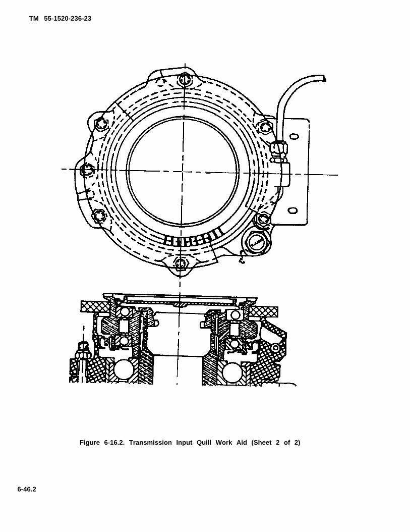
TM 55-1520-236-23
Figure 6-16.2. Transmission Input Quill Work Aid (Sheet 2 of 2)
6-46.2
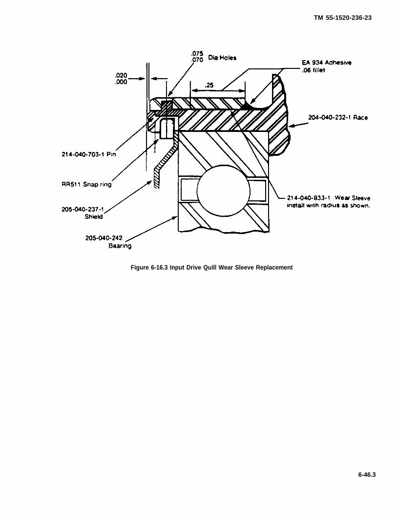
TM 55-1520-236-23
Figure 6-16.3 Input Drive Quill Wear Sleeve Replacement
6-46.3

(10, figure 6-15).
TM 55-1520-236-23
(15) Install new seal (Item 14, Figure 6-16) inSleeve Assembly (paragraph 6-41.f). Coat the seal lip(Item 14, Figure 6-16) and wear sleeve (Item 19, Figure 6-16) with a light film of grease (C58).
(16) Install freewheeling unit. Inspect for proper di-rection of freewheeling (outer race of clutch drives clock-wise).
NOTE
When installing nut (Item 2, Figure 6-16) torqueto 350-400 ft-lbs (use tool 25, Table 1-4, P/NT101306, NSN 4920-00-797-3672).
(17) Install new packing (Item 4, Figure 6-16) andreinstall the grease cap (Item 5, Figure 6-16) and securewith RR511 retaining ring (Item 6, Figure 6-16).
d. Deleted.
e. Deleted.
f. Install a new seal (14) in sleeve assembly (11) asfollows.
Cleaning solvent is flammable and toxic. Pro-vide adequate ventilation. Avoid prolongedbreathing of solvent vapors and contact withskin or eyes.
(1) Clean sleeve assembly in area where seal is tobe installed using MEK (C74).
(2) Apply 0.025 inch band of sealant (C107) toO.D. of the seal (14).
(3) Press seal (14) into sleeve assembly (11).Wipe excess adhesive.
(4) Cure at 70 TO 80 degrees F (21 TO 27 de-grees C) for 24 hours.
NOTE
If seal replacement does not stop leakage, for-ward quill to next higher maintenance level.
f.1. Install work aid (figure 6-16.1, sheet 2) and se-cure with tape or other suitable material. Remove retainingring (6) and grease cap (5).
g. Lubricate seal (14) with transmission oil (C79) or(C80) and position clutch assembly (1) in sleeve (11). In-stall nut (2) and torque 350 TO 400 foot-pounds with toolsdescribed in step b.
h. Install locking spring (3). Ensure that spring tangengages nut and pinion properly to perform Iocking func-tion,
i. Inspect groove in grease cap (5) provided forpacking (4). Remove any burrs which might damage pack-ing. Install new packing (4) on cap (5), Lubricate packingwith transmission oil (C79) (C79A) or (C80) and install re-tainer in sleeve (11). Install retaining ring (6).
j. Remove work aid (figure 6-16.1, sheet 2).
6-42. INSTALLATION — MAIN INPUT QUILL.
a. Remove cover from main input quill mounting padon transmission case. Check that mating surfaces of caseand quill are dean. Inspect grooves provided for packings(4 and 7, figure 6-16). Remove any burrs which might dam-age packing.
6-63).
d. Remove number 6 oil jet (62,right side of main transmission case.
figure 6-12) from
Rubber plug installation procedure must befollowed to prevent damage to bearings.
e. Fabricate rubber plug as follows:
(1) Cut a rubber plug (figure 6-17) Slightly largerthan the diameter of the roller bearing liner race on the in-board end of the input pinion.
6-46.4
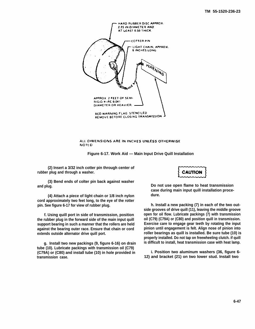
TM 55-1520-236-23
Figure 6-17. Work Aid — Main Input Drive Quill Installation
(2) Insert a 3/32 inch cotter pin through center ofrubber plug and through a washer.
(3) Bend ends of colter pin back against washerand plug.
(4) Attach a piece of light chain or 1/8 inch nyloncord approximately two feet long, to the eye of the rotterpin. See figure 6-17 for view of rubber plug.
f. Using quill port in side of transmission, positionthe rubber plug in the forward side of the main input quillsupport bearing in such a manner that the rollers are heldagainst the bearing outer race. Ensure that chain or cordextends outside alternator drive quill port.
g. Install two new packings (9, figure 6-16) on draintube (10). Lubricate packings with transmission oil (C79)(C79A) or (C80) and install tube (10) in hole provided intransmission case.
Do not use open flame to heat transmissioncase during main input quill installation proce-dure.
h. Install a new packing (7) in each of the two out-side grooves of drive quill (11), leaving the middle grooveopen for oil flow. Lubricate packings (7) with transmissionoil (C79) (C79A) or (C80) and position quill in transmission.Exercise care to engage gear teeth by rotating the inputpinion until engagement is felt. Align nose of pinion intoroller bearings as quill is installed. Be sure tube (10) isproperly installed. Do not tap on freewheeling clutch. if quillis difficult to install, heat transmission case with heat lamp.
i. Position two aluminum washers (36, figure 6-12) and bracket (21) on two lower stud. Install two
6-47
(figure 6-13)
TM 55-1520-236-23
aluminum washers (35), two thin steel washers (34), andtwo self-locking nuts (33). DO not torque nuts (33) atthis time.
j. Install clip (43, figure 6-12), thin steel washer,and self-locking nut at position illustrated. Do nottorque nut at this time
k. Position one aluminum washer on remaining fourstuds and install remaining four self-locking nuts.Tighten seven nuts (33) evenly and torque 160 TO 190inchpounds
l. Install brackets (22) and (46), using bolts, nuts,and washers removed in paragraph 6-39d.
m. Ensure that roller bearing separator plug,installed in step e. is removed when the input pinion hassufficiently engaged the roller alignment bearing. Thiswill prevent jamming the plug against the vertical shaft.Remove rubber plug installed in step d.
6-66).
p. Install number 6 oil jet (62, figure 6-12).
q. Install union (17, figure 6-16) with new packing(16). Install tube assembly (18).
r. Install plug (13) and new packing (12) at lowerright side of quill. Lockwire plug with lockwire (C137).
s. Apply sealant (C105) to quill case joint andaround drain tube (10). Install plugs (MS24391D2L),Gasket (MS28777-2), and lockwire (C137).
6-43. TAIL ROTOR DRIVE QUILL
6-44. DESCRIPTION-TAIL ROTOR DRIVE QUILL.
The tail rotor drive quill is located in the aft side of thetransmission sump case. The forward tail rotor drive-shaft is attached to a splined coupling which is part ofthe tail rotor drive quill.
6-45. REMOVAL-TAIL ROTOR DRIVE QUILL.
Premaintenance Requirements for Removal andRepair of Tail Rotor Drive Quill
Conditions Requirements
Model
Part Number orSerial Number
SpeciaI Tools
Test Equipment
Support Equipment
Minimum Personnel-Required
Consumable Materials
Special EnvironmentalConditions
AH 1P/E/F
All
(T28) (T55) (T26) (T35.1)
None
None
Two
(C56) (C 105) (C137)
None
a Open cowling at either side of transmission.
b. Remove forward section of tail rotor driveshaftparagraph 6-77).
paragraph 11-148.
d. Remove six nuts (6, figure 6-13) and washers (7).
f. Use sharp plastic scraper and cut sealant aroundperiphery of quill. Also remove sealant, or Iockwire,plugs, and gaskets from jackscrew holes.
Do not heat case with open flame.
g. Install three jackscrews (T28) in tapped holes inquill flange. Turn jackscrews evenly to pull quill fromcase. If quill is difficult to remove, heat case with heatlamp.
6-48
TM 55-1520-235-23
h. Install cover on open port on transmission g. Clean grease from inner coupling (16, figurecase. 6-19) and outer coupling (7) with clean cloth (C30)
and insert per paragraph 6-128.1.6 - 4 6 . I N S P E C T I O N — T A I L R O T O RDRIVE QUILL. h. Cut and remove Iockwire from nut (20) figure
6-19.
a. Inspect tail rotor drive quill for damage inaccordance with figure 6-18. i. Remove nut (2) with wrench (T55) and holding
fixture (T35.1).
b. Inspect grease seal, (6, figure 6-19) for cracksand deterioration.
NOTE
External leakage around seats Is notacceptable; however, a small amount ofseepage Is acceptable and does not in-dicate an unsatisfactory seal condition.Continuous flow (droplets) is excessiveand requires seal replacement.
j. Positon tail rotor quill in holding fixture (T35.1);then press oil seal (3) from nut (2) and install new seal,applying sealant (C107) to O.D. of seal (9) and I.D. onnut (2). Remove packing (1) from nut and install newpacking.
k. Install nut (2) with wrench (T55); torque to 1200TO 1800 inch-pounds and Iockwire (C137).
l. Replace grease seal (6) by installing new sealin small end of outer coupling (7) with seal lip towardflange end of coupling.
c. Inspect inner coupling (16) and outer coupling(7) while disassembled (paragraph 6-47). m. Press seal, using tongue depressor, into slot
between end of coupling teeth and flange. Hand pack
6 - 4 7 . R E P A I R — T A I L R O T O R D R I V E grease to 0.12 inch deep over top of internal spline
QUILL.teeth. Use grease (C56).
a. Replace tail rotor drive quill if damage exceedsn. Install packing (4), spacer (5), outer coupling
(7), with inner coupling (16) on pinion shaft andacceptable limits (paragraph 6-46). splines.
NOTE o. install washer (15) and coupling bolt (14) on
Remove seal plate (9, figure 6-19) slowlypinion shaft; torque coupling bolt 960 TO 1200inch-pounds.
so centering spring (10) will not fly out.
b. Polish out corrosion and mechanical damage inp. Install new packing (13) on retainer plug (12).
Install retainer plug (12) and secure with Iockspringaccordance with figure 6-18. (11) through grooves in the outboard end of inner
c. Secure quill, then remove retaining ring (8),coupling (16).
seal plate (9), and centering spring (10).WARNING
d. Remove lock-spring (11) and retainer plug (12).
e. Remove bolt (14) using a 1/2 inch square driveextension and holding wrench (T26). Remove washer(15).
f. Remove inner coupling (16) with outer coupling(7), and spacer (5).
CAUTION
Ensure that crowned tooth coupling islubricated prior to installation of tailrotor drive quill (paragraph 1-29).
q. Coat internal splines of outer coupling (7) withgrease (C56) to 0.12 inch depth over top of splineteeth.
r. Install centering spring (10), seaI plate (9), andretaining ring (8).
Do not use solvent to clean interior ofcoupling.
6-49
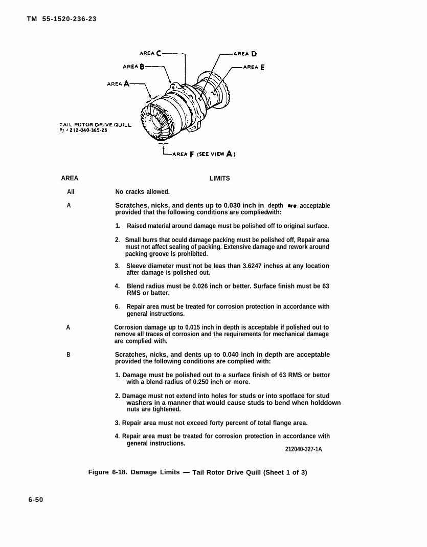
TM 55-1520-236-23
AREA
All
A
A
B
LIMITS
No cracks allowed.
Scratches, nicks, and dents up to 0.030 inch inprovided that the following conditions are complied
1.
2.
3.
4.
6.
depthwith:
acceptable
Raised material around damage must be polished off to original surface.
Small burrs that oculd damage packing must be polished off, Repair areamust not affect sealing of packing. Extensive damage and rework aroundpacking groove is prohibited.
Sleeve diameter must not be leas than 3.6247 inches at any locationafter damage is polished out.
Blend radius must be 0.026 inch or better. Surface finish must be 63RMS or batter.
Repair area must be treated for corrosion protection in accordance withgeneral instructions.
Corrosion damage up to 0.015 inch in depth is acceptable if polished out toremove all traces of corrosion and the requirements for mechanical damageare complied with.
Scratches, nicks, and dents up to 0.040 inch in depth are acceptableprovided the following conditions are complied with:
1. Damage must be polished out to a surface finish of 63 RMS or bettorwith a blend radius of 0.250 inch or more.
2. Damage must not extend into holes for studs or into spotface for studwashers in a manner that would cause studs to bend when holddownnuts are tightened.
3. Repair area must not exceed forty percent of total flange area.
4. Repair area must be treated for corrosion protection in accordance withgeneral instructions.
212040-327-1A
Figure 6-18. Damage Limits — Tail Rotor Drive Quill (Sheet 1 of 3)
6-50
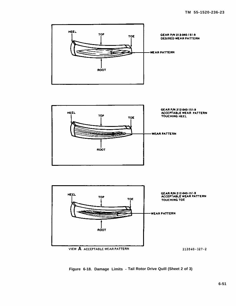
TM 55-1520-236-23
Figure 6-18. Damage Limits - Tail Rotor Drive Quill (Sheet 2 of 3)
6-51

TM 55-1520-236-23
LIMITSAREA
B
C
D
D
D
E
F
General
Corrosion damage up to 0.020 inch in depth is acceptable if polished out toremove all traces of corrosion and the requirements specified for mechanicaldamage are complied with.
Evidence of corrosion on sleeve adjacent to externally threaded ring (nut) thatretains bearings in sleeve is cause to replace quill.
Scratches. nicks, dents, and gouges on external surface up to 0.040 inch indepth are acceptable providing the following conditions are complied with:
1. The repaired area must be blended in smoothly.
2. The repair area bottom radius must be 0.500 inch or more.
3. The finish must be 63 RMS or better.
4. Reworked area must be treated for corrosion protection in accordancewith general instructions.
Corrosion damage on external surface up to 0.020 inch in depth is acceptableif polished out to remove all traces of corrosion and the requirementsspecified for mechanical damage are complied with.
Minor scratches and burrs on external surface of coupling are acceptable ifpolished out with India stone (C116).
Indication of overheating of coupling, such as multi-color appearance, iscause to remove the outer coupling and inspect splines and teeth. Inspectionprocedure is furnished in text.
1. Treat all rework areas on interior and external surfaces with Alodine forcorrosion protection. Refer to TM 43-0105 for additional corrosionprotection procedures.
2. Apply zinc chromate (C91) or polyemide epoxy prima (C88) to reworkareas on surfacesthat were painted originally, then paint to matchsurrounding surface.
212040-327-3A
Figure 6-18. Damage Limits - Tail Rotor Drive Quill (Sheet 3 of 3)
6-52
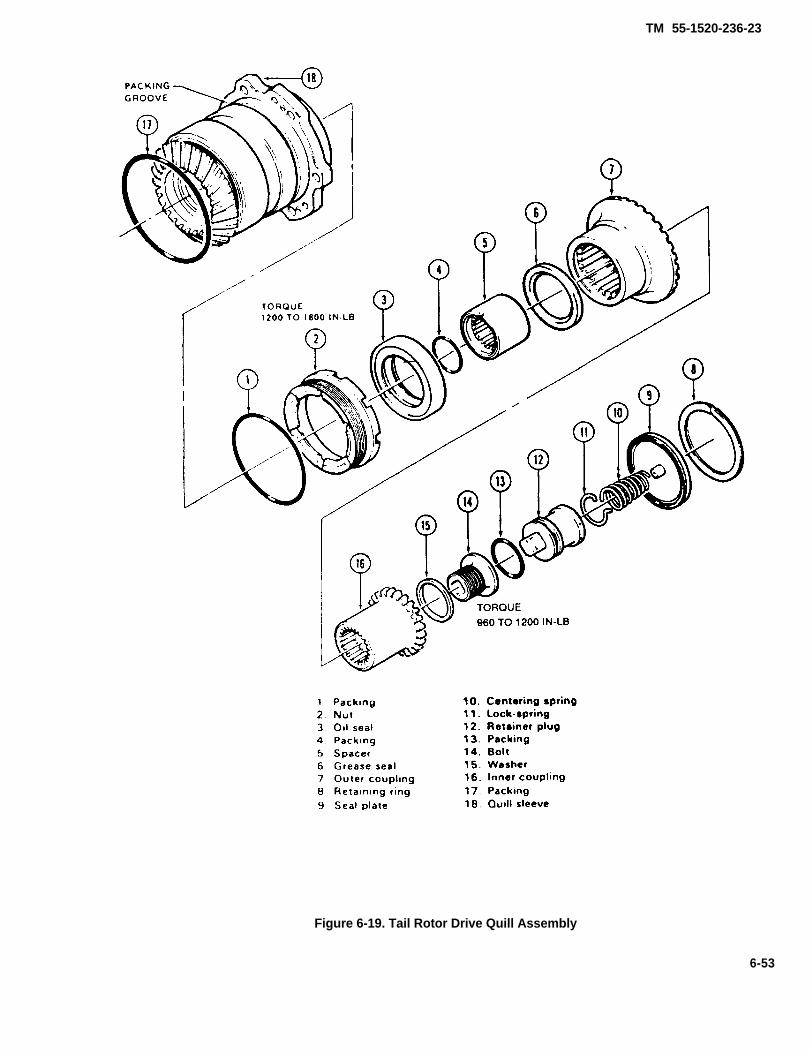
TM 55-1520-236-23
Figure 6-19. Tail Rotor Drive Quill Assembly
6-53
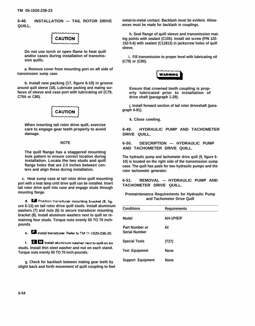
TM 55-1520-236-23
6-48. INSTALLATION — TAIL ROTOR DRIVEQUILL.
Do not use torch or open flame to heat quilland/or cases during installation of transmis-sion quills.
a. Remove cover from mounting port on aft side oftransmission sump case.
b. Install new packing (17, figure 6-19) in groovearound quill sleeve (18). Lubricate packing and mating sur-faces of sleeve and case port with lubricating oil (C79,C79A or C80).
When inserting tail rotor drive quill, exercisecare to engage gear teeth properly to avoiddamage.
NOTE
The quill flange has a staggered mountinghole pattern to ensure correct location duringinstallation. Locate the two studs and quillflange holes that are 2.0 inches between cen-ters and align these during installation.
c. Heat sump case at tail rotor drive quill mountingport with a heat lamp until drive quill can be installed. Inserttail rotor drive quill into case and engage studs throughmounting flange.
ure 6-13) on tail rotor drive quill studs. Install aluminumwashers (7) and nuts (6) to secure transducer mountingbracket (8). Install aluminum washers next to quill on re-maining four studs. Torque nuts evenly 50 TO 70 inch-pounds.
studs. Install thin steel washer and nut on each stand.Torque nuts evenly 50 TO 70 inch-pounds.
g. Check for backlash between mating gear teeth byslight back and forth movement of quill coupling to feel
metal-to-metal contact. Backlash must be evident. Allow-ances must be made for backlash in couplings.
h. Seal flange of quill sleeve and transmission mat-ing points with sealant (C105). Install set screw (P/N 120-152-5-6) with sealant (C11813) in jackscrew holes of quillsleeve.
i. Fill transmission to proper level with lubricating oil(C79) or (C80).
Ensure that crowned tooth coupling is prop-erly lubricated prior to installation ofdrive shaft (paragraph 1-29).
j. Install forward section of tail rotor driveshaft (para-graph 6-81).
k. Close cowling.
6-49. HYDRAULIC PUMP AND TACHOMETERDRIVE QUILL.
6-50. DESCRIPTION — HYDRAULIC PUMPAND TACHOMETER DRIVE QUILL.
The hydraulic pump and tachometer drive quill (9, figure 6-10) is located on the right side of the transmission sumpcase. The quill has pads for two hydraulic pumps and therotor tachometer generator.
6-51. REMOVAL — HYDRAULIC PUMP ANDTACHOMETER DRIVE QUILL.
Premaintenance Requirements for Hydraulic Pumpand Tachometer Drive Quill
Conditions Requirements
Model AH-1P/E/F
Part Number or AllSerial Number
Special Tools (T27)
Test Equipment None
Support Equipment None
6-54
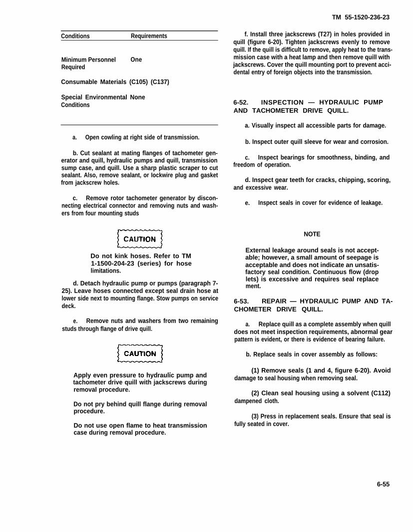
TM 55-1520-236-23
Conditions Requirements
Minimum Personnel OneRequired
Consumable Materials (C105) (C137)
Special Environmental NoneConditions
a. Open cowling at right side of transmission.
b. Cut sealant at mating flanges of tachometer gen-erator and quill, hydraulic pumps and quill, transmissionsump case, and quill. Use a sharp plastic scraper to cutsealant. Also, remove sealant, or Iockwire plug and gasketfrom jackscrew holes.
c. Remove rotor tachometer generator by discon-necting electrical connector and removing nuts and wash-ers from four mounting studs
Do not kink hoses. Refer to TM1-1500-204-23 (series) for hoselimitations.
d. Detach hydraulic pump or pumps (paragraph 7-25). Leave hoses connected except seal drain hose atlower side next to mounting flange. Stow pumps on servicedeck.
e. Remove nuts and washers from two remainingstuds through flange of drive quill.
Apply even pressure to hydraulic pump andtachometer drive quill with jackscrews duringremoval procedure.
Do not pry behind quill flange during removalprocedure.
Do not use open flame to heat transmissioncase during removal procedure.
f. Install three jackscrews (T27) in holes provided inquill (figure 6-20). Tighten jackscrews evenly to removequill. If the quill is difficult to remove, apply heat to the trans-mission case with a heat lamp and then remove quill withjackscrews. Cover the quill mounting port to prevent acci-dental entry of foreign objects into the transmission.
6-52. INSPECTION — HYDRAULIC PUMPAND TACHOMETER DRIVE QUILL.
a. Visually inspect all accessible parts for damage.
b. Inspect outer quill sleeve for wear and corrosion.
c. Inspect bearings for smoothness, binding, andfreedom of operation.
d. Inspect gear teeth for cracks, chipping, scoring,and excessive wear.
e. Inspect seals in cover for evidence of leakage.
NOTE
External leakage around seals is not accept-able; however, a small amount of seepage isacceptable and does not indicate an unsatis-factory seal condition. Continuous flow (droplets) is excessive and requires seal replacement.
6-53. REPAIR — HYDRAULIC PUMP AND TA-CHOMETER DRIVE QUILL.
a. Replace quill as a complete assembly when quilldoes not meet inspection requirements, abnormal gearpattern is evident, or there is evidence of bearing failure.
b. Replace seals in cover assembly as follows:
(1) Remove seals (1 and 4, figure 6-20). Avoiddamage to seal housing when removing seal.
(2) Clean seal housing using a solvent (C112)dampened cloth.
(3) Press in replacement seals. Ensure that seal isfully seated in cover.
6-55

TM 55-1520-236-23
Figure 6-20. Hydraulic Pump and Tachometer Drive Quill Assembly
When inserting drive quill, exercise care to en-gage gear teeth properly to avoid damage.
6-54. INSTALLATION — HYDRAULIC PUMP b. Uncover mounting pad at right side ofAND TACHOMETER DRIVE QUILL. transmission sump case. Heat sump case at drive
quill mounting pad with a heat lamp until drive quilla. Install packing (2, Figure 6-12) in groove around can be installed. Insert drive quill, engaging studs
quill sleeve, and lubricate with oil (C79) (C79A) or (C80). through mounting flange. Rotate main input quill
6-56

clockwise to ensure proper engagement of quill gearteeth with sump drive during installation.
c. Install washers and nuts on two shortest studs,at top and bottom of drive quill flange. Use thinaluminum washer next to flange and standard steelwasher next to each nut.
NOTE
Check backlash between mating teeth byslight back and forth movement of tailrotor drive quill coupling (4, figure 6-10)until metal-to-metal contact is felt andheard between hydraulic pump quill andsump drive pinion end gear teeth,Backlash must be evident.
d. Install hydraulic pump, or pumps (paragraph7-169), engaging pump shaft in drive quill.
e. Install rotor tachometer generator withelectrical connector 180 degrees down. Secure withnuts and washers on four studs. Connect andIockwire (C137) electrical cable connector.
f. Seal areas around mating flanges of quill andtransmission sump case, quill hydraulic pumps, andquill and tachometer generator with sealant(C105). Also install plugs (MS24391D2L), gasket(MS28777-2) in jackscrew hole, and Iockwire (C137),
6 -55 . FAN DRIVE QUILL.
6-56. DESCRIPTION – FAN DRIVE QUILL.
The fan drive quill (10, figure 6-10) is located on theforward side of the transmission. This quill transmitspower from the transmission input bevel gear to drivethe air distribution blower (fan).
6-57. REMOVAL – FAN DRIVE QUILL.
Premaintenance Requirements forFan Drive Quill
Conditions Requirements
Model AH-1P/E/F
Pert Number or AllSerial Number
Special Tools (T60) (T36) (T35.1)
TM 55-1520-236-23
Conditions Requirements
Test Equipment None
Support Equipment None
Minimum Personnel OneRequired
Consumable Materials (C105)
Special Environmental NoneConditions
a.
b.53).
c.
Open cowling at left side of transmission.
Remove ambient air blower (fan) (paragraph 13-
Remove Iockwire and remove six bolts andwashers that secure fan drive quill (10, figure 6-10).
d. Cut sealant at mating flange of fan drive quilland transmission case with sharp plastic scraper. Alsoremove sealant, or Iockwire, plug, and gasket.
Apply even pressure to quill withjackscrews during removal procedure.Do not pry behind quill flange duringremoval procedure. Do not use openflame to heat transmission case duringquill removal procedure.
e. Install three jackscrews (T60) in threaded holesprovided in quill. Tighten jackscrews evenly toremove quill. If the quill is difficult to remove, applyheat to the transmission case with a heat lamp andthen remove the quill with the jackscrews.
f. Cover the quill mounting port to preventaccidental entry of foreign objects into transmission.
6-58. INSPECTION – FAN DRIVE QUILL.
a. Visually inspect all accessible parts fordamage.
b. Inspect outer quill sleeve (4, figure 6-21) forwear and corrosion.
6-57

TM 55-1520-236-23
1. Seal2. Nut3. Packing4. Sleeve5. Gear
Figure 6-21. Fan Drive Quill Assembly
c. Inspect for bearing smoothness, binding, andfreedom of operation.
d. Inspect gear teeth (5) for cracks, chipping,scoring, and wear.
e. Inspect seal (1) for leakage.
NOTE
External leakage around seals is notacceptable; however, a small amountof seepage is acceptable and does notindicate an unsatisfactory seal condi-tion. Continuous flow (droplets) is ex-cessive and requires seal replacement.
6 -69 . REPAIR – FAN DRIVE QUILL.
Mount quill flange over pins in holding fixture(T35.1).
6-58
b. Remove Iockwire from nut (2, figure 6-21) andquill sleeve (4). Use care so as not to remove materialfrom Iockwire hole in sleeve (4).
c. Remove nut (2, figure 6-21) from front side ofsleeve (4) using wrench (T36).
d. Press seal (1) from nut (2).
e. Press new seal (1) into nut (2) with open side oflip positioned toward inboard side of nut.
f. Lubricate and install new packing (3) on outsideof nut and thread nut (2) into sleeve (4), Torque nut150 TO 200 foot-pounds, Iockwire (C137).
6 - 6 0 . I N S T A L L A T I O N – F A N D R I V EQUILL.
a. Install lubricated packing (3, figure 6-21) ingroove around quill sleeve.

When inserting fen drive quill, exercisecare to engage gear teeth properly toavoid damage.
b. Uncover mounting port at forward side oftransmission case. Heat main case at mounting portfor fan drive quill (10, figure 6-10) with a heat lampuntil drive quill can be installed.
c. Use three studs and three pushers as shown onfigure 6-22 to push quill into transmission. Installthree studs into case threads at equally spacedintervals.
TM 55-1520-236-23
d. Start the quill into the case port.
e. Install a steel washer on the top of the quillsleeve flange, then thread the pusher onto the stud.
f.
Be sure gears of quill and driving gear areproperly meshed before seating the quill.Rotate fan drive quill gearshaft whiledrawing quill into main case and feel forengagement of gear teeth.
Tighten pushers evenly until the quill is seated.
g. Remove pushers and studs. Install six boltsthrough sleeve flange into threaded inserts of case.
Figure 6-22. Work Aid — Quill Installation
6-59
6-61
6-62
6-63
6-64
TM 55-1520-236-23
h. Install thin aluminum washer next to quillflange and standard steel washer next to each bolthead. Torque bolts evenly and lockwire (C137).
i. Check for backlash between mating teeth byslight back and forth movement of quill coupling untilmetal-to-metal contact is felt end heard. Backlashmust be evident.
j. Also install plug (MS24391D2L) and gasket(MS28777-2) in jackscrew hole and Iockwire (C137).
k. Install air distribution blower fan (paragraph13-59).
D R I V EQUILL.
ALTERNATOR DRIVE QUILL.
The alternator drive quill (5, figure 6-10) is Iocated onthe left side of the transmission. The purpose of thisquill is to take power from the input bevel gear of thetransmission to drive the alternator.
DRIVE QUILL.
Premaintenance Requirements forAlternator Drive Quill
Conditions Requirements
Model
Part Number orSerial Number
Special Tools
Test Equipment
Support Equipment
Minimum PersonnelRequired
Consumable Materials
Special EnvironmentalConditions
AH-1P/E/F
S/N 77-22763 andSub.
(T56) (T57) (T58) (T60)
None
None
One
(C79) (C80) (C105)(C121) (C137)None
a. Open cowling at left side of main transmission
b. If alternator is installed, identify wires attachedto alternator for reinstallation in same location.Disconnect wires and electrical connector fromalternator. Remove alternator (paragraph 9-163).
c. If alternator drive quill cap (69, figure 6-12) isinstalled instead of alternator, loosen nut (68) andremove rim clenching clamp (67) and cap (69.
d. Straighten tang on lock washer (65). Removebolt (66). Remove five bolts (70) and washers (71).
e. Cut sealant at mating flange of alternator drive quilland transmission case with a sharp plastic scraper.Remove set screws from jackscrew holes.
Apply even pressure to quill withjackscrews during removal procedure.Do not pry behind quill flange duringremoval procedure. Do not use openflame to heat transmission case duringquill removal procedure.
f. Install three jackscrews (160) in threaded holesprovided in quill. Tighten jackscrews evenly toremove quill. if the quill is difficult to remove, applyheat to the transmission case with a heat lamp andthen remove the quill with the jackscrews.
g. Cover the quill mounting port to preventaccidental entry of foreign objects into transmission.
ALTERNATOR DRIVE QUILL,
a. Visually inspect all accessible parts fordamage.
b. Inspect outer quill sleeve for wear andcorrosion.
c. Inspect for bearing smoothness, binding, andfreedom of operation.
d. Inspect gear teeth for cracks, chipping, scoring,end wear.
e. Inspect seal for Ieakage.
6-60
TM 55-1520-236-23
NOTE
External leakage around seals is not accept-able; however, a small amount of see page isacceptable and does not indicate an unsatis-factory seal condition. Continuous flow (drop-lets) is excessive and requires seal replace-ment.
6-65. REPAIR – ALTERNATOR DRIVEQUILL.
a. Mount quill over pins in holding fixture (T57).
b. Remove Iockwire from nut (2, figure 6-23) andquill wear sleeve (4), using caution during removal to avoiddamage to Iockwire tab.
Remove nut (2) from front side of sleeve of quill(6) using wrench (T58).
d. Press seal (1) from nut (2).
Apply sealant (C105) to seal (1) on surface, mat-ing with nut (2).
f. Press new seal (1) into nut (2) with open side of lippositioned toward inboard side of nut.
g. Lubricate new packing (3) with oil (C79 (C79A) orC80). Install packing on nut (2), Install nut (2) in quillsleeve. Torque nut 150 TO 200 foot-pounds.
6-66. INSTALLATION – ALTERNATORDRIVE QUILL.
Lubricate new packing (63, figure 6-12) with oil(C79 (C79A) or C80) install packing in groove in alternatordrive quill sleeve.
b. Uncover mounting port at left side of transmissionmain case.
Install quill using three studs and three pushers(figure 6-22) as follows:
When inserting alternator drive quill, exercisecare to engage gear teeth properly to avoiddamage.
(1) Start the quill into the case port.
(2) Install three work aid studs (figure 6-22) atequally spaced intervals. Ensure that work aid studs havefull thread engagement with transmission.
(3) Install a steel washer on the top of the quillsleeve flange on each work aid stud. Install work aidpusher (figure. 6-22) on each stud.
h. Lockwire (C137) nut (2) to quill assembly (6).
6-61

TM 55-1520-236-23
Figure 6-23. Alternator Drive Quill Assembly
Rotate alternator drive quill generatorwhile drawing quill into transmissionand feel for engagement of gear teeth.
NOTE
If quill is difficult to install, heat maincase at mounting port for alternatordrive quill with a heat lamp.
(4) Tighten work aid pushers evenly until thequill is seated.
(5) Remove work aid pushers, washers andstuds.
d. Position lock (tab) washer (65, figure 6-12) onbolt (66) and install bolt in top center hole. Position one
6-62
steel washer (71) on each of five bolts (70) and installbolts. Torque bolts (66 and 70) evenly 160 TO 190inch-pounds. Bend locking tabs on lock (tab) washer(65) as in figure 6-23, detail A.
e. Check for backlash by slight back and forthmovement of quill gear shaft until metal-to-metal con-tact is felt. Backlash must be evident. As alternate pro-cedure, use backlash measurement tool (T56). Back-lash must be 0.005 TO 0.013 inch.
f. Seal area around flange of alternator drivequill and transmission with sealant (C105). Install setscrews, P/N 120-151-5-4, with (C106) in jackscrewholes.
g. Install alternator (paragraph 9-165), or posi-tion alternator drive quill cap (69) and rim clenchingdamp (67) on quill. Tighten nut (68) to secure clamp.
h. Close cowling at left side of main transmis-sion.

TM 55-1520-236-23
6 - 6 7 . M A I N R O T O R M A S TA S S E M B L Y .
6 - 6 8 . D E S C R I P T I O N – M A I N R O T O RMAST ASSEMBLY.
The main rotor mast assembly is a tubular steel shaftfitted with two bearings, which support it vertically inthe transmission. Mast driving splines are engagedwith transmission upper stage planetary gearproviding counterclockwise rotation as viewed fromabove. Splines on upper portion of mast providemounting for main rotor and control assemblies.
6 - 6 9 . R E M O V A L – MAIN ROTOR MASTASSEMBLY.
Premaintanence Requirements forRemoval — Main Rotor Mast
Conditions Requirements
Model
Part Number orSerial Number
Special TooIs
Test Equipment
Support Equipment
Minimum PersonnelRequired
Consumable Materials
Special EnvironmentalConditions
AH-IS
All
(T45)
None
(S4)
Two
(C22) (C36) (C41) (C46)(C47) (C70) (C74) (C91)(C105) (C107) (C112)(C116) (C123)
None
NOTE
This procedure is for removal of mastfrom a transmission that has previouslybeen removed from helicopter.
a. Install mast nut (1, figure 6-24) on top of mast.Attach clevis (S4) to nut (1). Attach hoist (T45) toclevis (S4) and take up cable slack.
b. Disconnect oil hose (6, figure 6-12) from jetassembly (19, figure 6-24).
c. Remove two nuts (21), washers (22), andwashers (23).
d. Remove eight nuts (13), washers (11), andwashers (12).
e . Care fu l l y l i f t mas t assembly ou t o ftransmission.
6 - 7 0 . C L E A N I N G – MAIN ROTOR MASTASSEMBLY.
Cleaning solvent is flammable and toxic.Provide adequate ventilation. Avoidprolonged breathing of solvent vaporsand contact with skin or eyes.
a. Clean mast with solvent (C112) and dry withfiltered compressed air. Keep solvent off seal (16,figure 6-24).
6 - 7 1 . I N S P E C T I O N – M A I N R O T O RMAST ASSEMBLY.
I n s p e c t m a s t f o r t h e w o r d"REWORKED" on flange in area I, figure6-25. If the word "REWORKED" is onthe flange and there is corrosion damagethat will require polishing out (figure 6-26), reject the mast; rework is permittedone time only.
a. Inspect friction sleeve (3, figure 6-24) asfollows:
NOTE
Friction sleeve may be inspected for wearand for bonding failure with mastinstalled on helicopter.
(1) If friction sleeve is to be inspected with mastinstalled on helicopter, remove collet set andattaching parts to gain access to friction sleeve. Referto paragraph 5-47.
6-63
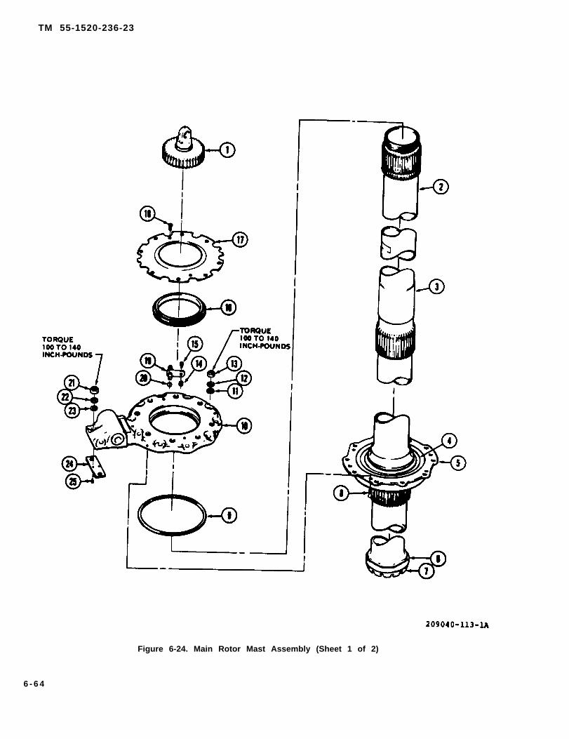
TM 55-1520-236-23
Figure 6-24. Main Rotor Mast Assembly (Sheet 1 of 2)
6 - 6 4
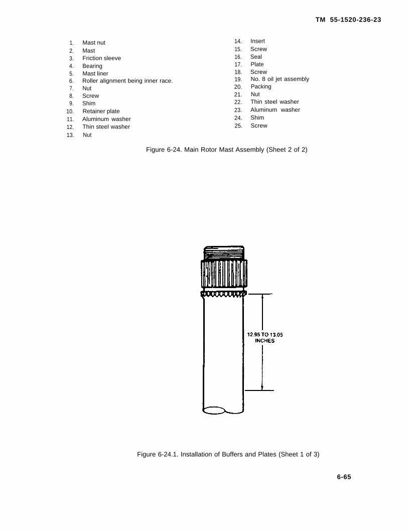
TM 55-1520-236-23
1.2.3.4.5.6.7.8.9.
10.11.12.13.
Mast nutMastFriction sleeveBearingMast linerRoller alignment being inner race.NutScrewShimRetainer plateAluminum washerThin steel washerNut
14.15.16.17.18.19.20.21.22.23.24.25.
InsertScrewSealPlateScrewNo. 8 oil jet assemblyPackingNutThin steel washerAluminum washerShimScrew
Figure 6-24. Main Rotor Mast Assembly (Sheet 2 of 2)
Figure 6-24.1. Installation of Buffers and Plates (Sheet 1 of 3)
6-65
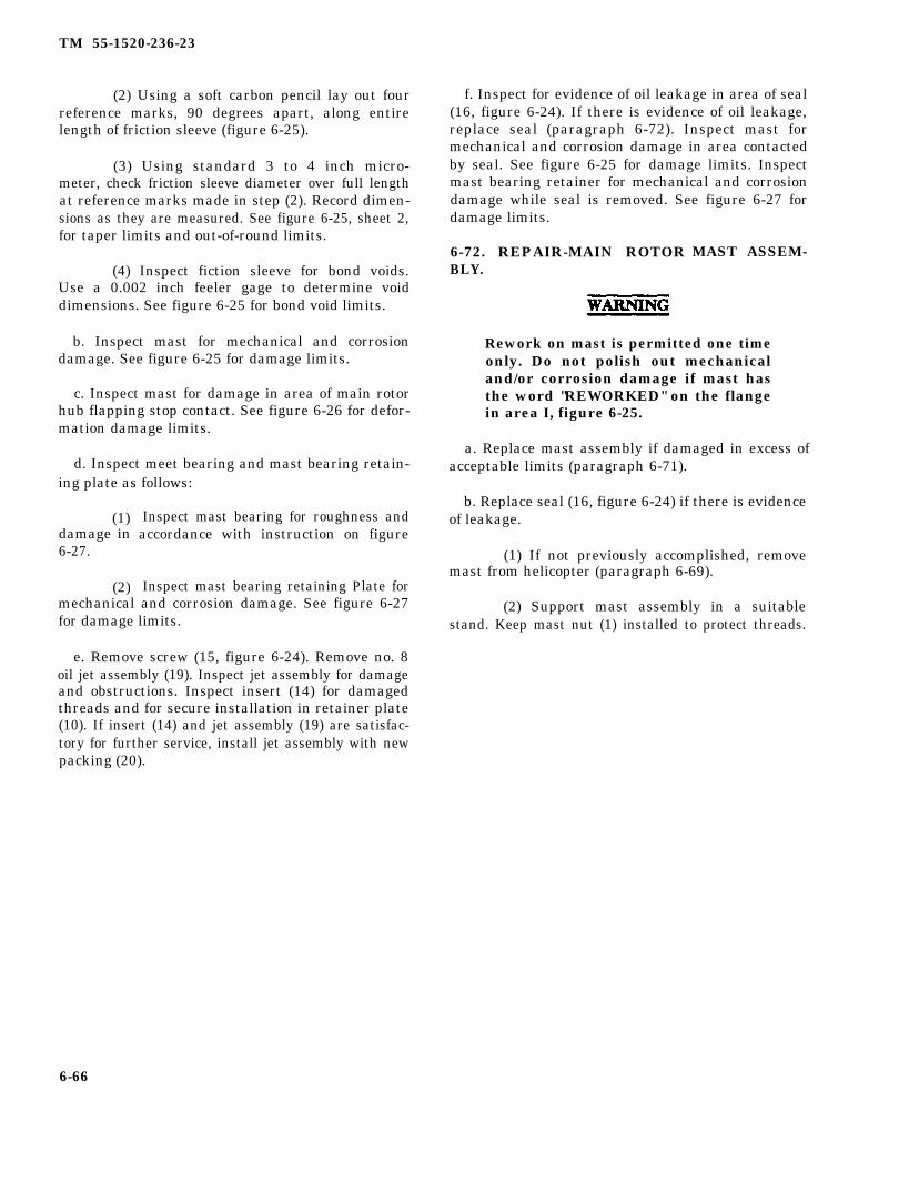
TM 55-1520-236-23
(2) Using a soft carbon pencil lay out fourreference marks, 90 degrees apart, along entirelength of friction sleeve (figure 6-25).
(3) Using standard 3 to 4 inch micro-meter, check friction sleeve diameter over full lengthat reference marks made in step (2). Record dimen-sions as they are measured. See figure 6-25, sheet 2,for taper limits and out-of-round limits.
(4) Inspect fiction sleeve for bond voids.Use a 0.002 inch feeler gage to determine voiddimensions. See figure 6-25 for bond void limits.
b. Inspect mast for mechanical and corrosiondamage. See figure 6-25 for damage limits.
c. Inspect mast for damage in area of main rotorhub flapping stop contact. See figure 6-26 for defor-mation damage limits.
d. Inspect meet bearing and mast bearing retain-ing plate as follows:
(1)damage in6-27.
(2)
Inspect mast bearing for roughness andaccordance with instruction on figure
Inspect mast bearing retaining Plate formechanical and corrosion damage. See figure 6-27for damage limits.
e. Remove screw (15, figure 6-24). Remove no. 8oil jet assembly (19). Inspect jet assembly for damageand obstructions. Inspect insert (14) for damagedthreads and for secure installation in retainer plate(10). If insert (14) and jet assembly (19) are satisfac-tory for further service, install jet assembly with newpacking (20).
f. Inspect for evidence of oil leakage in area of seal(16, figure 6-24). If there is evidence of oil leakage,replace seal (paragraph 6-72). Inspect mast formechanical and corrosion damage in area contactedby seal. See figure 6-25 for damage limits. Inspectmast bearing retainer for mechanical and corrosiondamage while seal is removed. See figure 6-27 fordamage limits.
6-72. REPAIR-MAIN ROTORBLY.
MAST ASSEM-
Rework on mast is permitted one timeonly. Do not polish out mechanicaland/or corrosion damage if mast hasthe word "REWORKED" on the flangein area I, figure 6-25.
a. Replace mast assembly if damaged in excess ofacceptable limits (paragraph 6-71).
b. Replace seal (16, figure 6-24) if there is evidenceof leakage.
(1) If not previously accomplished, removemast from helicopter (paragraph 6-69).
(2) Support mast assembly in a suitablestand. Keep mast nut (1) installed to protect threads.
6-66

TM 55-1520-236-23
Figure 6-24.1. Installation of Buffers and Plates (Sheet 2 of 3)
6-66.1

TM 55-1520-236-23
Figure 6-24.1. Installation of Buffers and Plates (Sheet 3 of 3)
6-66.2

TM 55-1520-236-23
Figure 6-24.2. Workaid for Mast Buffer
6-66.3

TM 55-1520-236-23
Figure 6-25. Damage Limits – Main Rotor Mast Assembly (Sheet 1 of 2)
6 - 6 6 . 4
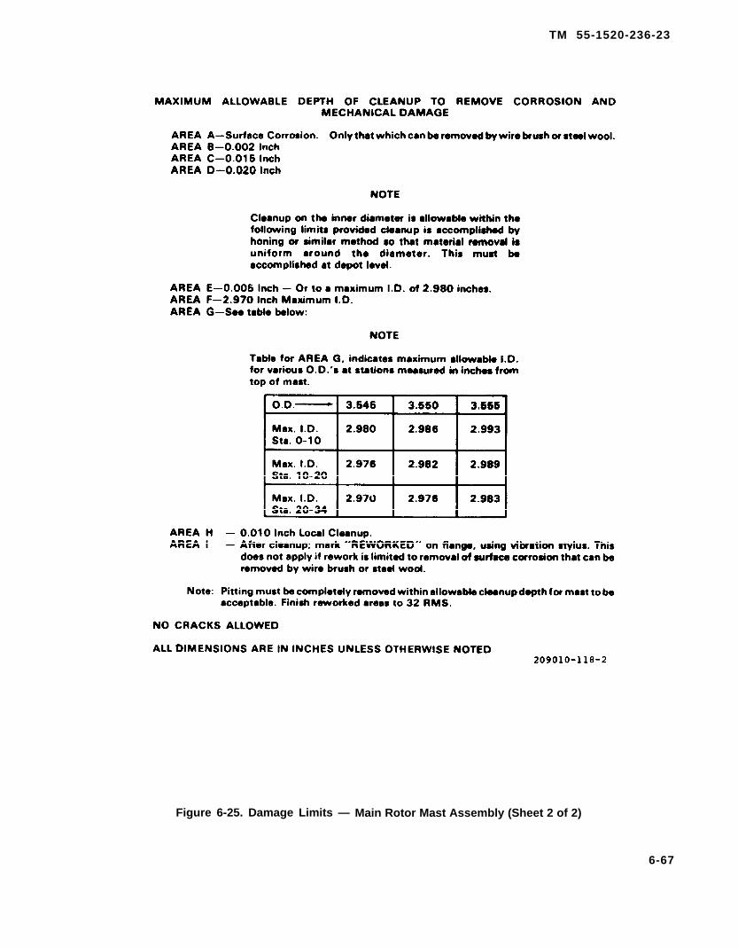
TM 55-1520-236-23
Figure 6-25. Damage Limits — Main Rotor Mast Assembly (Sheet 2 of 2)
6-67

TM 55-1520-236-23
Figure 6-26. DeformationLimits — Main Rotor Mast
(3) Remove two screws (18) and remove plate(17).
Ensure that shim (9) is indexed and re-installed in the same location. If shim (9)is lost or intermixed with similar shims,send mast assembly to next highermaintenance level.
(4)retainer
6-68
Remove four screws (8). Carefully removeplate (10). Remove shim (9) and index for
reinstallation in the same location. Do not removeshim (24).
(5) Press seal (16) out of retainer plate. Cleanold seaIant out of retainer plate with a sharp plasticscraper.
(6) Apply a thin coat of sealant (C105) onretainer plate (10) surfaces where seal will beinstalled. Press new seal (16) onto retainer plate withlip of seal up. Remove excess sealant with clean cloth.Ensure that four drain holes are not plugged withsealant.
Shim (9) that was removed in step (4)must be reinstalled. If shim (9) isdefective or there is any doubt that shimhas been intermixed with similar shims,send mast assembly to next higher levelof maintenance.
(7) Ensure that shim (24) was not removedfrom retainer plate (10). Position shim (9) of correctthickness in mast liner (5). Install retainer plate (10)on mast carefully to avoid damage to seal (16). Installfour screws (8). Ensure that heads of countersunkscrews are below surface of mast liner (5). Positionplate (17) on retainer plate (10) and install two screws(18).
c. Remove nicks and scratches that are withinacceptable limits of paragraph 6-71 from mastsplines with fine India stone (C116).
d. Polish out nick, scratch, and corrosion damagethat is within acceptable limits noted in paragraph 6-71, b. Use abrasive cloth (C36), and polish to a surfacefinish of 32 RMS or better. If acceptable limits areexceeded after complete clean-up of damage,forward mast assembly to next higher maintenancelevel.
Ensure compliance with following step eprior to returning mast assembly toservice.
e. If any polishing out work was accomplished onmast, mark the word "REWORKED" on flange in areaI as described on figure 6-25.

TM 55-1520-236-23
Figure 6-27. Damage Limits - Main Rotor Mast Bearing and Main Bearing Retaining Plate (Sheet 1 of 4)
6-69
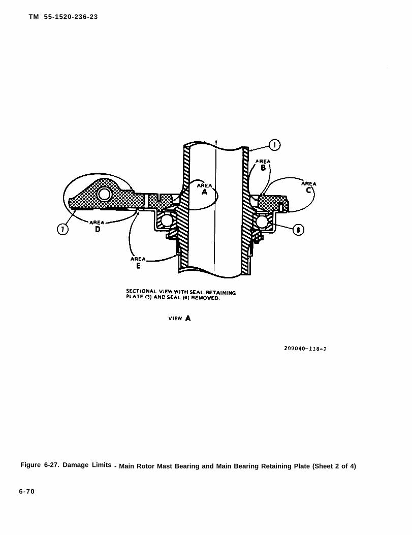
TM 55-1520-236-23
Figure 6-27. Damage Limits - Main Rotor Mast Bearing and Main Bearing Retaining Plate (Sheet 2 of 4)
6-70

TM 55-1520-236-23
Figure 6-27. Damage Limits - Main Rotor Mast Bearing and Main Bearing Retaining Plate (Sheet 3 of 4)
6-71

TM 55-1520-236-23
TM 43-0105
TM 43-0105t
Figure 6-27. Damage Limits - Main Rotor Mast Bearing and Main Bearing Retaining Plate (Sheet 4 of 4)
6-72

TM 55-1520-236-23
f. Touch up repair areas on mast above retainerplate (10) with a spray coat of primer (C88 or C91), thenspray on a coat of aluminum lacquer (C70).
g . Install buffer (2, figure 6-24.1) to mast (4) as fol-lows:
(1) Measure down 12.95 to 13.05 inches from bot-tom of upper mast spline and mark a line using a penal forbuffer (2) as shown in figure 1. Apply a layer of teflon tapearound mast below the marked reference line and securewith masking tape. Measure up 8.50 inches. Mark a lineusing a pencil for the area to be cleaned for buffer (2) andapply a layer of teflon tape around the mast above themarked reference line and secure with masking tape.
MEK is flammable; do not use near openflames, welding areas, or on hot surfaces. Donot smoke when using MEK, and do not use it
where others are smoking. Contact with liquidor vapor can cause skin and eye irritation anddrowsiness. If there is any prolonged skincontact, wash contacted area with soap andwater. Remove solvent-saturated clothing. Ifvapors cause drowsiness, go to fresh air. In allcases get immediate medical attention. Whenhandling liquid at air-exhausted workbench,wear approved gloves, goggles, and longsleeves. When handling liquid or liquid-soaked cloth in open unexhausted area, wearapproved respirator, gloves, and goggles. Dis-pose of liquid-soaked rags in approved metalcontainer. Metal containers of solution mustbe grounded to maintain electrical continuity.
NOTE
Do not remove cadmium plate from mast.
(2) Clean area for buffer (2) with a dean lint freecloth dampened with methyl-ethyl-ketone (MEK). Dry witha dean lint free cloth.
Figure 6-28. Transmission Top Case — Dimension Check
6-73

TM 55-1520-236-23
Adhesion promoter is flammable; keep awayfrom sparks, flames, and non-explosion proofdevices. Inhalation may cause nose and throatIrritation, headache, drowsiness, weakness,or exhaustion. Prolonged or repeated skincontact may cause irritation. Vapor and liquidmay cause eye irritation. Ingestion may causeintoxication and gaatro-intestinal irritation.Prolonged overexposure to ethanol can haveadverse effects on liver. If inhaled, remove tofresh sir, if not breathing give artificial respiretion. If breathing is difficult, give oxygen. Re-move contaminated clothing and wash withsoap and water. Flush eyes with plenty ofwater for 15 minutes while holding eyelidsopen. If ingested, dilute with one to twoglasses of water or milk. Induce vomiting bysticking finger down throat. In all cases, getimmediate medical attention. When workingwith adhesion promoter, wear approved respi-rator, goggles, and rubber gloves. Work inwell-ventilated area.
(3) Apply a light coat of adhesion promoterA934BX to cleaned area, use only enough to wet surface.Let dry for a minimum of 30 minutes.
(4) Fabricate a workaid from 0.010 inch 2024-T3aluminum alloy (figure 6-24.2). Workaid needs to be flexi-ble enough to mold to the shape of the mast to ensureproper bonding of the buffer. Cover one side of workaidwith teflon tape.
(5) Lightly hand abrade side of buffer (2, figure 6-24.1) to be bonded to mast (4) with 400 grit abrasive cloth.Remove sanding residue with a clean dry lint free cloth.
Adhesive may cause irritation to skin, eyes,and respiratory system. Thoroughly wash skinarea with soap and water and immediatelyflush eyes with water for 15 minutes. In allcases get immediate medical attention. Whenworking with adhesive, wear approved protec-tive gloves, goggles, or faceshield, and respi-rator approved for organic solvents. Use in awell-ventilated area away from open flame,spark sources, and heat.
(6) Mix adhesive EA956A/B in accordance with in-structions on container, and apply to mating surface ofbuffer (2) and surface of mast (4) at location shown.
(7) Position buffer (2) on mast (4) at locationshown in (figure 6-24.1). Twist buffer (2) around mast (4) tosmooth out adhesive. Position buffer (2) with split alignedwith master spline of mast (4). Wipe off excess adhesivewith a clean cloth dampened with MEK.
6-74
(8) Apply worked (figure 2) over buffer (2, figure 1)with teflon tape toward buffer (2) per dimensions shown.Wrap two full wraps of hoot shrink tape around workaid(figure 2) and heat shrink.
(9) Cure adhesive, EA956A/B for 24 hours at 75degrees F or for one hour at 175 to 190 degrees F.
(10) Remove heat shrink tape, workaid, maskingtape and teflon tape. Lightly hand abrade buffer (2) with180 grit abrasive paper followed by lightly scuffing withabrasive pad, until a uniform moleskin surface is obtained.
6-73. INSTALLATION — MAIN ROTOR MASTASSEMBLY.
a.
b.
c.
Ensure that proper shim (24, figure 6-24) is in-
Uncover opening in top of transmission.
Perform dimensional check between upper sur-face of transmission case and upper surface of planetaryadapter as follows:
(1) Measure distance from planetary adapter (2,figure 6-28) to top of top case (1). Minimum acceptable di-mension is 2.570 inches.
Exercise caution during reindexing of parts toprevent injury to fingertips.
(2) If minimum measurement is not obtained, ex-amine upper and lower sun gear in planetary assembliesto determine if tangs of planetary support liner are engagedwith mating slots of lower planetary liner. This can be deter-mined by use of fingertips. If tangs are disengaged, a gapof approximately 0.250 inch will be felt between the two lin-ers.
(3) If gap exists, reindex two liners by inserting thehands into the adapter and liner, palms outboard, liftingadapter slightly and rotating until the liners are correctlyaligned.
d. Seal mating surface of the transmission and themast liner prior to the installation of the mast. Use the fol-lowing procedure:
Cleaning solvent is flammable and toxic. Pro-vide adequate ventilation. Avoid prolongedbreathing of solvent vapors and contact withskin or eyes.
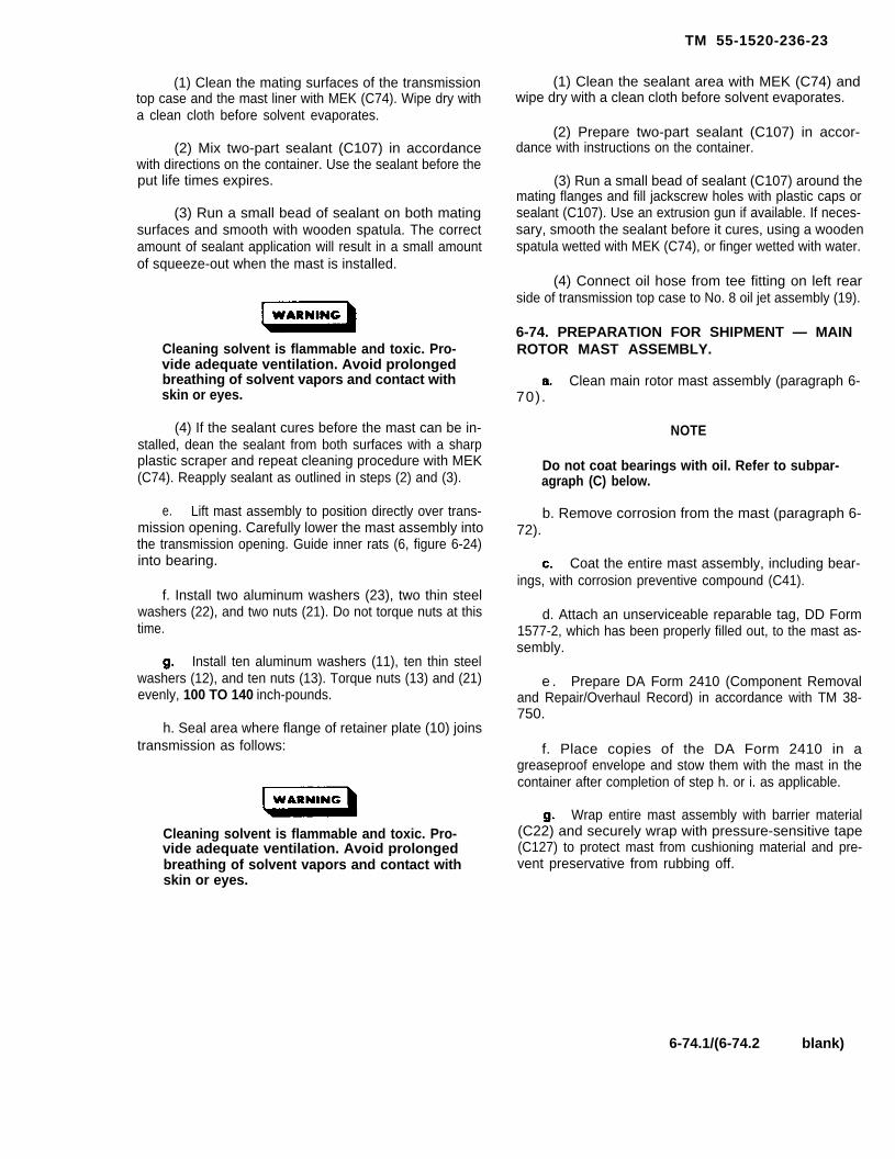
TM 55-1520-236-23
(1) Clean the mating surfaces of the transmissiontop case and the mast liner with MEK (C74). Wipe dry witha clean cloth before solvent evaporates.
(2) Mix two-part sealant (C107) in accordancewith directions on the container. Use the sealant before theput life times expires.
(3) Run a small bead of sealant on both matingsurfaces and smooth with wooden spatula. The correctamount of sealant application will result in a small amountof squeeze-out when the mast is installed.
Cleaning solvent is flammable and toxic. Pro-vide adequate ventilation. Avoid prolongedbreathing of solvent vapors and contact withskin or eyes.
(4) If the sealant cures before the mast can be in-stalled, dean the sealant from both surfaces with a sharpplastic scraper and repeat cleaning procedure with MEK(C74). Reapply sealant as outlined in steps (2) and (3).
e. Lift mast assembly to position directly over trans-mission opening. Carefully lower the mast assembly intothe transmission opening. Guide inner rats (6, figure 6-24)into bearing.
f. Install two aluminum washers (23), two thin steelwashers (22), and two nuts (21). Do not torque nuts at thistime.
Install ten aluminum washers (11), ten thin steelwashers (12), and ten nuts (13). Torque nuts (13) and (21)evenly, 100 TO 140 inch-pounds.
h. Seal area where flange of retainer plate (10) joinstransmission as follows:
Cleaning solvent is flammable and toxic. Pro-vide adequate ventilation. Avoid prolongedbreathing of solvent vapors and contact withskin or eyes.
(1) Clean the sealant area with MEK (C74) andwipe dry with a clean cloth before solvent evaporates.
(2) Prepare two-part sealant (C107) in accor-dance with instructions on the container.
(3) Run a small bead of sealant (C107) around themating flanges and fill jackscrew holes with plastic caps orsealant (C107). Use an extrusion gun if available. If neces-sary, smooth the sealant before it cures, using a woodenspatula wetted with MEK (C74), or finger wetted with water.
(4) Connect oil hose from tee fitting on left rearside of transmission top case to No. 8 oil jet assembly (19).
6-74. PREPARATION FOR SHIPMENT — MAINROTOR MAST ASSEMBLY.
Clean main rotor mast assembly (paragraph 6-70).
NOTE
Do not coat bearings with oil. Refer to subpar-agraph (C) below.
b. Remove corrosion from the mast (paragraph 6-72).
Coat the entire mast assembly, including bear-ings, with corrosion preventive compound (C41).
d. Attach an unserviceable reparable tag, DD Form1577-2, which has been properly filled out, to the mast as-sembly.
e . Prepare DA Form 2410 (Component Removaland Repair/Overhaul Record) in accordance with TM 38-750.
f. Place copies of the DA Form 2410 in agreaseproof envelope and stow them with the mast in thecontainer after completion of step h. or i. as applicable.
Wrap entire mast assembly with barrier material(C22) and securely wrap with pressure-sensitive tape(C127) to protect mast from cushioning material and pre-vent preservative from rubbing off.
6-74.1/(6-74.2 blank)


TM 55-1520-236-23
h. Reusable Metal Container (Preferred Method).If a reusable metal container, P/N 204-040-366MUSC-A19, NSN 8115-00-083-8335, complete withmolded heir pads is available, insert the wrappedmast in the container. If hair pads are not available,follow procedures as closely as possible, center thewrapped mast assembly in container with adequatecushioning material (C46) surrounding assembly. Becertain the mast assembly is held firmly in thecontainer and that all open spaces are filled withcushioning material.
6 - 7 5 . T A I L R O T O R
6-76. DESCRlPTlONDRIVESHAFT.
i. Plywood Container (Alternete Method). If aplywood shipping container is available, place thepreserved mast assembly in the plywood containerbetween the molded hair pads and secure lid.
j. Obliterate old markings from the container thatdo not coincide with the item to be returned. Markcontainer in accordance with MlL-STD-129. StencilDA Form 2410 control number on exterior ofcontainer.
S E C T I O N I V . T A I L R O T O R D R I V E S H A F T
D R I V E S H A F T .
- T A I L R O T O R
Five driveshaft sections transmit power from thetransmission to the tail rotor through two gearboxes.The shaft sections are identical and are supported bythree hanger assemblies on the tailboom and enginedeck.
6 - 7 7 . R E M O V A L – T A I L R O T O RDRIVESHAFT.
a. Open hinged access doors along top oftailboom and vertical fin by realeasing fasteners on leftside. Also remove tailpipe fairing, transmissioncowling, and intermediate gearbox cover, asnecessary to gain access.
Clamp set must he removed from bothends of shaft before removing either endof shaft from its mating curvic couplingto avoid coupling tooth or bearingdamage.
NOTE
Retain clamp set as a unit when removedto preclude intermix of set halves.
b. If chafing strips come loose, replace with newchafing strips.
c.
Secure the tail rotor blades to preventpersonnel injury and equipment damageany time a segment of the tail rotor drivesystem is disconnected. The tail rotorblades may cause uncontrolled systemrotation should there be a sudden gust ofwind when they are not secured.
Remove clamp set (2, figure 6-29) fromcoupling at each end of driveshaft (1). Push shaftagainst flexible coupling to disengage opposite end.
6-75

TM 55-1520-236-23
Figure 6-29. Tail Rotor Driveshaft lnstallation
6-76
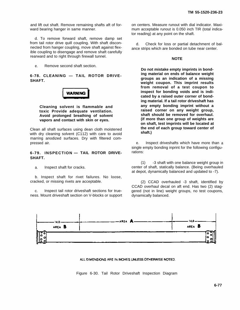
and lift out shaft. Remove remaining shafts aft of for-ward bearing hanger in same manner.
d. To remove forward shaft, remove damp setfrom tail rotor drive quill coupling. With shaft discon-nected from hanger coupling, move shaft against flex-ible coupling to disengage and remove shaft carefullyrearward and to right through firewall tunnel.
e. Remove second shaft section.
6-78. CLEANING — TAIL ROTOR DRIVE-SHAFT.
Cleaning solvent is flammable andtoxic Provide adequate ventilation.Avoid prolonged breathing of solventvapors and contact with skin or eyes.
Clean all shaft surfaces using dean cloth moistenedwith dry cleaning solvent (C112) with care to avoidmarring anodized surfaces. Dry with filtered com-pressed air.
6-79 . INSPECTION — TAIL ROTOR DRIVE-SHAFT.
a. Inspect shaft for cracks.
b. Inspect shaft for rivet failures. No loose,cracked, or missing rivets are acceptable.
c. Inspect tail rotor driveshaft sections for true-ness. Mount driveshaft section on V-blocks or support
TM 55-1520-236-23
on centers. Measure runout with dial indicator. Maxi-mum acceptable runout is 0.050 inch TIR (total indica-tor reading) at any point on the shaft.
d. Check for loss or partial detachment of bal-ance strips which are bonded on tube near center.
NOTE
Do not mistake empty imprints in bond-ing material on ends of balance weightgroups as an indication of a missingweight coupon. This imprint resultsfrom removal of a test coupon toinspect for bonding voids and is indi-cated by a raised outer corner of bond-ing material. If a tail rotor driveshaft hasany empty bonding imprint without araised corner on any weight group,shaft should be removed for overhaul.(if more than one group of weights areon shaft, test imprints will be located atthe end of each group toward center ofshaft.)
e. Inspect driveshafts which have more than asingle empty bonding inprint for the following configu-rations:
(1) -3 shaft with one balance weight group incenter of shaft, statically balance. (Being overhauledat depot, dynamically balanced and updated to -7).
(2) CCAD overhauled -3 shaft, identified byCCAD overhaul decal on aft end. Has two (2) stag-gered (not in line) weight groups, no test coupons,dynamically balanced.
Figure 6-30. Tail Rotor Driveshaft Inspection Diagram
6-77
TM 55-1520-236-23
(3) -7 shaft has two (2) weight groups (in line)dynamically balanced. (Factory -7 shafts have teatcoupon with each group and CCAD overhauled -7shafts have no test coupons).
(4) -5 shafts same type as (1) and (2), beingdynamically balanced and updated to -9 shafts.
(5) CCAD decals are removed at depot andno longer used.
(6) Cured epoxy paint at time of rework isoptional on driveshafts.
(7) Driveshafts identified by all the preceed-ing steps are serviceable. Any shafts having more thanone (1) empty imprint in bonding material per weightgroup and are not identified by preceding steps will beremoved from service as overhaul candidates.
f. Inspect for damaged or excessivety worncurvic coupling teeth. There should be no radial play orbacklash between mating teeth when fully meshedwith V-band damp (2, figure 6-29) removed.
g. Inspect shaft for grooves worn by V-bandclamp on shaft coupling to extent that such wear pre-vents proper clamping.
h. Inspect shaft for surface damage of shaft tubein excess of limits in (i) below.
i. Classify surface damage on shaft tube as ac-ceptable, reparable, or excessive by following limits.Define "Area A" as central portion of shaft and "AreaB" as portions within 14 inches of ends (figure 6-30).
(1) Any damage to anodized finish or greyepoxy paint requires anti-corrosion treatment in accor-dance with TM 43-0105.
(2) Nicks or scratches alighned within 15 de-grees of spanwise axis are acceptable without repairto maximum depth of 0.002 inch in "Area A" or 0.004inch in "Area B".
(3) Other nicks or scratches must be polishedout with crocus cloth (C42) provided depth of materialremoved does not exceed 0.008 inch in "Area A" or0.012 inch in "Area B".
NOTE
If total reworked area on one side ofshaft is 8 square inches greater than thetotal reworked area on opposite side,shaft may be out of balance and shouldbe replaced.
(4) Sharp dents are permissible to maximumdepth of 0.010 inch in "Area A" and 0.015 inch in “AreaB".
(5) Nonsharp dents are permissible to maxi-mum depth of 0.020 inch m "Area A" and 0.030 inch in"Area B".
NOTE
All dents should be carefully inspectedfor cracks, nicks, and scratches. Nocracks permitted. Nicks or scratchesshall be within Iimits. When nicks orscratches are present in a dent, totaldepth of a dent and nick or scratch com-bined may not exceed the limits for dentabove.
(6) Corrosion must be polished out withcrocus cloth (C37), provided depth of material removaldoes not exceed 0.012 inch in "Area B". Deeper corro-sion is cause for rejection.
NOTE
If total reworked surface on one sideexceeds the reworked surface on theopposite side by eight square inches,the shaft may be out of balance andshould be replaced.
j. Inspection — Driveshaft Clamps.
(1) Check bolt holes for wear, nicks, andscratches.
(2) Inspect spot face, lug fillets, and internalV-groove for nicks and scratches in excess of 0.008inch, and gouges or wear pattern extending into thefillet radius at bottom of internal V.
(3) Inspect all remaining surfaces for nicksand gouges exceeding 0.010 inch.
6-78
TM 55-1520-236-23
6 - 8 0 . R E P A I R — TAIL ROTOR DRIVE-SHAFT.
Replace driveshaft sections that are damagedin excess of acceptable limits (paragraph 6-79).
b. Send tail rotor driveshaft sections that requirepainting to next higher maintenance level for paintingand balancing.
6 - 8 1 . I N S T A L L A T I O N — T A I L R O T O RDRIVESHAFT.
Ensure that crowned tooth coupling isproperly lubricated prior to installationof driveshaft (paragraph 1-29).
NOTE
if driveshaft misalignment is sus-pected, refer to paragraph 6-79.
NOTE
Leave the hanger bearing assemblyloose until driveshaft is properlyseated.
6-78.1/(6-78.2 blank)

a. Engage shaft couplings with mating couplings. In-stall damp sets (2, figure 6-29) at each end with nuts intrailing direction of rotation and bolted joints indexed within1/8 inch of 90 degrees measured at perimeter of damps forbalance in operation.
NOTE
Clamp halves are matched by identical vendorand forging lot number, or by weight. Every ef-fort should be made to retain clamp halves sematched sets. All nuts on any one clomp setmust be identical part numbers. Randomclamp halves of some part numbers may bepaired if they meet either of the following cri-teria: (1) Weight differential of the two halvesdoes not exceed one gram, or (2) No exces-sive high frequency vibrations are introducedduring e maintenance test flight whenmatched with unknown weight difference.
Use new nuts each time clamps are installed.
b. Install tail rotor damp set (2, figure 6-29) bolts andnuts as follows:
(1) Start four nuts onto damp bolts by hand.
(2) Thread nuts on bolts to obtain complete threadengagement.
(3) Measure and record tare torque for each nut.
(4) Torque each nut in sequence illustrated in fig-ure 6-29 30 to 35 inch-pounds above tare torque recordedin preceding step. Keep gaps in ends of clamp set (2)equal within 0.020 inch.
(5) Tap very Iightly around outer surface of dampwith fiber mallet and re-check torque.
c. Install tailpipe fairing or gearbox cover as re-quired. Close access doors and cowling.
6-82. TAIL ROTOR DRIVESHAFT HANGERASSEMBLY.
6-83. DESCRIPTION — TAIL ROTORDRIVESHAFT HANGER ASSEMBLY.
Three hanger assemblies connect and support tail rotordriveshaft along top of tailboom and above the enginedeck. Each assembly consists of couplings on a short,splined shaft, mounted through a single-row sealed ball
TM 55-1520-236-23
bearing in a ring-shaped hanger equipped with two mount-ing lugs for attachment on a support fitting (figure 6-29).
6-84. REMOVAL— TAIL ROTORDRIVESHAFT HANGER ASSEMBLY.
Premaintenence Requirements forDriveshaft Hanger Assembly
a. Open hinged access doors along top of tailboomby releasing fasteners on left side. Open engine accessdoors.
Use caution when removing driveshaft. Dam-age to shaft or coupling may result from im-proper handling.
b. Remove tall rotor driveshafts from each side ofhangar (paragraph 6-77).
c. Remove bolt (6, figure 6-29) with nut (13) andwashers (4, 5, 14, and 15) at each side to detach hanger as-sembly from its bearing hanger support fitting (11 or 12).
6-85. lNSPECTION — TAIL ROTORDRIVESHAFT HANGER ASSEMBLY.
a. inspect three driveshaft hanger assemblies formetal particles and/or rust-colored fretting debris adjacentto bearing in bearing and shaft assembly (10, figure 6-31).If particles are found, replace affected park
6-79

TM 55-1520-236-23
Inspect three(10) for overheating.
(1) Deleted.
bearing and shaft assemblies
(2) Indications of overheating such as discol-oration of bearing (blue to blue/black in color) or multi-color appearance of hanger that darkens adjacent tobearing is cause for replacement.
(3) Brown coloring of bearing shield is normaland is not an indication of overheating.
b.1. Coupling overheat detector paint strip. A 1.0by 1.1 inch strip of zing-chromate primer is painted oneach side (180° apart) of every flexible driveshaftcoupling. The zinc-chromate primer (TT-P-1757) willturn brown at 375 ± 5°F, indicating:
(1) Loss of lubricant due to seal failure.
(2) Contaminated or improper lubricant.
(3) Incorrect cleaning and lubricating proce-dures.
(4) Drive train misalignment.
Also paint a 0.5 X 0.5 inch zinc-chromate primer stripon the top of the bearing and shaft assembly (refer-ence item 10, figure 6-31) 0.06 inches away from theidentification plate (reference item 17, figure 6-31).
Inspect three bearing and shaft assemblies(10) and outer flexible couplings (8) for grease leak-age. Wetting of adjacent areas by grease is cause forreplacement of affected parts with the following excep-tion: A small amount of grease expelled from aroundlip of seal in bearing and shaft assembly (10) indicatesslight over-lubrication and is not cause for hangerreplacement. Perform an evaluation of bearing andshaft assembly (10) as follows:
Do not clean or spray bearing or hangerassembly With any type of adventduring inspection. Use only deancloths without solvent to dean exteriorof hanger.
6-80
(1) Wipe grease from shaft of inner (spheri-cal) coupling (11), bearing and shaft assembly (10)with clean, lint-free cloth.
(2) Record on DA Form 2408-13, indicatingbearing by location and check again after one flight ofthe aircraft.
(3) If amount of grease expelled from seal ofhanger bearing does not decrease after this period oftime, replace bearing and shaft assembly (10).
d Inspect three bearing and shaft assemblies(10) for cracks, elongated bolt holes, and corrosion.
Inspect three bearing and shaft assemblies(10) for excessive bearing wear, roughness, or bind-
ing. If condition of bearing is in doubt, check as follows:
(1) Remove driveshaft from each end ofhanger assembly (pargraph 6-77).
(2) Rotate bearing while pressing in axially onend of hanger. Obvious roughness, catching, or bind-ing when turned by hand is cause for replacement.
(3) If ratcheting noise is detected whencoupling assembly is spun, while attached to airframe,replace bearing.
f. Inspect three non-flexible couplings (11) forscratches, nicks, dents, and cracks. Minor damagethat can be polished out with fine India stone (C116) isacceptable.
g. Inspect three outer flexible coupling (8) for dis-coloration due to overheating. If the coupling has amulticolor appearance, disassemble the coupling andinspect splines and teeth.
h. Inspect three outer flexible coupling (8) forscratches, nick, dents, and cracks. Minor damagethat can be polished out with fine India stone (C116) isacceptable.
i. Inspect three seals (9) for protrusion, leakage,cuts, tears and deterioration. Replace unserviceableseals.
j. Disassemble three outer flexible couplings (8)from inner flexible couplings (7) and inspect as follows:
(1) Remove retaining ring (1). At the sametime hold seal plate (2) against spring pressure.
(2) Remove seal plate (2) and spring (3).

TM 55-1520-236-23
(2A) Inspect retaining ring (1), and seal plate(2), for serviceability. Inspect center spring (3) byapplying a test Ioad of 5.0 ± 0.5 pounds to compressspring to 1.50 ± 0.10 inches.
Do not use solvent to dean assembleddriveshaft hanger assembly. Residuemay remain in assembly and preventproper Iubrication. Do not dean seal (9)with cleaning solvent.
(3) Hold outer flexible coupling (8) at full out-ward pisition and use a dean lint-free cloth to removeall old grease. Clean coupling splines thoroughly.Solvent (C112), may be used if driveshaft hangerassembly is completely disassembled.
NOTE
Leave the hanger bearing assemblyloose until driveshaft is propertyseated.
6-80.1/(6-80.2 blank)

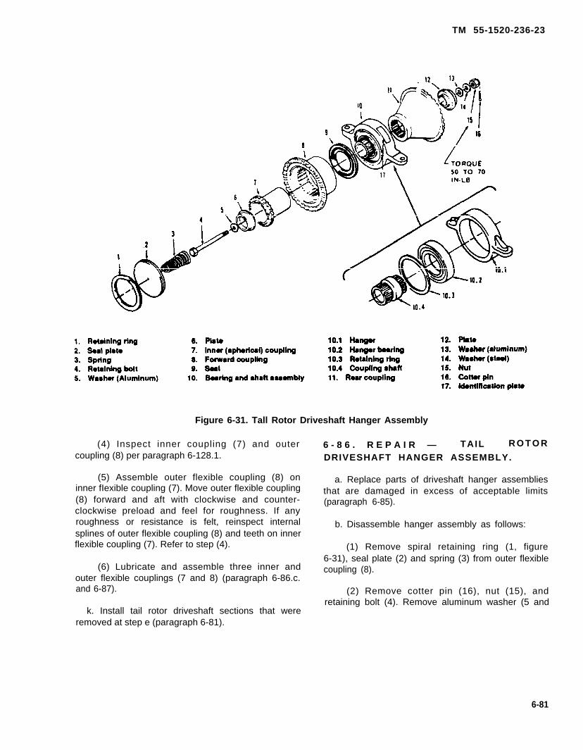
TM 55-1520-236-23
Figure 6-31. Tall Rotor Driveshaft Hanger Assembly
(4) Inspect inner coupling (7) and outercoupling (8) per paragraph 6-128.1.
(5) Assemble outer flexible coupling (8) oninner fIexible coupling (7). Move outer flexible coupling(8) forward and aft with clockwise and counter-clockwise preload and feel for roughness. If anyroughness or resistance is felt, reinspect internalsplines of outer flexible coupling (8) and teeth on innerflexible coupling (7). Refer to step (4).
(6) Lubricate and assemble three inner andouter flexible couplings (7 and 8) (paragraph 6-86.c.and 6-87).
k. Install tail rotor driveshaft sections that wereremoved at step e (paragraph 6-81).
6 - 8 6 . R E P A I R — TAIL R O T O R
DRIVESHAFT HANGER ASSEMBLY.
a. Replace parts of driveshaft hanger assembliesthat are damaged in excess of acceptable limits(paragraph 6-85).
b. Disassemble hanger assembly as follows:
(1) Remove spiral retaining ring (1, figure6-31), seal plate (2) and spring (3) from outer flexiblecoupling (8).
(2) Remove cotter pin (16), nut (15), andretaining bolt (4). Remove aluminum washer (5 and
6-81
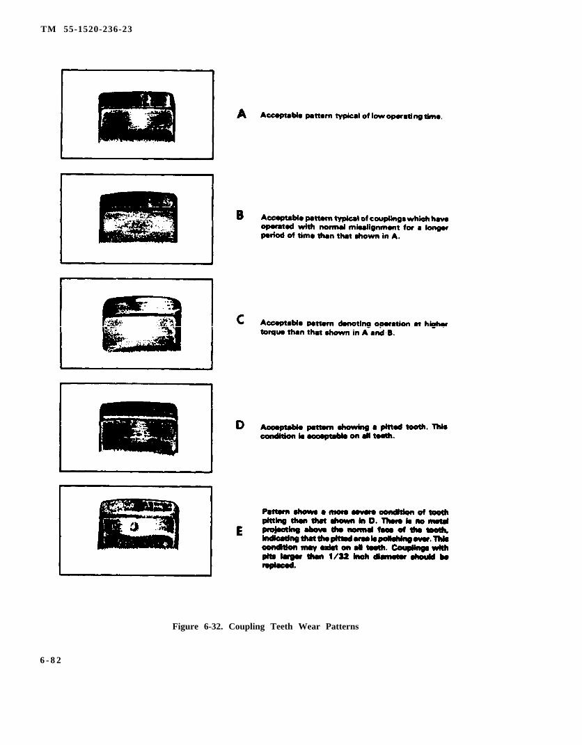
TM 55-1520-236-23
Figure 6-32. Coupling Teeth Wear Patterns
6 - 8 2

TM 55-1520-236-23
13) and steel washer (14). Remove inner flexible coupling(7), outer flexible coupling (8) and nonflexible coupling(11) from bearing and shaft assembly (10). Remove seat(9) from outer flexible coupling (8).
(3) If bearing replacement is necessary, proceedas follows.
(a) Press shaft (10.4) from tearing and shaftassembly (10).
(b) Remove retaining ring (10.3) from bearingand hanger (10.1).
(c) Press bearing (10.2) out of hanger (10.1)through retaining ring end.
(4) Assemble bearing and shaft assembly as fol-lows:
(a) Press new bearing (10.2) into hanger (10.1)through retaining ring end. Press on bearing outer raceonly.
(b) Support inner race of bearing (10.2) andpress shaft (10.4) into bearing. Bearing journal of shaftmust center within 0.003 to 0.016 inch.
(c) Install retaining ring (10.3) in hanger andshaft assembly (10).
c. Assemble banger assembly as follows:
It is possible to erroneously intermixouter coupling (8, figure 6-31) innercoupling (7) and bearing on bearingand shaft assembly (10) with similarparts manufactured for other heli-copters. Confirm that oil driveshafthanger assembly parts are correct partnumber (TM 55-1520-236-23P).
(1) Install seal (9, figure 6-31) into groove atsmall end of outer flexible coupling (8) with seal liptoward flange and of coupling. Use a burnishing tool toseat seal between gear tooth and end of coupling.
(2) Apply lubricant (C56) to splines of inner flex-ible coupling (7) and insert into outer flexible coupling (8).
(3) Install nonflexible coupling (11). Install innerflexible coupling (7) and outer flexible coupling (8) to the(forward) retaining ring side of bearing and shaft assem-
bly (10).
(4) Install aluminum washer (5) and plate (6)against head of retaining bolt (4) and insert bolt throughpreviously assembled parts.
(5) Install plate (12), aluminum washer (13), steelwasher (14), and nut (15) on retaining bolt (4). Torque nut(15) 50 TO 70 inch-pounds. Install cotter pin (16).
(6) Hold outer flexible coupling (8) at full out-ward position. Hand-pack lubricant (C56) to 0.12 inchdepth over top of internal spline teeth.
(7) Install spring (3), seal plate (2), and retainingring (1).
6-87. LUBRICATION—TAIL ROTOR DRIVE-SHAFT HANGER ASSEMBLY.
NOTE
Tail rotor driveshaft hanger assembliescan be lubricated while installed on tail-boom.
a. Hold seal plate (2, figure 6-31) against spring (3)and remove retaining ring (l).
b. Remove seal plate (2) and spring (3).
Do not use cleaning solvent inside flex-ible coupling. Solvent leaves residue.
c. Hold outer flexible coupling (8) full outboard andclean old grease from coupling with clean cloths.
d. Hand pack grease (C56) to 0.12 inch depth over topof spline teeth on outer flexible coupling (8)
Ensure seal plate vent hole is notclogged.
e. Keep outer flexible coupling (8) at full outboardposition. Install spring (3), seal plate (2), and retaining ring( 1 )
f. Gently push and pull flex coupling to full limits toevenly distribute grease full length of spline teeth.
6-83

TM 55-1520-236-23
6-88. INSTALLATION — TAIL ROTORDRIVESHAFT HANGER ASSEMBLY.
NOTE
If driveshaft misalignment is suspected, referto paragraph 6-95.
Place dissimilar metals tape (C120) (16, figure 6-29) on bearing hanger support fittings (11) and (12).
b. Position hanger assembly (7) on bearing hangersupport fitting (12) with outer flexible coupling (3) forward.
NOTE
Use additional washers if required to obtainproper thread engagement on bolts (6).
Omit washer (4) under bolt head when bearinghanger material is steel or stainless steel.
c . Install bolts (6), steel washers (5), aluminumwashers (4) if required, aluminum washers (15), steelwashers (14), and nuts (13). Ensure that aluminum wash-ers (15) are installed next to the support fitting.
d. Install tail rotor driveshaft sections (paragraph 6-81).
e. Torque nuts (13) evenly 50 TO 70 inch-pounds.
6-89. TAIL ROTOR DRIVESHAFT BEARINGHANGER SUPPORT FlTTING.
6-90. DESCRIPTION — TAIL ROTORDRIVESHAFT BEARING HANGER SUPPORTFlTTING.
Two bearing hanger support fittings (12, figure 6-29) are lo-cated on the tailboom. One bearing hanger support fitting(11) is located on the engine service deck. The bearinghanger support fittings support the three bearing hangerassemblies (7) and the tail rotor driveshaft.
6-91. REMOVAL — TAIL ROTOR DRIVESHAFTBEARING HANGER SUPPORT FlTTINGS.
Remove tail rotor driveshaft sections as required(paragraph 6-77).
b. Remove tail rotor driveshaft hangers as required(paragraph 6-64.)
Identify shims under bearing hanger supportfittings (11 and 12, figure 6-29) for reinstalla-tion in same position. Do not attempt to re-move or change shims.
c. Remove bearing hanger support fitting (11) by re-moving four screws and washers securing support to en-gine deck.
6-92. INSPECTION — TAIL ROTORDRIVESHAFT BEARING HANGER SUPPORTFITTINGS.
Inspect bearing hanger support fittings (11 and 12, figure 6-29) for scratches, nicks, dents, cracks, and corrosion. Su-perficial scratches and nicks are acceptable.
6-93. REPAIR — TAIL ROTOR DRIVESHAFTBEARING HANGER SUPPORT FlTTlNGS.
a. Replace tail rotor driveshaft bearing hanger sup-port fittings that are damaged in excess of acceptable limits(paragraph 6-92).
b. Touch up paint on tail rotor driveshaft bearinghanger support fittings to match existing finish.
6-94. INSTALLATION — TAIL ROTORDRIVESHAFT BEARING HANGER SUPPORTFITTING.
Identify shims under bearing hanger supportfittings (11 and 12, figure 6-29) for reinstalla-tion in same position. Do not attempt to re-move or change shims.
Place dissimilar metals tape (C120) on shimsprior to installing bearing hanger support fittings (11 and12).
b. Position bearing hanger support fitting (12, figure6-29) with tab on left side on tailboom and shims in posi-tion. Secure to tailboom with screws and washers.
c. Position bearing hanger support fitting (11) withtab on left side on engine deck and shims in position. Se-cure with screws and washers.
6-84

TM 55-1520-236-23
d. Install tail rotor driveshaft hanger (paragraph6-88).
Ensure that flexible couplings are properlyIubricated prior to installation ofdriveshaft (paragraph 1-29).
e. Install tail rotor driveshaft sections (paragraph6-81).
6 - 9 5 . A L I G N M E N T – T A I L R O T O RDRIVESHAFT BEARING HANGER SUPPORTFITTING.
Procedures herein are for aligning thefitting on engine deck with fittings ontailboom. Alignment of fittings ontailboom is a depot function.
a. Remove four driveshaft sections (1, figure 6-29) between transmission and intermediate gearbox(10) (paragraph 6-77).
b. Remove three hanger assemblies (7)paragraph 6-84).
c. Attach an alignment workaid (figure 6-33) toeach of the three bearing hanger support fittings (11and 12, figure 29). Bolts (6) with nuts and washersmay be used to attach workaids to fittings.
6-84.1/(6-84.2 blank)


TM 55-1520-236-23
Figure 6-33. Work Aid — Driveshaft Hanger Support Alignment
6-85
TM 55-1520-236-23
d. Place flashlight or suitable light againstforward end of work aid attached to bearinghanger support fining (11) on engine deck.
e. Look through aft end of work aid attached tothe most aft bearing hanger support fitting (12) atthe light. If Iight is not visible, bearing hangersupport fitting (11) on engine deck is misaligned.
f. If necessary, shim bearing hanger supportfitting as follows:
(1) Remove bearing hanger support fitting (11)(paragraph 6-91).
(2) Remove or add shims until light is visiblethrough all three work aids. Bond shims to enginedeck with adhesive (C14).
(3) Install bearing hanger support fitting (11)(paragraph 6-94).
g. Remove all three work aids from fittings.
h. Install three hanger assemblies (7)(paragraph 6-88).
Ensure that crowned tooth couplingis properly lubricated prior toinstallation of driveshaft (paragraph1-29).
i. Install four driveshaft sections (1) (paragraph6-81).
SECTION V. INTERMEDIATE GEARBOX
6-96. INTERMEDIATE GEARBOX.
6-97. DESCRIPTION - INTERMEDIATEGEARBOX.
The intermediate gearbox (15, figure 6-34) islocated on the tailboom at the base of the verticalfin. The gearbox provides a forty-two degreechange in direction of tail rotor driveshaft. Itconsists of a case with a gear quill in each end.The case is fitted with a breather-type oil filler cap,an oil level sight gage and a drain plug equippedwith a chip detector which activates warning lightson the pilot and gunner caution panels and themiscellaneous controls panel when excessivemetal particle contamination occurs. Onhelicopters without MWO 1-1520-236-50-30, thechip detector is straight and includes athreaded-stud electrical termination. Onhelicopters with MWO 1-1520-236-50-30, thechip detector is right-angled and includes anelectrical receptacle. Chip detector is connectedelectrically to 42° CHIP Iight on caution panel. Theinput and output quills have flexible couplings forattachment of drive-shafts. Access is provided bya cover with quick-release fasteners.
6-98. LUBRICATION - INTERMEDIATEGEARBOX.
a. Service gearbox with oil to proper level(paragraph 1-7).
b. Lubricate gearbox flexible couplings asfollows:
NOTE
Couplings can be lubricated withgearbox installed on tailboom anddriveshafts disconnected.
(1) Remove retaining ring (1, figure 6-35) whileholding seal plate (2) against pressure of centeringspring (3).
(2) Remove seal plate (2), centering spring (3),and spacer (5).
Do not use cleaning solvent insidecoupling. Solvent leaves residue.
NOTE
Care must be taken to ensure thatthe retainer plug does not becomeunsealed from inner coupling.
(3) Hold couplings at full outward position.Remove old grease as thoroughly as possible.
6-86

TM 55-1520-236-23
(4) Hand pack grease (C56) to 0.12 inch depthover top of internal spline teeth.
(5) Keep coupling at full outward position.Ensure retainer (6) and lock spring (4) are properlyseated Reinstall spacer (5), centering spring (3),seal plate (2), and spiral retaining ring (1).
6-86.1/6-86.2 blank)


TM 55-1520-236-23
Figure 6-34. Intermediate Gearbox Installation
6-87
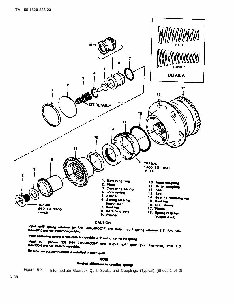
TM 55-1520-236-23
Figure 6-35. Intermediate Gearbox Quill, Seals, and Couplings (Typical) (Sheet 1 of 2)
6-88

TM
55-1520-236-23
Figure 6-35. Intermediate G
earbox Quill, S
eals, and Couplings (Typical) (S
heet 2 of 2)
6-8
9

TM 55-1520-236-23
6-98.1 COLLECTION OF DEBRIS SAMPLE.
a. Remove debris from chip detector probe.debris.
Retain
b. Clean chip detector with advent (C261) anddean cloth. Install chip detector.
c. Identify particles using information in figure 6-2.1and table 6-2. Pay particular attention to debris classi-fied as significant.
d. See figure 6-35.1 for maintenance action dic-tated by debris.
6-99. INSPECTION - INSTALLED lNTERMEDIATEGEARBOX.
NOTE
External leakage is not permitted aroundseal; however, a small amount of seep-age is permissible and does not indicatean unsatisfactory seal condition. Contin-uous flow (droplets) is considered ex-cessive and requires seal replacement.
a. Remove intermediate gearbox cover (fairing).
b. Inspect installed intermediate gearbox (15, figure6-34) as follows:
(1) Obvious mechanical and corosion damage.Refer to paragraph 6-102 for acceptable limits.
(2) Oil sight glass for correct oil level.
(3) Oil leakage.
(4) Lubrication leakage at flexible couplings (24) oninput quill and output quill.
(5) Secure installation of four bolts (12) that se-cure gearbox to tailboom. If Iockwire and/or torquelacquer on bolts indicates that bolts have moved, re-move all four bolts, inspect, and reinstall (paragraph6-105).
(6) Shake gearbox and check for looseness ontailboom. No looseness is acceptable.
(7) Cheek for evidence of fretting corrosion atmating surface between gearbox and tailboom thatcould be caused by movement of the gearbox on thetailboom.
(8) Magnetic chip detector (4) and wiring for se-cure installation and for damage.
(9) Inspect oil filler cap (10) for security of installa-tion.
(10) inspect tail rotor driveshaft damp set (fourbolts) for security of installation.
(11) Check for overheating of two flexible cou-plings (24) evidenced by multi-color appearance. Referto paragraph 6-110 if overheating is suspected.
(12) Insure number 5 driveshaft is not bottomedout. If number 5 driveshaft is bottomed out, replaceoutput coupling spring. Refer to paragraph 6-111 forrepair procedures.
Do not manually bottom out number 5driveshaft. This procedure may causedisplacement of the coupling lubricant.
c. install tail rotor gearbox covers (fairings) anddose vertical fin driveshaft door.
6-100. REMOVAL - INTERMEDIATE GEARBOX.
a. When the intermediate gearbox is to be replaced,unless conditions prevent operation, perform a ten min-ute ground runup and drain operation oil. If runup is notpractical, remove intermediate gearbox and flush withits own operating oil. Attach tag to intermediate gearboxstating: "PRESERVED WITH OPERATING LUBRI-CANT".
b. Remove gearbox cover and open tail rotor drive-shaft access doors.
c. Disconnect tail rotor driveshafts from gearboxinput and output couplings (paragraph 6-77).
6 - 9 0
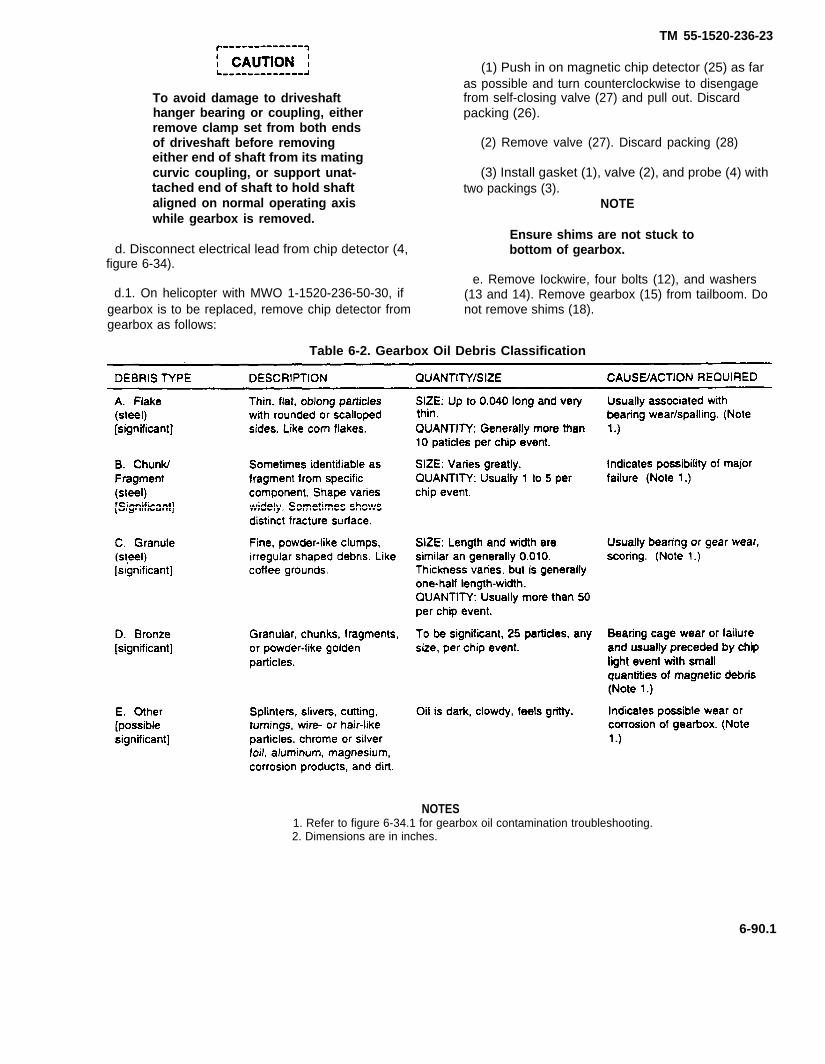
TM 55-1520-236-23
To avoid damage to driveshafthanger bearing or coupling, eitherremove clamp set from both endsof driveshaft before removingeither end of shaft from its matingcurvic coupling, or support unat-tached end of shaft to hold shaftaligned on normal operating axiswhile gearbox is removed.
d. Disconnect electrical lead from chip detector (4,figure 6-34).
d.1. On helicopter with MWO 1-1520-236-50-30, ifgearbox is to be replaced, remove chip detector fromgearbox as follows:
(1) Push in on magnetic chip detector (25) as faras possible and turn counterclockwise to disengagefrom self-closing valve (27) and pull out. Discardpacking (26).
(2) Remove valve (27). Discard packing (28)
(3) Install gasket (1), valve (2), and probe (4) withtwo packings (3).
NOTE
Ensure shims are not stuck tobottom of gearbox.
e. Remove Iockwire, four bolts (12), and washers(13 and 14). Remove gearbox (15) from tailboom. Donot remove shims (18).
Table 6-2. Gearbox Oil Debris Classification
NOTES1. Refer to figure 6-34.1 for gearbox oil contamination troubleshooting.2. Dimensions are in inches.
6-90.1
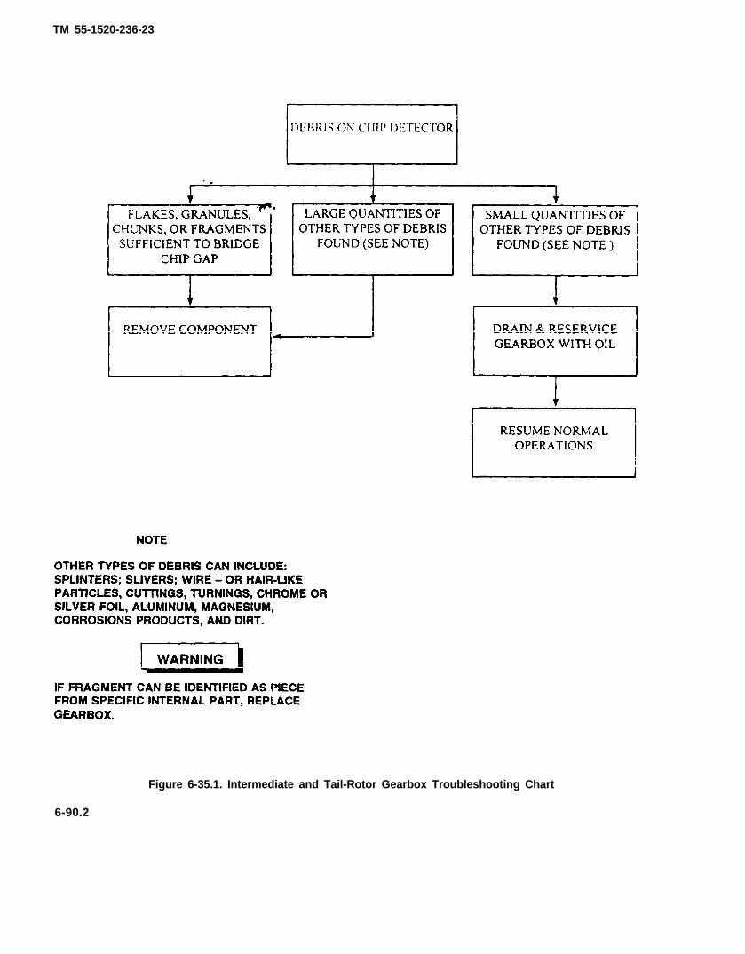
TM 55-1520-236-23
Figure 6-35.1. Intermediate and Tail-Rotor Gearbox Troubleshooting Chart
6-90.2
TM 55-1520-236-23
6-101. CLEANING - INTERMEDIATEGEARBOX.
Cleaning solvent is flammable andtoxic. Provide adequate ventilation.Avoid prolonged breathing ofsolvent vapors and contact withskin or eyes.
Do not force dirt or solvent intobearings or flexible couplings byuse of compressed air.
Clean removed parts and exterior of gearboxassembly with solvent (C112).
6-102. INSPECTION — INTERMEDIATE
GEARBOX (GEARBOX REMOVED
FROM HELICOPTER).
a. Inspect gearbox and historical records forevidence gearbox has been involved in an accident or
6-90.3/(6-90.4 blank)


incident that requires special inspection (paragraph6-103).
b. Inspect gearbox for oil leakage.
c. Inspect both gearbox flexible couplings forlubricant leakage.
NOTE
To remove chip detector (4 or 25,figure 6-34) push body of detectorin and turn left to disengagebayonet pins, then withdraw fromchip detector self-closing valve (2or 27).
TM 55-1520-236-23
d. Inspect chip detector (4 or 25) for metal particles(paragraph 6-4).
e. Inspect gearbox for elongated mounting boltholes. See figure 6-36 for maximum acceptableelongation.
f. Inspect gearbox for mechanical and corrosiondamage. See figure 6-36 for acceptable damagelimits and instructions to rework damaged gearboxcases.
g. Inspect oil filler cap (10, figure 6-34) for damagethat would affect function.
Figure 6-36. Damage Limits-Intermediate Gearbox (Sheet 1 of 7)
6-91
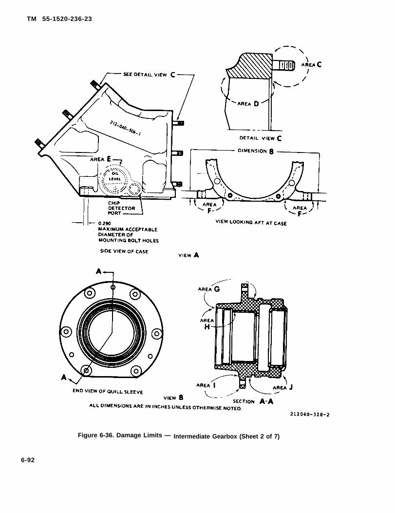
TM 55-1520-236-23
Figure 6-36. Damage Limits — Intermediate Gearbox (Sheet 2 of 7)
6-92

TM 55-1520-236-23
Figure 6-36. Damage Limits — Intermediate Gearbox (Sheet 3 of 7)
6 -93

TM 55-1520-236-23
AREA LIMITS
All ------ No cracks acceptable
Case Assembly Mechanical damage and/or corrosion pitting on the case outsideUndesignated “designated” areas is acceptable provided the damage is polished outareas and the rework to completely remove the damage is within the following
Iimits:
1. Rework is no more than 0.020 inch deep.
2. No more than forty percent of the area within one square inch ormore than twenty percent of the total area is damaged.
3. Damaged area must be treated for corrosion protection inaccordance with general instructions
. . . . Identification plate legible and securely bonded to case.
. . . . Minor scratches and burrs on external surface of coupling are acceptableif polished out with India stone. Indication of overheating of coupling,such as multi-color appearance, is cause to remove the outer couplingand inspect splines and teeth. Inspection procedure is furnished in text.These limits are also applicable to the coupling on the output quill.
. . . . Corrosion damage in area C may be reparable at higher level ofmaintenance. If there is evidence of corrosion under shims or aroundbase of studs, send gear box to higher level of maintenance.
212040-328-4
Figure 6-36. Damage Limits — Intermediate Gearbox (Sheet 4 of 7)
6-94

TM 55-1520-236-23
AREA LIMITS
D - - - - - - Mechanical damage and/or corrosion pitting on case in area D isacceptable provided the damage is polished out and the rework tocompletely remove the damage is within the following limits:
1. Rework is no more than 0.010 inch deep.
2. No more then twenty percent of the total surface area and no morethan ten percent of any one inch square is damaged.
E . . . . . .
F - - - - - -
3. Damaged area must be treated for corrosion protection inaccordance with general instructions.
Mechanical and corrosion damage limits for area E are the same as limitsfor area D.
Mechanical damage and/or corrosion fittings in area F on the lowersurface of the case is-acceptable provided the damage is polished out andthe rework to completely remove the damage is within the followinglimits:
1. Rework is no more than 0.030 inch deep.
2. No more than forty percent of area within any one inch square ormore than twenty percent of the total surface is damaged.
Mechanical damage and/or corrosion pitting on upper machined surfaceat four mounting bolt holes is acceptable provided the damage ispolished out and the rework to completely remove the damage is withinthe following limits:
1. Rework is no more than 0.020 inch deep.
2. No more than twenty percent of total area is damaged.
3. No more than ten percent of the area contacted by the washer isdamaged.
4. Minimum thickness of flange in damaged area is no less than0.430 inch.
S. Damaged area must be treated for corrosion protection inaccordance with general instructions.
NOTE
Damage on area F that is in excess of limits noted above maybe reparableat higher Ievel of maintenance.
Elongation of four mounting bolt holes is acceptable up to maximumdiameter of 0.290 inch.
Mechanical damage and/or corrosion pitting on quill sleeves in area G(exclusive of area l and under shim) is acceptable provided the damage ispolished out and the rework to completely remove the damage is withinthe following limits:
1. Rework is no more than 0.030 inch deep. 212040-328-5
Figure 6-36. Damage Limits — Intermediate Gearbox (Sheet 5 of 7)
6-95
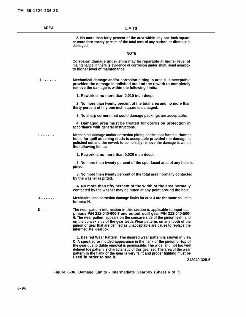
TM 55-1520-236-23
AREA LIMITS
2. No more than forty percent of the area within any one inch squareor more then twenty percent of the total area of any surface or diameter isdamaged.
NOTE
Corrosion damage under shim may be reparable at higher level ofmaintenance. If there is evidence of corrosion under shim. send gearboxto higher level of maintenance.
H . . . . . .
II . . . . . .
J - - - - - -
K . . . . . .
Mechanical damage and/or corrosion pitting in area H is acceptableprovided the damage is polished out l nd the rework to completelyremove the damage is within the following limits:
1. Rework is no more than 0.010 inch deep.
2. No more than twenty percent of the total area and no more thanthirty percent of l ny one inch square is damaged.
3. No sharp corners that could damage packings are acceptable.
4. Damaged area must be treated for corrosion protection inaccordance with general instructions.
Mechanical damage and/or corrosion pitting on the spot faced surface atholes for quill attaching studs is acceptable provided the damage ispolished out and the rework to completely remove the damage is withinthe following limits:
1. Rework is no more than 0.020 inch deep.
2. No more than twenty percent of the spot faced area of any hole ispined.
3. No more then twenty percent of the total area normally contactedby the washer is pitted.
4. No more than fifty percent of the width of the area normallycontacted by the washer may be pitted at any point around the hole.
Mechanical and corrosion damage limits for area J are the same as limitsfor area H.
The wear pattern information in this section is applicable to input quillpinions P/N 212-040-600-7 and output quill gear P/N 212-040-500-6. The wear pattern appears on the concave side of the pinion teeth andon the convex side of the gear teeth. Wear patterns on any tooth of thepinion or gear that are defined as unacceptable are cause to replace theintermediate gearbox.
1. Desired Wear Pattern: The desired wear pattem is shown in viewC. A speckled or mottled appearance in the flank of the pinion or top ofthe gear due to dulite removal is permissible. The wide and not too welldefined toe pattern is characteristic of this gear set. The area of the wearpattern in the flank of the gear is very faint and proper lighting must beused in order to see it.
212040-328-6
Figure 6-36. Damage Limits - Intermediate Gearbox (Sheet 6 of 7)
6-96
TM 55-1520-236-23
AREA LIMITS
2. Acceptable Wear Patterns: Examples of acceptable wear patterns areshown in views F and G. These figures show various pattern toe and heel loca-tions.
3. Pattern Limits at Toe: The pattern may touch the toe or be a maximum of1/8 inch from toe on gear number, see view D. Usually, the pattern will touch thetoe in the flank of the pinion and at the top of the gear as shown on view F. If thepattern touches the toe, but is more than 1/8 inch from heel on gear member,then the pattern is off the toe and is unacceptable. This method of inspectionmust be used, due to the wide toe pattern, to determine whether the pattern isjust touching the toe or is running off the toe. If pattern variation at the toe ex-ceeds 1/32 inch, it is unacceptable.
4. Pattern Limits at Heel: The pattern may touch the heel or be maximum of1/8 inch from heel on gear member, see view D. If pattern variation of the heelexceeds 1/32 inch it is unacceptable.
5. Pattern Profile: The pattern in the profile direction must touch or extendover the top of the pinion as shown by views E, F, and G. On the gear, the patternmay be 1/32 inch from the top or may extend over the top. Most of the gearpatterns will extend over the top as shown by views E, F, and G. A bright lineoccurring at the top of pinion or in the flank of the gear is unacceptable.
6. In addition to pattern size and Iocation, examine the drive face of all gearteeth for the following unacceptable defects: non-dean up, grinding scratches,pitting, corrosion, cuts, nicks, dents, grinding flats or barber poling (evidenced bydiagonal streaks in the wear pattern), scuffing, scoring, or inclusions. If any ofthese defects can be felt with a scribe having a 0.002 inch radius spherical point,the affected part is unacceptable.
GENERAL INSTRUCTIONS.
Repair mechanical and corrosion damage to ease and quill sleeve as follows:
1. Polish out corrosion damage to completely dean up surface. Use sandpaper (C102) or cro-cus cloth (C37). Blend repair in with surrounding surface and make minimum radius 0.250 inch.Use 400 grit abrasive paper (C102) to make repair area surface 63 microinches or better. Ensurethat depth and/or area of repair does not exceed acceptable limits specified for the areas desig-nated above. Treat reworked areas for corrosion protection with MIL-M-3171 C, Type VI treat-ment (commercial designation Dow No. 19) (C42). Refer to TM 43-0105 for application proce-dures. Prime all rework areas that were painted prior to repair. Use polyamide epoxy primer(C88). Paint to match existing finish.
2. Polish out mechanical damage to depth to remove all traces of the damage. Finish polishingout with 400 grit abrasive paper (C102) to blend repair smoothly into surrounding surface. Ensurethat damage does not exceed acceptable limits. Apply corrosion protection, prime, and paint inthe same manner as described in preceding step.
212040-328-7
Figure 6-36. Damage Limits — Intermediate Gearbox (Sheet 7 of 7)
6-97

TM 55-1520-236-23
h. Inspect sight glass (8) for damage that couldcause leakage and for staining that would prevent seeingoil level.
i. Inspect shims (18) for secure installation ontail boom,
j. If quill or quills are removed, refer to paragraph 6-110 for inspection procedure for gear wear patterns.
k. Inspect couplings for mechanical damage and forevidence of overheating. Refer to paragraph 6-110 if over-heating is suspected.
6 -103 . SPECIAL I N S P E C T I O N —INTERMEDIATE GEARBOX.
NOTE
Special inspections of intermediate gearboxare required after tail rotor drive system over-torque, sudden stoppage, compressor stall,etc. Refer to paragraph 1-55, Special Inspec-tion.
Remove output quill from intermediate gearbox(paragraph 6-108).
b. Inspect output quill gear teeth for scoring. See fig-ure 6-36 for procedure to check teeth for roughness with ascribe having a 0.002 inch spherical point.
c. Inspect output quill gear teeth for wear patternsoutside acceptable limits. See figure 6-36 for instructions toevaluate gear patterns.
d. If scoring, abnormal wear patterns, or other dis-crepancies are detected, send gearbox to next highermaintenance level.
6-104. REPAIR — INTERMEDIATE GEARBOX.
Replace gearbox if damaged in excess of accept-able limits (paragraphs 6-102 and 6-103).
b. Repair leaking quills by replacing seals or pack-ings (paragraph 6-111).
c. Replace oil filler cap and packing if damaged orunserviceable. If filler cap contains an insufficient amountof aluminum wool, replace as follows:
(2) Remove ring (11), cap (10), and spring assem-bly (9) from plug (7).
(3) Remove packing (8) from plug (7). Discardpacking.
(4) Remove ring spiralox (4), washer (5), andpacking (6) from plug (7). Discard packing (6).
Cleaning solvent is flammable and toxic. Pro-vide adequate ventilation. Avoid prolongedbreathing of solvent vapors and contact withskin or eyes.
(5) Clean parts with solvent (C112).
(6) Fill plug (7) with new aluminum wooI packing(6) (C20) and place washer (5) in plug. Check to determinewhether correct amount of aluminum wool is installed.Push washer (5) inward 0.06 inch. If washer springs backto its original position, the correct amount of aluminumwool is installed. Add or remove aluminum wool as re-quired. Secure washer (5) in plats with ring spiralox (4).
(7) Coat packing (8) with oil (C79 (C79A) or C80)and position packing on plug (7).
(8) Install spring assembly (9), cap (10), and ring(11) on plug (7). Insert pin (1) through cap (10) and bendend of pin to secure.
d. Replace sight glass (8, figure 6-34) if damaged orIeaking.
Cleaning solvent is flammable and toxic. Pro-vide adequate ventilation. Avoid prolongedbreathing of solvent vapors and contact withskin or eyes.
(1) Remove retaining ring (6, figure 6-34), packing(7), sight glass (8), and sight gage (9). Clean sight gage (9)with solvent (C112).
(1) Remove pin (1, figure 6-37) from cap (10).
6-98

TM 55-1520-236-23
(2) Position sight gage (9) in gearbox. Place newpacking (7) on sight glass (8). Install sight glass withflat side out. Install retaining ring (6).
e. Polish out mechanical and corrosion damage ongearbox case that is within limits shown on figure6-36. Comply with “General Instructions” on figure6-36.
f. Replace gasket (1, figure 6-34) if leaking. Torqueself-closing valve (2) 120 TO 150 inch-pounds andsecure with Iockwire (C137).
g. For helicopters with MWO 1-1520-236-50-30,replace packing (28), if leaking. Torque self closingvalve to 45 to 50 inch-pounds and secure withIockwire (C137).
6-105. INSTALLATION - INTERMEDIATEGEARBOX.
Do not remove or change shims installed ontailboom under gearbox, as any resultingmisalignment could cause excessive stresses,vibration, wear, and possible eventual failure ofcomponents in tail rotor drive train.
6-98.1/(6-98.2 blank)

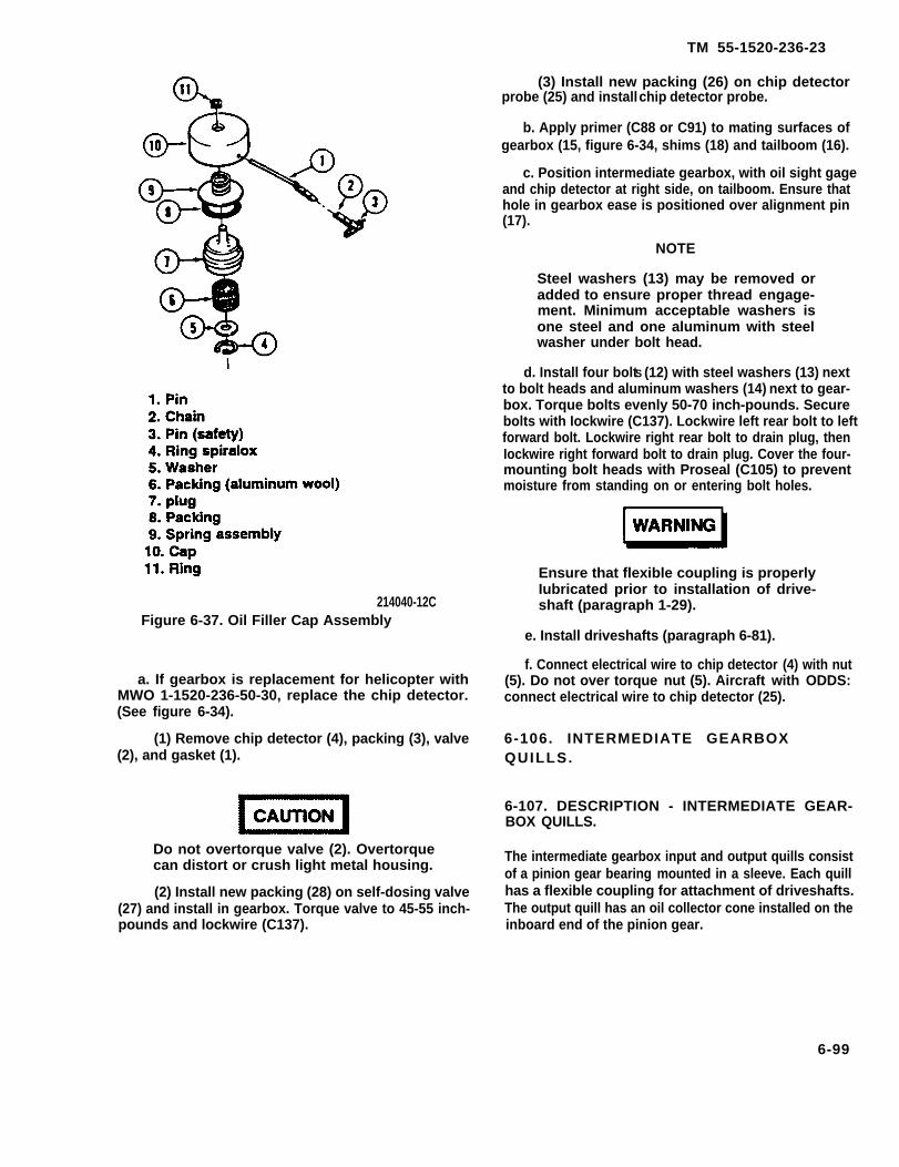
TM 55-1520-236-23
214040-12CFigure 6-37. Oil Filler Cap Assembly
a. If gearbox is replacement for helicopter withMWO 1-1520-236-50-30, replace the chip detector.(See figure 6-34).
(1) Remove chip detector (4), packing (3), valve(2), and gasket (1).
Do not overtorque valve (2). Overtorquecan distort or crush light metal housing.
(2) Install new packing (28) on self-dosing valve(27) and install in gearbox. Torque valve to 45-55 inch-pounds and lockwire (C137).
(3) Install new packing (26) on chip detectorprobe (25) and install chip detector probe.
b. Apply primer (C88 or C91) to mating surfaces ofgearbox (15, figure 6-34, shims (18) and tailboom (16).
c. Position intermediate gearbox, with oil sight gageand chip detector at right side, on tailboom. Ensure thathole in gearbox ease is positioned over alignment pin(17).
NOTE
Steel washers (13) may be removed oradded to ensure proper thread engage-ment. Minimum acceptable washers isone steel and one aluminum with steelwasher under bolt head.
d. Install four boltS (12) with steel washers (13) nextto bolt heads and aluminum washers (14) next to gear-box. Torque bolts evenly 50-70 inch-pounds. Securebolts with Iockwire (C137). Lockwire left rear bolt to leftforward bolt. Lockwire right rear bolt to drain plug, thenIockwire right forward bolt to drain plug. Cover the four-mounting bolt heads with Proseal (C105) to preventmoisture from standing on or entering bolt holes.
Ensure that flexible coupling is properlyIubricated prior to installation of drive-shaft (paragraph 1-29).
e. Install driveshafts (paragraph 6-81).
f. Connect electrical wire to chip detector (4) with nut(5). Do not over torque nut (5). Aircraft with ODDS:connect electrical wire to chip detector (25).
6-106. INTERMEDIATE GEARBOXQUILLS.
6-107. DESCRIPTION - INTERMEDIATE GEAR-BOX QUILLS.
The intermediate gearbox input and output quills consistof a pinion gear bearing mounted in a sleeve. Each quillhas a flexible coupling for attachment of driveshafts.The output quill has an oil collector cone installed on theinboard end of the pinion gear.
6-99
TM 55-1520-236-23
6-108. REMOVAL - INTERMEDIATEGEARBOX QUILLS.
Premaintenance Requirements for Removal ofIntermediate Gearbox Quills
Conditions Requirements
Model
Part No. or Serial No.
Special Tools
Test Equipment
Support Equipment
Minimum PersonnelRequired
Consumable Materials
Special EnvironmentalConditions
AH-1P/E/F
All
(T26) (T27) (T37) (T55)
None
None
One
(C56) (C106) (C112)(C116) (C137)
None
a. Remove gearbox and drain oil (paragraph 6-99).
NOTE
Either quill can be removed using thefollowing procedures.
b. Remove nuts (23, figure 6-34) and aluminumand steel washers (21 and 22).
c. Cut sealant around quill sleeve and gearboxcase with a sharp plastic scraper. Remove sealant, orIockwire, plugs, and gasket from jackscrew holes.
d. Install three jackscrews (T27) in jackscrew holesin quill sleeve, Tighten jackscrews evenly to pull quillfrom case.
NOTE
Do not remove shims from quill sleeve orfrom gearbox case.
e. Cover opening in gear case port to prevent entryof foreign material.
6-100
6-109. CLEANING — INTERMEDIATEGEARBOX QUILLS.
Cleaning solvent is flammable andtoxic. Provide adequate ventilation.Avoid prolonged breathing ofsolvent vapors and contacts withskin or eyes.
Do not force dirt or solvent intobearings or flexible couplings byuse of compressed air.
a. Prior to cleaning inspect quills for evidence of oiland/or grease leakage (paragraph 6-110).
b. Clean exterior of quill with solvent (C112).
c. Clean sealant from quill sleeve and gearboxcase with a plastic scraper.
NOTE
The following cleaning pertains toa disassembled quill. Do not usecleaning solvent inside couplings.Solvent leaves residue .
d. Use a clean dry cloth to clean lubricant frominner and outer coupling.
e. Clean old sealant from bearing retaining nut andreside of quill sleeve with a plastic scraper. Ensurethat sealant does not contaminate quill bearings.
6-110. INSPECTION - INTERMEDIATEGEARBOX QUILLS.
a. Inspect quills for evidence of oil leakage at seal(13, figure 6-35).
b. Inspect quills for evidence of grease leakage atseal (12).
c. Inspect inner couplings (10) on both quills forwear and damage on surface contacted by seal (13)during operation. Wear is allowable to minimumdiameter of 1.587 inches, provided groove is uniformand smooth.
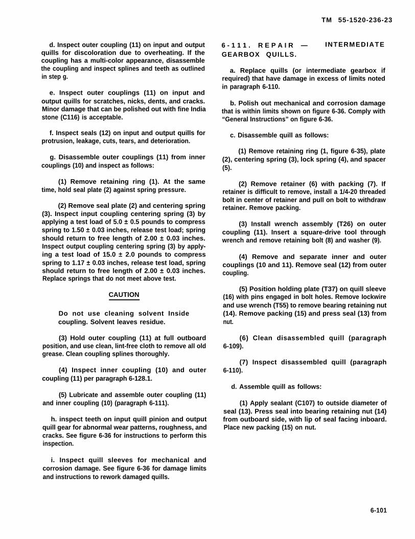
TM 55-1520-236-23
d. Inspect outer coupling (11) on input and outputquills for discoloration due to overheating. If thecoupling has a multi-color appearance, disassemblethe coupling and inspect splines and teeth as outlinedin step g.
e. Inspect outer couplings (11) on input andoutput quills for scratches, nicks, dents, and cracks.Minor damage that can be polished out with fine Indiastone (C116) is acceptable.
f. Inspect seals (12) on input and output quills forprotrusion, leakage, cuts, tears, and deterioration.
g. Disassemble outer couplings (11) from innercouplings (10) and inspect as follows:
(1) Remove retaining ring (1). At the sametime, hold seal plate (2) against spring pressure.
(2) Remove seal plate (2) and centering spring(3). Inspect input coupling centering spring (3) byapplying a test load of 5.0 ± 0.5 pounds to compressspring to 1.50 ± 0.03 inches, release test load; springshould return to free length of 2.00 ± 0.03 inches.Inspect output coupling centering spring (3) by apply-ing a test load of 15.0 ± 2.0 pounds to compressspring to 1.17 ± 0.03 inches, release test load, springshould return to free length of 2.00 ± 0.03 inches.Replace springs that do not meet above test.
CAUTION
Do not use cleaning solvent Insidecoupling. Solvent leaves residue.
(3) Hold outer coupling (11) at full outboardposition, and use clean, lint-free cloth to remove all oldgrease. Clean coupling splines thoroughly.
(4) Inspect inner coupling (10) and outercoupling (11) per paragraph 6-128.1.
(5) Lubricate and assemble outer coupling (11)and inner coupling (10) (paragraph 6-111).
h. inspect teeth on input quill pinion and outputquill gear for abnormal wear patterns, roughness, andcracks. See figure 6-36 for instructions to perform thisinspection.
6 - 1 1 1 . R E P A I R — INTERMEDIATE
GEARBOX QUILLS.
a. Replace quills (or intermediate gearbox ifrequired) that have damage in excess of limits notedin paragraph 6-110.
b. Polish out mechanical and corrosion damagethat is within limits shown on figure 6-36. Comply with“General Instructions” on figure 6-36.
c. Disassemble quill as follows:
(1) Remove retaining ring (1, figure 6-35), plate(2), centering spring (3), lock spring (4), and spacer(5).
(2) Remove retainer (6) with packing (7). Ifretainer is difficult to remove, install a 1/4-20 threadedbolt in center of retainer and pull on bolt to withdrawretainer. Remove packing.
(3) Install wrench assembly (T26) on outercoupling (11). Insert a square-drive tool throughwrench and remove retaining bolt (8) and washer (9).
(4) Remove and separate inner and outercouplings (10 and 11). Remove seal (12) from outercoupling.
(5) Position holding plate (T37) on quill sleeve(16) with pins engaged in bolt holes. Remove Iockwireand use wrench (T55) to remove bearing retaining nut(14). Remove packing (15) and press seal (13) fromnut.
(6) Clean disassembled quill (paragraph6-109).
(7) Inspect disassembled quill (paragraph6-110).
d. Assemble quill as follows:
(1) Apply sealant (C107) to outside diameter ofseal (13). Press seal into bearing retaining nut (14)from outboard side, with lip of seal facing inboard.Place new packing (15) on nut.
i. Inspect quill sleeves for mechanical andcorrosion damage. See figure 6-36 for damage limitsand instructions to rework damaged quills.
6-101
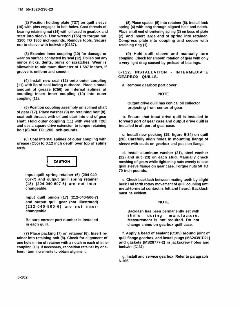
TM 55-1520-236-23
(2) Position holding plate (T37) on quill sleeve(16) with pins engaged in bolt holes. Coat threads ofbearing retaining nut (14) with oil used in gearbox andstart into sleeve. Use wrench (T55) to torque nut1200 TO 1800 inch-pounds. Remove tools. Securenut to sleeve with Iockwire (C137).
(3) Examine inner coupling (10) for damage orwear on surface contacted by seal (12). Polish out anyminor nicks. dents, burrs or scratches. Wear isallowable to minimum diameter of 1.587 inches, ifgroove is uniform and smooth.
(4) Install new seal (12) onto outer coupling(11) with lip of seal facing outboard. Place a smallamount of grease (C56) on internal splines ofcoupling Insert inner coupling (10) into outercoupling (11).
(5) Position coupling assembly on splined shaftof gear (17). Place washer (9) on retaining bolt (8),coat bolt threads with oil and start into end of gearshaft. Hold outer coupling (11) with wrench T26)and use a square-drive extension to torque retainingbolt (8) 960 TO 1200 inch-pounds.
(6) Coal internal splines of outer coupling withgrease (C56) to 0.12 inch depth over top of splineteeth.
Input quill spring retainer (6) (204-040-607-7) and output quill spring retainer(18) (204-040-607-5) are not inter-changeable.
Input quill pinion (17) (212-040-500-7)and output quill gear (not Illustrated)( 2 1 2 - 0 4 0 - 5 0 0 - 6 ) a r e n o t i n t e r -changeable.
Be sure correct part number is installedin each quill.
(7) Place packing (7) on retainer (6). Insert re-tainer into retaining bolt (8). Check for alignment ofone hole in rim of retainer with a notch in each of innercoupling (10). If necessary, reposition retainer by one-fourth turn increments to obtain alignment.
(8) Place spacer (5) into retainer (6). Install lockspring (4) with tang through aligned hole and notch.Place small end of centering spring (3) on boss of plate(2). and insert Iarge end of spring into retainer.Compress plate into coupling and secure withretaining ring (1).
(9) Hold quill sleeve and manually turncoupling. Check for smooth rotation of gear with onlya very light drag caused by preload of bearings.
6-112. INSTALLATION - INTERMEDIATEGEARBOX QUILLS.
a. Remove gearbox port cover.
NOTE
Output drive quill has conical oil collectorprojecting from center of gear.
b. Ensure that input drive quill is installed inforward port of gear case and output drive quill isinstalled in aft port of gear case.
c. Install new pecking (19, figure 6-34) on quill(20). Carefully align holes in mounting flange ofsleeve with studs on gearbox and position flange.
d. Install aluminum washer (21), steel washer(22) and nut (23) on each stud. Manually checkmeshing of gears while tightening nuts evenly to seatquill sleeve flange on gear case. Torque nuts 50 TO70 inch-pounds.
e. Check backlash between mating teeth by slightbeck l nd forth rotary movement of quill coupling untilmetal-to-metal contact is felt and heard. Backlashmust be evident.
NOTE
Backlash has been permanently set withshims d u r i n g m a n u f a c t u r e .Measurement is not required. Do notchange shims on gearbox quill case.
f. Apply a bead of sealant (C105) around joint ofquill flange gearbox, and install plugs (MS24391D2L)and gaskets (MS28777-2) in jackscrew holes andIockwire (C137).
g. Install and service gearbox. Refer to paragraph6-105.
6-102

TM 55-1520-236-23
SECTION VI. TAIL ROTOR DRIVE GEARBOX
6-113. TAIL ROTOR DRIVE GEARBOX. drain plug with a chip detector. The input quill has aflexible coupling for attachment of driveshaft. Control
6-114. DESCRIPTION - TAIL ROTOR linkage is attached on the left side, with a control rod
D R I V E G E A R B O X . extending through the rotor shaft.
A gearbox at top of tailboom vertical fin provides On helicopters without MWO 1-1520-236-50-30, the
ninety-degree change in direction of drive and speed chip detector is straight and includes a threaded-stud
reduction between the input driveshaft and the output electrical termination. On helicopters with MWO 1-
shaft on which the tail rotor is mounted. The gearbox 1520-236-50-30, the chip detector is right-angled and
consists of mating input and output gear quillincludes an electrical receptacle. Chip detector is
assemblies set into gear case provided with aconnected electrically to 90° CHIP light on the caution
breather-type oil filler cap, oil level sight gage, and apanel.
Figure 6-38. Tail Rotor Drive Gearbox Installation
6-103

TM 55-1520-236-23
6-115. INSPECTION - INSTALLED TAILROTOR DRIVE GEARBOX.
NOTE
External leakage is not permittedaround seal; however, a smallamount of seepage is permissablea n d d o e s n o t i n d i c a t e a nunsatisfactory seal condition.Condition flow (droplets) isconsidered excessive and requiresseal replacement.
a. Open vertical fin cover (19, figure 6-38) andremove tail rotor gearbox covers (fairings).
b. Shake gearbox and check for looseness on tailrotor gearbox support fitting (3).
c. Inspect for evidence of fretting corrosion at matingsurface between tail rotor gearbox (5) and tail rotorgearbox support fitting (3) that could be caused bymovement of the gearbox on the support. A grayresidue is an indication of fretting. Remove gearbox ifresidue is present (paragraph 6-117).
d. Inspect six nuts (18) for secure installation, correcttorque, and correct thread engagement (paragraph6-121).
e. Inspect clamp set (2) for secure installation.
f. Inspect control tube (8) and lever (9) for secureinstallation.
g. Inspect flexible coupling (4) for grease leakageand for overheating evidenced by multi-colorappearance.
h. Inspect tail rotor gearbox (5) for scratches, nicks,dents. cracks. corrosion, and oil leakage.
i. Disconnect electrical wire or cable plug from chipdetector.
j. Press in and turn counterclockwise to remove chipdetector probe (11 or 23, figure 6-39).
k. Inspect for magnetic particle buildup. Retaindebris. Clean, install, and connect the probe.
1. If chip detector is being inspected following chiplight, collect debris for classification (paragraph 6-98.1).
m. Inspect oil filler cap (4) for damage and correctamount of aluminum wool (paragraph 6-104).
n. Inspect oil sight glass (8) for correct oil level.
NOTE
Before installing tail rotor gearboxfairings, ensure that the isolationpad Is securely attached (Figure 2-93). Ensure fairing attachment hard-ware are installed in the properlocations; use of incorrect lengthscrews can damage gearbox casing.
o. Install tail rotor gearbox fairings and close verticalfin cover (19, figure 6-38).
6-115.1. DISASSEMBLY - TAIL ROTORGEARBOX INPUT QUILL (SEAL REPLACEMENTWITH GEARBOX INSTALLED ON HELICOPTER).
a. Drain oil from tail rotor gearbox. (Refer toparagraph 1-7.)
b. Open access cover on front of vertical fin.
Secure the tail rotor blades to preventprevent personal injury and equipmentdamage any time a segment of the tailrotor drive system is disconnected. Thetail rotor blades may cause uncontrolledsystem rotation should there be a suddengust of wind when they are not secured.
Clamp set must be removed from bothends of shaft before removing either endof shaft from its mating curvic coupling toavoid coupling tooth or bearing damage.
NOTE
Retain clamp set as a unit when removedto preclude intermix of set halves.
c. Remove clampset from curvic couplings (bothends of shaft).
6-104

TM 55-1520-236-23
d. Push shaft against coupling to disengageopposite end and remove driveshaft.
e. Remove curvic coupling as follows (figure6-40).
(1) Remove retaining ring (18), plate (17),centering spring (16) and spacer (14). Thread a1/4-20 bolt into center of retainer plug (13) andpull retainer with Iockspring (15) and packing (12)from inner coupling. Remove Iockspring andpacking from retainer.
(2) Hold outer coupling (1) with wrench,(T26) and use square adapter through wrench toremove coupling retaining bolt (11) and washer(10).
(3) Remove inner coupling (9) and outercoupling (1) from pinion splines.
(4) Remove inner coupling (9) from outercoupling (1). Remove seal (2) from outer coupling(1).
f. Remove sealer and Iockwire from retainingnut (4). Remove nut (4) using special socket(68SPL-12757-0136) or tool, (T36). Removespacer assembly (21) on pinion splines.
g. Remove packing (5) from nut (4).
h. Press seal (3) from retaining nut (4).
6-115.2. ASSEMBLY - TAIL ROTORDRIVE GEARBOX INPUT QUILL.
NOTE
Replace all removed seals andpackings with new items
a. Install spacer assembly (21) on pinionsplines.
NOTE
Large end of spacer assembly goesInboard (toward gearbox).
b. Press seal (3) into retainer nut (4) with lip ofseal facing inboard (toward gearbox). Applysealant (C105) to outside diameter of seal (3).Install packing (5) an nut (4).
c. Using special socket 68SPL-12757-0136,install nut (4). Torque nut 100 TO 150
foot-pounds. Lockwire (C137) nut (4) to sleeve.Apply a bead of sealer (C104) around mating jointof nut and sleeve.
d. Lubricate O.D. of seal (2) with grease (C56)and press into outer coupling (1) with lip of sealfacing toward coupling splines.
e. Place a small amount of grease (C56) ininternal splines of coupling (1), on lip of seal (2)and mating surface of coupling (9). Insert coupling(9) into coupling (1).
f. install couplings (9) and (1) on splines ofpinion shaft (6).
g. Place washer (10) on bolt (11) and threadbolt into pinion shaft (6).
h. Hold outer coupling (1) with wrench,T101307. Position square adapter through wrenchand torque bolt (11) 80 TO 100 foot-pounds.
i. Place packing (12) on retainer (13). Insertretainer into bolt (11). If one hole in rim of retainerdoes not align with notch of inner coupling (9), pullout retainer, rotate it ninety degrees and reinstall.Repeat if necessary to obtain alignment. Installlock spring (15).
j. Extend outer coupling (1) so that seal (2) isagainst the teeth of inner coupling (9). Coatinternal splines of outer coupling with grease (C56)to 0.12 inch depth overtop of spline teeth.
k. Place small end of centering spring (16) onboss of plate (17). Install spacer (14), spring (16)and plate (17) into coupling and install retainingring (18).
l. Install drive shaft by pushing shaft againstone coupling while mating shaft couplings withgearbox couplings.
m. Install damp set at each end of shaft asfollows:
Use new nuts each time clamps are installed.NOTE
Insure damp halves are matched. Allbolts and nuts on anyone clampmust be Identical parts to maintainbalance.
(1) Position damps with bolted joints indexed90 degrees to those of adjacent damps forbalance in operation.
6-104.1
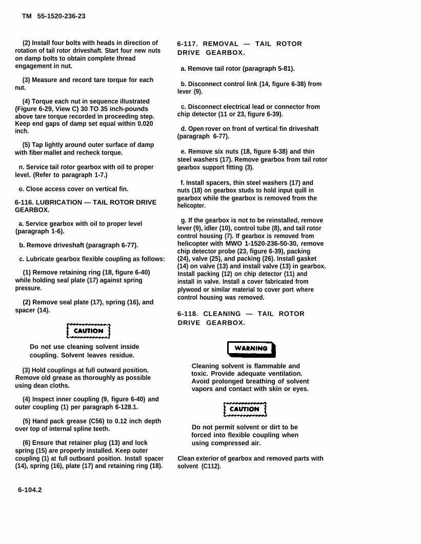
TM 55-1520-236-23
(2) Install four bolts with heads in direction ofrotation of tail rotor driveshaft. Start four new nutson damp bolts to obtain complete threadengagement in nut.
(3) Measure and record tare torque for eachnut.
(4) Torque each nut in sequence illustrated(Figure 6-29, View C) 30 TO 35 inch-poundsabove tare torque recorded in proceeding step.Keep end gaps of damp set equal within 0.020inch.
(5) Tap lightly around outer surface of dampwith fiber mallet and recheck torque.
n. Service tail rotor gearbox with oil to properlevel. (Refer to paragraph 1-7.)
o. Close access cover on vertical fin.
6-116. LUBRICATION — TAIL ROTOR DRIVEGEARBOX.
a. Service gearbox with oil to proper level(paragraph 1-6).
b. Remove driveshaft (paragraph 6-77).
c. Lubricate gearbox flexible coupling as follows:
(1) Remove retaining ring (18, figure 6-40)while holding seal plate (17) against springpressure.
(2) Remove seal plate (17), spring (16), andspacer (14).
Do not use cleaning solvent insidecoupling. Solvent leaves residue.
(3) Hold couplings at full outward position.Remove old grease as thoroughly as possibleusing dean cloths.
(4) Inspect inner coupling (9, figure 6-40) andouter coupling (1) per paragraph 6-128.1.
(5) Hand pack grease (C56) to 0.12 inch depthover top of internal spline teeth.
(6) Ensure that retainer plug (13) and lockspring (15) are properly installed. Keep outercoupling (1) at full outboard position. Install spacer(14), spring (16), plate (17) and retaining ring (18).
6-117. REMOVAL — TAIL ROTORDRIVE GEARBOX.
a. Remove tail rotor (paragraph 5-81).
b. Disconnect control link (14, figure 6-38) fromlever (9).
c. Disconnect electrical lead or connector fromchip detector (11 or 23, figure 6-39).
d. Open rover on front of vertical fin driveshaft(paragraph 6-77).
e. Remove six nuts (18, figure 6-38) and thinsteel washers (17). Remove gearbox from tail rotorgearbox support fitting (3).
f. Install spacers, thin steel washers (17) andnuts (18) on gearbox studs to hold input quill ingearbox while the gearbox is removed from thehelicopter.
g. If the gearbox is not to be reinstalled, removelever (9), idler (10), control tube (8), and tail rotorcontrol housing (7). If gearbox is removed fromhelicopter with MWO 1-1520-236-50-30, removechip detector probe (23, figure 6-39), packing(24), valve (25), and packing (26). Install gasket(14) on valve (13) and install valve (13) in gearbox.Install packing (12) on chip detector (11) andinstall in valve. Install a cover fabricated fromplywood or similar material to cover port wherecontrol housing was removed.
6-118. CLEANING — TAIL ROTORDRIVE GEARBOX.
Cleaning solvent is flammable andtoxic. Provide adequate ventilation.Avoid prolonged breathing of solventvapors and contact with skin or eyes.
Do not permit solvent or dirt to beforced into flexible coupling whenusing compressed air.
Clean exterior of gearbox and removed parts withsolvent (C112).
6-104.2

TM 55-1520-236-23
Figure 6-39. Tail Rotor Drive Gearbox Assembly
6-105
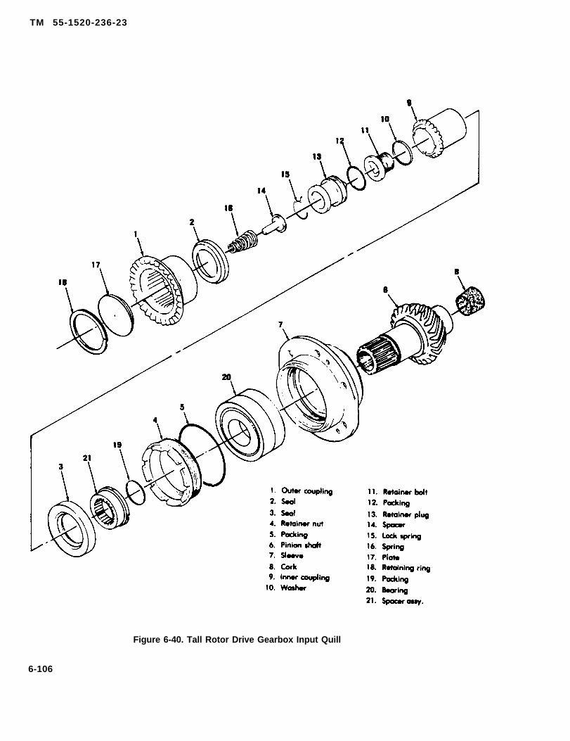
TM 55-1520-236-23
Figure 6-40. Tall Rotor Drive Gearbox Input Quill
6-106

TM 55-1520-236-23
6-119. INSPECTION - TAIL ROTORDRIVE GEARBOX (GEARBOX REMOVEDFROM HELICOPTER).
a. Inspect chip detector (11 or 23, figure 6-39) formetal particles. If particles are found, refer toparagraph 6-4 to determine required action.
b. Inspect oil filler cap (4) for damage and correctamount of aluminum wool (paragraph 6-104).
c. Inspect gearbox for damage in accordance withfigure 6-41.
6-120. REPAIR - TAIL ROTOR DRIVEGEARBOX.
a. Forward gearbox to next higher maintenancelevel if damage in excess of acceptable limits isdetected during inspection.
6-106.1/(6-106.2 blank)

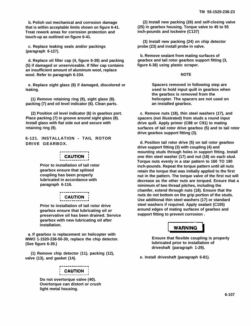
TM 55-1520-236-23
b. Polish out mechanical and corrosion damagethat is within acceptable limits shown on figure 6-41.Treat rework areas for corrosion protection andtouch-up as outlined on figure 6-41.
c. Replace leaking seals and/or packings(paragraph 6-127).
d. Replace oil filler cap (4, figure 6-39) and packing(5) if damaged or unserviceable. If filler cap containsan insufficient amount of aluminum wool, replacewool. Refer to paragraph 6-104.
e. Replace sight glass (8) if damaged, discolored orleaking.
(1) Remove retaining ring (9), sight glass (8).packing (7) and oil level indicator (6). Clean parts.
(2) Position oil level indicator (6) in gearbox port.Place packing (7) in groove around sight glass (8).Install glass with fiat side out and secure withretaining ring (9).
6-121. INSTALLATION - TAIL ROTORDRIVE GEARBOX.
Prior to installation of tail rotorgearbox ensure that splinedcoupling has been properlylubricated in accordance withparagraph 6-116.
Prior to installation of tail rotor drivegearbox ensure that lubricating oil orpreservative oil has been drained. Servicegearbox with new lubricating oil afterinstallation.
a. If gearbox is replacement on helicopter withMWO 1-1520-236-50-30, replace the chip detector.(See figure 6-39.)
(1) Remove chip detector (11), packing (12),valve (13), and gasket (14).
(2) Install new packing (26) and self-closing valve(25) in gearbox housing. Torque valve to 45 to 55inch-pounds and Iockwire (C137)
(3) Install new packing (24) on chip detectorprobe (23) and install probe in valve.
b. Remove sealant from mating surfaces ofgearbox and tail rotor gearbox support fitting (3,figure 6-38) using plastic scraper.
NOTE
Spacers removed in following step areused to hold input quill in gearbox whenthe gearbox is removed from thehelicopter. The spacers are not used onan installed gearbox.
c. Remove nuts (18), thin steel washers (17), andspacers (not illustrated) from studs a round inputdrive quill. Apply primer (C88 or C91) to matingsurfaces of tail rotor drive gearbox (5) and to tail rotordrive gearbox support fitting (3).
d. Position tail rotor drive (5) on tail rotor gearboxdrive support fitting (3) with coupling (4) andmounting studs through holes in support fitting. Installone thin steel washer (17) and nut (18) on each stud.Torque nuts evenly in a star pattern to 160 TO 190inch-pounds. Repeat the torque pattern until all nutsretain the torque that was initially applied to the firstnut in the pattern. The torque valve of the first nut willdecrease as the other nuts are torqued. Ensure that aminimum of two thread pitches, including thechamfer, extend through nuts (18). Ensure that thenuts do not bottom on the grip portion of the studs.Use additional thin steel washers (17) or standardsteel washers if required. Apply sealant (C105)around edges of mating surfaces of gearbox andsupport fitting to prevent corrosion .
Ensure that flexible coupling is properlylubricated prior to installation ofdriveshaft (paragraph 1-29).
e. Install driveshaft (paragraph 6-81).
Do not overtorque valve (40).Overtorque can distort or crushlight metal housing.
6-107
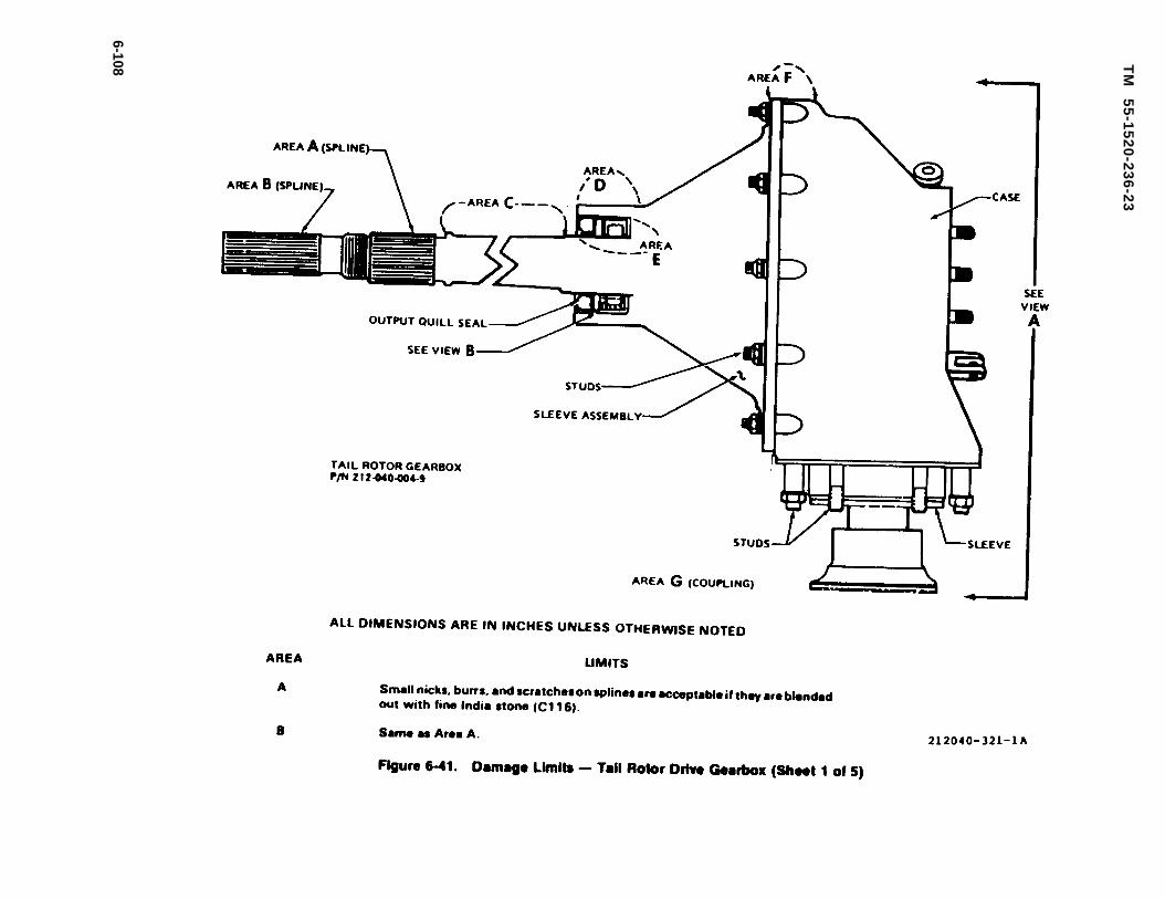
Figure 6-41.
TM
5
5-1
52
0-2
36
-23
6-108

TM 55-1520-236-23
Figure 6-41. Damage Limits - Tail Rotor Drive Gearbox (Sheet 2 of 5)
6-109
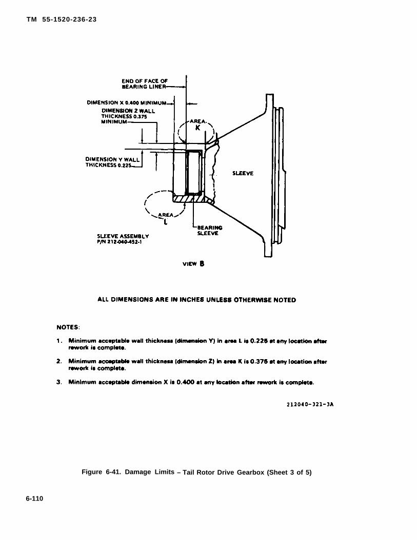
TM 55-1520-236-23
Figure 6-41. Damage Limits – Tail Rotor Drive Gearbox (Sheet 3 of 5)
6-110

TM 55-1520-236-23
Figure 6-41. Damage Limits — Tail Rotor Drive Gearbox (Sheet 4 of 5)
6-111

TM 55-1520-236-23
Figure 6-41. Damage Limits — Tail Rotor Drive Gearbox (Sheet 5 of 5)
6-112
TM 55-1520-236-23
f. If not previously accomplished, install control link-age on gearbox as follows:
(1) Remove cover at port for tail rotor drive controlhousing (7).
(2) Install control tube (8) and tail rotor drive con-trol housing (7). Refer to paragraph 5-105.c.
(3) Install idler (10).
(4) Install lever (9) on idler (10) and control tube(8).
g. Connect electrical lead to magnetic chip detector(11, figure 6-39).
h. Service gearbox with oil (paragraph 1-6).
i. Close vertical fin (19, figure 6-38),
j. Install and rig tail rotor (paragraph 5-105).
6-122. QUILLS, TAIL ROTOR DRIVE GEAR,BOX.
6-123. DESCRIPTION — QUILLS, TAIL ROTORDRIVE GEARBOX.
The tail rotor drive gearbox has an input and output quill.The input quill consists of a pinion gear and bearingmounted in a sleeve. The input quill has a flexible couplingfor attachment of driveshaft. The output quill has an outputshaft for mounting the tail rotor assembly. A gear mountedon the inboard end of the output shaft meshes with the pin-ion gear of the input quill.
6-124. REMOVAL — TAIL ROTOR DRIVEGEARBOX INPUT QUILL.
Premaintenance Requirements for Removal of TailRotor Gearbox Quills
Conditions Requirements
Model
Part No, or Serial No,
Special Tools
Test Equipment
AH-1P/E/F
All
(T26) (T37) (T55) (C27)
None
Conditions Requirements
Support Equipment None
Minimum Personnel TwoRequired
Consumable Materials (C37) (C56) (C78) (C79) (C79A)(C80)(C104) (C105) (C112)(C116) (C137)
Special Environmental NoneConditions
NOTE
Removal procedure only covers the input quillsince the output quill is not normally removedin the field.
Remove gearbox from helicopter and drain oil(pargraph 6-117).
b. Remove nuts (18, figure 6-39) and shipping spac-ers (19). The spacers are used to hold the input quill in po-sition during shipment. They may not be present on allgearboxes received for repair.
c. Remove sealant, or plugs and gaskets from threethreaded holes provided for jackscrews in the input quillsleeve and from the groove at the point where the inputquill (20) and the case (22) join.
d. Install three jackscrews (T27) in threaded holes ininput quill (20). Tighten jackscrews evenly to remove inputquill. Use heat lamp on case (22), if quill is very hard to re-move, but do not use open flame. Remove input quill (20)and locally dispose of packing (21).
Do not remove screws (15) and shim plate (16)or the matching shim plate and screws in-stalled on input quill. The correct thickness forthese shim plates is determined at time ofmanufacture, and they must not be removedexcept at a depot level maintenance facility.
e. Immediately after quill removal, inspect for evi-dence of corrosion around edges of the two shim
6-113

TM 55-1520-236-23
plates described in the caution above, but do not removethe shim plates. If there is any evidence of corrosion, pre-serve and reassemble the gearbox and forward it to nexthigher maintenance level.
f. Cover opening in case (22) and also cover theopen end of the quill to prevent contamination by dust orother foreign material until the gearbox can be inspected.
6-125. CLEANING — TAIL ROTOR DRIVEGEARBOX INPUT QUILL.
Cleaning solvent is flammable and toxic. Pro-vide adequate ventilation. Avoid prolongedbreathing of solvent vapors and contact withskin or eyes.
Do not permit dirt or solvent to be forced intobearing of input quill flexible coupling by useof compressed air.
NOTE
Do not use cleaning solvent inside coupling.Solvent leaves residue.
a. Clean exterior of quill with solvent (C112).
b. Clean oil sealant from quill sleeve and gearboxcase with a plastic scraper.
NOTE
The following cleaning pertains to a disassem-bled input quill. Do not use cleaning solventinside coupling. Solvent leaves residue.
c. Clean lubricant from inner and outer couplingusing a clean dry cloth.
d. Clean old sealant from bearing, retaining nut, andinside of quill sleeve with a plastic scraper. Ensure thatsealant does not contaminate quill bearings.
6-126. INSPECTION — TAIL ROTOR DRIVEGEARBOX INPUT QUILL.
a. Inspect bearing inside tail rotor drive gearbox thatsupports forward end of input quill pinion. Inspect the bear-ing for spalling, scoring, pitting, brinnelling, flaking, corro-sion, cracked or broken retainers, discoloration due tooverheating, and for roughness when the bearing is rolledby hand. See figure 6-42 for views of acceptable and unac-ceptable roller bearings.
b. inspect teeth on input quillwear and chipped teeth. See figureand unacceptable wear patterns.
pinion for abnormal6-43 for acceptable
c. If inspections in steps a. and b. reveal unaccept-able wear or damage, do not disassemble quill for repair.Reinstall quill, preserve gearbox, and forward gearbox tohigher level of maintenance.
d. Inspect quill for evidence of oil leakage at seal (3,figure 6-40).
e. Inspect quill for grease leakage at seal (2).
f. Inspect outer coupling (1) for discoloration due tooverheating. If the coupling has a multi-colored appear-ance, disassemble the coupling and inspect splines andteeth.
g. Inspect outer coupling (1) for scratches, nicks,dents, and cracks. Minor damage that can be polished outwith a fine India stone (C116) is acceptable.
h. Inspect seal (2) for protrusion, leakage, cuts,tears, and deterioration.
i. Disassemble outer coupling (1) from inner cou-pling (9) and inspect as follows:
(1) Remove retaining ring (18). At the same timehold seal plate (17) against spring pressure. Remove seatplate (17) and spring (16).
Do not use cleaning solvent inside coupling.Solvent leaves residue.
(2) Hold outer coupling (1) at full outboard posi-tion, and use dean, lint-free cloth to remove all old grease.Clean coupling splines thoroughly.
6-114

TM 55-1520-236-23
Figure 6-42. Roller Bearing Wear Patterns
(3) Inspect inner coupling (9, figure 6-40) andouter coupling (1) per paragraph 6-128.1.
(4) Assemble outer coupling (1, figure 6-40) oninner coupling (9). Move outer coupling (1) forwardand aft with clockwise and counterclockwise preloadand feel for roughness. If any roughness or resistanceis felt, reinspect splines on outer coupling (1) andteeth on inner coupling (9). Refer to step (3).
(5) Inspect inner coupling (9) for wear in thearea contacted by seal (3). Measure the diameter ofthe coupling in the worn area and in the adjacentunworn area. A maximum of 0.002 inch of wear isallowable if the diameter in the worn area is not lessthan 1.587 inch. The worn area must be free of nicksand dents that would affect function of seal (3).
(6) Inspect seal plate (17) for scratches, nicks,dents, and corrosion. Minor damage is acceptable ifpolished out, but any damage within 0.030 inch of theseal area is cause to replace the seal plate.
6-115
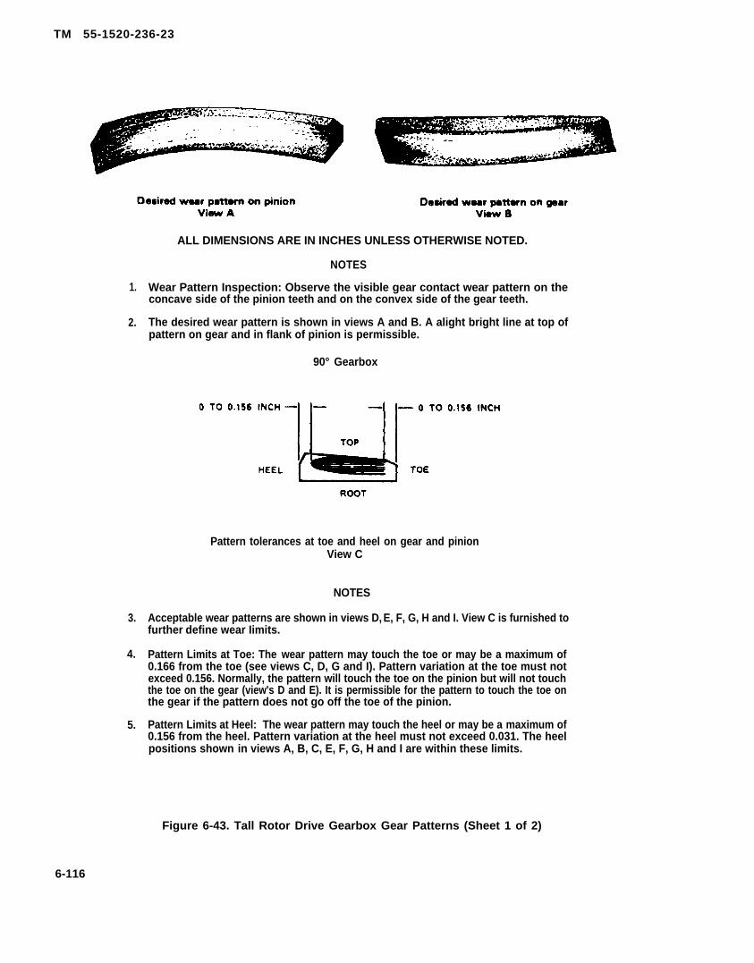
TM 55-1520-236-23
1.
2.
3.
4.
5.
ALL DIMENSIONS ARE IN INCHES UNLESS OTHERWISE NOTED.
NOTES
Wear Pattern Inspection: Observe the visible gear contact wear pattern on theconcave side of the pinion teeth and on the convex side of the gear teeth.
The desired wear pattern is shown in views A and B. A alight bright line at top ofpattern on gear and in flank of pinion is permissible.
90° Gearbox
Pattern tolerances at toe and heel on gear and pinionView C
NOTES
Acceptable wear patterns are shown in views D, E, F, G, H and I. View C is furnished tofurther define wear Iimits.
Pattern Limits at Toe: The wear pattern may touch the toe or may be a maximum of0.166 from the toe (see views C, D, G and I). Pattern variation at the toe must notexceed 0.156. Normally, the pattern will touch the toe on the pinion but will not touchthe toe on the gear (view's D and E). It is permissible for the pattern to touch the toe onthe gear if the pattern does not go off the toe of the pinion.
Pattern Limits at Heel: The wear pattern may touch the heel or may be a maximum of0.156 from the heel. Pattern variation at the heel must not exceed 0.031. The heelpositions shown in views A, B, C, E, F, G, H and I are within these limits.
Figure 6-43. Tall Rotor Drive Gearbox Gear Patterns (Sheet 1 of 2)
6-116

TM 55-1520-236-23
Figure 6-43 Tail Rotor Drive Gearbox Gear Patterns (Sheet 2 of 2)
6-117
TM 55-1520-236-23
(7) Lubricate end assemble outer coupling(1) and inner coupling (9) (paragraph 6-127).
j. Inspect retainer nut (4) for damaged threadsand corrosion.
k. Inspect seal (1, figure 6-39) for protrusion,leakage, cuts, tsars, and deterioration.
1. Inspect area adjacent to shim (16) end area oninput quill (20) adjacent to similar shim for corrosion.If any corrosion is detected send gearbox to higherlevel of maintenance. Do not remove shim (16) orsimilar shim on input quill.
6-127. REPAIR-TAIL ROTOR DRIVE GEARBOX QUILLS.
NOTE
Repair of gearbox input quill isl imi ted to replacement of com-ponents of the flexible coupling, seals(2 and 3, figure 6-40), and packing (19)and packing (21, figure 6-39). Repairof the output quill is limited to re-placement of seal (1).
a Disassemble input quills as follows:
(1) Remove retaining ring (18, figure 6-40),plate (17), spring (16) and spacer (14).
(2) Remove lockspring (15), retainer plug(13), and packing (12).
(3) Place holding plate (T53.1) in a vise.Secure quill in holding plate. Secure wrench (T26) toquill as shown on figure 6-44.
(4) Install square drive extension inretainer bolt (11, figure 6-40), hold wrench, (T26),and loosen retainer bolt. Remove retainer bolt (11)and washer (10).
(5) Remove outer coupling (1), and innercoupling (9). Remove seal (2) from outer coupling.
(6) Cut lockwire on retainer nut (4). Installwrench (T55) as shown in figure 6-45. Removeretainer nut (4, figure 6-40).
(8) Remove spacer assembly (21) from pinionshaft (6). Inspect spacer assembly for wear of the wearsleeve. Wear limit on the wear sleeve on the spacerassembly (21) in the area contacted by seal (3) is 0.002inch or a minimum shaft diameter of 1.430 inches.Check prior to installing a new seal (3). Corrosiondamage up to 0.005 inch deep is acceptable in the areacontacted by the seal if polished out to twice the depthof the corrosion and treated in accordance withgeneral instructions. Lubricating oil must not leakpast the seal after installation. Inspect packing (19)for damage. Replace packing (19) if damage is found.
b. Clean disassembled quill. Refer to paragraph6-125.
c. Polish out raised metal on teeth on outer cou-pling (1, figure 6-40) when the raised metal is causedby dents, nicks, or scratches. Use crocus cloth (C37)to remove the raised metal. Do not rework the internalteeth in the coupling.
d. Assemble input quill as follows:
(1) Install new packing (19) on pinion shaft(6), if necessary, and reinstall spacer assembly (21).Press seal (3) in retainer nut (4) with lip of seal facinginboard. Apply sealant (C105) to outside diameter ofseal (3). Position packing (5) on retainer nut (4). Lubri-cate packing, seal, and threads of nut with the type oilused in the gearbox.
(2) Place holding plate (T53.1) in a vise andsecure quill sleeve in holding plate as-shown in figure6-45.
(3) Install retainer nut (4, figure 6-40) inquill with wrench (T55) as shown in figure 6-45.Torque nut 100 TO 150 fret-pounds. Lockwire (C137)nut to sleeve. Apply a bead of sealer (C104) aroundmating joint of nut and sleeve. Remove wrench (T55).
(4) Use clean lint-free cloths to remove anyfilm of grease or cleaning solvent from outer coupling(1, figure 6-40) and inner coupling (9).
(5) Lubricate new seal (2) with grease (C56)and press into outer coupling (1) with lip of seal facingtoward curvic coupling teeth on coupling. Coat teethof inner coupling (9) with grease (C56) and installinner coupling in outer coupling.
(7) Press seal (3) from retainer nut (4) andremove packing (5).
6-118

TM 55-1520-236-23
(6) Install the couplings on pinion shaft (6). Placewasher (10) on retainer bolt (11) and thread nut into pin-ion shaft (6), Install special tools as shown on figure 6-44.Torque retaining bolt 80 TO 100 foot-pounds.
(7) Position packing (12, figure 6-40) on retainerplug (13) and lubricate with small amount of grease fromcoupling. Install retainer plug and lock spring (15).Ensure that tang of lock spring (15) is fully seated.
(8) Hold outer coupling (1) full outboard. Lubricatesplines of outer coupling (1) with grease (C58) to coversplines to a depth of 0.12 inch.
(9) Install spacer (14), spring (16), plate (17), andretaining ring (16).
6-118.1/(6-118.2 blank)

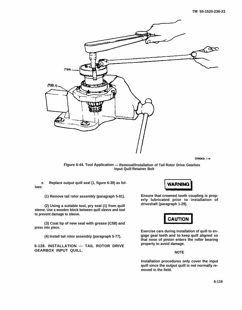
TM 55-1520-236-23
Figure 6-44. Tool Application — Removal/lnstallation of Tail Rotor Drive GearboxInput Quill Retainer Bolt
e. Replace output quill seal (1, figure 6-39) as fol-lows:
(1) Remove tail rotor assembly (paragraph 5-91).
(2) Using a suitable tool, pry seal (1) from quillsleeve. Use a wooden block between quill sleeve and toolto prevent damage to sleeve.
(3) Coat lip of new seal with grease (C58) andpress into piece.
(4) Install tail rotor assembly (paragraph 5-77).
6-128. INSTALLATION — TAIL ROTOR DRIVEGEARBOX INPUT QUILL.
Ensure that crowned tooth coupling is prop-erly lubricated prior to installation ofdriveshaft (paragraph 1-29).
Exercise care during installation of quill to en-gage gear teeth and to keep quill aligned sothat nose of pinion enters the roller bearingproperty to avoid damage.
NOTE
Installation procedures only cover the inputquill since the output quill is not normally re-moved in the field.
6-119

TM 55-1520-236-23
Figure 6-45. Tool Application - Removal/Installation of Tall Rotor Drive GearboxInput Quill Retainer Nut
a. Ensure that shim (16, figure 6-39) and similarshim on input quill are installed.
b. Heat gear case with a heat lamp. Lubricatenew packing (21) and mating surfaces of quill and casewith oil (C79 (C79A) or C80). Install packing on quilland install quill into case. Use care to engage bearingand gear teeth properly. Install shipping spacers (19)and nuts (18). Torque nuts 100 TO 140 inch-pounds tohold input quill in place.
c. Rotate quill by hand and check for free rotationand for a small amount of backlash clearance.
d. Apply a bead of sealant (C105) around matingjoint of quill and case, also fill three jackscrew holes.
6-128.1 INSPECTION – TAIL ROTOR DRIVE-SHAFT COUPLING AND SPHERICAL COUPLING.
NOTE
Couplings must be disassembled fromthe tell rotor drive quill, hangerassembly, 42 degree gearbox or the tallrotor gearbox before proceeding withinspection of the couplings.
a. Inspect coupling teeth for pitting and unusualwear patterns (figure 6-32).
b. Inspect coupling teeth for overheating. Referto paragraph 6-110 if overheating is suspected.
6-120
TM 55-1520-236-23
NOTE
Blackening of splines teeth and greaseoften occurs and is NOT a result ofoverheating. Overheating will beevidenced by heavy spline wear, thepresence of many steel particles in thegrease, and/or very heavy corrosionformation In the splines.
c. Inspect couplings for evidence of corrosion.Superficial corrosion (removable with abrasive pads(C01) is the only corrosion repair allowed).
d. Inspect external splines of spherical couplingfor wear.
(1) Secure spherical coupling (1, figure 6-45.1)in vise or other suitable fixture being careful not todamage the coupling. The seal (2) may remaininstalled on the coupling to aid in alignment of thecoupling during inspection.
(2) Using the driveshaft coupling (3) as aninspection aid, slide the driveshaft coupling onto thespherical coupling and position as shown in figure6-45.2.
(3) Rotate the driveshaft coupling as shown infigure 6-45.2 to take out all of the play between thesplines being careful to keep the couplings in line(avoid cocking the driveshaft coupling).
(4) Insert wire gage (table 1-4, item 107) be-tween the back side of the spherical coupling splinesand the driveshaft coupling splines, approximately halfwas between the root and the top of the splines asshown in figure 6-45.2. Record the size of the largestwire which can be inserted. Repeat this procedure inthree locations, approximately 120 degrees apart.
(5) If the largest wire that can be inserted isgreater than .027 inch, the spherical coupling is wornbeyond limits and must be replaced.
e. Inspect internal splines of driveshaft couplingfor wear.
NOTE
Inspection of the driveshaft couplingrequires the use of a spherical couplingwhich has bean Inspected for wear perparagraph 6-128.1.a. To reduce inspec-tion time, the use of one sphericalcoupling to inspect several driveshaftcouplings is recommended.
f. Retain the spherical coupling (1) in a fixture asdirected in paragraph 6-128.1.d(1).
g. Slide the driveshaft coupling onto the sphericalcoupling so that the splines align in the most severewear area as shown in figure 6-45.2.
h. To determine the appropriate wire size to usefor inspection of the driveshaft coupling, add .005inches to the diameter of the largest wire identified inparagraph 6-128.1.d(5). As an example, if the largestwire diameter was .025 inches, adding .005 incheswould result in .030 inches.
i. Rotate the driveshaft coupling in the drivedirection being careful not to cock the coupling.Attempt to insert the appropriate wire gage (table 1-4,item 107) between the back side of the sphericalcoupling splines and the driveshaft coupling splinesapproximately halfway between the root and the top ofthe splines (figure 54.3). Repeat this procedure atthree locations approximately 120 degrees apart.
j. if the wire can be inserted at any one of thethree locations, the driveshaft coupling is worn beyondlimits and should be replaced.
SECTION VII . TRANSMISSION OIL SYSTEM
6-129. TRANSMISSION OIL SYSTEM. The transmission oil system is entirely separate fromthat of the engine. It includes a pump, an external and
6-130. D E S C R I P T I O N — T R A N S M I S S I O N an internal fitter, a pressure relief valve, an auto-
OIL SYSTEM. matic emergency by-pass valve, an oil cooler with an
6-120.1

TM 55-1520-236-23
Figure 6-45.1 Driveshaft/Spherical Couplings
Figure 6-45.2 Coupling Inspection (Sheet 1 of 2)
6-120.2

TM 55-1520-236-234-23
Figure 6-45.2 Coupling Inspection (Sheet 2 of 2)
6-120.3/(6-120.4 blank)


TM 55-1520-236-23
integral temperature regulating valve, andconnecting lines. See figures 6-46 and 6-47. Oil isdistributed within the transmission by a series ofjets and internal passages. Oil pressure andtemperature indications are provided by athermocouple and a pressure transmitter. Athermo-switch and a pressure switch illuminatecaution panels lettered (pilot) XMSN OIL HOT,(gunner) XMSN OIL TEMP and XMSN OILPRESS and TRANS OIL HOT and TRANSOIL PRESS to warn of abnormal conditions.Servicing and drain provisions are located on theright side of the transmission. Oil level sight gageson the sump case can be viewed through awindow in the right-hand cowl door. Accessthrough this same door is provided to the oil filteron the main case and to the oil filter screen andchip detector on the sump case. A manual valve,located beneath the sump, drains oil overboardthrough an outlet in the bottom of the fuselage.Access to this valve is through the access panelunder the right wing.
a. (See figure 6-46.) In helicopters without MWO1-1520-236-50-30, oil from the transmissionpump flows through the transmission primary fitterand is circulated under pressure to the thermal(bypass) valve and oil cooler. The thermal valveallows oil to bypass the cooler until normaloperating oil temperatures are reached. Return oilfrom the thermal valve and cooler is returned tothe transmission through a 30-micron external oilfilter to the transmission-mounted inlet manifold.
b. (See figure 646.) In helicopters with MWO1-1520-236-50-30, oil from pump flows throughdebris monitor end is circulated under pressure tothermal (bypass) valve and oil cooler. The thermalvalve allows oil to bypass cooler until operatingtemperature is normal. Oil from thermal valve andcooler is returned to transmission mounted inletmanifold through a 3-micron external filter.
c. A manual valve, located beneath the sump,drains oil overboard through an outlet in thebottom of the fuselage. Access to this valve isthrough the access panel under the right wing.
6-131. TROUBLESHOOTING -TRANSMISSION OIL SYSTEM.
Refer to table 6-3 for troubleshooting trans-mission oil system. Observe the following duringsystem troubleshooting.
a. Low oil level will not cause a low oil pressureindication, provided sump contains enough oil to
cover pump inlet. Oil temperature might rise,however.
b. Effects of an oil leak will depend on itslocation in system and rate of leakage. An externalleak can eventually allow sump to be pumped dry,causing internal failure of transmission. While oilremains to supply the pump, the pressure reliefvalve will tend to maintain normal systempressure, compensating for leakage. This appliesespecially to leaks located between the pump andthe relief valve. Leaks occurring beyond the reliefvalve could cause indication of low oil pressure.Leakage to interior of transmission; while notaffecting oil level, could starve lubrication areasbeyond the leak and might affect indicated oilpressure and temperature. Leakage in the oilcooler circuit, unless very minor, causes the oilcooler automatic emergency bypass valve to shiftand direct oil directly to the transmission manifoldinstead of directing it through the oil cooler. Leaksin the oil cooler and connecting lines may causeabove normal oil temperatures.
c. Cumulative clogging of oil fitter screens willnot be shown by a gradual drop of indicated oilpressure. Pressure relief valve will maintainnormal system pressure even if filter screensbecome so dogged as to force oil flow throughfitter bypass valve.
d. “Use of wrong oil’ is omitted fromtroubleshooting chart because such a case wouldrequire special investigation as to damage andcorrective action. As to detecting such a condition,Iittle can be said except that most oils which mightbe available to use by error would tend to causehigh oil pressure and high oil temperatureindications, or excessive seal leakage.
e. When troubleshooting transmission casehalves, external or internal fluid loss isundesirable; however, the design of sealingmechanisms will not always ensure that a joint willbe completely free of fluid loss. The terminologyfor leakage is defined as follows:
(1) Weep. Slight loss of fluid beyond a sealingmechanism which causes staining or discolorationof painted surfaces, usually dry to the touch.
(2) Seep. Slight loss of fluid beyond the sealingmechanism which does not form droplets but ismoist to the touch.
NOTEFluid loss from a joint defined asweep or seep is acceptable althoughefforts shall be taken to keep the fluidloss to a minimum.
6-121

TM 55-1520-236-23
(3) Leak. Loss of fluid beyond a sealingmechanism which form a droplets.
(4) Drip. Loss of fluid beyond a sealingmechanism which forms drops that roll or drop awayfrom the point of leakage.
NOTE
must definitely be established byobserving the componentsuspected of leakage, after priorresidue of leakage evidence hasbean removed. If leaks or drips ap-ply to your transmission, removeitem from service and return todepot through normal supplychannels for overhaul.
Leaks and drips are not acceptableand the source of the fluid loss
Table 6-3. Troubleshooting - Transmission Oil System
CONDITION
TEST OR INSPECTION
CORRECTIVE ACTION
NOTE
Before you use this table, be sure you have performed all normal operational checks. If you have amalfunction which is not listed in this table, notify the next higher maintenance level.
1. Low oil pressure on caution panel or pressure gauge, but not on both.
STEP 1. Check for faulty caution panel (paragraph 9-276).
Replace faulty caution panel. Return faulty panel to next higher maintenance level.
STEP 2. Check for faulty pressure gauge (paragraph 8-233 and 8-234).
Replace faulty pressure gage (paragraphs 8-235 and 8-237).
STEP 3. Check electrical circuit for faulty wiring (paragraph 9-11).
Repair faulty electrical wiring (paragraph 9-12).
2. Low oil pressure on both caution panel and pressure gage.
STEP 1. Check pressure relief valve for adjustment or malfunction (paragraph 6-184.c).
Repair pressure relief valve (paragraph 6-184.c).
Replace pressure relief valve (paragraph 6-184.c).
STEP 2. Check for leakage and for restriction between pressure relief valve and transmitter.
Repair oil line or clean oil line to remove restriction as required.
STEP 3. Check for faulty oil pump (paragraph 6-135).
Replace faulty oil pump (paragraph 6-140).
6-122

TM 55-1520-236-23
Table 6-3. Troubleshooting - Transmission Oil System (Cont)
CONDITION
TEST OR INSPECTION
CORRECTIVE ACTION
3. No oil pressure with normal oil level in sump.
STEP 1. Check for faulty gage or transducer (paragraphs 8-243, 8-244, 8-251, and 8-252).
Replace faulty gage or transducer (paragraphs 8-245, 8-247, 8-253, and 8-255).
STEP 2. Check electrical circuits for faulty wiring (paragraph 9-11).
Repair faulty electrical wiring (paragraph 9-12).
STEP 3. Check for faulty oil pump (paragraph 6-135).
Replace transmission or replace oil pump only if not damaged internally and oil system notcontaminated with metal particles.
4. No oil pressure - check reveals no oil supply in transmission sump.
STEP 1. Check system to determine cause of oil loss.
Replace transmission and oil cooler (paragraphs 6-33 and 6-146).
Flush oil lines and repair as needed.
6-122.1/(6-122.2 blank)

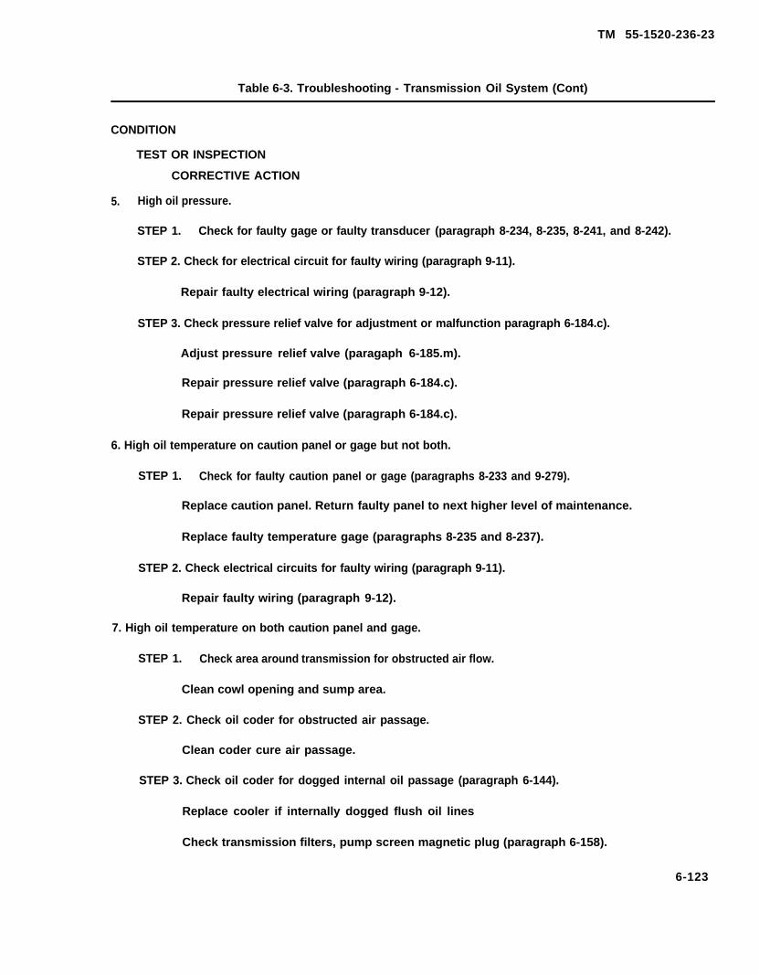
TM 55-1520-236-23
Table 6-3. Troubleshooting - Transmission Oil System (Cont)
CONDITION
TEST OR INSPECTION
CORRECTIVE ACTION
5. High oil pressure.
STEP 1. Check for faulty gage or faulty transducer (paragraph 8-234, 8-235, 8-241, and 8-242).
STEP 2. Check for electrical circuit for faulty wiring (paragraph 9-11).
Repair faulty electrical wiring (paragraph 9-12).
STEP 3. Check pressure relief valve for adjustment or malfunction paragraph 6-184.c).
Adjust pressure relief valve (paragaph 6-185.m).
Repair pressure relief valve (paragraph 6-184.c).
Repair pressure relief valve (paragraph 6-184.c).
6. High oil temperature on caution panel or gage but not both.
STEP 1. Check for faulty caution panel or gage (paragraphs 8-233 and 9-279).
Replace caution panel. Return faulty panel to next higher level of maintenance.
Replace faulty temperature gage (paragraphs 8-235 and 8-237).
STEP 2. Check electrical circuits for faulty wiring (paragraph 9-11).
Repair faulty wiring (paragraph 9-12).
7. High oil temperature on both caution panel and gage.
STEP 1. Check area around transmission for obstructed air flow.
Clean cowl opening and sump area.
STEP 2. Check oil coder for obstructed air passage.
Clean coder cure air passage.
STEP 3. Check oil coder for dogged internal oil passage (paragraph 6-144).
Replace cooler if internally dogged flush oil lines
Check transmission filters, pump screen magnetic plug (paragraph 6-158).
6-123
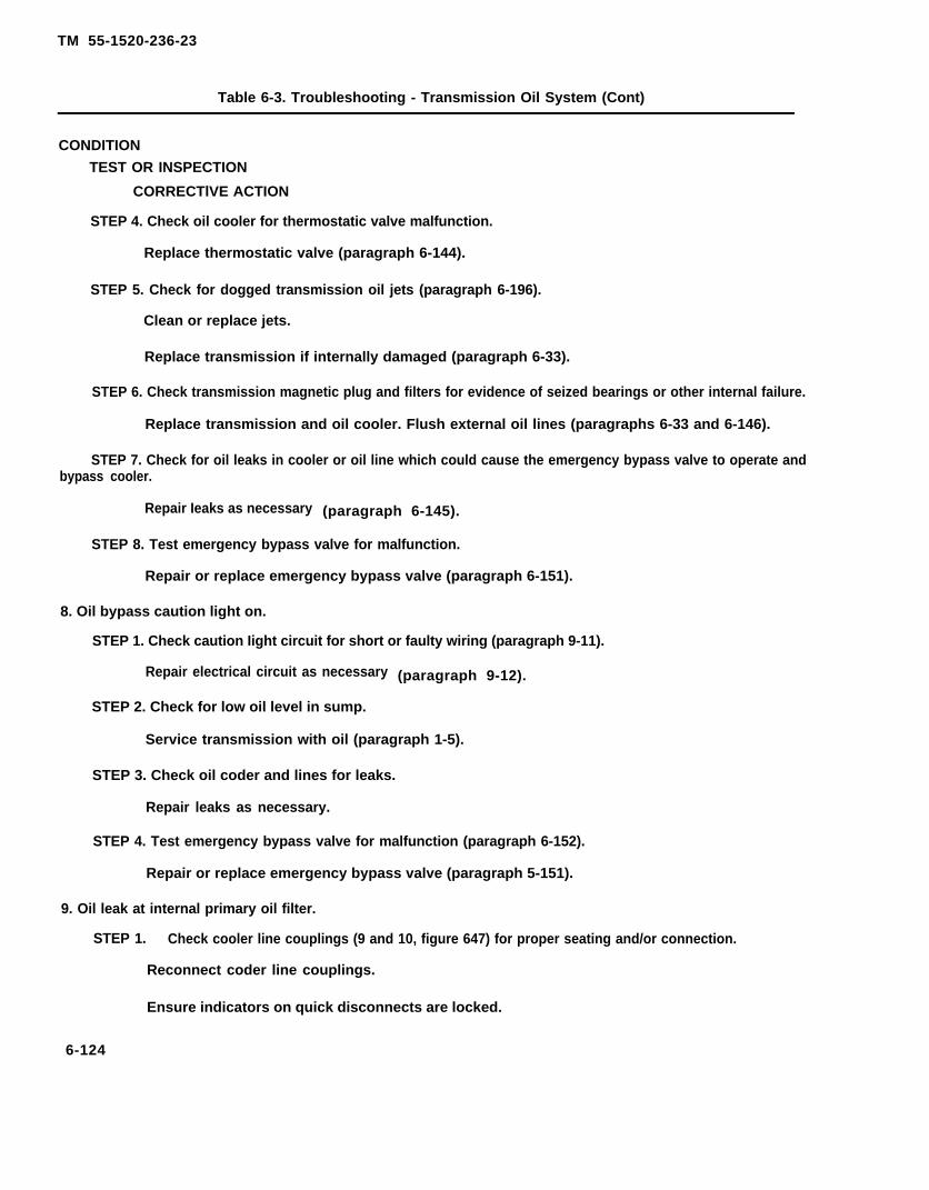
TM 55-1520-236-23
Table 6-3. Troubleshooting - Transmission Oil System (Cont)
CONDITION
TEST OR INSPECTION
CORRECTlVE ACTION
STEP 4. Check oil cooler for thermostatic valve malfunction.
Replace thermostatic valve (paragraph 6-144).
STEP 5. Check for dogged transmission oil jets (paragraph 6-196).
Clean or replace jets.
Replace transmission if internally damaged (paragraph 6-33).
STEP 6. Check transmission magnetic plug and filters for evidence of seized bearings or other internal failure.
Replace transmission and oil cooler. Flush external oil lines (paragraphs 6-33 and 6-146).
STEP 7. Check for oil leaks in cooler or oil line which could cause the emergency bypass valve to operate andbypass cooler.
Repair Ieaks as necessary (paragraph 6-145).
STEP 8. Test emergency bypass valve for malfunction.
Repair or replace emergency bypass valve (paragraph 6-151).
8. Oil bypass caution light on.
STEP 1. Check caution Iight circuit for short or faulty wiring (paragraph 9-11).
Repair electrical circuit as necessary (paragraph 9-12).
STEP 2. Check for low oil level in sump.
Service transmission with oil (paragraph 1-5).
STEP 3. Check oil coder and lines for leaks.
Repair leaks as necessary.
STEP 4. Test emergency bypass valve for malfunction (paragraph 6-152).
Repair or replace emergency bypass valve (paragraph 5-151).
9. Oil leak at internal primary oil filter.
STEP 1. Check cooler line couplings (9 and 10, figure 647) for proper seating and/or connection.
Reconnect coder line couplings.
Ensure indicators on quick disconnects are locked.
6-124

TM 55-1520-236-23
Table 6-3. Troubleshooting - Transmission Oil System (Cont)
CONDITION
TEST OR INSPECTION
CORRECTIVE ACTION
STEP 2. Check disconnects for wear and damage.
Replace defective cooler line couplings.
Replace packing (19, figure 6-47).
6 - 1 3 2 . O I L P U M P .
6-133. DESCRIPTION - OIL PUMP.
The oil pump is mounted into the underside of thetransmission sump case and is driven by a splinedshaft from the accessory and tail rotor drive gear.
6-134. REMOVAL - OIL PUMP.
a. Open access panel under wing on right side ofhelicopter.
b. Place a container under oil drain outlet beneathfuselage. Open valve beneath sump and drain oil.
c. Disconnect drain tubes from valve and tee. Providea container to collect trapped oil as pump is removed.
d. Remove pump retaining nuts and drain tee bracketfrom three mounting studs.
Tapped hole m pump body base isfor attaching puller only. Do notattempt to use for a jackscrew.
e. Pull pump from sump. When necessary, usethreaded puller in 1/4 UNF tapped hole in base atcenter of pump body.
Cleaning solvent is flammable andtoxic. Provide adequate ventilation.Avoid prolonged breathing ofsolvent vapors and contact withskin or eyes.
f. Wash assembled pump in solvent (C112) prior todisassembly. Drain thoroughly and dry with filteredcompressed air.
6-135. INSPECTION - OIL PUMP.
a. Inspect assembled pump as follows:
(1) Rotate pump shaft and check for binding.
(2) Visually inspect pump for evidence of wear ordamage.
(3) If evidence of binding, wear, or damage isfound, do not disassemble pump but forward to nexthigher level of maintenance.
NOTE
The following inspection for wear pertains to adisassembled pump.
6-125
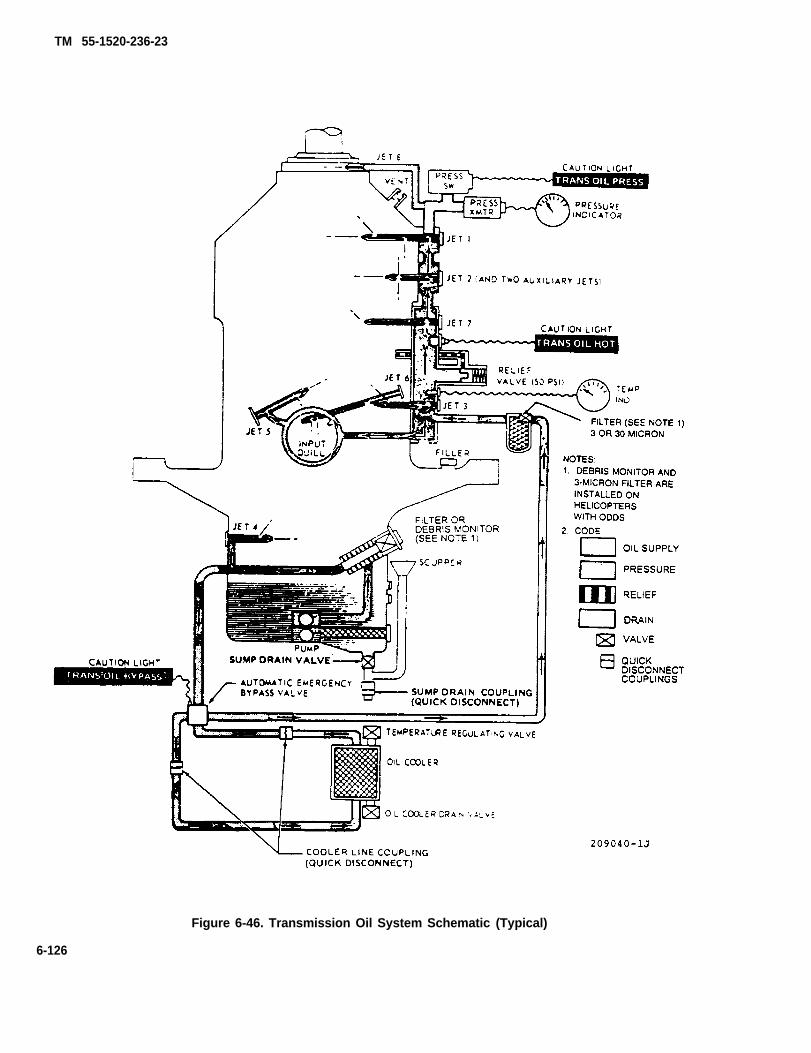
TM 55-1520-236-23
Figure 6-46. Transmission Oil System Schematic (Typical)
6-126
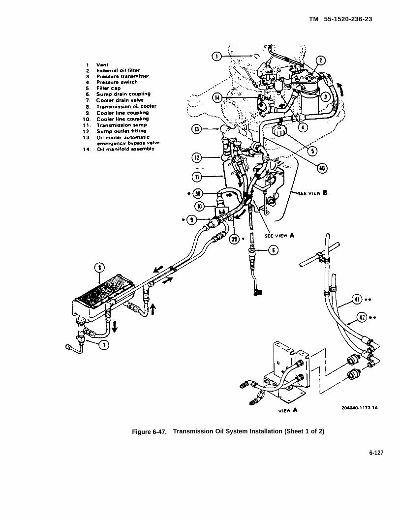
TM 55-1520-236-23
Figure 6-47. Transmission Oil System Installation (Sheet 1 of 2)
6-127
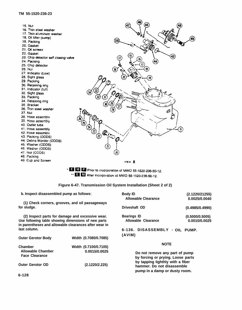
TM 55-1520-236-23
Figure 6-47. Transmission Oil System Installation (Sheet 2 of 2)
b. Inspect disassembled pump as follows: Body IDAllowable Clearance
(1) Check corners, grooves, and oil passagewaysfor sludge. Driveshaft OD
(2) Inspect parts for damage and excessive wear. Bearings IDUse following table showing dimensions of new parts Allowable Clearancein parentheses and allowable clearances after wear inlast column. 6-136. DISASSEMBLY -
(2.1220/21255)0.0025/0.0040
(0.4985/0.4990)
(0.5000/0.5005)0.0010/0.0025
OIL PUMP.
Outer Gerotor Body Width (0.7080/0.7085)(AVIM)
Chamber Width (0.7100/0.7105)Allowable Chamber 0.0015/0.0025Face Clearance
Outer Gerotor OD (2.1220/2.225)
NOTE
Do not remove any part of pumpby forcing or prying. Loose partsby tapping Iighthly with a fiberhammer. Do not disassemblepump in a damp or dusty room.
6-128

TM 55-1520-236-23
a. Remove retainer ring (1, figure 6-48) from body(10).
b. Remove retainer plate (2). Do not remove bear-ing from plate.
Inner and outer gerotors area matched eat. Donot intermix.
Remove retaining ring (3), inner gerotor (5), outergerotor (4), and woodruff key (6) from shaft (7).
d. Remove retaining ring (8).
e. Do not remove bearing from body (10).
Cleaning solvent is flammable and toxic. Pro-vide adequate ventilation. Avoid prolongedbreathing of solvent vapors and contact withskin or eyes.
(1) Wash all metal parts with solvent (Ch 2) anddry with dean, filtered, compressed air.
(2) Clean corners, grooves, and threads with ashort-bristled brush such as a toothbrush.
6-137. REPAIR — OIL PUMP (AVIM).
Repair is limited to inspection of pump for wear ordamage and testing pump output in accordance withparagraph 6-139. If wear limits, defined in paragraph
f. Clean disassembled pump as follows:
Figure 6-48. Transmission Oil Pump
6-129
TM 55-1520-236-23
6-135. are exceeded or if pump fails to meet test require-ments, forward pump to depot maintenance.
6-138. ASSEMBLY-OIL PUMP (AVIM)
a Lubricate parts with oil (C79 (C79A) or C80) forease in assembly.
b. Install retaining ring (8, figure 6-48) on shaft (7)inboard groove.
c. Insert woodruff key (6) in shaft (7) and install innergerotor (5) so that keyway engages key. Install retainingring (3) on outboard end of shaft.
d. Install shaft (7) in body (10). Install outer gerotor (4)over inner gerotor (5).
e. Install retainer plate (2) in body (10). Make surelocating pin is properly seated. Install retainer ring (1) inbody (10) with beveled side of ring facing up. Make surering is firmly seated in body groove.
f. Check that shaft (7) will rotate without binding.
6-139. TEST PROCEDURES-OIL PUMP (AVIM).
a. Use lubricating oil (C79 (C79A) or C80). Oil mustbe clean and free from foreign matter.
b. Oil must be 110 TO 130 degrees F (43 TO 54degrees C) for duration of rest.
c. Check pump shaft rotation in both directions. Shaftmust rotate freely; replace the pump if any binding isnoted.
d. Place pressure and vacuum gages as close to thepump as possible. See figure 6-49. Use piping that willcause no appreciable pressure changes between the gagesand the pumps. Use gages which are accurate within 0.5percent full scale.
Be sure shutoff valves are open beforestarting pump.
e. Make flow measurements with a meter that is accu-rate within plus or minus 1.0 percent
within plus or minus 1.0 percent or 20 RPM, whichever isgreater.
g. Observe the following:
(1) Operate pump at 3575 RPM.
(2) Oil temperature of 110 TO 130 degrees F (43TO 54 degrees C).
(3) Inlet pressure Of 24 TO 30 inches of mercury.
(4) Discharge pressure shall be 50 psig.
h. Minimum pump flow shall be 10.5 gpm.
6-140. INSTALLATION-OIL PUMP.
a. Install new packings (9, figure 6-48) in two groovesaround pump housing. Lubricate packing with transmis-sion oil.
b. Insert pump into mounting port, while main rotor isslowly rotated until pump shaft is positively engaged tosplined driveshaft in transmission sump. Install washersand nuts on studs, with drain tee bracket on forward stud.Torque nuts 50 TO 70 inch-pounds.
c. Apply a bead of sealant (C 105) around mating jointof oil pump and transmission.
d Connect drain line tubes to valve and tee.
e. Fill sump with oil (C79 (C79A) or C80) to normallevel on sight gages. Close access openings and cowling.
6-141. OIL COOLER
6-142. DESCRIPTION-OIL COOLER.
A radiator type oil cooler (1, figure 6-50) with aninternal temperature and bypass control valve isconnected into the transmission oil pressure externallines. The cooler is mounted beside the engine oilsystem cooler, under an opening in the engine
f. Measure pump speed with a tachometer directly cou-pled to the pump shaft. The tachometer must be accurate
6-130

TM 55-1520-236-23
Figure 6-49. Transmission OilPump-Test Setup
compartment deck. The two coolers are boltedtogether and share the same cooling air flow, buthave no oil circulation between them. ‘The inlet fit-ting is equipped with a manual drain valve andoverboard drain line.
6-143. REMOVAL-OIL COOLER
CAUTION
Use back-up wrenches when remov-ing and installing oil cooler drain fit-tings, valves, and lines.
a. Remove oil cooler duct on left side of fuselagebelow engine combustion section.
b, Drain oil from both coolers (paragraph 4-78).
c. Remove bleed air-driven turbine and fan duct(paragraph 4-78).
d. Disconnect engine oil cooler hoses (paragraph4-78), hoses (2 and 17, figure 6-50), and drain tube(18). Cover open fittings and hose ends.
f. separate engine oil cooler (paragraph 4-78) fromtransmission oil cooler by removing bolts (11),washers (6) and nuts (5).
g. If cooler is being replaced, remove fittings foruse on replacement assembly.
(1) Loosen nut (16) and remove elbow (14)with packings (16 and 13) and union (12). Remove nut(16).
(2) Remove nuts (10) and washers (9); thenremove adapter (8), gasket (7).
(3) Loosen nut (20); then remove packing(21) drain valve and tee assembly (19). Remove nut(20).
(4) Remove nuts (22) and washers (23); thenremove adapter (25) and gasket (24).
6-144. INSPECTION-OIL COOLER
a. Inspect fittings for damage.
b. Inspect cooler core and body for evidence ofleakage.
c. Inspect cooler core for clogged air passages andcleanliness.
d. Inspect temperature regulating valve (26, Fig-ure 6-50) and valve housing for stripped threads anddistortion, scoring, or wear of the seal surfaces. Checkfunctioning of bypass control valve as follows:
(1) Submerge valve in water heated to 150 to155 degrees F (66 to 68 degrees C) for five minutes.Valve should open.
(2) Remove valve ii-em water and measurelength and record.
(3) Submerge valve in water heated to 176to 180 degrees F (80 to 82 degrees C) for five minutes.Valve should open.
(4) Remove valve from water and measurelength. Minimum acceptable increase in valve lengthfrom dimension recorded in step (2) is 0.090 inch.
(5) If valve fails check, replace valve.
e. Remove bolts (4) and washers (3). Lower coolerassembly (1) out of compartment.
6-131

TM 55-1520-236-23
Figure 6-50. Transmission Oil Cooler Installation
6-132

TM 55-1520-236-23
6-144.1. CLEANING-OIL COOLER (AVIM).
CAUTION
When using steam and compressedair, be careful not to damage air finsby high pressures.
a. Steam clean the exterior surfaces and cor-rugated sir fins of each core. Remove obstructionsfrom air fins with a pick and compressed air.
b. Prepare oil cooler for internal cleaning as fol-lows:
(1) Remove lockwire end unscrew oil coolerbypass valve body (26, figure 6-50) from valve hous-ing in cooler.
(2) Press a rubber plug into the bypassopening in the valve housing.
(3) Reinstall temperature regulating valve(26) into valve housing so valve body bears upagainst the rubber plug.
c. Connect oil cooler in line with cleaning equip-ment in reverse of normal flow for first flush (figure6-50.1).
NOTE
Centrifugal pump in cleaning equip-ment must be capable of supplyingfluid at approximately 40 gpm whilemaintaining pressure of 76 psi.
d. To remove oil end loose sludge and to reducecontamination of cleaning solutions during followingoperations, pre-clean cooler interior as follows:
WARNING
Cleaning solvent is flammable andtoxic. Provide adequate ventilation.Avoid prolonged breathing of solventvapors and contact with skin or eyes.
(1) Flush core in reverse direction, withsolvent (C 112) for 30 minutes or until solvent ap-pears clean.
(2) Reverse lines to cooler and flush core indirection of normal flow for approximately 15minutes.
(3) Remove oil cooler from cleaning equip-ment and drain all fluid from cooler.
e. Remove dirt, carbon deposits, oil gum, leaddeposits, and other contaminants by connecting oilcooler to cleaning equipment (figure 422). Use clean-ing compound (C35).
(1) Flush core 30 TO 60 minutes in directionopposite to normal flow.
(2) Reverse lines and flush core in normaldirection for 15 minutes.
(9) Remove plug installed in bypass openingof valve housing and insert plug in cooling sectionopening. Reinstall temperature regulating valve (26,figure 6-50).
(4) Flush oil cooler in normal direction for 15minutes to clean bypass passage.
(6) Remove plug from cooling section open-ing in valve housing and install into bypass opening.Reinstall temperature regulating valve (26, figure6-50).
WARNING
Cleaning solvent is f lammable andtoxic. Provide adequate ventilation.Avoid prolonged breathing of solventvapors and contact with skin or eyes.
f. Connect oil cooler to cleaning equipment con-taining cleaning compound (C35). Install 100-meshscreen at inlet and outlet ports of oil cooler.
(1)tion.
f lush . ‘2 )
(3)
Flush core for 10 minutes in each direc-
Check 100-mesh screens between each
If screens are not clear, reflush core for 5minutes in each direction, repeat until screens areclear.
g. Remove rubber plug from bypass valve housingin oil cooler.
6-145. REPAIR-OIL COOLER
6-132.1

TM 55-1520-236-23
Figure 6-50.1. Oil Cooler Cleaning Schematic
6-132.2

TM 55-1520-236-23
WARNINGa. If cooler core shows evidence of external clog-
Cleaning solvent is flammable and ging, clean core using solvent (C112) and compressedtoxic. Provide adequate ventilation. air.Avoid prolonged breathing of solventvapors and contact with skin or eyes. b. If cooling fins on core are bent enough to disrupt
air flow, straighten using flat nose pliers. Use care toIf transmission internal failure has prevent damage to cooler core.o c c u r r e d , r e p l a c e c o o l e r a n dthoroughly flush all connecting linesand fittings with solvent (C112). Drywith filtered compressed air.
6-132.3/(6-132.4 blank)

TM 55-1520-236-23
c. Replace cooler if damaged or leaking.
d. Replace damaged fittings.
6-146. INSTALLATION — OIL COOLER.
If replacing cooler, install fittings from removedcooler assembly (1, figure 6-50).
(1) Install adapter (25) and gasket (24), using nuts(22) and washers (23).
(2) Install nut (20); then install packing (21) andvalve and tee assembly (19). Tighten nut (20).
(3) Install adapter (8) and gasket (7), using nuts(10) and washers (9).
(4) install nut (16); then install packings (15 and13), elbow (14), and union (12). Tighten nut (1 6).
b. Connect engine and transmission oil coolers,using bolts (11), washers (6) and nuts (5).
c. Place coolers in position in helicopter and secure,using bolts (4) and washers (3). Hold coolers in place withsuitable clamps while installing bolts.
d. Install turbine fan and duct (paragraph 4-91).
Check proper fit of flared ends of tubing tovalves and fittings. Do not allow preloading orstresses due to misalignment or improper fit.
e. Connect hoses (17 and 2) and flared drain line(18) to transmission oil cooler and hoses to engine oilcooler (paragraph 4-82).
f. Install oil cooling duct on left side of fuselage com-partment.
g. During first run-up after installing cooler, carefullyobserve transmission and engine instruments. Check oilcooler installation for leaks. After a brief period of running,add oil (C79 (C79A) or 80) to transmission and engine oiltank, as oil level will have lowered by the filling of emptylines and cooler.
6-147. AUTOMATIC EMERGENCY BYPASSVALVE.
6-148. DESCRIPTION — AUTOMATICEMERGENCY BYPASS VALVE.
The bypass valve (13, figure 6-47) is located on the aft sideof the transmission below the power input quill. The valveprotects the transmission against total loss of oil if a leakoccurs in the oil cooler and its connecting lines, by isolatingthe cooler circuit from the oil system proper. It consists of abody enclosing nozzles, piston assemblies, a compensat-ing spring, and a warning switch. Passageways within thevalve provide for normal and bypass flow of transmissionoil. The warning switch illuminates a light on the pilot cau-tion panel when the valve shifts into the by-pass position
6-149. REMOVAL — AUTOMATIC EMER-GENCY BYPASS VALVE.
a. Disconnect electrical lead from terminal at rightlower side of valve (13, figure 6-47).
When disconnecting hose from right end ofvalve, do not allow nut on fitting to turn whileloosening flare nut of hose elbow. Any turningof valve fitting nut will destroy calibration ofvalve.
b. Disconnect outlet tube (12) and three oil hoses(38, 39, 40) or (40, 41, 42) from fittings on valve. Cap fit-tings and open ends of tube and hoses.
NOTE
In step c. and d. two electrical cable bracketswill be detached but remain on wiring.
c. Remove two nuts which secure bottom of valvemounting bracket on transmission case studs.
d. Remove two bolts to detach top valve bracketfrom upper bracket, which remains attached on input drivequill studs.
e. Remove valve and bracket assembly.
f. Detach valve from bracket by removing lockwire,four bolts, and washers.
6-133
TM 55-1520-236-23
6-150. INSPECTION — AUTOMATICEMERGENCY BYPASS VALVE.
a. Inspect valve and fitting for leakage.
b. Inspect fittings and valve mounting holes for dam-aged threads.
6-151. REPAIR — AUTOMATIC EMERGENCYBYPASS VALVE. (AVIM)
Premaintenance Requirements for Repair ofAutomatic Emergency Bypass Valve
Conditions Requirements
Model
Part No. or Serial No.
Special Tools
Test Equipment
Support Equipment
Minimum PersonnelRequired
Consumable Materials
Special EnvironmentalConditions
AH-IS
All
(T49) (T50) (T51) (T52)
Test Stand
None
Two
(C74) (C78) (C79) (C79A) (C80)(C88)(C91) (C102) (C105)(C112) (C116) (C137)
Dust Free
a. Disassemble valve as follows:
Cleaning solvent is flammable and toxic. Pro-vide adequate ventilation. Avoid prolongedbreathing of solvent vapors and contact withskin or eyes.
(1) Soak “return end” of cooler bypass valve as-sembly (figure 6-51) in MEK (C74) for one hour, then re-move sealant.
NOTE
Be careful not to damage valve componentswhile removing sealant.
(2) Clamp fixture (T49) in vise, with drilled surfacein horizontal position. Attach oil cooler valve assembly tothe tool with four bolts (AN4-5A) or equivalent.
(3) Cut and remove lockwire from fitting (28, figure8-51), nut and switch (11).
(4) Remove union (3) and packing (14).
(5) Loosen checknut on elbow fitting (1). Loosenadapter (13) and remove fitting.
(6) Remove switch (11) and packing (12).
(7) Remove bolt (32) and elbow (30).
Use extreme care in disassembly of remainingvalve parts to avoid nicking or scratching.Package each part individually to avoid dam-age while handling.
(8) Remove fitting (28).
NOTE
Nozzle (21) will come out with the fitting; there-fore, hold threaded end of fitting upward afterremoval to prevent dropping nozzle.
(9) Remove nozzle (21) from fitting (28),
(10) Insert end of finger into open end of valve as-sembly and gently remove sleeve (19) and piston (20) fromvalve housing.
(11) Remove piston (20) from sleeve (19), beingvery careful not to bend or scratch the piston stem.
(12) Remove and discard washer (18) fromsleeve (19).
(13) Loosen nut (4) and remove nut and key (5)from fitting (6). Remove fitting (6) and nozzle (8) from
6-134
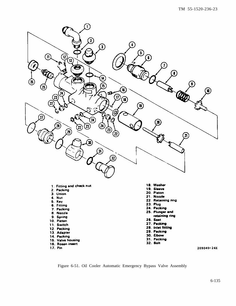
TM 55-1520-236-23
Figure 6-51. Oil Cooler Automatic Emergency Bypass Valve Assembly
6-135

TM 55-1520-236-23
valve housing (15). Be careful not to drop nozzle whenremoving fitting because nozzle comes out with thefitting.
(14) Remove nozzle (8) from fitting (6).
(15) Remove spring (9) from valve housing (l5).
(16) Remove piston (10) from valve housing(15) as follows:
(a) Insert finger into end of valve housing (15)from which fitting (6) was removed. Push piston (20)seat (26), and plunger (25) as far as possible towardopposite end of housing.
(b) Remove three. retaining rings (22). Pullthree plugs (23) and packings (24) from valve housing(15) with puller (T51).
(c) Insert tool (T50) into transfeed port andseparate plunger (25) and piston (20).
(d) Remove piston (20) from valve housing(1 5).
NOTE
Plunger (25) and housing (16) are matchfitted and are either discarded or reusedas a unit.
(17) Remove temporary cloth plug from end ofvalve housing (15) and remove plunger by insertingfinger into open end of plunger (25) and slowly pullingplunger from valve housing.
(18) Remove and discard all packings fromvalve components.
b. Clean disassembled bypass valve as follows:
Cleaning solvent is flammable and toxic.Provide adequate ventilation. Avoidprolonged breathing of solvent vaporsand contact with skin or eyes.
(1) Clean detail parts (6, 8,21, figure 6-51) individually with
6-136
9, 10, 19, 20, andsolvent (C112).
Wash and clean each of the below itemscarefully and individually to preventnicking, scratching, or other damage tothe parts.
(2) Plug all ports and holes in oil cooler bypasshousing (15) to prevent entrance of any liquid intointernal areas of valve housing.
(3) Remove paint from exterior portion of oilcooler bypass housing (15) by use of MEK (C74)andasuitable brush.
(4) Dry detail parts of oil cooler bypass valveassembly by use of low pressure, filtered air, or byplacing parts on dry clean cloth in such manner thatno part will contact any other part of the assembly.
c. Inspect parts of disassembled bypass valve asfollows:
(1) Inspect all threaded parts of oil coolerbypass valve for torn, crossed, or otherwise damagedthreads.
(2) Inspect all metal detail parts of oil coolerbypass valve assembly for nicks, scratches, surfacefinishes, and all other limits as shown and designatedin figure 6-52 through 6-61.
(3) Inspect Rosan inserts (16, figure 6-51) forsecure installation and for damaged threads.
NOTE
Housing assembly and plunger (15 and25. figure 6-51) are mated parts and areused or discarded as a unit.
d. Repair parts of bypass valve as follows:
(1) Do not repair the following parts (1, 3, 4, 5,9, 10, 11, 13, 17, 18, 19, 20, 22, 23, 26, and 30, figure6-51). Do not rework nicks or scratches withintolerance as indicated in figure 6-52 through 6-60.Replace any of the parts listed above that havedamage in excess of limits shown on illustrations.
(2) Replace fittings (6 or 28, figure 6-51) ifthreads are damaged.
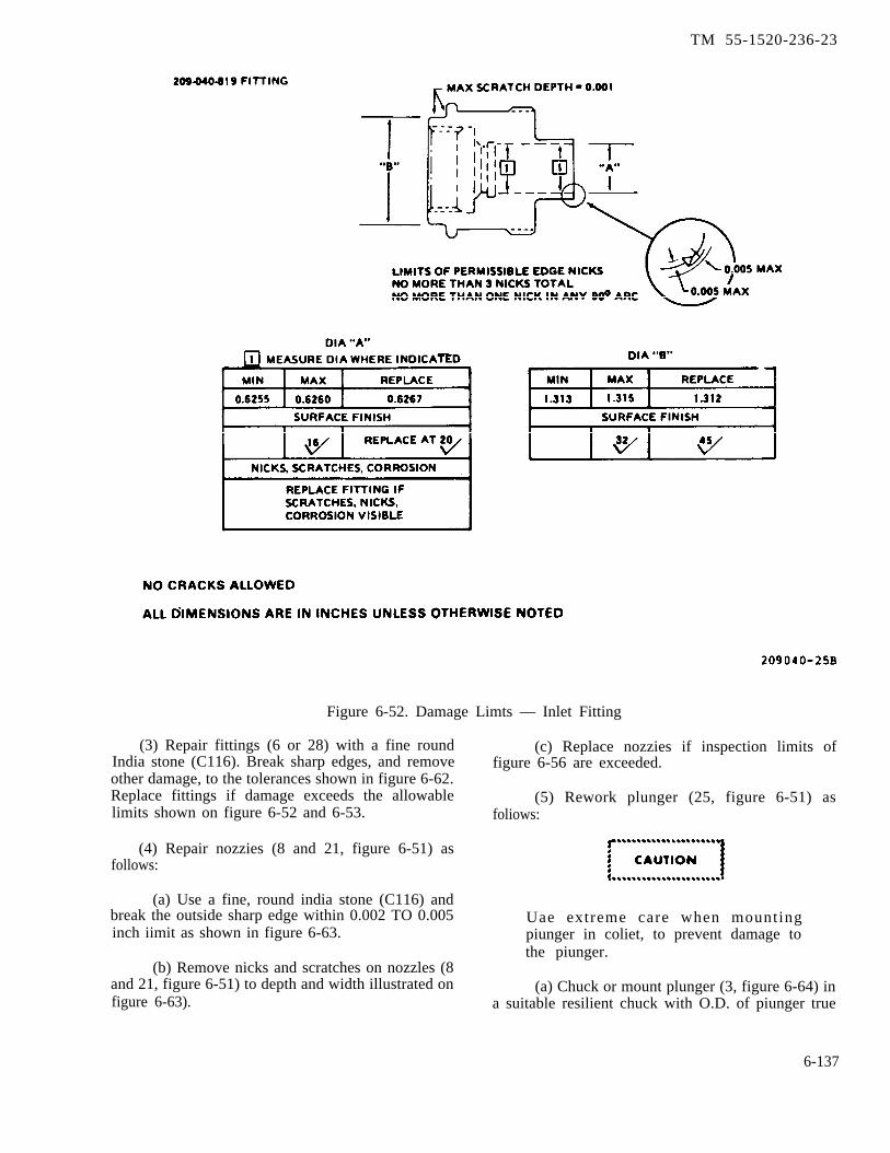
TM 55-1520-236-23
Figure 6-52. Damage Limts — Inlet Fitting
(3) Repair fittings (6 or 28) with a fine round (c) Replace nozzies if inspection limits ofIndia stone (C116). Break sharp edges, and remove figure 6-56 are exceeded.other damage, to the tolerances shown in figure 6-62.Replace fittings if damage exceeds the allowable (5) Rework plunger (25, figure 6-51) aslimits shown on figure 6-52 and 6-53. foliows:
(4) Repair nozzies (8 and 21, figure 6-51) asfollows:
(a) Use a fine, round india stone (C116) andbreak the outside sharp edge within 0.002 TO 0.005 Uae extreme care when mountinginch iimit as shown in figure 6-63. piunger in coliet, to prevent damage to
the piunger.(b) Remove nicks and scratches on nozzles (8
and 21, figure 6-51) to depth and width illustrated on (a) Chuck or mount plunger (3, figure 6-64) infigure 6-63). a suitable resilient chuck with O.D. of piunger true
6-137

TM 55-1520-236-23
Figure 6-53. Damage Limits — Return Bypass Fitting
within 0.0005 inch. Machine retention ring (1) to0.648 TO 0.650 inch diameter for width of 0.166TO 0.278 inch.
(b) Split and remove the remainder ofretention ring (1) from plunger with suitable sharppointed tool; use care not to nick or scratch theplunger.
(c) Remove and discard packing (2).
Cleaning solvent is flammable and toxic.Provide adequate ventilation. Avoidprolonged breathing of solvent vaporsand contact with skin or eyes.
(d) Clean plunger (3) with solvent (C112) andcoat with oil (C79).
6-138

TM 55-1520-236-23
Figure 6-54. Damage Limits — Inlet Bypass Piston
6-139
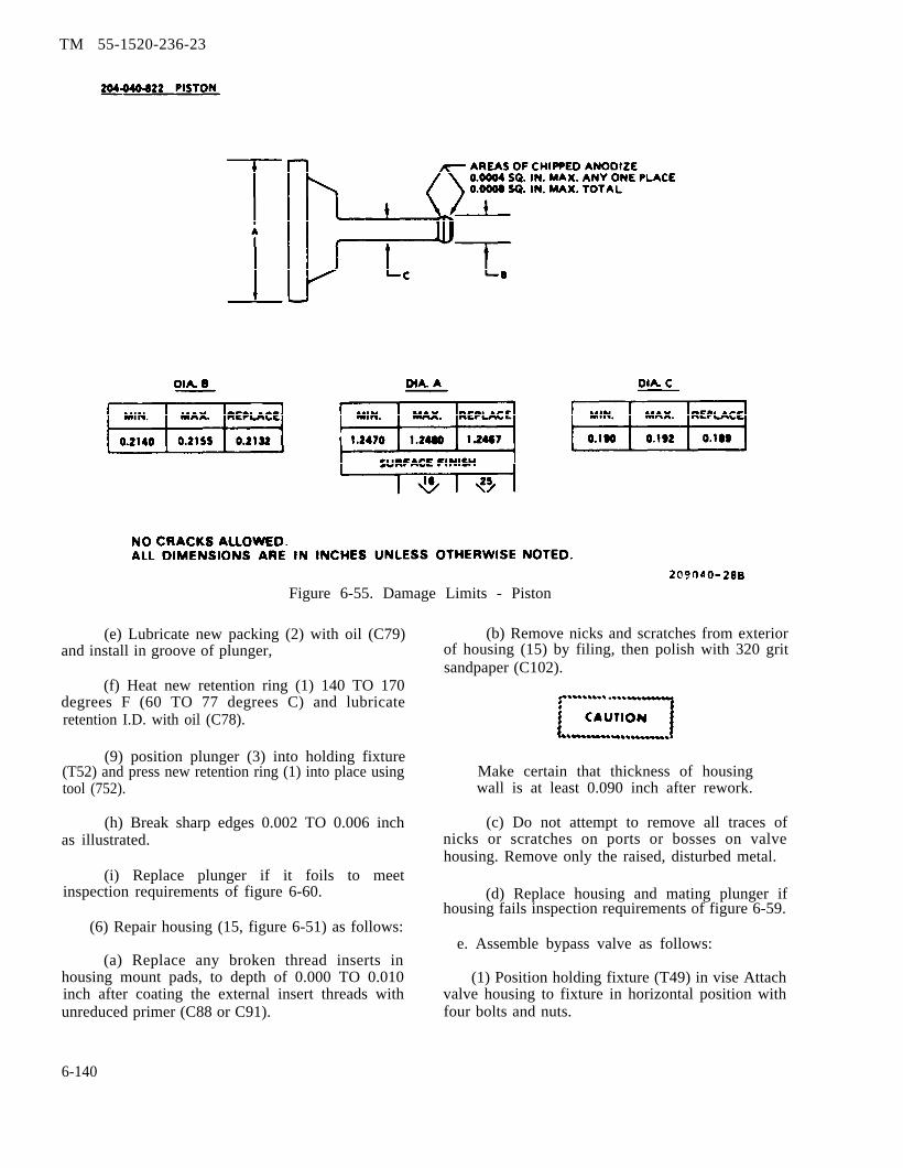
TM 55-1520-236-23
Figure 6-55. Damage Limits - Piston
(e) Lubricate new packing (2) with oil (C79)and install in groove of plunger,
(f) Heat new retention ring (1) 140 TO 170degrees F (60 TO 77 degrees C) and lubricateretention I.D. with oil (C78).
(9) position plunger (3) into holding fixture(T52) and press new retention ring (1) into place usingtool (752).
(h) Break sharp edges 0.002 TO 0.006 inchas illustrated.
(i) Replace plunger if it foils to meetinspection requirements of figure 6-60.
(6) Repair housing (15, figure 6-51) as follows:
(a) Replace any broken thread inserts inhousing mount pads, to depth of 0.000 TO 0.010inch after coating the external insert threads withunreduced primer (C88 or C91).
(b) Remove nicks and scratches from exteriorof housing (15) by filing, then polish with 320 gritsandpaper (C102).
Make certain that thickness of housingwall is at least 0.090 inch after rework.
(c) Do not attempt to remove all traces ofnicks or scratches on ports or bosses on valvehousing. Remove only the raised, disturbed metal.
(d) Replace housing and mating plunger ifhousing fails inspection requirements of figure 6-59.
e. Assemble bypass valve as follows:
(1) Position holding fixture (T49) in vise Attachvalve housing to fixture in horizontal position withfour bolts and nuts.
6-140
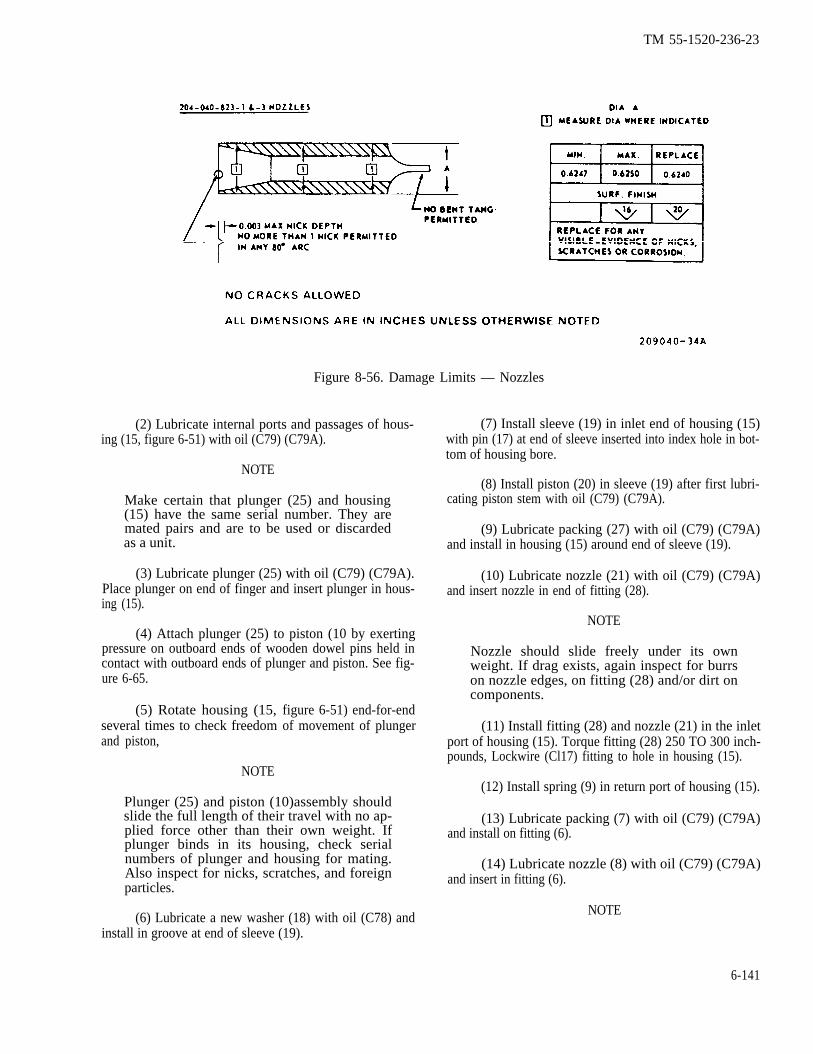
TM 55-1520-236-23
Figure 8-56. Damage Limits — Nozzles
(2) Lubricate internal ports and passages of hous-ing (15, figure 6-51) with oil (C79) (C79A).
NOTE
Make certain that plunger (25) and housing(15) have the same serial number. They aremated pairs and are to be used or discardedas a unit.
(3) Lubricate plunger (25) with oil (C79) (C79A).Place plunger on end of finger and insert plunger in hous-ing (15).
(4) Attach plunger (25) to piston (10 by exertingpressure on outboard ends of wooden dowel pins held incontact with outboard ends of plunger and piston. See fig-ure 6-65.
(5) Rotate housing (15,several times to check freedomand piston,
NOTE
figure 6-51) end-for-endof movement of plunger
Plunger (25) and piston (10)assembly shouldslide the full length of their travel with no ap-plied force other than their own weight. Ifplunger binds in its housing, check serialnumbers of plunger and housing for mating.Also inspect for nicks, scratches, and foreignparticles.
(6) Lubricate a new washer (18) with oil (C78) andinstall in groove at end of sleeve (19).
(7) Install sleeve (19) in inlet end of housing (15)with pin (17) at end of sleeve inserted into index hole in bot-tom of housing bore.
(8) Install piston (20) in sleeve (19) after first lubri-cating piston stem with oil (C79) (C79A).
(9) Lubricate packing (27) with oil (C79) (C79A)and install in housing (15) around end of sleeve (19).
(10) Lubricate nozzle (21) with oil (C79) (C79A)and insert nozzle in end of fitting (28).
NOTE
Nozzle should slide freely under its ownweight. If drag exists, again inspect for burrson nozzle edges, on fitting (28) and/or dirt oncomponents.
(11) Install fitting (28) and nozzle (21) in the inletport of housing (15). Torque fitting (28) 250 TO 300 inch-pounds, Lockwire (Cl17) fitting to hole in housing (15).
(12) Install spring (9) in return port of housing (15).
(13) Lubricate packing (7) with oil (C79) (C79A)and install on fitting (6).
(14) Lubricate nozzle (8) with oil (C79) (C79A)and insert in fitting (6).
NOTE
6-141
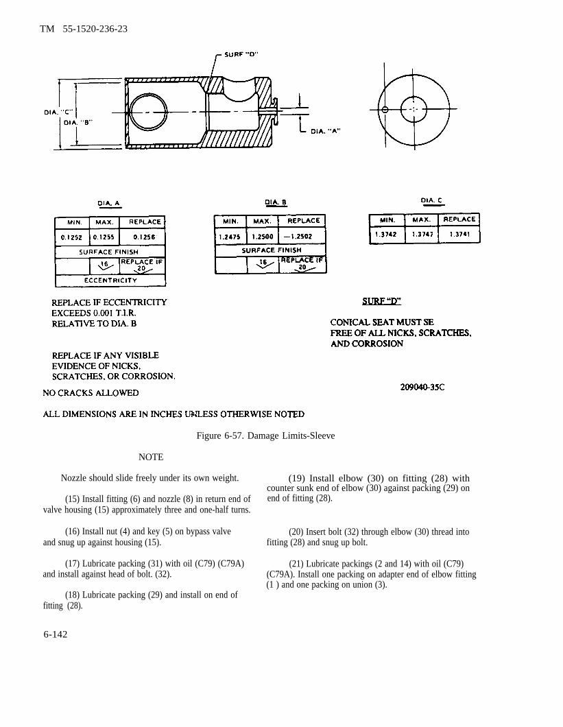
TM 55-1520-236-23
Figure 6-57. Damage Limits-Sleeve
NOTE
Nozzle should slide freely under its own weight.
(15) Install fitting (6) and nozzle (8) in return end ofvalve housing (15) approximately three and one-half turns.
(16) Install nut (4) and key (5) on bypass valveand snug up against housing (15).
(17) Lubricate packing (31) with oil (C79) (C79A)and install against head of bolt. (32).
(18) Lubricate packing (29) and install on end offitting (28).
6-142
(19) Install elbow (30) on fitting (28) withcounter sunk end of elbow (30) against packing (29) onend of fitting (28).
(20) Insert bolt (32) through elbow (30) thread intofitting (28) and snug up bolt.
(21) Lubricate packings (2 and 14) with oil (C79)(C79A). Install one packing on adapter end of elbow fitting(1 ) and one packing on union (3).
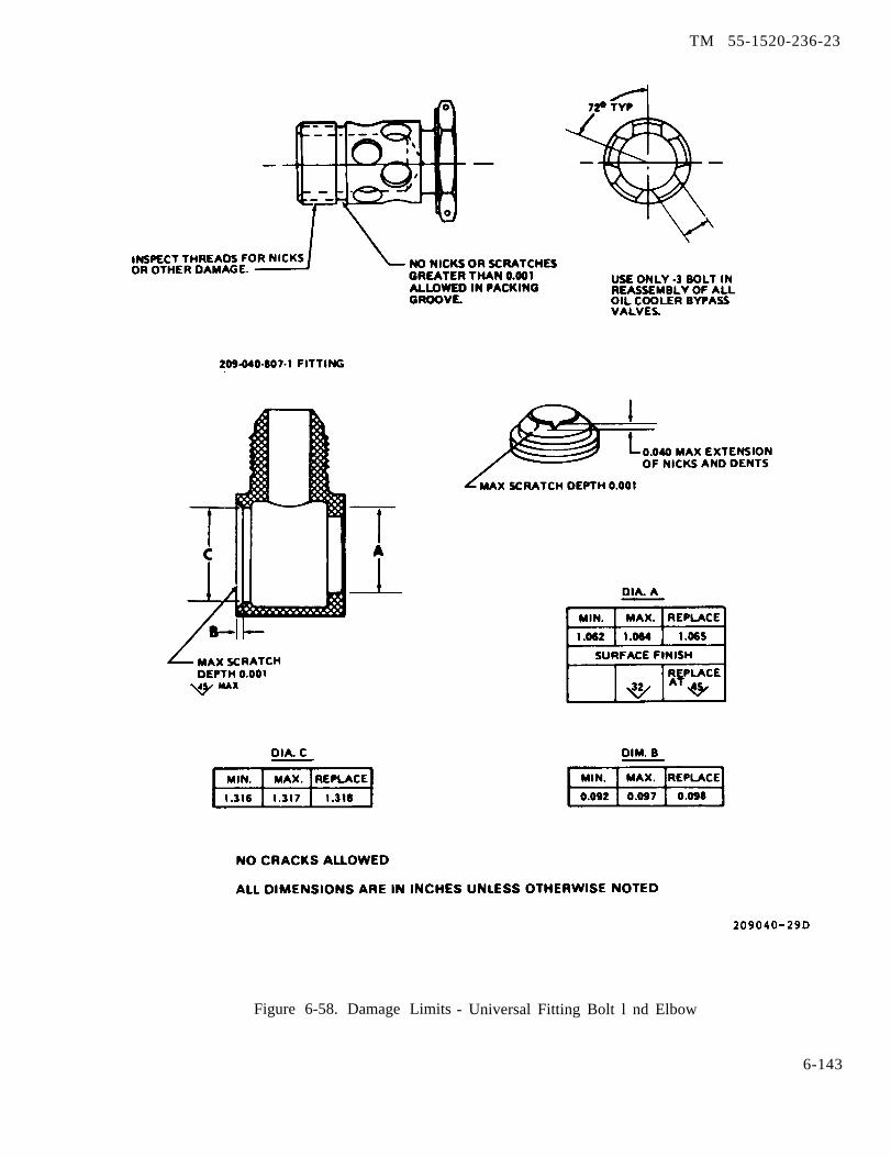
TM 55-1520-236-23
Figure 6-58. Damage Limits - Universal Fitting Bolt l nd Elbow
6-143
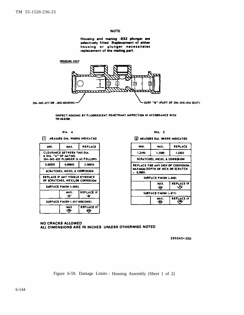
TM 55-1520-236-23
Figure 6-59. Damage Limits - Housing Assembly (Sheet 1 of 2)
6-144

TM 55-1520-236-23
Figure 6-59. Damage Limits — Housing Assembly (Sheet 2 of 2)
6-145
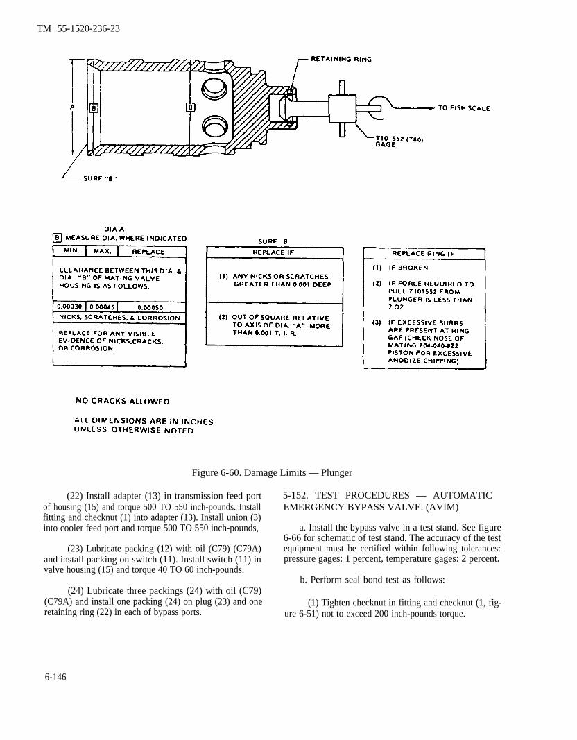
TM 55-1520-236-23
Figure 6-60. Damage Limits — Plunger
(22) Install adapter (13) in transmission feed portof housing (15) and torque 500 TO 550 inch-pounds. Installfitting and checknut (1) into adapter (13). Install union (3)into cooler feed port and torque 500 TO 550 inch-pounds,
(23) Lubricate packing (12) with oil (C79) (C79A)and install packing on switch (11). Install switch (11) invalve housing (15) and torque 40 TO 60 inch-pounds.
(24) Lubricate three packings (24) with oil (C79)(C79A) and install one packing (24) on plug (23) and oneretaining ring (22) in each of bypass ports.
5-152. TEST PROCEDURES — AUTOMATICEMERGENCY BYPASS VALVE. (AVIM)
a. Install the bypass valve in a test stand. See figure6-66 for schematic of test stand. The accuracy of the testequipment must be certified within following tolerances:pressure gages: 1 percent, temperature gages: 2 percent.
b. Perform seal bond test as follows:
(1) Tighten checknut in fitting and checknut (1, fig-ure 6-51) not to exceed 200 inch-pounds torque.
6-146
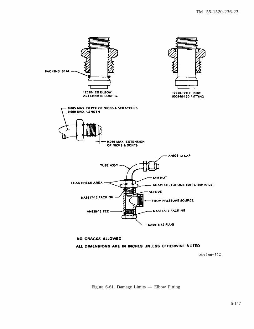
TM 55-1520-236-23
Figure 6-61. Damage Limits — Elbow Fitting
6-147

TM 55-1520-236-23
Figure 6-62. Fittings — Repair
(2) Remove compensator spring (9, figure 6-51)in order to ensure proper placement of other shiftingelements of valve.
(3) Position valves: V1-closed; V2-open; andV3-closed (figure 6-66).
(4) Monitor fluid discharged by means of V2 byflowmeter No. 2 and P1, at pressures of 13±5 and210±10 pounds per square inch. Leakage at thehigher pressure must be no more than 5cc/mingreater than the flow at the lower pressure,
c. Perform valve sensitivity test as follows:
(1) Install compensator spring (9, figure 6-51)in the oil cooler bypass valve and complete assemblyof valve.
(2) Set pressures as follows (figure 6-66):
Pl = 115 ±2 PSlG
P2 = 95 ±2 PSIG
P3 = 84 ±2 PSIG
P4 = 64 ±2 PSIG
6-148
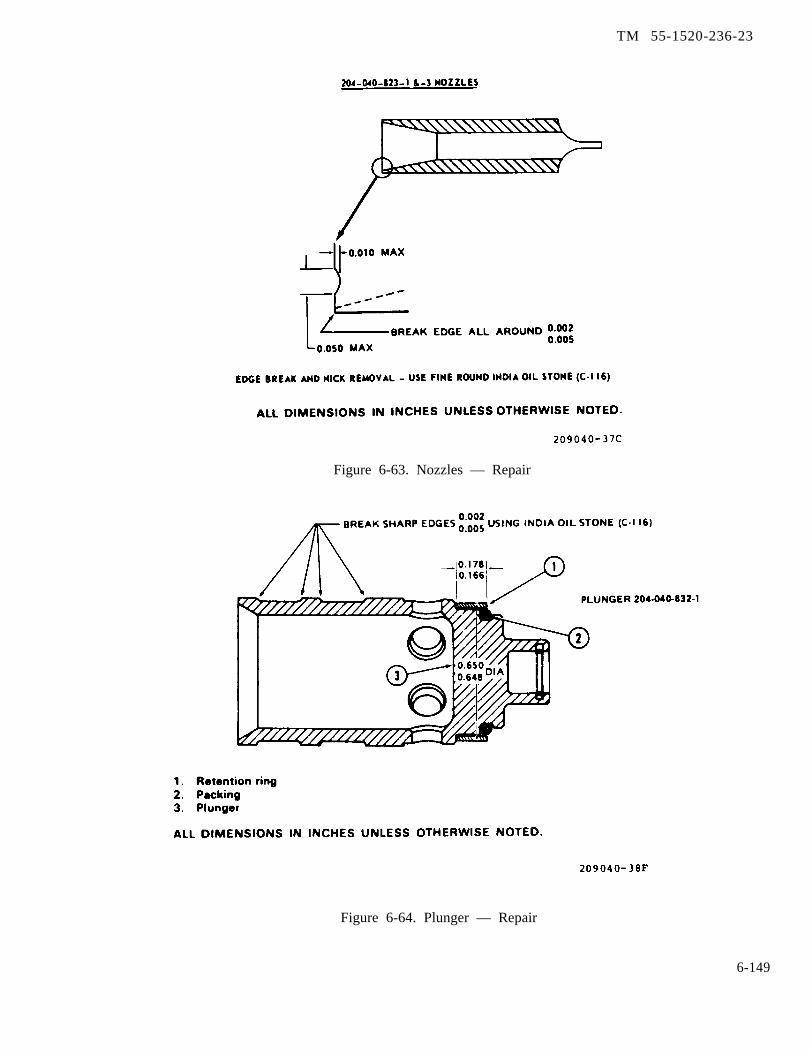
TM 55-1520-236-23
Figure 6-63. Nozzles — Repair
Figure 6-64. Plunger — Repair
6-149
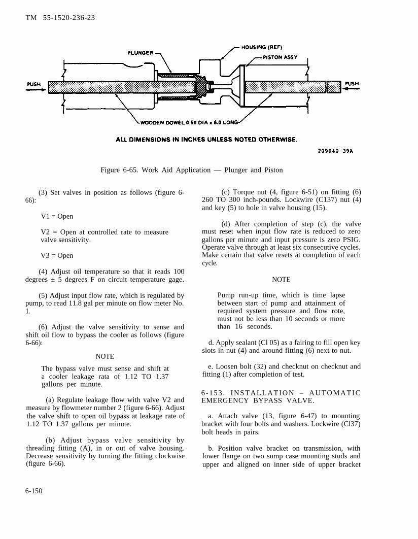
TM 55-1520-236-23
Figure 6-65. Work Aid Application — Plunger and Piston
(3) Set valves in position as follows (figure 6-66):
V1 = Open
V2 = Open at controlled rate to measurevalve sensitivity.
V3 = Open
(4) Adjust oil temperature so that it reads 100degrees ± 5 degrees F on circuit temperature gage.
(5) Adjust input flow rate, which is regulated bypump, to read 11.8 gal per minute on flow meter No.1.
(6) Adjust the valve sensitivity to sense andshift oil flow to bypass the cooler as follows (figure6-66):
NOTE
The bypass valve must sense and shift ata cooler leakage rata of 1.12 TO 1.37gallons per minute.
(a) Regulate leakage flow with valve V2 andmeasure by flowmeter number 2 (figure 6-66). Adjustthe valve shift to open oil bypass at leakage rate of1.12 TO 1.37 gallons per minute.
(b) Adjust bypass valve sensitivity bythreading fitting (A), in or out of valve housing.Decrease sensitivity by turning the fitting clockwise(figure 6-66).
(c) Torque nut (4, figure 6-51) on fitting (6)260 TO 300 inch-pounds. Lockwire (C137) nut (4)and key (5) to hole in valve housing (15).
(d) After completion of step (c), the valvemust reset when input flow rate is reduced to zerogallons per minute and input pressure is zero PSIG.Operate valve through at least six consecutive cycles.Make certain that valve resets at completion of eachcycle.
NOTE
Pump run-up time, which is time lapsebetween start of pump and attainment ofrequired system pressure and flow rote,must not be less than 10 seconds or morethan 16 seconds.
d. Apply sealant (Cl 05) as a fairing to fill open keyslots in nut (4) and around fitting (6) next to nut.
e. Loosen bolt (32) and checknut on checknut andfitting (1) after completion of test.
6 - 1 5 3 . I N S T A L L A T I O N – A U T O M A T I CEMERGENCY BYPASS VALVE.
a. Attach valve (13, figure 6-47) to mountingbracket with four bolts and washers. Lockwire (Cl37)bolt heads in pairs.
b. Position valve bracket on transmission, withlower flange on two sump case mounting studs andupper and aligned on inner side of upper bracket
6-150

TM 55-1520-236-23
Figure 6-66. Oil Cooler Automatic Emergency Bypass Valve — Bench Test Schematic
6-151

TM 55-1520-236-23
(which is attached on input drive quill mountingstuds).
c. Attach valve bracket to upper bracket with twobolts, using a washer on left bolt and attachingelectrical cable bracket on right bolt.
d. Attach lower end of bracket with nuts onstuds. using a washer on left stud and attachingelectrical cable bracket on right stud.
e. Position elbow (30, figure 6-51) to align withhose from transmission sump. Torque bolt (32)250 TO 350 inch-pounds. Lockwire (C137) bolt(32) to elbow (30). Connect hose to elbow (30).
f.
Ensure that items (38, 39) or (41, 42) offigure 6-47 are installed correctly to en-sure proper oil cooler bypass valve op-eration and oil flow direction through thecooler.
Connect valve-to-coder hose on union (3).
g. Position fitting (1) to align with valve-to-filtertube. Connect tube to fittings.
Do not allow nut on valve fitting to turnwhen tightening flarenut of hose elbow.Any turning of this nut will destroycalibration of valve.
h. Connect cooler-to-valve hose on fitting (6) atright end of valve.
L Connect electrical lead of caution panel circuitto terminal at right underside of valve (11). Coverterminal with rubber nipple.
j. At next ground run check for leaks and properoperation of oil system.
6-154. OIL FILTER (EXTERNAL).(Helicopters without MWO 1-1520-236-50-30).
6-155. DESCRIPTION - OIL FILTER(EXTERNAL).
An external oil filter (2, figure 6-47) for thetransmission oil system is bracket mounted on theright side of the transmission main case and isconnected to the external oil line between coolerand pressure relief valve manifold. The unitcontains a pleated paper type filter element, andincorporates a bypass valve set to open at 18 to22 psi to assure oil flow if filter element shouldbecome clogged. A visual indicator at top of filterwill pop out when bypass occurs, but has atemperature lock-out device to prevent actuationbelow 50 degrees F. If visual indicator button popsout, push button in and run up helicopter. If buttonpops out again, replace filter element assembly.
6-156. REMOVAL - OIL FILTER (EXTERNAL).
a. Open cowl door at right side of transmission.
b. Remove filter element (11, figure 6-67) forinspection or replacement.
(1) Place suitable container below filter to catchtrapped oil.
(2) Open V-band clamp (8).
(3) Remove filter (body) (13) downward.
(4) Remove fitter element (11) and packings (9)and (10).
c. Remove filter (head) (4) and bracket (3) asfollows:
(1) Disconnect hose assemblies (7 and 17)from filter (head) (4). Drain oil from hoses into acontainer. Cap or plug open hoses.
(2) Remove lockvire and four bolts (1) withwashers (2) to detach filter (head) (4) from bracket(3).
(3) If filter (head) (4) is being replaced, removeunion (6), elbow (16), nut (15), and packings (5and 14).
(4) Remove four bolts (23), washers (20, 21,22) and nuts (19), Remove bracket (3).
6-152

TM 55-1520-236-23
6 - l 5 7 . C L E A N I N G — O I L F I L T E R Clean filter (head) (4, Figure 6-67), filter (body) (13)
(EXTERNAL). and bracket (3) with solvent (C112). Dry thoroughly*filtered compressed air.
WARNING
Cleaning advent is flammable and toxic.Provide adequate ventilation. Avoidprolonged breathing of solvent vaporsand contact with akin or eyes.
6-l52.1/(6-152.2 blank)

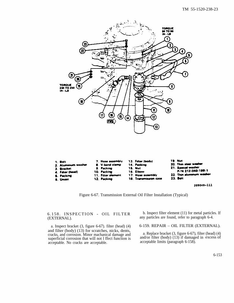
TM 55-1520-238-23
Figure 6-67. Transmission External Oil Filter Installation (Typical)
6 . 1 5 8 . I N S P E C T I O N - O I L F I L T E R b. Inspect filter element (11) for metal particles. If(EXTERNAL). any particles are found, refer to paragraph 6-4.
a. Inspect bracket (3, figure 6-67). filter (head) (4) 6-159. REPAIR – OIL FILTER (EXTERNAL).and filter (body) (13) for scratches, nicks, dents,cracks, and corrosion. Minor machanical damage and a. Replace bracket (3, figure 6-67), filter (head) (4)superficial corrosion that will not l ffect function is and/or filter (body) (13) if damaged in excess ofacceptable. No cracks are acceptable. acceptable limits (paragraph 6-158).
6-153

TM 55-1520-236-23
b. Replace filter element (11) and ail packings thatwere removed.
6-160. INSTALLATION - OIL FILTER(EXTERNAL).
a. Position bracket (3, figure 6-67) on top of lowerflange of transmission ring gear as illustrated. Installfour bolts (23) with thin aluminum washers (22) underbolt heads. Install special washers (21) next to trans-mission ease (18). Install thin steel washers (20) nextto nuts. Install nuts (19). Torque nuts (19) evenly 230-260 inch-pounds
b. Position filter (head) (4) under bracket (3) withoutlet aft. Install four bolts (1) with aluminum washers(2) under bolt heads. Torque bolts evenly 80-90 inch-pounds. Lockwire (C137) bolt heads in pairs.
c. Install union (6) and packing (5).
d. install hose assembly (7) on union (6).
e. Install elbow (16), packing (14), and nut (15).
f. Install hose assembly (17) on elbow (16).
g. Manually reset bypass indicator on filter (head)(4).
h. Install filter element (11) and filter (body) (13) asfollows:
(1)
(2)
(3)
(4)
Install packing (1O) on boss in filter (head) (4).
Install packing (9) on filter (head) (4).
Install packing(12) on boss filter (body) (13).
Place filter element (11) in fitter (body) (13)and seat firmly on boss.
(5) Position filter (body) (13) and filter element(11 ) on filter (head) (4) and install V-band damp (8)around flanges of filter (head) and filter (body). Torquedamp nut 50 inch-pounds.
6-160.1. EXTERNAL OIL FILTER. (Helicopters withMWO 1-1520-236-50-30).
6-160.2. DESCRIPTION - EXTERNAL OIL FILTER.
a. An external oil filter (4, figure 6-67.1) is bracketmounted on the tight side of the transmission maincase. It is connected in the oil line between cooler andpressure relief valve manifold.
b. Filter contains disposable 3-micron pleated-pa-per element and includes bypass valve. Valve is set toopen at 20 to 24 psi and reseat at 18 psi pressure. Adifferential pressure indicator pops out to indicate by-pass. Filter design prevents re-entry of trapped debrisinto system during bypass.
6-154
c. Filter is accessed by opening right side of trans-mission cowling.
d Drain valve on bottom of filter can be used todrain the filter for removal. Filter head is markedTRANSMISSION.
6-160.3. Cleaning - External Oil Filter. Clean filterbowl and head with cleaning solvent (C112). Dry withcompressed air.
Do not attempt to dean filter element forreuse. Oil system performance can be se-riously degraded.
6-160.4. INSPECTION - EXTERNAL OIL FILTER.
a. Make sure filter head (2, figure 6-67.2) is markedTRANSMISSION.
b. Check bypass indicator. Reset if edtended. Ifreset, check for proper operation at next runup.
c. Inspect filter head and bowl (6) for corrosion,cracks, and evidence of leaks.
d. Replace cracked or corroded parts. Correctleeks.
6-160.5. REPLACEMENT OF ELEMENT OR BOWL- EXTERNAL OIL FILTER. Proceed as follows: (figure6-67.2).
NOTE
Replacement of main transmission exter-nal oil filter is “ON CONDITION” changeonly when associated impeding bypassindicator button is extended (second re-set) or when main transmission is re-placed. Since fine filtration deans lubri-cant in the component, do not changelubricant when replacing fitter. Flushingand filtering system lubricant (unless thetransmission is being replaced) is not re-quired or authorized, as it may maskproblems and prevents trending data.
a. Place container below filter to catch oil. Removelockwire from cap of drain valve (8). Remove cap todrain oil.
b. Remove lockwire and coupling damp (4).
c. Remove filter bowl (6) and element (5)ward.
d. Remove packing (1) from filter head (2).
down-
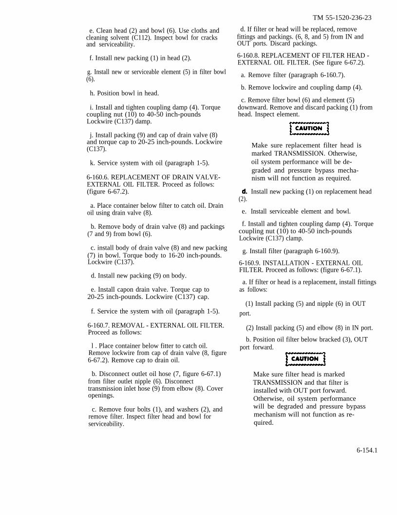
e. Clean head (2) and bowl (6). Use cloths andcleaning solvent (C112). Inspect bowl for cracksand serviceability.
f. Install new packing (1) in head (2).
g. Install new or serviceable element (5) in filter bowl(6).
h. Position bowl in head.
i. Install and tighten coupling damp (4). Torquecoupling nut (10) to 40-50 inch-poundsLockwire (C137) damp.
j. Install packing (9) and cap of drain valve (8)and torque cap to 20-25 inch-pounds. Lockwire(C137).
k. Service system with oil (paragraph 1-5).
6-160.6. REPLACEMENT OF DRAIN VALVE-EXTERNAL OIL FILTER. Proceed as follows:(figure 6-67.2).
a. Place container below filter to catch oil. Drainoil using drain valve (8).
b. Remove body of drain valve (8) and packings(7 and 9) from bowl (6).
c. install body of drain valve (8) and new packing(7) in bowl. Torque body to 16-20 inch-pounds.Lockwire (C137).
d. Install new packing (9) on body.
e. Install capon drain valve. Torque cap to20-25 inch-pounds. Lockwire (C137) cap.
f. Service the system with oil (paragraph 1-5).
6-160.7. REMOVAL - EXTERNAL OIL FILTER.Proceed as follows:
l . Place container below fitter to catch oil.Remove lockwire from cap of drain valve (8, figure6-67.2). Remove cap to drain oil.
b. Disconnect outlet oil hose (7, figure 6-67.1)from filter outlet nipple (6). Disconnecttransmission inlet hose (9) from elbow (8). Coveropenings.
c. Remove four bolts (1), and washers (2), andremove filter. Inspect filter head and bowl forserviceability.
TM 55-1520-236-23
d. If filter or head will be replaced, removefittings and packings. (6, 8, and 5) from IN andOUT ports. Discard packings.
6-160.8. REPLACEMENT OF FILTER HEAD -EXTERNAL OIL FILTER. (See figure 6-67.2).
a. Remove filter (paragraph 6-160.7).
b. Remove lockwire and coupling damp (4).
c. Remove filter bowl (6) and element (5)downward. Remove and discard packing (1) fromhead. Inspect element.
(2).
e.
Make sure replacement filter head ismarked TRANSMISSION. Otherwise,oil system performance will be de-graded and pressure bypass mecha-nism will not function as required.
Install new packing (1) on replacement head
Install serviceable element and bowl.
f. Install and tighten coupling damp (4). Torquecoupling nut (10) to 40-50 inch-poundsLockwire (C137) clamp.
g. Install filter (paragraph 6-160.9).
6-160.9. INSTALLATION - EXTERNAL OILFILTER. Proceed as follows: (figure 6-67.1).
a. If filter or head is a replacement, install fittingsas follows:
(1) Install packing (5) and nipple (6) in OUTport.
(2) Install packing (5) and elbow (8) in IN port.
b. Position oil filter below bracked (3), OUTport forward.
Make sure filter head is markedTRANSMISSION and that filter isinstalled with OUT port forward.Otherwise, oil system performancewill be degraded and pressure bypassmechanism will not function as re-quired.
6-154.1
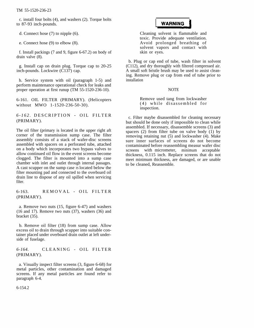
TM 55-1520-236-23
c. install four bolts (4), and washers (2). Torque boltsto 87-93 inch-pounds.
d. Connect hose (7) to nipple (6).
e. Connect hose (9) to elbow (8).
f. Install packings (7 and 9, figure 6-67.2) on body ofdrain valve (8).
g. Install cap on drain plug. Torque cap to 20-25inch-pounds. Lockwire (C137) cap.
h. Service system with oil (paragraph 1-5) andperform maintenance operational check for leaks andproper operation at first runup (TM 55-1520-236-10).
6-161. OIL FILTER (PRIMARY). (Helicopterswithout MWO 1-1520-236-50-30).
6 - 1 6 2 . D E S C R I P T I O N - O I L F I L T E R(PRIMARY).
The oil filter (primary is located in the upper right aftcorner of the transmission sump case. The filterassembly consists of a stack of wafer-disc screensassembled with spacers on a perforated tube, attachedon a body which incorporates two bypass valves toallow continued oil flow in the event screens becomeclogged. The filter is mounted into a sump casechamber with inlet and outlet through internal passages.A cast scupper on the sump case IS located below thefilter mounting pad and connected to the overboard oildrain line to dispose of any oil spilled when servicingfilter.
6-163. R E M O V A L - O I L F I L T E R(PRIMARY).
a. Remove two nuts (15, figure 6-47) and washers(16 and 17). Remove two nuts (37), washers (36) andbracket (35).
b. Remove oil filter (18) from sump case. Allowexcess oil to drain through scupper into suitable con-tainer placed under overboard drain outlet at left under-side of fuselage.
6-164. C L E A N I N G - O I L F I L T E R(PRIMARY).
Cleaning solvent is flammable andtoxic. Provide adequate ventilation.Avoid prolonged breathing ofsolvent vapors and contact withskin or eyes.
b. Plug or cap end of tube, wash filter in solvent(C112), and dry thoroughly with filtered compressed air.A small soft bristle brush may be used to assist clean-ing. Remove plug or cap from end of tube prior toinstallation
NOTE
Remove used tang from lockwasher( 4 ) w h i l e d i s a s s e m b l e d f o rinspection.
c. Filter maybe disassembled for cleaning necessarybut should be done only if impossible to clean whileassembled. If necessary, disassemble screens (3) andspacers (2) from filter tube on valve body (1) byremoving retaining nut (5) and lockwasher (4). Makesure inner surfaces of screens do not becomecontaminated before reassembling measur wafer discscreens with micrometer, minimum acceptablethickness, 0.115 inch. Replace screens that do notmeet minimum thickness, are damaged, or are unableto be cleaned, Reassemble.
a. Visually inspect filter screens (3, figure 6-68) formetal particles, other contamination and damagedscreens. If any metal particles are found refer toparagraph 6-4.
6-154.2
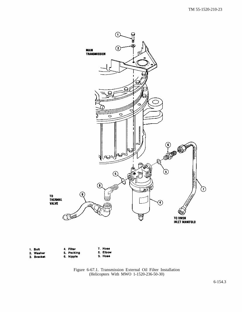
TM 55-1520-210-23
Figure 6-67.1. Transmission External Oil Filter Installation(Helicopters With MWO 1-1520-236-50-30)
6-154.3
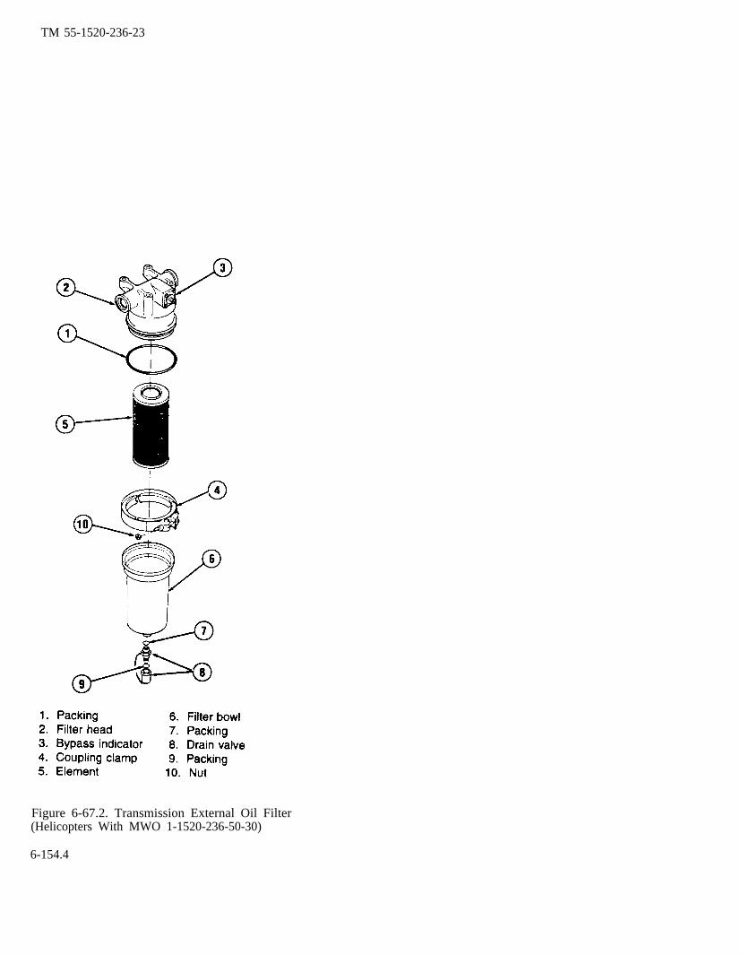
TM 55-1520-236-23
Figure 6-67.2. Transmission External Oil Filter(Helicopters With MWO 1-1520-236-50-30)
6-154.4

TM 55-1520-236-23
Table 6-68. Transmission Oil Filter (Primary) Assembly(Aircraft without ODDS)
6-155

TM 55-1520-236-23
filter by alternately installing spacers (2), then screens(3). Eleven spacers and ten screens are required.Install lockwasher (4) and nut (5). Tighten until spacersand screens cannot be rotated individually, then tightenadditional one-quarter turn. Bend lockwasher (4) tabagainst flat of nut (5).
6-165. INSTALLATION - OIL FILTER (PRI-MARY).
a. Install new packing (19, figure 6-47) on oil filter(18).
b. Install oil filter (18) in transmission sump (11) withone bypass valve at the top and one bypass at the 3:00position for proper bypass of oil in case of filter failure.
c. Place one bracket (35) on each of the two lowerstuds. Install one thin steel washer (36) on each brack-et. Install two nuts (37). Do not tighten nuts at this time
d. Place one thin aluminum washer (17) on each ofthe two upper studs. Install one thin steel washer (16)on each of the two upper studs. Install two nuts (15).Torque two nuts (15) and two nuts (37) evenly 50 to 70inch-pounds Wait a minimum of fifteen minutes andretorque nuts to same torque noted above.
e. Fill transmission to proper level with oil (para-graph 1-5).
6-165.1. DEBRIS MONITOR (Helicopters withMWO 1-1520-236-50-30).
6-185.2. DESCRIPTION - A full-flow debris monitor(44, figure 6-47) is installed on threaded studs on aftright comer of transmission sump. Inlet and outlet con-nections are internal. Ferrous (iron or steel) debris iscollected on a magnetic surface with two chip gaps.Non-ferrous debris is collected in removable scavengecup/screen, screen begin rated at 70 microns. Debrismonitor also includes two valves for cold start bypass orfor bypass when differential pressure exceeds [email protected] prevents re-entry of trapped debris into systemduring bypass. Chip detector is connected through re-ceptacle to XMSN CHIP capsule on caution panel. Ac-cess to debris monitor is through right transmissioncowling.
6-165.3. REMOVAL - DEBRIS MONITOR. Proceedas follows: (figure 6-47).
a. Position suitable container under overboarddrain.
b. Disconnect cable plug from chip detector recep-tacle.
c. Remove four nuts (47), washers (45 and 46), andbracket (35) from threaded studs.
d. Remove monitor (44) and packing (43). Let oildrain into scupper.
6-165.4. CLEANING/inspection - DEBRIS MON-ITOR.
NOTE
Debris monitor is inspected when CHIPXMSN caution fight comes on.
a. Remove debris monitor (44, figure 6-47). (para-graphs 6-1 65.3)
b. Inspect chip gaps for chips. Remove material foranalysis if chips are present.
c. Using a wrench on flats of tube, remove scav-enge cup and screen (49).
d. Inspect cup and screen for contamination. Re-move material for analysis if there is contamination.(Refer to paragraph 6-165.5)
e. Clean chip gaps and cup and screen. Use abrush and solvent (Ch 2). Dry parts with compressedair.
f. Inspect screen for damage.
g. Install scavenge cup and screen with new pack-ing (46). Torque tube to 22 to 30 inch-pounds
h. Install debris monitor (paragraph 6-165.6).
6-165.5. TRANSMISSION OIL CONTAMINATIONTROUBLE-SHOOTING (Helicopters with MWO1-1520-236-50-30). Following a chip light event, theparticles from the debris monitor (paragraph 6-165.4),screen, and external filter shall be examined and class-ified to determine maintenance action. Identify particlesusing information in paragraph 6-4.1. Refer to table6-1.2 for maintenance action dictated by debris.
If fragment can be identified as piecefrom specific part, replace transmission.
6-156
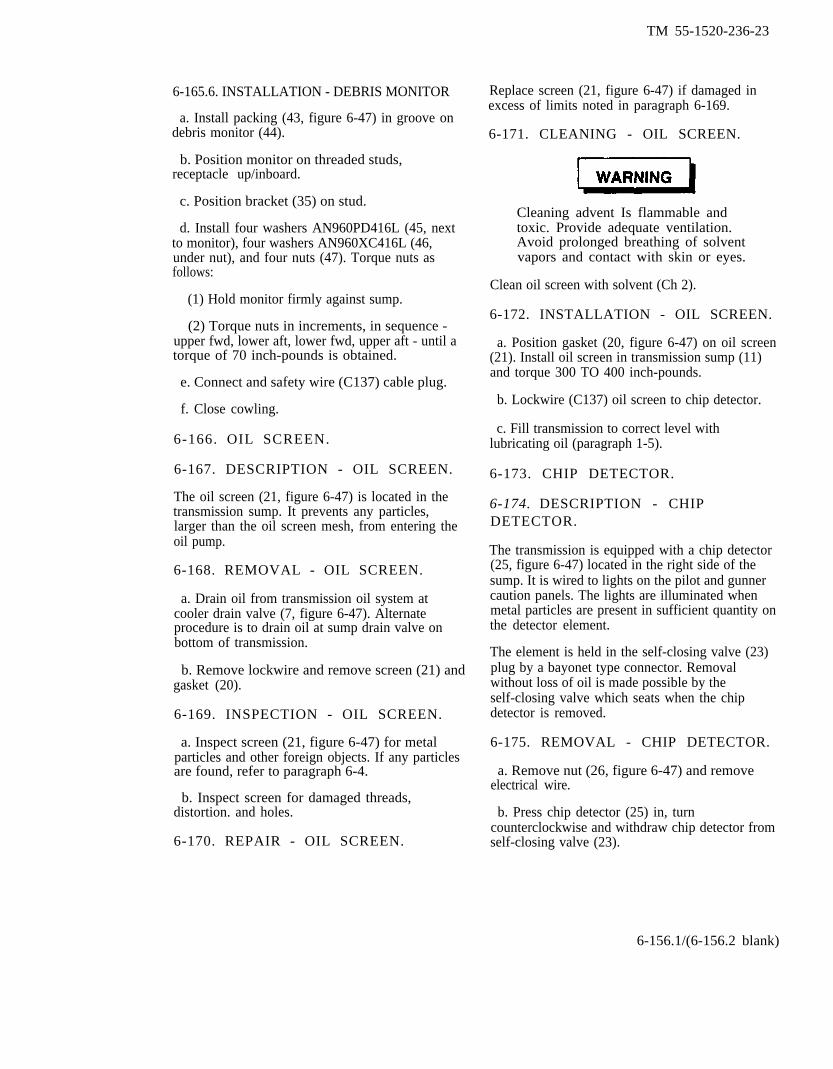
TM 55-1520-236-23
6-165.6. INSTALLATION - DEBRIS MONITOR
a. Install packing (43, figure 6-47) in groove ondebris monitor (44).
b. Position monitor on threaded studs,receptacle up/inboard.
c. Position bracket (35) on stud.
d. Install four washers AN960PD416L (45, nextto monitor), four washers AN960XC416L (46,under nut), and four nuts (47). Torque nuts asfollows:
(1) Hold monitor firmly against sump.
(2) Torque nuts in increments, in sequence -upper fwd, lower aft, lower fwd, upper aft - until atorque of 70 inch-pounds is obtained.
e. Connect and safety wire (C137) cable plug.
f. Close cowling.
6-166. OIL SCREEN.
6-167. DESCRIPTION - OIL SCREEN.
The oil screen (21, figure 6-47) is located in thetransmission sump. It prevents any particles,larger than the oil screen mesh, from entering theoil pump.
6-168. REMOVAL - OIL SCREEN.
a. Drain oil from transmission oil system atcooler drain valve (7, figure 6-47). Alternateprocedure is to drain oil at sump drain valve onbottom of transmission.
b. Remove lockwire and remove screen (21) andgasket (20).
6-169. INSPECTION - OIL SCREEN.
a. Inspect screen (21, figure 6-47) for metalparticles and other foreign objects. If any particlesare found, refer to paragraph 6-4.
b. Inspect screen for damaged threads,distortion. and holes.
6-170. REPAIR - OIL SCREEN.
Replace screen (21, figure 6-47) if damaged inexcess of limits noted in paragraph 6-169.
6-171. CLEANING - OIL SCREEN.
Cleaning advent Is flammable andtoxic. Provide adequate ventilation.Avoid prolonged breathing of solventvapors and contact with skin or eyes.
Clean oil screen with solvent (Ch 2).
6-172. INSTALLATION - OIL SCREEN.
a. Position gasket (20, figure 6-47) on oil screen(21). Install oil screen in transmission sump (11)and torque 300 TO 400 inch-pounds.
b. Lockwire (C137) oil screen to chip detector.
c. Fill transmission to correct level withlubricating oil (paragraph 1-5).
6-173. CHIP DETECTOR.
6-174. DESCRIPTION - CHIPDETECTOR.
The transmission is equipped with a chip detector(25, figure 6-47) located in the right side of thesump. It is wired to lights on the pilot and gunnercaution panels. The lights are illuminated whenmetal particles are present in sufficient quantity onthe detector element.
The element is held in the self-closing valve (23)plug by a bayonet type connector. Removalwithout loss of oil is made possible by theself-closing valve which seats when the chipdetector is removed.
6-175. REMOVAL - CHIP DETECTOR.
a. Remove nut (26, figure 6-47) and removeelectrical wire.
b. Press chip detector (25) in, turncounterclockwise and withdraw chip detector fromself-closing valve (23).
6-156.1/(6-156.2 blank)

TM 55-1520-236-23
c. If self-closing valve (23) is to be removed, drainoil from transmission at drain valve (7). Removelockwire and remove self-closing valve fromtransmission sump.
6-176. INSPECTION – CHIP DETECTOR.
a. Inspect chip detector (25, figure 6-47) for metalparticles. If any metal particles are found, refer toparagraph 6-4.
b. Inspect chip detector (25) for distortion anddamaged threads.
c. Inspect self-closing valve (23) for damagedthreads and proper operation of self-closing valve.
d. Inspect nut (26) for damaged threads.
e. Inspect gasket (22) and packing (24) for nicks.cuts, and deterioration.
6-177. CLEANING – CHIP DETECTOR,
Cleaning solvent is flammable and toxic.Provide adequate ventilation. Avoidprolonged breathing of solvent vaporsand contact with akin or eyes.
Clean chip detector (25, figure 6-47) and self-closingvalve (23) with solvent (C112).
6 -178 . REPAIR – CHIP DETECTOR,
Replace chip detector (25, figure 6-47), self-closingvalve (23), nut (26), packing (24), and/or gasket (22) ifdamaged.
6-179. I N S T A L L A T I O N – C H I PDETECTOR.
a . Position gasket (22, figure 6-47) on self-closingvalve (23). Install self-closing valve in transmissionsump. Torque 300 TO 400 inch-pounds. Lockwire(CI 37) self-closing valve to screen (21) and to sumpdrain plug.
b. Fill transmission to proper level withlubricating oil (paragraph 1-6). Inspect self-closingvalve (23) for oil leakage.
c. Install pocking (24) on chip detector (25) or self-closing valve (23).
d. Push chip detector (25) into self-closing valve(23) and turn clockwise. Ensure that chip detectorlocks in self-closing valve.
e. Place electrical wire on chip detector andinstall nut (26).
6 - 1 8 0 . O I L M A N I F O L D .
6-181. DESCRIPTION – OIL MANIFOLD.
The oil manifold (14, figure 6-47) is installed on theright side of transmission case. The manifold providesmounting points for the pressure relief valvetemperature bulb, thermoswitch, and No. 3 and No. 7oil jets.
6-182. DELETED.
NOTE
Deleted
6-157

TM 55-1520-236-23
Figure 6-69. Transmission Oil Manifold Installation
6-183. INSPECTION – OIL MANIFOLD.
a. Inspect manifold for damage or leakage.
b. Inspect components installed on manifold fordamage, leakage, or malfunction.
6-184 . REPAIR – OIL MANIFOLD.
NOTE
Components can b. replaced withmanifold installed on transmission,
a. Replacement — Temperature Bulb (3, figure 6-69).
(1) Remove lockwire and remove temperaturebulb (3).
(2) Install new bulb with new gasket.
(3) Lockwire (C137) temperature bulb topressure relief valve.
b. Replacement - Thermoswitch (6, figure 6-69).
(1) Remove lockwire and remove thermoswitch(6).
6-158

(2) install new thermoswitch with new gasket.Torque thermoswitch 12 inch-pounds and lockwire(C137).
Replacement and Repair — Pressure ReliefValve (4, figure 6-69).
(1) Remove lockwire and remove pressurerelief valve.
NOTE
If pressure relief valve is repaired orreplaced, transmission oil pressuremust be checked and adjusted. Refer tostep (4).
(2) Repair pressure relief valve as follows:
(a) Depress piston (4, figure 6-70) andremove retaining ring (5) from valve body (3).
(b) Remove piston (4) and spring (6) fromvalve body. If there has been leakage at top of valve,also remove nut (7) and screw (1), replace packing (2),and reinstall screw and nut.
(c) Check valve body (3) and piston (4) fordamage or obstructions.
TM 55-1520-236-23
(d) Install serviceable spring (6) and piston(4) in valve.
(e) Install retaining ring (5).
(3) Install pressure relief valve (4, figure 6-69)with new packing. Lockwire (C137) valve to tempera-ture bulb and thermoswitch. Check and adjust reliefvalve. Refer to step (4).
(4) If pressure relief valverepaired adjust as follows:
was replaced or
Adjustment of pressure relief valvewhile aircraft is operating could resultin serious injury or loss of life. Adjust-ment should be made after shutdown.
(a) Check transmission oil pressure onrunup. Comet oil pressure is 50 ± 5 psi.
(b) Loosen nut (7, figure 6-70) while hold-ing screw (1) at top of body- (3).-
(c) Turn screw (1) indecrease indicated oil pressure.
(d) Tighten nut (7).
to increase or out to
(e) Recheck oil pressure in operation.
6-185. DELETED.
Figure 6-70. Transmission Oil PressureRelief Valve Assembly
6-159

TM 55-1520-236-23
6 - 1 8 6 . S I G H T G A G E S .
6-187. DESCRIPTION – SIGHT GAGES.
Visual indication of oil level in transmission isprovided by two transparent sight gages (28 and 32figure 6-47) set into right side of sump case, backedby indicator discs with FULL and LOW markings.
6-188. REMOVAL – SIGHT GAGES.
a. Drain oil below gage level.
b. Remove retaining ring (34, figure 6-47),packing (33), sight glass (32), and indicator (31 ).
c. Remove retaining ring (30), pecking (29), sightglass (28), and indicator (27).
6-189. INSPECTION SIGHT GAGES.
a. Inspect sight glasses (28 and 32, figure 6-47)for cracks, excessive scratches, and stains, Crackedand/or damaged glasses that obstruct view ofindicators are not acceptable.
b. inspect indicators (27) and (31) for stains. Ifwords “full” and “low” as applicable are not legible,the indicators are not acceptable.
c. Inspect retaining rings (30 and 34) fordistortion.
6-190. REPAIR – SIGHT GAGES.
a. Replace sight glasses (28 and 32, figure 6-47),indicators (27 and 31), and retainers (30 and 34) ifdamage is excess of acceptable limits (paragraph 6-189).
6-191. INSTALLATION – SIGHT GAGES.
a. Position new packing (29, figure 6-47) on sightglass (28).
b.gage
c.
d.
l .
f.gage
g.
h.
i.
Position indicator “LOW”’ (27) in lower sightport in transmission sump.
Install sight glass (28) with flat side out.
Install retaining ring (30).
Position new packing (33) on sight glass (32).
Position indicator “FULL’” (31) in upper sightport in transmission sump.
Install sight glass (32} with flat side out.
Install retaining ring (34),
Fill transmission to full level with lubricating oil(paragraph 1-5). Check for oil leaks at sight gages.
6 - 1 9 2 . O I L J E T S .
6-193. DESCRIPTION – OIL JETS.
Eight jet assemblies are used in the transmission oilsystem to deliver aimed sprays of oil to gears andbearings. Each jet is identified to its mounting port bymatching stamped numerals on the jet and on thetransmission case. Locations and functions of the jetsare as follows: See figure 6-46.
No. 1-
No. 2-
No. 3-
No. 4-
No. 5-
Top right aft section of top case. Spraysupper mast bearing, mast driving spline,and upper stage planetary pinionbearings.
On housing at right aft on ring gear case.with two auxiliary jets fed by externaltubes and located 120 degrees apart onring gear case. Sprays pinion bearings andgears of both planetary stages.
On bottom of oil manifold at right aft onmain case. Sprays input bevel gears(leaving mesh) and delivers oil to No. 6 jetinside case.
On left side of sump case. Lubricatesaccessory and tail rotor drive quills.
Left aft main case, beside input drive quill.Lubricates input quill gears enteringmesh.
6-160

TM 55-1520-236-23
No. 6-
No. 7-
No. 8-
6 -194 .
Right side on main case, near oil manifold.Receives oil from No. 3 jet inside case.Sprays inboard bearing of input drive quill,and through end of gear to lubricatefreewheeling clutch.
Top of oil manifold at right aft on maincase. Lubricates upper bearings of inputdrive quill.
Located on the mast bearing retainingplate. Lubricates the upper mast bearing.
REMOVAL – OIL JETS.
a. Remove any jet, except auxiliary No. 2 jets, asfollows:
NOTE
Before removing No. 7 jet, remove oilpressure relief valve.
(1) Cut lockwire between two screw heads onjet and loosen both screws. Remove screw thatsecures plate of jet to case.
(2) Pull jet, with packings, from case. Exercisecare not to bend jet during removal. Cover open port toprevent contamination.
b. Remove No. 2 auxiliary jets as follows:
Do not attempt to remove the housing ofnumber 2 auxiliary oil jets. This housingis attached by two bolts, nuts and cotterpins inside the transmission case.Tampering with bolts may cause leaks.
(1) Disconnect oil tube from jet. Cap open endof tube.
(2) Remove lockwire and screw from jetmounting plate.
(3) Pull jet and packing from housing. Coveropen port.
6-195. CLEANING – OIL JETS.
a. Remove packing. Also remove screw, withseal, from outer end of jet (except auxiliary No. 2 jets)
to permit thorough cleaning, drainage, andinspection.
Cleaning solvent is flammable and toxic.Provide adequate ventilation. Avoidprolonged breathing of solvent vaporsand contact with skin or eyes.
b. Wash in solvent (Cl 12). A suitable brush canbe used, if needed. Drain and dry with filteredcompressed air. Be sure all jet openings are clear.
c. Install screw, with new seal, in outer end oftube.
6-196. INSPECTION – OIL JETS.
a. inspect jet openings for foreign material notremoved during cleaning.
b. Inspect jets for bending or other damage whichwould render them unserviceable.
6-197. REPAIR – OIL JETS.
Repair of oil jets is limited to replacement of jetswhich cannot be cleaned or jets which are bent orotherwise damaged. Replace all pecking duringinstallation.
6-198. INSTALLATION – OIL JETS.
a. Uncover mounting port.numerals beside port and on jet.
b. Install packings on jet tubeside of inlet slot.
Check matching
in grooves at each
c. Coat packings with oil (C80). Insert jet, alignlug, and secure to case with screw. Tighten bothscrews and lockwire (C137) heads together.
(1) For number 3 jet, use manifold attachmentbolt for attachment. Install electrical harness clampunder bolt head when oil jet is installed.
(2) Connect oil tube to auxiliary number 2 jets.Lockwire (C137) attaching screw to elbow fitting nextto tube connector nut.
(3) After installing number 7 jet, install oilpressure relief valve.
(4) Check for oil leaks at next runup.
8-161

TM 55-1520-236-23
6 - 1 9 9 . I N S P E C T I O N – T R A N S M I S S I O NVENT VALVE.
a. Inspect vent valve for clogged condition (1,figure 6-47).
b. Clean with dry compressed air.
c. Install vent valve using new gasket. Torque60 TO 100 inch-pounds. Lockwire (C137) to drilledhole in case.
6-162

TB 55-1520-236-23-1
By Order of the Secretary of the Army:
DENNIS J. REIMERGeneral, United States Army
Chief of Staff
Administrative Assistant to theSecretary of the Army
01933
DISTRIBUTION:To be distributed in accordance with DA Form 12-3 l-E, block no. 1149, requirements for TM 55-
1520-236-23-1.
“U.S. Government Printing Office 1996- 755-025/40104

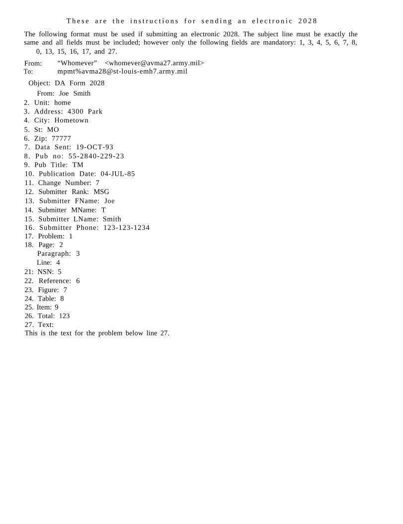
T h e s e a r e t h e i n s t r u c t i o n s f o r s e n d i n g a n e l e c t r o n i c 2 0 2 8
The following format must be used if submitting an electronic 2028. The subject line must be exactly thesame and all fields must be included; however only the following fields are mandatory: 1, 3, 4, 5, 6, 7, 8,
0, 13, 15, 16, 17, and 27.
From: “Whomever” <[email protected]>To: mpmt%[email protected]
Object: DA Form 2028
From: Joe Smith2. Unit: home3. Address: 4300 Park4. City: Hometown5. St: MO6. Zip: 777777. Data Sent: 19-OCT-938. Pub no: 55-2840-229-239. Pub Title: TM10. Publication Date: 04-JUL-8511. Change Number: 712. Submitter Rank: MSG13. Submitter FName: Joe14. Submitter MName: T15. Submitter LName: Smith16. Submitter Phone: 123-123-123417. Problem: 118. Page: 2
Paragraph: 3Line: 4
21: NSN: 522. Reference: 623. Figure: 724. Table: 825. Item: 926. Total: 12327. Text:This is the text for the problem below line 27.

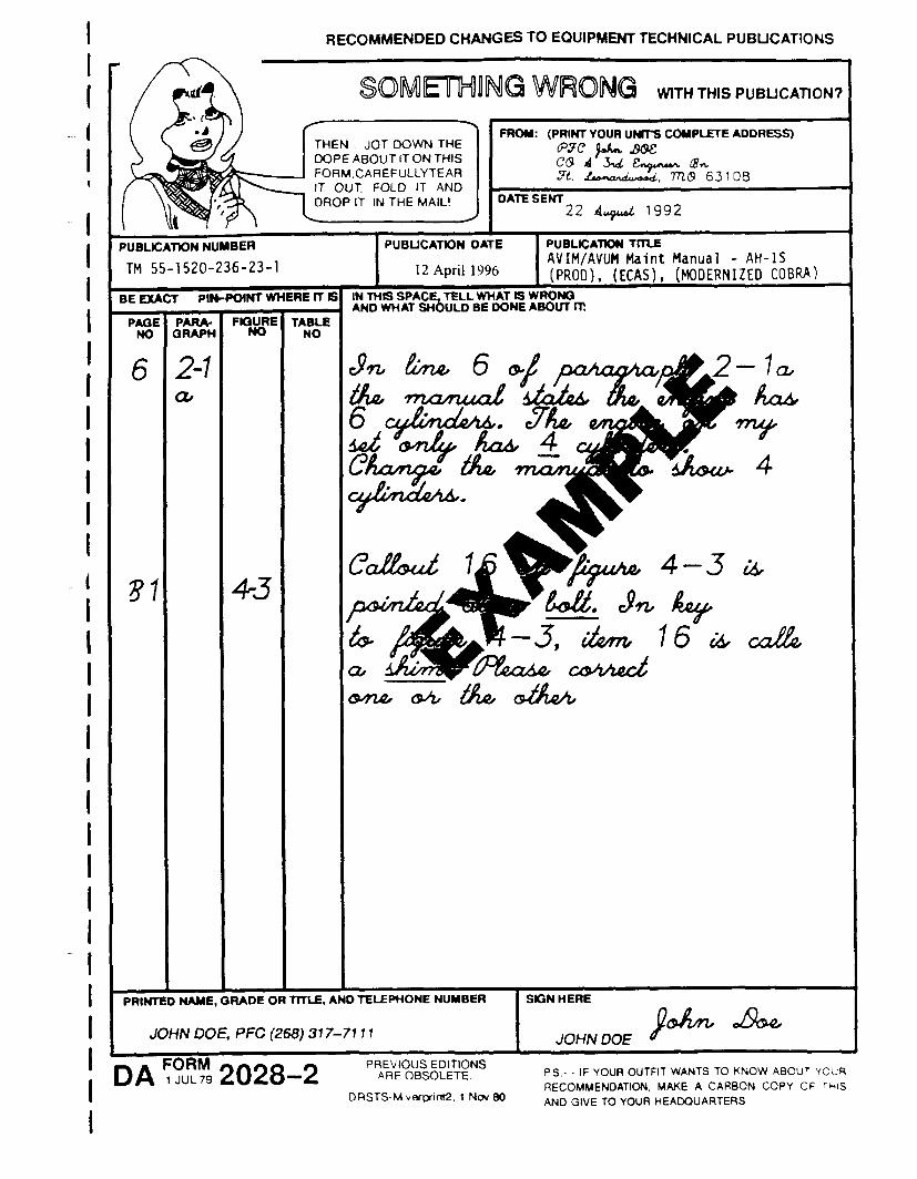


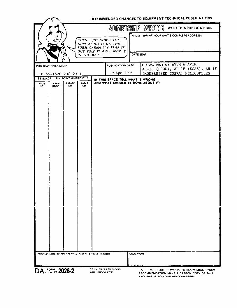


PIN : 032465-000

This fine document...
Was brought to you by me:
Liberated Manuals -- free army and government manuals
Why do I do it? I am tired of sleazy CD-ROM sellers, who take publicly available information, slap “watermarks” and other junk on it, and sell it. Those masters of search engine manipulation make sure that their sites that sell free information, come up first in search engines. They did not create it... They did not even scan it... Why should they get your money? Why are not letting you give those free manuals to your friends?
I am setting this document FREE. This document was made by the US Government and is NOT protected by Copyright. Feel free to share, republish, sell and so on.
I am not asking you for donations, fees or handouts. If you can, please provide a link to liberatedmanuals.com, so that free manuals come up first in search engines:
<A HREF=http://www.liberatedmanuals.com/>Free Military and Government Manuals</A>
– SincerelyIgor Chudovhttp://igor.chudov.com/
– Chicago Machinery Movers