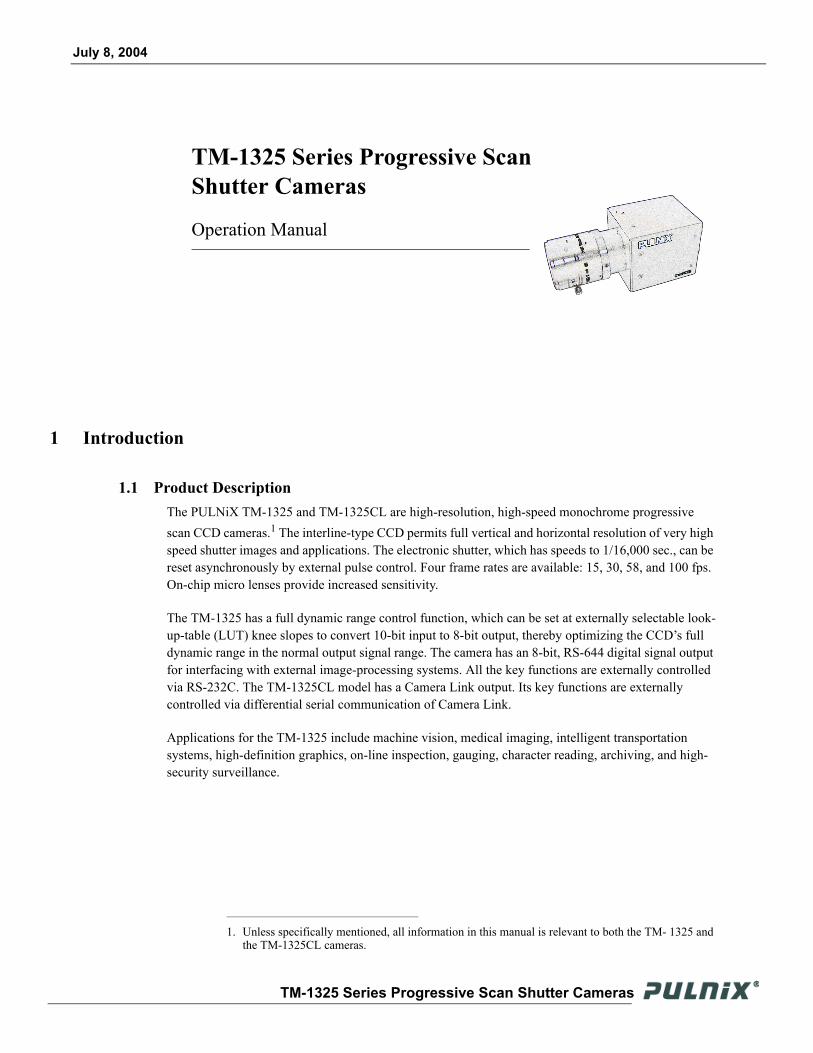
TM-1325 Series Progressive Scan Shutter Cameras - 1stVision
42
69-1143 Rev. A TM-1325 Series Progressive Scan Shutter Cameras Imaging Products Operation Manual
-
Upload
khangminh22 -
Category
Documents
-
view
1 -
download
0
Transcript of TM-1325 Series Progressive Scan Shutter Cameras - 1stVision

69-1143Rev. A
TM-1325 Series Progressive Scan Shutter Cameras
I m a g i n g P r o d u c t s
O p e r a t i o n M a n u a l

iNotice Page
TM-1325 Series Progressive Scan Shutter Camera
NoticeThe material contained in this manual consists of information that is proprietary to JAI PULNiX Inc., and may only be used by the purchasers of the product. JAI PULNiX Inc. makes no warranty for the use of its product and assumes no responsibility for any errors which may appear or for damages resulting from the use of the information contained herein. JAI PULNiX Inc. reserves the right to make changes without notice.
Microsoft, Windows 98, Windows 95, Windows NT, Windows XP, and Windows Explorer are either registered trademarks or trademarks of Microsoft Corporation in the United States and/or other countries.
WarrantyPlease contact your factory representative for warranty information.
CertificationsCE Compliance
The TM-1325 series camera has been certified to conform to the requirements of Council Directive 89/336/EC for electromag-netic compatibility and to comply with the following European Standards:
Immunity: EN50082-2/1997Emissions: CISPR22: 1997/EN55011: 1998 Class B
All JAI PULNiX products bearing the CE mark have been declared to be in conformance with the applicable EEC Council Directives. However, certain factory-installed options or customer-requested modifications may compromise electromagnetic compatibility and affect CE compliance. Please note that the use of interconnect cables that are not properly grounded and shielded may affect CE compliance.
Contact JAI PULNiX’s Applications Engineering Department for further information regarding CE compliance.
FCC
This equipment has been tested and found to comply with the limits for a Class A digital device, pursuant to Part 15 of the FCC Rules. These limits are designed to provide reasonable protection against harmful interference when the equipment is operated in a commercial environment. This equipment generates, uses and can radiate radio frequency energy and, if not installed and used in accordance with the instruction manual, may cause harmful interference to radio communications. Oper-ation of this equipment in a residential area may cause harmful interference, in which case the user will be required to correct the interference at his own expense.
WARNING Changes or modifications to this unit not expressly approved by the party responsible for
FCC compliance could void the user’s authority to operate the equipment.
TM-1325 Series Operation ManualJAI PULNiX Inc.1330 Orleans DriveSunnyvale, CA 94089Tel:(408) 747-0300 Tel:(800) 445-5444Fax:(408) 747-0880E-mail: [email protected]
ASSOCIATIO
N
AU
T
OM
ATED IMA
GIN
G
MEMBER
RE
GIS
TERED
FIR
MUL®
JAI PULNiX INC.
ISO-9001FILE #
A3942
Page iiTable of Contents
1 Introduction . . . . . . . . . . . . . . . . . . . . . . . . . . . . . . . . . . . 11.1 Product Description . . . . . . . . . . . . . . . . . . . . . . . . . . . . . 11.2 Features . . . . . . . . . . . . . . . . . . . . . . . . . . . . . . . . . . . . . . 21.3 Functional Options . . . . . . . . . . . . . . . . . . . . . . . . . . . . . . 31.4 System Configuration . . . . . . . . . . . . . . . . . . . . . . . . . . . . 4
2 Installation . . . . . . . . . . . . . . . . . . . . . . . . . . . . . . . . . . . . 52.1 Getting Started . . . . . . . . . . . . . . . . . . . . . . . . . . . . . . . . . 5
2.1.1 Unpacking Instructions . . . . . . . . . . . . . . . . . . . . . . . . . . . . . . . 52.1.2 Components List . . . . . . . . . . . . . . . . . . . . . . . . . . . . . . . . . . . . 52.1.3 Accessories and Options . . . . . . . . . . . . . . . . . . . . . . . . . . . . . 5
2.2 Camera Setup . . . . . . . . . . . . . . . . . . . . . . . . . . . . . . . . . 62.2.1 Heat Dissipation . . . . . . . . . . . . . . . . . . . . . . . . . . . . . . . . . . . . 62.2.2 Connector Pin Configurations . . . . . . . . . . . . . . . . . . . . . . . . . . 62.2.3 Shutter Speed Control Dial (TM-1325 only) . . . . . . . . . . . . . . . 92.2.4 RS-232 Communication Cable (TM-1325 only) . . . . . . . . . . . . 92.2.5 Digital Output Cable (TM-1325 only). . . . . . . . . . . . . . . . . . . . 102.2.6 Camera Link Cable (TM-1325CL only) . . . . . . . . . . . . . . . . . . 112.2.7 Power Supplies and Power Cable Setup . . . . . . . . . . . . . . . . 112.2.8 Attaching the Analog Video Output . . . . . . . . . . . . . . . . . . . . . 132.2.9 Attaching the Camera Lens. . . . . . . . . . . . . . . . . . . . . . . . . . . 13
3 Operation . . . . . . . . . . . . . . . . . . . . . . . . . . . . . . . . . . . . 143.1 Camera Rear Panel (TM-1325) . . . . . . . . . . . . . . . . . . . 14
3.1.1 Up/Down Switch . . . . . . . . . . . . . . . . . . . . . . . . . . . . . . . . . . . 143.1.2 Digital Output Connector. . . . . . . . . . . . . . . . . . . . . . . . . . . . . 143.1.3 Analog Output Connector . . . . . . . . . . . . . . . . . . . . . . . . . . . . 143.1.4 Power, RS-232, and External Sync Connector . . . . . . . . . . . . 143.1.5 Shutter Speed Control Switch . . . . . . . . . . . . . . . . . . . . . . . . . 143.1.6 Mode Selection Switch . . . . . . . . . . . . . . . . . . . . . . . . . . . . . . 14
3.2 Camera Rear Panel (TM-1325CL) . . . . . . . . . . . . . . . . . 163.2.1 Digital Output Connector (Camera Link Connector) . . . . . . . . 163.2.2 Analog Output Connector . . . . . . . . . . . . . . . . . . . . . . . . . . . . 163.2.3 Power and External Sync Connector . . . . . . . . . . . . . . . . . . . 16
3.3 Progressive Scanning. . . . . . . . . . . . . . . . . . . . . . . . . . . 173.4 Electronic Shutter . . . . . . . . . . . . . . . . . . . . . . . . . . . . . . 173.5 Integration. . . . . . . . . . . . . . . . . . . . . . . . . . . . . . . . . . . . 183.6 Asynchronous Reset . . . . . . . . . . . . . . . . . . . . . . . . . . . 18
3.6.1 External VINIT With Pulse Width . . . . . . . . . . . . . . . . . . . . . . 183.6.2 Internal Shutter Speed Control . . . . . . . . . . . . . . . . . . . . . . . . 19
3.7 Dynamic Range Control . . . . . . . . . . . . . . . . . . . . . . . . 203.7.1 Programmable Look-Up Table (LUT) and Knee Control . . . . . 20
3.8 Scan Modes . . . . . . . . . . . . . . . . . . . . . . . . . . . . . . . . . . 213.8.1 Full Progressive Scan . . . . . . . . . . . . . . . . . . . . . . . . . . . . . . . 213.8.2 Partial Scan. . . . . . . . . . . . . . . . . . . . . . . . . . . . . . . . . . . . . . . 21
3.9 External Sync . . . . . . . . . . . . . . . . . . . . . . . . . . . . . . . . . 213.10Camera Timing Charts . . . . . . . . . . . . . . . . . . . . . . . . . . 22
TM-1325 Series Progressive Scan Shutter Cameras
Page iiiTable of Contents
3.11Serial Communication Kit CS-232C (not required for “CL” version) . . . . . . . . . . . . . . . . . . . . 26
4 Troubleshooting . . . . . . . . . . . . . . . . . . . . . . . . . . . . . . 274.1 Problems and Solutions . . . . . . . . . . . . . . . . . . . . . . . . . 27
4.1.1 Symptom: No Video. . . . . . . . . . . . . . . . . . . . . . . . . . . . . . . . . 274.1.2 Symptom: Dark Video . . . . . . . . . . . . . . . . . . . . . . . . . . . . . . . 274.1.3 Symptom: Non-Synchronized Video . . . . . . . . . . . . . . . . . . . . 27
4.2 Troubleshooting Flowchart. . . . . . . . . . . . . . . . . . . . . . . 284.3 Troubleshooting Flowchart 2 . . . . . . . . . . . . . . . . . . . . . 294.4 Information and Support Resources . . . . . . . . . . . . . . . 30
5 Appendix . . . . . . . . . . . . . . . . . . . . . . . . . . . . . . . . . . . . 315.1 Specifications . . . . . . . . . . . . . . . . . . . . . . . . . . . . . . . . . 31
5.1.1 Physical Dimensions . . . . . . . . . . . . . . . . . . . . . . . . . . . . . . . . 33
TM-1325 Series Progressive Scan Shutter Cameras

Page ivList of Figures
TM-1325 Series Progressive Scan Shutter Cameras
FIGURE 1. TM-1325 System Configuration . . . . . . . . . . . . . . . . . . . . . . . . . . . . . . . . . . .4
FIGURE 2. TM-1325CL System Configuration . . . . . . . . . . . . . . . . . . . . . . . . . . . . . . . . .4
FIGURE 3. 12-Pin Connector on Rear Panel of Camera . . . . . . . . . . . . . . . . . . . . . . . . .6
FIGURE 4. 31-Pin Digital Connector on Rear Panel of Camera (TM-1325 only) . . . . . . .7
FIGURE 5. Serial Communication Cable RS-232B-12 . . . . . . . . . . . . . . . . . . . . . . . . . . .9
FIGURE 6. Pinout Configuration for Digital Output Cable . . . . . . . . . . . . . . . . . . . . . . . .10
FIGURE 7. 12P-02S Interface Cable (optional). . . . . . . . . . . . . . . . . . . . . . . . . . . . . . . .12
FIGURE 8. Pulse Width Async Shutter Timing . . . . . . . . . . . . . . . . . . . . . . . . . . . . . . . .19
FIGURE 9. Physical Dimensions (TM-1325) . . . . . . . . . . . . . . . . . . . . . . . . . . . . . . . . . .33
FIGURE 10.Physical Dimensions (TM-1325CL) . . . . . . . . . . . . . . . . . . . . . . . . . . . . . . .33
Page vList of Tables
TM-1325 Series Progressive Scan Shutter Cameras
TABLE 1. 12-Pin Connector (TM-1325) . . . . . . . . . . . . . . . . . . . . . . . . . . . . . . .6
TABLE 2. 12-Pin Connector (TM-1325CL). . . . . . . . . . . . . . . . . . . . . . . . . . . . .6
TABLE 3. 31-Pin Connector (MP211-031-113-4300) . . . . . . . . . . . . . . . . . . . . .7
TABLE 4. Connector Pinout Configurations (10226-6212 VC). . . . . . . . . . . . . .8
TABLE 5. Shutter Speed Control Dial. . . . . . . . . . . . . . . . . . . . . . . . . . . . . . . . .9
TABLE 6. Mode Selection Switch. . . . . . . . . . . . . . . . . . . . . . . . . . . . . . . . . . .15
TABLE 7. TM-1325 and TM-1325CL Product Specifications Table . . . . . . . . .31
July 8, 2004
TM-1325 Series Progressive Scan Shutter Cameras
Operation Manual
1 Introduction
1.1 Product DescriptionThe PULNiX TM-1325 and TM-1325CL are high-resolution, high-speed monochrome progressive scan CCD cameras.1 The interline-type CCD permits full vertical and horizontal resolution of very high speed shutter images and applications. The electronic shutter, which has speeds to 1/16,000 sec., can be reset asynchronously by external pulse control. Four frame rates are available: 15, 30, 58, and 100 fps. On-chip micro lenses provide increased sensitivity.
The TM-1325 has a full dynamic range control function, which can be set at externally selectable look-up-table (LUT) knee slopes to convert 10-bit input to 8-bit output, thereby optimizing the CCD’s full dynamic range in the normal output signal range. The camera has an 8-bit, RS-644 digital signal output for interfacing with external image-processing systems. All the key functions are externally controlled via RS-232C. The TM-1325CL model has a Camera Link output. Its key functions are externally controlled via differential serial communication of Camera Link.
Applications for the TM-1325 include machine vision, medical imaging, intelligent transportation systems, high-definition graphics, on-line inspection, gauging, character reading, archiving, and high-security surveillance.
1. Unless specifically mentioned, all information in this manual is relevant to both the TM- 1325 and the TM-1325CL cameras.
TM-1325 Series Progressive Scan Shutter Cameras
Page 2Introduction
1.2 Features• Miniaturized and lightweight
The printed circuit boards in the TM-1325 have been arranged with a new design philosophy in mind. This creates modular electronics for the camera, giving it flexibility. In addition, the use of miniature solid-state components results in a compact, lightweight camera that is 44mm x 44mm x 64mm in dimensions, and weighs only 140 grams.
• Imager
The TM-1325 uses a progressive scan interline transfer CCD that has the following features:- Resolution of 1392 x 1040 active pixels for excellent image quality.- 6.45 x 6.45 µm square pixels for precise dimensional measurement.- High-speed electronic shutter capability for high dynamic resolution of moving objects and
electronic iris control that eliminates the need for a mechanical shutter.- Progressive scan CCD eliminates interlace deterioration of image and increases ease of
computer interface.- High sensitivity and low noise at fast scanning. The CCD can drive faster than 55 MHz
pixel clock rate and has an excellent S/N ratio that is greater than 50dB.- The CCD for the TM-1325 has built-in microlenses.
• Electronic shutter
The TM-1325 has a substrate drain-type shutter mechanism which provides superb pictures at various speeds without smearing. A built-in manual shutter speed control selects the electronic shutter rate of 1/60 (non-async mode only), 1/125, 1/250, 1/500, 1/1,000, 1/2,000, 1/4,000, 1/8,000, or 1/16,000 second.With VINIT high (5V), the CCD keeps discharging. With a negative pulse to VINIT, the camera resets and purges the charge momentarily. Then it starts integrating for the period of shutter control set by either an external pulse width or internal shutter control. Progressive scanning permits a full 1040 lines of vertical resolution, as compared to a conventional CCD camera which captures only half the vertical lines per shutter.
• Asynchronous reset
The TM-1325’s asynchronous reset is flexible and accepts external horizontal drive (HD) for phase locking. When the VINIT pulse is applied, it resets the camera's scanning and purging of the CCD. There are two modes to control the asynchronous reset and shutter speed:
- External VINIT with pulse width. The duration between pulse edges controls the shutter speed externally.
- Internal shutter control mode. The speed control varies from 1/125 to 1/16,000 sec. The video signal starts with internal V reset timing related to shutter speed.
TM-1325 Series Progressive Scan Shutter Cameras

Page 3Introduction
• Output
The TM-1325 has an 8-bit RS-644 (LVDS) digital output for interfacing with external image-processing systems. The TM-1325 camera is also available with RS-422 digital output as an option (OP-93). The TM-1325CL has a Camera Link output. The analog output is 1.0 Vp-p composite video (75 ohms).
• Asynchronous image capturing
The TM-1325 captures async reset images and provides single-shot video output with single FDV. This makes it simpler for an ordinary frame grabber to capture the async reset images.
• Integration
The TM-1325 is capable of capturing high-resolution integration images. Its CCD imager can be exposed for longer than the normal scan timing of 1/30 sec. This integration feature provides extra sensitivity for applications in dark environments. The progressive scan imager permits a full frame of resolution in non-interlace format. Integration is achieved by controlling the #11 pin of the 12-pin connector to low (GND) or pulse width control VINIT to pin #6 of the 12-pin connector up to 1 second.
• Warranty
Contact your factory representative for warranty information.
1.3 Functional Options • Back-focus adjustment (OP97).
• Differential input, VINIT (OP89-3).
• Differential input, VD (OP89-4).
• RS-422 (digital) output for the TM-1325 (93).
TM-1325 Series Progressive Scan Shutter Cameras
Page 4Introduction
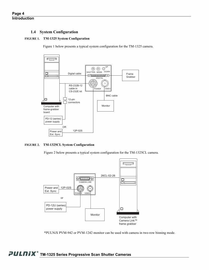
1.4 System ConfigurationFIGURE 1. TM-1325 System Configuration
Figure 1 below presents a typical system configuration for the TM-1325 camera.
FIGURE 2. TM-1325CL System Configuration
Figure 2 below presents a typical system configuration for the TM-1325CL camera.
Computer with
frame-grabber
board
Monitor
PD-12 (series)
power supply
Power and
Ext. Sync
Digital cableSHUTTER MODE
UP
DOWN
POWER VIDEO
098
7
6 54
3
1
2
10FE
DC
BA
2 34
5
6
789
DIGITAL
BNC cable
12P-02S
RS-232B-12
cable in
CS-232E kit
1
2
3
4 5 6
9
8
711 12
10
12-pin
connectors
OR
Frame
Grabber
CAMERA LINK
POWER VIDEO
Computer with
Camera Link™
frame grabber
PD-12U (series)
power supply
Power and
Ext. Sync
26CL-02-26
12P-02S
or
Monitor
1
2
3
4 5 6
9
8
711 12
10
*PULNiX PVM-942 or PVM-1242 monitor can be used with camera in two-row binning mode.
TM-1325 Series Progressive Scan Shutter Cameras
Page 5Installation
2 Installation
The following instructions are provided to help you to set up your camera quickly and easily. We suggest that you read through these instructions before you unpack and set up your camera system.
2.1 Getting Started
2.1.1 Unpacking Instructions
We recommend that you save the original packing cartons for the cameras and accessories in case you need to return or exchange an item.
We also recommend that you bench-test any equipment being sent to another location for field installation to assure that everything is fully operational as a system.
2.1.2 Components List
Please begin by checking your order against the Components List shown below to assure that you have received everything as ordered, and that nothing has been overlooked in the packing materials. If any item is missing, please contact your JAI PULNiX representative immediately.
• TM-1325 camera
• TM-1325 operation manual (if ordered)
• Camera-control software manual
• Camera-control software
2.1.3 Accessories and Options
Following is a list of additional accessories and options that may be required for your application. Please check with your PULNiX representative before you install your camera to determine what you might need.
• Digital output cable (not required for “CL” version)
- 30DG-02 (for standard model only)- 26CL-02-26 (for Camera Link model only)
• Serial Communication Kit CS-232E (not required for “CL” version)
Note: For CL models, the control software is included and serial communication is through the Camera Link cable. No additional accessories are required.
• PD-12UUP series power supply
• 12P-02S power cable
TM-1325 Series Progressive Scan Shutter Cameras
Page 6Installation
2.2 Camera Setup
2.2.1 Heat Dissipation
The TM-1325 camera is a compact 1.3K x 1K camera. Since all the electronics have been packed in a compact package, the outer case of the camera gets hot due to heat dissipation. JAI PULNiX recommends the following procedure for optimal performance of the camera:
1. Mount the camera on a large heat sink (camera bracket) made out of conductivematerial like aluminum.
2. Make sure the flow of heat from the camera case to the bracket is not blocked by a non-conducting material like plastic.
3. Make sure the camera has enough open space around it to facilitate the free flow of air.4. If possible, use a cooling fan to set up a positive air flow around the camera.
2.2.2 Connector Pin Configurations
2.2.2 (a) 12-Pin Connector (TM-1325)
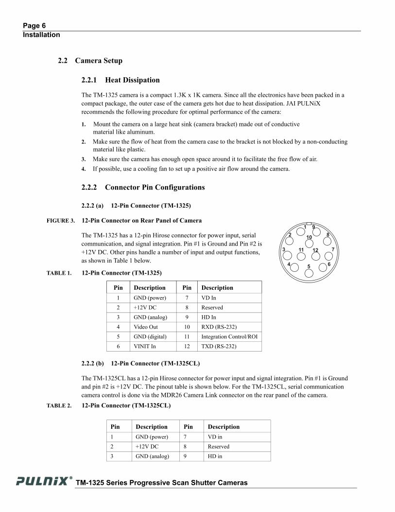
FIGURE 3. 12-Pin Connector on Rear Panel of Camera
The TM-1325 has a 12-pin Hirose connector for power input, serial communication, and signal integration. Pin #1 is Ground and Pin #2 is +12V DC. Other pins handle a number of input and output functions, as shown in Table 1 below.
TABLE 1. 12-Pin Connector (TM-1325)
2.2.2 (b) 12-Pin Connector (TM-1325CL)
The TM-1325CL has a 12-pin Hirose connector for power input and signal integration. Pin #1 is Ground and pin #2 is +12V DC. The pinout table is shown below. For the TM-1325CL, serial communication camera control is done via the MDR26 Camera Link connector on the rear panel of the camera.
Pin Description Pin Description1 GND (power) 7 VD In
2 +12V DC 8 Reserved
3 GND (analog) 9 HD In
4 Video Out 10 RXD (RS-232)
5 GND (digital) 11 Integration Control/ROI
6 VINIT In 12 TXD (RS-232)
TABLE 2. 12-Pin Connector (TM-1325CL)
Pin Description Pin Description1 GND (power) 7 VD in
2 +12V DC 8 Reserved
3 GND (analog) 9 HD in
1
2
3
45
6
9
8
711 12
10
TM-1325 Series Progressive Scan Shutter Cameras

Page 7Installation
2.2.2 (c) Digital Output Connector (TM-1325 only)
The TM-1325 has a 31-pin AirBorn connector (MP211-031-113-4300) on the rear panel to output 8-bit, RS-644 video data. The connector pin-out is shown in the figure below.
FIGURE 4. 31-Pin Digital Connector on Rear Panel of Camera (TM-1325 only)
Note: CLK: data clock, LDV: Line Data Valid, FDV: Frame Data Valid, INTEG: Integration control, EXT CLK: external pixel clock, []: Differential input option.
4 Video out 10 N/C
5 GND (digital) 11 Integration Control/ROI
6 VINIT in 12 N/C
TABLE 3. 31-Pin Connector (MP211-031-113-4300)
Pin # Description I/O Pin # Description I/O1 CLK+ Out 17 CLK- Out
2 LDV+ Out 18 LDV- Out
3 FDV+ Out 19 FDV- Out
4 GND 20 VINIT (TTL)[Integ (TTL)]
InIn
5 EXT HD (TTL)[EXT CLK+]
In 21 EXT VD (TTL)[EXT CLK-]
In
6 INTEG (TTL)[HD+]
InIn
22 N/C[HD-] In
7 N/C[VINIT+/(VD+)] In
23 GND[VINIT-/(VD-)] In
8 D0+ Out 24 D0- Out
9 D1+ Out 25 D1- Out
10 D2+ Out 26 D2- Out
11 D3+ Out 27 D3- Out
12 D4+ Out 28 D4- Out
13 D5+ Out 29 D5- Out
14 D6+ Out 30 D6- Out
15 D7+ Out 31 D7- Out
16 GND
TABLE 2. 12-Pin Connector (TM-1325CL) (Continued)
Pin Description Pin Description
1
1731
16
TM-1325 Series Progressive Scan Shutter Cameras
Page 8Installation
2.2.2 (d) Camera Link Connector
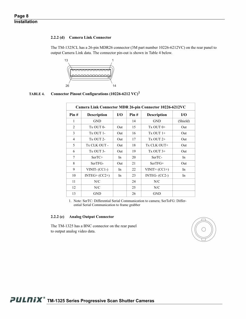
The TM-1325CL has a 26-pin MDR26 connector (3M part number 10226-6212VC) on the rear panel to output Camera Link data. The connector pin-out is shown in Table 4 below.
2.2.2 (e) Analog Output Connector
The TM-1325 has a BNC connector on the rear panel to output analog video data.
TABLE 4. Connector Pinout Configurations (10226-6212 VC)1
1. Note: SerTC: Differential Serial Communication to camera; SerToFG: Differ-ential Serial Communication to frame grabber
Camera Link Connector MDR 26-pin Connector 10226-6212VC
Pin # Description I/O Pin # Description I/O1 GND 14 GND (Shield)
2 Tx OUT 0- Out 15 Tx OUT 0+ Out
3 Tx OUT 1- Out 16 Tx OUT 1+ Out
4 Tx OUT 2- Out 17 Tx OUT 2+ Out
5 Tx CLK OUT - Out 18 Tx CLK OUT+ Out
6 Tx OUT 3- Out 19 Tx OUT 3+ Out
7 SerTC+ In 20 SerTC- In
8 SerTFG- Out 21 SerTFG+ Out
9 VINIT- (CC1-) In 22 VINIT+ (CC1+) In
10 INTEG+ (CC2+) In 23 INTEG- (CC2-) In
11 N/C 24 N/C
12 N/C 25 N/C
13 GND 26 GND
1
1426
13
TM-1325 Series Progressive Scan Shutter Cameras
Page 9Installation
2.2.3 Shutter Speed Control Dial (TM-1325 only)
Shutter speed can be selected by switching the shutter dial to the appropriate setting (0 through 9). The factory default settings correspond to the shutter speeds as shown in below.
2.2.4 RS-232 Communication Cable (TM-1325 only)
FIGURE 5. Serial Communication Cable RS-232B-12
The RS-232 controller set CS-232E includes cable RS-232B-12 interface cable, software disk, and a quick-start card. The TM-1325 camera’s built-in look-up table (LUT) can be controlled by an external RS-232 interface. The camera settings can be programmed or changed using the communication cable and software. Commands from the RS-232 interface will override the rear panel switch settings of the camera. Please refer to the camera control software manual for details on the graphical user interface.
TABLE 5. Shutter Speed Control Dial
Shutter Exposure Time (Seconds)
Normal Async0 no shutter (1/30) no shutter (1/30)
1 1/60 1/16,000
2 1/125 1/8,000
3 1/250 1/4,000
4 1/500 1/2,000
5 1/1,000 1/1,000
6 1/2,000 1/500
7 1/4,000 1/250
8 1/8,000 1/125
9 1/16,000 Ext. pulse width control
01 23
46
78
9
5
Receptacle
40±3mm
75mm±5mm Jack
1925±10mm
2000±20mm
190±5mm
61
5 9
TM-1325 Series Progressive Scan Shutter Cameras
Page 10Installation
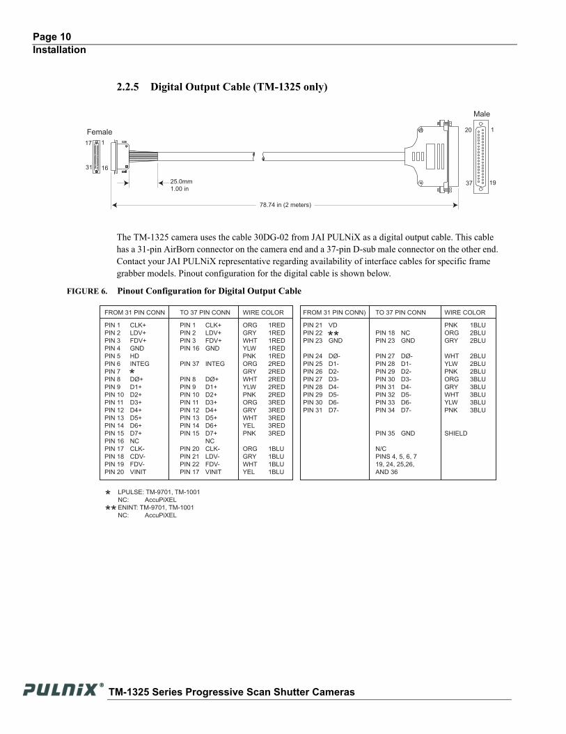
2.2.5 Digital Output Cable (TM-1325 only)
The TM-1325 camera uses the cable 30DG-02 from JAI PULNiX as a digital output cable. This cable has a 31-pin AirBorn connector on the camera end and a 37-pin D-sub male connector on the other end. Contact your JAI PULNiX representative regarding availability of interface cables for specific frame grabber models. Pinout configuration for the digital cable is shown below.
FIGURE 6. Pinout Configuration for Digital Output Cable
25.0mm 1.00 in
20 1
1937
1631
17 1
Female
78.74 in (2 meters)
Male
PIN 1 CLK+
PIN 2 LDV+
PIN 3 FDV+
PIN 4 GND
PIN 5 HD
PIN 6 INTEG
PIN 7
PIN 8 DØ+
PIN 9 D1+
PIN 10 D2+
PIN 11 D3+
PIN 12 D4+
PIN 13 D5+
PIN 14 D6+
PIN 15 D7+
PIN 16 NC
PIN 17 CLK-
PIN 18 CDV-
PIN 19 FDV-
PIN 20 VINIT
FROM 31 PIN CONN
PIN 1 CLK+
PIN 2 LDV+
PIN 3 FDV+
PIN 16 GND
PIN 37 INTEG
PIN 8 DØ+
PIN 9 D1+
PIN 10 D2+
PIN 11 D3+
PIN 12 D4+
PIN 13 D5+
PIN 14 D6+
PIN 15 D7+
NC
PIN 20 CLK-
PIN 21 LDV-
PIN 22 FDV-
PIN 17 VINIT
ORG 1RED
GRY 1RED
WHT 1RED
YLW 1RED
PNK 1RED
ORG 2RED
GRY 2RED
WHT 2RED
YLW 2RED
PNK 2RED
ORG 3RED
GRY 3RED
WHT 3RED
YEL 3RED
PNK 3RED
ORG 1BLU
GRY 1BLU
WHT 1BLU
YEL 1BLU
PIN 21 VD
PIN 22
PIN 23 GND
PIN 24 DØ-
PIN 25 D1-
PIN 26 D2-
PIN 27 D3-
PIN 28 D4-
PIN 29 D5-
PIN 30 D6-
PIN 31 D7-
PIN 18 NC
PIN 23 GND
PIN 27 DØ-
PIN 28 D1-
PIN 29 D2-
PIN 30 D3-
PIN 31 D4-
PIN 32 D5-
PIN 33 D6-
PIN 34 D7-
PIN 35 GND
N/C
PINS 4, 5, 6, 7
19, 24, 25,26,
AND 36
PNK 1BLU
ORG 2BLU
GRY 2BLU
WHT 2BLU
YLW 2BLU
PNK 2BLU
ORG 3BLU
GRY 3BLU
WHT 3BLU
YLW 3BLU
PNK 3BLU
SHIELD
TO 37 PIN CONN WIRE COLOR FROM 31 PIN CONN) TO 37 PIN CONN WIRE COLOR
*
LPULSE: TM-9701, TM-1001
NC: AccuPiXEL
ENINT: TM-9701, TM-1001
NC: AccuPiXEL
***
**
TM-1325 Series Progressive Scan Shutter Cameras
Page 11Installation
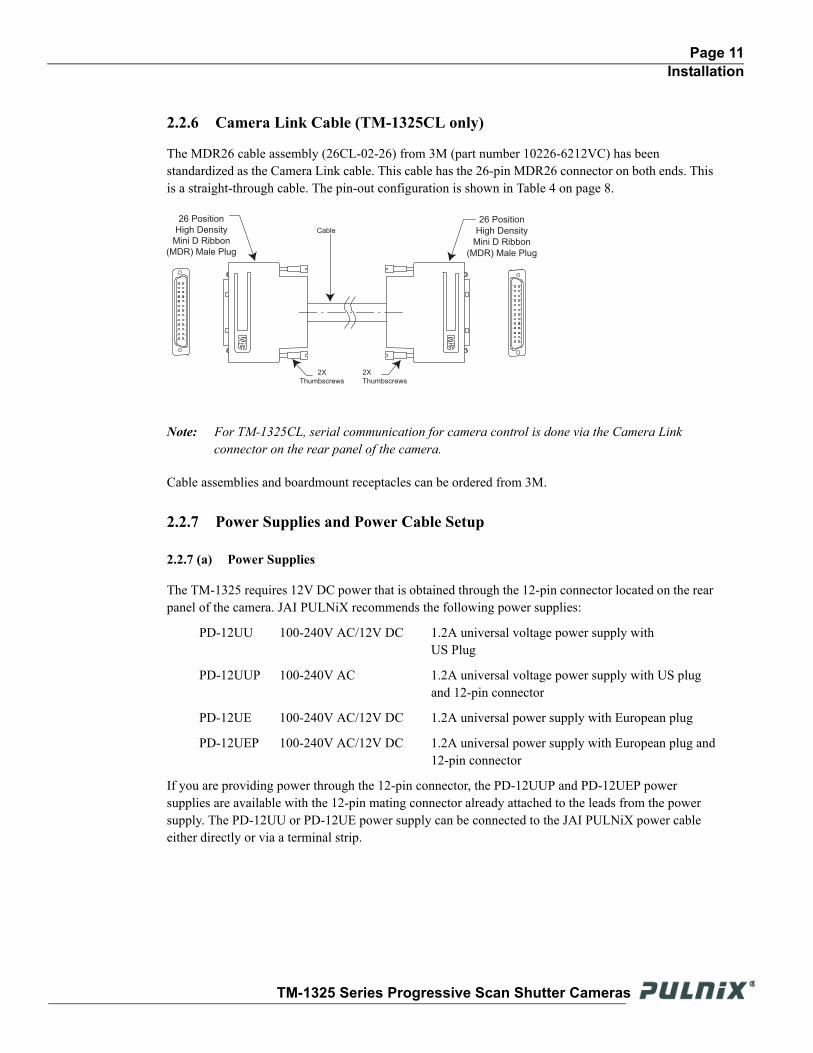
2.2.6 Camera Link Cable (TM-1325CL only)
The MDR26 cable assembly (26CL-02-26) from 3M (part number 10226-6212VC) has been standardized as the Camera Link cable. This cable has the 26-pin MDR26 connector on both ends. This is a straight-through cable. The pin-out configuration is shown in Table 4 on page 8.
Note: For TM-1325CL, serial communication for camera control is done via the Camera Link connector on the rear panel of the camera.
Cable assemblies and boardmount receptacles can be ordered from 3M.
2.2.7 Power Supplies and Power Cable Setup
2.2.7 (a) Power Supplies
The TM-1325 requires 12V DC power that is obtained through the 12-pin connector located on the rear panel of the camera. JAI PULNiX recommends the following power supplies:
PD-12UU 100-240V AC/12V DC 1.2A universal voltage power supply withUS Plug
PD-12UUP 100-240V AC 1.2A universal voltage power supply with US plugand 12-pin connector
PD-12UE 100-240V AC/12V DC 1.2A universal power supply with European plug
PD-12UEP 100-240V AC/12V DC 1.2A universal power supply with European plug and12-pin connector
If you are providing power through the 12-pin connector, the PD-12UUP and PD-12UEP power supplies are available with the 12-pin mating connector already attached to the leads from the power supply. The PD-12UU or PD-12UE power supply can be connected to the JAI PULNiX power cable either directly or via a terminal strip.
26 Position
High Density
Mini D Ribbon
(MDR) Male Plug
Cable
26 Position
High Density
Mini D Ribbon
(MDR) Male Plug
2X
Thumbscrews
2X
Thumbscrews
12
3
14
15
16
11
12
13
24
25
26
4
56
17
18
19
78
9
20
21
22
10 23
12
3
14
15
16
11
12
13
24
25
26
4
56
17
18
19
78
9
20
21
22
1023
TM-1325 Series Progressive Scan Shutter Cameras
Page 12Installation
When wiring the PD-12UU power supply directly, please note the following:
• The lead ends must be twisted together and tin-soldered for strength and electrical continuity.
• Shrink tubing or a similar insulator should be used to prevent exposed leads from touching and shorting.
• The +12V lead is marked with a red stripe or white lettering; be sure not to reverse the leads.
• All connections must be properly insulated to prevent shorting.
2.2.7 (b) PULNiX Power Cables
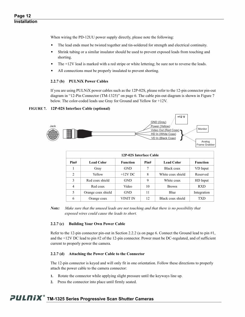
If you are using PULNiX power cables such as the 12P-02S, please refer to the 12-pin connector pin-out diagram in “12-Pin Connector (TM-1325)” on page 6. The cable pin-out diagram is shown in Figure 7 below. The color-coded leads use Gray for Ground and Yellow for +12V.
FIGURE 7. 12P-02S Interface Cable (optional)
Note: Make sure that the unused leads are not touching and that there is no possibility that exposed wires could cause the leads to short.
2.2.7 (c) Building Your Own Power Cable
Refer to the 12-pin connector pin-out in Section 2.2.2 (a on page 6. Connect the Ground lead to pin #1, and the +12V DC lead to pin #2 of the 12-pin connector. Power must be DC-regulated, and of sufficient current to properly power the camera.
2.2.7 (d) Attaching the Power Cable to the Connector
The 12-pin connector is keyed and will only fit in one orientation. Follow these directions to properly attach the power cable to the camera connector:
1. Rotate the connector while applying slight pressure until the keyways line up. 2. Press the connector into place until firmly seated.
12P-02S Interface Cable
Pin# Lead Color Function Pin# Lead Color Function
1 Gray GND 7 Black coax VD Input
2 Yellow +12V DC 8 White coax shield Reserved
3 Red coax shield GND 9 White coax HD Input
4 Red coax Video 10 Brown RXD
5 Orange coax shield GND 11 Blue Integration
6 Orange coax VINIT IN 12 Black coax shield TXD
HD In (White Coax)
Video Out (Red Coax)
VD In (Black Coax)
Power (Yellow)
+12 V
Monitor
Analog Frame Grabber
GND (Gray)
}Jack
TM-1325 Series Progressive Scan Shutter Cameras
Page 13Installation
3. Plug the power cord into the 100V AC socket. This will power the camera up.
2.2.8 Attaching the Analog Video Output
When connecting the TM-1325 to an analog frame grabber or a monitor, use the BNC connector on the rear panel of the camera. The input of the monitor should be balanced for 75 ohms termination. Standard RG-59 type coaxial cable should carry a full video signal for up to 100 feet. The TM-1325 has a two-row binning mode that can be used to display real-time images on PULNiX’s PVM-942 or PVM-1242 monitors. These monitors are specially modified to accept a 30Hz progressive scan image.
The multi-conductor cable 12P-02S from PULNiX can be used to transmit analog video, power, sync. signals, and serial communication. The mini coaxial leads in PULNiX multi-conductor cables are designed for short runs of no longer than 100 feet.
Note: Make sure that no extraneous wires are visible which could cause a short.
2.2.9 Attaching the Camera Lens
The TM-1325 camera accepts 2/3" or larger format size C-mount lenses. To attach the C-mount lens to the camera, carefully engage the threads and rotate the lens clockwise until it firmly seats on the mounting ring. Do not force the lens if it does not seat properly. Please note that some lenses with extremely long flangebacks may exceed the mounting depth of the camera.
TM-1325 Series Progressive Scan Shutter Cameras

Page 14Operation
3 Operation
3.1 Camera Rear Panel (TM-1325)
3.1.1 Up/Down Switch
The Mode Selection switch works in conjunction with the Up/Down switch. Refer to Table 6 on page 15 for information on the Up/Down switch.
3.1.2 Digital Output Connector
Refer to Section 2.2.2 (c on page 7 for information on the digital output connector.
3.1.3 Analog Output Connector
The TM-1325 camera has a BNC connector on the rear panel to output analog video data.
3.1.4 Power, RS-232, and External Sync Connector
Refer to Section 2.2.2 on page 6 for information on the power, RS-232, and external sync connector.
3.1.5 Shutter Speed Control Switch
Please refer to Section 2.2.3 on page 9 for information on the Shutter Speed Control switch. The factory default setting to the shutter speeds is no shutter.
3.1.6 Mode Selection Switch
Various modes can be implemented with the rear panel Mode Selection switch. The Mode Selection switch works in conjunction with the Up/Down switch and RS-232 external control. Commands from
SHUTTER MODE
UP
DOWN
POWER VIDEO
098
7
6 54
3
1
2
10FE
DC
BA
2 34
5
6
789
DIGITAL1
2
3
45
6
9
8
711 12
10
Up/Down switch
Digital Output connector
Analog Output connectorPower, RS-232, and External Sync Connector
Mode Selection switch
Shutter SpeedControl switch
TM-1325 Series Progressive Scan Shutter Cameras
Page 15Operation
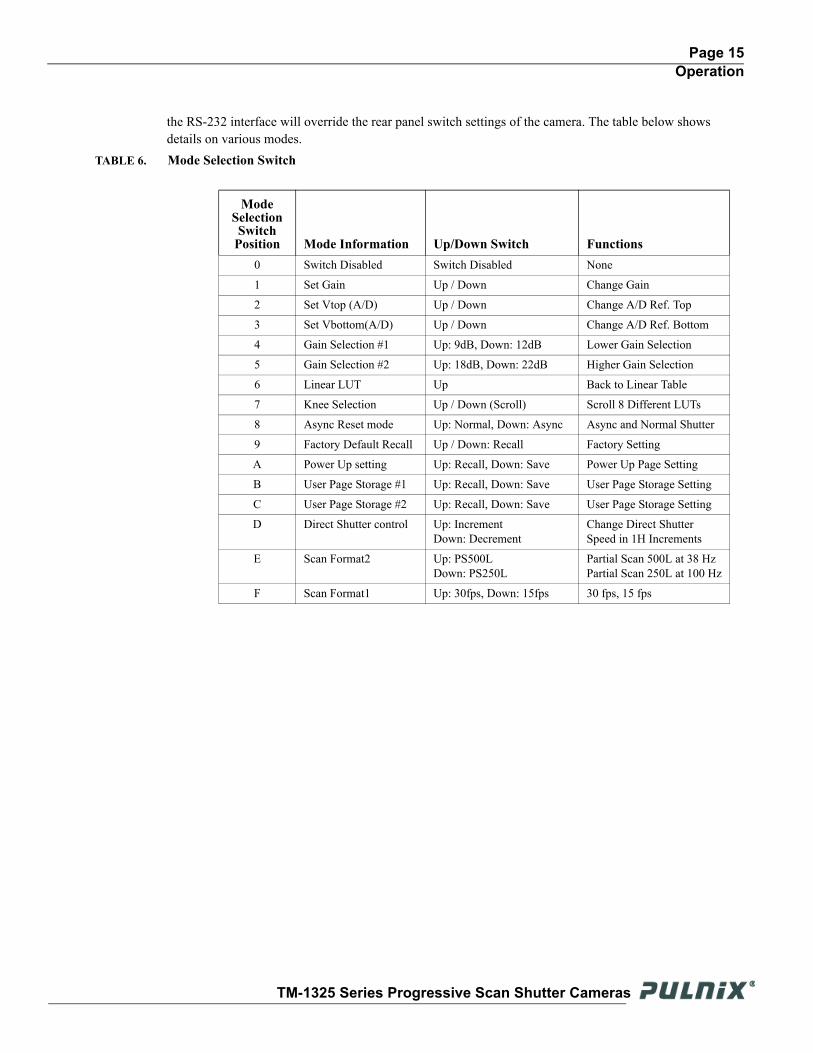
the RS-232 interface will override the rear panel switch settings of the camera. The table below shows details on various modes.
TABLE 6. Mode Selection Switch
Mode Selection Switch
Position Mode Information Up/Down Switch Functions0 Switch Disabled Switch Disabled None
1 Set Gain Up / Down Change Gain
2 Set Vtop (A/D) Up / Down Change A/D Ref. Top
3 Set Vbottom(A/D) Up / Down Change A/D Ref. Bottom
4 Gain Selection #1 Up: 9dB, Down: 12dB Lower Gain Selection
5 Gain Selection #2 Up: 18dB, Down: 22dB Higher Gain Selection
6 Linear LUT Up Back to Linear Table
7 Knee Selection Up / Down (Scroll) Scroll 8 Different LUTs
8 Async Reset mode Up: Normal, Down: Async Async and Normal Shutter
9 Factory Default Recall Up / Down: Recall Factory Setting
A Power Up setting Up: Recall, Down: Save Power Up Page Setting
B User Page Storage #1 Up: Recall, Down: Save User Page Storage Setting
C User Page Storage #2 Up: Recall, Down: Save User Page Storage Setting
D Direct Shutter control Up: IncrementDown: Decrement
Change Direct Shutter Speed in 1H Increments
E Scan Format2 Up: PS500LDown: PS250L
Partial Scan 500L at 38 HzPartial Scan 250L at 100 Hz
F Scan Format1 Up: 30fps, Down: 15fps 30 fps, 15 fps
TM-1325 Series Progressive Scan Shutter Cameras
Page 16Operation
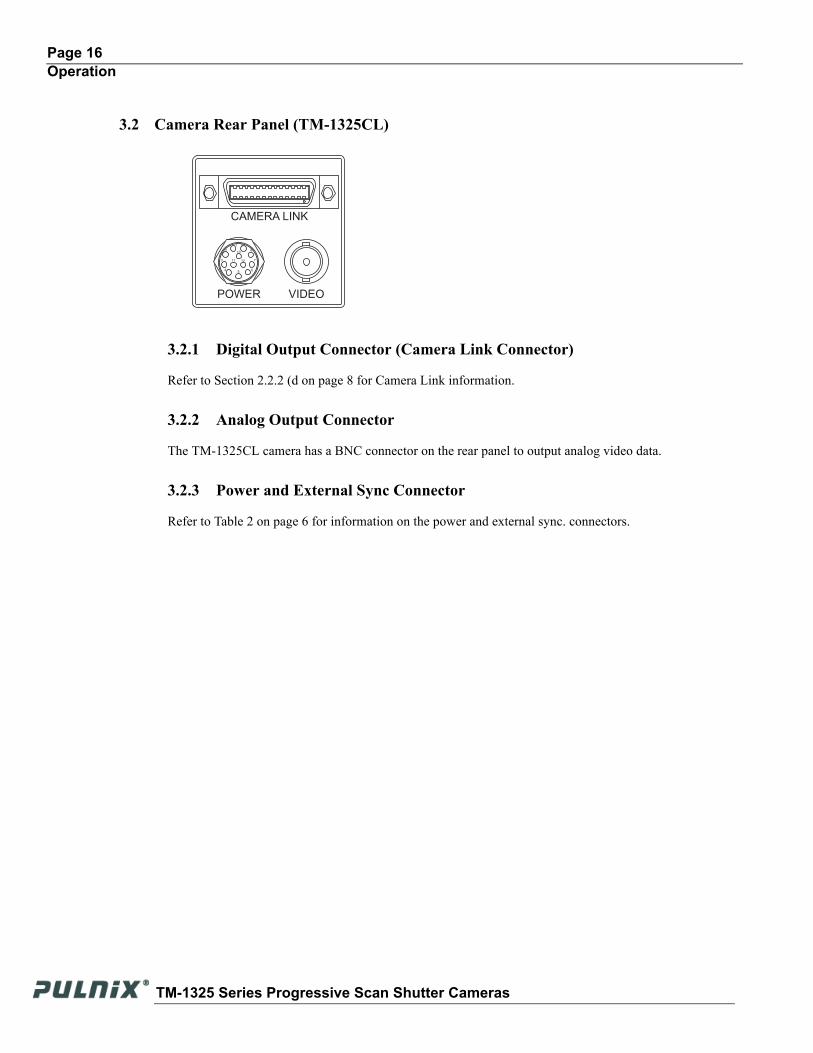
3.2 Camera Rear Panel (TM-1325CL)
3.2.1 Digital Output Connector (Camera Link Connector)
Refer to Section 2.2.2 (d on page 8 for Camera Link information.
3.2.2 Analog Output Connector
The TM-1325CL camera has a BNC connector on the rear panel to output analog video data.
3.2.3 Power and External Sync Connector
Refer to Table 2 on page 6 for information on the power and external sync. connectors.
CAMERA LINK
POWER VIDEO
1
2
3
4 5 6
9
8
711 12
10
TM-1325 Series Progressive Scan Shutter Cameras
Page 17Operation
3.3 Progressive ScanningStandard TV-system scanning is 525 lines interlace scanning as specified in the RS-170 protocol. Every other horizontal line (odd lines and even lines) is scanned at a 60Hz rate per field, and the scanning is completed with two fields (one frame) at 30Hz rate. Because of the interlace scanning, the vertical resolution of CCD cameras is limited at 350 TV lines, regardless of the horizontal resolution. When electronic shutter is applied, the CCD can hold only one field of charge at each exposure. Therefore, the vertical resolution of the electronic-shutter camera is only 244 TV lines. The situation is the same for an HDTV-format camera, since it has interlaced scanning and the vertical resolution of the shuttered image is 500 lines.
The TM-1325 uses a state-of-the-art progressive scanning interline transfer CCD which scans all lines sequentially from top to bottom at one frame rate (30Hz). Like a non-interlace computer screen, it generates a stable, crisp image without alternating lines and provides full vertical TV resolution of 1040 lines (a normal TV monitor display may not be able to show images due to monitor scanning).
The interline transfer architecture is also important to generate simultaneous shuttering. This is different from full frame transfer architecture which requires a mechanical shutter or strobe light in order to freeze the object motion.
The TM-1325 outputs the progressive scan image with an electronic shutter in two different formats:
• progressive scanning digital and analog output
The CCD signal goes through A/D and D/A converters and through 10-bit in, 8-bit out look-up table (LUT). The digital output is available from 31-pin connector with RS-644 format (55MHz clock rate).The analog output is the same as 75 ohms, 1Vp-p format at 15Hz rate available from BNC and 12-pin connector.
• partial scan output (display output)
Partial scanning increases the frame rate by reducing the number of horizontal lines that are output. The TM-1325 offers the following partial scanning modes: 1392 X 500 at 58 Hz, and 1392 x 250 at 100Hz.
3.4 Electronic ShutterThe TM-1325 has a substrate drain-type shutter mechanism which provides a superb picture at various speeds without smearing. A built-in manual shutter speed control selects the electronic shutter rate of 1/60 (non-async mode only), 1/125, 1/250, 1/500, 1/1,000, 1/2,000, 1/4,000, 1/8,000, or 1/16,000 second (non-asynchronous mode only).
With VINIT high (5V), the CCD keeps discharging. With a negative pulse to VINIT, the camera resets and purges the charge momentarily. Then it starts integrating for the period of shutter control set by either an external pulse width or internal shutter control. Progressive scanning permits a full 1040 lines of vertical resolution, as compared to a conventional CCD camera which captures only half the vertical lines per shutter.
TM-1325 Series Progressive Scan Shutter Cameras
Page 18Operation
3.5 IntegrationThe CCD imager of the TM-1325 can be exposed for longer than the normal scan timing of 1/30 sec. This integration feature provides extra sensitivity for dark-environment applications. The progressive-scan imager permits a full frame of resolution in non-interlace format. Integration is achieved by applying INTEG signal to pin #11 of the 12-pin connector or pin #6 of the 31-pin connector, or by feeding VINIT pulse width control up to 1 sec at the pulse width. Please refer to Figure 2.2.2 on page 6 for pin-out information on the 12-pin connector.
The CCD imager of the TM-1325 can be exposed for longer than the normal scan timing of 1/30 sec. This integration feature provides extra sensitivity for dark-environment applications. The progressive scan imager permits a full frame of resolution in non-interlace format. Integration is achieved by applying INTEG signal to pin #11 of the 12-pin connector or pin #6 of the 31-pin connector, or by feeding VINIT pulse width control up to 1 sec at the pulse width.
3.6 Asynchronous ResetThe TM-1325's asynchronous reset is flexible and accepts external horizontal drive (HD) for phase locking. When the VINIT pulse is applied, it resets the camera's scanning and purging of the CCD. For asynchronous image capturing by frame grabbers, it outputs single FDV at async reset. There are two modes to control the asynchronous reset and shutter speed:
• External VINIT with pulse width (no delay shutter)
• Internal shutter speed mode
3.6.1 External VINIT With Pulse Width
The TM-1325 can be reset with external reset pulse (VINIT). Set the dial switch to “9.” Apply a pulse-width control VINIT signal generated from an external event trigger to the camera. The internal reset pulse will be latched to HD and at the first HD timing from the external pulse leading edge (negative going edge). The CCD discharge pulse will be generated to clear the images. The internal VINIT will be generated at the following edge (positive going edge) of the external pulse, resetting the internal timing including the video sync. The shutter speed is the same as the external pulse width, but the integration delays 1H from the leading edge. For the immediate reset option, please contact JAI PULNiX.
For the progressive format, one frame of video output will start from the rising edge of the pulse width control. In Async mode with external pulse input high, the video output will be disabled as the camera continues discharging the CCD image, providing black video only.
TM-1325 Series Progressive Scan Shutter Cameras
Page 19Operation
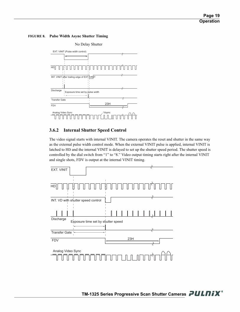
FIGURE 8. Pulse Width Async Shutter Timing
3.6.2 Internal Shutter Speed Control
The video signal starts with internal VINIT. The camera operates the reset and shutter in the same way as the external pulse width control mode. When the external VINIT pulse is applied, internal VINIT is latched to HD and the internal VINIT is delayed to set up the shutter speed period. The shutter speed is controlled by the dial switch from “1” to “8.” Video output timing starts right after the internal VINIT and single shots, FDV is output at the internal VINIT timing.
EXT. VINIT (Pulse width control)
HD
INT. VINIT after trailing edge of EXT. VINIT
Discharge
Transfer Gate
FDV
Analog Video Sync
Exposure time set by pulse width
23H
Vsync
No Delay Shutter
EXT. VINIT
HD
INT. VD with shutter speed control
Discharge
Transfer Gate
FDV
Analog Video Sync
Exposure time set by shutter speed
23H
TM-1325 Series Progressive Scan Shutter Cameras
Page 20Operation
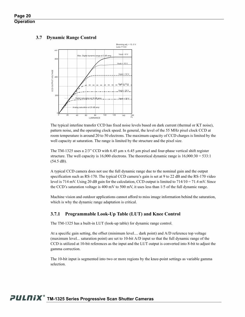
3.7 Dynamic Range Control
The typical interline transfer CCD has fixed noise levels based on dark current (thermal or KT noise), pattern noise, and the operating clock speed. In general, the level of the 55 MHz pixel clock CCD at room temperature is around 20 to 50 electrons. The maximum capacity of CCD charges is limited by the well capacity at saturation. The range is limited by the structure and the pixel size.
The TM-1325 uses a 2/3” CCD with 6.45 µm x 6.45 µm pixel and four-phase vertical shift register structure. The well capacity is 16,000 electrons. The theoretical dynamic range is 16,000:30 = 533:1 (54.5 dB).
A typical CCD camera does not use the full dynamic range due to the nominal gain and the output specification such as RS-170. The typical CCD camera’s gain is set at 9 to 22 dB and the RS-170 video level is 714 mV. Using 20 dB gain for the calculation, CCD output is limited to 714/10 = 71.4 mV. Since the CCD’s saturation voltage is 400 mV to 500 mV, it uses less than 1/5 of the full dynamic range.
Machine vision and outdoor applications cannot afford to miss image information behind the saturation, which is why the dynamic range adaptation is critical.
3.7.1 Programmable Look-Up Table (LUT) and Knee Control
The TM-1325 has a built-in LUT (look-up table) for dynamic range control.
At a specific gain setting, the offset (minimum level.... dark point) and A/D reference top voltage (maximum level... saturation point) are set to 10-bit A/D input so that the full dynamic range of the CCD is utilized at 10-bit references as the input and the LUT output is converted into 8-bit to adjust the gamma correction.
The 10-bit input is segmented into two or more regions by the knee-point settings as variable gamma selection.
0 20 40 10060 120800
200
400
600
FL
Lens: F=5.6
Vsub = 10 V
Vsub = 12 V
Vsub = 14 V
Vsub = 16 V
Vsub = 18 V
CC
D O
UT
PU
T V
OL
TA
GE
LUMINANCE
Blooming adj. = 13. 5 V
Digital saturation at 16 dB amp
Analog saturation at 20 dB amp
Max. Digital dynamic range at 3 dB amp
140 160
mV
Vsub = 8 V
TM-1325 Series Progressive Scan Shutter Cameras
Page 21Operation
LUT selections: (a standard LUT is 10 sets of knee-control LUT)
• Variable Gamma
• Variable knee curve
• Direct input LUT
3.8 Scan ModesThe TM-1325 supports the following scan modes:
3.8.1 Full Progressive Scan
The normal scan mode progressively scans a full frame of 1392 x 1040 pixels at 15/30 frames per second using the standard 27.5MHz/55MHz pixel clock and a single channel output. In contrast to interlace-scan cameras, all 1040 lines in the frame are exposed simultaneously per image capture.
3.8.2 Partial Scan
Partial scan is a standard feature in the TM-1325. 500 lines and 250 lines partial scan is selectable. It outputs an image center of 500 lines and 250 lines. At 500 lines, the frame rate is 58 frames/sec. At 250 lines, it is 100 frames/sec. Partial scanning outputs the full horizontal resolution, but limits the vertical resolution to increase the frame rate. The partial scan modes are 1392 x 500 lines at 58 Hz, and 1392 x 250 lines at 100 Hz. The scan mode is selectable by using the GUI or rear panel switches (TM-1325 LVDS model only).
3.9 External SyncThe TM-1325 accepts an external sync of standard HD and VD at TTL level for general locking to a system sync and clock. The external sync is only available for 15-frame mode and the frequency requirement is as follows:
30 fps: 15 fps:
fHD = 31.977 KHz ±5% fHD = 16 KHz ± 5%fVD = 30.08 Hz ± 5% fVD = 15.04Hz ± 5%(Internal Master clock = 110.00 MHz, (Internal Master Clock = 55 MHzPixel clock = 55.00 MHz) Pixel Clock = 27.5 MHz)
TM-1325 Series Progressive Scan Shutter Cameras
Page 22Operation
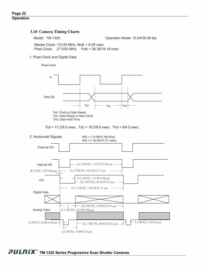
3.10 Camera Timing ChartsModel: TM-1325 Operation Mode: 15.04/30.08 fps
Master Clock: 110.00 MHz, Mclk = 9.09 nsec
Pixel Clock: 27.5/55 MHz, Pclk = 36.36/18.18 nsec
1. Pixel Clock and Digital Data
Tcd Tdc Thd
Tcd: Clock to Data Ready
Tdc: Data Ready to Next Clock
Thd: Data Hold Time
Pixel Clock
Data (B)
A
Tcd = 17.2/8.6 nsec, Tdc = 19.2/9.6 nsec, Thd = 9/4.5 nsec.
2. Horizontal Signals
External HD
Internal HD
LDV
Digital Data
Analog Video
fHD = [ 15.99/31.98 KHz]
tHD = [ 62.54/31.27 usec]
C [ 1720 P], ( 62.54/31.27 µs)
A [ 1520 P], ( 55.27/27.63 µs)
F [ 1720 P], ( 62.54/31.27 µs)
E[ 1392 P],( 50.62/25.31 µs)
D [ 328 P], ( 11.93/5.96 µs)
G [ 328 P], ( 11.93/5.96 µs)
H [1392 P], ( 50.62/25.31 µs)
J [ 238 P], ( 8.66/4.33 µs)
K [ 1392 P], (50.62/25.31 µs)L [ 99 P], ( 3.6/1.8 µs)I [ 90 P ], (3.28/1.64 µs)
B [ 9 P], ( 327/164 ns)
TM-1325 Series Progressive Scan Shutter Cameras
Page 23Operation
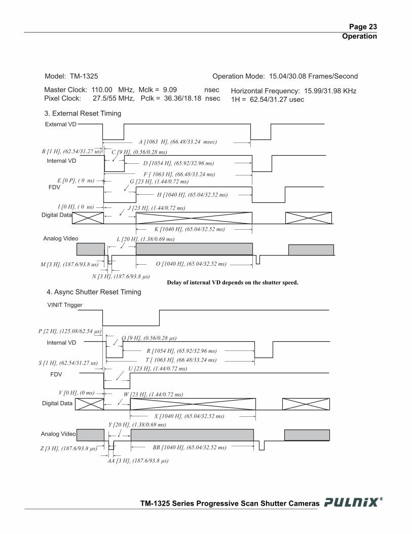
Model: TM-1325 Operation Mode: 15.04/30.08 Frames/Second
Master Clock: 110.00 MHz, Mclk = 9.09 nsec
Pixel Clock: 27.5/55 MHz, Pclk = 36.36/18.18 nsec
3. External Reset Timing
4. Async Shutter Reset Timing
External VD
Internal VD
FDV
Digital Data
Analog Video
VINIT Trigger
Internal VD
FDV
Digital Data
Analog Video
Horizontal Frequency: 15.99/31.98 KHz
1H = 62.54/31.27 usec
A [1063 H], (66.48/33.24 msec)
B [1 H], (62.54/31.27 us) C [9 H], (0.56/0.28 ms)
D [1054 H], (65.92/32.96 ms)
F [ 1063 H], (66.48/33.24 ms)
M [3 H], (187.6/93.8 us)
G [23 H], (1.44/0.72 ms)
J [23 H], (1.44/0.72 ms)
L [20 H], (1.38/0.69 ms)
N [3 H], (187.6/93.8 µs)
H [1040 H], (65.04/32.52 ms)
K [1040 H], (65.04/32.52 ms)
O [1040 H], (65.04/32.52 ms)
R [1054 H], (65.92/32.96 ms)
T [ 1063 H], (66.48/33.24 ms)
X [1040 H], (65.04/32.52 ms)
BB [1040 H], (65.04/32.52 ms)
P [2 H], (125.08/62.54 µs)
Y [20 H], (1.38/0.69 ms)
W [23 H], (1.44/0.72 ms)
AA [3 H], (187.6/93.8 µs)
Z [3 H], (187.6/93.8 µs)
Q [9 H], (0.56/0.28 µs)
U [23 H], (1.44/0.72 ms)
E [0 P], ( 0 ns)
I [0 H], ( 0 us)
S [1 H], (62.54/31.27 us)
V [0 H], (0 ms)
Delay of internal VD depends on the shutter speed.
TM-1325 Series Progressive Scan Shutter Cameras
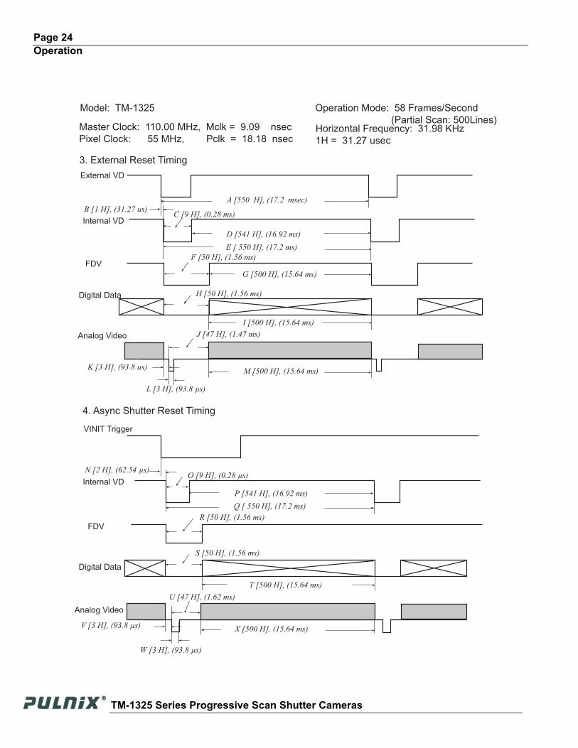
Page 24Operation
Model: TM-1325 Operation Mode: 58 Frames/Second
(Partial Scan: 500Lines)Master Clock: 110.00 MHz, Mclk = 9.09 nsec
Pixel Clock: 55 MHz, Pclk = 18.18 nsec
3. External Reset Timing
4. Async Shutter Reset Timing
External VD
Internal VD
FDV
Digital Data
Analog Video
VINIT Trigger
Internal VD
FDV
Digital Data
Analog Video
Horizontal Frequency: 31.98 KHz
1H = 31.27 usec
A [550 H], (17.2 msec)B [1 H], (31.27 us)
C [9 H], (0.28 ms)
D [541 H], (16.92 ms)
E [ 550 H], (17.2 ms)
K [3 H], (93.8 us)
F [50 H], (1.56 ms)
H [50 H], (1.56 ms)
J [47 H], (1.47 ms)
L [3 H], (93.8 µs)
G [500 H], (15.64 ms)
I [500 H], (15.64 ms)
M [500 H], (15.64 ms)
P [541 H], (16.92 ms)
Q [ 550 H], (17.2 ms)
T [500 H], (15.64 ms)
X [500 H], (15.64 ms)
N [2 H], (62.54 µs)
U [47 H], (1.62 ms)
S [50 H], (1.56 ms)
W [3 H], (93.8 µs)
V [3 H], (93.8 µs)
O [9 H], (0.28 µs)
R [50 H], (1.56 ms)
TM-1325 Series Progressive Scan Shutter Cameras
Page 25Operation
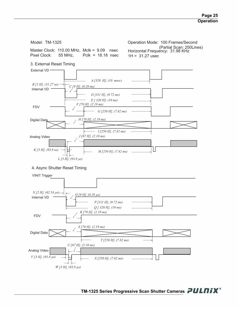
Model: TM-1325 Operation Mode: 100 Frames/Second
(Partial Scan: 250Lines)Master Clock: 110.00 MHz, Mclk = 9.09 nsec
Pixel Clock: 55 MHz, Pclk = 18.18 nsec
3. External Reset Timing
4. Async Shutter Reset Timing
External VD
Internal VD
FDV
Digital Data
Analog Video
VINIT Trigger
Internal VD
FDV
Digital Data
Analog Video
Horizontal Frequency: 31.98 KHz
1H = 31.27 usec
A [320 H], (10 msec)B [1 H], (31.27 us)
C [9 H], (0.28 ms)
D [311 H], (9.72 ms)
E [ 320 H], (10 ms)
K [3 H], (93.8 us)
F [70 H], (2.19 ms)
H [70 H], (2.19 ms)
J [67 H], (2.10 ms)
L [3 H], (93.8 µs)
G [250 H], (7.82 ms)
I [250 H], (7.82 ms)
M [250 H], (7.82 ms)
P [311 H], (9.72 ms)
Q [ 320 H], (10 ms)
T [250 H], (7.82 ms)
X [250 H], (7.82 ms)
N [2 H], (62.54 µs)
U [67 H], (2.10 ms)
S [70 H], (2.19 ms)
W [3 H], (93.8 µs)
V [3 H], (93.8 µs)
O [9 H], (0.28 µs)
R [70 H], (2.19 ms)
TM-1325 Series Progressive Scan Shutter Cameras
Page 26Operation
3.11 Serial Communication Kit CS-232C (not required for “CL” version)The TM-1325’s functions can be controlled by a PC via RS-232C communication using the CS-232E serial communication kit. This kit consists of the RS-232B-12 cable, software disk, and quick-start card. The software disk contains setup files for the graphical user interface (GUI) program. Refer to the camera control software manual for information on the GUI and ASCII command set.
Note: For CL models, the control software is included and serial communication is through the Camera Link cable. No additional accessories are required.
TM-1325 Series Progressive Scan Shutter Cameras

Page 27Troubleshooting
4 Troubleshooting
4.1 Problems and SolutionsFollowing are troubleshooting tips for common problems. In general, problems can easily be solved by following these instructions. If the following remedies fail to offer a solution to your problems, please contact a PULNiX representative.
4.1.1 Symptom: No Video
Remedies: Check that the following are properly connected and operational.
• Power supplies
• Power cables
• Main power source
• Shutter control
• Async mode
• Lens
• Digital output cable
• Analog video cable
4.1.2 Symptom: Dark Video
Remedies: Check that the following are properly connected and operational.
• Shutter selection
• Iris opening on the lens
4.1.3 Symptom: Non-Synchronized Video
Remedies: Check that the following are properly connected and operational.
• Proper mode output
• Frame grabber software camera selection
TM-1325 Series Progressive Scan Shutter Cameras
Page 28Troubleshooting
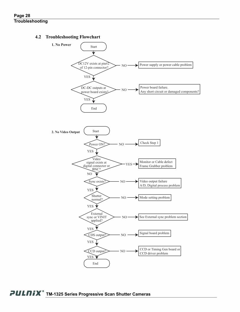
4.2 Troubleshooting Flowchart
Videosignal exists at
digital connector orBNC?
1. No Power
2. No Video Output Start
End
End
YES
YES
YES
NO
YES
YES
Check Step 1
Monitor or Cable defect
Frame Grabber problem
Video output failure
A/D, Digital process problem
Mode setting problem
See External sync problem section
Signal board problem
CCD or Timing Gen board or
CCD driver problem
Power supply or power cable problem
Power board failure.
Any short circuit or damaged components?
DC12V exists at pin#2
of 12-pin connector?
DC-DC outputs at
power board exists?
Start
Power ON?
Sync exists?
Shutter normal?
CDS output?
CCD output?
NO
YES
NO
YES
NO
NO
NO
NO
NO
NO
YES
YES
Externalsync or VINIT
applied?
TM-1325 Series Progressive Scan Shutter Cameras
Page 29Troubleshooting
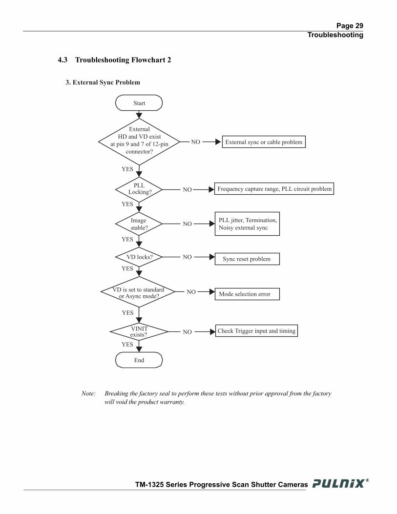
4.3 Troubleshooting Flowchart 2
Note: Breaking the factory seal to perform these tests without prior approval from the factory will void the product warranty.
External
HD and VD exist
at pin 9 and 7 of 12-pin
connector?
3. External Sync Problem
YES
Start
External sync or cable problem
PLL Locking?
Image
stable?
Frequency capture range, PLL circuit problem
PLL jitter, Termination,
Noisy external sync
VD locks?
VINIT exists?
Mode selection errorVD is set to standard
or Async mode?
Sync reset problem
Check Trigger input and timing
End
NO
NO
YES
YES
YES
YES
YES
NO
NO
NO
NO
TM-1325 Series Progressive Scan Shutter Cameras
Page 30Troubleshooting
4.4 Information and Support ResourcesFor further information and support:
Phone: (408) 747-0300 (800) 445-5444
Fax: (408) 747-0660E-mail: [email protected]: JAI PULNiX, Inc.
Sales Department1330 Orleans DriveSunnyvale, CA 94089ATTN: Video Applications
Web Site: www.jaipulnix.com
TM-1325 Series Progressive Scan Shutter Cameras
Page 31Appendix
5 Appendix
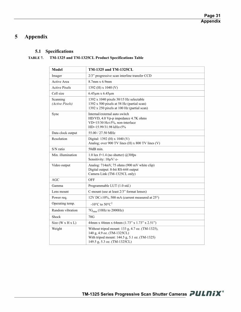
5.1 SpecificationsTABLE 7. TM-1325 and TM-1325CL Product Specifications Table
Model TM-1325 and TM-1325CLImager 2/3” progressive scan interline transfer CCD
Active Area 8.7mm x 6.9mm
Active Pixels 1392 (H) x 1040 (V)
Cell size 6.45µm x 6.45µm
Scanning(Active Pixels)
1392 x 1040 pixels 30/15 Hz selectable1392 x 500 pixels at 58 Hz (partial scan)1392 x 250 pixels at 100 Hz (partial scan)
Sync Internal/external auto switchHD/VD, 4.0 Vp-p impedance 4.7K ohmsVD=15/30 Hz±5%, non-interlaceHD=15.99/31.98 kHz±5%
Data clock output 55.00 / 27.50 MHz
Resolution Digital: 1392 (H) x 1040 (V)Analog; over 900 TV lines (H) x 800 TV lines (V)
S/N ratio 50dB min.
Min. illumination 1.0 lux f=1.4 (no shutter) @30fpsSensitivity: 10µV/ e-
Video output Analog: 714mV, 75 ohms (900 mV white clip)Digital output: 8-bit RS-644 outputCamera Link (TM-1325CL only)
AGC OFF
Gamma Programmable LUT (1.0 std.)
Lens mount C-mount (use at least 2/3” format lenses)
Power req. 12V DC±10%, 500 mA (current measured at 25°)
Operating temp. -10°C to 50°C1
Random vibration 7Grms (10Hz to 2000Hz)
Shock 70G
Size (W x H x L) 44mm x 44mm x 64mm (1.73” x 1.73” x 2.51”)
Weight Without tripod mount: 133 g, 4.7 oz. (TM-1325), 140 g, 4.9 oz. (TM-1325CL)With tripod mount: 144.5 g, 5.1 oz. (TM-1325) 149.5 g, 5.3 oz. (TM-1325CL)
TM-1325 Series Progressive Scan Shutter Cameras
Page 32Appendix
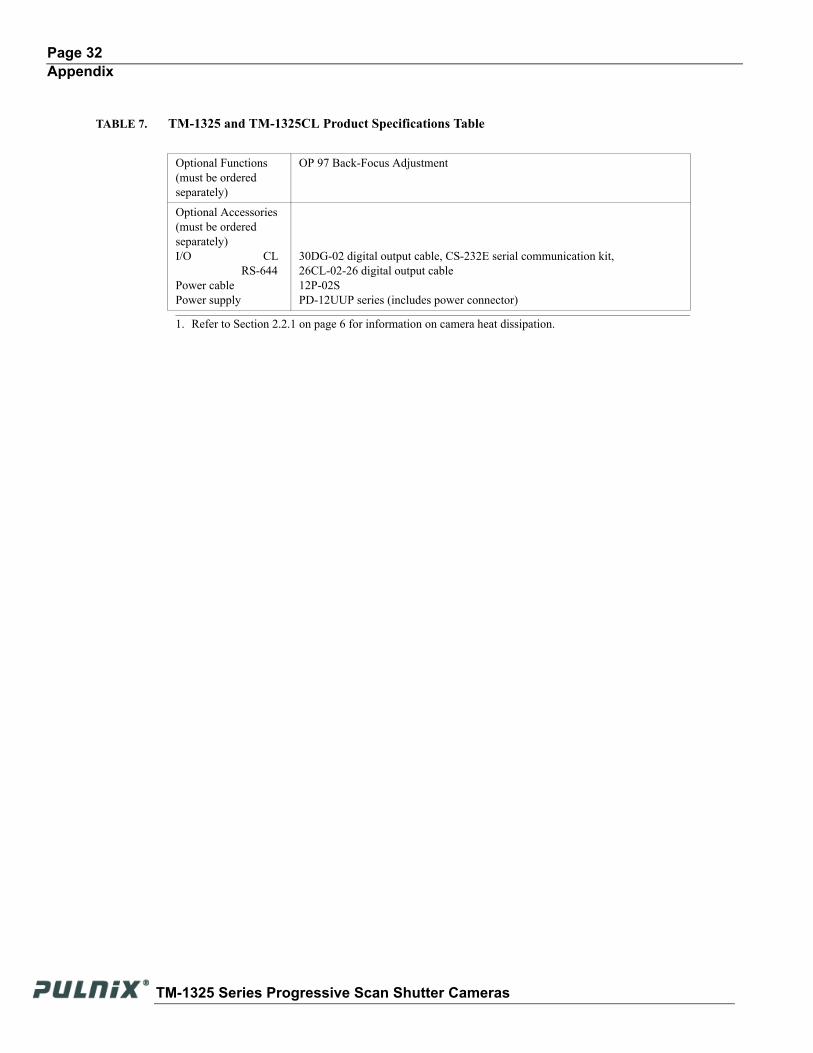
Optional Functions(must be ordered separately)
OP 97 Back-Focus Adjustment
Optional Accessories (must be ordered separately)I/O CL RS-644Power cablePower supply
30DG-02 digital output cable, CS-232E serial communication kit,26CL-02-26 digital output cable12P-02SPD-12UUP series (includes power connector)
1. Refer to Section 2.2.1 on page 6 for information on camera heat dissipation.
TABLE 7. TM-1325 and TM-1325CL Product Specifications Table
TM-1325 Series Progressive Scan Shutter Cameras
Page 33Appendix
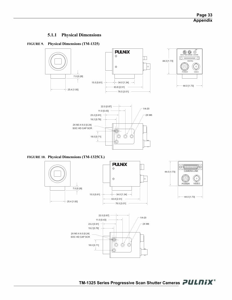
5.1.1 Physical Dimensions
FIGURE 9. Physical Dimensions (TM-1325)
FIGURE 10. Physical Dimensions (TM-1325CL)
25.4 [1.00]
7.0 [0.28]
15.5 [0.61]
22.0 [0.87]
18.0 [0.71]
2X M6
44.0 [1.73]
1/4-20
SOC HD CAP SCR
2X M3 X 6.0 [0.24]
19.2 [0.76]
23.2 [0.91]
11.0 [0.43]
63.8 [2.51]
76.5 [3.01]
34.0 [1.34]
44.0 [1.73]
POWER VIDEO
DIGITAL
SHUTTER
UP
DOWNMODE
25.4 [1.00]
7.0 [0.28]
15.5 [0.61]
63.8 [2.51]
76.5 [3.01]
34.0 [1.34]
22.0 [0.87]
18.0 [0.71]
2X M6
1/4-20
SOC HD CAP SCR
2X M3 X 6.0 [0.24]
19.2 [0.76]
23.2 [0.91]
11.0 [0.43]
44.0 [1.73]
44.0 [1.73] CAMERA LINK
POWER VIDEO
1
2
3
45
6
9
8
711 12
10
TM-1325 Series Progressive Scan Shutter Cameras

Page 34Appendix
TM-1325 Series Progressive Scan Shutter Cameras

JAI PULNiX Inc.1330 Orleans DriveSunnyvale, CA 94089
Tel: 408-747-0300Tel: 800-445-5444Fax: 408-747-0660
w w w . p u l n i x . c o m
I m a g i n g P r o d u c t s
69-1143Rev. A
Email: [email protected]