
Unified Frequency Domain Analysis of Lightfield Cameras
14
Unified Frequency Domain Analysis of Lightfield Cameras Todor Georgiev, Chintan Intwala, Sevkit Babakan, and Andrew Lumsdaine 1 Adobe Systems, 345 Park Ave, San Jose, CA 95110 2 Computer Science Department, Indiana University, Bloomington, IN 47405 Abstract. This paper presents a theory that encompasses both “plenop- tic” (microlens based) and “heterodyning” (mask based) cameras in a single frequency-domain mathematical formalism. Light-field capture has traditionally been analyzed using spatio-angular representation, with the exception of the frequency-domain “heterodyning” work. In this paper we interpret “heterodyning” as a general theory of multiplexing the ra- diance in the frequency domain. Using this interpretation, we derive a mathematical theory of recovering the 4D spatial and angular informa- tion from the multiplexed 2D frequency representation. The resulting method is applicable to all lightfield cameras, lens-based and mask-based. The generality of our approach suggests new designs for lightfield cam- eras. We present one such novel lightfield camera, based on a mask out- side a conventional camera. Experimental results are presented for all cameras described. 1 Introduction A central area of research in computational photography is capturing “light itself” as opposed to capturing a flat 2D picture. Advantages of light-field or integral photography are the ability to obtain information about the 3D struc- ture of the scene, and the new power of optical manipulation of the image, like refocusing and novel view synthesis. The light itself, or light-field, is mathematically described by the radiance density function, which is a complete record of light energy flowing along “all rays” in 3D space. This density is a field defined in the 4D domain of optical phase space, that is, the space of all lines in 3D with symplectic structure [1]. Conventional cameras, based on 2D image sensors, do not record the 4D radiance. Instead, they simply act as “integration devices”. In a typical setting, they integrate over the 2D aperture to produce a 2D projection of the full 4D radiance. Integral Photography [2,3] was proposed more than a century ago to “undo” this integration and measure the complete 4D radiance arriving at all points on a film plane or sensor. As demonstrated by Levoy and Hanrahan [4] and Gortler et al. [5], capturing the additional two dimensions of radiance data allows us to re-sort the rays of light to synthesize new photographs, sometimes referred to as “novel views.” Recently, Ng et al. [6] have shown that a full 4D light field can be captured even D. Forsyth, P. Torr, and A. Zisserman (Eds.): ECCV 2008, Part III, LNCS 5304, pp. 224–237, 2008. c Springer-Verlag Berlin Heidelberg 2008
-
Upload
independent -
Category
Documents
-
view
1 -
download
0
Transcript of Unified Frequency Domain Analysis of Lightfield Cameras

Unified Frequency Domain Analysis of Lightfield
Cameras
Todor Georgiev, Chintan Intwala, Sevkit Babakan, and Andrew Lumsdaine
1 Adobe Systems, 345 Park Ave, San Jose, CA 951102 Computer Science Department, Indiana University, Bloomington, IN 47405
Abstract. This paper presents a theory that encompasses both “plenop-tic” (microlens based) and “heterodyning” (mask based) cameras in asingle frequency-domain mathematical formalism. Light-field capture hastraditionally been analyzed using spatio-angular representation, with theexception of the frequency-domain “heterodyning” work. In this paperwe interpret “heterodyning” as a general theory of multiplexing the ra-diance in the frequency domain. Using this interpretation, we derive amathematical theory of recovering the 4D spatial and angular informa-tion from the multiplexed 2D frequency representation. The resultingmethod is applicable to all lightfield cameras, lens-based and mask-based.The generality of our approach suggests new designs for lightfield cam-eras. We present one such novel lightfield camera, based on a mask out-side a conventional camera. Experimental results are presented for allcameras described.
1 Introduction
A central area of research in computational photography is capturing “lightitself” as opposed to capturing a flat 2D picture. Advantages of light-field orintegral photography are the ability to obtain information about the 3D struc-ture of the scene, and the new power of optical manipulation of the image, likerefocusing and novel view synthesis.
The light itself, or light-field, is mathematically described by the radiancedensity function, which is a complete record of light energy flowing along “allrays” in 3D space. This density is a field defined in the 4D domain of opticalphase space, that is, the space of all lines in 3D with symplectic structure [1].
Conventional cameras, based on 2D image sensors, do not record the 4Dradiance. Instead, they simply act as “integration devices”. In a typical setting,they integrate over the 2D aperture to produce a 2D projection of the full 4Dradiance. Integral Photography [2,3] was proposed more than a century ago to“undo” this integration and measure the complete 4D radiance arriving at allpoints on a film plane or sensor.
As demonstrated by Levoy and Hanrahan [4] and Gortler et al. [5], capturingthe additional two dimensions of radiance data allows us to re-sort the rays oflight to synthesize new photographs, sometimes referred to as “novel views.”Recently, Ng et al. [6] have shown that a full 4D light field can be captured even
D. Forsyth, P. Torr, and A. Zisserman (Eds.): ECCV 2008, Part III, LNCS 5304, pp. 224–237, 2008.c© Springer-Verlag Berlin Heidelberg 2008

Unified Frequency Domain Analysis of Lightfield Cameras 225
with a hand-held “plenoptic” camera. This approach makes light field photog-raphy practical, giving the photographer the freedom and the power to makeadjustments of focus and aperture after the picture has been taken.
A number of works have developed techniques for analyzing radiance in thefrequency domain [7,8,9]. Several important results have been derived, amongwhich are: Applications of Poisson summation formula to lightfields, lightfielddisplays, and depth representation of scenes; light transport and optical trans-forms; Fourier slice theorem applied to refocusing, and others. However, withthe notable exception of “heterodyning” [10], frequency analysis of radiance hasnot been applied to the general understanding and design of light-field cameras.The main goal of this paper is to expand the results of “heterodyning.”
The contributions of our paper are:
1. We provide a general mathematical framework for analysing lightfield cam-eras in the frequency domain. Our theory is applicable to both lens-basedand mask-based light-field cameras.
2. We show that the concept of “heterodyning” is not just a new mask-basedcamera design. Rather, it is a new method for processing data from anylightfield camera in the freqyency domain.
3. We develop a generalized F/number matching condition and show that it isrequired for all lightfield camera designs, lens-based and mask-based.
4. We propose and demonstrate a new lightfield camera design that has a trans-parency mask placed in front of the main lens.
2 Prior Work and Basic Equations
2.1 Frequency Domain Representation
Recent works [7,8,9] have analyzed radiance, or light field, in frequency repre-sentation. Let r(x) be the radiance in conventional x−space, describing positionand angle. In more detail, the spatio-angular coordinates of a ray at a givenplane orthogonal to the optical axis are represented as a vector
x =(
qp
), (1)
where q is the location of ray-plane intersection, and p is a vector defining thetwo angles of that ray at location q. Following texts on optics [1,11], we useparaxial approximation assuming the angle is small. A simplified 2-dimensionalvector representation of a ray is shown in Figure 1. The physical ray-space is 4D.
In the frequency domain radiance is represented by the Fourier transform ofr(x):
R(ω) =∫
r(x)eiω·xdx (2)
where the spatial frequency ωq and the angular frequency ωp are grouped to-gether in a similar way as a 4D vector:
ω =(
ωq
ωp
). (3)

226 T. Georgiev et al.
Fig. 1. (a) Geometric representation of a ray as position and angle in an optical system.(b) Same ray described as a vector x = (q, p), in 2D ray space.
To simplify our text andfigureswewill oftenuse 2D radiancewith 1-dimensionalposition q and angle p for each ray.
2.2 Optical Transforms
We summarize and extend some results of previous work (e.g., [7,8,12]) abouttransformations of radiance in optical systems.
The operation of a lens L or a translation T can be described by a lineartransformation x′ = Ax operating on a ray x [11]. If a ray is described as aposition-angle vector (3), then L and T are given by the following matrices:
L =(
1 0− 1
f 1
)and T =
(1 t0 1
). (4)
Here, f is the focal length of the lens, and t is the translation (distance of flight).The combined action of several such elements is described by the composition
of their transforms. Now, since all elements in an optical system are describedonly by the above transforms, we can mathematically model any optical system(like a multielement camera lens or a light-field camera) as a single combinedtransform.
Another important observation is that radiance is conserved in a non-absorbingsystem. In other words, the radiance does not change along a ray during travelor transformation by optical elements. The mathematical representation of thisfact is that any optical matrix is symplectic [1]. Therefore, the determinant of anyoptical matrix is unity, i.e.,
det A = 1, (5)
which can also be seen directly from equation (4).Based on this conservation property, the radiance r′ after a transform is re-
lated to the radiance r before the transform by the following equation:
r′(x) = r(x0) = r(A−1x), (6)
where x0 is the ray which has been mapped into x by the optical transformationA, i.e., x = Ax0.

Unified Frequency Domain Analysis of Lightfield Cameras 227
The above transformation from r to r′ can be expressed in frequency repre-sentation as:
R′(ω) =∫
r′(x)eiω·xdx
=∫
r(A−1x)eiω·xdx
=∫
r(A−1x)eiωAA−1xdx
=∫
r(x0)eiωA·x0dx0
= R(AT ω), (7)
where AT is the transposed matrix, R(ω) is the Fourier transform of r(x), and wehave used (6) for the change of variables from x to x0. Note that this expressionis derived for any optical transform A, while previous works have consideredspecial cases [8].
Summarizing the basic equations that will be used throughout the paper, wehave:
x′ = Ax (8)r′(x) = r(A−1x) (9)R′(ω) = R(AT ω) (10)
3 Light-field Cameras in the Frequency Domain
3.1 Ives’ Camera
The first light-field camera (called “Process of Making Parallax Stereograms”)was invented in 1903 by Frederick Ives [2]. This camera can be described as anarray of pinhole cameras with the same focal distance f , as shown in Figure 2.This array of cameras is placed at the focal plane of a conventional large formatcamera.
We will develop the mathematical representation for the radiance transformsinside Ives’ camera in the frequency domain. This representation is a new result,and it will be used extensively throughout the paper.
Fig. 2. The Ives’ light-field camera. Only the focal plane with the pinholes is repre-sented in this figure.
228 T. Georgiev et al.
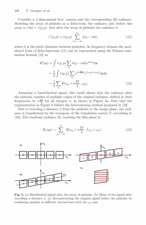
Consider a 1-dimensional Ives’ camera and the corresponding 2D radiance.Modeling the array of pinholes as a delta-train, the radiance, just before thisarray is r(x) = r(q, p). Just after the array of pinholes the radiance is
r′(q, p) = r(q, p)∞∑
m=−∞δ(q − mb), (11)
where b is the pitch (distance between pinholes). In frequency domain the mod-ulated train of delta-functions (11) can be represented using the Poisson sum-mation formula [13] as
R′(ω) =∫
r(q, p)∑m
δ(q − mb)eiω·xdx
=1b
∫r(q, p)
∑n
ein 2πqb ei(ωqq+ωpp)dqdp
=1b
∑n
R(ωq + n2π
b, ωp). (12)
Assuming a band-limited signal, this result shows that the radiance afterthe pinholes consists of multiple copies of the original radiance, shifted in theirfrequencies by n 2π
b for all integers n, as shown in Figure 3a. Note that therepresentation in Figure 3 follows the heterodyning method proposed in [10].
Due to traveling a distance f from the pinholes to the image plane, the radi-ance is transformed by the transpose of the translation matrix T , according to(10). The resultant radiance Rf reaching the film plane is:
Rf (ω) =∞∑
n=−∞R(ωq + n
2π
b, fωq + ωp). (13)
Fig. 3. (a) Bandlimited signal after the array of pinholes. (b) Shear of the signal aftertravelling a distance f . (c) Reconstructing the original signal before the pinholes bycombining samples at different intersections with the ωq axis.
Unified Frequency Domain Analysis of Lightfield Cameras 229
This equation shows that the signal is sheared in the direction of angularfrequency. This is represented in Figure 3b. The key observation here, first madein [10], is that a different angular frequency part of each copy of the spectrumintersects with the ωq axis. Since the film responds only to the DC component(zero angular frequency), it records only the thin “slice” where the spectrumintersects with the ωq axis.
The above observation suggest a method of reconstructing the complete spatio-angular representation of the radiance r(x). This can be done by stacking theabove slices along the ωp axis and performing inverse Fourier transform of thevolume image.
The original idea that we can pick up the above type of “slices” of a similarspatio-angular representation of a periodic mask in the frequency domain, anduse them to recover angular information, has been first proposed in the contextof a different camera in [10]. We will cover this in more detail in subsection 3.3.
3.2 Replacing the Pinhole Array with a (Micro) Lens Array
The idea of replacing the array of pinholes in front of the film with lenses was firstproposed by Lippmann back in 1908 [3]. Just as with a single pinhole camera,lenses gather much more light and produce better image quality than small holes.Lipmann called his approach Integral photography. Different versions of it havebeen proposed throughout the years, the most recent one being the plenopticcamera [6,14].
Our analysis of the integral camera in frequency space will be done in twosteps. (1) We consider an array of pinholes as in the Ives’ camera, only shiftedby a constant (for all pinholes) vector a. Each pinhole is covered by a prismwith angle of deviation depending on the shift, defined as pprism = a
f . (2) Weconsider the superposition of multiple shifted arrays of such pinhole-prisms, andshow that they all contribute to the final image in a similar way. Lippmann’sintegral photography is based on this coherent action of different arrays. It can beviewed as the limiting case where the plane is made completely of pinhole-prismsand all the light goes through. Each microlens is formed by the correspondingprisms, as a Fresnel lens.
Following the above derivation for the Ives camera in equation (12), the radi-ance after the pinhole-prism array can be expressed as
R′(ω) =∫
r(q, p +a
f)∑m
δ(q − mb − a)eiω·xdx
=1b
∫r(q, p +
a
f)∑
n
ein 2π(q−a)b ei(ωqq+ωpp)dqdp
=1b
∑n
e−i(ωpaf +n 2πa
b )R(ωq + n2π
b, ωp). (14)
Note that now there exist additional phase multipliers in each term of thesum. After the pinhole-prism array, the light travels a distance f to the film
230 T. Georgiev et al.
plane. Using equations (4) and (10) we obtain the following expression for theradiance at the film (sensor):
Rf (ω) =1b
∑n
e−i((fωq+ωp) af +n 2πa
b )R(ωq + n2π
b, fωq + ωp)
As explained above, the film (or sensor) only records zero angular frequencies.Therefore, by restricting ω to the ωq axis, we obtain the following final expres-sion:
Rf (ωq, 0) =1b
∑n
e−i(ωqa+n 2πab )R(ωq + n
2π
b, fωq) (15)
The effect of coherence would be easily observed for small a. It takes placedue to the term ωqa+n 2πa
b , where ωq is within πb from the corresponding center
(peak), which is at frequency n 2πb in each block. For every exponential term
with frequency ωq there is another term with frequency −n 2πb − ωq inside the
same block, but on the other side of the center. Those two frequencies produceopposite phases, which results in a real positive term, cos((ωq + n 2π
b )a). Thisterm is close to 1 for all rays.
Based on this analysis, the integral camera will also work with lenses for whicha can be as big as b
2 , and the area of the plane is completely covered. All theterms are still positive, but the efficiency of rays far from the center is lower,and high frequencies will be attenuated.
The above analysis leads to a surprising new result: The frequency methodof demultiplexing radiance, described in the case of Ives’ pinhole camera, is alsoapplicable to Lippmann’s microlens based integral photography. Similarly, theplenoptic camera, as well as other light-field cameras that can be shown to beequivalent to it, can be analyzed using this new formulation.
3.3 Replacing the Pinhole Array with a Mask
A light-field camera that uses a mask instead of pinholes or microlenses in frontof the sensor was first proposed in [10].
One way to analyze this camera would be to start again with the pinhole for-mula we derived for the Ives’ camera, and instead of prisms assume appropriateattenuation at each pinhole. On the other hand, it is also possible to directlyderive the result for periodic attenuation functions, like 1
2 (1 + cos(ω0q)). Thisattenuating mask modulates the light field to produce two spectral copies seenmathematically as follows
R′(ω) =12R(ω) +
12
∫r(x)cos(ω0q) eiω·xdx
=12R(ω) +
14
∫r(x)(eiω0q + e−iω0q) eiω·xdx
=12R(ω) +
14(R(ωq + ω0, ωp) + R(ωq − ω0, ωp)). (16)
Unified Frequency Domain Analysis of Lightfield Cameras 231
After the mask the signal travels a distance f to the sensor. Again usingequations (4) and (10) we obtain the final expression for the radiance:
Rf (ωq, ωp) =12R(ωq, fωq + ωp)
+14(R(ωq + ω0, fωq + ωp) + R(ωq − ω0, fωq + ωp)). (17)
Again we observe duplication of our bandlimited signal into multiple blocks,and shearing proportional to the travel distance. Any periodic mask can beanalyzed this way based on Fourier series expansion and considering individualcomponent frequencies. As first observed in [10], samples of the “mask signal” onthe ωq axis can be used to reconstruct the complete spatio-angular attenuationfunction of the mask. In our case we use the method to reconstruct the radianceR(ω).
3.4 Placing the Array in Front of the Camera
Another family of light-field cameras can be described as putting any of thearrays used on previous camera designs in front of a regular camera, and focusingit slightly behind the array.
The idea for this design is based on the fact that the image inside any camerais 3-dimensional, and is a distorted copy of the outside world. It is clear that thestructures we place inside the camera have their corresponding structures in theoutside world. This is based on the 1-to-1 mapping defined by the main cameralens.
The sensor plane corresponds to the plane of focus, and any optical elementsin front of it could be replaced by their enlarged copies in the real world, in frontof the plane of focus.
Because of this correspondence, and based on the lens formula, we can buildstructures in front of the camera and use them as if they were microstructuresinside. In the Results section we will demonstrate how a fine mask in front ofthe sensor, in an area not accessible due to the cover glass, can be replaced by amosquito mesh in front of the camera. We will return to this idea in section 4.3.
3.5 Generalized F/Number Matching
The angle of the cone of rays coming to a point on the sensor in a camera is Ω =1F , where F is the F/number of the main lens. As shown in [6], for a plenopticcamera the F/numbers of the main lens and the microlenses must match. Ageneralization of the F/Number matching rule to other radiance camera systemscan be derived using frequency domain analysis.
The final expression for the radiance in all cameras has second (angular fre-quency) argument in R equal to fωq, where f is the distance from the pinholes,microlenses or mask - to the sensor. This is a measure of the amount of shear,which can be seen as the tilt of the line fωq in Figure 3b.
232 T. Georgiev et al.
Assume a camera samples the angular frequency N times, i.e. sheared copiesof the signal intersect the ωq axis N times. For example, this could be a maskcontaining N frequencies at interval ω0. The frequency spectrum of this signalcovers an interval of Nω0 in the horizontal axis.
Because of the tilt, those peaks are spread in the vertical ωp direction to coveran interval of fNω0. Therefore, the following expression holds:
2ωp0 = fNω0, (18)
where ωp0 is the maximal angular frequency of the original signal.If the maximal number of samples in a light-field camera in angular direction
is N , then the maximal angular frequency would be ωp0 = 2π NΩ = 2πNF . By
substituting in (18), we obtain
4πF = fω0
Denote by ωb = 2πb the base frequency of the modulating structure with period
b. We have seen that our bandlimited signal captured with this structure needsto have maximum spatial frequency ω0
2 = ωb. Then ω0 = 4πb . If we substiture in
the above equation,
4πF = f4π
b.
In this way we obtain the final result:
F =f
b. (19)
Here, b is the pitch of the pinholes/microlenses or the period of the lowest fre-quency in the mask; f is the distance from the array of pinholes/microlenses orthe mask to the sensor. All cameras multiplexing in the frequency domain mustsatisfy this condition.
We refer the reader to a series of movies (available in the electronic version ofthe paper), showing how mask-based cameras work or fail to work for differentF/numbers.
4 Results
4.1 Mask-Based Cameras
We have built several working prototypes mask-based cameras. In order toachieve good resolution we need small value of the largest period b, on the orderof 0.1 mm. With F/number of the main lens equal to 4 we need to place themask about 0.4 mm from the surface of the sensor, which is impossible due tothe cover glass. This situation forced us to work with film based medium formatcamera. The reason for medium format is the bigger image which gives potential

Unified Frequency Domain Analysis of Lightfield Cameras 233
Fig. 4. Typical pictures as obtained from our camera designs and their correspondingFourier transforms (magnitude shown). From left to right are images from,(a) mask-based, (b) mosquito-net based, and, (c) lens-based cameras.
for higher resolution, and easier access to the film back, where we make ourmodifications.
We are using Contax 645 with a film back. We have experimented with two dif-ferent masks. First, we take a picture of a poster displaying computer generatedgrid, and then use the negative as a mask in front of the film. The computer gen-erated grid is is a 2D cosine mask with 3 harmonics in both spatial dimensions.The spacing of 0.5 mm is achieved by placing the developed negative betweentwo thin glasses. The film that is being exposed slides directly on the surface ofthe glass.
Another mask we used was a 3M computer screen filter. Measurements undermagnification showed that the filter contains about 14 black lines/mm, withthe lines being sandwiched between transparent plastic material 0.2mm thick.Accordingly, the F/number of the mask is about 3. In this section we only showresults obtained with this second mask, since the results from the first mask aresimilar.
Figure 5 shows a picture of the Contax camera and the film back with the3M filter glued to the window just in front of the film.
A sequence of parallax movies accompanying the electronic version of thispaper, which are generated from pictures at different apertures, show that thebest F/number is 5.6. This value is slightly higher than the expected 3 or 4.Possible reasons are the refractive index of the plastic material, which increasesoptical path, and possible micro-spacing between the film and the 3M filter dueto mechanical imperfection/dust.
Figure 7 shows two stereo views from the light-field generated from an imagetaken with the mask at F/5.6. The reader is encouraged to see the electronicversion of this paper for the original high resolution images. The supplementaryvideos present sequences of synthetic view sweeps through a range of angles, orrefocusing generated with the method of [6]. These videos create a clear senseof depth in the images.

234 T. Georgiev et al.
Fig. 5. Our camera with the 3M filter inthe film back
1mm 1mm
a = 2mda= 10cm
In FocusPlane
Grating
b = 80mm
Fig. 6. Our “mosquito net” setup
Fig. 7. Stereo images from our mask-based camera. Stereopsis can be achieved withcrossed eye observation. Close examination of the marked areas will also reveal hori-zontal parallax between the pictures.
4.2 “Mosquito-Net” Camera
The research reported in this paper was initially motivated by an interest inexplaining the unusual behavior exhibited by images taken through a mosquitonet. We demonstrate the operation of frequency domain demultiplexing withan external mask (a “mesh” or a “mosquito net”). Since real mosquito netsare irregular, we constructed a regular mask by printing out a pattern of 250vertical black lines on a transparency and mounting this transparency on glass.The printed lines were 1mm in width, with a spacing of 1mm, i.e,. the period isT = 2mm.
Pictures were taken with a 16 megapixel digital camera having an 80mm lens.The transparency mask was placed approximately 2m from the camera, and thecamera is focused on a plane about 10cm behind the transparency (see Figure 6).
Unified Frequency Domain Analysis of Lightfield Cameras 235
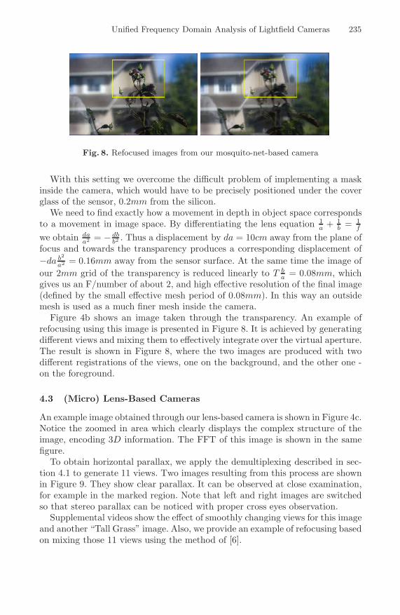
Fig. 8. Refocused images from our mosquito-net-based camera
With this setting we overcome the difficult problem of implementing a maskinside the camera, which would have to be precisely positioned under the coverglass of the sensor, 0.2mm from the silicon.
We need to find exactly how a movement in depth in object space correspondsto a movement in image space. By differentiating the lens equation 1
a + 1b = 1
f
we obtain daa2 = − db
b2 . Thus a displacement by da = 10cm away from the plane offocus and towards the transparency produces a corresponding displacement of−da b2
a2 = 0.16mm away from the sensor surface. At the same time the image ofour 2mm grid of the transparency is reduced linearly to T b
a = 0.08mm, whichgives us an F/number of about 2, and high effective resolution of the final image(defined by the small effective mesh period of 0.08mm). In this way an outsidemesh is used as a much finer mesh inside the camera.
Figure 4b shows an image taken through the transparency. An example ofrefocusing using this image is presented in Figure 8. It is achieved by generatingdifferent views and mixing them to effectively integrate over the virtual aperture.The result is shown in Figure 8, where the two images are produced with twodifferent registrations of the views, one on the background, and the other one -on the foreground.
4.3 (Micro) Lens-Based Cameras
An example image obtained through our lens-based camera is shown in Figure 4c.Notice the zoomed in area which clearly displays the complex structure of theimage, encoding 3D information. The FFT of this image is shown in the samefigure.
To obtain horizontal parallax, we apply the demultiplexing described in sec-tion 4.1 to generate 11 views. Two images resulting from this process are shownin Figure 9. They show clear parallax. It can be observed at close examination,for example in the marked region. Note that left and right images are switchedso that stereo parallax can be noticed with proper cross eyes observation.
Supplemental videos show the effect of smoothly changing views for this imageand another “Tall Grass” image. Also, we provide an example of refocusing basedon mixing those 11 views using the method of [6].

236 T. Georgiev et al.
Fig. 9. Stereo images from our lens-based camera. Stereopsis can be achieved withcrossed eye observation. Close examination of the marked areas will also reveal hori-zontal parallax between the pictures.
5 Conclusions and Future Work
In this paper, we have derived a new mathematical formalism for analyzinglight-field cameras in the frequency domain. The method of multiplexing the 4Dradiance onto the 2D sensor is shown to work in the frequency domain for anumber of of light-field cameras, both lens-based and mask-based.
The important conclusion we draw out of this finding is that the “hetero-dyning” method is not restricted to a special “heterodyning” type of camera. Itis a new method of demultiplexing captured lightfield data from any lightfieldcamera, mask based or microlens based.
Analyzing light-field cameras in the frequency domain and designing newapproaches based on that is a new emerging area of research, covering bothmask and lens based cameras. Mask based cameras are much cheaper and easierto build. Using microlenses, prisms, and other arrays of optical elements with thefrequency multiplexing approach might have unexpected new potential. Thereis much more to be done in this direction.
In relation to this approach, we have proposed and implemented a new“mosquito net” lightfield camera based on masks/nets in front of the main lens.We have also built prototypes of all these cameras in order to demonstrate thevalidity of this formalism.
In the last year, a whole new dimension has been added to to integral pho-tography due to unexpected possibilities with frequency domain multiplexing.Compact camera designs, and later post-processing based on computer vision areopening new possibilities. We hope that our work will inspire others to explorefurther this rich domain.
References
1. Guillemin, V., Sternberg, S.: Symplectic techniques in physics (1985)2. Ives, F.: Patent US 725,567 (1903)
Unified Frequency Domain Analysis of Lightfield Cameras 237
3. Lippmann, G.: Epreuves reversible donnant la sensation du relief. J. Phys. 7, 821–825 (1908)
4. Levoy, M., Hanrahan, P.: Light field rendering. ACM Trans. Graph, 31–42 (1996)5. Gortler, S.J., Grzeszczuk, R., Szeliski, R., Cohen, M.F.: The lumigraph. ACM
Trans. Graph, 43–54 (1996)6. Ng, R., Levoy, M., Brdif, M., Duval, G., Horowitz, M., Hanrahan, P.: Light field
photography with a hand-held plenoptic camera. Tech. Rep. (2005)7. Chai, J., Chan, S., Shum, H., Tong, X.: Plenoptic sampling. ACM Trans. Graph,
307–318 (2000)8. Durand, F., Holzschuch, N., Soler, C., Chan, E., Sillion, F.: A frequency analysis
of light transport. ACM Trans. Graph, 1115–1126 (2005)9. Ng, R.: Fourier slice photography. ACM Trans. Graph, 735–744 (2005)
10. Veeraraghavan, A., Mohan, A., Agrawal, A., Raskar, R., Tumblin, J.: Dappled pho-tography: Mask enhanced cameras for heterodyned light fields and coded aperturerefocusing. ACM Trans. Graph 26(3), 69 (2007)
11. Gerrard, A., Burch, J.M.: Introduction to matrix methods in optics (1994)12. Georgiev, T., Zheng, K.C., Curless, B., Salesin, D., Nayar, S., Intwala, C.: Spatio-
angular resolution tradeoffs in integral photography. In: Rendering Techniques2006: 17th Eurographics Workshop on Rendering, pp. 263–272 (June 2006)
13. Oppenheim, A.V., Willsky, A.S.: Signals and Systems. Prentice Hall, Upper SaddleRiver, New Jersey (1997)
14. Adelson, T., Wang, J.: Single lens stereo with a plenoptic camera. IEEE Transac-tions on Pattern Analysis and Machine Intelligence, 99–106 (1992)