
DIPSI: measure of the tip-tilt with a diffraction image phase sensing instrument
11
DIPSI: measure of the tip-tilt with a diffraction image phase sensing instrument Sergio Chueca* a , Marcos Reyes a , Achim Schumacher b , Luzma Montoya a a Instituto de Astrofísica de Canarias, C/ Via Lactea s/n, La Laguna, Tenerife, Spain 38200; b GTC, C/ Via Lactea s/n, La Laguna, Tenerife, Spain, 38200 ABSTRACT Large segmented mirrors require efficient co-phasing techniques in order to avoid the image degradation due to segments misalignment. DIPSI (Diffraction Image Phase Sensing Instrument) is an instrument developed by IAC, GRANTECAN and LAM. This instrument is being integrated in the Active Phasing Experiment (APE), aimed at testing different phasing techniques for an Extremely Large Telescope. This paper describes the mathematical solution for determining piston and tip-tilt simultaneously from the DIPSI images. A complete set of simulations is included to study the residual errors. Residual errors are bigger when piston and tip-tilt are combined (three degrees of freedom). Keywords: segmented telescope, co-phasing, ELT, relative angle, tip tilt correction 1. INTRODUCTION In the last years new co-phasing techniques have been studied and developed. APE (Active Phasing Experiment) is an experiment which integrates and validates non-adaptive wave-front control schemes and technologies for an ELT (Extremely Large Telescope). If the position of each segment of an ELT is not controlled, the resolution of the whole telescope will be the same as if telescope had the diameter equal to the size of one segment. To achieve the resolution corresponding with that of a monolithic telescope of the same diameter the segmented surface must be controlled with high precision better than λ/40 surface rms error 1 . The main objective of APE is to study and compare several co-phasing techniques in laboratory and on sky, to determine their viability and performance. The key subsystem to simulate primary segmentation in APE is the Active Segmented Mirror (ASM 10 ). The ASM is composed of 61 flat hexagonal mirrors 17 mm side to side and with a gap in-between of 100 μm. Each segment of the ASM is controlled in Piston, Tip and Tilt by means of piezo actuators having a stroke of 30 μm. APE implements four different sensors to co-phase the segmented mirror: - DIPSI – modification of the curvature sensor 5, 7, 8 - PYPS – based on the pyramid sensor 3 - ZEUS – the conceptual descendant of the Mach-Zehnder interferometer 2 - SHAPS – based on a Shack - Hartmann method 4 DIPSI (Diffraction Image Phase Sensing Instrument) is based on the analysis of the diffraction effect produced in the edge of the segment when observed on the defocused pupil plane. The concept of DIPSI has been deeply described for piston 7, 8 . Segment misalignment includes not only piston errors but also tip-tilt aberrations. The DIPSI instrument was first conceived to retrieve pure pistons but the signal includes also information about the tip-tilt between segments which can be analyzed 5 . Piston and tip-tilt disentanglement with DIPSI could be done with an experimental procedure. In the first part of this paper we describe the geometrical description for piston, tip and tilt algorithm of DIPSI and the two possible measurements: relative angle and piston step. In the second part we present a depth analysis of relative angle and how to measure it. In the third part, we analyze the global piston tip-tilt algorithm performance in different conditions. *[email protected]; phone +(34) 922 605 725; fax + (34) 922 605 210; www.iac.es Ground-based and Airborne Telescopes II, edited by Larry M. Stepp, Roberto Gilmozzi, Proc. of SPIE Vol. 7012, 701213, (2008) · 0277-786X/08/$18 · doi: 10.1117/12.787818 Proc. of SPIE Vol. 7012 701213-1 2008 SPIE Digital Library -- Subscriber Archive Copy
-
Upload
independent -
Category
Documents
-
view
2 -
download
0
Transcript of DIPSI: measure of the tip-tilt with a diffraction image phase sensing instrument
DIPSI: measure of the tip-tilt with a diffraction image phase sensing instrument
Sergio Chueca*a, Marcos Reyesa, Achim Schumacherb, Luzma Montoyaa
aInstituto de Astrofísica de Canarias, C/ Via Lactea s/n, La Laguna, Tenerife, Spain 38200; bGTC, C/ Via Lactea s/n, La Laguna, Tenerife, Spain, 38200
ABSTRACT
Large segmented mirrors require efficient co-phasing techniques in order to avoid the image degradation due to segments misalignment. DIPSI (Diffraction Image Phase Sensing Instrument) is an instrument developed by IAC, GRANTECAN and LAM. This instrument is being integrated in the Active Phasing Experiment (APE), aimed at testing different phasing techniques for an Extremely Large Telescope. This paper describes the mathematical solution for determining piston and tip-tilt simultaneously from the DIPSI images. A complete set of simulations is included to study the residual errors. Residual errors are bigger when piston and tip-tilt are combined (three degrees of freedom).
Keywords: segmented telescope, co-phasing, ELT, relative angle, tip tilt correction
1. INTRODUCTION In the last years new co-phasing techniques have been studied and developed. APE (Active Phasing Experiment) is an experiment which integrates and validates non-adaptive wave-front control schemes and technologies for an ELT (Extremely Large Telescope). If the position of each segment of an ELT is not controlled, the resolution of the whole telescope will be the same as if telescope had the diameter equal to the size of one segment. To achieve the resolution corresponding with that of a monolithic telescope of the same diameter the segmented surface must be controlled with high precision better than λ/40 surface rms error1. The main objective of APE is to study and compare several co-phasing techniques in laboratory and on sky, to determine their viability and performance. The key subsystem to simulate primary segmentation in APE is the Active Segmented Mirror (ASM10). The ASM is composed of 61 flat hexagonal mirrors 17 mm side to side and with a gap in-between of 100 µm. Each segment of the ASM is controlled in Piston, Tip and Tilt by means of piezo actuators having a stroke of 30 µm.
APE implements four different sensors to co-phase the segmented mirror:
- DIPSI – modification of the curvature sensor5, 7, 8
- PYPS – based on the pyramid sensor3
- ZEUS – the conceptual descendant of the Mach-Zehnder interferometer2
- SHAPS – based on a Shack - Hartmann method4
DIPSI (Diffraction Image Phase Sensing Instrument) is based on the analysis of the diffraction effect produced in the edge of the segment when observed on the defocused pupil plane. The concept of DIPSI has been deeply described for piston7, 8. Segment misalignment includes not only piston errors but also tip-tilt aberrations. The DIPSI instrument was first conceived to retrieve pure pistons but the signal includes also information about the tip-tilt between segments which can be analyzed5. Piston and tip-tilt disentanglement with DIPSI could be done with an experimental procedure.
In the first part of this paper we describe the geometrical description for piston, tip and tilt algorithm of DIPSI and the two possible measurements: relative angle and piston step. In the second part we present a depth analysis of relative angle and how to measure it. In the third part, we analyze the global piston tip-tilt algorithm performance in different conditions.
*[email protected]; phone +(34) 922 605 725; fax + (34) 922 605 210; www.iac.es
Ground-based and Airborne Telescopes II, edited by Larry M. Stepp, Roberto Gilmozzi,Proc. of SPIE Vol. 7012, 701213, (2008) · 0277-786X/08/$18 · doi: 10.1117/12.787818
Proc. of SPIE Vol. 7012 701213-12008 SPIE Digital Library -- Subscriber Archive Copy
Co-phase
Check DIPSI signal
just with piston step
2. OVERVIEW OF TIP-TILT IN DIPSI Segment misalignment in segmented mirror has three main components: piston, tip and tilt. One of the specific problems associated with segmented telescopes is phasing, implying an active control in three degrees of freedom of each individual segment: translation along the optical axis (piston) and rotation about two axes perpendicular to the optical axis (tip-tilt). The piston misalignment is caused by a jump between two adjacent segments and the tip-tilt misalignment is caused by the different orientation of adjacent segments. This leads to an aberration that produces wave-front changes, which can be used to measure the errors.
DIPSI is a powerful instrument to make misalignment measurements. The instrument is based on the analysis of the diffraction effect produced in the edge of the segment when observed on the defocused pupil plane. Then, the retrieval of segmented piston, tip and tilt is based on the analysis of each edge. Once the defocused image is obtained, a sub-image of each edge is extracted and analyzed. DIPSI will operate in three different modes.
1) Retrieve of pure piston. The analysis of the signal is done perpendicular to the segment edge.
2) Retrieve of pure tip-tilt. The analysis of the signal is done parallel (relative angle analysis) and perpendicular (piston step analysis) to the segment edge.
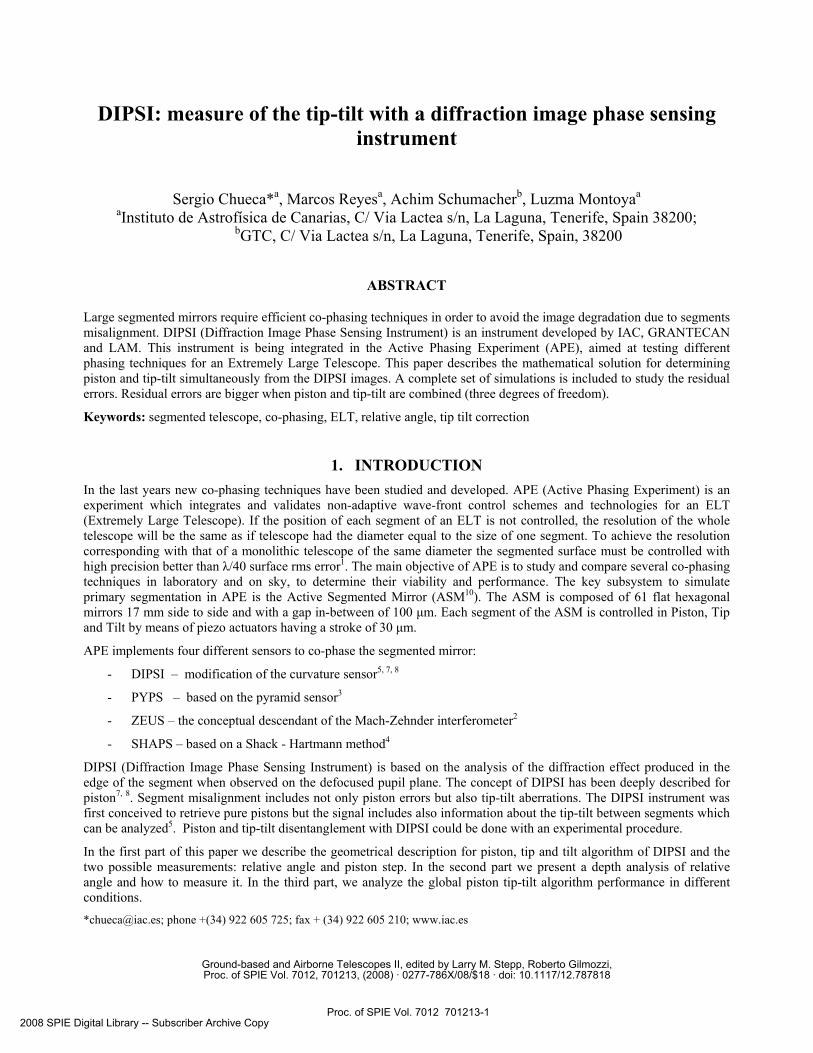
3) Retrieve piston and tip-tilt. In this case, signal from piston, tip and tilt is mixed in each edge. The presence of tip and tilt contaminates the piston signal, leading to a wrong characterization. However, errors can be decomposed into contribution to relative angle and piston step. Piston does not influence the relative angle signal, so the analysis is done initially for relative angle, allowing to determine a mirror configuration with just piston step between adjacent borders.
Fig. 1: Sequence-diagram for Piston Tip-Tilt Algorithm.
In Fig. 1 it is showed the Sequence-diagram for piston tip-tilt algorithm. There are two possible measurements in each edge: relative angle and piston step measurements. Piston step is only measurable when the relative angle is small due to relative angle signal disturbed the piston step signal.
2.1 Mathematical description of relative angle and piston step
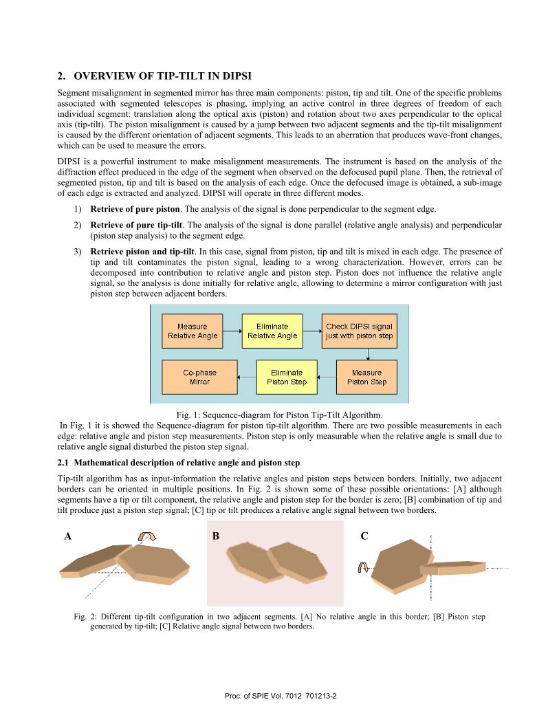
Tip-tilt algorithm has as input-information the relative angles and piston steps between borders. Initially, two adjacent borders can be oriented in multiple positions. In Fig. 2 is shown some of these possible orientations: [A] although segments have a tip or tilt component, the relative angle and piston step for the border is zero; [B] combination of tip and tilt produce just a piston step signal; [C] tip or tilt produces a relative angle signal between two borders.
Fig. 2: Different tip-tilt configuration in two adjacent segments. [A] No relative angle in this border; [B] Piston step generated by tip-tilt; [C] Relative angle signal between two borders.
A B C
Proc. of SPIE Vol. 7012 701213-2
SEG N
SEG P
SEG R
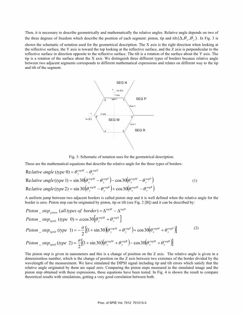
Then, it is necessary to describe geometrically and mathematically the relative angles. Relative angle depends on two of the three degrees of freedom which describe the position of each segment: piston, tip and tilt ),,( yx θθ∆ . In Fig. 3 is shown the schematic of notation used for the geometrical description. The X axis is the right direction when looking at the reflective surface, the Y axis is toward the top looking at the reflective surface, and the Z axis is perpendicular to the reflective surface in direction opposite to the reflective surface. The tilt is a rotation of the surface about the Y axis. The tip is a rotation of the surface about the X axis. We distinguish three different types of borders because relative angle between two adjacent segments corresponds to different mathematical expressions and relates on different way to the tip and tilt of the segment.
Fig. 3: Schematic of notation uses for the geometrical description.
These are the mathematical equations that describe the relative angle for the three types of borders:
( ) ( )( ) ( )segR
xsegMx
segRy
segMy
segPx
segMx
segPy
segMy
segNy
segMy
typeanglelative
typeanglelative
typeanglelative
θθθθ
θθθθ
θθ
−+−=
−−−=
−=
30cos30sin)2(Re
30cos30sin)1(Re
)0(Re
(1)
A uniform jump between two adjacent borders is called piston step and it is well defined when the relative angle for the border is zero. Piston step can be originated by piston, tip or tilt (see Fig. 2 [B]) and it can be described by:
[ ]( )( ) ( )[ ]
( )( ) ( )[ ]segRx
segMx
segRy
segMytiptilt
segPx
segMx
segPy
segMytiptilt
segNy
segMytiptilt
segNsegMpiston
atypestepPiston
atypestepPiston
atypestepPiston
borderoftypesallstepPiston
θθθθ
θθθθ
θθ
+−++=
++++−=
+=
∆−∆=
30cos30sin12
)2(_
30cos30sin12
)1(_
30cos)0(_
)(_
(2)
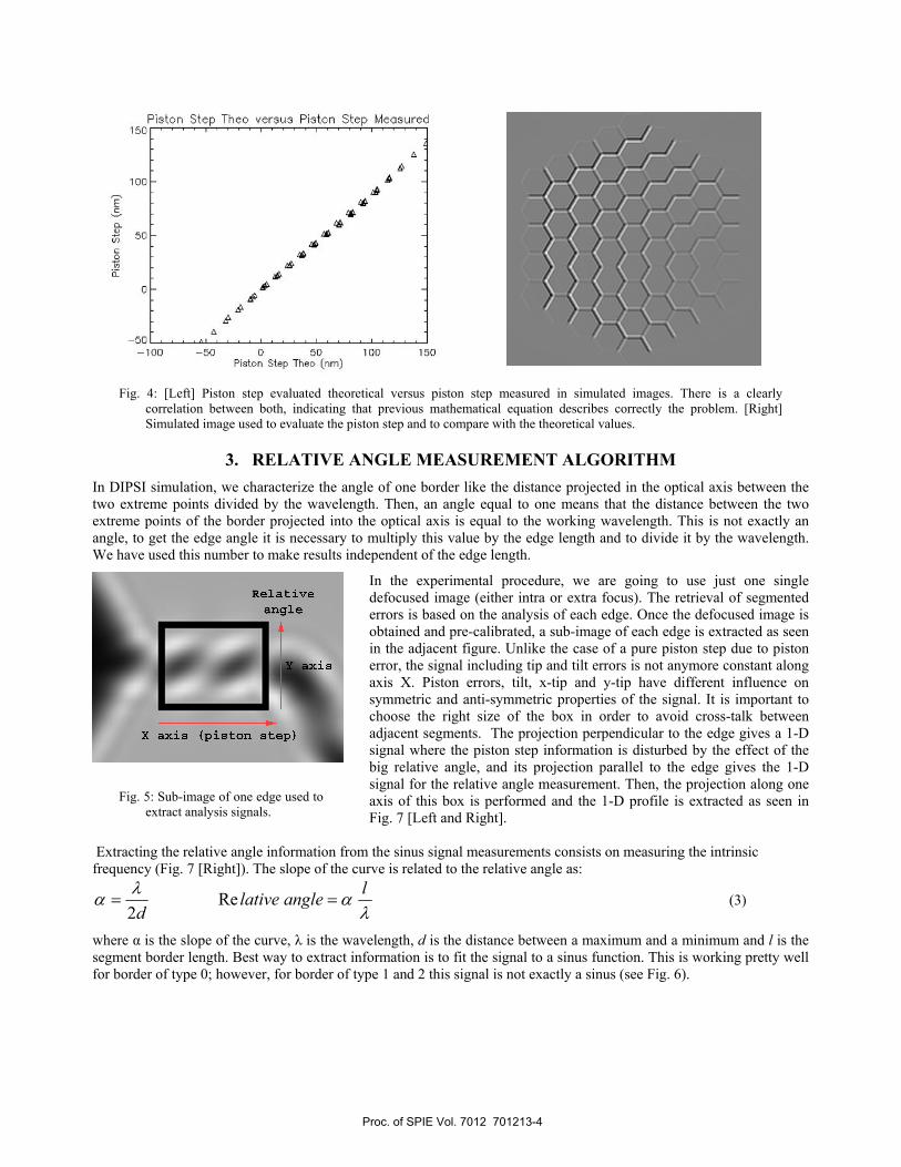
The piston step is given in nanometers and this is a change of position on the Z axis. The relative angle is given in a dimensionless number, which is the change of position on the Z axis between two extremes of the border divided by the wavelength of the measurement. We have simulated the DIPSI signal including tip and tilt errors which satisfy that the relative angle originated by them are equal zero. Comparing the piston steps measured in the simulated image and the piston step obtained with these expressions, these equations have been tested. In Fig. 4 is shown the result to compare theoretical results with simulations, getting a very good correlation between both.
Proc. of SPIE Vol. 7012 701213-3
Piston Step Thee versus Piston Step Measured150
Aa'
100- 4
S
50 14'a
'a
S0 6
64
—50 .
—100 —50 0 50 100 150Piston Step 1heo (nm)
Relative
angle
Fig. 4: [Left] Piston step evaluated theoretical versus piston step measured in simulated images. There is a clearly correlation between both, indicating that previous mathematical equation describes correctly the problem. [Right] Simulated image used to evaluate the piston step and to compare with the theoretical values.
3. RELATIVE ANGLE MEASUREMENT ALGORITHM In DIPSI simulation, we characterize the angle of one border like the distance projected in the optical axis between the two extreme points divided by the wavelength. Then, an angle equal to one means that the distance between the two extreme points of the border projected into the optical axis is equal to the working wavelength. This is not exactly an angle, to get the edge angle it is necessary to multiply this value by the edge length and to divide it by the wavelength. We have used this number to make results independent of the edge length.
In the experimental procedure, we are going to use just one single defocused image (either intra or extra focus). The retrieval of segmented errors is based on the analysis of each edge. Once the defocused image is obtained and pre-calibrated, a sub-image of each edge is extracted as seen in the adjacent figure. Unlike the case of a pure piston step due to piston error, the signal including tip and tilt errors is not anymore constant along axis X. Piston errors, tilt, x-tip and y-tip have different influence on symmetric and anti-symmetric properties of the signal. It is important to choose the right size of the box in order to avoid cross-talk between adjacent segments. The projection perpendicular to the edge gives a 1-D signal where the piston step information is disturbed by the effect of the big relative angle, and its projection parallel to the edge gives the 1-D signal for the relative angle measurement. Then, the projection along one axis of this box is performed and the 1-D profile is extracted as seen in Fig. 7 [Left and Right].
Extracting the relative angle information from the sinus signal measurements consists on measuring the intrinsic frequency (Fig. 7 [Right]). The slope of the curve is related to the relative angle as:
λαλα langlelative
d== Re
2 (3)
where α is the slope of the curve, λ is the wavelength, d is the distance between a maximum and a minimum and l is the segment border length. Best way to extract information is to fit the signal to a sinus function. This is working pretty well for border of type 0; however, for border of type 1 and 2 this signal is not exactly a sinus (see Fig. 6).
Fig. 5: Sub-image of one edge used to extract analysis signals.
Proc. of SPIE Vol. 7012 701213-4

0.05
1,00
—0.05
0 20 40 60Pixel number
APE Border: $4 Mi!10 155 (Err: 1.02)
I
—0.6 APE Seg I: IS eg 2: 2 Amplitud; OS3 Avg: DM130 20 40 60
Pixel number
- - - APE Border I Angie: 0.725 (Em 2.01)
NJAPE Seg I: IS eg 2: 32 Amplitud; O26 Avg: I
20 40Pixel number
0 60
0.4
0.2
0.0
—02
—0.4
0 20 40 60Pixel number
APE Border: 84 Migle: 108 (Err: 2.01)
—0.1
///
APE Seg I: IS eg 2: 32 Amplitud; O2D Avg: I
Pixel number
—I,-,0 20 40 60
• APE Border: $4 Mi!1e ?8 (Err: 1.54)
:APE Seg I: IS eg 2: 32 Amplitud; 0486 Avg: 0569
0 20 40 60Pixel number
0.4
0.2
0,0
—0-2
0 20 40 60Pixel number
—02
0 20 40 60Pixel number
Fig. 6: Simulated de-focused angle signals across a segment edge for relative angle values from 0 to 4. The signals were obtained using a simulation code implementation for DIPSI
Proc. of SPIE Vol. 7012 701213-5
I .2
1 .0
0.8
S 0.6
0.4
0.2
0.020 40
Position [pix]60 80
2;''5=4,=
Rekjtive
Position Ipix]0 20 40 €0
MIe a etep moved
e
4
MgIo; —2.1 Mgle Too; —205
AAA A5A AA a
A
A
a—10 —5 0 5 10
Step moved
MçIe vs step moved
6
Angle: 056 igIe leo: 0574
AA
4
2
0—10
A A
A
—5 0Step moved
5 10
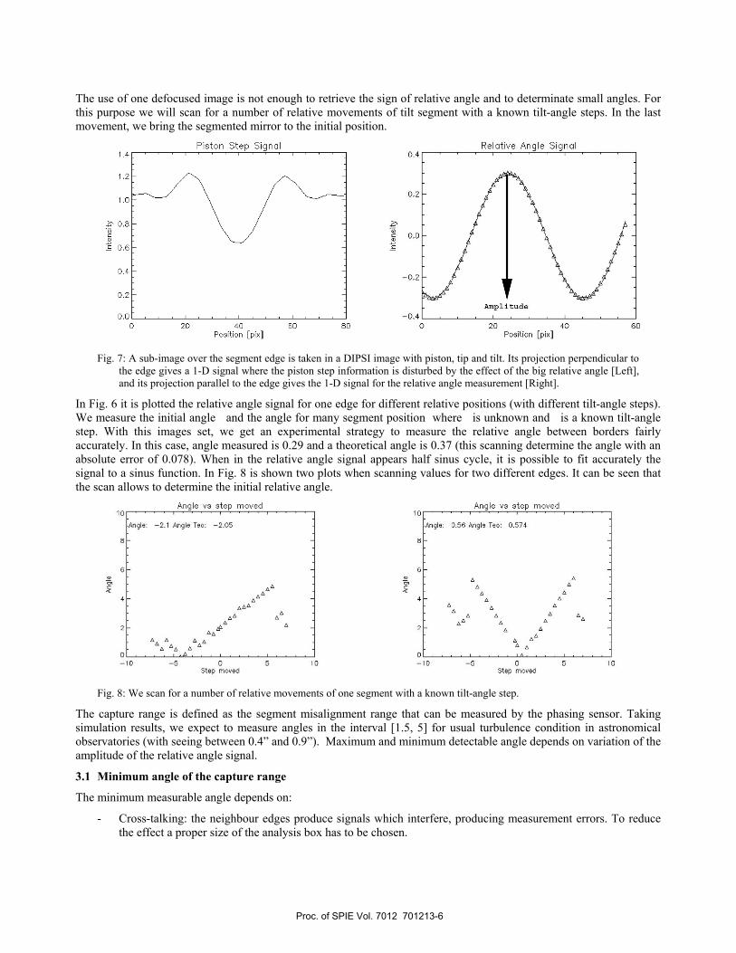
The use of one defocused image is not enough to retrieve the sign of relative angle and to determinate small angles. For this purpose we will scan for a number of relative movements of tilt segment with a known tilt-angle steps. In the last movement, we bring the segmented mirror to the initial position.
Fig. 7: A sub-image over the segment edge is taken in a DIPSI image with piston, tip and tilt. Its projection perpendicular to
the edge gives a 1-D signal where the piston step information is disturbed by the effect of the big relative angle [Left], and its projection parallel to the edge gives the 1-D signal for the relative angle measurement [Right].
In Fig. 6 it is plotted the relative angle signal for one edge for different relative positions (with different tilt-angle steps). We measure the initial angle and the angle for many segment position where is unknown and is a known tilt-angle step. With this images set, we get an experimental strategy to measure the relative angle between borders fairly accurately. In this case, angle measured is 0.29 and a theoretical angle is 0.37 (this scanning determine the angle with an absolute error of 0.078). When in the relative angle signal appears half sinus cycle, it is possible to fit accurately the signal to a sinus function. In Fig. 8 is shown two plots when scanning values for two different edges. It can be seen that the scan allows to determine the initial relative angle.
Fig. 8: We scan for a number of relative movements of one segment with a known tilt-angle step.
The capture range is defined as the segment misalignment range that can be measured by the phasing sensor. Taking simulation results, we expect to measure angles in the interval [1.5, 5] for usual turbulence condition in astronomical observatories (with seeing between 0.4” and 0.9”). Maximum and minimum detectable angle depends on variation of the amplitude of the relative angle signal.
3.1 Minimum angle of the capture range
The minimum measurable angle depends on:
- Cross-talking: the neighbour edges produce signals which interfere, producing measurement errors. To reduce the effect a proper size of the analysis box has to be chosen.
Proc. of SPIE Vol. 7012 701213-6
QI6UV A!WI g -p Z L C
yC'C V
-1cI
V
VVV
V aVG00 - V 0 0
00 0 VVV 0V 0
V V
VVV e
aibuv 01TI0 St. pntndwv
QI6UV A!WI 9 t t C
000o vx
xxxxx 7VvV0X xxxxx 0000000XO
xxxx xxxxxx 0
0 0
000 00
aibuv aAiTDIa S\ Pniudwv
- Edge imperfection: It is extremely difficult to polish the edge of a mirror to the same precision as the center. These segment aberrations give rise to signals near the segment edges which can be comparable in amplitude to those due to angle signal.
- Gap effects: A similar behaviour as in the case of the edge imperfection can be observed for signal including gaps between segments.
3.2 Maximum angle of the capture range
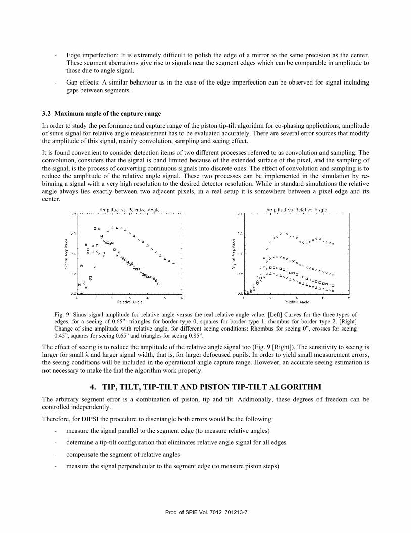
In order to study the performance and capture range of the piston tip-tilt algorithm for co-phasing applications, amplitude of sinus signal for relative angle measurement has to be evaluated accurately. There are several error sources that modify the amplitude of this signal, mainly convolution, sampling and seeing effect.
It is found convenient to consider detection items of two different processes referred to as convolution and sampling. The convolution, considers that the signal is band limited because of the extended surface of the pixel, and the sampling of the signal, is the process of converting continuous signals into discrete ones. The effect of convolution and sampling is to reduce the amplitude of the relative angle signal. These two processes can be implemented in the simulation by re-binning a signal with a very high resolution to the desired detector resolution. While in standard simulations the relative angle always lies exactly between two adjacent pixels, in a real setup it is somewhere between a pixel edge and its center.
Fig. 9: Sinus signal amplitude for relative angle versus the real relative angle value. [Left] Curves for the three types of edges, for a seeing of 0.65”: triangles for border type 0, squares for border type 1, rhombus for border type 2. [Right] Change of sine amplitude with relative angle, for different seeing conditions: Rhombus for seeing 0”, crosses for seeing 0.45”, squares for seeing 0.65” and triangles for seeing 0.85”.
The effect of seeing is to reduce the amplitude of the relative angle signal too (Fig. 9 [Right]). The sensitivity to seeing is larger for small λ and larger signal width, that is, for larger defocused pupils. In order to yield small measurement errors, the seeing conditions will be included in the operational angle capture range. However, an accurate seeing estimation is not necessary to make the that the algorithm work properly.
4. TIP, TILT, TIP-TILT AND PISTON TIP-TILT ALGORITHM The arbitrary segment error is a combination of piston, tip and tilt. Additionally, these degrees of freedom can be controlled independently.
Therefore, for DIPSI the procedure to disentangle both errors would be the following:
- measure the signal parallel to the segment edge (to measure relative angles)
- determine a tip-tilt configuration that eliminates relative angle signal for all edges
- compensate the segment of relative angles
- measure the signal perpendicular to the segment edge (to measure piston steps)
Proc. of SPIE Vol. 7012 701213-7
-
))))
)
J
- determine a piston tip-tilt configuration that eliminates piston step signal for all edges
- compensate the segment piston steps
Once the relative angle is measured for each edge, Single Value Decomposition (SVD) algorithm is used in order to solve the system of equations described in section 2 and compute piston, tip and tilt of each segment.
In simulation, we have used a random tip-tilt distribution. A tip-tilt distribution with an average value zero is called a random tip-tilt distribution. Each segment delivers six equations (one for each edge). We impose two global conditions:
• <average value of tilt in x-axis> = 0
• <average value of tip-tilt in y-axis> = 0
We performed tests to determine which piston, tip and tilt was the algorithm able to correct. The default configuration that we used for the simulations was:
- Piston, tip and tilt initial distribution have with average value of zero.
- Fried parameter equal to 0.15 m
- Wavelength 550 nm
- Defocus distance equal to 0.01 m
- Analysis Box for relative angle: 20 pixels (parallel) x 4 pixels (perpendicular)
- Analysis Box for piston step: 20 pixels (parallel) x 20 pixels (perpendicular)
- DIPSI parameters (detector and segment size). Photon noise and gap effect is not considered.
Final accuracy is a residual segmentation error. It is characterized by the wave-front RMS and by the statistical of the residual wave-front (mean, median, maximum and minimum residual error values).
4.1 Only Tip errors in the segmented mirror
From the mathematical point of view, this is a determined equations system with only one solution.
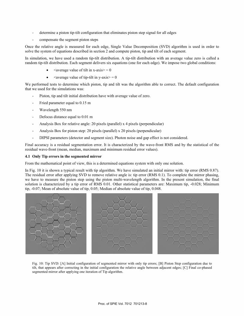
In Fig. 10 it is shown a typical result with tip algorithm. We have simulated an initial mirror with: tip error (RMS 0.87). The residual error after applying SVD to remove relative angle is: tip error (RMS 0.1). To complete the mirror phasing, we have to measure the piston step using the piston multi-wavelength algorithm. In the present simulation, the final solution is characterized by a tip error of RMS 0.01. Other statistical parameters are: Maximum tip, -0.028; Minimum tip, -0.07; Mean of absolute value of tip, 0.05; Median of absolute value of tip, 0.048.
Fig. 10: Tip SVD: [A] Initial configuration of segmented mirror with only tip errors; [B] Piston Step configuration due to tilt, that appears after correcting in the initial configuration the relative angle between adjacent edges; [C] Final co-phased segmented mirror after applying one iteration of Tip algorithm.
Proc. of SPIE Vol. 7012 701213-8
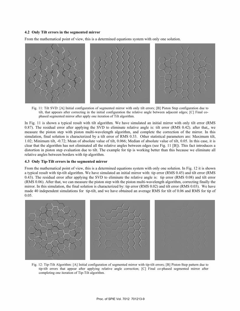
4.2 Only Tilt errors in the segmented mirror
From the mathematical point of view, this is a determined equations system with only one solution.
Fig. 11: Tilt SVD: [A] Initial configuration of segmented mirror with only tilt errors; [B] Piston Step configuration due to
tilt, that appears after correcting in the initial configuration the relative angle between adjacent edges; [C] Final co-phased segmented mirror after apply one iteration of Tilt algorithm.
In Fig. 11 is shown a typical result with tilt algorithm. We have simulated an initial mirror with only tilt error (RMS 0.87). The residual error after applying the SVD to eliminate relative angle is: tilt error (RMS 0.42). after that,, we measure the piston step with piston multi-wavelength algorithm, and complete the correction of the mirror. In this simulation, final solution is characterized by a tilt error of RMS 0.33. Other statistical parameters are: Maximum tilt, 1.02; Minimum tilt, -0.72; Mean of absolute value of tilt, 0.066; Median of absolute value of tilt, 0.05. In this case, it is clear that the algorithm has not eliminated all the relative angles between edges (see Fig. 11 [B]). This fact introduces a distortion in piston step evaluation due to tilt. The example for tip is working better than this because we eliminate all relative angles between borders with tip algorithm.
4.3 Only Tip-Tilt errors in the segmented mirror
From the mathematical point of view, this is a determined equations system with only one solution. In Fig. 12 it is shown a typical result with tip-tilt algorithm. We have simulated an initial mirror with: tip error (RMS 0.45) and tilt error (RMS 0.43). The residual error after applying the SVD to eliminate the relative angle is: tip error (RMS 0.08) and tilt error (RMS 0.06). After that, we can measure the piston step with the piston multi-wavelength algorithm, correcting finally the mirror. In this simulation, the final solution is characterized by: tip error (RMS 0.02) and tilt error (RMS 0.03). We have made 40 independent simulations for tip-tilt, and we have obtained an average RMS for tilt of 0.06 and RMS for tip of 0.05.
Fig. 12: Tip-Tilt Algorithm: [A] Initial configuration of segmented mirror with tip-tilt errors; [B] Piston-Step pattern due to
tip-tilt errors that appear after applying relative angle correction; [C] Final co-phased segmented mirror after completing one iteration of Tip-Tilt algorithm.
Proc. of SPIE Vol. 7012 701213-9
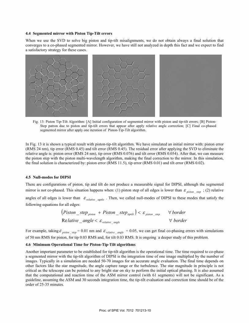
4.4 Segmented mirror with Piston Tip-Tilt errors
When we use the SVD to solve big piston and tip-tilt misalignments, we do not obtain always a final solution that converges to a co-phased segmented mirror. However, we have still not analyzed in depth this fact and we expect to find a satisfactory strategy for these cases.
Fig. 13: Piston Tip-Tilt Algorithm: [A] Initial configuration of segmented mirror with piston and tip-tilt errors; [B] Piston-
Step patron due to piston and tip-tilt errors that appear after apply relative angle correction; [C] Final co-phased segmented mirror after apply one iteration of Piston-Tip-Tilt algorithm.
In Fig. 13 it is shown a typical result with piston-tip-tilt algorithm. We have simulated an initial mirror with: piston error (RMS 24 nm), tip error (RMS 0.45) and tilt error (RMS 0.45). The residual error after applying the SVD to eliminate the relative angle is: piston error (RMS 24 nm), tip error (RMS 0.076) and tilt error (RMS 0.054). After that, we can measure the piston step with the piston multi-wavelength algorithm, making the final correction to the mirror. In this simulation, the final solution is characterized by: piston error (RMS 11.5), tip error (RMS 0.01) and tilt error (RMS 0.02).
4.5 Null-modes for DIPSI
There are configurations of piston, tip and tilt do not produce a measurable signal for DIPSI, although the segmented mirror is not co-phased. This situation happens when: (1) piston step of all edges is lower than steppiston _ε ; (2) relative
angles of all edges is lower than agnlerelative _ε . Then, we called null-modes of DIPSI to these modes that satisfy the following equations for all edges:
( )borderanglelativeborderstepPistonstepPiston
anglerelative
steppistontiptiltpiston
∀<
∀<+
_
_
_Re
__
ε
ε
For example, taking steppiston _ε = 0.01 nm and anglerelative _ε = 0.05, we can get final co-phasing errors with simulations of 50 nm RMS for piston, for tip 0.03 RMS and, for tilt 0.03 RMS. It is ongoing a deeper study of this problem.
4.6 Minimum Operational Time for Piston-Tip-Tilt algorithms
Another important parameter to be established for tip-tilt algorithm is the operational time. The time required to co-phase a segmented mirror with the tip-tilt algorithm of DIPSI is the integration time of one image multiplied by the number of images. Typically in a simulation are needed 50-70 images for an accurate angle evaluation. The final time depends on other factors like the star magnitude, the angle capture range or the turbulence. The star magnitude in principle is not critical as the telescope can be pointed to any bright star on sky to perform the initial optical phasing. It is also assumed that the computational and reaction time of the ASM mirror control (with 61 segments) will not be significant. As a guideline, assuming the ASM and 30 seconds integration time, the tip-tilt evaluation and correction time should be of the order of 25-35 minutes.
Proc. of SPIE Vol. 7012 701213-10
5. CONCLUSIONS AND FUTURE WORK The concept of DIPSI algorithm for piston-tip-tilt has been demonstrated by simulations. It has several advantages: minimal hardware and alignment requirements, broad seeing condition working range, independency with seeing fluctuations. By means of simulations we have tested the algorithm performance considering different sources of error. Specific conditions for the analysis box have been derived so that the algorithm can determine the relative angle. And some restrictions have been initially identified, in particular the number of different images that are required for the iterative method.
DIPSI has been developed for APE. At the moment it is being integrated in the APE bench, to carry out the performance tests in laboratory. The piston-tip-tilt algorithm will be verified in the laboratory during this year. During the APE experiments, it will be also possible to determine piston with one PWFS and tip-tilt with another PWFS. These permits to check than the results are compatible with other techniques.
ACKNOWLEDGEMENTS
DIPSI has been developed for APE. At the moment it is being integrated in the APE bench, to carry out the performance tests in laboratory. The piston-tip-tilt algorithm will be verified in the laboratory during this year.
[1] APE Science Plan. Document number: ELT-PLA-ESO-04601-0001 [2] Dohlen, K. et al “ZEUS: a cophasing sensor based on a Zernike contrast method”, Proc SPIE 6267-132 (2006) [3] Esposito, S, Pinna, E, Puglisi, A. , Tozzi, A. and P. Stefanini, "Pyramid sensor for segmented mirror alignment,"
Opt. Lett. 30, 2572-2574 (2005) [4] Gonte, F., Noethe, L., Araujo, C. and Derie, F. “Shack-Hartmann sensor for the active phasing experiment”, Proc
SPIE 6267, 131 (2006) [5] Montoya-Martínez, L., Reyes, M., Schumacher, A. and Hernández, E., “DIPSI: The Diffraction Image Phase
Sensing Instrument for APE”, Proc. SPIE 6267 (2006). [6] Rodríguez González, J.M. and Fuensalida, J.J., “Diffractional treatment of curvature sensing in segmented-mirror
telescopes“ , Proc. SPIE 4837, 276 (2003) [7] Schumacher, A. and Devaney, N., “Phasing segmented mirrors using defocused images at visible wavelengths”,
Mon. Not. R. Astron. Soc., 336, 537-546 (2006). [8] Schumacher, A., Devaney, N. and Montoya, L. “Phasing segmented mirrors: a modification of the Keck narrow-
band technique and its application to extremely large telescopes”, Appl. Opt., 41, 1297-1307 (2002). [9] ASM: scaled down active segmented mirror developed to simulate a segmented primary mirror [10] Dupuy, Ch., Frank, C., Gonté, F., Araujo Hauck, C at al , “ASM: scaled down active segmented mirror developed to
simulate a segmented primary mirror “, Proc. SPIE 6273, 62733E (2006)
Proc. of SPIE Vol. 7012 701213-11