Time resolved friction during dry sliding of metal on metal
24
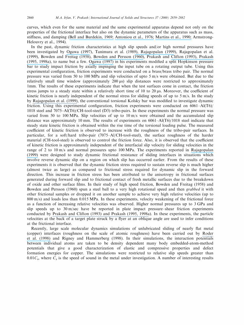
Time resolved friction during dry sliding of metal on metal Mohammad A. Irfan, Vikas Prakash* Department of Mechanical and Aerospace Engineering, Case Western Reserve University, Cleveland, OH 44106-7222, USA Received 2 September 1998; received in revised form 5 April 1999 Abstract In the present study, plate impact pressure–shear friction experiments are conducted to provide insight into time- resolved dry sliding characteristics of metal on metal at normal pressures of approximately 1.5 GPa, slip speeds up to 60 m/s and interfacial temperatures as high as 8008C. The plate impact friction experiments represent a significant improvement over conventional dynamic friction experiments by allowing control of interfacial tractions with the use of combined pressure–shear loading waves instead of manipulating actuator motion. Also, by measuring the combined normal and transverse motion of the rear surface of the target plate, critical frictional parameters such as the applied normal pressure, the interfacial slip resistance, and the interfacial slip speeds can be interpreted by using the framework of one-dimensional plane wave analysis. The experiments are conducted on a Carpentor Hampden tool-steel (D3)/Ti–6Al–4V tribo-pair. The frictional state at the tribo-pair interface is varied by varying the impact velocity and/or the surface roughness of the impacting surfaces. Moreover, by appropriate selection of flyer and target plate thickness the tribo-pair interface is subjected to step changes in normal pressure and step changes in applied shear stress. The results of these experiments provide new insights into the evolution of interfacial sliding resistance with accumulated interfacial slip, and its dependence on surface roughness, slip velocity, normal pressure and interfacial temperature. # 2000 Elsevier Science Ltd. All rights reserved. Keywords: Time resolved; Dynamic friction; High pressures; Elevated temperatures; Step decrements in pressure; High speed machining; Ti–6Al–4V 1. Introduction The nature of dynamic friction forces between two bodies in contact is a complex process and is aected by a long list of factors. Most experimental apparatus employed to investigate dynamic friction lack the reproducibility of friction data. This results in multi-branched friction-stress versus slip-velocity International Journal of Solids and Structures 37 (2000) 2859–2882 0020-7683/00/$ - see front matter # 2000 Elsevier Science Ltd. All rights reserved. PII: S0020-7683(99)00112-2 www.elsevier.com/locate/ijsolstr * Corresponding author. Fax: +1-216-368-6445. E-mail address: [email protected] (V. Prakash).
-
Upload
independent -
Category
Documents
-
view
1 -
download
0
Transcript of Time resolved friction during dry sliding of metal on metal
Time resolved friction during dry sliding of metal on metal
Mohammad A. Irfan, Vikas Prakash*
Department of Mechanical and Aerospace Engineering, Case Western Reserve University, Cleveland, OH 44106-7222, USA
Received 2 September 1998; received in revised form 5 April 1999
Abstract
In the present study, plate impact pressure±shear friction experiments are conducted to provide insight into time-resolved dry sliding characteristics of metal on metal at normal pressures of approximately 1.5 GPa, slip speeds upto 60 m/s and interfacial temperatures as high as 8008C. The plate impact friction experiments represent a signi®cant
improvement over conventional dynamic friction experiments by allowing control of interfacial tractions with theuse of combined pressure±shear loading waves instead of manipulating actuator motion. Also, by measuring thecombined normal and transverse motion of the rear surface of the target plate, critical frictional parameters such asthe applied normal pressure, the interfacial slip resistance, and the interfacial slip speeds can be interpreted by using
the framework of one-dimensional plane wave analysis.The experiments are conducted on a Carpentor Hampden tool-steel (D3)/Ti±6Al±4V tribo-pair. The frictional
state at the tribo-pair interface is varied by varying the impact velocity and/or the surface roughness of the
impacting surfaces. Moreover, by appropriate selection of ¯yer and target plate thickness the tribo-pair interface issubjected to step changes in normal pressure and step changes in applied shear stress. The results of theseexperiments provide new insights into the evolution of interfacial sliding resistance with accumulated interfacial slip,
and its dependence on surface roughness, slip velocity, normal pressure and interfacial temperature. # 2000 ElsevierScience Ltd. All rights reserved.
Keywords: Time resolved; Dynamic friction; High pressures; Elevated temperatures; Step decrements in pressure; High speed
machining; Ti±6Al±4V
1. Introduction
The nature of dynamic friction forces between two bodies in contact is a complex process and isa�ected by a long list of factors. Most experimental apparatus employed to investigate dynamic frictionlack the reproducibility of friction data. This results in multi-branched friction-stress versus slip-velocity
International Journal of Solids and Structures 37 (2000) 2859±2882
0020-7683/00/$ - see front matter # 2000 Elsevier Science Ltd. All rights reserved.
PII: S0020-7683(99 )00112-2
www.elsevier.com/locate/ijsolstr
* Corresponding author. Fax: +1-216-368-6445.
E-mail address: [email protected] (V. Prakash).
curves, which even for the same material and the same experimental apparatus depend not only on theproperties of the frictional interface but also on the dynamic parameters of the apparatus such as mass,sti�ness, and damping (Bell and Burdekin, 1969; Antoniou et al., 1976; Martins et al., 1990; Armstrong-Helouvry et al., 1994).
In the past, dynamic friction characteristics at high slip speeds and/or high normal pressures havebeen investigated by Ogawa (1997), Tanimura et al. (1989), Rajagopalan (1999), Rajagopalan et al.(1999), Bowden and Freitag (1958), Bowden and Persson (1960), Prakash and Clifton (1993), Prakash(1995, 1998a), to name but a few. Ogawa (1997) in his experiments modi®ed a split Hopkinson pressurebar to study impact friction by axially impinging the input tube on a rotating output tube. Using thisexperimental con®guration, friction experiments were conducted on a brass/brass tribo pair. The normalpressure was varied from 50 to 100 MPa and slip velocities of upto 5 m/s were obtained. But due to therelatively small time window (approximately 200 ms) slip distances were restricted to approximately1mm. The results of these experiments indicate that when the test surfaces come in contact, the frictionstress jumps to a steady state within a relatively short time of 10 to 20 ms. Moreover, the coe�cient ofkinetic friction is nearly independent of the normal stress for sliding speeds of up to 5 m/s. In the studyby Rajagopalan et al. (1999), the conventional torsional Kolsky bar was modi®ed to investigate dynamicfriction. Using this experimental con®guration, friction experiments were conducted on 6061±Al(T6)/1018 steel and 7075±Al(T6)/CH-tool-steel (D3) tribo-pairs. In these experiments the normal pressure wasvaried from 50 to 100 MPa. Slip velocities of up to 10 m/s were obtained and the accumulated slipdistance was approximately 10 mm. The results of experiments on 6061±Al(T6)/1018 steel indicate thatsteady state kinetic friction is obtained within the rise time of the torsional loading pulse. The measuredcoe�cient of kinetic friction is observed to increase with the roughness of the tribo-pair surfaces. Inparticular, for a soft/hard tribo-pair (7075±Al/CH-tool-steel), the surface roughness of the hardermaterial (CH-tool-steel) is observed to control the friction force. Also, it is observed that the coe�cientof kinetic friction is approximately independent of the interfacial slip velocity for sliding velocities in therange of 2 to 10 m/s and normal pressures upto 100 MPa. The experiments reported in Rajagopalan(1999) were designed to study dynamic frictional resistance of sliding interfaces in situations whichinvolve reverse dynamic slip on a region on which slip has occurred earlier. From the results of theseexperiments it is observed that the dynamic friction stress required to sustain reverse slip is much higher(almost twice as large) as compared to frictional stress required for dynamic slip in the forwarddirection. This increase in friction stress has been attributed to the anisotropy in frictional surfacesgenerated during forward slip and to frictional contact of fresh metallic surfaces due to the breakdownof oxide and other surface ®lms. In their study of high speed friction, Bowden and Freitag (1958) andBowden and Persson (1960) spun a steel ball to a very high rotational speed and then grabbed it withother frictional samples or dropped it on another sample to achieve very high relative velocities (up to800 m/s) and loads less than 0.015 MPa. In these experiments, velocity weakening of the frictional forceas a function of increasing relative velocities was observed. Higher normal pressures up to 3 GPa andslip speeds up to 30 m/sec have be reported in plate impact pressure±shear friction experimentsconducted by Prakash and Clifton (1993) and Prakash (1995, 1998a). In these experiments, the particlevelocities at the back of a target plate struck by a ¯yer at an oblique angle are used to infer conditionsat the frictional interface.
Recently, large scale molecular dynamics simulations of unlubricated sliding of nearly ¯at metal(copper) interfaces (roughness on the scale of atomic roughness) have been carried out by Roderet al. (1998) and Rigney and Hammerberg (1998). In their simulations, the interaction potentialsbetween individual atoms are taken to be density dependent many body embedded-atom-methodpotentials that give a good characterization of elastic and compressive properties and defectformation energies for copper. The simulations were restricted to relative slip speeds greater than0.01Cs, where Cs is the speed of sound in the metal under investigation. A number of interesting results
M.A. Irfan, V. Prakash / International Journal of Solids and Structures 37 (2000) 2859±28822860
have emerged from these simulations. In the high velocity regime, for slip velocities higher than 0.1Cs,the coe�cient of kinetic friction is found to decrease with increasing slip speeds. Associated with thisvelocity weakening is the evolution of microstructure in the vicinity of the sliding interface. This includesdislocation generation, dislocation motion both parallel and normal to the sliding interface, large plasticdeformation, and nucleation and di�usive coarsening of microstructure with distance from the interfaceas time increases. As sliding proceeds, material is also observed to mechanically mix from the upper andlower regions and vice-versa, leading to a thin layer (approximately 30 atom width) of the ®ne grainednano-crystalline region. For slip speeds lower than 0.1Cs, the tribo-pair materials are found to cold-weldtogether. However, by introducing nanometer scale asperities at the sliding interface, the system allowssliding even at slip speeds which had showed cold welding before.
The objective of the present study is aimed towards understanding the dynamic frictionalcharacteristics of sliding interfaces under relatively high normal pressures (500 MPa to 1.5 GPa),high slip speeds (1 to 100 m/s) and elevated temperatures. Under these conditions, the materialinterface is expected to be essentially stable, and to a large extent from the global point of view,the frictional forces developed appear to depend primarily on the applied normal pressures,slipping velocity, slip distance, interfacial temperatures and surface roughness. This category ofdynamic friction measurements encompass the general area of interfacial friction at the tool/diework-piece interface in several conventional and non-conventional material removal and/or materialforming operations.
The plate impact pressure±shear friction experiment (Prakash and Clifton, 1993; Prakash, 1995;Prakash, 1998a) is especially well suited for the present investigation. A primary concern in the use ofconventional dynamic friction con®gurations has been the in¯uence of sti�ness of the dynamic loadtrain on the measured frictional characteristics. Additionally, there have been concerns regarding theambiguity of the area of contact, and hence the distribution of the normal pressure at the tribo-pairinterface. With the use of the plate impact pressure±shear friction experiments, the aforementionedproblems associated with the measurement of dynamic friction are virtually eliminated. The use ofplanar pressure±shear waves to load the frictional interface results in an in®nitely high loading sti�ness,and any non-uniformity in geometry or alignment of the specimens result, in the worst case, in a slightspreading of the step-function load in time. This ensures uniform loading conditions over the entirecontact area and the measurements truly re¯ect the local frictional conditions rather than being somekind of a weighted average of unknown distributions. Moreover, the plane wave loading results in arapidly-attained steady state sliding condition with an e�ectively in®nite loading sti�ness. Consequently,changes in dynamic frictional resistance can be measured for arbitrary loading histories. Because thetotal slip distance is less than 250 mm, no signi®cant wear particles are generated, making the experimentideal for probing intrinsic dynamic slip resistance. Moreover, the principal advantage of thisexperimental con®guration is that it allows critical frictional parameters such as the applied normalpressure, the transmitted shear stress and the interfacial slip velocity to be interpreted by using theframework of one-dimensional plane wave analysis.
The tribo-pair employed in the present investigation is CH-tool-steel/Ti±6Al±4V. The choice of thetribo-pair is dictated by its technological importance and also because of the relative high melting pointsof the alloys precludes at and near surface melting during the sliding process. In order to investigate thedependence of the friction stress on normal pressure and slip speed, the experiment is designed tosubject the frictional interface to three well de®ned states: the ®rst state allows investigation of dynamicsliding characteristics of the frictional interface under constant normal pressure. The second state allowsthe investigation of the sliding characteristics of frictional interfaces subjected to step changes in normalpressure. The third state allows the investigation of friction-stress versus slip-velocity relationship atconstant normal pressures. Besides providing a fundamental insight into the evolution of interfacialsliding resistance with accumulated interfacial slip, slip velocity and normal pressure, the experimental
M.A. Irfan, V. Prakash / International Journal of Solids and Structures 37 (2000) 2859±2882 2861
results provide insights for determining the structure of the rate and state-dependent dynamic frictionlaws.
The organization of the paper is as follows: Section 2 describes the plate impact pressure±shearfriction experimental con®guration and outlines the procedure used for conducting the experiments.Section 3 provides details of wave propagation in the tribo-pair plates and discusses their designconsiderations. Section 4 presents the wave analysis used in the interpretation to obtain the interfacialtractions, slip speeds and accumulated slip displacement. The experimental results and discussion arepresented in Section 5. A summary of the main results is provided in Section 6.
2. Plate impact pressure shear friction experiment
2.1. Experimental con®guration
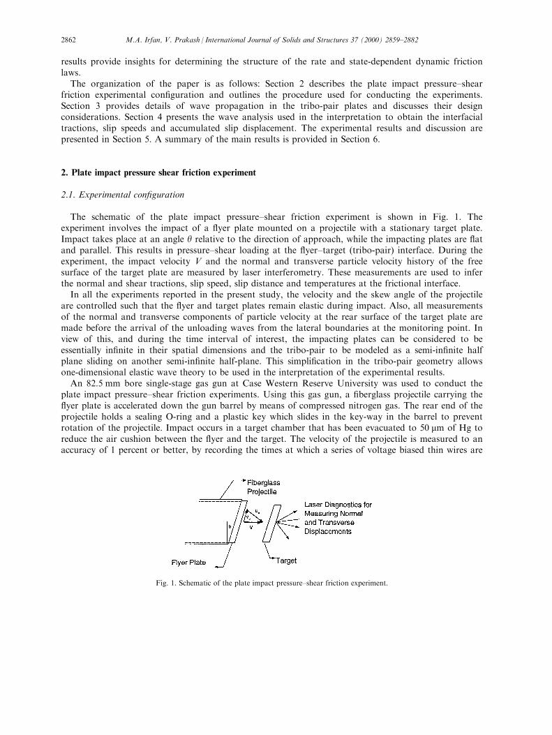
The schematic of the plate impact pressure±shear friction experiment is shown in Fig. 1. Theexperiment involves the impact of a ¯yer plate mounted on a projectile with a stationary target plate.Impact takes place at an angle y relative to the direction of approach, while the impacting plates are ¯atand parallel. This results in pressure±shear loading at the ¯yer±target (tribo-pair) interface. During theexperiment, the impact velocity V and the normal and transverse particle velocity history of the freesurface of the target plate are measured by laser interferometry. These measurements are used to inferthe normal and shear tractions, slip speed, slip distance and temperatures at the frictional interface.
In all the experiments reported in the present study, the velocity and the skew angle of the projectileare controlled such that the ¯yer and target plates remain elastic during impact. Also, all measurementsof the normal and transverse components of particle velocity at the rear surface of the target plate aremade before the arrival of the unloading waves from the lateral boundaries at the monitoring point. Inview of this, and during the time interval of interest, the impacting plates can be considered to beessentially in®nite in their spatial dimensions and the tribo-pair to be modeled as a semi-in®nite halfplane sliding on another semi-in®nite half-plane. This simpli®cation in the tribo-pair geometry allowsone-dimensional elastic wave theory to be used in the interpretation of the experimental results.
An 82.5 mm bore single-stage gas gun at Case Western Reserve University was used to conduct theplate impact pressure±shear friction experiments. Using this gas gun, a ®berglass projectile carrying the¯yer plate is accelerated down the gun barrel by means of compressed nitrogen gas. The rear end of theprojectile holds a sealing O-ring and a plastic key which slides in the key-way in the barrel to preventrotation of the projectile. Impact occurs in a target chamber that has been evacuated to 50 mm of Hg toreduce the air cushion between the ¯yer and the target. The velocity of the projectile is measured to anaccuracy of 1 percent or better, by recording the times at which a series of voltage biased thin wires are
Fig. 1. Schematic of the plate impact pressure±shear friction experiment.
M.A. Irfan, V. Prakash / International Journal of Solids and Structures 37 (2000) 2859±28822862
shorted out by contacting the ¯yer. To ensure generation of plane waves with wave-fronts su�cientlyparallel to the impact face, the ¯yer and target plates are carefully aligned to be parallel to within 2 �10ÿ5 radians by using an optical alignment scheme developed by Kumar and Clifton (1977). The actualtilt between the two plates is measured by recording the times at which four isolated, voltage-biasedpins, that are ¯ush with the surface of the target plate, are shorted to ground. The acceptable level oftilt in the experiments is of the order of 0.5 mrads.
A laser interferometric technique is used to obtain the normal and transverse particle velocity on therear surface of the target plate. An argon-ion laser with wavelength of 514.5 nm is used to provide acoherent monochromatic light source. Both the normal and transverse particle displacements aremeasured using the combined normal and transverse displacement interferometer (TDI) introduced byKim et al. (1977). Using this interferometer, the normal displacement of the rear surface of the targetplate is measured by combining a reference beam and a beam re¯ected from the target such that onepeak to peak variation of the intensity of the light corresponds to a displacement of l/2, where l is thewavelength of the laser light in use. The TDI is based on the phase di�erence between two N th orderbeams di�racted from a grating deposited on the rear surface of the target. The TDI sensitivity is givenby d/2n, where d is the pitch of the di�raction grating and N is the order of di�racted beams used (inour case, N = 1). The interference signals are detected by photo-diodes having a rise time of less than1 ns. The output of the photo-diodes is ampli®ed by wide band ampli®ers and then recorded on highspeed digital oscilloscopes. A digital data processing program is used to process the interferometricsignals and to calculate the normal and transverse particle velocities.
2.2. Tribo-pair materials and specimen preparation
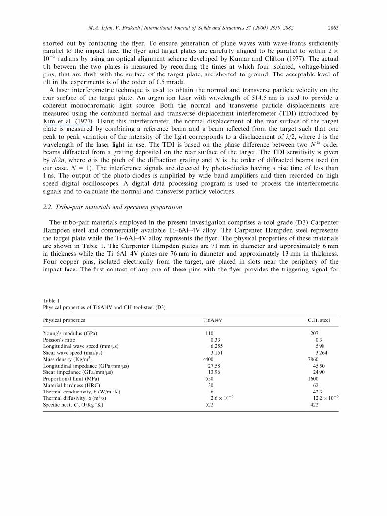
The tribo-pair materials employed in the present investigation comprises a tool grade (D3) CarpenterHampden steel and commercially available Ti±6Al±4V alloy. The Carpenter Hampden steel representsthe target plate while the Ti±6Al±4V alloy represents the ¯yer. The physical properties of these materialsare shown in Table 1. The Carpenter Hampden plates are 71 mm in diameter and approximately 6 mmin thickness while the Ti±6Al±4V plates are 76 mm in diameter and approximately 13 mm in thickness.Four copper pins, isolated electrically from the target, are placed in slots near the periphery of theimpact face. The ®rst contact of any one of these pins with the ¯yer provides the triggering signal for
Table 1
Physical properties of Ti6Al4V and CH tool-steel (D3)
Physical properties Ti6Al4V C.H. steel
Young's modulus (GPa) 110 207
Poisson's ratio 0.33 0.3
Longitudinal wave speed (mm/ms) 6.255 5.98
Shear wave speed (mm/ms) 3.151 3.264
Mass density (Kg/m3) 4400 7860
Longitudinal impedance (GPa/mm/ms) 27.58 45.50
Shear impedance (GPa/mm/ms) 13.96 24.90
Proportional limit (MPa) 550 1600
Material hardness (HRC) 30 62
Thermal conductivity, k (W/m 8K) 6 42.3
Thermal di�usivity, a (m2/s) 2.6� 10ÿ6 12.2� 10ÿ6
Speci®c heat, Cp (J/Kg 8K) 522 422
M.A. Irfan, V. Prakash / International Journal of Solids and Structures 37 (2000) 2859±2882 2863
the recording system. Moreover, as mentioned earlier, these pins are used to determine the tilt betweenthe target and ¯yer faces at impact.
The specimen and the ¯yer are lapped ¯at on both sides to within 2±3 Newton's rings over thediameter. Lapping is performed on a Lapmaster machine using 14.5 mm aluminum oxide powder inmineral oil. A Hommel
1
T500 diamond stylus surface pro®le measurement device is used to determinethe surface roughness pro®les of the lapped target and the ¯yer plates. To vary the surface roughness ofthe tribo-pair, the ¯yer and the target surfaces are polished on Texmeth cloth using 3 mm diamondpaste. This procedure allows the surface roughness of the Carpenter Hampden steel plate to be variedfrom 0.02 to 0.12 mm (RMS) without losing its ¯atness. The corresponding range for the Ti±6Al±4V¯yer plates is 0.07 to 0.18 mm.
In order to measure the combined normal and transverse particle displacement at the rear surface ofthe target plate, a holographic di�raction grating of 600 lines/mm is used. To fabricate the grating, oneside of the target plate is lapped to a ¯atness of 2±3 Newton's rings over the diameter and then polishedto a mirror ®nish using 3 mm diamond paste. After being cleaned, the surface is coated with a thin layerof Shipley Microposit
1
Photo resist S1813. The coated plates are then exposed to blue laser light. Twolaser beams are made to intersect on the surface of the target such that they generate approximately 600lines/mm. The grating is then developed in a mixture of one part of Shipley Microposit
1
developer 303Aand four parts of de-ionized water. The quality of the grating is checked by monitoring the di�ractedbeams.
3. Design of the experiment: wave propagation in the target and ¯yer plates
To investigate the dynamic sliding characteristics of frictional interfaces, the thickness of the ¯yer andtarget plates are designed such that the time for longitudinal wave propagation through the thickness ofthe ¯yer plate is greater than the round-trip time of the shear wave in the target plate and the unloadingwaves generated at the lateral boundary. Under these conditions, when the longitudinal wave re¯ectedfrom the free surface of the target plate arrives at the target/¯yer interface, the normal pressure at thefrictional interface is changed instantaneously. Since the longitudinal impedance of the ¯yer plate is lessthan the longitudinal impedance of the target plate, it results in a step drop in the applied normalpressure. Also, when the shear wave re¯ected from the target free surface arrives at the frictionalinterface, it produces a new frictional state while maintaining the same normal pressure. Thus, threedistinct dynamic frictional states are obtained in each experiment.
The wave propagation in the target and ¯yer is illustrated schematically in the time±distance diagramshown in Fig. 2. The abscissa represents the spatial position of the wave front at any particular timeand the ordinate represents the temporal location of the wave front. At impact, both longitudinal andshear waves are generated in the ¯yer and the target plates. In Fig. 2, the longitudinal wave fronts arerepresented by solid lines and the shear wave fronts are represented by dashed lines. The slope of thesolid line represents the inverse of the longitudinal wave speed whereas the slope of the dashed linerepresents the inverse of the shear wave speed in the material. In State 1 the tribo-pair interface is undera compressive pressure s1 and, depending on the interfacial resistance, a shear stress t1 is transmittedacross the interface. Thus, State 1 allows the investigation of dynamic sliding characteristics of thefrictional interface under constant normal pressure. The ®rst arrival of the compressive wave at the rearsurface of the target plate is denoted by the letter A. Upon re¯ection from the rear surface of the targetplate, an unloading wave is generated which propagates back towards the tribo-pair interface. When thisunloading wave arrives at the frictional interface, it reduces the applied normal pressure from s1 to s2.The corresponding friction stress is denoted by t2. The new frictional state hence produced is calledState 2 and allows investigation of the dynamic sliding characteristics of frictional interfaces subjected to
M.A. Irfan, V. Prakash / International Journal of Solids and Structures 37 (2000) 2859±28822864
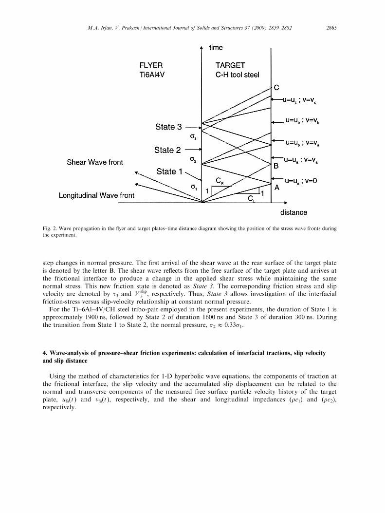
step changes in normal pressure. The ®rst arrival of the shear wave at the rear surface of the target plateis denoted by the letter B. The shear wave re¯ects from the free surface of the target plate and arrives atthe frictional interface to produce a change in the applied shear stress while maintaining the samenormal stress. This new friction state is denoted as State 3. The corresponding friction stress and slipvelocity are denoted by t3 and V
slip3 , respectively. Thus, State 3 allows investigation of the interfacial
friction-stress versus slip-velocity relationship at constant normal pressure.For the Ti±6Al±4V/CH steel tribo-pair employed in the present experiments, the duration of State 1 is
approximately 1900 ns, followed by State 2 of duration 1600 ns and State 3 of duration 300 ns. Duringthe transition from State 1 to State 2, the normal pressure, s2 1 0.33s1.
4. Wave-analysis of pressure±shear friction experiments: calculation of interfacial tractions, slip velocityand slip distance
Using the method of characteristics for 1-D hyperbolic wave equations, the components of traction atthe frictional interface, the slip velocity and the accumulated slip displacement can be related to thenormal and transverse components of the measured free surface particle velocity history of the targetplate, ufs(t ) and vfs(t ), respectively, and the shear and longitudinal impedances (rc1) and (rc2),respectively.
Fig. 2. Wave propagation in the ¯yer and target plates±time distance diagram showing the position of the stress wave fronts during
the experiment.
M.A. Irfan, V. Prakash / International Journal of Solids and Structures 37 (2000) 2859±2882 2865
4.1. State 1
Before impact, the ¯yer and the target plates are unstressed. The target is held stationary while the¯yer is accelerated and impacts the target at a measured velocity V. From the knowledge of the angle ofinclination y of the projectile, the initial normal and transverse particle velocities u0 and v0, respectively,of the ¯yer plate are given by
u0 � V cos y and v0 � V sin y: �1�When the ¯yer impacts the target, both normal and transverse components of velocity are imposed on
the impact face. A longitudinal compression stress wave with wave speed c1 and a shear (transverse)stress wave with a wave speed c2 propagates into the ¯yer and the target plates. From one dimensionalanalysis of the governing hyperbolic partial di�erential equations, the stress and the particle velocityrelations which hold along the characteristics are given by
s2�rc1�u � constant; alongdx
dt�3c1 �2�
and
t2�rc2�v � constant; alongdx
dt�3c2: �3�
In Eqs. (2) and (3), s and t are the normal and shear stresses, u and v are the normal and transversecomponents of the particle velocity, r is the mass density, and (rc1) and (rc2) are the longitudinal andshear impedance, respectively.
Using the initial conditions, it can be shown that all states at the impact face of an elastic ¯yer platemust satisfy the following characteristic relations:
s� �rc1�fu � �rc1�fu0 �4�
and
ÿt� �rc2�fv � �rc2�fv0: �5�Moreover, all states on the impact face of an elastic target plate must satisfy the following
characteristic equations:
ÿs� �rc1�tu � 0 �6�
and
t� �rc2�tv � 0: �7�In Eqs. (4)±(7), the subscripts `f' and `t' refer to the ¯yer and the target, respectively.Using Eqs. (1)±(7), the components of traction at the interface between the ¯yer and the target can be
expressed as:
t�t� � ÿ�rc2�t2
vfs�t� �8�
and
M.A. Irfan, V. Prakash / International Journal of Solids and Structures 37 (2000) 2859±28822866
s�t� � �rc1�t2
ufs�t�, �9�
where vfs(t ) and ufs(t ) are the transverse and the normal particle velocities at the rear surface of thetarget plate.
Based on the elementary de®nition of friction between two dry contact surfaces under no slipcondition, the coe�cient of static friction, ms, satis®es the inequality
msr���� ts����: �10�
For a fully elastic impact with no-slip at the interface, Eq. (10) provides a lower bound for the staticcoe�cient of friction, ms. When slipping occurs at the ¯yer±target interface, the measured free surfacevelocity of the target plate can be used along with Eqs. (8) and (9) to obtain the coe�cient of kineticfriction
mk�t� ����� ts����: �11�
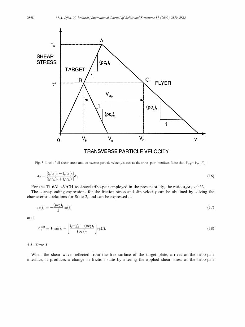
To calculate the interfacial slip velocity, the transverse particle velocity versus shear-stress diagram isutilized. The loci of all possible shear-stress and transverse particle velocity states, for a given ¯yer±target plate combination, are shown in Fig. 3. For a no-slip condition, the state of the interface isrepresented by the letter A. If the interface slip velocity is Vslip, the transmitted shear stress at the ¯yer±target interface is reduced from tA to t�. Consequently, the particle velocities on the ¯yer and the targetsides of the interface are represented by VB and VC, respectively. Then, from the knowledge of theimpact velocity V, the skew angle y, the shear impedances of the ¯yer and the target plates, and themeasured free-surface transverse velocity vfs(t ), the slip velocity can be expressed as
Vslip � VB ÿ VC � V sin yÿ� �rc2�t � �rc2�f
2�rc2�f
�vfs�t�: �12�
The accumulated slip distance can be obtained from Eq. (12) by integrating the slip velocity in time
dslip ��t0
Vslip�t�dt: �13�
Moreover, under conditions of no slip between the ¯yer and the target plates, the free surface particlevelocities of the rear surface of the target plate are related to the ¯yer velocity by
ufs � 2�rc1�f��rc1�t � �rc1�f �
V cos y �14�
and
vfs � 2�rc2�f��rc2�t � �rc2�f �
V sin y: �15�
4.2. State 2
When the compressive longitudinal wave re¯ects from the free surface of the target plate, it reducesthe compressive normal stress at the interface from s1 to s2
M.A. Irfan, V. Prakash / International Journal of Solids and Structures 37 (2000) 2859±2882 2867
s2 � ��rcL�f ÿ �rcL�t���rcL�f � �rcL�t�
s1: �16�
For the Ti±6Al±4V/CH tool-steel tribo-pair employed in the present study, the ratio s2/s100.33.The corresponding expressions for the friction stress and slip velocity can be obtained by solving the
characteristic relations for State 2, and can be expressed as
t2�t� � ÿ�rc2�t2
vB�t� �17�
and
Vslip2 � V sin yÿ
� �rc2�t � �rc2�f�rc2�f
�vB�t�: �18�
4.3. State 3
When the shear wave, re¯ected from the free surface of the target plate, arrives at the tribo-pairinterface, it produces a change in friction state by altering the applied shear stress at the tribo-pair
Fig. 3. Loci of all shear stress and transverse particle velocity states at the tribo±pair interface. Note that Vslip=VBÿVC.
M.A. Irfan, V. Prakash / International Journal of Solids and Structures 37 (2000) 2859±28822868
interface while maintaining the same normal stress. Thus, the measurements made during State 3 are adirect probe of the relationship between the friction stress and slip velocity at constant normal pressure.The corresponding relations for interfacial tractions and slip velocity can be obtained by solving thecharacteristic relations for State 3, and can be expressed as
t3�t� � ÿ�rc2�t2�vC�t� ÿ vA�t��, �19�
s3 � s2 �20�and
Vslip3 � V sin y�
� �rc2�t ÿ �rc2�f�rc2�f
�vA�t� ÿ
� �rc2�t � �rc2�f�rc2�f
�vC�t�: �21�
5. Experimental results and discussion
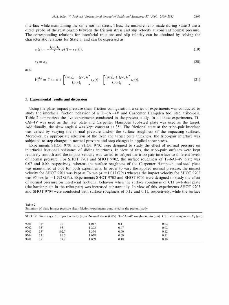
Using the plate±impact pressure shear friction con®guration, a series of experiments was conducted tostudy the interfacial friction behavior of a Ti±6Al±4V and Carpenter Hampden tool steel tribo-pair.Table 2 summarizes the ®ve experiments conducted in the present study. In all these experiments, Ti±6Al±4V was used as the ¯yer plate and Carpenter Hampden tool-steel plate was used as the target.Additionally, the skew angle y was kept constant at 358. The frictional state at the tribo-pair interfacewas varied by varying the normal pressure and/or the surface roughness of the impacting surfaces.Moreover, by appropriate selection of the ¯yer and target plate thickness, the tribo-pair interface wassubjected to step changes in normal pressure and step changes in applied shear stress.
Experiments SHOT 9701 and SHOT 9702 were designed to study the e�ect of normal pressure oninterfacial frictional resistance of sliding interfaces. In view of this, the tribo-pair surfaces were keptrelatively smooth and the impact velocity was varied to subject the tribo-pair interface to di�erent levelsof normal pressure. For SHOT 9701 and SHOT 9702, the surface roughness of Ti±6Al±4V plate was0.07 and 0.09, respectively, whereas the surface roughness of the Carpenter Hampden tool-steel platewas maintained at 0.02 for both experiments. In order to vary the applied normal pressure, the impactvelocity for SHOT 9701 was kept at 76 m/s (s1=1.017 GPa) whereas the impact velocity for SHOT 9702was 95 m/s (s1=1.292 GPa). Experiments SHOT 9703 and SHOT 9704 were designed to study the e�ectof normal pressure on interfacial frictional behavior when the surface roughness of CH tool-steel plate(the harder plate in the tribo-pair) was increased substantially. In view of this, experiments SHOT 9703and SHOT 9704 were conducted with surface roughness of 0.12 and 0.11, respectively, while the surface
Table 2
Summary of plate impact pressure shear friction experiments conducted in the present study
SHOT # Skew angle y Impact velocity (m/s) Normal stress (GPa) Ti±6Al±4V roughness, Rq (mm) C.H. steel roughness, Rq (mm)
9701 358 76 1.017 0.1 0.02
9702 358 95 1.292 0.07 0.02
9703 358 102.7 1.374 0.09 0.12
9704 358 80.5 1.078 0.09 0.11
9801 358 79.2 1.059 0.18 0.10
M.A. Irfan, V. Prakash / International Journal of Solids and Structures 37 (2000) 2859±2882 2869
roughness of the Ti±6Al±4V ¯yer plate was kept constant at 0.09 for both experiments. SHOT 9703 wasconducted at 102.7 m/s whereas the impact velocity for SHOT 9704 was 80.5 m/s. Finally SHOT 9801was conducted to study the e�ect of the increase in surface roughness of Ti±6Al±4V plate on the slidingresistance of the tribo-pair. For SHOT 9801 the surface roughness of Ti±6Al±4V was increased to 0.18from 0.09, while the surface roughness of the Carpenter Hampden tool-steel plate was kept similar tothe surface roughness of the Carpenter Hampden tool-steel plate employed in SHOT 9704. Moreover,the impact velocity for SHOT 9801 (79.2 m/s) was kept su�ciently close to the impact velocity employedin SHOT 9704 so as to keep the normal pressure the same in the two experiments.
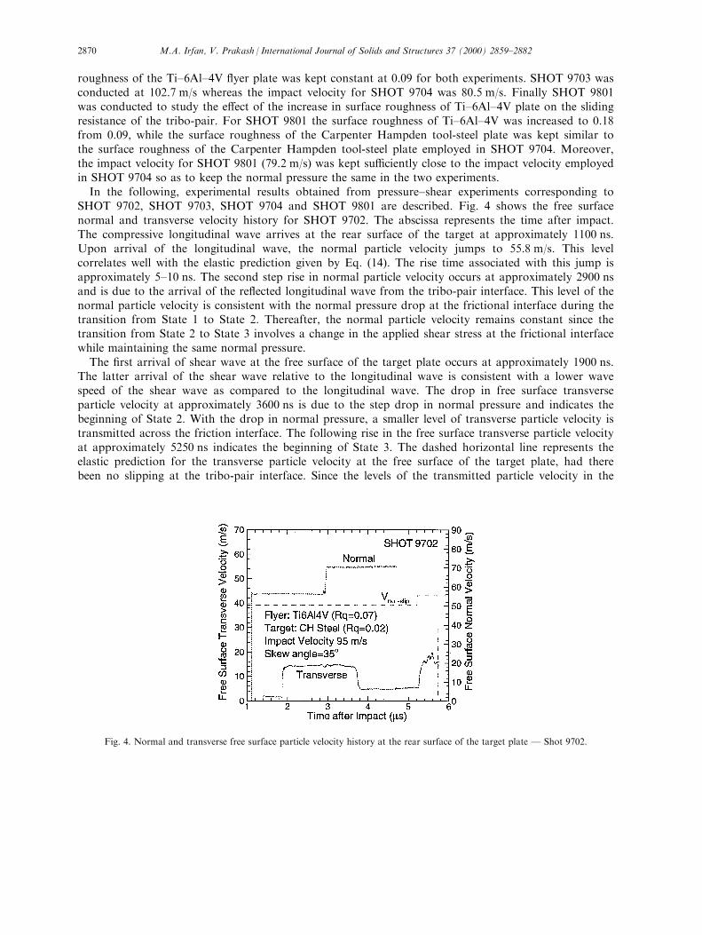
In the following, experimental results obtained from pressure±shear experiments corresponding toSHOT 9702, SHOT 9703, SHOT 9704 and SHOT 9801 are described. Fig. 4 shows the free surfacenormal and transverse velocity history for SHOT 9702. The abscissa represents the time after impact.The compressive longitudinal wave arrives at the rear surface of the target at approximately 1100 ns.Upon arrival of the longitudinal wave, the normal particle velocity jumps to 55.8 m/s. This levelcorrelates well with the elastic prediction given by Eq. (14). The rise time associated with this jump isapproximately 5±10 ns. The second step rise in normal particle velocity occurs at approximately 2900 nsand is due to the arrival of the re¯ected longitudinal wave from the tribo-pair interface. This level of thenormal particle velocity is consistent with the normal pressure drop at the frictional interface during thetransition from State 1 to State 2. Thereafter, the normal particle velocity remains constant since thetransition from State 2 to State 3 involves a change in the applied shear stress at the frictional interfacewhile maintaining the same normal pressure.
The ®rst arrival of shear wave at the free surface of the target plate occurs at approximately 1900 ns.The latter arrival of the shear wave relative to the longitudinal wave is consistent with a lower wavespeed of the shear wave as compared to the longitudinal wave. The drop in free surface transverseparticle velocity at approximately 3600 ns is due to the step drop in normal pressure and indicates thebeginning of State 2. With the drop in normal pressure, a smaller level of transverse particle velocity istransmitted across the friction interface. The following rise in the free surface transverse particle velocityat approximately 5250 ns indicates the beginning of State 3. The dashed horizontal line represents theelastic prediction for the transverse particle velocity at the free surface of the target plate, had therebeen no slipping at the tribo-pair interface. Since the levels of the transmitted particle velocity in the
Fig. 4. Normal and transverse free surface particle velocity history at the rear surface of the target plate Ð Shot 9702.
M.A. Irfan, V. Prakash / International Journal of Solids and Structures 37 (2000) 2859±28822870

three states are much lower than their corresponding no-slip predictions, the frictional interface isunderstood to be in a state of dynamic slip.
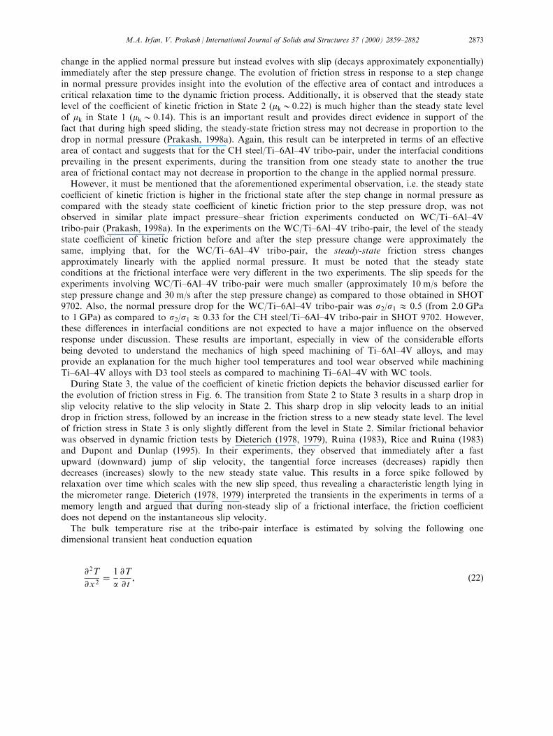
Fig. 5 shows the history of the interfacial normal pressure, friction stress and interfacial slip velocityas a function of time for SHOT 9702. These quantities are obtained from the measured normal andtransverse free surface particle velocity pro®les depicted in Fig. 5 in conjunction with Eqs. (8)±(21).During State 1, the normal pressure s1 at the frictional interface is 1.3 GPa. Immediately after theapplication of pressure±shear loading, the frictional interface jumps to a state of steady state slidingcharacteristic of the surface roughness and the applied normal pressure. In this steady state, thetransmitted shear stress t1 is approximately 0.18 GPa and the slip velocity V
slip1 is 34 m/s. The
attainment of the steady frictional state is consistent with the results of the molecular dynamicssimulations of Rigney and Hammerberg (1998) which clearly show that, for atomically smooth surfacesand relatively rough surfaces, a steady friction state is achieved very early in the loading process. Themolecular dynamic simulations also show that, for atomically smooth surfaces, the evolution of thefriction state to a steady state is preceded by a series of stick±slip events, which result in a wavestructure in the transverse velocity ®eld. However, the early time details of how a friction state evolvesto a steady state have not been resolved experimentally, at present. For Shot 9702, the steady statecontinues up to 1800 ns, when the arrival of the unloading normal wave from the free surface of thetarget plate results in a step drop of normal pressure. During the transition form State 1 to State 2, theunloading longitudinal wave reduces the normal pressure from s1=1.3 GPa to s2=0.325 GPa inapproximately 5±10 ns. It is interesting to note that the corresponding friction stress t2 does not followthis step drop in normal stress. Instead, the friction stress gradually approaches a new steady state levelcharacteristic of the current state of the frictional interface. At the reduced normal pressure, the steadystate friction stress is reduced to 0.06 GPa and the slip velocity V
slip2 increases to approximately 48 m/s.
State 2 continues up to approximately 3300 ns, at which time the re¯ected shear wave from the freesurface of the target plate arrives at the tribo-pair interface (State 3). The arrival of the unloading shearwave results in a change in the applied shear stress at the frictional interface while maintaining the samenormal pressure. Thus, State 3 is an exclusive measure of the shear stress versus slip velocityrelationship of the frictional interface at constant normal pressure. It is interesting to observe that achange in the applied shear stress at the interface results in a sharp drop in slip velocity, V
slip3 :
Corresponding to this drop in slip velocity is an initial rapid decrease in the friction stress followed by a
Fig. 5. Interfacial normal pressure, friction stress and slip velocity history Ð Shot 9702.
M.A. Irfan, V. Prakash / International Journal of Solids and Structures 37 (2000) 2859±2882 2871
slow rise in friction stress to a new steady state level of t3. The evolution of frictional stress immediatelyfollowing the arrival of the shear wave (transition form State 2 to State 3) is represented by a straightline since it is di�cult to accurately resolve this regime from the present experimental measurements ofthe free surface transverse particle velocity histories. Also, the steady state level for State 3 is di�cult tointerpret in the present experiments because of the relatively short time window available for State 3(only 0.3 ms).
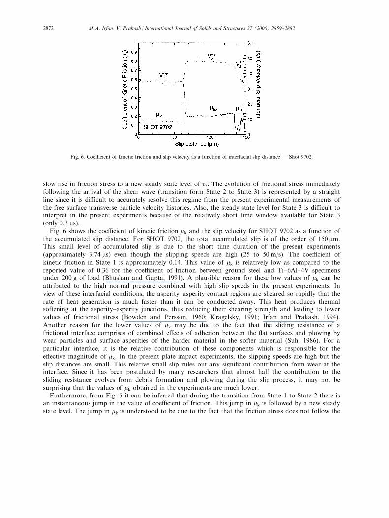
Fig. 6 shows the coe�cient of kinetic friction mk and the slip velocity for SHOT 9702 as a function ofthe accumulated slip distance. For SHOT 9702, the total accumulated slip is of the order of 150 mm.This small level of accumulated slip is due to the short time duration of the present experiments(approximately 3.74 ms) even though the slipping speeds are high (25 to 50 m/s). The coe�cient ofkinetic friction in State 1 is approximately 0.14. This value of mk is relatively low as compared to thereported value of 0.36 for the coe�cient of friction between ground steel and Ti±6Al±4V specimensunder 200 g of load (Bhushan and Gupta, 1991). A plausible reason for these low values of mk can beattributed to the high normal pressure combined with high slip speeds in the present experiments. Inview of these interfacial conditions, the asperity±asperity contact regions are sheared so rapidly that therate of heat generation is much faster than it can be conducted away. This heat produces thermalsoftening at the asperity±asperity junctions, thus reducing their shearing strength and leading to lowervalues of frictional stress (Bowden and Persson, 1960; Kragelsky, 1991; Irfan and Prakash, 1994).Another reason for the lower values of mk may be due to the fact that the sliding resistance of africtional interface comprises of combined e�ects of adhesion between the ¯at surfaces and plowing bywear particles and surface asperities of the harder material in the softer material (Suh, 1986). For aparticular interface, it is the relative contribution of these components which is responsible for thee�ective magnitude of mk. In the present plate impact experiments, the slipping speeds are high but theslip distances are small. This relative small slip rules out any signi®cant contribution from wear at theinterface. Since it has been postulated by many researchers that almost half the contribution to thesliding resistance evolves from debris formation and plowing during the slip process, it may not besurprising that the values of mk obtained in the experiments are much lower.
Furthermore, from Fig. 6 it can be inferred that during the transition from State 1 to State 2 there isan instantaneous jump in the value of coe�cient of friction. This jump in mk is followed by a new steadystate level. The jump in mk is understood to be due to the fact that the friction stress does not follow the
Fig. 6. Coe�cient of kinetic friction and slip velocity as a function of interfacial slip distance Ð Shot 9702.
M.A. Irfan, V. Prakash / International Journal of Solids and Structures 37 (2000) 2859±28822872
change in the applied normal pressure but instead evolves with slip (decays approximately exponentially)immediately after the step pressure change. The evolution of friction stress in response to a step changein normal pressure provides insight into the evolution of the e�ective area of contact and introduces acritical relaxation time to the dynamic friction process. Additionally, it is observed that the steady statelevel of the coe�cient of kinetic friction in State 2 (mk00.22) is much higher than the steady state levelof mk in State 1 (mk00.14). This is an important result and provides direct evidence in support of thefact that during high speed sliding, the steady-state friction stress may not decrease in proportion to thedrop in normal pressure (Prakash, 1998a). Again, this result can be interpreted in terms of an e�ectivearea of contact and suggests that for the CH steel/Ti±6Al±4V tribo-pair, under the interfacial conditionsprevailing in the present experiments, during the transition from one steady state to another the truearea of frictional contact may not decrease in proportion to the change in the applied normal pressure.
However, it must be mentioned that the aforementioned experimental observation, i.e. the steady statecoe�cient of kinetic friction is higher in the frictional state after the step change in normal pressure ascompared with the steady state coe�cient of kinetic friction prior to the step pressure drop, was notobserved in similar plate impact pressure±shear friction experiments conducted on WC/Ti±6Al±4Vtribo-pair (Prakash, 1998a). In the experiments on the WC/Ti±6Al±4V tribo-pair, the level of the steadystate coe�cient of kinetic friction before and after the step pressure change were approximately thesame, implying that, for the WC/Ti±6Al±4V tribo-pair, the steady-state friction stress changesapproximately linearly with the applied normal pressure. It must be noted that the steady stateconditions at the frictional interface were very di�erent in the two experiments. The slip speeds for theexperiments involving WC/Ti±6Al±4V tribo-pair were much smaller (approximately 10 m/s before thestep pressure change and 30 m/s after the step pressure change) as compared to those obtained in SHOT9702. Also, the normal pressure drop for the WC/Ti±6Al±4V tribo-pair was s2/s1 1 0.5 (from 2.0 GPato 1 GPa) as compared to s2/s1 1 0.33 for the CH steel/Ti±6Al±4V tribo-pair in SHOT 9702. However,these di�erences in interfacial conditions are not expected to have a major in¯uence on the observedresponse under discussion. These results are important, especially in view of the considerable e�ortsbeing devoted to understand the mechanics of high speed machining of Ti±6Al±4V alloys, and mayprovide an explanation for the much higher tool temperatures and tool wear observed while machiningTi±6Al±4V alloys with D3 tool steels as compared to machining Ti±6Al±4V with WC tools.
During State 3, the value of the coe�cient of kinetic friction depicts the behavior discussed earlier forthe evolution of friction stress in Fig. 6. The transition from State 2 to State 3 results in a sharp drop inslip velocity relative to the slip velocity in State 2. This sharp drop in slip velocity leads to an initialdrop in friction stress, followed by an increase in the friction stress to a new steady state level. The levelof friction stress in State 3 is only slightly di�erent from the level in State 2. Similar frictional behaviorwas observed in dynamic friction tests by Dieterich (1978, 1979), Ruina (1983), Rice and Ruina (1983)and Dupont and Dunlap (1995). In their experiments, they observed that immediately after a fastupward (downward) jump of slip velocity, the tangential force increases (decreases) rapidly thendecreases (increases) slowly to the new steady state value. This results in a force spike followed byrelaxation over time which scales with the new slip speed, thus revealing a characteristic length lying inthe micrometer range. Dieterich (1978, 1979) interpreted the transients in the experiments in terms of amemory length and argued that during non-steady slip of a frictional interface, the friction coe�cientdoes not depend on the instantaneous slip velocity.
The bulk temperature rise at the tribo-pair interface is estimated by solving the following onedimensional transient heat conduction equation
@2T
@x2� 1
a@T
@ t, �22�
M.A. Irfan, V. Prakash / International Journal of Solids and Structures 37 (2000) 2859±2882 2873
with initial condition
T�x,0� � 0 �23�and boundary conditions
ÿk@T@x�x � 0, t� � _q�t� �24�
and
T�x � 1, t� � 0: �25�In Eqs. (22)±(25), T is the temperature rise, k is the thermal conductivity, a is the thermal di�usivity
and x represents the distance perpendicular to the interface. Using Eqs. (22)±(25), the temperature risedistribution as a function of time and position can be obtained as
T�x, t� � 1
k
�t0
_q�x����ap����������������
p�tÿ x�p exp
ÿx2
4a�tÿ x�
!dx: �26�
In order to calculate the temperature distribution in the tribo-pair, an estimate for the heat source _q�t�is required. Using the experimentally measured frictional stress t, and the slip velocity Vslip, the heatgenerated at the interface can be estimated to be
_qTiÿ6Alÿ4V�t� � bt�t�Vslip�t� �27�and
_qCH steel�t� � �1ÿ b�t�t�Vslip�t�, �28�where b governs the partitioning of heat in the tribo-pair materials. The fraction b is estimated byequating the temperatures at the tribo-pair interface to yield
b � k1�����a2p
k2�����a1p � k1
�����a2p : �29�
In Eq. (29), k1, a1, k2 and a2, are the thermal conductivity and thermal di�usivity of Ti±6Al±4V andCH Steel, respectively. Table 1 lists the thermal properties for the two materials. In view of Eq. (29),approximately 23% of the heat generated at the tribo-pair interface due to frictional sliding goes intoTi±6Al±4V and 77% of the heat goes into CH steel.
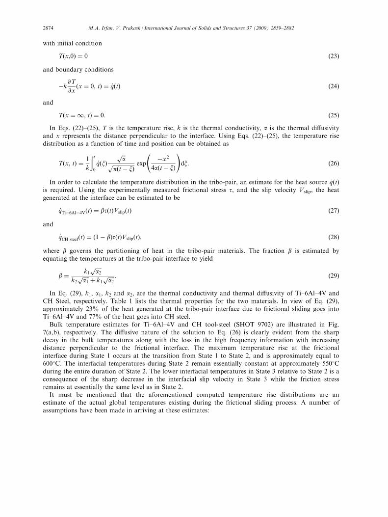
Bulk temperature estimates for Ti±6Al±4V and CH tool-steel (SHOT 9702) are illustrated in Fig.7(a,b), respectively. The di�usive nature of the solution to Eq. (26) is clearly evident from the sharpdecay in the bulk temperatures along with the loss in the high frequency information with increasingdistance perpendicular to the frictional interface. The maximum temperature rise at the frictionalinterface during State 1 occurs at the transition from State 1 to State 2, and is approximately equal to6008C. The interfacial temperatures during State 2 remain essentially constant at approximately 5508Cduring the entire duration of State 2. The lower interfacial temperatures in State 3 relative to State 2 is aconsequence of the sharp decrease in the interfacial slip velocity in State 3 while the friction stressremains at essentially the same level as in State 2.
It must be mentioned that the aforementioned computed temperature rise distributions are anestimate of the actual global temperatures existing during the frictional sliding process. A number ofassumptions have been made in arriving at these estimates:
M.A. Irfan, V. Prakash / International Journal of Solids and Structures 37 (2000) 2859±28822874
(a) the thermal properties of the tribo-pair materials are assumed to be constant at their roomtemperature values at all temperatures, and(b) all the interfacial frictional work is assumed to be converted to heat.
The assumption that all the frictional work is converted to heat is expected to lead to anoverestimation of the actual tribo-pair temperature rise distribution. However, it must be recalled that inthe present experiments, the impact velocity is controlled such that both the ¯yer and the targetmaterials remain elastic during the entire duration of the experiment. Thus, all inelastic processes duringthe pressure shear loading are expected to occur within a thin layer at the frictional interface, thethickness of which is of the order of the surface roughness of the tribo-pair materials. In view of thesearguments, the computed temperature pro®les are expected to represent the actual temperaturedistributions with an acceptable level of accuracy.
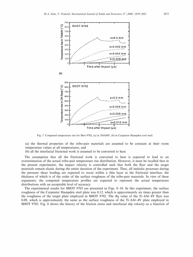
The experimental results for SHOT 9703 are presented in Figs. 8±10. In this experiment, the surfaceroughness of the Carpenter Hampden steel plate was 0.12, which is approximately six times greater thanthe roughness of the target plate employed in SHOT 9702. The Rq value of the Ti±6Al±4V ¯yer was0.09, which is approximately the same as the surface roughness of the Ti±6Al±4V plate employed inSHOT 9702. Fig. 8 shows the history of the friction stress and interfacial slip velocity as a function of
Fig. 7. Computed temperature rise for Shot 9702, (a) in Ti6Al4V, (b) in Carpentor Hampden tool steel.
M.A. Irfan, V. Prakash / International Journal of Solids and Structures 37 (2000) 2859±2882 2875
time after impact for SHOT 9703. During State 1, the normal pressure s1 at the interface was1.374 GPa. It is interesting to note the absence of steady-state friction during State 1 and the frictionstress is observed to decay steadily with slip. This non-steady friction state is understood to be a resultof the higher surface roughness of the CH steel plate (0.12) combined with the higher impact velocity(102.7 m/s) employed in SHOT 9703. The presence of higher initial surface roughness and higher normalpressures leads to a decrease in friction resistance with slip due to smoothening of the interface with slipand hence to a state of dynamic slip instability at the interface. It must be reiterated that in experimentsSHOT 9701 and SHOT 9702, for which the surface roughness of the tribo-pair materials was relativelysmooth, steady state conditions were obtained at both high and low normal pressures. The averagevalue of the frictional stress during State 1 for SHOT 9703 was approximately 0.3 GPa, which isrelatively higher than the frictional stress transmitted in SHOT 9702. The higher level of friction stress isattributed to the higher surface roughness of the target plate and higher normal pressures employed inSHOT 9703. During the transition from State 1 to State 2, the unloading longitudinal wave reduces thenormal pressure from 1.374 GPa to 0.344 GPa in approximately 5±10 ns. As also noted for SHOT 9702,
Fig. 8. Interfacial normal pressure, friction stress and slip velocity history Ð Shot 9703.
Fig. 9. Coe�cient of kinetic friction and slip velocity as a function of interfacial slip distance Ð Shot 9703.
M.A. Irfan, V. Prakash / International Journal of Solids and Structures 37 (2000) 2859±28822876
the friction stress t2 does not follow this step drop in normal stress. In fact, the friction stress graduallyevolves towards a new friction state characteristic of the current normal pressure and slip velocity. Atthe reduced normal pressure, the average friction stress is reduced to 0.16 GPa and the slip speed V
slip2
increases to approximately 45 m/s. In State 3, a drop in slip velocity �V slip3 � at the interface leads to an
initial rapid decrease in friction stress followed by a slow rise to a steady state level t3, as also observedin SHOT 9702.
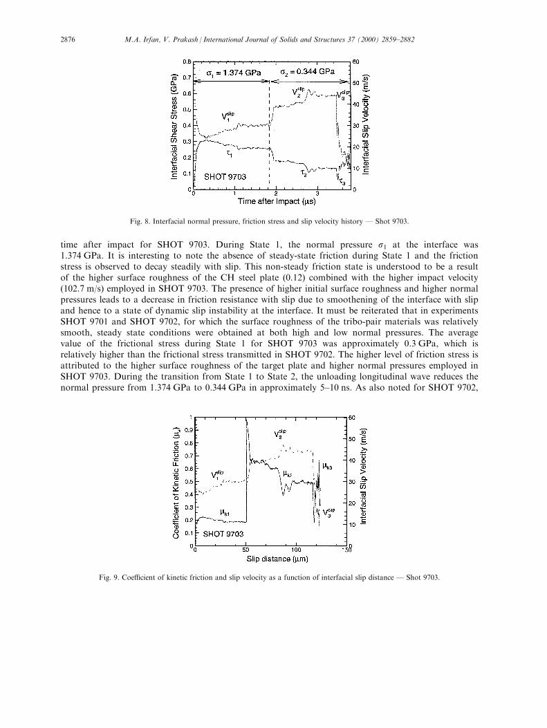
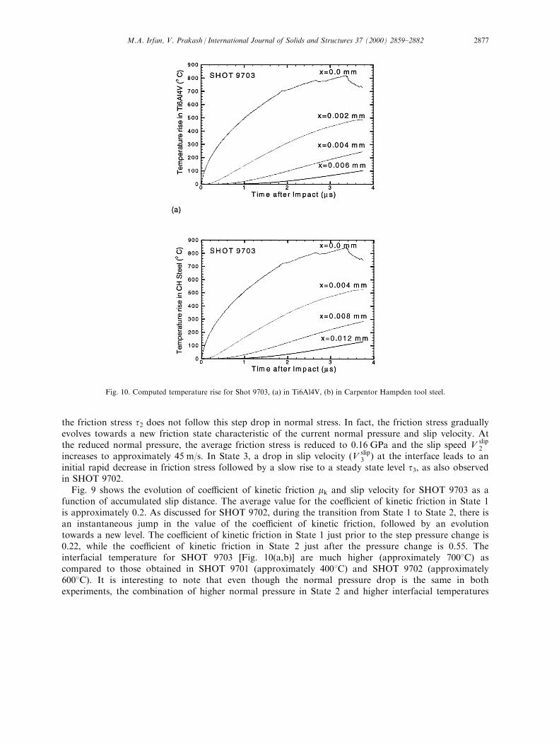
Fig. 9 shows the evolution of coe�cient of kinetic friction mk and slip velocity for SHOT 9703 as afunction of accumulated slip distance. The average value for the coe�cient of kinetic friction in State 1is approximately 0.2. As discussed for SHOT 9702, during the transition from State 1 to State 2, there isan instantaneous jump in the value of the coe�cient of kinetic friction, followed by an evolutiontowards a new level. The coe�cient of kinetic friction in State 1 just prior to the step pressure change is0.22, while the coe�cient of kinetic friction in State 2 just after the pressure change is 0.55. Theinterfacial temperature for SHOT 9703 [Fig. 10(a,b)] are much higher (approximately 7008C) ascompared to those obtained in SHOT 9701 (approximately 4008C) and SHOT 9702 (approximately6008C). It is interesting to note that even though the normal pressure drop is the same in bothexperiments, the combination of higher normal pressure in State 2 and higher interfacial temperatures
Fig. 10. Computed temperature rise for Shot 9703, (a) in Ti6Al4V, (b) in Carpentor Hampden tool steel.
M.A. Irfan, V. Prakash / International Journal of Solids and Structures 37 (2000) 2859±2882 2877
just prior to the step drop in normal pressure allow a much smaller decrease in the e�ective area ofcontact and hence to a higher coe�cient of kinetic friction ratio for SHOT 9703 �mk2
=mk103� as
compared to SHOT 9702 �mk2=mk1
01:8). During State 3, the value of the coe�cient of kinetic frictiondepicts the behavior discussed earlier for SHOT 9702.
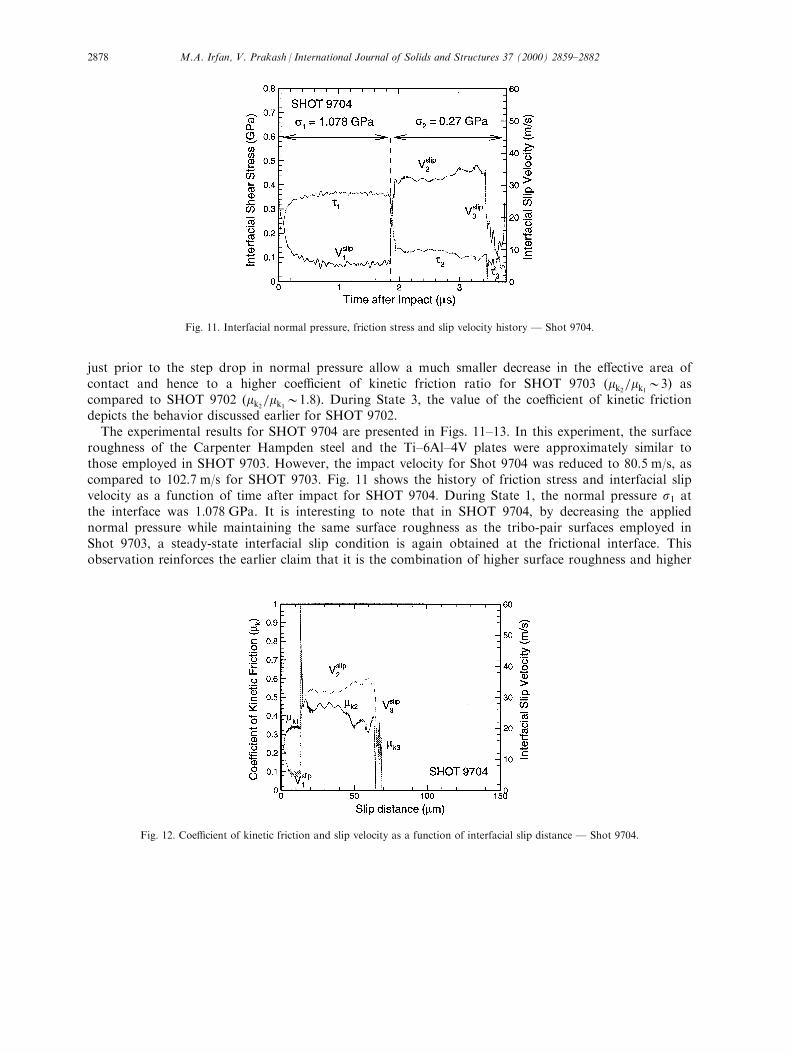
The experimental results for SHOT 9704 are presented in Figs. 11±13. In this experiment, the surfaceroughness of the Carpenter Hampden steel and the Ti±6Al±4V plates were approximately similar tothose employed in SHOT 9703. However, the impact velocity for Shot 9704 was reduced to 80.5 m/s, ascompared to 102.7 m/s for SHOT 9703. Fig. 11 shows the history of friction stress and interfacial slipvelocity as a function of time after impact for SHOT 9704. During State 1, the normal pressure s1 atthe interface was 1.078 GPa. It is interesting to note that in SHOT 9704, by decreasing the appliednormal pressure while maintaining the same surface roughness as the tribo-pair surfaces employed inShot 9703, a steady-state interfacial slip condition is again obtained at the frictional interface. Thisobservation reinforces the earlier claim that it is the combination of higher surface roughness and higher
Fig. 11. Interfacial normal pressure, friction stress and slip velocity history Ð Shot 9704.
Fig. 12. Coe�cient of kinetic friction and slip velocity as a function of interfacial slip distance Ð Shot 9704.
M.A. Irfan, V. Prakash / International Journal of Solids and Structures 37 (2000) 2859±28822878
normal pressures that leads to dynamic slip instability at the frictional interface. The average value ofthe friction stress during State 1 is approximately 0.37 GPa, which is relatively higher than the frictionalstress transmitted in SHOT 9703. During transition from State 1 to State 2, the unloading longitudinalwave instantaneously reduces the normal pressure from 1.078 GPa to 0.27 GPa. As also noted forSHOT 9702 and SHOT 9703, the friction stress t2 does not follow the step drop in normal stress andgradually evolves towards a new frictional state characteristic of the current normal pressure and currentslip velocity. After the normal pressure drop, the level of the steady-state friction stress is reduced to0.14 GPa and the steady-state slip velocity increases to 34 m/s. In State 3, a drop in slip velocity �V slip
3 �at the interface leads to an initial rapid decrease in friction stress followed by a slow rise to a steadystate level (t3), as also observed in SHOT 9702 and SHOT 9703.
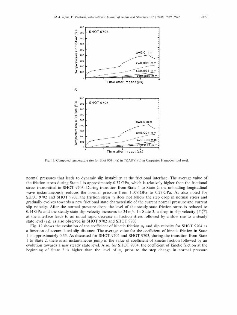
Fig. 12 shows the evolution of the coe�cient of kinetic friction mk and slip velocity for SHOT 9704 asa function of accumulated slip distance. The average value for the coe�cient of kinetic friction in State1 is approximately 0.35. As discussed for SHOT 9702 and SHOT 9703, during the transition from State1 to State 2, there is an instantaneous jump in the value of coe�cient of kinetic friction followed by anevolution towards a new steady state level. Also, for SHOT 9704, the coe�cient of kinetic friction at thebeginning of State 2 is higher than the level of mk prior to the step change in normal pressure
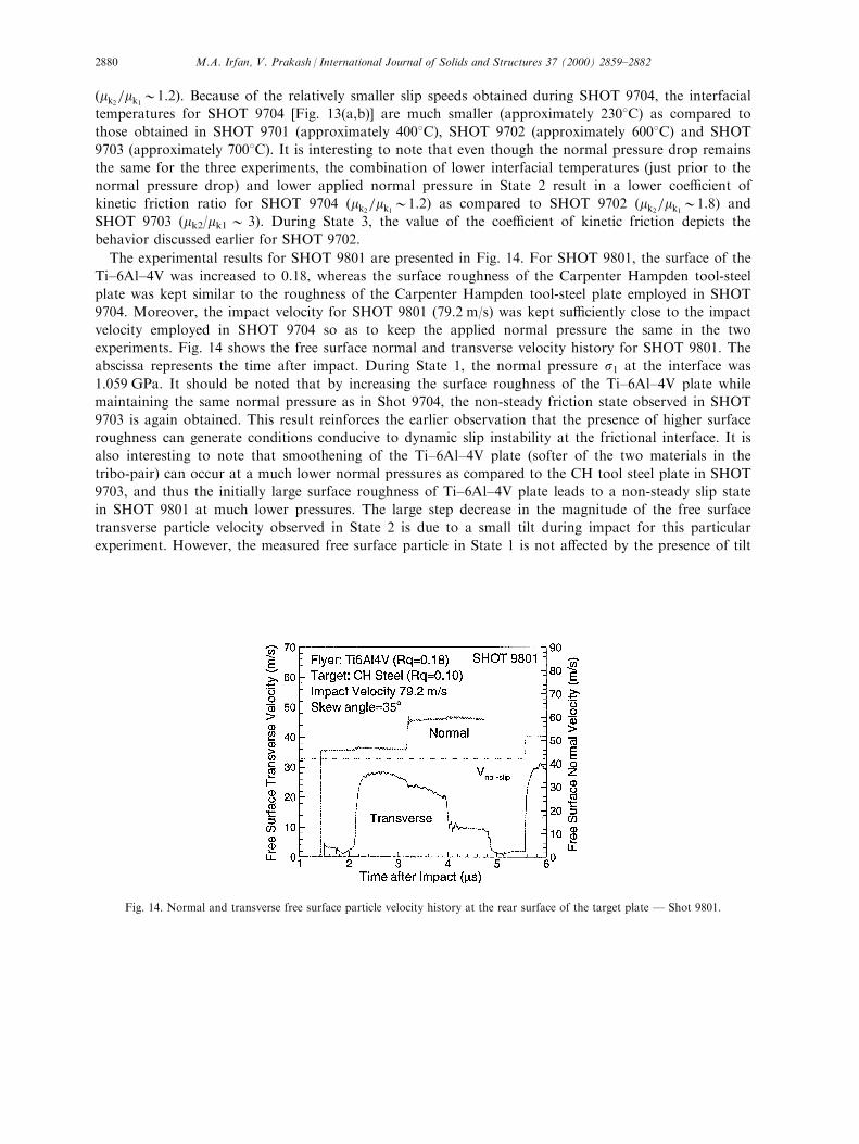
Fig. 13. Computed temperature rise for Shot 9704, (a) in Ti6Al4V, (b) in Carpentor Hampden tool steel.
M.A. Irfan, V. Prakash / International Journal of Solids and Structures 37 (2000) 2859±2882 2879
�mk2=mk1
01:2). Because of the relatively smaller slip speeds obtained during SHOT 9704, the interfacial
temperatures for SHOT 9704 [Fig. 13(a,b)] are much smaller (approximately 2308C) as compared to
those obtained in SHOT 9701 (approximately 4008C), SHOT 9702 (approximately 6008C) and SHOT
9703 (approximately 7008C). It is interesting to note that even though the normal pressure drop remains
the same for the three experiments, the combination of lower interfacial temperatures (just prior to the
normal pressure drop) and lower applied normal pressure in State 2 result in a lower coe�cient of
kinetic friction ratio for SHOT 9704 �mk2=mk1
01:2� as compared to SHOT 9702 �mk2=mk1
01:8� andSHOT 9703 (mk2/mk1 0 3). During State 3, the value of the coe�cient of kinetic friction depicts the
behavior discussed earlier for SHOT 9702.
The experimental results for SHOT 9801 are presented in Fig. 14. For SHOT 9801, the surface of the
Ti±6Al±4V was increased to 0.18, whereas the surface roughness of the Carpenter Hampden tool-steel
plate was kept similar to the roughness of the Carpenter Hampden tool-steel plate employed in SHOT
9704. Moreover, the impact velocity for SHOT 9801 (79.2 m/s) was kept su�ciently close to the impact
velocity employed in SHOT 9704 so as to keep the applied normal pressure the same in the two
experiments. Fig. 14 shows the free surface normal and transverse velocity history for SHOT 9801. The
abscissa represents the time after impact. During State 1, the normal pressure s1 at the interface was
1.059 GPa. It should be noted that by increasing the surface roughness of the Ti±6Al±4V plate while
maintaining the same normal pressure as in Shot 9704, the non-steady friction state observed in SHOT
9703 is again obtained. This result reinforces the earlier observation that the presence of higher surface
roughness can generate conditions conducive to dynamic slip instability at the frictional interface. It is
also interesting to note that smoothening of the Ti±6Al±4V plate (softer of the two materials in the
tribo-pair) can occur at a much lower normal pressures as compared to the CH tool steel plate in SHOT
9703, and thus the initially large surface roughness of Ti±6Al±4V plate leads to a non-steady slip state
in SHOT 9801 at much lower pressures. The large step decrease in the magnitude of the free surface
transverse particle velocity observed in State 2 is due to a small tilt during impact for this particular
experiment. However, the measured free surface particle in State 1 is not a�ected by the presence of tilt
Fig. 14. Normal and transverse free surface particle velocity history at the rear surface of the target plate Ð Shot 9801.
M.A. Irfan, V. Prakash / International Journal of Solids and Structures 37 (2000) 2859±28822880
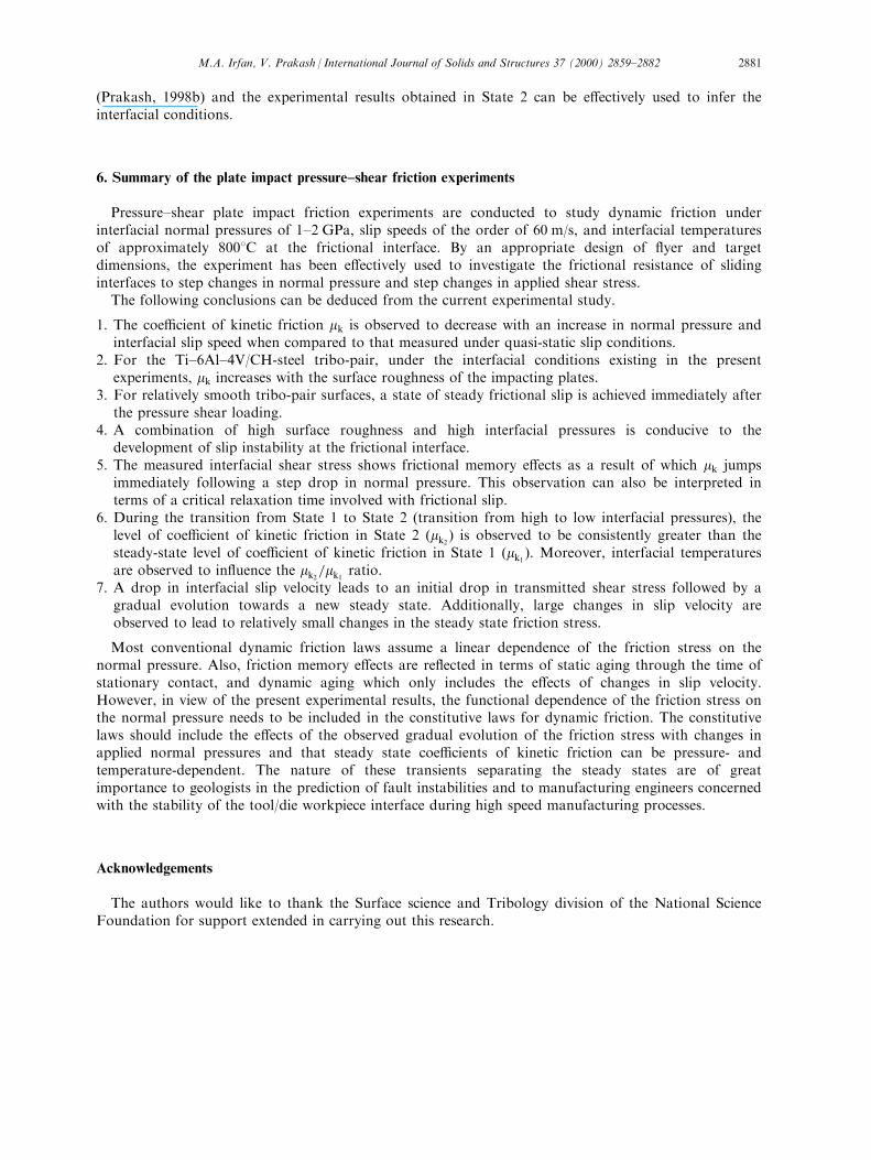
(Prakash, 1998b) and the experimental results obtained in State 2 can be e�ectively used to infer theinterfacial conditions.
6. Summary of the plate impact pressure±shear friction experiments
Pressure±shear plate impact friction experiments are conducted to study dynamic friction underinterfacial normal pressures of 1±2 GPa, slip speeds of the order of 60 m/s, and interfacial temperaturesof approximately 8008C at the frictional interface. By an appropriate design of ¯yer and targetdimensions, the experiment has been e�ectively used to investigate the frictional resistance of slidinginterfaces to step changes in normal pressure and step changes in applied shear stress.
The following conclusions can be deduced from the current experimental study.
1. The coe�cient of kinetic friction mk is observed to decrease with an increase in normal pressure andinterfacial slip speed when compared to that measured under quasi-static slip conditions.
2. For the Ti±6Al±4V/CH-steel tribo-pair, under the interfacial conditions existing in the presentexperiments, mk increases with the surface roughness of the impacting plates.
3. For relatively smooth tribo-pair surfaces, a state of steady frictional slip is achieved immediately afterthe pressure shear loading.
4. A combination of high surface roughness and high interfacial pressures is conducive to thedevelopment of slip instability at the frictional interface.
5. The measured interfacial shear stress shows frictional memory e�ects as a result of which mk jumpsimmediately following a step drop in normal pressure. This observation can also be interpreted interms of a critical relaxation time involved with frictional slip.
6. During the transition from State 1 to State 2 (transition from high to low interfacial pressures), thelevel of coe�cient of kinetic friction in State 2 �mk2
� is observed to be consistently greater than thesteady-state level of coe�cient of kinetic friction in State 1 �mk1
). Moreover, interfacial temperaturesare observed to in¯uence the mk2
=mk1ratio.
7. A drop in interfacial slip velocity leads to an initial drop in transmitted shear stress followed by agradual evolution towards a new steady state. Additionally, large changes in slip velocity areobserved to lead to relatively small changes in the steady state friction stress.
Most conventional dynamic friction laws assume a linear dependence of the friction stress on thenormal pressure. Also, friction memory e�ects are re¯ected in terms of static aging through the time ofstationary contact, and dynamic aging which only includes the e�ects of changes in slip velocity.However, in view of the present experimental results, the functional dependence of the friction stress onthe normal pressure needs to be included in the constitutive laws for dynamic friction. The constitutivelaws should include the e�ects of the observed gradual evolution of the friction stress with changes inapplied normal pressures and that steady state coe�cients of kinetic friction can be pressure- andtemperature-dependent. The nature of these transients separating the steady states are of greatimportance to geologists in the prediction of fault instabilities and to manufacturing engineers concernedwith the stability of the tool/die workpiece interface during high speed manufacturing processes.
Acknowledgements
The authors would like to thank the Surface science and Tribology division of the National ScienceFoundation for support extended in carrying out this research.
M.A. Irfan, V. Prakash / International Journal of Solids and Structures 37 (2000) 2859±2882 2881
References
Antoniou, S., Cameron, A., Gentle, C., 1976. The friction±speed relation from stick±slip data. Wear 36, 235±254.
Armstrong-Helouvry, B., Dupont, P., Canudas de Wit, C., 1994. A survey of models, analysis tools and compensation methods for
the control of machines with friction. Automatica 30 (7), 1083±1153.
Bell, R., Burdekin, M., 1969. A study of stick±slip motion of machine tool feed drives. In: Proceedings Institute of Mechanical
Engineers, vol. 184, pp. 543±560 Part I (30).
Bhushan, B., Gupta, B.K., 1991. Handbook of Tribology: Material Coatings and Surface Treatments. McGraw Hill Inc, NY.
Bowden, F.P., Freitag, E.H., 1958. The friction of solids at very high speeds, I. Metal on metal, II. Metal on diamond. Proceedings
of the Royal Society of London A248, 350±367.
Bowden, F.P., Persson, P.A., 1960. Deformation heating and melting of solids in high speed friction. Proceedings of the Royal
Society of London A260, 433±458.
Dieterich, J.H., 1978. Time dependent friction and mechanics of stick±slip. Pure and Applied Geophysics 116, 668±675.
Dieterich, J.H., 1979. Modeling of rock friction: I, experimental results and constitutive equations. Journal of Geophysical
Research 84, 2161±2168.
Dupont, P., Dunlap, E., 1995. Friction modeling and PD compensation at very low velocities. ASME Journal of Dynamic Systems
117 (1), 8±14.
Irfan, M.A., Prakash, V, 1994. Contact temperatures during sliding in pressure shear impact. In: Proceedings, Society of
Experimental Mechanics Conference. SEM, USA, pp. 173±182.
Kim, K.S., Clifton, R.J., Kumar, P., 1977. A combined normal and transverse displacement interferometer with an application to
impact of Y-cut Quartz. Journal of Applied Physics 48, 4132±4139.
Kragelsky, V., 1991. Friction Wear and Lubrication, Tribology Handbook. Pergamon Press, Mir Publishers, Moscow.
Kumar, P., Clifton, R.J., 1977. Optical alignment of impact faces for plate impact experiments. Journal of Applied Physics 48,
1366±1367.
Martins, J.A.C., Oden, J.T., Simones, F.M.F., 1990. A study of static and kinetic friction. International Journal of Engineering
Science 28, 29±92.
Ogawa, K., 1997. Impact friction test method by applying stress wave. Experimental Mechanics 37 (4), 398±402.
Prakash, V., 1995. A pressure±shear plate impact experiment for investigating transient friction. Experimental Mechanics 35 (4),
329±336.
Prakash, V., 1998a. Friction response of sliding interfaces subjected to time varying normal pressures. Journal of Tribology 120,
97±102.
Prakash, V., 1998b. Time-resolved friction with applications to high speed machining: experimental observations. Tribology
Transactions 41 (2), 189±198.
Prakash, V., Clifton, R.J., 1993. Time resolved dynamic friction measurements in pressure shear. In: Ramesh, K.T. (Ed.),
Experimental Techniques in the Dynamics of Deformable Bodies, AMD vol. 165. ASME, pp. 33±48.
Rajagopalan, S., 1999. Developement of a modi®ed torsional Kolsky bar to study dynamic friction. MS Thesis, Case Western
Reserve University, Cleveland, OH.
Rajagopalan, S., Irfan, M.A., Prakash, V., 1999. Novel experimental techniques for investigating time resolved high speed friction.
Wear 225±229, 1222±1237.
Rice, J.R., Ruina, A., 1983. Stability of steady frictional sliding. Journal of Applied Mechanics 50, 343±349.
Rigney, D.A., Hammerberg, J.E., 1998. Unlubricated sliding behavior of metals. MRS Bulletin 23 (6), 32±36.
Roder, J., Hammerberg, J.E., Holian, B.L., Bishop, A.R., 1998. Multichain Frenkel±Kontorova model for interfacial slip. Physical
Review B 57 (5), 2759±2766.
Ruina, A., 1983. Slip stability and state variable friction laws. Journal of Geophysical Research 88 (B12), 10359±10370.
Suh, N.P., 1986. Tribophysics. Prentice Hall, Englewood Cli�s, NJ.
Tanimura, S., Kaizu, K., Kawabata, H., 1989. Fundamental study of impact friction. Japanese Society of Mechanical Engineers
849 (1), 79±80.
M.A. Irfan, V. Prakash / International Journal of Solids and Structures 37 (2000) 2859±28822882