Effectiveness of Telescopic Advertisements Delivered via Personal Video Recorders
Upload
khangminh22Category
view
3download
0
Operator for
sliding and
telescopic
automatic doors
EVOLUS - EVOLUS-T - 16005 - GB - Rel.1.0 - 06/2013 - CD0555GB
GB
TRANSLATION OF ORIGINAL INSTRUCTIONS

TABLE OF CONTENTS:
GENERAL SAFETY WARNINGS page 4
GENERAL SAFETY OBLIGATIONS 4
1) MODEL DESCRIPTION 5
2) TECHNICAL SPECIFICATIONS OF THE EVOLUS OPERATOR 5
MECHANICAL COMPONENTS OF THE EVOLUS SLIDING DOOR OPERATOR
3) EVOLUS OPERATOR COMPONENTS 6
4) TECHNICAL DRAWINGS - COMPONENT ARRANGEMENT 7
5) COVERING CASING 9
6) ADJUSTING THE BELT TENSIONING 10
7) POSITIONING THE MECHANICAL LIMIT SWITCH 10
8) ANCHORING THE LEAVES TO THE CARRIAGES AND ADJUSTING THEM 11
9) INSTALLATION DIMENSIONS 12
10) SLIM ELECTRIC LOCK 14
MECHANICAL COMPONENTS OF THE EVOLUS-T TELESCOPIC DOOR OPERATOR
ANNEX "EVOLUS-T TELESCOPIC DOOR OPERATOR"
(supplied among the documents accompanying the EVOLUS-T operator).
ELECTRONIC SECTION
11) ELECTRIC ARRANGEMENTS 22
12) ELECTRIC CONNECTIONS 23
13) N-DSEL DIGITAL PROGRAMMER - SCOPE AND CONNECTIONS 27
14) COMMISSIONING OF AUTOMATED DEVICE (INITIAL SET-UP) 28
14.1) FIRST START OF N-DSEL DIGITAL PROGRAMMER 28
14.2) USE OF N-DSEL DIGITAL PROGRAMMER 28
14.3) SERIAL COMMUNICATION SETTINGS 28
14.4) INITIAL SET-UP 29
14.5) FUNCTIONAL TESTING 31
14.6) INPUT DIAGNOSTICS 31
15) BATTERY-OPERATED OPENING DEVICE EV-BAT1 32
16) BATTERY-OPERATED OPENING DEVICE EV-BAT2P 33
17) PROGRAM SELECTORS 34
17.1) MECHANICAL KEY SELECTOR EV-MSEL 34
17.2) N-DSEL DIGITAL PROGRAMMER - USED LIKE PROGRAM SELECTOR 35
18) GENERAL PROGRAMMING MENU 38
19) FUNCTIONS AND SETTINGS 38
19.1) FUNCTION SETTING 38
19.2) PARAMETER SETTING 38
FUNCTION TABLE 39
PARAMETER TABLE 41
20) LANGUAGE 43
21) PASSWORD MANAGEMENT 43
21.1) HOW TO CHANGE THE TECHNICAL PASSWORD 44
21.2) HOW TO CHANGE THE PRIMARY PASSWORD 44
21.3) HOW TO CHANGE THE SERVICE PASSWORD 45
21.4) ENABLING USER PASSWORD USAGE 46
21.5) DISABLING USER PASSWORD USAGE 46
22) INFORMATION AND EVENT MEMORY 47
23) MAINTENANCE 50
24) UR1 MODULE 51
24.1) UR1 MODULE IN THE OUT3 CONNECTOR OF THE EV-LOGIC2 CONTROL UNIT 51
24.2) UR1 MODULE IN THE OUT4 CONNECTOR OF THE EV-LOGIC2 CONTROL UNIT 51
25) SAFETY SENSORS 52
25.1) OA-AXIS T SENSOR 52
25.2) OAM-DUAL T SENSOR 52
25.3) OA-PRESENCE T SENSOR 53
26) GONG FUNCTION 54
27) EN/RF1 RADIO RECEIVER 55
28) FORCED CLOSING FUNCTION 56
29) INTERLOCK SYSTEM 57
29.1) ELECTRICAL CONNECTION FOR INTERLOCK 57
29.2) INTERLOCK APPLICATION WITH INDEPENDENT INTERNAL DETECTORS 58
29.3) INTERLOCK APPLICATION WITH A SINGLE INTERNAL DETECTOR 58
30) CHEMIST'S FUNCTION 59
31) MEANING OF BUZZER WARNING SIGNALS 60
32) MAINTENANCE PROGRAM 60
DECLARATION OF INCORPORATION OF PARTLY ASSEMBLED MACHINERY 61
GENERAL SAFETY WARNINGS
Carefully read this instruction manual for the safe installation and operation of the automatic door.Improper installation and incorrect use of the product could cause serious injury.Keep the instruction manual for future reference.The installer must provide all the information about operation and provide the system user with the user manual delivered with the product.
MEANING OF THE SYMBOLS USED IN THESE INSTRUCTIONS
The mechanical and electric installation must be performed by specialised personnel in accordance with current directives and regulations.The installer must make sure that the structure to be automated is stable and robust and if necessary, make it this way by making structural modifications.Keep product and packaging materials out of children's reach, as they might be a source of danger.Do not let the children stay or play within the range of the door.This product was designed and built exclusively for the purpose described in this documentation. Any other use that is not specifically indicated could adversely impact the condition of the product and the safety of people.Label accepts no responsibility for incorrect product installation and usage, as well as for any damages caused by changes made without its prior consent.Label is not responsible for the construction of the fixtures to be motorised.The IP22 degree of protection requires that the operator is installed only on the inner side of buildings.This product cannot be installed in explosive environments or atmospheres, or in the presence of flammable gases or fumes.Make sure that the characteristics of the electric distribution network are compatible with the technical data indicated in this manual and that upstream of the system there is an omnipolar switch with an opening distance of the contacts of at least 3mm and a residual current device.Connect the ground conduit of the electric system.The automatic door must be checked, started up and tested by skilled and well-prepared personnel.A technical dossier must be prepared for every automation as required by the Machine Directive.Disconnect the power supply before working on the automation and before opening the cover.Maintenance is of fundamental importance for the proper operation and safety of the automation. Check the efficiency of all parts every six months.Use only original spare parts for maintenance and when replacing product components.Cleaning operations must be performed with the power supply disconnected, using a damp cloth. Do not deposit or let water or other liquids penetrate into the EVOLUS operator or the accessories that are part of the system.
GENERAL SAFETY OBLIGATIONS
DANGER: Indication of dangerous situations that could cause material damage and personal injury.
WARNING: Identifies the procedures that must be understood and followed to prevent product damage or malfunctions.
NOTE: To point out and place attention on important information.
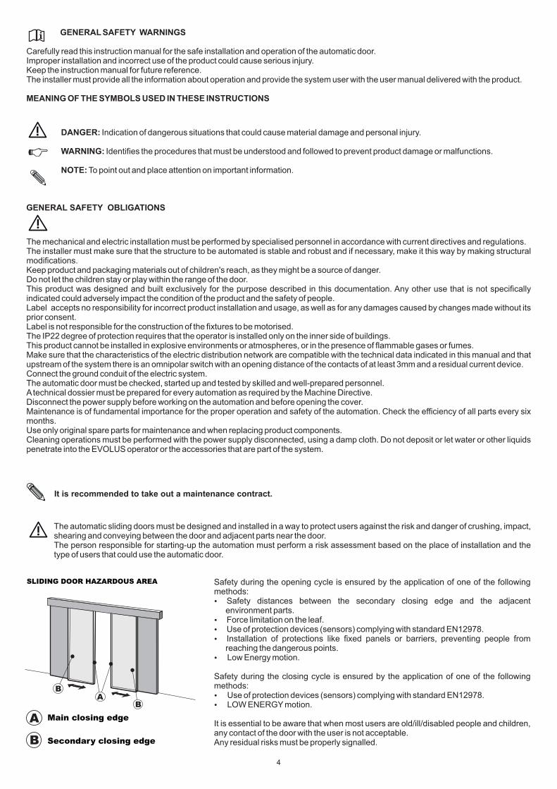
The automatic sliding doors must be designed and installed in a way to protect users against the risk and danger of crushing, impact, shearing and conveying between the door and adjacent parts near the door.The person responsible for starting-up the automation must perform a risk assessment based on the place of installation and the type of users that could use the automatic door.
Safety during the opening cycle is ensured by the application of one of the following methods: Safety distances between the secondary closing edge and the adjacent environment parts. Force limitation on the leaf. Use of protection devices (sensors) complying with standard EN12978. Installation of protections like fixed panels or barriers, preventing people from reaching the dangerous points. Low Energy motion.
Safety during the closing cycle is ensured by the application of one of the following methods: Use of protection devices (sensors) complying with standard EN12978. LOW ENERGY motion.
It is essential to be aware that when most users are old/ill/disabled people and children, any contact of the door with the user is not acceptable.Any residual risks must be properly signalled.
It is recommended to take out a maintenance contract.
SLIDING DOOR HAZARDOUS AREA
A
B
Main closing edge
Secondary closing edge
AB
B
4
5
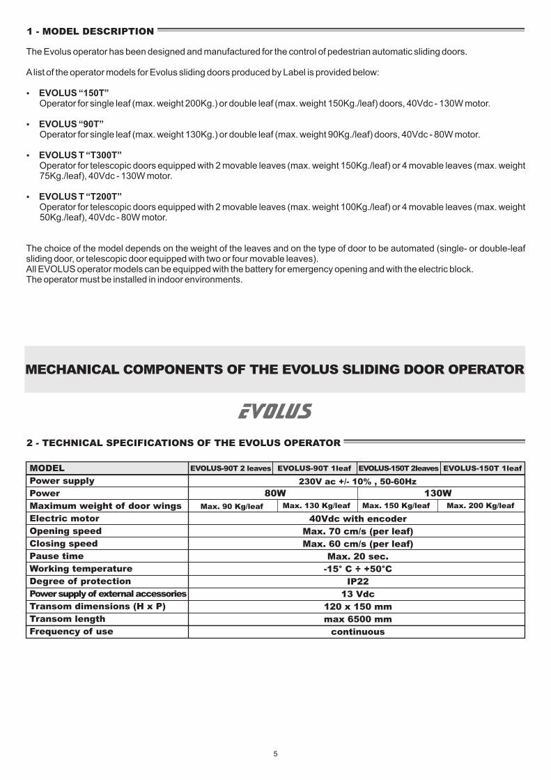
2 - TECHNICAL SPECIFICATIONS OF THE EVOLUS OPERATOR
MODEL
Power supply
Power
Maximum weight of door wings
Electric motor
Opening speed
Closing speed
Pause time
Working temperature
Degree of protection
Power supply of external accessories
Transom dimensions (H x P)
Transom length
Frequency of use
EVOLUS-90T 2 leaves
40Vdc with encoder
Max. 70 cm/s (per leaf)
Max. 60 cm/s (per leaf)
Max. 20 sec.
-15° C ÷ +50°C
IP22
13 Vdc
120 x 150 mm
max 6500 mm
continuous
230V ac +/- 10% , 50-60Hz
80W 130W
Max. 90 Kg/leaf
1 - MODEL DESCRIPTION
EVOLUS-90T 1leaf EVOLUS-150T 2leaves EVOLUS-150T 1leaf
The Evolus operator has been designed and manufactured for the control of pedestrian automatic sliding doors.
A list of the operator models for Evolus sliding doors produced by Label is provided below:
EVOLUS “150T” Operator for single leaf (max. weight 200Kg.) or double leaf (max. weight 150Kg./leaf) doors, 40Vdc - 130W motor.
EVOLUS “90T” Operator for single leaf (max. weight 130Kg.) or double leaf (max. weight 90Kg./leaf) doors, 40Vdc - 80W motor.
EVOLUS T “T300T” Operator for telescopic doors equipped with 2 movable leaves (max. weight 150Kg./leaf) or 4 movable leaves (max. weight
75Kg./leaf), 40Vdc - 130W motor.
EVOLUS T “T200T” Operator for telescopic doors equipped with 2 movable leaves (max. weight 100Kg./leaf) or 4 movable leaves (max. weight
50Kg./leaf), 40Vdc - 80W motor.
The choice of the model depends on the weight of the leaves and on the type of door to be automated (single- or double-leaf sliding door, or telescopic door equipped with two or four movable leaves).All EVOLUS operator models can be equipped with the battery for emergency opening and with the electric block.The operator must be installed in indoor environments.
MECHANICAL COMPONENTS OF THE EVOLUS SLIDING DOOR OPERATOR
Max. 130 Kg/leaf Max. 150 Kg/leaf Max. 200 Kg/leaf

6
12
13
14
17
16
12 clip
transom
sliding rail
casing
casing compensating profile
rail gasket
brush
13
14
15
16
17
15
18
18
2
1
3
4
side panel pair
electronic control unit
motor assembly with encoder
cover links
double wheel carriage5 10
6
7
8
9
upper belt coupling
lower belt coupling
cable gland
idle pulley
mechanical limit switch
driving belt
21
345678
9
10
1
10
4
11
11
3 - EVOLUS OPERATOR COMPONENTS

7
COMPONENT ARRANGEMENT
SINGLE DOOR LH LEAF WITHOUT ELECTRIC LOCK
LC = BELT LENGTH
LC = (F-M+120)x2
C = CONTROL UNIT
LT-LM-397
M = MOTORLT-LM-342
F = IDLE PULLEYLT-87
LM = LEAF WIDTH
LM = (LT-B+S)/2-12
PL = FREE PASSAGE
PL = (LT+B-S)/2-12
LT = TRANSOM LENGTH
LT = 2PL-B+S+24
SINGLE LEAF RH WITHOUT ELECTRIC LOCK
LC = BELT LENGTH
LC = (F-M+120)x2
C = CONTROL UNIT
LT-LM-397
M = MOTORLT-LM-342
F = IDLE PULLEYLT-87
LM = LEAF WIDTH
LM = (LT-B+S)/2-12
PL = FREE PASSAGE
PL = (LT+B-S)/2-12
LT = TRANSOM LENGTH
LT = 2PL-B+S+24
DOUBLE DOOR LEAF WITHOUT ELECTRIC LOCK
S S
BLM LM
PL
LT
LC = BELT LENGTH
LC = (F-M+120)x2
C = CONTROL UNIT
345mm
M = MOTOR400mm
F = IDLE PULLEYLT*3/4+75
LM = LEAF WIDTH
LM = (LT-B)/4+S/2-6
PL = FREE PASSAGE
PL = (LT+B)/2-S-6
LT = TRANSOM LENGTH
LT = 2PL-B+2S+24
FM
C
FM
CS
LT
PL
B
LM
S
LT
PL
B
LM
MC
F
4 - TECHNICAL DATA

8
SINGLE DOOR LH LEAF
WITH SLIM ELECTRIC LOCK
LC = BELT LENGTH
LC = (F-M+120)x2
C = CONTROL UNITLT-LM-397
M = MOTORLT-LM-342
F = IDLE PULLEYLT-87
LM = LEAF WIDTH
LM = (LT-B+S)/2-12
PL = FREE PASSAGE
PL = (LT+B-S)/2-12
LT = TRANSOM LENGTH
LT = 2PL-B+S+24
E = ELECTRIC LOCK75
SINGLE DOOR RH LEAF
WITH SLIM ELECTRIC LOCK
LC = BELT LENGTH
LC = (F-M+120)x2
C = CONTROL UNITLT-LM-522
M = MOTORLT-LM-467
F = IDLE PULLEYLT-212
LM = LEAF WIDTH
LM = (LT-B+S)/2-12
PL = FREE PASSAGE
PL = (LT+B-S)/2-12
LT = TRANSOM LENGTH
LT = 2PL-B+S+24
E = ELECTRIC LOCKLT-62
DOUBLE LEAF DOOR WITH SLIM ELECTRIC LOCK
S S
BLM LM
PL
LT
LC = BELT LENGTH
LC = (F-M+120)x2
C = CONTROL UNIT345mm
M = MOTOR400mm
F = IDLE PULLEYT*3/4+100
LM = LEAF WIDTH
LM = (LT-B)/4+S/2-6
PL = FREE PASSAGE
PL = (LT+B)/2-S-6
LT = TRANSOM LENGTH
LT = 2PL-B+2S+24
E = ELECTRIC LOCKT/2 + 5mm
FE
MC
S
LT
PL
B
LM
E
FM
C
MC
E
F
S
LT
PL
B
LM

5 - COVERING CASING
The casing of the EVOLUS automated equipment features two support links (A) specially designed to ensure that it remains stable in the opening position.
A
To fully remove the casing from the automated equipment press the end section of the pins (B) located on the support links and extract them by pulling them from the opposite end (Fig. 1) Manually support the casing before extracting the pin.In the lower section of the casing you can install an optional compensating profile allowing to close the gap between the fixture and the casing, thus improving the automated equipment appearance.To adjust the compensating profile depth you must detach the casing from the automated equipment and put it on a flat surface FIG. 3. Arrange the compensating profile as shown in the figure and fasten it to the casing by means of the special plastic clips.
Choose the optimum adjustment depth for the compensating profile referring to Fig. 4 then fasten each plastic clip by first inserting the clip teeth into the compensating profile grooves and then pushing the upper section of the clip forward until it connects to the casing.Put the casing back in place on the automated equipment by reinstalling the support links with the special pins, then close the casing over the automated equipment hooking the upper section to the transom FIG. 5.
Fasten the casing by means of the screws located on side panels FIG. 6.
If the transom is flush with the wall you can fasten the casing frontally, by drilling a hole at the front seat on the side panel and fastening the casing by means of the special EV-KFCF Kit (optional) FIG. 7.
SIDE PANEL SIDE VIEW
SIDE PANEL FRONT VIEW
A
FIG.1
FIG.2
FIG.5
FIG.3
FIG.6
FIG.7
B
9
X
FIG.4
No. of meshing teeth X dimension
8
7
6
5
4
3
66.8
62.7
58.5
54.4
50.2
46.1

6 - ADJUSTMENT OF THE BELT TENSIONING
To adjust belt tensioning slightly loosen the A screw of the idle pulley, then screw in (to increase belt tensioning) or unscrew (to decrease belt tensioning) the hexagonal screw B.After achieving the optimum driving belt tension fully tighten screw A.
A B
7 - POSITIONING THE MECHANICAL LIMIT SWITCH
The mechanical limit switch must be adjusted so that both during opening and closing it stops the carriage stroke before the mobile leaf crashes against any other component.It is also used by the electronic control unit to acquire the leaf limit points.When adjusting the opening mechanical limit switch take into account that except for the set-up manoeuvre and for the first manoeuvre after a power failure, at the end of the opening the mobile leaf stops about 5 mm before coming into contact with the limit switch.To adjust the limit switch loosen the 3 fastening screws, move the limit switch to the desired position, then fully tighten the 2 screws again.
FASTENING SCREWS
10
FIG.8
FIG.9
2
1
65
7
80
Upon request, the standard covering casing can be replaced with a smaller one, when the fixture section dimensions prevent the standard casing from closing on the transom.The smaller covering casing includes the slot for brush insertion.
STANDARD COVERING CASING SMALLER COVERING CASING

11
8 - ANCHORING THE LEAVES TO THE CARRIAGES AND ADJUSTING THEM
Undo the two front screws "A" of every carriage and remove the movable part "C" Fasten the movable part "C" you removed to the fixture at the distance indicated in figure 11, if an electric lock is not
installed, or in figure 12 if the electric lock is installed. Now hang the leaf to the automated equipment matching the two carriage parts, then screw the "A" screws into their seats
without tightening them. Adjust the height of the leaf by means of the control screw "B" and fully tighten the two "A" screws. Adjust the leaf horizontally by means of the eyelets "E" provided in the movable part of the carriage. To ensure that the automated equipment works properly it is important that the mobile leaf is perpendicular to the transom. Adjust the height of the opposing wheel by operating the adjustment screw (D) so that the wheel skims the top inner part of
the transom, but without exerting any pressure. Then manually move the leaf until it reaches the end of stroke and check that there are no frictions at any point; otherwise
adjust the opposing wheel position again.
D
C
E
A
BE
FIG.10
175
120
65
156
100
46 46
100
156 175
120
65
FIG.11
175
120
65
175
120
65 65
175
120
65
175
120
FIG.12
DOUBLE DOOR LEAF WITHOUT ELECTRIC LOCK
DOUBLE LEAF DOOR WITH SLIM ELECTRIC LOCK
9 - INSTALLATION MEASURES
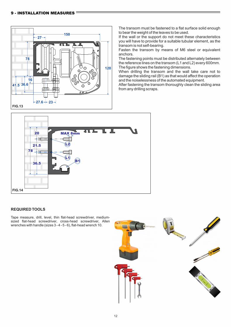
The transom must be fastened to a flat surface solid enough to bear the weight of the leaves to be used.If the wall or the support do not meet these characteristics you will have to provide for a suitable tubular element, as the transom is not self-bearing.Fasten the transom by means of M6 steel or equivalent anchors.The fastening points must be distributed alternately between the reference lines on the transom (L1 and L2) every 600mm.The figure shows the fastening dimensions.When drilling the transom and the wall take care not to damage the sliding rail (B1) as that would affect the operation and the noiselessness of the automated equipment.After fastening the transom thoroughly clean the sliding area from any drilling scraps.
12
150
120
27
27.6 23FIG.13
78
16
36.641.5
MAX 8mm
L1
L221.5
78
36.5B1
FIG.14
20
REQUIRED TOOLS
Tape measure, drill, level, thin flat-head screwdriver, medium-sized flat-head screwdriver, cross-head screwdriver, Allen wrenches with handle (sizes 3 - 4 - 5 - 6), flat-head wrench 10.

DIMENSIONAL TABLE FOR EVOLUS 90T AND 150T OPERATORS
1 MOBILE LEAF 2 MOBILE LEAVES
Dimensioning mm
PL = nominal passage opening
LT= automation length
LT=2PL-B+S+24
Dimensioning mm
LM= LT-B S 4 2
+ - 6
LM= leaf S= overlapping B=contact with
S=50 B=10
PL= LT+B 2
- - 6S
PL = nominal passage opening
LM= LT-B+S 2
-12
LM= leaf S= overlapping B=contact with
S=50 B=10
PL= LT+B-S 2
- 12
2000250030003500400045005000550060006500
516.5 641.5 766.5 891.51016.51141.51266.51391.51516.51641.5
949119914491699194921992449269929493199
2000250030003500400045005000550060006500
1008125815081758200822582508275830083258
968121814681718196822182468271829683218
S
LT
PL
B
LM
S S
BLM LM
PL
LT
SECTION WITH POLISHED EDGE ATTACHMENTSECTION WITH COMMERCIAL PROFILES
PAD1
P6S
PT1
150
120
2041.5
78
23
2541.5
39.1
70
50
H
13
H-1636.5
28
27
LT= automation length
LT=2PL-B+2S+24
LEGEND:
PL = FREE PASSAGELT = AUTOMATION LENGTHLM = LEAF WIDTHH = PASSAGE OPENING HEIGHT
13
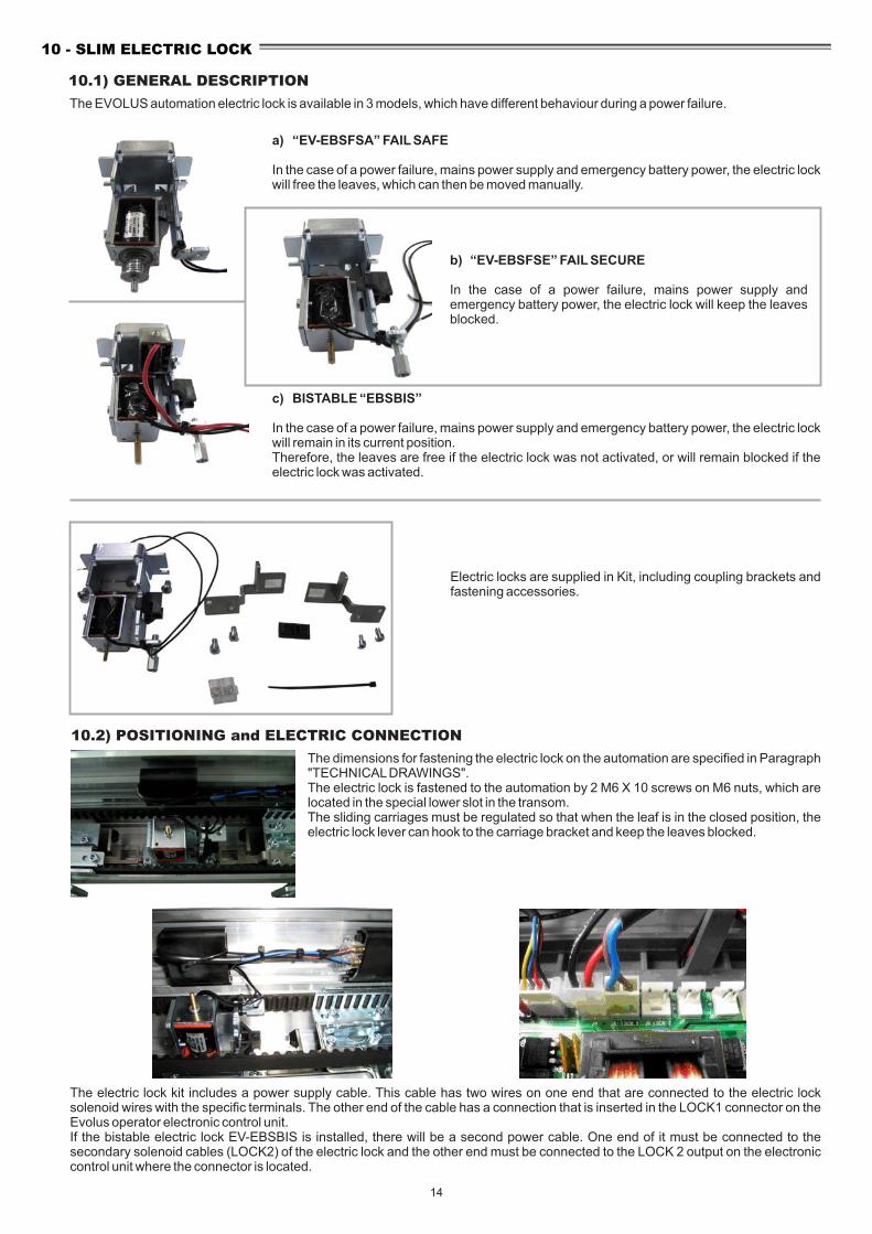
The EVOLUS automation electric lock is available in 3 models, which have different behaviour during a power failure.
a) “EV-EBSFSA” FAIL SAFE
In the case of a power failure, mains power supply and emergency battery power, the electric lock will free the leaves, which can then be moved manually.
b) “EV-EBSFSE” FAIL SECURE
In the case of a power failure, mains power supply and emergency battery power, the electric lock will keep the leaves blocked.
c) BISTABLE “EBSBIS”
In the case of a power failure, mains power supply and emergency battery power, the electric lock will remain in its current position.Therefore, the leaves are free if the electric lock was not activated, or will remain blocked if the electric lock was activated.
10.2) POSITIONING and ELECTRIC CONNECTION
The dimensions for fastening the electric lock on the automation are specified in Paragraph "TECHNICAL DRAWINGS".The electric lock is fastened to the automation by 2 M6 X 10 screws on M6 nuts, which are located in the special lower slot in the transom.The sliding carriages must be regulated so that when the leaf is in the closed position, the electric lock lever can hook to the carriage bracket and keep the leaves blocked.
The electric lock kit includes a power supply cable. This cable has two wires on one end that are connected to the electric lock solenoid wires with the specific terminals. The other end of the cable has a connection that is inserted in the LOCK1 connector on the Evolus operator electronic control unit.If the bistable electric lock EV-EBSBIS is installed, there will be a second power cable. One end of it must be connected to the secondary solenoid cables (LOCK2) of the electric lock and the other end must be connected to the LOCK 2 output on the electronic control unit where the connector is located.
Electric locks are supplied in Kit, including coupling brackets and fastening accessories.
10.1) GENERAL DESCRIPTION
10 - SLIM ELECTRIC LOCK
14

10.3) MANUAL RELEASE
The Fail Secure EV-EBSFSE and Bistable EV-EBSBIS models are equipped with the EV-EBSSMA manual release system that is used to release the electric lock in the case of a power failure, and therefore move the leaves freely.
CFix the bottom of the release knob to the side panel, using the supplied self-threading screws, on the two hole existing in the side panel.
RELEASE KNOB FASTENING
A
B
For the fastening on both the right and left side of the automation you need to fix the adjustment register on the bottom of the release knob.
Insert the steel cable inside the flexible sheath as shown in the figure.
15
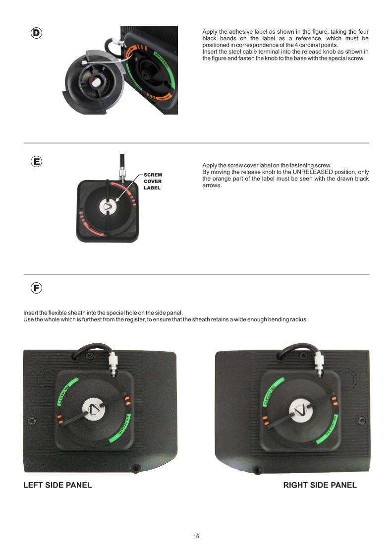
Apply the adhesive label as shown in the figure, taking the four black bands on the label as a reference, which must be positioned in correspondence of the 4 cardinal points.Insert the steel cable terminal into the release knob as shown in the figure and fasten the knob to the base with the special screw.
SCREW
COVER
LABEL
Apply the screw cover label on the fastening screw.By moving the release knob to the UNRELEASED position, only the orange part of the label must be seen with the drawn black arrows.
D
E
F
Insert the flexible sheath into the special hole on the side panel.Use the whole which is furthest from the register, to ensure that the sheath retains a wide enough bending radius.
LEFT SIDE PANEL RIGHT SIDE PANEL
16
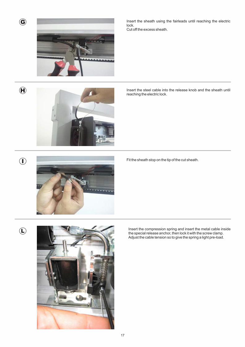
G
H
I
L
Insert the sheath using the fairleads until reaching the electric lock.Cut off the excess sheath.
Insert the steel cable into the release knob and the sheath until reaching the electric lock.
Fit the sheath stop on the tip of the cut sheath.
Insert the compression spring and insert the metal cable inside the special release anchor, then lock it with the screw clamp.Adjust the cable tension so to give the spring a light pre-load.
17

M
N
O
Check that the manual release works, when the knob is in the locked position, the electric lock must work normally.
When the knob is in the released position, the electric lock must remain open and free the leaves.
Cut the exceeding steel cable from the release anchor.
NOTE:In case of FAIL SECURE electric lock, by releasing the release, the electric lock will close.In case of a bistable electric lock, by releasing the release, it will open.In case it is necessary to manually close the door with a bistable electric lock, it will be sufficient to lift the core of the secondary solenoid with a screwdriver.
18

CABLE TERMINALCABLE BLOCKCABLE TERMINALLOWER SCREW
Pass the release cable in the slit in the base and then inside the adjustment register as shown in the figure. Then position the cable terminal on the release knob cable block (see figure).
Now, insert the release knob on the base of the mechanism, being careful to keep the cable terminal in the seat of the cable block and the knob in the correct position. When inserting the knob, the cable terminal must be in the position just beyond the lower fastening screw, in a clockwise direction.
Drill the wall and fasten the base of the release mechanism using the fastening screws.Apply the adhesive label as shown in the figure, taking the four black bands on the label as a reference, which must be positioned in correspondence of the 4 cardinal points.Insert the adjustment register using 2 nuts, one in the plastic slot and the other outside of it.
BLACK BANDS
BLACK BANDS
FASTENING SCREW
FASTENING SCREW
Identify the fastening point on the wall, taking into account that the standard cable sheath is 3 metre long and that it must reach the electric lock.
SCREW
COVER
LABEL
10.4) INSTALLATION OF THE MANUAL RELEASE ON THE WALL
Once the knob is inserted, fasten the closing screw, insert the sheath and turn the knob to the RELEASED position. In this position, only the orange part of the label must be seen with the drawn black arrows.Make sure that the system is operating by turning the knob clockwise and keeping the cable taut with your hand.
WARNING!:
THE KNOB TURNS MAX 45-50 DEGREES AND AT THE END, THERE ARE CLICKS IN ORDER TO MAINTAIN THE POSITION AFTER THE RELEASE.
Apply the provided screw cover label as shown in the figure and return the knob to the RELEASED position.
19

10.5) INSTALLATION OF THE MANUAL RELEASE OVER THE TRANSOM
A Put the drilling template into place, aligning it with the reference marks at the top of the EVOLUS transom.Align the template with the centre of the solenoid axis.
B
C
Drill a hole into the transom as indicated on the template.
Fix the release knob bottom using the supplied screws.Insert the 250mm sheath.
Apply the adhesive label as shown in the figure, taking the four black bands on the label as a reference, which must be positioned in correspondence of the 4 cardinal points.Insert the steel cable terminal into the release knob as shown in the figure and fasten the knob to the base with the special screw.
D
20

Apply the screw cover label on the fastening screw.By moving the release knob to the RELEASED position, only the orange part of the label must be seen with the drawn black arrows.
E
SCREW
COVER
LABEL
FInsert the compression spring and insert the metal cable inside the special release anchor, then lock it with the screw clamp.Adjust the cable tension so to give the spring a light pre-load.
Check that the manual release works, when the knob is in the locked position, the electric lock must work normally.
When the knob is in the released position, the electric lock must remain open and free the leaves.
Cut the exceeding steel cable from the release anchor.
G
H
21
ELECTRONIC SECTION
AUTOMATISM POWER SUPPLY
OUTER SIDE
INNER SIDE
1
2
3
4
5
6
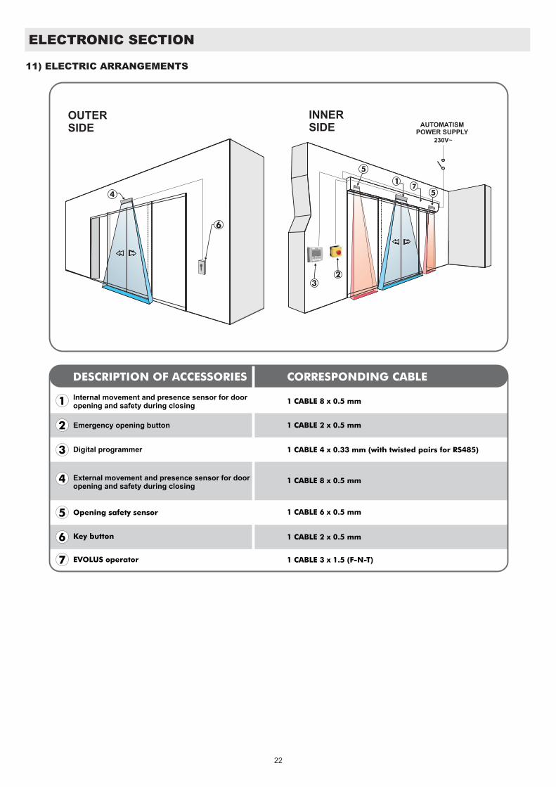
Internal movement and presence sensor for door opening and safety during closing
Emergency opening button
Digital programmer
External movement and presence sensor for door opening and safety during closing
Opening safety sensor
Key button
1 CABLE 8 x 0.5 mm
DESCRIPTION OF ACCESSORIES CORRESPONDING CABLE
1 CABLE 2 x 0.5 mm
1 CABLE 4 x 0.33 mm (with twisted pairs for RS485)
1 CABLE 8 x 0.5 mm
1 CABLE 6 x 0.5 mm
1 CABLE 2 x 0.5 mm
1 CABLE 3 x 1.5 (F-N-T)7
22
EVOLUS operator
7
11) ELECTRIC ARRANGEMENTS
ELE
CT
RIC
AL C
ON
NE
CT
ION
S - S
TA
ND
AR
D D
IAG
RA
M -
13V
STA
RT
40V
F12
30
Va
c
5A
J1
J3J4
J5J6
J7J8
+-
UR
1U
R1
UR
1U
R1
+13V
AB
TX
RX
+-
+-
2
+-
+-
BA
TT
ER
Y
CH
AR
GE
R
PR
J38
EARTH
NEUTRAL
PHASE
PO
WE
R
SU
PP
LY
S
WIT
CH
EL
EC
TR
IC L
OC
KB
ISTA
BL
E 2
°SO
LE
NO
ID
EL
EC
TR
IC L
OC
KFA
IL S
AF
EFA
IL S
EC
UR
EB
ISTA
BL
E 1
°SO
LE
NO
ID
BA
TT
ER
Y1
8V
-70
0m
Ah
MO
TO
R
WIT
H E
NC
OD
ER
+13V
AB
N-D
SE
L
DIG
ITA
L
PR
OG
RA
MM
ER
OP
EN
STA
RT
B
UT
TON
EX
TE
RN
AL
RA
DA
RA
CT
IVA
TIO
N A
ND
CL
OS
ING
SA
FE
TY
SE
NS
OR
2
SA
FE
TY
SE
NS
OR
S F
OR
OP
EN
ING
12
34
811
12
15
RA
DA
RIN
TC
OM
AU
X1
AU
X2
+-
TE
ST
INT
ER
NA
L R
AD
AR
AC
TIV
AT
ION
AN
D C
LO
SIN
G S
AF
ET
Y S
EN
SO
R 1
TE
ST
+-
TE
ST
TE
ST
1
+-
+-
PO
WE
RP
OW
ER
PO
WE
R
PO
WE
R
PR
J38
E.O.
2E.
C.2
E.O.
1OP
ENE.
C.1
PS
1
23
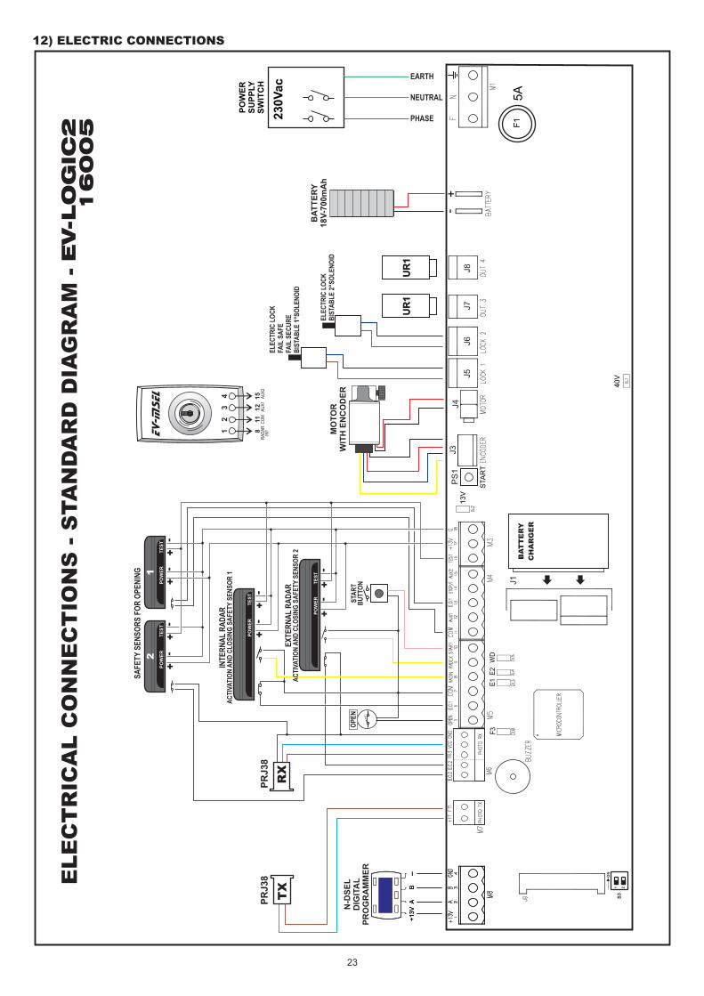
12) ELECTRIC CONNECTIONS
ON
S3
1 2
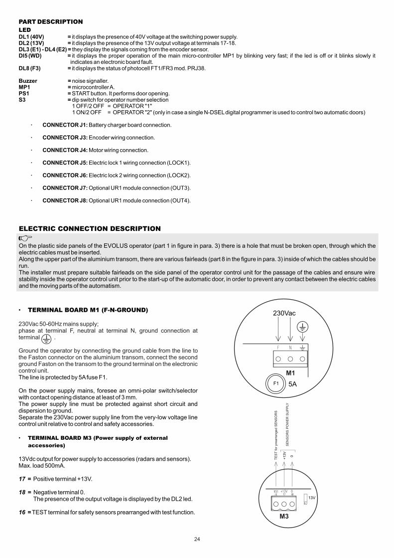
PART DESCRIPTION
LEDDL1 (40V) = it displays the presence of 40V voltage at the switching power supply.DL2 (13V) = it displays the presence of the 13V output voltage at terminals 17-18.DL3 (E1) - DL4 (E2) = they display the signals coming from the encoder sensor. Dl5 (WD) = it displays the proper operation of the main micro-controller MP1 by blinking very fast; if the led is off or it blinks slowly it
indicates an electronic board fault.DL8 (F3) = it displays the status of photocell FT1/FR3 mod. PRJ38.
Buzzer = noise signaller.MP1 = microcontroller A.PS1 = START button. It performs door opening.S3 = dip switch for operator number selection 1 OFF/2 OFF = OPERATOR "1" 1 ON/2 OFF = OPERATOR "2" (only in case a single N-DSEL digital programmer is used to control two automatic doors)
· CONNECTOR J1: Battery charger board connection.
· CONNECTOR J3: Encoder wiring connection.
· CONNECTOR J4: Motor wiring connection.
· CONNECTOR J5: Electric lock 1 wiring connection (LOCK1).
· CONNECTOR J6: Electric lock 2 wiring connection (LOCK2).
· CONNECTOR J7: Optional UR1 module connection (OUT3).
· CONNECTOR J8: Optional UR1 module connection (OUT4).
· TERMINAL BOARD M1 (F-N-GROUND)
230Vac 50-60Hz mains supply; phase at terminal F, neutral at terminal N, ground connection at terminal .
Ground the operator by connecting the ground cable from the line to the Faston connector on the aluminium transom, connect the second ground Faston on the transom to the ground terminal on the electronic control unit.The line is protected by 5A fuse F1.
On the power supply mains, foresee an omni-polar switch/selector with contact opening distance at least of 3 mm.The power supply line must be protected against short circuit and dispersion to ground.Separate the 230Vac power supply line from the very-low voltage line control unit relative to control and safety accessories.
· TERMINAL BOARD M3 (Power supply of external
accessories)
13Vdc output for power supply to accessories (radars and sensors).Max. load 500mA.
17 = Positive terminal +13V.
18 = Negative terminal 0. The presence of the output voltage is displayed by the DL2 led.
16 = TEST terminal for safety sensors prearranged with test function.
+1
3V
0
M3
13V
230Vac
M1
F1 5A
ELECTRIC CONNECTION DESCRIPTION
On the plastic side panels of the EVOLUS operator (part 1 in figure in para. 3) there is a hole that must be broken open, through which the electric cables must be inserted.Along the upper part of the aluminium transom, there are various fairleads (part 8 in the figure in para. 3) inside of which the cables should be run.The installer must prepare suitable fairleads on the side panel of the operator control unit for the passage of the cables and ensure wire stability inside the operator control unit prior to the start-up of the automatic door, in order to prevent any contact between the electric cables and the moving parts of the automatism.
24
TE
ST
for
pre
arr
anged S
EN
SO
RS
SE
NS
OR
S P
OW
ER
SU
PP
LY
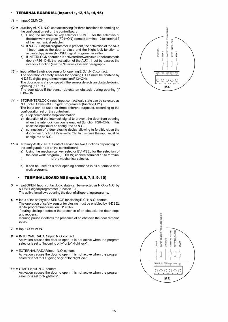
· TERMINAL BOARD M4 (Inputs 11, 12, 13, 14, 15)
11 = Input COMMON.
12 = auxiliary AUX 1. N.O. contact serving for three functions depending on the configuration set on the control board:
a) Using the mechanical key selector EV-MSEL for the selection of the door work program (F01=ON) connect terminal 12 to terminal 3 of the mechanical selector.
b) If N-DSEL digital programmer is present, the activation of the AUX 1 input causes the door to close and the Night lock function to activate, by-passing N-DSEL digital programmer setting.
c) If INTERLOCK operation is activated between two Label automatic doors (F26=ON), the activation of the AUX1 input by-passes the interlock function (see the “Interlock system” paragraph).
13 = input of the Safety side sensor for opening E.O.1; N.C. contact. The operation of safety sensor for opening E.O.1 must be enabled by
N-DSEL digital programmer (function F13=ON).The door opens at slow speed if the sensor detects an obstacle during opening (if F19= OFF).
The door stops if the sensor detects an obstacle during opening (if F19= ON).
14 = STOP/INTERLOCK input. Input contact logic state can be selected as N.O. or N.C. by N-DSEL digital programmer (function F21).
The input can be used for three different purposes, according to the configuration set on the control unit:
a) Stop command to stop door motion. b) detection of the interlock signal to prevent the door from opening
when the interlock function is enabled (function F26=ON). In this case the input must be configured as N.C..
c) connection of a door closing device allowing to forcibly close the door when function F22 is set to ON. In this case the input must be configured as N.C..
15 = auxiliary AUX 2. N.O. Contact serving for two functions depending on the configuration set on the control board:
a) Using the mechanical key selector EV-MSEL for the selection of the door work program (F01=ON) connect terminal 15 to terminal 4 of the mechanical selector.
b) It can be used as a door opening command in all automatic door work programs.
· TERMINAL BOARD M5 (Inputs 5, 6, 7, 8, 9, 10)
5 = input OPEN. Input contact logic state can be selected as N.O. or N.C. by N-DSEL digital programmer (function F20).
The activation allows opening the door of all operating programs.
6 = input of the safety side SENSOR for closing E.C.1; N.C. contact. The operation of safety sensor for closing must be enabled by N-DSEL
digital programmer (function F11=ON). If during closing it detects the presence of an obstacle the door stops
and reopens. If during pause it detects the presence of an obstacle the door remains
open.
7 = Input COMMON.
8 = INTERNAL RADAR input. N.O. contact. Activation causes the door to open. It is not active when the program
selector is set to "Incoming only" or to "Night lock".
9 = EXTERNAL RADAR input. N.O. contact. Activation causes the door to open. It is not active when the program
selector is set to "Outgoing only" or to "Night lock".
10 = START input. N.O. contact. Activation causes the door to open. It is not active when the program
selector is set to "Night lock".
25
AU
X1
AU
X2
M4
E.O.1
CO
MM
ON
SA
FE
TY
SE
NS
OR
FO
R O
PE
NIN
G
ST
OP
/ I
NT
ER
LO
CK
M5
ST
AR
T
OP
EN
OPEN COM
SA
FE
T S
EN
SO
R F
OR
CLO
SIN
G E
.C.1
INT
ER
NA
L R
AD
AR
EX
TE
RN
ALR
AD
AR
CO
MM
ON
E.C.1

· TERMINAL BOARD M6
E.O.2 = Input of safety sensor for opening E.O.2, N.C. contact. The operation of safety sensor for opening E.O.2 must be enabled by N-
DSEL digital programmer (function F14=ON). The door opens at slow speed if the sensor detects an obstacle during
opening (function F19= OFF). The door stops if the sensor detects an obstacle during opening
(function F19= ON).
E.C.2 = Input of safety sensor for closing E.C.2, N.C. contact. The operation of safety sensor for closing E.C.2 must be enabled by N-
DSEL digital programmer (function F12=ON). If during closing, sensor detects the presence of an obstacle the door
stops and reopens. If during pause, sensor detects the presence of an obstacle the door
remains open.
FR3 = PRJ38 PHOTOCELL receiving capsule signal (brown cable).
VCC = power supply positive for the receiving capsule (blue cable).
GND = power supply negative for the receiving capsule (black cable).
· TERMINAL BOARD M7
+FT = power supply positive of the transmitting capsule (blue cable).
Ft1 = PRJ38 PHOTOCELL transmitting capsule signal (brown cable).
· TERMINAL BOARD M8 (N-DSEL digital programmer)
1 = Power supply positive +13V
2 = Communication signal A
3 = Communication signal B
4 = Power supply negative GND
M8
M7
Photocell operation mode
The PRJ38 photocell is used as a STOP sensor in the panic exit breakout system.To ensure proper operation the photocells must be perfectly aligned and at the same height.The PRJ38 photocell must be enabled by the N-DSEL digital programmer (function F18=ON).The activation of the PRJ38 photocell stops the door motion and the control unit buzzer beeps 4 times.Interrupting the photocell infrared beam will cause the F3 led to light up (DL8).
PRJ38 PHOTOCELLS
The pair of PRJ38 Label photocells consists of a transmitting and a receiving capsule.The transmitting capsule, besides, is equipped with a 2-wire cable bearing the PRJ38-TX mark, while the receiving capsule has a 3-wire cable bearing the PRJ38-RX mark. Drill an 11.5 mm hole to fasten the capsules into the fixture.To avoid any interference due to exposure to direct sunlight we recommend that you install the receiving capsules on the side that is best protected against
RECEIVING TRANSMITTING
M6
FR3 VDC GND
PHOTO RX
E.C
.2
E.O
.2
PHOTO TX
FT1+
FT
N-DSELDIGITAL
PROGRAMMER
1 2 3
+13V B 0
4
A
26

27
The N-DSEL digital programmer is the essential tool for the installer, to configure the automatic door operation and perform the set-up and function/parameter setting operations, to carry out the system diagnostics and to access the event memory containing information about the automatism and its operation.Access to the programming menu is protected by a technical safety password, to ensure that only specialised and authorised personnel can perform any operation on the automatism.
N-DSEL digital programmer can also be used by the final user, but only for choosing the operating mode of automatic door; the user can also select the preferred language and set up a user password to prevent the use of digital programmer by unauthorized persons.
Connect the N-DSEL digital programmer to the control unit of the EVOLUS operator, using a 0.33mm 4-wire cable with twisted pairs for RS485 applications.
Terminal +13V = connect to terminal 1 of the EVOLUS control unit (+13V);Terminal - = connect to terminal 4 of the EVOLUS control unit (- GND);Terminal A = connect to terminal 2 of the EVOLUS control unit (A);Terminal B = connect to terminal 3 of the EVOLUS control unit (B);
For each subject-matter described in the following paragraphs the use of digital programmer (hereinafter N-DSEL) is explained in the specific case.
B A CN2 +13 -
13) N-DSEL DIGITAL PROGRAMMER – SCOPE and CONNECTIONS
A single N-DSEL digital programmer, connected to two EVOLUS operators, can manage the operation of two independent automatic doors.Connect in parallel the A - B signals of the two operators (see the diagram below).
M8
OPERATOR "1"
N-DSEL DIGITAL
PROGRAMMER
1 2 3
+13V B 0
4
A
OPERATOR "2"
M8
1 2 3 4
ON
S31
2
DIP1 = OFFDIP2 = OFF
ON
S31
2
DIP1 = ONDIP2 = OFF
80
18
100

14) COMMISSIONING OF AUTOMATED DEVICE (INITIAL SET-UP)
After performing the mechanical installation of the automatic door and the electrical connections to the electronic control unit, you can start up the automated equipment. Preliminary checks
- check the cleanliness of the sliding rail and of the ground guide;- check the belt's tension;- check that leaves are properly aligned and fastened to chariots;- check that the position of the mechanical limit switch is correct;- check that leaves move smoothly and frictionless;- check proper operation of the electric lock, if installed, and of the relevant manual release.
SET-UP operation is compulsory to allow the operator electronic control unit to acquire stroke points.During the stroke learning cycle there must be no obstacles in the leaf movement area.If the N-DSEL digital programmer is used to manage a single EVOLUS automatic door, dips 1 and 2 of the S3 dip-switch on the EV-LOGIC2 operator control unit bust be set to OFF.If the N-DSEL digital programmer is used to manage two EVOLUS automatic doors, dips 1 and 2 of the S3 dip-switch on the EV-LOGIC2 control unit of operator 1 must be set to OFF, while on the EV-LOGIC2 control unit of operator 2 dip 1 must be set to ON and dip 2 to OFF (see Table).
14.1) FIRST START OF N-DSEL DIGITAL PROGRAMMER
Power the EVOLUS operator by mains voltage, the control unit buzzer emits some quick, short beeps.
Language selection is shown on the display of N-DSEL digital programmer;
use the F2 and buttons to move arrow to the desired language.
Press EXIT button to exit “Language” section and enter “Serial communication setups” section, as described under para. 14.3.
14.2) USE OF N-DSEL DIGITAL PROGRAMMER
Power the EVOLUS operator by mains voltage, the control unit buzzer emits some quick, short beeps.The display signals the lack of communication between N-DSEL and operator control units since the serial code of EV-LOGIC2 logic board is not stored on N-DSEL.Press button for about 5 seconds to enter the general programming menu. The F1 button allows to move forward among the menu symbols. Select RS485 symbol. Give a quick pulse to ENTER to enter the “Serial communication setups” section, as described under para. 14.3.
N-DSEL programmer automatically detects the presence of operator electronic control unit (fig. A) and stores the board serial codeEV-LOGIC2 (fig. B).
When acquisition of serial code is completed, the display must show the closed padlock symbol on number 1 and the open padlock symbol on the ?, if a single EVOLUS operator is connected (fig. C),
fig.A fig.B
fig.CIf the N-DSEL digital programmer is connected to two EVOLUS operators to manage two automatic doors, instead, once serial code acquisition is completed the closed padlock symbol must be displayed on number 1 and on number 2 (fig. D)Press EXIT button to exit “Serial communication setups” section and enter the general programming menu.
Follow chapter 14.1 only if N-DSEL digital programmer is new and powered for the first time.Follow chapter 14.2 if digital programmer has already been used before.
Before powering the system set the S3 dip-switch of the EV-LOGIC2 logic board as specified in the table
EV-LOGIC2 OPERATOR 1
EV-LOGIC2 OPERATOR 2 ON
OFF
S3 DIP 1
OFF
OFF
S3 DIP 2
14.3) SERIAL COMMUNICATION SETTINGS
1
fig.D
28
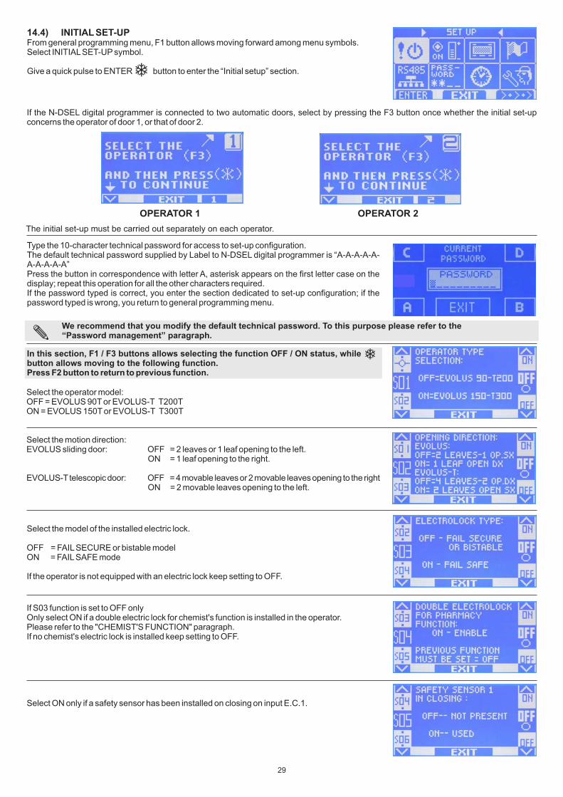
Select the model of the installed electric lock.
OFF = FAIL SECURE or bistable modelON = FAIL SAFE mode
If the operator is not equipped with an electric lock keep setting to OFF.
If S03 function is set to OFF onlyOnly select ON if a double electric lock for chemist's function is installed in the operator.Please refer to the "CHEMIST'S FUNCTION" paragraph.If no chemist's electric lock is installed keep setting to OFF.
Select ON only if a safety sensor has been installed on closing on input E.C.1.
We recommend that you modify the default technical password. To this purpose please refer to the “Password management” paragraph.
14.4) INITIAL SET-UPFrom general programming menu, F1 button allows moving forward among menu symbols.Select INITIAL SET-UP symbol.
Give a quick pulse to ENTER button to enter the “Initial setup” section.
Type the 10-character technical password for access to set-up configuration.The default technical password supplied by Label to N-DSEL digital programmer is “A-A-A-A-A-A-A-A-A-A”Press the button in correspondence with letter A, asterisk appears on the first letter case on the display; repeat this operation for all the other characters required.If the password typed is correct, you enter the section dedicated to set-up configuration; if the password typed is wrong, you return to general programming menu.
In this section, F1 / F3 buttons allows selecting the function OFF / ON status, while button allows moving to the following function. Press F2 button to return to previous function.
Select the operator model:OFF = EVOLUS 90T or EVOLUS-T T200TON = EVOLUS 150T or EVOLUS-T T300T
Select the motion direction:EVOLUS sliding door: OFF = 2 leaves or 1 leaf opening to the left. ON = 1 leaf opening to the right.
EVOLUS-T telescopic door: OFF = 4 movable leaves or 2 movable leaves opening to the right ON = 2 movable leaves opening to the left.
If the N-DSEL digital programmer is connected to two automatic doors, select by pressing the F3 button once whether the initial set-up concerns the operator of door 1, or that of door 2.
The initial set-up must be carried out separately on each operator.
OPERATOR 1 OPERATOR 2
29
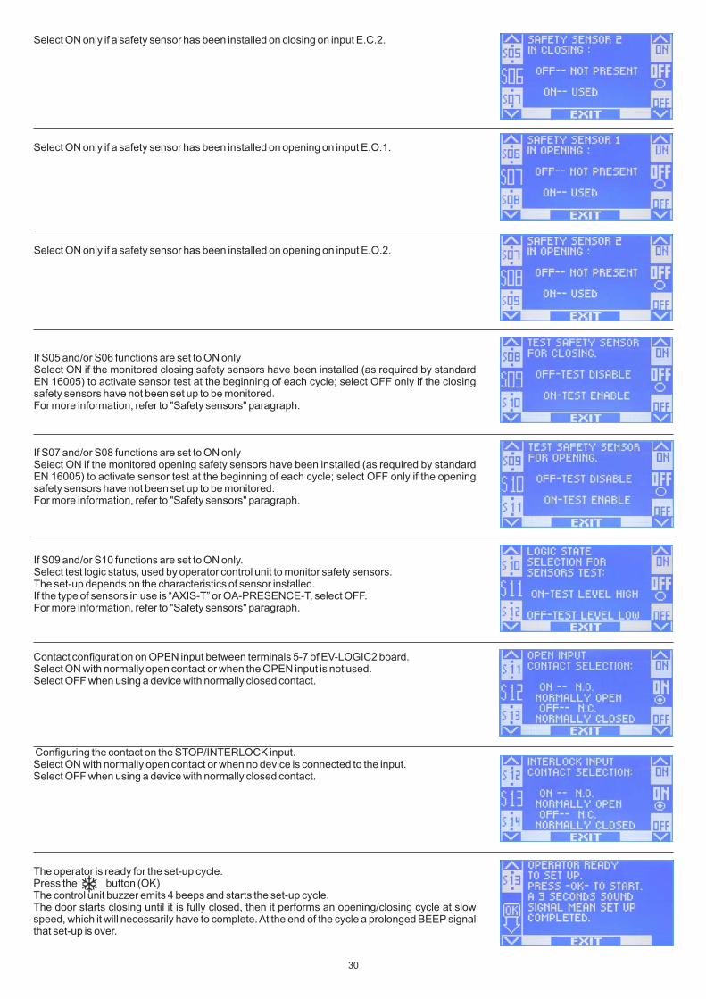
Contact configuration on OPEN input between terminals 5-7 of EV-LOGIC2 board.Select ON with normally open contact or when the OPEN input is not used.Select OFF when using a device with normally closed contact.
Configuring the contact on the STOP/INTERLOCK input.Select ON with normally open contact or when no device is connected to the input.Select OFF when using a device with normally closed contact.
The operator is ready for the set-up cycle.Press the button (OK)The control unit buzzer emits 4 beeps and starts the set-up cycle.The door starts closing until it is fully closed, then it performs an opening/closing cycle at slow speed, which it will necessarily have to complete. At the end of the cycle a prolonged BEEP signal that set-up is over.
Select ON only if a safety sensor has been installed on closing on input E.C.2.
Select ON only if a safety sensor has been installed on opening on input E.O.1.
Select ON only if a safety sensor has been installed on opening on input E.O.2.
If S05 and/or S06 functions are set to ON onlySelect ON if the monitored closing safety sensors have been installed (as required by standard EN 16005) to activate sensor test at the beginning of each cycle; select OFF only if the closing safety sensors have not been set up to be monitored.For more information, refer to "Safety sensors" paragraph.
If S07 and/or S08 functions are set to ON onlySelect ON if the monitored opening safety sensors have been installed (as required by standard EN 16005) to activate sensor test at the beginning of each cycle; select OFF only if the opening safety sensors have not been set up to be monitored.For more information, refer to "Safety sensors" paragraph.
If S09 and/or S10 functions are set to ON only.Select test logic status, used by operator control unit to monitor safety sensors.The set-up depends on the characteristics of sensor installed.If the type of sensors in use is “AXIS-T” or OA-PRESENCE-T, select OFF.For more information, refer to "Safety sensors" paragraph.
30

14.6) INPUT DIAGNOSTICSN-DSEL programmer allows checking the inputs status to ensure proper operation of all devices connected with EVOLUS operator.To enter "Inputs diagnostics" while the automatic door operating program is shown on display, keep F2 button pressed for about 3 seconds.The F3 button is only used in case the N-DSEL programmer is connected to two EVOLUS operators and the symbol "1" is displayed at the top right if the inputs on operator 1 are being viewed, or 2 if the viewed inputs are those of operator 2. Press F3 once to switch from 1 to 2 and vice versa.If the N-DSEL programmer only manages a single operator the symbol "1" is displayed at the top right.The display shows the symbols of all operator inputs, with the relevant terminal number.If an input is used, the corresponding symbol lights up with an arrow on a side.
14.5) FUNCTIONAL TESTINGSelect door automatic operation by program selector.Once the set-up is completed the default program selector is the N-DSEL digital programmer (function F01 = OFF). If the EV-MSEL mechanical selector is installed, set function F01 = ON (please refer to paragraph 19.1 “Function setting”).Refer to “Program selectors” paragraph describing the two types of selector provided for to select the automatic door operating mode.To start an opening manoeuvre, give a pulse to PS1 button (Start) on the EV-LOGIC2 board or engage the door opening devices.Ensure that door opening and closing cycle is properly performed and that pulse organs and safety sensors operate; to adjust sensor detection field, refer to the instructions delivered with the sensor.The safety sensors must ensure that the leaf doesn't impact against any automatic door users (please comply with the provisions contained in the regulations in force).During door movement, intermittent signals could be heard as emitted by the buzzer to indicate that the limit power delivered by operator has been reached, especially if leaf dimensions and weight are close to the limits allowed.A short noise signal by the buzzer during start in opening is to be considered as normal, as the pick-up phase is the moment requiring maximum force.Adjust the thrust power by P04 parameter of N-DSEL programmer (see . “Adjustment of parameters” paragraph).To deactivate the buzzer noise signal when the power limit is reached, set up F33 function to ON (see “Functions setup”).
Check that the electric lock and the manual release are working properly.If the operator is equipped with emergency battery, connect the battery connector to the BATTERY connector on the EV-LOGIC2 control unit, and make sure that the battery charger board is inserted into the J1 connector of the control unit (for detailed information about operation with the emergency battery please refer to para. “Emergency opening device”).Safety on impact: placing an obstacle in front of the leaf while it is in motion will cause the leaf to stop and the motion direction to be reversed; when performing the next cycle the leaf shall slow down in the point where it had come into contact with the obstacle.
To set up the available functions, refer to “Functions setup” paragraph.To adjust the variable parameters, refer to “Adjustment of parameters” section.
REPEATING THE INITIAL SET-UPSet-up operation must be repeated if one of the following conditions varies:leaf weight, leaf stroke, opening direction, type of electric lock, replacement of the EV-LOGIC2 board.
The buzzer noise signal for almost the entire stroke means that the leaf exceeds the limits allowed or frictions exist on the fixture; in this case, the movements of automatic door are difficult and the opening/closing cycle could not be completed.
EXTERNAL RADAR
INTERNAL RADAR
START
OPEN
SAFETY SENSOR FOR CLOSING E.C.2
SAFETY SENSOR FOR OPENING E.O.1
EN/RF1 RECEIVER activated by the SPYCO radio control
AUX 1SAFETY
SENSOR FOR OPENING E.O.2
AUX 2
SAFETY SENSOR FOR CLOSING E.C.1
STOP/INTERLOCK
PRJ38 STOP PHOTOCELL
31
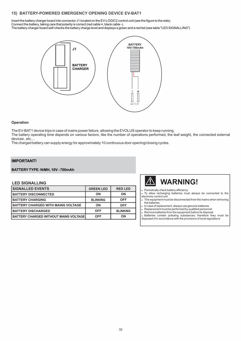
Insert the battery charger board into connector J1 located on the EV-LOGIC2 control unit (see the figure to the side).Connect the battery, taking care that polarity is correct (red cable +, black cable -).The battery charger board self-checks the battery charge level and displays a green and a red led (see table "LED SIGNALLING")
BATTERY CHARGER
J1
15) BATTERY-POWERED EMERGENCY OPENING DEVICE EV-BAT1
+-
BATTERY18V-700mAh
Operation
The EV-BAT1 device trips in case of mains power failure, allowing the EVOLUS operator to keep running.The battery operating time depends on various factors, like the number of operations performed, the leaf weight, the connected external devices , etc.... The charged battery can supply energy for approximately 10 continuous door opening/closing cycles.
IMPORTANT!
BATTERY TYPE: NiMH, 18V - 700mAh
Periodically check battery efficiency To allow recharging batteries must always be connected to the electronic control unit The equipment must be disconnected from the mains when removing the batteries In case of replacement, always use genuine batteries. Replacement must be performed by qualified personnel Remove batteries from the equipment before its disposal Batteries contain polluting substances; therefore they must be disposed of in accordance with the provisions of local regulations
!!SIGNALLED EVENTS
BATTERY DISCONNECTED
BATTERY CHARGING
BATTERY CHARGED WITH MAINS VOLTAGE
BATTERY DISCHARGED
ON ON
OFF
ON OFF
OFF
OFF
LED SIGNALLING
SIGNALLED EVENTS
BLINKING
ON
WARNING!RED LEDGREEN LED
BLINKING
32
BATTERY CHARGED WITHOUT MAINS VOLTAGE

IMPORTANT!Battery type: 3x6V (18V) - 1,3Ah
Periodically check battery efficiency To allow recharging batteries must always be connected to the electronic control unit The equipment must be disconnected from the mains when removing the batteries In case of replacement, always use genuine batteries. Replacement must be performed by qualified personnel Remove batteries from the equipment before its disposal Batteries contain polluting substances; therefore they must be disposed of in accordance with the provisions of local regulations
!!
GREEN LED RED LEDSIGNALLED EVENTS
BATTERY DISCONNECTED
BATTERY CHARGING
BATTERY CHARGED WITH MAINS VOLTAGE
LOW OR DAMAGED BATTERY WITH AND WITHOUT MAINS VOLTAGE
BATTERY CHARGED WITHOUT MAINS VOLTAGE
GREEN LED RED LED
LED SIGNALLING
SIGNALLED EVENTS
BATTERY DISCONNECTED
BATTERY CHARGING
BATTERY CHARGED WITH MAINS VOLTAGE
LOW OR DAMAGED BATTERY WITH AND WITHOUT MAINS VOLTAGE
BATTERY CHARGED WITHOUT MAINS VOLTAGE
ON ON
BLINKING OFF
ON OFF
OFF BLINKING
OFF ON
Battery unit location inside the EVOLUS operatorDepending on the space available inside the Evolus operator, the battery unit can be installed on the right side of the transom, next to the electronic control unit casing (Solution 1), or to the left of the gearmotor (Solution 2).
Front view
Solution 1
+--
--
Side view (screw in through the front slot of the plate)
+
Front view
Solution 2
Side view (screw in through the rear slot of the plate)
Fig.2
Insert the battery charger board into connector J1 located on the EV-LOGIC2 electronic control unit (see figure 1).Connect the battery, taking care that polarity is correct (red cable +, black cable -),
WARNING!
RED
BLACK
+--
--
16) BATTERY-POWERED EMERGENCY OPENING DEVICE EV-BAT2P
Fig.1 Fig.3
REDBLACK
OPERATIONThe EV-BAT2P device trips in case of mains power failure, allowing the EVOLUS operator to keep running.The battery operating time depends on various factors, on the number of operations performed, on the leaf weight, on the connected external devices, etc... Indicatively, the charged battery can supply energy for about 30 continuous door opening/closing cycles, or for approximately two hours if the door isn't operated.
33

17) PROGRAM SELECTORS
The program selector allows the door user to select the operating mode.Depending on one's preferences, the EV-MSEL mechanical key selector or the N-DSEL digital programmer can be used.Each program selector is described in details below.
ELECTRIC CONNECTIONS
Terminal 1 of EV-MSEL= to terminal 8 (Internal radar) of EVOLUS operator control unit.Terminal 2 of EV-MSEL= to terminal 11 (Common) of EVOLUS operator control unit.Terminal 3 of EV-MSEL= to terminal 12 (AUX 1) of EVOLUS operator control unit.Terminal 4 of EV-MSEL= to terminal 15 (AUX 2) of EVOLUS operator control unit.
17.1) EV-MSEL MECHANICAL KEY SELECTOR
The operation of the 5-position mechanical key selector must be enabled by setting the F01 function to ON on the N-DSEL programmer.
The key can be taken out of the selector when in any position in order to prevent the work program from undesired changes.3 ...>
MANUAL FREE DOOR PROGRAMThe manual free door program can be selected by means of the EV-MSEL selector to disable the automatic door automatic operation and to let the operator manually move the leaves.To enable the MANUAL FREE DOOR program in the desired position of the EV-MSEL mechanical selector, operate on the F36/F37 function combination on the N-DSEL digital programmer (see para. "FUNCTION SETTING").
Open door program The door stops in complete opening position.Reduced opening program during winter To open the door partiallyBi-directional automatic program The door automatically opens when each opening control activates. Single-direction automatic program output onlyTo exclude the incoming detection on external radar inputNight lock programThe door can only be open by OPEN input or radio control if EN/RF1 radio receiver is installed.
OPERATING MODE
Insert and rotate the key in EV-MSEL selector to select the program desired.
and
= no active symbol
and
For any check on proper connection and operation of key mechanical selector, enter inputs diagnostics (see par. 14.6) to ensure that different key positions correspond to activation of the following symbols:
34
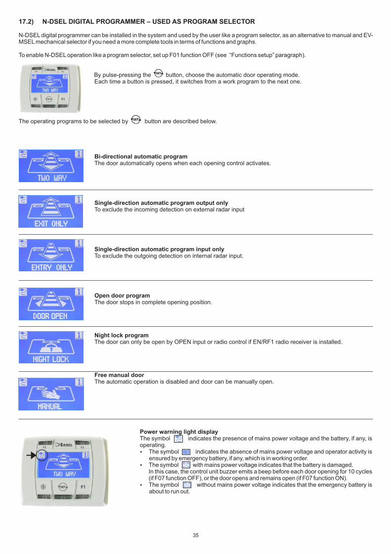
17.2) N-DSEL DIGITAL PROGRAMMER – USED AS PROGRAM SELECTOR
N-DSEL digital programmer can be installed in the system and used by the user like a program selector, as an alternative to manual and EV-MSEL mechanical selector if you need a more complete tools in terms of functions and graphs.
To enable N-DSEL operation like a program selector, set up F01 function OFF (see “Functions setup” paragraph).
By pulse-pressing the button, choose the automatic door operating mode. Each time a button is pressed, it switches from a work program to the next one.
The operating programs to be selected by button are described below.
Bi-directional automatic programThe door automatically opens when each opening control activates.
Single-direction automatic program output onlyTo exclude the incoming detection on external radar input
Single-direction automatic program input onlyTo exclude the outgoing detection on internal radar input.
Open door programThe door stops in complete opening position.
Night lock programThe door can only be open by OPEN input or radio control if EN/RF1 radio receiver is installed.
Free manual doorThe automatic operation is disabled and door can be manually open.
Power warning light displayThe symbol indicates the presence of mains power voltage and the battery, if any, is operating. The symbol indicates the absence of mains power voltage and operator activity is ensured by emergency battery, if any, which is in working order. The symbol with mains power voltage indicates that the battery is damaged.
In this case, the control unit buzzer emits a beep before each door opening for 10 cycles (if F07 function OFF), or the door opens and remains open (if F07 function ON).
The symbol without mains power voltage indicates that the emergency battery is about to run out.
35
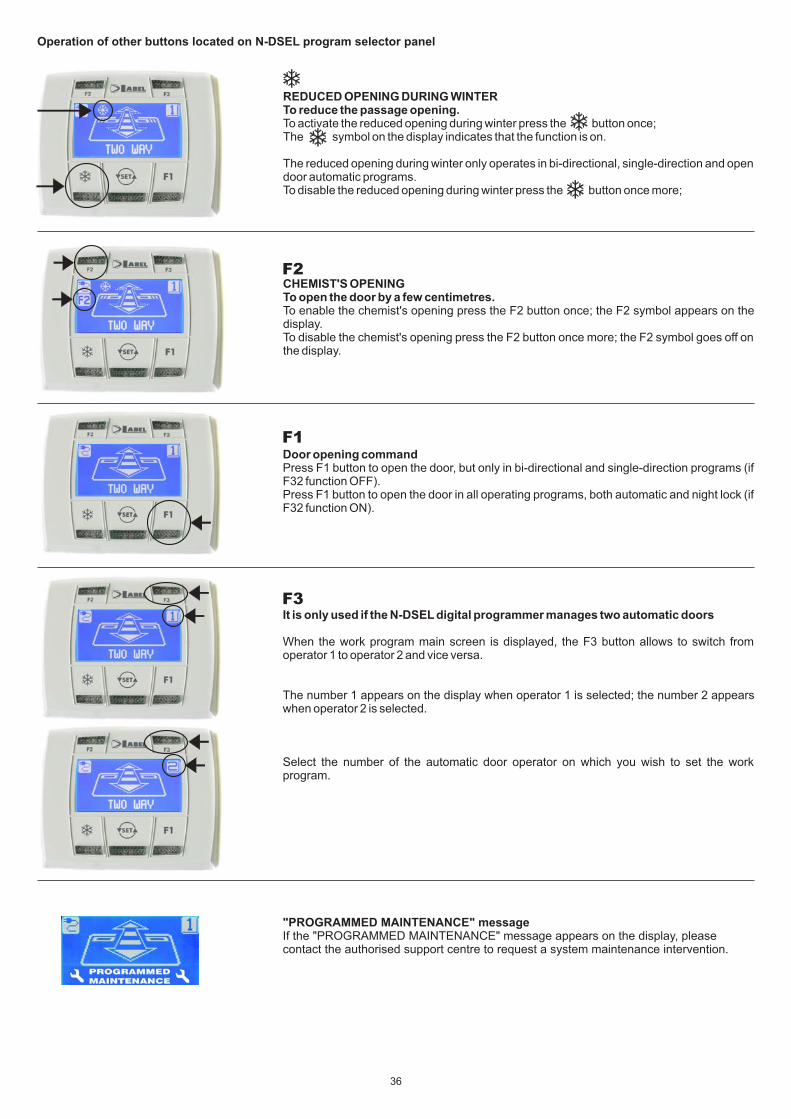
Door opening commandPress F1 button to open the door, but only in bi-directional and single-direction programs (if F32 function OFF).Press F1 button to open the door in all operating programs, both automatic and night lock (if F32 function ON).
It is only used if the N-DSEL digital programmer manages two automatic doors
When the work program main screen is displayed, the F3 button allows to switch from operator 1 to operator 2 and vice versa.
The number 1 appears on the display when operator 1 is selected; the number 2 appears when operator 2 is selected.
Select the number of the automatic door operator on which you wish to set the work program.
"PROGRAMMED MAINTENANCE" messageIf the "PROGRAMMED MAINTENANCE" message appears on the display, please contact the authorised support centre to request a system maintenance intervention.
Operation of other buttons located on N-DSEL program selector panel
REDUCED OPENING DURING WINTERTo reduce the passage opening.To activate the reduced opening during winter press the button once;The symbol on the display indicates that the function is on.
The reduced opening during winter only operates in bi-directional, single-direction and open door automatic programs. To disable the reduced opening during winter press the button once more;
CHEMIST'S OPENINGTo open the door by a few centimetres.To enable the chemist's opening press the F2 button once; the F2 symbol appears on the display.To disable the chemist's opening press the F2 button once more; the F2 symbol goes off on the display.
F2
F1
F3
36

18) GENERAL PROGRAMMING MENU
To enter the general programming menu while the automatic door operating program is shown on display, keep button pressed for about 5 seconds.
The programming menu consists of different sub-menus divided by subject (Diagram 1).
Choose the section you wish to access by pressing the F1 >> button.The selected menu icon is highlighted and the section title appears at the top of the display.
To enter the selected sub-menu, give a quick pulse on ENTER button.
To exit the general programming menu and return to the operating program view, press EXIT .
F1»
F1»
F1»
F1»
5”
UNUSED
UNUSED
F1»
F1»
F1»
Refer to par. 14.4 when entering the initial set-up section. If entering the serial communication setting section please refer to para. 14.3 For the other sub-menus, refer to the following paragraph on the section you have had access to
"SET-UP" SECTION
"FUNCTIONS AND POTENTIOMETERSSECTION"
"LANGUAGE" SECTION
"SERIAL COMMUNICATION SET UP" SECTION "PASSWORD MANAGEMENT"
SECTION
"SERVICE"SECTION
ENTER
EXIT EXIT EXIT EXIT
ENTER ENTER
EXIT EXIT EXITEXIT
ENTER ENTER ENTER
DIAGRAM 1
37
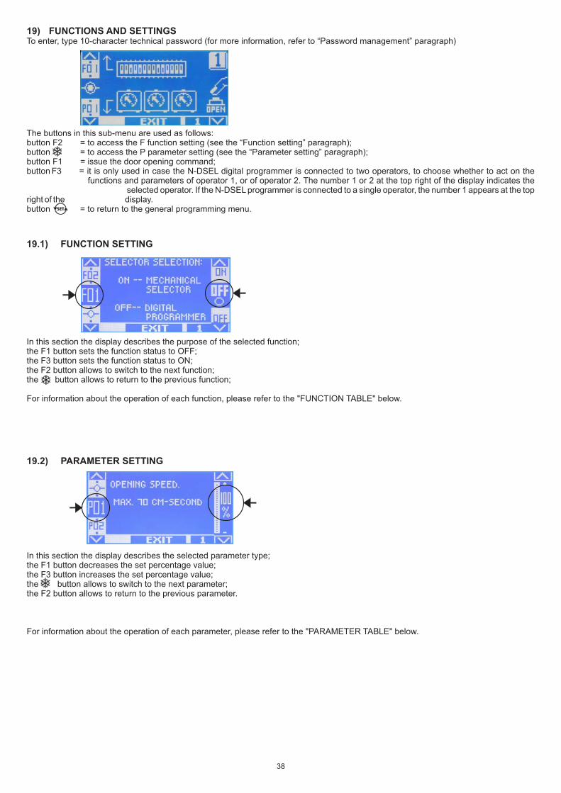
19) FUNCTIONS AND SETTINGSTo enter, type 10-character technical password (for more information, refer to “Password management” paragraph)
The buttons in this sub-menu are used as follows:button F2 = to access the F function setting (see the “Function setting” paragraph);button = to access the P parameter setting (see the “Parameter setting” paragraph);button F1 = issue the door opening command;button F3 = it is only used in case the N-DSEL digital programmer is connected to two operators, to choose whether to act on the functions and parameters of operator 1, or of operator 2. The number 1 or 2 at the top right of the display indicates the selected operator. If the N-DSEL programmer is connected to a single operator, the number 1 appears at the top right of the display.button = to return to the general programming menu.
19.1) FUNCTION SETTING
In this section the display describes the purpose of the selected function;the F1 button sets the function status to OFF;the F3 button sets the function status to ON; the F2 button allows to switch to the next function;the button allows to return to the previous function;
For information about the operation of each function, please refer to the "FUNCTION TABLE" below.
19.2) PARAMETER SETTING
In this section the display describes the selected parameter type;the F1 button decreases the set percentage value;the F3 button increases the set percentage value;the button allows to switch to the next parameter;the F2 button allows to return to the previous parameter.
For information about the operation of each parameter, please refer to the "PARAMETER TABLE" below.
38
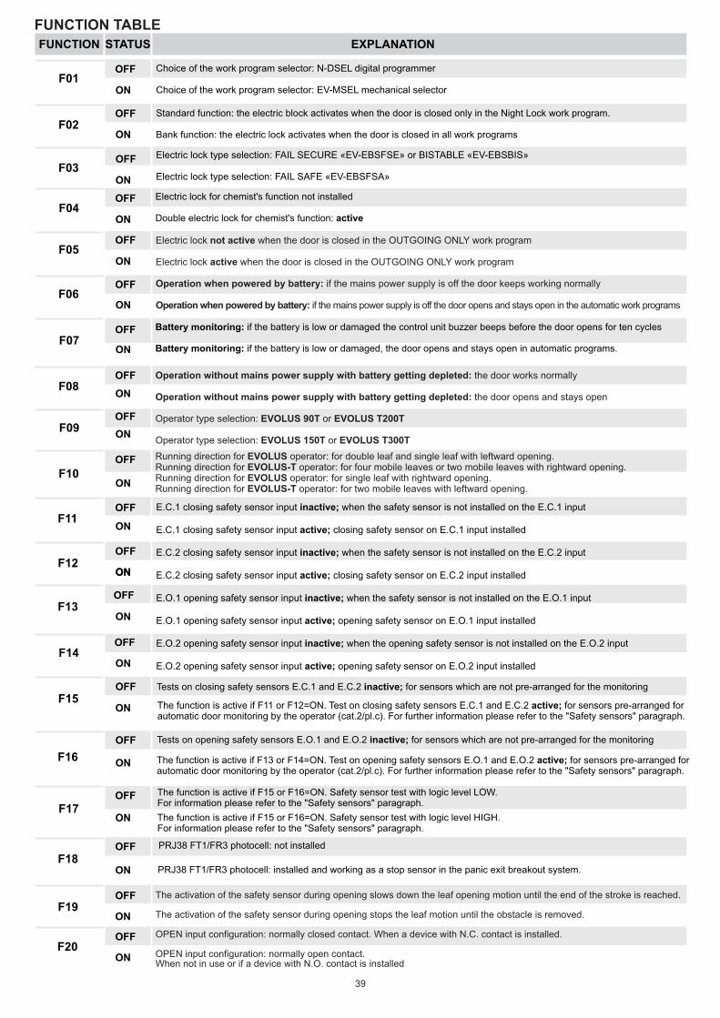
OFF
ONF01
FUNCTION EXPLANATION
Choice of the work program selector: N-DSEL digital programmer
Choice of the work program selector: EV-MSEL mechanical selector
OFF
ONF02
Standard function: the electric block activates when the door is closed only in the Night Lock work program.
Bank function: the electric lock activates when the door is closed in all work programs
OFF
ONF03
Electric lock type selection: FAIL SECURE «EV-EBSFSE» or BISTABLE «EV-EBSBIS»
Electric lock type selection: FAIL SAFE «EV-EBSFSA»
Electric lock for chemist's function not installed
Double electric lock for chemist's function: active
OFF
ONF04
OFF
ON
OFF
ON
F07OFF
ON
Battery monitoring: if the battery is low or damaged the control unit buzzer beeps before the door opens for ten cycles
Battery monitoring: if the battery is low or damaged, the door opens and stays open in automatic programs.
F08OFF
ON
F09OFF
ON
F10OFF
ON
F11OFF
ON
F12OFF
ON
F13OFF
ON
ON
F14OFF
ON
F15OFF
ON
Tests on closing safety sensors E.C.1 and E.C.2 inactive; for sensors which are not pre-arranged for the monitoring
The function is active if F11 or F12=ON. Test on closing safety sensors E.C.1 and E.C.2 active; for sensors pre-arranged for automatic door monitoring by the operator (cat.2/pl.c). For further information please refer to the "Safety sensors" paragraph.
F16
OFF
ON
Tests on opening safety sensors E.O.1 and E.O.2 inactive; for sensors which are not pre-arranged for the monitoring
The function is active if F13 or F14=ON. Test on opening safety sensors E.O.1 and E.O.2 active; for sensors pre-arranged for automatic door monitoring by the operator (cat.2/pl.c). For further information please refer to the "Safety sensors" paragraph.
F17OFF
ON The function is active if F15 or F16=ON. Safety sensor test with logic level HIGH.For information please refer to the "Safety sensors" paragraph.
F18OFF
ON
PRJ38 FT1/FR3 photocell: not installed
PRJ38 FT1/FR3 photocell: installed and working as a stop sensor in the panic exit breakout system.
F19OFF
ON
F20OFF
ON
F06
F05
FUNCTION TABLE
39
Electric lock not active when the door is closed in the OUTGOING ONLY work program
Electric lock active when the door is closed in the OUTGOING ONLY work program
Operation when powered by battery: if the mains power supply is off the door keeps working normally
Operation when powered by battery: if the mains power supply is off the door opens and stays open in the automatic work programs
Operation without mains power supply with battery getting depleted: the door works normally
Operation without mains power supply with battery getting depleted: the door opens and stays open
Operator type selection: EVOLUS 90T or EVOLUS T200T
Operator type selection: EVOLUS 150T or EVOLUS T300T
Running direction for EVOLUS operator: for double leaf and single leaf with leftward opening.Running direction for EVOLUS-T operator: for four mobile leaves or two mobile leaves with rightward opening.Running direction for EVOLUS operator: for single leaf with rightward opening.Running direction for EVOLUS-T operator: for two mobile leaves with leftward opening.
E.C.1 closing safety sensor input inactive; when the safety sensor is not installed on the E.C.1 input
E.C.1 closing safety sensor input active; closing safety sensor on E.C.1 input installed
E.C.2 closing safety sensor input inactive; when the safety sensor is not installed on the E.C.2 input
E.C.2 closing safety sensor input active; closing safety sensor on E.C.2 input installed
E.O.1 opening safety sensor input inactive; when the safety sensor is not installed on the E.O.1 input
E.O.1 opening safety sensor input active; opening safety sensor on E.O.1 input installed
E.O.2 opening safety sensor input inactive; when the opening safety sensor is not installed on the E.O.2 input
E.O.2 opening safety sensor input active; opening safety sensor on E.O.2 input installed
The function is active if F15 or F16=ON. Safety sensor test with logic level LOW.For information please refer to the "Safety sensors" paragraph.
The activation of the safety sensor during opening slows down the leaf opening motion until the end of the stroke is reached.
The activation of the safety sensor during opening stops the leaf motion until the obstacle is removed.
OPEN input configuration: normally closed contact. When a device with N.C. contact is installed.
OPEN input configuration: normally open contact.When not in use or if a device with N.O. contact is installed
STATUS
OFF
ONF21
OFF
ONF22
OFF
ONF23
In case of failure of the closing safety sensor test the door stays open
In case of failure of the closing safety sensor test the door closes slowly after 30 seconds
The function is active only if the total weight of the closing movable leaves has been set using the P35 parameter: single-leaf sliding door or telescopic door with two movable leaves. The function is active only if the total weight of the closing movable leaves has been set using the P35 parameter: double-leaf sliding door or telescopic door with four movable leaves.
OFF
ONF24
OFF
ONF25
F26OFF
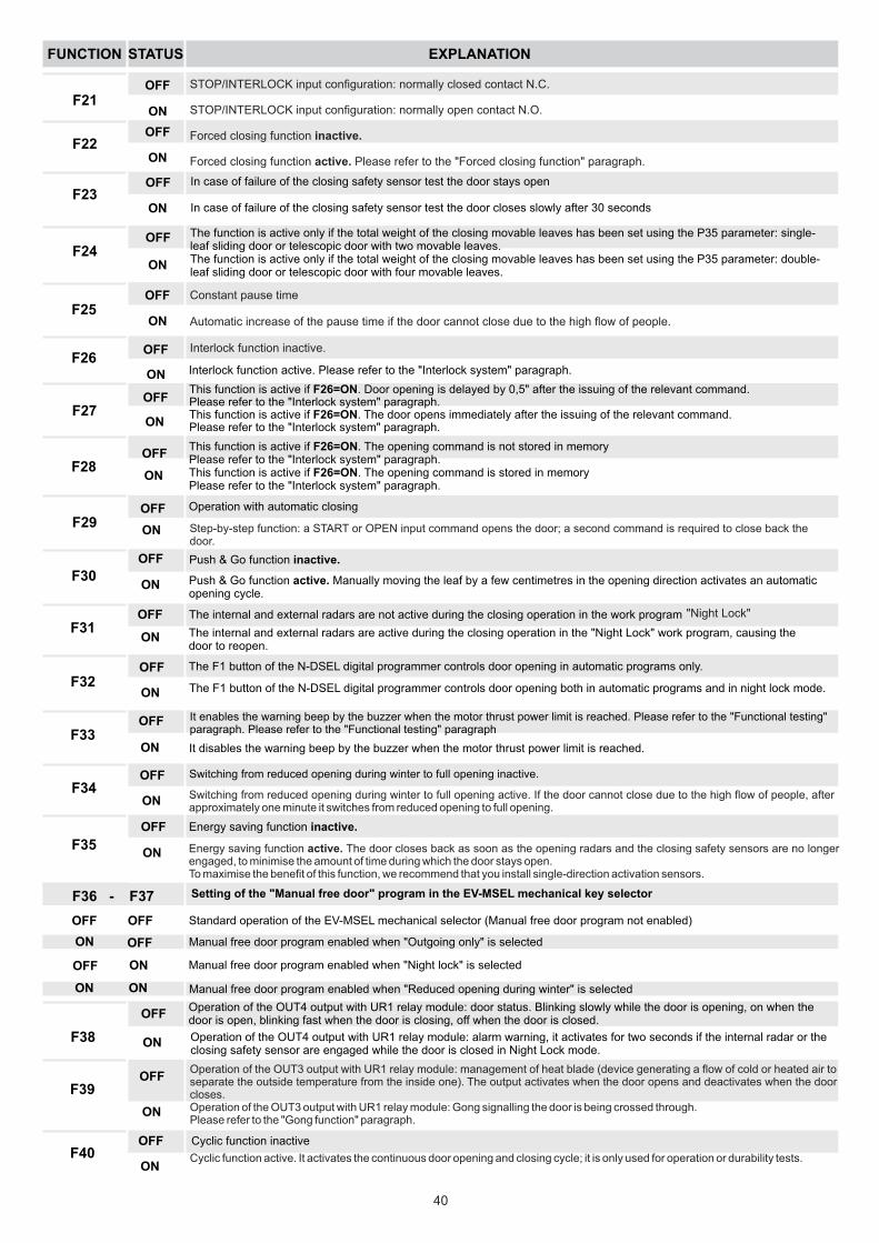
ON Interlock function active. Please refer to the "Interlock system" paragraph.
F27OFF
ON
This function is active if F26=ON. Door opening is delayed by 0,5" after the issuing of the relevant command. Please refer to the "Interlock system" paragraph.This function is active if F26=ON. The door opens immediately after the issuing of the relevant command.Please refer to the "Interlock system" paragraph.
F28OFF
ON
F29OFF Operation with automatic closing
ON
F30OFF
ON
F31OFF
ON
The internal and external radars are not active during the closing operation in the work program
F32OFF
ON
The F1 button of the N-DSEL digital programmer controls door opening in automatic programs only.
F33OFF
ON
It enables the warning beep by the buzzer when the motor thrust power limit is reached. Please refer to the "Functional testing" paragraph. Please refer to the "Functional testing" paragraph
F34OFF
ON
Switching from reduced opening during winter to full opening inactive.
F35
OFF
ON
F36 -
OFF
ON
F38
OFF
ON
Operation of the OUT4 output with UR1 relay module: door status. Blinking slowly while the door is opening, on when the door is open, blinking fast when the door is closing, off when the door is closed.
F39OFF
ON
F40OFF
ON
Cyclic function inactive
This function is active if F26=ON. The opening command is not stored in memory Please refer to the "Interlock system" paragraph.This function is active if F26=ON. The opening command is stored in memoryPlease refer to the "Interlock system" paragraph.
Push & Go function inactive.
Push & Go function active. Manually moving the leaf by a few centimetres in the opening direction activates an automatic opening cycle.
"Night Lock"
The internal and external radars are active during the closing operation in the "Night Lock" work program, causing the door to reopen.
The F1 button of the N-DSEL digital programmer controls door opening both in automatic programs and in night lock mode.
It disables the warning beep by the buzzer when the motor thrust power limit is reached.
Energy saving function inactive.
F37 Setting of the "Manual free door" program in the EV-MSEL mechanical key selector
OFF
OFF
OFF ON
ON ON
Standard operation of the EV-MSEL mechanical selector (Manual free door program not enabled)
Manual free door program enabled when "Outgoing only" is selected
Manual free door program enabled when "Night lock" is selected
Manual free door program enabled when "Reduced opening during winter" is selected
Operation of the OUT4 output with UR1 relay module: alarm warning, it activates for two seconds if the internal radar or the closing safety sensor are engaged while the door is closed in Night Lock mode.
FUNCTION EXPLANATION
40
STOP/INTERLOCK input configuration: normally closed contact N.C.
STOP/INTERLOCK input configuration: normally open contact N.O.
Forced closing function inactive.
Forced closing function active. Please refer to the "Forced closing function" paragraph.
Constant pause time
Automatic increase of the pause time if the door cannot close due to the high flow of people.
Interlock function inactive.
Step-by-step function: a START or OPEN input command opens the door; a second command is required to close back the door.
Energy saving function active. The door closes back as soon as the opening radars and the closing safety sensors are no longer engaged, to minimise the amount of time during which the door stays open.To maximise the benefit of this function, we recommend that you install single-direction activation sensors.
Switching from reduced opening during winter to full opening active. If the door cannot close due to the high flow of people, after approximately one minute it switches from reduced opening to full opening.
Operation of the OUT3 output with UR1 relay module: management of heat blade (device generating a flow of cold or heated air to separate the outside temperature from the inside one). The output activates when the door opens and deactivates when the door closes.Operation of the OUT3 output with UR1 relay module: Gong signalling the door is being crossed through.Please refer to the "Gong function" paragraph.
Cyclic function active. It activates the continuous door opening and closing cycle; it is only used for operation or durability tests.
STATUS
PARAMETER EXPLANATION
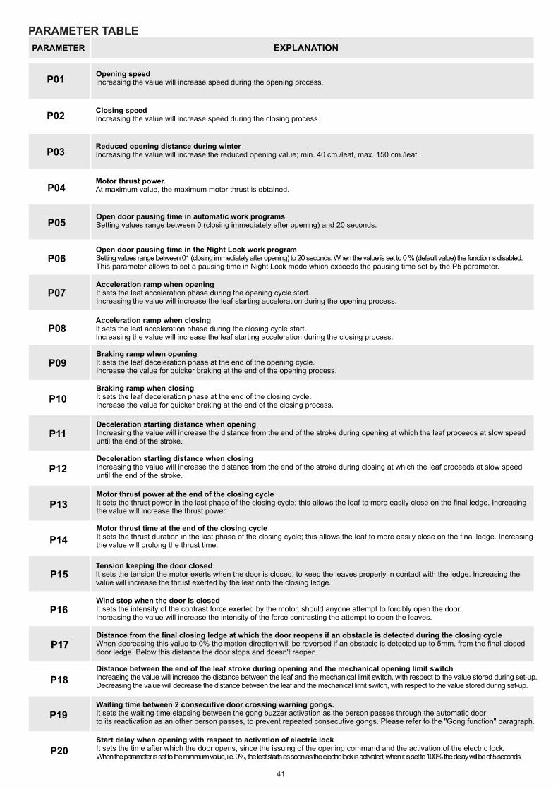
P01Opening speedIncreasing the value will increase speed during the opening process.
P02Closing speedIncreasing the value will increase speed during the closing process.
P03Reduced opening distance during winterIncreasing the value will increase the reduced opening value; min. 40 cm./leaf, max. 150 cm./leaf.
P04Motor thrust power.At maximum value, the maximum motor thrust is obtained.
P05Open door pausing time in automatic work programsSetting values range between 0 (closing immediately after opening) and 20 seconds.
P06Open door pausing time in the Night Lock work programSetting values range between 01 (closing immediately after opening) to 20 seconds. When the value is set to 0 % (default value) the function is disabled.This parameter allows to set a pausing time in Night Lock mode which exceeds the pausing time set by the P5 parameter.
P07Acceleration ramp when openingIt sets the leaf acceleration phase during the opening cycle start.Increasing the value will increase the leaf starting acceleration during the opening process.
P08Acceleration ramp when closingIt sets the leaf acceleration phase during the closing cycle start.Increasing the value will increase the leaf starting acceleration during the closing process.
P09
P10
P11
P12
P13
P14
Tension keeping the door closedIt sets the tension the motor exerts when the door is closed, to keep the leaves properly in contact with the ledge. Increasing the value will increase the thrust exerted by the leaf onto the closing ledge.
P15
P16Wind stop when the door is closedIt sets the intensity of the contrast force exerted by the motor, should anyone attempt to forcibly open the door.Increasing the value will increase the intensity of the force contrasting the attempt to open the leaves.
P17P17
P18
P19Waiting time between 2 consecutive door crossing warning gongs.It sets the waiting time elapsing between the gong buzzer activation as the person passes through the automatic door to its reactivation as an other person passes, to prevent repeated consecutive gongs. Please refer to the "Gong function" paragraph.
P20Start delay when opening with respect to activation of electric lockIt sets the time after which the door opens, since the issuing of the opening command and the activation of the electric lock.When the parameter is set to the minimum value, i.e. 0%, the leaf starts as soon as the electric lock is activated; when it is set to 100% the delay will be of 5 seconds.
PARAMETER TABLE
41
Braking ramp when openingIt sets the leaf deceleration phase at the end of the opening cycle.Increase the value for quicker braking at the end of the opening process.
Braking ramp when closingIt sets the leaf deceleration phase at the end of the closing cycle.Increase the value for quicker braking at the end of the closing process.
Deceleration starting distance when openingIncreasing the value will increase the distance from the end of the stroke during opening at which the leaf proceeds at slow speed until the end of the stroke.
Deceleration starting distance when closingIncreasing the value will increase the distance from the end of the stroke during closing at which the leaf proceeds at slow speed until the end of the stroke.
Motor thrust power at the end of the closing cycleIt sets the thrust power in the last phase of the closing cycle; this allows the leaf to more easily close on the final ledge. Increasing the value will increase the thrust power.
Motor thrust time at the end of the closing cycleIt sets the thrust duration in the last phase of the closing cycle; this allows the leaf to more easily close on the final ledge. Increasing the value will prolong the thrust time.
Distance from the final closing ledge at which the door reopens if an obstacle is detected during the closing cycleWhen decreasing this value to 0% the motion direction will be reversed if an obstacle is detected up to 5mm. from the final closed door ledge. Below this distance the door stops and doesn't reopen.
Distance between the end of the leaf stroke during opening and the mechanical opening limit switchIncreasing the value will increase the distance between the leaf and the mechanical limit switch, with respect to the value stored during set-up.Decreasing the value will decrease the distance between the leaf and the mechanical limit switch, with respect to the value stored during set-up.
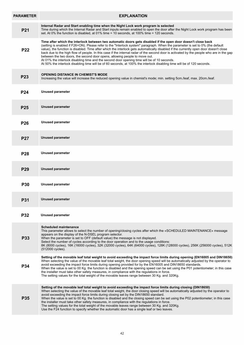
PARAMETER EXPLANATION
P21Internal Radar and Start enabling time when the Night Lock work program is selectedTime during which the Internal Radar and Start inputs remain enabled to open the door after the Night Lock work program has been set. At 0% the function is disabled, at 01% time = 10 seconds, at 100% time = 120 seconds.
P22
P23OPENING DISTANCE IN CHEMIST'S MODEIncreasing the value will increase the reduced opening value in chemist's mode; min. setting 5cm./leaf, max. 20cm./leaf.
P33
Scheduled maintenanceThis parameter allows to select the number of opening/closing cycles after which the «SCHEDULED MAINTENANCE» message appears on the display of the N-DSEL program selector.When the parameter is set to OFF (default value) the message is not displayed.Select the number of cycles according to the door operation and to the usage conditions:8K (8000 cycles), 16K (16000 cycles), 32K (32000 cycles), 64K (64000 cycles), 128K (128000 cycles), 256K (256000 cycles), 512K (512000 cycles).
P34
Setting of the movable leaf total weight to avoid exceeding the impact force limits during opening (EN16005 and DIN18650)When selecting the value of the movable leaf total weight, the door opening speed will be automatically adjusted by the operator to avoid exceeding the impact force limits during opening provided for by the EN16005 and DIN18650 standards.When the value is set to 00 Kg. the function is disabled and the opening speed can be set using the P01 potentiometer; in this case the installer must take other safety measures, in compliance with the regulations in force.The setting values for the total weight of the movable leaves range between 30 Kg. and 320Kg.
P24
P25
P26
P27
P28
P29
P30
P31
P32
Unused parameter
Unused parameter
Unused parameter
Unused parameter
Unused parameter
Unused parameter
Unused parameter
Unused parameter
Unused parameter
P35
Setting of the movable leaf total weight to avoid exceeding the impact force limits during closing (DIN18650)When selecting the value of the movable leaf total weight, the door closing speed will be automatically adjusted by the operator to avoid exceeding the impact force limits during closing set by the DIN18650 standard.When the value is set to 00 Kg. the function is disabled and the closing speed can be set using the P02 potentiometer; in this case the installer must take other safety measures, in compliance with the regulations in force.The setting values for the total weight of the movable leaves range between 30 Kg. and 320Kg.Use the F24 function to specify whether the automatic door has a single leaf or two leaves.
42
Time after which the interlock between two automatic doors gets disabled if the open door doesn't close back(setting is enabled if F26=ON). Please refer to the "Interlock system" paragraph. When the parameter is set to 0% (the default value), the function is disabled. Time after which the interlock gets automatically disabled if the currently open door doesn't close back due to the high flow of people. In this case if the internal radar of the second door is activated by the people who are in the gap between the two doors, the second door opens, allowing people to move out.At 01% the interlock disabling time and the second door opening time will be of 10 seconds.At 50% the interlock disabling time will be of 60 seconds, at 100% the interlock disabling time will be of 120 seconds.
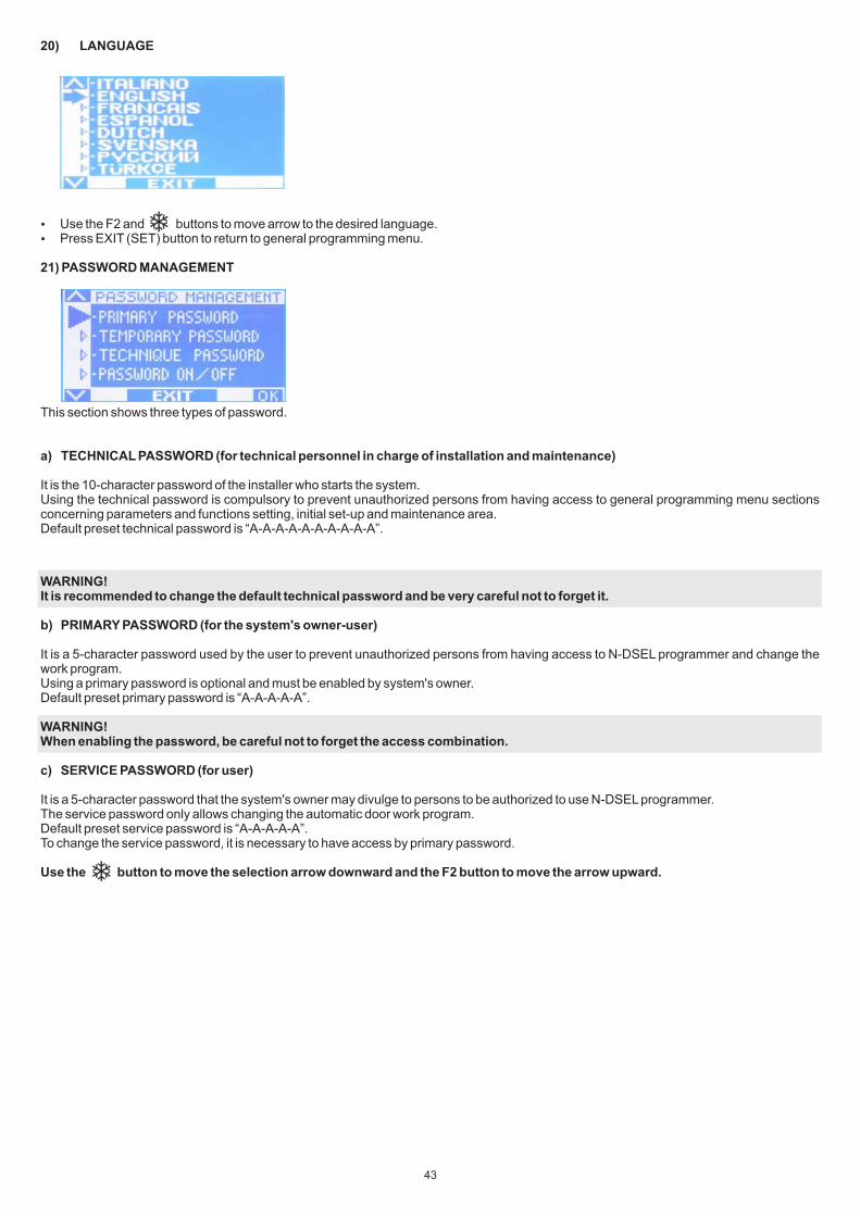
20) LANGUAGE
Use the F2 and buttons to move arrow to the desired language. Press EXIT (SET) button to return to general programming menu.
21) PASSWORD MANAGEMENT
This section shows three types of password.
a) TECHNICAL PASSWORD (for technical personnel in charge of installation and maintenance)
It is the 10-character password of the installer who starts the system.Using the technical password is compulsory to prevent unauthorized persons from having access to general programming menu sections concerning parameters and functions setting, initial set-up and maintenance area.Default preset technical password is “A-A-A-A-A-A-A-A-A-A”.
WARNING!It is recommended to change the default technical password and be very careful not to forget it.
b) PRIMARY PASSWORD (for the system's owner-user)
It is a 5-character password used by the user to prevent unauthorized persons from having access to N-DSEL programmer and change the work program.Using a primary password is optional and must be enabled by system's owner.Default preset primary password is “A-A-A-A-A”.
WARNING!When enabling the password, be careful not to forget the access combination.
c) SERVICE PASSWORD (for user)
It is a 5-character password that the system's owner may divulge to persons to be authorized to use N-DSEL programmer.The service password only allows changing the automatic door work program.Default preset service password is “A-A-A-A-A”.To change the service password, it is necessary to have access by primary password.
Use the button to move the selection arrow downward and the F2 button to move the arrow upward.
43

21.1) HOW TO CHANGE THE TECHNICAL PASSWORD
Select “TECHNICAL PASSWORD” Press OK (F1) button.
From this moment on, when having access to general programming to enter initial set-up, functions and adjustments, settings of serial communication and maintenance section, the new stored password needs to be typed. The password is not required afterwards, when switching sections without exiting the general programming menu. If the password typed is not correct, “PASSWORD ERROR” is shown on display and the general programming menu is restored.
21.2) HOW TO CHANGE THE PRIMARY PASSWORD
Select “PRIMARY PASSWORD” Press OK (F1) button.
Type the default preset technical password “A-A-A-A-A-A-A-A-A-A” by pressing 10 times on A button.
Type the new technical password, selecting a combination of 10 characters from the letters A-B-C-D.
It is required to repeat the new password, so type the previous combination again.
If the password typed is correct, “PASSWORD OK” is shown on display for one second and the general programming menu is restored.
Type the default preset primary password “A-A-A-A-A” by pressing 5 times on A button. (If the primary password is not the default password as it had already been changed before, type the currently-used primary password).
Type the new primary password, selecting a combination of 5 characters from the letters A-B-C-D.
44
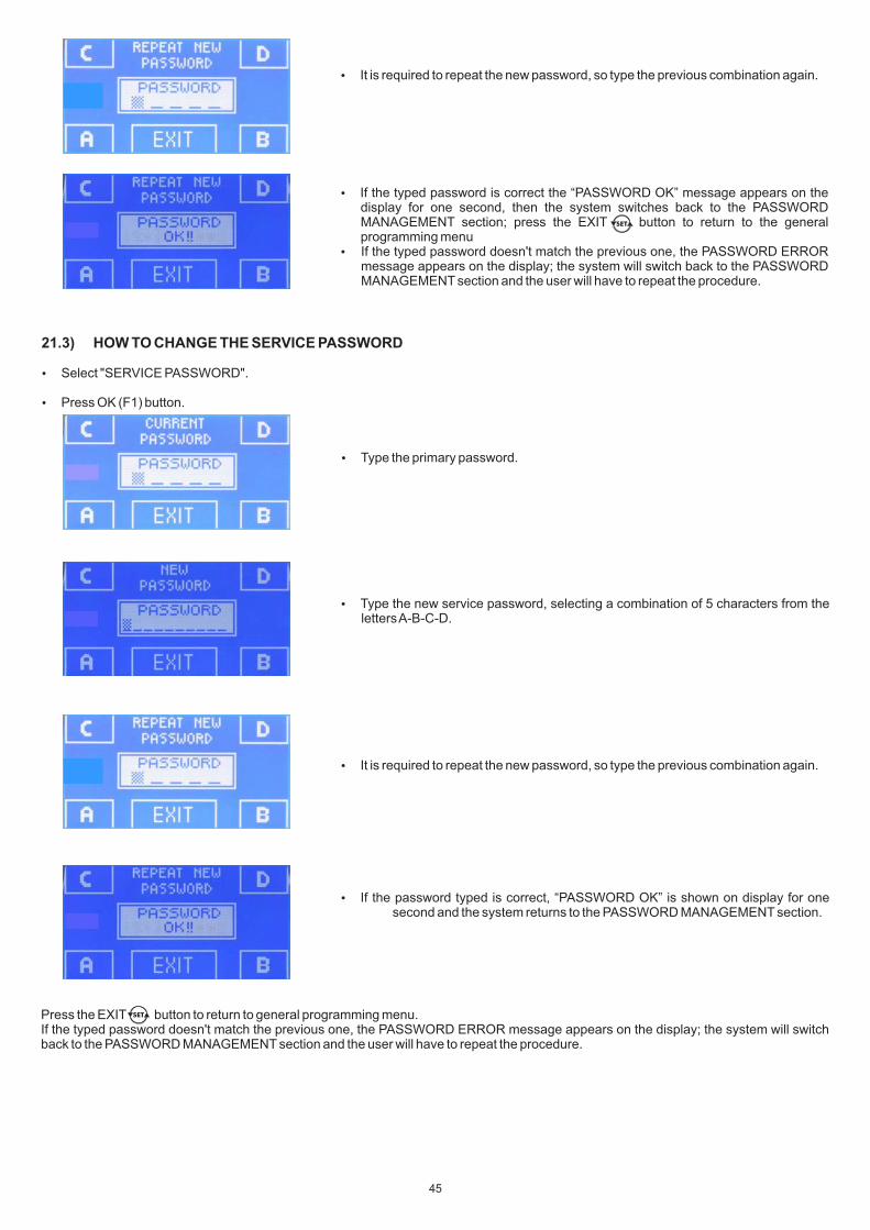
21.3) HOW TO CHANGE THE SERVICE PASSWORD
Select "SERVICE PASSWORD".
Press OK (F1) button.
It is required to repeat the new password, so type the previous combination again.
If the typed password is correct the “PASSWORD OK” message appears on the display for one second, then the system switches back to the PASSWORD MANAGEMENT section; press the EXIT button to return to the general programming menu
If the typed password doesn't match the previous one, the PASSWORD ERROR message appears on the display; the system will switch back to the PASSWORD MANAGEMENT section and the user will have to repeat the procedure.
Type the primary password.
Type the new service password, selecting a combination of 5 characters from the letters A-B-C-D.
It is required to repeat the new password, so type the previous combination again.
If the password typed is correct, “PASSWORD OK” is shown on display for one second and the system returns to the PASSWORD MANAGEMENT section.
Press the EXIT button to return to general programming menu.If the typed password doesn't match the previous one, the PASSWORD ERROR message appears on the display; the system will switch back to the PASSWORD MANAGEMENT section and the user will have to repeat the procedure.
45

21.4) ENABLING USER PASSWORD USAGE (primary and service)
Select “PASSWORD ON / OFF” Press OK (F1) button.
Press the ON button to enable the usage of user passwords and return to the PASSWORD MANAGEMENT menu. To return to the work program view press the EXIT button twice. From this moment on, whenever the user wants to access to N-DSEL digital programmer to change the automatic door work program, the primary or service password must be typed.
When the user decides to enable the password usage, it is recommended to change the combination of both primary and service password.
21.5) DISABLING USER PASSWORD USAGE
From the PASSWORD MANAGEMENT section, select “PASSWORD ON / OFF” Press OK (F1) button.
Press OFF (F1) button to disable user password usage. To return to the general programming menu press the EXIT button twice. From this moment on, the access to N-DSEL digital programmer like program selector is free.
Type the primary password.
Type the primary password.
46

22) INFORMATION AND EVENT MEMORY
N-DSEL digital programmer allows displaying information on automation and accessing to events memory, where fault errors are stored.
After displaying the automatic door work program, press the button for 5” to enter the information area (Diagram 2).
The buttons inside the information area are used as follows The v button allows to move to the next information or event in event memory. The ̂ F2 button allows to move to the next information or event in event memory. The F3 button is only used if the N-DSEL digital programmer is connected to two operators for the management of two automatic doors
and the symbol in the top right section of the display indicates 1 if the displayed information refer to operator 1, or 2 if they refer to operator 2.
Every touch on F3 button allows to switch from 1 to 2 and vice versa. If the N-DSEL programmer only manages a single operator the symbol "1" is displayed at the top right. The F1 button allows to switch to the event memory, to display error messages; press it again to return to the information area The EXIT button allows to return to main view of the door work program.
5”
EVENT MEMORY
ERROR
I1 I2 I3 I4 I5 I6F2 F2 F2 F2 F2
F1
EVENT MEMORY
ERRORF1
EVENT MEMORY
ERRORF1
EVENT MEMORY
ERRORF1
EVENT MEMORY
ERRORF1
EVENT MEMORY
ERRORF1
INFORMATION AREA
INFO
E1 E2 E3 E4 E5F2 F2 F2 F2
F1
INFORMATION AREA
INFOF1
INFORMATION AREA
INFOF1
INFORMATION AREA
INFOF1
INFORMATION AREA
INFOF1
The purpose of the diagram is illustrating the path to be followed to view the information and the event memory; the texts included in figures refer to the memory cells appearing on the left side of the display when viewing the information or the errors.
DIAGRAM 2
47
I1, I2, ... = INFORMATION AREAE1, E2, ... = EVENT MEMORY

MEANING
It identifies the EV-LOGIC2 control unit serial code.
It displays the software release of the EV-LOGIC2 control unit A microcontroller.
It displays the software release of the EV-LOGIC2 control unit B microcontroller.
Identification number including data for manufacturer use
INFORMATION AREA
NUMBER
I1
I2
I3
I4
I5
I6
INFORMATION
Serial number
Partial counter
Total cycles
A microcontroller version
B microcontroller version
Identification number
It displays the door opening/closing cycles which have been carried out since the latest maintenance intervention. This counter must be reset by the person in charge of maintenance after each intervention (please refer to the "Maintenance" paragraph).
It displays the door opening/closing cycles which have been carried out since the first start-up of the operator.
Refer to the following tables for the list of information and error messages.
The events memory stores the last 5 error messages in chronological order.When all the 5 memory cells are full of messages, the following event stored shall be located in E1 cell, the other memory events are shifted by one position and the event in E5 cell shall be deleted.The events memory stores messages, divided into warnings and errors.Stored errors are signalled by displaying the symbol directly from the main screen of the work program; access the events memory to show the relevant message.The warnings stored are not shown in the main screen of work program, but only stored in events memory.
48

SYMBOL MESSAGE ON DISPLAY
SYMBOL MESSAGE ON DISPLAY ACTION
WARNINGS
ERRORS
Massages which may be displayed in cells E1 through E5
The microcontroller operation check has detected a fault.
The system restores automatically after a few seconds. If the problem persists it is an issue with the EV-LOGIC2 control unit.
49
You need to turn the main 230V power supply OFF and then ON again after a few seconds.If the problem persists it is a defect on the EV-LOGIC2 control unit.
Check that the leaf slides properly and that there are no obstacles along the path it follows; also check that motor and encoder are connected, then repeat the set-up attempt.You need to turn the main 230V power supply OFF and then ON again after a few seconds.Check that the motor runs, that the motor and encoder connectors are properly plugged in and that the encoder and motor cables are not damaged.
The operator has not managed to complete the initial set-up.
You need to turn the main 230V power supply OFF and then ON again after a few seconds.If the problem persists it is an issue with the EV-LOGIC2 control unit or the encoder.
You need to turn the main 230V power supply OFF and then ON again after a few seconds.If the problem persists it is an issue with the EV-LOGIC2 control unit.
You need to turn the main 230V power supply OFF and then ON again after a few seconds.If the problem persists it is a defect on the EV-LOGIC2 control unit.
The system restores automatically after a few seconds and carries out an other testing attempt.If the problem persists it is a defect on the EV-LOGIC2 control unit.
Failed cyclic internal test of the current detect circuit.
CURRENT FAULT
POWER FAULT
INITIAL SETTING ERROR
ENCODER OR MOTOR ERROR
ENCODER FAULT
OPENING SAFETY SENSOR ERROR
CLOSING SAFETY SENSOR ERROR
BATTERY FAULT
BRAKING FAULT
BATTERY FAULT
EEPROM REGISTER FAULT
WATCH DOG ERROR
The motor piloting signal test has detected a fault.
Signals from the encoder are not detected.
Fault detected during the encoder operation test.
Failed opening safety sensor test.
Failed closing safety sensor test.
The system signals a damage to the battery.
The closing brake signal test has detected a fault.
Failed internal memory register test.
SOFTWARE RESET
OPENING OBSTACLE
CLOSING OBSTACLE
BATTERY DISCHARGED
Generic malfunction which triggered a microcontroller reset.
The door has come into contact with an obstacle while closing; this caused the motion direction to be reversed.
The door has come into contact with an obstacle during opening; this caused the motion direction to be reversed.
Low battery charge warning in the absence of mains power supply, during battery-powered operation.
System restoration is automatic.
If the problem persists, remove the obstacle or check that the leaf slides properly.
If the problem persists, remove the obstacle or check that the leaf slides properly.
As soon as the mains power supply is restored the battery will be recharged.
Check that the test settings and parameters are correct, that the test has also be enabled on the safety sensor and that the electrical connections between sensor and control unit are correct.
Check that the test settings and parameters are correct, that the test has also be enabled on the safety sensor and that the electrical connections between sensor and control unit are correct.
During operation the battery is constantly monitored. Should the system signal any damage to it, check that the battery and the battery charger board are working properly.
MEANING
MEANING
EVENT MEMORY
PROBLEM RESOLUTION

23) MAINTENANCE
To enter, type the 10-character technical password (for more information, refer to “Password management” paragraph).
This section is only accessed to reset any error existing in the event memory and the partial counter of the door opening/closing cycles.The event memory and partial counter reset must be performed by specialized personnel only during routine maintenance, after performing all system operation checks.
The buttons in this section are used as follows:
The v button allows to move forward in the reset type selection. The ̂ F2 button allows to return to the previous reset. F1 (OK) button allows to confirm data resetting for the selected reset type. The F3 button is only used if the N-DSEL digital programmer is connected to two operators for the management of two automatic doors and the symbol in the top right section of the display indicates 1 if the reset operations refer to operator 1, or 2 if they refer to operator 2. Every touch on F3 button allows to switch from 1 to 2 and vice versa. If the N-DSEL programmer only manages a single operator the symbol "1" is displayed at the top right.
50
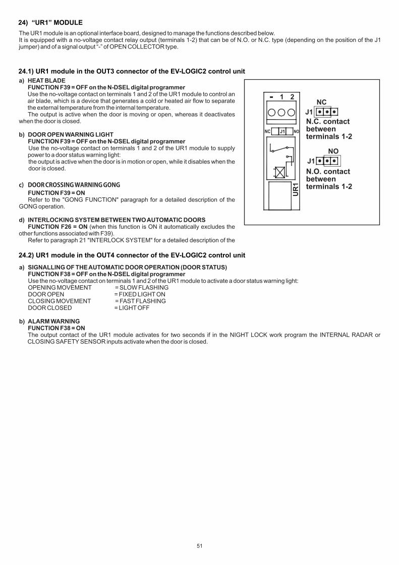
24) “UR1” MODULE
a) HEAT BLADEFUNCTION F39 = OFF on the N-DSEL digital programmer
Use the no-voltage contact on terminals 1 and 2 of the UR1 module to control an air blade, which is a device that generates a cold or heated air flow to separate the external temperature from the internal temperature. The output is active when the door is moving or open, whereas it deactivates when the door is closed.
b) DOOR OPEN WARNING LIGHT FUNCTION F39 = OFF on the N-DSEL digital programmer Use the no-voltage contact on terminals 1 and 2 of the UR1 module to supply
power to a door status warning light: the output is active when the door is in motion or open, while it disables when the door is closed.
c)� DOOR�CROSSING�WARNING�GONG FUNCTION F39 = ON Refer to the "GONG FUNCTION" paragraph for a detailed description of the GONG operation.
d) INTERLOCKING SYSTEM BETWEEN TWO AUTOMATIC DOORS FUNCTION F26 = ON (when this function is ON it automatically excludes the other functions associated with F39). Refer to paragraph 21 "INTERLOCK SYSTEM" for a detailed description of the
NC
J1
NO
J1
1 2-
NC NOJ1
N.C. contact between terminals 1-2
N.O. contact between terminals 1-2
UR
1
The UR1 module is an optional interface board, designed to manage the functions described below.It is equipped with a no-voltage contact relay output (terminals 1-2) that can be of N.O. or N.C. type (depending on the position of the J1 jumper) and of a signal output “-” of OPEN COLLECTOR type.
24.1) UR1 module in the OUT3 connector of the EV-LOGIC2 control unit
24.2) UR1 module in the OUT4 connector of the EV-LOGIC2 control unit
a) SIGNALLING OF THE AUTOMATIC DOOR OPERATION (DOOR STATUS) FUNCTION F38 = OFF on the N-DSEL digital programmer Use the no-voltage contact on terminals 1 and 2 of the UR1 module to activate a door status warning light: OPENING MOVEMENT = SLOW FLASHING DOOR OPEN = FIXED LIGHT ON CLOSING MOVEMENT = FAST FLASHING DOOR CLOSED = LIGHT OFF
b) ALARM WARNING FUNCTION F38 = ON The output contact of the UR1 module activates for two seconds if in the NIGHT LOCK work program the INTERNAL RADAR or
CLOSING SAFETY SENSOR inputs activate when the door is closed.
51
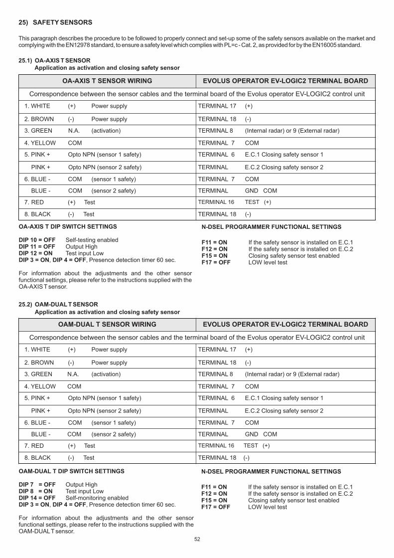
25) SAFETY SENSORS
This paragraph describes the procedure to be followed to properly connect and set-up some of the safety sensors available on the market and complying with the EN12978 standard, to ensure a safety level which complies with PL=c - Cat. 2, as provided for by the EN16005 standard.
25.1) OA-AXIS T SENSOR
OA-AXIS T SENSOR WIRING EVOLUS OPERATOR EV-LOGIC2 TERMINAL BOARD
Correspondence between the sensor cables and the terminal board of the Evolus operator EV-LOGIC2 control unit
1. WHITE (+) Power supply TERMINAL 17 (+)
2. BROWN (-) Power supply TERMINAL 18 (-)
3. GREEN N.A. (activation) TERMINAL 8 (Internal radar) or 9 (External radar)
4. YELLOW COM TERMINAL 7 COM
5. PINK + Opto NPN (sensor 1 safety) TERMINAL 6 E.C.1 Closing safety sensor 1
PINK + Opto NPN (sensor 2 safety) TERMINAL E.C.2 Closing safety sensor 2
6. BLUE - COM (sensor 1 safety) TERMINAL 7 COM
BLUE - COM (sensor 2 safety) TERMINAL GND COM
7. RED (+) Test TERMINAL 16 TEST (+)
8. BLACK (-) Test TERMINAL 18 (-)
OA-AXIS T DIP SWITCH SETTINGS DIP 10 = OFF Self-testing enabledDIP 11 = OFF Output HighDIP 12 = ON Test input LowDIP 3 = ON, DIP 4 = OFF, Presence detection timer 60 sec.
For information about the adjustments and the other sensor functional settings, please refer to the instructions supplied with the OA-AXIS T sensor.
N-DSEL PROGRAMMER FUNCTIONAL SETTINGS
F11 = ON If the safety sensor is installed on E.C.1 F12 = ON If the safety sensor is installed on E.C.2 F15 = ON Closing safety sensor test enabledF17 = OFF LOW level test
25.2) OAM-DUAL T SENSOR
OAM-DUAL T SENSOR WIRING EVOLUS OPERATOR EV-LOGIC2 TERMINAL BOARD
Correspondence between the sensor cables and the terminal board of the Evolus operator EV-LOGIC2 control unit
1. WHITE (+) Power supply TERMINAL 17 (+)
2. BROWN (-) Power supply TERMINAL 18 (-)
3. GREEN N.A. (activation) TERMINAL 8 (Internal radar) or 9 (External radar)
4. YELLOW COM TERMINAL 7 COM
5. PINK + Opto NPN (sensor 1 safety) TERMINAL 6 E.C.1 Closing safety sensor 1
PINK + Opto NPN (sensor 2 safety) TERMINAL E.C.2 Closing safety sensor 2
6. BLUE - COM (sensor 1 safety) TERMINAL 7 COM
BLUE - COM (sensor 2 safety) TERMINAL GND COM
7. RED (+) Test TERMINAL 16 TEST (+)
8. BLACK (-) Test TERMINAL 18 (-)
OAM-DUAL T DIP SWITCH SETTINGS
DIP 7 = OFF Output HighDIP 8 = ON Test input LowDIP 14 = OFF Self-monitoring enabledDIP 3 = ON, DIP 4 = OFF, Presence detection timer 60 sec.
For information about the adjustments and the other sensor functional settings, please refer to the instructions supplied with the OAM-DUAL T sensor.
N-DSEL PROGRAMMER FUNCTIONAL SETTINGS
F11 = ON If the safety sensor is installed on E.C.1 F12 = ON If the safety sensor is installed on E.C.2 F15 = ON Closing safety sensor test enabledF17 = OFF LOW level test
Application as activation and closing safety sensor
Application as activation and closing safety sensor
52
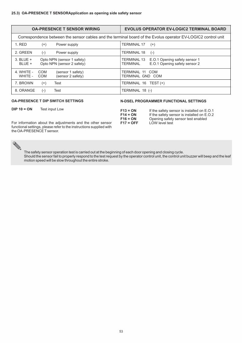
OA-PRESENCE T SENSOR WIRING EVOLUS OPERATOR EV-LOGIC2 TERMINAL BOARD
Correspondence between the sensor cables and the terminal board of the Evolus operator EV-LOGIC2 control unit
1. RED (+) Power supply TERMINAL 17 (+)
2. GREEN (-) Power supply TERMINAL 18 (-)
3. BLUE + Opto NPN (sensor 1 safety) BLUE + Opto NPN (sensor 2 safety)
TERMINAL 13 E.O.1 Opening safety sensor 1TERMINAL E.O.1 Opening safety sensor 2
4. WHITE - COM (sensor 1 safety) WHITE - COM (sensor 2 safety)
TERMINAL 11 COMTERMINAL GND COM
7. BROWN (+) Test TERMINAL 16 TEST (+)
8. ORANGE (-) Test TERMINAL 18 (-)
OA-PRESENCE T DIP SWITCH SETTINGS
DIP 10 = ON Test input Low
For information about the adjustments and the other sensor functional settings, please refer to the instructions supplied with the OA-PRESENCE T sensor.
N-DSEL PROGRAMMER FUNCTIONAL SETTINGS
F13 = ON If the safety sensor is installed on E.O.1F14 = ON If the safety sensor is installed on E.O.2 F16 = ON Opening safety sensor test enabledF17 = OFF LOW level test
The safety sensor operation test is carried out at the beginning of each door opening and closing cycle.Should the sensor fail to properly respond to the test request by the operator control unit, the control unit buzzer will beep and the leaf motion speed will be slow throughout the entire stroke.
25.3) OA-PRESENCE T SENSORApplication as opening side safety sensor
53

26) GONG FUNCTION
The GONG function is a entry warning triggered by the activation of the closing safety sensor (that is the sensor connected to the E.C.1 terminal, or to the E.C.2 terminal) while the automatic door is being crossed.To enable the GONG operation set the F39 function to ON on the N-DSEL digital programmer and insert the UR1 module into the J7 (OUT3) connector of the EV-LOGIC2 control unit.
f) Now the GONG function is definitely ON.By crossing the automatic door and by engaging the closing safety sensors the audible indication of the GONG will sound for 2 seconds; the GONG will then be inhibited for the waiting time set previously with P19.Once the waiting time has expired, the GONG will be activated again for 2 seconds if the door is crossed, engaging the closing safety sensors.
WARNING! If the interlocking function is used (F26 ON), the gong function will be automatically set to OFF.
Perform the following operations to activate the GONG function:
a) Use the UR1 module (please refer to paragraph 24) and insert it into the J7-OUT 3 connector of the EV-LOGIC2 control unit.b) Select the N.O contact between terminals 1-2 of the UR1 module by means of jumper J1.c) Connect the entry warning buzzer (GONG) by connecting the power supply to the voltage-free contact at terminals 1-2 of the UR1
module. The diagram above illustrates the electrical connection in the case a 12Vdc supply is used, by taking the power supply directly from terminals 17-18 of the EV-LOGIC2 control unit.
d) To activate the GONG function use the N-DSEL digital programmer and set function F39 to ON;at this point each time that the safety sensors are operated when closing the door the GONG will sound for 2 seconds.
e) To change the waiting time elapsing from when the GONG buzzer is activated to the next time it is activated, engaging the closing safety sensors, act on the P19 parameter on the N-DSEL digital programmer. This waiting time is used to prevent the buzzer from sounding continuously in the case of the passage of a high number of people. This time is reset when the door is completely closed. The table below provides some information about the waiting times according to the set value of P19.
GONG FUNCTION DIAGRAM
EV-LOGIC2 CONTROL UNIT
F39 on N-DSEL programmer
GONG FUNCTION ON
GONG FUNCTION OFF
ON
OFF
P19 on N-DSEL programmer
Waiting time between 2 consecutive door crossing warning GONGS.00% = GONG disabled;01% = immediate02% to 100% = 1 second to 4 minutes.
BA
TT
ER
Y C
HA
RG
ER
P19 = Waiting time between 2 consecutive door crossing warning gong activationsP19 at 00%P19 at 01% (default)P19 at 02%P19 at 05%P19 at 10%P19 at 15%P19 at 20%P19 at 25%P19 at 50%P19 at 100%
GONG OFFImmediate activation at each passage1 second interval5 seconds interval15 seconds interval30 seconds interval45 seconds interval60 seconds interval120 seconds interval255 seconds interval
54
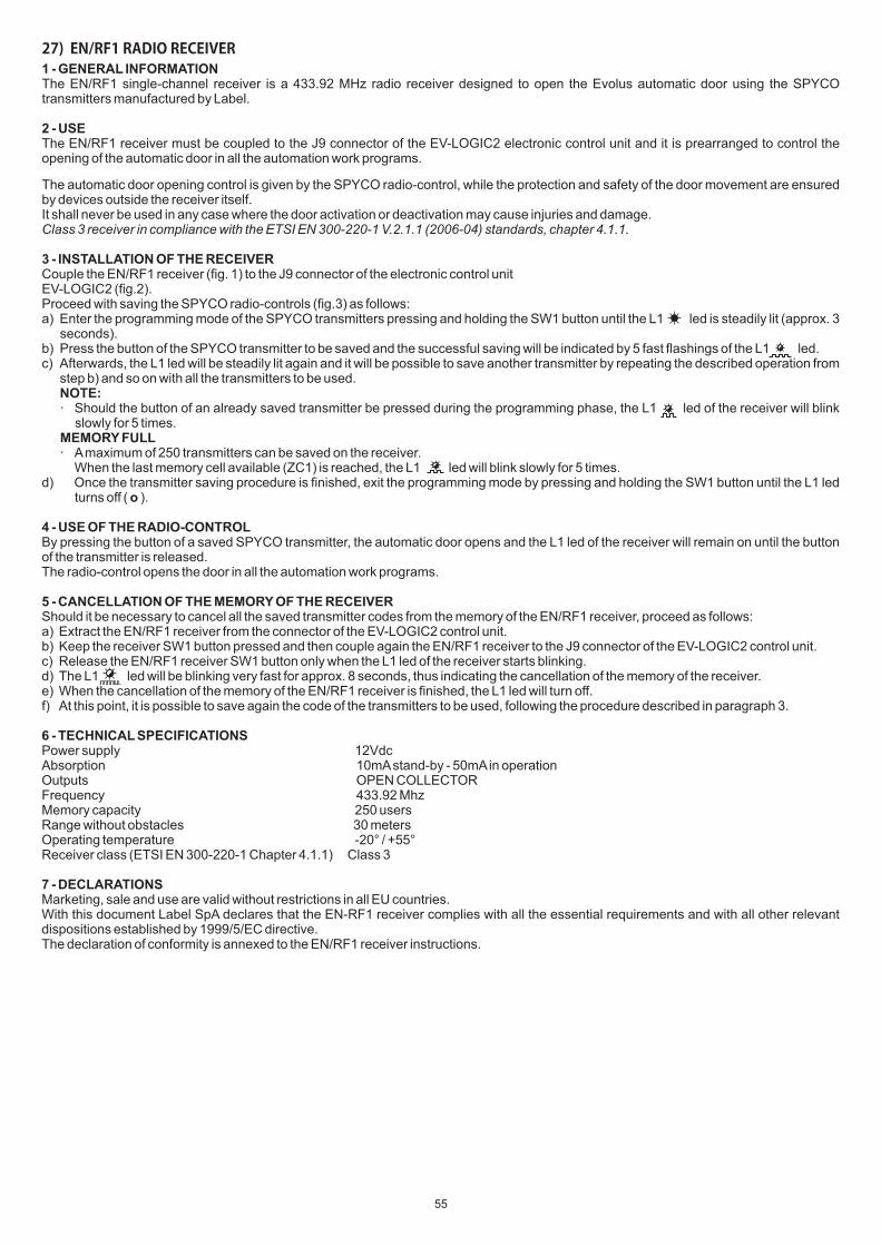
1 - GENERAL INFORMATIONThe EN/RF1 single-channel receiver is a 433.92 MHz radio receiver designed to open the Evolus automatic door using the SPYCO transmitters manufactured by Label.
2 - USEThe EN/RF1 receiver must be coupled to the J9 connector of the EV-LOGIC2 electronic control unit and it is prearranged to control the opening of the automatic door in all the automation work programs.
The automatic door opening control is given by the SPYCO radio-control, while the protection and safety of the door movement are ensured by devices outside the receiver itself.It shall never be used in any case where the door activation or deactivation may cause injuries and damage.Class 3 receiver in compliance with the ETSI EN 300-220-1 V.2.1.1 (2006-04) standards, chapter 4.1.1.
3 - INSTALLATION OF THE RECEIVERCouple the EN/RF1 receiver (fig. 1) to the J9 connector of the electronic control unit EV-LOGIC2 (fig.2).Proceed with saving the SPYCO radio-controls (fig.3) as follows:a) Enter the programming mode of the SPYCO transmitters pressing and holding the SW1 button until the L1 led is steadily lit (approx. 3
seconds).b) Press the button of the SPYCO transmitter to be saved and the successful saving will be indicated by 5 fast flashings of the L1 led.c) Afterwards, the L1 led will be steadily lit again and it will be possible to save another transmitter by repeating the described operation from
step b) and so on with all the transmitters to be used.NOTE:· Should the button of an already saved transmitter be pressed during the programming phase, the L1 led of the receiver will blink
slowly for 5 times.MEMORY FULL· A maximum of 250 transmitters can be saved on the receiver.
When the last memory cell available (ZC1) is reached, the L1 led will blink slowly for 5 times.d) Once the transmitter saving procedure is finished, exit the programming mode by pressing and holding the SW1 button until the L1 led
turns off ( o ).
4 - USE OF THE RADIO-CONTROLBy pressing the button of a saved SPYCO transmitter, the automatic door opens and the L1 led of the receiver will remain on until the button of the transmitter is released.The radio-control opens the door in all the automation work programs.
5 - CANCELLATION OF THE MEMORY OF THE RECEIVERShould it be necessary to cancel all the saved transmitter codes from the memory of the EN/RF1 receiver, proceed as follows:a) Extract the EN/RF1 receiver from the connector of the EV-LOGIC2 control unit.b) Keep the receiver SW1 button pressed and then couple again the EN/RF1 receiver to the J9 connector of the EV-LOGIC2 control unit.c) Release the EN/RF1 receiver SW1 button only when the L1 led of the receiver starts blinking.d) The L1 led will be blinking very fast for approx. 8 seconds, thus indicating the cancellation of the memory of the receiver.e) When the cancellation of the memory of the EN/RF1 receiver is finished, the L1 led will turn off.f) At this point, it is possible to save again the code of the transmitters to be used, following the procedure described in paragraph 3.
6 - TECHNICAL SPECIFICATIONSPower supply 12VdcAbsorption 10mA stand-by - 50mA in operationOutputs OPEN COLLECTORFrequency 433.92 MhzMemory capacity 250 usersRange without obstacles 30 metersOperating temperature -20° / +55°Receiver class (ETSI EN 300-220-1 Chapter 4.1.1) Class 3
7 - DECLARATIONSMarketing, sale and use are valid without restrictions in all EU countries.With this document Label SpA declares that the EN-RF1 receiver complies with all the essential requirements and with all other relevant dispositions established by 1999/5/EC directive.The declaration of conformity is annexed to the EN/RF1 receiver instructions.
27)��EN/RF1�RADIO�RECEIVER
55
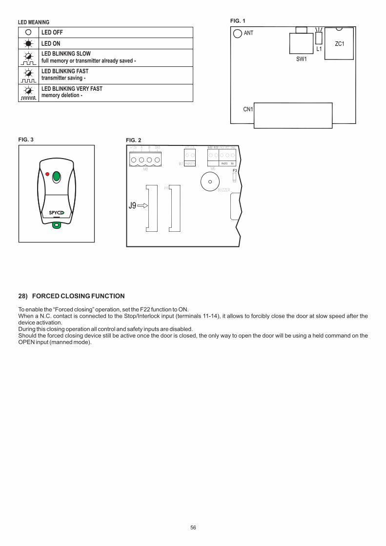
LED BLINKING SLOWfull memory or transmitter already saved -
LED OFF
LED ON
LED MEANING
LED BLINKING FASTtransmitter saving -
LED BLINKING VERY FASTmemory deletion -
FIG. 1
FIG. 2
SPYCSPYC
1 3
FIG. 3
28) FORCED CLOSING FUNCTION
To enable the “Forced closing” operation, set the F22 function to ON. When a N.C. contact is connected to the Stop/Interlock input (terminals 11-14), it allows to forcibly close the door at slow speed after the device activation.During this closing operation all control and safety inputs are disabled.Should the forced closing device still be active once the door is closed, the only way to open the door will be using a held command on the OPEN input (manned mode).
E.O.2 E.C.2
PHOTO RX
56

If you wish to by-pass the interlock operation and allow the two doors to operate independently, you need to connect an ON / OFF switch in parallel between terminals 12 (AUX1) and 7 (Common) of both operator control units.This way when the switch contact is open the interlock is enabled, while when the switch contact is closed the interlock is disabled and the two automatic doors can operate independently.
To enable interlocked operation you need to install the N-DSEL digital programmer as program selector. You cannot use the EV-MSEL mechanical key selector.
29) INTERLOCK SYSTEM
The interlock system is used to connect two automatic doors when a door can only open if the other is closed.For the electrical connection between the EV-LOGIC2 control units of the two operators you need to use a UR1 module (optional) for each control unit. Plug the UR1 module into the J7-OUT3 connector of the EV-LOGIC2 control unit.
29.1) ELECTRICAL CONNECTION FOR INTERLOCK
The above diagram shows the electrical connection between the two doors ensuring that they are interlocked during operation.· Terminal 11 (COM) of control unit 1 must be connected to terminal 2 of its own UR1 module.· Terminal 1 of the UR1 module of control unit 1 must be connected to terminal 14 (STOP/I) of control unit 2.· Terminal 11 (COM) of control unit 2 must be connected to terminal 2 of its own UR1 module.· Terminal 1 of the UR1 module of control unit 2 must be connected to terminal 14 (STOP/I) of control unit 1.· Terminals 7 (COM) of both control units must be connected to each other.
The dotted line of the ON/OFF switch connected to the AUX/1 input is used to disable the interlock operation (connection not essential for the system operation).Switch OFF (contact open): interlock ONSwitch ON (contact closed): interlock OFF.
BATTE
RY
CH
AR
GE
R
START AUX1 STOP/ICOM10 11 12 13 14 15
M4
WD
EV-LOGIC2 DOOR 1
BATTE
RY
CH
AR
GE
R
FR3 VDC GND E.C.1 RADIN RADEX START AUX1 AUX2STOP/I +13V 0TESTCOMCOM5 6 7 8 9 10 11 12 13 14 15 16 17 18
M3M4M5
F3
DL8
DL3
DL4
DL5
E1 E2 WD
PS1
START J3 J4 J5 J6 J7LOCK 1 LOCK 2 OUT 3J8
OU
T 4
ENCODER MOTOR
2 1 -
UR1
J1=NA
MP1X1
SWITCHON/OFF
FR3 VDC GND RADIN RADEX AUX2 +13V 0TESTCOM5 6 7 8 9 16 17 18
M3M5
F3
DL8
DL3
DL4
DL5
E1 E2
PS1
START J3 J4 J5 J6 J7LOCK 1 LOCK 2 OUT 3J8
OU
T 4
ENCODER MOTOR
2 1 -
UR1
J1=NA
MP1X1
OPEN E.O.2
EV-LOGIC2 DOOR 2
E.C.1OPEN E.O.2
57
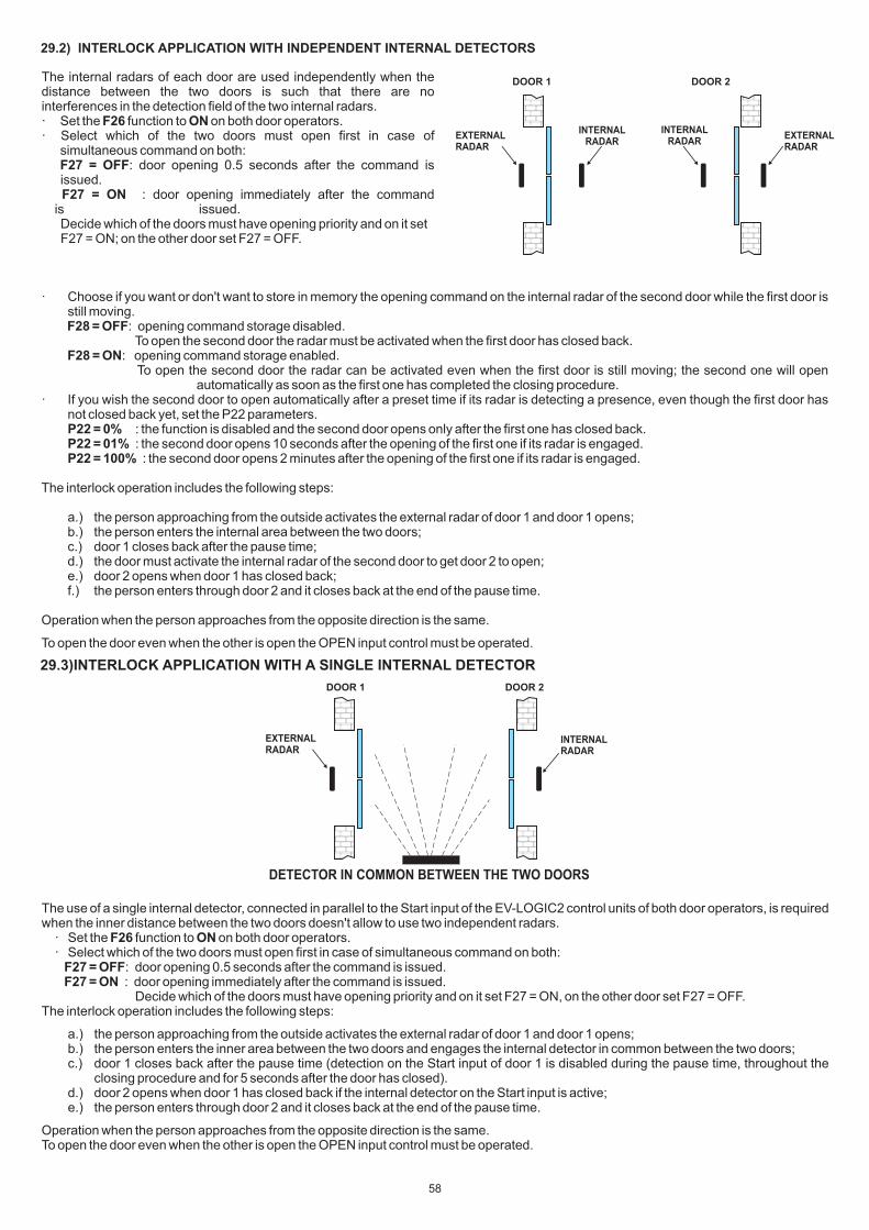
The use of a single internal detector, connected in parallel to the Start input of the EV-LOGIC2 control units of both door operators, is required when the inner distance between the two doors doesn't allow to use two independent radars.
· Set the F26 function to ON on both door operators.· Select which of the two doors must open first in case of simultaneous command on both: F27 = OFF: door opening 0.5 seconds after the command is issued. F27 = ON : door opening immediately after the command is issued. Decide which of the doors must have opening priority and on it set F27 = ON, on the other door set F27 = OFF.
The interlock operation includes the following steps:
a.) the person approaching from the outside activates the external radar of door 1 and door 1 opens;b.) the person enters the inner area between the two doors and engages the internal detector in common between the two doors;c.) door 1 closes back after the pause time (detection on the Start input of door 1 is disabled during the pause time, throughout the
closing procedure and for 5 seconds after the door has closed).d.) door 2 opens when door 1 has closed back if the internal detector on the Start input is active;e.) the person enters through door 2 and it closes back at the end of the pause time.
Operation when the person approaches from the opposite direction is the same.To open the door even when the other is open the OPEN input control must be operated.
DETECTOR IN COMMON BETWEEN THE TWO DOORS
INTERNAL RADAR
DOOR 1 DOOR 2
EXTERNAL RADAR
· Choose if you want or don't want to store in memory the opening command on the internal radar of the second door while the first door is still moving.
F28 = OFF: opening command storage disabled. To open the second door the radar must be activated when the first door has closed back. F28 = ON: opening command storage enabled. To open the second door the radar can be activated even when the first door is still moving; the second one will open automatically as soon as the first one has completed the closing procedure.
· If you wish the second door to open automatically after a preset time if its radar is detecting a presence, even though the first door has not closed back yet, set the P22 parameters.P22 = 0% : the function is disabled and the second door opens only after the first one has closed back.P22 = 01% : the second door opens 10 seconds after the opening of the first one if its radar is engaged.P22 = 100% : the second door opens 2 minutes after the opening of the first one if its radar is engaged.
The interlock operation includes the following steps:
a.) the person approaching from the outside activates the external radar of door 1 and door 1 opens;b.) the person enters the internal area between the two doors;c.) door 1 closes back after the pause time;d.) the door must activate the internal radar of the second door to get door 2 to open;e.) door 2 opens when door 1 has closed back;f.) the person enters through door 2 and it closes back at the end of the pause time.
Operation when the person approaches from the opposite direction is the same.
To open the door even when the other is open the OPEN input control must be operated.
29.3) INTERLOCK APPLICATION WITH A SINGLE INTERNAL DETECTOR
EXTERNAL RADAR
DOOR 1 DOOR 2The internal radars of each door are used independently when the distance between the two doors is such that there are no interferences in the detection field of the two internal radars.· Set the F26 function to ON on both door operators.· Select which of the two doors must open first in case of
simultaneous command on both: F27 = OFF: door opening 0.5 seconds after the command is issued.
F27 = ON : door opening immediately after the command is issued. Decide which of the doors must have opening priority and on it set F27 = ON; on the other door set F27 = OFF.
29.2) INTERLOCK APPLICATION WITH INDEPENDENT INTERNAL DETECTORS
INTERNAL RADAR
EXTERNAL RADAR
INTERNAL RADAR
58
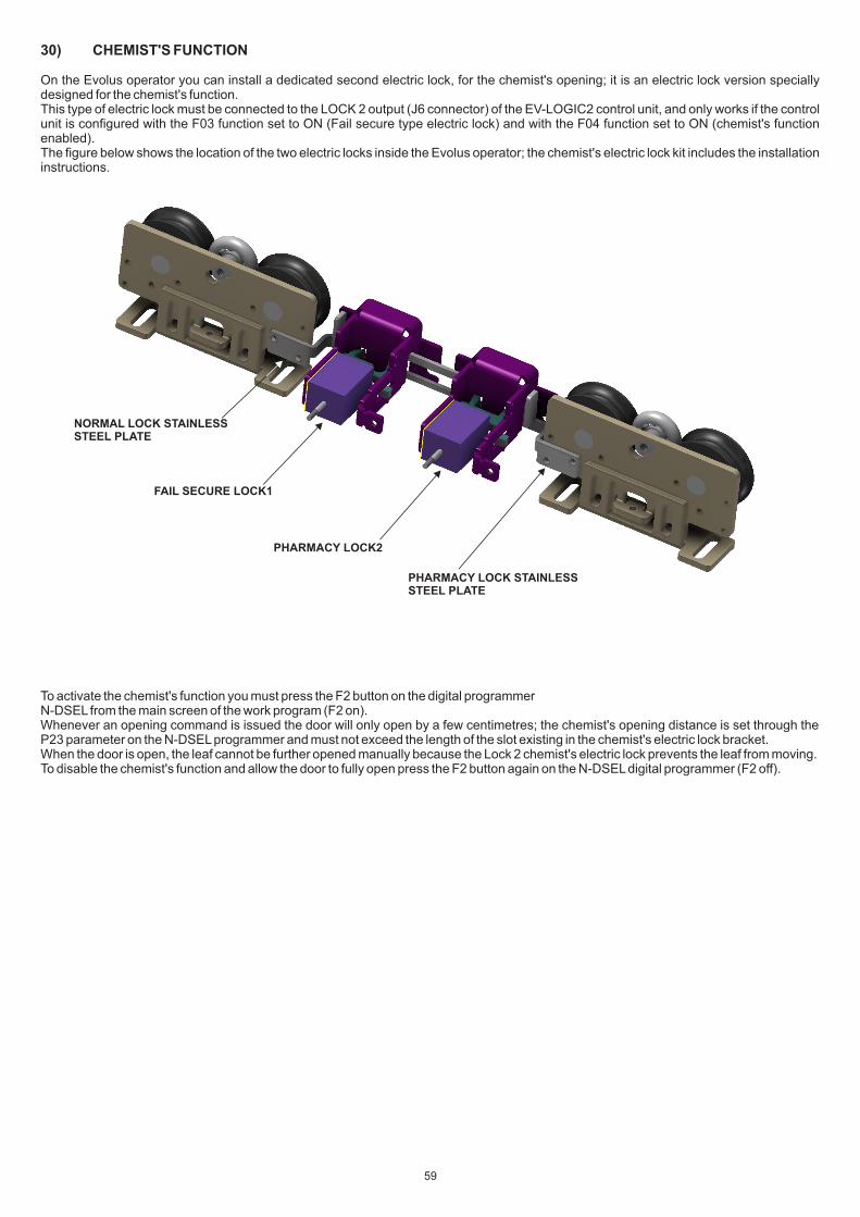
30) CHEMIST'S FUNCTION
On the Evolus operator you can install a dedicated second electric lock, for the chemist's opening; it is an electric lock version specially designed for the chemist's function. This type of electric lock must be connected to the LOCK 2 output (J6 connector) of the EV-LOGIC2 control unit, and only works if the control unit is configured with the F03 function set to ON (Fail secure type electric lock) and with the F04 function set to ON (chemist's function enabled).The figure below shows the location of the two electric locks inside the Evolus operator; the chemist's electric lock kit includes the installation instructions.
To activate the chemist's function you must press the F2 button on the digital programmerN-DSEL from the main screen of the work program (F2 on).Whenever an opening command is issued the door will only open by a few centimetres; the chemist's opening distance is set through the P23 parameter on the N-DSEL programmer and must not exceed the length of the slot existing in the chemist's electric lock bracket.When the door is open, the leaf cannot be further opened manually because the Lock 2 chemist's electric lock prevents the leaf from moving.To disable the chemist's function and allow the door to fully open press the F2 button again on the N-DSEL digital programmer (F2 off).
NORMAL LOCK STAINLESSSTEEL PLATE
FAIL SECURE LOCK1
PHARMACY LOCK2
PHARMACY LOCK STAINLESSSTEEL PLATE
59
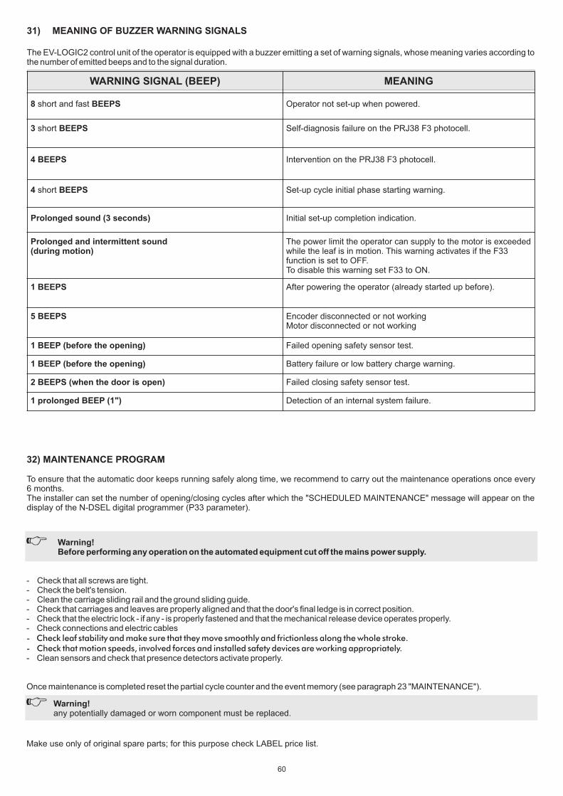
31) MEANING OF BUZZER WARNING SIGNALS
The EV-LOGIC2 control unit of the operator is equipped with a buzzer emitting a set of warning signals, whose meaning varies according to the number of emitted beeps and to the signal duration.
WARNING SIGNAL (BEEP) MEANING
8 short and fast BEEPS Operator not set-up when powered.
3 short BEEPS Self-diagnosis failure on the PRJ38 F3 photocell.
4 BEEPS Intervention on the PRJ38 F3 photocell.
4 short BEEPS Set-up cycle initial phase starting warning.
Prolonged sound (3 seconds) Initial set-up completion indication.
Prolonged and intermittent sound (during motion)
The power limit the operator can supply to the motor is exceeded while the leaf is in motion. This warning activates if the F33 function is set to OFF.To disable this warning set F33 to ON.
1 BEEPS After powering the operator (already started up before).
5 BEEPS Encoder disconnected or not workingMotor disconnected or not working
1 BEEP (before the opening) Failed opening safety sensor test.
1 BEEP (before the opening) Battery failure or low battery charge warning.
2 BEEPS (when the door is open) Failed closing safety sensor test.
1 prolonged BEEP (1") Detection of an internal system failure.
- Check that all screws are tight.- Check the belt's tension.- Clean the carriage sliding rail and the ground sliding guide.- Check that carriages and leaves are properly aligned and that the door's final ledge is in correct position.- Check that the electric lock - if any - is properly fastened and that the mechanical release device operates properly.- Check connections and electric cables- Check leaf stability and make sure that they move smoothly and frictionless along the whole stroke.- Check that motion speeds, involved forces and installed safety devices are working appropriately.- Clean sensors and check that presence detectors activate properly.
Once maintenance is completed reset the partial cycle counter and the event memory (see paragraph 23 "MAINTENANCE").
Make use only of original spare parts; for this purpose check LABEL price list.
32) MAINTENANCE PROGRAM
To ensure that the automatic door keeps running safely along time, we recommend to carry out the maintenance operations once every 6 months.The installer can set the number of opening/closing cycles after which the "SCHEDULED MAINTENANCE" message will appear on the display of the N-DSEL digital programmer (P33 parameter).
Warning!Before performing any operation on the automated equipment cut off the mains power supply.
Warning!any potentially damaged or worn component must be replaced.
60
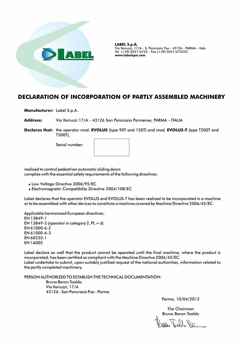
Manufacturer: Label S.p.A.
Address: Via Ilariuzzi 17/A - 43126 San Pancrazio Parmense, PARMA - ITALIA
Declares that: the operator mod. EVOLUS (type 90T and 150T) and mod. EVOLUS-T (type T200T and T300T),
Serial number:
realized to control pedestrian automatic sliding doorscomplies with the essential safety requirements of the following directives:
Low Voltage Directive 2006/95/EC Electromagnetic Compatibility Directive 2004/108/EC
Label declares that the operator EVOLUS and EVOLUS-T has been realized to be incorporated in a machine or to be assembled with other devices to constitute a machine covered by Machine Directive 2006/42/EC.
Applicable harmonised European directives:EN 13849-1EN 13849-2 (operator in category 2, PL = d)EN 61000-6-2EN 61000-6-3EN 60335-1EN 16005
Label declare as well that the product cannot be operated until the final machine, where the product is incorporated, has been certified as compliant with the Machine Directive 2006/42/EC.Label undertake to submit, upon suitably justified request of the national authorities, information related to the partly completed machinery.
PERSON AUTHORIZED TO ESTABLISH THE TECHNICAL DOCUMENTATION: Bruno Baron Toaldo Via Ilariuzzi, 17/A 43126 - San Pancrazio P.se - Parma
Parma, 10/04/2013
The ChairmanBruno Baron Toaldo
DECLARATION OF INCORPORATION OF PARTLY ASSEMBLED MACHINERY
LABEL S.p.A.Via Ilariuzzi, 17/A - S. Pancrazio P.se - 43126 - PARMA - Italy Tel. (+39) 0521/6752 - Fax (+39) 0521/675222 www.labelspa.com

notes

notes

Via Ilariuzzi, 17/A - S. Pancrazio P.se - 43126 PARMA - ITALIATel. (+39) 05 21/ 67 52 - Fax (+39) 05 21/ 67 52 22
[email protected] - www.labelspa.com
S.p.A.
CERTIFIED COMPANYQUALITY SYSTEM
UNI EN ISO 9001:2000
Made in Italyby
Copyright © 2022 FDOKUMEN