
Time-integrated pointers for enabling the analysis of detailed reaction mechanisms
15
Time-Integrated Pointers for Enabling the Analysis of Detailed Reaction Mechanisms Ioannis P. Androulakis and Jeffrey M. Grenda Corporate Strategic Research, ExxonMobil Research and Engineering, Annandale, NJ 08801 Joseph W. Bozzelli Dept. of Chemistry, New Jersey Institute of Technology, Newark, NJ 07102 DOI 10.1002/aic.10263 Published online in Wiley InterScience (www.interscience.wiley.com). A procedure for deriving time-integrated pointers to capture element transformations during numerical integration runs, on complex chemical mechanisms, is introduced. The principal advantage is that the resulting temporally integrated pointers allow derivation of importance criteria; and these weight the contribution of all species and reactions during the reaction interval. This approach quantifies the sources and sinks of reactions active over a period of time in terms of element flux. It provides identification of key reaction pathways and the derivation of a reduced skeletal representation at minimum computational cost, in the elementary mechanism analysis. We extend the analysis to more complex systems, such as burner-stabilized flames, that are governed by both reaction and diffusion. Here, we illustrate how some reaction pathways are altered in the presence of diffusion. Finally a new coupling of mechanism generation and mechanism reduction, which significantly reduces the computational burden associated with automated kinetic mechanism generation, is presented. The concepts are demonstrated with examples involving high- and low-temperature oxidation of hydrocarbons. © 2004 American Institute of Chemical Engineers AIChE J, 50: 2956 –2970, 2004 Introduction The demand for detailed fundamental kinetic mechanisms continues to be driven by the desire to develop methods for making accurate predictions and optimizing processes involv- ing complex chemical reacting systems, such as hydrocarbon or waste combustion and atmospheric chemistry. Use of accu- rate mechanisms for fundamental chemical understanding to achieve controls or optimum conversion is important for such a process to achieve improved efficiency or meet projected environmental regulations. Numerous detailed kinetic mechanisms have been manually constructed for a wide range of combustion and chemical process applications (Curran et al., 1998a,b; Dean, 1990; Mims et al., 1994; Westbrook, 2002). Most models are constructed based on extensive compilations of elementary chemical reac- tions, using kinetic parameters derived from a combination of experimental measurements, model estimates from computa- tional chemistry, and generic estimation of thermodynamic properties. Significant activity has been directed at understand- ing the fundamental processes associated with hydrocarbon oxidation and internal combustion engine efficiency by using models to optimize the combined engine–fuel system (Callahan et al., 1996; Kimura et al., 2001; Westbrook et al., 2001). Several models have been presented, for example, that extend prototype fuel feeds into the octane range, where these are related to ongoing low-temperature combustion improvements in automotive applications. There are also positive computational advances enabling automated kinetic mechanism generation (Broadbelt et al., Correspondence concerning this article should be addressed to I. P. Androulakis at Chemical and Biochemical Engineering Dept., Rutgers-The State University of New Jersey, Piscataway, NJ 08854; E-mail: [email protected]. © 2004 American Institute of Chemical Engineers 2956 AIChE Journal November 2004 Vol. 50, No. 11
Transcript of Time-integrated pointers for enabling the analysis of detailed reaction mechanisms
Time-Integrated Pointers for Enabling theAnalysis of Detailed Reaction Mechanisms
Ioannis P. Androulakis and Jeffrey M. GrendaCorporate Strategic Research, ExxonMobil Research and Engineering, Annandale, NJ 08801
Joseph W. BozzelliDept. of Chemistry, New Jersey Institute of Technology, Newark, NJ 07102
DOI 10.1002/aic.10263Published online in Wiley InterScience (www.interscience.wiley.com).
A procedure for deriving time-integrated pointers to capture element transformationsduring numerical integration runs, on complex chemical mechanisms, is introduced. Theprincipal advantage is that the resulting temporally integrated pointers allow derivationof importance criteria; and these weight the contribution of all species and reactionsduring the reaction interval. This approach quantifies the sources and sinks of reactionsactive over a period of time in terms of element flux. It provides identification of keyreaction pathways and the derivation of a reduced skeletal representation at minimumcomputational cost, in the elementary mechanism analysis. We extend the analysis to morecomplex systems, such as burner-stabilized flames, that are governed by both reaction anddiffusion. Here, we illustrate how some reaction pathways are altered in the presence ofdiffusion. Finally a new coupling of mechanism generation and mechanism reduction,which significantly reduces the computational burden associated with automated kineticmechanism generation, is presented. The concepts are demonstrated with examplesinvolving high- and low-temperature oxidation of hydrocarbons. © 2004 American Instituteof Chemical Engineers AIChE J, 50: 2956–2970, 2004
Introduction
The demand for detailed fundamental kinetic mechanismscontinues to be driven by the desire to develop methods formaking accurate predictions and optimizing processes involv-ing complex chemical reacting systems, such as hydrocarbonor waste combustion and atmospheric chemistry. Use of accu-rate mechanisms for fundamental chemical understanding toachieve controls or optimum conversion is important for sucha process to achieve improved efficiency or meet projectedenvironmental regulations.
Numerous detailed kinetic mechanisms have been manuallyconstructed for a wide range of combustion and chemical
process applications (Curran et al., 1998a,b; Dean, 1990; Mimset al., 1994; Westbrook, 2002). Most models are constructedbased on extensive compilations of elementary chemical reac-tions, using kinetic parameters derived from a combination ofexperimental measurements, model estimates from computa-tional chemistry, and generic estimation of thermodynamicproperties. Significant activity has been directed at understand-ing the fundamental processes associated with hydrocarbonoxidation and internal combustion engine efficiency by usingmodels to optimize the combined engine–fuel system (Callahanet al., 1996; Kimura et al., 2001; Westbrook et al., 2001).Several models have been presented, for example, that extendprototype fuel feeds into the octane range, where these arerelated to ongoing low-temperature combustion improvementsin automotive applications.
There are also positive computational advances enablingautomated kinetic mechanism generation (Broadbelt et al.,
Correspondence concerning this article should be addressed to I. P. Androulakis atChemical and Biochemical Engineering Dept., Rutgers-The State University of NewJersey, Piscataway, NJ 08854; E-mail: [email protected].
© 2004 American Institute of Chemical Engineers
2956 AIChE JournalNovember 2004 Vol. 50, No. 11
1994; Chevalier et al., 1992; Grenda et al.; 2001, 2002; Susnowet al., 1997; Warth et al., 2000). These codes enable thegeneration of such mechanisms; but the mechanisms are usu-ally so large, that are they difficult to implement directly. Thegenerated models provide significant kinetic insight and mod-eling capabilities, but also have major difficulties in applicationbecause of the enormous number of species and reactions thatare created. Models often include up to a thousand or morespecies and several thousand chemical reactions (Curran et al.,1998). As the emphasis continues to be placed on kineticmodels that retain a wide operating range of applicability, thereaction models will continue to increase in size.
The problems associated with mechanism size are two-fold. First, large mechanisms make the identification andextraction of kinetically important species and reactionsdifficult. As the chemical reaction process unfolds, manyprocesses exhibit a series of selected kinetic stages wherepathway importance increases and later diminishes. Thekinetic importance of species and/or reactions is time de-pendent and the temporal contributions are not known be-forehand. This makes manual identification by traditionalinstantaneous sensitivity analyses difficult. The second dif-ficulty with large mechanisms is the inability to couple suchkinetic models with computational fluid dynamics (CFD)simulations, which prevents their application to practicalindustrial systems where significant mixing or other nonho-mogeneous conditions may be dominant.
A number of model reduction approaches have been pro-posed in an attempt to identify reduced subset representationsor by developing alternative representations of the detailedmechanism that can be used with CFD calculations. A recentreview can be found in Tomlin et al. (1997).
The approach in this study follows the transformation ofelements (such as hydrogen, carbon, oxygen, and so on, fromreactants to intermediates to products) over time intervals. Wedemonstrate how temporal dependencies can be removed, byappropriate integration of flux pointers, to derive time-indepen-dent skeletal pathways. These pointers allow the derivation ofimportance criteria that weight the contribution of reactingspecies. The overall analysis provides key improvements to theevaluation of the chemical kinetics, species reduction, and useof automated mechanism generation.
This study includes:(1) Obtainment and use of time-integrated quantities, unlike
previous analyses that use only temporal metrics.(2) Demonstration of a framework applicable to systems
involving both chemical reaction and diffusion, unlike previousapproaches that decouple transport and chemistry to analyzethe kinetic mechanism.
(3) A novel automated integration of mechanism genera-tion and mechanism reduction, to address problems associ-ated with generation of very large mechanisms, which limitthe applicability of current automated mechanism genera-tion schemes.We describe the computational methodology and subsequentlyuse several examples illustrating the approach. The examplescover a wide range of reacting conditions including high- andlow-temperature oxidation, pyrolysis, and flame-stabilized cal-culations.
Time-Integrated Analysis of Detailed KineticMechanismsInstantaneous element flux analysis
The concept of element flux analysis, introduced by Revel etal. (1994), allows one to develop time-dependent flux diagramsthat identify key reaction pathways with minimal effort. Themain idea is to study principal reaction pathways along thereaction process coordinate. The atomic fluxes for each atom(C, H, O, N, Cl, S) at different reaction times are calculated,based on reaction rates, and the major sources and sinks foreach element are identified. According to Revel et al. (1994),the instantaneous chemical flux of atom A from species j tospecies k through reaction i is defined as
Aijk � qi
nA, jnA,k
NA,i(1)
where qi is the net production rate of reaction i (mol s�1), nA,j
is the number of atoms A in species j, nA,k is the number ofatoms A in species k, and NA,i is the total number of atoms ofelement A in reaction i. This definition allows the atomic fluxesthrough a given reaction to be distributed between the differentspecies of the reaction. To illustrate the definition let us con-sider the simple reaction
CH4 3 CH3 � H (2)
If we consider the flow of H mass, according to the definitiongiven by Eq. 1, then we have
ACH43CH3 � q4 � 3
8� 3
q
2ACH43H � q
4 � 1
8�
q
2(3)
where q stands for the net rate of the reaction. Here, three timesmore H ends in the methyl radical than atomic H. For any givenatom (A), we can then consider the transformations that occurfrom species to species, by all reactions in the network. Thetotal transfer of element mass for any pair of species account-ing for all reactions (i) that these species participate as reac-tants/products, as a function of time t, can then be defined as
A�FROM,TO�t� � �i�1
NR
Ai,FROM,TO�t� (4)
The computational model used in the calculation of the quan-tities in Eq. 4 is a premixed plug-flow reactor model. Thegoverning equations are
d ys
dz� �
r�1
NR
�rsRr
dT
dz� �
s�1
NS
Hsg
d ys
dz
Rr � KrFe�Er/RT �
s�1
NS
�Xs��rs
�
� KrRe�Er/RT �
s�1
NS
�Xs��rs
�
ys�0� � ys0 T�0� � T0 (5)
AIChE Journal 2957November 2004 Vol. 50, No. 11

Equation 5 defines the standard heat and material balance.Species mass fractions are denoted by y; molar concentrationsare denoted by X; the stoichiometric coefficient of species “s”in reaction “r” is denoted by �; H is the specific enthalpy ofspecies “s”; K denotes rate constants; and E is the activationenergy. The superscript 0 denotes initial conditions. The ther-mophysical properties and reaction rate definitions are handledusing CHEMKIN (Kee et al., 1996).
Most standard stiff integrators can be used for the integrationof the above systems on nonlinear ordinary differential equa-tions. A plug-flow reactor (PFR) model has been selected,although any other reactor model can be used. It will be shownbelow how this analysis can be extended, in a postprocessingmode, to more complex reaction–diffusion models.
A novel time-integrated element flux analysis
The fluxes defined in Eq. 4 are functions of time. Therefore,one repeats the analysis at preselected time instances during thereaction process. This is equivalent to taking snapshots duringthe reaction and trying to identify, in time, active sources andsinks. These flowcharts can then be used to identify reactionpathways as they develop over time. The approach as describedmakes it cumbersome to derive global information. The fluxeshave to be constructed at selected points in time. However, thetime points at which these computations are performed are notalways evident.
Here we introduce the concept of a time-integrated fluxindicator. The main idea is to derive (over time) an indicatorfor a source–sink combination based on integration of thequantity defined in Eq. 4. The quantity will be subsequentlynormalized as a means of representing the results. Therefore,we define the quantity
AFROM,TO �
�t�0
�
A�FROM,TO�t�dt
¥FROM� ¥TO� �t�0
�
A�FROM�,TO��t�dt
(6a)
The integrals in Eq. 6a are estimated numerically by account-ing for all the time instances as the integrator is generatingthem. In this way, the entire reaction trajectory is taken intoaccount, and there is no need to a priori select the location ofthe snapshots. The quantity defined in Eq. 6a allows one toassign a unique, overall number to each source–sink pair,which is representative of the entire reaction period. The nor-malization defined in Eq. 6a ensures that pathways activated atdifferent points in time receive appropriate weighting.
Similarly, a different type of normalization can be defined as
AFROM,TO �
�t�0
�
A�FROM,TO�t�dt
max �t�0
�
A�FROM,TO�t�dt
(6b)
This normalization is particularly helpful so as to report allpossible transformations relative to the input channel (that is,fuel decomposition in combustion). In a subsequent section wewill demonstrate its usefulness.
Time-integrated element flux analysis allows one to charac-terize the main transformations that take place during thereaction period. The analysis reveals key pathways in terms ofsource–sink relationships. However, this analysis does not re-veal any information related to the way (specific reaction path)these transformations take place. The purpose of the time-integrated element flux analysis is to establish “global” insightinto the reaction pathways. It allows for a comprehensive andmacroscopic view of the reactant transformation to intermedi-ate(s) and finally to products. By removing the temporal de-pendency it makes it possible to establish these types of rela-tions.
Once the skeletal mechanism has been derived, one canfollow this analysis with more detailed rate or sensitivity anal-ysis to determine the most significant reaction path contributorsto specific transformations. Time-integrated analysis corrobo-rates the interpretations derived from instantaneous rate andsensitivity analysis. The results that follow will establish sev-eral points: the time-integrated element flux analysis is a pow-erful method for identifying skeletal mechanisms with excel-lent predictive capabilities and it generates significant chemicalinsight into complex kinetic mechanisms.
Computer implementation
For completeness and possible application by the reader, wepresent a CHEMKIN-like pseudocode for estimating the quan-tities defining the element transfer from species FROM tospecies TO. The nomenclature used is the standard CHEMKINnomenclature. The flux is estimated at every time step (IT). Weloop over all reactions (NII) and identify all species participat-ing in each reaction (K and K1) in each integration step. If sucha pair, such as (CH4, CH3), contains the element of interest,such as C, denoted as (NCF(NELE,K).GT.0) whose flux wewish to monitor, we use the stoichiometric coefficients (IS-TOIC and ISTOIC1) to determine whether the species have areactant/product relationship (ISTOC*ISTOC1 .lt. 0). The netrate of reaction (QQ(I)) determines the “direction” of mass fluxand properly assigns K and K1 the role of source/sink (sourcespecies: IFROM, sink species: ITO). The temporal pointerAJK(IFROM, ITO, IT) is created and stored. To avoid thecreation of huge matrices in the IT dimension, the integrationis performed in small batches. Thus only a small number (50)of time intervals is actually stored. The main memory require-ment of the method, therefore, scales as Nspecies^2. Once thetime-dependent quantities AJK(IFROM,ITO,IT) are integratednumerically over the reaction interval IT�0, . . . , Final_Timewe obtain the time-integrated pointer, indicating the impor-tance of the transformation (IFROM, ITO). An exempt fromour Fortran implementation is provided that uses actualCHEMKIN nomenclature:
2958 AIChE JournalNovember 2004 Vol. 50, No. 11
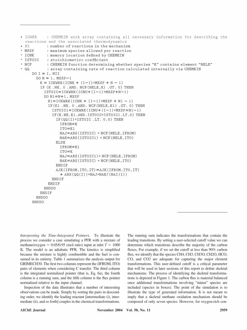
• ICWKR : CHEMKIN work array containing all necessary information for describing thereactions and the associated thermodynamics
• NI : number of reactions in the mechanism• MXSP : maximum species allowed per reaction• ICNK : memory location defined by CHEMKIN• ISTOIC : stoichiometirc coefficient• NCF : CHEMKIN function determining whether species “K” contains element “NELE”• QQ : array containing rate of reaction calculated internally via CHEMKIN
DO I � 1, NIIDO N � 1, MXSP�1K � ICKWRK(ICNK � (I�1)�MXSP � N � 1)IF (K .NE. 0 .AND. NCF(NELE,K) .GT. 0) THENISTOIC�ICKWRK(ICNU�(I�1)�MXSP�N�1)DO N1�N�1, MXSPK1�ICKWRK(ICNK � (I�1)�MXSP � N1 � 1)IF(K1 .NE. 0 .AND. NCF(NELE,K1) .GT. 0) THENISTOIC1�ICKWRK(ICNU�(I�1)�MXSP�N1�1)IF(K.NE.K1.AND.ISTOIC�ISTOIC1.LT.0) THENIF(QQ(I)�ISTOIC .LT. 0.0) THENIFROM�KITO�K1NAJ�ABS(ISTOIC) � NCF(NELE,IFROM)NAK�ABS(ISTOIC1) � NCF(NELE,ITO)
ELSEIFROM�K1ITO�KNAJ�ABS(ISTOIC1)� NCF(NELE,IFROM)NAK�ABS(ISTOIC) � NCF(NELE,ITO)
ENDIFAJK(IFROM,ITO,IT)�AJK(IFROM,ITO,IT)
� ABS(QQ(I))�NAJ�NAK/(NAI(I))ENDIF
ENDIFENDDO
ENDIFENDDO
ENDDO
Interpreting the Time-Integrated Pointers. To illustrate theprocess we consider a case simulating a PFR with a mixture ofmethane/oxygen � 0.05/0.95 (mol ratio) input at inlet T � 1000K. The model is an adiabatic PFR. The kinetics is simplifiedbecause the mixture is highly combustible and the fuel is con-sumed in its entirety. Table 1 summarizes the analysis output forGRIMECH30. The first two columns represent the (IFROM, ITO)pairs of elements when considering C transfer. The third columnis the integrated normalized pointer (that is, Eq. 6a), the fourthcolumn is a running sum, and the fifth column is the flux pointernormalized relative to the input channel.
Inspection of the data illustrates that a number of interestingobservations can be made. Simply by sorting the pairs in descend-ing order, we identify the leading reactant [intermediate (i), inter-mediate (ii), and so forth] couples in the chemical transformations.
The running sum indicates the transformations that contain theleading transitions. By setting a user-selected cutoff value we candetermine which transitions describe the majority of the carbonfluxes. For example, if we set the cutoff at less than 90% carbonflux, we identify that the species CH4, CH3, CH3O, CH2O, HCO,CO, and CO2 are adequate for capturing the major elementtransformations. This user-defined cutoff is a critical parameterthat will be used in later sections of this report to define skeletalmechanisms. The process of identifying the skeletal transforma-tions is depicted in Figure 1. The carbon flux is material balancedonce additional transformations involving “minor” species areincluded (species in boxes). The point of the simulation is toillustrate the type of generated information. It is not meant toimply that a skeletal methane oxidation mechanism should becomposed of only seven species. However, for oxygen-rich con-
AIChE Journal 2959November 2004 Vol. 50, No. 11
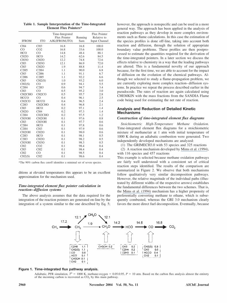
ditions at elevated temperatures this appears to be an excellentapproximation for the mechanism used.
Time-integrated element flux pointer calculation inreaction–diffusion systems
The above analysis assumes that the data required for theintegration of the reaction pointers are generated on-line by theintegration of a system similar to the one described by Eq. 5;
however, the approach is nonspecific and can be used in a moregeneral way. The approach has been applied in the analysis ofreaction pathways as they develop in more complex environ-ments such as flame calculations. In this case the estimation ofthe species profiles is done off-line, taking into account bothreaction and diffusion, through the solution of appropriateboundary value problems. These profiles are then postpro-cessed to estimate the quantities required for the derivation ofthe time-integrated pointers. In a later section we discuss theeffects relative to chemistry in a way that the leading pathwaysare altered. This is a fundamental novelty of our approachbecause, for the first time, we are able to account for the impactof diffusion on the evolution of the chemical pathways. Al-though we selected to study a flame-propagation problem, weare currently exploring more complex reaction–diffusion sys-tems. In practice we repeat the process described earlier in thepseudocode. The rates of reaction are again calculated usingCHEMKIN with the mass fractions from the SANDIA Flamecode being used for estimating the net rate of reaction.
Analysis and Reduction of Detailed KineticMechanismsConstruction of time-integrated element flux diagrams
Stoichiometric High-Temperature Methane Oxidation.Time-integrated element flux diagrams for a stoichiometricmixture of methane/air at 1 atm with initial temperature of1000 K during an adiabatic combustion were generated. Twoindependently developed mechanisms are analyzed:
(1) The GRIMECH3.0 with 53 species and 325 reactions(2) A reaction mechanism developed by Mims et al. (1994),
with 116 species and 457 reactionsThis example is selected because methane oxidation pathwaysare fairly well understood with a consistent set of criticalreaction steps identified. The results of the comparison aresummarized in Figure 2. We observe that both mechanismsfollow qualitatively very similar decomposition pathways.However, the relative magnitude of the individual paths (illus-trated by different widths of the respective arrows) establishesthe fundamental differences between the two schemes. That is,the Mims et al. (1994) mechanism has a higher propensity ofpreferentially converting methane to ethane, which is subse-quently combusted, whereas the GRI 3.0 mechanism clearlyfavors the more direct fuel decomposition. Eventually, because
Table 1. Sample Interpretation of the Time-IntegratedElement Flux Pointers*
IFROM ITO
Time-IntegratedFlux Pointer
AJK(IFROM,ITO)Running
Sum
Flux PointerRelative to
Input Channel
CH4 CH3 16.8 16.8 100.0CO CO2 16.8 33.6 100.0HCO CO 14.8 48.4 88.1CH2O HCO 14.2 62.6 84.5CH3O CH2O 12.2 74.8 72.6CH3 CH3O 12.1 86.9 72.0CH3 CH2O 1.9 88.8 11.4C2H5 C2H4 1.1 90.0 6.8CH3 C2H6 1.1 91.1 6.7C2H6 C2H5 1.1 92.2 6.6CH3 CH2(S) 1.0 93.2 6.0CH2(S) CO 0.9 94.1 5.5C2H4 C2H3 0.6 94.7 3.4CH3 CO 0.5 95.2 3.0CH2CHO CH2CO 0.5 95.7 2.8HCCO CO 0.4 96.1 2.5CH2CO HCCO 0.4 96.5 2.4C2H3 CH2CHO 0.4 96.8 2.1CH3 HCO 0.2 97.1 1.4CH2O CH4 0.2 97.3 1.4C2H4 CH2CHO 0.2 97.5 1.2CH3OH CH2OH 0.1 97.6 0.8CH3 CH3OH 0.1 97.7 0.6C2H4 HCO 0.1 97.8 0.6C2H4 CH3 0.1 97.9 0.6CH2OH CH2O 0.1 98.0 0.6C2H3 HCO 0.1 98.1 0.5C2H3 CH2O 0.1 98.2 0.5CH3OH CH3O 0.1 98.3 0.5CH2 CO2 0.1 98.4 0.4CH3 CH2 0.1 98.4 0.4CH2 CO 0.1 98.5 0.4CH2(S) CH2 0.1 98.6 0.4
*The 90% carbon flux cutoff identifies a minimal set of seven species.
Figure 1. Time-integrated flux pathway analysis.Adiabatic, PFR simulation, T0 � 1000 K, methane:oxygen � 0.05:0.95, P � 10 atm. Based on the carbon flux analysis almost the entiretyof the incoming carbon is recovered as CO2 by this main pathway.
2960 AIChE JournalNovember 2004 Vol. 50, No. 11
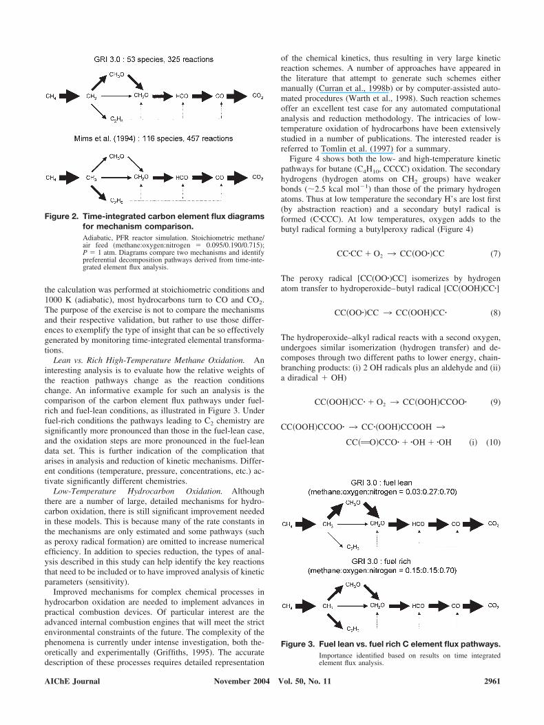
the calculation was performed at stoichiometric conditions and1000 K (adiabatic), most hydrocarbons turn to CO and CO2.The purpose of the exercise is not to compare the mechanismsand their respective validation, but rather to use those differ-ences to exemplify the type of insight that can be so effectivelygenerated by monitoring time-integrated elemental transforma-tions.
Lean vs. Rich High-Temperature Methane Oxidation. Aninteresting analysis is to evaluate how the relative weights ofthe reaction pathways change as the reaction conditionschange. An informative example for such an analysis is thecomparison of the carbon element flux pathways under fuel-rich and fuel-lean conditions, as illustrated in Figure 3. Underfuel-rich conditions the pathways leading to C2 chemistry aresignificantly more pronounced than those in the fuel-lean case,and the oxidation steps are more pronounced in the fuel-leandata set. This is further indication of the complication thatarises in analysis and reduction of kinetic mechanisms. Differ-ent conditions (temperature, pressure, concentrations, etc.) ac-tivate significantly different chemistries.
Low-Temperature Hydrocarbon Oxidation. Althoughthere are a number of large, detailed mechanisms for hydro-carbon oxidation, there is still significant improvement neededin these models. This is because many of the rate constants inthe mechanisms are only estimated and some pathways (suchas peroxy radical formation) are omitted to increase numericalefficiency. In addition to species reduction, the types of anal-ysis described in this study can help identify the key reactionsthat need to be included or to have improved analysis of kineticparameters (sensitivity).
Improved mechanisms for complex chemical processes inhydrocarbon oxidation are needed to implement advances inpractical combustion devices. Of particular interest are theadvanced internal combustion engines that will meet the strictenvironmental constraints of the future. The complexity of thephenomena is currently under intense investigation, both the-oretically and experimentally (Griffiths, 1995). The accuratedescription of these processes requires detailed representation
of the chemical kinetics, thus resulting in very large kineticreaction schemes. A number of approaches have appeared inthe literature that attempt to generate such schemes eithermanually (Curran et al., 1998b) or by computer-assisted auto-mated procedures (Warth et al., 1998). Such reaction schemesoffer an excellent test case for any automated computationalanalysis and reduction methodology. The intricacies of low-temperature oxidation of hydrocarbons have been extensivelystudied in a number of publications. The interested reader isreferred to Tomlin et al. (1997) for a summary.
Figure 4 shows both the low- and high-temperature kineticpathways for butane (C4H10, CCCC) oxidation. The secondaryhydrogens (hydrogen atoms on CH2 groups) have weakerbonds (2.5 kcal mol�1) than those of the primary hydrogenatoms. Thus at low temperature the secondary H’s are lost first(by abstraction reaction) and a secondary butyl radical isformed (C�CCC). At low temperatures, oxygen adds to thebutyl radical forming a butylperoxy radical (Figure 4)
CC�CC � O2 3 CC�OO��CC (7)
The peroxy radical [CC(OO�)CC] isomerizes by hydrogenatom transfer to hydroperoxide–butyl radical [CC(OOH)CC�]
CC�OO��CC 3 CC�OOH�CC� (8)
The hydroperoxide–alkyl radical reacts with a second oxygen,undergoes similar isomerization (hydrogen transfer) and de-composes through two different paths to lower energy, chain-branching products: (i) 2 OH radicals plus an aldehyde and (ii)a diradical OH)
CC�OOH�CC� � O2 3 CC�OOH�CCOO� (9)
CC�OOH�CCOO� 3 CC��OOH�CCOOH 3
CC�AO�CCO� � �OH � �OH �i� (10)
Figure 3. Fuel lean vs. fuel rich C element flux pathways.Importance identified based on results on time integratedelement flux analysis.
Figure 2. Time-integrated carbon element flux diagramsfor mechanism comparison.Adiabatic, PFR reactor simulation. Stoichiometric methane/air feed (methane:oxygen:nitrogen � 0.095/0.190/0.715);P � 1 atm. Diagrams compare two mechanisms and identifypreferential decomposition pathways derived from time-inte-grated element flux analysis.
AIChE Journal 2961November 2004 Vol. 50, No. 11

n CC�O��CCOO� � �OH �diradical � OH� �ii�
(11)
These paths are chain branching and are responsible for anincrease in oxidation rate that leads to the formation of coolflames.
As temperature increases the unimolecular dissociation re-actions of the initial butyperoxy and the hydroperoxide–butylradicals become more important and addition of the secondoxygen becomes disfavored. In addition an alternate reactionpath, HO2 molecular elimination starts to become more impor-tant and this significantly limits the extent of chain branching.These can be described (Figure 4) as
CC�CC � O2 4 CC�OO��CC
�reverse, dissociation reaction�
CC�OOH�CCOO� 4 CC��OOH�CCOOH
�reverse, dissociation reaction�
CCOO�CC 3 CCACC � HO2 �molecular elimination�
CC�OOH�CC� 3 Cyclic ether � OH COcy�CCCO�
(12)
Qualitatively, the resulting products from these two alter-nate paths amount to replacing the two active OH radicals byone OH or an even less reactive HO2, which slows theoxidation process. This is the phenomenon known as nega-tive temperature coefficient (NTC), where the apparent rateof oxidation decreases with increasing temperature attrib-uted to reduced forward reaction. As the temperature of thesystem increases further, usually above 900 –950 K, thepathway of the first oxygen addition becomes less favorableand �-scission (unimolecular dissociation processes of thehydrocarbon radical, not reaction with O2) dominate
CC�CC 3 CCAC � CH3� �beta scission� (13)
This defines the more usual high temperature oxidation chem-istry of hydrocarbons (Wilk et al., 1995).
Recently, the combustion group at Lawrence LivermoreNational Laboratory published a detailed mechanism for hy-drocarbon oxidation that includes much of the above-men-tioned kinetics (chemical activation reactions and diradicalproduct omitted; Curran et al., 1998a). A version of the mech-anism containing 385 species and 1895 reactions was analyzedusing the integrated element flux analysis approach. The con-ditions discussed in Minetti et al. (1996) were used for theanalysis. Table 2 depicts the pathways that the time-integratedelement flux analysis identifies as the critical ones, vs. initial
Figure 4. Potential energy diagram for chain-branching pathways that occur at moderate to low temperatures andlack of chain branching (chain propagation only) at somewhat higher (intermediate) temperatures.At very high temperatures the secondary n-butyl radical will under go unimolecular reaction (beta scission) to form propene methylradical.
2962 AIChE JournalNovember 2004 Vol. 50, No. 11
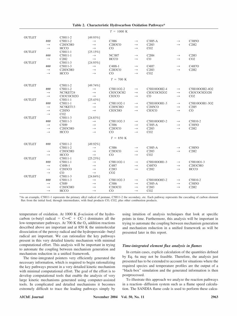
temperature of oxidation. At 1000 K �-scission of the hydro-carbon (n-butyl radical � CAC CC–) dominates all thelow-temperature pathways. At 700 K the O2 addition reactionsdescribed above are important and at 850 K the unimoleculardissociation of the peroxy radical and the hydroperoxide–butylradical are important. We can rationalize the key pathwayspresent in this very detailed kinetic mechanism with minimalcomputational effort. This analysis will be important in tryingto automate the coupling between mechanism generation andmechanism reduction in a unified framework.
The time-integrated pointers very efficiently generated thenecessary information, which is required to begin rationalizingthe key pathways present in a very detailed kinetic mechanismwith minimal computational effort. The goal of the effort is todevelop computational tools that enable the analysis of verylarge kinetic mechanisms generated using computer-assistedtools. In complicated and detailed mechanisms it becomesextremely difficult to trace the leading pathways simply by
using intuition of analysis techniques that look at specificpoints in time. Furthermore, this analysis will be important intrying to automate the coupling between mechanism generationand mechanism reduction in a unified framework as will bepresented later in this report.
Time-integrated element flux analysis in flames
In certain cases, explicit calculation of the quantities definedby Eq. 6a may not be feasible. Therefore, the analysis justpresented has to be extended to account for situations where therequired species and temperature profiles are the output of a“black-box” simulation and the generated information is thenpostprocessed.
To illustrate this approach we analyze the reaction pathwaysin a reaction–diffusion system such as a flame speed calcula-tion. The SANDIA flame code is used to perform these calcu-
Table 2. Characteristic Hydrocarbon Oxidation Pathways*
T � 1000 K
OUTLET C5H11-2 [49.93%]### C5H11-2 3 C3H6 3 C3H5-A 3 C3H5O3 C2H3CHO 3 C2H3CO 3 C2H3 3 C2H23 HCCO 3 CO 3 CO2
OUTLET C5H11-1 [25.15%]### C5H11-1 3 NC3H7 3 C2H4 3 C2H33 C2H2 3 HCCO 3 CO 3 CO2
OUTLET C5H11-3 [24.93%]### C5H11-3 3 C4H8-1 3 C4H7 3 C4H7O3 C2H3CHO 3 C2H3CO 3 C2H3 3 C2H23 HCCO 3 CO 3 CO2
T � 700 K
OUTLET C5H11-2 [49.74%]### C5H11-2 3 C5H11O2-2 3 C5H10OOH2-4 3 C5H10OOH2-4O23 NC5KET24 3 CH3COCH2 3 CH3COCH2O2 3 CH3COCH2O2H3 CH3COCH2O 3 CH3CO 3 CO 3 CO2
OUTLET C5H11-1 [25.43%]### C5H11-1 3 C5H11O2-1 3 C5H10OOH1-3 3 C5H10OOH1-3O23 NC5KET13 3 C2H5CHO 3 C2H5CO 3 C2H53 C2H5O 3 CH3CHO 3 CH3CO 3 CO3 CO2
OUTLET C5H11-3 [24.83%]### C5H11-3 3 C5H11O2-3 3 C5H10OOH3-2 3 C5H10-23 C5H9 3 C3H6 3 C3H5-A 3 C3H5O3 C2H3CHO 3 C2H3CO 3 C2H3 3 C2H23 HCCO 3 CO 3 CO2
T � 850 K
OUTLET ### C5H11-2 [49.92%]C5H11-2 3 C3H6 3 C3H5-A 3 C3H5O
3 C2H3CHO 3 C2H3CO 3 C2H3 3 C2H23 HCCO 3 CO 3 CO2
OUTLET C5H11-1 [25.23%]### C5H11-1 3 C5H11O2-1 3 C5H10OOH1-3 3 C5H10O1-33 C4H8-1 3 C4H7 3 C4H7O 3 C2H3CHO3 C2H3CO 3 C2H3 3 C2H2 3 HCCO3 CO 3 CO2
OUTLET C5H11-3 [24.84%]### C5H11-3 3 C5H11O2-3 3 C5H10OOH3-2 3 C5H10-23 C5H9 3 C3H6 3 C3H5-A 3 C3H5O3 C2H3CHO 3 C2H3CO 3 C2H3 3 C2H23 HCCO 3 CO 3 CO2
*As an example, C5H11-1 represents the primary alkyl radical of pentane, C5H11-2 the secondary, etc. Each pathway represents the cascading of carbon elementflux from the initial feed, through intermediates, with final products CO, CO2, plus other combustion products.
AIChE Journal 2963November 2004 Vol. 50, No. 11
lations (Kee et al., 1990). The flame calculations solve thefollowing two-point boundary value problem
M � �uA
MdT
dt�
1
cP
d
dx �AdT
dx� �A
cP�k�1
K
�YkVkcPk
dT
dx
�A
cP�k�1
K
khkWk � 0
MdYk
dt�
d
dx��AYkVk� � AkWk � 0 k � 1, . . . , M
� �PW�
RT(14)
Here, � denotes the density of the gas mixture, A is the area ofthe flame, cP is the specific heat capacity, x is the axialcoordinate, P is pressure, and M is the mass flow rate.
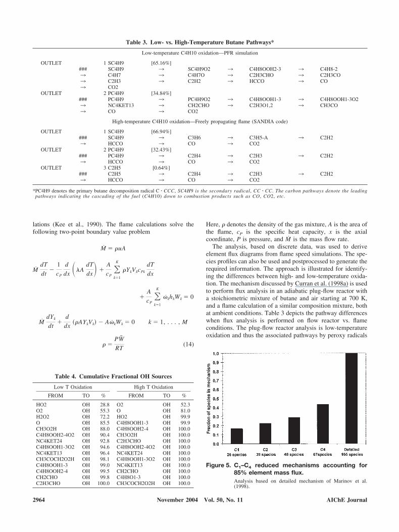
The analysis, based on discrete data, was used to deriveelement flux diagrams from flame speed simulations. The spe-cies profiles can also be used and postprocessed to generate therequired information. The approach is illustrated for identify-ing the differences between high- and low-temperature oxida-tion. The mechanism discussed by Curran et al. (1998a) is usedto perform flux analysis in an adiabatic plug-flow reactor witha stoichiometric mixture of butane and air starting at 700 K,and a flame calculation of a similar composition mixture, bothat ambient conditions. Table 3 depicts the pathway differenceswhen flux analysis is performed on flow reactor vs. flameconditions. The plug-flow reactor analysis is low-temperatureoxidation and thus the associated pathways by peroxy radicals
Figure 5. C1–C4 reduced mechanisms accounting for85% element mass flux.Analysis based on detailed mechanism of Marinov et al.(1998).
Table 4. Cumulative Fractional OH Sources
Low T Oxidation High T Oxidation
FROM TO % FROM TO %
HO2 OH 28.8 O2 OH 52.3O2 OH 55.3 O OH 81.0H2O2 OH 72.2 HO2 OH 99.9O OH 85.5 C4H8OOH1-3 OH 99.9CH3O2H OH 88.0 C4H8OOH2-4 OH 100.0C4H8OOH2-4O2 OH 90.4 CH3O2H OH 100.0NC4KET24 OH 92.8 C2H3CHO OH 100.0C4H8OOH1-3O2 OH 94.6 C4H8OOH2-4O2 OH 100.0NC4KET13 OH 96.4 NC4KET24 OH 100.0CH3COCH2O2H OH 98.1 C4H8OOH1-3O2 OH 100.0C4H8OOH1-3 OH 99.0 NC4KET13 OH 100.0C4H8OOH2-4 OH 99.5 CH2CHO OH 100.0CH2CHO OH 99.8 C4H8O1-3 OH 100.0C2H3CHO OH 100.0 CH3COCH2O2H OH 100.0
Table 3. Low- vs. High-Temperature Butane Pathways*
Low-temperature C4H10 oxidation—PFR simulation
OUTLET 1 SC4H9 [65.16%]### SC4H9 3 SC4H9O2 3 C4H8OOH2-3 3 C4H8-23 C4H7 3 C4H7O 3 C2H3CHO 3 C2H3CO3 C2H3 3 C2H2 3 HCCO 3 CO3 CO2
OUTLET 2 PC4H9 [34.84%]### PC4H9 3 PC4H9O2 3 C4H8OOH1-3 3 C4H8OOH1-3O23 NC4KET13 3 CH2CHO 3 C2H3O1,2 3 CH3CO3 CO 3 CO2
High-temperature C4H10 oxidation—Freely propagating flame (SANDIA code)
OUTLET 1 SC4H9 [66.94%]### SC4H9 3 C3H6 3 C3H5-A 3 C2H23 HCCO 3 CO 3 CO2
OUTLET 2 PC4H9 [32.43%]### PC4H9 3 C2H4 3 C2H3 3 C2H23 HCCO 3 CO 3 CO2
OUTLET 3 C2H5 [0.64%]### C2H5 3 C2H4 3 C2H3 3 C2H23 HCCO 3 CO 3 CO2
*PC4H9 denotes the primary butane decomposition radical C � CCC, SC4H9 is the secondary radical, CC � CC. The carbon pathways denote the leadingpathways indicating the cascading of the fuel (C4H10) down to combustion products such as CO, CO2, etc.
2964 AIChE JournalNovember 2004 Vol. 50, No. 11

are the primary outlets for the fuel. The high-temperaturechemistry, which is active during the stabilized flame opera-tion, makes such pathways negligible.
One of the key characteristics of high- vs. low-tempera-ture oxidation is that at low temperatures additional path-ways become active that allow additional production of OHradicals. As seen from Table 4, at high temperatures theprimary OH sources are H O2 and O OH (that is, thestandard routes), whereas at low temperatures about 15% ofOH production is attributed to pathways active exclusivelyby the peroxy radical chemistry. The thermodynamic controlof the kinetics gives rise to distinctly different pathwaysand, hence, very different chemical transformations in dif-ferent temperature regimes. The important point is that thepostprocessing of the flame data was able to correctly iden-tify the different contributions of high- and low-temperaturechemistry pathways.
Using time-integrated diagrams to identify skeletalreduced mechanisms
Flame Speed Predictions. The mechanism discussed inMarinov et al. (1998) was analyzed for the purpose of derivingsubsets of the reactive species that would adequately predictC1–C4 flame speeds. The original mechanism contains 155species and 689 reactions. Time-integrated flux analysis wasperformed at nominal conditions of stoichiometric mixtures at1300 K. Because we are primarily interested in flame chemis-try, focusing on high-temperature oxidation is a good indicatorof the chemical phenomena occurring. Skeletal mechanisms ofreduced size were identified (Figure 5) and the reduced mech-anisms were subsequently used in conjunction with the SAN-DIA flame code to predict laminar flame speeds. The agree-ment of the reduced skeletal mechanism with experiments isexcellent, as shown in Figures 6 and 7, for methane, ethane,propane, and butane.
Figure 6. Stoichiometric methane–ethane flame speed at atmospheric conditions.Solid symbols are experiments, solid line model predictions.
AIChE Journal 2965November 2004 Vol. 50, No. 11

The concept of time-integrated element flux analysis isalso used to identify the impact of molecular structure onfuel decomposition pathways in Farrell et al. (2004). Theydiscuss an extensive experimental study examining the im-pact of molecular structures on flame speed measurements.The flux analysis is used to interpret the relationship be-tween flame speed, molecular structure, and combustionchemistry.
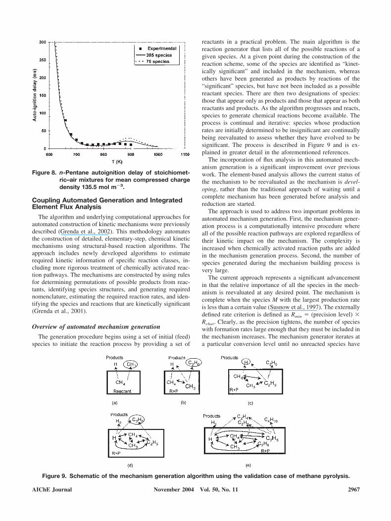
Low-Temperature Autoignition Delays. The mechanismdiscussed in Curran et al. (1998b) was analyzed using thetime-integrated element flux procedure to derive reducedmechanisms for low-temperature oxidation. In particular, wewere interested in evaluating the ability of reduced mecha-nisms to predict low-temperature autoignition delays (Min-netti et al., 1996). Autoignition delay defines a fundamentalproperty of fuels. It describes the time required for a mixtureof fuel and air to autoignite at a given initial pressure andtemperature. Experiments are conducted on a rapid compres-
sion machine (RCM). The mixture is quickly compressed toa target initial pressure and the corresponding temperature iscalculated as the adiabatic compression temperature. In thecalculation, the mixture is modeled using a constant volumecombustion process at the initial conditions of the com-pressed mixture. The mixture is allowed to autoignite atthese conditions and the time lag is recorded.
The mechanism of Curran et al. (1998) was used and sizereduction performed. A number of skeletal mechanismswere developed according the desired % flux threshold.Autoignition delays were then predicting using significantlyreduced mechanisms (75 species) and the detailed mecha-nism (385 species) and the predictions compared with ex-periments (Figure 8). The time-integrated element flux anal-ysis procedure has resulted in a substantially reduced sizemodel able to accurately capture the nonlinear behavior ofthe combustion systems and low temperatures.
Figure 7. Stoichiometric propane–butane flame speed at atmospheric conditions.Solid symbols are experiments; solid line, model predictions.
2966 AIChE JournalNovember 2004 Vol. 50, No. 11
Coupling Automated Generation and IntegratedElement Flux Analysis
The algorithm and underlying computational approaches forautomated construction of kinetic mechanisms were previouslydescribed (Grenda et al., 2002). This methodology automatesthe construction of detailed, elementary-step, chemical kineticmechanisms using structural-based reaction algorithms. Theapproach includes newly developed algorithms to estimaterequired kinetic information of specific reaction classes, in-cluding more rigorous treatment of chemically activated reac-tion pathways. The mechanisms are constructed by using rulesfor determining permutations of possible products from reac-tants, identifying species structures, and generating requirednomenclature, estimating the required reaction rates, and iden-tifying the species and reactions that are kinetically significant(Grenda et al., 2001).
Overview of automated mechanism generation
The generation procedure begins using a set of initial (feed)species to initiate the reaction process by providing a set of
reactants in a practical problem. The main algorithm is thereaction generator that lists all of the possible reactions of agiven species. At a given point during the construction of thereaction scheme, some of the species are identified as “kinet-ically significant” and included in the mechanism, whereasothers have been generated as products by reactions of the“significant” species, but have not been included as a possiblereactant species. There are then two designations of species:those that appear only as products and those that appear as bothreactants and products. As the algorithm progresses and reacts,species to generate chemical reactions become available. Theprocess is continual and iterative: species whose productionrates are initially determined to be insignificant are continuallybeing reevaluated to assess whether they have evolved to besignificant. The process is described in Figure 9 and is ex-plained in greater detail in the aforementioned references.
The incorporation of flux analysis in this automated mech-anism generation is a significant improvement over previouswork. The element-based analysis allows the current status ofthe mechanism to be reevaluated as the mechanism is devel-oping, rather than the traditional approach of waiting until acomplete mechanism has been generated before analysis andreduction are started.
The approach is used to address two important problems inautomated mechanism generation. First, the mechanism gener-ation process is a computationally intensive procedure whereall of the possible reaction pathways are explored regardless oftheir kinetic impact on the mechanism. The complexity isincreased when chemically activated reaction paths are addedin the mechanism generation process. Second, the number ofspecies generated during the mechanism building process isvery large.
The current approach represents a significant advancementin that the relative importance of all the species in the mech-anism is reevaluated at any desired point. The mechanism iscomplete when the species M with the largest production rateis less than a certain value (Susnow et al., 1997). The externallydefined rate criterion is defined as Rmin � (precision level) �Rchar. Clearly, as the precision tightens, the number of specieswith formation rates large enough that they must be included inthe mechanism increases. The mechanism generator iterates ata particular conversion level until no unreacted species have
Figure 8. n-Pentane autoignition delay of stoichiomet-ric–air mixtures for mean compressed chargedensity 135.5 mol m�3.
Figure 9. Schematic of the mechanism generation algorithm using the validation case of methane pyrolysis.
AIChE Journal 2967November 2004 Vol. 50, No. 11
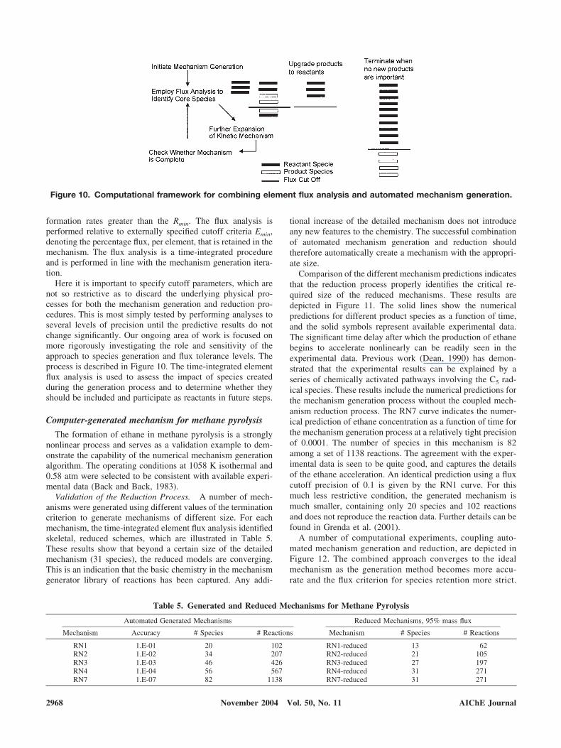
formation rates greater than the Rmin. The flux analysis isperformed relative to externally specified cutoff criteria Emin,denoting the percentage flux, per element, that is retained in themechanism. The flux analysis is a time-integrated procedureand is performed in line with the mechanism generation itera-tion.
Here it is important to specify cutoff parameters, which arenot so restrictive as to discard the underlying physical pro-cesses for both the mechanism generation and reduction pro-cedures. This is most simply tested by performing analyses toseveral levels of precision until the predictive results do notchange significantly. Our ongoing area of work is focused onmore rigorously investigating the role and sensitivity of theapproach to species generation and flux tolerance levels. Theprocess is described in Figure 10. The time-integrated elementflux analysis is used to assess the impact of species createdduring the generation process and to determine whether theyshould be included and participate as reactants in future steps.
Computer-generated mechanism for methane pyrolysis
The formation of ethane in methane pyrolysis is a stronglynonlinear process and serves as a validation example to dem-onstrate the capability of the numerical mechanism generationalgorithm. The operating conditions at 1058 K isothermal and0.58 atm were selected to be consistent with available experi-mental data (Back and Back, 1983).
Validation of the Reduction Process. A number of mech-anisms were generated using different values of the terminationcriterion to generate mechanisms of different size. For eachmechanism, the time-integrated element flux analysis identifiedskeletal, reduced schemes, which are illustrated in Table 5.These results show that beyond a certain size of the detailedmechanism (31 species), the reduced models are converging.This is an indication that the basic chemistry in the mechanismgenerator library of reactions has been captured. Any addi-
tional increase of the detailed mechanism does not introduceany new features to the chemistry. The successful combinationof automated mechanism generation and reduction shouldtherefore automatically create a mechanism with the appropri-ate size.
Comparison of the different mechanism predictions indicatesthat the reduction process properly identifies the critical re-quired size of the reduced mechanisms. These results aredepicted in Figure 11. The solid lines show the numericalpredictions for different product species as a function of time,and the solid symbols represent available experimental data.The significant time delay after which the production of ethanebegins to accelerate nonlinearly can be readily seen in theexperimental data. Previous work (Dean, 1990) has demon-strated that the experimental results can be explained by aseries of chemically activated pathways involving the C5 rad-ical species. These results include the numerical predictions forthe mechanism generation process without the coupled mech-anism reduction process. The RN7 curve indicates the numer-ical prediction of ethane concentration as a function of time forthe mechanism generation process at a relatively tight precisionof 0.0001. The number of species in this mechanism is 82among a set of 1138 reactions. The agreement with the exper-imental data is seen to be quite good, and captures the detailsof the ethane acceleration. An identical prediction using a fluxcutoff precision of 0.1 is given by the RN1 curve. For thismuch less restrictive condition, the generated mechanism ismuch smaller, containing only 20 species and 102 reactionsand does not reproduce the reaction data. Further details can befound in Grenda et al. (2001).
A number of computational experiments, coupling auto-mated mechanism generation and reduction, are depicted inFigure 12. The combined approach converges to the idealmechanism as the generation method becomes more accu-rate and the flux criterion for species retention more strict.
Figure 10. Computational framework for combining element flux analysis and automated mechanism generation.
Table 5. Generated and Reduced Mechanisms for Methane Pyrolysis
Automated Generated Mechanisms Reduced Mechanisms, 95% mass flux
Mechanism Accuracy # Species # Reactions Mechanism # Species # Reactions
RN1 1.E-01 20 102 RN1-reduced 13 62RN2 1.E-02 34 207 RN2-reduced 21 105RN3 1.E-03 46 426 RN3-reduced 27 197RN4 1.E-04 56 567 RN4-reduced 31 271RN7 1.E-07 82 1138 RN7-reduced 31 271
2968 AIChE JournalNovember 2004 Vol. 50, No. 11
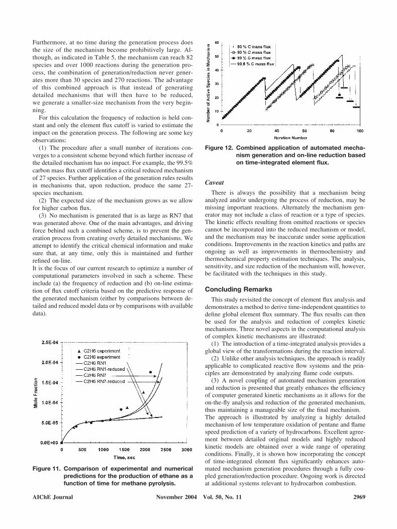
Furthermore, at no time during the generation process doesthe size of the mechanism become prohibitively large. Al-though, as indicated in Table 5, the mechanism can reach 82species and over 1000 reactions during the generation pro-cess, the combination of generation/reduction never gener-ates more than 30 species and 270 reactions. The advantageof this combined approach is that instead of generatingdetailed mechanisms that will then have to be reduced,we generate a smaller-size mechanism from the very begin-ning.
For this calculation the frequency of reduction is held con-stant and only the element flux cutoff is varied to estimate theimpact on the generation process. The following are some keyobservations:
(1) The procedure after a small number of iterations con-verges to a consistent scheme beyond which further increase ofthe detailed mechanism has no impact. For example, the 99.5%carbon mass flux cutoff identifies a critical reduced mechanismof 27 species. Further application of the generation rules resultsin mechanisms that, upon reduction, produce the same 27-species mechanism.
(2) The expected size of the mechanism grows as we allowfor higher carbon flux.
(3) No mechanism is generated that is as large as RN7 thatwas generated above. One of the main advantages, and drivingforce behind such a combined scheme, is to prevent the gen-eration process from creating overly detailed mechanisms. Weattempt to identify the critical chemical information and makesure that, at any time, only this is maintained and furtherrefined on-line.It is the focus of our current research to optimize a number ofcomputational parameters involved in such a scheme. Theseinclude (a) the frequency of reduction and (b) on-line estima-tion of flux cutoff criteria based on the predictive response ofthe generated mechanism (either by comparisons between de-tailed and reduced model data or by comparisons with availabledata).
Caveat
There is always the possibility that a mechanism beinganalyzed and/or undergoing the process of reduction, may bemissing important reactions. Alternately the mechanism gen-erator may not include a class of reaction or a type of species.The kinetic effects resulting from omitted reactions or speciescannot be incorporated into the reduced mechanism or model,and the mechanism may be inaccurate under some applicationconditions. Improvements in the reaction kinetics and paths areongoing as well as improvements in thermochemistry andthermochemical property estimation techniques. The analysis,sensitivity, and size reduction of the mechanism will, however,be facilitated with the techniques in this study.
Concluding Remarks
This study revisited the concept of element flux analysis anddemonstrates a method to derive time-independent quantities todefine global element flux summary. The flux results can thenbe used for the analysis and reduction of complex kineticmechanisms. Three novel aspects in the computational analysisof complex kinetic mechanisms are illustrated:
(1) The introduction of a time-integrated analysis provides aglobal view of the transformations during the reaction interval.
(2) Unlike other analysis techniques, the approach is readilyapplicable to complicated reactive flow systems and the prin-ciples are demonstrated by analyzing flame code outputs.
(3) A novel coupling of automated mechanism generationand reduction is presented that greatly enhances the efficiencyof computer generated kinetic mechanisms as it allows for theon-the-fly analysis and reduction of the generated mechanism,thus maintaining a manageable size of the final mechanism.The approach is illustrated by analyzing a highly detailedmechanism of low temperature oxidation of pentane and flamespeed prediction of a variety of hydrocarbons. Excellent agree-ment between detailed original models and highly reducedkinetic models are obtained over a wide range of operatingconditions. Finally, it is shown how incorporating the conceptof time-integrated element flux significantly enhances auto-mated mechanism generation procedures through a fully cou-pled generation/reduction procedure. Ongoing work is directedat additional systems relevant to hydrocarbon combustion.
Figure 11. Comparison of experimental and numericalpredictions for the production of ethane as afunction of time for methane pyrolysis.
Figure 12. Combined application of automated mecha-nism generation and on-line reduction basedon time-integrated element flux.
AIChE Journal 2969November 2004 Vol. 50, No. 11

Literature CitedBack, M. H., and R. A. Back, “Thermal Decomposition and Reactions of
Methane,” Pyrolysis: Theory and Industrial Practice, L. F. Albright,B. L. Crynes, and W. H. Concoran, eds., Academic Press, New York(1983).
Broadbelt, L. J., S. M. Stark, and M. T. Klein, “Computer-GeneratedPyrolysis Modeling: On the Fly Generation of Species, Reactions andRates,” Ind. Eng. Chem. Res., 33, 790 (1994).
Chevalier, C., W. J. Pitz, J. Warnatz, C. K. Westbrook, H. Melenk,“Hydrocarbon Ignition: Automatic Generation of Reaction Mechanismsand Applications to Modeling of Engine Shock,” Proc. Combust. Inst.,24, 1362 (1992).
Curran, H. J., P. Gaffuri, W. J. Pitz, and C. K. Westbrook, “A Compre-hensive Modeling Study of n-Heptane Oxidation,” Combust. Flame,114, 149 (1998b).
Curran, H. J., W. J. Pitz, C. K. Westbrook, C. V. Callahan, and F. L. Dryer,“Oxidation of Automotive Primary Reference Fuels at Elevated Pres-sures,” Proc. of the 27th Int. Symp. on Combustion, The CombustionInstitute, Pittsburgh, PA, pp. 379–387 (1998a).
Dean, A. M. “Detailed Kinetic Modeling of Autocatalysis in MethanePyrolysis,” J. Phys. Chem., 94, 32 (1990).
Farrell, J. T., R. J. Johnston, and I. P. Androulakis, “Molecular StructureEffects on Laminar Burning Velocities at Elevated Temperature andSAE paper 2004-01-2936 (2004).
Grenda, J. M., I. P. Androulakis, and J. W. Bozzelli, “Combined Use ofAutomated Kinetic Mechanism Generation and Reduction in the Devel-opment of Chemical Reaction Models,” 2nd Joint Meeting of the U.S.Sections of the Combustion Institute, Oakland, CA (2001).
Grenda, J. M., I. P. Androulakis, A. M. Dean, and W. H. Green, “Appli-cation of Computational Kinetic Mechanism Generation to Model theAutocatalytic Pyrolysis of Methane,” Ind. Eng. Chem. Res., 42(5), 1000(2002).
Kee, R. J., F. M. Rupley, E. Meeks, and J. A. Miller, “Chemkin—III: AFortran Chemical Kinetics Package for the Analysis of Gas-Phase
Chemical and Plasma Kinetics,” SANDIA Report, SAND96-8216(1996).
Marinov N. M., W. J. Pitz, C. K. Westbrook, A. M. Vincitore, M. J.Castaldi, and S. M. Senkan, “Aromatic and Polycyclic Aromatic Hy-drocarbon Formation in a Laminar Premixed n-Butane Flame,” Com-bust. Flame, 114, 192 (1998).
Mims, C. A., R. Mauti, A. M. Dean, and K. D. Rose, “Radical Chemistryof Methane Oxidative Coupling: Tracing of Ethylene Secondary Reac-tions with Computer Models and Isotopes,” J. Phys. Chem., 98, 13357(1994).
Revel, J., J. C. Boettner, M. Cathonet, and J. S. Bachman, “Derivation ofa Global Kinetic Mechanism for Methane Ignition and Combustion,”J. Chim. Phys. Phys.-Chim. Biol., 91, 365 (1994).
Smith, G. P., D. M. Golden, M. Frenklach, N. W. Moriarty, B. Eiteneer, M.Goldenberg, C. T. Bowman, R. K. Hanson, S. Song, W. C. Gardiner,V. V. Lissianski, and Z. Qin, GRIMECH 3.0, http://www.me.berke-ley.edu/gri_mech/
Susnow, R. G., A. M. Dean, W. H. Green, P. Peczak, and L. J. Broadblet,“Rate-Based Construction of Kinetic Models for Complex Systems,” J.Phys. Chem., 101, 3731 (1997).
Tomlin, A. S., T. Turanyi, and M. J. Pilling, “Mathematical Tools for theConstruction, Investigation and Reduction of Combustion Mechanisms,”Low-Temperature Combustion and Autoignition, Elsevier, Amsterdam(1997).
Turanyi, T., and T. Berges, “Reaction Rate Analysis of Complex KineticMechanisms,” Int. J. Chem. Kinet., 21, 83 (1989)
Warth, V., F. Battin-Leclerc, R. Fournet, P. A. Glaude, G. M. Come, andG. Scacchi, “Computer-Based Generation of Reaction Mechanisms forGas-Phase Oxidation,” Comput. Chem., 24, 541 (2000).
Westbrook, C. K., “The Internal Combustion Engine at Work,” http://www.llnl.gov/str/Westbrook.html (2002).
Wilk, R. D., R. S. Cohen, and N. P. Cernasky, “Oxidation of n-butane-Transition in the Mechanism Across the Region of Negative Tempera-ture Coefficient,” Ind. Eng. Chem. Res., 34(7), 2285 (1995).
Manuscript received Aug. 25, 2003, and revision received Feb. 26, 2004.
2970 AIChE JournalNovember 2004 Vol. 50, No. 11