SLF Rillenkugellager / Deep groove ball bearings - Hungaro ...

609
Three-dimensional numerical analysis of hydrodynamiccharacteristics of axial groove journal bearings runningwith ferrofluids under magnetic fieldY Sheikh Nejad and S A Gandjalikhan Nassab∗
Department of Mechanical Engineering, School of Engineering, Shahid Bahonar University, Kerman, Iran
The manuscript was received on 25 October 2009 and was accepted after revision for publication on 17 February 2010.
DOI: 10.1243/13506501JET751
Abstract: In this study, hydrodynamic characteristics of finite length journal bearings runningwith incompressible laminar flow under magnetic field are investigated. Ferrofluid as a lubricantcontains nanoparticles of magnetite (Fe3O4).The analysis is based on the numerical solution ofthe full Navier–Stokes equations using computational fluid dynamics techniques. Consideringthe complexity of the physical geometry, conformal mapping is used to generate an orthogonalgrid, and the governing equations are transformed in the computational domain. Discretizedforms of the transformed equations are obtained by the control volume method and solved bythe SIMPLE algorithm. Results indicated that when compared with the conventional lubricant,the ferrofluid as a lubricant enhances the hydrodynamic characteristics of journal bearings andprovides a higher load capacity. Besides, it was found that the other bearing characteristics areconsiderably affected by the applied magnetic field.
Keywords: ferrofluid, journal bearing, computational fluid dynamics, hydrodynamic character-istic, laminar flow
1 INTRODUCTION
Fluids that can be effectively controlled by magneticfields of moderate strength are a challenging subjectfor scientists interested in the basics of fluid mechan-ics as well as for application engineers. Suspensionsof magnetic nanoparticles with mean diameters ofapproximately 10 nm in appropriate carrier liquids area new class of smart materials, which are called fer-rofluids. When the magnetic field is applied to theferrofluids, each particle experiences a body force thatdepends on the magnetization of the magnetic mate-rial and on the strength and position of the appliedmagnetic field. Owing to specific properties in a mag-netic field, ferrofluids are actively used in differentindustrial, technical, and biological and medical appli-cations. A magnetic field gradient keeps the ferrofluidin space, even in the case of pressure differences
∗Corresponding author: Department of Mechanical Engineering,
School of Engineering, Shahid Bahonar University, 22 Bahman
Boulevard, Kerman 76169-133, Iran.
email: [email protected]
between two separated compartments. Today, manycomputer hard disk drivers contain a ferrofluid-sealedshaft. Ferrofluids are also used to improve heat dissi-pation in load speaker coils, enabling higher outputpower.
Other effect of magnetic field is on viscosity of fer-rofluids, which makes it to increase due to the factthat magnetic torque on each particle resists againstviscous torque, which is applied on particles by layerof fluid. Because of this effect, ferrofluids are used inmany lubricated bearings. As the application of elec-tric and magnetic fields increases the load capacityof a ferrofluid-lubricated bearing, magnetohydrody-namic (MHD) lubrication has been developed, andmuch works have been reported on the theoreticalanalysis of MHD thrust and journal bearings.
In contrast, lubrication plays a most vital role inthis great and complex civilization. To emphasize theimportance of this role, one needs to realize thatevery moving part of every machine is subject tofriction and wear. Besides, increasing trends towardshigher speed, higher performance but smaller size,machinery have pushed the operating condition ofbearings towards their ‘limit design’. Hence, for reliable
JET751 Proc. IMechE Vol. 224 Part J: J. Engineering Tribology
610 Y Sheikh Nejad and S A Gandjalikhan Nassab
prediction of the performance of such bearings, amodel that accounts for many operating conditionsis becoming increasingly important. Therefore, it isnecessary to carry out more research in this field toimprove the hydrodynamic characteristics of journalbearings lubricated with ferrofluid as a controllablefluid.
The accuracy of journal bearing performance pre-diction depends to a great extent on the ability topredict the oil flow pattern through the bearing. There-fore, the prediction of a bearing performance based onthe hydrodynamic analysis generally requires simul-taneous solution of equations governing the flow oflubricant. To reach this goal, a computational proce-dure for the numerical solution of three-dimensionalincompressible viscous flow between two rotatingeccentric cylinders with finite length is introduced inthis work. This type of flow has been a subject of inter-ests for many years. In 1994, Szeri [1] used a simplifiedthermohydrodynamic model for fluid film bearingsand also used Reynolds equation for the predictionof load capacity, Sommerfeld number, damping coef-ficient, and pressure distribution. In 1996, Khonsariet al. [2] presented the results of extensive amountof thermohydrodynamic simulation in the generaliza-tion of thermohydrodynamic analysis for journal bear-ings. In that work, the generalized Reynolds equationfor laminar incompressible Newtonian fluid understeady conditions was solved numerically and vali-dated by experimental data. Controllable high-speedjournal bearings, lubricated with electro-rheologicalfluids in an analytical and experimental approach,were studied by Nikolakopoulos [3] in 1998. In thatwork, an experiment on a high-speed journal bear-ing with small radial clearance was presented, andit was concluded that electro-rheological fluids canbe used to create ‘smart’ journal bearings. In 2002,thermohydrodynamic behaviour of journal bearingsrunning under different steady conditions was studiedby Moayeri and Gandjalikhan Nassab [4]. In that study,full dimensional Navier–Stokes and energy equationswere solved by finite volume method using com-putational fluid dynamics (CFD) techniques. Three-dimensional velocity field, pressure, and temperaturedistributions were demonstrated, and it was foundthat thermal effects in the fluid film are more pro-nounced for high values of the eccentricity ratioand journal speed and low value of clearance. In2007, Montazeri [5] performed numerical analysis ofhydrodynamic journal bearings lubricated with fer-rofluid. In that work, two-dimensional Navier–Stokesequation with constant viscosity was solved using CFDtechniques. For validation, numerical results werecompared with modified Reynolds equation, whichwas solved by finite difference techniques. In thatstudy, it was found that the bearing performance issignificantly modified when the magnetic effects arecomparable with the hydrodynamic effects.
Also, many papers were published to describethe behaviour and properties of the ferrofluid. Mostimportant concise study is performed by Odenbach[6] on magnetoviscous effects in ferrofluids. In thatstudy, the author gave introduction on magnetic fluids,magnetic properties of ferrofluids in the absence andpresence of the magnetic field, and some applicationsof ferrofluids. The author also gave some informationabout magnetoviscous effects in highly diluted fer-rofluids and magneto-rheological fluids. Some otherworks, such as those of Scherer and Figueiredo Neto[7], gave some information on properties and appli-cations of the ferrofluid, magnetic colloid, surfactedferrofluid, ionic ferrofluid, and their stability effectson lubricant flow.
The literature shows that there are several studies inwhich the two- and three-dimensional hydrodynamiccharacteristics of journal bearings were obtained bysolving the Reynolds equation, and in a few stud-ies, CFD techniques were employed to reach thisgoal. However, to the best of authors’ knowledge, thethree-dimensional hydrodynamic behaviour of jour-nal bearings running with ferrofluid under a magneticfield has not been obtained by CFD techniques. There-fore, in the present work, a set of governing equations,including the continuity and momentum equationsfor laminar ferrofluid flow in journal bearings, wassolved by CFD techniques, and the effect of mag-netic field on hydrodynamic characteristics of journalbearings was studied.
2 THEORY
2.1 Governing equations
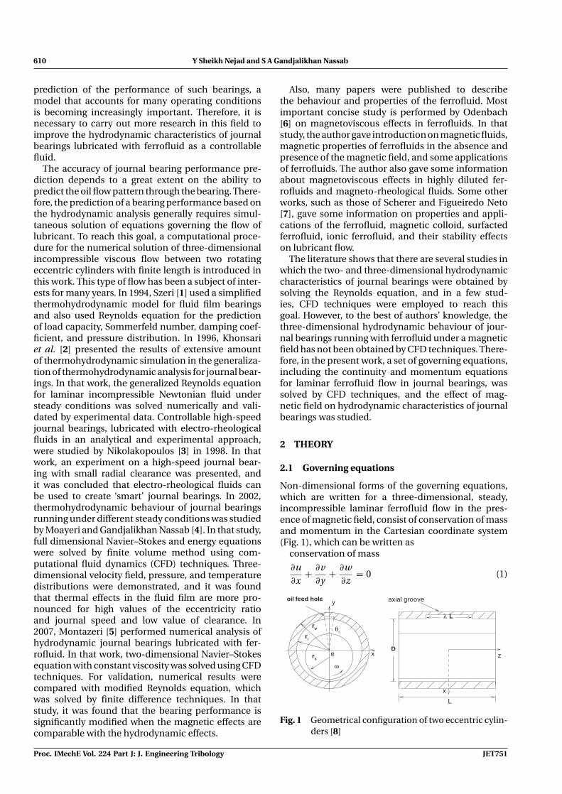
Non-dimensional forms of the governing equations,which are written for a three-dimensional, steady,incompressible laminar ferrofluid flow in the pres-ence of magnetic field, consist of conservation of massand momentum in the Cartesian coordinate system(Fig. 1), which can be written as
conservation of mass
∂u∂x
+ ∂v∂y
+ ∂w∂z
= 0 (1)
D
ro
ri
rs
Lλ
ω
θι
e x
y
z
x
L
axial grooveoil feed hole
Fig. 1 Geometrical configuration of two eccentric cylin-ders [8]
Proc. IMechE Vol. 224 Part J: J. Engineering Tribology JET751

Hydrodynamic characteristics of axial groove journal bearings 611
and conservation of momentum
∂
∂x
(u2 − 1
Re∂u∂x
)+ ∂
∂y
(uv − 1
Re∂u∂y
)
+ ∂
∂z
(uw − 1
Re∂u∂z
)= −∂p
∂x+ MH
∂H∂x
(2)
∂
∂x
(uv − 1
Re∂v∂x
)+ ∂
∂y
(v2 − 1
Re∂v∂y
)
+ ∂
∂z
(vw − 1
Re∂v∂z
)= −∂p
∂y+ MH
∂H∂y
(3)
∂
∂x
(uw − 1
Re∂w∂x
)+ ∂
∂y
(uw − 1
Re∂w∂y
)
+ ∂
∂z
(w2 − 1
Re∂w∂z
)= −∂p
∂z+ MH
∂H∂z
(4)
where the magnetic coefficient can be obtained asM = μ0χmH 2
0 /ρV2, in which H0 = I /2πri.
The value of induced magnetic force per unit volumeis given by fm = curl(H ) B + μ0Mg grad(H ), where B isthe magnetic field density and curl(H ) represents theinduced free current. For non-conductive base fluid,no free currents are induced. Considering isothermalconditions and linear behaviour of the ferrofluid Mg =χ H , then induced magnetic force per unit volumecan be given as fm = μ0χH grad(H ), which appearsin the right-hand side of momentum equations. Thedimensionless variables are defined as
x∗ = xc
, y∗ = yc
, z∗ = zc
, u∗ = u
V, v∗ = v
V,
w∗ = w
V, p∗ = p
ρV2 , Re = ρV c
η, Reref = ρV c
ηref
H ∗ = Hθ
H0= 1
r∗ , r∗ = rri
, H0 = I2πri
(5)
In these definitions, c is the radial clearance and V =rs ω is the shaft linear speed. It should be noted thatin Fig. 1 and equations (1) to (4), asterisks have beendropped for convenience.
2.2 Transformation functions
Because of the complex flow geometry in the (x, y)plane, which is the region between two eccentric cir-cles, the governing equations are transformed into asimple computational domain, such that the physi-cal domain at each axial location z = const. is con-formally mapped into a rectangular computationaldomain, which is shown in Fig. 2. The transformationbetween physical and computational planes can beperformed in two steps. Figure 2 shows these trans-formations along with their transformation functions.It is mentioned that the z-axis is the same for bothcomputational and physical coordinates. From thesetransformation functions, the relations between phys-ical and computational planes are obtained, and thetransformed forms of the governing equations for φ asa dependent variable in the computational plane canbe written in the following common form [9]
∂
∂ξ
(JAφ − φ
∂φ
∂ξ
)+ ∂
∂η
(JBφ − φ
∂φ
∂η
)
+ ∂
∂z
(JCφ − φ
∂φ
∂z
)= Sφ (6)
in which the values of A, B, C , φ , and Sφ vary from oneequation to the other according to Table 1.
In these equations
J = y2ξ + y2
η , U = yξ v + yηuJ
,
V = yηv − yξ uJ
, W = w
(7)
In obtaining the transformed form of the governingequation in the computational domain, the relationsxη = −yξ and xξ = yη, which are held for conformaltransformation, have been used.
2.3 Boundary conditions
Referring to Fig. 1, the following conditions in thephysical plane are considered.
1. Periodic boundary condition in the circumferentialsense is imposed for all dependent variables.
x
y
α
β
ξ = 0ξ = π
ηξ
η = − ln Rsη = 0
ri
rs
θe
ω
1Rs
Fig. 2 Mapping of the flow field [9]
JET751 Proc. IMechE Vol. 224 Part J: J. Engineering Tribology

612 Y Sheikh Nejad and S A Gandjalikhan Nassab
Table 1 Value of parameters in equation (6) for differentequations
A B C φ φ Sφ
Continuity equation U V W 1 0 0
ξ-moment equation U V W Uηref
Reref
∂
∂ξ(pyη) + ∂
∂η(pyξ )
η-moment equation U V W Vηref
Reref− ∂
∂ξ(pyξ ) − ∂
∂η(pyη)
z-moment equation U V W Wηref
Reref− ∂
∂z(JP)
2. No slip condition is used on the shaft and bushinner surface.
3. At the groove, where z � λL/2 and −θi � θ � θi,the following conditions are applied. Referring toFigs 1 and 2 and noticing that η = 0, the follow-ing are obtained: v = w = 0 and u = vi, where vi isthe dimensionless inlet fluid velocity at the groove,which can be corrected at each iteration. To cal-culate vi at each iteration, the following continuityequation will be considered [10]
vi = 1riθi(λL)
∫ ηm
0
∫ 2π
0JW dξ dη (8)
where double integral in the right-hand side iscomputed at the outlet section, z = L/2.
4. At the section z = 0 (mid-plane), the condition ofsymmetry, i.e. zero axial gradient of dependentvariables, is used.
5. At the outlet section z = L/2, p = 0 (atmosphericgauge pressure) and zero axial gradient of velocitycomponents are employed.
2.4 Magnetic field model
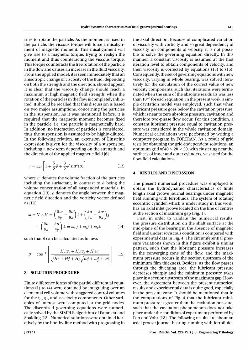
As Fig. 3 shows, the magnetic field is produced by acurrent passing through an infinitely long wire that islocated in the vicinity of the bearing at the distance rw.The wire makes an angle equal to ψ from the line ofcentres, which is considered to be π/2 in the presentcomputation.
The magnetic vector field is described in the cylin-drical coordinate system as follows
H = Hr er + Hθ eθ + Hzk (9)
the components of which in r-, θ-, and z-directions forthis model are
Hz = 0, Hr = 0, Hθ = I2πr
(10)
where r in equation (10) can be obtained by the cosinelaw
r =√
r2w + r2
0 − 2rwr0 cos(ψ − θ), r0 = √x2 + y2
(11)
Fig. 3 Displaced infinitely long wire magnetic fieldmodel
To obtain γ , the angle between rw and r, which isneeded for computing components of the magneticfield in x- and y-directions, sine law is used
γ = sin−1
[r0 sin(ψ − θ)
r
](12)
and the components of H in x- and y-directions canbe represented as follows
if x < 0, thenHx(x, y) = −H cos(γ )
Hy(x, y) = −H sin(γ )
and if x > 0, then
Hx(x, y) = −H cos(γ )
Hy(x, y) = −H sin(γ )
It should be mentioned that the direction of the mag-netic field H is normal to r; in other words, its directioncan be determined by the right-hand law.
2.5 Magnetic field effect on viscosity
As it is mentioned before, the magnetic field affectsthe viscosity by assuming a suspension of magneticnanoparticles under the influence of a shear flow. Itis obvious that the particles will rotate in the flowwith their axis of rotation parallel to the vorticity ofthe flow. For the purpose of illustration, it is consid-ered that the magnetic moment of the particles isfixed within the particle. First, it is considered thatthe applied magnetic field is perpendicular to the vor-ticity of the flow. In this situation, the magnetic fieldwill try to align the magnetic moment with the fielddirection, while the viscous torque exerted by the flow
Proc. IMechE Vol. 224 Part J: J. Engineering Tribology JET751
Hydrodynamic characteristics of axial groove journal bearings 613
tries to rotate the particle. As the moment is fixed inthe particle, the viscous torque will force a misalign-ment of magnetic moment. This misalignment willgive rise to a magnetic torque, trying to realign themoment and thus counteracting the viscous torque.This torque counteracts the free rotation of the particlein the flow and causes an increase in the fluid viscosity.From the applied model, it is seen immediately that ananisotropic change of viscosity of the fluid, dependingon both the strength and the direction, should appear.It is clear that the viscosity change should reach amaximum at high magnetic field strength, when therotation of the particles in the flow is completely inhib-ited. It should be recalled that this discussion is basedon two major assumptions, concerning the particlesin the suspension. As it was mentioned before, it isrequired that the magnetic moment becomes fixedin the particle, i.e. the particle is magnetically hard.In addition, no interaction of particles is considered,thus the suspension is assumed to be highly diluted.In the following relation, an extension of Einstein’sexpression is given for the viscosity of a suspension,including a new term depending on the strength andthe direction of the applied magnetic field [6]
η = ηref
[1 + 5
2ϕ̄ + 3
2ϕ′ sin2(β)
](13)
where ϕ′ denotes the volume fraction of the particlesincluding the surfactant, in contrast to ϕ̄ being thevolume concentration of all suspended materials. Inequation (13), β denotes the angle between the mag-netic field direction and the vorticity vector definedas [11]
ω = ∇ × V =(
∂w∂y
− ∂v∂z
)i +
(∂u∂z
− ∂w∂x
)j
+(
∂v∂x
− ∂u∂y
)k = ωx j + ωy j + ωzk (14)
such that β can be calculated as follows
β = cos−1
⎡⎢⎣ Hxwx + Hy wy + Hzwz√
H 2x + H 2
y + H 2z
√w2
x + w2y + w2
z
⎤⎥⎦ (15)
3 SOLUTION PROCEDURE
Finite difference forms of the partial differential equa-tions (1) to (4) were obtained by integrating over anelemental cell volume with staggered control volumesfor the ξ-, η-, and z-velocity components. Other vari-ables of interest were computed at the grid nodes.The discretized governing equations were numeri-cally solved by the SIMPLE algorithm of Patankar andSpalding [12]. Numerical solutions were obtained iter-atively by the line-by-line method with progressing in
the axial direction. Because of complicated variationof viscosity with vorticity and so great dependency ofviscosity on components of velocity, it is not possi-ble to solve the governing equation directly. In thismanner, a constant viscosity is assumed at the firstiteration level to obtain components of velocity, andthen viscosity is corrected by equations (13) to (15).Consequently, the set of governing equations with newviscosity, varying in whole bearing, was solved itera-tively for the calculation of the correct value of newvelocity components, such that iterations were termi-nated when the sum of the absolute residuals was lessthan 10−3 for each equation. In the present work, a sim-ple cavitation model was employed, such that whenlubricant pressure goes below the cavitation pressure,which is near to zero absolute pressure, cavitation andtherefore two-phase flow occur. For this condition, aconstant lubricant pressure equal to cavitation pres-sure was considered in the whole cavitation domain.Numerical calculations were performed by writing acomputer program in FORTRAN. As a result of gridtests for obtaining the grid-independent solutions, anoptimum grid of 40 × 20 × 20, with clustering near thesurfaces of inner and outer cylinders, was used for theflow-field calculations.
4 RESULTS AND DISCUSSION
The present numerical procedure was employed toobtain the hydrodynamic characteristics of finitelength axial groove journal bearings under magneticfield running with ferrofluids. The system of rotatingeccentric cylinder, which is under study in this work,has an axial inlet groove located on the line of centresat the section of maximum gap (Fig. 1).
First, in order to validate the numerical results,the pressure distribution on the shaft surface at themid-plane of the bearing in the absence of magneticfield and under isoviscous condition is compared withexperimental data in Fig. 4. The circumferential pres-sure variations shown in this figure exhibit a similarpattern, such that the lubricant pressure increasesin the converging zone of the flow, and the maxi-mum pressure occurs in the section upstream of theminimum film thickness. Besides, as the flow passesthrough the diverging area, the lubricant pressuredecreases sharply and the minimum pressure takesplace in a section upstream of the maximum gap. How-ever, the agreement between the present numericalresults and experimental data is quite good, especiallyin the pressure zone. It should be mentioned that inthe computations of Fig. 4 that the lubricant mini-mum pressure is greater than the cavitation pressure,such that the cavitation phenomenon does not takeplace under the condition of experiment performed byPan and Vohr [13]. The following results are about anaxial groove journal bearing running with ferrofluids
JET751 Proc. IMechE Vol. 224 Part J: J. Engineering Tribology

614 Y Sheikh Nejad and S A Gandjalikhan Nassab
-1
-0.5
0
0.5
1
ωθ
0 π
Expt.(Panetal.[13])
θ
p/[6
ηr2 s
ω/c
2 ]
2π
Present work
Fig. 4 Distribution of pressure in the circumferen-tial direction at mid-plane (z = 0). Reref = 134,c/rs = 0.0103, and ε = 0.68
Table 2 Bearing parameter and lubricantproperty
Parameter Unit Value
rs m 0.05ηref N s/m2 0.0192c/rs – 0.002–0.25rw /ri – 1.02–2λ – 0.3χ – 2.0ρ kg/m3 840ε – 0.4–0.5ω rad/s 0.07–230
whose parameters are given in Table 2. In order toshow the effect of magnetic field on lubricant pressure,the pressure distributions around the shaft surfacein the circumferential direction are plotted in Fig. 5for two different values of the magnetic coefficient.It is seen that the magnetic field causes a consider-able increase in the lubricant pressure, such that Fig. 5shows a pressure increase of about 200 per cent for abearing running under a magnetic field with magneticcoefficient M = 1, in comparison to the case with nomagnetic effect. Also, one can see that in both condi-tions of presence and absence of the magnetic field, asflow passes through the converging area, the pressureincreases rapidly, such that maximum pressure occursbefore minimum film thickness, after which pressuredecreases and remains constant in the diverging zonewhere cavitation occurs.
Figure 6 shows the magnetic intensity distributioninside the flow region for a magnetic coefficient ofM = 1. This figure shows a high intensity region nearto the wire carrying current such that, in the regionfar from the wire, the magnetic intensity is small. It
0
10
20
30
40
50
60
70
80
90
100
110
120
130
0 π 2πθ
P*
M=1
M=0
ωθ
Fig. 5 Pressure distribution in the circumferential direc-tion at the mid-plane. Reref = 50, rw/ri = 1.02,c/rs = 0.002, ε = 0.5, ϕ′ = 0.1, and ϕ̄ = 0.1
Fig. 6 Magnetic field intensity distribution, rw/ri = 2.0,M = 1, c/rs = 0.25, ε = 0.5, ϕ̄ = 0.1, and ϕ′ = 0.1
should be mentioned that the existence of high inten-sity region inside the pressure zone is a good task,because it causes an increase in the lubricant viscosityand then in the lubricant maximum pressure, whichimprove the bearing load capacity. Also, it is seen inFig. 6 that there is a considerable intensity gradient inboth circumferential and cross film directions.
It is evident that in journal bearings running underlubrication condition, the clearance ratio is very smallof the order of 10−3. Hence, one cannot show the oilflow pattern in the physical domain of the journalbearing. Therefore, in order to show a typical flowfield in the physical domain, numerical solution of thegoverning equation without magnetic effect for large
Proc. IMechE Vol. 224 Part J: J. Engineering Tribology JET751

Hydrodynamic characteristics of axial groove journal bearings 615
Fig. 7 Velocity field between two eccentric cylinders, Reref = 20, c/rs = 0.25, and ε = 0.5
clearance ratio, c/rs = 0.25, which is out of the lubrica-tion condition, is obtained, and results including thevelocity vectors at the mid-plane (z = 0) are shown inFig. 7. It is seen from Fig. 7(a) that the lubricant meanvelocity increases as the fluid passes through the con-verging area and then decreases in the diverging zone.The existence of unfavourable pressure gradient in thevicinity of maximum film thickness causes a reverseflow in this region, which is clearly seen in Fig. 7(b).Besides, the effect of axial groove where the lubri-cant flow enters into the bearing to compensate thelubricant outlet leakage is clearly seen in Fig. 7(c).
The volume concentration of all suspended materi-als is one of the main parameters that can affect lubri-cant pressure distribution. The effect of this parameteris studied in Fig. 8, in which the lubricant pressuredistributions along the axial direction at θ = 125◦ areplotted with three different values of volume con-centration. As can be seen, a significant increasein the amount of maximum pressure occurs whenthe volume concentration of all suspended materialsincreases. This behaviour may refer to the capabil-ity of lubricant to show more magnetic properties.Besides, a positive squeeze effect exists in the con-verging region up to the minimum film thickness.This situation can be found in Fig. 8. The maximumpressure occurs at the mid-plane (z = 0), and thenlubricant pressure decreases along the bearing lengthin the axial direction and becomes zero at the outletsection.
P*
L / 2L / 40
φ
φφ
= 0.6
= 0.1
= 0.3
z
160
20
40
60
80
100
120
140
Fig. 8 Pressure distribution in the axial directionat θ = 125◦ with different volume concentra-tions of all suspended materials ϕ̄. Reref = 50,rw/ri = 1.02, M = 1, c/rs = 0.002, ε = 0.5, andϕ′ = 0.1
The distribution of pressure along bearing, θ = 125◦
in the axial and circumferential directions, respec-tively, is depicted in Figs 9(a) and (b). These figurescan help to find out the influence of fraction of theparticles including the surfactant ϕ′ on distributionand maximum pressure. A considerable enhancement
JET751 Proc. IMechE Vol. 224 Part J: J. Engineering Tribology

616 Y Sheikh Nejad and S A Gandjalikhan Nassab
P*
L/2L/40
φ
φφ
= 0.6
= 0.1
= 0.3
z
20
40
60
80
100
120
140
0
25
50
75
100
125
150
175
0 π 2πθ
P*
ωθ
φ
φφ
= 0.6
= 0.1
= 0.3
(a) pressure distribution along the bearing (b) pressure distribution in circumferential direction
Fig. 9 Pressure distributions with different volume fractions of the particles including surfactantϕ′. Reref = 50, rw/ri = 1.02, M = 1, c/rs = 0.002, ε = 0.5, and ϕ̄ = 0.1
-25
0
25
50
75
100
125
P114.74796.337277.92759.516841.106722.69654.28629
-4.9188-23.329
0
− π
π
L/2
- L/2z
θ
P*
ω
z-L/2 L/2 θ
Fig. 10 Three-dimensional distribution of pressure on the shaft surface in the circumferential andaxial directions: Reref = 10, rw/ri = 10.2, M = 1, c/rs = 0.002, ε = 0.4, ϕ̄ = 0.1, and ϕ′ = 0.1
in the amount of maximum pressure occurs when thefraction of the particles increases. This may refer tothe capability of the lubricant to show more magneticproperties and impressive response.
To find a clear image of three-dimensional distri-bution of pressure in both circumferential and z-directions, Fig. 10 is plotted. This figure shows thelubricant pressure distribution on the surface of therotating shaft. It is seen in the pressure zone with
positive pressure that the maximum pressure takesplace at the mid-plane (z = 0), after which the lubri-cant pressure decreases towards the two bearing ends(z = ±L/2). Besides, the location of maximum pres-sure at each axial section is close to the minimum filmthickness (θ = π). The white line drawn in this figureshows the circumferential lubricant pressure distribu-tion at the mid-plane (z = 0). Figure 10 also shows thatcavitation takes place in some parts of the diverging
Proc. IMechE Vol. 224 Part J: J. Engineering Tribology JET751

Hydrodynamic characteristics of axial groove journal bearings 617
Fig. 11 Three-dimensional distribution of viscosity ratio η/ηref in both circumferential andz-directions: Reref = 50, rw/ri = 2.1, M = 1, c/rs = 0.25, ε = 0.5, ϕ′ = 0.1, and ϕ̄ = 0.1
area of the lubricant flow, such that at this region, thelubricant pressure is set equal to oil vapour pressure.It should be recalled that in this figure as well as otherfigures that show the lubricant pressure distribution,pressure is normalized by the dynamic pressure (ρV
2).
As this research focuses on the advantage of con-trollable feature of ferrofluids, in addition to bearinggeneral performance, the viscosity ratio distribution ofthe ferrofluid under magnetic field in journal bearingsis depicted in Fig. 11. This figure shows the variationof lubricant viscosity on the shaft surface in both axialand circumferential directions. As it is expected, theviscosity ratio (η/ηref ) is affected by the applied mag-netic field, such that its value is greater than unity in allgrid points. It shows that the magnetic field increasesthe lubricant viscosity and also the load capacity of thebearing. It is clear that in the absence of magnetic field,the value of viscosity ratio is equal to unity. It should bementioned that the variation of lubricant viscosity asshown in Fig. 11 is the result of viscosity dependenceon two factors:
(a) magnetic intensity;(b) the angle between vorticity vector and the mag-
netic vector field, based on equation (13).
These factors make a complicated distribution for fluidviscosity, similar to that shown in Fig. 11.
In order to study more about the effect of volumefraction of the particles on hydrodynamic character-
0.1 0.2 0.3 0.4 0.5 0.62200
2400
2600
2800
3000
3200
3400
3600
3800
LO
AD
CA
PA
CIT
Y(N
)
φ '
Fig. 12 Load capacity with respect to volume fraction ofthe particles ϕ′: Reref = 50, rw/ri = 1.02, M = 1,c/rs = 0.002, ε = 0.5, and ϕ̄ = 0.1
istics of journal bearings, the bearing load capacity,which is calculated by the integration of lubricantpressure on the shaft surface, is obtained using dif-ferent values of the parameter ϕ′, as shown in Fig. 12.It is seen that using ferrofluid with high value of par-ticle volume fraction improves the bearing load whichis as a main parameter in the lubrication.
JET751 Proc. IMechE Vol. 224 Part J: J. Engineering Tribology

618 Y Sheikh Nejad and S A Gandjalikhan Nassab
5 CONCLUSION
In this study, the three-dimensional hydrodynamiccharacteristics of axial groove journal bearings lubri-cated with ferrofluid under magnetic field are obtainedusing CFD techniques. In the numerical solution ofexact governing equation, to avoid any approximation,conformal mapping is used to transfer the governingequation to the computational plane. The transformedequations are solved for the velocity components andpressure by the SIMPLE algorithm. The numericalresults from this analysis can be used to investigatethe journal bearing performance and the oil flow pat-tern through this system. The main conclusion can besummarized as follows.
1. In the fluid flow between two eccentric cylinderssuch as lubricant flow in journal bearings, pressureincreases as the fluid passes through the converg-ing region and then falls in the diverging zone, suchthat the maximum pressure occurs before mini-mum film thickness. Impressive result was obtainedby applying magnetic field on bearings lubricatedwith ferrofluid. Pressure distribution changes con-siderably and maximum pressure increases.
2. The unfavourable pressure gradient in the circum-ferential direction, which exists in the vicinity ofmaximum film thickness, causes flow separation atthis region.
3. By applying the magnetic field, the lubricant vis-cosity increases, which causes impressive increasein maximum pressure and load capacity that leadto improve the journal bearing performance.
© Authors 2010
REFERENCES
1 Szeri, A. Z. A simplified THD model for fluid film bearing.Applied Image Inc., Tribology Section, Material & Com-ponents, Technical Division, Association for Informationand Image Management (AIIM), 1994.
2 Khonsari, M. M., Jang, J. Y., and Fillon, M. The gen-eralization of thermohydrodynamic analysis for journalbearing. J. Tribol., 1996, 118, 571–579.
3 Nikolakopoulos, P. G. Controllable high speed jour-nal bearings lubricated with electro-rheological fluids.Tribol. Int., 1998, 31(5), 402–412.
4 Moayeri, M. S. and Gandjalikhan Nassab, S. A. Ther-mohydrodynamic behavior of journal bearing runningunder different steady condition. Iran. J. Sci. Technol.Trans. B, 2002, 26, 515–532.
5 Montazeri, H. Numerical analysis of hydrodynamic jour-nal bearing lubricated with ferrofluid. Proc. IMechE,Part J: J. Engineering Tribology, 2007, 222, 51–60. DOI:10.1243/13506501JET314.
6 Odenbach, S. Magnetoviscous effects in ferrofluids, lec-ture notes in physics. In Physics and astronomy, 2001(Springer, Germany).
7 Scherer, C. and Figueiredo Neto, A. M. Ferrofluids:properties and applications. Braz. J. Phys., 2005, 35(3A),333–344.
8 Gandjalikhan Nassab, S. A. and Moayeri, M. S. Atwo dimensional THD analysis of journal bearing char-acteristics. Iran. J. Sci. Technol. Trans. B, 2000, 24,203–220.
9 Maneshian, B. and Gandjalikhan Nassab, S. A. Ther-mohydrodynamic characteristics of journal bearing run-ning under turbulent condition. IJE Trans. A, 2009, 22,181–194.
10 Maneshian, B. and Gandjalikhan Nassab, S. A. Ther-mohydrodynamic analysis of turbulent flow in jour-nal bearing running under different steady condition.Proc. IMechE, Part J: J. Engineering Tribology, 2009, 223,1115–1127. DOI: 10.1243/13506501JET575.
11 White, F. M. Viscous fluid flow, 2nd edition, 1991(McGraw-Hill, Inc., New York).
12 Patankar, S. V. and Spalding, B. D. A calculation pro-cedure for heat, mass and momentum transfer in threedimensional parabolic flow. Int. J. Heat Mass Transf.,1972, 15, 1787–1806.
13 Pan, C. H. T. and Vohr, J. H. Super laminar flow in bear-ings and seals. In Proceedings of the International Sym-posium on Lubrication in nuclear application, ASME,New York, 1967, pp. 219–245.
APPENDIX
Notation
c clearanceD bearing diametere eccentricityH magnetic intensityH0 reference magnetic intensityI current intensityL bearing lengthM magnetic coefficientp pressure (gauge)r distance of any point from wireri radius of the bearingrs radius of the shaftrw distance between wire and centre of
the bearingr0 distance of each point on clearance
space from bearing centreReref Reynolds number, Reref = ρV c/ηref
Rs transformation of rs
u, v, w components of velocity in x-, y-, andz-directions
U , V , W components of velocity in ξ-, η-, andz-directions
wx , wy , wz components of vorticity in x-, y-, andz-directions
x, y, z physical Cartesian coordinate axisZ physical plane
β angle between vorticity of flow and themagnetic field
Proc. IMechE Vol. 224 Part J: J. Engineering Tribology JET751

Hydrodynamic characteristics of axial groove journal bearings 619
γ angle between rw and rε eccentricity ratio, e/cη viscosityηref reference viscosityθ angle measured from axial
grooveθi angular span of axial grooveλ ratio of groove length to bearing
lengthμ0 vacuum permeability = 1.2566 × 10⁻⁶
(Vs/Am)ρ density
ϕ′ volume fraction of the particlesincluding the surfactant
ϕ̄ volume concentration of allsuspended materials
χm susceptibility of the fluidψ angle between rw and line of centres
measured from axial grooveω shaft rotational speed
Superscript
∗ non-dimensional parameter
JET751 Proc. IMechE Vol. 224 Part J: J. Engineering Tribology
Copyright © 2022 FDOKUMEN